ec mechanical lab manual
TRANSCRIPT

ENERGY CONVERSION LABORATORY [10MEL58]
S.J.B INSTITUTE OF TECHNOLOGY, MECH. ENGG. DEPT. Page 1
EXPERMENT NO. 1
ABELS’S PENSKY APPARATUS
AIM: To determine the flash and fire point of the lubricating oil using Abel‟s Pensky apparatus
APPARATUS: Abel‟s flash and fire point apparatus, thermometers and Broom sticks.
THEORY: Write the theory on following topics
a. Properties of oils with definition.
PROCEDURE:
1. The apparatus is setup as shown in the fig. A thermometer is inserted in the oil cup.
2. Before starting the room temperature is noted. The oil is heated for every 20
rise in
temperature is observed for the momentary flash.
3. The temperature at which flash appears is the flash point and is noted.
4. The oil is further heated till the oil catches the fire and burns continuously at least for
5sec and it is the fire point and is noted.
5. The flame is then put off
OBSERVATION:
1. Type of oil
TABULAR COLUMN:
Temperature oC
Remarks Flash point
oC
Fire point oC
RESULT:
Flash and Fire point of the given oil is_________ & ___________

ENERGY CONVERSION LABORATORY [10MEL58]
S.J.B INSTITUTE OF TECHNOLOGY, MECH. ENGG. DEPT. Page 2
EXPERMENT NO. 2
PENSKY MARTENS APPARATUS
AIM: To determine the flash and fire point of the lubricating oil by Pensky martens apparatus
APPARATUS: Pensky martens apparatus, thermometer, Broom sticks.
PROCEDURE:
1. The apparatus is setup as shown in fig. A thermometer is inserted in the oil cup.
2. Before starting the room temperature is noted. The oil is heated for every 20
rise in
temperature is observed for the momentary flash.
3. The temperature at which flash appears is the flash point is noted.
4. The oil is further heated till the oil catches the fire and burns continuously at least for
5sec and it is the fire point and is noted
5. The flame is then put off
OBSERVATION:
1. Type of oil
SCHEMATIC SKETCH:
Flexible
shaft
Jocket
Oil cup
Test Flame
Stirrer
Thermometer
Spring
lever arrgt
Wire gauge
ENERGY CONVERSION LABORATORY [10MEL58]
S.J.B INSTITUTE OF TECHNOLOGY, MECH. ENGG. DEPT. Page 3
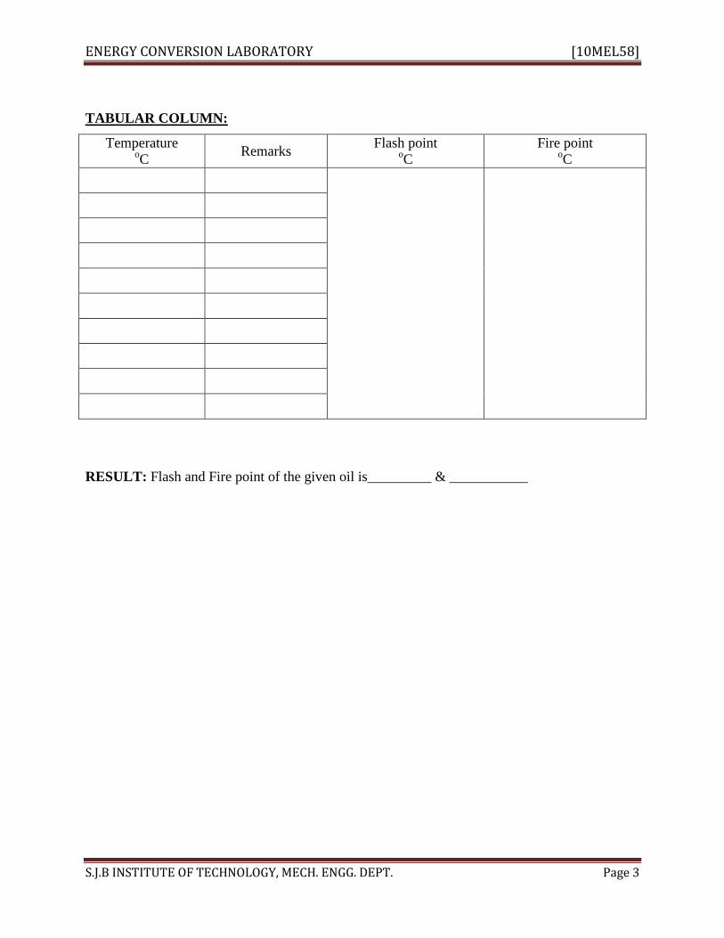
TABULAR COLUMN:
Temperature oC
Remarks Flash point
oC
Fire point oC
RESULT: Flash and Fire point of the given oil is_________ & ___________

ENERGY CONVERSION LABORATORY [10MEL58]
S.J.B INSTITUTE OF TECHNOLOGY, MECH. ENGG. DEPT. Page 4
EXPERIMENT NO. 3
JUNKER’S GAS CALORIMETER
AIM: To Determine the Lower Calorific Value of given gaseous fuel.
APPARATUS: Gas tank (fuel), governor, gas flow meter, stop watch, calorimeter, thermometer,
beaker.
THEORY : Write the theory on following topics
a. Definition of calorific value
b. Types of calorific values and their definitions
c. Types of calorimeters and their applications
d. Construction features of Junkers gas calorimeter
PROCEDURE:
1. Turn on the water by opening the control valve knob of the gas calorimeter to setting
ON.
2. Adjust the water supply in such a way that there will be only a small amount of
overflow of excess water to sink. By this air bubbles inside the water circulating will
be outlet.
3. Remove the burner from the calorimeter open the outlet tap of the governor. Allow
the gas to pass for three or four revolution as indicated by the flow meter then light
the burner and adjust the air regulator sleeve and the gas tap to get a luminous flame.
Clamp the burner keeping it to the top most position.
4. Adjust the flow of water to get a temperature difference of 120
C to 150
C between the
water inlet and outlet temperature. This is important if the flow of water is less than
that required, there will be a high temperature difference and water may escape as the
steam, so the water flow is to be adjusted in such a way that there will not be
formation of steam.
5. Allow the water outlet thermometer to indicate a steady temperature which may take
about 20 to 30 min. Keep the measuring jar beneath the swinging water outlet tube
and simultaneously count the number of revolution made by the gas flow meter
pointer to find the volume of gas consumed during the test period. When the pointer
has made two or three revolutions swing the water outlet back to waste.

ENERGY CONVERSION LABORATORY [10MEL58]
S.J.B INSTITUTE OF TECHNOLOGY, MECH. ENGG. DEPT. Page 5
6. Also immediately note the temperatures of water inlet and outlet as well as gas flow
meter keeping the water flow and gas flow same repeat the experiment trice or four
times and take the average of the reading and calculate the calorific value of the gas
OBSERVATION:
1. Type of fuel
SCHEMATIC SKETCH:
Governor
Over head
Waret Tank Gas Calorimeter
Burner
Gas Heter
Inlet
TABULAR COLUMN:
Sl.
No.
Vg1
ml
Vg2
ml
Vg
ml
Vw
ml
t
S
T1
oC
T2
oC
HCV
kJ/kg
Where,
Vg= Volume of gas supplied, ml
=Vg2-Vg1
ENERGY CONVERSION LABORATORY [10MEL58]
S.J.B INSTITUTE OF TECHNOLOGY, MECH. ENGG. DEPT. Page 6
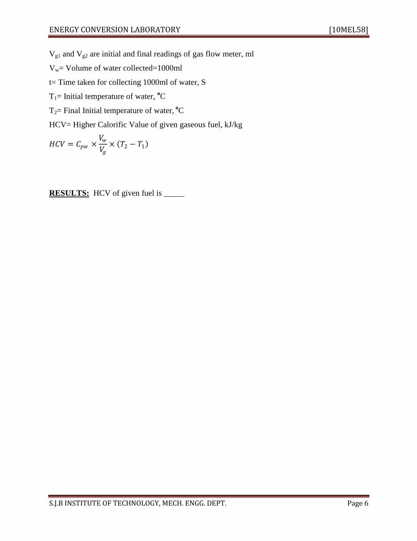
Vg1 and Vg2 are initial and final readings of gas flow meter, ml
Vw= Volume of water collected=1000ml
t= Time taken for collecting 1000ml of water, S
T1= Initial temperature of water, oC
T2= Final Initial temperature of water, o
C
HCV= Higher Calorific Value of given gaseous fuel, kJ/kg
𝐻𝐶𝑉 = 𝐶𝑝𝑤 ×𝑉𝑤𝑉𝑔
× 𝑇2 − 𝑇1
RESULTS: HCV of given fuel is _____

ENERGY CONVERSION LABORATORY [10MEL58]
S.J.B INSTITUTE OF TECHNOLOGY, MECH. ENGG. DEPT. Page 7
EXPERIMENT. NO. 4
RED WOOD VISCOMETER
AIM: To determine the kinematic and absolute viscosities of the given oil using red wood
viscometer.
APPARATUS: Red wood viscometer, stop watch, 50ml standard flask, thermometer
THEORY: Write the theory on following topics
a. Red Wood Viscometer description.
b. Definition of absolute viscosity, kinematic viscosity, viscosity index
c. Grading of lubricants, Single grade, Multi grade oils
d. Derivation of viscosity formula
PROCEDURE:
1. The instrument is cleaned and leveled. The oil is poured into the cylinder up to the
mark provided the thermometer is placed inside.
2. At the room temperature, time for flow of 50cc into the standard flask is noted.
3. The oil is again poured into the cylinder up to the mark and the heater is switched ON
4. The temperature of oil is adjusted as required. The oil and water are continuously
stirred during the experiment.
5. When the temperature is steady at the desired value the contact from the orifice is
removed to allow the oil to flow into 50ml standard flask.
6. The time taken for 50cc oil flow is recorded.
OBSERVATION:
1. Type of oil

ENERGY CONVERSION LABORATORY [10MEL58]
S.J.B INSTITUTE OF TECHNOLOGY, MECH. ENGG. DEPT. Page 8
SCHEMATIC SKETCH:
Water both
Electric
Heating Coil
Oil cup
Boil Valve
Oil level gauge
Stirrer
Flask
TABULAR COLUMN:
Sl. No. T
0C
m1
kg
m2
kg
m
kg
t
S
ρ
kg/m3
S RWN
m 2/ S
µ
N-S/m2
Where
T= Temperature of oil, 0C

ENERGY CONVERSION LABORATORY [10MEL58]
S.J.B INSTITUTE OF TECHNOLOGY, MECH. ENGG. DEPT. Page 9
m1 = Mass of empty flask, kg
m2 = Mass of flask with oil, kg
m = Mass of oil collected, kg = m2-m1
t = Time taken for collecting 60cc of oil in seconds
ρ = Density of oil, kg / m3
𝜌 = 𝑚
60 × 10−6
S=Specific gravity of the oil, N/m3
𝑆 =𝜌
1000
RWN= Red Wood Number
𝑅𝑊𝑁 =100 × 𝑆 × 𝑡
535 × 0.915
= Kinematic viscosity, m 2/ S
= 0.26𝑡 −188
𝑡 × 10−6
µ = Absolute viscosity, N-S/m2
𝜇 = × 𝜌
GRAPH: 1. T v/s µ 2. T v/s
RESULT: Viscosity of given oil _____ ______ ______
ENERGY CONVERSION LABORATORY [10MEL58]
S.J.B INSTITUTE OF TECHNOLOGY, MECH. ENGG. DEPT. Page 10
EXPERMENT NO. 5.
SAYBOLT VISCOMETER
AIM: To determine the viscosity of the given sample of oil using Saybolt viscometer
APPARATUS: Saybolt viscometer, Thermometer, Stopwatch, 60cc Flask, Balance.
THEORY: Write the theory on following topics
a. Saybolt Viscometer description.
b. Derivation of viscosity formula S
PROCEDURE:
1. The instrument is cleaned and leveled. The oil is poured into the cylinder up to the mark
provided the thermometer is placed inside.
2. At the room temperature, time for flow of 60cc into the standard flask is noted.
3. The oil is again poured into the cylinder upto the mark and the heater is switched ON
4. The temperature of oil is adjusted as required. The oil and water are continuously stirred
during the experiment.
5. When the temperature is steady at the desired value the contact from the orifice is
removed to allow the oil to flow into 60ml standard flask.
6. The time taken for 60cc oil flow is recorded.
SCHEMATIC SKETCH:

ENERGY CONVERSION LABORATORY [10MEL58]
S.J.B INSTITUTE OF TECHNOLOGY, MECH. ENGG. DEPT. Page 11
60MM
THERMO
METER
ELECTRICAL
COIL
HANDLE FOR
ROTATE
BALL
VALVE
GLASS
JAR STAND
TABULAR COLUMN:
Sl. No. T
0C
m1
kg
m2
kg
m
kg
t
S
ρ
kg/m3
m 2/ S
µ
N-S/m2
Where
T= Temperature of oil, 0C
m1 = Mass of empty flask, kg
m2 = Mass of flask with oil, kg
m = Mass of oil collected, kg = m2-m1
ENERGY CONVERSION LABORATORY [10MEL58]
S.J.B INSTITUTE OF TECHNOLOGY, MECH. ENGG. DEPT. Page 12
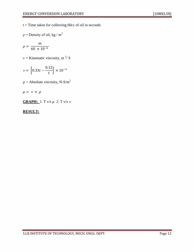
t = Time taken for collecting 60cc of oil in seconds
ρ = Density of oil, kg / m3
𝜌 = 𝑚
60 × 10−6
= Kinematic viscosity, m 2/ S
= 0.33𝑡 −0.12
𝑡 × 10−4
µ = Absolute viscosity, N-S/m2
𝜇 = × 𝜌
GRAPH: 1. T v/s µ 2. T v/s
RESULT:

ENERGY CONVERSION LABORATORY [10MEL58]
S.J.B INSTITUTE OF TECHNOLOGY, MECH. ENGG. DEPT. Page 13
EXPERIMENT NO. 6
VALVE TIMING DIAGRAM
AIM: To draw the value timing diagram of the given engine
APPARATUS: Given engine, measuring tape, scale.,
THEORY: Write the theory on following topics
a. Difference between 2-stroke and 4-stroke engine.
b. Define the valve over lapping.
c. Difference between SI and CI Engines.
d. Draw the theoretical valve time diagram for 4- stroke SI engine.
e. Draw the theoretical valve time diagram for 2- stroke CI engine.
PROCEDURE :
1. Note the location of the inlet and exhaust valves of the given engine.
2. The flywheel is turned in clockwise direction and the positions of TDC and BDC are
identified with respect to the crank position
3. The circumferential length of flywheel is measured with help of thread and ruler
4. The flywheel is turned in clock wise direction and the position and inlet valve begins to
open is marker.
5. This point is measured from the initial reference mark (TDC) and this length is noted.
6. The flywheel turned in the same direction and the position of inlet valve closing and
exhaust valve opening and exhaust valve closing are noted and corresponding length with
respective to the reference marks.
7. The reading is recorded in the tabular column and corresponding angles turned (in
degrees) are determined.
OBSERVATION:
1. Type of engine
SCHEMATIC SKETCH:

ENERGY CONVERSION LABORATORY [10MEL58]
S.J.B INSTITUTE OF TECHNOLOGY, MECH. ENGG. DEPT. Page 14
SUCTION STROKE
SUCTION VALVE
OPEN
COMPRESSION STROKE
BOTH VALVE ARE
CLOSED
IGNITION OR POWER
STROKE
BOTH VALVE ARE
CLOSED
EXHAUST STROKES
EXHAUST VALVE
OPEN
SUCTION STROKE
SUCTION VALVE
OPEN
TABULAR COLUMN :
Sl. No. Valve position Piston position L
m
𝜃o
degree
1 IVO
2 IVC
3 EVO
4 EVC
5
Where,
L = Arc length, cm
𝜃 =𝐿 × 360
𝜋 × 𝐷
𝜃 𝑖𝑛 𝑑𝑒𝑔𝑟𝑒𝑒𝑠
D=Flywheel diameter, m
Name of the stroke Crank angle
degree
Suction
Compression
Expansion
Exhaust
RESULT :

ENERGY CONVERSION LABORATORY [10MEL58]
S.J.B INSTITUTE OF TECHNOLOGY, MECH. ENGG. DEPT. Page 15
EXPERMENT NO. 7
PLANIMETER
AIM: To determine the area of irregular figure by using a planimeter.
APPARATUS: Planimeter, drawing board and sheet. Drawing instruments
THEORY: Write the theory on following topics
a. Different methods used for measuring irregular area
b. Principle of planimeter
c. Construction features of planimeter
PROCEDURE:
1. Fix the figure whose area is to be determined on a smooth surface, preferably on a
horizontal drawing board.
2. Set the index to read 100Sq cm on the tracing arm if the area is required in square cm.
3. Fix the anchor point inside or outside the figure such that the tracer is able to trace the
whole boundary of the area.
4. Mark a starting point on the boundary of the figure & place the tracer on the starting
point. Note the initial reading.
5. Move the tracer slowly along the boundary of the area in clock wise direction, until it
comes back to the starting point
6. The No. of times the zero of the dial passes the fixed index mark neither in a clockwise or
anticlockwise direction during the above process should be carefully noted. Record the
final reading F & compute the area by using the above equation.
SCHEMATIC SKETCH:

ENERGY CONVERSION LABORATORY [10MEL58]
S.J.B INSTITUTE OF TECHNOLOGY, MECH. ENGG. DEPT. Page 16
34
56
45
TABULAR COLUMN:
SL.
NO.
Shape of the
plane
Ath
cm2
PLANIMETER READING Am
cm2
% Error
I F M
1 Square
2 Circle
3 Triangle
4 Rectangle
5 Ellipse
Where
Ath= The theoretical area of the given shape, cm2
I = Initial reading
F = Final reading
M = Multiplier of planimeter, 100 cm2
Am = Measured area of the given shape cm2.
Am = 𝑀 𝐹 − 𝐼 ± 10 × 𝑁 + 𝐶
N= No. of rotations of the disc ( + ve for clockwise direction, -ve foe anticlockwise direction)
C= constant of planimeter, considered only when the anchor point is kept inside the plane
% Error= 𝐴𝑡 −𝐴𝑚
𝐴𝑡 × 100
RESULTS:

ENERGY CONVERSION LABORATORY [10MEL58]
S.J.B INSTITUTE OF TECHNOLOGY, MECH. ENGG. DEPT. Page 17
EXPERIMENT NO. 8
4-STROKE PETROL ENGINE
AIM: To determine the performance Characteristic of a 4-stroke petrol engine
APPARATUS: 4-Stroke petrol engine test rig, stop watch, fuel etc.,
THEORY: Write the theory on following topics
a. Definitions of IP, BP, FP, mechanical efficiency, thermal efficiency (brake and
indicated), volumetric efficiency, ISFC, BSFC, relative efficiency, air standard efficiency
b. Methods to measure FP
c. Methods to measure IP
PROCEDURE:
1. Check the fuel in the tank.
2. Switch ON the power supply & console on the panel board and Ensure ignition switch in
ON.
3. But keep the loading switches in off position initially. Allow the petrol and start the
engine by using rope.
4. Apply the load AC generator by switching on loading switches. Allow some time until
the speed stabilizes.
5. Repeat the procedure 4 to 5 different loads at constant speed i.e., 0.5KW load each
6. Tabulate the corresponding readings.
7. Once the experiment is over keep the petrol control valve in closed position. And switch
of the console & power supply
OBSERVATION:
Max power of the engine = 2.4KW
Rated speed = 3000rpm
Bore = 70mm
Stoke = 66.7mm
Compression ration = 4.76 : 1
Starting of the engine by rope
Loading – electrically air heater connected to AC generator
ENERGY CONVERSION LABORATORY [10MEL58]
S.J.B INSTITUTE OF TECHNOLOGY, MECH. ENGG. DEPT. Page 18
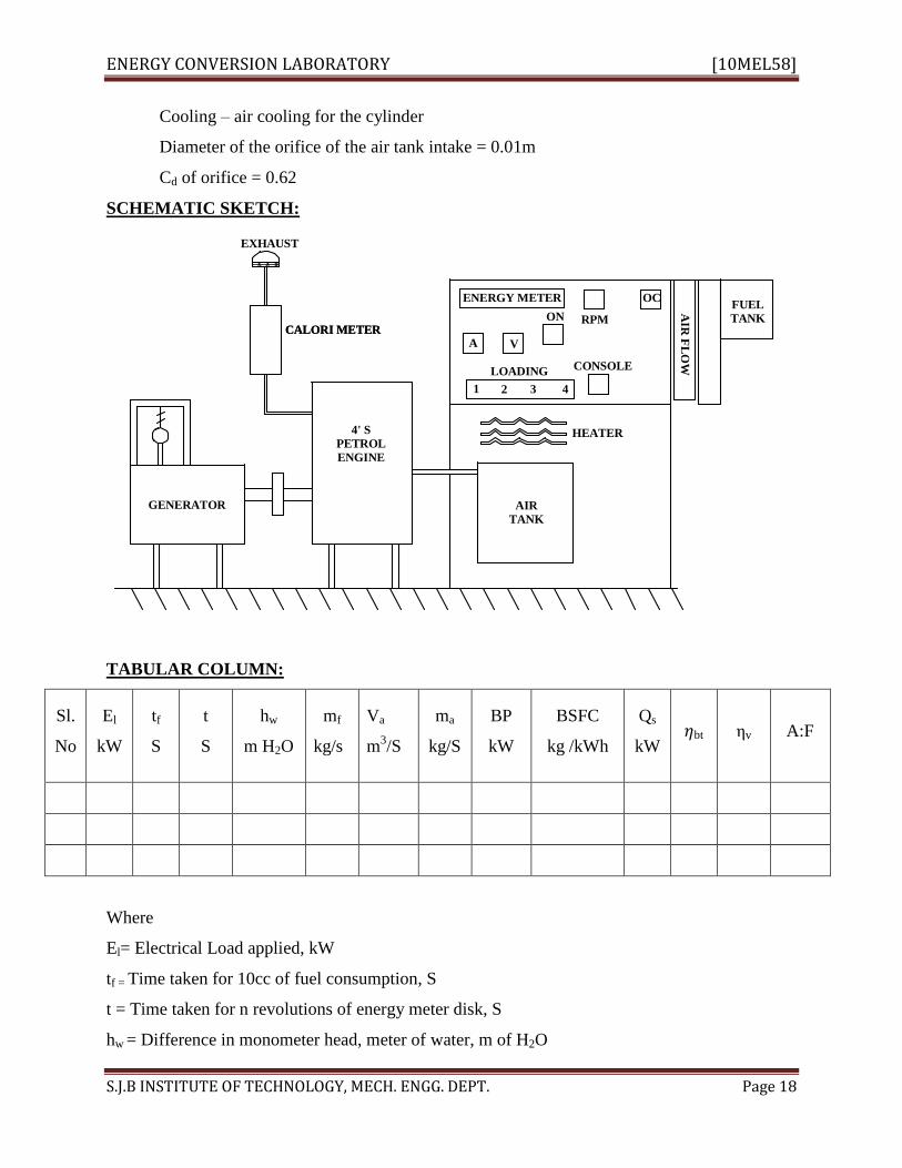
Cooling – air cooling for the cylinder
Diameter of the orifice of the air tank intake = 0.01m
Cd of orifice = 0.62
SCHEMATIC SKETCH:
CALORI METER
GENERATOR
EXHAUST
CALORI METER
4' S
PETROL
ENGINE
ENERGY METER
A V
ON
CONSOLE
1 2 43
RPM
OC
HEATER
AIR
TANK
AIR
FL
OW
FUEL
TANK
LOADING
TABULAR COLUMN:
Sl.
No
El
kW
tf
S
t
S
hw
m H2O
mf
kg/s
Va
m3/S
ma
kg/S
BP
kW
BSFC
kg /kWh
Qs
kW 𝜂bt ηv A:F
Where
El= Electrical Load applied, kW
tf = Time taken for 10cc of fuel consumption, S
t = Time taken for n revolutions of energy meter disk, S
hw = Difference in monometer head, meter of water, m of H2O

ENERGY CONVERSION LABORATORY [10MEL58]
S.J.B INSTITUTE OF TECHNOLOGY, MECH. ENGG. DEPT. Page 19
mf = Mass of fuel kg/s
= 𝑉𝑓 ×𝑆
1000×𝑡 = 𝑘𝑔/𝑠
vf = Volume of fuel consumed = 10cc
s = specific gravity of fuel
t = time taken for 10 cc fuel consumed, S
Va = Actual volume of air consumed, m3/S
𝑉𝑎 = 𝐶𝑑 × 𝐴𝑜 2𝑔𝑎
Cd = Coefficient of discharge = 0.62
Ao = Area of orifice,
𝐴𝑜 = 𝜋×𝑑𝑜
2
4
do = Diameter of Orifice, m
ha = Head of the air, m
𝑎 =𝑤 × 𝜌𝑤
𝜌𝑎
ρw = Density of water = 1000 kg /m3
ρa = Density of air, kg/ m3
𝜌𝑎 = 𝑝𝑎
𝑅𝑇𝑎
Pa = Atmospheric pressure = 101.3 kPa
R= Gas Constant for air = 0.287 kJ/kgK
Ta = Ambient temperature, K
ma = Mass of air kg/s
𝑚𝑎 = 𝜌𝑎 × 𝑉𝑎
CV = Calorific value kj/m3
BP = Brake power kw
BP =3600 ×𝑛
𝐾 ×𝑡
n = Number of revolution of energy meter
K = 1500 energy meter constant
BSFC = 𝑚𝑓
𝐵𝑃× 3600 = ⋯… . . 𝑘𝑔/𝑘𝑤 h
𝜂bt= 𝐵𝑃
𝑄𝑠 × 100 %

ENERGY CONVERSION LABORATORY [10MEL58]
S.J.B INSTITUTE OF TECHNOLOGY, MECH. ENGG. DEPT. Page 20
A:F = 𝑀𝑎
𝑀𝑓
ηv = 𝑉𝑎
𝑉𝑠 × 100
Vs = Swept volume of cylinder m3/s
Vs = 𝜋𝐷2 𝐿𝑁
60 × 4 ×2
D = Diameter of cylinder, m
L = Stroke length, m
N = Number of revolutions of crank shaft per min
RESULTS:
GRAPH:
FC Vs BP
SFC Vs BP
ηbth Vs BP
ηv Vs BP
A:F Vs BP

ENERGY CONVERSION LABORATORY [10MEL58]
S.J.B INSTITUTE OF TECHNOLOGY, MECH. ENGG. DEPT. Page 21
EXPERMENT NO. 9
VARIABLE COMPRESSION RATIO PETROL ENGINE
AIM: To determine the performance characteristics of a variable compression ratio of petrol
engine test rig at different compression ratio and at a fixed speed
APARATUS : Variable compression ratio petrol engine test rig, air inlet tank, digital
tachometer, energy meter, temperature indicator etc.,
THEORY: Write the theory on following topics
a. Define SFC
b. What are the methods to measure fuel consumption?
c. Define compression ratio.
d. Define volumetric efficiency.
e. Define thermal efficiency
f. Brake thermal efficiency.
PROCEDURE:
1. Fill the fuel tank with neat petrol
2. Check the sufficient lubricating oil in the oil pump.
3. Connect the control panel to electrical mains ie., 440 volts, 3 phase, 15A neutral
connection.
4. Select the compression ratio by using proper combination of head and spacer.
5. Keep the engine throttle to fully open position
6. Put on the mains to check mains on indicator
7. Put on the console, blower of DC machine is running and all the indicating instruments
glow
8. Block the dynamometer torque arm.
9. Push he start button so that engine starts
10. Switch on the electrical loading resistance
11. Unlock the torque arm and make it horizontal by taking the reading in spring balance.
12. For different load positions control the speed at constant valve. Take down the reading
for different parameter and tabulate them.
13. After the experiment is over close the petrol valve inlet to the carburetor to avoid retching
for subsequent start of engine.

ENERGY CONVERSION LABORATORY [10MEL58]
S.J.B INSTITUTE OF TECHNOLOGY, MECH. ENGG. DEPT. Page 22
14. Repeat the experiment for different compression ratio by maintaining the engine speed as
constant.
OBSERVATION:
1. Compression ratios=
2. Max. speed of the engine=
3. Max. BP of the engine=
SCHEMATIC SKETCH:
GENERATOR
EXHAUST
CALORI METER
4' S
PETROL
ENGINE
ENERGY METER
A V
ON
CONSOLE
1 2 43
RPM
OC
HEATER
AIR
TANK
AIR
FL
OW
FUEL
TANK
LOADING
TABULAR COLUMN:
STANDARD HEAD
Sl.
No
El
kW
tf
S
t
S
hw
m H2O
mf
kg/s
Va
m3/S
ma
kg/S
BP
kW
BSFC
kg /kWh
Qs
kW
𝜂bt
%
ηv
% A:F

ENERGY CONVERSION LABORATORY [10MEL58]
S.J.B INSTITUTE OF TECHNOLOGY, MECH. ENGG. DEPT. Page 23
0.5 HEAD
Sl.
No
El
kW
tf
S
t
S
hw
m H2O
mf
kg/s
Va
m3/S
ma
kg/S
BP
kW
BSFC
kg /kWh
Qs
kW 𝜂bt ηv A:F
Where
El= Electrical Load applied, kW
tf = Time taken for 10cc of fuel consumption, S
t = Time taken for n revolutions of energy meter disk, S
hw = Difference in monometer head, meter of water m of H2O
mf = Mass of fuel kg/s
= 𝑉𝑓 ×𝑆
1000×𝑡 = 𝑘𝑔/𝑠
vf = Volume of fuel consumed = 10cc
s = specific gravity of fuel
t = time taken for 10 cc fuel consumed, S
Va = Actual volume of air consumed, m3/S
𝑉𝑎 = 𝐶𝑑 × 𝐴𝑜 2𝑔𝑎
Cd = Coefficient of discharge = 0.62
Ao = Area of orifice,
𝐴𝑜 = 𝜋×𝑑𝑜
2
4
do = Diameter of Orifice, m
ha = Head of the air, m
𝑎 =𝑤 × 𝜌𝑤
𝜌𝑎
ρw = Density of water = 1000 kg /m3
ρa = Density of air, kg/ m3
𝜌𝑎 = 𝑝𝑎
𝑅𝑇𝑎

ENERGY CONVERSION LABORATORY [10MEL58]
S.J.B INSTITUTE OF TECHNOLOGY, MECH. ENGG. DEPT. Page 24
Pa = Atmospheric pressure = 101.3 kPa
R= Gas Constant for air = 0.287 kJ/kgK
Ta = Ambient temperature, K
ma = Mass of air kg/s
𝑚𝑎 = 𝜌𝑎 × 𝑉𝑎
CV = Calorific value kj/m3
BP = Brake power kw
BP =3600 ×𝑛
𝐾 ×𝑡
n = Number of revolution of energy meter
K = 1500 energy meter constant
BSFC = 𝑚𝑓
𝐵𝑃× 3600 = ⋯… . . 𝑘𝑔/𝑘𝑤 h
𝜂bt= 𝐵𝑃
𝑄𝑠 × 100 %
A:F = 𝑀𝑎
𝑀𝑓
ηv = 𝑉𝑎
𝑉𝑠 × 100
Vs = Swept volume of cylinder m3/s
Vs = 𝜋𝐷2 𝐿𝑁
4
D = Diameter of cylinder, m
L = Stroke length , m
N = Number of revolution per min
RESULTS:
GRAPH:
FC Vs BP
SFC Vs BP
ηbth Vs BP
ηv Vs BP
A:F Vs BP

ENERGY CONVERSION LABORATORY [10MEL58]
S.J.B INSTITUTE OF TECHNOLOGY, MECH. ENGG. DEPT. Page 25
EXPERIMENT NO. 10
FOUR STROKE VERICAL SINGLE CYLINDER DIELSEL ENGINE
AIM: To conduct a performance test on a mechanically loaded single cylinder 4 –stroke diesel
engine and to draw the heat balance sheet
APPARATUS: Single cylinder Diesel Engine Test Rig, stop watch, fuel, beaker, etc.,
THEORY:
PROCEDURE:
1. Switch On the power supply to the panel board and Start the engine by cranking.
2. Maintain the speed of engine as constant and note down the speed.
3. The engine is loaded by applying the mechanical load on the brake drum and different
reading are noted.
4. The temperature of cooling water at inlet and outlet is noted. The quantity of fuel supply
is also measured.
5. The load on the engine is increased gradually and different readings are noted again the
experiment is conducted for different loads 2kg, 4kg, 6kg, 8kg, and 10kg.
6. Note down all the readings and calculate the requirement
OBSERVATION:
Calorific value of diesel = 44100 kJ/kg
Specific gravity of diesel = 0.8275
Compression ratio of engine = 16:1
Bore = 80cm
Length of the stroke, L = 110mm
Rated speed of the engine = 1200rpm
Rated power 3.68 KW
Brake drum diameter = 350mm
Rope diameter = 0.015m
ENERGY CONVERSION LABORATORY [10MEL58]
S.J.B INSTITUTE OF TECHNOLOGY, MECH. ENGG. DEPT. Page 26
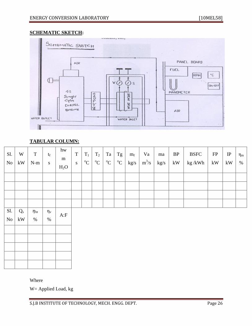
SCHEMATIC SKETCH:
TABULAR COLUMN:
Sl.
No
W
kW
T
N-m
tf
s
hw
m
H2O
T
s
T1
oC
T2
oC
Ta
oC
Tg
oC
mf
kg/s
Va
m3/s
ma
kg/s
BP
kW
BSFC
kg /kWh
FP
kW
IP
kW
ηm
%
Sl.
No
Qs
kW
𝜂bt
%
ηv
% A:F
Where
W= Applied Load, kg

ENERGY CONVERSION LABORATORY [10MEL58]
S.J.B INSTITUTE OF TECHNOLOGY, MECH. ENGG. DEPT. Page 27
T = Torque , N-m
T = (𝑊 − 𝑆) × 𝑅𝑒 × 9.81
Re = Effective diameter = 𝐷+𝑑
2
D= Diameter of the drum
d = Diameter of rope
tf = Time taken for 10cc of fuel consumption, S
hw = Difference in monometer head, meter of water m of H2O
t = Time for collecting 1 liter of water.
T1 = Water inlet temperature 0C
T2 = Water outlet temperature 0C
Ta = Air inlet temperature 0C
Tg = Exhaust gas temperature 0C
mf = Mass of fuel kg/s
= 𝑉𝑓 ×𝑆
1000×𝑡 = 𝑘𝑔/𝑠
vf = Volume of fuel consumed = 10cc
s = specific gravity of fuel
Va = Actual volume of air consumed, m3/S
𝑉𝑎 = 𝐶𝑑 × 𝐴𝑜 2𝑔𝑎
Cd = Coefficient of discharge = 0.62
Ao = Area of orifice,
𝐴𝑜 = 𝜋×𝑑𝑜
2
4
do = Diameter of Orifice, m
ha = Head of the air, m
𝑎 =𝑤 × 𝜌𝑤
𝜌𝑎
ρw = Density of water = 1000 kg /m3
ρa = Density of air , kg/ m3
𝜌𝑎 = 𝑝𝑎
𝑅𝑇𝑎
Pa = Atmospheric pressure = 101.3 kPa

ENERGY CONVERSION LABORATORY [10MEL58]
S.J.B INSTITUTE OF TECHNOLOGY, MECH. ENGG. DEPT. Page 28
R= Gas Constant for air = 0.287 kJ/kgK
Ta = Ambient temperature, K
ma = Mass of air kg/s
𝑚𝑎 = 𝜌𝑎 × 𝑉𝑎
CV = Calorific value kj/m3
BP = Brake power kw
BP =2 𝜋 𝑁 𝑇
6000
N = Number of revolution of crank shaft per minute
BSFC = 𝑚𝑓
𝐵𝑃× 3600 = ⋯… . . 𝑘𝑔/𝑘𝑤 h
Qs = Heat supplied , kW
Qs = mf × CV
CV = Calorific value of fuel
𝜂bt= 𝐵𝑃
𝑄𝑠 × 100 %
ηv = 𝑉𝑎
𝑉𝑠 × 100
Vs = Swept volume of cylinder m3/s
Vs = 𝜋𝐷2 𝐿𝑁
60 ×4×2
D = Diameter of cylinder, m
L = Stroke length, m
A:F = 𝑚𝑎
𝑚𝑓
FP = Frictional power, kW ( From Graph)
IP = Indicated power , kW
IP = BP + IP
ηm = Mechanical Efficiency
ηm= 𝐵𝑃
𝐼𝑃× 100
ENERGY CONVERSION LABORATORY [10MEL58]
S.J.B INSTITUTE OF TECHNOLOGY, MECH. ENGG. DEPT. Page 29
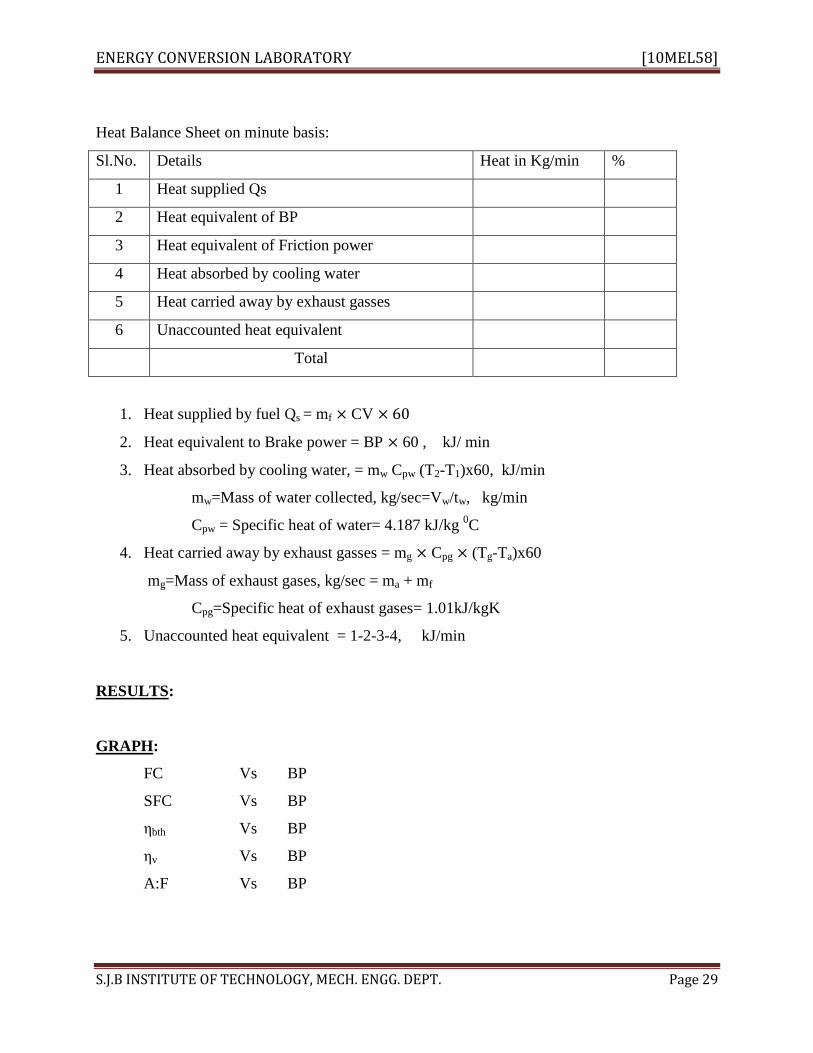
Heat Balance Sheet on minute basis:
Sl.No. Details Heat in Kg/min %
1 Heat supplied Qs
2 Heat equivalent of BP
3 Heat equivalent of Friction power
4 Heat absorbed by cooling water
5 Heat carried away by exhaust gasses
6 Unaccounted heat equivalent
Total
1. Heat supplied by fuel Qs = mf × CV × 60
2. Heat equivalent to Brake power = BP × 60 , kJ/ min
3. Heat absorbed by cooling water, = mw Cpw (T2-T1)x60, kJ/min
mw=Mass of water collected, kg/sec=Vw/tw, kg/min
Cpw = Specific heat of water= 4.187 kJ/kg 0C
4. Heat carried away by exhaust gasses = mg × Cpg × (Tg-Ta)x60
mg=Mass of exhaust gases, kg/sec = ma + mf
Cpg=Specific heat of exhaust gases= 1.01kJ/kgK
5. Unaccounted heat equivalent = 1-2-3-4, kJ/min
RESULTS:
GRAPH:
FC Vs BP
SFC Vs BP
ηbth Vs BP
ηv Vs BP
A:F Vs BP

ENERGY CONVERSION LABORATORY [10MEL58]
S.J.B INSTITUTE OF TECHNOLOGY, MECH. ENGG. DEPT. Page 30
EXPERIMENT NO. 11
MORSE TEST
AIM: To determine the frictional of the given multi cylinder spark ignition engine.
APPARATUS: Engine setup, thermometer, tachometer.
THEORY: This test is adopted to find the indicated power of each cylinder for high speed
internal combustion engine without using indicator diagram.
PROCEDURE:
1. The engine is started and allowed to turn for some time.
2. The engine is loaded to max. value by using hydraulic dynamometer and throttle position is
adjusted to get the desired rate speed, load and speed values are noted.
3. Current supplied to sparkling of Internal cylinder is stopped by operating lever.
4. Load is now decreased to bring spring back to original value without altering the position.
Reading of the spring balance is noted down.
5. Now current supplied to spark plug of 2nd
cylinder is stopped soon after the current supply to
the spark plug of the original rated speed the load is varied.
6. In the same manner the experiment is repeated for different out-off the engine.
SPECIFICATIONS:
Type: 4 stroke, four cylinder car engine with hydraulic loading.
Rated power= 10HP (1.36kw)
Rated speed: 1500 rpm
Distance between the centers of dynamometer to the point spring balance loading= 43.5cm
TABULAR COLUMN:
Condition of the engine W
N
N
rpm
BP
kW
IP
kW
ηm
All cylinders firing (BP)
Cylinder 1 is cut off (BP1)
Cylinder 2 is cut off(BP2)
Cylinder 3 is cut off(BP3)
W= Load applied on the engine through dynamometer when all cylinders firing, N

ENERGY CONVERSION LABORATORY [10MEL58]
S.J.B INSTITUTE OF TECHNOLOGY, MECH. ENGG. DEPT. Page 31
W1= Load applied on the engine when cylinder 1 cut-off, N
W2= Load applied on the engine when cylinder 2 cut-off, N
W3= Load applied on the engine when cylinder 3 cut-off, N
BP= Brake power of the engine when all cylinders firing, kW= WN/K
BP1= Brake power of the engine when cylinder 1 is cut-off= W1N/K
BP2= Brake power of the engine when cylinder 2 is cut-off =W2N/K
BP3= Brake power of the engine when cylinder 3 is cut-off =W3N/K
K= Dynamometer constant= 60×1000
2𝜋𝑅
R= Distance between the centers of dynamometer to the point spring balance loading, m
IP= Indicated power of the engine, kW=IP1+IP2+IP3
IP1= Indicated power of the cylinder 1=BP-BP1
IP2= Indicated power of the cylinder 2=BP-BP2
IP3= Indicated power of the cylinder 3=BP-BP3
ηm= Mechanical efficiency
ηm= 𝐵𝑃
𝐼𝑃× 100

ENERGY CONVERSION LABORATORY [10MEL58]
S.J.B INSTITUTE OF TECHNOLOGY, MECH. ENGG. DEPT. Page 32
EXPERIMENT NO. 12
BOMB CALORIMETER
AIM: To Determine the Calorific Value of solid or liquid Fuel by Bomb Calorimeter
APPARATUS: Bomb Calorimeter, dies, thermometer, fuse wire, Rheostat, stirrer, benzoic acid,
firing unit, pressure gauge.
SCHEMATIC SKETCH:
THEORY: Write the theory on following topics
a. Definition of calorific value
b. Types of calorific values and their definitions
c. Types of calorimeters and their applications
Bomb Calorimeter is normal used for determining the higher calorific value of solid fuels and
also used for liquid fuels. The combustion takes place at constant volume in a totally enclosed
vessel.
The bomb calorimeter consists of a strong stainless shell which is known as bomb. The inner
surface of the bomb is coated with special enamel to prevent the corrosion on account of acids
formed as result of combustion of fuels containing sulphur or nitrogen .The capacity of bomb is
650C.C and it can withstand upto 200atm.Though the thread are gas tight, water is filled in the
bomb to a specified level to act as well seal. On the top cover is placed with oxygen connection
and the product release value bottom cover of the bomb supports on rights, one of them carrying
a ring to support crucible made of silica and quartz. The upright are provided through the bottom
with two insulated firing plugs through which the leads from the main supply are taken through
rheostat. During a test, the bomb is placed in a copper vessel know as calorimeter which contains
2500CC of water that is agitated by a stirrer run by a motor. Thermometer is used to measure the
rise in temperature .therefore 30c to 4
0 c rise in temperature is anticipated with the specified
quantity of water in the calorimeter.
A know quantity of solid fuel in the powdered form is taken and a briquette prepared from it with
the help of briquette mold apparatus as shown. The mass sample of fuel taken for test is 1 gms.

ENERGY CONVERSION LABORATORY [10MEL58]
S.J.B INSTITUTE OF TECHNOLOGY, MECH. ENGG. DEPT. Page 33
PROCEDURE:
1. The briquette is placed in the crucible and fine fuse wire is coiled round it. The crucible is then
placed in the bomb. The bomb is then connected to the oxygen cylinder through oxygen valve
and the bore tube.
2. Oxygen is admitted to the bomb and the pressure is adjusted to about 25 to 30 atm. pr. The
water in the calorimeter is stirred and temperature noted. When the temperature has become
steady the electric circuit is closed by means of switch. The temperature starts rising
continuously due to mechanical energy input by the stirrer. It is only to be noted that the rise is
already. The fuse wire ignites the fuel in the presence of abundant availability of oxygen.
3. The temperature of water starts rising and with the help of precision thermometer reading upto
1/1000 c of the temperature is taken.
4. Initially the temp. are taken forever 15 seconds after firing till maximum temperature is
reached after wards the temperature reading are taken for every half minute for about 10 minutes
or till the drop in temperature for about 5 successive reading is uniform. Actually if the
calorimeter is perfectly insulated no drop in temperature will be recorded. After reaching the
temp. due to heat liberated by fuel the temperature may continue to rise steadily due to
mechanical energy input by the water.
5. After the experiment the bomb is taken out of the calorimeter. The product of combustion is
released with the help of release valve. It is dried and opened.
6. The in brunt fused wire if any is collected and weighed.
7. Temperature--- time curve is plotted.
TABULAR COLUMN
Trials mf
kg
T1
oC
T2
oC
CV
kJ/kg
mf= Mass of fuel burned, kg
T1= Initial temperature of water, oC

ENERGY CONVERSION LABORATORY [10MEL58]
S.J.B INSTITUTE OF TECHNOLOGY, MECH. ENGG. DEPT. Page 34
T2= Final temperature of water, oC
CV= Calorific value of the fuel, kJ/kg
𝐶𝑉 = 𝑚𝑤 + 𝑚𝑤𝑐 𝐶𝑝𝑤 𝑇2 − 𝑇1 −𝐶𝑤𝑖𝑟𝑒 𝑚𝑤𝑖𝑟𝑒
𝑚𝑓
mw= Mass of water taken in calorimeter, kg
mwc= Water equivalent of calorimeter, kg
Cpw= Specific heat of water, 4.2 kJ/kg
T1 and T2 = Initial and final temperature of water, oC
Cwire= Calorific value of wire, kJ/kg
mwire= Mass of wire burnt, kg
RESULTS: Calorific value of given fuel ____________kJ/kg

ENERGY CONVERSION LABORATORY [10MEL58]
S.J.B INSTITUTE OF TECHNOLOGY, MECH. ENGG. DEPT. Page 35
VIVA- QUESTIONS
1. What is Viscosity?
Ans .Viscosity is resistance for fluids to flow (one layer over other layer)
2. Where do you require the property , Viscosity (OR) Viscosity is single important property
lubricating oils should support load, carry away the heat and provide a fluid film between parts
,Which have relative motion thereby reducing friction. This viscosity decreases with increase in
temperature.
3. Do the instruments you use give the viscosity directly?
Ans No, they the time taken for the collection of a fixed quality of oil While passing through a
standard orifice in a standard flask. It is known as SUS (say bolt Universal seconds when
universal tip is used with say bolt viscometer or say bolt seconds when furol tip(thick oil)
Reword seconds when redwood viscometer is used. It is also known as viscosity index or
specific viscosity.
4. What are the units of viscosity?
Absolute viscosity or dynamic viscosity
5. What is SAE?
SAE40 is more viscous than SAE#) at high temperatures but at low temperatures SAE30 is
more visous than SAE40,some standard values are SAE 20 – 58 sus ; SAE 30- 70 SUS; SAE 40-
85 SUS;SAE 50- 110 SUS; at 98.80C etc.,
6. What is the influence of structural composition on viscosity of oils?
The larger the number of carbon atoms the higher the viscosity out of two compounds having the
same number of carbon atoms, the one with lower content of hydrogen will be more viscous.
7. What is the quantity of oil to be collected with Redwood viscometers?
50 ml.
8.What is the quantity of oil to be collected with saybolt viscometer?
60 ml.
9. What castor oil is not used as lubricating oil in IC engines?
Even though it is highly viscous at low temperatures as the temperature increases the viscosity
decreases very rapidly. Hence this is not as lubricating oil in IC. engines.
10. What is Flash point?

ENERGY CONVERSION LABORATORY [10MEL58]
S.J.B INSTITUTE OF TECHNOLOGY, MECH. ENGG. DEPT. Page 36
It is the minimum temperature at which oil vapors give a momentary flash when a naked flame is
introduced into the vapors.
11. What is Fire point /
It is the minimum temperature at which oil vapors burn continuously when a naked flame is
introduced into the vapors.
12. What is the significance of the test?
Knowing the flash point will indicate the crude from which the tested oil is derived from
standard tables, similarly any adulteration can be found out. Crank case dilution can also
determined.(When rings are worn out the compression gases leaks into crake case and get mixed
with lubricating oil in the sump which reduces the flash point0.The test also informative in
giving the storage temperature for safety.
This test is usually conducted for lubricating oils.
13. What are the different instruments used to determine flash point /
Cleveland (Open cup) apparatus Pensky Marten‟s (closed cup 0 apparatus Abel‟s (closed cup)
apparatus.
14. Which gives more accurate values /
Abel‟s flash point apparatus. In this the heating is very slow. First water surrounding the oil cup
is heated. Energy will be transmitted to the oil cup through air present between the outer jacket
and the oil cup. Closed cup instrumented shell give accurate values. However, the fire point
determinate by closed cup has no significance.
15.Out of flash point and fire point, which shall be higher /
Fire point will be greater than flash point by 2 to 50 c.
16. How can you identify flash point /
When a naked flame is introduced into the vapors, the vapors give a momentary bluish flash
followed by audible sound and then go out for want of more vapors.
17. What is the main difference between Pensky Marten‟s flash point apparatus and Abel‟s flash
point apparatus?
The heating is very rapid in the case of Pen sky Marten‟s apparatus where as in Abel‟s flash
point apparatus the heating is very slow.
18. When naked flame is introduced in to the vapors‟ in the case of closed cup apparatus?
The flame should be introduced into the vapors at every degree raise in temperature.

ENERGY CONVERSION LABORATORY [10MEL58]
S.J.B INSTITUTE OF TECHNOLOGY, MECH. ENGG. DEPT. Page 37
19. What is calorific value?
It is deified as the amount of heat energy liberated by the complete combustion of 1 kg fuel or
1m3of fuel (at STP)
20. What is HCV?
Higher calorific value or higher heating value is defined as the amount of heat energy liberated
by the complete combustion of 1 kg of fuel or 1m3of fuel (at STP)When the products of
combustion are cooled to room temperature and pressure or standard temperature and pressure.
21. What is L.C.V?
Lower calorific value is defined as the amount of heat energy liberated by the complete
combustion of 1kg of fuel or 1m3of fuel (at STP)When the products of combustion are not
cooled.
22. Why H C V is greater than L.C.V?
Most of the fuel consists of hydrogen which combines with oxygen to form steam when the
products of combustion are cooled .Water vapor steam present will condense liberating latent
heat of condensation which can be made use.
23. For What type of fuels bomb calorimeters used?
For the determination of H.C.V of liquid and solid fuels bomb calorimeter is used.
24. What calorific value you get When Junker‟s gas calorimeter is used?
H.C.V.
25. For Which gas you have determined HCV using Junker‟s gas calorimeter?
L.P.G
26. What is pressure?
Pressure is the force exerted per unit area.
27. What is absolute pressure?
Absolute pressure is the total pressure which is equal to the sum of atmospheric pressure and
gauge pressure if pressure is greater than atmospheric .if pressure is less than atmospheric;
absolute pressure is equal to the difference of atmospheric and the vacuum gauge pressure.
28. What is the type of pressure gauge you have calibrated?
Dead weight pressure gauge.
29. Why calibration is required?

ENERGY CONVERSION LABORATORY [10MEL58]
S.J.B INSTITUTE OF TECHNOLOGY, MECH. ENGG. DEPT. Page 38
During usage the pressure gauge may indicate wrong values, because of inertia and worn out of
parts. Hence frequently the pressure gauges are to be calibrated with standard gauges.
30. What is a thermocouple?
Thermocouple is a device which consists of two dissimilar and fixed together at ends. When the
ends are kept at different temperatures e.m.f. (D.C.Microvolts) will be induced. These are used to
determine temperature rapidly.
31. What are the materials that are used as Thermocouple materials?
Copper-constantan
Iron-constantan
Chrome-Alumel
32. What is V.T.D?
Valve time diagram which is drawn for 4-stroke engines
33. Why V.T.D. is obtained for engines?
During operation some of the parts are worn out, tappet clearance will be changed because of
which the valves will not be opened and closed as specified by the manufacturer.
In actual engines only tappel clearance will be checked both hot and cold with respect to the
standard manufacturer‟s specification with the help of feeler gauges.
34. How valves opening and closing is checked?
By actually feeling the push rods or by using feeler gauges which shall be placed between rocker
arm and value stem (lappet clearance)
35. How can you say when the value is about to open ?
Feeler gauge and push rod will get lightened.
36. When are the valves are to be opened and closed?
Even though theoretically valves are to be opened and closed at dead centre position, in actual
practice valves are opened before dead centre positions and closed after the other dead centre
positions.
Because of inertia, valves cannot be opened and closed at dead centre positions instantaneously.
Due to this they are made to open early, hence as the dead centre position is reached values will
be fully opened
Valves are made to close after the other dead centre so as make use of the momentum associated.
37. When the inlet valve will be opened and closed?

ENERGY CONVERSION LABORATORY [10MEL58]
S.J.B INSTITUTE OF TECHNOLOGY, MECH. ENGG. DEPT. Page 39
Inlet valve will be opened 100 to 25
0 before TDC(IDC) and closed 25 t0 40
0 after
B.D.C.(ODC)The suction process shall take place 2250 to 250
0 The aim is to introduce as much
quantity of change as possible.
38. When the exhaust valve will be opened and closed?
Exhaust value will be opened 25 to 400 before B.D.C. and closed 10 to 15
0 after TDC. The
exhaust process shall take place 2250
to 2400 C.A. The aim is to force as much of products of
combustion out as possible.
39. What is valve over lap?
It is the period during which both the valves are opened.
40. What is charge in S.I or petrol engine?
Air-fuel mixture.
41. What is charge in C.I. or Diesel engine?
Air is the charge.
42. What is the change for an I.C.engine?
The quantity that enters the engine cylinder during suction stroke.
43. What are T.D.C. & B.D.C. for a horizontal engine?
Corresponding to TDC the dead centre is called inner dead centre and corresponding to BDC it is
outer dead centre in horizontal engine.
44. What are the main differences between S.I and C.I engines?
In S.I.engine fuel is supplied with the help of carburetor during suction stroke .Ignition is done
with the help of ignition coil, spark plug, compression ratio is 6 to 10 follows Otto cycle.
In C.I.engine fuel is supplied with the help of fuel injector just before the completion of
compression stroke. The high pressures and temperature existing in the cylinder assisted by
turbulence causes ignition in C.I.engines at number of favorable spots. Compression ratio is 12
to 25.Follows diesel cycle.
In present day high speed C.I.engine the compression ratio is 8 to 12 and works on dual cycle
.The S.I.engine are compact and high speed engine.
The C.I.engine is bulky and is suitable for heavy vehicles or heavy duty power plant generator
sets.
45. What the differences between 2-stroke and 4-stroke engines?

ENERGY CONVERSION LABORATORY [10MEL58]
S.J.B INSTITUTE OF TECHNOLOGY, MECH. ENGG. DEPT. Page 40
In 4-stroke engine the working cycle will be completed in 4-stroke of the piston or in two
revolutions of the crank shaft. Requires valve mechanism, mechanical efficiency is low,
volumetric efficiency brake thermal efficiency are high, requires less lubricating oil, larger fly
wheel & un even turning moment.
Inb 2-stroke engines the working cycle will be completed in 2-strokes of the piston or one
revolution of the crank shaft. Mechanical efficiency is high. Volumetric efficiency & brake
thermal efficiency are low. Because of power in every revolution develops twice the power than
that of-stroke engine. Requires more lubricating oil. Occupies less space.
46. Define mechanical efficiency of an engine.
It is the ratio of b.p to i.p or brake thermal efficiency to indicated thermal efficiency or the ratio
of brake mean effective pressure to the indicated mean effective pressure.
47. What is s.f.c? Why it is determined /
s.f.c is the ratio of f.c. to b.p .i.e it is fuel consumed per unit power developed.it is determined to
compare the performance of different capacity engines.
It is 0.2 kg/kwh. For c.i engines.
0.35 kg/kwh.For s.i engines.
48. What is brake thermal efficiency?
It is the ratio of the b.p to the energy supplied. it is also known as overall efficiency. It is about
35% for c.i engines.15 to 20% for s.i. Engines.
49. What is volumetric efficiency?
It is the ratio of the actual mass drawn into the cylinder to the theoretical mass that can be drawn.
It is constant for c.i engines about 80% and for s.i engines it increases with increase in load.
In the case of compressor the volumetric efficiency decreases with increase in pressure.
50. What is indicated power & brake power?
Indicated power is the power available in the engine cylinder where as brake power is the power
available at the crank shaft or power out shaft.l.p-b.p.=f.p (frictional power)
51. What is maximum load for an engine?
The load calculated at the rated speed for the maximum power developed by the engine (as
specified by the manufacturer).
52. Why the engine is run at the rated speed?

ENERGY CONVERSION LABORATORY [10MEL58]
S.J.B INSTITUTE OF TECHNOLOGY, MECH. ENGG. DEPT. Page 41
As the load on the engine decreases, the speed increases and as the load increases, the speed
decreases. To run the engine at the rated speed at which the performance will be the best, fuel
quantity is varied.
53. What is governing?
Governing is the process of running the machines at rated speed.
In S.I.engine quantity of air fuel mixture is varied hence it is quantitative governing or throttle
governing.
In C.I.engine qualitative governing is adopted as the quantity of fuel is varied for the same
quantity of air.
54. What is the range of air-fuel ratio for S.I & C.I.engines?
For S.I. Engines 6:1 to 18:1 has both lean & rich limit.22:1 is the lease limit
For C.I.engines it varies from 90:1 to 25:1
55. Define relative efficiency.
It is defined as the ratio of the brake thermal efficiency or indicated thermal efficiency to the air
standard efficiency.
56. How do you identify air cooled engines from water cooled engines?
Air cooled engines have fine (extended surfaces) which increases the heat transfer from the
cylinder by providing more area. Water cooled engines have water jacket around the cylinder.
57. What is compression ratio?
It is the ratio of the total cylinder volume (stroke volume +Clearance volume) to the clearance
volume.
58. What is clearance ratio?
It is the ratio of clearance volume to the stroke volume.
59. What is a compressor?
Compressor is a device which increases the pressure of the working fluid by pressure ratio
greater than 2.5.
60. What is reciprocating air compressor?
Low pressure air is drawn into the cylinder of a compressor and is compressed to high pressure
with the help of piston and it delivers high pressure air. it is a positive displacement machine
(working fluid is confined positively).
61. What is the expression for clearance volumetric efficiency of compressor?

ENERGY CONVERSION LABORATORY [10MEL58]
S.J.B INSTITUTE OF TECHNOLOGY, MECH. ENGG. DEPT. Page 42
ηv =1-c [(pd/pHs)1/n
-1]
62. Why multistage compression is preferred?
If the compression is performed in stage the work required for compression gets decreases. The
compression may approach isothermal compression. In multistage compression the working fluid
after compression in one stage is taken to an inter cooler in which the temperature of the working
fluid is reduced. The work required in subsequent stages gets reduced.
63. Give the expression for work required for a single compression.
n/n-1.p1v1[(p2/p1)n-1/n
-1]
64. What is the condition for minimum work required for a 2-stage compression with perfect
inters cooling?
P2= p1p2
Intermediate pressure is the geometrical mean of supply and delivery pressure. Minimum work
required /cycle =2n/n-1 p1v1 [(p3/p1)n-1/2n
-1]
65. What is meant by stage of compression?
If compression is done in two cylinders it is know as 2-stage compressor. Air will be drawn into
the L.P.cylinder (low pressure cylinder) then into inter cooler where working fluid is cooled. The
air is compressed to the delivery pressure in the HP cylinder. (Higher pressure cylinder).
If there are more than two cylinders intermediate cylinders are used.
66. What is single acting and double acting cylinders?
If working fluid is introduced into the cylinder from one side of the piston it is known as single
acting and if the working fluid is introduced from both sides of the piston they are known as
double acting compressors.
In single acting the cycle will be complete in one revolution of the crank shaft and in double
acting two working cycles are completed in one revolution of the crank shaft.
67. What is mechanical efficiency of a compressor?
It is the ration of the indicated power required to the actual power required (b.p)
68. What approach is followed in thermodynamics?
Macroscopic approach (classical) in which combined action of number of molecules is
considered.
In microscopic approach the behavior of individual molecule is studied.
69. What is the difference between intensive and extensive properties?

ENERGY CONVERSION LABORATORY [10MEL58]
S.J.B INSTITUTE OF TECHNOLOGY, MECH. ENGG. DEPT. Page 43
Mass or volume dependent properties are extensive.
E.g.; energy, enthalpy, entropy, mass, volume etc.
Mass independent properties are intensive.
E.g.; pressure, temperature, density and all extensive properties per unit Mass.
If a matter is divided into two equal halves each one will have the same intensive property of the
original matter but half that of the extensive property of the original matter.
70. What is a property?
Property is an exact differential .It is a point function .it does not depend on the path the system
is brought to that given state.
71. What are the different types of systems?
A system is defined as any region in space or any quantity of matter on which attention is
focused for study.
A system is separated from its surrounding by a boundary. A system and its surroundings
together is called universe.
A system of fixed mass and identity is a closed system. No matter crosses but energy crosses.
Gas retained in a cylinder with piston is an example.
A system in which matter as well as energy crosses the system boundary is an open system. All
engineering appliances are examples.
An isolated system is one which is un-influenced by the surroundings
9Universe is assumed as an isolated system).
72. What is Zeroth law of thermodynamics?
When two bodies have equality of temperature with a third body separately, the two bodies will
have same equality of temperature. The third body is nothing but thermometer.
Hence zeroth law of thermodynamics leads the temperature measurement.
73 .What is Temperature?
Temperature is a property which determines whether or not a system is in thermal equilibrium
with the surroundings.
74. What is thermodynamic equilibrium?
When a system is in mechanical equilibrium chemical equilibrium and in thermal equilibrium
then it is said to be in thermodynamic equilibrium.

ENERGY CONVERSION LABORATORY [10MEL58]
S.J.B INSTITUTE OF TECHNOLOGY, MECH. ENGG. DEPT. Page 44
75 .What is a cycle? IF a system undergoes number of different processes and finally returns to
its initial position then the system is said to have undergone a thermodynamic cycle.
76. Define first law of thermodynamics.
During any cycle a closed system undergoes the cyclic integral of heat is equal to the cyclic
integral of work. The energy of an isolated system remains constant.
The perpetual motion machine of the first kind (PMM-I) is impossible to construct. Energy can
neither be created nor destroyed. A PMM-I is one which creates energy which is not possible.
77. What is the consequence of 1st law of thermodynamics?
Energy is a property.
78. What is steady flow process?
A steady flow is one which is independent of time. Most of the engineering application is steady
flow devices.
79. What is the quasistatic process?
A quasistatic process is one in which the deviation from thermodynamic equilibrium is
infinitesimal and each state through which the system passes are equilibrium states.
80. What is expression for work done for closed system?
Pad
81. What is expression for work done for open system?
Vdp
82. What are different names for constant volume process?
Isometric process,
83. What are different names for constant pressure process?
Isobaric or isopiestic process.
84. What are different names for constant temperature process /
Isothermal process or hyperbolic process.
85. What is a reversible adiabatic process?
Isentropic process.
86. What are the values of polytropic index for various processes?
For constant volume process n =0
For constant pressure process n=0
For constant temperature process n =1

ENERGY CONVERSION LABORATORY [10MEL58]
S.J.B INSTITUTE OF TECHNOLOGY, MECH. ENGG. DEPT. Page 45
For reversible adiabatic process n =r
87. What is an is enthalpy process?
Throttling process or wire drawing process.
88. What is the limitation of first law of thermodynamics?
It does not say whether a particular process is possible or not. it does not specify the extent of
conversion of heat into work.
89. Which are the high grades of energy?
Work, electrical work, K.E.etc.,
90. Which is the low grade form of energy?
Heat energy.
91. Define Enthalpy.
Enthalpy is defined as the sum of internal energy and the product of pressure and volume for any
system.
i.e. = u + pv.
For an open system it may be define as the sum of internal energy and flow work. It is the total
energy.
92. What is a heat engine?
Heat engine is a device which operates in a thermodynamic cycle and does certain amount of net
positive work as a result of heat transfer from a high temperature reservoir and to a low
temperature reservoir.
93. What is a heat pump?
Heat pump is a device which operates in a thermodynamic cycle and transfers heat energy from a
low temperature body to a high temperature body by receiving work.
94. What is a reservoir?
A reservoir is a body from which and to which heat energy can be transferred without change in
temperature.
95. What is a source & sink?
A source is a high temperature reservoir and sink is a low temperature reservoir.
96. What is a reversible process?
A reversible process is one which once having taken place can be reversed leaving no changes
either in the system or in the surroundings.

ENERGY CONVERSION LABORATORY [10MEL58]
S.J.B INSTITUTE OF TECHNOLOGY, MECH. ENGG. DEPT. Page 46
97. What are the factors that render a process irreversible?
Friction, heat transfer between finite temperature difference, mixing of two gases, unrestrained
expansion, electrical resistance, magnetic effects etc.,
98. What is available energy?
The energy that can be made use of from the energy supplied for useful work. The energy
beyond the dead state (sink conditions) cannot be made use.
Available energy =ηcarnot xq
99. What is irreversibility?
Loss in available energy is known as irreversibility.
100. What is irreversibility during a heat r=transfer process with temperature T1 & T2 ?
Irreversibility =To∆s
=To[(Q/T2) –(Q/T1)]
Where To be dead state temperature “Q” is heat transferred.
101. Write expressions for available energy for closed and open systems.
For closed systems available energy =(u1 –uo )+Po (v1 – vo)-To (S1-So)
Where Po(v1-vo) is displacement work at boundary.
For open system available energy = (h1-ho)-To (S1-So)
102. Define Kelvin –Planck statement of second law of thermodynamics.
It is impossible to construct a device which operates in a thermodynamic cycle and does certain
net positive work and exchanging heat with single reservoir.100% efficiency is not possible
PMM-II perpetual motion machine of the second kind which produces 100% efficiency is
impossible. Energy received cannot be completely converted into work.
103. Define clausius statement.
It is impossible to construct a device which operates in a thermodynamic cycle and transfer heat
energy from low temperature body to a high temperature body without receiving work.
The cop. (coefficient of performance) can not be infinity. This is also known as PMM-II.
104. Define efficiency.
Efficiency is defined as the ratio of the work done to the energy supplied.
105. Define C.O.P.
Coefficient of Performance is defined as the ratio of the desired effect to the energy supplied.
106. Defne C.O.P.of a refrigerator.

ENERGY CONVERSION LABORATORY [10MEL58]
S.J.B INSTITUTE OF TECHNOLOGY, MECH. ENGG. DEPT. Page 47
In refrigerator, refrigerating effect (cooling) is the desired effect.C.O.P. is defined as the ratio of
refrigerating effect to the energy supplied.
107. Define C.O.P. of heat pump.
Here the desired effect is the heat rejected.C.O.P of heat pump is defined as the ratio of heat
rejected to the energy supplied.
108. What is the relationship between C.O.P.of heat pump and C.O.P.of refrigerator?
C.O.P.of heat pump –C.O.P.of refrigerator =1.
109. What is another name of second law of thermodynamics?
Law of degradation of energy.
110. What is entropy?
Ans: It is a property which determines the disorder of a system. The higher the disorder, the
higher the entropy. Every process tends to reach a more probable state from less probable state.
That is entropy indicates the probability. It is said that the disorder goes on increasing and
finally reaches a most probable state. Ludwig – Boltzmann gives a relation for absolute entropy
s= K In where S is absolute entropy, K is constant and w is probability. At most probable state
(w=1) entropy is zero.
111. Define Third Law of Thermodynamics.
Ans. It is defined as at absolute zero temperature the entropy of a pure substance is zero. Nernst
–Siman statement states that, it is impossible, by any procedure, no matter however idealized, to
reduce a system to absolute zero, in a finite number of operations.
112. What is clausius theorem?
Ans: §(δQ/T)Rev = 0
113. What is clausius inequality ?
Ans §(δQ/T 0 where equality sign for reversible process.
114. What is PMM –III ?
Ans: Perpetual motion machine of the third kind do not have friction. Which once set in motion
will run indefinitely.
115. What is mean effective pressure?
Ans: Ii is a hypothetical or theoretical pressure which when acts throughout the stroke length of
the piston will produce the same work as that of the actual cycle or engine.
i.e. = [work / cycle / Stroke volume
ENERGY CONVERSION LABORATORY [10MEL58]
S.J.B INSTITUTE OF TECHNOLOGY, MECH. ENGG. DEPT. Page 48
116. Give the relation for b.p.
Ans: b.p. = πdNw / 60 kw. When W is in kN.
= 2πNT / 60 = 2πNWr / 60
= b.m.e.p x LANK / 60
Where K is ½ for 4 –stroke and K is 1 for 2-storke.
b.m.e.p in Kpa
117. Give the relation for i.p.
Ans: i.p. =i.m.e.p x LANK / 60
118. Give relation for f.p
Ans: i.p. –b.p. = f.p.
119. What is willian‟s line?
Ans: It is a curve drawn f.c. Vs b.p. or load for diesel engine. It is a straight line. If it is
extended towards negative axis of the power or load line it gives f.p.
120. What is Morse Test?
Ans: It is a constant speed test for multi cylinder engine in which the ignition is cut off
successively (in s.i. engines) or fuel supply cut –off (in diesel engines). This will give indicated
power of each cylinder.
121. What is the use of heat balance test?
Ans It shall give how the energy supplied is utilized namely energy for power developed,
energy in exhaust gases, energy carried in cooling medium, energy lost in friction etc.,
122. What is a pure substance?
Ans: A pure substance is one which is having uniform chemical composition throughout. It can
exist in all three forms. Eg: Steam refrigents etc.,
123. What is Gibb‟s phase rule?
Ans f = c + 2-p, where f is degrees of freedom c is no. of components and p is the number of
phases co exist.
124. What is critical point of water?
Ans: 0.01 0C and 0.006113 bar
125. What is critical point of water?
Ans: 374.140
C and 221.13 bar
126. Why steam is used as working fluid in steam turbines?

ENERGY CONVERSION LABORATORY [10MEL58]
S.J.B INSTITUTE OF TECHNOLOGY, MECH. ENGG. DEPT. Page 49
Ans: It is a pure substance whose specific volume changes rapidly during change of phase.
127. Which engines are most suitable for supercharging?
Ans: C.I> engines are most suitable. However racing vehicles of S.I. engines type also use
supercharging to reduce the size or bulk.
128. What are the affects of super charging?
Ans: Supercharging increases the density of charge admitted which in turn increases the power
output, compensate the altitude affect, reduces the size of the vehicle as in the case of racing
vehicles and to increase the power output of the existing engines (boosting).
129. What is the difference between supercharging and turbo charging?
Ans: Normally for increasing the charge admitted into the engine cylinder, roots blower is used.
If the blower is operated by the engine crank shaft it is known as supercharging and if the power
is derived from the exhaust gas turbine the same device is known as turbo charging.
130. What are the advantages of supercharging?
Ans: The power output increases, mechanical efficiency increases, volumetric efficiency
increases and the size of the engine will be reduced.
131. What is the main difference between the ratings of fuels by ON and CN?
Ans: For S.I engines as O.N increases the performance of S.I. engine will improve in all
aspects.
Increasing of C.N. will improve the combustion but do not influence the other parameters
by larger extent. Higher C.N. causes thermal loading for the engines.
132. What is the main difference between C.I. & S.I. engines in respect of knock?
Ans: In S. I. engines knock or detonation takes place at the end of combustion. It is the last
unburned portion which is responsible. The fuel knock takes place at the beginning of
combustion.
The fuel should have low self ignition temperature.
It is normally taken that the factors that influences knocking in S.I. engines reduces
knocking tendency in C.I. engines and vice-versa.
133. If petrol is used in Diesel engine what do you expect?
Ans: Let us assume the engine is in operation with diesel and suddenly the fuel is switched over
to petrol, as petrol is used as a cleaning agent the pressures can not be built up in the plunger
fuel pump, lubricating oil will be cleaned off the pump petrol vapor enters the engine cylinder.

ENERGY CONVERSION LABORATORY [10MEL58]
S.J.B INSTITUTE OF TECHNOLOGY, MECH. ENGG. DEPT. Page 50
As the engine cylinder walls are at high temperature fuel injected may burn with violent
knocking. After some time the power gets reduced and the fuel (petrol) quenches the cylinder
walls and the engine stops. The self ignition temperature of petrol is higher than that of petrol.
As such there is no spark plug the combustion can not sustain and engine comes to rest.
134. What do you expect if diesel is used in a petrol engine?
Ans: Let us assume that the engine is in operation with petrol and if suddenly the fuel is
switched over to Diesel. Diesel along with air will be drawn into the carburetor. As the density
of diesel is more, less quantity enters and the carburetor will not be able to vapor diesel
completely. The mixture as it enters the engine cylinder the combustion may take place for few
cycles and soon the cylinder wall will be quenched. Fuel knocking takes place and finally the
engine stops.
135. What are the different types of gas turbines?
Ans: Closed cycle gas turbines and open cycle gas turbines. For analysis closed cycles are
considered. In practice most of the gas turbines are open cycle gas turbines which follow joule
or Brayton cycle (Constant pressure heat addition cycle).
136. How is octane, paraffin is considered as best fuel for S. I. Engines?
Ans: Iso ( C8 H18 ) is an isomer of normal octane which is branched chain paraffin. This is also
known as tri –methyl! Pentane. This is used as a standard reference fuel for S.I. engines.
137. Which is the other standard reference fuel for S.I. engines?
Ans: Normal heptanes (C7 H16). This is considered as the worst (or very poor) fuel for S.I.
engines.
138. How the S.I. engine fuels are rated?
Ans: The S.I. engine fuels are rated by octane number (O.N.)
Octane number is defined as the percentage by volume of is octane in admixture of iso
octane and normal heptanes which exactly matches the knocking intensity of the test fuel, when
tested in a standard C.F.R. (Co-operative fuel research engine) under standard operating
conditions.
Iso octane is arbitrarily given an O.N. of 100
Where as normal Heptane is arbitrarily given an O.N. of „o‟
139. How the fuels are rated if O.N. is greater than 100?
Ans: ON = 100 + (PN-100) / 3

ENERGY CONVERSION LABORATORY [10MEL58]
S.J.B INSTITUTE OF TECHNOLOGY, MECH. ENGG. DEPT. Page 51
And Triptane number (T.N.) Triptane is iso heptanes or timothy! Butane A T.N. of 65.5 =
100 O.N. for aviation fuels, fuels having ON greater than hundred are used. Hence they are
rated either by P.N. or T.N.
140. What are additives for S.I. engine fuels?
Ans: Additives are the compounds, which shall increase the knock resistance of s.i. engine
fuels. They are tetra methyl! Lead (TML) AND Tetra Ethyl! Lead (TEL). Nowadays these
additives are banned as they cause lead poisoning.
141. What is the rating of C.I. engine fuels?
Ans: They are rated by cetane number. C.N. Cetane number is straight –chaine paraffin, which
is the best fuel for C.I. engines and arbitrarily given a C.N. of 100. This is (cetane C16H34 or
Hexadecane) is used as one standard reference fuel. Another standard reference fuel is α –
Methyl naphathalene (C10 H7 CH3 ) It is arbitrarily given a C.N. of „O‟
At present another reference fuel known as Heptamethyl nonane (C16H34) is used which
is having a C.N. of 15 for poor quality fuel.
142. What is C.N. ?
Ans: C.N. is defined as the percentage by volume of cetane in a mixture of cetane and alpha-
methyl naphathalene (Co H2n-12) which have the same ignition delay as that of test fuel when
tested in C.F.R. engine, under standard operating conditions.
143. What is the relationship between ON and CN?
Ans: The higher the OP the better it is suited for S.I. engines and has less C.N. which can not be
used in C.I. engines and vice-versa.
C.N. = 104−𝑂.𝑁.
2.75
144. What is the relationship between calorific value and number of hydrogen atoms in the fuel?
Ans: The higher the number of hydrogen atoms the higher the heating value, however the higher
the ratio of hydrogen to carbon atoms in a fuel the higher the heating value.
Thus petrol C8H18 is having large H/C ratio is having more heating or calorific value,
however the higher than diesel oil C12H26 (Dodecane). It is known that the calorific value of
hydrogen is 146540 kj/kg when compared to carbon calorific value of 33000 kj/kg. This is the
reason why paraffin‟s which are having more number of hydrogen atoms are used as i.c. engine
fuels.
145. What is detonation in S.I. engines ?
ENERGY CONVERSION LABORATORY [10MEL58]
S.J.B INSTITUTE OF TECHNOLOGY, MECH. ENGG. DEPT. Page 52
Ans: It is an abnormal combustion taking place in S.i. engines. It is also known as auto ignition,
spontaneous ignition, knocking and pinging.
When spark is introduced into the compressed charge before the piston reaches cover
dead centre position, there will be preparation period of the charge then oxidation takes place.
This period is known as reaction phase. It takes place near the spark plug. Once reaction takes
place the actual combustion will be initiated establishing a flame front which actually
transposes the surrounding layers. If the flame front travels at a speed such that the flame front
eats its way into the unburned portion. The combustion will be normal.
By the time the flame front reaches the last unburnt portion, if that charge attains self
ignition temperature, it burns along with the other portion without the assistance of flame front.
This is known as auto ignition or spontaneous ignition. For detonation it is the last unburnt
portion which is responsible or detonation occurs in S.I. engines at the end of combustion.
Because more charge burns at the same time, the rate of pressure rise will be high which may
make the pressure wave to strike the cylinder walls giving an audible noise similar to metallic
knock and hence it is also known as knocking. The rate of pressure rise should be 1.5 to 2 bar /
C.A.
To avoid detonation the fuel should have high self ignition temperature. Branched chain
paraffins have high self ignition temperature.
146. What are the factors that influence detonation?
Ans: The higher the charge temperature, pressure density, compression ratio increases
detonation tendency. It is found that at approximately 85% of the theoretical air fuel ratio (Rich
mixture) the detonation tendency decreases. The higher the speed, valve overlap branching of
fuel, and addition of TEL or TML shall decrease knocking tendency.
In S.T engines detonation is the limiting factor for compression ratio. It is known that the
higher the compression ratio, the higher the thermal efficiency. It should have high-self ignition
temperature to reduce detonation or knocking tendency.
147. What are the other types of abnormal combustion in S.I. engines?
Ans: They are surface ignition; run away, run on wild ping etc.
148. Explain surface ignition.
Ans: During operation certain parts of an engine will be overheated. The parts are exhaust
valve, spark plug, red hot carbon deposit, cylinder head etc., They initiate ignition.

ENERGY CONVERSION LABORATORY [10MEL58]
S.J.B INSTITUTE OF TECHNOLOGY, MECH. ENGG. DEPT. Page 53
If the ignition takes place prior to the normal spark ignition, this surface ignition is
known as pre-ignition. If the ignition takes place after normal spark ignition, the ignition is
known as post -ignition
Pre-ignition precedes the spark where as detonation follows the spark. Sustained
detonation leads to pre-ignition. Pre-ignition tend to increase the temperatures and the peak
pressures also occur before the cover dead centre position. In succeeding cycles further
advancement takes place and peak pressures oppose the piston movement, this decreasing the
power output and leads to rough engine operation.
If the engine continues to run even if the ignition is cut-off is known as run-on condition
If the ignition is very much advanced in addition to the normal spark ignition, it may
result to disastrous results like seizure or melting of piston.
Some times some fragments of glowing carbon deposit gets detached and move
erratically through the combustion chamber causing ignition now and then, known as wild ping.
If the deposits and conditions are favorable, ignition may occur simultaneously at number
of places which is known as rumble.
149. Explain the different types of combustion chambers for S.I. engines.
Ans: The combustion chambers are classified as L-head. T-head. I-head and F-head. It is
preferable to place exhaust valve which will be hot in the cylinder head. High speed engines use
over head valve engines.
150. Explain the combustion phenomenon in C.I. engines.
Ans: The combustion in C.I. engines is similar to combustion of heterogeneous mixtures, where
as combustion in S.I. engines are combustion of homogeneous mixtures.
Fuel will be injected into the turbulent or swirling air. The fuel will be injected at about
pressures of 200 atm. And sometimes even greater pressure. The fuel will mix with hot air.
Where ever the conditions are conducive or favorable the ignition takes place at number of
places. Once the ignition is initiated large quantity of fuel awaiting combustion burns
simultaneously. This period is known as un=controlled combustion. Once the fuel injection
starts the combustion will not be initiated instantly. Favorable conditions are to be reached for
ignition. The period between the injection of first droplet of fuel and the initiation of ignition or
combustion is known as delay period or ignition lag. The larger the delay period the larger the
quantity of fuel awaiting combustion and hence more un-controlled burning which may cause
ENERGY CONVERSION LABORATORY [10MEL58]
S.J.B INSTITUTE OF TECHNOLOGY, MECH. ENGG. DEPT. Page 54
the rate of pressure raise greater than 3.5 bar/CA. So to avoid abnormal combustion or fuel
knock in C.I engines the delay period should be low.
The third phase of combustion is the most desirable period which is known as controlled
rate of burning. During this period the fuel as it is injected It burns. This controlled rate burning
can be identified with a pressure raise of 3 to 3.5 bar/CA.
This controlled rate of burning may be achieved by providing suction swirl (LIP,
masking, contour of the manifold), compression turbulence with piston squish (of 1.2 mm to 1.6
mm gap) combustion turbulence using pre combustion chamber (20 to 30% clearance volume
and pre chamber is connected to the main chamber with the help of small holes), divided
combustion chamber (50% clearance volume and connected to the main chamber with large
single hole) air and energy cell.
The fourth stage of combustion is known as after burning which is not preferable as
energy will be wasted through exhaust.
151. Write notes on ignition lag or delay period.
Ans: The delay period is very important to avoid fuel knock or starting knock in C.I. engines.
The larger the delay period the engine is more prone for knocking. It should be as low as
possible. Normally straight chain paraffin‟s have lower self ignition have lower self ignition
temperature which are preferable than branched chain paraffins. Delay angle will be reduced
from 180 to 80 during which delay period will be reduced from 0.002 s to 0.00089 S. For coarse
fuel delay period is around 0.005 s. The finer the atomization the less the delay period.
Increasing injection pressures is not a solution as it will lead to starting difficulty.
Increasing CN do not increase the performance of the C.I. engine, will assist combustion
but also causes thermal loading.
152. What is supercharging?
Ans: Admittance of the charge into the cylinder larger than what the cylinder would obtain as
the result of regular or natural suction stroke is known as super charging. If the charge is
admitted as per the normal or natural suction the engines are known as naturally aspirated (NA)
engines.