operative approaches in orthopedic surgery and traumatology
TRANSCRIPT


Operative Approachesin Orthopedic Surgeryand Traumatology2nd Edition
Fridun Kerschbaumer, MDProfessorHead of the Orthopaedic Surgery and Rheumatology DepartmentRed Cross HospitalFrankfurt, Germany
Kuno Weise, MDProfessorFormerly Head of the BG Trauma Hospital TübingenUniversity of TübingenTübingen, Germany
Carl Joachim Wirth, MDProfessorFormerly Head of the Department of Orthopaedic SurgeryHannover Medical SchoolHannover, Germany
Alexander R. Vaccaro, MD, PhDRichard H. Rothman Professor and Chairman of Orthopaedic SurgeryProfessor of NeurosurgeryCo-Director of the Delaware Valley Spinal Cord Injury CenterCo-Chief of Spine SurgeryCo-Director of the Spine Fellowship ProgramPresident of the Rothman InstituteThomas Jefferson UniversityPhiladelphia, Pennsylvania, USA
747 illustrations
ThiemeStuttgart · New York · Delhi · Rio de Janeiro
Library of Congress Cataloging-in-Publication DataKerschbaumer, F. (Fridun), author.[Operative Zugangswege in Orthopädie und
Traumatologie. English]Operative approaches in orthopedic surgery and
traumatology / Fridun Kerschbaumer, Kuno Weise,Carl Joachim Wirth, Alexander R. Vaccaro. – 2nd edition.
p. ; cm.Authorized translation of the 4th German edition published
and copyrighted 2013 by Georg Thieme Verlag, Stuttgart,Germany; title of the German edition: Operative Zugangswegein Orthopädie und Traumatologie.Preceded by Operative approaches in orthopedic surgery and
traumatology / R. Bauer, F. Kerschbaumer, and S. Poisel. 1987.Includes bibliographical references and index.ISBN 978-3-13-705502-0 (alk. paper) –ISBN 978-3-13-173452-5 (e-book)I. Weise, K. (Kuno), author. II. Wirth, Carl Joachim, author. III.
Vaccaro, Alexander R., author. IV. Bauer, Rudolf, 1937 –Operative Zugangswege in Orthopädie und Traumatologie.English. Preceded by work: V. Title.
[DNLM: 1. Orthopedic Procedures–methods–Atlases.2. Bone and Bones–surgery–Atlases. 3. Wounds and Injuries–surgery–Atlases. WE 17]RD733.2617.4'71–dc23
2015003532
Translator: Geraldine O’Sullivan, Dublin, Ireland
Illustrators: Gerhard Spitzer †
Holger Vanselow, StuttgartReinhold Henkel †
© 2015 by Georg Thieme Verlag KG
Thieme Publishers StuttgartRüdigerstrasse 14, 70469 Stuttgart, Germany+49 [0]711 8931 421, [email protected]
Thieme Publishers New York333 Seventh Avenue, New York, NY 10001 USA+1 800 782 3488, [email protected]
Thieme Publishers DelhiA-12, Second Floor, Sector-2, Noida-201301Uttar Pradesh, India+91 120 45 566 00, [email protected]
Thieme Publishers Rio, Thieme Publicações Ltda.Argentina Building 16th floor, Ala A, 228 Praia do BotafogoRio de Janeiro 22250-040 Brazil+55 21 3736-3651
Cover design: Thieme Publishing GroupTypesetting by Druckhaus Götz GmbH, Ludwigsburg, GermanyPrinted in China by Everbest Printing Ltd., Hong Kong
ISBN 978-3-13-705502-0 5 4 3 2 1
Also available as an e-book:eISBN 978-3-13-173452-5
Important note: Medicine is an ever-changing science under-going continual development. Research and clinical experi-ence are continually expanding our knowledge, in particularour knowledge of proper treatment and drug therapy. Insofaras this book mentions any dosage or application, readers mayrest assured that the authors, editors, and publishers havemade every effort to ensure that such references are in accor-dance with the state of knowledge at the time of productionof the book.Nevertheless, this does not involve, imply, or express any
guarantee or responsibility on the part of the publishers inrespect to any dosage instructions and forms of applicationsstated in the book. Every user is requested to examine care-fully the manufacturers’ leaflets accompanying each drug andto check, if necessary in consultation with a physician or spe-cialist, whether the dosage schedules mentioned therein orthe contraindications stated by the manufacturers differ fromthe statements made in the present book. Such examination isparticularly important with drugs that are either rarely usedor have been newly released on the market. Every dosageschedule or every form of application used is entirely at theuser’s own risk and responsibility. The authors and publishersrequest every user to report to the publishers any discrepan-cies or inaccuracies noticed. If errors in this work are foundafter publication, errata will be posted at www.thieme.com onthe product description page.Some of the product names, patents, and registered designs
referred to in this book are in fact registered trademarks orproprietary names even though specific reference to this factis not always made in the text. Therefore, the appearance of aname without designation as proprietary is not to be constru-ed as a representation by the publisher that it is in the publicdomain.
This book, including all parts thereof, is legally protected bycopyright. Any use, exploitation, or commercialization outsidethe narrow limits set by copyright legislation without thepublisher’s consent is illegal and liable to prosecution. Thisapplies in particular to photostat reproduction, copying, mi-meographing, preparation of microfilms, and electronic dataprocessing and storage.
Contents
Foreword to the Second Edition . . . . . . . . . . . . . . . . . . . . . . . . . . . . . . . . . . . . . . . . . . . . . . . . . . . . . . . . . . . . . . viii
Foreword to the First Edition . . . . . . . . . . . . . . . . . . . . . . . . . . . . . . . . . . . . . . . . . . . . . . . . . . . . . . . . . . . . . . . . . ix
Preface . . . . . . . . . . . . . . . . . . . . . . . . . . . . . . . . . . . . . . . . . . . . . . . . . . . . . . . . . . . . . . . . . . . . . . . . . . . . . . . . . . . . . . . x
Contributors . . . . . . . . . . . . . . . . . . . . . . . . . . . . . . . . . . . . . . . . . . . . . . . . . . . . . . . . . . . . . . . . . . . . . . . . . . . . . . . . . . xi
Spine, Anterior Approaches
1 Cervical Spine and CervicothoracicJunction
1.1 Transoropharyngeal Approach C1–C2 (C3) . . . . . 2
1.2 Anterior Approach to the Cervical Spine C3–T2 4
1.3 Anterior Approach to the Lower Cervical andUpper Thoracic Spine C4–T3 According toCauchoix, Binet, and Evrard . . . . . . . . . . . . . . . . 13
2 Thoracic Spine2.1 Transthoracic Approach to the Thoracic
Spine T4–T11 . . . . . . . . . . . . . . . . . . . . . . . . . . . . 17
2.2 Anterior Transpleural Approach to theSpine T3–T11 According to Louis . . . . . . . . . . . . 28
2.3 High Thoracotomy T1–T4 . . . . . . . . . . . . . . . . . . 32
2.4 Thoracoscopic and Minimally Invasive,Thoracoscopy-Assisted Access to the ThoracicSpine . . . . . . . . . . . . . . . . . . . . . . . . . . . . . . . . . . . 36
3 Thoracolumbar Junction3.1 Retroperitoneal Extrapleural Approach to the
Thoracolumbar Spine T9–L5 According toHodgson . . . . . . . . . . . . . . . . . . . . . . . . . . . . . . . . 43
3.2 Approach to Thoracolumbar Spine with Two-foldThoracotomy T4–L5 According to Bauer . . . . . . . 55
3.3 Retroperitoneal Extrapleural Approach toThoracolumbar Spine T11–L5 According toMirbaha . . . . . . . . . . . . . . . . . . . . . . . . . . . . . . . . 59
4 Lumbar Spine and LumbosacralJunction
4.1 Retroperitoneal Approach to the Lumbar SpineL2–L5 . . . . . . . . . . . . . . . . . . . . . . . . . . . . . . . . . . 64
4.2 Transperitoneal Approach to the LumbosacralJunction L4–S1 . . . . . . . . . . . . . . . . . . . . . . . . . . . 68
4.3 Minimally Invasive Lateral Approach to theLumbar Spine L2–L5 . . . . . . . . . . . . . . . . . . . . . . 71
Spine, Posterior Approaches
5 Cervical Spine5.1 Posterior Approach to the Cervical Spine and
Occipitocervical Junction . . . . . . . . . . . . . . . . . . . 76
6 Thoracic and Lumbar Spine6.1 Costotransversectomy T3–T10 . . . . . . . . . . . . . . 80
6.2 Posterior Approach to the Thoracic and LumbarSpine . . . . . . . . . . . . . . . . . . . . . . . . . . . . . . . . . . . 84
6.3 Paraspinal Approach to the LumbosacralJunction According to Wiltse . . . . . . . . . . . . . . . 91
6.4 Short Posterior Approach to the Lumbar Spinefor Laminotomy and Removal of anIntervertebral Disk . . . . . . . . . . . . . . . . . . . . . . . . 92
Pelvis and Lower Extremity
7 Pelvis: Pelvic Ring7.1 Approach to the Symphysis and Anterior Pelvis 96
7.2 Anterior Approach to the Posterior Pelvis . . . . . 98
7.3 Posterior Approach to the Sacrum . . . . . . . . . . . 100
7.4 Lateral Minimally Invasive Approach forTrans-sacroiliac Screw Placement . . . . . . . . . . . . 101
7.5 Approach to the Ischium and Pubis . . . . . . . . . . 102
8 Pelvis: Acetabulum8.1 Ilioinguinal Approach According to Letournel . . 105
8.2 Posterior Approach to the Hip According toKocher-Langenbeck . . . . . . . . . . . . . . . . . . . . . . . 110
8.3 Anterior Limited Approach According to Stoppa 114
8.4 Transiliac Approach According to Judet . . . . . . . 116
8.5 Approach to the Acetabulum According to Judet 120
Contents
v
9 Hip Joint9.1 Posterior Approach to the Hip Joint with
Dislocation According to Ganz . . . . . . . . . . . . . . 124
9.2 Posterior Minimally Invasive Approach . . . . . . . 127
9.3 Transgluteal Approach According to Bauer . . . . . 131
9.4 Minimally Invasive Transgluteal Approach . . . . . 134
9.5 Anterolateral Approach to the Hip Joint . . . . . . . 136
9.6 Minimally Invasive Anterolateral Approach tothe Hip Joint . . . . . . . . . . . . . . . . . . . . . . . . . . . . . 140
9.7 Anterior Approach to the Hip Joint . . . . . . . . . . . 144
9.8 Anterior Minimally Invasive Approach . . . . . . . . 146
9.9 Arthroscopic Approaches to the Hip Joint . . . . . 149
10 Femur10.1 Anterior Approach . . . . . . . . . . . . . . . . . . . . . . . . 154
10.2 Lateral Proximal Approach to the MedullaryCavity of the Femur . . . . . . . . . . . . . . . . . . . . . . . 157
10.3 Lateral Approach to the Femur10.3a Lateral Approach—General Points . . . . . . . . . . . . 158
10.3b Lateral Approach—Exposure of the ProximalFemur . . . . . . . . . . . . . . . . . . . . . . . . . . . . . . . . . . 158
10.3c Lateral Approach—Exposure of the Distal Femur 161
10.4 Minimally Invasive Lateral Approachto the Femur . . . . . . . . . . . . . . . . . . . . . . . . . . . . 164
10.5 Medial Approach to the Femur . . . . . . . . . . . . . . 166
10.6 Posterior Approach to Femur . . . . . . . . . . . . . . . 170
10.7 Transarticular Medullary Cavity Approachto the Distal Femur . . . . . . . . . . . . . . . . . . . . . . . 175
11 Knee11.1 Anteromedial Minimally Invasive Approaches
to the Knee Joint . . . . . . . . . . . . . . . . . . . . . . . . . 176
11.2 Anteromedial Parapatellar Approach . . . . . . . . . 180
11.3 Short Medial Approach to the Knee . . . . . . . . . . 186
11.4 Anterolateral Approach to the Knee Joint . . . . . 188
11.5 Posterolateral Approach Accordingto Henderson . . . . . . . . . . . . . . . . . . . . . . . . . . . . 189
11.6 Posterior Approach to the Knee Joint Accordingto Trickey . . . . . . . . . . . . . . . . . . . . . . . . . . . . . . . 191
11.7 Arthroscopic Approaches . . . . . . . . . . . . . . . . . . . 196
12 Lower Leg12.1 Proximal Approach to the Medullary Cavity
of the Tibia . . . . . . . . . . . . . . . . . . . . . . . . . . . . . . 199
12.2 Direct Posterior Approach to the Tibial Plateau . 200
12.3 Posteromedial Approach to the Tibial Plateau . . 202
12.4 Posterolateral Approach to the Tibial Plateauwith Osteotomy of the Fibula . . . . . . . . . . . . . . . 204
12.5 Posterolateral Approach to the Tibia and Fibula 207
12.6 Posteromedial Approach to the Tibial Shaft . . . . 211
12.7 Minimally Invasive Approach to the Medialand Lateral Tibia . . . . . . . . . . . . . . . . . . . . . . . . . 213
12.8 Lateral Approach to the Fibula . . . . . . . . . . . . . . 218
13 Foot13.1 Anterior Approach to the Ankle Joint . . . . . . . . . 222
13.2 Anterolateral Approach to the Ankle Jointand Talocalcaneonavicular Joint . . . . . . . . . . . . . 225
13.3 Cincinnati Approach . . . . . . . . . . . . . . . . . . . . . . 228
13.4 Posteromedial Approach to the Ankle Jointand the Medial Side of theTalocalcaneonavicular Joint . . . . . . . . . . . . . . . . . 233
13.5 Dorsolateral Approach to the Ankle Joint . . . . . . 238
13.6 Medial Exposure of the Ankle Joint withOsteotomy of the Medial Malleolus . . . . . . . . . . 241
13.7 Arthroscopic Approaches . . . . . . . . . . . . . . . . . . . 243
13.8 Medial Approach to the Medial Malleolus . . . . . 245
13.9 Approach to the Lateral Malleolus . . . . . . . . . . . 246
13.10 Lateral Approach to the Calcaneus . . . . . . . . . . . 247
13.11 Lateral Approach to the Calcaneus andTalocalcaneonavicular Joint . . . . . . . . . . . . . . . . . 248
13.12 Medial Approach to the Calcaneus . . . . . . . . . . . 250
13.13 Lateral Approach to the TalocalcaneonavicularJoint . . . . . . . . . . . . . . . . . . . . . . . . . . . . . . . . . . . 251
13.14 Anterior Approach to the Metatarsal Joints . . . . 253
13.15 Medial Approach to the Tarsometatarsal Joints . 255
13.16 Plantar Approach to the MetatarsophalangealJoints . . . . . . . . . . . . . . . . . . . . . . . . . . . . . . . . . . . 258
13.17 Medial Approach to the MetatarsophalangealJoint of the Great Toe . . . . . . . . . . . . . . . . . . . . . 261
13.18 Posterior Approaches to the Metatarsal Bones,Metatarsophalangeal Joint, and InterphalangealJoint . . . . . . . . . . . . . . . . . . . . . . . . . . . . . . . . . . . 263
13.19 Plantar Approach to the Toe Flexor Tendons . . . 263
13.20 Extensor Approach to the Second Toe . . . . . . . . 264
Shoulder and Upper Extremity
14 Scapula and Clavicle14.1 Approach to the Clavicle and Acromioclavicular
Joint . . . . . . . . . . . . . . . . . . . . . . . . . . . . . . . . . . . 268
14.2 Approach to the Sternoclavicular Joint . . . . . . . . 270
14.3 Approach to the Scapula . . . . . . . . . . . . . . . . . . . 271
15 Shoulder15.1 Anterior Approach to the Shoulder Joint . . . . . . 277
15.2 Extended Anterior Approach to the ShoulderJoint with Exposure of the Proximal Humerus . 282
15.3 Anterosuperior Approach to the Shoulder Joint . 283
Contents
vi
15.4 Anterolateral Approach According to Bigliani . . 284
15.5 Posterosuperior Approach According toGschwend . . . . . . . . . . . . . . . . . . . . . . . . . . . . . . . 286
15.6 Posterior Approach to the Shoulder Joint . . . . . . 287
15.7 Arthroscopic Approach to the Shoulder . . . . . . . 289
16 Humerus16.1 Proximal Approach to the Humerus . . . . . . . . . . 295
16.2 Posterior Approach to the Humerus . . . . . . . . . . 296
16.3 Distal Posterior Approach to the Humerus . . . . 300
16.4 Anterior Approach to the Humerus . . . . . . . . . . 301
16.5 Lateral Approach to the Humerus . . . . . . . . . . . . 306
16.6 Medial Approach to the Humerus . . . . . . . . . . . . 309
17 Elbow17.1 Posterior Approach to the Elbow Joint . . . . . . . . 312
17.2 Lateral Approach to the Elbow Joint . . . . . . . . . . 320
17.3 Medial Approach to the Elbow Joint . . . . . . . . . . 325
17.4 Anterior Approach to the Elbow Joint . . . . . . . . 328
17.5 Approaches for Elbow Arthroscopy . . . . . . . . . . . 334
18 Forearm18.1 Anterior Approach to the Radius According
to Henry . . . . . . . . . . . . . . . . . . . . . . . . . . . . . . . . 338
18.2 Dorsolateral Approach to the Radius Accordingto Thompson . . . . . . . . . . . . . . . . . . . . . . . . . . . . 341
18.3 Approach to the Proximal Parts of the Radiusand Ulna According to Boyd . . . . . . . . . . . . . . . . 344
18.4 Lateral Approach to the Ulna . . . . . . . . . . . . . . . 346
18.5 Posterior Approach to the Distal Partof the Radius . . . . . . . . . . . . . . . . . . . . . . . . . . . . 348
18.6 Approach to the Distal Portion of the Ulna . . . . 350
18.7 Palmar Approach to the Distal Partof the Radius . . . . . . . . . . . . . . . . . . . . . . . . . . . . 351
19 Wrist19.1 Minimally Invasive Approach for Endoscopic
Carpal Tunnel Division . . . . . . . . . . . . . . . . . . . . . 354
19.2 Posterior Approach to the Wrist . . . . . . . . . . . . . 357
19.3 Palmar Approach to the Wrist . . . . . . . . . . . . . . 360
19.4 Approach for Arthroscopy . . . . . . . . . . . . . . . . . . 364
20 Hand20.1 Approach to the Palm According to Skoog . . . . . 369
20.2 Exposure of the Ulnar Nerve in the Canalof Guyon . . . . . . . . . . . . . . . . . . . . . . . . . . . . . . . . 372
20.3 Palmar Approach to the Scaphoid . . . . . . . . . . . . 374
20.4 Approach to the Carpometacarpal Jointof the Thumb . . . . . . . . . . . . . . . . . . . . . . . . . . . . 374
20.5 Approach to the First Extensor TendonCompartment . . . . . . . . . . . . . . . . . . . . . . . . . . . . 377
20.6 Dorsal Incisions Over the Dorsumof the Hand and Fingers
20.6a Dorsal Incisions—General Points . . . . . . . . . . . . . 378
20.6b Dorsal Approach to the MetacarpophalangealJoint . . . . . . . . . . . . . . . . . . . . . . . . . . . . . . . . . . . 378
20.6c Dorsal Approach to the ProximalInterphalangeal Joint . . . . . . . . . . . . . . . . . . . . . . 380
20.6d Dorsal Approach to the ProximalInterphalangeal Joint Involving Transection ofthe Collateral Ligament . . . . . . . . . . . . . . . . . . . . 381
20.6e Dorsal Approach to the Distal InterphalangealJoint . . . . . . . . . . . . . . . . . . . . . . . . . . . . . . . . . . . 383
20.7 Approach to the Finger Flexor Tendons . . . . . . . 384
20.8 Palmar Exposure of the Flexor Tendon andProximal Interphalangeal Joint . . . . . . . . . . . . . . 386
20.9 Approach to the Finger Flexor Tendon Via theMidlateral Incision . . . . . . . . . . . . . . . . . . . . . . . . 388
20.10 Approach to the Annular Ligamentof the Thumb . . . . . . . . . . . . . . . . . . . . . . . . . . . . 391
Index . . . . . . . . . . . . . . . . . . . . . . . . . . . . . . . . . . . . . . . . . . . . . . . . . . . . . . . . . . . . . . . . . . . . . . . . . . . . . . . . . . . . . . . . . 395
Contents
vii
Foreword to the Second Edition
More than three decades ago, I was fortunate to have a won-derful post-residency clinical experience at the Universitäts-klinik für Orthopädie in Innsbruck, Austria. In addition to anopportunity to perform complex operative procedures withextraordinary surgeons such as Rudolf Bauer and FridunKerschbaumer, I became enamored with their institution’sscientific environment of excellence and intellectual curiositythat inspires my surgical acumen even to this day. However,the greatest gift that my Tyrolean colleagues bestowed uponme was actually an English version of Operative Approaches inOrthopedic Surgery and Traumatology.
The impetus for this textbook was an extremely successfulmedical school musculoskeletal anatomy lecture series thatevolved into a mission to provide surgeons, regardless oftheir level of experience, with a unique, visually appealingatlas of orthopedic surgical approaches. Drs. Bauer andKerschbaumer, in collaboration with anatomist Sepp Poisel,painstakingly amassed 593 high-quality illustrations support-ed by succinct text which covered all of the salient aspects ofany surgical procedure—its indications, positioning, incisions,hazards, wound closure, and complications.
The first English edition of this exemplary atlas has not onlygarnered worldwide acclaim, it redefined the standard bywhich surgical exposures should be taught. Throughout myacademic career, this monograph has always been in proximi-ty to the operating room, and considered an invaluable refe-rence I shared with all members of the surgical team. In fact,my surgery colleagues commonly referred to it as simply “TheBook”.
Since the first edition, Dr. Poisel has passed away, and Dr.Bauer has retired. I applaud Dr. Kerschbaumer for his visionto update the original textbook for the new millennium. In thesecond English edition, the indications have been updated,and the operative approaches expanded to include the soft-tissue sparing and minimally-invasive endoscopic and arthros-copic techniques as new standards of modern practice. In thislatest edition, the clarity and organization of more than 700topographic anatomical illustrations comprehensively depictthe surgeon’s perspective of any orthopedic operative pro-cedure.
The second edition has also benefitted from its transition froman “authored” to an “edited” textbook. A highly accomplishedgroup of international contributors with extensive surgicalexperience in their respective fields have created this compre-hensive, state-of-the-art resource. The four renowned editors(Kerschbaumer, Weise, Wirth, and Vaccaro) have truly suc-ceeded in enhancing the quality of this latest edition whileretaining the spirit of the original text.
This textbook has already established itself as a remarkableasset for present-day musculoskeletal surgeons and traineesworldwide. I am confident that future generations will alsocome to appreciate the educational merits of “The Book”.
Ronald W. Lindsey, MD
Contents
viii
Foreword to the First Edition
Textbooks on surgical approaches for orthopedic surgeons arenot uncommon. In fact, each year an ever increasing numberof textbooks on surgical approaches in anatomy are distribu-ted to the medical audience. Why, one might ask, is anotherbook really necessary? Are not all these texts pretty much thesame? Can one just not go back to a rather standardized ana-tomical text and glean from that the relevant information ne-cessary for a particular surgical anatomical exposure?
For this Professor Bauer and his colleagues have an answer,and it is a resounding no. They have, in effect, provided uswith one of the most useful and exciting textbooks on ana-tomical approaches in surgery that I have ever had the plea-sure of reading. We are indeed fortunate that such a superbtextbook has been translated for the English speaking world.
As Professor Bauer and his colleagues have stated, the atlas hasbeen organized to show and demonstrate standardized ap-proaches from the skin incision to the particular target organsupplemented with detailed illustrations outlining the rele-vant anatomy. The exposure is well described in a concisefashion making it easy for the reader to follow the illustrationssequentially. I particularly liked the illustrations which weredrawn in a manner in which the surgeon visualizes the ana-tomy, rather than in the usual upright profile of most publish-ed textbooks. Illustrations from both the right and left side,particularly in the cervical spine, are tremendously helpful.
The organization structure describing exposures, discussingcomplications and outlining the dangers of particular ap-proaches is most useful.
It is apparent that Professor Bauer and his colleagues havedrawn on extensive experience in producing this atlas. Pro-fessor Bauer is well-known in orthopedic circles in the Englishspeaking world. Born in Vienna, December 25, 1937, he stu-died medicine at the University of Vienna and obtained hismedical doctorate in 1962. He was appointed as AssociateProfessor at the University of Innsbruck in 1974, being madeProfessor at the University Hospital in 1976. He is the authorof over 200 scientific papers and has written textbooks andmonographs in a variety of fields. He is a corresponding mem-ber of numerous orthopedic societies, both in Europe andNorth America. He is well respected for his work in trauma,spine, and pediatric and adult reconstructive surgery.
We are indeed fortunate that this textbook has been trans-lated into English. It is a unique, outstanding contributionand I feel should be an important and useful addition to thelibraries of all orthopedic surgeons and medical centers.
Autumn 1987 David S. Bradford, MD
Foreword to the First Edition
ix
Preface
Knowledge of the operative approaches in orthopedic andtrauma surgery is an essential prerequisite for the success ofany surgical procedure. Twenty-seven years ago the authorsRudolf Bauer, Fridun Kerschbaumer, and Sepp Poisel publishedan illustrated textbook for the English-speaking world. Thequality of the surgical topographic illustrations drawn by thelate Professor Gerhard Spitzer is still unique.
Recent advances in less invasive techniques and in endoscopicand arthroscopic procedures are the main reason for pub-lishing a new edition including these approaches. Further-more, soft-tissue-sparing techniques used in trauma surgeryhave been added. This new edition was written by seventeenauthors reflecting their special topographic experience andillustrated by Professor Spitzer, Holger Vanselow, and ReinholdHenkel.
As was done with the original edition, all new surgical ap-proaches were either documented step by step in the opera-ting theater or the authors demonstrated them on cadavers inthe presence of the illustrator.
The anatomical labels of the new illustrations were written byanatomists in the Department of Surgical Anatomy at the Uni-versity of Tübingen, Germany. The indications for the surgicalapproaches and the references have been adapted and up-dated.
This new edition would not have been possible without thesupport of Dr. Albrecht Hauff, Dr. Udo Schiller, Antje-KarenRichter, and Silvia Haller at Georg Thieme Verlag, Angelika-Marie Findgott and Dr. Martina Habeck at Thieme Publishers,and Geraldine O’Sullivan, who translated these new chapters.
We are very grateful to Professor Bernhard Hirt, Head of theDepartment for Surgical Anatomy at the University of Tübin-gen, for allowing us to use his laboratory for the anatomicaldissections and the audiovisual documentation. We thank Mr.Vanselow, our illustrator, for his drawings of the new oper-ative approaches and for staying so close to the style of theoriginal illustrations drawn by Professor Spitzer.
Fridun Kerschbaumer, MDKuno Weise, MD
Carl Joachim Wirth, MDAlexander R. Vaccaro, MD, PhD
Contents
x

Contributors
Rudolf Bauer, MDProfessorFormerly Department of Orthopaedic SurgeryMedical University of InnsbruckInnsbruck, Austria
Michael Dienst, MDAssociate ProfessorOCM Orthopaedic Surgery MunichMunich, Germany
Oliver Eberhardt, MDDepartment of Orthopaedic SurgeryOlgahospitalStuttgart, Germany
Karin Häringer, MDCenter for Orthopaedic Surgery and TraumatologyStädtisches Klinikum München BogenhausenMunich, Germany
Bernhard Hirt, MDProfessorHead of the Department of Clinical AnatomyInstitute of AnatomyUniversity of TübingenTübingen, Germany
Dankward Höntzsch, MDProfessorDepartment of Medical Technology DevelopmentBG Trauma Hospital TübingenUniversity of TübingenTübingen, Germany
Frank Kandziora, MDProfessorHead of the Center for Spinal SurgeryBG Trauma Hospital FrankfurtFrankfurt, Germany
Fridun Kerschbaumer, MDProfessorHead of the Orthopaedic Surgery and RheumatologyDepartmentRed Cross HospitalFrankfurt, Germany
Dieter Kohn, MDProfessorHead of the Department of Orthopaedic SurgerySaarland UniversityHomburg, Germany
Philipp Lobenhoffer, MDProfessorSportsclinic GermanyHannover, Germany
Markus Michel, MDOrthopaedic Center MünsingenMünsingen, Switzerland
Sepp Poisel, MD †
ProfessorFormerly Institute of AnatomyUniversity of InnsbruckInnsbruck, Austria
Andreas Roth, MDProfessorHead of the Division for Total Joint ReplacementUniversity Hospital LeipzigLeipzig, Germany
Fabian Stuby, MDSenior Surgeon at the Department for Traumaand Reconstructive SurgeryBG Trauma Hospital TübingenUniversity of TübingenTübingen, Germany
Alexander R. Vaccaro, MD, PhDRichard H. Rothman Professor and Chairman of OrthopaedicSurgeryProfessor of NeurosurgeryCo-Director of the Delaware Valley Spinal Cord Injury CenterCo-Chief of Spine SurgeryCo-Director of the Spine Fellowship ProgramPresident of the Rothman InstituteThomas Jefferson UniversityPhiladelphia, Pennsylvania, USA
Contributors
xi
Kuno Weise, MDProfessorFormerly Head of the BG Trauma Hospital TübingenUniversity of TübingenTübingen, Germany
Carl Joachim Wirth, MDProfessorFormerly Head of the Department of Orthopaedic SurgeryHannover Medical SchoolHannover, Germany
Thomas Wirth, MDProfessorHead of the Department of Orthopaedic SurgeryOlgahospitalStuttgart, Germany
Oleg Yastrebov, MDDepartment for Trauma and Reconstructive SurgeryDiakoniekrankenhaus HenriettenstiftungHannover, Germany
Contributors
xii
Spine,Anterior Approaches
1 Cervical Spine andCervicothoracic Junction 2
2 Thoracic Spine 17
3 Thoracolumbar Junction 43
4 Lumbar Spine and LumbosacralJunction 64
1 Cervical Spine and Cervicothoracic Junction
1.1 Transoropharyngeal ApproachC1–C2 (C3)R. Bauer, F. Kerschbaumer, S. Poisel
1.1.1 Principal Indications● Posttraumatic states, dens fractures, or pseudarthroses● Tumors● Osteomyelitis● Os odontoideum
1.1.2 Preparation of Patient, Positioning,Anesthesia, Incision
This approach continues to present the problem of openingspongy bone cavities in an area colonized by pathogens. Thor-ough oral disinfection is therefore required before the start ofthe operation. The procedure is performed under antibioticprotection, and antibiotics are applied locally before closureof the wound. The patient is placed in a supine position withthe head lowered and the cervical spine slightly overextended.The anesthesiology team stands on one side of the patient,and the operator at the head, with the assistants standing onboth sides of the head.
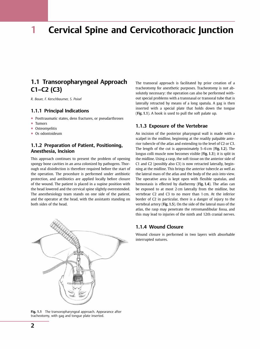
The transoral approach is facilitated by prior creation of atracheotomy for anesthetic purposes. Tracheotomy is not ab-solutely necessary: the operation can also be performed with-out special problems with a transnasal or transoral tube that islaterally retracted by means of a long spatula. A gag is theninserted with a special plate that holds down the tongue(Fig. 1.1). A hook is used to pull the soft palate up.
1.1.3 Exposure of the Vertebrae
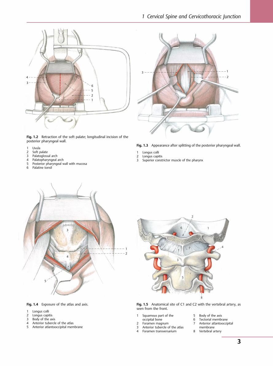
An incision of the posterior pharyngeal wall is made with ascalpel in the midline, beginning at the readily palpable ante-rior tubercle of the atlas and extending to the level of C2 or C3.The length of the cut is approximately 5–6 cm (Fig. 1.2). Thelongus colli muscle now becomes visible (Fig. 1.3); it is split inthe midline. Using a rasp, the soft tissue on the anterior side ofC1 and C2 (possibly also C3) is now retracted laterally, begin-ning at the midline. This brings the anterior tubercle as well asthe lateral mass of the atlas and the body of the axis into view.The operative area is kept open with flexible spatulas, andhemostasis is effected by diathermy (Fig. 1.4). The atlas canbe exposed to at most 2 cm laterally from the midline, butvertebrae C2 and C3 to no more than 1 cm. At the inferiorborder of C2 in particular, there is a danger of injury to thevertebral artery (Fig. 1.5). On the side of the lateral mass of theatlas, the rasp may penetrate the retromandibular fossa, andthis may lead to injuries of the ninth and 12th cranial nerves.
1.1.4 Wound Closure
Wound closure is performed in two layers with absorbableinterrupted sutures.
Fig. 1.1 The transoropharyngeal approach. Appearance aftertracheotomy, with gag and tongue plate inserted.
Spine, Anterior Approaches
2
6 5
4
3
1 2
3 1
2
Fig. 1.2 Retraction of the soft palate; longitudinal incision of theposterior pharyngeal wall.
1 Uvula2 Soft palate3 Palatoglossal arch4 Palatopharyngeal arch5 Posterior pharyngeal wall with mucosa6 Palatine tonsil
Fig. 1.3 Appearance after splitting of the posterior pharyngeal wall.
1 Longus colli2 Longus capitis3 Superior constrictor muscle of the pharynx
5
1 2
3
4
2
6
7
1
4
3
5
8
Fig. 1.4 Exposure of the atlas and axis.
1 Longus colli2 Longus capitis3 Body of the axis4 Anterior tubercle of the atlas5 Anterior atlantooccipital membrane
Fig. 1.5 Anatomical site of C1 and C2 with the vertebral artery, asseen from the front.
1 Squamous part of theoccipital bone
2 Foramen magnum3 Anterior tubercle of the atlas4 Foramen transversarium
5 Body of the axis6 Tectorial membrane7 Anterior atlantooccipital
membrane8 Vertebral artery
1 Cervical Spine and Cervicothoracic Junction
3
1.2 Anterior Approach to theCervical Spine C3–T2R. Bauer, F. Kerschbaumer, S. Poisel
1.2.1 Principal Indications● Trauma● Degenerative changes● Tumors● Spondylitis
1.2.2 Choice of Side of Approach
For the upper and middle portions of the cervical spine, anapproach is possible from either side. This also depends, how-ever, on the side of the lesion. Right-handed persons generallyprefer a right-sided approach, although for exposure of thecervical spine from C6 and below, the left-sided approach ispreferable so that injury to the recurrent laryngeal nerve,which runs irregularly and at a higher level on the right side,may be avoided.
1.2.3 Positioning and Incision
The patient is placed in a supine position, generally withoutskeletal extension except in the presence of fresh trauma. Acushion is placed between the shoulder blades; if hyper-extension is desired, a rolled-up pad is put beneath the cer-vical spine. The head is turned slightly toward the contra-lateral side, and both shoulders are pulled down with strips
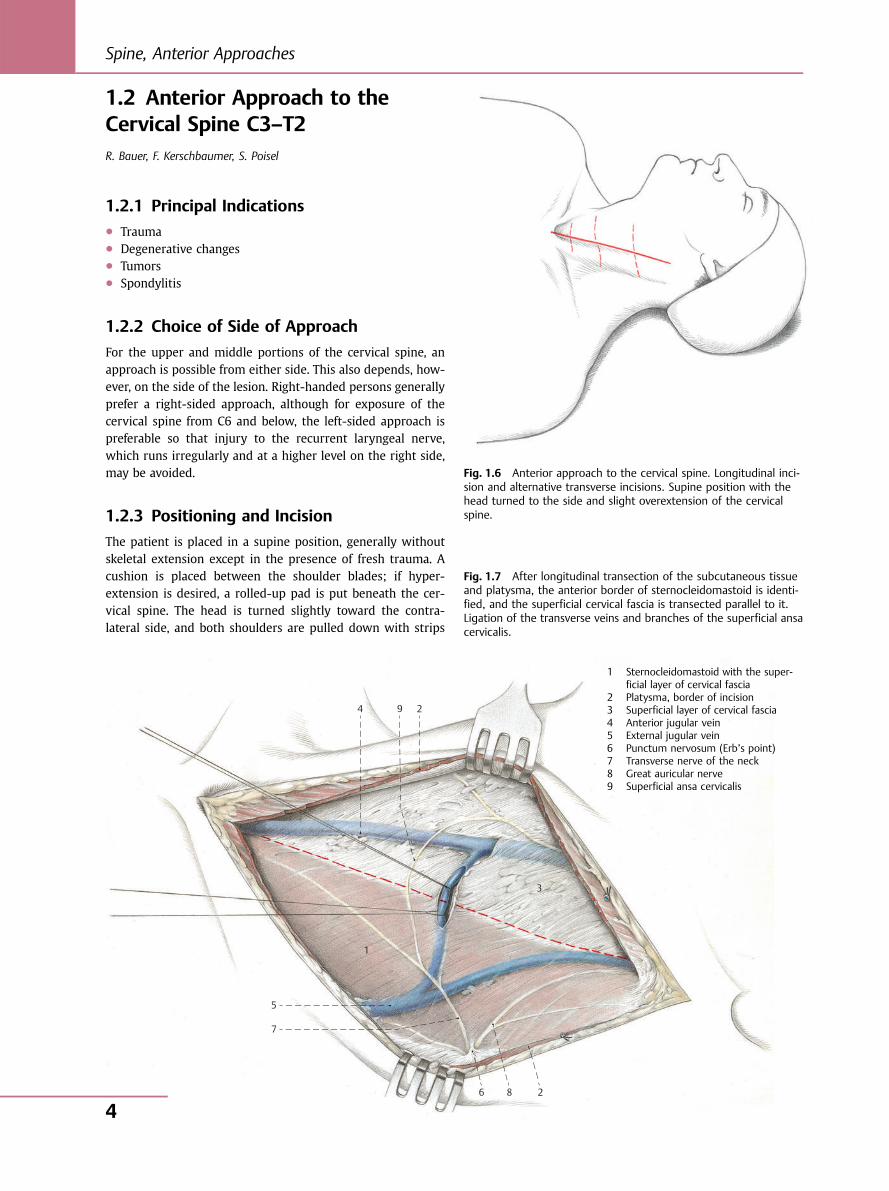
Fig. 1.6 Anterior approach to the cervical spine. Longitudinal inci-sion and alternative transverse incisions. Supine position with thehead turned to the side and slight overextension of the cervicalspine.
2 4
1
3
5
7
6 8 2
9
Fig. 1.7 After longitudinal transection of the subcutaneous tissueand platysma, the anterior border of sternocleidomastoid is identi-fied, and the superficial cervical fascia is transected parallel to it.Ligation of the transverse veins and branches of the superficial ansacervicalis.
1 Sternocleidomastoid with the super-ficial layer of cervical fascia
2 Platysma, border of incision3 Superficial layer of cervical fascia4 Anterior jugular vein5 External jugular vein6 Punctum nervosum (Erb’s point)7 Transverse nerve of the neck8 Great auricular nerve9 Superficial ansa cervicalis
Spine, Anterior Approaches
4
of adhesive tape. The operation is performed under endotra-cheal anesthesia.
The type of incision used depends on the desired extent of thevertebral exposure. If an exposure of only one or two seg-ments suffices, a transverse skin incision parallel to the skincreases of the neck is recommended. The level of the trans-verse incision may be chosen according to the following guide:● C3 and C4: incision two fingerbreadths caudal to the man-
dible at the level of the hyoid bone● C4 and C5: incision at the level of the thyroid cartilage● C5 and C6: incision at the level of the cricoid cartilage● C6 and T1: incision two fingerbreadths cranial to the
clavicle
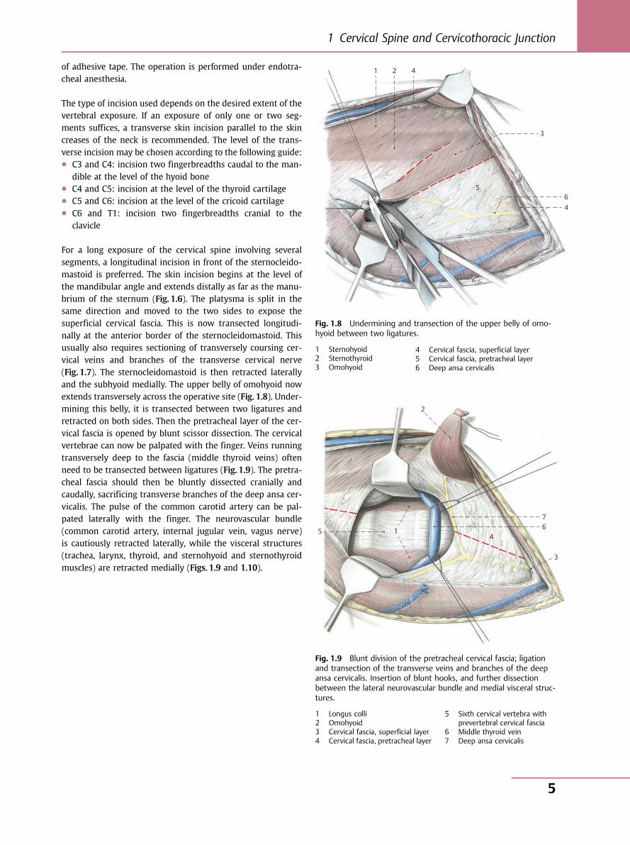
For a long exposure of the cervical spine involving severalsegments, a longitudinal incision in front of the sternocleido-mastoid is preferred. The skin incision begins at the level ofthe mandibular angle and extends distally as far as the manu-brium of the sternum (Fig. 1.6). The platysma is split in thesame direction and moved to the two sides to expose thesuperficial cervical fascia. This is now transected longitudi-nally at the anterior border of the sternocleidomastoid. Thisusually also requires sectioning of transversely coursing cer-vical veins and branches of the transverse cervical nerve(Fig. 1.7). The sternocleidomastoid is then retracted laterallyand the subhyoid medially. The upper belly of omohyoid nowextends transversely across the operative site (Fig. 1.8). Under-mining this belly, it is transected between two ligatures andretracted on both sides. Then the pretracheal layer of the cer-vical fascia is opened by blunt scissor dissection. The cervicalvertebrae can now be palpated with the finger. Veins runningtransversely deep to the fascia (middle thyroid veins) oftenneed to be transected between ligatures (Fig. 1.9). The pretra-cheal fascia should then be bluntly dissected cranially andcaudally, sacrificing transverse branches of the deep ansa cer-vicalis. The pulse of the common carotid artery can be pal-pated laterally with the finger. The neurovascular bundle(common carotid artery, internal jugular vein, vagus nerve)is cautiously retracted laterally, while the visceral structures(trachea, larynx, thyroid, and sternohyoid and sternothyroidmuscles) are retracted medially (Figs. 1.9 and 1.10).
6 5
4
3
1 2
4
7 6 5
4
3
1
2
Fig. 1.8 Undermining and transection of the upper belly of omo-hyoid between two ligatures.
1 Sternohyoid2 Sternothyroid3 Omohyoid
4 Cervical fascia, superficial layer5 Cervical fascia, pretracheal layer6 Deep ansa cervicalis
Fig. 1.9 Blunt division of the pretracheal cervical fascia; ligationand transection of the transverse veins and branches of the deepansa cervicalis. Insertion of blunt hooks, and further dissectionbetween the lateral neurovascular bundle and medial visceral struc-tures.
1 Longus colli2 Omohyoid3 Cervical fascia, superficial layer4 Cervical fascia, pretracheal layer
5 Sixth cervical vertebra withprevertebral cervical fascia
6 Middle thyroid vein7 Deep ansa cervicalis
1 Cervical Spine and Cervicothoracic Junction
5
1.2.4 Exposure of Cervical Vertebrae C2–C6
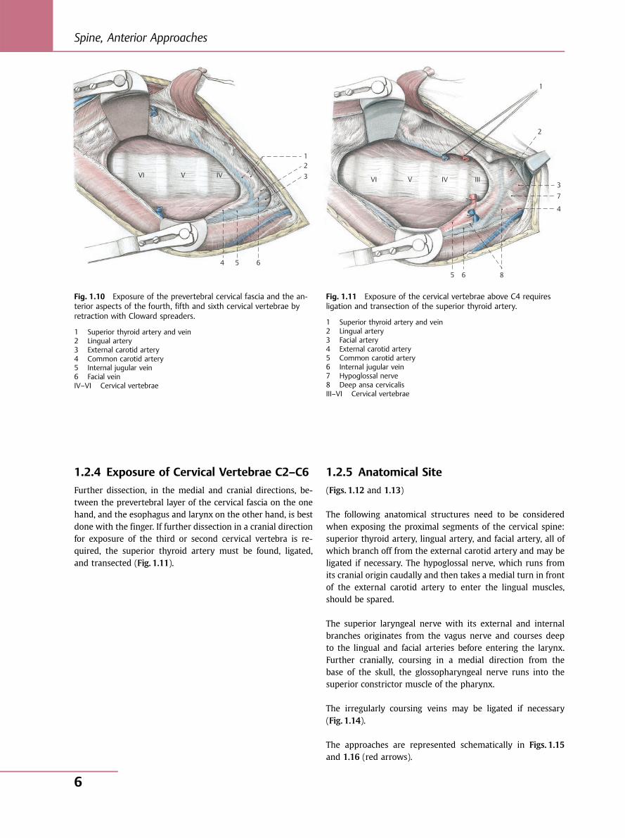
Further dissection, in the medial and cranial directions, be-tween the prevertebral layer of the cervical fascia on the onehand, and the esophagus and larynx on the other hand, is bestdone with the finger. If further dissection in a cranial directionfor exposure of the third or second cervical vertebra is re-quired, the superior thyroid artery must be found, ligated,and transected (Fig. 1.11).
1.2.5 Anatomical Site
(Figs. 1.12 and 1.13)
The following anatomical structures need to be consideredwhen exposing the proximal segments of the cervical spine:superior thyroid artery, lingual artery, and facial artery, all ofwhich branch off from the external carotid artery and may beligated if necessary. The hypoglossal nerve, which runs fromits cranial origin caudally and then takes a medial turn in frontof the external carotid artery to enter the lingual muscles,should be spared.
The superior laryngeal nerve with its external and internalbranches originates from the vagus nerve and courses deepto the lingual and facial arteries before entering the larynx.Further cranially, coursing in a medial direction from thebase of the skull, the glossopharyngeal nerve runs into thesuperior constrictor muscle of the pharynx.
The irregularly coursing veins may be ligated if necessary(Fig. 1.14).
The approaches are represented schematically in Figs. 1.15and 1.16 (red arrows).
V
6 5 4
3
1 2
VI IV V
8
7
6 5
4
3
1
2
VI IV III
Fig. 1.10 Exposure of the prevertebral cervical fascia and the an-terior aspects of the fourth, fifth and sixth cervical vertebrae byretraction with Cloward spreaders.
1 Superior thyroid artery and vein2 Lingual artery3 External carotid artery4 Common carotid artery5 Internal jugular vein6 Facial veinIV–VI Cervical vertebrae
Fig. 1.11 Exposure of the cervical vertebrae above C4 requiresligation and transection of the superior thyroid artery.
1 Superior thyroid artery and vein2 Lingual artery3 Facial artery4 External carotid artery5 Common carotid artery6 Internal jugular vein7 Hypoglossal nerve8 Deep ansa cervicalisIII–VI Cervical vertebrae
Spine, Anterior Approaches
6
10
11
12
13
14
15 16
17
18 19
20
9 8
7
6
5
4 3
1 2 21
22
23
24
2526
272829
30
31
32
33
12
10
11
12
13
14
15
16 17
18
19
20
9
8
7
6
5
4 3
1
2
21
22
23
24
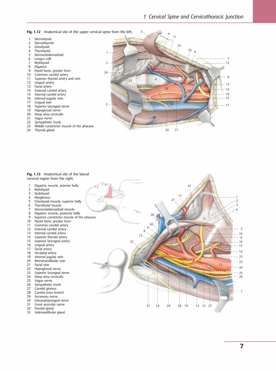
Fig. 1.12 Anatomical site of the upper cervical spine from the left.
1 Sternohyoid2 Sternothyroid3 Omohyoid4 Thyrohyoid5 Sternocleidomastoid6 Longus colli7 Mylohyoid8 Digastric9 Hyoid bone, greater horn10 Common carotid artery11 Superior thyroid artery and vein12 Lingual artery13 Facial artery14 External carotid artery15 Internal carotid artery16 Internal jugular vein17 Lingual vein18 Superior laryngeal nerve19 Hypoglossal nerve20 Deep ansa cervicalis21 Vagus nerve22 Sympathetic trunk23 Middle constrictor muscle of the pharynx24 Thyroid gland
Fig. 1.13 Anatomical site of the lateralcervical region from the right.
1 Digastric muscle, anterior belly2 Mylohyoid3 Stylohyoid4 Hyoglossus5 Omohyoid muscle, superior belly6 Thyrohyoid muscle7 Sternocleidomastoid muscle8 Digastric muscle, posterior belly9 Superior constrictor muscle of the pharynx10 Hyoid bone, greater horn11 Common carotid artery12 External carotid artery13 Internal carotid artery14 Superior thyroid artery15 Superior laryngeal artery16 Lingual artery17 Facial artery18 Occipital artery19 Internal jugular vein20 Retromandibular vein21 Facial vein22 Hypoglossal nerve23 Superior laryngeal nerve24 Deep ansa cervicalis25 Vagus nerve26 Sympathetic trunk27 Carotid glomus28 Carotid sinus branch29 Accessory nerve30 Glossopharyngeal nerve31 Great auricular nerve32 Parotid gland33 Submandibular gland
1 Cervical Spine and Cervicothoracic Junction
7

10
11
12
13
14
15
16
17
18 19
20
9 8 7
6
5
4 3
1 2
III
Type I Type III Type V
Type II Type IV Type VI
Fig. 1.14 Variations in venous drainage to the internal jugular vein.
Type I Thyrolinguofacial trunk (45%)Type II Linguofacial trunk (9%)Type III Linguofacial trunk with arcade (12%)Type IV Thyrolinguofacial trunk with connection to the anterior jugular vein (15%)Type V Thyrolingual trunk (7%)Type VI Independent afferent course of all three veins (12%)
Fig. 1.15 Anatomical cross-section at thelevel of the third cervical vertebra.
1 Cervical fascia, superficial layer2 Cervical fascia, pretracheal layer3 Cervical fascia, prevertebral layer4 Cervical fascia, carotid sheath5 Infrahyoid muscles6 Sternocleidomastoid7 Longus colli8 Longus capitis9 Anterior scalene muscle10 Middle scalene muscle11 Common carotid artery12 Vertebral artery13 Internal jugular vein14 Vertebral vein15 External jugular vein16 Vagus nerve17 Phrenic nerve18 Sympathetic trunk19 Larynx20 PharynxIII Cervical vertebra
Spine, Anterior Approaches
8

1.2.6 Exposure of Vertebrae C7–T2
If exposure of the caudally situated cervical vertebrae and thetwo superior thoracic vertebrae is required, the inferior thy-roid artery has to be located and ligated. Further exposure ofthe pretracheal cervical fascia in a caudal direction is per-formed bluntly with scissors, cotton balls, and, partly, withthe finger (Fig. 1.17).
1.2.7 Anatomical Site
The anterior aspect of the lower cervical and upper thoracicvertebrae is covered by the following structures, in descendingorder from cranial:
On the left side (Figs. 1.18 and 1.19): The inferior thyroidartery, which arises from the thyrocervical trunk or the sub-clavian artery and runs transversely across the anterior surfaceof the vertebrae, enters the inferior pole of the thyroid. Thesympathetic trunk with the stellate ganglion is located at ap-proximately the same level on the anterior aspect of longuscolli, and the vertebral artery is situated lateral to it. More
14 17 15 16 13
12
19 1 2 3
18 8 9
10
4 5
6 7
11 VI
Fig. 1.16 Anatomical cross-section at thelevel of the sixth cervical vertebra.
1 Sternohyoid2 Sternothyroid3 Sternocleidomastoid4 Longus colli5 Anterior scalene muscle6 Middle scalene muscle7 Posterior scalene muscle8 Common carotid artery9 Internal jugular vein10 External jugular vein11 Vertebral vessels12 Trachea13 Esophagus14 Thyroid gland15 Cervical fascia, superficial layer16 Cervical fascia, pretracheal layer17 Cervical fascia, prevertebral layer18 Vagus nerve19 Recurrent laryngeal nerveVI Cervical vertebra
6 5
4
3
1
2
VVIVII
Fig. 1.17 Exposure of the lower cervical spine and cervi-cothoracic junction (C6–T2); ligation and transection ofthe inferior thyroid artery.
1 Inferior thyroid artery2 Middle thyroid vein3 Superior thyroid artery and vein4 Internal jugular vein5 Common carotid artery6 Deep ansa cervicalisV–VII Cervical vertebrae
1 Cervical Spine and Cervicothoracic Junction
9
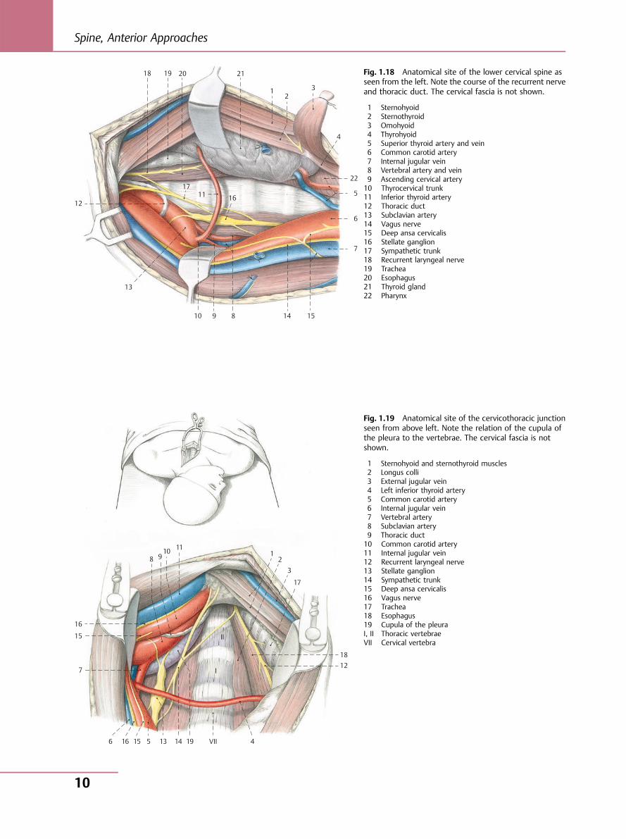
Fig. 1.18 Anatomical site of the lower cervical spine asseen from the left. Note the course of the recurrent nerveand thoracic duct. The cervical fascia is not shown.
1 Sternohyoid2 Sternothyroid3 Omohyoid4 Thyrohyoid5 Superior thyroid artery and vein6 Common carotid artery7 Internal jugular vein8 Vertebral artery and vein9 Ascending cervical artery10 Thyrocervical trunk11 Inferior thyroid artery12 Thoracic duct13 Subclavian artery14 Vagus nerve15 Deep ansa cervicalis16 Stellate ganglion17 Sympathetic trunk18 Recurrent laryngeal nerve19 Trachea20 Esophagus21 Thyroid gland22 Pharynx
10
11 12
13
14 15
16
17
18 19 20
9 8
7
6
5
4
3 1 2
21
22
10 11
12
13 14 15 16
17
18
19 VII
9 8
7
6 5 4
3
1 2
15
16
I
II
Fig. 1.19 Anatomical site of the cervicothoracic junctionseen from above left. Note the relation of the cupula ofthe pleura to the vertebrae. The cervical fascia is notshown.
1 Sternohyoid and sternothyroid muscles2 Longus colli3 External jugular vein4 Left inferior thyroid artery5 Common carotid artery6 Internal jugular vein7 Vertebral artery8 Subclavian artery9 Thoracic duct10 Common carotid artery11 Internal jugular vein12 Recurrent laryngeal nerve13 Stellate ganglion14 Sympathetic trunk15 Deep ansa cervicalis16 Vagus nerve17 Trachea18 Esophagus19 Cupula of the pleuraI, II Thoracic vertebraeVII Cervical vertebra
Spine, Anterior Approaches
10
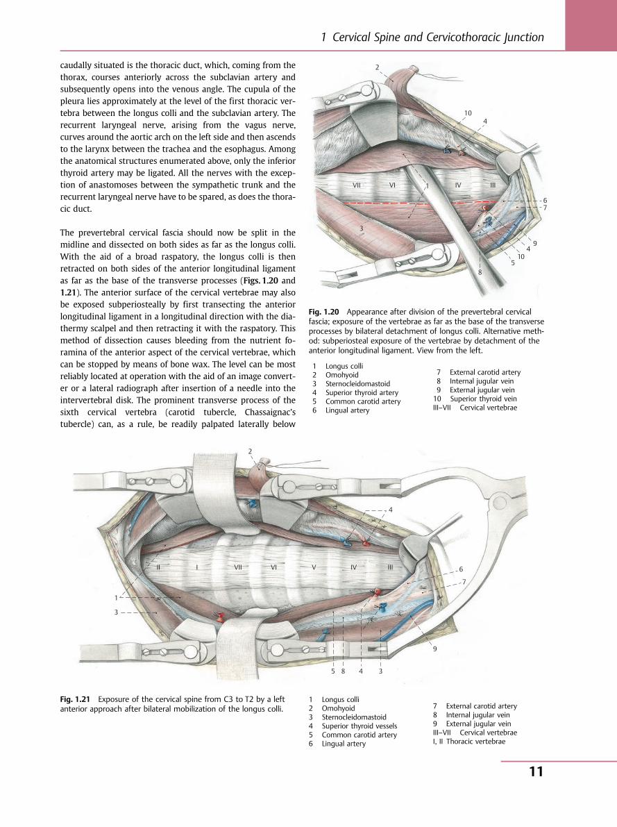
caudally situated is the thoracic duct, which, coming from thethorax, courses anteriorly across the subclavian artery andsubsequently opens into the venous angle. The cupula of thepleura lies approximately at the level of the first thoracic ver-tebra between the longus colli and the subclavian artery. Therecurrent laryngeal nerve, arising from the vagus nerve,curves around the aortic arch on the left side and then ascendsto the larynx between the trachea and the esophagus. Amongthe anatomical structures enumerated above, only the inferiorthyroid artery may be ligated. All the nerves with the excep-tion of anastomoses between the sympathetic trunk and therecurrent laryngeal nerve have to be spared, as does the thora-cic duct.
The prevertebral cervical fascia should now be split in themidline and dissected on both sides as far as the longus colli.With the aid of a broad raspatory, the longus colli is thenretracted on both sides of the anterior longitudinal ligamentas far as the base of the transverse processes (Figs. 1.20 and1.21). The anterior surface of the cervical vertebrae may alsobe exposed subperiosteally by first transecting the anteriorlongitudinal ligament in a longitudinal direction with the dia-thermy scalpel and then retracting it with the raspatory. Thismethod of dissection causes bleeding from the nutrient fo-ramina of the anterior aspect of the cervical vertebrae, whichcan be stopped by means of bone wax. The level can be mostreliably located at operation with the aid of an image convert-er or a lateral radiograph after insertion of a needle into theintervertebral disk. The prominent transverse process of thesixth cervical vertebra (carotid tubercle, Chassaignac’stubercle) can, as a rule, be readily palpated laterally below
10
VII
9
8
7 6
5
4
3
1
2
4 10
VI IV III
2
1
II I VII VI V IV III
3
5 8 4 3
9
7
6
4
Fig. 1.20 Appearance after division of the prevertebral cervicalfascia; exposure of the vertebrae as far as the base of the transverseprocesses by bilateral detachment of longus colli. Alternative meth-od: subperiosteal exposure of the vertebrae by detachment of theanterior longitudinal ligament. View from the left.
1 Longus colli2 Omohyoid3 Sternocleidomastoid4 Superior thyroid artery5 Common carotid artery6 Lingual artery
7 External carotid artery8 Internal jugular vein9 External jugular vein10 Superior thyroid veinIII–VII Cervical vertebrae
Fig. 1.21 Exposure of the cervical spine from C3 to T2 by a leftanterior approach after bilateral mobilization of the longus colli.
1 Longus colli2 Omohyoid3 Sternocleidomastoid4 Superior thyroid vessels5 Common carotid artery6 Lingual artery
7 External carotid artery8 Internal jugular vein9 External jugular veinIII–VII Cervical vertebraeI, II Thoracic vertebrae
1 Cervical Spine and Cervicothoracic Junction
11
the longus colli. However, in fewer than 10% of cases, theseventh cervical vertebra may also have a prominent trans-verse process if the vertebral artery runs in the cervical verte-bral foramen from C7. Fig. 1.21 shows the operative site of thecervical spine from the left anterior approach over an areafrom C3 to T2. Besides Cloward’s retractors, flexible spatulaswith a wide contact surface, which can be laterally applied tothe base of the transverse processes, have been found usefulfor broad exposure of the spine.
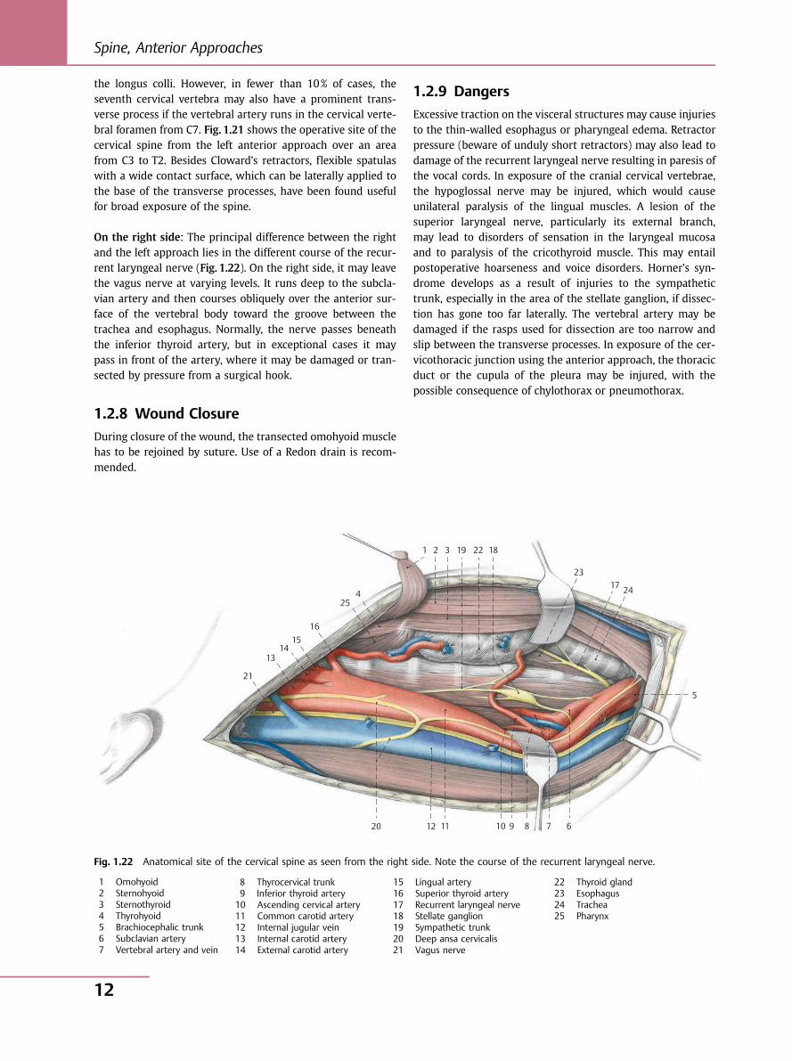
On the right side: The principal difference between the rightand the left approach lies in the different course of the recur-rent laryngeal nerve (Fig. 1.22). On the right side, it may leavethe vagus nerve at varying levels. It runs deep to the subcla-vian artery and then courses obliquely over the anterior sur-face of the vertebral body toward the groove between thetrachea and esophagus. Normally, the nerve passes beneaththe inferior thyroid artery, but in exceptional cases it maypass in front of the artery, where it may be damaged or tran-sected by pressure from a surgical hook.
1.2.8 Wound Closure
During closure of the wound, the transected omohyoid musclehas to be rejoined by suture. Use of a Redon drain is recom-mended.
1.2.9 Dangers
Excessive traction on the visceral structures may cause injuriesto the thin-walled esophagus or pharyngeal edema. Retractorpressure (beware of unduly short retractors) may also lead todamage of the recurrent laryngeal nerve resulting in paresis ofthe vocal cords. In exposure of the cranial cervical vertebrae,the hypoglossal nerve may be injured, which would causeunilateral paralysis of the lingual muscles. A lesion of thesuperior laryngeal nerve, particularly its external branch,may lead to disorders of sensation in the laryngeal mucosaand to paralysis of the cricothyroid muscle. This may entailpostoperative hoarseness and voice disorders. Horner’s syn-drome develops as a result of injuries to the sympathetictrunk, especially in the area of the stellate ganglion, if dissec-tion has gone too far laterally. The vertebral artery may bedamaged if the rasps used for dissection are too narrow andslip between the transverse processes. In exposure of the cer-vicothoracic junction using the anterior approach, the thoracicduct or the cupula of the pleura may be injured, with thepossible consequence of chylothorax or pneumothorax.
21
1314
1516
254
1 2 3 19 22 18
2317 24
5
678910111220
Fig. 1.22 Anatomical site of the cervical spine as seen from the right side. Note the course of the recurrent laryngeal nerve.
1 Omohyoid2 Sternohyoid3 Sternothyroid4 Thyrohyoid5 Brachiocephalic trunk6 Subclavian artery7 Vertebral artery and vein
8 Thyrocervical trunk9 Inferior thyroid artery10 Ascending cervical artery11 Common carotid artery12 Internal jugular vein13 Internal carotid artery14 External carotid artery
15 Lingual artery16 Superior thyroid artery17 Recurrent laryngeal nerve18 Stellate ganglion19 Sympathetic trunk20 Deep ansa cervicalis21 Vagus nerve
22 Thyroid gland23 Esophagus24 Trachea25 Pharynx
Spine, Anterior Approaches
12
1.2.10 Note
With adequate knowledge of the anatomy, the approachdescribed is easy and is associated with a low rate of compli-cations. It is therefore the standard approach for anterior ex-posure of the cervical spine. Other anterior and lateralapproaches have been described by Henry, Whitesides andKelly, Verbiest, Nanson, Hodgson, and others. These ap-proaches are suitable particularly for exposure of the spinalnerves, the vertebral artery, and the scalene muscle lacunae,and less suitable for clear exposure of the cervical spine fromthe front. For exposure of the upper cervical spine, and thecraniocervical junction in particular, Riley has described anapproach that, in addition to extensive skeletization of thesubmandibular space, involves dislocation of the temporo-mandibular joint and removal of the submandibular gland.
1.3 Anterior Approach to the LowerCervical and Upper Thoracic SpineC4–T3 According to Cauchoix, Binet,and EvrardR. Bauer, F. Kerschbaumer, S. Poisel
1.3.1 Principal Indications● Internal fixation of fracture dislocations● Tumors● Spondylitis
1.3.2 Choice of Side of Approach
The cervical portion of the approach is from the left side.
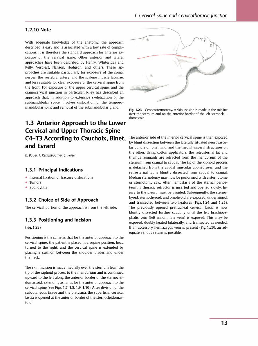
1.3.3 Positioning and Incision
(Fig. 1.23)
Positioning is the same as that for the anterior approach to thecervical spine: the patient is placed in a supine position, headturned to the right, and the cervical spine is extended byplacing a cushion between the shoulder blades and underthe neck.
The skin incision is made medially over the sternum from thetip of the xiphoid process to the manubrium and is continuedupward to the left along the anterior border of the sternoclei-domastoid, extending as far as for the anterior approach to thecervical spine (see Figs. 1.7, 1.8, 1.9, 1.10). After division of thesubcutaneous tissue and the platysma, the superficial cervicalfascia is opened at the anterior border of the sternocleidomas-toid.
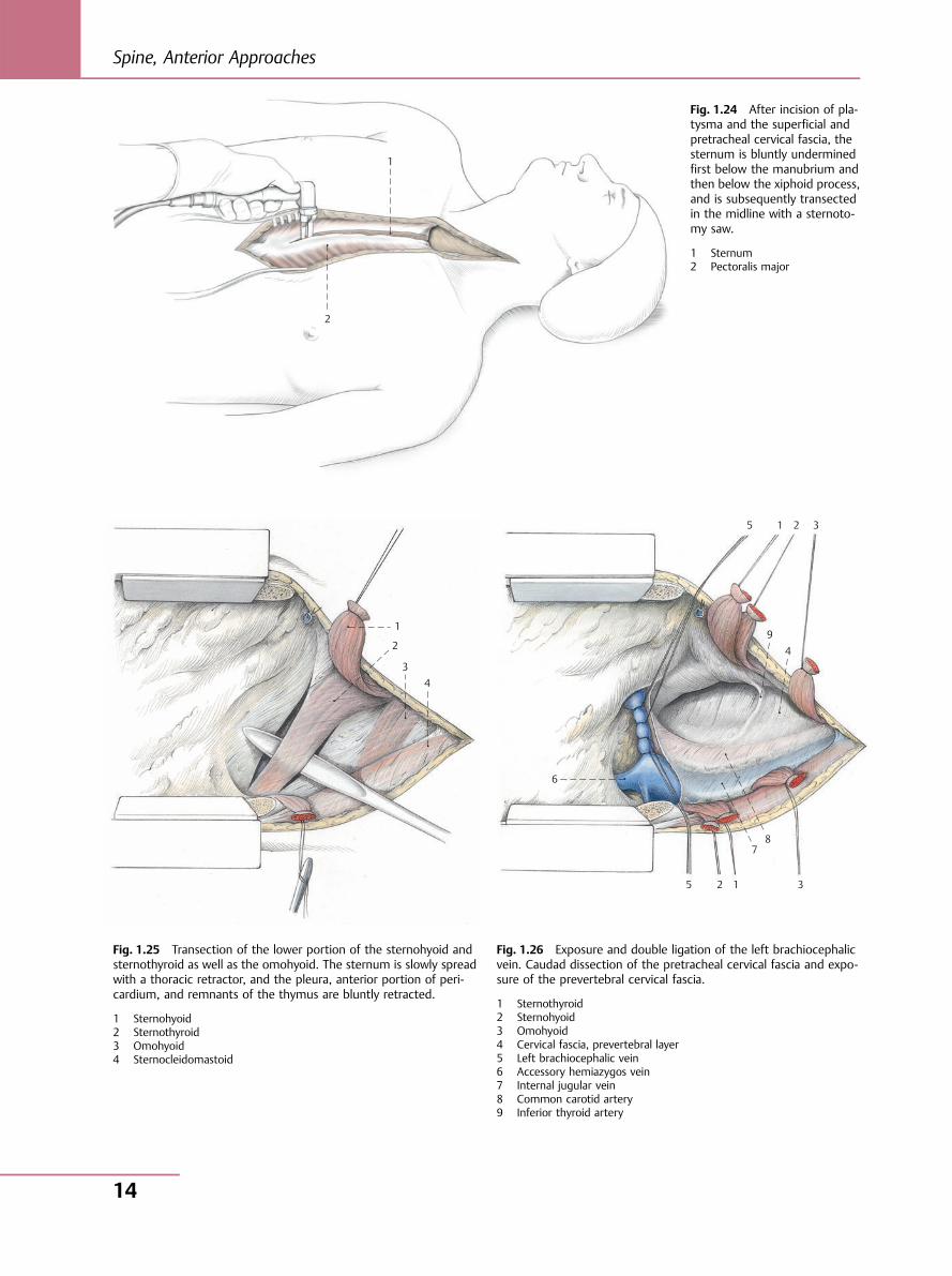
The anterior side of the inferior cervical spine is then exposedby blunt dissection between the laterally situated neurovascu-lar bundle on one hand, and the medial visceral structures onthe other. Using cotton applicators, the retrosternal fat andthymus remnants are retracted from the manubrium of thesternum from cranial to caudal. The tip of the xiphoid processis detached from the caudal muscular aponeuroses, and theretrosternal fat is bluntly dissected from caudal to cranial.Median sternotomy may now be performed with a sternotomeor sternotomy saw. After hemostasis of the sternal perios-teum, a thoracic retractor is inserted and opened slowly. In-jury to the pleura must be avoided. Subsequently, the sterno-hyoid, sternothyroid, and omohyoid are exposed, undermined,and transected between two ligatures (Figs. 1.24 and 1.25).The previously opened pretracheal cervical fascia is nowbluntly dissected further caudally until the left brachioce-phalic vein (left innominate vein) is exposed. This may beexposed, doubly ligated bilaterally, and transected as needed.If an accessory hemiazygos vein is present (Fig. 1.26), an ad-equate venous return is possible.
Fig. 1.23 Cervicosternotomy. A skin incision is made in the midlineover the sternum and on the anterior border of the left sternoclei-domastoid.
1 Cervical Spine and Cervicothoracic Junction
13
1
2
6
5 2 1
78
3
94
3215
1
2
3 4
Fig. 1.24 After incision of pla-tysma and the superficial andpretracheal cervical fascia, thesternum is bluntly underminedfirst below the manubrium andthen below the xiphoid process,and is subsequently transectedin the midline with a sternoto-my saw.
1 Sternum2 Pectoralis major
Fig. 1.25 Transection of the lower portion of the sternohyoid andsternothyroid as well as the omohyoid. The sternum is slowly spreadwith a thoracic retractor, and the pleura, anterior portion of peri-cardium, and remnants of the thymus are bluntly retracted.
1 Sternohyoid2 Sternothyroid3 Omohyoid4 Sternocleidomastoid
Fig. 1.26 Exposure and double ligation of the left brachiocephalicvein. Caudad dissection of the pretracheal cervical fascia and expo-sure of the prevertebral cervical fascia.
1 Sternothyroid2 Sternohyoid3 Omohyoid4 Cervical fascia, prevertebral layer5 Left brachiocephalic vein6 Accessory hemiazygos vein7 Internal jugular vein8 Common carotid artery9 Inferior thyroid artery
Spine, Anterior Approaches
14
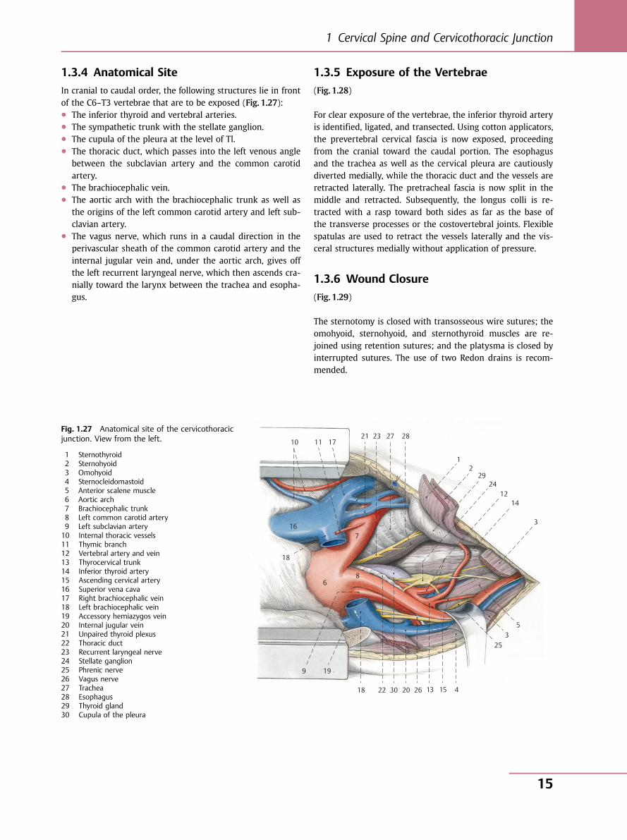
1.3.4 Anatomical Site
In cranial to caudal order, the following structures lie in frontof the C6–T3 vertebrae that are to be exposed (Fig. 1.27):● The inferior thyroid and vertebral arteries.● The sympathetic trunk with the stellate ganglion.● The cupula of the pleura at the level of Tl.● The thoracic duct, which passes into the left venous angle
between the subclavian artery and the common carotidartery.
● The brachiocephalic vein.● The aortic arch with the brachiocephalic trunk as well as
the origins of the left common carotid artery and left sub-clavian artery.
● The vagus nerve, which runs in a caudal direction in theperivascular sheath of the common carotid artery and theinternal jugular vein and, under the aortic arch, gives offthe left recurrent laryngeal nerve, which then ascends cra-nially toward the larynx between the trachea and esopha-gus.
1.3.5 Exposure of the Vertebrae
(Fig. 1.28)
For clear exposure of the vertebrae, the inferior thyroid arteryis identified, ligated, and transected. Using cotton applicators,the prevertebral cervical fascia is now exposed, proceedingfrom the cranial toward the caudal portion. The esophagusand the trachea as well as the cervical pleura are cautiouslydiverted medially, while the thoracic duct and the vessels areretracted laterally. The pretracheal fascia is now split in themiddle and retracted. Subsequently, the longus colli is re-tracted with a rasp toward both sides as far as the base ofthe transverse processes or the costovertebral joints. Flexiblespatulas are used to retract the vessels laterally and the vis-ceral structures medially without application of pressure.
1.3.6 Wound Closure
(Fig. 1.29)
The sternotomy is closed with transosseous wire sutures; theomohyoid, sternohyoid, and sternothyroid muscles are re-joined using retention sutures; and the platysma is closed byinterrupted sutures. The use of two Redon drains is recom-mended.
10 11 1721 23 27 28
12
2924
1214
3
53
25
4 15 13 26 20 30 22 18
19 9
16
18
6 8
7
Fig. 1.27 Anatomical site of the cervicothoracicjunction. View from the left.
1 Sternothyroid2 Sternohyoid3 Omohyoid4 Sternocleidomastoid5 Anterior scalene muscle6 Aortic arch7 Brachiocephalic trunk8 Left common carotid artery9 Left subclavian artery10 Internal thoracic vessels11 Thymic branch12 Vertebral artery and vein13 Thyrocervical trunk14 Inferior thyroid artery15 Ascending cervical artery16 Superior vena cava17 Right brachiocephalic vein18 Left brachiocephalic vein19 Accessory hemiazygos vein20 Internal jugular vein21 Unpaired thyroid plexus22 Thoracic duct23 Recurrent laryngeal nerve24 Stellate ganglion25 Phrenic nerve26 Vagus nerve27 Trachea28 Esophagus29 Thyroid gland30 Cupula of the pleura
1 Cervical Spine and Cervicothoracic Junction
15
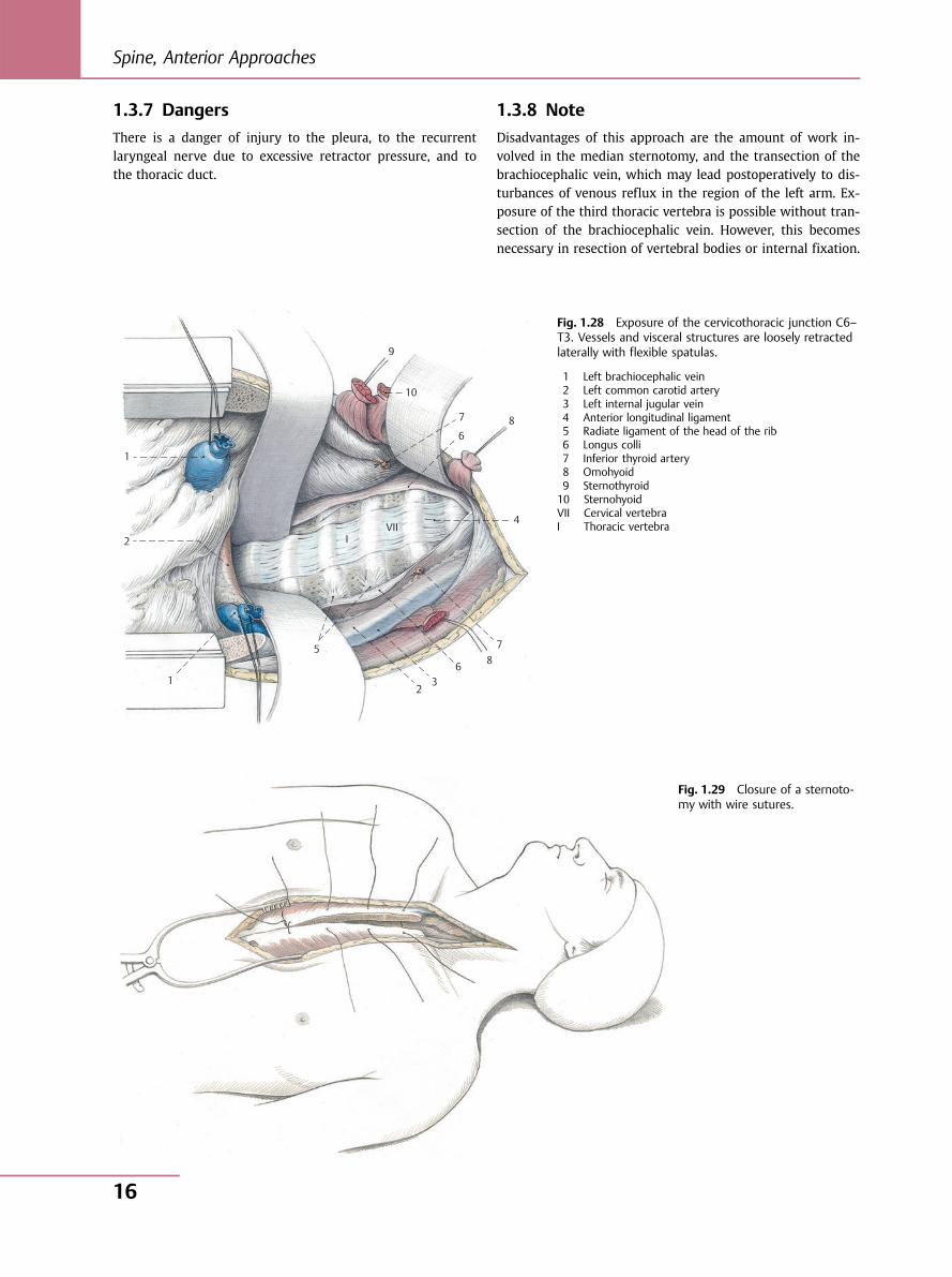
1.3.7 Dangers
There is a danger of injury to the pleura, to the recurrentlaryngeal nerve due to excessive retractor pressure, and tothe thoracic duct.
1.3.8 Note
Disadvantages of this approach are the amount of work in-volved in the median sternotomy, and the transection of thebrachiocephalic vein, which may lead postoperatively to dis-turbances of venous reflux in the region of the left arm. Ex-posure of the third thoracic vertebra is possible without tran-section of the brachiocephalic vein. However, this becomesnecessary in resection of vertebral bodies or internal fixation.
9
10
7
6 8
4
7 8 6
32
5
1
2 IVII
1
Fig. 1.28 Exposure of the cervicothoracic junction C6–T3. Vessels and visceral structures are loosely retractedlaterally with flexible spatulas.
1 Left brachiocephalic vein2 Left common carotid artery3 Left internal jugular vein4 Anterior longitudinal ligament5 Radiate ligament of the head of the rib6 Longus colli7 Inferior thyroid artery8 Omohyoid9 Sternothyroid10 SternohyoidVII Cervical vertebraI Thoracic vertebra
Fig. 1.29 Closure of a sternoto-my with wire sutures.
Spine, Anterior Approaches
16
2 Thoracic Spine
2.1 Transthoracic Approach to theThoracic Spine T4–T11R. Bauer, F. Kerschbaumer, S. Poisel
2.1.1 Indications● Kyphosis● Scoliosis● Vertebral body fractures● Tumors● Spondylitis
2.1.2 Choice of Side of Approach
Generally speaking, the thoracic spine can be approachedusing either right-sided or left-sided thoracotomy. Unless theindication prescribes the side to be used, right-sided thoracot-omy is preferable because of the vascular anatomy (the left-sided course of the aorta). However, in the case of scoliosis,thoracotomy is always performed on the side of the convexity.
2.1.3 Dorsolateral Thoracotomy with RibResection
With orthopedic indications, the thoracotomy is generally per-formed with rib resection. This creates better exposure inadult patients and in the case of thoracic deformities associ-ated with spinal deformities. In addition, the resected rib mayserve as graft material for vertebral fusion.
2.1.4 Choice of Rib to be Resected
Entry is generally made two ribs above the level of the centerof the lesion. Owing to the descending course of the ribs, it iseasier to cut along the lower rib in a caudal direction ratherthan toward the proximal end. If a rib is chosen whose loca-tion is too distal, it is difficult to reach the upper end of thedeformity. In younger individuals and those in whom the ribsare mobile, it may be possible to reach the vertebra corre-sponding to the resected rib. If this proves difficult, the seg-ment close to the spine of the next higher rib may be resectedthrough the same approach. The following vertebrae can bereached in favorable circumstances:● Resection of the fifth rib: a T5–T11 approach● Resection of the sixth rib: a T6–T12 approach● Resection of the seventh rib: a T7–L1 approach
However, there are exceptions to this rule. In patients withhorizontally coursing ribs, resection of the sixth rib mayallow vertebrae T5–T11 to be reached. On the other hand, ifthe ribs describe a sharply descending course, resection of thefifth rib only permits exposure of T6–T11. Finally, in patientswith severe spinal curvatures and commensurate thoracic de-formities, rib resection thoracotomy may provide access toonly two or three vertebrae.
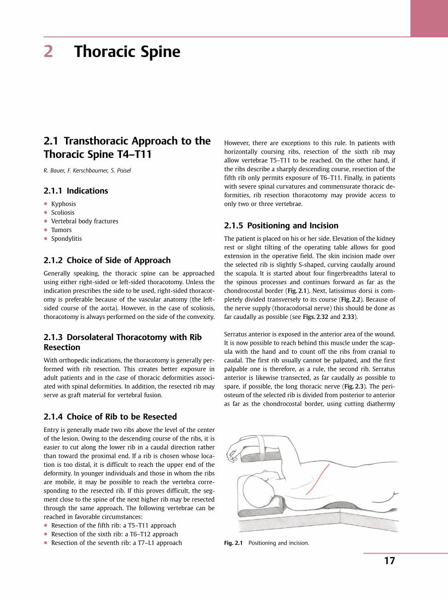
2.1.5 Positioning and Incision
The patient is placed on his or her side. Elevation of the kidneyrest or slight tilting of the operating table allows for goodextension in the operative field. The skin incision made overthe selected rib is slightly S-shaped, curving caudally aroundthe scapula. It is started about four fingerbreadths lateral tothe spinous processes and continues forward as far as thechondrocostal border (Fig. 2.1). Next, latissimus dorsi is com-pletely divided transversely to its course (Fig. 2.2). Because ofthe nerve supply (thoracodorsal nerve) this should be done asfar caudally as possible (see Figs. 2.32 and 2.33).
Serratus anterior is exposed in the anterior area of the wound.It is now possible to reach behind this muscle under the scap-ula with the hand and to count off the ribs from cranial tocaudal. The first rib usually cannot be palpated, and the firstpalpable one is therefore, as a rule, the second rib. Serratusanterior is likewise transected, as far caudally as possible tospare, if possible, the long thoracic nerve (Fig. 2.3). The peri-osteum of the selected rib is divided from posterior to anterioras far as the chondrocostal border, using cutting diathermy
Fig. 2.1 Positioning and incision.
2 Thoracic Spine
17
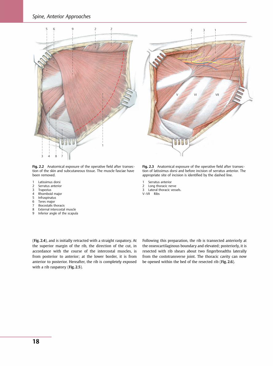
(Fig. 2.4), and is initially retracted with a straight raspatory. Atthe superior margin of the rib, the direction of the cut, inaccordance with the course of the intercostal muscles, isfrom posterior to anterior; at the lower border, it is fromanterior to posterior. Hereafter, the rib is completely exposedwith a rib raspatory (Fig. 2.5).
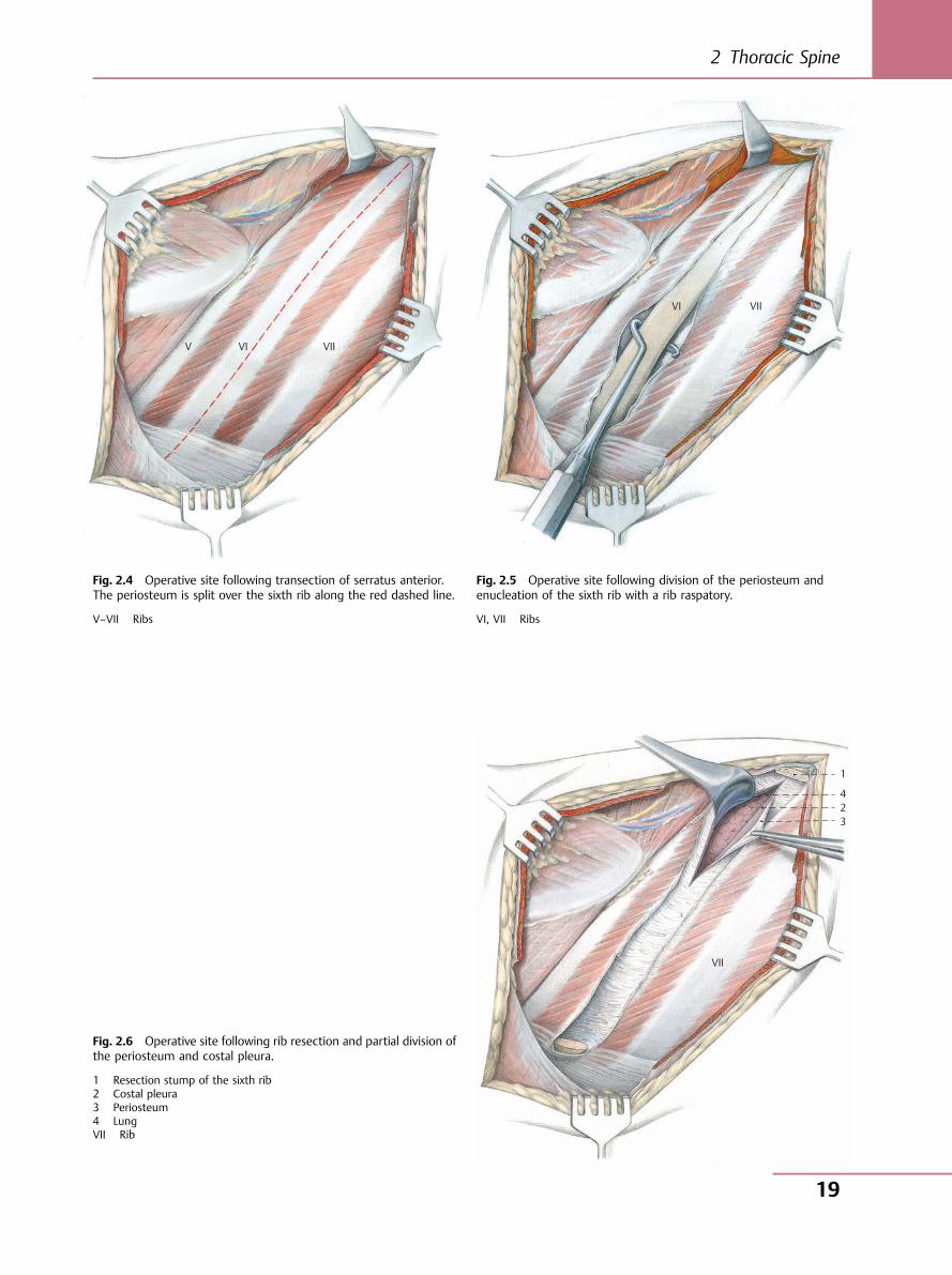
Following this preparation, the rib is transected anteriorly atthe osseocartilaginous boundary and elevated; posteriorly, it isresected with rib shears about two fingerbreadths laterallyfrom the costotransverse joint. The thoracic cavity can nowbe opened within the bed of the resected rib (Fig. 2.6).
5 6 9 2 2
1
7 8 4 3
Fig. 2.2 Anatomical exposure of the operative field after transec-tion of the skin and subcutaneous tissue. The muscle fasciae havebeen removed.
1 Latissimus dorsi2 Serratus anterior3 Trapezius4 Rhomboid major5 Infraspinatus6 Teres major7 Iliocostalis thoracis8 External intercostal muscle9 Inferior angle of the scapula
1 3 2
V VI VII
Fig. 2.3 Anatomical exposure of the operative field after transec-tion of latissimus dorsi and before incision of serratus anterior. Theappropriate site of incision is identified by the dashed line.
1 Serratus anterior2 Long thoracic nerve3 Lateral thoracic vessels.V–VII Ribs
Spine, Anterior Approaches
18
V VI VII
Fig. 2.4 Operative site following transection of serratus anterior.The periosteum is split over the sixth rib along the red dashed line.
V–VII Ribs
VI VII
Fig. 2.5 Operative site following division of the periosteum andenucleation of the sixth rib with a rib raspatory.
VI, VII Ribs
VII
1
4 2 3
Fig. 2.6 Operative site following rib resection and partial division ofthe periosteum and costal pleura.
1 Resection stump of the sixth rib2 Costal pleura3 Periosteum4 LungVII Rib
2 Thoracic Spine
19
2.1.6 Intercostal Thoracotomy
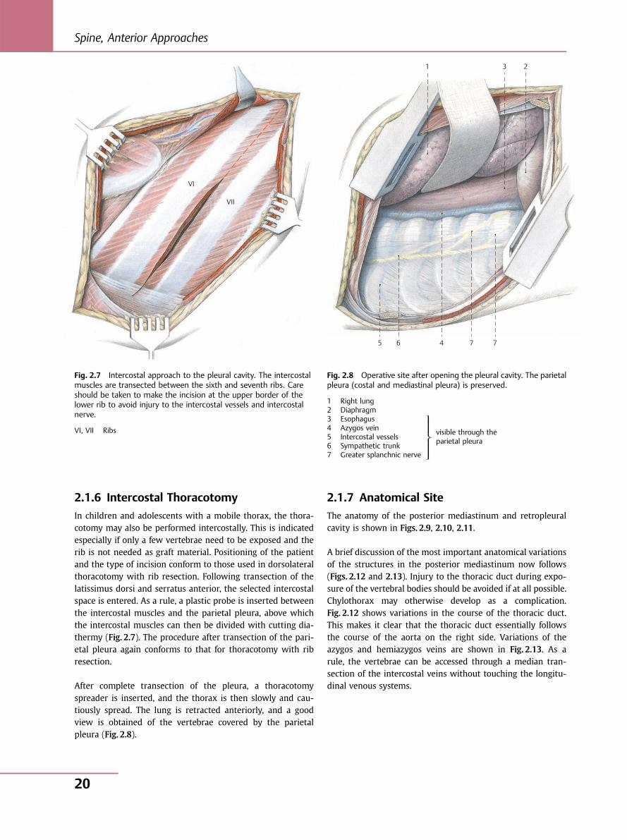
In children and adolescents with a mobile thorax, the thora-cotomy may also be performed intercostally. This is indicatedespecially if only a few vertebrae need to be exposed and therib is not needed as graft material. Positioning of the patientand the type of incision conform to those used in dorsolateralthoracotomy with rib resection. Following transection of thelatissimus dorsi and serratus anterior, the selected intercostalspace is entered. As a rule, a plastic probe is inserted betweenthe intercostal muscles and the parietal pleura, above whichthe intercostal muscles can then be divided with cutting dia-thermy (Fig. 2.7). The procedure after transection of the pari-etal pleura again conforms to that for thoracotomy with ribresection.
After complete transection of the pleura, a thoracotomyspreader is inserted, and the thorax is then slowly and cau-tiously spread. The lung is retracted anteriorly, and a goodview is obtained of the vertebrae covered by the parietalpleura (Fig. 2.8).
2.1.7 Anatomical Site
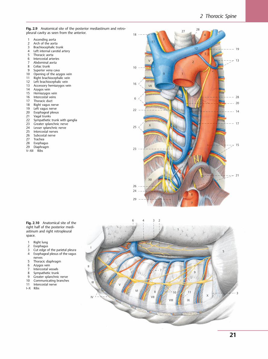
The anatomy of the posterior mediastinum and retropleuralcavity is shown in Figs. 2.9, 2.10, 2.11.
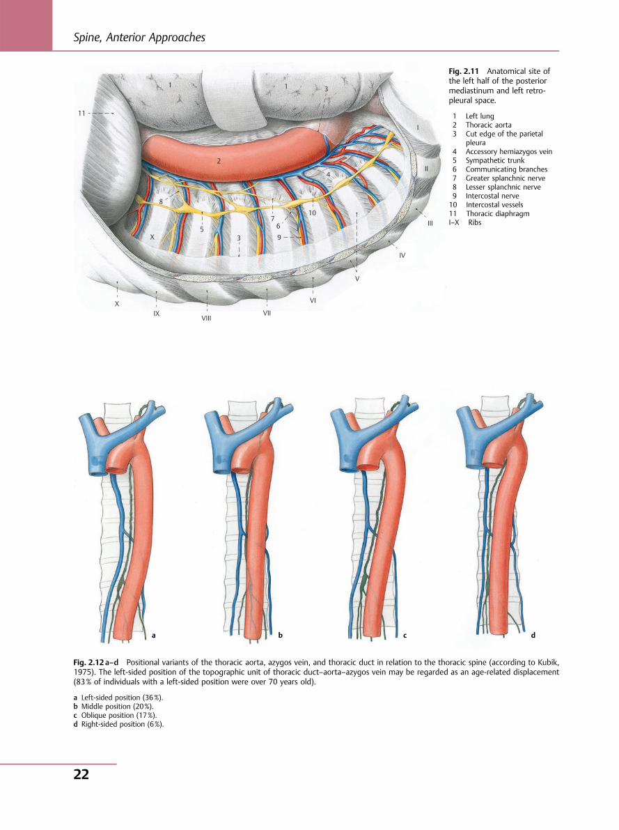
A brief discussion of the most important anatomical variationsof the structures in the posterior mediastinum now follows(Figs. 2.12 and 2.13). Injury to the thoracic duct during expo-sure of the vertebral bodies should be avoided if at all possible.Chylothorax may otherwise develop as a complication.Fig. 2.12 shows variations in the course of the thoracic duct.This makes it clear that the thoracic duct essentially followsthe course of the aorta on the right side. Variations of theazygos and hemiazygos veins are shown in Fig. 2.13. As arule, the vertebrae can be accessed through a median tran-section of the intercostal veins without touching the longitu-dinal venous systems.
VI
VII
Fig. 2.7 Intercostal approach to the pleural cavity. The intercostalmuscles are transected between the sixth and seventh ribs. Careshould be taken to make the incision at the upper border of thelower rib to avoid injury to the intercostal vessels and intercostalnerve.
VI, VII Ribs
1 3 2
5 6 4 7 7
Fig. 2.8 Operative site after opening the pleural cavity. The parietalpleura (costal and mediastinal pleura) is preserved.
1 Right lung2 Diaphragm3 Esophagus4 Azygos vein5 Intercostal vessels6 Sympathetic trunk7 Greater splanchnic nerve
visible through theparietal pleura
⎫⎪⎪⎬⎪⎪⎭
Spine, Anterior Approaches
20
18
16
10
22
25
23
2624
29
21
8
XII
X
VII
V
7
15
17
14
20
28
13
19
2827
311
9 1
2
5
12
4
6
6 4 3 2
1
5
3 11 108
7
IV
V
VI
VIIVIII IX
X
III
II
I
9
Fig. 2.9 Anatomical site of the posterior mediastinum and retro-pleural cavity as seen from the anterior.
1 Ascending aorta2 Arch of the aorta3 Brachiocephalic trunk4 Left internal carotid artery5 Thoracic aorta6 Intercostal arteries7 Abdominal aorta8 Celiac trunk9 Superior vena cava10 Opening of the azygos vein11 Right brachiocephalic vein12 Left brachiocephalic vein13 Accessory hemiazygos vein14 Azygos vein15 Hemiazygos vein16 Intercostal veins17 Thoracic duct18 Right vagus nerve19 Left vagus nerve20 Esophageal plexus21 Vagal trunks22 Sympathetic trunk with ganglia23 Greater splanchnic nerve24 Lesser splanchnic nerve25 Intercostal nerves26 Subcostal nerve27 Trachea28 Esophagus29 DiaphragmV–XII Ribs
Fig. 2.10 Anatomical site of theright half of the posterior medi-astinum and right retropleuralspace.
1 Right lung2 Esophagus3 Cut edge of the parietal pleura4 Esophageal plexus of the vagus
nerves5 Thoracic diaphragm6 Azygos vein7 Intercostal vessels8 Sympathetic trunk9 Greater splanchnic nerve10 Communicating branches11 Intercostal nerveI–X Ribs
2 Thoracic Spine
21
10
11
9
8
7 6 5
4
3 1
2
1
3
I
II
III
IV
V
VI
VIIVIII
IXX
X
Fig. 2.11 Anatomical site ofthe left half of the posteriormediastinum and left retro-pleural space.
1 Left lung2 Thoracic aorta3 Cut edge of the parietal
pleura4 Accessory hemiazygos vein5 Sympathetic trunk6 Communicating branches7 Greater splanchnic nerve8 Lesser splanchnic nerve9 Intercostal nerve10 Intercostal vessels11 Thoracic diaphragmI–X Ribs
Fig. 2.12 a–d Positional variants of the thoracic aorta, azygos vein, and thoracic duct in relation to the thoracic spine (according to Kubik,1975). The left-sided position of the topographic unit of thoracic duct–aorta–azygos vein may be regarded as an age-related displacement(83% of individuals with a left-sided position were over 70 years old).
a Left-sided position (36%).b Middle position (20%).c Oblique position (17%).d Right-sided position (6%).
a b c d
Spine, Anterior Approaches
22
1 3
2
a b c
d e f
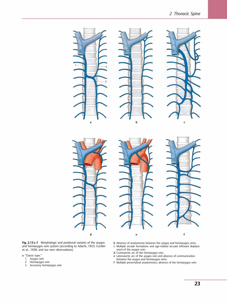
Fig. 2.13 a–f Morphologic and positional variants of the azygosand hemiazygos vein system (according to Adachi, 1933; Cordieret al., 1938; and our own observations).
a “Classic type.”1 Azygos vein2 Hemiazygos vein3 Accessory hemiazygos vein
b Absence of anastomosis between the azygos and hemiazygos veins.c Multiple arcade formations and age-related arcuate leftward displace-
ment of the azygos vein.d Cranioaortic arc of the hemiazygos vein.e Lateroaortic arc of the azygos vein and absence of communication
between the azygos and hemiazygos veins.f Multiple prevertebral anastomoses; absence of the hemiazygos vein.
2 Thoracic Spine
23
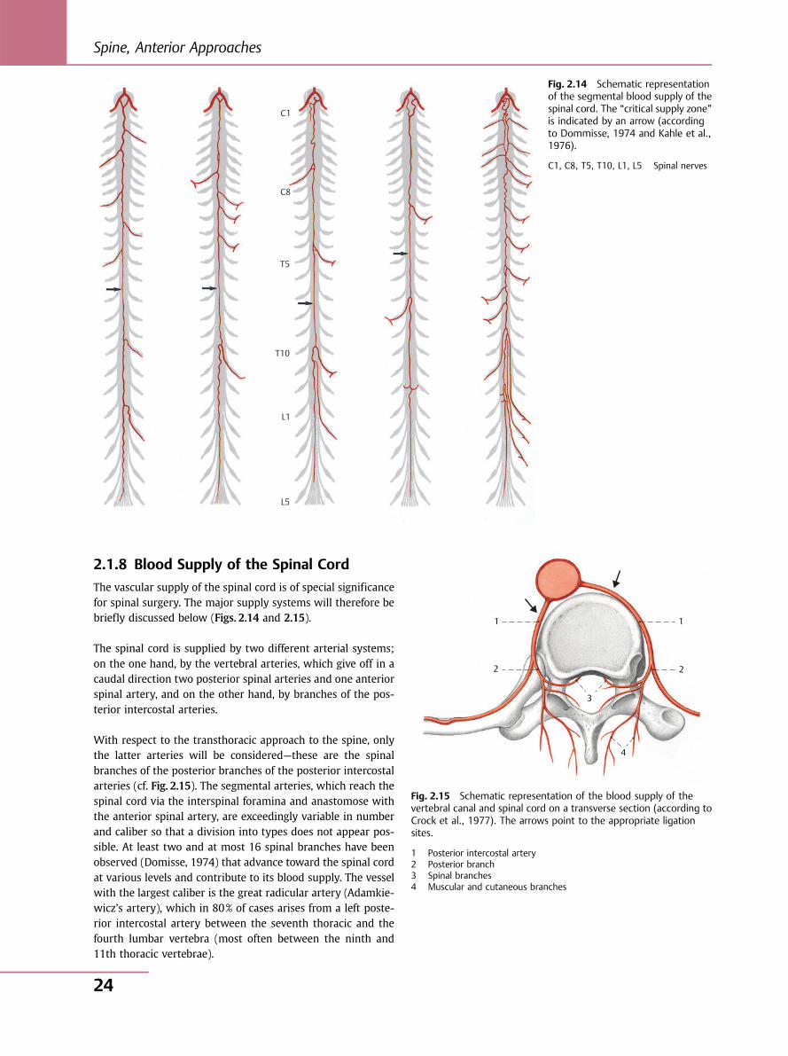
2.1.8 Blood Supply of the Spinal Cord
The vascular supply of the spinal cord is of special significancefor spinal surgery. The major supply systems will therefore bebriefly discussed below (Figs. 2.14 and 2.15).
The spinal cord is supplied by two different arterial systems;on the one hand, by the vertebral arteries, which give off in acaudal direction two posterior spinal arteries and one anteriorspinal artery, and on the other hand, by branches of the pos-terior intercostal arteries.
With respect to the transthoracic approach to the spine, onlythe latter arteries will be considered—these are the spinalbranches of the posterior branches of the posterior intercostalarteries (cf. Fig. 2.15). The segmental arteries, which reach thespinal cord via the interspinal foramina and anastomose withthe anterior spinal artery, are exceedingly variable in numberand caliber so that a division into types does not appear pos-sible. At least two and at most 16 spinal branches have beenobserved (Domisse, 1974) that advance toward the spinal cordat various levels and contribute to its blood supply. The vesselwith the largest caliber is the great radicular artery (Adamkie-wicz’s artery), which in 80% of cases arises from a left poste-rior intercostal artery between the seventh thoracic and thefourth lumbar vertebra (most often between the ninth and11th thoracic vertebrae).
C1
C8
T5
T10
L1
L5
Fig. 2.14 Schematic representationof the segmental blood supply of thespinal cord. The “critical supply zone”is indicated by an arrow (accordingto Dommisse, 1974 and Kahle et al.,1976).
C1, C8, T5, T10, L1, L5 Spinal nerves
1 1
2 2
3
4
Fig. 2.15 Schematic representation of the blood supply of thevertebral canal and spinal cord on a transverse section (according toCrock et al., 1977). The arrows point to the appropriate ligationsites.
1 Posterior intercostal artery2 Posterior branch3 Spinal branches4 Muscular and cutaneous branches
Spine, Anterior Approaches
24
It should be noted, without minimizing the importance ofAdamkiewicz’s artery, that it alone is hardly sufficient to sup-ply the caudal segments of the spinal cord. There are in factseveral medullary nutrient arteries at different levels that playa vital role in maintaining the supply of the spinal cord. This isconsistent with the experience of spinal surgeons who, partic-ularly in the treatment of scoliosis, have ligated between fourand 16 segmental arteries without causing any neurologicdysfunction. At any rate, it seems prudent to protect the seg-mental spinal arteries insofar as the surgical procedure allows.
In the spinal cord, there is a zone of cervical enlargement, athoracic zone, and a zone of lumbar enlargement. The numberand size of the branches supplying the cervical and lumbarcord are greater than those in the thoracic cord. Thus, thethoracic cord is described as a watershed. The “critical supplyzone” of the spinal cord generally lies between the fourth andninth thoracic vertebrae. It is in this zone that the greatestcaution should be exercised during surgery.
In exposing vertebrae by the anterior approach, it is importantto transect the segmental arteries as far forward as possible;also, the vessels should be dissected free only over a shortdistance in a posterior direction (Fig. 2.15). The arterial ar-cades that join the segmental arteries outside and inside thevertebral canal are thus preserved. To avoid damage to thespinal branches, the vessels should not be electrocoagulatednear the intervertebral foramen.
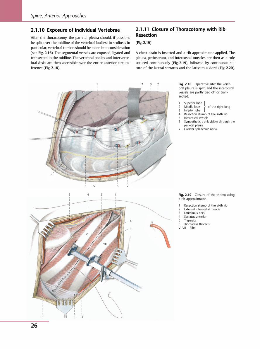
2.1.9 Site of Thoracotomy in Scoliosis
(Figs. 2.16 and 2.17)
In scoliosis, thoracotomy is always performed on the side ofthe convexity. Owing to the severe torsion of the vertebralbodies and the posterior rib-hump on the convex side, contactis often made immediately after thoracotomy with the spine,which is situated only a few centimeters under the resectedrib. The large thoracic vessels generally do not, or do not com-pletely, follow the line of the curvature, and are thereforeusually found on the concave side. This means that in left-sided thoracotomy for thoracic scoliosis with a left-sided con-vexity, the aorta is generally located on the right of the spine.
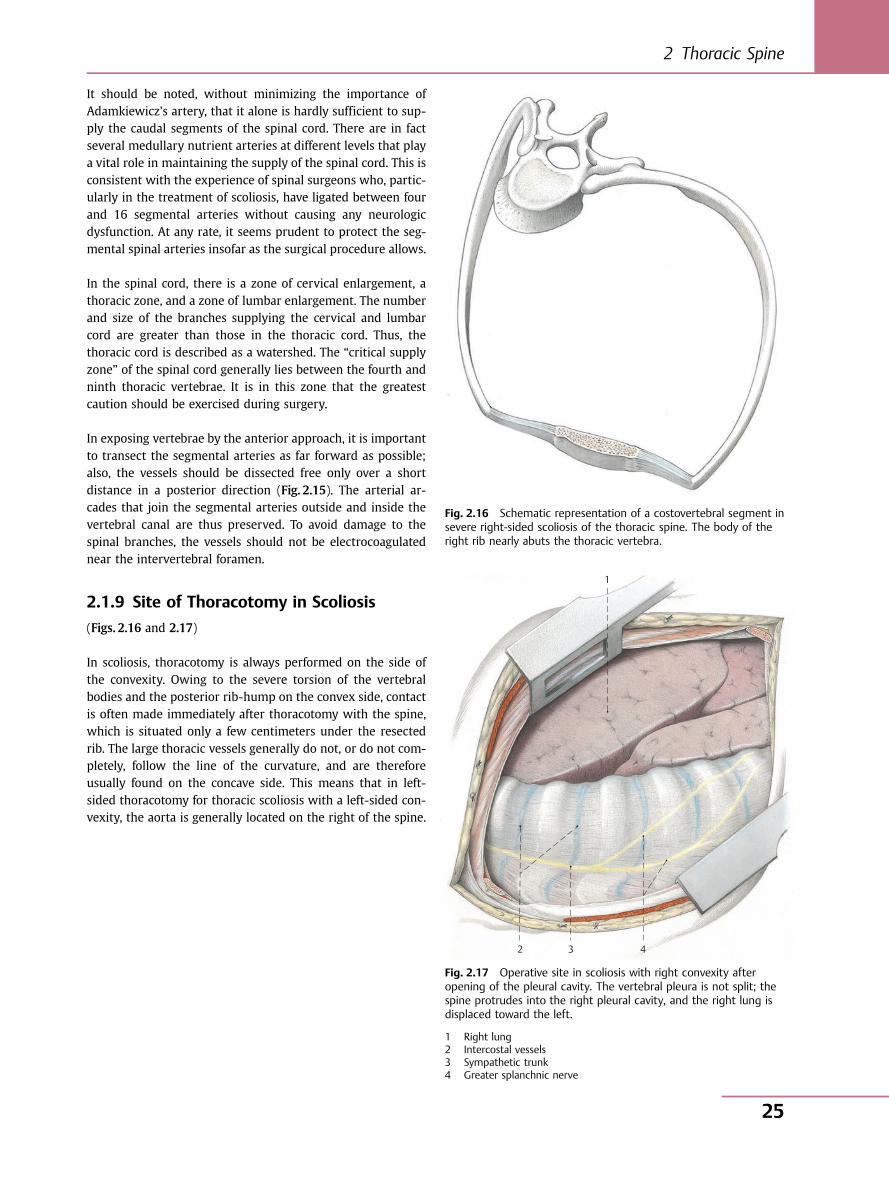
Fig. 2.16 Schematic representation of a costovertebral segment insevere right-sided scoliosis of the thoracic spine. The body of theright rib nearly abuts the thoracic vertebra.
1
4 3 2
Fig. 2.17 Operative site in scoliosis with right convexity afteropening of the pleural cavity. The vertebral pleura is not split; thespine protrudes into the right pleural cavity, and the right lung isdisplaced toward the left.
1 Right lung2 Intercostal vessels3 Sympathetic trunk4 Greater splanchnic nerve
2 Thoracic Spine
25
2.1.10 Exposure of Individual Vertebrae
After the thoracotomy, the parietal pleura should, if possible,be split over the midline of the vertebral bodies; in scoliosis inparticular, vertebral torsion should be taken into consideration(see Fig. 2.16). The segmental vessels are exposed, ligated andtransected in the midline. The vertebral bodies and interverte-bral disks are then accessible over the entire anterior circum-ference (Fig. 2.18).
2.1.11 Closure of Thoracotomy with RibResection
(Fig. 2.19)
A chest drain is inserted and a rib approximator applied. Thepleura, periosteum, and intercostal muscles are then as a rulesutured continuously (Fig. 2.19), followed by continuous su-ture of the lateral serratus and the latissimus dorsi (Fig. 2.20).
1 2 3 7
4
6 5 5 7
Fig. 2.18 Operative site: the verte-bral pleura is split, and the intercostalvessels are partly tied off or tran-sected.
1 Superior lobe2 Middle lobe3 Inferior lobe4 Resection stump of the sixth rib5 Intercostal vessels6 Sympathetic trunk visible through the
parietal pleura7 Greater splanchnic nerve
of the right lung
3 4
4
3
V
VII
3 6 5
2 1 Fig. 2.19 Closure of the thorax usinga rib approximator.
1 Resection stump of the sixth rib2 External intercostal muscle3 Latissimus dorsi4 Serratus anterior5 Trapezius6 Iliocostalis thoracisV, VII Ribs
⎫⎬⎭
Spine, Anterior Approaches
26
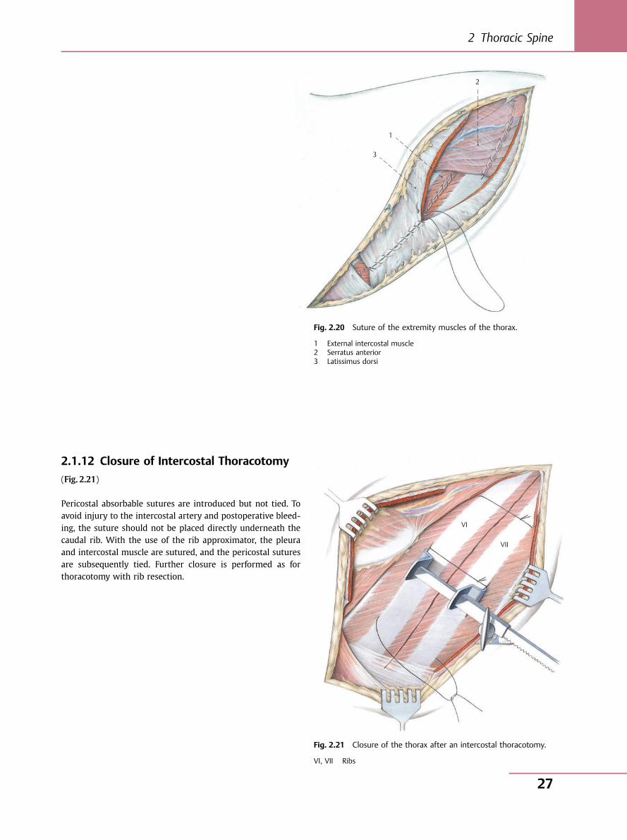
2.1.12 Closure of Intercostal Thoracotomy
(Fig. 2.21)
Pericostal absorbable sutures are introduced but not tied. Toavoid injury to the intercostal artery and postoperative bleed-ing, the suture should not be placed directly underneath thecaudal rib. With the use of the rib approximator, the pleuraand intercostal muscle are sutured, and the pericostal suturesare subsequently tied. Further closure is performed as forthoracotomy with rib resection.
3
1
2
Fig. 2.20 Suture of the extremity muscles of the thorax.
1 External intercostal muscle2 Serratus anterior3 Latissimus dorsi
VI
VII
Fig. 2.21 Closure of the thorax after an intercostal thoracotomy.
VI, VII Ribs
2 Thoracic Spine
27
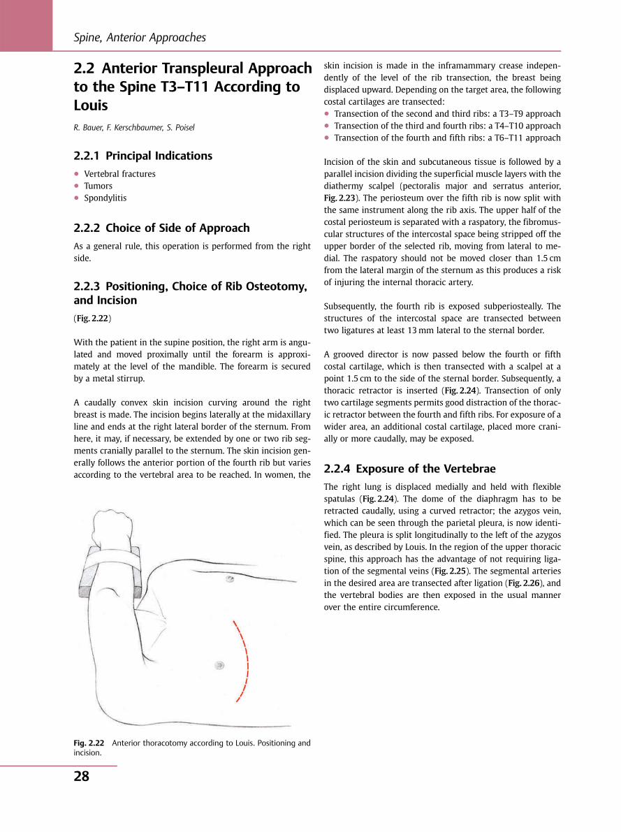
2.2 Anterior Transpleural Approachto the Spine T3–T11 According toLouisR. Bauer, F. Kerschbaumer, S. Poisel
2.2.1 Principal Indications● Vertebral fractures● Tumors● Spondylitis
2.2.2 Choice of Side of Approach
As a general rule, this operation is performed from the rightside.
2.2.3 Positioning, Choice of Rib Osteotomy,and Incision
(Fig. 2.22)
With the patient in the supine position, the right arm is angu-lated and moved proximally until the forearm is approxi-mately at the level of the mandible. The forearm is securedby a metal stirrup.
A caudally convex skin incision curving around the rightbreast is made. The incision begins laterally at the midaxillaryline and ends at the right lateral border of the sternum. Fromhere, it may, if necessary, be extended by one or two rib seg-ments cranially parallel to the sternum. The skin incision gen-erally follows the anterior portion of the fourth rib but variesaccording to the vertebral area to be reached. In women, the
skin incision is made in the inframammary crease indepen-dently of the level of the rib transection, the breast beingdisplaced upward. Depending on the target area, the followingcostal cartilages are transected:● Transection of the second and third ribs: a T3–T9 approach● Transection of the third and fourth ribs: a T4–T10 approach● Transection of the fourth and fifth ribs: a T6–T11 approach
Incision of the skin and subcutaneous tissue is followed by aparallel incision dividing the superficial muscle layers with thediathermy scalpel (pectoralis major and serratus anterior,Fig. 2.23). The periosteum over the fifth rib is now split withthe same instrument along the rib axis. The upper half of thecostal periosteum is separated with a raspatory, the fibromus-cular structures of the intercostal space being stripped off theupper border of the selected rib, moving from lateral to me-dial. The raspatory should not be moved closer than 1.5 cmfrom the lateral margin of the sternum as this produces a riskof injuring the internal thoracic artery.
Subsequently, the fourth rib is exposed subperiosteally. Thestructures of the intercostal space are transected betweentwo ligatures at least 13mm lateral to the sternal border.
A grooved director is now passed below the fourth or fifthcostal cartilage, which is then transected with a scalpel at apoint 1.5 cm to the side of the sternal border. Subsequently, athoracic retractor is inserted (Fig. 2.24). Transection of onlytwo cartilage segments permits good distraction of the thorac-ic retractor between the fourth and fifth ribs. For exposure of awider area, an additional costal cartilage, placed more crani-ally or more caudally, may be exposed.
2.2.4 Exposure of the Vertebrae
The right lung is displaced medially and held with flexiblespatulas (Fig. 2.24). The dome of the diaphragm has to beretracted caudally, using a curved retractor; the azygos vein,which can be seen through the parietal pleura, is now identi-fied. The pleura is split longitudinally to the left of the azygosvein, as described by Louis. In the region of the upper thoracicspine, this approach has the advantage of not requiring liga-tion of the segmental veins (Fig. 2.25). The segmental arteriesin the desired area are transected after ligation (Fig. 2.26), andthe vertebral bodies are then exposed in the usual mannerover the entire circumference.
Fig. 2.22 Anterior thoracotomy according to Louis. Positioning andincision.
Spine, Anterior Approaches
28

If vertebrae T3 and T4 have to be reached, their exposure ishampered by the fact that both the segmental veins and thearteries course obliquely to vertically above these vertebrae, sothat several vessels overlie a single vertebra (see Fig. 2.10). Toavoid the dissection of several segmental arteries, the parietal
pleura may be incised slightly diagonally between two seg-mental arteries at the level of the arch of the azygos vein(Fig. 2.27). The vertebral body is essentially accessible betweenthe segmental arteries; the arch of the azygos vein may beligated and transected.
4
IV
V
6
5
4
3
1
1
2
Fig. 2.23 Operative site after transection of pectoralis major. Theperiosteum over the fourth and fifth ribs is split. The ribs aretransected at the level of the costal cartilage. Transection of theintercostal tissue is shown by a dashed line.
1 Pectoralis major2 External intercostal muscle3 Internal intercostal muscle4 Costal cartilage5 Periosteum6 Intercostal veinIV, V Ribs
3 4
III
III
IVV
VI VII
21
Fig. 2.24 Operative site after opening of thepleural cavity and insertion of a rib spreader. Theparietal pleura is split over the spine on the leftside of the azygos vein (dashed line).
1 Azygos vein2 Intercostal vein3 Intercostal vessels4 LungIII–VII Ribs
2 Thoracic Spine
29
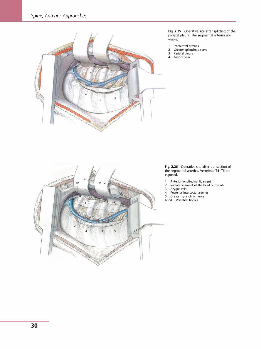
1
4
32
Fig. 2.25 Operative site after splitting of theparietal pleura. The segmental arteries arevisible.
1 Intercostal arteries2 Greater splanchnic nerve3 Parietal pleura4 Azygos vein
IV V VI 4
1
2
4 3 5
Fig. 2.26 Operative site after transection ofthe segmental arteries. Vertebrae T4–T6 areexposed.
1 Anterior longitudinal ligament2 Radiate ligament of the head of the rib3 Azygos vein4 Posterior intercostal arteries5 Greater splanchnic nerveIV–VI Vertebral bodies
Spine, Anterior Approaches
30
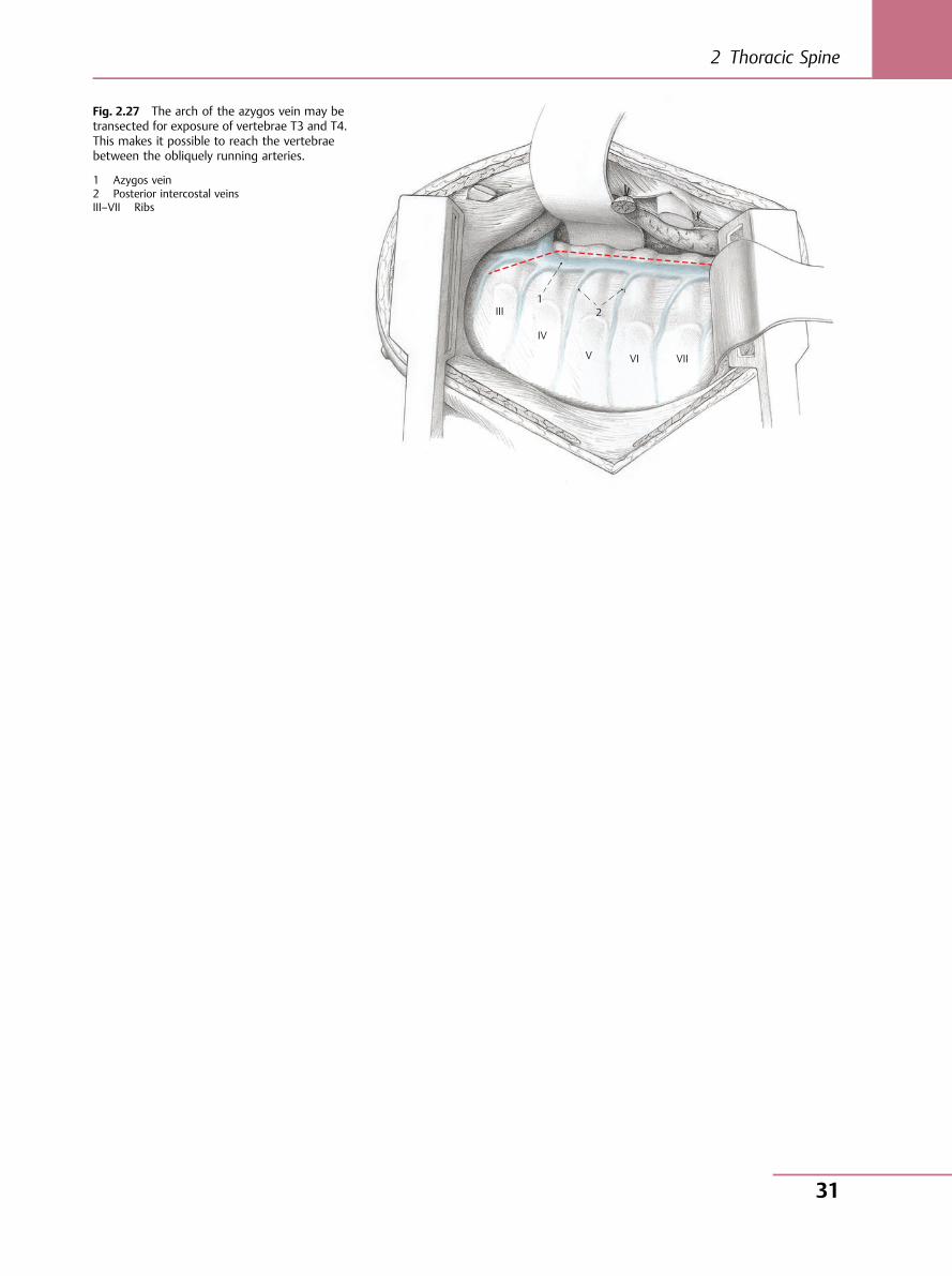
1 III
IV
V VI VII
2
Fig. 2.27 The arch of the azygos vein may betransected for exposure of vertebrae T3 and T4.This makes it possible to reach the vertebraebetween the obliquely running arteries.
1 Azygos vein2 Posterior intercostal veinsIII–VII Ribs
2 Thoracic Spine
31
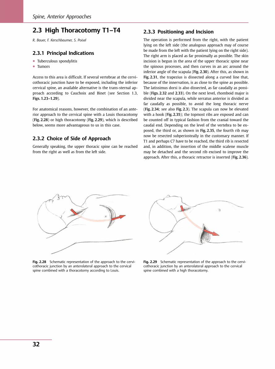
2.3 High Thoracotomy T1–T4R. Bauer, F. Kerschbaumer, S. Poisel
2.3.1 Principal Indications● Tuberculous spondylitis● Tumors
Access to this area is difficult. If several vertebrae at the cervi-cothoracic junction have to be exposed, including the inferiorcervical spine, an available alternative is the trans-sternal ap-proach according to Cauchoix and Binet (see Section 1.3,Figs. 1.23–1.29).
For anatomical reasons, however, the combination of an ante-rior approach to the cervical spine with a Louis thoracotomy(Fig. 2.28) or high thoracotomy (Fig. 2.29), which is describedbelow, seems more advantageous to us in this case.
2.3.2 Choice of Side of Approach
Generally speaking, the upper thoracic spine can be reachedfrom the right as well as from the left side.
2.3.3 Positioning and Incision
The operation is performed from the right, with the patientlying on the left side (the analogous approach may of coursebe made from the left with the patient lying on the right side).The right arm is placed as far proximally as possible. The skinincision is begun in the area of the upper thoracic spine nearthe spinous processes, and then curves in an arc around theinferior angle of the scapula (Fig. 2.30). After this, as shown inFig. 2.31, the trapezius is dissected along a curved line that,because of the innervation, is as close to the spine as possible.The latissimus dorsi is also dissected, as far caudally as possi-ble (Figs. 2.32 and 2.33). On the next level, rhomboid major isdivided near the scapula, while serratus anterior is divided asfar caudally as possible, to avoid the long thoracic nerve(Fig. 2.34; see also Fig. 2.3). The scapula can now be elevatedwith a hook (Fig. 2.35); the topmost ribs are exposed and canbe counted off in typical fashion from the cranial toward thecaudal end. Depending on the level of the vertebra to be ex-posed, the third or, as shown in Fig. 2.35, the fourth rib maynow be resected subperiosteally in the customary manner. IfT1 and perhaps C7 have to be reached, the third rib is resectedand, in addition, the insertion of the middle scalene musclemay be detached and the second rib excised to improve theapproach. After this, a thoracic retractor is inserted (Fig. 2.36).
Fig. 2.28 Schematic representation of the approach to the cervi-cothoracic junction by an anterolateral approach to the cervicalspine combined with a thoracotomy according to Louis.
Fig. 2.29 Schematic representation of the approach to the cervi-cothoracic junction by an anterolateral approach to the cervicalspine combined with a high thoracotomy.
Spine, Anterior Approaches
32
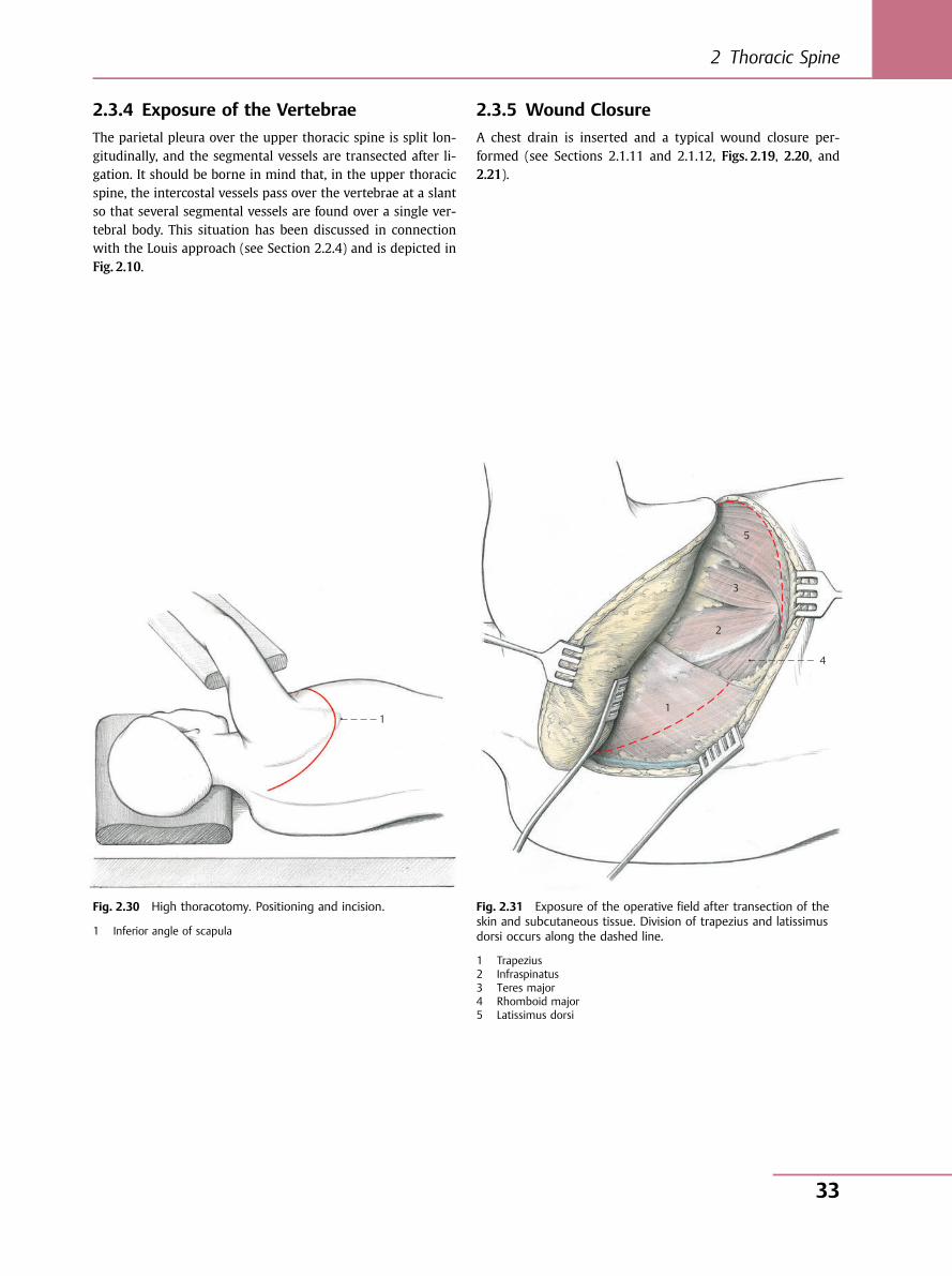
2.3.4 Exposure of the Vertebrae
The parietal pleura over the upper thoracic spine is split lon-gitudinally, and the segmental vessels are transected after li-gation. It should be borne in mind that, in the upper thoracicspine, the intercostal vessels pass over the vertebrae at a slantso that several segmental vessels are found over a single ver-tebral body. This situation has been discussed in connectionwith the Louis approach (see Section 2.2.4) and is depicted inFig. 2.10.
2.3.5 Wound Closure
A chest drain is inserted and a typical wound closure per-formed (see Sections 2.1.11 and 2.1.12, Figs. 2.19, 2.20, and2.21).
1
Fig. 2.30 High thoracotomy. Positioning and incision.
1 Inferior angle of scapula
4
1
2
3
5
Fig. 2.31 Exposure of the operative field after transection of theskin and subcutaneous tissue. Division of trapezius and latissimusdorsi occurs along the dashed line.
1 Trapezius2 Infraspinatus3 Teres major4 Rhomboid major5 Latissimus dorsi
2 Thoracic Spine
33
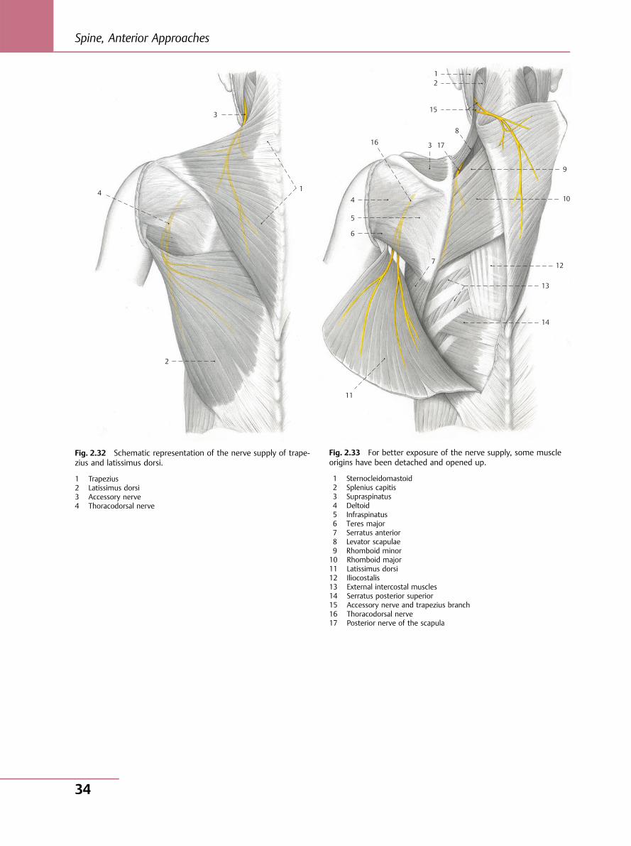
3
14
2
Fig. 2.32 Schematic representation of the nerve supply of trape-zius and latissimus dorsi.
1 Trapezius2 Latissimus dorsi3 Accessory nerve4 Thoracodorsal nerve
1 2
15
8
17 3 16
4
5
6
7
11
14
13
12
10
9
Fig. 2.33 For better exposure of the nerve supply, some muscleorigins have been detached and opened up.
1 Sternocleidomastoid2 Splenius capitis3 Supraspinatus4 Deltoid5 Infraspinatus6 Teres major7 Serratus anterior8 Levator scapulae9 Rhomboid minor10 Rhomboid major11 Latissimus dorsi12 Iliocostalis13 External intercostal muscles14 Serratus posterior superior15 Accessory nerve and trapezius branch16 Thoracodorsal nerve17 Posterior nerve of the scapula
Spine, Anterior Approaches
34
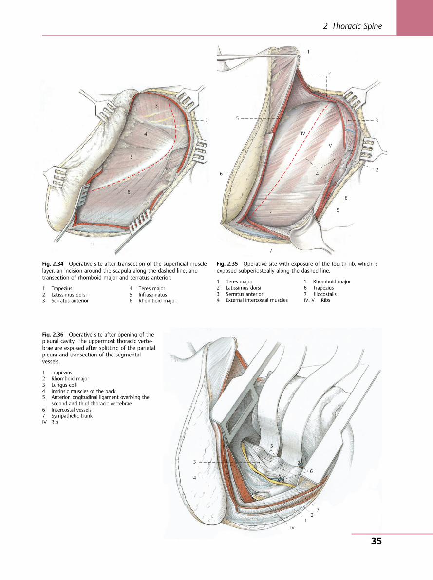
3
4
5
6
2
1
Fig. 2.34 Operative site after transection of the superficial musclelayer, an incision around the scapula along the dashed line, andtransection of rhomboid major and serratus anterior.
1 Trapezius2 Latissimus dorsi3 Serratus anterior
4 Teres major5 Infraspinatus6 Rhomboid major
1
2
3
24
IV
V
6
6
5
5
7
Fig. 2.35 Operative site with exposure of the fourth rib, which isexposed subperiosteally along the dashed line.
1 Teres major2 Latissimus dorsi3 Serratus anterior4 External intercostal muscles
5 Rhomboid major6 Trapezius7 IliocostalisIV, V Ribs
3
4
IV 1
2 7
6
5
Fig. 2.36 Operative site after opening of thepleural cavity. The uppermost thoracic verte-brae are exposed after splitting of the parietalpleura and transection of the segmentalvessels.
1 Trapezius2 Rhomboid major3 Longus colli4 Intrinsic muscles of the back5 Anterior longitudinal ligament overlying the
second and third thoracic vertebrae6 Intercostal vessels7 Sympathetic trunkIV Rib
2 Thoracic Spine
35
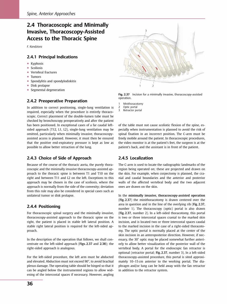
2.4 Thoracoscopic and MinimallyInvasive, Thoracoscopy-AssistedAccess to the Thoracic SpineF. Kandziora
2.4.1 Principal Indications● Kyphosis● Scoliosis● Vertebral fractures● Tumors● Spondylitis and spondylodiskitis● Disk prolapse● Segmental degeneration
2.4.2 Preoperative Preparation
In addition to correct positioning, single-lung ventilation isrequired, especially when the procedure is entirely thoraco-scopic. Correct placement of the double-lumen tube must bechecked by bronchoscopy preoperatively and after the patienthas been positioned. In exceptional cases of a far caudal left-sided approach (T12, L1, L2), single-lung ventilation may beomitted, particularly when minimally invasive, thoracoscopy-assisted access is planned. However, it must then be ensuredthat the positive end-expiratory pressure is kept as low aspossible to allow better retraction of the lung.
2.4.3 Choice of Side of Approach
Because of the course of the thoracic aorta, the purely thora-coscopic and the minimally invasive thoracoscopy-assisted ap-proach to the thoracic spine is between T1 and T10 on theright and between T11 and L2 on the left. Exceptions to thisapproach may be chosen in the case of scoliosis, where theapproach is normally from the side of the convexity; deviationfrom this rule may also be considered in special cases such asunilateral tumor or disk prolapse.
2.4.4 Positioning
For thoracoscopic spinal surgery and the minimally invasive,thoracoscopy-assisted approach to the thoracic spine on theright, the patient is placed in stable left lateral position. Astable right lateral position is required for the left-sided ap-proach.
In the description of the operation that follows, we shall con-centrate on the left-sided approach (Figs. 2.37 and 2.38); theright-sided approach is analogous.
For the left-sided procedure, the left arm must be abductedand elevated. Abduction must not exceed 90°, to avoid brachialplexus damage. The operating table should be hinged so that itcan be angled below the instrumented regions to allow wid-ening of the intercostal spaces if necessary. However, angling
of the table must not cause scoliotic flexion of the spine, es-pecially when instrumentation is planned to avoid the risk ofspinal fixation in an incorrect position. The C-arm must befreely mobile around the patient. In thoracoscopic procedures,the video monitor is at the patient’s feet, the surgeon is at thepatient’s back, and the assistant is in front of the patient.
2.4.5 Localization
The C-arm is used to locate the radiographic landmarks of theregion being operated on; these are projected and drawn onthe skin. For example, when corpectomy is planned, the cra-nial and caudal boundaries and the anterior and posteriorwalls of the affected vertebral body and the two adjacentones are drawn on the skin.
In the minimally invasive, thoracoscopy-assisted operation(Fig. 2.37) the minithoracotomy is drawn centered over thearea in question and in the line of the overlying rib (Fig. 2.37,number 1). The thoracoscopy (optic) portal is also drawn(Fig. 2.37, number 2). In a left-sided thoracotomy, this portalis two or three intercostal spaces cranial to the marked skinincision, and is located two or three intercostal spaces caudalto the marked incision in the case of a right-sided thoracoto-my. The optic portal is normally placed at the center of theskin incision in an anteroposterior direction. However, if nec-essary, the 30° optic may be placed somewhat further anteri-orly to allow better visualization of the posterior wall of thevertebral body. A portal for the endoscopic fan retractor isoptional (retractor portal; Fig. 2.37, number 3). In a left-sidedthoracoscopy-assisted procedure, this portal is sited approxi-mately 10–15 cm anterior to the working portal. The dia-phragm and/or lung can be held away with the fan retractorin addition to the retractor system.
Fig. 2.37 Incision for a minimally invasive, thoracoscopy-assistedoperation.
1 Minithoracotomy2 Optic portal3 Retractor portal
3
1 2
Spine, Anterior Approaches
36
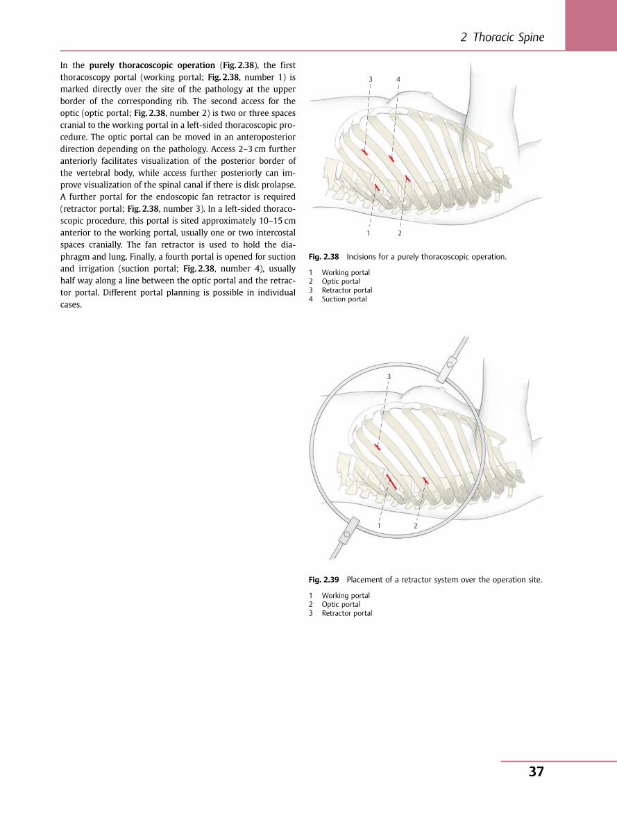
In the purely thoracoscopic operation (Fig. 2.38), the firstthoracoscopy portal (working portal; Fig. 2.38, number 1) ismarked directly over the site of the pathology at the upperborder of the corresponding rib. The second access for theoptic (optic portal; Fig. 2.38, number 2) is two or three spacescranial to the working portal in a left-sided thoracoscopic pro-cedure. The optic portal can be moved in an anteroposteriordirection depending on the pathology. Access 2–3 cm furtheranteriorly facilitates visualization of the posterior border ofthe vertebral body, while access further posteriorly can im-prove visualization of the spinal canal if there is disk prolapse.A further portal for the endoscopic fan retractor is required(retractor portal; Fig. 2.38, number 3). In a left-sided thoraco-scopic procedure, this portal is sited approximately 10–15 cmanterior to the working portal, usually one or two intercostalspaces cranially. The fan retractor is used to hold the dia-phragm and lung. Finally, a fourth portal is opened for suctionand irrigation (suction portal; Fig. 2.38, number 4), usuallyhalf way along a line between the optic portal and the retrac-tor portal. Different portal planning is possible in individualcases.
1 2
3
1 2
3 4
Fig. 2.38 Incisions for a purely thoracoscopic operation.
1 Working portal2 Optic portal3 Retractor portal4 Suction portal
Fig. 2.39 Placement of a retractor system over the operation site.
1 Working portal2 Optic portal3 Retractor portal
2 Thoracic Spine
37
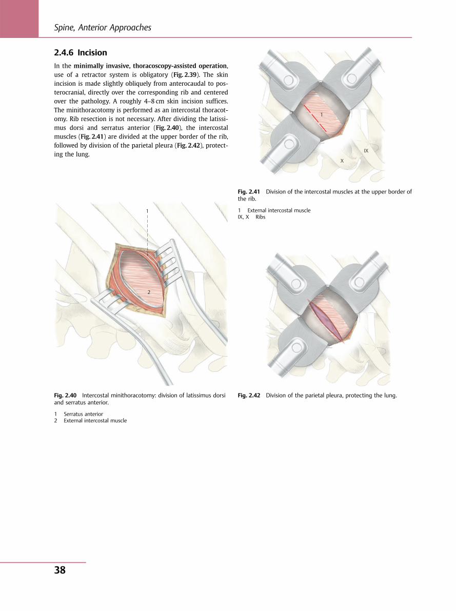
2.4.6 Incision
In the minimally invasive, thoracoscopy-assisted operation,use of a retractor system is obligatory (Fig. 2.39). The skinincision is made slightly obliquely from anterocaudal to pos-terocranial, directly over the corresponding rib and centeredover the pathology. A roughly 4–8 cm skin incision suffices.The minithoracotomy is performed as an intercostal thoracot-omy. Rib resection is not necessary. After dividing the latissi-mus dorsi and serratus anterior (Fig. 2.40), the intercostalmuscles (Fig. 2.41) are divided at the upper border of the rib,followed by division of the parietal pleura (Fig. 2.42), protect-ing the lung.
1
2
Fig. 2.40 Intercostal minithoracotomy: division of latissimus dorsiand serratus anterior.
1 Serratus anterior2 External intercostal muscle
1
X
IX
Fig. 2.41 Division of the intercostal muscles at the upper border ofthe rib.
1 External intercostal muscleIX, X Ribs
Fig. 2.42 Division of the parietal pleura, protecting the lung.
Spine, Anterior Approaches
38
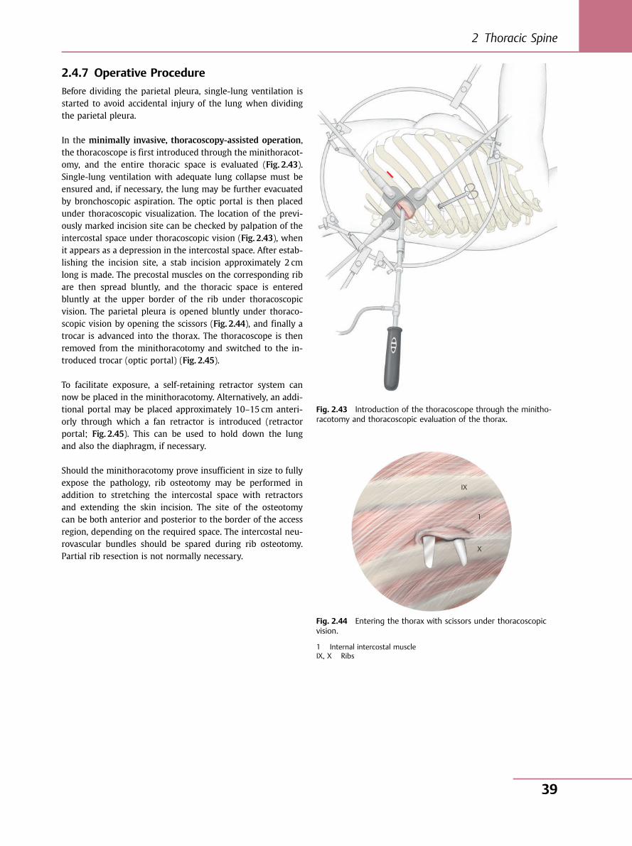
2.4.7 Operative Procedure
Before dividing the parietal pleura, single-lung ventilation isstarted to avoid accidental injury of the lung when dividingthe parietal pleura.
In the minimally invasive, thoracoscopy-assisted operation,the thoracoscope is first introduced through the minithoracot-omy, and the entire thoracic space is evaluated (Fig. 2.43).Single-lung ventilation with adequate lung collapse must beensured and, if necessary, the lung may be further evacuatedby bronchoscopic aspiration. The optic portal is then placedunder thoracoscopic visualization. The location of the previ-ously marked incision site can be checked by palpation of theintercostal space under thoracoscopic vision (Fig. 2.43), whenit appears as a depression in the intercostal space. After estab-lishing the incision site, a stab incision approximately 2 cmlong is made. The precostal muscles on the corresponding ribare then spread bluntly, and the thoracic space is enteredbluntly at the upper border of the rib under thoracoscopicvision. The parietal pleura is opened bluntly under thoraco-scopic vision by opening the scissors (Fig. 2.44), and finally atrocar is advanced into the thorax. The thoracoscope is thenremoved from the minithoracotomy and switched to the in-troduced trocar (optic portal) (Fig. 2.45).
To facilitate exposure, a self-retaining retractor system cannow be placed in the minithoracotomy. Alternatively, an addi-tional portal may be placed approximately 10–15 cm anteri-orly through which a fan retractor is introduced (retractorportal; Fig. 2.45). This can be used to hold down the lungand also the diaphragm, if necessary.
Should the minithoracotomy prove insufficient in size to fullyexpose the pathology, rib osteotomy may be performed inaddition to stretching the intercostal space with retractorsand extending the skin incision. The site of the osteotomycan be both anterior and posterior to the border of the accessregion, depending on the required space. The intercostal neu-rovascular bundles should be spared during rib osteotomy.Partial rib resection is not normally necessary.
Fig. 2.43 Introduction of the thoracoscope through the minitho-racotomy and thoracoscopic evaluation of the thorax.
IX
1
X
Fig. 2.44 Entering the thorax with scissors under thoracoscopicvision.
1 Internal intercostal muscleIX, X Ribs
2 Thoracic Spine
39
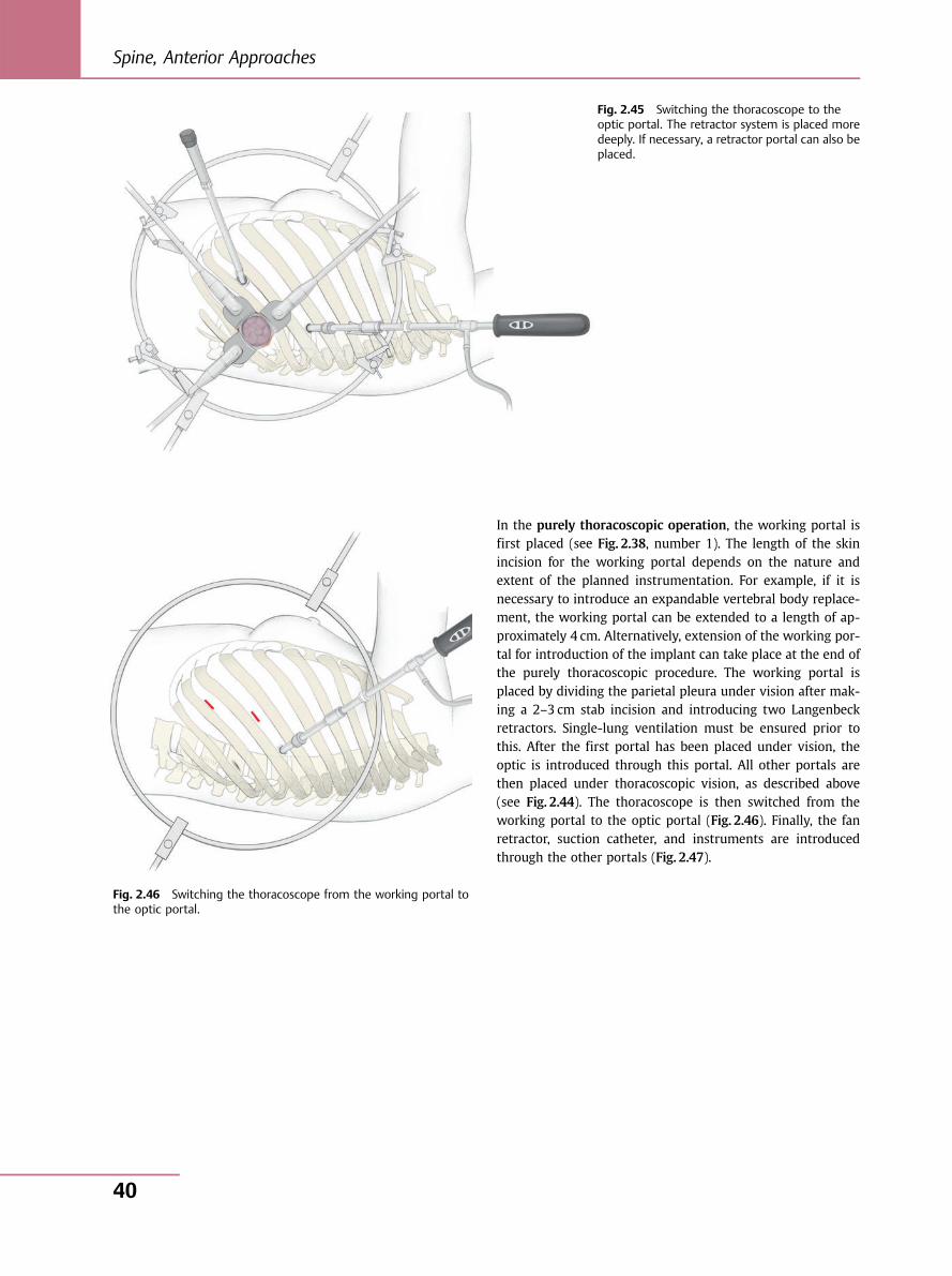
In the purely thoracoscopic operation, the working portal isfirst placed (see Fig. 2.38, number 1). The length of the skinincision for the working portal depends on the nature andextent of the planned instrumentation. For example, if it isnecessary to introduce an expandable vertebral body replace-ment, the working portal can be extended to a length of ap-proximately 4 cm. Alternatively, extension of the working por-tal for introduction of the implant can take place at the end ofthe purely thoracoscopic procedure. The working portal isplaced by dividing the parietal pleura under vision after mak-ing a 2–3 cm stab incision and introducing two Langenbeckretractors. Single-lung ventilation must be ensured prior tothis. After the first portal has been placed under vision, theoptic is introduced through this portal. All other portals arethen placed under thoracoscopic vision, as described above(see Fig. 2.44). The thoracoscope is then switched from theworking portal to the optic portal (Fig. 2.46). Finally, the fanretractor, suction catheter, and instruments are introducedthrough the other portals (Fig. 2.47).
Fig. 2.45 Switching the thoracoscope to theoptic portal. The retractor system is placed moredeeply. If necessary, a retractor portal can also beplaced.
Fig. 2.46 Switching the thoracoscope from the working portal tothe optic portal.
Spine, Anterior Approaches
40
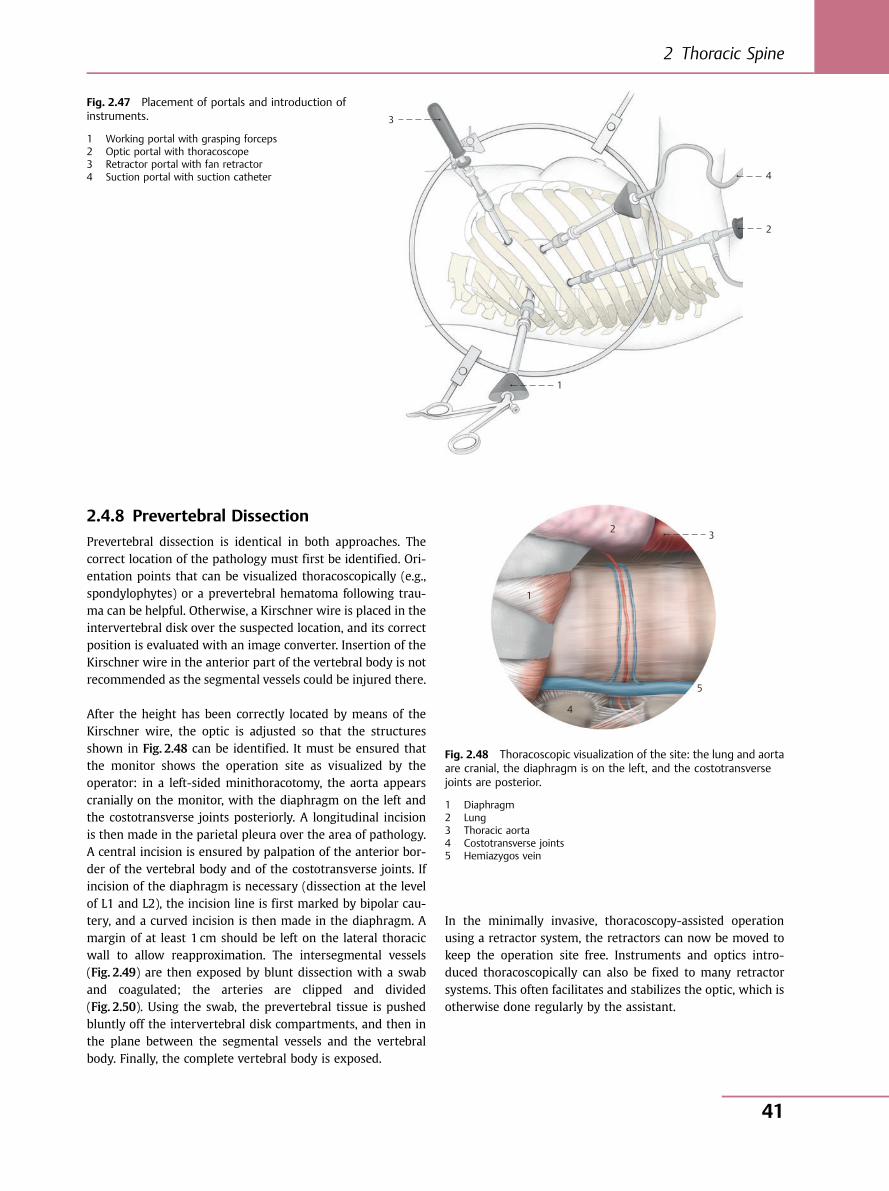
2.4.8 Prevertebral Dissection
Prevertebral dissection is identical in both approaches. Thecorrect location of the pathology must first be identified. Ori-entation points that can be visualized thoracoscopically (e.g.,spondylophytes) or a prevertebral hematoma following trau-ma can be helpful. Otherwise, a Kirschner wire is placed in theintervertebral disk over the suspected location, and its correctposition is evaluated with an image converter. Insertion of theKirschner wire in the anterior part of the vertebral body is notrecommended as the segmental vessels could be injured there.
After the height has been correctly located by means of theKirschner wire, the optic is adjusted so that the structuresshown in Fig. 2.48 can be identified. It must be ensured thatthe monitor shows the operation site as visualized by theoperator: in a left-sided minithoracotomy, the aorta appearscranially on the monitor, with the diaphragm on the left andthe costotransverse joints posteriorly. A longitudinal incisionis then made in the parietal pleura over the area of pathology.A central incision is ensured by palpation of the anterior bor-der of the vertebral body and of the costotransverse joints. Ifincision of the diaphragm is necessary (dissection at the levelof L1 and L2), the incision line is first marked by bipolar cau-tery, and a curved incision is then made in the diaphragm. Amargin of at least 1 cm should be left on the lateral thoracicwall to allow reapproximation. The intersegmental vessels(Fig. 2.49) are then exposed by blunt dissection with a swaband coagulated; the arteries are clipped and divided(Fig. 2.50). Using the swab, the prevertebral tissue is pushedbluntly off the intervertebral disk compartments, and then inthe plane between the segmental vessels and the vertebralbody. Finally, the complete vertebral body is exposed.
In the minimally invasive, thoracoscopy-assisted operationusing a retractor system, the retractors can now be moved tokeep the operation site free. Instruments and optics intro-duced thoracoscopically can also be fixed to many retractorsystems. This often facilitates and stabilizes the optic, which isotherwise done regularly by the assistant.
1
2
4
3
Fig. 2.47 Placement of portals and introduction ofinstruments.
1 Working portal with grasping forceps2 Optic portal with thoracoscope3 Retractor portal with fan retractor4 Suction portal with suction catheter
2 3
4
1
5
Fig. 2.48 Thoracoscopic visualization of the site: the lung and aortaare cranial, the diaphragm is on the left, and the costotransversejoints are posterior.
1 Diaphragm2 Lung3 Thoracic aorta4 Costotransverse joints5 Hemiazygos vein
2 Thoracic Spine
41
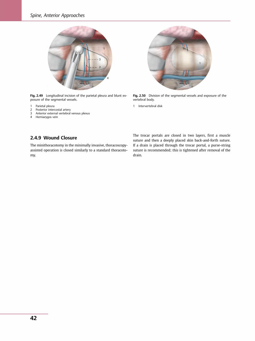
2.4.9 Wound Closure
The minithoracotomy in the minimally invasive, thoracoscopy-assisted operation is closed similarly to a standard thoracoto-my.
The trocar portals are closed in two layers, first a musclesuture and then a deeply placed skin back-and-forth suture.If a drain is placed through the trocar portal, a purse-stringsuture is recommended; this is tightened after removal of thedrain.
1
2
3
4
11111111
222222 22
3333333
4
1
Fig. 2.49 Longitudinal incision of the parietal pleura and blunt ex-posure of the segmental vessels.
1 Parietal pleura2 Posterior intercostal artery3 Anterior external vertebral venous plexus4 Hemiazygos vein
Fig. 2.50 Division of the segmental vessels and exposure of thevertebral body.
1 Intervertebral disk
Spine, Anterior Approaches
42
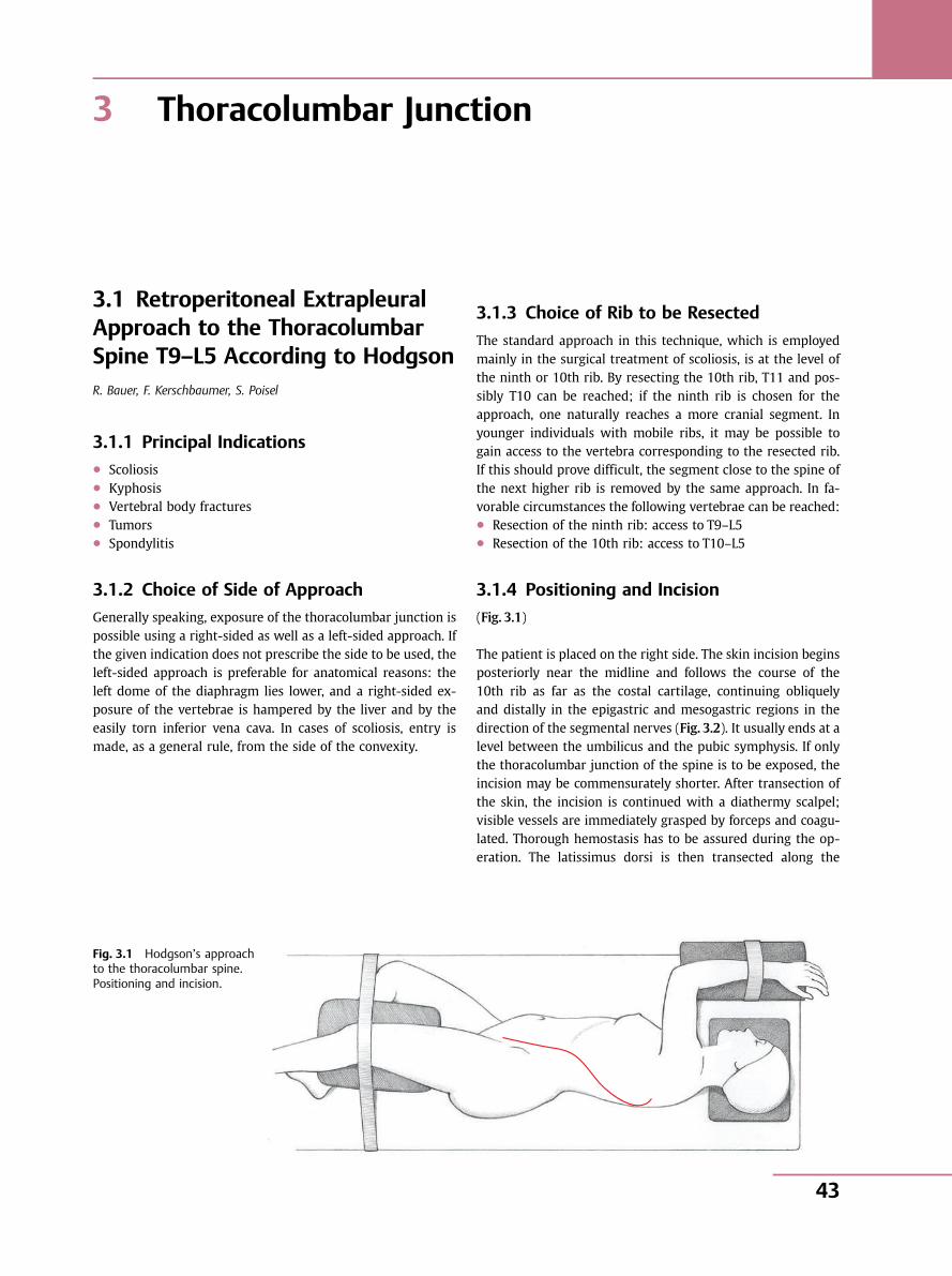
3 Thoracolumbar Junction
3.1 Retroperitoneal ExtrapleuralApproach to the ThoracolumbarSpine T9–L5 According to HodgsonR. Bauer, F. Kerschbaumer, S. Poisel
3.1.1 Principal Indications● Scoliosis● Kyphosis● Vertebral body fractures● Tumors● Spondylitis
3.1.2 Choice of Side of Approach
Generally speaking, exposure of the thoracolumbar junction ispossible using a right-sided as well as a left-sided approach. Ifthe given indication does not prescribe the side to be used, theleft-sided approach is preferable for anatomical reasons: theleft dome of the diaphragm lies lower, and a right-sided ex-posure of the vertebrae is hampered by the liver and by theeasily torn inferior vena cava. In cases of scoliosis, entry ismade, as a general rule, from the side of the convexity.
3.1.3 Choice of Rib to be Resected
The standard approach in this technique, which is employedmainly in the surgical treatment of scoliosis, is at the level ofthe ninth or 10th rib. By resecting the 10th rib, T11 and pos-sibly T10 can be reached; if the ninth rib is chosen for theapproach, one naturally reaches a more cranial segment. Inyounger individuals with mobile ribs, it may be possible togain access to the vertebra corresponding to the resected rib.If this should prove difficult, the segment close to the spine ofthe next higher rib is removed by the same approach. In fa-vorable circumstances the following vertebrae can be reached:● Resection of the ninth rib: access to T9–L5● Resection of the 10th rib: access to T10–L5
3.1.4 Positioning and Incision
(Fig. 3.1)
The patient is placed on the right side. The skin incision beginsposteriorly near the midline and follows the course of the10th rib as far as the costal cartilage, continuing obliquelyand distally in the epigastric and mesogastric regions in thedirection of the segmental nerves (Fig. 3.2). It usually ends at alevel between the umbilicus and the pubic symphysis. If onlythe thoracolumbar junction of the spine is to be exposed, theincision may be commensurately shorter. After transection ofthe skin, the incision is continued with a diathermy scalpel;visible vessels are immediately grasped by forceps and coagu-lated. Thorough hemostasis has to be assured during the op-eration. The latissimus dorsi is then transected along the
Fig. 3.1 Hodgson’s approachto the thoracolumbar spine.Positioning and incision.
3 Thoracolumbar Junction
43
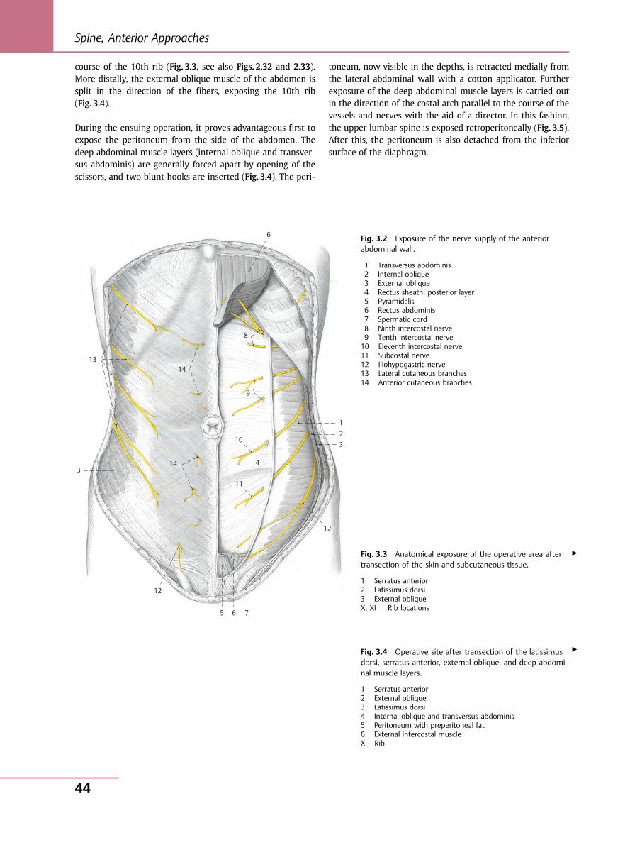
course of the 10th rib (Fig. 3.3, see also Figs. 2.32 and 2.33).More distally, the external oblique muscle of the abdomen issplit in the direction of the fibers, exposing the 10th rib(Fig. 3.4).
During the ensuing operation, it proves advantageous first toexpose the peritoneum from the side of the abdomen. Thedeep abdominal muscle layers (internal oblique and transver-sus abdominis) are generally forced apart by opening of thescissors, and two blunt hooks are inserted (Fig. 3.4). The peri-
toneum, now visible in the depths, is retracted medially fromthe lateral abdominal wall with a cotton applicator. Furtherexposure of the deep abdominal muscle layers is carried outin the direction of the costal arch parallel to the course of thevessels and nerves with the aid of a director. In this fashion,the upper lumbar spine is exposed retroperitoneally (Fig. 3.5).After this, the peritoneum is also detached from the inferiorsurface of the diaphragm.
Fig. 3.2 Exposure of the nerve supply of the anteriorabdominal wall.
1 Transversus abdominis2 Internal oblique3 External oblique4 Rectus sheath, posterior layer5 Pyramidalis6 Rectus abdominis7 Spermatic cord8 Ninth intercostal nerve9 Tenth intercostal nerve10 Eleventh intercostal nerve11 Subcostal nerve12 Iliohypogastric nerve13 Lateral cutaneous branches14 Anterior cutaneous branches
3
13 14
8
9
10
4
11
12
5 6 7
12
321
14
6
Fig. 3.3 Anatomical exposure of the operative area aftertransection of the skin and subcutaneous tissue.
1 Serratus anterior2 Latissimus dorsi3 External obliqueX, XI Rib locations
Fig. 3.4 Operative site after transection of the latissimusdorsi, serratus anterior, external oblique, and deep abdomi-nal muscle layers.
1 Serratus anterior2 External oblique3 Latissimus dorsi4 Internal oblique and transversus abdominis5 Peritoneum with preperitoneal fat6 External intercostal muscleX Rib
▶
▶
Spine, Anterior Approaches
44
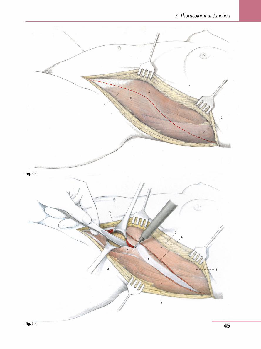
3
1
X
XI
2
1
2 6
3
4
X
5
Fig. 3.3
Fig. 3.4
3 Thoracolumbar Junction
45
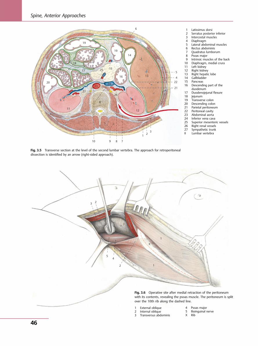
19
18
17
20
11
27
23
10 9 8 7
1 23
25 15
1914
6
135
422
21
12
II
16
26
24
Fig. 3.5 Transverse section at the level of the second lumbar vertebra. The approach for retroperitonealdissection is identified by an arrow (right-sided approach).
2 3
5 4
2 1
1
X
1 Latissimus dorsi2 Serratus posterior inferior3 Intercostal muscles4 Diaphragm5 Lateral abdominal muscles6 Rectus abdominis7 Quadratus lumborum8 Psoas major9 Intrinsic muscles of the back10 Diaphragm, medial crura11 Left kidney12 Right kidney13 Right hepatic lobe14 Gallbladder15 Pancreas16 Descending part of the
duodenum17 Duodenojejunal flexure18 Jejunum19 Transverse colon20 Descending colon21 Parietal peritoneum22 Peritoneal cavity23 Abdominal aorta24 Inferior vena cava25 Superior mesenteric vessels26 Right renal vessels27 Sympathetic trunkII Lumbar vertebra
Fig. 3.6 Operative site after medial retraction of the peritoneumwith its contents, revealing the psoas muscle. The peritoneum is splitover the 10th rib along the dashed line.
1 External oblique2 Internal oblique3 Transversus abdominis
4 Psoas major5 Ilioinguinal nerveX Rib
Spine, Anterior Approaches
46
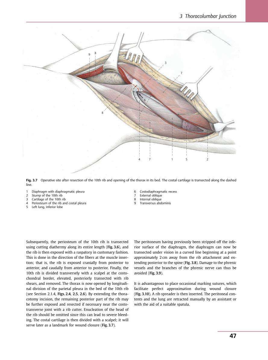
Subsequently, the periosteum of the 10th rib is transectedusing cutting diathermy along its entire length (Fig. 3.6), andthe rib is then exposed with a raspatory in customary fashion.This is done in the direction of the fibers at the muscle inser-tion; that is, the rib is exposed cranially from posterior toanterior, and caudally from anterior to posterior. Finally, the10th rib is divided transversely with a scalpel at the costo-chondral border, elevated, posteriorly transected with ribshears, and removed. The thorax is now opened by longitudi-nal division of the parietal pleura in the bed of the 10th rib(see Section 2.1.4, Figs. 2.4, 2.5, 2.6). By extending the thora-cotomy incision, the remaining posterior part of the rib maybe further exposed and resected if necessary near the costo-transverse joint with a rib cutter. Enucleation of the head ofthe rib should be omitted since this can lead to severe bleed-ing. The costal cartilage is then divided with a scalpel; it willserve later as a landmark for wound closure (Fig. 3.7).
The peritoneum having previously been stripped off the infe-rior surface of the diaphragm, the diaphragm can now betransected under vision in a curved line beginning at a pointapproximately 2 cm away from the rib attachment and ex-tending posterior to the spine (Fig. 3.8). Damage to the phrenicvessels and the branches of the phrenic nerve can thus beavoided (Fig. 3.9).
It is advantageous to place occasional marking sutures, whichfacilitate perfect approximation during wound closure(Fig. 3.10). A rib spreader is then inserted. The peritoneal con-tents and the lung are retracted manually by an assistant orwith the aid of a suitable spatula.
9 8
8
6
3
7
4 7 1 5 2
Fig. 3.7 Operative site after resection of the 10th rib and opening of the thorax in its bed. The costal cartilage is transected along the dashedline.
1 Diaphragm with diaphragmatic pleura2 Stump of the 10th rib3 Cartilage of the 10th rib4 Periosteum of the rib and costal pleura5 Left lung, inferior lobe
6 Costodiaphragmatic recess7 External oblique8 Internal oblique9 Transversus abdominis
3 Thoracolumbar Junction
47
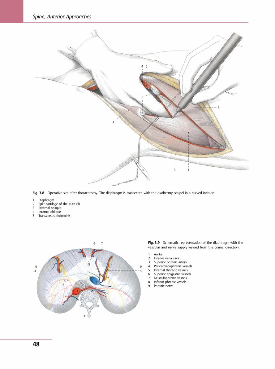
1 3
3
2
4
4 5
Fig. 3.8 Operative site after thoracotomy. The diaphragm is transected with the diathermy scalpel in a curved incision.
1 Diaphragm2 Split cartilage of the 10th rib3 External oblique4 Internal oblique5 Transversus abdominis
3
8
4 9
5
6 7
9 4
1
2
Fig. 3.9 Schematic representation of the diaphragm with thevascular and nerve supply viewed from the cranial direction.
1 Aorta2 Inferior vena cava3 Superior phrenic artery4 Pericardiacophrenic vessels5 Internal thoracic vessels6 Superior epigastric vessels7 Musculophrenic vessels8 Inferior phrenic vessels9 Phrenic nerve
Spine, Anterior Approaches
48
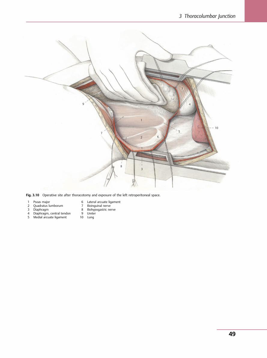
1
2
5
4
3
10
6
3 8
7
9
Fig. 3.10 Operative site after thoracotomy and exposure of the left retroperitoneal space.
1 Psoas major2 Quadratus lumborum3 Diaphragm4 Diaphragm, central tendon5 Medial arcuate ligament
6 Lateral arcuate ligament7 Ilioinguinal nerve8 Iliohypogastric nerve9 Ureter10 Lung
3 Thoracolumbar Junction
49
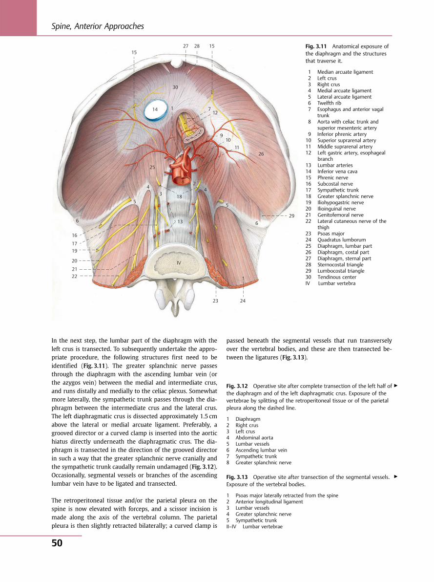
In the next step, the lumbar part of the diaphragm with theleft crus is transected. To subsequently undertake the appro-priate procedure, the following structures first need to beidentified (Fig. 3.11). The greater splanchnic nerve passesthrough the diaphragm with the ascending lumbar vein (orthe azygos vein) between the medial and intermediate crus,and runs distally and medially to the celiac plexus. Somewhatmore laterally, the sympathetic trunk passes through the dia-phragm between the intermediate crus and the lateral crus.The left diaphragmatic crus is dissected approximately 1.5 cmabove the lateral or medial arcuate ligament. Preferably, agrooved director or a curved clamp is inserted into the aortichiatus directly underneath the diaphragmatic crus. The dia-phragm is transected in the direction of the grooved directorin such a way that the greater splanchnic nerve cranially andthe sympathetic trunk caudally remain undamaged (Fig. 3.12).Occasionally, segmental vessels or branches of the ascendinglumbar vein have to be ligated and transected.
The retroperitoneal tissue and/or the parietal pleura on thespine is now elevated with forceps, and a scissor incision ismade along the axis of the vertebral column. The parietalpleura is then slightly retracted bilaterally; a curved clamp is
passed beneath the segmental vessels that run transverselyover the vertebral bodies, and these are then transected be-tween the ligatures (Fig. 3.13).
6
5
4
25
14
30
15 27 28 15
3
13
23 24
6
5
42
29
2611
109
1271
IV
18
8
16
1719
20
2122
Fig. 3.11 Anatomical exposure ofthe diaphragm and the structuresthat traverse it.
1 Median arcuate ligament2 Left crus3 Right crus4 Medial arcuate ligament5 Lateral arcuate ligament6 Twelfth rib7 Esophagus and anterior vagal
trunk8 Aorta with celiac trunk and
superior mesenteric artery9 Inferior phrenic artery10 Superior suprarenal artery11 Middle suprarenal artery12 Left gastric artery, esophageal
branch13 Lumbar arteries14 Inferior vena cava15 Phrenic nerve16 Subcostal nerve17 Sympathetic trunk18 Greater splanchnic nerve19 Iliohypogastric nerve20 Ilioinguinal nerve21 Genitofemoral nerve22 Lateral cutaneous nerve of the
thigh23 Psoas major24 Quadratus lumborum25 Diaphragm, lumbar part26 Diaphragm, costal part27 Diaphragm, sternal part28 Sternocostal triangle29 Lumbocostal triangle30 Tendinous centerIV Lumbar vertebra
▶Fig. 3.12 Operative site after complete transection of the left half ofthe diaphragm and of the left diaphragmatic crus. Exposure of thevertebrae by splitting of the retroperitoneal tissue or of the parietalpleura along the dashed line.
1 Diaphragm2 Right crus3 Left crus4 Abdominal aorta5 Lumbar vessels6 Ascending lumbar vein7 Sympathetic trunk8 Greater splanchnic nerve
Fig. 3.13 Operative site after transection of the segmental vessels.Exposure of the vertebral bodies.
1 Psoas major laterally retracted from the spine2 Anterior longitudinal ligament3 Lumbar vessels4 Greater splanchnic nerve5 Sympathetic trunkII–IV Lumbar vertebrae
▶
Spine, Anterior Approaches
50
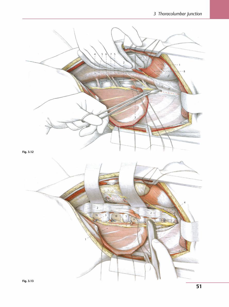
4 5 6 7 5
21
8
3
2
1
IV 3 5 2
4
III II
Fig. 3.12
Fig. 3.13
3 Thoracolumbar Junction
51
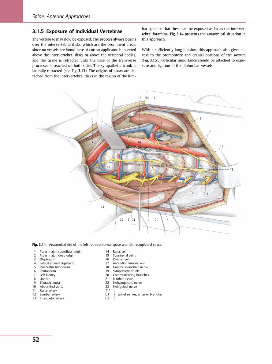
3.1.5 Exposure of Individual Vertebrae
The vertebrae may now be exposed. The process always beginsover the intervertebral disks, which are the prominent areas,since no vessels are found here. A cotton applicator is insertedabove the intervertebral disks or above the vertebral bodies,and the tissue is retracted until the base of the transverseprocesses is reached on both sides. The sympathetic trunk islaterally retracted (see Fig. 3.13). The origins of psoas are de-tached from the intervertebral disks in the region of the lum-
bar spine so that these can be exposed as far as the interver-tebral foramina. Fig. 3.14 presents the anatomical situation inthis approach.
With a sufficiently long incision, this approach also gives ac-cess to the promontory and cranial portions of the sacrum(Fig. 3.15). Particular importance should be attached to expo-sure and ligation of the iliolumbar vessels.
6 8
10
19
2
16 14 11
715
9
18
13
T1117L1
3
420121522
23
12L3
Fig. 3.14 Anatomical site of the left retroperitoneal space and left retropleural space.
1 Psoas major, superficial origin2 Psoas major, deep origin3 Diaphragm4 Lateral arcuate ligament5 Quadratus lumborum6 Peritoneum7 Left kidney8 Ureter9 Thoracic aorta10 Abdominal aorta11 Renal artery12 Lumbar artery13 Intercostal artery
14 Renal vein15 Suprarenal veins16 Ovarian vein17 Ascending lumbar vein18 Greater splanchnic nerve19 Sympathetic trunk20 Communicating branches21 Lumbar plexus22 Iliohypogastric nerve23 Ilioinguinal nerveT11L 1L 3
Spinal nerves, anterior branches⎫⎬⎭
Spine, Anterior Approaches
52
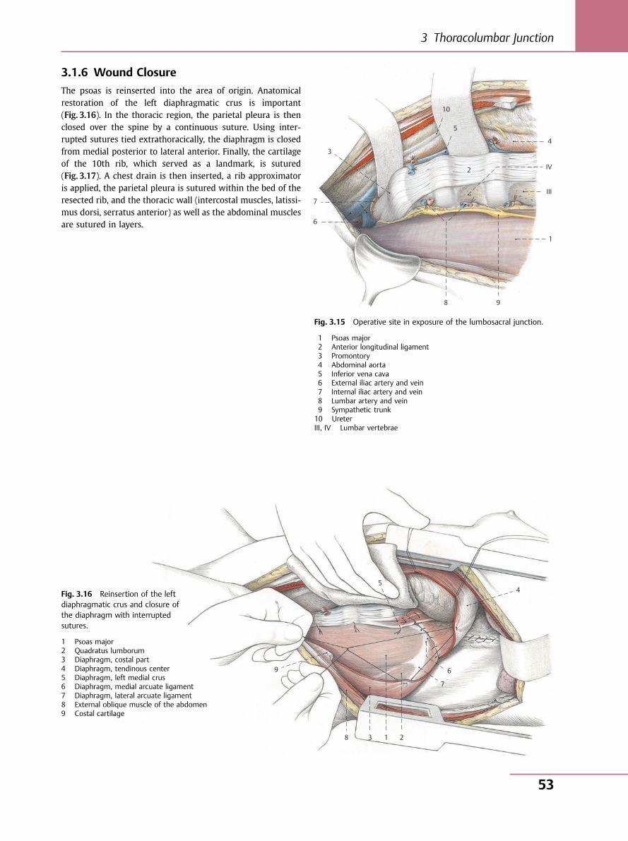
3.1.6 Wound Closure
The psoas is reinserted into the area of origin. Anatomicalrestoration of the left diaphragmatic crus is important(Fig. 3.16). In the thoracic region, the parietal pleura is thenclosed over the spine by a continuous suture. Using inter-rupted sutures tied extrathoracically, the diaphragm is closedfrom medial posterior to lateral anterior. Finally, the cartilageof the 10th rib, which served as a landmark, is sutured(Fig. 3.17). A chest drain is then inserted, a rib approximatoris applied, the parietal pleura is sutured within the bed of theresected rib, and the thoracic wall (intercostal muscles, latissi-mus dorsi, serratus anterior) as well as the abdominal musclesare sutured in layers.
9 8
6
7
3
10
5
2
1
III
IV
4
Fig. 3.15 Operative site in exposure of the lumbosacral junction.
1 Psoas major2 Anterior longitudinal ligament3 Promontory4 Abdominal aorta5 Inferior vena cava6 External iliac artery and vein7 Internal iliac artery and vein8 Lumbar artery and vein9 Sympathetic trunk10 UreterIII, IV Lumbar vertebrae
9
8 3 1 2
7
6
54Fig. 3.16 Reinsertion of the left
diaphragmatic crus and closure ofthe diaphragm with interruptedsutures.
1 Psoas major2 Quadratus lumborum3 Diaphragm, costal part4 Diaphragm, tendinous center5 Diaphragm, left medial crus6 Diaphragm, medial arcuate ligament7 Diaphragm, lateral arcuate ligament8 External oblique muscle of the abdomen9 Costal cartilage
3 Thoracolumbar Junction
53
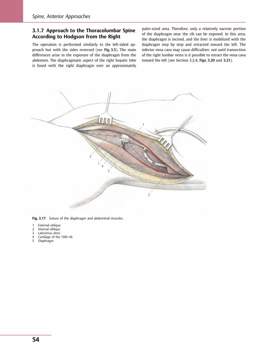
3.1.7 Approach to the Thoracolumbar SpineAccording to Hodgson from the Right
The operation is performed similarly to the left-sided ap-proach but with the sides reversed (see Fig. 3.5). The maindifferences arise in the exposure of the diaphragm from theabdomen. The diaphragmatic aspect of the right hepatic lobeis fused with the right diaphragm over an approximately
palm-sized area. Therefore, only a relatively narrow portionof the diaphragm near the rib can be exposed. In this area,the diaphragm is incised, and the liver is mobilized with thediaphragm step by step and retracted toward the left. Theinferior vena cava may cause difficulties: not until transectionof the right lumbar veins is it possible to retract the vena cavatoward the left (see Section 3.2.4, Figs. 3.20 and 3.21).
1
2
1 4
5
3
Fig. 3.17 Suture of the diaphragm and abdominal muscles.
1 External oblique2 Internal oblique3 Latissimus dorsi4 Cartilage of the 10th rib5 Diaphragm
Spine, Anterior Approaches
54
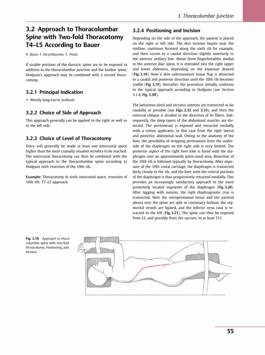
3.2 Approach to ThoracolumbarSpine with Two-fold ThoracotomyT4–L5 According to BauerR. Bauer, F. Kerschbaumer, S. Poisel
If sizable portions of the thoracic spine are to be exposed inaddition to the thoracolumbar junction and the lumbar spine,Hodgson’s approach may be combined with a second thora-cotomy.
3.2.1 Principal Indication● Mostly long-curve scoliosis
3.2.2 Choice of Side of Approach
This approach generally can be applied to the right as well asto the left side.
3.2.3 Choice of Level of Thoracotomy
Entry will generally be made at least one intercostal spacehigher than the most cranially situated vertebra to be reached.The intercostal thoracotomy can then be combined with thetypical approach to the thoracolumbar spine according toHodgson with resection of the 10th rib.
Example: Thoracotomy in sixth intercostal space, resection of10th rib: T7–L5 approach.
3.2.4 Positioning and Incision
Depending on the side of the approach, the patient is placedon the right or left side. The skin incision begins near themidline, continues forward along the sixth rib for example,and then curves in a caudal direction slightly anteriorly tothe anterior axillary line. About three fingerbreadths medialto the anterior iliac spine, it is extended into the right upperand lower abdomen, depending on the exposure desired(Fig. 3.18). Now a skin–subcutaneous tissue flap is dissectedin a caudal and posterior direction until the 10th rib becomesvisible (Fig. 3.19). Hereafter, the procedure initially conformsto the typical approach according to Hodgson (see Section3.1.4, Fig. 3.3ff).
The latissimus dorsi and serratus anterior are transected as farcaudally as possible (see Figs. 2.32 and 2.33), and then theexternal oblique is divided in the direction of its fibers. Sub-sequently, the deep layers of the abdominal muscles are dis-sected. The peritoneum is exposed and retracted mediallywith a cotton applicator, in this case from the right lateraland posterior abdominal wall. Owing to the anatomy of theliver, the possibility of stripping peritoneum from the under-side of the diaphragm on the right side is very limited. Theposterior aspect of the right liver lobe is fused with the dia-phragm over an approximately palm-sized area. Resection ofthe 10th rib is followed typically by thoracotomy. After expo-sure of the 10th costal cartilage, the diaphragm is transectedfairly closely to the rib, and the liver with the central portionsof the diaphragm is thus progressively retracted medially. Thisprovides an increasingly satisfactory approach to the moreposteriorly located segments of the diaphragm (Fig. 3.20).After tagging with sutures, the right diaphragmatic crus istransected. Next the retroperitoneal tissue and the parietalpleura over the spine are split in customary fashion, the seg-mental vessels are ligated, and the inferior vena cava is re-tracted to the left (Fig. 3.21). The spine can thus be exposedfrom L5, and possibly from the sacrum, to at least T11.
Fig. 3.18 Approach to thora-columbar spine with two-foldthoracotomy. Positioning andincision.
3 Thoracolumbar Junction
55
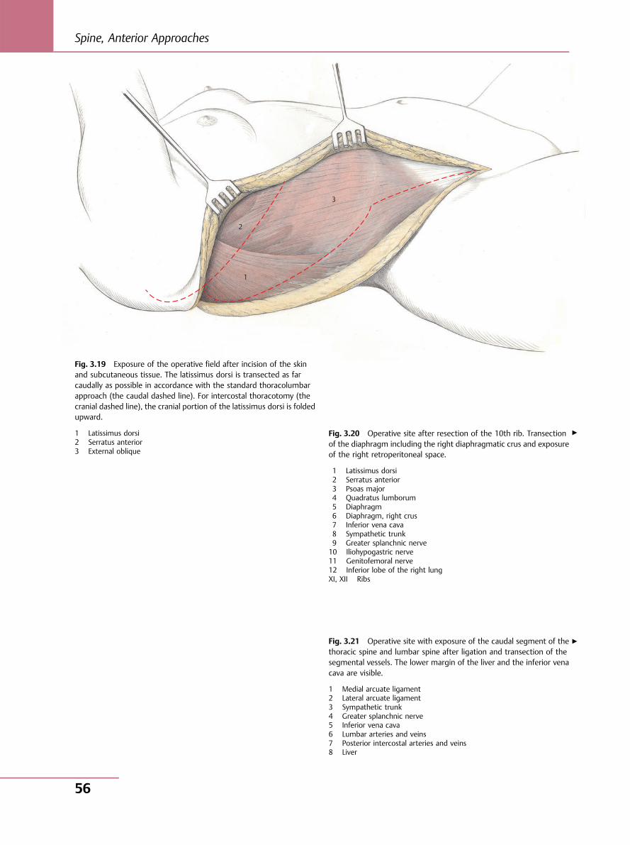
1
2
3
Fig. 3.19 Exposure of the operative field after incision of the skinand subcutaneous tissue. The latissimus dorsi is transected as farcaudally as possible in accordance with the standard thoracolumbarapproach (the caudal dashed line). For intercostal thoracotomy (thecranial dashed line), the cranial portion of the latissimus dorsi is foldedupward.
1 Latissimus dorsi2 Serratus anterior3 External oblique
Fig. 3.20 Operative site after resection of the 10th rib. Transectionof the diaphragm including the right diaphragmatic crus and exposureof the right retroperitoneal space.
1 Latissimus dorsi2 Serratus anterior3 Psoas major4 Quadratus lumborum5 Diaphragm6 Diaphragm, right crus7 Inferior vena cava8 Sympathetic trunk9 Greater splanchnic nerve10 Iliohypogastric nerve11 Genitofemoral nerve12 Inferior lobe of the right lungXI, XII Ribs
Fig. 3.21 Operative site with exposure of the caudal segment of thethoracic spine and lumbar spine after ligation and transection of thesegmental vessels. The lower margin of the liver and the inferior venacava are visible.
1 Medial arcuate ligament2 Lateral arcuate ligament3 Sympathetic trunk4 Greater splanchnic nerve5 Inferior vena cava6 Lumbar arteries and veins7 Posterior intercostal arteries and veins8 Liver
▶
▶
Spine, Anterior Approaches
56
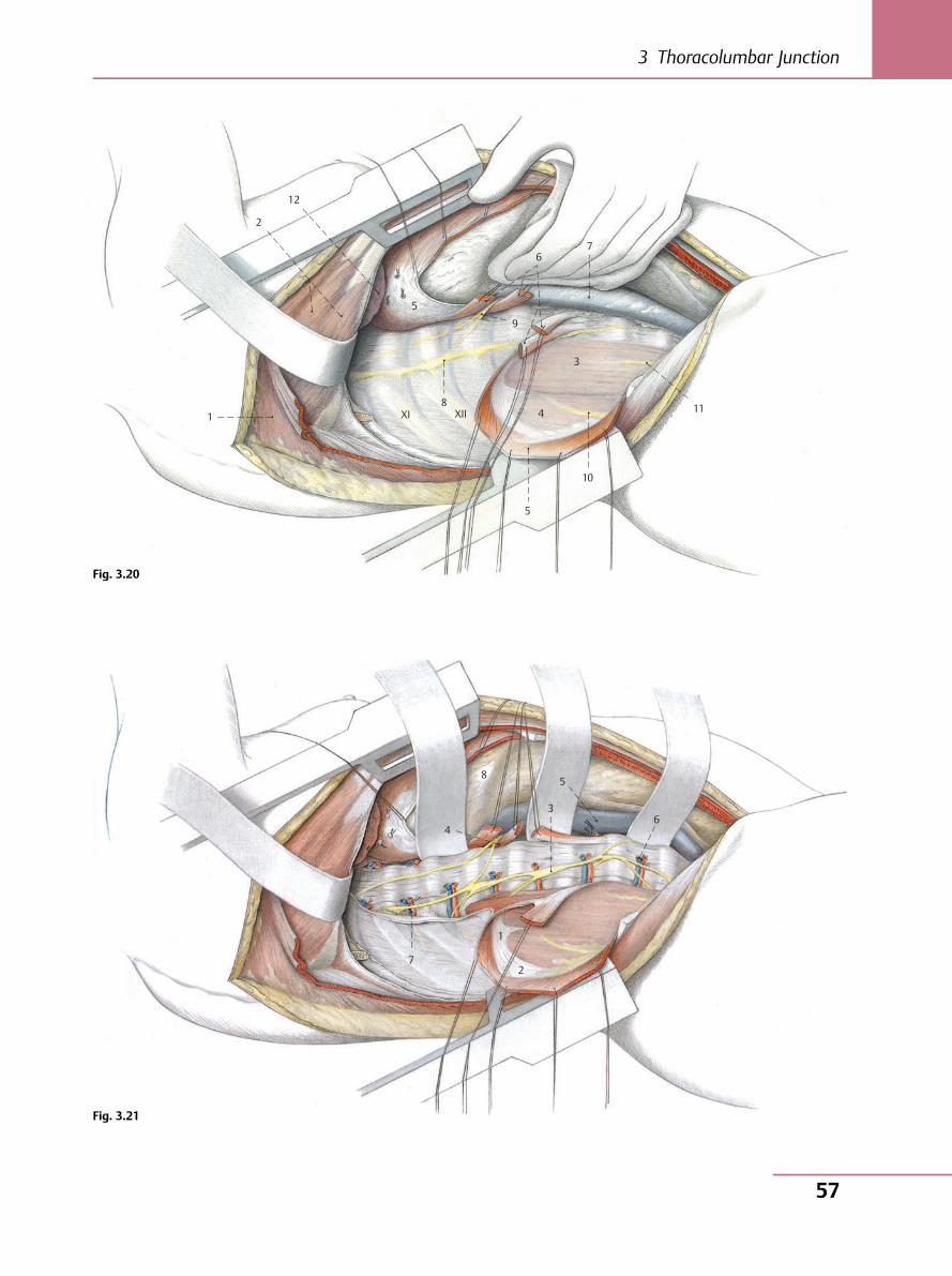
1
2
12
5
XI XII 8
9
67
3
4
5
10
11
7
1
2
4
8
3
5
6
Fig. 3.20
Fig. 3.21
3 Thoracolumbar Junction
57
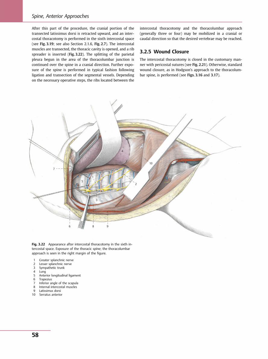
After this part of the procedure, the cranial portion of thetransected latissimus dorsi is retracted upward, and an inter-costal thoracotomy is performed in the sixth intercostal space(see Fig. 3.19; see also Section 2.1.6, Fig. 2.7). The intercostalmuscles are transected, the thoracic cavity is opened, and a ribspreader is inserted (Fig. 3.22). The splitting of the parietalpleura begun in the area of the thoracolumbar junction iscontinued over the spine in a cranial direction. Further expo-sure of the spine is performed in typical fashion followingligation and transection of the segmental vessels. Dependingon the necessary operative steps, the ribs located between the
intercostal thoracotomy and the thoracolumbar approach(generally three or four) may be mobilized in a cranial orcaudal direction so that the desired vertebrae may be reached.
3.2.5 Wound Closure
The intercostal thoracotomy is closed in the customary man-ner with pericostal sutures (see Fig. 2.21). Otherwise, standardwound closure, as in Hodgson’s approach to the thoracolum-bar spine, is performed (see Figs. 3.16 and 3.17).
7
6 8 9
3
51
2
10
4
Fig. 3.22 Appearance after intercostal thoracotomy in the sixth in-tercostal space. Exposure of the thoracic spine; the thoracolumbarapproach is seen in the right margin of the figure.
1 Greater splanchnic nerve2 Lesser splanchnic nerve3 Sympathetic trunk4 Lung5 Anterior longitudinal ligament6 Trapezius7 Inferior angle of the scapula8 Internal intercostal muscles9 Latissimus dorsi10 Serratus anterior
Spine, Anterior Approaches
58
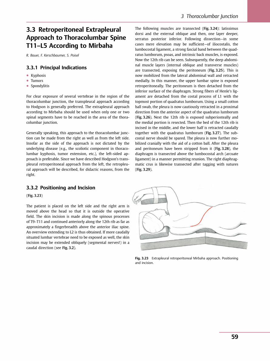
3.3 Retroperitoneal ExtrapleuralApproach to Thoracolumbar SpineT11–L5 According to MirbahaR. Bauer, F. Kerschbaumer, S. Poisel
3.3.1 Principal Indications● Kyphosis● Tumors● Spondylitis
For clear exposure of several vertebrae in the region of thethoracolumbar junction, the transpleural approach accordingto Hodgson is generally preferred. The extrapleural approachaccording to Mirbaha should be used when only one or twospinal segments have to be reached in the area of the thora-columbar junction.
Generally speaking, this approach to the thoracolumbar junc-tion can be made from the right as well as from the left side.Insofar as the side of the approach is not dictated by theunderlying disease (e.g., the scoliotic component in thoraco-lumbar kyphosis, tumor extension, etc.), the left-sided ap-proach is preferable. Since we have described Hodgson’s trans-pleural retroperitoneal approach from the left, the retropleu-ral approach will be described, for didactic reasons, from theright.
3.3.2 Positioning and Incision
(Fig. 3.23)
The patient is placed on the left side and the right arm ismoved above the head so that it is outside the operativefield. The skin incision is made along the spinous processesof T9–T11 and continued anteriorly along the 12th rib as far asapproximately a fingerbreadth above the anterior iliac spine.An overview extending to L2 is thus obtained. If more caudallysituated lumbar vertebrae need to be exposed as well, the skinincision may be extended obliquely (segmental nerves!) in acaudal direction (see Fig. 3.2).
The following muscles are transected (Fig. 3.24): latissimusdorsi and the external oblique and then, one layer deeper,serratus posterior inferior. Following dissection—in somecases mere elevation may be sufficient—of iliocostalis, thelumbocostal ligament, a strong fascial band between the quad-ratus lumborum, psoas, and intrinsic back muscles, is exposed.Now the 12th rib can be seen. Subsequently, the deep abdomi-nal muscle layers (internal oblique and transverse muscles)are transected, exposing the peritoneum (Fig. 3.25). This isnow mobilized from the lateral abdominal wall and retractedmedially. In this manner, the upper lumbar spine is exposedretroperitoneally. The peritoneum is then detached from theinferior surface of the diaphragm. Strong fibers of Henle’s lig-ament are detached from the costal process of L1 with thetopmost portion of quadratus lumborum. Using a small cottonball swab, the pleura is now cautiously retracted in a proximaldirection from the anterior aspect of the quadratus lumborum(Fig. 3.26). Next the 12th rib is exposed subperiosteally andthe medial portion is resected. Then the bed of the 12th rib isincised in the middle, and the lower half is retracted caudallytogether with the quadratus lumborum (Fig. 3.27). The sub-costal nerve should be spared. The pleura is now further mo-bilized cranially with the aid of a cotton ball. After the pleuraand peritoneum have been stripped from it (Fig. 3.28), thediaphragm is transected above the lumbocostal arch (arcuateligament) in a manner permitting reunion. The right diaphrag-matic crus is likewise transected after tagging with sutures(Fig. 3.29).
Fig. 3.23 Extrapleural retroperitoneal Mirbaha approach. Positioningand incision.
3 Thoracolumbar Junction
59
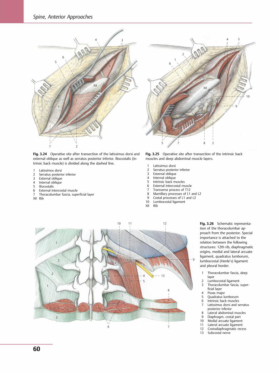
1
7 2
5 6
4 3
XII
1
XII
6
2
4 3
10
9
2875
1
2
2
1
3
6 7
8
5
4 13
12 11 10
9
Fig. 3.24 Operative site after transection of the latissimus dorsi andexternal oblique as well as serratus posterior inferior. Iliocostalis (in-trinsic back muscle) is divided along the dashed line.
1 Latissimus dorsi2 Serratus posterior inferior3 External oblique4 Internal oblique5 Iliocostalis6 External intercostal muscle7 Thoracolumbar fascia, superficial layerXII Rib
Fig. 3.25 Operative site after transection of the intrinsic backmuscles and deep abdominal muscle layers.
1 Latissimus dorsi2 Serratus posterior inferior3 External oblique4 Internal oblique5 Intrinsic back muscles6 External intercostal muscle7 Transverse process of T128 Mamillary processes of L1 and L29 Costal processes of L1 and L210 Lumbocostal ligamentXII Rib
Fig. 3.26 Schematic representa-tion of the thoracolumbar ap-proach from the posterior. Specialimportance is attached to therelation between the followingstructures: 12th rib, diaphragmaticorigins, medial and lateral arcuateligament, quadratus lumborum,lumbocostal (Henle’s) ligamentand pleural border.
1 Thoracolumbar fascia, deeplayer
2 Lumbocostal ligament3 Thoracolumbar fascia, super-
ficial layer4 Psoas major5 Quadratus lumborum6 Intrinsic back muscles7 Latissimus dorsi and serratus
posterior inferior8 Lateral abdominal muscles9 Diaphragm, costal part10 Medial arcuate ligament11 Lateral arcuate ligament12 Costodiaphragmatic recess13 Subcostal nerve
Spine, Anterior Approaches
60
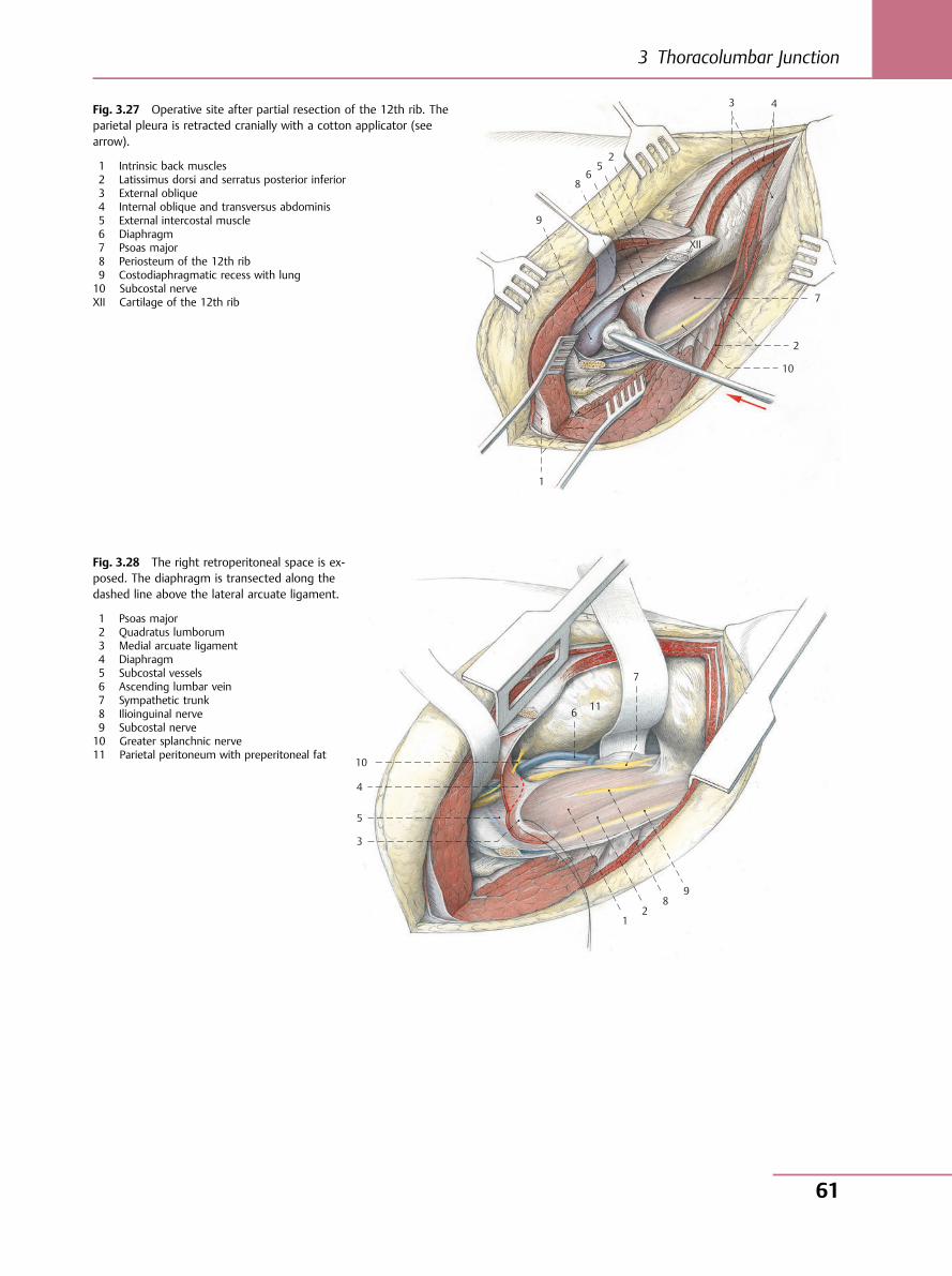
1
10
2
7
2 5
6 8
9
XII
3 4Fig. 3.27 Operative site after partial resection of the 12th rib. Theparietal pleura is retracted cranially with a cotton applicator (seearrow).
1 Intrinsic back muscles2 Latissimus dorsi and serratus posterior inferior3 External oblique4 Internal oblique and transversus abdominis5 External intercostal muscle6 Diaphragm7 Psoas major8 Periosteum of the 12th rib9 Costodiaphragmatic recess with lung10 Subcostal nerveXII Cartilage of the 12th rib
1 2
8 9
7
6 11
10
4
5
3
Fig. 3.28 The right retroperitoneal space is ex-posed. The diaphragm is transected along thedashed line above the lateral arcuate ligament.
1 Psoas major2 Quadratus lumborum3 Medial arcuate ligament4 Diaphragm5 Subcostal vessels6 Ascending lumbar vein7 Sympathetic trunk8 Ilioinguinal nerve9 Subcostal nerve10 Greater splanchnic nerve11 Parietal peritoneum with preperitoneal fat
3 Thoracolumbar Junction
61
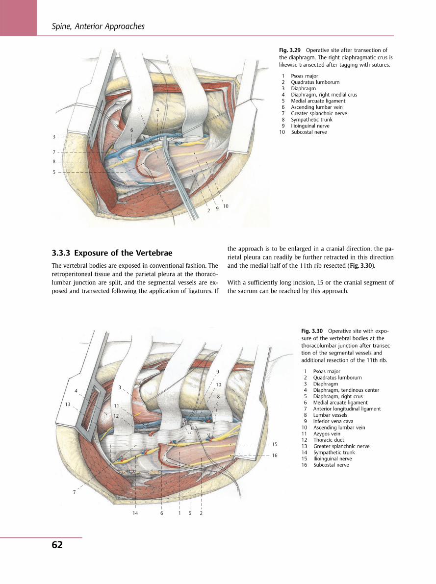
3.3.3 Exposure of the Vertebrae
The vertebral bodies are exposed in conventional fashion. Theretroperitoneal tissue and the parietal pleura at the thoraco-lumbar junction are split, and the segmental vessels are ex-posed and transected following the application of ligatures. If
the approach is to be enlarged in a cranial direction, the pa-rietal pleura can readily be further retracted in this directionand the medial half of the 11th rib resected (Fig. 3.30).
With a sufficiently long incision, L5 or the cranial segment ofthe sacrum can be reached by this approach.
1
6
4
3
7
8
5
2 9 10
Fig. 3.29 Operative site after transection ofthe diaphragm. The right diaphragmatic crus islikewise transected after tagging with sutures.
1 Psoas major2 Quadratus lumborum3 Diaphragm4 Diaphragm, right medial crus5 Medial arcuate ligament6 Ascending lumbar vein7 Greater splanchnic nerve8 Sympathetic trunk9 Ilioinguinal nerve10 Subcostal nerve
4
13
12
11
3
9
10
8
15
16
251614
7
Fig. 3.30 Operative site with expo-sure of the vertebral bodies at thethoracolumbar junction after transec-tion of the segmental vessels andadditional resection of the 11th rib.
1 Psoas major2 Quadratus lumborum3 Diaphragm4 Diaphragm, tendinous center5 Diaphragm, right crus6 Medial arcuate ligament7 Anterior longitudinal ligament8 Lumbar vessels9 Inferior vena cava10 Ascending lumbar vein11 Azygos vein12 Thoracic duct13 Greater splanchnic nerve14 Sympathetic trunk15 Ilioinguinal nerve16 Subcostal nerve
Spine, Anterior Approaches
62
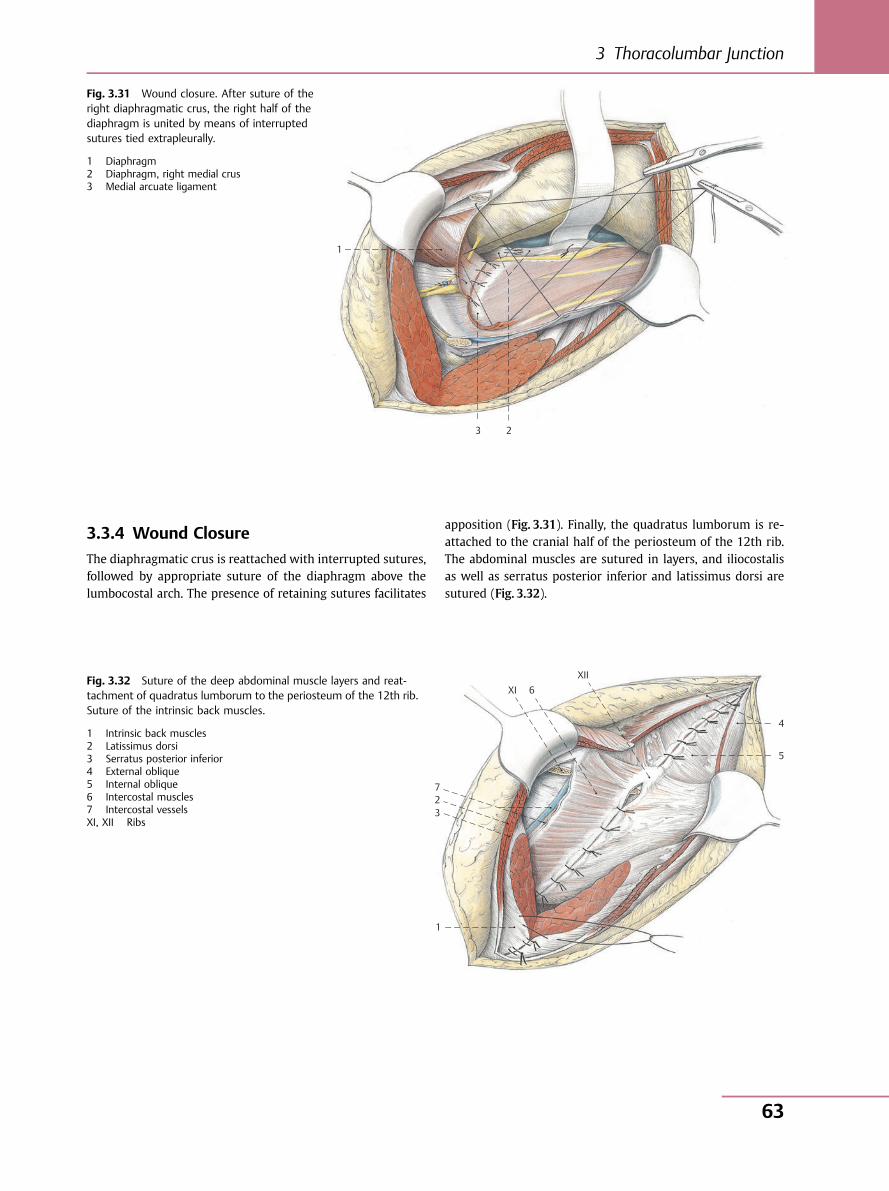
3.3.4 Wound Closure
The diaphragmatic crus is reattached with interrupted sutures,followed by appropriate suture of the diaphragm above thelumbocostal arch. The presence of retaining sutures facilitates
apposition (Fig. 3.31). Finally, the quadratus lumborum is re-attached to the cranial half of the periosteum of the 12th rib.The abdominal muscles are sutured in layers, and iliocostalisas well as serratus posterior inferior and latissimus dorsi aresutured (Fig. 3.32).
1
3 2
Fig. 3.31 Wound closure. After suture of theright diaphragmatic crus, the right half of thediaphragm is united by means of interruptedsutures tied extrapleurally.
1 Diaphragm2 Diaphragm, right medial crus3 Medial arcuate ligament
1
3 2 7
4
5
XI 6 XII Fig. 3.32 Suture of the deep abdominal muscle layers and reat-
tachment of quadratus lumborum to the periosteum of the 12th rib.Suture of the intrinsic back muscles.
1 Intrinsic back muscles2 Latissimus dorsi3 Serratus posterior inferior4 External oblique5 Internal oblique6 Intercostal muscles7 Intercostal vesselsXI, XII Ribs
3 Thoracolumbar Junction
63
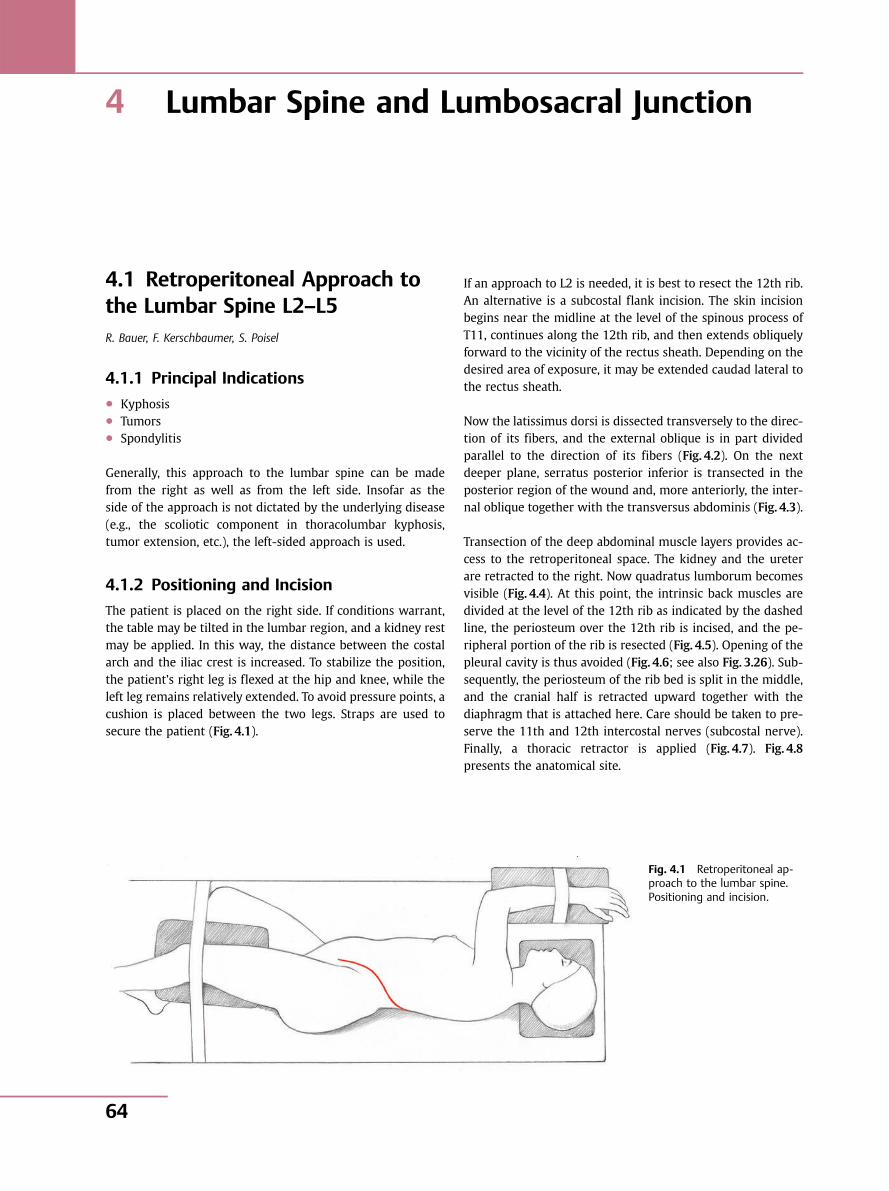
4 Lumbar Spine and Lumbosacral Junction
4.1 Retroperitoneal Approach tothe Lumbar Spine L2–L5R. Bauer, F. Kerschbaumer, S. Poisel
4.1.1 Principal Indications● Kyphosis● Tumors● Spondylitis
Generally, this approach to the lumbar spine can be madefrom the right as well as from the left side. Insofar as theside of the approach is not dictated by the underlying disease(e.g., the scoliotic component in thoracolumbar kyphosis,tumor extension, etc.), the left-sided approach is used.
4.1.2 Positioning and Incision
The patient is placed on the right side. If conditions warrant,the table may be tilted in the lumbar region, and a kidney restmay be applied. In this way, the distance between the costalarch and the iliac crest is increased. To stabilize the position,the patient’s right leg is flexed at the hip and knee, while theleft leg remains relatively extended. To avoid pressure points, acushion is placed between the two legs. Straps are used tosecure the patient (Fig. 4.1).
If an approach to L2 is needed, it is best to resect the 12th rib.An alternative is a subcostal flank incision. The skin incisionbegins near the midline at the level of the spinous process ofT11, continues along the 12th rib, and then extends obliquelyforward to the vicinity of the rectus sheath. Depending on thedesired area of exposure, it may be extended caudad lateral tothe rectus sheath.
Now the latissimus dorsi is dissected transversely to the direc-tion of its fibers, and the external oblique is in part dividedparallel to the direction of its fibers (Fig. 4.2). On the nextdeeper plane, serratus posterior inferior is transected in theposterior region of the wound and, more anteriorly, the inter-nal oblique together with the transversus abdominis (Fig. 4.3).
Transection of the deep abdominal muscle layers provides ac-cess to the retroperitoneal space. The kidney and the ureterare retracted to the right. Now quadratus lumborum becomesvisible (Fig. 4.4). At this point, the intrinsic back muscles aredivided at the level of the 12th rib as indicated by the dashedline, the periosteum over the 12th rib is incised, and the pe-ripheral portion of the rib is resected (Fig. 4.5). Opening of thepleural cavity is thus avoided (Fig. 4.6; see also Fig. 3.26). Sub-sequently, the periosteum of the rib bed is split in the middle,and the cranial half is retracted upward together with thediaphragm that is attached here. Care should be taken to pre-serve the 11th and 12th intercostal nerves (subcostal nerve).Finally, a thoracic retractor is applied (Fig. 4.7). Fig. 4.8presents the anatomical site.
Fig. 4.1 Retroperitoneal ap-proach to the lumbar spine.Positioning and incision.
Spine, Anterior Approaches
64
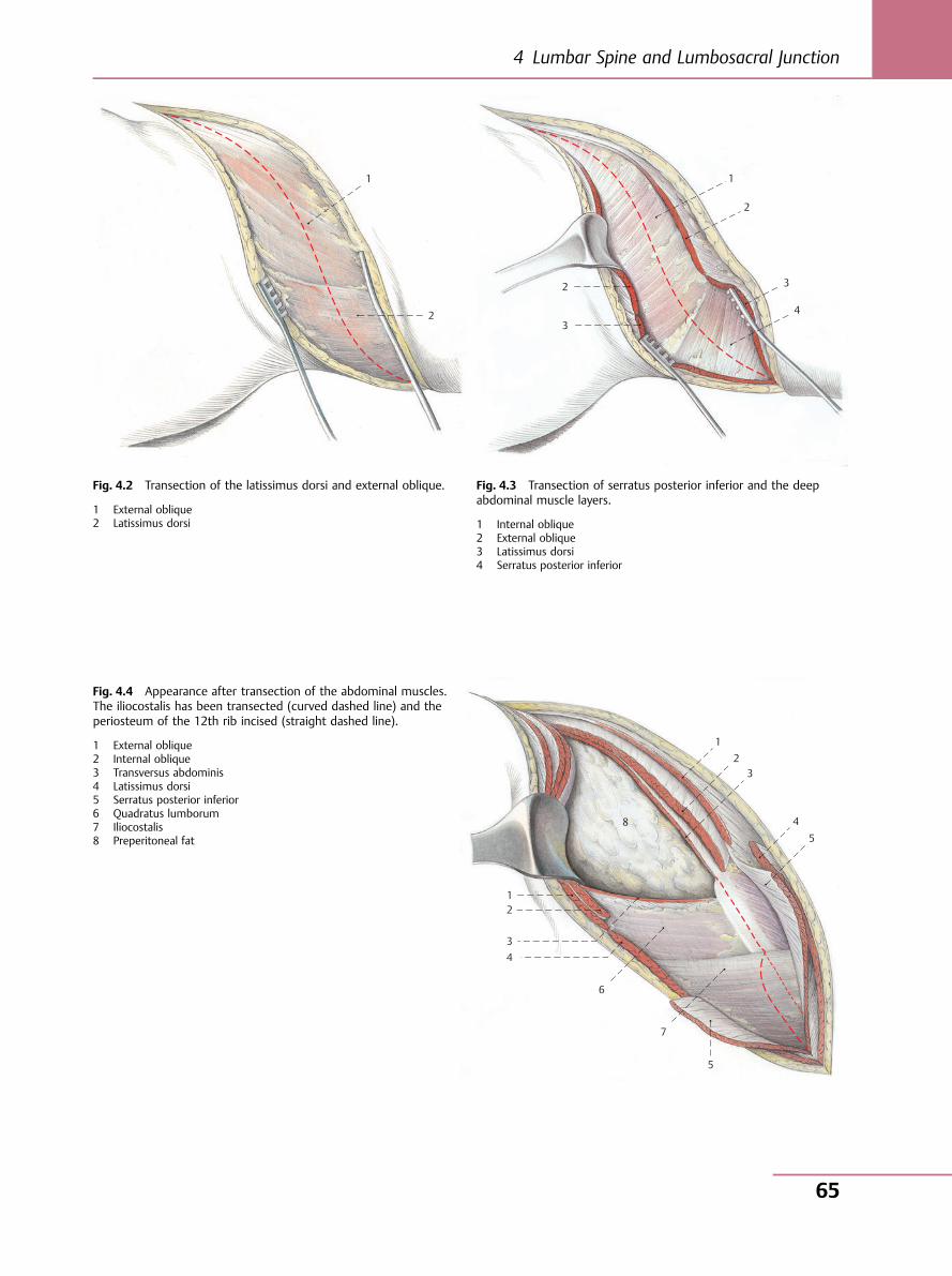
1
2
Fig. 4.2 Transection of the latissimus dorsi and external oblique.
1 External oblique2 Latissimus dorsi
2
3
1
2
3
4
Fig. 4.3 Transection of serratus posterior inferior and the deepabdominal muscle layers.
1 Internal oblique2 External oblique3 Latissimus dorsi4 Serratus posterior inferior
Fig. 4.4 Appearance after transection of the abdominal muscles.The iliocostalis has been transected (curved dashed line) and theperiosteum of the 12th rib incised (straight dashed line).
1 External oblique2 Internal oblique3 Transversus abdominis4 Latissimus dorsi5 Serratus posterior inferior6 Quadratus lumborum7 Iliocostalis8 Preperitoneal fat
1 2
3 4
6
7
5
5 4
3 2
1
8
4 Lumbar Spine and Lumbosacral Junction
65
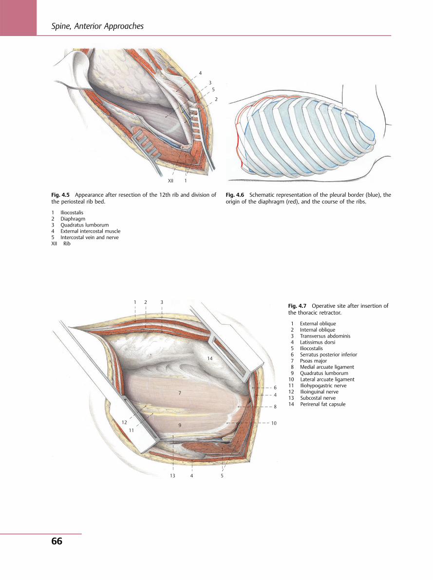
XII 1
2
53
4
Fig. 4.5 Appearance after resection of the 12th rib and division ofthe periosteal rib bed.
1 Iliocostalis2 Diaphragm3 Quadratus lumborum4 External intercostal muscle5 Intercostal vein and nerveXII Rib
Fig. 4.6 Schematic representation of the pleural border (blue), theorigin of the diaphragm (red), and the course of the ribs.
1 2 3
14
7
9
6 4
8
10
5 4 13
11
12
Fig. 4.7 Operative site after insertion ofthe thoracic retractor.
1 External oblique2 Internal oblique3 Transversus abdominis4 Latissimus dorsi5 Iliocostalis6 Serratus posterior inferior7 Psoas major8 Medial arcuate ligament9 Quadratus lumborum10 Lateral arcuate ligament11 Iliohypogastric nerve12 Ilioinguinal nerve13 Subcostal nerve14 Perirenal fat capsule
Spine, Anterior Approaches
66
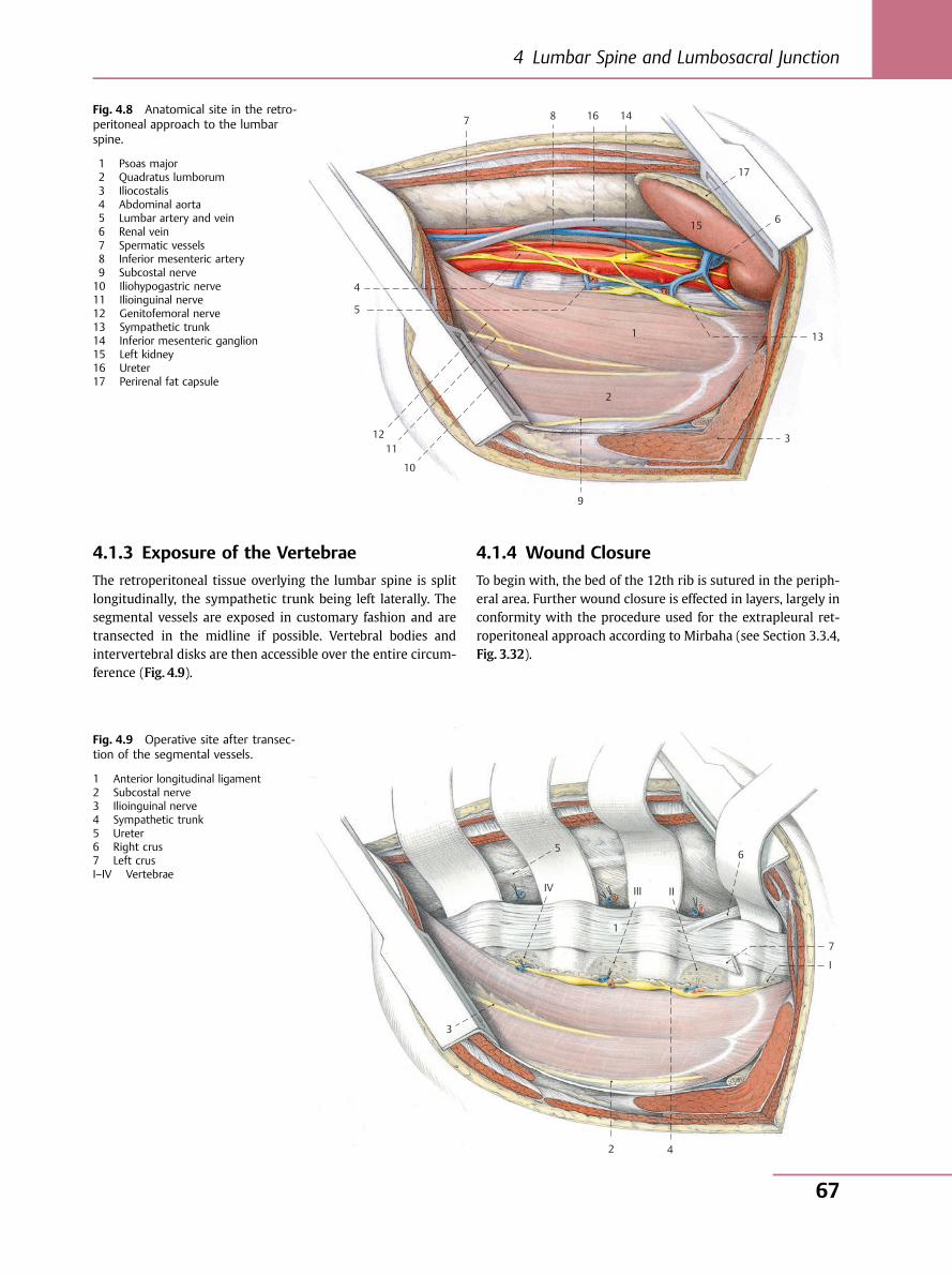
4.1.3 Exposure of the Vertebrae
The retroperitoneal tissue overlying the lumbar spine is splitlongitudinally, the sympathetic trunk being left laterally. Thesegmental vessels are exposed in customary fashion and aretransected in the midline if possible. Vertebral bodies andintervertebral disks are then accessible over the entire circum-ference (Fig. 4.9).
4.1.4 Wound Closure
To begin with, the bed of the 12th rib is sutured in the periph-eral area. Further wound closure is effected in layers, largely inconformity with the procedure used for the extrapleural ret-roperitoneal approach according to Mirbaha (see Section 3.3.4,Fig. 3.32).
1
2
9
3
13
6
17
15
14 16 8 7
4
5
12 11
10
Fig. 4.8 Anatomical site in the retro-peritoneal approach to the lumbarspine.
1 Psoas major2 Quadratus lumborum3 Iliocostalis4 Abdominal aorta5 Lumbar artery and vein6 Renal vein7 Spermatic vessels8 Inferior mesenteric artery9 Subcostal nerve10 Iliohypogastric nerve11 Ilioinguinal nerve12 Genitofemoral nerve13 Sympathetic trunk14 Inferior mesenteric ganglion15 Left kidney16 Ureter17 Perirenal fat capsule
7
6 5
4
3
1
2
I
IIIIIIV
Fig. 4.9 Operative site after transec-tion of the segmental vessels.
1 Anterior longitudinal ligament2 Subcostal nerve3 Ilioinguinal nerve4 Sympathetic trunk5 Ureter6 Right crus7 Left crusI–IV Vertebrae
4 Lumbar Spine and Lumbosacral Junction
67
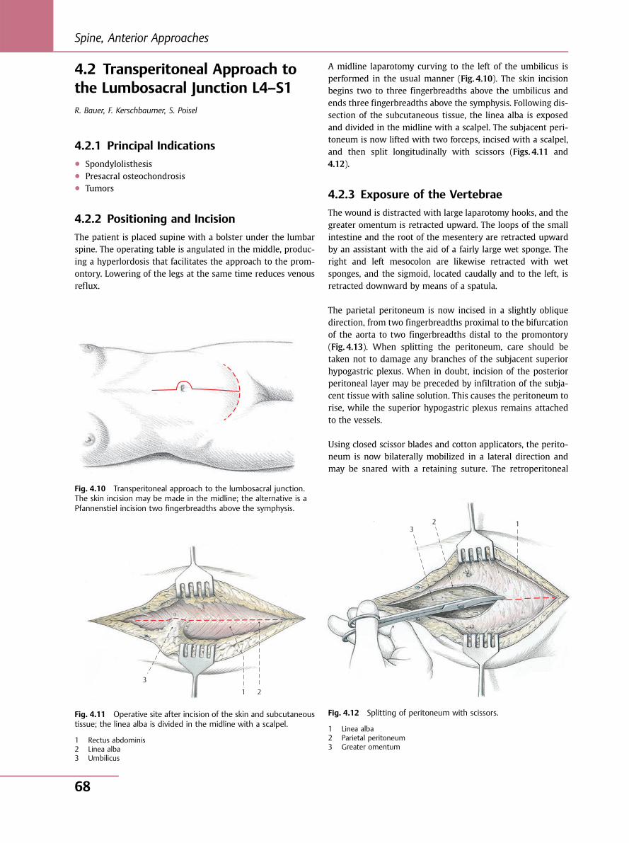
4.2 Transperitoneal Approach tothe Lumbosacral Junction L4–S1R. Bauer, F. Kerschbaumer, S. Poisel
4.2.1 Principal Indications● Spondylolisthesis● Presacral osteochondrosis● Tumors
4.2.2 Positioning and Incision
The patient is placed supine with a bolster under the lumbarspine. The operating table is angulated in the middle, produc-ing a hyperlordosis that facilitates the approach to the prom-ontory. Lowering of the legs at the same time reduces venousreflux.
A midline laparotomy curving to the left of the umbilicus isperformed in the usual manner (Fig. 4.10). The skin incisionbegins two to three fingerbreadths above the umbilicus andends three fingerbreadths above the symphysis. Following dis-section of the subcutaneous tissue, the linea alba is exposedand divided in the midline with a scalpel. The subjacent peri-toneum is now lifted with two forceps, incised with a scalpel,and then split longitudinally with scissors (Figs. 4.11 and4.12).
4.2.3 Exposure of the Vertebrae
The wound is distracted with large laparotomy hooks, and thegreater omentum is retracted upward. The loops of the smallintestine and the root of the mesentery are retracted upwardby an assistant with the aid of a fairly large wet sponge. Theright and left mesocolon are likewise retracted with wetsponges, and the sigmoid, located caudally and to the left, isretracted downward by means of a spatula.
The parietal peritoneum is now incised in a slightly obliquedirection, from two fingerbreadths proximal to the bifurcationof the aorta to two fingerbreadths distal to the promontory(Fig. 4.13). When splitting the peritoneum, care should betaken not to damage any branches of the subjacent superiorhypogastric plexus. When in doubt, incision of the posteriorperitoneal layer may be preceded by infiltration of the subja-cent tissue with saline solution. This causes the peritoneum torise, while the superior hypogastric plexus remains attachedto the vessels.
Using closed scissor blades and cotton applicators, the perito-neum is now bilaterally mobilized in a lateral direction andmay be snared with a retaining suture. The retroperitoneal
Fig. 4.10 Transperitoneal approach to the lumbosacral junction.The skin incision may be made in the midline; the alternative is aPfannenstiel incision two fingerbreadths above the symphysis.
1 2
3
Fig. 4.11 Operative site after incision of the skin and subcutaneoustissue; the linea alba is divided in the midline with a scalpel.
1 Rectus abdominis2 Linea alba3 Umbilicus
1 2 3
Fig. 4.12 Splitting of peritoneum with scissors.
1 Linea alba2 Parietal peritoneum3 Greater omentum
Spine, Anterior Approaches
68
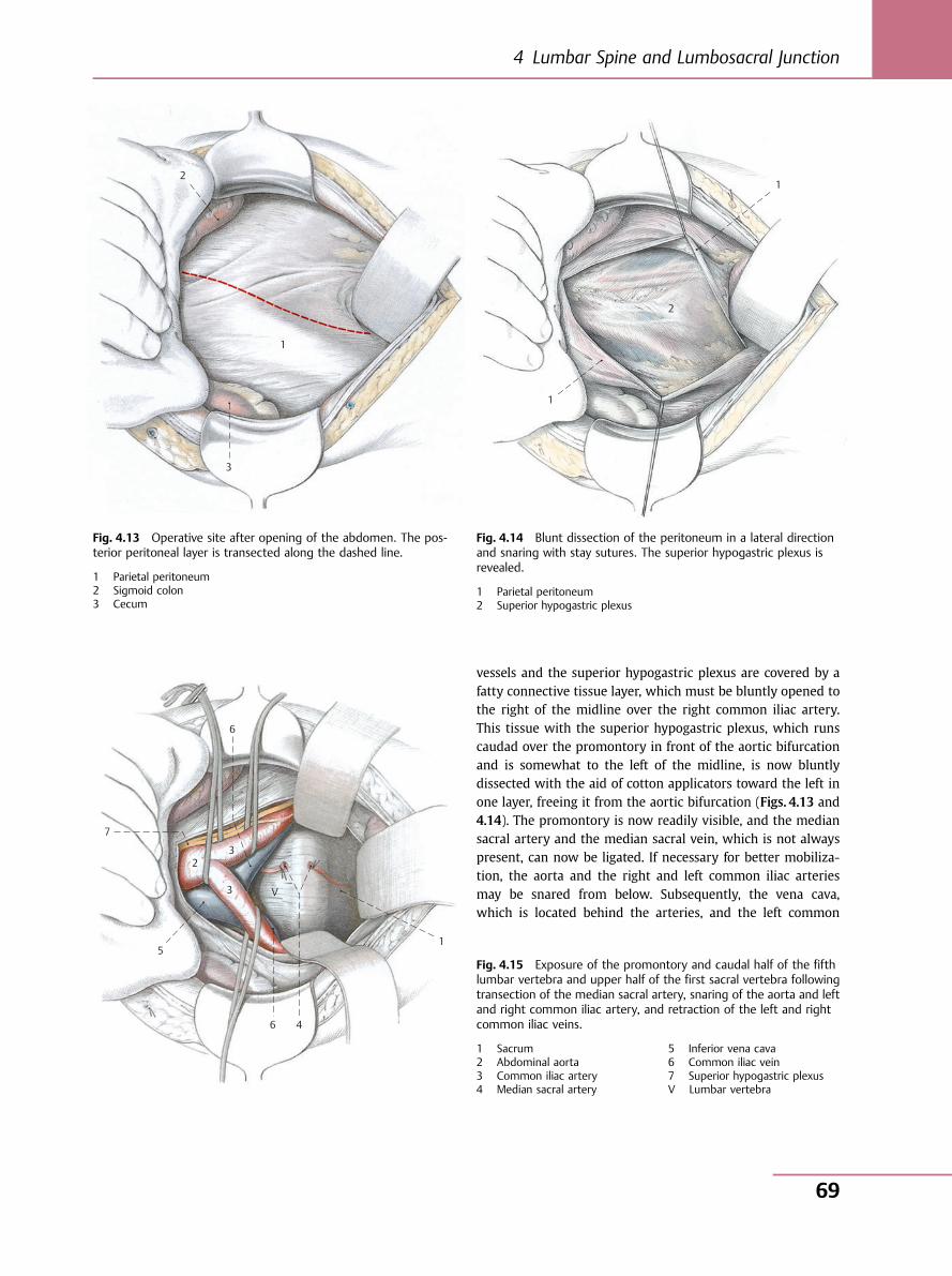
vessels and the superior hypogastric plexus are covered by afatty connective tissue layer, which must be bluntly opened tothe right of the midline over the right common iliac artery.This tissue with the superior hypogastric plexus, which runscaudad over the promontory in front of the aortic bifurcationand is somewhat to the left of the midline, is now bluntlydissected with the aid of cotton applicators toward the left inone layer, freeing it from the aortic bifurcation (Figs. 4.13 and4.14). The promontory is now readily visible, and the mediansacral artery and the median sacral vein, which is not alwayspresent, can now be ligated. If necessary for better mobiliza-tion, the aorta and the right and left common iliac arteriesmay be snared from below. Subsequently, the vena cava,which is located behind the arteries, and the left common
1
3
2
Fig. 4.13 Operative site after opening of the abdomen. The pos-terior peritoneal layer is transected along the dashed line.
1 Parietal peritoneum2 Sigmoid colon3 Cecum
1
1
2
Fig. 4.14 Blunt dissection of the peritoneum in a lateral directionand snaring with stay sutures. The superior hypogastric plexus isrevealed.
1 Parietal peritoneum2 Superior hypogastric plexus
6
7
5
6 4
1
V 3
2 3
Fig. 4.15 Exposure of the promontory and caudal half of the fifthlumbar vertebra and upper half of the first sacral vertebra followingtransection of the median sacral artery, snaring of the aorta and leftand right common iliac artery, and retraction of the left and rightcommon iliac veins.
1 Sacrum2 Abdominal aorta3 Common iliac artery4 Median sacral artery
5 Inferior vena cava6 Common iliac vein7 Superior hypogastric plexusV Lumbar vertebra
4 Lumbar Spine and Lumbosacral Junction
69
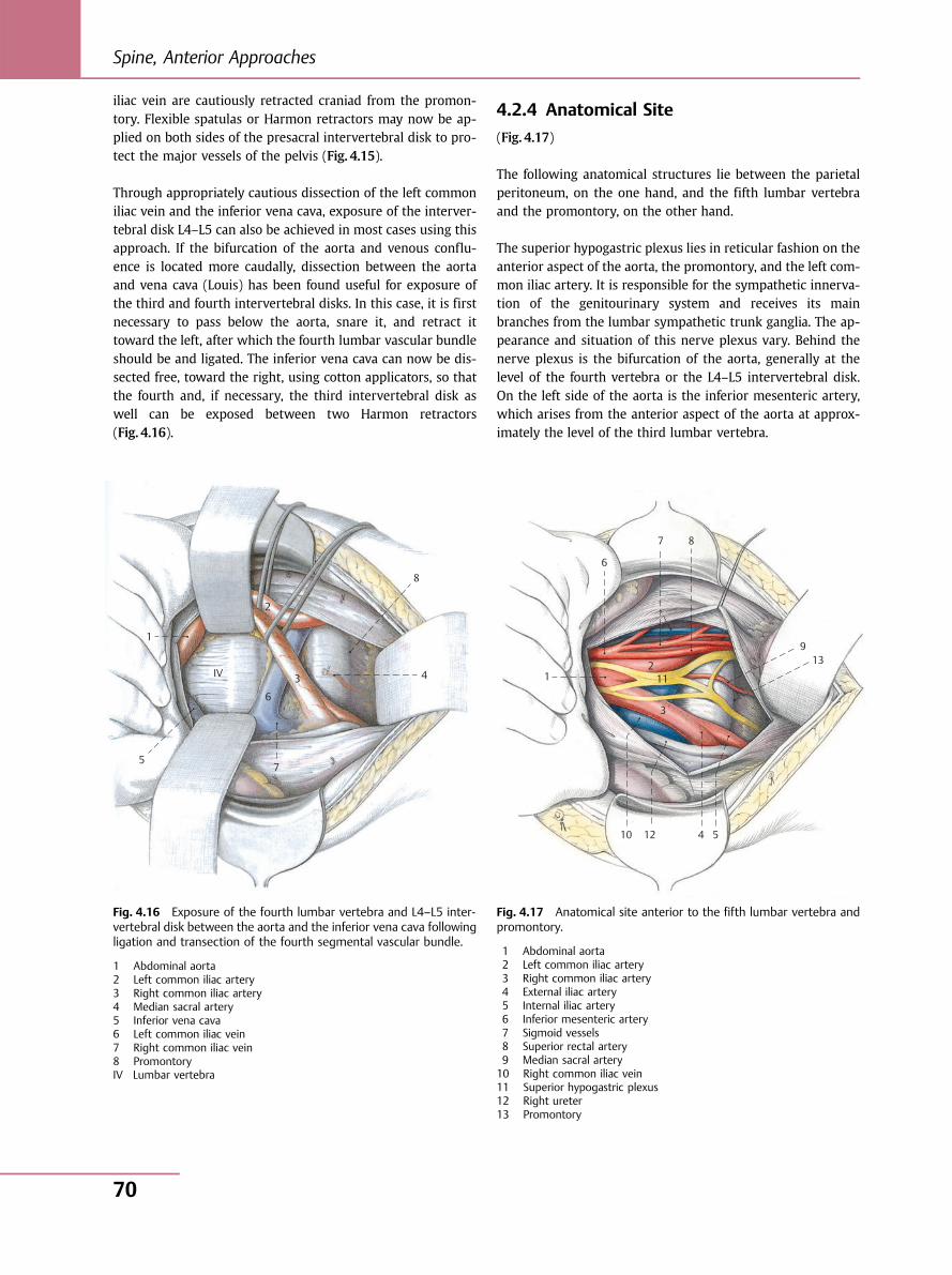
iliac vein are cautiously retracted craniad from the promon-tory. Flexible spatulas or Harmon retractors may now be ap-plied on both sides of the presacral intervertebral disk to pro-tect the major vessels of the pelvis (Fig. 4.15).
Through appropriately cautious dissection of the left commoniliac vein and the inferior vena cava, exposure of the interver-tebral disk L4–L5 can also be achieved in most cases using thisapproach. If the bifurcation of the aorta and venous conflu-ence is located more caudally, dissection between the aortaand vena cava (Louis) has been found useful for exposure ofthe third and fourth intervertebral disks. In this case, it is firstnecessary to pass below the aorta, snare it, and retract ittoward the left, after which the fourth lumbar vascular bundleshould be and ligated. The inferior vena cava can now be dis-sected free, toward the right, using cotton applicators, so thatthe fourth and, if necessary, the third intervertebral disk aswell can be exposed between two Harmon retractors(Fig. 4.16).
4.2.4 Anatomical Site
(Fig. 4.17)
The following anatomical structures lie between the parietalperitoneum, on the one hand, and the fifth lumbar vertebraand the promontory, on the other hand.
The superior hypogastric plexus lies in reticular fashion on theanterior aspect of the aorta, the promontory, and the left com-mon iliac artery. It is responsible for the sympathetic innerva-tion of the genitourinary system and receives its mainbranches from the lumbar sympathetic trunk ganglia. The ap-pearance and situation of this nerve plexus vary. Behind thenerve plexus is the bifurcation of the aorta, generally at thelevel of the fourth vertebra or the L4–L5 intervertebral disk.On the left side of the aorta is the inferior mesenteric artery,which arises from the anterior aspect of the aorta at approx-imately the level of the third lumbar vertebra.
1
5 7
6
3 4
8
2
IV
Fig. 4.16 Exposure of the fourth lumbar vertebra and L4–L5 inter-vertebral disk between the aorta and the inferior vena cava followingligation and transection of the fourth segmental vascular bundle.
1 Abdominal aorta2 Left common iliac artery3 Right common iliac artery4 Median sacral artery5 Inferior vena cava6 Left common iliac vein7 Right common iliac vein8 PromontoryIV Lumbar vertebra
10
11
12
13 9
8 7
6
5 4
3
1 2
Fig. 4.17 Anatomical site anterior to the fifth lumbar vertebra andpromontory.
1 Abdominal aorta2 Left common iliac artery3 Right common iliac artery4 External iliac artery5 Internal iliac artery6 Inferior mesenteric artery7 Sigmoid vessels8 Superior rectal artery9 Median sacral artery10 Right common iliac vein11 Superior hypogastric plexus12 Right ureter13 Promontory
Spine, Anterior Approaches
70
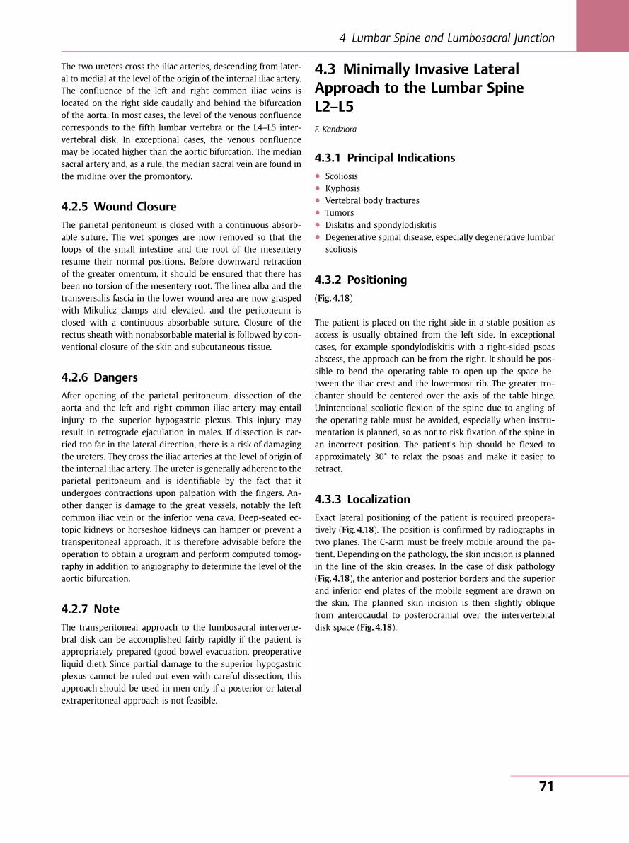
The two ureters cross the iliac arteries, descending from later-al to medial at the level of the origin of the internal iliac artery.The confluence of the left and right common iliac veins islocated on the right side caudally and behind the bifurcationof the aorta. In most cases, the level of the venous confluencecorresponds to the fifth lumbar vertebra or the L4–L5 inter-vertebral disk. In exceptional cases, the venous confluencemay be located higher than the aortic bifurcation. The mediansacral artery and, as a rule, the median sacral vein are found inthe midline over the promontory.
4.2.5 Wound Closure
The parietal peritoneum is closed with a continuous absorb-able suture. The wet sponges are now removed so that theloops of the small intestine and the root of the mesenteryresume their normal positions. Before downward retractionof the greater omentum, it should be ensured that there hasbeen no torsion of the mesentery root. The linea alba and thetransversalis fascia in the lower wound area are now graspedwith Mikulicz clamps and elevated, and the peritoneum isclosed with a continuous absorbable suture. Closure of therectus sheath with nonabsorbable material is followed by con-ventional closure of the skin and subcutaneous tissue.
4.2.6 Dangers
After opening of the parietal peritoneum, dissection of theaorta and the left and right common iliac artery may entailinjury to the superior hypogastric plexus. This injury mayresult in retrograde ejaculation in males. If dissection is car-ried too far in the lateral direction, there is a risk of damagingthe ureters. They cross the iliac arteries at the level of origin ofthe internal iliac artery. The ureter is generally adherent to theparietal peritoneum and is identifiable by the fact that itundergoes contractions upon palpation with the fingers. An-other danger is damage to the great vessels, notably the leftcommon iliac vein or the inferior vena cava. Deep-seated ec-topic kidneys or horseshoe kidneys can hamper or prevent atransperitoneal approach. It is therefore advisable before theoperation to obtain a urogram and perform computed tomog-raphy in addition to angiography to determine the level of theaortic bifurcation.
4.2.7 Note
The transperitoneal approach to the lumbosacral interverte-bral disk can be accomplished fairly rapidly if the patient isappropriately prepared (good bowel evacuation, preoperativeliquid diet). Since partial damage to the superior hypogastricplexus cannot be ruled out even with careful dissection, thisapproach should be used in men only if a posterior or lateralextraperitoneal approach is not feasible.
4.3 Minimally Invasive LateralApproach to the Lumbar SpineL2–L5F. Kandziora
4.3.1 Principal Indications● Scoliosis● Kyphosis● Vertebral body fractures● Tumors● Diskitis and spondylodiskitis● Degenerative spinal disease, especially degenerative lumbar
scoliosis
4.3.2 Positioning
(Fig. 4.18)
The patient is placed on the right side in a stable position asaccess is usually obtained from the left side. In exceptionalcases, for example spondylodiskitis with a right-sided psoasabscess, the approach can be from the right. It should be pos-sible to bend the operating table to open up the space be-tween the iliac crest and the lowermost rib. The greater tro-chanter should be centered over the axis of the table hinge.Unintentional scoliotic flexion of the spine due to angling ofthe operating table must be avoided, especially when instru-mentation is planned, so as not to risk fixation of the spine inan incorrect position. The patient’s hip should be flexed toapproximately 30° to relax the psoas and make it easier toretract.
4.3.3 Localization
Exact lateral positioning of the patient is required preopera-tively (Fig. 4.18). The position is confirmed by radiographs intwo planes. The C-arm must be freely mobile around the pa-tient. Depending on the pathology, the skin incision is plannedin the line of the skin creases. In the case of disk pathology(Fig. 4.18), the anterior and posterior borders and the superiorand inferior end plates of the mobile segment are drawn onthe skin. The planned skin incision is then slightly obliquefrom anterocaudal to posterocranial over the intervertebraldisk space (Fig. 4.18).
4 Lumbar Spine and Lumbosacral Junction
71
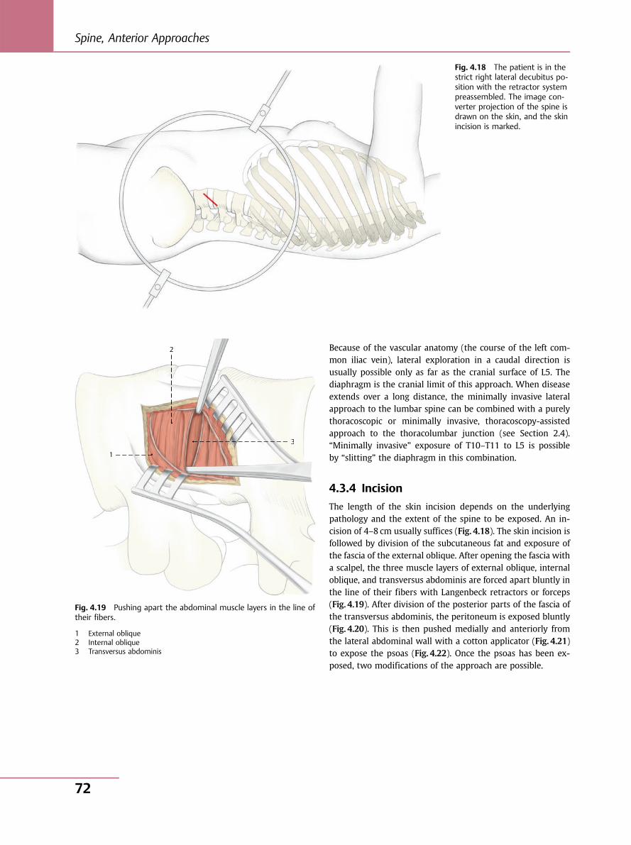
Because of the vascular anatomy (the course of the left com-mon iliac vein), lateral exploration in a caudal direction isusually possible only as far as the cranial surface of L5. Thediaphragm is the cranial limit of this approach. When diseaseextends over a long distance, the minimally invasive lateralapproach to the lumbar spine can be combined with a purelythoracoscopic or minimally invasive, thoracoscopy-assistedapproach to the thoracolumbar junction (see Section 2.4).“Minimally invasive” exposure of T10–T11 to L5 is possibleby “slitting” the diaphragm in this combination.
4.3.4 Incision
The length of the skin incision depends on the underlyingpathology and the extent of the spine to be exposed. An in-cision of 4–8 cm usually suffices (Fig. 4.18). The skin incision isfollowed by division of the subcutaneous fat and exposure ofthe fascia of the external oblique. After opening the fascia witha scalpel, the three muscle layers of external oblique, internaloblique, and transversus abdominis are forced apart bluntly inthe line of their fibers with Langenbeck retractors or forceps(Fig. 4.19). After division of the posterior parts of the fascia ofthe transversus abdominis, the peritoneum is exposed bluntly(Fig. 4.20). This is then pushed medially and anteriorly fromthe lateral abdominal wall with a cotton applicator (Fig. 4.21)to expose the psoas (Fig. 4.22). Once the psoas has been ex-posed, two modifications of the approach are possible.
Fig. 4.18 The patient is in thestrict right lateral decubitus po-sition with the retractor systempreassembled. The image con-verter projection of the spine isdrawn on the skin, and the skinincision is marked.
1
2
3
1
2
33
Fig. 4.19 Pushing apart the abdominal muscle layers in the line oftheir fibers.
1 External oblique2 Internal oblique3 Transversus abdominis
Spine, Anterior Approaches
72
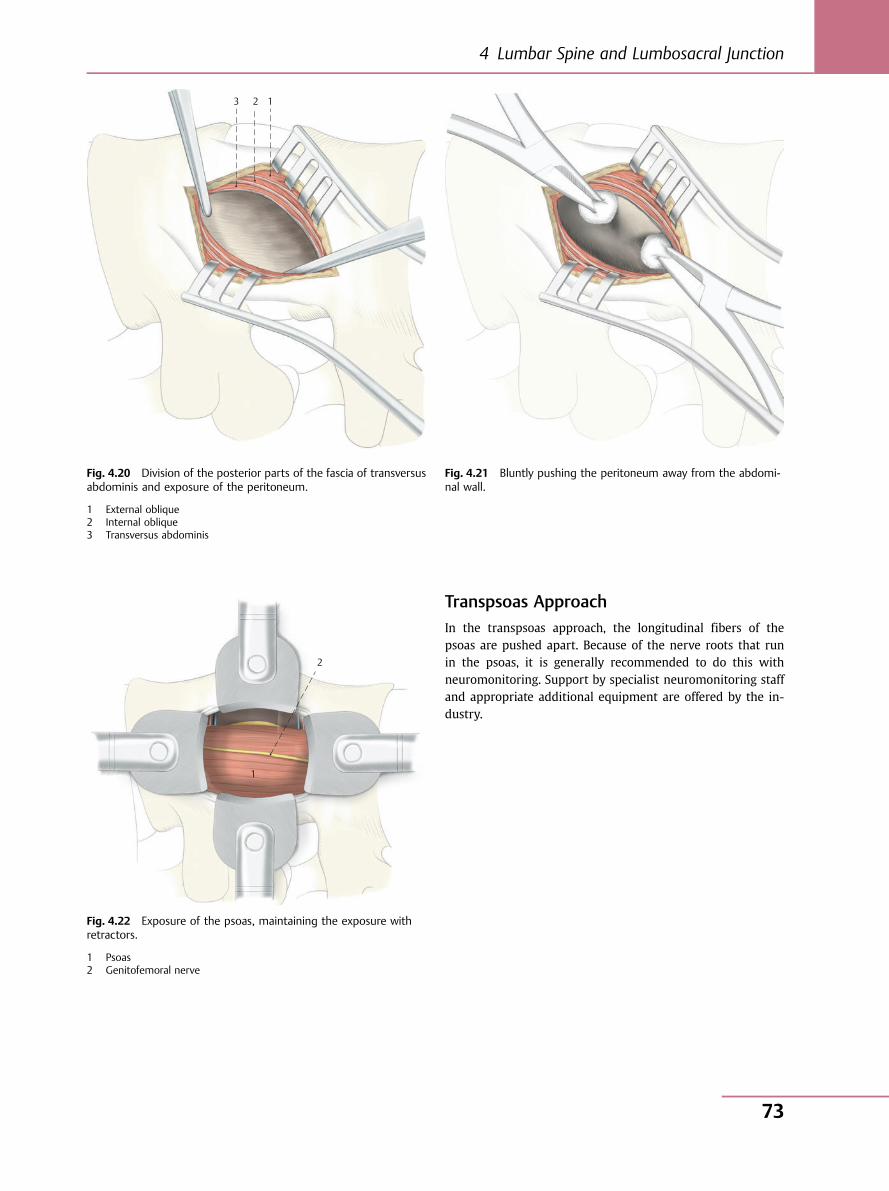
Transpsoas ApproachIn the transpsoas approach, the longitudinal fibers of thepsoas are pushed apart. Because of the nerve roots that runin the psoas, it is generally recommended to do this withneuromonitoring. Support by specialist neuromonitoring staffand appropriate additional equipment are offered by the in-dustry.
3 2 1
Fig. 4.20 Division of the posterior parts of the fascia of transversusabdominis and exposure of the peritoneum.
1 External oblique2 Internal oblique3 Transversus abdominis
Fig. 4.21 Bluntly pushing the peritoneum away from the abdomi-nal wall.
1
2
Fig. 4.22 Exposure of the psoas, maintaining the exposure withretractors.
1 Psoas2 Genitofemoral nerve
4 Lumbar Spine and Lumbosacral Junction
73
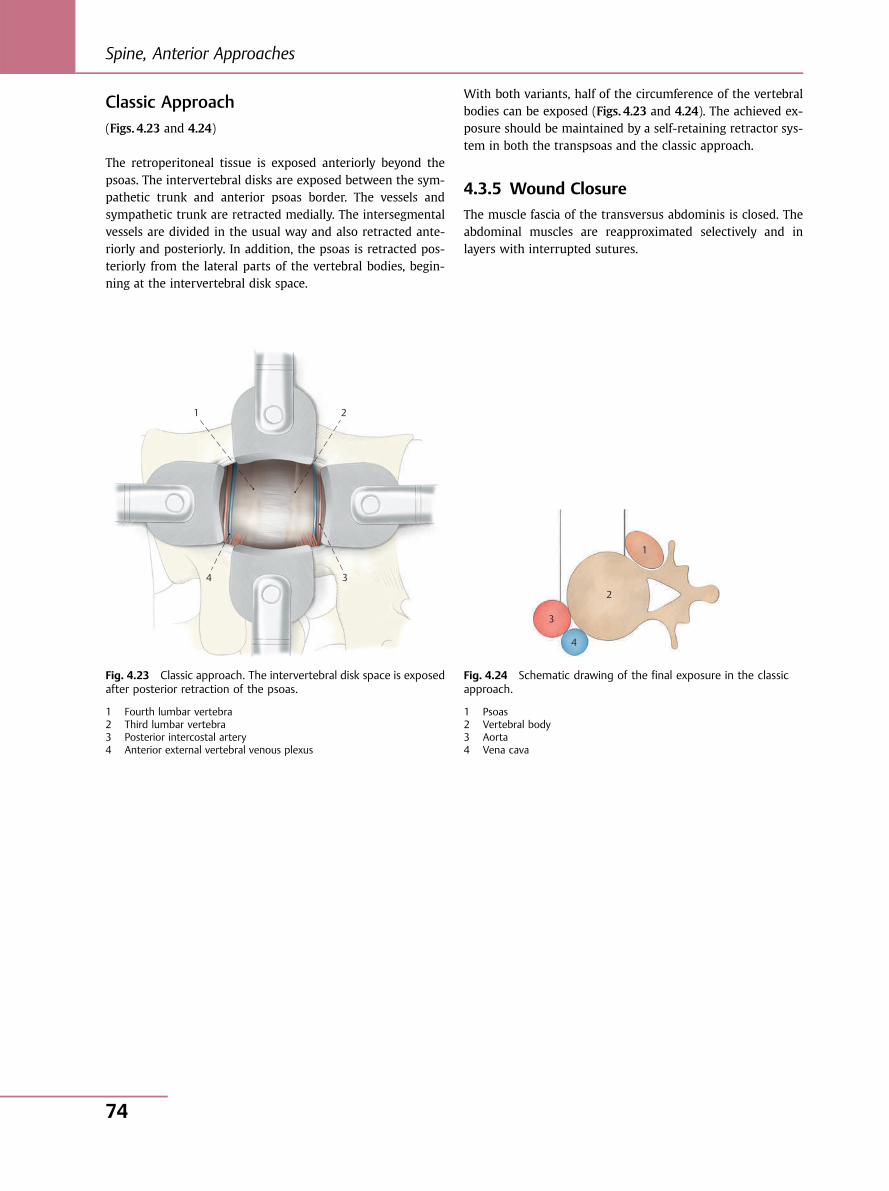
Classic Approach(Figs. 4.23 and 4.24)
The retroperitoneal tissue is exposed anteriorly beyond thepsoas. The intervertebral disks are exposed between the sym-pathetic trunk and anterior psoas border. The vessels andsympathetic trunk are retracted medially. The intersegmentalvessels are divided in the usual way and also retracted ante-riorly and posteriorly. In addition, the psoas is retracted pos-teriorly from the lateral parts of the vertebral bodies, begin-ning at the intervertebral disk space.
With both variants, half of the circumference of the vertebralbodies can be exposed (Figs. 4.23 and 4.24). The achieved ex-posure should be maintained by a self-retaining retractor sys-tem in both the transpsoas and the classic approach.
4.3.5 Wound Closure
The muscle fascia of the transversus abdominis is closed. Theabdominal muscles are reapproximated selectively and inlayers with interrupted sutures.
1 2
3 4
Fig. 4.23 Classic approach. The intervertebral disk space is exposedafter posterior retraction of the psoas.
1 Fourth lumbar vertebra2 Third lumbar vertebra3 Posterior intercostal artery4 Anterior external vertebral venous plexus
1
2
3
4
Fig. 4.24 Schematic drawing of the final exposure in the classicapproach.
1 Psoas2 Vertebral body3 Aorta4 Vena cava
Spine, Anterior Approaches
74
Spine,Posterior Approaches
5 Cervical Spine 76
6 Thoracic andLumbar Spine 80
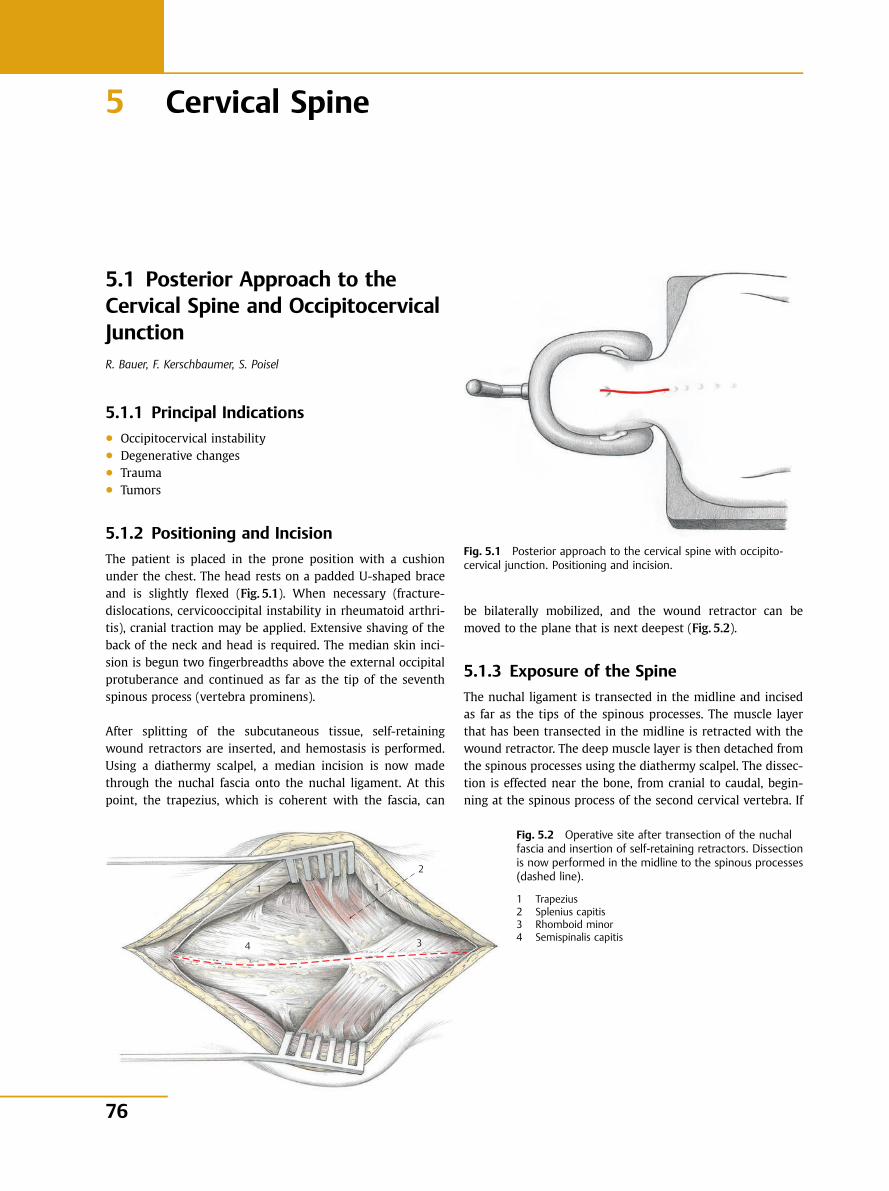
5 Cervical Spine
5.1 Posterior Approach to theCervical Spine and OccipitocervicalJunctionR. Bauer, F. Kerschbaumer, S. Poisel
5.1.1 Principal Indications● Occipitocervical instability● Degenerative changes● Trauma● Tumors
5.1.2 Positioning and Incision
The patient is placed in the prone position with a cushionunder the chest. The head rests on a padded U-shaped braceand is slightly flexed (Fig. 5.1). When necessary (fracture-dislocations, cervicooccipital instability in rheumatoid arthri-tis), cranial traction may be applied. Extensive shaving of theback of the neck and head is required. The median skin inci-sion is begun two fingerbreadths above the external occipitalprotuberance and continued as far as the tip of the seventhspinous process (vertebra prominens).
After splitting of the subcutaneous tissue, self-retainingwound retractors are inserted, and hemostasis is performed.Using a diathermy scalpel, a median incision is now madethrough the nuchal fascia onto the nuchal ligament. At thispoint, the trapezius, which is coherent with the fascia, can
Fig. 5.1 Posterior approach to the cervical spine with occipito-cervical junction. Positioning and incision.
1
2
3 4
1
Fig. 5.2 Operative site after transection of the nuchalfascia and insertion of self-retaining retractors. Dissectionis now performed in the midline to the spinous processes(dashed line).
1 Trapezius2 Splenius capitis3 Rhomboid minor4 Semispinalis capitis
be bilaterally mobilized, and the wound retractor can bemoved to the plane that is next deepest (Fig. 5.2).
5.1.3 Exposure of the Spine
The nuchal ligament is transected in the midline and incisedas far as the tips of the spinous processes. The muscle layerthat has been transected in the midline is retracted with thewound retractor. The deep muscle layer is then detached fromthe spinous processes using the diathermy scalpel. The dissec-tion is effected near the bone, from cranial to caudal, begin-ning at the spinous process of the second cervical vertebra. If
76
Spine, Posterior Approaches
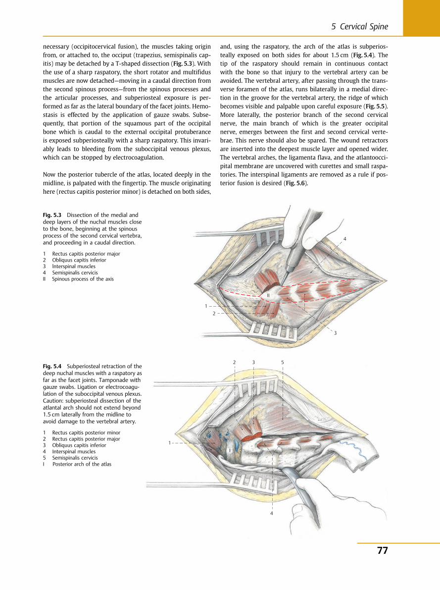
necessary (occipitocervical fusion), the muscles taking originfrom, or attached to, the occiput (trapezius, semispinalis cap-itis) may be detached by a T-shaped dissection (Fig. 5.3). Withthe use of a sharp raspatory, the short rotator and multifidusmuscles are now detached—moving in a caudal direction fromthe second spinous process—from the spinous processes andthe articular processes, and subperiosteal exposure is per-formed as far as the lateral boundary of the facet joints. Hemo-stasis is effected by the application of gauze swabs. Subse-quently, that portion of the squamous part of the occipitalbone which is caudal to the external occipital protuberanceis exposed subperiosteally with a sharp raspatory. This invari-ably leads to bleeding from the suboccipital venous plexus,which can be stopped by electrocoagulation.
Now the posterior tubercle of the atlas, located deeply in themidline, is palpated with the fingertip. The muscle originatinghere (rectus capitis posterior minor) is detached on both sides,
and, using the raspatory, the arch of the atlas is subperios-teally exposed on both sides for about 1.5 cm (Fig. 5.4). Thetip of the raspatory should remain in continuous contactwith the bone so that injury to the vertebral artery can beavoided. The vertebral artery, after passing through the trans-verse foramen of the atlas, runs bilaterally in a medial direc-tion in the groove for the vertebral artery, the ridge of whichbecomes visible and palpable upon careful exposure (Fig. 5.5).More laterally, the posterior branch of the second cervicalnerve, the main branch of which is the greater occipitalnerve, emerges between the first and second cervical verte-brae. This nerve should also be spared. The wound retractorsare inserted into the deepest muscle layer and opened wider.The vertebral arches, the ligamenta flava, and the atlantoocci-pital membrane are uncovered with curettes and small raspa-tories. The interspinal ligaments are removed as a rule if pos-terior fusion is desired (Fig. 5.6).
1 2
II
3
4
Fig. 5.3 Dissection of the medial anddeep layers of the nuchal muscles closeto the bone, beginning at the spinousprocess of the second cervical vertebra,and proceeding in a caudal direction.
1 Rectus capitis posterior major2 Obliquus capitis inferior3 lnterspinal muscles4 Semispinalis cervicisII Spinous process of the axis
5
4
3
1 I
2 Fig. 5.4 Subperiosteal retraction of thedeep nuchal muscles with a raspatory asfar as the facet joints. Tamponade withgauze swabs. Ligation or electrocoagu-lation of the suboccipital venous plexus.Caution: subperiosteal dissection of theatlantal arch should not extend beyond1.5 cm laterally from the midline toavoid damage to the vertebral artery.
1 Rectus capitis posterior minor2 Rectus capitis posterior major3 Obliquus capitis inferior4 Interspinal muscles5 Semispinalis cervicisI Posterior arch of the atlas
77
5 Cervical Spine
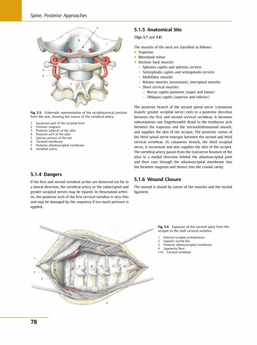
5.1.4 Dangers
If the first and second vertebral arches are dissected too far ina lateral direction, the vertebral artery or the suboccipital andgreater occipital nerves may be injured. In rheumatoid arthri-tis, the posterior arch of the first cervical vertebra is very thinand may be damaged by the raspatory if too much pressure isapplied.
5.1.5 Anatomical Site
(Figs. 5.7 and 5.8)
The muscles of the neck are classified as follows:● Trapezius● Rhomboid minor● Intrinsic back muscles
● Splenius capitis and splenius cervicis● Semispinalis capitis and semispinalis cervicis● Multifidus muscles● Rotator muscles (inconstant), interspinal muscles● Short cervical muscles:
– Rectus capitis posterior (major and minor)– Obliquus capitis (superior and inferior)
The posterior branch of the second spinal nerve (cutaneousbranch: greater occipital nerve) exits in a posterior directionbetween the first and second cervical vertebrae. It becomessubcutaneous one fingerbreadth distal to the tendinous archbetween the trapezius and the sternocleidomastoid muscle,and supplies the skin of the occiput. The posterior ramus ofthe third spinal nerve emerges between the second and thirdcervical vertebrae. Its cutaneous branch, the third occipitalnerve, is inconstant and also supplies the skin of the occiput.The vertebral artery passes from the transverse foramen of theatlas in a medial direction behind the atlantooccipital jointand then runs through the atlantooccipital membrane intothe foramen magnum and thence into the cranial cavity.
5.1.6 Wound Closure
The wound is closed by suture of the muscles and the nuchalligament.
6
2
1
3
7
5
4
8
Fig. 5.5 Schematic representation of the occipitocervical junctionfrom the rear, showing the course of the vertebral artery.
1 Squamous part of the occipital bone2 Foramen magnum3 Posterior tubercle of the atlas4 Posterior arch of the atlas5 Spinous process of the axis6 Tectorial membrane7 Posterior atlantooccipital membrane8 Vertebral artery
4
3
1
2
I II III IV V VI
Fig. 5.6 Exposure of the cervical spine from theocciput to the sixth cervical vertebra.
1 External occipital protuberance2 Superior nuchal line3 Posterior atlantooccipital membrane4 Ligamenta flavaI–VI Cervical vertebrae
78
Spine, Posterior Approaches
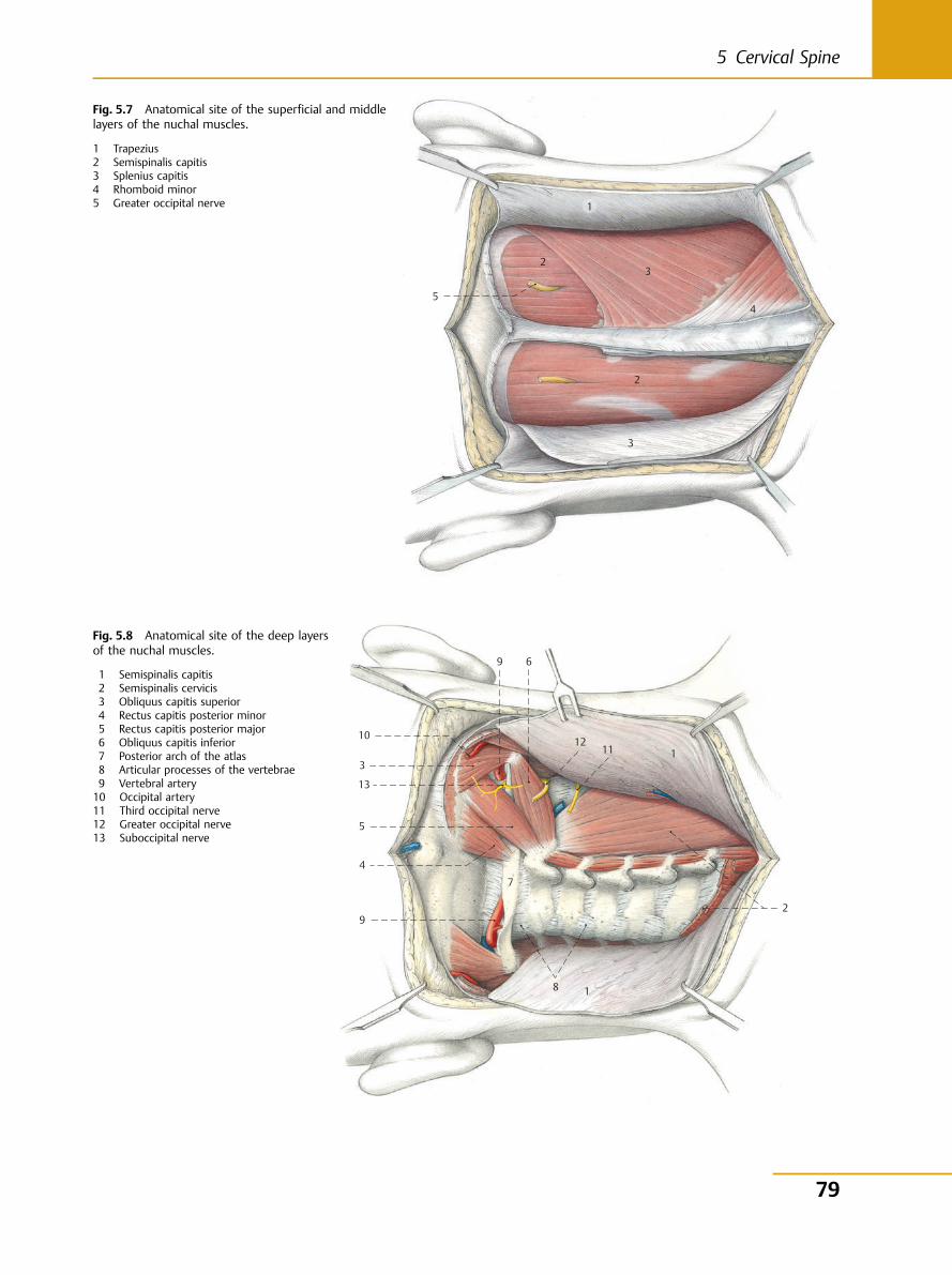
5
2
1
3
4
2
3
Fig. 5.7 Anatomical site of the superficial and middlelayers of the nuchal muscles.
1 Trapezius2 Semispinalis capitis3 Splenius capitis4 Rhomboid minor5 Greater occipital nerve
10 11
12
13
9
8
7
6
5
4
3 1
2
9
1
Fig. 5.8 Anatomical site of the deep layersof the nuchal muscles.
1 Semispinalis capitis2 Semispinalis cervicis3 Obliquus capitis superior4 Rectus capitis posterior minor5 Rectus capitis posterior major6 Obliquus capitis inferior7 Posterior arch of the atlas8 Articular processes of the vertebrae9 Vertebral artery10 Occipital artery11 Third occipital nerve12 Greater occipital nerve13 Suboccipital nerve
79
5 Cervical Spine
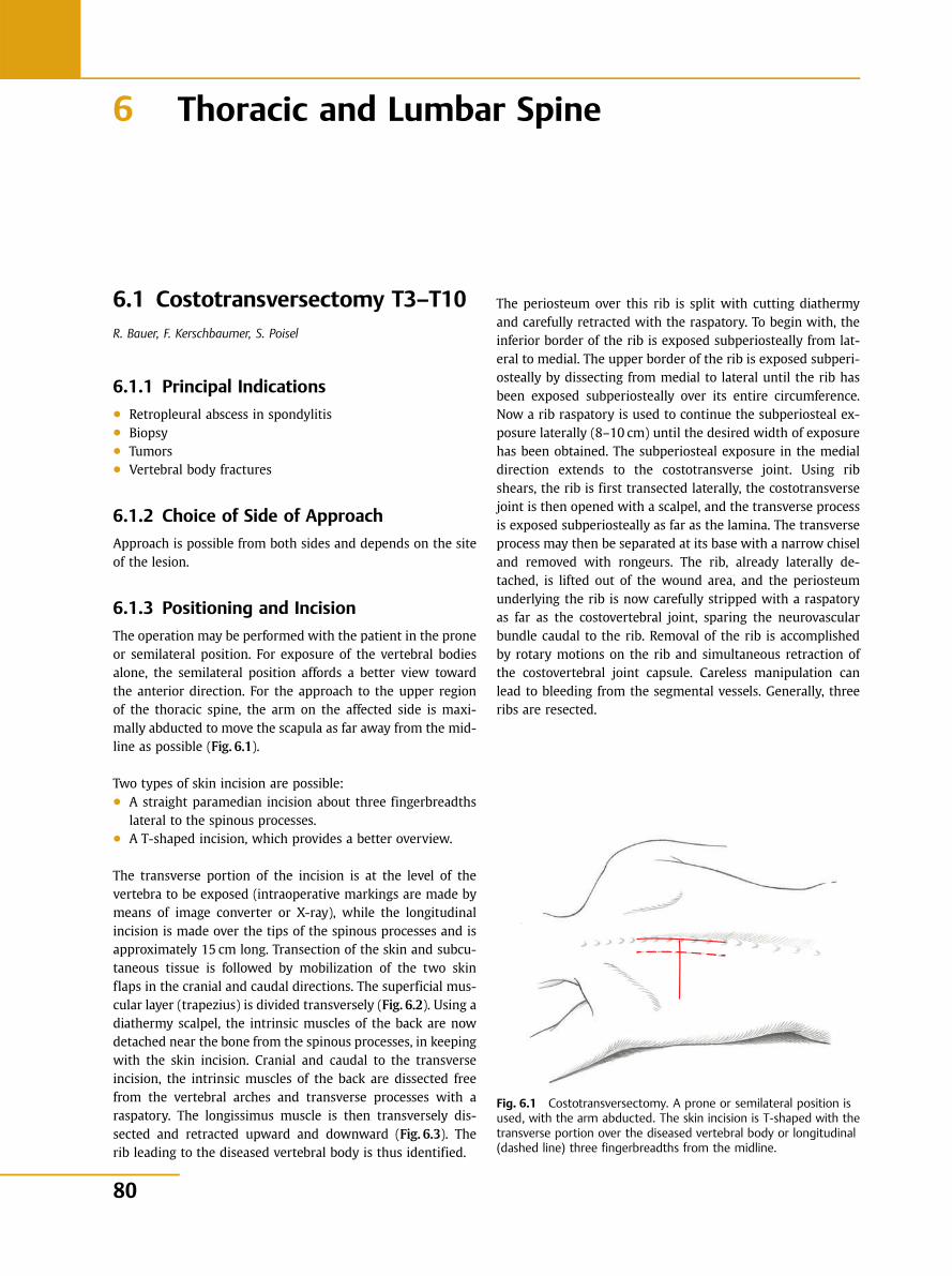
6 Thoracic and Lumbar Spine
6.1 Costotransversectomy T3–T10R. Bauer, F. Kerschbaumer, S. Poisel
6.1.1 Principal Indications● Retropleural abscess in spondylitis● Biopsy● Tumors● Vertebral body fractures
6.1.2 Choice of Side of Approach
Approach is possible from both sides and depends on the siteof the lesion.
6.1.3 Positioning and Incision
The operation may be performed with the patient in the proneor semilateral position. For exposure of the vertebral bodiesalone, the semilateral position affords a better view towardthe anterior direction. For the approach to the upper regionof the thoracic spine, the arm on the affected side is maxi-mally abducted to move the scapula as far away from the mid-line as possible (Fig. 6.1).
Two types of skin incision are possible:● A straight paramedian incision about three fingerbreadths
lateral to the spinous processes.● A T-shaped incision, which provides a better overview.
The transverse portion of the incision is at the level of thevertebra to be exposed (intraoperative markings are made bymeans of image converter or X-ray), while the longitudinalincision is made over the tips of the spinous processes and isapproximately 15 cm long. Transection of the skin and subcu-taneous tissue is followed by mobilization of the two skinflaps in the cranial and caudal directions. The superficial mus-cular layer (trapezius) is divided transversely (Fig. 6.2). Using adiathermy scalpel, the intrinsic muscles of the back are nowdetached near the bone from the spinous processes, in keepingwith the skin incision. Cranial and caudal to the transverseincision, the intrinsic muscles of the back are dissected freefrom the vertebral arches and transverse processes with araspatory. The longissimus muscle is then transversely dis-sected and retracted upward and downward (Fig. 6.3). Therib leading to the diseased vertebral body is thus identified.
The periosteum over this rib is split with cutting diathermyand carefully retracted with the raspatory. To begin with, theinferior border of the rib is exposed subperiosteally from lat-eral to medial. The upper border of the rib is exposed subperi-osteally by dissecting from medial to lateral until the rib hasbeen exposed subperiosteally over its entire circumference.Now a rib raspatory is used to continue the subperiosteal ex-posure laterally (8–10 cm) until the desired width of exposurehas been obtained. The subperiosteal exposure in the medialdirection extends to the costotransverse joint. Using ribshears, the rib is first transected laterally, the costotransversejoint is then opened with a scalpel, and the transverse processis exposed subperiosteally as far as the lamina. The transverseprocess may then be separated at its base with a narrow chiseland removed with rongeurs. The rib, already laterally de-tached, is lifted out of the wound area, and the periosteumunderlying the rib is now carefully stripped with a raspatoryas far as the costovertebral joint, sparing the neurovascularbundle caudal to the rib. Removal of the rib is accomplishedby rotary motions on the rib and simultaneous retraction ofthe costovertebral joint capsule. Careless manipulation canlead to bleeding from the segmental vessels. Generally, threeribs are resected.
Fig. 6.1 Costotransversectomy. A prone or semilateral position isused, with the arm abducted. The skin incision is T-shaped with thetransverse portion over the diseased vertebral body or longitudinal(dashed line) three fingerbreadths from the midline.
80
Spine, Posterior Approaches
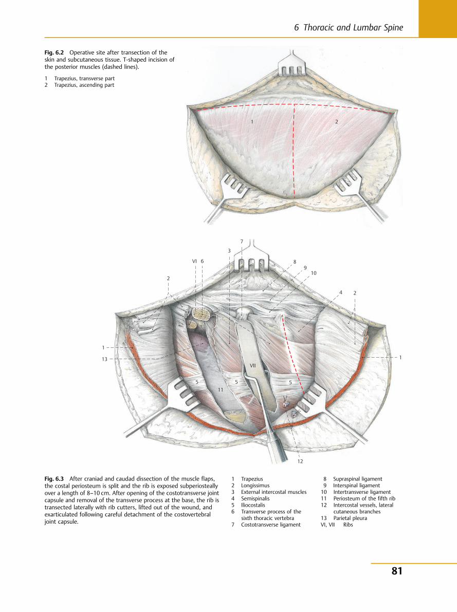
1 2
Fig. 6.2 Operative site after transection of theskin and subcutaneous tissue. T-shaped incision ofthe posterior muscles (dashed lines).
1 Trapezius, transverse part2 Trapezius, ascending part
1
2
VI 6
3
7
8 9
10
4 2
1
12
VII
5 5 5 11
13
Fig. 6.3 After craniad and caudad dissection of the muscle flaps,the costal periosteum is split and the rib is exposed subperiosteallyover a length of 8–10 cm. After opening of the costotransverse jointcapsule and removal of the transverse process at the base, the rib istransected laterally with rib cutters, lifted out of the wound, andexarticulated following careful detachment of the costovertebraljoint capsule.
1 Trapezius2 Longissimus3 External intercostal muscles4 Semispinalis5 Iliocostalis6 Transverse process of the
sixth thoracic vertebra7 Costotransverse ligament
8 Supraspinal ligament9 Interspinal ligament10 Intertransverse ligament11 Periosteum of the fifth rib12 Intercostal vessels, lateral
cutaneous branches13 Parietal pleuraVI, VII Ribs
81
6 Thoracic and Lumbar Spine
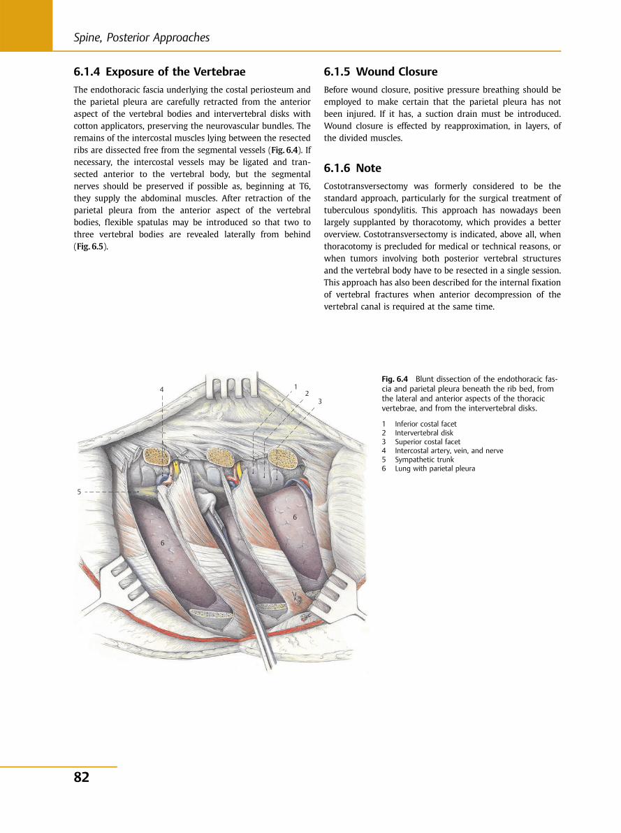
6.1.4 Exposure of the Vertebrae
The endothoracic fascia underlying the costal periosteum andthe parietal pleura are carefully retracted from the anterioraspect of the vertebral bodies and intervertebral disks withcotton applicators, preserving the neurovascular bundles. Theremains of the intercostal muscles lying between the resectedribs are dissected free from the segmental vessels (Fig. 6.4). Ifnecessary, the intercostal vessels may be ligated and tran-sected anterior to the vertebral body, but the segmentalnerves should be preserved if possible as, beginning at T6,they supply the abdominal muscles. After retraction of theparietal pleura from the anterior aspect of the vertebralbodies, flexible spatulas may be introduced so that two tothree vertebral bodies are revealed laterally from behind(Fig. 6.5).
6.1.5 Wound Closure
Before wound closure, positive pressure breathing should beemployed to make certain that the parietal pleura has notbeen injured. If it has, a suction drain must be introduced.Wound closure is effected by reapproximation, in layers, ofthe divided muscles.
6.1.6 Note
Costotransversectomy was formerly considered to be thestandard approach, particularly for the surgical treatment oftuberculous spondylitis. This approach has nowadays beenlargely supplanted by thoracotomy, which provides a betteroverview. Costotransversectomy is indicated, above all, whenthoracotomy is precluded for medical or technical reasons, orwhen tumors involving both posterior vertebral structuresand the vertebral body have to be resected in a single session.This approach has also been described for the internal fixationof vertebral fractures when anterior decompression of thevertebral canal is required at the same time.
5
4 1 2
3
6
6
Fig. 6.4 Blunt dissection of the endothoracic fas-cia and parietal pleura beneath the rib bed, fromthe lateral and anterior aspects of the thoracicvertebrae, and from the intervertebral disks.
1 Inferior costal facet2 Intervertebral disk3 Superior costal facet4 Intercostal artery, vein, and nerve5 Sympathetic trunk6 Lung with parietal pleura
82
Spine, Posterior Approaches
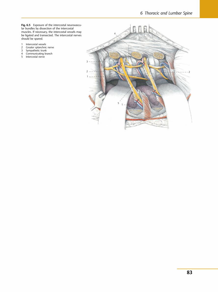
5
4
3
1
2
1
2
Fig. 6.5 Exposure of the intercostal neurovascu-lar bundles by dissection of the intercostalmuscles. If necessary, the intercostal vessels maybe ligated and transected. The intercostal nervesshould be spared.
1 Intercostal vessels2 Greater splanchnic nerve3 Sympathetic trunk4 Communicating branch5 Intercostal nerve
83
6 Thoracic and Lumbar Spine
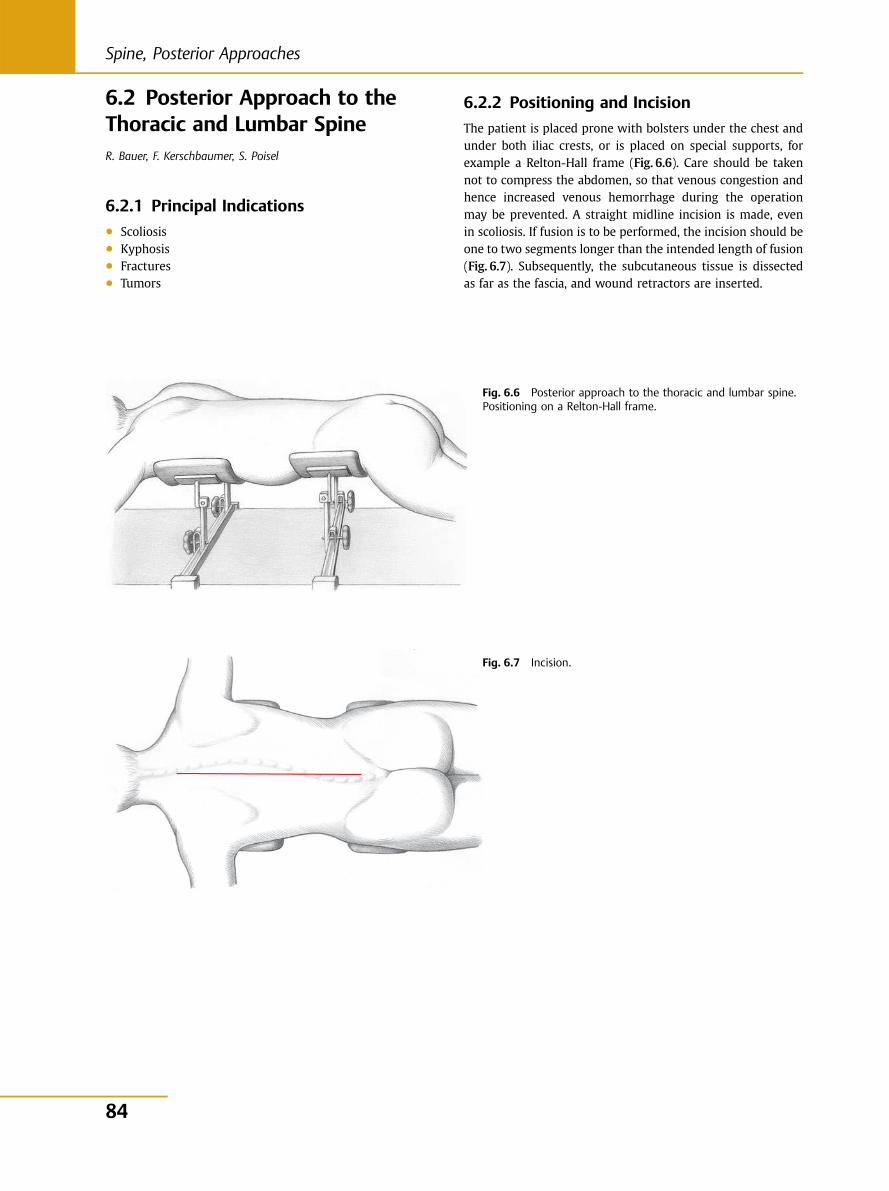
6.2 Posterior Approach to theThoracic and Lumbar SpineR. Bauer, F. Kerschbaumer, S. Poisel
6.2.1 Principal Indications● Scoliosis● Kyphosis● Fractures● Tumors
6.2.2 Positioning and Incision
The patient is placed prone with bolsters under the chest andunder both iliac crests, or is placed on special supports, forexample a Relton-Hall frame (Fig. 6.6). Care should be takennot to compress the abdomen, so that venous congestion andhence increased venous hemorrhage during the operationmay be prevented. A straight midline incision is made, evenin scoliosis. If fusion is to be performed, the incision should beone to two segments longer than the intended length of fusion(Fig. 6.7). Subsequently, the subcutaneous tissue is dissectedas far as the fascia, and wound retractors are inserted.
Fig. 6.6 Posterior approach to the thoracic and lumbar spine.Positioning on a Relton-Hall frame.
Fig. 6.7 Incision.
84
Spine, Posterior Approaches
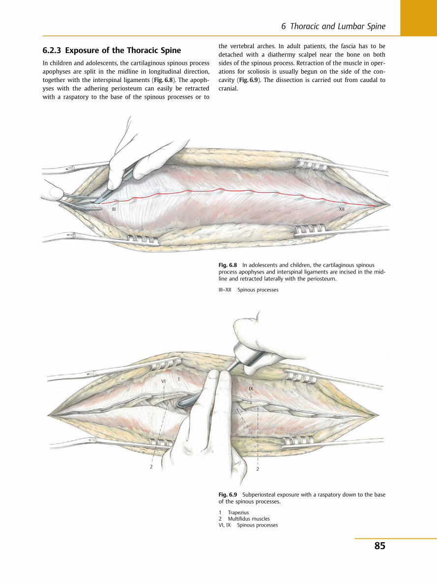
6.2.3 Exposure of the Thoracic Spine
In children and adolescents, the cartilaginous spinous processapophyses are split in the midline in longitudinal direction,together with the interspinal ligaments (Fig. 6.8). The apoph-yses with the adhering periosteum can easily be retractedwith a raspatory to the base of the spinous processes or to
the vertebral arches. In adult patients, the fascia has to bedetached with a diathermy scalpel near the bone on bothsides of the spinous process. Retraction of the muscle in oper-ations for scoliosis is usually begun on the side of the con-cavity (Fig. 6.9). The dissection is carried out from caudal tocranial.
III XII
Fig. 6.8 In adolescents and children, the cartilaginous spinousprocess apophyses and interspinal ligaments are incised in the mid-line and retracted laterally with the periosteum.
III–XII Spinous processes
1
2
VIIX
2
Fig. 6.9 Subperiosteal exposure with a raspatory down to the baseof the spinous processes.
1 Trapezius2 Multifidus musclesVI, IX Spinous processes
85
6 Thoracic and Lumbar Spine
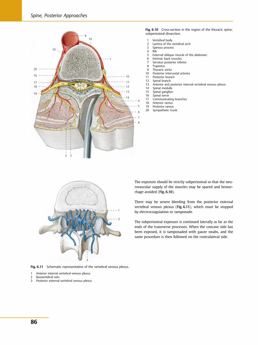
The exposure should be strictly subperiosteal so that the neu-rovascular supply of the muscles may be spared and hemor-rhage avoided (Fig. 6.10).
There may be severe bleeding from the posterior externalvertebral venous plexus (Fig. 6.11), which must be stoppedby electrocoagulation or tamponade.
The subperiosteal exposure is continued laterally as far as theends of the transverse processes. When the concave side hasbeen exposed, it is tamponaded with gauze swabs, and thesame procedure is then followed on the contralateral side.
19
18 17 15
20
10
9 10
1
10
1112
13
144
5
6
7
8
32
16
Fig. 6.10 Cross-section in the region of the thoracic spine;subperiosteal dissection.
1 Vertebral body2 Lamina of the vertebral arch3 Spinous process4 Rib5 External oblique muscle of the abdomen6 Intrinsic back muscles7 Serratus posterior inferior8 Trapezius9 Thoracic aorta10 Posterior intercostal arteries11 Posterior branch12 Spinal branch13 Anterior and posterior internal vertebral venous plexus14 Spinal medulla15 Spinal ganglion16 Spinal nerve17 Communicating branches18 Anterior ramus19 Posterior ramus20 Sympathetic trunk
3
1
2
Fig. 6.11 Schematic representation of the vertebral venous plexus.
1 Anterior internal vertebral venous plexus2 Basivertebral vein3 Posterior external vertebral venous plexus
86
Spine, Posterior Approaches
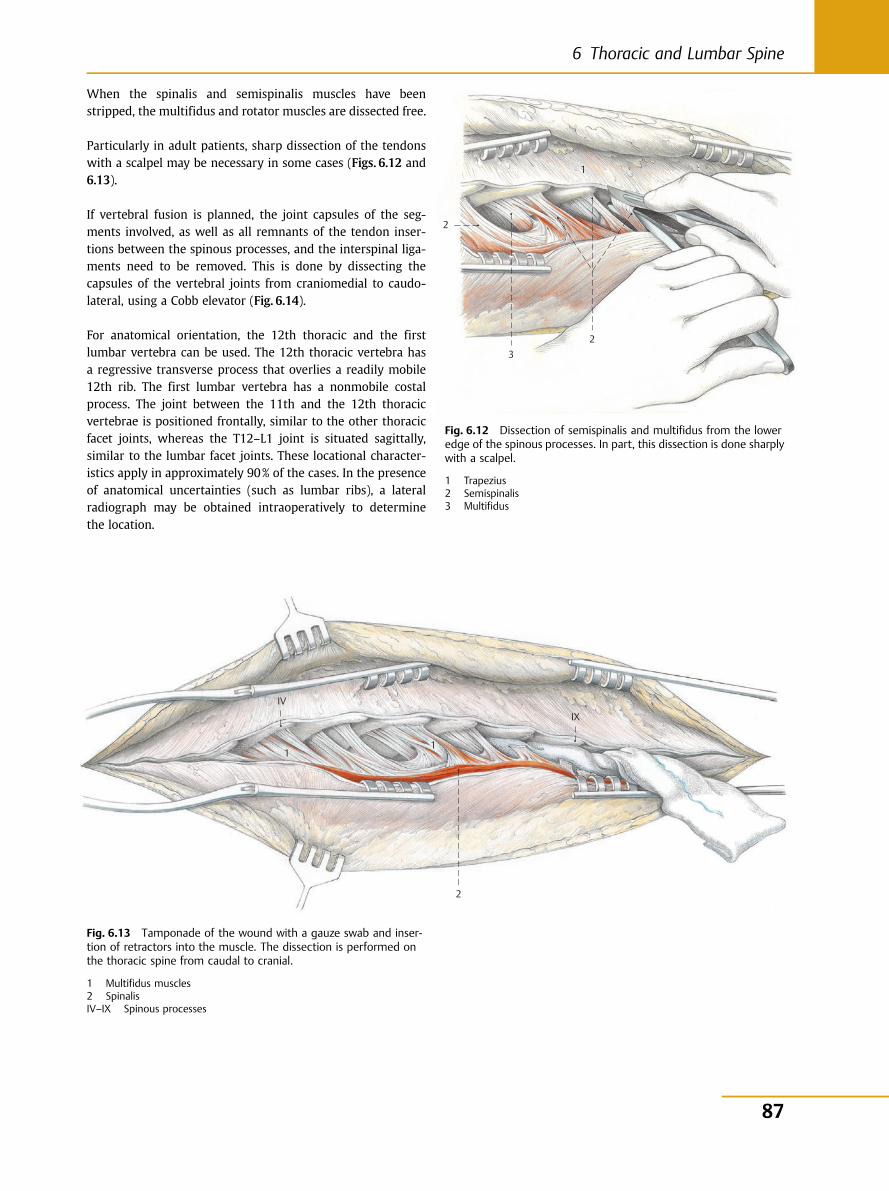
When the spinalis and semispinalis muscles have beenstripped, the multifidus and rotator muscles are dissected free.
Particularly in adult patients, sharp dissection of the tendonswith a scalpel may be necessary in some cases (Figs. 6.12 and6.13).
If vertebral fusion is planned, the joint capsules of the seg-ments involved, as well as all remnants of the tendon inser-tions between the spinous processes, and the interspinal liga-ments need to be removed. This is done by dissecting thecapsules of the vertebral joints from craniomedial to caudo-lateral, using a Cobb elevator (Fig. 6.14).
For anatomical orientation, the 12th thoracic and the firstlumbar vertebra can be used. The 12th thoracic vertebra hasa regressive transverse process that overlies a readily mobile12th rib. The first lumbar vertebra has a nonmobile costalprocess. The joint between the 11th and the 12th thoracicvertebrae is positioned frontally, similar to the other thoracicfacet joints, whereas the T12–L1 joint is situated sagittally,similar to the lumbar facet joints. These locational character-istics apply in approximately 90% of the cases. In the presenceof anatomical uncertainties (such as lumbar ribs), a lateralradiograph may be obtained intraoperatively to determinethe location.
3
1
2
2
Fig. 6.12 Dissection of semispinalis and multifidus from the loweredge of the spinous processes. In part, this dissection is done sharplywith a scalpel.
1 Trapezius2 Semispinalis3 Multifidus
1
2
IVIX
1
Fig. 6.13 Tamponade of the wound with a gauze swab and inser-tion of retractors into the muscle. The dissection is performed onthe thoracic spine from caudal to cranial.
1 Multifidus muscles2 SpinalisIV–IX Spinous processes
87
6 Thoracic and Lumbar Spine
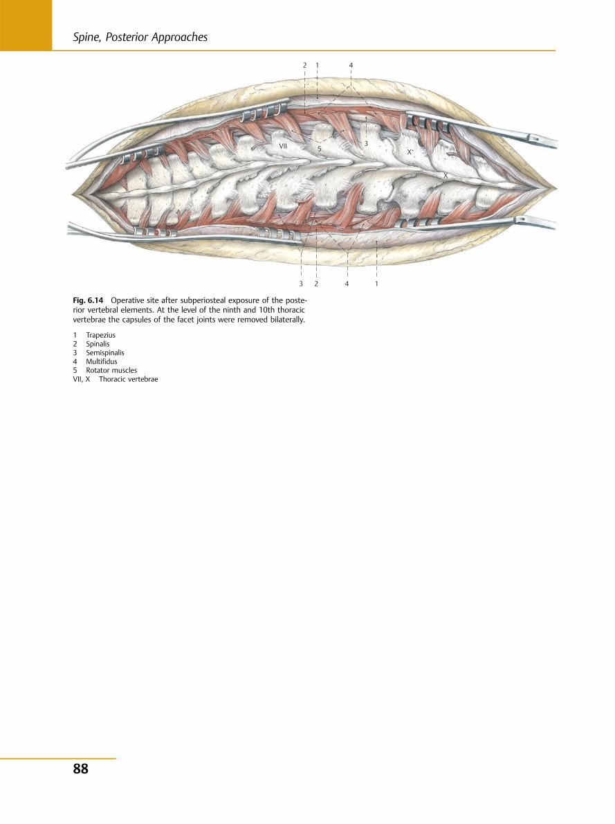
5
4 3 1 2
4
3
1 2
VIIX
X
Fig. 6.14 Operative site after subperiosteal exposure of the poste-rior vertebral elements. At the level of the ninth and 10th thoracicvertebrae the capsules of the facet joints were removed bilaterally.
1 Trapezius2 Spinalis3 Semispinalis4 Multifidus5 Rotator musclesVII, X Thoracic vertebrae
88
Spine, Posterior Approaches
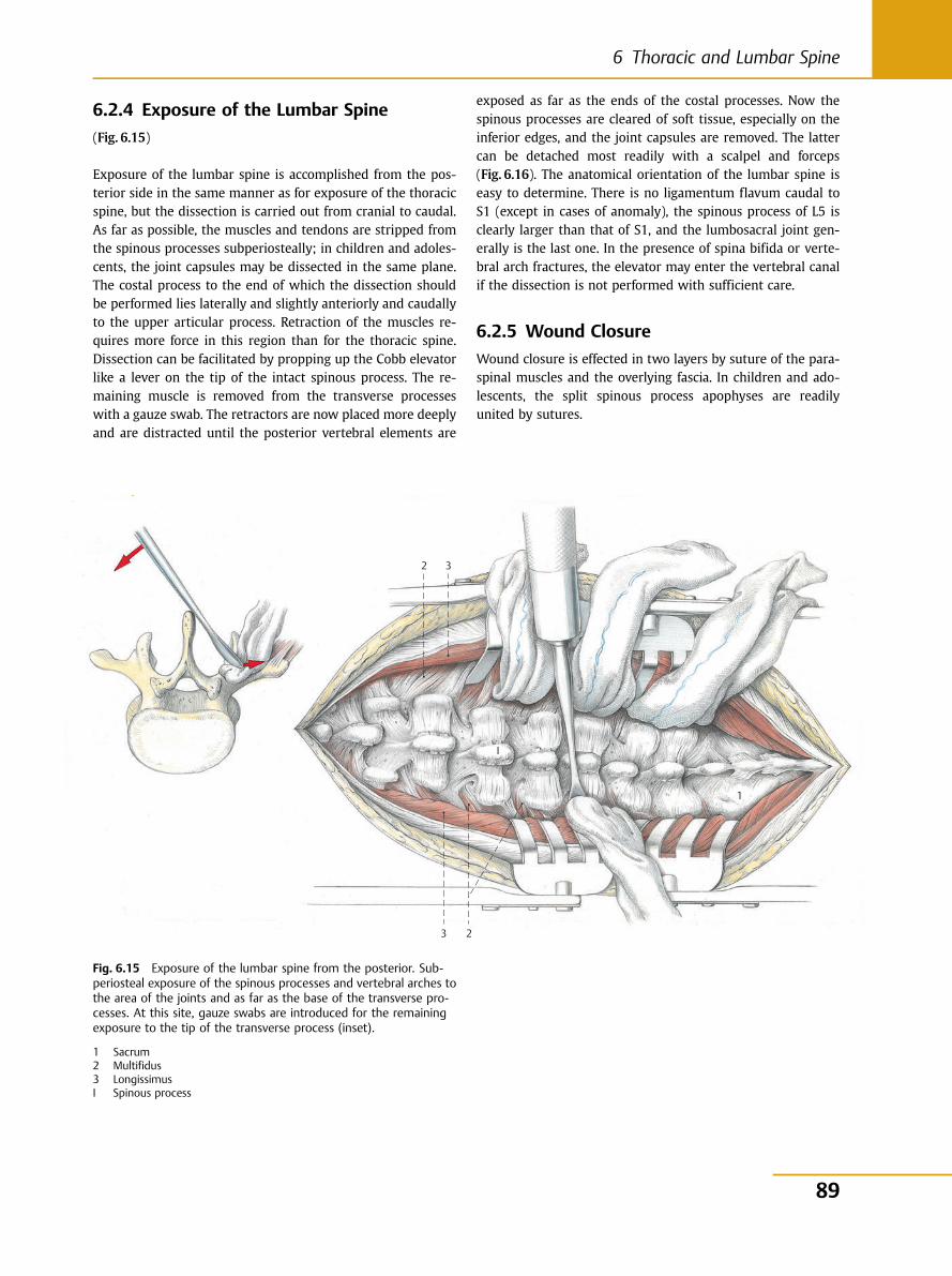
6.2.4 Exposure of the Lumbar Spine
(Fig. 6.15)
Exposure of the lumbar spine is accomplished from the pos-terior side in the same manner as for exposure of the thoracicspine, but the dissection is carried out from cranial to caudal.As far as possible, the muscles and tendons are stripped fromthe spinous processes subperiosteally; in children and adoles-cents, the joint capsules may be dissected in the same plane.The costal process to the end of which the dissection shouldbe performed lies laterally and slightly anteriorly and caudallyto the upper articular process. Retraction of the muscles re-quires more force in this region than for the thoracic spine.Dissection can be facilitated by propping up the Cobb elevatorlike a lever on the tip of the intact spinous process. The re-maining muscle is removed from the transverse processeswith a gauze swab. The retractors are now placed more deeplyand are distracted until the posterior vertebral elements are
exposed as far as the ends of the costal processes. Now thespinous processes are cleared of soft tissue, especially on theinferior edges, and the joint capsules are removed. The lattercan be detached most readily with a scalpel and forceps(Fig. 6.16). The anatomical orientation of the lumbar spine iseasy to determine. There is no ligamentum flavum caudal toS1 (except in cases of anomaly), the spinous process of L5 isclearly larger than that of S1, and the lumbosacral joint gen-erally is the last one. In the presence of spina bifida or verte-bral arch fractures, the elevator may enter the vertebral canalif the dissection is not performed with sufficient care.
6.2.5 Wound Closure
Wound closure is effected in two layers by suture of the para-spinal muscles and the overlying fascia. In children and ado-lescents, the split spinous process apophyses are readilyunited by sutures.
3
1
2
23
I
Fig. 6.15 Exposure of the lumbar spine from the posterior. Sub-periosteal exposure of the spinous processes and vertebral arches tothe area of the joints and as far as the base of the transverse pro-cesses. At this site, gauze swabs are introduced for the remainingexposure to the tip of the transverse process (inset).
1 Sacrum2 Multifidus3 LongissimusI Spinous process
89
6 Thoracic and Lumbar Spine
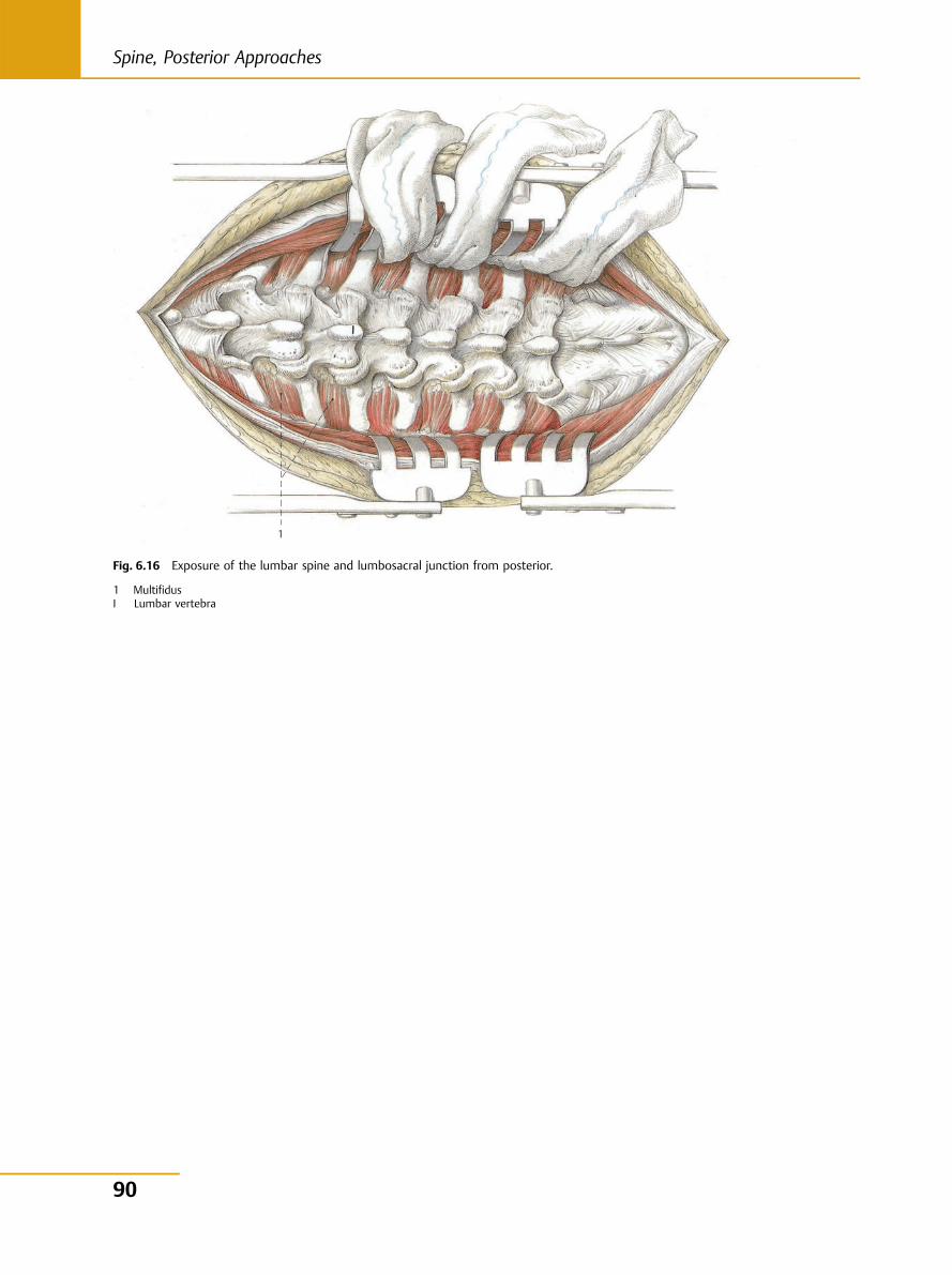
1
Fig. 6.16 Exposure of the lumbar spine and lumbosacral junction from posterior.
1 MultifidusI Lumbar vertebra
90
Spine, Posterior Approaches
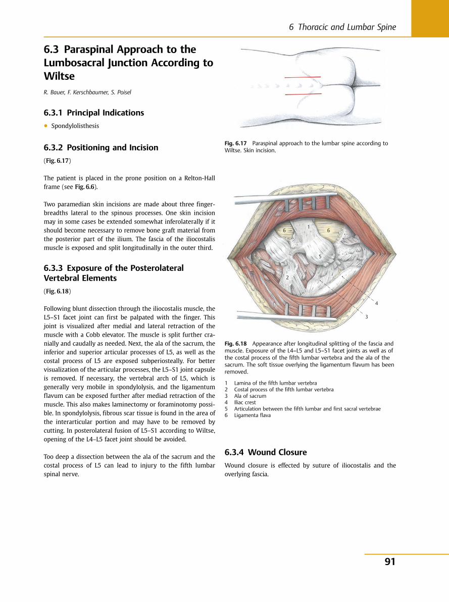
6.3 Paraspinal Approach to theLumbosacral Junction According toWiltseR. Bauer, F. Kerschbaumer, S. Poisel
6.3.1 Principal Indications● Spondylolisthesis
6.3.2 Positioning and Incision
(Fig. 6.17)
The patient is placed in the prone position on a Relton-Hallframe (see Fig. 6.6).
Two paramedian skin incisions are made about three finger-breadths lateral to the spinous processes. One skin incisionmay in some cases be extended somewhat inferolaterally if itshould become necessary to remove bone graft material fromthe posterior part of the ilium. The fascia of the iliocostalismuscle is exposed and split longitudinally in the outer third.
6.3.3 Exposure of the PosterolateralVertebral Elements
(Fig. 6.18)
Following blunt dissection through the iliocostalis muscle, theL5–S1 facet joint can first be palpated with the finger. Thisjoint is visualized after medial and lateral retraction of themuscle with a Cobb elevator. The muscle is split further cra-nially and caudally as needed. Next, the ala of the sacrum, theinferior and superior articular processes of L5, as well as thecostal process of L5 are exposed subperiosteally. For bettervisualization of the articular processes, the L5–S1 joint capsuleis removed. If necessary, the vertebral arch of L5, which isgenerally very mobile in spondylolysis, and the ligamentumflavum can be exposed further after mediad retraction of themuscle. This also makes laminectomy or foraminotomy possi-ble. In spondylolysis, fibrous scar tissue is found in the area ofthe interarticular portion and may have to be removed bycutting. In posterolateral fusion of L5–S1 according to Wiltse,opening of the L4–L5 facet joint should be avoided.
Too deep a dissection between the ala of the sacrum and thecostal process of L5 can lead to injury to the fifth lumbarspinal nerve.
6.3.4 Wound Closure
Wound closure is effected by suture of iliocostalis and theoverlying fascia.
Fig. 6.17 Paraspinal approach to the lumbar spine according toWiltse. Skin incision.
6 6
5
2
1
4
3
Fig. 6.18 Appearance after longitudinal splitting of the fascia andmuscle. Exposure of the L4–L5 and L5–S1 facet joints as well as ofthe costal process of the fifth lumbar vertebra and the ala of thesacrum. The soft tissue overlying the ligamentum flavum has beenremoved.
1 Lamina of the fifth lumbar vertebra2 Costal process of the fifth lumbar vertebra3 Ala of sacrum4 Iliac crest5 Articulation between the fifth lumbar and first sacral vertebrae6 Ligamenta flava
91
6 Thoracic and Lumbar Spine
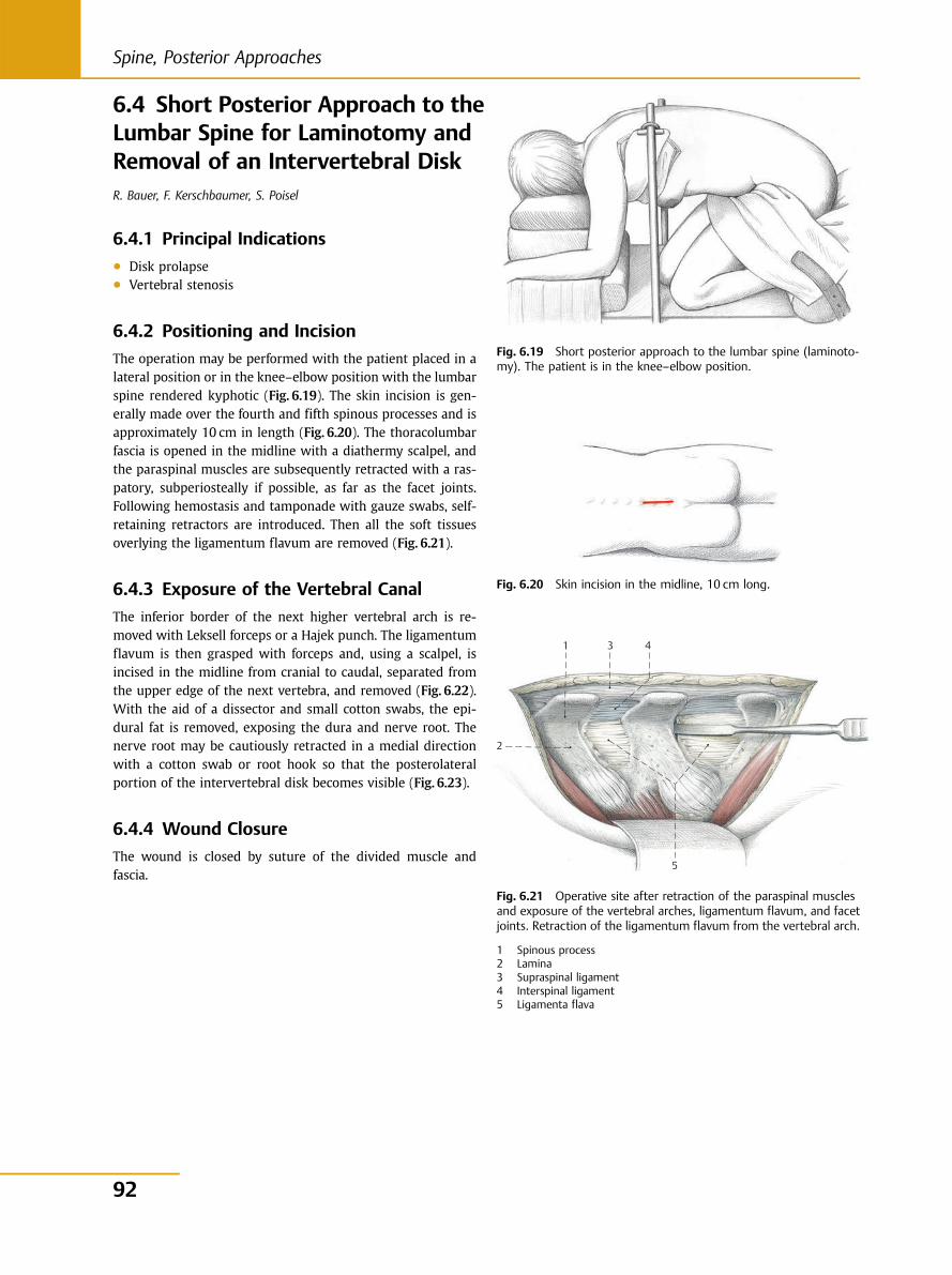
6.4 Short Posterior Approach to theLumbar Spine for Laminotomy andRemoval of an Intervertebral DiskR. Bauer, F. Kerschbaumer, S. Poisel
6.4.1 Principal Indications● Disk prolapse● Vertebral stenosis
6.4.2 Positioning and Incision
The operation may be performed with the patient placed in alateral position or in the knee–elbow position with the lumbarspine rendered kyphotic (Fig. 6.19). The skin incision is gen-erally made over the fourth and fifth spinous processes and isapproximately 10 cm in length (Fig. 6.20). The thoracolumbarfascia is opened in the midline with a diathermy scalpel, andthe paraspinal muscles are subsequently retracted with a ras-patory, subperiosteally if possible, as far as the facet joints.Following hemostasis and tamponade with gauze swabs, self-retaining retractors are introduced. Then all the soft tissuesoverlying the ligamentum flavum are removed (Fig. 6.21).
6.4.3 Exposure of the Vertebral Canal
The inferior border of the next higher vertebral arch is re-moved with Leksell forceps or a Hajek punch. The ligamentumflavum is then grasped with forceps and, using a scalpel, isincised in the midline from cranial to caudal, separated fromthe upper edge of the next vertebra, and removed (Fig. 6.22).With the aid of a dissector and small cotton swabs, the epi-dural fat is removed, exposing the dura and nerve root. Thenerve root may be cautiously retracted in a medial directionwith a cotton swab or root hook so that the posterolateralportion of the intervertebral disk becomes visible (Fig. 6.23).
6.4.4 Wound Closure
The wound is closed by suture of the divided muscle andfascia.
Fig. 6.19 Short posterior approach to the lumbar spine (laminoto-my). The patient is in the knee–elbow position.
Fig. 6.20 Skin incision in the midline, 10 cm long.
Fig. 6.21 Operative site after retraction of the paraspinal musclesand exposure of the vertebral arches, ligamentum flavum, and facetjoints. Retraction of the ligamentum flavum from the vertebral arch.
1 Spinous process2 Lamina3 Supraspinal ligament4 Interspinal ligament5 Ligamenta flava
431
2
5
92
Spine, Posterior Approaches
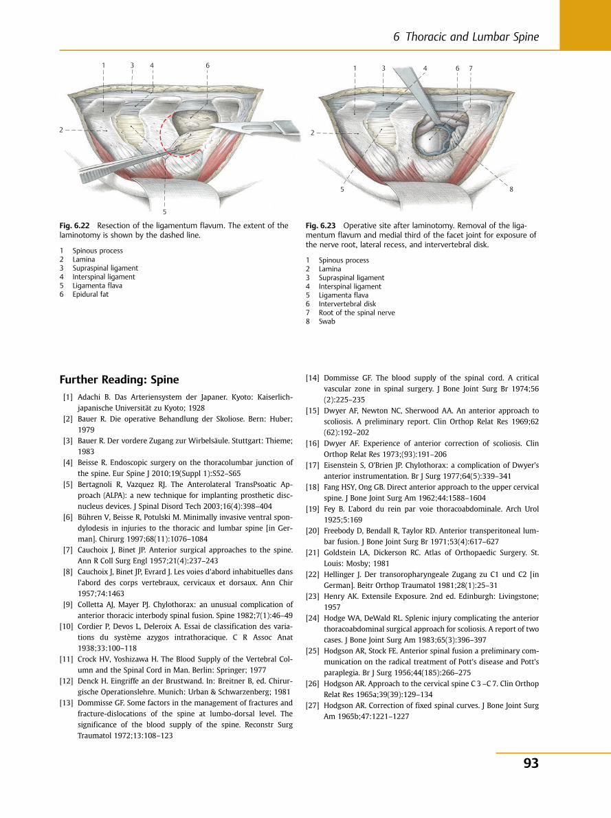
Further Reading: Spine[1] Adachi B. Das Arteriensystem der Japaner. Kyoto: Kaiserlich-
japanische Universität zu Kyoto; 1928[2] Bauer R. Die operative Behandlung der Skoliose. Bern: Huber;
1979[3] Bauer R. Der vordere Zugang zur Wirbelsäule. Stuttgart: Thieme;
1983[4] Beisse R. Endoscopic surgery on the thoracolumbar junction of
the spine. Eur Spine J 2010;19(Suppl 1):S52–S65[5] Bertagnoli R, Vazquez RJ. The Anterolateral TransPsoatic Ap-
proach (ALPA): a new technique for implanting prosthetic disc-nucleus devices. J Spinal Disord Tech 2003;16(4):398–404
[6] Bühren V, Beisse R, Potulski M. Minimally invasive ventral spon-dylodesis in injuries to the thoracic and lumbar spine [in Ger-man]. Chirurg 1997;68(11):1076–1084
[7] Cauchoix J, Binet JP. Anterior surgical approaches to the spine.Ann R Coll Surg Engl 1957;21(4):237–243
[8] Cauchoix J, Binet JP, Evrard J. Les voies d’abord inhabituelles dansl’abord des corps vertebraux, cervicaux et dorsaux. Ann Chir1957;74:1463
[9] Colletta AJ, Mayer PJ. Chylothorax: an unusual complication ofanterior thoracic interbody spinal fusion. Spine 1982;7(1):46–49
[10] Cordier P, Devos L, Deleroix A. Essai de classification des varia-tions du système azygos intrathoracique. C R Assoc Anat1938;33:100–118
[11] Crock HV, Yoshizawa H. The Blood Supply of the Vertebral Col-umn and the Spinal Cord in Man. Berlin: Springer; 1977
[12] Denck H. Eingriffe an der Brustwand. In: Breitner B, ed. Chirur-gische Operationslehre. Munich: Urban & Schwarzenberg; 1981
[13] Dommisse GF. Some factors in the management of fractures andfracture-dislocations of the spine at lumbo-dorsal level. Thesignificance of the blood supply of the spine. Reconstr SurgTraumatol 1972;13:108–123
Fig. 6.22 Resection of the ligamentum flavum. The extent of thelaminotomy is shown by the dashed line.
1 Spinous process2 Lamina3 Supraspinal ligament4 Interspinal ligament5 Ligamenta flava6 Epidural fat
Fig. 6.23 Operative site after laminotomy. Removal of the liga-mentum flavum and medial third of the facet joint for exposure ofthe nerve root, lateral recess, and intervertebral disk.
1 Spinous process2 Lamina3 Supraspinal ligament4 Interspinal ligament5 Ligamenta flava6 Intervertebral disk7 Root of the spinal nerve8 Swab
431
2
5
6 431
2
5
6 7
8
[14] Dommisse GF. The blood supply of the spinal cord. A criticalvascular zone in spinal surgery. J Bone Joint Surg Br 1974;56(2):225–235
[15] Dwyer AF, Newton NC, Sherwood AA. An anterior approach toscoliosis. A preliminary report. Clin Orthop Relat Res 1969;62(62):192–202
[16] Dwyer AF. Experience of anterior correction of scoliosis. ClinOrthop Relat Res 1973;(93):191–206
[17] Eisenstein S, O’Brien JP. Chylothorax: a complication of Dwyer’santerior instrumentation. Br J Surg 1977;64(5):339–341
[18] Fang HSY, Ong GB. Direct anterior approach to the upper cervicalspine. J Bone Joint Surg Am 1962;44:1588–1604
[19] Fey B. L’abord du rein par voie thoracoabdominale. Arch Urol1925;5:169
[20] Freebody D, Bendall R, Taylor RD. Anterior transperitoneal lum-bar fusion. J Bone Joint Surg Br 1971;53(4):617–627
[21] Goldstein LA, Dickerson RC. Atlas of Orthopaedic Surgery. St.Louis: Mosby; 1981
[22] Hellinger J. Der transoropharyngeale Zugang zu C1 und C2 [inGerman]. Beitr Orthop Traumatol 1981;28(1):25–31
[23] Henry AK. Extensile Exposure. 2nd ed. Edinburgh: Livingstone;1957
[24] Hodge WA, DeWald RL. Splenic injury complicating the anteriorthoracoabdominal surgical approach for scoliosis. A report of twocases. J Bone Joint Surg Am 1983;65(3):396–397
[25] Hodgson AR, Stock FE. Anterior spinal fusion a preliminary com-munication on the radical treatment of Pott’s disease and Pott’sparaplegia. Br J Surg 1956;44(185):266–275
[26] Hodgson AR. Approach to the cervical spine C 3 –C 7. Clin OrthopRelat Res 1965a;39(39):129–134
[27] Hodgson AR. Correction of fixed spinal curves. J Bone Joint SurgAm 1965b;47:1221–1227
93
6 Thoracic and Lumbar Spine
[28] Hodgson AR, Yau ACMC. Anterior surgical Approaches to the Spi-nal Column. In: Apley AG, ed. Recent Advances in Orthopedics.London: Churchill; 1969
[29] Hughes FA. Resection of the 12th rib in the surgical approach tothe renal fossa. J Urol 1949;61(2):159–162
[30] Kirkaldy-Willis WH, Thomas TG. Anterior approaches in the di-agnosis and treatment of infections to the vertebral bodies. JBone Joint Surg Am 1965;47:87–110
[31] Lagevarianten KS. Lage- und Formveränderungen der Pars tho-racalis des Ductus thoracicus. Fortschr Röntgenstr 1975;122(1):1–5
[32] Louis R. Surgery of the Spine. Berlin: Springer; 1983[33] McAfee PC, Regan JJ, Geis WP, Fedder IL. Minimally invasive an-
terior retroperitoneal approach to the lumbar spine. Emphasis onthe lateral BAK. Spine 1998;23(13):1476–1484
[34] Mayer HM. A new microsurgical technique for minimally inva-sive anterior lumbar interbody fusion. Spine 1997;22(6):691–699, discussion 700
[35] Mayer HM. The ALIF concept. Eur Spine J 2000;9(Suppl 1):S35–S43
[36] Mayer HM. Microsurgical Anterior Approach to T5 –T10 (mini-TTA). In: Mayer HM, ed. Minimally Invasive Spine Surgery: aSurgical Manual. Berlin: Springer; 2005:129–137
[37] Mirbaha MM. Anterior approach to the thoraco-lumbar junctionof the spine by a retroperitoneal-extrapleural technic. Clin Or-thop Relat Res 1973;(91):41–47
[38] Moe JH, Winter RB, Bradford DS, Lonstein JE. Scoliosis and OtherSpinal Deformities. Philadelphia: Saunders;1978
[39] Nagamatsu G. Dorso-lumbar approach to the kidney and adrenalwith osteoplastic flap. J Urol 1950;63(4):569–581
[40] Nanson EM. The anterior approach to upper dorsal sympathec-tomy. Surg Gynecol Obstet 1957;104(1):118–120
[41] Pimenta L. Lateral endoscopic transpsoas retroperitoneal ap-proach for lumbar spine surgery. VIII Brazilian Society Congresson Spine Pathology, May 2001; Belo Horizonte, Brazil
[42] Platzer W. Atlas der topographischen Anatomie. Stuttgart:Thieme; 1982
[43] Platzer W. Bewegungsapparat. 4th ed. Stuttgart: Thieme; 1984.Taschenatlas der Anatomie; Band 1
[44] Riley LH Jr. Surgical approaches to the anterior structures of thecervical spine. Clin Orthop Relat Res 1973;(91):16–20
[45] Riseborough EJ, Herndon JH. Scoliosis and Other Deformities ofthe Axial Skeleton. Boston: Little Brown; 1975
[46] Rosenthal D, Rosenthal R, de Simone A. Removal of a protrudedthoracic disc using microsurgical endoscopy. A new technique.Spine 1994;19(9):1087–1091
[47] Salcman M, Jamaris J, Leveque H, Ducker TB. Transoral cervicalcorpectomy with the aid of the microscope. Spine 1979;4(3):209–212
[48] Seddon HK. Pott’s Paraplegia. In: Platt H, ed. Modern Trends inOrthopedics. London: Butterworth; 1956
[49] Southwick WO, Robinson RA. Surgical approaches to the verte-bral bodies in the cervical and lumbar regions. J Bone Joint SurgAm 1957;39-A(3):631–644
[50] Verbiest H. Anterolateral operations for fractures and disloca-tions in the middle and lower parts of the cervical spine. Reportof a series of forty-seven cases. J Bone Joint Surg Am 1969;51(8):1489–1530
[51] Whitesides TE Jr, Kelly RP. Lateral approach to the upper cervicalspine for anterior fusion. South Med J 1966;59(8):879–883
[52] Wiltse LL, Bateman JG, Hutchinson RH, Nelson WE. The paraspi-nal sacrospinalis-splitting approach to the lumbar spine. J BoneJoint Surg Am 1968;50(5):919–926
[53] Wiltse LL. The paraspinal sacrospinalis-splitting approach to thelumbar spine. Clin Orthop Relat Res 1973;(91):48–57
94
Spine, Posterior Approaches
Pelvis and Lower Extremity
7 Pelvis: Pelvic Ring 96
8 Pelvis: Acetabulum 105
9 Hip Joint 124
10 Femur 154
11 Knee 176
12 Lower Leg 199
13 Foot 222
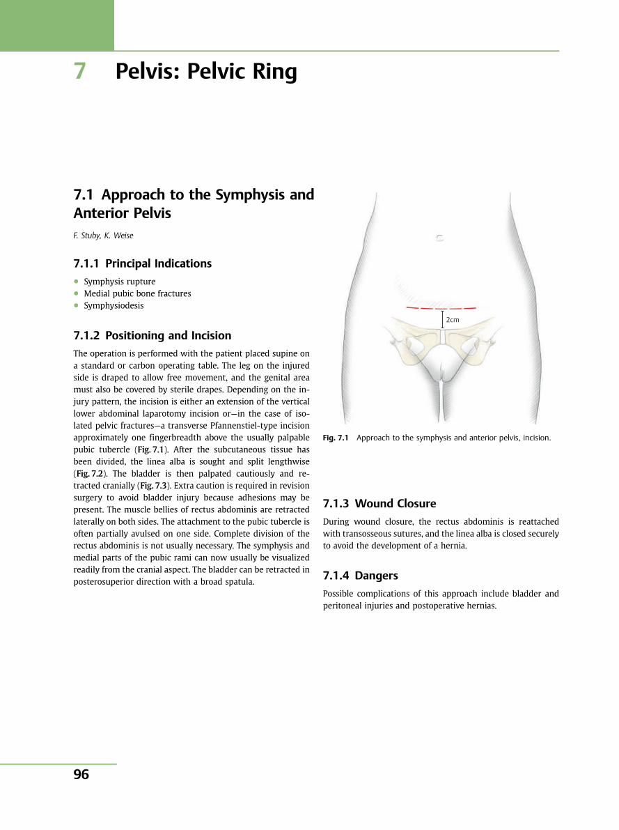
7 Pelvis: Pelvic Ring
7.1 Approach to the Symphysis andAnterior PelvisF. Stuby, K. Weise
7.1.1 Principal Indications● Symphysis rupture● Medial pubic bone fractures● Symphysiodesis
7.1.2 Positioning and Incision
The operation is performed with the patient placed supine ona standard or carbon operating table. The leg on the injuredside is draped to allow free movement, and the genital areamust also be covered by sterile drapes. Depending on the in-jury pattern, the incision is either an extension of the verticallower abdominal laparotomy incision or—in the case of iso-lated pelvic fractures—a transverse Pfannenstiel-type incisionapproximately one fingerbreadth above the usually palpablepubic tubercle (Fig. 7.1). After the subcutaneous tissue hasbeen divided, the linea alba is sought and split lengthwise(Fig. 7.2). The bladder is then palpated cautiously and re-tracted cranially (Fig. 7.3). Extra caution is required in revisionsurgery to avoid bladder injury because adhesions may bepresent. The muscle bellies of rectus abdominis are retractedlaterally on both sides. The attachment to the pubic tubercle isoften partially avulsed on one side. Complete division of therectus abdominis is not usually necessary. The symphysis andmedial parts of the pubic rami can now usually be visualizedreadily from the cranial aspect. The bladder can be retracted inposterosuperior direction with a broad spatula.
7.1.3 Wound Closure
During wound closure, the rectus abdominis is reattachedwith transosseous sutures, and the linea alba is closed securelyto avoid the development of a hernia.
7.1.4 Dangers
Possible complications of this approach include bladder andperitoneal injuries and postoperative hernias.
2cm
Fig. 7.1 Approach to the symphysis and anterior pelvis, incision.
Pelvis and Lower Extremity
96
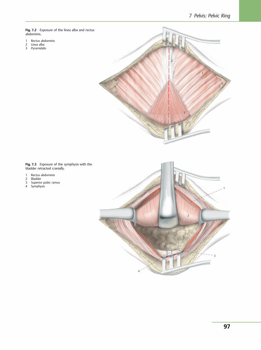
1
2
3
Fig. 7.2 Exposure of the linea alba and rectusabdominis.
1 Rectus abdominis2 Linea alba3 Pyramidalis
1
3
4
2
Fig. 7.3 Exposure of the symphysis with thebladder retracted cranially.
1 Rectus abdominis2 Bladder3 Superior pubic ramus4 Symphysis
7 Pelvis: Pelvic Ring
97
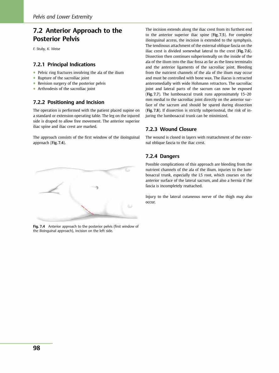
7.2 Anterior Approach to thePosterior PelvisF. Stuby, K. Weise
7.2.1 Principal Indications● Pelvic ring fractures involving the ala of the ilium● Rupture of the sacroiliac joint● Revision surgery of the posterior pelvis● Arthrodesis of the sacroiliac joint
7.2.2 Positioning and Incision
The operation is performed with the patient placed supine ona standard or extension operating table. The leg on the injuredside is draped to allow free movement. The anterior superioriliac spine and iliac crest are marked.
The approach consists of the first window of the ilioinguinalapproach (Fig. 7.4).
The incision extends along the iliac crest from its furthest endto the anterior superior iliac spine (Fig. 7.5). For completeilioinguinal access, the incision is extended to the symphysis.The tendinous attachment of the external oblique fascia on theiliac crest is divided somewhat lateral to the crest (Fig. 7.6).Dissection then continues subperiosteally on the inside of theala of the ilium into the iliac fossa as far as the linea terminalisand the anterior ligaments of the sacroiliac joint. Bleedingfrom the nutrient channels of the ala of the ilium may occurand must be controlled with bone wax. The iliacus is retractedanteromedially with wide Hohmann retractors. The sacroiliacjoint and lateral parts of the sacrum can now be exposed(Fig. 7.7). The lumbosacral trunk runs approximately 15–20mm medial to the sacroiliac joint directly on the anterior sur-face of the sacrum and should be spared during dissection(Fig. 7.8). If dissection is strictly subperiosteal, the risk of in-juring the lumbosacral trunk can be minimized.
7.2.3 Wound Closure
The wound is closed in layers with reattachment of the exter-nal oblique fascia to the iliac crest.
7.2.4 Dangers
Possible complications of this approach are bleeding from thenutrient channels of the ala of the ilium, injuries to the lum-bosacral trunk, especially the L5 root, which courses on theanterior surface of the lateral sacrum, and also a hernia if thefascia is incompletely reattached.
Injury to the lateral cutaneous nerve of the thigh may alsooccur.
Fig. 7.4 Anterior approach to the posterior pelvis (first window ofthe ilioinguinal approach), incision on the left side.
Pelvis and Lower Extremity
98
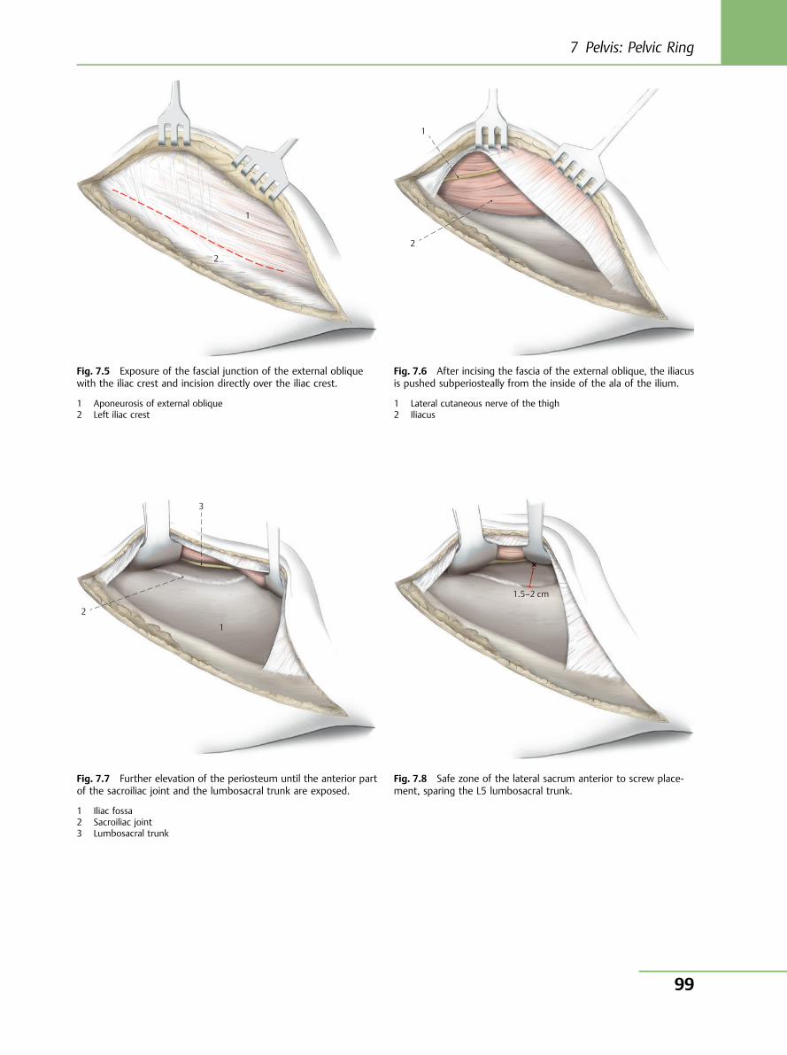
1
2
Fig. 7.5 Exposure of the fascial junction of the external obliquewith the iliac crest and incision directly over the iliac crest.
1 Aponeurosis of external oblique2 Left iliac crest
1
2
Fig. 7.6 After incising the fascia of the external oblique, the iliacusis pushed subperiosteally from the inside of the ala of the ilium.
1 Lateral cutaneous nerve of the thigh2 Iliacus
1
3
2
Fig. 7.7 Further elevation of the periosteum until the anterior partof the sacroiliac joint and the lumbosacral trunk are exposed.
1 Iliac fossa2 Sacroiliac joint3 Lumbosacral trunk
1.5–2 cm
Fig. 7.8 Safe zone of the lateral sacrum anterior to screw place-ment, sparing the L5 lumbosacral trunk.
7 Pelvis: Pelvic Ring
99
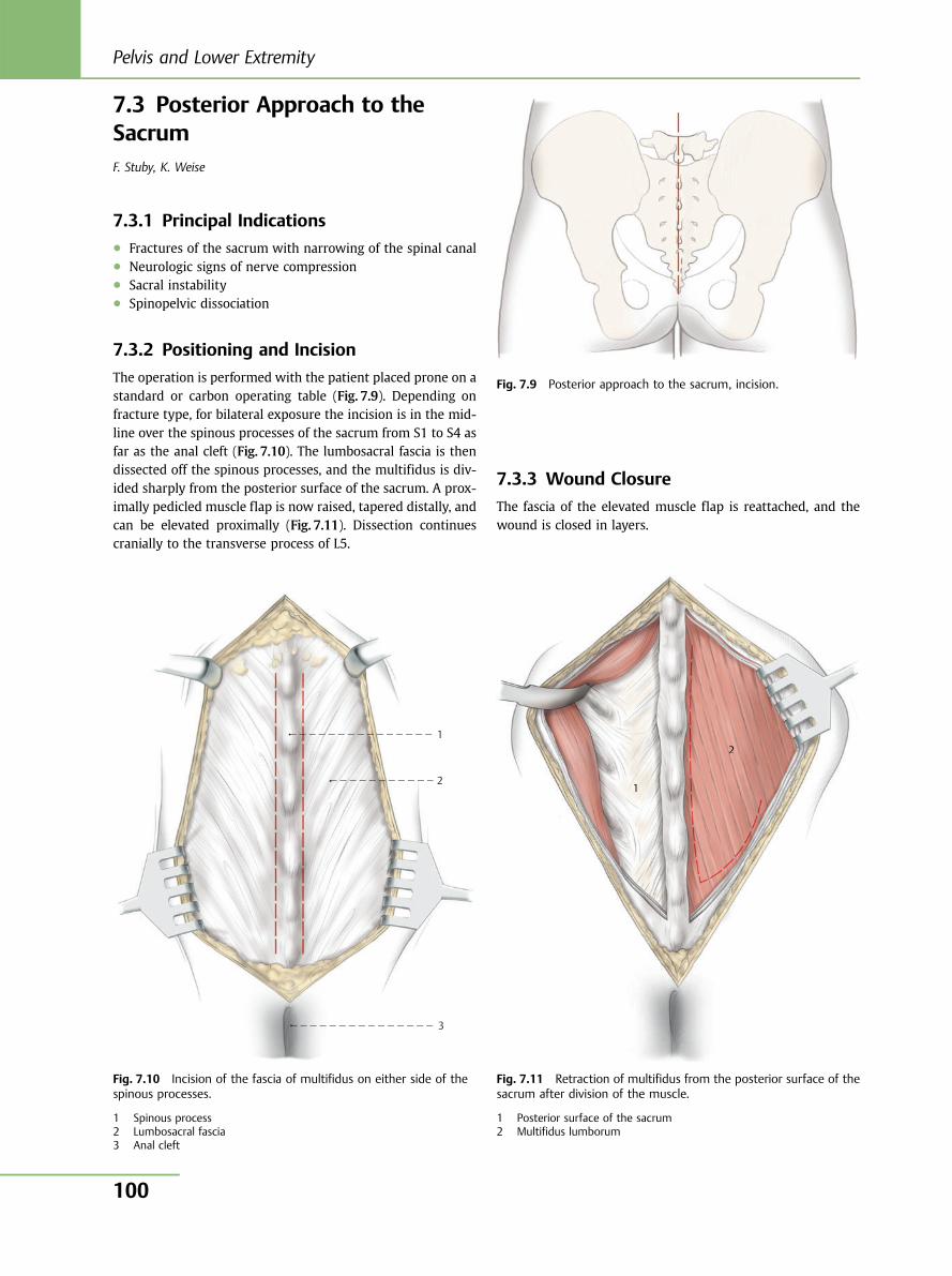
7.3 Posterior Approach to theSacrumF. Stuby, K. Weise
7.3.1 Principal Indications● Fractures of the sacrum with narrowing of the spinal canal● Neurologic signs of nerve compression● Sacral instability● Spinopelvic dissociation
7.3.2 Positioning and Incision
The operation is performed with the patient placed prone on astandard or carbon operating table (Fig. 7.9). Depending onfracture type, for bilateral exposure the incision is in the mid-line over the spinous processes of the sacrum from S1 to S4 asfar as the anal cleft (Fig. 7.10). The lumbosacral fascia is thendissected off the spinous processes, and the multifidus is div-ided sharply from the posterior surface of the sacrum. A prox-imally pedicled muscle flap is now raised, tapered distally, andcan be elevated proximally (Fig. 7.11). Dissection continuescranially to the transverse process of L5.
7.3.3 Wound Closure
The fascia of the elevated muscle flap is reattached, and thewound is closed in layers.
Fig. 7.9 Posterior approach to the sacrum, incision.
1
2
3
Fig. 7.10 Incision of the fascia of multifidus on either side of thespinous processes.
1 Spinous process2 Lumbosacral fascia3 Anal cleft
1
2
111
222222222222
Fig. 7.11 Retraction of multifidus from the posterior surface of thesacrum after division of the muscle.
1 Posterior surface of the sacrum2 Multifidus lumborum
Pelvis and Lower Extremity
100
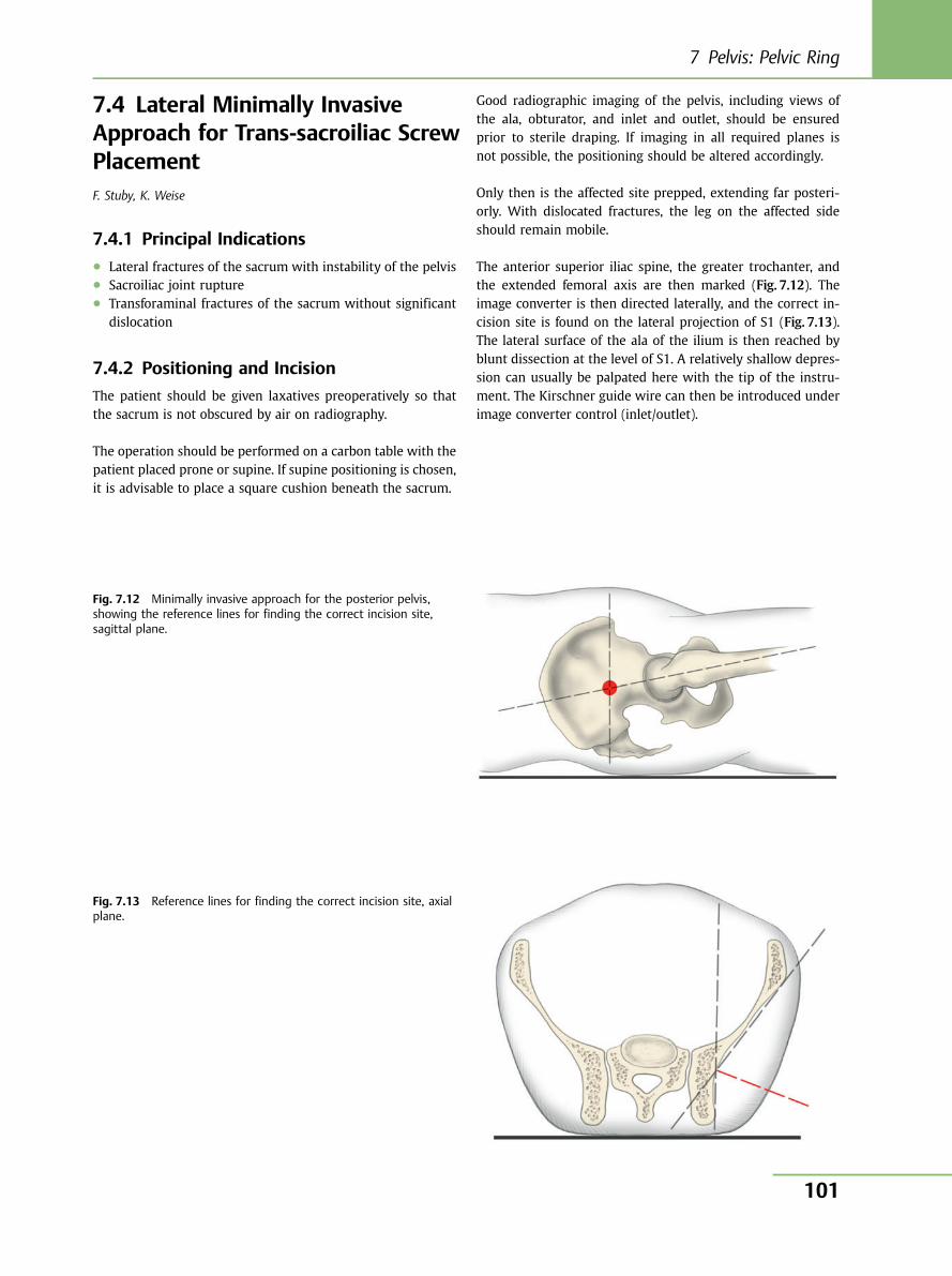
7.4 Lateral Minimally InvasiveApproach for Trans-sacroiliac ScrewPlacementF. Stuby, K. Weise
7.4.1 Principal Indications● Lateral fractures of the sacrum with instability of the pelvis● Sacroiliac joint rupture● Transforaminal fractures of the sacrum without significant
dislocation
7.4.2 Positioning and Incision
The patient should be given laxatives preoperatively so thatthe sacrum is not obscured by air on radiography.
The operation should be performed on a carbon table with thepatient placed prone or supine. If supine positioning is chosen,it is advisable to place a square cushion beneath the sacrum.
Good radiographic imaging of the pelvis, including views ofthe ala, obturator, and inlet and outlet, should be ensuredprior to sterile draping. If imaging in all required planes isnot possible, the positioning should be altered accordingly.
Only then is the affected site prepped, extending far posteri-orly. With dislocated fractures, the leg on the affected sideshould remain mobile.
The anterior superior iliac spine, the greater trochanter, andthe extended femoral axis are then marked (Fig. 7.12). Theimage converter is then directed laterally, and the correct in-cision site is found on the lateral projection of S1 (Fig. 7.13).The lateral surface of the ala of the ilium is then reached byblunt dissection at the level of S1. A relatively shallow depres-sion can usually be palpated here with the tip of the instru-ment. The Kirschner guide wire can then be introduced underimage converter control (inlet/outlet).
Fig. 7.12 Minimally invasive approach for the posterior pelvis,showing the reference lines for finding the correct incision site,sagittal plane.
Fig. 7.13 Reference lines for finding the correct incision site, axialplane.
7 Pelvis: Pelvic Ring
101
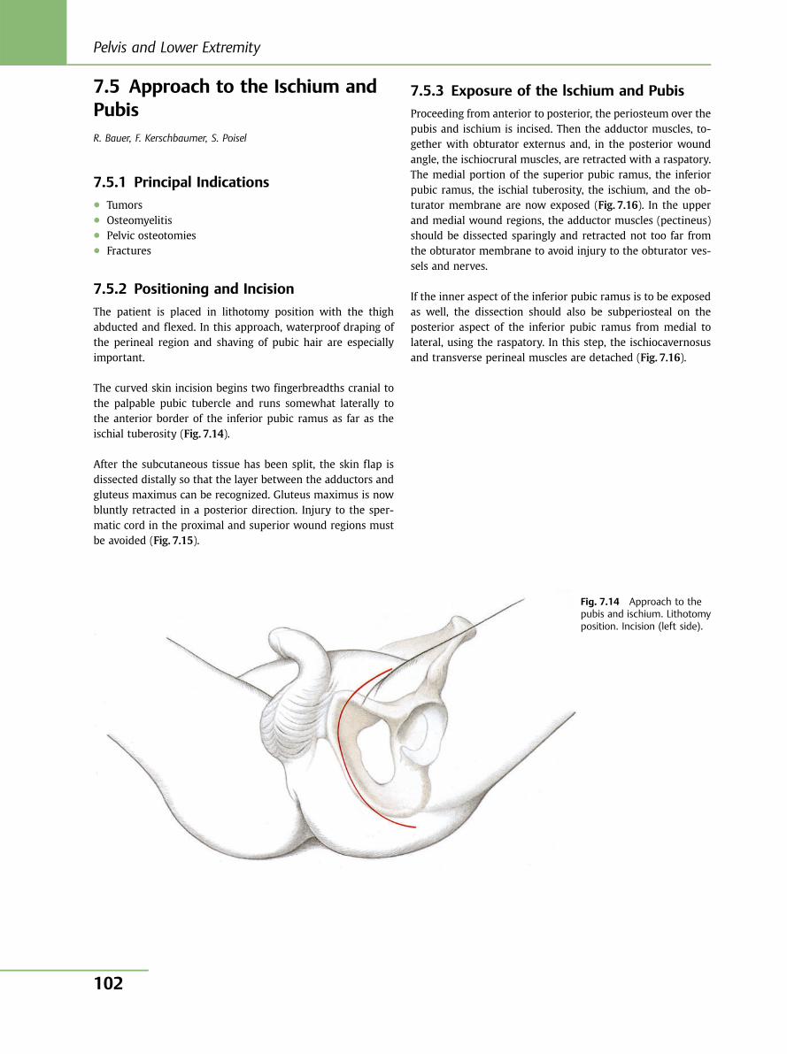
7.5 Approach to the Ischium andPubisR. Bauer, F. Kerschbaumer, S. Poisel
7.5.1 Principal Indications● Tumors● Osteomyelitis● Pelvic osteotomies● Fractures
7.5.2 Positioning and Incision
The patient is placed in lithotomy position with the thighabducted and flexed. In this approach, waterproof draping ofthe perineal region and shaving of pubic hair are especiallyimportant.
The curved skin incision begins two fingerbreadths cranial tothe palpable pubic tubercle and runs somewhat laterally tothe anterior border of the inferior pubic ramus as far as theischial tuberosity (Fig. 7.14).
After the subcutaneous tissue has been split, the skin flap isdissected distally so that the layer between the adductors andgluteus maximus can be recognized. Gluteus maximus is nowbluntly retracted in a posterior direction. Injury to the sper-matic cord in the proximal and superior wound regions mustbe avoided (Fig. 7.15).
7.5.3 Exposure of the lschium and Pubis
Proceeding from anterior to posterior, the periosteum over thepubis and ischium is incised. Then the adductor muscles, to-gether with obturator externus and, in the posterior woundangle, the ischiocrural muscles, are retracted with a raspatory.The medial portion of the superior pubic ramus, the inferiorpubic ramus, the ischial tuberosity, the ischium, and the ob-turator membrane are now exposed (Fig. 7.16). In the upperand medial wound regions, the adductor muscles (pectineus)should be dissected sparingly and retracted not too far fromthe obturator membrane to avoid injury to the obturator ves-sels and nerves.
If the inner aspect of the inferior pubic ramus is to be exposedas well, the dissection should also be subperiosteal on theposterior aspect of the inferior pubic ramus from medial tolateral, using the raspatory. In this step, the ischiocavernosusand transverse perineal muscles are detached (Fig. 7.16).
Fig. 7.14 Approach to thepubis and ischium. Lithotomyposition. Incision (left side).
Pelvis and Lower Extremity
102
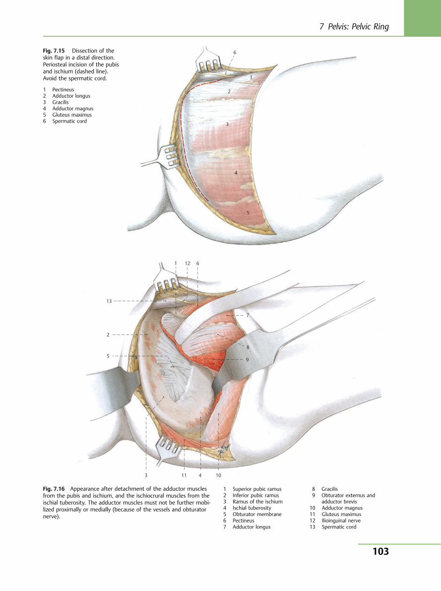
6
5
4
3
1
2
Fig. 7.15 Dissection of theskin flap in a distal direction.Periosteal incision of the pubisand ischium (dashed line).Avoid the spermatic cord.
1 Pectineus2 Adductor longus3 Gracilis4 Adductor magnus5 Gluteus maximus6 Spermatic cord
10 11
12
13
9
8
7
6
5
4 3
1
2
Fig. 7.16 Appearance after detachment of the adductor musclesfrom the pubis and ischium, and the ischiocrural muscles from theischial tuberosity. The adductor muscles must not be further mobi-lized proximally or medially (because of the vessels and obturatornerve).
1 Superior pubic ramus2 Inferior pubic ramus3 Ramus of the ischium4 Ischial tuberosity5 Obturator membrane6 Pectineus7 Adductor longus
8 Gracilis9 Obturator externus and
adductor brevis10 Adductor magnus11 Gluteus maximus12 Ilioinguinal nerve13 Spermatic cord
7 Pelvis: Pelvic Ring
103
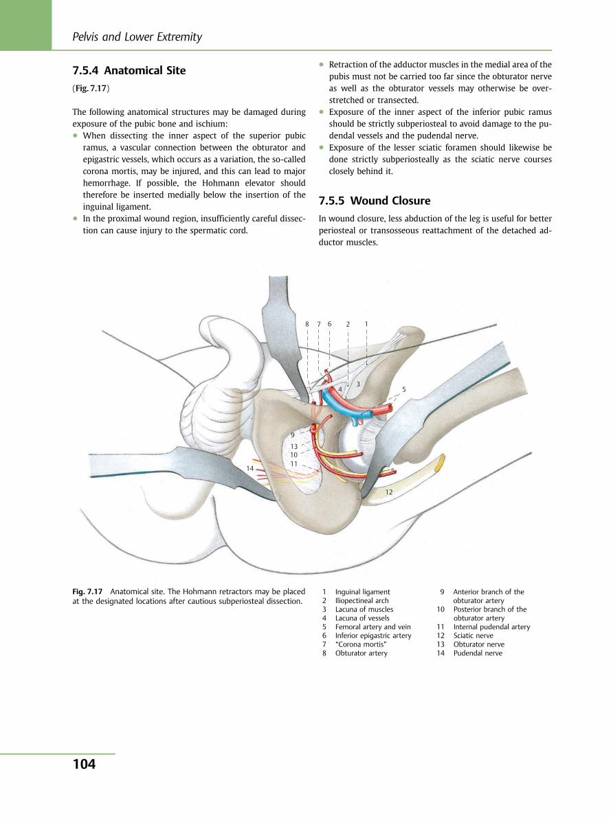
7.5.4 Anatomical Site
(Fig. 7.17)
The following anatomical structures may be damaged duringexposure of the pubic bone and ischium:● When dissecting the inner aspect of the superior pubic
ramus, a vascular connection between the obturator andepigastric vessels, which occurs as a variation, the so-calledcorona mortis, may be injured, and this can lead to majorhemorrhage. If possible, the Hohmann elevator shouldtherefore be inserted medially below the insertion of theinguinal ligament.
● In the proximal wound region, insufficiently careful dissec-tion can cause injury to the spermatic cord.
● Retraction of the adductor muscles in the medial area of thepubis must not be carried too far since the obturator nerveas well as the obturator vessels may otherwise be over-stretched or transected.
● Exposure of the inner aspect of the inferior pubic ramusshould be strictly subperiosteal to avoid damage to the pu-dendal vessels and the pudendal nerve.
● Exposure of the lesser sciatic foramen should likewise bedone strictly subperiosteally as the sciatic nerve coursesclosely behind it.
7.5.5 Wound Closure
In wound closure, less abduction of the leg is useful for betterperiosteal or transosseous reattachment of the detached ad-ductor muscles.
10 11
12
13
14
9
8 7 6
5 4 3
1 2
Fig. 7.17 Anatomical site. The Hohmann retractors may be placedat the designated locations after cautious subperiosteal dissection.
1 Inguinal ligament2 Iliopectineal arch3 Lacuna of muscles4 Lacuna of vessels5 Femoral artery and vein6 Inferior epigastric artery7 “Corona mortis”8 Obturator artery
9 Anterior branch of theobturator artery
10 Posterior branch of theobturator artery
11 Internal pudendal artery12 Sciatic nerve13 Obturator nerve14 Pudendal nerve
Pelvis and Lower Extremity
104
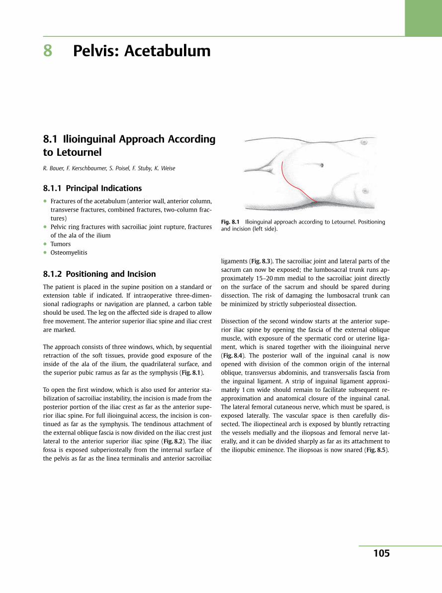
8 Pelvis: Acetabulum
8.1 Ilioinguinal Approach Accordingto LetournelR. Bauer, F. Kerschbaumer, S. Poisel, F. Stuby, K. Weise
8.1.1 Principal Indications● Fractures of the acetabulum (anterior wall, anterior column,
transverse fractures, combined fractures, two-column frac-tures)
● Pelvic ring fractures with sacroiliac joint rupture, fracturesof the ala of the ilium
● Tumors● Osteomyelitis
8.1.2 Positioning and Incision
The patient is placed in the supine position on a standard orextension table if indicated. If intraoperative three-dimen-sional radiographs or navigation are planned, a carbon tableshould be used. The leg on the affected side is draped to allowfree movement. The anterior superior iliac spine and iliac crestare marked.
The approach consists of three windows, which, by sequentialretraction of the soft tissues, provide good exposure of theinside of the ala of the ilium, the quadrilateral surface, andthe superior pubic ramus as far as the symphysis (Fig. 8.1).
To open the first window, which is also used for anterior sta-bilization of sacroiliac instability, the incision is made from theposterior portion of the iliac crest as far as the anterior supe-rior iliac spine. For full ilioinguinal access, the incision is con-tinued as far as the symphysis. The tendinous attachment ofthe external oblique fascia is now divided on the iliac crest justlateral to the anterior superior iliac spine (Fig. 8.2). The iliacfossa is exposed subperiosteally from the internal surface ofthe pelvis as far as the linea terminalis and anterior sacroiliac
ligaments (Fig. 8.3). The sacroiliac joint and lateral parts of thesacrum can now be exposed; the lumbosacral trunk runs ap-proximately 15–20mm medial to the sacroiliac joint directlyon the surface of the sacrum and should be spared duringdissection. The risk of damaging the lumbosacral trunk canbe minimized by strictly subperiosteal dissection.
Dissection of the second window starts at the anterior supe-rior iliac spine by opening the fascia of the external obliquemuscle, with exposure of the spermatic cord or uterine liga-ment, which is snared together with the ilioinguinal nerve(Fig. 8.4). The posterior wall of the inguinal canal is nowopened with division of the common origin of the internaloblique, transversus abdominis, and transversalis fascia fromthe inguinal ligament. A strip of inguinal ligament approxi-mately 1 cm wide should remain to facilitate subsequent re-approximation and anatomical closure of the inguinal canal.The lateral femoral cutaneous nerve, which must be spared, isexposed laterally. The vascular space is then carefully dis-sected. The iliopectineal arch is exposed by bluntly retractingthe vessels medially and the iliopsoas and femoral nerve lat-erally, and it can be divided sharply as far as its attachment tothe iliopubic eminence. The iliopsoas is now snared (Fig. 8.5).
Fig. 8.1 Ilioinguinal approach according to Letournel. Positioningand incision (left side).
8 Pelvis: Acetabulum
105
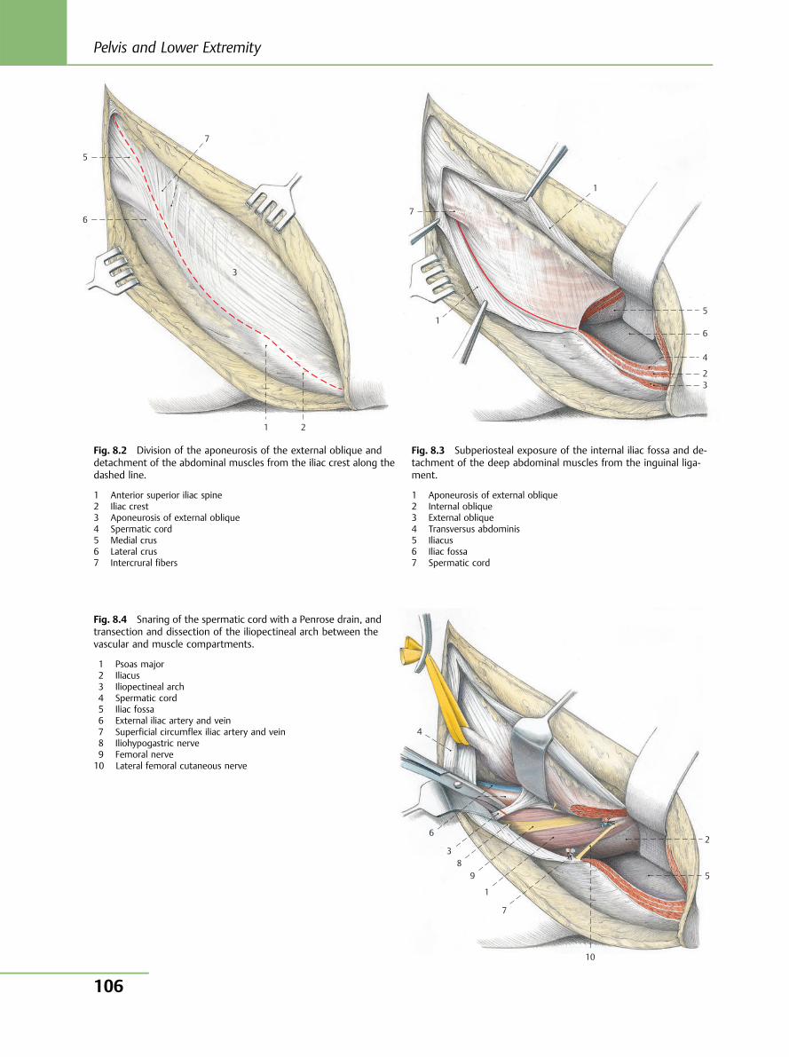
5
6
7
3
1 2
Fig. 8.2 Division of the aponeurosis of the external oblique anddetachment of the abdominal muscles from the iliac crest along thedashed line.
1 Anterior superior iliac spine2 Iliac crest3 Aponeurosis of external oblique4 Spermatic cord5 Medial crus6 Lateral crus7 Intercrural fibers
3 2
4
6
5
1
1
7
Fig. 8.3 Subperiosteal exposure of the internal iliac fossa and de-tachment of the deep abdominal muscles from the inguinal liga-ment.
1 Aponeurosis of external oblique2 Internal oblique3 External oblique4 Transversus abdominis5 Iliacus6 Iliac fossa7 Spermatic cord
4
6
3 8
9
1
7
10
5
2
Fig. 8.4 Snaring of the spermatic cord with a Penrose drain, andtransection and dissection of the iliopectineal arch between thevascular and muscle compartments.
1 Psoas major2 Iliacus3 Iliopectineal arch4 Spermatic cord5 Iliac fossa6 External iliac artery and vein7 Superficial circumflex iliac artery and vein8 Iliohypogastric nerve9 Femoral nerve10 Lateral femoral cutaneous nerve
Pelvis and Lower Extremity
106
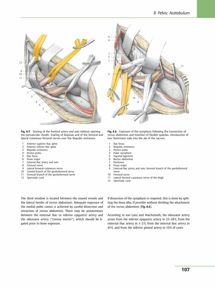
The third window is located between the snared vessels andthe lateral border of rectus abdominis. Adequate exposure ofthe medial pubic ramus is achieved by careful dissection andretraction of rectus abdominis. There may be anastomosesbetween the external iliac or inferior epigastric artery andthe obturator artery (“corona mortis”), which should be li-gated prior to bone exposure.
If dissection of the symphysis is required, this is done by split-ting the linea alba, if possible without dividing the attachmentof the rectus abdominis (Fig. 8.6).
According to von Lanz and Wachsmuth, the obturator arteryarises from the inferior epigastric artery in 22–28%, from theexternal iliac artery in 1–2%, from the internal iliac artery in45%, and from the inferior gluteal artery in 10% of cases.
12
10
11
7 3
8 6
2 9
1
5
4
Fig. 8.5 Snaring of the femoral artery and vein without openingthe perivascular sheath. Snaring of iliopsoas and of the femoral andlateral cutaneous femoral nerves over the iliopubic eminence.
1 Anterior superior iliac spine2 Anterior inferior iliac spine3 Iliopubic eminence4 Pecten pubis5 Iliac fossa6 Psoas major7 External iliac artery and vein8 Femoral nerve9 Lateral femoral cutaneous nerve10 Genital branch of the genitofemoral nerve11 Femoral branch of the genitofemoral nerve12 Spermatic cord
6 4
357
9
10
8
2
1211
1
Fig. 8.6 Exposure of the symphysis following the transection ofrectus abdominis and insertion of flexible spatulas. Introduction oftwo Steinmann nails into the ala of the sacrum.
1 Iliac fossa2 Iliopubic eminence3 Pecten pubis4 Pubic symphysis5 Inguinal ligament6 Rectus abdominis7 Pectineus8 Psoas major9 External iliac artery and vein, femoral branch of the genitofemoral
nerve10 Femoral nerve11 Lateral femoral cutaneous nerve of the thigh12 Spermatic cord
8 Pelvis: Acetabulum
107
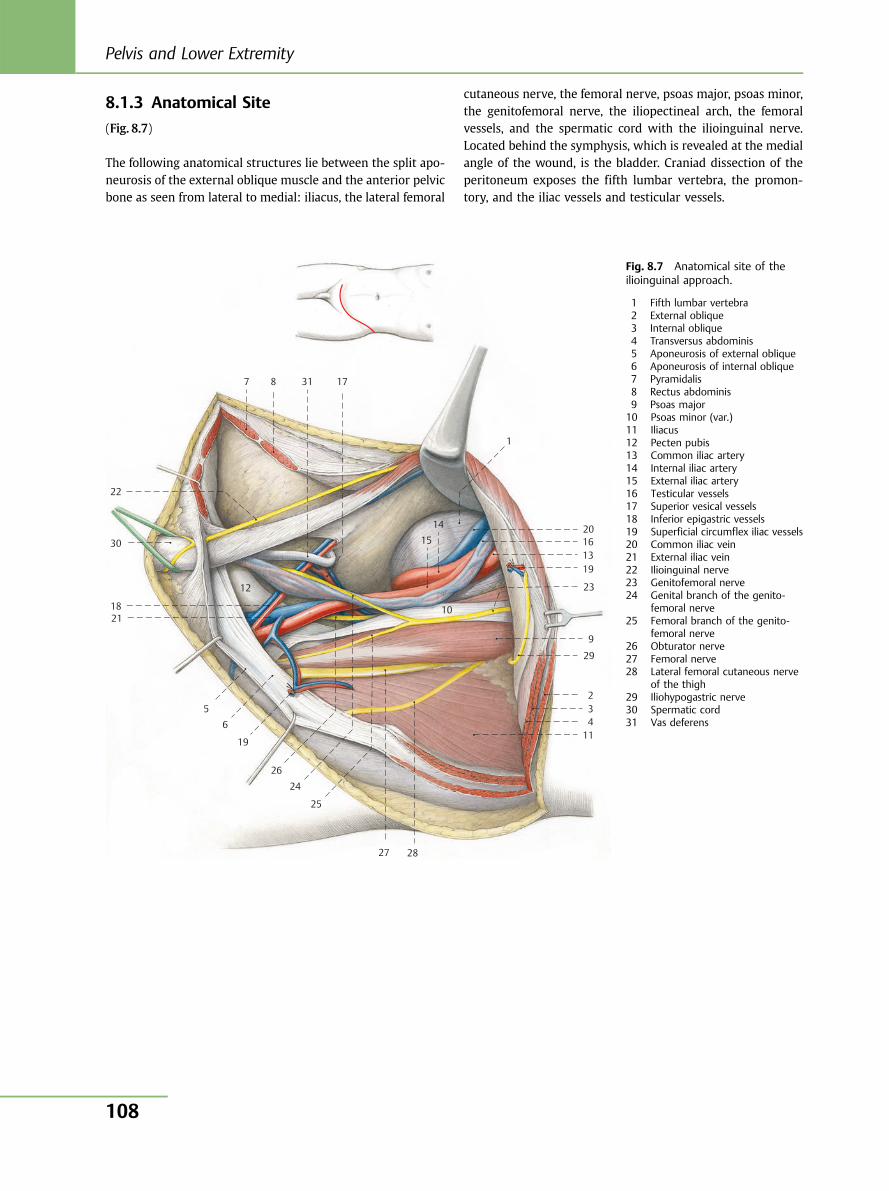
8.1.3 Anatomical Site
(Fig. 8.7)
The following anatomical structures lie between the split apo-neurosis of the external oblique muscle and the anterior pelvicbone as seen from lateral to medial: iliacus, the lateral femoral
cutaneous nerve, the femoral nerve, psoas major, psoas minor,the genitofemoral nerve, the iliopectineal arch, the femoralvessels, and the spermatic cord with the ilioinguinal nerve.Located behind the symphysis, which is revealed at the medialangle of the wound, is the bladder. Craniad dissection of theperitoneum exposes the fifth lumbar vertebra, the promon-tory, and the iliac vessels and testicular vessels.
22
30
18
12
21
5 6
19
26 24
25
27 28
11 432
29
9
23
19
10
1514
1
173187
131620
Fig. 8.7 Anatomical site of theilioinguinal approach.
1 Fifth lumbar vertebra2 External oblique3 Internal oblique4 Transversus abdominis5 Aponeurosis of external oblique6 Aponeurosis of internal oblique7 Pyramidalis8 Rectus abdominis9 Psoas major10 Psoas minor (var.)11 Iliacus12 Pecten pubis13 Common iliac artery14 Internal iliac artery15 External iliac artery16 Testicular vessels17 Superior vesical vessels18 Inferior epigastric vessels19 Superficial circumflex iliac vessels20 Common iliac vein21 External iliac vein22 Ilioinguinal nerve23 Genitofemoral nerve24 Genital branch of the genito-
femoral nerve25 Femoral branch of the genito-
femoral nerve26 Obturator nerve27 Femoral nerve28 Lateral femoral cutaneous nerve
of the thigh29 Iliohypogastric nerve30 Spermatic cord31 Vas deferens
Pelvis and Lower Extremity
108
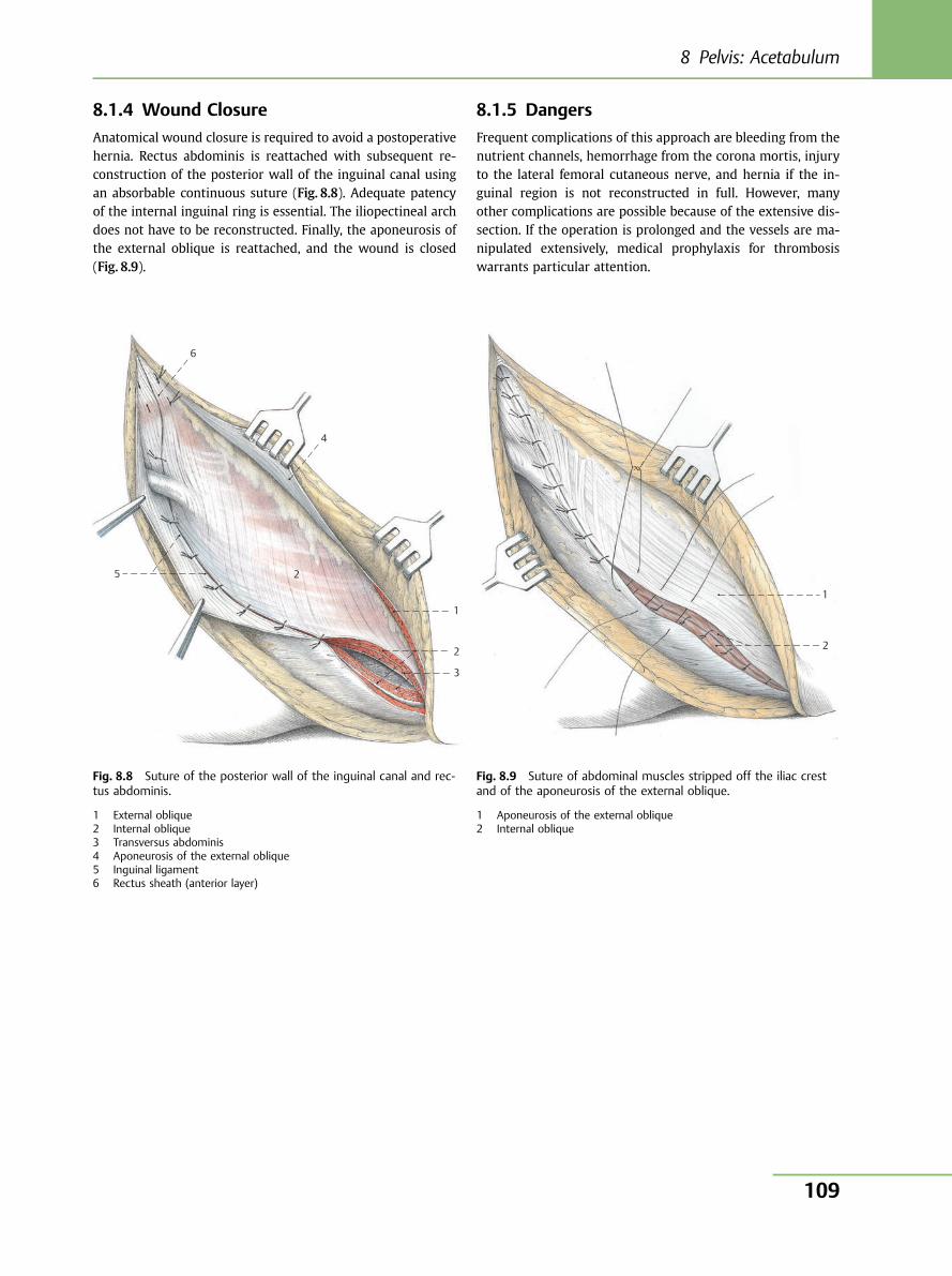
8.1.4 Wound Closure
Anatomical wound closure is required to avoid a postoperativehernia. Rectus abdominis is reattached with subsequent re-construction of the posterior wall of the inguinal canal usingan absorbable continuous suture (Fig. 8.8). Adequate patencyof the internal inguinal ring is essential. The iliopectineal archdoes not have to be reconstructed. Finally, the aponeurosis ofthe external oblique is reattached, and the wound is closed(Fig. 8.9).
8.1.5 Dangers
Frequent complications of this approach are bleeding from thenutrient channels, hemorrhage from the corona mortis, injuryto the lateral femoral cutaneous nerve, and hernia if the in-guinal region is not reconstructed in full. However, manyother complications are possible because of the extensive dis-section. If the operation is prolonged and the vessels are ma-nipulated extensively, medical prophylaxis for thrombosiswarrants particular attention.
Fig. 8.8 Suture of the posterior wall of the inguinal canal and rec-tus abdominis.
1 External oblique2 Internal oblique3 Transversus abdominis4 Aponeurosis of the external oblique5 Inguinal ligament6 Rectus sheath (anterior layer)
6
5
4
3
1
2
2
1
2
Fig. 8.9 Suture of abdominal muscles stripped off the iliac crestand of the aponeurosis of the external oblique.
1 Aponeurosis of the external oblique2 Internal oblique
8 Pelvis: Acetabulum
109
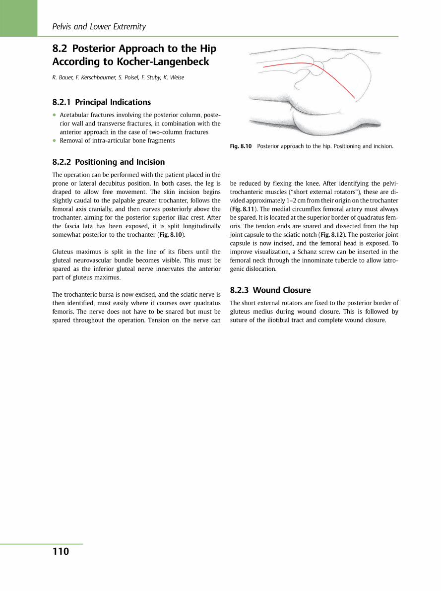
8.2 Posterior Approach to the HipAccording to Kocher-LangenbeckR. Bauer, F. Kerschbaumer, S. Poisel, F. Stuby, K. Weise
8.2.1 Principal Indications● Acetabular fractures involving the posterior column, poste-
rior wall and transverse fractures, in combination with theanterior approach in the case of two-column fractures
● Removal of intra-articular bone fragments
8.2.2 Positioning and Incision
The operation can be performed with the patient placed in theprone or lateral decubitus position. In both cases, the leg isdraped to allow free movement. The skin incision beginsslightly caudal to the palpable greater trochanter, follows thefemoral axis cranially, and then curves posteriorly above thetrochanter, aiming for the posterior superior iliac crest. Afterthe fascia lata has been exposed, it is split longitudinallysomewhat posterior to the trochanter (Fig. 8.10).
Gluteus maximus is split in the line of its fibers until thegluteal neurovascular bundle becomes visible. This must bespared as the inferior gluteal nerve innervates the anteriorpart of gluteus maximus.
The trochanteric bursa is now excised, and the sciatic nerve isthen identified, most easily where it courses over quadratusfemoris. The nerve does not have to be snared but must bespared throughout the operation. Tension on the nerve can
be reduced by flexing the knee. After identifying the pelvi-trochanteric muscles (“short external rotators”), these are di-vided approximately 1–2 cm from their origin on the trochanter(Fig. 8.11). The medial circumflex femoral artery must alwaysbe spared. It is located at the superior border of quadratus fem-oris. The tendon ends are snared and dissected from the hipjoint capsule to the sciatic notch (Fig. 8.12). The posterior jointcapsule is now incised, and the femoral head is exposed. Toimprove visualization, a Schanz screw can be inserted in thefemoral neck through the innominate tubercle to allow iatro-genic dislocation.
8.2.3 Wound Closure
The short external rotators are fixed to the posterior border ofgluteus medius during wound closure. This is followed bysuture of the iliotibial tract and complete wound closure.
Fig. 8.10 Posterior approach to the hip. Positioning and incision.
Pelvis and Lower Extremity
110
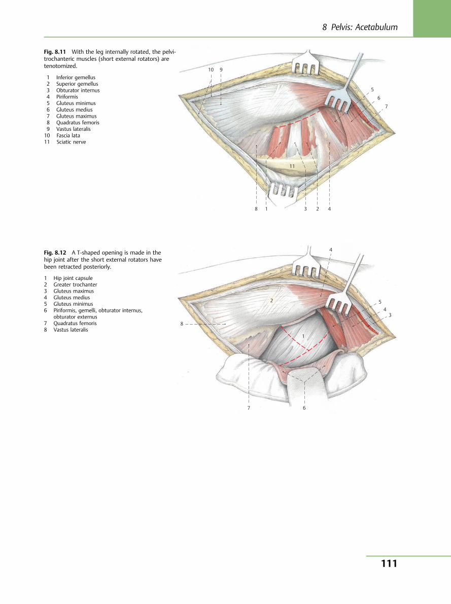
10
11
9
8
7
6
5
4 3 1 2
Fig. 8.11 With the leg internally rotated, the pelvi-trochanteric muscles (short external rotators) aretenotomized.
1 Inferior gemellus2 Superior gemellus3 Obturator internus4 Piriformis5 Gluteus minimus6 Gluteus medius7 Gluteus maximus8 Quadratus femoris9 Vastus lateralis10 Fascia lata11 Sciatic nerve
8
7 6
5 4
3
1
2
4 Fig. 8.12 A T-shaped opening is made in thehip joint after the short external rotators havebeen retracted posteriorly.
1 Hip joint capsule2 Greater trochanter3 Gluteus maximus4 Gluteus medius5 Gluteus minimus6 Piriformis, gemelli, obturator internus,
obturator externus7 Quadratus femoris8 Vastus lateralis
8 Pelvis: Acetabulum
111
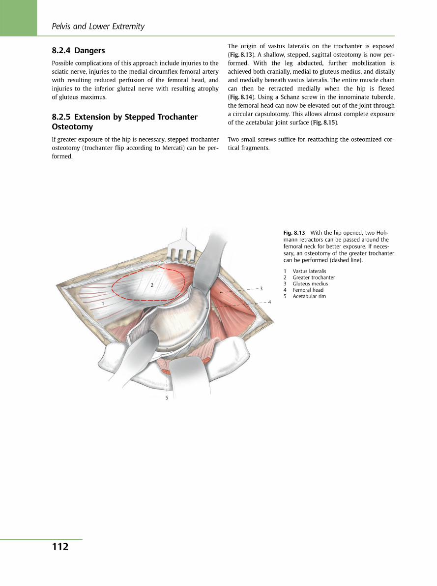
8.2.4 Dangers
Possible complications of this approach include injuries to thesciatic nerve, injuries to the medial circumflex femoral arterywith resulting reduced perfusion of the femoral head, andinjuries to the inferior gluteal nerve with resulting atrophyof gluteus maximus.
8.2.5 Extension by Stepped TrochanterOsteotomy
If greater exposure of the hip is necessary, stepped trochanterosteotomy (trochanter flip according to Mercati) can be per-formed.
The origin of vastus lateralis on the trochanter is exposed(Fig. 8.13). A shallow, stepped, sagittal osteotomy is now per-formed. With the leg abducted, further mobilization isachieved both cranially, medial to gluteus medius, and distallyand medially beneath vastus lateralis. The entire muscle chaincan then be retracted medially when the hip is flexed(Fig. 8.14). Using a Schanz screw in the innominate tubercle,the femoral head can now be elevated out of the joint througha circular capsulotomy. This allows almost complete exposureof the acetabular joint surface (Fig. 8.15).
Two small screws suffice for reattaching the osteomized cor-tical fragments.
5
3
4
2
1
Fig. 8.13 With the hip opened, two Hoh-mann retractors can be passed around thefemoral neck for better exposure. If neces-sary, an osteotomy of the greater trochantercan be performed (dashed line).
1 Vastus lateralis2 Greater trochanter3 Gluteus medius4 Femoral head5 Acetabular rim
Pelvis and Lower Extremity
112
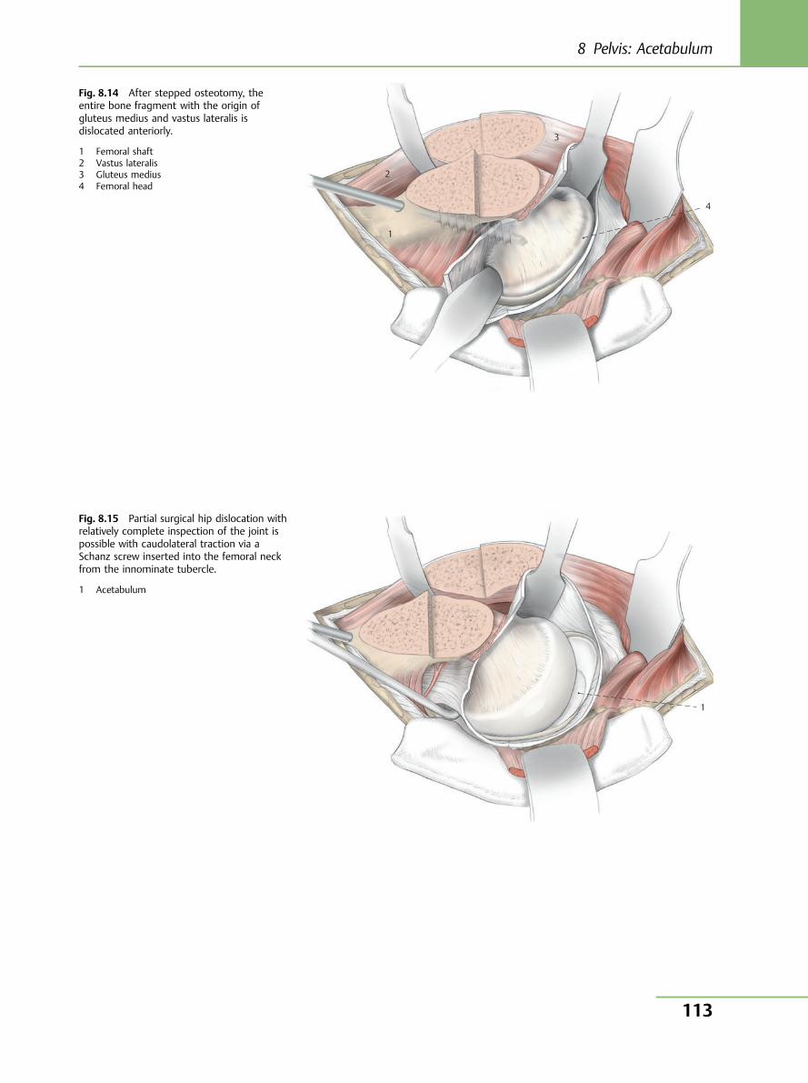
1
4
3
2
1
Fig. 8.14 After stepped osteotomy, theentire bone fragment with the origin ofgluteus medius and vastus lateralis isdislocated anteriorly.
1 Femoral shaft2 Vastus lateralis3 Gluteus medius4 Femoral head
Fig. 8.15 Partial surgical hip dislocation withrelatively complete inspection of the joint ispossible with caudolateral traction via aSchanz screw inserted into the femoral neckfrom the innominate tubercle.
1 Acetabulum
8 Pelvis: Acetabulum
113
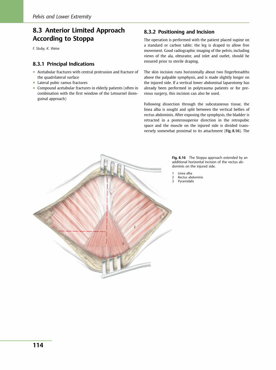
8.3 Anterior Limited ApproachAccording to StoppaF. Stuby, K. Weise
8.3.1 Principal Indications● Acetabular fractures with central protrusion and fracture of
the quadrilateral surface● Lateral pubic ramus fractures● Compound acetabular fractures in elderly patients (often in
combination with the first window of the Letournel ilioin-guinal approach)
8.3.2 Positioning and Incision
The operation is performed with the patient placed supine ona standard or carbon table; the leg is draped to allow freemovement. Good radiographic imaging of the pelvis, includingviews of the ala, obturator, and inlet and outlet, should beensured prior to sterile draping.
The skin incision runs horizontally about two fingerbreadthsabove the palpable symphysis, and is made slightly longer onthe injured side. If a vertical lower abdominal laparotomy hasalready been performed in polytrauma patients or for pre-vious surgery, this incision can also be used.
Following dissection through the subcutaneous tissue, thelinea alba is sought and split between the vertical bellies ofrectus abdominis. After exposing the symphysis, the bladder isretracted in a posterosuperior direction in the retropubicspace and the muscle on the injured side is divided trans-versely somewhat proximal to its attachment (Fig. 8.16). The
1
2
3
1111111111
2 22222222 22 2 2
3333333333333333333
Fig. 8.16 The Stoppa approach extended by anadditional horizontal incision of the rectus ab-dominis on the injured side.
1 Linea alba2 Rectus abdominis3 Pyramidalis
Pelvis and Lower Extremity
114
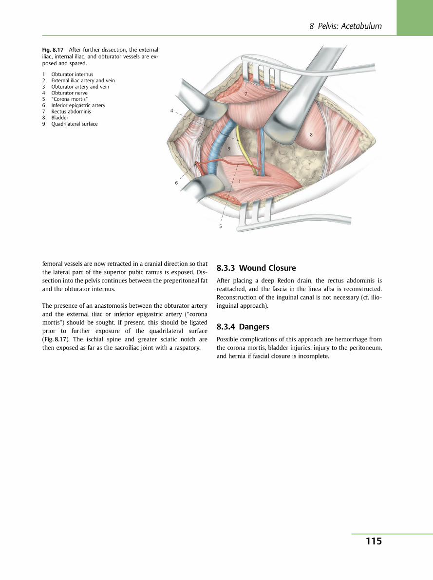
femoral vessels are now retracted in a cranial direction so thatthe lateral part of the superior pubic ramus is exposed. Dis-section into the pelvis continues between the preperitoneal fatand the obturator internus.
The presence of an anastomosis between the obturator arteryand the external iliac or inferior epigastric artery (“coronamortis”) should be sought. If present, this should be ligatedprior to further exposure of the quadrilateral surface(Fig. 8.17). The ischial spine and greater sciatic notch arethen exposed as far as the sacroiliac joint with a raspatory.
8.3.3 Wound Closure
After placing a deep Redon drain, the rectus abdominis isreattached, and the fascia in the linea alba is reconstructed.Reconstruction of the inguinal canal is not necessary (cf. ilio-inguinal approach).
8.3.4 Dangers
Possible complications of this approach are hemorrhage fromthe corona mortis, bladder injuries, injury to the peritoneum,and hernia if fascial closure is incomplete.
5
2 9
7
8
4
6
3
1
Fig. 8.17 After further dissection, the externaliliac, internal iliac, and obturator vessels are ex-posed and spared.
1 Obturator internus2 External iliac artery and vein3 Obturator artery and vein4 Obturator nerve5 “Corona mortis”6 Inferior epigastric artery7 Rectus abdominis8 Bladder9 Quadrilateral surface
8 Pelvis: Acetabulum
115
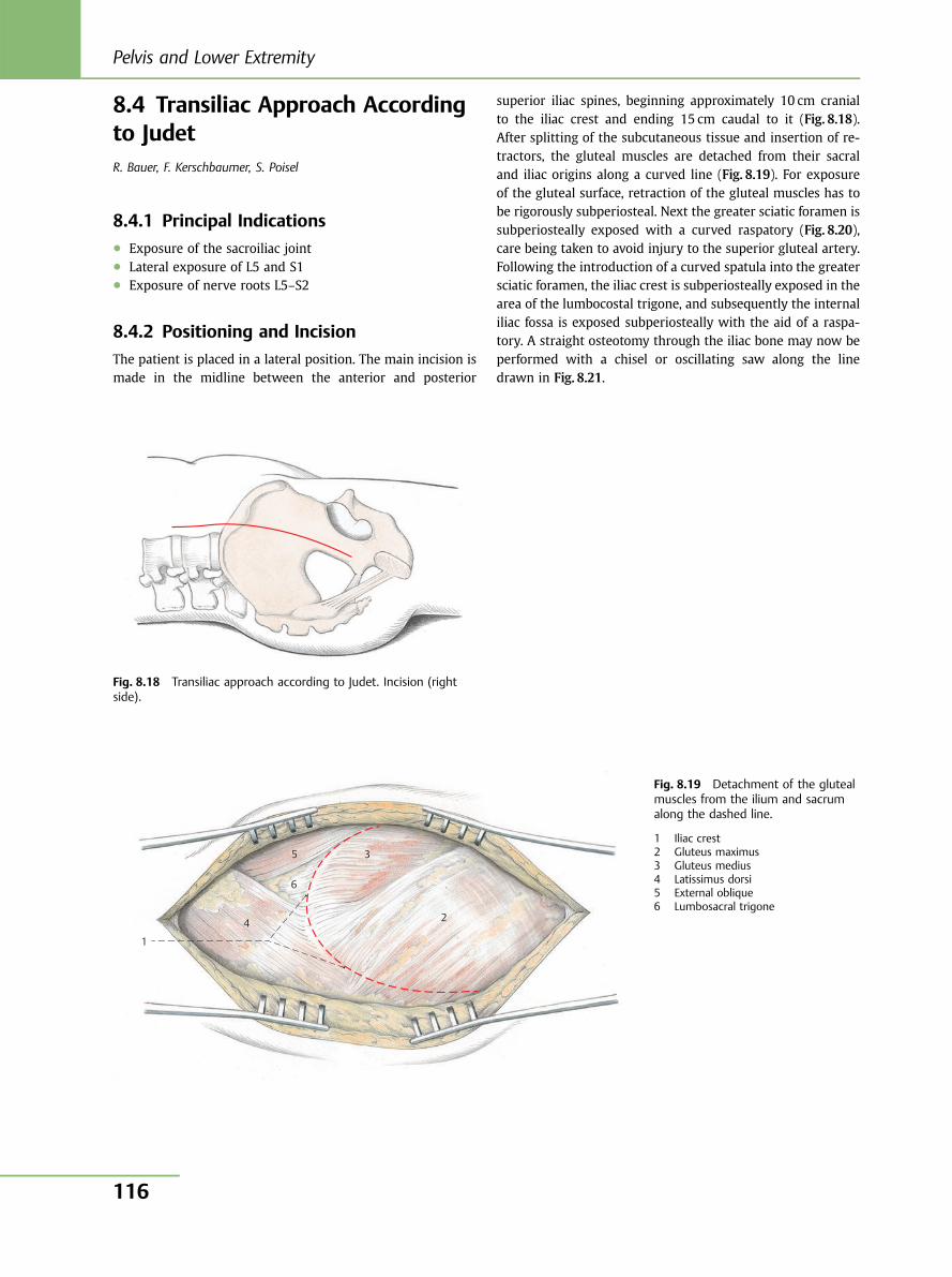
8.4 Transiliac Approach Accordingto JudetR. Bauer, F. Kerschbaumer, S. Poisel
8.4.1 Principal Indications● Exposure of the sacroiliac joint● Lateral exposure of L5 and S1● Exposure of nerve roots L5–S2
8.4.2 Positioning and Incision
The patient is placed in a lateral position. The main incision ismade in the midline between the anterior and posterior
superior iliac spines, beginning approximately 10 cm cranialto the iliac crest and ending 15 cm caudal to it (Fig. 8.18).After splitting of the subcutaneous tissue and insertion of re-tractors, the gluteal muscles are detached from their sacraland iliac origins along a curved line (Fig. 8.19). For exposureof the gluteal surface, retraction of the gluteal muscles has tobe rigorously subperiosteal. Next the greater sciatic foramen issubperiosteally exposed with a curved raspatory (Fig. 8.20),care being taken to avoid injury to the superior gluteal artery.Following the introduction of a curved spatula into the greatersciatic foramen, the iliac crest is subperiosteally exposed in thearea of the lumbocostal trigone, and subsequently the internaliliac fossa is exposed subperiosteally with the aid of a raspa-tory. A straight osteotomy through the iliac bone may now beperformed with a chisel or oscillating saw along the linedrawn in Fig. 8.21.
Fig. 8.18 Transiliac approach according to Judet. Incision (rightside).
1
4
6
5 3
2
Fig. 8.19 Detachment of the glutealmuscles from the ilium and sacrumalong the dashed line.
1 Iliac crest2 Gluteus maximus3 Gluteus medius4 Latissimus dorsi5 External oblique6 Lumbosacral trigone
Pelvis and Lower Extremity
116
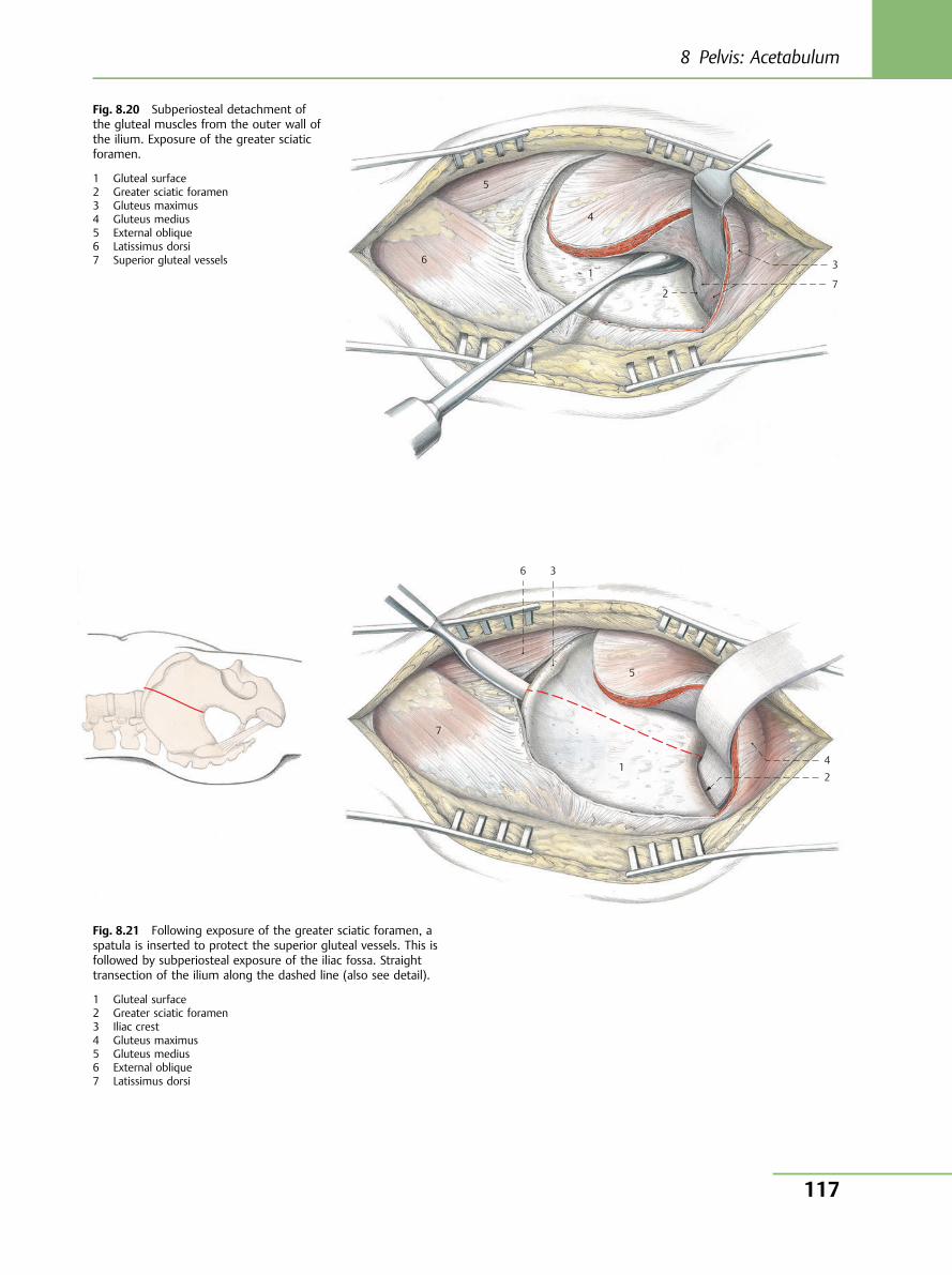
6
5
4
1
2 7
3
Fig. 8.20 Subperiosteal detachment ofthe gluteal muscles from the outer wall ofthe ilium. Exposure of the greater sciaticforamen.
1 Gluteal surface2 Greater sciatic foramen3 Gluteus maximus4 Gluteus medius5 External oblique6 Latissimus dorsi7 Superior gluteal vessels
6 3
5
1
7
42
Fig. 8.21 Following exposure of the greater sciatic foramen, aspatula is inserted to protect the superior gluteal vessels. This isfollowed by subperiosteal exposure of the iliac fossa. Straighttransection of the ilium along the dashed line (also see detail).
1 Gluteal surface2 Greater sciatic foramen3 Iliac crest4 Gluteus maximus5 Gluteus medius6 External oblique7 Latissimus dorsi
8 Pelvis: Acetabulum
117

8.4.3 Exposure of the Sacroiliac Joint
A Cobb elevator is introduced into the iliac fossa via the os-teotomy cleft. With the aid of the raspatory, the anterior por-tion of the ilium is retracted medially so that the posteriorportion can be grasped with bone-holding forceps and re-tracted laterally. Using the raspatory, the anterior portion ofthe sacroiliac joint capsule is subperiosteally retracted, andthe posterior iliac fragment is turned up laterally (Fig. 8.22).
After dissection and partial transection of parts of iliacus andblunt retraction of psoas major, the fifth lumbar vertebra, thepresacral intervertebral disk, and the superior portions of thefirst sacral vertebra are revealed. Further, the anteriorbranches of the first and fifth lumbar and first and secondsacral nerves can be visualized. Lying in the depth of thewound, covered by connective tissue, are the internal iliacartery and vein, and the superior gluteal artery and vein. Theauricular surface is likewise readily visible (Fig. 8.22).
4
5
6
7
8
15 16 17 18 19
13 12
10 9
11
3
2
1
14 20
21
22
Fig. 8.22 Operative site after opening of the anterior sacroiliac joint capsule and upward reflection of theposterior iliac fragment. Some fibers of the iliacus muscle have been transected, and psoas major has beenretracted in a medial direction. Exposure of the articular surface of the sacrum (auricular surface), the spinalnerves L4–S2, and the lateral surface of L5 and S1.
1 Fifth lumbar vertebra2 Promontory3 Auricular surface4 External oblique5 Internal oblique6 Latissimus dorsi7 Psoas major8 Quadratus lumborum9 External iliac artery10 Internal iliac artery11 Iliac branch of the iliolumbar artery (var.)
12 Lumbar branch of the iliolumbar artery (var.)13 Superior gluteal artery and vein14 External iliac vein15 Anterior ramus of L416 Anterior ramus of L517 Anterior ramus of S118 Anterior ramus of S219 Sacral plexus20 Obturator nerve21 Femoral nerve22 Superior gluteal nerve
Pelvis and Lower Extremity
118
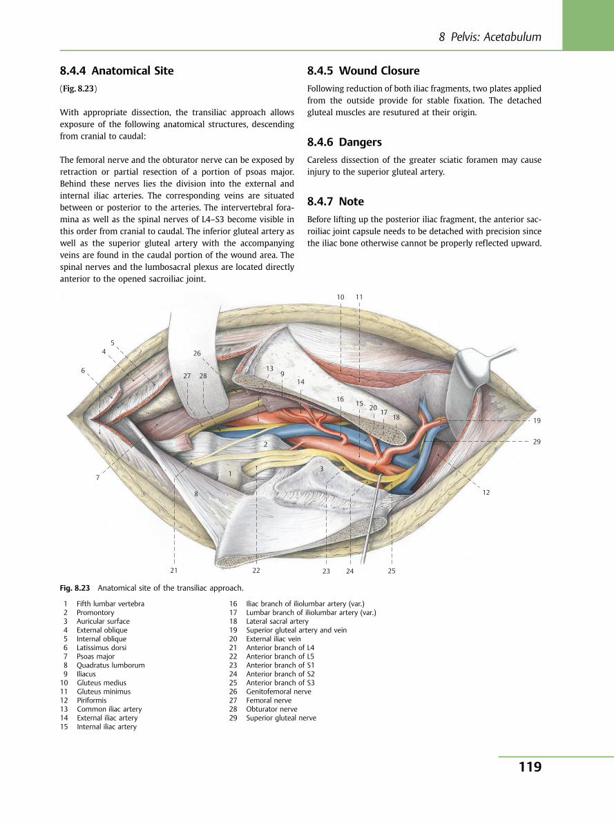
8.4.4 Anatomical Site
(Fig. 8.23)
With appropriate dissection, the transiliac approach allowsexposure of the following anatomical structures, descendingfrom cranial to caudal:
The femoral nerve and the obturator nerve can be exposed byretraction or partial resection of a portion of psoas major.Behind these nerves lies the division into the external andinternal iliac arteries. The corresponding veins are situatedbetween or posterior to the arteries. The intervertebral fora-mina as well as the spinal nerves of L4–S3 become visible inthis order from cranial to caudal. The inferior gluteal artery aswell as the superior gluteal artery with the accompanyingveins are found in the caudal portion of the wound area. Thespinal nerves and the lumbosacral plexus are located directlyanterior to the opened sacroiliac joint.
8.4.5 Wound Closure
Following reduction of both iliac fragments, two plates appliedfrom the outside provide for stable fixation. The detachedgluteal muscles are resutured at their origin.
8.4.6 Dangers
Careless dissection of the greater sciatic foramen may causeinjury to the superior gluteal artery.
8.4.7 Note
Before lifting up the posterior iliac fragment, the anterior sac-roiliac joint capsule needs to be detached with precision sincethe iliac bone otherwise cannot be properly reflected upward.
7 1
2
3
21 22 23 24 25
12
1817
201516
14
10 11
913
26
2827
54
6
29
19
8
Fig. 8.23 Anatomical site of the transiliac approach.
1 Fifth lumbar vertebra2 Promontory3 Auricular surface4 External oblique5 Internal oblique6 Latissimus dorsi7 Psoas major8 Quadratus lumborum9 Iliacus10 Gluteus medius11 Gluteus minimus12 Piriformis13 Common iliac artery14 External iliac artery15 Internal iliac artery
16 Iliac branch of iliolumbar artery (var.)17 Lumbar branch of iliolumbar artery (var.)18 Lateral sacral artery19 Superior gluteal artery and vein20 External iliac vein21 Anterior branch of L422 Anterior branch of L523 Anterior branch of S124 Anterior branch of S225 Anterior branch of S326 Genitofemoral nerve27 Femoral nerve28 Obturator nerve29 Superior gluteal nerve
8 Pelvis: Acetabulum
119
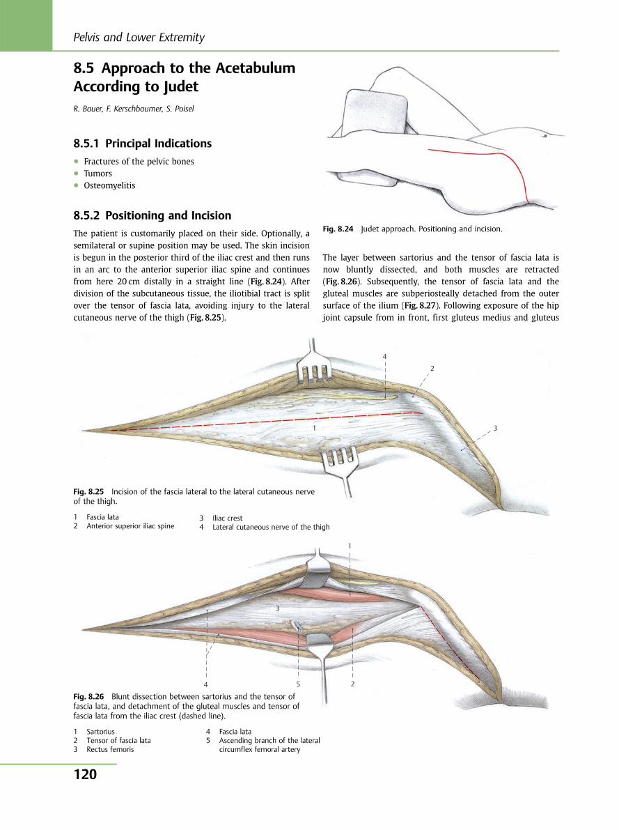
8.5 Approach to the AcetabulumAccording to JudetR. Bauer, F. Kerschbaumer, S. Poisel
8.5.1 Principal Indications● Fractures of the pelvic bones● Tumors● Osteomyelitis
8.5.2 Positioning and Incision
The patient is customarily placed on their side. Optionally, asemilateral or supine position may be used. The skin incisionis begun in the posterior third of the iliac crest and then runsin an arc to the anterior superior iliac spine and continuesfrom here 20 cm distally in a straight line (Fig. 8.24). Afterdivision of the subcutaneous tissue, the iliotibial tract is splitover the tensor of fascia lata, avoiding injury to the lateralcutaneous nerve of the thigh (Fig. 8.25).
The layer between sartorius and the tensor of fascia lata isnow bluntly dissected, and both muscles are retracted(Fig. 8.26). Subsequently, the tensor of fascia lata and thegluteal muscles are subperiosteally detached from the outersurface of the ilium (Fig. 8.27). Following exposure of the hipjoint capsule from in front, first gluteus medius and gluteus
Fig. 8.24 Judet approach. Positioning and incision.
4
3 1
2
Fig. 8.25 Incision of the fascia lateral to the lateral cutaneous nerveof the thigh.
1 Fascia lata2 Anterior superior iliac spine
3 Iliac crest4 Lateral cutaneous nerve of the thigh
5 4
3
1
2
Fig. 8.26 Blunt dissection between sartorius and the tensor offascia lata, and detachment of the gluteal muscles and tensor offascia lata from the iliac crest (dashed line).
1 Sartorius2 Tensor of fascia lata3 Rectus femoris
4 Fascia lata5 Ascending branch of the lateral
circumflex femoral artery
Pelvis and Lower Extremity
120
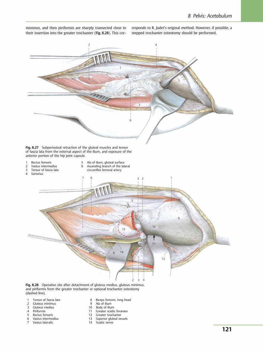
6
5
4
3
1
2
10
11
12
13
14
9
8
7 6
5
4
3 1 2
3 2
minimus, and then piriformis are sharply transected close totheir insertion into the greater trochanter (Fig. 8.28). This cor-
responds to R. Judet’s original method. However, if possible, astepped trochanter osteotomy should be performed.
Fig. 8.27 Subperiosteal retraction of the gluteal muscles and tensorof fascia lata from the external aspect of the ilium, and exposure of theanterior portion of the hip joint capsule.
1 Rectus femoris2 Vastus intermedius3 Tensor of fascia lata4 Sartorius
5 Ala of ilium, gluteal surface6 Ascending branch of the lateral
circumflex femoral artery
Fig. 8.28 Operative site after detachment of gluteus medius, gluteus minimus,and piriformis from the greater trochanter or optional trochanter osteotomy(dashed line).
1 Tensor of fascia lata2 Gluteus minimus3 Gluteus medius4 Piriformis5 Rectus femoris6 Vastus intermedius7 Vastus lateralis
8 Biceps femoris, long head9 Ala of ilium10 Body of ilium11 Greater sciatic foramen12 Greater trochanter13 Superior gluteal vessels14 Sciatic nerve
8 Pelvis: Acetabulum
121
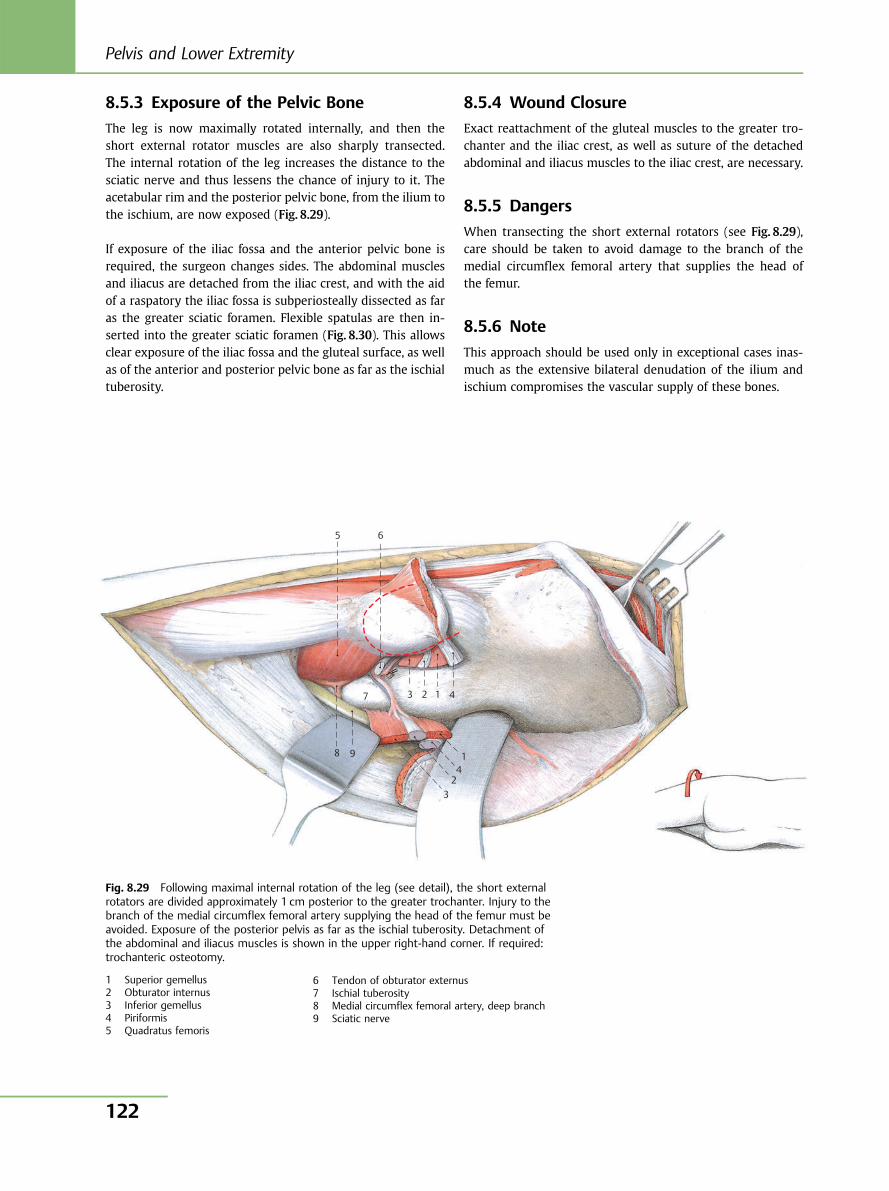
8.5.3 Exposure of the Pelvic Bone
The leg is now maximally rotated internally, and then theshort external rotator muscles are also sharply transected.The internal rotation of the leg increases the distance to thesciatic nerve and thus lessens the chance of injury to it. Theacetabular rim and the posterior pelvic bone, from the ilium tothe ischium, are now exposed (Fig. 8.29).
If exposure of the iliac fossa and the anterior pelvic bone isrequired, the surgeon changes sides. The abdominal musclesand iliacus are detached from the iliac crest, and with the aidof a raspatory the iliac fossa is subperiosteally dissected as faras the greater sciatic foramen. Flexible spatulas are then in-serted into the greater sciatic foramen (Fig. 8.30). This allowsclear exposure of the iliac fossa and the gluteal surface, as wellas of the anterior and posterior pelvic bone as far as the ischialtuberosity.
8.5.4 Wound Closure
Exact reattachment of the gluteal muscles to the greater tro-chanter and the iliac crest, as well as suture of the detachedabdominal and iliacus muscles to the iliac crest, are necessary.
8.5.5 Dangers
When transecting the short external rotators (see Fig. 8.29),care should be taken to avoid damage to the branch of themedial circumflex femoral artery that supplies the head ofthe femur.
8.5.6 Note
This approach should be used only in exceptional cases inas-much as the extensive bilateral denudation of the ilium andischium compromises the vascular supply of these bones.
9 8
7
6 5
4
3
1
2
3 2 4
1
Fig. 8.29 Following maximal internal rotation of the leg (see detail), the short externalrotators are divided approximately 1 cm posterior to the greater trochanter. Injury to thebranch of the medial circumflex femoral artery supplying the head of the femur must beavoided. Exposure of the posterior pelvis as far as the ischial tuberosity. Detachment ofthe abdominal and iliacus muscles is shown in the upper right-hand corner. If required:trochanteric osteotomy.
1 Superior gemellus2 Obturator internus3 Inferior gemellus4 Piriformis5 Quadratus femoris
6 Tendon of obturator externus7 Ischial tuberosity8 Medial circumflex femoral artery, deep branch9 Sciatic nerve
Pelvis and Lower Extremity
122
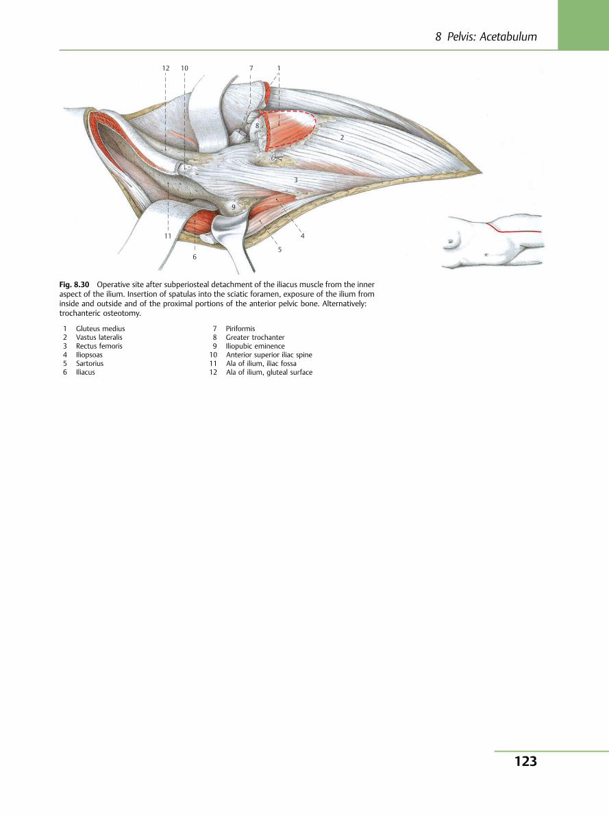
10
11
12
9
8
7
6 5
4
3
1
2
Fig. 8.30 Operative site after subperiosteal detachment of the iliacus muscle from the inneraspect of the ilium. Insertion of spatulas into the sciatic foramen, exposure of the ilium frominside and outside and of the proximal portions of the anterior pelvic bone. Alternatively:trochanteric osteotomy.
1 Gluteus medius2 Vastus lateralis3 Rectus femoris4 Iliopsoas5 Sartorius6 Iliacus
7 Piriformis8 Greater trochanter9 Iliopubic eminence10 Anterior superior iliac spine11 Ala of ilium, iliac fossa12 Ala of ilium, gluteal surface
8 Pelvis: Acetabulum
123
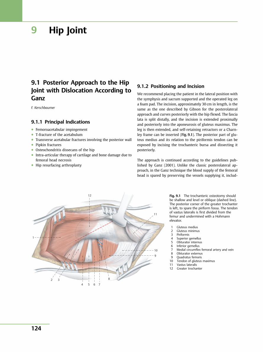
9 Hip Joint
9.1 Posterior Approach to the HipJoint with Dislocation According toGanzF. Kerschbaumer
9.1.1 Principal Indications● Femoroacetabular impingement● T-fracture of the acetabulum● Transverse acetabular fractures involving the posterior wall● Pipkin fractures● Osteochondritis dissecans of the hip● Intra-articular therapy of cartilage and bone damage due to
femoral head necrosis● Hip resurfacing arthroplasty
9.1.2 Positioning and Incision
We recommend placing the patient in the lateral position withthe symphysis and sacrum supported and the operated leg ona foam pad. The incision, approximately 30 cm in length, is thesame as the one described by Gibson for the posterolateralapproach and curves posteriorly with the hip flexed. The fascialata is split distally, and the incision is extended proximallyand posteriorly into the aponeurosis of gluteus maximus. Theleg is then extended, and self-retaining retractors or a Charn-ley frame can be inserted (Fig. 9.1). The posterior part of glu-teus medius and its relation to the piriformis tendon can beexposed by incising the trochanteric bursa and dissecting itposteriorly.
The approach is continued according to the guidelines pub-lished by Ganz (2001). Unlike the classic posterolateral ap-proach, in the Ganz technique the blood supply of the femoralhead is spared by preserving the vessels supplying it, includ-
12
1
2 34 5 6 7
8
9
10
11
Fig. 9.1 The trochanteric osteotomy shouldbe shallow and level or oblique (dashed line).The posterior corner of the greater trochanteris left, to spare the piriform fossa. The tendonof vastus lateralis is first divided from thefemur and undermined with a Hohmannelevator.
1 Gluteus medius2 Gluteus minimus3 Piriformis4 Superior gemellus5 Obturator internus6 Inferior gemellus7 Medial circumflex femoral artery and vein8 Obturator externus9 Quadratus femoris10 Tendon of gluteus maximus11 Vastus lateralis12 Greater trochanter
Pelvis and Lower Extremity
124
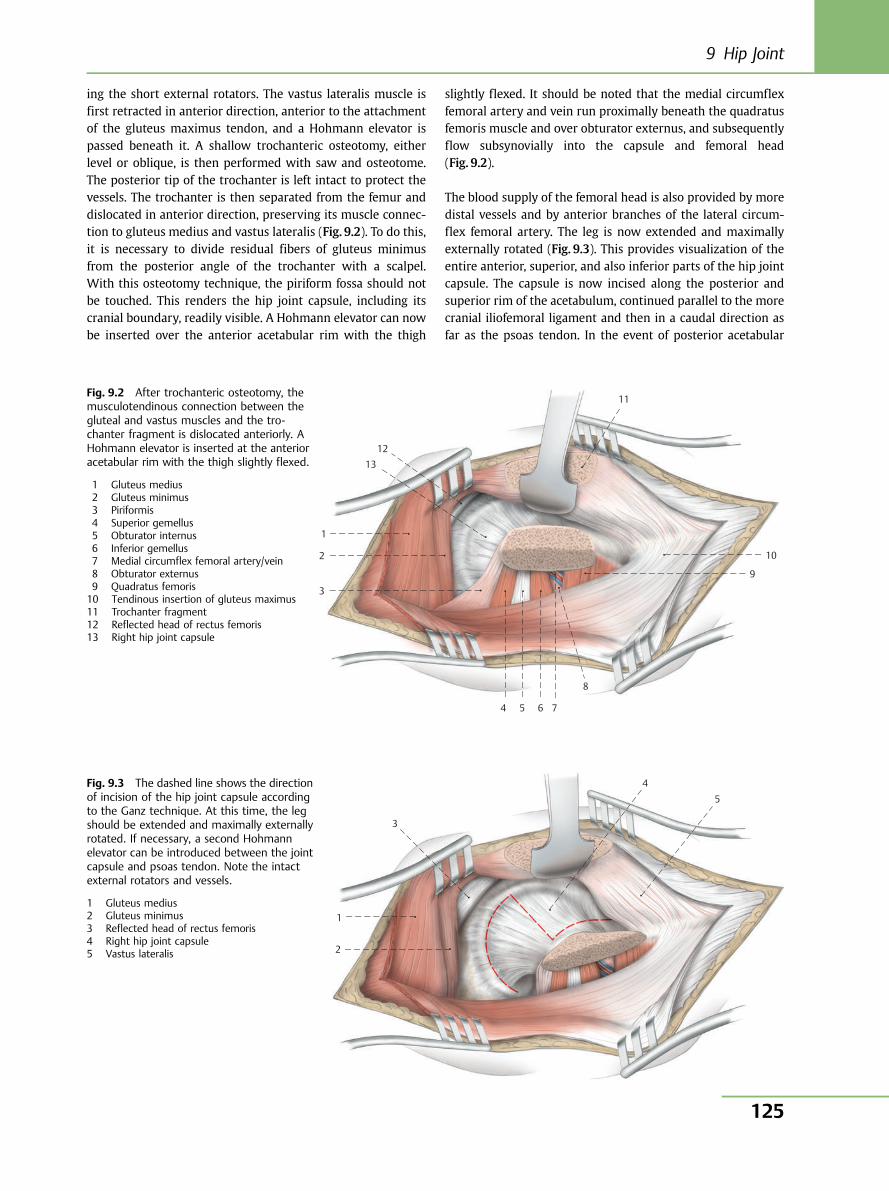
ing the short external rotators. The vastus lateralis muscle isfirst retracted in anterior direction, anterior to the attachmentof the gluteus maximus tendon, and a Hohmann elevator ispassed beneath it. A shallow trochanteric osteotomy, eitherlevel or oblique, is then performed with saw and osteotome.The posterior tip of the trochanter is left intact to protect thevessels. The trochanter is then separated from the femur anddislocated in anterior direction, preserving its muscle connec-tion to gluteus medius and vastus lateralis (Fig. 9.2). To do this,it is necessary to divide residual fibers of gluteus minimusfrom the posterior angle of the trochanter with a scalpel.With this osteotomy technique, the piriform fossa should notbe touched. This renders the hip joint capsule, including itscranial boundary, readily visible. A Hohmann elevator can nowbe inserted over the anterior acetabular rim with the thigh
slightly flexed. It should be noted that the medial circumflexfemoral artery and vein run proximally beneath the quadratusfemoris muscle and over obturator externus, and subsequentlyflow subsynovially into the capsule and femoral head(Fig. 9.2).
The blood supply of the femoral head is also provided by moredistal vessels and by anterior branches of the lateral circum-flex femoral artery. The leg is now extended and maximallyexternally rotated (Fig. 9.3). This provides visualization of theentire anterior, superior, and also inferior parts of the hip jointcapsule. The capsule is now incised along the posterior andsuperior rim of the acetabulum, continued parallel to the morecranial iliofemoral ligament and then in a caudal direction asfar as the psoas tendon. In the event of posterior acetabular
1
2
3
4 5 6 7
8
9
10
11
1213
Fig. 9.2 After trochanteric osteotomy, themusculotendinous connection between thegluteal and vastus muscles and the tro-chanter fragment is dislocated anteriorly. AHohmann elevator is inserted at the anterioracetabular rim with the thigh slightly flexed.
1 Gluteus medius2 Gluteus minimus3 Piriformis4 Superior gemellus5 Obturator internus6 Inferior gemellus7 Medial circumflex femoral artery/vein8 Obturator externus9 Quadratus femoris10 Tendinous insertion of gluteus maximus11 Trochanter fragment12 Reflected head of rectus femoris13 Right hip joint capsule
1
2
3
4 5
Fig. 9.3 The dashed line shows the directionof incision of the hip joint capsule accordingto the Ganz technique. At this time, the legshould be extended and maximally externallyrotated. If necessary, a second Hohmannelevator can be introduced between the jointcapsule and psoas tendon. Note the intactexternal rotators and vessels.
1 Gluteus medius2 Gluteus minimus3 Reflected head of rectus femoris4 Right hip joint capsule5 Vastus lateralis
9 Hip Joint
125
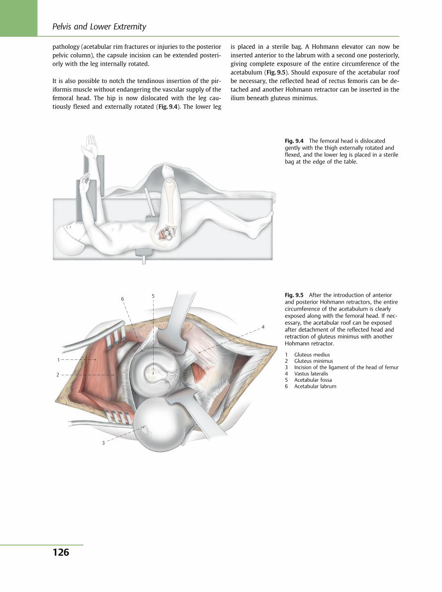
pathology (acetabular rim fractures or injuries to the posteriorpelvic column), the capsule incision can be extended posteri-orly with the leg internally rotated.
It is also possible to notch the tendinous insertion of the pir-iformis muscle without endangering the vascular supply of thefemoral head. The hip is now dislocated with the leg cau-tiously flexed and externally rotated (Fig. 9.4). The lower leg
is placed in a sterile bag. A Hohmann elevator can now beinserted anterior to the labrum with a second one posteriorly,giving complete exposure of the entire circumference of theacetabulum (Fig. 9.5). Should exposure of the acetabular roofbe necessary, the reflected head of rectus femoris can be de-tached and another Hohmann retractor can be inserted in theilium beneath gluteus minimus.
Fig. 9.4 The femoral head is dislocatedgently with the thigh externally rotated andflexed, and the lower leg is placed in a sterilebag at the edge of the table.
1
2
3
4
56Fig. 9.5 After the introduction of anteriorand posterior Hohmann retractors, the entirecircumference of the acetabulum is clearlyexposed along with the femoral head. If nec-essary, the acetabular roof can be exposedafter detachment of the reflected head andretraction of gluteus minimus with anotherHohmann retractor.
1 Gluteus medius2 Gluteus minimus3 Incision of the ligament of the head of femur4 Vastus lateralis5 Acetabular fossa6 Acetabular labrum
Pelvis and Lower Extremity
126
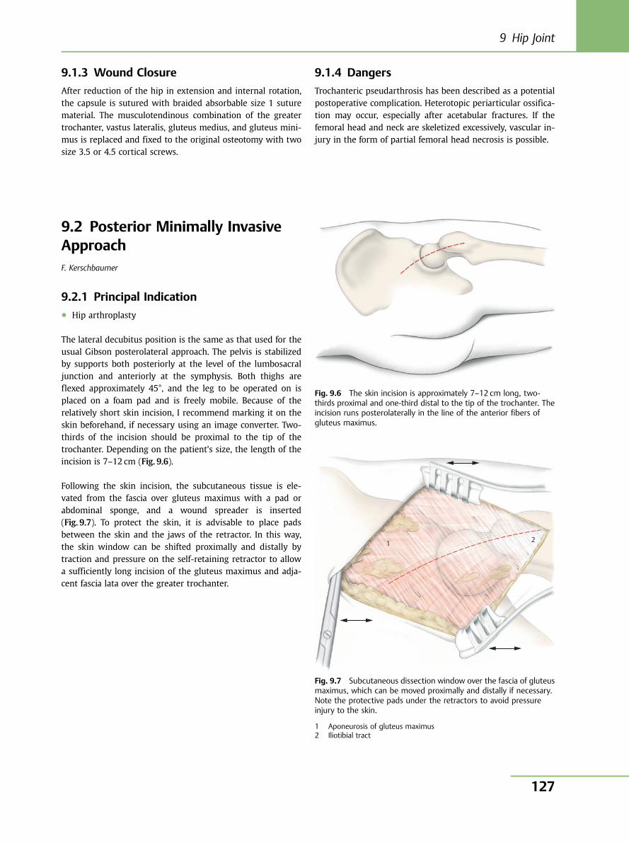
9.1.3 Wound Closure
After reduction of the hip in extension and internal rotation,the capsule is sutured with braided absorbable size 1 suturematerial. The musculotendinous combination of the greatertrochanter, vastus lateralis, gluteus medius, and gluteus mini-mus is replaced and fixed to the original osteotomy with twosize 3.5 or 4.5 cortical screws.
9.1.4 Dangers
Trochanteric pseudarthrosis has been described as a potentialpostoperative complication. Heterotopic periarticular ossifica-tion may occur, especially after acetabular fractures. If thefemoral head and neck are skeletized excessively, vascular in-jury in the form of partial femoral head necrosis is possible.
Fig. 9.6 The skin incision is approximately 7–12 cm long, two-thirds proximal and one-third distal to the tip of the trochanter. Theincision runs posterolaterally in the line of the anterior fibers ofgluteus maximus.
1 2
Fig. 9.7 Subcutaneous dissection window over the fascia of gluteusmaximus, which can be moved proximally and distally if necessary.Note the protective pads under the retractors to avoid pressureinjury to the skin.
1 Aponeurosis of gluteus maximus2 Iliotibial tract
9.2 Posterior Minimally InvasiveApproachF. Kerschbaumer
9.2.1 Principal Indication● Hip arthroplasty
The lateral decubitus position is the same as that used for theusual Gibson posterolateral approach. The pelvis is stabilizedby supports both posteriorly at the level of the lumbosacraljunction and anteriorly at the symphysis. Both thighs areflexed approximately 45°, and the leg to be operated on isplaced on a foam pad and is freely mobile. Because of therelatively short skin incision, I recommend marking it on theskin beforehand, if necessary using an image converter. Two-thirds of the incision should be proximal to the tip of thetrochanter. Depending on the patient’s size, the length of theincision is 7–12 cm (Fig. 9.6).
Following the skin incision, the subcutaneous tissue is ele-vated from the fascia over gluteus maximus with a pad orabdominal sponge, and a wound spreader is inserted(Fig. 9.7). To protect the skin, it is advisable to place padsbetween the skin and the jaws of the retractor. In this way,the skin window can be shifted proximally and distally bytraction and pressure on the self-retaining retractor to allowa sufficiently long incision of the gluteus maximus and adja-cent fascia lata over the greater trochanter.
9 Hip Joint
127
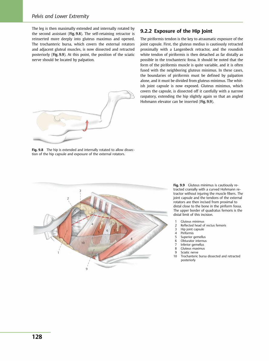
The leg is then maximally extended and internally rotated bythe second assistant (Fig. 9.8). The self-retaining retractor isreinserted more deeply into gluteus maximus and opened.The trochanteric bursa, which covers the external rotatorsand adjacent gluteal muscles, is now dissected and retractedposteriorly (Fig. 9.9). At this point, the position of the sciaticnerve should be located by palpation.
9.2.2 Exposure of the Hip Joint
The piriformis tendon is the key to atraumatic exposure of thejoint capsule. First, the gluteus medius is cautiously retractedproximally with a Langenbeck retractor, and the roundishwhite tendon of piriformis is then detached as far distally aspossible in the trochanteric fossa. It should be noted that theform of the piriformis muscle is quite variable, and it is oftenfused with the neighboring gluteus minimus. In these cases,the boundaries of piriformis must be defined by palpationalone, and it must be divided from gluteus minimus. The whit-ish joint capsule is now exposed. Gluteus minimus, whichcovers the capsule, is dissected off it carefully with a narrowraspatory, extending the hip slightly again so that an angledHohmann elevator can be inserted (Fig. 9.9).
Fig. 9.8 The hip is extended and internally rotated to allow dissec-tion of the hip capsule and exposure of the external rotators.
1
2
3
4
5 6 7
8
9
10
Fig. 9.9 Gluteus minimus is cautiously re-tracted cranially with a curved Hohmann re-tractor without injuring the muscle fibers. Thejoint capsule and the tendons of the externalrotators are then incised from proximal todistal close to the bone in the piriform fossa.The upper border of quadratus femoris is thedistal limit of this incision.
1 Gluteus minimus2 Reflected head of rectus femoris3 Hip joint capsule4 Piriformis5 Superior gemellus6 Obturator internus7 Inferior gemellus8 Gluteus maximus9 Sciatic nerve10 Trochanteric bursa dissected and retracted
posteriorly
Pelvis and Lower Extremity
128
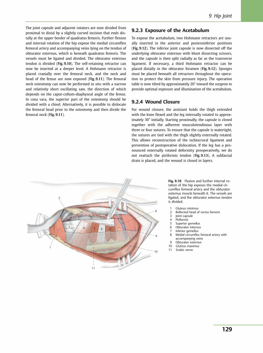
The joint capsule and adjacent rotators are now divided fromproximal to distal by a slightly curved incision that ends dis-tally at the upper border of quadratus femoris. Further flexionand internal rotation of the hip expose the medial circumflexfemoral artery and accompanying veins lying on the tendon ofobturator externus, which is beneath quadratus femoris. Thevessels must be ligated and divided. The obturator externustendon is divided (Fig. 9.10). The self-retaining retractor cannow be inserted at a deeper level. A Hohmann retractor isplaced cranially over the femoral neck, and the neck andhead of the femur are now exposed (Fig. 9.11). The femoralneck osteotomy can now be performed in situ with a narrowand relatively short oscillating saw, the direction of whichdepends on the caput-collum-diaphyseal angle of the femur.In coxa vara, the superior part of the osteotomy should bedivided with a chisel. Alternatively, it is possible to dislocatethe femoral head prior to the osteotomy and then divide thefemoral neck (Fig. 9.11).
9.2.3 Exposure of the Acetabulum
To expose the acetabulum, two Hohmann retractors are usu-ally inserted in the anterior and posteroinferior positions(Fig. 9.12). The inferior joint capsule is now dissected off theunderlying obturator externus with blunt dissecting scissors,and the capsule is then split radially as far as the transverseligament. If necessary, a third Hohmann retractor can beplaced distally in the obturator foramen (Fig. 9.12). Spongesmust be placed beneath all retractors throughout the opera-tion to protect the skin from pressure injury. The operationtable is now tilted by approximately 20° toward the surgeon toprovide optimal exposure and illumination of the acetabulum.
9.2.4 Wound Closure
For wound closure, the assistant holds the thigh extendedwith the knee flexed and the leg internally rotated to approx-imately 30° initially. Starting proximally, the capsule is closedtogether with the adherent musculotendinous layer withthree or four sutures. To ensure that the capsule is watertight,the sutures are tied with the thigh slightly externally rotated.This allows reconstruction of the ischiocrural ligament andprevention of postoperative dislocation. If the leg has a pro-nounced externally rotated deformity preoperatively, we donot reattach the piriformis tendon (Fig. 9.13). A subfascialdrain is placed, and the wound is closed in layers.
1
2
3 4 5 6 7
8
9
10
11
Fig. 9.10 Flexion and further internal ro-tation of the hip exposes the medial cir-cumflex femoral artery and the obturatorexternus muscle beneath it. The vessels areligated, and the obturator externus tendonis divided.
1 Gluteus minimus2 Reflected head of rectus femoris3 Joint capsule4 Piriformis5 Superior gemellus6 Obturator internus7 Inferior gemellus8 Medial circumflex femoral artery with
accompanying veins9 Obturator externus10 Gluteus maximus11 Sciatic nerve
9 Hip Joint
129
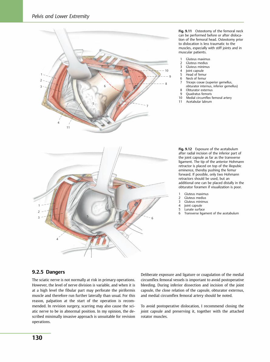
9.2.5 Dangers
The sciatic nerve is not normally at risk in primary operations.However, the level of nerve division is variable, and when it isat a high level the fibular part may perforate the piriformismuscle and therefore run further laterally than usual. For thisreason, palpation at the start of the operation is recom-mended. In revision surgery, scarring may also cause the sci-atic nerve to be in abnormal position. In my opinion, the de-scribed minimally invasive approach is unsuitable for revisionoperations.
Deliberate exposure and ligature or coagulation of the medialcircumflex femoral vessels is important to avoid postoperativebleeding. During inferior dissection and incision of the jointcapsule, the close relation of the capsule, obturator externus,and medial circumflex femoral artery should be noted.
To avoid postoperative dislocation, I recommend closing thejoint capsule and preserving it, together with the attachedrotator muscles.
1
2
3
4 11
5
6
7
8
10
9
Fig. 9.11 Osteotomy of the femoral neckcan be performed before or after disloca-tion of the femoral head. Osteotomy priorto dislocation is less traumatic to themuscles, especially with stiff joints and inmuscular patients.
1 Gluteus maximus2 Gluteus medius3 Gluteus minimus4 Joint capsule5 Head of femur6 Neck of femur7 Triceps coxae (superior gemellus,
obturator internus, inferior gemellus)8 Obturator externus9 Quadratus femoris10 Medial circumflex femoral artery11 Acetabular labrum
1
2
3
4
5 6
Fig. 9.12 Exposure of the acetabulumafter radial incision of the inferior part ofthe joint capsule as far as the transverseligament. The tip of the anterior Hohmannretractor is placed on top of the iliopubiceminence, thereby pushing the femurforward. If possible, only two Hohmannretractors should be used, but anadditional one can be placed distally in theobturator foramen if visualization is poor.
1 Gluteus maximus2 Gluteus medius3 Gluteus minimus4 Joint capsule5 Lunate surface6 Transverse ligament of the acetabulum
Pelvis and Lower Extremity
130
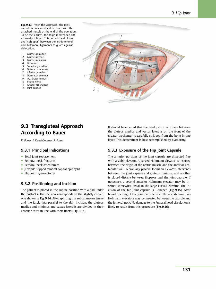
9.3 Transgluteal ApproachAccording to BauerR. Bauer, F. Kerschbaumer, S. Poisel
9.3.1 Principal Indications● Total joint replacement● Femoral neck fractures● Femoral neck osteotomies● Juvenile slipped femoral capital epiphysis● Hip joint synovectomy
9.3.2 Positioning and Incision
The patient is placed in the supine position with a pad underthe buttocks. The incision corresponds to the slightly curvedone shown in Fig. 9.24. After splitting the subcutaneous tissueand the fascia lata parallel to the skin incision, the gluteusmedius and minimus and vastus lateralis are divided in theiranterior third in line with their fibers (Fig. 9.14).
It should be ensured that the tendoperiosteal tissue betweenthe gluteus medius and vastus lateralis on the front of thegreater trochanter is carefully stripped from the bone in onelayer. This detachment is best accomplished by diathermy.
9.3.3 Exposure of the Hip Joint Capsule
The anterior portions of the joint capsule are dissected freewith a Cobb elevator. A curved Hohmann elevator is insertedbetween the origin of the rectus muscle and the anterior ace-tabular wall. A cranially placed Hohmann elevator intervenesbetween the joint capsule and gluteus minimus, and anotheris placed distally between iliopsoas and the joint capsule. Ifnecessary, a second anterior Hohmann elevator may be in-serted somewhat distal to the large curved elevator. The in-cision of the hip joint capsule is T-shaped (Fig. 9.15). Afterbroad opening of the joint capsule near the acetabulum, twoHohmann elevators may be inserted between the capsule andthe femoral neck. No damage to the femoral head circulation islikely to result from this procedure (Fig. 9.16).
1
2 3
4
5 6 78
9
11
12
10
Fig. 9.13 With this approach, the jointcapsule is preserved and is closed with theattached muscle at the end of the operation.To tie the sutures, the thigh is extended andexternally rotated. This corrects and closesany “soft spot” between the ischiofemoraland iliofemoral ligaments to guard againstdislocation.
1 Gluteus maximus2 Gluteus medius3 Gluteus minimus4 Piriformis5 Superior gemellus6 Obturator internus7 Inferior gemellus8 Obturator externus9 Quadratus femoris10 Sciatic nerve11 Greater trochanter12 Joint capsule
9 Hip Joint
131
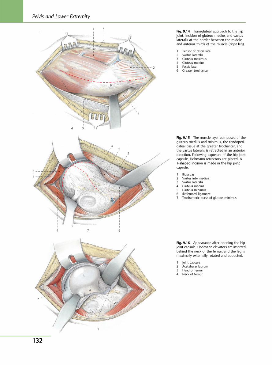
1 5
2
3
54
6
Fig. 9.14 Transgluteal approach to the hipjoint. Incision of gluteus medius and vastuslateralis at the border between the middleand anterior thirds of the muscle (right leg).
1 Tensor of fascia lata2 Vastus lateralis3 Gluteus maximus4 Gluteus medius5 Fascia lata6 Greater trochanter
1 2
6 7 4
4
5
3
2
3
4
1
Fig. 9.15 The muscle layer composed of thegluteus medius and minimus, the tendoperi-osteal tissue at the greater trochanter, andthe vastus lateralis is retracted in an anteriordirection. Following exposure of the hip jointcapsule, Hohmann retractors are placed. AT-shaped incision is made in the hip jointcapsule.
1 Iliopsoas2 Vastus intermedius3 Vastus lateralis4 Gluteus medius5 Gluteus minimus6 Iliofemoral ligament7 Trochanteric bursa of gluteus minimus
Fig. 9.16 Appearance after opening the hipjoint capsule. Hohmann elevators are insertedbehind the neck of the femur, and the leg ismaximally externally rotated and adducted.
1 Joint capsule2 Acetabular labrum3 Head of femur4 Neck of femur
Pelvis and Lower Extremity
132
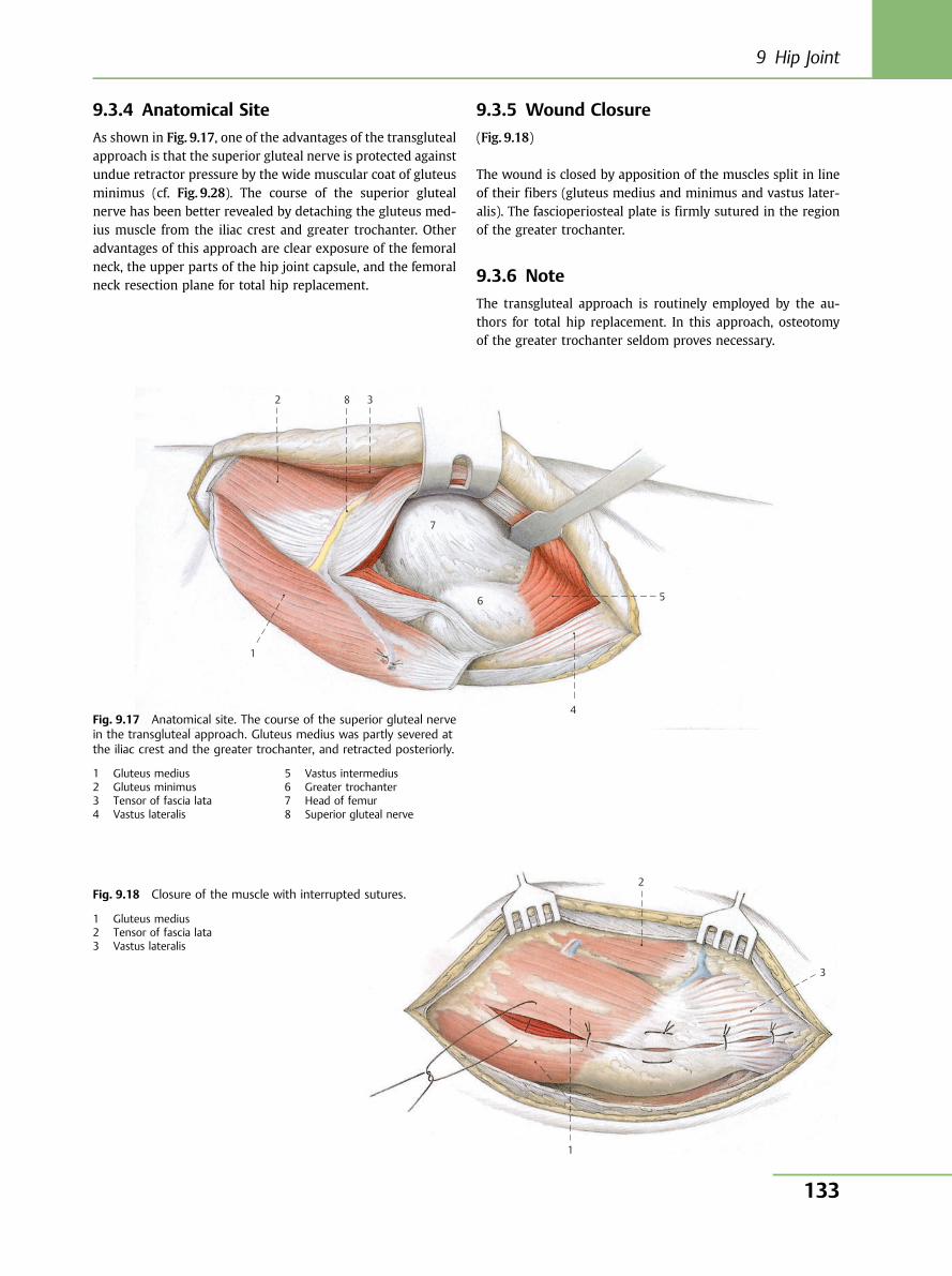
9.3.4 Anatomical Site
As shown in Fig. 9.17, one of the advantages of the transglutealapproach is that the superior gluteal nerve is protected againstundue retractor pressure by the wide muscular coat of gluteusminimus (cf. Fig. 9.28). The course of the superior glutealnerve has been better revealed by detaching the gluteus med-ius muscle from the iliac crest and greater trochanter. Otheradvantages of this approach are clear exposure of the femoralneck, the upper parts of the hip joint capsule, and the femoralneck resection plane for total hip replacement.
9.3.5 Wound Closure
(Fig. 9.18)
The wound is closed by apposition of the muscles split in lineof their fibers (gluteus medius and minimus and vastus later-alis). The fascioperiosteal plate is firmly sutured in the regionof the greater trochanter.
9.3.6 Note
The transgluteal approach is routinely employed by the au-thors for total hip replacement. In this approach, osteotomyof the greater trochanter seldom proves necessary.
1
2 8 3
7
6 5
4Fig. 9.17 Anatomical site. The course of the superior gluteal nervein the transgluteal approach. Gluteus medius was partly severed atthe iliac crest and the greater trochanter, and retracted posteriorly.
1 Gluteus medius2 Gluteus minimus3 Tensor of fascia lata4 Vastus lateralis
5 Vastus intermedius6 Greater trochanter7 Head of femur8 Superior gluteal nerve
1
2
3
Fig. 9.18 Closure of the muscle with interrupted sutures.
1 Gluteus medius2 Tensor of fascia lata3 Vastus lateralis
9 Hip Joint
133
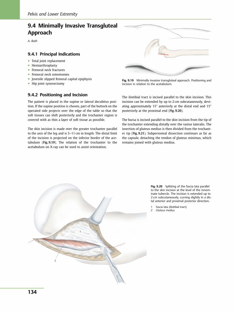
9.4 Minimally Invasive TransglutealApproachA. Roth
9.4.1 Principal Indications● Total joint replacement● Hemiarthroplasty● Femoral neck fractures● Femoral neck osteotomies● Juvenile slipped femoral capital epiphysis● Hip joint synovectomy
9.4.2 Positioning and Incision
The patient is placed in the supine or lateral decubitus posi-tion. If the supine position is chosen, part of the buttock on theoperated side projects over the edge of the table so that thesoft tissues can shift posteriorly and the trochanter region iscovered with as thin a layer of soft tissue as possible.
The skin incision is made over the greater trochanter parallelto the axis of the leg and is 5–11 cm in length. The distal limitof the incision is projected on the inferior border of the ace-tabulum (Fig. 9.19). The relation of the trochanter to theacetabulum on X-ray can be used to assist orientation.
The iliotibial tract is incised parallel to the skin incision. Thisincision can be extended by up to 2 cm subcutaneously, devi-ating approximately 15° anteriorly at the distal end and 15°posteriorly at the proximal end (Fig. 9.20).
The bursa is incised parallel to the skin incision from the tip ofthe trochanter extending distally over the vastus lateralis. Theinsertion of gluteus medius is then divided from the trochant-er tip (Fig. 9.21). Subperiosteal dissection continues as far asthe capsule, detaching the tendon of gluteus minimus, whichremains joined with gluteus medius.
1
2
Fig. 9.19 Minimally invasive transgluteal approach. Positioning andincision in relation to the acetabulum.
Fig. 9.20 Splitting of the fascia lata parallelto the skin incision at the level of the innom-inate tubercle. The incision is extended up to2 cm subcutaneously, curving slightly in a dis-tal anterior and proximal posterior direction.
1 Fascia lata (iliotibial tract)2 Gluteus medius
Pelvis and Lower Extremity
134
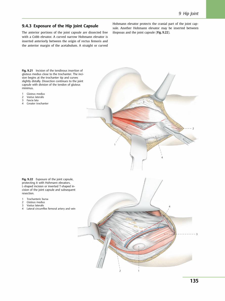
9.4.3 Exposure of the Hip Joint Capsule
The anterior portions of the joint capsule are dissected freewith a Cobb elevator. A curved narrow Hohmann elevator isinserted anteriorly between the origin of rectus femoris andthe anterior margin of the acetabulum. A straight or curved
Hohmann elevator protects the cranial part of the joint cap-sule. Another Hohmann elevator may be inserted betweeniliopsoas and the joint capsule (Fig. 9.22).
1
3
2
4
Fig. 9.21 Incision of the tendinous insertion ofgluteus medius close to the trochanter. The inci-sion begins at the trochanter tip and curvesslightly distally. Dissection continues to the jointcapsule with division of the tendon of gluteusminimus.
1 Gluteus medius2 Vastus lateralis3 Fascia lata4 Greater trochanter
4
3
12
Fig. 9.22 Exposure of the joint capsule,protecting it with Hohmann elevators.L-shaped incision or inverted T-shaped in-cision of the joint capsule and subsequentresection.
1 Trochanteric bursa2 Gluteus medius3 Vastus lateralis4 Lateral circumflex femoral artery and vein
9 Hip Joint
135
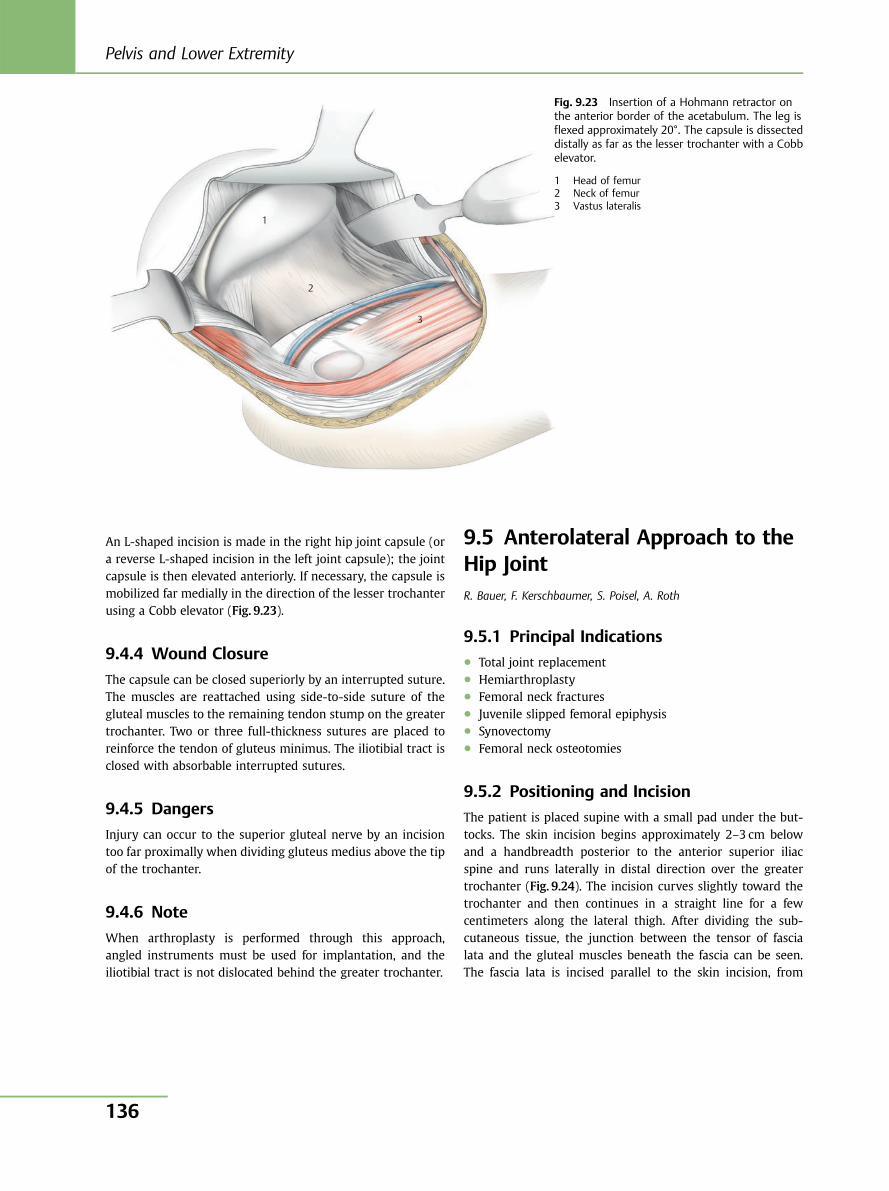
An L-shaped incision is made in the right hip joint capsule (ora reverse L-shaped incision in the left joint capsule); the jointcapsule is then elevated anteriorly. If necessary, the capsule ismobilized far medially in the direction of the lesser trochanterusing a Cobb elevator (Fig. 9.23).
9.4.4 Wound Closure
The capsule can be closed superiorly by an interrupted suture.The muscles are reattached using side-to-side suture of thegluteal muscles to the remaining tendon stump on the greatertrochanter. Two or three full-thickness sutures are placed toreinforce the tendon of gluteus minimus. The iliotibial tract isclosed with absorbable interrupted sutures.
9.4.5 Dangers
Injury can occur to the superior gluteal nerve by an incisiontoo far proximally when dividing gluteus medius above the tipof the trochanter.
9.4.6 Note
When arthroplasty is performed through this approach,angled instruments must be used for implantation, and theiliotibial tract is not dislocated behind the greater trochanter.
9.5 Anterolateral Approach to theHip JointR. Bauer, F. Kerschbaumer, S. Poisel, A. Roth
9.5.1 Principal Indications● Total joint replacement● Hemiarthroplasty● Femoral neck fractures● Juvenile slipped femoral epiphysis● Synovectomy● Femoral neck osteotomies
9.5.2 Positioning and Incision
The patient is placed supine with a small pad under the but-tocks. The skin incision begins approximately 2–3 cm belowand a handbreadth posterior to the anterior superior iliacspine and runs laterally in distal direction over the greatertrochanter (Fig. 9.24). The incision curves slightly toward thetrochanter and then continues in a straight line for a fewcentimeters along the lateral thigh. After dividing the sub-cutaneous tissue, the junction between the tensor of fascialata and the gluteal muscles beneath the fascia can be seen.The fascia lata is incised parallel to the skin incision, from
1
2
3
Fig. 9.23 Insertion of a Hohmann retractor onthe anterior border of the acetabulum. The leg isflexed approximately 20°. The capsule is dissecteddistally as far as the lesser trochanter with a Cobbelevator.
1 Head of femur2 Neck of femur3 Vastus lateralis
Pelvis and Lower Extremity
136
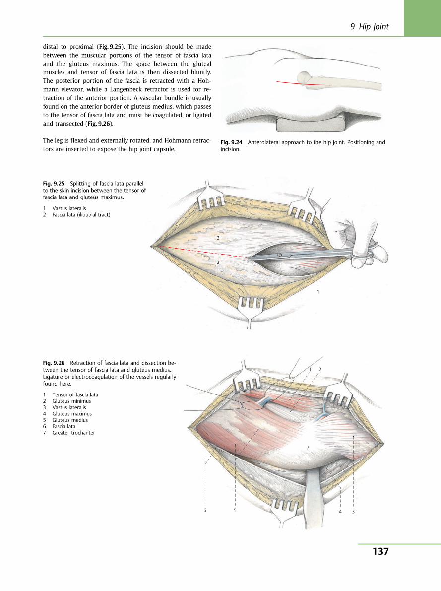
distal to proximal (Fig. 9.25). The incision should be madebetween the muscular portions of the tensor of fascia lataand the gluteus maximus. The space between the glutealmuscles and tensor of fascia lata is then dissected bluntly.The posterior portion of the fascia is retracted with a Hoh-mann elevator, while a Langenbeck retractor is used for re-traction of the anterior portion. A vascular bundle is usuallyfound on the anterior border of gluteus medius, which passesto the tensor of fascia lata and must be coagulated, or ligatedand transected (Fig. 9.26).
The leg is flexed and externally rotated, and Hohmann retrac-tors are inserted to expose the hip joint capsule.
Fig. 9.24 Anterolateral approach to the hip joint. Positioning andincision.
2
2
1
Fig. 9.25 Splitting of fascia lata parallelto the skin incision between the tensor offascia lata and gluteus maximus.
1 Vastus lateralis2 Fascia lata (iliotibial tract)
6 5 4 3
7
2 1 Fig. 9.26 Retraction of fascia lata and dissection be-tween the tensor of fascia lata and gluteus medius.Ligature or electrocoagulation of the vessels regularlyfound here.
1 Tensor of fascia lata2 Gluteus minimus3 Vastus lateralis4 Gluteus maximus5 Gluteus medius6 Fascia lata7 Greater trochanter
9 Hip Joint
137
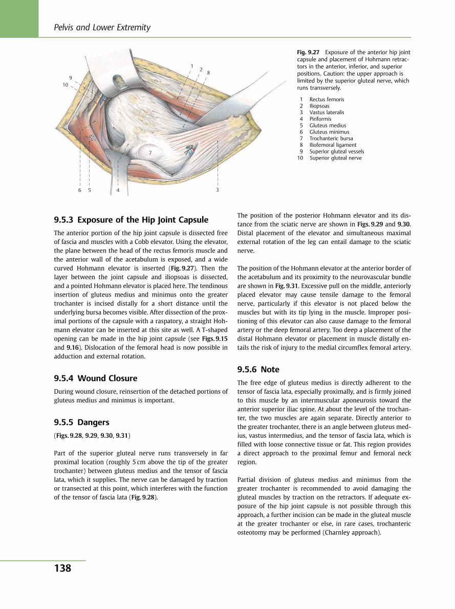
9.5.3 Exposure of the Hip Joint Capsule
The anterior portion of the hip joint capsule is dissected freeof fascia and muscles with a Cobb elevator. Using the elevator,the plane between the head of the rectus femoris muscle andthe anterior wall of the acetabulum is exposed, and a widecurved Hohmann elevator is inserted (Fig. 9.27). Then thelayer between the joint capsule and iliopsoas is dissected,and a pointed Hohmann elevator is placed here. The tendinousinsertion of gluteus medius and minimus onto the greatertrochanter is incised distally for a short distance until theunderlying bursa becomes visible. After dissection of the prox-imal portions of the capsule with a raspatory, a straight Hoh-mann elevator can be inserted at this site as well. A T-shapedopening can be made in the hip joint capsule (see Figs. 9.15and 9.16). Dislocation of the femoral head is now possible inadduction and external rotation.
9.5.4 Wound Closure
During wound closure, reinsertion of the detached portions ofgluteus medius and minimus is important.
9.5.5 Dangers
(Figs. 9.28, 9.29, 9.30, 9.31)
Part of the superior gluteal nerve runs transversely in farproximal location (roughly 5 cm above the tip of the greatertrochanter) between gluteus medius and the tensor of fascialata, which it supplies. The nerve can be damaged by tractionor transected at this point, which interferes with the functionof the tensor of fascia lata (Fig. 9.28).
The position of the posterior Hohmann elevator and its dis-tance from the sciatic nerve are shown in Figs. 9.29 and 9.30.Distal placement of the elevator and simultaneous maximalexternal rotation of the leg can entail damage to the sciaticnerve.
The position of the Hohmann elevator at the anterior border ofthe acetabulum and its proximity to the neurovascular bundleare shown in Fig. 9.31. Excessive pull on the middle, anteriorlyplaced elevator may cause tensile damage to the femoralnerve, particularly if this elevator is not placed below themuscles but with its tip lying in the muscle. Improper posi-tioning of this elevator can also cause damage to the femoralartery or the deep femoral artery. Too deep a placement of thedistal Hohmann elevator or placement in muscle distally en-tails the risk of injury to the medial circumflex femoral artery.
9.5.6 Note
The free edge of gluteus medius is directly adherent to thetensor of fascia lata, especially proximally, and is firmly joinedto this muscle by an intermuscular aponeurosis toward theanterior superior iliac spine. At about the level of the trochan-ter, the two muscles are again separate. Directly anterior tothe greater trochanter, there is an angle between gluteus med-ius, vastus intermedius, and the tensor of fascia lata, which isfilled with loose connective tissue or fat. This region providesa direct approach to the proximal femur and femoral neckregion.
Partial division of gluteus medius and minimus from thegreater trochanter is recommended to avoid damaging thegluteal muscles by traction on the retractors. If adequate ex-posure of the hip joint capsule is not possible through thisapproach, a further incision can be made in the gluteal muscleat the greater trochanter or else, in rare cases, trochantericosteotomy may be performed (Charnley approach).
1 2 8
3 4
7
5 6
10 9
Fig. 9.27 Exposure of the anterior hip jointcapsule and placement of Hohmann retrac-tors in the anterior, inferior, and superiorpositions. Caution: the upper approach islimited by the superior gluteal nerve, whichruns transversely.
1 Rectus femoris2 Iliopsoas3 Vastus lateralis4 Piriformis5 Gluteus medius6 Gluteus minimus7 Trochanteric bursa8 Iliofemoral ligament9 Superior gluteal vessels10 Superior gluteal nerve
Pelvis and Lower Extremity
138
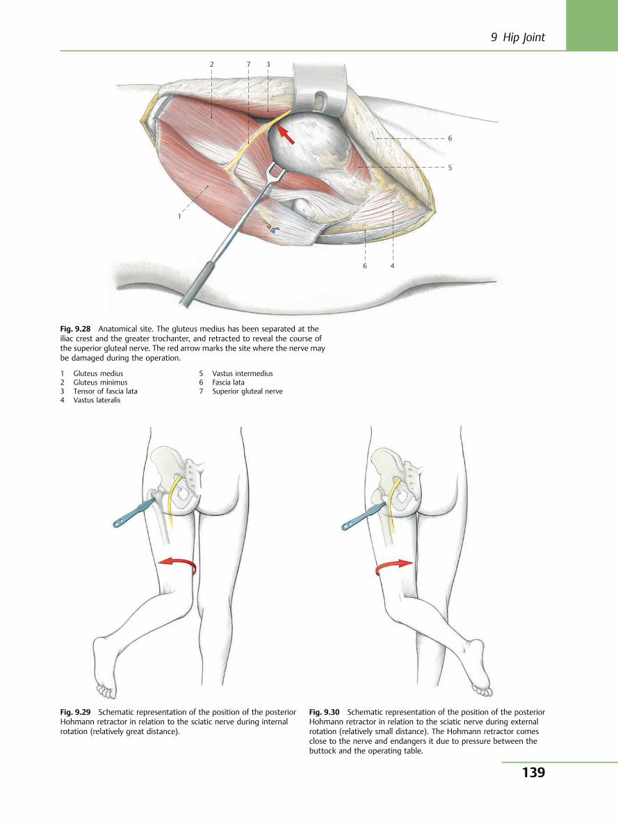
1
2 7 3
6
5
4 6
Fig. 9.28 Anatomical site. The gluteus medius has been separated at theiliac crest and the greater trochanter, and retracted to reveal the course ofthe superior gluteal nerve. The red arrow marks the site where the nerve maybe damaged during the operation.
1 Gluteus medius2 Gluteus minimus3 Tensor of fascia lata4 Vastus lateralis
5 Vastus intermedius6 Fascia lata7 Superior gluteal nerve
Fig. 9.29 Schematic representation of the position of the posteriorHohmann retractor in relation to the sciatic nerve during internalrotation (relatively great distance).
Fig. 9.30 Schematic representation of the position of the posteriorHohmann retractor in relation to the sciatic nerve during externalrotation (relatively small distance). The Hohmann retractor comesclose to the nerve and endangers it due to pressure between thebuttock and the operating table.
9 Hip Joint
139
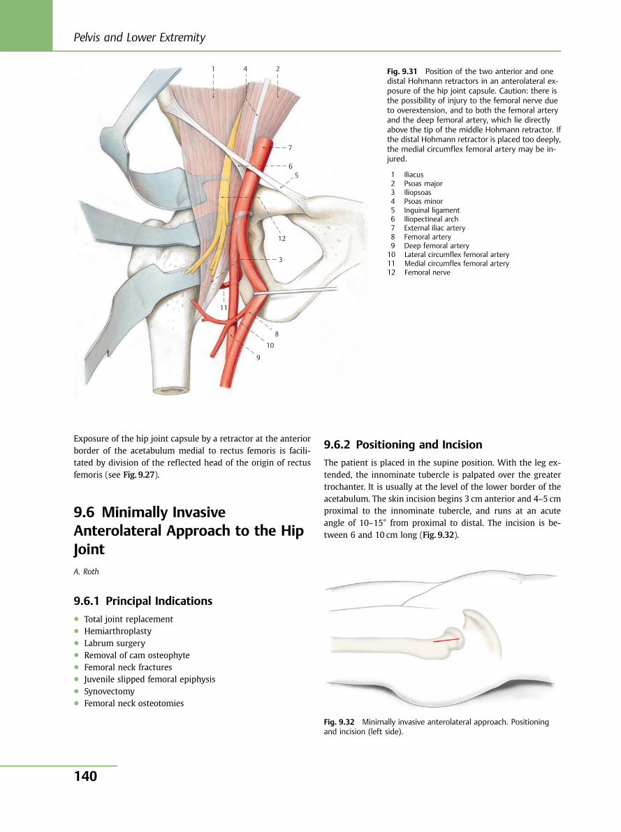
Exposure of the hip joint capsule by a retractor at the anteriorborder of the acetabulum medial to rectus femoris is facili-tated by division of the reflected head of the origin of rectusfemoris (see Fig. 9.27).
9.6 Minimally InvasiveAnterolateral Approach to the HipJointA. Roth
9.6.1 Principal Indications● Total joint replacement● Hemiarthroplasty● Labrum surgery● Removal of cam osteophyte● Femoral neck fractures● Juvenile slipped femoral epiphysis● Synovectomy● Femoral neck osteotomies
9.6.2 Positioning and Incision
The patient is placed in the supine position. With the leg ex-tended, the innominate tubercle is palpated over the greatertrochanter. It is usually at the level of the lower border of theacetabulum. The skin incision begins 3 cm anterior and 4–5 cmproximal to the innominate tubercle, and runs at an acuteangle of 10–15° from proximal to distal. The incision is be-tween 6 and 10 cm long (Fig. 9.32).
1 4 2
7
6 5
12
3
11
8
10
9
Fig. 9.31 Position of the two anterior and onedistal Hohmann retractors in an anterolateral ex-posure of the hip joint capsule. Caution: there isthe possibility of injury to the femoral nerve dueto overextension, and to both the femoral arteryand the deep femoral artery, which lie directlyabove the tip of the middle Hohmann retractor. Ifthe distal Hohmann retractor is placed too deeply,the medial circumflex femoral artery may be in-jured.
1 Iliacus2 Psoas major3 Iliopsoas4 Psoas minor5 Inguinal ligament6 Iliopectineal arch7 External iliac artery8 Femoral artery9 Deep femoral artery10 Lateral circumflex femoral artery11 Medial circumflex femoral artery12 Femoral nerve
Fig. 9.32 Minimally invasive anterolateral approach. Positioningand incision (left side).
Pelvis and Lower Extremity
140
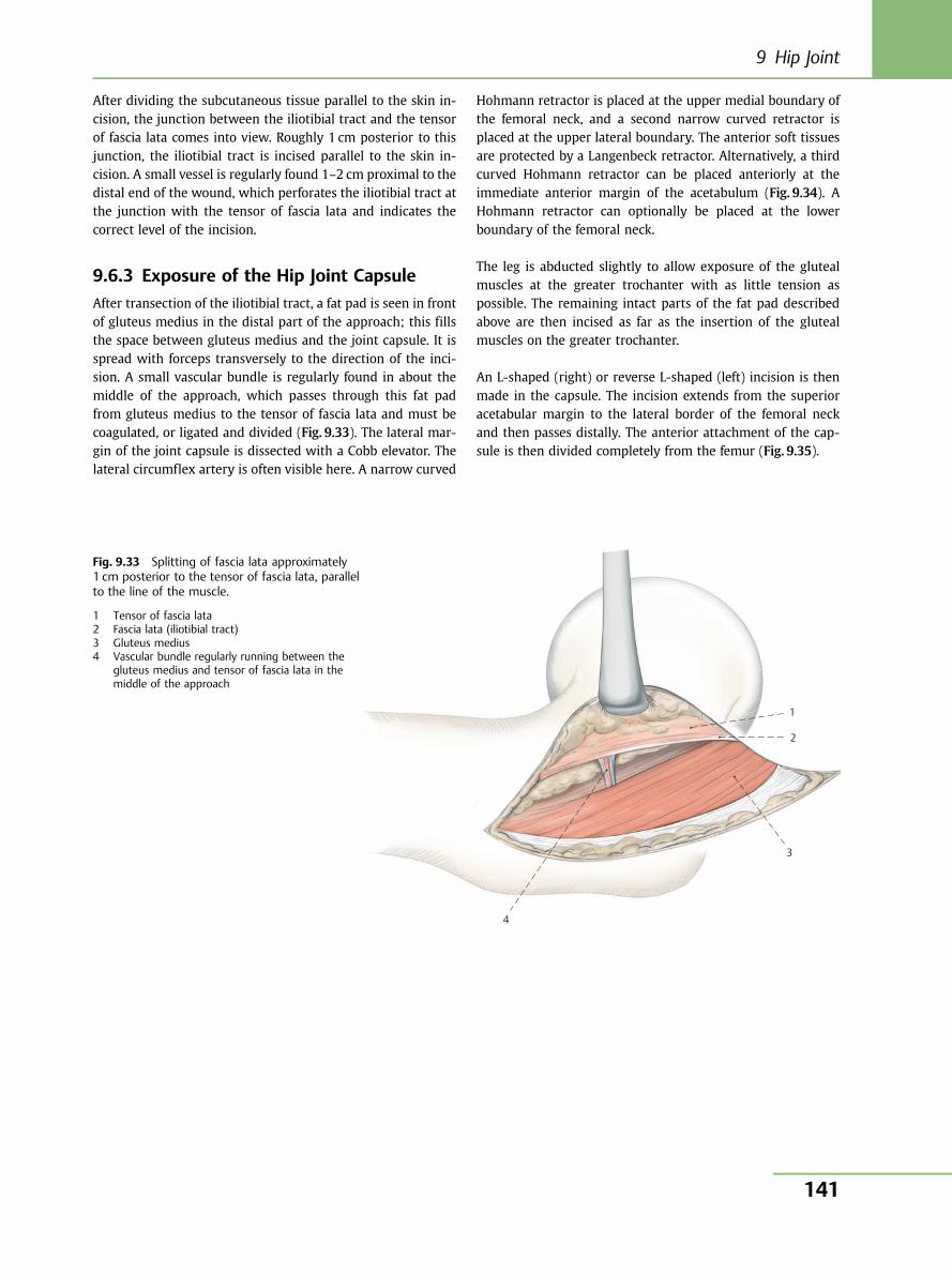
After dividing the subcutaneous tissue parallel to the skin in-cision, the junction between the iliotibial tract and the tensorof fascia lata comes into view. Roughly 1 cm posterior to thisjunction, the iliotibial tract is incised parallel to the skin in-cision. A small vessel is regularly found 1–2 cm proximal to thedistal end of the wound, which perforates the iliotibial tract atthe junction with the tensor of fascia lata and indicates thecorrect level of the incision.
9.6.3 Exposure of the Hip Joint Capsule
After transection of the iliotibial tract, a fat pad is seen in frontof gluteus medius in the distal part of the approach; this fillsthe space between gluteus medius and the joint capsule. It isspread with forceps transversely to the direction of the inci-sion. A small vascular bundle is regularly found in about themiddle of the approach, which passes through this fat padfrom gluteus medius to the tensor of fascia lata and must becoagulated, or ligated and divided (Fig. 9.33). The lateral mar-gin of the joint capsule is dissected with a Cobb elevator. Thelateral circumflex artery is often visible here. A narrow curved
Hohmann retractor is placed at the upper medial boundary ofthe femoral neck, and a second narrow curved retractor isplaced at the upper lateral boundary. The anterior soft tissuesare protected by a Langenbeck retractor. Alternatively, a thirdcurved Hohmann retractor can be placed anteriorly at theimmediate anterior margin of the acetabulum (Fig. 9.34). AHohmann retractor can optionally be placed at the lowerboundary of the femoral neck.
The leg is abducted slightly to allow exposure of the glutealmuscles at the greater trochanter with as little tension aspossible. The remaining intact parts of the fat pad describedabove are then incised as far as the insertion of the glutealmuscles on the greater trochanter.
An L-shaped (right) or reverse L-shaped (left) incision is thenmade in the capsule. The incision extends from the superioracetabular margin to the lateral border of the femoral neckand then passes distally. The anterior attachment of the cap-sule is then divided completely from the femur (Fig. 9.35).
1
2
3
4
Fig. 9.33 Splitting of fascia lata approximately1 cm posterior to the tensor of fascia lata, parallelto the line of the muscle.
1 Tensor of fascia lata2 Fascia lata (iliotibial tract)3 Gluteus medius4 Vascular bundle regularly running between the
gluteus medius and tensor of fascia lata in themiddle of the approach
9 Hip Joint
141
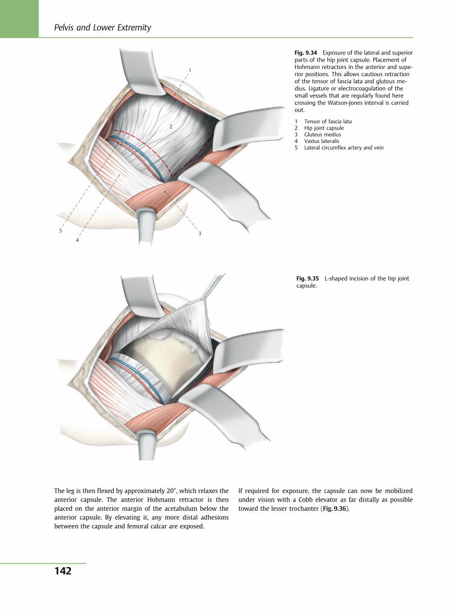
The leg is then flexed by approximately 20°, which relaxes theanterior capsule. The anterior Hohmann retractor is thenplaced on the anterior margin of the acetabulum below theanterior capsule. By elevating it, any more distal adhesionsbetween the capsule and femoral calcar are exposed.
If required for exposure, the capsule can now be mobilizedunder vision with a Cobb elevator as far distally as possibletoward the lesser trochanter (Fig. 9.36).
1
2
3 4
5
Fig. 9.34 Exposure of the lateral and superiorparts of the hip joint capsule. Placement ofHohmann retractors in the anterior and supe-rior positions. This allows cautious retractionof the tensor of fascia lata and gluteus me-dius. Ligature or electrocoagulation of thesmall vessels that are regularly found herecrossing the Watson-Jones interval is carriedout.
1 Tensor of fascia lata2 Hip joint capsule3 Gluteus medius4 Vastus lateralis5 Lateral circumflex artery and vein
Fig. 9.35 L-shaped incision of the hip jointcapsule.
Pelvis and Lower Extremity
142
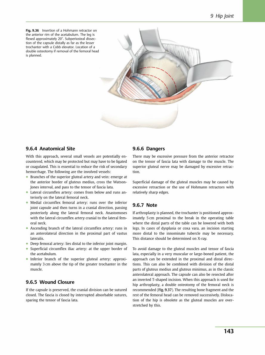
9.6.4 Anatomical Site
With this approach, several small vessels are potentially en-countered, which may be protected but may have to be ligatedor coagulated. This is essential to reduce the risk of secondaryhemorrhage. The following are the involved vessels:● Branches of the superior gluteal artery and vein: emerge at
the anterior border of gluteus medius, cross the Watson-Jones interval, and pass to the tensor of fascia lata.
● Lateral circumflex artery: comes from below and runs an-teriorly on the lateral femoral neck.
● Medial circumflex femoral artery: runs over the inferiorjoint capsule and then turns in a cranial direction, passingposteriorly along the lateral femoral neck. Anastomoseswith the lateral circumflex artery cranial to the lateral fem-oral neck.
● Ascending branch of the lateral circumflex artery: runs inan anterolateral direction in the proximal part of vastuslateralis.
● Deep femoral artery: lies distal to the inferior joint margin.● Superficial circumflex iliac artery: at the upper border of
the acetabulum.● Inferior branch of the superior gluteal artery: approxi-
mately 3 cm above the tip of the greater trochanter in themuscle.
9.6.5 Wound Closure
If the capsule is preserved, the cranial division can be suturedclosed. The fascia is closed by interrupted absorbable sutures,sparing the tensor of fascia lata.
9.6.6 Dangers
There may be excessive pressure from the anterior retractoron the tensor of fascia lata with damage to the muscle. Thesuperior gluteal nerve may be damaged by excessive retrac-tion.
Superficial damage of the gluteal muscles may be caused byexcessive retraction or the use of Hohmann retractors withrelatively sharp edges.
9.6.7 Note
If arthroplasty is planned, the trochanter is positioned approx-imately 5 cm proximal to the break in the operating tablewhere the distal parts of the table can be lowered with bothlegs. In cases of dysplasia or coxa vara, an incision startingmore distal to the innominate tubercle may be necessary.This distance should be determined on X-ray.
To avoid damage to the gluteal muscles and tensor of fascialata, especially in a very muscular or large-boned patient, theapproach can be extended in the proximal and distal direc-tions. This can also be combined with division of the distalparts of gluteus medius and gluteus minimus, as in the classicanterolateral approach. The capsule can also be resected afteran inverted T-shaped incision. When this approach is used forhip arthroplasty, a double osteotomy of the femoral neck isrecommended (Fig. 9.37). The resulting bone fragment and therest of the femoral head can be removed successively. Disloca-tion of the hip is obsolete as the gluteal muscles are over-stretched by this.
Fig. 9.36 Insertion of a Hohmann retractor onthe anterior rim of the acetabulum. The leg isflexed approximately 20°. Subperiosteal dissec-tion of the capsule distally as far as the lessertrochanter with a Cobb elevator. Location of adouble osteotomy if removal of the femoral headis planned.
9 Hip Joint
143
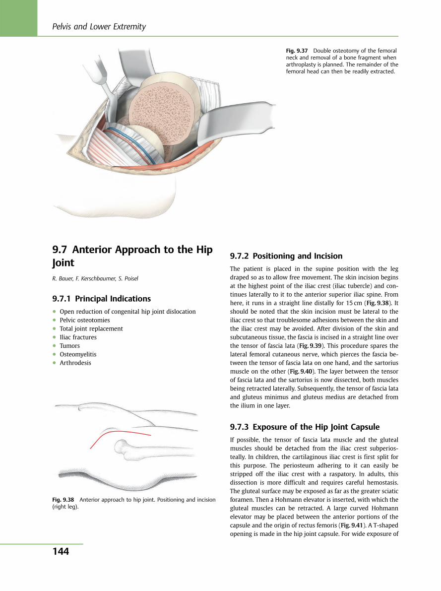
9.7 Anterior Approach to the HipJointR. Bauer, F. Kerschbaumer, S. Poisel
9.7.1 Principal Indications● Open reduction of congenital hip joint dislocation● Pelvic osteotomies● Total joint replacement● Iliac fractures● Tumors● Osteomyelitis● Arthrodesis
9.7.2 Positioning and Incision
The patient is placed in the supine position with the legdraped so as to allow free movement. The skin incision beginsat the highest point of the iliac crest (iliac tubercle) and con-tinues laterally to it to the anterior superior iliac spine. Fromhere, it runs in a straight line distally for 15 cm (Fig. 9.38). Itshould be noted that the skin incision must be lateral to theiliac crest so that troublesome adhesions between the skin andthe iliac crest may be avoided. After division of the skin andsubcutaneous tissue, the fascia is incised in a straight line overthe tensor of fascia lata (Fig. 9.39). This procedure spares thelateral femoral cutaneous nerve, which pierces the fascia be-tween the tensor of fascia lata on one hand, and the sartoriusmuscle on the other (Fig. 9.40). The layer between the tensorof fascia lata and the sartorius is now dissected, both musclesbeing retracted laterally. Subsequently, the tensor of fascia lataand gluteus minimus and gluteus medius are detached fromthe ilium in one layer.
9.7.3 Exposure of the Hip Joint Capsule
If possible, the tensor of fascia lata muscle and the glutealmuscles should be detached from the iliac crest subperios-teally. In children, the cartilaginous iliac crest is first split forthis purpose. The periosteum adhering to it can easily bestripped off the iliac crest with a raspatory. In adults, thisdissection is more difficult and requires careful hemostasis.The gluteal surface may be exposed as far as the greater sciaticforamen. Then a Hohmann elevator is inserted, with which thegluteal muscles can be retracted. A large curved Hohmannelevator may be placed between the anterior portions of thecapsule and the origin of rectus femoris (Fig. 9.41). A T-shapedopening is made in the hip joint capsule. For wide exposure of
Fig. 9.37 Double osteotomy of the femoralneck and removal of a bone fragment whenarthroplasty is planned. The remainder of thefemoral head can then be readily extracted.
Fig. 9.38 Anterior approach to hip joint. Positioning and incision(right leg).
Pelvis and Lower Extremity
144
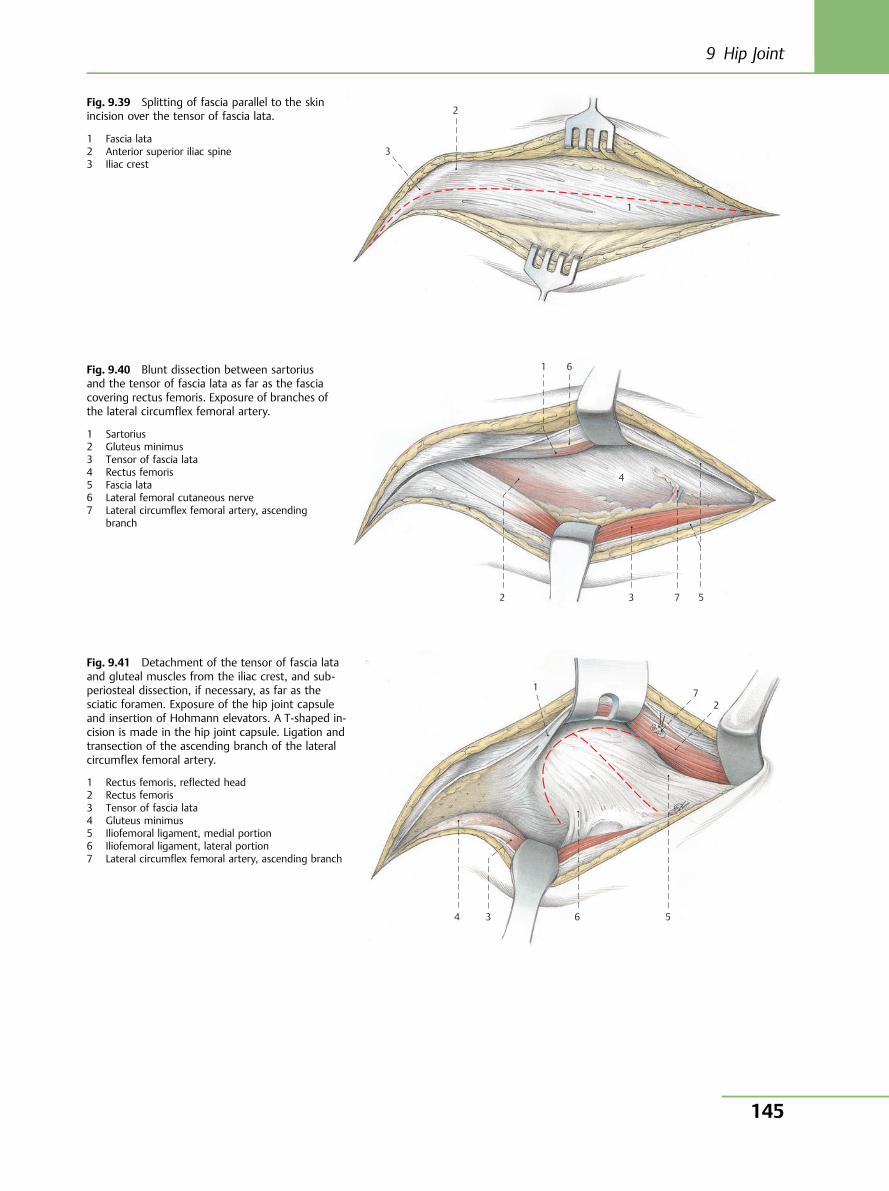
3
2
1
Fig. 9.39 Splitting of fascia parallel to the skinincision over the tensor of fascia lata.
1 Fascia lata2 Anterior superior iliac spine3 Iliac crest
2 3 7 5
4
6 1 Fig. 9.40 Blunt dissection between sartoriusand the tensor of fascia lata as far as the fasciacovering rectus femoris. Exposure of branches ofthe lateral circumflex femoral artery.
1 Sartorius2 Gluteus minimus3 Tensor of fascia lata4 Rectus femoris5 Fascia lata6 Lateral femoral cutaneous nerve7 Lateral circumflex femoral artery, ascending
branch
7
6 5 4 3
1
2
Fig. 9.41 Detachment of the tensor of fascia lataand gluteal muscles from the iliac crest, and sub-periosteal dissection, if necessary, as far as thesciatic foramen. Exposure of the hip joint capsuleand insertion of Hohmann elevators. A T-shaped in-cision is made in the hip joint capsule. Ligation andtransection of the ascending branch of the lateralcircumflex femoral artery.
1 Rectus femoris, reflected head2 Rectus femoris3 Tensor of fascia lata4 Gluteus minimus5 Iliofemoral ligament, medial portion6 Iliofemoral ligament, lateral portion7 Lateral circumflex femoral artery, ascending branch
9 Hip Joint
145
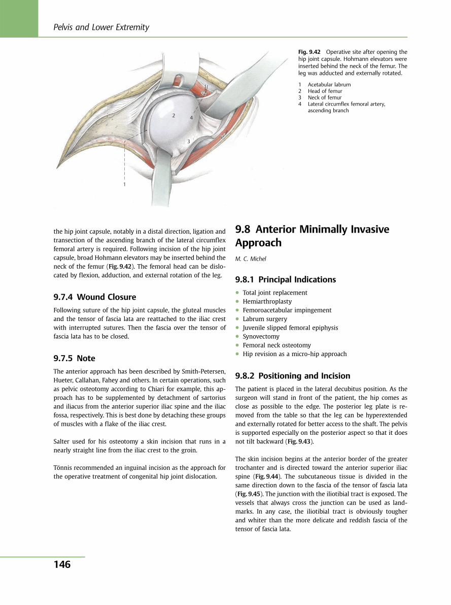
the hip joint capsule, notably in a distal direction, ligation andtransection of the ascending branch of the lateral circumflexfemoral artery is required. Following incision of the hip jointcapsule, broad Hohmann elevators may be inserted behind theneck of the femur (Fig. 9.42). The femoral head can be dislo-cated by flexion, adduction, and external rotation of the leg.
9.7.4 Wound Closure
Following suture of the hip joint capsule, the gluteal musclesand the tensor of fascia lata are reattached to the iliac crestwith interrupted sutures. Then the fascia over the tensor offascia lata has to be closed.
9.7.5 Note
The anterior approach has been described by Smith-Petersen,Hueter, Callahan, Fahey and others. In certain operations, suchas pelvic osteotomy according to Chiari for example, this ap-proach has to be supplemented by detachment of sartoriusand iliacus from the anterior superior iliac spine and the iliacfossa, respectively. This is best done by detaching these groupsof muscles with a flake of the iliac crest.
Salter used for his osteotomy a skin incision that runs in anearly straight line from the iliac crest to the groin.
Tönnis recommended an inguinal incision as the approach forthe operative treatment of congenital hip joint dislocation.
9.8 Anterior Minimally InvasiveApproachM. C. Michel
9.8.1 Principal Indications● Total joint replacement● Hemiarthroplasty● Femoroacetabular impingement● Labrum surgery● Juvenile slipped femoral epiphysis● Synovectomy● Femoral neck osteotomy● Hip revision as a micro-hip approach
9.8.2 Positioning and Incision
The patient is placed in the lateral decubitus position. As thesurgeon will stand in front of the patient, the hip comes asclose as possible to the edge. The posterior leg plate is re-moved from the table so that the leg can be hyperextendedand externally rotated for better access to the shaft. The pelvisis supported especially on the posterior aspect so that it doesnot tilt backward (Fig. 9.43).
The skin incision begins at the anterior border of the greatertrochanter and is directed toward the anterior superior iliacspine (Fig. 9.44). The subcutaneous tissue is divided in thesame direction down to the fascia of the tensor of fascia lata(Fig. 9.45). The junction with the iliotibial tract is exposed. Thevessels that always cross the junction can be used as land-marks. In any case, the iliotibial tract is obviously tougherand whiter than the more delicate and reddish fascia of thetensor of fascia lata.
4
3
1
2
Fig. 9.42 Operative site after opening thehip joint capsule. Hohmann elevators wereinserted behind the neck of the femur. Theleg was adducted and externally rotated.
1 Acetabular labrum2 Head of femur3 Neck of femur4 Lateral circumflex femoral artery,
ascending branch
Pelvis and Lower Extremity
146
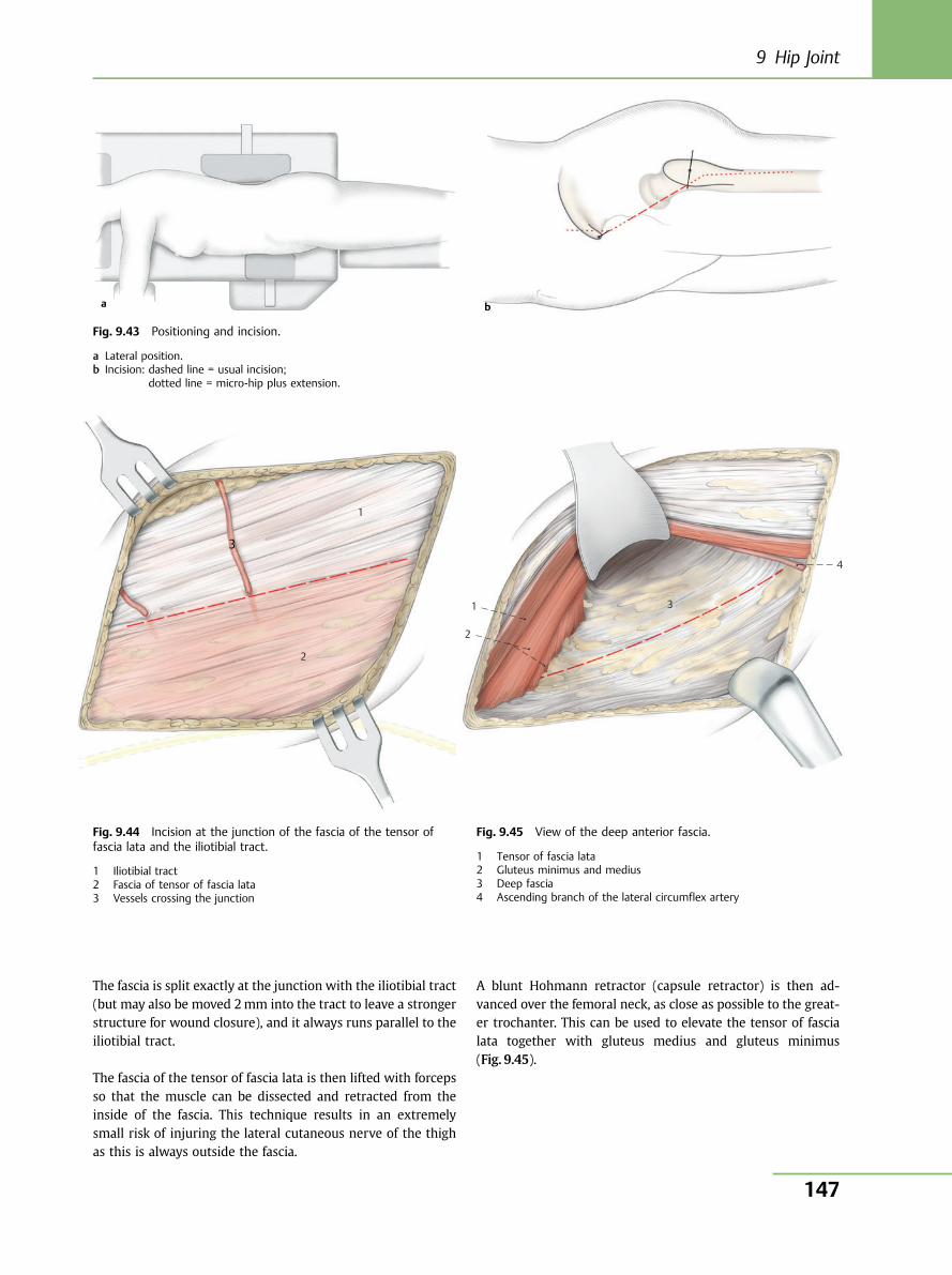
The fascia is split exactly at the junction with the iliotibial tract(but may also be moved 2mm into the tract to leave a strongerstructure for wound closure), and it always runs parallel to theiliotibial tract.
The fascia of the tensor of fascia lata is then lifted with forcepsso that the muscle can be dissected and retracted from theinside of the fascia. This technique results in an extremelysmall risk of injuring the lateral cutaneous nerve of the thighas this is always outside the fascia.
A blunt Hohmann retractor (capsule retractor) is then ad-vanced over the femoral neck, as close as possible to the great-er trochanter. This can be used to elevate the tensor of fascialata together with gluteus medius and gluteus minimus(Fig. 9.45).
a
Fig. 9.43 Positioning and incision.
a Lateral position.b Incision: dashed line = usual incision;
dotted line = micro-hip plus extension.
1
2
3
Fig. 9.44 Incision at the junction of the fascia of the tensor offascia lata and the iliotibial tract.
1 Iliotibial tract2 Fascia of tensor of fascia lata3 Vessels crossing the junction
4
3
2
1
Fig. 9.45 View of the deep anterior fascia.
1 Tensor of fascia lata2 Gluteus minimus and medius3 Deep fascia4 Ascending branch of the lateral circumflex artery
b
9 Hip Joint
147
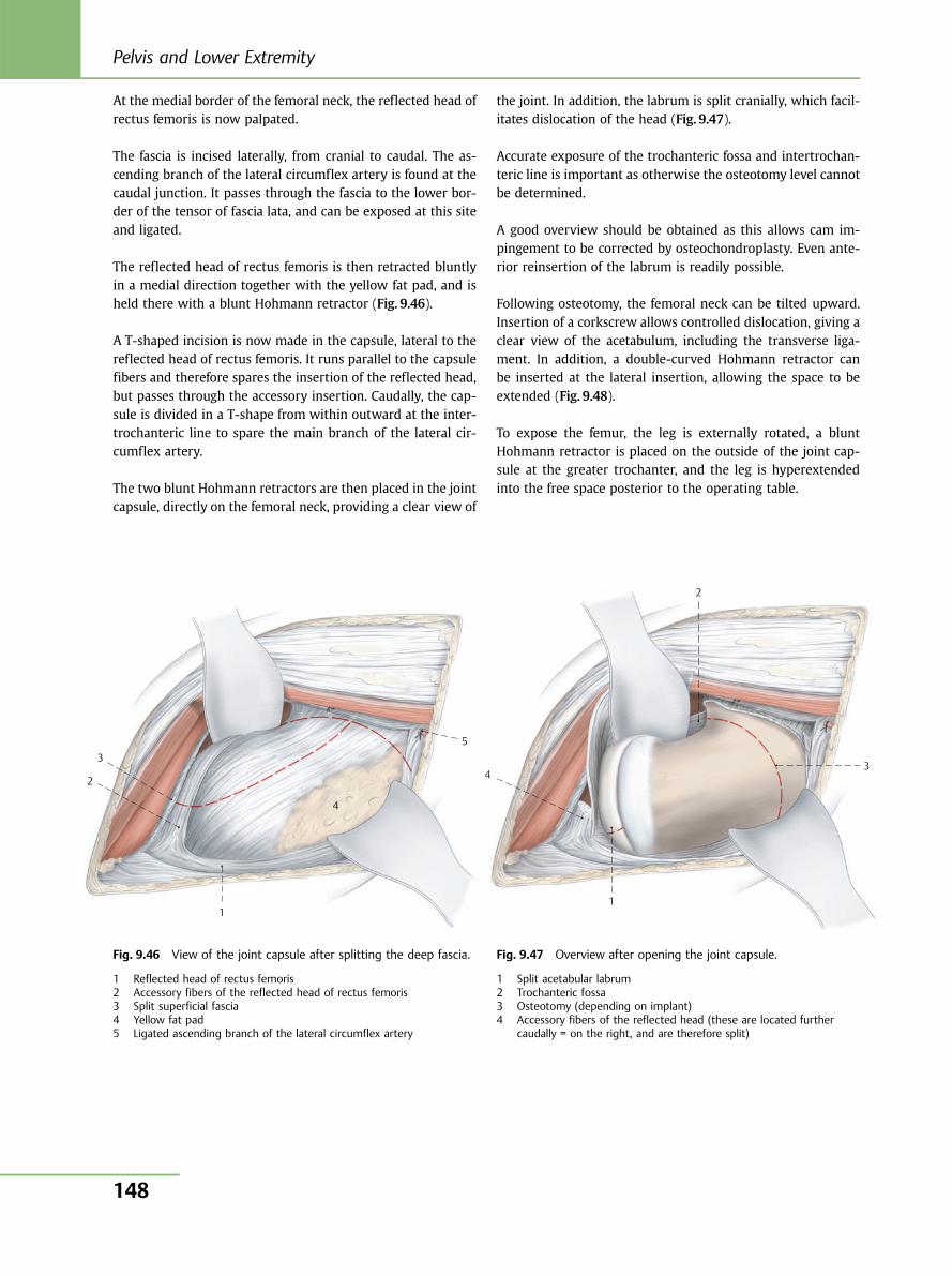
At the medial border of the femoral neck, the reflected head ofrectus femoris is now palpated.
The fascia is incised laterally, from cranial to caudal. The as-cending branch of the lateral circumflex artery is found at thecaudal junction. It passes through the fascia to the lower bor-der of the tensor of fascia lata, and can be exposed at this siteand ligated.
The reflected head of rectus femoris is then retracted bluntlyin a medial direction together with the yellow fat pad, and isheld there with a blunt Hohmann retractor (Fig. 9.46).
A T-shaped incision is now made in the capsule, lateral to thereflected head of rectus femoris. It runs parallel to the capsulefibers and therefore spares the insertion of the reflected head,but passes through the accessory insertion. Caudally, the cap-sule is divided in a T-shape from within outward at the inter-trochanteric line to spare the main branch of the lateral cir-cumflex artery.
The two blunt Hohmann retractors are then placed in the jointcapsule, directly on the femoral neck, providing a clear view of
the joint. In addition, the labrum is split cranially, which facil-itates dislocation of the head (Fig. 9.47).
Accurate exposure of the trochanteric fossa and intertrochan-teric line is important as otherwise the osteotomy level cannotbe determined.
A good overview should be obtained as this allows cam im-pingement to be corrected by osteochondroplasty. Even ante-rior reinsertion of the labrum is readily possible.
Following osteotomy, the femoral neck can be tilted upward.Insertion of a corkscrew allows controlled dislocation, giving aclear view of the acetabulum, including the transverse liga-ment. In addition, a double-curved Hohmann retractor canbe inserted at the lateral insertion, allowing the space to beextended (Fig. 9.48).
To expose the femur, the leg is externally rotated, a bluntHohmann retractor is placed on the outside of the joint cap-sule at the greater trochanter, and the leg is hyperextendedinto the free space posterior to the operating table.
1
2
3
4
5
Fig. 9.46 View of the joint capsule after splitting the deep fascia.
1 Reflected head of rectus femoris2 Accessory fibers of the reflected head of rectus femoris3 Split superficial fascia4 Yellow fat pad5 Ligated ascending branch of the lateral circumflex artery
1
2
3 4
Fig. 9.47 Overview after opening the joint capsule.
1 Split acetabular labrum2 Trochanteric fossa3 Osteotomy (depending on implant)4 Accessory fibers of the reflected head (these are located further
caudally = on the right, and are therefore split)
Pelvis and Lower Extremity
148
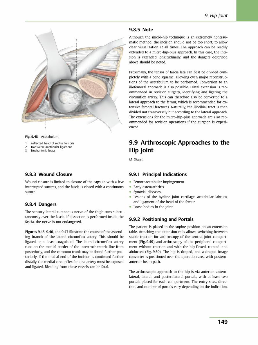
9.8.3 Wound Closure
Wound closure is limited to closure of the capsule with a fewinterrupted sutures, and the fascia is closed with a continuoussuture.
9.8.4 Dangers
The sensory lateral cutaneous nerve of the thigh runs subcu-taneously over the fascia. If dissection is performed inside thefascia, the nerve is not endangered.
Figures 9.45, 9.46, and 9.47 illustrate the course of the ascend-ing branch of the lateral circumflex artery. This should beligated or at least coagulated. The lateral circumflex arteryruns on the medial border of the intertrochanteric line fromposteriorly, and the common trunk may be found further pos-teriorly. If the medial end of the incision is continued furtherdistally, the medial circumflex femoral artery must be exposedand ligated. Bleeding from these vessels can be fatal.
9.8.5 Note
Although the micro-hip technique is an extremely nontrau-matic method, the incision should not be too short, to allowclear visualization at all times. The approach can be readilyextended to a micro-hip-plus approach. In this case, the inci-sion is extended longitudinally, and the dangers describedabove should be noted.
Proximally, the tensor of fascia lata can best be divided com-pletely with a bone squame, allowing even major reconstruc-tions of the acetabulum to be performed. Conversion to aniliofemoral approach is also possible. Distal extension is rec-ommended in revision surgery, identifying and ligating thecircumflex artery. This can therefore also be converted to alateral approach to the femur, which is recommended for ex-tensive femoral fractures. Naturally, the iliotibial tract is thendivided not transversely but according to the lateral approach.The extensions for the micro-hip-plus approach are also rec-ommended for revision operations if the surgeon is experi-enced.
9.9 Arthroscopic Approaches to theHip JointM. Dienst
9.9.1 Principal Indications● Femoroacetabular impingement● Early osteoarthritis● Synovial diseases● Lesions of the hyaline joint cartilage, acetabular labrum,
and ligament of the head of the femur● Loose bodies in the joint
9.9.2 Positioning and Portals
The patient is placed in the supine position on an extensiontable. Attaching the extension rails allows switching betweenstable traction for arthroscopy of the central joint compart-ment (Fig. 9.49) and arthroscopy of the peripheral compart-ment without traction and with the hip flexed, rotated, andabducted (Fig. 9.50). The hip is draped, and a draped imageconverter is positioned over the operation area with postero-anterior beam path.
The arthroscopic approach to the hip is via anterior, antero-lateral, lateral, and posterolateral portals, with at least twoportals placed for each compartment. The entry sites, direc-tion, and number of portals vary depending on the indication.
1
2
3
Fig. 9.48 Acetabulum.
1 Reflected head of rectus femoris2 Transverse acetabular ligament3 Trochanteric fossa
9 Hip Joint
149
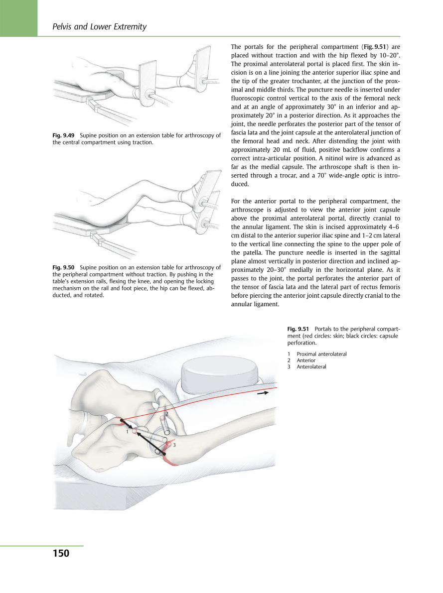
The portals for the peripheral compartment (Fig. 9.51) areplaced without traction and with the hip flexed by 10–20°.The proximal anterolateral portal is placed first. The skin in-cision is on a line joining the anterior superior iliac spine andthe tip of the greater trochanter, at the junction of the prox-imal and middle thirds. The puncture needle is inserted underfluoroscopic control vertical to the axis of the femoral neckand at an angle of approximately 30° in an inferior and ap-proximately 20° in a posterior direction. As it approaches thejoint, the needle perforates the posterior part of the tensor offascia lata and the joint capsule at the anterolateral junction ofthe femoral head and neck. After distending the joint withapproximately 20 mL of fluid, positive backflow confirms acorrect intra-articular position. A nitinol wire is advanced asfar as the medial capsule. The arthroscope shaft is then in-serted through a trocar, and a 70° wide-angle optic is intro-duced.
For the anterior portal to the peripheral compartment, thearthroscope is adjusted to view the anterior joint capsuleabove the proximal anterolateral portal, directly cranial tothe annular ligament. The skin is incised approximately 4–6cm distal to the anterior superior iliac spine and 1–2 cm lateralto the vertical line connecting the spine to the upper pole ofthe patella. The puncture needle is inserted in the sagittalplane almost vertically in posterior direction and inclined ap-proximately 20–30° medially in the horizontal plane. As itpasses to the joint, the portal perforates the anterior part ofthe tensor of fascia lata and the lateral part of rectus femorisbefore piercing the anterior joint capsule directly cranial to theannular ligament.
Fig. 9.49 Supine position on an extension table for arthroscopy ofthe central compartment using traction.
Fig. 9.50 Supine position on an extension table for arthroscopy ofthe peripheral compartment without traction. By pushing in thetable’s extension rails, flexing the knee, and opening the lockingmechanism on the rail and foot piece, the hip can be flexed, ab-ducted, and rotated.
1
3
2
Fig. 9.51 Portals to the peripheral compart-ment (red circles: skin; black circles: capsuleperforation.
1 Proximal anterolateral2 Anterior3 Anterolateral
Pelvis and Lower Extremity
150
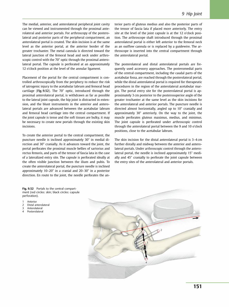
The medial, anterior, and anterolateral peripheral joint cavitycan be viewed and instrumented through the proximal ante-rolateral and anterior portals. For arthroscopy of the postero-lateral and posterior parts of the peripheral compartment, ananterolateral portal is created. The skin incision is at the samelevel as the anterior portal, at the anterior border of thegreater trochanter. The metal cannula is directed toward thelateral junction of the femoral head and neck under arthro-scopic control with the 70° optic through the proximal antero-lateral portal. The capsule is perforated at an approximately12 o’clock position at the level of the annular ligament.
Placement of the portal for the central compartment is con-trolled arthroscopically from the periphery to reduce the riskof iatrogenic injury to the acetabular labrum and femoral headcartilage (Fig. 9.52). The 70° optic, introduced through theproximal anterolateral portal, is withdrawn as far as possibleto the lateral joint capsule, the hip joint is distracted in exten-sion, and the blunt instruments in the anterior and antero-lateral portals are advanced between the acetabular labrumand femoral head cartilage into the central compartment. Ifthe joint capsule is tense and the soft tissues are bulky, it maybe necessary to create new portals through the existing skinincisions.
To create the anterior portal to the central compartment, thepuncture needle is inclined approximately 30° in medial di-rection and 30° cranially. As it advances toward the joint, theportal perforates the proximal muscle bellies of sartorius andrectus femoris, and parts of the tensor of fascia lata in the caseof a lateralized entry site. The capsule is perforated ideally atthe often visible junction between the ilium and pubis. Tocreate the anterolateral portal, the puncture needle is inclinedapproximately 10–20° in a cranial and 20–30° in a posteriordirection. En route to the joint, the needle perforates the an-
terior parts of gluteus medius and also the posterior parts ofthe tensor of fascia lata if placed more anteriorly. The entrysite at the level of the joint capsule is at the 12 o’clock posi-tion. The arthroscope shaft introduced through the proximalanterolateral portal is either left anterior to the femoral neckas an outflow cannula or is replaced by a guidewire. The ar-throscope is inserted into the central compartment throughthe anterolateral portal.
The posterolateral and distal anterolateral portals are fre-quently used accessory approaches. The posteromedial partsof the central compartment, including the caudal parts of theacetabular fossa, are reached through the posterolateral portal,while the distal anterolateral portal is required for therapeuticprocedures in the region of the anterolateral acetabular mar-gin. The portal entry site for the posterolateral portal is ap-proximately 3 cm posterior to the posterosuperior angle of thegreater trochanter at the same level as the skin incisions forthe anterolateral and anterior portals. The puncture needle isdirected almost horizontally, angled up to 10° cranially andapproximately 30° anteriorly. On the way to the joint, themuscle perforates gluteus maximus, medius, and minimus.The joint capsule is perforated under arthroscopic controlthrough the anterolateral portal between the 9 and 10 o’clockpositions, close to the acetabular labrum.
The skin incision for the distal anterolateral portal is 3–4 cmfurther distally and midway between the anterior and antero-lateral portals. Under arthroscopic control through the antero-lateral portal, the needle is inclined approximately 15° medi-ally and 45° cranially to perforate the joint capsule betweenthe entry sites of the anterolateral and anterior portals.
1
3
4
2
Fig. 9.52 Portals to the central compart-ment (red circles: skin; black circles: capsuleperforation).
1 Anterior2 Distal anterolateral3 Anterolateral4 Posterolateral
9 Hip Joint
151
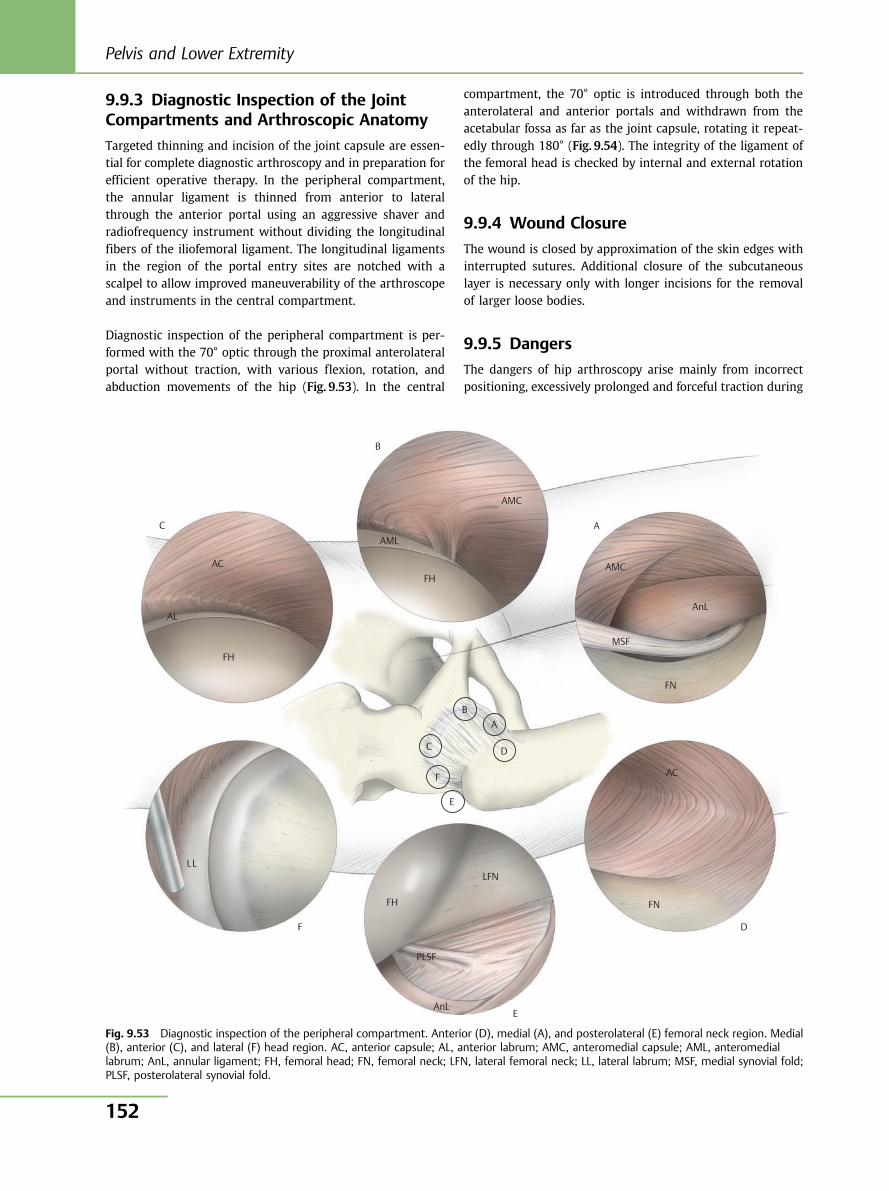
9.9.3 Diagnostic Inspection of the JointCompartments and Arthroscopic Anatomy
Targeted thinning and incision of the joint capsule are essen-tial for complete diagnostic arthroscopy and in preparation forefficient operative therapy. In the peripheral compartment,the annular ligament is thinned from anterior to lateralthrough the anterior portal using an aggressive shaver andradiofrequency instrument without dividing the longitudinalfibers of the iliofemoral ligament. The longitudinal ligamentsin the region of the portal entry sites are notched with ascalpel to allow improved maneuverability of the arthroscopeand instruments in the central compartment.
Diagnostic inspection of the peripheral compartment is per-formed with the 70° optic through the proximal anterolateralportal without traction, with various flexion, rotation, andabduction movements of the hip (Fig. 9.53). In the central
compartment, the 70° optic is introduced through both theanterolateral and anterior portals and withdrawn from theacetabular fossa as far as the joint capsule, rotating it repeat-edly through 180° (Fig. 9.54). The integrity of the ligament ofthe femoral head is checked by internal and external rotationof the hip.
9.9.4 Wound Closure
The wound is closed by approximation of the skin edges withinterrupted sutures. Additional closure of the subcutaneouslayer is necessary only with longer incisions for the removalof larger loose bodies.
9.9.5 Dangers
The dangers of hip arthroscopy arise mainly from incorrectpositioning, excessively prolonged and forceful traction during
AML
FH
AMC
AC
AL
FH
AMC
AnL
MSF
FN
AC
FN
LFN
FH
PLSF
AnL
DF
E
F
C
BA
D
E
B
C A
LL
Fig. 9.53 Diagnostic inspection of the peripheral compartment. Anterior (D), medial (A), and posterolateral (E) femoral neck region. Medial(B), anterior (C), and lateral (F) head region. AC, anterior capsule; AL, anterior labrum; AMC, anteromedial capsule; AML, anteromediallabrum; AnL, annular ligament; FH, femoral head; FN, femoral neck; LFN, lateral femoral neck; LL, lateral labrum; MSF, medial synovial fold;PLSF, posterolateral synovial fold.
Pelvis and Lower Extremity
152
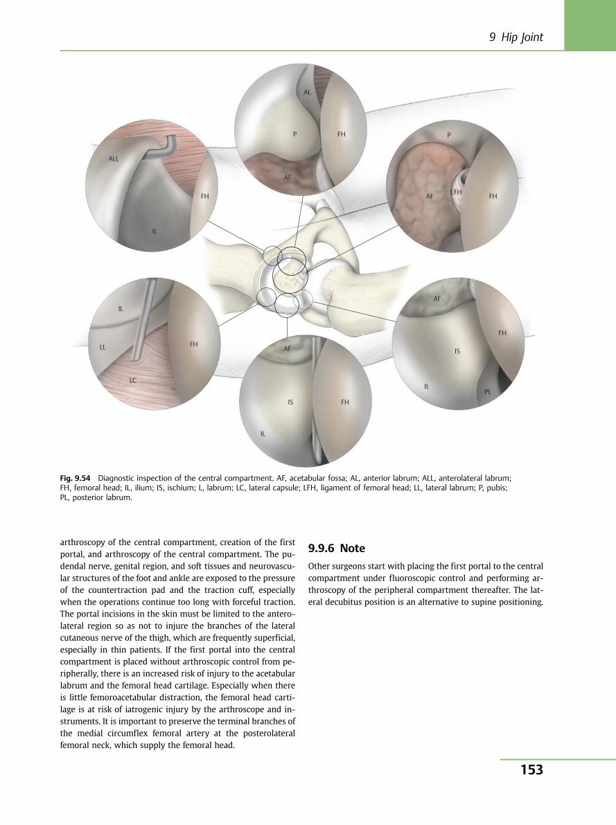
arthroscopy of the central compartment, creation of the firstportal, and arthroscopy of the central compartment. The pu-dendal nerve, genital region, and soft tissues and neurovascu-lar structures of the foot and ankle are exposed to the pressureof the countertraction pad and the traction cuff, especiallywhen the operations continue too long with forceful traction.The portal incisions in the skin must be limited to the antero-lateral region so as not to injure the branches of the lateralcutaneous nerve of the thigh, which are frequently superficial,especially in thin patients. If the first portal into the centralcompartment is placed without arthroscopic control from pe-ripherally, there is an increased risk of injury to the acetabularlabrum and the femoral head cartilage. Especially when thereis little femoroacetabular distraction, the femoral head carti-lage is at risk of iatrogenic injury by the arthroscope and in-struments. It is important to preserve the terminal branches ofthe medial circumflex femoral artery at the posterolateralfemoral neck, which supply the femoral head.
9.9.6 Note
Other surgeons start with placing the first portal to the centralcompartment under fluoroscopic control and performing ar-throscopy of the peripheral compartment thereafter. The lat-eral decubitus position is an alternative to supine positioning.
AL
P FH
FH FH LFH
FH
FH
FH IS
IS
IL
IL
IL
IL
LL
ALL
AF
AF
AF
P
PL
AF
LC
Fig. 9.54 Diagnostic inspection of the central compartment. AF, acetabular fossa; AL, anterior labrum; ALL, anterolateral labrum;FH, femoral head; IL, ilium; IS, ischium; L, labrum; LC, lateral capsule; LFH, ligament of femoral head; LL, lateral labrum; P, pubis;PL, posterior labrum.
9 Hip Joint
153
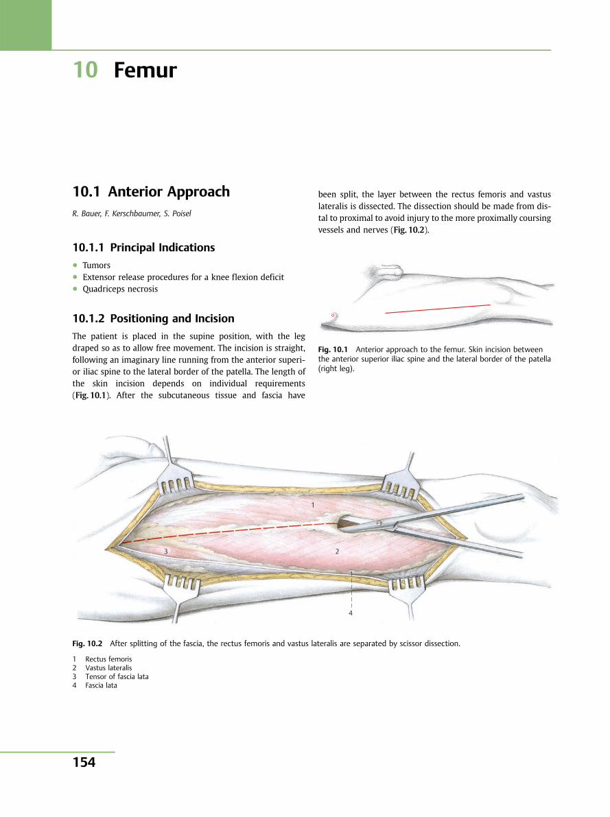
10 Femur
10.1 Anterior ApproachR. Bauer, F. Kerschbaumer, S. Poisel
10.1.1 Principal Indications● Tumors● Extensor release procedures for a knee flexion deficit● Quadriceps necrosis
10.1.2 Positioning and Incision
The patient is placed in the supine position, with the legdraped so as to allow free movement. The incision is straight,following an imaginary line running from the anterior superi-or iliac spine to the lateral border of the patella. The length ofthe skin incision depends on individual requirements(Fig. 10.1). After the subcutaneous tissue and fascia have
been split, the layer between the rectus femoris and vastuslateralis is dissected. The dissection should be made from dis-tal to proximal to avoid injury to the more proximally coursingvessels and nerves (Fig. 10.2).
Fig. 10.1 Anterior approach to the femur. Skin incision betweenthe anterior superior iliac spine and the lateral border of the patella(right leg).
3
1
2
4
Fig. 10.2 After splitting of the fascia, the rectus femoris and vastus lateralis are separated by scissor dissection.
1 Rectus femoris2 Vastus lateralis3 Tensor of fascia lata4 Fascia lata
Pelvis and Lower Extremity
154
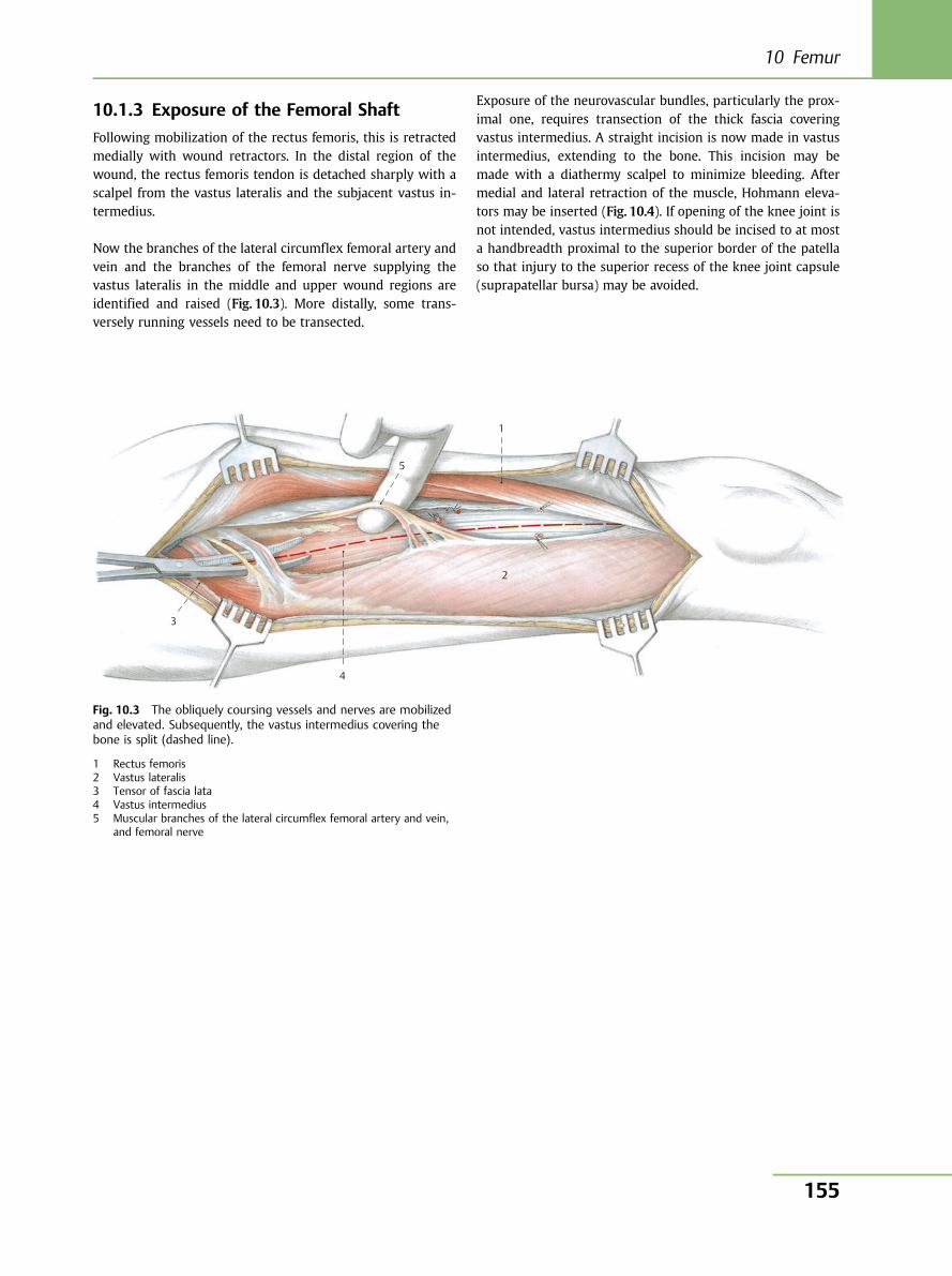
10.1.3 Exposure of the Femoral Shaft
Following mobilization of the rectus femoris, this is retractedmedially with wound retractors. In the distal region of thewound, the rectus femoris tendon is detached sharply with ascalpel from the vastus lateralis and the subjacent vastus in-termedius.
Now the branches of the lateral circumflex femoral artery andvein and the branches of the femoral nerve supplying thevastus lateralis in the middle and upper wound regions areidentified and raised (Fig. 10.3). More distally, some trans-versely running vessels need to be transected.
Exposure of the neurovascular bundles, particularly the prox-imal one, requires transection of the thick fascia coveringvastus intermedius. A straight incision is now made in vastusintermedius, extending to the bone. This incision may bemade with a diathermy scalpel to minimize bleeding. Aftermedial and lateral retraction of the muscle, Hohmann eleva-tors may be inserted (Fig. 10.4). If opening of the knee joint isnot intended, vastus intermedius should be incised to at mosta handbreadth proximal to the superior border of the patellaso that injury to the superior recess of the knee joint capsule(suprapatellar bursa) may be avoided.
1
5
2
4
3
Fig. 10.3 The obliquely coursing vessels and nerves are mobilizedand elevated. Subsequently, the vastus intermedius covering thebone is split (dashed line).
1 Rectus femoris2 Vastus lateralis3 Tensor of fascia lata4 Vastus intermedius5 Muscular branches of the lateral circumflex femoral artery and vein,
and femoral nerve
10 Femur
155
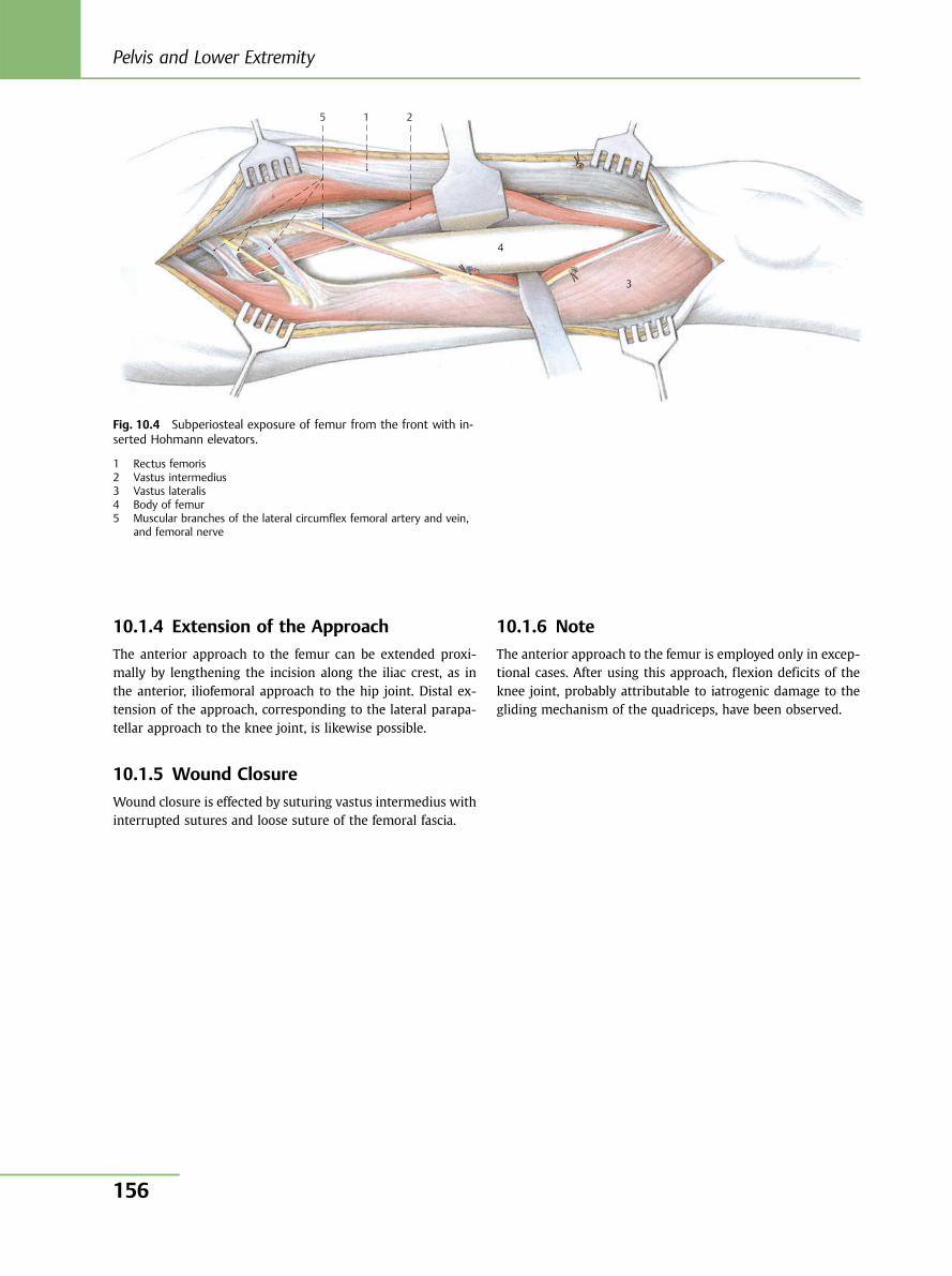
10.1.4 Extension of the Approach
The anterior approach to the femur can be extended proxi-mally by lengthening the incision along the iliac crest, as inthe anterior, iliofemoral approach to the hip joint. Distal ex-tension of the approach, corresponding to the lateral parapa-tellar approach to the knee joint, is likewise possible.
10.1.5 Wound Closure
Wound closure is effected by suturing vastus intermedius withinterrupted sutures and loose suture of the femoral fascia.
10.1.6 Note
The anterior approach to the femur is employed only in excep-tional cases. After using this approach, flexion deficits of theknee joint, probably attributable to iatrogenic damage to thegliding mechanism of the quadriceps, have been observed.
5 1 2
4
3
Fig. 10.4 Subperiosteal exposure of femur from the front with in-serted Hohmann elevators.
1 Rectus femoris2 Vastus intermedius3 Vastus lateralis4 Body of femur5 Muscular branches of the lateral circumflex femoral artery and vein,
and femoral nerve
Pelvis and Lower Extremity
156
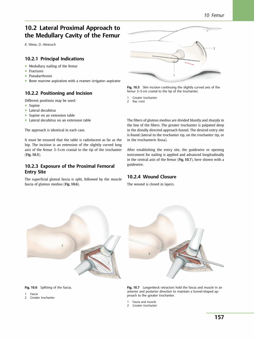
10.2 Lateral Proximal Approach tothe Medullary Cavity of the FemurK. Weise, D. Höntzsch
10.2.1 Principal Indications● Medullary nailing of the femur● Fractures● Pseudarthrosis● Bone marrow aspiration with a reamer–irrigator–aspirator
10.2.2 Positioning and Incision
Different positions may be used:● Supine● Lateral decubitus● Supine on an extension table● Lateral decubitus on an extension table
The approach is identical in each case.
It must be ensured that the table is radiolucent as far as thehip. The incision is an extension of the slightly curved longaxis of the femur 3–5 cm cranial to the tip of the trochanter(Fig. 10.5).
10.2.3 Exposure of the Proximal FemoralEntry Site
The superficial gluteal fascia is split, followed by the musclefascia of gluteus medius (Fig. 10.6).
The fibers of gluteus medius are divided bluntly and sharply inthe line of the fibers. The greater trochanter is palpated deepin the distally directed approach funnel. The desired entry siteis found (lateral to the trochanter tip, on the trochanter tip, orin the trochanteric fossa).
After establishing the entry site, the guidewire or openinginstrument for nailing is applied and advanced longitudinallyin the central axis of the femur (Fig. 10.7), here shown with aguidewire.
10.2.4 Wound Closure
The wound is closed in layers.
1
2
Fig. 10.5 Skin incision continuing the slightly curved axis of thefemur 3–5 cm cranial to the tip of the trochanter.
1 Greater trochanter2 Iliac crest
1
2
Fig. 10.6 Splitting of the fascia.
1 Fascia2 Greater trochanter
2
1
Fig. 10.7 Langenbeck retractors hold the fascia and muscle in ananterior and posterior direction to maintain a funnel-shaped ap-proach to the greater trochanter.
1 Fascia and muscle2 Greater trochanter
10 Femur
157
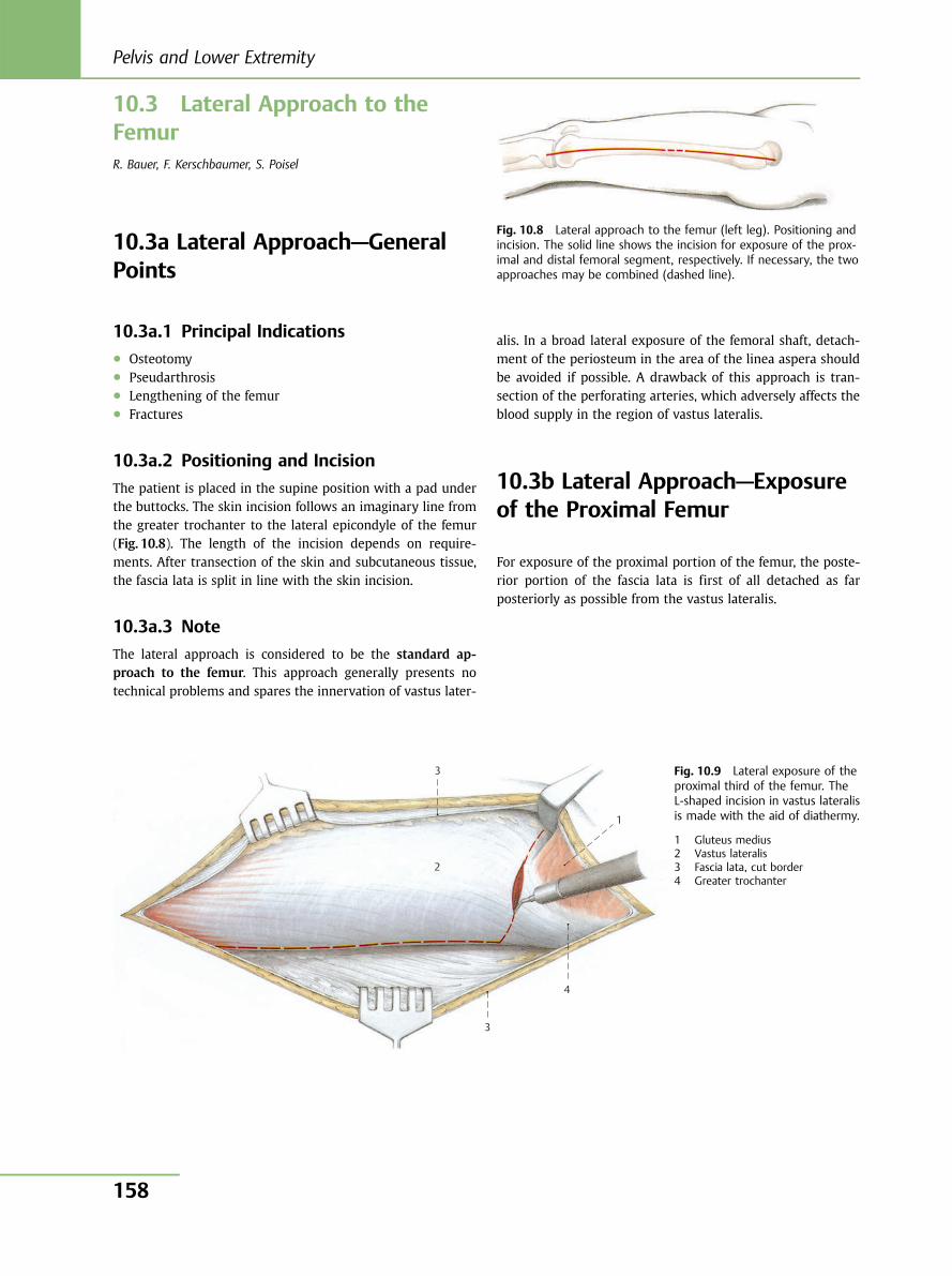
10.3 Lateral Approach to theFemurR. Bauer, F. Kerschbaumer, S. Poisel
10.3a Lateral Approach—GeneralPoints
10.3a.1 Principal Indications● Osteotomy● Pseudarthrosis● Lengthening of the femur● Fractures
10.3a.2 Positioning and Incision
The patient is placed in the supine position with a pad underthe buttocks. The skin incision follows an imaginary line fromthe greater trochanter to the lateral epicondyle of the femur(Fig. 10.8). The length of the incision depends on require-ments. After transection of the skin and subcutaneous tissue,the fascia lata is split in line with the skin incision.
10.3a.3 Note
The lateral approach is considered to be the standard ap-proach to the femur. This approach generally presents notechnical problems and spares the innervation of vastus later-
alis. In a broad lateral exposure of the femoral shaft, detach-ment of the periosteum in the area of the linea aspera shouldbe avoided if possible. A drawback of this approach is tran-section of the perforating arteries, which adversely affects theblood supply in the region of vastus lateralis.
10.3b Lateral Approach—Exposureof the Proximal Femur
For exposure of the proximal portion of the femur, the poste-rior portion of the fascia lata is first of all detached as farposteriorly as possible from the vastus lateralis.
Fig. 10.8 Lateral approach to the femur (left leg). Positioning andincision. The solid line shows the incision for exposure of the prox-imal and distal femoral segment, respectively. If necessary, the twoapproaches may be combined (dashed line).
1
2
3
3
4
Fig. 10.9 Lateral exposure of theproximal third of the femur. TheL-shaped incision in vastus lateralisis made with the aid of diathermy.
1 Gluteus medius2 Vastus lateralis3 Fascia lata, cut border4 Greater trochanter
Pelvis and Lower Extremity
158
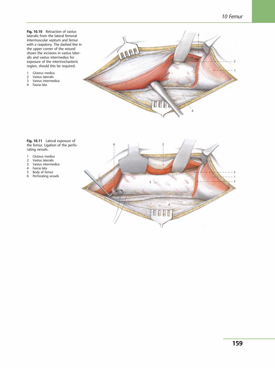
2
3
1
4
Fig. 10.10 Retraction of vastuslateralis from the lateral femoralintermuscular septum and femurwith a raspatory. The dashed line inthe upper corner of the woundshows the incisions in vastus later-alis and vastus intermedius forexposure of the intertrochantericregion, should this be required.
1 Gluteus medius2 Vastus lateralis3 Vastus intermedius4 Fascia lata
6 2
5
312
4
Fig. 10.11 Lateral exposure ofthe femur. Ligation of the perfo-rating vessels.
1 Gluteus medius2 Vastus lateralis3 Vastus intermedius4 Fascia lata5 Body of femur6 Perforating vessels
10 Femur
159
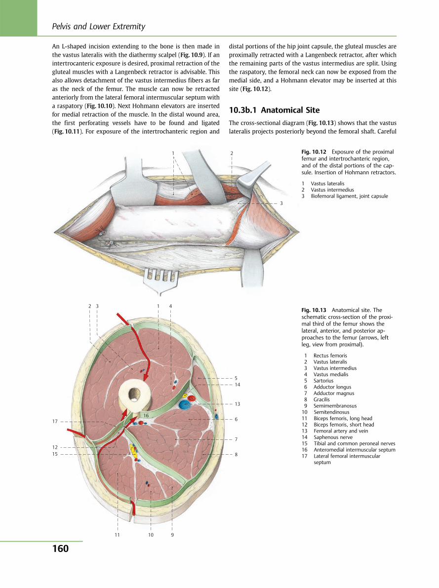
An L-shaped incision extending to the bone is then made inthe vastus lateralis with the diathermy scalpel (Fig. 10.9). If anintertrocanteric exposure is desired, proximal retraction of thegluteal muscles with a Langenbeck retractor is advisable. Thisalso allows detachment of the vastus intermedius fibers as faras the neck of the femur. The muscle can now be retractedanteriorly from the lateral femoral intermuscular septum witha raspatory (Fig. 10.10). Next Hohmann elevators are insertedfor medial retraction of the muscle. In the distal wound area,the first perforating vessels have to be found and ligated(Fig. 10.11). For exposure of the intertrochanteric region and
distal portions of the hip joint capsule, the gluteal muscles areproximally retracted with a Langenbeck retractor, after whichthe remaining parts of the vastus intermedius are split. Usingthe raspatory, the femoral neck can now be exposed from themedial side, and a Hohmann elevator may be inserted at thissite (Fig. 10.12).
10.3b.1 Anatomical Site
The cross-sectional diagram (Fig. 10.13) shows that the vastuslateralis projects posteriorly beyond the femoral shaft. Careful
3
1 2 Fig. 10.12 Exposure of the proximalfemur and intertrochanteric region,and of the distal portions of the cap-sule. Insertion of Hohmann retractors.
1 Vastus lateralis2 Vastus intermedius3 Iliofemoral ligament, joint capsule
10 11
12
13
14
15
16 17
9
8
7
6
5
4 3 1 2 Fig. 10.13 Anatomical site. Theschematic cross-section of the proxi-mal third of the femur shows thelateral, anterior, and posterior ap-proaches to the femur (arrows, leftleg, view from proximal).
1 Rectus femoris2 Vastus lateralis3 Vastus intermedius4 Vastus medialis5 Sartorius6 Adductor longus7 Adductor magnus8 Gracilis9 Semimembranosus10 Semitendinosus11 Biceps femoris, long head12 Biceps femoris, short head13 Femoral artery and vein14 Saphenous nerve15 Tibial and common peroneal nerves16 Anteromedial intermuscular septum17 Lateral femoral intermuscular
septum
Pelvis and Lower Extremity
160
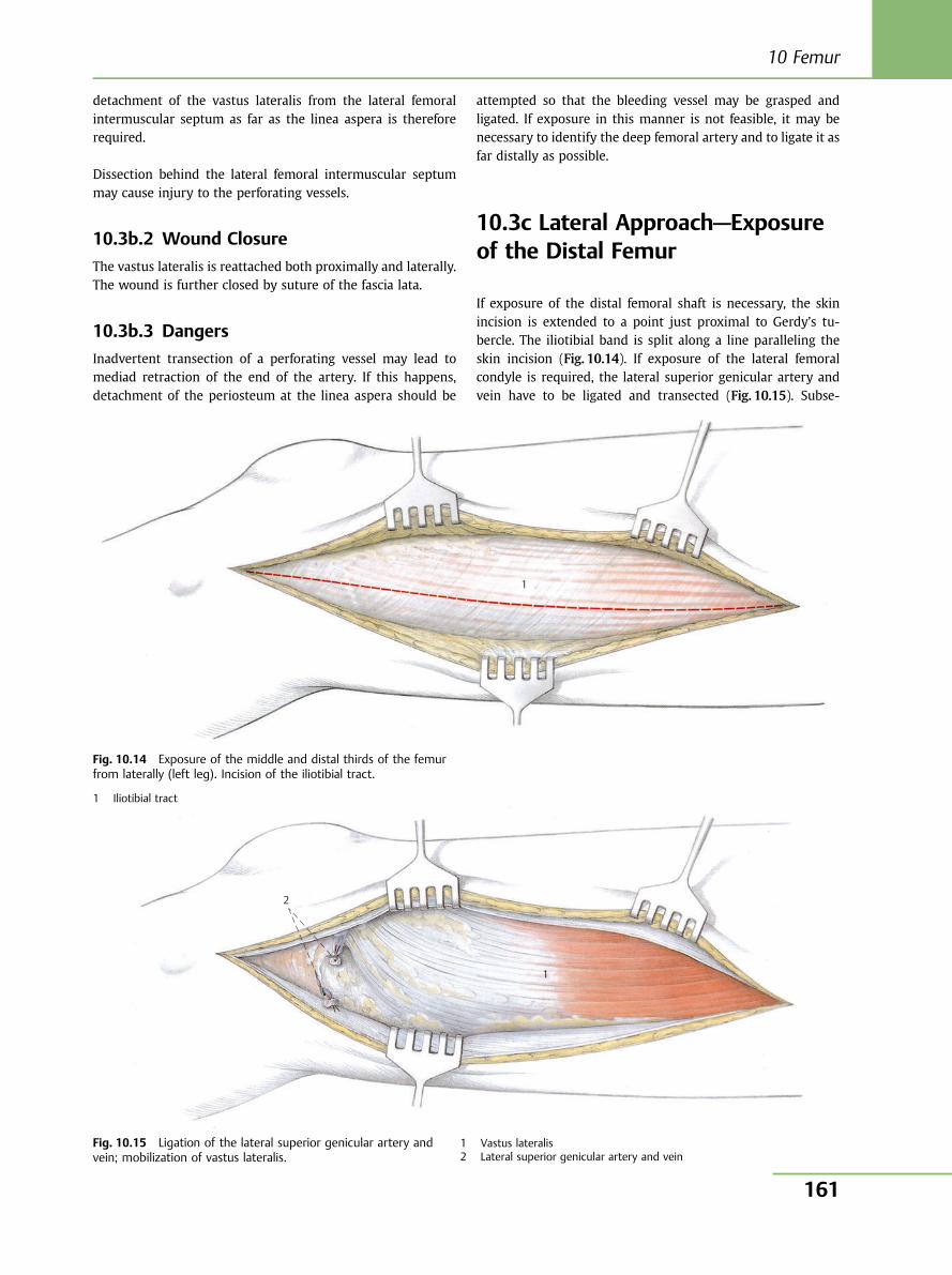
detachment of the vastus lateralis from the lateral femoralintermuscular septum as far as the linea aspera is thereforerequired.
Dissection behind the lateral femoral intermuscular septummay cause injury to the perforating vessels.
10.3b.2 Wound Closure
The vastus lateralis is reattached both proximally and laterally.The wound is further closed by suture of the fascia lata.
10.3b.3 Dangers
Inadvertent transection of a perforating vessel may lead tomediad retraction of the end of the artery. If this happens,detachment of the periosteum at the linea aspera should be
attempted so that the bleeding vessel may be grasped andligated. If exposure in this manner is not feasible, it may benecessary to identify the deep femoral artery and to ligate it asfar distally as possible.
10.3c Lateral Approach—Exposureof the Distal Femur
If exposure of the distal femoral shaft is necessary, the skinincision is extended to a point just proximal to Gerdy’s tu-bercle. The iliotibial band is split along a line paralleling theskin incision (Fig. 10.14). If exposure of the lateral femoralcondyle is required, the lateral superior genicular artery andvein have to be ligated and transected (Fig. 10.15). Subse-
1
Fig. 10.14 Exposure of the middle and distal thirds of the femurfrom laterally (left leg). Incision of the iliotibial tract.
1 Iliotibial tract
2
1
Fig. 10.15 Ligation of the lateral superior genicular artery andvein; mobilization of vastus lateralis.
1 Vastus lateralis2 Lateral superior genicular artery and vein
10 Femur
161
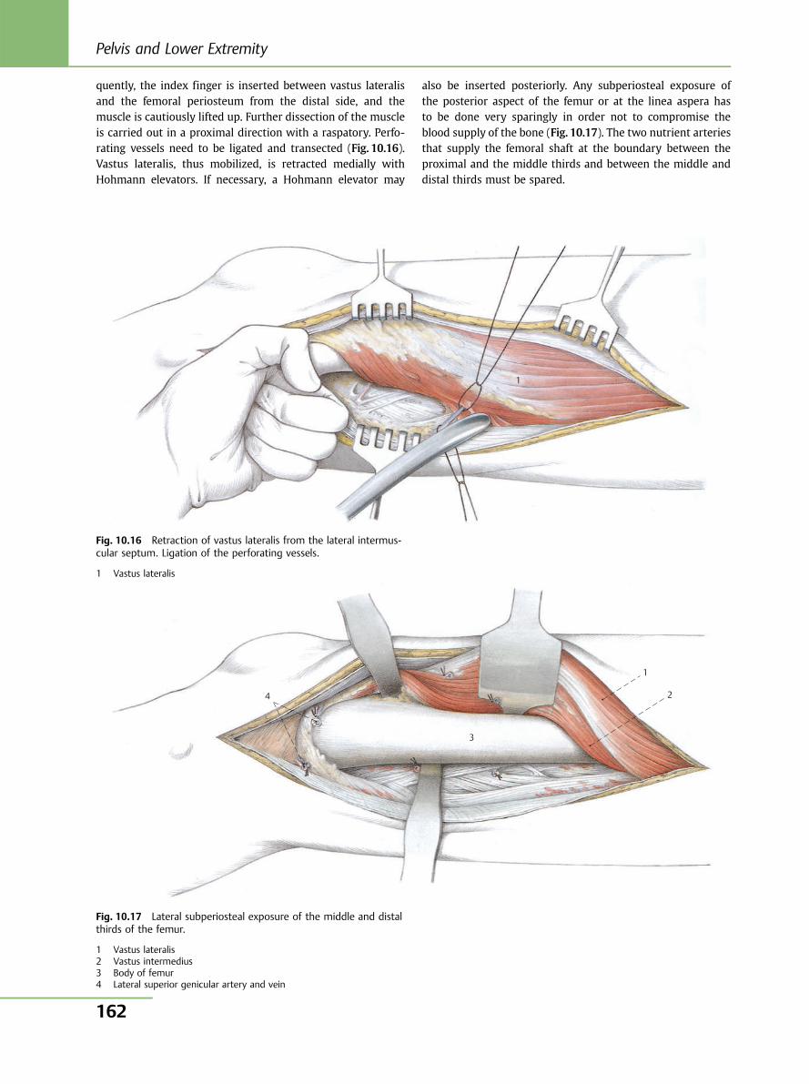
quently, the index finger is inserted between vastus lateralisand the femoral periosteum from the distal side, and themuscle is cautiously lifted up. Further dissection of the muscleis carried out in a proximal direction with a raspatory. Perfo-rating vessels need to be ligated and transected (Fig. 10.16).Vastus lateralis, thus mobilized, is retracted medially withHohmann elevators. If necessary, a Hohmann elevator may
also be inserted posteriorly. Any subperiosteal exposure ofthe posterior aspect of the femur or at the linea aspera hasto be done very sparingly in order not to compromise theblood supply of the bone (Fig. 10.17). The two nutrient arteriesthat supply the femoral shaft at the boundary between theproximal and the middle thirds and between the middle anddistal thirds must be spared.
1
Fig. 10.16 Retraction of vastus lateralis from the lateral intermus-cular septum. Ligation of the perforating vessels.
1 Vastus lateralis
1
2
3
4
Fig. 10.17 Lateral subperiosteal exposure of the middle and distalthirds of the femur.
1 Vastus lateralis2 Vastus intermedius3 Body of femur4 Lateral superior genicular artery and vein
Pelvis and Lower Extremity
162
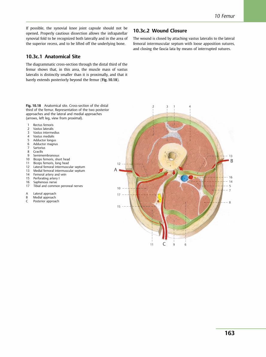
If possible, the synovial knee joint capsule should not beopened. Properly cautious dissection allows the infrapatellarsynovial fold to be recognized both laterally and in the area ofthe superior recess, and to be lifted off the underlying bone.
10.3c.1 Anatomical Site
The diagrammatic cross-section through the distal third of thefemur shows that, in this area, the muscle mass of vastuslateralis is distinctly smaller than it is proximally, and that itbarely extends posteriorly beyond the femur (Fig. 10.18).
10.3c.2 Wound Closure
The wound is closed by attaching vastus lateralis to the lateralfemoral intermuscular septum with loose apposition sutures,and closing the fascia lata by means of interrupted sutures.
Fig. 10.18 Anatomical site. Cross-section of the distalthird of the femur. Representation of the two posteriorapproaches and the lateral and medial approaches(arrows, left leg, view from proximal).
1 Rectus femoris2 Vastus lateralis3 Vastus intermedius4 Vastus medialis5 Adductor longus6 Adductor magnus7 Sartorius8 Gracilis9 Semimembranosus10 Biceps femoris, short head11 Biceps femoris, long head12 Lateral femoral intermuscular septum13 Medial femoral intermuscular septum14 Femoral artery and vein15 Perforating artery I16 Saphenous nerve17 Tibial and common peroneal nerves
A Lateral approachB Medial approachC Posterior approach
2
12
10
17
15
11 9 6
8
751416
13
A
B
C
3 1 4
10 Femur
163
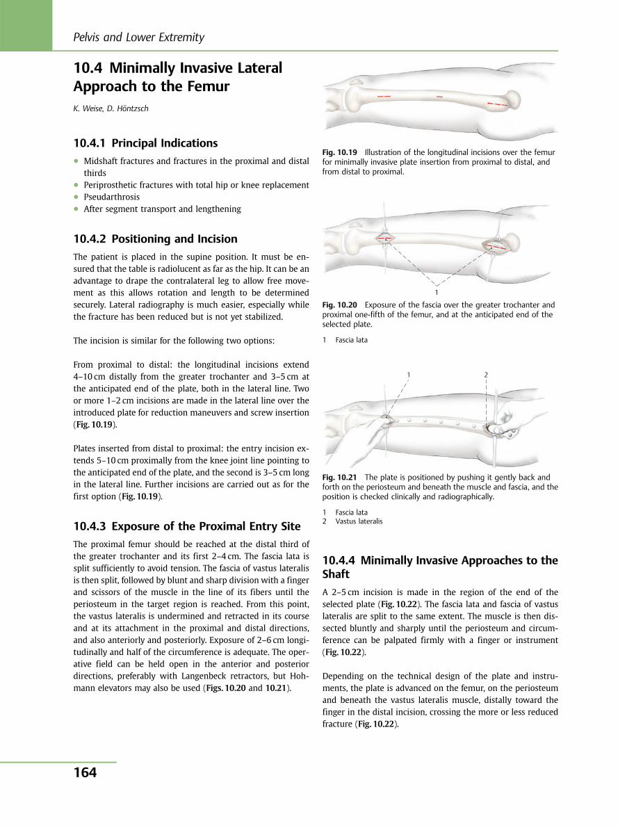
10.4 Minimally Invasive LateralApproach to the FemurK. Weise, D. Höntzsch
10.4.1 Principal Indications● Midshaft fractures and fractures in the proximal and distal
thirds● Periprosthetic fractures with total hip or knee replacement● Pseudarthrosis● After segment transport and lengthening
10.4.2 Positioning and Incision
The patient is placed in the supine position. It must be en-sured that the table is radiolucent as far as the hip. It can be anadvantage to drape the contralateral leg to allow free move-ment as this allows rotation and length to be determinedsecurely. Lateral radiography is much easier, especially whilethe fracture has been reduced but is not yet stabilized.
The incision is similar for the following two options:
From proximal to distal: the longitudinal incisions extend4–10 cm distally from the greater trochanter and 3–5 cm atthe anticipated end of the plate, both in the lateral line. Twoor more 1–2 cm incisions are made in the lateral line over theintroduced plate for reduction maneuvers and screw insertion(Fig. 10.19).
Plates inserted from distal to proximal: the entry incision ex-tends 5–10 cm proximally from the knee joint line pointing tothe anticipated end of the plate, and the second is 3–5 cm longin the lateral line. Further incisions are carried out as for thefirst option (Fig. 10.19).
10.4.3 Exposure of the Proximal Entry Site
The proximal femur should be reached at the distal third ofthe greater trochanter and its first 2–4 cm. The fascia lata issplit sufficiently to avoid tension. The fascia of vastus lateralisis then split, followed by blunt and sharp division with a fingerand scissors of the muscle in the line of its fibers until theperiosteum in the target region is reached. From this point,the vastus lateralis is undermined and retracted in its courseand at its attachment in the proximal and distal directions,and also anteriorly and posteriorly. Exposure of 2–6 cm longi-tudinally and half of the circumference is adequate. The oper-ative field can be held open in the anterior and posteriordirections, preferably with Langenbeck retractors, but Hoh-mann elevators may also be used (Figs. 10.20 and 10.21).
10.4.4 Minimally Invasive Approaches to theShaft
A 2–5 cm incision is made in the region of the end of theselected plate (Fig. 10.22). The fascia lata and fascia of vastuslateralis are split to the same extent. The muscle is then dis-sected bluntly and sharply until the periosteum and circum-ference can be palpated firmly with a finger or instrument(Fig. 10.22).
Depending on the technical design of the plate and instru-ments, the plate is advanced on the femur, on the periosteumand beneath the vastus lateralis muscle, distally toward thefinger in the distal incision, crossing the more or less reducedfracture (Fig. 10.22).
Fig. 10.19 Illustration of the longitudinal incisions over the femurfor minimally invasive plate insertion from proximal to distal, andfrom distal to proximal.
1
Fig. 10.20 Exposure of the fascia over the greater trochanter andproximal one-fifth of the femur, and at the anticipated end of theselected plate.
1 Fascia lata
1 2
Fig. 10.21 The plate is positioned by pushing it gently back andforth on the periosteum and beneath the muscle and fascia, and theposition is checked clinically and radiographically.
1 Fascia lata2 Vastus lateralis
Pelvis and Lower Extremity
164
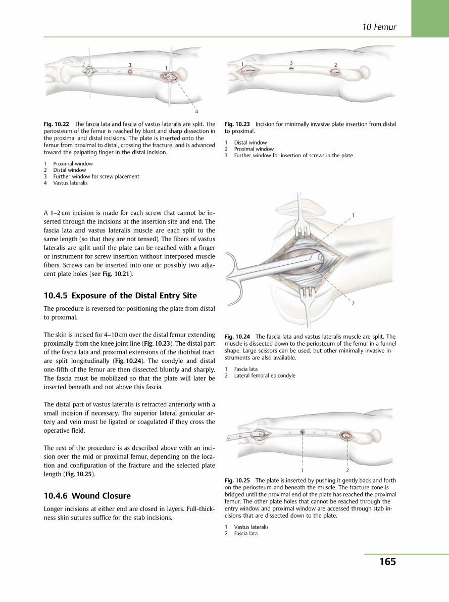
A 1–2 cm incision is made for each screw that cannot be in-serted through the incisions at the insertion site and end. Thefascia lata and vastus lateralis muscle are each split to thesame length (so that they are not tensed). The fibers of vastuslateralis are split until the plate can be reached with a fingeror instrument for screw insertion without interposed musclefibers. Screws can be inserted into one or possibly two adja-cent plate holes (see Fig. 10.21).
10.4.5 Exposure of the Distal Entry Site
The procedure is reversed for positioning the plate from distalto proximal.
The skin is incised for 4–10 cm over the distal femur extendingproximally from the knee joint line (Fig. 10.23). The distal partof the fascia lata and proximal extensions of the iliotibial tractare split longitudinally (Fig. 10.24). The condyle and distalone-fifth of the femur are then dissected bluntly and sharply.The fascia must be mobilized so that the plate will later beinserted beneath and not above this fascia.
The distal part of vastus lateralis is retracted anteriorly with asmall incision if necessary. The superior lateral genicular ar-tery and vein must be ligated or coagulated if they cross theoperative field.
The rest of the procedure is as described above with an inci-sion over the mid or proximal femur, depending on the loca-tion and configuration of the fracture and the selected platelength (Fig. 10.25).
10.4.6 Wound Closure
Longer incisions at either end are closed in layers. Full-thick-ness skin sutures suffice for the stab incisions.
2 3 1
4
Fig. 10.22 The fascia lata and fascia of vastus lateralis are split. Theperiosteum of the femur is reached by blunt and sharp dissection inthe proximal and distal incisions. The plate is inserted onto thefemur from proximal to distal, crossing the fracture, and is advancedtoward the palpating finger in the distal incision.
1 Proximal window2 Distal window3 Further window for screw placement4 Vastus lateralis
1 3 2
Fig. 10.23 Incision for minimally invasive plate insertion from distalto proximal.
1 Distal window2 Proximal window3 Further window for insertion of screws in the plate
1
2
Fig. 10.24 The fascia lata and vastus lateralis muscle are split. Themuscle is dissected down to the periosteum of the femur in a funnelshape. Large scissors can be used, but other minimally invasive in-struments are also available.
1 Fascia lata2 Lateral femoral epicondyle
1 2
Fig. 10.25 The plate is inserted by pushing it gently back and forthon the periosteum and beneath the muscle. The fracture zone isbridged until the proximal end of the plate has reached the proximalfemur. The other plate holes that cannot be reached through theentry window and proximal window are accessed through stab in-cisions that are dissected down to the plate.
1 Vastus lateralis2 Fascia lata
10 Femur
165
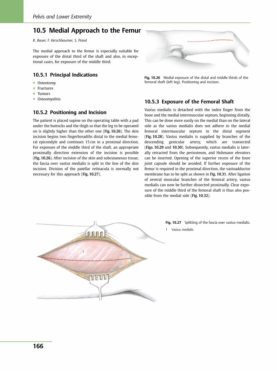
10.5 Medial Approach to the FemurR. Bauer, F. Kerschbaumer, S. Poisel
The medial approach to the femur is especially suitable forexposure of the distal third of the shaft and also, in excep-tional cases, for exposure of the middle third.
10.5.1 Principal Indications● Osteotomy● Fractures● Tumors● Osteomyelitis
10.5.2 Positioning and Incision
The patient is placed supine on the operating table with a padunder the buttocks and the thigh so that the leg to be operatedon is slightly higher than the other one (Fig. 10.26). The skinincision begins two fingerbreadths distal to the medial femo-ral epicondyle and continues 15 cm in a proximal direction.For exposure of the middle third of the shaft, an appropriateproximally direction extension of the incision is possible(Fig. 10.26). After incision of the skin and subcutaneous tissue,the fascia over vastus medialis is split in the line of the skinincision. Division of the patellar retinacula is normally notnecessary for this approach (Fig. 10.27).
10.5.3 Exposure of the Femoral Shaft
Vastus medialis is detached with the index finger from thebone and the medial intermuscular septum, beginning distally.This can be done more easily on the medial than on the lateralside as the vastus medialis does not adhere to the medialfemoral intermuscular septum in the distal segment(Fig. 10.28). Vastus medialis is supplied by branches of thedescending genicular artery, which are transected(Figs. 10.29 and 10.30). Subsequently, vastus medialis is later-ally retracted from the periosteum, and Hohmann elevatorscan be inserted. Opening of the superior recess of the kneejoint capsule should be avoided. If further exposure of thefemur is required in the proximal direction, the vastoadductormembrane has to be split as shown in Fig. 10.31. After ligationof several muscular branches of the femoral artery, vastusmedialis can now be further dissected proximally. Clear expo-sure of the middle third of the femoral shaft is thus also pos-sible from the medial side (Fig. 10.32).
1
Fig. 10.26 Medial exposure of the distal and middle thirds of thefemoral shaft (left leg). Positioning and incision.
Fig. 10.27 Splitting of the fascia over vastus medialis.
1 Vastus medialis
Pelvis and Lower Extremity
166
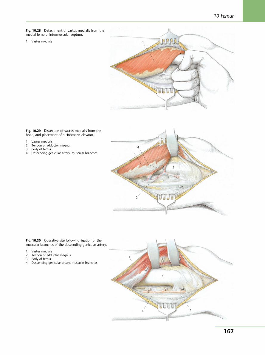
1
Fig. 10.28 Detachment of vastus medialis from themedial femoral intermuscular septum.
1 Vastus medialis
1
2
3
4
Fig. 10.29 Dissection of vastus medialis from thebone, and placement of a Hohmann elevator.
1 Vastus medialis2 Tendon of adductor magnus3 Body of femur4 Descending genicular artery, muscular branches
1
3
4 2
Fig. 10.30 Operative site following ligation of themuscular branches of the descending genicular artery.
1 Vastus medialis2 Tendon of adductor magnus3 Body of femur4 Descending genicular artery, muscular branches
10 Femur
167
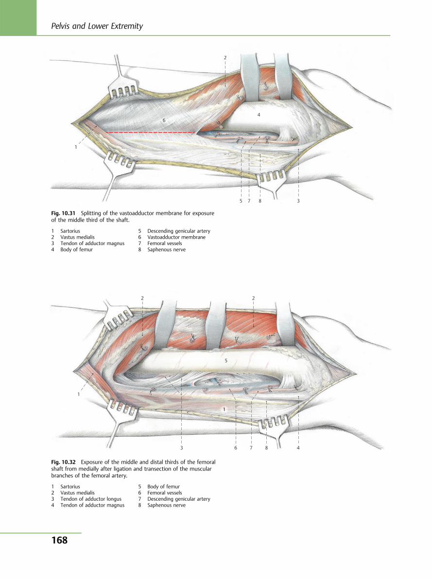
8 7
6
5
4
3
1
2
Fig. 10.31 Splitting of the vastoadductor membrane for exposureof the middle third of the shaft.
1 Sartorius2 Vastus medialis3 Tendon of adductor magnus4 Body of femur
5 Descending genicular artery6 Vastoadductor membrane7 Femoral vessels8 Saphenous nerve
8 7 6
5
4 3
1
2 2
1
Fig. 10.32 Exposure of the middle and distal thirds of the femoralshaft from medially after ligation and transection of the muscularbranches of the femoral artery.
1 Sartorius2 Vastus medialis3 Tendon of adductor longus4 Tendon of adductor magnus
5 Body of femur6 Femoral vessels7 Descending genicular artery8 Saphenous nerve
Pelvis and Lower Extremity
168
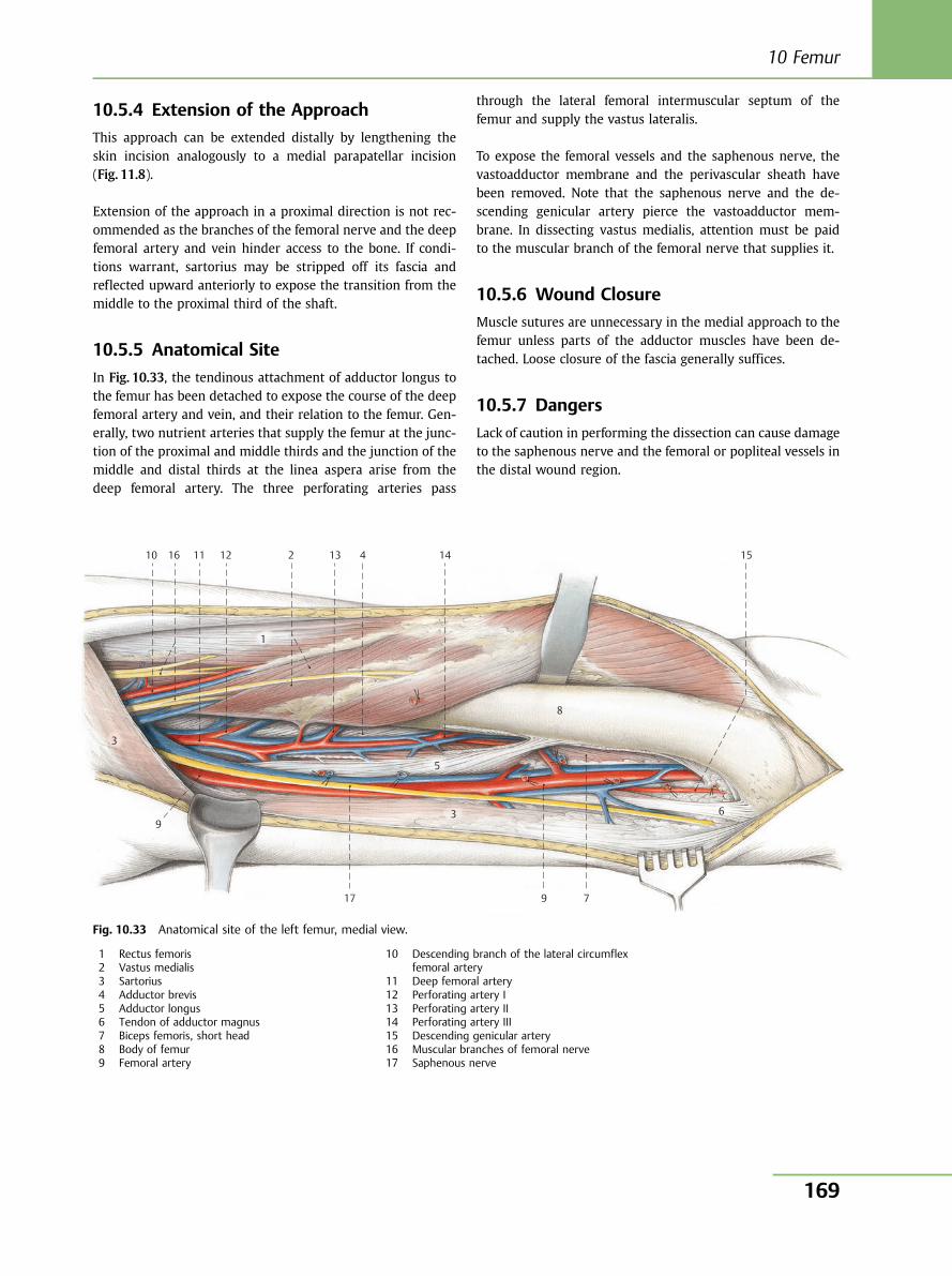
10.5.4 Extension of the Approach
This approach can be extended distally by lengthening theskin incision analogously to a medial parapatellar incision(Fig. 11.8).
Extension of the approach in a proximal direction is not rec-ommended as the branches of the femoral nerve and the deepfemoral artery and vein hinder access to the bone. If condi-tions warrant, sartorius may be stripped off its fascia andreflected upward anteriorly to expose the transition from themiddle to the proximal third of the shaft.
10.5.5 Anatomical Site
In Fig. 10.33, the tendinous attachment of adductor longus tothe femur has been detached to expose the course of the deepfemoral artery and vein, and their relation to the femur. Gen-erally, two nutrient arteries that supply the femur at the junc-tion of the proximal and middle thirds and the junction of themiddle and distal thirds at the linea aspera arise from thedeep femoral artery. The three perforating arteries pass
through the lateral femoral intermuscular septum of thefemur and supply the vastus lateralis.
To expose the femoral vessels and the saphenous nerve, thevastoadductor membrane and the perivascular sheath havebeen removed. Note that the saphenous nerve and the de-scending genicular artery pierce the vastoadductor mem-brane. In dissecting vastus medialis, attention must be paidto the muscular branch of the femoral nerve that supplies it.
10.5.6 Wound Closure
Muscle sutures are unnecessary in the medial approach to thefemur unless parts of the adductor muscles have been de-tached. Loose closure of the fascia generally suffices.
10.5.7 Dangers
Lack of caution in performing the dissection can cause damageto the saphenous nerve and the femoral or popliteal vessels inthe distal wound region.
10 11 12 13 14 15 16
17
9
8
7
6
5
4
3
1
2
9
3
Fig. 10.33 Anatomical site of the left femur, medial view.
1 Rectus femoris2 Vastus medialis3 Sartorius4 Adductor brevis5 Adductor longus6 Tendon of adductor magnus7 Biceps femoris, short head8 Body of femur9 Femoral artery
10 Descending branch of the lateral circumflexfemoral artery
11 Deep femoral artery12 Perforating artery I13 Perforating artery II14 Perforating artery III15 Descending genicular artery16 Muscular branches of femoral nerve17 Saphenous nerve
10 Femur
169
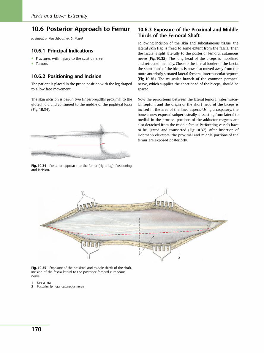
10.6 Posterior Approach to FemurR. Bauer, F. Kerschbaumer, S. Poisel
10.6.1 Principal Indications● Fractures with injury to the sciatic nerve● Tumors
10.6.2 Positioning and Incision
The patient is placed in the prone position with the leg drapedto allow free movement.
The skin incision is begun two fingerbreadths proximal to thegluteal fold and continued to the middle of the popliteal fossa(Fig. 10.34).
10.6.3 Exposure of the Proximal and MiddleThirds of the Femoral Shaft
Following incision of the skin and subcutaneous tissue, thelateral skin flap is freed to some extent from the fascia. Thenthe fascia is split laterally to the posterior femoral cutaneousnerve (Fig. 10.35). The long head of the biceps is mobilizedand retracted medially. Close to the lateral border of the fascia,the short head of the biceps is now also moved away from themore anteriorly situated lateral femoral intermuscular septum(Fig. 10.36). The muscular branch of the common peronealnerve, which supplies the short head of the biceps, should bespared.
Now the periosteum between the lateral femoral intermuscu-lar septum and the origin of the short head of the biceps isincised in the area of the linea aspera. Using a raspatory, thebone is now exposed subperiosteally, dissecting from lateral tomedial. In the process, portions of the adductor magnus arealso detached from the middle femur. Perforating vessels haveto be ligated and transected (Fig. 10.37). After insertion ofHohmann elevators, the proximal and middle portions of thefemur are exposed posteriorly.
Fig. 10.34 Posterior approach to the femur (right leg). Positioningand incision.
1 2
Fig. 10.35 Exposure of the proximal and middle thirds of the shaft.Incision of the fascia lateral to the posterior femoral cutaneousnerve.
1 Fascia lata2 Posterior femoral cutaneous nerve
Pelvis and Lower Extremity
170
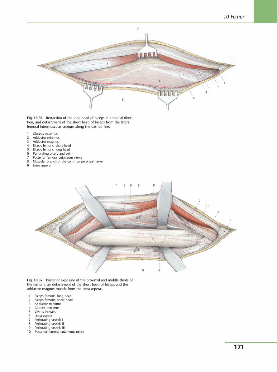
5
7
8
4
9
3 6
2 1
Fig. 10.36 Retraction of the long head of biceps in a medial direc-tion, and detachment of the short head of biceps from the lateralfemoral intermuscular septum along the dashed line.
1 Gluteus maximus2 Adductor minimus3 Adductor magnus4 Biceps femoris, short head5 Biceps femoris, long head6 Perforating artery and vein I7 Posterior femoral cutaneous nerve8 Muscular branch of the common peroneal nerve9 Linea aspera
1 2 9 8 8
7
10
4
65
3
Fig. 10.37 Posterior exposure of the proximal and middle thirds ofthe femur after detachment of the short head of biceps and theadductor magnus muscle from the linea aspera.
1 Biceps femoris, long head2 Biceps femoris, short head3 Adductor minimus4 Gluteus maximus5 Vastus lateralis6 Linea aspera7 Perforating vessels I8 Perforating vessels II9 Perforating vessels III10 Posterior femoral cutaneous nerve
10 Femur
171
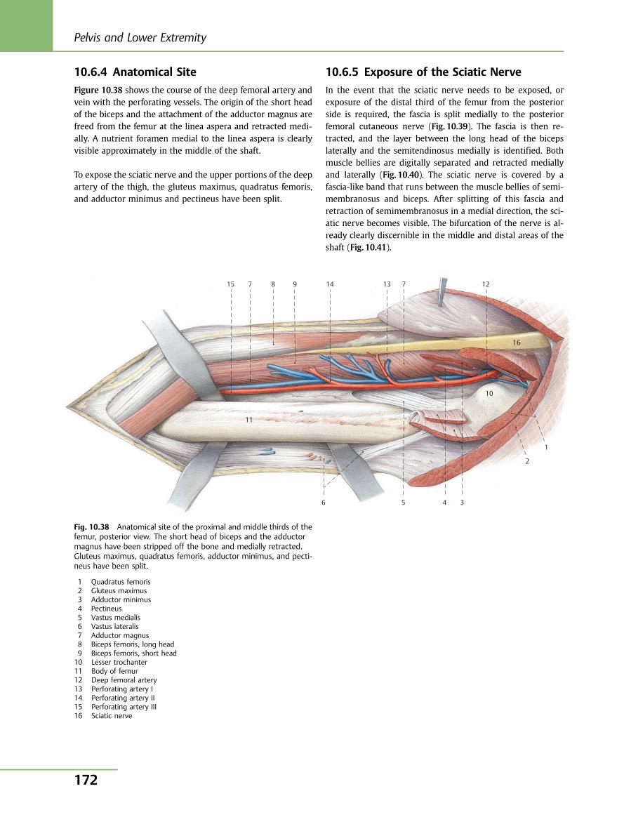
10.6.4 Anatomical Site
Figure 10.38 shows the course of the deep femoral artery andvein with the perforating vessels. The origin of the short headof the biceps and the attachment of the adductor magnus arefreed from the femur at the linea aspera and retracted medi-ally. A nutrient foramen medial to the linea aspera is clearlyvisible approximately in the middle of the shaft.
To expose the sciatic nerve and the upper portions of the deepartery of the thigh, the gluteus maximus, quadratus femoris,and adductor minimus and pectineus have been split.
10.6.5 Exposure of the Sciatic Nerve
In the event that the sciatic nerve needs to be exposed, orexposure of the distal third of the femur from the posteriorside is required, the fascia is split medially to the posteriorfemoral cutaneous nerve (Fig. 10.39). The fascia is then re-tracted, and the layer between the long head of the bicepslaterally and the semitendinosus medially is identified. Bothmuscle bellies are digitally separated and retracted mediallyand laterally (Fig. 10.40). The sciatic nerve is covered by afascia-like band that runs between the muscle bellies of semi-membranosus and biceps. After splitting of this fascia andretraction of semimembranosus in a medial direction, the sci-atic nerve becomes visible. The bifurcation of the nerve is al-ready clearly discernible in the middle and distal areas of theshaft (Fig. 10.41).
15 7 8 9 14 13 7 12
16
10
1
2
3 4 5 6
11
Fig. 10.38 Anatomical site of the proximal and middle thirds of thefemur, posterior view. The short head of biceps and the adductormagnus have been stripped off the bone and medially retracted.Gluteus maximus, quadratus femoris, adductor minimus, and pecti-neus have been split.
1 Quadratus femoris2 Gluteus maximus3 Adductor minimus4 Pectineus5 Vastus medialis6 Vastus lateralis7 Adductor magnus8 Biceps femoris, long head9 Biceps femoris, short head10 Lesser trochanter11 Body of femur12 Deep femoral artery13 Perforating artery I14 Perforating artery II15 Perforating artery III16 Sciatic nerve
Pelvis and Lower Extremity
172
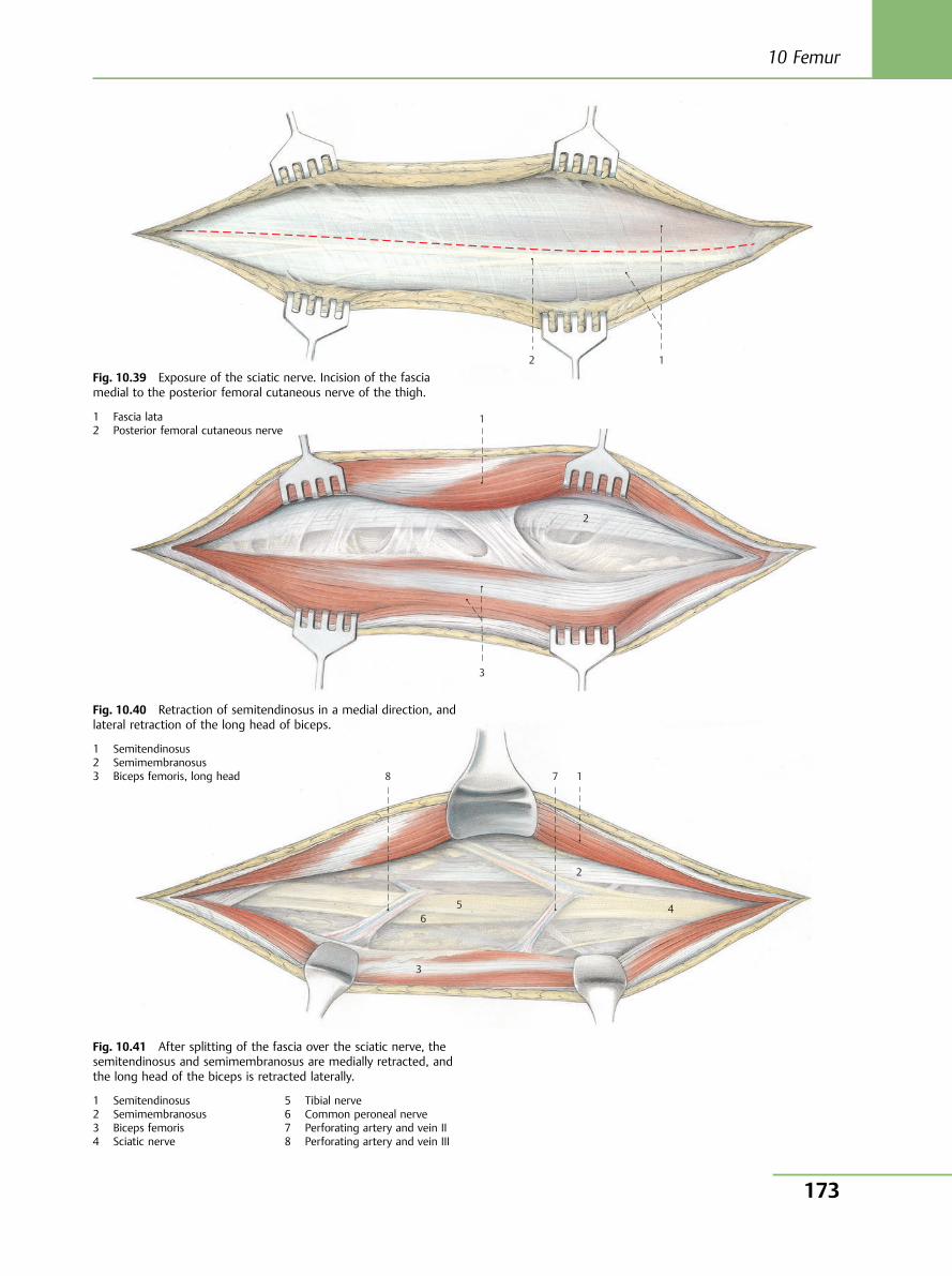
2 1
1
2
3
8 7 1
2
4 5 6
3
Fig. 10.39 Exposure of the sciatic nerve. Incision of the fasciamedial to the posterior femoral cutaneous nerve of the thigh.
1 Fascia lata2 Posterior femoral cutaneous nerve
Fig. 10.40 Retraction of semitendinosus in a medial direction, andlateral retraction of the long head of biceps.
1 Semitendinosus2 Semimembranosus3 Biceps femoris, long head
Fig. 10.41 After splitting of the fascia over the sciatic nerve, thesemitendinosus and semimembranosus are medially retracted, andthe long head of the biceps is retracted laterally.
1 Semitendinosus2 Semimembranosus3 Biceps femoris4 Sciatic nerve
5 Tibial nerve6 Common peroneal nerve7 Perforating artery and vein II8 Perforating artery and vein III
10 Femur
173
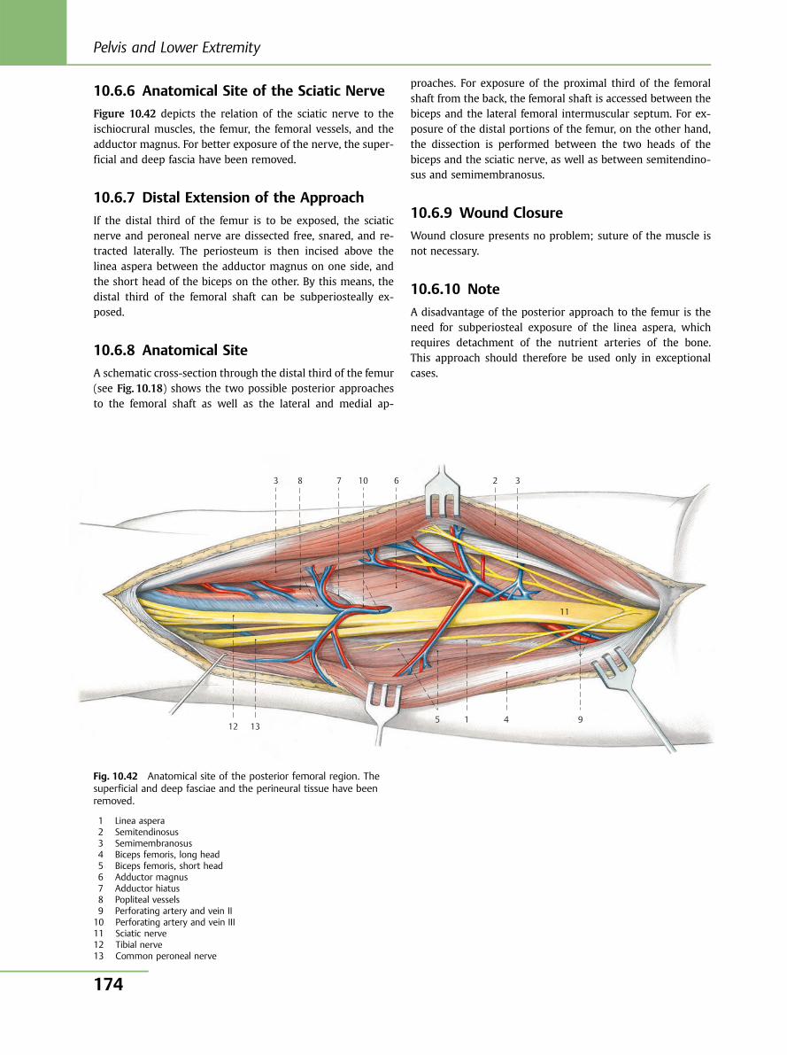
10.6.6 Anatomical Site of the Sciatic Nerve
Figure 10.42 depicts the relation of the sciatic nerve to theischiocrural muscles, the femur, the femoral vessels, and theadductor magnus. For better exposure of the nerve, the super-ficial and deep fascia have been removed.
10.6.7 Distal Extension of the Approach
If the distal third of the femur is to be exposed, the sciaticnerve and peroneal nerve are dissected free, snared, and re-tracted laterally. The periosteum is then incised above thelinea aspera between the adductor magnus on one side, andthe short head of the biceps on the other. By this means, thedistal third of the femoral shaft can be subperiosteally ex-posed.
10.6.8 Anatomical Site
A schematic cross-section through the distal third of the femur(see Fig. 10.18) shows the two possible posterior approachesto the femoral shaft as well as the lateral and medial ap-
proaches. For exposure of the proximal third of the femoralshaft from the back, the femoral shaft is accessed between thebiceps and the lateral femoral intermuscular septum. For ex-posure of the distal portions of the femur, on the other hand,the dissection is performed between the two heads of thebiceps and the sciatic nerve, as well as between semitendino-sus and semimembranosus.
10.6.9 Wound Closure
Wound closure presents no problem; suture of the muscle isnot necessary.
10.6.10 Note
A disadvantage of the posterior approach to the femur is theneed for subperiosteal exposure of the linea aspera, whichrequires detachment of the nutrient arteries of the bone.This approach should therefore be used only in exceptionalcases.
3 8 7 10 6 2 3
11
94151312
Fig. 10.42 Anatomical site of the posterior femoral region. Thesuperficial and deep fasciae and the perineural tissue have beenremoved.
1 Linea aspera2 Semitendinosus3 Semimembranosus4 Biceps femoris, long head5 Biceps femoris, short head6 Adductor magnus7 Adductor hiatus8 Popliteal vessels9 Perforating artery and vein II10 Perforating artery and vein III11 Sciatic nerve12 Tibial nerve13 Common peroneal nerve
Pelvis and Lower Extremity
174
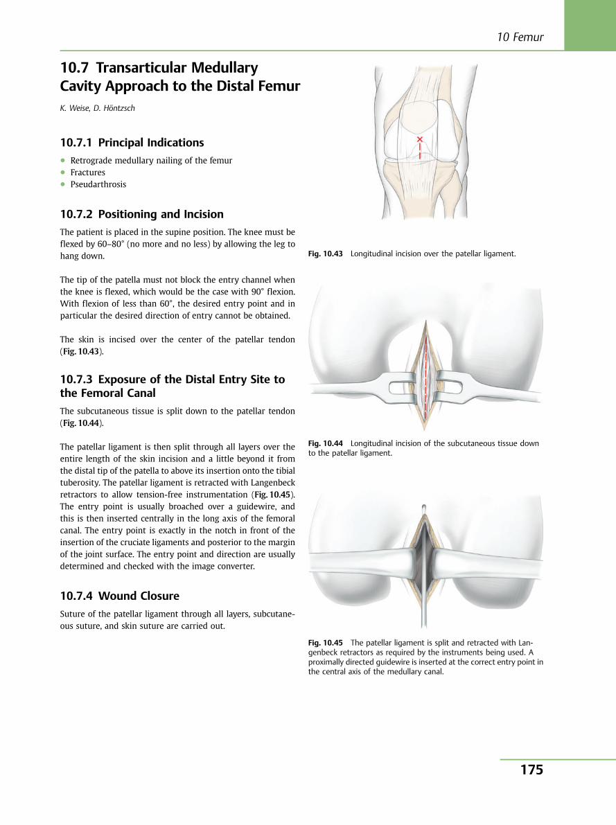
10.7 Transarticular MedullaryCavity Approach to the Distal FemurK. Weise, D. Höntzsch
10.7.1 Principal Indications● Retrograde medullary nailing of the femur● Fractures● Pseudarthrosis
10.7.2 Positioning and Incision
The patient is placed in the supine position. The knee must beflexed by 60–80° (no more and no less) by allowing the leg tohang down.
The tip of the patella must not block the entry channel whenthe knee is flexed, which would be the case with 90° flexion.With flexion of less than 60°, the desired entry point and inparticular the desired direction of entry cannot be obtained.
The skin is incised over the center of the patellar tendon(Fig. 10.43).
10.7.3 Exposure of the Distal Entry Site tothe Femoral Canal
The subcutaneous tissue is split down to the patellar tendon(Fig. 10.44).
The patellar ligament is then split through all layers over theentire length of the skin incision and a little beyond it fromthe distal tip of the patella to above its insertion onto the tibialtuberosity. The patellar ligament is retracted with Langenbeckretractors to allow tension-free instrumentation (Fig. 10.45).The entry point is usually broached over a guidewire, andthis is then inserted centrally in the long axis of the femoralcanal. The entry point is exactly in the notch in front of theinsertion of the cruciate ligaments and posterior to the marginof the joint surface. The entry point and direction are usuallydetermined and checked with the image converter.
10.7.4 Wound Closure
Suture of the patellar ligament through all layers, subcutane-ous suture, and skin suture are carried out.
Fig. 10.43 Longitudinal incision over the patellar ligament.
Fig. 10.44 Longitudinal incision of the subcutaneous tissue downto the patellar ligament.
Fig. 10.45 The patellar ligament is split and retracted with Lan-genbeck retractors as required by the instruments being used. Aproximally directed guidewire is inserted at the correct entry point inthe central axis of the medullary canal.
10 Femur
175
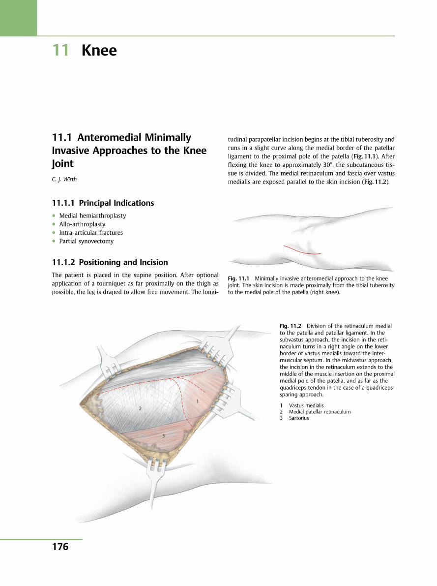
11 Knee
11.1 Anteromedial MinimallyInvasive Approaches to the KneeJointC. J. Wirth
11.1.1 Principal Indications● Medial hemiarthroplasty● Allo-arthroplasty● Intra-articular fractures● Partial synovectomy
11.1.2 Positioning and Incision
The patient is placed in the supine position. After optionalapplication of a tourniquet as far proximally on the thigh aspossible, the leg is draped to allow free movement. The longi-
tudinal parapatellar incision begins at the tibial tuberosity andruns in a slight curve along the medial border of the patellarligament to the proximal pole of the patella (Fig. 11.1). Afterflexing the knee to approximately 30°, the subcutaneous tis-sue is divided. The medial retinaculum and fascia over vastusmedialis are exposed parallel to the skin incision (Fig. 11.2).
Fig. 11.1 Minimally invasive anteromedial approach to the kneejoint. The skin incision is made proximally from the tibial tuberosityto the medial pole of the patella (right knee).
1 2
3
Fig. 11.2 Division of the retinaculum medialto the patella and patellar ligament. In thesubvastus approach, the incision in the reti-naculum turns in a right angle on the lowerborder of vastus medialis toward the inter-muscular septum. In the midvastus approach,the incision in the retinaculum extends to themiddle of the muscle insertion on the proximalmedial pole of the patella, and as far as thequadriceps tendon in the case of a quadriceps-sparing approach.
1 Vastus medialis2 Medial patellar retinaculum3 Sartorius
Pelvis and Lower Extremity
176
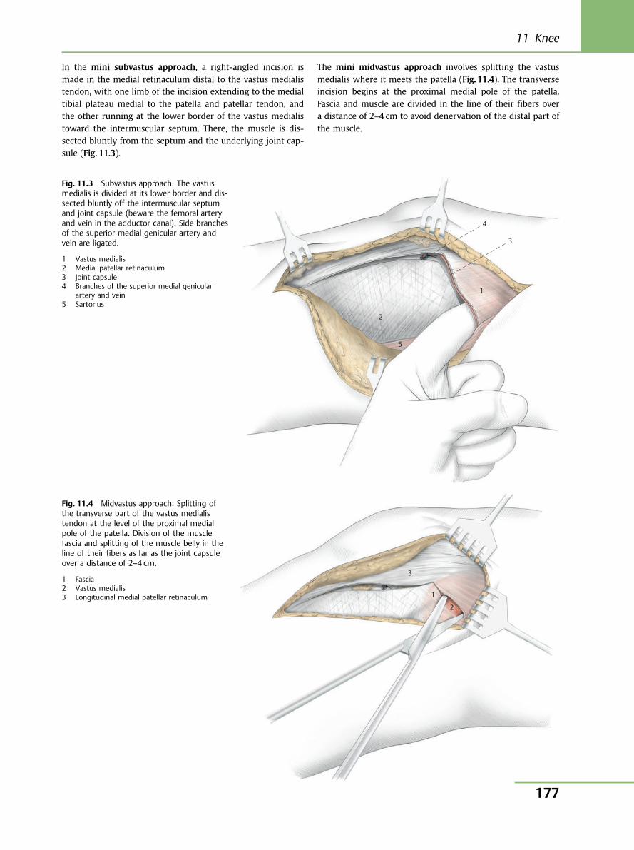
In the mini subvastus approach, a right-angled incision ismade in the medial retinaculum distal to the vastus medialistendon, with one limb of the incision extending to the medialtibial plateau medial to the patella and patellar tendon, andthe other running at the lower border of the vastus medialistoward the intermuscular septum. There, the muscle is dis-sected bluntly from the septum and the underlying joint cap-sule (Fig. 11.3).
The mini midvastus approach involves splitting the vastusmedialis where it meets the patella (Fig. 11.4). The transverseincision begins at the proximal medial pole of the patella.Fascia and muscle are divided in the line of their fibers overa distance of 2–4 cm to avoid denervation of the distal part ofthe muscle.
1
4
3
2
5
1
3
2
Fig. 11.3 Subvastus approach. The vastusmedialis is divided at its lower border and dis-sected bluntly off the intermuscular septumand joint capsule (beware the femoral arteryand vein in the adductor canal). Side branchesof the superior medial genicular artery andvein are ligated.
1 Vastus medialis2 Medial patellar retinaculum3 Joint capsule4 Branches of the superior medial genicular
artery and vein5 Sartorius
Fig. 11.4 Midvastus approach. Splitting ofthe transverse part of the vastus medialistendon at the level of the proximal medialpole of the patella. Division of the musclefascia and splitting of the muscle belly in theline of their fibers as far as the joint capsuleover a distance of 2–4 cm.
1 Fascia2 Vastus medialis3 Longitudinal medial patellar retinaculum
11 Knee
177
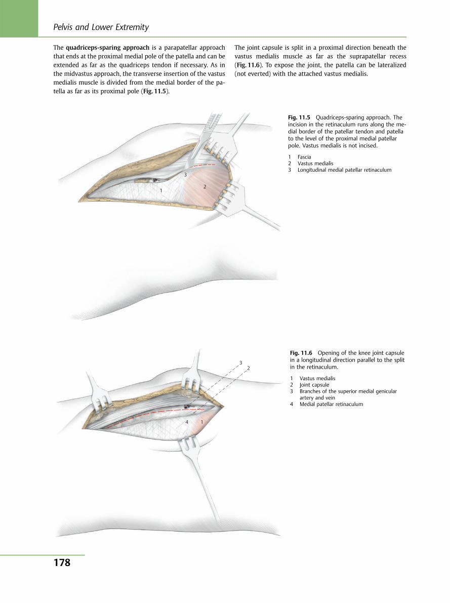
The quadriceps-sparing approach is a parapatellar approachthat ends at the proximal medial pole of the patella and can beextended as far as the quadriceps tendon if necessary. As inthe midvastus approach, the transverse insertion of the vastusmedialis muscle is divided from the medial border of the pa-tella as far as its proximal pole (Fig. 11.5).
The joint capsule is split in a proximal direction beneath thevastus medialis muscle as far as the suprapatellar recess(Fig. 11.6). To expose the joint, the patella can be lateralized(not everted) with the attached vastus medialis.
1
3
2
Fig. 11.5 Quadriceps-sparing approach. Theincision in the retinaculum runs along the me-dial border of the patellar tendon and patellato the level of the proximal medial patellarpole. Vastus medialis is not incised.
1 Fascia2 Vastus medialis3 Longitudinal medial patellar retinaculum
1
32
4
Fig. 11.6 Opening of the knee joint capsulein a longitudinal direction parallel to the splitin the retinaculum.
1 Vastus medialis2 Joint capsule3 Branches of the superior medial genicular
artery and vein4 Medial patellar retinaculum
Pelvis and Lower Extremity
178
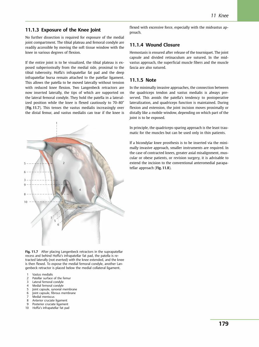
11.1.3 Exposure of the Knee Joint
No further dissection is required for exposure of the medialjoint compartment. The tibial plateau and femoral condyle arereadily accessible by moving the soft tissue window with theknee in various degrees of flexion.
If the entire joint is to be visualized, the tibial plateau is ex-posed subperiosteally from the medial side, proximal to thetibial tuberosity. Hoffa’s infrapatellar fat pad and the deepinfrapatellar bursa remain attached to the patellar ligament.This allows the patella to be moved laterally without tensionwith reduced knee flexion. Two Langenbeck retractors arenow inserted laterally, the tips of which are supported onthe lateral femoral condyle. They hold the patella in a lateral-ized position while the knee is flexed cautiously to 70–80°(Fig. 11.7). This tenses the vastus medialis increasingly overthe distal femur, and vastus medialis can tear if the knee is
flexed with excessive force, especially with the midvastus ap-proach.
11.1.4 Wound Closure
Hemostasis is ensured after release of the tourniquet. The jointcapsule and divided retinaculum are sutured. In the mid-vastus approach, the superficial muscle fibers and the musclefascia are also sutured.
11.1.5 Note
In the minimally invasive approaches, the connection betweenthe quadriceps tendon and vastus medialis is always pre-served. This avoids the patella’s tendency to postoperativelateralization, and quadriceps function is maintained. Duringflexion and extension, the joint incision moves proximally ordistally like a mobile window, depending on which part of thejoint is to be exposed.
In principle, the quadriceps-sparing approach is the least trau-matic for the muscles but can be used only in thin patients.
If a bicondylar knee prosthesis is to be inserted via the mini-mally invasive approach, smaller instruments are required. Inthe case of contracted knees, greater axial misalignment, mus-cular or obese patients, or revision surgery, it is advisable toextend the incision to the conventional anteromedial parapa-tellar approach (Fig. 11.8).
1
5
6
3
9
8
10
75
6
4
2
Fig. 11.7 After placing Langenbeck retractors in the suprapatellarrecess and behind Hoffa’s infrapatellar fat pad, the patella is re-tracted laterally (not everted) with the knee extended, and the kneeis then flexed. To expose the medial femoral condyle, another Lan-genbeck retractor is placed below the medial collateral ligament.
1 Vastus medialis2 Patellar surface of the femur3 Lateral femoral condyle4 Medial femoral condyle5 Joint capsule, synovial membrane6 Joint capsule, fibrous membrane7 Medial meniscus8 Anterior cruciate ligament9 Posterior cruciate ligament10 Hoffa’s infrapatellar fat pad
11 Knee
179
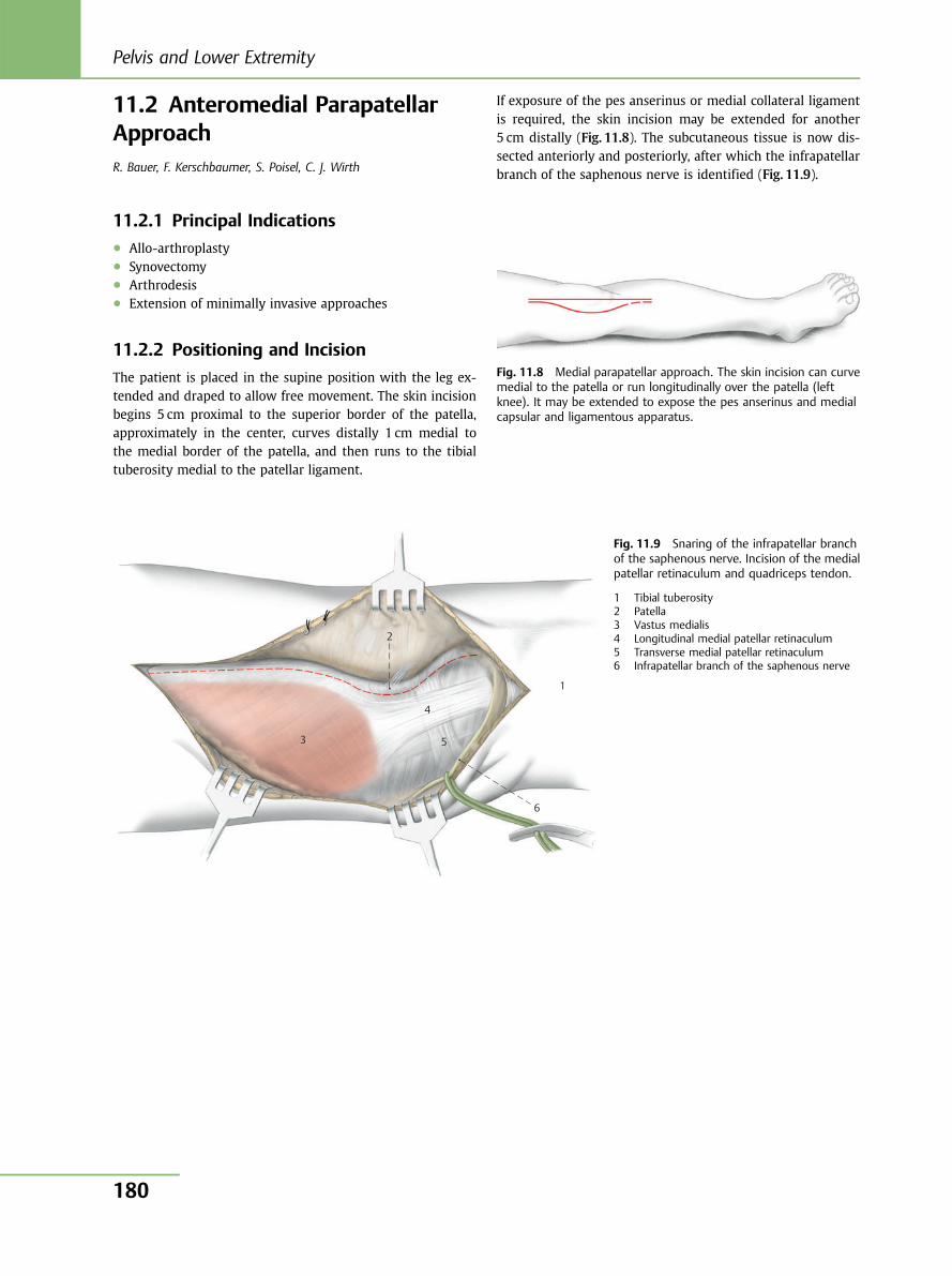
11.2 Anteromedial ParapatellarApproachR. Bauer, F. Kerschbaumer, S. Poisel, C. J. Wirth
11.2.1 Principal Indications● Allo-arthroplasty● Synovectomy● Arthrodesis● Extension of minimally invasive approaches
11.2.2 Positioning and Incision
The patient is placed in the supine position with the leg ex-tended and draped to allow free movement. The skin incisionbegins 5 cm proximal to the superior border of the patella,approximately in the center, curves distally 1 cm medial tothe medial border of the patella, and then runs to the tibialtuberosity medial to the patellar ligament.
If exposure of the pes anserinus or medial collateral ligamentis required, the skin incision may be extended for another5 cm distally (Fig. 11.8). The subcutaneous tissue is now dis-sected anteriorly and posteriorly, after which the infrapatellarbranch of the saphenous nerve is identified (Fig. 11.9).
Fig. 11.8 Medial parapatellar approach. The skin incision can curvemedial to the patella or run longitudinally over the patella (leftknee). It may be extended to expose the pes anserinus and medialcapsular and ligamentous apparatus.
1
2
3
4
6
5
Fig. 11.9 Snaring of the infrapatellar branchof the saphenous nerve. Incision of the medialpatellar retinaculum and quadriceps tendon.
1 Tibial tuberosity2 Patella3 Vastus medialis4 Longitudinal medial patellar retinaculum5 Transverse medial patellar retinaculum6 Infrapatellar branch of the saphenous nerve
Pelvis and Lower Extremity
180
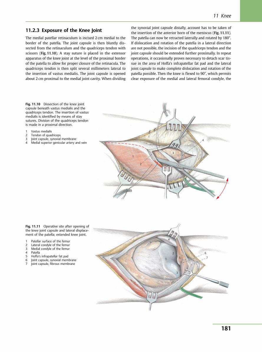
11.2.3 Exposure of the Knee Joint
The medial patellar retinaculum is incised 2 cm medial to theborder of the patella. The joint capsule is then bluntly dis-sected from the retinaculum and the quadriceps tendon withscissors (Fig. 11.10). A stay suture is placed in the extensorapparatus of the knee joint at the level of the proximal borderof the patella to allow for proper closure of the retinacula. Thequadriceps tendon is then split several millimeters lateral tothe insertion of vastus medialis. The joint capsule is openedabout 2 cm proximal to the medial joint cavity. When dividing
the synovial joint capsule distally, account has to be taken ofthe insertion of the anterior horn of the meniscus (Fig. 11.11).The patella can now be retracted laterally and rotated by 180°.If dislocation and rotation of the patella in a lateral directionare not possible, the incision of the quadriceps tendon and thejoint capsule should be extended further proximally. In repeatoperations, it occasionally proves necessary to detach scar tis-sue in the area of Hoffa’s infrapatellar fat pad and the lateraljoint capsule to make complete dislocation and rotation of thepatella possible. Then the knee is flexed to 90°, which permitsclear exposure of the medial and lateral femoral condyle, the
1
2
3
4
Fig. 11.10 Dissection of the knee jointcapsule beneath vastus medialis and thequadriceps tendon. The insertion of vastusmedialis is identified by means of staysutures. Division of the quadriceps tendonis made in a proximal direction.
1 Vastus medialis2 Tendon of quadriceps3 Joint capsule, synovial membrane4 Medial superior genicular artery and vein
1
4
2 5
3
6 7
Fig. 11.11 Operative site after opening ofthe knee joint capsule and lateral displace-ment of the patella; extended knee joint.
1 Patellar surface of the femur2 Lateral condyle of the femur3 Medial condyle of the femur4 Patella5 Hoffa’s infrapatellar fat pad6 Joint capsule, synovial membrane7 Joint capsule, fibrous membrane
11 Knee
181
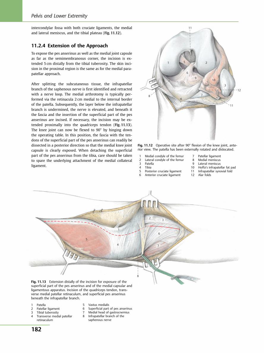
intercondylar fossa with both cruciate ligaments, the medialand lateral meniscus, and the tibial plateau (Fig. 11.12).
11.2.4 Extension of the Approach
To expose the pes anserinus as well as the medial joint capsuleas far as the semimembranosus corner, the incision is ex-tended 5 cm distally from the tibial tuberosity. The skin inci-sion in the proximal region is the same as for the medial para-patellar approach.
After splitting the subcutaneous tissue, the infrapatellarbranch of the saphenous nerve is first identified and retractedwith a nerve loop. The medial arthrotomy is typically per-formed via the retinacula 2 cm medial to the internal borderof the patella. Subsequently, the layer below the infrapatellarbranch is undermined, the nerve is elevated, and beneath itthe fascia and the insertion of the superficial part of the pesanserinus are incised. If necessary, the incision may be ex-tended proximally into the quadriceps tendon (Fig. 11.13).The knee joint can now be flexed to 90° by hinging downthe operating table. In this position, the fascia with the ten-dons of the superficial part of the pes anserinus can readily bedissected in a posterior direction so that the medial knee jointcapsule is clearly exposed. When detaching the superficialpart of the pes anserinus from the tibia, care should be takento spare the underlying attachment of the medial collateralligament.
8 4
1 5
6
9
2
11
10
7
11
12
3
5
4
8
7
6
3 2
1
Fig. 11.12 Operative site after 90° flexion of the knee joint, ante-rior view. The patella has been externally rotated and dislocated.
1 Medial condyle of the femur2 Lateral condyle of the femur3 Patella4 Tibia5 Posterior cruciate ligament6 Anterior cruciate ligament
7 Patellar ligament8 Medial meniscus9 Lateral meniscus10 Hoffa’s infrapatellar fat pad11 Infrapatellar synovial fold12 Alar folds
Fig. 11.13 Extension distally of the incision for exposure of thesuperficial part of the pes anserinus and of the medial capsular andligamentous apparatus. Incision of the quadriceps tendon, trans-verse medial patellar retinaculum, and superficial pes anserinusbeneath the infrapatellar branch.
1 Patella2 Patellar ligament3 Tibial tuberosity4 Transverse medial patellar
retinaculum
5 Vastus medialis6 Superficial part of pes anserinus7 Medial head of gastrocnemius8 Infrapatellar branch of the
saphenous nerve
Pelvis and Lower Extremity
182
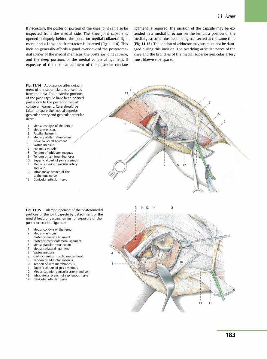
If necessary, the posterior portion of the knee joint can also beinspected from the medial side. The knee joint capsule isopened obliquely behind the posterior medial collateral liga-ment, and a Langenbeck retractor is inserted (Fig. 11.14). Thisincision generally affords a good overview of the posterome-dial corner of the medial meniscus, the posterior joint capsule,and the deep portions of the medial collateral ligament. Ifexposure of the tibial attachment of the posterior cruciate
ligament is required, the incision of the capsule may be ex-tended in a medial direction on the femur, a portion of themedial gastrocnemius head being transected at the same time(Fig. 11.15). The tendon of adductor magnus must not be dam-aged during this incision. The overlying articular nerve of theknee and the branches of the medial superior genicular arterymust likewise be spared.
10
11
12
13
9
8 7
6
5
4
3
1
2
7 9 12 14 2
5
6
10
3
1
4
8
13 11
Fig. 11.14 Appearance after detach-ment of the superficial pes anserinusfrom the tibia. The posterior portionsof the joint capsule have been openedposteriorly to the posterior medialcollateral ligament. Care should betaken to spare the medial superiorgenicular artery and genicular articularnerve.
1 Medial condyle of the femur2 Medial meniscus3 Patellar ligament4 Medial patellar retinaculum5 Tibial collateral ligament6 Vastus medialis7 Popliteus muscle8 Tendon of adductor magnus9 Tendon of semimembranosus10 Superficial part of pes anserinus11 Medial superior genicular artery
and vein12 Infrapatellar branch of the
saphenous nerve13 Genicular articular nerve
Fig. 11.15 Enlarged opening of the posteromedialportions of the joint capsule by detachment of themedial head of gastrocnemius for exposure of theposterior cruciate ligament.
1 Medial condyle of the femur2 Medial meniscus3 Posterior cruciate ligament4 Posterior meniscofemoral ligament5 Medial patellar retinaculum6 Medial collateral ligament7 Vastus medialis8 Gastrocnemius muscle, medial head9 Tendon of adductor magnus10 Tendon of semimembranosus11 Superficial part of pes anserinus12 Medial superior genicular artery and vein13 Infrapatellar branch of saphenous nerve14 Genicular articular nerve
11 Knee
183

11.2.5 Anatomical Site
(Fig. 11.16)
The so-called posteromedial joint corner or semimembrano-sus corner has special significance for the function of the kneejoint. The posterior portion of the medial knee joint capsule isdynamically stabilized by the semimembranosus. Semimem-branosus has five insertions whose direction is dependent onthe flexion of the knee joint. The reflected part runs beneaththe medial collateral ligament to the tibia and guards againstexternal rotation on flexion. The direct medial attachment tothe tibia causes contraction of the posterior capsule in theextended position. The oblique popliteal ligament is a radia-tion of the semimembranosus tendon into the posterior jointcapsule. Two other fiber tracts radiate into the posterior me-dial collateral ligament (posterior oblique ligament) on one
hand, and into the aponeurosis of the popliteus muscle onthe other.
Arthrotomies of the posteromedial portion of the joint may beperformed both anterior and posterior to the posterior medialcollateral ligament. This femorotibial ligament is closely con-nected to the posteromedial corner of the medial meniscus.The posterior horn of the meniscus is stabilized by this liga-ment. Additional dynamic stabilization of this ligament is pro-vided by branches of the semimembranosus tendon.
11.2.6 Wound Closure
The joint capsule, the medial head of gastrocnemius, and thedetached pes anserinus are sutured with interrupted sutures.As a rule, tourniquet release and hemostasis are advisableprior to wound closure.
10
11
12
9
8 7 6
5 4
3
1
2
4
Fig. 11.16 Anatomical site. The medial capsu-lar and ligamentous apparatus of the knee joint.
1 Vastus medialis2 Tendon of adductor magnus3 Semimembranosus4 Gastrocnemius muscle, medial head5 Medial condyle of the femur6 Medial condyle of the tibia7 Medial meniscus8 Superficial part of pes anserinus9 Posterior medial collateral ligament10 Medial collateral ligament11 Medial capsular ligament12 Condylar cap
Pelvis and Lower Extremity
184
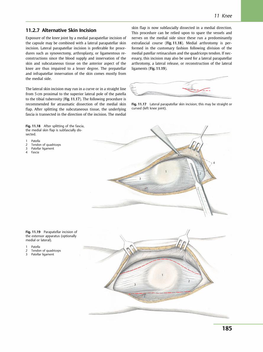
11.2.7 Alternative Skin Incision
Exposure of the knee joint by a medial parapatellar incision ofthe capsule may be combined with a lateral parapatellar skinincision. Lateral parapatellar incision is preferable for proce-dures such as synovectomy, arthroplasty, or ligamentous re-constructions since the blood supply and innervation of theskin and subcutaneous tissue on the anterior aspect of theknee are thus impaired to a lesser degree. The prepatellarand infrapatellar innervation of the skin comes mostly fromthe medial side.
The lateral skin incision may run in a curve or in a straight linefrom 5 cm proximal to the superior lateral pole of the patellato the tibial tuberosity (Fig. 11.17). The following procedure isrecommended for atraumatic dissection of the medial skinflap. After splitting the subcutaneous tissue, the underlyingfascia is transected in the direction of the incision. The medial
skin flap is now subfascially dissected in a medial direction.This procedure can be relied upon to spare the vessels andnerves on the medial side since these run a predominantlyextrafascial course (Fig. 11.18). Medial arthrotomy is per-formed in the customary fashion following division of themedial patellar retinaculum and the quadriceps tendon. If nec-essary, this incision may also be used for a lateral parapatellararthrotomy, a lateral release, or reconstruction of the lateralligaments (Fig. 11.19).
4
3
1 2
3
1
2
Fig. 11.17 Lateral parapatellar skin incision; this may be straight orcurved (left knee joint).
Fig. 11.18 After splitting of the fascia,the medial skin flap is subfascially dis-sected.
1 Patella2 Tendon of quadriceps3 Patellar ligament4 Fascia
Fig. 11.19 Parapatellar incision ofthe extensor apparatus (optionallymedial or lateral).
1 Patella2 Tendon of quadriceps3 Patellar ligament
11 Knee
185
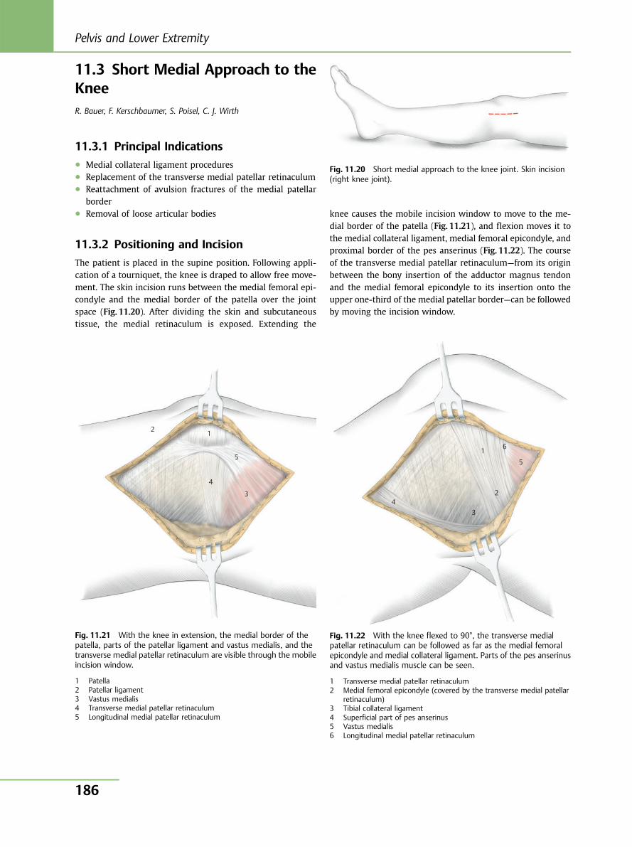
11.3 Short Medial Approach to theKneeR. Bauer, F. Kerschbaumer, S. Poisel, C. J. Wirth
11.3.1 Principal Indications● Medial collateral ligament procedures● Replacement of the transverse medial patellar retinaculum● Reattachment of avulsion fractures of the medial patellar
border● Removal of loose articular bodies
11.3.2 Positioning and Incision
The patient is placed in the supine position. Following appli-cation of a tourniquet, the knee is draped to allow free move-ment. The skin incision runs between the medial femoral epi-condyle and the medial border of the patella over the jointspace (Fig. 11.20). After dividing the skin and subcutaneoustissue, the medial retinaculum is exposed. Extending the
knee causes the mobile incision window to move to the me-dial border of the patella (Fig. 11.21), and flexion moves it tothe medial collateral ligament, medial femoral epicondyle, andproximal border of the pes anserinus (Fig. 11.22). The courseof the transverse medial patellar retinaculum—from its originbetween the bony insertion of the adductor magnus tendonand the medial femoral epicondyle to its insertion onto theupper one-third of the medial patellar border—can be followedby moving the incision window.
Fig. 11.20 Short medial approach to the knee joint. Skin incision(right knee joint).
1 2
3
4
5
Fig. 11.21 With the knee in extension, the medial border of thepatella, parts of the patellar ligament and vastus medialis, and thetransverse medial patellar retinaculum are visible through the mobileincision window.
1 Patella2 Patellar ligament3 Vastus medialis4 Transverse medial patellar retinaculum5 Longitudinal medial patellar retinaculum
1 5
2
34
6
Fig. 11.22 With the knee flexed to 90°, the transverse medialpatellar retinaculum can be followed as far as the medial femoralepicondyle and medial collateral ligament. Parts of the pes anserinusand vastus medialis muscle can be seen.
1 Transverse medial patellar retinaculum2 Medial femoral epicondyle (covered by the transverse medial patellar
retinaculum)3 Tibial collateral ligament4 Superficial part of pes anserinus5 Vastus medialis6 Longitudinal medial patellar retinaculum
Pelvis and Lower Extremity
186
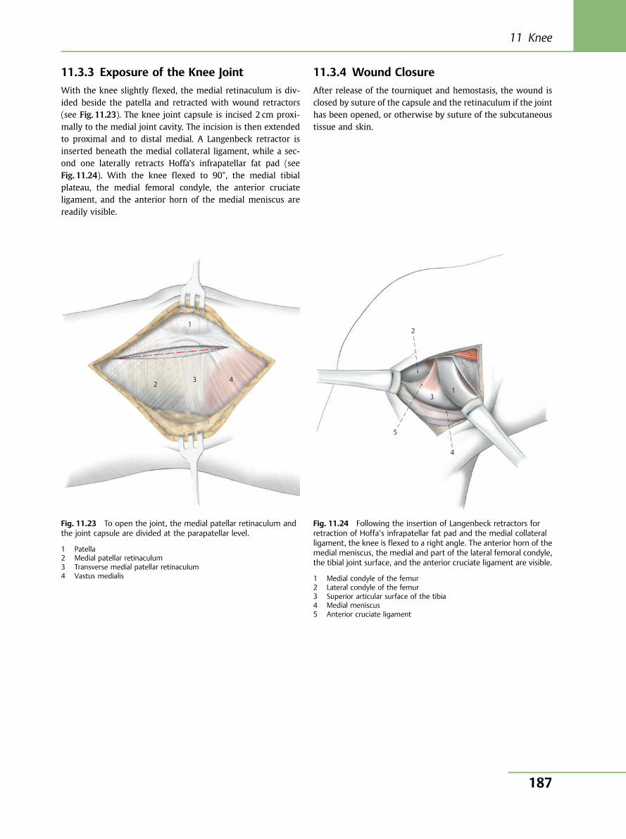
11.3.3 Exposure of the Knee Joint
With the knee slightly flexed, the medial retinaculum is div-ided beside the patella and retracted with wound retractors(see Fig. 11.23). The knee joint capsule is incised 2 cm proxi-mally to the medial joint cavity. The incision is then extendedto proximal and to distal medial. A Langenbeck retractor isinserted beneath the medial collateral ligament, while a sec-ond one laterally retracts Hoffa’s infrapatellar fat pad (seeFig. 11.24). With the knee flexed to 90°, the medial tibialplateau, the medial femoral condyle, the anterior cruciateligament, and the anterior horn of the medial meniscus arereadily visible.
11.3.4 Wound Closure
After release of the tourniquet and hemostasis, the wound isclosed by suture of the capsule and the retinaculum if the jointhas been opened, or otherwise by suture of the subcutaneoustissue and skin.
1
2 3 4
Fig. 11.23 To open the joint, the medial patellar retinaculum andthe joint capsule are divided at the parapatellar level.
1 Patella2 Medial patellar retinaculum3 Transverse medial patellar retinaculum4 Vastus medialis
2
13
5
4
Fig. 11.24 Following the insertion of Langenbeck retractors forretraction of Hoffa’s infrapatellar fat pad and the medial collateralligament, the knee is flexed to a right angle. The anterior horn of themedial meniscus, the medial and part of the lateral femoral condyle,the tibial joint surface, and the anterior cruciate ligament are visible.
1 Medial condyle of the femur2 Lateral condyle of the femur3 Superior articular surface of the tibia4 Medial meniscus5 Anterior cruciate ligament
11 Knee
187
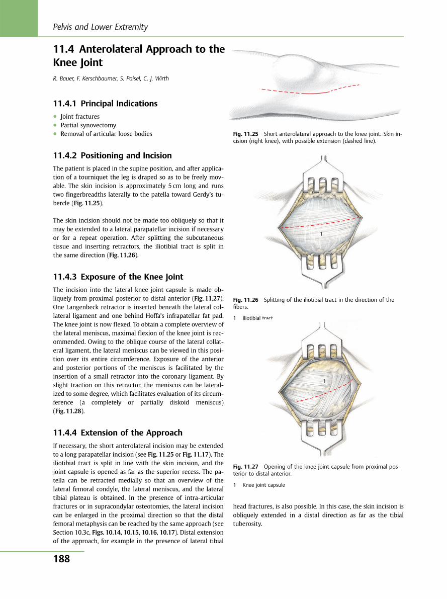
11.4 Anterolateral Approach to theKnee JointR. Bauer, F. Kerschbaumer, S. Poisel, C. J. Wirth
11.4.1 Principal Indications● Joint fractures● Partial synovectomy● Removal of articular loose bodies
11.4.2 Positioning and Incision
The patient is placed in the supine position, and after applica-tion of a tourniquet the leg is draped so as to be freely mov-able. The skin incision is approximately 5 cm long and runstwo fingerbreadths laterally to the patella toward Gerdy’s tu-bercle (Fig. 11.25).
The skin incision should not be made too obliquely so that itmay be extended to a lateral parapatellar incision if necessaryor for a repeat operation. After splitting the subcutaneoustissue and inserting retractors, the iliotibial tract is split inthe same direction (Fig. 11.26).
11.4.3 Exposure of the Knee Joint
The incision into the lateral knee joint capsule is made ob-liquely from proximal posterior to distal anterior (Fig. 11.27).One Langenbeck retractor is inserted beneath the lateral col-lateral ligament and one behind Hoffa’s infrapatellar fat pad.The knee joint is now flexed. To obtain a complete overview ofthe lateral meniscus, maximal flexion of the knee joint is rec-ommended. Owing to the oblique course of the lateral collat-eral ligament, the lateral meniscus can be viewed in this posi-tion over its entire circumference. Exposure of the anteriorand posterior portions of the meniscus is facilitated by theinsertion of a small retractor into the coronary ligament. Byslight traction on this retractor, the meniscus can be lateral-ized to some degree, which facilitates evaluation of its circum-ference (a completely or partially diskoid meniscus)(Fig. 11.28).
11.4.4 Extension of the Approach
If necessary, the short anterolateral incision may be extendedto a long parapatellar incision (see Fig. 11.25 or Fig. 11.17). Theiliotibial tract is split in line with the skin incision, and thejoint capsule is opened as far as the superior recess. The pa-tella can be retracted medially so that an overview of thelateral femoral condyle, the lateral meniscus, and the lateraltibial plateau is obtained. In the presence of intra-articularfractures or in supracondylar osteotomies, the lateral incisioncan be enlarged in the proximal direction so that the distalfemoral metaphysis can be reached by the same approach (seeSection 10.3c, Figs. 10.14, 10.15, 10.16, 10.17). Distal extensionof the approach, for example in the presence of lateral tibial
head fractures, is also possible. In this case, the skin incision isobliquely extended in a distal direction as far as the tibialtuberosity.
1
Fig. 11.25 Short anterolateral approach to the knee joint. Skin in-cision (right knee), with possible extension (dashed line).
Fig. 11.26 Splitting of the iliotibial tract in the direction of thefibers.
1 Iliotibial tract
Fig. 11.27 Opening of the knee joint capsule from proximal pos-terior to distal anterior.
1 Knee joint capsule
1
Pelvis and Lower Extremity
188
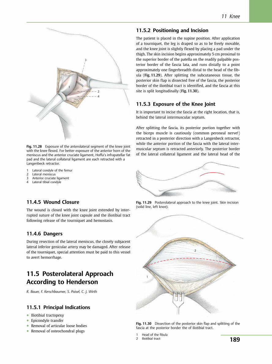
1
3
2 4
Fig. 11.28 Exposure of the anterolateral segment of the knee jointwith the knee flexed. For better exposure of the anterior horn of themeniscus and the anterior cruciate ligament, Hoffa’s infrapatellar fatpad and the lateral collateral ligament are each retracted with aLangenbeck retractor.
1 Lateral condyle of the femur2 Lateral meniscus3 Anterior cruciate ligament4 Lateral tibial condyle
Fig. 11.29 Posterolateral approach to the knee joint. Skin incision(solid line, left knee).
1
2
11.4.5 Wound Closure
The wound is closed with the knee joint extended by inter-rupted suture of the knee joint capsule and the iliotibial tractfollowing release of the tourniquet and hemostasis.
11.4.6 Dangers
During resection of the lateral meniscus, the closely subjacentlateral inferior genicular artery may be damaged. After releaseof the tourniquet, special attention must be paid to this vesselto avert hemorrhage.
11.5 Posterolateral ApproachAccording to HendersonR. Bauer, F. Kerschbaumer, S. Poisel, C. J. Wirth
11.5.1 Principal Indications● Iliotibial tractopexy● Epicondyle transfer● Removal of articular loose bodies● Removal of osteochondral plugs
11.5.2 Positioning and Incision
The patient is placed in the supine position. After applicationof a tourniquet, the leg is draped so as to be freely movable,and the knee joint is slightly flexed by placing a pad under thethigh. The skin incision begins approximately 5 cm proximal tothe superior border of the patella on the readily palpable pos-terior border of the fascia lata, and runs distally to a pointapproximately one fingerbreadth distal to the head of the fib-ula (Fig. 11.29). After splitting the subcutaneous tissue, theposterior skin flap is dissected free of the fascia, the posteriorborder of the iliotibial tract is identified, and the fascia at thissite is split longitudinally (Fig. 11.30).
11.5.3 Exposure of the Knee Joint
It is important to incise the fascia at the right location, that is,behind the lateral intermuscular septum.
After splitting the fascia, its posterior portion together withthe biceps muscle is cautiously (common peroneal nerve!)retracted in a posterior direction with a Langenbeck retractor,while the anterior portion of the fascia with the lateral inter-muscular septum is retracted anteriorly. The posterior borderof the lateral collateral ligament and the lateral head of the
Fig. 11.30 Dissection of the posterior skin flap and splitting of thefascia at the posterior border the of iliotibial tract.
1 Head of the fibula2 Iliotibial tract
11 Knee
189
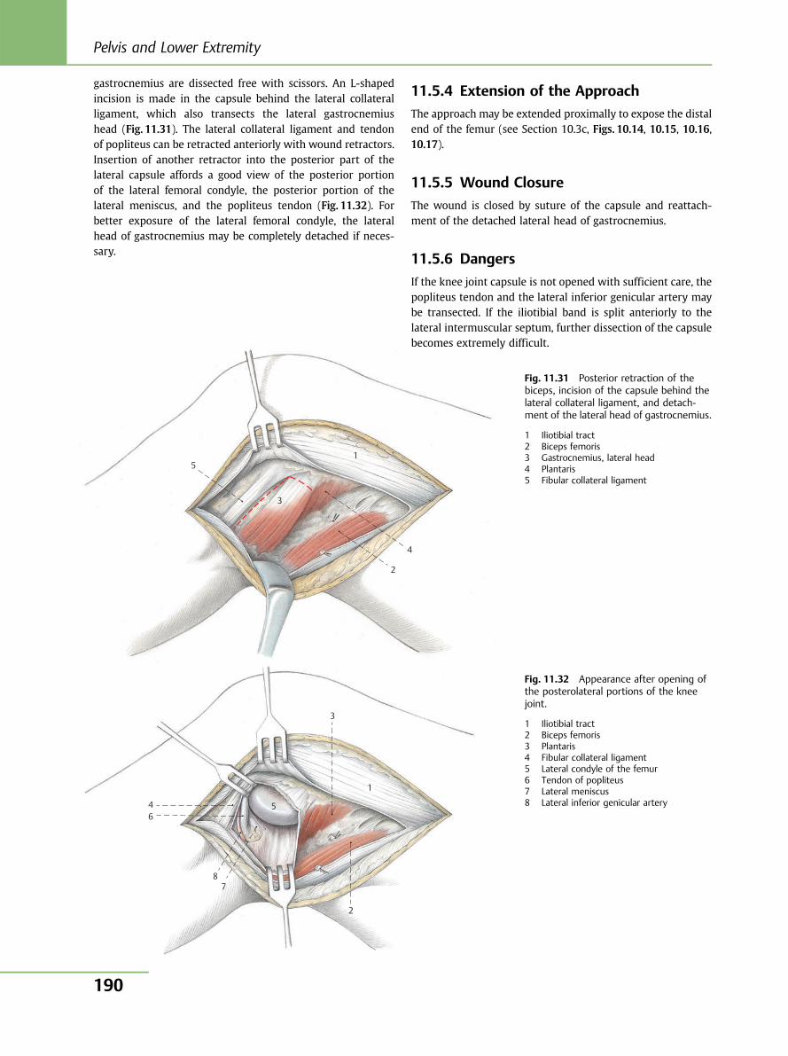
gastrocnemius are dissected free with scissors. An L-shapedincision is made in the capsule behind the lateral collateralligament, which also transects the lateral gastrocnemiushead (Fig. 11.31). The lateral collateral ligament and tendonof popliteus can be retracted anteriorly with wound retractors.Insertion of another retractor into the posterior part of thelateral capsule affords a good view of the posterior portionof the lateral femoral condyle, the posterior portion of thelateral meniscus, and the popliteus tendon (Fig. 11.32). Forbetter exposure of the lateral femoral condyle, the lateralhead of gastrocnemius may be completely detached if neces-sary.
11.5.4 Extension of the Approach
The approach may be extended proximally to expose the distalend of the femur (see Section 10.3c, Figs. 10.14, 10.15, 10.16,10.17).
11.5.5 Wound Closure
The wound is closed by suture of the capsule and reattach-ment of the detached lateral head of gastrocnemius.
11.5.6 Dangers
If the knee joint capsule is not opened with sufficient care, thepopliteus tendon and the lateral inferior genicular artery maybe transected. If the iliotibial band is split anteriorly to thelateral intermuscular septum, further dissection of the capsulebecomes extremely difficult.
5
3
1
2
4
4 6
8 7
2
3
1
5
Fig. 11.31 Posterior retraction of thebiceps, incision of the capsule behind thelateral collateral ligament, and detach-ment of the lateral head of gastrocnemius.
1 Iliotibial tract2 Biceps femoris3 Gastrocnemius, lateral head4 Plantaris5 Fibular collateral ligament
Fig. 11.32 Appearance after opening ofthe posterolateral portions of the kneejoint.
1 Iliotibial tract2 Biceps femoris3 Plantaris4 Fibular collateral ligament5 Lateral condyle of the femur6 Tendon of popliteus7 Lateral meniscus8 Lateral inferior genicular artery
Pelvis and Lower Extremity
190
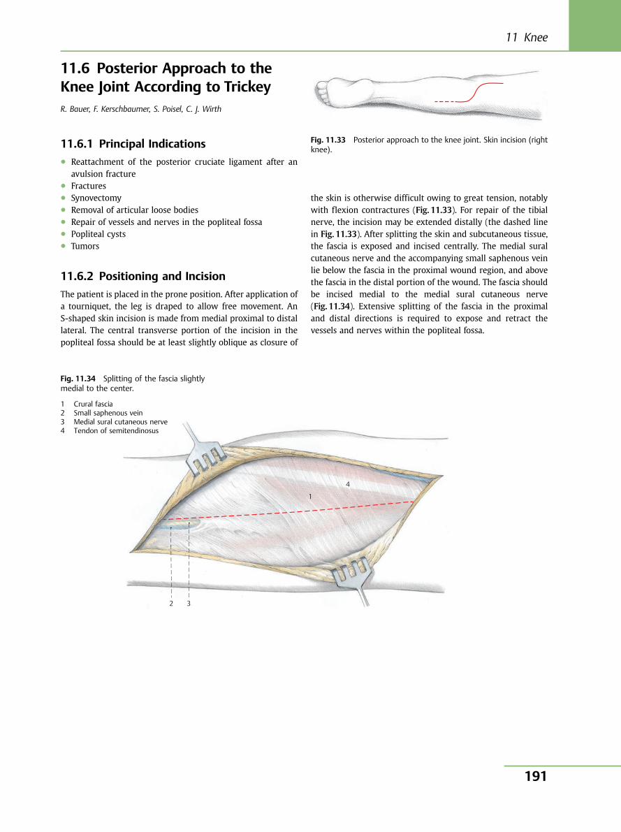
11.6 Posterior Approach to theKnee Joint According to TrickeyR. Bauer, F. Kerschbaumer, S. Poisel, C. J. Wirth
11.6.1 Principal Indications● Reattachment of the posterior cruciate ligament after an
avulsion fracture● Fractures● Synovectomy● Removal of articular loose bodies● Repair of vessels and nerves in the popliteal fossa● Popliteal cysts● Tumors
11.6.2 Positioning and Incision
The patient is placed in the prone position. After application ofa tourniquet, the leg is draped to allow free movement. AnS-shaped skin incision is made from medial proximal to distallateral. The central transverse portion of the incision in thepopliteal fossa should be at least slightly oblique as closure of
the skin is otherwise difficult owing to great tension, notablywith flexion contractures (Fig. 11.33). For repair of the tibialnerve, the incision may be extended distally (the dashed linein Fig. 11.33). After splitting the skin and subcutaneous tissue,the fascia is exposed and incised centrally. The medial suralcutaneous nerve and the accompanying small saphenous veinlie below the fascia in the proximal wound region, and abovethe fascia in the distal portion of the wound. The fascia shouldbe incised medial to the medial sural cutaneous nerve(Fig. 11.34). Extensive splitting of the fascia in the proximaland distal directions is required to expose and retract thevessels and nerves within the popliteal fossa.
Fig. 11.33 Posterior approach to the knee joint. Skin incision (rightknee).
4
2 3
1
Fig. 11.34 Splitting of the fascia slightlymedial to the center.
1 Crural fascia2 Small saphenous vein3 Medial sural cutaneous nerve4 Tendon of semitendinosus
11 Knee
191
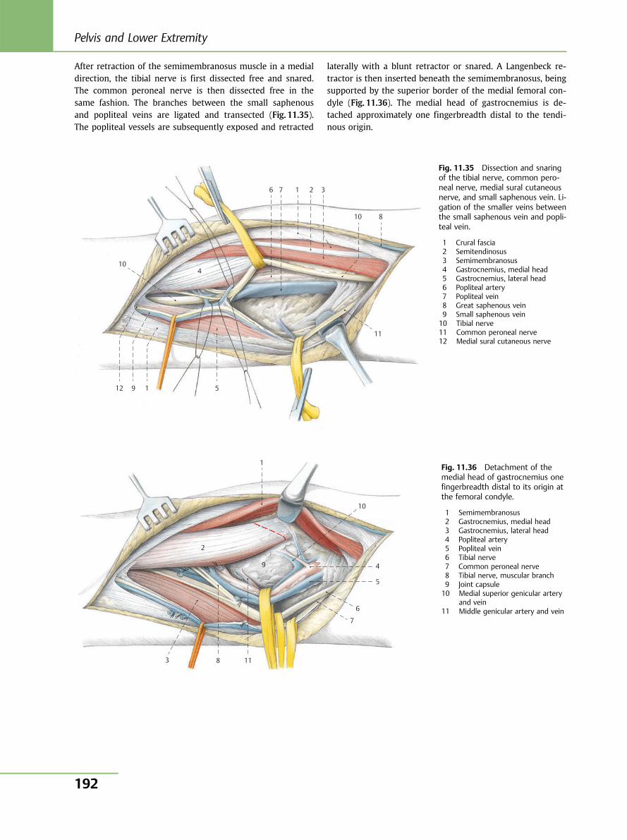
After retraction of the semimembranosus muscle in a medialdirection, the tibial nerve is first dissected free and snared.The common peroneal nerve is then dissected free in thesame fashion. The branches between the small saphenousand popliteal veins are ligated and transected (Fig. 11.35).The popliteal vessels are subsequently exposed and retracted
laterally with a blunt retractor or snared. A Langenbeck re-tractor is then inserted beneath the semimembranosus, beingsupported by the superior border of the medial femoral con-dyle (Fig. 11.36). The medial head of gastrocnemius is de-tached approximately one fingerbreadth distal to the tendi-nous origin.
10 4
6 7 1 2 3
10 8
11
5 1 9 12
Fig. 11.35 Dissection and snaringof the tibial nerve, common pero-neal nerve, medial sural cutaneousnerve, and small saphenous vein. Li-gation of the smaller veins betweenthe small saphenous vein and popli-teal vein.
1 Crural fascia2 Semitendinosus3 Semimembranosus4 Gastrocnemius, medial head5 Gastrocnemius, lateral head6 Popliteal artery7 Popliteal vein8 Great saphenous vein9 Small saphenous vein10 Tibial nerve11 Common peroneal nerve12 Medial sural cutaneous nerve
2
1
10
4
5
6
7
11
9
8 3
Fig. 11.36 Detachment of themedial head of gastrocnemius onefingerbreadth distal to its origin atthe femoral condyle.
1 Semimembranosus2 Gastrocnemius, medial head3 Gastrocnemius, lateral head4 Popliteal artery5 Popliteal vein6 Tibial nerve7 Common peroneal nerve8 Tibial nerve, muscular branch9 Joint capsule10 Medial superior genicular artery
and vein11 Middle genicular artery and vein
Pelvis and Lower Extremity
192
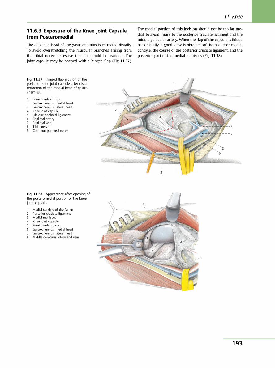
11.6.3 Exposure of the Knee Joint Capsulefrom Posteromedial
The detached head of the gastrocnemius is retracted distally.To avoid overstretching the muscular branches arising fromthe tibial nerve, excessive tension should be avoided. Thejoint capsule may be opened with a hinged flap (Fig. 11.37).
The medial portion of this incision should not be too far me-dial, to avoid injury to the posterior cruciate ligament and themiddle genicular artery. When the flap of the capsule is foldedback distally, a good view is obtained of the posterior medialcondyle, the course of the posterior cruciate ligament, and theposterior part of the medial meniscus (Fig. 11.38).
1
4
5 6
7
8
9
3
2
Fig. 11.37 Hinged flap incision of theposterior knee joint capsule after distalretraction of the medial head of gastro-cnemius.
1 Semimembranosus2 Gastrocnemius, medial head3 Gastrocnemius, lateral head4 Knee joint capsule5 Oblique popliteal ligament6 Popliteal artery7 Popliteal vein8 Tibial nerve9 Common peroneal nerve
5
4 6
7
4
8
2
3 1
Fig. 11.38 Appearance after opening ofthe posteromedial portion of the kneejoint capsule.
1 Medial condyle of the femur2 Posterior cruciate ligament3 Medial meniscus4 Knee joint capsule5 Semimembranosus6 Gastrocnemius, medial head7 Gastrocnemius, lateral head8 Middle genicular artery and vein
11 Knee
193
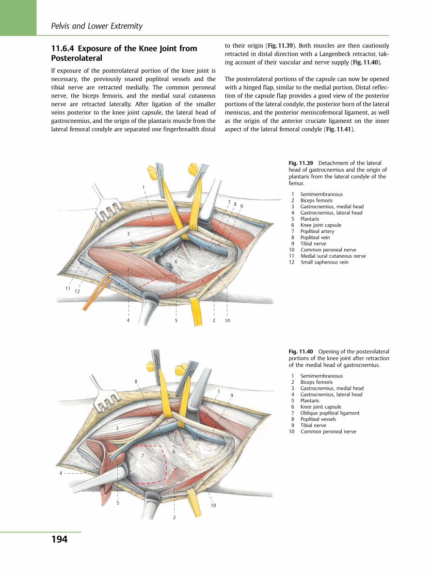
11.6.4 Exposure of the Knee Joint fromPosterolateral
If exposure of the posterolateral portion of the knee joint isnecessary, the previously snared popliteal vessels and thetibial nerve are retracted medially. The common peronealnerve, the biceps femoris, and the medial sural cutaneousnerve are retracted laterally. After ligation of the smallerveins posterior to the knee joint capsule, the lateral head ofgastrocnemius, and the origin of the plantaris muscle from thelateral femoral condyle are separated one fingerbreadth distal
to their origin (Fig. 11.39). Both muscles are then cautiouslyretracted in distal direction with a Langenbeck retractor, tak-ing account of their vascular and nerve supply (Fig. 11.40).
The posterolateral portions of the capsule can now be openedwith a hinged flap, similar to the medial portion. Distal reflec-tion of the capsule flap provides a good view of the posteriorportions of the lateral condyle, the posterior horn of the lateralmeniscus, and the posterior meniscofemoral ligament, as wellas the origin of the anterior cruciate ligament on the inneraspect of the lateral femoral condyle (Fig. 11.41).
1
7 8
10 2 5 4
12 11
3
6
9
Fig. 11.39 Detachment of the lateralhead of gastrocnemius and the origin ofplantaris from the lateral condyle of thefemur.
1 Semimembranosus2 Biceps femoris3 Gastrocnemius, medial head4 Gastrocnemius, lateral head5 Plantaris6 Knee joint capsule7 Popliteal artery8 Popliteal vein9 Tibial nerve10 Common peroneal nerve11 Medial sural cutaneous nerve12 Small saphenous vein
4
5
2
10
7 6
3
8
1 9
Fig. 11.40 Opening of the posterolateralportions of the knee joint after retractionof the medial head of gastrocnemius.
1 Semimembranosus2 Biceps femoris3 Gastrocnemius, medial head4 Gastrocnemius, lateral head5 Plantaris6 Knee joint capsule7 Oblique popliteal ligament8 Popliteal vessels9 Tibial nerve10 Common peroneal nerve
Pelvis and Lower Extremity
194
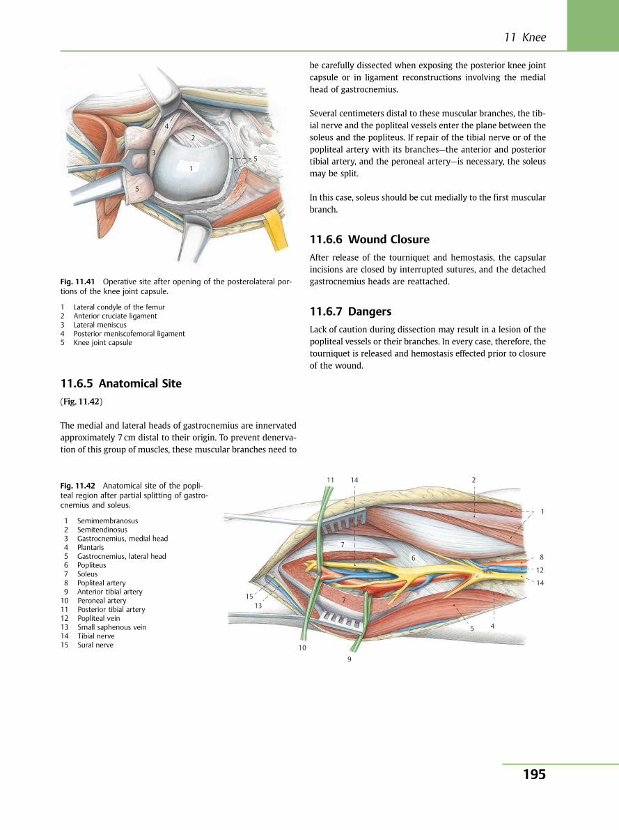
11.6.5 Anatomical Site
(Fig. 11.42)
The medial and lateral heads of gastrocnemius are innervatedapproximately 7 cm distal to their origin. To prevent denerva-tion of this group of muscles, these muscular branches need to
be carefully dissected when exposing the posterior knee jointcapsule or in ligament reconstructions involving the medialhead of gastrocnemius.
Several centimeters distal to these muscular branches, the tib-ial nerve and the popliteal vessels enter the plane between thesoleus and the popliteus. If repair of the tibial nerve or of thepopliteal artery with its branches—the anterior and posteriortibial artery, and the peroneal artery—is necessary, the soleusmay be split.
In this case, soleus should be cut medially to the first muscularbranch.
11.6.6 Wound Closure
After release of the tourniquet and hemostasis, the capsularincisions are closed by interrupted sutures, and the detachedgastrocnemius heads are reattached.
11.6.7 Dangers
Lack of caution during dissection may result in a lesion of thepopliteal vessels or their branches. In every case, therefore, thetourniquet is released and hemostasis effected prior to closureof the wound.
1
2
3
4
5
5
Fig. 11.41 Operative site after opening of the posterolateral por-tions of the knee joint capsule.
1 Lateral condyle of the femur2 Anterior cruciate ligament3 Lateral meniscus4 Posterior meniscofemoral ligament5 Knee joint capsule
15 13
10
7
7
11 14 2
1
8
12
14
4
6
5
9
Fig. 11.42 Anatomical site of the popli-teal region after partial splitting of gastro-cnemius and soleus.
1 Semimembranosus2 Semitendinosus3 Gastrocnemius, medial head4 Plantaris5 Gastrocnemius, lateral head6 Popliteus7 Soleus8 Popliteal artery9 Anterior tibial artery10 Peroneal artery11 Posterior tibial artery12 Popliteal vein13 Small saphenous vein14 Tibial nerve15 Sural nerve
11 Knee
195
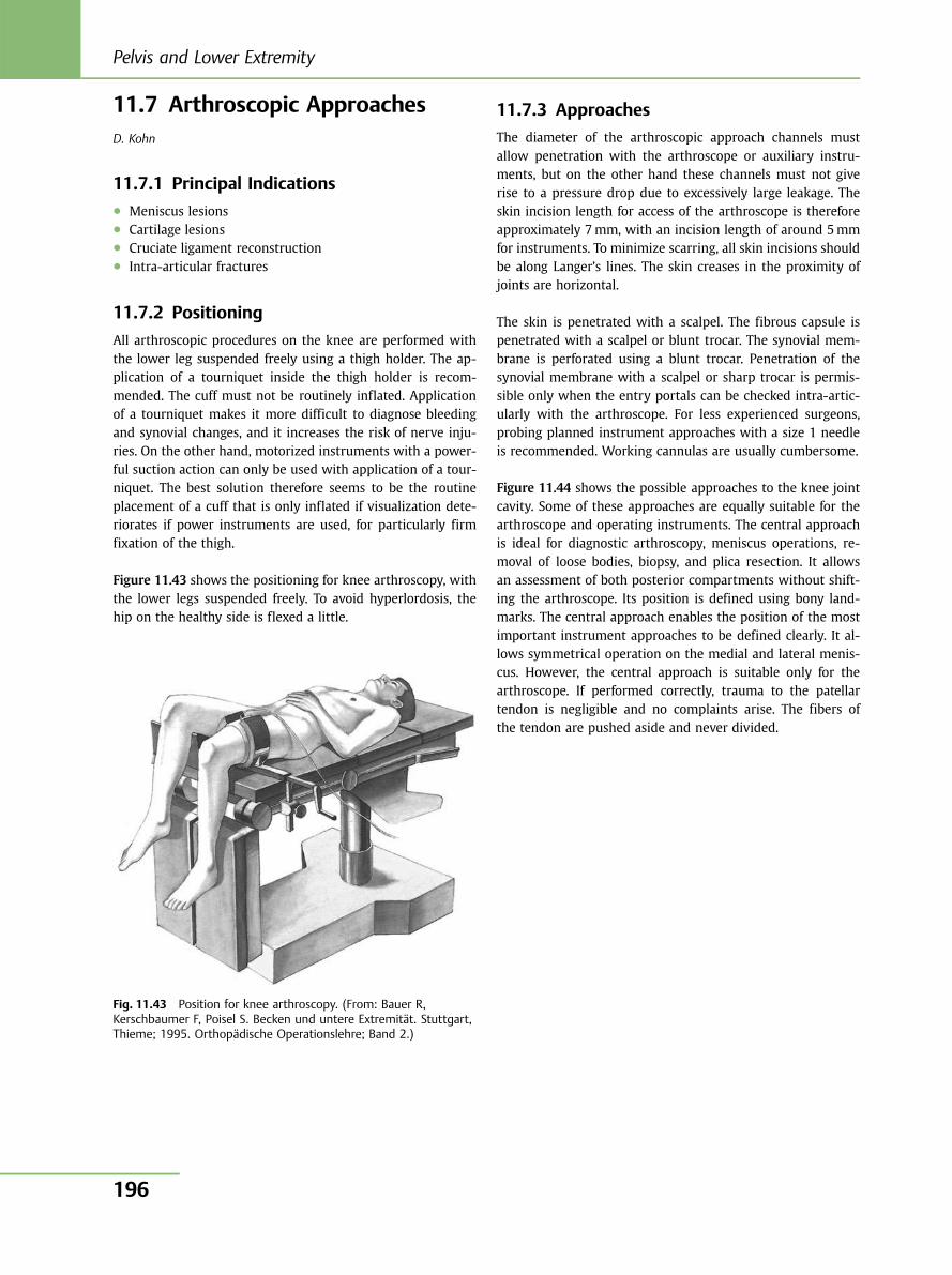
11.7 Arthroscopic ApproachesD. Kohn
11.7.1 Principal Indications● Meniscus lesions● Cartilage lesions● Cruciate ligament reconstruction● Intra-articular fractures
11.7.2 Positioning
All arthroscopic procedures on the knee are performed withthe lower leg suspended freely using a thigh holder. The ap-plication of a tourniquet inside the thigh holder is recom-mended. The cuff must not be routinely inflated. Applicationof a tourniquet makes it more difficult to diagnose bleedingand synovial changes, and it increases the risk of nerve inju-ries. On the other hand, motorized instruments with a power-ful suction action can only be used with application of a tour-niquet. The best solution therefore seems to be the routineplacement of a cuff that is only inflated if visualization dete-riorates if power instruments are used, for particularly firmfixation of the thigh.
Figure 11.43 shows the positioning for knee arthroscopy, withthe lower legs suspended freely. To avoid hyperlordosis, thehip on the healthy side is flexed a little.
11.7.3 Approaches
The diameter of the arthroscopic approach channels mustallow penetration with the arthroscope or auxiliary instru-ments, but on the other hand these channels must not giverise to a pressure drop due to excessively large leakage. Theskin incision length for access of the arthroscope is thereforeapproximately 7mm, with an incision length of around 5mmfor instruments. To minimize scarring, all skin incisions shouldbe along Langer’s lines. The skin creases in the proximity ofjoints are horizontal.
The skin is penetrated with a scalpel. The fibrous capsule ispenetrated with a scalpel or blunt trocar. The synovial mem-brane is perforated using a blunt trocar. Penetration of thesynovial membrane with a scalpel or sharp trocar is permis-sible only when the entry portals can be checked intra-artic-ularly with the arthroscope. For less experienced surgeons,probing planned instrument approaches with a size 1 needleis recommended. Working cannulas are usually cumbersome.
Figure 11.44 shows the possible approaches to the knee jointcavity. Some of these approaches are equally suitable for thearthroscope and operating instruments. The central approachis ideal for diagnostic arthroscopy, meniscus operations, re-moval of loose bodies, biopsy, and plica resection. It allowsan assessment of both posterior compartments without shift-ing the arthroscope. Its position is defined using bony land-marks. The central approach enables the position of the mostimportant instrument approaches to be defined clearly. It al-lows symmetrical operation on the medial and lateral menis-cus. However, the central approach is suitable only for thearthroscope. If performed correctly, trauma to the patellartendon is negligible and no complaints arise. The fibers ofthe tendon are pushed aside and never divided.
Fig. 11.43 Position for knee arthroscopy. (From: Bauer R,Kerschbaumer F, Poisel S. Becken und untere Extremität. Stuttgart,Thieme; 1995. Orthopädische Operationslehre; Band 2.)
Pelvis and Lower Extremity
196
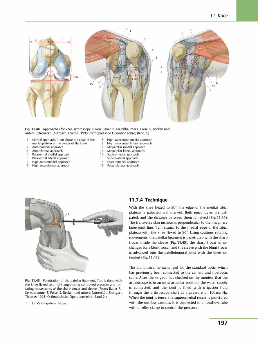
11.7.4 Technique
With the knee flexed to 90°, the edge of the medial tibialplateau is palpated and marked. Both epicondyles are pal-pated, and the distance between them is halved (Fig. 11.44).The transverse skin incision is perpendicular to the imaginaryknee joint line, 1 cm cranial to the medial edge of the tibialplateau with the knee flexed to 90°. Using cautious rotatingmovements, the patellar ligament is penetrated with the sharptrocar inside the sleeve (Fig. 11.45), the sharp trocar is ex-changed for a blunt trocar, and the sleeve with the blunt trocaris advanced into the patellofemoral joint with the knee ex-tended (Fig. 11.46).
The blunt trocar is exchanged for the standard optic, whichhas previously been connected to the camera and fiberopticcable. After the surgeon has checked on the monitor that thearthroscope is in an intra-articular position, the water supplyis connected, and the joint is filled with irrigation fluidthrough the arthroscope shaft at a pressure of 100mmHg.When the joint is tense, the superomedial recess is puncturedwith the outflow cannula. It is connected to an outflow tubewith a roller clamp to control the pressure.
1/2
1 cm
4 cm
1.5 cm
4 cm
1.5 cm
15 73
13 11
9
5
1
84
1
214
6
1210
1/2
Fig. 11.44 Approaches for knee arthroscopy. (From: Bauer R, Kerschbaumer F, Poisel S. Becken unduntere Extremität. Stuttgart, Thieme; 1995. Orthopädische Operationslehre; Band 2.)
1 Central approach, 1 cm above the edge of themedial plateau at the center of the knee
2 Anteromedial approach3 Anterolateral approach4 Paracentral medial approach5 Paracentral lateral approach6 High anteromedial approach7 High anterolateral approach
8 High paracentral medial approach9 High paracentral lateral approach10 Midpatellar medial approach11 Midpatellar lateral approach12 Superomedial approach13 Superolateral approach14 Posteromedial approach15 Posterolateral approach
1
Fig. 11.45 Penetration of the patellar ligament. This is done withthe knee flexed to a right angle using controlled pressure and ro-tating movements of the sharp trocar and sleeve. (From: Bauer R,Kerschbaumer F, Poisel S. Becken und untere Extremität. Stuttgart,Thieme; 1995. Orthopädische Operationslehre; Band 2.)
1 Hoffa’s infrapatellar fat pad
11 Knee
197
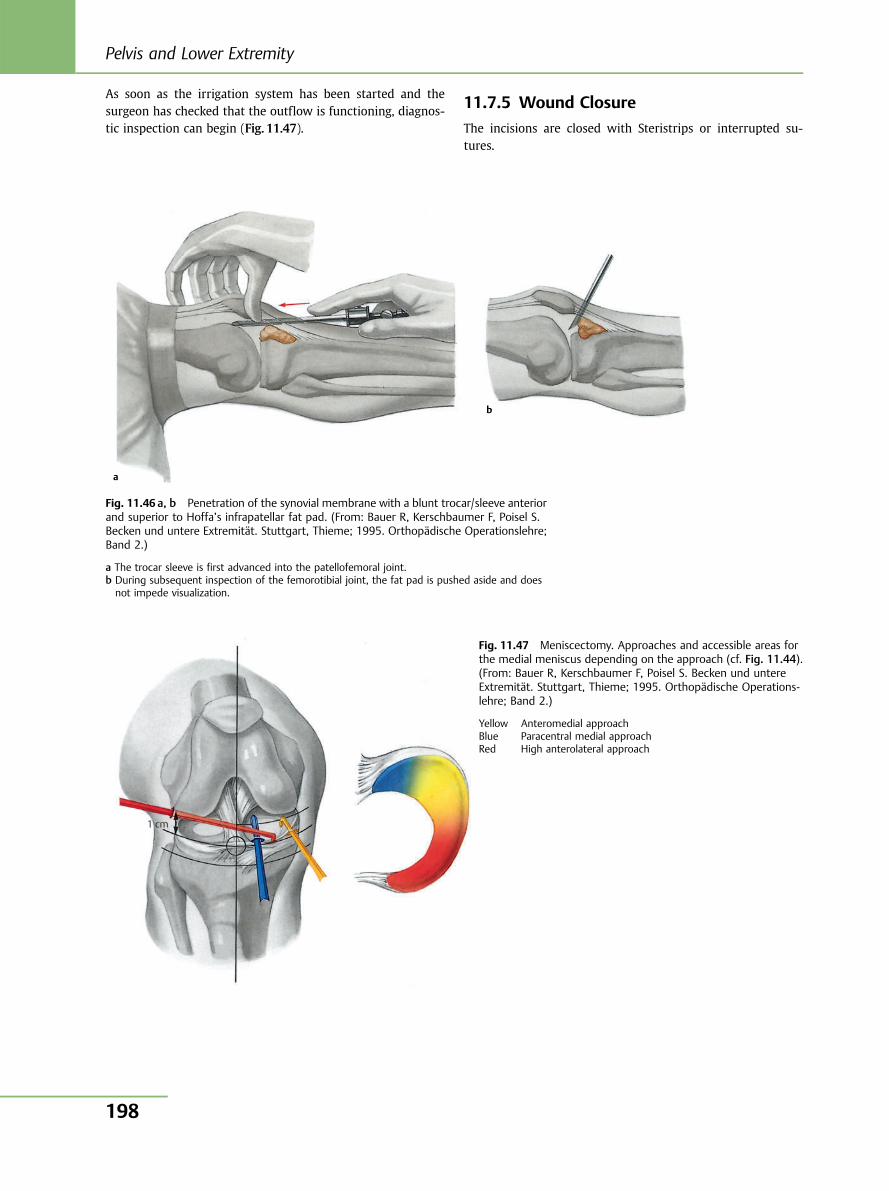
As soon as the irrigation system has been started and thesurgeon has checked that the outflow is functioning, diagnos-tic inspection can begin (Fig. 11.47).
11.7.5 Wound Closure
The incisions are closed with Steristrips or interrupted su-tures.
a
b
Fig. 11.46 a, b Penetration of the synovial membrane with a blunt trocar/sleeve anteriorand superior to Hoffa’s infrapatellar fat pad. (From: Bauer R, Kerschbaumer F, Poisel S.Becken und untere Extremität. Stuttgart, Thieme; 1995. Orthopädische Operationslehre;Band 2.)
a The trocar sleeve is first advanced into the patellofemoral joint.b During subsequent inspection of the femorotibial joint, the fat pad is pushed aside and doesnot impede visualization.
1 cm
Fig. 11.47 Meniscectomy. Approaches and accessible areas forthe medial meniscus depending on the approach (cf. Fig. 11.44).(From: Bauer R, Kerschbaumer F, Poisel S. Becken und untereExtremität. Stuttgart, Thieme; 1995. Orthopädische Operations-lehre; Band 2.)
Yellow Anteromedial approachBlue Paracentral medial approachRed High anterolateral approach
Pelvis and Lower Extremity
198
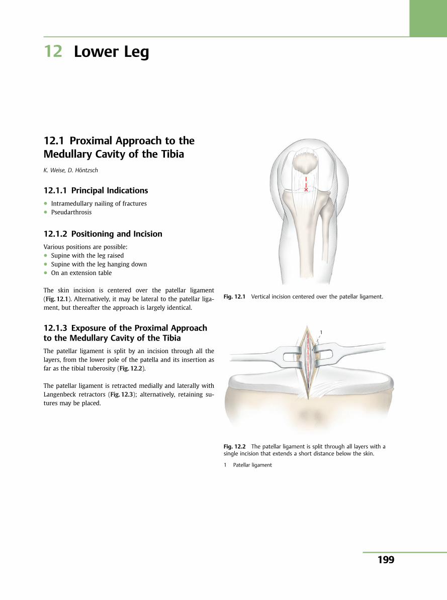
12 Lower Leg
12.1 Proximal Approach to theMedullary Cavity of the TibiaK. Weise, D. Höntzsch
12.1.1 Principal Indications● Intramedullary nailing of fractures● Pseudarthrosis
12.1.2 Positioning and Incision
Various positions are possible:● Supine with the leg raised● Supine with the leg hanging down● On an extension table
The skin incision is centered over the patellar ligament(Fig. 12.1). Alternatively, it may be lateral to the patellar liga-ment, but thereafter the approach is largely identical.
12.1.3 Exposure of the Proximal Approachto the Medullary Cavity of the Tibia
The patellar ligament is split by an incision through all thelayers, from the lower pole of the patella and its insertion asfar as the tibial tuberosity (Fig. 12.2).
The patellar ligament is retracted medially and laterally withLangenbeck retractors (Fig. 12.3); alternatively, retaining su-tures may be placed.
Fig. 12.1 Vertical incision centered over the patellar ligament.
1
Fig. 12.2 The patellar ligament is split through all layers with asingle incision that extends a short distance below the skin.
1 Patellar ligament
199
12 Lower Leg
199
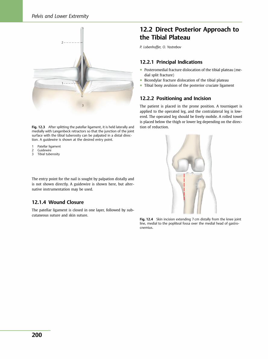
The entry point for the nail is sought by palpation distally andis not shown directly. A guidewire is shown here, but alter-native instrumentation may be used.
12.1.4 Wound Closure
The patellar ligament is closed in one layer, followed by sub-cutaneous suture and skin suture.
12.2 Direct Posterior Approach tothe Tibial PlateauP. Lobenhoffer, O. Yastrebov
12.2.1 Principal Indications● Posteromedial fracture dislocation of the tibial plateau (me-
dial split fracture)● Bicondylar fracture dislocation of the tibial plateau● Tibial bony avulsion of the posterior cruciate ligament
12.2.2 Positioning and Incision
The patient is placed in the prone position. A tourniquet isapplied to the operated leg, and the contralateral leg is low-ered. The operated leg should be freely mobile. A rolled towelis placed below the thigh or lower leg depending on the direc-tion of reduction.
2
1
3
Fig. 12.3 After splitting the patellar ligament, it is held laterally andmedially with Langenbeck retractors so that the junction of the jointsurface with the tibial tuberosity can be palpated in a distal direc-tion. A guidewire is shown at the desired entry point.
1 Patellar ligament2 Guidewire3 Tibial tuberosity
Fig. 12.4 Skin incision extending 7 cm distally from the knee jointline, medial to the popliteal fossa over the medial head of gastro-cnemius.
Pelvis and Lower Extremity
200
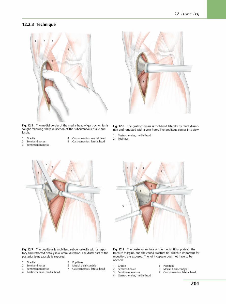
12.2.3 Technique
1
2 3
7
4
6
5
1 2 37
4
6
5
Fig. 12.5 The medial border of the medial head of gastrocnemius issought following sharp dissection of the subcutaneous tissue andfascia.
1 Gracilis2 Semitendinosus3 Semimembranosus
4 Gastrocnemius, medial head5 Gastrocnemius, lateral head
Fig. 12.6 The gastrocnemius is mobilized laterally by blunt dissec-tion and retracted with a vein hook. The popliteus comes into view.
1 Gastrocnemius, medial head2 Popliteus
Fig. 12.7 The popliteus is mobilized subperiosteally with a raspa-tory and retracted distally in a lateral direction. The distal part of theposterior joint capsule is exposed.
1 Gracilis2 Semitendinosus3 Semimembranosus4 Gastrocnemius, medial head
5 Popliteus6 Medial tibial condyle7 Gastrocnemius, lateral head
Fig. 12.8 The posterior surface of the medial tibial plateau, thefracture margins, and the caudal fracture tip, which is important forreduction, are exposed. The joint capsule does not have to beopened.
1 Gracilis2 Semitendinosus3 Semimembranosus4 Gastrocnemius, medial head
5 Popliteus6 Medial tibial condyle7 Gastrocnemius, lateral head
1 2 3
4
5
1
2
12 Lower Leg
201
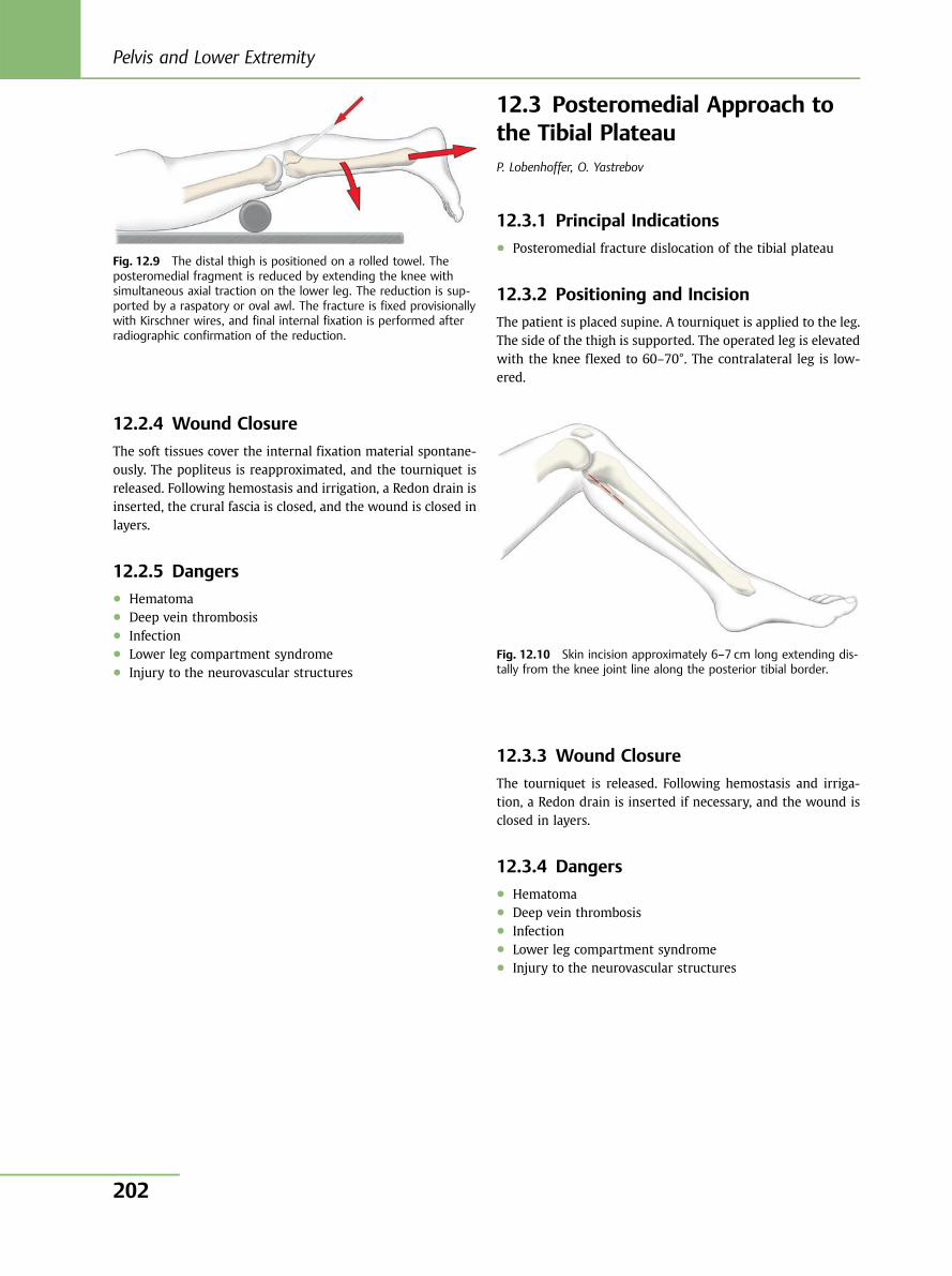
12.2.4 Wound Closure
The soft tissues cover the internal fixation material spontane-ously. The popliteus is reapproximated, and the tourniquet isreleased. Following hemostasis and irrigation, a Redon drain isinserted, the crural fascia is closed, and the wound is closed inlayers.
12.2.5 Dangers● Hematoma● Deep vein thrombosis● Infection● Lower leg compartment syndrome● Injury to the neurovascular structures
12.3 Posteromedial Approach tothe Tibial PlateauP. Lobenhoffer, O. Yastrebov
12.3.1 Principal Indications● Posteromedial fracture dislocation of the tibial plateau
12.3.2 Positioning and Incision
The patient is placed supine. A tourniquet is applied to the leg.The side of the thigh is supported. The operated leg is elevatedwith the knee flexed to 60–70°. The contralateral leg is low-ered.
12.3.3 Wound Closure
The tourniquet is released. Following hemostasis and irriga-tion, a Redon drain is inserted if necessary, and the wound isclosed in layers.
12.3.4 Dangers● Hematoma● Deep vein thrombosis● Infection● Lower leg compartment syndrome● Injury to the neurovascular structures
Fig. 12.9 The distal thigh is positioned on a rolled towel. Theposteromedial fragment is reduced by extending the knee withsimultaneous axial traction on the lower leg. The reduction is sup-ported by a raspatory or oval awl. The fracture is fixed provisionallywith Kirschner wires, and final internal fixation is performed afterradiographic confirmation of the reduction.
Fig. 12.10 Skin incision approximately 6–7 cm long extending dis-tally from the knee joint line along the posterior tibial border.
Pelvis and Lower Extremity
202
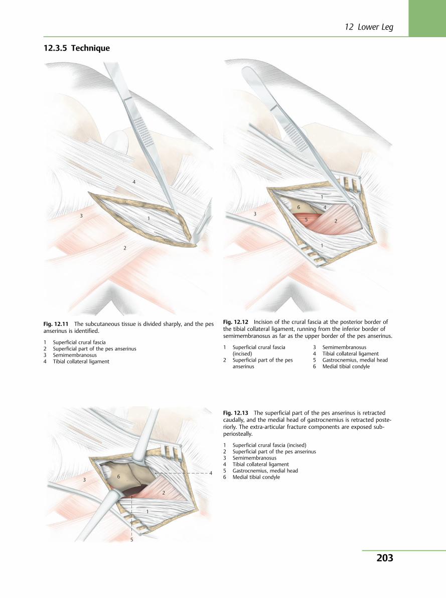
12.3.5 Technique
1
4
3
2
Fig. 12.11 The subcutaneous tissue is divided sharply, and the pesanserinus is identified.
1 Superficial crural fascia2 Superficial part of the pes anserinus3 Semimembranosus4 Tibial collateral ligament
1
2
1
4
5
63
Fig. 12.12 Incision of the crural fascia at the posterior border ofthe tibial collateral ligament, running from the inferior border ofsemimembranosus as far as the upper border of the pes anserinus.
1 Superficial crural fascia(incised)
2 Superficial part of the pesanserinus
3 Semimembranosus4 Tibial collateral ligament5 Gastrocnemius, medial head6 Medial tibial condyle
1
2
5
4 6 3
Fig. 12.13 The superficial part of the pes anserinus is retractedcaudally, and the medial head of gastrocnemius is retracted poste-riorly. The extra-articular fracture components are exposed sub-periosteally.
1 Superficial crural fascia (incised)2 Superficial part of the pes anserinus3 Semimembranosus4 Tibial collateral ligament5 Gastrocnemius, medial head6 Medial tibial condyle
12 Lower Leg
203
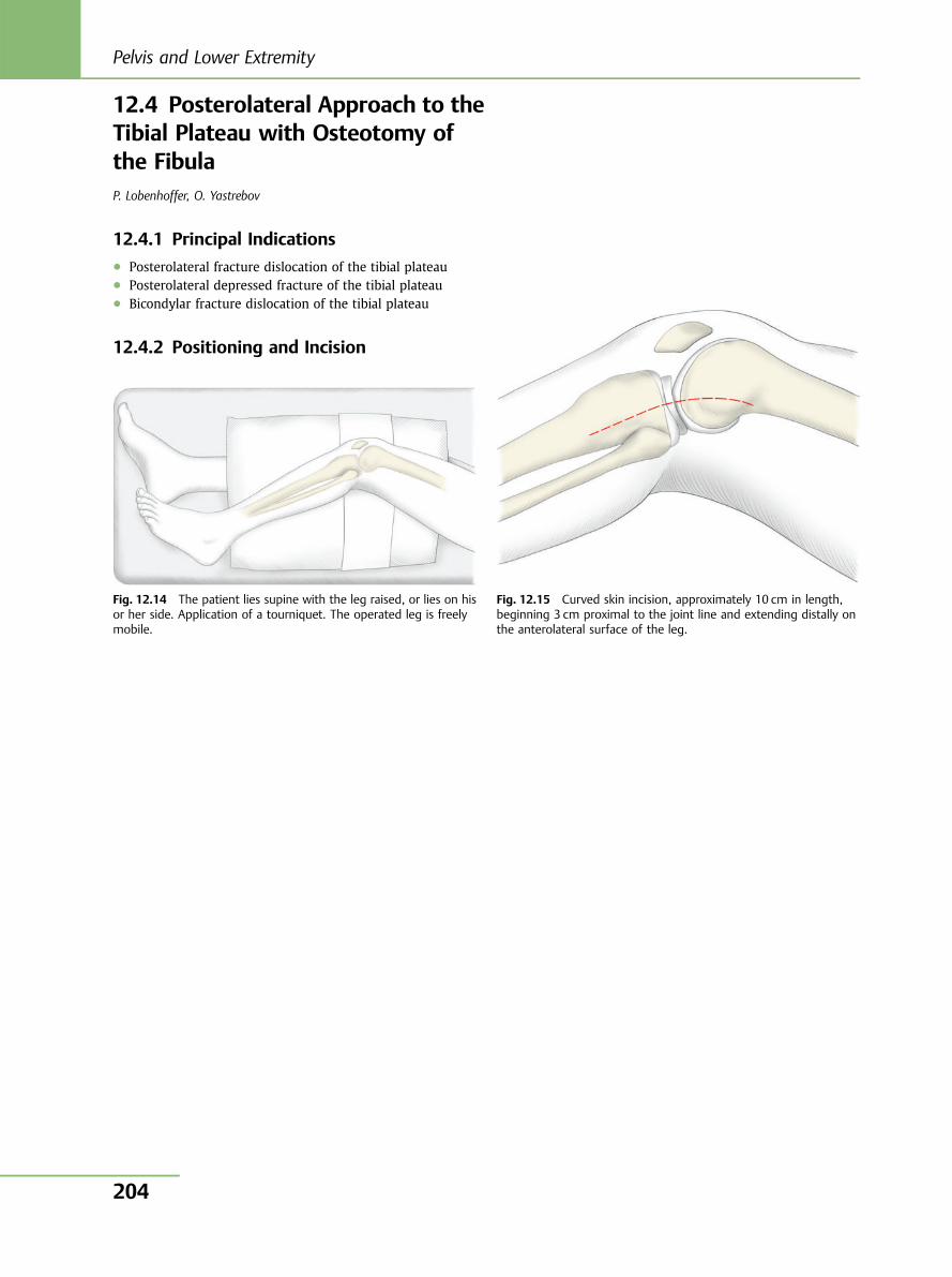
12.4 Posterolateral Approach to theTibial Plateau with Osteotomy ofthe FibulaP. Lobenhoffer, O. Yastrebov
12.4.1 Principal Indications● Posterolateral fracture dislocation of the tibial plateau● Posterolateral depressed fracture of the tibial plateau● Bicondylar fracture dislocation of the tibial plateau
12.4.2 Positioning and Incision
Fig. 12.14 The patient lies supine with the leg raised, or lies on hisor her side. Application of a tourniquet. The operated leg is freelymobile.
Fig. 12.15 Curved skin incision, approximately 10 cm in length,beginning 3 cm proximal to the joint line and extending distally onthe anterolateral surface of the leg.
Pelvis and Lower Extremity
204
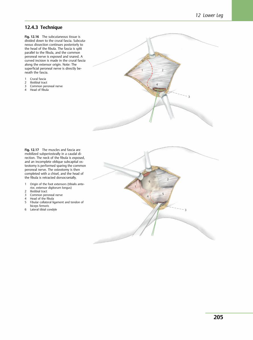
12.4.3 Technique
Fig. 12.16 The subcutaneous tissue isdivided down to the crural fascia. Subcuta-neous dissection continues posteriorly tothe head of the fibula. The fascia is splitparallel to the fibula, and the commonperoneal nerve is exposed and snared. Acurved incision is made in the crural fasciaalong the extensor origin. Note: Thesuperficial peroneal nerve is directly be-neath the fascia.
1 Crural fascia2 Iliotibial tract3 Common peroneal nerve4 Head of fibula
1 2
4
3
1
4
6 2
5
3
Fig. 12.17 The muscles and fascia aremobilized subperiosteally in a caudal di-rection. The neck of the fibula is exposed,and an incomplete oblique subcapital os-teotomy is performed sparing the commonperoneal nerve. The osteotomy is thencompleted with a chisel, and the head ofthe fibula is retracted dorsocranially.
1 Origin of the foot extensors (tibialis ante-rior, extensor digitorum longus)
2 Iliotibial tract3 Common peroneal nerve4 Head of the fibula5 Fibular collateral ligament and tendon of
biceps femoris6 Lateral tibial condyle
12 Lower Leg
205
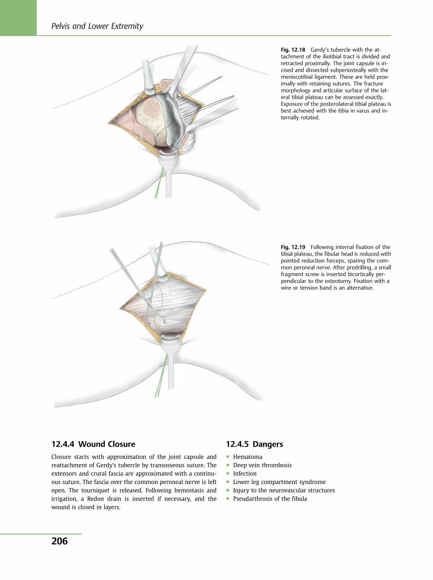
12.4.4 Wound Closure
Closure starts with approximation of the joint capsule andreattachment of Gerdy’s tubercle by transosseous suture. Theextensors and crural fascia are approximated with a continu-ous suture. The fascia over the common peroneal nerve is leftopen. The tourniquet is released. Following hemostasis andirrigation, a Redon drain is inserted if necessary, and thewound is closed in layers.
12.4.5 Dangers● Hematoma● Deep vein thrombosis● Infection● Lower leg compartment syndrome● Injury to the neurovascular structures● Pseudarthrosis of the fibula
Fig. 12.18 Gerdy’s tubercle with the at-tachment of the iliotibial tract is divided andretracted proximally. The joint capsule is in-cised and dissected subperiosteally with themeniscotibial ligament. These are held prox-imally with retaining sutures. The fracturemorphology and articular surface of the lat-eral tibial plateau can be assessed exactly.Exposure of the posterolateral tibial plateau isbest achieved with the tibia in varus and in-ternally rotated.
Fig. 12.19 Following internal fixation of thetibial plateau, the fibular head is reduced withpointed reduction forceps, sparing the com-mon peroneal nerve. After predrilling, a smallfragment screw is inserted bicortically per-pendicular to the osteotomy. Fixation with awire or tension band is an alternative.
Pelvis and Lower Extremity
206
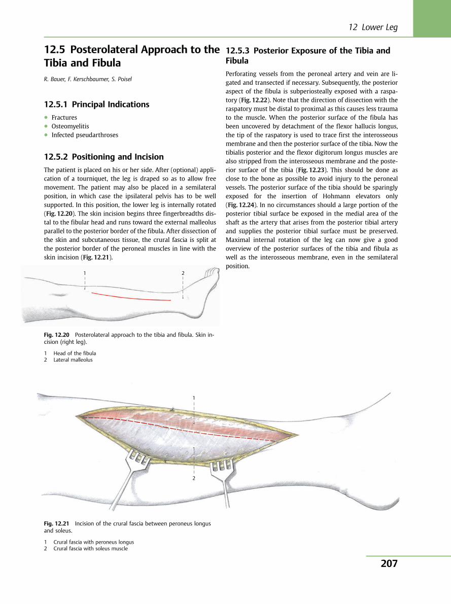
12.5 Posterolateral Approach to theTibia and FibulaR. Bauer, F. Kerschbaumer, S. Poisel
12.5.1 Principal Indications● Fractures● Osteomyelitis● Infected pseudarthroses
12.5.2 Positioning and Incision
The patient is placed on his or her side. After (optional) appli-cation of a tourniquet, the leg is draped so as to allow freemovement. The patient may also be placed in a semilateralposition, in which case the ipsilateral pelvis has to be wellsupported. In this position, the lower leg is internally rotated(Fig. 12.20). The skin incision begins three fingerbreadths dis-tal to the fibular head and runs toward the external malleolusparallel to the posterior border of the fibula. After dissection ofthe skin and subcutaneous tissue, the crural fascia is split atthe posterior border of the peroneal muscles in line with theskin incision (Fig. 12.21).
12.5.3 Posterior Exposure of the Tibia andFibula
Perforating vessels from the peroneal artery and vein are li-gated and transected if necessary. Subsequently, the posterioraspect of the fibula is subperiosteally exposed with a raspa-tory (Fig. 12.22). Note that the direction of dissection with theraspatory must be distal to proximal as this causes less traumato the muscle. When the posterior surface of the fibula hasbeen uncovered by detachment of the flexor hallucis longus,the tip of the raspatory is used to trace first the interosseousmembrane and then the posterior surface of the tibia. Now thetibialis posterior and the flexor digitorum longus muscles arealso stripped from the interosseous membrane and the poste-rior surface of the tibia (Fig. 12.23). This should be done asclose to the bone as possible to avoid injury to the peronealvessels. The posterior surface of the tibia should be sparinglyexposed for the insertion of Hohmann elevators only(Fig. 12.24). In no circumstances should a large portion of theposterior tibial surface be exposed in the medial area of theshaft as the artery that arises from the posterior tibial arteryand supplies the posterior tibial surface must be preserved.Maximal internal rotation of the leg can now give a goodoverview of the posterior surfaces of the tibia and fibula aswell as the interosseous membrane, even in the semilateralposition.
1 2
Fig. 12.20 Posterolateral approach to the tibia and fibula. Skin in-cision (right leg).
1 Head of the fibula2 Lateral malleolus
1
2
Fig. 12.21 Incision of the crural fascia between peroneus longusand soleus.
1 Crural fascia with peroneus longus2 Crural fascia with soleus muscle
12 Lower Leg
207
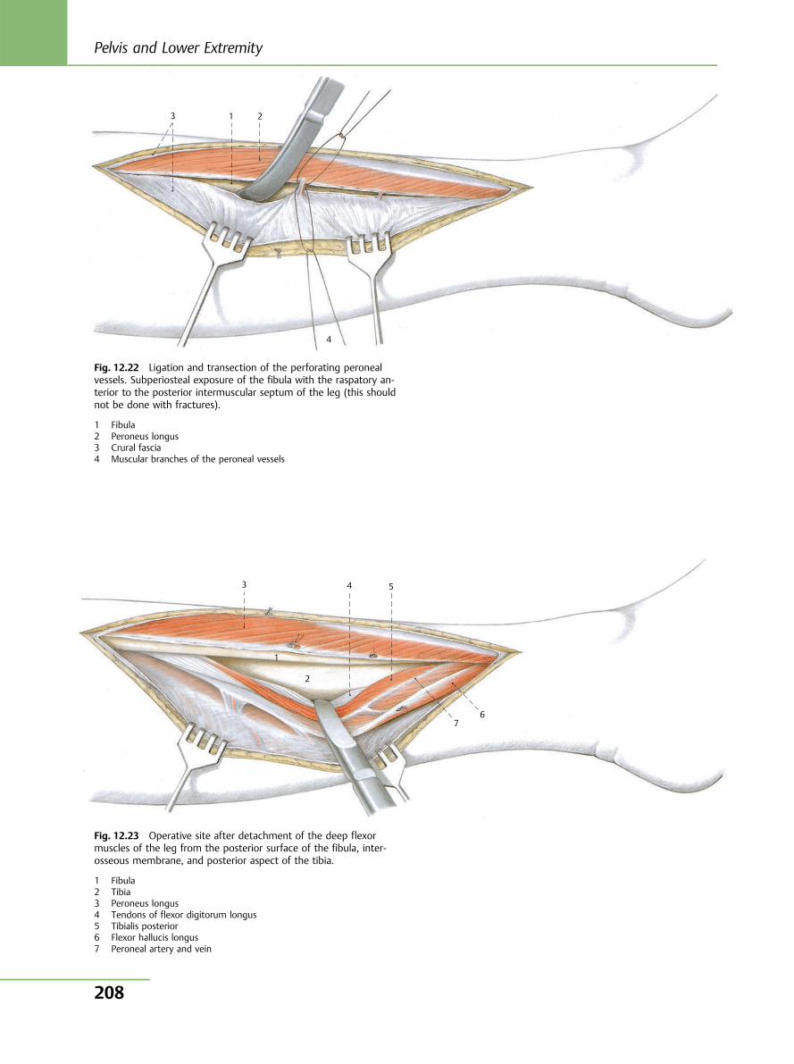
4
3 1 2
Fig. 12.22 Ligation and transection of the perforating peronealvessels. Subperiosteal exposure of the fibula with the raspatory an-terior to the posterior intermuscular septum of the leg (this shouldnot be done with fractures).
1 Fibula2 Peroneus longus3 Crural fascia4 Muscular branches of the peroneal vessels
7 6
5 4 3
1
2
Fig. 12.23 Operative site after detachment of the deep flexormuscles of the leg from the posterior surface of the fibula, inter-osseous membrane, and posterior aspect of the tibia.
1 Fibula2 Tibia3 Peroneus longus4 Tendons of flexor digitorum longus5 Tibialis posterior6 Flexor hallucis longus7 Peroneal artery and vein
Pelvis and Lower Extremity
208
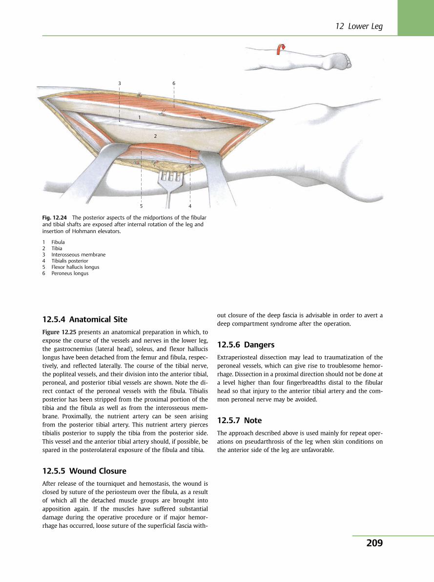
12.5.4 Anatomical Site
Figure 12.25 presents an anatomical preparation in which, toexpose the course of the vessels and nerves in the lower leg,the gastrocnemius (lateral head), soleus, and flexor hallucislongus have been detached from the femur and fibula, respec-tively, and reflected laterally. The course of the tibial nerve,the popliteal vessels, and their division into the anterior tibial,peroneal, and posterior tibial vessels are shown. Note the di-rect contact of the peroneal vessels with the fibula. Tibialisposterior has been stripped from the proximal portion of thetibia and the fibula as well as from the interosseous mem-brane. Proximally, the nutrient artery can be seen arisingfrom the posterior tibial artery. This nutrient artery piercestibialis posterior to supply the tibia from the posterior side.This vessel and the anterior tibial artery should, if possible, bespared in the posterolateral exposure of the fibula and tibia.
12.5.5 Wound Closure
After release of the tourniquet and hemostasis, the wound isclosed by suture of the periosteum over the fibula, as a resultof which all the detached muscle groups are brought intoapposition again. If the muscles have suffered substantialdamage during the operative procedure or if major hemor-rhage has occurred, loose suture of the superficial fascia with-
out closure of the deep fascia is advisable in order to avert adeep compartment syndrome after the operation.
12.5.6 Dangers
Extraperiosteal dissection may lead to traumatization of theperoneal vessels, which can give rise to troublesome hemor-rhage. Dissection in a proximal direction should not be done ata level higher than four fingerbreadths distal to the fibularhead so that injury to the anterior tibial artery and the com-mon peroneal nerve may be avoided.
12.5.7 Note
The approach described above is used mainly for repeat oper-ations on pseudarthrosis of the leg when skin conditions onthe anterior side of the leg are unfavorable.
6
5 4
3
1
2
Fig. 12.24 The posterior aspects of the midportions of the fibularand tibial shafts are exposed after internal rotation of the leg andinsertion of Hohmann elevators.
1 Fibula2 Tibia3 Interosseous membrane4 Tibialis posterior5 Flexor hallucis longus6 Peroneus longus
12 Lower Leg
209
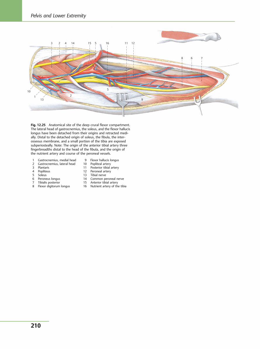
10
11 12
13
14 15 16
9
8 7 6
5 4 3
1
2
5
2
Fig. 12.25 Anatomical site of the deep crural flexor compartment.The lateral head of gastrocnemius, the soleus, and the flexor hallucislongus have been detached from their origins and retracted medi-ally. Distal to the detached origin of soleus, the fibula, the inter-osseous membrane, and a small portion of the tibia are exposedsubperiosteally. Note: The origin of the anterior tibial artery threefingerbreadths distal to the head of the fibula, and the origin ofthe nutrient artery and course of the peroneal vessels.
1 Gastrocnemius, medial head2 Gastrocnemius, lateral head3 Plantaris4 Popliteus5 Soleus6 Peroneus longus7 Tibialis posterior8 Flexor digitorum longus
9 Flexor hallucis longus10 Popliteal artery11 Posterior tibial artery12 Peroneal artery13 Tibial nerve14 Common peroneal nerve15 Anterior tibial artery16 Nutrient artery of the tibia
Pelvis and Lower Extremity
210
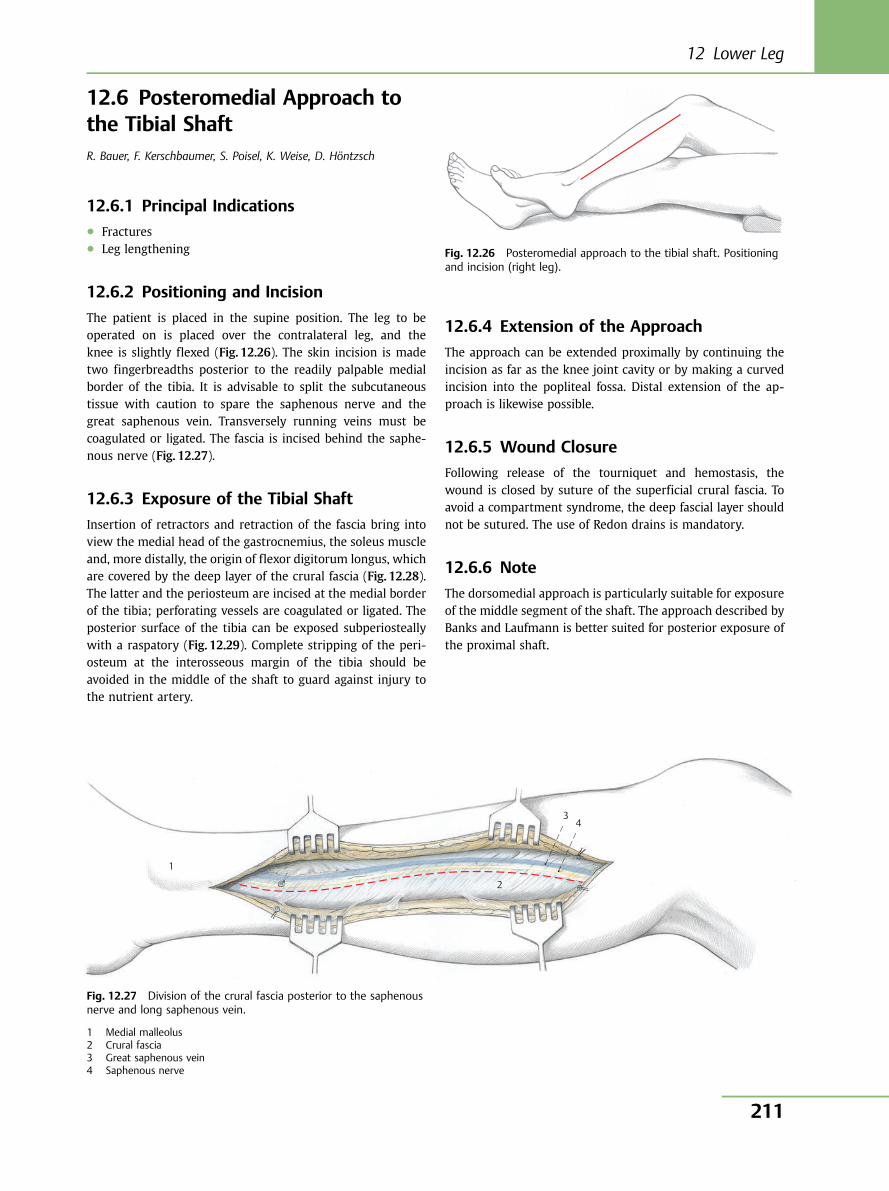
12.6 Posteromedial Approach tothe Tibial ShaftR. Bauer, F. Kerschbaumer, S. Poisel, K. Weise, D. Höntzsch
12.6.1 Principal Indications● Fractures● Leg lengthening
12.6.2 Positioning and Incision
The patient is placed in the supine position. The leg to beoperated on is placed over the contralateral leg, and theknee is slightly flexed (Fig. 12.26). The skin incision is madetwo fingerbreadths posterior to the readily palpable medialborder of the tibia. It is advisable to split the subcutaneoustissue with caution to spare the saphenous nerve and thegreat saphenous vein. Transversely running veins must becoagulated or ligated. The fascia is incised behind the saphe-nous nerve (Fig. 12.27).
12.6.3 Exposure of the Tibial Shaft
Insertion of retractors and retraction of the fascia bring intoview the medial head of the gastrocnemius, the soleus muscleand, more distally, the origin of flexor digitorum longus, whichare covered by the deep layer of the crural fascia (Fig. 12.28).The latter and the periosteum are incised at the medial borderof the tibia; perforating vessels are coagulated or ligated. Theposterior surface of the tibia can be exposed subperiosteallywith a raspatory (Fig. 12.29). Complete stripping of the peri-osteum at the interosseous margin of the tibia should beavoided in the middle of the shaft to guard against injury tothe nutrient artery.
12.6.4 Extension of the Approach
The approach can be extended proximally by continuing theincision as far as the knee joint cavity or by making a curvedincision into the popliteal fossa. Distal extension of the ap-proach is likewise possible.
12.6.5 Wound Closure
Following release of the tourniquet and hemostasis, thewound is closed by suture of the superficial crural fascia. Toavoid a compartment syndrome, the deep fascial layer shouldnot be sutured. The use of Redon drains is mandatory.
12.6.6 Note
The dorsomedial approach is particularly suitable for exposureof the middle segment of the shaft. The approach described byBanks and Laufmann is better suited for posterior exposure ofthe proximal shaft.
Fig. 12.26 Posteromedial approach to the tibial shaft. Positioningand incision (right leg).
1
2
3 4
Fig. 12.27 Division of the crural fascia posterior to the saphenousnerve and long saphenous vein.
1 Medial malleolus2 Crural fascia3 Great saphenous vein4 Saphenous nerve
12 Lower Leg
211
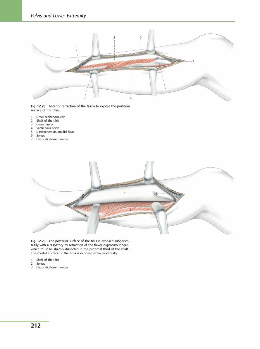
1
2 3
4
5
67
Fig. 12.28 Anterior retraction of the fascia to expose the posteriorsurface of the tibia.
1 Great saphenous vein2 Shaft of the tibia3 Crural fascia4 Saphenous nerve5 Gastrocnemius, medial head6 Soleus7 Flexor digitorum longus
1
23
Fig. 12.29 The posterior surface of the tibia is exposed subperios-teally with a raspatory by retraction of the flexor digitorum longus,which must be sharply dissected in the proximal third of the shaft.The medial surface of the tibia is exposed extraperiosteally.
1 Shaft of the tibia2 Soleus3 Flexor digitorum longus
Pelvis and Lower Extremity
212
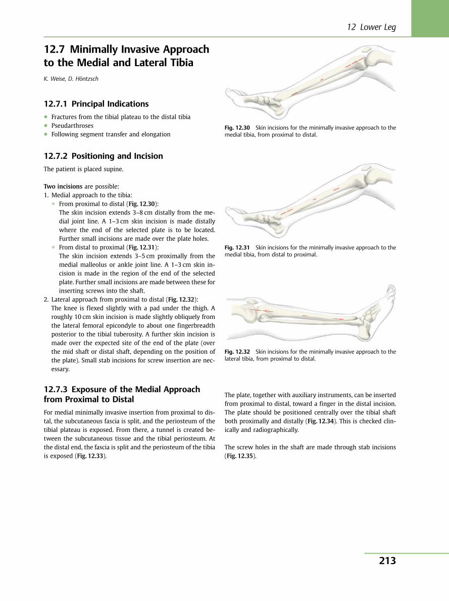
12.7 Minimally Invasive Approachto the Medial and Lateral TibiaK. Weise, D. Höntzsch
12.7.1 Principal Indications● Fractures from the tibial plateau to the distal tibia● Pseudarthroses● Following segment transfer and elongation
12.7.2 Positioning and Incision
The patient is placed supine.
Two incisions are possible:1. Medial approach to the tibia:
● From proximal to distal (Fig. 12.30):The skin incision extends 3–8 cm distally from the me-dial joint line. A 1–3 cm skin incision is made distallywhere the end of the selected plate is to be located.Further small incisions are made over the plate holes.
● From distal to proximal (Fig. 12.31):The skin incision extends 3–5 cm proximally from themedial malleolus or ankle joint line. A 1–3 cm skin in-cision is made in the region of the end of the selectedplate. Further small incisions are made between these forinserting screws into the shaft.
2. Lateral approach from proximal to distal (Fig. 12.32):The knee is flexed slightly with a pad under the thigh. Aroughly 10 cm skin incision is made slightly obliquely fromthe lateral femoral epicondyle to about one fingerbreadthposterior to the tibial tuberosity. A further skin incision ismade over the expected site of the end of the plate (overthe mid shaft or distal shaft, depending on the position ofthe plate). Small stab incisions for screw insertion are nec-essary.
12.7.3 Exposure of the Medial Approachfrom Proximal to Distal
For medial minimally invasive insertion from proximal to dis-tal, the subcutaneous fascia is split, and the periosteum of thetibial plateau is exposed. From there, a tunnel is created be-tween the subcutaneous tissue and the tibial periosteum. Atthe distal end, the fascia is split and the periosteum of the tibiais exposed (Fig. 12.33).
The plate, together with auxiliary instruments, can be insertedfrom proximal to distal, toward a finger in the distal incision.The plate should be positioned centrally over the tibial shaftboth proximally and distally (Fig. 12.34). This is checked clin-ically and radiographically.
The screw holes in the shaft are made through stab incisions(Fig. 12.35).
Fig. 12.30 Skin incisions for the minimally invasive approach to themedial tibia, from proximal to distal.
Fig. 12.31 Skin incisions for the minimally invasive approach to themedial tibia, from distal to proximal.
Fig. 12.32 Skin incisions for the minimally invasive approach to thelateral tibia, from proximal to distal.
12 Lower Leg
213
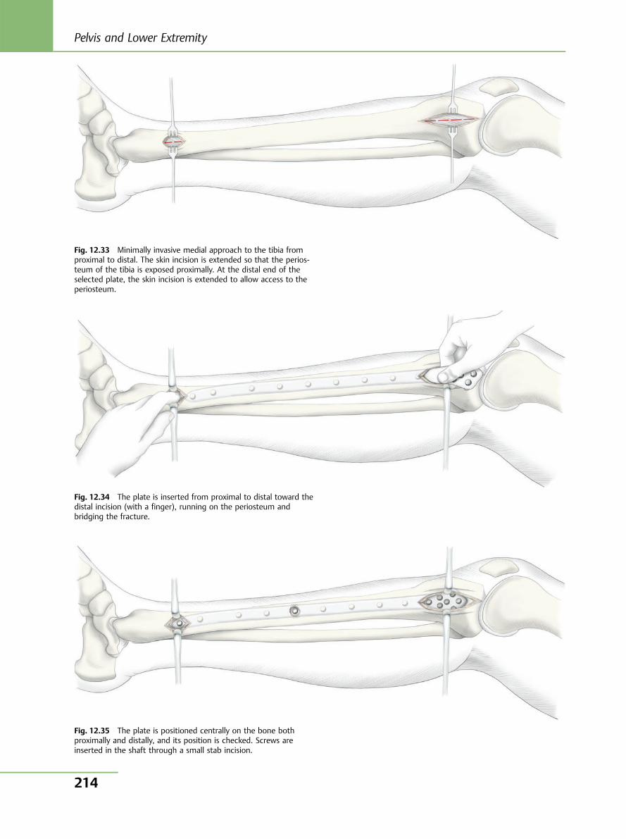
Fig. 12.33 Minimally invasive medial approach to the tibia fromproximal to distal. The skin incision is extended so that the perios-teum of the tibia is exposed proximally. At the distal end of theselected plate, the skin incision is extended to allow access to theperiosteum.
Fig. 12.34 The plate is inserted from proximal to distal toward thedistal incision (with a finger), running on the periosteum andbridging the fracture.
Fig. 12.35 The plate is positioned centrally on the bone bothproximally and distally, and its position is checked. Screws areinserted in the shaft through a small stab incision.
Pelvis and Lower Extremity
214
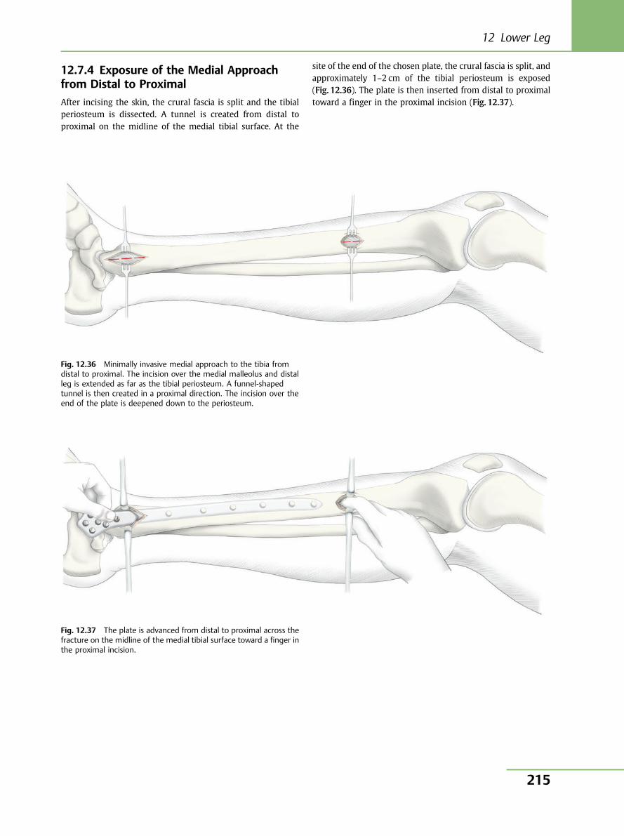
12.7.4 Exposure of the Medial Approachfrom Distal to Proximal
After incising the skin, the crural fascia is split and the tibialperiosteum is dissected. A tunnel is created from distal toproximal on the midline of the medial tibial surface. At the
site of the end of the chosen plate, the crural fascia is split, andapproximately 1–2 cm of the tibial periosteum is exposed(Fig. 12.36). The plate is then inserted from distal to proximaltoward a finger in the proximal incision (Fig. 12.37).
Fig. 12.36 Minimally invasive medial approach to the tibia fromdistal to proximal. The incision over the medial malleolus and distalleg is extended as far as the tibial periosteum. A funnel-shapedtunnel is then created in a proximal direction. The incision over theend of the plate is deepened down to the periosteum.
Fig. 12.37 The plate is advanced from distal to proximal across thefracture on the midline of the medial tibial surface toward a finger inthe proximal incision.
12 Lower Leg
215
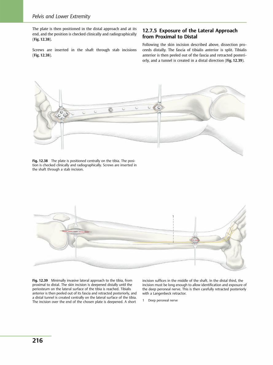
The plate is then positioned in the distal approach and at itsend, and the position is checked clinically and radiographically(Fig. 12.38).
Screws are inserted in the shaft through stab incisions(Fig. 12.38).
12.7.5 Exposure of the Lateral Approachfrom Proximal to Distal
Following the skin incision described above, dissection pro-ceeds distally. The fascia of tibialis anterior is split. Tibialisanterior is then peeled out of the fascia and retracted posteri-orly, and a tunnel is created in a distal direction (Fig. 12.39).
Fig. 12.38 The plate is positioned centrally on the tibia. The posi-tion is checked clinically and radiographically. Screws are inserted inthe shaft through a stab incision.
1
Fig. 12.39 Minimally invasive lateral approach to the tibia, fromproximal to distal. The skin incision is deepened distally until theperiosteum on the lateral surface of the tibia is reached. Tibialisanterior is then peeled out of its fascia and retracted posteriorly, anda distal tunnel is created centrally on the lateral surface of the tibia.The incision over the end of the chosen plate is deepened. A short
incision suffices in the middle of the shaft. In the distal third, theincision must be long enough to allow identification and exposure ofthe deep peroneal nerve. This is then carefully retracted posteriorlywith a Langenbeck retractor.
1 Deep peroneal nerve
Pelvis and Lower Extremity
216
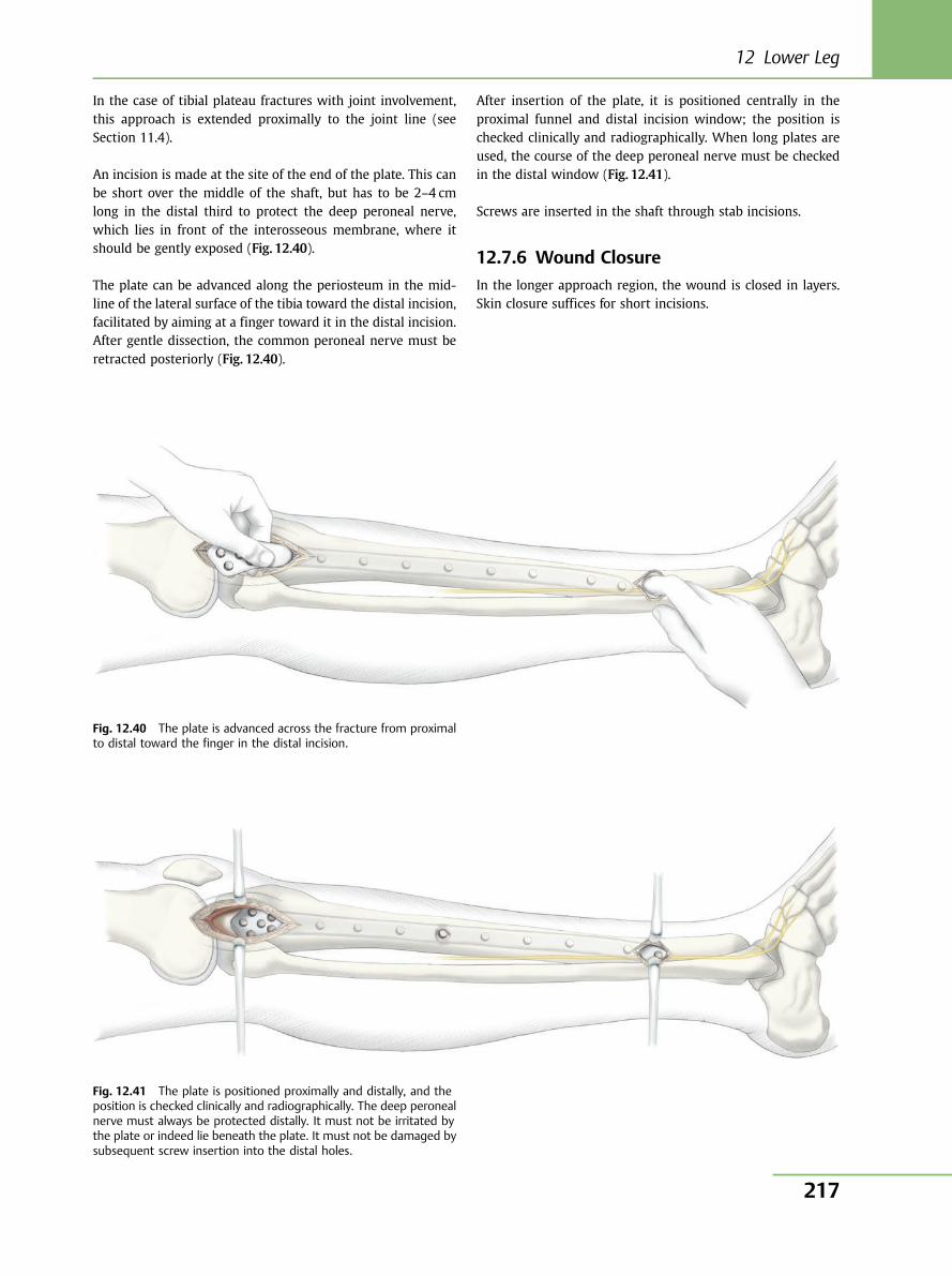
In the case of tibial plateau fractures with joint involvement,this approach is extended proximally to the joint line (seeSection 11.4).
An incision is made at the site of the end of the plate. This canbe short over the middle of the shaft, but has to be 2–4 cmlong in the distal third to protect the deep peroneal nerve,which lies in front of the interosseous membrane, where itshould be gently exposed (Fig. 12.40).
The plate can be advanced along the periosteum in the mid-line of the lateral surface of the tibia toward the distal incision,facilitated by aiming at a finger toward it in the distal incision.After gentle dissection, the common peroneal nerve must beretracted posteriorly (Fig. 12.40).
After insertion of the plate, it is positioned centrally in theproximal funnel and distal incision window; the position ischecked clinically and radiographically. When long plates areused, the course of the deep peroneal nerve must be checkedin the distal window (Fig. 12.41).
Screws are inserted in the shaft through stab incisions.
12.7.6 Wound Closure
In the longer approach region, the wound is closed in layers.Skin closure suffices for short incisions.
Fig. 12.40 The plate is advanced across the fracture from proximalto distal toward the finger in the distal incision.
Fig. 12.41 The plate is positioned proximally and distally, and theposition is checked clinically and radiographically. The deep peronealnerve must always be protected distally. It must not be irritated bythe plate or indeed lie beneath the plate. It must not be damaged bysubsequent screw insertion into the distal holes.
12 Lower Leg
217
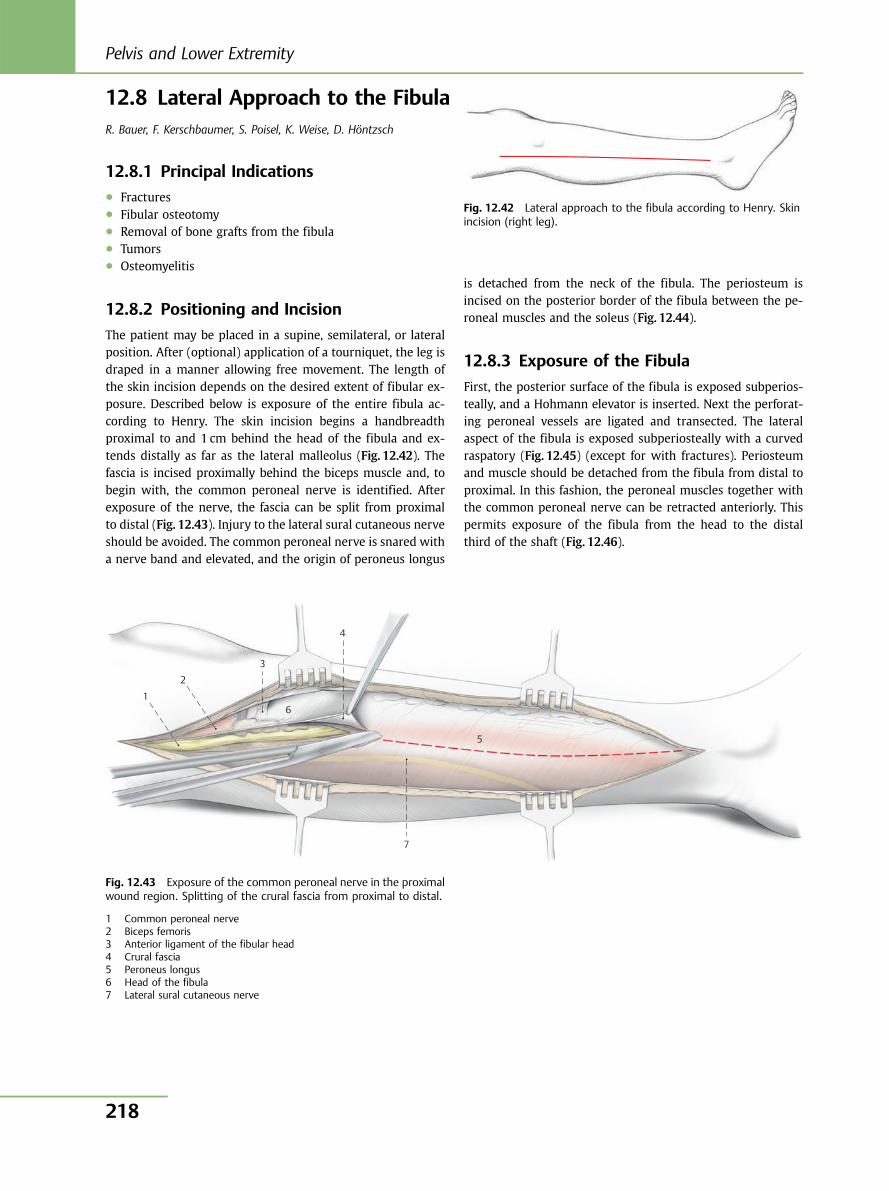
12.8 Lateral Approach to the FibulaR. Bauer, F. Kerschbaumer, S. Poisel, K. Weise, D. Höntzsch
12.8.1 Principal Indications● Fractures● Fibular osteotomy● Removal of bone grafts from the fibula● Tumors● Osteomyelitis
12.8.2 Positioning and Incision
The patient may be placed in a supine, semilateral, or lateralposition. After (optional) application of a tourniquet, the leg isdraped in a manner allowing free movement. The length ofthe skin incision depends on the desired extent of fibular ex-posure. Described below is exposure of the entire fibula ac-cording to Henry. The skin incision begins a handbreadthproximal to and 1 cm behind the head of the fibula and ex-tends distally as far as the lateral malleolus (Fig. 12.42). Thefascia is incised proximally behind the biceps muscle and, tobegin with, the common peroneal nerve is identified. Afterexposure of the nerve, the fascia can be split from proximalto distal (Fig. 12.43). Injury to the lateral sural cutaneous nerveshould be avoided. The common peroneal nerve is snared witha nerve band and elevated, and the origin of peroneus longus
is detached from the neck of the fibula. The periosteum isincised on the posterior border of the fibula between the pe-roneal muscles and the soleus (Fig. 12.44).
12.8.3 Exposure of the Fibula
First, the posterior surface of the fibula is exposed subperios-teally, and a Hohmann elevator is inserted. Next the perforat-ing peroneal vessels are ligated and transected. The lateralaspect of the fibula is exposed subperiosteally with a curvedraspatory (Fig. 12.45) (except for with fractures). Periosteumand muscle should be detached from the fibula from distal toproximal. In this fashion, the peroneal muscles together withthe common peroneal nerve can be retracted anteriorly. Thispermits exposure of the fibula from the head to the distalthird of the shaft (Fig. 12.46).
Fig. 12.42 Lateral approach to the fibula according to Henry. Skinincision (right leg).
1
2
3
4
5
7
6
Fig. 12.43 Exposure of the common peroneal nerve in the proximalwound region. Splitting of the crural fascia from proximal to distal.
1 Common peroneal nerve2 Biceps femoris3 Anterior ligament of the fibular head4 Crural fascia5 Peroneus longus6 Head of the fibula7 Lateral sural cutaneous nerve
Pelvis and Lower Extremity
218
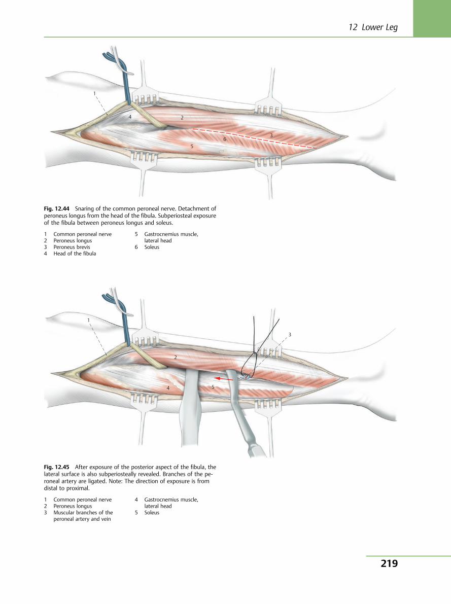
1
4 2
5 6
3
Fig. 12.44 Snaring of the common peroneal nerve. Detachment ofperoneus longus from the head of the fibula. Subperiosteal exposureof the fibula between peroneus longus and soleus.
1 Common peroneal nerve2 Peroneus longus3 Peroneus brevis4 Head of the fibula
5 Gastrocnemius muscle,lateral head
6 Soleus
1
3
2
4 5
Fig. 12.45 After exposure of the posterior aspect of the fibula, thelateral surface is also subperiosteally revealed. Branches of the pe-roneal artery are ligated. Note: The direction of exposure is fromdistal to proximal.
1 Common peroneal nerve2 Peroneus longus3 Muscular branches of the
peroneal artery and vein
4 Gastrocnemius muscle,lateral head
5 Soleus
12 Lower Leg
219
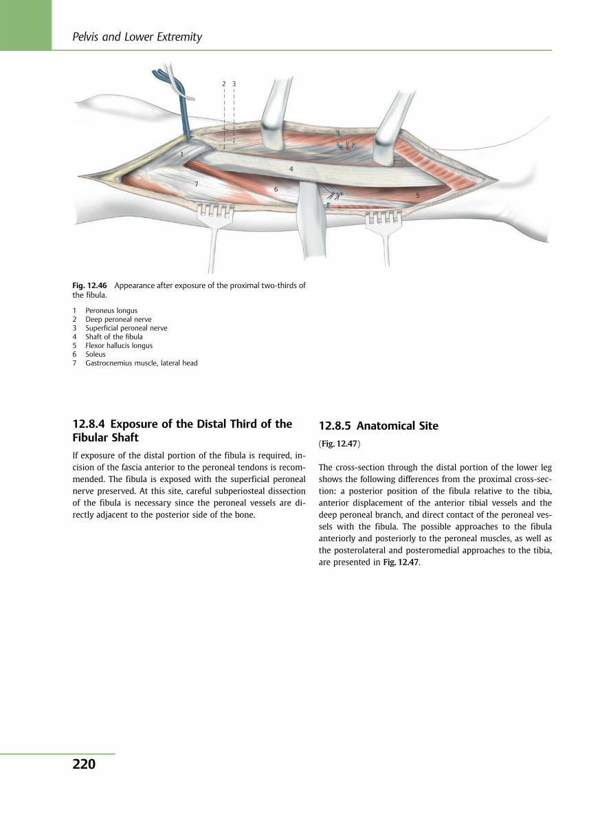
12.8.4 Exposure of the Distal Third of theFibular Shaft
If exposure of the distal portion of the fibula is required, in-cision of the fascia anterior to the peroneal tendons is recom-mended. The fibula is exposed with the superficial peronealnerve preserved. At this site, careful subperiosteal dissectionof the fibula is necessary since the peroneal vessels are di-rectly adjacent to the posterior side of the bone.
12.8.5 Anatomical Site
(Fig. 12.47)
The cross-section through the distal portion of the lower legshows the following differences from the proximal cross-sec-tion: a posterior position of the fibula relative to the tibia,anterior displacement of the anterior tibial vessels and thedeep peroneal branch, and direct contact of the peroneal ves-sels with the fibula. The possible approaches to the fibulaanteriorly and posteriorly to the peroneal muscles, as well asthe posterolateral and posteromedial approaches to the tibia,are presented in Fig. 12.47.
2
1
76
4
5
3
Fig. 12.46 Appearance after exposure of the proximal two-thirds ofthe fibula.
1 Peroneus longus2 Deep peroneal nerve3 Superficial peroneal nerve4 Shaft of the fibula5 Flexor hallucis longus6 Soleus7 Gastrocnemius muscle, lateral head
Pelvis and Lower Extremity
220
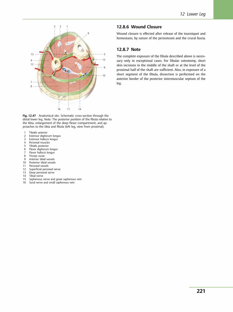
12.8.6 Wound Closure
Wound closure is effected after release of the tourniquet andhemostasis, by suture of the periosteum and the crural fascia.
12.8.7 Note
The complete exposure of the fibula described above is neces-sary only in exceptional cases. For fibular osteotomy, shortskin incisions in the middle of the shaft or at the level of theproximal half of the shaft are sufficient. Also, in exposure of ashort segment of the fibula, dissection is performed on theanterior border of the posterior intermuscular septum of theleg.
2 3 1
9
5
15
6
10
141116
8
7
124
13
Fig. 12.47 Anatomical site. Schematic cross-section through thedistal lower leg. Note: The posterior position of the fibula relative tothe tibia, enlargement of the deep flexor compartment, and ap-proaches to the tibia and fibula (left leg, view from proximal).
1 Tibialis anterior2 Extensor digitorum longus3 Extensor hallucis longus4 Peroneal muscles5 Tibialis posterior6 Flexor digitorum longus7 Flexor hallucis longus8 Triceps surae9 Anterior tibial vessels10 Posterior tibial vessels11 Peroneal vessels12 Superficial peroneal nerve13 Deep peroneal nerve14 Tibial nerve15 Saphenous nerve and great saphenous vein16 Sural nerve and small saphenous vein
12 Lower Leg
221
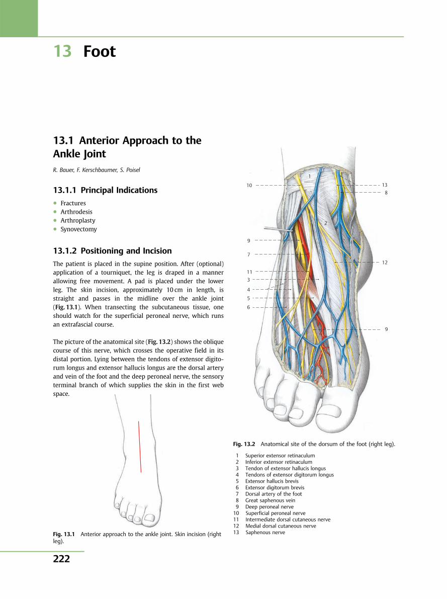
13 Foot
13.1 Anterior Approach to theAnkle JointR. Bauer, F. Kerschbaumer, S. Poisel
13.1.1 Principal Indications● Fractures● Arthrodesis● Arthroplasty● Synovectomy
13.1.2 Positioning and Incision
The patient is placed in the supine position. After (optional)application of a tourniquet, the leg is draped in a mannerallowing free movement. A pad is placed under the lowerleg. The skin incision, approximately 10 cm in length, isstraight and passes in the midline over the ankle joint(Fig. 13.1). When transecting the subcutaneous tissue, oneshould watch for the superficial peroneal nerve, which runsan extrafascial course.
The picture of the anatomical site (Fig. 13.2) shows the obliquecourse of this nerve, which crosses the operative field in itsdistal portion. Lying between the tendons of extensor digito-rum longus and extensor hallucis longus are the dorsal arteryand vein of the foot and the deep peroneal nerve, the sensoryterminal branch of which supplies the skin in the first webspace.
Fig. 13.1 Anterior approach to the ankle joint. Skin incision (rightleg).
6
5
4
3 11
7
9
10
1
13 8
12
9
2
Fig. 13.2 Anatomical site of the dorsum of the foot (right leg).
1 Superior extensor retinaculum2 Inferior extensor retinaculum3 Tendon of extensor hallucis longus4 Tendons of extensor digitorum longus5 Extensor hallucis brevis6 Extensor digitorum brevis7 Dorsal artery of the foot8 Great saphenous vein9 Deep peroneal nerve10 Superficial peroneal nerve11 Intermediate dorsal cutaneous nerve12 Medial dorsal cutaneous nerve13 Saphenous nerve
Pelvis and Lower Extremity
222
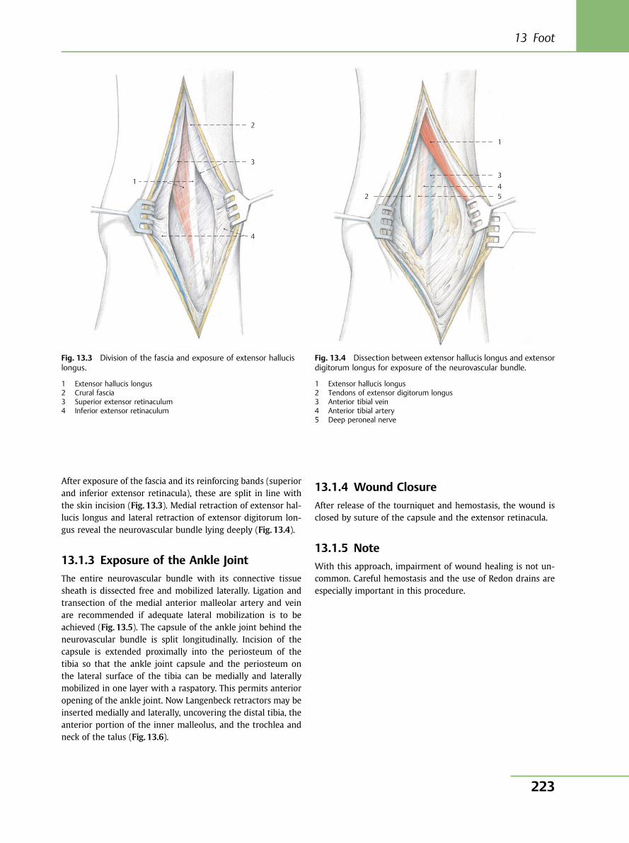
After exposure of the fascia and its reinforcing bands (superiorand inferior extensor retinacula), these are split in line withthe skin incision (Fig. 13.3). Medial retraction of extensor hal-lucis longus and lateral retraction of extensor digitorum lon-gus reveal the neurovascular bundle lying deeply (Fig. 13.4).
13.1.3 Exposure of the Ankle Joint
The entire neurovascular bundle with its connective tissuesheath is dissected free and mobilized laterally. Ligation andtransection of the medial anterior malleolar artery and veinare recommended if adequate lateral mobilization is to beachieved (Fig. 13.5). The capsule of the ankle joint behind theneurovascular bundle is split longitudinally. Incision of thecapsule is extended proximally into the periosteum of thetibia so that the ankle joint capsule and the periosteum onthe lateral surface of the tibia can be medially and laterallymobilized in one layer with a raspatory. This permits anterioropening of the ankle joint. Now Langenbeck retractors may beinserted medially and laterally, uncovering the distal tibia, theanterior portion of the inner malleolus, and the trochlea andneck of the talus (Fig. 13.6).
13.1.4 Wound Closure
After release of the tourniquet and hemostasis, the wound isclosed by suture of the capsule and the extensor retinacula.
13.1.5 Note
With this approach, impairment of wound healing is not un-common. Careful hemostasis and the use of Redon drains areespecially important in this procedure.
1
2
3
4
Fig. 13.3 Division of the fascia and exposure of extensor hallucislongus.
1 Extensor hallucis longus2 Crural fascia3 Superior extensor retinaculum4 Inferior extensor retinaculum
1
3 4 5 2
Fig. 13.4 Dissection between extensor hallucis longus and extensordigitorum longus for exposure of the neurovascular bundle.
1 Extensor hallucis longus2 Tendons of extensor digitorum longus3 Anterior tibial vein4 Anterior tibial artery5 Deep peroneal nerve
13 Foot
223
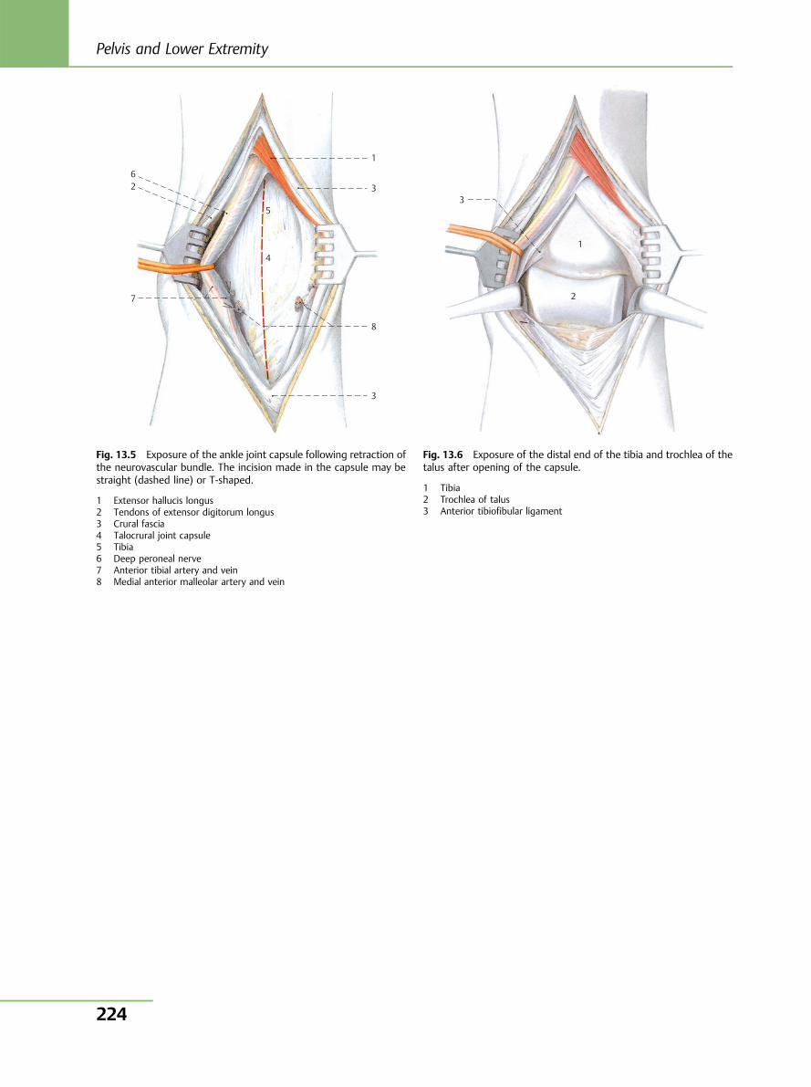
1
3
8
3
7
2
4
5
6
Fig. 13.5 Exposure of the ankle joint capsule following retraction ofthe neurovascular bundle. The incision made in the capsule may bestraight (dashed line) or T-shaped.
1 Extensor hallucis longus2 Tendons of extensor digitorum longus3 Crural fascia4 Talocrural joint capsule5 Tibia6 Deep peroneal nerve7 Anterior tibial artery and vein8 Medial anterior malleolar artery and vein
3
1
2
Fig. 13.6 Exposure of the distal end of the tibia and trochlea of thetalus after opening of the capsule.
1 Tibia2 Trochlea of talus3 Anterior tibiofibular ligament
Pelvis and Lower Extremity
224
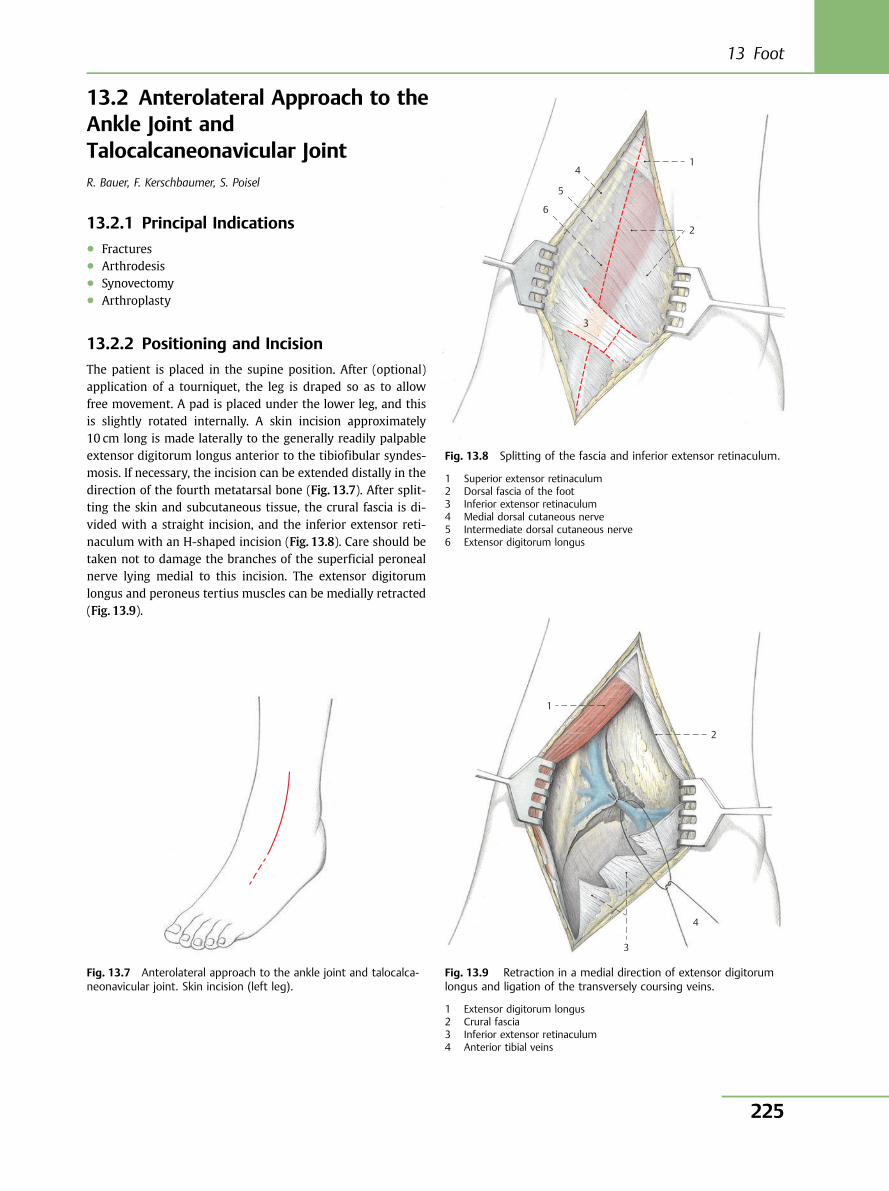
13.2 Anterolateral Approach to theAnkle Joint andTalocalcaneonavicular JointR. Bauer, F. Kerschbaumer, S. Poisel
13.2.1 Principal Indications● Fractures● Arthrodesis● Synovectomy● Arthroplasty
13.2.2 Positioning and Incision
The patient is placed in the supine position. After (optional)application of a tourniquet, the leg is draped so as to allowfree movement. A pad is placed under the lower leg, and thisis slightly rotated internally. A skin incision approximately10 cm long is made laterally to the generally readily palpableextensor digitorum longus anterior to the tibiofibular syndes-mosis. If necessary, the incision can be extended distally in thedirection of the fourth metatarsal bone (Fig. 13.7). After split-ting the skin and subcutaneous tissue, the crural fascia is di-vided with a straight incision, and the inferior extensor reti-naculum with an H-shaped incision (Fig. 13.8). Care should betaken not to damage the branches of the superficial peronealnerve lying medial to this incision. The extensor digitorumlongus and peroneus tertius muscles can be medially retracted(Fig. 13.9).
Fig. 13.7 Anterolateral approach to the ankle joint and talocalca-neonavicular joint. Skin incision (left leg).
3
6
5
4 1
2
Fig. 13.8 Splitting of the fascia and inferior extensor retinaculum.
1 Superior extensor retinaculum2 Dorsal fascia of the foot3 Inferior extensor retinaculum4 Medial dorsal cutaneous nerve5 Intermediate dorsal cutaneous nerve6 Extensor digitorum longus
1
2
4
3
Fig. 13.9 Retraction in a medial direction of extensor digitorumlongus and ligation of the transversely coursing veins.
1 Extensor digitorum longus2 Crural fascia3 Inferior extensor retinaculum4 Anterior tibial veins
13 Foot
225
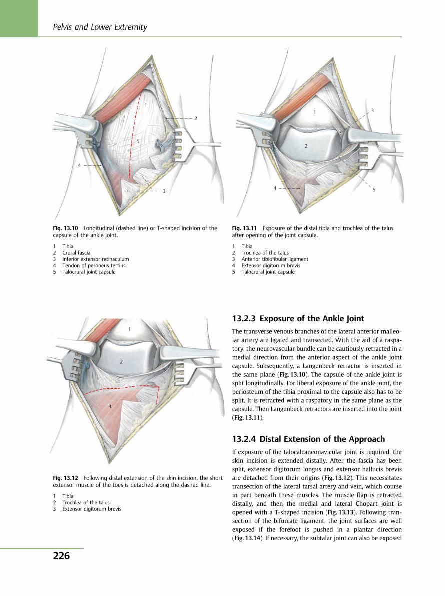
13.2.3 Exposure of the Ankle Joint
The transverse venous branches of the lateral anterior malleo-lar artery are ligated and transected. With the aid of a raspa-tory, the neurovascular bundle can be cautiously retracted in amedial direction from the anterior aspect of the ankle jointcapsule. Subsequently, a Langenbeck retractor is inserted inthe same plane (Fig. 13.10). The capsule of the ankle joint issplit longitudinally. For liberal exposure of the ankle joint, theperiosteum of the tibia proximal to the capsule also has to besplit. It is retracted with a raspatory in the same plane as thecapsule. Then Langenbeck retractors are inserted into the joint(Fig. 13.11).
13.2.4 Distal Extension of the Approach
If exposure of the talocalcaneonavicular joint is required, theskin incision is extended distally. After the fascia has beensplit, extensor digitorum longus and extensor hallucis brevisare detached from their origins (Fig. 13.12). This necessitatestransection of the lateral tarsal artery and vein, which coursein part beneath these muscles. The muscle flap is retracteddistally, and then the medial and lateral Chopart joint isopened with a T-shaped incision (Fig. 13.13). Following tran-section of the bifurcate ligament, the joint surfaces are wellexposed if the forefoot is pushed in a plantar direction(Fig. 13.14). If necessary, the subtalar joint can also be exposed
4
3
2
1
5
Fig. 13.10 Longitudinal (dashed line) or T-shaped incision of thecapsule of the ankle joint.
1 Tibia2 Crural fascia3 Inferior extensor retinaculum4 Tendon of peroneus tertius5 Talocrural joint capsule
4 5
3
2
1
Fig. 13.11 Exposure of the distal tibia and trochlea of the talusafter opening of the joint capsule.
1 Tibia2 Trochlea of the talus3 Anterior tibiofibular ligament4 Extensor digitorum brevis5 Talocrural joint capsule
1
2
3
Fig. 13.12 Following distal extension of the skin incision, the shortextensor muscle of the toes is detached along the dashed line.
1 Tibia2 Trochlea of the talus3 Extensor digitorum brevis
Pelvis and Lower Extremity
226
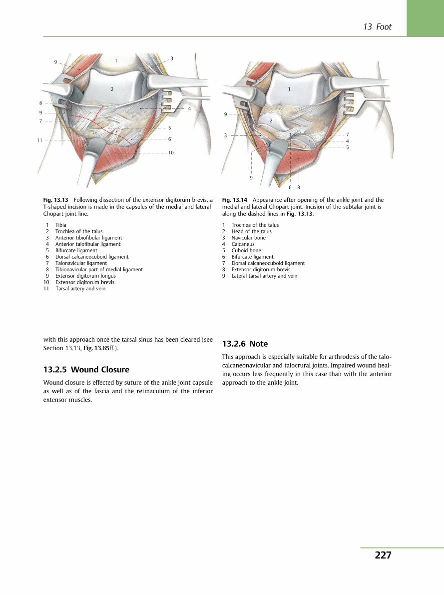
with this approach once the tarsal sinus has been cleared (seeSection 13.13, Fig. 13.65ff.).
13.2.5 Wound Closure
Wound closure is effected by suture of the ankle joint capsuleas well as of the fascia and the retinaculum of the inferiorextensor muscles.
13.2.6 Note
This approach is especially suitable for arthrodesis of the talo-calcaneonavicular and talocrural joints. Impaired wound heal-ing occurs less frequently in this case than with the anteriorapproach to the ankle joint.
8
9
9
2
1
7
11
10
6
5
4
3
Fig. 13.13 Following dissection of the extensor digitorum brevis, aT-shaped incision is made in the capsules of the medial and lateralChopart joint line.
1 Tibia2 Trochlea of the talus3 Anterior tibiofibular ligament4 Anterior talofibular ligament5 Bifurcate ligament6 Dorsal calcaneocuboid ligament7 Talonavicular ligament8 Tibionavicular part of medial ligament9 Extensor digitorum longus10 Extensor digitorum brevis11 Tarsal artery and vein
1
2 9
3
9
6 8
5 4 7
Fig. 13.14 Appearance after opening of the ankle joint and themedial and lateral Chopart joint. Incision of the subtalar joint isalong the dashed lines in Fig. 13.13.
1 Trochlea of the talus2 Head of the talus3 Navicular bone4 Calcaneus5 Cuboid bone6 Bifurcate ligament7 Dorsal calcaneocuboid ligament8 Extensor digitorum brevis9 Lateral tarsal artery and vein
13 Foot
227
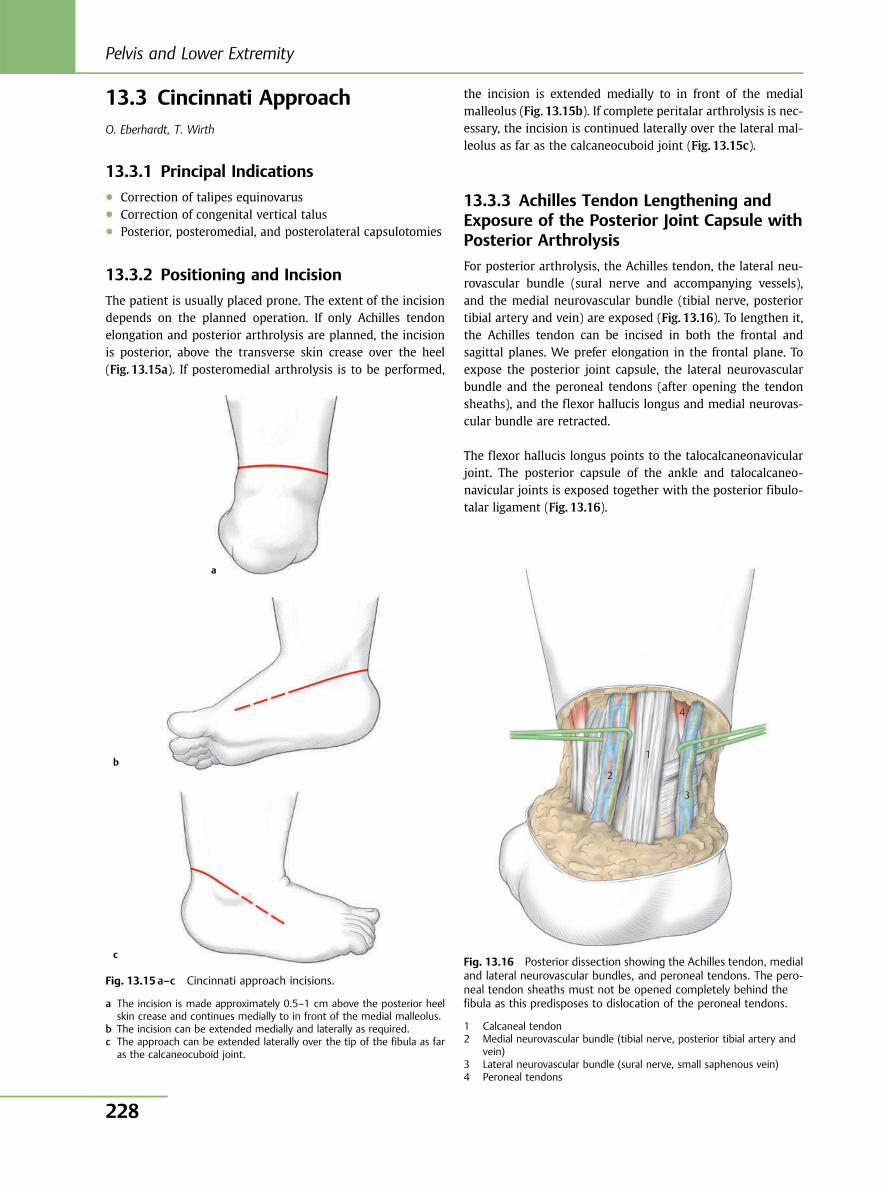
13.3 Cincinnati ApproachO. Eberhardt, T. Wirth
13.3.1 Principal Indications● Correction of talipes equinovarus● Correction of congenital vertical talus● Posterior, posteromedial, and posterolateral capsulotomies
13.3.2 Positioning and Incision
The patient is usually placed prone. The extent of the incisiondepends on the planned operation. If only Achilles tendonelongation and posterior arthrolysis are planned, the incisionis posterior, above the transverse skin crease over the heel(Fig. 13.15a). If posteromedial arthrolysis is to be performed,
the incision is extended medially to in front of the medialmalleolus (Fig. 13.15b). If complete peritalar arthrolysis is nec-essary, the incision is continued laterally over the lateral mal-leolus as far as the calcaneocuboid joint (Fig. 13.15c).
13.3.3 Achilles Tendon Lengthening andExposure of the Posterior Joint Capsule withPosterior Arthrolysis
For posterior arthrolysis, the Achilles tendon, the lateral neu-rovascular bundle (sural nerve and accompanying vessels),and the medial neurovascular bundle (tibial nerve, posteriortibial artery and vein) are exposed (Fig. 13.16). To lengthen it,the Achilles tendon can be incised in both the frontal andsagittal planes. We prefer elongation in the frontal plane. Toexpose the posterior joint capsule, the lateral neurovascularbundle and the peroneal tendons (after opening the tendonsheaths), and the flexor hallucis longus and medial neurovas-cular bundle are retracted.
The flexor hallucis longus points to the talocalcaneonavicularjoint. The posterior capsule of the ankle and talocalcaneo-navicular joints is exposed together with the posterior fibulo-talar ligament (Fig. 13.16).
a
b
c
Fig. 13.15 a–c Cincinnati approach incisions.
a The incision is made approximately 0.5–1 cm above the posterior heelskin crease and continues medially to in front of the medial malleolus.
b The incision can be extended medially and laterally as required.c The approach can be extended laterally over the tip of the fibula as far
as the calcaneocuboid joint.
Fig. 13.16 Posterior dissection showing the Achilles tendon, medialand lateral neurovascular bundles, and peroneal tendons. The pero-neal tendon sheaths must not be opened completely behind thefibula as this predisposes to dislocation of the peroneal tendons.
1 Calcaneal tendon2 Medial neurovascular bundle (tibial nerve, posterior tibial artery and
vein)3 Lateral neurovascular bundle (sural nerve, small saphenous vein)4 Peroneal tendons
1
2
4
3
Pelvis and Lower Extremity
228
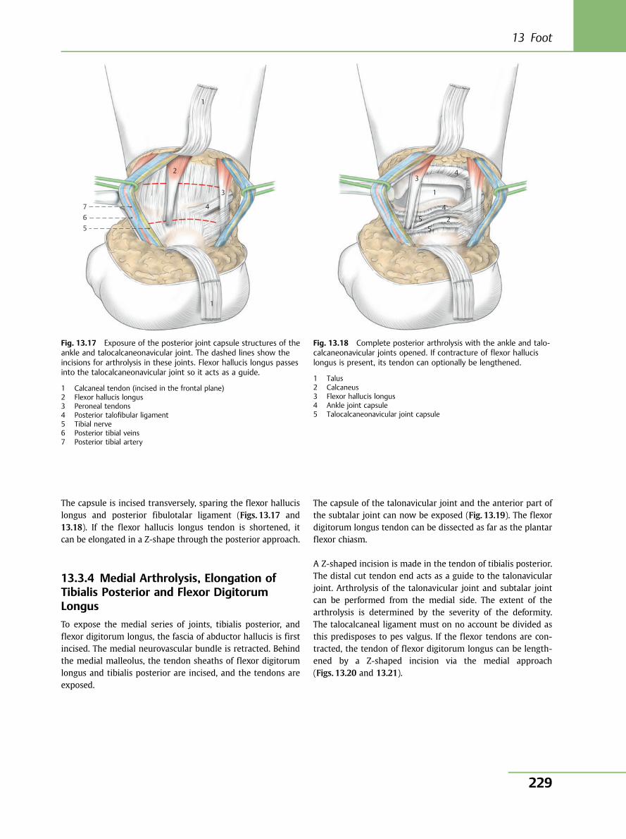
The capsule is incised transversely, sparing the flexor hallucislongus and posterior fibulotalar ligament (Figs. 13.17 and13.18). If the flexor hallucis longus tendon is shortened, itcan be elongated in a Z-shape through the posterior approach.
13.3.4 Medial Arthrolysis, Elongation ofTibialis Posterior and Flexor DigitorumLongus
To expose the medial series of joints, tibialis posterior, andflexor digitorum longus, the fascia of abductor hallucis is firstincised. The medial neurovascular bundle is retracted. Behindthe medial malleolus, the tendon sheaths of flexor digitorumlongus and tibialis posterior are incised, and the tendons areexposed.
The capsule of the talonavicular joint and the anterior part ofthe subtalar joint can now be exposed (Fig. 13.19). The flexordigitorum longus tendon can be dissected as far as the plantarflexor chiasm.
A Z-shaped incision is made in the tendon of tibialis posterior.The distal cut tendon end acts as a guide to the talonavicularjoint. Arthrolysis of the talonavicular joint and subtalar jointcan be performed from the medial side. The extent of thearthrolysis is determined by the severity of the deformity.The talocalcaneal ligament must on no account be divided asthis predisposes to pes valgus. If the flexor tendons are con-tracted, the tendon of flexor digitorum longus can be length-ened by a Z-shaped incision via the medial approach(Figs. 13.20 and 13.21).
1
2
3
4
1
567
Fig. 13.17 Exposure of the posterior joint capsule structures of theankle and talocalcaneonavicular joint. The dashed lines show theincisions for arthrolysis in these joints. Flexor hallucis longus passesinto the talocalcaneonavicular joint so it acts as a guide.
1 Calcaneal tendon (incised in the frontal plane)2 Flexor hallucis longus3 Peroneal tendons4 Posterior talofibular ligament5 Tibial nerve6 Posterior tibial veins7 Posterior tibial artery
1
2
3 4
4
5 5
Fig. 13.18 Complete posterior arthrolysis with the ankle and talo-calcaneonavicular joints opened. If contracture of flexor hallucislongus is present, its tendon can optionally be lengthened.
1 Talus2 Calcaneus3 Flexor hallucis longus4 Ankle joint capsule5 Talocalcaneonavicular joint capsule
13 Foot
229
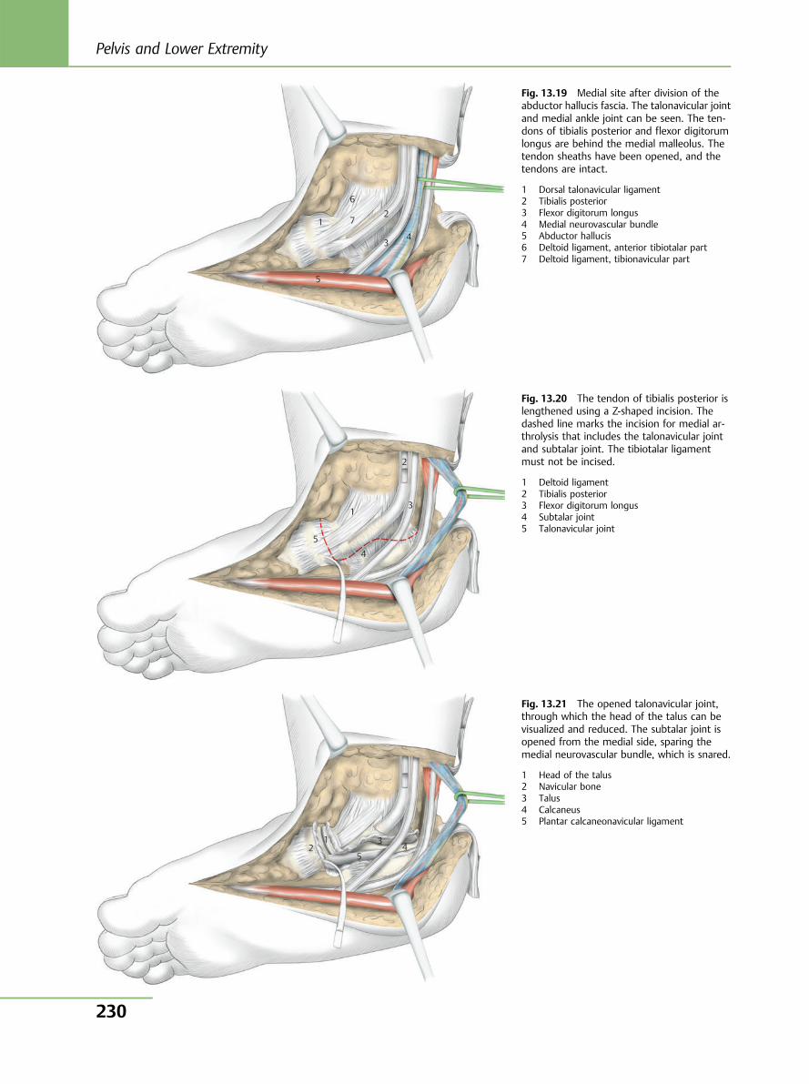
1
5
3
2
4
6
7
Fig. 13.19 Medial site after division of theabductor hallucis fascia. The talonavicular jointand medial ankle joint can be seen. The ten-dons of tibialis posterior and flexor digitorumlongus are behind the medial malleolus. Thetendon sheaths have been opened, and thetendons are intact.
1 Dorsal talonavicular ligament2 Tibialis posterior3 Flexor digitorum longus4 Medial neurovascular bundle5 Abductor hallucis6 Deltoid ligament, anterior tibiotalar part7 Deltoid ligament, tibionavicular part
1
2
3
4
5
Fig. 13.20 The tendon of tibialis posterior islengthened using a Z-shaped incision. Thedashed line marks the incision for medial ar-throlysis that includes the talonavicular jointand subtalar joint. The tibiotalar ligamentmust not be incised.
1 Deltoid ligament2 Tibialis posterior3 Flexor digitorum longus4 Subtalar joint5 Talonavicular joint
1 2
3
5 4
Fig. 13.21 The opened talonavicular joint,through which the head of the talus can bevisualized and reduced. The subtalar joint isopened from the medial side, sparing themedial neurovascular bundle, which is snared.
1 Head of the talus2 Navicular bone3 Talus4 Calcaneus5 Plantar calcaneonavicular ligament
Pelvis and Lower Extremity
230
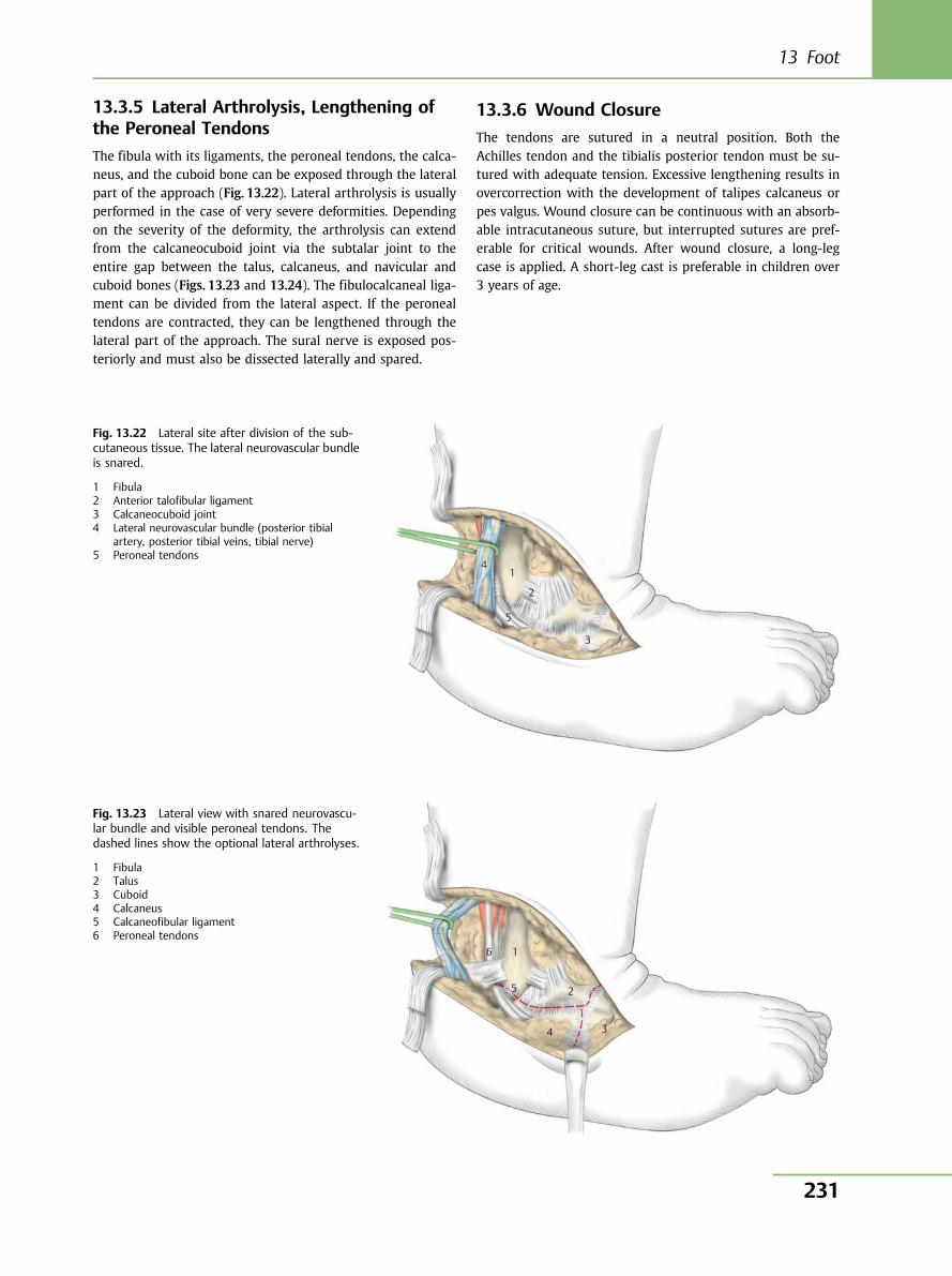
13.3.5 Lateral Arthrolysis, Lengthening ofthe Peroneal Tendons
The fibula with its ligaments, the peroneal tendons, the calca-neus, and the cuboid bone can be exposed through the lateralpart of the approach (Fig. 13.22). Lateral arthrolysis is usuallyperformed in the case of very severe deformities. Dependingon the severity of the deformity, the arthrolysis can extendfrom the calcaneocuboid joint via the subtalar joint to theentire gap between the talus, calcaneus, and navicular andcuboid bones (Figs. 13.23 and 13.24). The fibulocalcaneal liga-ment can be divided from the lateral aspect. If the peronealtendons are contracted, they can be lengthened through thelateral part of the approach. The sural nerve is exposed pos-teriorly and must also be dissected laterally and spared.
13.3.6 Wound Closure
The tendons are sutured in a neutral position. Both theAchilles tendon and the tibialis posterior tendon must be su-tured with adequate tension. Excessive lengthening results inovercorrection with the development of talipes calcaneus orpes valgus. Wound closure can be continuous with an absorb-able intracutaneous suture, but interrupted sutures are pref-erable for critical wounds. After wound closure, a long-legcase is applied. A short-leg cast is preferable in children over3 years of age.
4 1
2
5
3
Fig. 13.22 Lateral site after division of the sub-cutaneous tissue. The lateral neurovascular bundleis snared.
1 Fibula2 Anterior talofibular ligament3 Calcaneocuboid joint4 Lateral neurovascular bundle (posterior tibial
artery, posterior tibial veins, tibial nerve)5 Peroneal tendons
1 6
5 2
4 3
Fig. 13.23 Lateral view with snared neurovascu-lar bundle and visible peroneal tendons. Thedashed lines show the optional lateral arthrolyses.
1 Fibula2 Talus3 Cuboid4 Calcaneus5 Calcaneofibular ligament6 Peroneal tendons
13 Foot
231
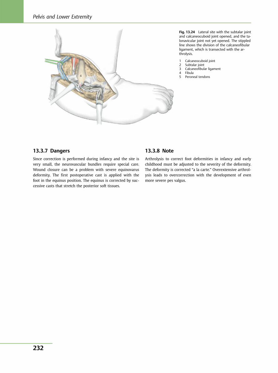
13.3.7 Dangers
Since correction is performed during infancy and the site isvery small, the neurovascular bundles require special care.Wound closure can be a problem with severe equinovarusdeformity. The first postoperative cast is applied with thefoot in the equinus position. The equinus is corrected by suc-cessive casts that stretch the posterior soft tissues.
13.3.8 Note
Arthrolysis to correct foot deformities in infancy and earlychildhood must be adjusted to the severity of the deformity.The deformity is corrected “a la carte.” Overextensive arthrol-ysis leads to overcorrection with the development of evenmore severe pes valgus.
1
2 3
4 5
Fig. 13.24 Lateral site with the subtalar jointand calcaneocuboid joint opened, and the ta-lonavicular joint not yet opened. The stippledline shows the division of the calcaneofibularligament, which is transected with the ar-throlysis.
1 Calcaneocuboid joint2 Subtalar joint3 Calcaneofibular ligament4 Fibula5 Peroneal tendons
Pelvis and Lower Extremity
232
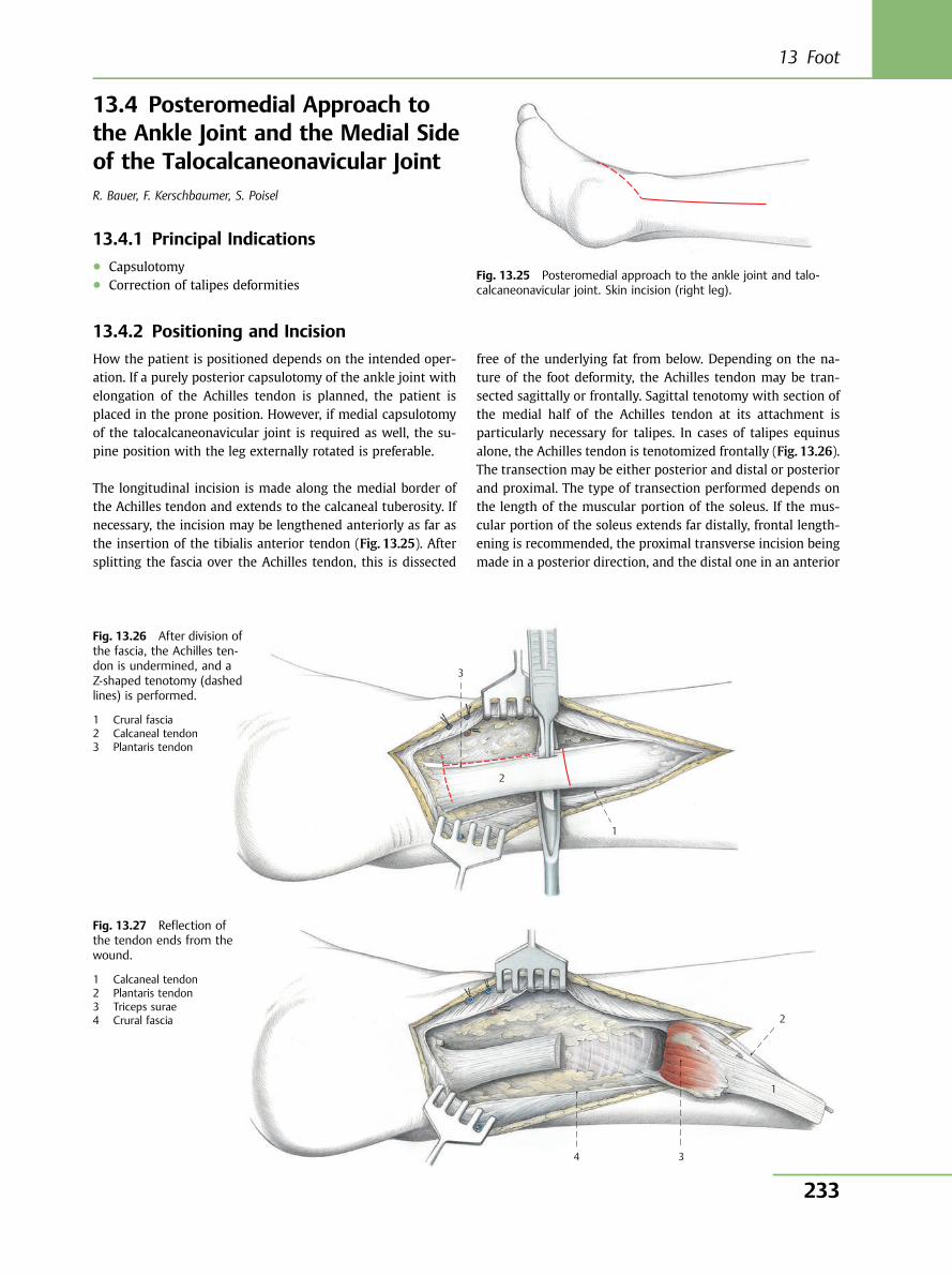
13.4 Posteromedial Approach tothe Ankle Joint and the Medial Sideof the Talocalcaneonavicular JointR. Bauer, F. Kerschbaumer, S. Poisel
13.4.1 Principal Indications● Capsulotomy● Correction of talipes deformities
13.4.2 Positioning and Incision
How the patient is positioned depends on the intended oper-ation. If a purely posterior capsulotomy of the ankle joint withelongation of the Achilles tendon is planned, the patient isplaced in the prone position. However, if medial capsulotomyof the talocalcaneonavicular joint is required as well, the su-pine position with the leg externally rotated is preferable.
The longitudinal incision is made along the medial border ofthe Achilles tendon and extends to the calcaneal tuberosity. Ifnecessary, the incision may be lengthened anteriorly as far asthe insertion of the tibialis anterior tendon (Fig. 13.25). Aftersplitting the fascia over the Achilles tendon, this is dissected
free of the underlying fat from below. Depending on the na-ture of the foot deformity, the Achilles tendon may be tran-sected sagittally or frontally. Sagittal tenotomy with section ofthe medial half of the Achilles tendon at its attachment isparticularly necessary for talipes. In cases of talipes equinusalone, the Achilles tendon is tenotomized frontally (Fig. 13.26).The transection may be either posterior and distal or posteriorand proximal. The type of transection performed depends onthe length of the muscular portion of the soleus. If the mus-cular portion of the soleus extends far distally, frontal length-ening is recommended, the proximal transverse incision beingmade in a posterior direction, and the distal one in an anterior
Fig. 13.25 Posteromedial approach to the ankle joint and talo-calcaneonavicular joint. Skin incision (right leg).
3
2
1
Fig. 13.26 After division ofthe fascia, the Achilles ten-don is undermined, and aZ-shaped tenotomy (dashedlines) is performed.
1 Crural fascia2 Calcaneal tendon3 Plantaris tendon
4 3
1
2
Fig. 13.27 Reflection ofthe tendon ends from thewound.
1 Calcaneal tendon2 Plantaris tendon3 Triceps surae4 Crural fascia
13 Foot
233
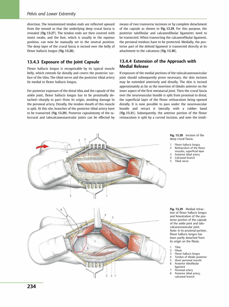
direction. The tenotomized tendon ends are reflected upwardfrom the wound so that the underlying deep crural fascia isrevealed (Fig. 13.27). The tendon ends are then covered withmoist swabs, and the foot, which is usually in the equinusposition, can now be manually set in the neutral position.The deep layer of the crural fascia is incised over the belly offlexor hallucis longus (Fig. 13.28).
13.4.3 Exposure of the Joint Capsule
Flexor hallucis longus is recognizable by its typical musclebelly, which extends far distally and covers the posterior sur-face of the tibia. The tibial nerve and the posterior tibial arterylie medial to flexor hallucis longus.
For posterior exposure of the distal tibia and the capsule of theankle joint, flexor hallucis longus has to be proximally de-tached—sharply in part—from its origin, avoiding damage tothe peroneal artery. Distally, the tendon sheath of this muscleis split. At this site, branches of the posterior tibial artery haveto be transected (Fig. 13.29). Posterior capsulotomy of the ta-locrural and talocalcaneonavicular joints can be effected by
means of two transverse incisions or by complete detachmentof the capsule as shown in Fig. 13.29. For this purpose, theposterior talofibular and calcaneofibular ligaments need tobe transected. When transecting the calcaneofibular ligament,the peroneal tendons have to be protected. Medially, the pos-terior part of the deltoid ligament is transected directly at itsattachment to the calcaneus (Fig. 13.30).
13.4.4 Extension of the Approach withMedial Release
If exposure of the medial portions of the talocalcaneonavicularjoint should subsequently prove necessary, the skin incisionmay be extended anteriorly and distally. The skin is incisedapproximately as far as the insertion of tibialis anterior on theinner aspect of the first metatarsal joint. Then the crural fasciaover the neurovascular bundle is split from proximal to distal,the superficial layer of the flexor retinaculum being openeddistally. It is now possible to pass under the neurovascularbundle and retract it laterally with a rubber band(Fig. 13.31). Subsequently, the anterior portion of the flexorretinaculum is split by a curved incision, and now the tendi-
4
5 3
1 2
Fig. 13.28 Incision of thedeep crural fascia.
1 Flexor hallucis longus2 Retinaculum of the flexor
muscles, superficial layer3 Posterior tibial artery4 Calcaneal branch5 Tibial nerve
8
4
1
6
3
725
Fig. 13.29 Mediad retrac-tion of flexor hallucis longusand fenestration of the pos-terior portion of the capsuleof the ankle joint and talo-calcaneonavicular joint.Note: In its proximal portion,flexor hallucis longus hasbeen partly detached fromits origin on the fibula.
1 Tibia2 Fibula3 Flexor hallucis longus4 Tendon of tibialis posterior5 Short peroneal muscle6 Posterior tibiofibular
ligament7 Peroneal artery8 Posterior tibial artery,
calcaneal branch
Pelvis and Lower Extremity
234
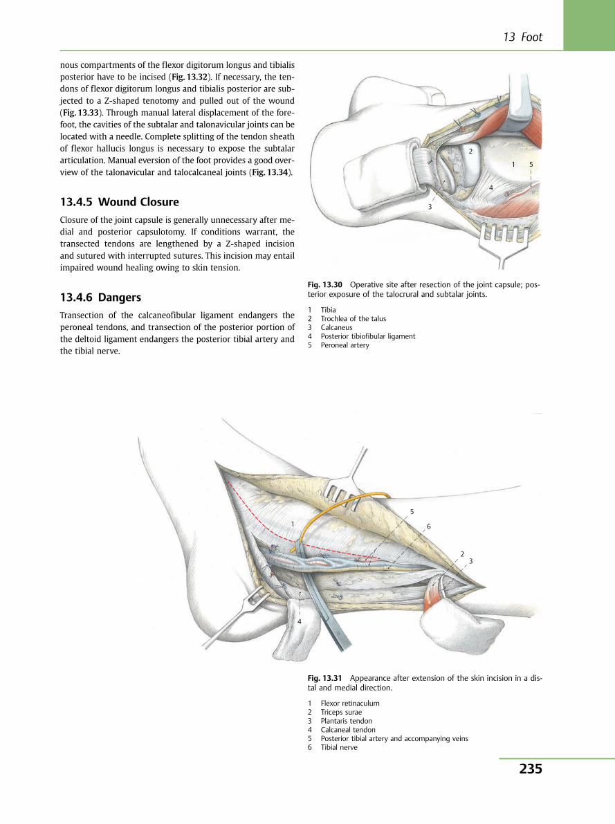
nous compartments of the flexor digitorum longus and tibialisposterior have to be incised (Fig. 13.32). If necessary, the ten-dons of flexor digitorum longus and tibialis posterior are sub-jected to a Z-shaped tenotomy and pulled out of the wound(Fig. 13.33). Through manual lateral displacement of the fore-foot, the cavities of the subtalar and talonavicular joints can belocated with a needle. Complete splitting of the tendon sheathof flexor hallucis longus is necessary to expose the subtalararticulation. Manual eversion of the foot provides a good over-view of the talonavicular and talocalcaneal joints (Fig. 13.34).
13.4.5 Wound Closure
Closure of the joint capsule is generally unnecessary after me-dial and posterior capsulotomy. If conditions warrant, thetransected tendons are lengthened by a Z-shaped incisionand sutured with interrupted sutures. This incision may entailimpaired wound healing owing to skin tension.
13.4.6 Dangers
Transection of the calcaneofibular ligament endangers theperoneal tendons, and transection of the posterior portion ofthe deltoid ligament endangers the posterior tibial artery andthe tibial nerve.
3
5 1
4
2
Fig. 13.30 Operative site after resection of the joint capsule; pos-terior exposure of the talocrural and subtalar joints.
1 Tibia2 Trochlea of the talus3 Calcaneus4 Posterior tibiofibular ligament5 Peroneal artery
4
1
5
6
2 3
Fig. 13.31 Appearance after extension of the skin incision in a dis-tal and medial direction.
1 Flexor retinaculum2 Triceps surae3 Plantaris tendon4 Calcaneal tendon5 Posterior tibial artery and accompanying veins6 Tibial nerve
13 Foot
235
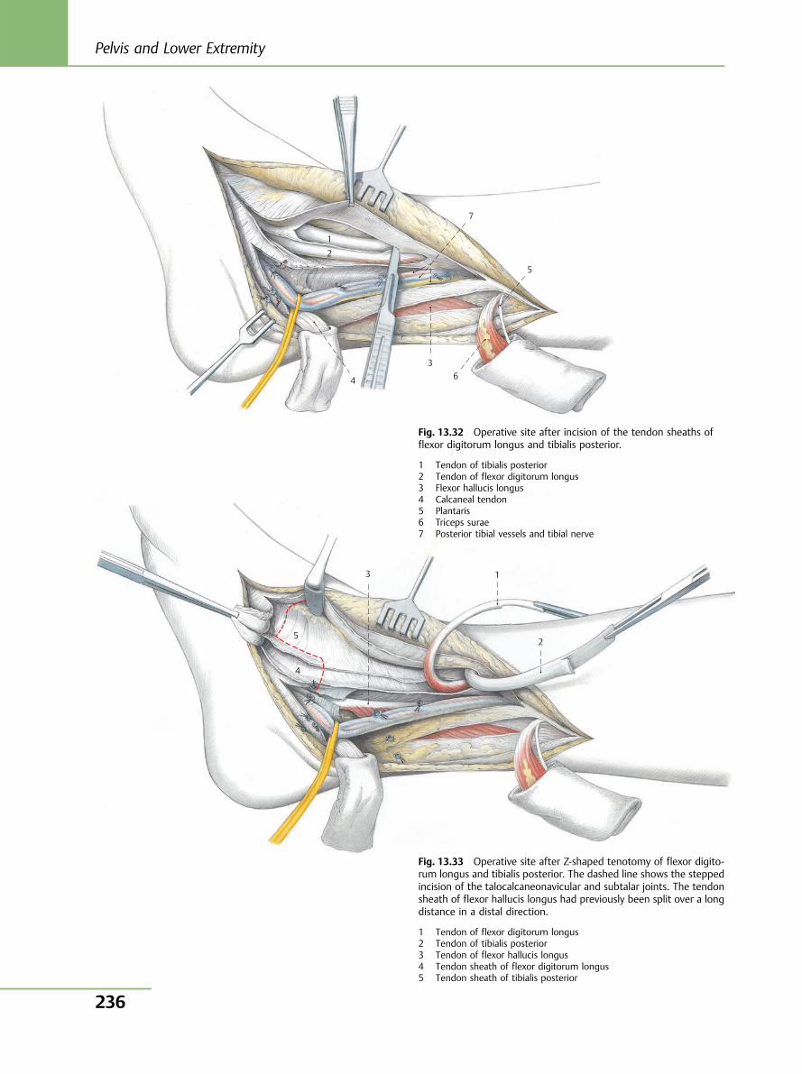
1 2
4
3 6
5
7
5
4
3 1
2
Fig. 13.32 Operative site after incision of the tendon sheaths offlexor digitorum longus and tibialis posterior.
1 Tendon of tibialis posterior2 Tendon of flexor digitorum longus3 Flexor hallucis longus4 Calcaneal tendon5 Plantaris6 Triceps surae7 Posterior tibial vessels and tibial nerve
Fig. 13.33 Operative site after Z-shaped tenotomy of flexor digito-rum longus and tibialis posterior. The dashed line shows the steppedincision of the talocalcaneonavicular and subtalar joints. The tendonsheath of flexor hallucis longus had previously been split over a longdistance in a distal direction.
1 Tendon of flexor digitorum longus2 Tendon of tibialis posterior3 Tendon of flexor hallucis longus4 Tendon sheath of flexor digitorum longus5 Tendon sheath of tibialis posterior
Pelvis and Lower Extremity
236
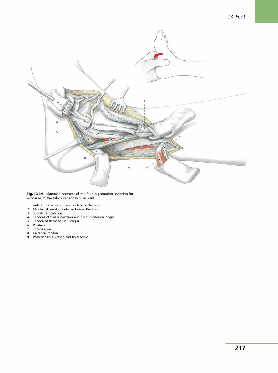
4
1
2
5
3
8
9 7
6
4
Fig. 13.34 Manual placement of the foot in pronation–eversion forexposure of the talocalcaneonavicular joint.
1 Anterior calcaneal articular surface of the talus2 Middle calcaneal articular surface of the talus3 Subtalar articulation4 Tendons of tibialis posterior and flexor digitorum longus5 Tendon of flexor hallucis longus6 Plantaris7 Triceps surae8 Calcaneal tendon9 Posterior tibial vessels and tibial nerve
13 Foot
237
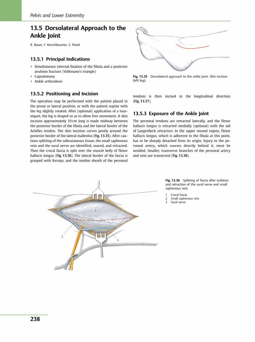
13.5 Dorsolateral Approach to theAnkle JointR. Bauer, F. Kerschbaumer, S. Poisel
13.5.1 Principal Indications● Simultaneous internal fixation of the fibula and a posterior
avulsion fracture (Volkmann’s triangle)● Capsulotomy● Ankle arthrodesis
13.5.2 Positioning and Incision
The operation may be performed with the patient placed inthe prone or lateral position, or with the patient supine withthe leg slightly rotated. After (optional) application of a tour-niquet, the leg is draped so as to allow free movement. A skinincision approximately 10 cm long is made midway betweenthe posterior border of the fibula and the lateral border of theAchilles tendon. The skin incision curves gently around theposterior border of the lateral malleolus (Fig. 13.35). After cau-tious splitting of the subcutaneous tissue, the small saphenousvein and the sural nerve are identified, snared, and retracted.Then the crural fascia is split over the muscle belly of flexorhallucis longus (Fig. 13.36). The lateral border of the fascia isgrasped with forceps, and the tendon sheath of the peroneal
tendons is then incised in the longitudinal direction(Fig. 13.37).
13.5.3 Exposure of the Ankle Joint
The peroneal tendons are retracted laterally, and the flexorhallucis longus is retracted medially (optional) with the aidof Langenbeck retractors. In the upper wound region, flexorhallucis longus, which is adherent to the fibula at this point,has to be sharply detached from its origin. Injury to the pe-roneal artery, which courses directly behind it, must beavoided. Smaller, transverse branches of the peroneal arteryand vein are transected (Fig. 13.38).
Fig. 13.35 Dorsolateral approach to the ankle joint. Skin incision(left leg).
1
23
Fig. 13.36 Splitting of fascia after isolationand retraction of the sural nerve and smallsaphenous vein.
1 Crural fascia2 Small saphenous vein3 Sural nerve
Pelvis and Lower Extremity
238
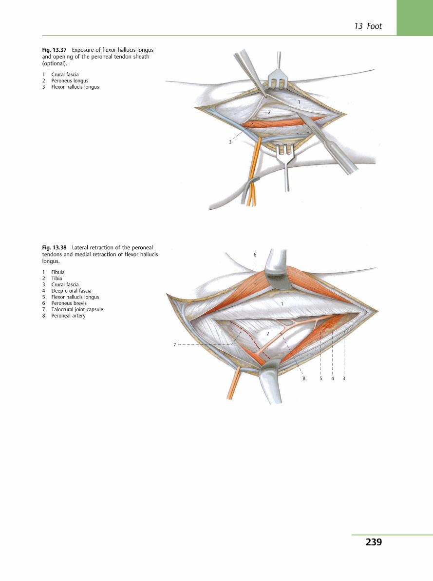
3
2
1
Fig. 13.37 Exposure of flexor hallucis longusand opening of the peroneal tendon sheath(optional).
1 Crural fascia2 Peroneus longus3 Flexor hallucis longus
1
6
7
8 5 4 3
2
Fig. 13.38 Lateral retraction of the peronealtendons and medial retraction of flexor hallucislongus.
1 Fibula2 Tibia3 Crural fascia4 Deep crural fascia5 Flexor hallucis longus6 Peroneus brevis7 Talocrural joint capsule8 Peroneal artery
13 Foot
239
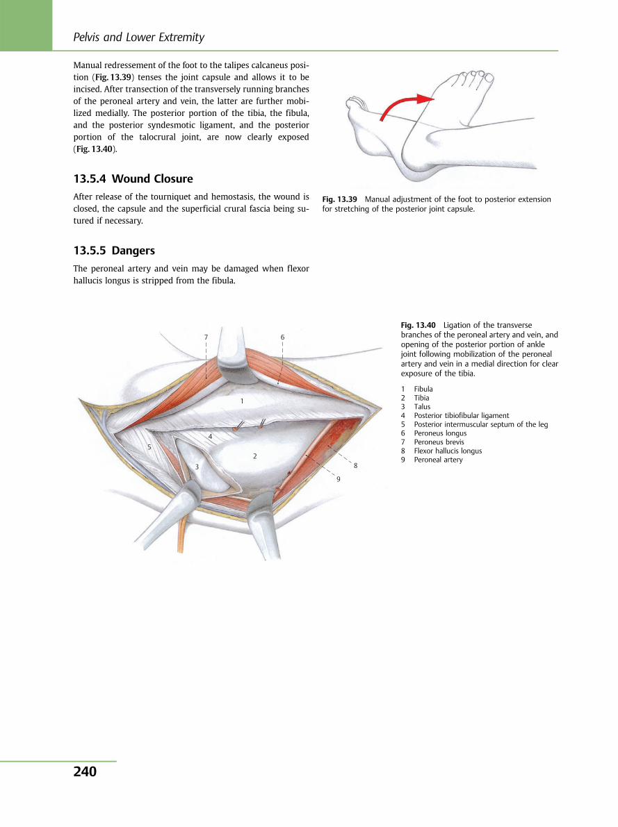
Manual redressement of the foot to the talipes calcaneus posi-tion (Fig. 13.39) tenses the joint capsule and allows it to beincised. After transection of the transversely running branchesof the peroneal artery and vein, the latter are further mobi-lized medially. The posterior portion of the tibia, the fibula,and the posterior syndesmotic ligament, and the posteriorportion of the talocrural joint, are now clearly exposed(Fig. 13.40).
13.5.4 Wound Closure
After release of the tourniquet and hemostasis, the wound isclosed, the capsule and the superficial crural fascia being su-tured if necessary.
13.5.5 Dangers
The peroneal artery and vein may be damaged when flexorhallucis longus is stripped from the fibula.
Fig. 13.39 Manual adjustment of the foot to posterior extensionfor stretching of the posterior joint capsule.
7 6
8
9
2
1
4
3
5
Fig. 13.40 Ligation of the transversebranches of the peroneal artery and vein, andopening of the posterior portion of anklejoint following mobilization of the peronealartery and vein in a medial direction for clearexposure of the tibia.
1 Fibula2 Tibia3 Talus4 Posterior tibiofibular ligament5 Posterior intermuscular septum of the leg6 Peroneus longus7 Peroneus brevis8 Flexor hallucis longus9 Peroneal artery
Pelvis and Lower Extremity
240
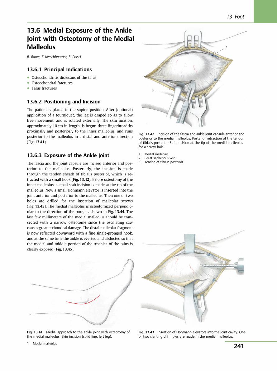
13.6 Medial Exposure of the AnkleJoint with Osteotomy of the MedialMalleolusR. Bauer, F. Kerschbaumer, S. Poisel
13.6.1 Principal Indications● Osteochondritis dissecans of the talus● Osteochondral fractures● Talus fractures
13.6.2 Positioning and Incision
The patient is placed in the supine position. After (optional)application of a tourniquet, the leg is draped so as to allowfree movement, and is rotated externally. The skin incision,approximately 10 cm in length, is begun three fingerbreadthsproximally and posteriorly to the inner malleolus, and runsposterior to the malleolus in a distal and anterior direction(Fig. 13.41).
13.6.3 Exposure of the Ankle Joint
The fascia and the joint capsule are incised anterior and pos-terior to the malleolus. Posteriorly, the incision is madethrough the tendon sheath of tibialis posterior, which is re-tracted with a small hook (Fig. 13.42). Before osteotomy of theinner malleolus, a small stab incision is made at the tip of themalleolus. Now a small Hohmann elevator is inserted into thejoint anterior and posterior to the malleolus. Then one or twoholes are drilled for the insertion of malleolar screws(Fig. 13.43). The medial malleolus is osteotomized perpendic-ular to the direction of the bore, as shown in Fig. 13.44. Thelast few millimeters of the medial malleolus should be tran-sected with a narrow osteotome since the oscillating sawcauses greater chondral damage. The distal malleolar fragmentis now reflected downward with a fine single-pronged hook,and at the same time the ankle is everted and abducted so thatthe medial and middle portion of the trochlea of the talus isclearly exposed (Fig. 13.45).
1
Fig. 13.41 Medial approach to the ankle joint with osteotomy ofthe medial malleolus. Skin incision (solid line, left leg).
1 Medial malleolus
1
2
3
Fig. 13.42 Incision of the fascia and ankle joint capsule anterior andposterior to the medial malleolus. Posterior retraction of the tendonof tibialis posterior. Stab incision at the tip of the medial malleolusfor a screw hole.
1 Medial malleolus2 Great saphenous vein3 Tendon of tibialis posterior
Fig. 13.43 Insertion of Hohmann elevators into the joint cavity. Oneor two slanting drill holes are made in the medial malleolus.
13 Foot
241
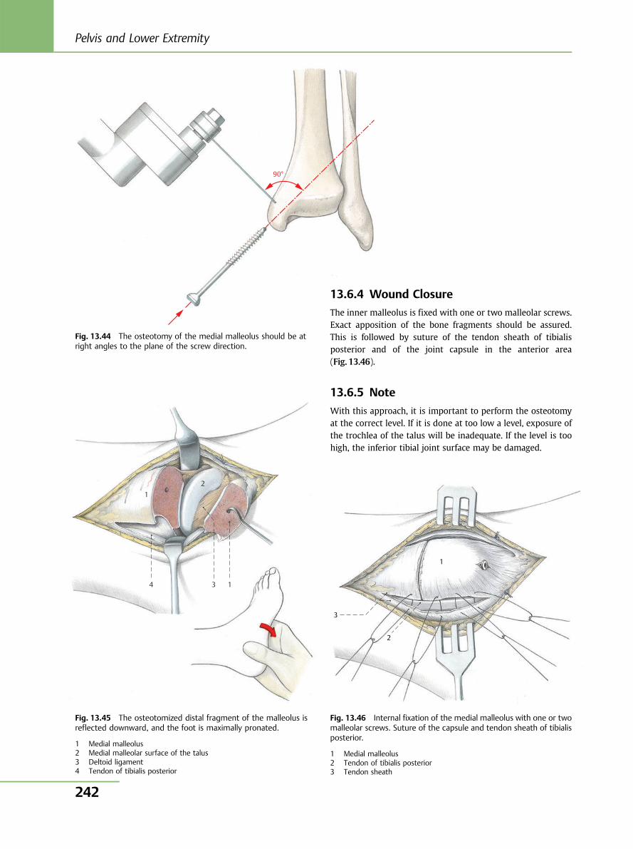
90°
Fig. 13.44 The osteotomy of the medial malleolus should be atright angles to the plane of the screw direction.
Fig. 13.45 The osteotomized distal fragment of the malleolus isreflected downward, and the foot is maximally pronated.
1 Medial malleolus2 Medial malleolar surface of the talus3 Deltoid ligament4 Tendon of tibialis posterior
1 2
4 3 1
13.6.4 Wound Closure
The inner malleolus is fixed with one or two malleolar screws.Exact apposition of the bone fragments should be assured.This is followed by suture of the tendon sheath of tibialisposterior and of the joint capsule in the anterior area(Fig. 13.46).
13.6.5 Note
With this approach, it is important to perform the osteotomyat the correct level. If it is done at too low a level, exposure ofthe trochlea of the talus will be inadequate. If the level is toohigh, the inferior tibial joint surface may be damaged.
Fig. 13.46 Internal fixation of the medial malleolus with one or twomalleolar screws. Suture of the capsule and tendon sheath of tibialisposterior.
1 Medial malleolus2 Tendon of tibialis posterior3 Tendon sheath
3
2
1
Pelvis and Lower Extremity
242
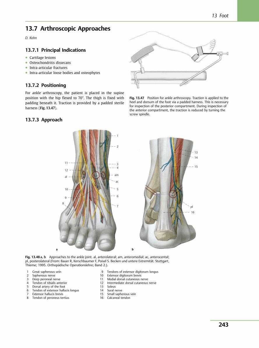
13.7 Arthroscopic ApproachesD. Kohn
13.7.1 Principal Indications● Cartilage lesions● Osteochondritis dissecans● Intra-articular fractures● Intra-articular loose bodies and osteophytes
13.7.2 Positioning
For ankle arthroscopy, the patient is placed in the supineposition with the hip flexed to 70°. The thigh is fixed withpadding beneath it. Traction is provided by a padded sterileharness (Fig. 13.47).
13.7.3 Approach
Fig. 13.47 Position for ankle arthroscopy. Traction is applied to theheel and dorsum of the foot via a padded harness. This is necessaryfor inspection of the posterior compartment. During inspection ofthe anterior compartment, the traction is reduced by turning thescrew spindle.
1
11
12
al
10
9
8
2
34
am
ac
5
6
7
a
13
14
15
pl
16
b
Fig. 13.48 a, b Approaches to the ankle joint. al, anterolateral; am, anteromedial; ac, anterocental;pl, posterolateral (From: Bauer R, Kerschbaumer F, Poisel S. Becken und untere Extremität. Stuttgart,Thieme; 1995. Orthopädische Operationslehre; Band 2.).
1 Great saphenous vein2 Saphenous nerve3 Deep peroneal nerve4 Tendon of tibialis anterior5 Dorsal artery of the foot6 Tendon of extensor hallucis longus7 Extensor hallucis brevis8 Tendon of peroneus tertius
9 Tendons of extensor digitorum longus10 Extensor digitorum brevis11 Medial dorsal cutaneous nerve12 Intermediate dorsal cutaneous nerve13 Soleus14 Sural nerve15 Small saphenous vein16 Calcaneal tendon
13 Foot
243
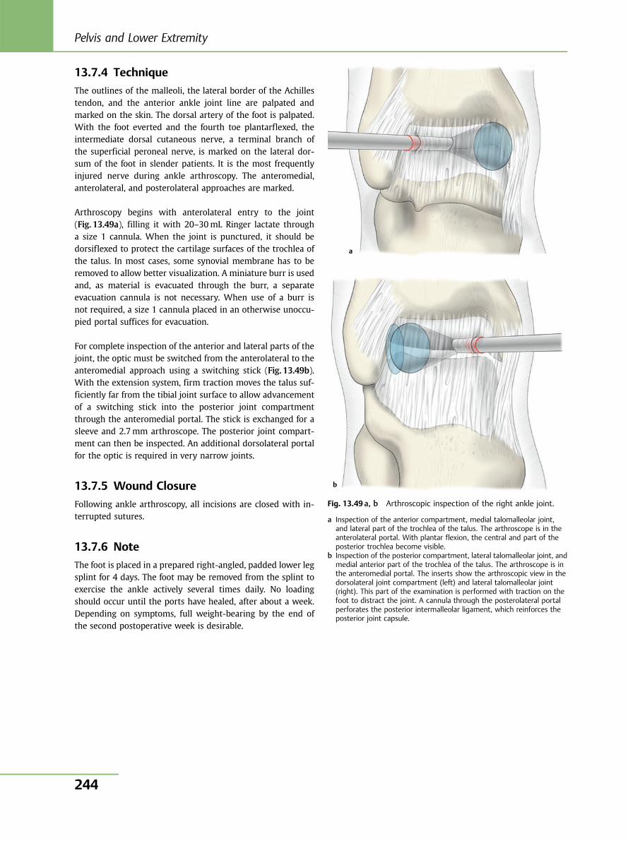
13.7.4 Technique
The outlines of the malleoli, the lateral border of the Achillestendon, and the anterior ankle joint line are palpated andmarked on the skin. The dorsal artery of the foot is palpated.With the foot everted and the fourth toe plantarflexed, theintermediate dorsal cutaneous nerve, a terminal branch ofthe superficial peroneal nerve, is marked on the lateral dor-sum of the foot in slender patients. It is the most frequentlyinjured nerve during ankle arthroscopy. The anteromedial,anterolateral, and posterolateral approaches are marked.
Arthroscopy begins with anterolateral entry to the joint(Fig. 13.49a), filling it with 20–30mL Ringer lactate througha size 1 cannula. When the joint is punctured, it should bedorsiflexed to protect the cartilage surfaces of the trochlea ofthe talus. In most cases, some synovial membrane has to beremoved to allow better visualization. A miniature burr is usedand, as material is evacuated through the burr, a separateevacuation cannula is not necessary. When use of a burr isnot required, a size 1 cannula placed in an otherwise unoccu-pied portal suffices for evacuation.
For complete inspection of the anterior and lateral parts of thejoint, the optic must be switched from the anterolateral to theanteromedial approach using a switching stick (Fig. 13.49b).With the extension system, firm traction moves the talus suf-ficiently far from the tibial joint surface to allow advancementof a switching stick into the posterior joint compartmentthrough the anteromedial portal. The stick is exchanged for asleeve and 2.7mm arthroscope. The posterior joint compart-ment can then be inspected. An additional dorsolateral portalfor the optic is required in very narrow joints.
13.7.5 Wound Closure
Following ankle arthroscopy, all incisions are closed with in-terrupted sutures.
13.7.6 Note
The foot is placed in a prepared right-angled, padded lower legsplint for 4 days. The foot may be removed from the splint toexercise the ankle actively several times daily. No loadingshould occur until the ports have healed, after about a week.Depending on symptoms, full weight-bearing by the end ofthe second postoperative week is desirable.
a
b
Fig. 13.49 a, b Arthroscopic inspection of the right ankle joint.
a Inspection of the anterior compartment, medial talomalleolar joint,and lateral part of the trochlea of the talus. The arthroscope is in theanterolateral portal. With plantar flexion, the central and part of theposterior trochlea become visible.
b Inspection of the posterior compartment, lateral talomalleolar joint, andmedial anterior part of the trochlea of the talus. The arthroscope is inthe anteromedial portal. The inserts show the arthroscopic view in thedorsolateral joint compartment (left) and lateral talomalleolar joint(right). This part of the examination is performed with traction on thefoot to distract the joint. A cannula through the posterolateral portalperforates the posterior intermalleolar ligament, which reinforces theposterior joint capsule.
Pelvis and Lower Extremity
244
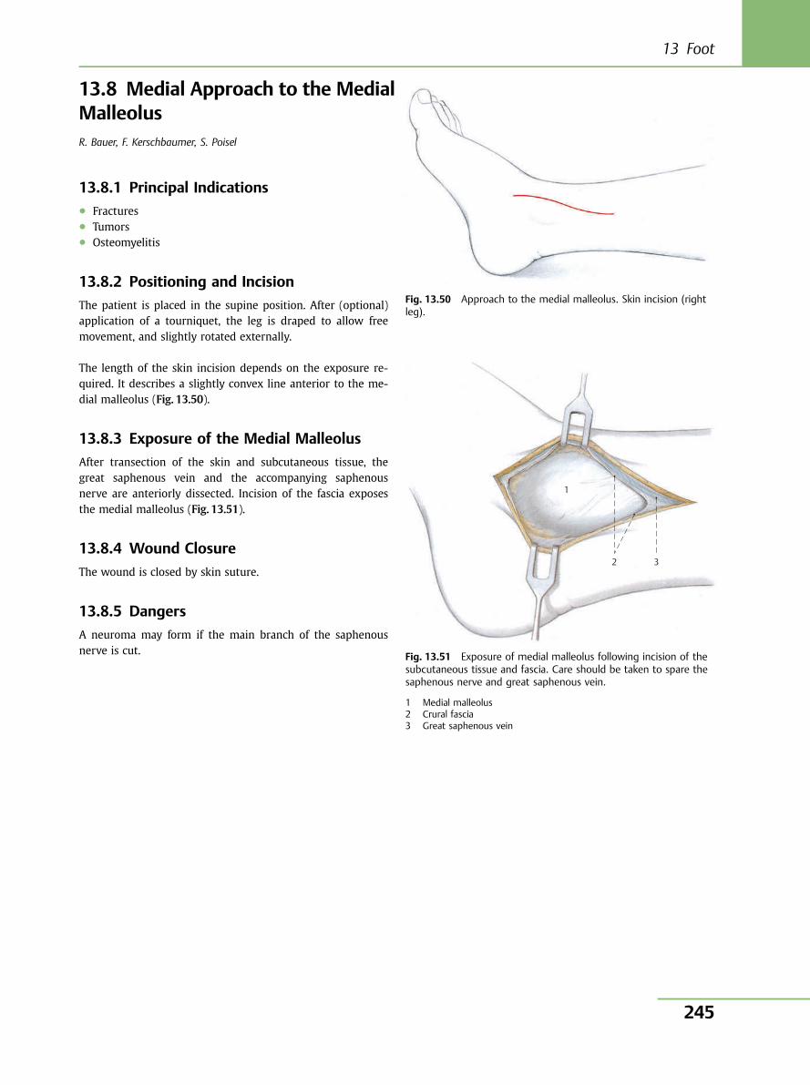
13.8 Medial Approach to the MedialMalleolusR. Bauer, F. Kerschbaumer, S. Poisel
13.8.1 Principal Indications● Fractures● Tumors● Osteomyelitis
13.8.2 Positioning and Incision
The patient is placed in the supine position. After (optional)application of a tourniquet, the leg is draped to allow freemovement, and slightly rotated externally.
The length of the skin incision depends on the exposure re-quired. It describes a slightly convex line anterior to the me-dial malleolus (Fig. 13.50).
13.8.3 Exposure of the Medial Malleolus
After transection of the skin and subcutaneous tissue, thegreat saphenous vein and the accompanying saphenousnerve are anteriorly dissected. Incision of the fascia exposesthe medial malleolus (Fig. 13.51).
13.8.4 Wound Closure
The wound is closed by skin suture.
13.8.5 Dangers
A neuroma may form if the main branch of the saphenousnerve is cut.
Fig. 13.50 Approach to the medial malleolus. Skin incision (rightleg).
1
2 3
Fig. 13.51 Exposure of medial malleolus following incision of thesubcutaneous tissue and fascia. Care should be taken to spare thesaphenous nerve and great saphenous vein.
1 Medial malleolus2 Crural fascia3 Great saphenous vein
13 Foot
245
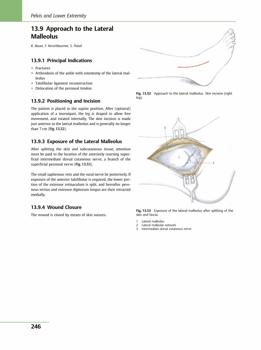
13.9 Approach to the LateralMalleolusR. Bauer, F. Kerschbaumer, S. Poisel
13.9.1 Principal Indications● Fractures● Arthrodesis of the ankle with osteotomy of the lateral mal-
leolus● Talofibular ligament reconstruction● Dislocation of the peroneal tendon
13.9.2 Positioning and Incision
The patient is placed in the supine position. After (optional)application of a tourniquet, the leg is draped to allow freemovement, and rotated internally. The skin incision is madejust anterior to the lateral malleolus and is generally no longerthan 7 cm (Fig. 13.52).
13.9.3 Exposure of the Lateral Malleolus
After splitting the skin and subcutaneous tissue, attentionmust be paid to the location of the anteriorly coursing super-ficial intermediate dorsal cutaneous nerve, a branch of thesuperficial peroneal nerve (Fig. 13.53).
The small saphenous vein and the sural nerve lie posteriorly. Ifexposure of the anterior talofibular is required, the lower por-tion of the extensor retinaculum is split, and hereafter pero-neus tertius and extensor digitorum longus are then retractedmedially.
13.9.4 Wound Closure
The wound is closed by means of skin sutures.
Fig. 13.52 Approach to the lateral malleolus. Skin incision (rightleg).
3
1
2
Fig. 13.53 Exposure of the lateral malleolus after splitting of theskin and fascia.
1 Lateral malleolus2 Lateral malleolar network3 Intermediate dorsal cutaneous nerve
Pelvis and Lower Extremity
246
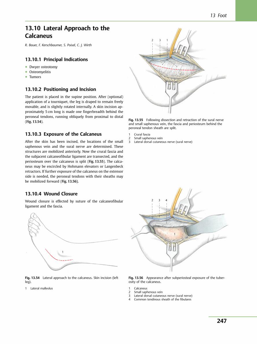
13.10 Lateral Approach to theCalcaneusR. Bauer, F. Kerschbaumer, S. Poisel, C. J. Wirth
13.10.1 Principal Indications● Dwyer osteotomy● Osteomyelitis● Tumors
13.10.2 Positioning and Incision
The patient is placed in the supine position. After (optional)application of a tourniquet, the leg is draped to remain freelymovable, and is slightly rotated internally. A skin incision ap-proximately 5 cm long is made one fingerbreadth behind theperoneal tendons, running obliquely from proximal to distal(Fig. 13.54).
13.10.3 Exposure of the Calcaneus
After the skin has been incised, the locations of the smallsaphenous vein and the sural nerve are determined. Thesestructures are mobilized anteriorly. Now the crural fascia andthe subjacent calcaneofibular ligament are transected, and theperiosteum over the calcaneus is split (Fig. 13.55). The calca-neus may be encircled by Hohmann elevators or Langenbeckretractors. If further exposure of the calcaneus on the extensorside is needed, the peroneal tendons with their sheaths maybe mobilized forward (Fig. 13.56).
13.10.4 Wound Closure
Wound closure is effected by suture of the calcaneofibularligament and the fascia.
1
Fig. 13.54 Lateral approach to the calcaneus. Skin incision (leftleg).
1 Lateral malleolus
1 3 2
Fig. 13.55 Following dissection and retraction of the sural nerveand small saphenous vein, the fascia and periosteum behind theperoneal tendon sheath are split.
1 Crural fascia2 Small saphenous vein3 Lateral dorsal cutaneous nerve (sural nerve)
1
4 3 2
Fig. 13.56 Appearance after subperiosteal exposure of the tuber-osity of the calcaneus.
1 Calcaneus2 Small saphenous vein3 Lateral dorsal cutaneous nerve (sural nerve)4 Common tendinous sheath of the fibulares
13 Foot
247
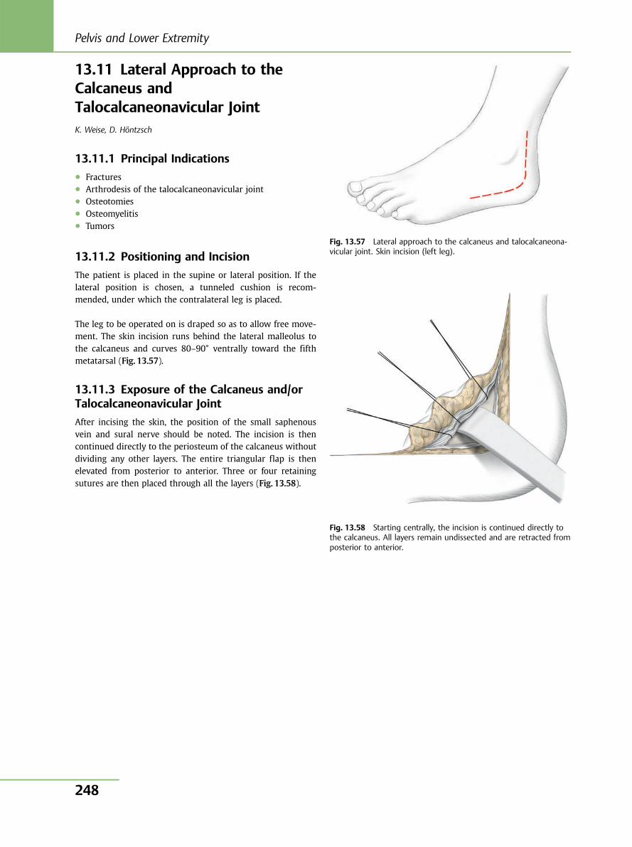
13.11 Lateral Approach to theCalcaneus andTalocalcaneonavicular JointK. Weise, D. Höntzsch
13.11.1 Principal Indications● Fractures● Arthrodesis of the talocalcaneonavicular joint● Osteotomies● Osteomyelitis● Tumors
13.11.2 Positioning and Incision
The patient is placed in the supine or lateral position. If thelateral position is chosen, a tunneled cushion is recom-mended, under which the contralateral leg is placed.
The leg to be operated on is draped so as to allow free move-ment. The skin incision runs behind the lateral malleolus tothe calcaneus and curves 80–90° ventrally toward the fifthmetatarsal (Fig. 13.57).
13.11.3 Exposure of the Calcaneus and/orTalocalcaneonavicular Joint
After incising the skin, the position of the small saphenousvein and sural nerve should be noted. The incision is thencontinued directly to the periosteum of the calcaneus withoutdividing any other layers. The entire triangular flap is thenelevated from posterior to anterior. Three or four retainingsutures are then placed through all the layers (Fig. 13.58).
Fig. 13.57 Lateral approach to the calcaneus and talocalcaneona-vicular joint. Skin incision (left leg).
Fig. 13.58 Starting centrally, the incision is continued directly tothe calcaneus. All layers remain undissected and are retracted fromposterior to anterior.
Pelvis and Lower Extremity
248
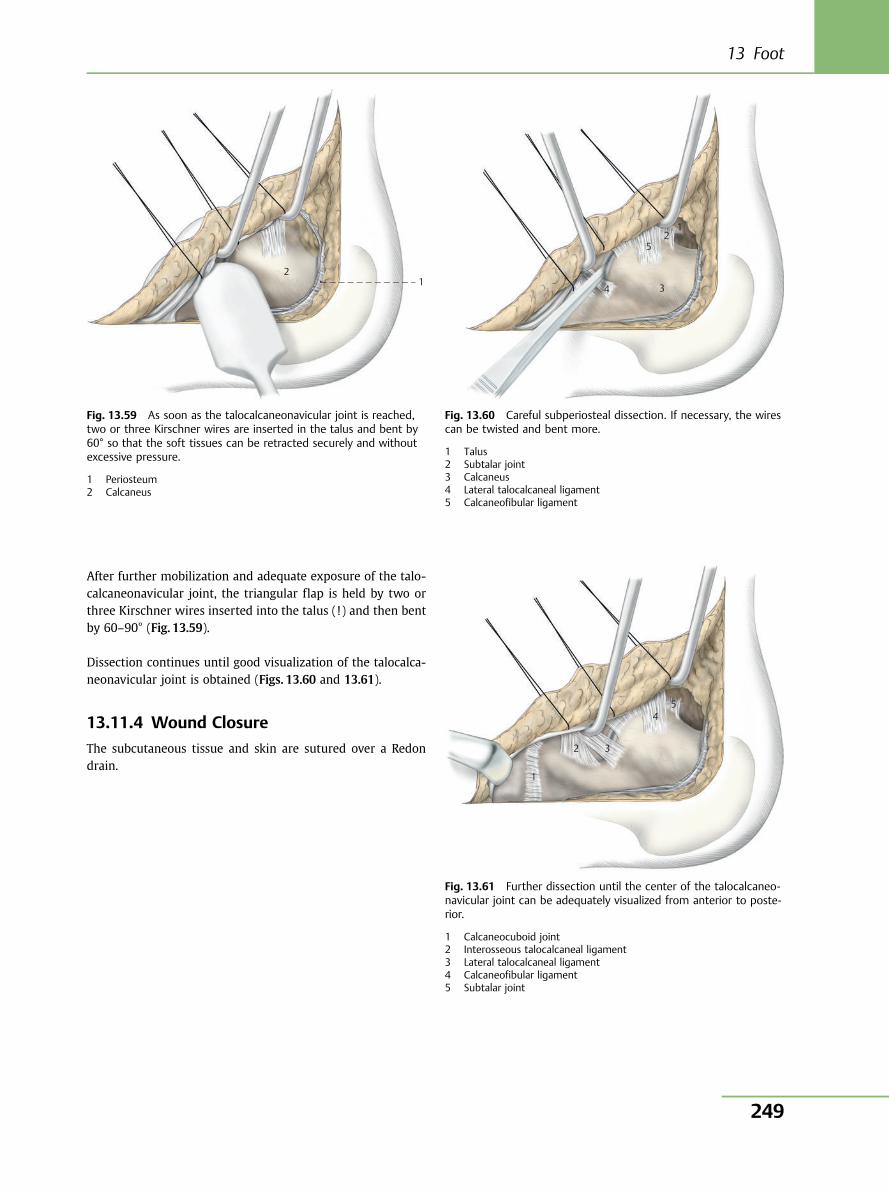
After further mobilization and adequate exposure of the talo-calcaneonavicular joint, the triangular flap is held by two orthree Kirschner wires inserted into the talus (!) and then bentby 60–90° (Fig. 13.59).
Dissection continues until good visualization of the talocalca-neonavicular joint is obtained (Figs. 13.60 and 13.61).
13.11.4 Wound Closure
The subcutaneous tissue and skin are sutured over a Redondrain.
1 2
Fig. 13.59 As soon as the talocalcaneonavicular joint is reached,two or three Kirschner wires are inserted in the talus and bent by60° so that the soft tissues can be retracted securely and withoutexcessive pressure.
1 Periosteum2 Calcaneus
1 2
3
5
4
Fig. 13.60 Careful subperiosteal dissection. If necessary, the wirescan be twisted and bent more.
1 Talus2 Subtalar joint3 Calcaneus4 Lateral talocalcaneal ligament5 Calcaneofibular ligament
1
2 3
45
Fig. 13.61 Further dissection until the center of the talocalcaneo-navicular joint can be adequately visualized from anterior to poste-rior.
1 Calcaneocuboid joint2 Interosseous talocalcaneal ligament3 Lateral talocalcaneal ligament4 Calcaneofibular ligament5 Subtalar joint
13 Foot
249
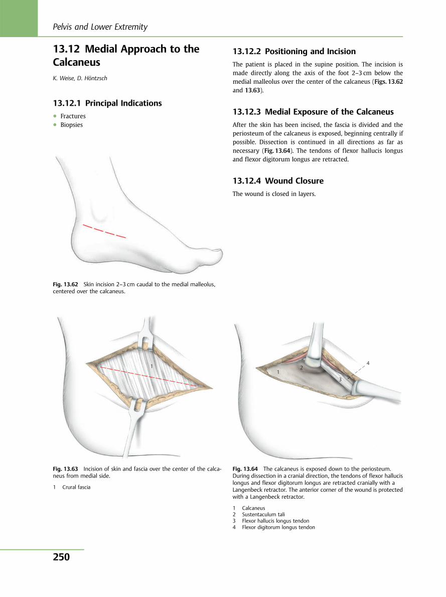
13.12 Medial Approach to theCalcaneusK. Weise, D. Höntzsch
13.12.1 Principal Indications● Fractures● Biopsies
13.12.2 Positioning and Incision
The patient is placed in the supine position. The incision ismade directly along the axis of the foot 2–3 cm below themedial malleolus over the center of the calcaneus (Figs. 13.62and 13.63).
13.12.3 Medial Exposure of the Calcaneus
After the skin has been incised, the fascia is divided and theperiosteum of the calcaneus is exposed, beginning centrally ifpossible. Dissection is continued in all directions as far asnecessary (Fig. 13.64). The tendons of flexor hallucis longusand flexor digitorum longus are retracted.
13.12.4 Wound Closure
The wound is closed in layers.
Fig. 13.62 Skin incision 2–3 cm caudal to the medial malleolus,centered over the calcaneus.
1
Fig. 13.63 Incision of skin and fascia over the center of the calca-neus from medial side.
1 Crural fascia
1 2
3
4
Fig. 13.64 The calcaneus is exposed down to the periosteum.During dissection in a cranial direction, the tendons of flexor hallucislongus and flexor digitorum longus are retracted cranially with aLangenbeck retractor. The anterior corner of the wound is protectedwith a Langenbeck retractor.
1 Calcaneus2 Sustentaculum tali3 Flexor hallucis longus tendon4 Flexor digitorum longus tendon
Pelvis and Lower Extremity
250
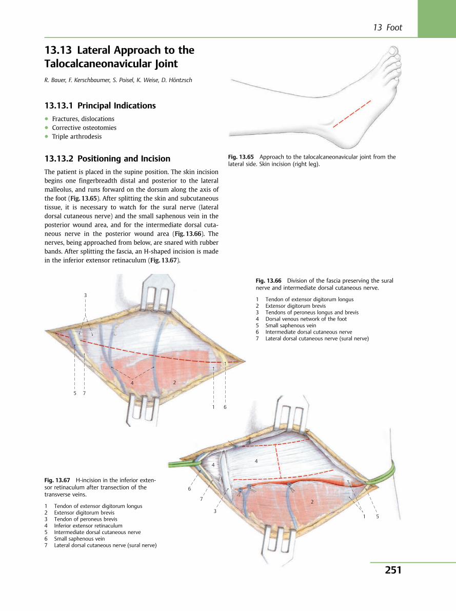
13.13 Lateral Approach to theTalocalcaneonavicular JointR. Bauer, F. Kerschbaumer, S. Poisel, K. Weise, D. Höntzsch
13.13.1 Principal Indications● Fractures, dislocations● Corrective osteotomies● Triple arthrodesis
13.13.2 Positioning and Incision
The patient is placed in the supine position. The skin incisionbegins one fingerbreadth distal and posterior to the lateralmalleolus, and runs forward on the dorsum along the axis ofthe foot (Fig. 13.65). After splitting the skin and subcutaneoustissue, it is necessary to watch for the sural nerve (lateraldorsal cutaneous nerve) and the small saphenous vein in theposterior wound area, and for the intermediate dorsal cuta-neous nerve in the posterior wound area (Fig. 13.66). Thenerves, being approached from below, are snared with rubberbands. After splitting the fascia, an H-shaped incision is madein the inferior extensor retinaculum (Fig. 13.67).
Fig. 13.65 Approach to the talocalcaneonavicular joint from thelateral side. Skin incision (right leg).
Fig. 13.66 Division of the fascia preserving the suralnerve and intermediate dorsal cutaneous nerve.
1 Tendon of extensor digitorum longus2 Extensor digitorum brevis3 Tendons of peroneus longus and brevis4 Dorsal venous network of the foot5 Small saphenous vein6 Intermediate dorsal cutaneous nerve7 Lateral dorsal cutaneous nerve (sural nerve)
Fig. 13.67 H-incision in the inferior exten-sor retinaculum after transection of thetransverse veins.
1 Tendon of extensor digitorum longus2 Extensor digitorum brevis3 Tendon of peroneus brevis4 Inferior extensor retinaculum5 Intermediate dorsal cutaneous nerve6 Small saphenous vein7 Lateral dorsal cutaneous nerve (sural nerve)
6
4 4
2
1 5 3
7
3
5 7
2 4
1 6
13 Foot
251
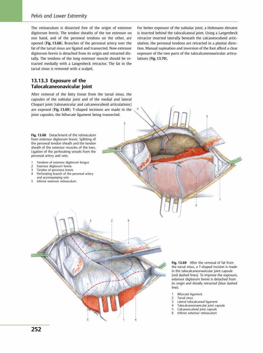
3 2 6
5 1 4
3
5
1
2
4
The retinaculum is dissected free of the origin of extensordigitorum brevis. The tendon sheaths of the toe extensor onone hand, and of the peroneal tendons on the other, areopened (Fig. 13.68). Branches of the peroneal artery over thefat of the tarsal sinus are ligated and transected. Now extensordigitorum brevis is detached from its origin and retracted dis-tally. The tendons of the long extensor muscle should be re-tracted medially with a Langenbeck retractor. The fat in thetarsal sinus is removed with a scalpel.
13.13.3 Exposure of theTalocalcaneonavicular Joint
After removal of the fatty tissue from the tarsal sinus, thecapsules of the subtalar joint and of the medial and lateralChopart joint (talonavicular and calcaneocuboid articulations)are exposed (Fig. 13.69). T-shaped incisions are made in thejoint capsules, the bifurcate ligament being transected.
For better exposure of the subtalar joint, a Hohmann elevatoris inserted behind the talocalcaneal joint. Using a Langenbeckretractor inserted laterally beneath the calcaneocuboid artic-ulation, the peroneal tendons are retracted in a plantar direc-tion. Manual supination and inversion of the foot afford a clearexposure of the two parts of the talocalcaneonavicular articu-lations (Fig. 13.70).
Fig. 13.68 Detachment of the retinaculumfrom extensor digitorum brevis. Splitting ofthe peroneal tendon sheath and the tendonsheath of the extensor muscles of the toes.Ligation of the perforating vessels from theperoneal artery and vein.
1 Tendons of extensor digitorum longus2 Extensor digitorum brevis3 Tendon of peroneus brevis4 Perforating branch of the peroneal artery
and accompanying vein5 Inferior extensor retinaculum
Fig. 13.69 After the removal of fat fromthe tarsal sinus, a T-shaped incision is madein the talocalcaneonavicular joint capsule(red dashed lines). To improve the exposure,extensor digitorum brevis is detached fromits origin and distally retracted (blue dashedline).
1 Bifurcate ligament2 Tarsal sinus3 Lateral talocalcaneal ligament4 Talocalcaneonavicular joint capsule5 Calcaneocuboid joint capsule6 Inferior extensor retinaculum
Pelvis and Lower Extremity
252
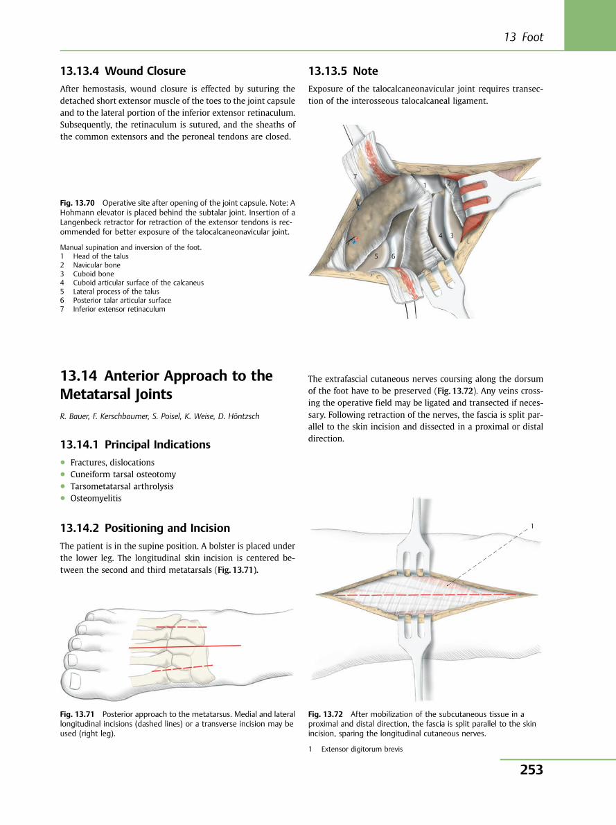
13.13.4 Wound Closure
After hemostasis, wound closure is effected by suturing thedetached short extensor muscle of the toes to the joint capsuleand to the lateral portion of the inferior extensor retinaculum.Subsequently, the retinaculum is sutured, and the sheaths ofthe common extensors and the peroneal tendons are closed.
13.13.5 Note
Exposure of the talocalcaneonavicular joint requires transec-tion of the interosseous talocalcaneal ligament.
1
71 2
34
65
Fig. 13.70 Operative site after opening of the joint capsule. Note: AHohmann elevator is placed behind the subtalar joint. Insertion of aLangenbeck retractor for retraction of the extensor tendons is rec-ommended for better exposure of the talocalcaneonavicular joint.
Manual supination and inversion of the foot.1 Head of the talus2 Navicular bone3 Cuboid bone4 Cuboid articular surface of the calcaneus5 Lateral process of the talus6 Posterior talar articular surface7 Inferior extensor retinaculum
Fig. 13.71 Posterior approach to the metatarsus. Medial and laterallongitudinal incisions (dashed lines) or a transverse incision may beused (right leg).
Fig. 13.72 After mobilization of the subcutaneous tissue in aproximal and distal direction, the fascia is split parallel to the skinincision, sparing the longitudinal cutaneous nerves.
1 Extensor digitorum brevis
13.14 Anterior Approach to theMetatarsal JointsR. Bauer, F. Kerschbaumer, S. Poisel, K. Weise, D. Höntzsch
13.14.1 Principal Indications● Fractures, dislocations● Cuneiform tarsal osteotomy● Tarsometatarsal arthrolysis● Osteomyelitis
13.14.2 Positioning and Incision
The patient is in the supine position. A bolster is placed underthe lower leg. The longitudinal skin incision is centered be-tween the second and third metatarsals (Fig. 13.71).
The extrafascial cutaneous nerves coursing along the dorsumof the foot have to be preserved (Fig. 13.72). Any veins cross-ing the operative field may be ligated and transected if neces-sary. Following retraction of the nerves, the fascia is split par-allel to the skin incision and dissected in a proximal or distaldirection.
13 Foot
253
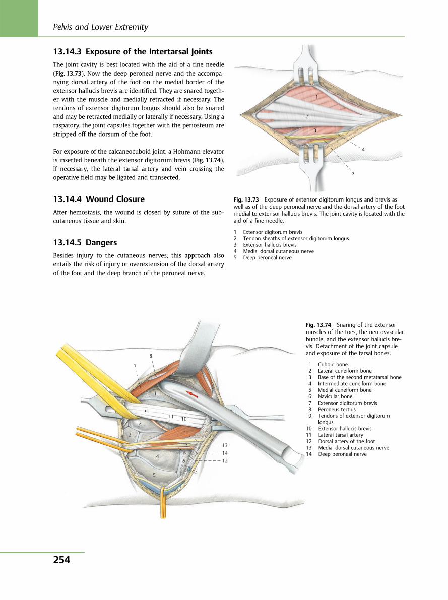
13.14.3 Exposure of the Intertarsal Joints
The joint cavity is best located with the aid of a fine needle(Fig. 13.73). Now the deep peroneal nerve and the accompa-nying dorsal artery of the foot on the medial border of theextensor hallucis brevis are identified. They are snared togeth-er with the muscle and medially retracted if necessary. Thetendons of extensor digitorum longus should also be snaredand may be retracted medially or laterally if necessary. Using araspatory, the joint capsules together with the periosteum arestripped off the dorsum of the foot.
For exposure of the calcaneocuboid joint, a Hohmann elevatoris inserted beneath the extensor digitorum brevis (Fig. 13.74).If necessary, the lateral tarsal artery and vein crossing theoperative field may be ligated and transected.
13.14.4 Wound Closure
After hemostasis, the wound is closed by suture of the sub-cutaneous tissue and skin.
13.14.5 Dangers
Besides injury to the cutaneous nerves, this approach alsoentails the risk of injury or overextension of the dorsal arteryof the foot and the deep branch of the peroneal nerve.
1
2
3
4
5
7
8
9
2
3
4
5
6
13 14 12
11 10
1
Fig. 13.73 Exposure of extensor digitorum longus and brevis aswell as of the deep peroneal nerve and the dorsal artery of the footmedial to extensor hallucis brevis. The joint cavity is located with theaid of a fine needle.
1 Extensor digitorum brevis2 Tendon sheaths of extensor digitorum longus3 Extensor hallucis brevis4 Medial dorsal cutaneous nerve5 Deep peroneal nerve
Fig. 13.74 Snaring of the extensormuscles of the toes, the neurovascularbundle, and the extensor hallucis bre-vis. Detachment of the joint capsuleand exposure of the tarsal bones.
1 Cuboid bone2 Lateral cuneiform bone3 Base of the second metatarsal bone4 Intermediate cuneiform bone5 Medial cuneiform bone6 Navicular bone7 Extensor digitorum brevis8 Peroneus tertius9 Tendons of extensor digitorum
longus10 Extensor hallucis brevis11 Lateral tarsal artery12 Dorsal artery of the foot13 Medial dorsal cutaneous nerve14 Deep peroneal nerve
Pelvis and Lower Extremity
254
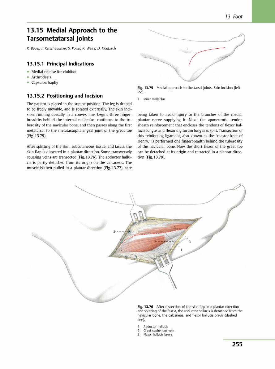
13.15 Medial Approach to theTarsometatarsal JointsR. Bauer, F. Kerschbaumer, S. Poisel, K. Weise, D. Höntzsch
13.15.1 Principal Indications● Medial release for clubfoot● Arthrodesis● Capsulorrhaphy
13.15.2 Positioning and Incision
The patient is placed in the supine position. The leg is drapedto be freely movable, and is rotated externally. The skin inci-sion, running dorsally in a convex line, begins three finger-breadths behind the internal malleolus, continues to the tu-berosity of the navicular bone, and then passes along the firstmetatarsal to the metatarsophalangeal joint of the great toe(Fig. 13.75).
After splitting of the skin, subcutaneous tissue, and fascia, theskin flap is dissected in a plantar direction. Some transverselycoursing veins are transected (Fig. 13.76). The abductor hallu-cis is partly detached from its origin on the calcaneus. Themuscle is then pulled in a plantar direction (Fig. 13.77), care
being taken to avoid injury to the branches of the medialplantar nerve supplying it. Next, the aponeurotic tendonsheath reinforcement that encloses the tendons of flexor hal-lucis longus and flexor digitorum longus is split. Transection ofthis reinforcing ligament, also known as the “master knot ofHenry,” is performed one fingerbreadth behind the tuberosityof the navicular bone. Now the short flexor of the great toecan be detached at its origin and retracted in a plantar direc-tion (Fig. 13.78).
1
Fig. 13.75 Medial approach to the tarsal joints. Skin incision (leftleg).
1 Inner malleolus
2
1
3
Fig. 13.76 After dissection of the skin flap in a plantar directionand splitting of the fascia, the abductor hallucis is detached from thenavicular bone, the calcaneus, and flexor hallucis brevis (dashedline).
1 Abductor hallucis2 Great saphenous vein3 Flexor hallucis brevis
13 Foot
255
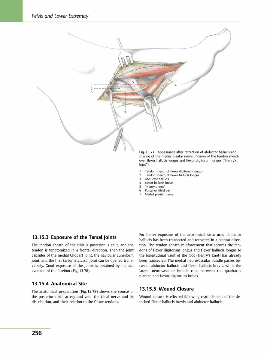
13.15.3 Exposure of the Tarsal Joints
The tendon sheath of the tibialis posterior is split, and thetendon is tenotomized in a frontal direction. Then the jointcapsules of the medial Chopart joint, the navicular cuneiformjoint, and the first tarsometatarsal joint can be opened trans-versely. Good exposure of the joints is obtained by manualeversion of the forefoot (Fig. 13.78).
13.15.4 Anatomical Site
The anatomical preparation (Fig. 13.79) shows the course ofthe posterior tibial artery and vein, the tibial nerve and itsdistribution, and their relation to the flexor tendons.
For better exposure of the anatomical structures, abductorhallucis has been transected and retracted in a plantar direc-tion. The tendon sheath reinforcement that secures the ten-dons of flexor digitorum longus and flexor hallucis longus tothe longitudinal vault of the foot (Henry’s knot) has alreadybeen transected. The medial neurovascular bundle passes be-tween abductor hallucis and flexor hallucis brevis, while thelateral neurovascular bundle runs between the quadratusplantae and flexor digitorum brevis.
13.15.5 Wound Closure
Wound closure is effected following reattachment of the de-tached flexor hallucis brevis and abductor hallucis.
1 2 6
7
5
3
4
Fig. 13.77 Appearance after retraction of abductor hallucis andsnaring of the medial plantar nerve. Incision of the tendon sheathover flexor hallucis longus and flexor digitorum longus (“Henry’sknot”).
1 Tendon sheath of flexor digitorum longus2 Tendon sheath of flexor hallucis longus3 Abductor hallucis4 Flexor hallucis brevis5 “Henry’s knot”6 Posterior tibial vein7 Medial plantar nerve
Pelvis and Lower Extremity
256
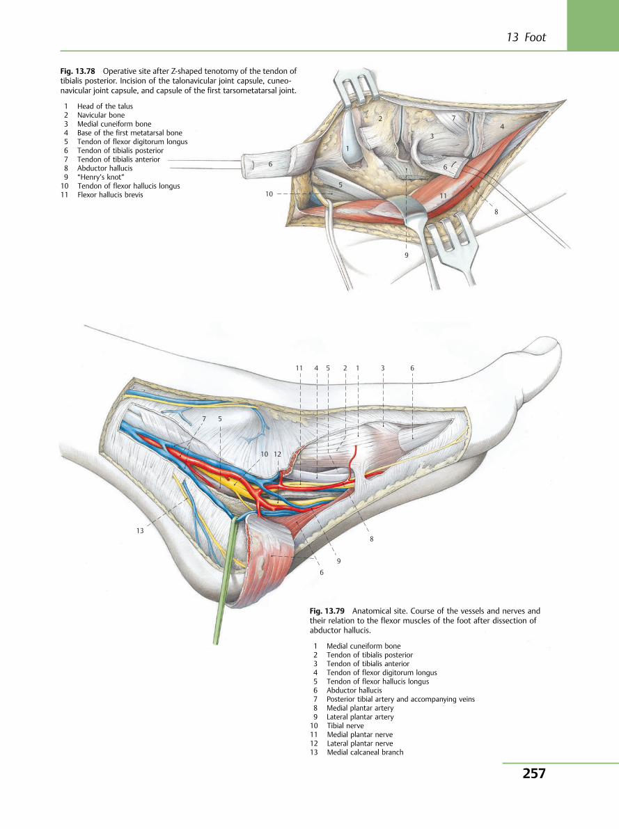
10
6
1
2
3
7 4
6
11
8
9
5
Fig. 13.78 Operative site after Z-shaped tenotomy of the tendon oftibialis posterior. Incision of the talonavicular joint capsule, cuneo-navicular joint capsule, and capsule of the first tarsometatarsal joint.
1 Head of the talus2 Navicular bone3 Medial cuneiform bone4 Base of the first metatarsal bone5 Tendon of flexor digitorum longus6 Tendon of tibialis posterior7 Tendon of tibialis anterior8 Abductor hallucis9 “Henry’s knot”10 Tendon of flexor hallucis longus11 Flexor hallucis brevis
13
7 5
10 12
8
9
6
11 4 5 2 1 3 6
Fig. 13.79 Anatomical site. Course of the vessels and nerves andtheir relation to the flexor muscles of the foot after dissection ofabductor hallucis.
1 Medial cuneiform bone2 Tendon of tibialis posterior3 Tendon of tibialis anterior4 Tendon of flexor digitorum longus5 Tendon of flexor hallucis longus6 Abductor hallucis7 Posterior tibial artery and accompanying veins8 Medial plantar artery9 Lateral plantar artery10 Tibial nerve11 Medial plantar nerve12 Lateral plantar nerve13 Medial calcaneal branch
13 Foot
257
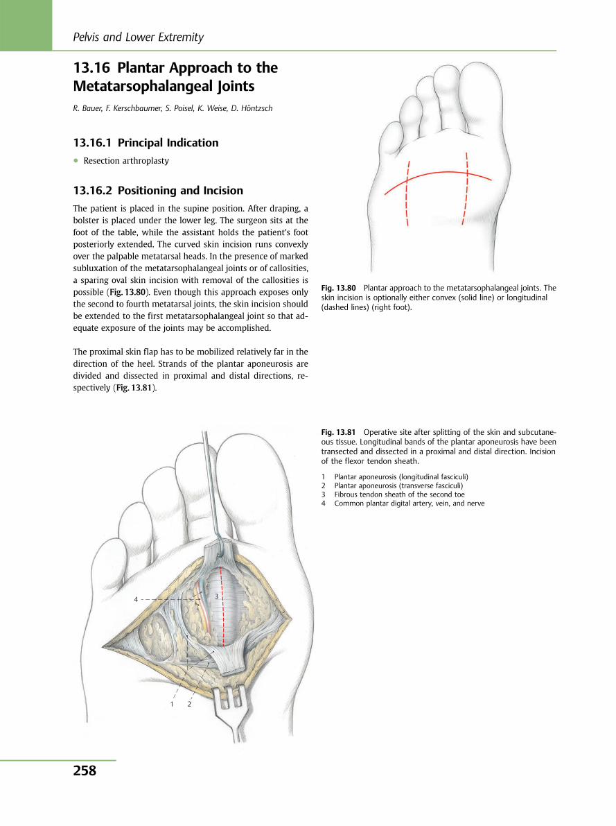
13.16 Plantar Approach to theMetatarsophalangeal JointsR. Bauer, F. Kerschbaumer, S. Poisel, K. Weise, D. Höntzsch
13.16.1 Principal Indication● Resection arthroplasty
13.16.2 Positioning and Incision
The patient is placed in the supine position. After draping, abolster is placed under the lower leg. The surgeon sits at thefoot of the table, while the assistant holds the patient’s footposteriorly extended. The curved skin incision runs convexlyover the palpable metatarsal heads. In the presence of markedsubluxation of the metatarsophalangeal joints or of callosities,a sparing oval skin incision with removal of the callosities ispossible (Fig. 13.80). Even though this approach exposes onlythe second to fourth metatarsal joints, the skin incision shouldbe extended to the first metatarsophalangeal joint so that ad-equate exposure of the joints may be accomplished.
The proximal skin flap has to be mobilized relatively far in thedirection of the heel. Strands of the plantar aponeurosis aredivided and dissected in proximal and distal directions, re-spectively (Fig. 13.81).
Fig. 13.80 Plantar approach to the metatarsophalangeal joints. Theskin incision is optionally either convex (solid line) or longitudinal(dashed lines) (right foot).
4
1
3
2
Fig. 13.81 Operative site after splitting of the skin and subcutane-ous tissue. Longitudinal bands of the plantar aponeurosis have beentransected and dissected in a proximal and distal direction. Incisionof the flexor tendon sheath.
1 Plantar aponeurosis (longitudinal fasciculi)2 Plantar aponeurosis (transverse fasciculi)3 Fibrous tendon sheath of the second toe4 Common plantar digital artery, vein, and nerve
Pelvis and Lower Extremity
258
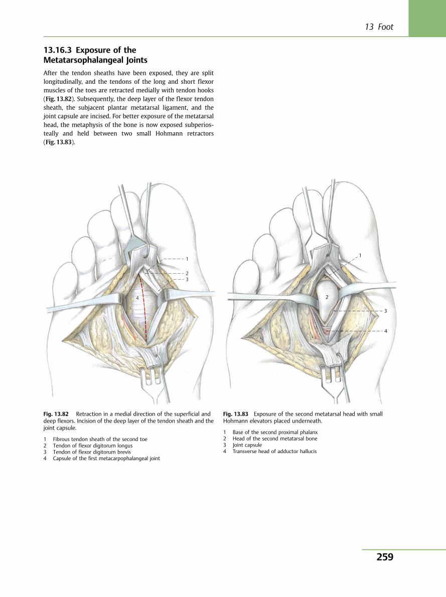
13.16.3 Exposure of theMetatarsophalangeal Joints
After the tendon sheaths have been exposed, they are splitlongitudinally, and the tendons of the long and short flexormuscles of the toes are retracted medially with tendon hooks(Fig. 13.82). Subsequently, the deep layer of the flexor tendonsheath, the subjacent plantar metatarsal ligament, and thejoint capsule are incised. For better exposure of the metatarsalhead, the metaphysis of the bone is now exposed subperios-teally and held between two small Hohmann retractors(Fig. 13.83).
1
2 3
4
Fig. 13.82 Retraction in a medial direction of the superficial anddeep flexors. Incision of the deep layer of the tendon sheath and thejoint capsule.
1 Fibrous tendon sheath of the second toe2 Tendon of flexor digitorum longus3 Tendon of flexor digitorum brevis4 Capsule of the first metacarpophalangeal joint
1
3
4
2
Fig. 13.83 Exposure of the second metatarsal head with smallHohmann elevators placed underneath.
1 Base of the second proximal phalanx2 Head of the second metatarsal bone3 Joint capsule4 Transverse head of adductor hallucis
13 Foot
259
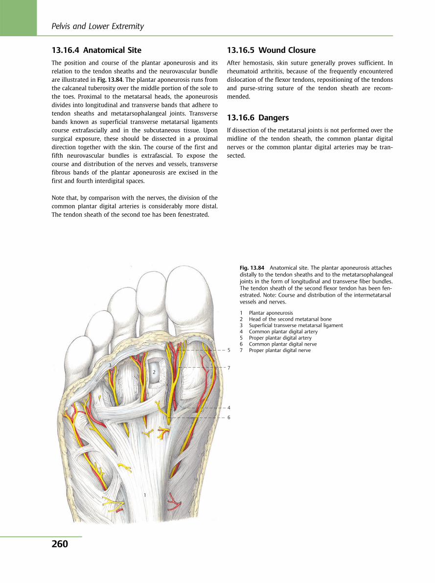
13.16.4 Anatomical Site
The position and course of the plantar aponeurosis and itsrelation to the tendon sheaths and the neurovascular bundleare illustrated in Fig. 13.84. The plantar aponeurosis runs fromthe calcaneal tuberosity over the middle portion of the sole tothe toes. Proximal to the metatarsal heads, the aponeurosisdivides into longitudinal and transverse bands that adhere totendon sheaths and metatarsophalangeal joints. Transversebands known as superficial transverse metatarsal ligamentscourse extrafascially and in the subcutaneous tissue. Uponsurgical exposure, these should be dissected in a proximaldirection together with the skin. The course of the first andfifth neurovascular bundles is extrafascial. To expose thecourse and distribution of the nerves and vessels, transversefibrous bands of the plantar aponeurosis are excised in thefirst and fourth interdigital spaces.
Note that, by comparison with the nerves, the division of thecommon plantar digital arteries is considerably more distal.The tendon sheath of the second toe has been fenestrated.
13.16.5 Wound Closure
After hemostasis, skin suture generally proves sufficient. Inrheumatoid arthritis, because of the frequently encountereddislocation of the flexor tendons, repositioning of the tendonsand purse-string suture of the tendon sheath are recom-mended.
13.16.6 Dangers
If dissection of the metatarsal joints is not performed over themidline of the tendon sheath, the common plantar digitalnerves or the common plantar digital arteries may be tran-sected.
1
2 3
5
7
4
6
Fig. 13.84 Anatomical site. The plantar aponeurosis attachesdistally to the tendon sheaths and to the metatarsophalangealjoints in the form of longitudinal and transverse fiber bundles.The tendon sheath of the second flexor tendon has been fen-estrated. Note: Course and distribution of the intermetatarsalvessels and nerves.
1 Plantar aponeurosis2 Head of the second metatarsal bone3 Superficial transverse metatarsal ligament4 Common plantar digital artery5 Proper plantar digital artery6 Common plantar digital nerve7 Proper plantar digital nerve
Pelvis and Lower Extremity
260
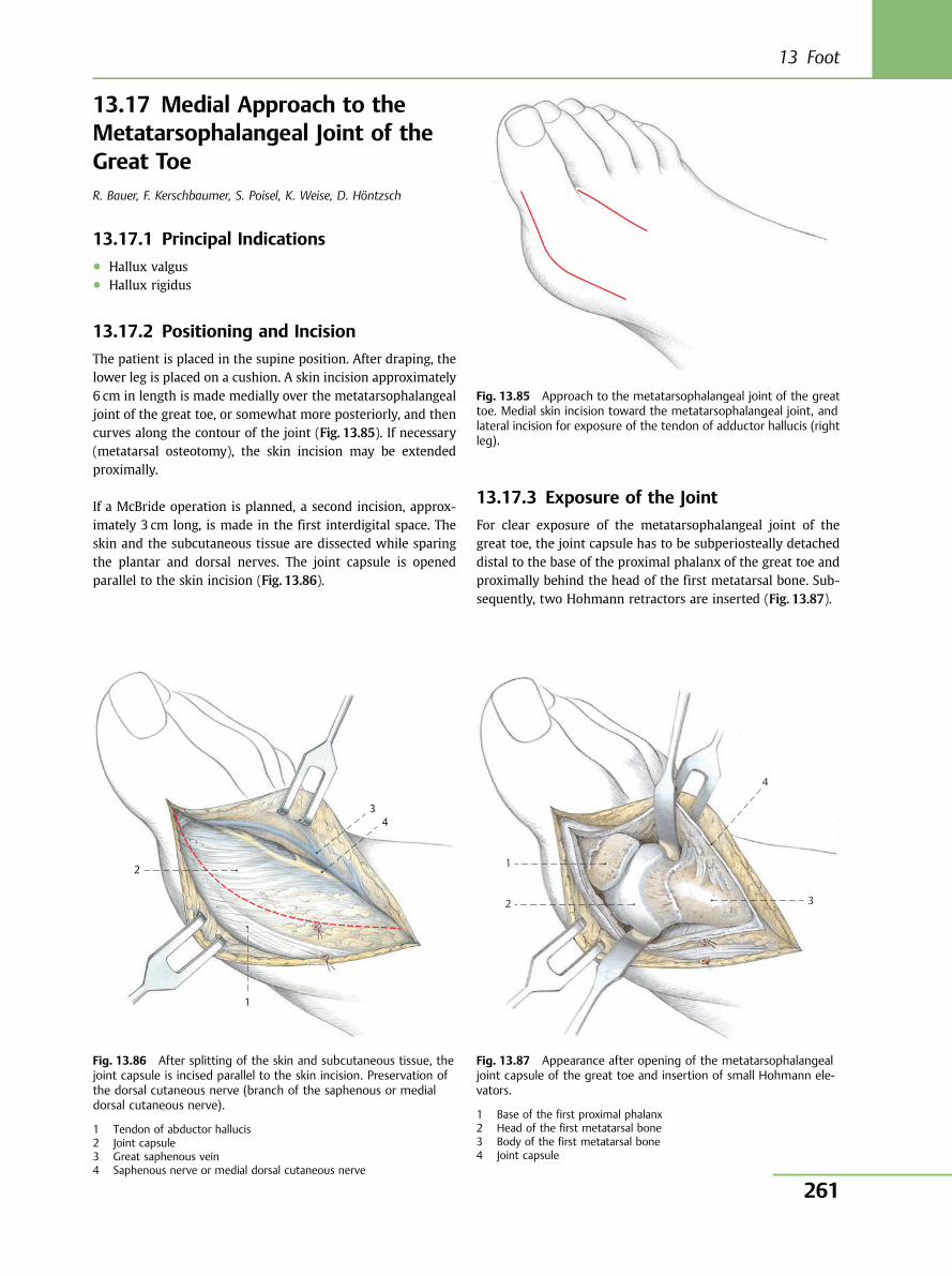
13.17 Medial Approach to theMetatarsophalangeal Joint of theGreat ToeR. Bauer, F. Kerschbaumer, S. Poisel, K. Weise, D. Höntzsch
13.17.1 Principal Indications● Hallux valgus● Hallux rigidus
13.17.2 Positioning and Incision
The patient is placed in the supine position. After draping, thelower leg is placed on a cushion. A skin incision approximately6 cm in length is made medially over the metatarsophalangealjoint of the great toe, or somewhat more posteriorly, and thencurves along the contour of the joint (Fig. 13.85). If necessary(metatarsal osteotomy), the skin incision may be extendedproximally.
If a McBride operation is planned, a second incision, approx-imately 3 cm long, is made in the first interdigital space. Theskin and the subcutaneous tissue are dissected while sparingthe plantar and dorsal nerves. The joint capsule is openedparallel to the skin incision (Fig. 13.86).
13.17.3 Exposure of the Joint
For clear exposure of the metatarsophalangeal joint of thegreat toe, the joint capsule has to be subperiosteally detacheddistal to the base of the proximal phalanx of the great toe andproximally behind the head of the first metatarsal bone. Sub-sequently, two Hohmann retractors are inserted (Fig. 13.87).
Fig. 13.85 Approach to the metatarsophalangeal joint of the greattoe. Medial skin incision toward the metatarsophalangeal joint, andlateral incision for exposure of the tendon of adductor hallucis (rightleg).
2
1
34
Fig. 13.86 After splitting of the skin and subcutaneous tissue, thejoint capsule is incised parallel to the skin incision. Preservation ofthe dorsal cutaneous nerve (branch of the saphenous or medialdorsal cutaneous nerve).
1 Tendon of abductor hallucis2 Joint capsule3 Great saphenous vein4 Saphenous nerve or medial dorsal cutaneous nerve
1
2 3
4
Fig. 13.87 Appearance after opening of the metatarsophalangealjoint capsule of the great toe and insertion of small Hohmann ele-vators.
1 Base of the first proximal phalanx2 Head of the first metatarsal bone3 Body of the first metatarsal bone4 Joint capsule
13 Foot
261
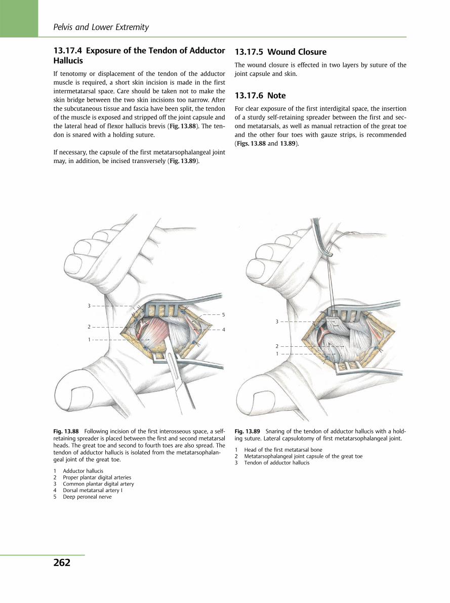
13.17.4 Exposure of the Tendon of AdductorHallucis
If tenotomy or displacement of the tendon of the adductormuscle is required, a short skin incision is made in the firstintermetatarsal space. Care should be taken not to make theskin bridge between the two skin incisions too narrow. Afterthe subcutaneous tissue and fascia have been split, the tendonof the muscle is exposed and stripped off the joint capsule andthe lateral head of flexor hallucis brevis (Fig. 13.88). The ten-don is snared with a holding suture.
If necessary, the capsule of the first metatarsophalangeal jointmay, in addition, be incised transversely (Fig. 13.89).
13.17.5 Wound Closure
The wound closure is effected in two layers by suture of thejoint capsule and skin.
13.17.6 Note
For clear exposure of the first interdigital space, the insertionof a sturdy self-retaining spreader between the first and sec-ond metatarsals, as well as manual retraction of the great toeand the other four toes with gauze strips, is recommended(Figs. 13.88 and 13.89).
1
2
3
5
4
Fig. 13.88 Following incision of the first interosseous space, a self-retaining spreader is placed between the first and second metatarsalheads. The great toe and second to fourth toes are also spread. Thetendon of adductor hallucis is isolated from the metatarsophalan-geal joint of the great toe.
1 Adductor hallucis2 Proper plantar digital arteries3 Common plantar digital artery4 Dorsal metatarsal artery I5 Deep peroneal nerve
1 2
3
Fig. 13.89 Snaring of the tendon of adductor hallucis with a hold-ing suture. Lateral capsulotomy of first metatarsophalangeal joint.
1 Head of the first metatarsal bone2 Metatarsophalangeal joint capsule of the great toe3 Tendon of adductor hallucis
Pelvis and Lower Extremity
262
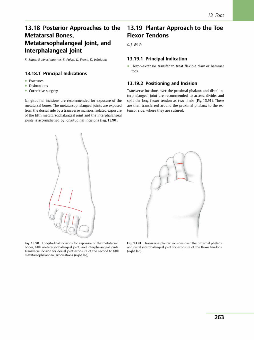
13.18 Posterior Approaches to theMetatarsal Bones,Metatarsophalangeal Joint, andInterphalangeal JointR. Bauer, F. Kerschbaumer, S. Poisel, K. Weise, D. Höntzsch
13.18.1 Principal Indications● Fractures● Dislocations● Corrective surgery
Longitudinal incisions are recommended for exposure of themetatarsal bones. The metatarsophalangeal joints are exposedfrom the dorsal side by a transverse incision. Isolated exposureof the fifth metatarsophalangeal joint and the interphalangealjoints is accomplished by longitudinal incisions (Fig. 13.90).
13.19 Plantar Approach to the ToeFlexor TendonsC. J. Wirth
13.19.1 Principal Indication● Flexor–extensor transfer to treat flexible claw or hammer
toes
13.19.2 Positioning and Incision
Transverse incisions over the proximal phalanx and distal in-terphalangeal joint are recommended to access, divide, andsplit the long flexor tendon as two limbs (Fig. 13.91). Theseare then transferred around the proximal phalanx to the ex-tensor side, where they are sutured.
Fig. 13.90 Longitudinal incisions for exposure of the metatarsalbones, fifth metatarsophalangeal joint, and interphalangeal joints.Transverse incision for dorsal joint exposure of the second to fifthmetatarsophalangeal articulations (right leg).
Fig. 13.91 Transverse plantar incisions over the proximal phalanxand distal interphalangeal joint for exposure of the flexor tendons(right leg).
13 Foot
263
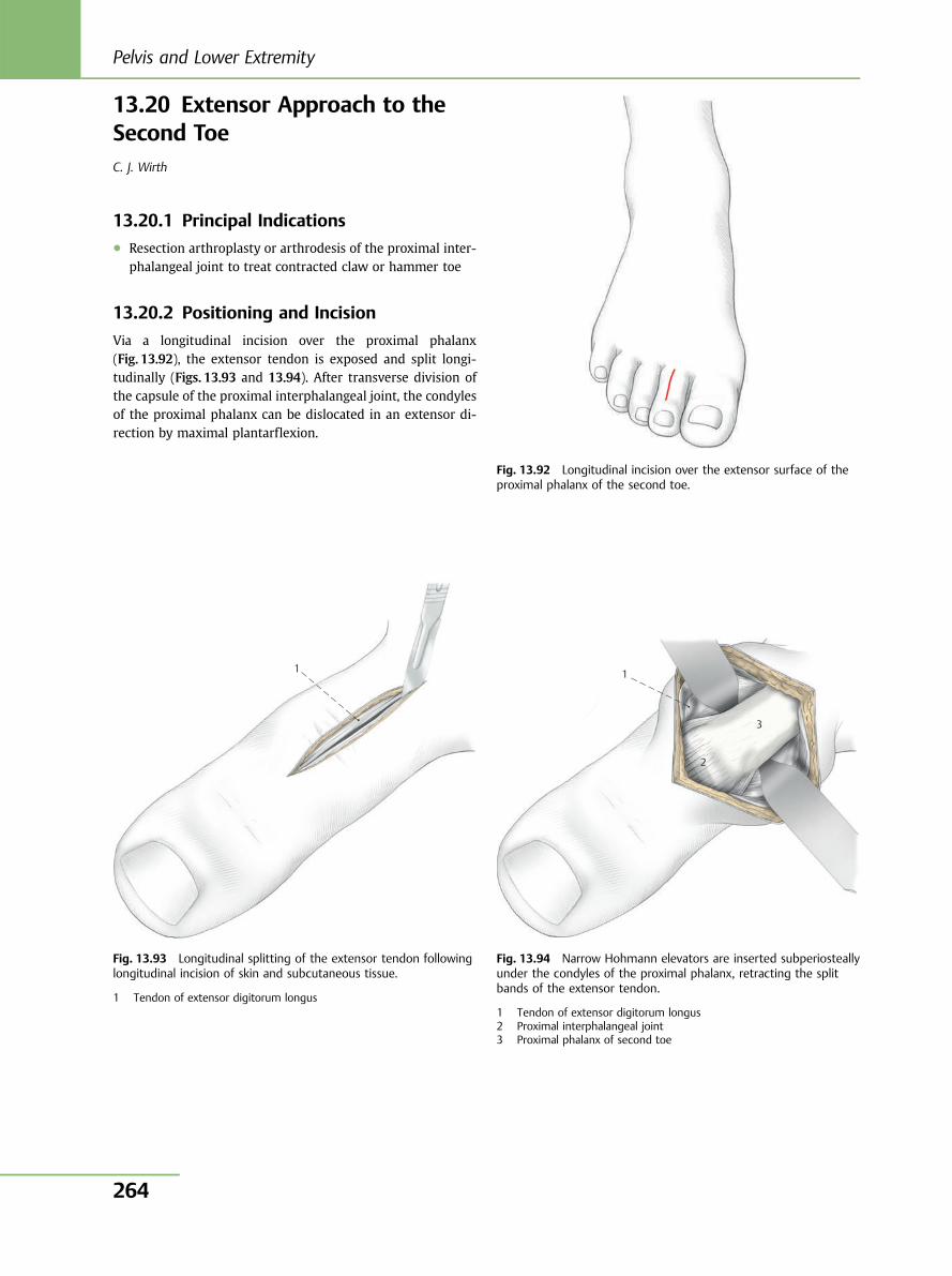
13.20 Extensor Approach to theSecond ToeC. J. Wirth
13.20.1 Principal Indications● Resection arthroplasty or arthrodesis of the proximal inter-
phalangeal joint to treat contracted claw or hammer toe
13.20.2 Positioning and Incision
Via a longitudinal incision over the proximal phalanx(Fig. 13.92), the extensor tendon is exposed and split longi-tudinally (Figs. 13.93 and 13.94). After transverse division ofthe capsule of the proximal interphalangeal joint, the condylesof the proximal phalanx can be dislocated in an extensor di-rection by maximal plantarflexion.
Fig. 13.92 Longitudinal incision over the extensor surface of theproximal phalanx of the second toe.
1
Fig. 13.93 Longitudinal splitting of the extensor tendon followinglongitudinal incision of skin and subcutaneous tissue.
1 Tendon of extensor digitorum longus
1
2
3
Fig. 13.94 Narrow Hohmann elevators are inserted subperiosteallyunder the condyles of the proximal phalanx, retracting the splitbands of the extensor tendon.
1 Tendon of extensor digitorum longus2 Proximal interphalangeal joint3 Proximal phalanx of second toe
Pelvis and Lower Extremity
264
Further Reading: Pelvis and Lower Limb[1] Anson BJ, McVay CB. Surgical Anatomy. Vol 1. Philadelphia:
Saunders; 1971[2] Banks SW, Laufmann H. An Atlas of Surgical Exposures of the
Extremities. Philadelphia: Saunders; 1968[3] Bauer R, Kerschbaumer F, Poisel S, Oberthaler W. The transglu-
teal approach to the hip joint. Arch Orthop Trauma Surg 1979;95(1–2):47–49
[4] Berger RA, Duwelius PJ. The two-incision minimally invasivetotal hip arthroplasty: technique and results. Orthop Clin NorthAm 2004;35(2):163–172
[5] Bertin KC, Röttinger H. Anterolateral mini-incision hip replace-ment surgery: a modified Watson-Jones approach. Clin OrthopRelat Res 2004;429(429):248–255
[6] Bonnaire F, Muller B. Mediale Schenkelhalsfraktur im Erwachse-nenalter und Osteosynthese mit der dynamischen Hüftschraube(DHS). Oper Orthop Traumatol 2001;13:121–134
[7] Cosentino R. Atlas of Anatomy and Surgical Approaches in Or-thopaedic Surgery; vol 2. Springfield, IL: Thomas; 1973
[8] Engh GA, Holt BT, Parks NL. A midvastus muscle-splitting ap-proach for total knee arthroplasty. J Arthroplasty 1997;12(3):322–331
[9] Engh GA, Parks NL. Surgical technique of the midvastus arthrot-omy. Clin Orthop Relat Res 1998; (351):270–274
[10] Fahey JJ. Surgical approaches to bones and joints. Surg Clin NorthAm 1949;29(1):65–76
[11] Ganz R, Gill TJ, Gautier E, Ganz K, Krügel N, Berlemann U. Surgicaldislocation of the adult hip: a technique with full access to thefemoral head and acetabulum without the risk of avascular ne-crosis. J Bone Joint Surg Br 2001;83(8):1119–1124
[12] Garden RS. The structure and function of the proximal end of thefemur. J Bone Joint Surg 1991;43:576
[13] Gautier E, Ganz K, Krügel N, Gill T, Ganz R. Anatomy of the medialfemoral circumflex artery and its surgical implications. J BoneJoint Surg Br 2000;82(5):679–683
[14] Grifka J, Kuster M. Orthopädie und Unfallchirurgie. Berlin:Springer; 2011
[15] Haas N, Schandelmeier P, Krettek C. Therapeutisches Konzept beider distalen Femurfraktur mit Gelenkbeteiligung. Hefte Unfall-heilkd 1990;212:179–187
[16] Halder A, Beier A, Neumann W. Mini-Subvastus-Zugang bei derImplantation von Knieendoprothesen. Oper Orthop Traumatol2009;21(1):14–24
[17] Hardinge K. The direct lateral approach to the hip. J Bone JointSurg Br 1982;64(1):17–19
[18] Hertel P. Frische und alte Kniebandverletzungen. Unfallchirurg1996;99(9):686–700
[19] Hirner A, Weise K. Chirurgie. 2nd ed. Stuttgart: Thieme; 2008[20] Hofmann AA, Plaster RL, Murdock LE. Subvastus (Southern) ap-
proach for primary total knee arthroplasty. Clin Orthop Relat Res1991;(269):70–77
[21] Hoppenfeld S, de Boer P. Surgical Exposures in Orthopaedics.Philadelphia: Lippincott; 1984
[22] Hube R, Keim M, Mayr HO. Der Mini-Midvastus-Zugang zur Im-plantation von Kniegelenkendoprothesen. Oper Orthop Trauma-tol 2009;21(1):3–13
[23] Hughston JC. A surgical approach to the medial and posteriorligaments of the knee. Clin Orthop Relat Res 1973;(91):29–33
[24] Insall J. A midline approach to the knee. J Bone Joint Surg Am1971;53(8):1584–1586
[25] Kerschbaumer F, Künzler S, Wahrburg J. Minimalzugang zumHüftgelenk. Einsatzmöglichkeiten der Pfannennavigation undRobotic. In: Konermann W, Haaker R, eds. Navigation und Robot-ic in der Gelenk- und Wirbelsäulenchirurgie. Berlin: Springer;2002:157–162
[26] Kinzl L. AO-Prinzipien des Frakturmanagements, Femur: Distal.Stuttgart: Thieme; 2003
[27] Kremer K, Lierse W, Platzer W, Schreiber HW, Weller S. Chirur-gische Operationslehre. Band 10: Untere Extremität. Stuttgart:Thieme; 1997
[28] Krettek C, Schandelmeier P, Tscherne H. Distale Femurfrakturen.Unfallchirurg 1996;90:2
[29] Krettek C, Gerich T, Miclau T. A minimally invasive medial ap-proach for proximal tibial fractures. Injury 2001;32(Suppl 1):SA4–SA13
[30] Letournel E. La voie ilio-inguinale. In: Méary R. Techniques Or-thopédiques 1978/9. Paris: Expansion Scientifique Française;1978
[31] Letournel E, Judet R, Elson RA. Fractures of the Acetabulum. Ber-lin: Springer; 1993
[32] Lüring C, Hüfner T, Kendoff D, et al. Beeinflusst der Zugangswegdie intraoperativ gemessene Beinachse in der Knieendoprothe-tik? Eine navigationsgestützte Studie am Kadaverknie. Unfall-chirurg 2005;108(4):274–278
[33] Mast J, Jakob R, Ganz R. Planning and Reduction Technique inFracture Surgery. Berlin: Springer; 1989.
[34] Matsen FA III. Compartmental syndrome. An unified concept.Clin Orthop Relat Res 1975;(113):8–14
[35] Matta JM, Tornetta P III. Internal fixation of unstable pelvic ringinjuries. Clin Orthop Relat Res 1996;(329):129–140
[36] Matta JM, Olson SA. Surgical treatment of acetabular fractures.In: Browner B, Jupiter J, Levine AM, Trafton PG, eds. SkeletalTrauma. Philadelphia: Saunders; 1998:1181–1222
[37] Müller W. Das Knie. Berlin: Springer; 1982[38] Mutschler W, Haas NP. Praxis der Unfallchirurgie. 2nd ed. Stutt-
gart: Thieme; 2004[39] Nast-Kolb D, Ruchholtz S, Schweiberer L. Behandlung von Pipkin-
Frakturen. Orthopade 1997;26(4):360–367[40] Nicola T. Atlas operativer Zugangswege in der Orthopädie. Mu-
nich: Urban & Schwarzenberg; 1971[41] Pichler W, Grechenig W, Tesch NP, Weinberg AM, Heidari N,
Clement H. The risk of iatrogenic injury to the deep peronealnerve in minimally invasive osteosynthesis of the tibia with theless invasive stabilisation system: a cadaver study. J Bone JointSurg Br 2009;91(3):385–387
[42] Platzer W. Bewegungsapparat. 4th ed. Stuttgart: Thieme; 1984.Taschenatlas der Anatomie; Band 1
[43] Pohlemann T, Kiessling B, Gänsslen A, Bosch U, Tscherne H.Standardisierte Osteosynthesetechniken am Beckenring. Ortho-pade 1992;21(6):373–384
[44] Pohlemann T, Bosch U, Gänsslen A, Tscherne H. The Hannoverexperience in management of pelvic fractures. Clin Orthop RelatRes 1994;(305):69–80
[45] Repicci JA, Eberle RW. Minimally invasive surgical technique forunicondylar knee arthroplasty. J South Orthop Assoc 1999;8(1):20–27
[46] Roth A, Layher F, Venbrocks RA. Transgluteal mini-incision. Tech-nique and our own results [in German]. Orthopade 2006;35(7):744–750
[47] Rüedi TP, Hochstetter AHC, Schlumpf R. Operative Zugänge zurOsteosynthese. Berlin: Springer; 1984
13 Foot
265

[48] Rüedi TP, Murphy WM. AO-Prinzipien des Frakturmanagements.Stuttgart: Thieme; 2008
[49] Schandelmaier P, Partenheimer A, Koenemann B, Grün OA, Kret-tek C. Distal femoral fractures and LISS stabilization. Injury2001;32(Suppl 3):SC55–SC63
[50] Schatzker J, Tile M. The Rational of Operative Fracture Care. 2nded. Berlin: Springer; 1996
[51] Sculco TP, Jordan LC. The mini-incision approach to total hip ar-throplasty. Instr Course Lect 2004;53:141–147
[52] Smith-Petersen MN. Approach to and exposure of the hip jointfor mold arthroplasty. J Bone Joint Surg Am 1949;31A(1):40–46
[53] Tile MH, Kellam J. (2003) Fractures of the Pelvic and Acetabulum.Philadelphia: Lippincott Williams & Wilkins; 2003
[54] Tria AJ Jr, Coon TM. Minimal incision total knee arthroplasty:early experience. Clin Orthop Relat Res 2003; (416):185–190
[55] von Lanz T, Wachsmuth W. Praktische Anatomie; Band I/4.Berlin: Springer; 1972
[56] Wagner M, Schabus R. Funktionelle Anatomie des Kniegelenkes.Berlin: Springer; 1982
[57] Wahrburg J, Kerschbaumer F. Uberlegungen zum Einsatz mecha-tronischer Implantationshilfen bei Minimalzugängen für Hüft-endoprothesen. Orthopade 2000;29(7):650–657
[58] Wenda K, Runkel M, Degreif J, Rudig L. Minimally invasive platefixation in femoral shaft fractures. Injury 1997;28(Suppl 1):A13–A19
[59] Wohlrab D, Zeh A, Mendel T, Hein W. Quadsparing-Zugang beiKnietotalendoprothesenimplantation. Oper Orthop Traumatol2009;21(1):25–34
[60] Zwipp H. Chirurgie des Fußes. Berlin: Springer; 1994
Pelvis and Lower Extremity
266
Shoulder and Upper Extremity
14 Scapula and Clavicle 268
15 Shoulder 277
16 Humerus 295
17 Elbow 312
18 Forearm 338
19 Wrist 354
20 Hand 369
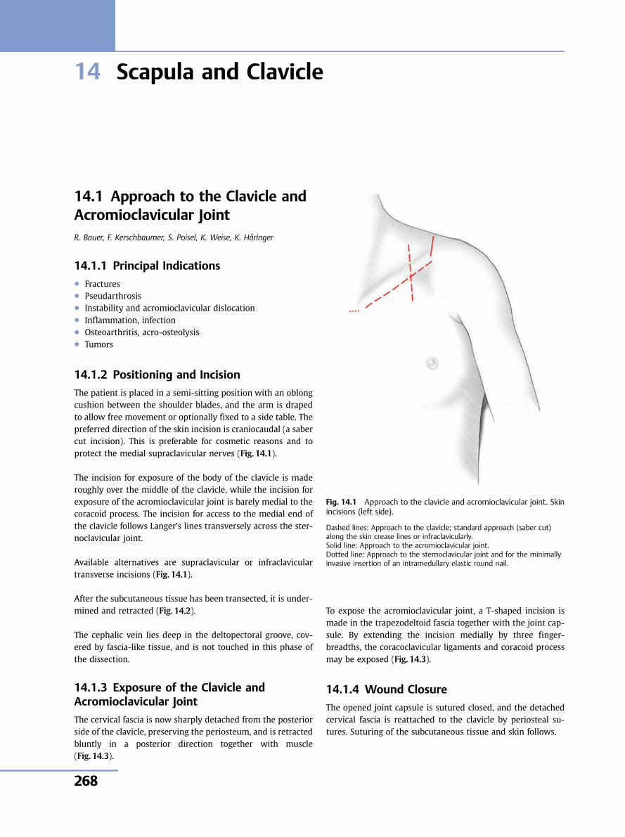
14 Scapula and Clavicle
14.1 Approach to the Clavicle andAcromioclavicular JointR. Bauer, F. Kerschbaumer, S. Poisel, K. Weise, K. Häringer
14.1.1 Principal Indications● Fractures● Pseudarthrosis● Instability and acromioclavicular dislocation● Inflammation, infection● Osteoarthritis, acro-osteolysis● Tumors
14.1.2 Positioning and Incision
The patient is placed in a semi-sitting position with an oblongcushion between the shoulder blades, and the arm is drapedto allow free movement or optionally fixed to a side table. Thepreferred direction of the skin incision is craniocaudal (a sabercut incision). This is preferable for cosmetic reasons and toprotect the medial supraclavicular nerves (Fig. 14.1).
The incision for exposure of the body of the clavicle is maderoughly over the middle of the clavicle, while the incision forexposure of the acromioclavicular joint is barely medial to thecoracoid process. The incision for access to the medial end ofthe clavicle follows Langer’s lines transversely across the ster-noclavicular joint.
Available alternatives are supraclavicular or infraclaviculartransverse incisions (Fig. 14.1).
After the subcutaneous tissue has been transected, it is under-mined and retracted (Fig. 14.2).
The cephalic vein lies deep in the deltopectoral groove, cov-ered by fascia-like tissue, and is not touched in this phase ofthe dissection.
14.1.3 Exposure of the Clavicle andAcromioclavicular Joint
The cervical fascia is now sharply detached from the posteriorside of the clavicle, preserving the periosteum, and is retractedbluntly in a posterior direction together with muscle(Fig. 14.3).
To expose the acromioclavicular joint, a T-shaped incision ismade in the trapezodeltoid fascia together with the joint cap-sule. By extending the incision medially by three finger-breadths, the coracoclavicular ligaments and coracoid processmay be exposed (Fig. 14.3).
14.1.4 Wound Closure
The opened joint capsule is sutured closed, and the detachedcervical fascia is reattached to the clavicle by periosteal su-tures. Suturing of the subcutaneous tissue and skin follows.
Fig. 14.1 Approach to the clavicle and acromioclavicular joint. Skinincisions (left side).
Dashed lines: Approach to the clavicle; standard approach (saber cut)along the skin crease lines or infraclavicularly.Solid line: Approach to the acromioclavicular joint.Dotted line: Approach to the sternoclavicular joint and for the minimallyinvasive insertion of an intramedullary elastic round nail.
Shoulder and Upper Extremity
268268
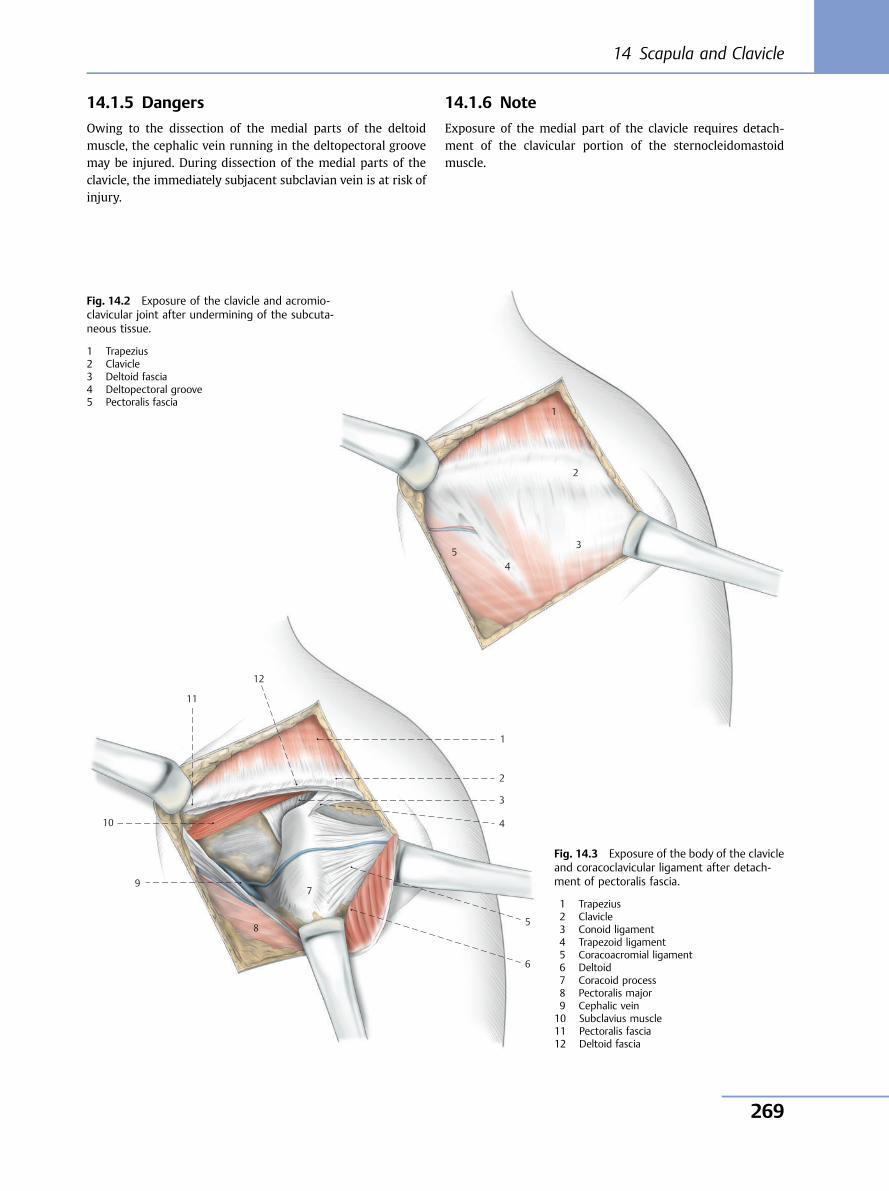
14.1.5 Dangers
Owing to the dissection of the medial parts of the deltoidmuscle, the cephalic vein running in the deltopectoral groovemay be injured. During dissection of the medial parts of theclavicle, the immediately subjacent subclavian vein is at risk ofinjury.
14.1.6 Note
Exposure of the medial part of the clavicle requires detach-ment of the clavicular portion of the sternocleidomastoidmuscle.
1
2
3
45
Fig. 14.2 Exposure of the clavicle and acromio-clavicular joint after undermining of the subcuta-neous tissue.
1 Trapezius2 Clavicle3 Deltoid fascia4 Deltopectoral groove5 Pectoralis fascia
12
1
2
3
4
5
6
7
8
11
10
9
Fig. 14.3 Exposure of the body of the clavicleand coracoclavicular ligament after detach-ment of pectoralis fascia.
1 Trapezius2 Clavicle3 Conoid ligament4 Trapezoid ligament5 Coracoacromial ligament6 Deltoid7 Coracoid process8 Pectoralis major9 Cephalic vein10 Subclavius muscle11 Pectoralis fascia12 Deltoid fascia
14 Scapula and Clavicle
269
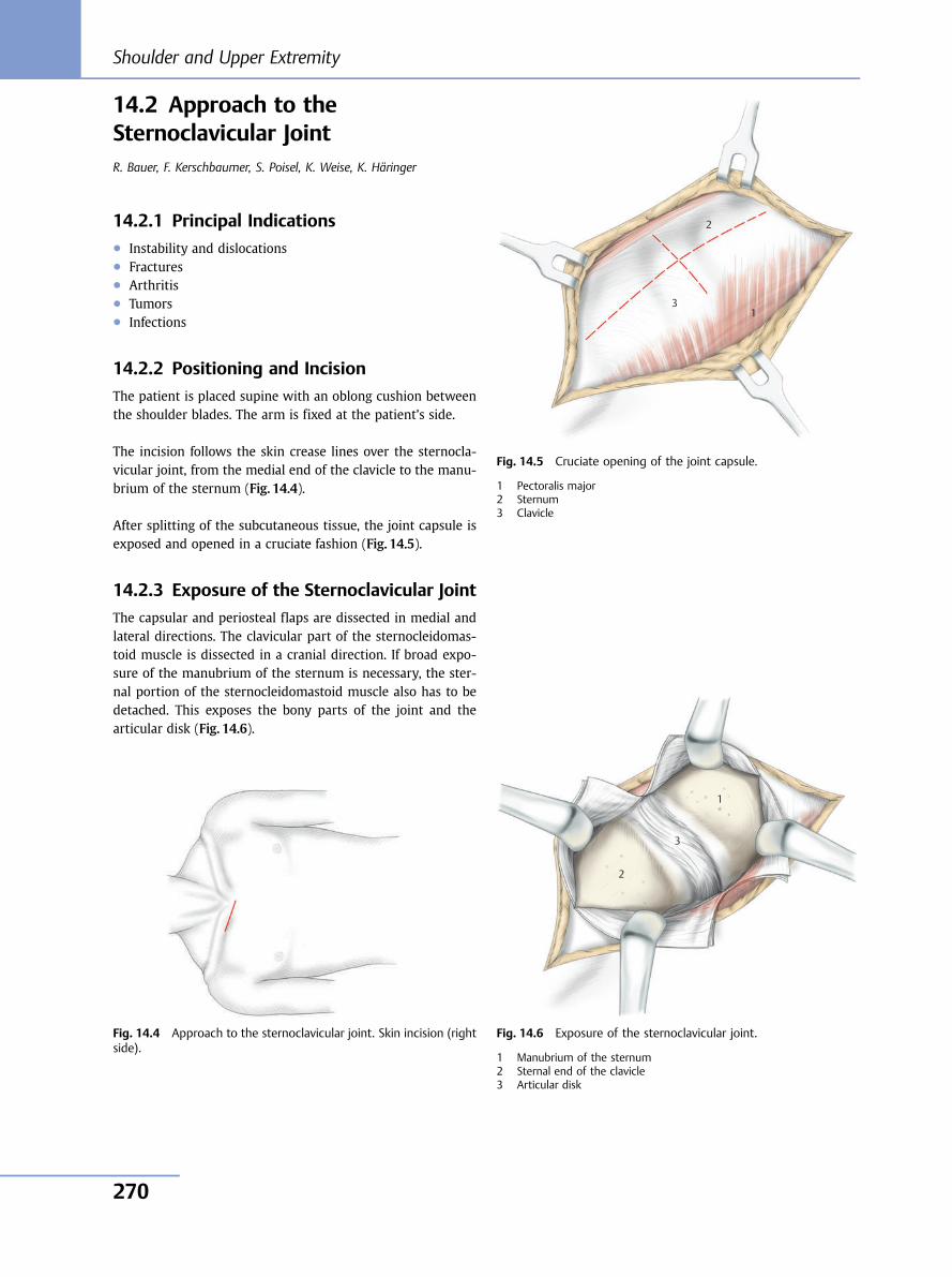
14.2 Approach to theSternoclavicular JointR. Bauer, F. Kerschbaumer, S. Poisel, K. Weise, K. Häringer
14.2.1 Principal Indications● Instability and dislocations● Fractures● Arthritis● Tumors● Infections
14.2.2 Positioning and Incision
The patient is placed supine with an oblong cushion betweenthe shoulder blades. The arm is fixed at the patient’s side.
The incision follows the skin crease lines over the sternocla-vicular joint, from the medial end of the clavicle to the manu-brium of the sternum (Fig. 14.4).
After splitting of the subcutaneous tissue, the joint capsule isexposed and opened in a cruciate fashion (Fig. 14.5).
14.2.3 Exposure of the Sternoclavicular Joint
The capsular and periosteal flaps are dissected in medial andlateral directions. The clavicular part of the sternocleidomas-toid muscle is dissected in a cranial direction. If broad expo-sure of the manubrium of the sternum is necessary, the ster-nal portion of the sternocleidomastoid muscle also has to bedetached. This exposes the bony parts of the joint and thearticular disk (Fig. 14.6).
Fig. 14.4 Approach to the sternoclavicular joint. Skin incision (rightside).
1
2
3
Fig. 14.5 Cruciate opening of the joint capsule.
1 Pectoralis major2 Sternum3 Clavicle
1
2
3
Fig. 14.6 Exposure of the sternoclavicular joint.
1 Manubrium of the sternum2 Sternal end of the clavicle3 Articular disk
Shoulder and Upper Extremity
270
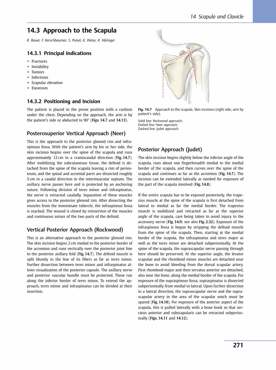
14.3 Approach to the ScapulaR. Bauer, F. Kerschbaumer, S. Poisel, K. Weise, K. Häringer
14.3.1 Principal Indications● Fractures● Instability● Tumors● Infections● Scapular elevation● Exostoses
14.3.2 Positioning and Incision
The patient is placed in the prone position with a cushionunder the chest. Depending on the approach, the arm is bythe patient’s side or abducted to 90° (Figs. 14.7 and 14.13).
Posterosuperior Vertical Approach (Neer)This is the approach to the posterior glenoid rim and infra-spinous fossa. With the patient’s arm by his or her side, theskin incision begins over the spine of the scapula and runsapproximately 12 cm in a craniocaudal direction (Fig. 14.7).After mobilizing the subcutaneous tissue, the deltoid is de-tached from the spine of the scapula leaving a rim of perios-teum, and the spinal and acromial parts are dissected roughly5 cm in a caudal direction in the intermuscular septum. Theaxillary nerve passes here and is protected by an anchoringsuture. Following division of teres minor and infraspinatus,the nerve is retracted caudally. Separation of these musclesgives access to the posterior glenoid rim. After dissecting themuscles from the innominate tubercle, the infraspinous fossais reached. The wound is closed by reinsertion of the musclesand continuous suture of the two parts of the deltoid.
Vertical Posterior Approach (Rockwood)This is an alternative approach to the posterior glenoid rim.The skin incision begins 2 cm medial to the posterior border ofthe acromion and runs vertically over the posterior joint lineto the posterior axillary fold (Fig. 14.7). The deltoid muscle issplit bluntly in the line of its fibers as far as teres minor.Further dissection between teres minor and infraspinatus al-lows visualization of the posterior capsule. The axillary nerveand posterior vascular bundle must be protected. These runalong the inferior border of teres minor. To extend the ap-proach, teres minor and infraspinatus can be divided at theirinsertion.
Posterior Approach (Judet)The skin incision begins slightly below the inferior angle of thescapula, runs about one fingerbreadth medial to the medialborder of the scapula, and then curves over the spine of thescapula and continues as far as the acromion (Fig. 14.7). Theincision can be extended laterally as needed for exposure ofthe part of the scapula involved (Fig. 14.8).
If the entire scapula has to be exposed posteriorly, the trape-zius muscle at the spine of the scapula is first detached fromlateral to medial as far the medial border. The trapeziusmuscle is mobilized and retracted as far as the superiorangle of the scapula, care being taken to avoid injury to theaccessory nerve (Fig. 14.9; see also Fig. 2.32). Exposure of theinfraspinous fossa is begun by stripping the deltoid musclefrom the spine of the scapula. Then, starting at the medialborder of the scapula, the infraspinatus and teres major aswell as the teres minor are detached subperiosteally. At thespine of the scapula, the suprascapular nerve passing throughhere should be preserved. At the superior angle, the levatorscapulae and the rhomboid minor muscles are detached nearthe bone to avoid bleeding from the dorsal scapular artery.First rhomboid major and then serratus anterior are detached,also near the bone, along the medial border of the scapula. Forexposure of the supraspinous fossa, supraspinatus is dissectedsubperiosteally from medial to lateral. Upon further dissectionin a lateral direction, the suprascapular nerve and the supra-scapular artery in the area of the scapular notch must bespared (Fig. 14.10). For exposure of the anterior aspect of thescapula, this is pulled laterally with a bone hook so that ser-ratus anterior and subscapularis can be retracted subperios-teally (Figs. 14.11 and 14.12).
Fig. 14.7 Approach to the scapula. Skin incisions (right side, arm bypatient’s side).
Solid line: Rockwood approach.Dotted line: Neer approach.Dashed line: Judet approach.
14 Scapula and Clavicle
271
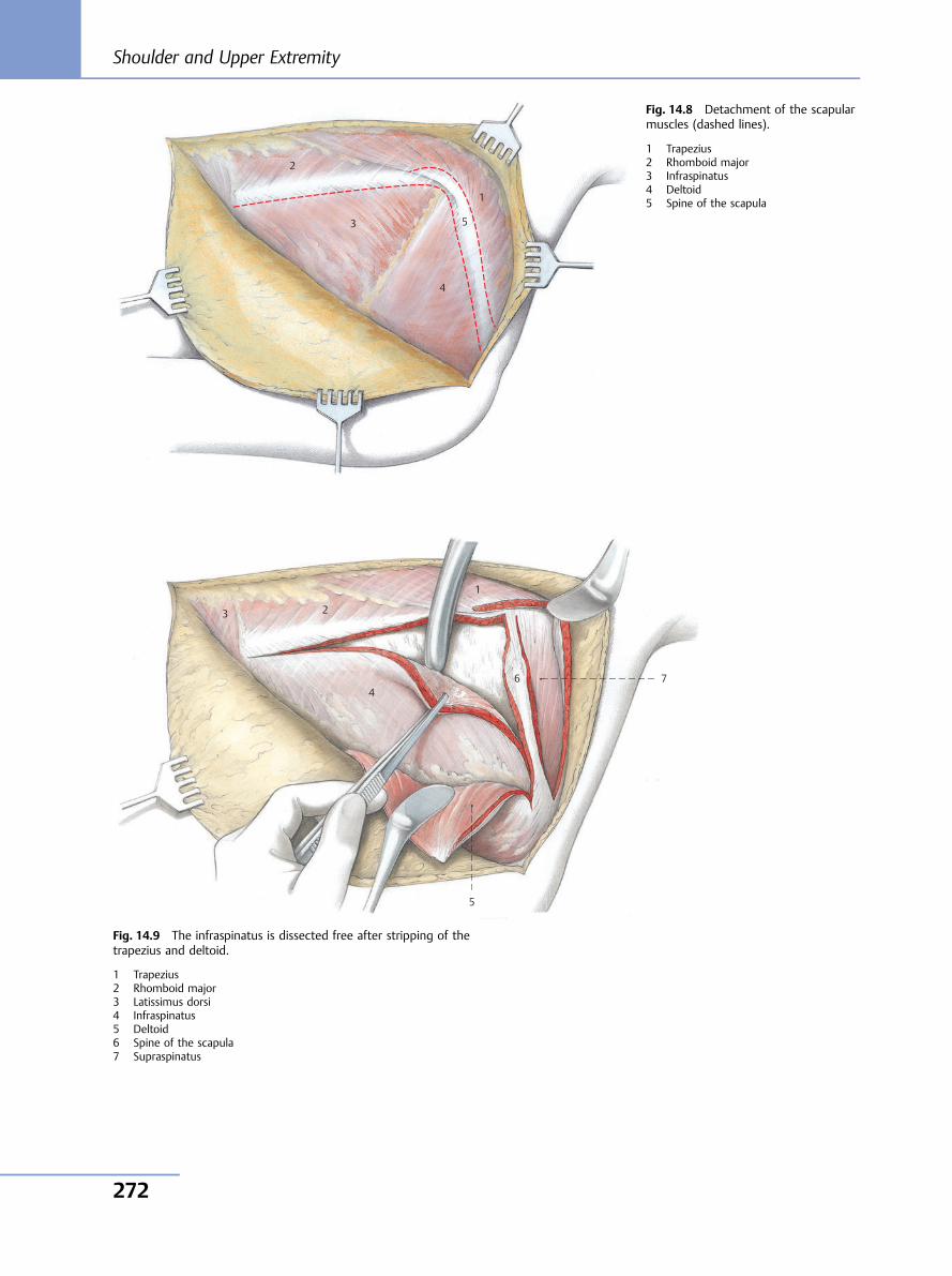
2
3 5
4
1
Fig. 14.8 Detachment of the scapularmuscles (dashed lines).
1 Trapezius2 Rhomboid major3 Infraspinatus4 Deltoid5 Spine of the scapula
3 2
1
6 7
5
4
Fig. 14.9 The infraspinatus is dissected free after stripping of thetrapezius and deltoid.
1 Trapezius2 Rhomboid major3 Latissimus dorsi4 Infraspinatus5 Deltoid6 Spine of the scapula7 Supraspinatus
Shoulder and Upper Extremity
272
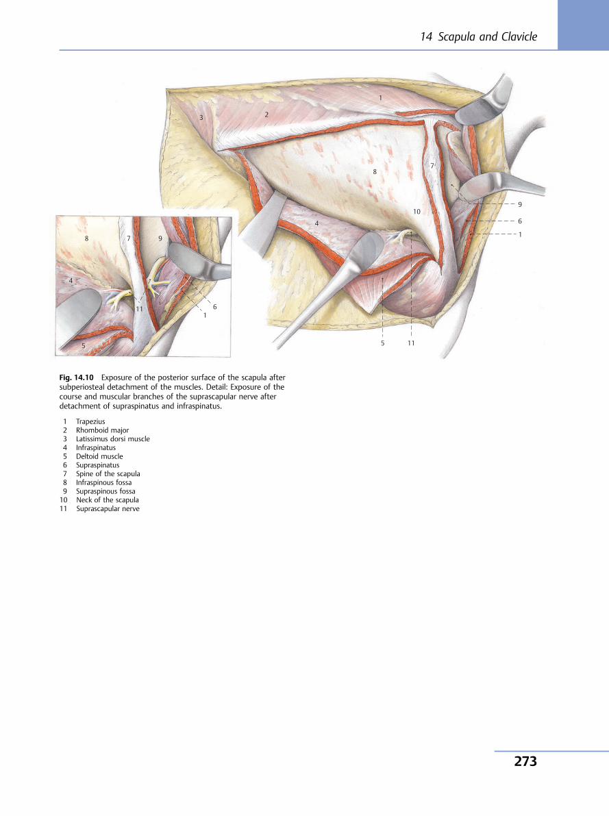
4
5
11
8 7 9
1
5 11
1
6
910
78
4
1
23
6
Fig. 14.10 Exposure of the posterior surface of the scapula aftersubperiosteal detachment of the muscles. Detail: Exposure of thecourse and muscular branches of the suprascapular nerve afterdetachment of supraspinatus and infraspinatus.
1 Trapezius2 Rhomboid major3 Latissimus dorsi muscle4 Infraspinatus5 Deltoid muscle6 Supraspinatus7 Spine of the scapula8 Infraspinous fossa9 Supraspinous fossa10 Neck of the scapula11 Suprascapular nerve
14 Scapula and Clavicle
273

9
2
4
7
5
8
6
10
3
21
Fig. 14.11 After stripping of the trapezius and rhomboid musclesand levator scapulae, the scapula is raised with a bone hook, andsubscapularis is dissected out.
1 Trapezius2 Rhomboid major3 Subscapularis4 Infraspinatus5 Supraspinatus6 Levator scapulae7 Spine of the scapula8 Superior angle9 Inferior angle10 Medial border
2 1
6
7
2
3
9 4
5
8
10
Fig. 14.12 Exposure of the costal surface of the scapula.
1 Trapezius2 Rhomboid major3 Subscapularis4 Infraspinatus5 Deltoid muscle6 Levator scapulae7 Superior angle8 Inferior angle9 Medial border10 Costal surface of the scapula
Shoulder and Upper Extremity
274
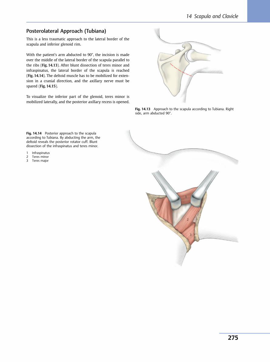
Posterolateral Approach (Tubiana)This is a less traumatic approach to the lateral border of thescapula and inferior glenoid rim.
With the patient’s arm abducted to 90°, the incision is madeover the middle of the lateral border of the scapula parallel tothe ribs (Fig. 14.13). After blunt dissection of teres minor andinfraspinatus, the lateral border of the scapula is reached(Fig. 14.14). The deltoid muscle has to be mobilized for exten-sion in a cranial direction, and the axillary nerve must bespared (Fig. 14.15).
To visualize the inferior part of the glenoid, teres minor ismobilized laterally, and the posterior axillary recess is opened.
Fig. 14.13 Approach to the scapula according to Tubiana. Rightside, arm abducted 90°.
1
2
3
Fig. 14.14 Posterior approach to the scapulaaccording to Tubiana. By abducting the arm, thedeltoid reveals the posterior rotator cuff. Bluntdissection of the infraspinatus and teres minor.
1 Infraspinatus2 Teres minor3 Teres major
14 Scapula and Clavicle
275
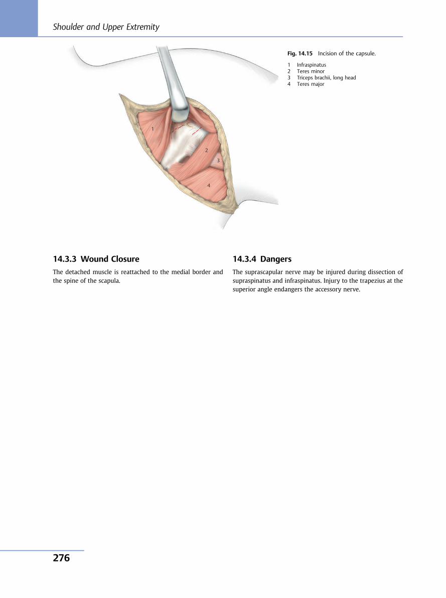
14.3.3 Wound Closure
The detached muscle is reattached to the medial border andthe spine of the scapula.
14.3.4 Dangers
The suprascapular nerve may be injured during dissection ofsupraspinatus and infraspinatus. Injury to the trapezius at thesuperior angle endangers the accessory nerve.
1
2
3
4
Fig. 14.15 Incision of the capsule.
1 Infraspinatus2 Teres minor3 Triceps brachii, long head4 Teres major
Shoulder and Upper Extremity
276
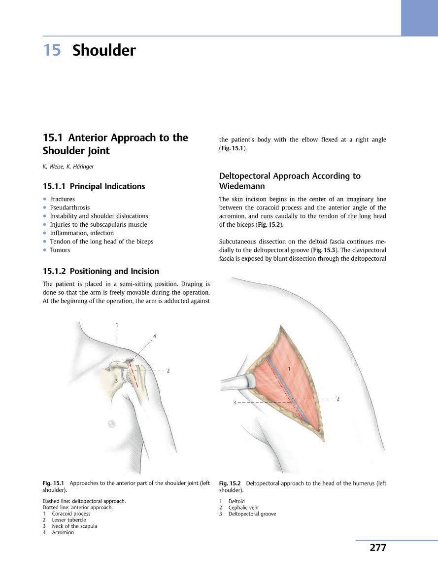
15 Shoulder
15.1 Anterior Approach to theShoulder JointK. Weise, K. Häringer
15.1.1 Principal Indications● Fractures● Pseudarthrosis● Instability and shoulder dislocations● Injuries to the subscapularis muscle● Inflammation, infection● Tendon of the long head of the biceps● Tumors
15.1.2 Positioning and Incision
The patient is placed in a semi-sitting position. Draping isdone so that the arm is freely movable during the operation.At the beginning of the operation, the arm is adducted against
the patient’s body with the elbow flexed at a right angle(Fig. 15.1).
Deltopectoral Approach According toWiedemannThe skin incision begins in the center of an imaginary linebetween the coracoid process and the anterior angle of theacromion, and runs caudally to the tendon of the long headof the biceps (Fig. 15.2).
Subcutaneous dissection on the deltoid fascia continues me-dially to the deltopectoral groove (Fig. 15.3). The clavipectoralfascia is exposed by blunt dissection through the deltopectoral
1
4
3
2
Fig. 15.1 Approaches to the anterior part of the shoulder joint (leftshoulder).
Dashed line: deltopectoral approach.Dotted line: anterior approach.1 Coracoid process2 Lesser tubercle3 Neck of the scapula4 Acromion
Fig. 15.2 Deltopectoral approach to the head of the humerus (leftshoulder).
1 Deltoid2 Cephalic vein3 Deltopectoral groove
1
2 3
15 Shoulder
277
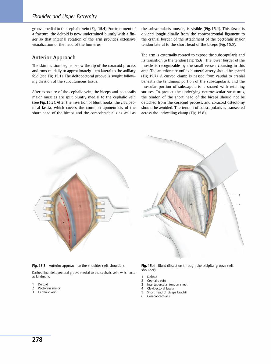
groove medial to the cephalic vein (Fig. 15.4). For treatment ofa fracture, the deltoid is now undermined bluntly with a fin-ger so that internal rotation of the arm provides extensivevisualization of the head of the humerus.
Anterior ApproachThe skin incision begins below the tip of the coracoid processand runs caudally to approximately 1 cm lateral to the axillaryfold (see Fig. 15.1). The deltopectoral groove is sought follow-ing division of the subcutaneous tissue.
After exposure of the cephalic vein, the biceps and pectoralismajor muscles are split bluntly medial to the cephalic vein(see Fig. 15.3). After the insertion of blunt hooks, the clavipec-toral fascia, which covers the common aponeurosis of theshort head of the biceps and the coracobrachialis as well as
the subscapularis muscle, is visible (Fig. 15.4). This fascia isdivided longitudinally from the coracoacromial ligament tothe cranial border of the attachment of the pectoralis majortendon lateral to the short head of the biceps (Fig. 15.5).
The arm is externally rotated to expose the subscapularis andits transition to the tendon (Fig. 15.6). The lower border of themuscle is recognizable by the small vessels coursing in thisarea. The anterior circumflex humeral artery should be spared(Fig. 15.7). A curved clamp is passed from caudal to cranialbeneath the tendinous portion of the subscapularis, and themuscular portion of subscapularis is snared with retainingsutures. To protect the underlying neurovascular structures,the tendon of the short head of the biceps should not bedetached from the coracoid process, and coracoid osteotomyshould be avoided. The tendon of subscapularis is transectedacross the indwelling clamp (Fig. 15.8).
1
2
3
Fig. 15.3 Anterior approach to the shoulder (left shoulder).
Dashed line: deltopectoral groove medial to the cephalic vein, which actsas landmark.
1 Deltoid2 Pectoralis major3 Cephalic vein
Fig. 15.4 Blunt dissection through the bicipital groove (leftshoulder).
1 Deltoid2 Cephalic vein3 Intertubercular tendon sheath4 Clavipectoral fascia5 Short head of biceps brachii6 Coracobrachialis
1
2 3 4 5
6
Shoulder and Upper Extremity
278
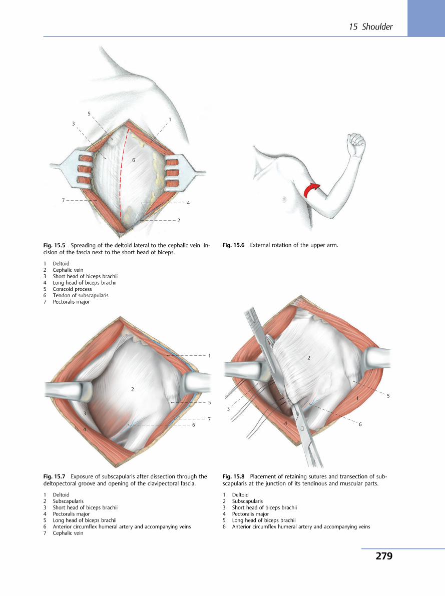
7
2
4
1 5
3
6
Fig. 15.5 Spreading of the deltoid lateral to the cephalic vein. In-cision of the fascia next to the short head of biceps.
1 Deltoid2 Cephalic vein3 Short head of biceps brachii4 Long head of biceps brachii5 Coracoid process6 Tendon of subscapularis7 Pectoralis major
2
3
4 6
7
5
1
1
2
3
5
6 4
Fig. 15.6 External rotation of the upper arm.
Fig. 15.7 Exposure of subscapularis after dissection through thedeltopectoral groove and opening of the clavipectoral fascia.
1 Deltoid2 Subscapularis3 Short head of biceps brachii4 Pectoralis major5 Long head of biceps brachii6 Anterior circumflex humeral artery and accompanying veins7 Cephalic vein
Fig. 15.8 Placement of retaining sutures and transection of sub-scapularis at the junction of its tendinous and muscular parts.
1 Deltoid2 Subscapularis3 Short head of biceps brachii4 Pectoralis major5 Long head of biceps brachii6 Anterior circumflex humeral artery and accompanying veins
15 Shoulder
279
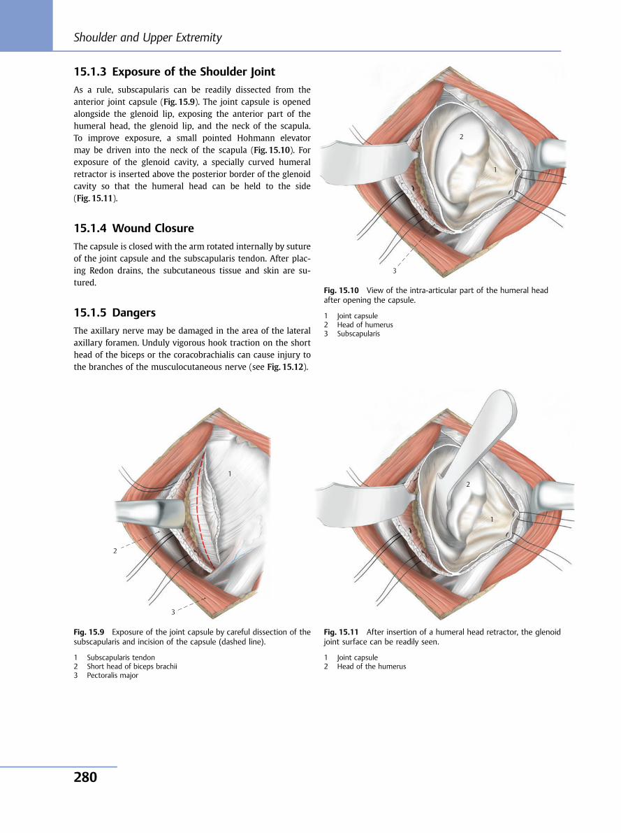
15.1.3 Exposure of the Shoulder Joint
As a rule, subscapularis can be readily dissected from theanterior joint capsule (Fig. 15.9). The joint capsule is openedalongside the glenoid lip, exposing the anterior part of thehumeral head, the glenoid lip, and the neck of the scapula.To improve exposure, a small pointed Hohmann elevatormay be driven into the neck of the scapula (Fig. 15.10). Forexposure of the glenoid cavity, a specially curved humeralretractor is inserted above the posterior border of the glenoidcavity so that the humeral head can be held to the side(Fig. 15.11).
15.1.4 Wound Closure
The capsule is closed with the arm rotated internally by sutureof the joint capsule and the subscapularis tendon. After plac-ing Redon drains, the subcutaneous tissue and skin are su-tured.
15.1.5 Dangers
The axillary nerve may be damaged in the area of the lateralaxillary foramen. Unduly vigorous hook traction on the shorthead of the biceps or the coracobrachialis can cause injury tothe branches of the musculocutaneous nerve (see Fig. 15.12).
1
2
3
Fig. 15.9 Exposure of the joint capsule by careful dissection of thesubscapularis and incision of the capsule (dashed line).
1 Subscapularis tendon2 Short head of biceps brachii3 Pectoralis major
3
2
1
Fig. 15.10 View of the intra-articular part of the humeral headafter opening the capsule.
1 Joint capsule2 Head of humerus3 Subscapularis
1
2
Fig. 15.11 After insertion of a humeral head retractor, the glenoidjoint surface can be readily seen.
1 Joint capsule2 Head of the humerus
Shoulder and Upper Extremity
280
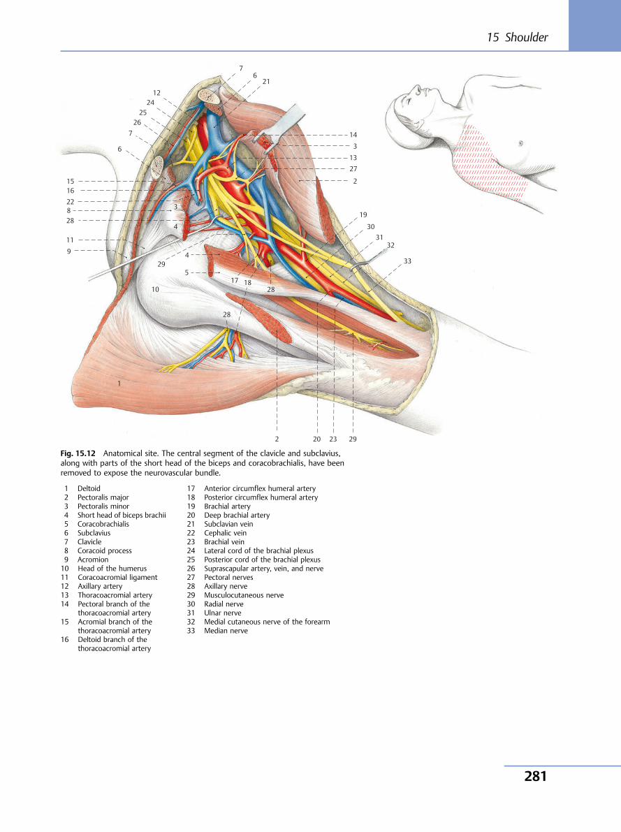
10
11
12
13
14
15 16
17 18
19
27
6
7
7 6
5
4
3
2
30
32
33
31
2923202
28
28
1
21
29
4
3
2425
26
22
288
9
Fig. 15.12 Anatomical site. The central segment of the clavicle and subclavius,along with parts of the short head of the biceps and coracobrachialis, have beenremoved to expose the neurovascular bundle.
1 Deltoid2 Pectoralis major3 Pectoralis minor4 Short head of biceps brachii5 Coracobrachialis6 Subclavius7 Clavicle8 Coracoid process9 Acromion10 Head of the humerus11 Coracoacromial ligament12 Axillary artery13 Thoracoacromial artery14 Pectoral branch of the
thoracoacromial artery15 Acromial branch of the
thoracoacromial artery16 Deltoid branch of the
thoracoacromial artery
17 Anterior circumflex humeral artery18 Posterior circumflex humeral artery19 Brachial artery20 Deep brachial artery21 Subclavian vein22 Cephalic vein23 Brachial vein24 Lateral cord of the brachial plexus25 Posterior cord of the brachial plexus26 Suprascapular artery, vein, and nerve27 Pectoral nerves28 Axillary nerve29 Musculocutaneous nerve30 Radial nerve31 Ulnar nerve32 Medial cutaneous nerve of the forearm33 Median nerve
15 Shoulder
281
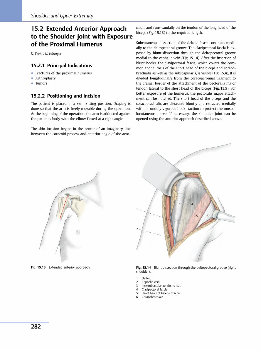
15.2 Extended Anterior Approachto the Shoulder Joint with Exposureof the Proximal HumerusK. Weise, K. Häringer
15.2.1 Principal Indications● Fractures of the proximal humerus● Arthroplasty● Tumors
15.2.2 Positioning and Incision
The patient is placed in a semi-sitting position. Draping isdone so that the arm is freely movable during the operation.At the beginning of the operation, the arm is adducted againstthe patient’s body with the elbow flexed at a right angle.
The skin incision begins in the center of an imaginary linebetween the coracoid process and anterior angle of the acro-
mion, and runs caudally on the tendon of the long head of thebiceps (Fig. 15.13) to the required length.
Subcutaneous dissection of the deltoid fascia continues medi-ally to the deltopectoral groove. The clavipectoral fascia is ex-posed by blunt dissection through the deltopectoral groovemedial to the cephalic vein (Fig. 15.14). After the insertion ofblunt hooks, the clavipectoral fascia, which covers the com-mon aponeurosis of the short head of the biceps and coraco-brachialis as well as the subscapularis, is visible (Fig. 15.4). It isdivided longitudinally from the coracoacromial ligament tothe cranial border of the attachment of the pectoralis majortendon lateral to the short head of the biceps (Fig. 15.5). Forbetter exposure of the humerus, the pectoralis major attach-ment can be notched. The short head of the biceps and thecoracobrachialis are dissected bluntly and retracted mediallywithout unduly vigorous hook traction to protect the muscu-locutaneous nerve. If necessary, the shoulder joint can beopened using the anterior approach described above.
1
3 4
5 6
2
Fig. 15.13 Extended anterior approach. Fig. 15.14 Blunt dissection through the deltopectoral groove (rightshoulder).
1 Deltoid2 Cephalic vein3 Intertubercular tendon sheath4 Clavipectoral fascia5 Short head of biceps brachii6 Coracobrachialis
Shoulder and Upper Extremity
282
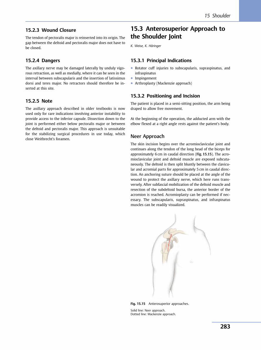
15.2.3 Wound Closure
The tendon of pectoralis major is reinserted into its origin. Thegap between the deltoid and pectoralis major does not have tobe closed.
15.2.4 Dangers
The axillary nerve may be damaged laterally by unduly vigo-rous retraction, as well as medially, where it can be seen in theinterval between subscapularis and the insertion of latissimusdorsi and teres major. No retractors should therefore be in-serted at this site.
15.2.5 Note
The axillary approach described in older textbooks is nowused only for rare indications involving anterior instability toprovide access to the inferior capsule. Dissection down to thejoint is performed either below pectoralis major or betweenthe deltoid and pectoralis major. This approach is unsuitablefor the stabilizing surgical procedures in use today, whichclose Weitbrecht’s foramen.
15.3 Anterosuperior Approach tothe Shoulder JointK. Weise, K. Häringer
15.3.1 Principal Indications● Rotator cuff injuries to subscapularis, supraspinatus, and
infraspinatus● Impingement● Arthroplasty (Mackenzie approach)
15.3.2 Positioning and Incision
The patient is placed in a semi-sitting position, the arm beingdraped to allow free movement.
At the beginning of the operation, the adducted arm with theelbow flexed at a right angle rests against the patient’s body.
Neer ApproachThe skin incision begins over the acromioclavicular joint andcontinues along the tendon of the long head of the biceps forapproximately 6 cm in caudal direction (Fig. 15.15). The acro-mioclavicular joint and deltoid muscle are exposed subcuta-neously. The deltoid is then split bluntly between the clavicu-lar and acromial parts for approximately 5 cm in caudal direc-tion. An anchoring suture should be placed at the angle of thewound to protect the axillary nerve, which here runs trans-versely. After subfascial mobilization of the deltoid muscle andresection of the subdeltoid bursa, the anterior border of theacromion is reached. Acromioplasty can be performed if nec-essary. The subscapularis, supraspinatus, and infraspinatusmuscles can be readily visualized.
Fig. 15.15 Anterosuperior approaches.
Solid line: Neer approach.Dotted line: Mackenzie approach.
15 Shoulder
283
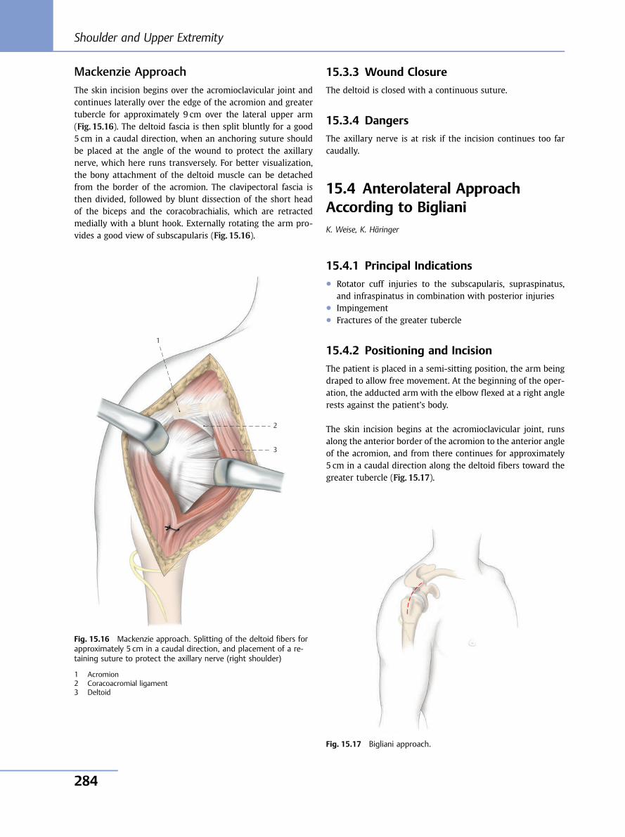
Mackenzie ApproachThe skin incision begins over the acromioclavicular joint andcontinues laterally over the edge of the acromion and greatertubercle for approximately 9 cm over the lateral upper arm(Fig. 15.16). The deltoid fascia is then split bluntly for a good5 cm in a caudal direction, when an anchoring suture shouldbe placed at the angle of the wound to protect the axillarynerve, which here runs transversely. For better visualization,the bony attachment of the deltoid muscle can be detachedfrom the border of the acromion. The clavipectoral fascia isthen divided, followed by blunt dissection of the short headof the biceps and the coracobrachialis, which are retractedmedially with a blunt hook. Externally rotating the arm pro-vides a good view of subscapularis (Fig. 15.16).
15.3.3 Wound Closure
The deltoid is closed with a continuous suture.
15.3.4 Dangers
The axillary nerve is at risk if the incision continues too farcaudally.
15.4 Anterolateral ApproachAccording to BiglianiK. Weise, K. Häringer
15.4.1 Principal Indications● Rotator cuff injuries to the subscapularis, supraspinatus,
and infraspinatus in combination with posterior injuries● Impingement● Fractures of the greater tubercle
15.4.2 Positioning and Incision
The patient is placed in a semi-sitting position, the arm beingdraped to allow free movement. At the beginning of the oper-ation, the adducted arm with the elbow flexed at a right anglerests against the patient’s body.
The skin incision begins at the acromioclavicular joint, runsalong the anterior border of the acromion to the anterior angleof the acromion, and from there continues for approximately5 cm in a caudal direction along the deltoid fibers toward thegreater tubercle (Fig. 15.17).
1
2
3
Fig. 15.16 Mackenzie approach. Splitting of the deltoid fibers forapproximately 5 cm in a caudal direction, and placement of a re-taining suture to protect the axillary nerve (right shoulder)
1 Acromion2 Coracoacromial ligament3 Deltoid
Fig. 15.17 Bigliani approach.
Shoulder and Upper Extremity
284
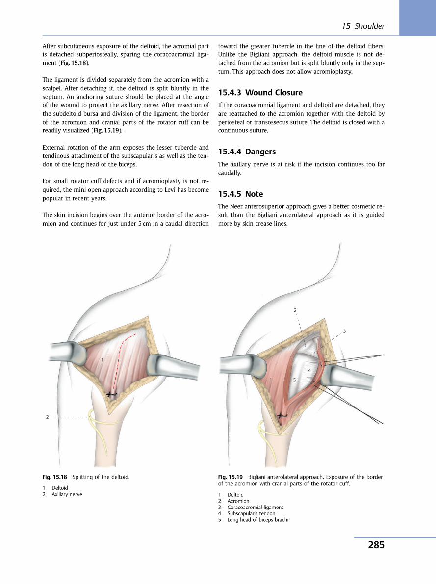
After subcutaneous exposure of the deltoid, the acromial partis detached subperiosteally, sparing the coracoacromial liga-ment (Fig. 15.18).
The ligament is divided separately from the acromion with ascalpel. After detaching it, the deltoid is split bluntly in theseptum. An anchoring suture should be placed at the angleof the wound to protect the axillary nerve. After resection ofthe subdeltoid bursa and division of the ligament, the borderof the acromion and cranial parts of the rotator cuff can bereadily visualized (Fig. 15.19).
External rotation of the arm exposes the lesser tubercle andtendinous attachment of the subscapularis as well as the ten-don of the long head of the biceps.
For small rotator cuff defects and if acromioplasty is not re-quired, the mini open approach according to Levi has becomepopular in recent years.
The skin incision begins over the anterior border of the acro-mion and continues for just under 5 cm in a caudal direction
toward the greater tubercle in the line of the deltoid fibers.Unlike the Bigliani approach, the deltoid muscle is not de-tached from the acromion but is split bluntly only in the sep-tum. This approach does not allow acromioplasty.
15.4.3 Wound Closure
If the coracoacromial ligament and deltoid are detached, theyare reattached to the acromion together with the deltoid byperiosteal or transosseous suture. The deltoid is closed with acontinuous suture.
15.4.4 Dangers
The axillary nerve is at risk if the incision continues too farcaudally.
15.4.5 Note
The Neer anterosuperior approach gives a better cosmetic re-sult than the Bigliani anterolateral approach as it is guidedmore by skin crease lines.
1
2
Fig. 15.18 Splitting of the deltoid.
1 Deltoid2 Axillary nerve
1 5
4
2
3
Fig. 15.19 Bigliani anterolateral approach. Exposure of the borderof the acromion with cranial parts of the rotator cuff.
1 Deltoid2 Acromion3 Coracoacromial ligament4 Subscapularis tendon5 Long head of biceps brachii
15 Shoulder
285
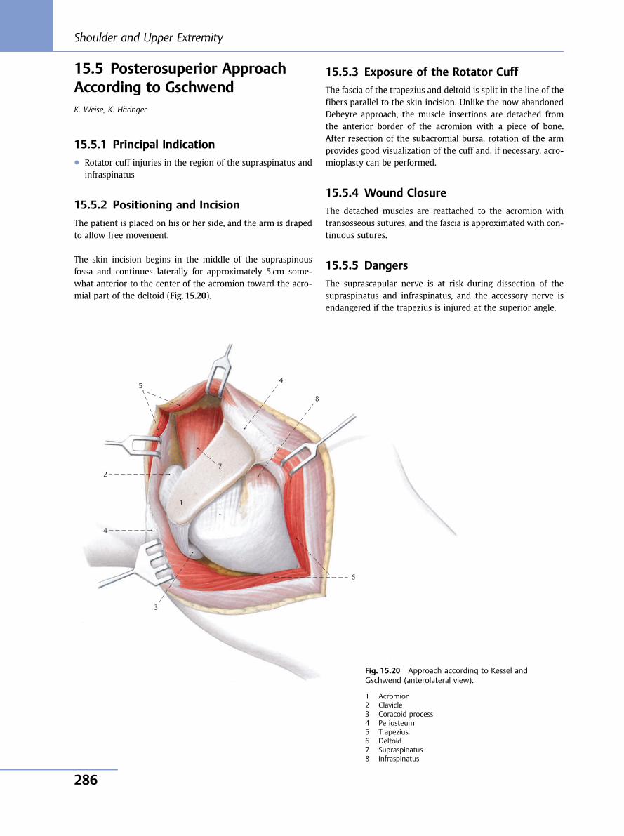
15.5 Posterosuperior ApproachAccording to GschwendK. Weise, K. Häringer
15.5.1 Principal Indication● Rotator cuff injuries in the region of the supraspinatus and
infraspinatus
15.5.2 Positioning and Incision
The patient is placed on his or her side, and the arm is drapedto allow free movement.
The skin incision begins in the middle of the supraspinousfossa and continues laterally for approximately 5 cm some-what anterior to the center of the acromion toward the acro-mial part of the deltoid (Fig. 15.20).
15.5.3 Exposure of the Rotator Cuff
The fascia of the trapezius and deltoid is split in the line of thefibers parallel to the skin incision. Unlike the now abandonedDebeyre approach, the muscle insertions are detached fromthe anterior border of the acromion with a piece of bone.After resection of the subacromial bursa, rotation of the armprovides good visualization of the cuff and, if necessary, acro-mioplasty can be performed.
15.5.4 Wound Closure
The detached muscles are reattached to the acromion withtransosseous sutures, and the fascia is approximated with con-tinuous sutures.
15.5.5 Dangers
The suprascapular nerve is at risk during dissection of thesupraspinatus and infraspinatus, and the accessory nerve isendangered if the trapezius is injured at the superior angle.
5
2
4
3
6
1
7
8
4
Fig. 15.20 Approach according to Kessel andGschwend (anterolateral view).
1 Acromion2 Clavicle3 Coracoid process4 Periosteum5 Trapezius6 Deltoid7 Supraspinatus8 Infraspinatus
Shoulder and Upper Extremity
286
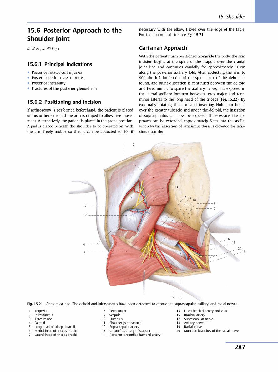
15.6 Posterior Approach to theShoulder JointK. Weise, K. Häringer
15.6.1 Principal Indications● Posterior rotator cuff injuries● Posterosuperior mass ruptures● Posterior instability● Fractures of the posterior glenoid rim
15.6.2 Positioning and Incision
If arthroscopy is performed beforehand, the patient is placedon his or her side, and the arm is draped to allow free move-ment. Alternatively, the patient is placed in the prone position.A pad is placed beneath the shoulder to be operated on, withthe arm freely mobile so that it can be abducted to 90° if
necessary with the elbow flexed over the edge of the table.For the anatomical site, see Fig. 15.21.
Gartsman ApproachWith the patient’s arm positioned alongside the body, the skinincision begins at the spine of the scapula over the cranialjoint line and continues caudally for approximately 10 cmalong the posterior axillary fold. After abducting the arm to90°, the inferior border of the spinal part of the deltoid isfound, and blunt dissection is continued between the deltoidand teres minor. To spare the axillary nerve, it is exposed inthe lateral axillary foramen between teres major and teresminor lateral to the long head of the triceps (Fig. 15.22). Byexternally rotating the arm and inserting Hohmann hooksover the greater tubercle and under the deltoid, the insertionof supraspinatus can now be exposed. If necessary, the ap-proach can be extended approximately 5 cm into the axilla,whereby the insertion of latissimus dorsi is elevated for latis-simus transfer.
1 2
9
13
18 14 10
8
5
16 15
20 19
7
3
4
12
17
11
6
Fig. 15.21 Anatomical site. The deltoid and infraspinatus have been detached to expose the suprascapular, axillary, and radial nerves.
1 Trapezius2 Infraspinatus3 Teres minor4 Deltoid5 Long head of triceps brachii6 Medial head of triceps brachii7 Lateral head of triceps brachii
8 Teres major9 Scapula10 Humerus11 Shoulder joint capsule12 Suprascapular artery13 Circumflex artery of scapula14 Posterior circumflex humeral artery
15 Deep brachial artery and vein16 Brachial artery17 Suprascapular nerve18 Axillary nerve19 Radial nerve20 Muscular branches of the radial nerve
15 Shoulder
287
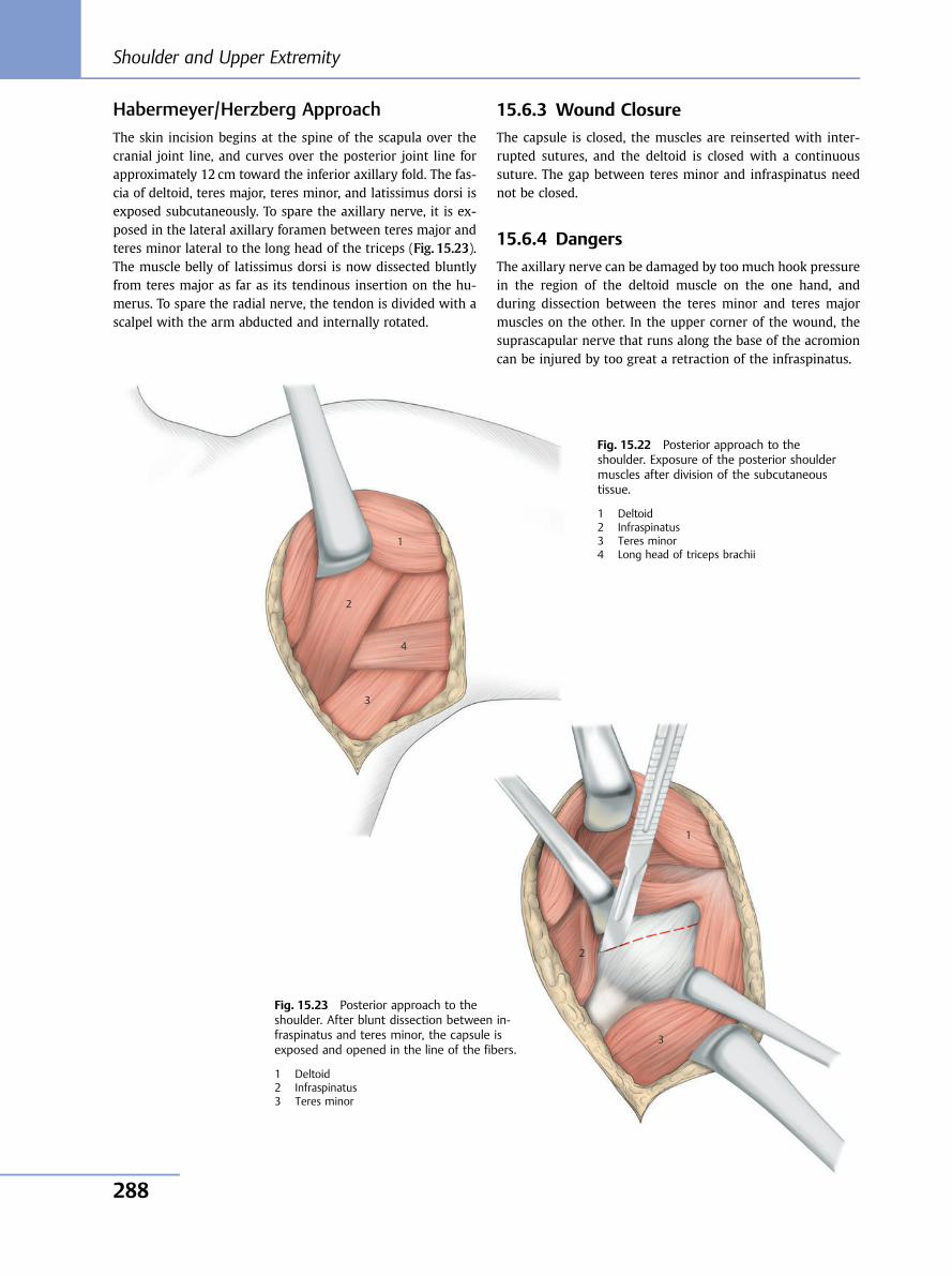
Habermeyer/Herzberg ApproachThe skin incision begins at the spine of the scapula over thecranial joint line, and curves over the posterior joint line forapproximately 12 cm toward the inferior axillary fold. The fas-cia of deltoid, teres major, teres minor, and latissimus dorsi isexposed subcutaneously. To spare the axillary nerve, it is ex-posed in the lateral axillary foramen between teres major andteres minor lateral to the long head of the triceps (Fig. 15.23).The muscle belly of latissimus dorsi is now dissected bluntlyfrom teres major as far as its tendinous insertion on the hu-merus. To spare the radial nerve, the tendon is divided with ascalpel with the arm abducted and internally rotated.
15.6.3 Wound Closure
The capsule is closed, the muscles are reinserted with inter-rupted sutures, and the deltoid is closed with a continuoussuture. The gap between teres minor and infraspinatus neednot be closed.
15.6.4 Dangers
The axillary nerve can be damaged by too much hook pressurein the region of the deltoid muscle on the one hand, andduring dissection between the teres minor and teres majormuscles on the other. In the upper corner of the wound, thesuprascapular nerve that runs along the base of the acromioncan be injured by too great a retraction of the infraspinatus.
Fig. 15.22 Posterior approach to theshoulder. Exposure of the posterior shouldermuscles after division of the subcutaneoustissue.
1 Deltoid2 Infraspinatus3 Teres minor4 Long head of triceps brachii
1
2
3
4
1
2
3
Fig. 15.23 Posterior approach to theshoulder. After blunt dissection between in-fraspinatus and teres minor, the capsule isexposed and opened in the line of the fibers.
1 Deltoid2 Infraspinatus3 Teres minor
Shoulder and Upper Extremity
288
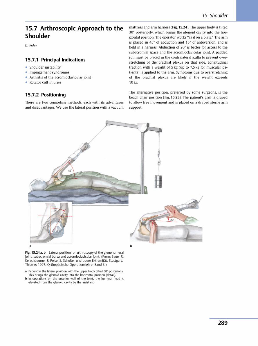
15.7 Arthroscopic Approach to theShoulderD. Kohn
15.7.1 Principal Indications● Shoulder instability● Impingement syndromes● Arthritis of the acromioclavicular joint● Rotator cuff injuries
15.7.2 Positioning
There are two competing methods, each with its advantagesand disadvantages. We use the lateral position with a vacuum
mattress and arm harness (Fig. 15.24). The upper body is tilted30° posteriorly, which brings the glenoid cavity into the hor-izontal position. The operator works “as if on a plate.” The armis placed in 45° of abduction and 15° of anteversion, and isheld in a harness. Abduction of 20° is better for access to thesubacromial space and the acromioclavicular joint. A paddedroll must be placed in the contralateral axilla to prevent over-stretching of the brachial plexus on that side. Longitudinaltraction with a weight of 5 kg (up to 7.5 kg for muscular pa-tients) is applied to the arm. Symptoms due to overstretchingof the brachial plexus are likely if the weight exceeds10 kg.
The alternative position, preferred by some surgeons, is thebeach chair position (Fig. 15.25). The patient’s arm is drapedto allow free movement and is placed on a draped sterile armsupport.
45°
30°
20°
Fig. 15.24 a, b Lateral position for arthroscopy of the glenohumeraljoint, subacromial bursa and acromioclavicular joint. (From: Bauer R,Kerschbaumer F, Poisel S. Schulter und obere Extremität. Stuttgart,Thieme; 1997. Orthopädische Operationslehre; Band 3.)
a Patient in the lateral position with the upper body tilted 30° posteriorly.This brings the glenoid cavity into the horizontal position (detail).
b In operations on the anterior wall of the joint, the humeral head iselevated from the glenoid cavity by the assistant.
a b
15 Shoulder
289
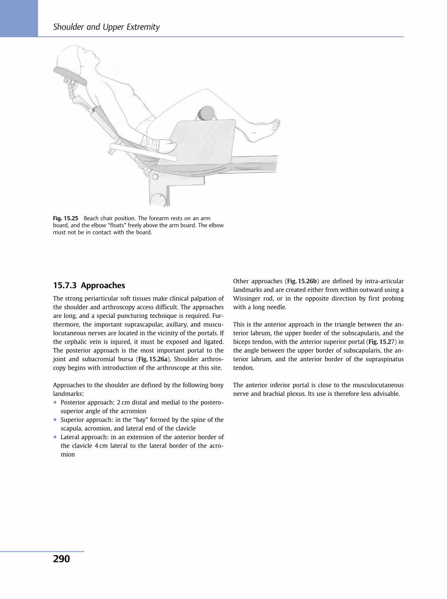
15.7.3 Approaches
The strong periarticular soft tissues make clinical palpation ofthe shoulder and arthroscopy access difficult. The approachesare long, and a special puncturing technique is required. Fur-thermore, the important suprascapular, axillary, and muscu-locutaneous nerves are located in the vicinity of the portals. Ifthe cephalic vein is injured, it must be exposed and ligated.The posterior approach is the most important portal to thejoint and subacromial bursa (Fig. 15.26a). Shoulder arthros-copy begins with introduction of the arthroscope at this site.
Approaches to the shoulder are defined by the following bonylandmarks:● Posterior approach: 2 cm distal and medial to the postero-
superior angle of the acromion● Superior approach: in the “bay” formed by the spine of the
scapula, acromion, and lateral end of the clavicle● Lateral approach: in an extension of the anterior border of
the clavicle 4 cm lateral to the lateral border of the acro-mion
Other approaches (Fig. 15.26b) are defined by intra-articularlandmarks and are created either from within outward using aWissinger rod, or in the opposite direction by first probingwith a long needle.
This is the anterior approach in the triangle between the an-terior labrum, the upper border of the subscapularis, and thebiceps tendon, with the anterior superior portal (Fig. 15.27) inthe angle between the upper border of subscapularis, the an-terior labrum, and the anterior border of the supraspinatustendon.
The anterior inferior portal is close to the musculocutaneousnerve and brachial plexus. Its use is therefore less advisable.
Fig. 15.25 Beach chair position. The forearm rests on an armboard, and the elbow “floats” freely above the arm board. The elbowmust not be in contact with the board.
Shoulder and Upper Extremity
290
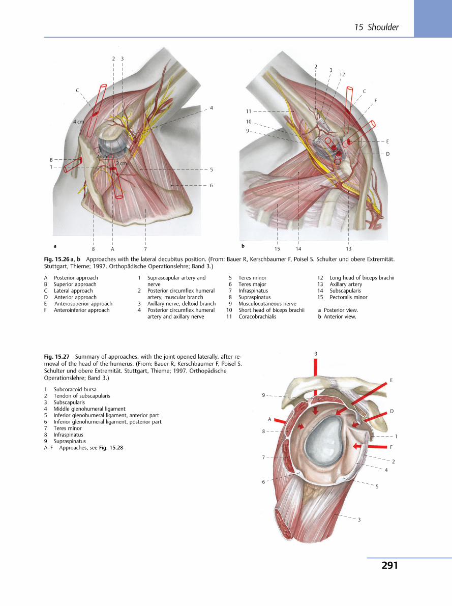
1 B
4 cm
C
2 3
4
5
6
7A8
2 cm2 cm
a
Fig. 15.26 a, b Approaches with the lateral decubitus position. (From: Bauer R, Kerschbaumer F, Poisel S. Schulter und obere Extremität.Stuttgart, Thieme; 1997. Orthopädische Operationslehre; Band 3.)
A Posterior approachB Superior approachC Lateral approachD Anterior approachE Anterosuperior approachF Anteroinferior approach
1 Suprascapular artery andnerve
2 Posterior circumflex humeralartery, muscular branch
3 Axillary nerve, deltoid branch4 Posterior circumflex humeral
artery and axillary nerve
5 Teres minor6 Teres major7 Infraspinatus8 Supraspinatus9 Musculocutaneous nerve10 Short head of biceps brachii11 Coracobrachialis
12 Long head of biceps brachii13 Axillary artery14 Subscapularis15 Pectoralis minor
a Posterior view.b Anterior view.
9
10
11
23
12
C
F
E
D
131415b
6
7
8
A
B
E
D
F
1
2
4
5
3
9
Fig. 15.27 Summary of approaches, with the joint opened laterally, after re-moval of the head of the humerus. (From: Bauer R, Kerschbaumer F, Poisel S.Schulter und obere Extremität. Stuttgart, Thieme; 1997. OrthopädischeOperationslehre; Band 3.)
1 Subcoracoid bursa2 Tendon of subscapularis3 Subscapularis4 Middle glenohumeral ligament5 Inferior glenohumeral ligament, anterior part6 Inferior glenohumeral ligament, posterior part7 Teres minor8 Infraspinatus9 SupraspinatusA–F Approaches, see Fig. 15.28
15 Shoulder
291
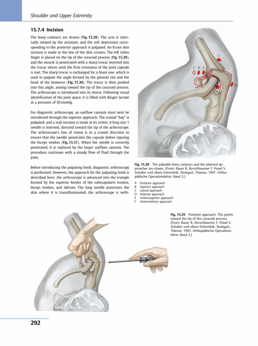
15.7.4 Incision
The bony contours are drawn (Fig. 15.28). The arm is inter-nally rotated by the assistant, and the soft depression corre-sponding to the posterior approach is palpated. An 8mm skinincision is made in the line of the skin creases. The left indexfinger is placed on the tip of the coracoid process (Fig. 15.29),and the muscle is penetrated with a sharp trocar inserted intothe trocar sleeve until the firm resistance of the joint capsuleis met. The sharp trocar is exchanged for a blunt one, which isused to palpate the angle formed by the glenoid rim and thehead of the humerus (Fig. 15.30). The trocar is then pushedinto this angle, aiming toward the tip of the coracoid process.The arthroscope is introduced into its sleeve. Following visualidentification of the joint space, it is filled with Ringer lactateat a pressure of 50mmHg.
For diagnostic arthroscopy, an outflow cannula must next beintroduced through the superior approach. The cranial “bay” ispalpated, and a stab incision is made at its center. A long size 1needle is inserted, directed toward the tip of the arthroscope.The arthroscope’s line of vision is in a cranial direction toensure that the needle penetrates the capsule before injuringthe biceps tendon (Fig. 15.31). When the needle is correctlypositioned, it is replaced by the larger outflow cannula. Theprocedure continues with a steady flow of fluid through thejoint.
Before introducing the palpating hook, diagnostic arthroscopyis performed. However, the approach for the palpating hook isdescribed here: the arthroscope is advanced into the triangleformed by the superior border of the subscapularis tendon,biceps tendon, and labrum. The long needle punctures theskin where it is transilluminated, the arthroscope is with-
B
A
C
D F E
Fig. 15.28 The palpable bony contours and the planned ap-proaches are drawn. (From: Bauer R, Kerschbaumer F, Poisel S.Schulter und obere Extremität. Stuttgart, Thieme; 1997. Ortho-pädische Operationslehre; Band 3.)
A Posterior approachB Superior approachC Lateral approachD Anterior approachE Anterosuperior approachF Anteroinferior approach
Fig. 15.29 Posterior approach. This pointstoward the tip of the coracoid process.(From: Bauer R, Kerschbaumer F, Poisel S.Schulter und obere Extremität. Stuttgart,Thieme; 1997. Orthopädische Operations-lehre; Band 3.)
Shoulder and Upper Extremity
292
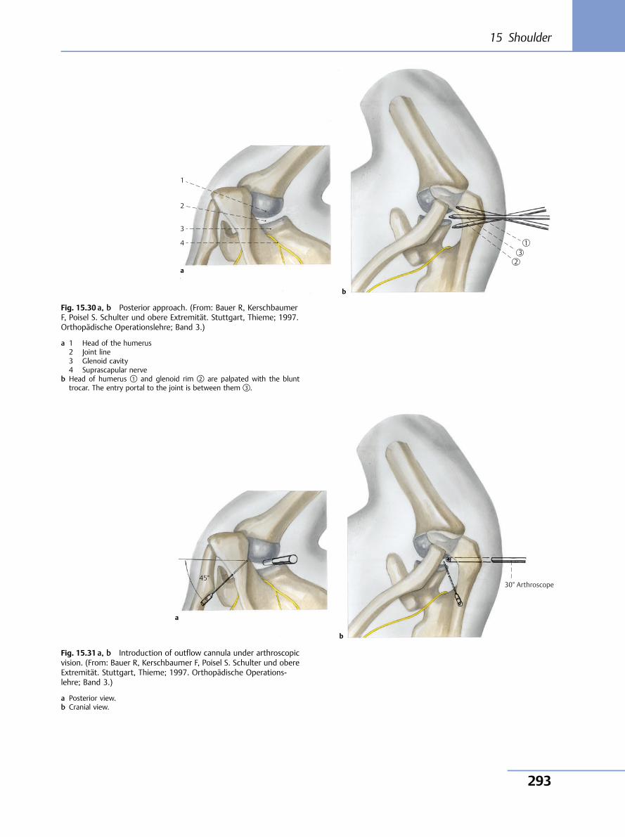
1
2
3
4 13
2a
b
30° Arthroscope45°
a
b
Fig. 15.30 a, b Posterior approach. (From: Bauer R, KerschbaumerF, Poisel S. Schulter und obere Extremität. Stuttgart, Thieme; 1997.Orthopädische Operationslehre; Band 3.)
a 1 Head of the humerus2 Joint line3 Glenoid cavity4 Suprascapular nerve
b Head of humerus ① and glenoid rim ② are palpated with the blunttrocar. The entry portal to the joint is between them ③.
Fig. 15.31 a, b Introduction of outflow cannula under arthroscopicvision. (From: Bauer R, Kerschbaumer F, Poisel S. Schulter und obereExtremität. Stuttgart, Thieme; 1997. Orthopädische Operations-lehre; Band 3.)
a Posterior view.b Cranial view.
15 Shoulder
293
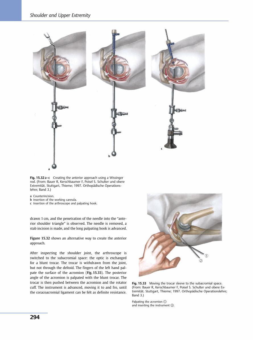
drawn 1 cm, and the penetration of the needle into the “ante-rior shoulder triangle” is observed. The needle is removed, astab incision is made, and the long palpating hook is advanced.
Figure 15.32 shows an alternative way to create the anteriorapproach.
After inspecting the shoulder joint, the arthroscope isswitched to the subacromial space: the optic is exchangedfor a blunt trocar. The trocar is withdrawn from the joint,but not through the deltoid. The fingers of the left hand pal-pate the surface of the acromion (Fig. 15.33). The posteriorangle of the acromion is palpated with the blunt trocar. Thetrocar is then pushed between the acromion and the rotatorcuff. The instrument is advanced, moving it to and fro, untilthe coracoacromial ligament can be felt as definite resistance.
Fig. 15.32 a–c Creating the anterior approach using a Wissingerrod. (From: Bauer R, Kerschbaumer F, Poisel S. Schulter und obereExtremität. Stuttgart, Thieme; 1997. Orthopädische Operations-lehre; Band 3.)
a Counterincision.b Insertion of the working cannula.c Insertion of the arthroscope and palpating hook.
Fig. 15.33 Moving the trocar sleeve to the subacromial space.(From: Bauer R, Kerschbaumer F, Poisel S. Schulter und obere Ex-tremität. Stuttgart, Thieme; 1997. Orthopädische Operationslehre;Band 3.)
Palpating the acromion ①and inserting the instrument ②.
1
2
a
b
c
Shoulder and Upper Extremity
294
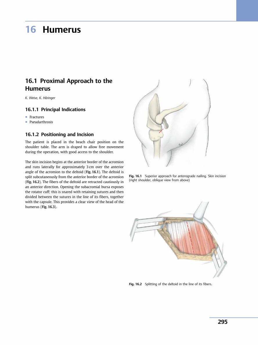
16 Humerus
16.1 Proximal Approach to theHumerusK. Weise, K. Häringer
16.1.1 Principal Indications● Fractures● Pseudarthrosis
16.1.2 Positioning and Incision
The patient is placed in the beach chair position on theshoulder table. The arm is draped to allow free movementduring the operation, with good access to the shoulder.
The skin incision begins at the anterior border of the acromionand runs laterally for approximately 3 cm over the anteriorangle of the acromion to the deltoid (Fig. 16.1). The deltoid issplit subcutaneously from the anterior border of the acromion(Fig. 16.2). The fibers of the deltoid are retracted cautiously inan anterior direction. Opening the subacromial bursa exposesthe rotator cuff; this is snared with retaining sutures and thendivided between the sutures in the line of its fibers, togetherwith the capsule. This provides a clear view of the head of thehumerus (Fig. 16.3).
Fig. 16.1 Superior approach for anterograde nailing. Skin incision(right shoulder, oblique view from above)
Fig. 16.2 Splitting of the deltoid in the line of its fibers.
16 Humerus
295
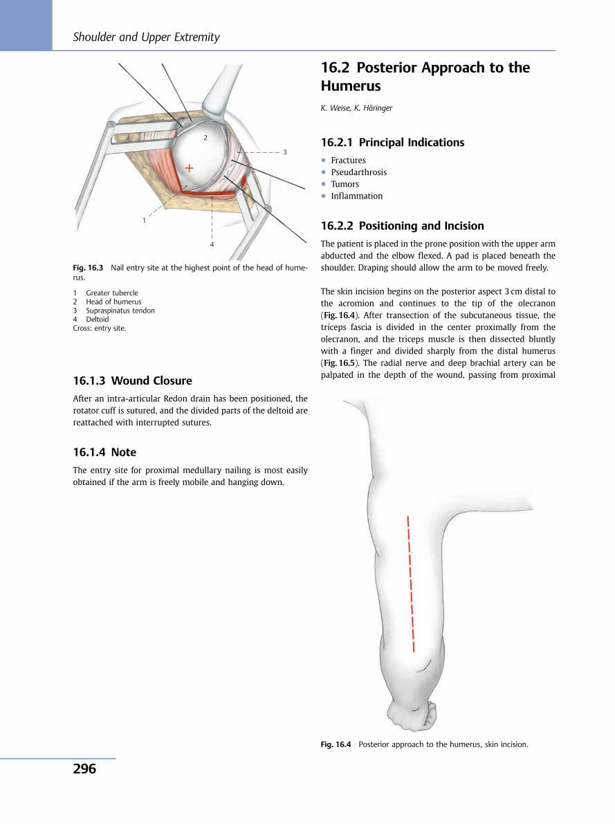
16.1.3 Wound Closure
After an intra-articular Redon drain has been positioned, therotator cuff is sutured, and the divided parts of the deltoid arereattached with interrupted sutures.
16.1.4 Note
The entry site for proximal medullary nailing is most easilyobtained if the arm is freely mobile and hanging down.
16.2 Posterior Approach to theHumerusK. Weise, K. Häringer
16.2.1 Principal Indications● Fractures● Pseudarthrosis● Tumors● Inflammation
16.2.2 Positioning and Incision
The patient is placed in the prone position with the upper armabducted and the elbow flexed. A pad is placed beneath theshoulder. Draping should allow the arm to be moved freely.
The skin incision begins on the posterior aspect 3 cm distal tothe acromion and continues to the tip of the olecranon(Fig. 16.4). After transection of the subcutaneous tissue, thetriceps fascia is divided in the center proximally from theolecranon, and the triceps muscle is then dissected bluntlywith a finger and divided sharply from the distal humerus(Fig. 16.5). The radial nerve and deep brachial artery can bepalpated in the depth of the wound, passing from proximal
2
3
4
1
Fig. 16.3 Nail entry site at the highest point of the head of hume-rus.
1 Greater tubercle2 Head of humerus3 Supraspinatus tendon4 DeltoidCross: entry site.
Fig. 16.4 Posterior approach to the humerus, skin incision.
Shoulder and Upper Extremity
296
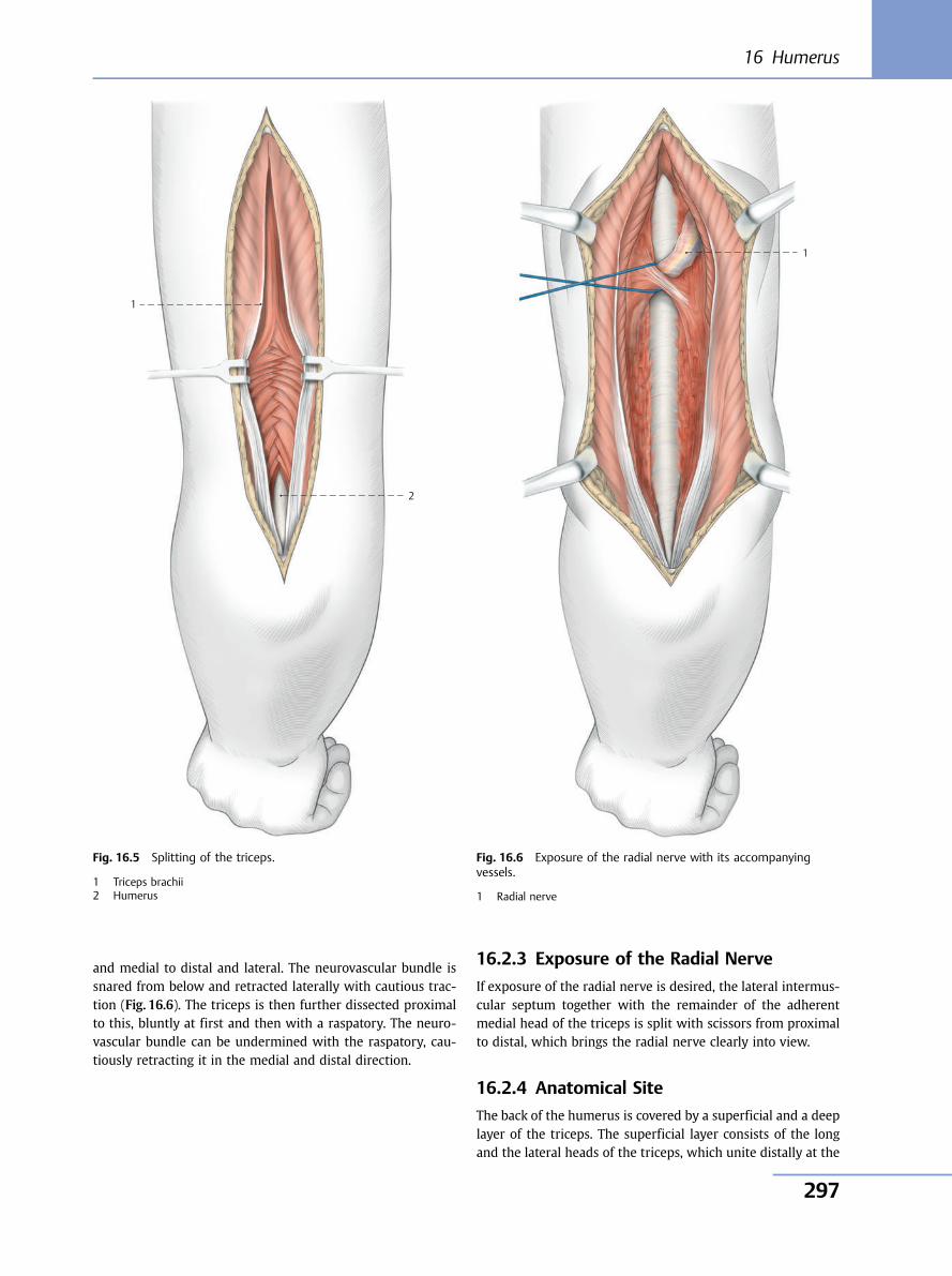
and medial to distal and lateral. The neurovascular bundle issnared from below and retracted laterally with cautious trac-tion (Fig. 16.6). The triceps is then further dissected proximalto this, bluntly at first and then with a raspatory. The neuro-vascular bundle can be undermined with the raspatory, cau-tiously retracting it in the medial and distal direction.
16.2.3 Exposure of the Radial Nerve
If exposure of the radial nerve is desired, the lateral intermus-cular septum together with the remainder of the adherentmedial head of the triceps is split with scissors from proximalto distal, which brings the radial nerve clearly into view.
16.2.4 Anatomical Site
The back of the humerus is covered by a superficial and a deeplayer of the triceps. The superficial layer consists of the longand the lateral heads of the triceps, which unite distally at the
1
2
Fig. 16.5 Splitting of the triceps.
1 Triceps brachii2 Humerus
1
Fig. 16.6 Exposure of the radial nerve with its accompanyingvessels.
1 Radial nerve
16 Humerus
297
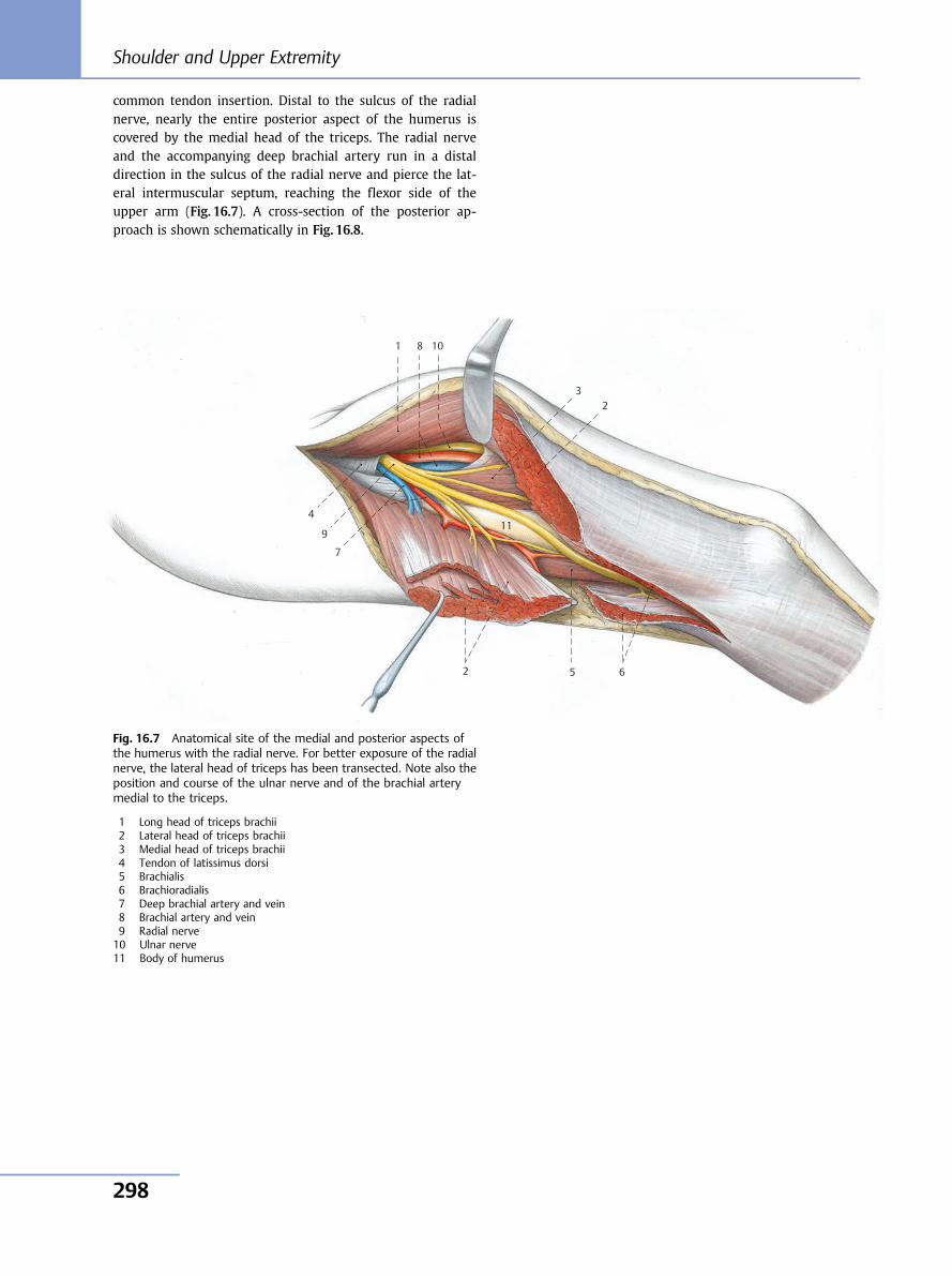
common tendon insertion. Distal to the sulcus of the radialnerve, nearly the entire posterior aspect of the humerus iscovered by the medial head of the triceps. The radial nerveand the accompanying deep brachial artery run in a distaldirection in the sulcus of the radial nerve and pierce the lat-eral intermuscular septum, reaching the flexor side of theupper arm (Fig. 16.7). A cross-section of the posterior ap-proach is shown schematically in Fig. 16.8.
1 8 10
3 2
11 4
9
7
2 5 6
Fig. 16.7 Anatomical site of the medial and posterior aspects ofthe humerus with the radial nerve. For better exposure of the radialnerve, the lateral head of triceps has been transected. Note also theposition and course of the ulnar nerve and of the brachial arterymedial to the triceps.
1 Long head of triceps brachii2 Lateral head of triceps brachii3 Medial head of triceps brachii4 Tendon of latissimus dorsi5 Brachialis6 Brachioradialis7 Deep brachial artery and vein8 Brachial artery and vein9 Radial nerve10 Ulnar nerve11 Body of humerus
Shoulder and Upper Extremity
298
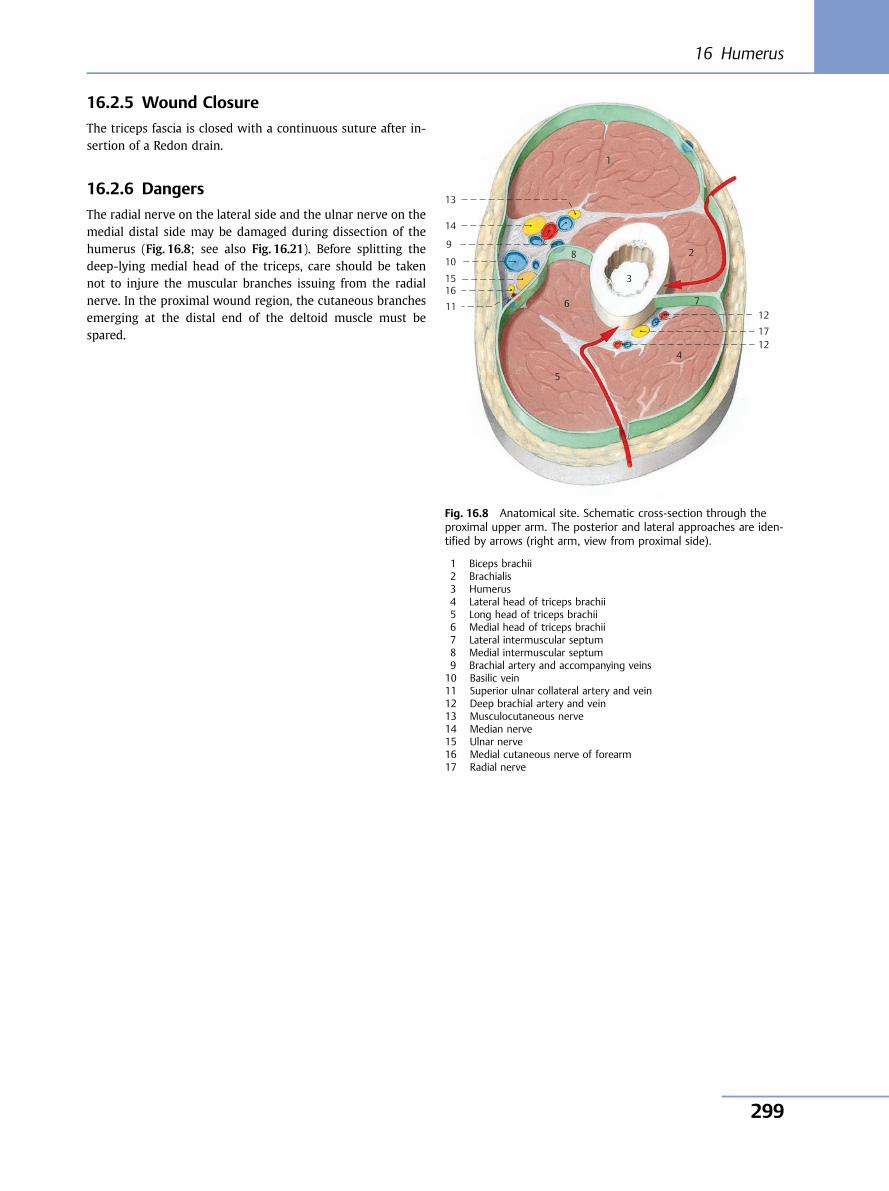
16.2.5 Wound Closure
The triceps fascia is closed with a continuous suture after in-sertion of a Redon drain.
16.2.6 Dangers
The radial nerve on the lateral side and the ulnar nerve on themedial distal side may be damaged during dissection of thehumerus (Fig. 16.8; see also Fig. 16.21). Before splitting thedeep-lying medial head of the triceps, care should be takennot to injure the muscular branches issuing from the radialnerve. In the proximal wound region, the cutaneous branchesemerging at the distal end of the deltoid muscle must bespared.
1
13
14
10
1516
1112
1712
4
5
6
28
3
7
9
Fig. 16.8 Anatomical site. Schematic cross-section through theproximal upper arm. The posterior and lateral approaches are iden-tified by arrows (right arm, view from proximal side).
1 Biceps brachii2 Brachialis3 Humerus4 Lateral head of triceps brachii5 Long head of triceps brachii6 Medial head of triceps brachii7 Lateral intermuscular septum8 Medial intermuscular septum9 Brachial artery and accompanying veins10 Basilic vein11 Superior ulnar collateral artery and vein12 Deep brachial artery and vein13 Musculocutaneous nerve14 Median nerve15 Ulnar nerve16 Medial cutaneous nerve of forearm17 Radial nerve
16 Humerus
299
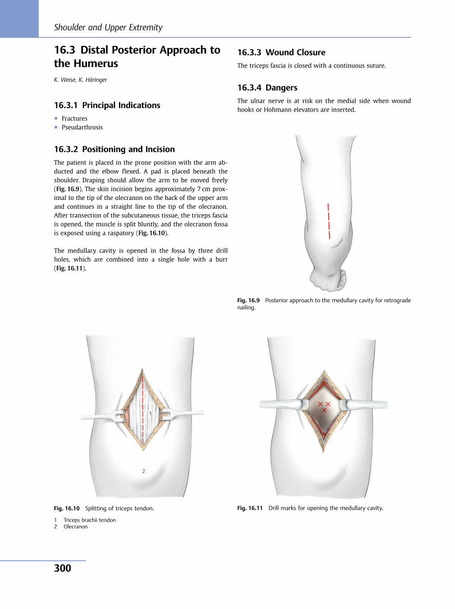
16.3 Distal Posterior Approach tothe HumerusK. Weise, K. Häringer
16.3.1 Principal Indications● Fractures● Pseudarthrosis
16.3.2 Positioning and Incision
The patient is placed in the prone position with the arm ab-ducted and the elbow flexed. A pad is placed beneath theshoulder. Draping should allow the arm to be moved freely(Fig. 16.9). The skin incision begins approximately 7 cm prox-imal to the tip of the olecranon on the back of the upper armand continues in a straight line to the tip of the olecranon.After transection of the subcutaneous tissue, the triceps fasciais opened, the muscle is split bluntly, and the olecranon fossais exposed using a raspatory (Fig. 16.10).
The medullary cavity is opened in the fossa by three drillholes, which are combined into a single hole with a burr(Fig. 16.11).
16.3.3 Wound Closure
The triceps fascia is closed with a continuous suture.
16.3.4 Dangers
The ulnar nerve is at risk on the medial side when woundhooks or Hohmann elevators are inserted.
Fig. 16.9 Posterior approach to the medullary cavity for retrogradenailing.
2
1
Fig. 16.10 Splitting of triceps tendon.
1 Triceps brachii tendon2 Olecranon
Fig. 16.11 Drill marks for opening the medullary cavity.
Shoulder and Upper Extremity
300
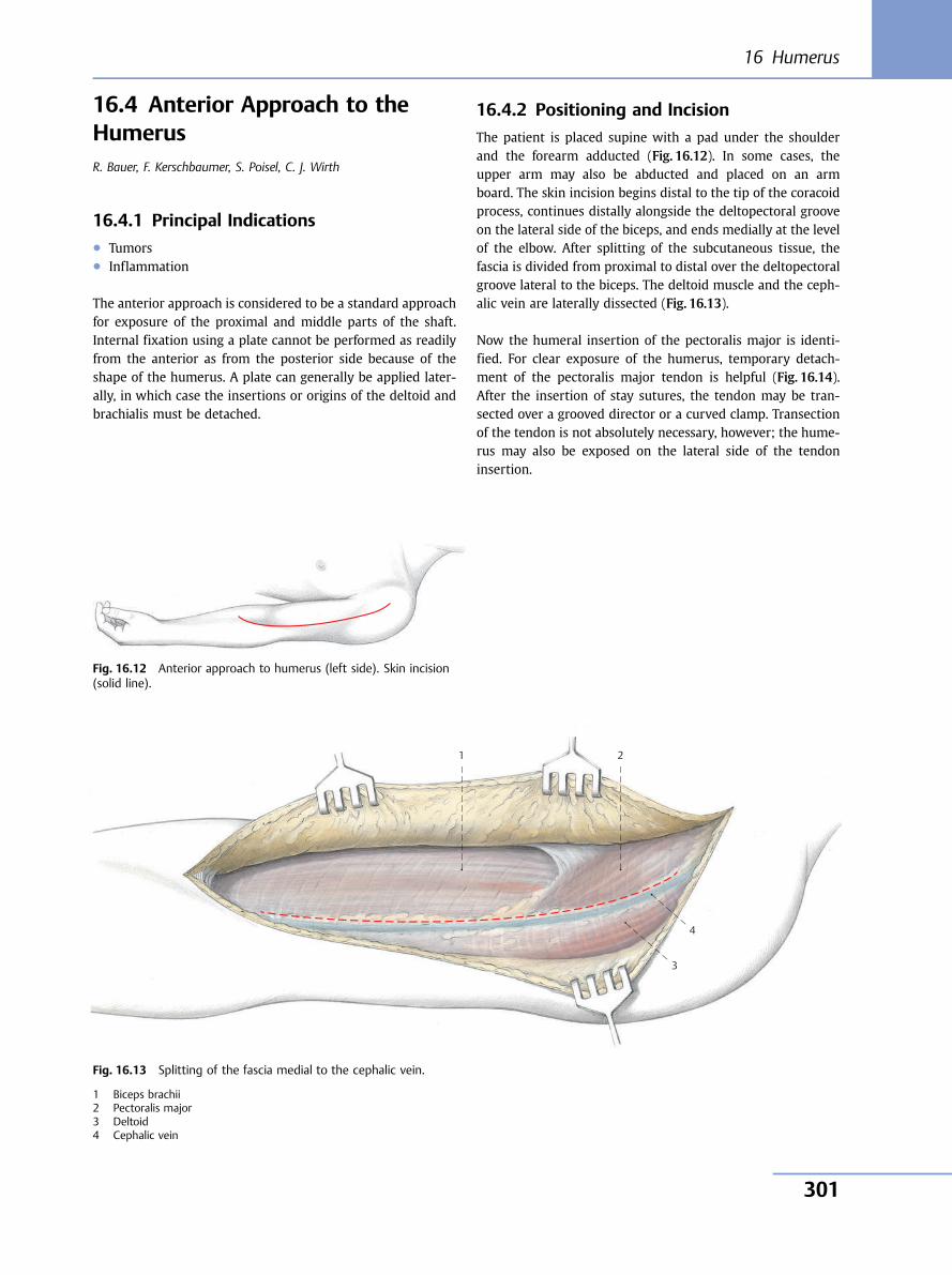
16.4 Anterior Approach to theHumerusR. Bauer, F. Kerschbaumer, S. Poisel, C. J. Wirth
16.4.1 Principal Indications● Tumors● Inflammation
The anterior approach is considered to be a standard approachfor exposure of the proximal and middle parts of the shaft.Internal fixation using a plate cannot be performed as readilyfrom the anterior as from the posterior side because of theshape of the humerus. A plate can generally be applied later-ally, in which case the insertions or origins of the deltoid andbrachialis must be detached.
16.4.2 Positioning and Incision
The patient is placed supine with a pad under the shoulderand the forearm adducted (Fig. 16.12). In some cases, theupper arm may also be abducted and placed on an armboard. The skin incision begins distal to the tip of the coracoidprocess, continues distally alongside the deltopectoral grooveon the lateral side of the biceps, and ends medially at the levelof the elbow. After splitting of the subcutaneous tissue, thefascia is divided from proximal to distal over the deltopectoralgroove lateral to the biceps. The deltoid muscle and the ceph-alic vein are laterally dissected (Fig. 16.13).
Now the humeral insertion of the pectoralis major is identi-fied. For clear exposure of the humerus, temporary detach-ment of the pectoralis major tendon is helpful (Fig. 16.14).After the insertion of stay sutures, the tendon may be tran-sected over a grooved director or a curved clamp. Transectionof the tendon is not absolutely necessary, however; the hume-rus may also be exposed on the lateral side of the tendoninsertion.
1 2
4
3
Fig. 16.12 Anterior approach to humerus (left side). Skin incision(solid line).
Fig. 16.13 Splitting of the fascia medial to the cephalic vein.
1 Biceps brachii2 Pectoralis major3 Deltoid4 Cephalic vein
16 Humerus
301
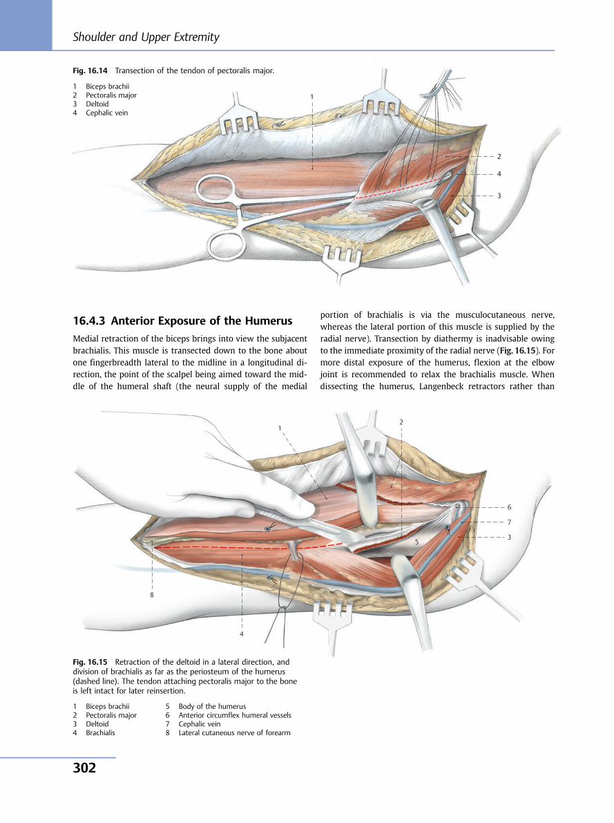
16.4.3 Anterior Exposure of the Humerus
Medial retraction of the biceps brings into view the subjacentbrachialis. This muscle is transected down to the bone aboutone fingerbreadth lateral to the midline in a longitudinal di-rection, the point of the scalpel being aimed toward the mid-dle of the humeral shaft (the neural supply of the medial
portion of brachialis is via the musculocutaneous nerve,whereas the lateral portion of this muscle is supplied by theradial nerve). Transection by diathermy is inadvisable owingto the immediate proximity of the radial nerve (Fig. 16.15). Formore distal exposure of the humerus, flexion at the elbowjoint is recommended to relax the brachialis muscle. Whendissecting the humerus, Langenbeck retractors rather than
1
2
4
3
Fig. 16.14 Transection of the tendon of pectoralis major.
1 Biceps brachii2 Pectoralis major3 Deltoid4 Cephalic vein
1 2
6
7
3 5
4
8
Fig. 16.15 Retraction of the deltoid in a lateral direction, anddivision of brachialis as far as the periosteum of the humerus(dashed line). The tendon attaching pectoralis major to the boneis left intact for later reinsertion.
1 Biceps brachii2 Pectoralis major3 Deltoid4 Brachialis
5 Body of the humerus6 Anterior circumflex humeral vessels7 Cephalic vein8 Lateral cutaneous nerve of forearm
Shoulder and Upper Extremity
302
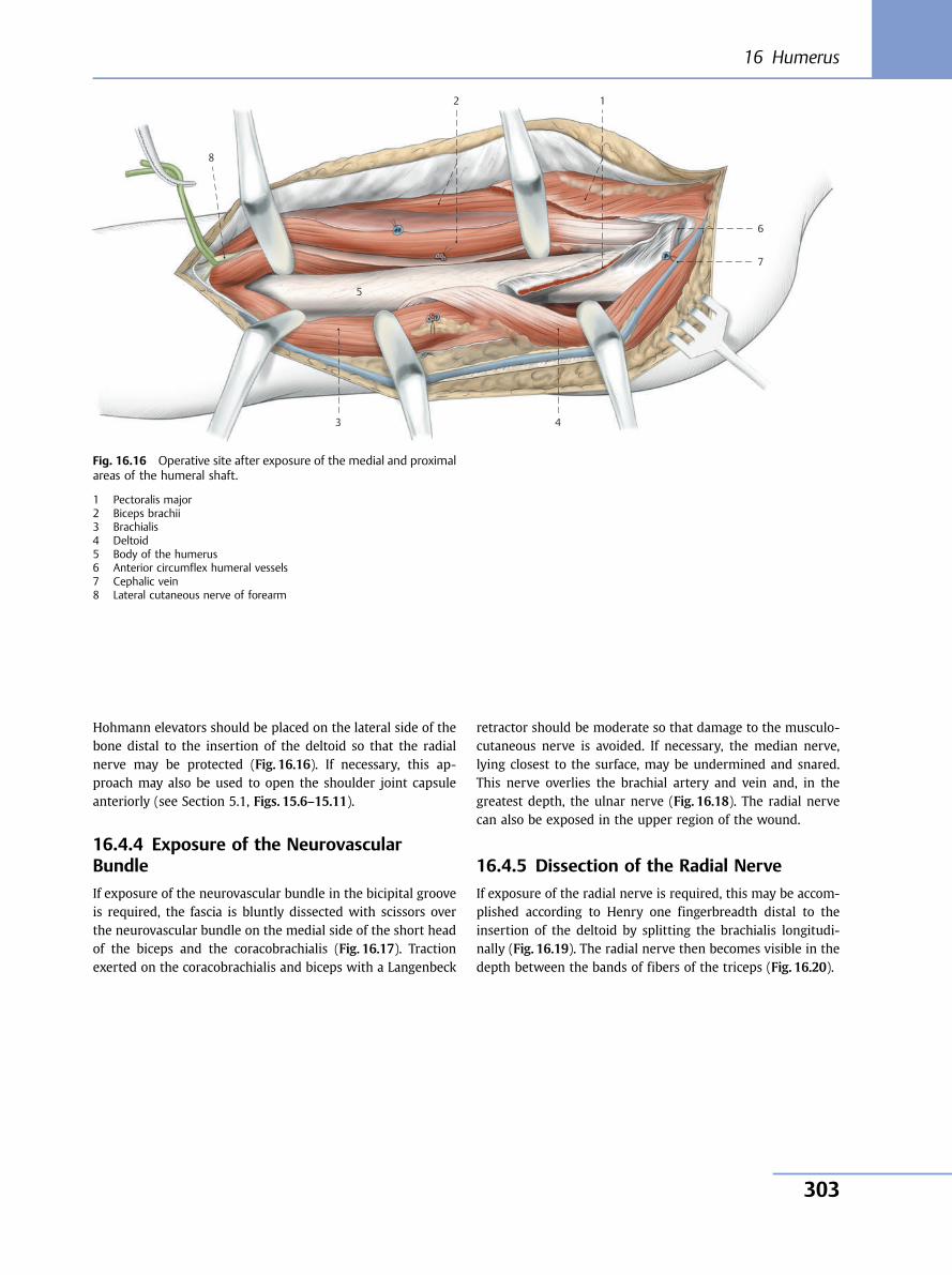
Hohmann elevators should be placed on the lateral side of thebone distal to the insertion of the deltoid so that the radialnerve may be protected (Fig. 16.16). If necessary, this ap-proach may also be used to open the shoulder joint capsuleanteriorly (see Section 5.1, Figs. 15.6–15.11).
16.4.4 Exposure of the NeurovascularBundle
If exposure of the neurovascular bundle in the bicipital grooveis required, the fascia is bluntly dissected with scissors overthe neurovascular bundle on the medial side of the short headof the biceps and the coracobrachialis (Fig. 16.17). Tractionexerted on the coracobrachialis and biceps with a Langenbeck
retractor should be moderate so that damage to the musculo-cutaneous nerve is avoided. If necessary, the median nerve,lying closest to the surface, may be undermined and snared.This nerve overlies the brachial artery and vein and, in thegreatest depth, the ulnar nerve (Fig. 16.18). The radial nervecan also be exposed in the upper region of the wound.
16.4.5 Dissection of the Radial Nerve
If exposure of the radial nerve is required, this may be accom-plished according to Henry one fingerbreadth distal to theinsertion of the deltoid by splitting the brachialis longitudi-nally (Fig. 16.19). The radial nerve then becomes visible in thedepth between the bands of fibers of the triceps (Fig. 16.20).
8
2 1
6
7
43
5
Fig. 16.16 Operative site after exposure of the medial and proximalareas of the humeral shaft.
1 Pectoralis major2 Biceps brachii3 Brachialis4 Deltoid5 Body of the humerus6 Anterior circumflex humeral vessels7 Cephalic vein8 Lateral cutaneous nerve of forearm
16 Humerus
303
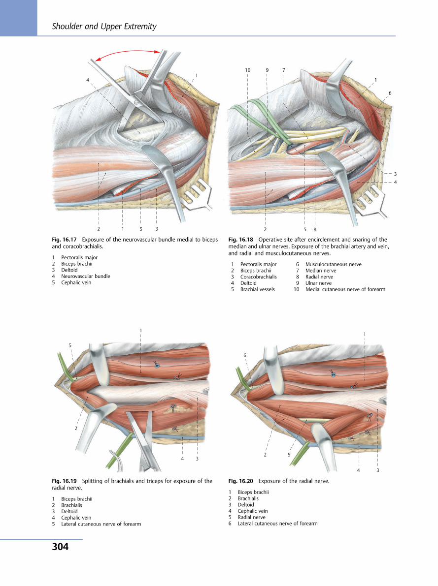
5
4
3 1 2
1
Fig. 16.17 Exposure of the neurovascular bundle medial to bicepsand coracobrachialis.
1 Pectoralis major2 Biceps brachii3 Deltoid4 Neurovascular bundle5 Cephalic vein
10 9
8
7
6
5
4
3
1
2
Fig. 16.18 Operative site after encirclement and snaring of themedian and ulnar nerves. Exposure of the brachial artery and vein,and radial and musculocutaneous nerves.
1 Pectoralis major2 Biceps brachii3 Coracobrachialis4 Deltoid5 Brachial vessels
6 Musculocutaneous nerve7 Median nerve8 Radial nerve9 Ulnar nerve10 Medial cutaneous nerve of forearm
1
5
2
4 3
Fig. 16.19 Splitting of brachialis and triceps for exposure of theradial nerve.
1 Biceps brachii2 Brachialis3 Deltoid4 Cephalic vein5 Lateral cutaneous nerve of forearm
1
6
2 5
4 3
Fig. 16.20 Exposure of the radial nerve.
1 Biceps brachii2 Brachialis3 Deltoid4 Cephalic vein5 Radial nerve6 Lateral cutaneous nerve of forearm
Shoulder and Upper Extremity
304
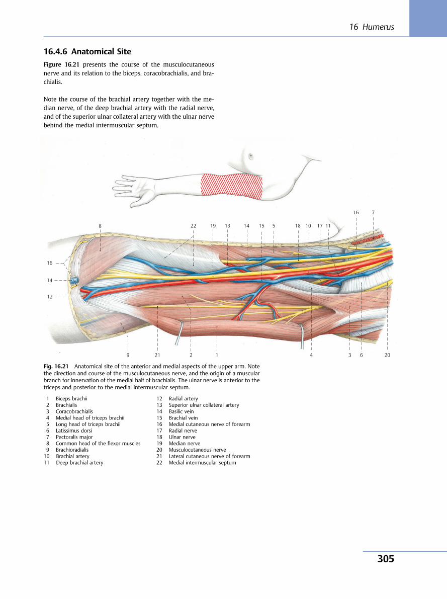
16.4.6 Anatomical Site
Figure 16.21 presents the course of the musculocutaneousnerve and its relation to the biceps, coracobrachialis, and bra-chialis.
Note the course of the brachial artery together with the me-dian nerve, of the deep brachial artery with the radial nerve,and of the superior ulnar collateral artery with the ulnar nervebehind the medial intermuscular septum.
10 11
12
13
14
15
16
17 18 19
209
8
7
6
5
4 3 1 2
14
16
21
22
Fig. 16.21 Anatomical site of the anterior and medial aspects of the upper arm. Notethe direction and course of the musculocutaneous nerve, and the origin of a muscularbranch for innervation of the medial half of brachialis. The ulnar nerve is anterior to thetriceps and posterior to the medial intermuscular septum.
1 Biceps brachii2 Brachialis3 Coracobrachialis4 Medial head of triceps brachii5 Long head of triceps brachii6 Latissimus dorsi7 Pectoralis major8 Common head of the flexor muscles9 Brachioradialis10 Brachial artery11 Deep brachial artery
12 Radial artery13 Superior ulnar collateral artery14 Basilic vein15 Brachial vein16 Medial cutaneous nerve of forearm17 Radial nerve18 Ulnar nerve19 Median nerve20 Musculocutaneous nerve21 Lateral cutaneous nerve of forearm22 Medial intermuscular septum
16 Humerus
305
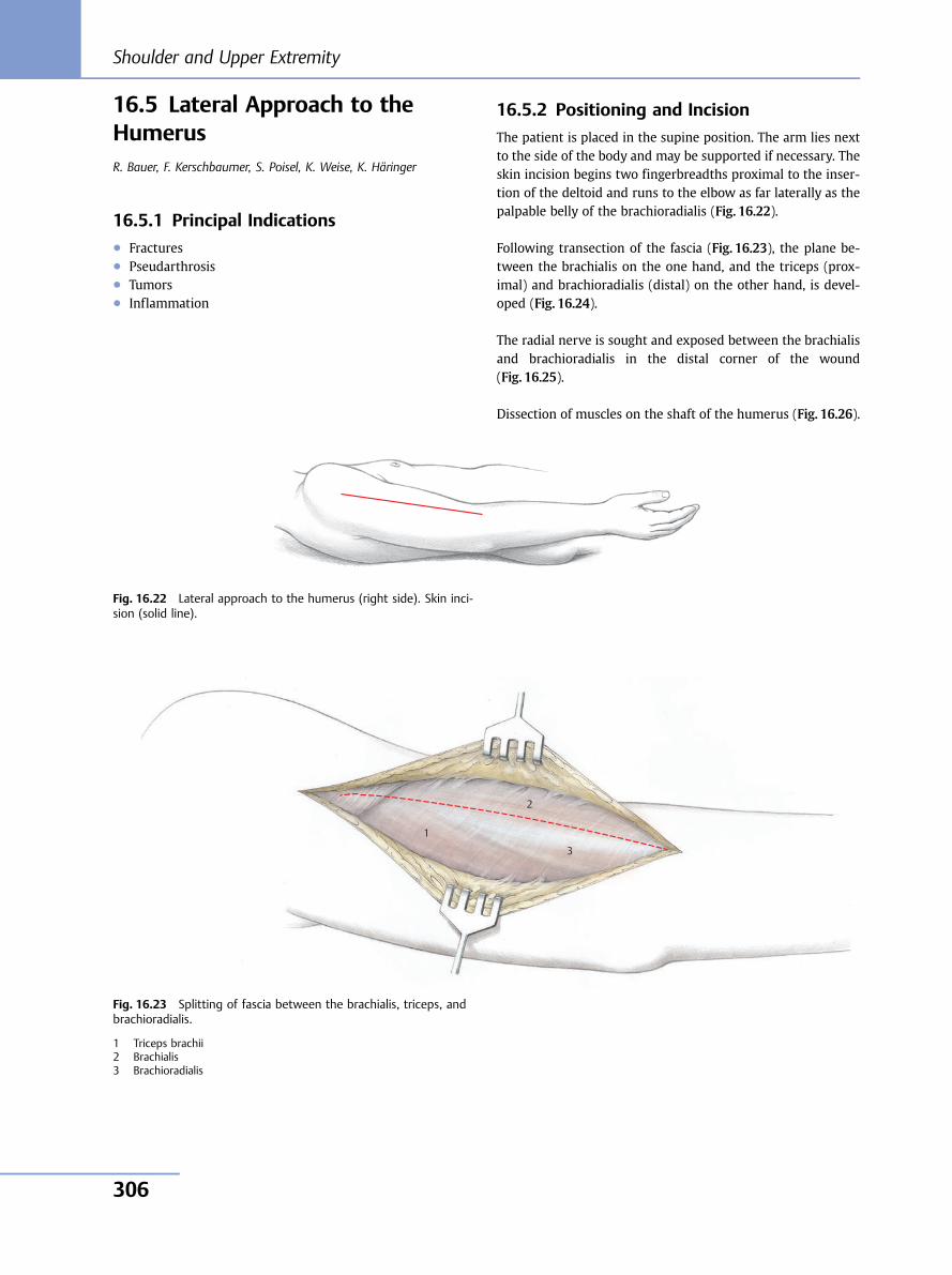
16.5 Lateral Approach to theHumerusR. Bauer, F. Kerschbaumer, S. Poisel, K. Weise, K. Häringer
16.5.1 Principal Indications● Fractures● Pseudarthrosis● Tumors● Inflammation
16.5.2 Positioning and Incision
The patient is placed in the supine position. The arm lies nextto the side of the body and may be supported if necessary. Theskin incision begins two fingerbreadths proximal to the inser-tion of the deltoid and runs to the elbow as far laterally as thepalpable belly of the brachioradialis (Fig. 16.22).
Following transection of the fascia (Fig. 16.23), the plane be-tween the brachialis on the one hand, and the triceps (prox-imal) and brachioradialis (distal) on the other hand, is devel-oped (Fig. 16.24).
The radial nerve is sought and exposed between the brachialisand brachioradialis in the distal corner of the wound(Fig. 16.25).
Dissection of muscles on the shaft of the humerus (Fig. 16.26).
Fig. 16.22 Lateral approach to the humerus (right side). Skin inci-sion (solid line).
3
1
2
Fig. 16.23 Splitting of fascia between the brachialis, triceps, andbrachioradialis.
1 Triceps brachii2 Brachialis3 Brachioradialis
Shoulder and Upper Extremity
306
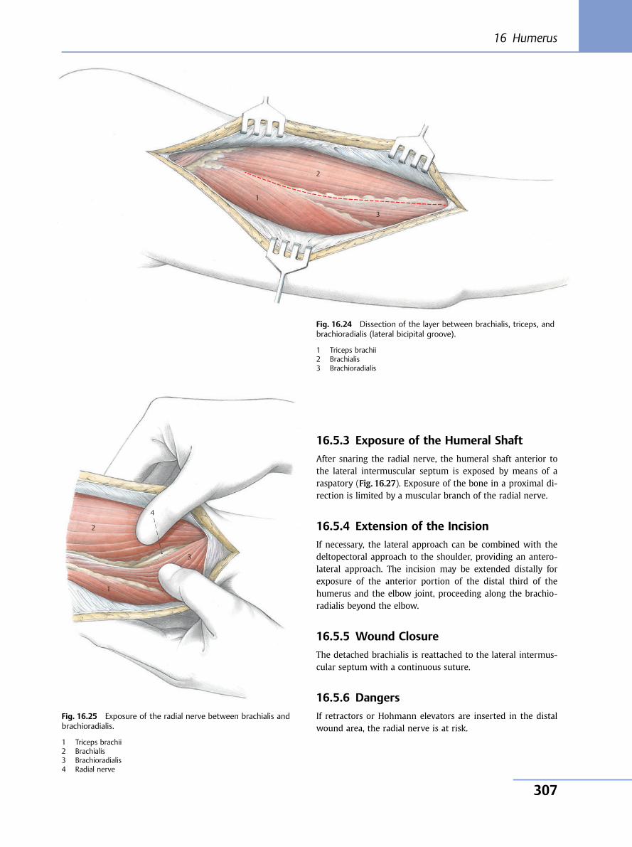
16.5.3 Exposure of the Humeral Shaft
After snaring the radial nerve, the humeral shaft anterior tothe lateral intermuscular septum is exposed by means of araspatory (Fig. 16.27). Exposure of the bone in a proximal di-rection is limited by a muscular branch of the radial nerve.
16.5.4 Extension of the Incision
If necessary, the lateral approach can be combined with thedeltopectoral approach to the shoulder, providing an antero-lateral approach. The incision may be extended distally forexposure of the anterior portion of the distal third of thehumerus and the elbow joint, proceeding along the brachio-radialis beyond the elbow.
16.5.5 Wound Closure
The detached brachialis is reattached to the lateral intermus-cular septum with a continuous suture.
16.5.6 Dangers
If retractors or Hohmann elevators are inserted in the distalwound area, the radial nerve is at risk.
3
1
2
Fig. 16.24 Dissection of the layer between brachialis, triceps, andbrachioradialis (lateral bicipital groove).
1 Triceps brachii2 Brachialis3 Brachioradialis
4
3
1
2
Fig. 16.25 Exposure of the radial nerve between brachialis andbrachioradialis.
1 Triceps brachii2 Brachialis3 Brachioradialis4 Radial nerve
16 Humerus
307
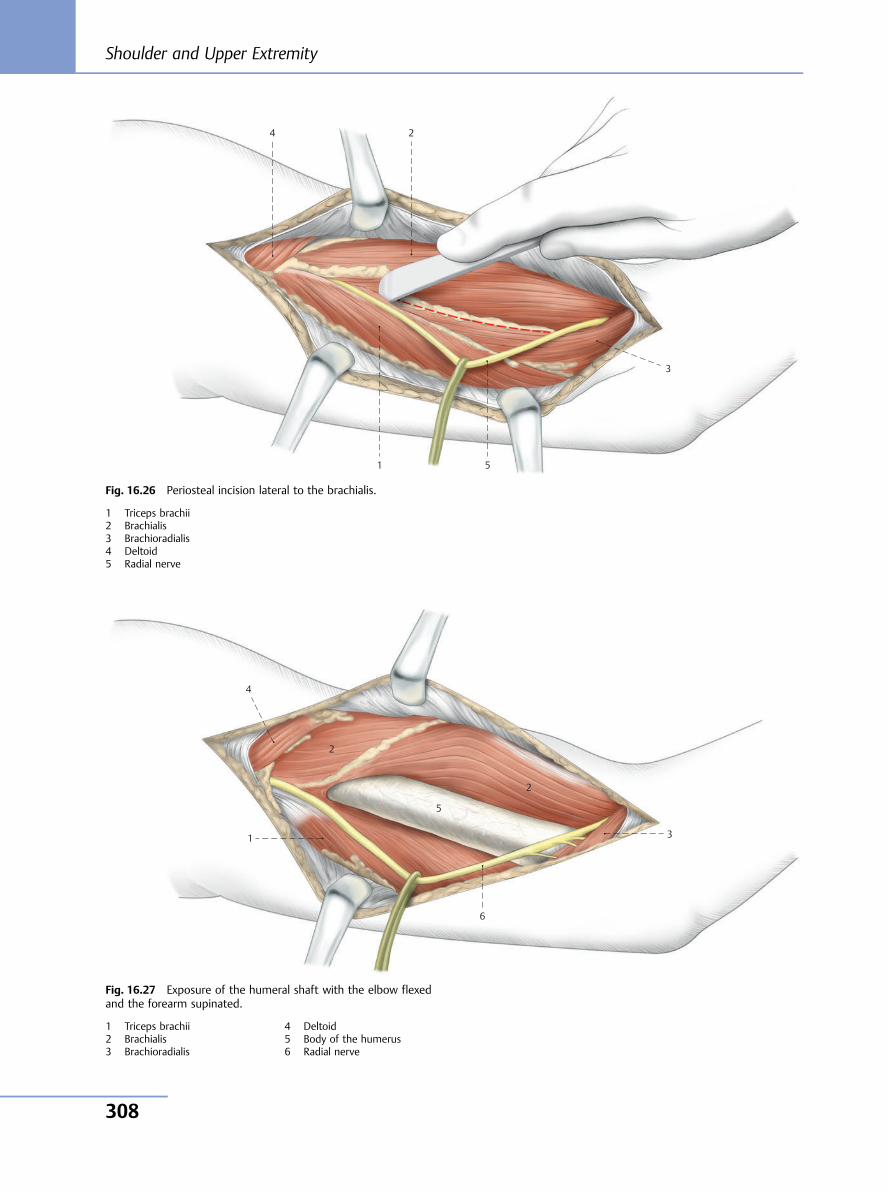
4 2
3
51
Fig. 16.26 Periosteal incision lateral to the brachialis.
1 Triceps brachii2 Brachialis3 Brachioradialis4 Deltoid5 Radial nerve
1
4
2
5
6
2
3
Fig. 16.27 Exposure of the humeral shaft with the elbow flexedand the forearm supinated.
1 Triceps brachii2 Brachialis3 Brachioradialis
4 Deltoid5 Body of the humerus6 Radial nerve
Shoulder and Upper Extremity
308
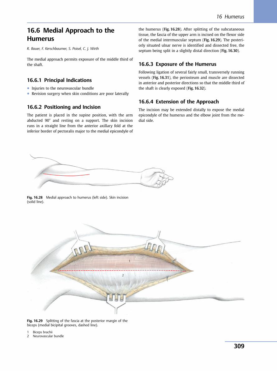
16.6 Medial Approach to theHumerusR. Bauer, F. Kerschbaumer, S. Poisel, C. J. Wirth
The medial approach permits exposure of the middle third ofthe shaft.
16.6.1 Principal Indications● Injuries to the neurovascular bundle● Revision surgery when skin conditions are poor laterally
16.6.2 Positioning and Incision
The patient is placed in the supine position, with the armabducted 90° and resting on a support. The skin incisionruns in a straight line from the anterior axillary fold at theinferior border of pectoralis major to the medial epicondyle of
the humerus (Fig. 16.28). After splitting of the subcutaneoustissue, the fascia of the upper arm is incised on the flexor sideof the medial intermuscular septum (Fig. 16.29). The posteri-orly situated ulnar nerve is identified and dissected free, theseptum being split in a slightly distal direction (Fig. 16.30).
16.6.3 Exposure of the Humerus
Following ligation of several fairly small, transversely runningvessels (Fig. 16.31), the periosteum and muscle are dissectedin anterior and posterior directions so that the middle third ofthe shaft is clearly exposed (Fig. 16.32).
16.6.4 Extension of the Approach
The incision may be extended distally to expose the medialepicondyle of the humerus and the elbow joint from the me-dial side.
Fig. 16.28 Medial approach to humerus (left side). Skin incision(solid line).
1
2
Fig. 16.29 Splitting of the fascia at the posterior margin of thebiceps (medial bicipital grooves, dashed line).
1 Biceps brachii2 Neurovascular bundle
16 Humerus
309
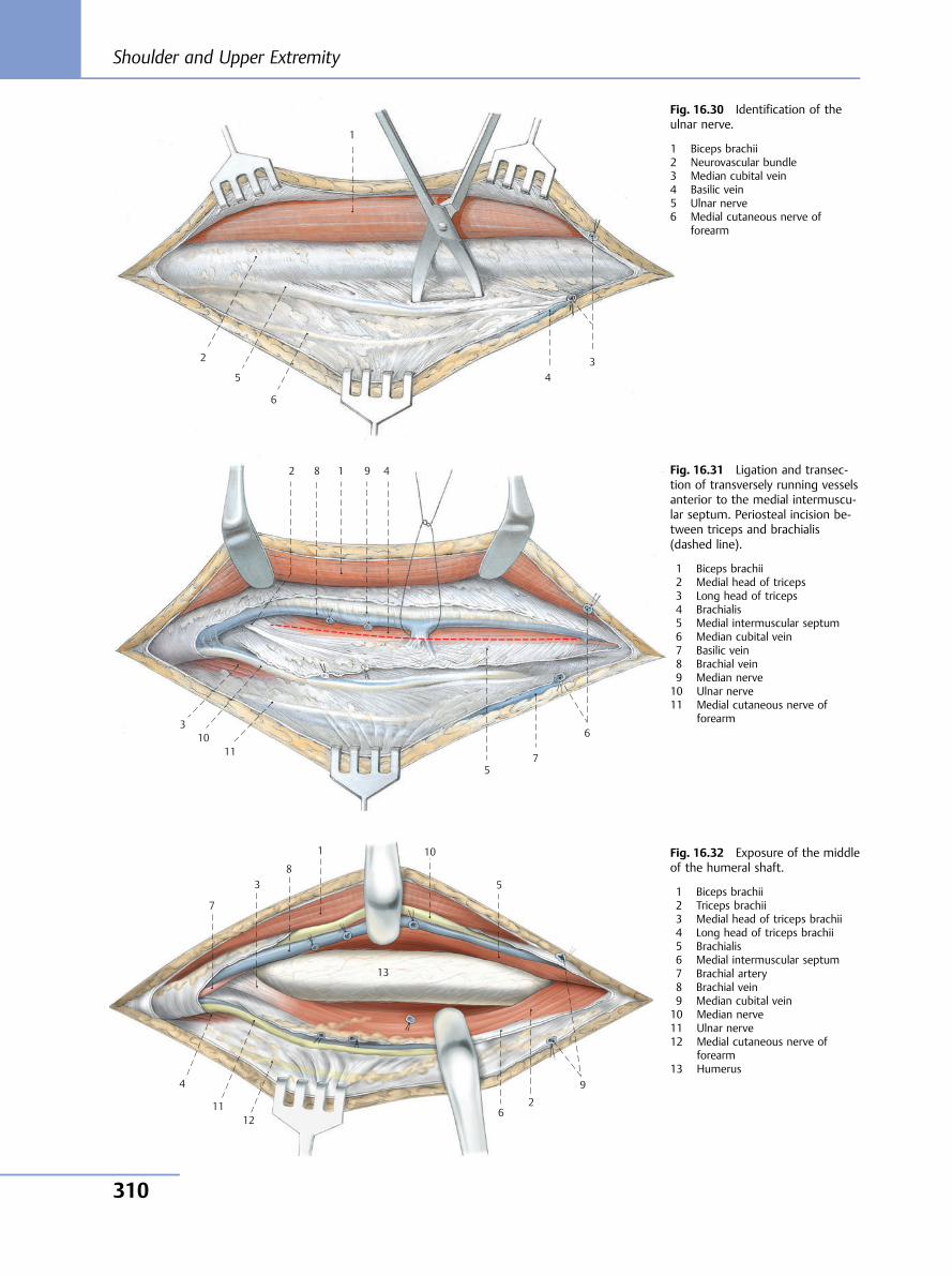
6
5 4 3
1
2
Fig. 16.30 Identification of theulnar nerve.
1 Biceps brachii2 Neurovascular bundle3 Median cubital vein4 Basilic vein5 Ulnar nerve6 Medial cutaneous nerve of
forearm
10 11
9 8
7
6
5
4
3
1 2 Fig. 16.31 Ligation and transec-tion of transversely running vesselsanterior to the medial intermuscu-lar septum. Periosteal incision be-tween triceps and brachialis(dashed line).
1 Biceps brachii2 Medial head of triceps3 Long head of triceps4 Brachialis5 Medial intermuscular septum6 Median cubital vein7 Basilic vein8 Brachial vein9 Median nerve10 Ulnar nerve11 Medial cutaneous nerve of
forearm
7
3 8
1 10
5
13
9
26
1211
4
Fig. 16.32 Exposure of the middleof the humeral shaft.
1 Biceps brachii2 Triceps brachii3 Medial head of triceps brachii4 Long head of triceps brachii5 Brachialis6 Medial intermuscular septum7 Brachial artery8 Brachial vein9 Median cubital vein10 Median nerve11 Ulnar nerve12 Medial cutaneous nerve of
forearm13 Humerus
Shoulder and Upper Extremity
310
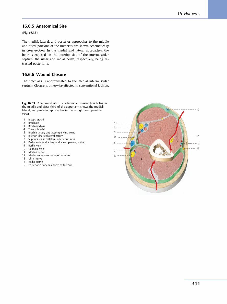
16.6.5 Anatomical Site
(Fig. 16.33)
The medial, lateral, and posterior approaches to the middleand distal portions of the humerus are shown schematicallyin cross-section. In the medial and lateral approaches, thebone is exposed on the anterior side of the intermuscularseptum, the ulnar and radial nerve, respectively, being re-tracted posteriorly.
16.6.6 Wound Closure
The brachialis is approximated to the medial intermuscularseptum. Closure is otherwise effected in conventional fashion.
10
11
12
13
14
15
9 8
7
6
5
1
2
3
4
4
Fig. 16.33 Anatomical site. The schematic cross-section betweenthe middle and distal third of the upper arm shows the medial,lateral, and posterior approaches (arrows) (right arm, proximalview).
1 Biceps brachii2 Brachialis3 Brachioradialis4 Triceps brachii5 Brachial artery and accompanying veins6 Inferior ulnar collateral artery7 Superior ulnar collateral artery and vein8 Radial collateral artery and accompanying veins9 Basilic vein10 Cephalic vein11 Median nerve12 Medial cutaneous nerve of forearm13 Ulnar nerve14 Radial nerve15 Posterior cutaneous nerve of forearm
16 Humerus
311
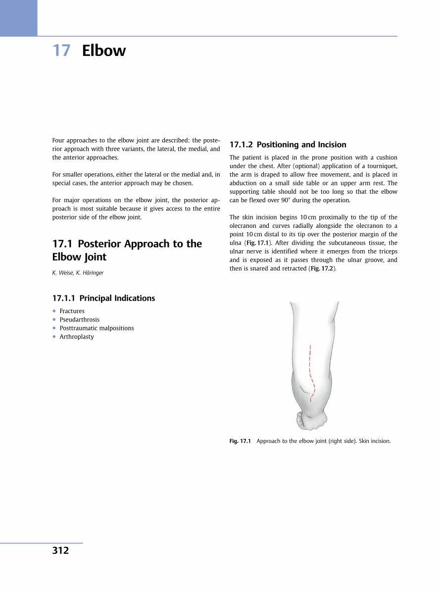
17 Elbow
Four approaches to the elbow joint are described: the poste-rior approach with three variants, the lateral, the medial, andthe anterior approaches.
For smaller operations, either the lateral or the medial and, inspecial cases, the anterior approach may be chosen.
For major operations on the elbow joint, the posterior ap-proach is most suitable because it gives access to the entireposterior side of the elbow joint.
17.1 Posterior Approach to theElbow JointK. Weise, K. Häringer
17.1.1 Principal Indications● Fractures● Pseudarthrosis● Posttraumatic malpositions● Arthroplasty
17.1.2 Positioning and Incision
The patient is placed in the prone position with a cushionunder the chest. After (optional) application of a tourniquet,the arm is draped to allow free movement, and is placed inabduction on a small side table or an upper arm rest. Thesupporting table should not be too long so that the elbowcan be flexed over 90° during the operation.
The skin incision begins 10 cm proximally to the tip of theolecranon and curves radially alongside the olecranon to apoint 10 cm distal to its tip over the posterior margin of theulna (Fig. 17.1). After dividing the subcutaneous tissue, theulnar nerve is identified where it emerges from the tricepsand is exposed as it passes through the ulnar groove, andthen is snared and retracted (Fig. 17.2).
Fig. 17.1 Approach to the elbow joint (right side). Skin incision.
Shoulder and Upper Extremity
312
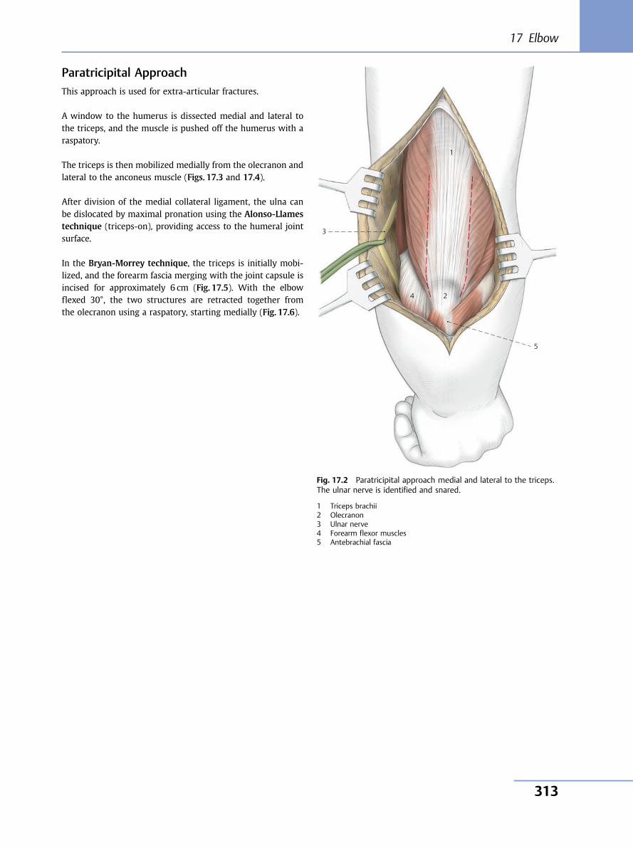
Paratricipital ApproachThis approach is used for extra-articular fractures.
A window to the humerus is dissected medial and lateral tothe triceps, and the muscle is pushed off the humerus with araspatory.
The triceps is then mobilized medially from the olecranon andlateral to the anconeus muscle (Figs. 17.3 and 17.4).
After division of the medial collateral ligament, the ulna canbe dislocated by maximal pronation using the Alonso-Llamestechnique (triceps-on), providing access to the humeral jointsurface.
In the Bryan-Morrey technique, the triceps is initially mobi-lized, and the forearm fascia merging with the joint capsule isincised for approximately 6 cm (Fig. 17.5). With the elbowflexed 30°, the two structures are retracted together fromthe olecranon using a raspatory, starting medially (Fig. 17.6).
1
3
4 2
5
Fig. 17.2 Paratricipital approach medial and lateral to the triceps.The ulnar nerve is identified and snared.
1 Triceps brachii2 Olecranon3 Ulnar nerve4 Forearm flexor muscles5 Antebrachial fascia
17 Elbow
313
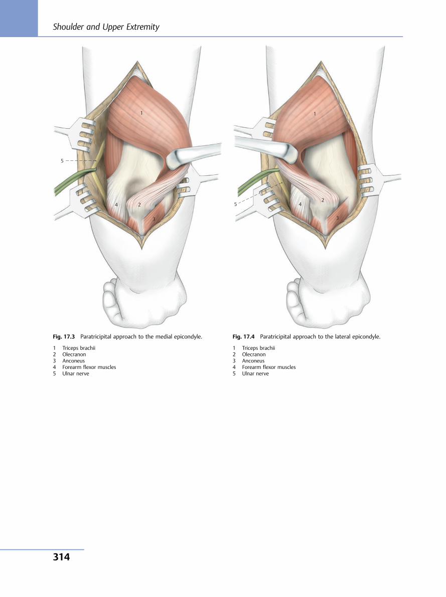
1
2
3
4 5
1
5
4 2
3
Fig. 17.3 Paratricipital approach to the medial epicondyle.
1 Triceps brachii2 Olecranon3 Anconeus4 Forearm flexor muscles5 Ulnar nerve
Fig. 17.4 Paratricipital approach to the lateral epicondyle.
1 Triceps brachii2 Olecranon3 Anconeus4 Forearm flexor muscles5 Ulnar nerve
Shoulder and Upper Extremity
314
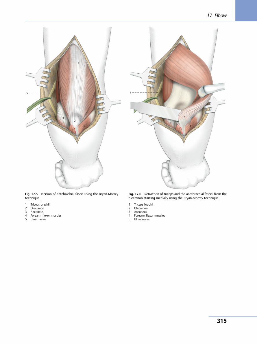
5
1
24
3
Fig. 17.5 Incision of antebrachial fascia using the Bryan-Morreytechnique.
1 Triceps brachii2 Olecranon3 Anconeus4 Forearm flexor muscles5 Ulnar nerve
5
1
2
3 4
Fig. 17.6 Retraction of triceps and the antebrachial fascial from theolecranon starting medially using the Bryan-Morrey technique.
1 Triceps brachii2 Olecranon3 Anconeus4 Forearm flexor muscles5 Ulnar nerve
17 Elbow
315
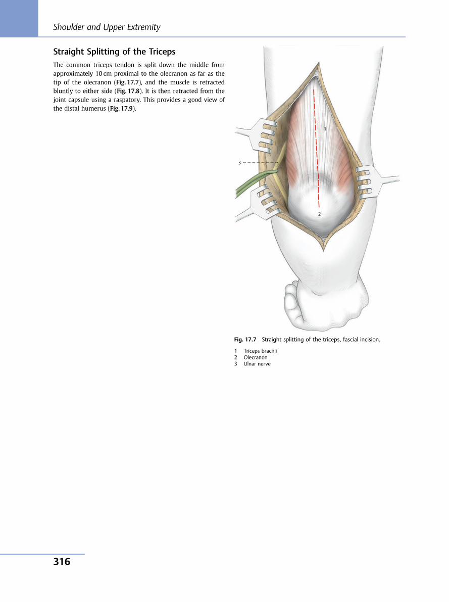
Straight Splitting of the TricepsThe common triceps tendon is split down the middle fromapproximately 10 cm proximal to the olecranon as far as thetip of the olecranon (Fig. 17.7), and the muscle is retractedbluntly to either side (Fig. 17.8). It is then retracted from thejoint capsule using a raspatory. This provides a good view ofthe distal humerus (Fig. 17.9).
1
2
3
Fig. 17.7 Straight splitting of the triceps, fascial incision.
1 Triceps brachii2 Olecranon3 Ulnar nerve
Shoulder and Upper Extremity
316
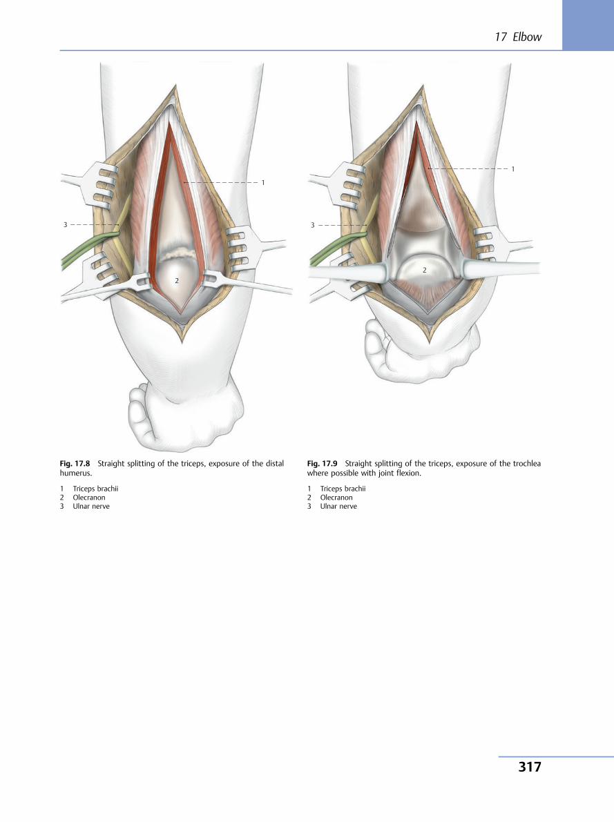
3
2
1
Fig. 17.8 Straight splitting of the triceps, exposure of the distalhumerus.
1 Triceps brachii2 Olecranon3 Ulnar nerve
3
1
2
Fig. 17.9 Straight splitting of the triceps, exposure of the trochleawhere possible with joint flexion.
1 Triceps brachii2 Olecranon3 Ulnar nerve
17 Elbow
317
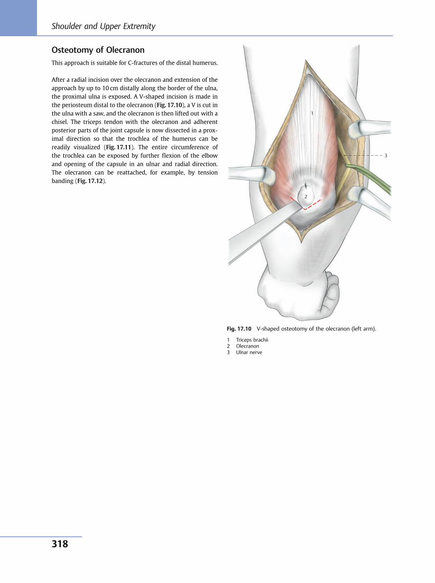
Osteotomy of OlecranonThis approach is suitable for C-fractures of the distal humerus.
After a radial incision over the olecranon and extension of theapproach by up to 10 cm distally along the border of the ulna,the proximal ulna is exposed. A V-shaped incision is made inthe periosteum distal to the olecranon (Fig. 17.10), a V is cut inthe ulna with a saw, and the olecranon is then lifted out with achisel. The triceps tendon with the olecranon and adherentposterior parts of the joint capsule is now dissected in a prox-imal direction so that the trochlea of the humerus can bereadily visualized (Fig. 17.11). The entire circumference ofthe trochlea can be exposed by further flexion of the elbowand opening of the capsule in an ulnar and radial direction.The olecranon can be reattached, for example, by tensionbanding (Fig. 17.12).
3
1
2
Fig. 17.10 V-shaped osteotomy of the olecranon (left arm).
1 Triceps brachii2 Olecranon3 Ulnar nerve
Shoulder and Upper Extremity
318
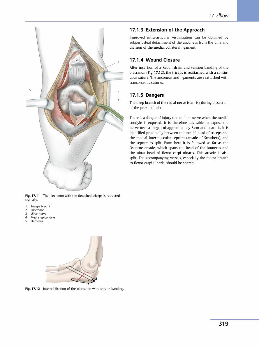
17.1.3 Extension of the Approach
Improved intra-articular visualization can be obtained bysubperiosteal detachment of the anconeus from the ulna anddivision of the medial collateral ligament.
17.1.4 Wound Closure
After insertion of a Redon drain and tension banding of theolecranon (Fig. 17.12), the triceps is reattached with a contin-uous suture. The anconeus and ligaments are reattached withtransosseous sutures.
17.1.5 Dangers
The deep branch of the radial nerve is at risk during dissectionof the proximal ulna.
There is a danger of injury to the ulnar nerve when the medialcondyle is exposed. It is therefore advisable to expose thenerve over a length of approximately 8 cm and snare it. It isidentified proximally between the medial head of triceps andthe medial intermuscular septum (arcade of Struthers), andthe septum is split. From here it is followed as far as theOsborne arcade, which spans the head of the humerus andthe ulnar head of flexor carpi ulnaris. This arcade is alsosplit. The accompanying vessels, especially the motor branchto flexor carpi ulnaris, should be spared.
5
2 1
3
4
Fig. 17.11 The olecranon with the detached triceps is retractedcranially.
1 Triceps brachii2 Olecranon3 Ulnar nerve4 Medial epicondyle5 Humerus
Fig. 17.12 Internal fixation of the olecranon with tension banding.
17 Elbow
319
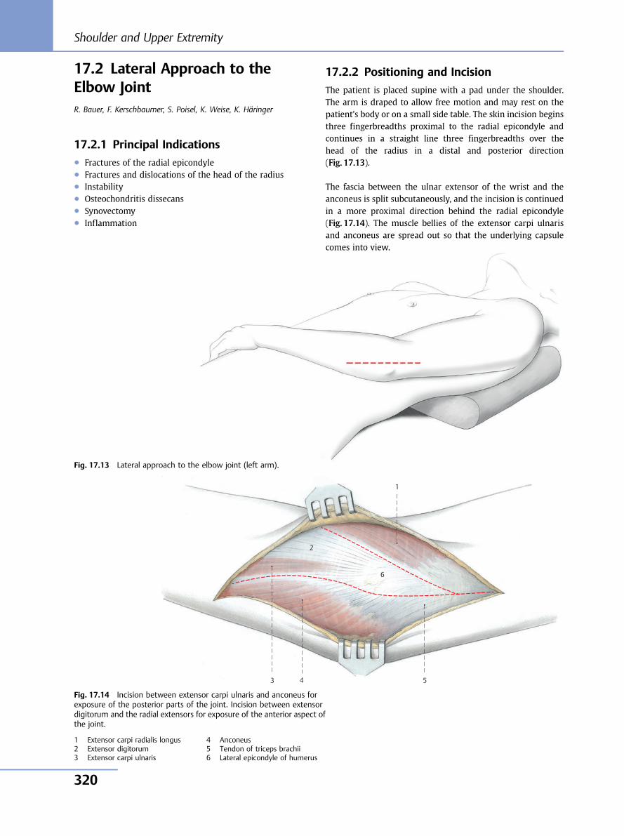
17.2 Lateral Approach to theElbow JointR. Bauer, F. Kerschbaumer, S. Poisel, K. Weise, K. Häringer
17.2.1 Principal Indications● Fractures of the radial epicondyle● Fractures and dislocations of the head of the radius● Instability● Osteochondritis dissecans● Synovectomy● Inflammation
17.2.2 Positioning and Incision
The patient is placed supine with a pad under the shoulder.The arm is draped to allow free motion and may rest on thepatient’s body or on a small side table. The skin incision beginsthree fingerbreadths proximal to the radial epicondyle andcontinues in a straight line three fingerbreadths over thehead of the radius in a distal and posterior direction(Fig. 17.13).
The fascia between the ulnar extensor of the wrist and theanconeus is split subcutaneously, and the incision is continuedin a more proximal direction behind the radial epicondyle(Fig. 17.14). The muscle bellies of the extensor carpi ulnarisand anconeus are spread out so that the underlying capsulecomes into view.
Fig. 17.13 Lateral approach to the elbow joint (left arm).
6
5 4 3
1
2
Fig. 17.14 Incision between extensor carpi ulnaris and anconeus forexposure of the posterior parts of the joint. Incision between extensordigitorum and the radial extensors for exposure of the anterior aspect ofthe joint.
1 Extensor carpi radialis longus2 Extensor digitorum3 Extensor carpi ulnaris
4 Anconeus5 Tendon of triceps brachii6 Lateral epicondyle of humerus
Shoulder and Upper Extremity
320
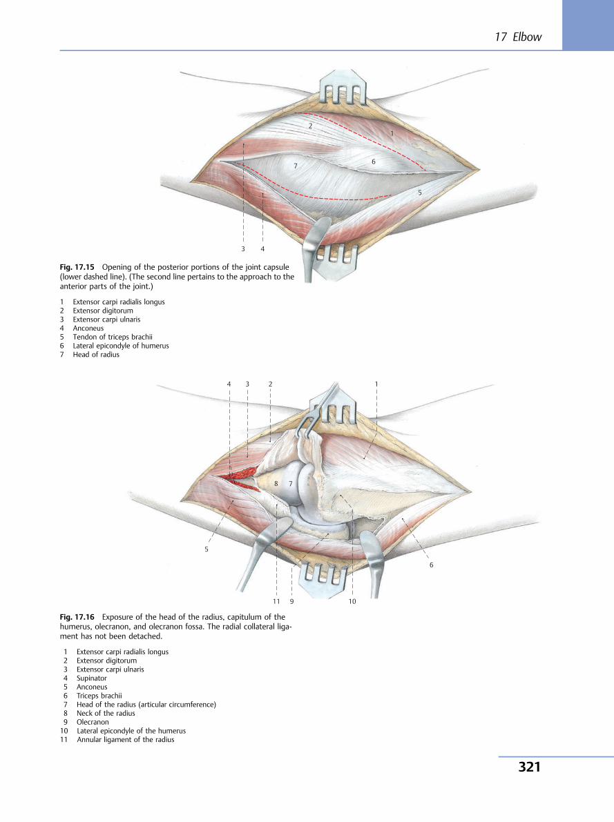
7 6
5
4 3
1 2
Fig. 17.15 Opening of the posterior portions of the joint capsule(lower dashed line). (The second line pertains to the approach to theanterior parts of the joint.)
1 Extensor carpi radialis longus2 Extensor digitorum3 Extensor carpi ulnaris4 Anconeus5 Tendon of triceps brachii6 Lateral epicondyle of humerus7 Head of radius
10 11 9
8 7
6
5
4 3 1 2
Fig. 17.16 Exposure of the head of the radius, capitulum of thehumerus, olecranon, and olecranon fossa. The radial collateral liga-ment has not been detached.
1 Extensor carpi radialis longus2 Extensor digitorum3 Extensor carpi ulnaris4 Supinator5 Anconeus6 Triceps brachii7 Head of the radius (articular circumference)8 Neck of the radius9 Olecranon10 Lateral epicondyle of the humerus11 Annular ligament of the radius
17 Elbow
321
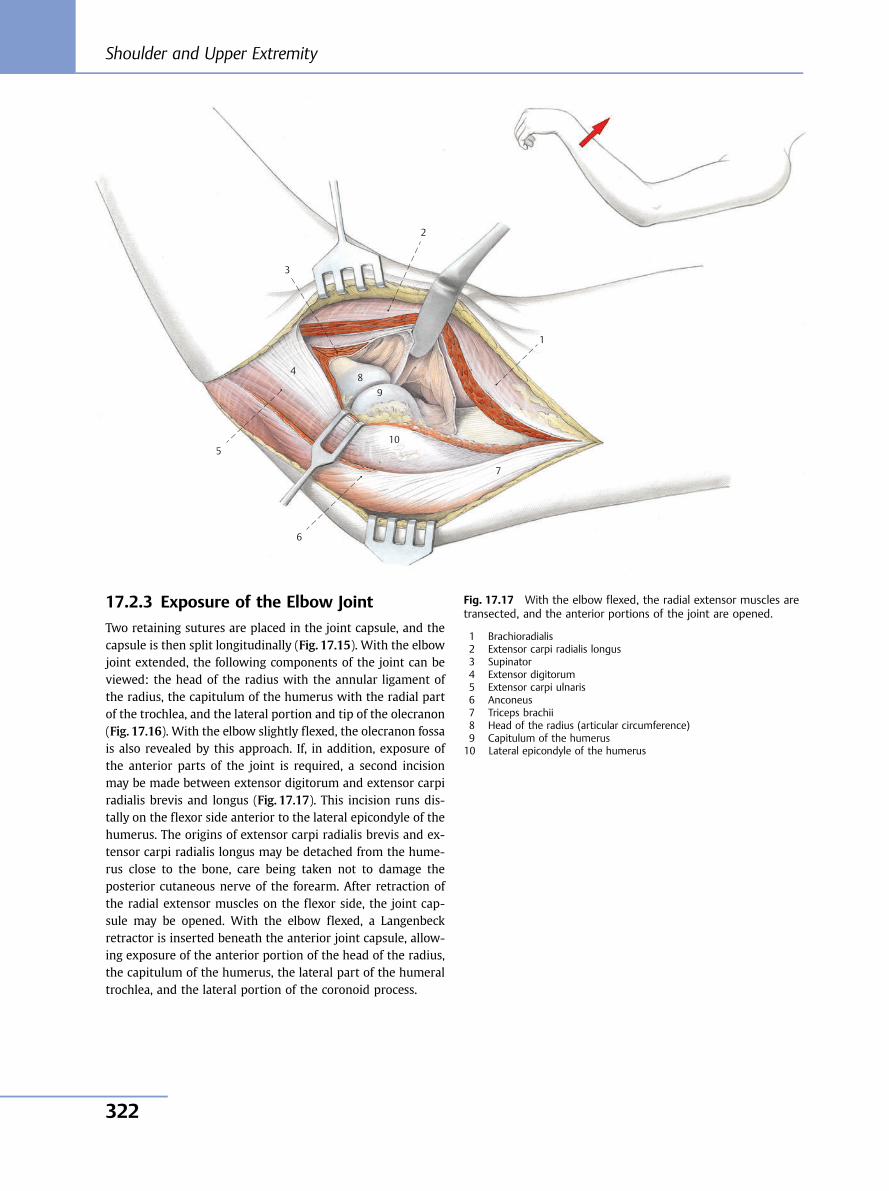
17.2.3 Exposure of the Elbow Joint
Two retaining sutures are placed in the joint capsule, and thecapsule is then split longitudinally (Fig. 17.15). With the elbowjoint extended, the following components of the joint can beviewed: the head of the radius with the annular ligament ofthe radius, the capitulum of the humerus with the radial partof the trochlea, and the lateral portion and tip of the olecranon(Fig. 17.16). With the elbow slightly flexed, the olecranon fossais also revealed by this approach. If, in addition, exposure ofthe anterior parts of the joint is required, a second incisionmay be made between extensor digitorum and extensor carpiradialis brevis and longus (Fig. 17.17). This incision runs dis-tally on the flexor side anterior to the lateral epicondyle of thehumerus. The origins of extensor carpi radialis brevis and ex-tensor carpi radialis longus may be detached from the hume-rus close to the bone, care being taken not to damage theposterior cutaneous nerve of the forearm. After retraction ofthe radial extensor muscles on the flexor side, the joint cap-sule may be opened. With the elbow flexed, a Langenbeckretractor is inserted beneath the anterior joint capsule, allow-ing exposure of the anterior portion of the head of the radius,the capitulum of the humerus, the lateral part of the humeraltrochlea, and the lateral portion of the coronoid process.
10
9 8
7
6
5
4
3
1
2
Fig. 17.17 With the elbow flexed, the radial extensor muscles aretransected, and the anterior portions of the joint are opened.
1 Brachioradialis2 Extensor carpi radialis longus3 Supinator4 Extensor digitorum5 Extensor carpi ulnaris6 Anconeus7 Triceps brachii8 Head of the radius (articular circumference)9 Capitulum of the humerus10 Lateral epicondyle of the humerus
Shoulder and Upper Extremity
322
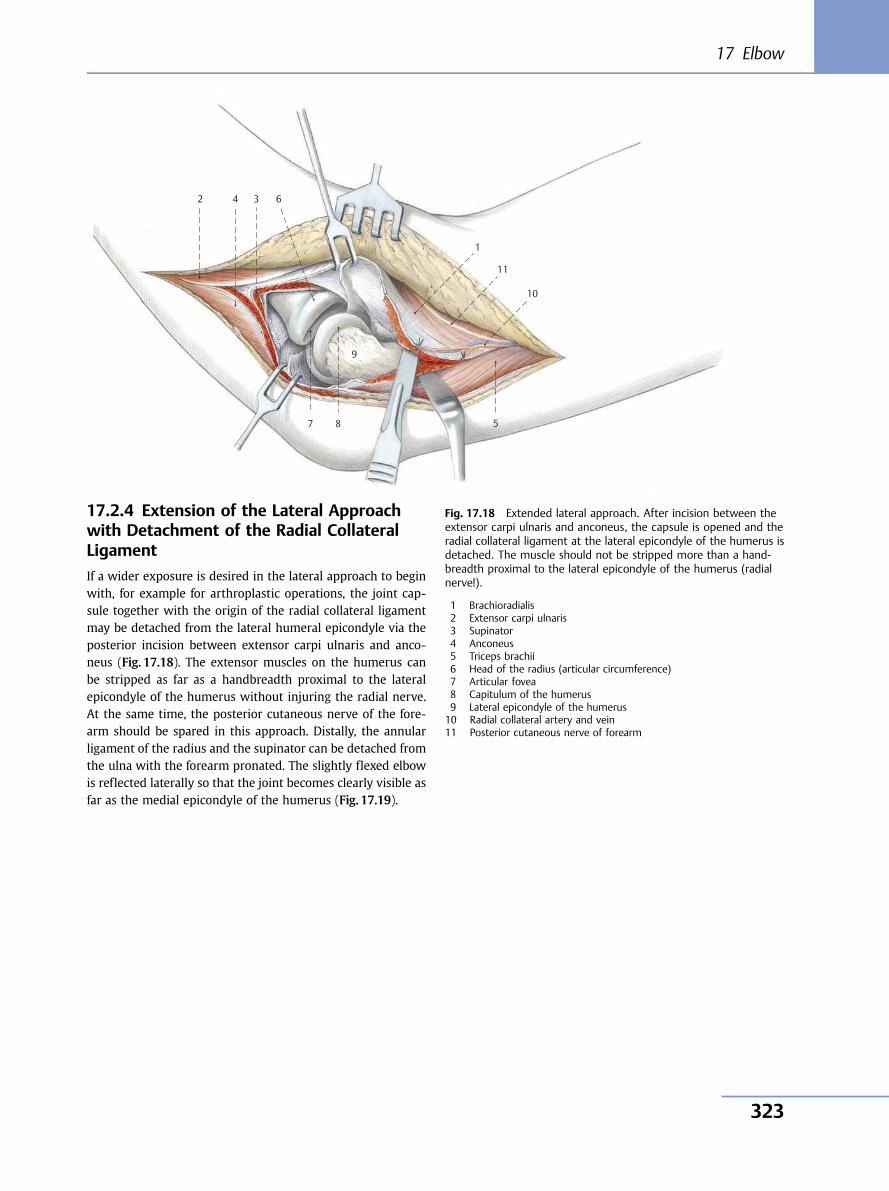
17.2.4 Extension of the Lateral Approachwith Detachment of the Radial CollateralLigament
If a wider exposure is desired in the lateral approach to beginwith, for example for arthroplastic operations, the joint cap-sule together with the origin of the radial collateral ligamentmay be detached from the lateral humeral epicondyle via theposterior incision between extensor carpi ulnaris and anco-neus (Fig. 17.18). The extensor muscles on the humerus canbe stripped as far as a handbreadth proximal to the lateralepicondyle of the humerus without injuring the radial nerve.At the same time, the posterior cutaneous nerve of the fore-arm should be spared in this approach. Distally, the annularligament of the radius and the supinator can be detached fromthe ulna with the forearm pronated. The slightly flexed elbowis reflected laterally so that the joint becomes clearly visible asfar as the medial epicondyle of the humerus (Fig. 17.19).
10
11
9
8 7
6
5
4 3
1
2
Fig. 17.18 Extended lateral approach. After incision between theextensor carpi ulnaris and anconeus, the capsule is opened and theradial collateral ligament at the lateral epicondyle of the humerus isdetached. The muscle should not be stripped more than a hand-breadth proximal to the lateral epicondyle of the humerus (radialnerve!).
1 Brachioradialis2 Extensor carpi ulnaris3 Supinator4 Anconeus5 Triceps brachii6 Head of the radius (articular circumference)7 Articular fovea8 Capitulum of the humerus9 Lateral epicondyle of the humerus10 Radial collateral artery and vein11 Posterior cutaneous nerve of forearm
17 Elbow
323
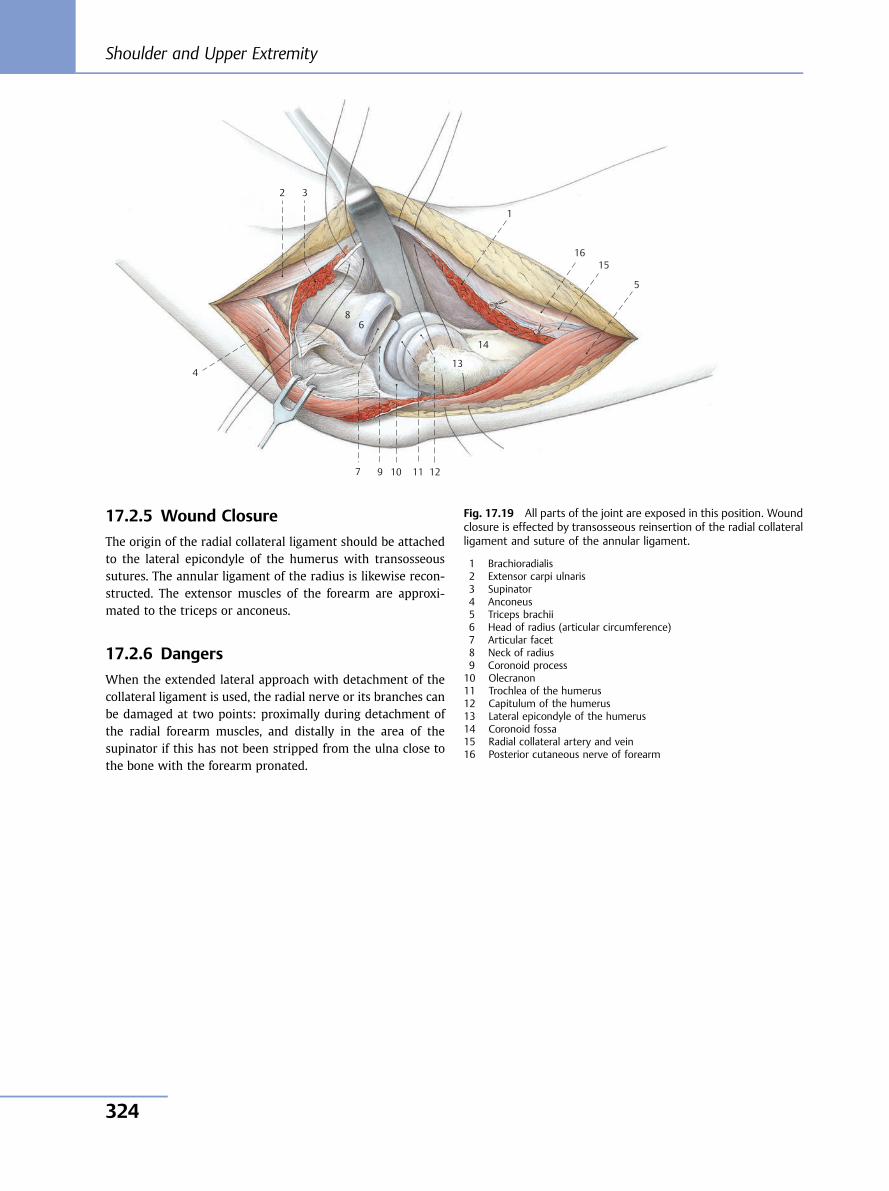
17.2.5 Wound Closure
The origin of the radial collateral ligament should be attachedto the lateral epicondyle of the humerus with transosseoussutures. The annular ligament of the radius is likewise recon-structed. The extensor muscles of the forearm are approxi-mated to the triceps or anconeus.
17.2.6 Dangers
When the extended lateral approach with detachment of thecollateral ligament is used, the radial nerve or its branches canbe damaged at two points: proximally during detachment ofthe radial forearm muscles, and distally in the area of thesupinator if this has not been stripped from the ulna close tothe bone with the forearm pronated.
10 11 12
13
14
15 16
9
8
7
6
5
4
3
1
2
Fig. 17.19 All parts of the joint are exposed in this position. Woundclosure is effected by transosseous reinsertion of the radial collateralligament and suture of the annular ligament.
1 Brachioradialis2 Extensor carpi ulnaris3 Supinator4 Anconeus5 Triceps brachii6 Head of radius (articular circumference)7 Articular facet8 Neck of radius9 Coronoid process10 Olecranon11 Trochlea of the humerus12 Capitulum of the humerus13 Lateral epicondyle of the humerus14 Coronoid fossa15 Radial collateral artery and vein16 Posterior cutaneous nerve of forearm
Shoulder and Upper Extremity
324
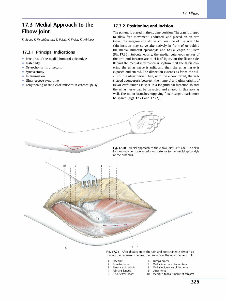
17.3 Medial Approach to theElbow JointR. Bauer, F. Kerschbaumer, S. Poisel, K. Weise, K. Häringer
17.3.1 Principal Indications● Fractures of the medial humeral epicondyle● Instability● Osteochondritis dissecans● Synovectomy● Inflammation● Ulnar groove syndrome● Lengthening of the flexor muscles in cerebral palsy
17.3.2 Positioning and Incision
The patient is placed in the supine position. The arm is drapedto allow free movement, abducted, and placed on an armtable. The surgeon sits at the axillary side of the arm. Theskin incision may curve alternatively in front of or behindthe medial humeral epicondyle and has a length of 10 cm(Fig. 17.20). Subcutaneously, the medial cutaneous nerves ofthe arm and forearm are at risk of injury on the flexor side.Behind the medial intermuscular septum, first the fascia cov-ering the ulnar nerve is split, and then the ulnar nerve isexposed and snared. The dissection extends as far as the sul-cus of the ulnar nerve. Then, with the elbow flexed, the sail-shaped aponeurosis between the humeral and ulnar origins offlexor carpi ulnaris is split in a longitudinal direction so thatthe ulnar nerve can be dissected and snared in this area aswell. The motor branches supplying flexor carpi ulnaris mustbe spared (Figs. 17.21 and 17.22).
10 9
8
7
6 5 4
3 1 2
Fig. 17.20 Medial approach to the elbow joint (left side). The skinincision may be made anterior or posterior to the medial epicondyleof the humerus.
Fig. 17.21 After dissection of the skin and subcutaneous tissue flapsparing the cutaneous nerves, the fascia over the ulnar nerve is split.
1 Brachialis2 Pronator teres3 Flexor carpi radialis4 Palmaris longus5 Flexor carpi ulnaris
6 Triceps brachii7 Medial intermuscular septum8 Medial epicondyle of humerus9 Ulnar nerve10 Medial cutaneous nerve of forearm
17 Elbow
325
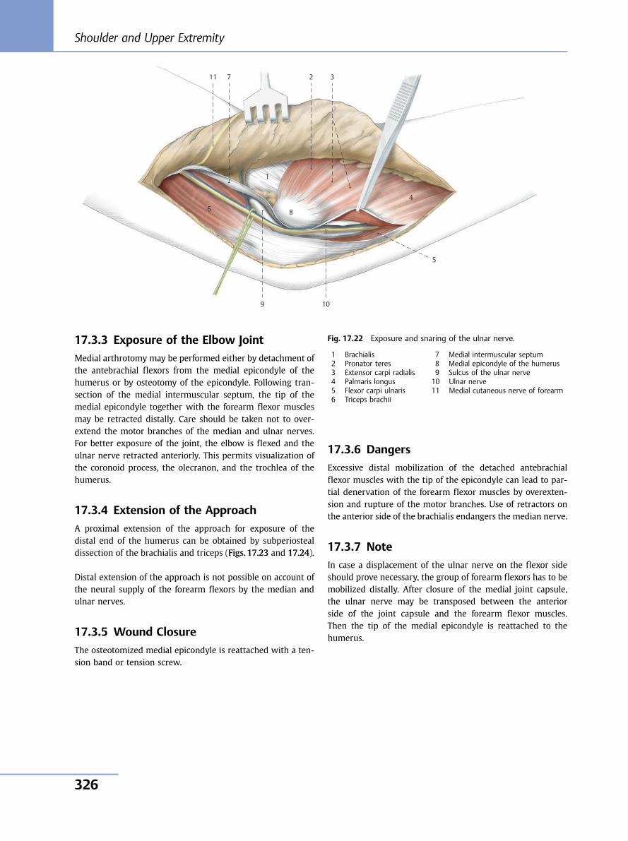
17.3.3 Exposure of the Elbow Joint
Medial arthrotomy may be performed either by detachment ofthe antebrachial flexors from the medial epicondyle of thehumerus or by osteotomy of the epicondyle. Following tran-section of the medial intermuscular septum, the tip of themedial epicondyle together with the forearm flexor musclesmay be retracted distally. Care should be taken not to over-extend the motor branches of the median and ulnar nerves.For better exposure of the joint, the elbow is flexed and theulnar nerve retracted anteriorly. This permits visualization ofthe coronoid process, the olecranon, and the trochlea of thehumerus.
17.3.4 Extension of the Approach
A proximal extension of the approach for exposure of thedistal end of the humerus can be obtained by subperiostealdissection of the brachialis and triceps (Figs. 17.23 and 17.24).
Distal extension of the approach is not possible on account ofthe neural supply of the forearm flexors by the median andulnar nerves.
17.3.5 Wound Closure
The osteotomized medial epicondyle is reattached with a ten-sion band or tension screw.
17.3.6 Dangers
Excessive distal mobilization of the detached antebrachialflexor muscles with the tip of the epicondyle can lead to par-tial denervation of the forearm flexor muscles by overexten-sion and rupture of the motor branches. Use of retractors onthe anterior side of the brachialis endangers the median nerve.
17.3.7 Note
In case a displacement of the ulnar nerve on the flexor sideshould prove necessary, the group of forearm flexors has to bemobilized distally. After closure of the medial joint capsule,the ulnar nerve may be transposed between the anteriorside of the joint capsule and the forearm flexor muscles.Then the tip of the medial epicondyle is reattached to thehumerus.
11 7 2 3
4
5
8
1
6
9 10
Fig. 17.22 Exposure and snaring of the ulnar nerve.
1 Brachialis2 Pronator teres3 Extensor carpi radialis4 Palmaris longus5 Flexor carpi ulnaris6 Triceps brachii
7 Medial intermuscular septum8 Medial epicondyle of the humerus9 Sulcus of the ulnar nerve10 Ulnar nerve11 Medial cutaneous nerve of forearm
Shoulder and Upper Extremity
326
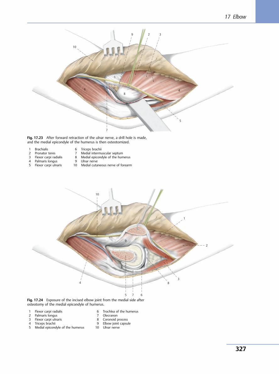
10
1
9 2 3
5
7
68
4
Fig. 17.23 After forward retraction of the ulnar nerve, a drill hole is made,and the medial epicondyle of the humerus is then osteotomized.
1 Brachialis2 Pronator teres3 Flexor carpi radialis4 Palmaris longus5 Flexor carpi ulnaris
6 Triceps brachii7 Medial intermuscular septum8 Medial epicondyle of the humerus9 Ulnar nerve10 Medial cutaneous nerve of forearm
10
1
2
3 8
6 7 5
4
9
Fig. 17.24 Exposure of the incised elbow joint from the medial side afterosteotomy of the medial epicondyle of humerus.
1 Flexor carpi radialis2 Palmaris longus3 Flexor carpi ulnaris4 Triceps brachii5 Medial epicondyle of the humerus
6 Trochlea of the humerus7 Olecranon8 Coronoid process9 Elbow joint capsule10 Ulnar nerve
17 Elbow
327
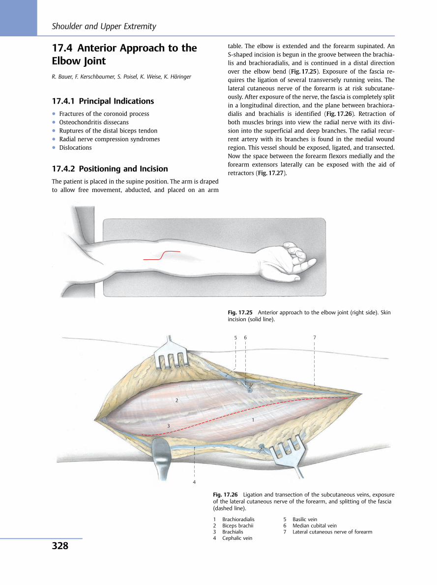
17.4 Anterior Approach to theElbow JointR. Bauer, F. Kerschbaumer, S. Poisel, K. Weise, K. Häringer
17.4.1 Principal Indications● Fractures of the coronoid process● Osteochondritis dissecans● Ruptures of the distal biceps tendon● Radial nerve compression syndromes● Dislocations
17.4.2 Positioning and Incision
The patient is placed in the supine position. The arm is drapedto allow free movement, abducted, and placed on an arm
table. The elbow is extended and the forearm supinated. AnS-shaped incision is begun in the groove between the brachia-lis and brachioradialis, and is continued in a distal directionover the elbow bend (Fig. 17.25). Exposure of the fascia re-quires the ligation of several transversely running veins. Thelateral cutaneous nerve of the forearm is at risk subcutane-ously. After exposure of the nerve, the fascia is completely splitin a longitudinal direction, and the plane between brachiora-dialis and brachialis is identified (Fig. 17.26). Retraction ofboth muscles brings into view the radial nerve with its divi-sion into the superficial and deep branches. The radial recur-rent artery with its branches is found in the medial woundregion. This vessel should be exposed, ligated, and transected.Now the space between the forearm flexors medially and theforearm extensors laterally can be exposed with the aid ofretractors (Fig. 17.27).
Fig. 17.25 Anterior approach to the elbow joint (right side). Skinincision (solid line).
7 6 5
4
3 1
2
Fig. 17.26 Ligation and transection of the subcutaneous veins, exposureof the lateral cutaneous nerve of the forearm, and splitting of the fascia(dashed line).
1 Brachioradialis2 Biceps brachii3 Brachialis4 Cephalic vein
5 Basilic vein6 Median cubital vein7 Lateral cutaneous nerve of forearm
Shoulder and Upper Extremity
328
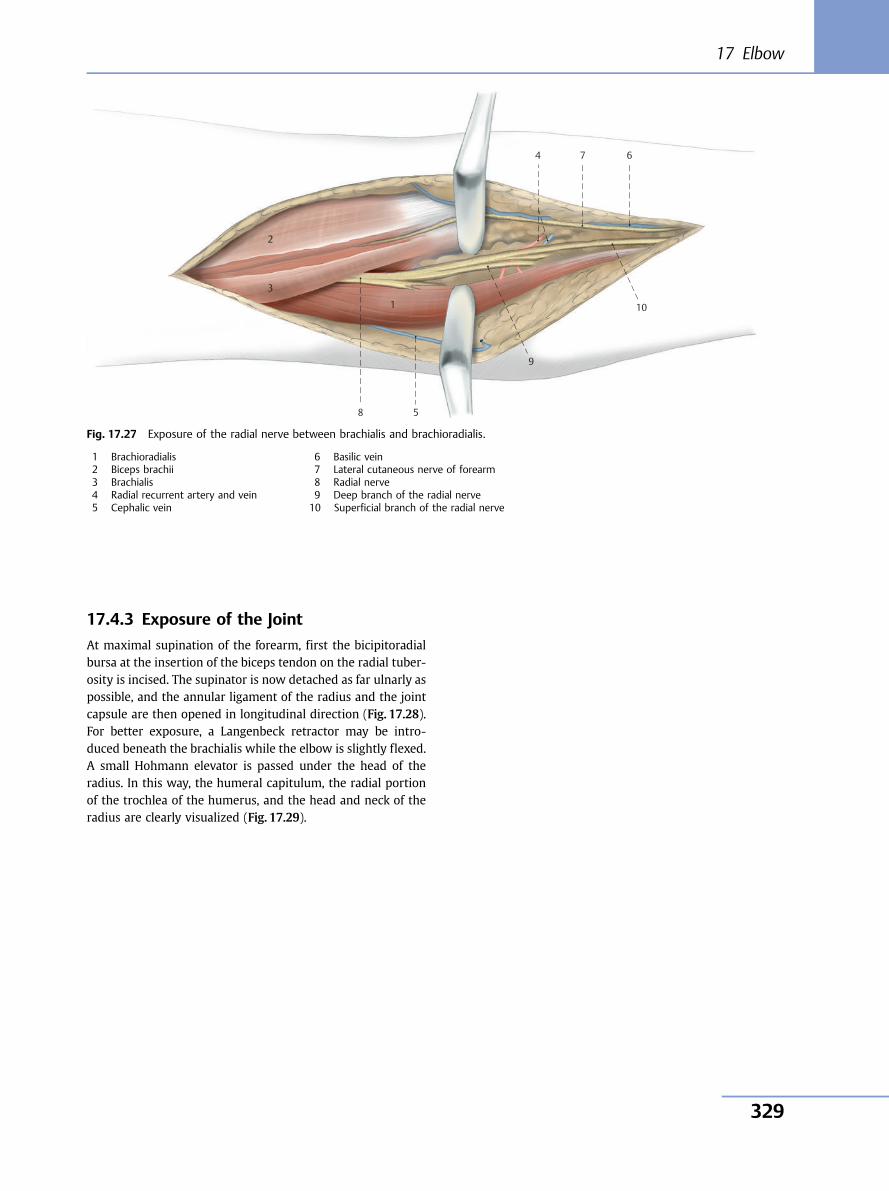
17.4.3 Exposure of the Joint
At maximal supination of the forearm, first the bicipitoradialbursa at the insertion of the biceps tendon on the radial tuber-osity is incised. The supinator is now detached as far ulnarly aspossible, and the annular ligament of the radius and the jointcapsule are then opened in longitudinal direction (Fig. 17.28).For better exposure, a Langenbeck retractor may be intro-duced beneath the brachialis while the elbow is slightly flexed.A small Hohmann elevator is passed under the head of theradius. In this way, the humeral capitulum, the radial portionof the trochlea of the humerus, and the head and neck of theradius are clearly visualized (Fig. 17.29).
4 7 6
10
9
58
1
3
2
Fig. 17.27 Exposure of the radial nerve between brachialis and brachioradialis.
1 Brachioradialis2 Biceps brachii3 Brachialis4 Radial recurrent artery and vein5 Cephalic vein
6 Basilic vein7 Lateral cutaneous nerve of forearm8 Radial nerve9 Deep branch of the radial nerve10 Superficial branch of the radial nerve
17 Elbow
329
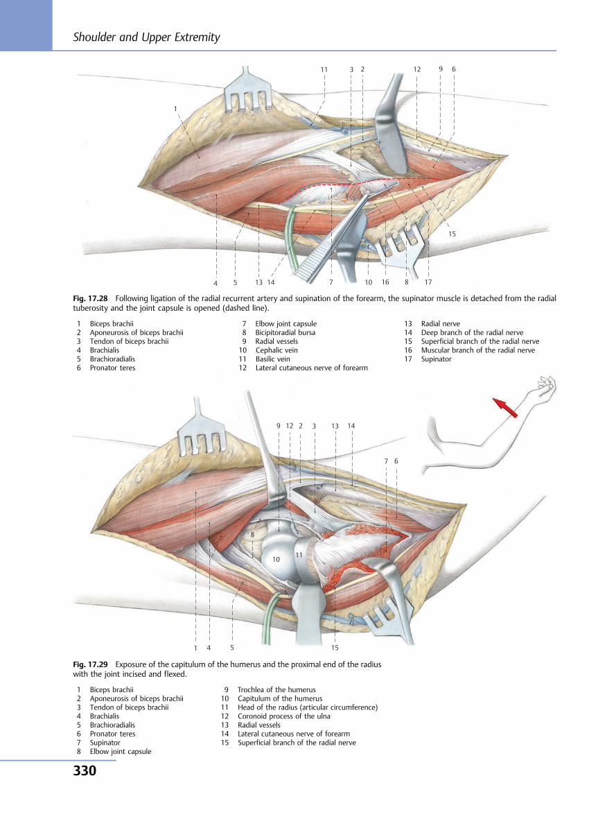
10
11 12
13 14
15
16 17
9
8 7
6
5 4
3
1
2
10 11
12 13 14
15
9
8
7 6
5 4
3
1
2
Fig. 17.28 Following ligation of the radial recurrent artery and supination of the forearm, the supinator muscle is detached from the radialtuberosity and the joint capsule is opened (dashed line).
1 Biceps brachii2 Aponeurosis of biceps brachii3 Tendon of biceps brachii4 Brachialis5 Brachioradialis6 Pronator teres
7 Elbow joint capsule8 Bicipitoradial bursa9 Radial vessels10 Cephalic vein11 Basilic vein12 Lateral cutaneous nerve of forearm
13 Radial nerve14 Deep branch of the radial nerve15 Superficial branch of the radial nerve16 Muscular branch of the radial nerve17 Supinator
Fig. 17.29 Exposure of the capitulum of the humerus and the proximal end of the radiuswith the joint incised and flexed.
1 Biceps brachii2 Aponeurosis of biceps brachii3 Tendon of biceps brachii4 Brachialis5 Brachioradialis6 Pronator teres7 Supinator8 Elbow joint capsule
9 Trochlea of the humerus10 Capitulum of the humerus11 Head of the radius (articular circumference)12 Coronoid process of the ulna13 Radial vessels14 Lateral cutaneous nerve of forearm15 Superficial branch of the radial nerve
Shoulder and Upper Extremity
330
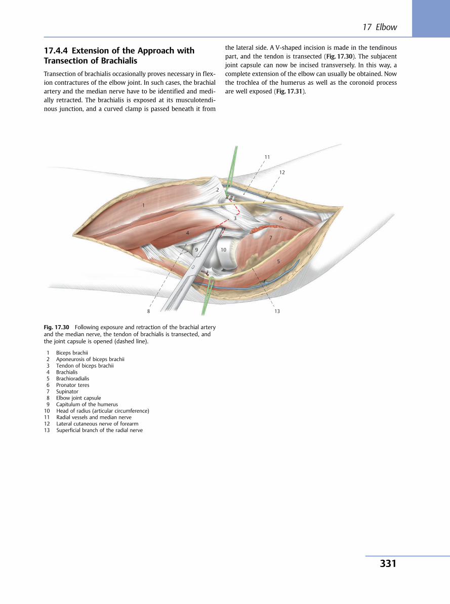
17.4.4 Extension of the Approach withTransection of Brachialis
Transection of brachialis occasionally proves necessary in flex-ion contractures of the elbow joint. In such cases, the brachialartery and the median nerve have to be identified and medi-ally retracted. The brachialis is exposed at its musculotendi-nous junction, and a curved clamp is passed beneath it from
the lateral side. A V-shaped incision is made in the tendinouspart, and the tendon is transected (Fig. 17.30). The subjacentjoint capsule can now be incised transversely. In this way, acomplete extension of the elbow can usually be obtained. Nowthe trochlea of the humerus as well as the coronoid processare well exposed (Fig. 17.31).
11
12
138
9 10
2
1
4
3
7
5
6
Fig. 17.30 Following exposure and retraction of the brachial arteryand the median nerve, the tendon of brachialis is transected, andthe joint capsule is opened (dashed line).
1 Biceps brachii2 Aponeurosis of biceps brachii3 Tendon of biceps brachii4 Brachialis5 Brachioradialis6 Pronator teres7 Supinator8 Elbow joint capsule9 Capitulum of the humerus10 Head of radius (articular circumference)11 Radial vessels and median nerve12 Lateral cutaneous nerve of forearm13 Superficial branch of the radial nerve
17 Elbow
331
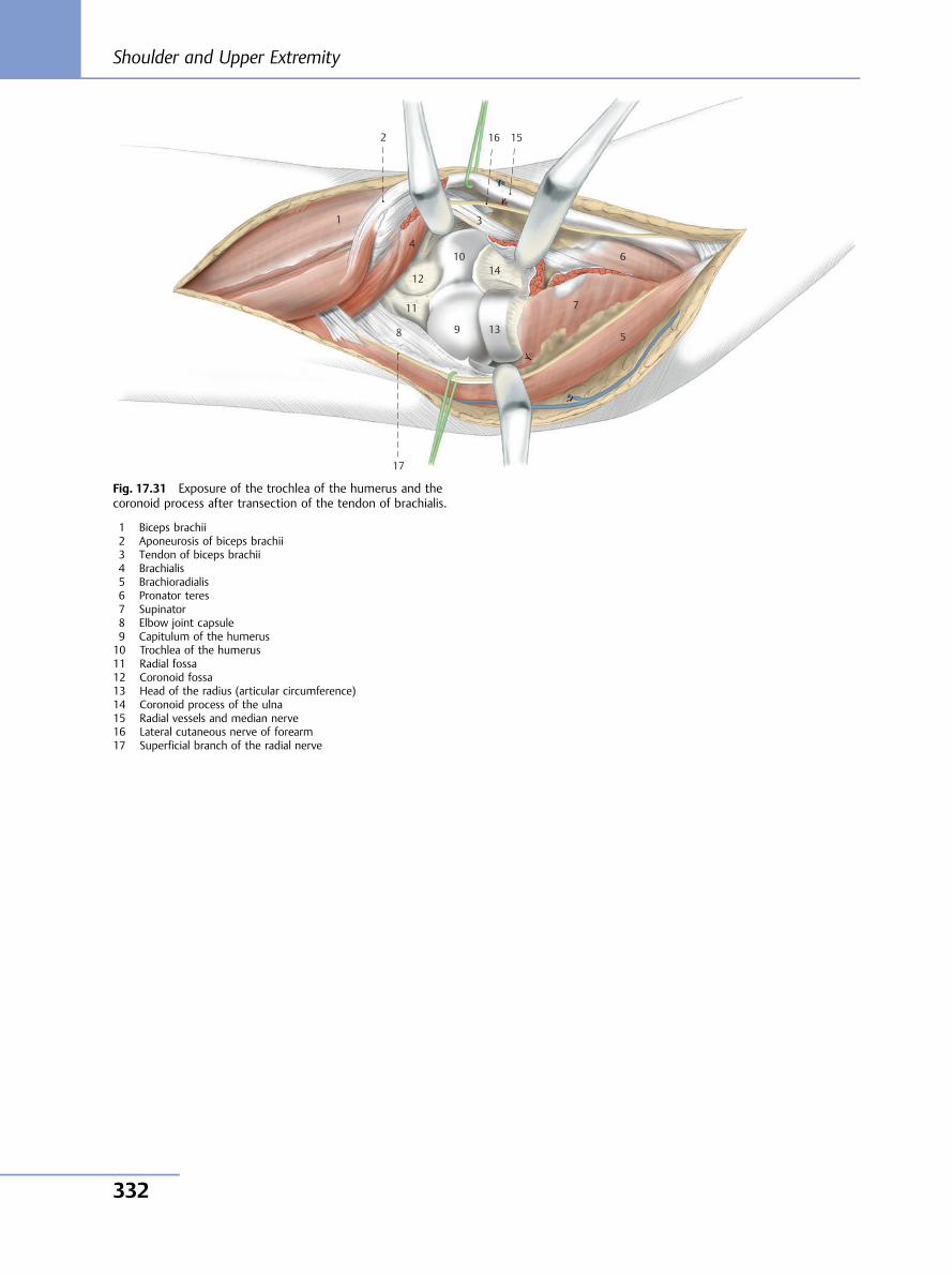
2
17
8
11
13
1410
3
4
7
5
6
9
12
16 15
1
Fig. 17.31 Exposure of the trochlea of the humerus and thecoronoid process after transection of the tendon of brachialis.
1 Biceps brachii2 Aponeurosis of biceps brachii3 Tendon of biceps brachii4 Brachialis5 Brachioradialis6 Pronator teres7 Supinator8 Elbow joint capsule9 Capitulum of the humerus10 Trochlea of the humerus11 Radial fossa12 Coronoid fossa13 Head of the radius (articular circumference)14 Coronoid process of the ulna15 Radial vessels and median nerve16 Lateral cutaneous nerve of forearm17 Superficial branch of the radial nerve
Shoulder and Upper Extremity
332
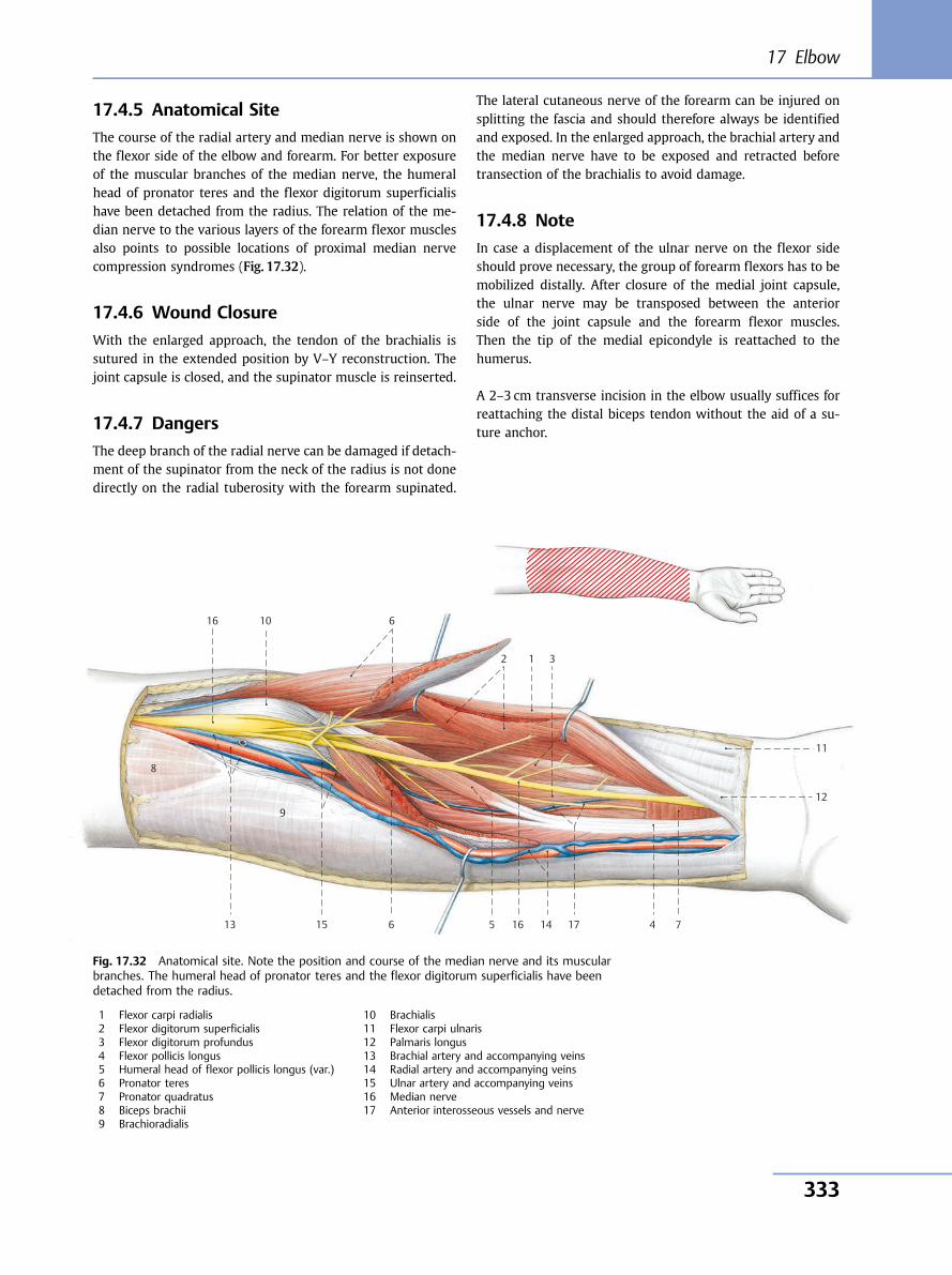
17.4.5 Anatomical Site
The course of the radial artery and median nerve is shown onthe flexor side of the elbow and forearm. For better exposureof the muscular branches of the median nerve, the humeralhead of pronator teres and the flexor digitorum superficialishave been detached from the radius. The relation of the me-dian nerve to the various layers of the forearm flexor musclesalso points to possible locations of proximal median nervecompression syndromes (Fig. 17.32).
17.4.6 Wound Closure
With the enlarged approach, the tendon of the brachialis issutured in the extended position by V–Y reconstruction. Thejoint capsule is closed, and the supinator muscle is reinserted.
17.4.7 Dangers
The deep branch of the radial nerve can be damaged if detach-ment of the supinator from the neck of the radius is not donedirectly on the radial tuberosity with the forearm supinated.
The lateral cutaneous nerve of the forearm can be injured onsplitting the fascia and should therefore always be identifiedand exposed. In the enlarged approach, the brachial artery andthe median nerve have to be exposed and retracted beforetransection of the brachialis to avoid damage.
17.4.8 Note
In case a displacement of the ulnar nerve on the flexor sideshould prove necessary, the group of forearm flexors has to bemobilized distally. After closure of the medial joint capsule,the ulnar nerve may be transposed between the anteriorside of the joint capsule and the forearm flexor muscles.Then the tip of the medial epicondyle is reattached to thehumerus.
A 2–3 cm transverse incision in the elbow usually suffices forreattaching the distal biceps tendon without the aid of a su-ture anchor.
10
11
12
13 14 15
16
17
9
8
7
6
5 4
3 1 2
6 16
Fig. 17.32 Anatomical site. Note the position and course of the median nerve and its muscularbranches. The humeral head of pronator teres and the flexor digitorum superficialis have beendetached from the radius.
1 Flexor carpi radialis2 Flexor digitorum superficialis3 Flexor digitorum profundus4 Flexor pollicis longus5 Humeral head of flexor pollicis longus (var.)6 Pronator teres7 Pronator quadratus8 Biceps brachii9 Brachioradialis
10 Brachialis11 Flexor carpi ulnaris12 Palmaris longus13 Brachial artery and accompanying veins14 Radial artery and accompanying veins15 Ulnar artery and accompanying veins16 Median nerve17 Anterior interosseous vessels and nerve
17 Elbow
333
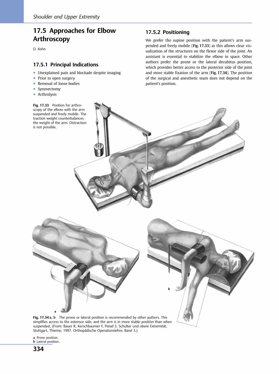
17.5 Approaches for ElbowArthroscopyD. Kohn
17.5.1 Principal Indications● Unexplained pain and blockade despite imaging● Prior to open surgery● Removal of loose bodies● Synovectomy● Arthrolysis
17.5.2 Positioning
We prefer the supine position with the patient’s arm sus-pended and freely mobile (Fig. 17.33) as this allows clear vis-ualization of the structures on the flexor side of the joint. Anassistant is essential to stabilize the elbow in space. Otherauthors prefer the prone or the lateral decubitus position,which provides better access to the posterior side of the jointand more stable fixation of the arm (Fig. 17.34). The positionof the surgical and anesthetic team does not depend on thepatient’s position.
Fig. 17.33 Position for arthro-scopy of the elbow with the armsuspended and freely mobile. Thetraction weight counterbalancesthe weight of the arm. Distractionis not possible.
Fig. 17.34 a, b The prone or lateral position is recommended by other authors. Thissimplifies access to the extensor side, and the arm is in more stable position than whensuspended. (From: Bauer R, Kerschbaumer F, Poisel S. Schulter und obere Extremität.Stuttgart, Thieme; 1997. Orthopädische Operationslehre; Band 3.)
a Prone position.b Lateral position.
a
b
Shoulder and Upper Extremity
334
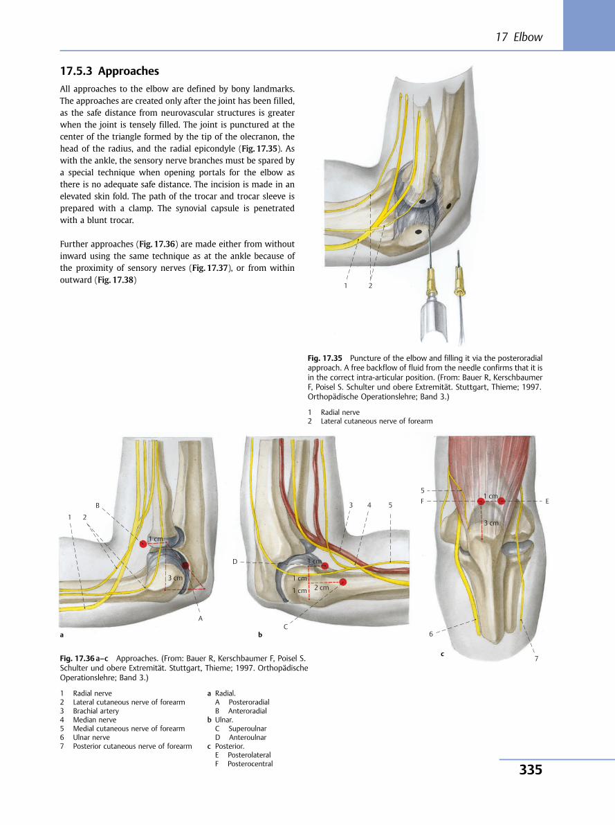
17.5.3 Approaches
All approaches to the elbow are defined by bony landmarks.The approaches are created only after the joint has been filled,as the safe distance from neurovascular structures is greaterwhen the joint is tensely filled. The joint is punctured at thecenter of the triangle formed by the tip of the olecranon, thehead of the radius, and the radial epicondyle (Fig. 17.35). Aswith the ankle, the sensory nerve branches must be spared bya special technique when opening portals for the elbow asthere is no adequate safe distance. The incision is made in anelevated skin fold. The path of the trocar and trocar sleeve isprepared with a clamp. The synovial capsule is penetratedwith a blunt trocar.
Further approaches (Fig. 17.36) are made either from withoutinward using the same technique as at the ankle because ofthe proximity of sensory nerves (Fig. 17.37), or from withinoutward (Fig. 17.38)
1 2
Fig. 17.35 Puncture of the elbow and filling it via the posteroradialapproach. A free backflow of fluid from the needle confirms that it isin the correct intra-articular position. (From: Bauer R, KerschbaumerF, Poisel S. Schulter und obere Extremität. Stuttgart, Thieme; 1997.Orthopädische Operationslehre; Band 3.)
1 Radial nerve2 Lateral cutaneous nerve of forearm
1 2
B
1 cm
3 cm
A
D
C 6
7
E F5
3 4 51 cm
3 cm
1 cm
1 cm
1 cm
2 cm
a b
cFig. 17.36 a–c Approaches. (From: Bauer R, Kerschbaumer F, Poisel S.Schulter und obere Extremität. Stuttgart, Thieme; 1997. OrthopädischeOperationslehre; Band 3.)
1 Radial nerve2 Lateral cutaneous nerve of forearm3 Brachial artery4 Median nerve5 Medial cutaneous nerve of forearm6 Ulnar nerve7 Posterior cutaneous nerve of forearm
a Radial.A PosteroradialB Anteroradial
b Ulnar.C SuperoulnarD Anteroulnar
c Posterior.E PosterolateralF Posterocentral
17 Elbow
335
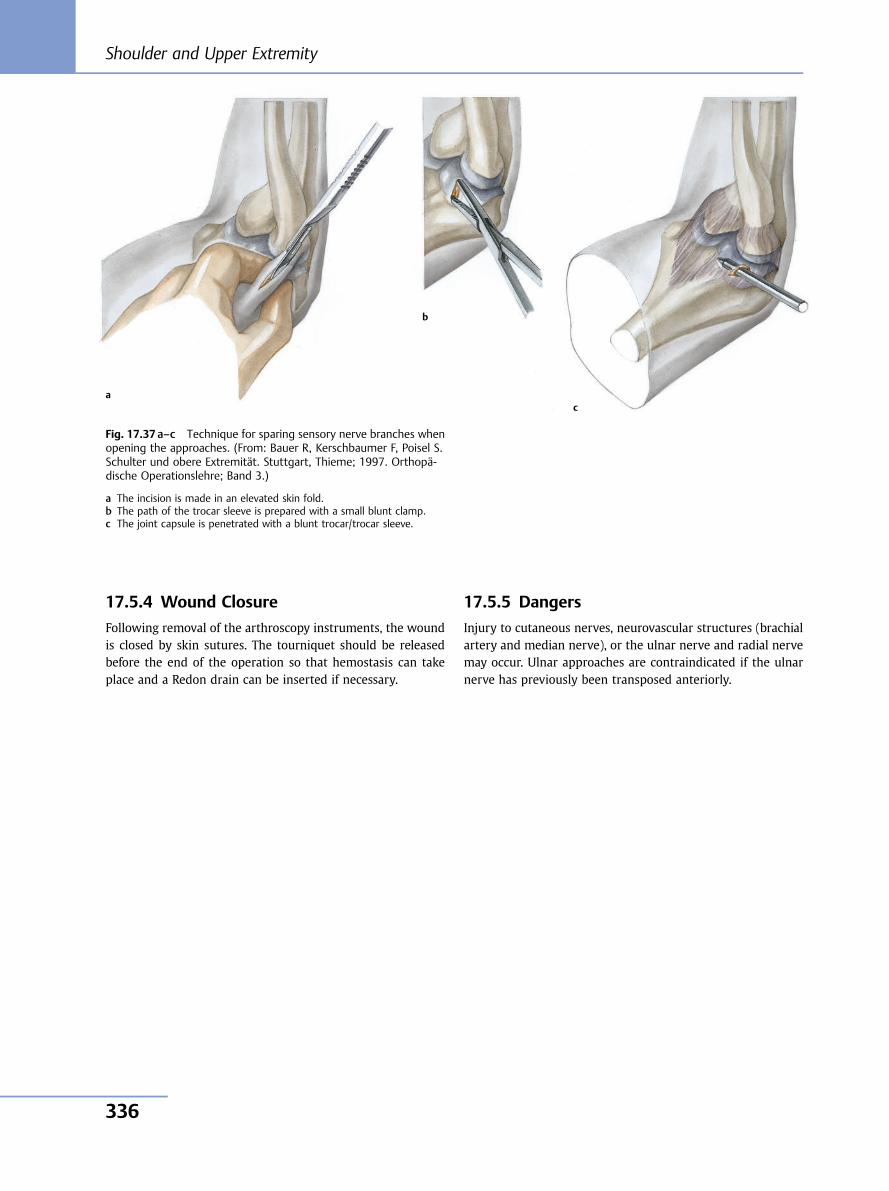
17.5.4 Wound Closure
Following removal of the arthroscopy instruments, the woundis closed by skin sutures. The tourniquet should be releasedbefore the end of the operation so that hemostasis can takeplace and a Redon drain can be inserted if necessary.
17.5.5 Dangers
Injury to cutaneous nerves, neurovascular structures (brachialartery and median nerve), or the ulnar nerve and radial nervemay occur. Ulnar approaches are contraindicated if the ulnarnerve has previously been transposed anteriorly.
Fig. 17.37 a–c Technique for sparing sensory nerve branches whenopening the approaches. (From: Bauer R, Kerschbaumer F, Poisel S.Schulter und obere Extremität. Stuttgart, Thieme; 1997. Orthopä-dische Operationslehre; Band 3.)
a The incision is made in an elevated skin fold.b The path of the trocar sleeve is prepared with a small blunt clamp.c The joint capsule is penetrated with a blunt trocar/trocar sleeve.
a
b
c
Shoulder and Upper Extremity
336
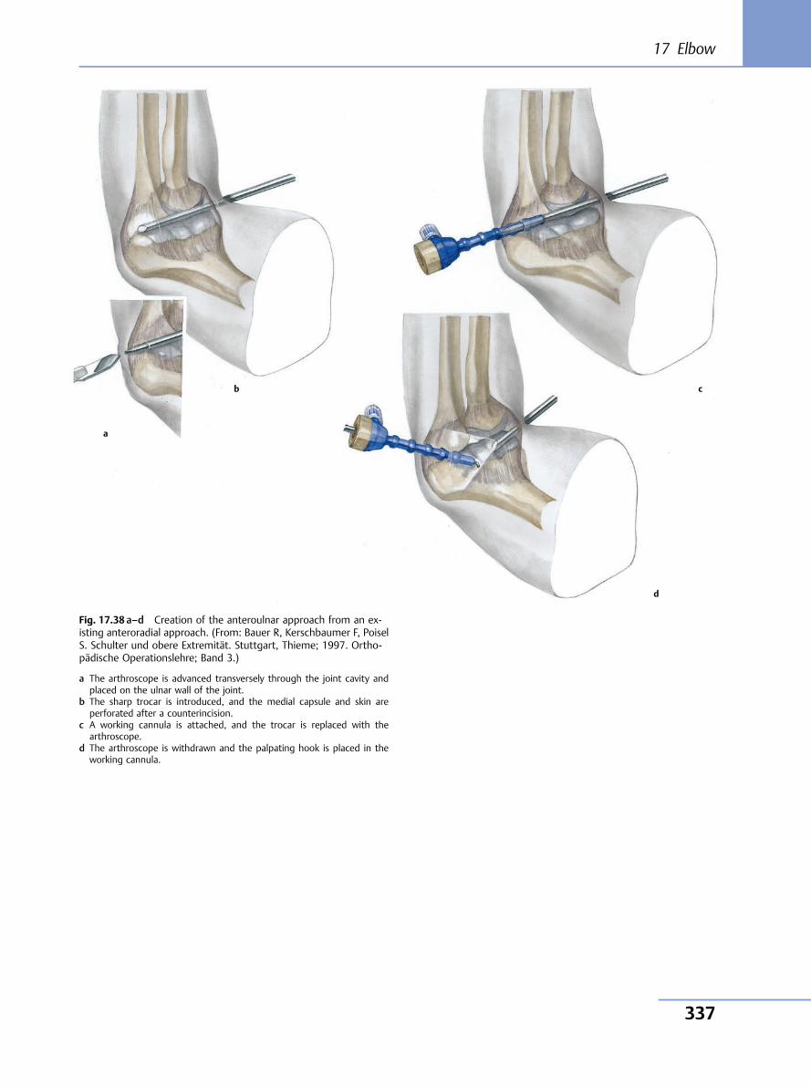
Fig. 17.38 a–d Creation of the anteroulnar approach from an ex-isting anteroradial approach. (From: Bauer R, Kerschbaumer F, PoiselS. Schulter und obere Extremität. Stuttgart, Thieme; 1997. Ortho-pädische Operationslehre; Band 3.)
a The arthroscope is advanced transversely through the joint cavity andplaced on the ulnar wall of the joint.
b The sharp trocar is introduced, and the medial capsule and skin areperforated after a counterincision.
c A working cannula is attached, and the trocar is replaced with thearthroscope.
d The arthroscope is withdrawn and the palpating hook is placed in theworking cannula.
a
b c
d
17 Elbow
337
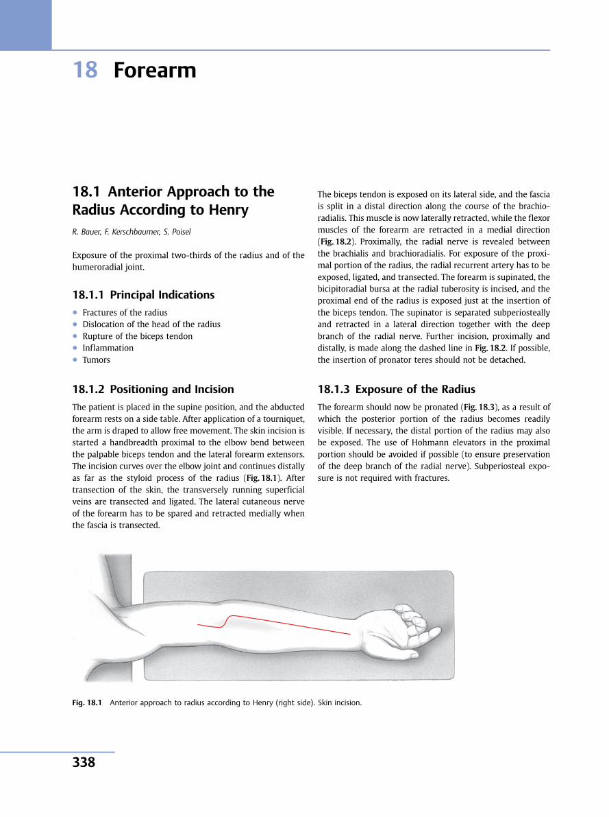
18 Forearm
18.1 Anterior Approach to theRadius According to HenryR. Bauer, F. Kerschbaumer, S. Poisel
Exposure of the proximal two-thirds of the radius and of thehumeroradial joint.
18.1.1 Principal Indications● Fractures of the radius● Dislocation of the head of the radius● Rupture of the biceps tendon● Inflammation● Tumors
18.1.2 Positioning and Incision
The patient is placed in the supine position, and the abductedforearm rests on a side table. After application of a tourniquet,the arm is draped to allow free movement. The skin incision isstarted a handbreadth proximal to the elbow bend betweenthe palpable biceps tendon and the lateral forearm extensors.The incision curves over the elbow joint and continues distallyas far as the styloid process of the radius (Fig. 18.1). Aftertransection of the skin, the transversely running superficialveins are transected and ligated. The lateral cutaneous nerveof the forearm has to be spared and retracted medially whenthe fascia is transected.
The biceps tendon is exposed on its lateral side, and the fasciais split in a distal direction along the course of the brachio-radialis. This muscle is now laterally retracted, while the flexormuscles of the forearm are retracted in a medial direction(Fig. 18.2). Proximally, the radial nerve is revealed betweenthe brachialis and brachioradialis. For exposure of the proxi-mal portion of the radius, the radial recurrent artery has to beexposed, ligated, and transected. The forearm is supinated, thebicipitoradial bursa at the radial tuberosity is incised, and theproximal end of the radius is exposed just at the insertion ofthe biceps tendon. The supinator is separated subperiosteallyand retracted in a lateral direction together with the deepbranch of the radial nerve. Further incision, proximally anddistally, is made along the dashed line in Fig. 18.2. If possible,the insertion of pronator teres should not be detached.
18.1.3 Exposure of the Radius
The forearm should now be pronated (Fig. 18.3), as a result ofwhich the posterior portion of the radius becomes readilyvisible. If necessary, the distal portion of the radius may alsobe exposed. The use of Hohmann elevators in the proximalportion should be avoided if possible (to ensure preservationof the deep branch of the radial nerve). Subperiosteal expo-sure is not required with fractures.
Fig. 18.1 Anterior approach to radius according to Henry (right side). Skin incision.
Shoulder and Upper Extremity
338
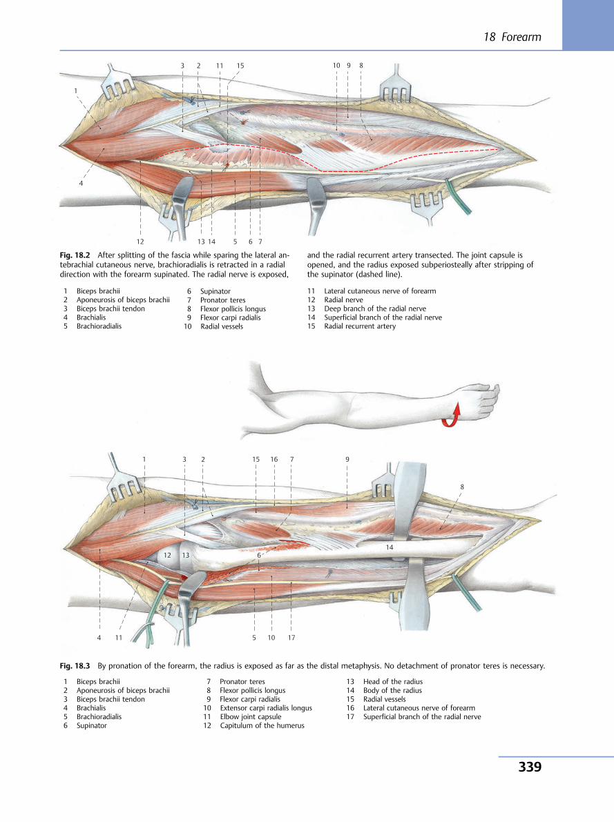
10 11
12 13 14
15 9 8
7 6 5
4
3
1
2
10 11
12 13 14
15 16
17
9
8
7
6
5 4
3 1 2
Fig. 18.2 After splitting of the fascia while sparing the lateral an-tebrachial cutaneous nerve, brachioradialis is retracted in a radialdirection with the forearm supinated. The radial nerve is exposed,
and the radial recurrent artery transected. The joint capsule isopened, and the radius exposed subperiosteally after stripping ofthe supinator (dashed line).
1 Biceps brachii2 Aponeurosis of biceps brachii3 Biceps brachii tendon4 Brachialis5 Brachioradialis
6 Supinator7 Pronator teres8 Flexor pollicis longus9 Flexor carpi radialis10 Radial vessels
11 Lateral cutaneous nerve of forearm12 Radial nerve13 Deep branch of the radial nerve14 Superficial branch of the radial nerve15 Radial recurrent artery
Fig. 18.3 By pronation of the forearm, the radius is exposed as far as the distal metaphysis. No detachment of pronator teres is necessary.
1 Biceps brachii2 Aponeurosis of biceps brachii3 Biceps brachii tendon4 Brachialis5 Brachioradialis6 Supinator
7 Pronator teres8 Flexor pollicis longus9 Flexor carpi radialis10 Extensor carpi radialis longus11 Elbow joint capsule12 Capitulum of the humerus
13 Head of the radius14 Body of the radius15 Radial vessels16 Lateral cutaneous nerve of forearm17 Superficial branch of the radial nerve
18 Forearm
339
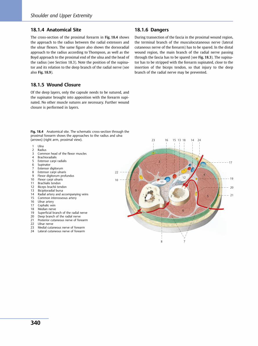
18.1.4 Anatomical Site
The cross-section of the proximal forearm in Fig. 18.4 showsthe approach to the radius between the radial extensors andthe ulnar flexors. The same figure also shows the dorsoradialapproach to the radius according to Thompson, as well as theBoyd approach to the proximal end of the ulna and the head ofthe radius (see Section 18.3). Note the position of the supina-tor and its relation to the deep branch of the radial nerve (seealso Fig. 18.9).
18.1.5 Wound Closure
Of the deep layers, only the capsule needs to be sutured, andthe supinator brought into apposition with the forearm supi-nated. No other muscle sutures are necessary. Further woundclosure is performed in layers.
18.1.6 Dangers
During transection of the fascia in the proximal wound region,the terminal branch of the musculocutaneous nerve (lateralcutaneous nerve of the forearm) has to be spared. In the distalwound region, the main branch of the radial nerve passingthrough the fascia has to be spared (see Fig. 18.3). The supina-tor has to be stripped with the forearm supinated, close to theinsertion of the biceps tendon, so that injury to the deepbranch of the radial nerve may be prevented.
10 11
12
13 14 15 16
17
18
19
23
9
8 7
6
5
4
3
1 2
22
24
20
21
Fig. 18.4 Anatomical site. The schematic cross-section through theproximal forearm shows the approaches to the radius and ulna(arrows) (right arm, proximal view).
1 Ulna2 Radius3 Common head of the flexor muscles4 Brachioradialis5 Extensor carpi radialis6 Supinator7 Extensor digitorum8 Extensor carpi ulnaris9 Flexor digitorum profundus10 Flexor carpi ulnaris11 Brachialis tendon12 Biceps brachii tendon13 Bicipitoradial bursa14 Radial artery and accompanying veins15 Common interosseous artery16 Ulnar artery17 Cephalic vein18 Median nerve19 Superficial branch of the radial nerve20 Deep branch of the radial nerve21 Posterior cutaneous nerve of forearm22 Ulnar nerve23 Medial cutaneous nerve of forearm24 Lateral cutaneous nerve of forearm
Shoulder and Upper Extremity
340
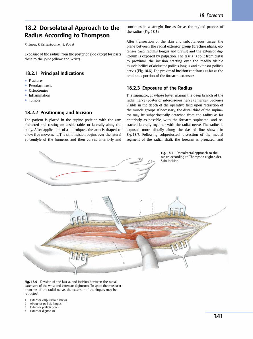
18.2 Dorsolateral Approach to theRadius According to ThompsonR. Bauer, F. Kerschbaumer, S. Poisel
Exposure of the radius from the posterior side except for partsclose to the joint (elbow and wrist).
18.2.1 Principal Indications● Fractures● Pseudarthrosis● Osteotomies● Inflammation● Tumors
18.2.2 Positioning and Incision
The patient is placed in the supine position with the armabducted and resting on a side table, or laterally along thebody. After application of a tourniquet, the arm is draped toallow free movement. The skin incision begins over the lateralepicondyle of the humerus and then curves anteriorly and
continues in a straight line as far as the styloid process ofthe radius (Fig. 18.5).
After transection of the skin and subcutaneous tissue, theplane between the radial extensor group (brachioradialis, ex-tensor carpi radialis longus and brevis) and the extensor dig-itorum is exposed by palpation. The fascia is split from distalto proximal, the incision starting over the readily visiblemuscle bellies of abductor pollicis longus and extensor pollicisbrevis (Fig. 18.6). The proximad incision continues as far as thetendinous portion of the forearm extensors.
18.2.3 Exposure of the Radius
The supinator, at whose lower margin the deep branch of theradial nerve (posterior interosseous nerve) emerges, becomesvisible in the depth of the operative field upon retraction ofthe muscle groups. If necessary, the distal third of the supina-tor may be subperiosteally detached from the radius as faranteriorly as possible, with the forearm supinated, and re-tracted laterally together with the radial nerve. The radius isexposed more distally along the dashed line shown inFig. 18.7. Following subperiosteal dissection of the medialsegment of the radial shaft, the forearm is pronated, and
Fig. 18.5 Dorsolateral approach to theradius according to Thompson (right side).Skin incision.
4
3 1 2
Fig. 18.6 Division of the fascia, and incision between the radialextensors of the wrist and extensor digitorum. To spare the muscularbranches of the radial nerve, the extensor of the fingers may beretracted.
1 Extensor carpi radialis brevis2 Abductor pollicis longus3 Extensor pollicis brevis4 Extensor digitorum
18 Forearm
341
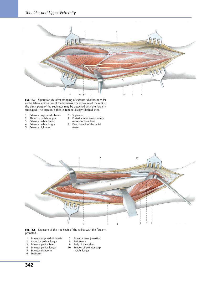
8 7 6 5 4 3
1 2
5
Fig. 18.7 Operative site after stripping of extensor digitorum as faras the lateral epicondyle of the humerus. For exposure of the radius,the distal parts of the supinator may be detached with the forearmsupinated. The incision is then extended distally (dashed line).
1 Extensor carpi radialis brevis2 Abductor pollicis longus3 Extensor pollicis brevis4 Extensor pollicis longus5 Extensor digitorum
6 Supinator7 Posterior interosseous artery
(muscular branches)8 Deep branch of the radial
nerve
10
9
8
7
6 5 4 3
1
2
Fig. 18.8 Exposure of the mid shaft of the radius with the forearmpronated.
1 Extensor carpi radialis brevis2 Abductor pollicis longus3 Extensor pollicis brevis4 Extensor pollicis longus5 Extensor digitorum6 Supinator
7 Pronator teres (insertion)8 Periosteum9 Body of the radius10 Tendon of extensor carpi
radialis longus
Shoulder and Upper Extremity
342
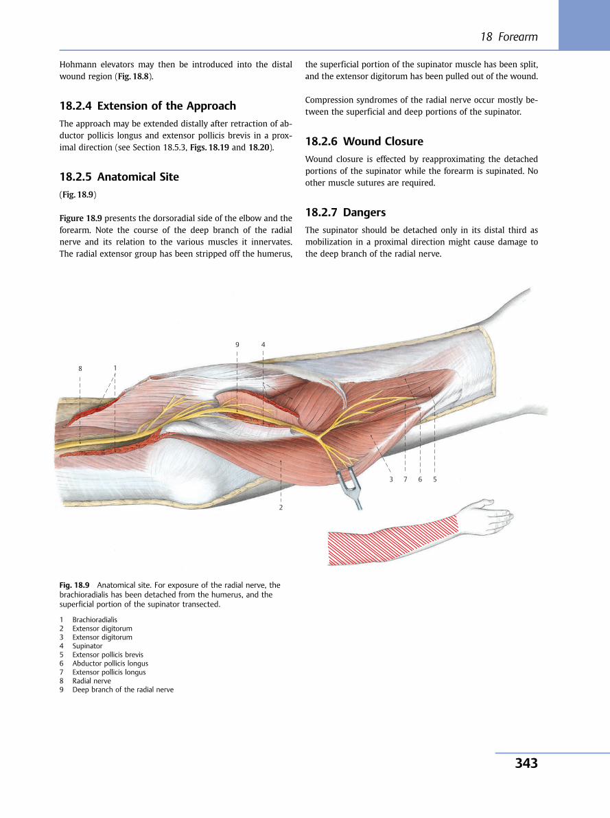
Hohmann elevators may then be introduced into the distalwound region (Fig. 18.8).
18.2.4 Extension of the Approach
The approach may be extended distally after retraction of ab-ductor pollicis longus and extensor pollicis brevis in a prox-imal direction (see Section 18.5.3, Figs. 18.19 and 18.20).
18.2.5 Anatomical Site
(Fig. 18.9)
Figure 18.9 presents the dorsoradial side of the elbow and theforearm. Note the course of the deep branch of the radialnerve and its relation to the various muscles it innervates.The radial extensor group has been stripped off the humerus,
the superficial portion of the supinator muscle has been split,and the extensor digitorum has been pulled out of the wound.
Compression syndromes of the radial nerve occur mostly be-tween the superficial and deep portions of the supinator.
18.2.6 Wound Closure
Wound closure is effected by reapproximating the detachedportions of the supinator while the forearm is supinated. Noother muscle sutures are required.
18.2.7 Dangers
The supinator should be detached only in its distal third asmobilization in a proximal direction might cause damage tothe deep branch of the radial nerve.
9
8
7 6 5
4
3
1
2
Fig. 18.9 Anatomical site. For exposure of the radial nerve, thebrachioradialis has been detached from the humerus, and thesuperficial portion of the supinator transected.
1 Brachioradialis2 Extensor digitorum3 Extensor digitorum4 Supinator5 Extensor pollicis brevis6 Abductor pollicis longus7 Extensor pollicis longus8 Radial nerve9 Deep branch of the radial nerve
18 Forearm
343
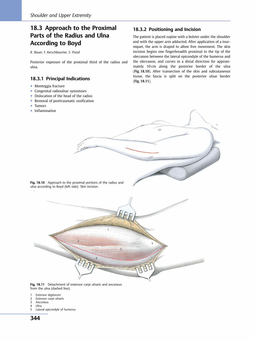
18.3 Approach to the ProximalParts of the Radius and UlnaAccording to BoydR. Bauer, F. Kerschbaumer, S. Poisel
Posterior exposure of the proximal third of the radius andulna.
18.3.1 Principal Indications● Monteggia fracture● Congenital radioulnar synostoses● Dislocation of the head of the radius● Removal of posttraumatic ossification● Tumors● Inflammation
18.3.2 Positioning and Incision
The patient is placed supine with a bolster under the shoulderand with the upper arm adducted. After application of a tour-niquet, the arm is draped to allow free movement. The skinincision begins one fingerbreadth proximal to the tip of theolecranon between the lateral epicondyle of the humerus andthe olecranon, and curves in a distal direction for approxi-mately 10 cm along the posterior border of the ulna(Fig. 18.10). After transection of the skin and subcutaneoustissue, the fascia is split on the posterior ulnar border(Fig. 18.11).
5
4
3
1
2
Fig. 18.10 Approach to the proximal portions of the radius andulna according to Boyd (left side). Skin incision.
Fig. 18.11 Detachment of extensor carpi ulnaris and anconeusfrom the ulna (dashed line).
1 Extensor digitorum2 Extensor carpi ulnaris3 Anconeus4 Ulna5 Lateral epicondyle of humerus
Shoulder and Upper Extremity
344
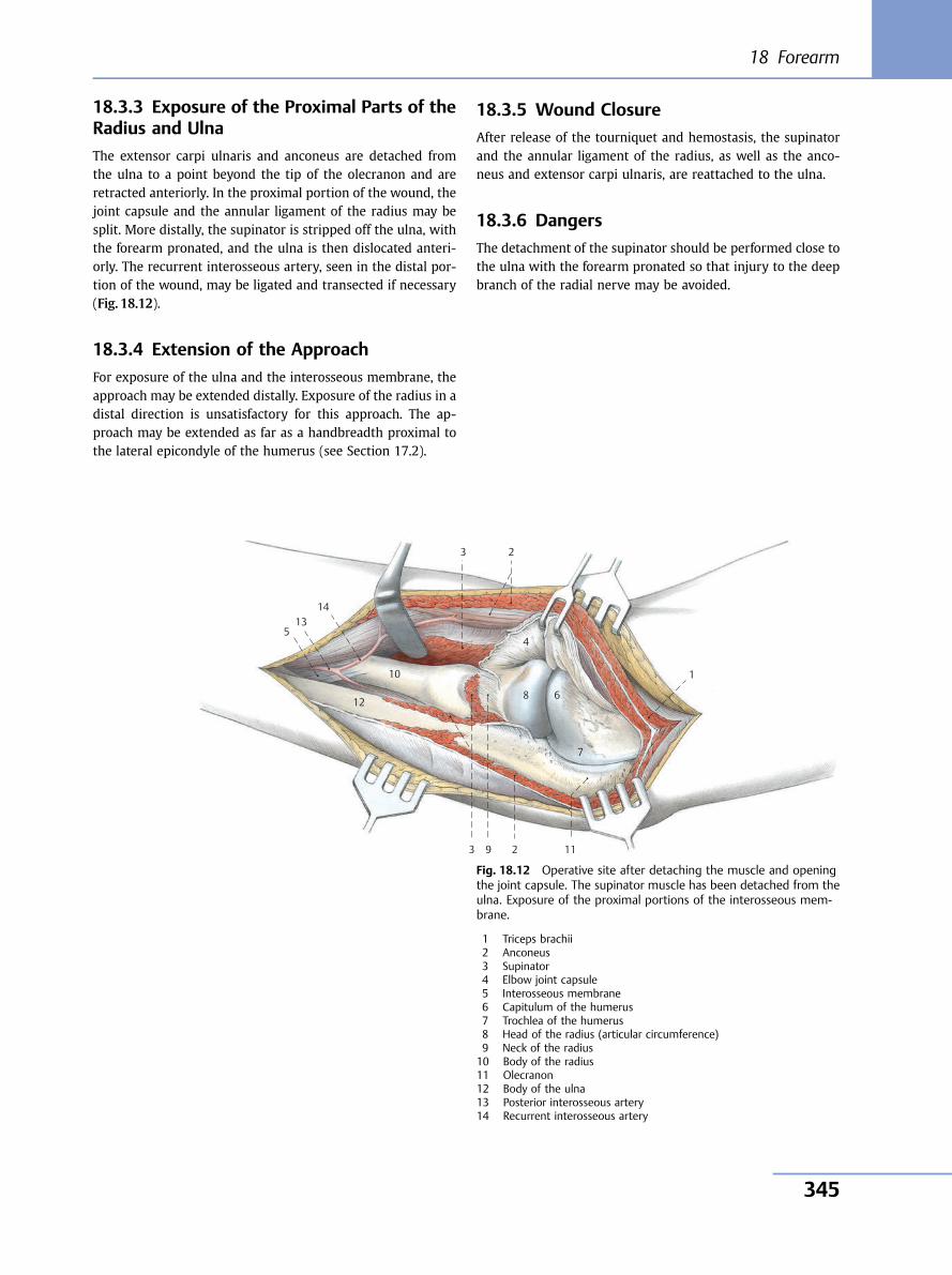
18.3.3 Exposure of the Proximal Parts of theRadius and Ulna
The extensor carpi ulnaris and anconeus are detached fromthe ulna to a point beyond the tip of the olecranon and areretracted anteriorly. In the proximal portion of the wound, thejoint capsule and the annular ligament of the radius may besplit. More distally, the supinator is stripped off the ulna, withthe forearm pronated, and the ulna is then dislocated anteri-orly. The recurrent interosseous artery, seen in the distal por-tion of the wound, may be ligated and transected if necessary(Fig. 18.12).
18.3.4 Extension of the Approach
For exposure of the ulna and the interosseous membrane, theapproach may be extended distally. Exposure of the radius in adistal direction is unsatisfactory for this approach. The ap-proach may be extended as far as a handbreadth proximal tothe lateral epicondyle of the humerus (see Section 17.2).
18.3.5 Wound Closure
After release of the tourniquet and hemostasis, the supinatorand the annular ligament of the radius, as well as the anco-neus and extensor carpi ulnaris, are reattached to the ulna.
18.3.6 Dangers
The detachment of the supinator should be performed close tothe ulna with the forearm pronated so that injury to the deepbranch of the radial nerve may be avoided.
3 2
4
8 6
7
1
11 2 9 3
12
10
5 13
14
Fig. 18.12 Operative site after detaching the muscle and openingthe joint capsule. The supinator muscle has been detached from theulna. Exposure of the proximal portions of the interosseous mem-brane.
1 Triceps brachii2 Anconeus3 Supinator4 Elbow joint capsule5 Interosseous membrane6 Capitulum of the humerus7 Trochlea of the humerus8 Head of the radius (articular circumference)9 Neck of the radius10 Body of the radius11 Olecranon12 Body of the ulna13 Posterior interosseous artery14 Recurrent interosseous artery
18 Forearm
345
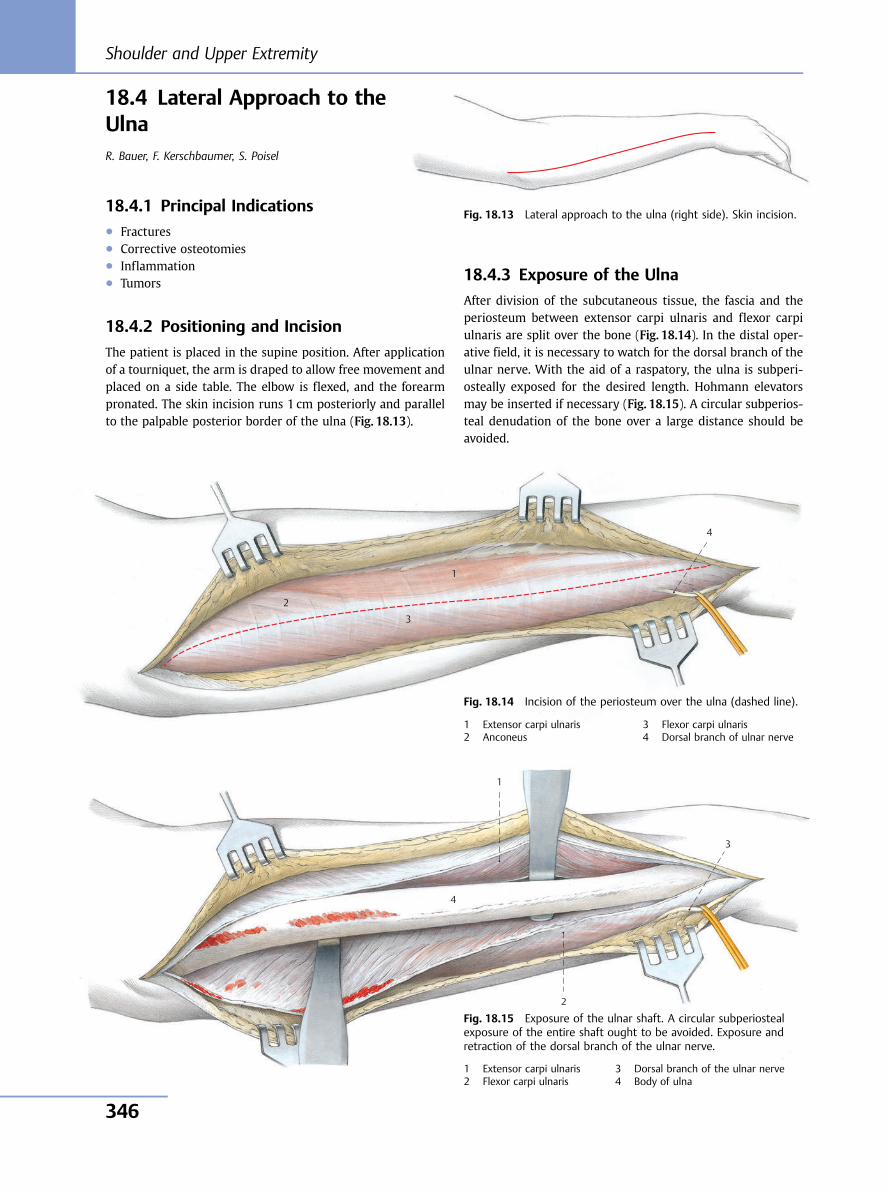
18.4 Lateral Approach to theUlnaR. Bauer, F. Kerschbaumer, S. Poisel
18.4.1 Principal Indications● Fractures● Corrective osteotomies● Inflammation● Tumors
18.4.2 Positioning and Incision
The patient is placed in the supine position. After applicationof a tourniquet, the arm is draped to allow free movement andplaced on a side table. The elbow is flexed, and the forearmpronated. The skin incision runs 1 cm posteriorly and parallelto the palpable posterior border of the ulna (Fig. 18.13).
18.4.3 Exposure of the Ulna
After division of the subcutaneous tissue, the fascia and theperiosteum between extensor carpi ulnaris and flexor carpiulnaris are split over the bone (Fig. 18.14). In the distal oper-ative field, it is necessary to watch for the dorsal branch of theulnar nerve. With the aid of a raspatory, the ulna is subperi-osteally exposed for the desired length. Hohmann elevatorsmay be inserted if necessary (Fig. 18.15). A circular subperios-teal denudation of the bone over a large distance should beavoided.
Fig. 18.13 Lateral approach to the ulna (right side). Skin incision.
4
3
1
2
Fig. 18.14 Incision of the periosteum over the ulna (dashed line).
1 Extensor carpi ulnaris2 Anconeus
3 Flexor carpi ulnaris4 Dorsal branch of ulnar nerve
4
3
2
1
Fig. 18.15 Exposure of the ulnar shaft. A circular subperiostealexposure of the entire shaft ought to be avoided. Exposure andretraction of the dorsal branch of the ulnar nerve.
1 Extensor carpi ulnaris2 Flexor carpi ulnaris
3 Dorsal branch of the ulnar nerve4 Body of ulna
Shoulder and Upper Extremity
346
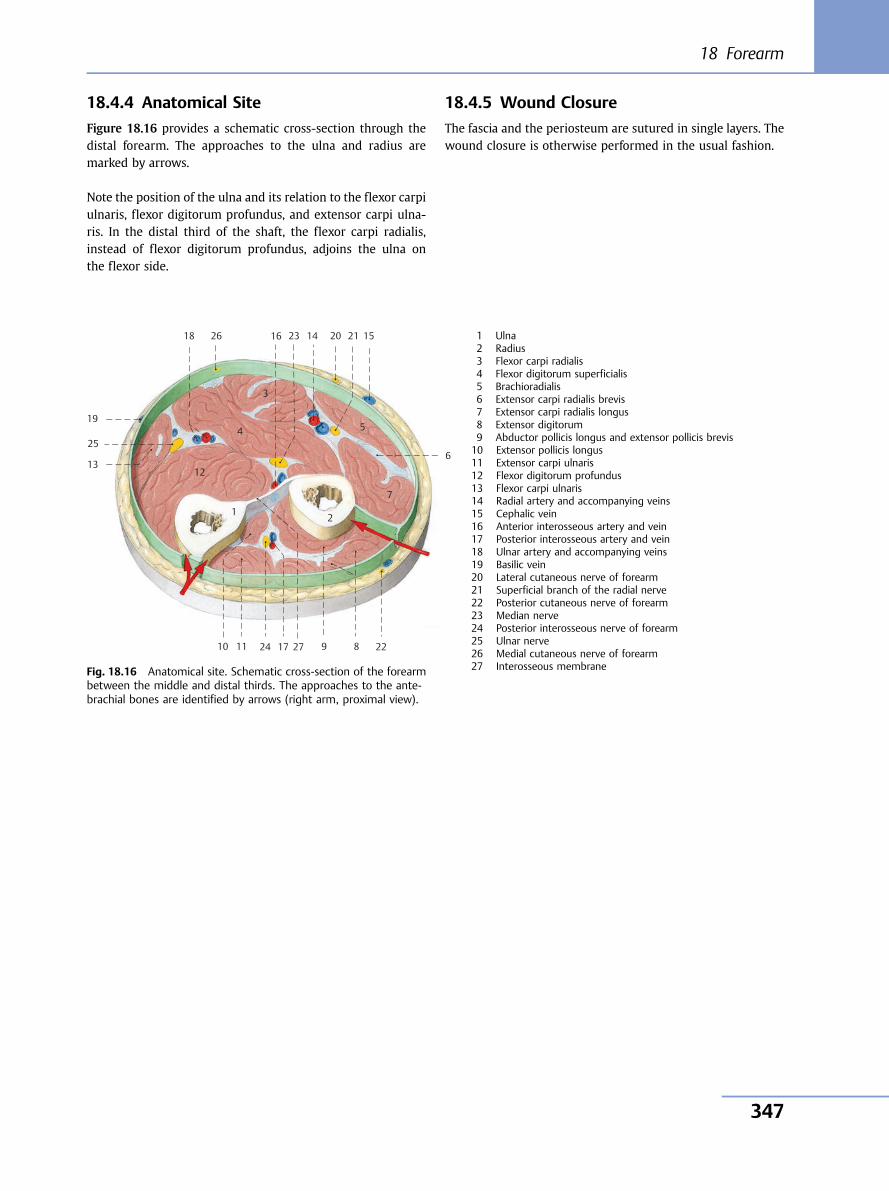
18.4.4 Anatomical Site
Figure 18.16 provides a schematic cross-section through thedistal forearm. The approaches to the ulna and radius aremarked by arrows.
Note the position of the ulna and its relation to the flexor carpiulnaris, flexor digitorum profundus, and extensor carpi ulna-ris. In the distal third of the shaft, the flexor carpi radialis,instead of flexor digitorum profundus, adjoins the ulna onthe flexor side.
18.4.5 Wound Closure
The fascia and the periosteum are sutured in single layers. Thewound closure is otherwise performed in the usual fashion.
10 11
12 13
14 15 16
17
18
19
20
9 8
7
6
5 4
3
1 2
212326
25
2224 27
Fig. 18.16 Anatomical site. Schematic cross-section of the forearmbetween the middle and distal thirds. The approaches to the ante-brachial bones are identified by arrows (right arm, proximal view).
1 Ulna2 Radius3 Flexor carpi radialis4 Flexor digitorum superficialis5 Brachioradialis6 Extensor carpi radialis brevis7 Extensor carpi radialis longus8 Extensor digitorum9 Abductor pollicis longus and extensor pollicis brevis10 Extensor pollicis longus11 Extensor carpi ulnaris12 Flexor digitorum profundus13 Flexor carpi ulnaris14 Radial artery and accompanying veins15 Cephalic vein16 Anterior interosseous artery and vein17 Posterior interosseous artery and vein18 Ulnar artery and accompanying veins19 Basilic vein20 Lateral cutaneous nerve of forearm21 Superficial branch of the radial nerve22 Posterior cutaneous nerve of forearm23 Median nerve24 Posterior interosseous nerve of forearm25 Ulnar nerve26 Medial cutaneous nerve of forearm27 Interosseous membrane
18 Forearm
347
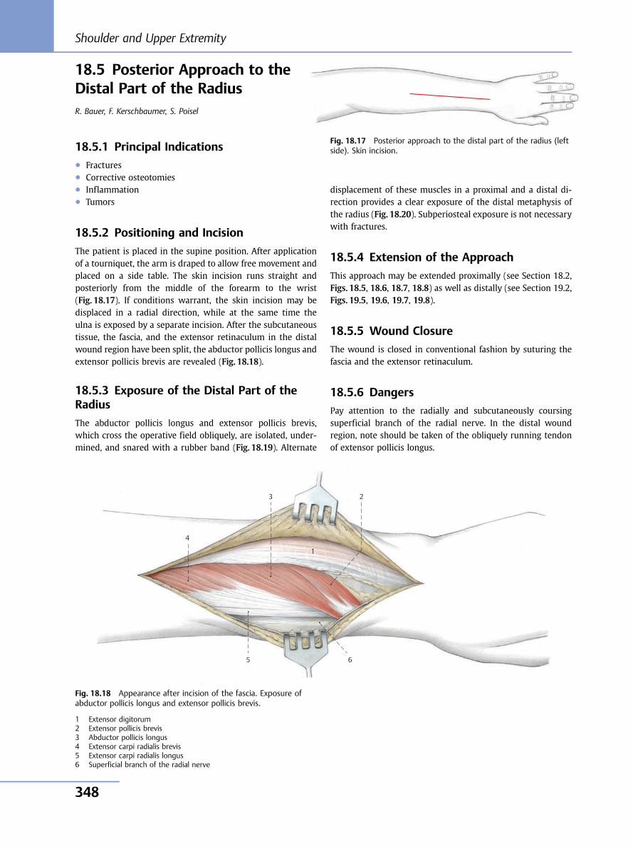
18.5 Posterior Approach to theDistal Part of the RadiusR. Bauer, F. Kerschbaumer, S. Poisel
18.5.1 Principal Indications● Fractures● Corrective osteotomies● Inflammation● Tumors
18.5.2 Positioning and Incision
The patient is placed in the supine position. After applicationof a tourniquet, the arm is draped to allow free movement andplaced on a side table. The skin incision runs straight andposteriorly from the middle of the forearm to the wrist(Fig. 18.17). If conditions warrant, the skin incision may bedisplaced in a radial direction, while at the same time theulna is exposed by a separate incision. After the subcutaneoustissue, the fascia, and the extensor retinaculum in the distalwound region have been split, the abductor pollicis longus andextensor pollicis brevis are revealed (Fig. 18.18).
18.5.3 Exposure of the Distal Part of theRadius
The abductor pollicis longus and extensor pollicis brevis,which cross the operative field obliquely, are isolated, under-mined, and snared with a rubber band (Fig. 18.19). Alternate
displacement of these muscles in a proximal and a distal di-rection provides a clear exposure of the distal metaphysis ofthe radius (Fig. 18.20). Subperiosteal exposure is not necessarywith fractures.
18.5.4 Extension of the Approach
This approach may be extended proximally (see Section 18.2,Figs. 18.5, 18.6, 18.7, 18.8) as well as distally (see Section 19.2,Figs. 19.5, 19.6, 19.7, 19.8).
18.5.5 Wound Closure
The wound is closed in conventional fashion by suturing thefascia and the extensor retinaculum.
18.5.6 Dangers
Pay attention to the radially and subcutaneously coursingsuperficial branch of the radial nerve. In the distal woundregion, note should be taken of the obliquely running tendonof extensor pollicis longus.
Fig. 18.17 Posterior approach to the distal part of the radius (leftside). Skin incision.
4
3 2
1
5 6
Fig. 18.18 Appearance after incision of the fascia. Exposure ofabductor pollicis longus and extensor pollicis brevis.
1 Extensor digitorum2 Extensor pollicis brevis3 Abductor pollicis longus4 Extensor carpi radialis brevis5 Extensor carpi radialis longus6 Superficial branch of the radial nerve
Shoulder and Upper Extremity
348
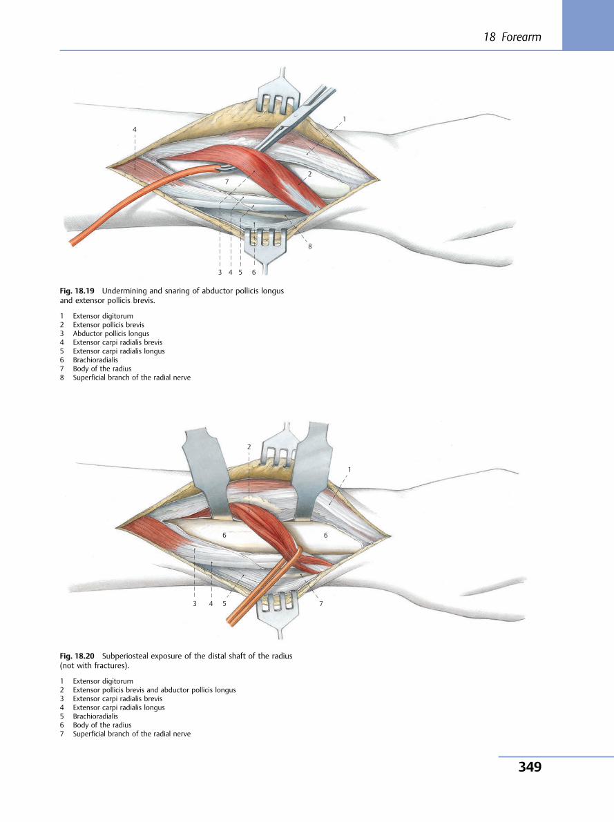
4
7
3 4 5 6
8
2
1
Fig. 18.19 Undermining and snaring of abductor pollicis longusand extensor pollicis brevis.
1 Extensor digitorum2 Extensor pollicis brevis3 Abductor pollicis longus4 Extensor carpi radialis brevis5 Extensor carpi radialis longus6 Brachioradialis7 Body of the radius8 Superficial branch of the radial nerve
3 4 5 7
6
1
2
6
Fig. 18.20 Subperiosteal exposure of the distal shaft of the radius(not with fractures).
1 Extensor digitorum2 Extensor pollicis brevis and abductor pollicis longus3 Extensor carpi radialis brevis4 Extensor carpi radialis longus5 Brachioradialis6 Body of the radius7 Superficial branch of the radial nerve
18 Forearm
349
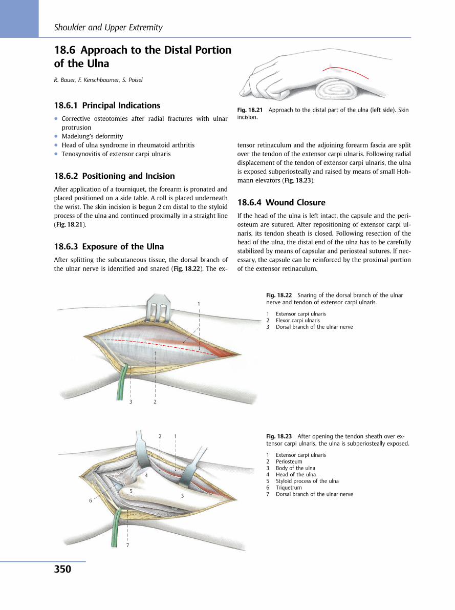
18.6 Approach to the Distal Portionof the UlnaR. Bauer, F. Kerschbaumer, S. Poisel
18.6.1 Principal Indications● Corrective osteotomies after radial fractures with ulnar
protrusion● Madelung’s deformity● Head of ulna syndrome in rheumatoid arthritis● Tenosynovitis of extensor carpi ulnaris
18.6.2 Positioning and Incision
After application of a tourniquet, the forearm is pronated andplaced positioned on a side table. A roll is placed underneaththe wrist. The skin incision is begun 2 cm distal to the styloidprocess of the ulna and continued proximally in a straight line(Fig. 18.21).
18.6.3 Exposure of the Ulna
After splitting the subcutaneous tissue, the dorsal branch ofthe ulnar nerve is identified and snared (Fig. 18.22). The ex-
tensor retinaculum and the adjoining forearm fascia are splitover the tendon of the extensor carpi ulnaris. Following radialdisplacement of the tendon of extensor carpi ulnaris, the ulnais exposed subperiosteally and raised by means of small Hoh-mann elevators (Fig. 18.23).
18.6.4 Wound Closure
If the head of the ulna is left intact, the capsule and the peri-osteum are sutured. After repositioning of extensor carpi ul-naris, its tendon sheath is closed. Following resection of thehead of the ulna, the distal end of the ulna has to be carefullystabilized by means of capsular and periosteal sutures. If nec-essary, the capsule can be reinforced by the proximal portionof the extensor retinaculum.
Fig. 18.21 Approach to the distal part of the ulna (left side). Skinincision.
3
1
2
Fig. 18.22 Snaring of the dorsal branch of the ulnarnerve and tendon of extensor carpi ulnaris.
1 Extensor carpi ulnaris2 Flexor carpi ulnaris3 Dorsal branch of the ulnar nerve
7
6
5
4
3
1 2 Fig. 18.23 After opening the tendon sheath over ex-tensor carpi ulnaris, the ulna is subperiosteally exposed.
1 Extensor carpi ulnaris2 Periosteum3 Body of the ulna4 Head of the ulna5 Styloid process of the ulna6 Triquetrum7 Dorsal branch of the ulnar nerve
Shoulder and Upper Extremity
350
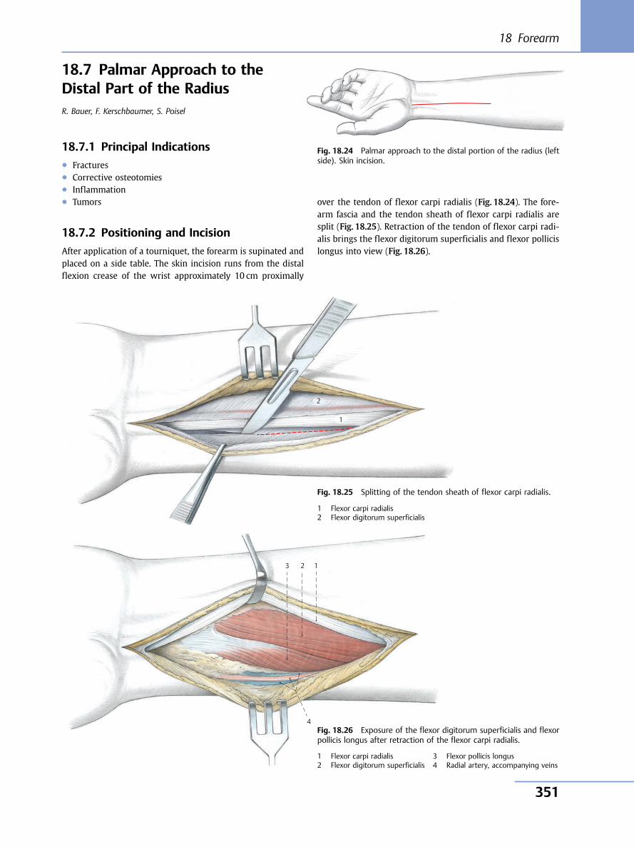
18.7 Palmar Approach to theDistal Part of the RadiusR. Bauer, F. Kerschbaumer, S. Poisel
18.7.1 Principal Indications● Fractures● Corrective osteotomies● Inflammation● Tumors
18.7.2 Positioning and Incision
After application of a tourniquet, the forearm is supinated andplaced on a side table. The skin incision runs from the distalflexion crease of the wrist approximately 10 cm proximally
over the tendon of flexor carpi radialis (Fig. 18.24). The fore-arm fascia and the tendon sheath of flexor carpi radialis aresplit (Fig. 18.25). Retraction of the tendon of flexor carpi radi-alis brings the flexor digitorum superficialis and flexor pollicislongus into view (Fig. 18.26).
Fig. 18.24 Palmar approach to the distal portion of the radius (leftside). Skin incision.
1
2
Fig. 18.25 Splitting of the tendon sheath of flexor carpi radialis.
1 Flexor carpi radialis2 Flexor digitorum superficialis
4
3 1 2
Fig. 18.26 Exposure of the flexor digitorum superficialis and flexorpollicis longus after retraction of the flexor carpi radialis.
1 Flexor carpi radialis2 Flexor digitorum superficialis
3 Flexor pollicis longus4 Radial artery, accompanying veins
18 Forearm
351
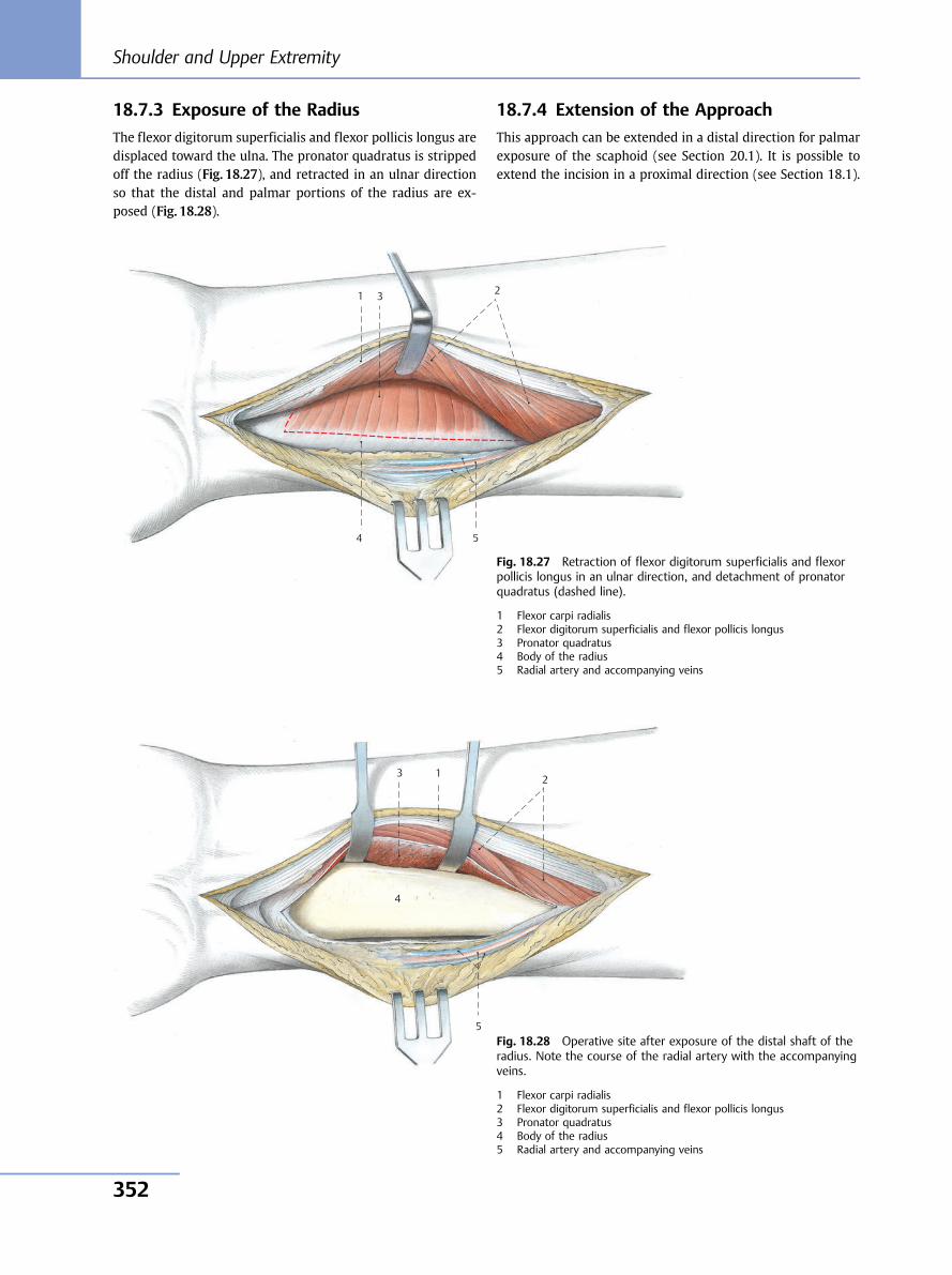
18.7.3 Exposure of the Radius
The flexor digitorum superficialis and flexor pollicis longus aredisplaced toward the ulna. The pronator quadratus is strippedoff the radius (Fig. 18.27), and retracted in an ulnar directionso that the distal and palmar portions of the radius are ex-posed (Fig. 18.28).
18.7.4 Extension of the Approach
This approach can be extended in a distal direction for palmarexposure of the scaphoid (see Section 20.1). It is possible toextend the incision in a proximal direction (see Section 18.1).
5 4
3 1 2
Fig. 18.27 Retraction of flexor digitorum superficialis and flexorpollicis longus in an ulnar direction, and detachment of pronatorquadratus (dashed line).
1 Flexor carpi radialis2 Flexor digitorum superficialis and flexor pollicis longus3 Pronator quadratus4 Body of the radius5 Radial artery and accompanying veins
5
4
3 1 2
Fig. 18.28 Operative site after exposure of the distal shaft of theradius. Note the course of the radial artery with the accompanyingveins.
1 Flexor carpi radialis2 Flexor digitorum superficialis and flexor pollicis longus3 Pronator quadratus4 Body of the radius5 Radial artery and accompanying veins
Shoulder and Upper Extremity
352
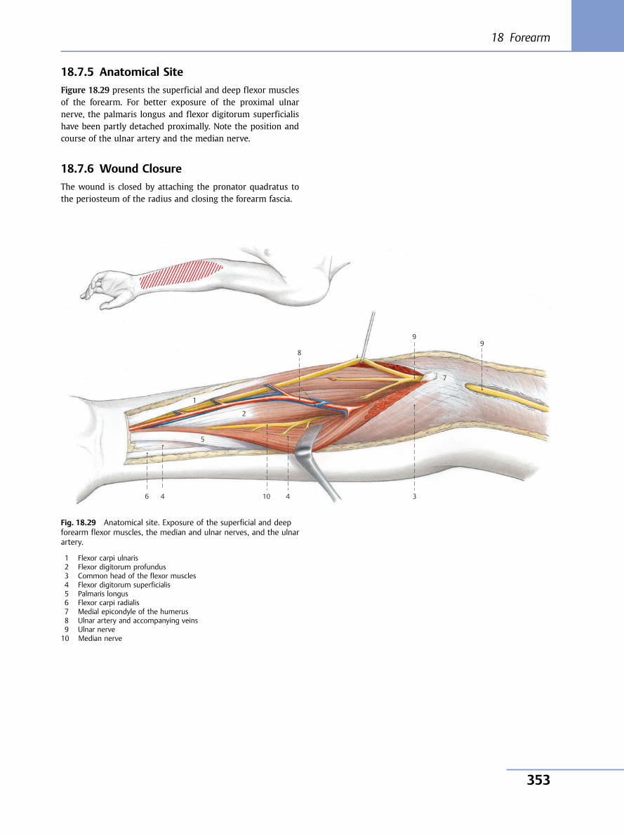
18.7.5 Anatomical Site
Figure 18.29 presents the superficial and deep flexor musclesof the forearm. For better exposure of the proximal ulnarnerve, the palmaris longus and flexor digitorum superficialishave been partly detached proximally. Note the position andcourse of the ulnar artery and the median nerve.
18.7.6 Wound Closure
The wound is closed by attaching the pronator quadratus tothe periosteum of the radius and closing the forearm fascia.
10
9 8
7
6
5
4 3
1
2
4
9
Fig. 18.29 Anatomical site. Exposure of the superficial and deepforearm flexor muscles, the median and ulnar nerves, and the ulnarartery.
1 Flexor carpi ulnaris2 Flexor digitorum profundus3 Common head of the flexor muscles4 Flexor digitorum superficialis5 Palmaris longus6 Flexor carpi radialis7 Medial epicondyle of the humerus8 Ulnar artery and accompanying veins9 Ulnar nerve10 Median nerve
18 Forearm
353
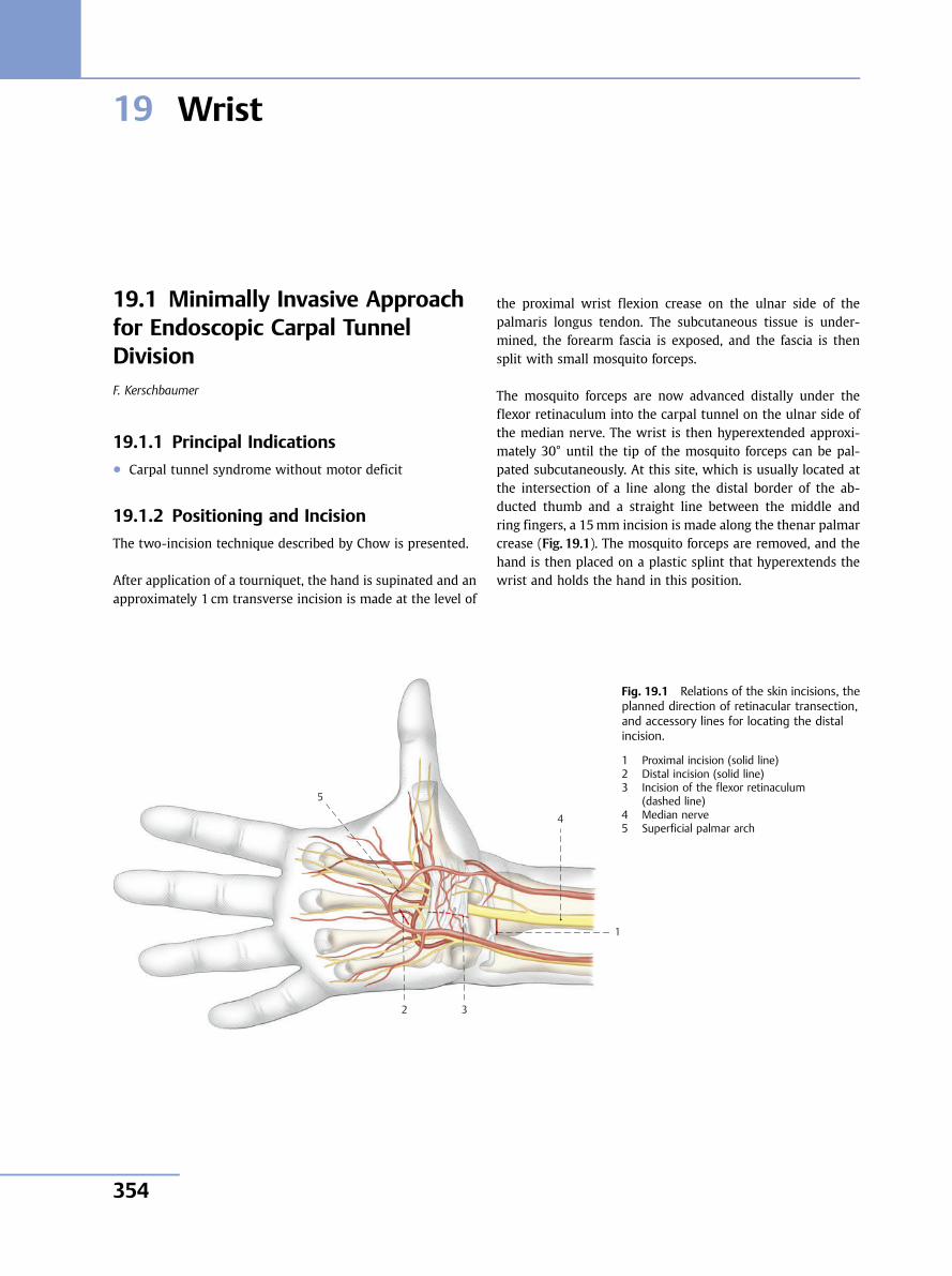
19 Wrist
19.1 Minimally Invasive Approachfor Endoscopic Carpal TunnelDivisionF. Kerschbaumer
19.1.1 Principal Indications● Carpal tunnel syndrome without motor deficit
19.1.2 Positioning and Incision
The two-incision technique described by Chow is presented.
After application of a tourniquet, the hand is supinated and anapproximately 1 cm transverse incision is made at the level of
the proximal wrist flexion crease on the ulnar side of thepalmaris longus tendon. The subcutaneous tissue is under-mined, the forearm fascia is exposed, and the fascia is thensplit with small mosquito forceps.
The mosquito forceps are now advanced distally under theflexor retinaculum into the carpal tunnel on the ulnar side ofthe median nerve. The wrist is then hyperextended approxi-mately 30° until the tip of the mosquito forceps can be pal-pated subcutaneously. At this site, which is usually located atthe intersection of a line along the distal border of the ab-ducted thumb and a straight line between the middle andring fingers, a 15mm incision is made along the thenar palmarcrease (Fig. 19.1). The mosquito forceps are removed, and thehand is then placed on a plastic splint that hyperextends thewrist and holds the hand in this position.
4
1
2 3
5
Fig. 19.1 Relations of the skin incisions, theplanned direction of retinacular transection,and accessory lines for locating the distalincision.
1 Proximal incision (solid line)2 Distal incision (solid line)3 Incision of the flexor retinaculum
(dashed line)4 Median nerve5 Superficial palmar arch
Shoulder and Upper Extremity
354
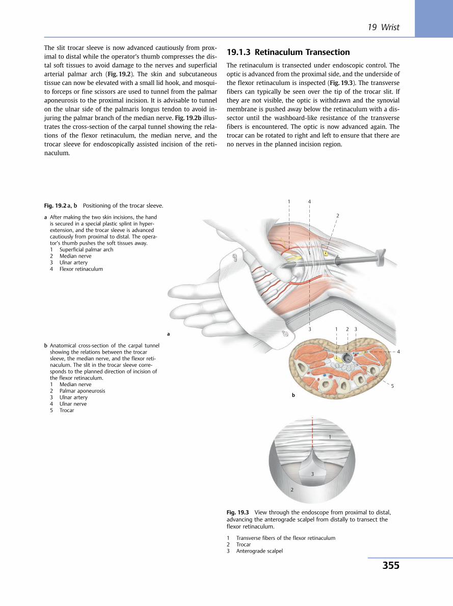
The slit trocar sleeve is now advanced cautiously from prox-imal to distal while the operator’s thumb compresses the dis-tal soft tissues to avoid damage to the nerves and superficialarterial palmar arch (Fig. 19.2). The skin and subcutaneoustissue can now be elevated with a small lid hook, and mosqui-to forceps or fine scissors are used to tunnel from the palmaraponeurosis to the proximal incision. It is advisable to tunnelon the ulnar side of the palmaris longus tendon to avoid in-juring the palmar branch of the median nerve. Fig. 19.2b illus-trates the cross-section of the carpal tunnel showing the rela-tions of the flexor retinaculum, the median nerve, and thetrocar sleeve for endoscopically assisted incision of the reti-naculum.
19.1.3 Retinaculum Transection
The retinaculum is transected under endoscopic control. Theoptic is advanced from the proximal side, and the underside ofthe flexor retinaculum is inspected (Fig. 19.3). The transversefibers can typically be seen over the tip of the trocar slit. Ifthey are not visible, the optic is withdrawn and the synovialmembrane is pushed away below the retinaculum with a dis-sector until the washboard-like resistance of the transversefibers is encountered. The optic is now advanced again. Thetrocar can be rotated to right and left to ensure that there areno nerves in the planned incision region.
1 4
3 1 2 3
4
5
2
Fig. 19.2 a, b Positioning of the trocar sleeve.
a After making the two skin incisions, the handis secured in a special plastic splint in hyper-extension, and the trocar sleeve is advancedcautiously from proximal to distal. The opera-tor’s thumb pushes the soft tissues away.1 Superficial palmar arch2 Median nerve3 Ulnar artery4 Flexor retinaculum
b Anatomical cross-section of the carpal tunnelshowing the relations between the trocarsleeve, the median nerve, and the flexor reti-naculum. The slit in the trocar sleeve corre-sponds to the planned direction of incision ofthe flexor retinaculum.1 Median nerve2 Palmar aponeurosis3 Ulnar artery4 Ulnar nerve5 Trocar
1
3
2
Fig. 19.3 View through the endoscope from proximal to distal,advancing the anterograde scalpel from distally to transect theflexor retinaculum.
1 Transverse fibers of the flexor retinaculum2 Trocar3 Anterograde scalpel
a
b
19 Wrist
355
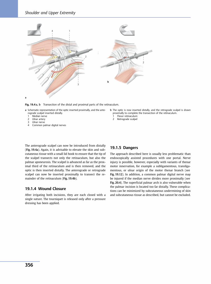
The anterograde scalpel can now be introduced from distally(Fig. 19.4a). Again, it is advisable to elevate the skin and sub-cutaneous tissue with a small lid hook to ensure that the tip ofthe scalpel transects not only the retinaculum, but also thepalmar aponeurosis. The scalpel is advanced as far as the prox-imal third of the retinaculum and is then removed, and theoptic is then inserted distally. The anterograde or retrogradescalpel can now be inserted proximally to transect the re-mainder of the retinaculum (Fig. 19.4b).
19.1.4 Wound Closure
After irrigating both incisions, they are each closed with asingle suture. The tourniquet is released only after a pressuredressing has been applied.
19.1.5 Dangers
The approach described here is usually less problematic thanendoscopically assisted procedures with one portal. Nerveinjury is possible, however, especially with variants of thenarmotor innervation, for example a subligamentous, transliga-mentous, or ulnar origin of the motor thenar branch (seeFig. 19.12). In addition, a common palmar digital nerve maybe injured if the median nerve divides more proximally (seeFig. 20.4). The superficial palmar arch is also vulnerable whenthe palmar incision is located too far distally. These complica-tions can be minimized by subcutaneous undermining of skinand subcutaneous tissue as described, but cannot be excluded.
4 1
2
2
1
3
Fig. 19.4 a, b Transection of the distal and proximal parts of the retinaculum.
a Schematic representation of the optic inserted proximally, and the ante-rograde scalpel inserted distally.1 Median nerve2 Ulnar artery3 Ulnar nerve4 Common palmar digital nerves
b The optic is now inserted distally, and the retrograde scalpel is drawnproximally to complete the transection of the retinaculum.1 Flexor retinaculum2 Retrograde scalpel
a
b
Shoulder and Upper Extremity
356
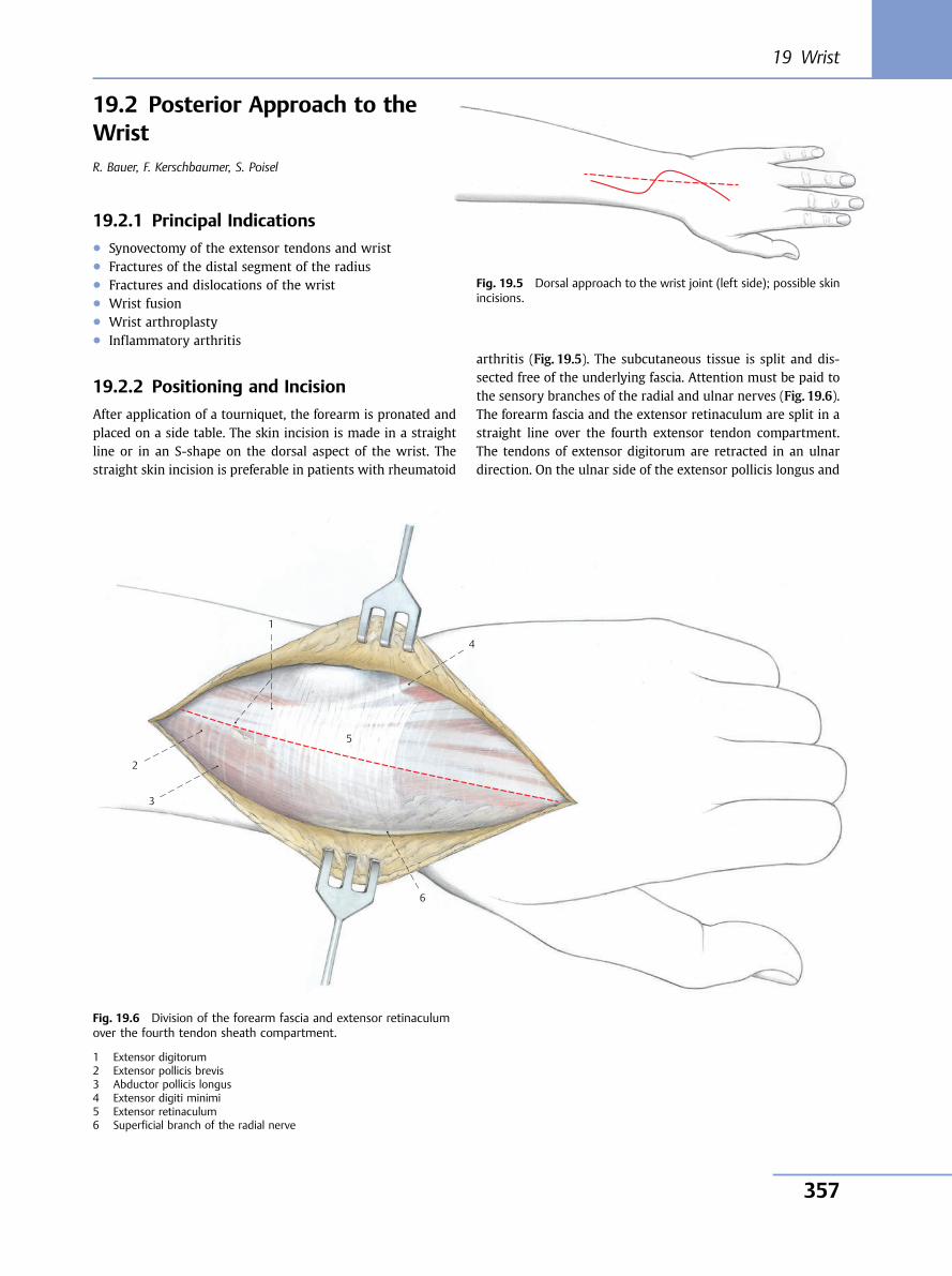
19.2 Posterior Approach to theWristR. Bauer, F. Kerschbaumer, S. Poisel
19.2.1 Principal Indications● Synovectomy of the extensor tendons and wrist● Fractures of the distal segment of the radius● Fractures and dislocations of the wrist● Wrist fusion● Wrist arthroplasty● Inflammatory arthritis
19.2.2 Positioning and Incision
After application of a tourniquet, the forearm is pronated andplaced on a side table. The skin incision is made in a straightline or in an S-shape on the dorsal aspect of the wrist. Thestraight skin incision is preferable in patients with rheumatoid
arthritis (Fig. 19.5). The subcutaneous tissue is split and dis-sected free of the underlying fascia. Attention must be paid tothe sensory branches of the radial and ulnar nerves (Fig. 19.6).The forearm fascia and the extensor retinaculum are split in astraight line over the fourth extensor tendon compartment.The tendons of extensor digitorum are retracted in an ulnardirection. On the ulnar side of the extensor pollicis longus and
Fig. 19.5 Dorsal approach to the wrist joint (left side); possible skinincisions.
5
4
3
1
2
6
Fig. 19.6 Division of the forearm fascia and extensor retinaculumover the fourth tendon sheath compartment.
1 Extensor digitorum2 Extensor pollicis brevis3 Abductor pollicis longus4 Extensor digiti minimi5 Extensor retinaculum6 Superficial branch of the radial nerve
19 Wrist
357
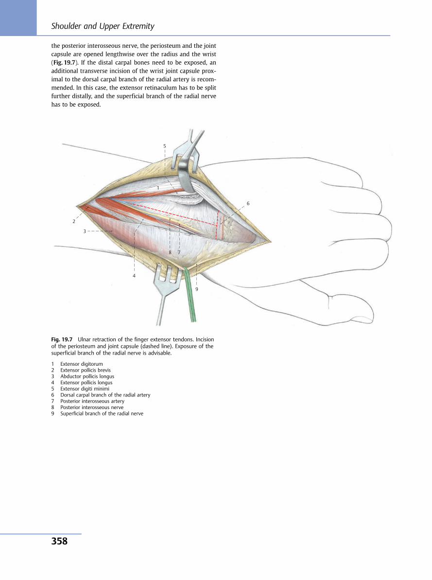
the posterior interosseous nerve, the periosteum and the jointcapsule are opened lengthwise over the radius and the wrist(Fig. 19.7). If the distal carpal bones need to be exposed, anadditional transverse incision of the wrist joint capsule prox-imal to the dorsal carpal branch of the radial artery is recom-mended. In this case, the extensor retinaculum has to be splitfurther distally, and the superficial branch of the radial nervehas to be exposed.
9
8 7
6
5
4
3
1
2
Fig. 19.7 Ulnar retraction of the finger extensor tendons. Incisionof the periosteum and joint capsule (dashed line). Exposure of thesuperficial branch of the radial nerve is advisable.
1 Extensor digitorum2 Extensor pollicis brevis3 Abductor pollicis longus4 Extensor pollicis longus5 Extensor digiti minimi6 Dorsal carpal branch of the radial artery7 Posterior interosseous artery8 Posterior interosseous nerve9 Superficial branch of the radial nerve
Shoulder and Upper Extremity
358
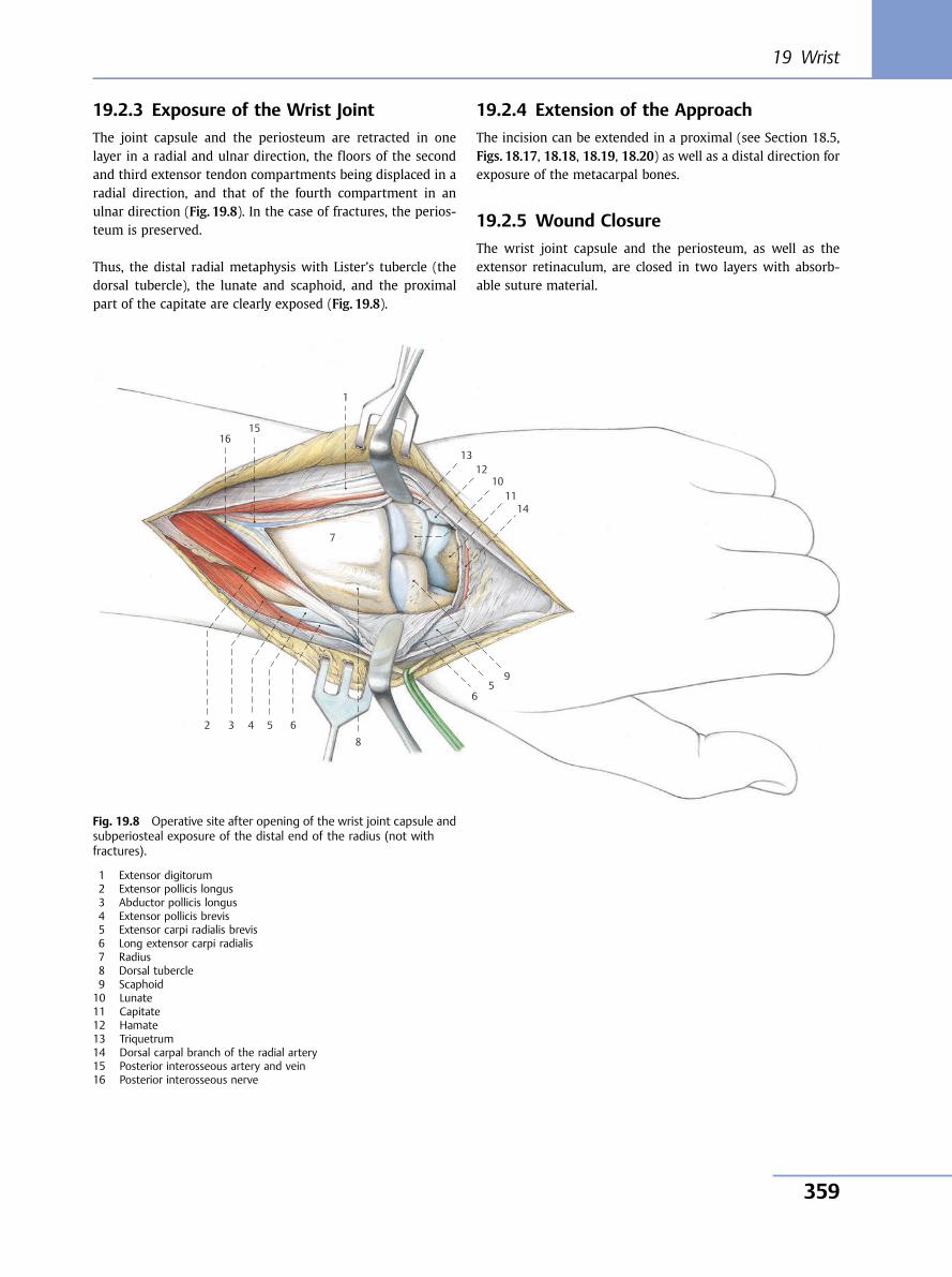
19.2.3 Exposure of the Wrist Joint
The joint capsule and the periosteum are retracted in onelayer in a radial and ulnar direction, the floors of the secondand third extensor tendon compartments being displaced in aradial direction, and that of the fourth compartment in anulnar direction (Fig. 19.8). In the case of fractures, the perios-teum is preserved.
Thus, the distal radial metaphysis with Lister’s tubercle (thedorsal tubercle), the lunate and scaphoid, and the proximalpart of the capitate are clearly exposed (Fig. 19.8).
19.2.4 Extension of the Approach
The incision can be extended in a proximal (see Section 18.5,Figs. 18.17, 18.18, 18.19, 18.20) as well as a distal direction forexposure of the metacarpal bones.
19.2.5 Wound Closure
The wrist joint capsule and the periosteum, as well as theextensor retinaculum, are closed in two layers with absorb-able suture material.
10 11
12 13
14
15 16
9
8
7
6 5 4 3
1
2
5 6
Fig. 19.8 Operative site after opening of the wrist joint capsule andsubperiosteal exposure of the distal end of the radius (not withfractures).
1 Extensor digitorum2 Extensor pollicis longus3 Abductor pollicis longus4 Extensor pollicis brevis5 Extensor carpi radialis brevis6 Long extensor carpi radialis7 Radius8 Dorsal tubercle9 Scaphoid10 Lunate11 Capitate12 Hamate13 Triquetrum14 Dorsal carpal branch of the radial artery15 Posterior interosseous artery and vein16 Posterior interosseous nerve
19 Wrist
359
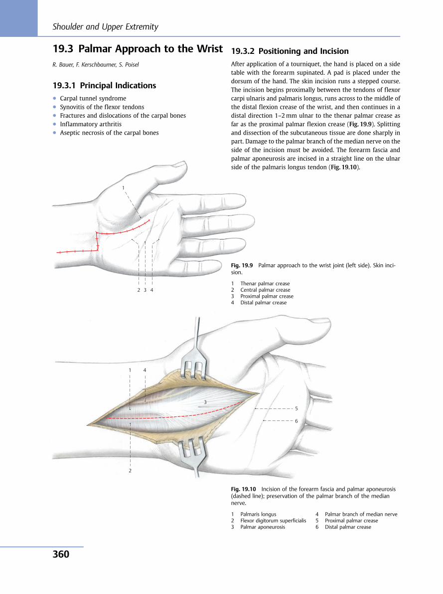
19.3 Palmar Approach to the WristR. Bauer, F. Kerschbaumer, S. Poisel
19.3.1 Principal Indications● Carpal tunnel syndrome● Synovitis of the flexor tendons● Fractures and dislocations of the carpal bones● Inflammatory arthritis● Aseptic necrosis of the carpal bones
4 3
1
2
Fig. 19.9 Palmar approach to the wrist joint (left side). Skin inci-sion.
1 Thenar palmar crease2 Central palmar crease3 Proximal palmar crease4 Distal palmar crease
6
5
4
3
1
2
Fig. 19.10 Incision of the forearm fascia and palmar aponeurosis(dashed line); preservation of the palmar branch of the mediannerve.
1 Palmaris longus2 Flexor digitorum superficialis3 Palmar aponeurosis
4 Palmar branch of median nerve5 Proximal palmar crease6 Distal palmar crease
19.3.2 Positioning and Incision
After application of a tourniquet, the hand is placed on a sidetable with the forearm supinated. A pad is placed under thedorsum of the hand. The skin incision runs a stepped course.The incision begins proximally between the tendons of flexorcarpi ulnaris and palmaris longus, runs across to the middle ofthe distal flexion crease of the wrist, and then continues in adistal direction 1–2mm ulnar to the thenar palmar crease asfar as the proximal palmar flexion crease (Fig. 19.9). Splittingand dissection of the subcutaneous tissue are done sharply inpart. Damage to the palmar branch of the median nerve on theside of the incision must be avoided. The forearm fascia andpalmar aponeurosis are incised in a straight line on the ulnarside of the palmaris longus tendon (Fig. 19.10).
Shoulder and Upper Extremity
360
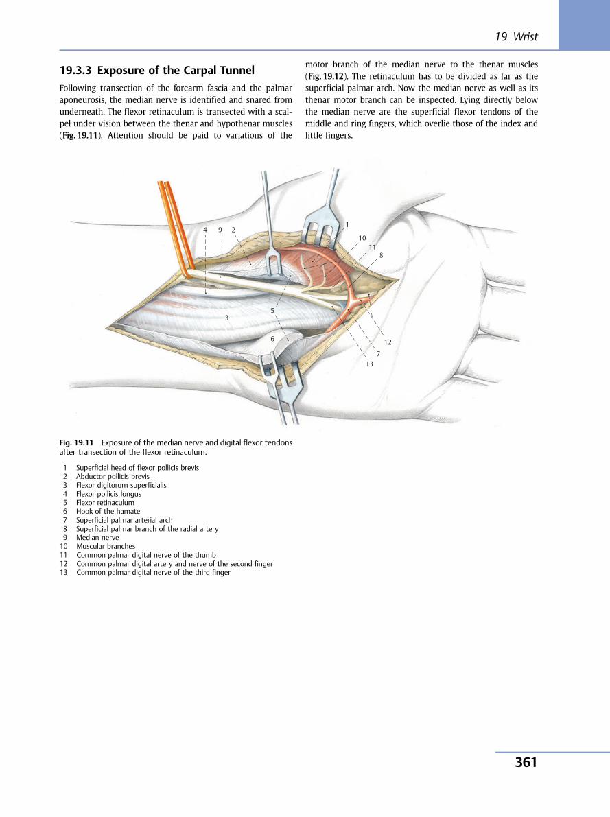
19.3.3 Exposure of the Carpal Tunnel
Following transection of the forearm fascia and the palmaraponeurosis, the median nerve is identified and snared fromunderneath. The flexor retinaculum is transected with a scal-pel under vision between the thenar and hypothenar muscles(Fig. 19.11). Attention should be paid to variations of the
motor branch of the median nerve to the thenar muscles(Fig. 19.12). The retinaculum has to be divided as far as thesuperficial palmar arch. Now the median nerve as well as itsthenar motor branch can be inspected. Lying directly belowthe median nerve are the superficial flexor tendons of themiddle and ring fingers, which overlie those of the index andlittle fingers.
10 11
12
13
9
8
7
6
5
4
3
1 2
Fig. 19.11 Exposure of the median nerve and digital flexor tendonsafter transection of the flexor retinaculum.
1 Superficial head of flexor pollicis brevis2 Abductor pollicis brevis3 Flexor digitorum superficialis4 Flexor pollicis longus5 Flexor retinaculum6 Hook of the hamate7 Superficial palmar arterial arch8 Superficial palmar branch of the radial artery9 Median nerve10 Muscular branches11 Common palmar digital nerve of the thumb12 Common palmar digital artery and nerve of the second finger13 Common palmar digital nerve of the third finger
19 Wrist
361
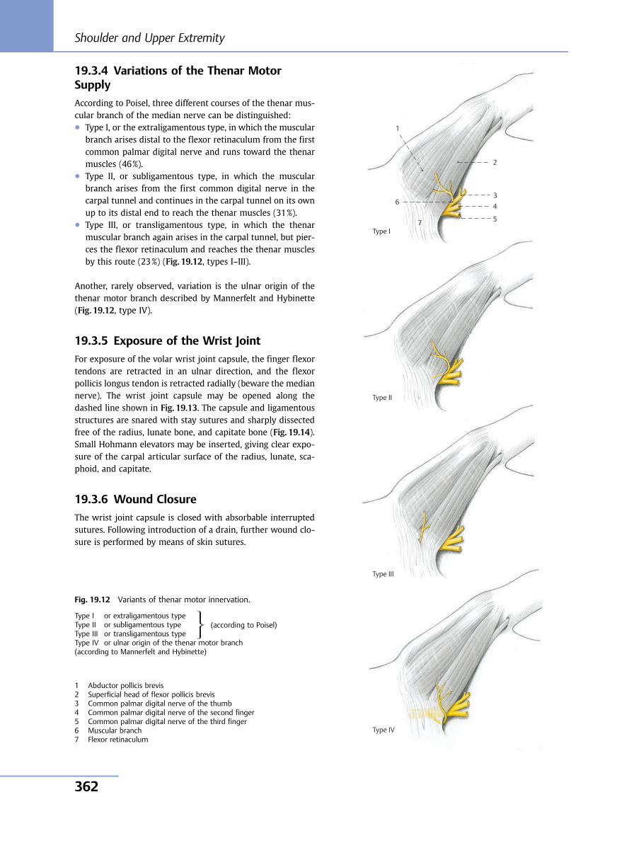
19.3.4 Variations of the Thenar MotorSupply
According to Poisel, three different courses of the thenar mus-cular branch of the median nerve can be distinguished:● Type I, or the extraligamentous type, in which the muscular
branch arises distal to the flexor retinaculum from the firstcommon palmar digital nerve and runs toward the thenarmuscles (46%).
● Type II, or subligamentous type, in which the muscularbranch arises from the first common digital nerve in thecarpal tunnel and continues in the carpal tunnel on its ownup to its distal end to reach the thenar muscles (31%).
● Type III, or transligamentous type, in which the thenarmuscular branch again arises in the carpal tunnel, but pier-ces the flexor retinaculum and reaches the thenar musclesby this route (23%) (Fig. 19.12, types I–III).
Another, rarely observed, variation is the ulnar origin of thethenar motor branch described by Mannerfelt and Hybinette(Fig. 19.12, type IV).
19.3.5 Exposure of the Wrist Joint
For exposure of the volar wrist joint capsule, the finger flexortendons are retracted in an ulnar direction, and the flexorpollicis longus tendon is retracted radially (beware the mediannerve). The wrist joint capsule may be opened along thedashed line shown in Fig. 19.13. The capsule and ligamentousstructures are snared with stay sutures and sharply dissectedfree of the radius, lunate bone, and capitate bone (Fig. 19.14).Small Hohmann elevators may be inserted, giving clear expo-sure of the carpal articular surface of the radius, lunate, sca-phoid, and capitate.
19.3.6 Wound Closure
The wrist joint capsule is closed with absorbable interruptedsutures. Following introduction of a drain, further wound clo-sure is performed by means of skin sutures.
Fig. 19.12 Variants of thenar motor innervation.
Type I or extraligamentous typeType II or subligamentous typeType III or transligamentous typeType IV or ulnar origin of the thenar motor branch(according to Mannerfelt and Hybinette)
⎫⎬⎭
(according to Poisel)
1 Abductor pollicis brevis2 Superficial head of flexor pollicis brevis3 Common palmar digital nerve of the thumb4 Common palmar digital nerve of the second finger5 Common palmar digital nerve of the third finger6 Muscular branch7 Flexor retinaculum
1
6
5
4 3
Type I
2
Type II
Type III
Type IV
7
Shoulder and Upper Extremity
362
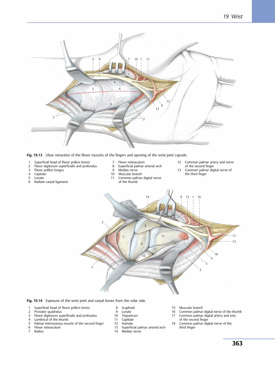
10 11
12
13
9
8
7
6
5 4
3 1
2 2
6
Fig. 19.13 Ulnar retraction of the flexor muscles of the fingers and opening of the wrist joint capsule.
1 Superficial head of flexor pollicis brevis2 Flexor digitorum superficialis and profundus3 Flexor pollicis longus4 Capitate5 Lunate6 Radiate carpal ligament
7 Flexor retinaculum8 Superficial palmar arterial arch9 Median nerve10 Muscular branch11 Common palmar digital nerve
of the thumb
12 Common palmar artery and nerveof the second finger
13 Common palmar digital nerve ofthe third finger
10
11
12
13
14 15 16
17
18
9
8
7
6
5
4
3 3
1
2
Fig. 19.14 Exposure of the wrist joint and carpal bones from the volar side.
1 Superficial head of flexor pollicis brevis2 Pronator quadratus3 Flexor digitorum superficialis and profundus4 Lumbrical of the thumb5 Palmar interosseous muscle of the second finger6 Flexor retinaculum7 Radius
8 Scaphoid9 Lunate10 Triquetrum11 Capitate12 Hamate13 Superficial palmar arterial arch14 Median nerve
15 Muscular branch16 Common palmar digital nerve of the thumb17 Common palmar digital artery and vein
of the second finger18 Common palmar digital nerve of the
third finger
19 Wrist
363
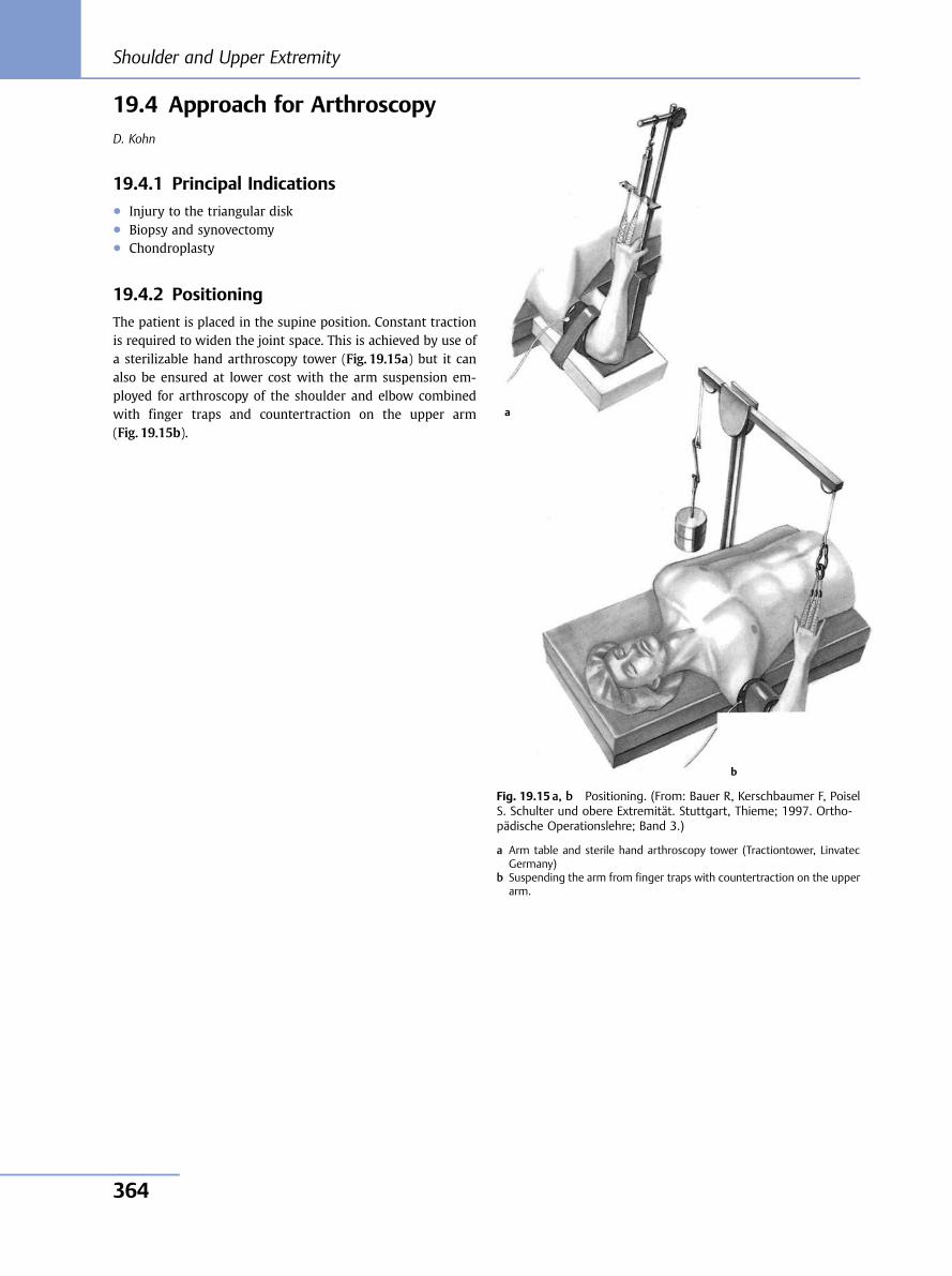
19.4 Approach for ArthroscopyD. Kohn
19.4.1 Principal Indications● Injury to the triangular disk● Biopsy and synovectomy● Chondroplasty
19.4.2 Positioning
The patient is placed in the supine position. Constant tractionis required to widen the joint space. This is achieved by use ofa sterilizable hand arthroscopy tower (Fig. 19.15a) but it canalso be ensured at lower cost with the arm suspension em-ployed for arthroscopy of the shoulder and elbow combinedwith finger traps and countertraction on the upper arm(Fig. 19.15b).
Fig. 19.15 a, b Positioning. (From: Bauer R, Kerschbaumer F, PoiselS. Schulter und obere Extremität. Stuttgart, Thieme; 1997. Ortho-pädische Operationslehre; Band 3.)
a Arm table and sterile hand arthroscopy tower (Tractiontower, LinvatecGermany)
b Suspending the arm from finger traps with countertraction on the upperarm.
a
b
Shoulder and Upper Extremity
364
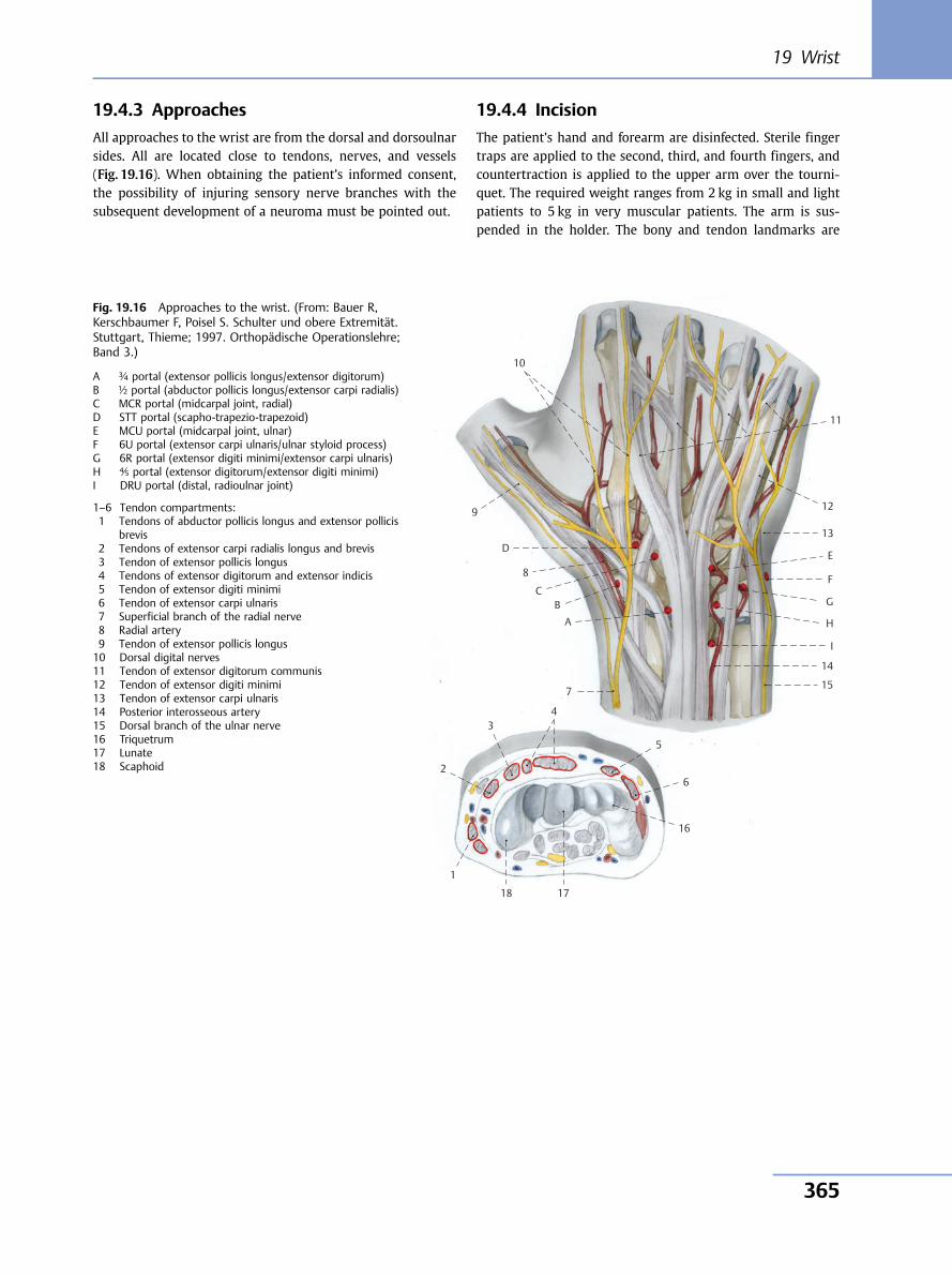
19.4.3 Approaches
All approaches to the wrist are from the dorsal and dorsoulnarsides. All are located close to tendons, nerves, and vessels(Fig. 19.16). When obtaining the patient’s informed consent,the possibility of injuring sensory nerve branches with thesubsequent development of a neuroma must be pointed out.
19.4.4 Incision
The patient’s hand and forearm are disinfected. Sterile fingertraps are applied to the second, third, and fourth fingers, andcountertraction is applied to the upper arm over the tourni-quet. The required weight ranges from 2 kg in small and lightpatients to 5 kg in very muscular patients. The arm is sus-pended in the holder. The bony and tendon landmarks are
10
11
12
13
E
F
G
H
I
14
15
9
D
8
CB
A
7
43
2
1
18 17
16
6
5
Fig. 19.16 Approaches to the wrist. (From: Bauer R,Kerschbaumer F, Poisel S. Schulter und obere Extremität.Stuttgart, Thieme; 1997. Orthopädische Operationslehre;Band 3.)
A ¾ portal (extensor pollicis longus/extensor digitorum)B ½ portal (abductor pollicis longus/extensor carpi radialis)C MCR portal (midcarpal joint, radial)D STT portal (scapho-trapezio-trapezoid)E MCU portal (midcarpal joint, ulnar)F 6U portal (extensor carpi ulnaris/ulnar styloid process)G 6R portal (extensor digiti minimi/extensor carpi ulnaris)H ⅘ portal (extensor digitorum/extensor digiti minimi)I DRU portal (distal, radioulnar joint)
1–6 Tendon compartments:1 Tendons of abductor pollicis longus and extensor pollicis
brevis2 Tendons of extensor carpi radialis longus and brevis3 Tendon of extensor pollicis longus4 Tendons of extensor digitorum and extensor indicis5 Tendon of extensor digiti minimi6 Tendon of extensor carpi ulnaris7 Superficial branch of the radial nerve8 Radial artery9 Tendon of extensor pollicis longus10 Dorsal digital nerves11 Tendon of extensor digitorum communis12 Tendon of extensor digiti minimi13 Tendon of extensor carpi ulnaris14 Posterior interosseous artery15 Dorsal branch of the ulnar nerve16 Triquetrum17 Lunate18 Scaphoid
19 Wrist
365
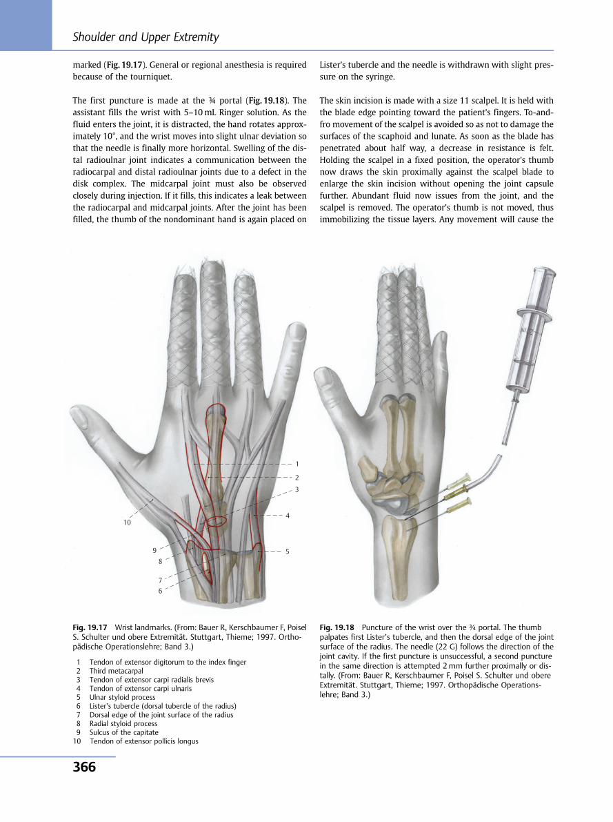
marked (Fig. 19.17). General or regional anesthesia is requiredbecause of the tourniquet.
The first puncture is made at the ¾ portal (Fig. 19.18). Theassistant fills the wrist with 5–10mL Ringer solution. As thefluid enters the joint, it is distracted, the hand rotates approx-imately 10°, and the wrist moves into slight ulnar deviation sothat the needle is finally more horizontal. Swelling of the dis-tal radioulnar joint indicates a communication between theradiocarpal and distal radioulnar joints due to a defect in thedisk complex. The midcarpal joint must also be observedclosely during injection. If it fills, this indicates a leak betweenthe radiocarpal and midcarpal joints. After the joint has beenfilled, the thumb of the nondominant hand is again placed on
Lister’s tubercle and the needle is withdrawn with slight pres-sure on the syringe.
The skin incision is made with a size 11 scalpel. It is held withthe blade edge pointing toward the patient’s fingers. To-and-fro movement of the scalpel is avoided so as not to damage thesurfaces of the scaphoid and lunate. As soon as the blade haspenetrated about half way, a decrease in resistance is felt.Holding the scalpel in a fixed position, the operator’s thumbnow draws the skin proximally against the scalpel blade toenlarge the skin incision without opening the joint capsulefurther. Abundant fluid now issues from the joint, and thescalpel is removed. The operator’s thumb is not moved, thusimmobilizing the tissue layers. Any movement will cause the
1
2
3
4
5
67
89
10
Fig. 19.17 Wrist landmarks. (From: Bauer R, Kerschbaumer F, PoiselS. Schulter und obere Extremität. Stuttgart, Thieme; 1997. Ortho-pädische Operationslehre; Band 3.)
1 Tendon of extensor digitorum to the index finger2 Third metacarpal3 Tendon of extensor carpi radialis brevis4 Tendon of extensor carpi ulnaris5 Ulnar styloid process6 Lister’s tubercle (dorsal tubercle of the radius)7 Dorsal edge of the joint surface of the radius8 Radial styloid process9 Sulcus of the capitate10 Tendon of extensor pollicis longus
Fig. 19.18 Puncture of the wrist over the ¾ portal. The thumbpalpates first Lister’s tubercle, and then the dorsal edge of the jointsurface of the radius. The needle (22 G) follows the direction of thejoint cavity. If the first puncture is unsuccessful, a second puncturein the same direction is attempted 2mm further proximally or dis-tally. (From: Bauer R, Kerschbaumer F, Poisel S. Schulter und obereExtremität. Stuttgart, Thieme; 1997. Orthopädische Operations-lehre; Band 3.)
Shoulder and Upper Extremity
366
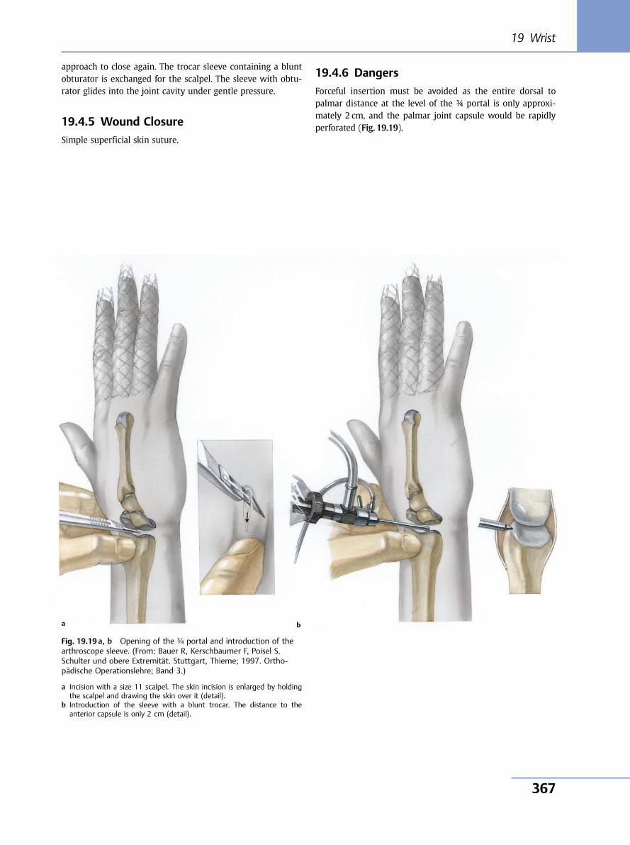
approach to close again. The trocar sleeve containing a bluntobturator is exchanged for the scalpel. The sleeve with obtu-rator glides into the joint cavity under gentle pressure.
19.4.5 Wound Closure
Simple superficial skin suture.
19.4.6 Dangers
Forceful insertion must be avoided as the entire dorsal topalmar distance at the level of the ¾ portal is only approxi-mately 2 cm, and the palmar joint capsule would be rapidlyperforated (Fig. 19.19).
Fig. 19.19 a, b Opening of the ¾ portal and introduction of thearthroscope sleeve. (From: Bauer R, Kerschbaumer F, Poisel S.Schulter und obere Extremität. Stuttgart, Thieme; 1997. Ortho-pädische Operationslehre; Band 3.)
a Incision with a size 11 scalpel. The skin incision is enlarged by holdingthe scalpel and drawing the skin over it (detail).
b Introduction of the sleeve with a blunt trocar. The distance to theanterior capsule is only 2 cm (detail).
a b
19 Wrist
367

Shoulder and Upper Extremity
368
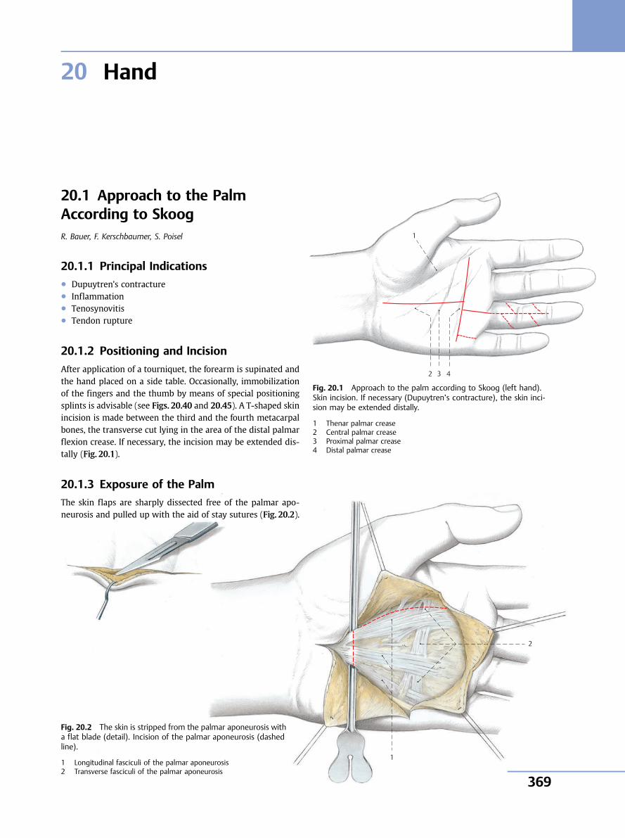
20 Hand
4 3
1
2
Fig. 20.1 Approach to the palm according to Skoog (left hand).Skin incision. If necessary (Dupuytren’s contracture), the skin inci-sion may be extended distally.
1 Thenar palmar crease2 Central palmar crease3 Proximal palmar crease4 Distal palmar crease
1
2
20.1 Approach to the PalmAccording to SkoogR. Bauer, F. Kerschbaumer, S. Poisel
20.1.1 Principal Indications● Dupuytren’s contracture● Inflammation● Tenosynovitis● Tendon rupture
20.1.2 Positioning and Incision
After application of a tourniquet, the forearm is supinated andthe hand placed on a side table. Occasionally, immobilizationof the fingers and the thumb by means of special positioningsplints is advisable (see Figs. 20.40 and 20.45). A T-shaped skinincision is made between the third and the fourth metacarpalbones, the transverse cut lying in the area of the distal palmarflexion crease. If necessary, the incision may be extended dis-tally (Fig. 20.1).
20.1.3 Exposure of the Palm
The skin flaps are sharply dissected free of the palmar apo-neurosis and pulled up with the aid of stay sutures (Fig. 20.2).
Fig. 20.2 The skin is stripped from the palmar aponeurosis witha flat blade (detail). Incision of the palmar aponeurosis (dashedline).
1 Longitudinal fasciculi of the palmar aponeurosis2 Transverse fasciculi of the palmar aponeurosis
20 Hand
369
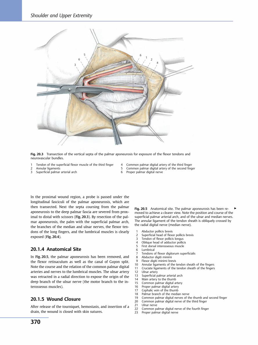
In the proximal wound region, a probe is passed under thelongitudinal fasciculi of the palmar aponeurosis, which arethen transected. Next the septa coursing from the palmaraponeurosis to the deep palmar fascia are severed from prox-imal to distal with scissors (Fig. 20.3). By resection of the pal-mar aponeurosis, the palm with the superficial palmar arch,the branches of the median and ulnar nerves, the flexor ten-dons of the long fingers, and the lumbrical muscles is clearlyexposed (Fig. 20.4).
20.1.4 Anatomical Site
In Fig. 20.5, the palmar aponeurosis has been removed, andthe flexor retinaculum as well as the canal of Guyon split.Note the course and the relation of the common palmar digitalarteries and nerves to the lumbrical muscles. The ulnar arterywas retracted in a radial direction to expose the origin of thedeep branch of the ulnar nerve (the motor branch to the in-terosseous muscles).
20.1.5 Wound Closure
After release of the tourniquet, hemostasis, and insertion of adrain, the wound is closed with skin sutures.
6
5
4 3
1 2
6
Fig. 20.3 Transection of the vertical septa of the palmar aponeurosis for exposure of the flexor tendons andneurovascular bundles.
1 Tendon of the superficial flexor muscle of the third finger2 Annular ligaments3 Superficial palmar arterial arch
4 Common palmar digital artery of the third finger5 Common palmar digital artery of the second finger6 Proper palmar digital nerve
Fig. 20.5 Anatomical site. The palmar aponeurosis has been re-moved to achieve a clearer view. Note the position and course of thesuperficial palmar arterial arch, and of the ulnar and median nerves.The annular ligament of the tendon sheath is obliquely crossed bythe radial digital nerve (median nerve).
1 Abductor pollicis brevis2 Superficial head of flexor pollicis brevis3 Tendon of flexor pollicis longus4 Oblique head of adductor pollicis5 First dorsal interosseous muscle6 Lumbrical7 Tendons of flexor digitorum superficialis8 Abductor digiti minimi9 Flexor digiti minimi brevis10 Annular ligaments of the tendon sheath of the fingers11 Cruciate ligaments of the tendon sheath of the fingers12 Ulnar artery13 Superficial palmar arterial arch14 Main artery to the thumb15 Common palmar digital artery16 Proper palmar digital artery17 Cephalic vein of the thumb18 Palmar branch of the median nerve19 Common palmar digital nerves of the thumb and second finger20 Common palmar digital nerve of the third finger21 Ulnar nerve22 Common palmar digital nerve of the fourth finger23 Proper palmar digital nerve
▶
Shoulder and Upper Extremity
370
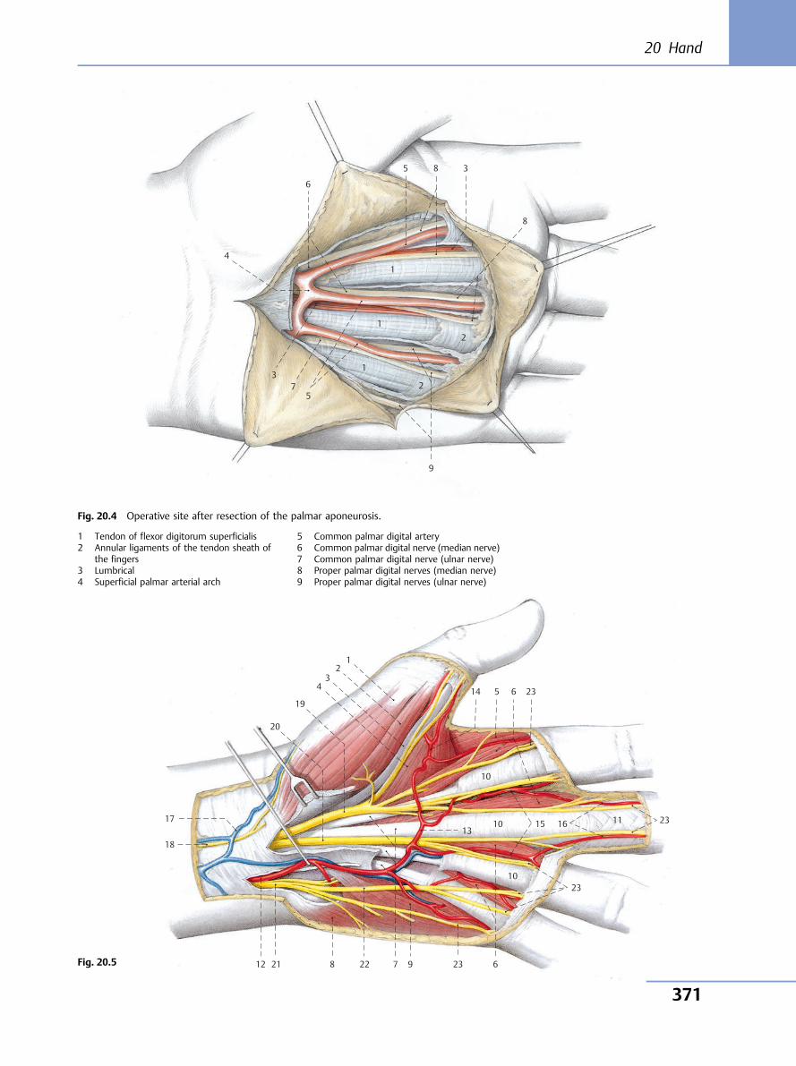
9
8
7
6
5
4
3
1
2
8
1
1 3
5 2
Fig. 20.4 Operative site after resection of the palmar aponeurosis.
1 Tendon of flexor digitorum superficialis2 Annular ligaments of the tendon sheath of
the fingers3 Lumbrical4 Superficial palmar arterial arch
5 Common palmar digital artery6 Common palmar digital nerve (median nerve)7 Common palmar digital nerve (ulnar nerve)8 Proper palmar digital nerves (median nerve)9 Proper palmar digital nerves (ulnar nerve)
Fig. 20.5
1 2
3 4
19
20
17
18
12 21 8 22 7 9 23 6
23 10
10
10
23 6514
15 16 11 23 13
20 Hand
371
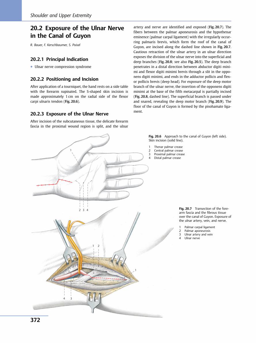
20.2 Exposure of the Ulnar Nervein the Canal of GuyonR. Bauer, F. Kerschbaumer, S. Poisel
20.2.1 Principal Indication● Ulnar nerve compression syndrome
20.2.2 Positioning and Incision
After application of a tourniquet, the hand rests on a side tablewith the forearm supinated. The S-shaped skin incision ismade approximately 1 cm on the radial side of the flexorcarpi ulnaris tendon (Fig. 20.6).
20.2.3 Exposure of the Ulnar Nerve
After incision of the subcutaneous tissue, the delicate forearmfascia in the proximal wound region is split, and the ulnar
artery and nerve are identified and exposed (Fig. 20.7). Thefibers between the palmar aponeurosis and the hypothenareminence (palmar carpal ligament) with the irregularly occur-ring palmaris brevis, which form the roof of the canal ofGuyon, are incised along the dashed line shown in Fig. 20.7.Cautious retraction of the ulnar artery in an ulnar directionexposes the division of the ulnar nerve into the superficial anddeep branches (Fig. 20.8; see also Fig. 20.5). The deep branchpenetrates in a distal direction between abductor digiti mini-mi and flexor digiti minimi brevis through a slit in the oppo-nens digiti minimi, and ends in the adductor pollicis and flex-or pollicis brevis (deep head). For exposure of the deep motorbranch of the ulnar nerve, the insertion of the opponens digitiminimi at the base of the fifth metacarpal is partially incised(Fig. 20.8, dashed line). The superficial branch is passed underand snared, revealing the deep motor branch (Fig. 20.9). Thefloor of the canal of Guyon is formed by the pisohamate liga-ment.
Fig. 20.6 Approach to the canal of Guyon (left side).Skin incision (solid line).
1 Thenar palmar crease2 Central palmar crease3 Proximal palmar crease4 Distal palmar crease
4 3
1 2
1
4 3
1
2 Fig. 20.7 Transection of the fore-arm fascia and the fibrous tissueover the canal of Guyon. Exposure ofthe ulnar artery, vein, and nerve.
1 Palmar carpal ligament2 Palmar aponeurosis3 Ulnar artery and vein4 Ulnar nerve
Shoulder and Upper Extremity
372
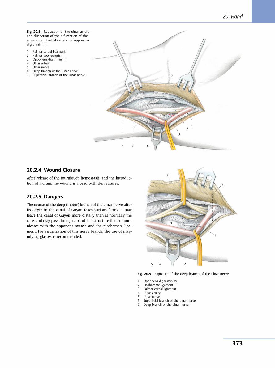
20.2.4 Wound Closure
After release of the tourniquet, hemostasis, and the introduc-tion of a drain, the wound is closed with skin sutures.
20.2.5 Dangers
The course of the deep (motor) branch of the ulnar nerve afterits origin in the canal of Guyon takes various forms. It mayleave the canal of Guyon more distally than is normally thecase, and may pass through a band-like structure that commu-nicates with the opponens muscle and the pisohamate liga-ment. For visualization of this nerve branch, the use of mag-nifying glasses is recommended.
7
6 5 4
3
1
2
Fig. 20.8 Retraction of the ulnar arteryand dissection of the bifurcation of theulnar nerve. Partial incision of opponensdigiti minimi.
1 Palmar carpal ligament2 Palmar aponeurosis3 Opponens digiti minimi4 Ulnar artery5 Ulnar nerve6 Deep branch of the ulnar nerve7 Superficial branch of the ulnar nerve
6
5 4
3
1
2
7
Fig. 20.9 Exposure of the deep branch of the ulnar nerve.
1 Opponens digiti minimi2 Pisohamate ligament3 Palmar carpal ligament4 Ulnar artery5 Ulnar nerve6 Superficial branch of the ulnar nerve7 Deep branch of the ulnar nerve
20 Hand
373
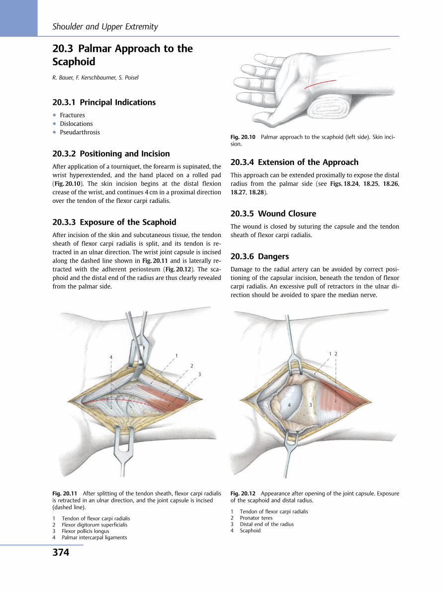
20.3 Palmar Approach to theScaphoidR. Bauer, F. Kerschbaumer, S. Poisel
20.3.1 Principal Indications● Fractures● Dislocations● Pseudarthrosis
20.3.2 Positioning and Incision
After application of a tourniquet, the forearm is supinated, thewrist hyperextended, and the hand placed on a rolled pad(Fig. 20.10). The skin incision begins at the distal flexioncrease of the wrist, and continues 4 cm in a proximal directionover the tendon of the flexor carpi radialis.
20.3.3 Exposure of the Scaphoid
After incision of the skin and subcutaneous tissue, the tendonsheath of flexor carpi radialis is split, and its tendon is re-tracted in an ulnar direction. The wrist joint capsule is incisedalong the dashed line shown in Fig. 20.11 and is laterally re-tracted with the adherent periosteum (Fig. 20.12). The sca-phoid and the distal end of the radius are thus clearly revealedfrom the palmar side.
20.3.4 Extension of the Approach
This approach can be extended proximally to expose the distalradius from the palmar side (see Figs. 18.24, 18.25, 18.26,18.27, 18.28).
20.3.5 Wound Closure
The wound is closed by suturing the capsule and the tendonsheath of flexor carpi radialis.
20.3.6 Dangers
Damage to the radial artery can be avoided by correct posi-tioning of the capsular incision, beneath the tendon of flexorcarpi radialis. An excessive pull of retractors in the ulnar di-rection should be avoided to spare the median nerve.
Fig. 20.10 Palmar approach to the scaphoid (left side). Skin inci-sion.
4
3
1
2
Fig. 20.11 After splitting of the tendon sheath, flexor carpi radialisis retracted in an ulnar direction, and the joint capsule is incised(dashed line).
1 Tendon of flexor carpi radialis2 Flexor digitorum superficialis3 Flexor pollicis longus4 Palmar intercarpal ligaments
4 3
1 2
Fig. 20.12 Appearance after opening of the joint capsule. Exposureof the scaphoid and distal radius.
1 Tendon of flexor carpi radialis2 Pronator teres3 Distal end of the radius4 Scaphoid
Shoulder and Upper Extremity
374
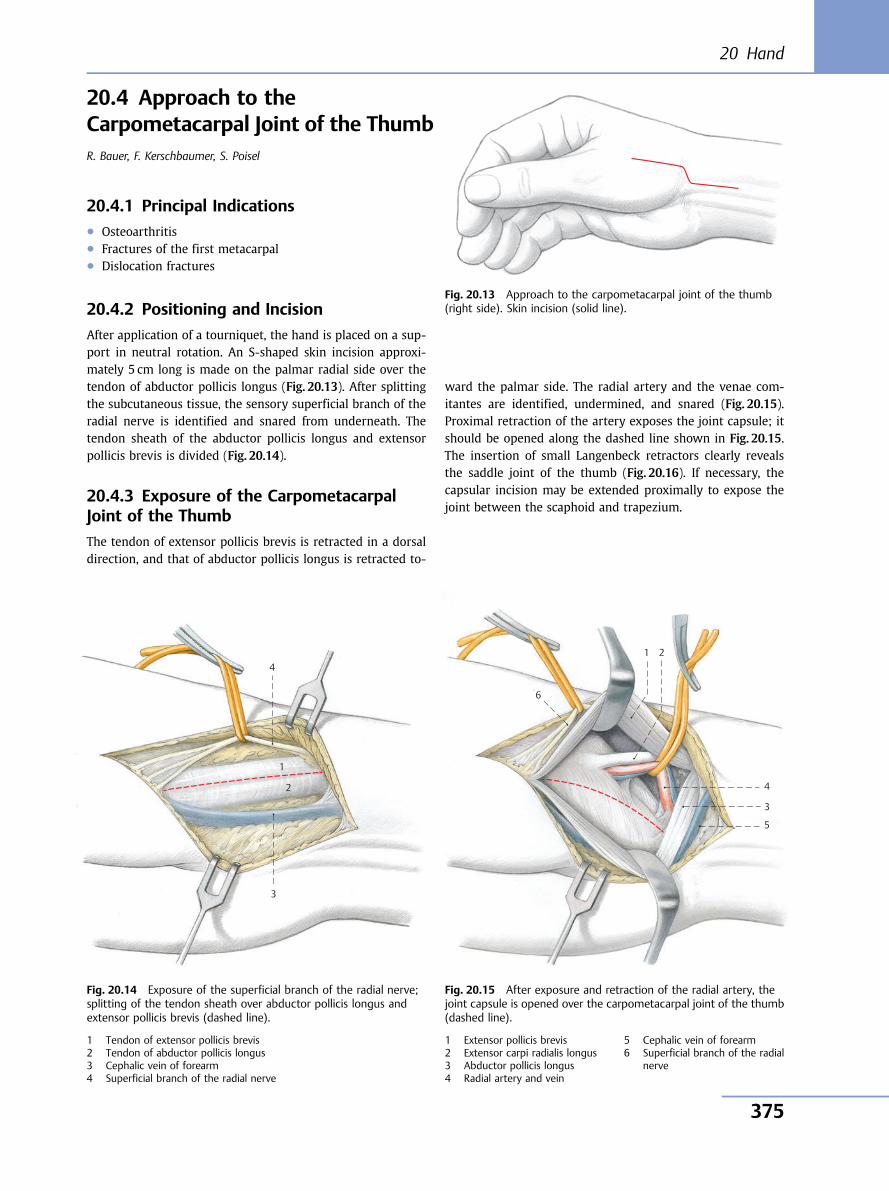
20.4 Approach to theCarpometacarpal Joint of the ThumbR. Bauer, F. Kerschbaumer, S. Poisel
20.4.1 Principal Indications● Osteoarthritis● Fractures of the first metacarpal● Dislocation fractures
20.4.2 Positioning and Incision
After application of a tourniquet, the hand is placed on a sup-port in neutral rotation. An S-shaped skin incision approxi-mately 5 cm long is made on the palmar radial side over thetendon of abductor pollicis longus (Fig. 20.13). After splittingthe subcutaneous tissue, the sensory superficial branch of theradial nerve is identified and snared from underneath. Thetendon sheath of the abductor pollicis longus and extensorpollicis brevis is divided (Fig. 20.14).
20.4.3 Exposure of the CarpometacarpalJoint of the Thumb
The tendon of extensor pollicis brevis is retracted in a dorsaldirection, and that of abductor pollicis longus is retracted to-
ward the palmar side. The radial artery and the venae com-itantes are identified, undermined, and snared (Fig. 20.15).Proximal retraction of the artery exposes the joint capsule; itshould be opened along the dashed line shown in Fig. 20.15.The insertion of small Langenbeck retractors clearly revealsthe saddle joint of the thumb (Fig. 20.16). If necessary, thecapsular incision may be extended proximally to expose thejoint between the scaphoid and trapezium.
Fig. 20.13 Approach to the carpometacarpal joint of the thumb(right side). Skin incision (solid line).
4
3
1
2
Fig. 20.14 Exposure of the superficial branch of the radial nerve;splitting of the tendon sheath over abductor pollicis longus andextensor pollicis brevis (dashed line).
1 Tendon of extensor pollicis brevis2 Tendon of abductor pollicis longus3 Cephalic vein of forearm4 Superficial branch of the radial nerve
6
5
4
3
1 2
Fig. 20.15 After exposure and retraction of the radial artery, thejoint capsule is opened over the carpometacarpal joint of the thumb(dashed line).
1 Extensor pollicis brevis2 Extensor carpi radialis longus3 Abductor pollicis longus4 Radial artery and vein
5 Cephalic vein of forearm6 Superficial branch of the radial
nerve
20 Hand
375
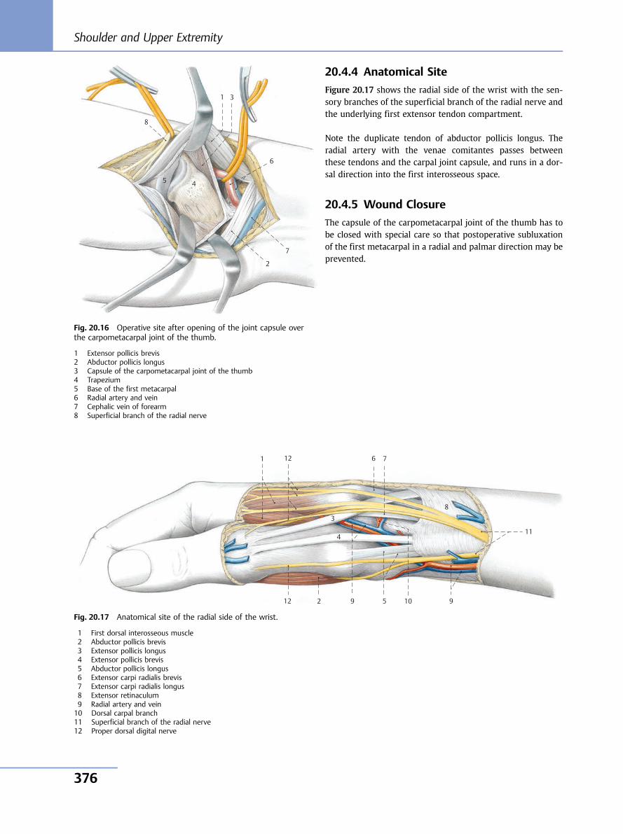
20.4.4 Anatomical Site
Figure 20.17 shows the radial side of the wrist with the sen-sory branches of the superficial branch of the radial nerve andthe underlying first extensor tendon compartment.
Note the duplicate tendon of abductor pollicis longus. Theradial artery with the venae comitantes passes betweenthese tendons and the carpal joint capsule, and runs in a dor-sal direction into the first interosseous space.
20.4.5 Wound Closure
The capsule of the carpometacarpal joint of the thumb has tobe closed with special care so that postoperative subluxationof the first metacarpal in a radial and palmar direction may beprevented.
8
7
6
5 4
3 1
2
Fig. 20.16 Operative site after opening of the joint capsule overthe carpometacarpal joint of the thumb.
1 Extensor pollicis brevis2 Abductor pollicis longus3 Capsule of the carpometacarpal joint of the thumb4 Trapezium5 Base of the first metacarpal6 Radial artery and vein7 Cephalic vein of forearm8 Superficial branch of the radial nerve
10
11
12
9
8
7 6
5
4
3
1
2 9 12
Fig. 20.17 Anatomical site of the radial side of the wrist.
1 First dorsal interosseous muscle2 Abductor pollicis brevis3 Extensor pollicis longus4 Extensor pollicis brevis5 Abductor pollicis longus6 Extensor carpi radialis brevis7 Extensor carpi radialis longus8 Extensor retinaculum9 Radial artery and vein10 Dorsal carpal branch11 Superficial branch of the radial nerve12 Proper dorsal digital nerve
Shoulder and Upper Extremity
376
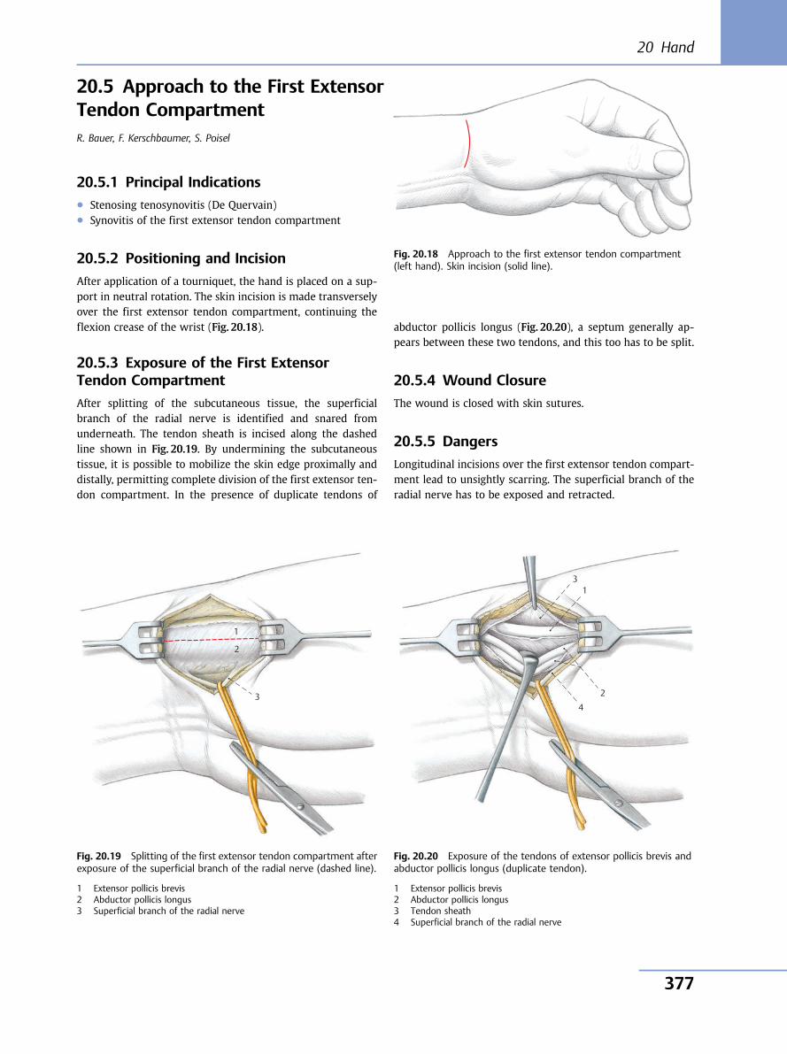
20.5 Approach to the First ExtensorTendon CompartmentR. Bauer, F. Kerschbaumer, S. Poisel
20.5.1 Principal Indications● Stenosing tenosynovitis (De Quervain)● Synovitis of the first extensor tendon compartment
20.5.2 Positioning and Incision
After application of a tourniquet, the hand is placed on a sup-port in neutral rotation. The skin incision is made transverselyover the first extensor tendon compartment, continuing theflexion crease of the wrist (Fig. 20.18).
20.5.3 Exposure of the First ExtensorTendon Compartment
After splitting of the subcutaneous tissue, the superficialbranch of the radial nerve is identified and snared fromunderneath. The tendon sheath is incised along the dashedline shown in Fig. 20.19. By undermining the subcutaneoustissue, it is possible to mobilize the skin edge proximally anddistally, permitting complete division of the first extensor ten-don compartment. In the presence of duplicate tendons of
abductor pollicis longus (Fig. 20.20), a septum generally ap-pears between these two tendons, and this too has to be split.
20.5.4 Wound Closure
The wound is closed with skin sutures.
20.5.5 Dangers
Longitudinal incisions over the first extensor tendon compart-ment lead to unsightly scarring. The superficial branch of theradial nerve has to be exposed and retracted.
Fig. 20.18 Approach to the first extensor tendon compartment(left hand). Skin incision (solid line).
3
1
2
Fig. 20.19 Splitting of the first extensor tendon compartment afterexposure of the superficial branch of the radial nerve (dashed line).
1 Extensor pollicis brevis2 Abductor pollicis longus3 Superficial branch of the radial nerve
4
3 1
2
Fig. 20.20 Exposure of the tendons of extensor pollicis brevis andabductor pollicis longus (duplicate tendon).
1 Extensor pollicis brevis2 Abductor pollicis longus3 Tendon sheath4 Superficial branch of the radial nerve
20 Hand
377
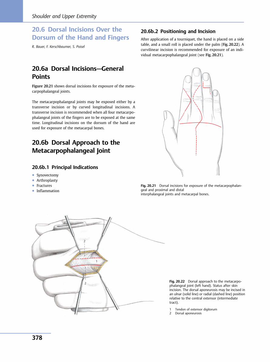
20.6 Dorsal Incisions Over theDorsum of the Hand and FingersR. Bauer, F. Kerschbaumer, S. Poisel
20.6a Dorsal Incisions—GeneralPointsFigure 20.21 shows dorsal incisions for exposure of the meta-carpophalangeal joints.
The metacarpophalangeal joints may be exposed either by atransverse incision or by curved longitudinal incisions. Atransverse incision is recommended when all four metacarpo-phalangeal joints of the fingers are to be exposed at the sametime. Longitudinal incisions on the dorsum of the hand areused for exposure of the metacarpal bones.
20.6b Dorsal Approach to theMetacarpophalangeal Joint
20.6b.1 Principal Indications● Synovectomy● Arthroplasty● Fractures● Inflammation
20.6b.2 Positioning and Incision
After application of a tourniquet, the hand is placed on a sidetable, and a small roll is placed under the palm (Fig. 20.22). Acurvilinear incision is recommended for exposure of an indi-vidual metacarpophalangeal joint (see Fig. 20.21).
1
2
2
Fig. 20.21 Dorsal incisions for exposure of the metacarpophalan-geal and proximal and distalinterphalangeal joints and metacarpal bones.
Fig. 20.22 Dorsal approach to the metacarpo-phalangeal joint (left hand). Status after skinincision. The dorsal aponeurosis may be incised inan ulnar (solid line) or radial (dashed line) positionrelative to the central extensor (intermediatetract).
1 Tendon of extensor digitorum2 Dorsal aponeurosis
Shoulder and Upper Extremity
378
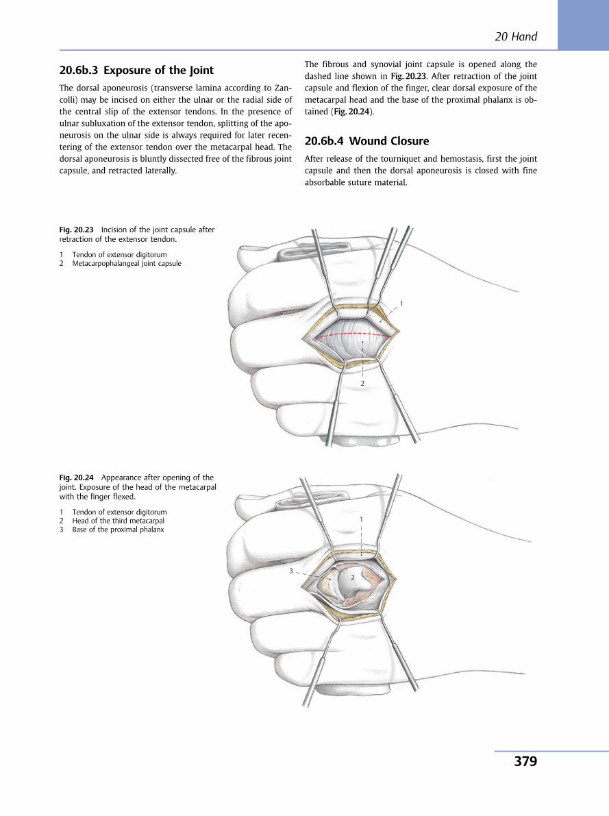
20.6b.3 Exposure of the Joint
The dorsal aponeurosis (transverse lamina according to Zan-colli) may be incised on either the ulnar or the radial side ofthe central slip of the extensor tendons. In the presence ofulnar subluxation of the extensor tendon, splitting of the apo-neurosis on the ulnar side is always required for later recen-tering of the extensor tendon over the metacarpal head. Thedorsal aponeurosis is bluntly dissected free of the fibrous jointcapsule, and retracted laterally.
The fibrous and synovial joint capsule is opened along thedashed line shown in Fig. 20.23. After retraction of the jointcapsule and flexion of the finger, clear dorsal exposure of themetacarpal head and the base of the proximal phalanx is ob-tained (Fig. 20.24).
20.6b.4 Wound Closure
After release of the tourniquet and hemostasis, first the jointcapsule and then the dorsal aponeurosis is closed with fineabsorbable suture material.
1
2
Fig. 20.23 Incision of the joint capsule afterretraction of the extensor tendon.
1 Tendon of extensor digitorum2 Metacarpophalangeal joint capsule
3
1
2
Fig. 20.24 Appearance after opening of thejoint. Exposure of the head of the metacarpalwith the finger flexed.
1 Tendon of extensor digitorum2 Head of the third metacarpal3 Base of the proximal phalanx
20 Hand
379
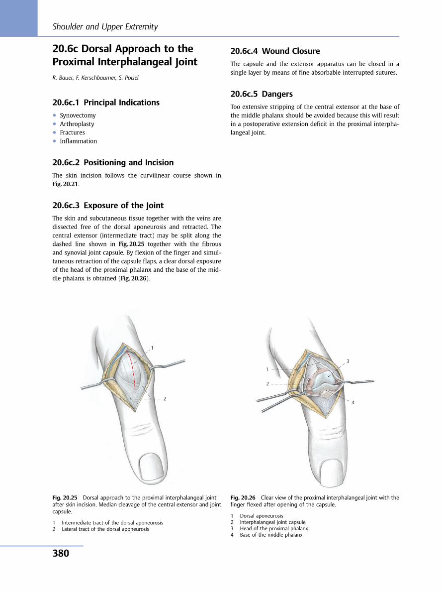
20.6c Dorsal Approach to theProximal Interphalangeal JointR. Bauer, F. Kerschbaumer, S. Poisel
20.6c.1 Principal Indications● Synovectomy● Arthroplasty● Fractures● Inflammation
20.6c.2 Positioning and Incision
The skin incision follows the curvilinear course shown inFig. 20.21.
20.6c.3 Exposure of the Joint
The skin and subcutaneous tissue together with the veins aredissected free of the dorsal aponeurosis and retracted. Thecentral extensor (intermediate tract) may be split along thedashed line shown in Fig. 20.25 together with the fibrousand synovial joint capsule. By flexion of the finger and simul-taneous retraction of the capsule flaps, a clear dorsal exposureof the head of the proximal phalanx and the base of the mid-dle phalanx is obtained (Fig. 20.26).
20.6c.4 Wound Closure
The capsule and the extensor apparatus can be closed in asingle layer by means of fine absorbable interrupted sutures.
20.6c.5 Dangers
Too extensive stripping of the central extensor at the base ofthe middle phalanx should be avoided because this will resultin a postoperative extension deficit in the proximal interpha-langeal joint.
1
2
Fig. 20.25 Dorsal approach to the proximal interphalangeal jointafter skin incision. Median cleavage of the central extensor and jointcapsule.
1 Intermediate tract of the dorsal aponeurosis2 Lateral tract of the dorsal aponeurosis
4
3
1
2
Fig. 20.26 Clear view of the proximal interphalangeal joint with thefinger flexed after opening of the capsule.
1 Dorsal aponeurosis2 Interphalangeal joint capsule3 Head of the proximal phalanx4 Base of the middle phalanx
Shoulder and Upper Extremity
380
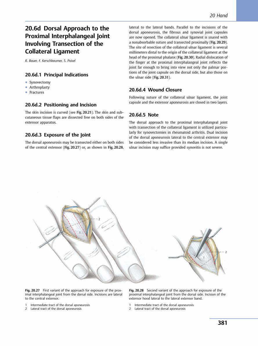
20.6d Dorsal Approach to theProximal Interphalangeal JointInvolving Transection of theCollateral LigamentR. Bauer, F. Kerschbaumer, S. Poisel
20.6d.1 Principal Indications● Synovectomy● Arthroplasty● Fractures
20.6d.2 Positioning and Incision
The skin incision is curved (see Fig. 20.21). The skin and sub-cutaneous tissue flaps are dissected free on both sides of theextensor apparatus.
20.6d.3 Exposure of the Joint
The dorsal aponeurosis may be transected either on both sidesof the central extensor (Fig. 20.27) or, as shown in Fig. 20.28,
lateral to the lateral bands. Parallel to the incisions of thedorsal aponeurosis, the fibrous and synovial joint capsulesare now opened. The collateral ulnar ligament is snared witha nonabsorbable suture and transected proximally (Fig. 20.29).The site of resection of the collateral ulnar ligament is severalmillimeters distal to the origin of the collateral ligament at thehead of the proximal phalanx (Fig. 20.30). Radial dislocation ofthe finger at the proximal interphalangeal joint reflects thejoint far enough to bring into view not only the palmar por-tions of the joint capsule on the dorsal side, but also those onthe ulnar side (Fig. 20.31).
20.6d.4 Wound Closure
Following suture of the collateral ulnar ligament, the jointcapsule and the extensor aponeurosis are closed in two layers.
20.6d.5 Note
The dorsal approach to the proximal interphalangeal jointwith transection of the collateral ligament is utilized particu-larly for synovectomies in rheumatoid arthritis. Dual incisionof the dorsal aponeurosis lateral to the central extensor maybe considered less invasive than its median incision. A singleulnar incision may suffice provided synovitis is not severe.
1
2
Fig. 20.27 First variant of the approach for exposure of the prox-imal interphalangeal joint from the dorsal side. Incisions are lateralto the central extensor.
1 Intermediate tract of the dorsal aponeurosis2 Lateral tract of the dorsal aponeurosis
2
1
Fig. 20.28 Second variant of the approach for exposure of theproximal interphalangeal joint from the dorsal side. Incision of theextensor hood lateral to the lateral extensor band.
1 Intermediate tract of the dorsal aponeurosis2 Lateral tract of the dorsal aponeurosis
20 Hand
381
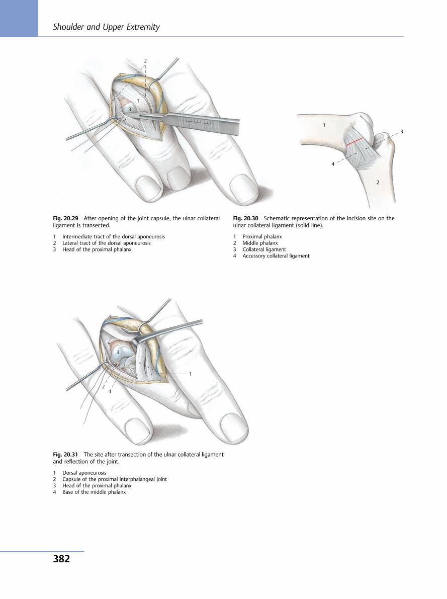
3
1
2
Fig. 20.29 After opening of the joint capsule, the ulnar collateralligament is transected.
1 Intermediate tract of the dorsal aponeurosis2 Lateral tract of the dorsal aponeurosis3 Head of the proximal phalanx
4
3 1
2
Fig. 20.30 Schematic representation of the incision site on theulnar collateral ligament (solid line).
1 Proximal phalanx2 Middle phalanx3 Collateral ligament4 Accessory collateral ligament
4
3
1
2
Fig. 20.31 The site after transection of the ulnar collateral ligamentand reflection of the joint.
1 Dorsal aponeurosis2 Capsule of the proximal interphalangeal joint3 Head of the proximal phalanx4 Base of the middle phalanx
Shoulder and Upper Extremity
382
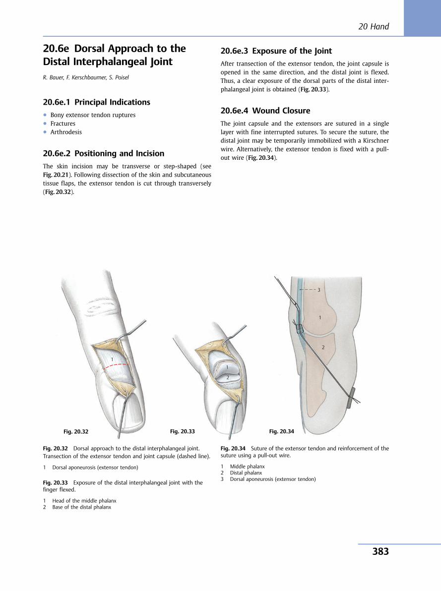
20.6e Dorsal Approach to theDistal Interphalangeal JointR. Bauer, F. Kerschbaumer, S. Poisel
20.6e.1 Principal Indications● Bony extensor tendon ruptures● Fractures● Arthrodesis
20.6e.2 Positioning and Incision
The skin incision may be transverse or step-shaped (seeFig. 20.21). Following dissection of the skin and subcutaneoustissue flaps, the extensor tendon is cut through transversely(Fig. 20.32).
20.6e.3 Exposure of the Joint
After transection of the extensor tendon, the joint capsule isopened in the same direction, and the distal joint is flexed.Thus, a clear exposure of the dorsal parts of the distal inter-phalangeal joint is obtained (Fig. 20.33).
20.6e.4 Wound Closure
The joint capsule and the extensors are sutured in a singlelayer with fine interrupted sutures. To secure the suture, thedistal joint may be temporarily immobilized with a Kirschnerwire. Alternatively, the extensor tendon is fixed with a pull-out wire (Fig. 20.34).
1
Fig. 20.32 Dorsal approach to the distal interphalangeal joint.Transection of the extensor tendon and joint capsule (dashed line).
1 Dorsal aponeurosis (extensor tendon)
Fig. 20.33 Exposure of the distal interphalangeal joint with thefinger flexed.
1 Head of the middle phalanx2 Base of the distal phalanx
1
2
Fig. 20.34 Suture of the extensor tendon and reinforcement of thesuture using a pull-out wire.
1 Middle phalanx2 Distal phalanx3 Dorsal aponeurosis (extensor tendon)
3
1
2
Fig. 20.32 Fig. 20.33 Fig. 20.34
20 Hand
383
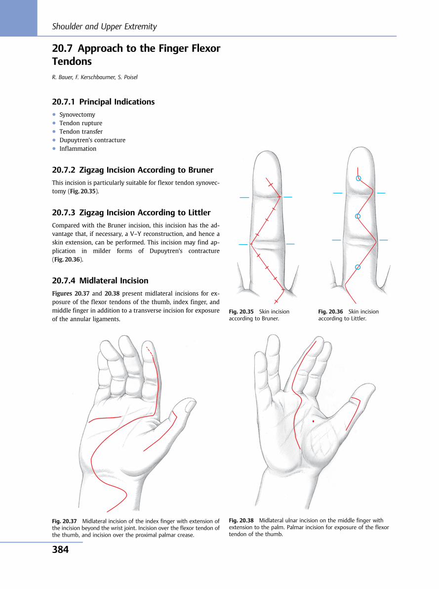
20.7 Approach to the Finger FlexorTendonsR. Bauer, F. Kerschbaumer, S. Poisel
20.7.1 Principal Indications● Synovectomy● Tendon rupture● Tendon transfer● Dupuytren’s contracture● Inflammation
20.7.2 Zigzag Incision According to Bruner
This incision is particularly suitable for flexor tendon synovec-tomy (Fig. 20.35).
20.7.3 Zigzag Incision According to Littler
Compared with the Bruner incision, this incision has the ad-vantage that, if necessary, a V–Y reconstruction, and hence askin extension, can be performed. This incision may find ap-plication in milder forms of Dupuytren’s contracture(Fig. 20.36).
20.7.4 Midlateral Incision
Figures 20.37 and 20.38 present midlateral incisions for ex-posure of the flexor tendons of the thumb, index finger, andmiddle finger in addition to a transverse incision for exposureof the annular ligaments.
Fig. 20.35 Skin incisionaccording to Bruner.
Fig. 20.36 Skin incisionaccording to Littler.
Fig. 20.37 Midlateral incision of the index finger with extension ofthe incision beyond the wrist joint. Incision over the flexor tendon ofthe thumb, and incision over the proximal palmar crease.
Fig. 20.38 Midlateral ulnar incision on the middle finger withextension to the palm. Palmar incision for exposure of the flexortendon of the thumb.
Shoulder and Upper Extremity
384
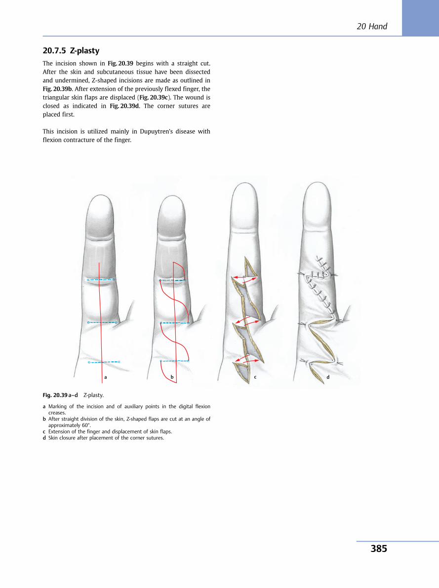
20.7.5 Z-plasty
The incision shown in Fig. 20.39 begins with a straight cut.After the skin and subcutaneous tissue have been dissectedand undermined, Z-shaped incisions are made as outlined inFig. 20.39b. After extension of the previously flexed finger, thetriangular skin flaps are displaced (Fig. 20.39c). The wound isclosed as indicated in Fig. 20.39d. The corner sutures areplaced first.
This incision is utilized mainly in Dupuytren’s disease withflexion contracture of the finger.
b c da
Fig. 20.39 a–d Z-plasty.
a Marking of the incision and of auxiliary points in the digital flexioncreases.
b After straight division of the skin, Z-shaped flaps are cut at an angle ofapproximately 60°.
c Extension of the finger and displacement of skin flaps.d Skin closure after placement of the corner sutures.
20 Hand
385
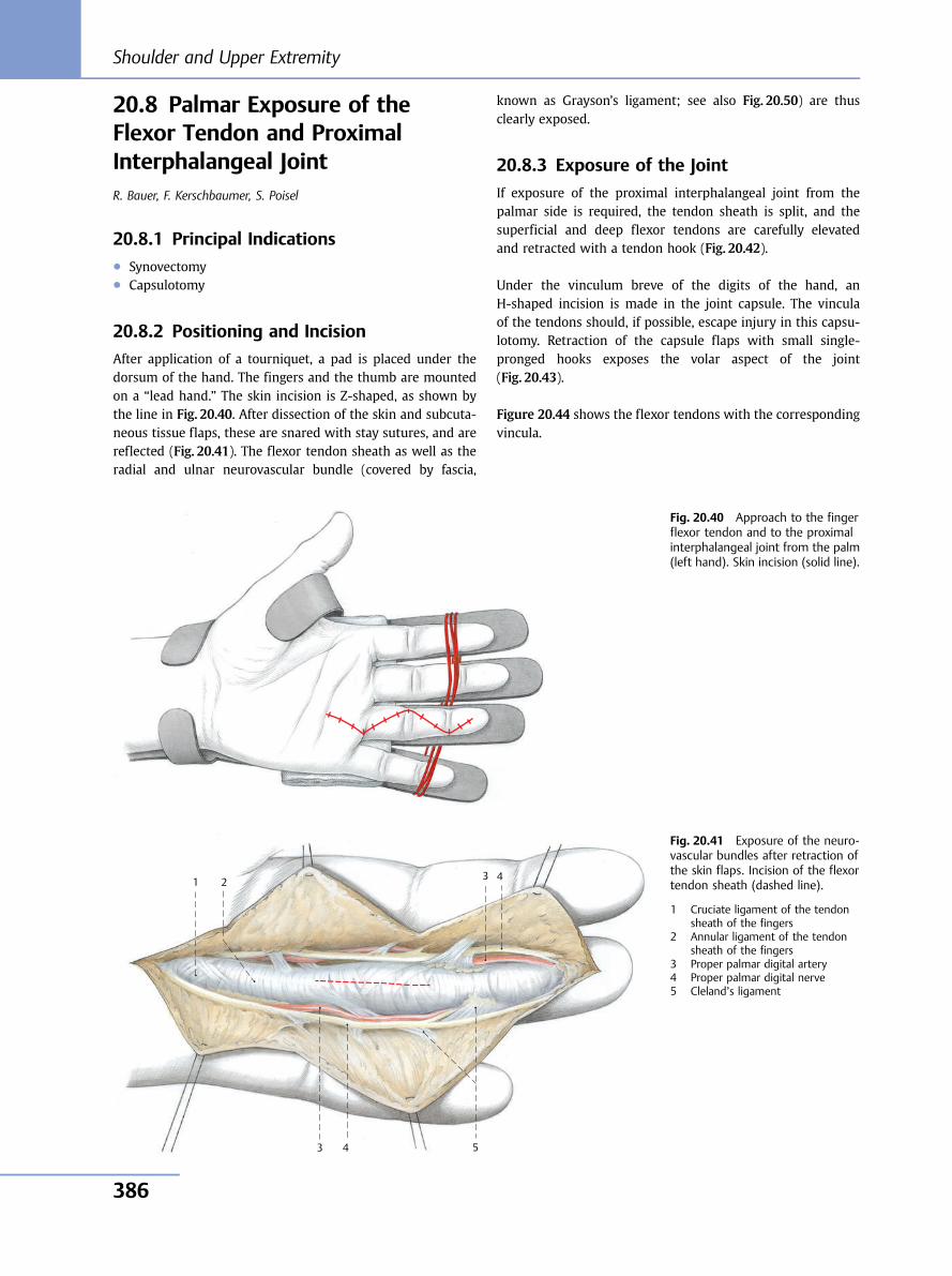
20.8 Palmar Exposure of theFlexor Tendon and ProximalInterphalangeal JointR. Bauer, F. Kerschbaumer, S. Poisel
20.8.1 Principal Indications● Synovectomy● Capsulotomy
20.8.2 Positioning and Incision
After application of a tourniquet, a pad is placed under thedorsum of the hand. The fingers and the thumb are mountedon a “lead hand.” The skin incision is Z-shaped, as shown bythe line in Fig. 20.40. After dissection of the skin and subcuta-neous tissue flaps, these are snared with stay sutures, and arereflected (Fig. 20.41). The flexor tendon sheath as well as theradial and ulnar neurovascular bundle (covered by fascia,
known as Grayson’s ligament; see also Fig. 20.50) are thusclearly exposed.
20.8.3 Exposure of the Joint
If exposure of the proximal interphalangeal joint from thepalmar side is required, the tendon sheath is split, and thesuperficial and deep flexor tendons are carefully elevatedand retracted with a tendon hook (Fig. 20.42).
Under the vinculum breve of the digits of the hand, anH-shaped incision is made in the joint capsule. The vinculaof the tendons should, if possible, escape injury in this capsu-lotomy. Retraction of the capsule flaps with small single-pronged hooks exposes the volar aspect of the joint(Fig. 20.43).
Figure 20.44 shows the flexor tendons with the correspondingvincula.
Fig. 20.40 Approach to the fingerflexor tendon and to the proximalinterphalangeal joint from the palm(left hand). Skin incision (solid line).
5 4 3
1 2 3 4
Fig. 20.41 Exposure of the neuro-vascular bundles after retraction ofthe skin flaps. Incision of the flexortendon sheath (dashed line).
1 Cruciate ligament of the tendonsheath of the fingers
2 Annular ligament of the tendonsheath of the fingers
3 Proper palmar digital artery4 Proper palmar digital nerve5 Cleland’s ligament
Shoulder and Upper Extremity
386
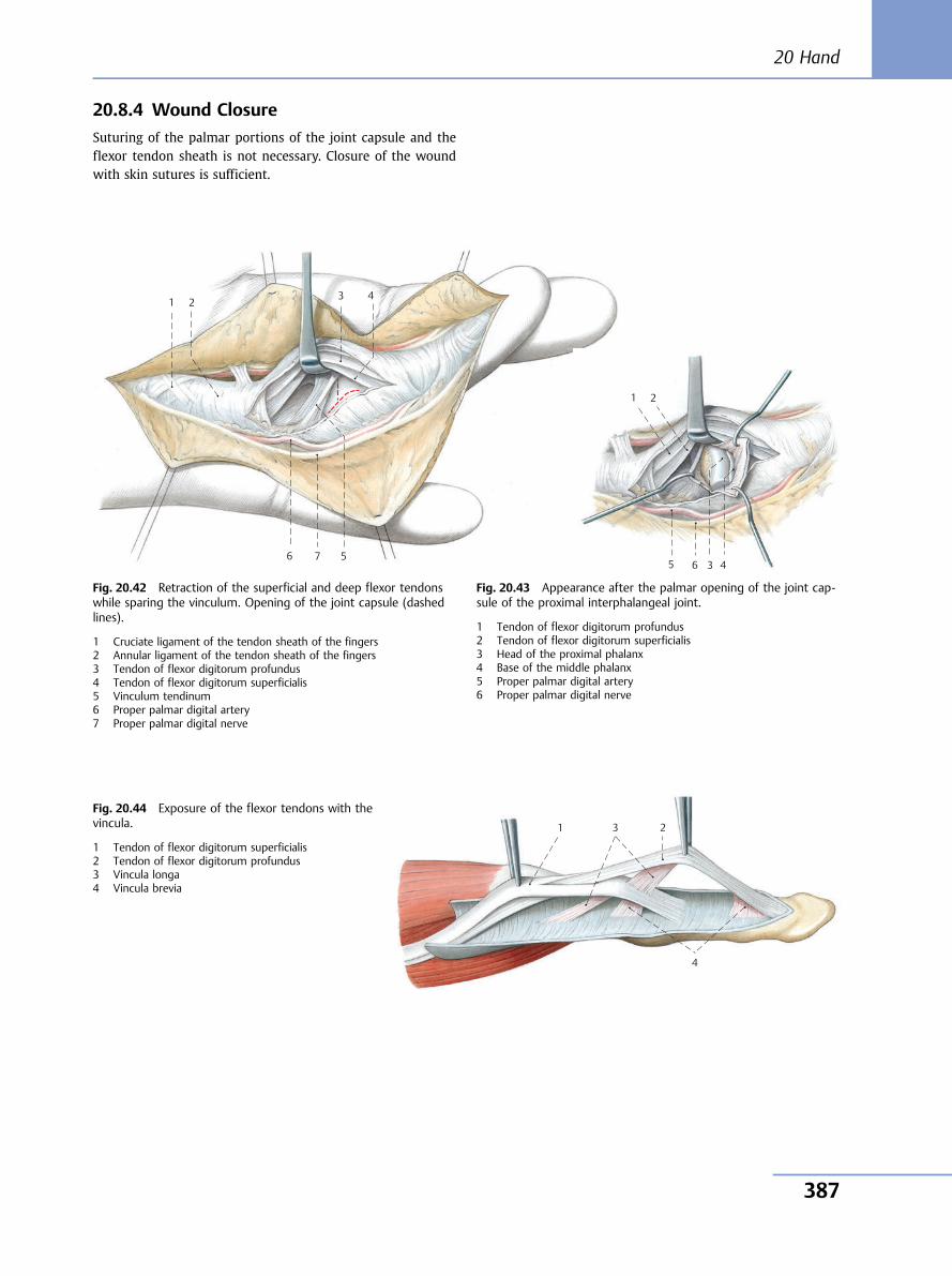
20.8.4 Wound Closure
Suturing of the palmar portions of the joint capsule and theflexor tendon sheath is not necessary. Closure of the woundwith skin sutures is sufficient.
7 6 5
4 3 1 2
Fig. 20.42 Retraction of the superficial and deep flexor tendonswhile sparing the vinculum. Opening of the joint capsule (dashedlines).
1 Cruciate ligament of the tendon sheath of the fingers2 Annular ligament of the tendon sheath of the fingers3 Tendon of flexor digitorum profundus4 Tendon of flexor digitorum superficialis5 Vinculum tendinum6 Proper palmar digital artery7 Proper palmar digital nerve
6 5 4 3
1 2
Fig. 20.43 Appearance after the palmar opening of the joint cap-sule of the proximal interphalangeal joint.
1 Tendon of flexor digitorum profundus2 Tendon of flexor digitorum superficialis3 Head of the proximal phalanx4 Base of the middle phalanx5 Proper palmar digital artery6 Proper palmar digital nerve
4
3 1 2
Fig. 20.44 Exposure of the flexor tendons with thevincula.
1 Tendon of flexor digitorum superficialis2 Tendon of flexor digitorum profundus3 Vincula longa4 Vincula brevia
20 Hand
387
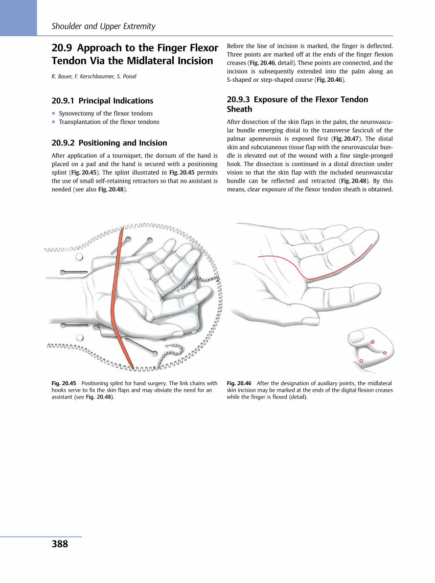
20.9 Approach to the Finger FlexorTendon Via the Midlateral IncisionR. Bauer, F. Kerschbaumer, S. Poisel
20.9.1 Principal Indications● Synovectomy of the flexor tendons● Transplantation of the flexor tendons
20.9.2 Positioning and Incision
After application of a tourniquet, the dorsum of the hand isplaced on a pad and the hand is secured with a positioningsplint (Fig. 20.45). The splint illustrated in Fig. 20.45 permitsthe use of small self-retaining retractors so that no assistant isneeded (see also Fig. 20.48).
Before the line of incision is marked, the finger is deflected.Three points are marked off at the ends of the finger flexioncreases (Fig. 20.46, detail). These points are connected, and theincision is subsequently extended into the palm along anS-shaped or step-shaped course (Fig. 20.46).
20.9.3 Exposure of the Flexor TendonSheath
After dissection of the skin flaps in the palm, the neurovascu-lar bundle emerging distal to the transverse fasciculi of thepalmar aponeurosis is exposed first (Fig. 20.47). The distalskin and subcutaneous tissue flap with the neurovascular bun-dle is elevated out of the wound with a fine single-prongedhook. The dissection is continued in a distal direction undervision so that the skin flap with the included neurovascularbundle can be reflected and retracted (Fig. 20.48). By thismeans, clear exposure of the flexor tendon sheath is obtained.
Fig. 20.45 Positioning splint for hand surgery. The link chains withhooks serve to fix the skin flaps and may obviate the need for anassistant (see Fig. 20.48).
Fig. 20.46 After the designation of auxiliary points, the midlateralskin incision may be marked at the ends of the digital flexion creaseswhile the finger is flexed (detail).
Shoulder and Upper Extremity
388
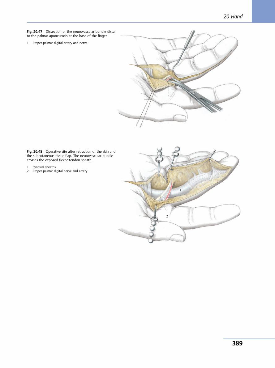
1
Fig. 20.47 Dissection of the neurovascular bundle distalto the palmar aponeurosis at the base of the finger.
1 Proper palmar digital artery and nerve
1
2
Fig. 20.48 Operative site after retraction of the skin andthe subcutaneous tissue flap. The neurovascular bundlecrosses the exposed flexor tendon sheath.
1 Synovial sheaths2 Proper palmar digital nerve and artery
20 Hand
389
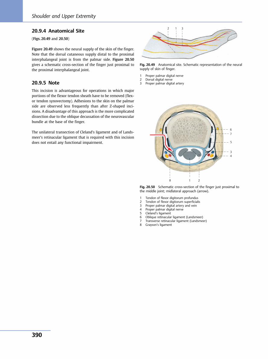
20.9.4 Anatomical Site
(Figs. 20.49 and 20.50)
Figure 20.49 shows the neural supply of the skin of the finger.Note that the dorsal cutaneous supply distal to the proximalinterphalangeal joint is from the palmar side. Figure 20.50gives a schematic cross-section of the finger just proximal tothe proximal interphalangeal joint.
20.9.5 Note
This incision is advantageous for operations in which majorportions of the flexor tendon sheath have to be removed (flex-or tendon synovectomy). Adhesions to the skin on the palmarside are observed less frequently than after Z-shaped inci-sions. A disadvantage of this approach is the more complicateddissection due to the oblique decussation of the neurovascularbundle at the base of the finger.
The unilateral transection of Cleland’s ligament and of Lands-meer’s retinacular ligament that is required with this incisiondoes not entail any functional impairment.
3 1 2
Fig. 20.49 Anatomical site. Schematic representation of the neuralsupply of skin of finger.
1 Proper palmar digital nerve2 Dorsal digital nerve3 Proper palmar digital artery
8
7 6
5
4 3
1 2
Fig. 20.50 Schematic cross-section of the finger just proximal tothe middle joint; midlateral approach (arrow).
1 Tendon of flexor digitorum profundus2 Tendon of flexor digitorum superficialis3 Proper palmar digital artery and vein4 Proper palmar digital nerve5 Cleland’s ligament6 Oblique retinacular ligament (Landsmeer)7 Transverse retinacular ligament (Landsmeer)8 Grayson’s ligament
Shoulder and Upper Extremity
390
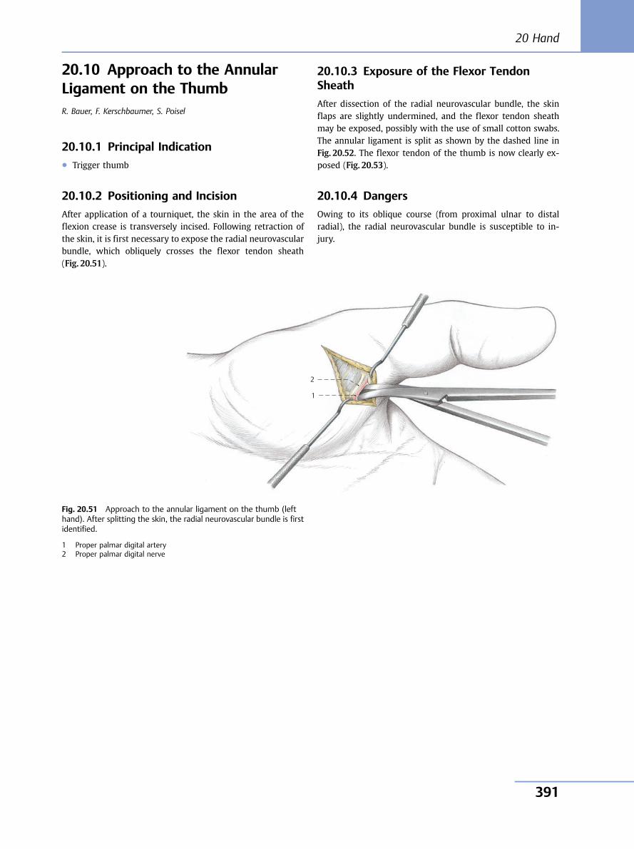
20.10 Approach to the AnnularLigament on the ThumbR. Bauer, F. Kerschbaumer, S. Poisel
20.10.1 Principal Indication● Trigger thumb
20.10.2 Positioning and Incision
After application of a tourniquet, the skin in the area of theflexion crease is transversely incised. Following retraction ofthe skin, it is first necessary to expose the radial neurovascularbundle, which obliquely crosses the flexor tendon sheath(Fig. 20.51).
20.10.3 Exposure of the Flexor TendonSheath
After dissection of the radial neurovascular bundle, the skinflaps are slightly undermined, and the flexor tendon sheathmay be exposed, possibly with the use of small cotton swabs.The annular ligament is split as shown by the dashed line inFig. 20.52. The flexor tendon of the thumb is now clearly ex-posed (Fig. 20.53).
20.10.4 Dangers
Owing to its oblique course (from proximal ulnar to distalradial), the radial neurovascular bundle is susceptible to in-jury.
1
2
Fig. 20.51 Approach to the annular ligament on the thumb (lefthand). After splitting the skin, the radial neurovascular bundle is firstidentified.
1 Proper palmar digital artery2 Proper palmar digital nerve
20 Hand
391
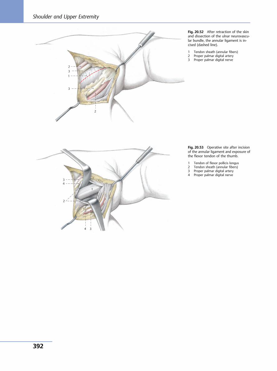
3 1
2
3
2
Fig. 20.52 After retraction of the skinand dissection of the ulnar neurovascu-lar bundle, the annular ligament is in-cised (dashed line).
1 Tendon sheath (annular fibers)2 Proper palmar digital artery3 Proper palmar digital nerve
4 3
1
2
3 4
Fig. 20.53 Operative site after incisionof the annular ligament and exposure ofthe flexor tendon of the thumb.
1 Tendon of flexor pollicis longus2 Tendon sheath (annular fibers)3 Proper palmar digital artery4 Proper palmar digital nerve
Shoulder and Upper Extremity
392
Further Reading: Shoulder and UpperExtremity[1] Alonso-Llames M. Bilaterotricipital approach to the elbow. Its
application in the osteosynthesis of supracondylar fractures ofthe humerus in children. Acta Orthop Scand 1972;43(6):479–490
[2] Anson BJ, McVay CB. Surgical Anatomy. Vol 1. Philadelphia:Saunders; 1971
[3] Banks SW, Laufmann II. An Atlas of Surgical Exposures of theExtremities. Philadelphia: Saunders; 1968
[4] Bigliani LU, Morrison DS, April EW. The morphology of the acro-mion and its relationship to rotator cuff tears. Orthop Trans1986;10:228
[5] Bigliani LU, Cordasco FA, McLlveen SJ, Musso ES. Operative repairof massive rotator cuff tears: long-term results. J Shoulder ElbowSurg 1992;1(3):120–130
[6] Bonnaire F, Bula P. Distale Humerusfrakturen. Trauma Berufs-krankh 2010;12(Suppl. 2):96–103
[7] Brodsky JW, Tullos HS, Gartsman GM. Simplified posterior ap-proach to the shoulder joint. A technical note. J Bone Joint SurgAm 1987;69(5):773–774
[8] Bryan RS, Morrey BF. Extensive posterior exposure of the elbow.A triceps-sparing approach. Clin Orthop Relat Res 1982;(166):188–192
[9] Consentino R. Atlas of Anatomy and Surgical Approaches in Or-thopaedic Surgery; vol 1. Springfield, IL: Thomas; 1960
[10] Debeyre J, Patthie D, Elmelik E. Repair of ruptures of the rotatorcuff of the shoulder: With a note of advancement of the supra-spinatus muscle. J Bone Joint Surg 1965;47-B:36–42
[11] Ewerbeck V, Wentzensen A. Standardverfahren in der operativenOrthopädie und Unfallchirurgie. 2nd rev ed. Stuttgart: Thieme;2004
[12] Fernandez DL, Jupiter JP. Fractures of the Distal Radius. Berlin:Springer; 1995
[13] Fernandez DL, Jupiter JP. Fractures of the Distal Radius. A Practi-cal Approach to Management. Berlin: Springer; 1996
[14] Fucentese SF, Jost B. Posteriorer Zugang zum Schultergelenk. Op-erative Orthopädie und Traumatologie. Band 22. Berlin: Springer;2010:188–195
[15] Geschwend N, Ivosevic-Radovanovic D, Brändli P. Die operativeBehandlung der Rotatorenmanschettenruptur. In: Helbig B,Blauth W, eds. Schulterschmerzen und Rupturen der Rotatoren-manschette. Hefte zur Unfallheilkunde 180. Berlin: Springer:1986:69–88
[16] Gohlke F, Hedtmann A. Schulter. In: Wirth CJ, Zichner L, eds.Orthopädie und orthopädische Chirurgie. Stuttgart: Thieme;2002
[17] Habermeyer P, Brunner U, Wiedemann E, Wilhelm K. Kompres-sionssyndrome an der Schulter und deren Differentialdiagnose.Orthopade 1987;16(6):448–457
[18] Habermeyer P, Lichtenberg S, Magosch P. Schulterchirurgie. 4thed. Munich: Urban & Fischer; 2008
[19] Hansis M, Schmidt HM. Unterarm und Handgelenk. In: Kremer K,Lierse W, Platzer W, Schreiber HW, Weller S, eds. ChirurgischeOperationslehre—Schultergürtel, obere Extremität. Stuttgart:Thieme; 1995
[20] Hepp P, Theopold J, Voigt C, Engel T, Josten C, Lill H. The surgicalapproach for locking plate osteosynthesis of displaced proximalhumeral fractures influences the functional outcome. J ShoulderElbow Surg 2008;17(1):21–28
[21] Hirner A, Weise K. Chirurgie. 2nd rev ed. Stuttgart: Thieme; 2008
[22] Höntzsch D, Maurer H. Schultergürtel. In: Kremer K, Lierse W,Platzer W, Schreiber HW, Weller S, eds. Chirurgische Operations-lehre – Schultergürtel, obere Extremität. Stuttgart: Thieme; 1995
[23] Hoppenfeld S, de Boer P. Surgical Exposures in Orthopaedics.Philadelphia: Lippincott; 1984
[24] Iannotti JP, Williams GR. Disorders of the Shoulder: Diagnosisand Management. Vols 1 and 2. Philadelphia: Lippincott Williams& Wilkins; 2007
[25] Kaplan E. Functional and Surgical Anatomy of the Hand. Phila-delphia: Lippincott; 1965
[26] Kremer K, Lierse W, Platzer W, Schreiber HW, Weller S. Schul-tergürtel und obere Extremität. Stuttgart: Thieme; 1995. Chirur-gische Operationslehre; Band 9
[27] Krettek C, Wiebking U. Proximale Humerusfraktur: Ist die win-kelstabile Plattenosteosynthese der konservativen Behandlungüberlegen? Unfallchirurg 2011;114(12):1059–1067
[28] von Laer L. Frakturen und Luxationen im Wachstumsalter. Stutt-gart: Thieme; 1996
[29] Landsmeer LM. Atlas of Anatomy of the Hand. Edinburgh:Churchill-Livingstone; 1976
[30] Matsen FA III, Thomas SC, Rockwood CA. Anterior GlenohumeralInstability. In: Rockwood CA, Matsen FA III, eds. The Shoulder.Philadelphia: Saunders; 1990:526
[31] Matsen FA III, Thomas SC, Rockwood CA, Wirth MA. Glenohu-meral Instability. In: Rockwood CA, Matsen FA. The Shoulder. 2nded. Philadelphia: Saunders; 1998:611–754
[32] Morrey DF. The Elbow and its Disorders. Philadelphia: Saunders;2000
[33] Müller ME, Allgöwer M, Schneider R, Willenegger H. Manual derOsteosynthese. Berlin: Springer; 1992
[34] Neer CS II. Anterior acromioplasty for the chronic impingementsyndrome in the shoulder: a preliminary report. J Bone Joint SurgAm 1972;54(1):41–50
[35] Neer CS. Shoulder Reconstruction. Philadelphia: Saunders; 1990:202–207
[36] Neviaser JS. Surgical approaches to the shoulder. Clin OrthopRelat Res 1973; (91):34–40
[37] Nicola T. Atlas operativer Zugangswege in der Orthopädie. Mu-nich: Urban & Schwarzenberg; 1971
[38] Oestern HJ, Tscherne H. Ergebnisse der AO-Sammelstudie überUnterarmschaftfrakturen. Unfallheilkunde 1983;86(3):136–142
[39] Platzer W. Atlas der topografischen Anatomie. Stuttgart: Thieme;1982
[40] Platzer W. Bewegungsapparat. In: Kahle E, Leonhardt H, PlatzerW. Taschenatlas der Anatomie. Band 1. 4th ed. Stuttgart: Thieme;1984
[41] Rauber/Kopsch. Anatomie des Menschen. Band 1–4. Stuttgart:Thieme; 1988
[42] Resch H, Beck E. Praktische Chirurgie des Schultergelenks. Inns-bruck: Bronweiler; 1989
[43] Resch H, Maurer H. Schultergelenk. In: Kremer K, Lierse W, Plat-zer W, Schreiber HW, Weller S, eds. Chirurgische Operations-lehre – Schultergürtel, obere Extremität. Stuttgart: Thieme; 1995
[44] Resch H, Povacz P, Ritter E, Matschi W. Transfer of the pectoralismajor muscle for the treatment of irreparable rupture of thesubscapularis tendon. J Bone Joint Surg Am 2000;82(3):372–382
[45] Rockwood CA, Green ADP, Buchholtz RW. Fractures in Adults. 3rded. Philadelphia: Lippincott; 1991
[46] Rüedi T, von Hochstetter AHC, Schlumpf R. Operative Zugängezur Osteosynthese. Berlin: Springer; 1984
[47] Schünke M, Schulte E, Schumacher U. Prometheus—Lernatlas derAnatomie. Stuttgart: Thieme; 2005
20 Hand
393
[48] Putz R, Pabst R, eds. Sobotta: Anatomie des Menschen. Munich:Urban & Fischer; 2006
[49] Tscherne H, Blauth M, Kasperczyk W. Indikationen zur konserva-tiv-funktionellen und operativen Therapie von Frakturen amSchultergürtel. In: Rahmanzadeh R, Meißner A, eds. Unfall- undWiederherstellungschirurgie des Schultergürtels. Berlin: Sprin-ger; 1992
[50] Tubiana R, Valentin P. The anatomy of the extensor apparatus ofthe fingers. Surg Clin North Am 1964;44:897–906
[51] Tubiana R, McCullough CJ, Masquelet AD. An Atlas of SurgicalExposure of the Upper Extremity. London: Martin Dunitz; 1990
[52] Weise K, Firbas W. Ellbogen. In: Kremer K, Lierse W, Platzer W,Schreiber HW, Weller S, eds. Chirurgische Operationslehre—Schultergürtel, obere Extremität. Stuttgart: Thieme; 1995
[53] Weise K. Verletzungen des Oberarms, Ellenbogens, Unterarmsund Handgelenks. In: Mutschler W, Haas NP, eds. Praxis der Un-fallchirurgie. 2nd rev ed. Stuttgart: Thieme; 2004
[54] Wiedemann E. Scapulafraktur. In: Habermeyer P, ed. Schulter-chirurgie. 2nd ed. Munich: Urban & Schwarzenberg; 2002
[55] Wiedemann E. Frakturen der Skapula. Unfallchirurg 2004;107(12):1124–1133
[56] Winker KH, Maurer H. Oberarm. In: Kremer K, Lierse W, PlatzerW, Schreiber HW, Weller S, eds. Chirurgische Operationslehre—Schultergürtel, obere Extremität. Stuttgart: Thieme; 1995
Shoulder and Upper Extremity
394
IndexNote: Page numbers followed by f indicate figures.
A
Abdominal wall, anterior,nerve supply to, ex-posure, 43 – 44, 44f
Acetabulumanterior limited approach
according to Stoppa,114 – 115,114f– 115f
exposure, in micro-hiptechnique, 148, 149f
fractures, 105, 110with central protrusion,
114compound, in elderly,
114lateral pubic ramus, 114transverse, involving
posterior wall, 124two-column, 105, 110
ilioinguinal approach ac-cording to Letournel,105 – 109,105f– 109f
anatomical site, 108,108f
intra-articular bone frag-ments, 110
Judet approach, 120 – 122,120f– 123f
labrumlesions, 149surgery on, 140, 146
osteomyelitis, 105T-fracture, 124transiliac approach accord-
ing to Judet,116 – 119,116f– 119f
anatomical site, 119,119f
tumors, 105Achilles tendon, lengthening,
228 – 229,228f– 229f
Acromioclavicular jointacro-osteolysis, 268approach to, 268 – 269,
268f– 269farthritis, 289dislocation, 268infection, 268inflammation, 268instability, 268osteoarthritis, 268tumors, 268
Alonso-Llames technique, forparatricipital ap-proach to elbowjoint, 313
Ankle jointanterior approach to,
222 – 223,222f– 224f
anterolateral approach to,225 – 227,225f– 227f
distal extension,226 – 227,226f– 227f
arthrodesis, 222, 225, 238with osteotomy of lateral
malleolus, 246arthroplasty, 222, 225arthroscopyapproaches, 243, 243ftechnique for, 244, 244f
avulsion fracture, posterior,238
capsulotomy, 233, 238posterior, 228 – 232,
228f– 232fposterolateral, 228 – 232,
228f– 232fposteromedial,
228 – 232,228f– 232f
cartilage lesions, 243dorsolateral approach to,
238 – 240,238f– 240f
fractures, 222, 225intra-articular, 243osteochondral, 241
lateral arthrolysis, 231,231f– 232f
loose bodies, intra-articu-lar, 243
medial arthrolysis, 229,230f
medial exposure, withosteotomy of medialmalleolus, 241 – 242,241f– 242f
osteochondritis dissecans,243
osteophytes, intra-articu-lar, 243
posterior arthrolysis,228 – 229,228f– 229f
posteromedial approach to,233 – 235,233f– 237f
synovectomy, 222, 225Aorta, thoracic, positional
variants, 20, 22fArm, upperdistal, cross-sectional
anatomy of, 311,311f
middle, cross-sectionalanatomy of, 311,311f
neurovascular bundleexposure, 303, 304finjuries, 309
proximal, cross-sectionalanatomy of, 299,299f
Azygos vein, morphologicand positional var-iants, 20, 22f, 23f
B
Bauer approachtransgluteal, to hip joint,
131 – 133,132f– 133f
for two-fold thoracotomyat thoracolumbarjunction, 55 – 58,55f– 58f
Biceps brachii musclelong head of, tendon, 277tendondistal ruptures, 328rupture, 338
Bigliani approach, to should-er joint, 284 – 285,284f– 285f
Boyd approach, to proximalulna and radial head,340, 340f, 344 – 345,344f– 345f
extension, 345Bruner zigzag incision, in
finger, 384, 384fBryan-Morrey technique, for
paratricipital ap-proach to elbowjoint, 313, 315f
C
Calcaneusbiopsy, 250Dwyer osteotomy, 247fractures, 248, 250lateral approach to, 247,
247f, 248 – 249,248f– 249f
medial approach to, 250,250f
osteomyelitis, 247, 248osteotomy, 248tumors, 247, 248
Index
395
Canal of Guyon, exposure,372 – 373,372f– 373f
Carpal bonesaseptic necrosis, 360dislocations, 360fractures, 360
Carpal tunnelendoscopic division, mini-
mally invasive ap-proach for,354 – 365,354f– 356f
exposure, in palmar ap-proach, 361, 361f
Carpal tunnel syndrome, 360without motor deficit, 354
Carpometacarpal joint, ofthumb, approach to,375 – 376,375f– 376f
Cauchoix, Binet, and Evrardapproach, for ante-rior exposure of cer-vicothoracic junc-tion, 13 – 16, 13f, 14f
Cervical spineC1–C2 (C3), transoropha-
ryngeal approach to,2, 2f, 3f
C2–C6, anterior approachto, exposure of ver-tebrae, 6, 6f
C3, anatomical cross-sec-tion at, 6, 8f
C3–C4, anterior approachto, level of incision, 5
C3–T2, anterior approachto, 4 – 13, 4f– 6f
C4–C5, anterior approachto, level of incision, 5
C4–T3, anterior approachaccording to Cau-choix, Binet, andEvrard, 13 – 16, 13f,14f
C5–C6, anterior approachto, level of incision, 5
C6, anatomical cross-sec-tion at, 6, 9f
C6–T1, anterior approachto, level of incision, 5
C6–T3, anterior approachto, exposure of ver-tebrae, 15, 16f
C7–T2, anterior approachto, exposure of ver-tebrae, 9 – 12, 9f, 11f
degenerative changes, 4, 76lateral, anterior approach
to, from right, ana-tomical site, 6, 7f
lower, from left, anatomicalsite, 9 – 12, 10f
osteomyelitis, 2posterior approach to,
76 – 79, 76f– 79fposttraumatic states, 2pseudarthroses, 2spondylitis, 4trauma, 4, 76tumors, 2, 4, 76upper, anterior approach tofrom left, anatomical site,
6, 7ffrom right, anatomical
site, 12, 12fCervicothoracic junction. See
also Cervical spineanatomical sitefrom above left, 9 – 12,
10ffrom left, 15, 15f
anterolateral approach to,with thoracotomyaccording to Louis,32, 32f
anterolateral approach tocervical spine, com-bined with highthoracotomy,32 – 33, 32f– 35f
exposure of vertebrae, an-terior approach to,15, 16f
fracture-dislocations, in-ternal fixation, 13
spondylitis, 13tumors, 13
Cincinnati approach,228 – 232,228f– 232f
Clavicleapproach to, 268 – 269,
268f– 269ffractures of, 268pseudarthrosis, 268tumors, 268
Claw toe, 263, 264Costotransversectomy, for
posterior approachto T3–T10, 80 – 83,80f– 83f
D
Dens fractures, 2De Quervain tenosynovitis, in
first extensor tendoncompartment ofhand, 377
Diaphragmanatomical exposure, 50fnerve supply, 48fstructures that traverse,
anatomical expo-sure, 50f
vascular supply, 48fDistal interphalangeal (DIP)
joint(s)arthrodesis, 383dorsal approach to, 383,
383ffractures, 383
Dupuytren's contracture,369, 384
Dwyer osteotomy, 247
E
Elbow jointanatomical site, anterior
exposure, 333, 333fanterior approach to,
328 – 333,328f– 333f
extension, with transec-tion of brachialis,331, 331f– 332f
arthrolysis, 334arthroplasty, 312arthroscopyapproaches for, 335,
335f, 337fpositioning for, 334, 334ftechnique for, 335 – 336,
335f– 337fdislocation, 328flexor muscle lengthening
in cerebral palsy, 325fractures, 312inflammation, 320, 325instability, 320, 325lateral approach to,
320 – 324,320f– 324f
extension, with detach-ment of radial col-lateral ligament, 323,323f, 324f
loose bodies in, removal,334
medial approach to,325 – 326,325f– 327f
osteochondritis dissecans,320, 325, 328
osteotomy of olecranon,318, 318f, 319f
paratricipital approach to,313, 313f, 314f
Alonso-Llames techni-que, 313
Bryan-Morrey technique,313, 315f
posterior approach to,312 – 319,312f– 319f
straight splitting of tri-ceps, 316, 316f, 317f
posttraumatic malposi-tions, 312
pseudarthrosis, 312synovectomy, 320, 325,
334Extensor carpi ulnaris
muscle, tenosynovi-tis of, 350
F
Femoral head, ligament of,lesions, 149
Femoral head necrosis, carti-lage and bone dam-age due to, intra-articular therapy for,124
Femoral neckfractures, 131, 134, 136,
140osteotomy, 129, 130f, 131,
134, 136, 140, 143,143f, 146
Femoroacetabular impinge-ment, 124, 146, 149
Femur. See also Slipped capi-tal femoral epiphysis
anterior approach to,154 – 156,154f– 156f
bone marrow aspirationfrom, with reamer–irrigator–aspirator,157
Index
396
distalcross-sectional anatomy
of, 163, 163fexposure oflateral approach to,161 – 163,161f– 163f
lateral approach to,anatomical site, 163,163f
medial approach to,163f
posterior approach to,163f, 174
fractures, 164, 175pseudarthrosis, 175transarticular medullary
cavity approach to,175, 175f
fractures, 157, 166with sciatic nerve injury,
170lateral approach togeneral considerations,
158, 158fminimally invasive,
164 – 165,164f– 165f
as standard approach,158
medial approach to,166 – 169,166f– 169f
anatomical site, 169,169f
medullary cavity, lateralproximal approachto, 157, 157f
medullary nailing, 157retrograde, 175
middle thirdanatomical site, 172,
172fposterior approach to,
170, 170f– 171fmidshaft fractures, 164osteomyelitis, 166osteotomy, 166posterior approach to,
170 – 174,170f– 174f
proximalanatomical site, 172,
172fcross-sectional anatomy
of, 160f
exposure ofanterior approach to,anatomical site, 160f
lateral approach to,158 – 161,158f– 160f
lateral approach to,anatomical site,160 – 161, 160f
posterior approach to,anatomical site, 160f
fractures, 164posterior approach to,
170, 170f– 171fpseudarthrosis, 157, 164tumors, 154, 166, 170
Fibula. See also Malleolus,lateral
bone grafts from, 218distalcross-sectional anatomy,
220, 221finternal fixation, 238
fractures, 207, 218infected pseudarthroses,
207lateral approach to,
218 – 221,218f– 221f
osteomyelitis, 207, 218osteotomy, 218posterior exposure, 207,
207f– 209fposterolateral approach to,
207 – 209,207f– 210f
shaft, distal third, expo-sure, 220
tumors, 218Finger(s)bony extensor tendon rup-
tures, 383cross-sectional anatomy of,
390, 390fflexor tendonsapproach to, 384 – 385,
384f– 385fapproach via midlateral
incision, 384, 384f,388 – 390,388f– 390f
Dupuytren's contracture,384
inflammation, 384palmar exposure,
386 – 387,386f– 387f
rupture, 384
synovectomy, 384, 386,388
tendon transfer proce-dures, 384
transplantation, 388nerve supply to, anatomi-
cal site, 390, 390fzigzag incisionaccording to Bruner, 384,
384faccording to Littler, 384,
384fz-plasty for, 385, 385f
Foot, dorsum, anatomicalsite, 222, 222f
Foot deformity. See alsoTalipes equinovarus,correction
correction, 233 – 235,233f– 237f. See alsoCincinnati approach
Forearmanatomical site, 352, 352fanterior exposure, 333,
333fanterior approach to,
338 – 340,338f– 340f
distal, cross-sectionalanatomy of, 347,347f
dorsolateral approach,anatomical site, 343,343f
middle, cross-sectionalanatomy of, 347,347f
proximal, cross-sectionalanatomy of, 340,340f
G
Ganz technique, for posteriorapproach to hip jointwith dislocation,124 – 127,124f– 126f
Gartsman approach, toshoulder joint, 287,288f
Glenoid rim, posterior, frac-tures, 287
Great toe (hallux). See HalluxGschwend approach, to
shoulder joint, 286,286f
H
Habermeyer/Herzberg ap-proach, to shoulderjoint, 288, 288f
Hallux, metatarsophalangealjoint of, medial ap-proach to, 261 – 262,261f– 262f
Hallux rigidus, 261Hallux valgus, 261Hammer toe, 263, 264Hand. See also Palm of hand;
Wristdorsum, dorsal incisions
over, 378 – 383,378f– 383f
first extensor tendon com-partment
approach to, 377, 377fstenosing tenosynovitis
(De Quervain), 377synovitis, 377
Hemiazygos vein, morpho-logic and positionalvariants, 20, 22f, 23f
Henderson approach, toknee, 189 – 190,189f– 190f
Henry approach, to radius,338 – 340,338f– 340f
Hip/Hip joint. See also Aceta-bulum; Femur
anterior approach to,144 – 146,144f– 146f
minimally invasive,146 – 149,147f– 149f
anterolateral approach to,136 – 140,136f– 140f
anatomical site, 138,139f, 143
minimally invasive,140 – 143,140f– 144f
arthrodesis, 144arthroplasty, 127arthroscopic anatomy, 152,
152f, 153farthroscopic approaches,
149 – 153,150f– 153f
for diagnostic inspection,152, 152f, 153f
Index
397
cam osteophyte, removal,140
congenital dislocation,open reduction, 144
hemiarthroplasty, 134,136, 140, 146
hyaline cartilage lesions,149
intra-articular bone frag-ments, 110
loose bodies in, 149osteoarthritis, early, 149osteochondritis dissecans,
124osteomyelitis, 144posterior approach toaccording to Kocher-
Langenbeck,110 – 113,110f– 113f
extension by steppedtrochanter osteoto-my, 112, 112f– 113f
with dislocation, accord-ing to Ganz,124 – 127,124f– 126f
minimally invasive,127 – 130,127f– 131f
resurfacing arthroplasty,124
revision surgery, as micro-hip approach, 146
synovectomy, 131, 134,136, 140, 146
synovial diseases, 149total joint replacement,
131, 134, 136, 140,144, 146
periprosthetic fractures,164
transgluteal approach toaccording to Bauer,
131 – 133,132f– 133f
anatomical site, 133,133f
minimally invasive,134 – 136,134f– 136f
tumors, 144Hodgson approach, retroper-
itoneal extrapleural,to thoracolumbarjunction
left-sided, 43 – 53, 43f– 54fright-sided, 43, 54
Humerusanatomical siteanterior exposure, 305,
305fmedial exposure,
297 – 298, 298fposterior exposure,
297 – 298, 298fanterior approach to,
301 – 305,301f– 305f
distalcross-sectional anatomy
of, 311, 311ffractures, 300posterior approach to,
300, 300fpseudarthrosis, 300
fractures, 295, 296, 300,306
greater tubercle, fractures,284
inflammation, 296, 301,306
lateral approach to,306 – 307,306f– 308f
anatomical site, 311,311f
medial approach to,309 – 311,309f– 311f
anatomical site, 311,311f
medial epicondyle, frac-tures, 325
middle, cross-sectionalanatomy of, 311,311f
posterior approach to,296 – 299,296f– 299f
anatomical site, 311,311f
proximalcross-sectional anatomy
of, 299, 299fexposure, extended an-
terior approach toshoulder joint and,282 – 283, 282f
fractures, 282proximal approach to,
295 – 296,295f– 296f
pseudarthrosis, 295, 296,300, 306
tumors, 296, 301, 306
I
Iliac fractures, 144Iliotibial tractopexy, 189Ilium, ala, fractures, 105Index finger, flexor tendons,
approach via mid-lateral incision, 384,384f
Infraspinatus muscle, inju-ries, 283, 284, 286
Internal jugular vein, varia-tions, 6, 8f
Interphalangeal joint(s), oftoes
dislocations, 263posterior approach to, 263,
263fIschiumanatomical site, 104, 104fapproach to, 102 – 104,
102f– 104f
J
Judet approachto acetabulum, 120 – 122,
120f– 123fto scapula, 271, 271f– 274ftransiliac, 116 – 119,
116f– 119f
K
Knee/Knee jointallo-arthroplasty, 176, 180anterolateral approach to,
188 – 189,188f– 189f
anteromedial approach toanatomical site, 184,
184fminimally invasive,
176 – 179,176f– 179f
midvastus approach,177, 177f
quadriceps-sparing ap-proach, 178, 178f
subvastus approach,177, 177f
parapatellar, 180 – 185,180f– 185f
extension, 182, 182farthrodesis, 180
arthroscopy, 196 – 198,196f– 198f
approaches, 196, 197ftechnique, 197 – 198,
197f– 198favulsion fracturesreattachment of medial
patellar border after,186
reattachment of poste-rior cruciate liga-ment after, 191
cartilage lesions, 196cruciate ligament recon-
struction, 196epicondyle transfer, 189exposure, 178 – 179, 178f,
179fflexion deficit, extensor
release proceduresfor, 154
fractures, 188, 191intra-articular, 196
intra-articular fractures,176
joint capsule, postero-medial exposure,193, 193f
loose bodies, removal, 186,188, 189, 191
medial collateral ligamentprocedures, 186
medial hemiarthroplasty,176
meniscus lesions, 196minimally invasive ap-
proach toanteromedial, 176 – 179,
176f– 179fextension of, 180
osteochondral plugs, re-moval, 189
partial synovectomy, 176posterior approach accord-
ing to Trickey,191 – 195,191f– 195f
posterior cruciate ligament,tibial bony avulsionof, 200
posterolateral approachaccording to Hen-derson, 189 – 190,189f– 190f
posterolateral exposure,194, 194f– 195f
anatomical site, 195,195f
Index
398
posteromedial joint corner,184, 184f
semimembranosus corner,184, 184f
short medial approach to,186 – 187, 186f, 187f
synovectomy, 180, 191partial, 188
total joint replacement,periprosthetic frac-tures, 164
transverse medial patellarretinaculum replace-ment, 186
tumors, 191Kocher-Langenbeck ap-
proach, to hip,110 – 113,110f– 113f
L
Leg lengthening, 211, 213Letournel approach, ilio-
inguinal, to acetabu-lum, 105 – 109,105f– 109f
Littler zigzag incision, in fin-ger, 384, 384f
Louis approach, anteriortranspleural, for ex-posure of T3–T11,28 – 31, 28f– 31f
Lower leg. See also Fibula;Tibia
deep crural flexor com-partment, anatomi-cal site, 209, 210f
distal, cross-sectionalanatomy, 220, 221f
Lower limb. See also Anklejoint; Femur; Fibula;Knee/Knee joint;Lower leg; Tibia
further reading, 265 – 266Lumbar spine. See also Thor-
acolumbar junctionanterior to L5, anatomical
site, 70 – 71, 70fdegenerative disease, 71degenerative scoliosis, 71diskitis, 71disk prolapse, 92disk removal, 92, 92f– 93ffractures, 84kyphosis, 64, 71
L2, transverse section atlevel of, 46f
L2–L5anatomical site, retro-
peritoneal exposure,67f
minimally invasive late-ral approach to,71 – 74, 71f– 74f
classic approach, 74,74f
transpsoas approach,73
retroperitoneal approachto, 64 – 67, 64f– 67f
L5, lateral exposure, 116laminotomy, 92, 92f– 93fposterior approach to,
84 – 89, 84f– 90fscoliosis, 71, 84short posterior approach
to, 92, 92f– 93fspondylitis, 64spondylodiskitis, 71tumors, 64, 71, 84vertebral body fractures,
71vertebral stenosis, 92
Lumbosacral junctionkyphosis, 64L4–S1anatomical site, 70 – 71,
70ftransperitoneal approach
to, 68 – 71, 68f– 70fparaspinal approach ac-
cording to Wiltse,91, 91f
posterior approach to,84 – 89, 84f– 90f
presacral osteochondritis,68
spondylitis, 64spondylolisthesis, 68, 91tumors, 64, 68
M
Mackenzie approach, toshoulder joint, 283f,284, 284f
Madelung's deformity, 350Malleoluslateralapproach to, 246, 246ffractures, 246
osteotomy, with arthro-desis of ankle, 246
medialfractures, 245medial approach to, 245,
245fosteomyelitis, 245osteotomy, medial expo-
sure of ankle jointand, 241 – 242,241f– 242f
tumors, 245Mediastinum, posterioranatomical site, anterior
approach to, 20, 21fleft half, anterior approach
to, anatomical site,20, 22f
right half, anterior ap-proach to, anatomi-cal site, 20, 21f
Metacarpal(s), first, fractures,375
Metacarpophalangeal joint(s)arthroplasty, 378dorsal approach to,
378 – 379,378f– 379f
fractures, 378inflammation, 378synovectomy, 378
Metatarsal bonesfractures, 263posterior approach to, 263,
263fMetatarsal jointsanterior approach to,
253 – 254,253f– 254f
dislocations, 253fractures, 253osteomyelitis, 253
Metatarsophalangeal joint(s)dislocations, 263of hallux (great toe), medi-
al approach to,261 – 262,261f– 262f
posterior approach to, 263,263f
Metatarsophalangeal joints,plantar approach to,258 – 260,258f– 260f
anatomical site, 260, 260f
Minithoracotomy, in mini-mally invasive tho-racoscopy-assistedaccess to thoracicspine, 36 – 42,36f– 42f
Mirbaha approach, extra-pleural retroperito-neal, to T11–L5,59 – 63, 59f– 63f
Monteggia fracture, 344
N
Neer approachto scapula, 271, 271fto shoulder joint, 283, 283f
Nuchal musclesdeep, anatomical site, 78,
80fmiddle layer, anatomical
site, 78, 80fsuperficial, anatomical site,
78, 80f
O
Occipitocervical junctioninstability, 76posterior approach to,
76 – 79, 76f– 79fvertebral artery in, course
of, 77, 78fOs odontoideum, 2
P
Palm of handanatomical site, 370, 371fapproach according to
Skoog, 369 – 371,369f– 371f
Dupuytren's contracture,369
inflammation, 369proximal palmar crease,
incision over, 384,384f
tendon rupture, 369tenosynovitis, 369
Pelvic osteotomy(ies), 144Pelvic ring, fractures, 105involving ala of ilium, 98
Index
399
Pelvisanterior, approach to, 96,
96f– 97ffurther reading, 265 – 266posterioranterior approach to, 98,
98f– 99flateral minimally inva-
sive approach to,101, 101f
revision surgery, 98Peroneal tendon, dislocation,
246Pipkin fractures, 124Pollex. See ThumbPopliteal cyst(s), 191Popliteal fossa, vessel/nerve
repair in, 191Popliteal region, posterolate-
ral exposure, ana-tomical site, 195,195f
Proximal interphalangeal(PIP) joint
arthroplasty, 380, 381capsulotomy, 386dorsal approach to, 380,
380fwith transection of col-
lateral ligament, 381,381f– 382f
fractures, 380, 381inflammation, 380palmar exposure,
386 – 387,386f– 387f
synovectomy, 380, 381Pubic boneanatomical site, 104, 104fapproach to, 102 – 104,
102f– 104fmedial fractures, 96
Q
Quadriceps femoris muscle,necrosis, 154
R
Radial nerve compressionsyndromes, 328
Radioulnar synostosis (con-genital), 344
Radiusanterior approach accord-
ing to Henry,338 – 340,338f– 340f
approach to, 347, 347fcorrective osteotomies for,
348distalcorrective osteotomies
for, 351fractures, 351, 357inflammation, 351palmar approach to,
351 – 353,351f– 353f
extension, 352posterior approach to,
348, 348f– 349ftumors, 351
dorsolateral approach ac-cording to Thomp-son, 340, 340f,341 – 343,341f– 343f
anatomical site, 343,343f
extension, 343epicondyle, fractures, 320fractures, 338, 341, 348with ulnar protrusion,
350headBoyd approach to, 340,
340f, 344 – 345,344f– 345f
extension, 345dislocation of, 338, 344fractures and disloca-
tions, 320inflammation, 338, 341,
344, 348osteotomies, 341posttraumatic ossification,
removal, 344pseudarthrosis, 341tumors, 338, 341, 344, 348
Retroperitoneal space, left,anatomical site, 52,52f
Retropleural cavityanterior approach to, ana-
tomical site, 20, 21fleft, anatomical site, 52, 52f
Retropleural spaceleft, anterior approach to,
anatomical site, 20,22f
right, anterior approach to,anatomical site, 20,21f
Rheumatoid arthritis, head ofulna syndrome in,350
Rib(s)fifth, resection with dorso-
lateral thoracotomy,T5–T11 approach, 17
ninth, resection, for accessto T9–L5, 43
resectionwith dorsolateral thora-
cotomy, 17, 18f, 19f,26, 26f, 27f
in Hodgson approach tothoracolumbarspine, 43
seventh, resection withdorsolateral thora-cotomy, T7–L1approach, 17
sixth, resection with dor-solateral thoraco-tomy, T6–T12approach, 17
tenth, resection, for accessto T10-L5, 43
Rockwood approach, toscapula, 271, 271f
Rotator cuff injuries, 283,284, 286, 289
posterior, 287
S
Sacroiliac jointarthrodesis, 98exposure, 116rupture, 98, 101, 105
Sacrumfractures, 100lateral, with pelvic insta-
bility, 101transforaminal, 101
instability, 100lateral minimally invasive
approach to, 101,101f
nerve compression in, 100posterior approach to, 100,
100fS1, lateral exposure, 116
Scaphoid bonedislocations, 374fractures, 374
palmar approach to, 374,374f
pseudarthrosis, 374Scapulaapproach to, 271 – 276,
271f– 276felevation, 271exostoses, 271fractures, 271infections, 271instability, 271posterior approach to (Ju-
det), 271, 271f– 274fposterolateral approach to
(Tubiana), 275,275f– 276f
posterosuperior verticalapproach to (Neer),271, 271f
tumors, 271vertical posterior approach
to (Rockwood), 271,271f
Sciatic nerveexposure, posterior ap-
proach for, 172, 173finjury, with femoral frac-
ture, 170in posterior femoral region,
anatomical site, 174,174f
Scoliosis, thoracotomy site in,25, 25f
Screw placement, trans-sa-croiliac, lateral mini-mally invasive ap-proach for, 101, 101f
Shoulder jointanatomical site, 281fposterior exposure, 287,
287fanterior approach to,
277 – 280,277f– 281f
extended, with exposureof proximal hume-rus, 282 – 283, 282f
anterolateral approach ac-cording to Bigliani,284 – 285,284f– 285f
anterosuperior approachto, 283 – 284, 283f,284f
arthroplasty, 282, 283arthroscopyapproaches, 290, 291f
Index
400
positioning for, 289, 289f,290
technique for, 292 – 294,292f– 294f
deltopectoral approach to,277 – 278, 277f
dislocation, 277fractures, 277further reading, 393 – 394impingement syndrome,
283, 284, 289infection, 277inflammation, 277instability, 277, 289posterior, 287
posterior approach to,287 – 288,287f– 288f
Gartsman, 287, 288fHabermeyer/Herzberg,
288, 288fposterosuperior approach
according toGschwend, 286, 286f
posterosuperior mass rup-tures, 287
pseudarthrosis, 277tumors, 277, 282
Skoog approach, to palm ofhand, 369 – 371,369f– 371f
Slipped capital femoral epi-physis, juvenile, 131,134, 136, 140, 146
Spinal cordblood supply of, 24 – 25,
24f“critical supply zone” of,
24f, 25Spinal nerve roots, L5–S2,
exposure, 116Spinecervical. See Cervical spinefurther reading, 93 – 94lumbar. See Lumbar spinethoracic. See Thoracic spine
Spinopelvic dissociation, 100Stenosing tenosynovitis
(De Quervain), infirst extensor tendoncompartment ofhand, 377
Sternoclavicular joint, 270,270f
arthritis, 270dislocations, 270infections, 270instability, 270
tumors, 270Stoppa approach, to acetabu-
lum, 114 – 115,114f– 115f
Subscapularis muscle, inju-ries, 277, 283, 284
Supraspinatus muscle, inju-ries, 283, 284, 286
Symphysiodesis, 96Symphysis pubisanterior approach to, 96,
96f– 97frupture, 96
T
Talipes equinovarus, cor-rection, 233 – 235,233f– 237f
Cincinnati approach,228 – 232,228f– 232f
Talocalcaneonavicular jointanterolateral approach to,
225 – 227,225f– 227f
arthrodesis, 248triple, 251
dislocations, 251fractures, 248, 251lateral approach to,
248 – 249,248f– 249f,251 – 253,251f– 253f
lateral arthrolysis, 231,231f– 232f
medial arthrolysis, 229,230f
osteomyelitis, 248osteotomy, 248, 251posterior arthrolysis,
228 – 229,228f– 229f
posteromedial approach to,233 – 235,233f– 237f
extension of approachwith medial release,234 – 235, 235f
tumors, 248Talofibular ligament, recon-
struction, 246Taluscongenital vertical, cor-
rection, Cincinnatiapproach, 228 – 232,228f– 232f
fractures, 241osteochondritis dissecans,
241Tarsometatarsal jointsanatomical site, 256, 257farthrolysis, 253medial approach to,
255 – 256,255f– 257f
Tarsus, cuneiform osteotomy,253
Thenar motor innervation,variations of, 362,362f
Thompson approach, toradius, 340, 340f,341 – 343,341f– 343f
Thoracic duct, positionalvariants, 20, 22f
Thoracic spine. See also Cer-vicothoracic junction
disk prolapse, 36fractures, 84kyphosis, 17, 36, 84and lumbar spine, poste-
rior approach to,84 – 90, 84f– 90f
minimally invasive thora-coscopy-assisted ac-cess to, 36 – 42,36f– 42f
posterior approach to,84 – 90, 84f– 88f
scoliosis, 17, 36, 84segmental degeneration,
36spondylitis, 17, 28, 36spondylodiskitis, 36subperiosteal dissection,
cross-sectional anat-omy, 86, 86f
thoracoscopic access to,36 – 42, 36f– 42f
T3–T10, posterior ap-proach to, 80 – 83,80f– 83f
T3–T11, anterior trans-pleural approach ac-cording to Louis,28 – 31, 28f– 31f
T4–T11, transthoracic ap-proach to, 17 – 27
tuberculous spondylitis, 32tumors, 17, 28, 32, 36, 84vertebral body fractures,
17vertebral fractures, 28, 36
Thoracolumbar junctionkyphosis, 43, 59scoliosis, 43long-curve, 55
spondylitis, 43, 59T4–L5, approach with two-
fold thoracotomy ac-cording to Bauer,55 – 58, 55f– 58f
T9–L5, retroperitoneal ex-trapleural approachaccording to Hodg-son
left-sided approach,43 – 53, 43f– 54f
right-sided approach, 43,54
T11–L5, retroperitonealextrapleural ap-proach according toMirbaha, 59 – 63,59f– 63f
tumors, 43, 59vertebral body fractures, 43
Thoracoscopyfor access to thoracic spine,
36 – 42, 36f– 42fin minimally invasive ac-
cess to thoracicspine, 36 – 42,36f– 42f
Thoracotomyanterior, according to
Louis, 28 – 31,28f– 31f
dorsolateral, with rib re-section, 17, 18f, 19f
closure, 26, 26f, 27ffor exposure of T4–T11,
17 – 27, 17f, 18f, 19intercostal, 20, 20fclosure, 27, 27fin two-fold thoracotomy
according to Bauer,55 – 58, 55f– 58f
in scoliosis, 25, 25fT1–T4 (high), 32 – 33,
32f– 35ftwo-fold, for approach to
thoracolumbarspine, 55 – 58,55f– 58f
Thumbannular ligament, ap-
proach to, 391,391f– 392f
Index
401
carpometacarpal jointapproach to, 375 – 376,
375f– 376ffracture-dislocation, 375osteoarthritis, 375
flexor tendons, approachvia midlateral inci-sion, 384, 384f
Tibia. See also Malleolus,medial
distalcross-sectional anatomy,
220, 221ffractures, 213
fractures, 207, 211, 213intramedullary nailing
of, 199infected pseudarthroses,
207medial and lateral, mini-
mally invasive ap-proach to, 213 – 217,213f– 217f
medullary cavity, proximalapproach to,199 – 200,199f– 200f
minimally invasive ap-proach to
lateral, from proximal todistal, 216 – 217,216f– 217f
medialfrom distal to proxi-mal, 215 – 216,215f– 216f
from proximal to dis-tal, 213, 214f
osteomyelitis, 207posterior exposure, 207,
207f– 209fposterolateral approach to,
207 – 209,207f– 210f
pseudarthrosis, 199, 213shaft, posteromedial ap-
proach to, 211,211f– 212f
Tibial plateaudepressed fracture, poste-
rolateral, 204direct posterior approach
to, 200 – 202,200f– 202f
fracture-dislocationbicondylar, 200, 204posterolateral, 204posteromedial, 200, 202
fractures, 213medial split fracture, 200posterolateral approach
with osteotomy offibula, 204 – 206,204f– 206f
posteromedial approach to,202, 202f– 203f
Toe(s). See also Hallux;Metatarsophalangealjoint(s)
corrective surgery for, 263,264
flexor tendons, plantar ap-proach to, 263, 263f
second, extensor approachto, 264, 264f
Triangular disk, injury to, 364Trickey approach, to knee,
191 – 195,191f– 195f
Trochanter flip according toMercati, 112,112f– 113f
Tubiana approach, to scapula,275, 275f– 276f
U
Ulnaapproaches to, 347, 347fcorrective osteotomies for,
346, 350distal, approach to, 350,
350ffractures, 346inflammation, 344, 346lateral approach to,
346 – 347,346f– 347f
posttraumatic ossification,removal, 344
proximal, Boyd approachto, 340, 340f,344 – 345,344f– 345f
extension, 345tumors, 344, 346
Ulnar groove syndrome, 325Ulnar nervecompression syndrome,
372exposure, in canal of
Guyon, 372 – 373,372f– 373f
Upper limb. See also Elbow;Forearm; Hand; Hu-merus; Wrist
further reading, 393 – 394
V
Venous plexus, vertebral, 86,86f
Vertebral artery, in occipito-cervical junction,course of, 77, 78f
Vertebral venous plexus, 86,86fVolkmann's triangle, 238
W
Wiltse approach, paraspinal,to lumbosacraljunction, 91, 91f
Wrist. See also Carpal tunnelarthroplasty, 357arthroscopyapproaches for, 365, 365fpositioning for, 364, 364ftechnique for, 365 – 367,
365f– 367fbiopsy, 364chondroplasty, 364dislocations, 357first extensor tendon com-
partment, approachto, 377, 377f
flexor tendons, synovitisof, 360
fractures, 357fusion, 357inflammatory arthritis,
357, 360landmarks, 365 – 366, 366fpalmar approach to,
360 – 362,360f– 363f
posterior approach to,357 – 359,357f– 359f
radial side, anatomical site,376, 376f
synovectomy, 357, 364
Index
402