sturdevants art and science of operative
TRANSCRIPT
236 Chapter 9-Ciass Ill, IV, and V Direct Composite and Glass lonomer Restorations
A
B
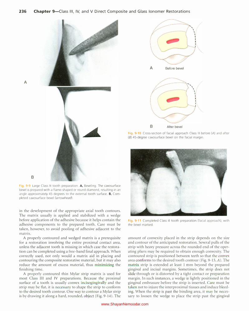
Fig. 9-9 Large Class Ill tooth preparation. A, Beveling. The cavosurface
bevel is prepared with a flame-shaped or round diamond, resulting in an
angle approximately 45 degrees to the external tooth surface. B. Com
pleted cavosurface bevel (arrowhead).
in the development of the appropriate axial tooth contours. The matrix usually is applied and stabilized with a wedge before application of the adhesive because it helps contain the adhesive components to the prepared tooth. Care must be taken, however, to avoid pooling of adhesive adjacent to the matrix.
A properly contoured and wedged matrix is a prerequisite for a restoration involving the entire proximal contact area, unless the adjacent tooth is missing in which case the restoration can be completed using a free-hand final approach. When correctly used, not only would a matrix aid in placing and contouring the composite restorative material, but it may also reduce the amount of excess material, thus minimizing the finishing time.
A properly contoured thin Mylar strip matrix is used for most Class Ill and IV preparations. Because the proximal surface of a tooth is usually convex incisogingivally and the strip may be flat, it is necessary to shape the strip to conform to the desired tooth contour. One way to contour a Mylar strip is by drawing it along a hard, rounded, object (Fig. 9-14). The
A Before bevel
B After bevel
Fig. 9-10 Cross-section of facial approach Class Ill before (A) and after
(B) 45-degree cavosurface bevel on the facial margin.
Fig. 9-11 Completed Class Ill tooth preparation (facial approach), with
the bevel marked.
amount of convexity placed in the strip depends on the size and contour of the anticipated restoration. Several pulls of the strip with heavy pressure across the rounded end of the operating pliers may be required to obtain enough convexity. The contoured strip is positioned between teeth so that the convex area conforms to the desired tooth contour (Fig. 9- IS , A). The matrix strip is extended at least I mm beyond the prepared gingival and incisal margins. Sometimes, the strip does not slide through or is distorted by a tight contact or preparation margin. In such instances, a wedge i lightly positioned in the gingival embrasure before the strip is inserted. Care must be taken not to injure the i11terproximal tissues and induce bleeding. When the strip is past the binding area, it may be necessary to loosen the wedge to place the strip past the gingival
www.ShayanNemoodar.com
Chapter 9-Ciass Ill, IV, and V Direct Composite and Glass lonomer Restorations 237
A
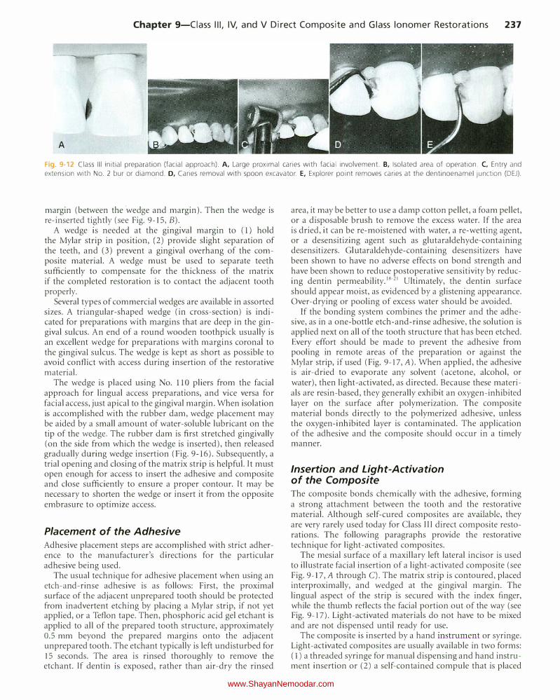
Fig. 9-12 Class Ill initial preparation (facial approach). A, Large proximal caries with facial involvement. B, Isolated area of operation. C, Entry and extension with No. 2 bur or diamond. D, Caries removal with spoon excavator. E, Explorer point removes caries at the dentinoenamel junction (DEJ).
margin (between the ·wedge and margin). Then the wedge is re-inserted tightly (see Fig. 9-15, B).
A wedge is needed at the gingival margin to (1) hold the Mylar strip in position, (2) provide slight separation of the teeth, and (3) prevent a gingival overhang of the composite material. A wedge must be used to separate teeth sufficiently to compensate for the thickness of the matrix if the completed restoration is to contact the adjacent tooth properly.
Several types of commercial wedges are available in assorted sizes. A triangular-shaped wedge (in cross-section) is indicated for preparations with margins that are deep in the gingival sulcus. An end of a round wooden toothpick usually is an excellent wedge for preparations with margins coronal to the gingival sulcus. The wedge is kept as short as possible to avoid conflict with access during insertion of the restorative material.
The wedge is placed using No. 110 pliers from the facial approach for lingual access preparations, and vice versa for facial access, just apical to the gingival margin. When isolation is accomplished with the rubber dam, wedge placement may be aided by a small amount of water-soluble lubricant on the tip of the wedge. The rubber dam is first stretched gingivally (on the side from which the wedge is inserted), then released gradually during wedge insertion (Fig. 9-16). Subsequently, a trial opening and closing of the matrix strip is helpful. It must open enough for access to insert the adhesive and composite and close sufficiently to ensure a proper contour. It may be necessary to shorten the wedge or insert it from the opposite embrasure to optimize access.
Placement of the Adhesive Adhesive placement steps are accomplished with strict adherence to the manufacturer's directions for the particular adhesive being used.
The usual technique for adhesive placement when using an etch-and-rinse adhesive is as follows: First, the proximal surface of the adjacent unprepared tooth should be protected from inadvertent etching by placing a Mylar strip, if not yet applied, or a Teflon tape. Then, phosphoric acid gel etchant is applied to all of the prepared tooth structure, approximately 0.5 mm beyond the prepared margins onto the adjacent unprepared tooth. The etchant typically is left undisturbed for 15 seconds. The area is rinsed thoroughly to remove the etchant. If dentin is exposed, rather than air-dry the rinsed
area, it may be better to use a damp cotton pellet, a foam pellet, or a disposable brush to remove the excess water. If the area is dried, it can be re-moistened with water, a re-wetting agent, or a desensitizing agent such as glutaraldehyde-containing desensitizers. Glutaraldehyde-containing desensitizers have been shown to have no adverse effects on bond strength and have been shown to reduce postoperative sensitivity by reducing dentin permeability. 18-21 Ultimately, the dentin surface should appear moist, as evidenced by a glistening appearance. Over-drying or pooling of excess water should be avoided.
If the bonding system combines the primer and the adhesive, as in a one-bottle etch-and-rinse adhesive, the solution is applied next on all of the tooth structure that has been etched. Every effort should be made to prevent the adhesive from pooling in remote areas of the preparation or against the Mylar strip, if used (Fig. 9-17,A). When applied, the adhesive is air-dried to evaporate any solvent (acetone, alcohol, or water), then light-activated, as directed. Because these materials are resin-based, they generally exhibit an oxygen-inhibited layer on the surface after polymerization. The composite material bonds directly to the polymerized adhesive, unless the oxygen-inhibited layer is contaminated. The application of the adhesive and the composite should occur in a timely manner.
Insertion and Light-Activation of the Composite The composite bonds chemically with the adhesive, forming a strong attachment between the tooth and the restorative material. Although self-cured composites are available, they are very rarely used today for Class III direct composite restorations. The following paragraphs provide the restorative technique for light-activated composites.
The mesial surface of a maxillary left lateral incisor is used to illustrate facial insertion of a light-activated composite (see Fig. 9-17, A through C). The matrix strip is contoured, placed interproximally, and wedged at the gingival margin. The lingual aspect of the strip is secured with the index finger, while the thumb reflects the facial portion out of the way (see Fig. 9-17). Light-activated materials do not have to be mixed and are not dispensed until ready for use.
The composite is inserted by a hand instrument or syringe. Light-activated composites are usually available in two forms: ( l) a threaded syringe for manual dispensing and hand instrument insertion or (2) a self-contained compule that is placed
www.ShayanNemoodar.com
238 Chapter 9-Ciass Ill, IV, and V Direct Composite and Glass lonomer Restorations
A
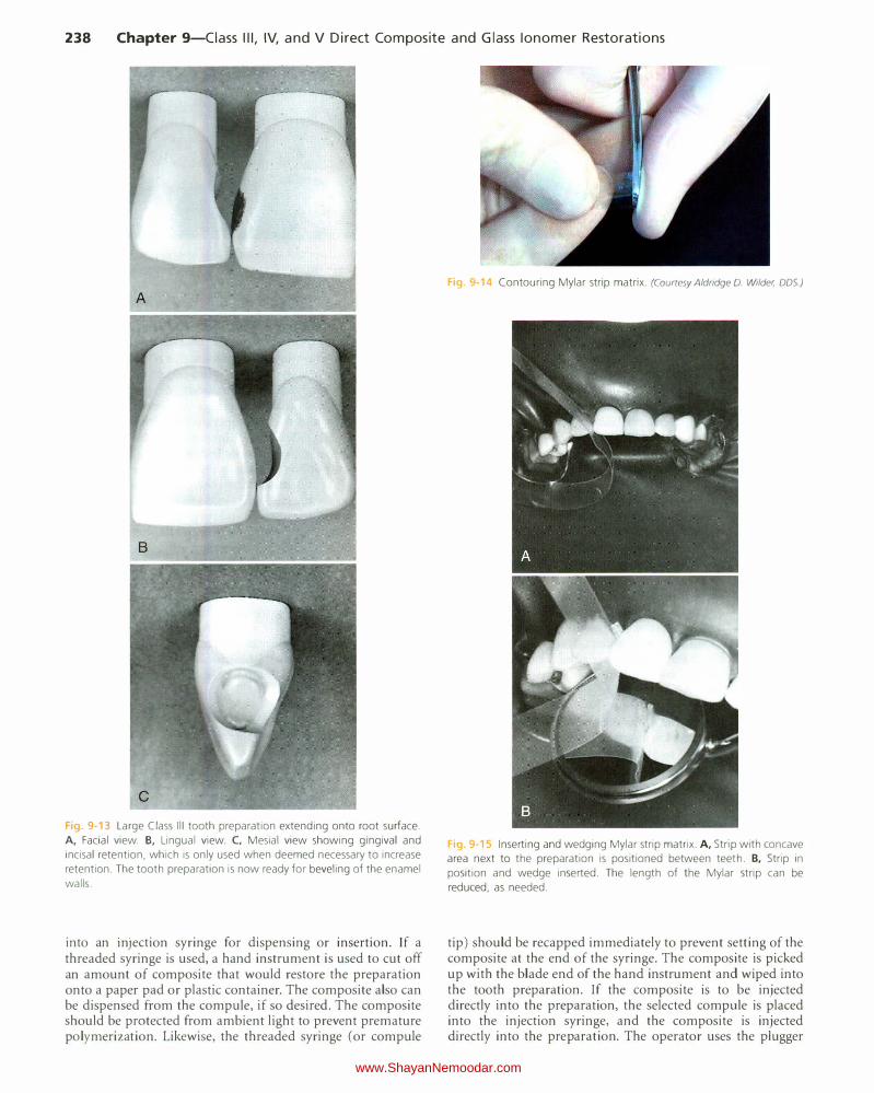
Fig 9-13 Large Class Ill tooth preparation extending onto root surface.
A, Facial view. B, Lingual view. C, Mesial view showing gingival and
incisal retention, which is only used when deemed necessary to increase
retention. The tooth preparation is now ready for beveling of the enamel
walls.
into an InJection syringe for dispensing or insertion. If a threaded syringe is used, a hand instrument is used to cut off an amount of composite that would restore the preparation onto a paper pad or plastic container. The composite also can be dispensed from the compute, if so desired. The composite should be protected from ambient light to prevent premature polymerization. Likewise, the threaded syringe (or com pule
Fig. 9·14 Contouring Mylar strip matrix. (Courtesy Aldridge D. Wilder, DDS)
Fig 9 15 Inserting and wedging Mylar strip matrix. A, Strip with concave
area next to the preparation is positioned between teeth. 8, Strip in
position and wedge inserted. The length of the Mylar strip can be
reduced, as needed.
tip) should be recapped immediately to prevent setting of the composite at the end of the syringe. The composite is picked up with the blade end of the hand instrument and wiped into the tooth preparation. If the composite is to be injected directly into the preparation, the selected compute is placed into the injection syringe, and the composite is injected directly into the preparation. The operator uses the plugger
www.ShayanNemoodar.com

Chapter 9-Ciass Ill, IV, and V Direct Composite and Glass lonomer Restorations 239
Fig. 9-16 Using a triangular wood wedge to expose gingival margin of
large proximal preparation. A, The dam is stretched facially and gingivally
with the fingertip. B, Insertion of wedge (the dam is released during
wedge insertion). C, Wedge in place.
end of the hand instrument to press the material into the preparation. If the composite has a tendency to stick to the instrument, a sparing amount of bonding resin or a gauze dampened in alcohol can be used to lubricate the instrument. Most modern composites will not stick to a clean instrument. A second increment of composite is applied, if needed, to fill the preparation completely and provide a slight excess so that positive pressure can be applied with the matrix strip when closed. Any gross excess is removed quickly with the blade of the insertion instrument or an explorer tine before closing the matrix.
The operator closes the lingual end of the strip over the composite and holds it with the index finger. Next, the operator pulls the matrix toward the facial direction to cover the facial margin with the composite. T his step will provide the best composite-tooth adaptation at that margin. Before lightactivating the composite, the operator closes the facial end of the strip over the tooth with the thumb and index finger of the other hand, tightening the gingival aspect of the strip ahead of the incisal portion. The matrix is held in such a way that light can reach the composite. The matrix can be held in this manner until light activation is complete.
When the material has been inserted, it is light-activated through the strip as directed (see Fig. 9-17, C). The strip should not be touched with the tip of the light initially because it could distort the contour of the restoration. The operator
Fig. 9-17 Insertion of light-activated composite. A, Bonding adhesive is
applied and light-activated. B, The lingual aspect of the strip is secured
with the index finger. while the facial portion is reflected away for access.
C, After insertion of the composite, the matrix strip is closed, and the
material is activated through the strip.
removes the index finger and light-activates the lingual surface. Longer light exposures usually are required for the polymerization of dark and opaque shades. If the restoration is under-contoured, more composite can be added to the previously placed composite and light-activated. No etching or adhesive is required between layers if the surface has not been contaminated, and the oxygen-inhibited layer remains.
With large restorations, it is better to add and light-activate the composite in several increments to reduce the effects of polymerization shrinkage and to ensure complete light activation in remote regions. Adjacent proximal tooth preparations should be restored one at a time. Techniques have been suggested for inserting two approximating restorations simultaneously, but these procedures may result in matrLx movement, poor adaptation, open contact, overhangs, and faulty contours (Fig. 9-18). lf two adjacent preparations are present, the preparation with the least access (usually the one prepared second ) is restored first. If too much convexity is present on the first proximal restoration, the excess must be removed before the second restoration is inserted. lf too little contour is present, more material is added to correct the contour. The proximal surface of the first restoration should be contoured completely before the second restoration is started. Because the second tooth preparation has been contaminated, it must be cleaned before bonding materials and composite are applied and the
www.ShayanNemoodar.com
240 Chapter 9-Ciass Ill, IV, and V Direct Composite and Glass lonomer Restorations
composite are inserted. During these procedures, a Mylar strip or Teflon tape should be in place to protect the first restoration and the tooth.
Contouring and Polishing of the Composite
Good technique and experience in inserting composites significantly reduce the amount of finishing required. Usually, a slight excess of material will need to be removed to provide the final contour and smooth finish. Coarse diamond instruments can be used to remove gross excess, but they generally are not recommended for finishing composites because of the high risk of inadvertently damaging the contiguous tooth structure. Compared with finishing burs and disks, they also leave a rough surface on the restoration and the tooth. Special fine diamond finishing instruments, 12-bladed carbide finishing burs, and abrasive finishing disks can be used to obtain excellent results if the manufacturers' instructions are followed. Care must be exercised with all rotary instruments to prevent damage to the tooth structure, especially at the gingival marginal areas.
Similar to tooth preparation rotary instruments, contouring and polishing instruments should be used according to the specific surface being contoured and polished. For example, flexible disks and finishing strips are suitable for convex and flat surfaces; finishing points and oval-shaped finishing burs
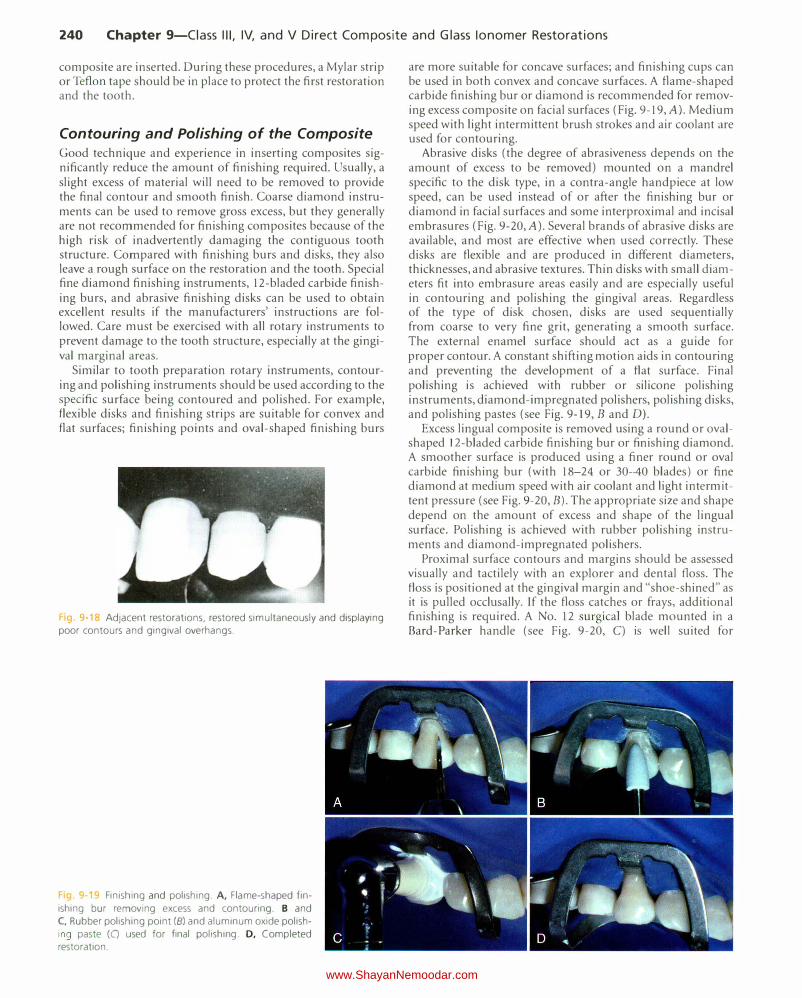
g 9 18 Adjacent restorations, restored simultaneously and displaying poor contours and gingival overhangs.
Finishing and polishing. A, Flame-shaped fin
ishing bur removing excess and contouring. B and C, Rubber polishing point (B) and aluminum oxide polishing paste (C) used for final polishing. D, Completed restoration.
are more suitable for concave surfaces; and finishing cups can be used in both convex and concave surfaces. A flame-shaped carbide finishing bur or diamond is recommended for removing excess composite on facial surfaces (Fig. 9-19, A). Medium speed with light intermittent brush strokes and air coolant are used for contouring.
Abrasive disks (the degree of abrasiveness depends on the amount of excess to be removed) mounted on a mandrel specific to the disk type, in a contra-angle handpiece at low speed, can be used instead of or after the finishing bur or diamond in facial surfaces and some interproximal and incisal embrasures (Fig. 9-20, A). Several brands of abrasive disks are available, and most are effective when used correctly. These disks are flexible and are produced in different diameters, thicknesses, and abrasive textures. Thin disks with small diameters fit into embrasure areas easily and are especially useful in contouring and polishing the gingival areas. Regardless of the type of disk chosen, disks are used sequentially from coarse to very fine grit, generating a smooth surface. The external enamel surface should act as a guide for proper contour. A constant shifting motion aids in contouring and preventing the development of a flat surface. Final polishing is achieved with rubber or silicone polishing instruments, diamond-impregnated polishers, polishing disks, and polishing pastes (see Fig. 9-19, Band D).
Excess lingual composite is removed using a round or ovalshaped 12-bladed carbide finishing bur or finishing diamond. A smoother surface is produced using a finer round or oval carbide finishing bur (with 18-24 or 30-40 blades ) or fine diamond at medium speed with air coolant and light intermittent pressure (see Fig. 9-20, B). The appropriate size and shape depend on the amount of excess and shape of the lingual surface. Polishing is achieved with rubber polishing instruments and diamond-impregnated polishers.
Proximal surface contours and margins should be assessed visually and tactilely with an explorer and dental floss. The floss is positioned at the gingival margin and "shoe-shined" as it is pulled occlusally. If the floss catches or frays, additional finishing is required. A No. 12 surgical blade mounted in a Bard-Parker handle (see Fig. 9-20, C) is well suited for
www.ShayanNemoodar.com
Chapter 9-Ciass Ill, IV, and V Direct Composite and Glass lonomer Restorations 241
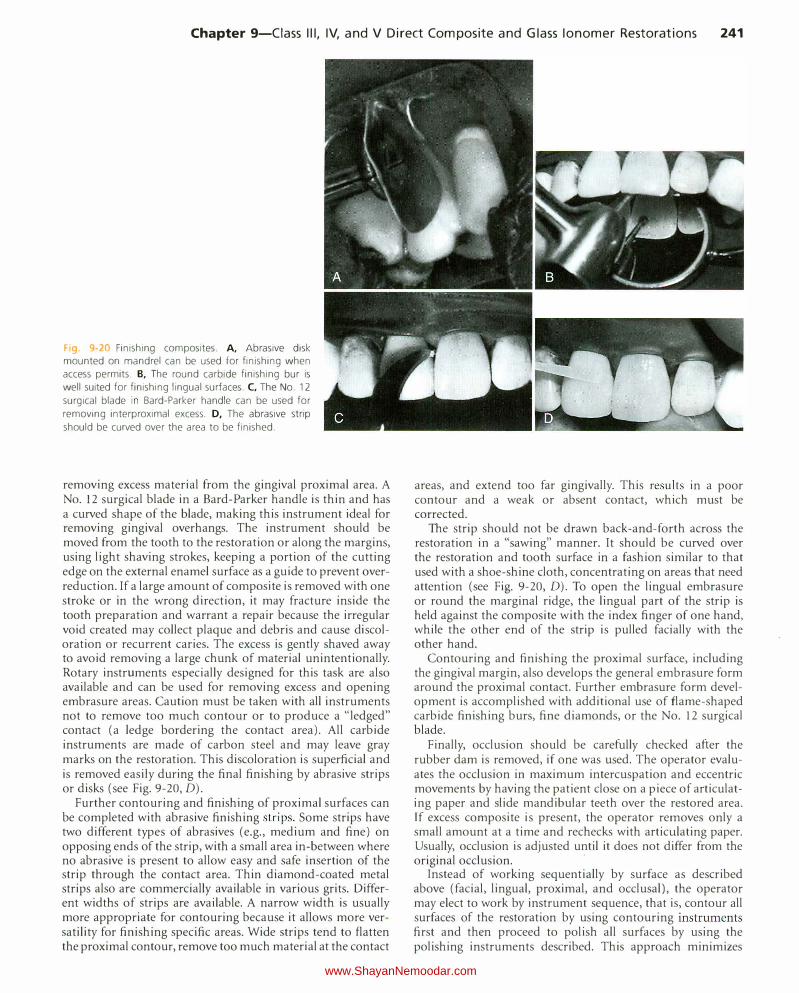
Fig. 9-20 Finishing composites. A, Abrasive disk mounted on mandrel can be used for finishing when access permits. B, The round carbide finishing bur is
well suited for finishing lingual surfaces. C, The No. 12 surgical blade in Bard-Parker handle can be used for
removing interproximal excess. D, The abrasive strip
should be curved over the area to be finished.
removing excess material from the gingival proximal area. A No. 12 surgical blade in a Bard-Parker handle is thin and has a curved shape of the blade, making this instrument ideal for removing gingival overhangs. The instrument should be moved from the tooth to the restoration or along the margins, using light shaving strokes, keeping a portion of the cutting edge on the external enamel surface as a guide to prevent overreduction. If a large amount of composite is removed with one stroke or in the wrong direction, it may fracture inside the tooth preparation and warrant a repair because the irregular void created may collect plaque and debris and cause discoloration or recurrent caries. The excess is gently shaved away to avoid removing a large chunk of material unintentionally. Rotary instruments especially designed for this task are also available and can be used for removing excess and opening embrasure areas. Caution must be taken with all instruments not to remove too much contour or to produce a "!edged" contact (a ledge bordering the contact area). All carbide instruments are made of carbon steel and may leave gray marks on the restoration. This discoloration is superficial and is removed easily during the final finishing by abrasive strips or disks (see Fig. 9-20, D).
Further contouring and finishing of proximal surfaces can be completed with abrasive finishing strips. Some strips have two different types of abrasives (e.g., medium and fine) on opposing ends of the strip, with a small area in-between where no abrasive is present to allow easy and safe insertion of the strip through the contact area. Thin diamond-coated metal strips also are commerciaiiy available in various grits. Different widths of strips are available. A narrow width is usually more appropriate for contouring because it allows more versatility for finishing specific areas. Wide strips tend to flatten the proximal contour, remove too much material at the contact
areas, and extend too far gingivally. This results in a poor contour and a weak or absent contact, which must be corrected.
The strip should not be drawn back-and-forth across the restoration in a "sawing" manner. It should be curved over the restoration and tooth surface in a fashion similar to that used with a shoe-shine cloth, concentrating on areas that need attention (see Fig. 9-20, D). To open the lingual embrasure or round the marginal ridge, the lingual part of the strip is held against the composite with the index finger of one hand, while the other end of the strip is pulled facially with the other hand.
Contouring and finishing the proximal surface, including the gingival margin, also develops the general embrasure form around the proximal contact. Further embrasure form development is accomplished with additional use of flame-shaped carbide finishing burs, fine diamonds, or the No. 12 surgical blade.
Finally, occlusion should be carefully checked after the rubber dam is removed, if one was used. The operator evaluates the occlusion in maximum intercuspation and eccentric movements by having the patient close on a piece of articulating paper and slide mandibular teeth over the restored area. If excess composite is present, the operator removes only a small amount at a time and rechecks with articulating paper. Usually, occlusion is adjusted until it does not differ from the original occlusion.
·
Instead of working sequentially by surface as described above (facial, lingual, proximal, and occlusal), the operator may elect to work by instrument sequence, that is, contour all surfaces of the restoration by using contouring instruments first and then proceed to polish all surfaces by using the polishing instruments described. This approach minimizes
www.ShayanNemoodar.com
242 Chapter 9-Ciass Ill, IV, and V Direct Composite and Glass lonomer Restorations
the amount of time necessary to change instruments between surfaces.
Clinical Technique for Class IV Direct Composite Restorations
Initial Clinical Procedures The same initial procedure considerations presented earlier are appropriate for Class IV direct composite restorations. The preoperative assessment of the occlusion is even more important for Class IV restorations because it might influence the tooth preparation extension (placing margins in noncontact areas) and retention and resistance form features (heavy occlusion requires increased retention and resistance form).
Also, proper shade selection can be more difficult for large Class IV restorations. Use of separate translucent and opaque shades of composite is often necessary. Specific information for esthetic considerations is presented in Chapter 12.
For large Class IV lesions or fractures, a preoperative impression may be taken to be used as a template for developing the restoration contours. This technique is described later.
Tooth Preparation Similar to the Class III preparation, the tooth preparation for a Class IV direct composite restoration involves (l) creating access to the defective structure (caries, fracture, non-carious defect), (2) removal of faulty structures (caries, defective dentin and enamel, defective restoration and base material), and (3) creating the convenience form for the restoration. The tooth preparation for large incisoproximal areas requires more attention to the retention form than that for a small Class IV defect. If a large amount of tooth structure is missing and the restoration is in a high stress area, groove retention form may be indicated even when the preparation periphery is entirely in enamel. Also, enamel bevels can be increased in width to provide greater surface area for etching, resulting in a stronger bond between the composite and the tooth and potentially better esthetic result.
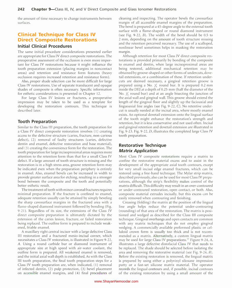
The treatment of teeth with minor coronal fractures requires minimal preparation. If the fracture is confined to enamel, adequate retention usually can be attained by simply beveling the sharp cavosurface margins in the fractured area with a flame-shaped diamond instrument followed by bonding (Fig. 9-21 ). Regardless of its size, the extensions of the Class IV
direct composite preparation is ultimately dictated by the extension of the caries lesion, fracture, or failed restoration being replaced. The outline form is prepared to include weakened, friable enamel.
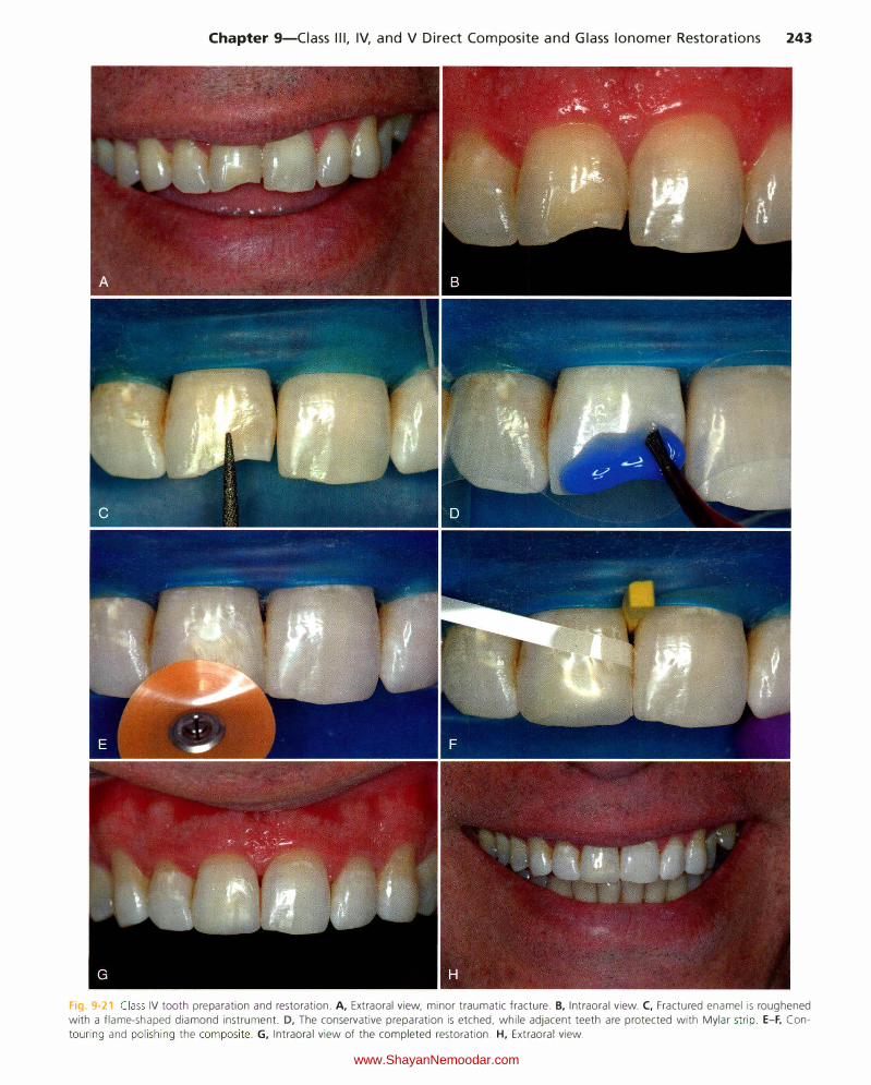
A maxillary right central incisor with a large defective Class II I restoration and a fractured mesio-incisal corner, which necessitates a Class TV restoration, is illustrated in Figure 9-22, A. Using a round carbide bur or diamond instrument of appropriate size at high speed with air-water coolant, the outline form is prepared. All weakened enamel is removed, and the initial axial wall depth is established. As with the Class III tooth preparation, the final tooth preparation steps for a Class IV tooth preparation are, when indicated, (l) removal of infected dentin, (2) pulp protection, (3) bevel placement on accessible enamel margins, and (4) final procedures of
cleaning and inspecting. The operator bevels the cavosurface margin of all accessible enamel margins of the preparation. The bevel is prepared at a 45-degree angle to the external tooth surface with a flame-shaped or round diamond instrument (see Fig. 9-22, B). The width of the bevel should be 0.5 to 2 mm, depending on the amount of tooth structure missing and the retention perceived necessary. The use of a scalloped, nonlinear bevel sometimes helps in masking the restoration margin.
Although retention for most Class IV direct composite restorations is provided primarily by bonding of the composite to enamel and dentin, when large incisoproximal areas are being restored, additional mechanical retention may be obtained by groove-shaped or other forms of undercuts, dovetail extensions, or a combination of these. If retention undercuts are deemed necessary, a gingival retention groove is prepared using a No. y,; round bur. lt is prepared 0.2 mm inside the DEJ at a depth of 0.25 mm (half the diameter of the No. y,; round bur) and at an angle bisecting the junction of the axial wall and gingival wall. This groove should e>.."tend the length of the gingival floor and slightly up the facioaxial and linguoaxial line angles (see Fig. 9-22, C). No retentive undercut is usually needed at the incisal area, where mostly enamel exists. An optional dovetail extension onto the lingual surface of the tooth might enhance the restoration's strength and retention, but it is less conservative and not used often. Incisal and gingival retention and dovetail extension are illustrated in Fig. 9-23. Fig. 9-22, D, illustrates the completed large Class IV
tooth preparation.
Restorative Technique Matrix Application Most Class IV composite restorations requ1re a matrix to confine the restorative material excess and to assist in the development of the appropriate axial tooth contours, except for very small incisal edge enamel fractures, which can be restored using a free-hand technique. The Mylar strip matrix, described previously, also can be used for most Class IV preparations, although the strip's flexibility makes control of the matrix difficult. This difficulty may result in an over-contoured or under-contoured restoration, open contact, or both. Also, composite material extrudes incisally, but this excess can be easily removed when contouring and finishing.
Creasing (folding) the matrix at the position of the lingual line angle helps reduce the potential under-contouring (rounding) of that area of the restoration. The matri..x is positioned and wedged as described for the Class II I composite technique. Gingival overhangs and open contacts are common with any matrix techniques that do not employ gingival wedging. A commercially available preformed plastic or celluloid crown form is usually too thick and is not recommended as a matrix. Alternatively, a custom lingual matrix may be used for large Class IV preparations."" Figure 9-24, A,
illustrates a large defective distofacial Class IV that needs to be replaced. The shade should be selected before isolating the area and removing the restorative material (see Fig. 9-24, B). Before the existing restoration is removed, the lingual matrix is prepared by using either a polyvinyl siloxane impression putty or a fast-set silicone matrix material. The operator records the lingual contours and, if possible, incisal contours of the existing restoration by using a small amount of the
www.ShayanNemoodar.com
Chapter 9-Ciass Ill, IV, and V Direct Composite and Glass lonomer Restorations 243
Fig. 9-21 Class IV tooth preparation and restoration. A, Extraoral view, minor traumatic fracture. B, Intraoral view. C, Fractured enamel is roughened with a flame-shaped diamond instrument. D, The conservative preparation is etched. while adjacent teeth are protected with Mylar str ip. E-F, Con
touring and polishing the composite. G, Intraoral view of the completed restoration. H, Extraoral view.
www.ShayanNemoodar.com
244 Chapter 9-Ciass Ill, IV, and V Direct Composite and Glass lonomer Restorations
Fig 9-22 Class IV tooth preparation. A, Large defec
tive Class Ill restoration with resulting fractured incisal
angle. B, Beveling cavosurface margin. C, Gingival
retention groove. D, Completed Class IV tooth preparation.
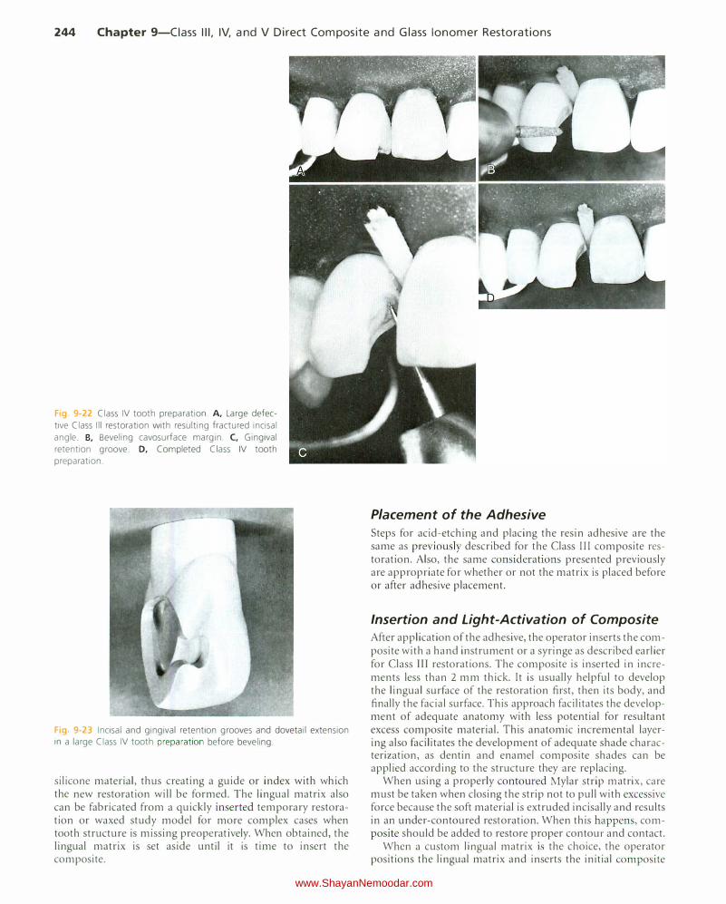
Fig 9-23 Incisal and gingival retention grooves and dovetail extension in a large Class IV tooth preparation before beveling.
silicone material, thus creating a guide or index with which the new restoration will be formed. The lingual matrix also can be fabricated from a quickly inserted temporary restoration or waxed study model for more complex cases when tooth structure is missing preoperatively. When obtained, the lingual matrix is set aside until it is time to insert the composite.
Placement of the Adhesive
Steps for acid-etching and placing the resin adhesive are the same as previously described for the Class III composite restoration. Also, the same considerations presented previously are appropriate for whether or not the matrix is placed before or after adhesive placement.
Insertion and Light-Activation of Composite
After application of the adhesive, the operator inserts the composite with a hand instrument or a syringe as described earlier for Class III restorations. The composite is inserted in increments less than 2 mm thick. It is usually helpful to develop the lingual surface of the restoration first, then its body, and finally the facial surface. This approach facilitates the development of adequate anatomy with less potential for resultant excess composite material. This anatomic incremental layering also facilitates the development of adequate shade characterization, as dentin and enamel composite shades can be applied according to the structure they are replacing.
When using a properly contoured Mylar strip matrix, care must be taken when closing the strip not to pull with excessive force because the soft material is extruded incisally and results in an under-contoured restoration. When this happens, composite should be added to restore proper contour and contact.
When a custom lingual matrix is the choice, the operator positions the lingual matrix and inserts the initial composite
www.ShayanNemoodar.com
Chapter 9-Ciass Ill, IV, and V Direct Composite and Glass lonomer Restorations 245
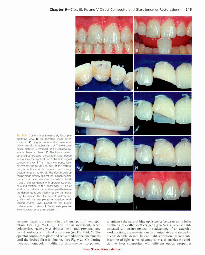
Fig. 9-24 Custom lingual matrix. A, Facial preoperative view. B, Pre-operative shade determination. C, Lingual pre-operative view after
placement of the rubber dam. D, The old com
posite material is removed, and a conservative
enamel bevel is placed. E, The lingual matrix
obtained before tooth preparation is positioned
and guides the application of the first lingual
composite layer. F, The lingual composite layer determines the future contours of the restoration; note the intrinsic material translucency. Custom lingual matrix. G, The dentin buildup can be made directly against the lingual enamel;
the clinician can visualize the whole tooth shape and place dentin with appropriate thickness and relation to the incisal edge. H, Color
modifier or tint blue material is applied between
the dentin lobes and slightly below the incisal
edge to simulate the blue natural opalescence.
I, View of the completed restoration (with
second enamel layer placed on the buccal
surface), after finishing. J, Facial post-operative
view (Courtesy of Dr Didier Dietschi)
increment against the matrix in the lingual part of the preparation (see Fig. 9-24, E). This initial increment, when polymerized, generally establishes the lingual, proximal, and incisal contours of the final restoration (see Fig. 9-24, F). The operator continues to place and activate additional increments until the desired form is obtained (see Fig. 9-24, G). During these additions, color modifiers or tints may be incorporated
to enhance the natural blue opalescence between tooth lobes or other subtle esthetic effects (see Fig. 9-24, H). Because lightactivated composites possess the advantage of an extended working time, the material can be manipulated and shaped to a considerable degree before light-activation. Incremental insertion of light-activated composites also enables the clinician to layer composites with different optical properties
www.ShayanNemoodar.com
246 Chapter 9-Ciass Ill, IV, and V Direct Composite and Glass lonomer Restorations
(more opaque, darker in color, or both, to mimic dentin; and more translucent, lighter in color, or both, to mimic enamel), which can result in natural-looking composite restorations. After polymerization, the lingual matrix is removed. To ensure optimal polymerization, the operator light-activates the restoration from facial and lingual directions. The final restoration is illustrated in Figure 9-24, I and f. This technique is particularly useful when the lingual contour of an existing composite restoration is to be duplicated in a new composite restoration, such as the case described. The technique facilitates the development of proper lingual, incisal, and proximal forms, reducing the need for contouring of the restoration.
Contouring and Polishing of the Composite Contouring and polishing the Class JV composite is similar to the technique described for a Class Ill composite but usually more difficult. The primary differences are the involvement of the incisal angle and incisal edge of the tooth and an extended facial surface in large Class IV restorations. Contouring and polishing these sections of the restoration require similar procedural steps but close assessment of the incisal edge length and thickness, as well as of the facial macroanatomy and microanatomy of the tooth being restored. Also, the potential occlusal relationship may be greater and require more adjustment and refinement. The facial, lingual, and proximal areas are contoured and finished as described previously.
Clinical Technique for Class V Direct Composite Restorations
Initial Clinical Procedures The same initial procedure considerations presented for Class III restorations apply for Class V restorations, except for occlusal evaluation, which is not required for Class V restorations. During shade selection, it should be remembered that the tooth is darker and more opaque in the cervical third. [solation may be achieved by a rubber dam and No. 212 retainer or with a cotton roll and retraction cord as previously described in Chapter 7.
Tooth Preparation Class V tooth preparations, by definition, are located in the gingival one third of the facial and lingual tooth surfaces. Because of esthetic considerations, composites most frequently are used for the restoration of Class V lesions in anterior and premolar teeth. Numerous factors, including esthetics, caries activity, access to the lesion, moisture control, and patient age, must be taken into consideration in material selection.
Because many Class V restorations involve root surfaces, at least on their cervical margins, careful consideration should be given to the choice of restorative material. Use of materials other than composite is considered when factors that can compromise the performance of composite restorations are present. These factors include decreased salivary function, decreased patient motivation or ability for home care, increased difficulty in adequately isolating the operating area, and increased difficulty in performing the operative procedure because of the patient's physical or medical problems.
Despite these concerns, the use of composite as a restorative material for Class V lesions predominates in areas of esthetic concern.
Similar to the Class Ill and IV preparations, tooth preparation for a Class V direct composite restoration involves (I) creating access to the defect (caries, non-carious defect), (2) removal of the defect (caries, defective dentin and enamel, defective restoration and base material), and (3) creating the convenience form for the restoration. The tooth preparation for large Class V lesions or defects areas may require more attention to retention form than that of a small Class V defect, especially when little enamel is available for bonding. Areas of hypermineralized (sclerotic) dentin also may require special attention, as these respond differently to bonding than areas with normal dentin.23.25 Enamel bevels are usually used on the occlusal margins of the preparation, while at the cervical margin, enamel bevels are usually not recommended because of the absence of enamel in this area. Class V tooth preparations will vary slightly, depending on the type and extension of the defect being restored.
Class V Tooth Preparation for Small or Moderate Lesions or Defects That Do Not Extend Onto the Root Surface The objective of the Class V tooth preparation for small or moderate lesions or defects that do not extend onto the root surface is to restore the lesion or defect as conservatively as possible. No effort is made to prepare the walls as butt joints, and usually no groove retention is incorporated. The lesion or defect is "scooped" out, resulting in a preparation form that may have a divergent wall configuration and an axial surface that usually is not uniform in depth (see Fig. 9-6, E and F). Small or moderate Class V tooth preparations are ideal for small enamel defects or small primary caries lesions (Fig. 9-25, A). These include decalcified and hypoplastic areas located in the cervical third of the teeth. The typical outline form for a Class V lesion in enamel is shown in Figure 9-26.
After the usual preliminary procedures, the initial tooth preparation is accomplished with a round diamond or carbide bur (see Fig. 9-25, B), eliminating the entire enamel lesion or defect. The preparation is extended into dentin only when the defect warrants such extension. No effort is made to prepare 90-degree cavosurface margins. If infected dentin remains, it is removed with a round bur or spoon excavator. Usually, this preparation technique will result in a slightly beveled enamel margin. If deemed necessary, the enamel margin can be further beveled. The completed preparation with etched enamel and etched and primed dentin is shown in Figure 9-25, C.
An example of a small Class V tooth preparation is presented in Figure 9-5, A, which illustrates a path of a decalcified enamel lesion (in enamel only) having a broken, rough surface that extends mesially or distally from the cavitated lesion (or failing existing restoration). After preparation of the cavitated lesion (or failing restoration), the margins of the preparation are extended to include these areas of decalcification by using a round diamond or bur to prepare the cavosurface margin in the form of a chamfer, extended in the enamel only to a depth that removes the defect. A completed preparation of this type is illustrated in Figure 9-5, B.
www.ShayanNemoodar.com
Chapter 9-Ciass Ill, IV, and V Direct Composite and Glass lonomer Restorations 247
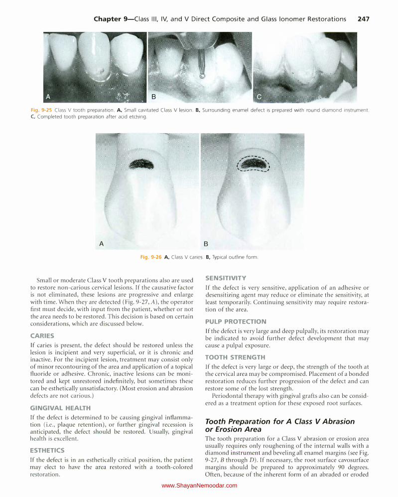
Fig. 9-25 Class V tooth preparation. A, Small cavitated Class V lesion. B. Surrounding enamel defect is prepared with round diamond instrument.
C, Completed tooth preparation after acid etching.
A B
Fig. 9-26 A. Class V caries. B, Typical outline form.
Small or moderate Class V tooth preparations also are used to restore non-carious cervical lesions. If the causative factor is not eliminated, these lesions are progressive and enlarge with time. When they are detected (Fig. 9-27, A), the operator first must decide, with input from the patient, whether or not the area needs to be restored. This decision is based on certain considerations, which are discussed below.
CARIES If caries is present, the defect should be restored unless the lesion is incipient and very superficial, or it is chronic and inactive. For the incipient lesion, treatment may consist only of minor recontouring of the area and application of a topical fluoride or adhesive. Chronic, inactive lesions can be monitored and kept unrestored indefinitely, but sometimes these can be esthetically unsatisfactory. (Most erosion and abrasion defects are not carious.)
GINGIVAL HEALTH If the defect is determined to be causing gingival inflammation (i.e., plaque retention), or further gingival recession is anticipated, the defect should be restored. Usually, gingival health is excellent.
ESTHETICS
If the defect is in an esthetically critical position, the patient may elect to have the area restored with a tooth-colored restoration.
SENSITIVITY
If the defect is very sensitive, application of an adhesive or desensitizing agent may reduce or eliminate the sensitivity, at least temporarily. Continuing sensitivity may require restoration of the area.
PULP PROTECTION Jf the defect is very large and deep pulpally, its restoration may be indicated to avoid further defect development that may cause a pulpal exposure.
TOOTH STRENGTH If the defect is very large or deep, the strength of the tooth at the cervical area may be compromised. Placement of a bonded restoration reduces further progression of the defect and can restore some of the lost strength.
Periodontal therapy with gingival grafts also can be considered as a treatment option for these exposed root surfaces.
Tooth Preparation for A Class V Abrasion or Erosion Area The tooth preparation for a Class V abrasion or erosion area usually requires only roughening of the internal walls with a diamond instrument and beveling all enamel margins (see Fig. 9-27, B through D). If necessary, the root surface cavosurface margins should be prepared to approximately 90 degrees. Often, because of the inherent form of an abraded or eroded
www.ShayanNemoodar.com
248 Chapter 9-Ciass Ill, IV, and V Direct Composite and Glass lonomer Restorations
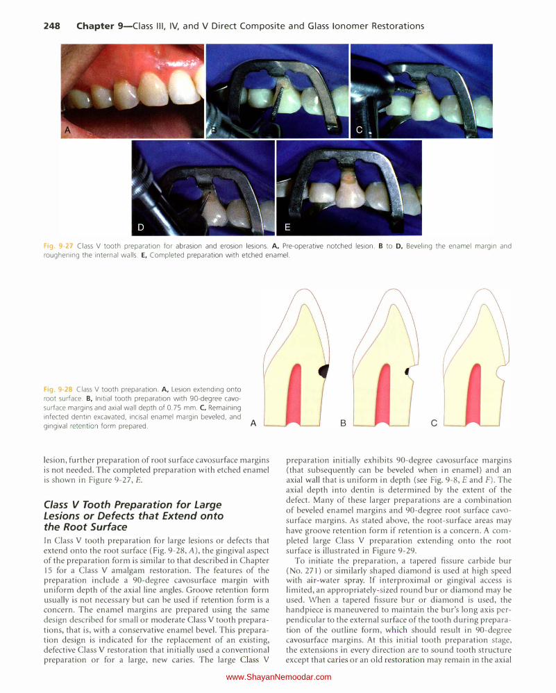
Fig. 9 27 Class V tooth preparation for abrasion and erosion lesions. A, Pre-operative notched lesion. B to D, Beveling the enamel margin and roughening the internal walls. E, Completed preparation with etched enamel.
'19. 9 2° Class V tooth preparation. A, Lesion extending onto
root surface. B, Initial tooth preparation with 90-degree cava
surface margins and axial wall depth of 0.75 mm. C, Remaining infected dentin excavated, incisal enamel margin beveled, and gingival retention form prepared. A
lesion, further preparation of root surface cavosurface margins is not needed. The completed preparation with etched enamel is shown in Figure 9-27, E.
Class V Tooth Preparation for Large Lesions or Defects that Extend onto the Root Surface In Class V tooth preparation for large lesions or defects that extend onto the root surface (Fig. 9-28, A), the gingival aspect of the preparation form is similar to that described in Chapter 15 for a Class V amalgam restoration. The features of the preparation include a 90-degree cavosurface margin with uniform depth of the axial line angles. Groove retention form usually is not necessary but can be used if retention form is a concern. The enamel margins are prepared using the same design described for small or moderate Class V tooth preparations, that is, with a conservative enamel bevel. This preparation design is indicated for the replacement of an existing, defective Class V restoration that initially used a conventional preparation or for a large, new caries. The large Class V
B c
preparation initially exJ1ibits 90-degree cavosurface margins (that subsequently can be beveled when in enamel) and an axial wall that is uniform in depth (see Fig. 9-8, E and F). The axial depth into dentin is determined by the extent of the defect. Many of these larger preparations are a combination of beveled enamel margins and 90-degree root surface cavasurface margins. As stated above, the root-surface areas may have groove retention form if retention is a concern. A completed large Class V preparation extending onto the root surface is illustrated in Figure 9-29.
To initiate the preparation, a tapered fissure carbide bur (No. 271) or similarly shaped diamond is used at high speed with air-water spray. If interproximal or gingival access is limited, an appropriately-sized round bur or diamond may be used. When a tapered fissure bur or diamond is used, the handpiece is maneuvered to maintain the bur's long axis perpendicular to the external surface of the tooth during preparation of the outline form, which should result in 90-degree cavosurface margins. At this initial tooth preparation stage, the extensions in every direction are to sound tooth structure except that caries or an old restoration may remain in the axial
www.ShayanNemoodar.com
Chapter 9-Ciass Ill, IV, and V Direct Composite and Glass lonomer Restorations 249
wall (see Fig. 9-28, B). Any infected dentin remaining on this initial axial wall is removed during the final stage of tooth preparation. Any old restorative material remaining may or may not be removed according to the concepts stated previously. When the desired distal extension is obtained, the instrument is moved mesially, incisally (occlusally), and gingivally for indicated extensions, while maintaining proper depth and the instrument's long axis perpendicular to the external surface. The axial wall should follow the original contour of the facial or lingual surface, which is convex outward mesiodistally and sometimes occlusogingivally. The outline form extension of the mesial, distal, occlusal (incisal), and gingival walls is dictated by the extent of the caries, defect, or old restorative material indicated for replacement (sometimes the new material abuts a still satisfactory old restoration).
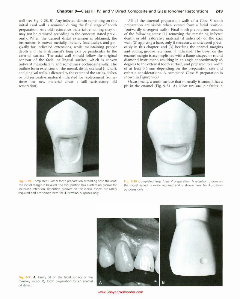
Fig. 9 29 Completed Class V tooth preparation extending onto the root;
the incisal margin is beveled; the root portion has a retention groove for
increased retention. Retention grooves on the incisal aspect are rarely required and are shown here for illustration purposes only.
Fig. 9-31 A, Faulty pit on the facial surface of the maxillary incisor. B, Tooth preparation for an enamel
pit defect.
All of the external preparation walls of a Class V tooth preparation are visible when viewed from a facial position (outwardly divergent walls). Final tooth preparation consists of the following steps: ( 1) removing the remaining infected dentin or old restorative material (if indicated) on the axial wall; (2) applying a base, only if necessary, as discussed previously in this chapter; and (3) beveling the enamel margins and adding groove retention, if indicated. The bevel on the enamel margin is accomplished with a flame-shaped or round diamond instrument, resulting in an angle approximately 45 degrees to the external tooth surface, and prepared to a width of at least 0.5 mm depending on the preparation size and esthetic considerations. A completed Class V preparation is shown in Figure 9-30.
Occasionally, a tooth surface that normally is smooth has a pit in the enamel (Fig. 9-31, A). Most unusual pit faults in
Fig. 9-30 Completed large Class V preparation. A retention groove on
the incisal aspect is rarely required and is shown here for illustration
purposes only.
www.ShayanNemoodar.com
250 Chapter 9-Ciass Ill, IV, and V Direct Composite and Glass !anomer Restorations
enamel are restored best with the preparation design described for small or moderate Class V defects. For such a preparation for an unusual pit fault, the outline form (extensions and depth) is dictated by the extent of the fault or caries lesion. Faults existing entirely in enamel are prepared with an appropriately-sized round diamond instrument by merely eliminating the defect (see Fig. 9-31 , B). Adequate retention is obtained by bonding. When the defect includes carious dentin, the infected portion is removed also, leaving a flared enamel margm.
Restorative Technique No matrix is needed for Class V restorations because the contour can be controlled as the composite restorative material is being inserted.
Acid Etching and Placement of the Adhesive The techniques for acid etching of the involved tooth structure and placement of the adhesive are the same as previously described in this chapter.
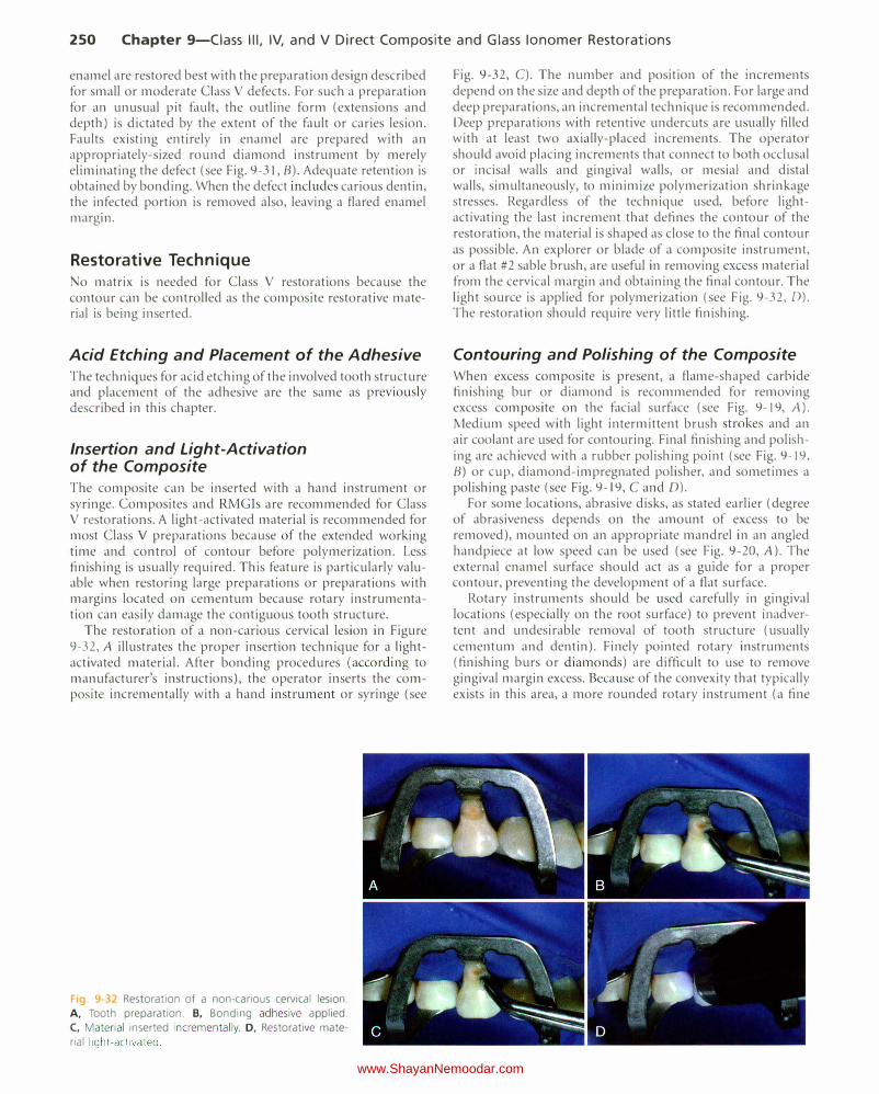
Insertion and Light-Activation of the Composite The composite can be inserted with a hand instrument or syringe. Composites and RMG!s are recommended for Class V restorations. A light-activated material is recommended for most Class V preparations because of the extended working time and control of contour before polymerization. Less finishing is usually required. This feature is particularly valuable when restoring large preparations or preparations with margins located on cementum because rotary instrumentation can easily damage the contiguous tooth structure.
The restoration of a non-carious cervical lesion in Figure 9-32, A illustrates the proper insertion technique for a lightactivated material. After bonding procedures (according to manufacturer's instructions), the operator inserts the composite incrementally with a hand instrument or syringe (see
Fig. 9-32 Restoration of a non-carious cervical lesion.
A, Tooth preparation. B, Bonding adhesive applied.
C, Material inserted incrementally. D, Restorative mate
rial light-activated .
Fig. 9-32, C). The number and position of the increments depend on the size and depth of the preparation. For large and deep preparations, an incremental technique is recommended. Deep preparations with retentive undercuts are usually filled with at least two axially-placed increments. The operator should avoid placing increments that connect to both occlusal or incisal walls and gingival walls, or mesial and distal walls, simultaneously, to minimize polymerization shrinkage stresses. Regardless of the technique used, before lightactivating the last increment that defines the contour of the restoration, the material is shaped as close to the final contour as possible. An explorer or blade of a composite instrument, or a flat #2 sable brush, are useful in removing excess material from the cervical margin and obtaining the final contour. The light source is applied for polymerization (see Fig. 9-32 , D). The restoration should require very little finishing.
Contouring and Polishing of the Composite When excess composite is present, a flame-shaped carbide finishing bur or diamond is recommended for removing excess composite on the facial surface (see Fig. 9-19, A). Medium speed with light intermittent brush strokes and an air coolant are used for contouring. Final finishing and polishing are achieved with a rubber polishing point (see Fig. 9-19, B) or cup, diamond-impregnated polisher, and sometimes a polishing paste (see Fig. 9-19, C and D).
For some locations, abrasive disks, as stated earlier (degree of abrasiveness depends on the amount of excess to be removed), mounted on an appropriate mandrel in an angled handpiece at low speed can be used (see Fig. 9-20, A). The external enamel surface should act as a guide for a proper contour, preventing the development of a flat surface.
Rotary instruments should be used carefully in gingival locations (especially on the root surface) to prevent inadvertent and undesirable removal of tooth structure (usually cementum and dentin). Finely pointed rotary instruments (finishing burs or diamonds) are difficult to use to remove gingival margin excess. Because of the convexity that typically exists in this area, a more rounded rotary instrument (a fine
www.ShayanNemoodar.com
Chapter 9-Ciass Ill, IV, and V Direct Composite and Glass lonomer Restorations 251
diamond) may remove the excess with less potential to damage the unprepared root surface. Likewise, abrasive disks used on the root surface can cause ditching of the cementum, if not used correctly.
Clinical Technique for Glass lonomer Restorations
Glass ionomers possess the favorable quality of releasing fluoride when exposed to the oral environment.26'27 These materials also have been shown to "recharge" with fluoride when exposed to fluoride from various sources.28 These properties may render glass ionomer restorations more resistant to recurrent caries, especially in patients with caries activity. Because of this potential anticariogenic quality, glass ionomer may be the material of choice for restoring root-surface caries in patients with high caries activity and in whom esthetics is not as critical. (See Online Chapter 18 for types of glass ionomers.)
Because of their limited strength and wear resistance, glass ionomers are indicated generally for the restoration of
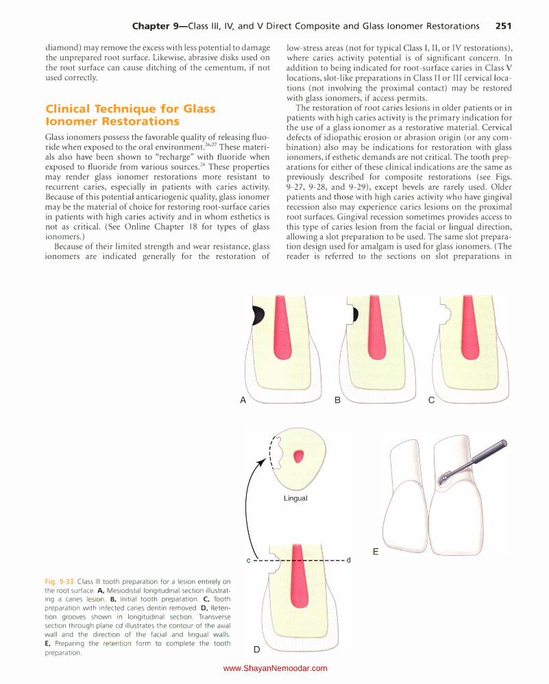
Fig 9-33 Class Ill tooth preparation for a lesion entirely on
the root surface. A, Mesiodistal longitudinal section illustratIng a caries lesion . B, Initial tooth preparation. C, Tooth
preparation with infected caries dentin removed. D, Reten
tion grooves shown in longitudinal section. Transverse section through plane cd illustrates the contour of the axial
wall and the direction of the facial and lingual walls.
E, Preparing the retention form to complete the tooth
preparation.
A
low-stress areas (not for typical Class I, II, or IV restorations), where caries activity potential is of significant concern. In addition to being indicated for root-surface caries in Class V
locations, slot-like preparations in Class II or III cervical locations (not involving the proximal contact) may be restored with glass ionomers, if access permits.
The restoration of root caries lesions in older patients or in patients with high caries activity is the primary indication for the use of a glass ionomer as a restorative material. Cervical defects of idiopathic erosion or abrasion origin (or any combination) also may be indications for restoration with glass ionomers, if esthetic demands are not critical. The tooth preparations for either of these clinical indications are the same as previously described for composite restorations (see Figs. 9-27, 9-28, and 9-29), except bevels are rarely used. Older patients and those with high caries activity who have gingival recession also may experience caries lesions on the proximal root surfaces. Gingival recession sometimes provides access to this type of caries lesion from the facial or lingual direction, allowing a slot preparation to be used. The same slot preparation design used for amalgam is used for glass ionomers. (The reader is referred to the sections on slot preparations in
B
E
www.ShayanNemoodar.com
252 Chapter 9-Ciass Ill, IV, and V Direct Composite and Glass lonomer Restorations
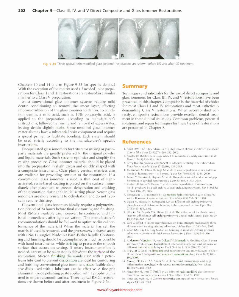
Fig. 9-34 Three typical resin-modified glass ionomer restorations are shown before (A) and after (8) treatment.
Chapters 10 and 14 and to Figure 9-33 for specific details.) With the exception of the matrix used (if needed), slot preparations for Class II and Ill restorations are restored in a similar manner to a Class V preparation.
Most conventional glass ionomer systems require mild dentin conditioning to remove the smear layer, effecting improved adhesion of the glass ionomer to dentin. To condition dentin, a mild acid, such as 10% polyacrylic acid, is applied to the preparation, according to manufacturer's instructions, followed by rinsing and removal of excess water, leaving dentin slightly moist. Some modified glass ionomer materials may have a substantial resin component and require a special primer to facilitate bonding. Each system should be used strictly according to the manufacturer's specific instructions.
Encapsulated glass ionomers for triturator mixing or pastepaste materials are greatly preferred to the original powder and liquid materials. Such systems optimize and simplify the mixing procedure. Glass ionomer material should be placed into the preparation in slight excess and quickly shaped with a composite instrument. Clear plastic cervical matrices also are available for providing contour to the restoration. If a conventional glass ionomer is used, a thin coat of lightactivated, resin-based coating is placed on the surface immediately after placement to prevent dehydration and cracking of the restoration during the initial setting phase. Newer glass ionomers are more resistant to dehydration and do not typically require this step.
Conventional glass ionomers ideally require a polymerization period of 24 hours before final contouring and finishing. Most RMG!s available can, however, be contoured and finished immediately after light activation. (The manufacturer's recommendations should be followed to optimize clinical performance of the material.) When the material has set, the matrix, if used, is removed, and the gross excess is shaved away with a No. 12 surgical blade in a Bard-Parker handle. Contouring and finishing should be accomplished as much as possible with hand instruments, while striving to preserve the smooth surface that occurs on setting. If rotary instrumentation is needed, care must be taken not to dehydrate the surface of the restoration. Micron finishing diamonds used with a petroleum lubricant to prevent desiccation are ideal for contouring and finishing conventional glass ionomers. Also, flexible abrasive disks used with a lubricant can be effective. A fine-grit aluminum oxide polishing paste applied with a prophy cup is used to impart a smooth surface. T hree typical RMGI restorations are shown before and after treatment in Figure 9-34.
Summary
Techniques and rationales for the use of direct composite and glass ionomers for Class III, IV, and V restorations have been presented in this chapter. Composite is the material of choice for most Class III and IV restorations and most esthetically demanding Class V restorations. When accomplished correctly, composite restorations provide excellent dental treatment in these clinical situations. Common problems, potential solutions, and repair techniques for these types of restorations are presented in Chapter 8.
References
I. Small BW: The rubber dam-a first step toward clinical excellence. Compe111/
Colli ill Edllc Delli 23(3):276-280, 282,2002.
2. Smales R): Rubber dam usage related to restoration quality and survival. Br
Delli J 174(9):330-333, 1993.
3. Terry DA: An essential component to adhesive dentistry: The rubber dam. Pmct Prowl Aesthct Delli 17(2): 106, 108, 2005.
4. Hashimoto M, Ohno H, Kaga M, et al: In vivo degradation of resin-dentin
bonds in humans over I to 3 years. f Delli Res 79(6):1385-1391, 2000.
5. lwami Y, Shimizu A, Hayashi M, et al: Three-dimensional evaluation of gap
formation of cervical restorations. f Delli 33(4):325-333, 2005.
6. Koshiro K, Inoue S, Tanaka T, et al: In vivo degradation of resin-dentin bonds produced by a self-etch vs. a total-etch adhesive system. Ellr f Oral Sci 112(4):368-375, 2004.
7. Torstenson Bt Brannstrom M: Composite resin contraction gaps measured with a fluorescent resin technique. Dmt Miller 4(5):238-242, 1988.
8. Ogata M, Harada N, Yamaguchi S, et al: Effect of self-etching primer vs phosphoric acid etchant on bonding to bur-prepared dentin. Opcr Delli
27(5):447-454, 2002.
9. Oliveira SS, Pugach MK, Hilton )F, et al: The inlluence of the dentin smear layer on adhesion: A self-etching primer vs. a total-etch system. Dent Mater
19(8):758-767, 2003.
I 0. Tani C: Effect of smear la)'er thickness on bond strength mediated by three
all-in-one self etching priming adhesives . f Adhes Dent 16:340-346, 2003.
I I. Chan KM, Tay FR, King NM, et al: Bonding of mild self-etching primers/
adhesives to dentin with thick smear layers. Am f Dent 16(5):340-346,
2003.
12. Andersson-Wenckcrt IE, van Dijken )W, Horstedt P: Modified Cl.1ss II open sandwich restorations: Evalu ation of interfacial adaptation dnd intluence of different restorative techniques . Eur f Om/ Sci 110(3):270-275, 2002.
13. lksnault C , Attal )P: Simulated oral environment and microle,tk,tgc of CIJss II resin-based composite and sandwich restor,1tions. Am f Delli 16(3):186-
190,2003.
14. Murray P E, Hafez AA, Smith AJ. et al: Bacterial microlcakagc .tnd pulp inOammation associated with various restorative materials. Dew !vlater
18(6):470-478, 2002.
15. Nagaminc M, ltota T, Torii Y, et al: Effect of resin-modified glass ionomer cements on secondary caries . A111 J Dent 10(4):173-178, 1997.
16. Ritter AV, Swift EJ, )r. Current restorative concepts of pulp protection. E111iod
7iJpics 5 :41-48, 2003.
www.ShayanNemoodar.com
Chapter 9-Ciass Ill, IV, and V Direct Composite and Glass lonomer Restorations 253
17. Goracci G, Mori G: Scanning electron microscopic evaluation of resin-dentin and calcium hydroxide-dentin interface with resin composite restorations. Quintessence lnt 27(2): 129-135, 1996.
18. Reinhardt JW, Stephens NH, Fortin D: Effect of Gluma desensitization on dentin bond strength. A111 I Dent 8(4): 170-172, 1995.
19. Ritter AV, Bertoli C, Swift E), )r: Dentin bond strengths as a function of solvent and glutaraldehyde content. Alii I Dwt 14(4):221-226, 200 I.
20. Ritter AV, Swift E), jr, Yamauchi M: Effects of phosphoric acid and glutaraldehyde-HEMA on dentin collagen. Eur f Oral Sci 109(5):348-353,
2001.
21. SchUpbach P, Lutz F, Finger Wj: Closing of dentinal tubules by GLUM A desensitizer. Eur I Oral Sci 105:414-421, 1997.
22. Dietschi D: Free-hand bonding in the esthetic treatment of anterior teeth: Creating the illusion./ Esthet Dent 9(4): 156-164, 1997.
23. Ritter AV, Heymann HO, Swift E), )r, et al: Clinical evaluation of an ali-in-one adhesive in non-carious cervical lesions with different degrees of dentin sclerosis. Oper Dent 33(4):370-378, 2008.
24. Tay FR, Pashley DH: Resin bonding to cervical sclerotic dentin: A review. I Dwt 32(3):173-196, 2004.
25. Yoshiyama M, Sano H, Ebisu S, et al: Regional strengths of bonding agents to cervical sclerotic root dentin./ Dent nes 75(6):1404-1413, 1996.
26. Mount G): Adhesion of glass-ionomer cement in the clinical environment. Oper Den/16(4):141-148, 1991.
27. Swift E), jr: Effects of glass ionomers on recurrent caries. Oper Dettt 14(1):40-43, 1989.
28. Markovic D, Petrovic BB, Peric TO: Fluoride content and recharge ability of five glassionomer dental materials. BMC Oral Health 8:21, 2008.
www.ShayanNemoodar.com
Chapter 1 Q
Class I, II, and VI Direct Composite Restorations and Other Tooth -Colored Restorations Andre V. Ritter, Ricardo Walter, Theodore M. Roberson
Class I, II, and VI Direct Composite Restorations
Posterior composite restorations were introduced in the late 1960s and early 1970s.1·7 Because of the improved physical properties of composites and bonding systems, studies typically report successful results for their use in posterior teeth.8.15 The American Dental Association (ADA) indicates the appropriateness of composites for use as pit-and-fissure sealants, preventive resin restorations, and Class I and II restorations for initial and moderate-sized lesions, using modified conservative tooth preparations.16 The ADA further states that "when used correctly in the primary and permanent dentition, the expected lifetime of resin-based composites can be comparable to that of amalgam in Class I, Class II, and Class V restorations."17 The longevity of posterior composites, however, is directly related to factors such as the size of the restoration, the patient's caries risk, and operator technique.15'18.23
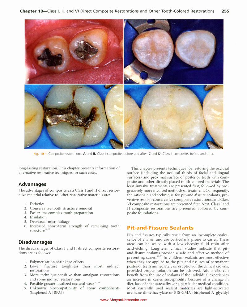
This chapter presents information about typical Class I, II, and VI direct composite restorations (Fig. 10-1), also known as posterior composite restorations. The chapter also presents information and techniques for pit-and-fissure sealants, preventive resin or conservative composite restorations, extensive Class I I restorations, and foundations.
Pertinent Material Qualities and Properties As presented in Chapter 8, composite is a material that has sufficient strength for Class I and II restorations. It is insulative and, in most cases, does not require pulpal protection with bases. Because composite is bonded to enamel and dentin, tooth preparations for composite can be very conservative. A composite restoration not only is retained well in the tooth, but also can strengthen the remaining unprepared tooth
254
structure.24•25 Class I and II composite restorations also have all the other benefits of bonding presented in Chapters 4 and 8.
Indications Class I, II, and VI direct composite restorations are indicated for the restoration of primary caries lesions in the occlusal (Class I and VI) and proximal (Class ll) surfaces of posterior teeth. When used in posterior teeth, direct composite will perform best in small- and moderate-sized restorations, preferably with enamel margins. Because composites are tooth-colored, these restorations are particularly indicated when esthetics is considered to be of primary importance. They also are indicated occasionally as large restorations that may serve as foundations for crowns. Additionally, in selected cases, large composite restorations may be used where an interim restoration is indicated or where economics or other factors preclude a more definitive restoration such as a crown.
Contraindications The main contraindication for use of composite for Class I, l l, and VI restorations is an operating area that cannot be adequately isolated. Class land II composites also may be contraindicated for large restorations when heavy occlusal stresses are present.261 n restorations in which the proximal box extends onto the root surface, posterior composites should only be used if absolutely required because of the difficulty in predictably bonding to the gingival wall absent an enamel margin. Extended (deep) gingival margins also can be more difficult to light-activate owing to their location. Whenever a defect extends onto the root surface, negative effects for the restoration may occur, no matter what restorative material is being used. Any extension onto the root surface requires the best and most meticulous efforts of the operator to ensure a successful,
www.ShayanNemoodar.com
Chapter 10-Ciass I, II, and VI Direct Composite Restorations and Other Tooth-Colored Restorations 255
Fig. 10-1 Composite restorations. A and B, Class I composite, before and after. C and D, Class II composite, before and after.
long-lasting restoration. This chapter presents information of alternative restorative techniques for such cases.
Advantages The advantages of composite as a Class I and II direct restorative material relative to other restorative materials are:
1. Esthetics 2. Conservative tooth structure removal 3. Easier, less complex tooth preparation 4. Insulation 5. Decreased microleakage 6. Increased short-term strength of remaining tooth
structure24'27
Disadvantages The disadvantages of Class I and II direct composite restorations are as follows:
I. Polymerization shrinkage effects 2. Lower fracture toughness than most indirect
restorations 3. More technique-sensitive than amalgam restorations
and some indirect restorations 4. Possible greater localized occlusal wear28.30 5. Unknown biocompatibility of some components
(bisphenol A [BPA])
This chapter presents techniques for restoring the occlusal surface (including the occlusal thirds of facial and lingual surfaces) and proximal surface of posterior teeth with composite and other directly placed tooth-colored materials. The least invasive treatments are presented first, followed by progressively more involved methods of treatment. Consequently, the rationale and technique for pit-and-fissure sealants, preventive resin or conservative composite restorations, and Class VI composite restorations are presented first. Next, Class I and II composite restorations are presented, followed by composite foundations.
Pit-and-Fissure Sealants
Pits and fissures typically result from an incomplete coalescence of enamel and are particularly prone to caries. These areas can be sealed with a low-viscosity fluid resin after acid-etching. Long-term clinical studies indicate that pitand-fissure sealants provide a safe and effective method of preventing caries.31.33 In children, sealants are most effective when they are applied to the pits and fissures of permanent posterior teeth immediately on eruption of the clinical crowns, provided proper isolation can be achieved. Adults also can benefit from the use of sealants if the individual experiences an increase in caries susceptibility because of a change in diet, lack of adequate saliva, or a particular medical condition. Most currently used sealant materials are light-activated urethane dimethacrylate or BlS-GMA (bisphenol A-glycidyl
www.ShayanNemoodar.com

256 Chapter 10-Ciass I, II, and VI Direct Composite Restorations and Other Tooth-Colored Restorations
methacrylate) resins. Opaquers and tints frequently are added to sealants to produce color contrast to aid in visual assessment.
Indications Sealants are indicated, regardless of the patient's age, for either preventive or therapeutic uses, depending on the patient's caries risk, tooth morphology, or presence of incipient enamel caries.
In assessing the occlusal surfaces of posterior teeth as potential candidates for a sealant procedure, the primary decision is whether or not a cavitated lesion exists. This decision is based primarily on radiographic and clinical examinations, although other technologies for occlusal caries detection are available. Explorers must be used judiciously in the detection of caries, as a sharp explorer tine may cause a cavitation. The clinical examination should be primarily focused on visual assessments of a clean tooth surface, preferably under adequate light and magnification. If the examination reveals chalkiness or softening of the tooth structure at the base or walls of the pit or groove, brown-gray discoloration radiating peripherally from the pit or groove, or radiolucency beneath the enamel surface on the radiograph, it is likely that an active caries lesion is present and a sealant may not be indicated. The patient's caries risk also should be considered when considering treatment options. See Chapter 3 for a discussion of emerging technologies for occlusal caries detection and monitoring, including laser fluorescence and alternative current (AC) impedance spectroscopy.
When no cavitated caries lesion is diagnosed, the treatment decision is either to pursue no treatment or to place a pit-andfissure sealant, particularly if the surface is at high risk for future caries. If a small caries lesion is detected, and the adjacent grooves and pits, although sound at the present time, are at risk for caries in the future, a preventive resin restoration or conservative composite restoration (which combines a small Class l composite with a sealant) may be the treatment recommendation. Before any of these treatments are initiated, the operator must be certain that no interproximal (Class Jl) caries or fault exists.
Although studies show that sealants can be applied over small, cavitated lesions, with no subsequent progression of caries, sealants should be used primarily for the prevention of caries rather than for the treatment of existing caries lesions. 34·35
A bitewing radiograph should be obtained and evaluated before sealant placement to ensure that no dentinal or proximal caries is evident. Only caries-free pits and fissures or incipient lesions in enamel not extending to the dentinoenamel junction (DEJ) currently are recommended for treatment with pit-and-fissure sealants.36
Clinical Technique Because materials and techniques vary, lt IS important to follow the manufacturer's instructions for the sealant material being used. A standard method for applying sealants to posterior teeth is presented here. Each quadrant is treated separately and may involve one or more teeth. The following discussion deals with a fissure present on a mandibular first permanent molar (Fig. 10-2, A). The tooth is isolated by using a rubber dam (or another effective isolation method such as
cotton rolls or Isolite). Isolation of the area is crucial to the success of the sealant. Sealant placement in younger patients is more common, and since molar teeth are often not fully erupted in these patients, isolation can be difficult. If proper isolation cannot be obtained, the bond of the sealant material to the tooth surface can be compromised, resulting in either loss of the sealant or caries under the sealant. The area is cleaned with a slurry of pumice on a bristle brush (see Fig. 10-2, B). Bristles reach into faulty areas better than a rubber prophy cup can, which tends to burnish debris and pumice into the pits and fissures. The tooth is rinsed thoroughly, while the explorer tip is used carefully to remove residual pumice or additional debris. The tooth surface is dried, and etched with 35% to 40% phosphoric acid for 15 to 30 seconds. Liquid acid etchants were used in the past, but gel etchants are more popular now because they are easier to apply and to control. However, only gels that are sufficiently fluid to penetrate the grooves and fissures should be used. Airborne particle abrasion techniques have been advocated for preparing pits and grooves before sealant placement, but their effectiveness has not been fully investigated yet.37
One technique that is used by many clinicians, especially in cases where occlusal caries could be present in deep grooves, is to lightly prepare the suspicious grooves with a thin flameshaped diamond to lightly roughen the enamel, remove the fluoride-rich enamel that is more impervious to acid-etching, and open the grooves and fissures for better resin penetration. If caries is noted to extend toward the DE), the preparation is then approached as a preventive resin restoration (see the next section in this Chapter).
Properly acid-etched enamel surface has a lightly frosted appearance (see Fig. I0-2, C). Fluoride-rich, acid-resistant enamel may need to be etched for a longer time. Any brown stains that originally may have been in the pits and fissures still may be present and should be allowed to remain. The sealant material is then applied with an applicator or small hand instrument. The sealant is gently teased into place, to avoid entrapping air, and it should overfill slightly all pits and fissures, but it should not extend onto unetched surfaces. If too much sealant is applied, excess can be removed with a microbrush prior to light-activation. After light-activation and removal of the rubber dam, if used, the occlusion is evaluated by using articulating paper. If necessary, a round carbide finishing bur or white stone is used to remove any excess sealant. The surface usually does not require further polishing.
Preventive Resin and Conservative Composite Restorations
When restoring minimally carious pits and fissures on an unrestored tooth, an ultraconservative preparation design is recommended. This design allows for restoration of the lesion or defect with minimal removal of the tooth structure and often may be combined with the use of flowable composite or sealant to seal radiating non-carious fissures or pits that are at high risk for subsequent caries activity (Fig. 10-3). Originally referred to as a preventive resin restoration, this type of ultraconservative restoration is now termed conservative composite restoration at the University of North Carolina.3839 An accurate diagnosis is essential before restoring the occlusal surface of a posterior tooth. The crucial factor in this clinical assessment
www.ShayanNemoodar.com

Chapter 10-Ciass I, II, and VI Direct Composite Restorations and Other Tooth-Colored Restorations 257
Fig.10-2 Steps in application of pit-and-fissure sealant. A, After isolation and thorough cleaning of the occlusal surface to be sealed. B, After acid
etching, rinsing, and drying. C, With sealant applied.
is whether or not the suspicious pit or fissure has active caries that requires restorative intervention. Usually, a conservative composite restoration is the treatment of choice for the primary occlusal caries lesion as the tooth preparation can be minimally invasive.
Sometimes, if a definitive diagnosis of caries cannot be made, an exploratory preparation of the suspicious area is performed with a small bur or diamond (Fig. 10-4). This approach is particularly indicated in patients at high risk for caries. The objective of this procedure is to explore suspicious pits or grooves with a very small bur or diamond to determine the extent of the suspected fault. As the tooth preparation is deepened, an assessment is made in the suspicious areas to determine whether or not to continue the preparation toward the DEJ (see Fig. 10-4, C). If the suspicious fault is removed or found to be sound at a shallow preparation depth (minimal dentin caries), the conservative exploratory preparation and adjacent pits and fissures are etched with 35% to 40% phosphoric acid for 15 to 30 seconds, rinsed thoroughly, and lightly dried. The etched surfaces then are treated with an adhesive, which is placed and light-activated, according to manufacturer's instructions. The conservatively prepared area can then be
restored with a flowable composite, which is placed and lightactivated, according to manufacturer's instructions. The adjacent etched pits and fissures, if judged to be at risk, can then be sealed using a pit-and-fissure sealant or the same flowable composite following the technique described previously. If the suspicious area is found to be carious, the preparation depth is extended until all of the caries is removed, and the prepared area is then restored with composite as described later in this chapter (Class I direct composite restoration), and unprepared pits and fissures are sealed. In the example presented in Fig. 10-4, the preparation was restored with composite.
An example of a conservative composite restoration is illustrated in Figure 10-5, A. All initial examinations are inconclusive relative to a definitive diagnosis of active caries in this site. Figure 10-5, B through D, shows the initial, exploratory tooth preparation of the fissure. The initial depth is kept just into dentin where caries is present. Where caries is not present, the preparation stops on enamel. The occlusal extension is complete when a caries-free DEJ is reached. lf dentin at the pulpal floor is judged to be infected as evidenced by a soft feel or "stick" of the explorer, a larger round bur, No. 330 bur or diamond, or No. 245 bur or diamond is used to extend the
www.ShayanNemoodar.com
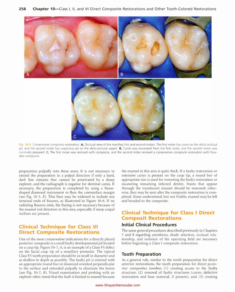
258 Chapter 10-Ciass I, II, and VI Direct Composite Restorations and Other Tooth-Colored Restorations
Fig 10-3 Conservative composite restoration. A, Occlusal view of the maxillary first and second molars. The first molar has caries on the distal occlusal
pit, and the second molar has suspicious pit on the disto-occlusal aspect. B, Caries was excavated from the first molar, and the second molar was
minimally prepared. C, The first molar was restored with composite, and the second molar received a conservative composite restoration with flow
able composite.
preparation pulpally into these areas. It is not necessary to extend the preparation in a pulpal direction if only a hard, dark line remains that cannot be penetrated by a sharp explorer, and the radiograph is negative for dentinal caries. If necessary, the preparation is completed by using a flameshaped diamond instrument to flare the cavosurface margin (see Fig. 10-5, E). This flare may be widened to include any terminal ends of fissures, as illustrated in Figure 10-6. If no radiating fissures exist, the flaring is not necessary because of the enamel rod direction in this area, especially if steep cuspal inclines are present.
Clinical Technique for Class VI
Direct Composite Restorations
One of the most conservative indications for a directly placed posterior composite is a small faulty developmental pit located on a cusp tip. Figure I 0-7, A, is an exam pie of a Class VI defect on the facial cusp tip of a maxillary premolar. The typical Class VI tooth preparation should be as small in diameter and as shallow in depth as possible. The faulty pit is entered with an appropriate round bur or diamond oriented perpendicular to the surface and extended pulpally to eliminate the lesion (see Fig. 10-7, B). Visual examination and probing with an explorer often reveal that the fault is limited to enamel because
the enamel in this area is quite thick. If a faulty restoration or extensive caries is present on the cusp tip, a round bur of appropriate size is used for removing the faulty restoration or excavating remaining infected dentin. Stains that appear through the translucent enamel should be removed; otherwise, they may be seen after the composite restoration is completed. Some undermined, but not friable, enamel may be left and bonded to the composite.
Clinical Technique for Class I Direct Composit Restorations
Initial Clinical Procedures The same general procedures described previously in Chapters 7 and 8 regarding anesthesia, shade selection, occlusal relationship, and isolation of the operating field are necessary before beginning a Class I composite restoration.
Tooth Preparation As a general rule, similar to the tooth preparation for direct anterior restorations, the tooth preparation for direct posterior composites involves (l) creating access to the faulty structure, (2) removal of faulty structures (caries, defective restoration and base material, if present), and (3) creating
www.ShayanNemoodar.com
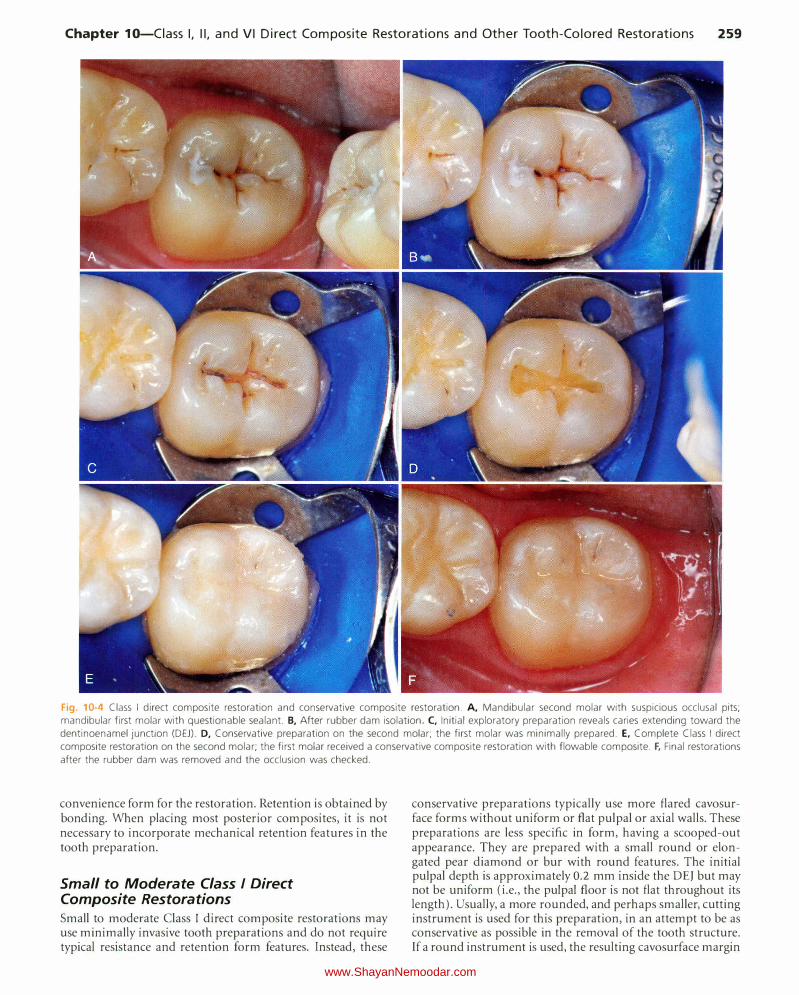
Chapter 10-Ciass I, II, and VI Direct Composite Restorations and Other Tooth-Colored Restorations 259
Fig. 10-4 Class I direct composite restoration and conservative composite restoration. A, Mandibular second molar with suspicious occlusal pits; mandibular first molar with questionable sealant. B, After rubber dam isolation. C, Initial exploratory preparation reveals caries extending toward the
dentinoenamel junction (DEJ). D, Conservative preparation on the second molar; the first molar was minimally prepared. E, Complete Class I direct
composite restoration on the second molar; the first molar received a conservative composite restoration with flowable composite. F, Final restorations
after the rubber dam was removed and the occlusion was checked.
convenience form for the restoration. Retention is obtained by bonding. When placing most posterior composites, it is not necessary to incorporate mechanical retention features in the tooth preparation.
Small to Moderate Class I Direct Composite Restorations
Small to moderate Class I direct composite restorations may use minimally invasive tooth preparations and do not require typical resistance and retention form features. Instead, these
conservative preparations typically use more flared cavosurface forms without uniform or flat pulpal or axial walls. These preparations are less specific in form, having a scooped-out appearance. They are prepared with a small round or elongated pear diamond or bur with round features. The initial pulpal depth is approximately 0.2 mm inside the DEJ but may not be uniform (i.e., the pulpal floor is not flat throughout its length). Usually, a more rounded, and perhaps smaller, cutting instrument is used for this preparation, in an attempt to be as conservative as possible in the removal of the tooth structure. If a round instrument is used, the resulting cavosurface margin
www.ShayanNemoodar.com
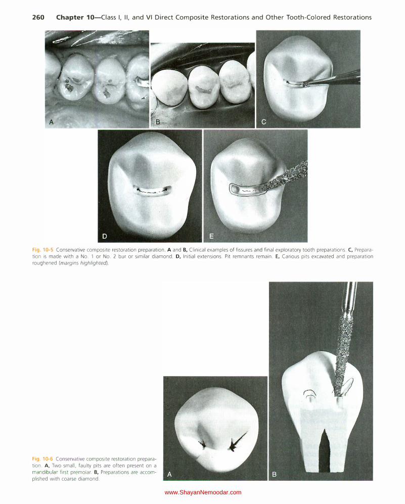
260 Chapter 10-Ciass I, II, and VI Direct Composite Restorations and Other Tooth-Colored Restorations
'----·
Fig. 10-5 Conservative composite restoration preparation. A and B, Clinical examples of fissures and final exploratory tooth preparations. C, Preparation is made with a No. 1 or No. 2 bur or similar diamond. D, Initial extensions. Pit remnants remain. E, Carious pits excavated and preparation roughened (margins highlighted).
Fig 10-6 Conservative composite restoration prepara
tion. A, Two small, faulty pits are often present on a mandibular first premolar. B, Preparations are accom
plished with coarse diamond.
www.ShayanNemoodar.com
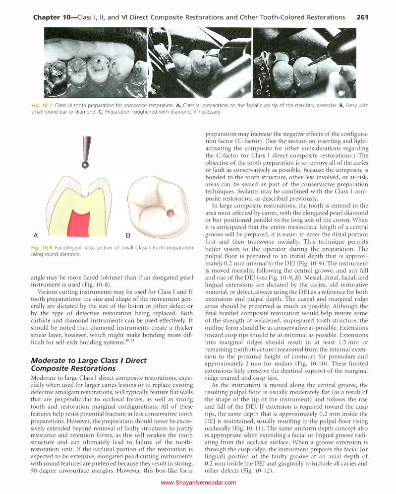
Chapter 10-Ciass I, II, and VI Direct Composite Restorations and Other Tooth-Colored Restorations 261
Fig. 10-7 Class VI tooth preparation for composite restoration. A, Class VI preparation on the facial cusp tip of the maxillary premolar. B, Entry with
small round bur or diamond. C, Preparation roughened with diamond, if necessary.
A B
Fig. 10-8 Faciolingual cross-section of small Class I tooth preparation
using round diamond.
angle may be more flared (obtuse) than if an elongated pearl instrument is used (Fig. 10-8).
Various cutting instruments may be used for Class I and If tooth preparations; the size and shape of the instrument generally are dictated by the size of the lesion or other defect or by the type of defective restoration being replaced. Both carbide and diamond instruments can be used effectively. It should be noted that diamond instruments create a thicker smear layer, however, which might make bonding more difficult for self-etch bonding systems.40-43
Moderate to Large Class I Direct Composite Restorations
Moderate to large Class I direct composite restorations, especially when used for larger caries lesions or to replace existing defective amalgam restorations, will typically feature flat walls that are perpendicular to occlusal forces, as well as strong tooth and restoration marginal configurations. All of these features help resist potential fracture in less conservative tooth preparations. However, the preparation should never be excessively extended beyond removal of faulty structures to justify resistance and retention forms, as this will weaken the tooth structure and can ultimately lead to failure of the toothrestoration unit. If the occlusal portion of the restoration is expected to be extensive, elongated pearl cutting instruments with round features are preferred because they result in strong, 90-degree cavosurface margins. However, this box-like form
preparation may increase the negative effects of the configuration factor (C-factor). (See the section on inserting and lightactivating the composite for other considerations regarding the C-factor for Class I direct composite restorations.) The objective of the tooth preparation is to remove all of the caries or fault as conservatively as possible. Because the composite is bonded to the tooth structure, other less involved, or at-risk, areas can be sealed as part of the conservative preparation techniques. Sealants may be combined with the Class I composite restoration, as described previously.
In large composite restorations, the tooth is entered in the area most affected by caries, with the elongated pearl diamond or bur positioned parallel to the long axis of the crown. When it is anticipated that the entire mesiodistal length of a central groove will be prepared, it is easier to enter the distal portion first and then transverse mesially. This technique permits better vision to the operator during the preparation. The pulpal floor is prepared to an initial depth that is approximately 0.2 mm internal to the DEJ (Fig. 10-9). The instrument is moved mesially, following the central groove, and any fall and rise of the DEJ (see Fig. 10-9, B). Mesial, distal, facial, and lingual extensions are dictated by the caries, old restorative material, or defect, always using the DEJ as a reference for both extensions and pulpal depth. The cuspal and marginal ridge areas should be preserved as much as possible. Although the final bonded composite restoration would help restore some of the strength of weakened, unprepared tooth structure, the outline form should be as conservative as possible. Extensions toward cusp tips should be as minimal as possible. Extensions into marginal ridges should result in at least 1.5 mm of remaining tooth structure (measured from the internal extension to the proximal height of contour) for premolars and approximately 2 mm for molars (Fig. 10-10). These limited extensions help preserve the dentinal support of the marginal ridge enamel and cusp tips.
As the instrument is moved along the central groove, the resulting pulpal floor is usually moderately flat (as a result of the shape of the tip of the instrument) and follows the rise and fall of the DEJ. If extension is required toward the cusp tips, the same depth that is approximately 0.2 mm inside the DEJ is maintained, usually resulting in the pulpal floor rising occlusally (Fig. 10-ll ). The same uniform deptl1 concept also is appropriate when extending a facial or lingual groove radiating from the occlusal surface. When a groove extension is through the cusp ridge, the instrument prepares the facial (or lingual) portion of the faulty groove at an axial depth of 0.2 mm inside the DEJ and gingivally to include all caries and other defects (Fig. I 0-12).
www.ShayanNemoodar.com
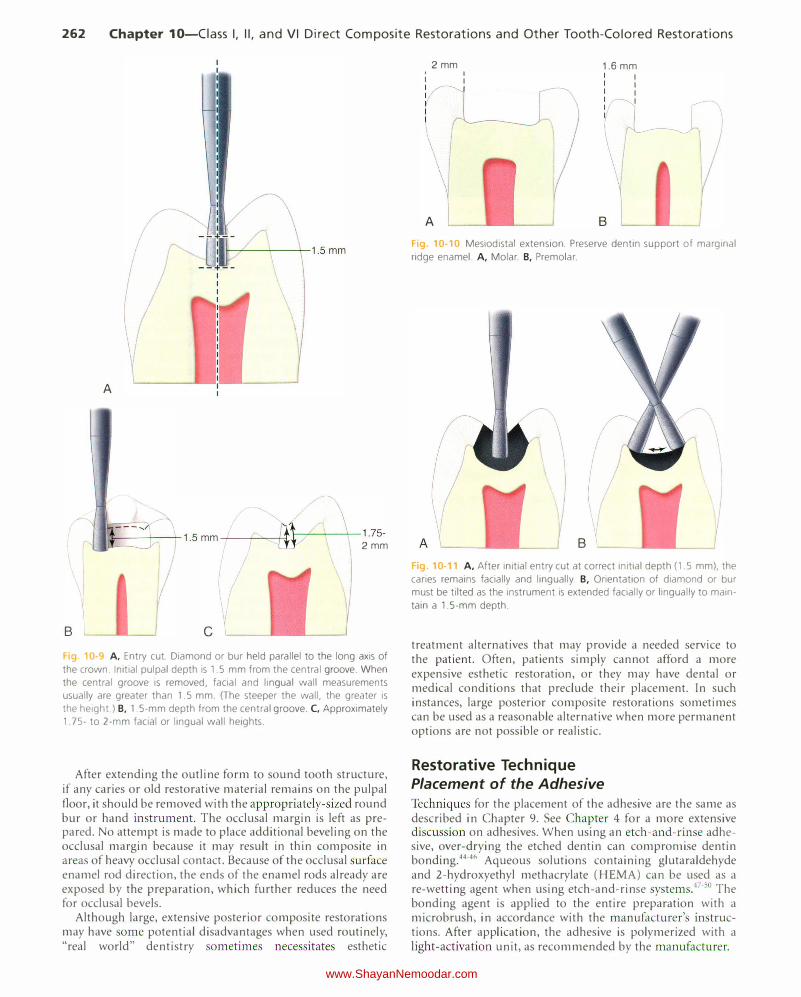
262 Chapter 10-Ciass I, II, and VI Direct Composite Restorations and Other Tooth-Colored Restorations
B
/�
I
A
., J,_ ___ --"'-_ 1.5 mm __ .;..__rAI-___ \_,___1.75-11! 2mm
c Fig 10-9 A, Entry cut. Diamond or bur held parallel to the long axis of
the crown. Initial pulpal depth is 1.5 mm from the central groove. When
the central groove is removed, facial and lingual wall measurements
usually are greater than 1.5 mm. (The steeper the wall, the greater is
the height.) B, 1.5-mm depth from the central groove. C, Approximately
1.75- to 2-mm facial or lingual wall heights.
After extending the outline form to sound tooth structure, if any caries or old restorative material remains on the pulpal floor, it should be removed with the appropriately-sized round bur or hand instrument. The occlusal margin is left as prepared. No attempt is made to place additional beveling on the occlusal margin because it may result in thin composite in areas of heavy occlusal contact. Because of the occlusal surface enamel rod direction, the ends of the enamel rods already are exposed by the preparation, which further reduces the need for occlusal bevels.
Although large, extensive posterior composite restorations may have some potential disadvantages when used routinely, "real world" dentistry sometimes necessitates esthetic
2mm '
I
vI
A
I
I
r---r 1.6 mm
Fig. 10·10 Mesiodistal extension. Preserve dentin support of marginal
ridge enamel. A, Molar. B, Premolar.
B g. 10-11 A, After initial entry cut at correct initial depth (1.5 mm), the
caries remains facially and lingually. B, Orientation of diamond or bur
must be tilted as the instrument is extended facially or lingually to main
tain a 1.5-mm depth.
treatment alternatives that may provide a needed service to the patient. Often, patients simply cannot afford a more expensive esthetic restoration, or they may have dental or medical conditions that preclude their placement. In such instances, large posterior composite restorations sometimes can be used as a reasonable alternative when more permanent options are not possible or realistic.
Restorative Technique Placement of the Adhesive Techniques for the placement of the adhesive are the same as described in Chapter 9. See Chapter 4 for a more extensive discussion on adhesives. When using an etch-and-rinse adhesive, over-drying the etched dentin can compromise dentin bonding.44•46 Aqueous solutions containing glutaraldehyde and 2-hydroxyethyl methacrylate (HEMA) can be used as a re-wetting agent when using etch-and-rinse systems.4 7 . 50 The bonding agent is applied to the entire preparation with a microbrush, in accordance with the manufacturer's instructions. After application, the adhesive is polymerized with a light-activation unit, as recommended by the manufacturer.
www.ShayanNemoodar.com
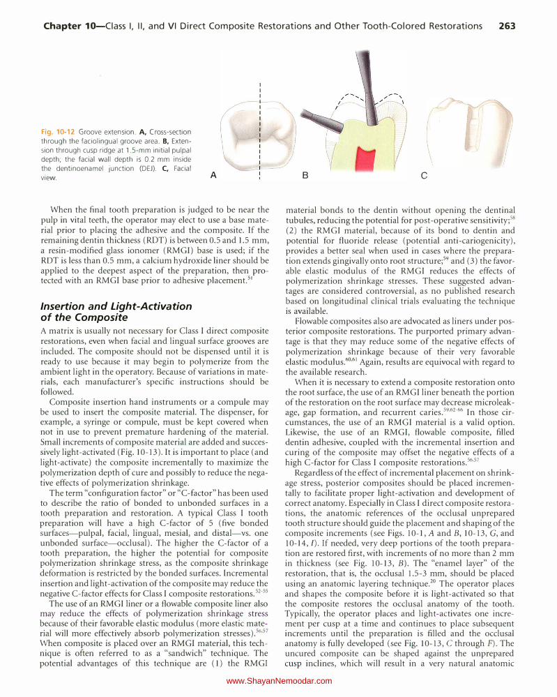
Chapter 10-Ciass I, II, and VI Direct Composite Restorations and Other Tooth-Colored Restorations 263
Fig. 10-12 Groove extension. A, Cross-section
through the faciolingual groove area. B, Exten
sion through cusp ridge at 1.5-mm initial pulpal
depth; the facial wall depth is 0.2 mm inside
the dentinoenamel junction (DEJ). C, Facial
view. A
When the final tooth preparation is judged to be near the pulp in vital teeth, the operator may elect to use a base material prior to placing the adhesive and the composite. If the remaining dentin thickness (ROT) is between 0.5 and 1.5 mm, a resin-modified glass ionomer (RMGI) base is used; if the ROT is less than 0.5 mm, a calcium hydroxide liner should be applied to the deepest aspect of the preparation, then protected with an RMGI base prior to adhesive placement.51
Insertion and Light-Activation of the Composite A matrix is usually not necessary for Class I direct composite restorations, even when facial and lingual surface grooves are included. The composite should not be dispensed until it is ready to use because it may begin to polymerize from the ambient light in the opera tory. Because of variations in materials, each manufacturer's specific instructions should be followed.
Composite insertion hand instruments or a compule may be used to insert the composite material. The dispenser, for example, a syringe or compule, must be kept covered when not in use to prevent premature hardening of the material. Small increments of composite material are added and successively light-activated (Fig. 10-13).It is important to place (and light-activate) the composite incrementally to maximize the polymerization depth of cure and possibly to reduce the negative effects of polymerization shrinkage.
The term "configuration factor" or "C-factor" has been used to describe the ratio of bonded to unbonded surfaces in a tooth preparation and restoration. A typical Class I tooth preparation will have a high C-factor of 5 (five bonded surfaces-pulpal, facial, lingual, mesial, and distal-vs. one unbonded surface-occlusal). The higher the C-factor of a tooth preparation, the higher the potential for composite polymerization shrinkage stress, as the composite shrinkage deformation is restricted by the bonded surfaces. incremental insertion and light-activation of the composite may reduce the negative C-factor effects for Class I composite restorations. 52-55
The use of an RMGI liner or a flowable composite liner also may reduce the effects of polymerization shrinkage stress because of their favorable elastic modulus (more elastic material will more effectively absorb polymerization stresses).56'57 When composite is placed over an RMGI material, this technique is often referred to as a "sandwich" technique. The potential advantages of this technique are (1) the RMGI
B c
material bonds to the dentin without opening the dentinal tubules, reducing the potential for post-operative sensitivity;58 (2) the RMGI material, because of its bond to dentin and potential for fluoride release (potential anti-cariogenicity), provides a better seal when used in cases where the preparation extends gingivally onto root structure;59 and (3) the favorable elastic modulus of the RMGI reduces the effects of polymerization shrinkage stresses. These suggested advantages are considered controversial, as no published research based on longitudinal clinical trials evaluating the technique is available.
Plowable composites also are advocated as liners under posterior composite restorations. The purported primary advantage is that they may reduce some of the negative effects of polymerization shrinkage because of their very favorable elastic modulus.60'61 Again, results are equivocal with regard to the available research.
When it is necessary to extend a composite restoration onto the root surface, the use of an RMGI liner beneath the portion of the restoration on the root surface may decrease micro leakage, gap formation, and recurrent caries.59'62-66 In those circumstances, the use of an RMGI material is a valid option. Likewise, the use of an RMGI, flowable composite, filled dentin adhesive, coupled with the incremental insertion and curing of the composite may offset the negative effects of a high C-factor for Class I composite restorations.56'57
Regardless of the effect of incremental placement on shrinkage stress, posterior composites should be placed incrementally to facilitate proper light-activation and development of correct anatomy. Especially in Class I direct composite restorations, the anatomic references of the occlusal unprepared tooth structure should guide the placement and shaping of the composite increments (see Figs. 10-1, A and B, 10-13, G, and 10-14, I). If needed, very deep portions of the tooth preparation are restored first, with increments of no more than 2 mm in thickness (see Fig. 10-13, B). The "enamel layer" of the restoration, that is, the occlusal 1.5-3 mm, should be placed using an anatomic layering technique.20 The operator places and shapes the composite before it is light-activated so that the composite restores the occlusal anatomy of the tooth. Typically, the operator places and light-activates one increment per cusp at a time and continues to place subsequent increments until the preparation is filled and the occlusal anatomy is fully developed (see Fig. 10-13, C through F). The uncured composite can be shaped against the unprepared cusp inclines, which will result in a very natural anatomic
www.ShayanNemoodar.com
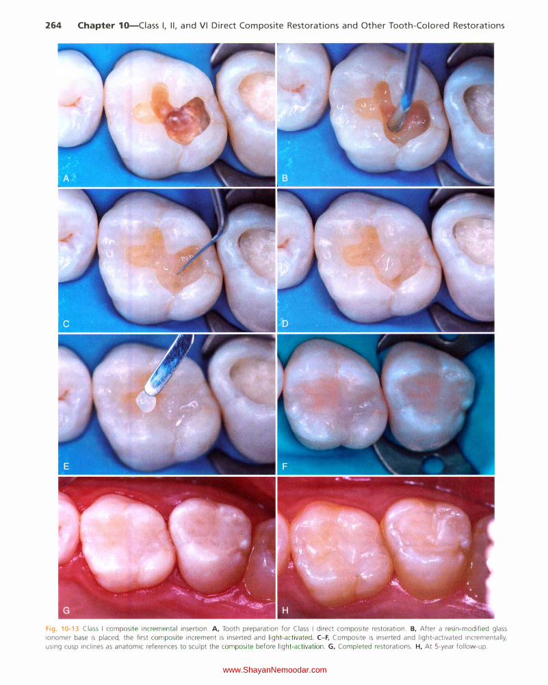
264 Chapter 10-Ciass I, II, and VI Direct Composite Restorations and Other Tooth-Colored Restorations
Fig. 10-13 Class I composite incremental insertion. A, Tooth preparation for Class I direct composite restoration. B, After a resin-modified glass
ionomer base is placed, the first composite increment is inserted and light-activated . C-F, Composite is inserted and light-activated incrementally,
using cusp inclines as anatomic references to sculpt the composite before light-activation . G, Completed restorations. H, At 5-year follow-up.
www.ShayanNemoodar.com
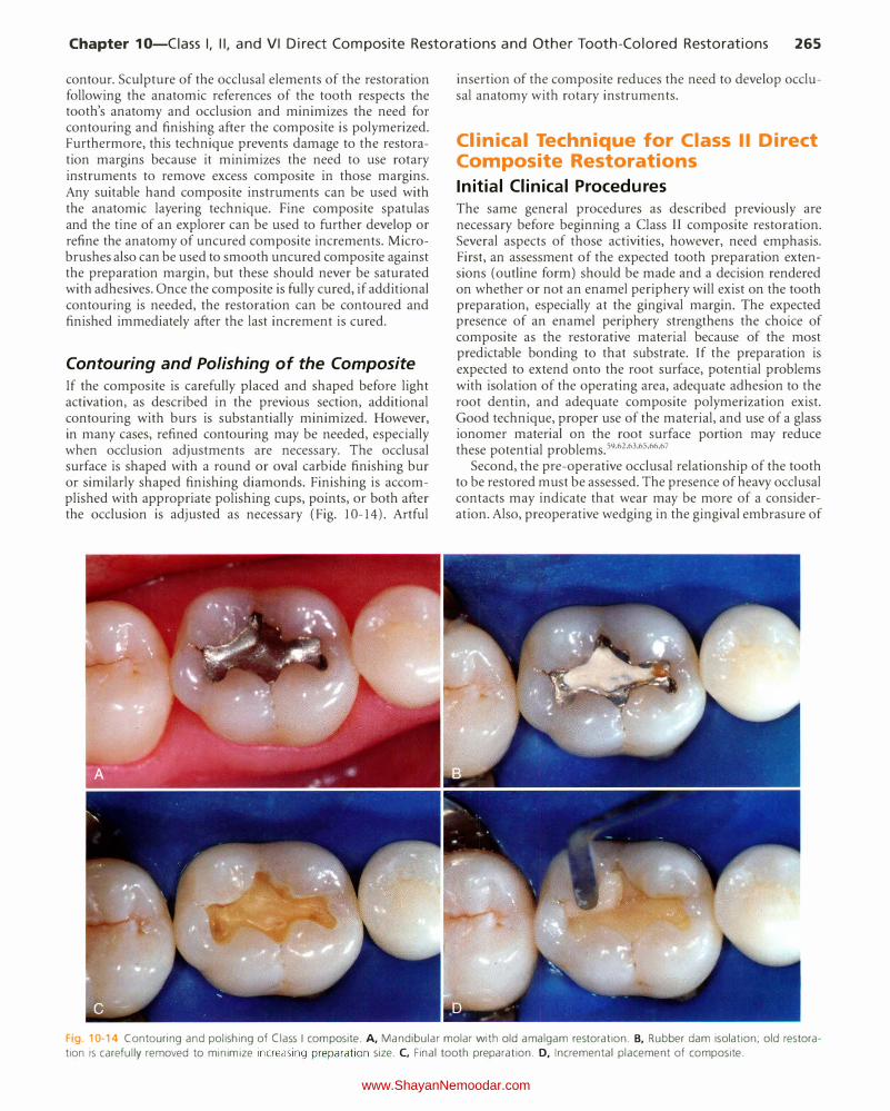
Chapter 10-Ciass I, II, and VI Direct Composite Restorations and Other Tooth-Colored Restorations 265
contour. Sculpture of the occlusal elements of the restoration following the anatomic references of the tooth respects the tooth's anatomy and occlusion and minimizes the need for contouring and finishing after the composite is polymerized. Furthermore, this technique prevents damage to the restoration margins because it minimizes the need to use rotary instruments to remove excess composite in those margins. Any suitable hand composite instruments can be used with the anatomic layering technique. Fine composite spatulas and the tine of an explorer can be used to further develop or refine the anatomy of uncured composite increments. Microbrushes also can be used to smooth uncured composite against the preparation margin, but these should never be saturated with adhesives. Once the composite is fully cured, if additional contouring is needed, the restoration can be contoured and finished immediately after the last increment is cured.
Contouring and Polishing of the Composite If the composite is carefully placed and shaped before light activation, as described in the previous section, additional contouring with burs is substantially minimized. However, in many cases, refined contouring may be needed, especially when occlusion adjustments are necessary. The occlusal surface is shaped with a round or oval carbide finishing bur or similarly shaped finishing diamonds. Finishing is accomplished with appropriate polishing cups, points, or both after the occlusion is adjusted as necessary (Fig. 10-14). Artful
insertion of the composite reduces the need to develop occlusal anatomy with rotary instruments.
Clinical Technique for Class II Direct Composite Restorations
Initial Clinical Procedures The same general procedures as described previously are necessary before beginning a Class II composite restoration. Several aspects of those activities, however, need emphasis. First, an assessment of the expected tooth preparation extensions (outline form) should be made and a decision rendered on whether or not an enamel periphery will exist on the tooth preparation, especially at the gingival margin. The expected presence of an enamel periphery strengthens the choice of composite as the restorative material because of the most predictable bonding to that substrate. If the preparation is expected to extend onto the root surface, potential problems with isolation of the operating area, adequate adhesion to the root dentin, and adequate composite polymerization exist. Good technique, proper use of the material, and use of a glass ionomer material on the root surface portion may reduce these potential problems. 59"62"63'65'66'67
Second, the pre-operative occlusal relationship of the tooth to be restored must be assessed. The presence of heavy occlusal contacts may indicate that wear may be more of a consideration. Also, preoperative wedging in the gingival embrasure of
Fig. 10-14 Contouring and polishing of Class I composite. A, Mandibular molar with old amalgam restoration. B, Rubber dam isolation; old restora
tion is carefully removed to minimize increasing preparation size. C, Final tooth preparation. D, Incremental placement of composite.
www.ShayanNemoodar.com
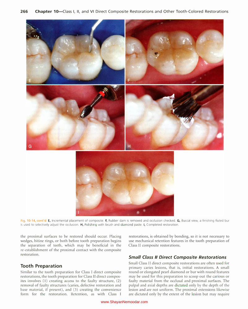
266 Chapter 10-Ciass I, II, and VI Direct Composite Restorations and Other Tooth-Colored Restorations
Fig. 10-14, cont'd E, Incremental placement of composite. F, Rubber dam is removed and occlusion checked. G, Buccal view, a finishing fluted bur
is used to selectively adjust the occlusion. H, Polishing with brush and diamond paste. I, Completed restoration.
the proximal surfaces to be restored should occur. Placing wedges, bitine rings, or both before tooth preparation begins the separation of teeth, which may be beneficial in the re-establishment of the proximal contact with the composite restoration.
Tooth Preparation Similar to the tooth preparation for Class I direct composite restorations, the tooth preparation for Class II direct composites involves (1) creating access to the faulty structure, (2) removal of faulty structures (caries, defective restoration and base material, if present), and (3) creating the convenience form for the restoration. Retention, as with Class I
restorations, is obtained by bonding, so it is not necessary to use mechanical retention features in the tooth preparation of Class II composite restorations.
Small Class II Direct Composite Restorations Small Class I I direct composite restorations are often used for primary caries lesions, that is, initial restorations. A small round or elongated pearl diamond or bur with round features may be used for this preparation to scoop out the carious or faulty material from the occlusal and proximal surfaces. The pulpal and axial depths are dictated only by the depth of the lesion and are not uniform. The proximal extensions likewise are dictated only by the extent of the lesion but may require
www.ShayanNemoodar.com
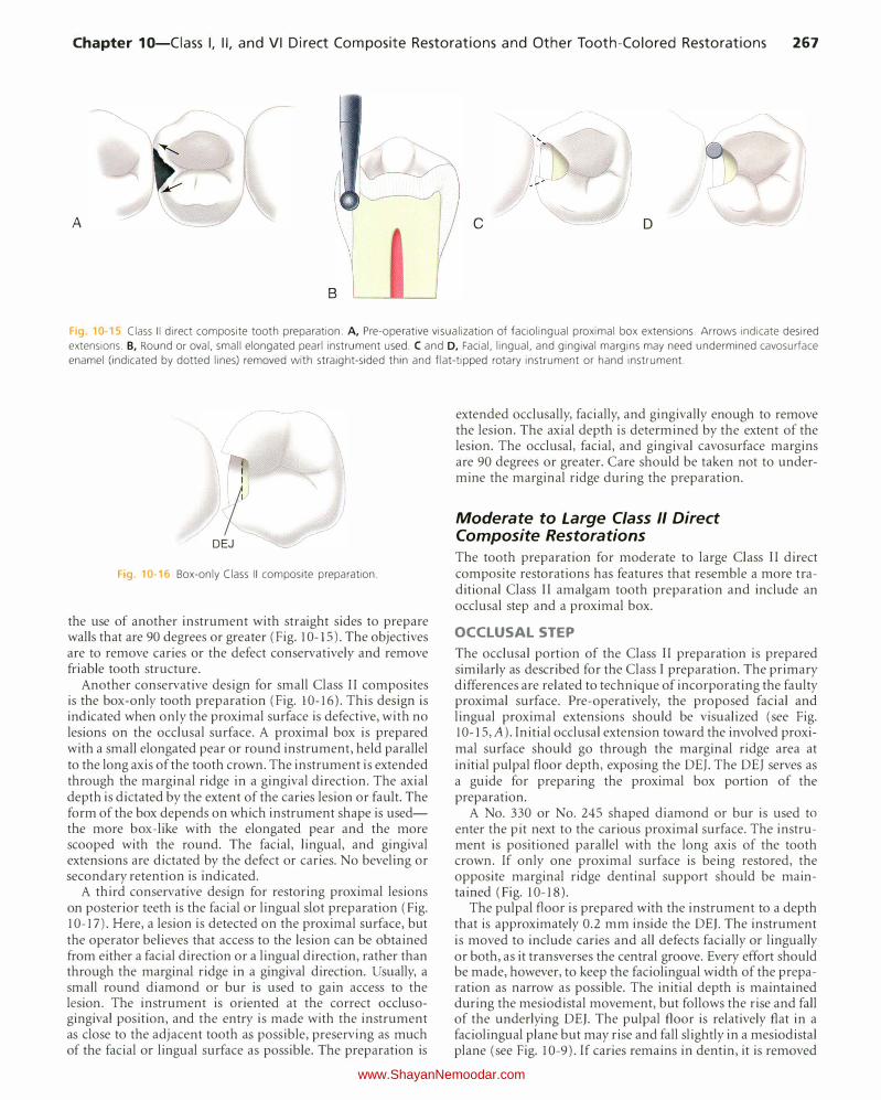
Chapter 10-Ciass I, II, and VI Direct Composite Restorations and Other Tooth-Colored Restorations 267
A c D
8
Fig. 10-15 Class II direct composite tooth preparation. A, Pre-operative visualization of faciolingual proximal box extensions. Arrows indicate desired
extensions. B, Round or oval, small elongated pearl instrument used. C and D, Facial, lingual, and gingival margins may need undermined cavosurface
enamel (indicated by dotted lines) removed with straight-sided thin and flat-tipped rotary instrument or hand instrument.
I
I DEJ
Fig. 10-16 Box-only Class II composite preparation.
the use of another instrument with straight sides to prepare walls that are 90 degrees or greater (Fig. 10-15). The objectives are to remove caries or the defect conservatively and remove friable tooth structure.
Another conservative design for small Class II composites is the box-only tooth preparation (Fig. 10-16). This design is indicated when only the proximal surface is defective, with no lesions on the occlusal surface. A proximal box is prepared with a small elongated pear or round instrument, held parallel to the long axis of the tooth crown. The instrument is extended through the marginal ridge in a gingival direction. The axial depth is dictated by the extent of the caries lesion or fault. The form of the box depends on which instrument shape is usedthe more box-like with the elongated pear and the more scooped with the round. The facial, lingual, and gingival extensions are dictated by the defect or caries. No beveling or secondary retention is indicated.
A third conservative design for restoring proximal lesions on posterior teeth is the facial or lingual slot preparation (Fig. 10-17). Here, a lesion is detected on the proximal surface, but the operator believes that access to the lesion can be obtained from either a facial direction or a lingual direction, rather than through the marginal ridge in a gingival direction. Usually, a small round diamond or bur is used to gain access to the lesion. The instrument is oriented at the correct occlusogingivaJ position, and the entry is made with the instrument as close to the adjacent tooth as possible, preserving as much of the facial or lingual surface as possible. The preparation is
extended occlusally, facially, and gingivally enough to remove the lesion. The axial depth is determined by the extent of the lesion. The occlusal, facial, and gingival cavosurface margins are 90 degrees or greater. Care should be taken not to undermine the marginal ridge during the preparation.
Moderate to Large Class II Direct Composite Restorations
The tooth preparation for moderate to large Class II direct composite restorations has features that resemble a more traditional Class II amalgam tooth preparation and include an occlusal step and a proximal box.
OCCLUSAL STEP
The occlusal portion of the Class II preparation is prepared similarly as described for the Class I preparation. The primary differences are related to technique of incorporating the faulty proximal surface. Pre-operatively, the proposed facial and lingual proximal extensions should be visualized (see Fig. 10-15, A). Initial occlusal extension toward the involved proximal surface should go through the marginal ridge area at initial pulpal floor depth, exposing the DEJ. The DEJ serves as a guide for preparing the proximal box portion of the preparation.
A No. 330 or No. 245 shaped diamond or bur is used to enter the pit next to the carious proximal surface. The instrument is positioned parallel with the long axis of the tooth crown. If only one proximal surface is being restored, the opposite marginal ridge dentinal support should be maintained (Fig. 10-18).
The pulpal floor is prepared with the instrument to a depth that is approximately 0.2 mm inside the DE}. The instrument is moved to include caries and all defects facially or lingually or both, as it transverses the central groove. Every effort should be made, however, to keep the faciolingual width of the preparation as narrow as possible. The initial depth is maintained during the mesiodistal movement, but follows the rise and fall of the underlying DE}. The pulpal floor is relatively flat in a faciolingual plane but may rise and fall slightly in a mesiodistal plane (see Fig. 10-9). If caries remains in dentin, it is removed
www.ShayanNemoodar.com
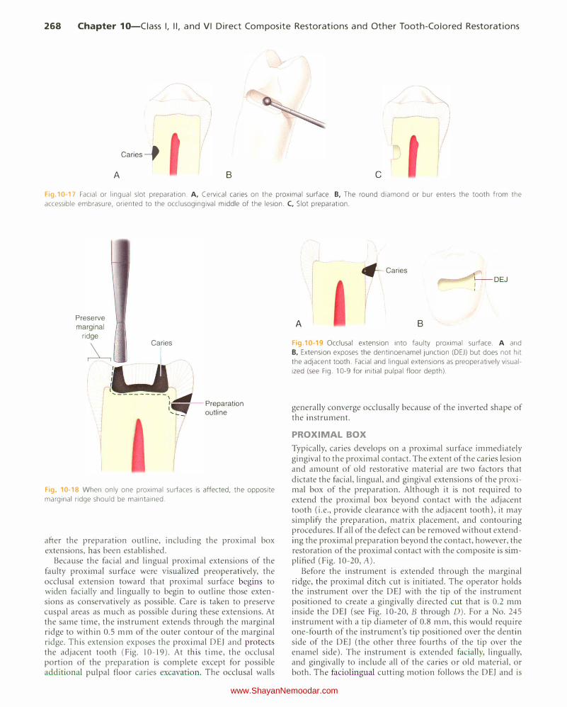
268 Chapter 10-Ciass I, II, and VI Direct Composite Restorations and Other Tooth-Colored Restorations
Caries_,
A B c
Fig.10-17 Facial or lingual slot preparation. A, Cervical caries on the proximal surface. B, The round diamond or bur enters the tooth from the
accessible embrasure, oriented to the occlusogingival middle of the lesion. C, Slot preparation.
Preserve marginal
ridge � Caries
:U '---------, � �- Preparation
'� outline
Fig 10-18 When only one proximal surfaces is affected, the opposite
marg1nal ridge should be maintained.
after the preparation outline, including the proximal box extensions, has been established.
Because the facial and lingual proximal extensions of the faulty proximal surface were visualized preoperatively, the occlusal extension toward that proximal surface begins to widen facially and lingually to begin to outline those extensions as conservatively as possible. Care is taken to preserve cuspal areas as much as possible during these extensions. At the same time, the instrument extends through the marginal ridge to within 0.5 mm of the outer contour of the marginal ridge. This extension exposes the proximal DEJ and protects the adjacent tooth (Fig. 1 0-19). At this time, the occlusal portion of the preparation is complete except for possible additional pulpal floor caries excavation. The occlusal walls
-- Caries
A B
Fig.10-19 Occlusal extension into faulty proximal surface. A and
B, Extension exposes the dentinoenamel junction (DEJ) but does not hit
the adjacent tooth. Facial and lingual extensions as preoperatively visual
ized (see Fig. 10-9 for initial pulpal floor depth).
generally converge occlusally because of the inverted shape of the instrument.
PROXIMAL BOX
Typically, caries develops on a proximal surface immediately gingival to the proximal contact. The extent of the caries lesion and amount of old restorative material are two factors that dictate the facial, lingual, and gingival extensions of the proximal box of the preparation. Although it is not required to extend the proximal box beyond contact with the adjacent tooth (i.e., provide clearance with the adjacent tooth), it may simplify the preparation, matrix placement, and contouring procedures. If all of the defect can be removed without extending the proximal preparation beyond the contact, however, the restoration of the proximal contact with the composite is simplified (Fig. 10-20, A).
Before the instrument is extended through the marginal ridge, the proximal ditch cut is initiated. The operator holds the instrument over the DEJ with the tip of the instrument positioned to create a gingivally directed cut that is 0.2 mm inside the DEJ (see Fig. 10-20, B through D). For a No. 245 instrument with a tip diameter of 0.8 mm, this would require one-fourth of the instrument's tip positioned over the dentin side of the DEJ (the other three fourths of the tip over the enamel side). The instrument is extended facially, lingually, and gingivally to include all of the caries or old material, or both. The faciolingual cutting motion follows the DEJ and is
www.ShayanNemoodar.com
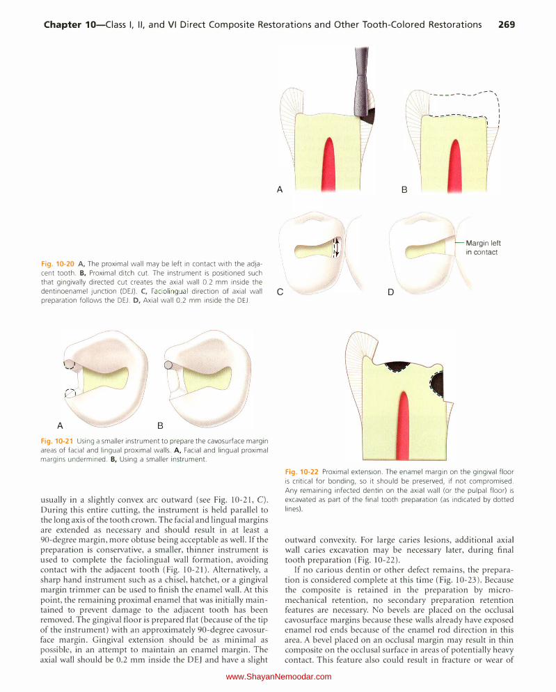
Chapter 10-Ciass I, II, and VI Direct Composite Restorations and Other Tooth-Colored Restorations 269
Fig. 10-20 A, The proximal wall may be left in contact with the adja
cent tooth. B, Proximal ditch cut. The instrument is positioned such
that gingivally directed cut creates the axial wall 0.2 mm inside the
dentinoenamel junction (DEJ). C, Faciolingual direction of axial wall
preparation follows the DEJ. D, Axial wall 0.2 mm inside the DEJ.
(
/
A B
Fig. 10-21 Using a smaller instrument to prepare the cavosurface margin
areas of facial and lingual proximal walls. A, Facial and lingual proximal
margins undermined. B, Using a smaller instrument.
usually in a slightly convex arc outward (see Fig. 10-21, C). During this entire cutting, the instrument is held parallel to the long axis of the tooth crown. The facial and lingual margins are extended as necessary and should result in at least a 90-degree margin, more obtuse being acceptable as well. If the preparation is conservative, a smaller, thinner instrument is used to complete the faciolingual wall formation, avoiding contact with the adjacent tooth (Fig. 10-21). Alternatively, a sharp hand instrument such as a chisel, hatchet, or a gingival margin trimmer can be used to finish the enamel wall. At this point, the remaining proximal enamel that was initially maintained to prevent damage to the adjacent tooth has been removed. The gingival floor is prepared flat (because of the tip of the instrument) with an approximately 90-degree cavosurface margin. Gingival extension should be as minimal as possible, in an attempt to maintain an enamel margin. The axial wall should be 0.2 mm inside the DEJ and have a slight
�-...... I I
�-----------, I I I
---- - �':\ I
I
\ A
c
B
D
Margin left in contact
Fig. 10-22 Proximal extension. The enamel margin on the gingival floor
is critical for bonding, so it should be preserved, if not compromised.
Any remaining infected dentin on the axial wall (or the pulpal floor) is
excavated as part of the final tooth preparation (as indicated by dotted
lines)
outward convexity. For large caries lesions, additional axial wall caries excavation may be necessary later, during final tooth preparation (Fig. 10-22).
If no carious dentin or other defect remains, the preparation is considered complete at this time (Fig. 10-23). Because the composite is retained in the preparation by micromechanical retention, no secondary preparation retention features are necessary. No bevels are placed on the occlusal cavosurface margins because these walls already have exposed enamel rod ends because of the enamel rod direction in this area. A bevel placed on an occlusal margin may result in thin composite on the occlusal surface in areas of potentially heavy contact. This feature also could result in fracture or wear of
www.ShayanNemoodar.com
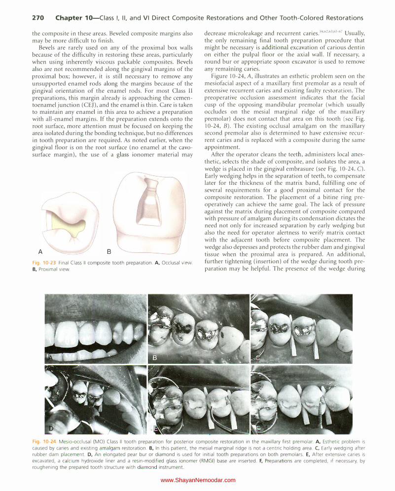
270 Chapter 10-Ciass I, II, and VI Direct Composite Restorations and Other Tooth-Colored Restorations
the composite in these areas. Beveled composite margins also may be more difficult to finish.
Bevels are rarely used on any of the proximal box walls because of the difficulty in restoring these areas, particularly when using inherently viscous packable composites. Bevels also are not recommended along the gingival margins of the proximal box; however, it is still necessary to remove any unsupported enamel rods along the margins because of the gingival orientation of the enamel rods. For most Class II preparations, this margin already is approaching the cementoenamel junction (CEJ), and the enamel is thin. Care is taken to maintain any enamel in this area to achieve a preparation with all-enamel margins. If the preparation extends onto the root surface, more attention must be focused on keeping the area isolated during the bonding technique, but no differences in tooth preparation are required. As noted earlier, when the gingival floor is on the root surface (no enamel at the cavosurface margin), the use of a glass ionomer material may
I
/ A B
Fig 10 23 Final Class II composite tooth preparation. A, Occlusal view.
B, Proximal view.
decrease micro leakage and recurrent caries. 59·"2•63•65�67 Usually, the only remaining final tooth preparation procedure that might be necessary is additional excavation of carious dentin on either the pulpal floor or the axial wall. If necessary, a round bur or appropriate spoon excavator is used to remove any remammg caries.
Figure 10-24, A, illustrates an esthetic problem seen on the mesiofacial aspect of a maxillary first premolar as a result of extensive recurrent caries and existing faulty restoration. The preoperative occlusion assessment indicates that the facial cusp of the opposing mandibular premolar (which usually occludes on the mesial marginal ridge of the maxillary premolar) does not contact that area on this tooth (see Fig. I 0-24, B). The existing occlusal amalgam on the maxillary second premolar also is determined to have extensive recurrent caries and is replaced with a composite during the same appointment.
After the operator cleans the teeth, administers local anesthetic, selects the shade of composite, and isolates the area, a wedge is placed in the gingival embrasure (see Fig. I 0-24, C). Early wedging helps in the separation of teeth, to compensate later for the thickness of the matrix band, fulfilling one of several requirements for a good proximal contact for the composite restoration. The placement of a bitine ring preoperatively can achieve the same goal. The lack of pressure against the matrix during placement of composite compared with pressure of amalgam during its condensation dictates the need not only for increased separation by early wedging but also the need for operator alertness to verify matrix contact with the adjacent tooth before composite placement. The wedge also depresses and protects the rubber dam and gingival tissue when the proximal area is prepared. An additional, further tightening (insertion) of the wedge during tooth preparation may be helpful. The presence of the wedge during
Fig 10-24 Mesio-occlusal (MO) Class II tooth preparation for posterior composite restoration in the maxillary first premolar. A, Esthetic problem is
caused by caries and existing amalgam restoration. B, In this patient, the mesial marginal ridge is not a centric holding area. C, Early wedging after rubber dam placement. D, An elongated pear bur or diamond is used for initial tooth preparations on both premolars. E, After extensive caries is
excavated, a calcium hydroxide liner and a resin-modified glass ionomer ( RMGI) base are inserted. F, Preparations are completed, if necessary, by
roughening the prepared tooth structure with diamond instrument.
www.ShayanNemoodar.com
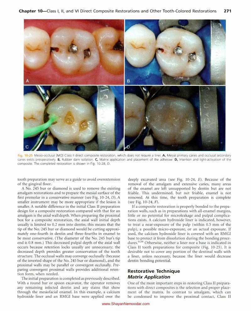
Chapter 10-Ciass I, II, and VI Direct Composite Restorations and Other Tooth-Colored Restorations 271
Fig. 10-25 Mesio-occlusal (MO) Class II direct composite restoration, which does not require a liner. A, Mesial primary caries and occlusal secondary
caries exists preoperatively. B, Rubber dam isolation. C, Matrix application and placement of the adhesive. D, Insertion and light-activation of the composite. The completed restoration is shown in Fig. 10-28, D.
tooth preparation may serve as a guide to avoid overextension of the gingival floor.
A No. 245 bur or diamond is used to remove the existing amalgam restorations and to prepare the mesial surface of the first premolar in a conservative manner (see Fig. 10-24, D). A smaller instrument may be more appropriate if the lesion is smaller. A notable difference in the initial Class II preparation design for a composite restoration compared with that for an amalgam is the axial wall depth. When preparing the proximal box for a composite restoration, the axial wall initial depth usually is limited to 0.2 mm into dentin; this means that the tip of the No. 245 bur or diamond would be cutting approximately one-fourth in dentin and three-fourths in enamel to be most conservative. (The diameter of the No. 245 bur's tip end is 0.8 mm.) This decreased pulpal depth of the axial wall occurs because retention locks usually are unnecessary; the decreased depth provides greater conservation of the tooth structure. The occlusal walls may converge occlusally (because of the inverted shape of the No. 245 bur or diamond), and the proximal walls may be parallel or convergent occlusally. Preparing convergent proximal walls provides additional retention form, when needed.
The initial preparation is completed as previously described. With a round bur or spoon excavator, the operator removes any remaining infected dentin and any stains that show through the mesiofacial enamel. In this example, a calcium hydroxide liner and an RMGI base were applied over the
deeply excavated area (see Fig. 10-24, E). Because of the removal of the amalgam and extensive caries, many areas of the enamel are left unsupported by dentin but are not friable. This undermined, but not friable, enamel is not removed. At this time, the tooth preparation is complete (see Fig. 10-24, F).
If a composite restoration is properly bonded to the preparation walls, such as in preparations with all-enamel margins, little or no potential for microleakage and pulpal complications exists. A calcium hydroxide liner is indicated, however, to treat a near-exposure of the pulp (within 0.5 mm of the pulp), a possible micro-exposure, or an actual exposure. If used, the calcium hydroxide liner is covered with an RMGI
base to protect it from dissolution during the bonding procedures.51'68 Otherwise, neither a liner nor a base is indicated in Class II tooth preparations for composite (Fig. 10-25). It is desirable not to cover any portion of the dentinal walls with a liner, unless necessary, because the liner would decrease dentin bonding potential.
Restorative Technique Matrix Application One of the most important steps in restoring Class II preparations with direct composites is the selection and proper placement of the matrix. In contrast to amalgam, which can be condensed to improve the proximal contact, Class II
www.ShayanNemoodar.com
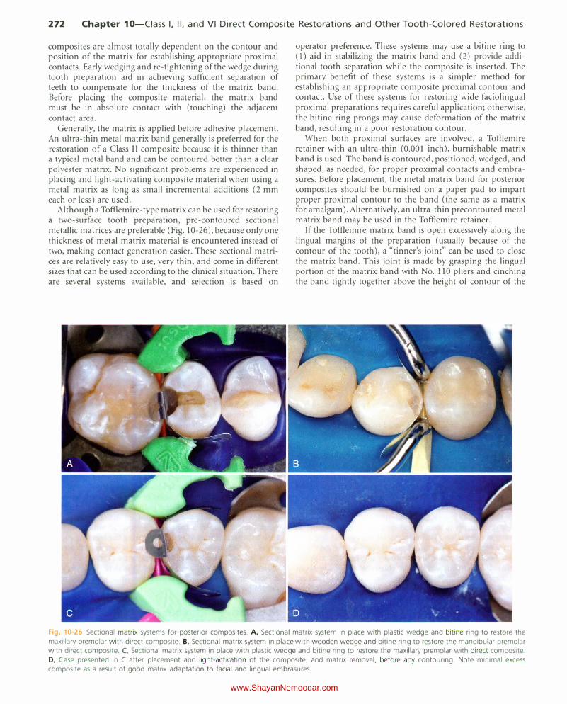
272 Chapter 10-Ciass I, II, and VI Direct Composite Restorations and Other Tooth-Colored Restorations
composites are almost totally dependent on the contour and position of the matrix for establishing appropriate proximal contacts. Early wedging and re-tightening of the wedge during tooth preparation aid in achieving sufficient separation of teeth to compensate for the thickness of the matrix band. Before placing the composite material, the matrix band must be in absolute contact with (touching) the adjacent contact area.
Generally, the matrix is applied before adhesive placement. An ultra-thin metal matrix band generally is preferred for the restoration of a Class II composite because it is thinner than a typical metal band and can be contoured better than a clear polyester matrix. No significant problems are experienced in placing and light-activating composite material when using a metal matrix as long as small incremental additions (2 mm each or less) are used.
Although a Tofflemire-type matrix can be used for restoring a two-surface tooth preparation, pre-contoured sectional metallic matrices are preferable (Fig. 10-26), because only one thickness of metal matrix material is encountered instead of two, making contact generation easier. These sectional matrices are relatively easy to use, very thin, and come in different sizes that can be used according to the clinical situation. There are several systems available, and selection is based on
operator preference. These systems may use a bitine ring to ( l) aid in stabilizing the matrix band and (2) provide additional tooth separation while the composite is inserted. The primary benefit of these systems is a simpler method for establishing an appropriate composite proximal contour and contact. Use of these systems for restoring wide faciolingual proximal preparations requires careful application; otherwise, the bitine ring prongs may cause deformation of the matrix band, resulting in a poor restoration contour.
When both proximal surfaces are involved, a Tofflemire retainer with an ultra-thin (0.001 inch), burnishable matrix band is used. The band is contoured, positioned, wedged, and shaped, as needed, for proper proximal contacts and embrasures. Before placement, the metal matrix band for posterior composites should be burnished on a paper pad to impart proper proximal contour to the band (the same as a matrix for amalgam). Alternatively, an ultra-thin precontoured metal matrix band may be used in the Tofflemire retainer.
If the Tofflemire matrix band is open excessively along the lingual margins of the preparation (usually because of the contour of the tooth), a "tinner's joint" can be used to close the matrix band. This joint is made by grasping the lingual portion of the matrix band with No. 110 pliers and cinching the band tightly together above the height of contour of the
Fig 10-26 Sectional matrix systems for posterior composites. A, Sectional matrix system in place with plastic wedge and biti ne ring to restore the
maxillary premolar with direct composite. B, Sectional matrix system in place with wooden wedge and bitine ring to restore the mandibular premolar with direct composite. C, Sectional matrix system in place with plastic wedge and bitine ring to restore the maxillary premolar with direct composite.
D, Case presented in C after placement and light-activation of the composite, and matrix removal, before any contouring. Note minimal excess
composite as a result of good matrix adaptation to facial and lingual embrasures.
www.ShayanNemoodar.com
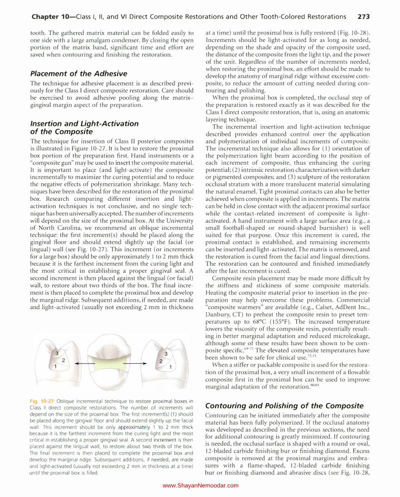
Chapter 10-Ciass I, II, and VI Direct Composite Restorations and Other Tooth-Colored Restorations 273
tooth. The gathered matrix material can be folded easily to one side with a large amalgam condenser. By closing the open portion of the matrix band, significant time and effort are saved when contouring and finishing the restoration.
Placement of the Adhesive The technique for adhesive placement is as described previously for the Class I direct composite restoration. Care should be exercised to avoid adhesive pooling along the matrixgingival margin aspect of the preparation.
Insertion and Light-Activation of the Composite The technique for insertion of Class II posterior composites is illustrated in Figure 10-27. It is best to restore the proximal box portion of the preparation first. Hand instruments or a "composite gun" may be used to insert the composite material. It is important to place (and light-activate) the composite incrementally to maximize the curing potential and to reduce the negative effects of polymerization shrinkage. Many techniques have been described for the restoration of the proximal box. Research comparing different insertion and lightactivation techniques is not conclusive, and no single technique has been universally accepted. The number of increments will depend on the size of the proximal box. At the University of North Carolina, we recommend an oblique incremental technique: the first increment(s) should be placed along the gingival floor and should extend slightly up the facial (or lingual) wall (see Fig. 10-27). This increment (or increments for a large box) should be only approximately I to 2 mm thick because it is the farthest increment from the curing light and the most critical in establishing a proper gingival seal. A second increment is then placed against the lingual (or facial) wall, to restore about two thirds of the box. The final increment is then placed to complete the proximal box and develop the marginal ridge. Subsequent additions, if needed, are made and light-activated (usually not exceeding 2 mm in thickness
3
2
Fig 10-27 Oblique incremental technique to restore proximal boxes in
Class II direct composite restorations. The number of increments will
depend on the size of the proximal box. The first increment(s) (1) should be placed along the gingival floor and should extend slightly up the facial
wall. This increment should be only approximately 1 to 2 mm thick because it is the farthest increment from the curing light and the most critical in establishing a proper gingival seal. A second increment is then
placed against the lingual wall, to restore about two thirds of the box.
The final increment is then placed to complete the proximal box and
develop the marginal ridge. Subsequent additions, if needed, are made
and light-activated (usually not exceeding 2 mm in thickness at a time)
until the proximal box is filled.
at a time) until the proximal box is fully restored (Fig. 10-28). Increments should be light-activated for as long as needed, depending on the shade and opacity of the composite used, the distance of the composite from the light tip, and the power of the unit. Regardless of the number of increments needed, when restoring the proximal box, an effort should be made to develop the anatomy of marginal ridge without excessive composite, to reduce the amount of cutting needed during contouring and polishing.
When the proximal box is completed, the occlusal step of the preparation is restored exactly as it was described for the Class I direct composite restoration, that is, using an anatomic layering technique.
The incremental insertion and light-activation technique described provides enhanced control over the application and polymerization of individual increments of composite. The incremental technique also allows for ( 1) orientation of the polymerization light beam according to the position of each increment of composite, thus enhancing the curing potential; (2) intrinsic restoration characterization with darker or pigmented composites; and (3) sculpture of the restoration occlusal stratum with a more translucent material simulating the natural enamel. Tight proximal contacts can also be better achieved when composite is applied in increments. The matrix can be held in close contact with the adjacent proximal surface while the contact-related increment of composite is lightactivated. A hand instrument with a large surface area (e.g., a small football-shaped or round-shaped burnisher) is well suited for that purpose. Once this increment is cured, the proximal contact is established, and remaining increments can be inserted and light-activated. The matrix is removed, and the restoration is cured from the facial and lingual directions. The restoration can be contoured and finished immediately after the last increment is cured.
Composite resin placement may be made more difficult by the stiffness and stickiness of some composite materials. Heating the composite material prior to insertion in the preparation may help overcome these problems. Commercial "composite warmers" are available (e.g., Calset, AdDent Inc., Danbury, CT) to preheat the composite resin to preset temperatures up to 68°C (l55°F). The increased temperature lowers the viscosity of the composite resin, potentially resulting in better marginal adaptation and reduced microleakage, although some of these results have been shown to be composite specific.69-72 The elevated composite temperatures have been shown to be safe for clinical use.73•74
When a stiffer or packable composite is used for the restoration of the proximal box, a very small increment of a flowable composite first in the proximal box can be used to improve marginal adaptation of the restoration.60•61
Contouring and Polishing of the Composite Contouring can be initiated immediately after the composite material has been fully polymerized. If the occlusal anatomy was developed as described in the previous sections, the need for additional contouring is greatly minimized. If contouring is needed, the occlusal surface is shaped with a round or oval, 12-bladed carbide finishing bur or finishing diamond. Excess composite is removed at the proximal margins and embrasures with a flame-shaped, 12-bladed carbide finishing bur or finishing diamond and abrasive discs (see Fig. I 0-28,
www.ShayanNemoodar.com

274 Chapter 10-Ciass I, II, and VI Direct Composite Restorations and Other Tooth-Colored Restorations
Fig 10�28 Contouring and finishing of posterior composite restorations. A, After sectional matrix removal, excess composite is noted on facial and
lingual prox1mal embrasures. B, Contouring lingual embrasure with finishing disk. C, Polishing the occlusal surface with finishing brush. D, Completed
restoration. E. Note minimal excess composite after removal of sectional matrix because of good matrix adaptation to facial and lingual embrasures
and careful incremental insertion of the composite. F-H, Contouring and polishing with disks and brush.
www.ShayanNemoodar.com
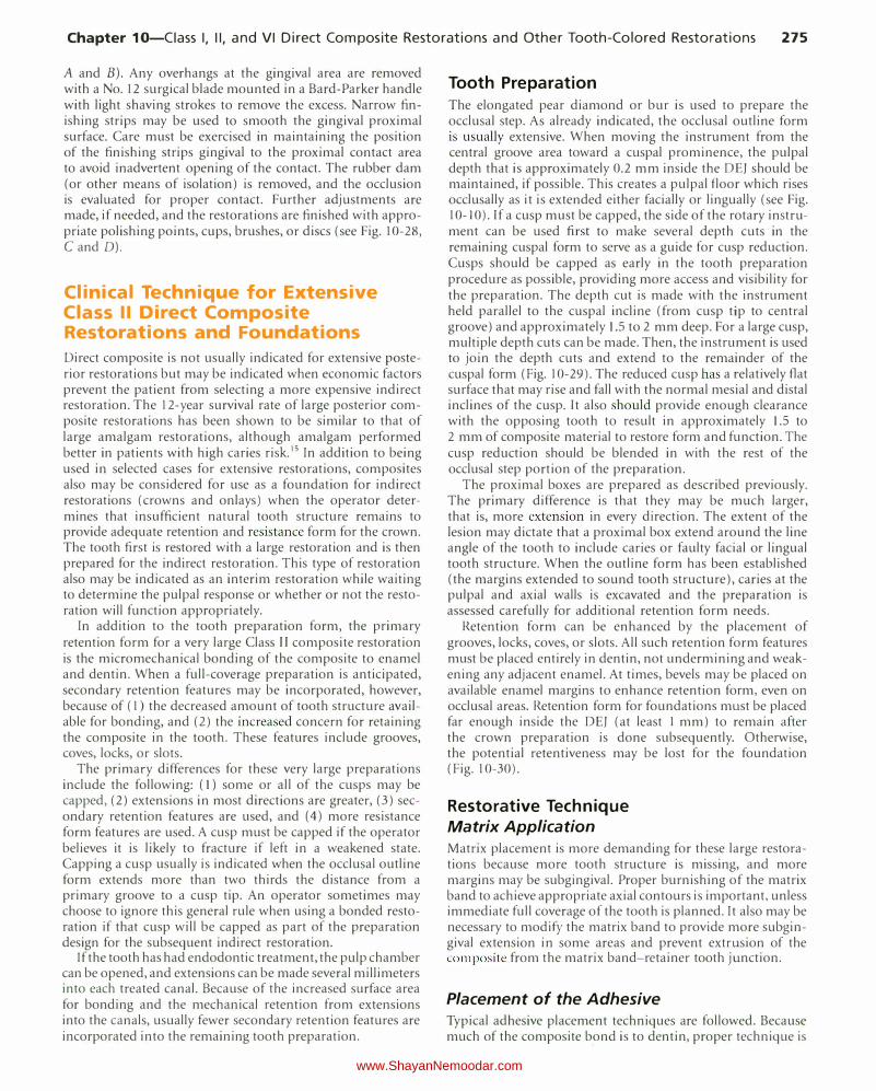
Chapter 10-Ciass I, II, and VI Direct Composite Restorations and Other Tooth-Colored Restorations 275
A and B). Any overhangs at the gingival area are removed with a No. 12 surgical blade mounted in a Bard-Parker handle with light shaving strokes to remove the excess. Narrow finishing strips may be used to smooth the gingival proximal surface. Care must be exercised in maintaining the position of the finishing strips gingival to the proximal contact area to avoid inadvertent opening of the contact. The rubber dam (or other means of isolation) is removed, and the occlusion is evaluated for proper contact. Further adjustments are made, if needed, and the restorations are finished with appropriate polishing points, cups, brushes, or discs (see Fig. 10-28, C and D).
Clinical Technique for Extensive Class II Direct Composite Restorations and Foundations
Direct composite is not usually indicated for extensive posterior restorations but may be indicated when economic factors prevent the patient from selecting a more expensive indirect restoration. The 12-year survival rate of large posterior composite restorations has been shown to be similar to that of large amalgam restorations, although amalgam performed better in patients with high caries risk.15 In addition to being used in selected cases for extensive restorations, composites also may be considered for use as a foundation for indirect restorations (crowns and onlays) when the operator determines that insufficient natural tooth structure remains to provide adequate retention and resistance form for the crown. The tooth first is restored with a large restoration and is then prepared for the indirect restoration. This type of restoration also may be indicated as an interim restoration while waiting to determine the pulpal response or whether or not the restoration will function appropriately.
In addition to the tooth preparation form, the primary retention form for a very large Class II composite restoration is the micromechanical bonding of the composite to enamel and dentin. When a full-coverage preparation is anticipated, secondary retention features may be incorporated, however, because of ( 1) the decreased amount of tooth structure available for bonding, and (2) the increased concern for retaining the composite in the tooth. These features include grooves, coves, locks, or slots.
The primary differences for these very large preparations include the following: (1) some or all of the cusps may be capped, (2) extensions in most directions are greater, (3) secondary retention features are used, and ( 4) more resistance form features are used. A cusp must be capped if the operator believes it is likely to fracture if left in a weakened state. Capping a cusp usuaLly is indicated when the occlusal outline form extends more than two thirds the distance from a primary groove to a cusp tip. An operator sometimes may choose to ignore this general rule when using a bonded restoration if that cusp will be capped as part of the preparation design for the subsequent indirect restoration.
If the tooth has had endodontic treatment, the pulp chamber can be opened, and extensions can be made several millimeters into each treated canal. Because of the increased surface area for bonding and the mechanical retention from extensions into the canals, usually fewer secondary retention features are incorporated into the remaining tooth preparation.
Tooth Preparation The elongated pear diamond or bur is used to prepare the occlusal step. As already indicated, the occlusal outline form is usually extensive. When moving the instrument from the central groove area toward a cuspal prominence, the pulpal depth that is approximately 0.2 mm inside the DE] should be maintained, if possible. This creates a pulpal floor which rises occlusally as it is extended either facially or lingually (see Fig. 10-10). If a cusp must be capped, the side of the rotary instrument can be used first to make several depth cuts in the remaining cuspal form to serve as a guide for cusp reduction. Cusps should be capped as early in the tooth preparation procedure as possible, providing more access and visibility for the preparation. The depth cut is made with the instrument held parallel to the cuspal incline (from cusp tip to central groove) and approximately 1.5 to 2 mm deep. For a large cusp, multiple depth cuts can be made. Then, the instrument is used to join the depth cuts and extend to the remainder of the cuspal form (Fig. 10-29). The reduced cusp has a relatively flat surface that may rise and fall with the normal mesial and distal inclines of the cusp. It also should provide enough clearance with the opposing tooth to result in approximately l.S to 2 mm of composite material to restore form and function. The cusp reduction should be blended in with the rest of the occlusal step portion of the preparation.
The proximal boxes are prepared as described previously. The primary difference is that they may be much larger, that is, more extension in every direction. The extent of the lesion may dictate that a proximal box extend around the line angle of the tooth to include caries or faulty facial or lingual tooth structure. When the outline form has been established (the margins extended to sound tooth structure), caries at the pulpal and axial walls is excavated and the preparation is assessed carefully for additional retention form needs.
Retention form can be enhanced by the placement of grooves, locks, coves, or slots. All such retention form features must be placed entirely in dentin, not undermining and weakening any adjacent enamel. At times, bevels may be placed on available enamel margins to enhance retention form, even on occlusal areas. Retention form for foundations must be placed far enough inside the DEJ (at least 1 mm) to remain after the crown preparation is done subsequently. Otherwise, the potential retentiveness may be lost for the foundation (Fig. 10-30).
Restorative Technique Matrix Application Matrix placement is more demanding for these large restorations because more tooth structure is missing, and more margins may be subgingival. Proper burnishing of the matrix band to achieve appropriate axial contours is important, unless immediate full coverage of the tooth is planned. It also may be necessary to modify the matrix band to provide more subgingival extension in some areas and prevent extrusion of the composite from the matrix band-retainer tooth junction.
Placement of the Adhesive Typical adhesive placement techniques are followed. Because much of the composite bond is to dentin, proper technique is
www.ShayanNemoodar.com
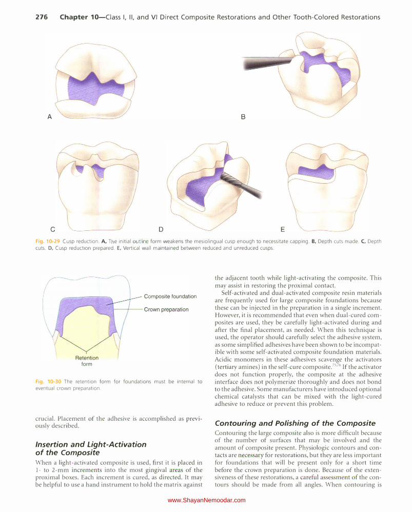
276 Chapter 10-Ciass I, II, and VI Direct Composite Restorations and Other Tooth-Colored Restorations
A B
c D E
F1g. 10-29 Cusp reduction. A, The initial outline form weakens the mesiolingual cusp enough to necessitate capping. B, Depth cuts made. C, Depth
cuts. D, Cusp reduction prepared. E, Vertical wall maintained between reduced and unreduced cusps.
Retention form
Composite foundation
Fig 0-3 The retention form for foundations must be internal to
eventual crown preparation.
crucial. Placement of the adhesive is accomplished as previously described.
Insertion and Light-Activation of the Composite When a light-activated composite is used, first it is placed in 1- to 2-mm increments into the most gingival areas of the proximal boxes. Each increment is cured, as directed. It may be helpful to use a hand instrument to hold the matrix against
the adjacent tooth while light-activating the composite. This may assist in restoring the proximal contact.
Self-activated and dual-activated composite resin materials are frequently used for large composite foundations because these can be injected in the preparation in a single increment. However, it is recommended that even when dual-cured composites are used, they be carefully light-activated during and after the final placement, as needed. When this technique is used, the operator should carefully select the adhesive system, as some simplified adhesives have been shown to be incompatible with some self-activated composite foundation materials. Acidic monomers in these adhesives scavenge the activators (tertiary amines) in the self-cure composite. 75'76 If the activator does not function properly, the composite at the adhesive interface does not polymerize thoroughly and does not bond to the adhesive. Some manufacturers have introduced optional chemical catalysts that can be mixed with the light-cured adhesive to reduce or prevent this problem.
Contouring and Polishing of the Composite Contouring the large composite also is more difficult because of the number of surfaces that may be involved and the amount of composite present. Physiologic contours and contacts are necessary for restorations, but they are less important for foundations that will be present only for a short time before the crown preparation is done. Because of the extensiveness of these restorations, a careful asse sment of the contours should be made from all angles. When contouring is
www.ShayanNemoodar.com
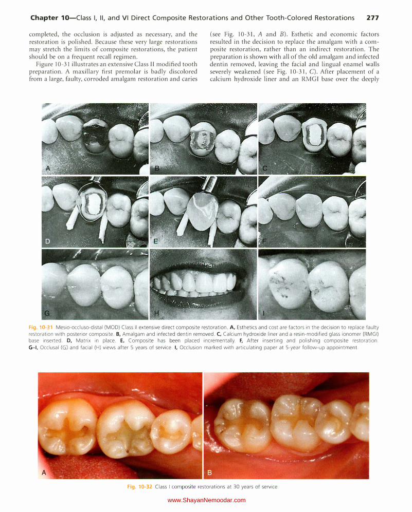
Chapter 10-Ciass I, II, and VI Direct Composite Restorations and Other Tooth-Colored Restorations 277
completed, the occlusion is adjusted as necessary, and the restoration is polished. Because these very large restorations may stretch the limits of composite restorations, the patient should be on a frequent recall regimen.
Figure 10-31 illustrates an extensive Class II modified tooth preparation. A maxillary first premolar is badly discolored from a large, faulty, corroded amalgam restoration and caries
(see Fig. 10-31, A and B). Esthetic and economic factors resulted in the decision to replace the amalgam with a composite restoration, rather than an indirect restoration. The preparation is shown with all of the old amalgam and infected dentin removed, leaving the facial and lingual enamel walls severely weakened (see Fig. 10-31, C). After placement of a calcium hydroxide liner and an RMGI base over the deeply
F1g 1G-31 Mesio-occluso-distal (MOD) Class II extensive direct composite restoration. A, Esthetics and cost are factors in the decision to replace faulty
restoration with posterior composite. B, Amalgam and infected dentin removed. C, Calcium hydroxide liner and a resin-modified glass ionomer (RMGI) base inserted. D, Matrix in place. E, Composite has been placed incrementally. F, After inserting and polishing composite restoration.
G-1, Occlusal (G) and facial (H) views after 5 years of service. I, Occlusion marked with articulating paper at 5-year follow-up appointment.
Fig. 10-32 Class I composite restorations at 30 years of service.
www.ShayanNemoodar.com
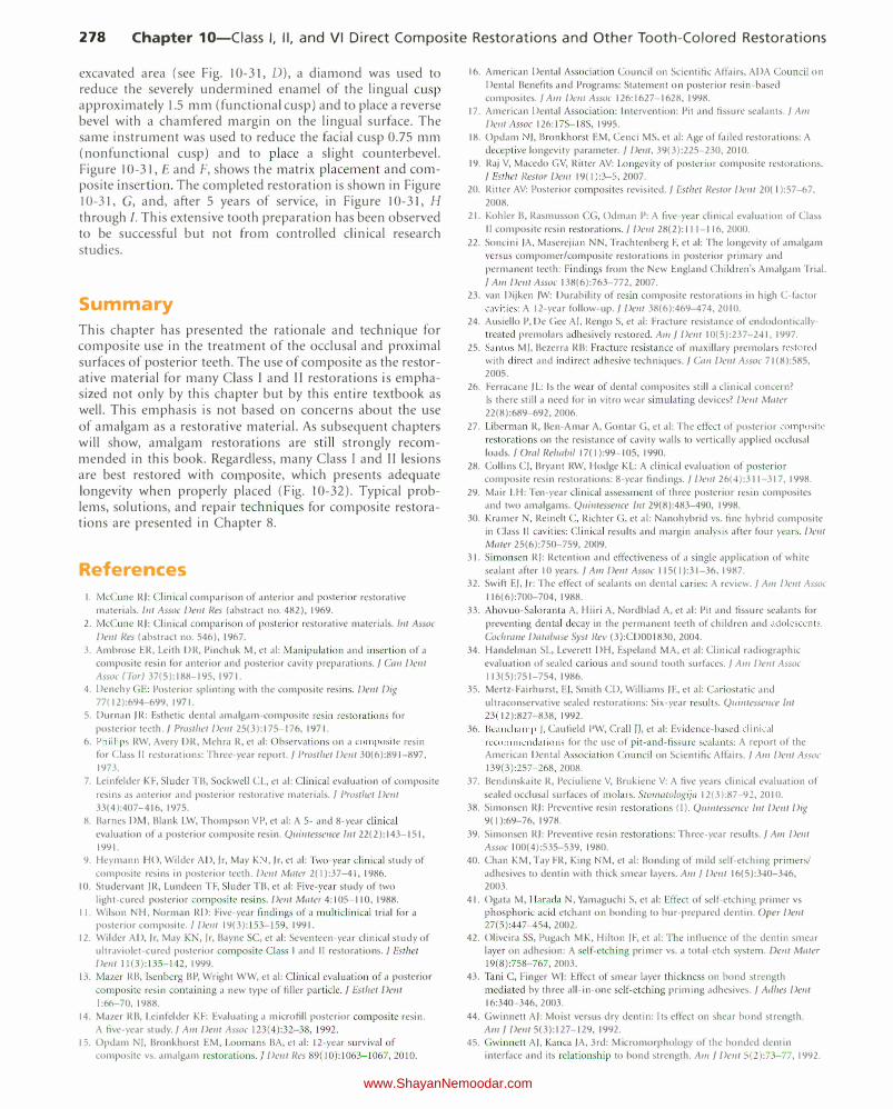
278 Chapter 10-Ciass I, II, and VI Direct Composite Restorations and Other Tooth-Colored Restorations
excavated area (see Fig. 10-31, D), a diamond was used to reduce the severely undermined enamel of the lingual cusp approximately 1.5 mm (functional cusp) and to place a reverse bevel with a chamfered margin on the lingual surface. The same instrument was used to reduce the facial cusp 0.75 mm (nonfunctional cusp) and to place a slight counterbevel. Figure 10-31, E and F, shows the matrix placement and composite insertion. The completed restoration is shown in Figure 10-31, G, and, after 5 years of service, in Figure 10-31, H
through I. This extensive tooth preparation has been observed to be successful but not from controlled clinical research studies.
Summary
This chapter has presented the rationale and technique for composite use in the treatment of the occlusal and proximal surfaces of posterior teeth. The use of composite as the restorative material for many Class I and II restorations is emphasized not only by this chapter but by this entire textbook as well. This emphasis is not based on concerns about the use of amalgam as a restorative material. As subsequent chapters will show, amalgam restorations are still strongly recommended in this book. Regardless, many Class I and Il lesions are best restored with composite, which presents adequate longevity when properly placed (Fig. 10-32). Typical problems, solutions, and repair techniques for composite restorations are presented in Chapter 8.
References
I. McCune RJ: Clinical comparison of anterior and posterior restorative materials. lnt Assoc Dent Res (abstract no. 482), 1969.
2. McCune RJ: Clinical comparison of posterior restorative materials. /nt Assoc
Dent I?es (abstract no. 546), 1967.
3. Ambrose ER, Leith DR, Pinchuk M, et al: Manipulation and insertion of a composite resin for anterior and posterior cavity preparations.] Cnn Dwt Assoc (Tor) 37(5):188-195, 1971.
4. Denehy GE: Posterior splinting with the composite resins. Dent Dig 77( 12):694-699, 1971.
5. Durnan JR: Esthetic dental amalgam-composite resin restorations for posterior teeth.] Prosthet Dent 25(3):175-176, 1971.
6. Phillips RW, Avery DR, Mehra R, et al: Observations on a composite resin for Class II restorations: Three-year report.] Prosthet Dent 30(6):891-897,
1973.
7. Leinfelder KF, Sluder TB, Sockwell CL, et al: Clinical evaluation of composite
resins as anterior and posterior restorative materials. I Prosthet Dent 33( 4 ):407-416, 1975.
8. Barnes DM, Blank LW, Thompson VP, et al: A 5- and 8-year clinical evaluation of a posterior composite resin. Quintesseuce lnt 22(2): 143-151,
1991.
9. Heymann HO, Wilder AD, Jr, May K , Jr. et al: Two-year clinical study of composite resins in posterior teeth. Dwt Mater 2( I ):37-41, 1986.
10. Studervant JR, Lundeen TF, Sluder TB, et al: Five-year study of two light-cured posterior composite resins. Dent Mater 4:105-110, 1988.
II. Wilson NH, Norman RD: Five-year findings of a multiclinical trial for a posterior composite. I Dent 19(3 ): 153-159, 1991.
12. Wilder AD, Jr, May KN, Jr, Bayne SC, et al: Seventeen-year clinical study of ultraviolet-cured posterior composite Class I and II restorations./ Esther Dent 11(3):135-142, 1999.
13. Mazer RB, I senberg BP, Wright W W, et al: Clinical evaluation of a posterior
composite resin containing a new type of filler particle. j Esthet Dwt
I :66-70, 1988.
14. Mazer RB, Leinfelder KF: Evaluating a microfill posterior composite resin. A five-year study.] Am Delli Assoc 123(4):32-38, 1992.
15. Opdam NJ, Bronkhorst EM, Loomans BA, et al: 12-year survival of composite vs. amalgam restorations.] Dwt Res 89(10):1063-1067, 2010.
16. American Dental Association Council on Scientific Affairs, ADA Council on
Dental Benefits and Programs: Statement on posterior resin-based composites./ A111 Dent Assoc 126:1627-1628, 1998.
17. American Dental Association: Intervention: Pit and fissure sealants.] A111 Dent Assoc 126: 17S-18S, 1995.
18. Opdam ), Bronkhorst EM, Cenci MS. et al: Age of failed restorations: A deceptive longevity parameter. j Dent, 39(3):225-230, 2010.
19. Raj V, Macedo G V, Ritter AV: Longevity of posterior composite restorations. ] Esthet l?estor Dent 19( I ):3-5, 2007.
20. Ritter AV: Posterior composites revisited.] Esther Restor Dmt 20( I ):57-67.
2008.
21. Kohler B, Rasmusson CG, Odman P: A live-year clinical evaluation of Class II composite resin restorations. j Dent 28(2): 111-116, 2000.
22. SalKini )A, Maserejian NN, Trachtenberg F, et al: The longevity of amalgam versus compomer/composite restorations in posterior primary and
permanent teeth: Findings from the New England Children's Amalgam Trial.
I A111 Dwt Assoc 138(6):763-772, 2007.
23. van Dijken JW: Durability of resin composite restorations in high C-factor cavities: A 12-year follow-up.] Delli 38(6):469-474, 20 I 0.
24. Ausiello P, De Gee AI. Rengo S, et al: Fracture resistance of endodonticallytreated premolars adhesively restored. A111] Delli 10(5):237-241, 1997.
25. Santos M), Bezerra RB: Fracture resistance of maxillary premolars restored
with direct and indirect adhesive techniques.] Can Dwt Assoc 71 (8):585,
2005.
26. Ferracane JL: Is the wear of dental composites still a clinical concern? Is there still a need for in vitro wear simulating devices? Dent Mnter 22(8):689-692, 2006.
27. Liberman R, Ben-A mar A, Gontar G, et al: The effect of po>terior composite
restorations on the resistance of cavity walls to vertically applied occlusal loads. j Om/ Relwbil 17( I ):99-1 05, 1990.
28. Collins CJ, Bryant RW, Hodge KL: A clinical evaluation of posterior composite resin restorations: 8-year findings.] Dent 26(4):311-317, 1998.
29. Mair LH: Ten-year clinical assessment of three posterior resin composites and two amalgams. Quintessence 111129(8):483-490, 1998.
30. Kramer N, Reinelt C, Richter G, et al: Nanohybrid vs. fine hybrid composite in Class II cavities: Clinical results and margin analysis after four years. Dent Mater 25(6):750-759, 2009.
31. Simonsen RJ: Retention and effectiveness of a single application of white sealant after 10 years.] A111 Delli Assoc 115( I ):31-36, 1987.
32. Swift EJ. Jr: The effect of sealants on dental caries: A review.] A111 Delli Assoc
116(6):700-704, 1988.
33. Ahovuo-Saloranta A, Hiiri A, Nordblad A, et al: Pit and fissure sealants for
preventing dental decay in the permanent teeth of children and adolescents.
Cochm11e Database Syst liev (3):CDOO I830 , 2004.
34. Handelman SL, Leverett DH, Espeland MA, et al: Clinical radiographic evaluation of sealed carious and sound tooth surfaces.] A111 Dent Assoc I 13(5):751-754, 1986.
35. Mertz-Fairhurst, EJ, Smith CD, Williams JE, et al: Cariostatic and ultraconservative sealed restorations: Six-year results. Q11illtessence Jnt 23( 12):827-838, 1992.
36. Beauchamp ), Caufield PW, CraiiiJ, et al: Evidence� based clinical
recommendations for the use of pit- and-fissure sealants: A report of the American Dental Association Council on Scientific Affairs.] A111 Delft Assoc 139(3):257-268, 2008.
37. Bendinskaite R, Peciuliene V, Brukiene V: A five years clinical evaluation of
sealed occlusal surfaces of molars. Sto111atologijn 12(3):87-91, 2010.
38. Simonsen RJ: Preventive resin restorations (I ). Quilltesse11ce 1111 Dent Dig 9( I ):69-76, 1978.
39. Simonsen RJ: Preventive resin restorations: Three-year results.] A111 De11t Assoc I 00( 4):535-539, 1980.
40. Chan KM, Tay FR, King M, et al: Bonding of mild self-etching primers/ adhesives to dentin with thick smear layers. Alii / Dwt 16(5):340-346,
2003.
41. Ogata M, Harada N, Yamaguchi S, et al: Effect of self-etching primer vs phosphoric acid etchant on bonding to bur-prepared dentin. Oper Dent 27(5 ):447-454, 2002.
42. Oliveira SS, Pugach MK, Hilton JF, et al: The influence of the dentin smear layer on adhesion: A self-etching primer vs. a total-etch system. Delli Mater 19(8):758-767, 2003.
43. Tani C, Finger WJ: Effect of smear layer thickness on bond strength mediated by three ail-in-one self-etching priming adhesives.] Adhes Dent 16:340-346, 2003.
44. Gwinnett AJ: Moist versus dry dentin: I ts effect on shear bond strength. A111 ] Dent 5(3 ): 127-129, 1992.
45. Gwinnett A), Kanca )A, 3rd: Micromorphology of the bonded dentin interface and its relationship to bond strength. Am ] Dent 5(2):73-77, 1992.
www.ShayanNemoodar.com
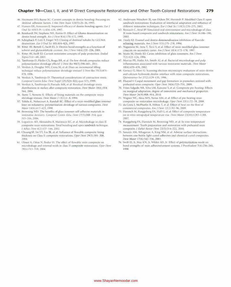
Chapter 10-Ciass I, II, and VI Direct Composite Restorations and Other Tooth-Colored Restorations 279
46. Heymann HO, Bayne SC: Current concepts in dentin bonding: Focusing on dentinal adhesion factors. f Am Dent Assoc 124(5):26-36, 1993.
47. Hansen EK, Asmussen E: Improved efficacy of dentin-bonding agents. Eur f Oral Sci 105(5 Pt I ):434--439, 1997.
48. Reinhardt JW, Stephens NH, Fortin D: Effect of Gluma desensitization on dentin bond strength. A111 f Dent8(4):170-172, 1995.
49. Schlipbach P, Lutz F, Finger W ): Closing of dentinal tubules by GLUM A
desensitizer. Eur f Oral Sci 105:41 4--421, 1997. 50. Ritter AV, Bertoli C, Swift E), jr: Dentin bond strengths as a function of
solvent and glutaraldehyde content. Ant f Dent 14(4):221-226, 2001.
51. Ritter AV, Swift E): Current restorative concepts of pulp protection. Endod Topics 5:41-48, 2003.
52. Tantbirojn D, Pfeifer CS, Braga RR, et al: Do low-shrink composites reduce polymerization shrinkage effects? j Dent Res 90(5):596-601, 2011.
53. Versluis A, Douglas WH, Cross M, et al: Does an incremental filling
technique reduce polymerization shrinkage stresses? f Dent Res 75(3):871-
878, 1996.
54. Versluis A, Tantbirojn D: T heoretical considerations of contraction stress. Compend Conlin Educ Dwt Suppl (25):S24-S32; quiz S73, 1999.
55. Versluis A, Tantbirojn 0, Pintado MR, et al: Residual shrinkage stress distributions in molars after composite restoration. Dent Mater 20(6):554-564, 2004.
56. lkemi T, Nemoto K: Effects of lining materials on the composite resins shrinkage stresses. Dent Mater j 13( I): 1-8, 1994.
57. Tolidis K, Nobecourt A, Randall RC: Effect of a resin-modified glass ionomer liner on volumetric polymerization shrinkage of various composites. Dent Mater 14(6):417-423, 1998.
58. Browning WD: T he benefits of glass ionomer self-adhesive materials in
restorative dentistry. Compwd Conlin Ed11c Dent27(5):308-314; quiz 315-316, 2006.
59. Loguercio AD, Alessandra R, Mazzocco KC, et al: Microleakage in class II composite resin restorations: Total bonding and open sandwich technique. f Adl!es Dent4(2):137-144, 2002.
60. Chuang SF, )in YT, Liu )K, et a!: Influence of flowable composite lining thickness on Class ll composite restorations. Oper Dent 29(3):301-308, 2004.
61. Olmez A, Oztas N, Bodur H: T he effect of flowable resin composite on microleakage and internal voids in class II composite restorations. Oper Dent 29(6):713-719, 2004.
62. Andersson-Wenckert IE, van Dijken JW, Horstedt P: Modified Class II open sandwich restorations: Evaluation of interfacial adaptation and influence of
different restorative techniques. Eur f Oral Sci 110(3):270-275, 2002. 63. Besnault C, Attal )P: Simulated oral environment and microleakage of class
II resin-based composite and sandwich restorations. Am f Dent 16:186-190, 2003.
64. Donly K): Enamel and dentin demineralization inhibition of fluoridereleasing materials. Am j Dent 7(5):275-278, 1994.
65. Nagamine M, ltota T, Torii Y, et a!: Effect of resin-modified glass ionomer cements on secondary caries. Am f Dent 10(4):173-178, 1997.
66. Souto M, Donly K): Caries inhibition of glass ionomers. Ant j Dent 7(2): 122-124, 1994.
67. Murray PE, Hafez AA, Smith A), et a!: Bacterial microleakage and pulp inflammation associated with various restorative materials. Dent Mater 18(6):470-478, 2002.
68. Goracci G, Mori G: Scanning electron microscopic evaluation of resin-dentin
and calcium hydroxide-dentin interface with resin composite restorations.
Quintesswce lnt 27(2): 129-135, 1996.
69. Elsayad 1: Cuspal movement and gap formation in premolars restored with preheated resin composite. Oper Dent 34(6):725-731, 2009.
70. Fr6es-Salgado NR, Silva LM, Kawano Y, et a!: Composite pre-heating: Effects on marginal adaptation, degree of conversion and mechanical properties. Dent Mater 26(9):908-914, 20 I 0.
71. Wagner WC, Aksu MN, Neme AM, et a!: Effect of pre-heating resin composite on restoration microleakage. Oper Dwt 33( I ):72-78, 2008.
72. da Costa ), McPharlin R, Hilton T, et a!: Effect of heat on the flow of commercial composites. Am f Dent 22(2):92-96, 2009.
73. Daronch M, Rueggeberg FA, Hall G, et a!: Effect of composite temperature on in vitro intra pulpal temperature rise. Dent Mater 23( 10): 1283-1288, 2007.
74. Rueggeberg FA, Daronch M, Browning WD, et al: In vivo temperature
measurement: Tooth preparation and restoration with preheated resin composite. f Esthet Restor Dent 22(5):314-322, 2010.
75. Sa nares AM, ltthagarun A, King NM, et a!: Adverse surface interactions between one-bottle light-cured adhesives and chemical-cured composites. Dwt Mater 17(6):542-556, 200 I.
76. Swift E), )r, May KN, )r, Wilder AD, )r: Effect of polymerization mode on bond strengths of resin adhesive/cement systems. f Prostl!odont 7(4):256-260, 1998.
www.ShayanNemoodar.com
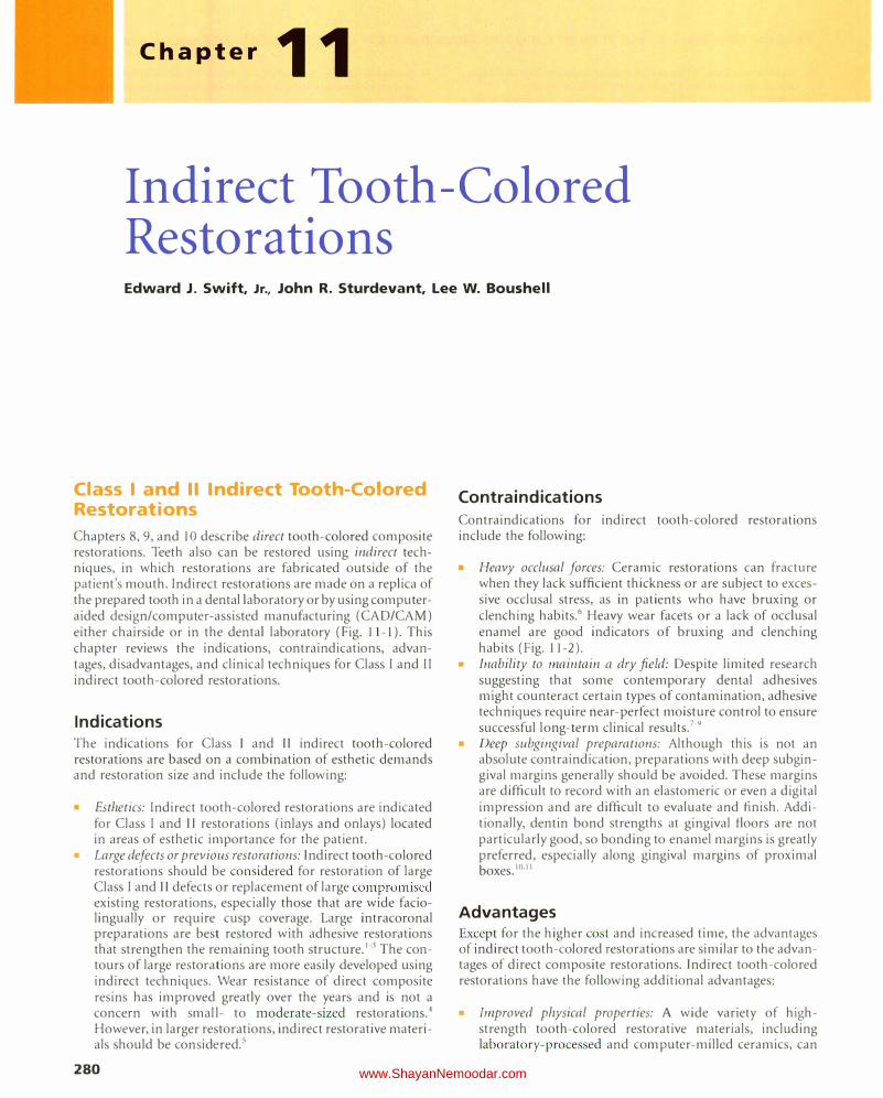
Chapter 11
Indirect Tooth -Colored
Restorations Edward J. Swift, Jr., John R. Sturdevant, Lee W. Boushell
Class I and II Indirect Tooth-Colored Restorations
Chapters 8, 9, and 10 describe direct tooth-colored composite restorations. Teeth also can be restored using indirect techniques, in which restorations are fabricated outside of the patient's mouth. Indirect restorations are made on a replica of the prepared tooth in a dental laboratory or by using computeraided design/computer-assisted manufacturing (CAD/CAM) either chairside or in the dental laboratory (Fig. 11-l ). This chapter reviews the indications, contraindications, advantages, disadvantages, and clinical techniques for Class I and II indirect tooth-colored restorations.
Indications T he indications for Class I and II indirect tooth-colored restorations are based on a combination of esthetic demands and restoration size and include the following:
Esthetics: Indirect tooth-colored restorations are indicated for Class I and II restorations (inlays and onlays) located in areas of esthetic importance for the patient. Large defects or previous restorations: Indirect tooth-colored restorations should be considered for restoration of large Class I and II defects or replacement of large compromised existing restorations, especially those that are wide faciolingually or require cusp coverage. Large intracoronal preparations are best restored with adhesive restorations that strengthen the remaining tooth structure.1•3 The contours of large restorations are more easily developed using indirect techniques. Wear resistance of direct composite resins has improved greatly over the years and is not a concern with small- to moderate-sized restorations.4 However, in larger restorations, indirect restorative materials should be considered.5
280
Contraindications Contraindications for indirect tooth-colored restorations include the following:
• Heavy occlusal forces: Ceramic restorations can fracture when they lack sufficient thickness or are subject to excessive occlusal stress, as in patients who have bruxing or clenching habits.6 Heavy wear facets or a lack of occlusal enamel are good indicators of bruxing and clenching habits (Fig. 1 1-2).
• Inability to maintain a dry field: Despite limited research suggesting that some contemporary dental adhesives might counteract certain types of contamination, adhesive techniques require near-perfect moisture control to ensure successful long-term clinical results.7·9
• Deep subgingival preparations: Although this is not an absolute contraindication, preparations with deep subgingival margins generally should be avoided. These margins are difficult to record with an elastomeric or even a digital impression and are difficult to evaluate and finish. Additionally, dentin bond strengths at gingival floors are not particularly good, so bonding to enamel margins is greatly preferred, especially along gingival margins of proximal boxes.10"11
Advantages Except for the higher cost and increased time, the advantages of indirect tooth-colored restorations are similar to the advantages of direct composite restorations. Indirect tooth-colored restorations have the following additional advantages:
• Improved physical properties: A wide variety of highstrength tooth-colored restorative materials, including laboratory-processed and computer-milled ceramics, can
www.ShayanNemoodar.com
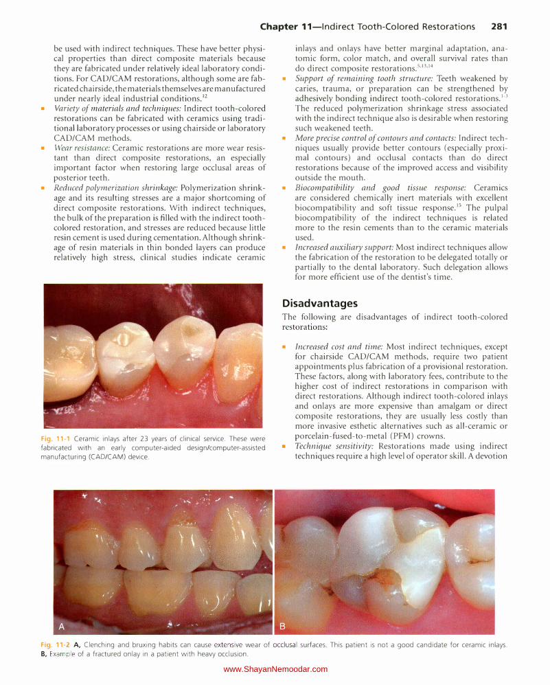
Chapter 11-lndirect Tooth-Colored Restorations 281
be used with indirect techniques. These have better physical properties than direct composite materials because they are fabricated under relatively ideal laboratory conditions. For CAD/CAM restorations, although some are fabricated chairside, the materials themselves are manufactured under nearly ideal industrial conditions.12
• Variety of materials and techniques: Indirect tooth-colored restorations can be fabricated with ceramics using traditional laboratory processes or using chairside or laboratory CAD/CAM methods.
• Wear resistance: Ceramic restorations are more wear resistant than direct composite restorations, an especially important factor when restoring large occlusal areas of posterior teeth.
• Reduced polymerization shrinkage: Polymerization shrinkage and its resulting stresses are a major shortcoming of direct composite restorations. With indirect techniques, the bulk of the preparation is filled with the indirect toothcolored restoration, and stresses are reduced because little resin cement is used during cementation. Although shrinkage of resin materials in thin bonded layers can produce relatively high stress, clinical studies indicate ceramic
Fig. 11-1 Ceramic inlays after 23 years of clinical service. These were
fabricated with an early computer-aided design/computer-assisted
manufacturing (CAD/CAM) device.
inlays and onlays have better marginal adaptation, anatomic form, color match, and overall survival rates than do direct composite restorations.5•13•14
• Support of remaining tooth structure: Teeth weakened by caries, trauma, or preparation can be strengthened by adhesively bonding indirect tooth-colored restorations.1•3 The reduced polymerization shrinkage stress associated with the indirect technique also is desirable when restoring such weakened teeth.
• More precise control of contours and contacts: Indirect techniques usually provide better contours (especially proximal contours) and occlusal contacts than do direct restorations because of the improved access and visibility outside the mouth.
• Biocompatibility and good tissue response: Ceramics are considered chemically inert materials with excellent biocompatibility and soft tissue response.15 The pulpal biocompatibility of the indirect techniques is related more to the resin cements than to the ceramic materials used.
• Increased auxiliary support: Most indirect techniques allow the fabrication of the restoration to be delegated totally or partially to the dental laboratory. Such delegation allows for more efficient use of the dentist's time.
Disadvantages The following are disadvantages of indirect tooth-colored restorations:
• Increased cost and time: Most indirect techniques, except for chairside CAD/CAM methods, require two patient appointments plus fabrication of a provisional restoration. These factors, along with laboratory fees, contribute to the higher cost of indirect restorations in comparison with direct restorations. Although indirect tooth-colored inlays and onlays are more expensive than amalgam or direct composite restorations, they are usually less costly than more invasive esthetic alternatives such as all-ceramic or porcelain-fused-to-metal (PFM) crowns.
• Technique sensitivity: Restorations made using indirect techniques require a high level of operator skill. A devotion
Fig 11·2 A, Clenching and bruxing habits can cause extensive wear of occlusal surfaces. This patient is not a good candidate for ceramic inlays.
B, Example of a fractured onlay in a patient with heavy occlusion.
www.ShayanNemoodar.com
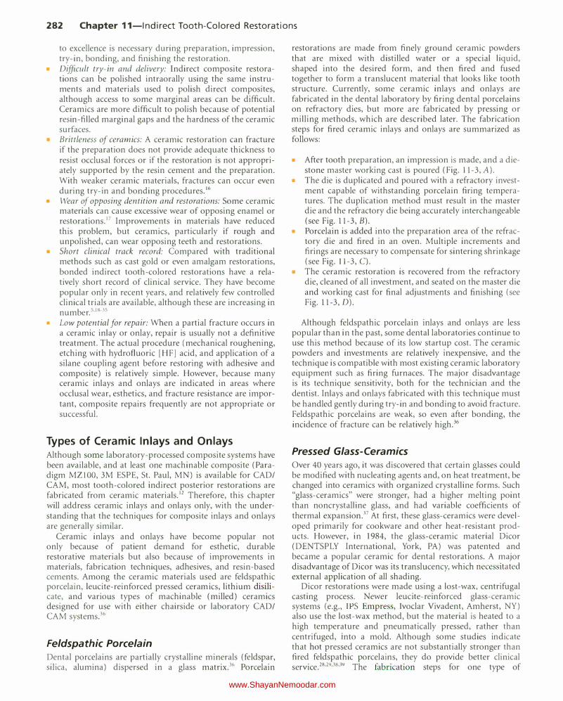
282 Chapter 11-lndirect Tooth-Colored Restorations
to excellence is necessary during preparation, impression, try-in, bonding, and finishing the restoration.
• Difficult try-in and delivery: Indirect composite restorations can be polished intraorally using the same instruments and materials used to polish direct composites, although access to some marginal areas can be difficult. Ceramics are more difficult to polish because of potential resin-filled marginal gaps and the hardness of the ceramic surfaces.
• Brittleness of ceramics: A ceramic restoration can fracture if the preparation does not provide adequate thickness to resist occlusal forces or if the restoration is not appropriately supported by the resin cement and the preparation. With weaker ceramic materials, fractures can occur even during try-in and bonding procedures.16
• Wear of opposing dentition and restorations: Some ceramic materials can cause excessive wear of opposing enamel or restorations.17 Improvements in materials have reduced this problem, but ceramics, particularly if rough and unpolished, can wear opposing teeth and restorations.
• Short clinical track record: Compared with traditional methods such as cast gold or even amalgam restorations, bonded indirect tooth-colored restorations have a relatively short record of clinical service. They have become popular only in recent years, and relatively few controlled clinical trials are available, although these are increasing in number.s,IS-Js
• Low potential for repair: When a partial fracture occurs in a ceramic inlay or onlay, repair is usually not a definitive treatment. The actual procedure (mechanical roughening, etching with hydrofluoric [HF] acid, and application of a silane coupling agent before restoring with adhesive and composite) is relatively simple. However, because many ceramic inlays and onlays are indicated in areas where occlusal wear, esthetics, and fracture resistance are important, composite repairs frequently are not appropriate or successful.
Types of Ceramic Inlays and Onlays Although some laboratory-processed composite systems have been available, and at least one machinable composite (Paradigm MZIOO, 3M ESPE, St. Paul, MN) is available for CAD/ CAM, most tooth-colored indirect posterior restorations are fabricated from ceramic materials.12 Therefore, this chapter will address ceramic inlays and onlays only, with the understanding that the techniques for composite inlays and onlays are generally similar.
Ceramic inlays and onlays have become popular not only because of patient demand for esthetic, durable restorative materials but also because of improvements in materials, fabrication techniques, adhesives, and resin-based cements. Among the ceramic materials used are feldspathic porcelain, leucite-reinforced pressed ceramics, lithium disilicate, and various types of machinable (milled) ceramics designed for use with either chairside or laboratory CAD/ CAM systems.36
Feldspathic Porcelain
Dental porcelains are partially crystalline minerals (feldspar, silica, alumina) dispersed in a glass matrix.36 Porcelain
restorations are made from finely ground ceramic powders that are mixed with distilled water or a special liquid, shaped into the desired form, and then fired and fused together to form a translucent material that looks like tooth structure. Currently, some ceramic inlays and onlays are fabricated in the dental laboratory by firing dental porcelains on refractory dies, but more are fabricated by pressing or milling methods, which are described later. The fabrication steps for fired ceramic inlays and onlays are summarized as follows:
• After tooth preparation, an impression is made, and a diestone master working cast is poured (Fig. 11-3, A).
• The die is duplicated and poured with a refractory investment capable of withstanding porcelain firing temperatures. The duplication method must result in the master die and the refractory die being accurately interchangeable (see Fig. 11-3, B).
• Porcelain is added into the preparation area of the refractory die and fired in an oven. Multiple increments and firings are necessary to compensate for sintering shrinkage (see Fig. ll-3, C). The ceramic restoration is recovered from the refractory die, cleaned of all investment, and seated on the master die and working cast for final adjustments and finishing (see Fig. 11-3, D).
Although feldspathic porcelain inlays and onlays are less popular than in the past, some dental laboratories continue to use this method because of its low startup cost. The ceramic powders and investments are relatively inexpensive, and the technique is compatible with most existing ceramic laboratory equipment such as firing furnaces. The major disadvantage is its technique sensitivity, both for the technician and the dentist. Inlays and onlays fabricated with this technique must be handled gently during try-in and bonding to avoid fracture. Feldspathic porcelains are weak, so even after bonding, the incidence of fracture can be relatively high.36
Pressed Glass-Ceramics
Over 40 years ago, it was discovered that certain glasses could be modified with nucleating agents and, on heat treatment, be changed into ceramics with organized crystalline forms. Such "glass-ceramics" were stronger, had a higher melting point than noncrystalline glass, and had variable coefficients of thermal expansion.37 At first, these glass-ceramics were developed primarily for cookware and other heat-resistant products. However, in 1984, the glass-ceramic material Dicor (DENTSPLY International, York, PA) was patented and became a popular ceramic for dental restorations. A major disadvantage of Dicor was its translucency, which necessitated external application of all shading.
Dicor restorations were made using a lost-wax, centrifugal casting process. Newer leucite-reinforced glass-ceramic systems (e.g., IPS Empress, Ivoclar Vivadent, Amherst, NY ) also use the lost-wax method, but the material is heated to a high temperature and pneumatically pressed, rather than centrifuged, into a mold. Although some studies indicate that hot pressed ceramics are not substantially stronger than fired feldspathic porcelains, they do provide better clinical service.28•29•38•39 The fabrication steps for one type of
www.ShayanNemoodar.com
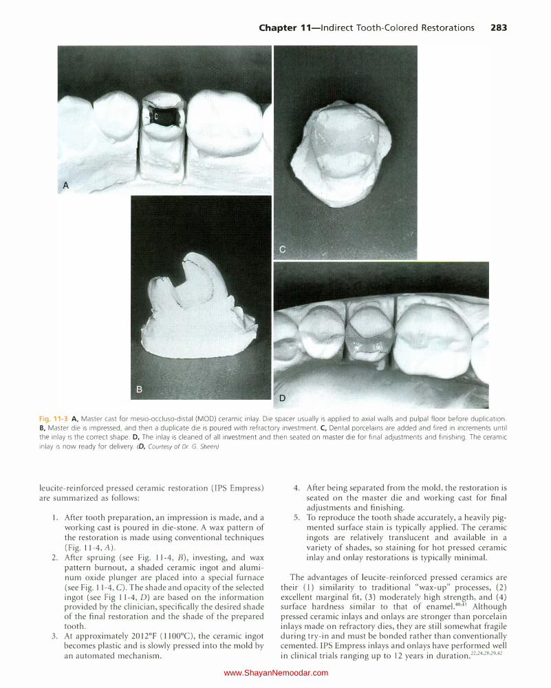
Chapter 11-lndirect Tooth-Colored Restorations 283
Fig. 11-3 A, Master cast for mesio-occluso-distal (MOD) ceramic inlay. Die spacer usually is applied to axial walls and pulpal floor before duplication.
B, Master die is impressed, and then a duplicate die is poured with refractory investment. C, Dental porcelains are added and fired in increments until
the inlay is the correct shape. D, The inlay is cleaned of all investment and then seated on master die for final adjustments and finishing. The ceramic
inlay is now ready for delivery. (D, Courtesy of Dr G. Sheen)
leucite-reinforced pressed ceramic restoration (IPS Empress) are summarized as follows:
1. After tooth preparation, an impression is made, and a working cast is poured in die-stone. A wax pattern of the restoration is made using conventional techniques (Fig. 11-4, A).
2. After spruing (see Fig. 11-4, B), investing, and wax pattern burnout, a shaded ceramic ingot and aluminum oxide plunger are placed into a special furnace (see Fig. 11-4, C). T he shade and opacity of the selected ingot (see Fig 11-4, D) are based on the information provided by the clinician, specifically the desired shade of the final restoration and the shade of the prepared tooth.
3. At approximately 20 l2°F (ll00°C), the ceramic ingot becomes plastic and is slowly pressed into the mold by an automated mechanism.
4. After being separated from the mold, the restoration is seated on the master die and working cast for final adjustments and finishing.
5. To reproduce the tooth shade accurately, a heavily pigmented surface stain is typically applied. The ceramic ingots are relatively translucent and available in a variety of shades, so staining for hot pressed ceramic inlay and onlay restorations is typically minimal.
The advantages of leucite-reinforced pressed ceramics are their (l) similarity to traditional "wax-up" processes, (2) excellent marginal fit, (3) moderately high strength, and (4) surface hardness similar to that of enamel.40.41 Although pressed ceramic inlays and onlays are stronger than porcelain inlays made on refractory dies, they are still somewhat fragile during try-in and must be bonded rather than conventionally cemented. IPS Empress inlays and on lays have performed well in clinical trials ranging up to 12 years in duration.22•24•28•29•42
www.ShayanNemoodar.com
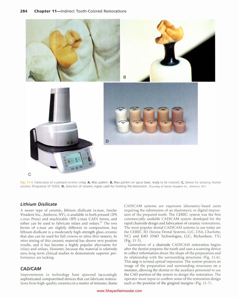
284 Chapter 11-lndirect Tooth-Colored Restorations
D
Fg 1 -4 Fabrication of a pressed ceramic onlay. A, Wax pattern. B, Wax pattern on sprue base, ready to be invested. C, Device for pressing heated ceramic (Programat EP 5000). D, Selection of ceramic ingots used for forming the restoration. (Courtesy of lvoclar Vivadent Inc, Amherst. NY)
Lithium Disilicate
A newer type of ceramic, lithium disilicate (e.max, Ivoclar Vivadent Inc., Amherst, NY), is available in both pressed (IPS e.max Press) and machinable (IPS e.max CAD) forms, and either can be used to fabricate inlays and onlays.43 The two forms of e.max are slightly different in composition, but lithium disilicate is a moderately high-strength glass ceramic that also can be used for full crowns or ultra-thin veneers. In vitro testing of this ceramic material has shown very positive results, and it has become a highly popular alternative for inlays and onlays. However, because th e material is relatively new, long-term clinical studies to demonstrate superior performance are lacking.
CAD/CAM
Improvements in technology have spawned increasingly sophisticated computerized devices that can fabricate restorations from high-quality ceramics in a matter of minutes. Some
CAD/CAM systems are expensive laboratory-based units requiring the submission of an elastomeric or digital impression of the prepared tooth. The CEREC system was the first commercially available CAD/CAM system developed for the rapid chairside design and fabrication of ceramic restorations. The most popular dental CAD/CAM systems in use today are the CEREC 3D (Sirona Dental Systems, LLC, USA, Charlotte, NC) and E4D (D4D Technologies, LLC, Richardson, TX) (Fig. 11-5).
Generation of a chairside CAD/CAM restoration begins after the dentist prepares the tooth and uses a scanning device to collect information about the shape of the preparation and its relationship with the surrounding structures (Fig. 11-6). This step is termed optical impression. The system projects an image of the preparation and surrounding structures on a monitor, allowing the dentist or the auxiliary personnel to use the CAD portion of the system to design the restoration. The operator must input or confirm some of the restoration de ign such as the position of the gingival margins (Fig. 11-7).
www.ShayanNemoodar.com
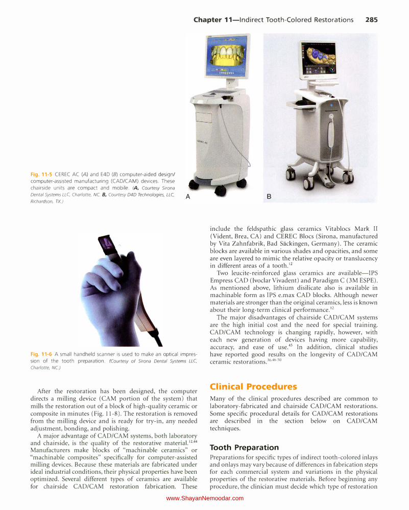
Chapter 11-lndirect Tooth-Colored Restorations 285
Fig. 11-5 CEREC AC (A) and E4D (B) computer-aided design/
computer-assisted manufacturing (CAD/CAM) devices. These
chairside units are compact and mobile. (A, Courtesy Sirona
Dental Systems LLC Charlotte, NC. 8, Courtesy D4D Technologies, LLC Richardson, TX.)
Fig. 11-6 A small handheld scanner is used to make an optical impres
sion of the tooth preparation. (Courtesy of Sirona Dental Systems LLC
Charlotte, NC.)
After the restoration has been designed, the computer directs a milling device (CAM portion of the system) that mills the restoration out of a block of high-quality ceramic or composite in minutes (Fig. 11-8). The restoration is removed from the milling device and is ready for try-in, any needed adjustment, bonding, and polishing.
A major advantage of CAD/CAM systems, both laboratory and chairside, is the quality of the restorative material.12.44 Manufacturers make blocks of "machinable ceramics" or "machinable composites" specifically for computer-assisted milling devices. Because these materials are fabricated under ideal industrial conditions, their physical properties have been optimized. Several different types of ceramics are available for chairside CAD/CAM restoration fabrication. These
B
include the feldspathic glass ceramics Vitablocs Mark II (Vident, Brea, CA) and CEREC Blocs (Sirona, manufactured by Vita Zahnfabrik, Bad Sackingen, Germany). The ceramic blocks are available in various shades and opacities, and some are even layered to mimic the relative opacity or translucency in different areas of a tooth.12
Two leucite-reinforced glass ceramics are available-IPS Empress CAD (Ivoclar Viva dent) and Paradigm C (3M ESPE). As mentioned above, lithium disilicate also is available in machinable form as IPS e.max CAD blocks. Although newer materials are stronger than the original ceramics, less is known about their long-term clinical performance.12
The major disadvantages of chairside CAD/CAM systems are the high initial cost and the need for special training. CAD/CAM technology is changing rapidly, however, with each new generation of devices having more capability, accuracy, and ease of use.45 In addition, clinical studies have reported good results on the longevity of CAD/CAM ceramic restorations. 30.46-50
Clinical Procedures
Many of the clinical procedures described are common to laboratory-fabricated and chairside CAD/CAM restorations. Some specific procedural details for CAD/CAM restorations are described in the section below on CAD/CAM techniques.
Tooth Preparation
Preparations for specific types of indirect tooth-colored inlays and on lays may vary because of differences in fabrication steps for each commercial system and variations in the physical properties of the restorative materials. Before beginning any procedure, the clinician must decide which type of restoration
www.ShayanNemoodar.com