robot application in orthopedic surgery: drilling control
TRANSCRIPT

Robot application in orthopedic surgery: drilling control
George Boiadjiev 1, Kazimir Zagurski
2, Tony Boiadjiev
3, Kamen Delchev
1, Rumen Kastelov
4,
Vladimir Kotev 5
1 Institute of Mechanics – Bulgarian Academy of Sciences, Acad. G. Bonchev St., Bl. 4, 1113 Sofia, Bulgaria
2 Institute of system engineering and robotics - Bulgarian Academy of Sciences, Acad. G. Bonchev St., Bl. 2, 1113 Sofia
3 Institute of information and communication technologies – Bulgarian Academy of Sciences, Acad. G. Bonchev St., Bl. 2,
1113 Sofia 4 Emergency Medical Institute “Pirogov”, Orthopaedic ward, 21 Macedonia Blvd., 1606 Sofia
5 Gifu University, Faculty of Engineering,Department of Human and Information Systems, 1-1 Yanagido, Gifu 501-1193,
JAPAN
Correspondence to: George Boiadjiev, e-mail: [email protected]
Abstract Many orthopedic operations involve drilling and tapping
before the insertion of screws into bone. Usually the drilling is
executed by hand. It leads to lots of problems. The accuracy of
the drilling, braking the blood vessels after the rear hole,
overheating, oscillations widening the hole diameter are some
of examples for that. To avoid these problems and to reduce
the subjective factor the automation of drilling is
recommended. In the work the automatic drilling robot is
presented as well as experiments for establishment the drilling
process technical parameters and its control. The time, linear
velocity, angular velocity, resistant force, depth of penetration
and temperature are monitored during the drilling process.
The robot is user-friendly, i.e. the surgeon can operate easy.
The required working task is set simply and the information
during the process execution is received in real time. The
surgeon has no influence to the process. He must only to take
care of keeping a contact with a bone while the robot
autonomously executes the drilling and takes a decision to
stop. Conclusions are made that the automatic bone drilling
assures higher accuracy and patient safety.
Index Terms – control, experiments, orthopedic surgery,
robot
I. INTRODUCTION
Nowadays robot application in orthopedic surgery arise.
The International Society for Computer Assisted
Orthopedic Surgery was founded and Symposiums on
Automated and Computer Aided Orthopedic Surgery is
organized almost every year. That proves the actuality of
this topic and guarantees future development.
Robotic and navigation systems are one of the most
advanced areas of applications and their range is increasing
[1,2]. In order to overcome the inaccuracy of hand-
controlled positioning of the surgical tools (“...the average
projection of the drill bit beyond the far cortex was 6.31
mm” [3]) many robot system have been developed [4-8].
Electrical instruments are often applied in the orthopedic
surgery – for instance cutting and drilling machines, saws
etc. which the surgeon holds in his hands during
manipulation. The drilling devices are used approximately
in 95% of post-trauma interventions. Since orthopedic
screws are often implanted in bones it is needed to realize
the bone drilling process before. But hand-drilling leads to
some problems as getting the big outlets, breaking the
tendons or blood vessels, overheating etc. [9]. Also an
excessive growth in temperature around a drilling place
causes thermal necrosis of bone which is associated with
irreversible changes in its structure and physical properties.
The hold of the screw is decreased; reducing the stability
and strength of the fixation and the presence of necrotic
tissue delays healing and predispose to infection [10-12].
The automatic drilling could decrease the subjective factor
and avoid to some extent the existing problems.
Generally the drilling process is very complex thing – many
parameters have to be taken into account. Mostly some of
them are unknown. That makes modeling very hard and
usually experimental approaches are usually developed.
They concern parameter identification – bone structure,
forces and torques, temperature, accuracy and so on [13-
18]. As a result of our lots of experiments the following
conclusions are formulated [16]. The robot for automatic
bone drilling must be designed with components capable to
assure:
torque not less than 1.5 Nm
drilling force not less than 100N
force sensor range up to 100 N
temperature not over 52 deg, o C
accuracy: less than 0.5 mm difference of
preliminary set depth or the length of whole bone
At the same time the dimensions and masses of the robot
components must be as small as possible.
The purpose of the work is to present a robot for automatic
bone drilling in orthopedic surgery underlying on its
technical characteristics and achievements in the area of
engineering and control. Drilling algorithms are described
and experimental results are discussed.
GSTF International Journal of Engineering Technology (JET) Vol.1 No.1, 2012
125 © 2012 GSTF
II. DRILLING ROBOT “ODRO”
The robot ODRO (Orthopedic Drilling RObot) is intended
to improve the patient’s safety by removing the subjective
factor and avoid the problems in hand bone drilling,
increasing manipulations accuracy and safety.
On fig.1 the kinematic structure of ODRO is shown. It has
one translation and one revolute joint with co-linear axes,
where q1 and q2 are generalized coordinates. The joints are
driven by two motors for each kind of motion.
Fig.1. Kinematic scheme.
The constructive scheme is presented on fig.2.
Fig.2. Constructive scheme of ODRO.
Notations: 1-liner drive; 2-force sensor; 3-BLDC motor.
Further, some details of its design will be presented – the
power and electronics blocks, the PC-terminals, the
executive mechanical module etc.
A. Components
Linear actuator 43000–17. It is a stepper motor with
embedded screw for linear motion. It has high precision at
low speeds, small by size and realizes translation of 1 mm
for 4032 micro steps.
Brushless DC motor MAXON with servo controller/driver
1-Q-CE and amplifier DEC 50-5. Such motors have many
advantages. They have better speed versus torque
characteristics, high dynamic response, high efficiency,
long operating life, noiseless operation, higher speed
ranges, rugged construction and so on. Also, torque
delivered with respect to the motor size, is higher, making it
useful in applications where the space and the weight are
critical factors. The module can give torques 1.5 – 1.7 Nm.
Controllers comprise two main components – controlling
device and power drive. They are:
-controller / Driver TMCM-110-42 for control of one-
axis stepper motor linear actuator 43000-17.
-servo Controller / Driver for BLDC MAXON. It has
built-in PID-regulators for positioning and for speed.
-force sensor MLP-25 for the bone resistant force.
-temperature sensor SP i-tec 2005D. It is an infrared non-
contact temperature measuring instrument.
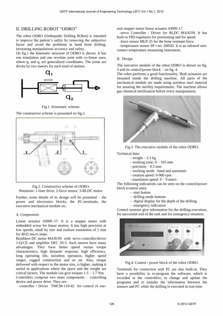
B. Design
The executive module of the robot ODRO is shown on fig.
3 and its control/power block – on fig. 4.
The robot performs a good functionality. Both actuators are
mounted inside the drilling machine. All parts of the
mechanical module are made using stainless steel material
for assuring the sterility requirements. The machine allows
gas chemical sterilization before every manipulation.
Fig.3. The executive module of the robot ODRO.
Technical data:
- weight – 2.3 kg
- working zone: 0 – 105 mm
- precision – 0.5 mm
- working mode: hand and automatic
- rotation speed: 0-900 rpm
- translation speed: 0 – 9 mm/s
The following indications can be seen on the control/power
block (control unit):
- start button
- drilling mode buttons
- digital display for the depth of the drilling
- emergency indication
Control systems give information for the drilling execution,
for successful end of the task and for emergency situation.
Fig.4. Control / power block of the robot ODRO.
Terminals for connection with PC are also built-in. They
have a possibility to re-program the software, which is
recorded in the controllers; to change and update the
programs and to transfer the information between the
sensors and PC while the drilling is executed in real time.
GSTF International Journal of Engineering Technology (JET) Vol.1 No.1, 2012
126 © 2012 GSTF

III. CONTROL ALGORITHM
On fig.5 the control algorithm block-scheme is shown.
The BLDC motor is controlled by MAXON controller and
the stepper motor – by TRINAMIC controller where the
force data sensor are processing in.
fig.5 Control algorithm block-scheme
The control algorithms are executed in the specific program
language TMCL-IDE. The commands can be executed
immediately after their input (direct regime) or the program
can be downloaded in the controller for autonomous
execution (stand-alone regime).
For every cycle the program recognize the current state,
executes the corresponding algorithm and takes a decision
depending on determined criteria for going to the next state.
An algorithm for current calculation of the “next target
position” for the stepper motor is realized depending on the
force sensor data. The actual force sensor data are
considered in comparison with the previous given values.
The last reflects to the safety requirements in the sense that
the exceeding of a given limit value is not allowed.
An algorithm for identification of the resistant force value
during the drilling process is executed. This value is in
relation with the objects manipulation characteristics and
the drill bit diameter. The obtained value is used for taking
the decision for completion of the bone cortex drilling.
The control algorithms work in two regimes: drilling to
reach a preliminary desired depth and through the whole
bone. In the last case the control algorithm allows breaking
the drilling process automatically when the cutting screw
reaches the marrow. Then the surgeon can make a decision
to go on or come back to the starting position. In details the
control algorithm can be described as following.
The machine first executes a “Self Test” program to report
the readiness for work. The surgeon sets the desired
working mode by pressing the corresponding button.
Looking the display information for desired task acceptance
the surgeon presses the button “Confirm”. The drilling
process starts executing the following steps:
pressing the start button
after the Ref. Pos. is found the searching for a
contact with the bone begins (speed - 6mm/s)
at the moment of contact registration a drilling
starts up to 1mm (speed 0.5 mm/s)
drilling the next 1 mm and identification of the
resistant force FR for the actual specific case; the
obtained value is used to set the limit of the
resistant force which must not be overcome further
drilling the first cortex (speed ~ 2 mm/s) up to its
end and automatically stop
when the start button is released and then pressed
again the translation starts through the marrow for
searching the second contact (speed 6 mm/s)
registration the second contact – the control is the
same as the first contact
drilling the second cortex (speed ~ 2 mm/s) up to
its end and automatically stop the translation and
rotation motion
moving back without rotation to the Ref. Pos and
checking for missed steps (speed 6mm/s)
moving to Start pos. (which is near to Ref. Pos)
and stop the motion
the machine is ready for the next setting of the
drilling mode and new working task execution
Real-time information appears on the display corresponding
to the current manipulation.
The main control program is realized as a set of separate
states – “Searching for Contact State”, “Drilling State”,
“Checking for Missing Steps State”, “Contact not Found
State”, “Ready State” etc. They are relevant to
corresponding sub-operations that have to be taken during
the whole drilling process. While in “Stand-alone mode”,
the program recognizes the current state, executes the
corresponding algorithm and takes a decision, depending on
determined criteria, for going to the next appropriate state.
IV. RESULTS
As it was said, before drilling start the robot is performing
“self-test” to specify its state and confirm a readiness for
work. The checking includes execution of preliminary set
rotation and translation speeds, working zone; force sensor
and start button functioning, and reference position. At the
beginning the resistant force is identified specifically for
the concrete object – its age, sex and medical status. Such a
“tuning” is important for safe execution of drilling.
On fig. 5 the information in real time of drilling execution
about the size of bone walls and marrow is shown on LCD
display. It gives the surgeon a possibility to preset a
“maximal-border limitation” which improve the safety.
Fig.5. Bone structure identification result after the whole
bone drilling: first cortex (20 mm), marrow (17 mm) and
the last cortex (18 mm). The sum (bone width) is 55 mm.
GSTF International Journal of Engineering Technology (JET) Vol.1 No.1, 2012
127 © 2012 GSTF

By means of the designed setup various experiments have
been executed. The drilling mode includes the following
monitored parameters:
Time [s]
Linear velocity [mm/s]
Angular velocity [rpm]
Resistant force [N]
Depth of penetration [mm]
Temperature [deg., o C]
The graphics for resistant force and “stop-decision”
function are shown on fig.6. On horizontal scale (x) is the
time – one discrete sample corresponds to 100 ms, i.e. the
whole process is 13.7 sec. On vertical scale (y) is the force
[N]. The first contact is realized at 20 samples and the
second – at 60 on x-axes. The stop-decision takes place
when its value repeats being less than zero during 5 sample
times. On fig.6 it occurs at 55 samples for the first cortex -
the value is less than zero but it is not repeated 5 times and
the drilling goes on. For the second cortex at 122 samples
the value is less than zero more than 5 times and the drilling
stops.
Fig.6. Graphics of resistant force during full bone drilling
(2mm/ s; drill bit Ø4 mm) and “stop-decision” function.
During the drilling process the resistant force FAct is tracked
all the time. A component ε=FAct-FR and an integral
component Ierr=4ε are formed, i.e. a “window” is obtained
with dimension 4 samples, which gives an information for
resistant force deviation. The stop decision is realized as a
function Fstop=f(F0, ε, Ierr), where F0 is the machine
resistance during free motion depending on its orientation
to the bone (including gravity effect). In the same time the
speed is reduced twice aiming to assure minimal
penetration and not to allow big outlet and breaking some
pieces of the bone.
The last figure illustrates the resistant force when the
cutting screw reaches the marrow. During “decision time” it
is zero and appears again while the cutting screw goes to
drill off the rear part of the bone.
V. CONCLUSIONS AND DISCUSSIONS
The automatic bone drilling can entirely solve the problems
arising during usually executed hand drilling. The proposed
experimental setup is designed to identify some parameters
of bone drilling process as resistant force due to variable
bone density, appropriate mechanical torque during the
manipulation, linear speed as well as motors and drives
electromechanical parameters.
Generally the accuracy problem at the automatic bone
drilling can be formulated as: to determine the right
moment of time to stop the drilling assuring not to widen
the rear whole and to realize minimal penetration in soft
tissues behind the bone wall. Also the automatic drilling
must guarantee the patient safety, i.e. to exclude the bone
damage for the sake of overheating and the big drilling
force stress.
The orthopedic robots and integrated computer systems as
ROBODOC, CASPAR etc. are very complex which reflects
to a high cost. Operating with so high-technology apparatus
needs a specialized training and education not so for the
surgeons but for whole teams. The maintenance also takes
additional resources. In this sense it is good not to neglect
the simple systems specialized just for one specific
manipulation. Such an understanding becomes more
popular recently. In comparison with the other systems
ODRO has differences as low cost, user friendly (no need
of special engineering knowledge for working), small size
and simple construction. In the same time it assures the
needed accuracy, precision, reliability and safety of the
manipulation. Moreover, the presented robot is user-
friendly, i.e. the surgeon can operate very easy and the
required task is set very simply and the information during
the process execution is received in real time. The most
important thing is that the surgeon can not influent the
process; he has only to take care of keeping the contact with
the bone. The drilling accuracy of the depth of the hole is
0.2 mm.
Finally, the automatic drilling eliminates whole surgical
manipulation – manually measurement of the penetration in
the bone. The last is one more proof of the automatic
drilling advantages.
The bone resistant force was experimentally obtained to
vary round 30-40 N and its maximal value does not exceed
50 N. The presented experiments estimate the value of 50 N
as an average; some small peaks appear but not over 100 N.
The resistant force function, which can be obtained in
experimental way only, is much helpful for the robot
control. The last means maintaining speeds (linear and
angular) assuring execution of the preliminary determined
control law.
Summarizing, drilling robot application in surgery is an
interesting practical task itself which is still under
development. Its successful solution will have very positive
effect on bone drilling manipulations and screw
implantations, their precision executions, reliability and
safety.
ACKNOWLEDGEMENT
This work was supported under FY2012 Researcher
Exchange Program between the Japan Society for the
Promotion of Science and the Institute of Mechanics –
Bulgarian Academy of Sciences.
REFERENCES
[1] M. Toole, K Bouazza-Marouf, D. Kerr, M.
Gooroochurn and M. Vloeberghs. “A methodology
GSTF International Journal of Engineering Technology (JET) Vol.1 No.1, 2012
128 © 2012 GSTF

for design and appraisal of surgical robotic
systems”, Robotica (2010), 8, pp. 297–310.
Cambridge University Press, 2009.
[2] P. Gomes “Surgical robotics: Reviewing the past,
analysing the present, imagining the future”, J. of
Robotics and Computer-Integrating
Manufacturing, vol. 27, pp. 261-266, 2011.
[3] H.Clement, et al.“Drilling, not a benign procedure:
Laboratory simulation of true drilling depth”
Injury, 2011, doi:10.1016/j.injury.2011.11.017.
[4] K. Hagio, N. Sugano, M. Takashina, T. Nishii, H.
Yoshikawa, and T. Ochi. “Effectiveness of the
ROBODOC system during total hip arthroplasty in
preventing intraoperative pulmonary embolism”,
MICCAI 2002 LNCS 2488, pp. 339-346, 2002.
[5] U. Hagn, M. Nickl, S. Jörg, G. Passig, T. Bahls,
A. Nothhelfer, F. Hacker, L. Le-Tien, L Albu-
Schäffer, R. Konietschke, M. Grebenstein, R
Warpup, R. Haslinger, M. Frommberger, and G.
Hirzinger. “The DLR MIRO: a versatile
lightweight robot for surgical applications”,
Industrial Robot: An International Journal, Vol.
35, No 4, pp.324–336, 2008.
[6] G. Воiadjiev, R. Kastelov, T. Boiadjiev, D.
Vassileva, “Robot Application in Medicine for
Orthopaedic Drilling Manipulation”, In Proc. of
the 8th Mechatronics Forum International
Conference on Mechatronics, 2002, Twente,
Netherlands. (CD), ISBN 9036517664, Book of
Abstracts, 87, ISBN 9036517672.
[7] T. Boiadjiev, G. Boiadjiev, V. Vitkov, “Surgery
Assisting Robot Module for Orthopedic
Manipulation Bone Drilling”, In Proc. of the 11th
Int. Power Electronics and Motion Control
Conference EPE – PEMC, Riga, Latvia, 2004, CD
[8] S. Sarakankosol, W. Charoensuk, and J.
Suthakorn, “Development of the microVibrated
Robot for Orthopedic Surgery in Drilling
Application”, In Proc of the 7th Asian Conference
on Computer Aided Surgery (ACCAS), 2011.
[9] B. Allotta, G. Giacalone, and L Rinaldi. “A hand-
held drilling tool for orthopedic surgery” IEEE
Trans. on Mechatronics, Vol. 2, No 4, pp. 218-
229, 1997.
[10] C. Natali, P. Ingle, and J. Dowell, “Orthopedic
Bone Drills Can They Be Improved? Temperature
Changing Near the Drilling Face.” J. of British
Editorial Society of Bone and Joint Surgery, Vol.
78 B(3), pp. 357-362, 1996.
[11] M.T. Hillery and I. Shuaib, “Temperature effects
in the drilling of human and bovine bone”,
Journal of Materials Processing Technology, 92-
93, pp. 302-308, 1999.
[12] G Augustin, et al., “Cortical bone drilling and
thermal osteonecrosis”, J. of Clin. Biomech.
doi:10.1016/j.clinbiomech.2011.10.010, 2011.
[13] K. Alam, A.V. Mitrofanov, and V.V.
Silberschmidt, “Experimental investigations of
forces and torque in conventional and
ultrasonically-assisted drilling of cortical bone”, J.
Medical Engineering & Physics, Vol. 33, pp. 234–
239, 2011.
[14] Z. Taha, A. Salah, and J. Lee. “Bone Breakthrough
Detection for Orthopedic Robot-Assisted
Surgery”, APIEMS 2008, In Proc. of the 9th Asia
Pasific Industrial Engineering & Management
Systems Conference, pp. 2742-2746, 2008.
[15] G Boiadjiev, T Boiadjiev, V Vitkov, K Delchev, R
Kastelov, and K. Zagurski “Robotized System for
Automation of the Drilling in the Orthopedic
Surgery. Control Algorithms and Experimental
Results.”In Proc. of 9th IFAC Symp Robot Control
SYROCO’09, Gifu, Japan, pp. 633-638, 2009.
[16] T. Boiadjiev, K. Zagurski, G. Boiadjiev, K.
Delchev, V. Vitkov, I. Veneva, and R. Kastelov,
“Identification of the Bone Structure during the
Automatic Drilling in the Orthopedic surgery”, J.
of Mechanics Based Design of Structures and
Machines, Vol. 39, No 2, pp. 285 – 302, 2011.
[17] T. Gao, et al., “Automatic identification of
otological drilling faults: an intelligent recognition
algorithm.”, Int. J. of Medical Robotics and
Computer Assisted Surgery, Vol.6, No 2, pp. 231-
238, 2010.
[18] T. Gao, et al., “A method for identifying otological
drill milling through bone tissue wall.” Int. J. of
Medical Robotics and Computer Assisted Surgery,
Vol. 7, No 2, pp. 148-155, 2011.
[19] B. Davies, R Hibberd, A. Timoney, and J.
Wickhan. “Mechanical constraints – the answer to
safe robotic surgery.” J. of Innovation and
Technology in Biology and Medicine,Vol 13, No 4,
pp. 426- 436, 1992.
[20] BG.Patent No 1053 /July 24, 2008.
[21] BG Patent No 66136 / August 17, 2011.
George Boiadjirv is an associate
professor with the Department of
Mechanics of Multibody Systems at
the Institute of Mechanics,
Bulgarian Academy of Sciences. He
received the M.Sc. degree in
mathematics from the Faculty of
Mathematics and Mechanics at Sofia
University (1984), and the Ph.D.
(1993) in electromechanical systems
modelling from the Institute of Mechanics, Bulgarian
Academy of Sciences. He is currently working in the areas
of dynamics and control of multibody systems and robot-
manipulators.
Kazimir Zagurski is a Senior
Research Assistant at the Institute of
System Engineering and Robotics –
Bulgarian Academy of Sciences. He
received the M.Sc. degree in
Electrical Engineering from the
GSTF International Journal of Engineering Technology (JET) Vol.1 No.1, 2012
129 © 2012 GSTF

Technical University of Sofia. His main activities and
responsibilities are:
R&D in the field of medical robotics.
Participation in a Group for Development of
Automatic bone drilling robot for orthopaedic
surgery.
Participation in number of collaboration activities
for CERN (European Organization For Nuclear
Research) and ETHZ, Institute for Particle Physics
(Swiss Federal Institute of Technology - Zurich)
Microcontroller control systems – hardware and
software design.
Tony Boiadjiev is an associate
professor with the Institute of
information and communication
technologies – Bulgarian Academy
of Sciences. He received the M.Sc.
degree in electronics and
automation from the Technical
University of Sofia (1988), and the
Ph.D. (1997) from the Central
Laboratory of Mechatronics and Instrumentation –
Bulgarian Academy of Sciences. He is currently
working in the areas of modelling, simulation and control
of robotic manipulators.
Kamen Delchev is an associate
professor with the Department of
Mechanics of Multibody Systems at
the Institute of Mechanics,
Bulgarian Academy of Sciences. He
received the M.Sc. degree in
mechanics from the Faculty of
Mathematics and Mechanics at
Sofia University (1980), and the
Ph.D. (1994) in robot control from the Keldysh Institute of
Applied Mathematics at the Russian Academy of Sciences.
He is currently working in the areas of dynamics and
identification of multibody systems, point-to-point motion
tasks and Iterative learning control of robotic manipulators.
Rumen Castelov is an associate
professor on Orthopaedics and
Traumatology, (2003), and Head of
the Department of Orthopaedic
Trauma Surgery, University
Emergency Hospital “Pirogov”,
Sofia. He received his M.Sc. degree
in Medicine, (1986), and the Ph.D.
degree, (1998), from the Medical
University, Sofia, Bulgaria. His major fields of scientific
research are: Reduction of intraarticular knee fractures,
arthroscopy, artificial joints.
Vladimir Kotev is an assistant
professor at Institute of Mechanics
at the Bulgarian Academy of
Science. He is a JSPS Postdoctoral
fellow at Kawasaki and Mouri
Laboratory, Faculty of Engineering,
Gifu University. He has been
working on design and dynamics of
mechanisms for mechatronics
systems and robots. He received the
PhD in Biomechanics at Institute of Mechanics (2008), and
M.Sc. degree in Mechanical engineering from Technical
University Sofia (2002).
GSTF International Journal of Engineering Technology (JET) Vol.1 No.1, 2012
130 © 2012 GSTF