applications of 3d printing technology in orthopedic treatment
TRANSCRIPT
BioMed Research International
Applications of 3D PrintingTechnology in Orthopedic Treatment
Lead Guest Editor: Xiaojun DuanGuest Editors: Ben Wang, Liu Yang, and Anish R. Kadakia
Applications of 3D Printing Technology inOrthopedic Treatment

BioMed Research International
Applications of 3D Printing Technologyin Orthopedic Treatment
Lead Guest Editor: Xiaojun DuanGuest Editors: Ben Wang, Liu Yang, and Anish R.Kadakia

Copyright © 2021 Hindawi Limited. All rights reserved.
is is a special issue published in “BioMed Research International.” All articles are open access articles distributed under the CreativeCommons Attribution License, which permits unrestricted use, distribution, and reproduction in any medium, provided the originalwork is properly cited.
Editorial Board
Y. Ahn, Republic of KoreaParisa Azimi, IranGeorge Babis, GreeceFabiano Bini, ItalyElisa Borsani, ItalyBarbara Buffoli, ItalyFeng Cai, ChinaFrederic CAILOTTO, FranceAntonio Capone, ItalyMing-Chau Chang, TaiwanChul Hyun Cho, Republic of KoreaMarcello De Fine, ItalyLars Donath, GermanyPeter Dr. Varga, Switzerlandaqif El Khassawna, GermanyGiuseppe Filardo, ItalyMattia Fortina, ItalyYou-Shui Gao, ChinaAlberto Grassi, ItalyZbigniew Gugala, USANiels Hammer, New ZealandHyuk-Soo Han, Republic of KoreaPhilipp Honigmann, SwitzerlandYing-Hui Hua, ChinaFrancesco Inchingolo, ItalyFang-chun Jin, ChinaJoby John, United KingdomJean-François Kaux, BelgiumAmal Khoury, IsraelSae Hoon Kim, Republic of KoreaNaomi Kobayashi, JapanPanagiotis Korovessis, GreeceArvind G. Kulkarni, IndiaZhu Kun-Peng, ChinaYong Seuk Lee, Republic of KoreaKai-Uwe Lewandrowski, BrazilChenshuang Li, USAXiaodong Li, USAJianfeng Li, ChinaDohyung Lim, Republic of KoreaSheldon Lin, USAMatthew R. McCann, Canada
Hiroaki Minehara, JapanKyeongsoon Park, Republic of KoreaKun Bo Park, Republic of KoreaJose A. Parraca, PortugalDmitry Popkov, RussiaWilliam B. Rodgers, USAomas S. Roukis, USAAjoy Prasad Shetty, IndiaKangquan Shou, ChinaHae-Ryong Song, Republic of KoreaMartin Stoddart, SwitzerlandZdenek Svoboda, Czech RepublicMitsuhiro Takeno, JapanKentaro Uchida, JapanMeng-Huang Wu, TaiwanRadovan Zdero, CanadaHaining Zhang, ChinaChunfeng Zhao, USAJun Zou, China
Contents
Applications of 3D Printing Technology in Orthopedic TreatmentXiaojun Duan , Ben Wang, Liu Yang, and Anish R. KadakiaEditorial (3 pages), Article ID 9892456, Volume 2021 (2021)
Corrigendum to “Application of 3D Printing-Assisted Articulating Spacer in Two-Stage RevisionSurgery for Periprosthetic Infection a"er Total Knee Arthroplasty: A Retrospective ObservationalStudy”Lingtong Kong , Jiawei Mei , Wufei Ge , Xiansheng Jin, Xiaoxuan Chen , Xianzuo Zhang , andChen Zhu
Corrigendum (1 page), Article ID 9792626, Volume 2021 (2021)
Overview of In-Hospital 3D Printing and Practical Applications in Hand SurgeryMarco Keller , Alissa Guebeli , Florian ieringer , and Philipp Honigmann
Research Article (14 pages), Article ID 4650245, Volume 2021 (2021)
Application of Mixed Reality Using Optical See-+rough Head-Mounted Displays in TransforaminalPercutaneous Endoscopic Lumbar DiscectomyXiaoyang Liu, Jianmin Sun, Meimei Zheng, and Xingang Cui
Research Article (8 pages), Article ID 9717184, Volume 2021 (2021)
+e Bony Resection Accuracy with Patient-Specific Instruments during Total Knee Arthroplasty: ARetrospective Case Series StudyLiang Yuan , Bin Yang , Xiaohua Wang, Bin Sun, Ke Zhang, Yichen Yan, Jie Liu , and Jie Yao
Research Article (9 pages), Article ID 8674847, Volume 2021 (2021)
Application of 3D Printing-Assisted Articulating Spacer in Two-Stage Revision Surgery forPeriprosthetic Infection a"er Total Knee Arthroplasty: A Retrospective Observational StudyLingtong Kong , Jiawei Mei , Wufei Ge , Xiansheng Jin, Xiaoxuan Chen , Xianzuo Zhang , andChen Zhu
Research Article (12 pages), Article ID 3948638, Volume 2021 (2021)
In-Hospital 3D Printed Scaphoid Prosthesis Using Medical-Grade Polyetheretherketone (PEEK)BiomaterialPhilipp Honigmann , Neha Sharma , Ralf Schumacher , Jasmine Rueegg , Mathias Haefeli , andFlorian ieringer
Research Article (7 pages), Article ID 1301028, Volume 2021 (2021)
Endoscopic Treatment of Symptomatic Foot and Ankle Bone Cyst with 3D Printing ApplicationChanggui Zhang, Jin Cao , Hongli Zhu , Huaquan Fan , Liu Yang , and Xiaojun Duan
Research Article (10 pages), Article ID 8323658, Volume 2020 (2020)
+ree-Dimensional-Printed Guiding Template for Unicompartmental Knee ArthroplastyFei Gu, Liangliang Li, Huikang Zhang, Xuxiang Li, Chen Ling, Liming Wang , and Qingqiang Yao
Research Article (10 pages), Article ID 7019794, Volume 2020 (2020)
In Vivo Reconstruction of the Acetabular Bone Defect by the Individualized +ree-Dimensional PrintedPorous Augment in a Swine ModelJun Fu , Yi Xiang , Ming Ni , Xiaojuan Qu , Yonggang Zhou , Libo Hao , Guoqiang Zhang ,and Jiying Chen
Research Article (10 pages), Article ID 4542302, Volume 2020 (2020)
Reconstruction of Bony Defects a"er Tumor Resection with 3D-Printed Anatomically Conforming PelvicProstheses through a Novel Treatment StrategyWei Peng , Runlong Zheng, Hongmei Wang, and Xunwu Huang
Research Article (16 pages), Article ID 8513070, Volume 2020 (2020)
3D Printed Personalized Guide Plate in the Femoral Head Core DecompressionLiangliang Cheng , Xing Qiu, Lei Yang, Chi Xiao, Baoyi Liu, Chukwuemeka Samuel Okoye, and DeweiZhao
Research Article (5 pages), Article ID 7250528, Volume 2020 (2020)
3D-Printed Patient-Specific Instrumentation Technique Vs. Conventional Technique in Medial OpenWedge High Tibial Osteotomy: A Prospective Comparative StudyYunhe Mao , Yang Xiong, Qi Li, Gang Chen, Weili Fu, Xin Tang, Luxi Yang, and Jian Li
Research Article (10 pages), Article ID 1923172, Volume 2020 (2020)
Influence of the Postcuring Process on Dimensional Accuracy and Seating of 3D-Printed Polymeric FixedProsthesesJaewon Kim and Du-Hyeong Lee
Research Article (7 pages), Article ID 2150182, Volume 2020 (2020)
Corrigendum to “Prime-Boost Vaccination Using Chemokine-Fused gp120 DNA and HIV EnvelopePeptides Activates Both Immediate and Long-Term Memory Cellular Responses in Rhesus Macaques”Hong Qin, Pramod N. Nehete , Hong He , Bharti Nehete, Stephanie Buchl, Soung-chul Cha, JagannadhaK. Sastry, and Larry W. KwakCorrigendum (2 pages), Article ID 5471638, Volume 2020 (2020)
Corrigendum to “Combined Industrial Wastewater Treatment in Anaerobic Bioreactor Post-Treated inConstructed Wetland”Bibi Saima Zeb , Qaisar Mahmood , Saima Jadoon , Arshid Pervez, Muhammad Irshad , MuhammadBilal, and Zulfiqar Ahmad BhattiCorrigendum (9 pages), Article ID 6102379, Volume 2020 (2020)
Acetabular Bone Defect in Total Hip Arthroplasty for Crowe II or III Developmental Dysplasia of theHip: A Finite Element StudyYinqiao Du , Jun Fu, Jingyang Sun, Guoqiang Zhang, Jiying Chen, Ming Ni , and Yonggang Zhou
Research Article (12 pages), Article ID 4809013, Volume 2020 (2020)
EditorialApplications of 3D Printing Technology in Orthopedic Treatment
Xiaojun Duan ,1 Ben Wang,2 Liu Yang,1 and Anish R. Kadakia3
1Center for Joint Surgery, Southwest Hospital, Third Military Medical University (Army Medical University), Chongqing, China2Georgia Institute of Technology, Atlanta, USA3Northwestern University, Chicago, USA
Correspondence should be addressed to Xiaojun Duan; [email protected]
Received 28 July 2021; Accepted 28 July 2021; Published 15 August 2021
Copyright © 2021 Xiaojun Duan et al. This is an open access article distributed under the Creative Commons Attribution License,which permits unrestricted use, distribution, and reproduction in any medium, provided the original work is properly cited.
Three-dimensional (3D) printing technology, also known asadditive manufacturing (AM) or rapid prototyping (RP), is aspecial technique which could fabricate 3D models usingcomputer-assisted design (CAD). It was firstly developed bya Japanese doctor forty years ago and initially used inmanufacturing and industry [1]. During recent decades, withthe development of manufacturing technology and materialsscience, 3D printing has also been used in some medical fieldssuch as dentistry, maxillofacial surgery, and neurosurgery [2].Application of 3D printing in orthopedics is also increasinglypopular, mainly including preoperative planning, surgicalguides, personalized implants, and customized prostheses [3,4]. Individualized surgical treatment could be easily and accu-rately formulated under the aid of 3D printing and reduce theoperation time and postoperative complications [5–7].Depending on its unique advantages, 3D printing will lead asurgeon to precisionmedicine and provide patients with bettertreatment effects at lower cost [8, 9]. At present, the Chinesegovernment, enterprises, universities, and institutes haveinvested a lot of resources in related research including print-ing technology, raw materials, and clinical applications andhave made important progress. For example, our center uses3D printing technology to manufacture implants of poroustantalum for clinical surgical treatment; in this special issue,a great majority of the submissions come from China, whichreport their latest developments in 3D printing. As the edito-rial team, we pay attention to some recent progressive researchin 3D printing technology for orthopedic treatment. Below is asummary of these accepted articles.
The study by L. Kong et al. reported a set of articular spacersolutions using 3D printing technology in revision surgery forperiprosthetic joint infection (PJI) after total knee arthroplasty.They compared the treatment effects between 3D printingspacer and static spacer in a retrospective study and stated thatthe 3D printing spacer group had less bone loss, less intraoper-ative blood loss, and greater knee function than the static spacergroup. This technique effectively provides a new method tomake accurate and personalized spacers in PJI and lower therates of reinfection and complications.
The paper by Y. Du et al. evaluated the stability of theacetabular cup with different types of bone defects in totalhip arthroplasty for developmental dysplasia of the hip(DDH) using the finite element analysis (FEA) model. Theauthors found that the diameter of the femoral ceramic headhad no significant impact on the stability of the acetabularcup. When the uncoverage rates of the cup were less than24.5%, the stability of the cup was satisfactory even withoutthe use of screws. However, when the uncoverage rates weremore than 24.5%, it was necessary to apply screws to improvethe primary stabilization of the cup. Although their study isjust based on the FEA model instead of clinical application,the results are still beneficial to the subsequent clinical study.
L. Yuan et al. retrospectively analyzed the bony resectionaccuracy during total knee arthroplasty (TKA) with patient-specific instrumentation (PSI) produced by 3D printing tech-nology. They conducted full-length computed tomography(CT) for every patient and drafted detailed preoperativeplans including the bony resection thickness. PSI was manu-
HindawiBioMed Research InternationalVolume 2021, Article ID 9892456, 3 pageshttps://doi.org/10.1155/2021/9892456
factured based on the CT data and operation plan. Each boneresected in the operation was also measured with CT toreconstruct the three-dimensional radiographs. The boneresection thickness was compared between the preoperativeplan and intraoperative data to assess the resection accuracyin different bone sites. The results of this study show that PSIhad a generally good accuracy during the femur and tibiabone resection in TKA.
X. Liu et al. evaluated the application of mixed reality(MixR) technology during transforaminal percutaneousendoscopic discectomy (TPED), and optical see-throughhead-mounted displays (OST-HMDs) were used to assistoperation. They compared the difference of clinical effectsbetween conventional TPED and MixR-assisted TPED andfound that mixed reality (MixR) technology could signifi-cantly reduce the operation time and radiation exposureduring the total operation procedure. This technology maybe a powerful auxiliary tool for TPED but would increasethe eye fatigue because of the application of OST-HMDs.
J. Kim et al. investigated whether the postcuring processcould influence the dimensional accuracy and seating of 3Dprinting dental prostheses. A study stone model was designedand fabricated to verify this hypothesis. Results showed thatthe postcuring process significantly affected the fit anddimensional precision of 3D printing polymeric prostheses.They suggested that seating on the stone model was a betterchoice for minimizing the deformity of the dental prosthesisand reducing adverse effects during the postcuring process.
F. Gu et al. designed a three-dimensional printed patient-customized guiding template (3DGT) to increase the efficacyand safety of unicompartmental knee arthroplasty (UKA).Personalized guiding template could provide helpful assis-tance in several procedures of operation planning, intraoper-ative positioning, and osteotomy. This study concluded that3DGT could shorten operation time, reduce surgical trauma,and promote recovery.
P. Honigmann et al. presented the first inhospital 3Dprinted scaphoid prosthesis using polyetheretherketone(PEEK) biomaterial via fused filament fabrication (FFF),one of the 3D printing technologies. The surface of this med-ical grade PEEK prosthesis did not show “FFF stair-stepping”phenomenon, which was usually common in the industrialgrade scaphoid prosthesis. The biocompatible and implant-able polymers such as PEEK applied in 3D printing couldoffer great potential in the treatment of complex jointdamage in the hospital environment.
M. Keller et al. reviewed the latest practical application of3D printing in hand surgery and introduced the most com-mon printing techniques and some materials. They provideda useful overview of the 3D printing technology applied innumerous aspects such as surgical guides, personalizedimplants for bone defects, customized splints, and preopera-tive plan. The authors hold the opinion that orthopedics,especially hand surgery, will benefit from 3D printing in thenear future.
L. Cheng et al. retrospectively investigated the utilizationand feasibility of 3D printing technology for core decompres-sion in patients with osteonecrosis of the femoral head(ONFH). The operation process went well and consumed less
time than traditional methods with the aid of personalizedguide plates and reduced the usage of intraoperative X-rayfluoroscopy. The results indicated that 3D printing hadseveral advantages of improving efficiency, being moreconvenient, and accurate positioning.
C. Zhang et al. revealed the efficacy of arthroscopy intreating bone cysts of the foot and ankle combined with 3Dprinting individualized guides. Better VAS score and AOFASscore and less intraoperative bleeding were displayed inpatients with the assistance of 3D printing. It is concludedthat 3D printing could significantly help surgeons to fastand smoothly establish a portal in arthroscopic ankle surgery.
J. Fu et al. reconstructed the acetabular bone defect in aswine model to evaluate the bone ingrowth, biomechanics,and matching degree of the 3D printed porous prosthesis.Based on the results, the authors found that the 3D printedporous augments showed great porosity and pore size andhad magnificent stiffness and elastic modulus. The anatomi-cal matching extent was excellent, which could enhance thestability of the porous prosthesis. Although this study wasconducted in minipigs, it displayed the great potential of3D printed porous augment in the treatment of clinicalsevere acetabular bone defects.
Y. Mao et al. compared the clinical effects of 3D printedpatient-specific instrumentation (PSI) with conventional sur-gical techniques in medial open wedge high tibial osteotomy(MOWHTO). The results of this prospective comparativestudy showed that 3D printed PSI had significantly lowercorrection errors in terms of mFTA and mMPTA anddemanded shorter duration and less radiation exposure.They concluded that 3D printing technique could be recom-mended as an effective assistant for MOWHTO in the treat-ment of varus because of its accuracy and effectiveness.
W. Peng et al. reported an entirely anatomicallyconforming pelvic prosthesis for pelvic reconstruction. Pelvictumor is a complex disease due to the vascular invasion oftumor issue, and most of the patients suffering from pelvictumor undergo the surgery of tumor resection and hemipel-vic replacement. The authors showed that 3D-printed pros-thesis was of value for patients with complex pelvic tumors.
Conflicts of Interest
The editors declare that there are no conflicts of interestregarding the publication of this special issue.
Acknowledgments
We would like to express our great gratitude to Xin Chenfrom the Center for Joint Surgery of Southwest Hospital forlanguage support and appreciate all authors and editorswho contributed to this special issue. We also want to thankthe reviewers who made this special issue possible.
Xiaojun DuanBen WangLiu Yang
Anish R. Kadakia
2 BioMed Research International
References
[1] A. Zhakeyev, P.Wang, L. Zhang,W. Shu, H.Wang, and J. Xuan,“Additive manufacturing: unlocking the evolution of energymaterials,” Advanced Science, vol. 4, no. 10, article 1700187,2017.
[2] M. Michalski and J. Ross, “The shape of things to come: 3Dprinting in medicine,” JAMA, vol. 312, no. 21, pp. 2213-2214,2014.
[3] M. Burn, A. Ta, and G. Gogola, “Three-dimensional printing ofprosthetic hands for children,” The Journal of Hand Surgery,vol. 41, no. 5, pp. e103–e109, 2016.
[4] N. Skelley, M. Smith, R. Ma, and J. L. Cook, “Three-dimen-sional printing technology in orthopaedics,” The Journal ofthe American Academy of Orthopaedic Surgeons, vol. 27,no. 24, pp. 918–925, 2019.
[5] P. Fadero andM. Shah, “Three dimensional (3D) modelling andsurgical planning in trauma and orthopaedics,” The Surgeon,vol. 12, no. 6, pp. 328–333, 2014.
[6] M. Citak, L. Kochsiek, T. Gehrke, C. Haasper, E. M. Suero, andH. Mau, “Preliminary results of a 3D-printed acetabular com-ponent in the management of extensive defects,” Hip Interna-tional, vol. 28, no. 3, pp. 266–271, 2018.
[7] X. Duan, P. He, H. Fan, C. Zhang, F. Wang, and L. Yang,“Application of 3D-printed personalized guide in arthroscopicankle arthrodesis,” BioMed Research International, vol. 2018,Article ID 3531293, 8 pages, 2018.
[8] S. Lawson, A. Alwakwak, A. Rownaghi, and F. Rezaei,“Gel-print-grow: a new way of 3D printing metal-organicframeworks,” ACS Applied Materials & Interfaces, vol. 12,no. 50, pp. 56108–56117, 2020.
[9] X. Duan, H. Fan, F. Wang, P. He, and L. Yang, “Application of3D-printed customized guides in subtalar joint arthrodesis,”Orthopaedic Surgery, vol. 11, no. 3, pp. 405–413, 2019.
3BioMed Research International
CorrigendumCorrigendum to “Application of 3D Printing-Assisted ArticulatingSpacer in Two-Stage Revision Surgery for Periprosthetic Infectionafter Total Knee Arthroplasty: A RetrospectiveObservational Study”
Lingtong Kong ,1 Jiawei Mei ,1 Wufei Ge ,1 Xiansheng Jin,2 Xiaoxuan Chen ,3
Xianzuo Zhang ,4 and Chen Zhu 1
1Department of Orthopedics, The Affiliated Provincial Hospital of Anhui Medical University, Hefei 230001, China2IAT-Chungu Joint Laboratory for Additive Manufacturing Anhui Chungu 3D Printing Institute of Intelligent Equipment andIndustrial Technology, Wuhu 241200, China3College of Chemistry and Chemical Engineering, Xiamen University, Xiamen 361005, China4Department of Orthopedics, The First Affiliated Hospital of USTC, Division of Life Sciences and Medicine, University of Science andTechnology of China, Hefei 230022, China
Correspondence should be addressed to Xianzuo Zhang; [email protected] and Chen Zhu; [email protected]
Received 24 May 2021; Accepted 24 May 2021; Published 7 June 2021
Copyright © 2021 Lingtong Kong et al. This is an open access article distributed under the Creative Commons Attribution License,which permits unrestricted use, distribution, and reproduction in any medium, provided the original work is properly cited.
In the article titled “Application of 3D Printing-AssistedArticulating Spacer in Two-Stage Revision Surgery forPeriprosthetic Infection after Total Knee Arthroplasty: ARetrospective Observational Study” [1], some of theauthors were linked to the incorrect affiliations in the affil-iation list. The correct author affiliations are now correctedin the author information above.
References
[1] L. Kong, J. Mei, W. Ge et al., “Application of 3D printing-assisted articulating spacer in two-stage revision surgery forperiprosthetic infection after total knee arthroplasty: a retro-spective observational study,” BioMed Research International,vol. 2021, Article ID 3948638, 12 pages, 2021.
HindawiBioMed Research InternationalVolume 2021, Article ID 9792626, 1 pagehttps://doi.org/10.1155/2021/9792626
Research ArticleOverview of In-Hospital 3D Printing and Practical Applications inHand Surgery
Marco Keller ,1,2 Alissa Guebeli ,1,2 Florian Thieringer ,2,3
and Philipp Honigmann 1,2,4
1Hand Surgery, Department of Orthopaedic Surgery and Traumatology, Kantonsspital Baselland, 4410 Liestal, Switzerland2Medical Additive Manufacturing Research Group, Department of Biomedical Engineering, University of Basel,4123 Allschwil, Switzerland3Department of Oral and Cranio-Maxillofacial Surgery, University Hospital Basel, Basel, Switzerland4Department of Biomedical Engineering and Physics, Amsterdam UMC, University of Amsterdam, Amsterdam, Netherlands
Correspondence should be addressed to Marco Keller; [email protected]
Received 23 June 2020; Revised 3 January 2021; Accepted 22 March 2021; Published 27 March 2021
Academic Editor: Xiaojun Duan
Copyright © 2021 Marco Keller et al. This is an open access article distributed under the Creative Commons Attribution License,which permits unrestricted use, distribution, and reproduction in any medium, provided the original work is properly cited.
Three-dimensional (3D) printing is spreading in hand surgery. There is an increasing number of practical applications like thetraining of junior hand surgeons, patient education, preoperative planning, and 3D printing of customized casts, customizedsurgical guides, implants, and prostheses. Some high-quality studies highlight the value for surgeons, but there is still a lack ofhigh-level evidence for improved clinical endpoints and hence actual impact on the patient’s outcome. This article provides anoverview over the latest applications of 3D printing in hand surgery and practical experience of implementing them into dailyclinical routine.
1. Introduction
Three-dimensional (3D) printing, also known as AdditiveManufacturing (AM), is a manufacturing technology whichenables the production of three-dimensional models of acomputer-designed template or data from medical imagingtechnologies by specially designed printers.
In 1981, a Japanese doctor, Hideo Kodama, developeda rapid prototyping technique, using a photosensitive resinthat was polymerized by an UV light, creating the first 3Dprinting technique, an ancestor for SLA (stereolithogra-phy). In 1986, the first patent for SLA was submitted byChuck Hull, and in 1988, two further 3D printing tech-niques were developed: SLS (“selective laser sintering”, inwhich powder grains are fused together locally by a laser)and FDM (“fused deposition modelling”, 3D printing withfilaments) [1, 2].
In the following years, several additional methods weredeveloped, including Binder Jetting and Polyjet, which are
methods based on the inkjet printing technology, makingcolor printing and combination of different materialspossible [3].
3D printing was first used in the automobile, aerospace,and consumer product industries. Along with the radicalimprovements financed by these industries, new applicationshave been developed for its use in the medical field. Accord-ing to the different aspects of every medical subspecialty, theimplementation of 3D printing occurred with different paceand intensity. The applications of 3D printing in hand sur-gery are, compared to other subspecialties like for examplecraniomaxillofacial surgery, currently limited. In orthopaedicsurgery, especially hand surgery, 3D printing enables the pro-duction of complex anatomical forms from data such asComputertomography (CT) images.
Current fields of application are the training of younghand surgeons, patient education, preoperative planningand fabrication of customized rehabilitation devices, custom-ized surgical guiding tools, implants, and prostheses [4, 5].
HindawiBioMed Research InternationalVolume 2021, Article ID 4650245, 14 pageshttps://doi.org/10.1155/2021/4650245
An overview over the development and current imple-mentations of 3D printing in each field is given in the subse-quent paragraphs.
2. Printing Techniques and Materials
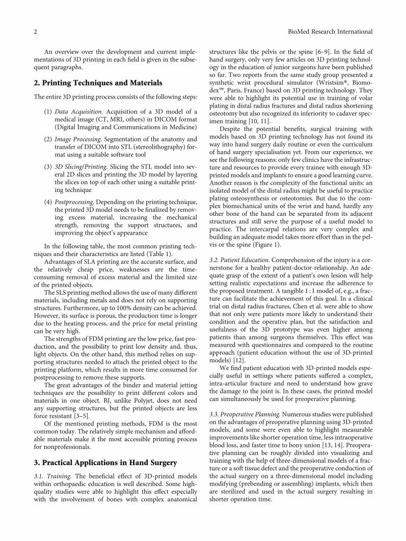
The entire 3D printing process consists of the following steps:
(1) Data Acquisition. Acquisition of a 3D model of amedical image (CT, MRI, others) in DICOM format(Digital Imaging and Communications in Medicine)
(2) Image Processing. Segmentation of the anatomy andtransfer of DICOM into STL (stereolithography) for-mat using a suitable software tool
(3) 3D Slicing/Printing. Slicing the STL model into sev-eral 2D slices and printing the 3D model by layeringthe slices on top of each other using a suitable print-ing technique
(4) Postprocessing. Depending on the printing technique,the printed 3D model needs to be finalized by remov-ing excess material, increasing the mechanicalstrength, removing the support structures, andimproving the object’s appearance
In the following table, the most common printing tech-niques and their characteristics are listed (Table 1).
Advantages of SLA printing are the accurate surface, andthe relatively cheap price, weaknesses are the time-consuming removal of excess material and the limited sizeof the printed objects.
The SLS printing method allows the use of many differentmaterials, including metals and does not rely on supportingstructures. Furthermore, up to 100% density can be achieved.However, its surface is porous, the production time is longerdue to the heating process, and the price for metal printingcan be very high.
The strengths of FDM printing are the low price, fast pro-duction, and the possibility to print low density and, thus,light objects. On the other hand, this method relies on sup-porting structures needed to attach the printed object to theprinting platform, which results in more time consumed forpostprocessing to remove these supports.
The great advantages of the binder and material jettingtechniques are the possibility to print different colors andmaterials in one object. BJ, unlike Polyjet, does not needany supporting structures, but the printed objects are lessforce resistant [3–5].
Of the mentioned printing methods, FDM is the mostcommon today. The relatively simple mechanism and afford-able materials make it the most accessible printing processfor nonprofessionals.
3. Practical Applications in Hand Surgery
3.1. Training. The beneficial effect of 3D-printed modelswithin orthopaedic education is well described. Some high-quality studies were able to highlight this effect especiallywith the involvement of bones with complex anatomical
structures like the pelvis or the spine [6–9]. In the field ofhand surgery, only very few articles on 3D printing technol-ogy in the education of junior surgeons have been publishedso far. Two reports from the same study group presented asynthetic wrist procedural simulator (Wristsim®, Biomo-dex™, Paris, France) based on 3D printing technology. Theywere able to highlight its potential use in training of volarplating in distal radius fractures and distal radius shorteningosteotomy but also recognized its inferiority to cadaver spec-imen training [10, 11].
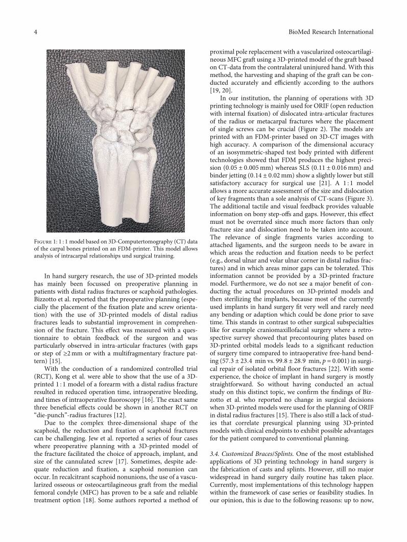
Despite the potential benefits, surgical training withmodels based on 3D printing technology has not found itsway into hand surgery daily routine or even the curriculumof hand surgery specialisation yet. From our experience, wesee the following reasons: only few clinics have the infrastruc-ture and resources to provide every trainee with enough 3D-printed models and implants to ensure a good learning curve.Another reason is the complexity of the functional units: anisolated model of the distal radius might be useful to practiceplating osteosynthesis or osteotomies. But due to the com-plex biomechanical units of the wrist and hand, hardly anyother bone of the hand can be separated from its adjacentstructures and still serve the purpose of a useful model topractice. The intercarpal relations are very complex andbuilding an adequate model takes more effort than in the pel-vis or the spine (Figure 1).
3.2. Patient Education. Comprehension of the injury is a cor-nerstone for a healthy patient-doctor-relationship. An ade-quate grasp of the extent of a patient’s own lesion will helpsetting realistic expectations and increase the adherence tothe proposed treatment. A tangible 1 : 1 model of, e.g., a frac-ture can facilitate the achievement of this goal. In a clinicaltrial on distal radius fractures, Chen et al. were able to showthat not only were patients more likely to understand theircondition and the operative plan, but the satisfaction andusefulness of the 3D prototype was even higher amongpatients than among surgeons themselves. This effect wasmeasured with questionnaires and compared to the routineapproach (patient education without the use of 3D-printedmodels) [12].
We find patient education with 3D-printed models espe-cially useful in settings where patients suffered a complex,intra-articular fracture and need to understand how gravethe damage to the joint is. In these cases, the printed modelcan simultaneously be used for preoperative planning.
3.3. Preoperative Planning.Numerous studies were publishedon the advantages of preoperative planning using 3D-printedmodels, and some were even able to highlight measurableimprovements like shorter operation time, less intraoperativeblood loss, and faster time to bony union [13, 14]. Preopera-tive planning can be roughly divided into visualizing andtraining with the help of three-dimensional models of a frac-ture or a soft tissue defect and the preoperative conduction ofthe actual surgery on a three-dimensional model includingmodifying (prebending or assembling) implants, which thenare sterilized and used in the actual surgery resulting inshorter operation time.
2 BioMed Research International
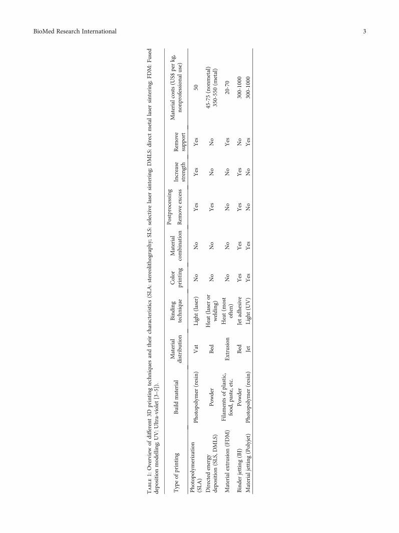
Table1:
Overview
ofdifferent3D
printing
techniqu
esandtheircharacteristics(SLA
:stereolitho
graphy;SLS:
selectivelasersintering;
DMLS:direct
metal
lasersintering;
FDM:F
used
depo
sition
mod
ellin
g;UV:U
ltra-violet[3–5]).
Typeof
printing
Build
material
Material
distribu
tion
Binding
techniqu
eColor
printing
Material
combination
Postprocessing
Materialcosts(U
S$perkg,
nonp
rofessionalu
se)
Rem
oveexcess
Increase
strength
Rem
ove
supp
ort
Pho
topo
lymerization
(SLA
)Pho
topo
lymer
(resin)
Vat
Light(laser)
No
No
Yes
Yes
Yes
50
Directedenergy
depo
sition
(SLS,D
MLS)
Pow
der
Bed
Heat(laser
orwelding)
No
No
Yes
No
No
45-75(non
metal)
350-550(m
etal)
Materialextrusion
(FDM)
Filamentsof
plastic,
food
,paste,etc.
Extrusion
Heat(m
ost
often)
No
No
No
No
Yes
20-70
Binderjetting(BJ)
Pow
der
Bed
Jetadhesive
Yes
Yes
Yes
Yes
No
300-1000
Materialjetting
(Polyjet)
Pho
topo
lymer
(resin)
Jet
Light(U
V)
Yes
Yes
No
No
Yes
300-1000
3BioMed Research International
In hand surgery research, the use of 3D-printed modelshas mainly been focussed on preoperative planning inpatients with distal radius fractures or scaphoid pathologies.Bizzotto et al. reported that the preoperative planning (espe-cially the placement of the fixation plate and screw orienta-tion) with the use of 3D-printed models of distal radiusfractures leads to substantial improvement in comprehen-sion of the fracture. This effect was measured with a ques-tionnaire to obtain feedback of the surgeon and wasparticularly observed in intra-articular fractures (with gapsor step of ≥2mm or with a multifragmentary fracture pat-tern) [15].
With the conduction of a randomized controlled trial(RCT), Kong et al. were able to show that the use of a 3D-printed 1 : 1 model of a forearm with a distal radius fractureresulted in reduced operation time, intraoperative bleeding,and times of intraoperative fluoroscopy [16]. The exact samethree beneficial effects could be shown in another RCT on“die-punch”-radius fractures [12].
Due to the complex three-dimensional shape of thescaphoid, the reduction and fixation of scaphoid fracturescan be challenging. Jew et al. reported a series of four caseswhere preoperative planning with a 3D-printed model ofthe fracture facilitated the choice of approach, implant, andsize of the cannulated screw [17]. Sometimes, despite ade-quate reduction and fixation, a scaphoid nonunion canoccur. In recalcitrant scaphoid nonunions, the use of a vascu-larized osseous or osteocartilagineous graft from the medialfemoral condyle (MFC) has proven to be a safe and reliabletreatment option [18]. Some authors reported a method of
proximal pole replacement with a vascularized osteocartilagi-neous MFC graft using a 3D-printed model of the graft basedon CT-data from the contralateral uninjured hand. With thismethod, the harvesting and shaping of the graft can be con-ducted accurately and efficiently according to the authors[19, 20].
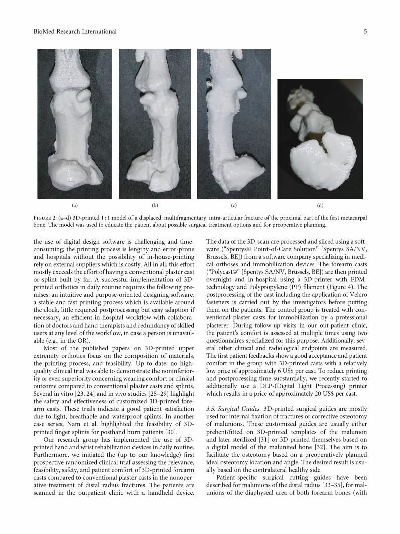
In our institution, the planning of operations with 3Dprinting technology is mainly used for ORIF (open reductionwith internal fixation) of dislocated intra-articular fracturesof the radius or metacarpal fractures where the placementof single screws can be crucial (Figure 2). The models areprinted with an FDM-printer based on 3D-CT images withhigh accuracy. A comparison of the dimensional accuracyof an isosymmetric-shaped test body printed with differenttechnologies showed that FDM produces the highest preci-sion (0:05 ± 0:005mm) whereas SLS (0:11 ± 0:016mm) andbinder jetting (0:14 ± 0:02mm) show a slightly lower but stillsatisfactory accuracy for surgical use [21]. A 1 : 1 modelallows a more accurate assessment of the size and dislocationof key fragments than a sole analysis of CT-scans (Figure 3).The additional tactile and visual feedback provides valuableinformation on bony step-offs and gaps. However, this effectmust not be overrated since much more factors than onlyfracture size and dislocation need to be taken into account.The relevance of single fragments varies according toattached ligaments, and the surgeon needs to be aware inwhich areas the reduction and fixation needs to be perfect(e.g., dorsal ulnar and volar ulnar corner in distal radius frac-tures) and in which areas minor gaps can be tolerated. Thisinformation cannot be provided by a 3D-printed fracturemodel. Furthermore, we do not see a major benefit of con-ducting the actual procedures on 3D-printed models andthen sterilizing the implants, because most of the currentlyused implants in hand surgery fit very well and rarely needany bending or adaption which could be done prior to savetime. This stands in contrast to other surgical subspecialtieslike for example craniomaxillofacial surgery where a retro-spective survey showed that precontouring plates based on3D-printed orbital models leads to a significant reductionof surgery time compared to intraoperative free-hand bend-ing (57:3 ± 23:4 min vs. 99:8 ± 28:9 min, p = 0:001) in surgi-cal repair of isolated orbital floor fractures [22]. With someexperience, the choice of implant in hand surgery is mostlystraightforward. So without having conducted an actualstudy on this distinct topic, we confirm the findings of Biz-zotto et al. who reported no change in surgical decisionswhen 3D-printed models were used for the planning of ORIFin distal radius fractures [15]. There is also still a lack of stud-ies that correlate presurgical planning using 3D-printedmodels with clinical endpoints to exhibit possible advantagesfor the patient compared to conventional planning.
3.4. Customized Braces/Splints. One of the most establishedapplications of 3D printing technology in hand surgery isthe fabrication of casts and splints. However, still no majorwidespread in hand surgery daily routine has taken place.Currently, most implementations of this technology happenwithin the framework of case series or feasibility studies. Inour opinion, this is due to the following reasons: up to now,
Figure 1: 1 : 1 model based on 3D-Computertomography (CT) dataof the carpal bones printed on an FDM-printer. This model allowsanalysis of intracarpal relationships und surgical training.
4 BioMed Research International
the use of digital design software is challenging and time-consuming; the printing process is lengthy and error-proneand hospitals without the possibility of in-house-printingrely on external suppliers which is costly. All in all, this effortmostly exceeds the effort of having a conventional plaster castor splint built by far. A successful implementation of 3D-printed orthotics in daily routine requires the following pre-mises: an intuitive and purpose-oriented designing software,a stable and fast printing process which is available aroundthe clock, little required postprocessing but easy adaption ifnecessary, an efficient in-hospital workflow with collabora-tion of doctors and hand therapists and redundancy of skilledusers at any level of the workflow, in case a person is unavail-able (e.g., in the OR).
Most of the published papers on 3D-printed upperextremity orthotics focus on the composition of materials,the printing process, and feasibility. Up to date, no high-quality clinical trial was able to demonstrate the noninferior-ity or even superiority concerning wearing comfort or clinicaloutcome compared to conventional plaster casts and splints.Several in vitro [23, 24] and in vivo studies [25–29] highlightthe safety and effectiveness of customized 3D-printed fore-arm casts. These trials indicate a good patient satisfactiondue to light, breathable and waterproof splints. In anothercase series, Nam et al. highlighted the feasibility of 3D-printed finger splints for posthand burn patients [30].
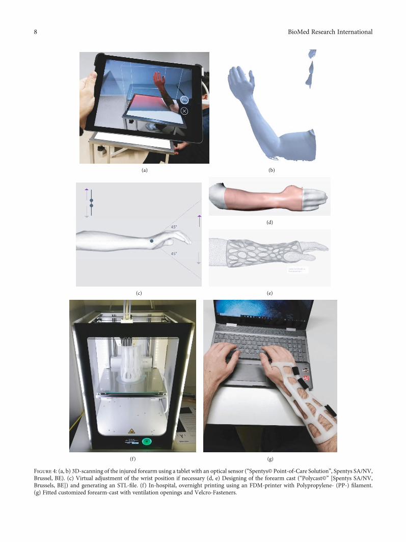
Our research group has implemented the use of 3D-printed hand and wrist rehabilitation devices in daily routine.Furthermore, we initiated the (up to our knowledge) firstprospective randomized clinical trial assessing the relevance,feasibility, safety, and patient comfort of 3D-printed forearmcasts compared to conventional plaster casts in the nonoper-ative treatment of distal radius fractures. The patients arescanned in the outpatient clinic with a handheld device.
The data of the 3D-scan are processed and sliced using a soft-ware (“Spentys© Point-of-Care Solution” [Spentys SA/NV,Brussels, BE]) from a software company specializing in medi-cal orthoses and immobilization devices. The forearm casts(“Polycast©” [Spentys SA/NV, Brussels, BE]) are then printedovernight and in-hospital using a 3D-printer with FDM-technology and Polypropylene (PP) filament (Figure 4). Thepostprocessing of the cast including the application of Velcrofasteners is carried out by the investigators before puttingthem on the patients. The control group is treated with con-ventional plaster casts for immobilization by a professionalplasterer. During follow-up visits in our out-patient clinic,the patient’s comfort is assessed at multiple times using twoquestionnaires specialized for this purpose. Additionally, sev-eral other clinical and radiological endpoints are measured.The first patient feedbacks show a good acceptance and patientcomfort in the group with 3D-printed casts with a relativelylow price of approximately 6 US$ per cast. To reduce printingand postprocessing time substantially, we recently started toadditionally use a DLP-(Digital Light Processing) printerwhich results in a price of approximately 20 US$ per cast.
3.5. Surgical Guides. 3D-printed surgical guides are mostlyused for internal fixation of fractures or corrective osteotomyof malunions. These customized guides are usually eitherprebent/fitted on 3D-printed templates of the malunionand later sterilized [31] or 3D-printed themselves based ona digital model of the malunited bone [32]. The aim is tofacilitate the osteotomy based on a preoperatively plannedideal osteotomy location and angle. The desired result is usu-ally based on the contralateral healthy side.
Patient-specific surgical cutting guides have beendescribed for malunions of the distal radius [33–35], for mal-unions of the diaphyseal area of both forearm bones (with
(a) (b) (c) (d)
Figure 2: (a–d) 3D-printed 1 : 1 model of a displaced, multifragmentary, intra-articular fracture of the proximal part of the first metacarpalbone. The model was used to educate the patient about possible surgical treatment options and for preoperative planning.
5BioMed Research International
(a) (b)
(c) (d)
(e) (f)
Figure 3: Continued.
6 BioMed Research International
custom-made fixation plates) [32], and for malunions of thescaphoid [36]. The senior author of this article presented amethod using an acrylate Kirschner wire guide in combina-tion with an acrylate wedge template for distal radius malu-nions which allow to harvest a precisely suitable iliac crestbone graft [37]. In a retrospective assessment of the earlyclinical outcome, 3D-planned and guided single-cut osteo-tomies of the forearm proved to be an accurate and reliablemethod [38].
Customized 3D-printed guides have also been used forosteosynthesis of scaphoid fractures. Yin et al. presented amethod using a 3D-printed glove-like patient-specific guid-ing template to allow 1-shot percutaneous fixation [39]. DeWolf et al. presented another 3D-printed targeting devicefor scaphoid fractures and were able to show on cadavers thatit provides similar accuracy while significantly reducingintraoperative radiation exposure and procedure time [40].
Most of these studies have a descriptive character andlack a control group. A systematic review on three-dimensional virtual planning of corrective osteotomies ofdistal radius malunions identified the following issues: noclinical study comparing the results of 3D-planning tech-niques with conventional planning methods could be identi-fied. While the authors highlighted the benefit of 3D-planning, most studies used conventional two-dimensional(2D) radiographs to assess the radiological result of the pro-cedures. This might lead to underestimation of residualdeformities. Furthermore, a great heterogeneity of differentradius malunions was seen. The authors concluded that nofull comprehension of the added value of 3D-planning in dis-tal radius malunion corrective osteotomy can be achievedwithout randomized controlled trials [41].
3.6. Personalized Implants/Solutions for Bone Defects. Besidesorthopaedic aids like personalized splints, the trend for cus-tomization has also gained widespread use in the production
of surgical implants. 3D printing technology is well estab-lished in the field of plastic and reconstructive surgery, whereit is used to fabricate individualized synthetic and biologicimplants, regenerative scaffolds, and cell-specific tissues andorgans [42]. In craniofacial surgery, the use of patient-specific implants made from polymethylmethacrylate(PMMA) has proven to be cost-effective and applicable indaily clinical practice [43]. Yet again in hand surgery, up tonow, there is only a hand full of case reports and feasibilitystudies on this topic. The printed implants are mostly basedon scans of the contralateral healthy side.
In 2017, Kim et al. compared a 3D-printed volar lockingdistal radius plate fabricated by laser sintering of titaniumalloy powder with two conventional volar locking plates. Bio-mechanical testing showed that the 3D-printed plate had asignificantly higher strength than conventional plates, yetthe implant was not customized to the bone [44].
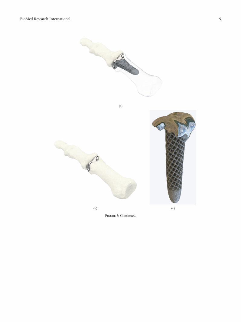
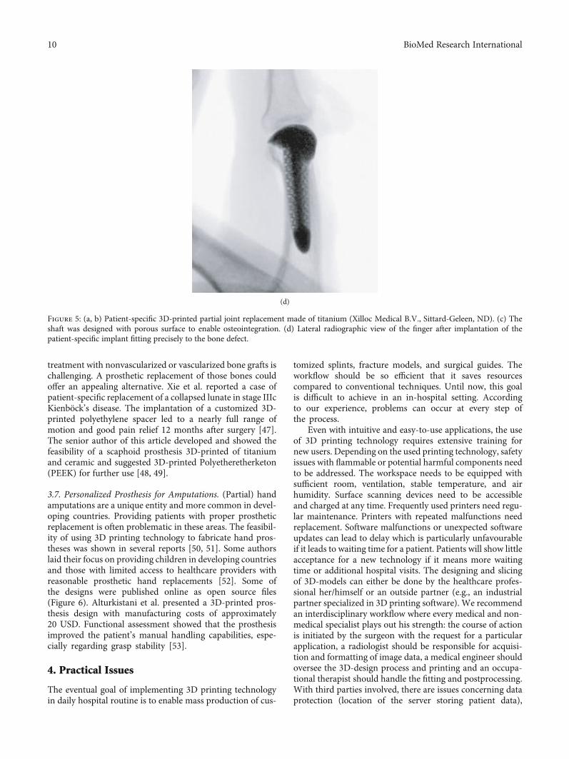
Other authors reported a 3D-printed (titanium) replace-ment of a finger proximal phalanx after recurrence of a giantcell tumor [45] or the replacement of the distal radius withcustomized, uncemented 3D-printed prostheses (Metal-PE(polyethylene)-combination with hydroxyapatite coating) in11 patients with giant cell tumors [46]. Both report satisfac-tional functional outcomes with short-term oncologic sal-vage. Our own study group was able to replace parts of theproximal phalanx in a patient with a defect-lesion of theindex finger after a chainsaw accident with a patient-specific implant. Since an “off the shelf” implant was nofavourable option due to insufficient bone stock a patient-specific 3D-printed partial joint replacement made of tita-nium was used. The shaft was designed with a porous surfaceto allow osteointegration (Figure 5). The patient’s range ofmotion in the proximal interphalangeal joint improved frompreoperative 20° to postoperative 60°.
Carpal bones are complex in their anatomy and are atrisk for fracture nonunion or avascular necrosis. Surgical
(g) (h) (i)
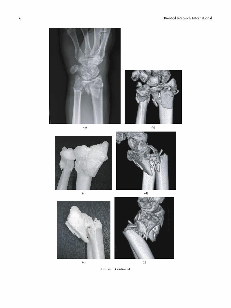
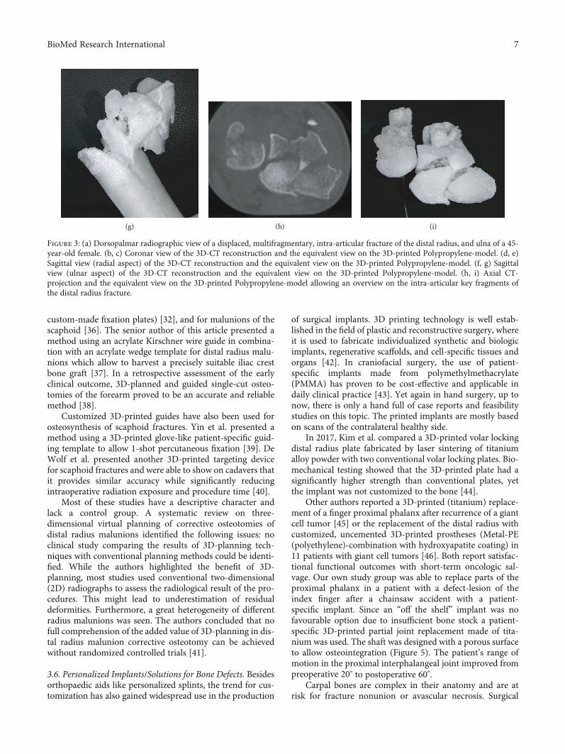
Figure 3: (a) Dorsopalmar radiographic view of a displaced, multifragmentary, intra-articular fracture of the distal radius, and ulna of a 45-year-old female. (b, c) Coronar view of the 3D-CT reconstruction and the equivalent view on the 3D-printed Polypropylene-model. (d, e)Sagittal view (radial aspect) of the 3D-CT reconstruction and the equivalent view on the 3D-printed Polypropylene-model. (f, g) Sagittalview (ulnar aspect) of the 3D-CT reconstruction and the equivalent view on the 3D-printed Polypropylene-model. (h, i) Axial CT-projection and the equivalent view on the 3D-printed Polypropylene-model allowing an overview on the intra-articular key fragments ofthe distal radius fracture.
7BioMed Research International
(a) (b)
(c)
(d)
(e)
(f) (g)
Figure 4: (a, b) 3D-scanning of the injured forearm using a tablet with an optical sensor (“Spentys© Point-of-Care Solution”, Spentys SA/NV,Brussel, BE). (c) Virtual adjustment of the wrist position if necessary (d, e) Designing of the forearm cast (“Polycast©” [Spentys SA/NV,Brussels, BE]) and generating an STL-file. (f) In-hospital, overnight printing using an FDM-printer with Polypropylene- (PP-) filament.(g) Fitted customized forearm-cast with ventilation openings and Velcro-Fasteners.
8 BioMed Research International
(a)
(b) (c)
Figure 5: Continued.
9BioMed Research International
treatment with nonvascularized or vascularized bone grafts ischallenging. A prosthetic replacement of those bones couldoffer an appealing alternative. Xie et al. reported a case ofpatient-specific replacement of a collapsed lunate in stage IIIcKienböck’s disease. The implantation of a customized 3D-printed polyethylene spacer led to a nearly full range ofmotion and good pain relief 12 months after surgery [47].The senior author of this article developed and showed thefeasibility of a scaphoid prosthesis 3D-printed of titaniumand ceramic and suggested 3D-printed Polyetheretherketon(PEEK) for further use [48, 49].
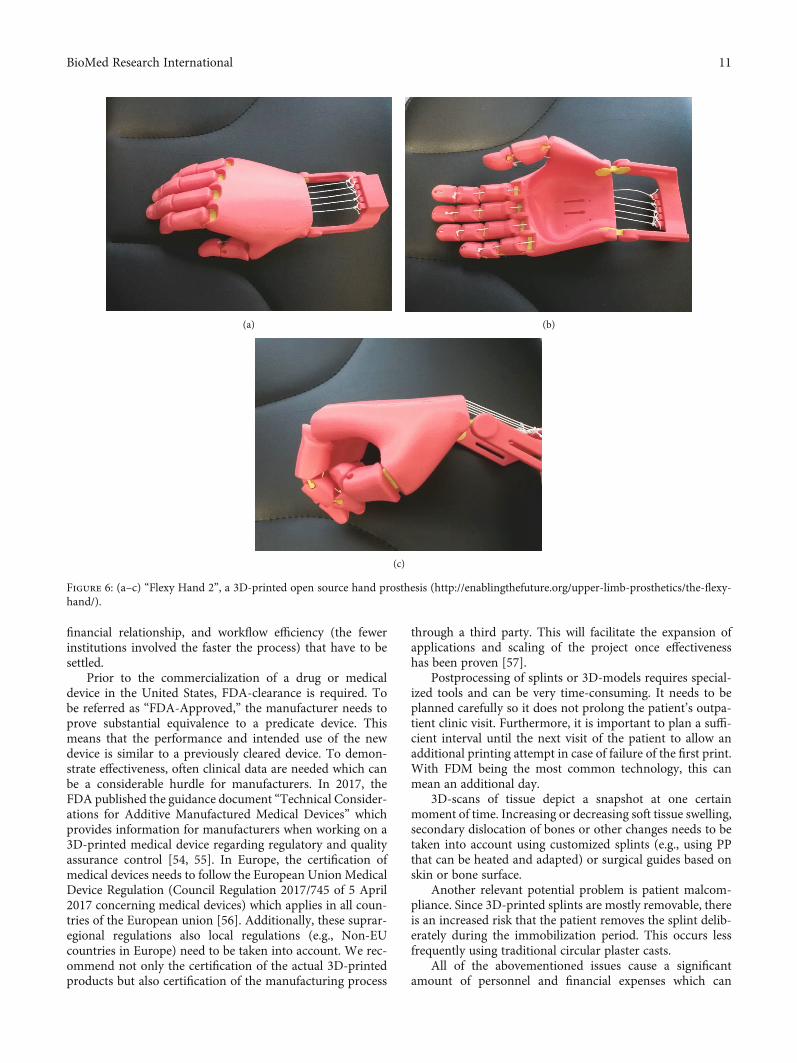
3.7. Personalized Prosthesis for Amputations. (Partial) handamputations are a unique entity and more common in devel-oping countries. Providing patients with proper prostheticreplacement is often problematic in these areas. The feasibil-ity of using 3D printing technology to fabricate hand pros-theses was shown in several reports [50, 51]. Some authorslaid their focus on providing children in developing countriesand those with limited access to healthcare providers withreasonable prosthetic hand replacements [52]. Some ofthe designs were published online as open source files(Figure 6). Alturkistani et al. presented a 3D-printed pros-thesis design with manufacturing costs of approximately20 USD. Functional assessment showed that the prosthesisimproved the patient’s manual handling capabilities, espe-cially regarding grasp stability [53].
4. Practical Issues
The eventual goal of implementing 3D printing technologyin daily hospital routine is to enable mass production of cus-
tomized splints, fracture models, and surgical guides. Theworkflow should be so efficient that it saves resourcescompared to conventional techniques. Until now, this goalis difficult to achieve in an in-hospital setting. Accordingto our experience, problems can occur at every step ofthe process.
Even with intuitive and easy-to-use applications, the useof 3D printing technology requires extensive training fornew users. Depending on the used printing technology, safetyissues with flammable or potential harmful components needto be addressed. The workspace needs to be equipped withsufficient room, ventilation, stable temperature, and airhumidity. Surface scanning devices need to be accessibleand charged at any time. Frequently used printers need regu-lar maintenance. Printers with repeated malfunctions needreplacement. Software malfunctions or unexpected softwareupdates can lead to delay which is particularly unfavourableif it leads to waiting time for a patient. Patients will show littleacceptance for a new technology if it means more waitingtime or additional hospital visits. The designing and slicingof 3D-models can either be done by the healthcare profes-sional her/himself or an outside partner (e.g., an industrialpartner specialized in 3D printing software). We recommendan interdisciplinary workflow where every medical and non-medical specialist plays out his strength: the course of actionis initiated by the surgeon with the request for a particularapplication, a radiologist should be responsible for acquisi-tion and formatting of image data, a medical engineer shouldoversee the 3D-design process and printing and an occupa-tional therapist should handle the fitting and postprocessing.With third parties involved, there are issues concerning dataprotection (location of the server storing patient data),
(d)
Figure 5: (a, b) Patient-specific 3D-printed partial joint replacement made of titanium (Xilloc Medical B.V., Sittard-Geleen, ND). (c) Theshaft was designed with porous surface to enable osteointegration. (d) Lateral radiographic view of the finger after implantation of thepatient-specific implant fitting precisely to the bone defect.
10 BioMed Research International
financial relationship, and workflow efficiency (the fewerinstitutions involved the faster the process) that have to besettled.
Prior to the commercialization of a drug or medicaldevice in the United States, FDA-clearance is required. Tobe referred as “FDA-Approved,” the manufacturer needs toprove substantial equivalence to a predicate device. Thismeans that the performance and intended use of the newdevice is similar to a previously cleared device. To demon-strate effectiveness, often clinical data are needed which canbe a considerable hurdle for manufacturers. In 2017, theFDA published the guidance document “Technical Consider-ations for Additive Manufactured Medical Devices” whichprovides information for manufacturers when working on a3D-printed medical device regarding regulatory and qualityassurance control [54, 55]. In Europe, the certification ofmedical devices needs to follow the European Union MedicalDevice Regulation (Council Regulation 2017/745 of 5 April2017 concerning medical devices) which applies in all coun-tries of the European union [56]. Additionally, these suprar-egional regulations also local regulations (e.g., Non-EUcountries in Europe) need to be taken into account. We rec-ommend not only the certification of the actual 3D-printedproducts but also certification of the manufacturing process
through a third party. This will facilitate the expansion ofapplications and scaling of the project once effectivenesshas been proven [57].
Postprocessing of splints or 3D-models requires special-ized tools and can be very time-consuming. It needs to beplanned carefully so it does not prolong the patient’s outpa-tient clinic visit. Furthermore, it is important to plan a suffi-cient interval until the next visit of the patient to allow anadditional printing attempt in case of failure of the first print.With FDM being the most common technology, this canmean an additional day.
3D-scans of tissue depict a snapshot at one certainmoment of time. Increasing or decreasing soft tissue swelling,secondary dislocation of bones or other changes needs to betaken into account using customized splints (e.g., using PPthat can be heated and adapted) or surgical guides based onskin or bone surface.
Another relevant potential problem is patient malcom-pliance. Since 3D-printed splints are mostly removable, thereis an increased risk that the patient removes the splint delib-erately during the immobilization period. This occurs lessfrequently using traditional circular plaster casts.
All of the abovementioned issues cause a significantamount of personnel and financial expenses which can
(a) (b)
(c)
Figure 6: (a–c) “Flexy Hand 2”, a 3D-printed open source hand prosthesis (http://enablingthefuture.org/upper-limb-prosthetics/the-flexy-hand/).
11BioMed Research International
initially be overwhelming compared to using conventionaltechnologies. In our opinion, the efficiency can be maximizedby conducting as many substeps as possible in-hospital, evenif it requires substantial financial investments in the begin-ning. The workflow should be tested extensively and usedon patients only when its stability is proved to guaranteegood treatment quality.
5. Conclusion
Although the history of 3D printing technology is nearly 40years old, its use is not yet well established in hand surgerycompared to other medical subspecialities like craniomaxil-lofacial surgery or dentistry. Only in the last few years, inter-est among hand surgeons and the 3D printing industry hasrisen and intensive research has been initiated. Possible rea-sons for this delay are the following: in the eyes of the indus-try, hand surgery was not known to be a lucrative businessinvestment. Hand surgeons relied on conventional provenproducts in their daily routine and did not see a significantpotential benefit of the 3D printing technology for theirwork. With the general interest focussing more and moreon patient-specific or personalized treatment, 3D printingbecame increasingly interesting for hand surgeons.
However, research on its use in hand surgery is stillscarce. Up to now, complicated digital design software,lengthy and error-prone printing processes and expensivehardware were factors that inhibited a major widespread of3D printing in daily routine. The idea that one person shouldbe able to perform all substeps of the process, which requireprofound skills in different areas, might be another reason.For a successful implementation of 3D printing in dailyroutine, we therefore recommend the involvement of dif-ferent medical and nonmedical specialists throughout theprocess. With today’s complexity of digital design softwareprograms, we found it to be most efficient to outsource thedigital designing to closely collaborating medical engineers.At least with applications, where no complete automationis possible yet. In order to increase efficiency, postproces-sing of printed objects can be handled by hand therapists,who often have more expertise in this area compared tohand surgeons.
The technical foundations for future applications such asbioprinting (replacement of tissue defects), in-hospital, oreven in-OR implant-printing on demand are mostly knowntoday. But due to missing clinical proof of effectiveness, gov-ernmental regulations, and too expensive and elaborateprinting processes and materials their implementation indaily hand surgery routine is currently far from realistic. Bysimplifying workflows and reducing production costs, webelieve that in the near future 3D printing technology canadd a significant value to hand surgery.
Data Availability
Readers can access any data underlying the findings of thisresearch article by contacting the authors.
Conflicts of Interest
The senior author has an honorary-based consultant func-tion at the company Medartis AG, Basel, Switzerland. Ourresearch group is supported by the company Spentys©(Spentys SA/NV, Brussels, BE) with printing materials andtechnical support.
References
[1] H. Kodama, “A scheme for three-dimensional display byautomatic fabrication of three-dimensional model,” IEICETransactions on Electronics, vol. J64-C, pp. 237–241, 1981.
[2] C. Hull, “Apparatus for production of three-dimensionalobjects by stereolithography,” 1986, US Patent 638905.
[3] V. Matter-Parrat and P. Liverneaux, “3D printing in handsurgery,” Hand Surgery and Rehabilitation, vol. 38, no. 6,pp. 338–347, 2019.
[4] S. Negi, S. Dhiman, and R. Kumar Sharma, “Basics andapplications of rapid prototyping medical models,” RapidPrototyping Journal, vol. 20, no. 3, pp. 256–267, 2014.
[5] M. Javaid and A. Haleem, “Additive manufacturing applica-tions in orthopaedics: a review,” Journal of Clinical Orthopae-dics and Trauma, vol. 9, no. 3, pp. 202–206, 2018.
[6] B. Langridge, S. Momin, B. Coumbe, E. Woin, M. Griffin, andP. Butler, “Systematic review of the use of 3-dimensional print-ing in surgical teaching and assessment,” Journal of SurgicalEducation, vol. 75, no. 1, pp. 209–221, 2018.
[7] Y. AbouHashem, M. Dayal, S. Savanah, and G. Štrkalj, “Theapplication of 3D printing in anatomy education,” MedicalEducation Online, vol. 20, no. 1, article 29847, 2015.
[8] Z. Huang, W. Song, Y. Zhang et al., “Three-dimensional print-ing model improves morphological understanding in acetabu-lar fracture learning: a multicenter, randomized, controlledstudy,” PLoS One, vol. 13, no. 1, article e0191328, 2018.
[9] A. Wu, K. Wang, J. Wang et al., “The addition of 3D printedmodels to enhance the teaching and learning of bone spatialanatomy and fractures for undergraduate students: a random-ized controlled study,” Annals of Translational Medicine,vol. 6, no. 20, p. 403, 2018.
[10] P. Lazarus, E. Pire, C. Sapa et al., “Design and evaluation of anew synthetic wrist procedural simulator (Wristsim ®) fortraining of distal radius fracture fixation by volar plating,”Hand Surgery and Rehabilitation, vol. 36, no. 4, pp. 275–280,2017.
[11] I. Naroura, J. J. Hidalgo Diaz, F. Xavier et al., “Teaching ofdistal radius shortening osteotomy: three-dimensional proce-dural simulator versus bone procedural simulator,” The Jour-nal of Hand Surgery, European Volume, vol. 43, no. 9,pp. 961–966, 2018.
[12] C. Chen, L. Cai, C. Zhang, J. Wang, X. Guo, and Y. Zhou,“Treatment of die-punch fractures with 3D printing technol-ogy,” Journal of Investigative Surgery, vol. 31, no. 5, pp. 385–392, 2017.
[13] P. S. Corona, M. Vicente, K. Tetsworth, and V. Glatt, “Prelim-inary results using patient-specific 3d printed models toimprove preoperative planning for correction of post-traumatic tibial deformities with circular frames,” Injury,vol. 49, Suppl 2, pp. S51–S59, 2018.
[14] L. Xie, C. Chen, Y. Zhang, W. Zheng, H. Chen, and L. Cai,“Three-dimensional printing assisted ORIF versus
12 BioMed Research International
conventional ORIF for Tibial plateau fractures: a systematicreview and meta-analysis,” International Journal of Surgery,vol. 57, pp. 35–44, 2018.
[15] N. Bizzotto, I. Tami, A. Tami et al., “3D printed models of dis-tal radius fractures,” Injury, vol. 47, no. 4, pp. 976–978, 2016.
[16] L. Kong, G. Yang, J. Yu et al., “Surgical treatment of intra-articular distal radius fractures with the assistance of three-dimensional printing technique,”Medicine, vol. 99, no. 8, arti-cle e19259, 2020.
[17] N. Jew, J. D. Lipman, and M. G. Carlson, “The use of three-dimensional printing for complex scaphoid fractures,” TheJournal of Hand Surgery, vol. 44, no. 2, pp. 165.e1–165.e6,2019.
[18] M. Keller, T. Kastenberger, A. F. Anoar et al., “Clinical andradiological results of the vascularized medial femoral condylegraft for scaphoid non-union,” Archives of Orthopaedic andTrauma Surgery, vol. 140, no. 6, pp. 835–842, 2020.
[19] M. T. Houdek, J. M. Matsumoto, J. M. Morris, A. T. Bishop,and A. Y. Shin, “Technique for 3-dimesional (3D) modelingof osteoarticular medial femoral condyle vascularized graftingto replace the proximal pole of unsalvagable scaphoid non-unions,” Techniques in Hand & Upper Extremity Surgery,vol. 20, no. 3, pp. 117–124, 2016.
[20] E. M. Taylor and M. L. Iorio, “Surgeon-based 3D printing formicrovascular bone flaps,” Journal of Reconstructive Microsur-gery, vol. 33, no. 6, pp. 441–445, 2017.
[21] B. Msallem, N. Sharma, S. Cao, F. S. Halbeisen, H. F. Zeilhofer,and F. M. Thieringer, “Evaluation of the dimensional accuracyof 3D-printed anatomical mandibular models using FFF, SLA,SLS, MJ, and BJ printing technology,” Journal of Clinical Med-icine, vol. 9, no. 3, p. 817, 2020.
[22] G. R. Sigron, N. Rüedi, F. Chammartin et al., “Three-dimen-sional analysis of isolated orbital floor fractures pre- andpost-reconstruction with standard titanium meshes and“hybrid” patient-specific implants,” Journal of Clinical Medi-cine, vol. 9, no. 5, article E1579, p. 1579, 2020.
[23] P. Hoogervorst, R. Knox, K. Tanaka et al., “A biomechanicalcomparison of fiberglass casts and 3-dimensional-printed,open-latticed, ventilated casts,” Hand, vol. 15, no. 6, pp. 842–849, 2020.
[24] A. Cazon, S. Kelly, A. M. Paterson, R. J. Bibb, and R. I.Campbell, “Analysis and comparison of wrist splint designsusing the finite element method: multi-material three-dimensional printing compared to typical existing practicewith thermoplastics,” Proceedings of the Institution ofMechanical Engineers. Part H, vol. 231, no. 9, pp. 881–897, 2017.
[25] Y. J. Chen, H. Lin, X. Zhang, W. Huang, L. Shi, and D. Wang,“Application of 3D-printed and patient-specific cast for thetreatment of distal radius fractures: Initial Experience,” 3DPrinting in Medicine, vol. 3, no. 1, p. 11, 2017.
[26] J. Graham, M. Wang, K. Frizzell, C. Watkins, P. Beredjiklian,and M. Rivlin, “Conventional vs 3-dimensional printed castwear comfort,” Hand, vol. 15, no. 3, pp. 388–392, 2020.
[27] H. Lin, L. Shi, and D. Wang, “A Rapid and intelligent design-ing technique for patient-specific and 3D-printed orthopediccast,” 3D Printing in Medicine, vol. 2, no. 1, 2016.
[28] J. Li and H. Tanaka, “Rapid customization system for 3D-printed splint using programmable modeling technique - apractical approach,” 3D Printing in Medicine, vol. 4, no. 1,p. 5, 2018.
[29] C. Kienzle and M. Schäfer, Integration of additive manufactur-ing processes (3D Printing) in orthopaedic technology fittingroutine, Verlag Orthopädie-Technik, Dortmund, 2018.
[30] H. S. Nam, C. H. Seo, S. Y. Joo, D. H. Kim, and D. S. Park, “Theapplication of three-dimensional printed finger splints for posthand burn patients: a case series investigation,” Annals ofRehabilitation Medicine, vol. 42, no. 4, pp. 634–638, 2018.
[31] Y. Hamada, H. Gotani, K. Sasaki, Y. Tanaka, H. Egawa, andT. Kanchanathepsak, “Corrective osteotomy of maluniteddiaphyseal fractures of the forearm simplified using 3-dimensional CT data: proposal of our simple strategy throughcase presentation,”Hand, vol. 12, no. 5, pp. NP95–NP98, 2017.
[32] A. M. Byrne, B. Impelmans, V. Bertrand, A. van Haver, andF. Verstreken, “Corrective osteotomy for malunited diaphysealforearm fractures using preoperative 3-dimensional planningand patient-specific surgical guides and implants,” The Journalof Hand Surgery, vol. 42, no. 10, pp. 836.e1–836.e12, 2017.
[33] A. Schweizer, P. Fürnstahl, and L. Nagy, “Three-dimensionalcorrection of distal radius intra-articular malunions usingpatient-specific drill guides,” The Journal of Hand Surgery,vol. 38, no. 12, pp. 2339–2347, 2013.
[34] M. Kunz, B. Ma, J. F. Rudan, R. E. Ellis, and D. R. Pichora,“Image-guided distal radius osteotomy using patient-specificinstrument guides,” The Journal of Hand Surgery, vol. 38,no. 8, pp. 1618–1624, 2013.
[35] S. Roner, F. Carrillo, L. Vlachopoulos, A. Schweizer, L. Nagy,and P. Fuernstahl, “Improving accuracy of opening-wedgeosteotomies of distal radius using a patient-specific ramp-guide technique,” BMC Musculoskeletal Disorders, vol. 19,no. 1, p. 374, 2018.
[36] A. Schweizer, F. Mauler, L. Vlachopoulos, L. Nagy, andP. Fürnstahl, “Computer-assisted 3-dimensional reconstruc-tions of scaphoid fractures and nonunions with and withoutthe use of patient-specific guides: early clinical outcomes andpostoperative assessments of reconstruction accuracy,” TheJournal of Hand Surgery, vol. 41, no. 1, pp. 59–69, 2016.
[37] P. Honigmann, F. Thieringer, R. Steiger, M. Haefeli,R. Schumacher, and J. A. Henning, “A Simple 3-DimensionalPrinted Aid for a Corrective Palmar Opening Wedge Osteot-omy of the Distal Radius,” The Journal of Hand Surgery,vol. 41, no. 3, pp. 464–469, 2016.
[38] S. Roner, L. Vlachopoulos, L. Nagy, A. Schweizer, andP. Fürnstahl, “Accuracy and early clinical outcome of 3-dimensional planned and guided single-cut osteotomies ofmalunited forearm bones,” The Journal of Hand Surgery,vol. 42, no. 12, pp. 1031.e1–1031.e8, 2017.
[39] H. Yin, J. Xu, and W. Xu, “3-Dimensional Printing-AssistedPercutaneous Fixation for Acute Scaphoid Fracture: 1-ShotProcedure,” The Journal of Hand Surgery, vol. 42, no. 4,pp. 301.e1–301.e5, 2017.
[40] M. C. DeWolf, A. Hartov, T. A. Fortney, and L. G. Warhold,“Three-dimensional printed targeting device for scaphoidfracture fixation,” Hand, 2020.
[41] R. J. O. de Muinck Keizer, K. M. Lechner, M. A. M. Mulders,N. W. L. Schep, D. Eygendaal, and J. C. Goslings, “Three-dimensional virtual planning of corrective osteotomies of dis-tal radius malunions: a systematic review and meta-analysis,”Strategies in Trauma and Limb Reconstruction, vol. 12, no. 2,pp. 77–89, 2017.
[42] A. J. Bauermeister, A. Zuriarrain, and M. I. Newman, “Three-dimensional printing in plastic and reconstructive surgery: a
13BioMed Research International
systematic review,” Annals of Plastic Surgery, vol. 77, no. 5,pp. 569–576, 2016.
[43] D. Chamo, B. Msallem, N. Sharma, S. Aghlmandi, C. Kunz,and F. M. Thieringer, “Accuracy assessment of molded,patient-specific polymethylmethacrylate craniofacial implantscompared to their 3D printed originals,” Journal of ClinicalMedicine, vol. 9, no. 3, p. 832, 2020.
[44] S. J. Kim, Y. H. Jo, W. S. Choi et al., “Biomechanical propertiesof 3-dimensional printed volar locking distal radius plate:comparison with conventional volar locking plate,” The Jour-nal of Hand Surgery, vol. 42, no. 9, pp. 747.e1–747.e6, 2017.
[45] G. Beltrami, “Custom 3D-printed finger proximal phalanx assalvage of limb function after aggressive recurrence of giantcell tumour,” BMJ Case Reports, no. article bcr2018226007,2018.
[46] M. Lu, L. Min, C. Xiao et al., “Uncemented three-dimensional-printed prosthetic replacement for giant cell tumor of distalradius: a new design of prosthesis and surgical techniques,”Cancer Management and Research, vol. Volume 10, pp. 265–277, 2018.
[47] M. M. Xie, K. L. Tang, and C. S. Yuan, “3D printing lunateprosthesis for stage IIIc Kienböck’s disease: a case report,”Archives of Orthopaedic and Trauma Surgery, vol. 138, no. 4,pp. 447–451, 2018.
[48] P. Honigmann, N. Sharma, B. Okolo, U. Popp, B. Msallem,and F. M. Thieringer, “Patient-specific surgical implants madeof 3D printed PEEK: material, technology, and scope of surgi-cal application,” BioMed Research International, vol. 2018,Article ID 4520636, 8 pages, 2018.
[49] P. Honigmann, R. Schumacher, R. Marek, F. Büttner,F. Thieringer, and M. Haefeli, “A three-dimensional printedpatient-specific scaphoid replacement: a cadaveric study,”The Journal of Hand Surgery, European Volume, vol. 43,no. 4, pp. 407–412, 2018.
[50] M. B. Burn, A. Ta, and G. R. Gogola, “Three-dimensionalprinting of prosthetic hands for children,” The Journal of HandSurgery, vol. 41, no. 5, pp. e103–e109, 2016.
[51] M. Yoshikawa, R. Sato, T. Higashihara, T. Ogasawara, andN. Kawashima, “Rehand: realistic electric prosthetic hand cre-ated with a 3D printer,” in Conference Proceedings: AnnualInternational Conference of the IEEE Engineering in Medicineand Biology Society, pp. 2470–2473, Milan, Italy, Aug 2015.
[52] J. Zuniga, D. Katsavelis, J. Peck et al., “Cyborg beast: a low-cost3d-printed prosthetic hand for children with upper-limb dif-ferences,” BMC Research Notes, vol. 8, no. 1, p. 10, 2015.
[53] R. Alturkistani, K. A, S. Devasahayam et al., “Affordable pas-sive 3D-printed prosthesis for persons with partial handamputation,” Prosthetics and Orthotics International, vol. 44,no. 2, pp. 92–98, 2020.
[54] J. D’Alessio and A. Christensen, “Chapter 7-3D printing forcommercial orthopedic applications: advances and chal-lenges,” in 3D Printing in Orthopaedic Surgery, pp. 65–83,Elsevier B.V., 2019.
[55] FDA, Technical Considerations for Additive ManufacturedMedical Devices, Guidance for Industry and FDA Staffhttps://w w w . f d a . g o v / d o w n l o a d s / M e d i c a l D e v i c e s /DeviceRegulationandGuidance/GuidanceDocuments/UCM499809.pdf.
[56] European Union Medical Device Regulation(Council Regula-tion 2017/745 of 5 April 2017 concerning medical devices),https://eur-lex.europa.eu/legal-content/EN/TXT/?uri=CELEX:32017R0745.
[57] J. Graham and J. Peck, “Chapter 17 FDA Regulation of Polyar-yletheretherketone Implants,” in PEEK Biomaterials Hand-book, pp. 431–445, William Andrew Publishing, 2019.
14 BioMed Research International
Research ArticleApplication of Mixed Reality Using Optical See-Through Head-Mounted Displays in Transforaminal Percutaneous EndoscopicLumbar Discectomy
Xiaoyang Liu,1 Jianmin Sun,1 Meimei Zheng,2 and Xingang Cui 1
1Department of Spine, Shandong Provincial Hospital Affiliated to Shandong First Medical University, Shandong Provincial HospitalAffiliated to Shandong University, Jinan, China2Department of Neurology, The First Affiliated Hospital of Shandong First Medical University, Jinan, China
Correspondence should be addressed to Xingang Cui; [email protected]
Received 9 July 2020; Revised 17 January 2021; Accepted 30 January 2021; Published 16 February 2021
Academic Editor: Hyuk-Soo Han
Copyright © 2021 Xiaoyang Liu et al. This is an open access article distributed under the Creative Commons Attribution License,which permits unrestricted use, distribution, and reproduction in any medium, provided the original work is properly cited.
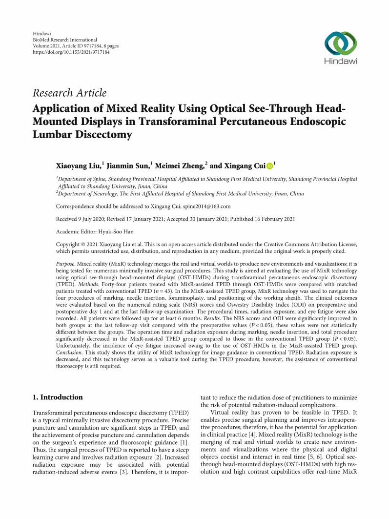
Purpose. Mixed reality (MixR) technology merges the real and virtual worlds to produce new environments and visualizations; it isbeing tested for numerous minimally invasive surgical procedures. This study is aimed at evaluating the use of MixR technologyusing optical see-through head-mounted displays (OST-HMDs) during transforaminal percutaneous endoscopic discectomy(TPED). Methods. Forty-four patients treated with MixR-assisted TPED through OST-HMDs were compared with matchedpatients treated with conventional TPED (n = 43). In the MixR-assisted TPED group, MixR technology was used to navigate thefour procedures of marking, needle insertion, foraminoplasty, and positioning of the working sheath. The clinical outcomeswere evaluated based on the numerical rating scale (NRS) scores and Oswestry Disability Index (ODI) on preoperative andpostoperative day 1 and at the last follow-up examination. The procedural times, radiation exposure, and eye fatigue were alsorecorded. All patients were followed up for at least 6 months. Results. The NRS scores and ODI were significantly improved inboth groups at the last follow-up visit compared with the preoperative values (P < 0:05); these values were not statisticallydifferent between the groups. The operation time and radiation exposure during marking, needle insertion, and total proceduresignificantly decreased in the MixR-assisted TPED group compared to those in the conventional TPED group (P < 0:05).Unfortunately, the incidence of eye fatigue increased owing to the use of OST-HMDs in the MixR-assisted TPED group.Conclusion. This study shows the utility of MixR technology for image guidance in conventional TPED. Radiation exposure isdecreased, and this technology serves as a valuable tool during the TPED procedure; however, the assistance of conventionalfluoroscopy is still required.
1. Introduction
Transforaminal percutaneous endoscopic discectomy (TPED)is a typical minimally invasive discectomy procedure. Precisepuncture and cannulation are significant steps in TPED, andthe achievement of precise puncture and cannulation dependson the surgeon’s experience and fluoroscopic guidance [1].Thus, the surgical process of TPED is reported to have a steeplearning curve and involves radiation exposure [2]. Increasedradiation exposure may be associated with potentialradiation-induced adverse events [3]. Therefore, it is impor-
tant to reduce the radiation dose of practitioners to minimizethe risk of potential radiation-induced complications.
Virtual reality has proven to be feasible in TPED. Itenables precise surgical planning and improves intraopera-tive procedures; therefore, it has the potential for applicationin clinical practice [4]. Mixed reality (MixR) technology is themerging of real and virtual worlds to create new environ-ments and visualizations where the physical and digitalobjects coexist and interact in real time [5, 6]. Optical see-through head-mounted displays (OST-HMDs) with high res-olution and high contrast capabilities offer real-time MixR
HindawiBioMed Research InternationalVolume 2021, Article ID 9717184, 8 pageshttps://doi.org/10.1155/2021/9717184
visualization of radiographic images that can be projectedover the interventional site without hampering direct controlof procedural manipulations [7]. MixR devices have beentested in image-guided minimally invasive surgical proce-dures [6, 7]. It is speculated that MixR technology mayimprove the surgical experience, shorten the operating time,and decrease the adverse effects of TPED. Unfortunately,MixR through OST-HMDs has not been introduced inTPED. Herein, we attempt to introduce and determine theutility of MixR navigation during the conventional TPEDprocedure.
2. Material and Methods
2.1. Patients. This comparative study was approved by theethics committee of a university hospital and was conductedin accordance with the guidelines of the Declaration ofHelsinki. Written informed consent was obtained from eachparticipant. From June 2018 to July 2019, 44 patients withlumbar disc herniation, who had failed to respond to conser-vative treatment for more than 6 weeks, were treated withMixR-assisted TPED. Another 43 patients were selected froma clinical database between February 2018 and June 2019,according to their demographic characteristics and disease-related features to ensure comparability between the twogroups; these patients were treated with conventional TPED.The inclusion criteria were as follows: (1) radicular leg paindue to lumbar disc herniation confirmed through magneticresonance imaging and (2) TPED at a single level. The exclu-sion criteria were as follows: (1) segmental instability, (2)lumbar spinal stenosis, (3) calcified disc herniation, (4) recur-rent lumbar disc herniation, (5) painless weakness, and (6)TPED at multiple levels. All patients were followed up forat least 6 months, with an average of 12 months.
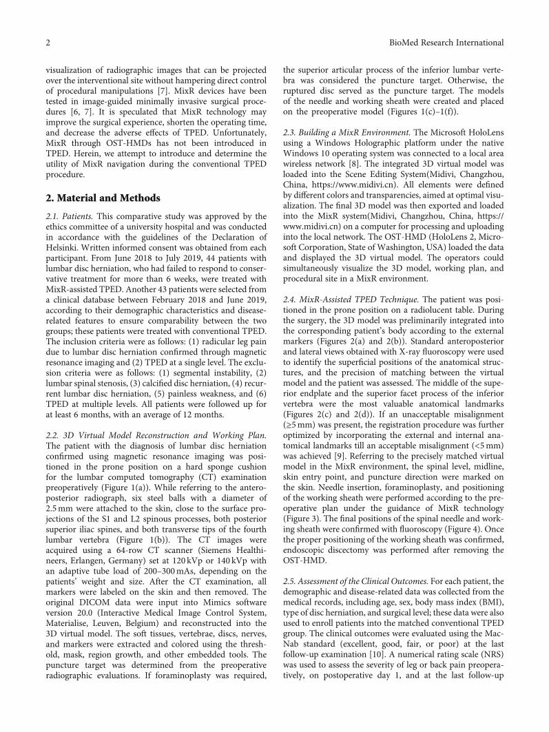
2.2. 3D Virtual Model Reconstruction and Working Plan.The patient with the diagnosis of lumbar disc herniationconfirmed using magnetic resonance imaging was posi-tioned in the prone position on a hard sponge cushionfor the lumbar computed tomography (CT) examinationpreoperatively (Figure 1(a)). While referring to the antero-posterior radiograph, six steel balls with a diameter of2.5mm were attached to the skin, close to the surface pro-jections of the S1 and L2 spinous processes, both posteriorsuperior iliac spines, and both transverse tips of the fourthlumbar vertebra (Figure 1(b)). The CT images wereacquired using a 64-row CT scanner (Siemens Healthi-neers, Erlangen, Germany) set at 120 kVp or 140 kVp withan adaptive tube load of 200–300mAs, depending on thepatients’ weight and size. After the CT examination, allmarkers were labeled on the skin and then removed. Theoriginal DICOM data were input into Mimics softwareversion 20.0 (Interactive Medical Image Control System,Materialise, Leuven, Belgium) and reconstructed into the3D virtual model. The soft tissues, vertebrae, discs, nerves,and markers were extracted and colored using the thresh-old, mask, region growth, and other embedded tools. Thepuncture target was determined from the preoperativeradiographic evaluations. If foraminoplasty was required,
the superior articular process of the inferior lumbar verte-bra was considered the puncture target. Otherwise, theruptured disc served as the puncture target. The modelsof the needle and working sheath were created and placedon the preoperative model (Figures 1(c)–1(f)).
2.3. Building a MixR Environment. The Microsoft HoloLensusing a Windows Holographic platform under the nativeWindows 10 operating system was connected to a local areawireless network [8]. The integrated 3D virtual model wasloaded into the Scene Editing System(Midivi, Changzhou,China, https://www.midivi.cn). All elements were definedby different colors and transparencies, aimed at optimal visu-alization. The final 3D model was then exported and loadedinto the MixR system(Midivi, Changzhou, China, https://www.midivi.cn) on a computer for processing and uploadinginto the local network. The OST-HMD (HoloLens 2, Micro-soft Corporation, State of Washington, USA) loaded the dataand displayed the 3D virtual model. The operators couldsimultaneously visualize the 3D model, working plan, andprocedural site in a MixR environment.
2.4. MixR-Assisted TPED Technique. The patient was posi-tioned in the prone position on a radiolucent table. Duringthe surgery, the 3D model was preliminarily integrated intothe corresponding patient’s body according to the externalmarkers (Figures 2(a) and 2(b)). Standard anteroposteriorand lateral views obtained with X-ray fluoroscopy were usedto identify the superficial positions of the anatomical struc-tures, and the precision of matching between the virtualmodel and the patient was assessed. The middle of the supe-rior endplate and the superior facet process of the inferiorvertebra were the most valuable anatomical landmarks(Figures 2(c) and 2(d)). If an unacceptable misalignment(≥5mm) was present, the registration procedure was furtheroptimized by incorporating the external and internal ana-tomical landmarks till an acceptable misalignment (<5mm)was achieved [9]. Referring to the precisely matched virtualmodel in the MixR environment, the spinal level, midline,skin entry point, and puncture direction were marked onthe skin. Needle insertion, foraminoplasty, and positioningof the working sheath were performed according to the pre-operative plan under the guidance of MixR technology(Figure 3). The final positions of the spinal needle and work-ing sheath were confirmed with fluoroscopy (Figure 4). Oncethe proper positioning of the working sheath was confirmed,endoscopic discectomy was performed after removing theOST-HMD.
2.5. Assessment of the Clinical Outcomes. For each patient, thedemographic and disease-related data was collected from themedical records, including age, sex, body mass index (BMI),type of disc herniation, and surgical level; these data were alsoused to enroll patients into the matched conventional TPEDgroup. The clinical outcomes were evaluated using the Mac-Nab standard (excellent, good, fair, or poor) at the lastfollow-up examination [10]. A numerical rating scale (NRS)was used to assess the severity of leg or back pain preopera-tively, on postoperative day 1, and at the last follow-up
2 BioMed Research International
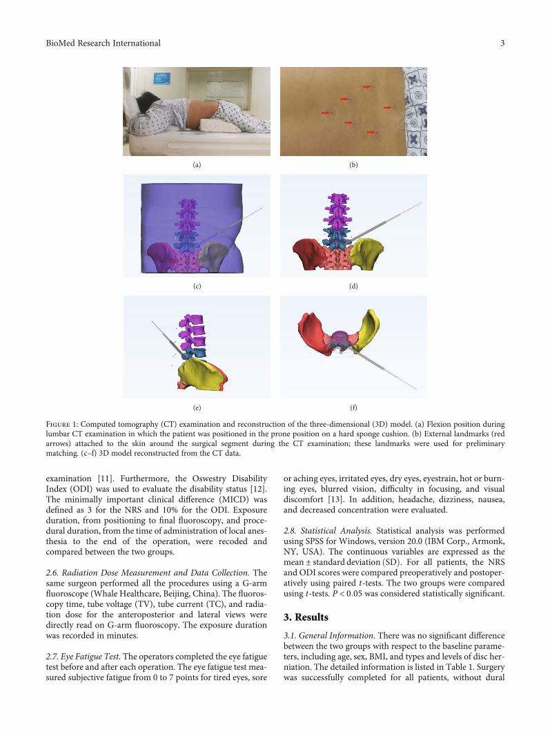
examination [11]. Furthermore, the Oswestry DisabilityIndex (ODI) was used to evaluate the disability status [12].The minimally important clinical difference (MICD) wasdefined as 3 for the NRS and 10% for the ODI. Exposureduration, from positioning to final fluoroscopy, and proce-dural duration, from the time of administration of local anes-thesia to the end of the operation, were recoded andcompared between the two groups.
2.6. Radiation Dose Measurement and Data Collection. Thesame surgeon performed all the procedures using a G-armfluoroscope (Whale Healthcare, Beijing, China). The fluoros-copy time, tube voltage (TV), tube current (TC), and radia-tion dose for the anteroposterior and lateral views weredirectly read on G-arm fluoroscopy. The exposure durationwas recorded in minutes.
2.7. Eye Fatigue Test. The operators completed the eye fatiguetest before and after each operation. The eye fatigue test mea-sured subjective fatigue from 0 to 7 points for tired eyes, sore
or aching eyes, irritated eyes, dry eyes, eyestrain, hot or burn-ing eyes, blurred vision, difficulty in focusing, and visualdiscomfort [13]. In addition, headache, dizziness, nausea,and decreased concentration were evaluated.
2.8. Statistical Analysis. Statistical analysis was performedusing SPSS for Windows, version 20.0 (IBM Corp., Armonk,NY, USA). The continuous variables are expressed as themean ± standard deviation ðSDÞ. For all patients, the NRSand ODI scores were compared preoperatively and postoper-atively using paired t-tests. The two groups were comparedusing t-tests. P < 0:05 was considered statistically significant.
3. Results
3.1. General Information. There was no significant differencebetween the two groups with respect to the baseline parame-ters, including age, sex, BMI, and types and levels of disc her-niation. The detailed information is listed in Table 1. Surgerywas successfully completed for all patients, without dural
(a) (b)
(c) (d)
(e) (f)
Figure 1: Computed tomography (CT) examination and reconstruction of the three-dimensional (3D) model. (a) Flexion position duringlumbar CT examination in which the patient was positioned in the prone position on a hard sponge cushion. (b) External landmarks (redarrows) attached to the skin around the surgical segment during the CT examination; these landmarks were used for preliminarymatching. (c–f) 3D model reconstructed from the CT data.
3BioMed Research International
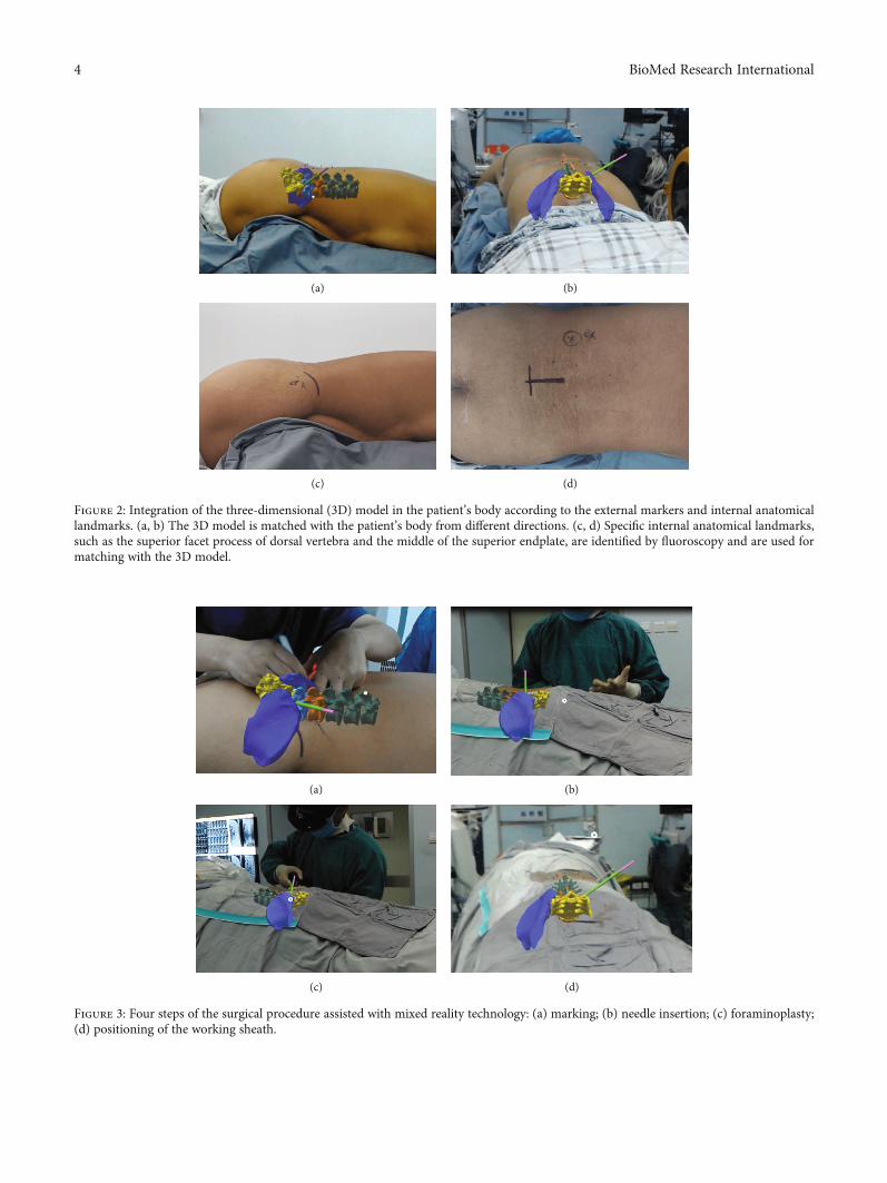
(a) (b)
(c) (d)
Figure 2: Integration of the three-dimensional (3D) model in the patient’s body according to the external markers and internal anatomicallandmarks. (a, b) The 3D model is matched with the patient’s body from different directions. (c, d) Specific internal anatomical landmarks,such as the superior facet process of dorsal vertebra and the middle of the superior endplate, are identified by fluoroscopy and are used formatching with the 3D model.
(a) (b)
(c) (d)
Figure 3: Four steps of the surgical procedure assisted with mixed reality technology: (a) marking; (b) needle insertion; (c) foraminoplasty;(d) positioning of the working sheath.
4 BioMed Research International
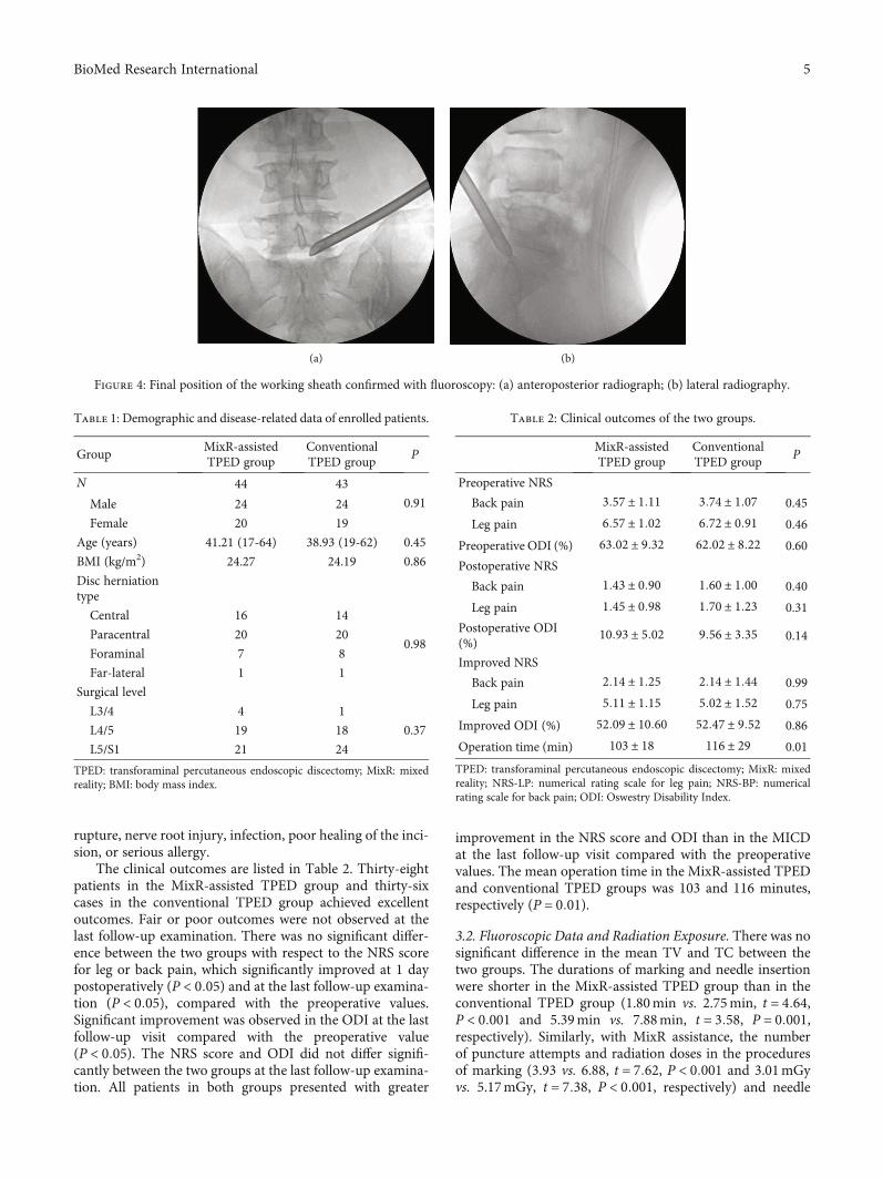
rupture, nerve root injury, infection, poor healing of the inci-sion, or serious allergy.
The clinical outcomes are listed in Table 2. Thirty-eightpatients in the MixR-assisted TPED group and thirty-sixcases in the conventional TPED group achieved excellentoutcomes. Fair or poor outcomes were not observed at thelast follow-up examination. There was no significant differ-ence between the two groups with respect to the NRS scorefor leg or back pain, which significantly improved at 1 daypostoperatively (P < 0:05) and at the last follow-up examina-tion (P < 0:05), compared with the preoperative values.Significant improvement was observed in the ODI at the lastfollow-up visit compared with the preoperative value(P < 0:05). The NRS score and ODI did not differ signifi-cantly between the two groups at the last follow-up examina-tion. All patients in both groups presented with greater
improvement in the NRS score and ODI than in the MICDat the last follow-up visit compared with the preoperativevalues. The mean operation time in the MixR-assisted TPEDand conventional TPED groups was 103 and 116 minutes,respectively (P = 0:01).
3.2. Fluoroscopic Data and Radiation Exposure. There was nosignificant difference in the mean TV and TC between thetwo groups. The durations of marking and needle insertionwere shorter in the MixR-assisted TPED group than in theconventional TPED group (1.80min vs. 2.75min, t = 4:64,P < 0:001 and 5.39min vs. 7.88min, t = 3:58, P = 0:001,respectively). Similarly, with MixR assistance, the numberof puncture attempts and radiation doses in the proceduresof marking (3.93 vs. 6.88, t = 7:62, P < 0:001 and 3.01mGyvs. 5.17mGy, t = 7:38, P < 0:001, respectively) and needle
(a) (b)
Figure 4: Final position of the working sheath confirmed with fluoroscopy: (a) anteroposterior radiograph; (b) lateral radiography.
Table 1: Demographic and disease-related data of enrolled patients.
GroupMixR-assistedTPED group
ConventionalTPED group
P
N 44 43
0.91Male 24 24
Female 20 19
Age (years) 41.21 (17-64) 38.93 (19-62) 0.45
BMI (kg/m2) 24.27 24.19 0.86
Disc herniationtype
Central 16 14
0.98Paracentral 20 20
Foraminal 7 8
Far-lateral 1 1
Surgical level
L3/4 4 1
0.37L4/5 19 18
L5/S1 21 24
TPED: transforaminal percutaneous endoscopic discectomy; MixR: mixedreality; BMI: body mass index.
Table 2: Clinical outcomes of the two groups.
MixR-assistedTPED group
ConventionalTPED group
P
Preoperative NRS
Back pain 3:57 ± 1:11 3:74 ± 1:07 0.45
Leg pain 6:57 ± 1:02 6:72 ± 0:91 0.46
Preoperative ODI (%) 63:02 ± 9:32 62:02 ± 8:22 0.60
Postoperative NRS
Back pain 1:43 ± 0:90 1:60 ± 1:00 0.40
Leg pain 1:45 ± 0:98 1:70 ± 1:23 0.31
Postoperative ODI(%)
10:93 ± 5:02 9:56 ± 3:35 0.14
Improved NRS
Back pain 2:14 ± 1:25 2:14 ± 1:44 0.99
Leg pain 5:11 ± 1:15 5:02 ± 1:52 0.75
Improved ODI (%) 52:09 ± 10:60 52:47 ± 9:52 0.86
Operation time (min) 103 ± 18 116 ± 29 0.01
TPED: transforaminal percutaneous endoscopic discectomy; MixR: mixedreality; NRS-LP: numerical rating scale for leg pain; NRS-BP: numericalrating scale for back pain; ODI: Oswestry Disability Index.
5BioMed Research International
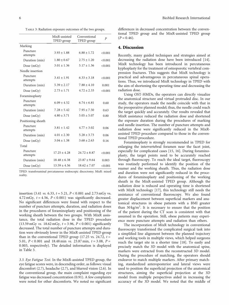
insertion (3.41 vs. 6.33, t = 5:21, P < 0:001 and 2.73mGy vs.4.72mGy, t = 4:56, P < 0:001) was significantly decreased.No significant differences were found with respect to thenumber of puncture attempts, duration, and radiation dosesin the procedures of foraminoplasty and positioning of theworking sheath between the two groups. With MixR assis-tance, the total radiation dose in the TPED procedure(13.59mGy vs. 18.62mGy, t = 3:96, P < 0:001) significantlydecreased. The total number of puncture attempts and dura-tion were obviously lower in the MixR-assisted TPED groupthan in the conventional TPED group (17.25 vs. 24.72, t =5:01, P < 0:001 and 18.48min vs. 23.87min, t = 3:08, P =0:003, respectively). The detailed information is displayedin Table 3.
3.3. Eye Fatigue Test. In the MixR-assisted TPED group, theeye fatigue scores were, in descending order, as follows: visualdiscomfort (2.7), headache (2.7), and blurred vision (2.6). Inthe conventional group, the main complaint regarding eyefatigue was decreased concentration (0.91). A few complaintswere noted for other discomforts. We noted no significant
differences in decreased concentration between the conven-tional TPED group and the MixR-assisted TPED group(P = 0:46).
4. Discussion
Recently, many guided techniques and strategies aimed atdecreasing the radiation dose have been introduced [14].MixR technology has been introduced in percutaneouskyphoplasty for the treatment of osteoporotic vertebral com-pression fractures. This suggests that MixR technology ispractical and advantageous in percutaneous spinal opera-tions. Thus, we introduced MixR technology in TPED withthe aim of shortening the operating time and decreasing theradiation dose.
Using OST-HMDs, the operators can directly visualizethe anatomical structure and virtual protruded disc. In ourstudy, the operators made the needle coincide with that inthe preoperative planned model; thus, the needle could reachthe target quickly and accurately. Our results revealed thatMixR assistance reduced the radiation dose and shortenedthe exposure duration during the procedures of markingand needle insertion. The number of puncture attempts andradiation dose were significantly reduced in the MixR-assisted TPED procedure compared to those in the conven-tional TPED procedure.
Foraminoplasty is strongly recommended in TPED forenlarging the intervertebral foramen near the facet joint,especially for complicated cases [15, 16]. During foramino-plasty, the target points need to be accurately reachedthrough fluoroscopy. To reach the ideal target, fluoroscopywas routinely performed to identify the position of thereamer and the working sheath. Thus, the radiation doseand duration were not significantly reduced in the proce-dures of foraminoplasty and positioning of the workingsheath in the MixR-assisted TPED group. Although theradiation dose is reduced and operating time is shortenedwith MixR technology [17], this technology still needs theassistance of conventional fluoroscopy. We also foundgreater displacement between superficial markers and ana-tomical structures in obese patients with a BMI greaterthan 30 kg/m2. It is necessary to ensure that the positionof the patient during the CT scan is consistent with thatassumed in the operation. Still, obese patients may experi-ence more puncture attempts and radiation than others.
The incorporation of MixR technology in conventionalfluoroscopy transformed the complicated surgical task intoa simplified line alignment between the planned trajectoryand working tools in multiple views, which helped surgeonsreach the target site in a shorter time [18]. To easily andprecisely match the 3D model with the anatomical spine,markers were extracted from the reconstructed 3D model.During the procedure of matching, the operators shouldendeavor to match multiple markers. After primary match-ing, standardized anteroposterior and lateral views wereused to position the superficial projection of the anatomicalstructures, aiming the superficial projection at the 3Dmodel from multiple perspectives aided in increasing theaccuracy of the 3D model. We noted that the middle of
Table 3: Radiation exposure outcomes of the two groups.
MixR-assistedTPED group
ConventionalTPED group
P
Marking
Punctureattempts
3:93 ± 1:88 6:88 ± 1:72 <0.001
Duration (min) 1:80 ± 0:67 2:75 ± 1:20 <0.001Dose (mGy) 3:01 ± 1:36 5:17 ± 1:36 <0.001
Needle insertion
Punctureattempts
3:41 ± 1:91 6:33 ± 3:18 <0.001
Duration (min) 5:39 ± 2:17 7:88 ± 4:10 0.001
Dose (mGy) 2:73 ± 1:71 4:72 ± 2:33 <0.001Foraminoplasty
Punctureattempts
6:09 ± 4:52 6:74 ± 6:81 0.60
Duration (min) 7:28 ± 5:42 7:95 ± 7:50 0.63
Dose (mGy) 4:80 ± 3:71 5:05 ± 5:07 0.80
Positioning sheath
Punctureattempts
3:81 ± 1:42 4:77 ± 3:02 0.06
Duration (min) 4:01 ± 2:30 5:28 ± 3:73 0.06
Dose (mGy) 3:04 ± 1:38 3:68 ± 2:63 0.16
Total
Punctureattempts
17:25 ± 4:28 24:72 ± 8:87 <0.001
Duration (min) 18:48 ± 6:38 23:87 ± 9:64 0.003
Dose (mGy) 13:59 ± 4:56 18:62 ± 7:07 <0.001TPED: transforaminal percutaneous endoscopic discectomy; MixR: mixedreality.
6 BioMed Research International
the superior endplate and the superior facet process of theinferior vertebra were the ideal anatomical landmarks.Moreover, the operators should intermittently match theholographic model with the anatomical structures andsuperficial markers from multiple directions during the sur-gical procedure. We also found that the 3D holographicmodel reconstructed from flexion CT images providedgreater accuracy and practicality in the TPED procedurethan that obtained from conventional supine CT images.Flexion CT examination was considered the necessary com-ponent of the preoperative evaluation in patients who werediagnosed using magnetic resonance images. Thus, an addi-tional CT scan was not required when MixR technologywas used.
There are several potential advantages of MixR-assistedTPED. First, the 3D model and the procedural site are con-stantly present in the operator’s field of view. The operatorsdo not need to move their field of view away from the proce-dural site to obtain image guidance information. In addition,the change from the procedural site to the virtual model canbe easily achieved by slightly raising the head. The transitionfrom a classic clinical set-up to an OST-HMD displayrequires less adaptation than that required in other visualiza-tion models [19].
The introduction of MixR into TPED is aimed at not onlydecreasing the radiation dose and operation time but alsoreducing the operation difficulty and shortening the learningcurve of residents [4]. In addition, we found great signifi-cance in MixR assistance in both the preoperative plan andthe guidance of surgical procedures. Meanwhile, medicalconsumable material is not needed in MixR-assisted opera-tions. Thus, the use of MixR technology cannot increase theexpenses of patients and the government. Therefore, MixRtechnology has good cost-effectiveness in clinical practiceand operations.
There are several limitations. The procedural time andradiation dose during working sheath placement may differamong patients with disc herniation at L5/S1 or L4/L5 [4].Unfortunately, we cannot perform subgroup analysis accord-ing to the different levels because of the small sample size.Moreover, users may experience discomfort and eye fatiguewhen using the HoloLens for durations longer than half anhour. In addition, at the current early stage of developmentof this technology, only a few software programs of use areavailable to the surgeons. Both MixR system (Midivi) andStarAtlas 3.0 (Visual3D, Beijing, China) present the abilityto manipulate and visualize holograms [20]. As the popular-ity of MixR technology increases, we expect that more surgi-cally useful software will be developed [21].
5. Conclusions
This preliminary study shows the utility of MixR technologyfor image guidance in conventional TPED. The radiationexposure significantly decreased with MixR visualizationguidance, and this technology serves as a valuable tool duringthe TPED procedure; however, the assistance of conventionalfluoroscopy is still required.
Data Availability
The data used to support the findings of this study areincluded within the article.
Conflicts of Interest
The authors declare that they have no conflicts of interest.
Acknowledgments
The study was supported by funding from the Key Researchand Development Program of Shandong Province(2018GSF118074).
References
[1] R. Wu, X. Liao, and H. Xia, “Radiation exposure to the surgeonduring ultrasound-assisted transforaminal percutaneousendoscopic lumbar discectomy: a prospective study,” WorldNeurosurgery, vol. 101, pp. 658–665.e1, 2017.
[2] G. Fan, C. Feng, W. Xie et al., “Isocentric navigation for thetraining of percutaneous endoscopic transforaminal discect-omy: a feasibility study,” BioMed Research International,vol. 2018, Article ID 6740942, 8 pages, 2018.
[3] M. W. Mariscalco, T. Yamashita, M. P. Steinmetz, A. A. Krish-naney, I. H. Lieberman, and T. E. Mroz, “Radiation exposureto the surgeon during open lumbar microdiscectomy and min-imally invasive microdiscectomy: a prospective, controlledtrial,” Spine (Phila Pa 1976), vol. 36, no. 3, pp. 255–260, 2011.
[4] Z. Zhou, S. Hu, Y. Z. Zhao et al., “Feasibility of virtual realitycombined with isocentric navigation in transforaminal percu-taneous endoscopic discectomy: a cadaver study,” OrthopaedicSurgery, vol. 11, no. 3, pp. 493–499, 2019.
[5] T. M. Peters and C. A. Linte, “Image-guided interventions andcomputer-integrated therapy: quo vadis?,” Medical ImageAnalysis, vol. 33, pp. 56–63, 2016.
[6] G. Ameri, J. S. H. Baxter, D. Bainbridge, T. M. Peters, and E. C.S. Chen, “Mixed reality ultrasound guidance system: a casestudy in system development and a cautionary tale,” Interna-tional Journal of Computer Assisted Radiology and Surgery,vol. 13, no. 4, pp. 495–505, 2018.
[7] G. Deib, A. Johnson, M. Unberath et al., “Image guided percu-taneous spine procedures using an optical see-through headmounted display: proof of concept and rationale,” Journal ofNeuroInterventional Surgery, vol. 10, no. 12, pp. 1187–1191,2018.
[8] M. G. Hanna, I. Ahmed, J. Nine, S. Prajapati, andL. Pantanowitz, “Augmented reality technology using MicrosoftHoloLens in anatomic pathology,” Archives of Pathology & Lab-oratory Medicine, vol. 142, no. 5, pp. 638–644, 2018.
[9] Y. Zhao, X. Bo, C. Wang et al., “Guided punctures with ultra-sound volume navigation in percutaneous transforaminalendoscopic discectomy: a technical note,” World Neurosur-gery, vol. 119, pp. 77–84, 2018.
[10] I. Macnab, “Negative disc exploration. An analysis of thecauses of nerve-root involvement in sixty-eight patients,” TheJournal of Bone & Joint Surgery, vol. 53, no. 5, pp. 891–903,1971.
[11] J. S. Dixon and H. A. Bird, “Reproducibility along a 10 cm ver-tical visual analogue scale,” Annals of the Rheumatic Diseases,vol. 40, no. 1, pp. 87–89, 1981.
7BioMed Research International
[12] J. C. Fairbank, J. Couper, J. B. Davies, and J. P. O'Brien, “TheOswestry low back pain disability questionnaire,” Physiother-apy, vol. 66, no. 8, pp. 271–273, 1980.
[13] C. H. Kim, S. Y. Ryu, J. Y. Yoon et al., “See-through type 3Dhead-mounted display-based surgical microscope system formicrosurgery: a feasibility study,” JMIR mHealth and uHealth,vol. 7, no. 3, article e11251, 2019.
[14] P. Stefan, S. Habert, A. Winkler et al., “A radiation-free mixed-reality training environment and assessment concept for C-arm-based surgery,” International Journal of ComputerAssisted Radiology and Surgery, vol. 13, no. 9, pp. 1335–1344,2018.
[15] K. C. Choi, J. S. Kim, D. C. Lee, and C. K. Park, “Percutaneousendoscopic lumbar discectomy: minimally invasive techniquefor multiple episodes of lumbar disc herniation,” BMCMuscu-loskeletal Disorders, vol. 18, no. 1, p. 329, 2017.
[16] M. T. N. Knight, I. Jago, C. Norris, L. Midwinter, andC. Boynes, “Transforaminal endoscopic lumbar decompres-sion & foraminoplasty: a 10 year prospective survivability out-come study of the treatment of foraminal stenosis and failedback surgery,” International Journal of Spine Surgery, vol. 8,2014.
[17] M. Fischer, B. Fuerst, S. C. Lee et al., “Preclinical usabilitystudy of multiple augmented reality concepts for K-wire place-ment,” International Journal of Computer Assisted Radiologyand Surgery, vol. 11, no. 6, pp. 1007–1014, 2016.
[18] S. C. Lee, B. Fuerst, K. Tateno et al., “Multi-modal imaging,model-based tracking, and mixed reality visualisation fororthopaedic surgery,” Healthcare Technology Letters, vol. 4,no. 5, pp. 168–173, 2017.
[19] L. Qian, A. Barthel, A. Johnson et al., “Comparison of opticalsee-through head-mounted displays for surgical interventionswith object-anchored 2D-display,” International Journal ofComputer Assisted Radiology and Surgery, vol. 12, no. 6,pp. 901–910, 2017.
[20] P. Wei, Q. Yao, Y. Xu, H. Zhang, Y. Gu, and L. Wang, “Percu-taneous kyphoplasty assisted with/without mixed reality tech-nology in treatment of OVCF with IVC: a prospective study,”Journal of Orthopaedic Surgery and Research, vol. 14, no. 1,p. 255, 2019.
[21] O. M. Tepper, H. L. Rudy, A. Lefkowitz et al., “Mixed realitywith HoloLens: where virtual reality meets augmented realityin the operating room,” Plastic and Reconstructive Surgery,vol. 140, no. 5, pp. 1066–1070, 2017.
8 BioMed Research International
Research ArticleThe Bony Resection Accuracy with Patient-SpecificInstruments during Total Knee Arthroplasty: A Retrospective CaseSeries Study
Liang Yuan ,1 Bin Yang ,1 Xiaohua Wang,1 Bin Sun,1 Ke Zhang,1 Yichen Yan,2 Jie Liu ,3
and Jie Yao 2
1Department of Orthopedics, Peking University International Hospital, Beijing 102206, China2Key Laboratory for Biomechanics and Mechanobiology of Ministry of Education, School of Biological Science andMedical Engineering, Beijing Advanced Innovation Centre for Biomedical Engineering, Beihang University, Beijing 100191, China3Department of Vascular and Endovascular Surgery, Chinese PLA General Hospital, Beijing 100853, China
Correspondence should be addressed to Jie Liu; [email protected] and Jie Yao; [email protected]
Received 4 August 2020; Revised 23 December 2020; Accepted 27 January 2021; Published 16 February 2021
Academic Editor: Liu Yang
Copyright © 2021 Liang Yuan et al. This is an open access article distributed under the Creative Commons Attribution License,which permits unrestricted use, distribution, and reproduction in any medium, provided the original work is properly cited.
Purpose. Bony resection is the primary step during total knee arthroplasty. The accuracy of bony resection was highly addressedbecause it was deemed to have a good relationship with mechanical line. Patient-specific instruments (PSI) were invented tocopy the bony resection references from the preoperative surgical plan during a total knee arthroplasty (TKA); however, theaccuracy still remains controversial. This study was aimed at finding out the accuracy of the bony resection during PSI-assistedTKA. Methods. Forty-two PSI-assisted TKAs (based on full-length leg CT images) were analyzed retrospectively. Resected bonesof every patient were given a CT scan, and three-dimensional radiographs were reconstructed. The thickness of each bonyresection was measured with the three-dimensional radiographs and recorded. The saw blade thickness (1.27mm) was added tothe measurements, and the results represented intraoperative bone resection thickness. A comparison between intraoperativebone resection thickness and preoperatively planned thickness was conducted. The differences were calculated, and the outlierswere defined as >3mm. Results. The distal femoral condyle had the most accurate bone cuts with the smallest difference(median, 1.0mm at the distal medial femoral condyle and 0.8mm at the distal lateral femoral condyle) and the least outliers(none at the distal medial femoral condyle and 1 (2.4%) at the distal lateral femoral condyle). The tibial plateau came in second(median difference, 0.8mm at the medial tibial plateau and 1.4mm at the lateral tibial plateau; outliers, none at the medial tibialplateau and 1 (2.6%) at the lateral tibial plateau). Regardless of whether the threshold was set to >2mm (14 (17.9%) at the tibialplateau vs. 12 (14.6%) at the distal femoral condyle, p > 0:05) or >3mm (1 (1.3%) at the tibial plateau vs. 1 (1.2%) at the distalfemoral condyle, p > 0:05), the accuracy of tibial plateau osteotomy was similar to that of the distal femoral condyle. Osteotomyaccuracy at the posterior femoral condyle and the anterior femoral condyle were the worst. Outliers were up to 6 (15.0%) at theposterior medial femoral condyle, 5 (12.2%) at the posterior lateral femoral condyle, and 6 (15.8%) at the anterior femoralcondyle. The percentages of overcut and undercut tended to 50% in most parts except the lateral tibial plateau. At the lateraltibial plateau, the undercut percentage was twice that of the overcut. Conclusion. The tibial plateau and the distal femoralcondyle share a similar accuracy of osteotomy with PSI. PSI have a generally good accuracy during the femur and tibia boneresection in TKA. PSI could be a kind of user-friendly tool which can simplify TKA with good accuracy. Level of Evidence. Thisis a Level IV case series with no comparison group.
1. Introduction
Total knee arthroplasty (TKA) has been a reliable optionwith excellent long-term results for patients suffering from
advanced knee osteoarthritis and other severe knee diseases[1–4]. One of the keys to a good TKA is the reconstructionof the lower extremity mechanical axis. To achieve this pur-pose, precise bony resection and accurate prosthesis
HindawiBioMed Research InternationalVolume 2021, Article ID 8674847, 9 pageshttps://doi.org/10.1155/2021/8674847
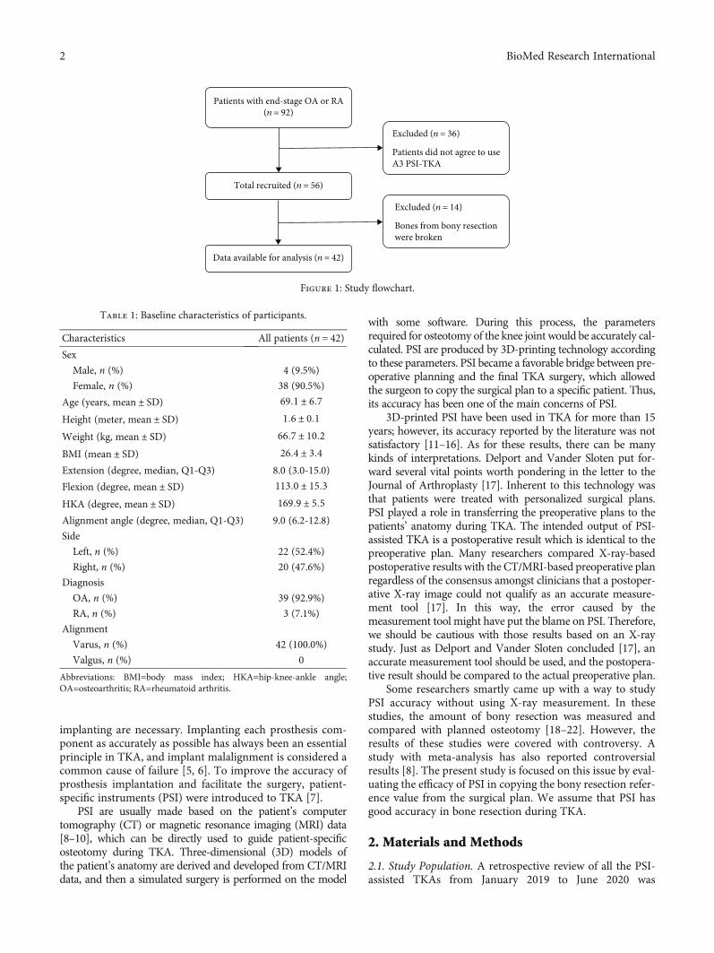
implanting are necessary. Implanting each prosthesis com-ponent as accurately as possible has always been an essentialprinciple in TKA, and implant malalignment is considered acommon cause of failure [5, 6]. To improve the accuracy ofprosthesis implantation and facilitate the surgery, patient-specific instruments (PSI) were introduced to TKA [7].
PSI are usually made based on the patient’s computertomography (CT) or magnetic resonance imaging (MRI) data[8–10], which can be directly used to guide patient-specificosteotomy during TKA. Three-dimensional (3D) models ofthe patient’s anatomy are derived and developed from CT/MRIdata, and then a simulated surgery is performed on the model
with some software. During this process, the parametersrequired for osteotomy of the knee joint would be accurately cal-culated. PSI are produced by 3D-printing technology accordingto these parameters. PSI became a favorable bridge between pre-operative planning and the final TKA surgery, which allowedthe surgeon to copy the surgical plan to a specific patient. Thus,its accuracy has been one of the main concerns of PSI.
3D-printed PSI have been used in TKA for more than 15years; however, its accuracy reported by the literature was notsatisfactory [11–16]. As for these results, there can be manykinds of interpretations. Delport and Vander Sloten put for-ward several vital points worth pondering in the letter to theJournal of Arthroplasty [17]. Inherent to this technology wasthat patients were treated with personalized surgical plans.PSI played a role in transferring the preoperative plans to thepatients’ anatomy during TKA. The intended output of PSI-assisted TKA is a postoperative result which is identical to thepreoperative plan. Many researchers compared X-ray-basedpostoperative results with the CT/MRI-based preoperative planregardless of the consensus amongst clinicians that a postoper-ative X-ray image could not qualify as an accurate measure-ment tool [17]. In this way, the error caused by themeasurement tool might have put the blame on PSI. Therefore,we should be cautious with those results based on an X-raystudy. Just as Delport and Vander Sloten concluded [17], anaccurate measurement tool should be used, and the postopera-tive result should be compared to the actual preoperative plan.
Some researchers smartly came up with a way to studyPSI accuracy without using X-ray measurement. In thesestudies, the amount of bony resection was measured andcompared with planned osteotomy [18–22]. However, theresults of these studies were covered with controversy. Astudy with meta-analysis has also reported controversialresults [8]. The present study is focused on this issue by eval-uating the efficacy of PSI in copying the bony resection refer-ence value from the surgical plan. We assume that PSI hasgood accuracy in bone resection during TKA.
2. Materials and Methods
2.1. Study Population. A retrospective review of all the PSI-assisted TKAs from January 2019 to June 2020 was
Total recruited (n = 56)
Data available for analysis (n = 42)
Excluded (n = 36)
Patients did not agree to useA3 PSI-TKA
Patients with end-stage OA or RA(n = 92)
Excluded (n = 14)
Bones from bony resectionwere broken
Figure 1: Study flowchart.
Table 1: Baseline characteristics of participants.
Characteristics All patients (n = 42)Sex
Male, n (%) 4 (9.5%)
Female, n (%) 38 (90.5%)
Age (years, mean ± SD) 69:1 ± 6:7Height (meter, mean ± SD) 1:6 ± 0:1Weight (kg, mean ± SD) 66:7 ± 10:2BMI (mean ± SD) 26:4 ± 3:4Extension (degree, median, Q1-Q3) 8.0 (3.0-15.0)
Flexion (degree, mean ± SD) 113:0 ± 15:3HKA (degree, mean ± SD) 169:9 ± 5:5Alignment angle (degree, median, Q1-Q3) 9.0 (6.2-12.8)
Side
Left, n (%) 22 (52.4%)
Right, n (%) 20 (47.6%)
Diagnosis
OA, n (%) 39 (92.9%)
RA, n (%) 3 (7.1%)
Alignment
Varus, n (%) 42 (100.0%)
Valgus, n (%) 0
Abbreviations: BMI=body mass index; HKA=hip-knee-ankle angle;OA=osteoarthritis; RA=rheumatoid arthritis.
2 BioMed Research International
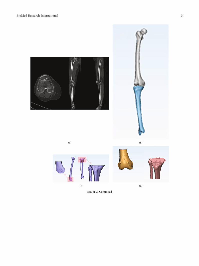
(a) (b)
(c) (d)
Figure 2: Continued.
3BioMed Research International
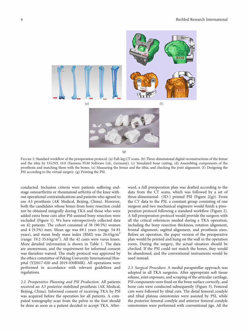
conducted. Inclusion criteria were patients suffering end-stage osteoarthritis or rheumatoid arthritis of the knee with-out operational contraindications and patients who agreed touse A3 prosthesis (AK Medical, Beijing, China). However,both the candidates whose bones from bony resection couldnot be obtained integrally during TKA and those who wereadded extra bone cuts after PSI-assisted bony resection wereexcluded (Figure 1). We have retrospectively collected dataon 42 patients. The cohort consisted of 38 (90.5%) womenand 4 (9.5%) men. Mean age was 69.1 years (range: 54-81years), and mean body mass index (BMI) was 26.4 kg/m2
(range: 19.2-35.6 kg/m2). All the 42 cases were varus knees.More detailed information is shown in Table 1. The dataare anonymous, and the requirement for informed consentwas therefore waived. The study protocol was approved bythe ethics committee of Peking University International Hos-pital (YJ2017-020 and 2019-030BMR). All operations wereperformed in accordance with relevant guidelines andregulations.
2.2. Preoperative Planning and PSI Production. All patientsreceived an A3 posterior-stabilized prosthesis (AK Medical,Beijing, China). Informed consent of receiving TKA by PSIwas acquired before the operation for all patients. A com-puted tomography scan from the pelvis to the foot shouldbe done as soon as a patient decided to accept TKA. After-
ward, a full preoperation plan was drafted according to thedata from the CT scans, which was followed by a set ofthree-dimensional- (3D-) printed PSI (Figure 2(g)). Fromthe CT data to the PSI, a constant group consisting of onesurgeon and two mechanical engineers would finish a preo-peration protocol following a standard workflow (Figure 2).A full preoperation protocol would provide the surgeon withall the critical references needed during a TKA operation,including the bony resection thickness, rotation alignment,frontal alignment, sagittal alignment, and prosthesis sizes.Before an operation, the paper version of the preoperativeplan would be printed and hung on the wall in the operationroom. During the surgery, the actual situation should bechecked. If the PSI could not match the bones, they wouldbe abandoned, and the conventional instruments would beused instead.
2.3. Surgical Procedure. A medial parapatellar approach wasadopted in all TKA surgeries. After appropriate soft tissuerelease, joint exposure, and scraping of the articular cartilage,PSI components were fixed on the bone surface correctly, andbone cuts were conducted subsequently (Figure 3). Femoralcuts were followed by tibial cuts. The distal femoral condyleand tibial plateau osteotomies were assisted by PSI, whilethe posterior femoral condyle and anterior femoral condyleosteotomies were performed with conventional jigs. All the
(e) (f)
(g)
Figure 2: Standard workflow of the preoperation protocol. (a) Full-leg CT scans. (b) Three-dimensional digital reconstructions of the femurand the tibia by UG/NX 10.0 (Siemens PLM Software Ltd., Germany). (c) Simulated bone cutting. (d) Assembling components of theprosthesis and matching them with the bones. (e) Measuring the femur and the tibia, and checking the joint alignment. (f) Designing thePSI according to the virtual surgery. (g) Printing the PSI.
4 BioMed Research International
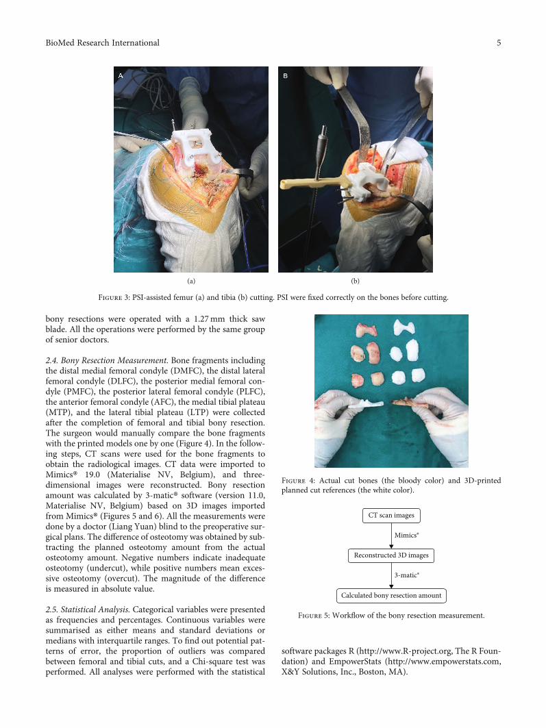
bony resections were operated with a 1.27mm thick sawblade. All the operations were performed by the same groupof senior doctors.
2.4. Bony Resection Measurement. Bone fragments includingthe distal medial femoral condyle (DMFC), the distal lateralfemoral condyle (DLFC), the posterior medial femoral con-dyle (PMFC), the posterior lateral femoral condyle (PLFC),the anterior femoral condyle (AFC), the medial tibial plateau(MTP), and the lateral tibial plateau (LTP) were collectedafter the completion of femoral and tibial bony resection.The surgeon would manually compare the bone fragmentswith the printed models one by one (Figure 4). In the follow-ing steps, CT scans were used for the bone fragments toobtain the radiological images. CT data were imported toMimics® 19.0 (Materialise NV, Belgium), and three-dimensional images were reconstructed. Bony resectionamount was calculated by 3-matic® software (version 11.0,Materialise NV, Belgium) based on 3D images importedfrom Mimics® (Figures 5 and 6). All the measurements weredone by a doctor (Liang Yuan) blind to the preoperative sur-gical plans. The difference of osteotomy was obtained by sub-tracting the planned osteotomy amount from the actualosteotomy amount. Negative numbers indicate inadequateosteotomy (undercut), while positive numbers mean exces-sive osteotomy (overcut). The magnitude of the differenceis measured in absolute value.
2.5. Statistical Analysis. Categorical variables were presentedas frequencies and percentages. Continuous variables weresummarised as either means and standard deviations ormedians with interquartile ranges. To find out potential pat-terns of error, the proportion of outliers was comparedbetween femoral and tibial cuts, and a Chi-square test wasperformed. All analyses were performed with the statistical
software packages R (http://www.R-project.org, The R Foun-dation) and EmpowerStats (http://www.empowerstats.com,X&Y Solutions, Inc., Boston, MA).
(a) (b)
Figure 3: PSI-assisted femur (a) and tibia (b) cutting. PSI were fixed correctly on the bones before cutting.
Figure 4: Actual cut bones (the bloody color) and 3D-printedplanned cut references (the white color).
CT scan images
Reconstructed 3D images
Mimics®
3-matic®
Calculated bony resection amount
Figure 5: Workflow of the bony resection measurement.
5BioMed Research International
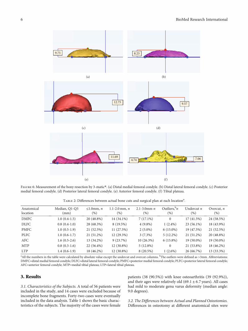
3. Results
3.1. Characteristics of the Subjects. A total of 56 patients wereincluded in the study, and 14 cases were excluded because ofincomplete bone fragments. Forty-two cases were eventuallyincluded in the data analysis. Table 1 shows the basic charac-teristics of the subjects. The majority of the cases were female
patients (38 (90.5%)) with knee osteoarthritis (39 (92.9%)),and their ages were relatively old (69:1 ± 6:7 years). All caseshad mild to moderate genu varus deformity (median angle:9.0 degrees).
3.2. The Differences between Actual and Planned Osteotomies.Differences in osteotomy at different anatomical sites were
9.75
(a)
8.23
(b)
12.75
(c)
9.57
(d)
11.69
(e)
7.064.74
(f)
Figure 6: Measurement of the bony resection by 3-matic®. (a) Distal medial femoral condyle. (b) Distal lateral femoral condyle. (c) Posteriormedial femoral condyle. (d) Posterior lateral femoral condyle. (e) Anterior femoral condyle. (f) Tibial plateau.
Table 2: Differences between actual bone cuts and surgical plan at each locationa.
Anatomicallocation
Median, Q1-Q3(mm)
≤1.0mm, n(%)
1.1-2.0mm, n(%)
2.1-3.0mm n(%)
Outliers,bn(%)
Undercut n(%)
Overcut, n(%)
DMFC 1.0 (0.4-1.5) 20 (48.8%) 14 (34.1%) 7 (17.1%) 0 17 (41.5%) 24 (58.5%)
DLFC 0.8 (0.4-1.0) 28 (68.3%) 8 (19.5%) 4 (9.8%) 1 (2.4%) 23 (56.1%) 18 (43.9%)
PMFC 1.0 (0.5-1.9) 21 (52.5%) 11 (27.5%) 2 (5.0%) 6 (15.0%) 19 (47.5%) 21 (52.5%)
PLFC 1.0 (0.6-1.7) 21 (51.2%) 12 (29.3%) 3 (7.3%) 5 (12.2%) 21 (51.2%) 20 (48.8%)
AFC 1.6 (0.5-2.6) 13 (34.2%) 9 (23.7%) 10 (26.3%) 6 (15.8%) 19 (50.0%) 19 (50.0%)
MTP 0.8 (0.3-1.6) 22 (56.4%) 12 (30.8%) 5 (12.8%) 0 21 (53.8%) 18 (46.2%)
LTP 1.4 (0.6-1.9) 18 (46.2%) 12 (30.8%) 8 (20.5%) 1 (2.6%) 26 (66.7%) 13 (33.3%)aAll the numbers in the table were calculated by absolute value except the undercut and overcut columns. bThe outliers were defined as >3mm. Abbreviations:DMFC=distal medial femoral condyle; DLFC=distal lateral femoral condyle; PMFC=posterior medial femoral condyle; PLFC=posterior lateral femoral condyle;AFC=anterior femoral condyle; MTP=medial tibial plateau; LTP=lateral tibial plateau.
6 BioMed Research International
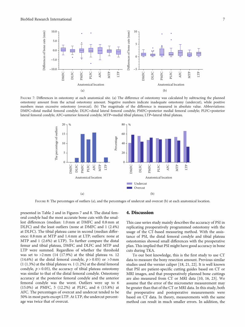
presented in Table 2 and in Figures 7 and 8. The distal fem-oral condyle had the most accurate bone cuts with the smal-lest differences (median: 1.0mm at DMFC and 0.8mm atDLFC) and the least outliers (none at DMFC and 1 (2.4%)at DLFC). The tibial plateau came in second (median differ-ence: 0.8mm at MTP and 1.4mm at LTP; outliers: none atMTP and 1 (2.6%) at LTP). To further compare the distalfemur and tibial plateau, DMFC and DLFC and MTP andLTP were summed. Regardless of whether the thresholdwas set to >2mm (14 (17.9%) at the tibial plateau vs. 12(14.6%) at the distal femoral condyle, p > 0:05) or >3mm(1 (1.3%) at the tibial plateau vs. 1 (1.2%) at the distal femoralcondyle, p > 0:05), the accuracy of tibial plateau osteotomywas similar to that of the distal femoral condyle. Osteotomyaccuracy at the posterior femoral condyle and the anteriorfemoral condyle was the worst. Outliers were up to 6(15.0%) at PMFC, 5 (12.2%) at PLFC, and 6 (15.8%) atAFC. The percentages of overcut and undercut tended to be50% in most parts except LTP. At LTP, the undercut percent-age was twice that of overcut.
4. Discussion
This case series study mainly describes the accuracy of PSI inreplicating preoperatively programmed osteotomy with theusage of the CT-based measuring method. With the assis-tance of PSI, the distal femoral condyle and tibial plateauosteotomies showed small differences with the preoperativeplan. This implied that PSI might have good accuracy in bonecuts during TKA.
To our best knowledge, this is the first study to use CTdata to measure the bony resection amount. Previous similarstudies used the vernier caliper [18, 21, 22]. It is well knownthat PSI are patient-specific cutting guides based on CT orMRI images, and that preoperatively planned bone cuttingsare also measured from CT or MRI data [10, 16, 23]. Weassume that the error of the micrometer measurement maybe greater than that of the CT orMRI data. In this study, boththe preoperative and postoperative measurements werebased on CT data. In theory, measurements with the samemethod can result in much smaller errors. In addition, the
−10.0
Anatomical location
DM
FC
DLF
C
PMFC
PLFC
AFC
MTP LT
P
−5.0
0.0
10.0
5.0D
iffer
ence
s of b
one c
uts (
mm
)
(a)
−5
Anatomical location
DM
FC
DLF
C
PMFC
PLFC
AFC
MTP LT
P
0
10
5
Diff
eren
ces o
f bon
e cut
s (m
m)
(b)
Figure 7: Differences in osteotomy at each anatomical site. (a) The difference of osteotomy was calculated by subtracting the plannedosteotomy amount from the actual osteotomy amount. Negative numbers indicate inadequate osteotomy (undercut), while positivenumbers mean excessive osteotomy (overcut). (b) The magnitude of the difference is measured in absolute value. Abbreviations:DMFC=distal medial femoral condyle; DLFC=distal lateral femoral condyle; PMFC=posterior medial femoral condyle; PLFC=posteriorlateral femoral condyle; AFC=anterior femoral condyle; MTP=medial tibial plateau; LTP=lateral tibial plateau.
0
Anatomical location
DM
FC
DLF
C
PMFC
PLFC
AFC
MTP LT
P
5
10
20 %
15
The p
erce
ntag
e of o
utlie
rs
(a)
0
Anatomical location
DM
FC
DLF
C
PMFC
PLFC
AFC
MTP LT
P
20
40
80 %
60
Perc
enta
ge
UndercutOvercut
(b)
Figure 8: The percentages of outliers (a), and the percentages of undercut and overcut (b) at each anatomical location.
7BioMed Research International
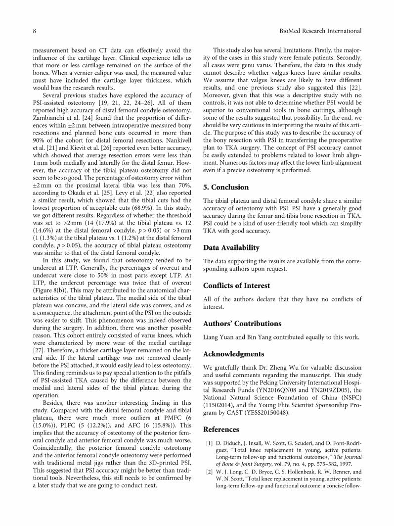
measurement based on CT data can effectively avoid theinfluence of the cartilage layer. Clinical experience tells usthat more or less cartilage remained on the surface of thebones. When a vernier caliper was used, the measured valuemust have included the cartilage layer thickness, whichwould bias the research results.
Several previous studies have explored the accuracy ofPSI-assisted osteotomy [19, 21, 22, 24–26]. All of themreported high accuracy of distal femoral condyle osteotomy.Zambianchi et al. [24] found that the proportion of differ-ences within ±2mm between intraoperative measured bonyresections and planned bone cuts occurred in more than90% of the cohort for distal femoral resections. Nankivellet al. [21] and Kievit et al. [26] reported even better accuracy,which showed that average resection errors were less than1mm both medially and laterally for the distal femur. How-ever, the accuracy of the tibial plateau osteotomy did notseem to be so good. The percentage of osteotomy error within±2mm on the proximal lateral tibia was less than 70%,according to Okada et al. [25]. Levy et al. [22] also reporteda similar result, which showed that the tibial cuts had thelowest proportion of acceptable cuts (68.9%). In this study,we got different results. Regardless of whether the thresholdwas set to >2mm (14 (17.9%) at the tibial plateau vs. 12(14.6%) at the distal femoral condyle, p > 0:05) or >3mm(1 (1.3%) at the tibial plateau vs. 1 (1.2%) at the distal femoralcondyle, p > 0:05), the accuracy of tibial plateau osteotomywas similar to that of the distal femoral condyle.
In this study, we found that osteotomy tended to beundercut at LTP. Generally, the percentages of overcut andundercut were close to 50% in most parts except LTP. AtLTP, the undercut percentage was twice that of overcut(Figure 8(b)). This may be attributed to the anatomical char-acteristics of the tibial plateau. The medial side of the tibialplateau was concave, and the lateral side was convex, and asa consequence, the attachment point of the PSI on the outsidewas easier to shift. This phenomenon was indeed observedduring the surgery. In addition, there was another possiblereason. This cohort entirely consisted of varus knees, whichwere characterized by more wear of the medial cartilage[27]. Therefore, a thicker cartilage layer remained on the lat-eral side. If the lateral cartilage was not removed cleanlybefore the PSI attached, it would easily lead to less osteotomy.This finding reminds us to pay special attention to the pitfallsof PSI-assisted TKA caused by the difference between themedial and lateral sides of the tibial plateau during theoperation.
Besides, there was another interesting finding in thisstudy. Compared with the distal femoral condyle and tibialplateau, there were much more outliers at PMFC (6(15.0%)), PLFC (5 (12.2%)), and AFC (6 (15.8%)). Thisimplies that the accuracy of osteotomy of the posterior fem-oral condyle and anterior femoral condyle was much worse.Coincidentally, the posterior femoral condyle osteotomyand the anterior femoral condyle osteotomy were performedwith traditional metal jigs rather than the 3D-printed PSI.This suggested that PSI accuracy might be better than tradi-tional tools. Nevertheless, this still needs to be confirmed bya later study that we are going to conduct next.
This study also has several limitations. Firstly, the major-ity of the cases in this study were female patients. Secondly,all cases were genu varus. Therefore, the data in this studycannot describe whether valgus knees have similar results.We assume that valgus knees are likely to have differentresults, and one previous study also suggested this [22].Moreover, given that this was a descriptive study with nocontrols, it was not able to determine whether PSI would besuperior to conventional tools in bone cuttings, althoughsome of the results suggested that possibility. In the end, weshould be very cautious in interpreting the results of this arti-cle. The purpose of this study was to describe the accuracy ofthe bony resection with PSI in transferring the preoperativeplan to TKA surgery. The concept of PSI accuracy cannotbe easily extended to problems related to lower limb align-ment. Numerous factors may affect the lower limb alignmenteven if a precise osteotomy is performed.
5. Conclusion
The tibial plateau and distal femoral condyle share a similaraccuracy of osteotomy with PSI. PSI have a generally goodaccuracy during the femur and tibia bone resection in TKA.PSI could be a kind of user-friendly tool which can simplifyTKA with good accuracy.
Data Availability
The data supporting the results are available from the corre-sponding authors upon request.
Conflicts of Interest
All of the authors declare that they have no conflicts ofinterest.
Authors’ Contributions
Liang Yuan and Bin Yang contributed equally to this work.
Acknowledgments
We gratefully thank Dr. Zheng Wu for valuable discussionand useful comments regarding the manuscript. This studywas supported by the Peking University International Hospi-tal Research Funds (YN2016QN08 and YN2019ZD05), theNational Natural Science Foundation of China (NSFC)(11502014), and the Young Elite Scientist Sponsorship Pro-gram by CAST (YESS20150048).
References
[1] D. Diduch, J. Insall, W. Scott, G. Scuderi, and D. Font-Rodri-guez, “Total knee replacement in young, active patients.Long-term follow-up and functional outcome∗,” The Journalof Bone & Joint Surgery, vol. 79, no. 4, pp. 575–582, 1997.
[2] W. J. Long, C. D. Bryce, C. S. Hollenbeak, R. W. Benner, andW. N. Scott, “Total knee replacement in young, active patients:long-term follow-up and functional outcome: a concise follow-
8 BioMed Research International
up of a previous report,” The Journal of Bone and JointSurgery-American Volume, vol. 96, pp. e151–e151, 2014.
[3] Y. Ishii, H. Noguchi, J. Sato, T. Sakurai, and S. Toyabe, “Com-parison of long-term clinical outcomes after bilateral mobile-bearing total knee arthroplasties using PCL-retaining andPCL-substituting implants in the same patients,” Knee Surgery,Sports Traumatology, Arthroscopy, vol. 25, no. 12, pp. 3711–3717, 2017.
[4] J. T. Evans, R. W. Walker, J. P. Evans, A. W. Blom, A. Sayers,and M. R. Whitehouse, “How long does a knee replacementlast? A systematic review and meta-analysis of case series andnational registry reports with more than 15 years of follow-up,” Lancet, vol. 393, no. 10172, pp. 655–663, 2019.
[5] P. F. Sharkey, W. J. Hozack, R. H. Rothman, S. Shastri, andS. M. Jacoby, “Why are total knee arthroplasties failingtoday?,” Clinical Orthopaedics and Related Research, vol. 404,pp. 7–13, 2002.
[6] P. F. Sharkey, P. M. Lichstein, C. Shen, A. T. Tokarski, andJ. Parvizi, “Why are total knee arthroplasties failing today—-has anything changed after 10 years?,” The Journal of Arthro-plasty, vol. 29, no. 9, pp. 1774–1778, 2014.
[7] R. M. Nunley, B. S. Ellison, E. L. Ruh et al., “Are patient-specific cutting blocks cost-effective for total knee arthro-plasty?,” Clinical Orthopaedics and Related Research, vol. 470,pp. 889–894, 2012.
[8] E. Thienpont, P. Schwab, and P. Fennema, “Efficacy of patient-specific instruments in total knee arthroplasty,” The Journal ofBone and Joint Surgery, vol. 99, no. 6, pp. 521–530, 2017.
[9] Z. Li, Z. Yang, W. Liao et al., “Fewer femoral rotational outliersproduced with CT- than with MRI-based patient-specificinstrumentation in total knee arthroplasty,” Knee Surgery,Sports Traumatology, Arthroscopy, vol. 28, no. 9, pp. 2930–2941, 2020.
[10] V. V. G. An, B. S. Sivakumar, K. Phan, Y. D. Levy, andW. J. M.Bruce, “Accuracy of MRI-based vs. CT-based patient-specificinstrumentation in total knee arthroplasty: a meta-analysis,”Journal of Orthopaedic Science, vol. 22, no. 1, pp. 116–120,2017.
[11] P. B. Voleti, M. J. Hamula, K. D. Baldwin, and G. Lee, “Currentdata do not support routine use of patient-specific instrumen-tation in total knee arthroplasty,” The Journal of Arthroplasty,vol. 29, no. 9, pp. 1709–1712, 2014.
[12] R. Russell, T. Brown, M. Huo, and R. Jones, “Patient-specificinstrumentation does not improve alignment in total kneearthroplasty,” The Journal of Knee Surgery, vol. 27, no. 6,pp. 501–504, 2014.
[13] E. Cavaignac, R. Pailhé, G. Laumond et al., “Evaluation of theaccuracy of patient-specific cutting blocks for total kneearthroplasty: a meta-analysis,” International Orthopaedics,vol. 39, no. 8, pp. 1541–1552, 2015.
[14] H. J. T. A. Huijbregts, R. J. K. Khan, E. Sorensen, D. P. Fick,and S. Haebich, “Patient-specific instrumentation does notimprove radiographic alignment or clinical outcomes aftertotal knee arthroplasty,” Acta Orthopaedica, vol. 87, no. 4,pp. 386–394, 2016.
[15] B. Sharareh and R. Schwarzkopf, “Review article: patient-specific versus standard instrumentation for total knee arthro-plasty,” Journal of Orthopaedic Surgery, vol. 23, no. 1, pp. 100–106, 2015.
[16] E. Thienpont, P. E. Schwab, and P. Fennema, “A systematicreview and meta-analysis of patient-specific instrumentation
for improving alignment of the components in total kneereplacement,” The Bone & Joint Journal, vol. 96-B, no. 8,pp. 1052–1061, 2014.
[17] H. P. Delport and S. J. Vander, “Evaluation of patient specificinstruments. To measure is to know!,” The Journal of Arthro-plasty, vol. 30, no. 4, pp. 720-721, 2015.
[18] C. H. Yeo, A. Jariwala, N. Pourgiezis, and A. Pillai, “Assessingthe accuracy of bone resection by cutting blocks in patient-specific total knee replacements,” ISRN Orthopedics,vol. 2012, 4 pages, 2012.
[19] G. C. Wernecke, S. Taylor, P. Wernecke, S. J. MacDessi, andD. B. Chen, “Resection accuracy of patient-specific cuttingguides in total knee replacement,” ANZ Journal of Surgery,vol. 87, no. 11, pp. 921–924, 2017.
[20] I. Nizam and A. V. Batra, “Accuracy of bone resection in totalknee arthroplasty using CT assisted-3D printed patient spe-cific cutting guides,” SICOT-J, vol. 4, p. 29, 2018.
[21] M. Nankivell, G. West, and N. Pourgiezis, “Operative effi-ciency and accuracy of patient-specific cutting guides in totalknee replacement,” ANZ Journal of Surgery, vol. 85, no. 6,pp. 452–455, 2015.
[22] Y. D. Levy, V. V. G. An, C. J. W. Shean, F. R. Groen, P. M.Walker, and W. J. M. Bruce, “The accuracy of bony resectionfrom patient-specific guides during total knee arthroplasty,”Knee Surgery, Sports Traumatology, Arthroscopy, vol. 25,no. 6, pp. 1678–1685, 2017.
[23] X. Wu, B. Xiang, M. G. M. Schotanus, Z. Liu, Y. Chen, andW. Huang, “CT- versus MRI-based patient-specific instru-mentation for total knee arthroplasty: a systematic reviewand meta-analysis,” The Surgeon, vol. 15, no. 6, pp. 336–348,2017.
[24] F. Zambianchi, A. Colombelli, V. Digennaro et al., “Assess-ment of patient-specific instrumentation precision throughbone resection measurements,” Knee Surgery, Sports Trauma-tology, Arthroscopy, vol. 25, pp. 2841–2848, 2015.
[25] Y. Okada, A. Teramoto, T. Suzuki, Y. Kii, K. Watanabe, andT. Yamashita, “Preoperative corrections are required for plan-ning of patient-specific instrumentation in total knee arthro-plasty,” The Knee, vol. 24, no. 6, pp. 1492–1497, 2017.
[26] A. J. Kievit, J. G. G. Dobbe, G. J. Streekstra, L. Blankevoort, andM. U. Schafroth, “Predicted osteotomy planes are accuratewhen using patient-specific instrumentation for total kneearthroplasty in cadavers: a descriptive analysis,” Knee Surgery,Sports Traumatology, Arthroscopy, vol. 26, no. 6, pp. 1751–1758, 2018.
[27] M. K. Harman, G. D. Markovich, S. A. Banks, and W. A.Hodge, “Wear patterns on tibial plateaus from varus and val-gus osteoarthritic knees,” Clinical Orthopaedics and RelatedResearch, pp. 149–158, 1998.
9BioMed Research International
Research ArticleApplication of 3D Printing-Assisted Articulating Spacer in Two-Stage Revision Surgery for Periprosthetic Infection after TotalKnee Arthroplasty: A Retrospective Observational Study
Lingtong Kong ,1,2 Jiawei Mei ,1,2 Wufei Ge ,1,2 Xiansheng Jin,3 Xiaoxuan Chen ,4
Xianzuo Zhang ,2 and Chen Zhu 2
1Department of Orthopedics, The Affiliated Provincial Hospital of Anhui Medical University, Hefei 230001, China2Department of Orthopedics, The First Affiliated Hospital of USTC, Division of Life Sciences and Medicine, University of Science andTechnology of China, Hefei 230022, China3IAT-Chungu Joint Laboratory for Additive Manufacturing Anhui Chungu 3D Printing Institute of Intelligent Equipment andIndustrial Technology, Wuhu 241200, China4College of Chemistry and Chemical Engineering, Xiamen University, Xiamen 361005, China
Correspondence should be addressed to Xianzuo Zhang; [email protected] and Chen Zhu; [email protected]
Received 4 August 2020; Revised 24 November 2020; Accepted 27 January 2021; Published 8 February 2021
Academic Editor: Liu Yang
Copyright © 2021 Lingtong Kong et al. This is an open access article distributed under the Creative Commons Attribution License,which permits unrestricted use, distribution, and reproduction in any medium, provided the original work is properly cited.
Background. Bone cement spacers are widely used in two-stage revision surgeries for periprosthetic joint infection (PJI) after totalknee arthroplasty. Current spacer design results in insufficient release of drugs; therefore, current spacers have low efficacy. In thisstudy, we explored a set of alternative articular spacer using 3D printing technology. This novel spacer will increase effectiveness ofrevision surgery for PJI.Methods. The spacer was designed using CAD software and constructed on site using 3D-printed siliconemold during debridement surgery. We carried out a retrospective study among patients undergoing treatment using traditionalstatic and new articular spacers. Infection control rate, bone loss, difficulty of revision surgery, knee joint range of motion,function evaluation, and subjective satisfaction of the patients in the two groups were compared. Results. Forty-two patientsundergoing knee revision surgery between Jan 2014 and Nov 2019 were included in this study. Twenty-two patients weretreated with static antibiotic cement spacers, whereas the other twenty patients were with treated with 3D printing-assistedantibiotic loaded articulating spacers. Patients in the articular group showed significantly lower bone loss on the femur site andtibial site compared with patients in the static group. In addition, patients in the articular group showed significantly lessoperation time, intraoperative blood loss, and improved knee function and patient overall satisfaction compared with patients inthe static group. Conclusions. The 3D printing-assisted articular spacer provides satisfactory range of motion during the interimperiod, prevents bone loss, facilitates second-stage reimplantation and postoperative rehabilitation, and results in low reinfectionand complication rates.
1. Introduction
Total knee arthroplasty (TKA) is an effective method fortreatment of end-stage knee disorders, including osteoarthri-tis, traumatic arthritis, and inflammatory arthritis [1, 2].Approximately, 400,000 TKA procedures are performed inthe United States yearly [3]. However, TKA surgery is associ-ated with periprosthetic joint infection (PJI). Primary TKA isassociated with approximately 0.5%-2.0% PJI incidence,
whereas total knee revision (TKR) surgeries are associatedwith approximately 15%-20% PJI incidence [4–6].
Although new approaches for treatment of PJIs such asdebridement and implant retention (DAIR) and one-stagerevision have been proposed, two-stage revision strategyremains the gold standard treatment for chronic PJI afterTKA [7–9]. Previous studies report that the infection controlrate after treatment using two-stage revision strategy isapproximately 80%-90% [9, 10]. The patient undergoes at
HindawiBioMed Research InternationalVolume 2021, Article ID 3948638, 12 pageshttps://doi.org/10.1155/2021/3948638
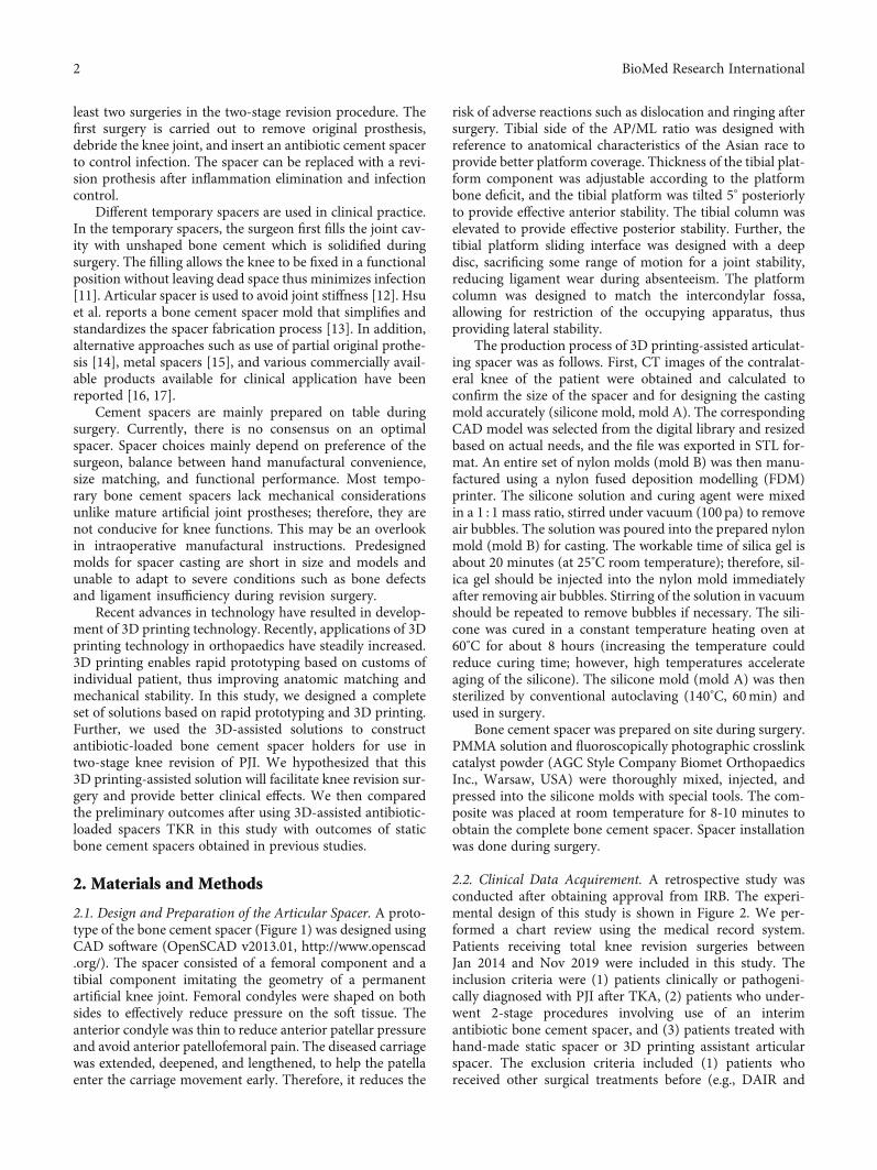
least two surgeries in the two-stage revision procedure. Thefirst surgery is carried out to remove original prosthesis,debride the knee joint, and insert an antibiotic cement spacerto control infection. The spacer can be replaced with a revi-sion prothesis after inflammation elimination and infectioncontrol.
Different temporary spacers are used in clinical practice.In the temporary spacers, the surgeon first fills the joint cav-ity with unshaped bone cement which is solidified duringsurgery. The filling allows the knee to be fixed in a functionalposition without leaving dead space thus minimizes infection[11]. Articular spacer is used to avoid joint stiffness [12]. Hsuet al. reports a bone cement spacer mold that simplifies andstandardizes the spacer fabrication process [13]. In addition,alternative approaches such as use of partial original prothe-sis [14], metal spacers [15], and various commercially avail-able products available for clinical application have beenreported [16, 17].
Cement spacers are mainly prepared on table duringsurgery. Currently, there is no consensus on an optimalspacer. Spacer choices mainly depend on preference of thesurgeon, balance between hand manufactural convenience,size matching, and functional performance. Most tempo-rary bone cement spacers lack mechanical considerationsunlike mature artificial joint prostheses; therefore, they arenot conducive for knee functions. This may be an overlookin intraoperative manufactural instructions. Predesignedmolds for spacer casting are short in size and models andunable to adapt to severe conditions such as bone defectsand ligament insufficiency during revision surgery.
Recent advances in technology have resulted in develop-ment of 3D printing technology. Recently, applications of 3Dprinting technology in orthopaedics have steadily increased.3D printing enables rapid prototyping based on customs ofindividual patient, thus improving anatomic matching andmechanical stability. In this study, we designed a completeset of solutions based on rapid prototyping and 3D printing.Further, we used the 3D-assisted solutions to constructantibiotic-loaded bone cement spacer holders for use intwo-stage knee revision of PJI. We hypothesized that this3D printing-assisted solution will facilitate knee revision sur-gery and provide better clinical effects. We then comparedthe preliminary outcomes after using 3D-assisted antibiotic-loaded spacers TKR in this study with outcomes of staticbone cement spacers obtained in previous studies.
2. Materials and Methods
2.1. Design and Preparation of the Articular Spacer. A proto-type of the bone cement spacer (Figure 1) was designed usingCAD software (OpenSCAD v2013.01, http://www.openscad.org/). The spacer consisted of a femoral component and atibial component imitating the geometry of a permanentartificial knee joint. Femoral condyles were shaped on bothsides to effectively reduce pressure on the soft tissue. Theanterior condyle was thin to reduce anterior patellar pressureand avoid anterior patellofemoral pain. The diseased carriagewas extended, deepened, and lengthened, to help the patellaenter the carriage movement early. Therefore, it reduces the
risk of adverse reactions such as dislocation and ringing aftersurgery. Tibial side of the AP/ML ratio was designed withreference to anatomical characteristics of the Asian race toprovide better platform coverage. Thickness of the tibial plat-form component was adjustable according to the platformbone deficit, and the tibial platform was tilted 5° posteriorlyto provide effective anterior stability. The tibial column waselevated to provide effective posterior stability. Further, thetibial platform sliding interface was designed with a deepdisc, sacrificing some range of motion for a joint stability,reducing ligament wear during absenteeism. The platformcolumn was designed to match the intercondylar fossa,allowing for restriction of the occupying apparatus, thusproviding lateral stability.
The production process of 3D printing-assisted articulat-ing spacer was as follows. First, CT images of the contralat-eral knee of the patient were obtained and calculated toconfirm the size of the spacer and for designing the castingmold accurately (silicone mold, mold A). The correspondingCAD model was selected from the digital library and resizedbased on actual needs, and the file was exported in STL for-mat. An entire set of nylon molds (mold B) was then manu-factured using a nylon fused deposition modelling (FDM)printer. The silicone solution and curing agent were mixedin a 1 : 1 mass ratio, stirred under vacuum (100 pa) to removeair bubbles. The solution was poured into the prepared nylonmold (mold B) for casting. The workable time of silica gel isabout 20 minutes (at 25°C room temperature); therefore, sil-ica gel should be injected into the nylon mold immediatelyafter removing air bubbles. Stirring of the solution in vacuumshould be repeated to remove bubbles if necessary. The sili-cone was cured in a constant temperature heating oven at60°C for about 8 hours (increasing the temperature couldreduce curing time; however, high temperatures accelerateaging of the silicone). The silicone mold (mold A) was thensterilized by conventional autoclaving (140°C, 60min) andused in surgery.
Bone cement spacer was prepared on site during surgery.PMMA solution and fluoroscopically photographic crosslinkcatalyst powder (AGC Style Company Biomet OrthopaedicsInc., Warsaw, USA) were thoroughly mixed, injected, andpressed into the silicone molds with special tools. The com-posite was placed at room temperature for 8-10 minutes toobtain the complete bone cement spacer. Spacer installationwas done during surgery.
2.2. Clinical Data Acquirement. A retrospective study wasconducted after obtaining approval from IRB. The experi-mental design of this study is shown in Figure 2. We per-formed a chart review using the medical record system.Patients receiving total knee revision surgeries betweenJan 2014 and Nov 2019 were included in this study. Theinclusion criteria were (1) patients clinically or pathogeni-cally diagnosed with PJI after TKA, (2) patients who under-went 2-stage procedures involving use of an interimantibiotic bone cement spacer, and (3) patients treated withhand-made static spacer or 3D printing assistant articularspacer. The exclusion criteria included (1) patients whoreceived other surgical treatments before (e.g., DAIR and
2 BioMed Research International
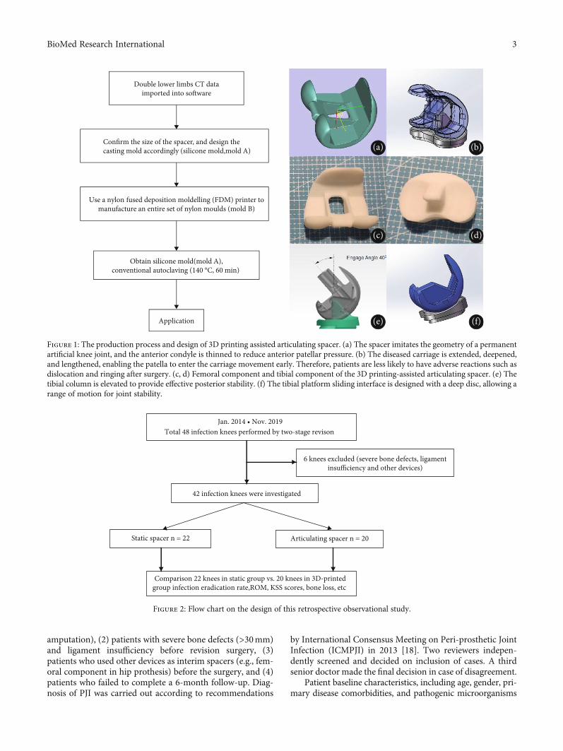
amputation), (2) patients with severe bone defects (>30mm)and ligament insufficiency before revision surgery, (3)patients who used other devices as interim spacers (e.g., fem-oral component in hip prothesis) before the surgery, and (4)patients who failed to complete a 6-month follow-up. Diag-nosis of PJI was carried out according to recommendations
by International Consensus Meeting on Peri-prosthetic JointInfection (ICMPJI) in 2013 [18]. Two reviewers indepen-dently screened and decided on inclusion of cases. A thirdsenior doctor made the final decision in case of disagreement.
Patient baseline characteristics, including age, gender, pri-mary disease comorbidities, and pathogenic microorganisms
Confirm the size of the spacer, and design thecasting mold accordingly (silicone mold,mold A)
Use a nylon fused deposition moldelling (FDM) printer tomanufacture an entire set of nylon moulds (mold B)
Obtain silicone mold(mold A),conventional autoclaving (140 °C, 60 min)
Application
Double lower limbs CT dataimported into so�ware
(a) (b)
(c) (d)
(e) (f)
Figure 1: The production process and design of 3D printing assisted articulating spacer. (a) The spacer imitates the geometry of a permanentartificial knee joint, and the anterior condyle is thinned to reduce anterior patellar pressure. (b) The diseased carriage is extended, deepened,and lengthened, enabling the patella to enter the carriage movement early. Therefore, patients are less likely to have adverse reactions such asdislocation and ringing after surgery. (c, d) Femoral component and tibial component of the 3D printing-assisted articulating spacer. (e) Thetibial column is elevated to provide effective posterior stability. (f) The tibial platform sliding interface is designed with a deep disc, allowing arange of motion for joint stability.
Jan. 2014 • Nov. 2019Total 48 infection knees performed by two-stage revison
6 knees excluded (severe bone defects, ligamentinsufficiency and other devices)
42 infection knees were investigated
Static spacer n = 22 Articulating spacer n = 20
Comparison 22 knees in static group vs. 20 knees in 3D-printedgroup infection eradication rate,ROM, KSS scores, bone loss, etc
Figure 2: Flow chart on the design of this retrospective observational study.
3BioMed Research International
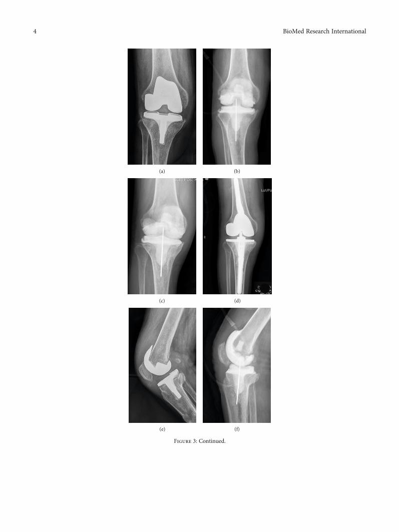
(a) (b)
(c) (d)
(e) (f)
Figure 3: Continued.
4 BioMed Research International
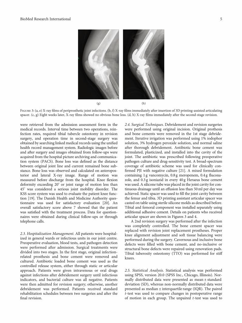
were retrieved from the admission assessment form in themedical records. Interval time between two operations, rein-fection rates, required tibial tubercle osteotomy in revisionsurgery, and operation time in second-stage surgery wasobtained by searching linkedmedical records using the unifiedhealth record management system. Radiologic images beforeand after surgery and images obtained from follow-ups wereacquired from the hospital picture archiving and communica-tion system (PACS). Bone loss was defined as the distancebetween original joint line and current remained bone sub-stance. Bone loss was observed and calculated on anteropos-terior and lateral X-ray image. Range of motion wasmeasured before discharge from the hospital. Knee flexiondeformity exceeding 20° or joint range of motion less than45° was considered a serious joint mobility disorder. TheKSS score system was used to evaluate the patient knee func-tion [19]. The Danish Health and Medicine Authority ques-tionnaire was used for satisfactory evaluation [20]. Anoverall satisfactory score above 7 showed that the patientwas satisfied with the treatment process. Data for question-naires were obtained during clinical follow-ups or throughtelephone calls.
2.3. Hospitalization Management. All patients were hospital-ized in general wards or infectious units in our joint centre.Preoperative evaluation, blood tests, and pathogen detectionwere performed after admission. Surgical treatments weredivided into two stages. In the first stage, original infection-related prosthesis and bone cement were removed andcultured. Antibiotic loaded bone cement was used as thecontrolled release system, either through static or articularapproach. Patients were given intravenous or oral drugsagainst infections after debridement surgery until infectiousindicators, and bacterial culture was all negative. Patientswere then admitted for revision surgery; otherwise, anotherdebridement was performed. Patients received standardrehabilitation schedules between two surgeries and after thefinal revision.
2.4. Surgical Techniques. Debridement and revision surgerieswere performed using original incision. Original prothesisand bone cements were removed in the 1st stage debride-ment. Iterative irrigation was performed using 1% iodophorsolution, 3% hydrogen peroxide solution, and normal salineafter thorough debridement. Antibiotic bone cement wasformulated, plasticized, and installed into the cavity of thejoint. The antibiotic was prescribed following preoperativepathogen culture and drug-sensitivity test. A broad-spectrumcoverage of antibiotic scheme was used for clinically con-firmed PJI with negative culture [21]. A mixed formulationcontaining 1 g vancomycin, 0.8 g meropenem, 0.4 g flucona-zole, and 0.3 g isoniazid in every 40g Heraeus bone cementwas used. A silicone tube was placed in the joint cavity for con-tinuous drainage until an effusion less than 50ml per day wasachieved. Static spacer was used to fill the joint cavity betweenthe femur and tibia. 3D printing assistant articular spacer wascasted on table using sterile silicone molds as described before.Tibial and femoral component was installed separately usingadditional adhesive cement. Details on patients who receivedarticular spacer are shown in Figures 3 and 4.
A 2nd revision surgery was performed after the infectionwas completely controlled. The bone cement spacer wasreplaced with revision joint replacement prostheses. Properknee alignment adjustment and soft tissue balancing wereperformed during the surgery. Cavernous and inclusive bonedefects were filled with bone cement, and no-inclusive orstructural bone defects were repaired using renovation pads.Tibial tuberosity osteotomy (TTO) was performed for stiffknees.
2.5. Statistical Analysis. Statistical analysis was performedusing SPSS, version 20.0 (SPSS Inc., Chicago, Illinois). Nor-mally distributed data were presented as mean ± standarddeviation (SD), whereas non-normally distributed data werepresented as median ± interquartile range (IQR). The pairedt-test was used to compare changes in postoperative rangeof motion in each group. The unpaired t-test was used to
(g) (h)
Figure 3: (a, e) X-ray films of periprosthetic joint infections. (b, f) X-ray films immediately after insertion of 3D printing-assisted articulatingspacer. (c, g) Eight weeks later, X-ray films showed no obvious bone loss. (d, h) X-ray films immediately after the second-stage revision.
5BioMed Research International
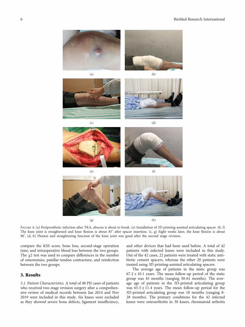
compare the KSS score, bone loss, second-stage operationtime, and intraoperative blood loss between the two groups.The χ2 test was used to compare differences in the numberof osteotomies, patellar tendon contracture, and reinfectionbetween the two groups.
3. Results
3.1. Patient Characteristics. A total of 48 PJI cases of patientswho received two-stage revision surgery after a comprehen-sive review of medical records between Jan 2014 and Nov2019 were included in this study. Six knees were excludedas they showed severe bone defects, ligament insufficiency,
and other devices that had been used before. A total of 42patients with infected knees were included in this study.Out of the 42 cases, 22 patients were treated with static anti-biotic cement spacers, whereas the other 20 patients weretreated using 3D printing-assisted articulating spacers.
The average age of patients in the static group was67:2 ± 10:1 years. The mean follow-up period of the staticgroup was 43 months (ranging 30-61 months). The aver-age age of patients in the 3D-printed articulating groupwas 65:5 ± 11:4 years. The mean follow-up period for the3D-printed articulating group was 18 months (ranging 8-28 months). The primary conditions for the 42 infectedknees were osteoarthritis in 30 knees, rheumatoid arthritis
(a) (b)
(c) (d)
(e) (f)
(g) (h)
Figure 4: (a) Periprosthetic infection after TKA, abscess is about to break. (e) Installation of 3D printing-assisted articulating spacer. (b, f)The knee joint is straightened and knee flexion is about 85° after spacer insertion. (c, g) Eight weeks later, the knee flexion is about90°. (d, h) Flexion and straightening function of the knee joint was good after the second stage revision.
6 BioMed Research International
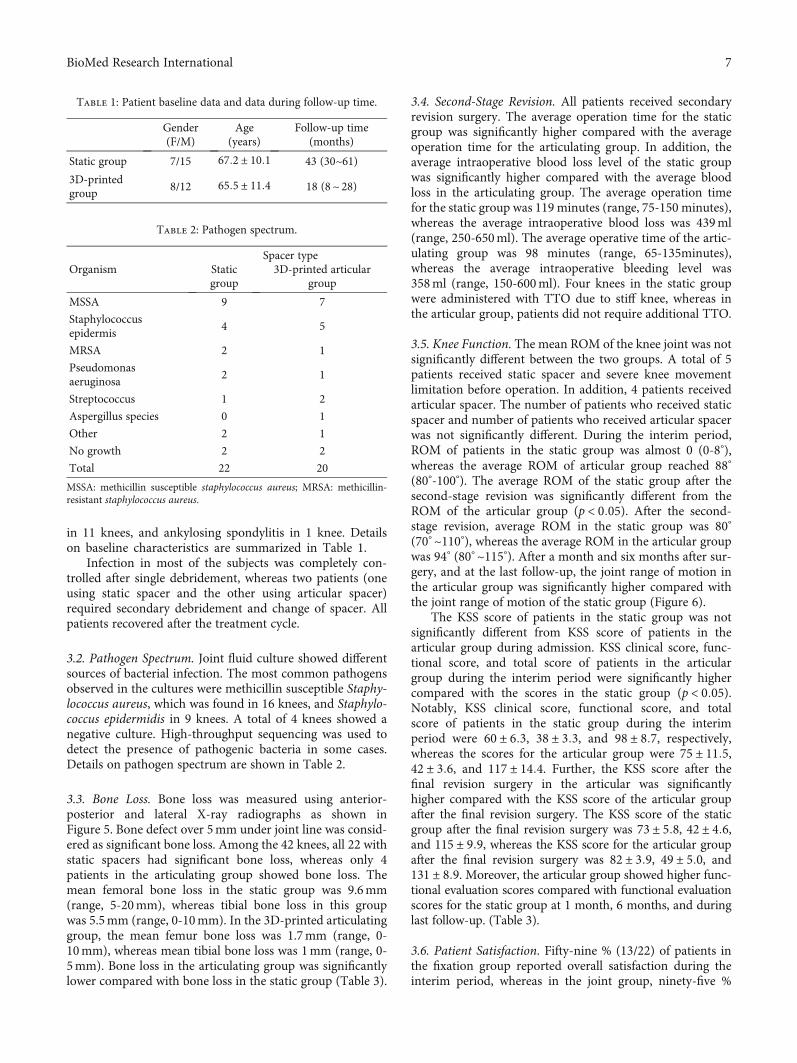
in 11 knees, and ankylosing spondylitis in 1 knee. Detailson baseline characteristics are summarized in Table 1.
Infection in most of the subjects was completely con-trolled after single debridement, whereas two patients (oneusing static spacer and the other using articular spacer)required secondary debridement and change of spacer. Allpatients recovered after the treatment cycle.
3.2. Pathogen Spectrum. Joint fluid culture showed differentsources of bacterial infection. The most common pathogensobserved in the cultures were methicillin susceptible Staphy-lococcus aureus, which was found in 16 knees, and Staphylo-coccus epidermidis in 9 knees. A total of 4 knees showed anegative culture. High-throughput sequencing was used todetect the presence of pathogenic bacteria in some cases.Details on pathogen spectrum are shown in Table 2.
3.3. Bone Loss. Bone loss was measured using anterior-posterior and lateral X-ray radiographs as shown inFigure 5. Bone defect over 5mm under joint line was consid-ered as significant bone loss. Among the 42 knees, all 22 withstatic spacers had significant bone loss, whereas only 4patients in the articulating group showed bone loss. Themean femoral bone loss in the static group was 9.6mm(range, 5-20mm), whereas tibial bone loss in this groupwas 5.5mm (range, 0-10mm). In the 3D-printed articulatinggroup, the mean femur bone loss was 1.7mm (range, 0-10mm), whereas mean tibial bone loss was 1mm (range, 0-5mm). Bone loss in the articulating group was significantlylower compared with bone loss in the static group (Table 3).
3.4. Second-Stage Revision. All patients received secondaryrevision surgery. The average operation time for the staticgroup was significantly higher compared with the averageoperation time for the articulating group. In addition, theaverage intraoperative blood loss level of the static groupwas significantly higher compared with the average bloodloss in the articulating group. The average operation timefor the static group was 119 minutes (range, 75-150 minutes),whereas the average intraoperative blood loss was 439ml(range, 250-650ml). The average operative time of the artic-ulating group was 98 minutes (range, 65-135minutes),whereas the average intraoperative bleeding level was358ml (range, 150-600ml). Four knees in the static groupwere administered with TTO due to stiff knee, whereas inthe articular group, patients did not require additional TTO.
3.5. Knee Function. The mean ROM of the knee joint was notsignificantly different between the two groups. A total of 5patients received static spacer and severe knee movementlimitation before operation. In addition, 4 patients receivedarticular spacer. The number of patients who received staticspacer and number of patients who received articular spacerwas not significantly different. During the interim period,ROM of patients in the static group was almost 0 (0-8°),whereas the average ROM of articular group reached 88°
(80°-100°). The average ROM of the static group after thesecond-stage revision was significantly different from theROM of the articular group (p < 0:05). After the second-stage revision, average ROM in the static group was 80°
(70° ~110°), whereas the average ROM in the articular groupwas 94° (80° ~115°). After a month and six months after sur-gery, and at the last follow-up, the joint range of motion inthe articular group was significantly higher compared withthe joint range of motion of the static group (Figure 6).
The KSS score of patients in the static group was notsignificantly different from KSS score of patients in thearticular group during admission. KSS clinical score, func-tional score, and total score of patients in the articulargroup during the interim period were significantly highercompared with the scores in the static group (p < 0:05).Notably, KSS clinical score, functional score, and totalscore of patients in the static group during the interimperiod were 60 ± 6:3, 38 ± 3:3, and 98 ± 8:7, respectively,whereas the scores for the articular group were 75 ± 11:5,42 ± 3:6, and 117 ± 14:4. Further, the KSS score after thefinal revision surgery in the articular was significantlyhigher compared with the KSS score of the articular groupafter the final revision surgery. The KSS score of the staticgroup after the final revision surgery was 73 ± 5:8, 42 ± 4:6,and 115 ± 9:9, whereas the KSS score for the articular groupafter the final revision surgery was 82 ± 3:9, 49 ± 5:0, and131 ± 8:9. Moreover, the articular group showed higher func-tional evaluation scores compared with functional evaluationscores for the static group at 1 month, 6 months, and duringlast follow-up. (Table 3).
3.6. Patient Satisfaction. Fifty-nine % (13/22) of patients inthe fixation group reported overall satisfaction during theinterim period, whereas in the joint group, ninety-five %
Table 1: Patient baseline data and data during follow-up time.
Gender(F/M)
Age(years)
Follow-up time(months)
Static group 7/15 67:2 ± 10:1 43 (30~61)3D-printedgroup
8/12 65:5 ± 11:4 18 (8~ 28)
Table 2: Pathogen spectrum.
OrganismSpacer type
Staticgroup
3D-printed articulargroup
MSSA 9 7
Staphylococcusepidermis
4 5
MRSA 2 1
Pseudomonasaeruginosa
2 1
Streptococcus 1 2
Aspergillus species 0 1
Other 2 1
No growth 2 2
Total 22 20
MSSA: methicillin susceptible staphylococcus aureus; MRSA: methicillin-resistant staphylococcus aureus.
7BioMed Research International
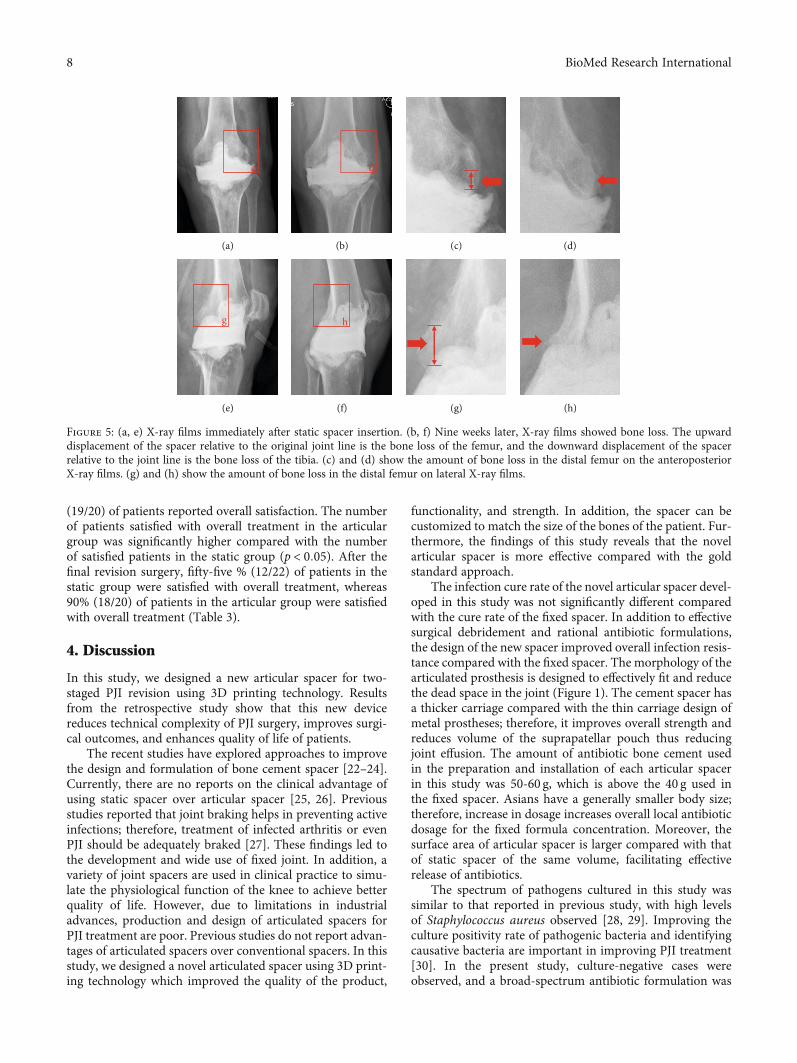
(19/20) of patients reported overall satisfaction. The numberof patients satisfied with overall treatment in the articulargroup was significantly higher compared with the numberof satisfied patients in the static group (p < 0:05). After thefinal revision surgery, fifty-five % (12/22) of patients in thestatic group were satisfied with overall treatment, whereas90% (18/20) of patients in the articular group were satisfiedwith overall treatment (Table 3).
4. Discussion
In this study, we designed a new articular spacer for two-staged PJI revision using 3D printing technology. Resultsfrom the retrospective study show that this new devicereduces technical complexity of PJI surgery, improves surgi-cal outcomes, and enhances quality of life of patients.
The recent studies have explored approaches to improvethe design and formulation of bone cement spacer [22–24].Currently, there are no reports on the clinical advantage ofusing static spacer over articular spacer [25, 26]. Previousstudies reported that joint braking helps in preventing activeinfections; therefore, treatment of infected arthritis or evenPJI should be adequately braked [27]. These findings led tothe development and wide use of fixed joint. In addition, avariety of joint spacers are used in clinical practice to simu-late the physiological function of the knee to achieve betterquality of life. However, due to limitations in industrialadvances, production and design of articulated spacers forPJI treatment are poor. Previous studies do not report advan-tages of articulated spacers over conventional spacers. In thisstudy, we designed a novel articulated spacer using 3D print-ing technology which improved the quality of the product,
functionality, and strength. In addition, the spacer can becustomized to match the size of the bones of the patient. Fur-thermore, the findings of this study reveals that the novelarticular spacer is more effective compared with the goldstandard approach.
The infection cure rate of the novel articular spacer devel-oped in this study was not significantly different comparedwith the cure rate of the fixed spacer. In addition to effectivesurgical debridement and rational antibiotic formulations,the design of the new spacer improved overall infection resis-tance compared with the fixed spacer. The morphology of thearticulated prosthesis is designed to effectively fit and reducethe dead space in the joint (Figure 1). The cement spacer hasa thicker carriage compared with the thin carriage design ofmetal prostheses; therefore, it improves overall strength andreduces volume of the suprapatellar pouch thus reducingjoint effusion. The amount of antibiotic bone cement usedin the preparation and installation of each articular spacerin this study was 50-60 g, which is above the 40 g used inthe fixed spacer. Asians have a generally smaller body size;therefore, increase in dosage increases overall local antibioticdosage for the fixed formula concentration. Moreover, thesurface area of articular spacer is larger compared with thatof static spacer of the same volume, facilitating effectiverelease of antibiotics.
The spectrum of pathogens cultured in this study wassimilar to that reported in previous study, with high levelsof Staphylococcus aureus observed [28, 29]. Improving theculture positivity rate of pathogenic bacteria and identifyingcausative bacteria are important in improving PJI treatment[30]. In the present study, culture-negative cases wereobserved, and a broad-spectrum antibiotic formulation was
c
(a)
d
(b) (c) (d)
g
(e)
h
(f) (g) (h)
Figure 5: (a, e) X-ray films immediately after static spacer insertion. (b, f) Nine weeks later, X-ray films showed bone loss. The upwarddisplacement of the spacer relative to the original joint line is the bone loss of the femur, and the downward displacement of the spacerrelative to the joint line is the bone loss of the tibia. (c) and (d) show the amount of bone loss in the distal femur on the anteroposteriorX-ray films. (g) and (h) show the amount of bone loss in the distal femur on lateral X-ray films.
8 BioMed Research International
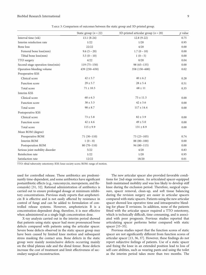
used for controlled release. These antibiotics are predomi-nantly time-dependent, and some antibiotics have significantpostantibiotic effects (e.g., vancomycin, meropenem, and flu-conazole) [31, 32]. Rational administration of antibiotics iscarried out to ensure prolonged dosage at minimum inhibi-tory concentrations. Previous study reports that amphoteri-cin B is effective and is not easily affected by resistance incontrol of fungi and can be added to formulation of con-trolled release systems. However, amphotericin B is aconcentration-dependent drug; therefore, it is mor effectivewhen administered as a single high concentration dose.
X-ray analysis carried out in the interim period showedthat patients using static spacer had more pronounced bonedefects compared with patients using the articular spacer.Severe bone defects observed in the static spacer group mayhave been caused by limited knee motion and subsequentstress masking the contact area. Bone defects in the staticgroup were mainly noninclusive defects occurring mainlyon the tibial plateau side and the distal femur. Bone defectsincrease the cost of treatment and limit effectiveness of sec-ondary surgical reconstruction.
The new articular spacer also provided favorable condi-tions for 2nd-stage revision. An articulated spacer-equippedlimb maintained mobility and was less likely to develop stiffknee during the exclusion period. Therefore, surgical expo-sure, spacer removal, clean-up, and soft tissue balancingduring the revision surgery are easier in articular spacerscompared with static spacers. Patients using the new articularspacer showed less operative time and intraoperative bleed-ing for phase II revisions. In addition, none of the patientsfitted with the articular spacer required a TTO osteotomy,which is technically difficult, time consuming, and is associ-ated with poor prognosis. Previous studies reported thatarticulating spacer performs better compared with staticspacer [33–35].
Previous studies report that the function scores of staticspacer are not significantly different from function scores ofarticular spacer [13, 36, 37]. However, these findings do notreport subjective feelings of patients. Use of a static spacerand fixing the knee in an extended position lead to loss ofself-care abilities, such as wearing pants and using the toiletas the interim period takes more than two months. The
Table 3: Comparison of outcomes between the static group and 3D-printed group.
Static group (n = 22) 3D-printed articular group (n = 20) p value
Interval time (wk) 13.1 (8-24) 12.8 (9-22) 0.75
Interim reinfection rate 1/22 1/20 0.95
Bone loss 22/22 4/20 0.00
Femoral bone loss(mm) 9.6 (5~ 20) 1.7 (0~ 10) 0.00
Tibial bone loss(mm) 5.5 (0~ 10) 1 (0~ 5) 0.00
TTO surgery 4/22 0/20 0.04
Second-stage operation time(min) 119 (75~150) 98 (65~135) 0.00
Operation bleeding volume 439 (250~650) 358 (150~600) 0.02
Preoperative KSS
Clinical score 42 ± 5:7 40 ± 6:2 0.28
Function score 29 ± 5:7 28 ± 5:4 0.51
Total score 71 ± 10:5 68 ± 11 0.35
Interim KSS
Clinical score 60 ± 6:3 75 ± 11:5 0.00
Function score 38 ± 3:3 42 ± 3:6 0.00
Total score 98 ± 8:7 117 ± 14:4 0.00
Postoperative KSS
Clinical score 73 ± 5:8 82 ± 3:9 0.00
Function score 42 ± 4:6 49 ± 5:0 0.00
Total score 115 ± 9:9 131 ± 8:9 0.00
Mean ROM (degree)
Preoperative ROM 71 (30~110) 73 (23~105) 0.74
Interim ROM 1 (0~ 8) 88 (80~100) 0.00
Postoperation ROM 80 (70~110) 94 (80~115) 0.00
Serious joint mobility disorder 5/22 4/20 0.83
Reinfection rate 1/22 1/20 0.95
Satisfaction rate 12/22 18/20 0.01
TTO: tibial tuberosity osteotomy; KSS: knee society score; ROM: range of motion.
9BioMed Research International
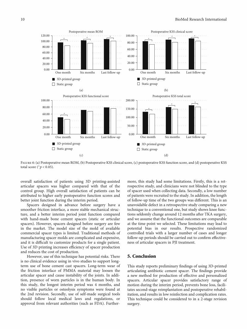
overall satisfaction of patients using 3D printing-assistedarticular spacers was higher compared with that of thecontrol group. High overall satisfaction of patients can beattributed to higher early postoperative function scores andbetter joint function during the interim period.
Spacers designed in advance before surgery have asmoother friction interface, a more stable mechanical struc-ture, and a better interim period joint function comparedwith hand-made bone cement spacers (static or articularspacers). However, spacers designed before surgery are fewin the market. The model size of the mold of availablecommercial spacer types is limited. Traditional methods ofmanufacturing spacer molds are complicated and expensive,and it is difficult to customize products for a single patient.Use of 3D printing increases efficiency of spacer productionand reduces the cost of production.
However, use of this technique has potential risks. Thereis no clinical evidence using in vivo studies to support long-term use of bone cement cast spacers. Long-term wear ofthe friction interface of PMMA material may loosen thearticular spacer and cause instability of the joints. In addi-tion, presence of worn particles is in the human body. Inthis study, the longest interim period was 4 months, andno visible particles or osteolysis symptoms were found atthe 2nd revision. Secondly, use of self-made surgical toolsshould follow local medical laws and regulations, orapproval from relevant authorities (such as FDA). Further-
more, this study had some limitations. Firstly, this is a ret-rospective study, and clinicians were not blinded to the typeof spacer used when collecting data. Secondly, a low numberof patients were recruited to the study. In addition, the lengthof follow-up time of the two groups was different. This is anunavoidable defect in a retrospective study comparing a newtechnique to a conventional one, but study shows knee func-tions seldomly change around 12 months after TKA surgery,and we assume that the functional outcomes are comparableat the time point we selected. These limitations may lead topotential bias in our results. Prospective randomizedcontrolled trials with a larger number of cases and longerfollow-up periods should be carried out to confirm effective-ness of articular spacers in PJI treatment.
5. Conclusion
This study reports preliminary findings of using 3D-printedarticulating antibiotic cement spacer. The findings providea new method for production of effective and personalizedspacers. Articular spacer provides satisfactory range ofmotion during the interim period, prevents bone loss, facili-tates second-stage reimplantation and postoperative rehabil-itation, and results in low reinfection and complication rates.This technique could be considered to in a 2-stage revisionsurgery.
120.00Postoperative mean ROM
100.00
80.00
60.00
40.00
20.00
0.00One month
3D-printed groupStatic group
Six months Last follow-up
⁎⁎
⁎
(a)
Postoperative KSS clinical score
0.00One month Six months Last follow-up
20.00
40.00
60.00
80.00
100.00
3D-printed groupStatic group
⁎
⁎ ⁎
(b)
Postoperative KSS functional score100.00
80.00
60.00
40.00
20.00
0.00One month Six months Last follow-up
3D-printed groupStatic group
⁎
(c)
Postoperative KSS total score200.00
150.00
100.00
50.00
0.00One month Six months Last follow-up
3D-printed groupStatic group
⁎
⁎
⁎
(d)
Figure 6: (a) Postoperative mean ROM, (b) Postoperative KSS clinical score, (c) postoperative KSS function score, and (d) postoperative KSStotal score (∗p < 0:05).
10 BioMed Research International
Data Availability
The data used to support the findings of this study areavailable from the corresponding author upon request.
Ethical Approval
This study was approved by the ethics committee of the FirstAffiliated Hospital of USTC. An optout of the informedconsent, information disclosure, and a negative opportunityis guaranteed in the Ethical approval.
Consent
All the patients included in this study gave informed consentfor the article to be published.
Conflicts of Interest
Authors declare that they have no conflicts of interest.
Authors’ Contributions
XZ conceived and designed the study. LK collected the dataand performed the statistical analysis. LK, JM, andWGwrotethe manuscript. XJ and XC provided the 3D printing tech-nique support. CZ provided funding and administrative sup-port. All authors read and approved the final manuscript.Lingtong Kong, Jiawei Mei, and Wufei Ge contributedequally to this work.
Acknowledgments
This study was supported by the National Natural ScienceFoundation of China (Grant No. 81871788), the Project forScience and Technology leader of Anhui Province (GrantNo. 2018H177), Scientific Research Fund of Anhui Educa-tion (Grant No. 2017jyxm1097), Anhui Provincial Postdoc-toral Science Foundation (Grant No. 2019B302), theFundamental Research Funds for the Central Universities(WK9110000173) and Key Research and Development Planof Anhui Province (Grant No. 912278014064).
References
[1] A. J. Price, A. Alvand, A. Troelsen et al., “Knee replacement,”Lancet, vol. 392, no. 10158, pp. 1672–1682, 2018.
[2] A. J. Carr, O. Robertsson, S. Graves et al., “Knee replacement,”Lancet, vol. 379, no. 9823, pp. 1331–1340, 2012.
[3] M. Varacallo, T. D. Luo, and N. A. Johanson, Total kneearthroplasty (TKA) techniques, StatPearls, Treasure Island(FL), 2020.
[4] B. H. Kapadia, R. A. Berg, J. A. Daley, J. Fritz, A. Bhave, andM. A. Mont, “Periprosthetic joint infection,” Lancet, vol. 387,no. 10016, pp. 386–394, 2016.
[5] A. R. Cochran, K. L. Ong, E. Lau, M. A. Mont, and A. L. Mal-kani, “Risk of reinfection after treatment of infected Total kneeArthroplasty,” The Journal of Arthroplasty, vol. 31, no. 9,pp. 156–161, 2016.
[6] H. Dale, A. M. Fenstad, G. Hallan et al., “Increasing risk ofprosthetic joint infection after total hip arthroplasty,” ActaOrthopaedica, vol. 83, no. 5, pp. 449–458, 2012.
[7] N. S. Nagra, T. W. Hamilton, S. Ganatra, D. W. Murray, andH. Pandit, “One-stage versus two-stage exchange arthroplastyfor infected total knee arthroplasty: a systematic review,” KneeSurgery, Sports Traumatology, Arthroscopy, vol. 24, no. 10,pp. 3106–3114, 2016.
[8] A. Siddiqi, N. E. George, P. B. White et al., “Articulatingspacers as a modified one-stage revision total knee arthro-plasty: a preliminary analysis,” Surgical Technology Interna-tional, vol. 32, pp. 239–248, 2018.
[9] J. Lu, J. Han, C. Zhang, Y. Yang, and Z. Yao, “Infection aftertotal knee arthroplasty and its gold standard surgical treat-ment: spacers used in two-stage revision arthroplasty,” Intrac-table & rare diseases research, vol. 6, no. 4, pp. 256–261, 2017.
[10] D. R. Osmon, E. F. Berbari, A. R. Berendt et al., “Diagnosis andmanagement of prosthetic joint infection: clinical practiceguidelines by the Infectious Diseases Society of America,”Clinical Infectious Diseases, vol. 56, no. 1, pp. e1–e25, 2013.
[11] A. D. Hanssen and M. J. Spangehl, “Practical applications ofantibiotic-loaded bone cement for treatment of infected jointreplacements,” Clinical Orthopaedics and Related Research,vol. 427, pp. 79–85, 2004.
[12] A. A. Hofmann, K. R. Kane, T. K. Tkach, R. L. Plaster, andM. P. Camargo, “Treatment of infected total knee arthroplastyusing an articulating spacer,” Clinical Orthopaedics & RelatedResearch, vol. 321, pp. 45–54, 1995.
[13] Y. C. Hsu, H. C. Cheng, T. P. Ng, and K. Y. Chiu, “Antibiotic-loaded cement articulating spacer for 2-stage reimplantationin infected total knee arthroplasty: a simple and economicmethod,” The Journal of Arthroplasty, vol. 22, no. 7,pp. 1060–1066, 2007.
[14] E. Jämsen, P. Sheng, P. Halonen et al., “Spacer prostheses intwo-stage revision of infected knee arthroplasty,” InternationalOrthopaedics, vol. 30, no. 4, pp. 257–261, 2006.
[15] M. Gathen, J. Schmolders, M. D. Wimmer et al., “Modulararthrodesis system TITAN (KAM-TITAN) after failed revi-sion total knee arthroplasty: operative technique and clinicalexperience,” Operative Orthopädie und Traumatologie,vol. 32, no. 1, pp. 58–72, 2020.
[16] A. A. Shaikh, C. W. Ha, Y. G. Park, and Y. B. Park, “Two-stageapproach to primary TKA in infected arthritic knees usingintraoperatively molded articulating cement spacers,” ClinicalOrthopaedics and Related Research, vol. 472, no. 7, pp. 2201–2207, 2014.
[17] L. C. Warth, C. J. Hadley, and E. L. Grossman, “Two-stagetreatment for Total knee Arthroplasty infection utilizing anarticulating prefabricated antibiotic spacer,” The Journal ofArthroplasty, vol. 35, no. 3, pp. S57–S62, 2020.
[18] H. J. Cooper and C. J. Della Valle, “The two-stage standard inrevision total hip replacement,” The bone & joint journal,vol. 95-B, 11 Supplement A, pp. 84–87, 2013.
[19] W. Lopez-Aqueres, B. Kemp, M. Plopper, F. R. Staples, andK. Brummel-Smith, “Health needs of the Hispanic elderly,”Journal of the American Geriatrics Society, vol. 32, no. 3,pp. 191–198, 1984.
[20] H. Husted, H. C. Hansen, G. Holm et al., “Accelerated versusconventional hospital stay in total hip and knee arthroplastyIII: patient satisfaction,” Ugeskrift for Laeger, vol. 168, no. 22,pp. 2148–2151, 2006.
11BioMed Research International
[21] J. Wang, Q. Wang, H. Shen, and X. Zhang, “Comparable out-come of culture-negative and culture-positive periprosthetichip joint infection for patients undergoing two-stage revision,”International Orthopaedics, vol. 42, no. 3, pp. 469–477, 2018.
[22] M. Villanueva, A. Ríos, J. Pereiro, F. Chana, and H. Fahandez-Saddi, “Hand-made articulating spacers for infected total kneearthroplasty: a technical note,” Acta Orthopaedica, vol. 77,no. 2, pp. 329–332, 2006.
[23] Y. P. Su, O. K. Lee,W.M. Chen, and T. H. Chen, “A facile tech-nique to make articulating spacers for infected total kneearthroplasty,” Journal of the Chinese Medical Association,vol. 72, no. 3, pp. 138–145, 2009.
[24] S. M. Sporer, “Spacer design options and consideration forperiprosthetic joint infection,” The Journal of Arthroplasty,vol. 35, no. 3, pp. S31–S34, 2020.
[25] P. B. Voleti, K. D. Baldwin, and G. C. Lee, “Use of static orarticulating spacers for infection following total knee arthro-plasty: a systematic literature review,” The Journal of Boneand Joint Surgery. American Volume, vol. 95, no. 17,pp. 1594–1599, 2013.
[26] M. Citak, M. Citak, and D. Kendoff, “Dynamic versus staticcement spacer in periprosthetic knee infection: a meta-analy-sis,” Orthopade, vol. 44, no. 8, pp. 599–606, 2015.
[27] R. M. Meek, D. Dunlop, D. S. Garbuz, R. McGraw, N. V.Greidanus, and B. A. Masri, “Patient satisfaction and func-tional status after aseptic versus septic revision total kneearthroplasty using the PROSTALAC articulating spacer,”The Journal of Arthroplasty, vol. 19, no. 7, pp. 874–879,2004.
[28] D. Zajonz, L. Wuthe, A. C. Rodloff et al., “Infektionen vonHüft- und Knieendoprothesen,” Chirurg, vol. 87, no. 4,pp. 332–339, 2016.
[29] T. Rosteius, O. Jansen, T. Fehmer et al., “Evaluating the micro-bial pattern of periprosthetic joint infections of the hip andknee,” Journal of Medical Microbiology, vol. 67, no. 11,pp. 1608–1613, 2018.
[30] J. H. J. van Erp, A. C. Heineken, R. J. A. van Wensen et al.,“Optimization of the empirical antibiotic choice during thetreatment of acute prosthetic joint infections: a retrospectiveanalysis of 91 patients,” Acta Orthopaedica, vol. 90, no. 5,pp. 455–459, 2019.
[31] V. Post, P. Wahl, R. G. Richards, and T. F. Moriarty, “Vanco-mycin displays time-dependent eradication of mature Staphy-lococcus aureus biofilms,” Journal of Orthopaedic Research,vol. 35, no. 2, pp. 381–388, 2017.
[32] D. J. Tennent, S. M. Shiels, C. J. Sanchez Jr. et al., “Time-dependent effectiveness of locally applied Vancomycin powderin a contaminated traumatic orthopaedic wound model,” Jour-nal of Orthopaedic Trauma, vol. 30, no. 10, pp. 531–537, 2016.
[33] E. C. Bowman and A. L. Malkani, “Point/Counterpoint: Staticvs Articulating Spacers–Static Spacers for Resection Arthro-plasty of the Knee,” The Journal of Arthroplasty, vol. 35,no. 3, pp. S35–S39, 2020.
[34] P. M. Preobrazhensky, S. A. Bozhkova, A. V. Kazemirsky, R. M.Tikhilov, T. A. Kulaba, and N. N. Kornilov, “Functional out-come of two-stage reimplantation in patients with peripros-thetic joint infection after primary total knee arthroplasty,”International Orthopaedics, vol. 43, no. 11, pp. 2503–2509, 2019.
[35] C. R. Nahhas, P. N. Chalmers, J. Parvizi et al., “A randomizedtrial of static and articulating spacers for the treatment ofinfection following total knee arthroplasty,” The Journal of
Bone and Joint Surgery. American Volume, vol. 102, no. 9,pp. 778–787, 2020.
[36] H. Ding, J. Yao, W. Chang, and F. Liu, “Comparison of theefficacy of static versus articular spacers in two-stage revisionsurgery for the treatment of infection following total kneearthroplasty: a meta-analysis,” Journal of Orthopaedic Surgeryand Research, vol. 12, no. 1, 2017.
[37] M. G. Freeman, T. K. Fehring, S. M. Odum, K. Fehring, W. L.Griffin, and J. B. Mason, “Functional advantage of articulatingversus static spacers in 2-stage revision for total knee arthro-plasty infection,” The Journal of Arthroplasty, vol. 22, no. 8,pp. 1116–1121, 2007.
12 BioMed Research International
Research ArticleIn-Hospital 3D Printed Scaphoid Prosthesis Using Medical-GradePolyetheretherketone (PEEK) Biomaterial
Philipp Honigmann ,1,2,3 Neha Sharma ,2,4 Ralf Schumacher ,5 Jasmine Rueegg ,5
Mathias Haefeli ,3,6 and Florian Thieringer 2,4
1Hand Surgery, Cantonal Hospital Baselland, Rheinstrasse 26, 4410 Liestal, Switzerland2Medical Additive Manufacturing Research Group, Department of Biomedical Engineering, University of Basel, Gewerbestrasse 16,4123 Allschwil, Switzerland3Amsterdam UMC, University of Amsterdam, Department of Biomedical Engineering and Physics, Amsterdam Movement Sciences,Meibergdreef 9, Amsterdam, Netherlands4Department of Oral and Cranio-Maxillofacial Surgery, University Hospital Basel, Spitalstrasse 21, 4031 Basel, Switzerland5Medartis AG, Hochbergerstrasse 60 E, 4057 Basel, Switzerland6Hand Surgery, Cantonal Hospital of Grisons, Loestrasse 170, 7000 Chur, Switzerland
Correspondence should be addressed to Philipp Honigmann; [email protected]
Received 9 June 2020; Revised 3 November 2020; Accepted 26 December 2020; Published 12 January 2021
Academic Editor: Liu Yang
Copyright © 2021 Philipp Honigmann et al. This is an open access article distributed under the Creative Commons AttributionLicense, which permits unrestricted use, distribution, and reproduction in any medium, provided the original work isproperly cited.
Recently, three-dimensional (3D) printing has become increasingly popular in the medical sector for the production of anatomicalbiomodels, surgical guides, and prosthetics. With the availability of low-cost desktop 3D printers and affordable materials, the in-house or point-of-care manufacturing of biomodels and Class II medical devices has gained considerable attention in personalizedmedicine. Another projected development in medical 3D printing for personalized treatment is the in-house production of patient-specific implants (PSIs) for partial and total bone replacements made of medical-grade material such as polyetheretherketone(PEEK). We present the first in-hospital 3D printed scaphoid prosthesis using medical-grade PEEK with fused filamentfabrication (FFF) 3D printing technology.
1. Introduction
Additive manufacturing, also known as three-dimensional(3D) printing, is a growing trend in the medical field. Eventhough 3D printing technology is over 30 years old. Thisaspect is distinctly evident with an exponential increase inthe number of publications on 3D printing in the medicalspecialties, especially in the orthopedic field [1, 2].
Medical 3D printing has entirely transformed the currentera of personalized medicine with its state-of-art usefulnessand applications. With the utilization of consumer-leveldesktop 3D printers in hospitals, 3D printing offers severalmedical and clinical applications including, but not limitedto, anatomical, pathological fracture, and tumor biomodels,
customized surgical tools, and prosthetic aids [3–8]. Thistechnology can build a 3D object by creating complex, cus-tomized anatomical and medical structures as defined in acomputer-aided design (CAD) digital file. In a basic technicalsetup, the two-dimensional (2D) Digital Imaging and Com-munications in Medicine (DICOM) medical imaging data-sets are converted into 3D data, which are transferred to a3D printer. An illustration of an in-house 3D printed biomo-del for a distal intra-articular radius fracture case, fabricatedvia a fused filament fabrication (FFF) 3D printing technologyusing cone-beam computed tomography (CBCT) DICOMdataset, is shown in Figure 1 [9].
While the fabrication of biomodels is easily conceivable atthe point-of-care, the production of Class II medical devices
HindawiBioMed Research InternationalVolume 2021, Article ID 1301028, 7 pageshttps://doi.org/10.1155/2021/1301028
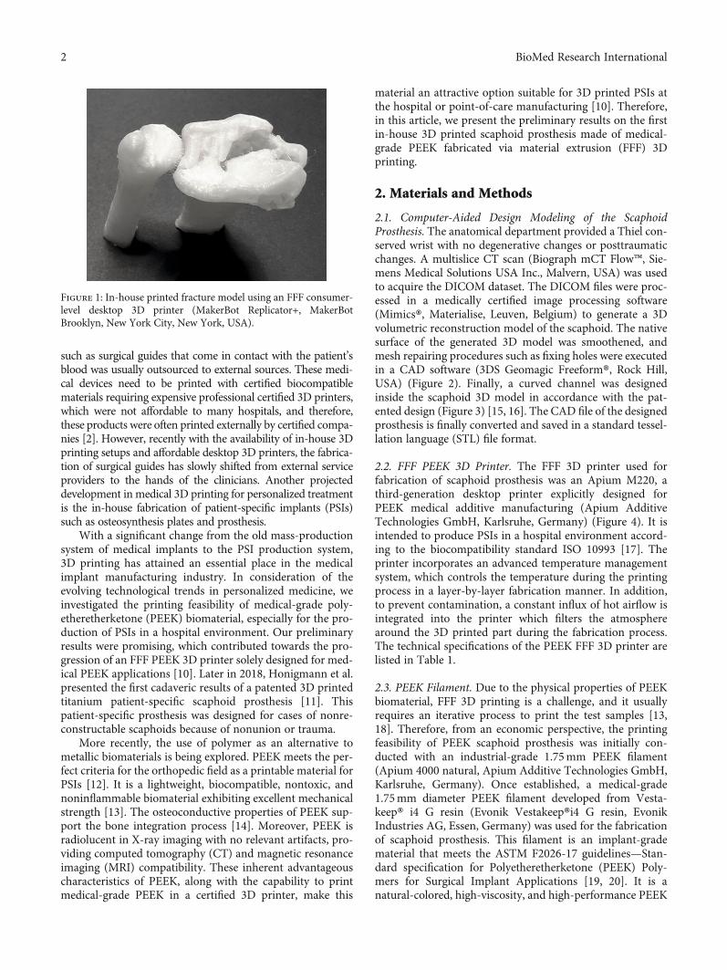
such as surgical guides that come in contact with the patient’sblood was usually outsourced to external sources. These medi-cal devices need to be printed with certified biocompatiblematerials requiring expensive professional certified 3D printers,which were not affordable to many hospitals, and therefore,these products were often printed externally by certified compa-nies [2]. However, recently with the availability of in-house 3Dprinting setups and affordable desktop 3D printers, the fabrica-tion of surgical guides has slowly shifted from external serviceproviders to the hands of the clinicians. Another projecteddevelopment in medical 3D printing for personalized treatmentis the in-house fabrication of patient-specific implants (PSIs)such as osteosynthesis plates and prosthesis.
With a significant change from the old mass-productionsystem of medical implants to the PSI production system,3D printing has attained an essential place in the medicalimplant manufacturing industry. In consideration of theevolving technological trends in personalized medicine, weinvestigated the printing feasibility of medical-grade poly-etheretherketone (PEEK) biomaterial, especially for the pro-duction of PSIs in a hospital environment. Our preliminaryresults were promising, which contributed towards the pro-gression of an FFF PEEK 3D printer solely designed for med-ical PEEK applications [10]. Later in 2018, Honigmann et al.presented the first cadaveric results of a patented 3D printedtitanium patient-specific scaphoid prosthesis [11]. Thispatient-specific prosthesis was designed for cases of nonre-constructable scaphoids because of nonunion or trauma.
More recently, the use of polymer as an alternative tometallic biomaterials is being explored. PEEK meets the per-fect criteria for the orthopedic field as a printable material forPSIs [12]. It is a lightweight, biocompatible, nontoxic, andnoninflammable biomaterial exhibiting excellent mechanicalstrength [13]. The osteoconductive properties of PEEK sup-port the bone integration process [14]. Moreover, PEEK isradiolucent in X-ray imaging with no relevant artifacts, pro-viding computed tomography (CT) and magnetic resonanceimaging (MRI) compatibility. These inherent advantageouscharacteristics of PEEK, along with the capability to printmedical-grade PEEK in a certified 3D printer, make this
material an attractive option suitable for 3D printed PSIs atthe hospital or point-of-care manufacturing [10]. Therefore,in this article, we present the preliminary results on the firstin-house 3D printed scaphoid prosthesis made of medical-grade PEEK fabricated via material extrusion (FFF) 3Dprinting.
2. Materials and Methods
2.1. Computer-Aided Design Modeling of the ScaphoidProsthesis. The anatomical department provided a Thiel con-served wrist with no degenerative changes or posttraumaticchanges. A multislice CT scan (Biograph mCT Flow™, Sie-mens Medical Solutions USA Inc., Malvern, USA) was usedto acquire the DICOM dataset. The DICOM files were proc-essed in a medically certified image processing software(Mimics®, Materialise, Leuven, Belgium) to generate a 3Dvolumetric reconstruction model of the scaphoid. The nativesurface of the generated 3D model was smoothened, andmesh repairing procedures such as fixing holes were executedin a CAD software (3DS Geomagic Freeform®, Rock Hill,USA) (Figure 2). Finally, a curved channel was designedinside the scaphoid 3D model in accordance with the pat-ented design (Figure 3) [15, 16]. The CAD file of the designedprosthesis is finally converted and saved in a standard tessel-lation language (STL) file format.
2.2. FFF PEEK 3D Printer. The FFF 3D printer used forfabrication of scaphoid prosthesis was an Apium M220, athird-generation desktop printer explicitly designed forPEEK medical additive manufacturing (Apium AdditiveTechnologies GmbH, Karlsruhe, Germany) (Figure 4). It isintended to produce PSIs in a hospital environment accord-ing to the biocompatibility standard ISO 10993 [17]. Theprinter incorporates an advanced temperature managementsystem, which controls the temperature during the printingprocess in a layer-by-layer fabrication manner. In addition,to prevent contamination, a constant influx of hot airflow isintegrated into the printer which filters the atmospherearound the 3D printed part during the fabrication process.The technical specifications of the PEEK FFF 3D printer arelisted in Table 1.
2.3. PEEK Filament. Due to the physical properties of PEEKbiomaterial, FFF 3D printing is a challenge, and it usuallyrequires an iterative process to print the test samples [13,18]. Therefore, from an economic perspective, the printingfeasibility of PEEK scaphoid prosthesis was initially con-ducted with an industrial-grade 1.75mm PEEK filament(Apium 4000 natural, Apium Additive Technologies GmbH,Karlsruhe, Germany). Once established, a medical-grade1.75mm diameter PEEK filament developed from Vesta-keep® i4 G resin (Evonik Vestakeep®i4 G resin, EvonikIndustries AG, Essen, Germany) was used for the fabricationof scaphoid prosthesis. This filament is an implant-gradematerial that meets the ASTM F2026-17 guidelines—Stan-dard specification for Polyetheretherketone (PEEK) Poly-mers for Surgical Implant Applications [19, 20]. It is anatural-colored, high-viscosity, and high-performance PEEK
Figure 1: In-house printed fracture model using an FFF consumer-level desktop 3D printer (MakerBot Replicator+, MakerBotBrooklyn, New York City, New York, USA).
2 BioMed Research International
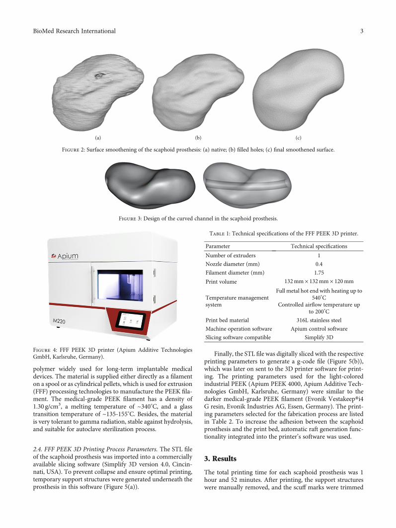
polymer widely used for long-term implantable medicaldevices. The material is supplied either directly as a filamenton a spool or as cylindrical pellets, which is used for extrusion(FFF) processing technologies to manufacture the PEEK fila-ment. The medical-grade PEEK filament has a density of1.30 g/cm3, a melting temperature of ~340°C, and a glasstransition temperature of ~135-155°C. Besides, the materialis very tolerant to gamma radiation, stable against hydrolysis,and suitable for autoclave sterilization process.
2.4. FFF PEEK 3D Printing Process Parameters. The STL fileof the scaphoid prosthesis was imported into a commerciallyavailable slicing software (Simplify 3D version 4.0, Cincin-nati, USA). To prevent collapse and ensure optimal printing,temporary support structures were generated underneath theprosthesis in this software (Figure 5(a)).
Finally, the STL file was digitally sliced with the respectiveprinting parameters to generate a g-code file (Figure 5(b)),which was later on sent to the 3D printer software for print-ing. The printing parameters used for the light-coloredindustrial PEEK (Apium PEEK 4000, Apium Additive Tech-nologies GmbH, Karlsruhe, Germany) were similar to thedarker medical-grade PEEK filament (Evonik Vestakeep®i4G resin, Evonik Industries AG, Essen, Germany). The print-ing parameters selected for the fabrication process are listedin Table 2. To increase the adhesion between the scaphoidprosthesis and the print bed, automatic raft generation func-tionality integrated into the printer’s software was used.
3. Results
The total printing time for each scaphoid prosthesis was 1hour and 52 minutes. After printing, the support structureswere manually removed, and the scuff marks were trimmed
(a) (b) (c)
Figure 2: Surface smoothening of the scaphoid prosthesis: (a) native; (b) filled holes; (c) final smoothened surface.
Figure 3: Design of the curved channel in the scaphoid prosthesis.
Figure 4: FFF PEEK 3D printer (Apium Additive TechnologiesGmbH, Karlsruhe, Germany).
Table 1: Technical specifications of the FFF PEEK 3D printer.
Parameter Technical specifications
Number of extruders 1
Nozzle diameter (mm) 0.4
Filament diameter (mm) 1.75
Print volume 132mm × 132mm × 120mm
Temperature managementsystem
Full metal hot end with heating up to540°C
Controlled airflow temperature upto 200°C
Print bed material 316L stainless steel
Machine operation software Apium control software
Slicing software compatible Simplify 3D
3BioMed Research International
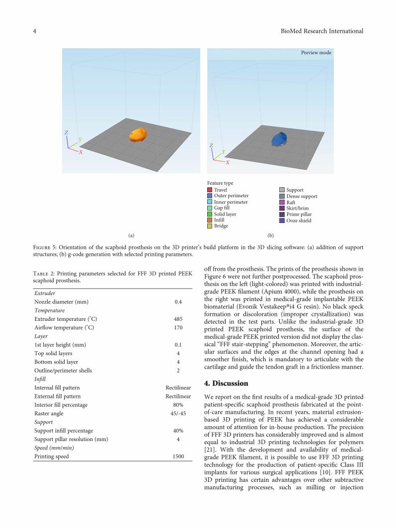
off from the prosthesis. The prints of the prosthesis shown inFigure 6 were not further postprocessed. The scaphoid pros-thesis on the left (light-colored) was printed with industrial-grade PEEK filament (Apium 4000), while the prosthesis onthe right was printed in medical-grade implantable PEEKbiomaterial (Evonik Vestakeep®i4 G resin). No black speckformation or discoloration (improper crystallization) wasdetected in the test parts. Unlike the industrial-grade 3Dprinted PEEK scaphoid prosthesis, the surface of themedical-grade PEEK printed version did not display the clas-sical “FFF stair-stepping” phenomenon. Moreover, the artic-ular surfaces and the edges at the channel opening had asmoother finish, which is mandatory to articulate with thecartilage and guide the tendon graft in a frictionless manner.
4. Discussion
We report on the first results of a medical-grade 3D printedpatient-specific scaphoid prosthesis fabricated at the point-of-care manufacturing. In recent years, material extrusion-based 3D printing of PEEK has achieved a considerableamount of attention for in-house production. The precisionof FFF 3D printers has considerably improved and is almostequal to industrial 3D printing technologies for polymers[21]. With the development and availability of medical-grade PEEK filament, it is possible to use FFF 3D printingtechnology for the production of patient-specific Class IIIimplants for various surgical applications [10]. FFF PEEK3D printing has certain advantages over other subtractivemanufacturing processes, such as milling or injection
X
Y
Z
(a)
X
Y
Z
TravelFeature type
Outer perimeterInner perimeterGap fillSolid layerInfillBridge
Support
Preview mode
Dense supportRa�Skirt/brimPrime pillarOoze shield
(b)
Figure 5: Orientation of the scaphoid prosthesis on the 3D printer’s build platform in the 3D slicing software: (a) addition of supportstructures; (b) g-code generation with selected printing parameters.
Table 2: Printing parameters selected for FFF 3D printed PEEKscaphoid prosthesis.
Extruder
Nozzle diameter (mm) 0.4
Temperature
Extruder temperature (°C) 485
Airflow temperature (°C) 170
Layer
1st layer height (mm) 0.1
Top solid layers 4
Bottom solid layer 4
Outline/perimeter shells 2
Infill
Internal fill pattern Rectilinear
External fill pattern Rectilinear
Interior fill percentage 80%
Raster angle 45/-45
Support
Support infill percentage 40%
Support pillar resolution (mm) 4
Speed (mm/min)
Printing speed 1500
4 BioMed Research International
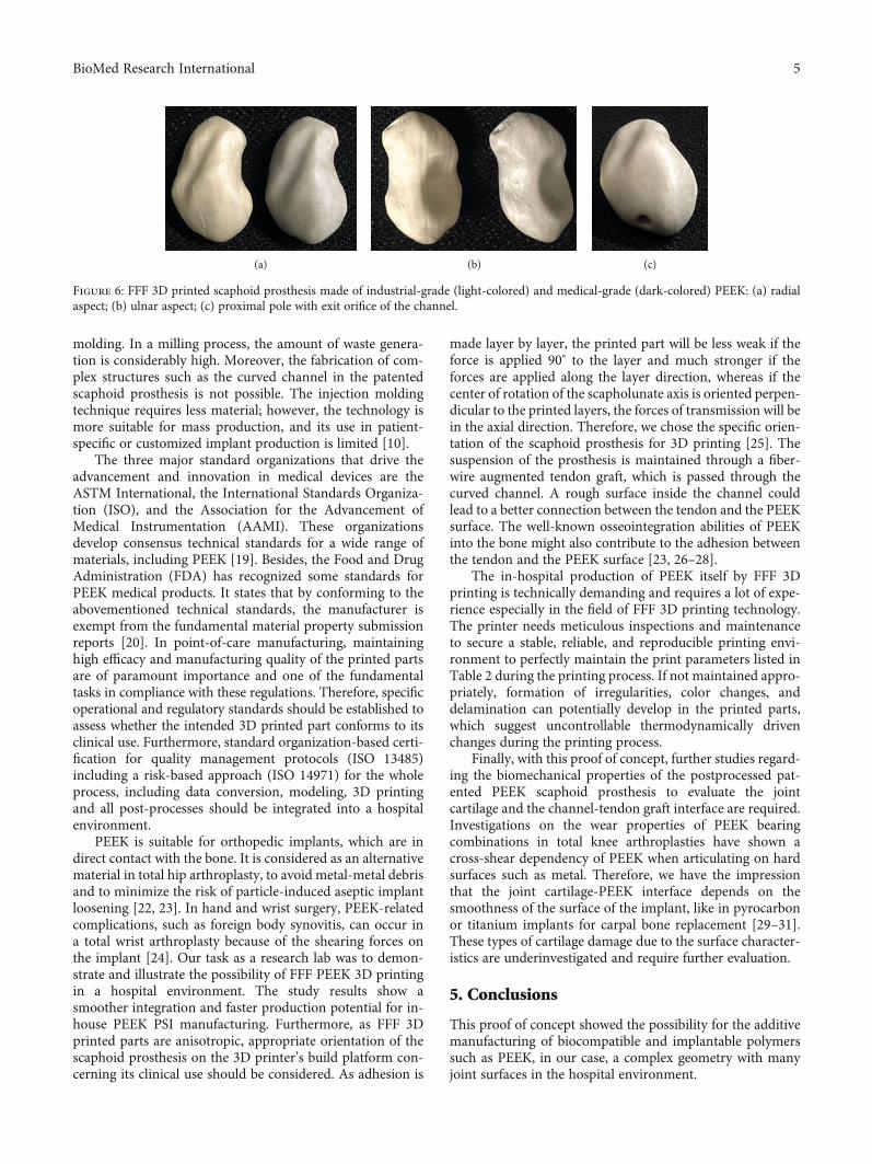
molding. In a milling process, the amount of waste genera-tion is considerably high. Moreover, the fabrication of com-plex structures such as the curved channel in the patentedscaphoid prosthesis is not possible. The injection moldingtechnique requires less material; however, the technology ismore suitable for mass production, and its use in patient-specific or customized implant production is limited [10].
The three major standard organizations that drive theadvancement and innovation in medical devices are theASTM International, the International Standards Organiza-tion (ISO), and the Association for the Advancement ofMedical Instrumentation (AAMI). These organizationsdevelop consensus technical standards for a wide range ofmaterials, including PEEK [19]. Besides, the Food and DrugAdministration (FDA) has recognized some standards forPEEK medical products. It states that by conforming to theabovementioned technical standards, the manufacturer isexempt from the fundamental material property submissionreports [20]. In point-of-care manufacturing, maintaininghigh efficacy and manufacturing quality of the printed partsare of paramount importance and one of the fundamentaltasks in compliance with these regulations. Therefore, specificoperational and regulatory standards should be established toassess whether the intended 3D printed part conforms to itsclinical use. Furthermore, standard organization-based certi-fication for quality management protocols (ISO 13485)including a risk-based approach (ISO 14971) for the wholeprocess, including data conversion, modeling, 3D printingand all post-processes should be integrated into a hospitalenvironment.
PEEK is suitable for orthopedic implants, which are indirect contact with the bone. It is considered as an alternativematerial in total hip arthroplasty, to avoid metal-metal debrisand to minimize the risk of particle-induced aseptic implantloosening [22, 23]. In hand and wrist surgery, PEEK-relatedcomplications, such as foreign body synovitis, can occur ina total wrist arthroplasty because of the shearing forces onthe implant [24]. Our task as a research lab was to demon-strate and illustrate the possibility of FFF PEEK 3D printingin a hospital environment. The study results show asmoother integration and faster production potential for in-house PEEK PSI manufacturing. Furthermore, as FFF 3Dprinted parts are anisotropic, appropriate orientation of thescaphoid prosthesis on the 3D printer’s build platform con-cerning its clinical use should be considered. As adhesion is
made layer by layer, the printed part will be less weak if theforce is applied 90° to the layer and much stronger if theforces are applied along the layer direction, whereas if thecenter of rotation of the scapholunate axis is oriented perpen-dicular to the printed layers, the forces of transmission will bein the axial direction. Therefore, we chose the specific orien-tation of the scaphoid prosthesis for 3D printing [25]. Thesuspension of the prosthesis is maintained through a fiber-wire augmented tendon graft, which is passed through thecurved channel. A rough surface inside the channel couldlead to a better connection between the tendon and the PEEKsurface. The well-known osseointegration abilities of PEEKinto the bone might also contribute to the adhesion betweenthe tendon and the PEEK surface [23, 26–28].
The in-hospital production of PEEK itself by FFF 3Dprinting is technically demanding and requires a lot of expe-rience especially in the field of FFF 3D printing technology.The printer needs meticulous inspections and maintenanceto secure a stable, reliable, and reproducible printing envi-ronment to perfectly maintain the print parameters listed inTable 2 during the printing process. If not maintained appro-priately, formation of irregularities, color changes, anddelamination can potentially develop in the printed parts,which suggest uncontrollable thermodynamically drivenchanges during the printing process.
Finally, with this proof of concept, further studies regard-ing the biomechanical properties of the postprocessed pat-ented PEEK scaphoid prosthesis to evaluate the jointcartilage and the channel-tendon graft interface are required.Investigations on the wear properties of PEEK bearingcombinations in total knee arthroplasties have shown across-shear dependency of PEEK when articulating on hardsurfaces such as metal. Therefore, we have the impressionthat the joint cartilage-PEEK interface depends on thesmoothness of the surface of the implant, like in pyrocarbonor titanium implants for carpal bone replacement [29–31].These types of cartilage damage due to the surface character-istics are underinvestigated and require further evaluation.
5. Conclusions
This proof of concept showed the possibility for the additivemanufacturing of biocompatible and implantable polymerssuch as PEEK, in our case, a complex geometry with manyjoint surfaces in the hospital environment.
(a) (b) (c)
Figure 6: FFF 3D printed scaphoid prosthesis made of industrial-grade (light-colored) and medical-grade (dark-colored) PEEK: (a) radialaspect; (b) ulnar aspect; (c) proximal pole with exit orifice of the channel.
5BioMed Research International
Data Availability
Availability of the digital STL and g-code files is restricteddue to the ownership of the patent by Medartis AG. Requestsfor a patient-specific scaphoid replacement should be madeto the abovementioned company. More data on the materialand the printer can be found at https://apiumtec.com.
Conflicts of Interest
PH, MH, and FT are consultants at Medartis AG, Basel, Swit-zerland. The company owns the patent of the patient-specificscaphoid prosthesis.
Authors’ Contributions
Philipp Honigmann and Neha Sharma contributed equally tothis work.
Acknowledgments
The development of the prosthesis was supported by theDeutsche Arthrose-Hilfe e.V [P341-A544-Hinterman-n/EP2-honi1-hand-en-III–2017-17].
References
[1] S. Weidert, S. Andress, E. Suero et al., “3D printing in orthope-dic and trauma surgery education and training: possibilitiesand fields of application,” Unfallchirurg, vol. 122, no. 6,pp. 444–451, 2019.
[2] K. C. Wong, “3D-printed patient-specific applications inorthopedics,” Orthopedic Research and Reviews, vol. 8,pp. 57–66, 2016.
[3] N. Bizzotto, I. Tami, A. Tami et al., “3D printed models of dis-tal radius fractures,” Injury, vol. 47, no. 4, pp. 976–978, 2016.
[4] A. A. Giannopoulos, L. Chepelev, A. Sheikh et al., “3D printedventricular septal defect patch: a primer for the 2015 Radiolog-ical Society of North America (RSNA) hands-on course in 3Dprinting,” 3D Printing inMedicine, vol. 1, no. 1, pp. 1–20, 2015.
[5] M. D. Tam, S. D. Laycock, D. Bell, and A. Chojnowski, “3-Dprintout of a DICOM file to aid surgical planning in a 6 yearold patient with a large scapular osteochondroma complicat-ing congenital diaphyseal aclasia,” Journal of Radiology CaseReports, vol. 6, no. 1, pp. 31–37, 2012.
[6] M. Guvendiren, 3D Bioprinting in Medicine, Springer, 2019.[7] J. Zuniga, D. Katsavelis, J. Peck et al., “Cyborg beast: a low-cost
3D-printed prosthetic hand for children with upper-limb dif-ferences,” BMC Research Notes, vol. 8, no. 1, pp. 1–10, 2015.
[8] J. M. Zuniga, J. L. Peck, R. Srivastava et al., “Functionalchanges through the usage of 3D-printed transitional prosthe-ses in children,” Disability and Rehabilitation Assistive Tech-nology, vol. 14, no. 1, pp. 68–74, 2019.
[9] A. Pallaver and P. Honigmann, “The role of cone-beam com-puted tomography (CBCT) scan for detection and follow-upof traumatic wrist pathologies,” The Journal of Hand Surgery,vol. 44, no. 12, pp. 1081–1087, 2019.
[10] P. Honigmann, N. Sharma, B. Okolo, U. Popp, B. Msallem,and F. M. Thieringer, “Patient-specific surgical implants madeof 3D printed PEEK: material, technology, and scope of surgi-
cal application,” BioMed Research International, vol. 2018,no. 8, Article ID 4520636, p. 8, 2018.
[11] P. Honigmann, R. Schumacher, R. Marek, F. Büttner,F. Thieringer, and M. Haefeli, “A three-dimensional printedpatient-specific scaphoid replacement: a cadaveric study,”Journal of Hand Surgery, vol. 79, 2018.
[12] A. Padolino, G. Porcellini, B. Guollo et al., “Comparison ofCFR-PEEK and conventional titanium locking plates for prox-imal humeral fractures: a retrospective controlled study ofpatient outcomes,” Musculoskeletal Surgery, vol. 102, Supple-ment 1, pp. 49–56, 2018.
[13] M. Vaezi and S. Yang, “Extrusion-based additive manufactur-ing of PEEK for biomedical applications,” Virtual and PhysicalPrototyping, vol. 10, no. 3, pp. 123–135, 2015.
[14] P. Johansson, R. Jimbo, Y. Naito, P. Kjellin, F. Currie, andA. Wennerberg, “Polyether ether ketone implants achieveincreased bone fusion when coated with nano-sized hydroxy-apatite: a histomorphometric study in rabbit bone,” Interna-tional Journal of Nanomedicine, vol. 11, pp. 1435–1442,2016.
[15] P. Honigmann, F. Thieringer, R. Schumacher, and M. Haefeli,US020170143501A120170525, pp. 1–23, 2017.
[16] P. Honigmann, F. Thieringer, R. Schumacher, and M. Haefeli,“Scaphoid prosthesis-European Patent Office - EP 3170477 A1scaphoid prosthesis-European Patent Office-EP 3170477 A1,”pp. 1–27, 2017.
[17] M. Garcia-Leiner, O. Ghita, R. McKay, and S. K. P. Biomaterials,“Additive manufacturing of polyaryletherketones,” in PEEKBiomaterials Handbook, pp. 89–103, Elsevier, 2019.
[18] J. W. Stansbury and M. J. Idacavage, “3D printing with poly-mers: challenges among expanding options and opportuni-ties,” Dental Materials: Official Publication of the Academy ofDental Materials, vol. 32, no. 1, pp. 54–64, 2016.
[19] ASTM International, F2026-17, Standard Specification forPolyetheretherketone (PEEK) Polymers for Surgical ImplantApplications, ASTM International, West Conshohocken, PA,2010.
[20] J. Graham and J. Peck, “FDA regulation of PEEK implants,” inPEEK Biomaterials Handbook, pp. 431–445, William AndrewPublishing, 2019.
[21] B. Msallem, N. Sharma, S. Cao, F. S. Halbeisen, H.-F. Zeilhofer,and F. M. Thieringer, “Evaluation of the dimensional accuracyof 3D-printed anatomical mandibular models using FFF, SLA,SLS, MJ, and BJ printing technology,” Journal of Clinical Med-icine, vol. 9, no. 3, p. 817, 2020.
[22] S. M. Kurtz, Chapter 2- Synthesis and Processing of PEEK forSurgical Implants, Elsevier Inc., 2019.
[23] M. Jarman-Smith, M. Brady, S. M. Kurtz, N. M. Cordaro,W. R. Walsh, and E. Ouellette, Chapter 13- Porosity in PEEK,Elsevier Inc., 2019.
[24] T. Karjalainen, K. Pamilo, and A. Reito, “Implant failure afterMotec Wrist Joint Prosthesis due to failure of ball and socket-type articulation-two patients with adverse reaction to metaldebris and polyether ether ketone,” The Journal of Hand Sur-gery, vol. 43, no. 11, pp. 1044.e1–1044.e4, 2018.
[25] M. G. A. de Roo, M. Muurling, J. G. G. Dobbe, M. E. Brinkhorst,G. J. Streekstra, and S. D. Strackee, “A four-dimensional-CTstudy of in vivo scapholunate rotation axes: possible implica-tions for scapholunate ligament reconstruction,” Journal ofHand Surgery (European Volume), vol. 44, no. 5, pp. 479–487,2019.
6 BioMed Research International
[26] J. W. Brantigan, P. C. McAfee, B. W. Cunningham, H. Wang,and C. M. Orbegoso, “Interbody lumbar fusion using a carbonfiber cage implant versus allograft bone,” Spine, vol. 19, no. 13,pp. 1436–1443, 1994.
[27] A. H. C. Poulsson, D. Eglin, S. Zeiter et al., “Osseointegrationof machined, injection moulded and oxygen plasma modifiedPEEK implants in a sheep model,” Biomaterials, vol. 35,no. 12, pp. 3717–3728, 2014.
[28] R. D. Carpenter, B. S. Klosterhoff, F. B. Torstrick et al., “Effectof porous orthopaedic implant material and structure on loadsharing with simulated bone ingrowth: a finite element analy-sis comparing titanium and PEEK,” Journal of the MechanicalBehavior of Biomedical Materials, vol. 80, pp. 68–76, 2018.
[29] O. Spingardi and M. I. Rossello, “The total scaphoid titaniumarthroplasty: a 15-year experience,” Hand, vol. 6, no. 2,pp. 179–184, 2011.
[30] M. Henry, “Outcomes assessment of lunate replacementarthroplasty with intrinsic carpal ligament reconstruction inKienböck's disease,” The Hand, vol. 9, no. 3, pp. 364–369,2014.
[31] P. Bellemère, “Pyrocarbon implants for the hand and wrist,”Hand Surgery & Rehabilitation, vol. 37, no. 3, pp. 129–154,2018.
7BioMed Research International
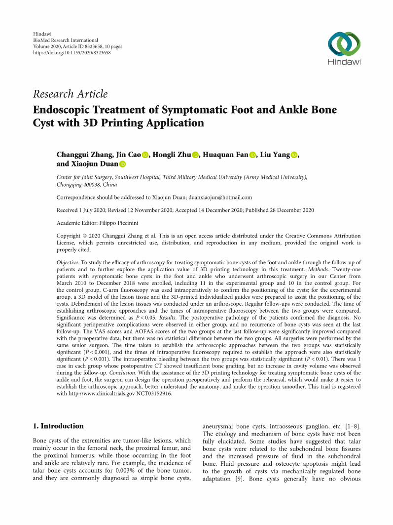
Research ArticleEndoscopic Treatment of Symptomatic Foot and Ankle BoneCyst with 3D Printing Application
Changgui Zhang, Jin Cao , Hongli Zhu , Huaquan Fan , Liu Yang ,and Xiaojun Duan
Center for Joint Surgery, Southwest Hospital, Third Military Medical University (Army Medical University),Chongqing 400038, China
Correspondence should be addressed to Xiaojun Duan; [email protected]
Received 1 July 2020; Revised 12 November 2020; Accepted 14 December 2020; Published 28 December 2020
Academic Editor: Filippo Piccinini
Copyright © 2020 Changgui Zhang et al. This is an open access article distributed under the Creative Commons AttributionLicense, which permits unrestricted use, distribution, and reproduction in any medium, provided the original work isproperly cited.
Objective. To study the efficacy of arthroscopy for treating symptomatic bone cysts of the foot and ankle through the follow-up ofpatients and to further explore the application value of 3D printing technology in this treatment. Methods. Twenty-onepatients with symptomatic bone cysts in the foot and ankle who underwent arthroscopic surgery in our Center fromMarch 2010 to December 2018 were enrolled, including 11 in the experimental group and 10 in the control group. Forthe control group, C-arm fluoroscopy was used intraoperatively to confirm the positioning of the cysts; for the experimentalgroup, a 3D model of the lesion tissue and the 3D-printed individualized guides were prepared to assist the positioning of thecysts. Debridement of the lesion tissues was conducted under an arthroscope. Regular follow-ups were conducted. The time ofestablishing arthroscopic approaches and the times of intraoperative fluoroscopy between the two groups were compared.Significance was determined as P < 0:05. Results. The postoperative pathology of the patients confirmed the diagnosis. Nosignificant perioperative complications were observed in either group, and no recurrence of bone cysts was seen at the lastfollow-up. The VAS scores and AOFAS scores of the two groups at the last follow-up were significantly improved comparedwith the preoperative data, but there was no statistical difference between the two groups. All surgeries were performed by thesame senior surgeon. The time taken to establish the arthroscopic approaches between the two groups was statisticallysignificant (P < 0:001), and the times of intraoperative fluoroscopy required to establish the approach were also statisticallysignificant (P < 0:001). The intraoperative bleeding between the two groups was statistically significant (P < 0:01). There was 1case in each group whose postoperative CT showed insufficient bone grafting, but no increase in cavity volume was observedduring the follow-up. Conclusion. With the assistance of the 3D printing technology for treating symptomatic bone cysts of theankle and foot, the surgeon can design the operation preoperatively and perform the rehearsal, which would make it easier toestablish the arthroscopic approach, better understand the anatomy, and make the operation smoother. This trial is registeredwith http://www.clinicaltrials.gov NCT03152916.
1. Introduction
Bone cysts of the extremities are tumor-like lesions, whichmainly occur in the femoral neck, the proximal femur, andthe proximal humerus, while those occurring in the footand ankle are relatively rare. For example, the incidence oftalar bone cysts accounts for 0.003% of the bone tumor,and they are commonly diagnosed as simple bone cysts,
aneurysmal bone cysts, intraosseous ganglion, etc. [1–8].The etiology and mechanism of bone cysts have not beenfully elucidated. Some studies have suggested that talarbone cysts were related to the subchondral bone fissuresand the increased pressure of fluid in the subchondralbone. Fluid pressure and osteocyte apoptosis might leadto the growth of cysts via mechanically regulated boneadaptation [9]. Bone cysts generally have no obvious
HindawiBioMed Research InternationalVolume 2020, Article ID 8323658, 10 pageshttps://doi.org/10.1155/2020/8323658
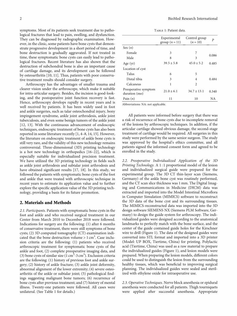
symptoms. Most of its patients seek treatment due to patho-logical fractures that lead to pain, swelling, and dysfunction.They can be diagnosed by radiographic examination. How-ever, in the clinic, some patients have bone cysts that demon-strate progressive development in a short period of time, andbone destruction is gradually aggravated. If not treated intime, these symptomatic bone cysts can easily lead to patho-logical fractures. Recent literature has also shown that thedestruction of subchondral bone is also an important causeof cartilage damage, and its development can be followedby osteoarthritis [10, 11]. Thus, patients with poor conserva-tive treatment results should consider surgery.
Arthroscopy has the advantages of smaller trauma andclearer vision under the arthroscope, which make it suitablefor intra-articular surgery. Besides, the incision is good-look-ing, and the postoperative joint function recovery is fast.Hence, arthroscopy develops rapidly in recent years and iswell received by patients. It has been widely used in footand ankle surgeries, such as talar osteochondral injury, bonyimpingement syndrome, ankle joint arthrodesis, ankle jointtuberculosis, and even some benign tumors of the ankle joint[12, 13]. With the continuous advancement of endoscopictechniques, endoscopic treatment of bone cysts has also beenreported in some literature recently [1, 4–8, 14, 15]. However,the literature on endoscopic treatment of ankle bone cysts isstill very rare, and the validity of this new technology remainscontroversial. Three-dimensional (3D) printing technologyis a hot new technology in orthopedics [16–22], which isespecially suitable for individualized precision treatment.We have utilized the 3D printing technology in fields suchas ankle joint arthrodesis and subtalar joint arthrodesis andhave obtained significant results [17, 18]. In this study, wefollowed the patients with symptomatic bone cysts of the footand ankle that were treated with arthroscopic technique inrecent years to estimate its application value and to furtherexplore the specific application value of the 3D printing tech-nology, providing a basis for its future promotion.
2. Materials and Methods
2.1. Participants. Patients with symptomatic bone cysts in thefoot and ankle and who received surgical treatment in ourCenter from March 2010 to December 2018 were followed.Indications for surgery are the following: (1) after 6 monthsof conservative treatment, there were still symptoms of bonecysts; (2) 3D computed tomography (CT) examination indi-cated that the bone destruction volume > 1 cm3. Case inclu-sion criteria are the following: (1) patients who receivedarthroscopic treatment for symptomatic bone cysts of theankle and foot, (2) complete preoperative imaging data, and(3) bone cysts of similar size (1 cm3-3 cm3). Exclusion criteriaare the following: (1) history of previous foot and ankle sur-gery; (2) history of ankle fracture; (3) ankle joint deformity,abnormal alignment of the lower extremity; (4) severe osteo-arthritis of the ankle or subtalar joint; (5) pathological find-ings suggesting malignant bone tumors; (6) recurrence ofbone cysts after previous treatment; and (7) history of mentalillness. Twenty-one patients were followed. All cases wereunilateral. (See Table 1 for details.)
All patients were informed before surgery that there wasa risk of recurrence of bone cysts due to incomplete removalof the lesions by arthroscopic techniques. In addition, if thearticular cartilage showed obvious damage, the second-stagetreatment of cartilage would be required. All surgeries in thisstudy were performed by the same senior surgeon. The studywas approved by the hospital’s ethics committee, and allpatients signed the informed consent form and agreed to beenrolled in the study.
2.2. Preoperative Individualized Application of the 3DPrinting Technology. A 1 : 1 proportional model of the lesionand individualized surgical guide were prepared for theexperimental group. The 3D CT thin-layer scan (Siemens,Germany) of the ankle bone cyst was routinely performed,and the CT scan slice thickness was 1mm. The Digital Imag-ing and Communications in Medicine (DICM) data wasextracted and imported into the Model Intestinal Microflorain Computer Simulation (MIMICS) software to reconstructthe 3D data of the bone cyst and its surrounding tissues.The MIMICS-reconstructed data was imported into the 3Ddesign software SIEMENS NX (Siemens PLM Software, Ger-many) to design the guide system for arthroscopy. The indi-vidualized guides were designed according to the anatomicallandmarks to perfectly match with the bone surface, and thecenter of the guide contained guide holes for the Kirschnerwire to drill (Figure 1). The data of the designed guides wereconverted into STL format and imported into a 3D printer(Model: UP BOX, Tiertime, China) for printing. Polylacticacid (Tiertime, China) was used as a raw material to preparethe individualized guides (Figure 1), and lesion models wereprepared. When preparing the lesion models, different colorscould be used to distinguish the lesion from the surroundinghealthy tissues, which was beneficial to improving surgicalplanning. The individualized guides were sealed and steril-ized with ethylene oxide for intraoperative use.
2.3. Operative Techniques.Nerve block anesthesia or epiduralanesthesia were conducted for all patients. Thigh tourniquetswere applied after successful anesthesia. Appropriate
Table 1: Patient data.
Experimentalgroup (n = 11)
Control group(n = 10) P
Sex (n)
Female 3 70.086
Male 8 3
Age (yr) 39:5 ± 5:8 45:0 ± 5:2 0.485
Location of cyst
Talus 6 5
0.484Distal tibia 3 4
Calcaneus 1 2
Preoperative symptomduration (mo)
21:0 ± 6:1 34:7 ± 13:1 0.340
Pain (n) 11 10 NA
Abbreviations: NA: not applicable.
2 BioMed Research International
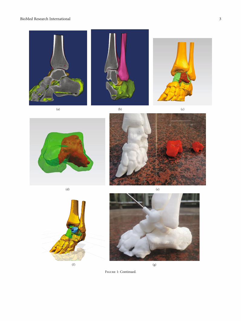
(a) (b) (c)
(d) (e)
(f) (g)
Figure 1: Continued.
3BioMed Research International
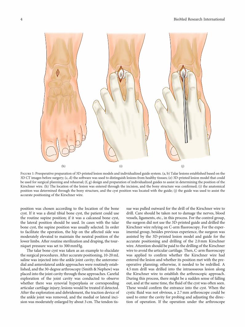
position was chosen according to the location of the bonecyst. If it was a distal tibial bone cyst, the patient could usethe routine supine position; if it was a calcaneal bone cyst,the lateral position should be used. In cases with the talarbone cyst, the supine position was usually selected. In orderto facilitate the operation, the hip on the affected side wasmoderately elevated to maintain the neutral position of thelower limbs. After routine sterilization and draping, the tour-niquet pressure was set to 300mmHg.
The talar bone cyst was taken as an example to elucidatethe surgical procedures. After accurate positioning, 10-20mLsaline was injected into the ankle joint cavity; the anterome-dial and anterolateral ankle approaches were routinely estab-lished, and the 30-degree arthroscopy (Smith &Nephew) wasplaced into the joint cavity through these approaches. Carefulexploration of the joint cavity was conducted to observewhether there was synovial hyperplasia or correspondingarticular cartilage injury; lesions would be treated if detected.After the exploration and debridement, the traction device ofthe ankle joint was removed, and the medial or lateral inci-sion was moderately enlarged by about 3 cm. The tendon tis-
sue was pulled outward for the drill of the Kirschner wire todrill. Care should be taken not to damage the nerves, bloodvessels, ligaments, etc., in this process. For the control group,the surgeon did not use the 3D-printed guide and drilled theKirschner wire relying on C-arm fluoroscopy. For the exper-imental group, besides previous experience, the surgeon wasassisted by the 3D-printed lesion model and guide for theaccurate positioning and drilling of the 2.0mm Kirschnerwire. Attention should be paid to the drilling of the Kirschnerwire to avoid the articular cartilage. Then, C-arm fluoroscopywas applied to confirm whether the Kirschner wire hadentered the lesion and whether its position met with the pre-operative planning; otherwise, it needed to be redrilled. A4.5mm drill was drilled into the intraosseous lesion alongthe Kirschner wire to establish the arthroscopic approach.During this process, there might be a sudden sense of fallingout, and at the same time, the fluid of the cyst was often seen.These would confirm the entrance into the cyst. When thecystic fluid was not obvious, a 2.7mm arthroscope could beused to enter the cavity for probing and adjusting the direc-tion of operation. If the operation under the arthroscope
(h) (i) (j)
Figure 1: Preoperative preparation of 3D-printed lesion models and individualized guide system. (a, b) Talar lesions established based on the3D CT images before surgery; (c, d) the software was used to distinguish lesions from healthy tissues; (e) 3D-printed lesion model that couldbe used for surgical planning and rehearsal; (f, g) design and preparation of individualized guides to assist in determining the position of theKirschner wire. (h) The location of the lesion was entered through the incision, and the bony structure was confirmed; (i) the anatomicalposition was determined through the bony structure, and the cyst position was located with the guide; (j) the guide was used to assist theaccurate positioning of the Kirschner wire.
4 BioMed Research International
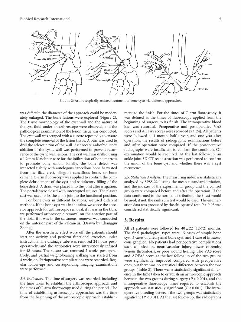
was difficult, the diameter of the approach could be moder-ately enlarged. The bone lesions were explored (Figure 2).The tissue morphology of the cyst wall and the nature ofthe cyst fluid under an arthroscope were observed, and thepathological examination of the lesion tissue was conducted.The cyst wall was scraped with a curette repeatedly to ensurethe complete removal of the lesion tissue. A burr was used todrill the sclerotic rim of the wall. Arthrocare radiofrequencyablation of the cystic wall was performed to prevent recur-rence of the cystic wall lesions. The cyst wall was drilled usinga 1.2mm Kirschner wire for the infiltration of bone marrowto promote bony union. Finally, the bone defect wasimpacted tightly with autologous cancellous bone harvestedfrom the iliac crest, allograft cancellous bone, or bonecement. C-arm fluoroscopy was applied to confirm the com-plete debridement of the cyst and satisfactory filling of thebone defect. A drain was placed into the joint after irrigation.The portals were closed with interrupted sutures. The plastercast was used to fix the ankle joint to the functional position.
For bone cysts in different locations, we used differentmethods. If the bone cyst was in the talus, we chose the ante-rior approach for arthroscopic removal; if it was in the tibia,we performed arthroscopic removal on the anterior part ofthe tibia; if it was in the calcaneus, removal was conductedon the anterior part of the calcaneus. (Drawn by ChangguiZhang.)
After the anesthetic effect wore off, the patients shouldstart toe activity and perform functional exercises underinstruction. The drainage tube was removed 24 hours post-operatively, and the antibiotics were intravenously infusedfor 48 hours. The suture was removed 2 weeks postopera-tively, and partial weight-bearing walking was started from4 weeks on. Perioperative complications were recorded. Reg-ular follow-ups and corresponding imaging examinationswere performed.
2.4. Indicators. The time of surgery was recorded, includingthe time taken to establish the arthroscopic approach andthe times of C-arm fluoroscopy used during the period. Thetime of establishing arthroscopic approaches was the timefrom the beginning of the arthroscopic approach establish-
ment to the finish. For the times of C-arm fluoroscopy, itwas defined as the times of fluoroscopy applied from thebeginning of surgery to its finish. The intraoperative bloodloss was recorded. Preoperative and postoperative VASscores and AOFAS scores were recorded [23, 24]. All patientswere followed at 1 month, half a year, and one year afteroperation; the results of radiographic examinations beforeand after operation were compared. If the postoperativeradiographs were insufficient to confirm the condition, CTexamination would be required. At the last follow-up, anankle joint 3D CT reconstruction was performed to confirmthe union of the bone cyst and whether there was a cystrecurrence.
2.5. Statistical Analysis. The measuring index was statisticallyanalyzed by SPSS 22.0 using the mean ± standard deviation,and the indexes of the experimental group and the controlgroup were compared before and after the operation. If thedata conformed to the normal distribution, the t-test wouldbe used; if not, the rank sum test would be used. The enumer-ation data was processed by the chi-squared test. P < 0:05wasconsidered statistically significant.
3. Results
All 21 patients were followed for 40 ± 22 (12-72) months.The final pathological types were 15 cases of simple bonecyst, 5 cases of aneurysmal bone cyst, and 1 case of intraoss-eous ganglion. No patients had perioperative complicationssuch as infection, neurovascular injury, lower extremityvenous thrombosis, or poor wound healing. The VAS scoreand AOFAS score at the last follow-up of the two groupswere significantly improved compared with preoperativeones, but there was no statistical difference between the twogroups (Table 2). There was a statistically significant differ-ence in the time taken to establish an arthroscopic approachbetween the two groups during surgery (P < 0:001), and theintraoperative fluoroscopy times required to establish theapproach was statistically significant (P < 0:001). The intra-operative bleeding between the two groups was statisticallysignificant (P < 0:01). At the last follow-up, the radiographs
Figure 2: Arthroscopically assisted treatment of bone cysts via different approaches.
5BioMed Research International
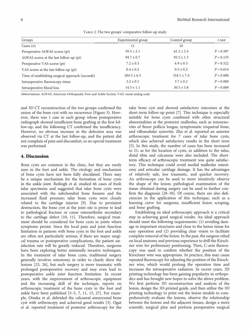
and 3D CT reconstruction of the two groups confirmed theunion of the bone cyst with no recurrence (Figure 3). How-ever, there was 1 case in each group whose postoperativeradiograph showed insufficient bone grafting at the first fol-low-up, and the following CT confirmed the insufficiency.However, no obvious increase in the defection area wasobserved via CT at the last follow-up, and the patient didnot complain of pain and discomfort, so no special treatmentwas performed.
4. Discussion
Bone cysts are common in the clinic, but they are rarelyseen in the foot and ankle. The etiology and mechanismof bone cysts have not been fully elucidated. There maybe a unique mechanism for the formation of bone cystsin the ankle joint. Reilingh et al. studied 66 cases of freshtalar specimens and suggested that talar bone cysts wereassociated with the subchondral bone fissures and theincreased fluid pressure; talar bone cysts were closelyrelated to the cartilage injuries [9]. Due to persistentdestruction, the bone cyst at the joint site is prone to leadto pathological fracture or cause osteoarthritis secondaryto the cartilage defect [10, 11]. Therefore, surgical treat-ment should be considered for bone cysts in joints wheresymptoms persist. Since the local pain and joint functionlimitation in patients with bone cysts in the foot and ankleare often not particularly serious, if there are major surgi-cal trauma or postoperative complications, the patient sat-isfaction rate will be greatly reduced. Therefore, surgeonshave been exploring better minimally invasive techniques.In the treatment of talar bone cysts, traditional surgerygenerally involves osteotomy in order to clearly show thelesions [25, 26], but such surgery is more traumatic withprolonged postoperative recovery and may even lead topostoperative ankle joint function limitation. In recentyears, with the improvement of arthroscopic equipmentand the increasing skill of the technique, reports onarthroscopic treatment of the bone cysts in the foot andankle have been published [3–5, 7, 11, 15, 27]. For exam-ple, Otsuka et al. debrided the calcaneal aneurysmal bonecyst with arthroscopy and achieved good results [3]. Ogutet al. reported treatment of posterior arthroscopy for the
talar bone cyst and showed satisfactory outcomes at theshort-term follow-up point [7]. This technique is especiallysuitable for bone cysts combined with other structuralabnormalities at the posterior malleolus, such as tenosyno-vitis of flexor pollicis longus, symptomatic triquetral bone,and villonodular synovitis. Zhu et al. reported an anteriorarthroscopic treatment for 7 cases of talar bone cysts,which also achieved satisfactory results in the short term[5]. In this study, the number of cases has been increasedto 21; as for the location of cysts, in addition to the talus,distal tibia and calcaneus were also included. The short-term efficacy of arthroscopic treatment was quite satisfac-tory. This technique could avoid medial malleolar osteot-omy and articular cartilage damage. It has the advantagesof relatively safe, less traumatic, and quicker recovery.An arthroscope can be used to more intuitively observethe shape of the lesion; pathological examination of thetissue obtained during surgery can be used to further con-firm the diagnosis [28–30]. Of course, there are also defi-ciencies in the application of this technique, such as alearning curve for surgeons, insufficient lesion scraping,and bone grafting.
Establishing an ideal arthroscopic approach is a criticalstep in achieving good surgical results. An ideal approachshould meet the following requirements: (1) avoiding dam-age to important structures and close to the lesion tissue foreasy operation and (2) providing clear vision to facilitatecomplete removal of the lesion. In the past, the surgeon reliedon local anatomy and previous experience to drill the Kirsch-ner wire for preliminary positioning. Then, C-arm fluoros-copy was used to confirm whether the position of theKirschner wire was appropriate. In practice, this may causerepeated fluoroscopy for adjusting the position of the Kirsch-ner wire, which would prolong the operation time andincreases the intraoperative radiation. In recent years, 3Dprinting technology has been gaining popularity in orthope-dics and has brought new hopes to solve the above problem.We first perform 3D reconstruction and analysis of thelesion, design the 3D-printed guide, and then utilize the 3Dprinting technology to print out the lesion models to com-prehensively evaluate the lesions, observe the relationshipbetween the lesions and the adjacent tissues, design a morescientific surgical plan and perform preoperative surgical
Table 2: The two groups’ comparative follow-up study.
Groups Experimental group Control group t-test
Cases (n) 11 10
Preoperative AOFAS scores (pt) 59:5 ± 2:1 61:2 ± 2:4 P = 0:587AOFAS scores at the last follow-up (pt) 94:7 ± 0:7 92:5 ± 1:3 P = 0:135Preoperative VAS scores (pt) 7:2 ± 0:3 6:9 ± 0:3 P = 0:522VAS scores at the last follow-up (pt) 0:4 ± 0:2 0:5 ± 0:2 P = 0:614Time of establishing surgical approach (seconds) 204:5 ± 6:5 318:1 ± 7:4 P = 0:000Intraoperative fluoroscopy times 2:2 ± 0:1 3:7 ± 0:2 P = 0:000Intraoperative blood loss 14:5 ± 1:1 30:5 ± 5:8 P = 0:009Abbreviations: AOFAS: American Orthopaedic Foot and Ankle Society; VAS: visual analog scale.
6 BioMed Research International
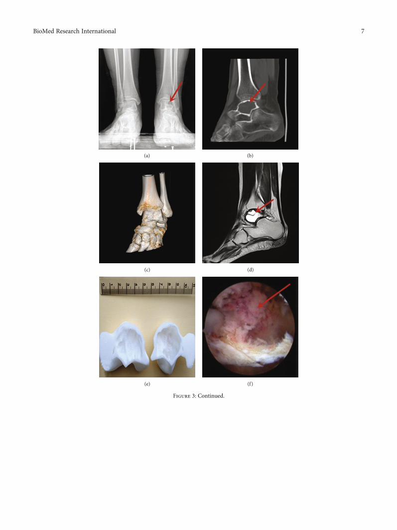
(a) (b)
(c) (d)
(e) (f)
Figure 3: Continued.
7BioMed Research International
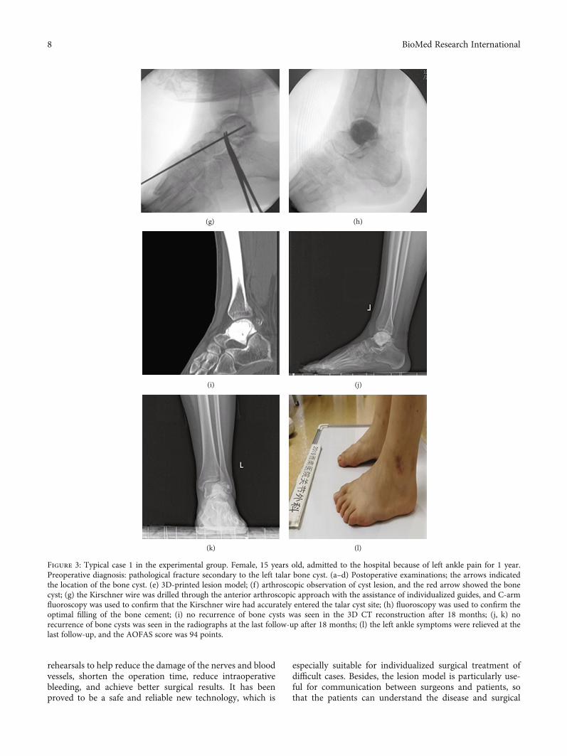
rehearsals to help reduce the damage of the nerves and bloodvessels, shorten the operation time, reduce intraoperativebleeding, and achieve better surgical results. It has beenproved to be a safe and reliable new technology, which is
especially suitable for individualized surgical treatment ofdifficult cases. Besides, the lesion model is particularly use-ful for communication between surgeons and patients, sothat the patients can understand the disease and surgical
(g) (h)
(i) (j)
(k) (l)
Figure 3: Typical case 1 in the experimental group. Female, 15 years old, admitted to the hospital because of left ankle pain for 1 year.Preoperative diagnosis: pathological fracture secondary to the left talar bone cyst. (a–d) Postoperative examinations; the arrows indicatedthe location of the bone cyst. (e) 3D-printed lesion model; (f) arthroscopic observation of cyst lesion, and the red arrow showed the bonecyst; (g) the Kirschner wire was drilled through the anterior arthroscopic approach with the assistance of individualized guides, and C-armfluoroscopy was used to confirm that the Kirschner wire had accurately entered the talar cyst site; (h) fluoroscopy was used to confirm theoptimal filling of the bone cement; (i) no recurrence of bone cysts was seen in the 3D CT reconstruction after 18 months; (j, k) norecurrence of bone cysts was seen in the radiographs at the last follow-up after 18 months; (l) the left ankle symptoms were relieved at thelast follow-up, and the AOFAS score was 94 points.
8 BioMed Research International
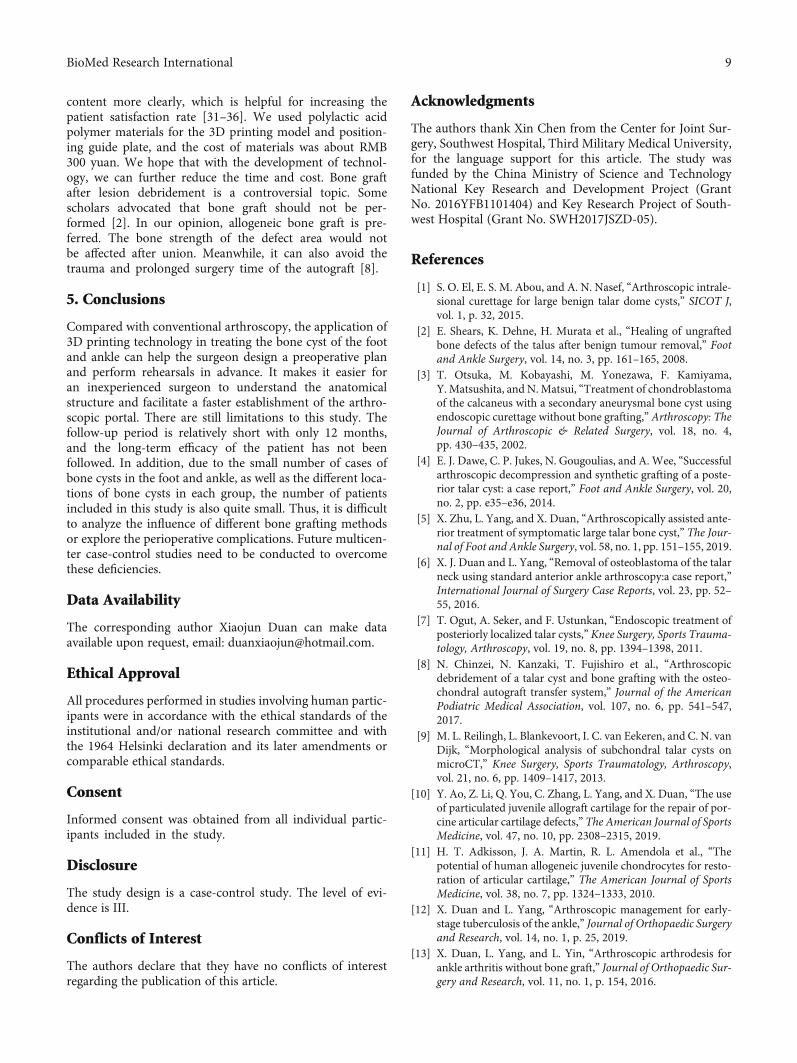
content more clearly, which is helpful for increasing thepatient satisfaction rate [31–36]. We used polylactic acidpolymer materials for the 3D printing model and position-ing guide plate, and the cost of materials was about RMB300 yuan. We hope that with the development of technol-ogy, we can further reduce the time and cost. Bone graftafter lesion debridement is a controversial topic. Somescholars advocated that bone graft should not be per-formed [2]. In our opinion, allogeneic bone graft is pre-ferred. The bone strength of the defect area would notbe affected after union. Meanwhile, it can also avoid thetrauma and prolonged surgery time of the autograft [8].
5. Conclusions
Compared with conventional arthroscopy, the application of3D printing technology in treating the bone cyst of the footand ankle can help the surgeon design a preoperative planand perform rehearsals in advance. It makes it easier foran inexperienced surgeon to understand the anatomicalstructure and facilitate a faster establishment of the arthro-scopic portal. There are still limitations to this study. Thefollow-up period is relatively short with only 12 months,and the long-term efficacy of the patient has not beenfollowed. In addition, due to the small number of cases ofbone cysts in the foot and ankle, as well as the different loca-tions of bone cysts in each group, the number of patientsincluded in this study is also quite small. Thus, it is difficultto analyze the influence of different bone grafting methodsor explore the perioperative complications. Future multicen-ter case-control studies need to be conducted to overcomethese deficiencies.
Data Availability
The corresponding author Xiaojun Duan can make dataavailable upon request, email: [email protected].
Ethical Approval
All procedures performed in studies involving human partic-ipants were in accordance with the ethical standards of theinstitutional and/or national research committee and withthe 1964 Helsinki declaration and its later amendments orcomparable ethical standards.
Consent
Informed consent was obtained from all individual partic-ipants included in the study.
Disclosure
The study design is a case-control study. The level of evi-dence is III.
Conflicts of Interest
The authors declare that they have no conflicts of interestregarding the publication of this article.
Acknowledgments
The authors thank Xin Chen from the Center for Joint Sur-gery, Southwest Hospital, Third Military Medical University,for the language support for this article. The study wasfunded by the China Ministry of Science and TechnologyNational Key Research and Development Project (GrantNo. 2016YFB1101404) and Key Research Project of South-west Hospital (Grant No. SWH2017JSZD-05).
References
[1] S. O. El, E. S. M. Abou, and A. N. Nasef, “Arthroscopic intrale-sional curettage for large benign talar dome cysts,” SICOT J,vol. 1, p. 32, 2015.
[2] E. Shears, K. Dehne, H. Murata et al., “Healing of ungraftedbone defects of the talus after benign tumour removal,” Footand Ankle Surgery, vol. 14, no. 3, pp. 161–165, 2008.
[3] T. Otsuka, M. Kobayashi, M. Yonezawa, F. Kamiyama,Y. Matsushita, and N. Matsui, “Treatment of chondroblastomaof the calcaneus with a secondary aneurysmal bone cyst usingendoscopic curettage without bone grafting,” Arthroscopy: TheJournal of Arthroscopic & Related Surgery, vol. 18, no. 4,pp. 430–435, 2002.
[4] E. J. Dawe, C. P. Jukes, N. Gougoulias, and A. Wee, “Successfularthroscopic decompression and synthetic grafting of a poste-rior talar cyst: a case report,” Foot and Ankle Surgery, vol. 20,no. 2, pp. e35–e36, 2014.
[5] X. Zhu, L. Yang, and X. Duan, “Arthroscopically assisted ante-rior treatment of symptomatic large talar bone cyst,” The Jour-nal of Foot and Ankle Surgery, vol. 58, no. 1, pp. 151–155, 2019.
[6] X. J. Duan and L. Yang, “Removal of osteoblastoma of the talarneck using standard anterior ankle arthroscopy:a case report,”International Journal of Surgery Case Reports, vol. 23, pp. 52–55, 2016.
[7] T. Ogut, A. Seker, and F. Ustunkan, “Endoscopic treatment ofposteriorly localized talar cysts,” Knee Surgery, Sports Trauma-tology, Arthroscopy, vol. 19, no. 8, pp. 1394–1398, 2011.
[8] N. Chinzei, N. Kanzaki, T. Fujishiro et al., “Arthroscopicdebridement of a talar cyst and bone grafting with the osteo-chondral autograft transfer system,” Journal of the AmericanPodiatric Medical Association, vol. 107, no. 6, pp. 541–547,2017.
[9] M. L. Reilingh, L. Blankevoort, I. C. van Eekeren, and C. N. vanDijk, “Morphological analysis of subchondral talar cysts onmicroCT,” Knee Surgery, Sports Traumatology, Arthroscopy,vol. 21, no. 6, pp. 1409–1417, 2013.
[10] Y. Ao, Z. Li, Q. You, C. Zhang, L. Yang, and X. Duan, “The useof particulated juvenile allograft cartilage for the repair of por-cine articular cartilage defects,” The American Journal of SportsMedicine, vol. 47, no. 10, pp. 2308–2315, 2019.
[11] H. T. Adkisson, J. A. Martin, R. L. Amendola et al., “Thepotential of human allogeneic juvenile chondrocytes for resto-ration of articular cartilage,” The American Journal of SportsMedicine, vol. 38, no. 7, pp. 1324–1333, 2010.
[12] X. Duan and L. Yang, “Arthroscopic management for early-stage tuberculosis of the ankle,” Journal of Orthopaedic Surgeryand Research, vol. 14, no. 1, p. 25, 2019.
[13] X. Duan, L. Yang, and L. Yin, “Arthroscopic arthrodesis forankle arthritis without bone graft,” Journal of Orthopaedic Sur-gery and Research, vol. 11, no. 1, p. 154, 2016.
9BioMed Research International
[14] M. E. Abdel-Wanis, H. Tsuchiya, K. Uehara, and K. Tomita,“Minimal curettage, multiple drilling, and continuous decom-pression through a cannulated screw for treatment of calcanealsimple bone cysts in children,” Journal of Pediatric Orthope-dics, vol. 22, no. 4, pp. 540–543, 2002.
[15] T. H. Lui, “Arthroscopic curettage and bone grafting of bonecysts of the talar body,” Arthroscopy Techniques, vol. 6, no. 1,pp. e7–e13, 2017.
[16] X. Ren, L. Yang, and X. J. Duan, “Three-dimensional printingin the surgical treatment of osteoid osteoma of the calcaneus: acase report,” Journal of International Medical Research, vol. 45,no. 1, pp. 372–380, 2017.
[17] X. Duan, P. He, H. Fan, C. Zhang, F. Wang, and L. Yang,“Application of 3D-printed personalized guide in arthroscopicankle arthrodesis,” BioMed Research International, vol. 2018,Article ID 3531293, 8 pages, 2018.
[18] X. J. Duan, H. Q. Fan, F. Y. Wang, P. He, and L. Yang, “Appli-cation of 3D-printed customized guides in subtalar jointarthrodesis,” Orthopaedic Surgery, vol. 11, no. 3, pp. 405–413, 2019.
[19] P. Zheng, P. Xu, Q. Yao, K. Tang, and Y. Lou, “3D-printednavigation template in proximal femoral osteotomy for olderchildren with developmental dysplasia of the hip,” ScientificReports, vol. 7, no. 1, p. 44993, 2017.
[20] T. Schepers and D. Misselyn, “3D printing calcaneal fractures:continuously improving our care by making a complex prob-lem tangible,” Journal of Investigative Surgery, vol. 31, no. 6,pp. 568-569, 2018.
[21] H. Cai, “Application of 3D printing in orthopedics: status quoand opportunities in China,” The Annals of TranslationalMedicine, vol. 3, Suppl 1, p. S12, 2015.
[22] K. J. Chung, B. Huang, C. H. Choi, Y. W. Park, and H. N. Kim,“Utility of 3D printing for complex distal tibial fractures andmalleolar avulsion fractures: technical tip,” Foot & Ankle Inter-national, vol. 36, no. 12, pp. 1504–1510, 2015.
[23] H. B. Kitaoka, I. J. Alexander, R. S. Adelaar, J. A. Nunley, M. S.Myerson, and M. Sanders, “Clinical rating systems for theankle-hindfoot, midfoot, hallux, and lesser toes,” Foot & AnkleInternational, vol. 15, no. 7, pp. 349–353, 1994.
[24] T. Ibrahim, A. Beiri, M. Azzabi, A. J. Best, G. J. Taylor, andD. K. Menon, “Reliability and validity of the subjective compo-nent of the American Orthopaedic Foot and Ankle Societyclinical rating scales,” The Journal of Foot and Ankle Surgery,vol. 46, no. 2, pp. 65–74, 2007.
[25] T. Y. Emre, T. Ege, H. T. Cift, D. T. Demircioglu, B. Seyhan,and M. Uzun, “Open mosaicplasty in osteochondral lesionsof the talus: a prospective study,” The Journal of Foot andAnkle Surgery, vol. 51, no. 5, pp. 556–560, 2012.
[26] A. W. Ross, C. D. Murawski, E. J. Fraser et al., “Autologousosteochondral transplantation for osteochondral lesions ofthe talus: does previous bone marrow stimulation negativelyaffect clinical outcome?,” Arthroscopy, vol. 32, no. 7,pp. 1377–1383, 2016.
[27] O. Cebesoy, “Intraosseous ganglion of the talus treated withthe talonavicular joint approach without exposing the anklejoint,” Journal of the American Podiatric Medical Association,vol. 97, no. 5, pp. 424–427, 2007.
[28] T. Otsuka, M. Kobayashi, I. Sekiya et al., “A new treatment ofaneurysmal bone cyst by endoscopic curettage without bonegrafting,” Arthroscopy: The Journal of Arthroscopic & RelatedSurgery, vol. 17, no. 7, pp. 1–10, 2001.
[29] J. F. Dietz, S. M. Kachar, and D. J. Nagle, “Endoscopicallyassisted excision of digital enchondroma,” Arthroscopy: TheJournal of Arthroscopic & Related Surgery, vol. 23, no. 6,pp. 671–678, 2007.
[30] J. Y. Jeon, H. W. Chung, J. W. Kwon, S. H. Hong, G. Y. Lee,and K. N. Ryu, “Imaging findings of various talus bonetumors–clinico-radiologic features of talus bone tumors,”Clinical Imaging, vol. 40, no. 4, pp. 666–677, 2016.
[31] P. E. Scholten, M. C. Altena, R. Krips, and C. N. van Dijk,“Treatment of a large intraosseous talar ganglion by meansof hindfoot endoscopy,” Arthroscopy: The Journal of Arthro-scopic & Related Surgery, vol. 19, no. 1, pp. 96–100, 2003.
[32] H. He, H. Xu, H. Lu, Y. Dang, W. Huang, and Q. Zhang, “Amisdiagnosed case of osteoid osteoma of the talus: a casereport and literature review,” BMC Musculoskeletal Disorders,vol. 18, no. 1, p. 35, 2017.
[33] S. Tuzuner and A. T. Aydin, “Arthroscopic removal of an oste-oid osteoma at the talar neck,” Arthroscopy: The Journal ofArthroscopic & Related Surgery, vol. 14, no. 4, pp. 405–409,1998.
[34] S. W. Snow, M. Sobel, E. F. DiCarlo, F. M. Thompson, and J. T.Deland, “Chronic ankle pain caused by osteoid osteoma of theneck of the talus,” Foot & Ankle International, vol. 18, no. 2,pp. 98–101, 1997.
[35] B. Maurel, T. Le Corroller, G. Bierry, X. Buy, P. Host, andA. Gangi, “Treatment of symptomatic para-articular intraoss-eous cysts by percutaneous injection of bone cement,” SkeletalRadiology, vol. 42, no. 1, pp. 43–48, 2013.
[36] K. Zhang, Y. Gao, H. Dai, S. Zhang, G. Li, and B. Yu, “Chon-droblastoma of the talus: a case report and literature review,”The Journal of Foot and Ankle Surgery, vol. 51, no. 2,pp. 262–265, 2012.
10 BioMed Research International
Research ArticleThree-Dimensional-Printed Guiding Template forUnicompartmental Knee Arthroplasty
Fei Gu,1,2,3 Liangliang Li,2,4 Huikang Zhang,2,5 Xuxiang Li,1,2 Chen Ling,1,2
Liming Wang ,1,2 and Qingqiang Yao 1,2
1Department of Orthopaedics, Nanjing First Hospital, Nanjing Medical University, No. 68, Changle Rd, Qinhuai District,Nanjing 210006, China2Institute of Digital Medicine, Nanjing Medical University, No. 68, Changle Rd, Qinhuai District, Nanjing 210006, China3The Second People’s Hospital of Lianyungang, No. 41, Hailian East Rd, Haizhou District, Lianyungang 222000, China4Department of Orthopedics, The Affiliated Jiangning Hospital with Nanjing Medical University, Nanjing 211100, China5Nanjing Clinical Nuclear Medicine Center, Nanjing First Hospital, Nanjing Medical University, No. 68, Changle Rd,Qinhuai District, Nanjing 210006, China
Correspondence should be addressed to Liming Wang; [email protected] and Qingqiang Yao; [email protected]
Received 4 August 2020; Accepted 4 December 2020; Published 19 December 2020
Academic Editor: Anish R. Kadakia
Copyright © 2020 Fei Gu et al. This is an open access article distributed under the Creative Commons Attribution License, whichpermits unrestricted use, distribution, and reproduction in any medium, provided the original work is properly cited.
Background. For unicompartmental knee arthroplasty (UKA), accurate alignment of the limb is crucial. This study is aimed atinvestigating the efficacy and safety of a three-dimensional printed patient-customized guiding template (3DGT) for UKA.Methods. A total of 22 patients receiving UKA were randomly divided into the 3DGT-UKA group (n = 11) and traditional UKAgroup (T-UKA group; n = 11). In the 3DGT-UKA group, the line and angle of osteotomy were decided on a 3D image of thelimb reconstructed from imaging data; a guiding template was then designed and printed out. The patients in the T-UKA groupunderwent conventional UKA. Prosthesis size, operation time, postoperative drainage, hip–knee angle (HKA), pain, andHospital for Special Surgery (HSS) scores were recorded at day 1, week 1, month 1, and month 3 after surgery. Results. Therewas no significant difference in the size of prostheses between the preoperatively designed and actually used in the 3DGT-UKAgroup (p > 0:05). HKA was comparable in 3DGT-UKA and T-UKA patients. Operation time was shorter (53:6 ± 6:4 minutes vs.75:8 ± 7:1 minutes) and wound drainage was less (93:2 ± 3:9mL vs. 85:2 ± 3:0mL) in 3DGT-UKA than in T-UKA (p < 0:05).Hospital stay was shorter in the 3DGT-UKA group. The 3DGT-UKA group had a lower VAS score on day 1, week 1, andmonth 1 and a higher HSS score on week 1 and month 1 after surgery. No varus/valgus deformity or prosthesis loosening wasobserved in either group at the final follow-up. Conclusion. The 3D-printed patient-customized guiding template may helpdecrease operation time, decrease blood loss, and improve short-term clinical outcomes in patients undergoing UKA surgery.
1. Introduction
The prevalence of osteoarthritis (OA) of the knee hasincreased rapidly with the aging of the population, and ithas become a major cause of pain and disability. For medialcompartment knee osteoarthritis (MOA), unicompartmentalknee arthroplasty (UKA) has several advantages over totalknee arthroplasty (TKA), including the preservation of
almost all functions of the knee joint, lower postoperativecomplications rate, and quicker postoperative functionalrecovery. However, for successful UKA, accurate alignmentof the limb is crucial; even a minimal shift may decrease thelifespan of the prosthesis and lead to a need for revision sur-gery [1, 2]. Currently, the balance of soft tissues, the selectionof prosthesis size, the angle of osteotomy, and related lowerlimb alignment are mainly decided by visual assessment of
HindawiBioMed Research InternationalVolume 2020, Article ID 7019794, 10 pageshttps://doi.org/10.1155/2020/7019794
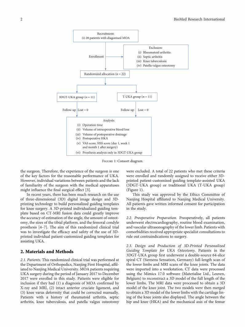
the surgeon. Therefore, the experience of the surgeon is oneof the key factors for the reasonable performance of UKA.However, individual variations between patients and the lackof familiarity of the surgeon with the medical apparatusesmight influence the final surgical effect [3].
In recent years, there has been much research on the useof three-dimensional (3D) digital image design and 3D-printing technology to build personalized guiding templatesfor knee surgery. A 3D-printed individualized guiding tem-plate based on CT-MRI fusion data could greatly improvethe accuracy of estimation of the angle, the amount of osteot-omy, the sizes of the tibial platform, and the femoral condyleprosthesis [4–7]. The aim of this randomized clinical trialwas to investigate the efficacy and safety of the use of 3D-printed individual patient-customized guiding templates forassisting UKA.
2. Materials and Methods
2.1. Patients. This randomized clinical trial was performed atthe Department of Orthopedics, Nanjing First Hospital, affil-iated to Nanjing Medical University. MOA patients requiringUKA surgery during the period of January 2017 to December2017 were enrolled in this study. Patients were eligible forinclusion if they had (1) a diagnosis of MOA confirmed byX-ray and MRI, (2) intact anterior cruciate ligament, and(3) knee varus deformity that could be corrected manually.Patients with a history of rheumatoid arthritis, septicarthritis, knee tuberculosis, and patella valgus osteotomy
were excluded. A total of 22 patients who met these criteriawere enrolled and randomly assigned to receive either 3D-printed patient-customized guiding template-assisted UKA(3DGT-UKA group) or traditional UKA (T-UKA group)(Figure 1).
This study was approved by the Ethics Committee ofNanjing Hospital affiliated to Nanjing Medical University.All patients gave written informed consent for participationin the study.
2.2. Preoperative Preparation. Preoperatively, all patientsunderwent electrocardiography, routine blood examination,and vascular ultrasonography of the lower limb. Patients withcomorbidities received appropriate specialist consultations torule out contraindications to surgery.
2.3. Design and Production of 3D-Printed PersonalizedGuiding Template for UKA Osteotomy. Patients in the3DGT-UKA group first underwent a double-source 64-slicespiral CT (Siemens Sensation, Germany) full-length scan ofthe lower limbs and MRI scans of the knee joints. The datawere imported into a workstation. CT data were processedusing the Mimics 17.0 software (Materialise Ltd., Leuven,Belgium) to reconstruct a 3D model of the full length of thelower limbs. The MRI data were processed to obtain a 3Dmodel of the knee joint. The two models were then mergedto obtain a 3Dmodel of the lower limbs with the cartilage lin-ing of the knee joints also displayed. The angle between thehip and knee (HKA) and the mechanical axis of the femur
Recruitment:
Randomized allocation (n = 22)
3DGT-UKA group (n = 11) T-UKA group (n = 11)
Follow-up Follow-up Lost = 0
Analysis:
Enrollment
28 patients with diagonised MOA(i)
Rheumatoid arthritisSeptic arthritisKnee tuberculosisPatella valgus osteotomy
(i)(ii)
(iii)(iv)
Operation timeVolume of intraoperative blood lossVolume of postoperative drainagePostoperative HKAVAS score. HSS score (day 1, week 1and month 1 after surgery)Prosthesis analysis only in 3DGT-UKA group
(i)(ii)
(iii)(iv)(v)
(vi)
Exclusion:
Lost = 0
Figure 1: Consort diagram.
2 BioMed Research International
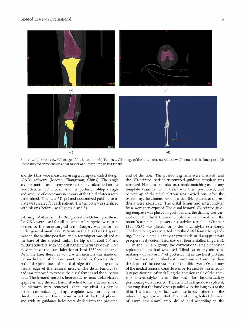
and the tibia were measured using a computer-aided design(CAD) software (Medivi, Changzhou, China). The angleand amount of osteotomy were accurately calculated on thereconstructed 3D model, and the posterior oblique angleand amount of osteotomy necessary at the tibial plateau weredetermined. Finally, a 3D-printed customized guiding tem-plate was created for each patient. The template was sterilizedwith plasma before use (Figures 2 and 3).
2.4. Surgical Methods. The 3rd generation Oxford prosthesesfor UKA were used for all patients. All surgeries were per-formed by the same surgical team. Surgery was performedunder general anesthesia. Patients in the 3DGT-UKA groupwere in the supine position, and a tourniquet was placed atthe base of the affected limb. The hip was flexed 30° andmildly abducted, with the calf hanging naturally down. Freemovement of the knee joint for at least 135° was ensured.With the knee flexed at 90°, a 6-cm incision was made onthe medial side of the knee joint, extending from the distalend of the joint line at the medial edge of the tibia up to themedial edge of the femoral muscle. The distal femoral fatpad was removed to expose the distal femur and the superiortibia. The femoral condyle, intercondylar fossa, tibial plateauepiphysis, and the soft tissue attached to the anterior side ofthe platform were removed. Then, the tibial 3D-printedpatient-customized guiding template was carefully andclosely applied on the anterior aspect of the tibial plateau,and with its guidance holes were drilled into the proximal
end of the tibia. The positioning nails were inserted, andthe 3D-printed patient-customized guiding template wasremoved. Next, the manufacturer-made matching osteotomytemplate (Zimmer Ltd., USA) was then positioned, andosteotomy of the tibial plateau was carried out. After theosteotomy, the dimensions of the cut tibial plateau and pros-thesis were measured. The distal femur and intercondylarfossa were then exposed. The distal femoral 3D-printed guid-ing template was placed in position, and the drilling was car-ried out. The distal femoral template was removed, and themanufacturer-made posterior condylar template (ZimmerLtd., USA) was placed for posterior condylar osteotomy.The bone bung was inserted into the distal femur for grind-ing. Finally, a single condylar prosthesis of the appropriatepreoperatively determined size was then installed (Figure 4).
In the T-UKA group, the conventional single condylarreplacement method was used. Tibial osteotomy aimed atmaking a downward 7° of posterior tilt in the tibial plateau.The thickness of the tibial osteotomy was 2-3mm less thanthe depth of the deepest part of the tibial wear. Osteotomyof the medial femoral condyle was performed by intramedul-lary positioning. After drilling the anterior angle of the ante-rior intercondylar fossa, the rods for intramedullarypositioning were inserted. The femoral drill guide was placed,ensuring that the handle was parallel with the long axis of thetibia. The kneading surface was close to each other, and therelevant angle was adjusted. The positioning holes (diameterof 4mm and 6mm) were drilled and according to the
(a) (b)
(c) (d)
Figure 2: (a) Front view CT image of the knee joint. (b) Top view CT image of the knee joint. (c) Side view CT image of the knee joint. (d)Reconstructed three-dimensional model of a lower limb in full length.
3BioMed Research International

position of them; the posterior femoral condyle was cut andground. Prostheses of appropriate sizes were then installedinto the tibia and femur.
Drainage tubes were placed in both groups after sur-gery [8–10]. All patients routinely received antibioticsand analgesics, as well as low-molecular-weight heparinas an anticoagulant therapy. Passive exercises were started24 hours after surgery. The drainage tube was removed 48hours after surgery. Patients were encouraged to walk withthe help of a walking assistance device and to performstretching and contracting exercise of quadriceps. A full-length radiograph of the affected lower limb and a positivelateral radiograph of the knee joint were examined at 2days postoperation, and the HKA deviation was obtained(Figure 5). Sutures were removed 2 weeks after surgery.The VAS scores on day 1, week 1, month 1, and month3 after surgery, and the Hospital for Special Surgery(HSS) scores on week 1, month 1, and month 3 aftersurgery, were recorded.
2.5. Postoperative Evaluation. An outpatient follow-up forthree months was conducted to evaluate the recovery of the
patients. And all patients involved in this study completedthe postoperative follow-up. The sizes of the preoperativelydesigned theoretical prosthesis and that of the actual prosthe-sis used during the operation in the 3DGT-UKA group werecompared. The operation time, intraoperative blood loss,postoperative drainage, and postoperative HKA were com-pared between the two groups. VAS score on day 1, week 1,month 1, and month 3 after surgery and HSS score on week1, month 1, and month 3 were also compared between thetwo groups. Because the operation time of patients in bothgroups was within the set time (90 minutes) of a lowerextremity tourniquet, the volume of postoperative drainagewas recorded and calculated as the volume of blood loss inthe current study.
2.6. Statistical Analysis. Statistical analysis was performedusing the SPSS 22.0 statistical software (IBM Corp., Armonk,NY, USA). The rank-sum test was performed for ranked datain the two groups. The t-test was used for the analysis mea-surement data and the chi-squared test for enumeration data.Statistical significance was at p ≤ 0:05.
(a) (b)
(c) (d)
Figure 3: (a) Front view of the femoral 3D-printed guiding template. (b) Side view of the femoral 3D-printed guiding template. (c) Front viewof the tibial 3D-printed guiding template. (d) Side view of the tibial 3D-printed guiding template.
4 BioMed Research International
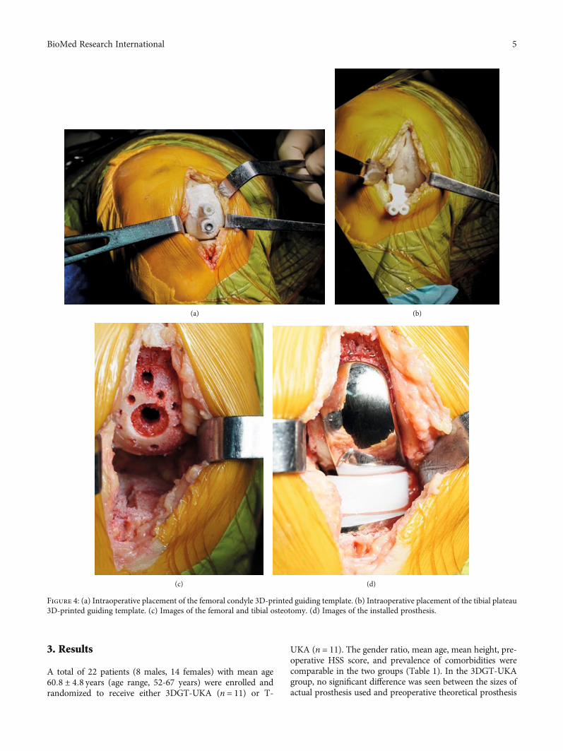
3. Results
A total of 22 patients (8 males, 14 females) with mean age60:8 ± 4:8 years (age range, 52-67 years) were enrolled andrandomized to receive either 3DGT-UKA (n = 11) or T-
UKA (n = 11). The gender ratio, mean age, mean height, pre-operative HSS score, and prevalence of comorbidities werecomparable in the two groups (Table 1). In the 3DGT-UKAgroup, no significant difference was seen between the sizes ofactual prosthesis used and preoperative theoretical prosthesis
(a) (b)
(c) (d)
Figure 4: (a) Intraoperative placement of the femoral condyle 3D-printed guiding template. (b) Intraoperative placement of the tibial plateau3D-printed guiding template. (c) Images of the femoral and tibial osteotomy. (d) Images of the installed prosthesis.
5BioMed Research International
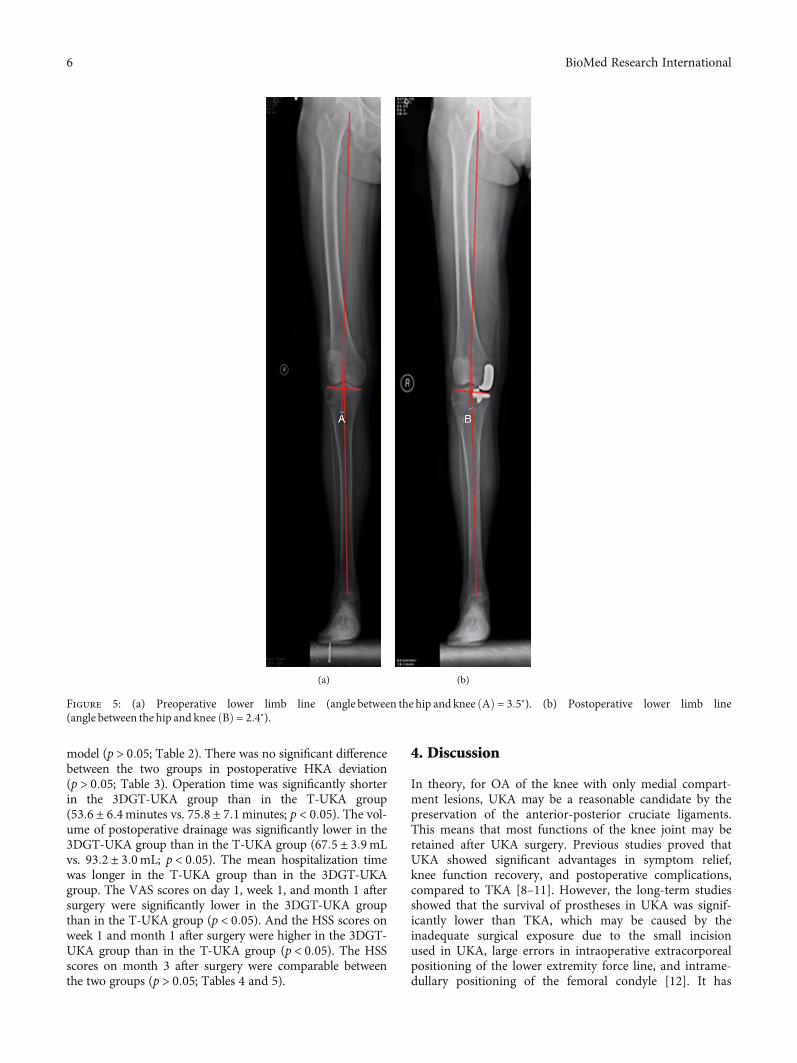
model (p > 0:05; Table 2). There was no significant differencebetween the two groups in postoperative HKA deviation(p > 0:05; Table 3). Operation time was significantly shorterin the 3DGT-UKA group than in the T-UKA group(53:6 ± 6:4minutes vs. 75:8 ± 7:1minutes; p < 0:05). The vol-ume of postoperative drainage was significantly lower in the3DGT-UKA group than in the T-UKA group (67:5 ± 3:9mLvs. 93:2 ± 3:0mL; p < 0:05). The mean hospitalization timewas longer in the T-UKA group than in the 3DGT-UKAgroup. The VAS scores on day 1, week 1, and month 1 aftersurgery were significantly lower in the 3DGT-UKA groupthan in the T-UKA group (p < 0:05). And the HSS scores onweek 1 and month 1 after surgery were higher in the 3DGT-UKA group than in the T-UKA group (p < 0:05). The HSSscores on month 3 after surgery were comparable betweenthe two groups (p > 0:05; Tables 4 and 5).
4. Discussion
In theory, for OA of the knee with only medial compart-ment lesions, UKA may be a reasonable candidate by thepreservation of the anterior-posterior cruciate ligaments.This means that most functions of the knee joint may beretained after UKA surgery. Previous studies proved thatUKA showed significant advantages in symptom relief,knee function recovery, and postoperative complications,compared to TKA [8–11]. However, the long-term studiesshowed that the survival of prostheses in UKA was signif-icantly lower than TKA, which may be caused by theinadequate surgical exposure due to the small incisionused in UKA, large errors in intraoperative extracorporealpositioning of the lower extremity force line, and intrame-dullary positioning of the femoral condyle [12]. It has
(a) (b)
Figure 5: (a) Preoperative lower limb line (angle between the hip and knee ðAÞ = 3:5°). (b) Postoperative lower limb line(angle between the hip and knee ðBÞ = 2:4°).
6 BioMed Research International

Table1:Dem
ograph
icandclinicalcharacteristicsof
patientsin
the3D
GT-U
KAgrou
pandT-U
KAgrou
p.
Group
Num
ber
Gender
Age
(yr,mean±
SD)
Height
(cm,m
ean±
SD)
Difference
ofkn
eejoints
Pre-operative
HSS
score
(mean±
SD)
Alignm
entof
lower
limb,
° −(m
ean±
SD)
Hypertension,
n(%
)Diabetes,
n(%
)Male
Female
Left
Right
3DGT-U
KA
113
860:00±
4:31
159:55
±7:94
65
77:82±
2:44
7:23±
0:96
4(36%
)2(18%
)
T-U
KA
115
661:64±
5:33
161:64
±6:44
56
76:92±
2:47
7:19±
0:90
3(27%
)2(18%
)
tvalue1
−0.791
−0.678
0.868
0.092
pvalue2
0.659
0.438
0.505
1.000
0.395
0.928
1.000
1.000
1 The
ttestwas
used
forthecomparisonof
age,height,p
reop
erativeHSS
score,andalignm
entof
preoperative
lower
limb.
2 Fisher’sexacttestwas
used
forcomparisonof
gend
erratioandsurgery.
7BioMed Research International
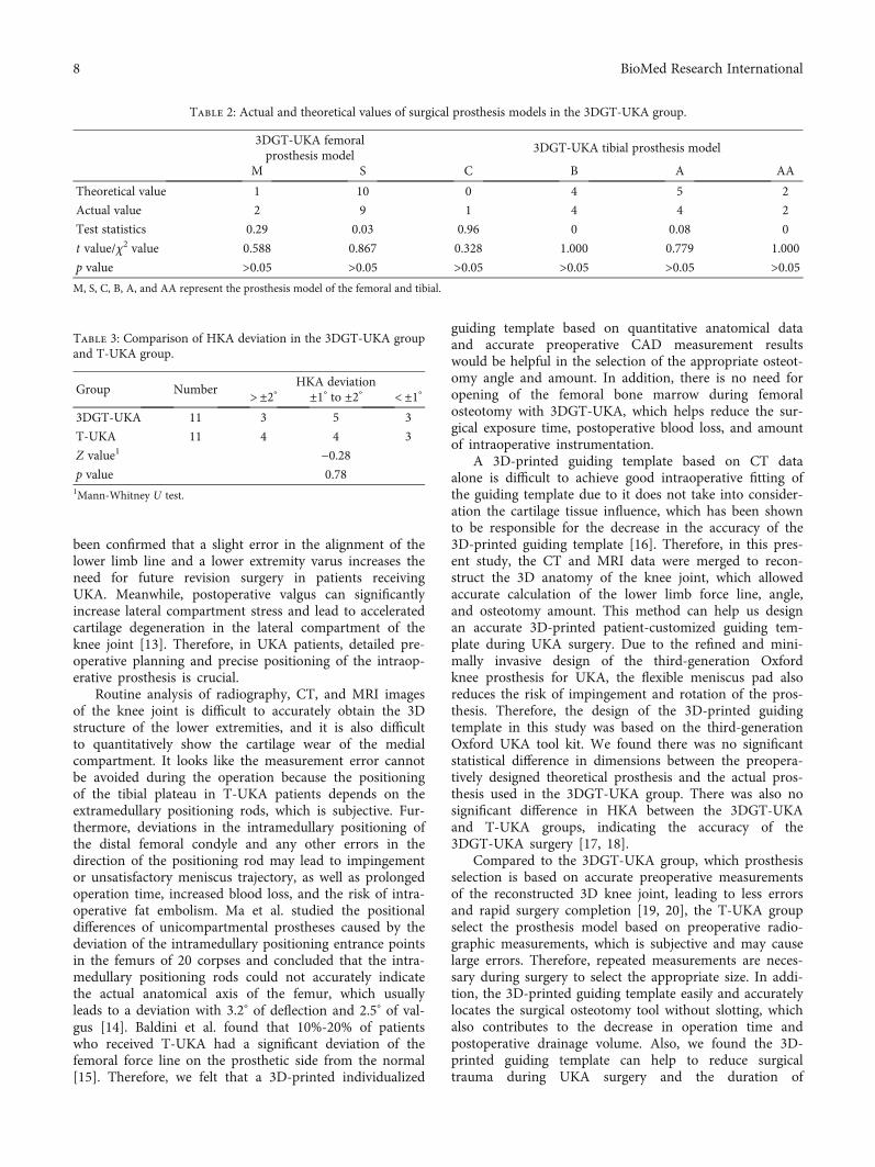
been confirmed that a slight error in the alignment of thelower limb line and a lower extremity varus increases theneed for future revision surgery in patients receivingUKA. Meanwhile, postoperative valgus can significantlyincrease lateral compartment stress and lead to acceleratedcartilage degeneration in the lateral compartment of theknee joint [13]. Therefore, in UKA patients, detailed pre-operative planning and precise positioning of the intraop-erative prosthesis is crucial.
Routine analysis of radiography, CT, and MRI imagesof the knee joint is difficult to accurately obtain the 3Dstructure of the lower extremities, and it is also difficultto quantitatively show the cartilage wear of the medialcompartment. It looks like the measurement error cannotbe avoided during the operation because the positioningof the tibial plateau in T-UKA patients depends on theextramedullary positioning rods, which is subjective. Fur-thermore, deviations in the intramedullary positioning ofthe distal femoral condyle and any other errors in thedirection of the positioning rod may lead to impingementor unsatisfactory meniscus trajectory, as well as prolongedoperation time, increased blood loss, and the risk of intra-operative fat embolism. Ma et al. studied the positionaldifferences of unicompartmental prostheses caused by thedeviation of the intramedullary positioning entrance pointsin the femurs of 20 corpses and concluded that the intra-medullary positioning rods could not accurately indicatethe actual anatomical axis of the femur, which usuallyleads to a deviation with 3.2° of deflection and 2.5° of val-gus [14]. Baldini et al. found that 10%-20% of patientswho received T-UKA had a significant deviation of thefemoral force line on the prosthetic side from the normal[15]. Therefore, we felt that a 3D-printed individualized
guiding template based on quantitative anatomical dataand accurate preoperative CAD measurement resultswould be helpful in the selection of the appropriate osteot-omy angle and amount. In addition, there is no need foropening of the femoral bone marrow during femoralosteotomy with 3DGT-UKA, which helps reduce the sur-gical exposure time, postoperative blood loss, and amountof intraoperative instrumentation.
A 3D-printed guiding template based on CT dataalone is difficult to achieve good intraoperative fitting ofthe guiding template due to it does not take into consider-ation the cartilage tissue influence, which has been shownto be responsible for the decrease in the accuracy of the3D-printed guiding template [16]. Therefore, in this pres-ent study, the CT and MRI data were merged to recon-struct the 3D anatomy of the knee joint, which allowedaccurate calculation of the lower limb force line, angle,and osteotomy amount. This method can help us designan accurate 3D-printed patient-customized guiding tem-plate during UKA surgery. Due to the refined and mini-mally invasive design of the third-generation Oxfordknee prosthesis for UKA, the flexible meniscus pad alsoreduces the risk of impingement and rotation of the pros-thesis. Therefore, the design of the 3D-printed guidingtemplate in this study was based on the third-generationOxford UKA tool kit. We found there was no significantstatistical difference in dimensions between the preopera-tively designed theoretical prosthesis and the actual pros-thesis used in the 3DGT-UKA group. There was also nosignificant difference in HKA between the 3DGT-UKAand T-UKA groups, indicating the accuracy of the3DGT-UKA surgery [17, 18].
Compared to the 3DGT-UKA group, which prosthesisselection is based on accurate preoperative measurementsof the reconstructed 3D knee joint, leading to less errorsand rapid surgery completion [19, 20], the T-UKA groupselect the prosthesis model based on preoperative radio-graphic measurements, which is subjective and may causelarge errors. Therefore, repeated measurements are neces-sary during surgery to select the appropriate size. In addi-tion, the 3D-printed guiding template easily and accuratelylocates the surgical osteotomy tool without slotting, whichalso contributes to the decrease in operation time andpostoperative drainage volume. Also, we found the 3D-printed guiding template can help to reduce surgicaltrauma during UKA surgery and the duration of
Table 2: Actual and theoretical values of surgical prosthesis models in the 3DGT-UKA group.
3DGT-UKA femoralprosthesis model
3DGT-UKA tibial prosthesis model
M S C B A AA
Theoretical value 1 10 0 4 5 2
Actual value 2 9 1 4 4 2
Test statistics 0.29 0.03 0.96 0 0.08 0
t value/χ2 value 0.588 0.867 0.328 1.000 0.779 1.000
p value >0.05 >0.05 >0.05 >0.05 >0.05 >0.05M, S, C, B, A, and AA represent the prosthesis model of the femoral and tibial.
Table 3: Comparison of HKA deviation in the 3DGT-UKA groupand T-UKA group.
Group NumberHKA deviation
>±2° ±1° to ±2° < ±1°
3DGT-UKA 11 3 5 3
T-UKA 11 4 4 3
Z value1 −0.28p value 0.781Mann-Whitney U test.
8 BioMed Research International
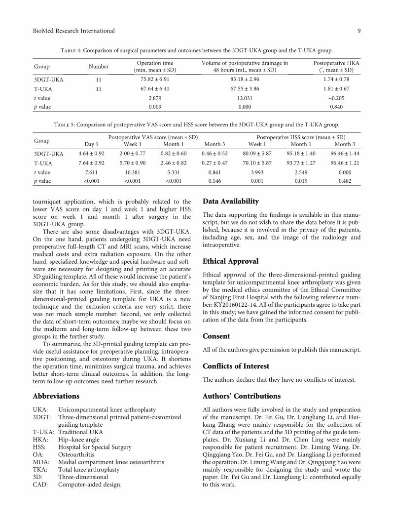
tourniquet application, which is probably related to thelower VAS score on day 1 and week 1 and higher HSSscore on week 1 and month 1 after surgery in the3DGT-UKA group.
There are also some disadvantages with 3DGT-UKA.On the one hand, patients undergoing 3DGT-UKA needpreoperative full-length CT and MRI scans, which increasemedical costs and extra radiation exposure. On the otherhand, specialized knowledge and special hardware and soft-ware are necessary for designing and printing an accurate3D guiding template. All of these would increase the patient’seconomic burden. As for this study, we should also empha-size that it has some limitations. First, since the three-dimensional-printed guiding template for UKA is a newtechnique and the exclusion criteria are very strict, therewas not much sample number. Second, we only collectedthe data of short-term outcomes; maybe we should focus onthe midterm and long-term follow-up between these twogroups in the further study.
To summarize, the 3D-printed guiding template can pro-vide useful assistance for preoperative planning, intraopera-tive positioning, and osteotomy during UKA. It shortensthe operation time, minimizes surgical trauma, and achievesbetter short-term clinical outcomes. In addition, the long-term follow-up outcomes need further research.
Abbreviations
UKA: Unicompartmental knee arthroplasty3DGT: Three-dimensional printed patient-customized
guiding templateT-UKA: Traditional UKAHKA: Hip–knee angleHSS: Hospital for Special SurgeryOA: OsteoarthritisMOA: Medial compartment knee osteoarthritisTKA: Total knee arthroplasty3D: Three-dimensionalCAD: Computer-aided design.
Data Availability
The data supporting the findings is available in this manu-script, but we do not wish to share the data before it is pub-lished, because it is involved in the privacy of the patients,including age, sex, and the image of the radiology andintraoperative.
Ethical Approval
Ethical approval of the three-dimensional-printed guidingtemplate for unicompartmental knee arthroplasty was givenby the medical ethics committee of the Ethical Committeeof Nanjing First Hospital with the following reference num-ber: KY20160122-14. All of the participants agree to take partin this study; we have gained the informed consent for publi-cation of the data from the participants.
Consent
All of the authors give permission to publish this manuscript.
Conflicts of Interest
The authors declare that they have no conflicts of interest.
Authors’ Contributions
All authors were fully involved in the study and preparationof the manuscript. Dr. Fei Gu, Dr. Liangliang Li, and Hui-kang Zhang were mainly responsible for the collection ofCT data of the patients and the 3D printing of the guide tem-plates. Dr. Xuxiang Li and Dr. Chen Ling were mainlyresponsible for patient recruitment. Dr. Liming Wang, Dr.Qingqiang Yao, Dr. Fei Gu, and Dr. Liangliang Li performedthe operation. Dr. LimingWang and Dr. Qingqiang Yao weremainly responsible for designing the study and wrote thepaper. Dr. Fei Gu and Dr. Liangliang Li contributed equallyto this work.
Table 4: Comparison of surgical parameters and outcomes between the 3DGT-UKA group and the T-UKA group.
Group NumberOperation time
(min, mean ± SD)Volume of postoperative drainage in
48 hours (mL, mean ± SD)Postoperative HKA(°, mean ± SD)
3DGT-UKA 11 75:82 ± 6:91 85:18 ± 2:96 1:74 ± 0:78T-UKA 11 67:64 ± 6:41 67:55 ± 3:86 1:81 ± 0:67t value 2.879 12.031 −0.205p value 0.009 0.000 0.840
Table 5: Comparison of postoperative VAS score and HSS score between the 3DGT-UKA group and the T-UKA group.
GroupPostoperative VAS score (mean ± SD) Postoperative HSS score (mean ± SD)
Day 1 Week 1 Month 1 Month 3 Week 1 Month 1 Month 3
3DGT-UKA 4:64 ± 0:92 2:00 ± 0:77 0:82 ± 0:60 0:46 ± 0:52 80:09 ± 5:87 95:18 ± 1:40 96:46 ± 1:44T-UKA 7:64 ± 0:92 5:70 ± 0:90 2:46 ± 0:82 0:27 ± 0:47 70:10 ± 5:87 93:73 ± 1:27 96:46 ± 1:21t value 7.611 10.381 5.331 0.861 3.993 2.549 0.000
p value <0.001 <0.001 <0.001 0.146 0.001 0.019 0.482
9BioMed Research International
Acknowledgments
Thanks are due to Miss Xu and Miss Peng for their helpduring the collection of the patients’ CT data. This studywas supported by the National Key Research and Develop-ment Program of China (2018YFC1105204), National Natu-ral Science Foundation of China (81601612, 81771985), andKey Research Program of Science & Technology SupportProgram of Jiangsu Province (BE 2015613, BE 2016763).
References
[1] N. P. Kort, J. J. van Raay, J. Cheung, C. Jolink, and R. Deutman,“Analysis of Oxford medial unicompartmental knee replace-ment using the minimally invasive technique in patients aged60 and above:an independent prospective series,” KneeSurgery, Sports Traumatology, Arthroscopy, vol. 15, no. 11,pp. 1331–1334, 2007.
[2] F. Voss, M. B. Sheinkop, J. O. Galante, R. M. Barden, and A. G.Rosenberg, “Miller-Galante unicompartmental knee arthro-plasty at 2- to 5-year follow-up evaluations,” The Journal ofArthroplasty, vol. 10, no. 6, pp. 764–771, 1995.
[3] M. Chowdhry, R. S. Khakha, M. Norris, A. Kheiran, and S. K.Chauhan, “Improved survival of computer-assisted unicom-partmental knee arthroplasty: 252 cases with a minimumfollow-up of 5 years,” The Journal of Arthroplasty, vol. 32,no. 4, pp. 1132–1136, 2017.
[4] A. Manzotti, P. Cerveri, C. Pullen, and N. Confalonieri,“Computer-assisted unicompartmental knee arthroplastyusing dedicated software versus a conventional technique,”International Orthopaedics, vol. 38, no. 2, pp. 457–463,2014.
[5] R. Pailhé, J. Cognault, J. Massfelder et al., “Comparative studyof computer-assisted total knee arthroplasty after openingwedge osteotomy versus after unicompartmental arthro-plasty,” The bone & joint journal, vol. 98, no. 12, pp. 1620–1624, 2017.
[6] D. K. Bae and S. J. Song, “Computer assisted navigation inknee arthroplasty,” Clinics in Orthopedic Surgery, vol. 3,no. 4, pp. 259–267, 2011.
[7] D. Saragaglia, J. Massfelder, R. Refaie et al., “Computer-assisted total knee replacement after medial opening wedgehigh tibial osteotomy: medium-term results in a series ofninety cases,” International Orthopaedics, vol. 40, no. 1,pp. 35–40, 2017.
[8] P. Hernigou and G. Deschamps, “Alignment influences wearin the knee after medial unicompartmental arthroplasty,” Clin-ical Orthopaedics and Related Research, vol. 423, pp. 161–165,2004.
[9] P. Hernigou and G. Deschamps, “Posterior slope of the tibialimplant and the outcome of unicompartmental knee arthro-plasty,” The Journal of Bone and Joint Surgery. American Vol-ume, vol. 86, no. 3, pp. 506–511, 2004.
[10] N. P. Kort, J. J. van Raay, and B. J. Thomassen, “Alignment ofthe femoral component in a mobile-bearing unicompartmen-tal knee arthroplasty: a study in 10 cadaver femora,” The Knee,vol. 14, no. 4, pp. 280–283, 2007.
[11] T. Walker, T. Gotterbarm, T. Bruckner, C. Merle, and M. R.Streit, “Total versus unicompartmental knee replacement forisolated lateral osteoarthritis: a matched-pairs study,” Interna-tional Orthopaedics, vol. 38, no. 11, pp. 2259–2264, 2014.
[12] B. Bordini, S. Stea, S. Falcioni, C. Ancarani, and A. Toni, “Uni-compartmental knee arthroplasty,” The Knee, vol. 21, no. 6,pp. 1275–1279, 2014.
[13] O. R. Kwon, K. T. Kang, J. Son, D. S. Suh, C. Baek, and Y. G.Koh, “Importance of joint line preservation in unicompart-mental knee arthroplasty: finite element analysis,” Journal ofOrthopaedic Research, vol. 35, no. 2, pp. 347–352, 2017.
[14] B. Ma, W. Long, J. F. Rudan, and R. E. Ellis, “Three-dimen-sional analysis of alignment error in using femoral intramedul-lary guides in unicompartmental knee arthroplasty,” TheJournal of arthroplasty, vol. 21, no. 2, pp. 271–278, 2006.
[15] A. Baldini and P. Adravanti, “Less invasive TKA,” ClinicalOrthopaedics and Related Research, vol. 466, no. 11,pp. 2694–2700, 2008.
[16] V. De Santis, A. Burrofato, R. D’Apolito et al., “Evaluation ofaccuracy of bone cuts and implant positioning in total kneearthroplasty using patient specific instrumentation,” Journalof Biological Regulators & Homeostatic Agents, vol. 31, 4 suppl1, pp. 51–60, 2017.
[17] J. Y. Jenny and C. Boeri, “Accuracy of implantation of aunicompartmental total knee arthroplasty with 2 differentinstrumentations,” The Journal of Arthroplasty, vol. 17,no. 8, pp. 1016–1020, 2002.
[18] G. Keene, D. Simpson, and Y. Kalairajah, “Limb alignment incomputer-assisted minimally-invasive unicompartmentalknee replacement,” Journal of Bone and Joint Surgery. BritishVolume (London), vol. 88, pp. 44–48, 2006.
[19] R. A. Berger, R. M. Meneghini, J. J. Jacobs et al., “Results ofunicompartmental knee arthroplasty at a follow-up of ten-years follow-up,” Journal of Bone and Joint Surgery,vol. 87, pp. 999–1006, 2005.
[20] J. Newman, R. V. Pydisetty, and C. Ackroyd, “Unicompart-mental or total knee replacement: the 15-year results of a pro-spective randomised controlled trial,” Journal of Bone andJoint Surgery. British Volume (London), vol. 91, pp. 52–57,2009.
10 BioMed Research International
Research ArticleIn Vivo Reconstruction of the Acetabular Bone Defect by theIndividualized Three-Dimensional Printed Porous Augment in aSwine Model
Jun Fu ,1 Yi Xiang ,2 Ming Ni ,1 Xiaojuan Qu ,3 Yonggang Zhou ,1 Libo Hao ,1
Guoqiang Zhang ,1 and Jiying Chen 1
1Department of Orthopaedics, The First Medical Centre, Chinese PLA General Hospital, Beijing 100853, China2Department of Orthopaedics, The Logistics Support Forces of Chinese PLA 985 Hospital, Taiyuan, Shanxi 030001, China3Otolaryngological Department, The Logistics Support Forces of Chinese PLA 985 Hospital, Taiyuan, Shanxi 030001, China
Correspondence should be addressed to Guoqiang Zhang; [email protected] and Jiying Chen; [email protected]
Received 23 June 2020; Revised 14 October 2020; Accepted 17 November 2020; Published 1 December 2020
Academic Editor: Anish R. Kadakia
Copyright © 2020 Jun Fu et al. This is an open access article distributed under the Creative Commons Attribution License, whichpermits unrestricted use, distribution, and reproduction in any medium, provided the original work is properly cited.
Background and Purpose. This study established an animal model of the acetabular bone defect in swine and evaluated the boneingrowth, biomechanics, and matching degree of the individualized three-dimensional (3D) printed porous augment. Methods.As an acetabular bone defect model created in Bama miniswine, an augment individually fabricated by 3D print technique withTi6Al4V powders was implanted to repair the defect. Nine swine were divided into three groups, including the immediatebiomechanics group, 12-week biomechanics group, and 12-week histological group. The inner structural parameters of the 3Dprinted porous augment were measured by scanning electron microscopy (SEM), including porosity, pore size, and trabeculardiameter. The matching degree between the postoperative augment and the designed augment was assessed by CT scanning and3D reconstruction. In addition, biomechanical properties, such as stiffness, compressive strength, and the elastic modulus of the3D printed porous augment, were measured by means of a mechanical testing machine. Moreover, bone ingrowth and implantosseointegration were histomorphometrically assessed. Results. In terms of the inner structural parameters of the 3D printedporous augment, the porosity was 55:48 ± 0:61%, pore size 319:23 ± 25:05 μm, and trabecular diameter 240:10 ± 23:50μm.Biomechanically, the stiffness was 21464:60 ± 1091:69N/mm, compressive strength 231:10 ± 11:77MPa, and elastic modulus5:35 ± 0:23GPa, respectively. Furthermore, the matching extent between the postoperative augment and the designed one wasup to 91:40 ± 2:83%. Besides, the maximal shear strength of the 3D printed augment was 929:46 ± 295:99N immediately afterimplantation, whereas the strength was 1521:93 ± 98:38N 12 weeks after surgery (p = 0:0302). The bone mineral apposition rate(μm per day) 12 weeks post operation was 3:77 ± 0:93μm/d. The percentage bone volume of new bone was 22:30 ± 4:51% 12weeks after surgery. Conclusion. The 3D printed porous Ti6Al4V augment designed in this study was well biocompatible withbone tissue, possessed proper biomechanical features, and was anatomically well matched with the defect bone. Therefore, the3D printed porous Ti6Al4V augment possesses great potential as an alternative for individualized treatment of severe acetabularbone defects.
1. Introduction
Total hip arthroplasty (THA) represents one of the most suc-cessful surgeries in the 20th century and has been employedfor releasing pain, correcting the deformity, and improvingthe function of the hip joint [1, 2]. The management of severeacetabular bone defects in primary or revision THA remains
a challenge for surgeons, and the ideal defect reconstructionis a critical factor for a successful THA [3]. Traditionally,major acetabular defects in primary and revision THA havebeen reconstructed by impaction bone grafting (IBG), metalaugments, and cup/cage constructs [2]. Recently, given theimproved biocompatibility and biomechanical properties ofthe trabecular metal (TM), TM augments and cups are most
HindawiBioMed Research InternationalVolume 2020, Article ID 4542302, 10 pageshttps://doi.org/10.1155/2020/4542302
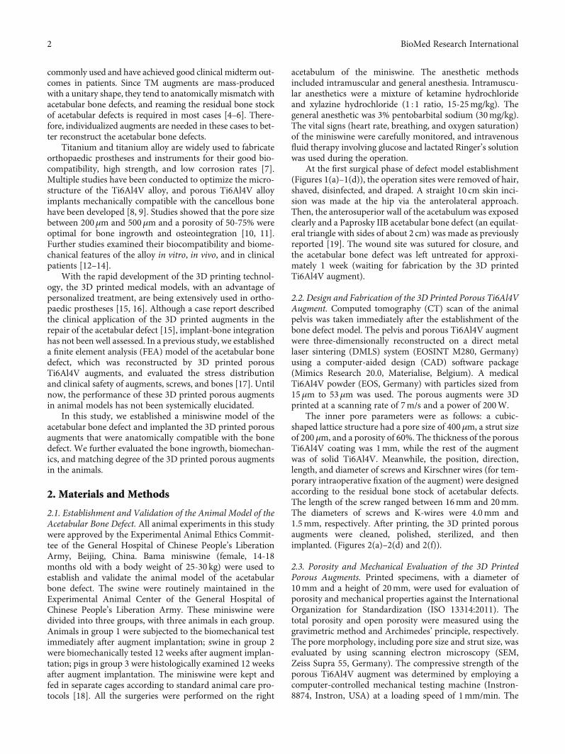
commonly used and have achieved good clinical midterm out-comes in patients. Since TM augments are mass-producedwith a unitary shape, they tend to anatomically mismatch withacetabular bone defects, and reaming the residual bone stockof acetabular defects is required in most cases [4–6]. There-fore, individualized augments are needed in these cases to bet-ter reconstruct the acetabular bone defects.
Titanium and titanium alloy are widely used to fabricateorthopaedic prostheses and instruments for their good bio-compatibility, high strength, and low corrosion rates [7].Multiple studies have been conducted to optimize the micro-structure of the Ti6Al4V alloy, and porous Ti6Al4V alloyimplants mechanically compatible with the cancellous bonehave been developed [8, 9]. Studies showed that the pore sizebetween 200μm and 500μm and a porosity of 50-75% wereoptimal for bone ingrowth and osteointegration [10, 11].Further studies examined their biocompatibility and biome-chanical features of the alloy in vitro, in vivo, and in clinicalpatients [12–14].
With the rapid development of the 3D printing technol-ogy, the 3D printed medical models, with an advantage ofpersonalized treatment, are being extensively used in ortho-paedic prostheses [15, 16]. Although a case report describedthe clinical application of the 3D printed augments in therepair of the acetabular defect [15], implant-bone integrationhas not been well assessed. In a previous study, we establisheda finite element analysis (FEA) model of the acetabular bonedefect, which was reconstructed by 3D printed porousTi6Al4V augments, and evaluated the stress distributionand clinical safety of augments, screws, and bones [17]. Untilnow, the performance of these 3D printed porous augmentsin animal models has not been systemically elucidated.
In this study, we established a miniswine model of theacetabular bone defect and implanted the 3D printed porousaugments that were anatomically compatible with the bonedefect. We further evaluated the bone ingrowth, biomechan-ics, and matching degree of the 3D printed porous augmentsin the animals.
2. Materials and Methods
2.1. Establishment and Validation of the Animal Model of theAcetabular Bone Defect. All animal experiments in this studywere approved by the Experimental Animal Ethics Commit-tee of the General Hospital of Chinese People’s LiberationArmy, Beijing, China. Bama miniswine (female, 14-18months old with a body weight of 25-30 kg) were used toestablish and validate the animal model of the acetabularbone defect. The swine were routinely maintained in theExperimental Animal Center of the General Hospital ofChinese People’s Liberation Army. These miniswine weredivided into three groups, with three animals in each group.Animals in group 1 were subjected to the biomechanical testimmediately after augment implantation; swine in group 2were biomechanically tested 12 weeks after augment implan-tation; pigs in group 3 were histologically examined 12 weeksafter augment implantation. The miniswine were kept andfed in separate cages according to standard animal care pro-tocols [18]. All the surgeries were performed on the right
acetabulum of the miniswine. The anesthetic methodsincluded intramuscular and general anesthesia. Intramuscu-lar anesthetics were a mixture of ketamine hydrochlorideand xylazine hydrochloride (1 : 1 ratio, 15-25mg/kg). Thegeneral anesthetic was 3% pentobarbital sodium (30mg/kg).The vital signs (heart rate, breathing, and oxygen saturation)of the miniswine were carefully monitored, and intravenousfluid therapy involving glucose and lactated Ringer’s solutionwas used during the operation.
At the first surgical phase of defect model establishment(Figures 1(a)–1(d)), the operation sites were removed of hair,shaved, disinfected, and draped. A straight 10 cm skin inci-sion was made at the hip via the anterolateral approach.Then, the anterosuperior wall of the acetabulum was exposedclearly and a Paprosky IIB acetabular bone defect (an equilat-eral triangle with sides of about 2 cm) was made as previouslyreported [19]. The wound site was sutured for closure, andthe acetabular bone defect was left untreated for approxi-mately 1 week (waiting for fabrication by the 3D printedTi6Al4V augment).
2.2. Design and Fabrication of the 3D Printed Porous Ti6Al4VAugment. Computed tomography (CT) scan of the animalpelvis was taken immediately after the establishment of thebone defect model. The pelvis and porous Ti6Al4V augmentwere three-dimensionally reconstructed on a direct metallaser sintering (DMLS) system (EOSINT M280, Germany)using a computer-aided design (CAD) software package(Mimics Research 20.0, Materialise, Belgium). A medicalTi6Al4V powder (EOS, Germany) with particles sized from15μm to 53μm was used. The porous augments were 3Dprinted at a scanning rate of 7m/s and a power of 200W.
The inner pore parameters were as follows: a cubic-shaped lattice structure had a pore size of 400μm, a strut sizeof 200μm, and a porosity of 60%. The thickness of the porousTi6Al4V coating was 1mm, while the rest of the augmentwas of solid Ti6Al4V. Meanwhile, the position, direction,length, and diameter of screws and Kirschner wires (for tem-porary intraoperative fixation of the augment) were designedaccording to the residual bone stock of acetabular defects.The length of the screw ranged between 16mm and 20mm.The diameters of screws and K-wires were 4.0mm and1.5mm, respectively. After printing, the 3D printed porousaugments were cleaned, polished, sterilized, and thenimplanted. (Figures 2(a)–2(d) and 2(f)).
2.3. Porosity and Mechanical Evaluation of the 3D PrintedPorous Augments. Printed specimens, with a diameter of10mm and a height of 20mm, were used for evaluation ofporosity and mechanical properties against the InternationalOrganization for Standardization (ISO 13314:2011). Thetotal porosity and open porosity were measured using thegravimetric method and Archimedes’ principle, respectively.The pore morphology, including pore size and strut size, wasevaluated by using scanning electron microscopy (SEM,Zeiss Supra 55, Germany). The compressive strength of theporous Ti6Al4V augment was determined by employing acomputer-controlled mechanical testing machine (Instron-8874, Instron, USA) at a loading speed of 1mm/min. The
2 BioMed Research International
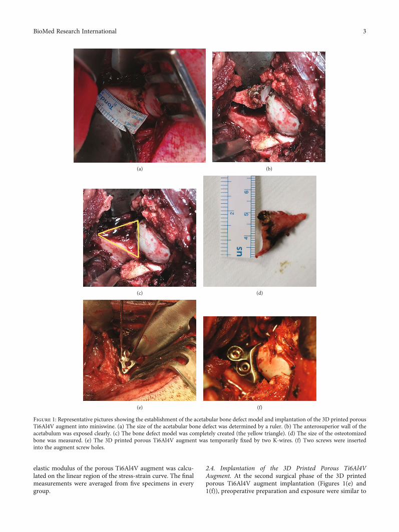
elastic modulus of the porous Ti6Al4V augment was calcu-lated on the linear region of the stress-strain curve. The finalmeasurements were averaged from five specimens in everygroup.
2.4. Implantation of the 3D Printed Porous Ti6Al4VAugment. At the second surgical phase of the 3D printedporous Ti6Al4V augment implantation (Figures 1(e) and1(f)), preoperative preparation and exposure were similar to
(a) (b)
(c) (d)
(e) (f)
Figure 1: Representative pictures showing the establishment of the acetabular bone defect model and implantation of the 3D printed porousTi6Al4V augment into miniswine. (a) The size of the acetabular bone defect was determined by a ruler. (b) The anterosuperior wall of theacetabulum was exposed clearly. (c) The bone defect model was completely created (the yellow triangle). (d) The size of the osteotomizedbone was measured. (e) The 3D printed porous Ti6Al4V augment was temporarily fixed by two K-wires. (f) Two screws were insertedinto the augment screw holes.
3BioMed Research International
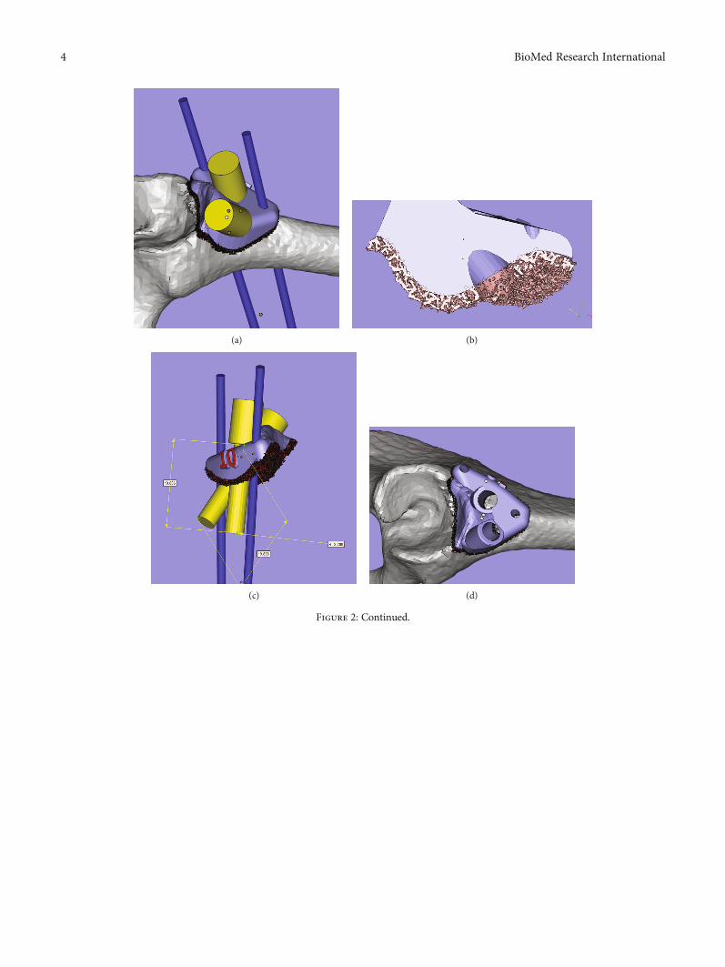
(a) (b)
(c) (d)
Figure 2: Continued.
4 BioMed Research International
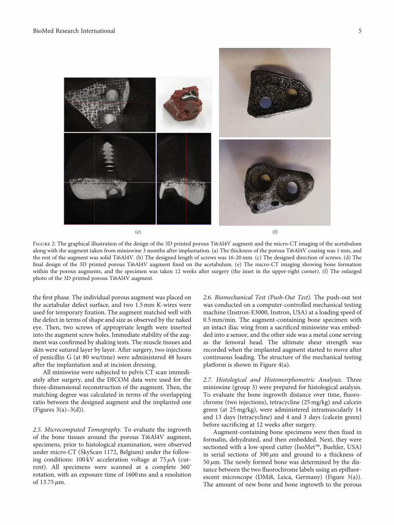
the first phase. The individual porous augment was placed onthe acetabular defect surface, and two 1.5mm K-wires wereused for temporary fixation. The augment matched well withthe defect in terms of shape and size as observed by the nakedeye. Then, two screws of appropriate length were insertedinto the augment screw holes. Immediate stability of the aug-ment was confirmed by shaking tests. The muscle tissues andskin were sutured layer by layer. After surgery, two injectionsof penicillin G (at 80 wu/time) were administered 48 hoursafter the implantation and at incision dressing.
All miniswine were subjected to pelvis CT scan immedi-ately after surgery, and the DICOM data were used for thethree-dimensional reconstruction of the augment. Then, thematching degree was calculated in terms of the overlappingratio between the designed augment and the implanted one(Figures 3(a)–3(d)).
2.5. Microcomputed Tomography. To evaluate the ingrowthof the bone tissues around the porous Ti6Al4V augment,specimens, prior to histological examination, were observedunder micro-CT (SkyScan 1172, Belgium) under the follow-ing conditions: 100 kV acceleration voltage at 75μA (cur-rent). All specimens were scanned at a complete 360°
rotation, with an exposure time of 1600ms and a resolutionof 13.75μm.
2.6. Biomechanical Test (Push-Out Test). The push-out testwas conducted on a computer-controlled mechanical testingmachine (Instron-E3000, Instron, USA) at a loading speed of0.5mm/min. The augment-containing bone specimen withan intact iliac wing from a sacrificed miniswine was embed-ded into a sensor, and the other side was a metal cone servingas the femoral head. The ultimate shear strength wasrecorded when the implanted augment started to move aftercontinuous loading. The structure of the mechanical testingplatform is shown in Figure 4(a).
2.7. Histological and Histomorphometric Analyses. Threeminiswine (group 3) were prepared for histological analysis.To evaluate the bone ingrowth distance over time, fluoro-chrome (two injections), tetracycline (25mg/kg) and calceingreen (at 25mg/kg), were administered intramuscularly 14and 13 days (tetracycline) and 4 and 3 days (calcein green)before sacrificing at 12 weeks after surgery.
Augment-containing bone specimens were then fixed informalin, dehydrated, and then embedded. Next, they weresectioned with a low-speed cutter (IsoMet™, Buehler, USA)in serial sections of 300μm and ground to a thickness of50μm. The newly formed bone was determined by the dis-tance between the two fluorochrome labels using an epifluor-escent microscope (DMi8, Leica, Germany) (Figure 5(a)).The amount of new bone and bone ingrowth to the porous
(e) (f)
Figure 2: The graphical illustration of the design of the 3D printed porous Ti6Al4V augment and the micro-CT imaging of the acetabulumalong with the augment taken from miniswine 3 months after implantation. (a) The thickness of the porous Ti6Al4V coating was 1mm, andthe rest of the augment was solid Ti6Al4V. (b) The designed length of screws was 16-20mm. (c) The designed direction of screws. (d) Thefinal design of the 3D printed porous Ti6Al4V augment fixed on the acetabulum. (e) The micro-CT imaging showing bone formationwithin the porous augments, and the specimen was taken 12 weeks after surgery (the inset in the upper-right corner). (f) The enlargedphoto of the 3D printed porous Ti6Al4V augment.
5BioMed Research International
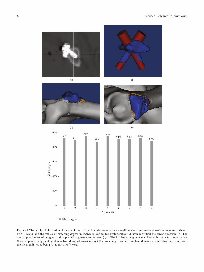
(a) (b)
(c) (d)
100%
80%
60%
40%
20%
0%1 2 3 4 5 6 7 8 9
Pig number
Mat
ch d
egre
e
Match degree
93%90%
96%
88%
95%91% 91% 93%
89%
(e)
Figure 3: The graphical illustration of the calculation of matching degree with the three-dimensional reconstruction of the augment as shownby CT scans, and the values of matching degree in individual swine. (a) Postoperative CT scan identified the screw direction. (b) Theoverlapping ranges of designed and implanted augments and screws. (c, d) The implanted augment matched with the defect bone surface(blue, implanted augment; golden yellow, designed augment). (e) The matching degrees of implanted augments in individual swine, withthe mean ± SD value being 91:40 ± 3:01% (n = 9).
6 BioMed Research International
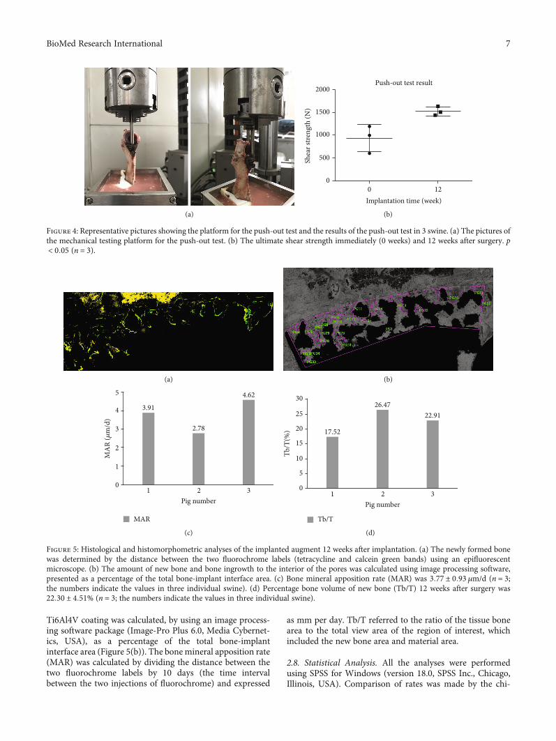
Ti6Al4V coating was calculated, by using an image process-ing software package (Image-Pro Plus 6.0, Media Cybernet-ics, USA), as a percentage of the total bone-implantinterface area (Figure 5(b)). The bone mineral apposition rate(MAR) was calculated by dividing the distance between thetwo fluorochrome labels by 10 days (the time intervalbetween the two injections of fluorochrome) and expressed
as mm per day. Tb/T referred to the ratio of the tissue bonearea to the total view area of the region of interest, whichincluded the new bone area and material area.
2.8. Statistical Analysis. All the analyses were performedusing SPSS for Windows (version 18.0, SPSS Inc., Chicago,Illinois, USA). Comparison of rates was made by the chi-
(a)
Push-out test result
0Implantation time (week)
12
2000
1500
1000
Shea
r stre
ngth
(N)
500
0
(b)
Figure 4: Representative pictures showing the platform for the push-out test and the results of the push-out test in 3 swine. (a) The pictures ofthe mechanical testing platform for the push-out test. (b) The ultimate shear strength immediately (0 weeks) and 12 weeks after surgery. p< 0:05 (n = 3).
(a) (b)
5
4
3
MA
R (𝜇
m/d
)
2
1
01 2
Pig number3
3.91
2.78
4.62
MAR
(c)
30
25
20
Tb/T
(%)
15
10
5
01 2
Pig number3
17.52
26.4722.91
Tb/T
(d)
Figure 5: Histological and histomorphometric analyses of the implanted augment 12 weeks after implantation. (a) The newly formed bonewas determined by the distance between the two fluorochrome labels (tetracycline and calcein green bands) using an epifluorescentmicroscope. (b) The amount of new bone and bone ingrowth to the interior of the pores was calculated using image processing software,presented as a percentage of the total bone-implant interface area. (c) Bone mineral apposition rate (MAR) was 3:77 ± 0:93 μm/d (n = 3;the numbers indicate the values in three individual swine). (d) Percentage bone volume of new bone (Tb/T) 12 weeks after surgery was22:30 ± 4:51% (n = 3; the numbers indicate the values in three individual swine).
7BioMed Research International
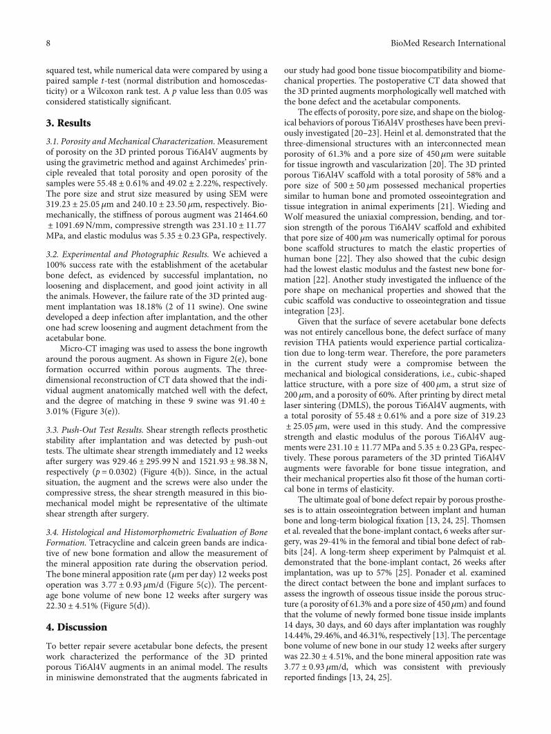
squared test, while numerical data were compared by using apaired sample t-test (normal distribution and homoscedas-ticity) or a Wilcoxon rank test. A p value less than 0.05 wasconsidered statistically significant.
3. Results
3.1. Porosity and Mechanical Characterization.Measurementof porosity on the 3D printed porous Ti6Al4V augments byusing the gravimetric method and against Archimedes’ prin-ciple revealed that total porosity and open porosity of thesamples were 55:48 ± 0:61% and 49:02 ± 2:22%, respectively.The pore size and strut size measured by using SEM were319:23 ± 25:05 μm and 240:10 ± 23:50μm, respectively. Bio-mechanically, the stiffness of porous augment was 21464:60± 1091:69N/mm, compressive strength was 231:10 ± 11:77MPa, and elastic modulus was 5:35 ± 0:23GPa, respectively.
3.2. Experimental and Photographic Results. We achieved a100% success rate with the establishment of the acetabularbone defect, as evidenced by successful implantation, noloosening and displacement, and good joint activity in allthe animals. However, the failure rate of the 3D printed aug-ment implantation was 18.18% (2 of 11 swine). One swinedeveloped a deep infection after implantation, and the otherone had screw loosening and augment detachment from theacetabular bone.
Micro-CT imaging was used to assess the bone ingrowtharound the porous augment. As shown in Figure 2(e), boneformation occurred within porous augments. The three-dimensional reconstruction of CT data showed that the indi-vidual augment anatomically matched well with the defect,and the degree of matching in these 9 swine was 91:40 ±3:01% (Figure 3(e)).
3.3. Push-Out Test Results. Shear strength reflects prostheticstability after implantation and was detected by push-outtests. The ultimate shear strength immediately and 12 weeksafter surgery was 929:46 ± 295:99N and 1521:93 ± 98:38N,respectively (p = 0:0302) (Figure 4(b)). Since, in the actualsituation, the augment and the screws were also under thecompressive stress, the shear strength measured in this bio-mechanical model might be representative of the ultimateshear strength after surgery.
3.4. Histological and Histomorphometric Evaluation of BoneFormation. Tetracycline and calcein green bands are indica-tive of new bone formation and allow the measurement ofthe mineral apposition rate during the observation period.The bone mineral apposition rate (μmper day) 12 weeks postoperation was 3:77 ± 0:93 μm/d (Figure 5(c)). The percent-age bone volume of new bone 12 weeks after surgery was22:30 ± 4:51% (Figure 5(d)).
4. Discussion
To better repair severe acetabular bone defects, the presentwork characterized the performance of the 3D printedporous Ti6Al4V augments in an animal model. The resultsin miniswine demonstrated that the augments fabricated in
our study had good bone tissue biocompatibility and biome-chanical properties. The postoperative CT data showed thatthe 3D printed augments morphologically well matched withthe bone defect and the acetabular components.
The effects of porosity, pore size, and shape on the biolog-ical behaviors of porous Ti6Al4V prostheses have been previ-ously investigated [20–23]. Heinl et al. demonstrated that thethree-dimensional structures with an interconnected meanporosity of 61.3% and a pore size of 450μm were suitablefor tissue ingrowth and vascularization [20]. The 3D printedporous Ti6Al4V scaffold with a total porosity of 58% and apore size of 500 ± 50 μm possessed mechanical propertiessimilar to human bone and promoted osseointegration andtissue integration in animal experiments [21]. Wieding andWolf measured the uniaxial compression, bending, and tor-sion strength of the porous Ti6Al4V scaffold and exhibitedthat pore size of 400μm was numerically optimal for porousbone scaffold structures to match the elastic properties ofhuman bone [22]. They also showed that the cubic designhad the lowest elastic modulus and the fastest new bone for-mation [22]. Another study investigated the influence of thepore shape on mechanical properties and showed that thecubic scaffold was conductive to osseointegration and tissueintegration [23].
Given that the surface of severe acetabular bone defectswas not entirely cancellous bone, the defect surface of manyrevision THA patients would experience partial corticaliza-tion due to long-term wear. Therefore, the pore parametersin the current study were a compromise between themechanical and biological considerations, i.e., cubic-shapedlattice structure, with a pore size of 400μm, a strut size of200μm, and a porosity of 60%. After printing by direct metallaser sintering (DMLS), the porous Ti6Al4V augments, witha total porosity of 55:48 ± 0:61% and a pore size of 319:23± 25:05 μm, were used in this study. And the compressivestrength and elastic modulus of the porous Ti6Al4V aug-ments were 231:10 ± 11:77MPa and 5:35 ± 0:23GPa, respec-tively. These porous parameters of the 3D printed Ti6Al4Vaugments were favorable for bone tissue integration, andtheir mechanical properties also fit those of the human corti-cal bone in terms of elasticity.
The ultimate goal of bone defect repair by porous prosthe-ses is to attain osseointegration between implant and humanbone and long-term biological fixation [13, 24, 25]. Thomsenet al. revealed that the bone-implant contact, 6 weeks after sur-gery, was 29-41% in the femoral and tibial bone defect of rab-bits [24]. A long-term sheep experiment by Palmquist et al.demonstrated that the bone-implant contact, 26 weeks afterimplantation, was up to 57% [25]. Ponader et al. examinedthe direct contact between the bone and implant surfaces toassess the ingrowth of osseous tissue inside the porous struc-ture (a porosity of 61.3% and a pore size of 450μm) and foundthat the volume of newly formed bone tissue inside implants14 days, 30 days, and 60 days after implantation was roughly14.44%, 29.46%, and 46.31%, respectively [13]. The percentagebone volume of new bone in our study 12 weeks after surgerywas 22:30 ± 4:51%, and the bone mineral apposition rate was3:77 ± 0:93μm/d, which was consistent with previouslyreported findings [13, 24, 25].
8 BioMed Research International
The ultimate shear strength and the minimum load thatseparates bone from the augment are effective indicators ofstability of the implanted augment, since they objectivelyreflect the adhesive strength between the augment and thenewly formed bone tissues. The ultimate shear strengthin our study immediately and 12 weeks after surgery was929:46 ± 295:99N and 1521:93 ± 98:38N (p = 0:0302),respectively. The body weight of the miniswine in ourstudy was 25-30 kg, while the mean shear strength immedi-ately after surgery was 929.46N (approximately 90 kg bodyweight), which was three times the body weight of a minis-wine. Consequently, the immediate stability between thebone and the augment sufficed to support the daily activityof miniswine. As to the volume of newly formed bone insidethe porous augment, the shear strength increased to1521.93N 12 weeks after the operation.
These results suggested that the 3D printed porousTi6Al4V augments fabricated in this study had good bonetissue biocompatibility and biomechanical properties. Inaddition, our previous study on the finite element analysisalso indicated that the periacetabular bone strength wasadequate to support the patients’ single-legged standingimmediately after surgery [17]. Moreover, the postoperativethree-dimensional reconstruction of CT data showed thatthe porous augment anatomically matched well with theacetabular bone defect.
This study had several limitations. First, only one type ofacetabular bone defect (Paprosky IIB) was created in the cur-rent animal experiments. The Paprosky IIB type bone defectonly represents the injury of the dome region of the acetabu-lum with the biggest shear strength, when compared to othertypes of acetabular bone defects. Second, the uncontrollednature of the study prevented us from proving the advantagesof the 3D printed porous Ti6Al4V augments over other alter-natives. However, the positive results in both the animalmodels made us believe that the 3D printed porous Ti6Al4Vaugment is an effective choice for managing severe acetabularbone defects.
In summary, the 3D printed porous Ti6Al4V augmentpresented good bone tissue biocompatibility and biomechan-ical properties in our animal model. These augments ana-tomically well matched with the defect bone. Therefore, the3D printed porous Ti6Al4V augment possesses great poten-tial as an alternative for individualized treatment of severeacetabular bone defects.
Data Availability
The datasets used and/or analyzed during the current studyare available from the corresponding authors on reasonablerequest.
Ethical Approval
The study was approved by the Medical Ethics Committee ofthe General Hospital of Chinese People’s Liberation Armyand performed in accordance with the ethical standards inthe 1964 Declaration of Helsinki.
Disclosure
The manuscript submitted does not contain informationabout medical device(s)/drug(s).
Conflicts of Interest
The authors declare no conflict of interest.
Authors’ Contributions
Jun Fu, Yi Xiang, and Ming Ni have contributed equally tothis work and are the co-first authors. All authors have readthe journal’s authorship agreement.
Acknowledgments
We are indebted to Shenzhen Institutes of Advanced Tech-nology (Chinese Academy of Sciences), Orthopaedic Labo-ratory of Beijing Jishuitan Hospital, and Naton Institute ofMedical Technology, for their assistance in the histopatho-logic preparation, micro-CT scan, and the porous Ti6Al4Vaugment fabrication in this study. This project was sup-ported by grants from the National Key Research andDevelopment Program of China (Nos. 2020YFC2004900and 2017YFB1104100) and the Military Medical andHealth Achievements Expansion Project (19WKS09).
References
[1] S. Kurtz, K. Ong, E. Lau, F. Mowat, and M. Halpern, “Projec-tions of primary and revision hip and knee arthroplasty inthe United States from 2005 to 2030,” The Journal of Boneand Joint Surgery-American Volume, vol. 89, no. 4, pp. 780–785, 2007.
[2] W. Y. Shon, S. S. Santhanam, and J. W. Choi, “Acetabularreconstruction in total hip arthroplasty,” Hip & Pelvis,vol. 28, no. 1, pp. 1–14, 2016.
[3] J. M. Cuckler, “Management strategies for acetabular defects inrevision total hip arthroplasty,” The Journal of Arthroplasty,vol. 17, no. 4, pp. 153–156, 2002.
[4] M. Fernandez-Fairen, A. Murcia, A. Blanco, A. Merono,A. Murcia Jr., and J. Ballester, “Revision of failed total hiparthroplasty acetabular cups to porous tantalum components:a 5-year follow-up study,” The Journal of Arthroplasty, vol. 25,no. 6, pp. 865–872, 2010.
[5] S. M. Sporer and W. G. Paprosky, “The use of a trabecularmetal acetabular component and trabecular metal augmentfor severe acetabular defects,” The Journal of Arthroplasty,vol. 21, no. 6, pp. 83–86, 2006.
[6] M. R. Whitehouse, B. A. Masri, C. P. Duncan, and D. S.Garbuz, “Continued good results with modular trabecularmetal augments for acetabular defects in hip arthroplasty at 7to 11 years,” Clinical Orthopaedics and Related Research,vol. 473, no. 2, pp. 521–527, 2015.
[7] V. Swaminathan and J. L. Gilbert, “Fretting corrosion ofCoCrMo and Ti6Al4V interfaces,” Biomaterials, vol. 33,no. 22, pp. 5487–5503, 2012.
[8] J. Li, W. Li, Z. Li et al., “In vitroandin vivoevaluations of thefully porous Ti6Al4V acetabular cups fabricated by a sinteringtechnique,” RSC Advances, vol. 9, no. 12, pp. 6724–6732, 2019.
9BioMed Research International
[9] B. Zhang, X. Pei, C. Zhou et al., “The biomimetic design and3D printing of customized mechanical properties porousTi6Al4V scaffold for load-bearing bone reconstruction,”Mate-rials & Design, vol. 152, pp. 30–39, 2018.
[10] S. Kujala, J. Ryhänen, A. Danilov, and J. Tuukkanen, “Effect ofporosity on the osteointegration and bone ingrowth of aweight-bearing nickel–titanium bone graft substitute,” Bioma-terials, vol. 24, no. 25, pp. 4691–4697, 2003.
[11] J. Wang, M. Yang, Y. Zhu, L. Wang, A. P. Tomsia, and C. Mao,“Phage nanofibers induce vascularized osteogenesis in 3Dprinted bone scaffolds,” Advanced Materials, vol. 26, no. 29,pp. 4961–4966, 2014.
[12] S. M. Kalantari, H. Arabi, S. Mirdamadi, and S. A. Mirsalehi,“Biocompatibility and compressive properties of Ti-6Al-4Vscaffolds having Mg element,” Journal of the MechanicalBehavior of Biomedical Materials, vol. 48, pp. 183–191, 2015.
[13] S. Ponader, C. Von Wilmowsky, M. Widenmayer et al., “Invivo performance of selective electron beam-melted Ti-6Al-4V structures,” Journal of Biomedical Materials Research PartA, vol. 92, no. 1, pp. 56–62, 2010.
[14] R. Ramakrishnaiah, A. A. al kheraif, A. Mohammad et al.,“Preliminary fabrication and characterization of electron beammelted Ti-6Al-4V customized dental implant,” Saudi Journalof Biological Sciences, vol. 24, no. 4, pp. 787–796, 2017.
[15] P. Honigmann, N. Sharma, B. Okolo, U. Popp, B. Msallem,and F. M. Thieringer, “Patient-specific surgical implants madeof 3D printed PEEK: material, technology, and scope of surgi-cal application,” BioMed Research International, vol. 2018,Article ID 4520636, 8 pages, 2018.
[16] H. Lal and M. K. Patralekh, “3D printing and its applicationsin orthopaedic trauma: a technological marvel,” Journal ofClinical Orthopaedics and Trauma, vol. 9, no. 3, pp. 260–268,2018.
[17] J. Fu, M. Ni, J. Chen et al., “Reconstruction of severe acetabularbone defect with 3D printed Ti6Al4V augment: a finite ele-ment study,” BioMed Research International, vol. 2018, ArticleID 6367203, 8 pages, 2018.
[18] A. C. Smith and M. M. Swindle, “Preparation of swine for thelaboratory,” ILAR Journal, vol. 47, no. 4, pp. 358–363, 2006.
[19] W. G. Paprosky, P. G. Perona, and J. M. Lawrence, “Acetabulardefect classification and surgical reconstruction in revisionarthroplasty: a 6-year follow-up evaluation,” The Journal ofArthroplasty, vol. 9, no. 1, pp. 33–44, 1994.
[20] P. Heinl, L. Muller, C. Korner, R. F. Singer, and F. A. Muller,“Cellular Ti–6Al–4V structures with interconnected macroporosity for bone implants fabricated by selective electronbeam melting,” Acta Biomaterialia, vol. 4, no. 5, pp. 1536–1544, 2008.
[21] P. K. Srivas, K. Kapat, P. Dadhich et al., “Osseointegrationassessment of extrusion printed Ti6Al4V scaffold towardsaccelerated skeletal defect healing via tissue in-growth,” Bio-printing, vol. 6, pp. 8–17, 2017.
[22] J. Wieding, A. Wolf, and R. Bader, “Numerical optimization ofopen-porous bone scaffold structures to match the elasticproperties of human cortical bone,” Journal of the MechanicalBehavior of Biomedical Materials, vol. 37, pp. 56–68, 2014.
[23] M. Schumacher, U. Deisinger, R. Detsch, and G. Ziegler,“Indirect rapid prototyping of biphasic calcium phosphatescaffolds as bone substitutes: influence of phase composi-tion, macroporosity and pore geometry on mechanical
properties,” Journal of Materials Science: Materials in Medi-cine, vol. 21, no. 12, pp. 3119–3127, 2010.
[24] P. Thomsen, J. Malmström, L. Emanuelsson, M. Rene, andA. Snis, “Electron beam-melted, free-form-fabricated titaniumalloy implants: material surface characterization and earlybone response in rabbits,” Journal of Biomedical MaterialsResearch Part B: Applied Biomaterials, vol. 90, no. 1, pp. 35–44, 2009.
[25] A. Palmquist, A. Snis, L. Emanuelsson, M. Browne, andP. Thomsen, “Long-term biocompatibility and osseointegra-tion of electron beam melted, free-form-fabricated solid andporous titanium alloy: experimental studies in sheep,” Journalof Biomaterials Applications, vol. 27, pp. 1003–1016, 2013.
10 BioMed Research International
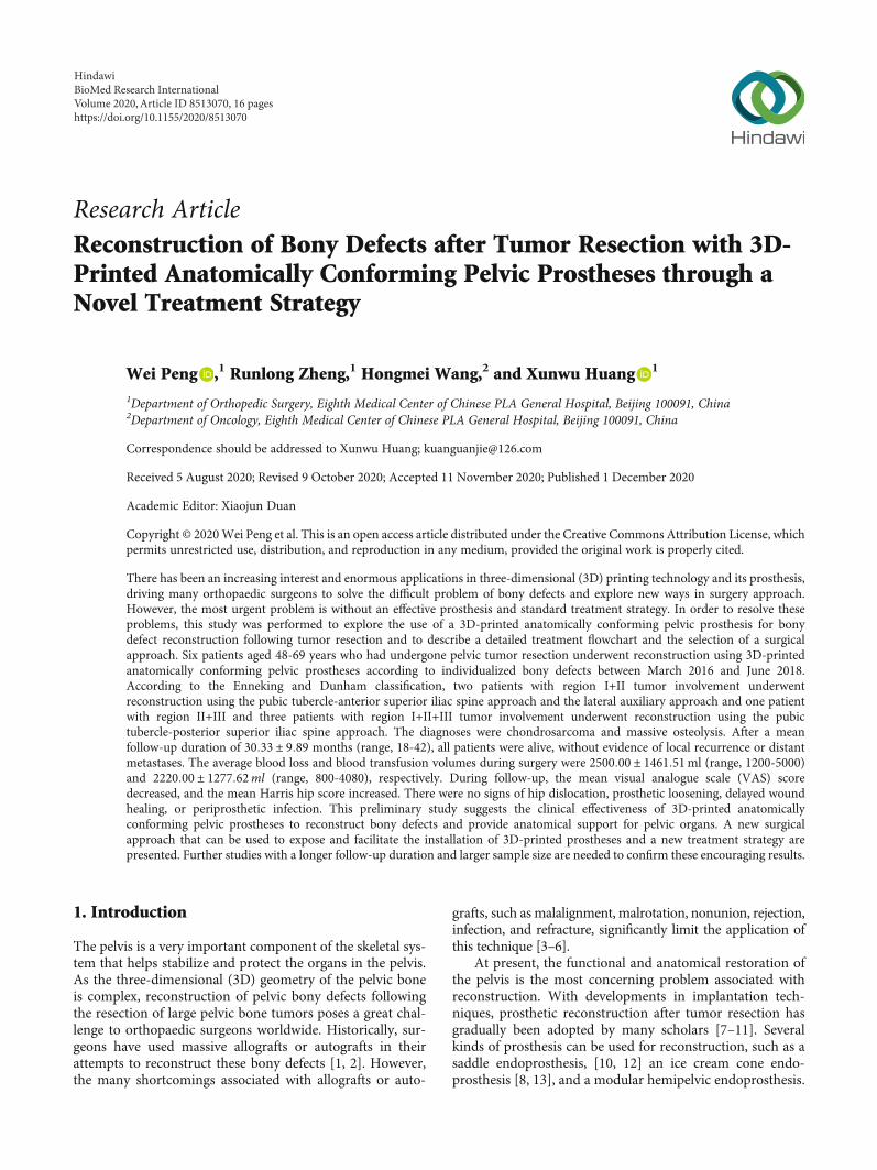
Research ArticleReconstruction of Bony Defects after Tumor Resection with 3D-Printed Anatomically Conforming Pelvic Prostheses through aNovel Treatment Strategy
Wei Peng ,1 Runlong Zheng,1 Hongmei Wang,2 and Xunwu Huang 1
1Department of Orthopedic Surgery, Eighth Medical Center of Chinese PLA General Hospital, Beijing 100091, China2Department of Oncology, Eighth Medical Center of Chinese PLA General Hospital, Beijing 100091, China
Correspondence should be addressed to Xunwu Huang; [email protected]
Received 5 August 2020; Revised 9 October 2020; Accepted 11 November 2020; Published 1 December 2020
Academic Editor: Xiaojun Duan
Copyright © 2020Wei Peng et al. This is an open access article distributed under the Creative Commons Attribution License, whichpermits unrestricted use, distribution, and reproduction in any medium, provided the original work is properly cited.
There has been an increasing interest and enormous applications in three-dimensional (3D) printing technology and its prosthesis,driving many orthopaedic surgeons to solve the difficult problem of bony defects and explore new ways in surgery approach.However, the most urgent problem is without an effective prosthesis and standard treatment strategy. In order to resolve theseproblems, this study was performed to explore the use of a 3D-printed anatomically conforming pelvic prosthesis for bonydefect reconstruction following tumor resection and to describe a detailed treatment flowchart and the selection of a surgicalapproach. Six patients aged 48-69 years who had undergone pelvic tumor resection underwent reconstruction using 3D-printedanatomically conforming pelvic prostheses according to individualized bony defects between March 2016 and June 2018.According to the Enneking and Dunham classification, two patients with region I+II tumor involvement underwentreconstruction using the pubic tubercle-anterior superior iliac spine approach and the lateral auxiliary approach and one patientwith region II+III and three patients with region I+II+III tumor involvement underwent reconstruction using the pubictubercle-posterior superior iliac spine approach. The diagnoses were chondrosarcoma and massive osteolysis. After a meanfollow-up duration of 30:33 ± 9:89 months (range, 18-42), all patients were alive, without evidence of local recurrence or distantmetastases. The average blood loss and blood transfusion volumes during surgery were 2500:00 ± 1461:51ml (range, 1200-5000)and 2220:00 ± 1277:62ml (range, 800-4080), respectively. During follow-up, the mean visual analogue scale (VAS) scoredecreased, and the mean Harris hip score increased. There were no signs of hip dislocation, prosthetic loosening, delayed woundhealing, or periprosthetic infection. This preliminary study suggests the clinical effectiveness of 3D-printed anatomicallyconforming pelvic prostheses to reconstruct bony defects and provide anatomical support for pelvic organs. A new surgicalapproach that can be used to expose and facilitate the installation of 3D-printed prostheses and a new treatment strategy arepresented. Further studies with a longer follow-up duration and larger sample size are needed to confirm these encouraging results.
1. Introduction
The pelvis is a very important component of the skeletal sys-tem that helps stabilize and protect the organs in the pelvis.As the three-dimensional (3D) geometry of the pelvic boneis complex, reconstruction of pelvic bony defects followingthe resection of large pelvic bone tumors poses a great chal-lenge to orthopaedic surgeons worldwide. Historically, sur-geons have used massive allografts or autografts in theirattempts to reconstruct these bony defects [1, 2]. However,the many shortcomings associated with allografts or auto-
grafts, such as malalignment, malrotation, nonunion, rejection,infection, and refracture, significantly limit the application ofthis technique [3–6].
At present, the functional and anatomical restoration ofthe pelvis is the most concerning problem associated withreconstruction. With developments in implantation tech-niques, prosthetic reconstruction after tumor resection hasgradually been adopted by many scholars [7–11]. Severalkinds of prosthesis can be used for reconstruction, such as asaddle endoprosthesis, [10, 12] an ice cream cone endo-prosthesis [8, 13], and a modular hemipelvic endoprosthesis.
HindawiBioMed Research InternationalVolume 2020, Article ID 8513070, 16 pageshttps://doi.org/10.1155/2020/8513070
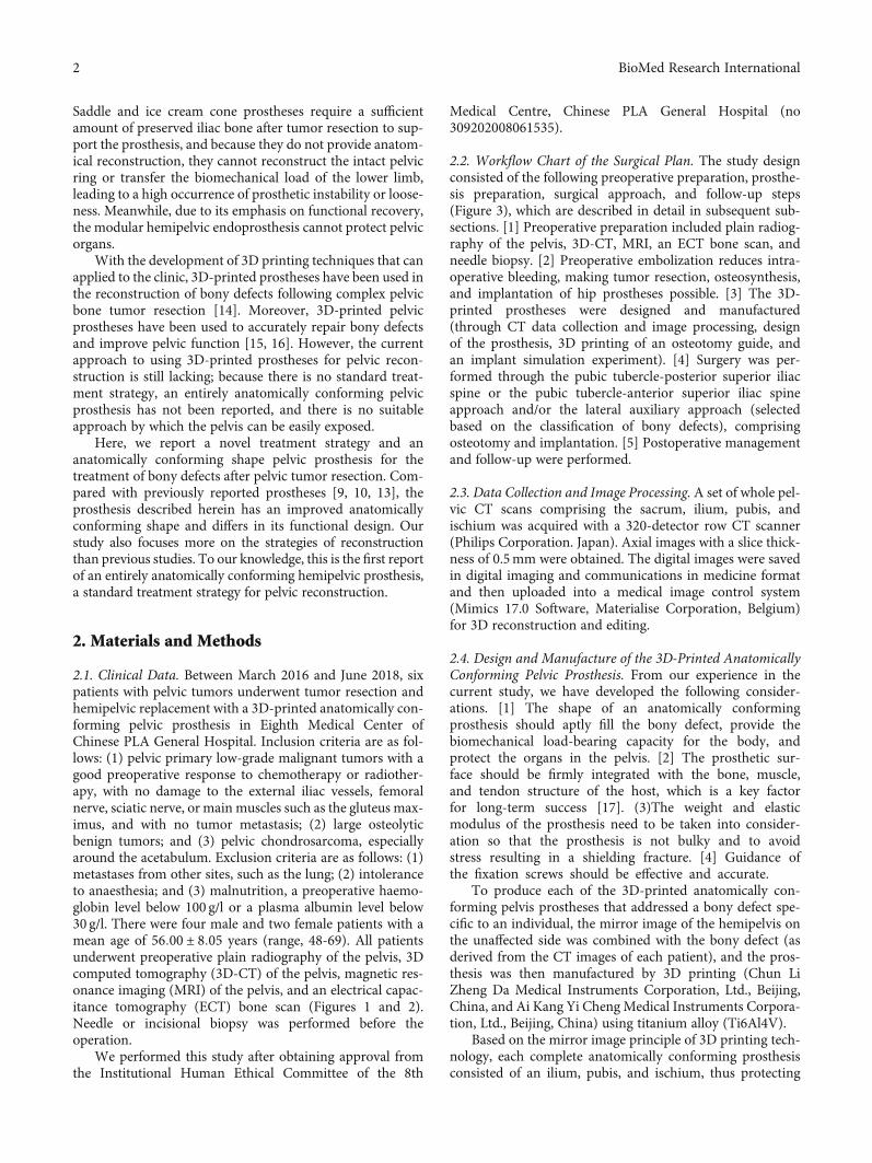
Saddle and ice cream cone prostheses require a sufficientamount of preserved iliac bone after tumor resection to sup-port the prosthesis, and because they do not provide anatom-ical reconstruction, they cannot reconstruct the intact pelvicring or transfer the biomechanical load of the lower limb,leading to a high occurrence of prosthetic instability or loose-ness. Meanwhile, due to its emphasis on functional recovery,the modular hemipelvic endoprosthesis cannot protect pelvicorgans.
With the development of 3D printing techniques that canapplied to the clinic, 3D-printed prostheses have been used inthe reconstruction of bony defects following complex pelvicbone tumor resection [14]. Moreover, 3D-printed pelvicprostheses have been used to accurately repair bony defectsand improve pelvic function [15, 16]. However, the currentapproach to using 3D-printed prostheses for pelvic recon-struction is still lacking; because there is no standard treat-ment strategy, an entirely anatomically conforming pelvicprosthesis has not been reported, and there is no suitableapproach by which the pelvis can be easily exposed.
Here, we report a novel treatment strategy and ananatomically conforming shape pelvic prosthesis for thetreatment of bony defects after pelvic tumor resection. Com-pared with previously reported prostheses [9, 10, 13], theprosthesis described herein has an improved anatomicallyconforming shape and differs in its functional design. Ourstudy also focuses more on the strategies of reconstructionthan previous studies. To our knowledge, this is the first reportof an entirely anatomically conforming hemipelvic prosthesis,a standard treatment strategy for pelvic reconstruction.
2. Materials and Methods
2.1. Clinical Data. Between March 2016 and June 2018, sixpatients with pelvic tumors underwent tumor resection andhemipelvic replacement with a 3D-printed anatomically con-forming pelvic prosthesis in Eighth Medical Center ofChinese PLA General Hospital. Inclusion criteria are as fol-lows: (1) pelvic primary low-grade malignant tumors with agood preoperative response to chemotherapy or radiother-apy, with no damage to the external iliac vessels, femoralnerve, sciatic nerve, or main muscles such as the gluteus max-imus, and with no tumor metastasis; (2) large osteolyticbenign tumors; and (3) pelvic chondrosarcoma, especiallyaround the acetabulum. Exclusion criteria are as follows: (1)metastases from other sites, such as the lung; (2) intoleranceto anaesthesia; and (3) malnutrition, a preoperative haemo-globin level below 100 g/l or a plasma albumin level below30 g/l. There were four male and two female patients with amean age of 56:00 ± 8:05 years (range, 48-69). All patientsunderwent preoperative plain radiography of the pelvis, 3Dcomputed tomography (3D-CT) of the pelvis, magnetic res-onance imaging (MRI) of the pelvis, and an electrical capac-itance tomography (ECT) bone scan (Figures 1 and 2).Needle or incisional biopsy was performed before theoperation.
We performed this study after obtaining approval fromthe Institutional Human Ethical Committee of the 8th
Medical Centre, Chinese PLA General Hospital (no309202008061535).
2.2. Workflow Chart of the Surgical Plan. The study designconsisted of the following preoperative preparation, prosthe-sis preparation, surgical approach, and follow-up steps(Figure 3), which are described in detail in subsequent sub-sections. [1] Preoperative preparation included plain radiog-raphy of the pelvis, 3D-CT, MRI, an ECT bone scan, andneedle biopsy. [2] Preoperative embolization reduces intra-operative bleeding, making tumor resection, osteosynthesis,and implantation of hip prostheses possible. [3] The 3D-printed prostheses were designed and manufactured(through CT data collection and image processing, designof the prosthesis, 3D printing of an osteotomy guide, andan implant simulation experiment). [4] Surgery was per-formed through the pubic tubercle-posterior superior iliacspine or the pubic tubercle-anterior superior iliac spineapproach and/or the lateral auxiliary approach (selectedbased on the classification of bony defects), comprisingosteotomy and implantation. [5] Postoperative managementand follow-up were performed.
2.3. Data Collection and Image Processing. A set of whole pel-vic CT scans comprising the sacrum, ilium, pubis, andischium was acquired with a 320-detector row CT scanner(Philips Corporation. Japan). Axial images with a slice thick-ness of 0.5mm were obtained. The digital images were savedin digital imaging and communications in medicine formatand then uploaded into a medical image control system(Mimics 17.0 Software, Materialise Corporation, Belgium)for 3D reconstruction and editing.
2.4. Design and Manufacture of the 3D-Printed AnatomicallyConforming Pelvic Prosthesis. From our experience in thecurrent study, we have developed the following consider-ations. [1] The shape of an anatomically conformingprosthesis should aptly fill the bony defect, provide thebiomechanical load-bearing capacity for the body, andprotect the organs in the pelvis. [2] The prosthetic sur-face should be firmly integrated with the bone, muscle,and tendon structure of the host, which is a key factorfor long-term success [17]. (3)The weight and elasticmodulus of the prosthesis need to be taken into consider-ation so that the prosthesis is not bulky and to avoidstress resulting in a shielding fracture. [4] Guidance ofthe fixation screws should be effective and accurate.
To produce each of the 3D-printed anatomically con-forming pelvis prostheses that addressed a bony defect spe-cific to an individual, the mirror image of the hemipelvis onthe unaffected side was combined with the bony defect (asderived from the CT images of each patient), and the pros-thesis was then manufactured by 3D printing (Chun LiZheng Da Medical Instruments Corporation, Ltd., Beijing,China, and Ai Kang Yi Cheng Medical Instruments Corpora-tion, Ltd., Beijing, China) using titanium alloy (Ti6Al4V).
Based on the mirror image principle of 3D printing tech-nology, each complete anatomically conforming prosthesisconsisted of an ilium, pubis, and ischium, thus protecting
2 BioMed Research International
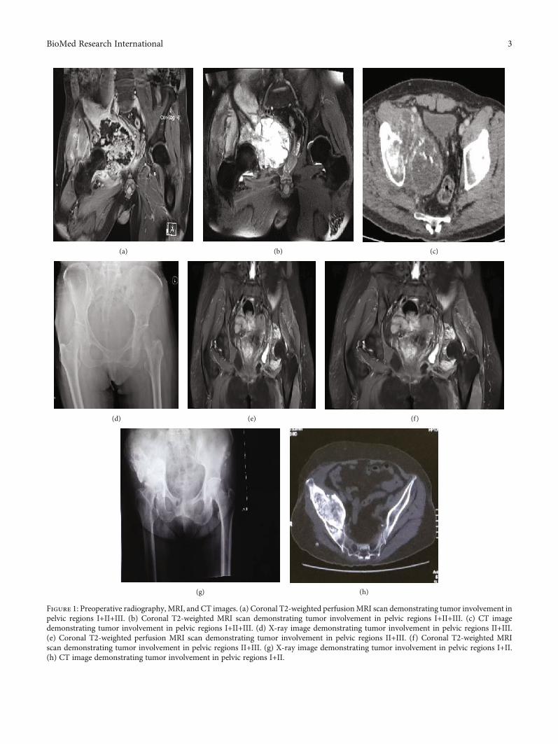
(a) (b) (c)
(d) (e) (f)
(g) (h)
Figure 1: Preoperative radiography, MRI, and CT images. (a) Coronal T2-weighted perfusionMRI scan demonstrating tumor involvement inpelvic regions I+II+III. (b) Coronal T2-weighted MRI scan demonstrating tumor involvement in pelvic regions I+II+III. (c) CT imagedemonstrating tumor involvement in pelvic regions I+II+III. (d) X-ray image demonstrating tumor involvement in pelvic regions II+III.(e) Coronal T2-weighted perfusion MRI scan demonstrating tumor involvement in pelvic regions II+III. (f) Coronal T2-weighted MRIscan demonstrating tumor involvement in pelvic regions II+III. (g) X-ray image demonstrating tumor involvement in pelvic regions I+II.(h) CT image demonstrating tumor involvement in pelvic regions I+II.
3BioMed Research International
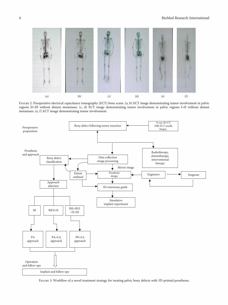
Bony defectclassification
Data collectionimage processing
Radiotherapy,chemotherapy,interventional
therapy
Approachselection
Extentoutlined
Engineers Surgeons
3D osteotomy guide
Simulativeimplant experiment
RI RII/I+II RII+III/I+II+III
PAapproach
PA+LAapproach
PP+LAapproach
Implant and follow-ups
Prosthesisdesign
Mirror image
Prosthesisand approach
Operationand follow-ups
Bony defect following tumor resectionX-ray 3D-CT
MRI ECT needlebiopsy Preoperative
preparation
Figure 3: Workflow of a novel treatment strategy for treating pelvic bony defects with 3D-printed prostheses.
(a) (b) (c) (d) (e) (f)
Figure 2: Preoperative electrical capacitance tomography (ECT) bone scans. (a, b) ECT image demonstrating tumor involvement in pelvicregions II+III without distant metastases. (c, d) ECT image demonstrating tumor involvement in pelvic regions I+II without distantmetastases. (e, f) ECT image demonstrating tumor involvement.
4 BioMed Research International
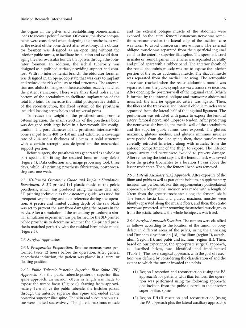
the organs in the pelvis and reestablishing biomechanicalloads to recover pelvic function. Of course, the above compo-nents were considered when designing the prosthesis, as wellas the extent of the bone defect after osteotomy. The obtura-tor foramen was designed as an open ring without theinferior pubic ramus, to facilitate installation and avoid dam-aging the neurovascular bundle that passes through the obtu-rator foramen. In addition, the ischial tuberosity wasdesigned as a polished surface, providing support and com-fort. With no inferior ischial branch, the obturator foramenwas designed in an open-loop state that was easy to implantand reduced the risk of injury to vital structures. The antever-sion and abduction angles of the acetabulum exactly matchedthe patient’s anatomy. There were three fixed holes at thebottom of the acetabulum to facilitate implantation of thetotal hip joint. To increase the initial postoperative stabilityof the reconstruction, the fixed system of the prosthesisincluded locking screw holes and universal pores.
To reduce the weight of the prosthesis and promoteosteointegration, the main structure of the prosthesis bodywas designed with large holes in a honeycomb-like config-uration. The pore diameter of the prosthesis interface withbone ranged from 400 to 450μm and exhibited a coveragerate of 70% and a thickness of 1.5mm. A solid structurewith a certain strength was designed on the mechanicalsupport portion.
Before surgery, the prosthesis was generated as a whole orpart specific for fitting the resected bone or bony defect(Figure 4). Data collection and image processing took threedays, while 3D printing prosthesis fabrication, postproces-sing cost one week.
2.5. 3D-Printed Osteotomy Guide and Implant SimulationExperiment. A 3D-printed 1 : 1 plastic model of the pelvicprosthesis, which was produced using the same data and3D printing technique as the osteotomy guide, was used forpreoperative planning and as a reference during the opera-tion. A precise and limited cutting depth of the saw bladewas set to prevent the saw from damaging the organs in thepelvis. After a simulation of the osteotomy procedure, a sim-ilar simulation experiment was performed for the 3D-printedpelvic prosthesis to determine whether the 3D-printed pros-thesis matched perfectly with the residual hemipelvic model(Figure 5).
2.6. Surgical Approaches
2.6.1. Preoperative Preparation. Routine enemas were per-formed twice 12 hours before the operation. After generalanaesthesia induction, the patient was placed in a lateral orfloating position.
2.6.2. Pubic Tubercle-Posterior Superior Iliac Spine (PP)Approach. For the pubic tubercle-posterior superior iliacspine approach, an incision 60 cm in length was made toexpose the tumor focus (Figure 6). Starting from approxi-mately 1 cm above the pubic tubercle, the incision passedthrough the anterior superior iliac spine and ended at theposterior superior iliac spine. The skin and subcutaneous tis-sue were incised successively. The gluteus maximus muscle
and the external oblique muscle of the abdomen wereexposed. As the lateral femoral cutaneous nerve was some-times encountered at the lateral edge of the incision, carewas taken to avoid unnecessary nerve injury. The externaloblique muscle was separated from the superficial inguinalcanal to the anterior superior iliac spine. The spermatic cordin males or round ligament in females was separated carefullyand pulled apart with a rubber band. The anterior sheath ofthe rectus abdominis muscle was cut to expose the inferiorportion of the rectus abdominis muscle. The iliacus musclewas separated from the medial iliac wing. The retropubicspace was reached when the rectus abdominis muscle wasseparated from the pubic symphysis via a transverse incision.After opening the posterior wall of the inguinal canal (whichis formed by the internal oblique and transverse abdominalmuscles), the inferior epigastric artery was ligated. Then,the fibers of the transverse and internal oblique muscles wereseparated from the lateral half of the inguinal ligament. Theperitoneum was retracted with gauze to expose the femoralartery, femoral nerve, and iliopsoas tendon. After protectingthe neurovascular bundle, the medial wall of the acetabulumand the superior pubic ramus were exposed. The gluteusmaximus, gluteus medius, and gluteus minimus muscleswere peeled from the iliac spine; then, these muscles werecarefully retracted inferiorly along with muscles from theanterior compartment of the thigh to expose. The inferiorgluteal artery and nerve were avoided to prevent damage.After removing the joint capsule, the femoral neck was sawedfrom the greater trochanter to a location 1.5 cm above thelesser trochanter. Then, the femoral head was removed.
2.6.3. Lateral Auxiliary (LA) Approach. After exposure of theilium and pubis as well as part of the ischium, a supplementaryincision was performed. For this supplementary posterolateralapproach, a longitudinal incision was made with a length of20 cm from the greater trochanter along the femoral shaft.The tensor fascia lata and gluteus maximus muscles werebluntly separated along the muscle fibers, and then, the sciaticnerve was protected. After removing the attachedmuscle groupfrom the sciatic tubercle, the whole hemipelvis was freed.
2.6.4. Surgical Approach Selection. The tumors were classifiedas follows according to the location of the tumor or bonydefect in different areas of the pelvis, using the Ennekingand Dunham classification [18]: the ilium (region I), acetab-ulum (region II), and pubis and ischium (region III). Then,based on our experience, the appropriate surgical approach,as described below, was identified and implemented(Table 1). The novel surgical approach, with the goal of resec-tion, was defined by considering the classification of and theextent to which the tumor invaded the pelvis.
(1) Region I resection and reconstruction (using the PAapproach): for patients with iliac tumors, the opera-tion was performed using the following approach:one incision from the pubic tubercle to the anteriorsuperior iliac spine
(2) Region II/I+II resection and reconstruction (usingthe PA approach plus the lateral auxiliary approach):
5BioMed Research International
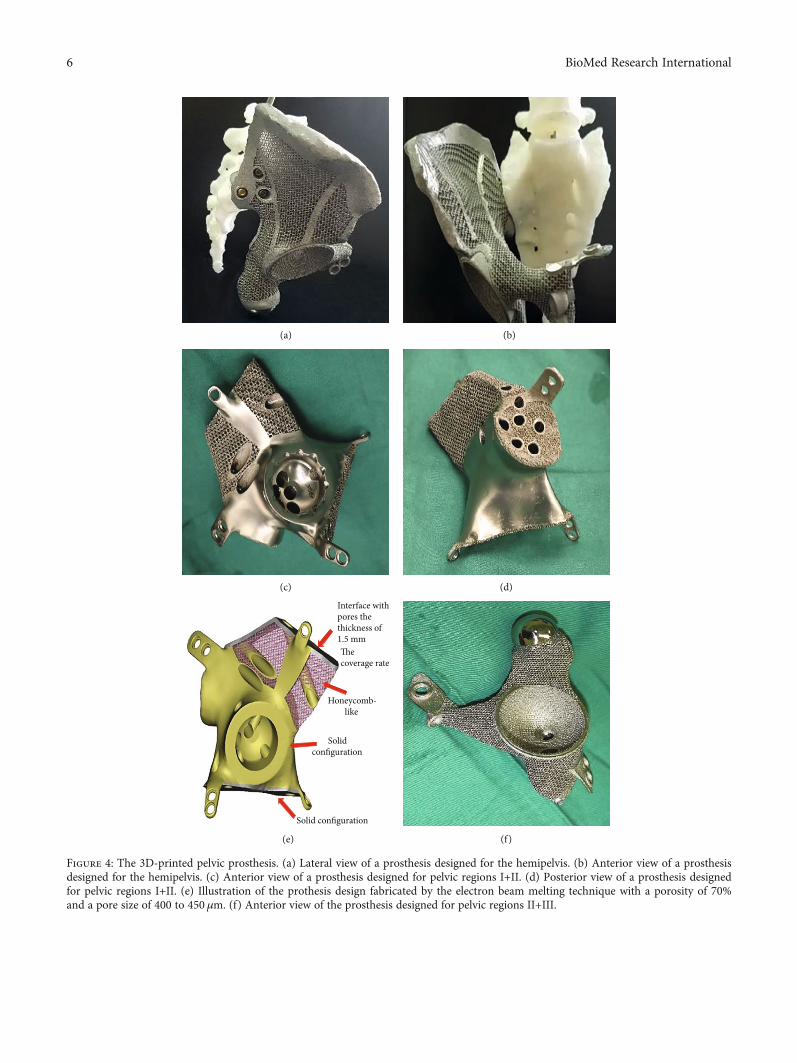
(a) (b)
(c) (d)
Honeycomb-like
Solidconfiguration
Solid configuration
Interface withpores thethickness of1.5 mmThe coverage rate
(e) (f)
Figure 4: The 3D-printed pelvic prosthesis. (a) Lateral view of a prosthesis designed for the hemipelvis. (b) Anterior view of a prosthesisdesigned for the hemipelvis. (c) Anterior view of a prosthesis designed for pelvic regions I+II. (d) Posterior view of a prosthesis designedfor pelvic regions I+II. (e) Illustration of the prothesis design fabricated by the electron beam melting technique with a porosity of 70%and a pore size of 400 to 450 μm. (f) Anterior view of the prosthesis designed for pelvic regions II+III.
6 BioMed Research International
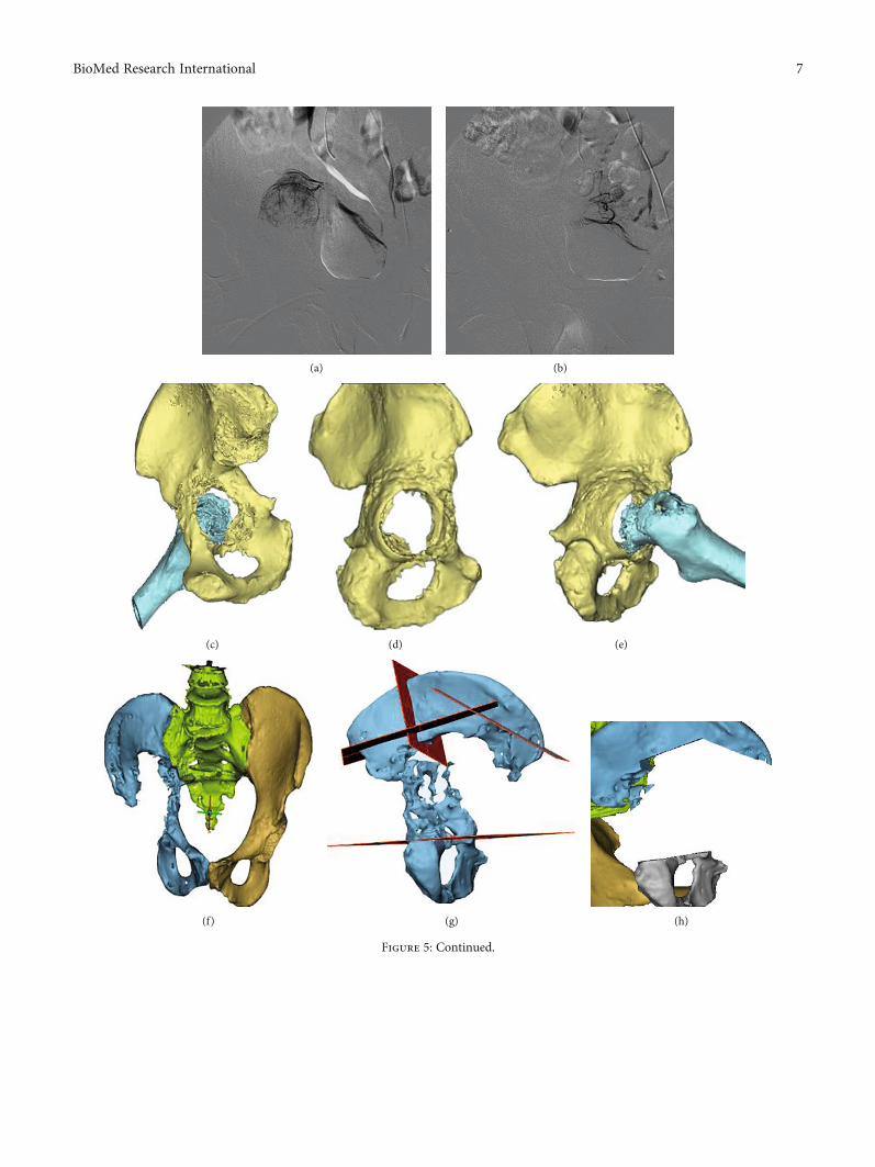
(a) (b)
(c) (d) (e)
(f) (g) (h)
Figure 5: Continued.
7BioMed Research International
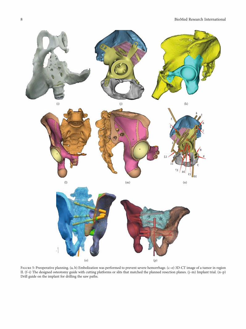
(i) (j) (k)
(l) (m)
4 5
6
7
8
9
151617
11
12
1
2
3
10
3
(n)
(o) (p)
Figure 5: Preoperative planning. (a, b) Embolization was performed to prevent severe hemorrhage. (c–e) 3D-CT image of a tumor in regionII. (f–i) The designed osteotomy guide with cutting platforms or slits that matched the planned resection planes. (j–m) Implant trial. (n–p)Drill guide on the implant for drilling the saw paths.
8 BioMed Research International
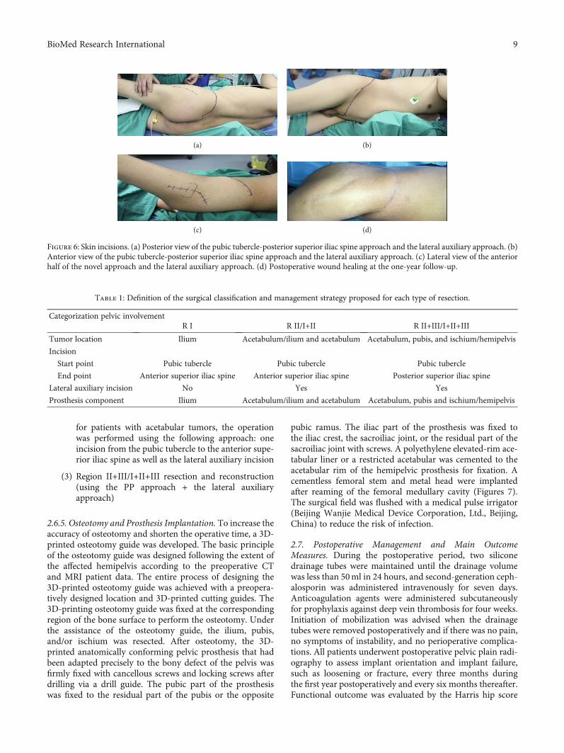
for patients with acetabular tumors, the operationwas performed using the following approach: oneincision from the pubic tubercle to the anterior supe-rior iliac spine as well as the lateral auxiliary incision
(3) Region II+III/I+II+III resection and reconstruction(using the PP approach + the lateral auxiliaryapproach)
2.6.5. Osteotomy and Prosthesis Implantation. To increase theaccuracy of osteotomy and shorten the operative time, a 3D-printed osteotomy guide was developed. The basic principleof the osteotomy guide was designed following the extent ofthe affected hemipelvis according to the preoperative CTand MRI patient data. The entire process of designing the3D-printed osteotomy guide was achieved with a preopera-tively designed location and 3D-printed cutting guides. The3D-printing osteotomy guide was fixed at the correspondingregion of the bone surface to perform the osteotomy. Underthe assistance of the osteotomy guide, the ilium, pubis,and/or ischium was resected. After osteotomy, the 3D-printed anatomically conforming pelvic prosthesis that hadbeen adapted precisely to the bony defect of the pelvis wasfirmly fixed with cancellous screws and locking screws afterdrilling via a drill guide. The pubic part of the prosthesiswas fixed to the residual part of the pubis or the opposite
pubic ramus. The iliac part of the prosthesis was fixed tothe iliac crest, the sacroiliac joint, or the residual part of thesacroiliac joint with screws. A polyethylene elevated-rim ace-tabular liner or a restricted acetabular was cemented to theacetabular rim of the hemipelvic prosthesis for fixation. Acementless femoral stem and metal head were implantedafter reaming of the femoral medullary cavity (Figures 7).The surgical field was flushed with a medical pulse irrigator(Beijing Wanjie Medical Device Corporation, Ltd., Beijing,China) to reduce the risk of infection.
2.7. Postoperative Management and Main OutcomeMeasures. During the postoperative period, two siliconedrainage tubes were maintained until the drainage volumewas less than 50ml in 24 hours, and second-generation ceph-alosporin was administered intravenously for seven days.Anticoagulation agents were administered subcutaneouslyfor prophylaxis against deep vein thrombosis for four weeks.Initiation of mobilization was advised when the drainagetubes were removed postoperatively and if there was no pain,no symptoms of instability, and no perioperative complica-tions. All patients underwent postoperative pelvic plain radi-ography to assess implant orientation and implant failure,such as loosening or fracture, every three months duringthe first year postoperatively and every six months thereafter.Functional outcome was evaluated by the Harris hip score
Table 1: Definition of the surgical classification and management strategy proposed for each type of resection.
Categorization pelvic involvementR I R II/I+II R II+III/I+II+III
Tumor location Ilium Acetabulum/ilium and acetabulum Acetabulum, pubis, and ischium/hemipelvis
Incision
Start point Pubic tubercle Pubic tubercle Pubic tubercle
End point Anterior superior iliac spine Anterior superior iliac spine Posterior superior iliac spine
Lateral auxiliary incision No Yes Yes
Prosthesis component Ilium Acetabulum/ilium and acetabulum Acetabulum, pubis and ischium/hemipelvis
(a) (b)
(c) (d)
Figure 6: Skin incisions. (a) Posterior view of the pubic tubercle-posterior superior iliac spine approach and the lateral auxiliary approach. (b)Anterior view of the pubic tubercle-posterior superior iliac spine approach and the lateral auxiliary approach. (c) Lateral view of the anteriorhalf of the novel approach and the lateral auxiliary approach. (d) Postoperative wound healing at the one-year follow-up.
9BioMed Research International
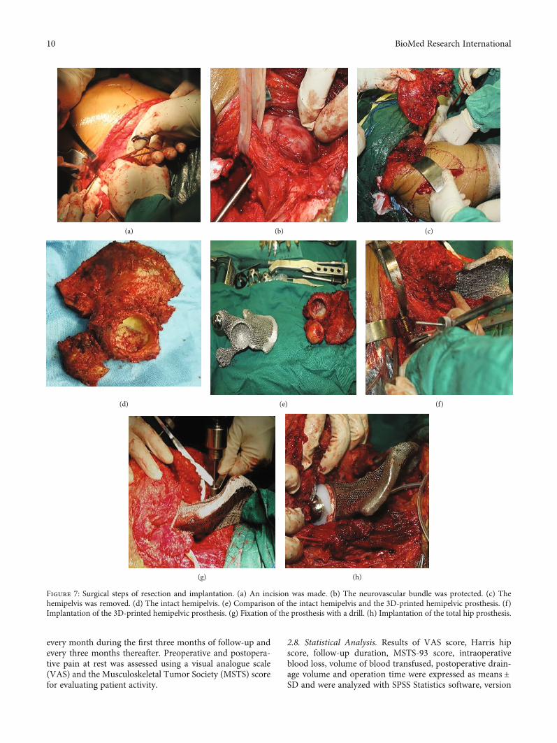
every month during the first three months of follow-up andevery three months thereafter. Preoperative and postopera-tive pain at rest was assessed using a visual analogue scale(VAS) and the Musculoskeletal Tumor Society (MSTS) scorefor evaluating patient activity.
2.8. Statistical Analysis. Results of VAS score, Harris hipscore, follow-up duration, MSTS-93 score, intraoperativeblood loss, volume of blood transfused, postoperative drain-age volume and operation time were expressed as means ±SD and were analyzed with SPSS Statistics software, version
(a) (b) (c)
(d) (e) (f)
(g) (h)
Figure 7: Surgical steps of resection and implantation. (a) An incision was made. (b) The neurovascular bundle was protected. (c) Thehemipelvis was removed. (d) The intact hemipelvis. (e) Comparison of the intact hemipelvis and the 3D-printed hemipelvic prosthesis. (f)Implantation of the 3D-printed hemipelvic prosthesis. (g) Fixation of the prosthesis with a drill. (h) Implantation of the total hip prosthesis.
10 BioMed Research International
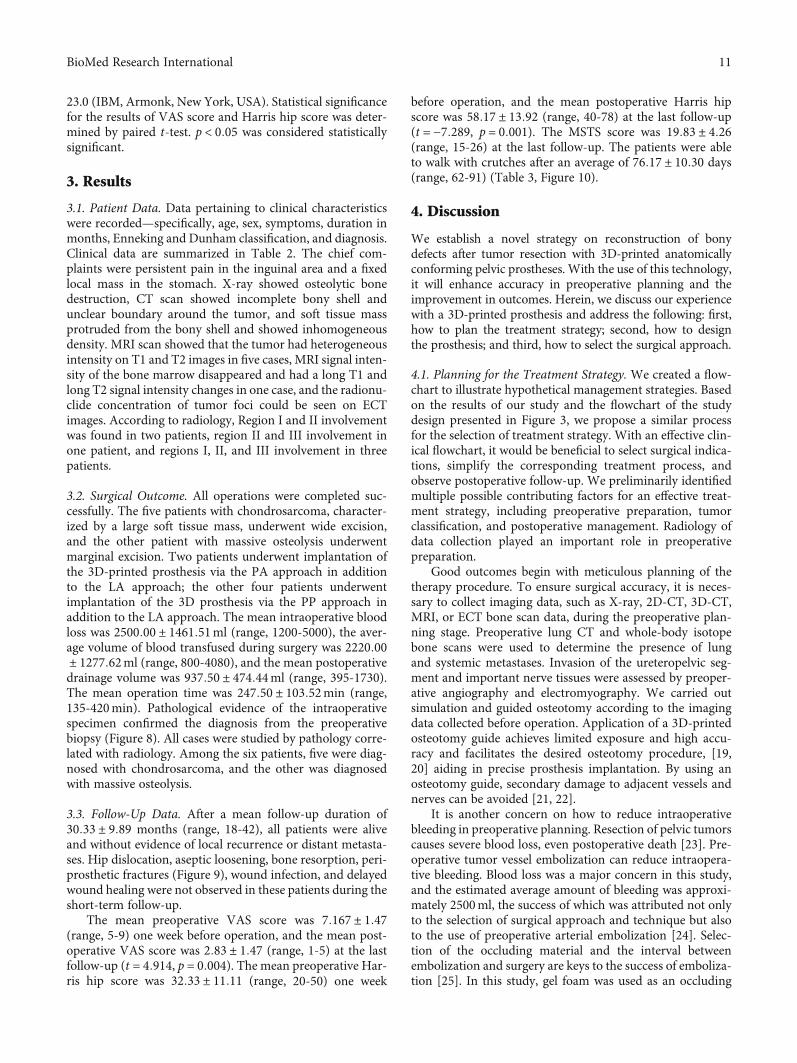
23.0 (IBM, Armonk, New York, USA). Statistical significancefor the results of VAS score and Harris hip score was deter-mined by paired t-test. p < 0:05 was considered statisticallysignificant.
3. Results
3.1. Patient Data. Data pertaining to clinical characteristicswere recorded—specifically, age, sex, symptoms, duration inmonths, Enneking and Dunham classification, and diagnosis.Clinical data are summarized in Table 2. The chief com-plaints were persistent pain in the inguinal area and a fixedlocal mass in the stomach. X-ray showed osteolytic bonedestruction, CT scan showed incomplete bony shell andunclear boundary around the tumor, and soft tissue massprotruded from the bony shell and showed inhomogeneousdensity. MRI scan showed that the tumor had heterogeneousintensity on T1 and T2 images in five cases, MRI signal inten-sity of the bone marrow disappeared and had a long T1 andlong T2 signal intensity changes in one case, and the radionu-clide concentration of tumor foci could be seen on ECTimages. According to radiology, Region I and II involvementwas found in two patients, region II and III involvement inone patient, and regions I, II, and III involvement in threepatients.
3.2. Surgical Outcome. All operations were completed suc-cessfully. The five patients with chondrosarcoma, character-ized by a large soft tissue mass, underwent wide excision,and the other patient with massive osteolysis underwentmarginal excision. Two patients underwent implantation ofthe 3D-printed prosthesis via the PA approach in additionto the LA approach; the other four patients underwentimplantation of the 3D prosthesis via the PP approach inaddition to the LA approach. The mean intraoperative bloodloss was 2500:00 ± 1461:51ml (range, 1200-5000), the aver-age volume of blood transfused during surgery was 2220:00± 1277:62ml (range, 800-4080), and the mean postoperativedrainage volume was 937:50 ± 474:44ml (range, 395-1730).The mean operation time was 247:50 ± 103:52min (range,135-420min). Pathological evidence of the intraoperativespecimen confirmed the diagnosis from the preoperativebiopsy (Figure 8). All cases were studied by pathology corre-lated with radiology. Among the six patients, five were diag-nosed with chondrosarcoma, and the other was diagnosedwith massive osteolysis.
3.3. Follow-Up Data. After a mean follow-up duration of30:33 ± 9:89 months (range, 18-42), all patients were aliveand without evidence of local recurrence or distant metasta-ses. Hip dislocation, aseptic loosening, bone resorption, peri-prosthetic fractures (Figure 9), wound infection, and delayedwound healing were not observed in these patients during theshort-term follow-up.
The mean preoperative VAS score was 7:167 ± 1:47(range, 5-9) one week before operation, and the mean post-operative VAS score was 2:83 ± 1:47 (range, 1-5) at the lastfollow-up (t = 4:914, p = 0:004). The mean preoperative Har-ris hip score was 32:33 ± 11:11 (range, 20-50) one week
before operation, and the mean postoperative Harris hipscore was 58:17 ± 13:92 (range, 40-78) at the last follow-up(t = −7:289, p = 0:001). The MSTS score was 19:83 ± 4:26(range, 15-26) at the last follow-up. The patients were ableto walk with crutches after an average of 76:17 ± 10:30 days(range, 62-91) (Table 3, Figure 10).
4. Discussion
We establish a novel strategy on reconstruction of bonydefects after tumor resection with 3D-printed anatomicallyconforming pelvic prostheses. With the use of this technology,it will enhance accuracy in preoperative planning and theimprovement in outcomes. Herein, we discuss our experiencewith a 3D-printed prosthesis and address the following: first,how to plan the treatment strategy; second, how to designthe prosthesis; and third, how to select the surgical approach.
4.1. Planning for the Treatment Strategy. We created a flow-chart to illustrate hypothetical management strategies. Basedon the results of our study and the flowchart of the studydesign presented in Figure 3, we propose a similar processfor the selection of treatment strategy. With an effective clin-ical flowchart, it would be beneficial to select surgical indica-tions, simplify the corresponding treatment process, andobserve postoperative follow-up. We preliminarily identifiedmultiple possible contributing factors for an effective treat-ment strategy, including preoperative preparation, tumorclassification, and postoperative management. Radiology ofdata collection played an important role in preoperativepreparation.
Good outcomes begin with meticulous planning of thetherapy procedure. To ensure surgical accuracy, it is neces-sary to collect imaging data, such as X-ray, 2D-CT, 3D-CT,MRI, or ECT bone scan data, during the preoperative plan-ning stage. Preoperative lung CT and whole-body isotopebone scans were used to determine the presence of lungand systemic metastases. Invasion of the ureteropelvic seg-ment and important nerve tissues were assessed by preoper-ative angiography and electromyography. We carried outsimulation and guided osteotomy according to the imagingdata collected before operation. Application of a 3D-printedosteotomy guide achieves limited exposure and high accu-racy and facilitates the desired osteotomy procedure, [19,20] aiding in precise prosthesis implantation. By using anosteotomy guide, secondary damage to adjacent vessels andnerves can be avoided [21, 22].
It is another concern on how to reduce intraoperativebleeding in preoperative planning. Resection of pelvic tumorscauses severe blood loss, even postoperative death [23]. Pre-operative tumor vessel embolization can reduce intraopera-tive bleeding. Blood loss was a major concern in this study,and the estimated average amount of bleeding was approxi-mately 2500ml, the success of which was attributed not onlyto the selection of surgical approach and technique but alsoto the use of preoperative arterial embolization [24]. Selec-tion of the occluding material and the interval betweenembolization and surgery are keys to the success of emboliza-tion [25]. In this study, gel foam was used as an occluding
11BioMed Research International
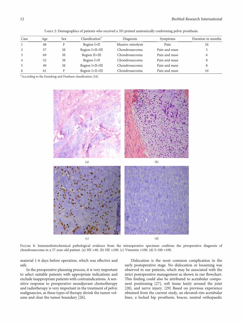
material 1-6 days before operation, which was effective andsafe.
In the preoperative planning process, it is very importantto select suitable patients with appropriate indications andexclude inappropriate patients with contraindications. A sen-sitive response to preoperative neoadjuvant chemotherapyand radiotherapy is very important in the treatment of pelvicmalignancies, as these types of therapy shrink the tumor vol-ume and clear the tumor boundary [26].
Dislocation is the most common complication in theearly postoperative stage. No dislocation or loosening wasobserved in our patients, which may be associated with thestrict postoperative management as shown in our flowchart.This finding could also be attributed to acetabular compo-nent positioning [27], soft tissue laxity around the joint[28], and nerve injury. [29] Based on previous experienceobtained from the current study, an elevated-rim acetabularliner, a locked hip prosthesis, braces, neutral orthopaedic
(a) (b)
(c) (d)
Figure 8: Immunohistochemical pathological evidence from the intraoperative specimen confirms the preoperative diagnosis ofchondrosarcoma in a 57-year-old patient. (a) HE ×40. (b) HE ×100. (c) Vimentin ×100. (d) S-100 ×100.
Table 2: Demographics of patients who received a 3D-printed anatomically conforming pelvic prosthesis.
Case Age Sex Classification※ Diagnosis Symptoms Duration in months
1 48 F Region I+II Massive osteolysis Pain 24
2 57 M Region I+II+III Chondrosarcoma Pain and mass 5
3 69 M Region II+III Chondrosarcoma Pain and mass 6
4 52 M Region I+II Chondrosarcoma Pain and mass 8
5 49 M Region I+II+III Chondrosarcoma Pain and mass 8
6 61 F Region I+II+III Chondrosarcoma Pain and mass 10※According to the Enneking and Dunham classification [18].
12 BioMed Research International
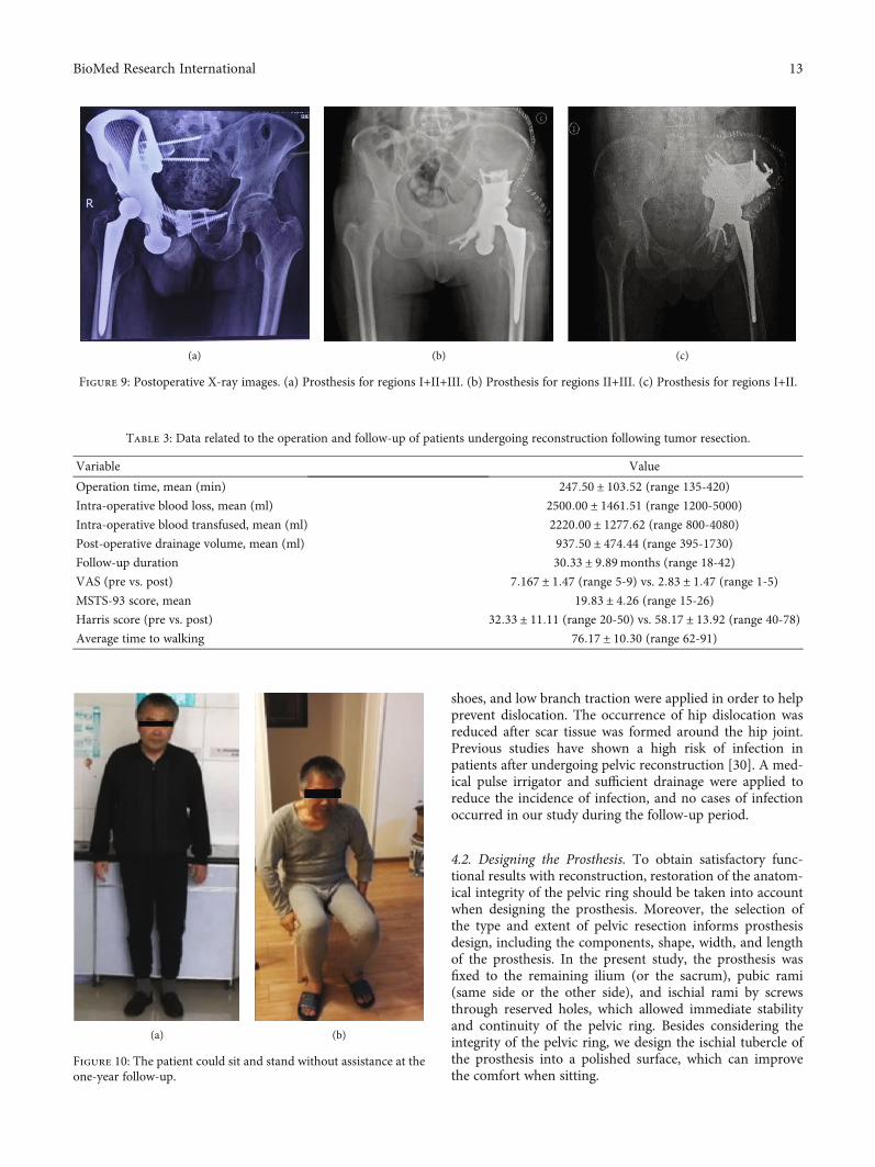
shoes, and low branch traction were applied in order to helpprevent dislocation. The occurrence of hip dislocation wasreduced after scar tissue was formed around the hip joint.Previous studies have shown a high risk of infection inpatients after undergoing pelvic reconstruction [30]. A med-ical pulse irrigator and sufficient drainage were applied toreduce the incidence of infection, and no cases of infectionoccurred in our study during the follow-up period.
4.2. Designing the Prosthesis. To obtain satisfactory func-tional results with reconstruction, restoration of the anatom-ical integrity of the pelvic ring should be taken into accountwhen designing the prosthesis. Moreover, the selection ofthe type and extent of pelvic resection informs prosthesisdesign, including the components, shape, width, and lengthof the prosthesis. In the present study, the prosthesis wasfixed to the remaining ilium (or the sacrum), pubic rami(same side or the other side), and ischial rami by screwsthrough reserved holes, which allowed immediate stabilityand continuity of the pelvic ring. Besides considering theintegrity of the pelvic ring, we design the ischial tubercle ofthe prosthesis into a polished surface, which can improvethe comfort when sitting.
(a) (b) (c)
Figure 9: Postoperative X-ray images. (a) Prosthesis for regions I+II+III. (b) Prosthesis for regions II+III. (c) Prosthesis for regions I+II.
(a) (b)
Figure 10: The patient could sit and stand without assistance at theone-year follow-up.
Table 3: Data related to the operation and follow-up of patients undergoing reconstruction following tumor resection.
Variable Value
Operation time, mean (min) 247:50 ± 103:52 (range 135-420)Intra-operative blood loss, mean (ml) 2500:00 ± 1461:51 (range 1200-5000)Intra-operative blood transfused, mean (ml) 2220:00 ± 1277:62 (range 800-4080)Post-operative drainage volume, mean (ml) 937:50 ± 474:44 (range 395-1730)Follow-up duration 30:33 ± 9:89months (range 18-42)
VAS (pre vs. post) 7:167 ± 1:47 (range 5-9) vs. 2:83 ± 1:47 (range 1-5)MSTS-93 score, mean 19:83 ± 4:26 (range 15-26)Harris score (pre vs. post) 32:33 ± 11:11 (range 20-50) vs. 58:17 ± 13:92 (range 40-78)Average time to walking 76:17 ± 10:30 (range 62-91)
13BioMed Research International
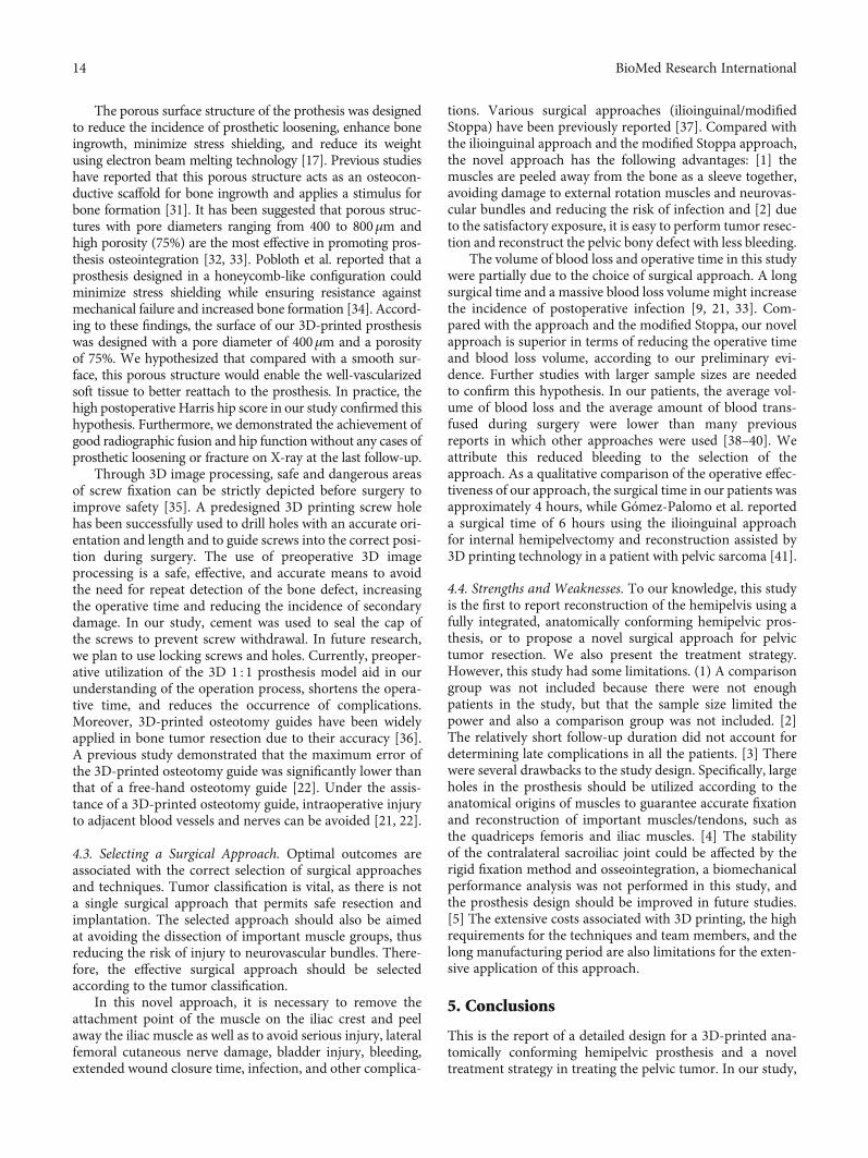
The porous surface structure of the prothesis was designedto reduce the incidence of prosthetic loosening, enhance boneingrowth, minimize stress shielding, and reduce its weightusing electron beam melting technology [17]. Previous studieshave reported that this porous structure acts as an osteocon-ductive scaffold for bone ingrowth and applies a stimulus forbone formation [31]. It has been suggested that porous struc-tures with pore diameters ranging from 400 to 800μm andhigh porosity (75%) are the most effective in promoting pros-thesis osteointegration [32, 33]. Pobloth et al. reported that aprosthesis designed in a honeycomb-like configuration couldminimize stress shielding while ensuring resistance againstmechanical failure and increased bone formation [34]. Accord-ing to these findings, the surface of our 3D-printed prosthesiswas designed with a pore diameter of 400μm and a porosityof 75%. We hypothesized that compared with a smooth sur-face, this porous structure would enable the well-vascularizedsoft tissue to better reattach to the prosthesis. In practice, thehigh postoperative Harris hip score in our study confirmed thishypothesis. Furthermore, we demonstrated the achievement ofgood radiographic fusion and hip function without any cases ofprosthetic loosening or fracture on X-ray at the last follow-up.
Through 3D image processing, safe and dangerous areasof screw fixation can be strictly depicted before surgery toimprove safety [35]. A predesigned 3D printing screw holehas been successfully used to drill holes with an accurate ori-entation and length and to guide screws into the correct posi-tion during surgery. The use of preoperative 3D imageprocessing is a safe, effective, and accurate means to avoidthe need for repeat detection of the bone defect, increasingthe operative time and reducing the incidence of secondarydamage. In our study, cement was used to seal the cap ofthe screws to prevent screw withdrawal. In future research,we plan to use locking screws and holes. Currently, preoper-ative utilization of the 3D 1 : 1 prosthesis model aid in ourunderstanding of the operation process, shortens the opera-tive time, and reduces the occurrence of complications.Moreover, 3D-printed osteotomy guides have been widelyapplied in bone tumor resection due to their accuracy [36].A previous study demonstrated that the maximum error ofthe 3D-printed osteotomy guide was significantly lower thanthat of a free-hand osteotomy guide [22]. Under the assis-tance of a 3D-printed osteotomy guide, intraoperative injuryto adjacent blood vessels and nerves can be avoided [21, 22].
4.3. Selecting a Surgical Approach. Optimal outcomes areassociated with the correct selection of surgical approachesand techniques. Tumor classification is vital, as there is nota single surgical approach that permits safe resection andimplantation. The selected approach should also be aimedat avoiding the dissection of important muscle groups, thusreducing the risk of injury to neurovascular bundles. There-fore, the effective surgical approach should be selectedaccording to the tumor classification.
In this novel approach, it is necessary to remove theattachment point of the muscle on the iliac crest and peelaway the iliac muscle as well as to avoid serious injury, lateralfemoral cutaneous nerve damage, bladder injury, bleeding,extended wound closure time, infection, and other complica-
tions. Various surgical approaches (ilioinguinal/modifiedStoppa) have been previously reported [37]. Compared withthe ilioinguinal approach and the modified Stoppa approach,the novel approach has the following advantages: [1] themuscles are peeled away from the bone as a sleeve together,avoiding damage to external rotation muscles and neurovas-cular bundles and reducing the risk of infection and [2] dueto the satisfactory exposure, it is easy to perform tumor resec-tion and reconstruct the pelvic bony defect with less bleeding.
The volume of blood loss and operative time in this studywere partially due to the choice of surgical approach. A longsurgical time and a massive blood loss volume might increasethe incidence of postoperative infection [9, 21, 33]. Com-pared with the approach and the modified Stoppa, our novelapproach is superior in terms of reducing the operative timeand blood loss volume, according to our preliminary evi-dence. Further studies with larger sample sizes are neededto confirm this hypothesis. In our patients, the average vol-ume of blood loss and the average amount of blood trans-fused during surgery were lower than many previousreports in which other approaches were used [38–40]. Weattribute this reduced bleeding to the selection of theapproach. As a qualitative comparison of the operative effec-tiveness of our approach, the surgical time in our patients wasapproximately 4 hours, while Gómez-Palomo et al. reporteda surgical time of 6 hours using the ilioinguinal approachfor internal hemipelvectomy and reconstruction assisted by3D printing technology in a patient with pelvic sarcoma [41].
4.4. Strengths and Weaknesses. To our knowledge, this studyis the first to report reconstruction of the hemipelvis using afully integrated, anatomically conforming hemipelvic pros-thesis, or to propose a novel surgical approach for pelvictumor resection. We also present the treatment strategy.However, this study had some limitations. (1) A comparisongroup was not included because there were not enoughpatients in the study, but that the sample size limited thepower and also a comparison group was not included. [2]The relatively short follow-up duration did not account fordetermining late complications in all the patients. [3] Therewere several drawbacks to the study design. Specifically, largeholes in the prosthesis should be utilized according to theanatomical origins of muscles to guarantee accurate fixationand reconstruction of important muscles/tendons, such asthe quadriceps femoris and iliac muscles. [4] The stabilityof the contralateral sacroiliac joint could be affected by therigid fixation method and osseointegration, a biomechanicalperformance analysis was not performed in this study, andthe prosthesis design should be improved in future studies.[5] The extensive costs associated with 3D printing, the highrequirements for the techniques and team members, and thelong manufacturing period are also limitations for the exten-sive application of this approach.
5. Conclusions
This is the report of a detailed design for a 3D-printed ana-tomically conforming hemipelvic prosthesis and a noveltreatment strategy in treating the pelvic tumor. In our study,
14 BioMed Research International
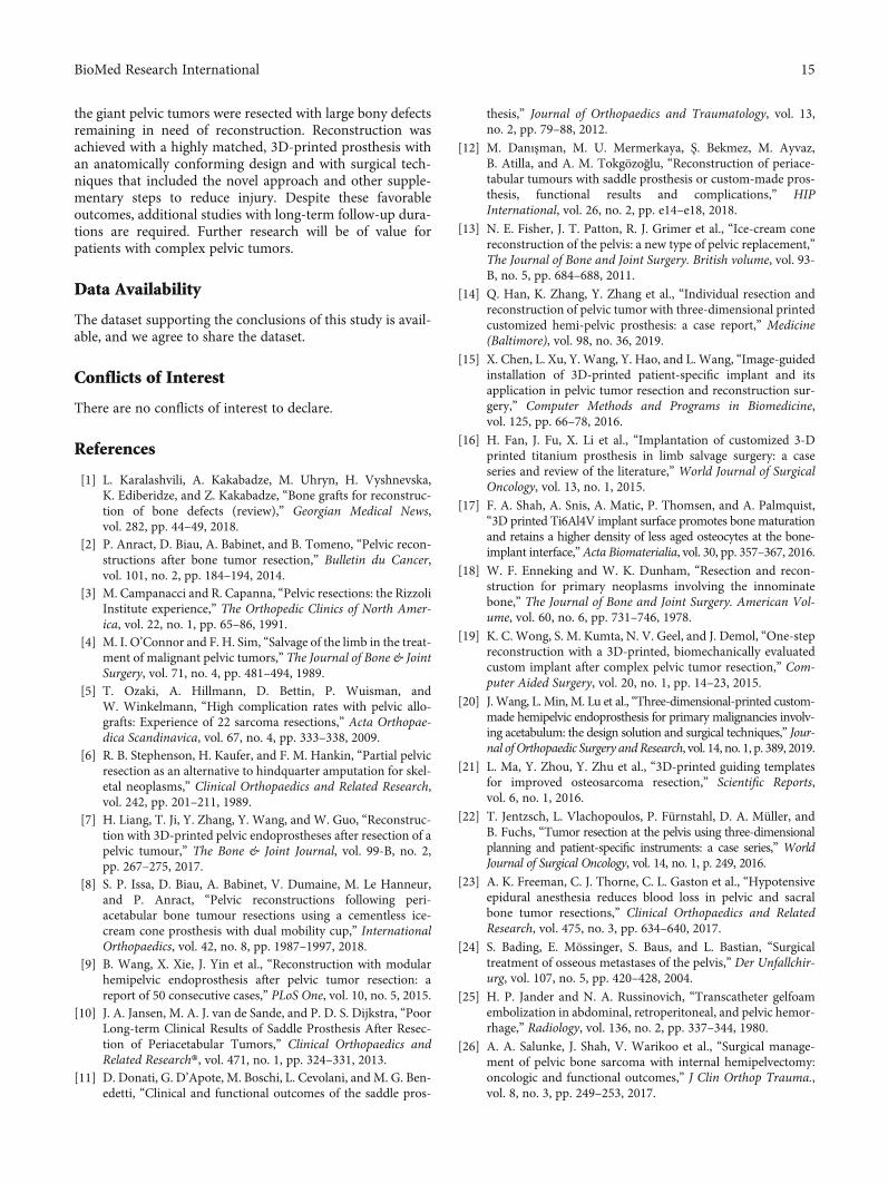
the giant pelvic tumors were resected with large bony defectsremaining in need of reconstruction. Reconstruction wasachieved with a highly matched, 3D-printed prosthesis withan anatomically conforming design and with surgical tech-niques that included the novel approach and other supple-mentary steps to reduce injury. Despite these favorableoutcomes, additional studies with long-term follow-up dura-tions are required. Further research will be of value forpatients with complex pelvic tumors.
Data Availability
The dataset supporting the conclusions of this study is avail-able, and we agree to share the dataset.
Conflicts of Interest
There are no conflicts of interest to declare.
References
[1] L. Karalashvili, A. Kakabadze, M. Uhryn, H. Vyshnevska,K. Ediberidze, and Z. Kakabadze, “Bone grafts for reconstruc-tion of bone defects (review),” Georgian Medical News,vol. 282, pp. 44–49, 2018.
[2] P. Anract, D. Biau, A. Babinet, and B. Tomeno, “Pelvic recon-structions after bone tumor resection,” Bulletin du Cancer,vol. 101, no. 2, pp. 184–194, 2014.
[3] M. Campanacci and R. Capanna, “Pelvic resections: the RizzoliInstitute experience,” The Orthopedic Clinics of North Amer-ica, vol. 22, no. 1, pp. 65–86, 1991.
[4] M. I. O’Connor and F. H. Sim, “Salvage of the limb in the treat-ment of malignant pelvic tumors,” The Journal of Bone & JointSurgery, vol. 71, no. 4, pp. 481–494, 1989.
[5] T. Ozaki, A. Hillmann, D. Bettin, P. Wuisman, andW. Winkelmann, “High complication rates with pelvic allo-grafts: Experience of 22 sarcoma resections,” Acta Orthopae-dica Scandinavica, vol. 67, no. 4, pp. 333–338, 2009.
[6] R. B. Stephenson, H. Kaufer, and F. M. Hankin, “Partial pelvicresection as an alternative to hindquarter amputation for skel-etal neoplasms,” Clinical Orthopaedics and Related Research,vol. 242, pp. 201–211, 1989.
[7] H. Liang, T. Ji, Y. Zhang, Y. Wang, and W. Guo, “Reconstruc-tion with 3D-printed pelvic endoprostheses after resection of apelvic tumour,” The Bone & Joint Journal, vol. 99-B, no. 2,pp. 267–275, 2017.
[8] S. P. Issa, D. Biau, A. Babinet, V. Dumaine, M. Le Hanneur,and P. Anract, “Pelvic reconstructions following peri-acetabular bone tumour resections using a cementless ice-cream cone prosthesis with dual mobility cup,” InternationalOrthopaedics, vol. 42, no. 8, pp. 1987–1997, 2018.
[9] B. Wang, X. Xie, J. Yin et al., “Reconstruction with modularhemipelvic endoprosthesis after pelvic tumor resection: areport of 50 consecutive cases,” PLoS One, vol. 10, no. 5, 2015.
[10] J. A. Jansen, M. A. J. van de Sande, and P. D. S. Dijkstra, “PoorLong-term Clinical Results of Saddle Prosthesis After Resec-tion of Periacetabular Tumors,” Clinical Orthopaedics andRelated Research®, vol. 471, no. 1, pp. 324–331, 2013.
[11] D. Donati, G. D’Apote, M. Boschi, L. Cevolani, and M. G. Ben-edetti, “Clinical and functional outcomes of the saddle pros-
thesis,” Journal of Orthopaedics and Traumatology, vol. 13,no. 2, pp. 79–88, 2012.
[12] M. Danışman, M. U. Mermerkaya, Ş. Bekmez, M. Ayvaz,B. Atilla, and A. M. Tokgözoğlu, “Reconstruction of periace-tabular tumours with saddle prosthesis or custom-made pros-thesis, functional results and complications,” HIPInternational, vol. 26, no. 2, pp. e14–e18, 2018.
[13] N. E. Fisher, J. T. Patton, R. J. Grimer et al., “Ice-cream conereconstruction of the pelvis: a new type of pelvic replacement,”The Journal of Bone and Joint Surgery. British volume, vol. 93-B, no. 5, pp. 684–688, 2011.
[14] Q. Han, K. Zhang, Y. Zhang et al., “Individual resection andreconstruction of pelvic tumor with three-dimensional printedcustomized hemi-pelvic prosthesis: a case report,” Medicine(Baltimore), vol. 98, no. 36, 2019.
[15] X. Chen, L. Xu, Y. Wang, Y. Hao, and L. Wang, “Image-guidedinstallation of 3D-printed patient-specific implant and itsapplication in pelvic tumor resection and reconstruction sur-gery,” Computer Methods and Programs in Biomedicine,vol. 125, pp. 66–78, 2016.
[16] H. Fan, J. Fu, X. Li et al., “Implantation of customized 3-Dprinted titanium prosthesis in limb salvage surgery: a caseseries and review of the literature,” World Journal of SurgicalOncology, vol. 13, no. 1, 2015.
[17] F. A. Shah, A. Snis, A. Matic, P. Thomsen, and A. Palmquist,“3D printed Ti6Al4V implant surface promotes bone maturationand retains a higher density of less aged osteocytes at the bone-implant interface,”Acta Biomaterialia, vol. 30, pp. 357–367, 2016.
[18] W. F. Enneking and W. K. Dunham, “Resection and recon-struction for primary neoplasms involving the innominatebone,” The Journal of Bone and Joint Surgery. American Vol-ume, vol. 60, no. 6, pp. 731–746, 1978.
[19] K. C. Wong, S. M. Kumta, N. V. Geel, and J. Demol, “One-stepreconstruction with a 3D-printed, biomechanically evaluatedcustom implant after complex pelvic tumor resection,” Com-puter Aided Surgery, vol. 20, no. 1, pp. 14–23, 2015.
[20] J. Wang, L. Min, M. Lu et al., “Three-dimensional-printed custom-made hemipelvic endoprosthesis for primary malignancies involv-ing acetabulum: the design solution and surgical techniques,” Jour-nal of Orthopaedic Surgery andResearch, vol. 14, no. 1, p. 389, 2019.
[21] L. Ma, Y. Zhou, Y. Zhu et al., “3D-printed guiding templatesfor improved osteosarcoma resection,” Scientific Reports,vol. 6, no. 1, 2016.
[22] T. Jentzsch, L. Vlachopoulos, P. Fürnstahl, D. A. Müller, andB. Fuchs, “Tumor resection at the pelvis using three-dimensionalplanning and patient-specific instruments: a case series,” WorldJournal of Surgical Oncology, vol. 14, no. 1, p. 249, 2016.
[23] A. K. Freeman, C. J. Thorne, C. L. Gaston et al., “Hypotensiveepidural anesthesia reduces blood loss in pelvic and sacralbone tumor resections,” Clinical Orthopaedics and RelatedResearch, vol. 475, no. 3, pp. 634–640, 2017.
[24] S. Bading, E. Mössinger, S. Baus, and L. Bastian, “Surgicaltreatment of osseous metastases of the pelvis,” Der Unfallchir-urg, vol. 107, no. 5, pp. 420–428, 2004.
[25] H. P. Jander and N. A. Russinovich, “Transcatheter gelfoamembolization in abdominal, retroperitoneal, and pelvic hemor-rhage,” Radiology, vol. 136, no. 2, pp. 337–344, 1980.
[26] A. A. Salunke, J. Shah, V. Warikoo et al., “Surgical manage-ment of pelvic bone sarcoma with internal hemipelvectomy:oncologic and functional outcomes,” J Clin Orthop Trauma.,vol. 8, no. 3, pp. 249–253, 2017.
15BioMed Research International
[27] F. E. Rowan, B. Benjamin, J. R. Pietrak, and F. S. Haddad, “Pre-vention of dislocation after total hip arthroplasty,” The Journalof Arthroplasty, vol. 33, no. 5, pp. 1316–1324, 2018.
[28] M. Takao, Y. Otake, N. Fukuda, Y. Sato, M. Armand, andN. Sugano, “The posterior capsular ligamentous complex con-tributes to hip joint stability in distraction,” The Journal ofArthroplasty, vol. 33, no. 3, pp. 919–924, 2018.
[29] Y. Higuchi, Y. Hasegawa, and N. Ishiguro, “Leg lengthening ofmore than 5 cm is a risk factor for sciatic nerve injury aftertotal hip arthroplasty for adult hip dislocation,” Nagoya Jour-nal of Medical Science, vol. 77, no. 3, pp. 455–463, 2015.
[30] S. Miwa, T. Shirai, N. Yamamoto et al., “Risk factors for surgi-cal site infection after malignant bone tumor resection andreconstruction,” BMC Cancer, vol. 19, no. 1, p. 33, 2019.
[31] H. D. Kim, S. Amirthalingam, S. L. Kim, S. S. Lee,J. Rangasamy, and N. S. Hwang, “Biomimetic Materials andFabrication Approaches for Bone Tissue Engineering,”Advanced Healthcare Materials, vol. 6, no. 23, 2017.
[32] J. Markhoff, J. Wieding, V. Weissmann, J. Pasold, A. Jonitz-Heincke, and R. Bader, “Influence of different three-dimensional open porous titanium scaffold designs on humanosteoblasts behavior in static and dynamic cell investigations,”Materials (Basel)., vol. 8, no. 8, pp. 5490–5507, 2015.
[33] R. Wei, W. Guo, T. Ji, Y. Zhang, and H. Liang, “One-stepreconstruction with a 3D-printed, custom-made prosthesisafter total en bloc sacrectomy: a technical note,” EuropeanSpine Journal, vol. 26, no. 7, pp. 1902–1909, 2017.
[34] A. M. Pobloth, S. Checa, H. Razi et al., “Mechanobiologicallyoptimized 3D titanium-mesh scaffolds enhance bone regener-ation in critical segmental defects in sheep,” Sci Transl Med,vol. 10, no. 423, p. eaam8828, 2018.
[35] K. C. Wong and S. M. Kumta, “Computer-assisted tumor sur-gery in malignant bone tumors,” Clinical Orthopaedics andRelated Research, vol. 471, no. 3, pp. 750–761, 2013.
[36] V. Y. Ng, J. H. DeClaire, K. R. Berend, B. C. Gulick, and A. V.Lombardi, “Improved accuracy of alignment with patient-specific positioning guides compared with manual instrumen-tation in TKA,” Clinical Orthopaedics and Related Research,vol. 470, no. 1, pp. 99–107, 2012.
[37] M. P. Mott, R. E. Meehan, and H. Zhu, “Ilioinguinal approachto manage benign pelvic and acetabular tumors,” AmericanJournal of Orthopedics (Belle Mead, N.J.), vol. 30, no. 7,pp. 554–559, 2001.
[38] K. R. Dai, M. N. Yan, Z. A. Zhu, and Y. H. Sun, “Computer-aided custom-made hemipelvic prosthesis used in extensivepelvic lesions,” The Journal of Arthroplasty, vol. 22, no. 7,pp. 981–986, 2007.
[39] B. Wang, Y. Hao, F. Pu, W. Jiang, and Z. Shao, “Computer-aided designed, three dimensional-printed hemipelvic pros-thesis for peri-acetabular malignant bone tumour,” Interna-tional Orthopaedics, vol. 42, no. 3, pp. 687–694, 2018.
[40] W. Sun, J. Li, Q. Li, G. Li, and Z. Cai, “Clinical effectiveness ofhemipelvic reconstruction using computer-aided custom-madeprostheses after resection of malignant pelvic tumors,” The Jour-nal of Arthroplasty, vol. 26, no. 8, pp. 1508–1513, 2011.
[41] J. M. Gómez-Palomo, F. J. Estades-Rubio, S. Meschian-Coretti,E. Montañez-Heredia, and F. J. De Santos-de la Fuente, “Inter-nal hemipelvectomy and reconstruction assisted by 3D print-ing technology using premade intraoperative cutting andplacement guides in a patient with pelvic sarcoma: a casereport,” JBJS Case Connect., vol. 9, no. 4, 2019.
16 BioMed Research International
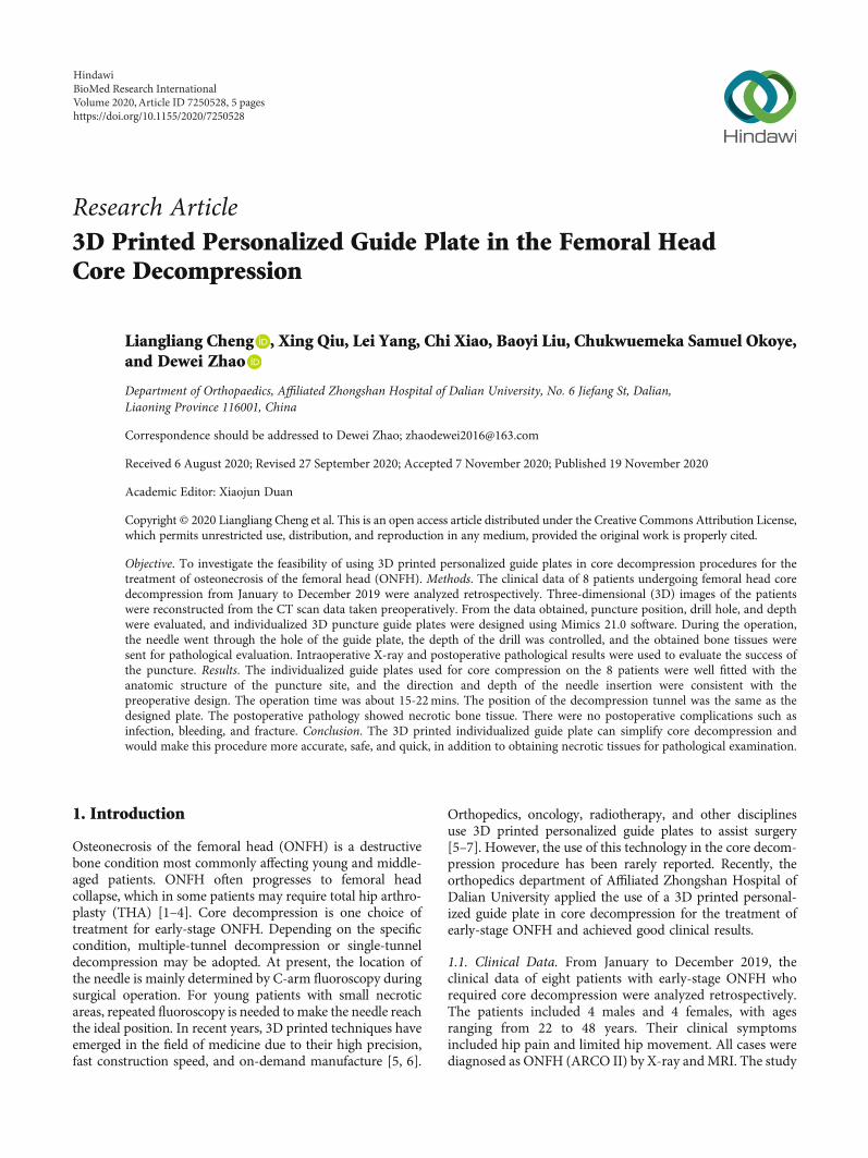
Research Article3D Printed Personalized Guide Plate in the Femoral HeadCore Decompression
Liangliang Cheng , Xing Qiu, Lei Yang, Chi Xiao, Baoyi Liu, Chukwuemeka Samuel Okoye,and Dewei Zhao
Department of Orthopaedics, Affiliated Zhongshan Hospital of Dalian University, No. 6 Jiefang St, Dalian,Liaoning Province 116001, China
Correspondence should be addressed to Dewei Zhao; [email protected]
Received 6 August 2020; Revised 27 September 2020; Accepted 7 November 2020; Published 19 November 2020
Academic Editor: Xiaojun Duan
Copyright © 2020 Liangliang Cheng et al. This is an open access article distributed under the Creative Commons Attribution License,which permits unrestricted use, distribution, and reproduction in any medium, provided the original work is properly cited.
Objective. To investigate the feasibility of using 3D printed personalized guide plates in core decompression procedures for thetreatment of osteonecrosis of the femoral head (ONFH). Methods. The clinical data of 8 patients undergoing femoral head coredecompression from January to December 2019 were analyzed retrospectively. Three-dimensional (3D) images of the patientswere reconstructed from the CT scan data taken preoperatively. From the data obtained, puncture position, drill hole, and depthwere evaluated, and individualized 3D puncture guide plates were designed using Mimics 21.0 software. During the operation,the needle went through the hole of the guide plate, the depth of the drill was controlled, and the obtained bone tissues weresent for pathological evaluation. Intraoperative X-ray and postoperative pathological results were used to evaluate the success ofthe puncture. Results. The individualized guide plates used for core compression on the 8 patients were well fitted with theanatomic structure of the puncture site, and the direction and depth of the needle insertion were consistent with thepreoperative design. The operation time was about 15-22mins. The position of the decompression tunnel was the same as thedesigned plate. The postoperative pathology showed necrotic bone tissue. There were no postoperative complications such asinfection, bleeding, and fracture. Conclusion. The 3D printed individualized guide plate can simplify core decompression andwould make this procedure more accurate, safe, and quick, in addition to obtaining necrotic tissues for pathological examination.
1. Introduction
Osteonecrosis of the femoral head (ONFH) is a destructivebone condition most commonly affecting young and middle-aged patients. ONFH often progresses to femoral headcollapse, which in some patients may require total hip arthro-plasty (THA) [1–4]. Core decompression is one choice oftreatment for early-stage ONFH. Depending on the specificcondition, multiple-tunnel decompression or single-tunneldecompression may be adopted. At present, the location ofthe needle is mainly determined by C-arm fluoroscopy duringsurgical operation. For young patients with small necroticareas, repeated fluoroscopy is needed to make the needle reachthe ideal position. In recent years, 3D printed techniques haveemerged in the field of medicine due to their high precision,fast construction speed, and on-demand manufacture [5, 6].
Orthopedics, oncology, radiotherapy, and other disciplinesuse 3D printed personalized guide plates to assist surgery[5–7]. However, the use of this technology in the core decom-pression procedure has been rarely reported. Recently, theorthopedics department of Affiliated Zhongshan Hospital ofDalian University applied the use of a 3D printed personal-ized guide plate in core decompression for the treatment ofearly-stage ONFH and achieved good clinical results.
1.1. Clinical Data. From January to December 2019, theclinical data of eight patients with early-stage ONFH whorequired core decompression were analyzed retrospectively.The patients included 4 males and 4 females, with agesranging from 22 to 48 years. Their clinical symptomsincluded hip pain and limited hip movement. All cases werediagnosed as ONFH (ARCO II) by X-ray andMRI. The study
HindawiBioMed Research InternationalVolume 2020, Article ID 7250528, 5 pageshttps://doi.org/10.1155/2020/7250528
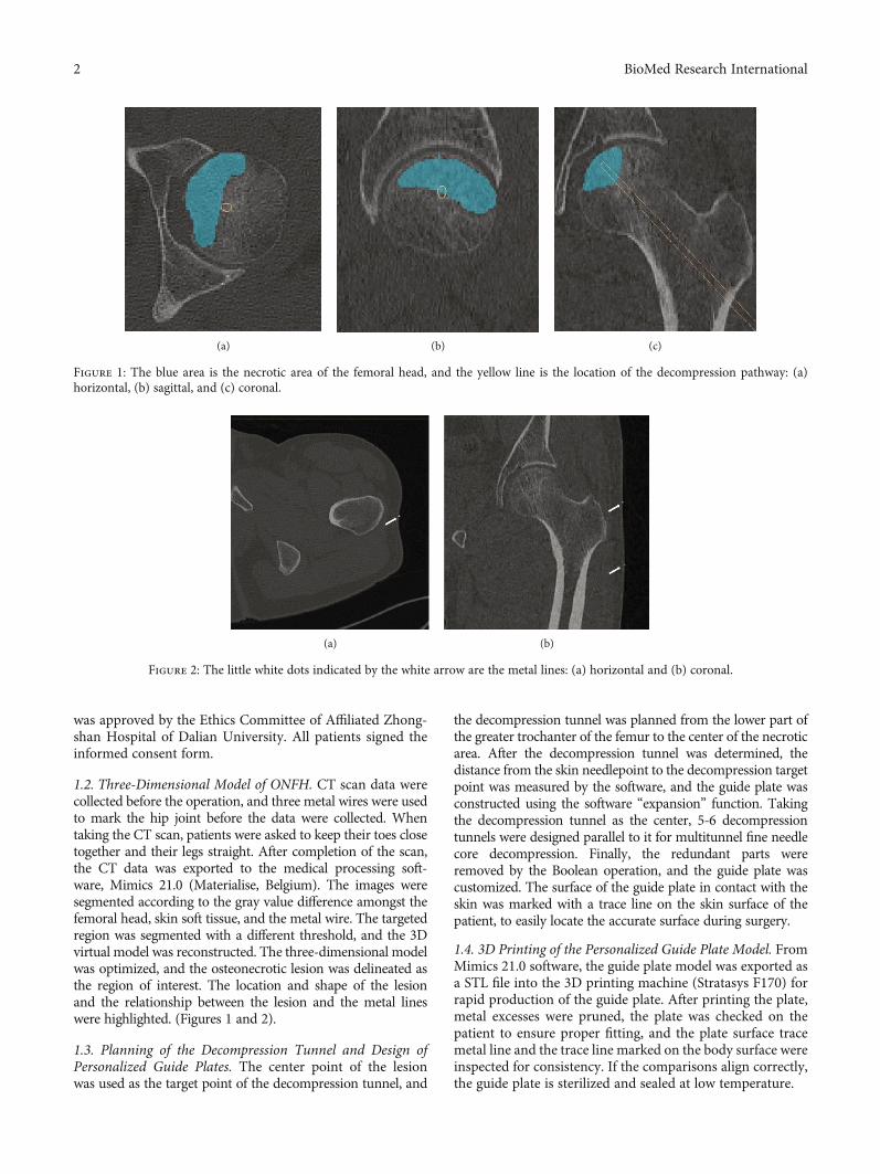
was approved by the Ethics Committee of Affiliated Zhong-shan Hospital of Dalian University. All patients signed theinformed consent form.
1.2. Three-Dimensional Model of ONFH. CT scan data werecollected before the operation, and three metal wires were usedto mark the hip joint before the data were collected. Whentaking the CT scan, patients were asked to keep their toes closetogether and their legs straight. After completion of the scan,the CT data was exported to the medical processing soft-ware, Mimics 21.0 (Materialise, Belgium). The images weresegmented according to the gray value difference amongst thefemoral head, skin soft tissue, and the metal wire. The targetedregion was segmented with a different threshold, and the 3Dvirtual model was reconstructed. The three-dimensional modelwas optimized, and the osteonecrotic lesion was delineated asthe region of interest. The location and shape of the lesionand the relationship between the lesion and the metal lineswere highlighted. (Figures 1 and 2).
1.3. Planning of the Decompression Tunnel and Design ofPersonalized Guide Plates. The center point of the lesionwas used as the target point of the decompression tunnel, and
the decompression tunnel was planned from the lower part ofthe greater trochanter of the femur to the center of the necroticarea. After the decompression tunnel was determined, thedistance from the skin needlepoint to the decompression targetpoint was measured by the software, and the guide plate wasconstructed using the software “expansion” function. Takingthe decompression tunnel as the center, 5-6 decompressiontunnels were designed parallel to it for multitunnel fine needlecore decompression. Finally, the redundant parts wereremoved by the Boolean operation, and the guide plate wascustomized. The surface of the guide plate in contact with theskin was marked with a trace line on the skin surface of thepatient, to easily locate the accurate surface during surgery.
1.4. 3D Printing of the Personalized Guide Plate Model. FromMimics 21.0 software, the guide plate model was exported asa STL file into the 3D printing machine (Stratasys F170) forrapid production of the guide plate. After printing the plate,metal excesses were pruned, the plate was checked on thepatient to ensure proper fitting, and the plate surface tracemetal line and the trace line marked on the body surface wereinspected for consistency. If the comparisons align correctly,the guide plate is sterilized and sealed at low temperature.
(a) (b) (c)
Figure 1: The blue area is the necrotic area of the femoral head, and the yellow line is the location of the decompression pathway: (a)horizontal, (b) sagittal, and (c) coronal.
(a) (b)
Figure 2: The little white dots indicated by the white arrow are the metal lines: (a) horizontal and (b) coronal.
2 BioMed Research International
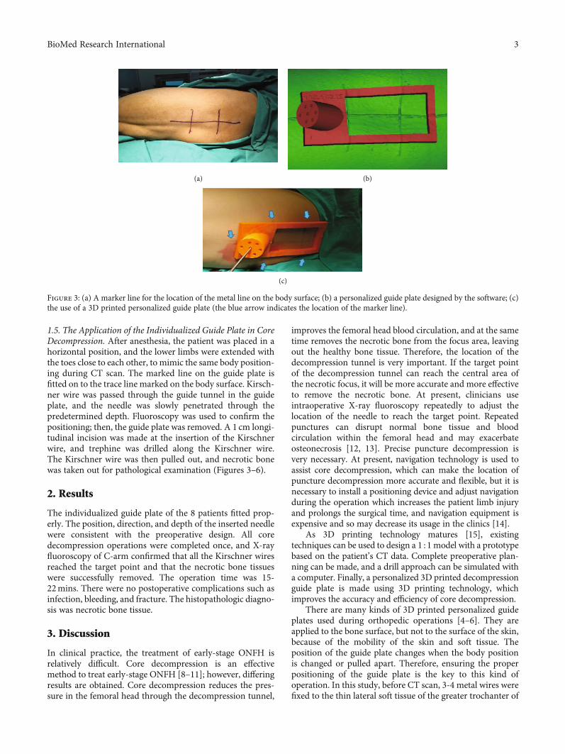
1.5. The Application of the Individualized Guide Plate in CoreDecompression. After anesthesia, the patient was placed in ahorizontal position, and the lower limbs were extended withthe toes close to each other, to mimic the same body position-ing during CT scan. The marked line on the guide plate isfitted on to the trace line marked on the body surface. Kirsch-ner wire was passed through the guide tunnel in the guideplate, and the needle was slowly penetrated through thepredetermined depth. Fluoroscopy was used to confirm thepositioning; then, the guide plate was removed. A 1 cm longi-tudinal incision was made at the insertion of the Kirschnerwire, and trephine was drilled along the Kirschner wire.The Kirschner wire was then pulled out, and necrotic bonewas taken out for pathological examination (Figures 3–6).
2. Results
The individualized guide plate of the 8 patients fitted prop-erly. The position, direction, and depth of the inserted needlewere consistent with the preoperative design. All coredecompression operations were completed once, and X-rayfluoroscopy of C-arm confirmed that all the Kirschner wiresreached the target point and that the necrotic bone tissueswere successfully removed. The operation time was 15-22mins. There were no postoperative complications such asinfection, bleeding, and fracture. The histopathologic diagno-sis was necrotic bone tissue.
3. Discussion
In clinical practice, the treatment of early-stage ONFH isrelatively difficult. Core decompression is an effectivemethod to treat early-stage ONFH [8–11]; however, differingresults are obtained. Core decompression reduces the pres-sure in the femoral head through the decompression tunnel,
improves the femoral head blood circulation, and at the sametime removes the necrotic bone from the focus area, leavingout the healthy bone tissue. Therefore, the location of thedecompression tunnel is very important. If the target pointof the decompression tunnel can reach the central area ofthe necrotic focus, it will be more accurate and more effectiveto remove the necrotic bone. At present, clinicians useintraoperative X-ray fluoroscopy repeatedly to adjust thelocation of the needle to reach the target point. Repeatedpunctures can disrupt normal bone tissue and bloodcirculation within the femoral head and may exacerbateosteonecrosis [12, 13]. Precise puncture decompression isvery necessary. At present, navigation technology is used toassist core decompression, which can make the location ofpuncture decompression more accurate and flexible, but it isnecessary to install a positioning device and adjust navigationduring the operation which increases the patient limb injuryand prolongs the surgical time, and navigation equipment isexpensive and so may decrease its usage in the clinics [14].
As 3D printing technology matures [15], existingtechniques can be used to design a 1 : 1 model with a prototypebased on the patient’s CT data. Complete preoperative plan-ning can be made, and a drill approach can be simulated witha computer. Finally, a personalized 3D printed decompressionguide plate is made using 3D printing technology, whichimproves the accuracy and efficiency of core decompression.
There are many kinds of 3D printed personalized guideplates used during orthopedic operations [4–6]. They areapplied to the bone surface, but not to the surface of the skin,because of the mobility of the skin and soft tissue. Theposition of the guide plate changes when the body positionis changed or pulled apart. Therefore, ensuring the properpositioning of the guide plate is the key to this kind ofoperation. In this study, before CT scan, 3-4 metal wires werefixed to the thin lateral soft tissue of the greater trochanter of
(a) (b)
(c)
Figure 3: (a) A marker line for the location of the metal line on the body surface; (b) a personalized guide plate designed by the software; (c)the use of a 3D printed personalized guide plate (the blue arrow indicates the location of the marker line).
3BioMed Research International
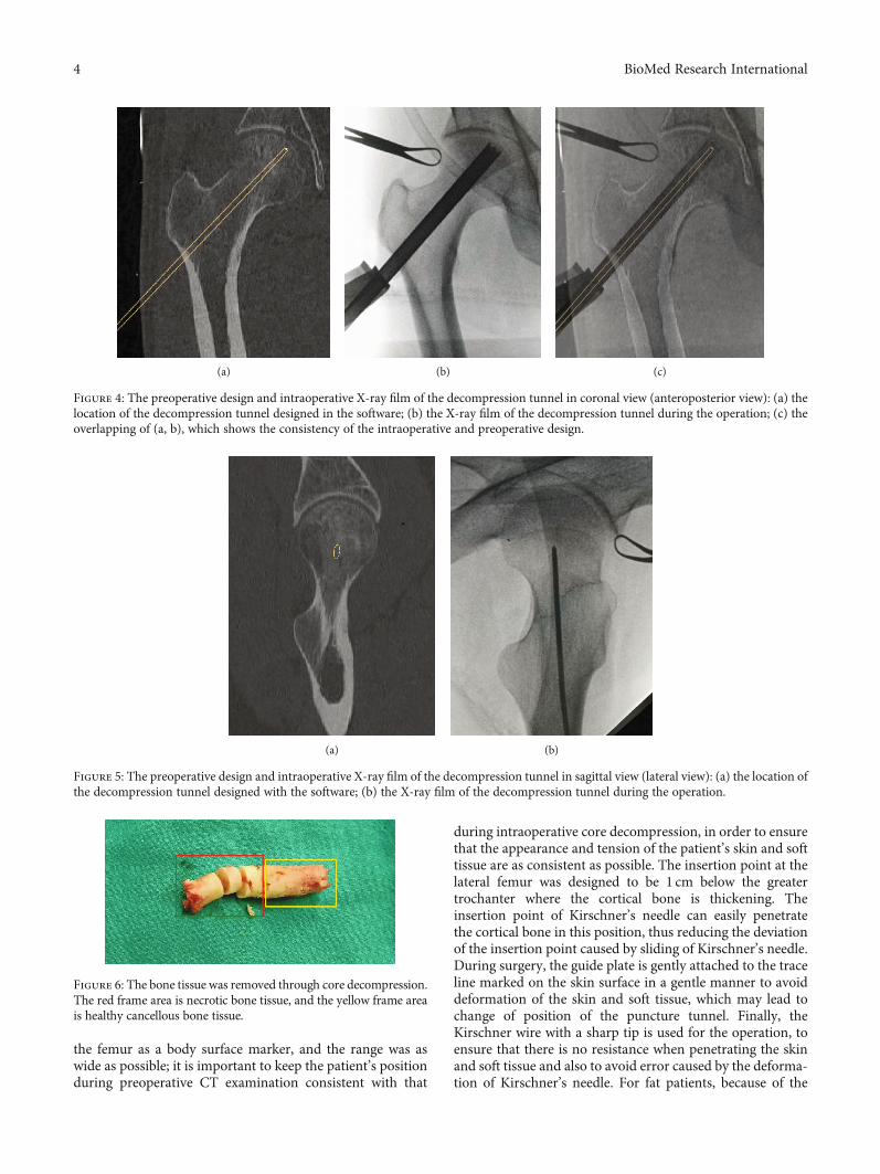
the femur as a body surface marker, and the range was aswide as possible; it is important to keep the patient’s positionduring preoperative CT examination consistent with that
during intraoperative core decompression, in order to ensurethat the appearance and tension of the patient’s skin and softtissue are as consistent as possible. The insertion point at thelateral femur was designed to be 1 cm below the greatertrochanter where the cortical bone is thickening. Theinsertion point of Kirschner’s needle can easily penetratethe cortical bone in this position, thus reducing the deviationof the insertion point caused by sliding of Kirschner’s needle.During surgery, the guide plate is gently attached to the traceline marked on the skin surface in a gentle manner to avoiddeformation of the skin and soft tissue, which may lead tochange of position of the puncture tunnel. Finally, theKirschner wire with a sharp tip is used for the operation, toensure that there is no resistance when penetrating the skinand soft tissue and also to avoid error caused by the deforma-tion of Kirschner’s needle. For fat patients, because of the
(a) (b) (c)
Figure 4: The preoperative design and intraoperative X-ray film of the decompression tunnel in coronal view (anteroposterior view): (a) thelocation of the decompression tunnel designed in the software; (b) the X-ray film of the decompression tunnel during the operation; (c) theoverlapping of (a, b), which shows the consistency of the intraoperative and preoperative design.
(a) (b)
Figure 5: The preoperative design and intraoperative X-ray film of the decompression tunnel in sagittal view (lateral view): (a) the location ofthe decompression tunnel designed with the software; (b) the X-ray film of the decompression tunnel during the operation.
Figure 6: The bone tissue was removed through core decompression.The red frame area is necrotic bone tissue, and the yellow frame areais healthy cancellous bone tissue.
4 BioMed Research International
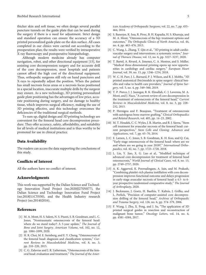
thicker skin and soft tissue, we often design several parallelpuncture tunnels on the guide plate that can be used duringthe surgery if there is a need for adjustment. Strict designand standard operation can ensure the accuracy of a 3Dprinted personalized guide plate on the skin surface. All casescompleted in our clinics were carried out according to thepreoperation plan; the results were verified by intraoperativeX-ray fluoroscopy and postoperative histopathology.
Although modern medicine already has computernavigation, robot, and other directional equipment [15], forassisting core decompression surgery and for accurate drillof the core decompression, most hospitals and patientscannot afford the high cost of the directional equipment.Thus, orthopedic surgeons still rely on hand punctures andX-rays to repeatedly adjust the position. When the patienthas small necrosis focus areas or a necrosis focus positionedin a special location, inaccurate multiple drills by the surgeonmay ensure. As a new technology, 3D printing personalizedguide plate positioning has the advantages of low price, accu-rate positioning during surgery, and no damage to healthytissue, which improves surgical efficiency, making the use of3D printing effective, and this technology overcomes thedeficiencies of the traditional surgical methods.
To sum up, digital design and 3D printing technology areconvenient for the femoral head core decompression proce-dure. They offer accuracy, safety, affordability, and suitabilityfor all levels of medical institutions and is thus worthy to bepromoted for use in clinical practice.
Data Availability
The readers can access the data supporting the conclusions ofthis study.
Conflicts of Interest
All the authors have no conflict of interest.
Acknowledgments
This work was supported by the Dalian Science and Technol-ogy Innovation Fund Project (no.2020JJ27SN077), theDalian Science and Technology Innovation Fund Project(no.2018J11CY030), and the Health Industry researchProject (no.201402016).
References
[1] M. A. Mont, H. S. Salem, N. S. Piuzzi, S. B. Goodman, and L. C.Jones, “Nontraumatic osteonecrosis of the femoral head:where do we stand today?: A 5-year update,” The Journal ofBone and Joint Surgery. American Volume, vol. 102, no. 12,pp. 1084–1099, 2020.
[2] H. R. Choi, M. E. Steinberg, and E. Y. Cheng, “Osteonecrosis ofthe femoral head: diagnosis and classification systems,” Cur-rent Reviews in Musculoskeletal Medicine, vol. 8, no. 3,pp. 210–220, 2015.
[3] C. G. Zalavras and J. R. Lieberman, “Osteonecrosis of the fem-oral head: evaluation and treatment,” The Journal of the Amer-
ican Academy of Orthopaedic Surgeons, vol. 22, no. 7, pp. 455–464, 2014.
[4] S. Banerjee, K. Issa, R. Pivec, B. H. Kapadia, H. S. Khanuja, andM. A. Mont, “Osteonecrosis of the hip: treatment options andoutcomes,” The Orthopedic Clinics of North America, vol. 44,no. 4, pp. 463–476, 2013.
[5] C. Wang, L. Zhang, T. Qin et al., “3D printing in adult cardio-vascular surgery and interventions: a systematic review,” Jour-nal of Thoracic Disease, vol. 12, no. 6, pp. 3227–3237, 2020.
[6] T. Bartel, A. Rivard, A. Jimenez, C. A. Mestres, and S. Müller,“Medical three-dimensional printing opens up new opportu-nities in cardiology and cardiac surgery,” European HeartJournal, vol. 39, no. 15, pp. 1246–1254, 2018.
[7] W. C. H. Parr, J. L. Burnard, P. J. Wilson, and R. J. Mobbs, “3Dprinted anatomical (bio)models in spine surgery: clinical ben-efits and value to health care providers,” Journal of Spine Sur-gery, vol. 5, no. 4, pp. 549–560, 2019.
[8] T. P. Pierce, J. J. Jauregui, R. K. Elmallah, C. J. Lavernia, M. A.Mont, and J. Nace, “A current review of core decompression inthe treatment of osteonecrosis of the femoral head,” CurrentReviews in Musculoskeletal Medicine, vol. 8, no. 3, pp. 228–232, 2015.
[9] P. Hernigou and F. Beaujean, “Treatment of osteonecrosiswith autologous bone marrow grafting,” Clinical Orthopaedicsand Related Research, vol. 405, pp. 14–23, 2002.
[10] M. T. Houdek, C. C. Wyles, J. R. Martin, and R. J. Sierra, “Stemcell treatment for avascular necrosis of the femoral head: cur-rent perspectives,” Stem Cells and Cloning: Advances andApplications, vol. 7, pp. 65–70, 2014.
[11] E. Larson, L. C. Jones, S. B. Goodman, K. H. Koo, and Q. Cui,“Early-stage osteonecrosis of the femoral head: where are weand where are we going in year 2018?,” International Ortho-paedics, vol. 42, no. 7, pp. 1723–1728, 2018.
[12] L. Lin, Y. Jiao, X. G. Luo et al., “Modified technique ofadvanced core decompression for treatment of femoral headosteonecrosis,” World Journal of Clinical Cases, vol. 8, no. 13,pp. 2749–2757, 2020.
[13] A. K. Aggarwal, K. Poornalingam, A. Jain, and M. Prakash,“Combining platelet-rich plasma instillation with core decom-pression improves functional outcome and delays progressionin early-stage avascular necrosis of femoral head: a 4.5- to 6-year prospective randomized comparative study,” The Journalof Arthroplasty, 2020.
[14] J. Beckmann, J. Goetz, H. Baethis, T. Kalteis, J. Grifka, andL. Perlick, “Precision of computer-assisted core decompres-sion drilling of the femoral head,” Archives of Orthopaedicand Trauma Surgery, vol. 126, no. 6, pp. 374–379, 2006.
[15] F. Wang, J. Zhu, X. Peng, and J. Su, “The application of 3Dprinted surgical guides in resection and reconstruction ofmalignant bone tumor,” Oncology Letters, vol. 14, no. 4,pp. 4581–4584, 2017.
5BioMed Research International
Research Article3D-Printed Patient-Specific Instrumentation Technique Vs.Conventional Technique in Medial Open Wedge High TibialOsteotomy: A Prospective Comparative Study
Yunhe Mao ,1 Yang Xiong,1 Qi Li,1 Gang Chen,1 Weili Fu,1 Xin Tang,1 Luxi Yang,2
and Jian Li 1
1Department of Sports Medicine, West China Hospital, Sichuan University, No. 37, Guoxue Alley, Chengdu, China2Sichuan International Expo Group, Chengdu, China
Correspondence should be addressed to Jian Li; [email protected]
Received 7 August 2020; Revised 8 October 2020; Accepted 6 November 2020; Published 17 November 2020
Academic Editor: Xiaojun Duan
Copyright © 2020 Yunhe Mao et al. This is an open access article distributed under the Creative Commons Attribution License,which permits unrestricted use, distribution, and reproduction in any medium, provided the original work is properly cited.
Purpose. The purpose of this study was to compare the accuracy and clinical outcomes of the medial open wedge high tibialosteotomy (MOWHTO) using a three-dimensional (3D-) printed patient-specific instrumentation (PSI) with that ofconventional surgical techniques. Methods. A prospective comparative study which included 18 patients who underwentMOWHTO using 3D-printed PSI technique (3D-printed group) and 19 patients with conventional technique was conductedfrom Jan 2019 to Dec 2019. After the preoperative planning, 3D-printed PSI (cutting guide model) was used in MOWHTO for3D-printed group, while freehand osteotomies were adopted in the conventional group. The accuracy of MOWHTO for eachmethod was compared using the radiological index obtained preoperatively and postoperatively, including mechanicalfemorotibial angle (mFTA) and medial mechanical proximal tibial angle (mMPTA), and correction error. Regular clinicaloutcomes were also compared between the 2 groups. Results. The correction errors in the 3D-printed group were significantlylower than the conventional group (mFTA, 0:2° ± 0:6° vs. 1:2° ± 1:4°, P = 0:004) (mMPTA, 0:1° ± 0:4° vs. 2:2° ± 1:8°, P < 0:00001). There was a significantly shorter duration (P < 0:00001) and lower radiation exposures (P < 0:00001) for the osteotomyprocedure in the 3D-printed group than in the conventional group. There were significantly higher subjective IKDC scores(P = 0:009) and Lysholm scores (P = 0:03) in the 3D-printed group at the 3-month follow-up, but not significantly different atother time points. Fewer complications occurred in the 3D-printed group. Conclusions. With the assistance of the 3D-printedpatient-specific cutting guide model, a safe and feasible MOWHTO can be conducted with superior accuracy than theconventional technique.
1. Introduction
Medial open wedge high tibial osteotomy (MOWHTO) isa well-established surgical procedure in dealing with earlyor mild stage of knee osteoarthritis (OA), and this nativeknee-preserving surgery could ensure long-lasting clinicalsuccess (>10 years) in the overall treatments of knee OA[1, 2]. MOWHTO is typically applied for the correctionof varus malalignment of the lower extremities in isolatedmedial compartment arthritis of the knee [3–5]. If accu-rately performed, MOWHTO has the potential to delay
or even possibly prevent the development of end-stageOA, by shifting the weight-bearing axis toward the lateralcompartment [3, 6]; the loading is redistributed, and kneefunction is thereby restored and could avert total kneearthroplasty (TKA).
Nevertheless, the downsides of this procedure remainnotable. Except for the high rates of knotty local complica-tions, including increased tibial slope, hinge fractures, infec-tions, and delayed union [7, 8], the main obstacle lies in theaccuracy of performing osteotomy [9]. A successfulMOWHTO requires the angular correction to be achieved
HindawiBioMed Research InternationalVolume 2020, Article ID 1923172, 10 pageshttps://doi.org/10.1155/2020/1923172
accurately in both the sagittal and coronal planes, making itfairly challenging to determine the accurate osteotomy open-ing distance with the current conventional techniques [4, 10].The systematic review by Van den Bempt et al. [4] revealedthat the accuracy of conventional MOWHTO was below75% in 8 out of 14 cohorts. Small errors in osteotomy posi-tioning can lead to severe local complications such as lateralcortex fractures [11], and minor inaccuracy of angular cor-rection in the coronal plane hinders the long-term successof this operation and even accelerates the progression ofOA [12]. For the small tolerance for errors and the complex-ity for mastery, conventional MOWHTO gradually comes tobe an unfavorable alternative [13].
However, the newly developed ancillary technology inthe modality of 3D-printed patient-specific instrumentation(PSI) may be a solution to the accuracy requirements ofHTO planning and execution [13]. This technique was ini-tially carried out in maxillofacial surgery [14]; however, itspracticability was more adequately embodied in the laterorthopedic studies [5, 15–17]. The feasibility and proof-of-concept study by Victor and Premanathan [17] reportedPSI for 14 cases of osteotomy around the knee yielded satis-factory outcomes, suggesting it to be a prospective solution.In the study by Van Genechten et al. [5], similar competentpostoperative overall results were achieved by MOWHTOwith the assistance of the 3D-printed PSI. Moreover, with asafer and faster osteotomy, it allows orthopedists to performmore concomitant surgeries at one time, such as meniscect-omy and anterior cruciate ligament reconstruction (ACLR)[18–20]. Nevertheless, despite all these desirable superiori-ties, there was an evident scarcity of prospective comparativestudies with robust evidences to prove the clinical advantagesof PSI over conventional techniques in MOWHTO.
This study is thus designed to identify the safety, feasibil-ity, and reliability of 3D-printed PSI for MOWHTO and todetermine whether this novel technique could achieve betterclinical outcomes and accuracy, when compared with con-ventional MOWHTO, in terms of correcting the varus mala-lignments in patients with isolated medial compartment OA.The null hypothesis was that MOWHTO with PSI techniquecould offer better clinical outcomes, fewer complications, andmore accurate realignment over the traditional MOWHTO.
2. Methods
2.1. Patients. 18 MOWHTO surgeries with 3D-printed PSItechnique and 19 conventional MOWHTO were conductedbetween Jan 2019 and Dec 2019 at Sports Medicine Center,Western China Hospital, Sichuan University. The study wasapproved by the Health Sciences Research Ethics Board atSichuan University and at the local research ethics board ateach institution (ID: 2018534)
Patients were considered for inclusion if they meet thefollowing criteria: (1) age between 35 and 60 years old; (2)isolated medial compartment OA, Kellgren-Lawrence grade≤ III; (3) radiological evidences for varus malalignment(varus > 6°, mechanical medial proximal tibial angle,mMPTA < 85°); (4) ROM: flexion ≥ 120°, loss of extension≤ 10°; and (5) outer bridge grade for cartilage injury < IV
(defect area < 2:5 cm2). Patients were thoroughly informedabout the pre- and postoperative radiology protocol, theplanning procedure, and the PSI surgical technique. On avoluntary basis, for the patients who agreed to take HTO atour medical center, either with novel PSI or conventionaltechnique, preoperative hip-to-ankle double-limb weight-bearing X-ray view of the knee (anteroposterior (AP), lateralview), whole lower limb CT scan of both sides, and MRI ofthe affected knee were taken. The same imaging protocolwas repeated 3 months and 12 months after surgery to eval-uate the angular correction in both sagittal and coronalplanes, the accuracy of hardware positioning, the conditionof the cartilage, and the healing of the osteotomy.
All included patients in both groups had completed theprementioned radiology protocol and clinical assessments.The demographic characteristics of the included patientswere shown in Table 1.
2.2. Preoperative Planning. With reference to the methodol-ogy and parameters provided by Chieh-Szu et al. [21, 22],under the guidance of a radiology engineer (B.J.), by usingthe DICOM (digital imaging and communication in medi-cine) data, continuum-based tibial and fibular models fromthe CT image (slice thickness: 1.5mm; image resolution:512× 512 pixels) were reconstructed as the intact model. Acomputerized osteotomy simulation software (OsteoMaster)was adopted to create the 3D bone anatomy virtual models ofthe lower limbs (Figure 1).
After the optimal sagittal and coronal correction angles,depth, width, height, slope, and position of the osteotomywere determined, the PSI cutting guide model was then builtaccordingly using additive layer manufacturing (3D printing)for the accurate osteotomy in the material of hydroxyapatite.Every osteotomy case was planned by a single investigator(Y.X.) who was highly trained in working with 3D medicalsoftware programs according to the protocol previously men-tioned (Figure 1).
2.3. Surgical Procedures. Surgeries were performed by a singlesenior surgeon (J.L.). Firstly, intra-articular procedures wereperformed, arthroscopy was taken at each patient in theexploration for concomitant diseases, and articular debride-ment, free body removal, meniscectomy, or ACLR were con-ducted if necessary.
For the PSI technique, a 10-cm vertical medial tibia skinincision was made 2 cm below the tibial articular surface;then, the pes anserinus tendon was explored and loosen toallow greater surgical exposure; the tibial insertion of thesuperficial layer of the fibular collateral ligament (FCL) wasthen released, and osseous landmarks were made for thePSI cutting guide model positioning, fixed by saw pins. Then,the two-planar osteotomy was performed by a swing sawthrough the cutting grooves of the guide model, the wedgeshape gap was widened length by length with steel rulersand fixed at the predetermined angle via a metal bar stabi-lizer, then a distractor was used to maintain this interspace,and the PSI guide model was removed. Finally, a properlycurved HTO plate was attached to the medial surface of thetibia as closely as possible, and the locking plate was tightly
2 BioMed Research International
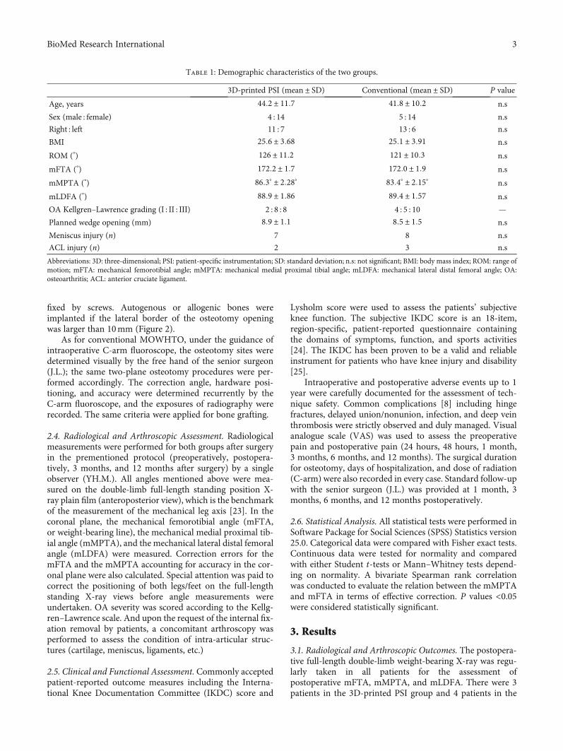
fixed by screws. Autogenous or allogenic bones wereimplanted if the lateral border of the osteotomy openingwas larger than 10mm (Figure 2).
As for conventional MOWHTO, under the guidance ofintraoperative C-arm fluoroscope, the osteotomy sites weredetermined visually by the free hand of the senior surgeon(J.L.); the same two-plane osteotomy procedures were per-formed accordingly. The correction angle, hardware posi-tioning, and accuracy were determined recurrently by theC-arm fluoroscope, and the exposures of radiography wererecorded. The same criteria were applied for bone grafting.
2.4. Radiological and Arthroscopic Assessment. Radiologicalmeasurements were performed for both groups after surgeryin the prementioned protocol (preoperatively, postopera-tively, 3 months, and 12 months after surgery) by a singleobserver (YH.M.). All angles mentioned above were mea-sured on the double-limb full-length standing position X-ray plain film (anteroposterior view), which is the benchmarkof the measurement of the mechanical leg axis [23]. In thecoronal plane, the mechanical femorotibial angle (mFTA,or weight-bearing line), the mechanical medial proximal tib-ial angle (mMPTA), and the mechanical lateral distal femoralangle (mLDFA) were measured. Correction errors for themFTA and the mMPTA accounting for accuracy in the cor-onal plane were also calculated. Special attention was paid tocorrect the positioning of both legs/feet on the full-lengthstanding X-ray views before angle measurements wereundertaken. OA severity was scored according to the Kellg-ren–Lawrence scale. And upon the request of the internal fix-ation removal by patients, a concomitant arthroscopy wasperformed to assess the condition of intra-articular struc-tures (cartilage, meniscus, ligaments, etc.)
2.5. Clinical and Functional Assessment. Commonly acceptedpatient-reported outcome measures including the Interna-tional Knee Documentation Committee (IKDC) score and
Lysholm score were used to assess the patients’ subjectiveknee function. The subjective IKDC score is an 18-item,region-specific, patient-reported questionnaire containingthe domains of symptoms, function, and sports activities[24]. The IKDC has been proven to be a valid and reliableinstrument for patients who have knee injury and disability[25].
Intraoperative and postoperative adverse events up to 1year were carefully documented for the assessment of tech-nique safety. Common complications [8] including hingefractures, delayed union/nonunion, infection, and deep veinthrombosis were strictly observed and duly managed. Visualanalogue scale (VAS) was used to assess the preoperativepain and postoperative pain (24 hours, 48 hours, 1 month,3 months, 6 months, and 12 months). The surgical durationfor osteotomy, days of hospitalization, and dose of radiation(C-arm) were also recorded in every case. Standard follow-upwith the senior surgeon (J.L.) was provided at 1 month, 3months, 6 months, and 12 months postoperatively.
2.6. Statistical Analysis. All statistical tests were performed inSoftware Package for Social Sciences (SPSS) Statistics version25.0. Categorical data were compared with Fisher exact tests.Continuous data were tested for normality and comparedwith either Student t-tests or Mann–Whitney tests depend-ing on normality. A bivariate Spearman rank correlationwas conducted to evaluate the relation between the mMPTAand mFTA in terms of effective correction. P values <0.05were considered statistically significant.
3. Results
3.1. Radiological and Arthroscopic Outcomes. The postopera-tive full-length double-limb weight-bearing X-ray was regu-larly taken in all patients for the assessment ofpostoperative mFTA, mMPTA, and mLDFA. There were 3patients in the 3D-printed PSI group and 4 patients in the
Table 1: Demographic characteristics of the two groups.
3D-printed PSI (mean ± SD) Conventional (mean ± SD) P value
Age, years 44:2 ± 11:7 41:8 ± 10:2 n.s
Sex (male : female) 4 : 14 5 : 14 n.s
Right : left 11 : 7 13 : 6 n.s
BMI 25:6 ± 3:68 25:1 ± 3:91 n.s
ROM (°) 126 ± 11:2 121 ± 10:3 n.s
mFTA (°) 172:2 ± 1:7 172:0 ± 1:9 n.s
mMPTA (°) 86:3° ± 2:28° 83:4° ± 2:15° n.s
mLDFA (°) 88:9 ± 1:86 89:4 ± 1:57 n.s
OA Kellgren–Lawrence grading (I : II : III) 2 : 8 : 8 4 : 5 : 10 —
Planned wedge opening (mm) 8:9 ± 1:1 8:5 ± 1:5 n.s
Meniscus injury (n) 7 8 n.s
ACL injury (n) 2 3 n.s
Abbreviations: 3D: three-dimensional; PSI: patient-specific instrumentation; SD: standard deviation; n.s: not significant; BMI: body mass index; ROM: range ofmotion; mFTA: mechanical femorotibial angle; mMPTA: mechanical medial proximal tibial angle; mLDFA: mechanical lateral distal femoral angle; OA:osteoarthritis; ACL: anterior cruciate ligament.
3BioMed Research International
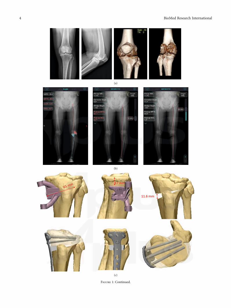
(a)
(b)
(c)
Figure 1: Continued.
4 BioMed Research International
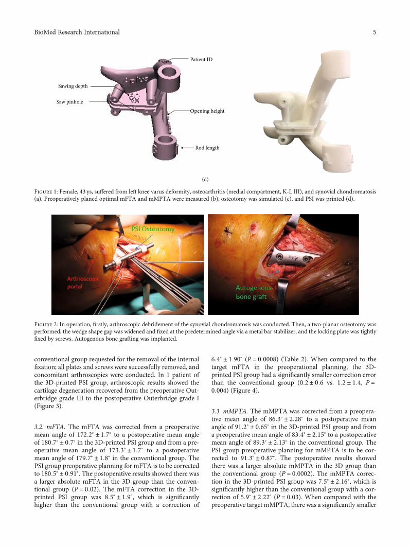
conventional group requested for the removal of the internalfixation; all plates and screws were successfully removed, andconcomitant arthroscopies were conducted. In 1 patient ofthe 3D-printed PSI group, arthroscopic results showed thecartilage degeneration recovered from the preoperative Out-erbridge grade III to the postoperative Outerbridge grade I(Figure 3).
3.2. mFTA. The mFTA was corrected from a preoperativemean angle of 172:2° ± 1:7° to a postoperative mean angleof 180:7° ± 0:7° in the 3D-printed PSI group and from a pre-operative mean angle of 173:3° ± 1:7° to a postoperativemean angle of 179:7° ± 1:8° in the conventional group. ThePSI group preoperative planning for mFTA is to be correctedto 180:5° ± 0:91°. The postoperative results showed there wasa larger absolute mFTA in the 3D group than the conven-tional group (P = 0:02). The mFTA correction in the 3D-printed PSI group was 8:5° ± 1:9°, which is significantlyhigher than the conventional group with a correction of
6:4° ± 1:90° (P = 0:0008) (Table 2). When compared to thetarget mFTA in the preoperational planning, the 3D-printed PSI group had a significantly smaller correction errorthan the conventional group (0:2 ± 0:6 vs. 1:2 ± 1:4, P =0:004) (Figure 4).
3.3. mMPTA. The mMPTA was corrected from a preopera-tive mean angle of 86:3° ± 2:28° to a postoperative meanangle of 91:2° ± 0:65° in the 3D-printed PSI group and froma preoperative mean angle of 83:4° ± 2:15° to a postoperativemean angle of 89:3° ± 2:13° in the conventional group. ThePSI group preoperative planning for mMPTA is to be cor-rected to 91:3° ± 0:87°. The postoperative results showedthere was a larger absolute mMPTA in the 3D group thanthe conventional group (P = 0:0002). The mMPTA correc-tion in the 3D-printed PSI group was 7:5° ± 2:16°, which issignificantly higher than the conventional group with a cor-rection of 5:9° ± 2:22° (P = 0:03). When compared with thepreoperative target mMPTA, there was a significantly smaller
Patient ID
Opening height
Rod length
Saw pinhole
Sawing depth
(d)
Figure 1: Female, 43 ys, suffered from left knee varus deformity, osteoarthritis (medial compartment, K-L III), and synovial chondromatosis(a). Preoperatively planed optimal mFTA and mMPTA were measured (b), osteotomy was simulated (c), and PSI was printed (d).
Figure 2: In operation, firstly, arthroscopic debridement of the synovial chondromatosis was conducted. Then, a two-planar osteotomy wasperformed, the wedge shape gap was widened and fixed at the predetermined angle via a metal bar stabilizer, and the locking plate was tightlyfixed by screws. Autogenous bone grafting was implanted.
5BioMed Research International
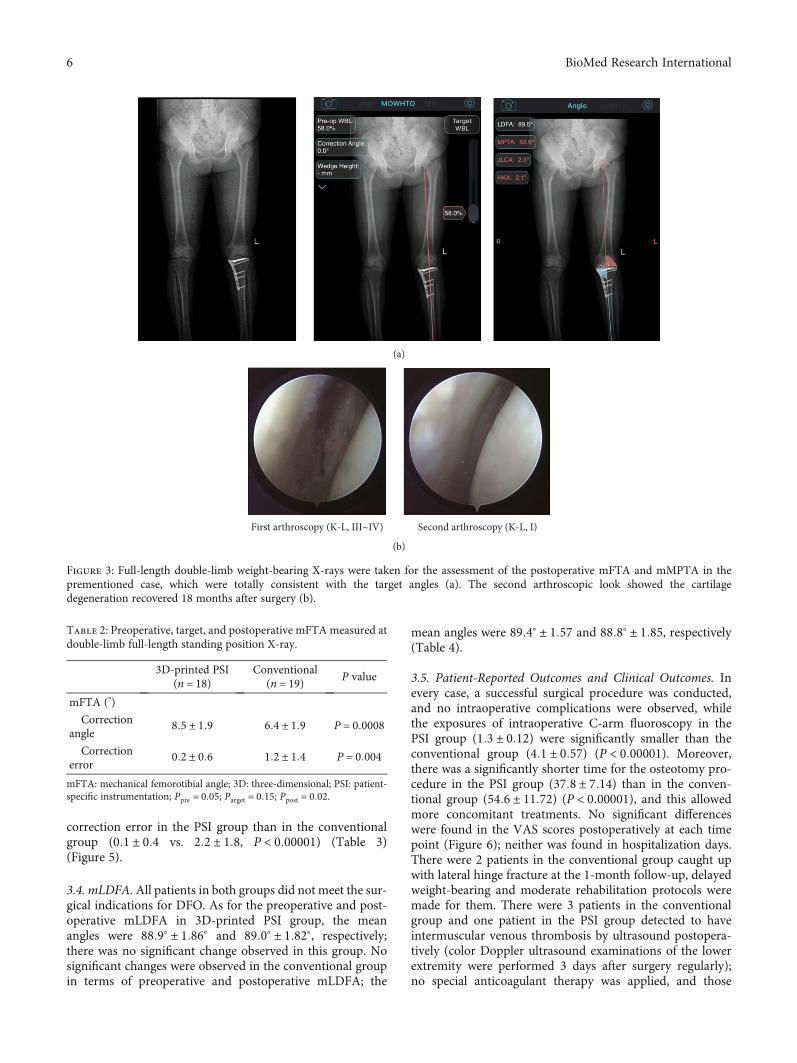
correction error in the PSI group than in the conventionalgroup (0:1 ± 0:4 vs. 2:2 ± 1:8, P < 0:00001) (Table 3)(Figure 5).
3.4. mLDFA.All patients in both groups did not meet the sur-gical indications for DFO. As for the preoperative and post-operative mLDFA in 3D-printed PSI group, the meanangles were 88:9° ± 1:86° and 89:0° ± 1:82°, respectively;there was no significant change observed in this group. Nosignificant changes were observed in the conventional groupin terms of preoperative and postoperative mLDFA; the
mean angles were 89:4° ± 1:57 and 88:8° ± 1:85, respectively(Table 4).
3.5. Patient-Reported Outcomes and Clinical Outcomes. Inevery case, a successful surgical procedure was conducted,and no intraoperative complications were observed, whilethe exposures of intraoperative C-arm fluoroscopy in thePSI group (1:3 ± 0:12) were significantly smaller than theconventional group (4:1 ± 0:57) (P < 0:00001). Moreover,there was a significantly shorter time for the osteotomy pro-cedure in the PSI group (37:8 ± 7:14) than in the conven-tional group (54:6 ± 11:72) (P < 0:00001), and this allowedmore concomitant treatments. No significant differenceswere found in the VAS scores postoperatively at each timepoint (Figure 6); neither was found in hospitalization days.There were 2 patients in the conventional group caught upwith lateral hinge fracture at the 1-month follow-up, delayedweight-bearing and moderate rehabilitation protocols weremade for them. There were 3 patients in the conventionalgroup and one patient in the PSI group detected to haveintermuscular venous thrombosis by ultrasound postopera-tively (color Doppler ultrasound examinations of the lowerextremity were performed 3 days after surgery regularly);no special anticoagulant therapy was applied, and those
(a)
First arthroscopy (K-L, III~IV) Second arthroscopy (K-L, I)
(b)
Figure 3: Full-length double-limb weight-bearing X-rays were taken for the assessment of the postoperative mFTA and mMPTA in theprementioned case, which were totally consistent with the target angles (a). The second arthroscopic look showed the cartilagedegeneration recovered 18 months after surgery (b).
Table 2: Preoperative, target, and postoperative mFTAmeasured atdouble-limb full-length standing position X-ray.
3D-printed PSI(n = 18)
Conventional(n = 19) P value
mFTA (°)
Correctionangle
8:5 ± 1:9 6:4 ± 1:9 P = 0:0008
Correctionerror
0:2 ± 0:6 1:2 ± 1:4 P = 0:004
mFTA: mechanical femorotibial angle; 3D: three-dimensional; PSI: patient-specific instrumentation; Ppre = 0:05; Parget = 0:15; Ppost = 0:02.
6 BioMed Research International
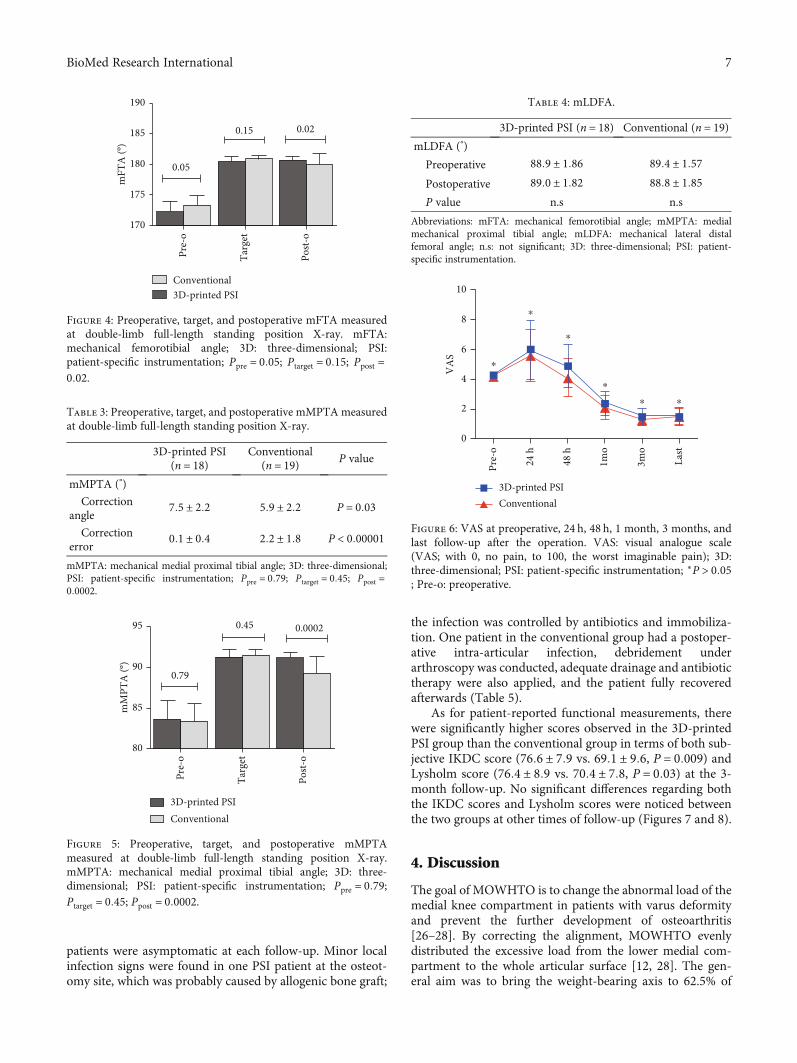
patients were asymptomatic at each follow-up. Minor localinfection signs were found in one PSI patient at the osteot-omy site, which was probably caused by allogenic bone graft;
the infection was controlled by antibiotics and immobiliza-tion. One patient in the conventional group had a postoper-ative intra-articular infection, debridement underarthroscopy was conducted, adequate drainage and antibiotictherapy were also applied, and the patient fully recoveredafterwards (Table 5).
As for patient-reported functional measurements, therewere significantly higher scores observed in the 3D-printedPSI group than the conventional group in terms of both sub-jective IKDC score (76:6 ± 7:9 vs. 69:1 ± 9:6, P = 0:009) andLysholm score (76:4 ± 8:9 vs. 70:4 ± 7:8, P = 0:03) at the 3-month follow-up. No significant differences regarding boththe IKDC scores and Lysholm scores were noticed betweenthe two groups at other times of follow-up (Figures 7 and 8).
4. Discussion
The goal of MOWHTO is to change the abnormal load of themedial knee compartment in patients with varus deformityand prevent the further development of osteoarthritis[26–28]. By correcting the alignment, MOWHTO evenlydistributed the excessive load from the lower medial com-partment to the whole articular surface [12, 28]. The gen-eral aim was to bring the weight-bearing axis to 62.5% of
0.020.15
0.05
190
185
180
mFT
A (º
)
175
170Ta
rget
Pre-
o
Post-
o
Conventional3D-printed PSI
Figure 4: Preoperative, target, and postoperative mFTA measuredat double-limb full-length standing position X-ray. mFTA:mechanical femorotibial angle; 3D: three-dimensional; PSI:patient-specific instrumentation; Ppre = 0:05; Ptarget = 0:15; Ppost =0:02.
Table 3: Preoperative, target, and postoperative mMPTAmeasuredat double-limb full-length standing position X-ray.
3D-printed PSI(n = 18)
Conventional(n = 19) P value
mMPTA (°)
Correctionangle
7:5 ± 2:2 5:9 ± 2:2 P = 0:03
Correctionerror
0:1 ± 0:4 2:2 ± 1:8 P < 0:00001
mMPTA: mechanical medial proximal tibial angle; 3D: three-dimensional;PSI: patient-specific instrumentation; Ppre = 0:79; Ptarget = 0:45; Ppost =0:0002.
0.79
0.45 0.000295
90
85
80
mM
PTA
(º)
Targ
et
Pre-
o
Post-
o
Conventional3D-printed PSI
Figure 5: Preoperative, target, and postoperative mMPTAmeasured at double-limb full-length standing position X-ray.mMPTA: mechanical medial proximal tibial angle; 3D: three-dimensional; PSI: patient-specific instrumentation; Ppre = 0:79;Ptarget = 0:45; Ppost = 0:0002.
Table 4: mLDFA.
3D-printed PSI (n = 18) Conventional (n = 19)mLDFA (°)
Preoperative 88:9 ± 1:86 89:4 ± 1:57
Postoperative 89:0 ± 1:82 88:8 ± 1:85P value n.s n.s
Abbreviations: mFTA: mechanical femorotibial angle; mMPTA: medialmechanical proximal tibial angle; mLDFA: mechanical lateral distalfemoral angle; n.s: not significant; 3D: three-dimensional; PSI: patient-specific instrumentation.
10
8
6
4
2
0V
AS
Pre-
o
24 h
48 h
1mo
3mo
Last
⁎⁎
⁎
⁎
⁎
⁎
Conventional3D-printed PSI
Figure 6: VAS at preoperative, 24 h, 48 h, 1 month, 3 months, andlast follow-up after the operation. VAS: visual analogue scale(VAS; with 0, no pain, to 100, the worst imaginable pain); 3D:three-dimensional; PSI: patient-specific instrumentation; ∗P > 0:05; Pre-o: preoperative.
7BioMed Research International
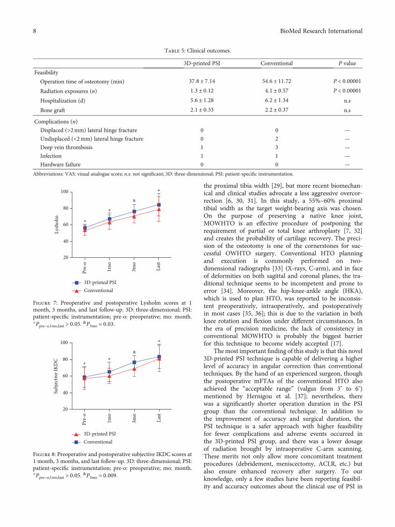
the proximal tibia width [29], but more recent biomechan-ical and clinical studies advocate a less aggressive overcor-rection [6, 30, 31]. In this study, a 55%~60% proximaltibial width as the target weight-bearing axis was chosen.On the purpose of preserving a native knee joint,MOWHTO is an effective procedure of postponing therequirement of partial or total knee arthroplasty [7, 32]and creates the probability of cartilage recovery. The preci-sion of the osteotomy is one of the cornerstones for suc-cessful OWHTO surgery. Conventional HTO planningand execution is commonly performed on two-dimensional radiographs [33] (X-rays, C-arm), and in faceof deformities on both sagittal and coronal planes, the tra-ditional technique seems to be incompetent and prone toerror [34]. Moreover, the hip-knee-ankle angle (HKA),which is used to plan HTO, was reported to be inconsis-tent preoperatively, intraoperatively, and postoperativelyin most cases [35, 36]; this is due to the variation in bothknee rotation and flexion under different circumstances. Inthe era of precision medicine, the lack of consistency inconventional MOWHTO is probably the biggest barrierfor this technique to become widely accepted [17].
The most important finding of this study is that this novel3D-printed PSI technique is capable of delivering a higherlevel of accuracy in angular correction than conventionaltechniques. By the hand of an experienced surgeon, thoughthe postoperative mFTAs of the conventional HTO alsoachieved the “acceptable range” (valgus from 3° to 6°)mentioned by Hernigou et al. [37]; nevertheless, therewas a significantly shorter operation duration in the PSIgroup than the conventional technique. In addition tothe improvement of accuracy and surgical duration, thePSI technique is a safer approach with higher feasibilityfor fewer complications and adverse events occurred inthe 3D-printed PSI group, and there was a lower dosageof radiation brought by intraoperative C-arm scanning.These merits not only allow more concomitant treatmentprocedures (debridement, meniscectomy, ACLR, etc.) butalso ensure enhanced recovery after surgery. To ourknowledge, only a few studies have been reporting feasibil-ity and accuracy outcomes about the clinical use of PSI in
Table 5: Clinical outcomes.
3D-printed PSI Conventional P value
Feasibility
Operation time of osteotomy (min) 37:8 ± 7:14 54:6 ± 11:72 P < 0:00001
Radiation exposures (n) 1:3 ± 0:12 4:1 ± 0:57 P < 0:00001
Hospitalization (d) 5:6 ± 1:28 6:2 ± 1:34 n.s
Bone graft 2:1 ± 0:33 2:2 ± 0:37 n.s
Complications (n)
Displaced (>2mm) lateral hinge fracture 0 0 —
Undisplaced (<2mm) lateral hinge fracture 0 2 —
Deep vein thrombosis 1 3 —
Infection 1 1 —
Hardware failure 0 0 —
Abbreviations: VAS: visual analogue score; n.s: not significant; 3D: three-dimensional; PSI: patient-specific instrumentation.
Conventional3D-printed PSI
Lysh
olm
100
80
60
40
20
Pre-
o
1mo
3mo
Last
⁎
⁎
⁎
&
Figure 7: Preoperative and postoperative Lysholm scores at 1month, 3 months, and last follow-up. 3D: three-dimensional; PSI:patient-specific instrumentation; pre-o: preoperative; mo: month.∗Ppre−o,1mo,last > 0:05. &P3mo = 0:03.
100
Subj
ectiv
e IK
DC 80
60
40
20
Pre-
o
1mo
3mo
Last
⁎
⁎⁎
&
Conventional3D-printed PSI
Figure 8: Preoperative and postoperative subjective IKDC scores at1 month, 3 months, and last follow-up. 3D: three-dimensional; PSI:patient-specific instrumentation; pre-o: preoperative; mo: month.∗Ppre−o,1mo,last > 0:05. &P3mo = 0:009.
8 BioMed Research International
osteotomy around the knee [5, 15, 17, 19, 20, 22]. In thestudy by Van Genechten et al. [5], the two planarMOWHTOs were performed in a relatively conventionalmanner (freehand), while a PSI 3D-printed wedge and castwere adopted instead of the HTO plate. Interestingly, theyalso got excellent corrections outcomes; this precision wasachieved by the patient-specific wedge model fixationrather than the osteotomy procedure itself. As such, theaccuracy of the precised MOWHTO can be achieved inmore than one way with the assistance of the PSI 3D-printed technique. In earlier laboratory studies, the finiteelement analysis (FEA) model by Chieh-Szu et al. [21]indicated there was a significant reduction of compressiveload on the tibial plateau in their PSI osteotomy kneeswhen compared with conventional ones (78.8MPa vs.91.9MPa, under 600-N force); it revealed the PSI tech-nique was capable of improving the structural stability,and this novel approach may have the potential to reducethe incidence of hardware dislocation and hinge fractures.In all, although the techniques of PSI and execution ofrelated HTOs varied greatly, the outcomes turned favour-able for PSI 3D-printed technique in all existing studies.However, the accuracy and clinical advantage of PSI overthe conventional surgical methodology in MOWHTO stillneeds to be proven in large comparative studies withlong-term follow-up.
Moreover, the effective treatment for knee OA is notmerely about the correction of malalignment; further atten-tion should be paid to the intra-articular illness. A visualassessment under arthroscopy can provide a more effectivediagnosis of cartilage degeneration. In addition, treatmentfor the concomitant disease of OA (such as loose body, syno-vitis, meniscus injury, and ACLR) can also be practicedarthroscopically. A comprehensive surgical treatment meritsfurther focus; we should not be limited to isolated osteotomy.Besides, to obtain robust immediate postoperative stabilityand biomechanics, autogenous bone grafting was recom-mended in cases with the wedge opening higher than10mm, and a crossing screw may also be considered; thus,enhanced recovery after surgery can be achieved.
5. Conclusion
With the assistance of 3D-printed PSI, a safe and feasibleMOWHTO can be conducted with superior accuracy thanthe conventional techniques. The combination of precise3D osteotomy cutting guide model contributed to a moreaccurate translation from planning to surgery, and a shorteroperation duration created the opportunities for more con-comitant treatments.
Data Availability
The results in this study are available from the correspondingauthor on reasonable request.
Conflicts of Interest
There are no conflicts of interest.
Authors’ Contributions
Yunhe Mao and Yan Xiong are co-first authors. Jian Li is thecorresponding author.
Acknowledgments
This study was supported by the 1.3.5 project for disciplinesof excellence, West China Hospital, Sichuan University.
References
[1] M. Darees, S. Putman, T. Brosset, T. Roumazeille, G. Pasquier,and H. Migaud, “Opening-wedge high tibial osteotomy per-formed with locking plate fixation (TomoFix) and earlyweight-bearing but without filling the defect. A concisefollow-up note of 48 cases at 10 years' follow-up,” Orthopae-dics & Traumatology, Surgery & Research, vol. 104, no. 4,pp. 477–480, 2018.
[2] M. E. Hantes, P. Natsaridis, A. A. Koutalos, Y. Ono,N. Doxariotis, and K. N. Malizos, “Satisfactory functionaland radiological outcomes can be expected in young patientsunder 45 years old after open wedge high tibial osteotomy ina long-term follow-up,” Knee Surgery, Sports Traumatology,Arthroscopy, vol. 26, no. 11, pp. 3199–3205, 2018.
[3] R. R. Bannuru, M. C. Osani, E. E. Vaysbrot et al., “OARSIguidelines for the non-surgical management of knee, hip,and polyarticular osteoarthritis,” Osteoarthritis and Cartilage,vol. 27, no. 11, pp. 1578–1589, 2019.
[4] M. Van den Bempt, W. Van Genechten, T. Claes, and S. Claes,“How accurately does high tibial osteotomy correct themechanical axis of an arthritic varus knee? A systematicreview,” The Knee, vol. 23, no. 6, pp. 925–935, 2016.
[5] W. van Genechten, W. van Tilborg, M. Van den Bempt,A. Van Haver, and P. Verdonk, “Feasibility and 3D Planningof a Novel Patient-Specific Instrumentation Technique inMedial Opening-Wedge High Tibial Osteotomy,” The Journalof Knee Surgery, 2020.
[6] J. L. Martay, A. J. Palmer, N. K. Bangerter et al., “A preliminarymodeling investigation into the safe correction zone for hightibial osteotomy,” The Knee, vol. 25, no. 2, pp. 286–295, 2018.
[7] J. F. Konopka, A. H. Gomoll, T. S. Thornhill, J. N. Katz, andE. Losina, “The cost-effectiveness of surgical treatment ofmedial unicompartmental knee osteoarthritis in youngerpatients,” The Journal of Bone and Joint Surgery. AmericanVolume, vol. 97, no. 10, pp. 807–817, 2015.
[8] R. Martin, T. B. Birmingham, K. Willits, R. Litchfield, M. E.Lebel, and J. R. Giffin, “Adverse event rates and classificationsin medial opening wedge high tibial osteotomy,” The Ameri-can Journal of Sports Medicine, vol. 42, no. 5, pp. 1118–1126,2014.
[9] D. W. Elson, “The surgical accuracy of knee osteotomy,” TheKnee, vol. 24, no. 2, pp. 167–169, 2017.
[10] Z. P. Wu, P. Zhang, J. Z. Bai et al., “Comparison of navigatedand conventional high tibial osteotomy for the treatment ofosteoarthritic knees with varus deformity: a meta-analysis,”International Journal of Surgery, vol. 55, pp. 211–219, 2018.
[11] S. B. Han, D. H. Lee, G. M. Shetty, D. J. Chae, J. G. Song, andK. W. Nha, “A "safe zone" in medial open-wedge high tibiaosteotomy to prevent lateral cortex fracture,” Knee Surg SportsTraumatol Arthrosc, vol. 21, no. 1, pp. 90–95, 2013.
9BioMed Research International
[12] T. R. Sprenger and J. F. Doerzbacher, “Tibial osteotomy for thetreatment of varus gonarthrosis. Survival and failure analysisto twenty-two years,” The Journal of Bone and Joint Surgery.American Volume, vol. 85, no. 3, pp. 469–474, 2003.
[13] G. G. Jones, M. Jaere, S. Clarke, and J. Cobb, “3D printing andhigh tibial osteotomy,” EFORTOpen Rev, vol. 3, no. 5, pp. 254–259, 2018.
[14] D. P. Sarment, K. Al-Shammari, and C. E. Kazor, “Stereolitho-graphic surgical templates for placement of dental implants incomplex cases,” The International Journal of Periodontics &Restorative Dentistry, vol. 23, no. 3, pp. 287–295, 2003.
[15] H. J. Kim, J. Park, J. Y. Shin, I. H. Park, K. H. Park, and H. S.Kyung, “More accurate correction can be obtained using athree-dimensional printed model in open-wedge high tibialosteotomy,” Knee Surgery, Sports Traumatology, Arthroscopy,vol. 26, no. 11, pp. 3452–3458, 2018.
[16] S. Lu, Y. Z. Zhang, Z. Wang et al., “Accuracy and efficacy ofthoracic pedicle screws in scoliosis with patient-specific drilltemplate,” Medical & Biological Engineering & Computing,vol. 50, no. 7, pp. 751–758, 2012.
[17] J. Victor and A. Premanathan, “Virtual 3D planning andpatient specific surgical guides for osteotomies around theknee,” Bone Joint J, vol. 95-b, 11_Supple_A, pp. 153–158, 2013.
[18] M. Donnez, M. Ollivier, M. Munier et al., “Are three-dimensional patient-specific cutting guides for open wedgehigh tibial osteotomy accurate? An in vitro study,” Journal ofOrthopaedic Surgery and Research, vol. 13, no. 1, p. 171, 2018.
[19] M. Munier, M. Donnez, M. Ollivier et al., “Can three-dimensional patient-specific cutting guides be used to achieveoptimal correction for high tibial osteotomy? Pilot study,”Orthopaedics & Traumatology, Surgery & Research, vol. 103,no. 2, pp. 245–250, 2017.
[20] R. Pérez-Mañanes, J. Burró, J. Manaute, F. Rodriguez, andJ. Martín, “3D Surgical Printing Cutting Guides for Open-Wedge High Tibial Osteotomy: Do It Yourself,” The Journalof Knee Surgery, vol. 29, no. 8, pp. 690–695, 2016.
[21] J. Chieh-Szu Yang, C. F. Chen, and O. K. Lee, “Benefits ofopposite screw insertion technique in medial open-wedge hightibial osteotomy: a virtual biomechanical study,” J OrthopTranslat, vol. 20, pp. 31–36, 2020.
[22] J. C.-S. Yang, C.-F. Chen, C.-A. Luo et al., “Clinical ExperienceUsing a 3D-Printed Patient-Specific Instrument for MedialOpening Wedge High Tibial Osteotomy,” BioMed ResearchInternational, vol. 2018, Article ID 9246529, 9 pages, 2018.
[23] L. Sharma, J. Song, D. T. Felson, S. Cahue, E. Shamiyeh, andD. D. Dunlop, “The role of knee alignment in disease progres-sion and functional decline in knee osteoarthritis,” JAMA,vol. 286, no. 2, pp. 188–195, 2001.
[24] J. J. Irrgang, A. F. Anderson, A. L. Boland et al., “Developmentand Validation of the International Knee DocumentationCommittee Subjective Knee Form,” The American Journal ofSports Medicine, vol. 29, no. 5, pp. 600–613, 2017.
[25] L. D. Higgins, M. K. Taylor, D. Park et al., “Reliability andvalidity of the international knee documentation committee(IKDC) subjective knee form,” Joint, Bone, Spine, vol. 74,no. 6, pp. 594–599, 2007.
[26] G. Bauer, J. Insall, and T. Koshino, “Tibial osteotomy in gonar-throsis (osteo-arthritis of the knee),” The Journal of Bone andJoint Surgery. American Volume, vol. 51, no. 8, pp. 1545–1563, 1969.
[27] J. N. Insall, D. M. Joseph, and C. Msika, “High tibial osteotomyfor varus gonarthrosis. A long-term follow-up study,” TheJournal of Bone and Joint Surgery. American Volume, vol. 66,no. 7, pp. 1040–1048, 1984.
[28] K. Yasuda, T. Majima, T. Tsuchida, and K. Kaneda, “A ten- to15-year follow-up observation of high tibial osteotomy inmedial compartment osteoarthrosis,” Clin Orthop Relat Res,no. 282, pp. 186–195, 1992.
[29] T. H. O. M. A. S. W. DUGDALE, F. R. A. N. K. R. NOYES, andD. A. V. I. D. STYER, “Preoperative Planning for High Tibialosteotomy. The effect of lateral tibiofemoral separation andtibiofemoral length,” Clinical Orthopaedics and RelatedResearch, no. 274, pp. 248–264, 1992.
[30] J. C. Stanley, K. G. Robinson, B. M. Devitt et al., “Computerassisted alignment of opening wedge high tibial osteotomyprovides limited improvement of radiographic outcomes com-pared to flouroscopic alignment,” The Knee, vol. 23, no. 2,pp. 289–294, 2016.
[31] G. J. van de Pol, N. Verdonschot, and A. van Kampen, “Thevalue of the intra-operative clinical mechanical axis measure-ment in open-wedge valgus high tibial osteotomies,” The Knee,vol. 19, no. 6, pp. 933–938, 2012.
[32] W. B. Smith II, J. Steinberg, S. Scholtes, and I. R. Mcnamara,“Medial compartment knee osteoarthritis: age-stratified cost-effectiveness of total knee arthroplasty, unicompartmentalknee arthroplasty, and high tibial osteotomy,” Knee Surgery,Sports Traumatology, Arthroscopy, vol. 25, no. 3, pp. 924–933, 2017.
[33] J. Brinkman, P. Lobenhoffer, J. Agneskirchner, A. Staubli,A. Wymenga, and R. van Heerwaarden, “Osteotomies aroundthe knee: patient selection, stability of fixation and bone heal-ing in high tibial osteotomies,” The Journal of Bone and JointSurgery. British Volume, vol. 90, no. 12, pp. 1548–1557, 2008.
[34] H. Kawakami, N. Sugano, K. Yonenobu et al., “Effects of rota-tion on measurement of lower limb alignment for knee osteot-omy,” Journal of Orthopaedic Research, vol. 22, no. 6,pp. 1248–1253, 2004.
[35] T. Koshino, M. Takeyama, L. S. Jiang, T. Yoshida, and T. Saito,“Underestimation of varus angulation in knees with flexiondeformity,” The Knee, vol. 9, no. 4, pp. 275–279, 2002.
[36] K. E. Swanson, G. W. Stocks, P. D. Warren, M. R. Hazel, andH. F. Janssen, “Does axial limb rotation affect the alignmentmeasurements in deformed limbs?,” Clin Orthop Relat Res,vol. 371, no. 371, pp. 246–252, 2000.
[37] P. Hernigou, D. Medevielle, J. Debeyre, and D. Goutallier,“Proximal tibial osteotomy for osteoarthritis with varus defor-mity. A ten to thirteen-year follow-up study,” The Journal ofBone and Joint Surgery. American Volume, vol. 69, no. 3,pp. 332–354, 1987.
10 BioMed Research International
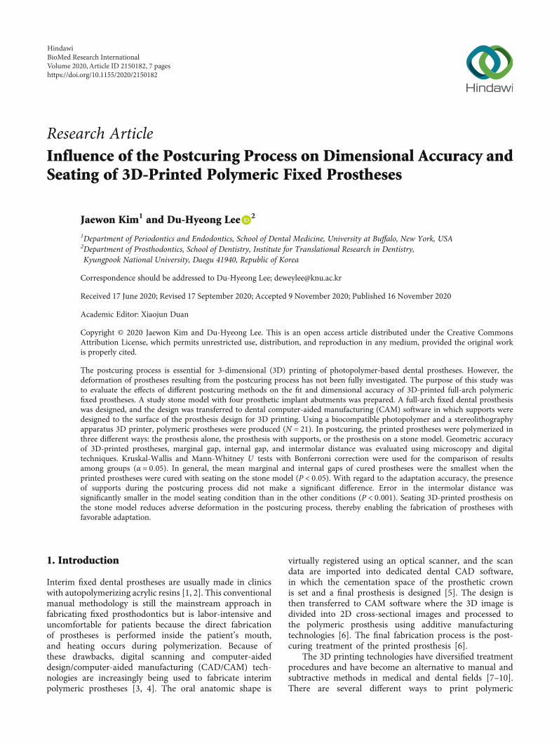
Research ArticleInfluence of the Postcuring Process on Dimensional Accuracy andSeating of 3D-Printed Polymeric Fixed Prostheses
Jaewon Kim1 and Du-Hyeong Lee 2
1Department of Periodontics and Endodontics, School of Dental Medicine, University at Buffalo, New York, USA2Department of Prosthodontics, School of Dentistry, Institute for Translational Research in Dentistry,Kyungpook National University, Daegu 41940, Republic of Korea
Correspondence should be addressed to Du-Hyeong Lee; [email protected]
Received 17 June 2020; Revised 17 September 2020; Accepted 9 November 2020; Published 16 November 2020
Academic Editor: Xiaojun Duan
Copyright © 2020 Jaewon Kim and Du-Hyeong Lee. This is an open access article distributed under the Creative CommonsAttribution License, which permits unrestricted use, distribution, and reproduction in any medium, provided the original workis properly cited.
The postcuring process is essential for 3-dimensional (3D) printing of photopolymer-based dental prostheses. However, thedeformation of prostheses resulting from the postcuring process has not been fully investigated. The purpose of this study wasto evaluate the effects of different postcuring methods on the fit and dimensional accuracy of 3D-printed full-arch polymericfixed prostheses. A study stone model with four prosthetic implant abutments was prepared. A full-arch fixed dental prosthesiswas designed, and the design was transferred to dental computer-aided manufacturing (CAM) software in which supports weredesigned to the surface of the prosthesis design for 3D printing. Using a biocompatible photopolymer and a stereolithographyapparatus 3D printer, polymeric prostheses were produced (N = 21). In postcuring, the printed prostheses were polymerized inthree different ways: the prosthesis alone, the prosthesis with supports, or the prosthesis on a stone model. Geometric accuracyof 3D-printed prostheses, marginal gap, internal gap, and intermolar distance was evaluated using microscopy and digitaltechniques. Kruskal-Wallis and Mann-Whitney U tests with Bonferroni correction were used for the comparison of resultsamong groups (α = 0:05). In general, the mean marginal and internal gaps of cured prostheses were the smallest when theprinted prostheses were cured with seating on the stone model (P < 0:05). With regard to the adaptation accuracy, the presenceof supports during the postcuring process did not make a significant difference. Error in the intermolar distance wassignificantly smaller in the model seating condition than in the other conditions (P < 0:001). Seating 3D-printed prosthesis onthe stone model reduces adverse deformation in the postcuring process, thereby enabling the fabrication of prostheses withfavorable adaptation.
1. Introduction
Interim fixed dental prostheses are usually made in clinicswith autopolymerizing acrylic resins [1, 2]. This conventionalmanual methodology is still the mainstream approach infabricating fixed prosthodontics but is labor-intensive anduncomfortable for patients because the direct fabricationof prostheses is performed inside the patient’s mouth,and heating occurs during polymerization. Because ofthese drawbacks, digital scanning and computer-aideddesign/computer-aided manufacturing (CAD/CAM) tech-nologies are increasingly being used to fabricate interimpolymeric prostheses [3, 4]. The oral anatomic shape is
virtually registered using an optical scanner, and the scandata are imported into dedicated dental CAD software,in which the cementation space of the prosthetic crownis set and a final prosthesis is designed [5]. The design isthen transferred to CAM software where the 3D image isdivided into 2D cross-sectional images and processed tothe polymeric prosthesis using additive manufacturingtechnologies [6]. The final fabrication process is the post-curing treatment of the printed prosthesis [6].
The 3D printing technologies have diversified treatmentprocedures and have become an alternative to manual andsubtractive methods in medical and dental fields [7–10].There are several different ways to print polymeric
HindawiBioMed Research InternationalVolume 2020, Article ID 2150182, 7 pageshttps://doi.org/10.1155/2020/2150182
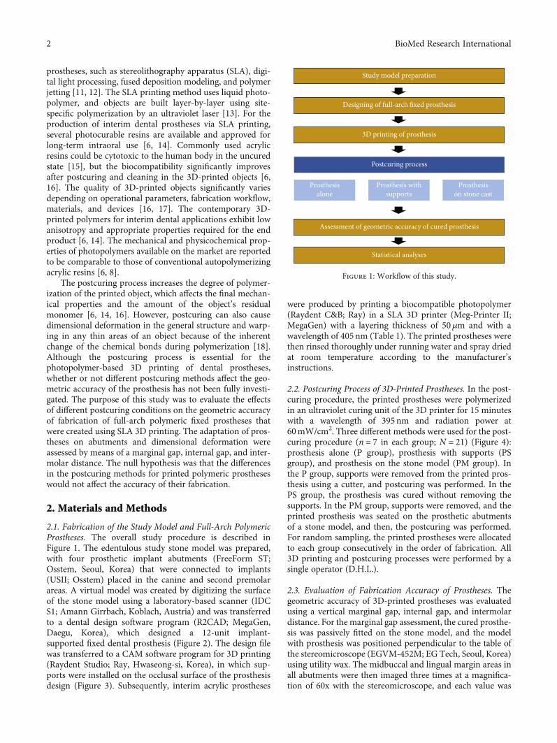
prostheses, such as stereolithography apparatus (SLA), digi-tal light processing, fused deposition modeling, and polymerjetting [11, 12]. The SLA printing method uses liquid photo-polymer, and objects are built layer-by-layer using site-specific polymerization by an ultraviolet laser [13]. For theproduction of interim dental prostheses via SLA printing,several photocurable resins are available and approved forlong-term intraoral use [6, 14]. Commonly used acrylicresins could be cytotoxic to the human body in the uncuredstate [15], but the biocompatibility significantly improvesafter postcuring and cleaning in the 3D-printed objects [6,16]. The quality of 3D-printed objects significantly variesdepending on operational parameters, fabrication workflow,materials, and devices [16, 17]. The contemporary 3D-printed polymers for interim dental applications exhibit lowanisotropy and appropriate properties required for the endproduct [6, 14]. The mechanical and physicochemical prop-erties of photopolymers available on the market are reportedto be comparable to those of conventional autopolymerizingacrylic resins [6, 8].
The postcuring process increases the degree of polymer-ization of the printed object, which affects the final mechan-ical properties and the amount of the object’s residualmonomer [6, 14, 16]. However, postcuring can also causedimensional deformation in the general structure and warp-ing in any thin areas of an object because of the inherentchange of the chemical bonds during polymerization [18].Although the postcuring process is essential for thephotopolymer-based 3D printing of dental prostheses,whether or not different postcuring methods affect the geo-metric accuracy of the prosthesis has not been fully investi-gated. The purpose of this study was to evaluate the effectsof different postcuring conditions on the geometric accuracyof fabrication of full-arch polymeric fixed prostheses thatwere created using SLA 3D printing. The adaptation of pros-theses on abutments and dimensional deformation wereassessed by means of a marginal gap, internal gap, and inter-molar distance. The null hypothesis was that the differencesin the postcuring methods for printed polymeric prostheseswould not affect the accuracy of their fabrication.
2. Materials and Methods
2.1. Fabrication of the Study Model and Full-Arch PolymericProstheses. The overall study procedure is described inFigure 1. The edentulous study stone model was prepared,with four prosthetic implant abutments (FreeForm ST;Osstem, Seoul, Korea) that were connected to implants(USII; Osstem) placed in the canine and second premolarareas. A virtual model was created by digitizing the surfaceof the stone model using a laboratory-based scanner (IDCS1; Amann Girrbach, Koblach, Austria) and was transferredto a dental design software program (R2CAD; MegaGen,Daegu, Korea), which designed a 12-unit implant-supported fixed dental prosthesis (Figure 2). The design filewas transferred to a CAM software program for 3D printing(Raydent Studio; Ray, Hwaseong-si, Korea), in which sup-ports were installed on the occlusal surface of the prosthesisdesign (Figure 3). Subsequently, interim acrylic prostheses
were produced by printing a biocompatible photopolymer(Raydent C&B; Ray) in a SLA 3D printer (Meg-Printer II;MegaGen) with a layering thickness of 50μm and with awavelength of 405nm (Table 1). The printed prostheses werethen rinsed thoroughly under running water and spray driedat room temperature according to the manufacturer’sinstructions.
2.2. Postcuring Process of 3D-Printed Prostheses. In the post-curing procedure, the printed prostheses were polymerizedin an ultraviolet curing unit of the 3D printer for 15 minuteswith a wavelength of 395nm and radiation power at60mW/cm2. Three different methods were used for the post-curing procedure (n = 7 in each group; N = 21) (Figure 4):prosthesis alone (P group), prosthesis with supports (PSgroup), and prosthesis on the stone model (PM group). Inthe P group, supports were removed from the printed pros-thesis using a cutter, and postcuring was performed. In thePS group, the prosthesis was cured without removing thesupports. In the PM group, supports were removed, and theprinted prosthesis was seated on the prosthetic abutmentsof a stone model, and then, the postcuring was performed.For random sampling, the printed prostheses were allocatedto each group consecutively in the order of fabrication. All3D printing and postcuring processes were performed by asingle operator (D.H.L.).
2.3. Evaluation of Fabrication Accuracy of Prostheses. Thegeometric accuracy of 3D-printed prostheses was evaluatedusing a vertical marginal gap, internal gap, and intermolardistance. For the marginal gap assessment, the cured prosthe-sis was passively fitted on the stone model, and the modelwith prosthesis was positioned perpendicular to the table ofthe stereomicroscope (EGVM-452M; EG Tech, Seoul, Korea)using utility wax. The midbuccal and lingual margin areas inall abutments were then imaged three times at a magnifica-tion of 60x with the stereomicroscope, and each value was
Study model preparation
Designing of full-arch fixed prosthesis
3D printing of prosthesis
Postcuring process
Assessment of geometric accuracy of cured prosthesis
Statistical analyses
Prosthesisalone
Prosthesis withsupports
Prosthesison stone cast
Figure 1: Workflow of this study.
2 BioMed Research International
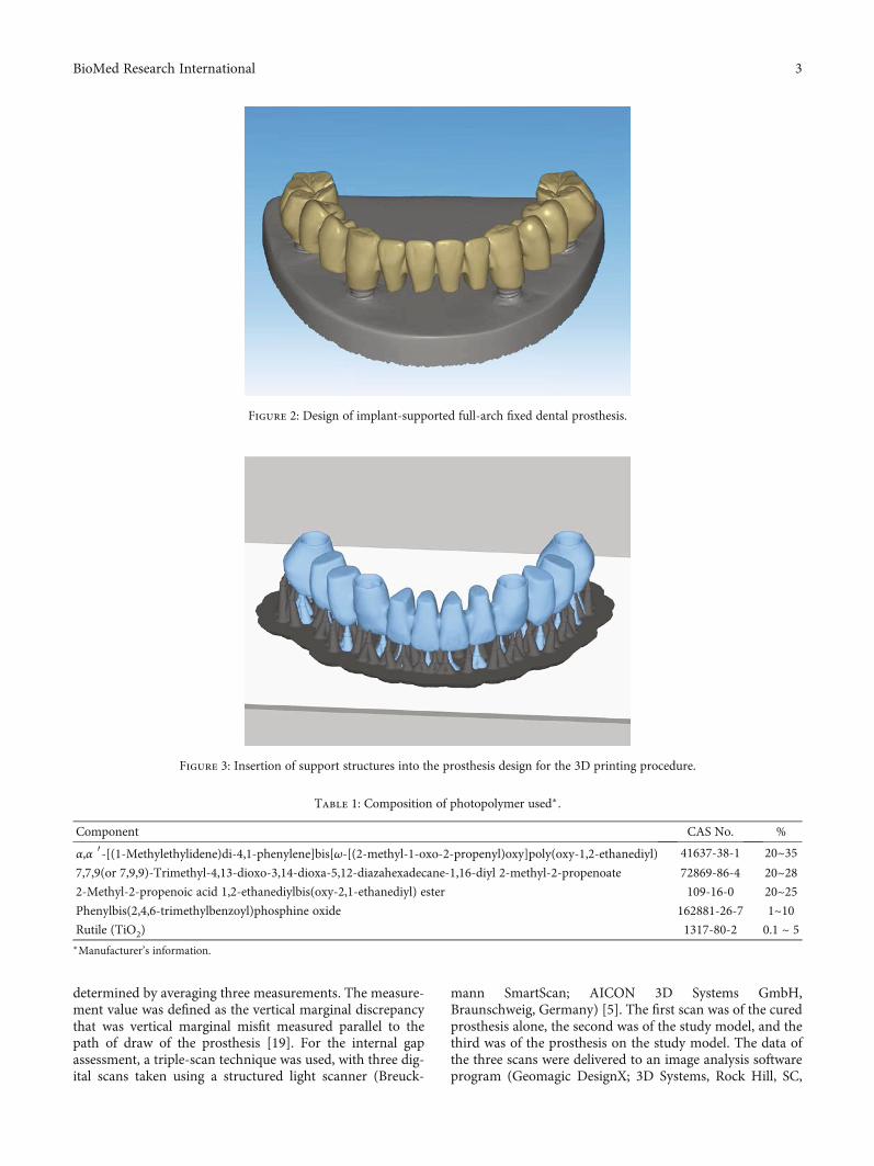
determined by averaging three measurements. The measure-ment value was defined as the vertical marginal discrepancythat was vertical marginal misfit measured parallel to thepath of draw of the prosthesis [19]. For the internal gapassessment, a triple-scan technique was used, with three dig-ital scans taken using a structured light scanner (Breuck-
mann SmartScan; AICON 3D Systems GmbH,Braunschweig, Germany) [5]. The first scan was of the curedprosthesis alone, the second was of the study model, and thethird was of the prosthesis on the study model. The data ofthe three scans were delivered to an image analysis softwareprogram (Geomagic DesignX; 3D Systems, Rock Hill, SC,
Figure 2: Design of implant-supported full-arch fixed dental prosthesis.
Figure 3: Insertion of support structures into the prosthesis design for the 3D printing procedure.
Table 1: Composition of photopolymer used∗.
Component CAS No. %
α,α ′-[(1-Methylethylidene)di-4,1-phenylene]bis[ω-[(2-methyl-1-oxo-2-propenyl)oxy]poly(oxy-1,2-ethanediyl) 41637-38-1 20~357,7,9(or 7,9,9)-Trimethyl-4,13-dioxo-3,14-dioxa-5,12-diazahexadecane-1,16-diyl 2-methyl-2-propenoate 72869-86-4 20~282-Methyl-2-propenoic acid 1,2-ethanediylbis(oxy-2,1-ethanediyl) ester 109-16-0 20~25Phenylbis(2,4,6-trimethylbenzoyl)phosphine oxide 162881-26-7 1~10Rutile (TiO2) 1317-80-2 0.1 ~ 5∗Manufacturer’s information.
3BioMed Research International
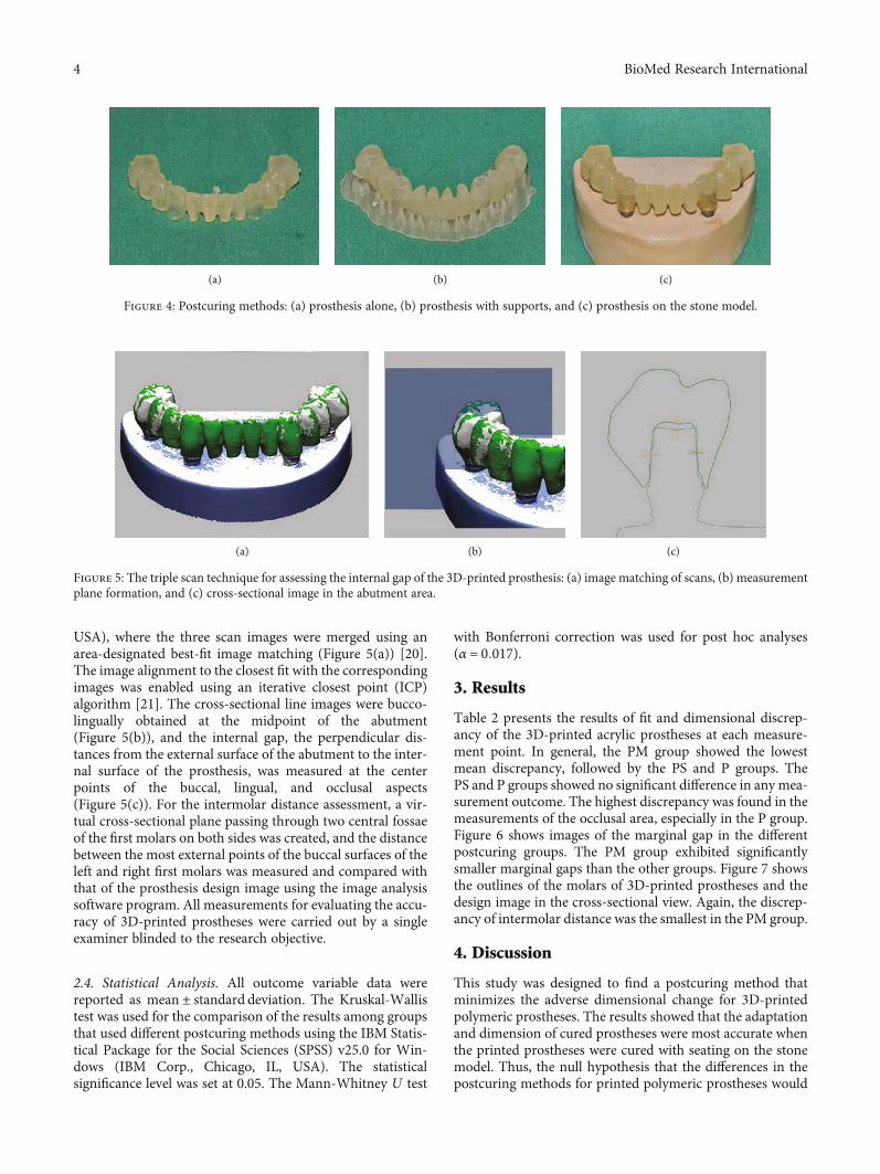
USA), where the three scan images were merged using anarea-designated best-fit image matching (Figure 5(a)) [20].The image alignment to the closest fit with the correspondingimages was enabled using an iterative closest point (ICP)algorithm [21]. The cross-sectional line images were bucco-lingually obtained at the midpoint of the abutment(Figure 5(b)), and the internal gap, the perpendicular dis-tances from the external surface of the abutment to the inter-nal surface of the prosthesis, was measured at the centerpoints of the buccal, lingual, and occlusal aspects(Figure 5(c)). For the intermolar distance assessment, a vir-tual cross-sectional plane passing through two central fossaeof the first molars on both sides was created, and the distancebetween the most external points of the buccal surfaces of theleft and right first molars was measured and compared withthat of the prosthesis design image using the image analysissoftware program. All measurements for evaluating the accu-racy of 3D-printed prostheses were carried out by a singleexaminer blinded to the research objective.
2.4. Statistical Analysis. All outcome variable data werereported as mean ± standard deviation. The Kruskal-Wallistest was used for the comparison of the results among groupsthat used different postcuring methods using the IBM Statis-tical Package for the Social Sciences (SPSS) v25.0 for Win-dows (IBM Corp., Chicago, IL, USA). The statisticalsignificance level was set at 0.05. The Mann-Whitney U test
with Bonferroni correction was used for post hoc analyses(α = 0:017).
3. Results
Table 2 presents the results of fit and dimensional discrep-ancy of the 3D-printed acrylic prostheses at each measure-ment point. In general, the PM group showed the lowestmean discrepancy, followed by the PS and P groups. ThePS and P groups showed no significant difference in any mea-surement outcome. The highest discrepancy was found in themeasurements of the occlusal area, especially in the P group.Figure 6 shows images of the marginal gap in the differentpostcuring groups. The PM group exhibited significantlysmaller marginal gaps than the other groups. Figure 7 showsthe outlines of the molars of 3D-printed prostheses and thedesign image in the cross-sectional view. Again, the discrep-ancy of intermolar distance was the smallest in the PM group.
4. Discussion
This study was designed to find a postcuring method thatminimizes the adverse dimensional change for 3D-printedpolymeric prostheses. The results showed that the adaptationand dimension of cured prostheses were most accurate whenthe printed prostheses were cured with seating on the stonemodel. Thus, the null hypothesis that the differences in thepostcuring methods for printed polymeric prostheses would
(a) (b) (c)
Figure 4: Postcuring methods: (a) prosthesis alone, (b) prosthesis with supports, and (c) prosthesis on the stone model.
(a) (b) (c)
Figure 5: The triple scan technique for assessing the internal gap of the 3D-printed prosthesis: (a) image matching of scans, (b) measurementplane formation, and (c) cross-sectional image in the abutment area.
4 BioMed Research International
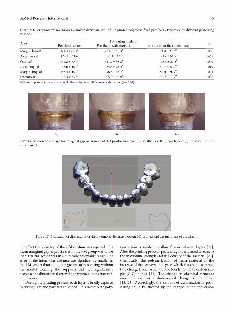
not affect the accuracy of their fabrication was rejected. Themean marginal gap of prostheses in the PM group was lowerthan 120μm, which was in a clinically acceptable range. Theerror in the intermolar distance was significantly smaller inthe PM group than the other groups of postcuring withoutthe model. Leaving the supports did not significantlydecrease the dimensional error that happened in the postcur-ing process.
During the printing process, each layer is briefly exposedto curing light and partially solidified. This incomplete poly-
merization is needed to allow fusion between layers [22].After the printing process, postcuring is performed to achievethe maximum strength and full density of the material [23].Chemically, the polymerization of resin material is theincrease of the conversion degree, which is a chemical struc-ture change from carbon double bonds (C=C) to carbon sin-gle (C-C) bonds [24]. The change in chemical structureinevitably involves a dimensional change of the object[23, 25]. Accordingly, the amount of deformation in post-curing could be affected by the change in the conversion
Table 2: Discrepancy values (mean ± standard deviation; μm) of 3D-printed polymeric fixed prostheses fabricated by different postcuringmethods.
AreaPostcuring methods
PProsthesis alone Prosthesis with supports Prosthesis on the stone model
Margin, buccal 274:4 ± 64:4a 233:0 ± 40:3a 91:8 ± 27:4b 0.008
Axial, buccal 122:1 ± 51:6 125:4 ± 47:8 94:7 ± 64:5 0.468
Occlusal 332:8 ± 70:7a 311:7 ± 58:2a 126:3 ± 27:3b 0.009
Axial, lingual 138:6 ± 46:7a 134:3 ± 28:4a 64:4 ± 22:2b 0.019
Margin, lingual 256:4 ± 46:2a 196:8 ± 38:7a 89:0 ± 26:7b 0.004
Intermolar 115:4 ± 25:3a 105:9 ± 12:9a 39:2 ± 17:7b 0.008
Different superscript lowercase letters indicate significant differences within a row (α = 0:05).
(a) (b) (c)
Figure 6: Microscopic image for marginal gap measurement: (a) prosthesis alone, (b) prosthesis with supports, and (c) prosthesis on thestone model.
Figure 7: Evaluation of discrepancy of the intermolar distance between 3D-printed and design image of prosthesis.
5BioMed Research International
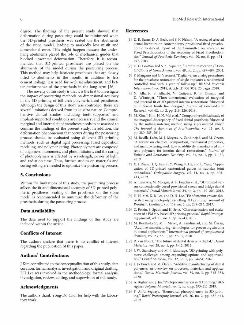
degree. The findings of the present study showed thatdeformation during postcuring could be minimized whenthe 3D-printed prosthesis was seated on the abutmentsof the stone model, leading to markedly low misfit anddimensional error. This might happen because the under-lying abutments played the role of mechanical guides thatblocked unwanted deformation. Therefore, it is recom-mended that 3D-printed prostheses are placed on theabutments of the model during the postcuring process.This method may help fabricate prostheses that are closelyfitted to abutments in the mouth, in addition to lesscement leakage, less need for occlusal adjustment, and bet-ter performance of the prosthesis in the long term [26].
The novelty of this study is that it is the first to investigatethe impact of postcuring methods on dimensional accuracyin the 3D printing of full-arch polymeric fixed prostheses.Although the design of this study was controlled, there areseveral limitations derived from its in vitro nature. Compre-hensive clinical studies including tooth-supported andimplant-supported conditions are necessary, and the clinicalmarginal and internal fit of prostheses needs to be assessed toconfirm the findings of the present study. In addition, thedeformation phenomenon that occurs during the postcuringprocess should be evaluated using different 3D printingmethods, such as digital light processing, fused depositionmodeling, and polymer jetting. Photopolymers are composedof oligomers, monomers, and photoinitiators, and the curingof photopolymers is affected by wavelength, power of light,and radiation time. Thus, further studies on materials andcuring setting are needed to optimize the postcuring process.
5. Conclusions
Within the limitations of this study, the postcuring processaffects the fit and dimensional accuracy of 3D-printed poly-meric prostheses. Seating of the prosthesis on the stonemodel is recommended to minimize the deformity of theprosthesis during the postcuring process.
Data Availability
The data used to support the findings of this study areincluded within the article.
Conflicts of Interest
The authors declare that there is no conflict of interestregarding the publication of this paper.
Authors’ Contributions
J Kim contributed to the conceptualization of this study, datacuration, formal analysis, investigation, and original drafting.DH Lee was involved in the methodology, formal analysis,investigation, review, editing, and supervision of this study.
Acknowledgments
The authors thank Yong-Do Choi for help with the labora-tory work.
References
[1] D. R. Burns, D. A. Beck, and S. K. Nelson, “A review of selecteddental literature on contemporary provisional fixed prostho-dontic treatment: report of the Committee on Research inFixed Prosthodontics of the Academy of Fixed Prosthodon-tics,” Journal of Prosthetic Dentistry, vol. 90, no. 5, pp. 474–497, 2003.
[2] D. G. Gratton and S. A. Aquilino, “Interim restorations,” Den-tal Clinics of North America, vol. 48, no. 2, pp. 487–497, 2004.
[3] F. Mangano and G. Veronesi, “Digital versus analog proceduresfor the prosthetic restoration of single implants: a randomizedcontrolled trial with 1 year of follow-up,” BioMed ResearchInternational, vol. 2018, Article ID 5325032, 20 pages, 2018.
[4] N. Alharbi, S. Alharbi, V. Cuijpers, R. B. Osman, andD. Wismeijer, “Three-dimensional evaluation of marginaland internal fit of 3D-printed interim restorations fabricatedon different finish line designs,” Journal of ProsthodonticResearch, vol. 62, no. 2, pp. 218–226, 2018.
[5] M. Kim, J. Kim, H. N. Mai et al., “Comparative clinical study ofthe marginal discrepancy of fixed dental prosthesis fabricatedby the milling-sintering method using a presintered alloy,”The Journal of Advanced of Prosthodontics, vol. 11, no. 5,pp. 280–285, 2019.
[6] M. Revilla-León, M. J. Meyers, A. Zandinejad, and M. Özcan,“A review on chemical composition, mechanical properties,and manufacturing work flow of additively manufactured cur-rent polymers for interim dental restorations,” Journal ofEsthetic and Restorative Dentistry, vol. 31, no. 1, pp. 51–57,2019.
[7] X. J. Duan, H. Q. Fan, F. Y. Wang, P. He, and L. Yang, “Appli-cation of 3D-printed customized guides in subtalar jointarthrodesis,” Orthopaedic Surgery, vol. 11, no. 3, pp. 405–413, 2019.
[8] A. Tahayeri, M. Morgan, A. P. Fugolin et al., “3D printed ver-sus conventionally cured provisional crown and bridge dentalmaterials,” Dental Materials, vol. 34, no. 2, pp. 192–200, 2018.
[9] H. N. Mai, K. B. Lee, and D. H. Lee, “Fit of interim crowns fab-ricated using photopolymer-jetting 3D printing,” Journal ofProsthetic Dentistry, vol. 118, no. 2, pp. 208–215, 2017.
[10] C. Polzin, S. Spath, and H. Seitz, “Characterization and evalu-ation of a PMMA-based 3D printing process,” Rapid Prototyp-ing Journal, vol. 19, no. 1, pp. 37–43, 2013.
[11] M. Revilla-León, M. J. Meyer, A. Zandinejad, and M. Özcan,“Additive manufacturing technologies for processing zirconiain dental applications,” International journal of computerizeddentistry, vol. 23, no. 1, pp. 27–37, 2020.
[12] R. van Noort, “The future of dental devices is digital,” DentalMaterials, vol. 28, no. 1, pp. 3–12, 2012.
[13] J. W. Stansbury and M. J. Idacavage, “3D printing with poly-mers: challenges among expanding options and opportuni-ties,” Dental Materials, vol. 32, no. 1, pp. 54–64, 2016.
[14] J. Jockusch and M. Özcan, “Additive manufacturing of dentalpolymers: an overview on processes, materials and applica-tions,” Dental Materials Journal, vol. 39, no. 3, pp. 345–354,2020.
[15] A. Bagheri and J. Jin, “Photopolymerization in 3D printing,” ACSApplied Polymer Materials, vol. 1, no. 4, pp. 593–611, 2019.
[16] F. Alifui-Segbaya, “Biomedical photopolymers in 3D print-ing,” Rapid Prototyping Journal, vol. 26, no. 2, pp. 437–444,2019.
6 BioMed Research International
[17] N. Alharbi, R. Osman, and D. Wismeijer, “Effects of builddirection on the mechanical properties of 3D-printed com-plete coverage interim dental restorations,” Journal of Pros-thetic Dentistry, vol. 115, no. 6, pp. 760–767, 2016.
[18] J. R. Dizon, A. Espera, Q. Chen, and R. Advincula, “Mechani-cal characterization of 3D-printed polymers,” AdditiveManufacturing, vol. 20, pp. 44–67, 2017.
[19] J. R. Holmes, S. C. Bayne, G. A. Holland, and W. D. Sulik,“Considerations in measurement of marginal fit,” Journal ofProsthetic Dentistry, vol. 62, no. 4, pp. 405–408, 1989.
[20] S. Holst, M. Karl, M. Wichmann, and R. E. Matta, “A newtriple-scan protocol for 3D fit assessment of dental restora-tions,” Quintessence International, vol. 42, no. 8, pp. 651–657, 2011.
[21] A. Almukhtar, X. Ju, B. Khambay, J. McDonald, and A. Ayoub,“Comparison of the accuracy of voxel based registration andsurface based registration for 3D assessment of surgical changefollowing orthognathic surgery,” PLoS One, vol. 9, no. 4, articlee93402, 2014.
[22] J. Crivello and E. Reichmanis, “Photopolymer materials andprocesses for advanced technologies,” Chemistry of Materials,vol. 26, pp. 533–548, 2013.
[23] K. Yoshida and E. H. Greener, “Effect of photoinitiator ondegree of conversion of unfilled light-cured resin,” Journal ofDentistry, vol. 22, no. 5, pp. 296–299, 1994.
[24] D. H. Lee, H. N. Mai, J. C. Yang, and T. Y. Kwon, “The effect of4,4'-bis(N,N-diethylamino) benzophenone on the degree ofconversion in liquid photopolymer for dental 3D printing,”The Journal of Advanced of Prosthodontics, vol. 7, no. 5,pp. 386–391, 2015.
[25] M. Balkenhol, M. Knapp, P. Ferger, U. Heun, andB.Wöstmann, “Correlation between polymerization shrinkageand marginal fit of temporary crowns,” Dental Materials,vol. 24, no. 11, pp. 1575–1584, 2008.
[26] D. Ehrenberg, G. I. Weiner, and S. Weiner, “Long-term effectsof storage and thermal cycling on the marginal adaptation ofprovisional resin crowns: a pilot study,” Journal of ProstheticDentistry, vol. 95, no. 3, pp. 230–236, 2006.
7BioMed Research International
CorrigendumCorrigendum to “Prime-Boost Vaccination Using Chemokine-Fused gp120 DNA and HIV Envelope Peptides Activates BothImmediate and Long-Term Memory Cellular Responses inRhesus Macaques”
Hong Qin,1,2 Pramod N. Nehete ,3 Hong He ,2,4 Bharti Nehete,3 Stephanie Buchl,3
Soung-chul Cha,1,2 Jagannadha K. Sastry,2,3,4 and Larry W. Kwak1,2
1Department of Lymphoma and Myeloma, M. D. Anderson Cancer Center, The University of Texas, Houston, TX 77030, USA2Center for Cancer Immunology Research, M. D. Anderson Cancer Center, The University of Texas, Houston, TX 77030, USA3Department of Veterinary Sciences, M. D. Anderson Cancer Center, The University of Texas, Bastrop, TX 78602, USA4Department of Immunology, M. D. Anderson Cancer Center, The University of Texas, Houston, TX 77030, USA
Correspondence should be addressed to Jagannadha K. Sastry; [email protected]
Received 18 June 2020; Accepted 22 June 2020; Published 31 October 2020
Copyright © 2020 Hong Qin et al. This is an open access article distributed under the Creative Commons Attribution License,which permits unrestricted use, distribution, and reproduction in any medium, provided the original work is properly cited.
In the article titled “Prime-Boost Vaccination UsingChemokine-Fused gp120 DNA and HIV Envelope PeptidesActivates Both Immediate and Long-Term Memory CellularResponses in Rhesus Macaques” [1] (published when thejournal was titled Journal of Biomedicine and Biotechnology),as raised on PubPeer, there is duplication of panels inFigure 2 [2].
Figure 2(e) is the same as Figure 2(i).Figure 2(f) is the same as Figure 2(i), though Figure 2(f)
has a blue block in the top right of the dot plot. Figure 2(g) isthe same as Figure 2(k).
Figures 2(e)–2(g) were directly above Figures 2(i)–2(k) inthe figure. Dr. Jagannadha Sastry reexamined the originaldata with the third author Hong He who conducted the assayand data analysis and found that this error was introducedwhen copying data from FlowJo to PowerPoint. The authorsprovided a corrected figure redone by Dr. He, as shownbelow:
HindawiBioMed Research InternationalVolume 2020, Article ID 5471638, 2 pageshttps://doi.org/10.1155/2020/5471638
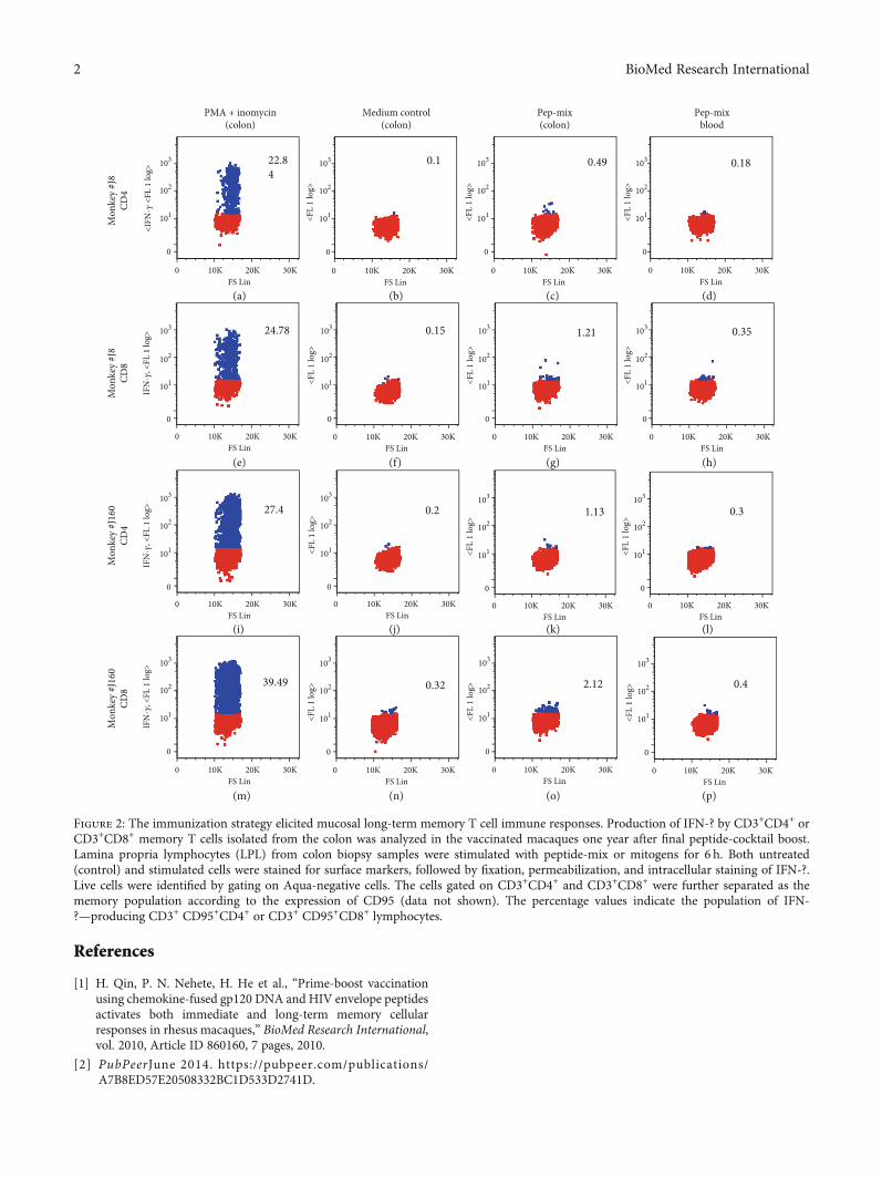
References
[1] H. Qin, P. N. Nehete, H. He et al., “Prime-boost vaccinationusing chemokine-fused gp120 DNA and HIV envelope peptidesactivates both immediate and long-term memory cellularresponses in rhesus macaques,” BioMed Research International,vol. 2010, Article ID 860160, 7 pages, 2010.
[2] PubPeerJune 2014. https://pubpeer.com/publications/A7B8ED57E20508332BC1D533D2741D.
Mon
key
#J16
0CD
8
39.49
IFN
-𝛾, <
FL 1
log>
0 10K 20K 30KFS Lin
0
0.32
0 10K 20K 30KFS Lin
0
<FL
1 lo
g> 2.12
0 10K 20K 30KFS Lin
0
<FL
1 lo
g> 0.4
0 10K 20K 30KFS Lin
0
<FL
1 lo
g>
Mon
key
#J16
0CD
4
27.4
0 10K 20K 30KFS Lin
IFN
-𝛾, <
FL 1
log>
0
0.2
0 10K 20K 30KFS Lin
0
<FL
1 lo
g>
1.13
0 10K 20K 30KFS Lin
0
<FL
1 lo
g>
0.3
0 10K 20K 30KFS Lin
0
<FL
1 lo
g>
Mon
key
#J8
CD8
24.78
IFN
-𝛾, <
FL 1
log>
0 10K 20K 30KFS Lin
0
0.15
0 10K 20K 30KFS Lin
0
<FL
1 lo
g>
0 10K 20K 30KFS Lin
0
<FL
1 lo
g>
1.21 0.35
0 10K 20K 30KFS Lin
0
<FL
1 lo
g>
PMA + inomycin(colon)
Mon
key
#J8
CD4
0 10K 20K 30KFS Lin
0
<IFN
-𝛾 <
FL 1
log>
22.84
Medium control(colon)
0 10K 20K 30KFS Lin
0
<FL
1 lo
g>
0.1
Pep-mix(colon)
0 10K 20K 30KFS Lin
0
<FL
1 lo
g>
0.49
Pep-mixblood
0 10K 20K 30KFS Lin
0
101
102
103
101
102
103
101
102
103
101
102
103
101
102
103
101
102
103
101
102
103
101
102
103
101
102
103
101
102
103
101
102
103
101
102
103
101
102
103
101
102
103
101
102
103
101
102
103
<FL
1 lo
g>
0.18
(a) (b) (c) (d)
(e) (f) (g) (h)
(i) (j) (k) (l)
(m) (n) (o) (p)
Figure 2: The immunization strategy elicited mucosal long-term memory T cell immune responses. Production of IFN-? by CD3+CD4+ orCD3+CD8+ memory T cells isolated from the colon was analyzed in the vaccinated macaques one year after final peptide-cocktail boost.Lamina propria lymphocytes (LPL) from colon biopsy samples were stimulated with peptide-mix or mitogens for 6 h. Both untreated(control) and stimulated cells were stained for surface markers, followed by fixation, permeabilization, and intracellular staining of IFN-?.Live cells were identified by gating on Aqua-negative cells. The cells gated on CD3+CD4+ and CD3+CD8+ were further separated as thememory population according to the expression of CD95 (data not shown). The percentage values indicate the population of IFN-?—producing CD3+ CD95+CD4+ or CD3+ CD95+CD8+ lymphocytes.
2 BioMed Research International
CorrigendumCorrigendum to “Combined Industrial Wastewater Treatment inAnaerobic Bioreactor Post-Treated in Constructed Wetland”
Bibi Saima Zeb ,1 Qaisar Mahmood ,1 Saima Jadoon ,2 Arshid Pervez,1
Muhammad Irshad ,1 Muhammad Bilal,1 and Zulfiqar Ahmad Bhatti1
1Department of Environmental Sciences, COMSATS Institute of Information Technology, Abbottabad 22060, Pakistan2Department of Natural Resources Engineering and Management, University of Kurdistan, Erbil, Iraq
Correspondence should be addressed to Qaisar Mahmood; [email protected]
Received 29 April 2020; Accepted 21 May 2020; Published 29 September 2020
Copyright © 2020 Bibi Saima Zeb et al. This is an open access article distributed under the Creative Commons Attribution License,which permits unrestricted use, distribution, and reproduction in any medium, provided the original work is properly cited.
In the article titled “Combined Industrial Wastewater Treat-ment in Anaerobic Bioreactor Post-treated in ConstructedWetland” [1], there were typographical errors and errors inthe figures. These have been corrected in the revised versionshown below:
(1) The abstract was revised for typographical errors
(2) Language corrections were made in the text
(3) The objectives of the study were clearly mentioned
(4) All acronyms were spelled out when used for the firsttime
(5) Corrections were made to the captions of Figures 1 to10, to aid clear understanding of the plots
(6) Table 2 was deleted as its values were repeated inTable 3 and hence section 3.1 was also deleted
(7) A separate Discussion section was added
(8) An additional article was cited as reference 42 [2] andthe previous references 42-49 became references 43-50
The corrected article is as follows.
Abstract
Constructed Wetland (CW), containing monoculture ofArundo donax L., was investigated for the post-treatment ofeffluent from Anaerobic Bioreactor (ABR) treating combined
industrial wastewater. Different dilutions of combined indus-trial wastewater (20, 40, 60, and 80% v/v) and original waste-water were fed into the ABR as pretreatment. ABR effluentwas post-treated by the laboratory scale CW. The removalefficiencies of Chemical Oxygen Demand (COD), Biochemi-cal Oxygen Demand (BOD), Total Suspended Solids (TSS),nitrates and ammonia were 80%, 78-82%, 91.7%, 88-92%and 100%, respectively, for original industrial wastewatertreated in ABR. ABR was found efficient in the removal ofthe metals Ni, Pb and Cd with removal efficiencies in theorder of Cd (2.7%)>Ni (79%)>Pb (85%). Post-treatmentof the ABR-treated effluent was carried out in lab scale CWplanted with A. donax L. CW was effective in removal ofCOD and various heavy metals present in ABR effluents.Post-treatment in CW resulted in reducing the metal con-centrations of Ni, Pb and Cd to 1.95mg/L, 0mg/L and0.004mg/L, respectively, which were within the limits ofpermissible water quality standards for industrial effluents.The treatment strategy was effective and sustainable totreat combined industrial wastewater.
1. Introduction
Pakistan’s current population of 180 million is expected togrow to about 221 million by the year end 2025 [1]. InPakistan and other developing countries, water pollution isa major threat to the livelihood of people [2]. Heavy metalcontamination of aquatic and terrestrial ecosystems is amajor environmental problem. Each pollution problem calls
HindawiBioMed Research InternationalVolume 2020, Article ID 6102379, 9 pageshttps://doi.org/10.1155/2020/6102379
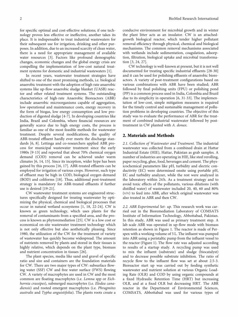
for specific optimal and cost-effective solutions; if one tech-nology proves less effective or ineffective, another takes itsplace. It is indispensable to treat industrial wastewaters fortheir subsequent use for irrigation, drinking and other pur-poses. In addition, due to an increased scarcity of clean water,there is a need for appropriate management of availablewater resources [3]. Factors like profound demographicchanges, economic changes and the global energy crisis arecompelling the implementation of low-cost natural treat-ment systems for domestic and industrial wastewaters [1].
In recent years, wastewater treatment strategies haveshifted to one of the most promising methods, i.e. biologicalanaerobic treatment with the adoption of high rate anaerobicsystems like up-flow anaerobic sludge blanket (UASB) reac-tor and other related treatment systems. The outstandingcharacteristics of high-rate Anaerobic Bioreactors (ABR)include anaerobic microorganisms capable of aggregation,low operational and maintenance costs, energy recovery inthe form of biogas, low energy consumption and low pro-duction of digested sludge [4-7]. In developing countries likeIndia, Brazil and Colombia, where financial resources aregenerally scarce due to high energy costs, the process isfamiliar as one of the most feasible methods for wastewatertreatment. Despite several modifications, the quality ofABR-treated effluent hardly ever meets the discharge stan-dards [6, 8]. Lettinga and co-researchers applied ABR pro-cess for municipal wastewater treatment since the early1980s [9-13] and reported that about 70% chemical oxygendemand (COD) removal can be achieved under warmclimates [6, 14, 15]. Since its inception, wider hype has beengained by this process [16, 17]. ABR-treated effluents can beemployed for irrigation of various crops. However, such typeof effluent may be high in COD, biological oxygen demand(BOD) and coliforms [18]. Thus, additional post-treatmentstrategy is mandatory for ABR-treated effluents if furtheruse is desired [19-21].
CW wastewater treatment systems are engineered struc-tures specifically designed for treating wastewater by opti-mizing the physical, chemical and biological processes thatoccur in natural wetland ecosystems [1, 18, 22-24]. CW isknown as green technology, which uses plants for theremoval of contaminants from a specified area, and the pro-cess is known as phytoremediation [25]. CW is a low cost oreconomical on-site wastewater treatment technology whichis not only effective but also aesthetically pleasing. Since1980, the utilization of the CW for the treatment of varietyof wastewater has quickly become widespread. The amountof nutrients removed by plants and stored in their tissues ishighly relative, which depends on the plant type, biomassand nutrient concentration in tissues [26].
The plant species, media like sand and gravel of specificratio and size and containers are the foundation materialsfor CW. There are two major types of CW: subsurface flow-ing water (SSF) CW and free water surface (FWS) flowingCW. A variety of macrophytes are used in CW and the mostcommon are floating macrophytes (i.e. Lemna spp or Eich-hornia crassipes), submerged macrophytes (i.e. Elodea cana-diensis) and rooted emergent macrophytes (i.e. Phragmitesaustralis and Typha anguistifolia). The plants roots create a
conducive environment for microbial growth and in winterthe plant litter acts as an insulator. CW is an attached-growth biological reactor, which tender higher pollutantremoval efficiency through physical, chemical and biologicalmechanisms. The common removal mechanisms associatedwith wetlands include sedimentation, coagulation, adsorp-tion, filtration, biological uptake and microbial transforma-tion [3, 24, 27].
CW technology is well-known at present, but it is not welldocumented for treating specific industrial effluents [28-30]and it can be used for polishing effluents of anaerobic biore-actors. A variety of post-treatment configurations based onvarious combinations with ABR have been studied; ABRfollowed by final polishing units (FPU) or polishing pond(PP) is a common process used in India, Colombia and Brazildue to its simplicity in operation [6, 31-33]. The implemen-tation of low-cost, simple mitigation measures is requiredfor the timely control and sustainable management of pollu-tion problems in developing countries. The objective of thisstudy was to evaluate the performance of ABR for the treat-ment of combined industrial wastewater followed by post-treatment in CW planted with A. donax.
2. Materials and Methods
2.1. Collection of Wastewater and Treatment. The industrialwastewater was collected from a combined drain at HattarIndustrial Estate (HIE), Hattar, Pakistan as grab samples. Anumber of industries are operating in HIE, like steel rerolling,paper recycling, ghee, food, beverages and cement. The phys-icochemical parameters like pH, turbidity and electric con-ductivity (EC) were determined onsite using portable pH,EC and turbidity analyzer, while the rest were analyzed inthe laboratory within 24 h. As a treatment strategy and toavoid toxic effects of the pollutants, various dilutions (withdistilled water) of wastewater included 20, 40, 60 and 80%(v/v) to feed into ABR, after which original wastewater wasalso treated in ABR and then CW.
2.2. ABR Experimental Set- up. This research work was car-ried out in the Bioremediation Laboratory of COMSATSInstitute of Information Technology, Abbottabad, Pakistan.In this study, ABR was used as primary treatment step. Alab scale ABR was operated in up-flow mode with biomassretention as shown in Figure 1. The reactor is made of Per-spex with a working volume of 5 L. The influent was pumpedinto ABR using a peristaltic pump from the influent vessel tothe reactor (Figure 1). The flow rate was adjusted accordingto results of a startup study. A recycling pump was usedto mix the influent (substrate) and sludge (biocatalyst)and to decrease possible substrate inhibition. The ratio ofrecycle flow to the influent flow was set at about 2.5-3.Bioreactor start up was carried out by feeding syntheticwastewater and nutrient solution at various Organic Load-ing Rate (OLR) and COD by using organic compounds ata fixed Hydraulic Retention Time (HRT) but increasingOLR, and at a fixed OLR but decreasing HRT. The ABRreactor in the Department of Environmental Sciences,COMSATS, Abbottabad was used for various types of
2 BioMed Research International
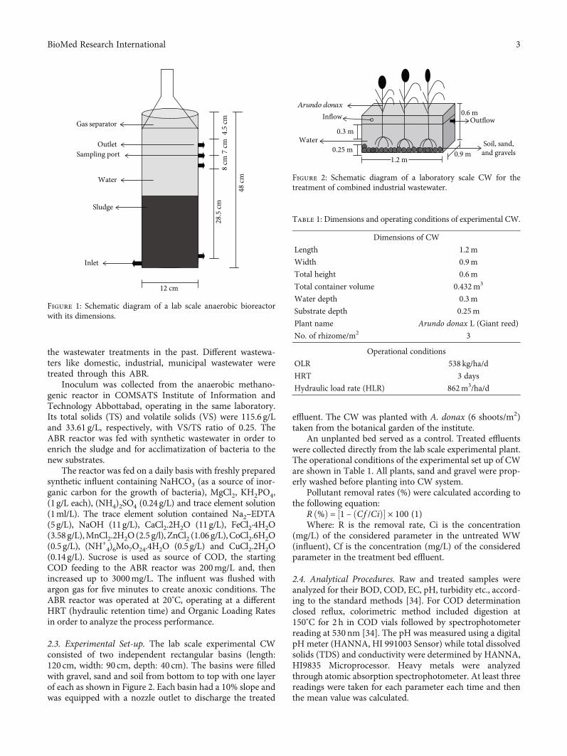
the wastewater treatments in the past. Different wastewa-ters like domestic, industrial, municipal wastewater weretreated through this ABR.
Inoculum was collected from the anaerobic methano-genic reactor in COMSATS Institute of Information andTechnology Abbottabad, operating in the same laboratory.Its total solids (TS) and volatile solids (VS) were 115.6 g/Land 33.61 g/L, respectively, with VS/TS ratio of 0.25. TheABR reactor was fed with synthetic wastewater in order toenrich the sludge and for acclimatization of bacteria to thenew substrates.
The reactor was fed on a daily basis with freshly preparedsynthetic influent containing NaHCO3 (as a source of inor-ganic carbon for the growth of bacteria), MgCl2, KH2PO4,(1g/L each), (NH4)2SO4 (0.24 g/L) and trace element solution(1ml/L). The trace element solution contained Na2–EDTA(5g/L), NaOH (11g/L), CaCl2.2H2O (11g/L), FeCl2·4H2O(3.58 g/L),MnCl2.2H2O(2.5 g/l), ZnCl2 (1.06 g/L), CoCl2.6H2O(0.5g/L), (NH+
4)6Mo7O24.4H2O (0.5 g/L) and CuCl2.2H2O(0.14 g/L). Sucrose is used as source of COD, the startingCOD feeding to the ABR reactor was 200mg/L and, thenincreased up to 3000mg/L. The influent was flushed withargon gas for five minutes to create anoxic conditions. TheABR reactor was operated at 20°C, operating at a differentHRT (hydraulic retention time) and Organic Loading Ratesin order to analyze the process performance.
2.3. Experimental Set-up. The lab scale experimental CWconsisted of two independent rectangular basins (length:120 cm, width: 90 cm, depth: 40 cm). The basins were filledwith gravel, sand and soil from bottom to top with one layerof each as shown in Figure 2. Each basin had a 10% slope andwas equipped with a nozzle outlet to discharge the treated
effluent. The CW was planted with A. donax (6 shoots/m2)taken from the botanical garden of the institute.
An unplanted bed served as a control. Treated effluentswere collected directly from the lab scale experimental plant.The operational conditions of the experimental set up of CWare shown in Table 1. All plants, sand and gravel were prop-erly washed before planting into CW system.
Pollutant removal rates (%) were calculated according tothe following equation:
R ð%Þ = ½1 – ðCf /CiÞ� × 100 (1)Where: R is the removal rate, Ci is the concentration
(mg/L) of the considered parameter in the untreated WW(influent), Cf is the concentration (mg/L) of the consideredparameter in the treatment bed effluent.
2.4. Analytical Procedures. Raw and treated samples wereanalyzed for their BOD, COD, EC, pH, turbidity etc., accord-ing to the standard methods [34]. For COD determinationclosed reflux, colorimetric method included digestion at150°C for 2 h in COD vials followed by spectrophotometerreading at 530nm [34]. The pH was measured using a digitalpH meter (HANNA, HI 991003 Sensor) while total dissolvedsolids (TDS) and conductivity were determined by HANNA,HI9835 Microprocessor. Heavy metals were analyzedthrough atomic absorption spectrophotometer. At least threereadings were taken for each parameter each time and thenthe mean value was calculated.
Gas separator
OutletSampling port
Water
Sludge
Inlet
8 cm
28.5
cm7
cm4.
5 cm
48 cm
12 cm
Figure 1: Schematic diagram of a lab scale anaerobic bioreactorwith its dimensions.
Arundo donaxInflow
0.3 mWater
0.6 mOutflow
Soil, sand,and gravels0.25 m
1.2 m0.9 m
Figure 2: Schematic diagram of a laboratory scale CW for thetreatment of combined industrial wastewater.
Table 1: Dimensions and operating conditions of experimental CW.
Dimensions of CW
Length 1.2m
Width 0.9m
Total height 0.6m
Total container volume 0.432m3
Water depth 0.3m
Substrate depth 0.25m
Plant name Arundo donax L (Giant reed)
No. of rhizome/m2 3
Operational conditions
OLR 538 kg/ha/d
HRT 3 days
Hydraulic load rate (HLR) 862m3/ha/d
3BioMed Research International
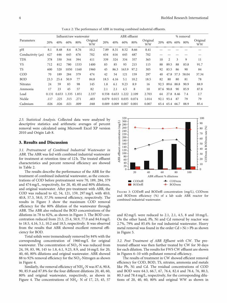
2.5. Statistical Analysis. Collected data were analyzed bydescriptive statistics and arithmetic averages of percentremoval were calculated using Microsoft Excel XP version2010 and Origin Lab 8.
3. Results and Discussion
3.1. Pretreatment of Combined Industrial Wastewater inABR. The ABR was fed with combined industrial wastewaterfor treatment at retention time of 12h. The treated effluentcharacteristics and percent removal efficiency are showedin Table 2.
The results describe the performance of the ABR for thetreatment of combined industrial wastewater, as the concen-trations of COD before pretreatment were 70, 189, 284, 379and 474mg/L, respectively, for 20, 40, 60 and 80% dilutions,and original wastewater. After pre-treatment with ABR, theCOD was reduced to 42, 54, 121, 159, 297mg/L with 40.0,40.8, 57.3, 58.0, 37.3% removal efficiency, respectively. Theresults in Figure 3 show the maximum COD removalefficiency for the 80% dilution of the wastewater throughABR. The ABR also reduced the BOD concentrations of thedilutions in 78 to 82%, as shown in Figure 3. The BOD con-centration reduced from 23.3, 25.4, 50.9, 77.0 and 84.8mg/Lto 18.5, 4.16, 5.1, 10.2 and 18.5, respectively. It was observedfrom the results that ABR showed excellent removal effi-ciency for BOD.
Total solids were tremendously removed by 84% with thecorresponding concentration of 1960mg/L for originalwastewater. The concentration of NO3-N was reduced from24, 59, 83, 98, 145 to 1.8, 6.1, 9.23, 8.9, and 16mg/L for 20,40, 60, 80% dilutions and original wastewater. ABR showed88 to 92% removal efficiency for the NO3-Nitrogen as shownin Figure 4.
Similarly, the removal efficiency of NH4-N was 87.6, 90.8,90, 85.9 and 87.8% for the four different dilutions 20, 40, 60,80% and original wastewater, respectively, as shown inFigure 4. The concentrations of NH4- N of 17, 23, 45, 57
and 82mg/L were reduced to 2.1, 2.1, 4.5, 8 and 10mg/L.On the other hand, Pb, Ni and Cd removal by reactor was2.7%, 79% and 85.4% for real industrial wastewater. Heavymetal removal was found in the order Cd>Ni>Pb as shownin Figure 5.
3.2. Post Treatment of ABR Effluent with CW. The pre-treated effluent was then further treated by CW for 30 daysfor each dilution. The results for FWS CW effluent are shownin Figures 6–10 with pollutant removal efficiency.
The results of treatment in CW showed efficient removalefficiency for COD, BOD, TS, nitrates, ammonia and metalslike Pb, Ni and Cd. The residual concentrations of CODand BOD were 64.3, 66.7, 67, 76.4, 82.4 and 78.4, 76, 80.3,80.3 and 78.4mg/L, respectively, for the corresponding dilu-tions of 20, 40, 60, 80% and original WW as shown in
Table 2: The performance of ABR in treating combined industrial effluents.
ParametersInfluent/raw wastewater ABR effluent % removal
20% 40% 60% 80%OriginalWW
20% 40% 60% 80%OriginalWW
20% 40% 60% 80%OriginalWW
pH 8.1 8.48 8.6 8.76 10.2 7.89 8.31 8.52 8.66 8.41 — — — — —
Conductivity (μs) 627 646 645 676 702 654 616 645 687 702 — — — — —
TDS 378 330 344 394 411 339 324 334 357 365 10 2 3 9 11
VS 712 812 780 1333 1400 83 85 93 215 115 88 89.5 88 83.8 91.7
TS 600 520 1050 1160 1960 45 86.3 163.9 97.2 305 92 83.5 86 90 84
COD 70 189 284 379 474 42 54 121 159 297 40 47.8 57.3 58.04 37.34
BOD 23.3 25.4 50.9 77 84.8 18.5 4.16 5.1 10.2 18.5 82 80 80 81 78
Nitrates 24 59 83 98 145 1.8 6.1 9.23 8.9 16 92.5 89.6 88.8 90.9 88.9
Ammonia 17 23 45 57 82 2.1 2.1 4.5 8 10 87.6 90.8 90 85.9 87.8
Lead 0.131 0.653 1.335 1.851 2.337 0.558 0.653 1.222 2.109 2.703 64 27.8 8.46 7.4 2.7
Nickle .117 .225 .315 .271 .403 0.079 0.015 0.035 0.074 1.014 92.1 93.4 87 79 79
Cadmium .026 .026 .021 .009 .048 0.009 0.009 0.007 0.001 0.007 65.4 65.4 66.7 88.9 85.4
20 40 60 80 1000
20406080
100120140160180200220240260280300320
COD
rem
& B
OD
rem
rate
(%)
ABR effluent % dilutionsCODefflBODeffl
010
2030
405060
7080
90100
CODremBODrem
ABR
efflue
nt co
ncen
trat
ion
(mg/
L)
Figure 3: CODeffl and BODeffl concentration (mg/L), CODremand BODrem efficiency (%) of a lab scale ABR reactor forcombined industrial wastewater.
4 BioMed Research International
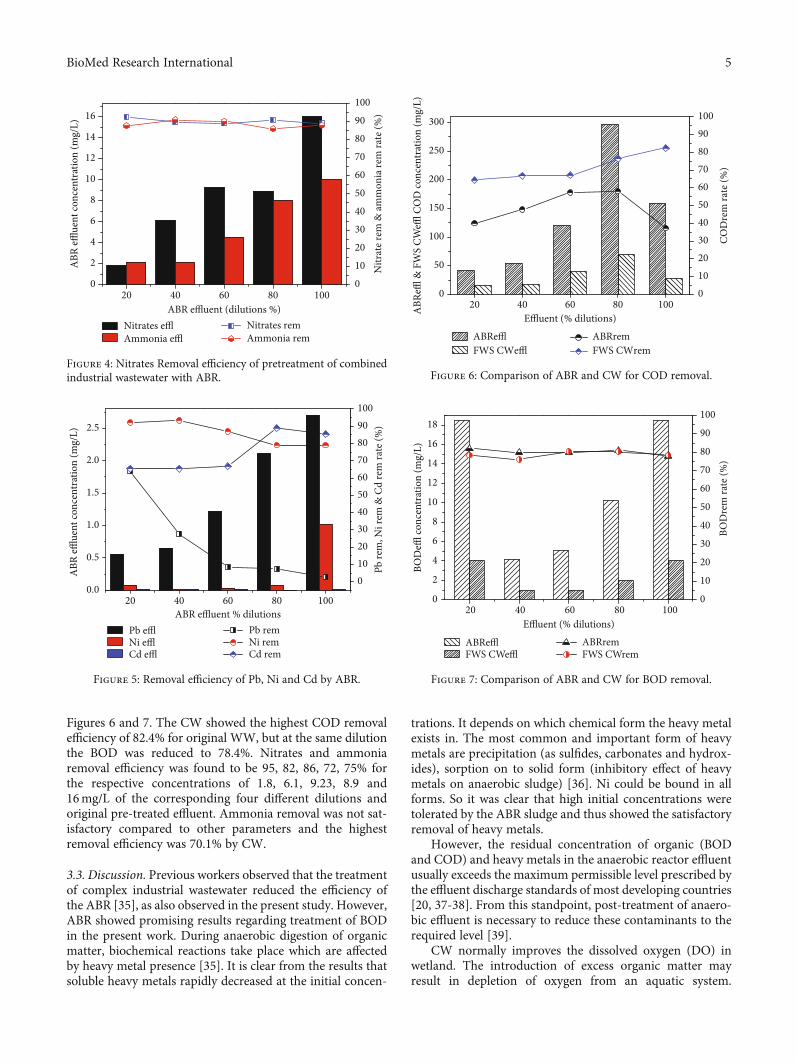
Figures 6 and 7. The CW showed the highest COD removalefficiency of 82.4% for original WW, but at the same dilutionthe BOD was reduced to 78.4%. Nitrates and ammoniaremoval efficiency was found to be 95, 82, 86, 72, 75% forthe respective concentrations of 1.8, 6.1, 9.23, 8.9 and16mg/L of the corresponding four different dilutions andoriginal pre-treated effluent. Ammonia removal was not sat-isfactory compared to other parameters and the highestremoval efficiency was 70.1% by CW.
3.3. Discussion. Previous workers observed that the treatmentof complex industrial wastewater reduced the efficiency ofthe ABR [35], as also observed in the present study. However,ABR showed promising results regarding treatment of BODin the present work. During anaerobic digestion of organicmatter, biochemical reactions take place which are affectedby heavy metal presence [35]. It is clear from the results thatsoluble heavy metals rapidly decreased at the initial concen-
trations. It depends on which chemical form the heavy metalexists in. The most common and important form of heavymetals are precipitation (as sulfides, carbonates and hydrox-ides), sorption on to solid form (inhibitory effect of heavymetals on anaerobic sludge) [36]. Ni could be bound in allforms. So it was clear that high initial concentrations weretolerated by the ABR sludge and thus showed the satisfactoryremoval of heavy metals.
However, the residual concentration of organic (BODand COD) and heavy metals in the anaerobic reactor effluentusually exceeds the maximum permissible level prescribed bythe effluent discharge standards of most developing countries[20, 37-38]. From this standpoint, post-treatment of anaero-bic effluent is necessary to reduce these contaminants to therequired level [39].
CW normally improves the dissolved oxygen (DO) inwetland. The introduction of excess organic matter mayresult in depletion of oxygen from an aquatic system.
20 40 60 80 1000
2
4
6
8
10
12
14
16
Nitr
ate r
em &
amm
onia
rem
rate
(%)
ABR effluent (dilutions %)Nitrates efflAmmonia effl
0
10
20
30
40
50
60
70
80
90
100
Nitrates remAmmonia rem
ABR
efflue
nt co
ncen
trat
ion
(mg/
L)
Figure 4: Nitrates Removal efficiency of pretreatment of combinedindustrial wastewater with ABR.
Pb remNi remCd rem
20 40 60 80 1000.0
0.5
1.0
1.5
2.0
2.5
Pb re
m, N
i rem
& C
d re
m ra
te (%
)
ABR effluent % dilutionsPb efflNi efflCd effl
0102030405060708090100
ABR
efflue
nt co
ncen
trat
ion
(mg/
L)
Figure 5: Removal efficiency of Pb, Ni and Cd by ABR.
20 40 60 80 1000
50
100
150
200
250
300
COD
rem
rate
(%)
Effluent (% dilutions)
0102030405060708090100
ABR
effl &
FW
S CW
effl C
OD
conc
entr
atio
n (m
g/L)
ABRremFWS CWremFWS CWeffl
ABReffl
Figure 6: Comparison of ABR and CW for COD removal.
20 40 60 80 1000
2
4
6
8
10
12
14
16
18
Effluent (% dilutions)
ABRefflFWS CWeffl
0
10
20
30
40
50
60
70
80
90
100
ABRremFWS CWrem
BOD
rem
rate
(%)
BOD
effl co
ncen
trat
ion
(mg/
L)
Figure 7: Comparison of ABR and CW for BOD removal.
5BioMed Research International
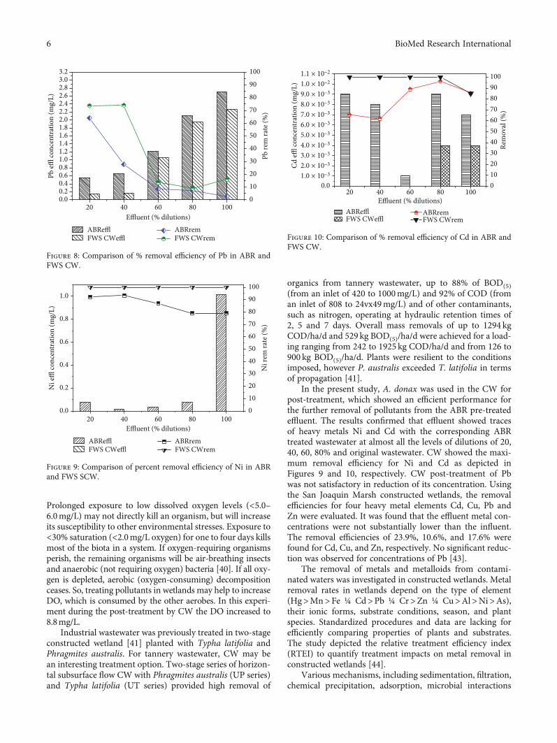
Prolonged exposure to low dissolved oxygen levels (<5.0–6.0mg/L) may not directly kill an organism, but will increaseits susceptibility to other environmental stresses. Exposure to<30% saturation (<2.0mg/L oxygen) for one to four days killsmost of the biota in a system. If oxygen-requiring organismsperish, the remaining organisms will be air-breathing insectsand anaerobic (not requiring oxygen) bacteria [40]. If all oxy-gen is depleted, aerobic (oxygen-consuming) decompositionceases. So, treating pollutants in wetlands may help to increaseDO, which is consumed by the other aerobes. In this experi-ment during the post-treatment by CW the DO increased to8.8mg/L.
Industrial wastewater was previously treated in two-stageconstructed wetland [41] planted with Typha latifolia andPhragmites australis. For tannery wastewater, CW may bean interesting treatment option. Two-stage series of horizon-tal subsurface flow CW with Phragmites australis (UP series)and Typha latifolia (UT series) provided high removal of
organics from tannery wastewater, up to 88% of BOD(5)(from an inlet of 420 to 1000mg/L) and 92% of COD (froman inlet of 808 to 24vx49mg/L) and of other contaminants,such as nitrogen, operating at hydraulic retention times of2, 5 and 7 days. Overall mass removals of up to 1294 kgCOD/ha/d and 529 kg BOD(5)/ha/d were achieved for a load-ing ranging from 242 to 1925 kg COD/ha/d and from 126 to900 kg BOD(5)/ha/d. Plants were resilient to the conditionsimposed, however P. australis exceeded T. latifolia in termsof propagation [41].
In the present study, A. donax was used in the CW forpost-treatment, which showed an efficient performance forthe further removal of pollutants from the ABR pre-treatedeffluent. The results confirmed that effluent showed tracesof heavy metals Ni and Cd with the corresponding ABRtreated wastewater at almost all the levels of dilutions of 20,40, 60, 80% and original wastewater. CW showed the maxi-mum removal efficiency for Ni and Cd as depicted inFigures 9 and 10, respectively. CW post-treatment of Pbwas not satisfactory in reduction of its concentration. Usingthe San Joaquin Marsh constructed wetlands, the removalefficiencies for four heavy metal elements Cd, Cu, Pb andZn were evaluated. It was found that the effluent metal con-centrations were not substantially lower than the influent.The removal efficiencies of 23.9%, 10.6%, and 17.6% werefound for Cd, Cu, and Zn, respectively. No significant reduc-tion was observed for concentrations of Pb [43].
The removal of metals and metalloids from contami-nated waters was investigated in constructed wetlands. Metalremoval rates in wetlands depend on the type of element(Hg>Mn>Fe ¼ Cd>Pb ¼ Cr>Zn ¼ Cu>Al>Ni>As),their ionic forms, substrate conditions, season, and plantspecies. Standardized procedures and data are lacking forefficiently comparing properties of plants and substrates.The study depicted the relative treatment efficiency index(RTEI) to quantify treatment impacts on metal removal inconstructed wetlands [44].
Various mechanisms, including sedimentation, filtration,chemical precipitation, adsorption, microbial interactions
ABRefflFWS CWeffl
20 40 60 80 1000.0
1.0 × 10–32.0 × 10–33.0 × 10–34.0 × 10–35.0 × 10–36.0 × 10–37.0 × 10–38.0 × 10–39.0 × 10–31.0 × 10–21.1 × 10⁻²
Effluent (% dilutions)
0102030405060708090100
ABRremFWS CWrem
Rem
oval
(%)
Cd
effl co
ncen
trat
ion
(mg/
L)
Figure 10: Comparison of % removal efficiency of Cd in ABR andFWS CW.
20 40 60 80 1000.0
0.2
0.4
0.6
0.8
1.0
Ni r
em ra
te (%
)
Effluent (% dilutions)
0102030405060708090100
ABRefflFWS CWeffl
ABRremFWS CWrem
Ni e
ffl co
ncen
trat
ion
(mg/
L)
Figure 9: Comparison of percent removal efficiency of Ni in ABRand FWS SCW.
20 40 60 80 1000.00.20.40.60.81.01.21.41.61.82.02.22.42.62.83.03.2
Effluent (% dilutions)ABRefflFWS CWeffl
0
10
20
30
40
50
60
70
80
90
100
Pb re
m ra
te (%
)
ABRremFWS CWrem
Pb effl
conc
entr
atio
n (m
g/L)
Figure 8: Comparison of % removal efficiency of Pb in ABR andFWS CW.
6 BioMed Research International
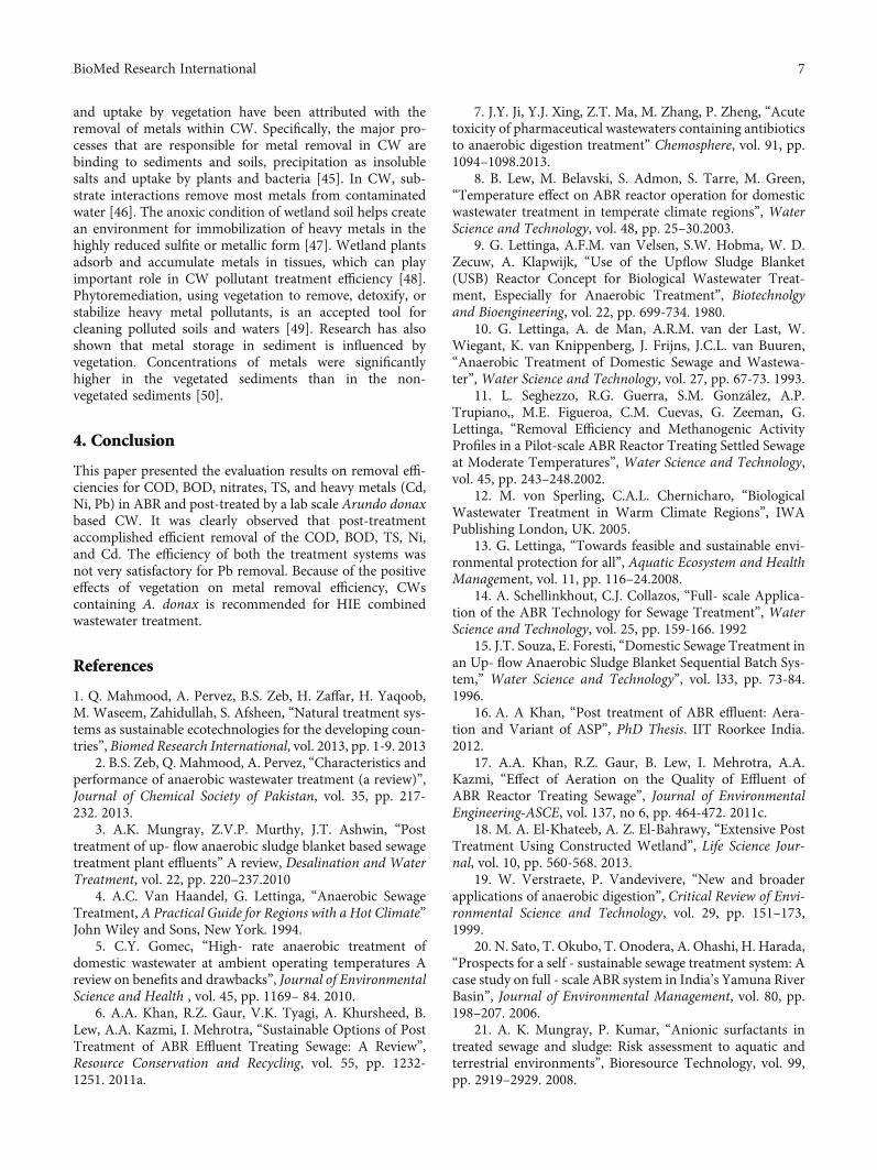
and uptake by vegetation have been attributed with theremoval of metals within CW. Specifically, the major pro-cesses that are responsible for metal removal in CW arebinding to sediments and soils, precipitation as insolublesalts and uptake by plants and bacteria [45]. In CW, sub-strate interactions remove most metals from contaminatedwater [46]. The anoxic condition of wetland soil helps createan environment for immobilization of heavy metals in thehighly reduced sulfite or metallic form [47]. Wetland plantsadsorb and accumulate metals in tissues, which can playimportant role in CW pollutant treatment efficiency [48].Phytoremediation, using vegetation to remove, detoxify, orstabilize heavy metal pollutants, is an accepted tool forcleaning polluted soils and waters [49]. Research has alsoshown that metal storage in sediment is influenced byvegetation. Concentrations of metals were significantlyhigher in the vegetated sediments than in the non-vegetated sediments [50].
4. Conclusion
This paper presented the evaluation results on removal effi-ciencies for COD, BOD, nitrates, TS, and heavy metals (Cd,Ni, Pb) in ABR and post-treated by a lab scale Arundo donaxbased CW. It was clearly observed that post-treatmentaccomplished efficient removal of the COD, BOD, TS, Ni,and Cd. The efficiency of both the treatment systems wasnot very satisfactory for Pb removal. Because of the positiveeffects of vegetation on metal removal efficiency, CWscontaining A. donax is recommended for HIE combinedwastewater treatment.
References
1. Q. Mahmood, A. Pervez, B.S. Zeb, H. Zaffar, H. Yaqoob,M. Waseem, Zahidullah, S. Afsheen, “Natural treatment sys-tems as sustainable ecotechnologies for the developing coun-tries”, Biomed Research International, vol. 2013, pp. 1-9. 2013
2. B.S. Zeb, Q. Mahmood, A. Pervez, “Characteristics andperformance of anaerobic wastewater treatment (a review)”,Journal of Chemical Society of Pakistan, vol. 35, pp. 217-232. 2013.
3. A.K. Mungray, Z.V.P. Murthy, J.T. Ashwin, “Posttreatment of up- flow anaerobic sludge blanket based sewagetreatment plant effluents” A review, Desalination and WaterTreatment, vol. 22, pp. 220–237.2010
4. A.C. Van Haandel, G. Lettinga, “Anaerobic SewageTreatment, A Practical Guide for Regions with a Hot Climate”John Wiley and Sons, New York. 1994.
5. C.Y. Gomec, “High- rate anaerobic treatment ofdomestic wastewater at ambient operating temperatures Areview on benefits and drawbacks”, Journal of EnvironmentalScience and Health , vol. 45, pp. 1169– 84. 2010.
6. A.A. Khan, R.Z. Gaur, V.K. Tyagi, A. Khursheed, B.Lew, A.A. Kazmi, I. Mehrotra, “Sustainable Options of PostTreatment of ABR Effluent Treating Sewage: A Review”,Resource Conservation and Recycling, vol. 55, pp. 1232-1251. 2011a.
7. J.Y. Ji, Y.J. Xing, Z.T. Ma, M. Zhang, P. Zheng, “Acutetoxicity of pharmaceutical wastewaters containing antibioticsto anaerobic digestion treatment” Chemosphere, vol. 91, pp.1094–1098.2013.
8. B. Lew, M. Belavski, S. Admon, S. Tarre, M. Green,“Temperature effect on ABR reactor operation for domesticwastewater treatment in temperate climate regions”, WaterScience and Technology, vol. 48, pp. 25–30.2003.
9. G. Lettinga, A.F.M. van Velsen, S.W. Hobma, W. D.Zecuw, A. Klapwijk, “Use of the Upflow Sludge Blanket(USB) Reactor Concept for Biological Wastewater Treat-ment, Especially for Anaerobic Treatment”, Biotechnolgyand Bioengineering, vol. 22, pp. 699-734. 1980.
10. G. Lettinga, A. de Man, A.R.M. van der Last, W.Wiegant, K. van Knippenberg, J. Frijns, J.C.L. van Buuren,“Anaerobic Treatment of Domestic Sewage and Wastewa-ter”, Water Science and Technology, vol. 27, pp. 67-73. 1993.
11. L. Seghezzo, R.G. Guerra, S.M. González, A.P.Trupiano,, M.E. Figueroa, C.M. Cuevas, G. Zeeman, G.Lettinga, “Removal Efficiency and Methanogenic ActivityProfiles in a Pilot-scale ABR Reactor Treating Settled Sewageat Moderate Temperatures”, Water Science and Technology,vol. 45, pp. 243–248.2002.
12. M. von Sperling, C.A.L. Chernicharo, “BiologicalWastewater Treatment in Warm Climate Regions”, IWAPublishing London, UK. 2005.
13. G. Lettinga, “Towards feasible and sustainable envi-ronmental protection for all”, Aquatic Ecosystem and HealthManagement, vol. 11, pp. 116–24.2008.
14. A. Schellinkhout, C.J. Collazos, “Full- scale Applica-tion of the ABR Technology for Sewage Treatment”, WaterScience and Technology, vol. 25, pp. 159-166. 1992
15. J.T. Souza, E. Foresti, “Domestic Sewage Treatment inan Up- flow Anaerobic Sludge Blanket Sequential Batch Sys-tem,” Water Science and Technology”, vol. l33, pp. 73-84.1996.
16. A. A Khan, “Post treatment of ABR effluent: Aera-tion and Variant of ASP”, PhD Thesis. IIT Roorkee India.2012.
17. A.A. Khan, R.Z. Gaur, B. Lew, I. Mehrotra, A.A.Kazmi, “Effect of Aeration on the Quality of Effluent ofABR Reactor Treating Sewage”, Journal of EnvironmentalEngineering-ASCE, vol. 137, no 6, pp. 464-472. 2011c.
18. M. A. El-Khateeb, A. Z. El-Bahrawy, “Extensive PostTreatment Using Constructed Wetland”, Life Science Jour-nal, vol. 10, pp. 560-568. 2013.
19. W. Verstraete, P. Vandevivere, “New and broaderapplications of anaerobic digestion”, Critical Review of Envi-ronmental Science and Technology, vol. 29, pp. 151–173,1999.
20. N. Sato, T. Okubo, T. Onodera, A. Ohashi, H. Harada,“Prospects for a self - sustainable sewage treatment system: Acase study on full - scale ABR system in India’s Yamuna RiverBasin”, Journal of Environmental Management, vol. 80, pp.198–207. 2006.
21. A. K. Mungray, P. Kumar, “Anionic surfactants intreated sewage and sludge: Risk assessment to aquatic andterrestrial environments”, Bioresource Technology, vol. 99,pp. 2919–2929. 2008.
7BioMed Research International
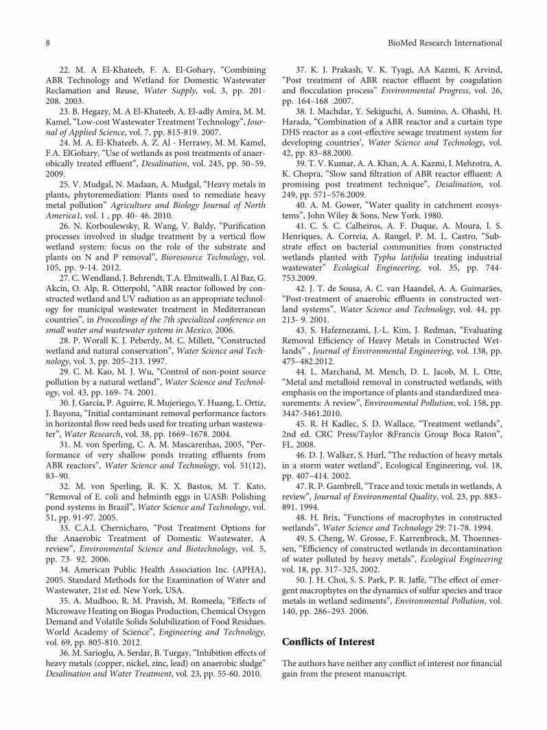
22. M. A El-Khateeb, F. A. El-Gohary, “CombiningABR Technology and Wetland for Domestic WastewaterReclamation and Reuse, Water Supply, vol. 3, pp. 201-208. 2003.
23. B. Hegazy, M. A El-Khateeb, A. El-adly Amira, M. M.Kamel, “Low-cost Wastewater Treatment Technology”, Jour-nal of Applied Science, vol. 7, pp. 815-819. 2007.
24. M. A. El-Khateeb, A. Z. Al - Herrawy, M. M. Kamel,F.A. ElGohary, “Use of wetlands as post treatments of anaer-obically treated effluent”, Desalination, vol. 245, pp. 50–59.2009.
25. V. Mudgal, N. Madaan, A. Mudgal, “Heavy metals inplants, phytoremediation: Plants used to remediate heavymetal pollution” Agriculture and Biology Journal of NorthAmerica1, vol. 1 , pp. 40- 46. 2010.
26. N. Korboulewsky, R. Wang, V. Baldy, “Purificationprocesses involved in sludge treatment by a vertical flowwetland system: focus on the role of the substrate andplants on N and P removal”, Bioresource Technology, vol.105, pp. 9-14. 2012.
27. C.Wendland, J. Behrendt, T.A. Elmitwalli, I. Al Baz, G.Akcin, O. Alp, R. Otterpohl, “ABR reactor followed by con-structed wetland and UV radiation as an appropriate technol-ogy for municipal wastewater treatment in Mediterraneancountries”, in Proceedings of the 7th specialized conference onsmall water and wastewater systems in Mexico, 2006.
28. P. Worall K. J. Peberdy, M. C. Millett, “Constructedwetland and natural conservation”, Water Science and Tech-nology, vol. 3, pp. 205–213. 1997.
29. C. M. Kao, M. J. Wu, “Control of non-point sourcepollution by a natural wetland”, Water Science and Technol-ogy, vol. 43, pp. 169- 74. 2001.
30. J. García, P. Aguirre, R. Mujeriego, Y. Huang, L. Ortiz,J. Bayona, “Initial contaminant removal performance factorsin horizontal flow reed beds used for treating urban wastewa-ter”, Water Research, vol. 38, pp. 1669–1678. 2004.
31. M. von Sperling, C. A. M. Mascarenhas, 2005, “Per-formance of very shallow ponds treating effluents fromABR reactors”, Water Science and Technology, vol. 51(12),83–90.
32. M. von Sperling, R. K. X. Bastos, M. T. Kato,“Removal of E. coli and helminth eggs in UASB: Polishingpond systems in Brazil”, Water Science and Technology, vol.51, pp. 91-97. 2005.
33. C.A.L Chernicharo, “Post Treatment Options forthe Anaerobic Treatment of Domestic Wastewater, Areview”, Environmental Science and Biotechnology, vol. 5,pp. 73- 92. 2006.
34. American Public Health Association Inc. (APHA),2005. Standard Methods for the Examination of Water andWastewater, 21st ed. New York, USA.
35. A. Mudhoo, R. M. Pravish, M. Romeela, “Effects ofMicrowave Heating on Biogas Production, Chemical OxygenDemand and Volatile Solids Solubilization of Food Residues.World Academy of Science”, Engineering and Technology,vol. 69, pp. 805-810. 2012.
36. M. Sarioglu, A. Serdar, B. Turgay, “Inhibition effects ofheavy metals (copper, nickel, zinc, lead) on anaerobic sludge”Desalination and Water Treatment, vol. 23, pp. 55-60. 2010.
37. K. J. Prakash, V. K. Tyagi, AA Kazmi, K Arvind,“Post treatment of ABR reactor effluent by coagulationand flocculation process” Environmental Progress, vol. 26,pp. 164–168 .2007.
38. I. Machdar, Y. Sekiguchi, A. Sumino, A. Ohashi, H.Harada, “Combination of a ABR reactor and a curtain typeDHS reactor as a cost-effective sewage treatment system fordeveloping countries’, Water Science and Technology, vol.42, pp. 83–88.2000.
39. T. V. Kumar, A. A. Khan, A. A. Kazmi, I. Mehrotra, A.K. Chopra, “Slow sand filtration of ABR reactor effluent: Apromising post treatment technique”, Desalination, vol.249, pp. 571–576.2009.
40. A. M. Gower, “Water quality in catchment ecosys-tems”, John Wiley & Sons, New York. 1980.
41. C. S. C. Calheiros, A. F. Duque, A. Moura, I. S.Henriques, A. Correia, A. Rangel, P. M. L. Castro, “Sub-strate effect on bacterial communities from constructedwetlands planted with Typha latifolia treating industrialwastewater” Ecological Engineering, vol. 35, pp. 744-753.2009.
42. J. T. de Sousa, A. C. van Haandel, A. A. Guimarães,“Post-treatment of anaerobic effluents in constructed wet-land systems”, Water Science and Technology, vol. 44, pp.213- 9. 2001.
43. S. Hafeznezami, J.-L. Kim, J. Redman, “EvaluatingRemoval Efficiency of Heavy Metals in Constructed Wet-lands” , Journal of Environmental Engineering, vol. 138, pp.475–482.2012.
44. L. Marchand, M. Mench, D. L. Jacob, M. L. Otte,“Metal and metalloid removal in constructed wetlands, withemphasis on the importance of plants and standardized mea-surements: A review”, Environmental Pollution, vol. 158, pp.3447-3461.2010.
45. R. H Kadlec, S. D. Wallace, “Treatment wetlands”,2nd ed. CRC Press/Taylor &Francis Group Boca Raton”,FL. 2008.
46. D. J. Walker, S. Hurl, “The reduction of heavy metalsin a storm water wetland”, Ecological Engineering, vol. 18,pp. 407–414. 2002.
47. R. P. Gambrell, “Trace and toxic metals in wetlands, Areview”, Journal of Environmental Quality, vol. 23, pp. 883–891. 1994.
48. H. Brix, “Functions of macrophytes in constructedwetlands”, Water Science and Technology 29: 71-78. 1994.
49. S. Cheng, W. Grosse, F. Karrenbrock, M. Thoennes-sen, “Efficiency of constructed wetlands in decontaminationof water polluted by heavy metals”, Ecological Engineeringvol. 18, pp. 317–325, 2002.
50. J. H. Choi, S. S. Park, P. R. Jaffé, “The effect of emer-gent macrophytes on the dynamics of sulfur species and tracemetals in wetland sediments”, Environmental Pollution, vol.140, pp. 286–293. 2006.
Conflicts of Interest
The authors have neither any conflict of interest nor financialgain from the present manuscript.
8 BioMed Research International

References
[1] B. S. Zeb, Q. Mahmood, S. Jadoon et al., “Combined IndustrialWastewater Treatment in Anaerobic Bioreactor Posttreated inConstructed Wetland,” BioMed Research International,vol. 2013, Article ID 957853, 8 pages, 2013.
[2] J. T. de Sousa, A. C. van Haandel, and A. A. V. Guimarães,“Post-treatment of anaerobic effluents in constructed wetlandsystems,” Water Science and Technology, vol. 44, no. 4,pp. 213–219, 2001.
9BioMed Research International
Research ArticleAcetabular Bone Defect in Total Hip Arthroplasty for Crowe II orIII Developmental Dysplasia of the Hip: A Finite Element Study
Yinqiao Du , Jun Fu, Jingyang Sun, Guoqiang Zhang, Jiying Chen, Ming Ni ,and Yonggang Zhou
Department of Orthopaedics, Chinese People’s Liberation Army General Hospital, 28 Fuxing Road, Haidian District, Beijing,China 100853
Correspondence should be addressed to Ming Ni; [email protected] and Yonggang Zhou; [email protected]
Received 9 May 2020; Accepted 8 August 2020; Published 25 August 2020
Guest Editor: Liu Yang
Copyright © 2020 Yinqiao Du et al. This is an open access article distributed under the Creative Commons Attribution License,which permits unrestricted use, distribution, and reproduction in any medium, provided the original work is properly cited.
Background. The purpose of this study was to establish the finite element analysis (FEA) model of acetabular bone defect in Crowetype II or III developmental dysplasia of the hip (DDH), which could evaluate the stability of the acetabular cup with different typesof bone defects, different diameters of femoral ceramic heads, and the use of screws and analyze the stress distribution of screws.Methods. The FEA model was based on the CT scan of a female patient without any acetabular bone defect. The model ofacetabular bone defect in total hip arthroplasty for Crowe II or III DDH was made by the increasing superolateral bone defectarea of the acetabular cup. Point A was located in the most medial part of the acetabular bone defect. A 52mm PINNACLE cupwith POROCOAT Porous coating was implanted, and two screws (the lengths were 25mm and 40mm) were implanted to fixthe acetabular cup. The stability of the acetabular cup and the von Mises stress of point A and screws were analyzed by a single-legged stance loading applied in 1948N (normal working). The different diameters of the femoral ceramic head (28mm, 32mm,and 36mm) were also analyzed. Results. The von Mises stress of point A was gradually increased with the increasing uncoveragevalues. When the uncoverage values exceeded 24.5%, the von Mises stress of point A without screws increased significantly,leading to instability of the cup. Screws could effectively reduce the von Mises stress of point A with uncoverage values of morethan 24.5%. However, the peak von Mises stress in the screws with the uncoverage values that exceeded 24.5% was considerablyincreased. The diameter of the femoral ceramic head had no significant effect on the von Mises stress and the stability of theacetabular cup. Conclusions. We recommend that uncoverage values of less than 24.5% with or without screw is safe for patientswith Crowe II or III DDH.
1. Introduction
Total hip arthroplasty (THA) is one of the most successfulsurgeries in the 20th century; a gradually increasing amountof patients with developmental dysplasia of the hip (DDH)received THA to release pain and improve function [1–3].Despite their surgical complexity, DDH patients had alsonotably low rates of revision and obtained durable clinicalresults [2, 4–7]. During THA surgery, an obvious superolat-eral bone defect has been reported to be frequently observedabove the surface of the acetabular cup at the level of thetrue acetabulum, especially in patients with Crowe II or IIIDDH [7, 8].
It has been recommended that the acetabular cupuncoverage should not exceed 30% of its overall surface [9].If the uncoverage was more than 30%, a structural bone graft-ing may be needed [10–12]. However, all of these decisionswere made which depended on the intraoperative judgmentof surgeons. There is no previous publication reporting thespecific value of uncoverage in THA of DDH patients.
The aim of this current study was to establish a finiteelement analysis (FEA) model of acetabular bone defect inTHA for Crowe II or III DDH, in which the acetabular cupwas positioned at the anatomical center of rotation of thehip without grafting. Then, the stability of the acetabularcup with different types of bone defects, different diameters
HindawiBioMed Research InternationalVolume 2020, Article ID 4809013, 12 pageshttps://doi.org/10.1155/2020/4809013
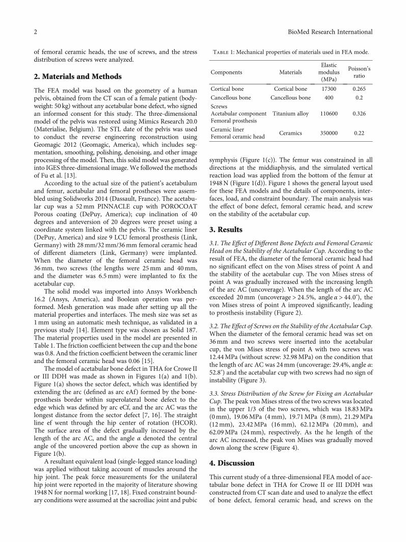
of femoral ceramic heads, the use of screws, and the stressdistribution of screws were analyzed.
2. Materials and Methods
The FEA model was based on the geometry of a humanpelvis, obtained from the CT scan of a female patient (body-weight: 50kg) without any acetabular bone defect, who signedan informed consent for this study. The three-dimensionalmodel of the pelvis was restored using Mimics Research 20.0(Materialise, Belgium). The STL date of the pelvis was usedto conduct the reverse engineering reconstruction usingGeomagic 2012 (Geomagic, America), which includes seg-mentation, smoothing, polishing, denoising, and other imageprocessing of the model. Then, this solid model was generatedinto IGES three-dimensional image.We followed the methodsof Fu et al. [13].
According to the actual size of the patient’s acetabulumand femur, acetabular and femoral prostheses were assem-bled using Solidworks 2014 (Dassault, France). The acetabu-lar cup was a 52mm PINNACLE cup with POROCOATPorous coating (DePuy, America); cup inclination of 40degrees and anteversion of 20 degrees were preset using acoordinate system linked with the pelvis. The ceramic liner(DePuy, America) and size 9 LCU femoral prosthesis (Link,Germany) with 28mm/32mm/36mm femoral ceramic headof different diameters (Link, Germany) were implanted.When the diameter of the femoral ceramic head was36mm, two screws (the lengths were 25mm and 40mm,and the diameter was 6.5mm) were implanted to fix theacetabular cup.
The solid model was imported into Ansys Workbench16.2 (Ansys, America), and Boolean operation was per-formed. Mesh generation was made after setting up all thematerial properties and interfaces. The mesh size was set as1mm using an automatic mesh technique, as validated in aprevious study [14]. Element type was chosen as Solid 187.The material properties used in the model are presented inTable 1. The friction coefficient between the cup and the bonewas 0.8. And the friction coefficient between the ceramic linerand the femoral ceramic head was 0.06 [15].
The model of acetabular bone defect in THA for Crowe IIor III DDH was made as shown in Figures 1(a) and 1(b).Figure 1(a) shows the sector defect, which was identified byextending the arc (defined as arc eAf) formed by the bone-prosthesis border within superolateral bone defect to theedge which was defined by arc eCf, and the arc AC was thelongest distance from the sector defect [7, 16]. The straightline ef went through the hip center of rotation (HCOR).The surface area of the defect gradually increased by thelength of the arc AC, and the angle α denoted the centralangle of the uncovered portion above the cup as shown inFigure 1(b).
A resultant equivalent load (single-legged stance loading)was applied without taking account of muscles around thehip joint. The peak force measurements for the unilateralhip joint were reported in the majority of literature showing1948N for normal working [17, 18]. Fixed constraint bound-ary conditions were assumed at the sacroiliac joint and pubic
symphysis (Figure 1(c)). The femur was constrained in alldirections at the middiaphysis, and the simulated verticalreaction load was applied from the bottom of the femur at1948N (Figure 1(d)). Figure 1 shows the general layout usedfor these FEA models and the details of components, inter-faces, load, and constraint boundary. The main analysis wasthe effect of bone defect, femoral ceramic head, and screwon the stability of the acetabular cup.
3. Results
3.1. The Effect of Different Bone Defects and Femoral CeramicHead on the Stability of the Acetabular Cup. According to theresult of FEA, the diameter of the femoral ceramic head hadno significant effect on the von Mises stress of point A andthe stability of the acetabular cup. The von Mises stress ofpoint A was gradually increased with the increasing lengthof the arc AC (uncoverage). When the length of the arc ACexceeded 20mm (uncoverage > 24:5%, angle α > 44:0°), thevon Mises stress of point A improved significantly, leadingto prosthesis instability (Figure 2).
3.2. The Effect of Screws on the Stability of the Acetabular Cup.When the diameter of the femoral ceramic head was set on36mm and two screws were inserted into the acetabularcup, the von Mises stress of point A with two screws was12.44MPa (without screw: 32.98MPa) on the condition thatthe length of arc AC was 24mm (uncoverage: 29.4%, angle α:52.8°) and the acetabular cup with two screws had no sign ofinstability (Figure 3).
3.3. Stress Distribution of the Screw for Fixing an AcetabularCup. The peak von Mises stress of the two screws was locatedin the upper 1/3 of the two screws, which was 18.83MPa(0mm), 19.06MPa (4mm), 19.71MPa (8mm), 21.29MPa(12mm), 23.42MPa (16mm), 62.12MPa (20mm), and62.09MPa (24mm), respectively. As the he length of thearc AC increased, the peak von Mises was gradually moveddown along the screw (Figure 4).
4. Discussion
This current study of a three-dimensional FEA model of ace-tabular bone defect in THA for Crowe II or III DDH wasconstructed from CT scan date and used to analyze the effectof bone defect, femoral ceramic head, and screws on the
Table 1: Mechanical properties of materials used in FEA mode.
Components MaterialsElasticmodulus(MPa)
Poisson’sratio
Cortical bone Cortical bone 17300 0.265
Cancellous bone Cancellous bone 400 0.2
ScrewsAcetabular componentFemoral prosthesis
Titanium alloy 110600 0.326
Ceramic linerFemoral ceramic head
Ceramics 350000 0.22
2 BioMed Research International
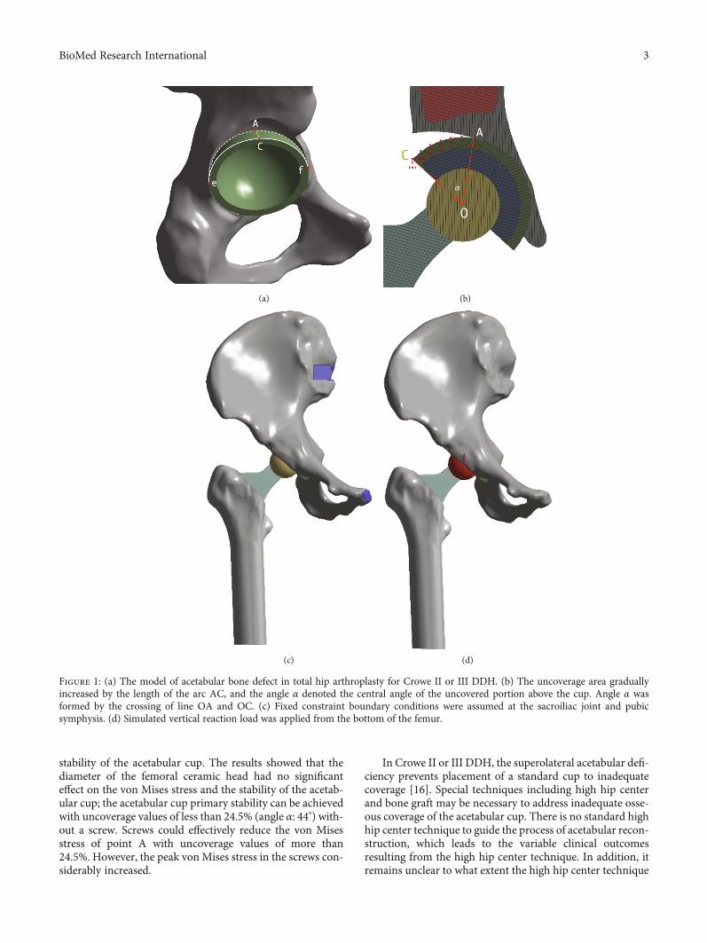
stability of the acetabular cup. The results showed that thediameter of the femoral ceramic head had no significanteffect on the von Mises stress and the stability of the acetab-ular cup; the acetabular cup primary stability can be achievedwith uncoverage values of less than 24.5% (angle α: 44°) with-out a screw. Screws could effectively reduce the von Misesstress of point A with uncoverage values of more than24.5%. However, the peak von Mises stress in the screws con-siderably increased.
In Crowe II or III DDH, the superolateral acetabular defi-ciency prevents placement of a standard cup to inadequatecoverage [16]. Special techniques including high hip centerand bone graft may be necessary to address inadequate osse-ous coverage of the acetabular cup. There is no standard highhip center technique to guide the process of acetabular recon-struction, which leads to the variable clinical outcomesresulting from the high hip center technique. In addition, itremains unclear to what extent the high hip center technique
(a)
𝛼
(b)
(c) (d)
Figure 1: (a) The model of acetabular bone defect in total hip arthroplasty for Crowe II or III DDH. (b) The uncoverage area graduallyincreased by the length of the arc AC, and the angle α denoted the central angle of the uncovered portion above the cup. Angle α wasformed by the crossing of line OA and OC. (c) Fixed constraint boundary conditions were assumed at the sacroiliac joint and pubicsymphysis. (d) Simulated vertical reaction load was applied from the bottom of the femur.
3BioMed Research International
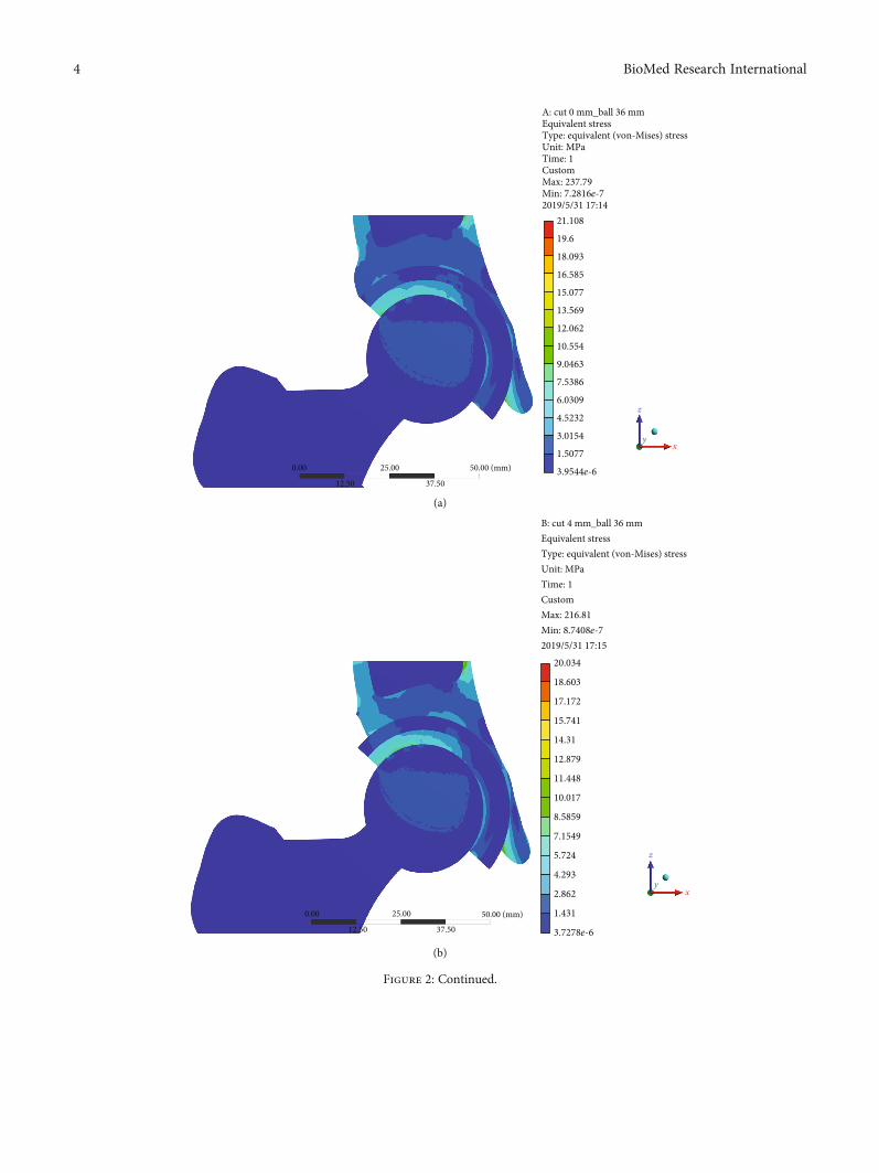
21.108
A: cut 0 mm_ball 36 mmEquivalent stressType: equivalent (von-Mises) stressUnit: MPaTime: 1CustomMax: 237.79Min: 7.2816e-72019/5/31 17:14
19.6
18.093
16.585
15.077
13.569
12.062
10.554
9.0463
7.5386
6.0309
4.5232
3.0154
1.5077
3.9544e-650.00 (mm)25.00
12.50 37.50
0.00
z
xy
(a)
20.034
18.603
17.172
15.741
14.31
12.879
11.448
10.017
8.5859
7.1549
5.724
4.293
2.862
50.00 (mm)25.00
12.50 37.50
0.00 1.431
3.7278e-6
B: cut 4 mm_ball 36 mmEquivalent stressType: equivalent (von-Mises) stressUnit: MPaTime: 1CustomMax: 216.81Min: 8.7408e-72019/5/31 17:15
z
xy
(b)
Figure 2: Continued.
4 BioMed Research International
19.38
17.996
16.611
15.227
13.843
12.458
11.074
9.6899
8.3056
6.9214
5.5371
4.1528
2.7685
1.3843
3.9926e-6
C: cut 8 mm_ball 36 mm
Equivalent stressType: equivalent (von-Mises) stressUnit: MPaTime: 1CustomMax: 216.97Min: 6.9037e-72019/5/31 17:14
50.00 (mm)25.0012.50 37.50
0.00
z
xy
(c)
19.313
17.933
16.554
15.174
13.795
11.036
9.6563
8.2768
6.8973
5.5179
4.1384
2.7589
1.3795
5.2568e-6
12.415
50.00 (mm)25.0012.50 37.50
0.00
D: cut 12 mm_ball 36 mmEquivalent stressType: equivalent (von-Mises) stressUnit: MPaTime: 1CustomMax: 220.56Min: 1.9748e-62019/5/31 17:15
z
xy
(d)
Figure 2: Continued.
5BioMed Research International
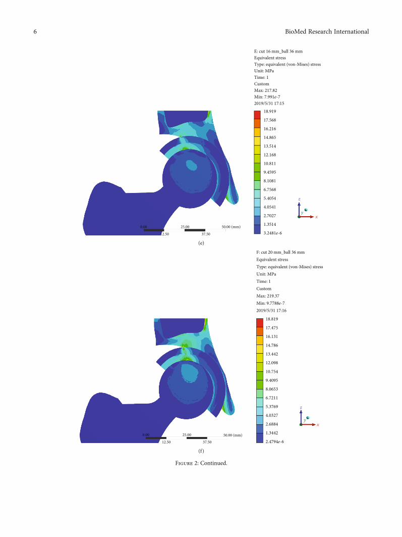
50.00 (mm)25.00
12.50 37.50
0.00
z
x
18.919
17.568
16.216
14.865
13.514
12.168
10.811
9.4595
8.1081
6.7568
5.4054
4.0541
2.7027
1.3514
3.2481e-6
E: cut 16 mm_ball 36 mmEquivalent stressType: equivalent (von-Mises) stressUnit: MPaTime: 1CustomMax: 217.82Min: 7.991e-72019/5/31 17:15
y
(e)
18.819
17.475
16.131
14.786
13.442
12.098
10.754
9.4095
8.0653
6.7211
5.3769
4.0327
2.6884
1.3442
2.4794e-650.00 (mm)25.00
12.50 37.50
0.00
F: cut 20 mm_ball 36 mmEquivalent stressType: equivalent (von-Mises) stressUnit: MPaTime: 1CustomMax: 219.37Min: 9.7788e-72019/5/31 17:16
z
x
y
(f)
Figure 2: Continued.
6 BioMed Research International
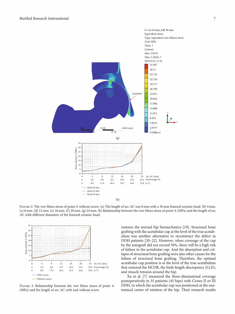
restores the normal hip biomechanics [19]. Structural bonegrafting with the acetabular cup at the level of the true acetab-ulum was another alternative to reconstruct the defect inDDH patients [20–22]. However, when coverage of the cupby the autograft did not exceed 50%, there will be a high riskof failure in the acetabular cup. And the absorption and col-lapse of structural bone grafting were also other causes for thefailure of structural bone grafting. Therefore, the optimalacetabular cup position is at the level of the true acetabulumthat restored the HCOR, the limb-length discrepancy (LLD),and muscle tension around the hip.
Xu et al. [7] measured the three-dimensional coveragepostoperatively in 35 patients (45 hips) with Crowe II or IIIDDH, in which the acetabular cup was positioned at the ana-tomical center of rotation of the hip. Their research results
41.687
38.71
35.732
32.754
29.777
26.799
23.821
20.844
17.866
14.888
11.911
8.933
5.9553
2.97779.2986e-6
G: cut 24 mm_ball 36 mmEquivalent stressType: equivalent (von-Mises) stressUnit: MPaTime: 1CustomMax: 229.45Min: 3.3203e-72019/5/31 17:16
50.00 (mm)
Instability
25.0012.50 37.50
0.00
z
xy
(g)
00
5
10
15
20
Stre
ss o
f poi
nt A
(MPa
)
25
30
35
00
44.98.8
89.8
17.6
1214.726.4
1619.635.2
2024.544.0
24 Arc AC (mm)Uncoverage𝛼
29.452.8
Head 28 mmHead 32 mmHead 36 mm
(h)
Figure 2: The von Mises stress of point A without screw. (a) The length of arc AC was 0mm with a 36mm femoral ceramic head. (b) 4mm.(c) 8mm. (d) 12mm. (e) 16mm. (f) 20mm. (g) 24mm. (h) Relationship between the von Mises stress of point A (MPa) and the length of arcAC with different diameters of the femoral ceramic head.
00
5
10
15
20
Stre
ss o
f poi
nt A
(MPa
)
25
30
35
00
44.98.8
89.8
17.6
1214.726.4
1619.635.2
2024.544.0
24 Arc AC (mm)Uncoverage𝛼
29.452.8
With screwsWithout screws
Figure 3: Relationship between the von Mises stress of point A(MPa) and the length of arc AC with and without screw.
7BioMed Research International
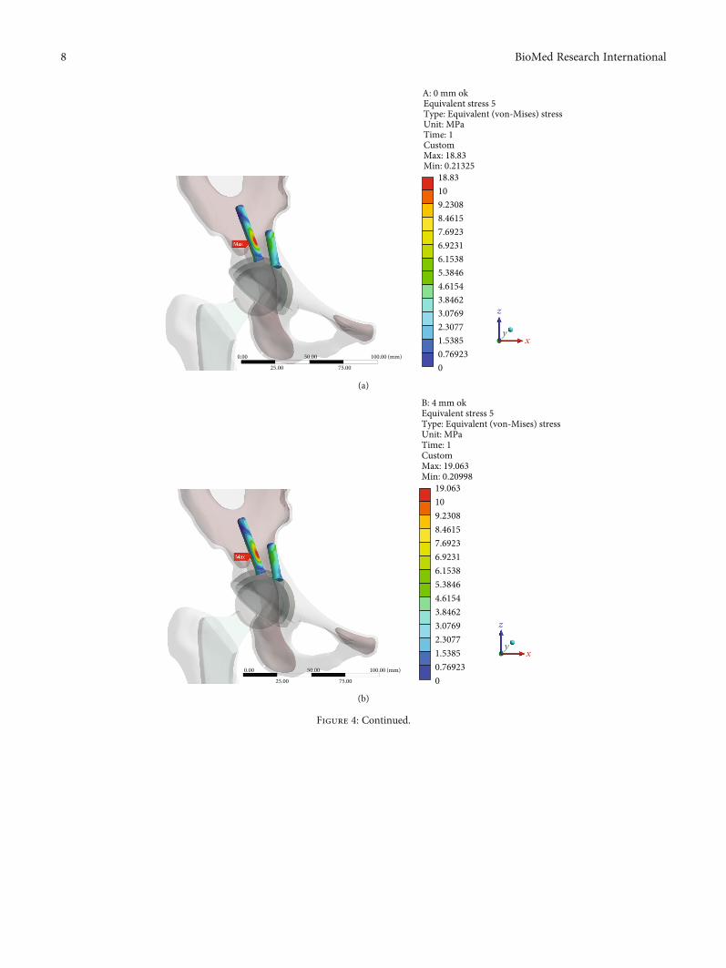
A: 0 mm okEquivalent stress 5Type: Equivalent (von-Mises) stressUnit: MPaTime: 1CustomMax: 18.83Min: 0.21325
18.83109.23088.46157.69236.92316.15385.38464.61543.84623.07692.30771.53850.769230.00 50.00
75.0025.00
100.00 (mm)
0
z
xy
(a)
B: 4 mm okEquivalent stress 5Type: Equivalent (von-Mises) stressUnit: MPaTime: 1CustomMax: 19.063Min: 0.20998
0.00 50.00
75.0025.00
100.00 (mm)
19.063109.23088.46157.69236.92316.15385.38464.61543.84623.07692.30771.53850.769230
z
xy
(b)
Figure 4: Continued.
8 BioMed Research International
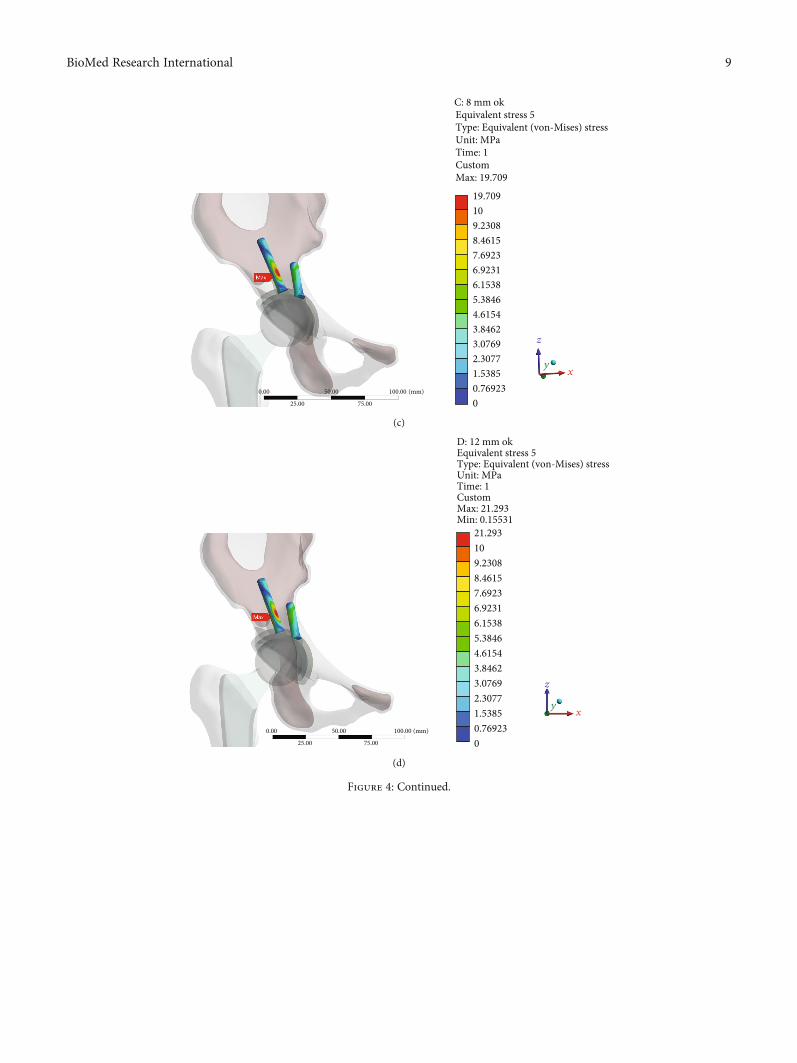
19.709109.23088.46157.69236.92316.15385.38464.61543.84623.07692.30771.53850.769230
C: 8 mm ok
Time: 1Custom
Equivalent stress 5Type: Equivalent (von-Mises) stressUnit: MPa
Max: 19.709
z
x
0.00 50.00
75.0025.00
100.00 (mm)
y
(c)
21.293109.23088.46157.69236.92316.15385.38464.61543.84623.07692.30771.53850.769230
D: 12 mm okEquivalent stress 5Type: Equivalent (von-Mises) stressUnit: MPaTime: 1CustomMax: 21.293Min: 0.15531
z
x
0.00 50.00
75.0025.00
100.00 (mm)
y
(d)
Figure 4: Continued.
9BioMed Research International
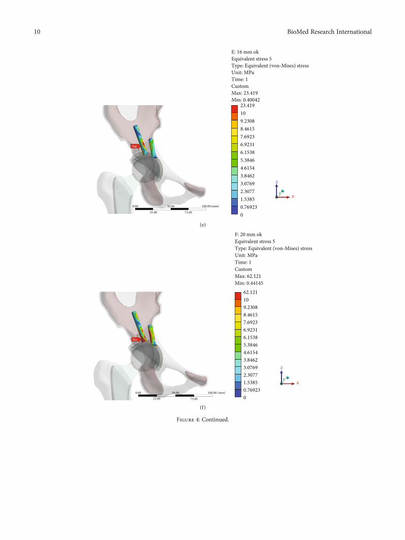
23.419109.23088.46157.69236.92316.15385.38464.61543.84623.07692.30771.53850.769230
0.00 50.00
75.0025.00
100.00 (mm)
E: 16 mm okEquivalent stress 5Type: Equivalent (von-Mises) stressUnit: MPaTime: 1CustomMax: 23.419Min: 0.40042
z
xy
(e)
62.121109.23088.46157.69236.92316.15385.38464.61543.84623.07692.30771.53850.769230
0.00 50.00
75.0025.00
100.00 (mm)
F: 20 mm okEquivalent stress 5Type: Equivalent (von-Mises) stressUnit: MPaTime: 1CustomMax: 62.121Min: 0.44145
z
xy
(f)
Figure 4: Continued.
10 BioMed Research International
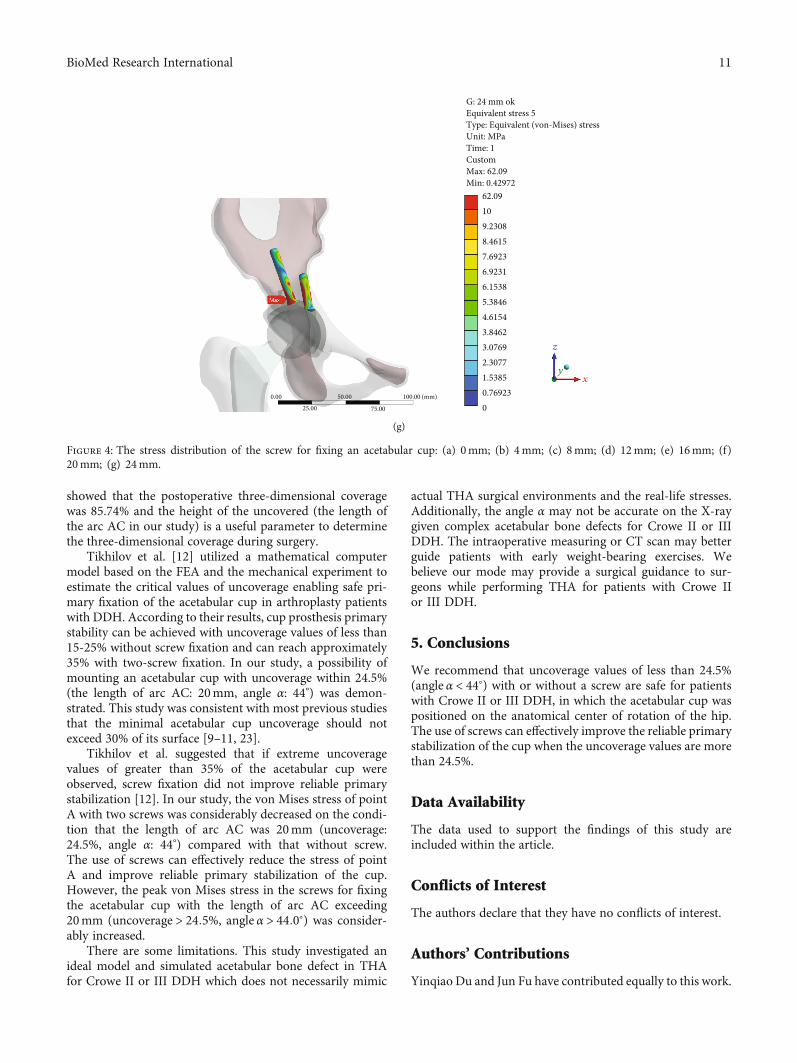
showed that the postoperative three-dimensional coveragewas 85.74% and the height of the uncovered (the length ofthe arc AC in our study) is a useful parameter to determinethe three-dimensional coverage during surgery.
Tikhilov et al. [12] utilized a mathematical computermodel based on the FEA and the mechanical experiment toestimate the critical values of uncoverage enabling safe pri-mary fixation of the acetabular cup in arthroplasty patientswith DDH. According to their results, cup prosthesis primarystability can be achieved with uncoverage values of less than15-25% without screw fixation and can reach approximately35% with two-screw fixation. In our study, a possibility ofmounting an acetabular cup with uncoverage within 24.5%(the length of arc AC: 20mm, angle α: 44°) was demon-strated. This study was consistent with most previous studiesthat the minimal acetabular cup uncoverage should notexceed 30% of its surface [9–11, 23].
Tikhilov et al. suggested that if extreme uncoveragevalues of greater than 35% of the acetabular cup wereobserved, screw fixation did not improve reliable primarystabilization [12]. In our study, the von Mises stress of pointA with two screws was considerably decreased on the condi-tion that the length of arc AC was 20mm (uncoverage:24.5%, angle α: 44°) compared with that without screw.The use of screws can effectively reduce the stress of pointA and improve reliable primary stabilization of the cup.However, the peak von Mises stress in the screws for fixingthe acetabular cup with the length of arc AC exceeding20mm (uncoverage > 24:5%, angle α > 44:0°) was consider-ably increased.
There are some limitations. This study investigated anideal model and simulated acetabular bone defect in THAfor Crowe II or III DDH which does not necessarily mimic
actual THA surgical environments and the real-life stresses.Additionally, the angle α may not be accurate on the X-raygiven complex acetabular bone defects for Crowe II or IIIDDH. The intraoperative measuring or CT scan may betterguide patients with early weight-bearing exercises. Webelieve our mode may provide a surgical guidance to sur-geons while performing THA for patients with Crowe IIor III DDH.
5. Conclusions
We recommend that uncoverage values of less than 24.5%(angle α < 44°) with or without a screw are safe for patientswith Crowe II or III DDH, in which the acetabular cup waspositioned on the anatomical center of rotation of the hip.The use of screws can effectively improve the reliable primarystabilization of the cup when the uncoverage values are morethan 24.5%.
Data Availability
The data used to support the findings of this study areincluded within the article.
Conflicts of Interest
The authors declare that they have no conflicts of interest.
Authors’ Contributions
Yinqiao Du and Jun Fu have contributed equally to this work.
0.00 50.00
75.0025.00
100.00 (mm)
G: 24 mm okEquivalent stress 5Type: Equivalent (von-Mises) stressUnit: MPaTime: 1CustomMax: 62.09Min: 0.42972
z
yx
62.09109.23088.46157.69236.92316.15385.38464.61543.84623.07692.30771.53850.769230
(g)
Figure 4: The stress distribution of the screw for fixing an acetabular cup: (a) 0mm; (b) 4mm; (c) 8mm; (d) 12mm; (e) 16mm; (f)20mm; (g) 24mm.
11BioMed Research International
Acknowledgments
This work received support from the National Key Researchand Development Program of China (No. 2017YFB1104104).
References
[1] C. D. Watts, J. R. Martin, K. A. Fehring, and W. L. Griffin,“Inferomedial hip center decreases failure rates in cementlesstotal hip arthroplasty for Crowe II and III hip dysplasia,” TheJournal of Arthroplasty, vol. 33, no. 7, pp. 2177–2181, 2018.
[2] O. F. Hitz, X. Flecher, S. Parratte, M. Ollivier, and J.-N. Argenson, “Minimum 10-year outcome of one-stage totalhip arthroplasty without subtrochanteric osteotomy using acementless custom stem for Crowe III and IV hip dislocation,”The Journal of Arthroplasty, vol. 33, no. 7, pp. 2197–2202,2018.
[3] M. Kim and T. Kadowaki, “High long-term survival of bulkfemoral head autograft for acetabular reconstruction incementless THA for developmental hip dysplasia,” ClinicalOrthopaedics and Related Research, vol. 468, no. 6, pp. 1611–1620, 2010.
[4] J. Shen, J. Sun, H. Ma, Y. Du, T. Li, and Y. Zhou, “High hipcenter technique in total hip arthroplasty for Crowe type II–III developmental dysplasia: results of midterm follow-up,”Orthopaedic surgery, 2020.
[5] M. Montalti, F. Castagnini, F. Giardina, E. Tassinari, F. Biondi,and A. Toni, “Cementless total hip arthroplasty in Crowe IIIand IV dysplasia: high hip center and modular necks,” TheJournal of Arthroplasty, vol. 33, no. 6, pp. 1813–1819, 2018.
[6] L. J. Seo, J. Gabor, D. Novikov, J. E. Feng, R. Schwarzkopf, andJ. M. Vigdorchik, “Outcomes in 385 developmental dysplastichips requiring total hip arthroplasty,” Archives of Orthopaedicand Trauma Surgery, vol. 139, no. 5, pp. 723–728, 2019.
[7] J. Xu, X. Qu, H. Li, Y. Mao, D. Yu, and Z. Zhu, “Three-dimen-sional host bone coverage in total hip arthroplasty for Crowetypes II and III developmental dysplasia of the hip,” The Jour-nal of Arthroplasty, vol. 32, no. 4, pp. 1374–1380, 2017.
[8] C. Wang, H. Xiao, W. Yang et al., “Accuracy and practicabilityof a patient-specific guide using acetabular superolateral rimduring THA in Crowe II/III DDH patients: a retrospectivestudy,” Journal of orthopaedic surgery and research., vol. 14,no. 1, p. 19, 2019.
[9] M. J. Anderson andW. H. Harris, “Total hip arthroplasty withinsertion of the acetabular component without cement in hipswith total congenital dislocation or marked congenital dyspla-sia,” The Journal of Bone and Joint Surgery American, vol. 81,no. 3, pp. 347–354, 1999.
[10] B. Atilla, H. Ali, M. C. Aksoy, O. Caglar, A. M. Tokgozoglu,andM. Alpaslan, “Position of the acetabular component deter-mines the fate of femoral head autografts in total hip replace-ment for acetabular dysplasia,” The Journal of Bone and JointSurgery British, vol. 89-B, no. 7, pp. 874–878, 2007.
[11] T. M. Thillemann, A. B. Pedersen, S. P. Johnsen, andK. Søballe, “Implant survival after primary total hip arthro-plasty due to childhood hip disorders: results from the DanishHip Arthroplasty Registry,” Acta Orthopaedica, vol. 79, no. 6,pp. 769–776, 2009.
[12] R. Tikhilov, I. Shubnyakov, S. Burns et al., “Experimental studyof the installation acetabular component with uncoverage inarthroplasty patients with severe developmental hip dyspla-
sia,” International Orthopaedics, vol. 40, no. 8, pp. 1595–1599, 2016.
[13] J. Fu, M. Ni, J. Chen et al., “Reconstruction of severe acetabularbone defect with 3D printed Ti6Al4V augment: a finite ele-ment study,” BioMed Research International, vol. 2018, ArticleID 6367203, 8 pages, 2018.
[14] A. Dutt, “Effect of mesh size on finite element analysis ofbeam,” International Journal of Mechanical Engineering,vol. 2, no. 12, pp. 8–10, 2015.
[15] L. Ma and W. M. Rainforth, “The effect of lubrication on thefriction and wear of Biolox®delta,” Acta Biomaterialia, vol. 8,no. 6, pp. 2348–2359, 2012.
[16] Y. Nie, F. Pei, B. Shen, P. Kang, and Z. Li, “Implication of ace-tabular width on the anteroposterior pelvic radiograph ofpatients with developmental dysplasia of the hip,” The Journalof Arthroplasty, vol. 30, no. 3, pp. 489–494, 2015.
[17] G. Bergmann, G. Deuretzbacher, M. Heller et al., “Hip contactforces and gait patterns from routine activities,” Journal of Bio-mechanics, vol. 34, no. 7, pp. 859–871, 2001.
[18] P. Christen, K. Ito, F. Galis, and B. van Rietbergen, “Determi-nation of hip-joint loading patterns of living and extinct mam-mals using an inverse Wolff's law approach,” Biomechanicsand Modeling in Mechanobiology, vol. 14, no. 2, pp. 427–432,2015.
[19] M. W. Pagnano, A. D. Hanssen, D. G. Lewallen, and W. J.Shaughnessy, “The effect of superior placement of the acetab-ular component on the rate of loosening after total hip arthro-plasty,” The Journal of Bone & Joint Surgery, vol. 78, no. 7,pp. 1004–1014, 1996.
[20] D. Delimar, A. Aljinovic, and G. Bicanic, “Failure of bulk bonegrafts after total hip arthroplasty for hip dysplasia,” Archives ofOrthopaedic and Trauma Surgery, vol. 134, no. 8, pp. 1167–1173, 2014.
[21] S. Kobayashi, N. Saito, M. Nawata, H. Horiuchi, R. Iorio, andK. Takaoka, “Total hip arthroplasty with bulk femoral headautograft for acetabular reconstruction in DDH,” The Journalof Bone and Joint Surgery American Volume, vol. 86, Supple-ment 1, pp. 11–17, 2004.
[22] P. Bobak, B. M. Wroblewski, P. D. Siney, P. A. Fleming, andR. Hall, “Charnley low-friction arthroplasty with an autograftof the femoral head for developmental dysplasia of the hip,”The Journal of Bone And Joint Surgery British, vol. 82-B,no. 4, pp. 508–511, 2000.
[23] L.Wang, A. R. Thoreson, R. T. Trousdale, B. F. Morrey, K. Dai,and K. N. An, “Two-dimensional and three-dimensional cupcoverage in total hip arthroplasty with developmental dyspla-sia of the hip,” Journal of Biomechanics, vol. 46, no. 10,pp. 1746–1751, 2013.
12 BioMed Research International