hybrid navigation interface for orthopedic and trauma surgery
TRANSCRIPT
Hybrid Navigation Interface for Orthopedic andTrauma Surgery
Joerg Traub1, Philipp Stefan1, Sandro Michael Heining2, Tobias Sielhorst1,Christian Riquarts2, Ekkehard Euler2, and Nassir Navab1
1 Chair for Computer Aided Medical Procedures (CAMP), TU Munich, Germany{traub, stefanp, sielhors, navab}@cs.tum.edu
2 Chirurgische Klinik und Poliklinik - Innenstadt, LMU Munich, Germany{Sandro-Michael.Heining, Christian.Riquarts,
Ekkehard.Euler}@med.uni-muenchen.de
Abstract. Several visualization methods for intraoperative navigationsystems were proposed in the past. In standard slice based navigation,three dimensional imaging data is visualized on a two dimensional userinterface in the surgery room. Another technology is the in-situ visual-ization i.e. the superimposition of imaging data directly into the viewof the surgeon, spatially registered with the patient. Thus, the three di-mensional information is represented on a three dimensional interface.We created a hybrid navigation interface combining an augmented real-ity visualization system, which is based on a stereoscopic head mounteddisplay, with a standard two dimensional navigation interface. Using anexperimental setup, trauma surgeons performed a drilling task using thestandard slice based navigation system, different visualization modes ofan augmented reality system, and the combination of both. The inte-gration of a standard slice based navigation interface into an augmentedreality visualization overcomes the shortcomings of both systems.
1 Introduction
Standard slice based navigation systems are commonly used and commerciallyavailable for orthopedic and trauma surgery. In general they consist of a posi-tion and orientation tracking system and a two dimensional user interface. Thesesystems visualize the navigation information based on three dimensional medicalimaging data on an external monitor. The three major drawbacks of state of theart navigation systems are a) every imaging and navigation device comes with itsown user interface, b) the guidance information based on three dimensional data isvisualized on two dimensional user interfaces, and c) the navigational informationis not visualized directly on the operation situs, forcing the surgeon to observe thenavigation information at a different location as the action is performed.
Augmented reality visualization was introduced as an alternative user inter-face for navigated surgery. The navigation information is superimposed ontothe surgeon’s view of the real world. In the past decade numerous applicationsand hardware setups using augmented reality visualization in medical navigation
R. Larsen, M. Nielsen, and J. Sporring (Eds.): MICCAI 2006, LNCS 4190, pp. 373–380, 2006.c© Springer-Verlag Berlin Heidelberg 2006
374 J. Traub et al.
were proposed. King, Edwards et al. [1] developed a stereoscopic system calledMAGI that is used for microscope based neurosurgery. Birkfellner et al. [2] de-signed and developed the VarioscopeAR, an augmented reality head mountedoperation microscope, for maxillofacial surgery. Sauer et al. [3] use a stereo-scopic video-see through head mounted display to visualize three dimensionalimaging data for various domains in interventional radiology and surgery [4].
In the past standard navigation systems and augmented reality were presentedas concurrent approaches and evaluations dealt with the comparison of two di-mensional user interfaces versus three dimensional in-situ visualization tech-niques [5]. Based on a head mounted display augmented reality system (section2) we implemented a hybrid navigation interface (section 3.3) as a combinationof the standard slice based navigation (section 3.1) and augmented reality visu-alizations (section 3.2). We propose to fuse the two separate interfaces to createone single three dimensional user interface for orthopedic and trauma surgery ap-plications. Exemplary applications are pedicle screw placement in spinal surgery,orthopedic implant positioning and osteochondritis dissecans. In order to eval-uate possible benefits of the fusion of these systems isolated systems and itsusefulness for surgery, we designed a phantom experiment, in which a drill mustbe navigated to a given target location. Three surgeons evaluated different visu-alization systems through a set of detailed experiments (section 4).
2 System Setup
Our system is a combination of two existing components, a three dimensionaluser interface and an optical tracking system. We developed a fully automaticprocedure that is based on a CT scan with attached fiducials that are visiblein CT and tracking space. This allows to use the proposed visualization on anyobject after a CT scan with attached fiducials is performed.
2.1 Hardware Setup
The augmented reality system is based on a stereoscopic video see-through headmounted display (HMD) developed by Sauer et al. (SCR, Princeton, USA) [3].The head mounted display is equipped with two color cameras to obtain images ofthe observed scene. Additionally a tracking camera is attached to the system forhead pose estimation[6]. This technique, often referred to as inside-out tracking,has been proven to minimize the error of visualization in augmented reality [7].
There are two reasons for the preference of a video-see-through display to anoptical-see-through device. Firstly these systems achieve a perfect synchroniza-tion of video and head pose data since the cameras are genlocked, eliminatingany time lag between the images of the cameras, which could lead to perceivablejitter or swimming [8]. Secondly we have more options for visualization sincewe have the full control over the image display, whereas in optical systems onlybrightening of the augmentation is possible.
The drawback of using a single camera for instrument tracking is that largemarker configurations are needed for a precise localization of targets[9]. As large
Hybrid Navigation Interface for Orthopedic and Trauma Surgery 375
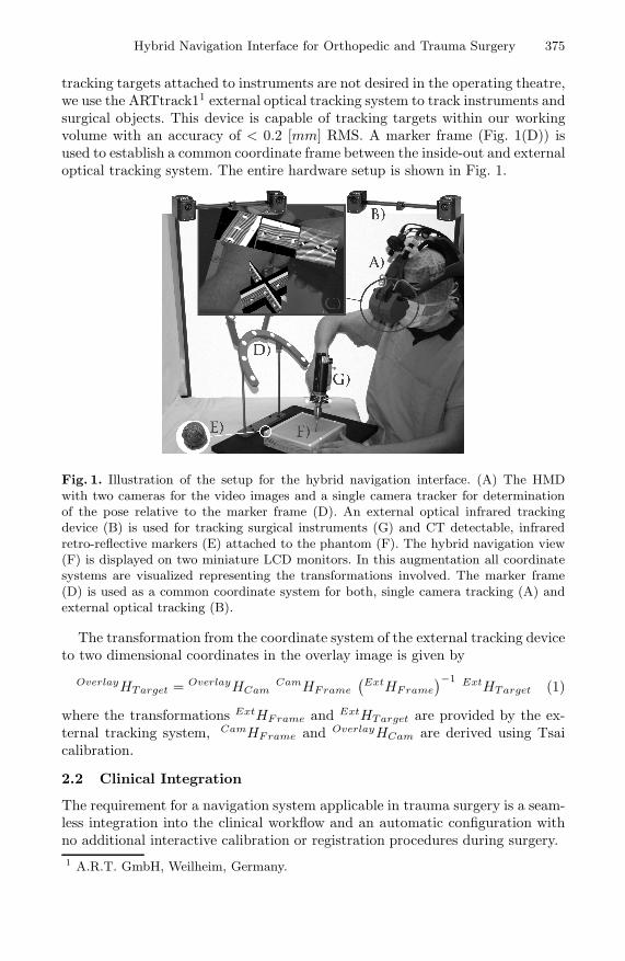
tracking targets attached to instruments are not desired in the operating theatre,we use the ARTtrack11 external optical tracking system to track instruments andsurgical objects. This device is capable of tracking targets within our workingvolume with an accuracy of < 0.2 [mm] RMS. A marker frame (Fig. 1(D)) isused to establish a common coordinate frame between the inside-out and externaloptical tracking system. The entire hardware setup is shown in Fig. 1.
Fig. 1. Illustration of the setup for the hybrid navigation interface. (A) The HMDwith two cameras for the video images and a single camera tracker for determinationof the pose relative to the marker frame (D). An external optical infrared trackingdevice (B) is used for tracking surgical instruments (G) and CT detectable, infraredretro-reflective markers (E) attached to the phantom (F). The hybrid navigation view(F) is displayed on two miniature LCD monitors. In this augmentation all coordinatesystems are visualized representing the transformations involved. The marker frame(D) is used as a common coordinate system for both, single camera tracking (A) andexternal optical tracking (B).
The transformation from the coordinate system of the external tracking deviceto two dimensional coordinates in the overlay image is given by
OverlayHTarget = OverlayHCamCamHFrame
(ExtHFrame
)−1 ExtHTarget (1)
where the transformations ExtHFrame and ExtHTarget are provided by the ex-ternal tracking system, CamHFrame and OverlayHCam are derived using Tsaicalibration.
2.2 Clinical Integration
The requirement for a navigation system applicable in trauma surgery is a seam-less integration into the clinical workflow and an automatic configuration withno additional interactive calibration or registration procedures during surgery.1 A.R.T. GmbH, Weilheim, Germany.
376 J. Traub et al.
Most methods described in literature use tracked pointers to register mark-ers in patient space with their corresponding centroids segmented from imagingdata [1]. We designed markers that are automatically detectable both in theimaging data and in the physical space. We use 4 [mm] CT-Spots from BeekleyCorp (Bristol, CT, USA), coated with infrared retro reflective material (Fig.1(E)). Following the approach of Wang et al.[10], we use an automatic segmen-tation based on binary thresholding and region growing, followed by a classifica-tion of the segmented region. The centroids of segmented regions are calculatedintensity-weighted using the voxel intensities of the imaging data.
Finally, the correct point correspondences are established and the transfor-mation TargetHCT from the CT coordinates into the tracking coordinates iscomputed. This is done by a distance-weighted graph matching approach [11]followed by a point based registration algorithm [12]. Thus the data in the CTcoordinate system can be transformed to the overlay image coordinate system byOverlayHCT = OverlayHTarget
TargetHCT , with OverlayHTarget from equation 1.
3 Navigation Modes
3.1 Standard Slice Based Navigation Interface
In standard slice based navigation systems information is presented on two di-mensional monitors. The slices displayed are controlled by the pose of the in-strument. This pose, as well as the virtual extension of the instrument is drawnonto the slice. We implemented this in our visualization software to have allnavigation modes presented in the head mounted display. Therefore, we projectthe slices at a fixed location in space (Fig. 2(d)).
3.2 Augmented Reality Visualization Modes
We implemented various augmented reality visualization modes. The require-ment for navigation is the guidance of surgical instruments to a specific targetpoint based on three dimensional imaging data. The requirement for the clinicalintegration is that no interaction is required to prepare the data (e.g. interactivesegmentation or planning). All three implemented augmented reality navigationmodes work directly on the DICOM data with the imaging data registered asdescribed in section 2.2.
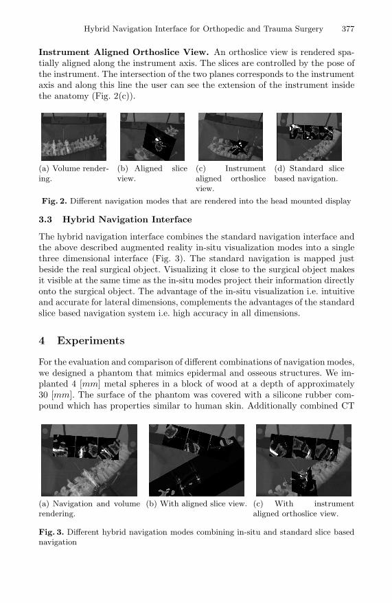
Volume Rendering. Multiple planes parallel to the image plane are clippedagainst the volume boundaries and rendered by interpolating within the volumeand blending appropriately. Intensity values in the volume domain are mapped tothe three dimensional color space using transfer functions in order to accentuateanatomically interesting structures. Additionally to the volume the extension ofthe instrument axis is visualized to provide navigational feedback (Fig. 2(a)).Aligned Slice View. Any arbitrary slice can be visualized in-situ onto thesurgical object. We visualize the plane defined by the target point and the sagit-tal, frontal, or axial direction as normal vector of the plane. The extension ofthe instrument axis is visualized. Its intersection with the plane is explicitlyhighlighted (Fig. 2(b)).
Hybrid Navigation Interface for Orthopedic and Trauma Surgery 377
Instrument Aligned Orthoslice View. An orthoslice view is rendered spa-tially aligned along the instrument axis. The slices are controlled by the pose ofthe instrument. The intersection of the two planes corresponds to the instrumentaxis and along this line the user can see the extension of the instrument insidethe anatomy (Fig. 2(c)).
(a) Volume render-ing.
(b) Aligned sliceview.
(c) Instrumentaligned orthosliceview.
(d) Standard slicebased navigation.
Fig. 2. Different navigation modes that are rendered into the head mounted display
3.3 Hybrid Navigation Interface
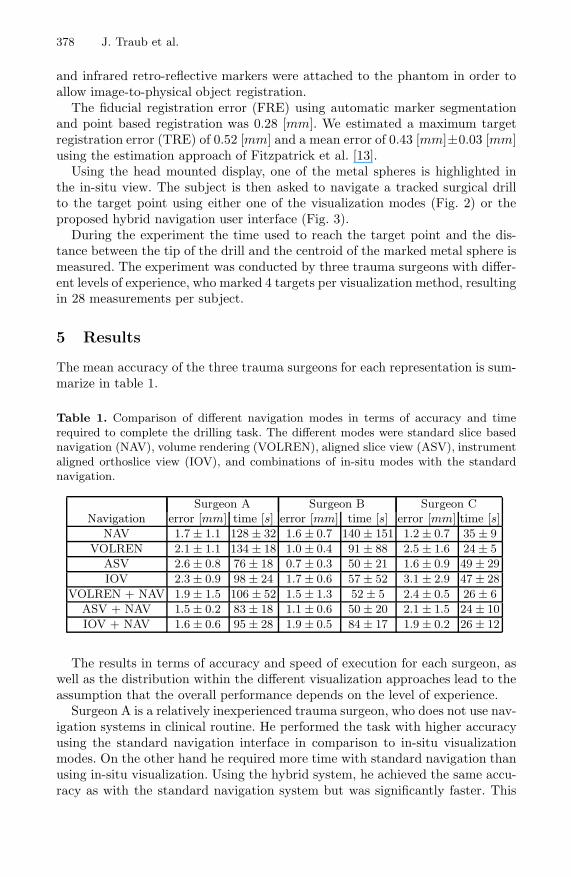
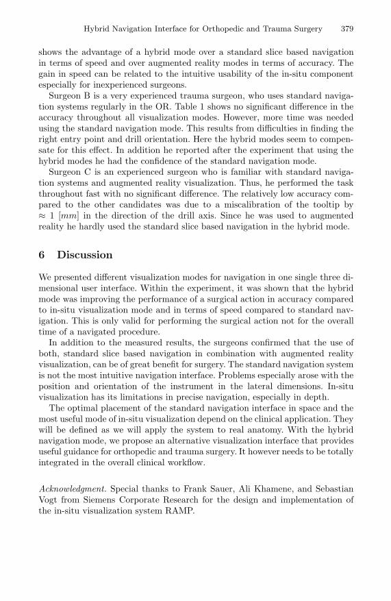
The hybrid navigation interface combines the standard navigation interface andthe above described augmented reality in-situ visualization modes into a singlethree dimensional interface (Fig. 3). The standard navigation is mapped justbeside the real surgical object. Visualizing it close to the surgical object makesit visible at the same time as the in-situ modes project their information directlyonto the surgical object. The advantage of the in-situ visualization i.e. intuitiveand accurate for lateral dimensions, complements the advantages of the standardslice based navigation system i.e. high accuracy in all dimensions.
4 Experiments
For the evaluation and comparison of different combinations of navigation modes,we designed a phantom that mimics epidermal and osseous structures. We im-planted 4 [mm] metal spheres in a block of wood at a depth of approximately30 [mm]. The surface of the phantom was covered with a silicone rubber com-pound which has properties similar to human skin. Additionally combined CT
(a) Navigation and volumerendering.
(b) With aligned slice view. (c) With instrumentaligned orthoslice view.
Fig. 3. Different hybrid navigation modes combining in-situ and standard slice basednavigation
378 J. Traub et al.
and infrared retro-reflective markers were attached to the phantom in order toallow image-to-physical object registration.
The fiducial registration error (FRE) using automatic marker segmentationand point based registration was 0.28 [mm]. We estimated a maximum targetregistration error (TRE) of 0.52 [mm] and a mean error of 0.43 [mm]±0.03 [mm]using the estimation approach of Fitzpatrick et al. [13].
Using the head mounted display, one of the metal spheres is highlighted inthe in-situ view. The subject is then asked to navigate a tracked surgical drillto the target point using either one of the visualization modes (Fig. 2) or theproposed hybrid navigation user interface (Fig. 3).
During the experiment the time used to reach the target point and the dis-tance between the tip of the drill and the centroid of the marked metal sphere ismeasured. The experiment was conducted by three trauma surgeons with differ-ent levels of experience, who marked 4 targets per visualization method, resultingin 28 measurements per subject.
5 Results
The mean accuracy of the three trauma surgeons for each representation is sum-marize in table 1.
Table 1. Comparison of different navigation modes in terms of accuracy and timerequired to complete the drilling task. The different modes were standard slice basednavigation (NAV), volume rendering (VOLREN), aligned slice view (ASV), instrumentaligned orthoslice view (IOV), and combinations of in-situ modes with the standardnavigation.
Surgeon A Surgeon B Surgeon CNavigation error [mm] time [s] error [mm] time [s] error [mm] time [s]
NAV 1.7 ± 1.1 128 ± 32 1.6 ± 0.7 140 ± 151 1.2 ± 0.7 35 ± 9VOLREN 2.1 ± 1.1 134 ± 18 1.0 ± 0.4 91 ± 88 2.5 ± 1.6 24 ± 5
ASV 2.6 ± 0.8 76 ± 18 0.7 ± 0.3 50 ± 21 1.6 ± 0.9 49 ± 29IOV 2.3 ± 0.9 98 ± 24 1.7 ± 0.6 57 ± 52 3.1 ± 2.9 47 ± 28
VOLREN + NAV 1.9 ± 1.5 106 ± 52 1.5 ± 1.3 52 ± 5 2.4 ± 0.5 26 ± 6ASV + NAV 1.5 ± 0.2 83 ± 18 1.1 ± 0.6 50 ± 20 2.1 ± 1.5 24 ± 10IOV + NAV 1.6 ± 0.6 95 ± 28 1.9 ± 0.5 84 ± 17 1.9 ± 0.2 26 ± 12
The results in terms of accuracy and speed of execution for each surgeon, aswell as the distribution within the different visualization approaches lead to theassumption that the overall performance depends on the level of experience.
Surgeon A is a relatively inexperienced trauma surgeon, who does not use nav-igation systems in clinical routine. He performed the task with higher accuracyusing the standard navigation interface in comparison to in-situ visualizationmodes. On the other hand he required more time with standard navigation thanusing in-situ visualization. Using the hybrid system, he achieved the same accu-racy as with the standard navigation system but was significantly faster. This
Hybrid Navigation Interface for Orthopedic and Trauma Surgery 379
shows the advantage of a hybrid mode over a standard slice based navigationin terms of speed and over augmented reality modes in terms of accuracy. Thegain in speed can be related to the intuitive usability of the in-situ componentespecially for inexperienced surgeons.
Surgeon B is a very experienced trauma surgeon, who uses standard naviga-tion systems regularly in the OR. Table 1 shows no significant difference in theaccuracy throughout all visualization modes. However, more time was neededusing the standard navigation mode. This results from difficulties in finding theright entry point and drill orientation. Here the hybrid modes seem to compen-sate for this effect. In addition he reported after the experiment that using thehybrid modes he had the confidence of the standard navigation mode.
Surgeon C is an experienced surgeon who is familiar with standard naviga-tion systems and augmented reality visualization. Thus, he performed the taskthroughout fast with no significant difference. The relatively low accuracy com-pared to the other candidates was due to a miscalibration of the tooltip by≈ 1 [mm] in the direction of the drill axis. Since he was used to augmentedreality he hardly used the standard slice based navigation in the hybrid mode.
6 Discussion
We presented different visualization modes for navigation in one single three di-mensional user interface. Within the experiment, it was shown that the hybridmode was improving the performance of a surgical action in accuracy comparedto in-situ visualization mode and in terms of speed compared to standard nav-igation. This is only valid for performing the surgical action not for the overalltime of a navigated procedure.
In addition to the measured results, the surgeons confirmed that the use ofboth, standard slice based navigation in combination with augmented realityvisualization, can be of great benefit for surgery. The standard navigation systemis not the most intuitive navigation interface. Problems especially arose with theposition and orientation of the instrument in the lateral dimensions. In-situvisualization has its limitations in precise navigation, especially in depth.
The optimal placement of the standard navigation interface in space and themost useful mode of in-situ visualization depend on the clinical application. Theywill be defined as we will apply the system to real anatomy. With the hybridnavigation mode, we propose an alternative visualization interface that providesuseful guidance for orthopedic and trauma surgery. It however needs to be totallyintegrated in the overall clinical workflow.
Acknowledgment. Special thanks to Frank Sauer, Ali Khamene, and SebastianVogt from Siemens Corporate Research for the design and implementation ofthe in-situ visualization system RAMP.
380 J. Traub et al.
References
1. King, A.P., Edwards, P.J., Maurer, Jr., C.R., de Cunha, D.A., Hawkes, D.J., Hill,D.L.G., Gaston, R.P., Fenlon, M.R., Strong, A.J., Chandler, C.L., Richards, A.,Gleeson, M.J.: A system for microscope-assisted guided interventions. IEEE Trans.Med. Imag. 19(11) (2000) 1082–1093
2. Birkfellner, W., Figl, M., Huber, K., Watzinger, F., Wanschitz, F., Hummel, J.,Hanel, R., Greimel, W., Homolka, P., Ewers, R., Bergmann, H.: A head-mountedoperating binocular for augmented reality visualization in medicinedesign and ini-tial evaluation. IEEE Trans. Med. Imag. 21(8) (2002) 991–997
3. Sauer, F., Khamene, A., Bascle, B., Rubino, G.J.: A head-mounted display systemfor augmented reality image guidance: Towards clinical evaluation for imri-guidedneurosurgery. In: Proc. of MICCAI, Springer-Verlag (2001) 707–716
4. Wacker, F.K., Vogt, S., Khamene, A., Jesberger, J.A., Nour, S.G., Elgort, D.R.,Sauer, F., Duerk, J.L., Lewin, J.S.: An augmented reality system for mr im-ageguided needle biopsy: Initial results in a swine model. Radiology 238(2) (2006)497–504
5. Azar, F.S., Perrin, N., Khamene, A., Vogt, S., Sauer, F.: User performance analysisof different image-based navigation systems for needle placement procedures. In:Proc. of the SPIE, Volume 5367, pp. 110-121 (2004). (2004) 110–121
6. Sauer, F., Wenzel, F., Vogt, S., Tao, Y., Genc, Y., Bani-Hashemi, A.: Augmentedworkspace: designing an ar testbed. In: Proc. of IEEE and ACM ISAR. (2000)47–53
7. Hoff, W.A., Vincent, T.L.: Analysis of head pose accuracy in augmented reality.IEEE Trans. Visualization and Computer Graphics 6 (2000)
8. Sauer, F., Schoepf, U.J., Khamene, A., Vogt, S., Das, M., Silverman, S.G.: Aug-mented reality system for ct-guided interventions: System description and initialphantom trials. In: Medical Imaging: Visualization, Image-Guided Procedures, andDisplay. (2003)
9. Vogt, S., Khamene, A., Sauer, F., Niemann, H.: Single camera tracking of markerclusters: Multiparameter cluster optimization and experimental verification. In:Proc. of IEEE and ACM ISMAR. (2002) 127–136
10. Wang, M.Y., Maurer, Jr., C.R., Fitzpatrick, J.M., Maciunas, R.J.: An automatictechnique for finding and localizing externally attached markers in ct and mr vol-ume images of the head. IEEE Trans. Biomed. Eng. 43(6) (1996) 627–637
11. Gold, S., Rangarajan, A.: A graduated assignment algorithm for graph matching.IEEE Trans. Pattern Anal. Mach. Intell. 18(4) (1996) 377388
12. Umeyama, S.: Least-squares estimation of transformation parameters between twopoint patterns. IEEE Trans. Pattern Anal. Mach. Intell. 13(4) (1991) 376–380
13. Fitzpatrick, J.M., West, J.B., Maurer, Jr., C.R.: Predicting error in rigid-bodypoint-based registration. IEEE Trans. Med. Imag. 14(5) (1998) 694–702