bingyun li · thomas webster editors - orthopedic biomaterials
TRANSCRIPT
Bingyun Li · Thomas Webster Editors
Orthopedic BiomaterialsAdvances and Applications

Orthopedic Biomaterials
Bingyun Li • Thomas WebsterEditors
Orthopedic BiomaterialsAdvances and Applications
ISBN 978-3-319-73663-1 ISBN 978-3-319-73664-8 (eBook)https://doi.org/10.1007/978-3-319-73664-8
Library of Congress Control Number: 2018932335
© Springer International Publishing AG, part of Springer Nature 2017This work is subject to copyright. All rights are reserved by the Publisher, whether the whole or part of the material is concerned, specifically the rights of translation, reprinting, reuse of illustrations, recitation, broadcasting, reproduction on microfilms or in any other physical way, and transmission or information storage and retrieval, electronic adaptation, computer software, or by similar or dissimilar methodology now known or hereafter developed.The use of general descriptive names, registered names, trademarks, service marks, etc. in this publication does not imply, even in the absence of a specific statement, that such names are exempt from the relevant protective laws and regulations and therefore free for general use.The publisher, the authors and the editors are safe to assume that the advice and information in this book are believed to be true and accurate at the date of publication. Neither the publisher nor the authors or the editors give a warranty, express or implied, with respect to the material contained herein or for any errors or omissions that may have been made. The publisher remains neutral with regard to jurisdictional claims in published maps and institutional affiliations.
Printed on acid-free paper
This Springer imprint is published by the registered company Springer International Publishing AG part of Springer Nature.The registered company address is: Gewerbestrasse 11, 6330 Cham, Switzerland
EditorsBingyun LiDepartment of Orthopedics School of MedicineWest Virginia UniversityMorgantown, WV, USA
Thomas WebsterChemical EngineeringNortheastern UniversityBoston, MA, USA
v
What a Time for Orthopedic Biomaterial Research and Education!
This is certainly an exciting time to be studying Orthopedic Biomaterials. With a record number of orthopedic implant device surgeries, orthopedic medical devices, and returning motor function back to those who lost it due to disease or trauma, the orthopedic field is growing at an alarming rate — so fast, it is hard for many of us to keep up. There are a record number of biomaterial educational programs and students entering the field of orthopedic biomaterials. Bone health and repair is all around us, and it is clear that people are intrigued and excited for its future.
This is a timely book that is centered on all things orthopedics. It covers advances in new research directions for orthopedic biomaterials such as nanotechnology, stem cells, 3D printing, new exciting orthopedic chemistries, surface modifications, bone cancer, self-assembled materials, in situ sensors, and so much more. It high-lights how researchers and clinicians are pushing the envelope in bone disease pre-vention, detection, and treatment. It covers more traditional areas such as hip, craniofacial, and spinal implants but also pushes us in new directions such as implantable sensors that can potentially determine changes in bone health and then respond to those changes to ensure strong healthy bones. It also emphasizes novel solutions to traditionally difficult orthopedic tissue repair, such as meniscus repair and other orthopedic soft tissue regeneration strategies.
Most importantly, this book highlights the dynamic field of orthopedic biomate-rials as it introduces new chemistries to orthopedic tissue regeneration, such as pep-tides, nanomaterials, biodegradable metals, new polymers, and so much more. It entices the reader to consider how you can kill bacteria without using antibiotics or drugs that bacteria have been known to mutate around. It discusses how to develop surfaces to increase lubricity to decrease harmful wear debris. In every aspect of orthopedic tissue regeneration, it critically evaluates where we are and where we need to be.
Preface

vi
This book is most appropriate for anyone who wants to keep abreast of this ever-changing field and contradicts the notion that nothing new has happened in orthope-dics since the introduction of the Charnley hip in the 1960s. With the FDA approving new nanomedicines, new polymers, and new surface treatments continuously, so much has changed. If you missed it, this is your chance to catch up. This book pro-vides a thorough insight into such changes which have been the most successful and revolutionary for the field.
We hope you enjoy this book highlighting the latest and greatest in orthopedic biomaterials. So, sit back, relax, and enjoy your journey into the past, present, and future of Orthopedic Biomaterials!
Bingyun LiThomas Webster
Morgantown, WV, USABoston, MA, USA
Preface
vii
Contents
Part I Nanotechnology and Biomimetics
Orthopedic Nanomaterials ............................................................................ 3Tolou Shokuhfar, Emre Firlar, Mostafa Rezazadeh Shirdar, and Mohammad Mahdi Taheri
Nanotechnology for Reducing Orthopedic Implant Infections: Synthesis, Characterization, and Properties ............................................... 31Luting Liu and Thomas J. Webster
Orthopedic Applications of Silver and Silver Nanoparticles ..................... 63Jason Kang, Krystal Hughes, Malcolm Xing, and Bingyun Li
Formulation and Evaluation of Nanoenhanced Anti-bacterial Calcium Phosphate Bone Cements ............................................................... 85Karthik Tappa, Udayabhanu Jammalamadaka, and David K. Mills
Biomimetic Orthopedic Materials ................................................................ 109R. Portillo-Lara, E. Shirzaei Sani, and N. Annabi
Hydroxyapatite: Design with Nature ........................................................... 141Xiao Yang
Calcium Phosphate Coatings for Metallic Orthopedic Biomaterials ........ 167Yingchao Su, Yufeng Zheng, Liping Tang, Yi-Xian Qin, and Donghui Zhu
Part II Polymer Biomaterials
Collagen-Based Scaffolds for Bone Tissue Engineering Applications ....... 187Madhura P. Nijsure and Vipuil Kishore
Poly(ethylene glycol) and Co-polymer Based- Hydrogels for Craniofacial Bone Tissue Engineering ................................................... 225Arbi M. Aghali
viii
Peptides as Orthopedic Biomaterials ........................................................... 247Derek E. Andreini, Zachary J. Werner, Christopher D. Bell, Malcolm Xing, and Bingyun Li
Part III Degradable Metal Biomaterials
Biodegradable Metals for Orthopedic Applications ................................... 275Ke Yang, Lili Tan, Peng Wan, Xiaoming Yu, and Zheng Ma
Development of Biodegradable Zn-Based Medical Implants .................... 311Yingchao Su, Yadong Wang, Liping Tang, Yufeng Zheng, Yi-Xian Qin, and Donghui Zhu
Surface Modification and Coatings for Controlling the Degradation and Bioactivity of Magnesium Alloys for Medical Applications ................ 331Ian Johnson, Jiajia Lin, and Huinan Liu
Part IV Biomaterial Implants and Devices
Materials for Orthopedic Applications ........................................................ 367Roche C. de Guzman
Composite Orthopedic Fixation Devices ...................................................... 399Bryant Heimbach and Mei Wei
PEEK Titanium Composite (PTC) for Spinal Implants ............................. 427Erik I. Waldorff, Samuel Fang, Nianli Zhang, Livia Visai, Marcello Imbriani, Emanuele Magalini, Eleonora Preve, Pierfrancesco Robotti, Andrew L. Raines, Evan Goldberg, Jiechao Jiang, Kirk C. McGilvray, Jeremiah Easley, Howard B. Seim, Christian M. Puttlitz, and James T. Ryaby
Advances in Bearing Materials for Total Artificial Hip Arthroplasty ............................................................................................ 467Rohit Khanna
Bone Grafts and Bone Substitutes for Bone Defect Management ............. 495Wenhao Wang and Kelvin W. K. Yeung
Novel Composites for Human Meniscus Replacement ............................... 547Adijat Omowumi Inyang, Tamer Abdalrahman, and Christopher Leonard Vaughan
Biomaterial-Mediated Drug Delivery in Primary and Metastatic Cancers of the Bone ....................................................................................... 569Patrick F. Forde and Katie B. Ryan
Index ................................................................................................................ 605
Contents

Part INanotechnology and Biomimetics
3© Springer International Publishing AG, part of Springer Nature 2017B. Li, T. Webster (eds.), Orthopedic Biomaterials, https://doi.org/10.1007/978-3-319-73664-8_1
Orthopedic Nanomaterials
Tolou Shokuhfar, Emre Firlar, Mostafa Rezazadeh Shirdar, and Mohammad Mahdi Taheri
Keywords Nanotechnology · Nanomaterial · Orthopedic implant · Nano-size · Surface · Toxicity · Bone · Characterization · Atomic force microscopy · FTIR · fluorescent microscopy
1 Introduction: Nanotechnology and Nanomaterials
Nanotechnology can be defined as the science and engineering involved in the design, synthesis, characterization, and application of materials and devices at the nano-scale [1]. Today, nanotechnology is a rapidly expanding field, playing an important role in our society. It is changing our lifestyle in many fields, such as energy, environment, medicine, construction, transportation, and telecommunica-tions. It brings a complex challenge to both theoretical and experimental sciences and provides a great opportunity for the development and welfare of human health [2]. The concept of nanotechnology started with the talk by Richard Feynman enti-tled “there is a plenty of room at the bottom” in 1959. Richard Feynman primarily highlighted immense capacity and potential of nanotechnology at an American Physical Society meeting at the California Institute of Technology [3]. Since then, nanotechnology has revolutionized science and played a significant role in every aspect of the society. Early applications of nanotechnology began with the crafting
T. Shokuhfar (*) Department of Dentistry, University of Illinois at Chicago, Chicago, IL, USA
Department of Bioengineering, University of Illinois at Chicago, Chicago, IL, USAe-mail: [email protected]
E. Firlar Department of Bioengineering, University of Illinois at Chicago, Chicago, IL, USA
Department of Mechanical and Industrial Engineering, University of Illinois at Chicago, Chicago, IL, USA
M. R. Shirdar · M. M. Taheri Department of Bioengineering, University of Illinois at Chicago, Chicago, IL, USA
4
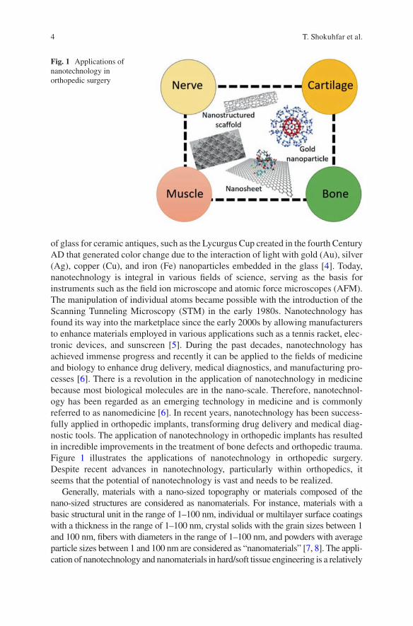
of glass for ceramic antiques, such as the Lycurgus Cup created in the fourth Century AD that generated color change due to the interaction of light with gold (Au), silver (Ag), copper (Cu), and iron (Fe) nanoparticles embedded in the glass [4]. Today, nanotechnology is integral in various fields of science, serving as the basis for instruments such as the field ion microscope and atomic force microscopes (AFM). The manipulation of individual atoms became possible with the introduction of the Scanning Tunneling Microscopy (STM) in the early 1980s. Nanotechnology has found its way into the marketplace since the early 2000s by allowing manufacturers to enhance materials employed in various applications such as a tennis racket, elec-tronic devices, and sunscreen [5]. During the past decades, nanotechnology has achieved immense progress and recently it can be applied to the fields of medicine and biology to enhance drug delivery, medical diagnostics, and manufacturing pro-cesses [6]. There is a revolution in the application of nanotechnology in medicine because most biological molecules are in the nano-scale. Therefore, nanotechnol-ogy has been regarded as an emerging technology in medicine and is commonly referred to as nanomedicine [6]. In recent years, nanotechnology has been success-fully applied in orthopedic implants, transforming drug delivery and medical diag-nostic tools. The application of nanotechnology in orthopedic implants has resulted in incredible improvements in the treatment of bone defects and orthopedic trauma. Figure 1 illustrates the applications of nanotechnology in orthopedic surgery. Despite recent advances in nanotechnology, particularly within orthopedics, it seems that the potential of nanotechnology is vast and needs to be realized.
Generally, materials with a nano-sized topography or materials composed of the nano-sized structures are considered as nanomaterials. For instance, materials with a basic structural unit in the range of 1–100 nm, individual or multilayer surface coatings with a thickness in the range of 1–100 nm, crystal solids with the grain sizes between 1 and 100 nm, fibers with diameters in the range of 1–100 nm, and powders with average particle sizes between 1 and 100 nm are considered as “nanomaterials” [7, 8]. The appli-cation of nanotechnology and nanomaterials in hard/soft tissue engineering is a relatively
Fig. 1 Applications of nanotechnology in orthopedic surgery
T. Shokuhfar et al.
5
new frontier research. So far, the application of nano-scale materials has been tested for a wide range of materials such as polymers, metals, composites, and ceramics. These nanomaterials show superior properties as compared to the micron-sized materials.
Over the last decades, nanomaterials have been highlighted as promising candi-dates for overcoming problems associated with the failure of conventional biomate-rials and implants. Studies indicate that materials in the nano-scale exhibited excellent properties, such as superior mechanical, electrical, cytocompatible, cata-lytic, and magnetic properties as compared to their micron structured counterparts. Due to the unique physical properties and the greater surface area in a given volume, nanomaterials can be designed to mimic the natural environment of tissues to pro-mote cell growth, tissue regeneration and even to reduce infection rates [9]. Nanomaterials have been also applied as coatings and scaffolding to provide a better interaction between the implant surface and surrounding tissue [10]. Therefore, nanomaterials can be selected as the next generation of implant coatings to enhance implant/tissue integration owing to their unique surface properties, which provide a more suitable environment for bone ingrowth [9]. Decreasing the likelihood of infection and improving scar appearance are a few examples of the advantages of using nanotechnology for implants [11]. It was reported that the application of a nanotexture material in total joint replacement improved osteoblast adhesion and osseointegration, hence increased the success rate of implantation [11].
Today there are many common and significant clinical problems of bone and joints such as bone fractures, bone cancer, and osteoarthritis. The National Center for Health Statistics (NCHS) reports a large number of patients with bone fractures, osteoarthri-tis and associated disorders annually [12]. According to the American Academy of Orthopedic Surgeons, there was about a 83% increase in hip replacements between 2000 and 2004 [12]. Although the need for orthopedic implants has been increased, the conventional implant materials last only 10–15 years on average. With this limita-tion, the rate of implant failures, such as implant loosening, osteolysis, inflammation, infection, and wear debris, is severely increased [11]. Therefore, there is an urgent need to design the new generation of cytocompatible bone and joint replacement can-didates to regenerate bone tissue at the defect sites that will last the lifetime of the patient. The application of nanomaterials which are biomimetic with excellent mechanical properties has become an urgent requirement in orthopedics. Materials at the nano-scale exhibit unique surface properties such as surface wettability, surface chemistry, surface energy and surface topography due to the higher available surface area and roughness as compared to the micron-sized counterparts. It has been shown that the adhesion of specific proteins, such as fibronectin, vitronectin, and laminin, is directly related to the surface properties and bioactivity of implants [11]. In addition, osseointegration between implant materials and bone tissue is considered as a critical factor in designing successful orthopedic implants [1]. Studies have demonstrated that nanostructured materials with desirable cell adhesion properties can promote protein adhesion as well as new bone growth as an advantage of such nanomaterials as com-pared to conventional materials for tissue growth [1]. Therefore, various metals, poly-mers, nanophase ceramics and composite scaffolds have been designed for orthopedic applications via controlling surface properties. Many studies have indicated that nanostructured ceramics enhance friction and wear problems associated with joint
Orthopedic Nanomaterials
6
replacement components [13, 14]. For instance, the application of nano-hydroxyapa-tite (HA) as a substitute, filler, coating, and composite material in orthopedics pro-motes biomineralization [15, 16].
Nanotechnology and nanomaterials have revolutionized many fields such as biol-ogy and medicine. Enhanced drug delivery, medical diagnostics, and bioengineering are few examples. Recently, researchers have demonstrated that nanotechnology and nanomaterials possess a huge potential for further applications in disease detection, intervention and particularly orthopedics [10]. Introducing a new dimension to tech-nology and materials with the possibility of manipulating at the nano level has been regarded as an emerging science in many fields of competitive industries. This chap-ter provides a brief introduction to the nanotechnology and nanomaterials in ortho-pedic applications and tissue engineering. In addition, the toxicological effect of nanomaterials in the orthopedic applications is discussed. Finally, the last section of the chapter dedicated to the characterization of the orthopedic nanomaterials pro-vides very critical information for the design and fabrication of these materials.
2 Nanomaterials Enhanced Orthopedic Implants
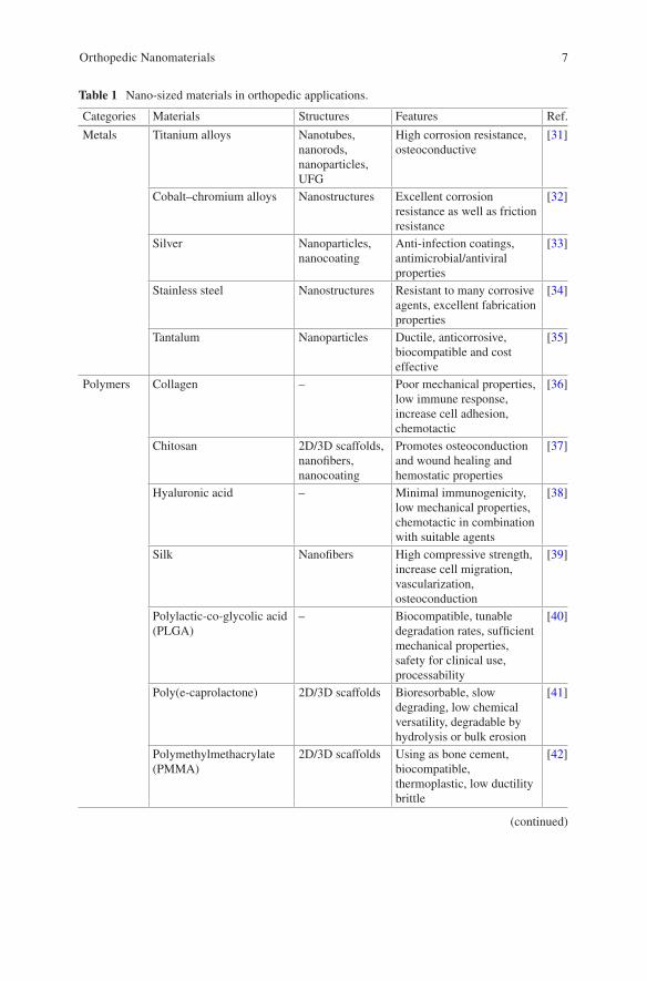
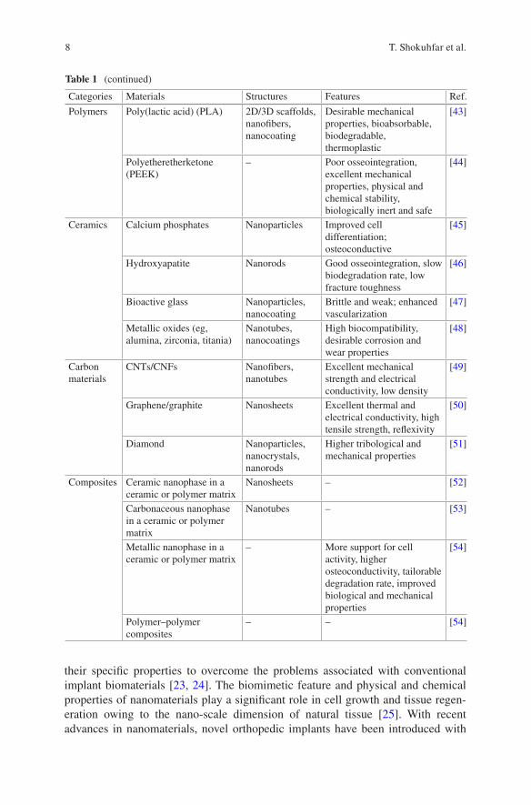
Applications of orthopedic implants are growing rapidly across the world. Many bone defects with low potential for regeneration are the result of trauma, tumor, infection or periprosthetic osteolysis and need to be surgically treated [17]. Surveys have shown that in the United States alone, there are over 600,000 joint replacements annually and about 80% of all transplantations are bone autografts and allografts [17]. However, bone autografts and allografts have shown many drawbacks such as immunological rejection, the risk of infection, and the high cost of operation [18]. The average life-time of a conventional orthopedic implant is not permanent and unfortunately, there has been many cases of failed implants [19, 20]. Once an implant fails, revision surger-ies are required, which increase pain, the cost of treatment, and added risk of post-surgery complications [18]. The poor surface interaction between the biomaterial and host tissue results in insufficient tissue regeneration around the biomaterials after implantation, which is one of the key factors of implant failure [21]. Therefore, an orthopedic implant must be inhabitable for osteoblast to proliferate the implant surface and regenerate new bone tissue [22]. By controlling surface properties, a broad range of ceramics, polymers, metals and composite scaffolds at the nano-scale have been designed for bone/cartilage tissue engineering applications [10]. Just like conventional or micro-structured materials, nanomaterials also can be classified as nanoparticles, nanocrystals, nanofibers, nanoclusters, nanotubes, nanowires, nanofilms, nanorods, etc. The success rate of bone tissue engineering products is strongly influenced by appropriate material selection and the fabrication method for producing a scaffold. So far, various natural and synthetic biomaterials such as ceramics, polymers, and a com-bination of them have been employed for bone tissue engineering applications [10]. Table 1 summarizes nano-sized materials used in orthopedic applications.
Although a wide range of materials at the micro-scale have been employed for orthopedic applications, nanomaterials have attracted considerable attention due to
T. Shokuhfar et al.
7
Table 1 Nano-sized materials in orthopedic applications.
Categories Materials Structures Features Ref.
Metals Titanium alloys Nanotubes, nanorods, nanoparticles, UFG
High corrosion resistance, osteoconductive
[31]
Cobalt–chromium alloys Nanostructures Excellent corrosion resistance as well as friction resistance
[32]
Silver Nanoparticles, nanocoating
Anti-infection coatings, antimicrobial/antiviral properties
[33]
Stainless steel Nanostructures Resistant to many corrosive agents, excellent fabrication properties
[34]
Tantalum Nanoparticles Ductile, anticorrosive, biocompatible and cost effective
[35]
Polymers Collagen – Poor mechanical properties, low immune response, increase cell adhesion, chemotactic
[36]
Chitosan 2D/3D scaffolds, nanofibers, nanocoating
Promotes osteoconduction and wound healing and hemostatic properties
[37]
Hyaluronic acid – Minimal immunogenicity, low mechanical properties, chemotactic in combination with suitable agents
[38]
Silk Nanofibers High compressive strength, increase cell migration, vascularization, osteoconduction
[39]
Polylactic-co-glycolic acid (PLGA)
– Biocompatible, tunable degradation rates, sufficient mechanical properties, safety for clinical use, processability
[40]
Poly(e-caprolactone) 2D/3D scaffolds Bioresorbable, slow degrading, low chemical versatility, degradable by hydrolysis or bulk erosion
[41]
Polymethylmethacrylate (PMMA)
2D/3D scaffolds Using as bone cement, biocompatible, thermoplastic, low ductility brittle
[42]
(continued)
Orthopedic Nanomaterials
8
their specific properties to overcome the problems associated with conventional implant biomaterials [23, 24]. The biomimetic feature and physical and chemical properties of nanomaterials play a significant role in cell growth and tissue regen-eration owing to the nano-scale dimension of natural tissue [25]. With recent advances in nanomaterials, novel orthopedic implants have been introduced with
Table 1 (continued)
Categories Materials Structures Features Ref.
Polymers Poly(lactic acid) (PLA) 2D/3D scaffolds, nanofibers, nanocoating
Desirable mechanical properties, bioabsorbable, biodegradable, thermoplastic
[43]
Polyetheretherketone (PEEK)
– Poor osseointegration, excellent mechanical properties, physical and chemical stability, biologically inert and safe
[44]
Ceramics Calcium phosphates Nanoparticles Improved cell differentiation; osteoconductive
[45]
Hydroxyapatite Nanorods Good osseointegration, slow biodegradation rate, low fracture toughness
[46]
Bioactive glass Nanoparticles, nanocoating
Brittle and weak; enhanced vascularization
[47]
Metallic oxides (eg, alumina, zirconia, titania)
Nanotubes, nanocoatings
High biocompatibility, desirable corrosion and wear properties
[48]
Carbon materials
CNTs/CNFs Nanofibers, nanotubes
Excellent mechanical strength and electrical conductivity, low density
[49]
Graphene/graphite Nanosheets Excellent thermal and electrical conductivity, high tensile strength, reflexivity
[50]
Diamond Nanoparticles, nanocrystals, nanorods
Higher tribological and mechanical properties
[51]
Composites Ceramic nanophase in a ceramic or polymer matrix
Nanosheets – [52]
Carbonaceous nanophase in a ceramic or polymer matrix
Nanotubes – [53]
Metallic nanophase in a ceramic or polymer matrix
– More support for cell activity, higher osteoconductivity, tailorable degradation rate, improved biological and mechanical properties
[54]
Polymer–polymer composites
– – [54]
T. Shokuhfar et al.
9
great potential for better osseointegration to efficiently stimulate new bone growth as compared to conventional implants [26].
Excellent physiochemical properties and nanostructured extracellular matrices (ECM) of nanomaterials can decrease infection and increase bone growth [27]. Investigations have shown that implants with a nano-scale surface roughness that mimic natural tissue promote more tissue growth than smooth implants [28]. In addition, it was demonstrated that nano-sized materials can be beneficial in promot-ing bone growth, or detrimental in promoting inflammation or infection [26]. Therefore, the design and fabrication of nanomaterials is a new confront in orthope-dic applications which offers a new type of implant and scaffold that can mimic the complex and hierarchical structure of hard/soft tissues [26].
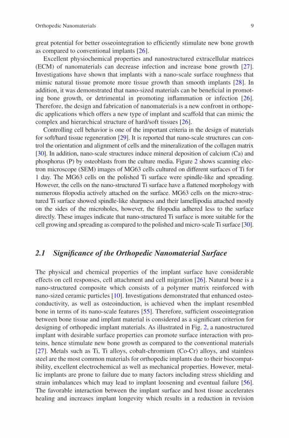
Controlling cell behavior is one of the important criteria in the design of materials for soft/hard tissue regeneration [29]. It is reported that nano-scale structures can con-trol the orientation and alignment of cells and the mineralization of the collagen matrix [30]. In addition, nano-scale structures induce mineral deposition of calcium (Ca) and phosphorus (P) by osteoblasts from the culture media. Figure 2 shows scanning elec-tron microscope (SEM) images of MG63 cells cultured on different surfaces of Ti for 1 day. The MG63 cells on the polished Ti surface were spindle-like and spreading. However, the cells on the nano-structured Ti surface have a flattened morphology with numerous filopodia actively attached on the surface. MG63 cells on the micro-struc-tured Ti surface showed spindle-like sharpness and their lamellipodia attached mostly on the sides of the microholes, however, the filopodia adhered less to the surface directly. These images indicate that nano-structured Ti surface is more suitable for the cell growing and spreading as compared to the polished and micro-scale Ti surface [30].
2.1 Significance of the Orthopedic Nanomaterial Surface
The physical and chemical properties of the implant surface have considerable effects on cell responses, cell attachment and cell migration [26]. Natural bone is a nano-structured composite which consists of a polymer matrix reinforced with nano-sized ceramic particles [10]. Investigations demonstrated that enhanced osteo-conductivity, as well as osteoinduction, is achieved when the implant resembled bone in terms of its nano-scale features [55]. Therefore, sufficient osseointegration between bone tissue and implant material is considered as a significant criterion for designing of orthopedic implant materials. As illustrated in Fig. 2, a nanostructured implant with desirable surface properties can promote surface interaction with pro-teins, hence stimulate new bone growth as compared to the conventional materials [27]. Metals such as Ti, Ti alloys, cobalt-chromium (Co-Cr) alloys, and stainless steel are the most common materials for orthopedic implants due to their biocompat-ibility, excellent electrochemical as well as mechanical properties. However, metal-lic implants are prone to failure due to many factors including stress shielding and strain imbalances which may lead to implant loosening and eventual failure [56]. The favorable interaction between the implant surface and host tissue accelerates healing and increases implant longevity which results in a reduction in revision
Orthopedic Nanomaterials
10
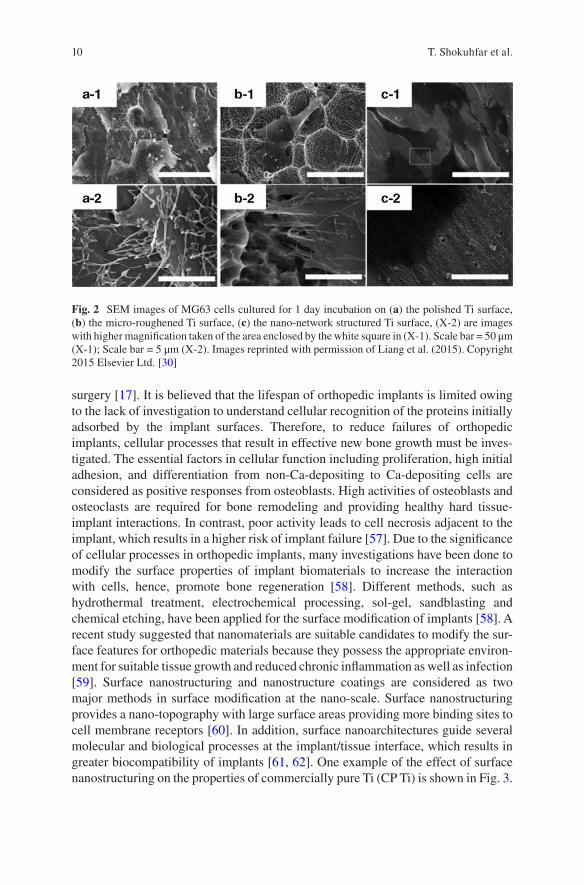
surgery [17]. It is believed that the lifespan of orthopedic implants is limited owing to the lack of investigation to understand cellular recognition of the proteins initially adsorbed by the implant surfaces. Therefore, to reduce failures of orthopedic implants, cellular processes that result in effective new bone growth must be inves-tigated. The essential factors in cellular function including proliferation, high initial adhesion, and differentiation from non-Ca-depositing to Ca-depositing cells are considered as positive responses from osteoblasts. High activities of osteoblasts and osteoclasts are required for bone remodeling and providing healthy hard tissue-implant interactions. In contrast, poor activity leads to cell necrosis adjacent to the implant, which results in a higher risk of implant failure [57]. Due to the significance of cellular processes in orthopedic implants, many investigations have been done to modify the surface properties of implant biomaterials to increase the interaction with cells, hence, promote bone regeneration [58]. Different methods, such as hydrothermal treatment, electrochemical processing, sol-gel, sandblasting and chemical etching, have been applied for the surface modification of implants [58]. A recent study suggested that nanomaterials are suitable candidates to modify the sur-face features for orthopedic materials because they possess the appropriate environ-ment for suitable tissue growth and reduced chronic inflammation as well as infection [59]. Surface nanostructuring and nanostructure coatings are considered as two major methods in surface modification at the nano-scale. Surface nanostructuring provides a nano-topography with large surface areas providing more binding sites to cell membrane receptors [60]. In addition, surface nanoarchitectures guide several molecular and biological processes at the implant/tissue interface, which results in greater biocompatibility of implants [61, 62]. One example of the effect of surface nanostructuring on the properties of commercially pure Ti (CP Ti) is shown in Fig. 3.
Fig. 2 SEM images of MG63 cells cultured for 1 day incubation on (a) the polished Ti surface, (b) the micro-roughened Ti surface, (c) the nano-network structured Ti surface, (X-2) are images with higher magnification taken of the area enclosed by the white square in (X-1). Scale bar = 50 μm (X-1); Scale bar = 5 μm (X-2). Images reprinted with permission of Liang et al. (2015). Copyright 2015 Elsevier Ltd. [30]
T. Shokuhfar et al.
11
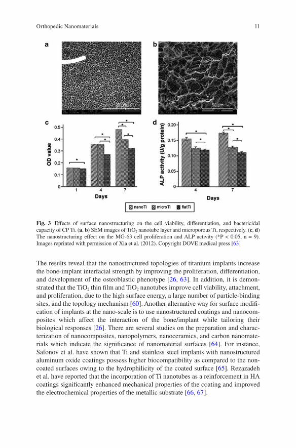
The results reveal that the nanostructured topologies of titanium implants increase the bone-implant interfacial strength by improving the proliferation, differentiation, and development of the osteoblastic phenotype [26, 63]. In addition, it is demon-strated that the TiO2 thin film and TiO2 nanotubes improve cell viability, attachment, and proliferation, due to the high surface energy, a large number of particle-binding sites, and the topology mechanism [60]. Another alternative way for surface modifi-cation of implants at the nano-scale is to use nanostructured coatings and nanocom-posites which affect the interaction of the bone/implant while tailoring their biological responses [26]. There are several studies on the preparation and charac-terization of nanocomposites, nanopolymers, nanoceramics, and carbon nanomate-rials which indicate the significance of nanomaterial surfaces [64]. For instance, Safonov et al. have shown that Ti and stainless steel implants with nanostructured aluminum oxide coatings possess higher biocompatibility as compared to the non-coated surfaces owing to the hydrophilicity of the coated surface [65]. Rezazadeh et al. have reported that the incorporation of Ti nanotubes as a reinforcement in HA coatings significantly enhanced mechanical properties of the coating and improved the electrochemical properties of the metallic substrate [66, 67].
Fig. 3 Effects of surface nanostructuring on the cell viability, differentiation, and bactericidal capacity of CP Ti. (a, b) SEM images of TiO2 nanotube layer and microporous Ti, respectively. (c, d) The nanostructuring effect on the MG-63 cell proliferation and ALP activity (*P < 0.05, n = 9). Images reprinted with permission of Xia et al. (2012). Copyright DOVE medical press [63]
Orthopedic Nanomaterials
12
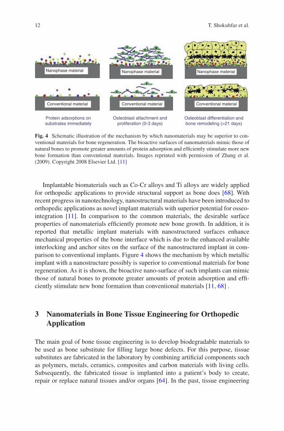
Implantable biomaterials such as Co-Cr alloys and Ti alloys are widely applied for orthopedic applications to provide structural support as bone does [68]. With recent progress in nanotechnology, nanostructural materials have been introduced to orthopedic applications as novel implant materials with superior potential for osseo-integration [11]. In comparison to the common materials, the desirable surface properties of nanomaterials efficiently promote new bone growth. In addition, it is reported that metallic implant materials with nanostructured surfaces enhance mechanical properties of the bone interface which is due to the enhanced available interlocking and anchor sites on the surface of the nanostructured implant in com-parison to conventional implants. Figure 4 shows the mechanism by which metallic implant with a nanostructure possibly is superior to conventional materials for bone regeneration. As it is shown, the bioactive nano-surface of such implants can mimic those of natural bones to promote greater amounts of protein adsorption and effi-ciently stimulate new bone formation than conventional materials [11, 68] .
3 Nanomaterials in Bone Tissue Engineering for Orthopedic Application
The main goal of bone tissue engineering is to develop biodegradable materials to be used as bone substitute for filling large bone defects. For this purpose, tissue substitutes are fabricated in the laboratory by combining artificial components such as polymers, metals, ceramics, composites and carbon materials with living cells. Subsequently, the fabricated tissue is implanted into a patient’s body to create, repair or replace natural tissues and/or organs [64]. In the past, tissue engineering
Nanophase material Nanophase material Nanophase material
Conventional materialConventional materialConventional material
Protein adsorptions onsubstrates immediately
Osteoblast attachment andproliferation (0-3 days)
Osteoblast differentiation andbone remodeling (>21 days)
Fig. 4 Schematic illustration of the mechanism by which nanomaterials may be superior to con-ventional materials for bone regeneration. The bioactive surfaces of nanomaterials mimic those of natural bones to promote greater amounts of protein adsorption and efficiently stimulate more new bone formation than conventional materials. Images reprinted with permission of Zhang et al. (2009). Copyright 2008 Elsevier Ltd. [11]
T. Shokuhfar et al.
13
with the incorporation of autografts and allografts had a variety of drawbacks for the patients [69]. Today, by controlling surface properties, a broad range of metals, polymers, nanophase ceramics and composite scaffolds is designed for tissue engi-neering applications [17]. In designing scaffolds as a temporary 3D matrix, biode-gradability and the same functionality of the ECM network should be considered. Therefore, understanding the interaction between the cell and matrix is of para-mount importance [70]. The functional roles of the native ECM scaffold are struc-tural, biological, and biochemical. Structural: to play an important role in supporting cells and provide a substrate for cell migration and survival; Biological: to play a functional role which is required to separate growth factors and other chemical cues that regulate cell fate; and Biochemical: to offer bioactive peptide sequences which lead to receptor binding and activate intracellular signaling pathways [10].
Recently, it was reported that the size and topographical features of the structural elements in the ECM also need to be considered as key characteristics of the ECM [10]. Comprehensive consideration of structural properties of the scaffolds and their interactions with soft/hard tissue at the nano-scale range is needed for the successful design of scaffolds [71]. Lately, fabrication of biomimetic nanostructured tissue scaffolds which encapsulate cells for orthopedic applications such as bone and car-tilage tissue has been tremendously increased [10]. The architecture of the scaffold defines the ultimate shape of new hard tissues by providing the necessary support for the cells to proliferate and differentiate [10]. Therefore, these scaffolds should be able to provide suitable diffusion of oxygen and nutrients to cells embedded within the scaffold as well as proper diffusion of waste from the cells [72].
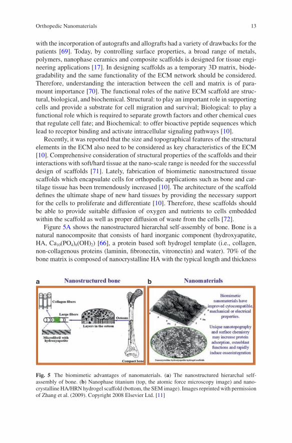
Figure 5A shows the nanostructured hierarchal self-assembly of bone. Bone is a natural nanocomposite that consists of hard inorganic component (hydroxyapatite, HA, Ca10(PO4)6(OH)2) [66], a protein based soft hydrogel template (i.e., collagen, non-collagenous proteins (laminin, fibronectin, vitronectin) and water). 70% of the bone matrix is composed of nanocrystalline HA with the typical length and thickness
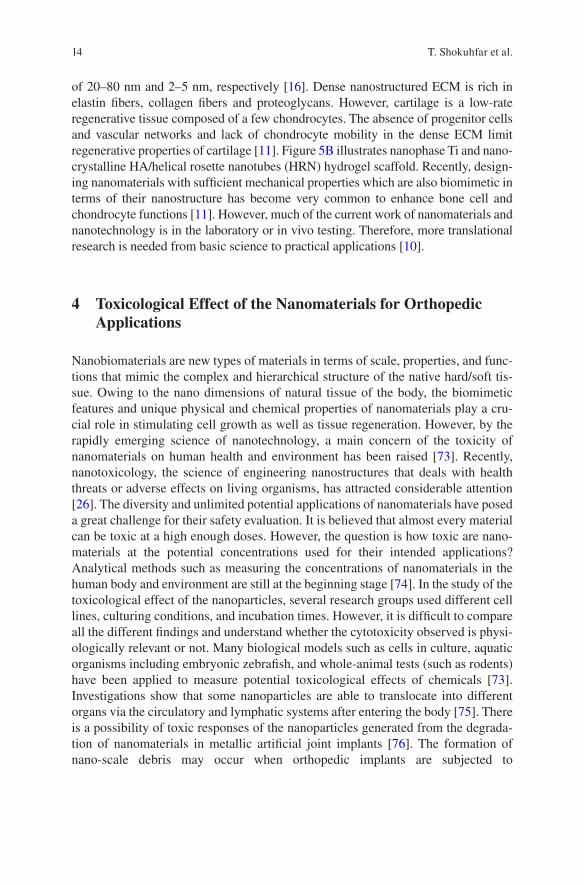
Fig. 5 The biomimetic advantages of nanomaterials. (a) The nanostructured hierarchal self-assembly of bone. (b) Nanophase titanium (top, the atomic force microscopy image) and nano-crystalline HA/HRN hydrogel scaffold (bottom, the SEM image). Images reprinted with permission of Zhang et al. (2009). Copyright 2008 Elsevier Ltd. [11]
Orthopedic Nanomaterials
14
of 20–80 nm and 2–5 nm, respectively [16]. Dense nanostructured ECM is rich in elastin fibers, collagen fibers and proteoglycans. However, cartilage is a low-rate regenerative tissue composed of a few chondrocytes. The absence of progenitor cells and vascular networks and lack of chondrocyte mobility in the dense ECM limit regenerative properties of cartilage [11]. Figure 5B illustrates nanophase Ti and nano-crystalline HA/helical rosette nanotubes (HRN) hydrogel scaffold. Recently, design-ing nanomaterials with sufficient mechanical properties which are also biomimetic in terms of their nanostructure has become very common to enhance bone cell and chondrocyte functions [11]. However, much of the current work of nanomaterials and nanotechnology is in the laboratory or in vivo testing. Therefore, more translational research is needed from basic science to practical applications [10].
4 Toxicological Effect of the Nanomaterials for Orthopedic Applications
Nanobiomaterials are new types of materials in terms of scale, properties, and func-tions that mimic the complex and hierarchical structure of the native hard/soft tis-sue. Owing to the nano dimensions of natural tissue of the body, the biomimetic features and unique physical and chemical properties of nanomaterials play a cru-cial role in stimulating cell growth as well as tissue regeneration. However, by the rapidly emerging science of nanotechnology, a main concern of the toxicity of nanomaterials on human health and environment has been raised [73]. Recently, nanotoxicology, the science of engineering nanostructures that deals with health threats or adverse effects on living organisms, has attracted considerable attention [26]. The diversity and unlimited potential applications of nanomaterials have posed a great challenge for their safety evaluation. It is believed that almost every material can be toxic at a high enough doses. However, the question is how toxic are nano-materials at the potential concentrations used for their intended applications? Analytical methods such as measuring the concentrations of nanomaterials in the human body and environment are still at the beginning stage [74]. In the study of the toxicological effect of the nanoparticles, several research groups used different cell lines, culturing conditions, and incubation times. However, it is difficult to compare all the different findings and understand whether the cytotoxicity observed is physi-ologically relevant or not. Many biological models such as cells in culture, aquatic organisms including embryonic zebrafish, and whole-animal tests (such as rodents) have been applied to measure potential toxicological effects of chemicals [73]. Investigations show that some nanoparticles are able to translocate into different organs via the circulatory and lymphatic systems after entering the body [75]. There is a possibility of toxic responses of the nanoparticles generated from the degrada-tion of nanomaterials in metallic artificial joint implants [76]. The formation of nano-scale debris may occur when orthopedic implants are subjected to
T. Shokuhfar et al.
15
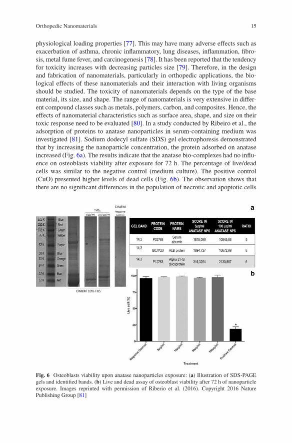
physiological loading properties [77]. This may have many adverse effects such as exacerbation of asthma, chronic inflammatory, lung diseases, inflammation, fibro-sis, metal fume fever, and carcinogenesis [78]. It has been reported that the tendency for toxicity increases with decreasing particles size [79]. Therefore, in the design and fabrication of nanomaterials, particularly in orthopedic applications, the bio-logical effects of these nanomaterials and their interaction with living organisms should be studied. The toxicity of nanomaterials depends on the type of the base material, its size, and shape. The range of nanomaterials is very extensive in differ-ent compound classes such as metals, polymers, carbon, and composites. Hence, the effects of nanomaterial characteristics such as surface area, shape, and size on their toxic response need to be evaluated [80]. In a study conducted by Ribeiro et al., the adsorption of proteins to anatase nanoparticles in serum-containing medium was investigated [81]. Sodium dodecyl sulfate (SDS) gel electrophoresis demonstrated that by increasing the nanoparticle concentration, the protein adsorbed on anatase increased (Fig. 6a). The results indicate that the anatase bio-complexes had no influ-ence on osteoblasts viability after exposure for 72 h. The percentage of live/dead cells was similar to the negative control (medium culture). The positive control (CuO) presented higher levels of dead cells (Fig. 6b). The observation shows that there are no significant differences in the population of necrotic and apoptotic cells
Fig. 6 Osteoblasts viability upon anatase nanoparticles exposure: (a) Illustration of SDS-PAGE gels and identified bands. (b) Live and dead assay of osteoblast viability after 72 h of nanoparticle exposure. Images reprinted with permission of Riberio et al. (2016). Copyright 2016 Nature Publishing Group [81]
Orthopedic Nanomaterials
16
exposed to the different concentrations of anatase nanoparticles [81]. It is believed that in order to determine the toxic effects of nanomaterials, more effort is required for in vivo evaluations, clinical trials, and toxicological surveys before it is com-mercialized for orthopedic applications.
5 Characterization of Orthopedic Nanomaterials
Properties of the nanomaterials used in orthopedics should be studied and well doc-umented before and after their clinical applications. Depending on the interaction of these nanomaterials with the host tissue in the body, size, shape, crystal structure, elemental analysis, chemical bonding, and biocompatibility of these materials need to be investigated. Nanotechnology tools that can enable advanced characterization of nanomaterials and their interactions with biological systems have been recently developed. Such advanced tools can provide new insights for understanding the biocompatibility as well as non-toxicity of nanomaterials used in orthopedics and other medical applications. SEM and AFM are used mainly for the investigation of surface morphology at the nano-scale. In addition, Transmission Electron Microscopy (TEM) provides 2D and 3D images of 3D structures. It also reveals crystal structure information as well through electron diffraction, in a similar fash-ion with how a X-ray Diffractometer does. Via Electron Energy Loss Spectroscopy (EELS, attached to TEM) and Energy Dispersive X-Ray Spectrometry (EDS, as attached to either SEM and TEM), chemical analysis is carried out. Biocompatibility can be examined using either SEM or a Fluorescence Microscope. Chemical bond-ing information can be obtained via Fourier Transform Infrared Spectroscopy (FTIR) and Raman Spectroscopy. Investigation of the properties of the nanomateri-als as synthesized or in environments mimicking real-life conditions provides criti-cal information for optimization of the manufacturing parameters of these materials.
5.1 Size, Shape and Topological Information
5.1.1 Scanning Electron Microscopy
A conventional SEM is very powerful for the size and shape analysis of nanomateri-als with resolutions down to 1 nm. SEM samples can be very large. Upon the inter-action of primary electrons with the nanomaterial, secondary electrons are created at the surface providing topographical information of the sample. Backscattered electrons are also generated and they create atomic number related contrast. X-rays and Auger electrons are also emitted which are fingerprints for elements [82].
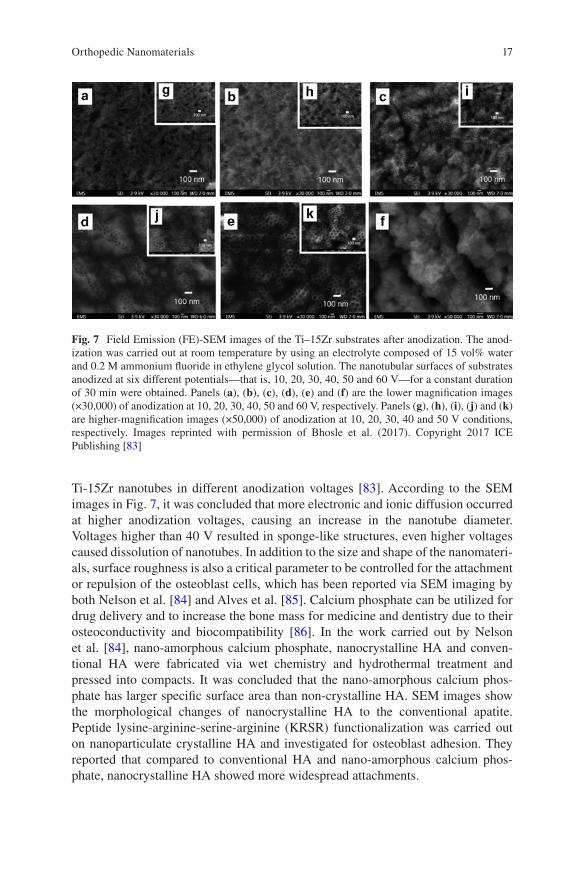
Ti is one of several metals, whose alloys are frequently employed as nanomateri-als. In a recent work, Bhosle et al. carried out the anodization technique to create
T. Shokuhfar et al.
17
Ti-15Zr nanotubes in different anodization voltages [83]. According to the SEM images in Fig. 7, it was concluded that more electronic and ionic diffusion occurred at higher anodization voltages, causing an increase in the nanotube diameter. Voltages higher than 40 V resulted in sponge-like structures, even higher voltages caused dissolution of nanotubes. In addition to the size and shape of the nanomateri-als, surface roughness is also a critical parameter to be controlled for the attachment or repulsion of the osteoblast cells, which has been reported via SEM imaging by both Nelson et al. [84] and Alves et al. [85]. Calcium phosphate can be utilized for drug delivery and to increase the bone mass for medicine and dentistry due to their osteoconductivity and biocompatibility [86]. In the work carried out by Nelson et al. [84], nano-amorphous calcium phosphate, nanocrystalline HA and conven-tional HA were fabricated via wet chemistry and hydrothermal treatment and pressed into compacts. It was concluded that the nano-amorphous calcium phos-phate has larger specific surface area than non-crystalline HA. SEM images show the morphological changes of nanocrystalline HA to the conventional apatite. Peptide lysine-arginine-serine-arginine (KRSR) functionalization was carried out on nanoparticulate crystalline HA and investigated for osteoblast adhesion. They reported that compared to conventional HA and nano-amorphous calcium phos-phate, nanocrystalline HA showed more widespread attachments.
Fig. 7 Field Emission (FE)-SEM images of the Ti–15Zr substrates after anodization. The anod-ization was carried out at room temperature by using an electrolyte composed of 15 vol% water and 0.2 M ammonium fluoride in ethylene glycol solution. The nanotubular surfaces of substrates anodized at six different potentials—that is, 10, 20, 30, 40, 50 and 60 V—for a constant duration of 30 min were obtained. Panels (a), (b), (c), (d), (e) and (f) are the lower magnification images (×30,000) of anodization at 10, 20, 30, 40, 50 and 60 V, respectively. Panels (g), (h), (i), (j) and (k) are higher-magnification images (×50,000) of anodization at 10, 20, 30, 40 and 50 V conditions, respectively. Images reprinted with permission of Bhosle et al. (2017). Copyright 2017 ICE Publishing [83]
Orthopedic Nanomaterials
18
5.1.2 Fluorescence Microscopy
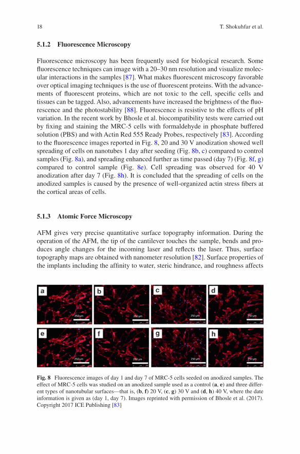
Fluorescence microscopy has been frequently used for biological research. Some fluorescence techniques can image with a 20–30 nm resolution and visualize molec-ular interactions in the samples [87]. What makes fluorescent microscopy favorable over optical imaging techniques is the use of fluorescent proteins. With the advance-ments of fluorescent proteins, which are not toxic to the cell, specific cells and tissues can be tagged. Also, advancements have increased the brightness of the fluo-rescence and the photostability [88]. Fluorescence is resistive to the effects of pH variation. In the recent work by Bhosle et al. biocompatibility tests were carried out by fixing and staining the MRC-5 cells with formaldehyde in phosphate buffered solution (PBS) and with Actin Red 555 Ready Probes, respectively [83]. According to the fluorescence images reported in Fig. 8, 20 and 30 V anodization showed well spreading of cells on nanotubes 1 day after seeding (Fig. 8b, c) compared to control samples (Fig. 8a), and spreading enhanced further as time passed (day 7) (Fig. 8f, g) compared to control sample (Fig. 8e). Cell spreading was observed for 40 V anodization after day 7 (Fig. 8h). It is concluded that the spreading of cells on the anodized samples is caused by the presence of well-organized actin stress fibers at the cortical areas of cells.
5.1.3 Atomic Force Microscopy
AFM gives very precise quantitative surface topography information. During the operation of the AFM, the tip of the cantilever touches the sample, bends and pro-duces angle changes for the incoming laser and reflects the laser. Thus, surface topography maps are obtained with nanometer resolution [82]. Surface properties of the implants including the affinity to water, steric hindrance, and roughness affects
Fig. 8 Fluorescence images of day 1 and day 7 of MRC-5 cells seeded on anodized samples. The effect of MRC-5 cells was studied on an anodized sample used as a control (a, e) and three differ-ent types of nanotubular surfaces—that is, (b, f) 20 V, (c, g) 30 V and (d, h) 40 V, where the date information is given as (day 1, day 7). Images reprinted with permission of Bhosle et al. (2017). Copyright 2017 ICE Publishing [83]
T. Shokuhfar et al.
19
the cell adhesion on the surfaces, as discussed by Park et al. [89]. Based on the AFM surface topography maps, the surface of the nanophase TiO2 is rougher than conven-tional TiO2.
5.2 Inner View, Crystal Structure, Chemical Information
5.2.1 Transmission Electron Microscopy
A modern TEM can resolve features with sizes lower than 0.1 nm, after the incor-poration of aberration correctors. A conventional TEM provides a 2D projection image of a 3D object with a contrast depending on the thickness and density using a parallel coherent beam. With this, size and shape information of the nanoparticles can be obtained. Electrons reflect upon their interactions with atoms in specific planes of the crystals. This crystal structure information is a fingerprint for each material. With the electron holography technique, magnetic features of the materials can also be detected. When used in scanning mode, that is, scanning transmission electron microscope (STEM), similar to a SEM, electrons that reflect in high angles construct atomic number dependent images. Using this mode and EELS and EDS, atomic resolution chemical characterization can be done. EELS records the energy loss information for each electron, which is characteristic of elements, molecules, bonding or electronic structure. EDS records the energy of the X-ray produced, which again is a fingerprint for each element [90].
If the sample has organic materials or is hydrated with weak bonding, to eliminate the possible electron induced material damage, these nanomaterials should be imaged and characterized either as in liquid state or frozen state. Liquid state TEM involves either usage of a fluid flow holder or graphene liquid cells, in which liquids are encapsulated in between either two Si3N4 windows or two graphene layers, respec-tively [91, 92]. The former has the advantage of flowing in liquid to monitor the interaction of the nanomaterials in the shell with the flow, but is very thick, whereas the latter has no capability of flowing any liquid, but is very thin, making dynamic atomic resolution liquid imaging possible. These two techniques are capable of mon-itoring live nano-scale activities. Cryo-TEM is also very useful to preserve the struc-ture at liquid nitrogen temperatures and to do static imaging with low sample damage due to the low temperature during imaging [93]. Colloidal samples can be simply cryo-plunged and thicker samples need to be high pressure frozen, cryo-microtomed and imaged in cryogenically or undergo freeze-substitution and prepared for conven-tional imaging. With the invention of the single particle analysis via cryo-TEM, mul-tiple images of the homogeneously distributed nanomaterials are combined, grouped and processed to simulate a 3D object. Cryo-tomography is also a complementary tool for single particle analysis where the materials are tilted with discrete angles and images are collected at each tilting angle and processed to create a 3D object.
Metallic implants are known to undergo surface degradation when implanted in the human body and release debris and metallic ions which can cause inflammatory
Orthopedic Nanomaterials
20
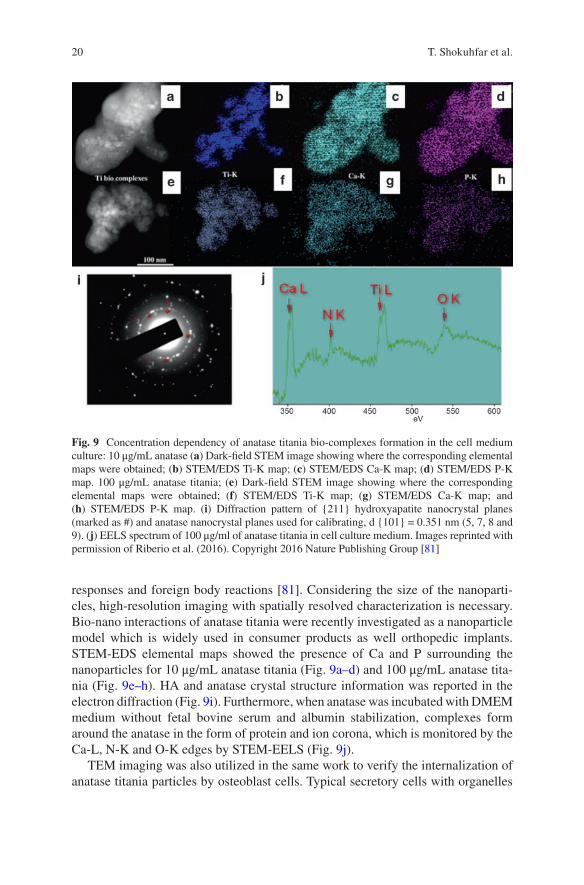
responses and foreign body reactions [81]. Considering the size of the nanoparti-cles, high-resolution imaging with spatially resolved characterization is necessary. Bio-nano interactions of anatase titania were recently investigated as a nanoparticle model which is widely used in consumer products as well orthopedic implants. STEM-EDS elemental maps showed the presence of Ca and P surrounding the nanoparticles for 10 μg/mL anatase titania (Fig. 9a–d) and 100 μg/mL anatase tita-nia (Fig. 9e–h). HA and anatase crystal structure information was reported in the electron diffraction (Fig. 9i). Furthermore, when anatase was incubated with DMEM medium without fetal bovine serum and albumin stabilization, complexes form around the anatase in the form of protein and ion corona, which is monitored by the Ca-L, N-K and O-K edges by STEM-EELS (Fig. 9j).
TEM imaging was also utilized in the same work to verify the internalization of anatase titania particles by osteoblast cells. Typical secretory cells with organelles
Fig. 9 Concentration dependency of anatase titania bio-complexes formation in the cell medium culture: 10 μg/mL anatase (a) Dark-field STEM image showing where the corresponding elemental maps were obtained; (b) STEM/EDS Ti-K map; (c) STEM/EDS Ca-K map; (d) STEM/EDS P-K map. 100 μg/mL anatase titania; (e) Dark-field STEM image showing where the corresponding elemental maps were obtained; (f) STEM/EDS Ti-K map; (g) STEM/EDS Ca-K map; and (h) STEM/EDS P-K map. (i) Diffraction pattern of {211} hydroxyapatite nanocrystal planes (marked as #) and anatase nanocrystal planes used for calibrating, d {101} = 0.351 nm (5, 7, 8 and 9). (j) EELS spectrum of 100 μg/ml of anatase titania in cell culture medium. Images reprinted with permission of Riberio et al. (2016). Copyright 2016 Nature Publishing Group [81]
T. Shokuhfar et al.
21
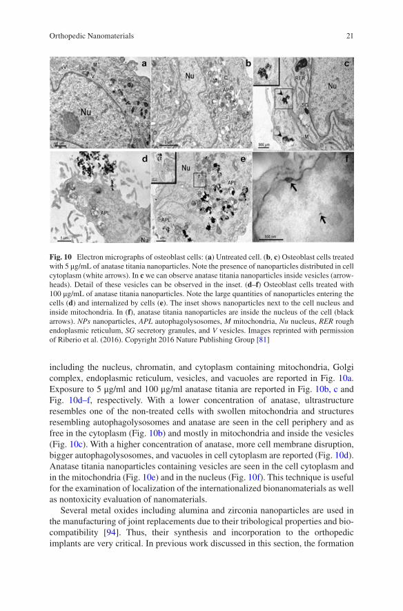
including the nucleus, chromatin, and cytoplasm containing mitochondria, Golgi complex, endoplasmic reticulum, vesicles, and vacuoles are reported in Fig. 10a. Exposure to 5 μg/ml and 100 μg/ml anatase titania are reported in Fig. 10b, c and Fig. 10d–f, respectively. With a lower concentration of anatase, ultrastructure resembles one of the non-treated cells with swollen mitochondria and structures resembling autophagolysosomes and anatase are seen in the cell periphery and as free in the cytoplasm (Fig. 10b) and mostly in mitochondria and inside the vesicles (Fig. 10c). With a higher concentration of anatase, more cell membrane disruption, bigger autophagolysosomes, and vacuoles in cell cytoplasm are reported (Fig. 10d). Anatase titania nanoparticles containing vesicles are seen in the cell cytoplasm and in the mitochondria (Fig. 10e) and in the nucleus (Fig. 10f). This technique is useful for the examination of localization of the internationalized bionanomaterials as well as nontoxicity evaluation of nanomaterials.
Several metal oxides including alumina and zirconia nanoparticles are used in the manufacturing of joint replacements due to their tribological properties and bio-compatibility [94]. Thus, their synthesis and incorporation to the orthopedic implants are very critical. In previous work discussed in this section, the formation
Fig. 10 Electron micrographs of osteoblast cells: (a) Untreated cell. (b, c) Osteoblast cells treated with 5 μg/mL of anatase titania nanoparticles. Note the presence of nanoparticles distributed in cell cytoplasm (white arrows). In c we can observe anatase titania nanoparticles inside vesicles (arrow-heads). Detail of these vesicles can be observed in the inset. (d–f) Osteoblast cells treated with 100 μg/mL of anatase titania nanoparticles. Note the large quantities of nanoparticles entering the cells (d) and internalized by cells (e). The inset shows nanoparticles next to the cell nucleus and inside mitochondria. In (f), anatase titania nanoparticles are inside the nucleus of the cell (black arrows). NPs nanoparticles, APL autophagolysosomes, M mitochondria, Nu nucleus, RER rough endoplasmic reticulum, SG secretory granules, and V vesicles. Images reprinted with permission of Riberio et al. (2016). Copyright 2016 Nature Publishing Group [81]
Orthopedic Nanomaterials
22
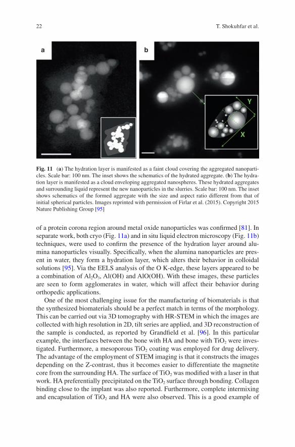
of a protein corona region around metal oxide nanoparticles was confirmed [81]. In separate work, both cryo (Fig. 11a) and in situ liquid electron microscopy (Fig. 11b) techniques, were used to confirm the presence of the hydration layer around alu-mina nanoparticles visually. Specifically, when the alumina nanoparticles are pres-ent in water, they form a hydration layer, which alters their behavior in colloidal solutions [95]. Via the EELS analysis of the O K-edge, these layers appeared to be a combination of Al2O3, Al(OH) and AlO(OH). With these images, these particles are seen to form agglomerates in water, which will affect their behavior during orthopedic applications.
One of the most challenging issue for the manufacturing of biomaterials is that the synthesized biomaterials should be a perfect match in terms of the morphology. This can be carried out via 3D tomography with HR-STEM in which the images are collected with high resolution in 2D, tilt series are applied, and 3D reconstruction of the sample is conducted, as reported by Grandfield et al. [96]. In this particular example, the interfaces between the bone with HA and bone with TiO2 were inves-tigated. Furthermore, a mesoporous TiO2 coating was employed for drug delivery. The advantage of the employment of STEM imaging is that it constructs the images depending on the Z-contrast, thus it becomes easier to differentiate the magnetite core from the surrounding HA. The surface of TiO2 was modified with a laser in that work. HA preferentially precipitated on the TiO2 surface through bonding. Collagen binding close to the implant was also reported. Furthermore, complete intermixing and encapsulation of TiO2 and HA were also observed. This is a good example of
Fig. 11 (a) The hydration layer is manifested as a faint cloud covering the aggregated nanoparti-cles. Scale bar: 100 nm. The inset shows the schematics of the hydrated aggregate. (b) The hydra-tion layer is manifested as a cloud enveloping aggregated nanospheres. These hydrated aggregates and surrounding liquid represent the new nanoparticles in the slurries. Scale bar: 100 nm. The inset shows schematics of the formed aggregate with the size and aspect ratio different from that of initial spherical particles. Images reprinted with permission of Firlar et al. (2015). Copyright 2015 Nature Publishing Group [95]
T. Shokuhfar et al.
23
the visualization osseointegration between the bone and the implant. Through HAADF STEM images and 3D reconstruction of TiO2 on Ti implants, the intercon-nection of the pores in 3D was revealed, providing the basis for drug loading and release mechanisms.
5.2.2 X-Ray Diffraction Spectroscopy
X-ray diffraction (XRD) is another important crystal structure characterization method. It can be considered as an alternative to electron diffraction, which was discussed previously. XRD provides structural analysis of the sample, based on the diffraction of X-rays [97] as opposed to the diffracted electrons in electron diffrac-tion in TEM. A beam of X-rays hit the sample, and the resulting spectrum gives peaks based on the direction of the diffracted X-rays, which correlates with the distribution of atoms in the crystal. The amount of the sample can be a lot larger in XRD compared to electron diffraction. XRD is commonly used in characterizing nanomaterials used in orthopedic applications because it analyzes the crystal struc-tures and the phases [98, 99]. XRD is useful in coating experiments. With the previ-ous XRD data knowledge of the coating material, the synthesis stages of the coatings on the substrates can be monitored [100].
Kuo et al. used XRD to analyze the crystallography of HA coatings at increasing temperatures [101]. The findings indicated that the main component of HA was dicalcium phosphate dihydrate at lower currents. However, at a higher current and higher temperatures, part of the HA underwent a phase transformation. By knowing when the HA changed its structure, they could determine the best temperature to deposit the coating. Webster et al. not only used XRD to characterize various HA formulations but also obtained the lattice patterns [102]. They were then able to com-pare the lattice parameters of all the variants of HA, which would help to determine other substituents that can be used to substitute Ca. Razavi et al. also used XRD to analyze the composition, but was specifically looking to see if the substrate would be corrosive if it was protected with magnesium oxide. Because the XRD pattern showed Mg2SiO4, this means that magnesium oxide did protect the substrate [103].
5.3 Chemical Bonding Information
5.3.1 Fourier Transform Infrared Spectroscopy
FTIR can be utilized to characterize the composition of the nanomaterials. FTIR identifies functional groups by measuring the absorption of the sample. Infrared radiation passes through the sample, where the sample then absorbs some of the radiation, and the rest will be transmitted [104]. The absorption peak is the result of the frequencies of the vibrations between the atoms of the sample. Then, the
Orthopedic Nanomaterials
24
resulting spectrum will show the absorption peaks that represent the functional groups in the sample. The intensity of the peak can also quantitatively show the amount of that functional group that is present as compared to the other functional groups in the sample. All compounds have specific spectra because different com-pounds have a unique combination of atoms, resulting in different absorption peaks. Being able to identify functional groups is useful to confirm or identify unknown function groups in the resulting nanomaterial. A majority of research groups use FTIR to analyze the nanomaterial coatings on alloys for orthopedic implants. FTIR is commonly used in composition characterization of the synthesized coatings.
Cao et al. used FTIR to identify the phosphate and hydroxide group on their surface coating [105]. They treated Mg-Zn-Ca alloy by micro arc oxidation (MAO), and then coated the treated alloy with TiO2. Therefore, the spectrum confirmed that the TiO2 layer reacted with the MAO coating. Razavi et al. similarly used MAO to coat magnesium (Mg) alloys with nanostructured diopside [103]. However, they used FTIR to evaluate in vitro bioactivity. After coating the alloys, they immersed the alloys in simulated body fluid for 672 h for analyzing the bioactivity of the coat-ing. A precipitate layer was formed on the surface, which was analyzed using FTIR and found that it contained phosphate and carbonate groups. FTIR is a very helpful device to analyze the composition of a sample, and even to evaluate the molecular interaction in the sample [106]. Further nanomaterials characterization studies to identify the compositions of the coatings via FTIR were reported earlier [107–109], specifically to confirm if the synthesis of the coating is completed [110]. For instance, it is used to determine whether the sample is crystallized [111], or the original sample is altered over the time after process [112].
5.3.2 Raman Spectroscopy
Raman spectroscopy is similar to FTIR in that both spectra are based on the vibra-tions of molecules in the sample [113]. However, Raman spectroscopy has vibra-tional modes. Also, samples can be used without any preparation for analysis, making it a useful technique to monitor the sample before and after treatment [114]. Raman spectroscopy can be used complementary to FTIR for the detection of dif-ferent functional groups.
Using Raman spectroscopy, Greer et al. evaluated the composition of Ti-based sol-gel [115]. However, they monitored the sample through the entire annealing pro-cess to analyze the structural phases. They could see the different phases as they increased the temperature. By knowing what phase the sample is in during the anneal-ing process, they could determine when the annealing process was completed.
6 Summary
Future prospects for nanomaterials in orthopedic applications appear to be game changing. Although orthopedic implants have become more successful over the recent decades, they have not been perfected. Today there is a significant demand
T. Shokuhfar et al.
25
for the development of a bone substitute that is bioactive and exhibits mechanical and surface properties comparable with those of natural bone. Owing to the unique and exceptional physical and chemical properties of these nanomaterials, and fur-thermore their functions, specifically, enabling tissue regeneration, drug delivery, antimicrobial properties, enhancing bone growth, etc., they have been proposed as the next generation of orthopedic materials with high promise towards increasing the success rate of implantation by promoting osseointegration. The wide range of benefits of nanotechnology and nanomaterials in orthopedic applications can be realized even more, once further tests and studies concerning the nanotoxicity of such materials are completed. In addition, properties of the orthopedic nanomateri-als and their interaction with host tissue need to be studied before and after their clinical applications. Currently, tools and techniques have been developed which enable advanced characterization of nanomaterials and their interactions with bio-logical systems. The recent high success of such characterizations and tests will enable the use of broad range of nanostructured biomaterials for orthopedic applica-tions specially targeted towards patients with certain medical conditions, and those with compromised bone tissues. Finally, it is safe to say that the promise of nanosci-ence and nanotechnology can positively change the future of orthopedic implants and those receiving or in need for them.
Acknowledgement The authors are grateful to the National Science Foundation, CAREER award DMR-1564950 for providing partial financial support.
References
1. Tasker LH, Sparey-Taylor GJ, Nokes LDM. Applications of nanotechnology in orthopaedics. Clin Orthop Relat Res. 2007;456:243–9.
2. Di Sia P. Nanotechnology among innovation, health and risks. Proc Soc Behav Sci. 2017;237:1076–80.
3. Toumey C. Plenty of room, plenty of history. Nat Nanotechnol. 2009;4(12):783–4. 4. Mauro JC, Ellison AJ, Pye LD. Glass: the nanotechnology connection. Int J Appl Glas Sci.
2013;4(2):64–75. 5. Sakamoto JH, van de Ven AL, Godin B, Blanco E, Serda RE, Grattoni A, Ziemys A,
Bouamrani A, Hu T, Ranganathan SI, De Rosa E, Martinez JO, Smid CA, Buchanan RM, Lee S-Y, Srinivasan S, Landry M, Meyn A, Tasciotti E, Liu X, Decuzzi P, Ferrari M. Enabling individualized therapy through nanotechnology. Pharmacol Res. 2010;62(2):57–89.
6. Mirza AZ, Siddiqui FA. Nanomedicine and drug delivery: a mini review. Int Nano Lett. 2014;4(1):94.
7. Chistiakov DA. Endogenous and exogenous stem cells: a role in lung repair and use in airway tissue engineering and transplantation. J Biomed Sci. 2010;17(1):92.
8. Wang M, Abbineni G, Clevenger A, Mao C, Xu S. Upconversion nanoparticles: synthe-sis, surface modification and biological applications. Nanomed Nanotechnol Biol Med. 2011;7(6):710–29.
9. Leonida MD, Kumar I. Nanomaterials, scaffolds, and skin tissue regeneration. Cham: Springer International Publishing; 2016. p. 103–16.
Orthopedic Nanomaterials
26
10. Parchi PD, Vittorio O, Andreani L, Piolanti N, Cirillo G, Iemma F, Hampel S, Lisanti M. How nanotechnology can really improve the future of orthopedic implants and scaffolds for bone and cartilage defects. J. Nanomed Biotherapeutic Discov. 2013;3(2):114. https://doi.org/10.4172/2155-983X.1000114.
11. Zhang L, Webster TJ. Nanotechnology and nanomaterials: Promises for improved tissue regeneration. Nano Today. 2009;4(1):66–80.
12. AAOS. Information about musculoskeletal conditions. Rosemont, IL: AAOS; 2013. p. 26. 13. Catledge SA, Thomas V, Vohra YK. Nanostructured diamond coatings for orthopaedic appli-
cations. Woodhead Publ Ser Biomater. 2013;2013:105–50. 14. Catledge SA, Fries MD, Vohra YK, Lacefield WR, Lemons JE, Woodard S, Venugopalan
R. Nanostructured ceramics for biomedical implants. J Nanosci Nanotechnol. 2002;2(3–4):293–312.
15. Taheri MM, Abdul Kadir MR, Ahmad Shafie NK, Shokuhfar T, Assadian M, Rezazadeh Shirdar M. Green synthesis of silver nanoneedles using shallot and apricot tree gum. Trans Nonferrous Met Soc China. 2015;25(10):3286–90.
16. Taheri MM, Abdul Kadir MR, Shokuhfar T, Hamlekhan A, Shirdar MR, Naghizadeh F. Fluoridated hydroxyapatite nanorods as novel fillers for improving mechanical properties of dental composite: synthesis and application. Mater Des. 2015;82:119–25.
17. Christenson EM, Anseth KS, van den Beucken JJJP, Chan CK, Ercan B, Jansen JA, Laurencin CT, Li W-J, Murugan R, Nair LS, Ramakrishna S, Tuan RS, Webster TJ, Mikos AG. Nanobiomaterial applications in orthopedics. J Orthop Res. 2007;25(1):11–22.
18. Sato M, Webster TJ. Nanobiotechnology: implications for the future of nanotechnology in orthopedic applications. Expert Rev Med Devices. 2004;1(1):105–14.
19. Sato M, Webster TJ. Orthopedic tissue engineering using nanomaterials. In Nanotechnologies for the life sciences. Weinheim: Wiley-VCH Verlag GmbH & Co. KGaA; 2007.
20. Balasundaram G, Webster TJ, Akasaka T, Wroblewski BM, Ingham E, Kamali A, Stone MH, Ingham E, Montanaro L, Baquey CH. A perspective on nanophase materials for orthopedic implant applications. J Mater Chem. 2006;16(38):3737.
21. Marot D, Knezevic M, Novakovic G. Bone tissue engineering with human stem cells. Stem Cell Res Ther. 2010;1(2):10.
22. Boccaccini AR, Keim S, Ma R, Li Y, Zhitomirsky I. Electrophoretic deposition of biomateri-als. J R Soc Interface. 2010;7(Suppl_5):S581–613.
23. Yang L, Zhang L, Webster TJ. Carbon nanostructures for orthopedic medical applications. Nanomedicine. 2011;6(7):1231–44.
24. Hodgkinson T, Yuan X-F, Bayat A. Adult stem cells in tissue engineering. Expert Rev Med Devices. 2009;6(6):621–40.
25. Chun YW, Webster TJ. The role of nanomedicine in growing tissues. Ann Biomed Eng. 2009;37(10):2034–47.
26. Simchi A, Mazaheri M, Eslahi N, Ordikhani F, Tamjid E. Nanomedicine applications in orthopedic medicine: state of the art. Int J Nanomedicine. 2015;10:6039.
27. Shirwaiker RA, Samberg ME, Cohen PH, Wysk RA, Monteiro-Riviere NA. Nanomaterials and synergistic low-intensity direct current (LIDC) stimulation technology for ortho-pedic implantable medical devices. Wiley Interdiscip Rev Nanomed Nanobiotechnol. 2013;5(3):191–204.
28. Khang D, Carpenter J, Chun YW, Pareta R, Webster TJ. Nanotechnology for regenerative medicine. Biomed Microdevices. 2010;12(4):575–87.
29. Hench LL, Polak JM. Third-generation biomedical materials. Science. 2002;295(5557): 1014–7.
30. Liang J, Song R, Huang Q, Yang Y, Lin L, Zhang Y, Jiang P, Duan H, Dong X, Lin C. Electrochemical construction of a bio-inspired micro/nano-textured structure with cell-sized microhole arrays on biomedical titanium to enhance bioactivity. Electrochim Acta. 2015;174:1149–59.
31. Mishnaevsky L, Levashov E, Valiev RZ, Segurado J, Sabirov I, Enikeev N, Prokoshkin S, Solov’yov AV, Korotitskiy A, Gutmanas E, Gotman I, Rabkin E, Psakh’e S, Dluhoš L,
T. Shokuhfar et al.
27
Seefeldt M, Smolin A. Nanostructured titanium-based materials for medical implants: model-ing and development. Mater Sci Eng R Rep. 2014;81:1–19.
32. Yamanaka K, Mori M, Chiba A. Nanoarchitectured Co–Cr–Mo orthopedic implant alloys: nitrogen-enhanced nanostructural evolution and its effect on phase stability. Acta Biomater. 2013;9(4):6259–67.
33. Pauksch L, Hartmann S, Rohnke M, Szalay G, Alt V, Schnettler R, Lips KS. Biocompatibility of silver nanoparticles and silver ions in primary human mesenchymal stem cells and osteo-blasts. Acta Biomater. 2014;10(1):439–49.
34. Krawczynska AT, Gloc M, Lublinska K. Intergranular corrosion resistance of nanostructured austenitic stainless steel. J Mater Sci. 2013;48(13):4517–23.
35. Mohandas G, Oskolkov N, McMahon MT, Walczak P, Janowski M. Porous tantalum and tantalum oxide nanoparticles for regenerative medicine. Acta Neurobiol Exp (Wars). 2014;74(2):188–96.
36. Schiavi J, Keller L, Morand D-N, De Isla N, Huck O, Lutz JC, Mainard D, Schwinté P, Benkirane-Jessel N. Active implant combining human stem cell microtissues and growth factors for bone-regenerative nanomedicine. Nanomedicine. 2015;10(5):753–63.
37. Levengood SL, Zhang M. Chitosan-based scaffolds for bone tissue engineering. J Mater Chem B Mater Biol Med. 2014;2(21):3161–84.
38. Lee P, Tran K, Chang W, Shelke NB, Kumbar SG, Yu X. Influence of chondroitin sulfate and hyaluronic acid presence in nanofibers and its alignment on the bone marrow stromal cells: cartilage regeneration. J Biomed Nanotechnol. 2014;10(8):1469–79.
39. Zhang W, Zhu C, Ye D, Xu L, Zhang X, Wu Q, Zhang X, Kaplan DL, Jiang X. Porous silk scaffolds for delivery of growth factors and stem cells to enhance bone regeneration. PLoS One. 2014;9(7):e102371.
40. Gentile P, Chiono V, Carmagnola I, Hatton P. An overview of poly(lactic-co-glycolic) acid (PLGA)-based biomaterials for bone tissue engineering. Int J Mol Sci. 2014;15(3):3640–59.
41. Winkins S, Kamath M, Dhanasekaran M, Ahmed S. Polycaprolactone scaffold engineered for sustained release of resveratrol: therapeutic enhancement in bone tissue engineering. Int J Nanomedicine. 2013;9:183.
42. Xing Z-C, Han S-J, Shin Y-S, Koo T-H, Moon S, Jeong Y, Kang I-K. Enhanced osteoblast responses to poly(methyl methacrylate)/hydroxyapatite electrospun nanocomposites for bone tissue engineering. J Biomater Sci Polym Ed. 2012;24(1):61–76.
43. Lopes MS, Jardini AL, Filho RM. Poly (lactic acid) production for tissue engineering appli-cations. Proc Eng. 2012;42:1402–13.
44. Evans NT, Torstrick FB, Lee CSD, Dupont KM, Safranski DL, Chang WA, Macedo AE, Lin ASP, Boothby JM, Whittingslow DC, Carson RA, Guldberg RE, Gall K. High-strength, surface-porous polyether-ether-ketone for load-bearing orthopedic implants. Acta Biomater. 2015;13:159–67.
45. Wang P, Zhao L, Liu J, Weir MD, Zhou X, Xu HHK. Bone tissue engineering via nanostruc-tured calcium phosphate biomaterials and stem cells. Bone Res. 2014;2:14017.
46. Zhou C, Deng C, Chen X, Zhao X, Chen Y, Fan Y, Zhang X. Mechanical and biological prop-erties of the micro−/nano-grain functionally graded hydroxyapatite bioceramics for bone tissue engineering. J Mech Behav Biomed Mater. 2015;48:1–11.
47. Tamjid E, Bagheri R, Vossoughi M, Simchi A. Effect of particle size on the in vitro bioactiv-ity, hydrophilicity and mechanical properties of bioactive glass-reinforced polycaprolactone composites. Mater Sci Eng C. 2011;31(7):1526–33.
48. Price RL, Haberstroh KM, Webster TJ. Enhanced functions of osteoblasts on nanostructured surfaces of carbon and alumina. Med Biol Eng Comput. 2003;41(3):372–5.
49. Newman P, Minett A, Ellis-Behnke R, Zreiqat H. Carbon nanotubes: their potential and pitfalls for bone tissue regeneration and engineering. Nanomed Nanotechnol Biol Med. 2013;9(8):1139–58.
50. Zhao C, Lu X, Zanden C, Liu J. The promising application of graphene oxide as coating materials in orthopedic implants: preparation, characterization and cell behavior. Biomed Mater. 2015;10(1):15019.
Orthopedic Nanomaterials
28
51. Mansoorianfar M, Shokrgozar MA, Mehrjoo M, Tamjid E, Simchi A. Nanodiamonds for sur-face engineering of orthopedic implants: Enhanced biocompatibility in human osteosarcoma cell culture. Diam Relat Mater. 2013;40:107–14.
52. Hickey DJ, Ercan B, Sun L, Webster TJ. Adding MgO nanoparticles to hydroxyapatite–PLLA nanocomposites for improved bone tissue engineering applications. Acta Biomater. 2015;14:175–84.
53. Liao CZ, Li K, Wong HM, Tong WY, Yeung KWK, Tjong SC. Novel polypropylene bio-composites reinforced with carbon nanotubes and hydroxyapatite nanorods for bone replace-ments. Mater Sci Eng C. 2013;33(3):1380–8.
54. Pishbin F, Mouriño V, Gilchrist JB, McComb DW, Kreppel S, Salih V, Ryan MP, Boccaccini AR. Single-step electrochemical deposition of antimicrobial orthopaedic coatings based on a bioactive glass/chitosan/nano-silver composite system. Acta Biomater. 2013;9(7):7469–79.
55. Longmire MR, Ogawa M, Choyke PL, Kobayashi H. Biologically optimized nanosized mol-ecules and particles: more than just size. Bioconjug Chem. 2011;22(6):993–1000.
56. Katz D, Kany J, Valenti P, Sauzières P, Gleyze P, El Kholti K. New design of a cementless gle-noid component in unconstrained shoulder arthroplasty: a prospective medium-term analysis of 143 cases. Eur J Orthop Surg Traumatol. 2013;23(1):27–34.
57. Cobelli N, Scharf B, Crisi GM, Hardin J, Santambrogio L. Mediators of the inflammatory response to joint replacement devices. Nat Rev Rheumatol. 2011;7(10):600–8.
58. Izman S, Rafiq M, Anwar M, Nazim EM, Rosliza R, Shah A, Hass MA. Surface modification techniques for biomedical grade of titanium alloys: oxidation, carburization and ion implan-tation processes. In: Nurul Amin AKM, editor. Titanium alloys—towards achieving enhanced properties for diversified applications. London: InTech; 2012.
59. Wang Q, Yang X, Liu D, Zhao J. Fabrication, characterization and photocatalytic properties of Ag nanoparticles modified TiO2 NTs. J Alloys Compd. 2012;527:106–11.
60. Lin L, Wang H, Ni M, Rui Y, Cheng T-Y, Cheng C-K, Pan X, Li G, Lin C. Enhanced osteo-integration of medical titanium implant with surface modifications in micro/nanoscale struc-tures. J Orthop Transl. 2014;2(1):35–42.
61. Kasemo B, Gold J. Implant surfaces and interface processes. Adv Dent Res. 1999;13(1):8–20. 62. Bauer S, Schmuki P, von der Mark K, Park J. Engineering biocompatible implant surfaces.
Prog Mater Sci. 2013;58(3):261–326. 63. Xia L, Feng B, Wang P, Ding S, Liu Z, Zhou J, Yu R. In vitro and in vivo studies of surface-
structured implants for bone formation. Int J Nanomedicine. 2012;7:4873–81. 64. Mazaheri M, Eslahi N, Ordikhani F, Tamjid E, Simchi A. Nanomedicine applications in
orthopedic medicine: state of the art. Int J Nanomedicine. 2015;10:6039–53. 65. Safonov V, Zykova A, Smolik J, Rogowska R, Lukyanchenko V, Kolesnikov D. Modification
of implant material surface properties by means of oxide nano-structured coatings deposition. Appl Surf Sci. 2014;310:174–9.
66. Rezazadeh Shirdar M, Sudin I, Taheri MM, Keyvanfar A, Yusop MZM, kadir MRA. A novel hydroxyapatite composite reinforced with titanium nanotubes coated on Co–Cr-based alloy. Vacuum. 2015;122:82–9.
67. Rezazadeh Shirdar M, Taheri MM, Moradifard H, Keyvanfar A, Shafaghat A, Shokuhfar T, Izman S. Hydroxyapatite–titania nanotube composite as a coating layer on Co–Cr-based implants: Mechanical and electrochemical optimization. Ceram Int. 2016;42(6):6942–54.
68. Breme H, Biehl V, Reger N, Gawalt E. Chapter 1a Metallic biomaterials: introduction. In: Black J, Hastings G, editors. Handbook of biomaterial properties. New York, NY: Springer New York; 2016. p. 151–8.
69. Smith GD, Knutsen G, Richardson JB. A clinical review of cartilage repair techniques. J Bone Joint Surg Br. 2005;87B(4):445–9.
70. Mafi P, Hindocha S, Mafi R, Khan WS. Evaluation of biological protein-based collagen scaf-folds in cartilage and musculoskeletal tissue engineering—a systematic review of the litera-ture. Curr Stem Cell Res Ther. 2012;7(4):302–9.
71. Cartmell S. Controlled release scaffolds for bone tissue engineering. J Pharm Sci. 2009;98(2):430–41.
T. Shokuhfar et al.
29
72. Li Z, Kawashita M. Current progress in inorganic artificial biomaterials. J Artif Organs. 2011;14(3):163–70.
73. Ray PC, Yu H, Fu PP. Toxicity and environmental risks of nanomaterials: challenges and future needs. J Environ Sci Health C Environ Carcinog Ecotoxicol Rev. 2009;27(1):1–35.
74. Majestic BJ, Erdakos GB, Lewandowski M, Oliver KD, Willis RD, Kleindienst TE, Bhave PV. A review of selected engineered nanoparticles in the atmosphere: sources, transformations, and techniques for sampling and analysis. Int J Occup Environ Health. 2010;16(4):488–507.
75. Bakand S, Hayes A, Dechsakulthorn F. Nanoparticles: a review of particle toxicology follow-ing inhalation exposure. Inhal Toxicol. 2012;24(2):125–35.
76. Madl AK, Kovochich M, Liong M, Finley BL, Paustenbach DJ, Oberdörster G. Toxicology of wear particles of cobalt-chromium alloy metal-on-metal hip implants. Part II: importance of physicochemical properties and dose in animal and in vitro studies as a basis for risk assess-ment. Nanomed Nanotechnol Biol Med. 2015;11(5):1285–98.
77. Webster TJ, Ahn ES. Nanostructured biomaterials for tissue engineering bone. Adv Biochem Eng Biotechnol. 2007;103:275–308.
78. Cheng L-C, Jiang X, Wang J, Chen C, Liu R-S. Nano-bio effects: interaction of nanomateri-als with cells. Nanoscale. 2013;5(9):3547.
79. Fan AM, Alexeeff G. Nanotechnology and nanomaterials: toxicology, risk assessment, and regulations. J Nanosci Nanotechnol. 2010;10(12):8646–57.
80. Fischer HC, Chan WC. Nanotoxicity: the growing need for in vivo study. Curr Opin Biotechnol. 2007;18(6):565–71.
81. Ribeiro AR, Gemini-Piperni S, Travassos R, Lemgruber L, C Silva R, Rossi AL, Farina M, Anselme K, Shokuhfar T, Shahbazian-Yassar R, Borojevic R, Rocha LA, Werckmann J, Granjeiro JM. Trojan-like internalization of anatase titanium dioxide nanoparticles by human osteoblast cells. Sci Rep. 2016;6:23615.
82. Goldstein J, Newbury D, Joy DC, Michael J, Ritchie NWM, Scott JH. Scanning electron microscopy and X-ray microanalysis. New York: Springer; 2017.
83. Bhosle S, Patel S, Taheril MM, Sukotjo C, Shokuhfar T. Electrochemical anodisation of Ti–15Zr implant: effect of different voltages and times. Surf Innov. 2017;5(1):82–9.
84. Nelson M, Balasundaram G, Webster TJ. Increased osteoblast adhesion on nanoparticulate crystalline hydroxyapatite functionalized with KRSR. Int J Nanomedicine. 2006;1(3):339–49.
85. Alves SA, Patel SB, Sukotjo C, Mathew MT, Filho PN, Celis J-P, Rocha LA, Shokuhfar T. Synthesis of calcium-phosphorous doped TiO2 nanotubes by anodization and reverse polarization: a promising strategy for an efficient biofunctional implant surface. Appl Surf Sci. 2017;399:682–701.
86. Wang M. Bioactive materials and processing. In: Biomaterials and tissue engineering. Heidelberg: Springer; 2004. p. 1–87.
87. Bates M, Huang B, Dempsey GT, Zhuang X. S-Multicolor super-resolution imaging with photo-switchable fluorescent probes. Science. 2007;317(5845):1749–53.
88. Lippincott-Schwartz J, Snapp E, Kenworthy A. Studying protein dynamics in living cells. Nat Rev Mol Cell Biol. 2001;2(6):444–56.
89. Park MR, Banks MK, Applegate B, Webster TJ. Influence of nanophase titania topography on bacterial attachment and metabolism. Int J Nanomedicine. 2008;3(4):497–504.
90. Williams DB, Carter CB. Transmission electron microscopy: a textbook for materials sci-ence. Boston, MA: Springer US; 2009.
91. Evans JE, Jungjohann KL, Browning ND, Arslan I. Controlled growth of nanoparticles from solution with in situ liquid transmission electron microscopy. Nano Lett. 2011;11(7):2809–13.
92. Wang C, Qiao Q, Shokuhfar T, Klie RF. High-resolution electron microscopy and spectros-copy of ferritin in biocompatible graphene liquid cells and graphene sandwiches. Adv Mater. 2014;26(21):3410–4.
93. Mandelkow E, Mandelkow E, Milligan RA. Microtubule dynamics and microtubule caps: a time-resolved cryo- electron microscopy study. J Cell Biol. 1991;114(5):977–91.
94. Dalla Pria P. Evolution and new application of the alumina ceramics in joint replacement. Eur J Orthop Surg Traumatol. 2007;17(3):253–6.
Orthopedic Nanomaterials
30
95. Firlar E, Çınar S, Kashyap S, Akinc M, Prozorov T. Direct visualization of the hydration layer on alumina nanoparticles with the fluid cell STEM in situ. Sci Rep. 2015;5:9830.
96. Grandfield K, Palmquist A, Engqvist H. High-resolution three-dimensional probes of bioma-terials and their interfaces. Philos Trans R Soc A Math Phys Eng Sci. 2012;370:1337–51.
97. Nelson SA. X-ray crystallography. Sci Am. 2010;219(1):1–6. 98. Feng B, Weng J, Yang BC, Qu SX, Zhang XD. Characterization of surface oxide films on
titanium and adhesion of osteoblast. Biomaterials. 2003;24(25):4663–70. 99. Eslami N, Mahmoodian R, Hamdi M, Khatir NM, Herliansyah MK, Rafieerad AR. Study
the synthesis, characterization and immersion of dense and porous bovine hydroxyapatite structures in Hank’s balanced salt solution. JOM. 2017;69(4):691–8.
100. Anselme K, Bigerelle M, Noel B, Dufresne E, Judas D, Iost A, Hardouin P. Qualitative and quantitative study of human osteoblast adhesion on materials with various surface rough-nesses. J Biomed Mater Res. 2000;49(2):155–66.
101. Kuo MC, Yen SK. The process of electrochemical deposited hydroxyapatite coatings on bio-medical titanium at room temperature. Mater Sci Eng C. 2002;20(1–2):153–60.
102. Webster TJ, Massa-Schlueter EA, Smith JL, Slamovich EB. Osteoblast response to hydroxy-apatite doped with divalent and trivalent cations. Biomaterials. 2004;25(11):2111–21.
103. Razavi M, Fathi M, Savabi O, Vashaee D, Tayebi L. In vitro study of nanostructured diopside coating on Mg alloy orthopedic implants. Mater Sci Eng C. 2014;41:168–77.
104. Ganzoury MA, Allam NK, Nicolet T, All C. Introduction to fourier transform infrared spec-trometry. Renew Sust Energ Rev. 2015;50:1–8.
105. Cao G, Wang L, Fu Z, Hu J, Guan S, Zhang C, Wang L, Zhu S. Chemically anchoring of TiO2 coating on OH-terminated Mg 3(PO3)2 surface and its influence on the in vitro degradation resistance of Mg-Zn-Ca alloy. Appl Surf Sci. 2014;308:38–42.
106. Ambre A, Katti KS, Katti DR. In situ mineralized hydroxyapatite on amino acid modified nanoclays as novel bone biomaterials. Mater Sci Eng C. 2011;31(5):1017–29.
107. Yazdimamaghani M, Razavi M, Vashaee D, Tayebi L. Development and degradation behav-ior of magnesium scaffolds coated with polycaprolactone for bone tissue engineering. Mater Lett. 2014;132:106–10.
108. Cordero-Arias L, Boccaccini AR, Virtanen S. Electrochemical behavior of nanostructured TiO2/alginate composite coating on magnesium alloy AZ91D via electrophoretic deposition. Surf Coat Technol. 2015;265:212–7.
109. Shi J, Dong LL, He F, Zhao S, Yang GL. Osteoblast responses to thin nanohydroxyapatite coated on roughened titanium surfaces deposited by an electrochemical process. Oral Surg Oral Med Oral Pathol Oral Radiol. 2013;116(5):e311–6.
110. Killion J a, Geever LM, Devine DM, Higginbotham CL. Fabrication and in vitro biological evaluation of photopolymerisable hydroxyapatite hydrogel composites for bone regeneration. J Biomater Appl. 2014;28(8):1274–83.
111. Rojaee R, Fathi M, Raeissi K, Taherian M. Electrophoretic deposition of bioactive glass nanopowders on magnesium based alloy for biomedical applications. Ceram Int. 2014;40(6):7879–88.
112. Deeken CR, Bachman SL, Ramshaw BJ, Grant SA. Characterization of bionanocomposite scaffolds comprised of mercaptoethylamine-functionalized gold nanoparticles crosslinked to acellular porcine tissue. J Mater Sci Mater Med. 2012;23(2):537–46.
113. Cerruti M, Sahai N. Silicate biomaterials for orthopaedic and dental implants. Rev Miner Geochem. 2006;64(1):283–313.
114. Bertoluzza A, Fagnano C, Monti P, Simoni R, Tinti A, Tosi MR, Caramazza R. Raman spec-troscopy in the study of biocompatibility. Clin Mater. 1992;9(1):49–68.
115. Greer AIM, Lim TS, Brydone AS, Gadegaard N. Mechanical compatibility of sol-gel anneal-ing with titanium for orthopaedic prostheses. J Mater Sci Mater Med. 2016;27(1):1–6.
T. Shokuhfar et al.
31© Springer International Publishing AG, part of Springer Nature 2017B. Li, T. Webster (eds.), Orthopedic Biomaterials, https://doi.org/10.1007/978-3-319-73664-8_2
Nanotechnology for Reducing Orthopedic Implant Infections: Synthesis, Characterization, and Properties
Luting Liu and Thomas J. Webster
Keywords Bone · Bacteria · Microorganisms · Nanotextured · Topography · Surface roughness · Nanoparticles · Infection · Nanomedicine · Nano-textured · Morphology · Nanometer
1 Introduction
1.1 Current Implants and Implantable Devices
Each year millions of patients improve their quality of life through surgical proce-dures that involve implants or implantable medical devices. Medical implants are devices or tissues that are placed inside or on the surface of the body. Many implants are prosthetics, intended to replace or restore the function of traumatized or degener-ated tissues and organs. Other implants deliver medication, monitor body functions, or provide support to organs and tissues [1]. Currently, implants are being used in many different parts of the body for various applications such as orthopedics, pace-makers, cardiovascular stents, and catheters [2]. Concurrent with the increased life span in today’s world, the number of age-related diseases has also increased. For example, the global orthopedic implants market was valued at USD 4.3 billion in 2015 and is expected to reach USD 6.2 billion by 2024, according to a new report by Grand View Research, Inc. The constantly rising geriatric population is primarily driving the growth of the market since people aged above 65 years are at a high risk of developing degenerative disc disease, low bone density, and osteoarthritis [3].
In addition, the increasing number of sports-related injuries along with the grow-ing phenomena of road accidents is fueling the number of trauma cases, thereby propelling the demand for orthopedic implants. Cardiovascular diseases are another example. Over the last two decades, coronary stents have become a new standard in angioplasty procedures [4]. In 2004, the number of implanted drug-eluting stents
L. Liu · T. J. Webster (*) Department of Chemical Engineering, Northeastern University, Boston, MA, USAe-mail: [email protected]
32
[2] alone exceeded two million. Increasing incidence rates of cardiovascular diseases favors the growth of cardiovascular interventional procedures. The global cardiovascular implants market is poised to grow at a CAGR of around 4.5% over the next decade [5]. In 2014, the global catheters market size was estimated at USD 26.38 billion, of which cardiovascular catheters accounted for the largest product segment at USD 10.17 billion, and is expected to grow at a CAGR of 9.7% from 2014 to 2020 [6]. The rising demand for implants and implantable medical devices across the globe leads to a significant rise in demand for biomaterials [7]. Transparency Market Research estimates that the global biomaterials’ market will exhibit a healthy 4.1% CAGR from 2013 and 2019, rising to a valuation of US $33,600 million by 2019. The most important criterion for the long-term success of implants is the selection of a suitable implant biomaterial.
To improve the biological performance of an implant, it is necessary to select a material that does not elicit any negative biological responses and at the same time maintains adequate function [8, 9]. It is mandatory for the scientists, engineers and clinicians to have a comprehensive knowledge of various biomaterials used for implants. However, this is not enough. For the future of successful implants, we must think beyond simply creating materials that do not create a negative response, but one that understands the patient’s reaction to the implant and responds in real time to correct any negative reaction. This is because, as has been proven, there are several different responses patient’s may have to the same implant chemistry due to altered immune systems. Thus, implants of the future must be intelligent to first recognize tissue/cell responses and secondly respond accordingly.
2 Implant Biomaterials
Biomaterials are chiefly sourced or synthesized from a variety of metals, polymers, and ceramics. Metals are based on metallic bonds, ceramics are based on ionic bonds, and polymers are based on covalent bonds. In terms of the type of biomateri-als used in implantable devices, metals are currently the most preferred materials [10]. The segment of metals accounted for a more than 50% of the global market’s revenue in 2012 and is expected to remain the dominant contributor of revenue to the global market in the next few years as well [7]. The segment of polymers, which currently holds the second position in terms of share in the market, however, is expected to exhibit the most promising growth rate over the forecasted period. The vast advances in polymer technologies, easy availability of a number of bio-compatible polymers, and continuous research and development activities in the field of biopolymers are expected to encourage implantable device manufacturers to consider the increased use of polymers. Polymers also have an upper hand over met-als for medical applications, especially when it comes to elasticity, flexibility, lon-gevity, and bio-inertness [11].
Conventionally, as mentioned, the best performance of the vast majority of implantable devices is achieved when the biomaterials used in their construction are
L. Liu and T. J. Webster
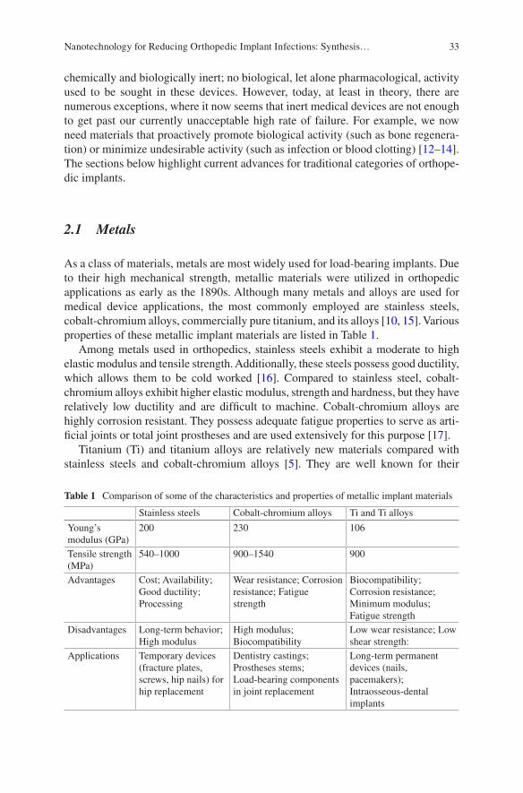
33
chemically and biologically inert; no biological, let alone pharmacological, activity used to be sought in these devices. However, today, at least in theory, there are numerous exceptions, where it now seems that inert medical devices are not enough to get past our currently unacceptable high rate of failure. For example, we now need materials that proactively promote biological activity (such as bone regenera-tion) or minimize undesirable activity (such as infection or blood clotting) [12–14]. The sections below highlight current advances for traditional categories of orthope-dic implants.
2.1 Metals
As a class of materials, metals are most widely used for load-bearing implants. Due to their high mechanical strength, metallic materials were utilized in orthopedic applications as early as the 1890s. Although many metals and alloys are used for medical device applications, the most commonly employed are stainless steels, cobalt-chromium alloys, commercially pure titanium, and its alloys [10, 15]. Various properties of these metallic implant materials are listed in Table 1.
Among metals used in orthopedics, stainless steels exhibit a moderate to high elastic modulus and tensile strength. Additionally, these steels possess good ductility, which allows them to be cold worked [16]. Compared to stainless steel, cobalt- chromium alloys exhibit higher elastic modulus, strength and hardness, but they have relatively low ductility and are difficult to machine. Cobalt-chromium alloys are highly corrosion resistant. They possess adequate fatigue properties to serve as arti-ficial joints or total joint prostheses and are used extensively for this purpose [17].
Titanium (Ti) and titanium alloys are relatively new materials compared with stainless steels and cobalt-chromium alloys [5]. They are well known for their
Table 1 Comparison of some of the characteristics and properties of metallic implant materials
Stainless steels Cobalt-chromium alloys Ti and Ti alloys
Young’s modulus (GPa)
200 230 106
Tensile strength (MPa)
540–1000 900–1540 900
Advantages Cost; Availability; Good ductility; Processing
Wear resistance; Corrosion resistance; Fatigue strength
Biocompatibility; Corrosion resistance; Minimum modulus; Fatigue strength
Disadvantages Long-term behavior; High modulus
High modulus; Biocompatibility
Low wear resistance; Low shear strength:
Applications Temporary devices (fracture plates, screws, hip nails) for hip replacement
Dentistry castings; Prostheses stems; Load-bearing components in joint replacement
Long-term permanent devices (nails, pacemakers); Intraosseous-dental implants
Nanotechnology for Reducing Orthopedic Implant Infections: Synthesis…
34
excellent corrosion resistance and high specific strength. The main drawback of Ti and its alloys is their inadequate wear resistance [18, 19]. In consideration of the biocompatibility of the metals and alloys, the susceptibility of the material to corro-sion and the effect the corrosion has on the tissue are the key aspects [20, 21]. Corrosion resistance of the currently used 316L stainless steel, cobalt-chromium, and Ti-based implant alloys relies on their passivation by a thin surface layer of oxide. Stainless steel is one of the least corrosion resistant metals and never appears to fully integrate with bone or soft tissue, thus, it is usually used for temporary implants only. Ti and cobalt-chromium alloys do not corrode in the body; however, metal ions slowly diffuse through the oxide layer and accumulate in the tissue.
When a metal implant is placed in the human body, it becomes surrounded by a layer of fibrous tissue of a thickness that is proportional to the amount and toxicity of the dissolution products and to the amount of motion between the implant and the adjacent tissues [22]. The proliferation of a fibrous layer as much as 2 mm thick is encountered with the use of stainless steel implants, while Ti may elicit a minimal fibrous encapsulation under some conditions comparatively. Ti was found to be the only metallic biomaterial to osseointegrate presumably due to the slow growth of hydrated titanium oxide on the surface of the Ti implant that leads to the incorpora-tion of calcium and phosphorus [23]. In general, metals are by far the oldest materi-als for fabricating implantable devices. They are still the most preferred materials currently, and will continue to dominate the market in the next few years as well [6]. However, as produced, the metals mentioned above do not have any ability to inhibit or slow the growth of bacteria that leads to infection.
2.2 Polymers
Polymeric materials are rapidly replacing other material classes such as metals and ceramics for use as biomaterials because of their versatility. Their applications range from facial prostheses, endotracheal tubes to dentures, hip and knee joints. Various synthetic and natural polymers are used in such implants and devices [11, 24]. Many researchers consider natural polymers to have additional benefits over synthetic polymers, such as their biodegradable properties. However, synthetic polymers have been the material of choice for implants because of their ease of production, availability and versatility of manipulation [25]. There are many other types of commercially available synthetic polymers used in implants and devices, which are listed in Table 2.
As the polymer molecular weight increases, material strength also increases while elasticity decreases. Ultrahigh molecular weight polyethylene (UHMWPE) was the first polymeric material used in medicine since the 1960s. UHMWPE is highly resistant to corrosive chemicals and has extremely low moisture absorption, a very low coefficient of friction, characteristic of self-lubrication and high resis-tance to abrasion. UHMWPE emerged as a bearing material in many joint replace-ment devices [26].
L. Liu and T. J. Webster
35
Polypropylene (PP), similarly to PE, is a thermoplastic polymer that can also be altered according to its density. PP has been widely used as surgical mesh to rein-force weakened tissues while also acting as a scaffold for fibro-collagenous tissues to grow on the mesh itself and has mainly been applied in urogynecology to treat stress urinary incontinence and pelvic organ prolapse. Recently, numerous studies have examined its use in other parts of the body, such as for implant-based breast reconstruction [27]. PP has also been used together with titanium to produce a mesh with a thinner capsular contracture, which is a major complication in implant-based breast reconstruction. It is also a good material that can be used as a supportive soft tissue structure [28].
Polymethylmethacrylate (PMMA) has been used in various medical implants such as in intraocular lenses, dental implant restoration, and as bone cements in total joint replacements [29–31]. The primary purpose of PMMA as a bone cement is to fill the space between the prostheses and bone to achieve a more uniform stress distribution, and bone cements do not serve as adhesives [32]. However, PMMA does not support osseointegration [8], which restricts its applicability to a great degree. PMMA was the first material to be successfully used in intraocular lenses in the eye when the original lens is removed in the treatment of cataracts or myopia [33]. Tissue growth for PMMA orbital implants has also been tested, and results showed that fibro-vascular ingrowth of tissues from surrounding orbital tissues in the eyes could be achieved with no signs of infection. Intraocular lenses have also been developed using PMMA, and the results showed that the chromatic difference of focus values were similar to the physiological values measured in young eyes.
Polyetheretherketone (PEEK), a thermoplastic polymer, approved as a medical grade material by the U.S. FDA in the late 1990s, has recently been studied and used as a substitute for metallic implant materials because of its appropriate biocompat-ibility and extremely low elastic modulus (3–4 GPa), which reduces the extent of stress shielding that is often observed in Ti-based metallic implants [34, 35]. PEEK is also considered as an advanced biomaterial used with a high-resolution magnetic
Table 2 Polymers used for implantable devices
Polymers Applications
Polyethylene (PE) Joint replacement devices, total hip arthroplastyPolypropylene (PP) Heart valve structures, surgical mesh, suturesPolymethylmethacrylate (PMMA)
Dental restorations, intraocular lenses, bone cements in total joint replacements
Polyetheretherketone (PEEK) Partial replacement of skullPolyethylene terephthalate (PET)
Vascular grafts and prosthesis, shunt, sutures
Silicones\polydimethylsiloxane (PDMS)
Encapsulate material in implants, catheters, tubing, shunt, packaging materials for implantable devices
Polytetrafluoroethylene (PTTE) Catheter coating, vascular graft, vascular prosthesesPolyamides (Nylons) SuturesPolyurethane (PU) Breast implants, catheter coatingsPolyvinylchloride (PVC) Tubing, catheters, blood containers
Nanotechnology for Reducing Orthopedic Implant Infections: Synthesis…
36
resonance imaging (MRI), for creating a partial replacement of the skull in neuro-surgical applications. The use of polyethylene terephthalate (PET) in medical devices has endured for more than 50 years. Current medical applications of PET include implantable sutures, surgical mesh, vascular grafts, heart valve sewing cuffs and components for percutaneous access devices due to its notable biological char-acteristics of biostability and promotion of tissue ingrowth [9, 36].
Silicones are polymers that include any inert, synthetic compound made up of repeating units of siloxane, have been widely used as an encapsulant material in implants (i.e., breast implants, testicle implants, pectoral implants) [37]. Silicone was studied to be the most reliable for long-term encapsulation in the body com-pared to epoxy resin and polyurethane because of their lower surface energy and smoother topography [38]. These features also prevent cells and molecules from being absorbed by the polymer itself. There were also fewer defects observed on the silicon surface, indicating better protective functions. Polydimethylsiloxane (PDMS) is a common derivative of silicone that has been used in pacemakers, blood pumps, mammary prostheses, catheters, shunts, cochlear implants, esophagus replacements, and as a packaging material for implantable electronic devices and sensors [39]. Polytetrafluoroethylene (PTFE) (also called Teflon) was developed by DuPont Co, which is frequently employed as a coating on catheters. PTFE coated catheters are also commonly used to drain urine after surgeries and have recently been used as controls in further research to reduce infections. Expanded PTFE grafts are clinically acceptable for peripheral vascular surgery and arteriovenous shunts [36, 40].
Polyamide (PA) is a macromolecule with repeating units linked by amide bonds. The most common form of PA used in biomedical implants and devices is nylon, which is often used as a material for fibers in composites to increase the mechanical strength of the composite, such as suture materials. Nylon has been tested to study microbial [10] contamination and results indicated that nylon has the ability to pre-vent bacterial transmission [41]. Polyurethane (PU) has been used in a wide range of implants and can also be easily modified to fit different biomedical applications. However, PU can be affected by chemical attacks in vivo, resulting in the degrada-tion of the material. When handled correctly, the degradation kinetics can be con-trolled to facilitate the growth of new tissues. It was also found that PU has a lower water permeability and PU breast implants showed very low rates of capsular con-tracture [42, 43].
Polyvinylchloride (PVC) is the world’s third-most widely produced synthetic plastic polymer, after PE and PP. The two main applications areas for medically approved PVC compounds are blood containers and tubing. In Europe, the con-sumption of PVC for medical devices is approximately 85,000 tons every year. The reasons for using flexible PVC in these applications for over 50 years are numerous and based on cost effectiveness linked to transparency, light weight, softness, tear strength, kink resistance, suitability for sterilization and biocompatibility [25]. Potentially, devices made from bioresorbable polymers can overcome problems associated with metal implants like stress protection, potential for corrosion, wear and debris formation as well as the necessity of implant removal. The most
L. Liu and T. J. Webster
37
commonly investigated and widely used synthetic biodegradable polymers are poly-glycolide (PGA), polylactide (PLA) and polycaprolactone (PCL) [44, 45]. These polymers are well known for their good biocompatibility, with their degradation products being eliminated from the body by metabolic pathways. Many reports have shown that the different PLA-based substrates do not present toxicity since the cells were found to differentiate over the different polymers, as demonstrated by the pro-duction of extracellular matrix components by various cell types [46].
However, as in the case of metals, none of these polymers mentioned above were developed to reduce infection and/or bacteria growth and do not possess such prop-erties as used today.
2.3 Ceramics
Restorative materials in dentistry such as crowns, cements and dentures are com-posed of ceramic materials. The poor fracture toughness of ceramics severely limits their use for load-bearing applications. They are generally used to replace or fix hard connective tissue, such as bone [9, 47]. Bone itself is a composite, comprising an organic phase and an inorganic phase. This inorganic phase is mainly composed of crystalline calcium hydroxyapatite with the chemical formula Ca10(PO4)6(OH)2. Thus, synthetic calcium hydroxyapatite is a good candidate for a successful bioma-terial. Several dental and orthopedic metal implants are coated with hydroxyapatite to ensure long-term fixation in bone [48]. Zirconium dioxide or zirconia ceramics, a bioinert nonresorbable metal oxide, are used to manufacture femoral heads for total hip replacements and are potentially suitable for the highly mechanically loaded environments found in joint replacements due to its high strength, toughness and surface finish [49]. A ceramic that is used in load-bearing applications is high- purity alumina. High purity alumina bioceramics have been developed as an alterna-tive to surgical metal alloys for total hip prosthesis and tooth implants. The high hardness, low friction coefficient and excellent corrosion resistance of alumina offers a very low wear rate at the articulating surfaces in orthopedic applications. Most importantly, over 3000 alumina implants monitored by the FDA have been successfully implemented since 1987 [50].
Again, however, the ceramics mentioned above possess no inherent properties, nor were designed to, reduce infection and/or bacteria adhesion and growth.
3 Problems with Conventional Implants
The risks of implantable medical devices include surgical risks during placement or removal and implant failure due to mechanical (i.e., stress-strain imbalances, implant migration and wear debris) or biological (most notably, foreign body reac-tions and bacterial infections) factors [51–53]. Herein, biological factors will be the
Nanotechnology for Reducing Orthopedic Implant Infections: Synthesis…
38
primary focus, particularly infection due to their growing concern. To highlight this problem, the Centers for Disease Control recently predicted that deaths due to infec-tion and antibiotic-resistant bacteria will overcome the number of people who die from all cancers by 2050; such alarming statistics highlight the need for more atten-tion to design medical devices that inhibit bacteria functions.
3.1 Host Response to Foreign Materials
When an implant is inserted into the body, some immediate biological reactions will take place near the implanted area. This is essentially the body’s response to a newly implanted foreign material [54]. The foreign body reaction is composed of macro-phages and foreign body giant cells as the end-stage response of the inflammatory and wound healing responses following implantation of a medical device, prosthe-sis, or biomaterial. The chemical, physical, and morphological characteristics of the biomaterial surfaces are considered to play an important role in modulating the foreign body reaction in the first few weeks following implantation of a medical device, even though the foreign body reaction at the tissue/material interface is pres-ent for the entire in vivo lifetime of the medical device [54]. An understanding of the foreign body reaction is important as the foreign body reaction may impact the biocompatibility of the medical device, prosthesis, or implanted biomaterial and may directly determine the success or failure of implantation [13, 55]. After the implantation procedure, the body follows a sequence of local events during the heal-ing response. In order, these are acute inflammation, chronic inflammation, granula-tion tissue formation, foreign body reaction and fibrosis. Inflammation is the reaction of vascularized living tissue to local injury. The inflammatory response comprises an initial acute phase and a subsequent chronic phase. The initial inflam-matory response is activated regardless of the type of biomaterial and the location of injury [56, 57].
The acute phase lasts from hours to days and is marked by fluid and protein exu-dation as well as a neutrophilic reaction. Neutrophils are recruited to the site of inflammation by chemical mediators to phagocytize microorganisms and foreign materials. Afterwards, neutrophils recruit monocytes to the inflammation area (where monocytes will further differentiate into macrophages). They attach on the surfaces of the biomaterial by adsorbed proteins, basically immunoglobulin G (IgG) and complement-activated fragment (C3b) [58]. Proteins adsorb to an implanted material instantaneously after being inserted in the body. Macrophages then secrete degradative agents (such as superoxides and free radicals), which severely damage the implant. Persistency of the inflammatory response leads to chronic inflamma-tion. Main cell types observed during chronic inflammation are monocytes, macro-phages and lymphocytes. Macrophages are the most important type of cells in chronic inflammation due to the secretion of a great number of biologically active products such as: proteases, arachidonic acid metabolites, reactive oxygen
L. Liu and T. J. Webster
39
metabolites, coagulation factors and growth factors (which are important to recruit fibroblasts and epithelial cells) [14, 59].
The third step in the foreign body response is granulation tissue formation. Endothelial cells and fibroblasts form granulation tissue. This tissue is the hallmark of the healing response. It is granular in appearance and contains many small blood vessels. In addition, macrophages fuse together to form foreign body giant cells to phagocytize the foreign materials more effectively. The amount of granulation tis-sue determines the extent of fibrosis. The foreign body reaction, the fourth step in wound healing, contains foreign body giant cells and granulation tissue (such as fibroblasts, capillaries and macrophages). The last step in the wound healing response is fibrosis, which is the fibrous tissue encapsulation of the implant [60]. This fibrous wall confines the implant and consequently prevents it from interacting with the surrounding tissue [8].
The resulting collagenous fibrotic capsule, up to several hundred micrometers thick, physically and physiologically separates the device from host tissue. Lacking vasculature, the capsule can be impermeable to cells and can hinder metabolite transport, slow healing, resist device-tissue integration and create niches susceptible to infection [61]. Thus, outwitting the natural immune response is the most formi-dable challenge, which drives the demand for developing novel implant biomaterial surfaces to provoke a significant foreign-body response.
Of course, missing from this traditional explanation of the foreign body reaction to implants are bacteria. It is now well understood that some bacteria will be present in any surgical site due to the presence of bacteria on one’s own skin (e.g., Staph. epidermidis). An on-going debate in the field is whether one wants an extensive inflammatory response to clear such bacteria from the implant surface, or to mini-mize the inflammatory response since chronic inflammation reduces bone (and/or any tissue) formation juxtaposed to the implant.
3.2 Bacterial and Biofilm Infections
The implant surface is susceptible to infection because of two main reasons, namely formation of a surface biofilm and compromised immune ability at the implant/tis-sue interface [61, 62]. Many patients are on immune suppressants after surgery which, while decreasing the chances for chronic inflammation, also increases the chances for infection. Infection has been reported on numerous implantable devices including central venous catheters, endotracheal tubes, intrauterine devices, ortho-pedic joint prosthetics, and percutaneous orthopedic devices, etc. [63]. A very large proportion of all implant-related infections are caused by staphylococci, specifically Staphylococcus aureus (S. aureus) and Staphylococcus epidermidis (S. epidermi-dis). Staphylococcus is a genus of Gram-positive bacteria, nonspore forming facul-tative anaerobes that grow by aerobic respiration or fermentation, with diameters of 0.5–1.5 μm. Staphylococcus comprises up to two-thirds of all pathogens in implant infections, which are difficult to treat due to the ability of the organisms to form
Nanotechnology for Reducing Orthopedic Implant Infections: Synthesis…
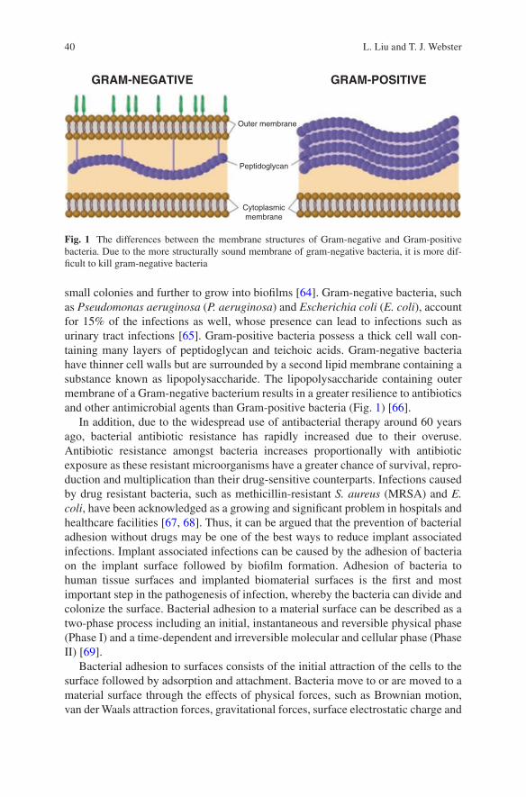
40
small colonies and further to grow into biofilms [64]. Gram-negative bacteria, such as Pseudomonas aeruginosa (P. aeruginosa) and Escherichia coli (E. coli), account for 15% of the infections as well, whose presence can lead to infections such as urinary tract infections [65]. Gram-positive bacteria possess a thick cell wall con-taining many layers of peptidoglycan and teichoic acids. Gram-negative bacteria have thinner cell walls but are surrounded by a second lipid membrane containing a substance known as lipopolysaccharide. The lipopolysaccharide containing outer membrane of a Gram-negative bacterium results in a greater resilience to antibiotics and other antimicrobial agents than Gram-positive bacteria (Fig. 1) [66].
In addition, due to the widespread use of antibacterial therapy around 60 years ago, bacterial antibiotic resistance has rapidly increased due to their overuse. Antibiotic resistance amongst bacteria increases proportionally with antibiotic exposure as these resistant microorganisms have a greater chance of survival, repro-duction and multiplication than their drug-sensitive counterparts. Infections caused by drug resistant bacteria, such as methicillin-resistant S. aureus (MRSA) and E. coli, have been acknowledged as a growing and significant problem in hospitals and healthcare facilities [67, 68]. Thus, it can be argued that the prevention of bacterial adhesion without drugs may be one of the best ways to reduce implant associated infections. Implant associated infections can be caused by the adhesion of bacteria on the implant surface followed by biofilm formation. Adhesion of bacteria to human tissue surfaces and implanted biomaterial surfaces is the first and most important step in the pathogenesis of infection, whereby the bacteria can divide and colonize the surface. Bacterial adhesion to a material surface can be described as a two-phase process including an initial, instantaneous and reversible physical phase (Phase I) and a time-dependent and irreversible molecular and cellular phase (Phase II) [69].
Bacterial adhesion to surfaces consists of the initial attraction of the cells to the surface followed by adsorption and attachment. Bacteria move to or are moved to a material surface through the effects of physical forces, such as Brownian motion, van der Waals attraction forces, gravitational forces, surface electrostatic charge and
Outer membrane
GRAM-NEGATIVE GRAM-POSITIVE
Peptidoglycan
Cytoplasmicmembrane
Fig. 1 The differences between the membrane structures of Gram-negative and Gram-positive bacteria. Due to the more structurally sound membrane of gram-negative bacteria, it is more dif-ficult to kill gram-negative bacteria
L. Liu and T. J. Webster
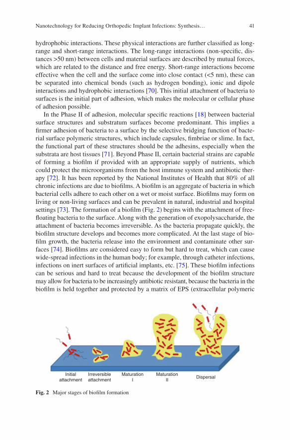
41
hydrophobic interactions. These physical interactions are further classified as long- range and short-range interactions. The long-range interactions (non-specific, dis-tances >50 nm) between cells and material surfaces are described by mutual forces, which are related to the distance and free energy. Short-range interactions become effective when the cell and the surface come into close contact (<5 nm), these can be separated into chemical bonds (such as hydrogen bonding), ionic and dipole interactions and hydrophobic interactions [70]. This initial attachment of bacteria to surfaces is the initial part of adhesion, which makes the molecular or cellular phase of adhesion possible.
In the Phase II of adhesion, molecular specific reactions [18] between bacterial surface structures and substratum surfaces become predominant. This implies a firmer adhesion of bacteria to a surface by the selective bridging function of bacte-rial surface polymeric structures, which include capsules, fimbriae or slime. In fact, the functional part of these structures should be the adhesins, especially when the substrata are host tissues [71]. Beyond Phase II, certain bacterial strains are capable of forming a biofilm if provided with an appropriate supply of nutrients, which could protect the microorganisms from the host immune system and antibiotic ther-apy [72]. It has been reported by the National Institutes of Health that 80% of all chronic infections are due to biofilms. A biofilm is an aggregate of bacteria in which bacterial cells adhere to each other on a wet or moist surface. Biofilms may form on living or non-living surfaces and can be prevalent in natural, industrial and hospital settings [73]. The formation of a biofilm (Fig. 2) begins with the attachment of free- floating bacteria to the surface. Along with the generation of exopolysaccharide, the attachment of bacteria becomes irreversible. As the bacteria propagate quickly, the biofilm structure develops and becomes more complicated. At the last stage of bio-film growth, the bacteria release into the environment and contaminate other sur-faces [74]. Biofilms are considered easy to form but hard to treat, which can cause wide-spread infections in the human body; for example, through catheter infections, infections on inert surfaces of artificial implants, etc. [75]. These biofilm infections can be serious and hard to treat because the development of the biofilm structure may allow for bacteria to be increasingly antibiotic resistant, because the bacteria in the biofilm is held together and protected by a matrix of EPS (extracellular polymeric
Initialattachment
Irreversibleattachment
MaturationI
MaturationII
Dispersal
Fig. 2 Major stages of biofilm formation
Nanotechnology for Reducing Orthopedic Implant Infections: Synthesis…
42
substance or exopolysaccharide). This matrix protects bacteria cells within it and facilitates communication among them through biochemical signals, resulting in their increased resistance to detergents and antibiotics [76].
Bacterial adhesion and biofilm formation processes are influenced by environ-mental factors, bacterial properties, material surface properties and the presence of serum or tissue proteins. Properties of the substrate, such as chemical composition of the material, surface charge, hydrophobicity, surface roughness and the presence of specific proteins at the surface, are all thought to be important in the initial cell attachment process. Reduction of microbial adhesion to an implant (without the use of drugs) could be an attractive method for reducing infection and nanotechnology may hold some answers.
4 Where Bio Meet Nano: The Use of Nanotechnology in Implants
Implanted materials trigger an immune system response to isolate non-natural mate-rials [20]. Once any foreign material enters the body, a natural inflammatory response immediately kicks in, coating the intruder’s surface with thousands of pro-teins and marshaling immune cells such as macrophages to remove it, making the implant eventually blind to the biochemistry outside. Outwitting the natural immune response is the most formidable challenge in this field. All of these bring a large challenge of developing and inducing biocompatible implant materials. In order to accomplish this, we try to make foreign implants look natural in the body [77]. Nanotechnology (involved in designing and engineering of materials, devices and systems on the order of less than 100 nm) is one of the current fields of high interest that can control properties of implants and tissue engineering scaffolds. It deals with systems and structures that result in new properties due to their small size (1–100 nm) [78, 79].
Because protein adsorption and cell attachment on different implant surface depends both on surface chemistry and on the surface nano-scale features, the modi-fication of implants usually involves different surface treatments. The surface is either coated with a functional film or patterned at the nano-scale [80–82]. Cell or protein adhesive groups are commonly introduced as terminal groups in self- assembled layers of functional amphiphiles. The surface patterning can be done either by coating the implant with nanoparticle films with specific dimensions or physically fabricating the implant surface with nanostructures by using template- molding methods or by using lithography to optimize the interactions between the functional coatings/nanostructured patterns and cells/tissue [21]. For example, many companies now coat bone implants with nano-scale-textured hydroxyapatite, a mineral found in bone. This hydroxyapatite coating tricks the body into incorpo-rating the implant as though it was a real bone. Hydroxyapatite coatings can make
L. Liu and T. J. Webster
43
the implants “stickier”, but to have a truly successful implant, the surrounding nor-mal bone needs to grow around the implant [83].
Ti nanotubes are being developed by a number of groups to enhance osteointe-gration [84]. Silver nanoparticles have been investigated for potential use on the surfaces of orthopedic implants to fight post-operation bacterial infections due to their antimicrobial properties. One potential problem is that silver nanoparticles also inhibit the growth of osteoblasts, so fighting infection and encouraging bone growth might not be simultaneously achievable with silver [85].
Companies such as Amedica use implants composed of silicon nitride to simul-taneously decrease bacterial growth and encourage the formation of bone. This could be because at the nano-scale the silicon nitride is textured in a way that attracts osteoblasts and repels bacteria.
Moreover, nanotechnology has recently generated tremendous interest for vari-ous biosensing applications. Nanotechnology can aid in functioning of biosensing materials to contact, detect, and recognize target medical signals since it can pro-vide for materials smaller in size, better in magnetic, optical and electrical proper-ties, and more similar to the structure of bone tissue [86]. NanoShield, a start-up company, is developing a nanosensor that can measure how well an implant is doing. Carbon nanotubes on the implant detect what kinds of cells are attached to the implant, and transmit this information through an embedded microchip. Each cell in the body has different electrical properties, and these properties can tell the nanosensor if an osteoblast, an inflammatory cell, or a bacterium is attached. A nanostructured film on the implant could then release drugs, such as antimicrobials or anti-inflammatory molecules, depending on which type of cell is detected by the nanosensor [87]. Altering the surface of implants with nanotechnology has showed great potential to improve the performance of implants and will undoubtedly make them even better in the future.
5 The Role of Surfaces in Biological Properties
5.1 The Effect of Nanotopography on Protein Adsorption
Biocompatibility is the key property of biomedical materials. The biocompatibility of a material largely depends on a series of biological responses occurring at the interface of the material’s surface and a biological system. Protein adsorption on the surface of a biomaterial is the first step in these responses. The adsorbed protein layer then determines the type and extent of the subsequent responses [88]. Therefore, studies on the behavior of protein adsorption are crucial to improve the biocompatibility of materials. Protein adsorption is a complicated process influ-enced by various factors, including the nature of proteins themselves, the surface property of materials, and the circumstances that the materials are facing. Protein adsorption behavior could be affected by both the surface chemistry and topography
Nanotechnology for Reducing Orthopedic Implant Infections: Synthesis…
44
of the materials. In the past few years, the effect of surface chemical compositions on protein adsorption has been extensively studied. The influence of surface topog-raphy on protein adsorption began to receive keen interest only very recently, although it was found as early as in 1964 that a cell’s behavior could be influenced by its surrounding topography. Material surfaces may have multifarious topographi-cal structures. The characteristics of these topographic structures basically include roughness, curvature, and specific geometrical figures. By altering implant surface properties, it is possible to guide select protein adsorption, as well as control the quantity and conformation of the adsorbed proteins, allowing researchers to guide select cell adhesion on to the implant surfaces, potentially improving the success and longevity of the implant [89]. One of the most promising approaches to altering surface properties of biomaterials is decreasing the material surface feature size into the nanophase regime.
When using a nanophase material, where at least one surface feature size is less than 100 nm, implant surface properties will change (i.e., surface area, energy, topography, and charge). With the development of nanotechnology, it has been fea-sible to introduce nanotopography onto materials surfaces, which provides a conve-nient platform to investigate the behavior and mechanism of protein adsorption as well as subsequent biological responses such as cell adhesion [90–93].
Surface roughness is a common element to materials. Surface wettability and energy are significantly affected by different roughness values, which will certainly further influence the behavior of biological molecules contacting the material sur-face. Research outcomes concerning the effect of nanometer scale roughness on the amount of adsorbed proteins are to some extent inconsistent. Cai et al. investigated protein adsorption on different material surfaces with diverse roughnesses. Their results indicated that there were no linear relationship between roughness and the amount of adsorbed proteins and roughness had no significant effect on the amount of adsorbed proteins [94].
However, Rechendorff et al. showed that with the augment of tantalum surface roughness, though surface area also approximately increased by 20%, the corre-sponding saturation amount of fibrinogen markedly increased by about 70%, which evidently indicated that the amount of adsorbed protein was influenced by surface roughness [95]. We believe that the aforementioned different conclusions were associated with the substrates, the sorts of proteins, and the methods to test protein adsorption. Therefore, further study is needed to find out the effect of surface rough-ness on the amount of adsorbed protein. A linear regression model was initially developed by Khang et al. to relate surface topography and wettability with protein adsorption, which is now commonly used to predict the size of nano-scale features that should be incorporated on medical devices to improve their performance [96].
Surface energy expressed as a general equation by a linear function of a rough-ness factor and with a coupling constant was given as:
E E rs reff s eff( ) = + ´0, r
L. Liu and T. J. Webster
45
Here, reff is the effective roughness, ρ is the coupling constant and E0,s is the ini-tial surface energy not related to nano-scale roughness (flat or very smooth surface reff ~ 0). Thus, individual factors (roughness or surface energy) on protein adsorp-tion could be easily demonstrated as:
F r ,E r Eadsorption eff s eff s( ) = ´ + ´a b
Here, Fadsorption is the protein adsorption, Es is surface energy of the material, and α and β are coupling constants. When the two equations are coupled, it is possible to define protein adsorption as a function of only reff, as shown below:
F r A r Eadsorption eff eff s( ) = ´ + ´b
Here, A = α + β × ρCoupling A indicates the contribution of nanophase surface roughness and β
indicated the contribution of ground surface energy on protein adsorption on to a biomaterial surface [97]. Since protein adsorption behavior could be affected by nanometer-scale roughness, more attention should be paid to the effect of roughness on the biocompatibility of biomaterials. In addition, biomedical materials or devices have defined all geometrical figures. Therefore, the effect of such geometrical fig-ures on protein and other biological molecules should also be investigated, so that biomedical materials or devices could be rationally designed. Galli et al. produced nanometer groove structures with dimensions similar to protein size on silicon and titanium surfaces. They chose protein A and F-actin as two different model proteins. The results suggested that on silicon surfaces, the amount of adsorbed F-actin was lower than on nanometer groove structures than on plane surfaces and F-actin was inclined to adsorb along with the nanometer groove structure; on titanium surfaces, the adsorption density of F-actin was related to the height of surface topography. Different from F-actin, there was no difference in protein adsorption behavior and activity on different surface topographies for protein A [98].
The above results suggested that different proteins with dissimilar characteristics (i.e., shape and size) have distinct responses to diverse nanotopographies. Sutherland et al. prepared pits with diameters of 40 nm and a depth of 10 nm on material sur-faces. Quartz crystal microbalance experiments indicated that the amounts of adsorbed fibrinogen on plane and nanopits surfaces were similar. In order to test whether nanopit structures affected the biological activity of adsorbed fibrinogen, both plane and nanopits surfaces with preadsorbed fibrinogen were incubated in unactivated platelets solutions, and it was found that more platelets adhered on the nanopit surface. They presumed that this was a result of different conformations and orientations adopted by fibrinogen on different surface topographies. The confor-mation and orientation on nanopits surface were favorable for the combination of ligands in fibrinogen and receptors on platelet membranes, leading to more adhered platelets on nanopit surfaces [99]. In summary, protein adsorption behavior could be influenced by surface nanotopography. However, protein adsorption is merely the
Nanotechnology for Reducing Orthopedic Implant Infections: Synthesis…
46
first step in a series of biological responses after a biomaterial comes in contact with a biological environment, and the subsequent responses, such as cell attachment and platelet adhesion, will determine the ultimate biocompatibility of biomaterials. Thus, research about the effect of surface nanotopography on protein adsorption is just beginning. The influence of absorbed protein conformation, orientation, and structure induced by surface nanotopography on subsequent cell behavior deserves further investigation. In addition, surface topography and surface chemical compo-sitions are two sides of one coin. Each side is relatively independent, affecting the adsorption behavior of proteins and other biological molecules, but also supplemen-tal to each other, determining the biocompatibility of all the biomaterials. Therefore, chemical modification on an optimized surface topography, or constructing a topog-raphy structure on the surface with a specific chemical composition is another trend, so that most desirable material surface properties can be obtained by a synergic effect of surface topography and chemical composition.
5.2 The Effect of Nanotopography on Cellular Functions
The rapid development of fabrication and processing technologies in the past two decades has enabled researchers to introduce nano-scale features into materials, which, interestingly, have been shown to greatly regulate the behavior and fate of biological cells. In particular, important cell responses (such as adhesion, prolifera-tion, differentiation, migration, and filopodial growth) have all been correlated with material nanotopography [100]. Given its great potential, intensive efforts have been made, both experimentally and theoretically, to understand why and how cells respond to nano-scale surface features. It is important to emphasize that many natu-ral tissues are essentially composed of nano-scale structures. For example, bone possesses a complex organic-inorganic nanocomposite structure. The organic phase is mainly composed of type I collagen, which is arranged into nanofibers ranging from 50 to 500 nm in diameter. The inorganic phase consists of non-stoichiometric hydroxyapatite crystals with lengths of about 100 nm, widths of 20–30 nm and thicknesses of 3–6 nm, which are embedded between the collagen fibers. Therefore, by mimicking their natural nanostructure on implants, biomaterials might be able to enhance/regulate the functions of specific cells or tissues.
This principle has been demonstrated through the wide application of synthetic polymers (poly (lactic-co-glycolic) acid (PLGA), PDMS, etc.) and metals (Ti, stain-less steel, etc.) in clinical practice as well as in laboratory research. In particular, the capabilities of surfaces with ordered nanofeatures in regulating the behavior, includ-ing adhesion, growth, alignment and elongation, of cells have been convincingly demonstrated. For instance, it was found that PLGA surfaces with 200-nm spherical topographies promote the adhesion of endothelial and smooth muscle cells, com-pared to smooth PLGA substrates. On the other hand, as reported by Smith et al., the presence of nanometer scale roughness on PLGA surfaces, prepared by sodium hydroxide-etching, inhibits the adhesion of fibroblasts (cells that form connective
L. Liu and T. J. Webster
47
tissue) while, interestingly, promotes osteoblast adhesion [101]. These properties may be definitely due to the altered surface energy one gets with different nano-scale features which in turn alters initial protein adsorption.
Anodization is one of the simplest surface modification processes used to create nanotextured and nanotubular features on metal oxides, which has been shown to improve bone formation. Anodization of Ti leads to the formation of titanium diox-ide (TiO2) nanotubes on the surface, and the presence of these nanotubes mimics the natural nano-scale features of bone. It was found that increasing the anodization voltages from 5 V, 10 V, 15 V to 20 V resulted in a Ti surface that contained nanotubular- like structures with an inner diameter from 20 nm, 40 nm, 60 nm to 80 nm, respectively.
Numerous studies have shown improved osteoblast attachment, migration, and proliferation on nanotubular anodized Ti surfaces. Most importantly, it was also demonstrated that decreased numbers of macrophages adhered to nanotubular Ti surfaces compared with unanodized conventional nanosmooth Ti (controls), which should be strongly considered to improve orthopedic implant efficacy since it implies reduced inflammation [102]. 316L stainless steel with tunable nanometer pit sizes (0, 25, 50, and 60 nm) were fabricated by Ni et al. with an anodization procedure. They found that compared with unanodized (that is, nano-smooth) sur-faces, the 50 and 60 nm diameter nano-pit surfaces dramatically enhanced initial human dermal fibroblast attachment and growth for up to 3 days in culture. Such nanopit surfaces can be designed to support fibroblast growth and, thus, improve the use of 316L stainless steel for various implant applications (such as for enhanced skin healing for amputee devices and for percutaneous implants) [103].
It is not difficult to infer that different types of cells will probably respond dis-tinctly to the same surface nanotopography. This kind of cell type-specific response suggests that nanotopography might be able to selectively mediate the functions and activities of various cells. This selective mediation on different cell types renders the possibility of suppressing the activities of undesired cells while simultaneously promoting the response of target cells.
5.3 The Effect of Nanotopography on Bacterial Attachment
Billions of dollars are spent annually worldwide to combat the adverse effects of bacterial attachment and biofilm formation on biomaterials for medical applications such as catheters, artificial heart valve replacements, and orthopedic and dental implants. While advances in the fabrication of antifouling surfaces have been reported recently, a number of the essential aspects responsible for the formation of biofilms remain unresolved, including the important initial stages of bacterial attachment to a substrate surface. The reduction of bacterial attachment to surfaces is a key concept in the prevention or minimization of biofilm formation. The chemi-cal and physical characteristics of both the substrate and bacteria are important in understanding the attachment process, but substrate modification is likely the most
Nanotechnology for Reducing Orthopedic Implant Infections: Synthesis…
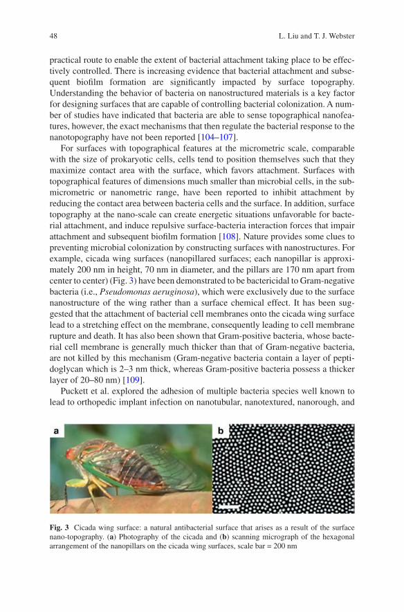
48
practical route to enable the extent of bacterial attachment taking place to be effec-tively controlled. There is increasing evidence that bacterial attachment and subse-quent biofilm formation are significantly impacted by surface topography. Understanding the behavior of bacteria on nanostructured materials is a key factor for designing surfaces that are capable of controlling bacterial colonization. A num-ber of studies have indicated that bacteria are able to sense topographical nanofea-tures, however, the exact mechanisms that then regulate the bacterial response to the nanotopography have not been reported [104–107].
For surfaces with topographical features at the micrometric scale, comparable with the size of prokaryotic cells, cells tend to position themselves such that they maximize contact area with the surface, which favors attachment. Surfaces with topographical features of dimensions much smaller than microbial cells, in the sub-micrometric or nanometric range, have been reported to inhibit attachment by reducing the contact area between bacteria cells and the surface. In addition, surface topography at the nano-scale can create energetic situations unfavorable for bacte-rial attachment, and induce repulsive surface-bacteria interaction forces that impair attachment and subsequent biofilm formation [108]. Nature provides some clues to preventing microbial colonization by constructing surfaces with nanostructures. For example, cicada wing surfaces (nanopillared surfaces; each nanopillar is approxi-mately 200 nm in height, 70 nm in diameter, and the pillars are 170 nm apart from center to center) (Fig. 3) have been demonstrated to be bactericidal to Gram-negative bacteria (i.e., Pseudomonas aeruginosa), which were exclusively due to the surface nanostructure of the wing rather than a surface chemical effect. It has been sug-gested that the attachment of bacterial cell membranes onto the cicada wing surface lead to a stretching effect on the membrane, consequently leading to cell membrane rupture and death. It has also been shown that Gram-positive bacteria, whose bacte-rial cell membrane is generally much thicker than that of Gram-negative bacteria, are not killed by this mechanism (Gram-negative bacteria contain a layer of pepti-doglycan which is 2–3 nm thick, whereas Gram-positive bacteria possess a thicker layer of 20–80 nm) [109].
Puckett et al. explored the adhesion of multiple bacteria species well known to lead to orthopedic implant infection on nanotubular, nanotextured, nanorough, and
Fig. 3 Cicada wing surface: a natural antibacterial surface that arises as a result of the surface nano-topography. (a) Photography of the cicada and (b) scanning micrograph of the hexagonal arrangement of the nanopillars on the cicada wing surfaces, scale bar = 200 nm
L. Liu and T. J. Webster
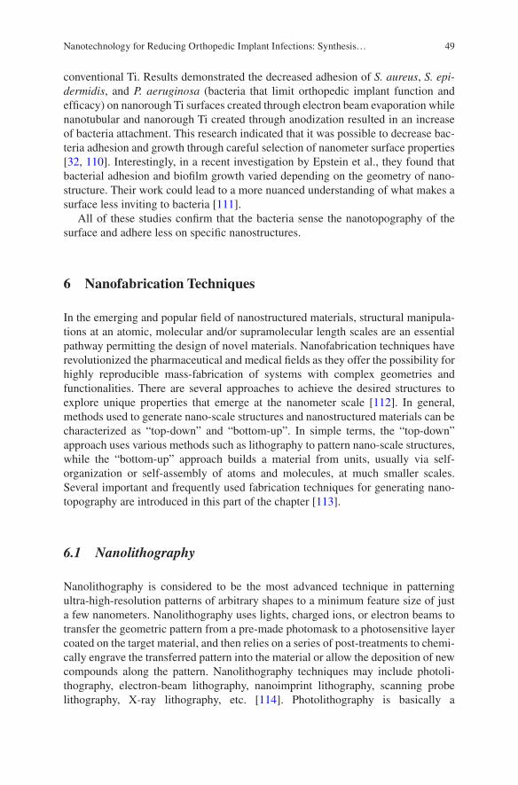
49
conventional Ti. Results demonstrated the decreased adhesion of S. aureus, S. epi-dermidis, and P. aeruginosa (bacteria that limit orthopedic implant function and efficacy) on nanorough Ti surfaces created through electron beam evaporation while nanotubular and nanorough Ti created through anodization resulted in an increase of bacteria attachment. This research indicated that it was possible to decrease bac-teria adhesion and growth through careful selection of nanometer surface properties [32, 110]. Interestingly, in a recent investigation by Epstein et al., they found that bacterial adhesion and biofilm growth varied depending on the geometry of nano-structure. Their work could lead to a more nuanced understanding of what makes a surface less inviting to bacteria [111].
All of these studies confirm that the bacteria sense the nanotopography of the surface and adhere less on specific nanostructures.
6 Nanofabrication Techniques
In the emerging and popular field of nanostructured materials, structural manipula-tions at an atomic, molecular and/or supramolecular length scales are an essential pathway permitting the design of novel materials. Nanofabrication techniques have revolutionized the pharmaceutical and medical fields as they offer the possibility for highly reproducible mass-fabrication of systems with complex geometries and functionalities. There are several approaches to achieve the desired structures to explore unique properties that emerge at the nanometer scale [112]. In general, methods used to generate nano-scale structures and nanostructured materials can be characterized as “top-down” and “bottom-up”. In simple terms, the “top-down” approach uses various methods such as lithography to pattern nano-scale structures, while the “bottom-up” approach builds a material from units, usually via self- organization or self-assembly of atoms and molecules, at much smaller scales. Several important and frequently used fabrication techniques for generating nano- topography are introduced in this part of the chapter [113].
6.1 Nanolithography
Nanolithography is considered to be the most advanced technique in patterning ultra-high-resolution patterns of arbitrary shapes to a minimum feature size of just a few nanometers. Nanolithography uses lights, charged ions, or electron beams to transfer the geometric pattern from a pre-made photomask to a photosensitive layer coated on the target material, and then relies on a series of post-treatments to chemi-cally engrave the transferred pattern into the material or allow the deposition of new compounds along the pattern. Nanolithography techniques may include photoli-thography, electron-beam lithography, nanoimprint lithography, scanning probe lithography, X-ray lithography, etc. [114]. Photolithography is basically a
Nanotechnology for Reducing Orthopedic Implant Infections: Synthesis…
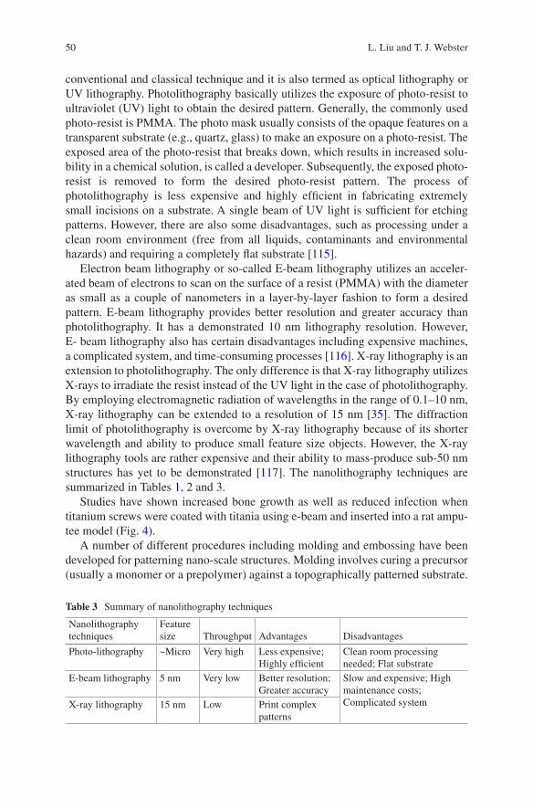
50
conventional and classical technique and it is also termed as optical lithography or UV lithography. Photolithography basically utilizes the exposure of photo-resist to ultraviolet (UV) light to obtain the desired pattern. Generally, the commonly used photo-resist is PMMA. The photo mask usually consists of the opaque features on a transparent substrate (e.g., quartz, glass) to make an exposure on a photo-resist. The exposed area of the photo-resist that breaks down, which results in increased solu-bility in a chemical solution, is called a developer. Subsequently, the exposed photo- resist is removed to form the desired photo-resist pattern. The process of photolithography is less expensive and highly efficient in fabricating extremely small incisions on a substrate. A single beam of UV light is sufficient for etching patterns. However, there are also some disadvantages, such as processing under a clean room environment (free from all liquids, contaminants and environmental hazards) and requiring a completely flat substrate [115].
Electron beam lithography or so-called E-beam lithography utilizes an acceler-ated beam of electrons to scan on the surface of a resist (PMMA) with the diameter as small as a couple of nanometers in a layer-by-layer fashion to form a desired pattern. E-beam lithography provides better resolution and greater accuracy than photolithography. It has a demonstrated 10 nm lithography resolution. However, E- beam lithography also has certain disadvantages including expensive machines, a complicated system, and time-consuming processes [116]. X-ray lithography is an extension to photolithography. The only difference is that X-ray lithography utilizes X-rays to irradiate the resist instead of the UV light in the case of photolithography. By employing electromagnetic radiation of wavelengths in the range of 0.1–10 nm, X-ray lithography can be extended to a resolution of 15 nm [35]. The diffraction limit of photolithography is overcome by X-ray lithography because of its shorter wavelength and ability to produce small feature size objects. However, the X-ray lithography tools are rather expensive and their ability to mass-produce sub-50 nm structures has yet to be demonstrated [117]. The nanolithography techniques are summarized in Tables 1, 2 and 3.
Studies have shown increased bone growth as well as reduced infection when titanium screws were coated with titania using e-beam and inserted into a rat ampu-tee model (Fig. 4).
A number of different procedures including molding and embossing have been developed for patterning nano-scale structures. Molding involves curing a precursor (usually a monomer or a prepolymer) against a topographically patterned substrate.
Table 3 Summary of nanolithography techniques
Nanolithography techniques
Feature size Throughput Advantages Disadvantages
Photo-lithography ~Micro Very high Less expensive; Highly efficient
Clean room processing needed; Flat substrate
E-beam lithography 5 nm Very low Better resolution; Greater accuracy
Slow and expensive; High maintenance costs; Complicated systemX-ray lithography 15 nm Low Print complex
patterns
L. Liu and T. J. Webster
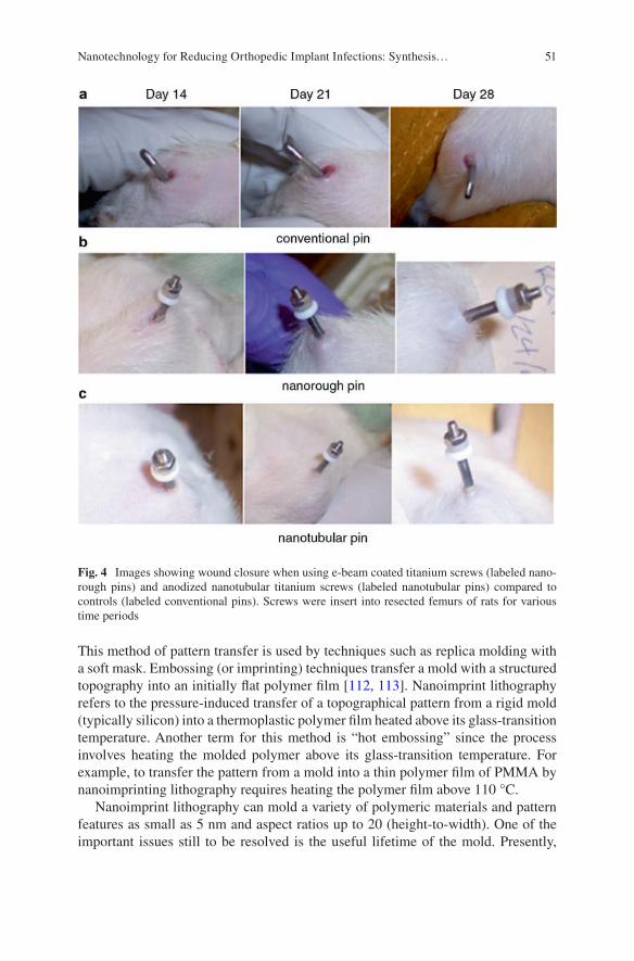
51
This method of pattern transfer is used by techniques such as replica molding with a soft mask. Embossing (or imprinting) techniques transfer a mold with a structured topography into an initially flat polymer film [112, 113]. Nanoimprint lithography refers to the pressure-induced transfer of a topographical pattern from a rigid mold (typically silicon) into a thermoplastic polymer film heated above its glass- transition temperature. Another term for this method is “hot embossing” since the process involves heating the molded polymer above its glass-transition temperature. For example, to transfer the pattern from a mold into a thin polymer film of PMMA by nanoimprinting lithography requires heating the polymer film above 110 °C.
Nanoimprint lithography can mold a variety of polymeric materials and pattern features as small as 5 nm and aspect ratios up to 20 (height-to-width). One of the important issues still to be resolved is the useful lifetime of the mold. Presently,
Fig. 4 Images showing wound closure when using e-beam coated titanium screws (labeled nano-rough pins) and anodized nanotubular titanium screws (labeled nanotubular pins) compared to controls (labeled conventional pins). Screws were insert into resected femurs of rats for various time periods
Nanotechnology for Reducing Orthopedic Implant Infections: Synthesis…
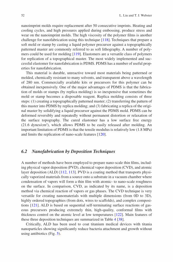
52
nanoimprint molds require replacement after 50 consecutive imprints. Heating and cooling cycles, and high pressures applied during embossing, produce stress and wear on the nanoimprint molds. The high viscosity of the polymer films is another challenge for nanofabrication using this technique [118]. Techniques that prepare a soft mold or stamp by casting a liquid polymer precursor against a topographically patterned master are commonly referred to as soft lithography. A number of poly-mers could be used for molding [119]. Elastomers are a versatile class of polymers for replication of a topographical master. The most widely implemented and suc-cessful elastomer for nanofabrication is PDMS. PDMS has a number of useful prop-erties for nanofabrication.
This material is durable, unreactive toward most materials being patterned or molded, chemically resistant to many solvents, and transparent above a wavelength of 280 nm. Commercially available kits or precursors for this polymer can be obtained inexpensively. One of the major advantages of PDMS is that the fabrica-tion of molds or stamps (by replica molding) is so inexpensive that sometimes the mold or stamp becomes a disposable reagent. Replica molding consists of three steps: (1) creating a topographically patterned master; (2) transferring the pattern of this master into PDMS by replica molding; and (3) fabricating a replica of the origi-nal master by solidifying a liquid precursor against the PDMS mold. PDMS can be deformed reversibly and repeatedly without permanent distortion or relaxation of the surface topography. The cured elastomer has a low surface free energy (21.6 dynes/cm2), which allows PDMS to be easily released after molding. An important limitation of PDMS is that the tensile modulus is relatively low (1.8 MPa) and limits the replication of nano-scale features [120].
6.2 Nanofabrication by Deposition Techniques
A number of methods have been employed to prepare nano-scale thin films, includ-ing physical vapor deposition (PVD), chemical vapor deposition (CVD), and atomic layer deposition (ALD) [112, 113]. PVD is a coating method that transports physi-cally vaporized materials from a source onto a substrate in a vacuum chamber where condensation of vapors will form a thin film with atomic- to nano-scale roughness on the surface. In comparison, CVD, as indicated by its name, is a deposition method via chemical reaction of vapors or gas phases. The CVD technique is very versatile for creating nanomaterials with multiple dimensions (from 0D to 3D), highly ordered topographies (from dots, wires to scaffolds), and complex composi-tions [121]. ALD is based on sequential self-terminating surface reactions of gas-eous precursors producing extremely thin, high-quality, conformal films with thickness control on the atomic level at low temperatures [122]. Main features of these three deposition techniques are summarized in Table 4 [38].
Critically, ALD has been used to coat titanium medical devices with titania nanoparticles showing significantly reduce bacteria attachment and growth without using antibiotics (Fig. 5).
L. Liu and T. J. Webster
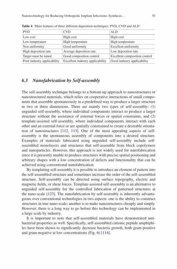
53
6.3 Nanofabrication by Self-assembly
The self-assembly technique belongs to a bottom-up approach to nanostructures or nanostructured materials, which relies on cooperative interactions of small compo-nents that assemble spontaneously in a predefined way to produce a larger structure in two or three dimensions. There are mainly two types of self-assembly: (1) unguided self-assembly, where individual components interact to produce a larger structure without the assistance of external forces or spatial constraints, and (2) template-assisted self-assembly, where individual components interact with each other and an external force or are spatially constrained to create a desirable orienta-tion of nanostructures [112, 113]. One of the most appealing aspects of self- assembly is the spontaneous assembly of components into a desired structure. Examples of materials fabricated using unguided self-assembly include self- assembled monolayers and structures that self-assemble from block copolymers and nanoparticles. However, this approach is not widely used for nanofabrication since it is presently unable to produce structures with precise spatial positioning and arbitrary shapes with a low concentration of defects and functionality that can be achieved using conventional nanofabrication.
By templating self-assembly it is possible to introduce an element of pattern into the self-assembled structure and sometimes increase the order of the self-assembled structure. Self-assembly can be directed using surface topography, electric and magnetic fields, or shear forces. Template-assisted self-assembly is an alternative to unguided self-assembly for the controlled fabrication of patterned structures at the nano-scale [123]. The nanofabrication by self-assembly is inherently advanta-geous over conventional technologies in two aspects: one is the ability to construct structures in true nano-scale; another is to make nanostructures cheaply and simply. However, there is a long way to go before this technology can be implemented in a large scale by industry.
It is important to note that self-assembled materials have demonstrated anti- bacterial properties as well. Specifically, self-assembled cationic peptide amphiphi-les have been shown to significantly decrease bacteria growth, both gram-positive and gram-negative at low concentrations (Fig. 6) [114].
Table 4 Main features of three different deposition techniques: PVD, CVD and ALD
PVD CVD ALD
Low cost High cost High costLow temperature High temperature High temperatureNon uniformity Good uniformity Excellent uniformityHigh deposition rate Average deposition rate Low deposition rateTarget must be tuned Good composition control Excellent composition controlPoor industry applicability Excellent industry applicability Good industry applicability
Nanotechnology for Reducing Orthopedic Implant Infections: Synthesis…
54
7 Sensors
Of course, with all of the nanomaterials that have been developed to reduce bacteria function, a critical question still remains: can we develop the next generation of biomaterials to sense bacteria presence before an infection occurs. In this manner, researchers have created a sensor grown out of titanium based hip implants [124].
Fig. 5 (a) SEM images of ALD titania coated on titanium medical implants and (b) E. coli colony forming units (CFU) on such samples after 24 h. Data = mean ± SEM; N = 3; *p < 0.01 compared to Ti control (untreated). Temperatures refer to ALD heating conditions
L. Liu and T. J. Webster
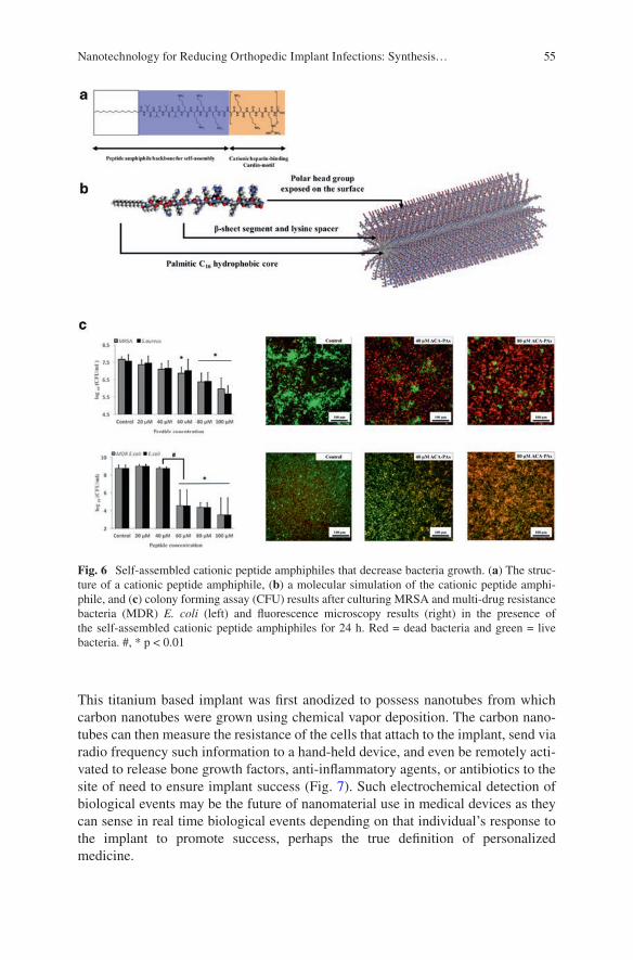
55
This titanium based implant was first anodized to possess nanotubes from which carbon nanotubes were grown using chemical vapor deposition. The carbon nano-tubes can then measure the resistance of the cells that attach to the implant, send via radio frequency such information to a hand-held device, and even be remotely acti-vated to release bone growth factors, anti-inflammatory agents, or antibiotics to the site of need to ensure implant success (Fig. 7). Such electrochemical detection of biological events may be the future of nanomaterial use in medical devices as they can sense in real time biological events depending on that individual’s response to the implant to promote success, perhaps the true definition of personalized medicine.
Fig. 6 Self-assembled cationic peptide amphiphiles that decrease bacteria growth. (a) The struc-ture of a cationic peptide amphiphile, (b) a molecular simulation of the cationic peptide amphi-phile, and (c) colony forming assay (CFU) results after culturing MRSA and multi-drug resistance bacteria (MDR) E. coli (left) and fluorescence microscopy results (right) in the presence of the self-assembled cationic peptide amphiphiles for 24 h. Red = dead bacteria and green = live bacteria. #, * p < 0.01
Nanotechnology for Reducing Orthopedic Implant Infections: Synthesis…
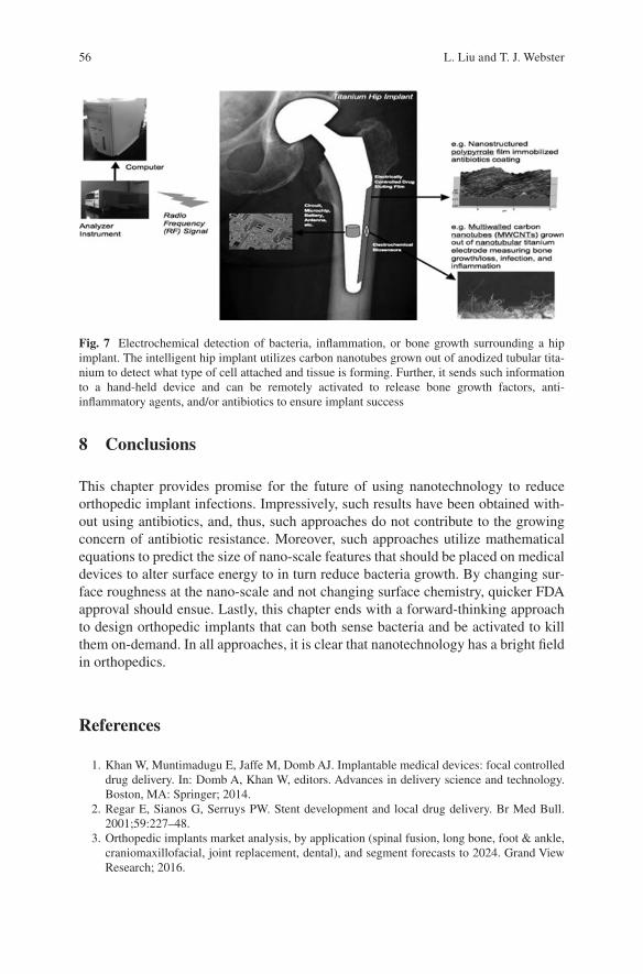
56
8 Conclusions
This chapter provides promise for the future of using nanotechnology to reduce orthopedic implant infections. Impressively, such results have been obtained with-out using antibiotics, and, thus, such approaches do not contribute to the growing concern of antibiotic resistance. Moreover, such approaches utilize mathematical equations to predict the size of nano-scale features that should be placed on medical devices to alter surface energy to in turn reduce bacteria growth. By changing sur-face roughness at the nano-scale and not changing surface chemistry, quicker FDA approval should ensue. Lastly, this chapter ends with a forward-thinking approach to design orthopedic implants that can both sense bacteria and be activated to kill them on-demand. In all approaches, it is clear that nanotechnology has a bright field in orthopedics.
References
1. Khan W, Muntimadugu E, Jaffe M, Domb AJ. Implantable medical devices: focal controlled drug delivery. In: Domb A, Khan W, editors. Advances in delivery science and technology. Boston, MA: Springer; 2014.
2. Regar E, Sianos G, Serruys PW. Stent development and local drug delivery. Br Med Bull. 2001;59:227–48.
3. Orthopedic implants market analysis, by application (spinal fusion, long bone, foot & ankle, craniomaxillofacial, joint replacement, dental), and segment forecasts to 2024. Grand View Research; 2016.
Fig. 7 Electrochemical detection of bacteria, inflammation, or bone growth surrounding a hip implant. The intelligent hip implant utilizes carbon nanotubes grown out of anodized tubular tita-nium to detect what type of cell attached and tissue is forming. Further, it sends such information to a hand-held device and can be remotely activated to release bone growth factors, anti- inflammatory agents, and/or antibiotics to ensure implant success
L. Liu and T. J. Webster
57
4. Wischke C, Lendlein A. Designing multifunctional polymers for cardiovascular implants. Clin Hemorheol Microcirc. 2011;49:347–55.
5. Cardiovascular implants market analysis & trends-device, procedure, disease condition- forecast to 2025. Research and Markets; 2016.
6. Catheters market analysis by product (cardiovascular, urology, intravenous, neurovascular and specialty catheters) and segment forecasts to 2020. Grand View Research; 2014.
7. Biomaterials market for implantable devices (material type-metals, polymers, ceramics and natural; applications-cardiology, orthopedics, dental, ophthalmology and others)-global industry analysis, size, share, growth, trends and forecast 2013-2019. Transparency Market Research; 2014.
8. Grainger DW. All charged up about implanted biomaterials. Nat Biotechnol. 2013;31:507–9. 9. Saini M, Singh Y, Arora P, Arora V, Jain K. Implant biomaterials: a comprehensive review.
World J Clin Cases. 2015;3:52–7. 10. Chen Q, Thouas GA. Metallic implant biomaterials. Mater Sci Eng R-Rep. 2015;87:1–57. 11. Teo AJT, Mishra A, Park I, Kim Y-J, Park W-T, Yoon Y-J. Polymeric biomaterials for medical
implants and devices. ACS Biomater Sci Eng. 2016;2:454–72. 12. Matassi F, Nistri L, Paez DC, Innocenti M. New biomaterials for bone regeneration. Clin
Cases Miner Bone Metab. 2011;8:21–4. 13. Nablo BJ, Prichard HL, Butler RD, Klitzman B, Schoenfisch MH. Inhibition of implant-
associated infections via nitric oxide release. Biomaterials. 2005;26:6984–90. 14. Mel A, Cousins BG, Seifalian AM. Surface modification of biomaterials: a quest for blood
compatibility. Int J Biomater. 2012;2012:707863. 15. Gotman I. Characteristics of metals used in implants. J Endourol. 1997;11:383–9. 16. Godbole N, Yadav S, Ramachandran M, Belemkar S. A review on surface treatment of stain-
less steel orthopedic implants. Int J Pharm Sci Rev Res. 2016;36:190–4. 17. Holzwarth U, Thomas P, Kachler W, Göske J, Schuh A. Metallurgical differentiation of
cobalt-chromium alloys for implants. Orthopade. 2005;34:1046–7. 1049–51 18. Oldani C, Dominguez A. Titanium as a biomaterial for implants. In: Fokter S, editor. Recent
advances in arthroplasty. London: InTech; 2012. 19. Rack HJ, Qazi JI. Titanium alloys for biomedical applications. Mater Sci Eng C.
2006;26:1269–77. 20. Hofmann J, Michel R, Holm R, Zilkens J. Corrosion behaviour of stainless steel implants in
biological media. Surf Interface Anal. 1981;3:110–7. 21. Flecka C, Eiflerb D. Corrosion, fatigue and corrosion fatigue behaviour of metal implant
materials, especially titanium alloys. Int J Fatigue. 2010;32:929–35. 22. Nuss KMR, Rechenberg B. Biocompatibility issues with modern implants in bone-a review
for clinical orthopedics. Open Orthop J. 2008;2:66–78. 23. Plecko M, Sievert C, Andermatt D, Frigg R, Kronen P, Klein K, Stübinger S, Nuss K, Bürki
A, Ferguson S, Stoeckle U, Rechenberg B. Osseointegration and biocompatibility of differ-ent metal implants - a comparative experimental investigation in sheep. BMC Musculoskelet Disord. 2012;13:32.
24. Rickert D. Polymeric implant materials for the reconstruction of tracheal and pharyngeal mucosal defects in head and neck surgery. GMS Curr Top Otorhinolaryngol Head Neck Surg. 2009;8:Doc06.
25. Maitz MF. Applications of synthetic polymers in clinical medicine. Biosurf Biotribol. 2015;1:161–76.
26. Kurtz SM. UHMWPE biomaterials handbook: ultra high molecular weight polyethylene in total joint replacement and medical devices. Philadelphia: Elsevier Science; 2009.
27. Li X, Kruger JA, Jor JWY, Wong V, Dietz HP, Nash MP, Nielsen PMF. Characterizing the ex vivo mechanical properties of synthetic polypropylene surgical mesh. J Mech Behavior Biomed Mater. 2014;37:48–55.
Nanotechnology for Reducing Orthopedic Implant Infections: Synthesis…
58
28. Bergmann PA, Becker B, Mauss KL, Liodaki ME, Knobloch J, Mailänder P, Siemers F. Titanium-coated polypropylene mesh (TiLoop Bra) an effective prevention for capsular contracture? Eur J Plastic Surg. 2014;37:339–46.
29. Terrada C, Julian K, Cassoux N, Prieur AM, Debre M, Quartier P, LeHoang P, Bodaghi B. Cataract surgery with primary intraocular lens implantation in children with uveitis: long- term outcomes. J Cataract Refract Surg. 2011;37:1977–83.
30. Rivkin AA. Prospective study of non-surgical primary rhinoplasty using a polymethylmeth-acrylate injectable implant. Dermatol Surg. 2014;40:305–13.
31. Leigh JA. Use of PMMA in expansion dental implants. J Biomed Mater Res. 1975;9:233–42. 32. Eyerer P, Jin R. Influence of mixing technique on some properties of PMMA bone cement.
J Biomed Mater Res A. 1985;20:1057–94. 33. Panahi-Bazaz M-R, Zamani M, Abazar B. Hydrophilic acrylic versus PMMA intraocular lens
implantation in pediatric cataract surgery. J Ophthalmic Vis Res. 2009;4:201–7. 34. Kurtz SM, Devine JN. PEEK biomaterials in trauma, orthopedic, and spinal implants.
Biomaterials. 2007;28:4845–69. 35. Garcia-Gonzaleza D, Jayamohanb J, Sotiropoulosc SN, Yoond S-H, Cookd J, Siviourd CR,
Ariasa A, Jérusalem A. On the mechanical behaviour of PEEK and HA cranial implants under impact loading. J Mech Behav Biomed Mater. 2017;69:342–54.
36. Aronoff MS. Market study: biomaterials supply for permanent medical implants. J Biomater Appl. 1995;9:205–61.
37. Chugay N, Chugay P, Shiffman M. Body implants: overview. In body sculpting with silicone implants. New York: Springer; 2014. p. 1–12.
38. Rahimi A, Mashak A. Review on rubbers in medicine: natural, silicone and polyurethane rub-bers. Plast Rubber Compos. 2013;42:223–30.
39. Qin Y, Howlader MM, Deen MJ, Haddara YM, Selvaganapathy PR. Polymer integration for packaging of implantable sensors. Sensors Actuators B Chem. 2014;202:758.
40. Geeroms B, Laleman W, Laenen A, Heye S, Verslype C, van der Merwe S, Nevens F, Maleux G. Expanded polytetrafluoroethylene-covered stent-grafts for transjugular intrahepatic por-tosystemic shunts in cirrhotic patients: Long-term patency and clinical outcome results. Eur Radiol. 2017;27(5):1795–803.
41. Masood R, Hussain T, Umar M, Azeemullah, Areeb T, Riaz S. In situ development and application of natural coatings on non-absorbable sutures to reduce incision site infections. J Wound Care. 2017;26:115–20.
42. Roohpour N, Wasikiewicz JM, Moshaverinia A, Paul D, Grahn MF, Rehman IU, Vadgama P. Polyurethane membranes modified with isopropyl myristate as a potential candidate for encapsulating electronic implants: a study of biocompatibility and water permeability. Polymers. 2010;2:102–19.
43. de la Peña-Salcedo J, Soto-Miranda M, Lopez-Salguero J. Back to the future: a 15-year experience with polyurethane foam-covered breast implants using the partial-subfascial tech-nique. Aesthetic Plast Surg. 2012;36:331–8.
44. Adeosun SO, Lawal GI, Gbenebor OP. Characteristics of biodegradable implants. J Miner Mater Charact Eng. 2014;2:88–106.
45. Gogolewski S. Bioresorbable polymers in trauma and bone surgery. Injury. 2000;31:D28–32. 46. Santos AR Jr. Bioresorbable polymers for tissue engineering. In: Eberli D, editor. Tissue
engineering. London: InTech; 2010. 47. Andreiotelli M, Wenz HJ, Kohal RJ. Are ceramic implants a viable alternative to titanium
implants? A systematic literature review. Clin Oral Implants Res. 2009;20(Suppl 4):32–47. 48. Al-Sanabani JS, Madfa AA, Al-Sanabani FA. Application of calcium phosphate materials in
dentistry. Int J Biomater. 2013;2013:876132. 49. Özkurt Z, Kazazoğlu E. Zirconia dental implants: a literature review. J Oral Implantol.
2011;37:367–76. 50. Maccauro G, Bianchino G, Sangiorgi S, Magnani G, Marotta D, Manicone PF, Raffaelli
L, Rossi Iommetti P, Stewart A, Cittadini A, Sgambato A. Development of a new
L. Liu and T. J. Webster
59
zirconia- toughened alumina: promising mechanical properties and absence of in vitro carci-nogenicity. Int J Immunopathol Pharmacol. 2009;22:773–9.
51. Anderson JM, Rodriguez A, Chang DT. Foreign body reaction to biomaterials. Semin Immunol. 2008;20:86–100.
52. Eiff CV, Jansen B, Kohnen W, Becker K. Infection associated with medical devices. patho-genesis, management, prophylaxis. Drugs. 2005;65:179–214.
53. Klevens RM, Edwards JR, Richards CL Jr, et al. Estimating health care-associated infections and deaths in U.S. hospitals, 2002. Public Health Rep. 2007;122:160–6.
54. Morais JM, Papadimitrakopoulos F, Burgess DJ. Biomaterials/tissue interactions: possible solutions to overcome foreign body response. AAPS J. 2010;12:188–96.
55. Onuki Y, Bhardwaj U, Papadimitrakopoulos F, Burgess DJ. A review of the biocompatibility of implantable devices: current challenges to overcome foreign body response. J Diabetes Sci Technol. 2008;2:1003–15.
56. Dekel N, Gnainsky Y, Granot I, Racicot K, Mor G. The role of inflammation for a successful implantation. Am J Reprod Immunol. 2014;72:141–7.
57. Tang L, Eaton JW. Inflammatory responses to biomaterials. Am J Clin Pathol. 1995;103:466–71.
58. Kolaczkowska E, Kubes P. Neutrophil recruitment and function in health and inflammation. Nat Rev Immunol. 2013;13:159–75.
59. Ueha S, Shand FHW, Matsushima K. Cellular and molecular mechanisms of chronic inflammation- associated organ fibrosis. Front Immunol. 2012;3:71.
60. Stroncek JD, Reichert WM. Overview of wound healing in different tissue types; Indwelling neural implants: strategies for contending with the in vivo environment. Boca Raton, FL: CRC Press/Taylor & Francis; 2008.
61. Jansen B, Peters G. Foreign body associated infection. J Antimicrob Chemother. 1993;32:69–75.
62. Wolcott RD, Ehrlich GD. Biofilms and chronic infections. JAMA. 2008;299(22):2682–4. 63. Hedrick TL, Adams JD, Sawyer RG. Implant-associated infections: an overview. J Long-
Term Eff Med Implants. 2006;16:83–99. 64. Montanaro L, Speziale P, Campoccia D, Ravaioli S, Cangini I, Pietrocola G, Giannini S,
Arciola CR. Scenery of Staphylococcus implant infections in orthopedics. Future Microbiol. 2011;6:1329–49.
65. Behzadi P, Behzadi E, Yazdanbod H, Aghapour R, Akbari Cheshmeh M, Salehian OD. A survey on urinary tract infections associated with the three most common uropathogenic bacteria. Maedica (Buchar). 2010;5:111–5.
66. New spin on gram stain bacteria. June 12, 2015. Available from: https://hemtecks.wordpress.com/2015/06/12/new-spin-on-gram-stain-bacteria/.
67. Stewart PS, Costerton JW. Antibiotic resistance of bacteria in biofilms. Lancet. 2001;358(9276):135–8.
68. Hidron AI, Edwards JR, Patel J. Antimicrobial-resistant pathogens associated with healthcare- associated infections: annual summary of data reported to the National Healthcare Safety Network at the Centers for Disease Control and Prevention, 2006-2007. Infect Control Hosp Epidemiol. 2008;29(11):996–1101.
69. Ribeiro M, Monteiro FJ, Ferraz MP. Infection of orthopedic implants with emphasis on bacterial adhesion process and techniques used in studying bacterial-material interactions. Biomatter. 2012;2:176–94.
70. Katsikogianni M, Missirlis YF. Concise review of mechanisms of bacterial adhesion to bio-materials and of techniques used in estimating bacteria-material interactions. Eur Cell Mater. 2004;8:37–57.
71. An YH, Friedman RJ. Concise review of mechanisms of bacterial adhesion to biomaterial surfaces. J Biomed Mater Res. 1998;43:338–48.
72. Costerton JW. Introduction to biofilm. Int J Antimicrob Agents. 1999;11(3–4):217–21.
Nanotechnology for Reducing Orthopedic Implant Infections: Synthesis…
60
73. Ryder MA. Catheter related infections: it’s all about biofilm. Adv Pract Nurs eJournal. 2005;5:1–16.
74. Major stages of biofilm formation. Available from: http://orthobond.com/technology/nosocomial-challenge/antimicrobial-surfaces/strategy/.
75. Noimark S, Dunnill CW, Wilson M, Parkin IP. The role of surface in catheter-associated infections. Chem Soc Rev. 2009;38:3435–48.
76. Costerton JW, Stewart PS, Greenberg EP. Bacterial biofilms: a common cause of 49 persistent infections. Science. 1999;284:1318–22.
77. Williams DF. On the nature of biomaterials. Biomaterials. 2009;30:5897–909. 78. Williams D. The relationship between biomaterials and nanotechnology. Biomaterials.
2008;29:1737–8. 79. Pathan DS, Doshi SB, Muglikar SD. Nanotechnology in implants: the future is small. Univ
Res J Dent. 2015;5:8–13. 80. Yang L, Liu H, Lin Y. Biomaterial nanotopography-mediated cell responses: experiment and
modeling. Int J Smart Nano Mater. 2014;5:227–56. 81. Slepicka P, Kasalkova NS, Siegel J, Kolska Z, Bacakova L, Svorcik V. Nano-structured
and functionalized surfaces for cytocompatibility improvement and bactericidal action. Biotechnol Adv. 2015;33:1120–9.
82. Park GE, Webster TJ. A review of nanotechnology for the development of better orthopedic implants. J Biomed Nanotechnol. 2005 Mar;1(1):18–29.
83. Ong JL, Chan DC. Hydroxyapatite and their use as coatings in dental implants: a review. Crit Rev Biomed Eng. 2000;28:667–707.
84. Lee J-K, Choi D-S, Jang I, Choi W-Y. Improved osseointegration of dental titanium implants by TiO2 nanotube arrays with recombinant human bone morphogenetic protein-2: a pilot in vivo study. Int J Nanomedicine. 2015;10:1145–54.
85. Brennan SA, Ní Fhoghlú C, Devitt BM, O'Mahony FJ, Brabazon D, Walsh A. Silver nanopar-ticles and their orthopaedic applications. Bone Joint J. 2015;97-B:582–9.
86. Liu L, Webster TJ. In situ sensor advancements for osteoporosis prevention, diagnosis, and treatment. Curr Osteoporos Rep. 2016;6:386–95.
87. Sirivisoot S, Pareta RA, Webster TJ. A conductive nanostructured polymer electrodepos-ited on titanium as a controllable, local drug delivery platform. J Biomed Mater Res A. 2011;99:586–97.
88. Andrade JD, Hlady V. Protein adsorption and materials biocompatibility: a tutorial review and suggested hypotheses; biopolymers/non-exclusion HPLC. Advances in polymer science, vol. 79. Berlin, Heidelberg: Springer; 1986.
89. Raffaini G, Ganazzoli F. Protein adsorption on biomaterial and nanomaterial surfaces: a molecular modeling approach to study non-covalent interactions. J Appl Biomater Biomech. 2010;8:135–45.
90. Song W, Chen H. Protein adsorption on materials surfaces with nano-topography. Chin Sci Bull. 2007;52:3169.
91. Carpenter J, Khang D, Webster TJ. Nanometer polymer surface features: the influence on surface energy, protein adsorption and endothelial cell adhesion. Nanotechnology. 2008;19:505103.
92. Denis FA, Hanarp P, Sutherland DS, Gold J, Mustin C, Rouxhet PG, Dufrêne YF. Protein adsorption on model surfaces with controlled nanotopography and chemistry. Langmuir. 2002;18:819–28.
93. Scopelliti PE, Borgonovo A, Indrieri M, Giorgetti L, Bongiorno G, Carbone R, Podesta` A, Milani P. The effect of surface nanometre-scale morphology on protein adsorption. PLoS One. 2010;5:e11862.
94. Cai K, Bossert J, Jandt KD. Does the nanometre scale topography of titanium influence pro-tein adsorption and cell proliferation? Colloids Surf B. 2006;49:136–44.
95. Rechendorff K, Hovgaard MB, Foss M, et al. Enhancement of protein adsorption induced by surface roughness. Langmuir. 2006;22:10885–8.
L. Liu and T. J. Webster
61
96. Khang D, Kim SY, Liu-Snyder P, Palmore GTR, Durbin SM, Webster TJ. Enhanced fibro-nectin adsorption on carbon nanotube/ poly (carbonate) urethane: Independent role of surface nano-roughness and associated surface energy. Biomaterials. 2007;28:4756–68.
97. Ercan B, Khang D, Carpenter J, Webster TJ. Using mathematical models to understand the effect of nanoscale roughness on protein adsorption for improving medical devices. Int J Nanomed. 2013;8:75–81.
98. Galli C, Coen MC, Hauert R, Katanaevc VL, Wymannd MP, Gröninga P, Schlapbacha L. Protein adsorption on topographically nanostructured titanium. Surf Sci. 2001;474:L180–4.
99. Sutherland DS, Broberg M, Nygren H, Kasemo B. Influence of nanoscale surface topography and chemistry on the functional behaviour of an adsorbed model macromolecule. Macromol Biosci. 2001;1:270–3.
100. Tsimbouri P, Gadegaard N, Burgess K, White K, Reynolds P, Herzyk P, Oreffo R, Dalby MJ. Nanotopographical effects on mesenchymal stem cell morphology and phenotype. J Cell Biochem. 2014;115:380–90.
101. Smith LL, Niziolek PJ, Haberstroh KM, Nauman EA, Webster TJ. Decreased fibroblast and increased osteoblast adhesion on nanostructured NaOH-etched PLGA scaffolds. Int J Nanomed. 2007;2:383–8.
102. Rajyalakshmi A, Ercan B, Balasubramanian K, Webster TJ. Reduced adhesion of mac-rophages on anodized titanium with selected nanotube surface features. Int J Nanomed. 2011;6:1765–71.
103. Ni S, Sun L, Ercan B, Liu L, Ziemer K, Webster TJ. A mechanism for the enhanced attach-ment and proliferation of fibroblasts on anodized 316L stainless steel with nano-pit arrays. J Biomed Mater Res B. 2014;102:1297–303.
104. Pegalajar-Jurado A, Easton CD, Crawford RJ, McArthur SL. Fabrication of a platform to isolate the influences of surface nanotopography from chemistry on bacterial attachment and growth. Biointerphases. 2015;10:011002.
105. Mitik-Dineva N, Wang J, Mocanasu RC, Stoddart PR, Crawford RJ, Ivanova EP. Impact of nano-topography on bacterial attachment. Biotechnol J. 2008;3:536–44.
106. Rizzello L, Sorce B, Sabella S, Vecchio G, Galeone A, Brunetti V, Cingolani R, Pompa PP. Impact of nanoscale topography on genomics and proteomics of adherent bacteria. ACS Nano. 2011;5:1865–76.
107. Aguayo S, Strange A, Gadegaard N, Dalbyc MJ, Bozeca L. Influence of biomaterial nano-topography on the adhesive and elastic properties of Staphylococcus aureus cells. RSC Adv. 2016;6:89347–55.
108. Feng G, Cheng Y, Wang S-Y, Borca-Tasciuc DA, Worobo RW, Moraru CI. Bacterial attach-ment and biofilm formation on surfaces are reduced by small-diameter nanoscale pores: how small is small enough? NPJ Biofilms Microbiomes. 2015;1:5022.
109. Pogodin S, Hasan J, Baulin VA, Webb HK, Truong VK. Biophysical model of bacterial cell interactions with nanopatterned cicada wing surfaces. Biophys J. 2013;104:835–40.
110. Puckett SD, Taylor E, Raimondo T, Webster TJ. The relationship between the nanostructure of titanium surfaces and bacterial attachment. Biomaterials. 2010;31:706–13.
111. Epstein AK, Hochbaum AI, Kim P, Aizenberg J. Control of bacterial biofilm growth on sur-faces by nanostructural mechanics and geometry. Nanotechnology. 2011;22:494007.
112. Gates BD, Xu Q, Stewart M, Ryan D, Willson CG, Whitesides GM. New approaches to nano-fabrication: molding, printing, and other techniques. Chem Rev. 2005;105:1171–96.
113. Biswas A, Bayer IS, Biris AS, Wang T, Dervishi E, Faupel F. Advances in top–down and bottom-up surface nanofabrication: techniques, applications & future prospects. Adv Colloid Interf Sci. 2012;170:2–27.
114. Ruchita, Srivastava R, Yadav BC. Nanolithography: processing methods for nanofabrication development. Imp J Interdiscip Res. 2016;2:275–84.
115. Ausschnitt CP, Thomas AC, Wiltshire TJ. Advanced DUV photolithography in a pilot envi-ronment. IBM J Res Dev-Opt Lithogr. 1997;41:21–37.
Nanotechnology for Reducing Orthopedic Implant Infections: Synthesis…
62
116. Chen Y. Nanofabrication by electron beam lithography and its applications: a review. Microelectron Eng. 2015;135:57–72.
117. Fabrizio ED, Fillipo R, Cabrini S, Kumar R, Perennes F, Altissimo M, Businaro L, Cojac D, Vaccari L, Prasciolu M, Candeloro P. X-ray lithography for micro- and nano-fabrication at ELETTRA for interdisciplinary applications. J Phys Condens Matter. 2004;16:S3517–35.
118. Zhou W, Min G, Zhang J, Liu Y, Wang J, Zhang Y, Sun Y. Nanoimprint lithography: a pro-cessing technique for nanofabrication advancement. Nano-Micro Lett. 2011;3:135–40.
119. Wolfe DB, Love JC, Whitesides GM. Nanostructure replicated by polymer molding. Dekker encyclopedia of nanoscience and nanotechnology, vol. 6. Boca Raton: CRC Press; 2004. p. 2657–66.
120. Hassanin H, Mohammadkhani A, Jiang K. Fabrication of hybrid nanostructure arrays using a PDMS/PDMS replication process. Lab Chip. 2012;12:4160–7.
121. Lukaszkowicz K. Review of nanocomposite thin films and coatings deposited by PVD and CVD technology. Nanomaterials. London: InTech; 2011.
122. Liu M, Li X, Karuturi SK, Tokb AIY, Fan HJ. Atomic layer deposition for nanofabrication and interface engineering. Nanoscale. 2012;4:1522–8.
123. Ozin GA, Hou K, Lotsch BV, Cademartiri L, Puzzo DP, Scotognella F, Ghadimi A, Thomson J. Nanofabrication by self-assembly. Mater Today. 2009;12:12–23.
124. Sirivisoot S, Webster TJ. Multiwalled carbon nanotubes enhance electrochemical properties of titanium to determine in situ bone formation. Nanotechnology. 2008;19(29):295101–13.
L. Liu and T. J. Webster
63© Springer International Publishing AG, part of Springer Nature 2017B. Li, T. Webster (eds.), Orthopedic Biomaterials, https://doi.org/10.1007/978-3-319-73664-8_3
Orthopedic Applications of Silver and Silver Nanoparticles
Jason Kang, Krystal Hughes, Malcolm Xing, and Bingyun Li
Keywords Nanotechnology · Nanoparticle · Silver · Antimicrobial · Infection · Bacteria · Toxicity · Nanotoxicity · Clinical use · Antibiotic resistance · Megaprosthese · Bone cement · In vitro · In vivo
1 Introduction
Silver (Ag) is a soft, metallic transition metal with unique chemical and physical properties that make it an attractive metal for various applications. Ag is an excel-lent conductor of heat and electricity and has been used in photography and the electrical and electronic industries. In addition, Ag has been used in the production of coins, jewelry, silverware, and decorative items due to its malleability, ductility, bright color, and resistance to oxidation. Ag also has well-known antimicrobial properties which could be important in the prevention and treatment of infection. The antimicrobial properties of Ag have been known for centuries, as Ag has been used to treat water supplies via Ag coins since ancient Egypt and to craft antiseptic surgical instruments since the Middle Ages [1]. Recently, interest in the use of Ag as an antimicrobial agent has attracted renewed interest as antibiotic resistance is
J. Kang · K. Hughes Department of Orthopaedics, School of Medicine, West Virginia University, Morgantown, WV, USA
M. Xing Department of Mechanical Engineering, University of Manitoba, Winnipeg, MB, Canada
The Children’s Hospital Research Institute of Manitoba, Winnipeg, MB, Canada
B. Li (*) Department of Orthopaedics, School of Medicine, West Virginia University, Morgantown, WV, USA
Mary Babb Randolph Cancer Center, Morgantown, WV, USAe-mail: [email protected]; http://medicine.hsc.wvu.edu/ortho/li
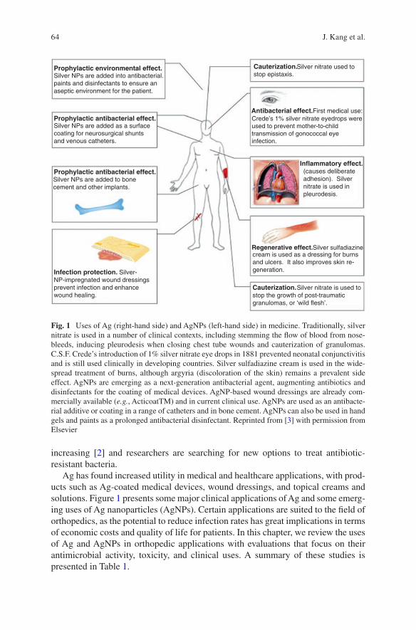
64
increasing [2] and researchers are searching for new options to treat antibiotic- resistant bacteria.
Ag has found increased utility in medical and healthcare applications, with prod-ucts such as Ag-coated medical devices, wound dressings, and topical creams and solutions. Figure 1 presents some major clinical applications of Ag and some emerg-ing uses of Ag nanoparticles (AgNPs). Certain applications are suited to the field of orthopedics, as the potential to reduce infection rates has great implications in terms of economic costs and quality of life for patients. In this chapter, we review the uses of Ag and AgNPs in orthopedic applications with evaluations that focus on their antimicrobial activity, toxicity, and clinical uses. A summary of these studies is presented in Table 1.
Prophylactic environmental effect.
Prophylactic antibacterial effect.
Prophylactic antibacterial effect.
Infection protection.
Silver NPs are added into antibacterial.paints and disinfectants to ensure anaseptic environment for the patient.
Silver NPs are added as a surfacecoating for neurosurgical shuntsand venous catheters.
Silver NPs are added to bonecement and other implants.
Silver- NP-impregnated wound dressingsprevent infection and enhancewound healing.
Cauterization.
Antibacterial effect.
Inflammatory effect.
Cauterization.
Regenerative effect.
Silver nitrate used to
First medical use:Crede’s 1% silver nitrate eyedrops wereused to prevent mother-to-childtransmission of gonococcal eyeinfection.
(causes deliberateadhesion). Silvernitrate is used inpleurodesis.
cream is used as a dressing for burnsand ulcers. It also improves skin re-generation.
stop the growth of post-traumaticgranulomas, or ‘wild flesh’.
Silver nitrate is used to
Silver sulfadiazine
stop epistaxis.
Fig. 1 Uses of Ag (right-hand side) and AgNPs (left-hand side) in medicine. Traditionally, silver nitrate is used in a number of clinical contexts, including stemming the flow of blood from nose-bleeds, inducing pleurodesis when closing chest tube wounds and cauterization of granulomas. C.S.F. Crede’s introduction of 1% silver nitrate eye drops in 1881 prevented neonatal conjunctivitis and is still used clinically in developing countries. Silver sulfadiazine cream is used in the wide-spread treatment of burns, although argyria (discoloration of the skin) remains a prevalent side effect. AgNPs are emerging as a next-generation antibacterial agent, augmenting antibiotics and disinfectants for the coating of medical devices. AgNP-based wound dressings are already com-mercially available (e.g., ActicoatTM) and in current clinical use. AgNPs are used as an antibacte-rial additive or coating in a range of catheters and in bone cement. AgNPs can also be used in hand gels and paints as a prolonged antibacterial disinfectant. Reprinted from [3] with permission from Elsevier
J. Kang et al.
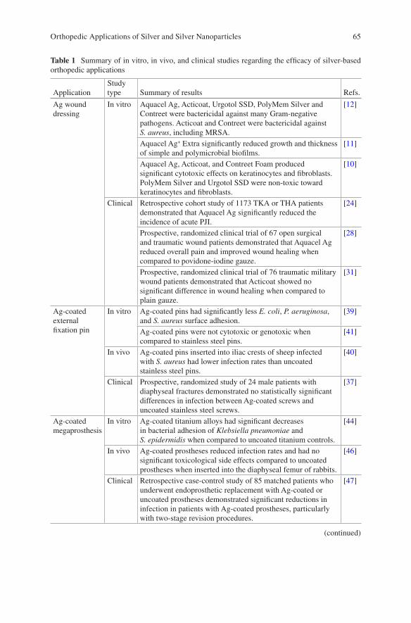
65
Table 1 Summary of in vitro, in vivo, and clinical studies regarding the efficacy of silver-based orthopedic applications
ApplicationStudy type Summary of results Refs.
Ag wound dressing
In vitro Aquacel Ag, Acticoat, Urgotol SSD, PolyMem Silver and Contreet were bactericidal against many Gram-negative pathogens. Acticoat and Contreet were bactericidal against S. aureus, including MRSA.
[12]
Aquacel Ag+ Extra significantly reduced growth and thickness of simple and polymicrobial biofilms.
[11]
Aquacel Ag, Acticoat, and Contreet Foam produced significant cytotoxic effects on keratinocytes and fibroblasts. PolyMem Silver and Urgotol SSD were non-toxic toward keratinocytes and fibroblasts.
[10]
Clinical Retrospective cohort study of 1173 TKA or THA patients demonstrated that Aquacel Ag significantly reduced the incidence of acute PJI.
[24]
Prospective, randomized clinical trial of 67 open surgical and traumatic wound patients demonstrated that Aquacel Ag reduced overall pain and improved wound healing when compared to povidone-iodine gauze.
[28]
Prospective, randomized clinical trial of 76 traumatic military wound patients demonstrated that Acticoat showed no significant difference in wound healing when compared to plain gauze.
[31]
Ag-coated external fixation pin
In vitro Ag-coated pins had significantly less E. coli, P. aeruginosa, and S. aureus surface adhesion.
[39]
Ag-coated pins were not cytotoxic or genotoxic when compared to stainless steel pins.
[41]
In vivo Ag-coated pins inserted into iliac crests of sheep infected with S. aureus had lower infection rates than uncoated stainless steel pins.
[40]
Clinical Prospective, randomized study of 24 male patients with diaphyseal fractures demonstrated no statistically significant differences in infection between Ag-coated screws and uncoated stainless steel screws.
[37]
Ag-coated megaprosthesis
In vitro Ag-coated titanium alloys had significant decreases in bacterial adhesion of Klebsiella pneumoniae and S. epidermidis when compared to uncoated titanium controls.
[44]
In vivo Ag-coated prostheses reduced infection rates and had no significant toxicological side effects compared to uncoated prostheses when inserted into the diaphyseal femur of rabbits.
[46]
Clinical Retrospective case-control study of 85 matched patients who underwent endoprosthetic replacement with Ag-coated or uncoated prostheses demonstrated significant reductions in infection in patients with Ag-coated prostheses, particularly with two-stage revision procedures.
[47]
(continued)
Orthopedic Applications of Silver and Silver Nanoparticles
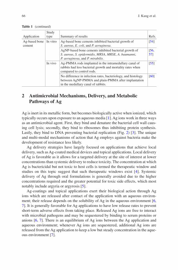
66
2 Antimicrobial Mechanisms, Delivery, and Metabolic Pathways of Ag
Ag is inert in its metallic form, but becomes biologically active when ionized, which typically occurs upon exposure to an aqueous media [1]. Ag ions work in three ways as an antimicrobial agent. First, they bind and denature the bacterial cell wall caus-ing cell lysis; secondly, they bind to ribosomes thus inhibiting protein synthesis. Lastly, they bind to DNA preventing bacterial replication (Fig. 2) [3]. The unique and multi-modal mechanisms of action that Ag employs against bacteria make the development of resistance less likely.
Ag delivery strategies have largely focused on applications that achieve local delivery, such as Ag-coated medical devices and topical applications. Local delivery of Ag is favorable as it allows for a targeted delivery at the site of interest at lower concentrations than systemic delivery to reduce toxicity. The concentration at which Ag is bactericidal but not toxic to host cells is termed the therapeutic window and studies on this topic suggest that such therapeutic windows exist [4]. Systemic delivery of Ag through oral formulations is generally avoided due to the higher concentrations required and the greater potential for toxic side effects, which most notably include argyria or argyrosis [5].
Ag-coatings and topical applications exert their biological action through Ag ions which are released after contact of the application with an aqueous environ-ment; their release depends on the solubility of Ag in the aqueous environment [6, 7]. It is generally favorable for Ag applications to have low release rates to prevent short-term adverse effects from taking place. Released Ag ions are free to interact with microbial pathogens and may be sequestered by binding to serum proteins or anions [6, 7]. There is an equilibrium of Ag ions between the Ag application and aqueous environment; whenever Ag ions are sequestered, additional Ag ions are released from the Ag application to keep a low but steady concentration in the aque-ous environment [7].
Table 1 (continued)
ApplicationStudy type Summary of results Refs.
Ag-based bone cement
In vitro Ag-based bone cements inhibited bacterial growth of S. aureus, E. coli, and P. aeruginosa.
[54]
AgNP-based bone cements inhibited bacterial growth of S. aureus, S. epidermidis, MRSA, MRSE, A. baumanni, P. aeruginosa, and P. mirabilis.
[56, 57]
In vivo Ag-PMMA rods implanted in the intramedullary canal of rabbits had less bacterial growth and mortality rates when compared to control rods.
[55]
No difference in infection rates, bacteriology, and histology between AgNP-PMMA and plain-PMMA after implantation in the medullary canal of rabbits.
[60]
J. Kang et al.
67
The metabolic fate of Ag ions in the body is dependent upon the organic and metallic complexes that it may form with other materials. Walker et al. published a review article detailing the metabolic pathways of Ag [7]. Depending on the bio-molecules or anions to which Ag ions bind, they may be stored in nearby tissues and/or organs as inert complexes or excreted from the body via natural tissue turn-over or via urinary and fecal routes. Ag ions bound to anions, typically chloride ions, remain at the site and may deposit near the surrounding tissues. Ag ions may also bind to extracellular matrix proteins, which is particularly relevant for topical applications on the skin, and may remain in the tissue as inert sulfide compounds or be removed through natural tissue turnover. Ag ions bound to mobile proteins may enter the systemic circulation, whereby they are excreted from the urine, complexed with bile in the liver to be excreted in fecal matter, or uptaken by organs and depos-ited as inert Ag sulfide and selenide complexes [7].
Silver ions may denatureribosomes, thereby inhibitingprotein synthesis and causingdegradation of the plasmamembrane.
Silver ions bind to DNAbases. This causes DNAto condense and lose itsability to replicate, therebypreventing bacterialreproduction via binaryfission.
Silver ions causedestruction of thepeptidoglycan bacterialcell well and lysis ofthe cell membrane.
DNA plasmid
70S ribosome
Bacterial cell wall
Silver ions (Ag+)
Fig. 2 Mechanisms of the antibacterial activity of Ag ions. It is widely accepted that the major antibacterial effect of AgNPs is mediated by its partial oxidation and release of Ag ions. Ag ions interact with: the peptidoglycan cell wall and the plasma membrane, causing cell lysis; bacterial (cytoplasmic) DNA, preventing DNA replication; and bacterial proteins, disrupting protein synthe-sis. Multifaceted antibacterial activity is the key to low bacterial resistance rates observed for Ag and AgNPs. AgNPs also can directly damage and penetrate the cell wall and plasma membrane. Reprinted from [3] with permission from Elsevier
Orthopedic Applications of Silver and Silver Nanoparticles
68
3 Ag Dressings
Ag dressings are comprised of standard wound dressings [8], such as gauze, algi-nates, films, foams, hydrocolloids, or hydrogels, with the addition of Ag. Ag may be found as a coating on the surface of the dressing, impregnated within the material of the dressing, or a combination of the two [9]. The Ag found within these dressings may come in a variety of forms that include elemental Ag, inorganic compounds with Ag, or organic complexes with Ag [9].
In general, Ag dressings may be classified as Ag-delivery dressings or Ag-containing dressings [10]. Ag-delivery dressings act to deliver Ag to the wound site after contact with the dressings [9, 10]. Ag-containing dressings typically act by absorbing wound exudate containing bacteria [9, 10]. A detailed look at the mecha-nism of Ag-containing dressings, specifically the action of Aquacel Ag toward bio-film disruption, is described by Parsons et al. and is shown in Fig. 3 [11]. In brief, Ag-containing dressings first absorb wound exudate and disrupt the biofilms; the exposed bacteria become susceptible to the action by ionic Ag within the dressings. The dressings absorb the bacteria and remain there until removal of the dressings.
There are many commercially-made Ag dressings available, with around 50 dif-ferent formulations and brands on the market [9]. Some of the more commonly cited formulations found in studies include Aquacel® Ag (ConvaTec), Acticoat™
Phase 1 Phase 2 Phase 3 Phase 4 Phase 5
Dressing
Effectiveantimicrobial
actionBiofilm Exu
date
Ant
ibio
film
Abs
orpt
ion
Wound bed
Dressingapplication, hydration
by absorption ofexudates
Antibiofilmsubstances
penetrate anddisrupt EPS
Antimicrobialsilver ions
access and actupon exposed
bacteria
Disruptedbiofilm EPS and
bacteriaabsorbed by
dressing
Dressingremoval, EPSand bacteriaremoved with
dressing
Fig. 3 Functionality of the next-generation antibiofilm carboxymethylcellulose Ag-containing wound dressing (NGAD) [11]. Phase 1: The applied NGAD dressing hydrates and gels in contact with wound fluids, contacting intimately the wound bed and surface biofilm. Phase 2: Biofilm is loosened and dispersed due to the synergistic action of the disodium ethylenediaminetetraacetate and benzethonium chloride in combination with sodium silver carboxymethylcellulose (CMC) fibers. Phase 3: Exposed microorganisms become highly susceptible to killing by the action of ionic Ag. Phase 4: Residual biofilm and cells are immobilized within the gelled dressing. Phase 5: Biofilm biomass is reduced by dressing removal. Reference 11 is an open access article which permits unrestricted use, distribution, and reproduction
J. Kang et al.
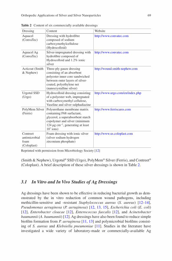
69
(Smith & Nephew), Urgotul® SSD (Urgo), PolyMem® Silver (Ferris), and Contreet® (Coloplast). A brief description of these silver dressings is shown in Table 2.
3.1 In Vitro and In Vivo Studies of Ag Dressings
Ag dressings have been shown to be effective in reducing bacterial growth as dem-onstrated by the in vitro reduction of common wound pathogens, including methicillin- sensitive and -resistant Staphylococcus aureus (S. aureus) [12–14], Pseudomonas aeruginosa (P. aeruginosa) [12, 13, 15], Escherichia coli (E. coli) [12], Enterobacter cloacae [12], Enterococcus faecalis [12], and Acinetobacter baumannii (A. baumannii) [12]. Ag dressings have also been found to reduce simple biofilm formation from P. aeruginosa [11, 13] and polymicrobial biofilms consist-ing of S. aureus and Klebsiella pneumoniae [11]. Studies in the literature have investigated a wide variety of laboratory-made or commercially-available Ag
Table 2 Content of six commercially available dressings
Dressing Content Website
Aquacel (ConvaTec)
Dressing with hydrofibre composed of sodium carboxymethylcellulose (Hydrocolloid)
http://www.convatec.com
Aquacel Ag (ConvaTec)
Silver-impregnated dressing with hydrofibre composed of Hydrocolloid and 1.2% ionic silver
http://www.convatec.com
Acticoat (Smith & Nephew)
Three-ply gauze dressing consisting of an absorbent polyester inner core sandwiched between outer layers of silver- coated, polyethylene net (nanocrystalline silver)
http://wound.smith-nephew.com
Urgotul SSD (Urgo)
Hydrocolloid dressing consisting of a polyester web, impregnated with carboxymethyl cellulose, Vaseline and silver sulphadiazine
http://www.urgo.com/en/index.php
PolyMem Silver (Ferris)
Polyurethane membrane matrix containing F68 surfactant, glycerol, a superabsorbent starch copolymer and silver (minimum 124 μg cm−2, generating at least 107 ions)
http://www.ferriscares.com
Contreet antimicrobial foam (Coloplast)
Foam dressing with ionic silver (silver sodium hydrogen zirconium phosphate)
http://www.us.coloplast.com
Reprinted with permission from Microbiology Society [12]
Orthopedic Applications of Silver and Silver Nanoparticles
70
dressings and have generally shown that Ag dressings have efficacious antimicro-bial properties. However, Ag dressings may show differing results when comparing the antimicrobial efficacies among different formulations.
Ip et al. [12] examined the antibacterial activity of five commercially available Ag dressings (Aquacel® Ag, Acticoat™, Urgotol® SSD, PolyMem® Silver, and Contreet®) against many common Gram-positive and -negative bacteria using an in vitro culture broth method. The Ag dressings varied in terms of antimicrobial spec-trum and rapidity of action. All dressings were effective against Gram-negative bac-teria; however, only Acticoat and Contreet were also effective against S. aureus. Overall, Acticoat and Contreet had the most rapid and broad spectrum of antimicro-bial activity. Rapid antimicrobial activity is desired to reduce interference from bac-teria in wound healing and to reduce likelihood of bacterial resistance.
Lin et al. [15] found that Ag-containing dressings (Aquacel® Ag, Acticoat 7, and KoCarbonAg) prevented external bacteria from entering the wound and had the ability to retain bacteria within the dressing in vitro. In addition, the authors showed that use of Ag-containing dressings led to improved wound healing compared to gauze dressings in vivo, which can be attributed to a reduced bacterial burden at the wound, as prevention of critical colonization of bacteria prevents interference from wound healing.
Certain Ag dressings have also been shown to reduce biofilm formation. Parsons et al. [11] investigated the use of Aquacel Ag+ Extra toward biofilm disruption and compared its efficacy against two other commercially-available Ag dressings (Acticoat 7 and Silvercel Non-Adherent). Staining procedures were done on the biofilms followed by confocal laser scanning microscopy to capture the image for analysis. The results showed that Aquacel Ag+ Extra was more effective in reducing biofilm growth compared to the other two Ag dressings. In addition, Aquacel Ag+ Extra significantly reduced the growth of viable biofilm cells and significantly reduced biofilm thickness with significantly fewer extracellular polymeric sub-stances. Bourdillon et al. [13] also investigated the use of Ag dressings against bio-film disruption. In their study, three commercially-available Ag dressings (Aquacel Ag, Acticoat 7, and Promogran Prisma) were examined for their efficacy at reducing bacterial burden and biofilm formation. The results showed that all Ag dressings reduced S. aureus and P. aeruginosa vegetative cultures. However, when tested against P. aeruginosa biofilms, only Promogran Prisma significantly reduced the biofilm population and its protease production.
Despite the antimicrobial efficacy of Ag dressings in vitro, there is concern that Ag dressings could result in adverse side effects from too much silver being deliv-ered to tissues. In addressing this concern, many studies have investigated the in vitro cytotoxicity of Ag dressings. Paddle-Ledinek et al. [16] investigated the in vitro cytotoxicity of several Ag dressings. Keratinocytes were exposed to Ag dress-ing extracts and cell survival was determined by MTT assays. They demonstrated that extracts from the Ag dressings induced significant reductions in keratinocyte viability, with variable effects depending on the dressing formulations. It was found that Acticoat, Aquacel Ag, Avance, and Contreet-H induced the greatest cytotoxicity among all the Ag dressings tested.
J. Kang et al.
71
Burd et al. [10] investigated the cytotoxicity of five commercially available Ag dressings (Aquacel Ag, Acticoat, Contreet Foam, PolyMem Silver, and Urgotol SSD). In the monolayer cell culture, their results showed that PolyMem Silver and Urgotol SSD were relatively safe for keratinocytes and fibroblasts. However, Aquacel Ag, Acticoat, and Contreet Foam produced significant cytotoxic effects on keratinocytes and fibroblasts with varied effects depending on the media. In the tis-sue explant culture model, delayed reepithelization was observed in all Ag dressings as measured by the reepithelization index upon histological examination. In the mouse excisional wound model, delayed or inhibited wound reepithelization was observed in all Ag dressings as measured by the ratio of the epithelial gap to wound gap upon histological examination.
One study indicated that the in vitro cytotoxicity of Ag dressings does not neces-sarily predict how Ag dressings may function in wound healing in vivo. Hiro et al. [17] investigated multiple different Ag dressings and primarily evaluated their in vitro cytotoxicity and in vivo process of wound healing. The in vitro cytotoxicity was determined by evaluating fibroblast function using fibroblast-populated colla-gen lattices and fibroblast viability using the Trypan Blue assay and MTT assay. The in vivo process of wound healing was evaluated utilizing a rat model. Their results showed that all Ag dressings were cytotoxic to fibroblasts. However, despite the cytotoxicity, their in vivo model demonstrated that all of the Ag dressings, except Contreet Foam and Acticoat, resulted in improved wound healing.
3.2 Clinical Studies
Ag dressings have been shown to be effective in wound care, particularly in the treatment of burn wounds [18, 19], diabetic ulcers [20], and chronic ulcers [21]. In the field of orthopedics, Ag dressings have found applications in the prevention of periprosthetic joint infections (PJI) and traumatic injuries. PJI is a potentially cata-strophic complication that is estimated to occur in about 0.92% of cases following total knee arthroplasty (TKA) and 0.88% of cases following total hip arthroplasty (THA) [22]. PJIs are associated with significant morbidity and mortality, and may lead to costly surgical revisions, long-term disability, and even death [23]. Ag dress-ings have shown promise in lowering the infection burden following surgery and there have been a number of clinical studies demonstrating the effectiveness of Ag dressings post-TKA and -THA. Of note, the majority of studies in the literature regarding the use of Ag dressings in clinical cases post-arthroplasty have primarily investigated the effects of Aquacel Ag. As a result, there remains a need for more clinical studies investigating the effects of different Ag dressings post-arthroplasty.
A few clinical studies have investigated the incidence of acute PJI using Ag dressings. Grosso et al. [24] conducted a retrospective cohort trial in 1173 patients who underwent TKA or THA and received either an Aquacel Ag dressing or stan-dard xeroform dressing. Their results showed that the Aquacel Ag dressing signifi-cantly reduced the incidence of acute PJI, as the incidence of acute PJI was 1.58%
Orthopedic Applications of Silver and Silver Nanoparticles
72
in the standard xeroform dressing group and 0.33% in the Aquacel Ag dressing group (p = 0.03). In a similar study, Cai et al. [25] conducted a retrospective case- control study of patients who underwent a TKA or THA and received either the Aquacel Ag dressing or standard gauze dressing. The authors reviewed 903 cases who received the Aquacel Ag dressing and 875 cases with the standard gauze dress-ing. They found that the Aquacel Ag dressing significantly reduced the incidence of acute PJI, as the incidence of acute PJI was 1.7% in the standard gauze dressing group and 0.44% in the Aquacel Ag dressing group (p = 0.005).
Some clinical studies have also investigated other aspects of Ag dressings includ-ing wound complications, blistering of skin, number of dressing changes, and patient satisfaction. Springer et al. [26] conducted a randomized controlled trial in 300 patients who were scheduled to undergo TKA or THA and were randomized to receive Aquacel Ag or a standard surgical dressing. In patients who received Aquacel Ag, there were statistically significantly fewer wound complications (p = 0.015), fewer blisters (p = 0.026), fewer dressing changes (p < 0.0001), and greater overall patient satisfaction (p < 0.0001). Ravenscroft et al. [27] conducted a prospective, randomized controlled trial in 200 patients who were scheduled to undergo TKA, THA, or surgery for a femoral neck fracture, and were randomized to receive either Cutiplast (a commonly used dressing for orthopedic procedures that is comprised of an absorbent perforated dressing with adhesive borders) or Aquacel Ag covered with Tegaderm. It was determined that, in patients who received the Aquacel/Tegaderm dressing, there was statistically significantly fewer wound complications (p < 0.00001), which included dressing failure, skin blistering, or any signs of infec-tion. There was also statistically significantly fewer wound dressing changes (p = 0.03) and statistically lower pain scores at the time of dressing change (p = 0.001) in patients who received the Aquacel/Tegaderm dressing.
Ag dressings have also found applications in traumatic injuries. Traumatic inju-ries present challenges to surgeons as they must address infection control and appropriate bone and/or soft tissue healing. Ag dressings are a potential solution to this problem and there have been a number of clinical studies investigating the use of Ag dressings in traumatic injuries.
Several clinical studies have shown that Ag dressings may lead to reduced infec-tion and improved wound healing. Jurczak et al. [28] conducted a prospective, ran-domized clinical trial assessing the use of a Hydrofiber dressing (Aquacel Ag) compared to povidone-iodine gauze for the treatment of open surgical and traumatic wounds. There were 35 patients in the Hydrofiber Ag dressing group and 32 patients in the povidone-iodine gauze group. Results demonstrated that the Hydrofiber Ag dressing group was significantly better than the povidone-iodine gauze treatment group in terms of pain management (p < 0.001), comfort (p < 0.001), and exudate management (p < 0.001). For wound healing, there was a 23% and 9% healing rate in the Hydrofiber Ag and povidone-iodine group, respectively. Keen et al. [29] con-ducted a retrospective case series of Gustilo/Anderson type II and III open fractures that received a unique treatment protocol including irrigation and debridement, intravenous antibiotics, and a nanocrystalline Ag dressing (Acticoat) placed within
J. Kang et al.
73
the wound with an overlying negative pressure dressing. They found only one sign of clinical infection among the 17 patients who met inclusion criteria.
However, several clinical studies have also shown that Ag dressings did not have positive outcomes in traumatic injuries. Kadar et al. [30] conducted a prospective, randomized clinical trial assessing the use of a Ag dressing (SilvalGuard) compared to a regular dressing (OPSITE) in elderly patients undergoing surgery for hip frac-tures. A matched group of 55 patients were randomized to receive the Ag dressing or regular dressing and were followed for 1 week to monitor for signs of clinical infection. There were no significant differences in signs of clinical infection between the two groups, as infection was seen in 2 of 31 patients in the Ag dressing group and 2 of 24 patients in the regular dressing group. Fries et al. [31] conducted a pro-spective, randomized clinical trial assessing the use of nanocrystalline Ag dressings (Acticoat) compared to standard of care dressings (plain gauze) upon traumatic military wounds. There were 76 patients in the trial who were randomized to receive the Ag dressing or standard of care dressing, and the results showed no statistical differences between the groups in terms of wound colonization (p = 0.1384, Fishers) and time to wound healing (p = 0.5009, Mann-Whitney).
4 Ag-Coated Prosthetic Implants
Prosthetic implants are commonly used in the field of orthopedics in procedures such as internal fixation and arthroplasty [32, 33]. However, use of these implants may increase the risk for implant-associated infections, as implanted foreign bodies are more susceptible to infection. It has been reported that the incidence of infected joint prosthesis and fracture-fixation devices is 2% and 5%, respectively [34]. Implant-associated infections have many clinical and economic consequences, and typically require expensive surgical revisions [34].
Implant-associated infections are caused by a triad of factors, which involve the interaction between the microorganism, implant, and host [35]. Formation of bio-films is believed to be one important factor in the pathogenesis of implant- associated infections; biofilms are difficult to eradicate due to their resistance to internal and external environmental factors that allow for survival of the microorganisms [35]. Foreign body implants have key characteristics that promote the formation of bio-films. Foreign body implants lack microcirculation, which is important in delivering therapeutic agents and the host response to infection [35]. In addition, there are many surface characteristics of foreign body implants that can promote biofilm for-mation, which include the composition of the material, surface charge, surface roughness, and hydrophobicity [36].
One potential solution to reduce the risk of infection involves coating the pros-thetic implants with Ag. Thin layers of Ag coating on prosthetic implants can help reduce biofilm formation. In orthopedics, Ag-coated prosthetic implants are primar-ily being used in external fixation devices and megaprostheses.
Orthopedic Applications of Silver and Silver Nanoparticles
74
4.1 Ag-Coated External Fixation Pins: In Vitro, In Vivo, and Clinical Studies
External fixation is often used in settings of trauma or limb reconstruction to stabi-lize the bone or joint and involves the placement of percutaneous pins and wires. The use of external fixation pins may put patients at risk for infection because the pins may act as a conduit for the transfer of bacteria on the skin to the underlying soft tissue and bone; the incidence of pin tract infections is high and has been reported to be as high as 63%. In vitro and in vivo studies have shown that Ag-coated external fixation pins could significantly reduce bacterial colonization and infection rates; however, no clinical advantages have been observed in several clinical studies [37, 38].
4.1.1 In Vitro and In Vivo Studies
One property that Ag-coated prosthetic devices may have in reducing infection is through inhibiting the initial stages of colonization by decreasing the adhesion of bacteria to their surfaces. This was shown in an in vitro study by Wassall et al. [39], where it was demonstrated that Ag-coated external fixation pins had significantly less bacterial adhesion compared to control stainless steel pins (p < 0.05). Reduced bacterial adhesion on Ag-coated pins was also shown with E. coli, P. aeruginosa, and S. aureus, but not with Staphylococcus haemolyticus.
One of the initial in vivo studies investigating the prevention of infection using Ag-coated external fixation pins was done by Collinge et al. [40] In their in vivo study, six sheep were inoculated with S. aureus and had Ag-coated and uncoated stainless steel pins inserted in the iliac crest for 19 days. The pin tips were removed and cultured for bacterial growth; Ag-coated pins led to less infection than uncoated pins (confidence interval [CI] > 85%). The infection rate in the Ag-coated pins was 62% (22 of 36 pins) compared to 84% (10 of 12 pins) in the uncoated pins. The pins were also assessed for mechanical anchorage and inflammation. The results sup-ported an association between mechanical anchorage and infection, as infected pins were more likely to be loose. Biofilm growth on the pin tips was examined with scanning electron microscopy (SEM) and decreased biofilm colonization was seen in the Ag-coated pins when compared with the uncoated pins.
Bosetti et al. [41] assessed the cytotoxic and genotoxic properties of Ag-coated external fixation pins in vitro. Their study showed that Ag-coated pins were not cytotoxic nor genotoxic when compared to control stainless steel pins. Genotoxicity studies were done by examining the frequency of sister chromatid exchanges (SCE) and kinetics in human peripheral blood lymphocytes. Results of the SCE exchange showed no significant differences between Ag-coated pins and control stainless steel pins. The lymphocyte kinetics data further suggested that Ag-coated pins did not cause cell-cycle delay. Cytotoxicity studies showed that, after 4 days, human
J. Kang et al.
75
osteoblast cells cultured with Ag-coated pins displayed typical morphology and cell spreading.
4.1.2 Clinical Studies
One of the initial clinical studies performed to assess the effects of Ag-coated exter-nal fixation pins was done by Massè et al. [38]. The authors conducted a prospec-tive, randomized study to assess the efficacy of Ag-coated screws in preventing external pin tract infection. Twenty-four male patients with diaphyseal fractures of the tibia or femur underwent external fixation with Ag-coated screws and uncoated stainless steel screws. The rate of positive culture from the screw tips was 30.0% (15 of 50 screws) in the Ag-coated group and 42.9% (24 of 56 screws) in the uncoated group; however, this difference was not statistically significant (p = 0.243). There were no significant differences between the Ag-coated group and uncoated group in terms of inflammation and mechanical anchorage scores. The differences between pre-operative and post-operative blood Ag levels were statistically significant (p < 0.001).
In another prospective, a randomized study conducted by Coester et al. [37], 22 patients underwent external fixation for tibial fractures. They received Ag-coated pins and uncoated stainless steel pins that were randomized by clamp position to allow for a side-by-side comparison. The results showed no significant differences in the performance of the Ag-coated pins and uncoated stainless steel pins in regard to the rate of pin tract infection, bacterial growth of the pins, clinical appearance of the pin sites, and mechanical integrity of the pins upon removal.
4.2 Ag-Coated Megaprostheses: In Vitro, In Vivo, and Clinical Studies
Typically, megaprostheses are used to reconstruct skeletal defects after bone or soft tissue tumor resection, major trauma, or end-stage revision arthroplasty [42]. The most serious complication after the implantation of megaprostheses is peripros-thetic infection, with reported incidence rates of infection between 11% and 23%, depending on the site of replacement [43]. Previously attempted preventative mea-sures have had limited success [43]. In this section, we review the in vitro, in vivo, and clinical studies regarding the efficacy of Ag-coated megaprostheses in reducing infection and also examine the cytotoxicity of Ag toward host cells.
Orthopedic Applications of Silver and Silver Nanoparticles
76
4.2.1 In Vitro and In Vivo Studies
Megaprostheses are typically composed of titanium due to their high resistance to corrosion and excellent biocompatibility [42]. However, plain titanium megapros-theses are susceptible to bacterial adhesion. To reduce the development of infection on titanium surfaces, a number of strategies have been investigated and include the use of Ag coatings. Ewald et al. [44] developed Ag-coated titanium alloys via physi-cal vapor deposition to coat titanium surfaces with a titanium alloy containing 0.7–9% Ag and investigated the in vitro antimicrobial and biocompatibility properties. There was a significant decrease in the adhesion of bacteria on the Ag-coated tita-nium surface when compared to uncoated titanium controls, with up to a 64% decrease against Klebsiella pneumoniae and up to a 52% decrease against Staphylococcus epidermidis. In addition, there was no observed cytotoxicity against epithelial and osteoblast cell lines, as cell activity and protein content were not sig-nificantly changed.
Hardes et al. [45] incubated Ag and titanium supplements with osteosarcoma cell lines and evaluated the effect of Ag on cell viability and cell function in vitro. Their results showed that Ag was non-cytotoxic at low concentrations (e.g., 5 mg) and significantly stimulated more alkaline phosphatase production, indicative of osteo-genic differentiation, than titanium. However, at higher concentrations (e.g., >10 mg), Ag was found to be cytotoxic with a drastic decrease in viability and alkaline phosphatase production, and thus it was less biocompatible when com-pared to titanium.
Gosheger et al. [46] reported that Ag-coated megaendoprostheses reduced infec-tion rates and had no significant toxicological side effects when used in an in vivo animal model. The study design involved inserting either Ag-coated prostheses or uncoated titanium-vanadium prostheses into the diaphyseal femur of rabbits. The rabbits were infected with S. aureus and were observed for 90 days. The results showed that the infection rate in the Ag-coated group was significantly lower than the uncoated group (p < 0.05), as the infection rate in the Ag-coated group was 7% compared to 47% in the uncoated group. Regarding the potential toxicity of Ag-coated prostheses, elevated Ag levels of the Ag-coated group were seen in the blood (median 1.883 ppb) and in organs (0.798 to 86.002 ppb) when compared to the uncoated group. However, these levels of Ag were considered to be non-toxic since no toxicological side effects were found and no histological abnormalities were observed in any of the organs studied.
4.2.2 Clinical Studies
Wafa et al. [47] conducted a retrospective case-control study to evaluate the inci-dence of periprosthetic infection in patients who underwent endoprosthetic replace-ment for bone tumors and received either Ag-coated prostheses (Alguna-coated) or uncoated prostheses. Their results suggest that Ag-coated prostheses are successful in reducing post-operative infection rates, particularly evident in two-stage
J. Kang et al.
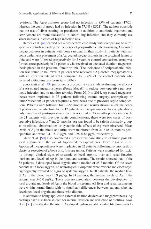
77
revisions. The Ag-prostheses group had no infection in 85% of patients (17/20) whereas the control group had no infection in 57.1% (12/21). The authors conclude that the use of silver coating on prostheses in addition to antibiotic treatment and debridement are more successful in controlling infection and they currently use silver implants in cases of high infection risk.
Hardes et al. [48] carried out a prospective case study with comparison to retro-spective controls regarding the incidence of periprosthetic infection using Ag-coated megaprostheses in patients with bone sarcoma. In their study, 51 patients with sar-coma underwent placement of a Ag-coated megaprosthesis in the proximal femur or tibia, and were followed prospectively for 5 years. A control comparison group was formed retrospectively in 74 patients who received an uncoated titanium megapros-thesis placed in the proximal femur or tibia. The incidence of periprosthetic infec-tion was found to be lower in patients who received a Ag-coated megaprosthesis, with an infection rate of 5.9% compared to 17.6% of the control patients who received a titanium prosthesis (p = 0.062).
Scoccianti et al. [49] performed a prospective case study evaluating the efficacy of a Ag-coated megaprostheses (Porag MegaC) to reduce post-operative peripros-thetic infection and to monitor toxicity. From 2010 to 2014, Ag-coated megapros-theses were implanted in 33 patients following trauma surgery, arthroplasty, or tumor resection; 21 patients required a prostheses due to previous septic complica-tions. Patients were followed for 12–56 months and results showed a low incidence of post-operative infection. In the 12 patients with no previous septic complications, only one case of post-operative infection occurred at 25 months post-operation. In the 21 patients with previous septic complications, there were two cases of post- operative infection, at 7 and 24 months. Ag was found to be safe in this study group, as no clinical abnormalities or systemic side effects of Ag were observed. Mean levels of Ag in the blood and urine were monitored from 24 h to 36 months post- operation and were 0.41–5.33 μg/L and 0.28–0.86 μg/L, respectively.
Glehr et al. [50] also conducted a prospective case study to examine possible local argyria with the use of Ag-coated megaprostheses. From 2004 to 2011, Ag-coated megaprostheses were implanted in 32 patients following revision arthro-plasty or resection of a bone or soft tissue tumor. Patients were monitored for toxic-ity through clinical signs of systemic or local argyria, liver and renal function markers, and levels of Ag in the blood and seroma. The results showed that, of the 32 patients, 7 developed local argyria after a median of 25.7 months. Of the seven patients with local argyria, no neurological symptoms were evident and electronys-tagmography revealed no signs of systemic argyria. In 20 patients, the median level of Ag in the blood was 15.9 μg/kg. In 14 patients, the median levels of Ag in the seroma was 545.0 μg/kg. There was no association between the development of local argyria and levels of Ag in the blood or seroma. All liver and renal parameters were within normal limits with no significant differences between patients who had developed local argyria and those who did not.
In addition to being applied to external fixation devices and megaprostheses, Ag coatings have also been studied for internal fixation and reduction of biofilms. Kose et al. [51] investigated the use of Ag doped hydroxyapatite coated titanium nails to
Orthopedic Applications of Silver and Silver Nanoparticles
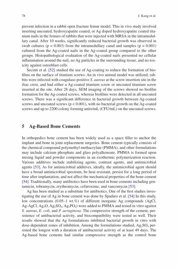
78
prevent infection in a rabbit open fracture femur model. This in vivo study involved inserting uncoated, hydroxyapatite coated, or Ag doped hydroxyapatite coated tita-nium nails in the femurs of rabbits that were injected with MRSA in the intramedul-lary canal. After 10 weeks, significantly reduced bacterial growth was observed in swab cultures (p = 0.003) from the intramedullary canal and samples (p = 0.001) cultured from the Ag-coated nails in the Ag-coated group compared to the other groups. Histopathological evaluation of the Ag-coated nails presented no cellular inflammation around the nail, no Ag particles in the surrounding tissue, and no tox-icity against osteoblast cells.
Secinti et al. [52] studied the use of Ag-coating to reduce the formation of bio-films on the surface of titanium screws. An in vivo animal model was utilized; rab-bits were infected with coagulase-positive S. aureus at the screw insertion site in the iliac crest, and had either a Ag-coated titanium screw or uncoated titanium screw inserted at the site. After 28 days, SEM imaging of the screws showed no biofilm formation for the Ag-coated screws, whereas biofilms were detected in all uncoated screws. There was a significant difference in bacterial growth between Ag-coated screws and uncoated screws (p < 0.001), with no bacterial growth on the Ag-coated screws and up to 2200 colony forming units/mL (CFU/mL) on the uncoated screws.
5 Ag-Based Bone Cements
In orthopedics bone cement has been widely used as a space filler to anchor the implant and bone in joint replacement surgeries. Bone cement typically consists of the chemical compound polymethyl methacrylate (PMMA), and other formulations may include calcium phosphate and glass polyalkenoate. PMMA is formed upon mixing liquid and powder components in an exothermic polymerization reaction. Various additives include stabilizing agents, contrast agents, and antimicrobial agents [53]. As for antimicrobial additives, ideally, the antimicrobial agent should have a broad antimicrobial spectrum, be heat resistant, persist for a long period of time after implantation, and not affect the mechanical properties of the bone cement [54]. Traditionally, many antibiotics have been used in bone cements including gen-tamicin, tobramycin, erythromycin, cefuroxime, and vancomycin [53].
Ag has been studied as a substitute for antibiotics. One of the first studies inves-tigating the use of Ag in bone cement was done by Spadaro et al. [54] In this study, low concentrations (0.05–1 wt.%) of different inorganic Ag compounds (AgCl, Ag-AgCl, Ag2O, Ag2SO4, Ag3PO4) were added to PMMA and tested in vitro against S. aureus, E. coli, and P. aeruginosa. The compressive strength of the cement, per-sistence of antibacterial activity, and biocompatibility were tested as well. Their results showed that the Ag formulations inhibited bacterial growth in vitro with dose-dependent zones of inhibition. Among the formulations studied, Ag2SO4 per-sisted the longest with a duration of antibacterial activity of at least 49 days. The Ag-based bone cements had similar compressive strength as the control bone
J. Kang et al.
79
cements. The biocompatibility tests in rabbit muscle tissues showed no significant differences between the Ag bone cement and the control bone cements.
Dueland et al. [55] compared the efficacy of Ag bone cement (Ag-PMMA), gen-tamicin bone cement (gentamicin-PMMA), and plain bone cement using an in vivo animal model. The Ag-PMMA rods were made with the addition of 1 wt.% Ag2SO4. New Zealand rabbits were inoculated with S. aureus in the proximal tibial medul-lary canal and had either Ag-PMMA rods, gentamicin-PMMA rods, or control rods without antimicrobial agents implanted in the intramedullary canal. Evaluation of the treatment and control groups was done by quantifying the bacterial growth from the tibias after 6 weeks and mortality rates of the rabbits. The results showed that bacterial growth found in the Ag-PMMA group (35.6 ± 43 × 106 CFU) and gentamicin- PMMA group (8.6 ± 13 × 106 CFU) were significantly reduced when compared to the control group (89.4 ± 60 × 106 CFU). The mortality rate of the Ag-PMMA group, gentamicin-PMMA group, and control group was 22%, 6%, and 61%, respectively. There was a significantly lower mortality rate of the Ag-PMMA group and gentamicin-PMMA group when compared to the control group, but no significant differences were found when comparing the two treatment groups with each other.
AgNPs were also incorporated within bone cements. Alt et al. [56] found that AgNP-loaded bone cements had a dose-dependent inhibition of bacterial growth, with complete inhibition at a concentration of 1% AgNPs against MRSA, S. epider-midis, and methicillin-resistant S. epidermidis. In comparison, plain bone cements did not inhibit bacterial growth and gentamicin-loaded bone cements showed incomplete inhibition. The AgNP-loaded bone cements displayed no in vitro cyto-toxicity and no significant differences were found when comparing to controls. Oei et al. [57] reported that AgNP-PMMA had 99.9% bacterial inhibition against S. aureus, A. baumannii, P. aeruginosa, and Proteus mirabilis when compared to plain PMMA controls. Prokopovich et al. [58] developed a PMMA bone cement impreg-nated with tiopronin-capped AgNPs and found that it had antimicrobial activities against MRSA. In addition, no cytotoxicity was observed against osteoblasts via MTT assays and the mechanical strength was comparable to the control PMMA without nanoparticles. Slane et al. [59] showed that AgNP-PMMA bone cements significantly reduced biofilm formation for S. epidermidis and S. aureus when com-pared to the bone cement control (p < 0.001).
Despite studies demonstrating the efficacy of AgNP-loaded bone cements against bacteria in vitro, studies completed in vivo suggested a different outcome. In a study done by Moojen et al. [60], the in vivo efficacy of AgNP-loaded bone cement against methicillin sensitive S. aureus infection was determined. In the design of the study, New Zealand rabbits were infected with S. aureus in the medullary canal of the femur, and implanted with AgNP-PMMA, tobramycin-PMMA, or plain- PMMA. After 14 days, the rabbits were analyzed for infection based on infection rates, bacteriology, and histology. All rabbits in the AgNP-PMMA cement and plain cement groups were infected, whereas only 17% in the tobramycin-PMMA group were infected. The bacteriology showed no differences in the growth between the AgNP-PMMA cement group and the plain cement group, whereas no growth was
Orthopedic Applications of Silver and Silver Nanoparticles
80
observed in the tobramycin group. The histopathology study revealed that all signs of infection (periosteal thickening, enlargement of Haversian canals, and cortical destruction) were present in all rabbits of the AgNP-PMMA and plain cement groups. In contrast, signs of infection were absent in the tobramycin-PMMA group, except for two rabbits with some enlargement of Haversian canals. The authors sug-gested that the differences observed may be due to the different release profiles of the treatment agents. In the implant infection model, not only was bacteria present at the implant surface, but also distal to the implant. Antibiotic-loaded bone cements were able to act both at the implant surface and distal to it. In contrast, AgNP- PMMA bone cements contained nanoparticles that were not released from the cements and needed to be ionized to become active. It suggested that AgNP loaded bone cements were able to act locally, but would have decreased efficacy in prevent-ing infection at distal locations [60].
6 Summary
Ag and AgNPs have found some applications in orthopedics. These include Ag dressings, Ag-coated prosthetic implants, and Ag-based bone cements. Most studies seem to show strong antimicrobial properties of Ag along with limited toxicity, while inconsistencies exist among various studies, and among in vitro, in vivo, and clinical studies. Some applications have been heavily explored, such as Ag dress-ings and Ag-coated megaprostheses, and there have been quite a few clinical studies reported which support their antimicrobial efficacy and limited toxicity. However, other applications, including Ag-coated external fixation pins and Ag-based bone cements have either limited or no reported clinical studies. There remains a need for more clinical studies to better understand the uses of Ag and AgNPs before imple-menting these applications into daily practice. Some of the main concerns are their toxicity and potential accumulation in the body. In addition, the long-term clinical effects of Ag and AgNPs are not well known; future research may need to reduce their toxicity, which may likely broaden their clinical applications.
Acknowledgement We acknowledge financial support from AO Foundation (Project S-13-15L was supported by the AO Foundation), Osteosynthesis & Trauma Care Foundation, the West Virginia National Aeronautics and Space Administration Experimental Program to Stimulate Competitive Research (WV NASA EPSCoR), NIH Grant P20GM103434, and the National Institute of General Medical Sciences of the National Institutes of Health under Award Number 2U54GM104942-02. This work was also supported by the Office of the Assistant Secretary of Defense for Health Affairs, through the Peer Reviewed Medical Research Program, Discovery Award under Award No. W81XWH-17-1-0603. Opinions, interpretations, conclusions, and recom-mendations are those of the authors and are not necessarily endorsed by the funding agencies. We thank Suzanne Danley for proofreading.
J. Kang et al.
81
References
1. Lansdown AB. Silver in health care: antimicrobial effects and safety in use. Curr Probl Dermatol. 2006;33:17–34.
2. Li B, Webster TJ. Bacteria antibiotic resistance: New challenges and opportunities for implant- associated orthopedic infections. J Orthop Res 2017. https://doi.org/10.1002/jor.23656.
3. Chaloupka K, Malam Y, Seifalian AM. Nanosilver as a new generation of nanoproduct in bio-medical applications. Trends Biotechnol. 2010;28(11):580–8.
4. Chernousova S, Epple M. Silver as antibacterial agent: ion, nanoparticle, and metal. Angew Chem Int Ed Engl. 2013;52(6):1636–53.
5. Drake PL, Hazelwood KJ. Exposure-related health effects of silver and silver compounds: a review. Ann Occup Hyg. 2005;49(7):575–85.
6. Gunawan C, Marquis CP, Amal R, Sotiriou GA, Rice SA, Harry EJ. Widespread and indiscriminate nanosilver use: genuine potential for microbial resistance. ACS Nano. 2017;11(4):3438–45.
7. Walker M, Parsons D. The biological fate of silver ions following the use of silver-containing wound care products—a review. Int Wound J. 2014;11(5):496–504.
8. National Collaborating Centre for Ws, Children’s H. National Institute for Health and Clinical Excellence: guidance. Surgical site infection: prevention and treatment of surgical site infec-tion. London: RCOG Press National Collaborating Centre for Women’s and Children’s Health; 2008.
9. Leaper D. Appropriate use of silver dressings in wounds: an expert working group consensus. Wounds Int. 2012;9(5):461–4.
10. Burd A, Kwok CH, Hung SC, Chan HS, Gu H, Lam WK, Huang L. A comparative study of the cytotoxicity of silver-based dressings in monolayer cell, tissue explant, and animal models. Wound Repair Regen. 2007;15(1):94–104.
11. Parsons D, Meredith K, Rowlands VJ, Short D, Metcalf DG, Bowler PG. Enhanced perfor-mance and mode of action of a novel antibiofilm hydrofiber(R) wound dressing. Biomed Res Int. 2016;2016:7616471. PMCID:PMC5136405
12. Ip M, Lui SL, Poon VKM, Lung I, Burd A. Antimicrobial activities of silver dressings: an in vitro comparison. J Med Microbiol. 2006;55(1):59–63.
13. Bourdillon KA, Delury CP, Cullen BM. Biofilms and delayed healing—an in vitro evaluation of silver- and iodine-containing dressings and their effect on bacterial and human cells. Int Wound J 2017. https://doi.org/10.1111/iwj.12761.
14. Mohseni M, Shamloo A, Aghababaei Z, Vossoughi M, Moravvej H. Antimicrobial wound dressing containing silver sulfadiazine with high biocompatibility: in vitro study. Artif Organs. 2016;40(8):765–73.
15. Lin YH, Hsu WS, Chung WY, Ko TH, Lin JH. Silver-based wound dressings reduce bacterial burden and promote wound healing. Int Wound J. 2016;13(4):505–11.
16. Paddle-Ledinek JE, Nasa Z, Cleland HJ. Effect of different wound dressings on cell viability and proliferation. Plast Reconstr Surg. 2006;117(7 Suppl):110S–8S. discussion 9S–20S
17. Hiro ME, Pierpont YN, Ko F, Wright TE, Robson MC, Payne WG. Comparative evaluation of silver-containing antimicrobial dressings on in vitro and in vivo processes of wound healing. Eplasty. 2012;12:e48. PMCID:PMC3471607
18. Gee Kee E, Stockton K, Kimble RM, Cuttle L, McPhail SM. Cost-effectiveness of silver dress-ings for paediatric partial thickness burns: an economic evaluation from a randomized con-trolled trial. Burns. 2017;43(4):724–32.
19. Munteanu A, Florescu IP, Nitescu C. A modern method of treatment: the role of silver dress-ings in promoting healing and preventing pathological scarring in patients with burn wounds. J Med Life. 2016;9(3):306–15. PMCID:PMC5154321
20. Jude EB, Apelqvist J, Spraul M, Martini J. Prospective randomized controlled study of Hydrofiber dressing containing ionic silver or calcium alginate dressings in non-ischaemic diabetic foot ulcers. Diabet Med. 2007;24(3):280–8.
Orthopedic Applications of Silver and Silver Nanoparticles
82
21. Jemec GB, Kerihuel JC, Ousey K, Lauemoller SL, Leaper DJ. Cost-effective use of silver dress-ings for the treatment of hard-to-heal chronic venous leg ulcers. PLoS One. 2014;9(6):e100582. PMCID:PMC4063949
22. Kurtz SM, Lau E, Schmier J, Ong KL, Zhao K, Parvizi J. Infection burden for hip and knee arthroplasty in the United States. J Arthroplast. 2008;23(7):984–91.
23. Lamagni T. Epidemiology and burden of prosthetic joint infections. J Antimicrob Chemother. 2014;69(Suppl 1):i5–10.
24. Grosso MJ, Berg A, LaRussa S, Murtaugh T, Trofa DP, Geller JA. Silver-impregnated occlu-sive dressing reduces rates of acute periprosthetic joint infection after total joint arthroplasty. J Arthroplast. 2017;32(3):929–32.
25. Cai J, Karam JA, Parvizi J, Smith EB, Sharkey PF. Aquacel surgical dressing reduces the rate of acute PJI following total joint arthroplasty: a case-control study. J Arthroplast. 2014;29(6):1098–100.
26. Springer BD, Beaver WB, Griffin WL, Mason JB, Odum SM. Role of surgical dressings in total joint arthroplasty: a randomized controlled trial. Am J Orthop (Belle Mead NJ). 2015;44(9):415–20.
27. Ravenscroft MJ, Harker J, Buch KA. A prospective, randomised, controlled trial comparing wound dressings used in hip and knee surgery: aquacel and tegaderm versus cutiplast. Ann R Coll Surg Engl. 2006;88(1):18–22.
28. Jurczak F, Dugre T, Johnstone A, Offori T, Vujovic Z, Hollander D. Randomised clinical trial of Hydrofiber dressing with silver versus povidone-iodine gauze in the management of open surgical and traumatic wounds. Int Wound J. 2007;4(1):66–76.
29. Keen JS, Desai PP, Smith CS, Suk M. Efficacy of hydrosurgical debridement and nanocrys-talline silver dressings for infection prevention in type II and III open injuries. Int Wound J. 2012;9(1):7–13.
30. Kadar A, Eisenberg G, Yahav E, Drexler M, Salai M, Steinberg EL. Surgical site infection in elderly patients with hip fractures, silver-coated versus regular dressings: a randomised pro-spective trial. J Wound Care. 2015;24(10):441–2. 4–5
31. Fries CA, Ayalew Y, Penn-Barwell JG, Porter K, Jeffery SL, Midwinter MJ. Prospective ran-domised controlled trial of nanocrystalline silver dressing versus plain gauze as the initial post- debridement management of military wounds on wound microbiology and healing. Injury. 2014;45(7):1111–6.
32. Muller ME. Internal fixation for fresh fractures and for non-union. Proc R Soc Med. 1963;56:455–60. PMCID:PMC1897011
33. Harris WH, Sledge CB. Total hip and total knee replacement. N Engl J Med. 1990;323(11):725–31.
34. Darouiche RO. Treatment of infections associated with surgical implants. N Engl J Med. 2004;350(14):1422–9.
35. Trampuz A, Widmer AF. Infections associated with orthopedic implants. Curr Opin Infect Dis. 2006;19(4):349–56.
36. Ribeiro M, Monteiro FJ, Ferraz MP. Infection of orthopedic implants with emphasis on bacterial adhesion process and techniques used in studying bacterial-material interactions. Biomatter. 2012;2(4):176–94.
37. Coester LM, Nepola JV, Allen J, Marsh JL. The effects of silver coated external fixation pins. Iowa Orthop J. 2006;26:48–53. PMCID:PMC1888577
38. Masse A, Bruno A, Bosetti M, Biasibetti A, Cannas M, Gallinaro P. Prevention of pin track infection in external fixation with silver coated pins: clinical and microbiological results. J Biomed Mater Res. 2000;53(5):600–4.
39. Wassall MA, Santin M, Isalberti C, Cannas M, Denyer SP. Adhesion of bacteria to stainless steel and silver-coated orthopedic external fixation pins. J Biomed Mater Res. 1997;36(3):325–30.
40. Collinge CA, Goll G, Seligson D, Easley KJ. Pin tract infections: silver vs uncoated pins. Orthopedics. 1994;17(5):445–8.
41. Bosetti M, Masse A, Tobin E, Cannas M. Silver coated materials for external fixation devices: in vitro biocompatibility and genotoxicity. Biomaterials. 2002;23(3):887–92.
J. Kang et al.
83
42. Gkavardina A, Tsagozis P. The use of megaprostheses for reconstruction of large skeletal defects in the extremities: a critical review. Open Orthop J. 2014;8:384–9.
43. Schmidt-Braekling T, Streitbuerger A, Gosheger G, Boettner F, Nottrott M, Ahrens H, Dieckmann R, Guder W, Andreou D, Hauschild G, Moellenbeck B, Waldstein W, Hardes J. Silver-coated megaprostheses: review of the literature. Eur J Orthop Surg Traumatol. 2017;27(4):483–9.
44. Ewald A, Glückermann SK, Thull R, Gbureck U. Antimicrobial titanium/silver PVD coatings on titanium. BioMed Eng Online. 2006;5:22.
45. Hardes J, Streitburger A, Ahrens H, Nusselt T, Gebert C, Winkelmann W, Battmann A, Gosheger G. The influence of elementary silver versus titanium on osteoblasts behaviour in vitro using human osteosarcoma cell lines. Sarcoma. 2007;2007:26539. PMCID:PMC1920591
46. Gosheger G, Hardes J, Ahrens H, Streitburger A, Buerger H, Erren M, Gunsel A, Kemper FH, Winkelmann W, Von Eiff C. Silver-coated megaendoprostheses in a rabbit model—an analysis of the infection rate and toxicological side effects. Biomaterials. 2004;25(24):5547–56.
47. Wafa H, Grimer RJ, Reddy K, Jeys L, Abudu A, Carter SR, Tillman RM. Retrospective evalu-ation of the incidence of early periprosthetic infection with silver-treated endoprostheses in high-risk patients: case-control study. Bone Joint J. 2015;97-b(2):252–7.
48. Hardes J, von Eiff C, Streitbuerger A, Balke M, Budny T, Henrichs MP, Hauschild G, Ahrens H. Reduction of periprosthetic infection with silver-coated megaprostheses in patients with bone sarcoma. J Surg Oncol. 2010;101(5):389–95.
49. Scoccianti G, Frenos F, Beltrami G, Campanacci DA, Capanna R. Levels of silver ions in body fluids and clinical results in silver-coated megaprostheses after tumour, trauma or failed arthroplasty. Injury. 2016;47(Suppl 4):S11–S6.
50. Glehr M, Leithner A, Friesenbichler J, Goessler W, Avian A, Andreou D, Maurer-Ertl W, Windhager R, Tunn PU. Argyria following the use of silver-coated megaprostheses: no association between the development of local argyria and elevated silver levels. Bone Joint J. 2013;95-b(7):988–92.
51. Kose N, Caylak R, Peksen C, Kiremitci A, Burukoglu D, Koparal S, Dogan A. Silver ion doped ceramic nano-powder coated nails prevent infection in open fractures: In vivo study. Injury. 2016;47(2):320–4.
52. Secinti KD, Ozalp H, Attar A, Sargon MF. Nanoparticle silver ion coatings inhibit biofilm formation on titanium implants. J Clin Neurosci. 2011;18(3):391–5.
53. Vaishya R, Chauhan M, Vaish A. Bone cement. J Clin Orthop Trauma. 2013;4(4):157–63. 54. Spadaro JA, Webster DA, Becker RO. Silver polymethyl methacrylate antibacterial bone
cement. Clin Orthop Relat Res. 1979;(143):266–70. 55. Dueland R, Spadaro JA, Rahn BA. Silver antibacterial bone cement. Comparison with genta-
micin in experimental osteomyelitis. Clin Orthop Relat Res. 1982;169:264–8. 56. Alt V, Bechert T, Steinrucke P, Wagener M, Seidel P, Dingeldein E, Domann E, Schnettler
R. An in vitro assessment of the antibacterial properties and cytotoxicity of nanoparticulate silver bone cement. Biomaterials. 2004;25(18):4383–91.
57. Oei JD, Zhao WW, Chu L, DeSilva MN, Ghimire A, Rawls HR, Whang K. Antimicrobial acrylic materials with in situ generated silver nanoparticles. J Biomed Mater Res B Appl Biomater. 2012;100(2):409–15.
58. Prokopovich P, Leech R, Carmalt CJ, Parkin IP, Perni S. A novel bone cement impregnated with silver-tiopronin nanoparticles: its antimicrobial, cytotoxic, and mechanical properties. Int J Nanomed. 2013;8:2227–37. PMCID:PMC3693822
59. Slane J, Vivanco J, Rose W, Ploeg HL, Squire M. Mechanical, material, and antimicrobial properties of acrylic bone cement impregnated with silver nanoparticles. Mater Sci Eng C Mater Biol Appl. 2015;48:188–96.
60. Moojen DJ, Vogely HC, Fleer A, Verbout AJ, Castelein RM, Dhert WJ. No efficacy of silver bone cement in the prevention of methicillin-sensitive Staphylococcal infections in a rabbit contaminated implant bed model. J Orthop Res. 2009;27(8):1002–7.
Orthopedic Applications of Silver and Silver Nanoparticles
85© Springer International Publishing AG, part of Springer Nature 2017B. Li, T. Webster (eds.), Orthopedic Biomaterials, https://doi.org/10.1007/978-3-319-73664-8_4
Formulation and Evaluation of Nanoenhanced Anti-bacterial Calcium Phosphate Bone Cements
Karthik Tappa, Udayabhanu Jammalamadaka, and David K. Mills
Keywords Aluminosilicates · Antibiotics · Bone cement · Bone repair · Drug delivery · Calcium phosphate · Calcium lactate · Growth inhibition · Halloysite · Hydroxyapatite · Infection · Mechanical loading · PMMA
1 Introduction
Mechanical insufficiency of bone can result from many diseases or conditions that may be metabolic (osteomalacia, gout), endocrine (hyperparathyroidism), neo-plastic (osteosarcoma, enchondromata), traumatic (stress fracture), infective (osteomyelitis), and degenerative (osteoporosis, osteoarthritis) [1]. Despite being a dynamically active tissue, bone cannot repair itself if the affected area is consid-ered to be of a ‘critical size’ [2]. In such cases, orthopedic implants such as metal-lic rods, plates, pins and screws are used. Acrylic resins, polypropylene and polyurethane are common biomaterials used as bone cements to hold the metallic implants in position.
Poly(methyl methacrylate) (PMMA) is a widely used bone cement [3, 4]. The most common method of application is the dry mixing of drugs along with the bone cement and administering it into the body [5]. While long considered the ‘gold’ standard in local antibiotic therapy, it has many disadvantages. Damage in the sur-rounding tissue due to formation of radiolucent fibrous tissues at the bone/cement interface was observed due to the release of toxic methylmethacrylate (MMA) monomer [6, 7]. These cements are also know for setting exothermally at high tem-peratures ranging from 70 °C to 120 °C, causing tissue necrosis to the surrounding tissue and aseptic loosening of the implant [8]. Previous studies have also shown a reduction in mechanical properties on the addition of antibiotics [9]. Moreover, the release of anti-infective agents from the cement is limited and is significantly less
K. Tappa · U. Jammalamadaka · D. K. Mills (*) Center for Biomedical Engineering and Rehabilitation Science, Louisiana Tech University, Ruston, LA, USAe-mail: [email protected]
86
than maximal antibiotic release [10]. Additionally, PMMA cements are excessively stiff, lack elasticity, and do not allow tissue growth within the cement [11].
Calcium phosphate bone cements (CPCs) have been studied as a potential ortho-pedic implant materials for the past 80 years [12]. These cements were FDA approved in 1996 for the treatment of craniofacial defects [13]. They are known for their osteoconductive and osteoinductive properties. Due to the similarities in CPC composition to the mineral phase of bone, these bone cements show high bioresorb-ability, leading to new host tissue formation, and better tissue/implant integration. CPCs have many advantages over PMMA cement. They set endothermically at body temperatures, low shrinkage on setting, can be molded as dense or porous materials depending upon the site of injury, and have good formability (ability to fill complex cavities and spaces) [14].
CPCs are blends of calcium phosphate salts mixed with aqueous solutions. Usually, a basic and an acidic calcium phosphate salt are mixed in predetermined proportions to react with each other in the presence of an aqueous medium and precipitates hydroxyapatite (HA) as an end product [15]. The stoichiometric reac-tions that occur during cement setting are complex and are effected by many factors including particle size of the salts, aqueous medium-to-calcium phosphate salt ratios, and type of aqueous medium used. The mechanical strength of the CPCs also depend on setting conditions [16]. However, due to its low mechanical properties, applications of CPCs are limited only to non-weight-bearing bone defects. Recent studies on absorbable fibers [17] and chitosan showed an improvement in load- bearing capabilities of CPCs [18, 19]. Chitosan and its derivatives are natural bio-polymers that are biocompatible, bioresorbable and osteoconductive [20]. CPCs can also be modified through additives (i.e., silicon, strontium, zinc) and delivered as a paste, putty or in an injectable form and set in situ to provide adaptation to complex- shaped defects [17, 21]. Polymer materials added as an organic phase to the CPCs have been shown to improve the biological response, physicochemical and mechanical properties, such as injectability, cohesion, resorption and toughness [18, 19, 22].
Halloysite nanotubes (HNTs) are commercially available layered aluminosili-cate nanotubes. These are naturally found as raw mineral deposits. The core hol-low tubule of HNTs is capable of carrying drugs and other active agents [23, 24]. HNTs are charge differentiated. With a positively charged lumen and negatively charged external surface, these nanoparticles allow additional functional modifi-cations that increase their drug loading capabilities [25, 26]. HNTs have an inner diameter of 15–100 nm and their size vary from 500 to 1000 nm depending on the deposition [27]. Due to their high length-to-diameter ratio, nano-sized lumen, and abundant availability, HNTs are intensely studied as controlled or sustained release agents [23, 25, 26]. When HNTs are added to polymeric materials, they improve material and mechanical performance and stability [25]. HNTs have been used to increase surface area, impart high surface reactivity, and improve mechan-ical strength, all with a relatively low cost [25, 28]. To achieve increases in mate-rial toughness, mechanical strength, and thermal stability, HNTs have been incorporated into a variety of polymers, and examples include: PMMA [27],
K. Tappa et al.
87
poly(butylene succinate) [29], polyamide-12 [30], styrene-butadiene [31], epoxy [32], and chitosan [33]. In two previous studies using electrospinning, HNTs were used to enhance the polymer material properties including biological, chemical, mechanical and thermal [25].
Currently, the applications of CPCs in regenerative medicine and orthopedic sur-gery are limited only to non-weight-bearing regions such as cranioplasty [34, 35]. There is a critical need for developing an osteogenic and osteoconductive cement that can be used in load-bearing sites. Our objective in this study was to use HNTs to improve the mechanical and anti-infective properties of CPCs. The common thread between these two objectives is the use of HNTs to provide a means of sus-tained release of anti-infective agents (gentamicin sulfate and neomycin sulfate) and to improve the material properties (tensile strength and adhesiveness) of the cement. The choice of the CPC component materials was also a critical factor. Table 1 describes the different types of CPC formulations used by various researchers.
2 Materials
2.1 Materials
CPDA: Calcium phosphate dibasic anhydrous (HCaO4P), CPMM: calcium phos-phate monobasic monohydrate (H4CaO8P2·H2O), β-TCP: β-tri calcium phosphate (Ca3O8P2), calcium l-lactate (C6H10CaO6×H2O), chitosan oligosaccharide lactate, low molecular weight chitosan, HNTs, PCL: polycaprolactone (C6H10O2) and gen-tamicin sulfate (GS) were brought from Sigma-Aldrich, St. Louis, MO. TTCP: Tetra calcium phosphate (Ca4O4P) was ordered from CaP Biomaterials, E. Troy, WI. Calcium carbonate (CaCO3) and cupric chloride (CuCl2) were obtained from Nasco, Fort Atkinson, WI. Sodium phosphate dibasic (Na2HPO4) was brought from Fisher Scientific Company, Waltham, MA. Neomycin Sulfate (NS) was obtained from Gibco, NY. Gentamicin detecting reagents including o-phthalaldehyde, 2-hydroxy ethyl mercaptan, Sodium borate were brought from Sigma-Aldrich, St. Louis, MO.
2.2 Antibiotics
Gentamicin: Gentamicin Sulfate (GS) is an aminoglycoside with a broad spectrum of antibacterial activity. It is synthesized from micromonospora, Gram-positive bac-teria. GS irreversibly binds to the 30S-subunit and 16S rRNA of bacterial ribosomes and interferes with the initiation complex between mRNA and the 30S-subunit, inhibiting protein synthesis. It specifically binds to a single amino acid of protein S12, interfering with the decoding site. This interference leads to a misreading of
Formulation and Evaluation of Nanoenhanced Anti-bacterial Calcium Phosphate Bone…
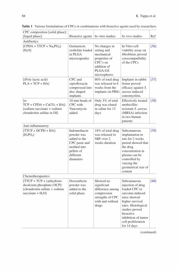
88
Table 1 Various formulations of CPCs in combinations with bioactive agents used by researchers
CPC composition [solid phase]: [liquid phase] Bioactive agents In vitro studies In vivo studies Ref
Antibiotics[CPDA + TTCP + Na2PO4]: [H2O]
Gentamicin crobefate loaded in PLGA microcapsules
No changes in setting and mechanical properties of CPC’s on addition of PLGA-GS microspheres
In Vitro cell viability assay on fibroblasts proved cytocompatibility of the CPCs
[36]
[(Poly lactic acid) PLA + TCP + HA]
CPC and ciprofloxacin compressed into disc shaped implants
80% of total drug was released in 6 weeks from the implants (in PBS)
Implants in rabbit femur proved efficacy against S. aureus induced osteomyelitis.
[37]
[α- TCP + CPDA + CaCO3 + HA]: [sodium succinate + sodium chondroitin sulfate in DI]
10 mm beads of CPC with Vancomycin added
Only 5% of total drug was eluted in saline for 13 days
Effectively treated methicillin- resistant S. aureus (MRSA) infection in two human patients
[38]
Anti-inflammatory[TTCP + DCPD + HA]: [H3PO4]
Indomethacin powder was added to the CPC paste and molded into pellets of different diameters
18% of total drug was released in SBF over 2 weeks duration
Subcutaneous implantation in rats for 2 weeks period showed that the drug concentration in plasma can be controlled by varying the geometrical size of cement
[39]
Chemotherapeutics[TTCP + TCP + (anhydrous dicalcium phosphate) DCP]: [chondroitin sulfate + sodium succinate + H2O]
Doxorubicin powder was added to the solid phase
Showed no significant difference among compression strengths of CPC with and without drugs
Subcutaneous injection of drug loaded CPC in sarcoma induced mice showed higher survival rates. Histological studies proved bioactive inhibition of tumor cell proliferation for 14 days
[40]
(continued)
K. Tappa et al.
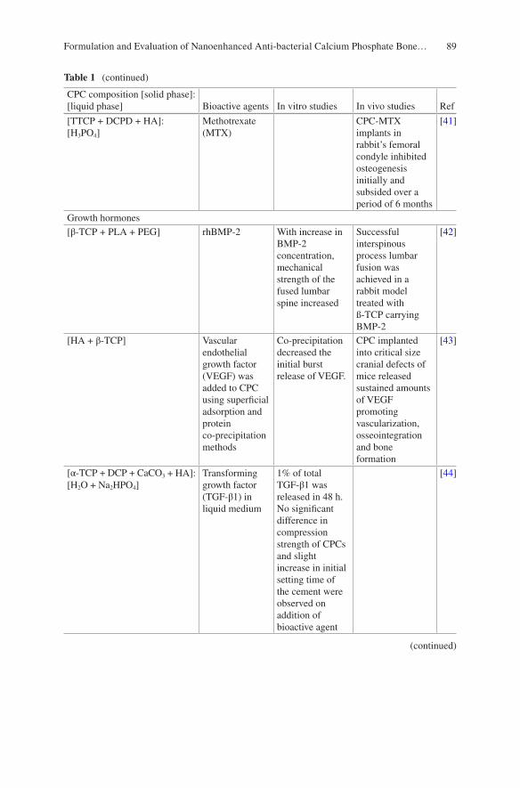
89
Table 1 (continued)
CPC composition [solid phase]: [liquid phase] Bioactive agents In vitro studies In vivo studies Ref
[TTCP + DCPD + HA]: [H3PO4]
Methotrexate (MTX)
CPC-MTX implants in rabbit’s femoral condyle inhibited osteogenesis initially and subsided over a period of 6 months
[41]
Growth hormones[β-TCP + PLA + PEG] rhBMP-2 With increase in
BMP-2 concentration, mechanical strength of the fused lumbar spine increased
Successful interspinous process lumbar fusion was achieved in a rabbit model treated with ß-TCP carrying BMP-2
[42]
[HA + β-TCP] Vascular endothelial growth factor (VEGF) was added to CPC using superficial adsorption and protein co-precipitation methods
Co-precipitation decreased the initial burst release of VEGF.
CPC implanted into critical size cranial defects of mice released sustained amounts of VEGF promoting vascularization, osseointegration and bone formation
[43]
[α- TCP + DCP + CaCO3 + HA]: [H2O + Na2HPO4]
Transforming growth factor (TGF-β1) in liquid medium
1% of total TGF-β1 was released in 48 h. No significant difference in compression strength of CPCs and slight increase in initial setting time of the cement were observed on addition of bioactive agent
[44]
(continued)
Formulation and Evaluation of Nanoenhanced Anti-bacterial Calcium Phosphate Bone…
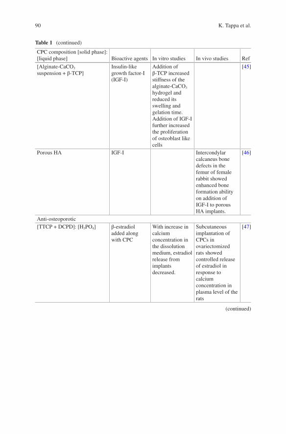
90
Table 1 (continued)
CPC composition [solid phase]: [liquid phase] Bioactive agents In vitro studies In vivo studies Ref
[Alginate-CaCO3 suspension + β-TCP]
Insulin-like growth factor-I (IGF-I)
Addition of β-TCP increased stiffness of the alginate-CaCO3 hydrogel and reduced its swelling and gelation time. Addition of IGF-I further increased the proliferation of osteoblast like cells
[45]
Porous HA IGF-I Intercondylar calcaneus bone defects in the femur of female rabbit showed enhanced bone formation ability on addition of IGF-I to porous HA implants.
[46]
Anti-osteoporotic[TTCP + DCPD]: [H3PO4] β-estradiol
added along with CPC
With increase in calcium concentration in the dissolution medium, estradiol release from implants decreased.
Subcutaneous implantation of CPCs in ovariectomized rats showed controlled release of estradiol in response to calcium concentration in plasma level of the rats
[47]
(continued)
K. Tappa et al.

91
mRNA and the production of non-functional proteins. As it has less absorption through the small intestine, it is mostly administered intravenously or intramuscu-larly. It is well known as an effective topical treatment for primary and secondary bacterial infections. It is heat stable and retains its antibacterial property, even after autoclaving. Accordingly, it is used mainly in bone implants, where high tempera-tures are released during the setting of cements [51].
Table 1 (continued)
CPC composition [solid phase]: [liquid phase] Bioactive agents In vitro studies In vivo studies Ref
[β- TCP + TTCP + HA + DCPA] Alendronate Setting time of the cement increased as alendronate concentration in CPC increased. Reduction in mechanical strength of the cement on addition of drugs. No cytotoxic effects were observed for rat MSCs
[48]
Othersβ-TCP MgO and SrO Addition of MgO
and SrO decreased the compressive strength of cement but enhanced osteoblast cell attachment and growth
Implantations in male rats promoted osteogenesis and quicker bone healing ability
[49]
Commercially available CPC: CERAPASTE (Kobayashi Medical Co., Osaka, Japan)
Cisplatin and caffeine
90% of total drugs loaded were released in 8 weeks. Inhibition of osteosarcoma cell proliferation was greater for cisplatin and caffeine in combination than cisplatin alone
Cement samples with cisplatin and caffeine implanted in rat showed higher tumor inhibition ability than CPCs with cisplatin alone
[50]
Formulation and Evaluation of Nanoenhanced Anti-bacterial Calcium Phosphate Bone…
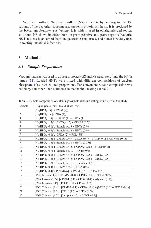
92
Neomycin sulfate: Neomycin sulfate (NS) also acts by binding to the 30S subunit of the bacterial ribosome and prevents protein synthesis. It is produced by the bacterium Streptomyces fradiae. It is widely used in ophthalmic and topical solutions. NS shows its effect both on gram-positive and gram-negative bacteria. NS is not easily absorbed from the gastrointestinal track, and hence is widely used in treating intestinal infections.
3 Methods
3.1 Sample Preparation
Vacuum loading was used to dope antibiotics (GS and NS separately) into the HNTs lumen [31]. Loaded HNTs were mixed with different compositions of calcium phosphate salts in calculated proportions. For convenience, each composition was coded by a number, then subjected to mechanical testing (Table 2).
Table 2 Sample composition of calcium phosphate salts and setting liquid used in this study
Sample [Liquid phase (ml)]: [solid phase (mg)]
1 [Na2HPO4 (1)]: [CPMM (2)]2 [Na2HPO4 (1): [CPDA (2)]3 [Na2HPO4 (1.8)]: [CPMM (1) + CPDA (1)]4 [Na2HPO4 (1.5)]: [CaCO3 (1.5) + CPMM (0.5)]5 [Na2HPO4 (0.6)]: [Sample no. 3 + HNTs (7%)]6 [Na2HPO4 (0.6)]: [Sample no. 3 + HNTs (5%)]7 [Na2HPO4 (0.6)]: [CPDA (2) + PCL (5%)]8 [Na2HPO4 (1.6)]: [CPMM (0.4) + CPDA (0.4) + β-TCP (0.1) + Chitosan (0.1)]9 [Na2HPO4 (1.6)]: [Sample no. 8 + HNTs (0.05)]10 [Na2HPO4 (0.9)]: [CPMM (0.45) + CPDA (0.45) + β-TCP (0.1)]11 [Na2HPO4 (0.9)]: [Sample no. 10 + HNTs (0.05)]12 [Na2HPO4 (0.9)]: [CPMM (0.75) + CPDA (0.75) + CaCO3 (0.5)]13 [Na2HPO4 (1.2)]: [CPMM (0.45) + CPDA (0.45) + CaCO3 (0.5)]14 [Na2HPO4 (1.2)]: [Sample no. 13 + Chitosan (0.5)]15 [Na2HPO4 (0.4)]: [CPMM (0.5) + CPDA (0.5)]16 [Na2HPO4 (0.4) + PCL (0.4)]: [CPMM (0.5) + CPDA (0.5)]17 [1% Chitosan (1.2)]: [CPMM (0.4) + CPDA (0.4) + PDDA (0.2)]18 [5% Chitosan (1.2)]: [CPMM (0.4) + CPDA (0.4) + Alginate (0.2)]19 [5% Chitosan (1.4)]: [TTCP (1.5) + CPDA (0.5)]20 [10% Chitosan (1.4)]: [CPMM (0.4) + CPDA (0.4) + β-TCP (0.1) + PDDA (0.1)]21 [10% Chitosan (1.2)]: [TTCP (1.5) + CPDA (0.5)]22 [10% Chitosan (1.2)]: [Sample no. 21 + β-TCP (0.2)]
K. Tappa et al.
93
3.2 HNT Loading
GS (500 mg) was dissolved in deionized water (DI) and sonicated until a clear solution was formed. HNT powder (1 g) was added to this solution and sonicated for 30 min. This suspension was kept in a vacuum chamber for 20 min and then left at room temperature for 20 min. This alternating cycle of vacuum and rest at room tempera-ture was repeated for three times. To remove the drug on the surface of the nanopar-ticles, HNTs were thoroughly washed with DI (3×) and air dried. This procedure was also followed for loading HNTs with NS.
3.3 Formulation of CPCs
The process of developing a potential loading-bearing CPC required the testing of different formulations of calcium phosphate salts mixed with a variety of aqueous media (Table 2). All formulations were hand mixed using a mortar and pestle, within a safety hood, and under ambient conditions (at atmospheric pressure and room temperature). All salts were thoroughly mortared until a uniform mixture of pow-ders was obtained. The liquid phase was added to the powder mixture in small quantities with constant stirring until a thick, uniform, moldable paste was formed. This paste was transferred using a sterile spatula into plastic molds for further testing.
For compression testing, cylindrical molds of 6 mm (inner diameter) and 12 mm (length) were used according to the ISO specifications (no. 4104). For flexural test-ing, CPC constructs of dimensions 65 mm × 10 mm × 4 mm were fabricated using paraffin wax molds in accordance to the ASTM F417-78 standards. An ADMET expert 2600 universal testing machine was used to test the mechanical strength of the CPC scaffolds. All compression testing samples were subjected to a cross-head speed of 1 mm/min and were tested in multiples of 3.
For bacterial and cell-culture techniques, CPC discs with the dimensions of 5 mm × 1.5 mm and 10 mm × 2 mm, respectively, were prepared using metallic molds. All the cell and bacterial culture scaffolds were prepared using sterile DI. Prior to the experiment, all samples were sterilized by dipping in alcohol and dried under a class II hood. See Fig. 1 for an overview of the entire doped HNT/CPC composite process.
3.4 Scanning Electron Microscopy
The external morphology of CPC constructs was analyzed using a Scanning Electron Microscope (SEM). A HITACHI Field Emission S4800 microscope (Hitachi, Japan) was used to image the fracture ends of the CPC scaffolds. The surfaces of these
Formulation and Evaluation of Nanoenhanced Anti-bacterial Calcium Phosphate Bone…
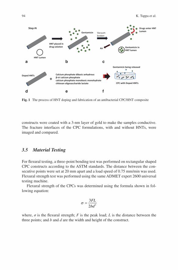
94
constructs were coated with a 3-nm layer of gold to make the samples conductive. The fracture interfaces of the CPC formulations, with and without HNTs, were imaged and compared.
3.5 Material Testing
For flexural testing, a three-point bending test was performed on rectangular shaped CPC constructs according to the ASTM standards. The distance between the con-secutive points were set at 20 mm apart and a load speed of 0.75 mm/min was used. Flexural strength test was performed using the same ADMET expert 2600 universal testing machine.
Flexural strength of the CPCs was determined using the formula shown in fol-lowing equation:
s =
3
2 2
FL
bd
where, σ is the flexural strength; F is the peak load; L is the distance between the three points; and b and d are the width and height of the construct.
Calcium phosphate dibasic anhydrousβ-tri calcium phosphatecalcium phosphate monobasic monohydratechitosan oligosaccharide lactate CPC with Doped HNTs
Gentamicin being released
Doped HNTs
+
Step #1
HNT placed indrug solution
HNT Lumen
Air
Gentamicin Vacuumbroken
Drugs enter HNTLumen
Gentamicin inHNT lumen
a b c
d e f
Fig. 1 The process of HNT doping and fabrication of an antibacterial CPC/HNT composite
K. Tappa et al.
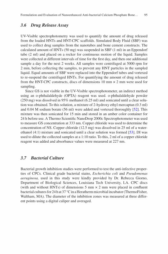
95
3.6 Drug Release Assay
UV-Visible spectrophotometry was used to quantify the amount of drug released from the loaded HNTs and HNT-CPC scaffolds. Simulated Body Fluid (SBF) was used to collect drug samples from the nanotubes and bone cement constructs. The calculated amount of HNTs (50 mg) was suspended in SBF (1 ml) in an Eppendorf tube (2 ml) and placed on a rocker for continuous motion of the liquid. Samples were collected at different intervals of time for the first day, and then one additional sample a day for the next 2 weeks. All samples were centrifuged at 5000 rpm for 2 min, before collecting the samples, to prevent any HNT particles in the sampled liquid. Equal amounts of SBF were replaced into the Eppendorf tubes and vortexed to re-suspend the centrifuged HNTs. For quantifying the amount of drug released from the HNT-CPC constructs, discs of dimensions 10 mm × 2 mm were used for sampling.
Since GS is not visible in the UV-Visible spectrophotometer, an indirect method using an o-phthalaldehyde (OPTA) reagent was used. o-phthalaldehyde powder (250 mg) was dissolved in 95% methanol (6.25 ml) and sonicated until a clear solu-tion was obtained. To this solution, a mixture of 2-hydroxy ethyl mercaptan (0.3 ml) and 0.04 M sodium borate (56 ml) were added and vortexed thoroughly [52]. This mixture was then sonicated for 15 min and stored in an amber color container for 24 h before use. A Thermo Scientific NanoDrop 2000c Spectrophotometer was used to measure GS concentration at 333 nm. Copper chloride was used to determine the concentration of NS. Copper chloride (12.5 mg) was dissolved in 25 ml of a water- ethanol (4:1) mixture and sonicated until a clear solution was formed [53]. DI was used to dilute the collected samples at a 1:10 ratio. To this, 2 ml of a copper chloride reagent was added and absorbance values were measured at 227 nm.
3.7 Bacterial Culture
Bacterial growth inhibition studies were performed to test the anti-infective proper-ties of CPCs. Clinical grade bacterial stains, Escherichia coli and Pseudomonas aeruginosa, used in this study were kindly provided by Dr. Rebecca Giorno, Department of Biological Sciences, Louisiana Tech University, LA. CPC discs (with and without HNTs) of dimensions 5 mm × 2 mm were placed in confluent bacterial cultures for 24 h at 37 °C in a Heratherm microbial incubator (ThermoFisher, Waltham, MA). The diameter of the inhibition zones was measured at three differ-ent points using a digital caliper and averaged.
Formulation and Evaluation of Nanoenhanced Anti-bacterial Calcium Phosphate Bone…
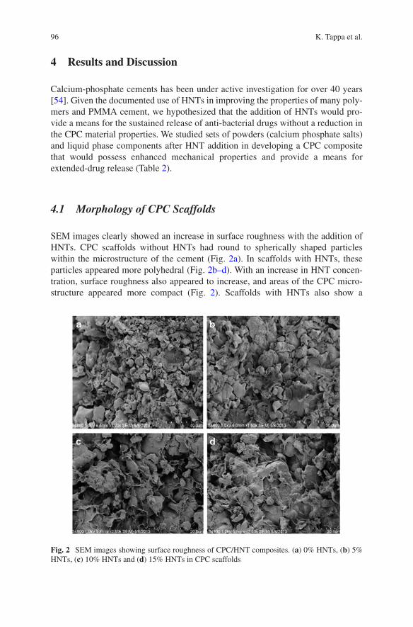
96
4 Results and Discussion
Calcium-phosphate cements has been under active investigation for over 40 years [54]. Given the documented use of HNTs in improving the properties of many poly-mers and PMMA cement, we hypothesized that the addition of HNTs would pro-vide a means for the sustained release of anti-bacterial drugs without a reduction in the CPC material properties. We studied sets of powders (calcium phosphate salts) and liquid phase components after HNT addition in developing a CPC composite that would possess enhanced mechanical properties and provide a means for extended-drug release (Table 2).
4.1 Morphology of CPC Scaffolds
SEM images clearly showed an increase in surface roughness with the addition of HNTs. CPC scaffolds without HNTs had round to spherically shaped particles within the microstructure of the cement (Fig. 2a). In scaffolds with HNTs, these particles appeared more polyhedral (Fig. 2b–d). With an increase in HNT concen-tration, surface roughness also appeared to increase, and areas of the CPC micro-structure appeared more compact (Fig. 2). Scaffolds with HNTs also show a
Fig. 2 SEM images showing surface roughness of CPC/HNT composites. (a) 0% HNTs, (b) 5% HNTs, (c) 10% HNTs and (d) 15% HNTs in CPC scaffolds
K. Tappa et al.
97
microstructure of entangled micro-crystals, which are believed to be responsible for the mechanical resistance and the high surface area (see below for further discus-sion). Increased surface roughness would also provide osteoblasts with a means for better cell attachment, proliferation and functionality leading to enhanced osteocon-ductivity [54, 55].
4.2 Mechanical Properties
Compression testing was performed on all the formulations showed in Table 2. Each formulation was tested in multiples of 3 (n = 3) and results averaged. Samples were soaked in DI water for 24 h and checked for their anti-washout properties. Some of the formulations (samples 1, 2, 3, 4 and 7) were too brittle and broke easily before they could be removed from the molds. Formulation no. 11 had good mechanical properties, but was not cohesive and easily washed off when soaked in DI overnight. When sodium phosphate was used as a setting liquid, most of the formulations did not provide good anti-washout properties. In contrast, chitosan lactate when added to CPC resulted in cement with fast-setting anti-washout characteristics [18, 19]. When 5% w/v chitosan lactate was added to the CPC-HNT mixture, the samples were hard, malleable and cohesive. Chitosan lactate at 10% w/v produced a thick viscous liquid, and hence increased its concentration was not attempted. Sample no. 21, overall, produced the best result. This composition, TTCP (1.46 g) and CPDA (0.54 g) triturated in 10% w/v chitosan lactate, showed a cohesive nature and did not disintegrate, and had greater mechanical properties than the rest of the formulations. Table 3 shows the compression strength values of the different CPC formulations tested.
4.2.1 Compression Strength
CPC samples showed a gradual increase in compressive strength with % HNT (w/w) addition up to 10% (Fig. 3a) (Table 4). This gain in compressive resis-tance may be due to a phenomenon called ‘crack-tip blunting’ [17], a process where a propagating crack is either stopped or deflected due to a solid particle obstruction [17]. At 20% HNTs addition, there was a decline in compressive resistance and this may be due to failure to produce the final end-product or formation of clusters due to the uneven distribution of HNT particles. The graph in Fig. 3a shows the compression strength values of CPCs with different HNT concentrations.
Formulation and Evaluation of Nanoenhanced Anti-bacterial Calcium Phosphate Bone…
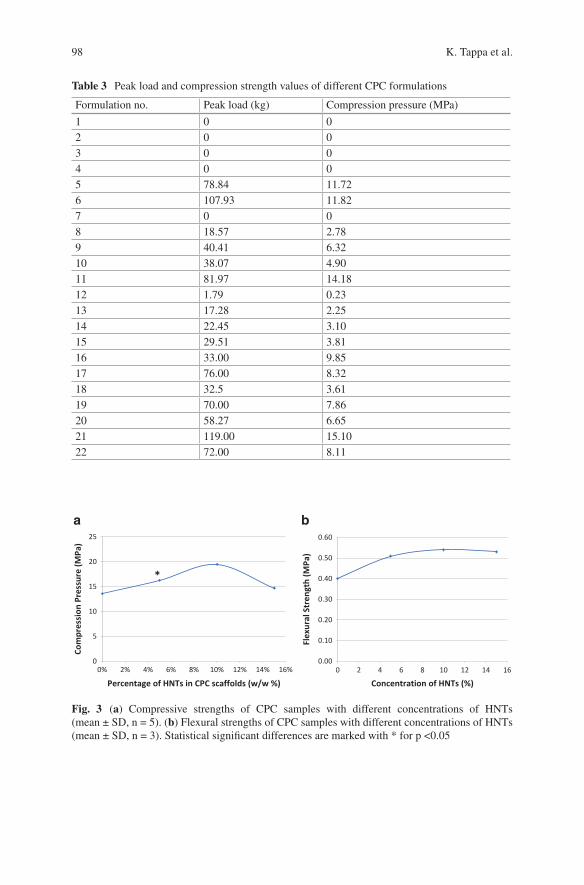
98
Table 3 Peak load and compression strength values of different CPC formulations
Formulation no. Peak load (kg) Compression pressure (MPa)
1 0 02 0 03 0 04 0 05 78.84 11.726 107.93 11.827 0 08 18.57 2.789 40.41 6.3210 38.07 4.9011 81.97 14.1812 1.79 0.2313 17.28 2.2514 22.45 3.1015 29.51 3.8116 33.00 9.8517 76.00 8.3218 32.5 3.6119 70.00 7.8620 58.27 6.6521 119.00 15.1022 72.00 8.11
0% 2% 4% 6% 8% 10% 12% 14% 16%
Percentage of HNTs in CPC scaffolds (w/w %)
Com
pres
sion
Pre
ssur
e (M
Pa)
25
a b
20
15
10
5
0
*
0.60
0.50
0.40
0.30
0.20
0.10
0.000 2 4 6 8 10 12 14 16
Concentration of HNTs (%)
Flex
ural
Str
engt
h (M
Pa)
Fig. 3 (a) Compressive strengths of CPC samples with different concentrations of HNTs (mean ± SD, n = 5). (b) Flexural strengths of CPC samples with different concentrations of HNTs (mean ± SD, n = 3). Statistical significant differences are marked with * for p <0.05
K. Tappa et al.
99
4.2.2 Flexural Strength
The flexural strength values of the CPC scaffolds also increased with an increase in HNT concentration from 5% to 10% w/w. Further addition of HNTs yielded no increase in flexural strength values as observed with our compression tests (Fig. 3b). Table 5 shows the peak load and flexural strength values of CPC scaffolds with dif-ferent HNT concentrations. An elevation from 5% w/w HNT concentration to 10% w/w HNT concentration was observed with no change thereafter (Fig. 3b).
Incorporation of anti-infective agents directly into the CPCs often shows an insufficient or unwanted pattern of drug release and reduced cement strength, which may be due to a change in crystal structure or dissolution of anti-infective agents through pores in the cement [9]. The ideal bone cement formulation must permit incorporation of a drug without compromising its mechanical properties [56]. HNTs are often used as a bulk filler to enhance the biological properties, dispersion rate, strength resistance, thermomechanical and physical properties of nanocomposites [29–33].
4.3 Drug Release Profile
To estimate the concentration of anti-infective agents released from CPC constructs, a drug release study was performed using UV-Visible spectroscopy techniques. Using a NanoDrop 2000c spectrophotometer, the drug absorbance values were measured at 333 nm (for GS) and 227 nm (for NS). An equation was derived from the standard-graph curve and was used to back calculate the amount of drug released from the absorbance values.
Due to its high length-to-diameter ratio and hollow inner core, HNTs are known to be easily loaded with varying substances and to provide sustained release [23, 25, 28]. In the case of both HNTs and CPC scaffolds, a ‘burst’ release of GS was
Table 4 Peak load and compression pressure of CPC samples with different HNT concentrations
HNT concentration (%) Peak load (kg) Compression pressure (MPa)
0 53.41 13.595 60.10 16.3110 67.36 19.4815 52.09 14.72
Table 5 Peak loads and flexural strength values of CPC samples with different HNT concentrations
Concentration of HNT (w/w %) Peak load (kg) Flexural strength (MPa)
0 1.44 0.405 1.86 0.5110 1.96 0.5415 1.95 0.53
Formulation and Evaluation of Nanoenhanced Anti-bacterial Calcium Phosphate Bone…
100
observed for the first 24 h of elution (Fig. 4). Within the first 24 h, 1.9 mg/ml of the drug was eluted from HNTs and 0.9 mg/ml from the CPC scaffolds. Following the initial burst, the rate of elution reduced significantly and followed an extended release profile. After 48 h, drug release from the CPC constructs was decreased. Cement constructs released only 0.05 mg/ml which was within the working concen-tration of the drug. A similar release pattern was observed with NS loaded HNT- CPC scaffolds. For the first 24 h, 1.04 mg/ml of NS was released from the cement con-structs. The burst effect resulting in the rapid initial release of a drug often appears with several nanoparticle-based systems. This drug release effect appears to be due to drugs bound to the HNT outer surface or drugs trapped between adjacent nano-tubes. Typically, after the initial burst, a more gradual release occurs, resulting from the release of the drug bound inside the tube (a sustained release) [23, 51]. After 7 days, CPC scaffolds had released 35–40% of their loaded drug (Fig. 4). In the first 24 h, 15% of the total drug was released; however, by day 3, the total percentage release increased to 30%. After that, this trend was sustained throughout the 7-day experimental period. The same pattern of release was observed with both GS and NF as shown in Fig. 4. Since the loaded HNTs are also present inside the CPC con-structs, we believe drug release would continue for a further extended period as the cement starts degrading to form bone.
4.4 Bacterial Culture
Hardened cement samples with different concentrations of GS- and NS-doped HNTs were added to confluent LB-agar plates of E. coli and P. aeruginosa and were incubated for 24 h at 37 °C. CPC constructs, with HNTs but no GS, did not show any growth inhibition, and all other GS-doped samples had inhibition diameters ranging from 11 to 23 mm (Fig. 5). The diameter of inhibition zones increased with an increase in HNT/GS concentration.
Figure 6 shows the zones of inhibition for CPC scaffolds loaded with different concentrations of HNT-NS. CPC constructs with HNTs but no NS showed no inhibition zones, while NS-doped HNT-CPC’s showed clear zones of inhibition for E. coli (Fig. 6a, b) and P. aeruginosa (Fig. 6c, d). Similar to that observed with HNT-GS, the inhibition diameter increased with an increase in HNT/NS concentration.
All tests were performed in multiples of 3 (n = 3), and a one-way ANOVA was conducted at a significance level of 0.05. There was a significant difference in inhi-bition diameters among different concentrations of doped HNTs. The graphs in Fig. 7 shows the inhibition diameters of CPC scaffolds containing different concen-trations of HNTs against E. coli and P. aeruginosa.
The use of antibiotics in the bone graft or oral applications before surgery often does not provide sufficient protection from infection [54, 55]. Bacterial infections associated with bone repair procedures or the introduction of materials into dam-aged bone typically lead to inflammation, tissue necrosis and eventually bone loss
K. Tappa et al.
101
a
b
Fig. 4 (a) Graph showing concentrations of GS released from CPC folds and HNTs at different time intervals. (b) Graph showing concentrations of NS released from CPC folds and HNTs at different time intervals
Formulation and Evaluation of Nanoenhanced Anti-bacterial Calcium Phosphate Bone…
102
Fig. 5 Inhibition zones of CPCs loaded with different concentrations of HNT-GS against E. coli (a, b), P. aeruginosa (c, d)
Fig. 6 Inhibition zones of CPCs loaded with different concentrations of HNT-NS against E. coli (a, b) and P. aeruginosa (c, d)
K. Tappa et al.
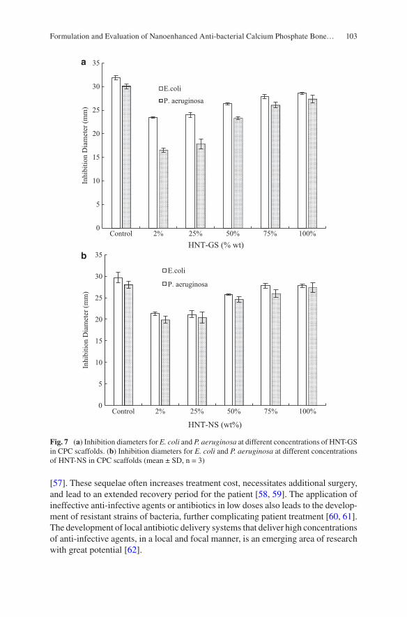
103
[57]. These sequelae often increases treatment cost, necessitates additional surgery, and lead to an extended recovery period for the patient [58, 59]. The application of ineffective anti-infective agents or antibiotics in low doses also leads to the develop-ment of resistant strains of bacteria, further complicating patient treatment [60, 61]. The development of local antibiotic delivery systems that deliver high concentrations of anti-infective agents, in a local and focal manner, is an emerging area of research with great potential [62].
0
5
10
15
20
25
30
35
Control 2% 25% 50% 75% 100%
Inhi
bitio
n D
iam
eter
(mm
)
HNT-GS (% wt)
E.coli
P. aeruginosa
0
5
10
15
20
25
30
35
Control 2% 25% 50% 75% 100%
Inhi
bitio
n D
iam
eter
(mm
)
HNT-NS (wt%)
E.coli
P. aeruginosa
a
b
Fig. 7 (a) Inhibition diameters for E. coli and P. aeruginosa at different concentrations of HNT-GS in CPC scaffolds. (b) Inhibition diameters for E. coli and P. aeruginosa at different concentrations of HNT-NS in CPC scaffolds (mean ± SD, n = 3)
Formulation and Evaluation of Nanoenhanced Anti-bacterial Calcium Phosphate Bone…
104
5 Conclusions
In this study, our research goal was achieved through the addition of HNTs into a novel CPC mixture composed of TTCP and CPDA as the solid phase and 10% chi-tosan lactate as the liquid phase. HNTs worked effectively both as antibiotic drug carrier and mechanical property enhancer. The SEM images of the constructs showed that the addition of HNTs increased the surface roughness of the CPC, which in turn may increase its osteoconductivity as surface roughness favors cell attachment, proliferation, and ECM synthesis. Halloysite addition also increased the compressive strength of our CPCs. CPC/HNT disks further showed an extended release of all antibiotics, and our zone of inhibition studies provided evidence that CPC-HNT composites can inhibit bacterial growth thus providing a localized anti- infective field at the site of application.
6 Future Work
The treatment of bone defects carries the risk of infection and treatment may even be required despite an infection that is already present. This situation continues to be a formidable challenge for clinicians and a major research focus for bioengi-neers. There has been a significant number of studies regarding materials for bone regeneration [63, 64] and materials with local antibiotic delivery capabilities [65, 66]. Over the past decade, dual-function biomaterials, bearing both antibacterial and osteoinductive properties have proven to be a viable mode of treatment for infected bone defects [67, 68]. Organic–inorganic composite nanomaterials have gained significant attention in recent years primarily due to their potential for enhanced bone regeneration [72]. Inorganic nanoparticles have also been used to enhance the physical and biological properties of organic polymers due to their nanostructure and unique physicochemical properties [69, 70]. For example, silica nanoparticles have been used to increase the mechanical strength, enhance cell adhesion, and induce osteogenesis of polymeric matrices [71, 72]. Clay nanoparti-cles, such as halloysite and montmorillonite, are also being explored as drug deliv-ery vehicles and in bone tissue engineering to enhance mechanical strength and stimulate bone tissue formation [52, 73–75]. Karnik et al. developed a calcium phosphate/HNT hydrogel coating that promoted osteoblastic differentiation of MSCs and can be explored further using different composition [76]. Enhanced material properties and cell adhesion and functionality were observed in several polymer composite studies that incorporated HNTs [77, 78].
This study also shows potential as a dual-function drug/growth factor delivery system for infected bone defects such as periapical bone lesions, contaminated bone fractures or refractory infected wound sites. While we used several antibiotics as model drugs, combinations of antibiotics could be loaded into the CPC-HNT com-posite. Furthermore, complex-drug combination could also be designed by
K. Tappa et al.
105
incorporating antibiotics and growth factors or chemotherapeutic agents, singly or in combination. Coating the HNT surface with a polymer containing embedded antibiotics would also offer an anti-infective/osteogenic combination. Finally, the HNT surface could be modified with selected metal nanoparticles. Silver nanopar-ticle coated HNTs have potential as a therapeutic approach offering anti-microbial osteogenic properties and enhanced mechanical properties. Currently, potential dual- function treatment modalities are under investigation in vitro and in a series of critical defect small animal studies. These are designed to evaluate the effectiveness of CPC/HNT composites after implantation in infected bone defects.
Acknowledgments The authors wish to acknowledge the Governor’s Biotechnology Initiative, The Enterprise Fund and the Opportunities for Partnerships in Technology with Industry (OPT-IN).
References
1. Downey P, Siegel MI. Bone biology and the clinical implications for osteoporosis. Phys Ther. 2006;86(1):77–91.
2. Kalfas IH. Principles of bone healing. Neurosurg Focus. 2001;10(4):7–10. 3. J. C. J. Webb, R. F. Spencer, (2007) The role of polymethylmethacrylate bone cement in mod-
ern orthopaedic surgery. Journal of Bone and Joint Surgery - British Volume 89-B (7):851–857 4. Ture Kindt-Larsen, Daniel B. Smith, Jørgen Steen Jensen, (1995) Innovations in acrylic bone
cement and application equipment. Journal of Applied Biomaterials 6 (1):75–83 5. Hahn M, Vogel M, Pompesius-Kempa M, Delling G. Trabecular bone pattern factor—a new
parameter for simple quantification of bone microarchitecture. Bone. 1992;13(4):327–30. 6. Stańczyk M, van Rietbergen B. Thermal analysis of bone cement polymerisation at the cement-
bone interface. J Biomech. 2004;37(12):1803–10. 7. Sommerfeldt DW, Rubin CT. Biology of bone and how it orchestrates the form and function of
the skeleton. Eur Spine J. 2001;10:S86–95. 8. Liebschner M, Wettergreen M. Optimization of bone scaffold engineering for load bearing
applications. In: Ashammakhi N, Ferretti P, editors. Topics in tissue engineering, vol. 1, chap-ter 6. Oulu: University of Oulu; 2003. p. 1–39.
9. Stevens MM. Biomaterials for bone tissue engineering. Mater Today. 2008;11(5):18–25. 10. Pohl AP. Mechanical manipulation of fractures to enhance fracture healing. J. Bone Joint Surg.
2002;84-B(Suppl III):213–4. 11. Rubin CT, Lanyon LE. Regulation of bone formation by applied dynamic loads. J Bone Joint
Surg Am. 1984;66(3):397–402. 12. Beloti MM, Rosa AL. Osteoblast differentiation of human bone marrow cells under continuous
and discontinuous treatment with dexamethasone. Braz Dent J. 2005;16(2):156–61. 13. Tjong SC. Synthesis and properties of nano-hydroxyapatite/ polymer nanocomposites for bone
tissue engineering. Emirate of Sharjah: Bentham Science Publishers; 2012. p. 82–142. 14. http://www.surgeryencyclopedia.com/A-Ce/Bone-Grafting.html. 15. Damien CJ, Parsons JR. Bone graft and bone graft substitutes: a review of current technology
and applications. J Appl Biomater. 1991;2(3):187–208. 16. Schmitz JP, Hollinger JO, Milam SB. Reconstruction of bone using calcium phosphate bone
cements: a critical review. J Oral Maxillofac Surg. 1999;57(9):1122–6. 17. Rimondini L, Fini M, Giardino R. The microbial infection of biomaterials: A challenge for
clinicians and researchers. A short review. J Appl Biomater Biomech. 2005;3(1):1–10.
Formulation and Evaluation of Nanoenhanced Anti-bacterial Calcium Phosphate Bone…
106
18. Shen M, Kim Y. Osteoporotic vertebral compression fractures: a review of current surgical management techniques. Am J Orthop. 2007;36(5):241–8.
19. Younger EM, Chapman MW. Morbidity at bone graft donor sites. J Orthop Trauma. 1989;3(3):192–5.
20. Matl FD, Obermeier A, Repmann S, Friess W, Stemberger A, Kuehn K-D. New anti-infective coatings of medical implants. Antimicrob Agents Chemother. 2008;52(6):1957–63.
21. Bistolfi A, Massazza G, Verné E, Massè A, Deledda D, Ferraris S, Miola M, Galetto F, Crova M. Antibiotic-loaded cement in orthopedic surgery: A review. ISRN Orthop. 2011;2011:1–8.
22. Lautenschlager EP, Jacobs JJ, Marshall GW, Meyer PR. Mechanical properties of bone cements containing large doses of antibiotic powders. J Biomed Mater Res. 1976;10(6):929–38.
23. Gomoll AH, Fitz W, Scott RD, Thornhill TS, Bellare A. Nanoparticulate fillers improve the mechanical strength of bone cement. Acta Orthop. 2008;79(3):421–7.
24. Sfeir C, Ho L. Fracture repair. In: Lieberman JR, Friedlaender GE, editors. Bone regeneration and repair. Totowa, NJ: Humana Press; 2005. p. 21–44.
25. Perez RA, Kim H, Ginebra M-P. Polymeric additives to enhance the functional properties of calcium phosphate cements. J Tissue Eng. 2012;3(1):2041731412439555.
26. Deng D, Dong L, Xie Q. Effects of adding resorbable chitosan microspheres to calcium phos-phate cements for bone regeneration. Mater Sci Eng C Mater Biol Appl. 2015;47:266–72. https://doi.org/10.1016/j.msec.2014.11.049. Epub 2014 Nov 14
27. Aryaei A, Liu J, Jayatissa AH, Jayasuriya AC. Cross-linked chitosan improves the mechani-cal properties of calcium phosphate-chitosan cement. Mater Sci Eng C Mater Biol Appl. 2015;54:14–9. https://doi.org/10.1016/j.msec.2015.04.024. Epub 2015 Apr 22
28. Tanase CE, Popa MI, Verestiuc L. Biomimetic bone scaffolds based on chitosan and calcium phosphates. Mater Lett. 2011;65:1681–3.
29. Venkatesan J. Chitin and chitosan composites for bone tissue regeneration. Adv Good Nutri Res. 2014;73:59–81.
30. Bandyopadhyay A, Petersen J, Fielding G, Banerjee S, Bose S. ZnO, SiO2, and SrO doping in resorbable tricalcium phosphates: Influence on strength degradation, mechanical properties, and in vitro bone–cell material interactions. J Biomed Mater Res B. 2012;2012(100B):2203–12.
31. Abdullayev E, Lvov Y. Halloysite clay nanotubes for controlled release of protective agents. J Nanosci Nanotechnol. 2011;11(11):10007–26.
32. Du M, Guo B, Jia D. Newly emerging applications of halloysite nanotubes: a review. Polym Int. 2010;59(5):574–82.
33. Lvov Y, Wang W, Zhang L, Fakhrullin R. Halloysite clay nanotubes for loading and sustained release of functional compounds. Adv Mater. 2016;28(6):1227–50. https://doi.org/10.1002/adma.201502341.
34. Kamble R, Ghag M, Gaikawad S, Panda BK. Review article halloysite nanotubes and applica-tions: A review. J Adv Sci Res. 2012;3(2):25–9.
35. Wei W, Abdllayev E, Goeders A, Hollister A, Lvov Y, Mills DK. Clay nanotube/poly(methyl methacrylate) bone cement composite with sustained antibiotic release. Macromol Mater Eng. 2012;297:645–53.
36. Schnieders J, Gbureck U, Thull R, Kissel T. Controlled release of gentamicin from cal-cium phosphate-poly(lactic acid-co-glycolic acid) composite bone cement. Biomaterials. 2006;27(23):4239–49.
37. Alvarez H, Castro C, Moujir L, Perera A, Delgado A, Soriano I, Évora C, Sánchez E. Efficacy of ciprofloxacin implants in treating experimental osteomyelitis. J Biomed Mater Res B Appl Biomater. 2008;85(1):93–104.
38. Sasaki T, Ishibashi Y, Katano H, Nagumo A, Toh S. In vitro elution of vancomycin from cal-cium phosphate cement. J Arthroplasty. 2005;20(8):1055–9.
39. Otsuka M, Nakahigashi Y, Matsuda Y, Fox JL, Higuchi WI, Sugiyama Y. Effect of geometrical cement size on in vitro and in vivo indomethacin release from self-setting apatite cement. J Control Release. 1998;52(3):281–9.
K. Tappa et al.
107
40. Tani T, Okada K, Takahashi S, Suzuki N, Shimada Y, Itoi E. Doxorubicin-loaded calcium phos-phate cement in the management of bone and soft tissue tumors. In Vivo. 2006;20(1):55–60.
41. Li D, Yang Z, Li X, Li Z, Li J, Yang J. A histological evaluation on osteogenesis and resorption of methotrexate-loaded calcium phosphate cement in vivo. Biomed Mater. 2010;5(2):25007.
42. Matsumoto T, Toyoda H, Dohzono S, Yasuda H, Wakitani S, Nakamura H, Takaoka K. Efficacy of interspinous process lumbar fusion with recombinant human bone morphogenetic protein-2 delivered with a synthetic polymer and β-tricalcium phosphate in a rabbit model. Eur Spine J. 2012;21(7):1338–45.
43. Wernike E, Montjovent MO, Liu Y, Wismeijer D, Hunziker EB, Siebenrock KA, Hofstetter W, Klenke FM. Vegf incorporated into calcium phosphate ceramics promotes vascularisation and bone formation in vivo. Eur Cells Mater. 2010;19:30–40.
44. Blom EJ, Klein-Nulend J, Wolke JGC, van Waas M a J, Driessens FCM, Burger EH. Transforming growth factor-beta1 incorporation in a calcium phosphate bone cement: material properties and release characteristics. J Biomed Mater Res. 2002;59(2):265–72.
45. Luginbuehl V, Wenk E, Koch A, Gander B, Merkle HP, Meinel L. Insulin-like growth fac-tor I-releasing alginate-tricalciumphosphate composites for bone regeneration. Pharm Res. 2005;22(6):940–50.
46. Damien E, Hing K, Saeed S, Revell PA. A preliminary study on the enhancement of the osteointegration of a novel synthetic hydroxyapatite scaffold in vivo. J Biomed Mater Res A. 2003;66(2):241–6.
47. Otsuka M, Matsuda Y, Baig AA, Chhettry A, Higuchi WI. Calcium-level responsive controlled drug delivery from implant dosage forms to treat osteoporosis in an animal model. Adv Drug Deliv Rev. 2000;42(3):249–58.
48. Jindong Z, Hai T, Junchao G, Bo W, Li B, Qiang WB. Evaluation of a novel osteoporotic drug delivery system in vitro: alendronate-loaded calcium phosphate cement. Orthopedics. 2010;33(8). https://doi.org/10.3928/01477447-20100625-15.
49. Banerjee SS, Tarafder S, Davies NM, Bandyopadhyay A, Bose S. Understanding the influence of MgO and SrO binary doping on the mechanical and biological properties of β-TCP ceram-ics. Acta Biomater. 2010;6(10):4167–74.
50. Tanzawa Y, Tsuchiya H, Shirai T, Nishida H, Hayashi K, Takeuchi A, Kawahara M, Tomita K. Potentiation of the antitumor effect of calcium phosphate cement containing anticancer drug and caffeine on rat osteosarcoma. J Orthop Sci. 2011;16(1):77–84.
51. Sun l, Boyer C, Grimes R, Mills DK. Drug coated clay nanoparticles for delivery of chemo-therapeutics. Curr Nanosci. 2016;12(2):207–14.
52. Karnik S, Mills DK. Nanoenhanced hydrogel system with sustained release capabilities. J Biomed Mater Res A. 2015;103(7):2416–26.
53. Wu W, Cao X, Luo J, He G, Zhang Y. Morphology, thermal, and mechanical properties of poly(butylene succinate) reinforced with halloysite nanotube. Polym Compos. 2014;35:847–55.
54. Lecouvet B, Gutierrez J, Sclavons M, Bailly C. Structure property relationships in polyamide 12/halloysite nanotube nanocomposites. Polym Degrad Stab. 2011;96:226–35.
55. Guo B, Chen F, Lei Y, Liu X, Wan J, Jia D. Styrene-butadiene rubber/halloysite nanotubes nanocomposites modified by sorbic acid. Appl Surf Sci. 2009;255:7329–36.
56. Deng S, Zhang J, Ye L. Halloysite–epoxy nanocomposites with improved particle dis-persion through ball mill homogenisation and chemical treatment. Compos Sci Technol. 2009;69:2497–505.
57. Liu M, Zhang Y, Wu C, Xiong S, Zhou C. Chitosan/halloysite nanotubes bionanocomposites: Structure, mechanical properties and biocompatibility. Int J Biol Macromol. 2012;51:566–75.
58. Jge H, Jr VH, Hc M, Hj B. Backgrounds of antibiotic-loaded bone cement and prosthesis- related infection. Biomaterials. 2004;25(3):1–24.
59. Campana V, Milano G, Pagano E, Barba M, Cicione C, Salonna G, Logroscino G. Bone sub-stitutes in orthopaedic surgery: from basic science to clinical practice. J Mater Sci Mater Med. 2014;25(10):2445–61. https://doi.org/10.1007/s10856-014-5240-2.
Formulation and Evaluation of Nanoenhanced Anti-bacterial Calcium Phosphate Bone…
108
60. Thornes B, Murray P, Bouchier-Hayes D. Development of resistant strains of Staphylococcus epidermidis on gentamicin-loaded bone cement in vivo. J Bone Joint Surg Br. 2002;84:758–60.
61. Zwingenberger S, Nich C, Valladares RD, Yao Z, Stiehler M, Goodman SB. Recommendations and considerations for the use of biologics in orthopedic surgery. BioDrugs. 2012;26(4):245–56. https://doi.org/10.2165/11631680-000000000-00000.
62. Campoccia D, Montanaro L, Speziale P, Arciola CR. Antibiotic-loaded biomaterials and the risks for the spread of antibiotic resistance following their prophylactic and therapeutic clinical use. Biomaterials. 2010;31:6363–77.
63. Gong T, Xie J, Liao J, Zhang T, Lin S, Lin Y. Nanomaterials and bone regeneration. Bone Res. 2015;3:15029. https://doi.org/10.1038/boneres.2015.29.
64. Kretlow JD, Mikos AG. Review: mineralization of synthetic polymer scaffolds for bone tissue engineering. Tissue Eng. 2007;13:927–38.
65. Soundrapandian C, Datta S, Sa B. Drug-eluting implants for osteomyelitis. Crit Rev Ther Drug Carrier Syst. 2006;24(6):493–545.
66. Tsourvakas S. Local antibiotic therapy in the treatment of bone and soft tissue infections. In: Danilla S, editor. Selected topics in plastic reconstructive surgery. London: InTech; 2012. ISBN: 978-953-307-836-6.
67. Lu H, Liu Y, Guo J, Wu H, Wang J, Wu G. Biomaterials with antibacterial and osteoinductive properties to repair infected bone defects. Int J Mol Sci. 2016;17:334. https://doi.org/10.3390/ijms17030334.
68. Zheng Z, Yin W, Zara JN, Li W, Kwak J, Mamidi R, Lee M, Siu RK, Ngo R, Wang J, et al. The use of BMP-2 coupled—nanosilver-PLGA composite grafts to induce bone repair in grossly infected segmental defects. Biomaterials. 2010;31:9293–300.
69. Wang Q, Yan J, Yang J, Bingyun Li B. Nanomaterials promise better bone repair. Mater Today. 2016;19(8):451–63.
70. Tautzenberger A, Kovtun A, Ignatius A. Nanoparticles and their potential for application in bone. Int J Nanomed. 2012;7:4545–57. https://doi.org/10.2147/IJN.S34127.
71. Beck GR, Ha S-W, Camalier CE, Yamaguchi M, Li Y, Lee J-K, Weitzmann MN. Bioactive silica based nanoparticles stimulate bone forming osteoblasts, suppress bone esorbing osteo-clasts, and enhance bone mineral density in vivo. Nanomedicine. 2012;8(6):793–803. https://doi.org/10.1016/j.nano.2011.11.003.
72. Ha SW, Weitzmann M, Beck GR. Bioactive silica nanoparticles promote osteoblast differentia-tion through stimulation of autophagy and direct association with LC3 and p62. ACS Nano. 2014;8(6):5898–910. https://doi.org/10.1021/nn5009879.
73. Wang Y, Wang X, Li H, Xue D, Shi Z, Qi Y, Ma Q, Pan Z. Assessing the character of the rhBMP-2-and vancomycin-loaded calcium sulphate composites in vitro and in vivo. Arch Orthop Trauma Surg. 2011;131:991–1001.
74. Katti KS, Katti DR, Dash R. Synthesis and characterization of a novel chitosan/montmorillon-ite/hydroxyapatite nanocomposite for bone tissue engineering. Biomed Mater. 2008;3:1–12.
75. Mieszawska AJ, Llamas JG, Vaiana CA, Kadakia MP, Naik RR, Kaplan DL. Clay-enriched silk biomaterials for bone formation. Acta Biomater. 2011;7(8):3036–41. https://doi.org/10.1016/j.actbio.2011.04.016.
76. Karnik S, Jammalamadaka U, Tappa K, Mills DK. Performance evaluation of nanoclay enriched anti-microbial hydrogels for biomedical applications. Heliyon. 2016;2:e00072. https://doi.org/10.3390/app6090265.
77. Huang B, Liu M, Long Z, Shen Y, Zhou C. Effects of halloysite nanotubes on physical proper-ties and cytocompatibility of alginate composite hydrogels. Mat Sci Eng C. 2017;70(1):303–10.
78. Liu M, Wu C, Wu YJ, Xiong S, Zhou C. Chitosan–halloysite nanotubes nanocomposite scaffolds for tissue engineering. J Mater Chem B. 2013;1:2078–89.
K. Tappa et al.
109© Springer International Publishing AG, part of Springer Nature 2017B. Li, T. Webster (eds.), Orthopedic Biomaterials, https://doi.org/10.1007/978-3-319-73664-8_5
Biomimetic Orthopedic Materials
R. Portillo-Lara, E. Shirzaei Sani, and N. Annabi
Keywords Biomimetic biomaterial · Biologically inspired biomaterial · Orthopedic biomaterial · Bone tissue engineering · Cartilage tissue engineering · Musculoskeletal tissue · Engineering · Regenerative medicine · Nanofibrous scaffold · Biofabrication · 3D bioprinting
1 Introduction
Biomimetics refers to the design and engineering of artificial materials, structures, and systems which emulate those naturally occurring in biological entities. In recent years, interdisciplinary approaches based on biomimicry, materials sciences, and tissue engineering have provided insight into the molecular and structural mecha-nisms that underlie the multifunctionality, adaptability, strength, and elasticity found in biological tissues [1]. In turn, the translation of this knowledge has enabled the engineering of various types of biomimetic materials with defined chemical composition, physical structure, and biological function for a wide range of bio-medical applications [2]. This retroactive feedback between the laboratory and the
Portillo-Lara and Shirzaei Sani contributed equally to this work.
R. Portillo-Lara Department of Chemical Engineering, Northeastern University, Boston, MA, USA
Tecnologico de Monterrey, Escuela de Ingeniería y Ciencias, Zapopan, JAL, Mexico
E. Shirzaei Sani Department of Chemical Engineering, Northeastern University, Boston, MA, USA
N. Annabi (*) Department of Chemical Engineering, Northeastern University, Boston, MA, USA
Harvard-MIT Division of Health Sciences and Technology, Massachusetts Institute of Technology, Cambridge, MA, USA
Biomaterials Innovation Research Center, Brigham and Women’s Hospital, Harvard Medical School, Boston, MA, USAe-mail: [email protected]
110
clinic has allowed the identification of new therapeutic approaches to restore the functionality of diseased or injured organs and tissues. Biomimetic materials com-bine the physical properties of core materials with the biochemical properties of native tissues to deliver different types of physiological stimuli that modulate cell behavior [3]. In particular, the remarkably complex organization, architecture, and function of physiological tissues are highly dependent on the composition and structure of the extracellular matrix (ECM). Therefore, significant efforts have been made to engineer biomimetic materials that can recapitulate specific features of the native ECM to act as bioactive templates to promote repair and functional recon-struction of various types of tissues [4].
Due to the aging global population, musculoskeletal conditions have become an increasingly greater burden for the healthcare industry. For instance, according to estimates from the Department of Health and Human Resources, more than one million patients undergo total hip or knee replacement surgery every year in the US [5]. Current therapeutic approaches for muscle, bone, ligament, and cartilage repair are mostly based on the use of autografts or allografts, which assist in the healing and regeneration of musculoskeletal injuries. However, conventional grafting sources are greatly limited by donor availability and the risk of disease transfer or rejection [6]. Moreover, the treatment of larger injuries, where substantial loss of tissue occurs, still rely on the use of inert devices that only serve to prevent further trauma and possess no regenerative capacity. Previous studies have demonstrated that the regeneration of connective tissues requires the presence of scaffolds that provide structural support and direct cell differentiation towards specific pheno-types [7]. On the other hand, the regeneration of hard tissues such as bone necessi-tates the use of three dimensional (3D) scaffolds that deliver biochemical signals to induce new bone formation (i.e., osteoinductivity) [8]. These scaffolds should also be ideally biodegraded progressively into biocompatible byproducts, and possess a dynamic structure that supports load adaptive bone remodeling. Moreover, orthope-dic implants also require direct morphological and mechanical integration into the native bone structures (i.e., osseointegration) to provide proper biomechanical com-pliance and transduction of mechanical stimuli [9]. Therefore, there is a critical need for the development of prosthetic implants or substitute materials that mimic the physical, biochemical and biological properties of musculoskeletal tissues such as bone (Fig. 1a), muscle (Fig. 1b), and cartilage (Fig. 1c). In this regard, the use of biomimetic biomaterials is a highly attractive strategy to replace or regenerate mus-culoskeletal tissues for the treatment of orthopedic patients.
In recent years, implantable materials have been increasingly used to not only replace missing structures, but also to provide a supportive framework into which autologous bone, vasculature, and soft tissues could grow to regenerate diseased tis-sues [10]. Metals and ceramics are commonly used in orthopedic procedures such as total hip replacements, while polymers are mostly used as biomaterials for the repair of damaged soft and hard tissues [11]. More recently, biomimetic therapeutic approaches have been used to engineer structural and functional tissue replacements, as well as scaffolds that promote or modulate innate regenerative responses. However, the accurate recapitulation of the complex morphology of human tissues remains
R. Portillo-Lara et al.
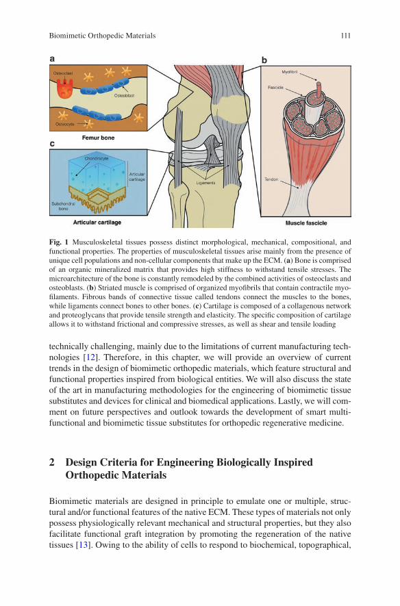
111
technically challenging, mainly due to the limitations of current manufacturing tech-nologies [12]. Therefore, in this chapter, we will provide an overview of current trends in the design of biomimetic orthopedic materials, which feature structural and functional properties inspired from biological entities. We will also discuss the state of the art in manufacturing methodologies for the engineering of biomimetic tissue substitutes and devices for clinical and biomedical applications. Lastly, we will com-ment on future perspectives and outlook towards the development of smart multi-functional and biomimetic tissue substitutes for orthopedic regenerative medicine.
2 Design Criteria for Engineering Biologically Inspired Orthopedic Materials
Biomimetic materials are designed in principle to emulate one or multiple, struc-tural and/or functional features of the native ECM. These types of materials not only possess physiologically relevant mechanical and structural properties, but they also facilitate functional graft integration by promoting the regeneration of the native tissues [13]. Owing to the ability of cells to respond to biochemical, topographical,
Fig. 1 Musculoskeletal tissues possess distinct morphological, mechanical, compositional, and functional properties. The properties of musculoskeletal tissues arise mainly from the presence of unique cell populations and non-cellular components that make up the ECM. (a) Bone is comprised of an organic mineralized matrix that provides high stiffness to withstand tensile stresses. The microarchitecture of the bone is constantly remodeled by the combined activities of osteoclasts and osteoblasts. (b) Striated muscle is comprised of organized myofibrils that contain contractile myo-filaments. Fibrous bands of connective tissue called tendons connect the muscles to the bones, while ligaments connect bones to other bones. (c) Cartilage is composed of a collagenous network and proteoglycans that provide tensile strength and elasticity. The specific composition of cartilage allows it to withstand frictional and compressive stresses, as well as shear and tensile loading
Biomimetic Orthopedic Materials
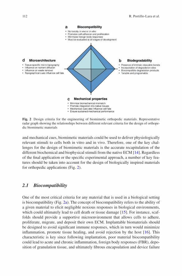
112
and mechanical cues, biomimetic materials could be used to deliver physiologically relevant stimuli to cells both in vitro and in vivo. Therefore, one of the key chal-lenges for the design of biomimetic materials is the accurate recapitulation of the different biochemical and biophysical stimuli from the native ECM [14]. Regardless of the final application or the specific experimental approach, a number of key fea-tures should be taken into account for the design of biologically inspired materials for orthopedic applications (Fig. 2).
2.1 Biocompatibility
One of the most critical criteria for any material that is used in a biological setting is biocompatibility (Fig. 2a). The concept of biocompatibility refers to the ability of a given material to elicit negligible noxious responses in biological environments, which could ultimately lead to cell death or tissue damage [15]. For instance, scaf-folds should provide a supportive microenvironment that allows cells to adhere, proliferate, migrate, and deposit their own ECM. Implantable biomaterials should be designed to avoid significant immune responses, which in turn would minimize inflammation, promote tissue healing, and avoid rejection by the host [16]. This characteristic is key since following implantation, poor material biocompatibility could lead to acute and chronic inflammation, foreign body responses (FBR), depo-sition of granulation tissue, and ultimately fibrous encapsulation and device failure
Fig. 2 Design criteria for the engineering of biomimetic orthopedic materials. Representative radar graph showing the relationships between different relevant criteria for the design of orthope-dic biomimetic materials
R. Portillo-Lara et al.

113
[17]. Therefore, a thorough and systematic evaluation of material biocompatibility should be performed at the earliest stages of development, which should include comparative analyses with commercially available products. In addition, the testing methodology should also consider its intended final application for a more accurate evaluation [18]. Material biocompatibility should be consistently evaluated through-out all stages of product development, from in vitro cytotoxicity tests to post-market retroactive feedback systems. Therefore, it is critical to develop more robust plat-forms that accurately identify biological responses, since tissue engineered scaf-folds and biomaterial based devices often contain multiple biochemical or cellular components [17].
In recent years, the traditional concept of biocompatibility, relating to inert mate-rials that do not elicit toxic responses, has evolved to refer to tailored materials that respond to physiological stimuli, while also interacting with and integrating into the surrounding native tissues. In particular, these phenomena are heavily influenced by the interactions between cells from the immune system, and host proteins adsorbed to the surface of the biomaterials [19]. Therefore, biomimetic surface nanotopogra-phies [20, 21], as well as biomimetic coatings [22] have been used to minimize FBR, improve tissue integration, and enhance implant bioactivity. These studies demonstrate that biomimetic structured surfaces could enhance the biocompatibility of implantable devices, and favor their structural and functional integration into the native tissues. In addition, previous studies have demonstrated that several biocom-patible materials could induce significant oxidative stress and inflammation in the surrounding tissue upon biodegradation [11]. Thus, the potential toxicity of biodeg-radation products should also be investigated, and not assumed from the given chemistry of the material.
2.2 Biodegradability
Biodegradability refers to the transformation of an implantable material from a sta-ble structure into soluble byproducts that can be resorbed or excreted by the body (Fig. 2b) [23]. Conventional biodegradable materials have been extensively used in the clinic in the form of resorbable sutures, films, and fixation devices such as screws and plates [24, 25]. In the field of tissue engineering, biodegradable materi-als have been used in the development of 3D scaffolds, as well as degradable vehi-cles for drug delivery and release [26]. In this regard, several groups have reported the engineering of polymeric hydrogels with hydrolytically or enzymatically cleav-able bonds for controlled biomimetic biodegradation [27, 28]. For instance, syn-thetic aliphatic polyesters such as poly(lactic acid) (PLA), poly(glycolic acid) (PGA) [29, 30], as well as naturally-derived polymers such as gelatin or hyaluronic acid (HA) [31, 32] have been widely used for scaffold fabrication due to their well characterized degradation behavior. Biomimetic degradation mechanisms have also been introduced into polymeric hydrogels, by incorporating specific degradation sites sensitive to matrix metalloproteases (MMPs), elastases, or plasmin [33–35].
Biomimetic Orthopedic Materials
114
Moreover, tissue engineered scaffolds should be biodegraded into biocompatible byproducts, and at a specific rate that matches the speed at which new autologous tissue is synthesized. For instance, the biodegradation rate of chondroinductive hydrogels has been shown to influence spatial distribution and matrix deposition of 3D encapsulated chondrocytes in vitro [36]. On the other hand, the modulation of the biodegradation rate for scaffolds used as delivery vehicles allows the fine tuning of the kinetics and spatiotemporal presentation of the entrapped biomolecule to local tissues [37].
The ability to modulate the biodegradation rate of materials used for orthopedic applications allows for the engineering of smart scaffolds and delivery systems that possess increased therapeutic efficacy. 3D scaffolds with programmable degrada-tion sites could be efficiently remodeled through biomimetic mechanisms, similar to those involved in the remodeling of native ECM components [38, 39]. In addi-tion, polymeric hydrogels with controlled degradation rates could be used to fill critical size bone defects to act as reservoirs for the delivery of a variety of therapeu-tic drugs and biomolecules [40]. Here, the subsequent biodegradation of the mate-rial would lead to passive or programmable drug release at predetermined concentrations that influence local tissue responses [41]. Lastly, one important con-sideration is the fact that the mechanical properties of resorbable materials are often different from those used for permanent implants [26]. Therefore, the design and engineering of biodegradable materials with physical properties and structural fea-tures similar to their non-degradable counterparts remains a significant technical challenge.
2.3 Mechanical Properties
Physiological tissues possess distinct mechanical properties that vary according to the function that they carry out in the body. Tissue engineered constructs should accurately reproduce the mechanical properties of the anatomic structure they aim to restore or replace to avoid biomechanical mismatch and device failure (Fig. 2c). Although this important consideration should be incorporated into the design of virtually all types of biomaterials, it is particularly relevant in the field of orthopedic tissue engineering. For instance, tissue engineered scaffolds for bone, cartilage, ten-dons or ligament regeneration should exhibit adequate mechanical performance from the time of implantation to the completion of the remodeling process [15]. Furthermore, the appropriate mechanical requirements of these scaffolds should be tailored to each individual patient, since parameters such as age, weight, sex, degree of physical activity, and additional health complications, which may influence the intrinsic regenerative capacity of these tissues [42].
Bone is a composite material that is mainly comprised of two solid phases, which correspond to an organic extracellular collagenous matrix that is impreg-nated with inorganic materials [43]. The mechanical properties of bone tissues are dictated by the structural relationships between these two phases at different levels
R. Portillo-Lara et al.
115
of the hierarchical structural organization in bones. This unique organized structure exhibits a dynamic and irregular arrangement of its components, which is respon-sible for the heterogeneous and anisotropic mechanics of bone at the macro- and micro-scales. For instance, previous studies have reported that the Young’s modulus of large tensile cortical specimens corresponds to ≈14–20 GPa, while that of micro-bending cortical specimens corresponds to 5.4 GPa [44]. The intrinsically high stiffness of bone tissues hinders the development of cell-laden scaffolds for regen-erative orthopedics, since stiff substrata often leads to poor viability and prolifera-tion of encapsulated cells in vitro. Therefore, tissue engineered scaffolds aimed to function as bone grafts are generally fabricated with osteogenic cues that could induce new bone formation in vivo. In contrast, the mechanical properties of scaf-folds used for load-bearing applications should accurately match the mechanical properties of bone to ensure proper implant function [45]. Another musculoskeletal tissue that possesses a hierarchical structural organization is cartilage. The compo-sition and organization of cartilage vary according to the depth of the tissue, which is generally divided into three zones: the superficial, middle, and deep zones [46]. The composition and orientation of the cartilage results in the anisotropic mechani-cal behavior of these tissues. For instance, previous studies on the mechanics of the human knee reported a dynamic stiffness of 4.5 MPa at a loading frequency of 0.1 Hz [47], and an aggregate static modulus of 0.1–2.0 MPa [48]. In addition, the swellability of cartilage due to the presence of proteoglycans in the collagenous matrix grants cartilage its viscoelastic properties and provides fluid load support [49]. Similarly, tendons also behave viscoelastically and exhibit adaptive responses to conditions of increased loading, as well as force-relaxation, creep, and hysteresis [50, 51]. Adaptive responses are also found in ligaments, which exhibit significant time- and history-dependent viscoelastic properties, as well as temperature- sensitive mechanical properties [43].
The mechanical properties not only determine the biomechanical performance of tissue engineered scaffolds, but they also influence cell responses that mediate tis-sue regeneration. The intrinsic regenerative response in bone tissues has been shown to be modulated through multiple physical (e.g., topography, stiffness, shear stress, electrical fields) and biochemical (e.g., growth factors, differential gene and protein expression) factors [52]. During bone repair, the composition and 3D structure of the ECM provide physical cues that modulate cell function in a spatiotemporal- dependent fashion [53]. Biomimetic scaffolds for orthopedic tissue engineering applications must adequately transduce these physiological stimuli to resident or implanted cell populations to efficiently promote osteogenic responses. Biomimetic bone implants should achieve successful integration by matching the mechanical properties of the native bone tissues, while also promoting preferential bone cell adhesion, ECM deposition, and biomimetic mineralization [54]. However, biomate-rials with optimal mechanical compliance could still prove unsuccessful in vivo due to insufficient vascularization, low cell infiltration, or poor nutrient diffusion. Therefore, the optimization of the mechanical properties should be carried out in parallel to the optimization of the microstructural features of the tissue engineered scaffolds.
Biomimetic Orthopedic Materials
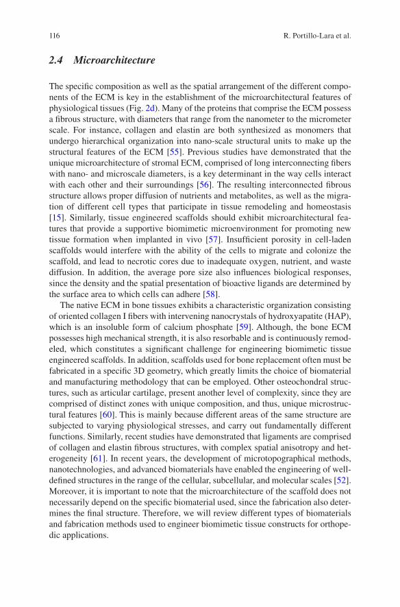
116
2.4 Microarchitecture
The specific composition as well as the spatial arrangement of the different compo-nents of the ECM is key in the establishment of the microarchitectural features of physiological tissues (Fig. 2d). Many of the proteins that comprise the ECM possess a fibrous structure, with diameters that range from the nanometer to the micrometer scale. For instance, collagen and elastin are both synthesized as monomers that undergo hierarchical organization into nano-scale structural units to make up the structural features of the ECM [55]. Previous studies have demonstrated that the unique microarchitecture of stromal ECM, comprised of long interconnecting fibers with nano- and microscale diameters, is a key determinant in the way cells interact with each other and their surroundings [56]. The resulting interconnected fibrous structure allows proper diffusion of nutrients and metabolites, as well as the migra-tion of different cell types that participate in tissue remodeling and homeostasis [15]. Similarly, tissue engineered scaffolds should exhibit microarchitectural fea-tures that provide a supportive biomimetic microenvironment for promoting new tissue formation when implanted in vivo [57]. Insufficient porosity in cell-laden scaffolds would interfere with the ability of the cells to migrate and colonize the scaffold, and lead to necrotic cores due to inadequate oxygen, nutrient, and waste diffusion. In addition, the average pore size also influences biological responses, since the density and the spatial presentation of bioactive ligands are determined by the surface area to which cells can adhere [58].
The native ECM in bone tissues exhibits a characteristic organization consisting of oriented collagen I fibers with intervening nanocrystals of hydroxyapatite (HAP), which is an insoluble form of calcium phosphate [59]. Although, the bone ECM possesses high mechanical strength, it is also resorbable and is continuously remod-eled, which constitutes a significant challenge for engineering biomimetic tissue engineered scaffolds. In addition, scaffolds used for bone replacement often must be fabricated in a specific 3D geometry, which greatly limits the choice of biomaterial and manufacturing methodology that can be employed. Other osteochondral struc-tures, such as articular cartilage, present another level of complexity, since they are comprised of distinct zones with unique composition, and thus, unique microstruc-tural features [60]. This is mainly because different areas of the same structure are subjected to varying physiological stresses, and carry out fundamentally different functions. Similarly, recent studies have demonstrated that ligaments are comprised of collagen and elastin fibrous structures, with complex spatial anisotropy and het-erogeneity [61]. In recent years, the development of microtopographical methods, nanotechnologies, and advanced biomaterials have enabled the engineering of well- defined structures in the range of the cellular, subcellular, and molecular scales [52]. Moreover, it is important to note that the microarchitecture of the scaffold does not necessarily depend on the specific biomaterial used, since the fabrication also deter-mines the final structure. Therefore, we will review different types of biomaterials and fabrication methods used to engineer biomimetic tissue constructs for orthope-dic applications.
R. Portillo-Lara et al.
117
3 Nanofibrous Materials
One of the most exciting and rapidly evolving research areas in tissue engineering is the design and fabrication of artificial scaffolds that mimic the native ECM. Artificial scaffolds should mimic the micro- and nanofibrous structure of the native ECM in order to support the growth of new tissues [16]. Different techniques with varying degrees of success have been developed to engineer nanofibrous biomi-metic scaffolds, including molecular self-assembly, electrospinning, and phase separation (Fig. 3) [62, 63]. Here, we focus on the current state of nanofibrous scaf-folds in tissue engineering with an emphasis on orthopedic applications.
3.1 Self-assembly
Self-assembly is generally defined as a spontaneous, autonomous, and reversible processing of components into stable patterns or structures. This technique has been used to fabricate supramolecular architectures through non-covalent interac-tions, such as hydrogen bonds, ionic bonds, electrostatic, and hydrophobic interac-tions (Fig. 3a) [63]. For tissue engineering applications, peptides, peptide amphiphiles (PAs), and proteins are the most commonly used functional supramo-lecular structures to form one dimensional nanofibrous assemblies [64]. Using this approach, different nanofibrillar scaffolds have been engineered for bone [65–67], dental [68, 69], and other orthopedic tissue engineering applications [70]. For instance, Sargeant et al. reported a hybrid bone implant biomaterial consisting of a porous titanium foam filled with a self-assembled PA nanofiber matrix, which could promote bone formation around and inside the implant and enhance vascular-ization without any cytotoxic response [71]. In another study, Hosseinkhani et al. could effectively enhance homogeneous ectopic bone formation in a 3D hybrid scaffold consisting of self-assembled PA nanofibers, and a PGA fiber-laden colla-gen sponge [72].
Although self-assembly is a promising technique for the manufacture of highly aligned and injectable nanofibrous scaffolds for tissue engineering applications, there are still challenges that need to be addressed before this method can be widely used in developing biomimetic scaffolds. One of the current limitations of self- assembled scaffolds is the inability to control the pore size and pore structure, which are key factors for cell encapsulation, proliferation and migration. In addi-tion, poor mechanical strength and stability, as well as uncontrollable degradation rates also limit the potential of this technique for orthopedic tissue engineering applications [16].
Biomimetic Orthopedic Materials
118
3.2 Electrospinning
Electrospinning has been widely used for fabricating micro- and nanofibrous struc-tures in tissue engineering by means of electrostatic force [64]. This technique has been utilized to engineer sub-micro or nanofibrous scaffolds with tunable pore size, fiber size, mechanical strength, and degradation rate [73]. During electrospinning, a polymeric solution is elongated and whipped continuously from an orifice to a col-lector using an electric field at a high voltage (Fig. 3b). The simplicity and the high capability to fabricate nanofibers by using a variety of synthetic and naturally derived biomaterials, has made electrospinning a highly attractive technique to engineer fibrous scaffolds for tissue engineering applications. For orthopedic appli-cations, different biomaterials have been utilized to form electrospun fibers, includ-ing natural polymers such as collagen [74, 75], gelatin [76, 77], chitosan [78, 79], silk [80, 81], and synthetic polymers such as poly(l-lactic acid) (PLLA) [82], poly(lactic-co- glycolic acid) (PLGA) [83, 84], poly(ε-caprolactone) (PCL) [85, 86], poly(ethylene oxide) (PEO) [87], and poly(vinyl alcohol) (PVA) [75]. The fiber diameters can easily be tuned by varying the polymer concentration or processing
Fig. 3 Biomimetic fibrous scaffolds. Schematic of current techniques used for the formation of biomimetic fibrous scaffolds: (a) self-assembly, (b) electrospinning, (c) phase separation. Scale bars: 500 nm (a), 10 μm (b, c). The image was modified and reprinted with permission from [62]
R. Portillo-Lara et al.
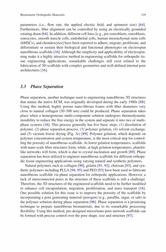
119
parameters (i.e., flow rate, the applied electric field, and spinneret size) [64]. Furthermore, fiber alignment can be controlled by using an electrically grounded rotating drum [64]. In addition, different cell lines [e.g., pre-osteoblasts, osteoblasts, osteocytes, smooth muscle cells, endothelial cells, human mesenchymal stem cells (hMSCs), and chondrocytes] have been reported to adhere, migrate, proliferate, and differentiate or sustain their biological and functional phenotypes on electrospun nanofibrous scaffolds [16]. Although the simplicity and applicability of electrospin-ning make it a highly attractive method in engineering scaffolds for orthopedic tis-sue engineering applications, remarkable challenges still exist related to the fabrication of 3D scaffolds with complex geometries and well-defined internal pore architectures [16].
3.3 Phase Separation
Phase separation, another technique used to engineering nanofibrous 3D structures that mimic the native ECM, was originally developed during the early 1980s [88]. Using this method, highly porous nano-fibrous foams with fiber diameters very close to natural collagen (50–500 nm) could be produced. Phase separation takes place when a homogeneous multi-component solution undergoes thermodynamic instability to reduce the free energy in the system and separate it into two or multi- phase systems [16]. This process generally has five basic steps: (1) dissolution of polymer, (2) phase separation process, (3) polymer gelation, (4) solvent exchange, and (5) vacuum freeze drying (Fig. 3c) [89]. Polymer gelation, which depends on polymer concentration and system temperature, is the most critical step for control-ling the porosity of nanofibrous scaffolds. At lower gelation temperatures, scaffolds with nano-scale fiber structures form, while, at high gelation temperatures, platelet-like networks will form, which is due to crystal nucleation and growth [89]. Phase separation has been utilized to engineer nanofibrous scaffolds for different orthope-dic tissue engineering applications using varying natural and synthetic polymers.
Natural polymers such as collagen [90], gelatin [91, 92], chitosan [93], and syn-thetic polymers including PLLA [94, 95] and PEO [93] have been used to fabricate nanofibrous scaffolds via phase separation for orthopedic applications. However, a lack of interconnected pores in the structure of these scaffolds is still a challenge. Therefore, the 3D structures of the engineered scaffolds need to be further modified to enhance cell encapsulation, migration, proliferation, and mass transport [16]. One possible solution for this issue is to improve the porosity of the scaffolds by incorporating a pore generating material (porogen) (e.g., paraffin, sugar, or salt) in the polymer solution during phase separation [96]. Phase separation is a promising technique to prepare nanofibrous biomaterials, due to its remarkable processing flexibility. Using this method, pre-designed micro/nano-pore network scaffolds can be formed with precise control over the pore shape, size and structure [97].
Biomimetic Orthopedic Materials
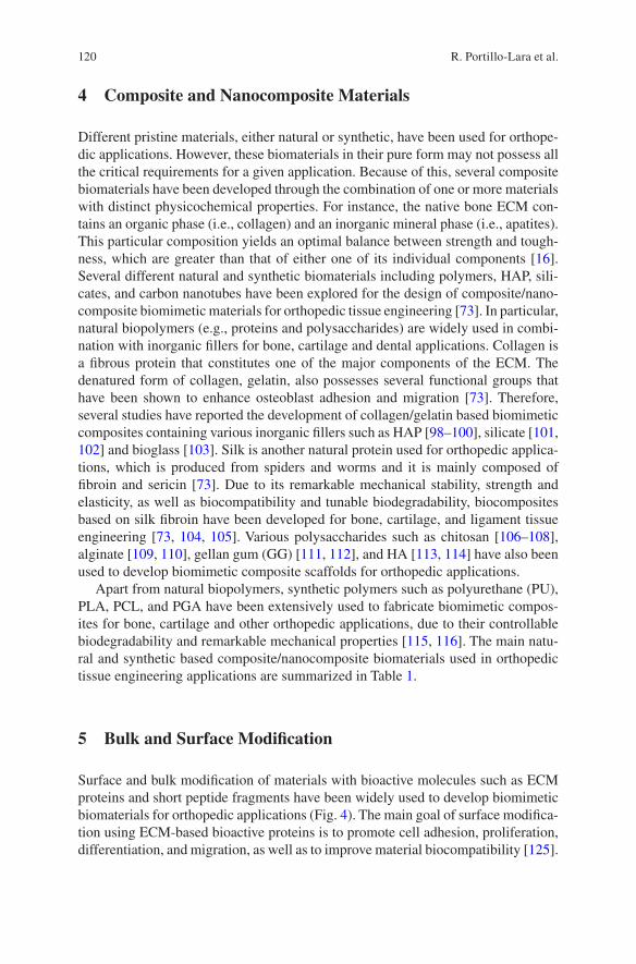
120
4 Composite and Nanocomposite Materials
Different pristine materials, either natural or synthetic, have been used for orthope-dic applications. However, these biomaterials in their pure form may not possess all the critical requirements for a given application. Because of this, several composite biomaterials have been developed through the combination of one or more materials with distinct physicochemical properties. For instance, the native bone ECM con-tains an organic phase (i.e., collagen) and an inorganic mineral phase (i.e., apatites). This particular composition yields an optimal balance between strength and tough-ness, which are greater than that of either one of its individual components [16]. Several different natural and synthetic biomaterials including polymers, HAP, sili-cates, and carbon nanotubes have been explored for the design of composite/nano-composite biomimetic materials for orthopedic tissue engineering [73]. In particular, natural biopolymers (e.g., proteins and polysaccharides) are widely used in combi-nation with inorganic fillers for bone, cartilage and dental applications. Collagen is a fibrous protein that constitutes one of the major components of the ECM. The denatured form of collagen, gelatin, also possesses several functional groups that have been shown to enhance osteoblast adhesion and migration [73]. Therefore, several studies have reported the development of collagen/gelatin based biomimetic composites containing various inorganic fillers such as HAP [98–100], silicate [101, 102] and bioglass [103]. Silk is another natural protein used for orthopedic applica-tions, which is produced from spiders and worms and it is mainly composed of fibroin and sericin [73]. Due to its remarkable mechanical stability, strength and elasticity, as well as biocompatibility and tunable biodegradability, biocomposites based on silk fibroin have been developed for bone, cartilage, and ligament tissue engineering [73, 104, 105]. Various polysaccharides such as chitosan [106–108], alginate [109, 110], gellan gum (GG) [111, 112], and HA [113, 114] have also been used to develop biomimetic composite scaffolds for orthopedic applications.
Apart from natural biopolymers, synthetic polymers such as polyurethane (PU), PLA, PCL, and PGA have been extensively used to fabricate biomimetic compos-ites for bone, cartilage and other orthopedic applications, due to their controllable biodegradability and remarkable mechanical properties [115, 116]. The main natu-ral and synthetic based composite/nanocomposite biomaterials used in orthopedic tissue engineering applications are summarized in Table 1.
5 Bulk and Surface Modification
Surface and bulk modification of materials with bioactive molecules such as ECM proteins and short peptide fragments have been widely used to develop biomimetic biomaterials for orthopedic applications (Fig. 4). The main goal of surface modifica-tion using ECM-based bioactive proteins is to promote cell adhesion, proliferation, differentiation, and migration, as well as to improve material biocompatibility [125].
R. Portillo-Lara et al.
121
Tabl
e 1
Mai
n na
tura
l and
syn
thet
ic p
olym
eric
bio
mat
eria
ls u
sed
in o
rtho
pedi
c tis
sue
engi
neer
ing
Mat
rix/
rein
forc
emen
tC
ell/s
tem
cel
lsA
pplic
atio
nR
efer
ence
Com
pone
nt 1
Com
pone
nt 2
Mic
ro/n
anom
ater
ial
Col
lage
n–
Hyd
roxy
apat
ite (
HA
P)B
one
mar
row
str
omal
cel
lsB
one
tissu
e re
gene
ratio
n[9
8]–
Hum
an a
dipo
se ti
ssue
SC
s (h
AD
SCs)
Tre
atm
ent o
f bo
ne d
efec
ts[1
17]
Phos
phat
idyl
seri
neB
iogl
ass
(BG
)R
at m
esen
chym
al s
tem
cel
ls
(rM
SCs)
Bon
e tis
sue
engi
neer
ing
[118
]
Gel
atin
–M
G-6
3 hu
man
-ost
eobl
ast
Har
d tis
sue
rege
nera
tion
[119
]–
Mes
opor
ous
silic
a na
nofib
ers
Hum
an o
steo
blas
t-lik
e ce
lls
(MG
63)
Bon
e tis
sue
rege
nera
tion
[120
]
Ant
imic
robi
al p
eptid
eSi
licat
e na
nopa
rtic
les
hMSC
sA
ntim
icro
bial
and
adh
esiv
e hy
drog
el
as o
rtho
pedi
c im
plan
t coa
ting
[121
]
Silk
fibr
oin
–H
AP
hMSC
sB
one
tissu
e re
gene
ratio
n[1
22]
–C
arbo
nate
-con
tain
ing
apat
ite (
CA
P)H
uman
bon
e m
esen
chym
al
stro
mal
cel
ls (
BM
SCs)
Bon
e tis
sue
rege
nera
tion
[123
]
Chi
tosa
nG
elat
inH
AP
Saos
-2 c
ells
Bon
e tis
sue
rege
nera
tion
[124
]–
HA
PPr
e-os
teob
last
s (M
C
3T3-
E1)
Bon
e tis
sue
rege
nera
tion
[100
]
Alg
inat
e–
HA
PR
at o
steo
sarc
oma
UM
R10
6 ce
llsT
issu
e en
gine
erin
g[1
01]
–B
GhM
SCs
Bon
e tis
sue
engi
neer
ing
[102
]G
ella
n gu
m (
GG
)–
–R
at lu
ng fi
brob
last
s (L
929
cells
)In
terv
erte
bral
dis
c tis
sue-
engi
neer
ing
[103
]
–H
AP
MG
-63
hum
an-o
steo
blas
tB
one
tissu
e en
gine
erin
g[1
04]
Hya
luro
nic
acid
(H
A)
Chi
tosa
n–
Cho
ndro
cyte
sC
artil
age
tissu
e en
gine
erin
g[1
05]
–A
dult
cani
ne c
hond
rocy
tes
Car
tilag
e tis
sue
engi
neer
ing
[106
]
(con
tinue
d)
Biomimetic Orthopedic Materials
122
Tabl
e 1
(con
tinue
d)
Mat
rix/
rein
forc
emen
tC
ell/s
tem
cel
lsA
pplic
atio
nR
efer
ence
Com
pone
nt 1
Com
pone
nt 2
Mic
ro/n
anom
ater
ial
Poly
uret
hane
Fibr
in–
Cho
ndro
cyte
sA
rtic
ular
car
tilag
e tis
sue
engi
neer
ing
[117
]–
HA
PB
MSC
sR
epai
r an
d su
bstit
ute
of h
uman
m
enis
ci o
f th
e kn
ee-j
oint
and
art
icul
ar
cart
ilage
[119
]
Poly
(lac
tic a
cid)
(P
LA
)C
olla
gen
HA
PN
eona
tal r
at c
alva
ria
oste
obla
stL
arge
bon
y de
fect
s/bo
ne ti
ssue
en
gine
erin
g[1
20]
–A
lloge
neic
per
icho
ndro
cyte
Art
icul
ar c
artil
age
repa
ir[1
21]
–G
old
NPs
Prim
ary
rat m
uscl
e ce
llsSk
elet
al m
uscl
e tis
sue
engi
neer
ing
[118
]Po
ly(ε
- ca
prol
acto
ne)
(PC
L)
Alg
inat
e, fi
brin
, pol
y-
acry
lam
ide
(PA
Am
)–
–A
rtic
ular
car
tilag
e re
pair
[122
]
–H
AP
–B
one
tissu
e en
gine
erin
g[1
23]
–H
AP
–C
ontr
olle
d dr
ug r
elea
se in
the
poro
us
bone
sca
ffol
d[1
24]
R. Portillo-Lara et al.
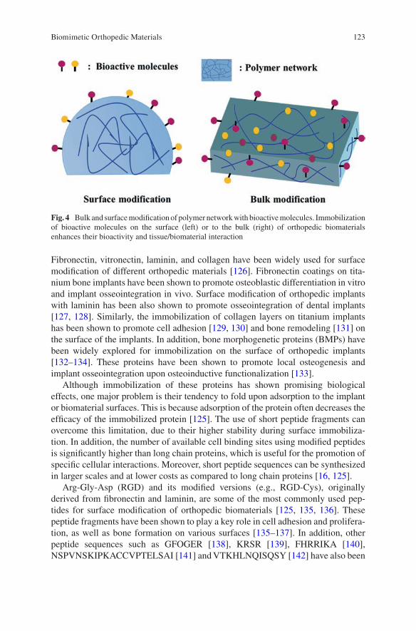
123
Fibronectin, vitronectin, laminin, and collagen have been widely used for surface modification of different orthopedic materials [126]. Fibronectin coatings on tita-nium bone implants have been shown to promote osteoblastic differentiation in vitro and implant osseointegration in vivo. Surface modification of orthopedic implants with laminin has been also shown to promote osseointegration of dental implants [127, 128]. Similarly, the immobilization of collagen layers on titanium implants has been shown to promote cell adhesion [129, 130] and bone remodeling [131] on the surface of the implants. In addition, bone morphogenetic proteins (BMPs) have been widely explored for immobilization on the surface of orthopedic implants [132–134]. These proteins have been shown to promote local osteogenesis and implant osseointegration upon osteoinductive functionalization [133].
Although immobilization of these proteins has shown promising biological effects, one major problem is their tendency to fold upon adsorption to the implant or biomaterial surfaces. This is because adsorption of the protein often decreases the efficacy of the immobilized protein [125]. The use of short peptide fragments can overcome this limitation, due to their higher stability during surface immobiliza-tion. In addition, the number of available cell binding sites using modified peptides is significantly higher than long chain proteins, which is useful for the promotion of specific cellular interactions. Moreover, short peptide sequences can be synthesized in larger scales and at lower costs as compared to long chain proteins [16, 125].
Arg-Gly-Asp (RGD) and its modified versions (e.g., RGD-Cys), originally derived from fibronectin and laminin, are some of the most commonly used pep-tides for surface modification of orthopedic biomaterials [125, 135, 136]. These peptide fragments have been shown to play a key role in cell adhesion and prolifera-tion, as well as bone formation on various surfaces [135–137]. In addition, other peptide sequences such as GFOGER [138], KRSR [139], FHRRIKA [140], NSPVNSKIPKACCVPTELSAI [141] and VTKHLNQISQSY [142] have also been
Fig. 4 Bulk and surface modification of polymer network with bioactive molecules. Immobilization of bioactive molecules on the surface (left) or to the bulk (right) of orthopedic biomaterials enhances their bioactivity and tissue/biomaterial interaction
Biomimetic Orthopedic Materials
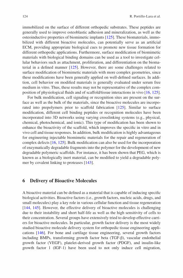
124
immobilized on the surface of different orthopedic substrates. These peptides are generally used to improve osteoblastic adhesion and mineralization, as well as the osteoinductive properties of biomimetic implants [125]. These biomaterials, immo-bilized with different bioactive molecules, can potentially serve as an artificial ECM, providing appropriate biological cues to promote new tissue formation for different orthopedic applications. Furthermore, surface modification of biomimetic materials with biological binding domains can be used as a tool to investigate cel-lular behaviors such as attachment, proliferation, and differentiation on the bioma-terial in a defined manner [125]. However, there are some challenges related to surface modification of biomimetic materials with more complex geometries, since these modifications have been generally applied on well-defined surfaces. In addi-tion, cell behavior on modified materials is generally evaluated under serum free medium in vitro. Thus, these results may not be representative of the complex com-position of physiological fluids and of scaffold/tissue interactions in vivo [16, 125].
For bulk modification, cell signaling or recognition sites are present on the sur-face as well as the bulk of the materials, since the bioactive molecules are incorpo-rated into prepolymers prior to scaffold fabrication [125]. Similar to surface modification, different cell binding peptides or recognition molecules have been incorporated into 3D networks using varying crosslinking systems (e.g., physical, chemical, photochemical, and ionic). This type of modification has been shown to enhance the bioactivity of the scaffold, which improves the specific in vitro and in vivo cell and tissue responses. In addition, bulk modification is highly advantageous for engineering injectable biomimetic materials for the repair and regeneration of complex defects [16, 125]. Bulk modification can also be used for the incorporation of enzymatically degradable fragments into the polymer for the development of new degradable polymeric scaffolds. For instance, it has been shown that PEG, which is known as a biologically inert material, can be modified to yield a degradable poly-mer by covalent linking to proteases [143].
6 Delivery of Bioactive Molecules
A bioactive material can be defined as a material that is capable of inducing specific biological activities. Bioactive factors (i.e., growth factors, nucleic acids, drugs, and small molecules) play a key role in various cellular function and tissue regeneration [144, 145]. However, the effective delivery of bioactive molecules is challenging due to their instability and short half-life as well as the high sensitivity of cells to their concentration. Several groups have extensively tried to develop effective carri-ers for bioactive molecules. In particular, growth factor delivery is the most widely studied bioactive molecule delivery system for orthopedic tissue engineering appli-cations [146]. For bone and cartilage tissue engineering, several growth factors including BMPs, transforming growth factor beta (TGF-β), vascular endothelial growth factor (VEGF), platelet-derived growth factor (PDGF), and insulin-like growth factor 1 (IGF-1) have been used to not only induce cell migration,
R. Portillo-Lara et al.
125
proliferation and differentiation of hMSCs, but also to enhance new tissue forma-tion, vascularization and remodeling, especially in the case of large defect sizes [147]. Similarly, different growth factors including VEGF, PDGF, TGF-β, and fibro-blast growth factors (FGFs) have been used for skeletal muscle regeneration [148–150]. In addition to growth factors, the delivery of other bioactive molecules including nucleic acids (i.e., DNA and RNA), antimicrobial agents (i.e., antibiotics, metal oxides, and antimicrobial peptides) and drugs have been widely studied for various orthopedic applications (Fig. 5) [134, 144, 151, 152].
These bioactive molecules can be coated on the surface, loaded directly into the scaffolds, or incorporated into micro- and nanocarriers (i.e., micro- and nano-spheres, sheets, and nanotubes) [144]. The incorporation of bioactive molecules into scaffolds and carriers can be achieved through physical entrapment, chemical bond, or absorption (i.e., covalent immobilization, ionic binding) [146]. Although the delivery of bioactive molecules plays a critical role in orthopedic tissue engi-neering, there are still challenges related to the controlling of release kinetics and targeted local delivery. In addition, to realize the full potential of these approaches in orthopedic applications, it is critical to understand the role of natural biological signal during tissue development and healing [144].
Fig. 5 Schematic of current bioactive molecule delivery technologies and their orthopedic applications
Biomimetic Orthopedic Materials
126
7 Biofabrication
Biofabrication refers to the use of biological materials and mechanisms for the auto-mated manufacture of biologically functional products [153]. Biofabrication tech-niques offer several technical advantages, such as automation, scalability, precise 3D positioning of different cell types, and the ability for in situ fabrication [154]. Biofabrication strategies can be mainly categorized into top-down and bottom-up manufacturing, depending on the overall workflow [155]. Top-down biofabrication relies on the engineering of scaffolds with anisotropic mechanical and structural properties, which are subsequently seeded with different cell types. On the other hand, bottom-up biofabrication relies on the encapsulation of cells within a given biomaterial, which is then assembled into a final structure. Although top-down meth-ods are comparatively simpler and straightforward, bottom-up techniques can be used to assemble cell-laden modules into predefined structures with controllable cell distribution. In addition, biomanufactured constructs often require a maturation phase of the pre-tissue assembly either in vitro or in vivo, to allow for the development of a coherent functional structure [156]. Biofabrication relies heavily on 3D bioprinting strategies to accurately position cells and biomaterials into physiologically relevant arrangements. In this section, we will provide an overview of the integration of advanced biomaterials and 3D bioprinting approaches to engineer biomimetic con-structs for musculoskeletal tissue engineering in orthopedic applications.
7.1 3D Bioprinting
3D bioprinting refers to the manufacture of biological structures through layer-by- layer deposition of cells and biomaterials, via a computer-controlled 3D printing device. In recent years, several groups have reported the application of different bioprinting techniques such as inkjet cell printing, extrusion-based technologies, stereolithography, and laser-induced forward transfer, for the manufacturing of load bearing tissues such as bone and cartilage [154, 157]. In general, 3D bioprinting allows the deposition of cell-free polymers, as well as cell aggregates, cell-laden hydrogels or viscous fluids, or cell-seeded microcarriers, which are collectively referred to as bioinks [158]. Computer-assisted design (CAD) tools can be used to direct the placement of specific cell types and materials into physiologically rele-vant and biomimetic geometries, which recapitulate the structure and composition of native tissues [159]. Biomimetic perfusion systems could also be incorporated into the engineered tissue constructs to ensure adequate diffusion of oxygen and nutrients, and proper tissue maturation [160]. Moreover, bioprinting platforms can be readily adapted to accommodate a wide range of biomaterials such as synthetic- based and naturally derived polymers, blood derived proteins, and decellularized ECM [155].
R. Portillo-Lara et al.
127
Due to the inability of critical-sized bone defects to undergo spontaneous regen-eration, the demand for clinically relevant bone substitutes remains significantly high. Similarly, the restricted availability and donor site morbidity associated with autologous tissue grafts, greatly limit the potential of this approach for the regenera-tion of cartilage [161, 162], tendons [163], and ligaments [164, 165]. Tissue engi-neered constructs for osteochondral regeneration should accurately match the physical and biochemical properties of the native tissues. However, the engineering of biomimetic constructs requires the optimal integration of porosity, scaffold archi-tecture, mechanical strength, soluble and insoluble bioactive cues, and type of bio-material, which is remarkably challenging for conventional tissue engineering approaches. In contrast, 3D bioprinting offers the possibility to deposit cells and biomolecules in precise 3D arrangements, and in predetermined and user-controlled geometries. Thus, the remarkable micro- and macroscale accuracy of 3D printed scaffolds, as well as the ability to incorporate different types of biomaterials, has enabled the manufacturing of implants that accurately mimic the composition, structure, and function of osteochondral tissues [166].
Inkjet printing refers to the drop-by-drop deposition of polymeric hydrogels or other cell-supportive biomaterials to manufacture 3D cellular or acellular structures (Fig. 6a) [158]. The small droplet print volumes used for inkjet bioprinting allow the manufacturing of high-resolution structures with highly biomimetic microarchitec-tures. Examples of this technique for bone tissue engineering applications include inkjet printing of scaffolds made from HAP [167], α-tricalcium phosphate (α-TCP) [168], α-TCP/collagen [169], and HAP/β-TCP [170], lactose-modified chitosan [171], as well as the titanium alloy Ti-6Al-4V [172] and inert alumina ceramics [173]. Inkjet bioprinting has also been explored for 3D cartilage tissue engineering using chondrocytes encapsulated in PEG [174], poly(ethylene glycol) diacrylate (PEGDA) [175], fibrin/collagen [176], as well as hMSCs encapsulated in poly(ethylene glycol) dimethacrylate (PEGDMA)/HAP [177]. In addition, inkjet bioprinting has also been used to engineer composite bone and cartilage tissue con-structs, using hMSCs encapsulated in PEGDMA/gelatin methacryloyl (GelMA) [178, 179] and PEG [179]. Despite the high resolution achieved through drop-by- drop deposition, inkjet techniques rely on the use of rapidly polymerizing materials to achieve proper structural stability and throughput [158]. In turn, this requirement limits the type of materials that can be used for this application, and impairs the ability to scale up processes to fabricate large tissue constructs.
Extrusion-based bioprinting relies on the use of a syringe and piston array to dis-pense materials through microscale nozzles, which can produce 3D cell-laden struc-tures with comparatively higher structural stability than drop-by-drop techniques (Fig. 6b) [155]. For instance, this technique has been used to fabricate aligned myo-blast-laden fibers for skeletal muscle regeneration, which were comprised of a blend of alginate and the thermo-responsive block copolymer Pluronic® [180], as well as PEG/fibrinogen [181]. Other examples of this technique include integrated tissue-organ printing (ITOP), which is an extrusion-based technique that can generate stable free-form tissue constructs with clinically relevant sizes and high structural integrity [182]. In a recent study, ITOP was used to fabricate mandible and calvarial bone, as
Biomimetic Orthopedic Materials
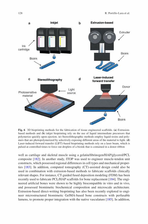
128
well as cartilage and skeletal muscle using a gelatin/fibrinogen/HAP/glycerol/PCL composite [182]. In another study, ITOP was used to engineer muscle-tendon unit constructs, which possessed regional differences in cell types and mechanical proper-ties [183]. In addition, computed tomography (CT)-assisted design could also be used in combination with extrusion-based methods to fabricate scaffolds clinically relevant shapes. For instance, CT-guided fused deposition modeling (FDM) has been recently used to fabricate PCL/HAP scaffolds for bone replacement [184]. The engi-neered artificial bones were shown to be highly biocompatible in vitro and in vivo, and possessed biomimetic biochemical composition and microscale architecture. Extrusion-based direct-writing bioprinting has also been recently explored to engi-neer microstructured biomimetic GelMA-based bone constructs with perfusable lumens, to promote proper integration with the native vasculature [185]. In addition,
Fig. 6 3D bioprinting methods for the fabrication of tissue engineered scaffolds. (a) Extrusion- based methods and (b) inkjet bioprinting rely on the use of liquid intermediate precursors that polymerize quickly upon ejection. (c) Stereolithographic methods employ liquid resins and poly-mers that are photopolymerized by selectively exposing different areas of the material to light. (d) Laser-induced forward transfer (LIFT)-based bioprinting methods rely on a laser beam, which is pulsed at controlled times to force out droplets of a bioink that is contained in a donor ribbon
R. Portillo-Lara et al.
129
GelMA scaffolds have also been directly bioprinted on the surface of titanium implants, to induce mineral deposition and enhance osseointegration [186]. Extrusion-based techniques were also shown to be compatible with in situ 3D printing applica-tions (i.e., Biopen), which enable the on-demand delivery of cellular and acellular biomaterials for clinical applications [187]. Using this approach, hMSCs encapsu-lated in HA-methacrylate/GelMA bioink could be directly delivered in real-time into critical-size defects in vivo for the repair and regeneration of cartilage tissues [188]. Similarly, another bioink comprised of chondrocytes encapsulated in alginate sul-fate-nanocellulose has also been reported for cartilage extrusion-based bioprinting applications [189].
Stereolithography (SLA) systems are generally comprised of a reservoir contain-ing a photocurable polymer solution or resin, a computer-guided laser with X-Y motion, and a fabrication platform for spatially-controlled irradiation with vertical control (Fig. 6c) [158, 190]. Among the biomaterials used for in combination with SLA is 45S5 Bioglass®, a highly bioactive silicate glass that can bond strongly with bone tissues when exposed to physiological body fluids [191]. Other groups have reported the use of poly(trimethylene carbonate) (PTMC) resins containing HAP nanoparticles, to engineer osteoinductive scaffolds with controlled architectures using SLA [192]. SLA has also been used in combination with low intensity pulsed ultrasound to fabricate biomimetic osteogenic scaffolds, using RGDS-modified PEGDA containing nanocrystalline HAP [193]. Micro-CT and scanning electron microscopy (SEM) have also been used to aid in the design of biomimetic osteo-chondral scaffolds to investigate and replicate the microstructure of the cartilage- bone transitional structures in combination with SLA [194]. In addition, visible light-based projection stereolithography (VL-PSL) techniques have been developed to fabricate 3D cell-laden structures with high resolution and fabrication speed, while also minimizing the potential for cell damage from UV light sources and lasers [194]. Previous groups have reported the use of VL-PSL to fabricate cell- laden biodegradable chondrogenic matrixes with custom architectures, comprised of poly-d,l-lactic acid (PDLLA)/PEG/HA [195]. In particular, SLA greatly facili-tates the fabrication of scaffolds with high cell density (>106 cells mL−1) due to the absence of shear stress caused by the nozzles used for inkjet- and microextrusion- based bioprinting [155]. However, SLA systems are limited by the need for photo-curable materials with viscosities less than 5 Pa [196].
Laser-induced forward transfer (LIFT)-based bioprinting systems are comprised of a laser beam that can be pulsed at controlled times, and a laser-transparent donor ribbon that contains the printable biomaterial, and a substrate onto which the mate-rial is deposited (Fig. 6d) [158]. LIFT bioprinting has been previously used to fabri-cate 2D and 3D constructs comprised of nano-HAP and human osteoprogenitor cells [197]. In this study, the printing process did not alter the physicochemical properties of the nano-HAP, as well as the ability of osteoblastic cells to adhere, spread, prolif-erate, and differentiate. LIFT has also been used for in situ delivery applications for bone regeneration, through the bioprinting of mesenchymal stromal cells associated with collagen and nano-HAP [198]. In particular, LIFT-based bioprinting allows the use of multiple donor ribbons with different cell types and biomaterials, to fabricate
Biomimetic Orthopedic Materials
130
scaffolds with increased complexity and more elaborate cellular spatial arrange-ments. Although this approach has not been as extensively explored as other bio-printing methods, the high cell viabilities associated with the lack of forces directly applied on the cells and minimal clogging issues make LIFT highly attractive for tissue engineering applications [155].
8 Current Challenges and Future Perspectives
Despite significant advancements in the development of advanced biomaterials, the engineering of biomimetic tissues that accurately recapitulate the physical, bio-chemical, and functional properties of musculoskeletal tissues remains technically challenging. The remarkable complexity of biological tissues highlights the need for biomimetic scaffolds that can withstand and transduce native biomechanical forces, and induce specific biological responses to promote tissue regeneration and repair. Current approaches are greatly limited by the inability to achieve adequate nutrient and metabolite transport, which often leads to low cell viability, necrotic cores, and poor integration with the host tissues, while also impairing the long-term structural integrity of the scaffolds [52]. The integration of biomimetics into the design of next-generation biomaterials and biofabrication tools, will allow the engineering of scaffolds with biomimetic physical structures and biochemical composition. Bioactive scaffolds with physiological microarchitectures will not only exhibit supe-rior mechanical performance and integration with the surrounding tissues, but they will also deliver mechanical and topographical cues to modulate cell fate in vivo without the need for exogenous growth factors. The ability to trigger specific cellu-lar responses through the incorporation of bioactive materials and geometries and in the absence of therapeutic molecules, will greatly facilitate the clinical translation of these approaches. In addition, the integration of biodegradable materials with solu-ble and insoluble cues will yield scaffolds that can be dynamically remodeled, to allow the formation of new autologous tissue with physicochemical characteristics identical to native tissues. Therefore, fundamental research to improve the current understanding of the mechanisms that underlie tissue morphogenesis will also pro-vide insight into new biomimetic approaches for biomaterial design. Although most of the orthopedic scaffolds used currently in the clinic rely on the use of composite materials, next-generation approaches should rely instead on the integration of mul-tiple physicochemical stimuli and different platform technologies to provide multi-functionality to the implants. In addition, future approaches should be based on smart and responsive designs that harness the intrinsic regenerative capacity of mus-culoskeletal tissues, by mimicking the native regenerative and developmental micro-environments. Future breakthroughs in the field of biomimetic orthopedic biomaterials will rely on interdisciplinary approaches with respect to high-resolu-tion biofabrication methods and smart multi-functional biomaterials, as well as molecular and cellular biology. Furthermore, the establishment of strong retroactive feedback channels between the clinic and the laboratory will favor the rapid integra-tion of clinical data into the design of next-generation therapeutic approaches.
R. Portillo-Lara et al.
131
Acknowledgements N.A. acknowledges the support from the National Institutes of Health (NIH, R01EB023052-01A1, R01HL140618-01), the American Heart Association (AHA, 16SDG31280010), The Center for Dental, Oral & Craniofacial Tissue & Organ Regeneration (C-DOCTOR) Interdisciplinary Project Team award, FY17 TIER 1 Interdisciplinary Research Seed Grants from Northeastern University, and the startup fund provided by the Department of Chemical Engineering, College of Engineering at Northeastern University. R.P.L. acknowledges institutional funding received from the Escuela de Ingeniería y Ciencias at Tecnológico de Monterrey, México (L03022214).
References
1. Kushner AM, Guan Z. Modular design in natural and biomimetic soft materials. Angew Chem Int Ed Engl. 2011;50(39):9026–57.
2. Chen C, et al. Research trends in biomimetic medical materials for tissue engineering: 3D bioprinting, surface modification, nano/micro-technology and clinical aspects in tissue engi-neering of cartilage and bone. Biomater Res. 2016;20:10.
3. Green JJ, Elisseeff JH. Mimicking biological functionality with polymers for biomedical applications. Nature. 2016;540(7633):386–94.
4. Yi S, et al. Extracellular matrix scaffolds for tissue engineering and regenerative medicine. Curr Stem Cell Res Ther. 2017;12(3):233–46.
5. Maradit Kremers H, et al. Prevalence of total hip and knee replacement in the United States. J Bone Joint Surg Am. 2015;97(17):1386–97.
6. Laurencin CT, et al. Tissue engineering: orthopedic applications. Annu Rev Biomed Eng. 1999;1:19–46.
7. Yannas IV. Tissue and organ regeneration in adults: extension of the paradigm to several organs. 2nd ed. New York: Springer; 2015. p. xxiii. 332 pages
8. Sprio S, et al. Biomimesis and biomorphic transformations: new concepts applied to bone regeneration. J Biotechnol. 2011;156(4):347–55.
9. Balasundaram G, Webster TJ. Nanotechnology and biomaterials for orthopedic medical applications. Nanomedicine (Lond). 2006;1(2):169–76.
10. Raphel J, et al. Multifunctional coatings to simultaneously promote osseointegration and prevent infection of orthopaedic implants. Biomaterials. 2016;84:301–14.
11. Mouthuy PA, et al. Biocompatibility of implantable materials: an oxidative stress viewpoint. Biomaterials. 2016;109:55–68.
12. Ruys A. Biomimetic biomaterials: structure and applications, vol. 57. Sawston: Woodhead Publishing; 2013. p. 3.
13. Zhang X, et al. Biomimetic scaffold design for functional and integrative tendon repair. J Shoulder Elb Surg. 2012;21(2):266–77.
14. Holzapfel BM, et al. How smart do biomaterials need to be? A translational science and clini-cal point of view. Adv Drug Deliv Rev. 2013;65(4):581–603.
15. O'Brien FJ. Biomaterials & scaffolds for tissue engineering. Mater Today. 2011;14(3):88–95. 16. Ma PX. Biomimetic materials for tissue engineering. Adv Drug Deliv Rev. 2008;60(2):184–98. 17. Anderson JM. Future challenges in the in vitro and in vivo evaluation of biomaterial biocom-
patibility. Regen Biomater. 2016;3(2):73–7. 18. Sridhar R, et al. Medical devices regulatory aspects: a special focus on polymeric material
based devices. Curr Pharm Des. 2015;21(42):6246–59. 19. Harvey AG, Hill EW, Bayat A. Designing implant surface topography for improved biocom-
patibility. Expert Rev Med Devices. 2013;10(2):257–67. 20. Wang G, et al. Enhancing orthopedic implant bioactivity: refining the nanotopography.
Nanomedicine (Lond). 2015;10(8):1327–41.
Biomimetic Orthopedic Materials
132
21. Lahner M, et al. Biomimetic structured surfaces increase primary adhesion capacity of carti-lage implants. Technol Health Care. 2015;23(2):205–13.
22. Zhao JM, et al. Biomimetic deposition of hydroxyapatite by mixed acid treatment of titanium surfaces. J Nanosci Nanotechnol. 2015;15(3):2552–5.
23. Tibbitt MW, et al. Progress in material design for biomedical applications. Proc Natl Acad Sci U S A. 2015;112(47):14444–51.
24. Pillai CK, Sharma CP. Review paper: absorbable polymeric surgical sutures: chemistry, pro-duction, properties, biodegradability, and performance. J Biomater Appl. 2010;25(4):291–366.
25. Ulery BD, Nair LS, Laurencin CT. Biomedical applications of biodegradable polymers. J Polym Sci B Polym Phys. 2011;49(12):832–64.
26. Sotomi Y, et al. Bioresorbable scaffold: the emerging reality and future directions. Circ Res. 2017;120(8):1341–52.
27. Guan X, et al. Development of hydrogels for regenerative engineering. Biotechnol J. 2017; 12(5). https://doi.org/10.1002/biot.201600394.
28. Yang J, et al. Cell-laden hydrogels for osteochondral and cartilage tissue engineering. Acta Biomater. 2017;57:1–25.
29. Ma PX, Langer R. Degradation, structure and properties of fibrous nonwoven poly(glycolic acid) scaffolds for tissue engineering. Polymers Medicine Pharmacy. 1995;394:99–104.
30. Chen VJ, Ma PX. The effect of surface area on the degradation rate of nano-fibrous poly(L- lactic acid) foams. Biomaterials. 2006;27(20):3708–15.
31. Klotz BJ, et al. Gelatin-methacryloyl hydrogels: towards biofabrication-based tissue repair. Trends Biotechnol. 2016;34(5):394–407.
32. Sahoo S, et al. Hydrolytically degradable hyaluronic acid hydrogels with controlled temporal structures. Biomacromolecules. 2008;9(4):1088–92.
33. Wassenaar JW, et al. Modulating in vivo degradation rate of injectable extracellular matrix hydrogels. J Mater Chem B Mater Biol Med. 2016;4(16):2794–802.
34. Coletta DJ, et al. Bone regeneration mediated by a bioactive and biodegradable ECM-like hydrogel based on elastin-like recombinamers. Tissue Eng Part A. 2017;23(23–24):1361–71.
35. Peeters M, et al. BMP-2 and BMP-2/7 heterodimers conjugated to a fibrin/hyaluronic acid hydrogel in a large animal model of mild intervertebral disc degeneration. Biores Open Access. 2015;4(1):398–406.
36. Bryant SJ, Anseth KS. Controlling the spatial distribution of ECM components in degradable PEG hydrogels for tissue engineering cartilage. J Biomed Mater Res A. 2003;64((1):70–9.
37. Sheikhpour M, Barani L, Kasaeian A. Biomimetics in drug delivery systems: a critical review. J Control Release. 2017;253:97–109.
38. Alford AI, Kozloff KM, Hankenson KD. Extracellular matrix networks in bone remodeling. Int J Biochem Cell Biol. 2015;65:20–31.
39. Paiva KB, Granjeiro JM. Bone tissue remodeling and development: focus on matrix metal-loproteinase functions. Arch Biochem Biophys. 2014;561:74–87.
40. Kondiah PJ, et al. A review of injectable polymeric hydrogel systems for application in bone tissue engineering. Molecules. 2016;21(11):pii: E1580.
41. Gibbs DM, et al. A review of hydrogel use in fracture healing and bone regeneration. J Tissue Eng Regen Med. 2016;10(3):187–98.
42. Hutmacher DW. Scaffolds in tissue engineering bone and cartilage. Biomaterials. 2000; 21(24):2529–43.
43. Pal S. Design of artificial human joints & organs. New York: Springer; 2013. 44. Rho JY, Kuhn-Spearing L, Zioupos P. Mechanical properties and the hierarchical structure of
bone. Med Eng Phys. 1998;20(2):92–102. 45. Velasco MA, Narvaez-Tovar CA, Garzon-Alvarado DA. Design, materials, and mechanobi-
ology of biodegradable scaffolds for bone tissue engineering. Biomed Res Int. 2015;2015: 729076.
46. Pearle AD, Warren RF, Rodeo SA. Basic science of articular cartilage and osteoarthritis. Clin Sports Med. 2005;24(1):1–12.
R. Portillo-Lara et al.
133
47. Treppo S, et al. Comparison of biomechanical and biochemical properties of cartilage from human knee and ankle pairs. J Orthop Res. 2000;18(5):739–48.
48. Moutos FT, Estes BT, Guilak F. Multifunctional hybrid three-dimensionally woven scaffolds for cartilage tissue engineering. Macromol Biosci. 2010;10(11):1355–64.
49. Hendrikson WJ, et al. The use of finite element analyses to design and fabricate three- dimensional scaffolds for skeletal tissue engineering. Front Bioeng Biotechnol. 2017;5:30.
50. Maganaris CN, et al. Quantification of internal stress-strain fields in human tendon: unrav-eling the mechanisms that underlie regional tendon adaptations and mal-adaptations to mechanical loading and the effectiveness of therapeutic eccentric exercise. Front Physiol. 2017;8:91.
51. Youngstrom DW, Barrett JG. Engineering tendon: scaffolds, bioreactors, and models of regeneration. Stem Cells Int. 2016;2016:3919030.
52. Fernandez-Yague MA, et al. Biomimetic approaches in bone tissue engineering: Integrating biological and physicomechanical strategies. Adv Drug Deliv Rev. 2015;84:1–29.
53. Markides H, McLaren JS, El Haj AJ. Overcoming translational challenges—the delivery of mechanical stimuli in vivo. Int J Biochem Cell Biol. 2015;69:162–72.
54. Sailaja GS, et al. Biomimetic approaches with smart interfaces for bone regeneration. J Biomed Sci. 2016;23(1):77.
55. Madurantakam PA, et al. Science of nanofibrous scaffold fabrication: strategies for next gen-eration tissue-engineering scaffolds. Nanomedicine (Lond). 2009;4(2):193–206.
56. Hogrebe NJ, Reinhardt JW, Gooch KJ. Biomaterial microarchitecture: a potent regula-tor of individual cell behavior and multicellular organization. J Biomed Mater Res A. 2017;105(2):640–61.
57. Akhmanova M, et al. Physical, spatial, and molecular aspects of extracellular matrix of in vivo niches and artificial scaffolds relevant to stem cells research. Stem Cells Int. 2015;2015: 167025.
58. Maheshwari G, et al. Cell adhesion and motility depend on nanoscale RGD clustering. J Cell Sci. 2000;113(Pt 10):1677–86.
59. Curry AS, et al. Taking cues from the extracellular matrix to design bone-mimetic regenera-tive scaffolds. Matrix Biol. 2016;52-54:397–412.
60. Tatman PD, et al. Multiscale biofabrication of articular cartilage: bioinspired and biomimetic approaches. Tissue Eng Part B Rev. 2015;21(6):543–59.
61. Ban E, et al. Collagen organization in facet capsular ligaments varies with spinal region and with ligament deformation. J Biomech Eng. 2017;139(7). https://doi.org/10.1115/1.4036019.
62. Wade RJ, Burdick JA. Engineering ECM signals into biomaterials. Mater Today. 2012; 15(10):454–9.
63. Smith LA, Liu X, Ma PX. Tissue engineering with nano-fibrous scaffolds. Soft Matter. 2008; 4(11):2144–9.
64. Chen R, Hunt JA. Biomimetic materials processing for tissue-engineering processes. J Mater Chem. 2007;17(38):3974–9.
65. Hartgerink JD, Beniash E, Stupp SI. Self-assembly and mineralization of peptide-amphiphile nanofibers. Science. 2001;294(5547):1684–8.
66. Mata A, et al. Bone regeneration mediated by biomimetic mineralization of a nanofiber matrix. Biomaterials. 2010;31(23):6004–12.
67. Horii A, et al. Biological designer self-assembling peptide nanofiber scaffolds significantly enhance osteoblast proliferation, differentiation and 3-D migration. PLoS One. 2007;2(2):e190.
68. Galler KM, et al. Self-assembling peptide amphiphile nanofibers as a scaffold for dental stem cells. Tissue Eng A. 2008;14(12):2051–8.
69. Kirkham J, et al. Self-assembling peptide scaffolds promote enamel remineralization. J Dent Res. 2007;86(5):426–30.
70. Shah RN, et al. Supramolecular design of self-assembling nanofibers for cartilage regenera-tion. Proc Natl Acad Sci U S A. 2010;107(8):3293–8.
Biomimetic Orthopedic Materials
134
71. Sargeant TD, et al. Hybrid bone implants: self-assembly of peptide amphiphile nanofibers within porous titanium. Biomaterials. 2008;29(2):161–71.
72. Hosseinkhani H, et al. Ectopic bone formation in collagen sponge self-assembled peptide- amphiphile nanofibers hybrid scaffold in a perfusion culture bioreactor. Biomaterials. 2006; 27(29):5089–98.
73. Pina S, Oliveira JM, Reis RL. Natural-based nanocomposites for bone tissue engineering and regenerative medicine: a review. Adv Mater. 2015;27(7):1143–69.
74. Buttafoco L, et al. Electrospinning of collagen and elastin for tissue engineering applications. Biomaterials. 2006;27(5):724–34.
75. Asran AS, Henning S, Michler GH. Polyvinyl alcohol–collagen–hydroxyapatite biocompos-ite nanofibrous scaffold: mimicking the key features of natural bone at the nanoscale level. Polymer. 2010;51(4):868–76.
76. Zhang Y, et al. Electrospinning of gelatin fibers and gelatin/PCL composite fibrous scaffolds. J Biomed Mater Res B Appl Biomater. 2005;72((1):156–65.
77. Kim HW, Song JH, Kim HE. Nanofiber generation of gelatin–hydroxyapatite biomimetics for guided tissue regeneration. Adv Funct Mater. 2005;15(12):1988–94.
78. Park YJ, et al. Immobilization of bone morphogenetic protein-2 on a nanofibrous chitosan membrane for enhanced guided bone regeneration. Biotechnol Appl Biochem. 2006;43(Pt 1): 17–24.
79. Shalumon KT, et al. Effect of incorporation of nanoscale bioactive glass and hydroxyapatite in PCL/chitosan nanofibers for bone and periodontal tissue engineering. J Biomed Nanotechnol. 2013;9(3):430–40.
80. Li C, et al. Electrospun silk-BMP-2 scaffolds for bone tissue engineering. Biomaterials. 2006; 27(16):3115–24.
81. Jin HJ, et al. Human bone marrow stromal cell responses on electrospun silk fibroin mats. Biomaterials. 2004;25(6):1039–47.
82. Prabhakaran MP, Venugopal J, Ramakrishna S. Electrospun nanostructured scaffolds for bone tissue engineering. Acta Biomater. 2009;5(8):2884–93.
83. Shin YC, et al. Stimulated myoblast differentiation on graphene oxide-impregnated PLGA- collagen hybrid fibre matrices. J Nanobiotechnol. 2015;13(1):21.
84. Zamanlui S, et al. Enhanced chondrogenic differentiation of human bone marrow mesen-chymal stem cells on PCL/PLGA electrospun with different alignment and composition. Int J Polym Mater Polym Biomater. 2018;67:50–60.
85. Yoshimoto H, et al. A biodegradable nanofiber scaffold by electrospinning and its potential for bone tissue engineering. Biomaterials. 2003;24(12):2077–82.
86. Phipps MC, et al. Increasing the pore sizes of bone-mimetic electrospun scaffolds comprised of polycaprolactone, collagen I and hydroxyapatite to enhance cell infiltration. Biomaterials. 2012;33(2):524–34.
87. Brun P, et al. Electrospun scaffolds of self-assembling peptides with poly(ethylene oxide) for bone tissue engineering. Acta Biomater. 2011;7(6):2526–32.
88. Ma PX, Zhang R. Synthetic nano-scale fibrous extracellular matrix. J Biomed Mater Res. 1999;46(1):60–72.
89. Vasita R, Katti DS. Nanofibers and their applications in tissue engineering. Int J Nanomedicine. 2006;1(1):15.
90. Hu Y, et al. Development of a porous poly (L-lactic acid)/hydroxyapatite/collagen scaffold as a BMP delivery system and its use in healing canine segmental bone defect. J Biomed Mater Res A. 2003;67(2):591–8.
91. Liu X, et al. Biomimetic nanofibrous gelatin/apatite composite scaffolds for bone tissue engi-neering. Biomaterials. 2009;30(12):2252–8.
92. Liu X, Ma PX. Phase separation, pore structure, and properties of nanofibrous gelatin scaf-folds. Biomaterials. 2009;30(25):4094–103.
93. Toskas G, et al. Chitosan (PEO)/silica hybrid nanofibers as a potential biomaterial for bone regeneration. Carbohydr Polym. 2013;94(2):713–22.
R. Portillo-Lara et al.
135
94. Chen VJ, Smith LA, Ma PX. Bone regeneration on computer-designed nano-fibrous scaf-folds. Biomaterials. 2006;27(21):3973–9.
95. Wei G, Ma PX. Macroporous and nanofibrous polymer scaffolds and polymer/bone-like apatite composite scaffolds generated by sugar spheres. J Biomed Mater Res A. 2006;78((2):306–15.
96. Zhang R, Ma PX. Synthetic nano-fibrillar extracellular matrices with predesigned macropo-rous architectures. J Biomed Mater Res. 2000;52(2):430–8.
97. Holzwarth JM, Ma PX. Biomimetic nanofibrous scaffolds for bone tissue engineering. Biomaterials. 2011;32(36):9622–9.
98. Villa MM, et al. Bone tissue engineering with a collagen-hydroxyapatite scaffold and cul-ture expanded bone marrow stromal cells. J Biomed Mater Res B Appl Biomater. 2015; 103(2):243–53.
99. Calabrese G, et al. Collagen-hydroxyapatite scaffolds induce human adipose derived stem cells osteogenic differentiation in vitro. PLoS One. 2016;11(3):e0151181.
100. Kim HW, Kim HE, Salih V. Stimulation of osteoblast responses to biomimetic nanocompos-ites of gelatin-hydroxyapatite for tissue engineering scaffolds. Biomaterials. 2005;26(25): 5221–30.
101. Ravichandran R, et al. Bioinspired hybrid mesoporous silica–gelatin sandwich construct for bone tissue engineering. Microporous Mesoporous Mater. 2014;187:53–62.
102. Cheng H, et al. Mussel-inspired multifunctional hydrogel coating for prevention of infections and enhanced osteogenesis. ACS Appl Mater Interfaces. 2017;9(13):11428–39.
103. Xu C, et al. Biocompatibility and osteogenesis of biomimetic bioglass-collagen- phosphatidylserine composite scaffolds for bone tissue engineering. Biomaterials. 2011; 32(4):1051–8.
104. Bhumiratana S, et al. Nucleation and growth of mineralized bone matrix on silk- hydroxyapatite composite scaffolds. Biomaterials. 2011;32(11):2812–20.
105. Zhang Y, et al. The osteogenic properties of CaP/silk composite scaffolds. Biomaterials. 2010;31(10):2848–56.
106. Isikli C, Hasirci V, Hasirci N. Development of porous chitosan-gelatin/hydroxyapatite composite scaffolds for hard tissue-engineering applications. J Tissue Eng Regen Med. 2012;6(2):135–43.
107. Deepthi S, et al. An overview of chitin or chitosan/nano ceramic composite scaffolds for bone tissue engineering. Int J Biol Macromol. 2016;93(Pt B):1338–53.
108. Thein-Han WW, Misra RD. Biomimetic chitosan-nanohydroxyapatite composite scaffolds for bone tissue engineering. Acta Biomater. 2009;5(4):1182–97.
109. Lin HR, Yeh YJ. Porous alginate/hydroxyapatite composite scaffolds for bone tissue engi-neering: preparation, characterization, and in vitro studies. J Biomed Mater Res B Appl Biomater. 2004;71(1):52–65.
110. Luo Y, et al. Hierarchical mesoporous bioactive glass/alginate composite scaffolds fabricated by three-dimensional plotting for bone tissue engineering. Biofabrication. 2012;5(1):015005.
111. Silva-Correia J, et al. Gellan gum-based hydrogels for intervertebral disc tissue-engineering applications. J Tissue Eng Regen Med. 2011;5(6):e97–107.
112. Manda-Guiba G, et al. Gellan gum: hydroxyapatite composite hydrogels for bone tissue engi-neering. J Tissue Eng Regen Med. 2012;6(Suppl. 2):15.
113. Tan H, et al. Injectable in situ forming biodegradable chitosan-hyaluronic acid based hydro-gels for cartilage tissue engineering. Biomaterials. 2009;30(13):2499–506.
114. Tang S, et al. Fabrication and characterization of porous hyaluronic acid-collagen composite scaffolds. J Biomed Mater Res A. 2007;82(2):323–35.
115. Middleton JC, Tipton AJ. Synthetic biodegradable polymers as orthopedic devices. Biomaterials. 2000;21(23):2335–46.
116. Gunatillake P, Mayadunne R, Adhikari R. Recent developments in biodegradable synthetic polymers. Biotechnol Annu Rev. 2006;12:301–47.
117. Lee CR, et al. Fibrin-polyurethane composites for articular cartilage tissue engineering: a preliminary analysis. Tissue Eng. 2005;11(9–10):1562–73.
Biomimetic Orthopedic Materials
136
118. McKeon-Fischer KD, Freeman JW. Characterization of electrospun poly(L-lactide) and gold nanoparticle composite scaffolds for skeletal muscle tissue engineering. J Tissue Eng Regen Med. 2011;5(7):560–8.
119. Dong Z, Li Y, Zou Q. Degradation and biocompatibility of porous nano- hydroxyapatite/polyurethane composite scaffold for bone tissue engineering. Appl Surf Sci. 2009;255(12): 6087–91.
120. Liao SS, et al. Hierarchically biomimetic bone scaffold materials: nano-HA/collagen/PLA composite. J Biomed Mater Res B Appl Biomater. 2004;69((2):158–65.
121. Chu CR, et al. Articular cartilage repair using allogeneic perichondrocyteseeded biode-gradable porous polylactic acid (PLA): a tissue-engineering study. J Biomed Mater Res. 1995;29(9):1147–54.
122. Liao IC, et al. Composite three-dimensional woven scaffolds with interpenetrating net-work hydrogels to create functional synthetic articular cartilage. Adv Funct Mater. 2013; 23(47):5833–9.
123. Zhao J, et al. Preparation of bioactive porous HA/PCL composite scaffolds. Appl Surf Sci. 2008;255(5):2942–6.
124. Kim HW, Knowles JC, Kim HE. Hydroxyapatite/poly(epsilon-caprolactone) composite coatings on hydroxyapatite porous bone scaffold for drug delivery. Biomaterials. 2004; 25(7–8):1279–87.
125. Shin H, Jo S, Mikos AG. Biomimetic materials for tissue engineering. Biomaterials. 2003;24(24):4353–64.
126. Humphries MJ, et al. Identification of an alternatively spliced site in human plasma fibronec-tin that mediates cell type-specific adhesion. J Cell Biol. 1986;103(6):2637–47.
127. Bougas K, et al. In vivo evaluation of a novel implant coating agent: laminin-1. Clin Implant Dent Relat Res. 2014;16(5):728–35.
128. Javed F, et al. Laminin coatings on implant surfaces promote osseointegration: fact or fiction? Arch Oral Biol. 2016;68:153–61.
129. Munisamy S, Vaidyanathan TK, Vaidyanathan J. A bone-like precoating strategy for implants: collagen immobilization and mineralization on pure titanium implant surface. J Oral Implantol. 2008;34(2):67–75.
130. Nagai M, et al. In vitro study of collagen coating of titanium implants for initial cell attach-ment. Dent Mater J. 2002;21(3):250–60.
131. Rammelt S, et al. Coating of titanium implants with type-I collagen. J Orthop Res. 2004; 22(5):1025–34.
132. Schmidmaier G, et al. Bone morphogenetic protein-2 coating of titanium implants increases biomechanical strength and accelerates bone remodeling in fracture treatment: a biomechani-cal and histological study in rats. Bone. 2002;30(6):816–22.
133. Wang J, et al. BMP-functionalised coatings to promote osteogenesis for orthopaedic implants. Int J Mol Sci. 2014;15(6):10150–68.
134. Goodman SB, et al. The future of biologic coatings for orthopaedic implants. Biomaterials. 2013;34(13):3174–83.
135. Ferris DM, et al. RGD-coated titanium implants stimulate increased bone formation in vivo. Biomaterials. 1999;20(23–24):2323–31.
136. Elmengaard B, Bechtold JE, Søballe K. In vivo study of the effect of RGD treatment on bone ongrowth on press-fit titanium alloy implants. Biomaterials. 2005;26(17):3521–6.
137. Agarwal R, García AJ. Biomaterial strategies for engineering implants for enhanced osseoin-tegration and bone repair. Adv Drug Deliv Rev. 2015;94:53–62.
138. Reyes CD, et al. Biomolecular surface coating to enhance orthopaedic tissue healing and integration. Biomaterials. 2007;28(21):3228–35.
139. Dee KC, Andersen TT, Bizios R. Design and function of novel osteoblast-adhesive peptides for chemical modification of biomaterials. J Biomed Mater Res A. 1998;40(3):371–7.
140. Rezania A, Healy KE. Biomimetic peptide surfaces that regulate adhesion, spreading, cyto-skeletal organization, and mineralization of the matrix deposited by osteoblast-like cells. Biotechnol Prog. 1999;15(1):19–32.
R. Portillo-Lara et al.
137
141. Suzuki Y, et al. Alginate hydrogel linked with synthetic oligopeptide derived from BMP-2 allows ectopic osteoinduction in vivo. J Biomed Mater Res. 2000;50(3):405–9.
142. Ramaraju H, Miller SJ, Kohn DH. Dual-functioning phage-derived peptides encourage human bone marrow cell-specific attachment to mineralized biomaterials. Connect Tissue Res. 2014;55(Suppl 1):160–3.
143. West JL, Hubbell JA. Polymeric biomaterials with degradation sites for proteases involved in cell migration. Macromolecules. 1999;32(1):241–4.
144. Samorezov JE, Alsberg E. Spatial regulation of controlled bioactive factor delivery for bone tissue engineering. Adv Drug Deliv Rev. 2015;84:45–67.
145. Seeherman H, Wozney JM. Delivery of bone morphogenetic proteins for orthopedic tissue regeneration. Cytokine Growth Factor Rev. 2005;16(3):329–45.
146. Blackwood KA, et al. Scaffolds for growth factor delivery as applied to bone tissue engineer-ing. Int J Polym Sci. 2012;2012:25.
147. Chen FM, Zhang M, Wu ZF. Toward delivery of multiple growth factors in tissue engineer-ing. Biomaterials. 2010;31(24):6279–308.
148. Chen RR, Mooney DJ. Polymeric growth factor delivery strategies for tissue engineering. Pharm Res. 2003;20(8):1103–12.
149. Borselli C, et al. Functional muscle regeneration with combined delivery of angiogenesis and myogenesis factors. Proc Natl Acad Sci U S A. 2010;107(8):3287–92.
150. Doukas J, et al. Delivery of FGF genes to wound repair cells enhances arteriogenesis and myogenesis in skeletal muscle. Mol Ther. 2002;5(5 Pt 1):517–27.
151. Whitehead KA, Langer R, Anderson DG. Knocking down barriers: advances in siRNA deliv-ery. Nat Rev Drug Discov. 2009;8(2):129–38.
152. Stallmann HP, et al. Antimicrobial peptides: review of their application in musculoskeletal infections. Injury. 2006;37(2):S34–40.
153. Liu Y, et al. Biofabrication to build the biology-device interface. Biofabrication. 2010; 2(2):022002.
154. Patra S, Young V. A review of 3D printing techniques and the future in biofabrication of bio-printed tissue. Cell Biochem Biophys. 2016;74(2):93–8.
155. Pedde RD, et al. Emerging biofabrication strategies for engineering complex tissue con-structs. Adv Mater. 2017;29(19). https://doi.org/10.1002/adma.201606061.
156. Groll J, et al. Biofabrication: reappraising the definition of an evolving field. Biofabrication. 2016;8(1):013001.
157. Orciani M, et al. Biofabrication and bone tissue regeneration: cell source, approaches, and challenges. Front Bioeng Biotechnol. 2017;5:17.
158. Skardal A, Atala A. Biomaterials for integration with 3-D bioprinting. Ann Biomed Eng. 2015;43(3):730–46.
159. Derby B. Printing and prototyping of tissues and scaffolds. Science. 2012;338(6109):921–6. 160. Datta P, Ayan B, Ozbolat IT. Bioprinting for vascular and vascularized tissue biofabrication.
Acta Biomater. 2017;51:1–20. 161. Imade S, et al. Effectiveness and limitations of autologous osteochondral grafting for the
treatment of articular cartilage defects in the knee. Knee Surg Sports Traumatol Arthrosc. 2012;20(1):160–5.
162. Camp CL, Stuart MJ, Krych AJ. Current concepts of articular cartilage restoration techniques in the knee. Sports Health. 2014;6(3):265–73.
163. Charalambous CP, Kwaees TA. Anatomical considerations in hamstring tendon harvesting for anterior cruciate ligament reconstruction. Muscles Ligaments Tendons J. 2012;2(4):253–7.
164. Macaulay AA, Perfetti DC, Levine WN. Anterior cruciate ligament graft choices. Sports Health. 2012;4(1):63–8.
165. Koh HS, et al. Factors affecting patients’ graft choice in anterior cruciate ligament recon-struction. Clin Orthop Surg. 2010;2(2):69–75.
166. Shaunak S, Dhinsa BS, Khan WS. The role of 3D modelling and printing in orthopaedic tissue engineering: a review of the current literature. Curr Stem Cell Res Ther. 2017;12(3):225–32.
Biomimetic Orthopedic Materials
138
167. Will J, et al. Porous ceramic bone scaffolds for vascularized bone tissue regeneration. J Mater Sci Mater Med. 2008;19(8):2781–90.
168. Saijo H, et al. Maxillofacial reconstruction using custom-made artificial bones fabricated by inkjet printing technology. J Artif Organs. 2009;12(3):200–5.
169. Inzana JA, et al. 3D printing of composite calcium phosphate and collagen scaffolds for bone regeneration. Biomaterials. 2014;35(13):4026–34.
170. Wang Y, et al. 3D fabrication and characterization of phosphoric acid scaffold with a HA/beta-TCP weight ratio of 60:40 for bone tissue engineering applications. PLoS One. 2017;12(4):e0174870.
171. Nganga S, et al. Inkjet printing of Chitlac-nanosilver--a method to create functional coatings for non-metallic bone implants. Biofabrication. 2014;6(4):041001.
172. Barui S, et al. Microstructure and compression properties of 3D powder printed Ti-6Al-4V scaffolds with designed porosity: experimental and computational analysis. Mater Sci Eng C Mater Biol Appl. 2017;70(Pt 1):812–23.
173. Lauria I, et al. Inkjet printed periodical micropatterns made of inert alumina ceramics induce contact guidance and stimulate osteogenic differentiation of mesenchymal stromal cells. Acta Biomater. 2016;44:85–96.
174. Cui X, et al. Direct human cartilage repair using three-dimensional bioprinting technology. Tissue Eng A. 2012;18(11–12):1304–12.
175. Cui X, et al. Human cartilage tissue fabrication using three-dimensional inkjet printing tech-nology. J Vis Exp. 2014(88). https://doi.org/10.3791/51294.
176. Xu T, et al. Hybrid printing of mechanically and biologically improved constructs for carti-lage tissue engineering applications. Biofabrication. 2013;5(1):015001.
177. Gao G, et al. Bioactive nanoparticles stimulate bone tissue formation in bioprinted three- dimensional scaffold and human mesenchymal stem cells. Biotechnol J. 2014;9(10):1304–11.
178. Gao G, et al. Improved properties of bone and cartilage tissue from 3D inkjet-bioprinted human mesenchymal stem cells by simultaneous deposition and photocrosslinking in PEG- GelMA. Biotechnol Lett. 2015;37(11):2349–55.
179. Gao G, et al. Inkjet-bioprinted acrylated peptides and PEG hydrogel with human mesenchy-mal stem cells promote robust bone and cartilage formation with minimal printhead clogging. Biotechnol J. 2015;10(10):1568–77.
180. Mozetic P, et al. Engineering muscle cell alignment through 3D bioprinting. J Biomed Mater Res A. 2017;105(9):2582–8.
181. Costantini M, et al. Microfluidic-enhanced 3D bioprinting of aligned myoblast-laden hydrogels leads to functionally organized myofibers in vitro and in vivo. Biomaterials. 2017;131:98–110.
182. Kang HW, et al. A 3D bioprinting system to produce human-scale tissue constructs with structural integrity. Nat Biotechnol. 2016;34(3):312–9.
183. Merceron TK, et al. A 3D bioprinted complex structure for engineering the muscle-tendon unit. Biofabrication. 2015;7(3):035003.
184. Xu N, et al. 3D artificial bones for bone repair prepared by computed tomography-guided fused deposition modeling for bone repair. ACS Appl Mater Interfaces. 2014;6(17):14952–63.
185. Byambaa B, et al. Bioprinted osteogenic and vasculogenic patterns for engineering 3D bone tissue. Adv Healthc Mater. 2017;6(16). https://doi.org/10.1002/adhm.201700015.
186. McBeth C, et al. 3D bioprinting of GelMA scaffolds triggers mineral deposition by primary human osteoblasts. Biofabrication. 2017;9(1):015009.
187. O’Connell CD, et al. Development of the Biopen: a handheld device for surgical printing of adipose stem cells at a chondral wound site. Biofabrication. 2016;8(1):015019.
188. Di Bella C, et al. In-situ handheld 3D bioprinting for cartilage regeneration. J Tissue Eng Regen Med. 2017. https://doi.org/10.1002/term.2476.
189. Muller M, et al. Alginate sulfate-nanocellulose bioinks for cartilage bioprinting applications. Ann Biomed Eng. 2017;45(1):210–23.
R. Portillo-Lara et al.
139
190. Skoog SA, Goering PL, Narayan RJ. Stereolithography in tissue engineering. J Mater Sci Mater Med. 2014;25(3):845–56.
191. Thavornyutikarn B, et al. Porous 45S5 Bioglass(R)-based scaffolds using stereolithography: effect of partial pre-sintering on structural and mechanical properties of scaffolds. Mater Sci Eng C Mater Biol Appl. 2017;75:1281–8.
192. Guillaume O, et al. Surface-enrichment with hydroxyapatite nanoparticles in stereo-lithography-fabricated composite polymer scaffolds promotes bone repair. Acta Biomater. 2017;54:386–98.
193. Zhou X, et al. Improved human bone marrow mesenchymal stem cell osteogenesis in 3D bioprinted tissue scaffolds with low intensity pulsed ultrasound stimulation. Sci Rep. 2016;6:32876.
194. Bian W, et al. Morphological characteristics of cartilage-bone transitional structures in the human knee joint and CAD design of an osteochondral scaffold. Biomed Eng Online. 2016;15(1):82.
195. Sun AX, et al. Projection stereolithographic fabrication of human adipose stem cell- incorporated biodegradable scaffolds for cartilage tissue engineering. Front Bioeng Biotechnol. 2015;3:115.
196. Melchels FP, Feijen J, Grijpma DW. A review on stereolithography and its applications in biomedical engineering. Biomaterials. 2010;31(24):6121–30.
197. Catros S, et al. Laser-assisted bioprinting for creating on-demand patterns of human osteo-progenitor cells and nano-hydroxyapatite. Biofabrication. 2011;3(2):025001.
198. Keriquel V, et al. In situ printing of mesenchymal stromal cells, by laser-assisted bioprinting, for in vivo bone regeneration applications. Sci Rep. 2017;7(1):1778.
Biomimetic Orthopedic Materials
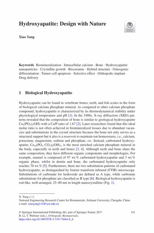
141© Springer International Publishing AG, part of Springer Nature 2017B. Li, T. Webster (eds.), Orthopedic Biomaterials, https://doi.org/10.1007/978-3-319-73664-8_6
Hydroxyapatite: Design with Nature
Xiao Yang
Keywords Biomineralization · Intracellular calcium · Bone · Hydroxyapatite nanoparticles · Crystallite growth · Bioceramic · Hybrid structure · Osteogenic differentiation · Tumor cell apoptosis · Selective effect · Orthopedic implant · Drug delivery
1 Biological Hydroxyapatite
Hydroxyapatite can be found in vertebrate bones, teeth, and fish scales in the form of biological calcium phosphate mineral. As compared to other calcium phosphate compound, hydroxyapatite is characterized by its thermodynamical stability under physiological temperature and pH [1]. In the 1900s, X-ray diffraction (XRD) pat-terns revealed that the composition of bone is similar to geological hydroxyapatite Ca5(PO4)3(OH) with a Ca/P ratio of 1.67 [2]. Later researchers found that this ideal molar ratio is not often achieved in biomineralized tissues due to abundant vacan-cies and substitutions in the crystal structure because the bone not only serves as a structural support but it also is a reservoir to maintain ion homeostasis, i.e., calcium, potassium, magnesium, sodium and phosphate, etc. Instead, carbonated hydroxy-apatite, Ca10(PO4, CO3)6(OH)2, is the most enriched calcium phosphate mineral in the body, especially in teeth and bones [3, 4]. Although teeth and bone share the same composition, they have different organic components and morphologies. For example, enamel is composed of 97 wt.% carbonated hydroxyapatite and 3 wt.% organic phase, whilst in dentin and bone, the carbonated hydroxyapatite only reaches 70 wt.% [5]. Furthermore, there are two substitution patterns of carbonated hydroxyapatite, as distinguished by fourier transform infrared (FTIR) microscopy. Substitutions of carbonate for hydroxide are defined as A type, while carbonate substitutions for phosphate are classified as B type [6]. Biological hydroxyapatite is rod-like, well-arranged, 25–80 nm in length nanocrystalline (Fig. 1).
X. Yang (*) National Engineering Research Center for Biomaterials, Sichuan University, Chengdu, Chinae-mail: [email protected]
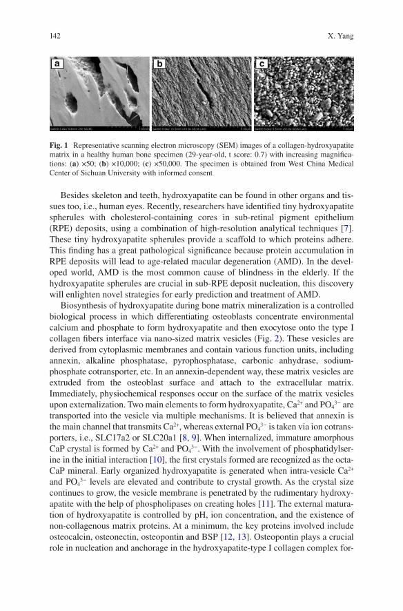
142
Besides skeleton and teeth, hydroxyapatite can be found in other organs and tis-sues too, i.e., human eyes. Recently, researchers have identified tiny hydroxyapatite spherules with cholesterol-containing cores in sub-retinal pigment epithelium (RPE) deposits, using a combination of high-resolution analytical techniques [7]. These tiny hydroxyapatite spherules provide a scaffold to which proteins adhere. This finding has a great pathological significance because protein accumulation in RPE deposits will lead to age-related macular degeneration (AMD). In the devel-oped world, AMD is the most common cause of blindness in the elderly. If the hydroxyapatite spherules are crucial in sub-RPE deposit nucleation, this discovery will enlighten novel strategies for early prediction and treatment of AMD.
Biosynthesis of hydroxyapatite during bone matrix mineralization is a controlled biological process in which differentiating osteoblasts concentrate environmental calcium and phosphate to form hydroxyapatite and then exocytose onto the type I collagen fibers interface via nano-sized matrix vesicles (Fig. 2). These vesicles are derived from cytoplasmic membranes and contain various function units, including annexin, alkaline phosphatase, pyrophosphatase, carbonic anhydrase, sodium- phosphate cotransporter, etc. In an annexin-dependent way, these matrix vesicles are extruded from the osteoblast surface and attach to the extracellular matrix. Immediately, physiochemical responses occur on the surface of the matrix vesicles upon externalization. Two main elements to form hydroxyapatite, Ca2+ and PO4
3− are transported into the vesicle via multiple mechanisms. It is believed that annexin is the main channel that transmits Ca2+, whereas external PO4
3− is taken via ion cotrans-porters, i.e., SLC17a2 or SLC20a1 [8, 9]. When internalized, immature amorphous CaP crystal is formed by Ca2+ and PO4
3−. With the involvement of phosphatidylser-ine in the initial interaction [10], the first crystals formed are recognized as the octa-CaP mineral. Early organized hydroxyapatite is generated when intra- vesicle Ca2+ and PO4
3− levels are elevated and contribute to crystal growth. As the crystal size continues to grow, the vesicle membrane is penetrated by the rudimentary hydroxy-apatite with the help of phospholipases on creating holes [11]. The external matura-tion of hydroxyapatite is controlled by pH, ion concentration, and the existence of non-collagenous matrix proteins. At a minimum, the key proteins involved include osteocalcin, osteonectin, osteopontin and BSP [12, 13]. Osteopontin plays a crucial role in nucleation and anchorage in the hydroxyapatite-type I collagen complex for-
Fig. 1 Representative scanning electron microscopy (SEM) images of a collagen-hydroxyapatite matrix in a healthy human bone specimen (29-year-old, t score: 0.7) with increasing magnifica-tions: (a) ×50; (b) ×10,000; (c) ×50,000. The specimen is obtained from West China Medical Center of Sichuan University with informed consent
X. Yang
143
mation. It is a phosphorylated sialoprotein containing a conserved sequence of con-tiguous aspartic acid residues. High levels of osteopontin are expressed in mineralized tissues and has been shown to inhibit the in vitro formation of hydroxyapatite [14]. However, when 95% of its phosphorylation sites are filled, it appears to promote hydroxyapatite formation [13]. Osteopontin has an Arg-Gly- Asp (RGD) sequence that may provide anchorage for osteoblasts [15]. The effective deposition of hydroxy-apatite crystals from cells can be observed even in the in vitro culture. For instance, in the typical osteoblastic MC3T3-E1 cell culture supplemented with osteogenic medium, XRD and FTIR analysis of crystals isolated from the cell culture indicated that the mineral phase was poorly crystalline hydroxyapatite, approximately 10–20 nm in length [16]. Overall, the compositional and structural properties of the in vitro osteoblast cell culture derived mineral are highly similar to those of bone.
The self-assemble process of the hydroxyapatite-collagen complex is still largely unknown [17]. However, its final conformation in bony tissue is well understood. In the 1980s, transmission electron micrographs of an individual mineralized collagen fibril had already unveiled that hydroxyapatite crystals are reside mainly within the fibrils and at the gap regions. It was observed that the plate-shaped crystals are uni-formly stacked across the collagen fibril diameter [18, 19]. Nowadays, scientists have taken it one step further to quantify that in the periodic 67 nm cross-striated arrangement of the fibril [20], the less dense 40 nm-long gap region is the place where hydroxyapatite crystals grow [21].
Fig. 2 Biosynthesis of hydroxyapatite in nano-sized matrix vesicles released from osteoblasts. Membrane channels and transports are required for the internalization of Ca2+ and Pi. Amorphous CaP is first formed and then developed into octa-CaP crystals. Mature hydroxyapatite is finally formed and penetrated through the vesicle membrane
Hydroxyapatite: Design with Nature
144
2 Synthetic Methods
The synthesis of nanosized hydroxyapatite powders is attracting great interest. The primary reason is that the nanocrystalline hydroxyapatite powders demonstrate enhanced densification and improved sinterability owing to greater surface area, which can increase bulk material fracture toughness, energy to failure, and other mechanical properties [22, 23]. Moreover, the importance of synthetic nanosized particles also correspondents to the biological hydroxyapatite crystals seen in nature. It yields better bioactivity due to its similarity to the natural bone composite [24–26]. A wide variety of routes have been developed to synthesize hydroxyapatite nanoparticles (HANPs) (see Table 1) and were extensively reviewed [27–29]. In general, there are three main pathways often being considered: wet chemistry, dry methods and high-temperature processing.
1) Wet chemistry. Sources of calcium and phosphate ions are in aqueous solutions in which hydroxyapatite crystals are congregated by precipitation process. It includes conventional chemical precipitation, sol-gel method, emulsion method, hydrothermal method, and sonochemical method. Wet chemistry is advanta-geous to precisely adjust morphology and size of the particles and it is the most frequently used method for the synthesis of HANPs. Particle crystallinity and phase purity, however, is hard to be controlled in this method.
2) Dry method. The dry method includes solid state synthesis and a mechanochem-ical process, which are much less often used than wet chemistry. This method is capable of producing highly crystalline hydroxyapatite with low cost raw mate-rials, i.e., egg shells, abalone shells, etc. The size of the synthesized particles is above the nano-level and the phase purity is even lower than wet chemistry.
Table 1 Comparison of different methods in literature to prepare hydroxyapatite particles
Preparation methods Particle shape Cost Crystallinity References
Chemical precipitation
Sphere, rod, nanopyramid Low Frequently low
[30–33]
Sol-gel Needle, plate, prolate spheroidal
Low Variable [34–37]
Microemulsion Sphere, rod High High [38–40]Solid state Sphere, rod, flake, hexagonal
rodLow Very high [41, 42]
Hydrothermal Sphere, rod, pseudo-cubic, pseudo-spherical
Generally high
Variable [43, 44]
Template assisted method
Frequently rod Low Variable [45–47]
Biomimetic Rod, needle, sphere Low Variable [48–50]Heat treatment Irregular Low Variable [51, 52]Sonochemical Rod, sphere Generally
lowVariable [46, 53]
X. Yang
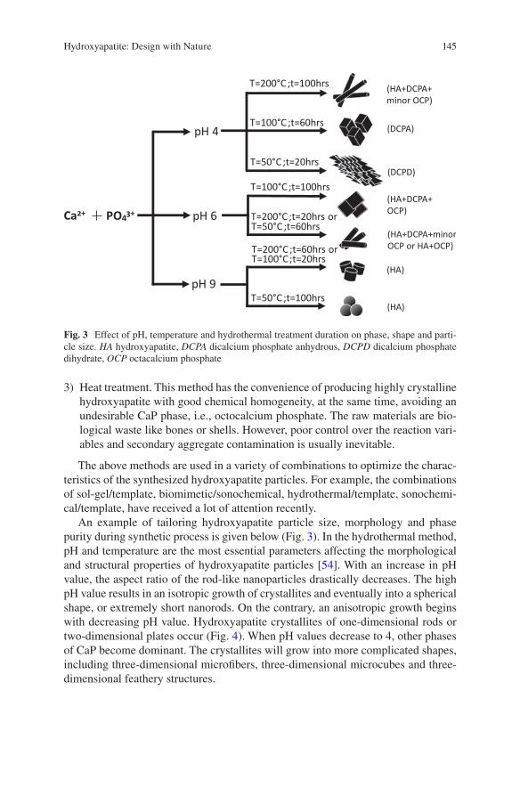
145
3) Heat treatment. This method has the convenience of producing highly crystalline hydroxyapatite with good chemical homogeneity, at the same time, avoiding an undesirable CaP phase, i.e., octocalcium phosphate. The raw materials are bio-logical waste like bones or shells. However, poor control over the reaction vari-ables and secondary aggregate contamination is usually inevitable.
The above methods are used in a variety of combinations to optimize the charac-teristics of the synthesized hydroxyapatite particles. For example, the combinations of sol-gel/template, biomimetic/sonochemical, hydrothermal/template, sonochemi-cal/template, have received a lot of attention recently.
An example of tailoring hydroxyapatite particle size, morphology and phase purity during synthetic process is given below (Fig. 3). In the hydrothermal method, pH and temperature are the most essential parameters affecting the morphological and structural properties of hydroxyapatite particles [54]. With an increase in pH value, the aspect ratio of the rod-like nanoparticles drastically decreases. The high pH value results in an isotropic growth of crystallites and eventually into a spherical shape, or extremely short nanorods. On the contrary, an anisotropic growth begins with decreasing pH value. Hydroxyapatite crystallites of one-dimensional rods or two-dimensional plates occur (Fig. 4). When pH values decrease to 4, other phases of CaP become dominant. The crystallites will grow into more complicated shapes, including three-dimensional microfibers, three-dimensional microcubes and three- dimensional feathery structures.
PO43+Ca2+
pH 4
pH 6
pH 9
T=200°C;t=100hrs
T=100°C ;t=60hrs
T=50°C ;t=20hrs
T=100°C;t=100hrs
T=200°C;t=20hrs orT=50°C ;t=60hrs
T=200°C;t=60hrs orT=100°C;t=20hrs
T=50°C ;t=100hrs
(HA+DCPA+ minor OCP)
(DCPA)
(DCPD)
(HA+DCPA+OCP)
(HA+DCPA+minorOCP or HA+OCP)
(HA)
(HA)
Fig. 3 Effect of pH, temperature and hydrothermal treatment duration on phase, shape and parti-cle size. HA hydroxyapatite, DCPA dicalcium phosphate anhydrous, DCPD dicalcium phosphate dihydrate, OCP octacalcium phosphate
Hydroxyapatite: Design with Nature
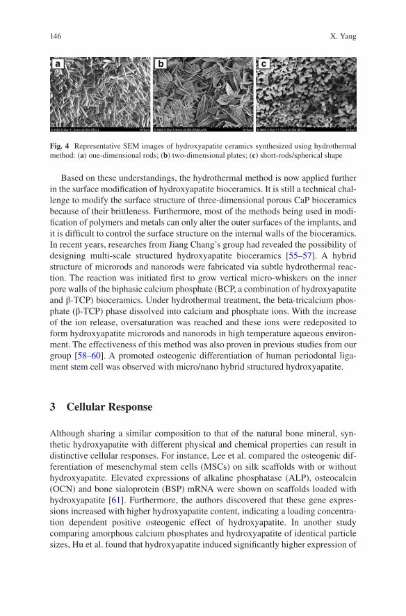
146
Based on these understandings, the hydrothermal method is now applied further in the surface modification of hydroxyapatite bioceramics. It is still a technical chal-lenge to modify the surface structure of three-dimensional porous CaP bioceramics because of their brittleness. Furthermore, most of the methods being used in modi-fication of polymers and metals can only alter the outer surfaces of the implants, and it is difficult to control the surface structure on the internal walls of the bioceramics. In recent years, researches from Jiang Chang’s group had revealed the possibility of designing multi-scale structured hydroxyapatite bioceramics [55–57]. A hybrid structure of microrods and nanorods were fabricated via subtle hydrothermal reac-tion. The reaction was initiated first to grow vertical micro-whiskers on the inner pore walls of the biphasic calcium phosphate (BCP, a combination of hydroxyapatite and β-TCP) bioceramics. Under hydrothermal treatment, the beta-tricalcium phos-phate (β-TCP) phase dissolved into calcium and phosphate ions. With the increase of the ion release, oversaturation was reached and these ions were redeposited to form hydroxyapatite microrods and nanorods in high temperature aqueous environ-ment. The effectiveness of this method was also proven in previous studies from our group [58–60]. A promoted osteogenic differentiation of human periodontal liga-ment stem cell was observed with micro/nano hybrid structured hydroxyapatite.
3 Cellular Response
Although sharing a similar composition to that of the natural bone mineral, syn-thetic hydroxyapatite with different physical and chemical properties can result in distinctive cellular responses. For instance, Lee et al. compared the osteogenic dif-ferentiation of mesenchymal stem cells (MSCs) on silk scaffolds with or without hydroxyapatite. Elevated expressions of alkaline phosphatase (ALP), osteocalcin (OCN) and bone sialoprotein (BSP) mRNA were shown on scaffolds loaded with hydroxyapatite [61]. Furthermore, the authors discovered that these gene expres-sions increased with higher hydroxyapatite content, indicating a loading concentra-tion dependent positive osteogenic effect of hydroxyapatite. In another study comparing amorphous calcium phosphates and hydroxyapatite of identical particle sizes, Hu et al. found that hydroxyapatite induced significantly higher expression of
Fig. 4 Representative SEM images of hydroxyapatite ceramics synthesized using hydrothermal method: (a) one-dimensional rods; (b) two-dimensional plates; (c) short-rods/spherical shape
X. Yang
147
type I collagen, osteopontin (OPN) and OCN mRNA in bone marrow derived MSCs culture at day 14, as compared to amorphous calcium phosphates [62]. On the con-trary, in rat osteoblast cultures supplemented with 10–40 nm HANPs, Xu et al. revealed that the growth of osteoblasts was inhibited in a particle dose-dependent manner [63]. These HANPs significantly induced apoptosis in osteoblasts via a mitochondrial-dependent pathway, in which p53 and cytochrome c are involved. These findings are seemingly controversial, however, they were caused by different physicochemical properties of the synthesized hydroxyapatite. In the following sec-tions, we categorize the effect of hydroxyapatite on stem cells into osteogenic dif-ferentiation and tumor cell inhibition, with the corresponding material factors responsible specified.
3.1 Hydroxyapatite Bioceramic Induced Osteogenic Differentiation
Surface roughness (grain size) and crystallinity of hydroxyapatite ceramics played a critical role in cell adhesion and cell differentiation. Zhou et al. discovered that rab-bit bone mesenchymal stem cells (BMSCs) attached better on hydroxyapatite sur-faces with an Ra value of 11.9 nm compared to an Ra value of 54.2 nm [64]. In addition, at the micro-scale, Deligianni et al. also observed that human BMSCs adhered better on hydroxyapatite bioceramic disks with smaller surface features (Ra ≈ 0.7 μm compared to Ra ≈ 4 μm) [65]. In aspect of crystallinity, it was demon-strated by Hu et al. that BMSCs grew better on hydroxyapatite with higher crystal-linity as compared to amorphous low crystallinity calcium phosphates [62]. Berube et al. also presented that rat calvarial derived primary osteoblast cultures spread well on highly crystallinity hydroxyapatite surfaces [66]. It is suggested that surface roughness of the hydroxyapatite is correlated with cell-adhesive extracellular matrix (ECM) protein adsorption [67], and the insolvable crystallized hydroxyapatite sur-faces offered nucleation sites for the precipitation of apatite crystals in culture medium [68]. Webster et al. revealed a greater amount of serum protein adsorption onto hydroxyapatite with a grain size of 67 nm and an Ra value of 17 nm, as com-pared to the hydroxyapatite possessing a grain size of 179 nm and an Ra value of 10 nm [26]. The author attributed the elevated protein adsorption to an increase in roughness at the nano-level. Later, it was discovered in an in vivo experiment that bone formation was enhanced with nanocrystallized hydroxyapatite modified implant surfaces [69]. However, it is not always the smaller grain size, the superior osteoinductivity. Okada et al., who compared the cellular responses of rat BMSCs seeded on various types of hydroxyapatite nanocrystals (nanofiber, nanoneedle and nano sheets), suggested that the contact domain size between the cell and the sub-strate would greatly affect the adhesion activity and subsequent responses of BMSCs [70]. Focal adhesion distribution in the cells was limited by isolated small domains of the nanostructured hydroxyapatite, which further corresponded with the
Hydroxyapatite: Design with Nature
148
formation of intracellular stress-sensing fibers. Contact domains larger than 100 nm in width would result in stable adhesion as required for cell survival. Furthermore, a recent study showed that hydroxyapatite bioceramics with a micro-/nano-hybrid sur-face topography significantly enhanced adipose derived stem cell attachment, viabil-ity and osteogenic differentiation, as compared to mono patterned controls [57].
Besides surface roughness and crystallinity, factors such as microporosity, pH and surface charge of hydroxyapatite also affect its protein adsorption and cell adhesion. In a study investigating the effect of zeta potential, specific area and microporosity of hydroxyapatite on protein adsorption behavior, Rouahi et al. dis-covered that microporosity played an important role in protein adsorption amount [71]. Work from Kandori’s group suggested that at neutral pH, more anionic bovine serum albumin was adsorbed on hydroxyapatite surfaces of higher crystallinity. Despite the overall surface charge of hydroxyapatite being negative, this adsorption behavior was mainly mediated via exposed calcium, the positively charged sites [72]. It seems that the capacity of proteins to conform to the surface and the pres-ence of cationic groups appear to enhance protein adsorption on hydroxyapatite.
The osteogenic differentiation ability of bioceramics appears to be greatly influ-enced by Ca2+ ions in equilibrium with or released from its surfaces. The requirement of calcium ion channels and calcium sensing receptors (CaSR) in Ca2+ mediated osteogenesis of pre-osteoblasts has been confirmed [73]. Jung et al. revealed that the accumulation of extracellular calcium ions might be caused by slight dissolution of hydroxyapatite. These ions were effectively internalized by ion channels, via the acti-vated CaMK2α/CAM pathway. The upstream regulator of osteoblast differentiation, CREB pathway, might be subsequently activated. Besides calcium transportation, there should be other signal pathways that exist in the process of osteogenesis induced by hydroxyapatite. For instance, recently, the activation of an Akt signaling pathway was observed by Xia et al. in cells cultured on hydroxyapatite ceramics [57]. Higher protein levels of phosphorylated Akt was observed in hydroxyapatite co-cultured cell groups at day 2. Moreover, the osteoinduction effects of hydroxyapatite ceramics could be abolished by the Akt signaling pathway inhibitor, LY294002. It has been reported that this signal pathway played a significant role in osteogenic differentia-tion of progenitor cells, via mediation of angiogenic factor expression, such as VEGF [74–76]. Angiogenesis is considered to be an essential process in new bone forma-tion, and calcium phosphate bioceramics inducing in vivo osteoinduction is highly dependent on adequate vascularization [77]. Other than signaling pathways, the work of Ha et al. suggests that the osteoblast lineage commitment modulated by hydroxy-apatite might be related to stimulation of DNA methylation [78].
3.2 HANPs Induced Cancer Cell Apoptosis
Different from bulk hydroxyapatite bioceramics, HANPs show distinctive anti- tumor ability. It is widely confirmed that apoptosis of various kinds of tumor cells can be aroused by HANPs. For example, HANPs with a proper concentration and
X. Yang
149
particle size (150 μg/mL, 50–60 nm) were found to induce the apoptosis of malig-nant melanoma A375 cells [79, 80]. Whilst apoptosis of gastric cancer cells SGC- 7901 was induced by HANPs at a lower concentration (25 μg/mL, <50 nm) [81]. It is generally accepted that the apoptosis induced by HANPs was mediated mainly through mitochondrial-dependent and caspase-family dependent pathways [27]. Table 2 lists several (not all) types of tumor cells whose proliferation could be sup-pressed by HANPs.
The tumor cell inhibitory effect of HANPs is closely associated with the material properties. Particle size of the HANPs is the most studied factor that governs the induced biological functions. Yuan et al. completed a systematic comparison on cell apoptosis rate upon treatment of different sizes of HANPs. A human hepatoma HepG2 cell model was used in their study to characterize apoptosis-induction, levels of apoptotic signaling proteins and anti-tumor activity with 20–180 nm HANPs treatment. Their findings validated the fact that the anti-tumor activity of HANPs was strongly dependent on particle size and the efficacy increased in the order of 175 nm < 78 nm < 26 nm < 45 nm. Their research group discovered that the effective size of HANPs with anti-tumor function ranged from 20 nm to 80 nm, with the best efficiency from 45 nm HANPs. The function was achieved through activated cas-pase-3 and caspase-9 genes, decreased Bcl-2 protein, and increased protein levels of Bax and Bid as well as the release of mitochondrial cytochrome c into cytoplasm. Together with FITC-labeled HANPs cellular internalization results, they concluded the effect of HANPs on the induced cytotoxicity and apoptosis in HepG2 cells was predominantly dependent on their size and the cellular localization. Another study conducted by Zhang et al. also proved that, as compared to 70 nm, HANPs with 40 nm lengths had a stronger negative effect on MC3T3-E1 cell proliferation [91]. Intracellular reactive oxygen species (ROS) and calcium concentration were ele-vated with internalization of 40 nm HANPs. Besides particle size, particle concen-tration of HANPs is the second most researched property that may affect cellular response. It is often the higher concentration, the greater suppression effect of tumor cell proliferation. For normal cells, Remya et al. synthesized 50 nm- sized HANPs
Table 2 Effect of HANPs on different types of tumor cells reported in the literature
HANPs size (nm) Cell type Effect Reference
20–80 MG63 Inhibited proliferation [82]26–78 HepG2 Induced apoptosis [83]30 Human macrophages Inhibited proliferation [84]30–80 Rat macrophages Inhibited proliferation [85]50 Hepatoma cell line BEL-7402 Induced apoptosis [86]50 Human oral epithelium Induced apoptosis [87]50 MGC80-3, Os-732, Bel-7402 Inhibited proliferation [88]≤50 Gastric Cancer SGC-7901 cells Inhibited proliferation [81]50–60 Malignant melanoma A375 cells Induced apoptosis [79]50–80 C6 cells Induced apoptosis [89]<100 Hepatocellular carcinoma cells Inhibited proliferation [90]
Hydroxyapatite: Design with Nature
150
using a precipitation method to study the cytotoxicity, ROS and apoptotic behavior of MSCs [92]. The cell viability assay indicated that HANPs did not induce cytotox-icity up to 800 μg/ml. However, the concentration associated effect closely corre-sponded to the synthetic method to prepare HANPs. The suspended gel preparation method was proven to be the most toxic, by which cell death took place when the HANPs concentration was higher than 31 μg/ml [93]. Other preparations were toxic but only at higher concentrations (>250 μg/ml). The surface charge and morphology of HANPs also matter in their biological functions [94, 95].
A selective effect of HANPs on tumor cells and normal cells was widely observed. Cai et al. [96] prepared HANPs, approximately 20 nm, 40 nm and 80 nm in size, and investigated their effects on the viability of MSCs and osteosarcoma cells (U2OS). Enhanced cell viability of MSCs was determined with HANPs treat-ment, especially for the 20 nm particles. On the contrary, the proliferation of osteo-sarcoma cells was inhibited by HANPs, remarkably so for the identical 20 nm particles. Upon the same HANPs treatment, co-culture systems (tumor vs. normal cells) of MGC80-3/ HeLa/HepG2 vs. L-02 [97, 98], MG63 vs. primary osteoblast [99], A594 vs. 16HBE [100], and Bel-7402 vs. L-02 [88] all showed selective inhi-bition on tumor cells, but no effect on normal cells. The current understanding on the mechanism of this selective effect of HANPs was attributed to the following reasons: (1) caspase-3, -8 and -9 is activated only in tumor cells by HANPs (~50 nm) but not in normal cells; (2) HANPs is preferentially accumulated in the mitochon-dria of tumor cells. Several mitochondrial-dependent apoptotic genes were highly expressed, i.e., bcl-2, bax, cyto c; (3) intracellular calcium levels are abnormally elevated only in tumor cells; (4) internalization of HANPs in the cytoplasm and nucleus was observed to be more in tumor cells, as compared to normal cells. These different cellular responses to HANPs might be associated with distinguished phys-iochemical features and metabolic pathways between tumor and normal cells.
4 Applications
Hydroxyapatite has been employed for a variety of biomedical applications. For instance, it is widely used as a matrice for bone tissue engineering and drug release materials. Synthetic hydroxyapatite exhibits strong affinity to host hard tissues due to its similarity to the natural inorganic component of the bone matrix. Chemical bonding with the host tissue grants hydroxyapatite a superiority to be used as a bio-ceramic scaffold or as a coating layer for metallic implants in clinical applications. In the 1990s, hydroxyapatite was simply shaped into condensed cylinders and implanted into the trabecular bone of rabbits. As observed, the cylinders demon-strated a tight integration with surrounding bone tissue [101]. The hydroxyapatite particles were tightly incorporated into the preexisting trabecular bone after 28 days of implantation. Similar in vivo results were observed with electropolished titanium cylinders coated with hydroxyapatite [69]. Furthermore, among various monophasic
X. Yang
151
calcium phosphate materials, hydroxyapatite is the most stable and the least soluble phase [102, 103]. It has a Ksp value of 2.9 × 10−58 over a pH range of ~3.5 to ~9.7 [104]. The primary advantages of synthetic hydroxyapatite are its biocompatibility, good osteoconductive and moderate osteoinductive abilities. The general applica-tions of hydroxyapatite materials are characterized in the following sections.
4.1 In the Form of Bioceramics for Orthopedic Reconstruction
In the 1990s, Yamasaki and Klein et al. discovered that certain types of calcium phosphate ceramics possess the ability to induce osseous substance formation in soft tissues [105, 106]. Both research groups revealed that, with suitable porous structures, hydroxyapatite ceramics had osteoinductivity, whilst dense hydroxyapa-tite did not. Osteoinductivity refers to a bone graft material which is able to cause ectopic bone formation, without the addition of growth factors or bone cells [107–111]. The conclusion of this work is supported by many recent studies [108, 112–114]. The findings are enlightening that better bone regeneration might be able to be achieved in clinical segmental bone defects, without involvement of exogenous bio-logical factors [110, 115]. By this approach, disease transmission and allogeneic immunological reaction can be circumvented. Nowadays, a faster degradation rate than hydroxyapatite is believed to be more advantageous for the osteoinduction of bioceramics [112]. However, for the process of new bone formation to take place, a mechanically stable structure is essential. For this reason, hydroxyapatite in combi-nation with a more soluble β-TCP phase, known as BCP bioceramics, is commonly used in clinical bone repair.
The osteoinduction of porous BCP bioceramics is strongly associated with its ability to develop bone-like apatite on the surface. The abundance of the bone-like apatite appears to be inversely correlated with the HA/β-TCP ratio of the ceramics. Greater amounts of apatite is measured with lower ratios. It was proposed that the formation of bone-like apatite results from the partial dissolution of bioceramics to reach a supersaturation of the calcium and phosphate ions in the porous microenvi-ronment. The reprecipitation of these ions incorporates the carbonate, magnesium ions presented in the biological fluid, and thus bone-like apatite is formed. Commercial BCP bioceramics of varying HA/β-TCP are currently available in dif-ferent forms: granules, blocks, wedges and cylinders. Clinical applications of BCP bioceramics include but are not limited to: repair of large bony defects, correction of scoliosis, lumbar spine fusion, ophthalmic implant, periodontal defects, fillers for enchondroma of the metacarpals and phalanges of the hand. For a long time, BCP bioceramics are considered as the gold standard of bone substitutes in bone recon-structive surgery [116–120]. Nowadays, new emerging 3D printing of bioceramics allows designing individual-specific geometries that are reconstructed from CT scans and therefore fit perfectly into the bone defect. In this attempt, Detsch et al. designed 3D printed BCP scaffolds by gluing granules together by a binder liquid
Hydroxyapatite: Design with Nature
152
following a sintering step [121]. After seeding monocytic RAW 264.7 cells on the surface of the 3D printed BCP, great cell differentiation and resorption activity was observed. This demonstrated the potential of using 3D printed BCP bioceramics to serve as a better bone substitute with desired shapes.
4.2 Incorporation with Polymers as Scaffolds for Bone Substitution
The chemical composition of hydroxyapatite makes it an excellent candidate for bone repair and replacement. However, mechanical properties are major factors which limit its use in clinical situations [122]. To be more specific, the inherent brittleness, fragility and lack of flexibility of calcium phosphate ceramics hindered their application as a load-bearing implant. To overcome its weakness in mechanical performance without compromise of the biocompatibility, one solution is to use hydroxyapatite in combination with polymeric scaffolds. The porous scaffolds from natural polymers with nano-sized hydroxyapatite addition are highly recommended for use in bone regeneration. The ideal model would form a secure bond by surface hydroxyapatite with surrounding tissue which allows migration and growth of the bone forming cells into the scaffold. The major fabrication methods include solvent casting, freeze drying process, electrospinning and in situ mineralization of hydroxyapatite in a polymer matrix [123].
1) Solvent/solution casting method. This method involves a dissolution step of polymer in an organic solvent which contains hydroxyapatite powders. The solu-tion is then casted into a 3D mold. The solvent will be evaporated eventually. No specialized equipment is required in preparation steps of this technique. The solvent casting method is often used in combination with other techniques. A combination of solvent casting and freeze-drying has been reported by Aboudzadeh et al. to develop poly lactic-co-glycolic acid (PLGA)/ HANPs scaf-folds with an interconnected porous network (70% porosity) [124]. In their study, the solvent, N-methyl pyrrolidone, was a non-toxic parenteral pharmaceu-tical product. The PLGA/HANPs composite scaffolds with different percentages of HANPs were assessed thoroughly. An elevated bioactivity was observed with an increase of hydroxyapatite content. In another study, Azami et al. prepared a 3D nanocomposite of gelatin with HANPs through a novel layer solvent casting combined method using a freeze-drying technique. The prepared scaffolds are of well-fined porous structure with porosity ranging from 75 to 93%. The compressive modulus is about 180 MPa. L929 fibroblasts laden on the scaffold exhibited a high proliferation rate.
2) Freeze-drying method. This method was developed in the 1980s and is being used now. The nanofibers generated by this technique are similar to those of the natural type I collagen bone matrix since it offers the arrangement of structures of a certain porosity and pore size with homogeneity. The theory behind it is that
X. Yang
153
solvent effectiveness decreases with decreasing temperature. When cooling down, the homogeneous multi-component system tends to separate by phase due to the unstableness caused by thermodynamics. During the phase separation pro-cess, a polymer-rich phase and a polymer-lean phase are formed. A microporous structure is formed when removing the solvent leaving the polymer-rich phase to solidify. This process drives the polymer and hydroxyapatite mixture into inter-stitial space. The ice solvent is then evaporated when the mixture is lypophilized. In this method, the structure is dependent on polymer material type, concentra-tion, quenching temperature and solvent used [125].
3) Electron spinning method. Electrospinning is a simple but versatile technique creating functional nanofiber scaffolds with well-defined hierarchical structures. This method has been widely used to fabricate ceramic nanofibers. It has the advantage of rendering high-porosity structures and a large surface area to vol-ume ratio due to the small diameter of fibers. Materials used in this method can be natural macromolecules or synthetic biodegradable polymers, such as chito-san, silk fibroin, collagen, poly (ε-caprolactone) (PCL), polyglycolic acid (PGA), polylactic acid (PLA) and poly l-lactic acid (PLLA), or in combinations [123]. In addition, during electrospinning, various substances including hydroxyapatite particles and growth factors can be incorporated into the nanofibers. Recently, Bao et al. adopted a co-electrospinning technique to incorporate hydroxyapatite into poly (d,l-lactide-co-trimethylene carbonate) (PLMC), which possesses a shape memory function. The switching temperature for actuating shape recovery of the composite HA/PLMC fibrous scaffold was finely adjusted to fall between 43.5 and 51.3 °C by tuning the HA weight percentage. Alkaline phosphatase secretion and mineral deposition of the osteoblasts was greatly elevated when incorporating HA with PLMC nanofibers [126].
4) Biomimetic mineralization of hydroxyapatite. This technique is a process simi-lar to the in situ mineralization of hydroxyapatite onto the collagen fibers incor-porated with bone forming proteins. Nucleation and growth of carbonated hydroxyapatite onto the polymers is involved. The mechanism was studied in detail by Kobubo et al. [127]. Calcium ions in solution are attracted to the nega-tively charged polymers. Alternative layers of calcium-rich and phosphate-rich amorphous calcium phosphate are then deposited until the surface potential is balanced. These layers will eventually crystallize into bone-like apatite [128, 129]. Mineralized collagen prepared with this technique is now commercialized as a clinical applicable product, Bongold® by the Allgens company [130]. It is often used alone or in collaboration with PMMA bone cement as a filling mate-rial. The combination has appropriate elasticity modulus and compressive strength similar to those of bone. Besides, compared to pure PMMA cement, its biocompatibility is greatly enhanced.
Other methods including electrodeposition, stereolithography and 3D printing are also widely used. For example, Guilaume et al. recently prepared photo- crosslinkable poly(trimethylene carbonate) (PTMC) resins containing 20 and 40 wt.% of HANPs and fabricated scaffolds with controlled macro-architecture
Hydroxyapatite: Design with Nature
154
[131]. Their research revealed that the stereolithography process was responsible for the formation of a rich microscale layer of HA corralling scaffolds. Bone regen-eration in a rabbit calvarial defect was significantly improved using this scaffold.
4.3 Coating for Metallic Implants
One of the great innovations in the last 20 years has been to coat bioinert prostheses by calcium phosphates. Among different calcium phosphates, hydroxyapatite is mostly used as a coating for a metallic implant to induce osseointegration. In the interface, a strong bond between hydroxyapatite-coated implant and the surround-ing bone tissue may be established. It has been reported that, for hydroxyapatite- coated titanium prosthesis, the shear strength of the interface between bone and implant is approximately 6.5 times stronger than that of the non-coated titanium alone [132]. Furthermore, a significantly faster bone formation can be achieved with a hydroxyapatite coating, as documented using large animal models [133–135]. Especially, under a compromised bone condition, i.e., bone rarefaction, osseointe-gration and survival rate of an implant could be greatly improved with hydroxyapa-tite coatings. However, in healthy bone, the result of hydroxyapatite coatings would show few statistically significant differences as compared to uncoated implants, as widely observed in dental, hip and knee implants cases [136–141]. It indicates that hydroxyapatite-coated implants are more appropriate for patients with poor bone quality [142]. It was also suggested that the hydroxyapatite coatings may not be suitable for use in bipolar hemiarthroplasty. High concentrations of polyethylene may accumulate in the joint space due to the sealing effect of the coating. As a result, massive proximal femoral osteolysis occurs [142]. The above discussion is mainly based on titanium implants. As for magnesium alloys, hydroxyapatite coat-ings have a different function. As a biodegradable metal, magnesium alloys could eliminate stress shielding effects and implant removal surgery [143]. However, the degradation rates of magnesium implants must be modulated to match the rates of new bone formation. Hydroxyapatite coatings on magnesium alloys were proven to be an effective approach to control their degradation rates. For example, the high corrosion-resistant Mg–Zn–Ca alloy implants were developed based on hydroxy-apatite coating techniques, i.e., pulse electrophoresis [144].
4.4 Drug Delivery Carriers for Bone Formation
In the 1970s, it was discovered that serum proteins could be reversibly adsorbed to hydroxyapatite surface depending upon protein structure, protein charge and sur-face charge. In recent years, significant attention has been attracted to the use of hydroxyapatite as a bone implant and as drug delivery vehicle simultaneously, add-ing a new function to their application. The term ‘drug’ here is not only limited to
X. Yang
155
therapeutic agents, but also refers to growth factors, enzymes and genes (DNA, RNAs). Hydroxyapatite meets the requirements to be applied as a drug carrier. That is, the capacity to load a drug physically or chemically, retain it until a target site is reached, and gradually degrade over time [145]. Major concerns associated with synthetic polymeric delivery systems are the biodegradation in body fluids before it reaches the target and the by-products which can be toxic. However, hydroxyapatite- based drug delivery does not have these disadvantages. First, hydroxyapatite parti-cles are almost insoluble at body fluid circulation (pH 7.4) and are not prone to enzymatic degradation. Second, the degradation products of hydroxyapatite are Ca2+ and PO4
3−, which are already inherent to the body. Thus, their solubility, non- toxic degradation products and non-immunoresponse make hydroxyapatite a suit-able candidate for drug delivery. Bone antiresorptive bisphosphates and anabolic parathyroid hormone (PTH) derivants are the frequently used therapeutic agents incorporated with hydroxyapatite for local delivery. For example, Ardura et al. loaded parathyroid hormone-related protein (PTHrP) onto modified gelatin-coated hydroxyapatite implants to improve bone defect healing in the tibia of osteoporotic rats [146]. Enhanced defect repair, in terms of increased bone volume/tissue volume (BV/TV), trabecular thickness (Tb.Th) and cortical thickness (Ct.Th), occurred in the presence of PTHrP incorporated hydroxyapatite implants. Osteogenesis related BMPs and vascularization associated VEGFs proteins are the most commonly delivered growth factors by hydroxyapatite carriers for bone formation. Recently, Shi et al. successfully functionalized hydroxyapatite particles with lactoferrin, a promising novel bone growth factor. An improved biocompatibility and bone form-ing potential was observed in the HA-lactoferrin complex group [147].
Furthermore, HANPs were effective carriers for transmembrane gene delivery or non-viral silencing and transfection. Electrostatic interactions between calcium ions in hydroxyapatite and phosphate groups in the backbone of the DNA or RNA struc-ture are the major force that drives the binding. The genes are often targeted for tumor cells, i.e., osteosarcoma. These exogenous gene sequences can inhibit the fundamental cellular functions of the receptor cells or induce apoptosis. Other than anti-tumor genes, bone-forming aimed gene delivery is also preferred in hydroxy-apatite based applications. Curtin et al. had incorporated HANPs with pDNA in collagen-based scaffolds [148]. Following HANPs-BMP2 transfection in cell cul-tures, significantly promoted osteogenesis was then observed. The hydroxyapatite- based gene delivery efficiency is highly dependent on its surface charge, surface area, chemistry and crystallinity. Hanifi et al. found that gene delivery could be enhanced with the incorporation of a β-TCP phase into hydroxyapatite via an increased solubility in endosome [149]. Following the dissolution of a calcium phosphate carrier, loaded genes can easily escape from endosomes and integrate into the cell genome subsequently.
Besides nanoparticles, hydroxyapatite containing scaffolds have also been widely reported to effectively deliver drugs and growth factors for bone regeneration pur-poses. Compared to systematic delivery, the local growth drug/factor delivery with bone substitutes under disease conditions is more efficient. Recombinant human (bone morphogenetic proteins) BMP-2 protein was combined with a collagen- hydroxyapatite
Hydroxyapatite: Design with Nature
156
porous scaffold fabricated via lyophilization [150]. The controlled release of BMP-2 with the scaffold lasted for at least 21 days. At a critical- sized rat calvarial defect, after 8 weeks of implantation, this BMP-2 incorporated collagen-hydroxyapatite scaffold showed significantly enhanced new bone regeneration as compared to the non-loaded controls, without eliciting bone resorption or anomalies.
5 Conclusions
Hydroxyapatite is both a natural material of ancient history (basic component of skeleton) as well as a synthetic material with modern history. Synthetic hydroxy-apatite is one of the most studied materials for bone repair with a variety of prepara-tion methods. In the forms of particle, ceramic or coating, it has been used clinically in a wide range of different applications. For the future development of implants incorporated with hydroxyapatite, a better understanding of the influence of particle size, concentration, crystal morphology and surface features controls and interacts with cells holds great significance. Furthermore, the biosafety of nanosized hydroxy-apatite particle following chronic exposure should be thoroughly investigated.
Acknowledgements The author wishes to thank Professor Xingdong Zhang (National Engineering Research Center for Biomaterials, Sichuan University) for providing insightful com-ments to this manuscript. The author is grateful to Professor Kai Zhang and Xiangdong Zhu from our research center for their technical guidance.
References
1. Kalita SJ, Bhardwaj A, Bhatt HA. Nanocrystalline calcium phosphate ceramics in biomedical engineering. Mater Sci Eng C Biomim Mater Sensors Syst. 2007;27:441–9. file://localhost/Users/rudihoetzel/Uni/Papers/2007/Kalita/Kalita_Mater. Sci. Eng. C Biomim. Mater. Sens. Syst._2007.pdf%5Cnpapers://66582432-3a6a-44fc-b266-774d13a6b7da/Paper/p2636
2. Boskey AL. Mineralization of bones and teeth. Elements. 2007;3:385–91. https://doi.org/10. 2113/GSELEMENTS.3.6.385.
3. Olszta MJ, Cheng X, Jee SS, Kumar R, Kim YY, Kaufman MJ, Douglas EP, Gower LB. Bone structure and formation: a new perspective. Mater Sci Eng R Rep. 2007;58:77–116. https://doi.org/10.1016/j.mser.2007.05.001.
4. Weiner S. An overview of biomineralization processes and the problem of the vital effect. Rev Miner Geochem. 2003;54:1–29. https://doi.org/10.2113/0540001.
5. Aizenberg J. Skeleton of Euplectella sp.: structural hierarchy from the nanoscale to the mac-roscale. Science. 2005;309:275–8. https://doi.org/10.1126/science.1112255.
6. Barralet J, Best S, Bonfield W. Carbonate substitution in precipitated hydroxyapatite: an investigation into the effects of reaction temperature and bicarbonate ion concentration. J Biomed Mater Res. 1998;41:79–86. https://doi.org/10.1002/(SICI)1097-4636(199807)41: 1<79::AID-JBM10>3.0.CO;2-C.
7. Thompson RB, Reffatto V, Bundy JG, Kortvely E, Flinn JM, Lanzirotti A, Jones EA, McPhail DS, Fearn S, Boldt K, Ueffing M, Ratu SGS, Pauleikhoff L, Bird AC, Lengyel
X. Yang
157
I. Identification of hydroxyapatite spherules provides new insight into subretinal pigment epithelial deposit formation in the aging eye. Proc Natl Acad Sci U S A. 2015;112:1565–70. https://doi.org/10.1073/pnas.1413347112.
8. Shih YV, Hwang Y, Phadke A, Kang H, Hwang NS, Caro EJ. Calcium phosphate-bearing matrices induce osteogenic differentiation of stem cells through adenosine signaling. Proc Natl Acad Sci U S A. 2013;111:990–5. https://doi.org/10.1073/pnas.1321717111.
9. Beck GR Jr. Inorganic phosphate as a signaling molecule in osteoblast differentiation. J Cell Biochem. 2003;90:234–43. https://doi.org/10.1002/jcb.10622.
10. van Leeuwen JP, van Driel M, van den Bemd GJ, Pols HA. Vitamin D control of osteo-blast function and bone extracellular matrix mineralization. Crit Rev Eukaryot Gene Expr. 2001;11:199–226. https://doi.org/10.1615/CritRevEukarGeneExpr.v11.i1-3.100.
11. Jones D, Morgan C, Cockcroft S. Phospholipase D and membrane traffic. Potential roles in regulated exocytosis, membrane delivery and vesicle budding. Biochim Biophys Acta Mol Cell Biol Lipids. 1999;1439:229–44. https://doi.org/10.1016/S1388-1981(99)00097-9.
12. Anderson HC. Molecular biology of matrix vesicles. Clin Orthop Relat Res 1995 (314) 266–80. https://doi.org/10.1097/00003086-199505000-00034.
13. Gericke A, Qin C, Spevak L, Fujimoto Y, Butler WT, Sørensen ES, Boskey AL. Importance of phosphorylation for osteopontin regulation of biomineralization. Calcif Tissue Int. 2005; 77:45–54. https://doi.org/10.1007/s00223-004-1288-1.
14. Hunter GK, Kyle CL, Goldberg HA. Modulation of crystal formation by bone phosphopro-teins: structural specificity of the osteopontin-mediated inhibition of hydroxyapatite forma-tion. Biochem. J. 1994;300(Pt 3):723–8. https://doi.org/10.1042/bj3020175.
15. Flores ME, Norgård M, Heinegård D, Reinholt FP, Andersson G. RGD-directed attachment of isolated rat osteoclasts to osteopontin, bone sialoprotein, and fibronectin. Exp Cell Res. 1992;201:526–30. https://doi.org/10.1016/0014-4827(92)90305-R.
16. Addison WN, Nelea V, Chicatun F, Chien YC, Tran-Khanh N, Buschmann MD, Nazhat SN, Kaartinen MT, Vali H, Tecklenburg MM, Franceschi RT, McKee MD. Extracellular matrix mineralization in murine MC3T3-E1 osteoblast cultures: an ultrastructural, compositional and comparative analysis with mouse bone. Bone. 2015;71:244–56. https://doi.org/10.1016/j.bone.2014.11.003.
17. Niu L, Jee SE, Jiao K, Tonggu L, Li M, Wang L, Yang Y, Bian J, Breschi L, Jang SS, Chen J, Pashley DH, Tay FR. Collagen intrafibrillar mineralization as a result of the balance between osmotic equilibrium and electroneutrality. Nat Mater. 2016;16:370–8. https://doi.org/10.1038/nmat4789.
18. Miller A, Parker SB. Collagen: the organic matrix of bone. Philos Trans R Soc B Biol Sci. 1984;304:455–77. https://doi.org/10.1098/rstb.1984.0040.
19. Weiner S, Traub W. Organization of hydroxyapatite crystals within collagen fibrils. FEBS Lett. 1986;206:262–6. https://doi.org/10.1016/0014-5793(86)80993-0.
20. Orgel JPRO, Irving TC, Miller A, Wess TJ. Microfibrillar structure of type I collagen in situ. Proc Natl Acad Sci U S A. 2006;103:9001–5. https://doi.org/10.1073/pnas.0502718103.
21. Mahamid J, Aichmayer B, Shimoni E, Ziblat R, Li C, Siegel S, Paris O, Fratzl P, Weiner S, Addadi L. Mapping amorphous calcium phosphate transformation into crystalline mineral from the cell to the bone in zebrafish fin rays. Proc Natl Acad Sci U S A. 2010;107:6316–21. https://doi.org/10.1073/pnas.0914218107.
22. Wang J, Shaw LL. Nanocrystalline hydroxyapatite with simultaneous enhancements in hard-ness and toughness. Biomaterials. 2009;30:6565–72. https://doi.org/10.1016/j.biomaterials. 2009.08.048.
23. Gervaso F, Scalera F, Kunjalukkal Padmanabhan S, Sannino A, Licciulli A. High-performance hydroxyapatite scaffolds for bone tissue engineering applications. Int J Appl Ceram Technol. 2012;9:507–16. https://doi.org/10.1111/j.1744-7402.2011.02662.x.
24. Webster TJ, Ergun C, Doremus RH, Siegel RW, Bizios R. Enhanced functions of osteoblasts on nanophase ceramics. Biomaterials. 2000;21:1803–10. https://doi.org/10.1016/S0142-9612 (00)00075-2.
Hydroxyapatite: Design with Nature
158
25. Webster TJ, Ergun C, Doremus RH, Siegel RW, Bizios R. Enhanced osteoclast-like cell functions on nanophase ceramics. Biomaterials. 2001;22:1327–33. https://doi.org/10.1016/S0142-9612(00)00285-4.
26. Webster TJ, Ergun C, Doremus RH, Siegel RW, Bizios R. Specific proteins mediate enhanced osteoblast adhesion on nanophase ceramics. J Biomed Mater Res. 2000;51:475–83. https://doi.org/10.1002/1097-4636(20000905)51:3<475::AID-JBM23>3.0.CO;2-9.
27. Zhou H, Lee J. Nanoscale hydroxyapatite particles for bone tissue engineering. Acta Biomater. 2011;7:2769–81. https://doi.org/10.1016/j.actbio.2011.03.019.
28. Sadat-Shojai M, Khorasani MT, Dinpanah-Khoshdargi E, Jamshidi A. Synthesis methods for nanosized hydroxyapatite with diverse structures. Acta Biomater. 2013;9:7591–621. https://doi.org/10.1016/j.actbio.2013.04.012.
29. Fox K, Tran PA, Tran N. Recent advances in research applications of nanophase hydroxyapa-tite. ChemPhysChem. 2012;13:2495–506. https://doi.org/10.1002/cphc.201200080.
30. Dhand V, Rhee KY, Park SJ. The facile and low temperature synthesis of nanophase hydroxyapatite crystals using wet chemistry. Mater Sci Eng C. 2014;36:152–9. https://doi.org/10.1016/j.msec.2013.11.049.
31. Santhosh S, Balasivanandha Prabu S. Thermal stability of nano hydroxyapatite synthesized from sea shells through wet chemical synthesis. Mater Lett. 2013;97:121–4. https://doi.org/10. 1016/j.matlet.2013.01.081.
32. Abidi SSA, Murtaza Q. Synthesis and characterization of nano-hydroxyapatite powder using wet chemical precipitation reaction. J Mater Sci Technol. 2014;30:307–10. https://doi.org/10.1016/j.jmst.2013.10.011.
33. Liu W, Qian G, Zhang B, Liu L, Liu H. Facile synthesis of spherical nano hydroxyapatite and its application in photocatalytic degradation of methyl orange dye under UV irradiation. Mater Lett. 2016;178:15–7. https://doi.org/10.1016/j.matlet.2016.04.175.
34. Bakan F, Laçin O, Sarac H. A novel low temperature sol-gel synthesis process for ther-mally stable nano crystalline hydroxyapatite. Powder Technol. 2013;233:295–302. https://doi.org/10.1016/j.powtec.2012.08.030.
35. Sanosh KP, Chu M-C, Balakrishnan A, Kim TN, Cho S-J. Preparation and characterization of nano-hydroxyapatite powder using sol-gel technique. Bull Mater Sci. 2009;32:465–70. https://doi.org/10.1007/s12034-009-0069-x.
36. Klinkaewnarong J, Utara S. Preparation and characterization of nanohydroxyapatite by modified sol-gel method with natural rubber latex as a templating agent. Inorg Nano-Metal Chem. 2017;47:340–6. https://doi.org/10.1080/15533174.2016.1186045.
37. Ben-Arfa BAE, Salvado IMM, Ferreira JMF, Pullar RC. Novel route for rapid sol-gel syn-thesis of hydroxyapatite, avoiding ageing and using fast drying with a 50-fold to 200-fold reduction in process time. Mater Sci Eng C. 2017;70 (796–804. https://doi.org/10.1016/j.msec.2016.09.054.
38. Gao YL, Wang XS, Cui HH, Mu MM, Huang FZ. Microemulsion synthesis of hydroxy-apatite nanomaterials and their adsorption behaviors for Cr3+ ions. Russ J Phys Chem A. 2016;90:1039–41. https://doi.org/10.1134/S0036024416050137.
39. Song Y, Gao J, Zhang Y, Song S. Preparation and characterization of nano-hydroxyapa-tite and its competitive adsorption kinetics of copper and lead ions in water. Nanomater Nanotechnol. 2016;6:184798041668080. https://doi.org/10.1177/1847980416680807.
40. Ma X, Chen Y, Qian J, Yuan Y, Liu C. Controllable synthesis of spherical hydroxyapatite nanoparticles using inverse microemulsion method. Mater Chem Phys. 2016;183:220–9. https://doi.org/10.1016/j.matchemphys.2016.08.021.
41. Chen J, Wen Z, Zhong S, Wang Z, Wu J, Zhang Q. Synthesis of hydroxyapatite nanorods from abalone shells via hydrothermal solid-state conversion. Mater Des. 2015;87:445–9. https://doi.org/10.1016/j.matdes.2015.08.056.
42. Ingole VH, Hussein KH, Kashale AA, Gattu KP, Dhanayat SS, Vinchurkar A, Chang J, Ghule AV. Invitro bioactivity and osteogenic activity study of solid state synthesized
X. Yang
159
nano- hydroxyapatite using recycled eggshell bio-waste. Chem Select. 2016;1:3901–8. https://doi.org/10.1002/slct.201601092.
43. Chen YQ, Xing XF, Gao WM. Synthesis of spherical nano-hydroxyapatite by hydrothermal method with L-lysine template. Key Eng Mater. 2014;633:17–20. https://doi.org/10.4028/www.scientific.net/KEM.633.17.
44. Geng Z, Yuan Q, Zhuo X, Li Z, Cui Z, Zhu S, Liang Y, Liu Y, Bao H, Li X, Huo Q, Yang X. Synthesis, characterization, and biological evaluation of nanostructured hydroxyapatite with different dimensions. Nano. 2017;7:38. https://doi.org/10.3390/nano7020038.
45. Türk S, Altınsoy I, ÇelebiEfe G, Ipek M, Özacar M, Bindal C. Microwave-assisted bio-mimetic synthesis of hydroxyapatite using different sources of calcium. Mater Sci Eng C. 2017;76:528–35. https://doi.org/10.1016/j.msec.2017.03.116.
46. Utara S, Klinkaewnarong J. Preparation of nano-hydroxyapatite particles by ultrasonic method at 25 kHz using natural rubber latex as a templating agent. Chiang Mai J Sci. 2016;43:320–8.
47. Gao X, Song J, Ji P, Zhang X, Li X, Xu X, Wang M, Zhang S, Deng Y, Deng F, Wei S. Polydopamine-templated hydroxyapatite reinforced polycaprolactone composite nanofi-bers with enhanced cytocompatibility and osteogenesis for bone tissue engineering. ACS Appl Mater Interfaces. 2016;8:3499–515. https://doi.org/10.1021/acsami.5b12413.
48. Sheikh L, Tripathy S, Nayar S. Biomimetic matrix mediated room temperature synthesis and characterization of nano-hydroxyapatite towards targeted drug delivery. RSC Adv. 2016;6:62556–71. https://doi.org/10.1039/C6RA06759J.
49. Leena M, Rana D, Webster TJ, Ramalingam M. Accelerated synthesis of biomimetic nano hydroxyapatite using simulated body fluid. Mater Chem Phys. 2016;180:166–72. https://doi.org/10.1016/j.matchemphys.2016.05.060.
50. Yoruç ABH, Aydınoğlu A. The precursors effects on biomimetic hydroxyapatite ceramic powders. Mater Sci Eng C. 2017;75:934–46. https://doi.org/10.1016/j.msec.2017.02.049.
51. Sunil BR, Jagannatham M. Producing hydroxyapatite from fish bones by heat treatment. Mater Lett. 2016;185:411–4. https://doi.org/10.1016/j.matlet.2016.09.039.
52. Wu SC, Hsu HC, Hsu SK, Tseng CP, Ho WF. Preparation and characterization of hydroxyap-atite synthesized from oyster shell powders. Adv Powder Technol. 2017;28:1154–8. https://doi.org/10.1016/j.apt.2017.02.001.
53. Shavandi A, Bekhit AEDA, Ali A, Sun Z. Synthesis of nano-hydroxyapatite (nHA) from waste mussel shells using a rapid microwave method. Mater Chem Phys. 2015;149:607–16. https://doi.org/10.1016/j.matchemphys.2014.11.016.
54. Sadat-Shojai M, Khorasani M-T, Jamshidi A. Hydrothermal processing of hydroxyapatite nanoparticles—a Taguchi experimental design approach. J Cryst Growth. 2012;361:73–84. https://doi.org/10.1016/j.jcrysgro.2012.09.010.
55. Xia L, Lin K, Jiang X, Xu Y, Zhang M, Chang J, Zhang Z. Enhanced osteogenesis through nano-structured surface design of macroporous hydroxyapatite bioceramic scaffolds via acti-vation of ERK and p38 MAPK signaling pathways. J Mater Chem B. 2013;1:5403. https://doi.org/10.1039/c3tb20945h.
56. Lin K, Xia L, Gan J, Zhang Z, Chen H, Jiang X, Chang J. Tailoring the nanostructured sur-faces of hydroxyapatite bioceramics to promote protein adsorption, osteoblast growth, and osteogenic differentiation. ACS Appl Mater Interfaces. 2013;5:8008–17. https://doi.org/10. 1021/am402089w.
57. Xia L, Lin K, Jiang X, Fang B, Xu Y, Liu J, Zeng D, Zhang M, Zhang X, Chang J, Zhang Z. Effect of nano-structured bioceramic surface on osteogenic differentiation of adipose derived stem cells. Biomaterials. 2014;35:8514–27. https://doi.org/10.1016/j.biomaterials. 2014.06.028.
58. Chen Y, Sun Z, Li Y, Hong Y. Preparation and biological effects of apatite nanosheet- constructed porous ceramics. J Mater Chem B. 2017;5:807–16. https://doi.org/10.1039/C6TB01902A.
Hydroxyapatite: Design with Nature
160
59. Ye X, Zhou C, Xiao Z, Fan Y, Zhu X, Sun Y, Zhang X. Fabrication and characterization of porous 3D whisker-covered calcium phosphate scaffolds. Mater Lett. 2014;128:179–82. https://doi.org/10.1016/j.matlet.2014.04.142.
60. Chen Y, Sun Z, Li Y, Hong Y. Osteogenic commitment of mesenchymal stem cells in apa-tite nanorod-aligned ceramics. ACS Appl Mater Interfaces. 2014;6:21886–93. https://doi.org/10.1021/am5064662.
61. Lee JH, Rim NG, Jung HS, Shin H. Control of osteogenic differentiation and mineralization of human mesenchymal stem cells on composite nanofibers containing poly [lactic- co-(glycolic acid)] and hydroxyapatite. Macromol Biosci. 2010;10:173–82. https://doi.org/10.1002/mabi. 200900169.
62. Hu Q, Tan Z, Liu Y, Tao J, Cai Y, Zhang M, Pan H, Xu X, Tang R. Effect of crystallinity of calcium phosphate nanoparticles on adhesion, proliferation, and differentiation of bone marrow mesenchymal stem cells. J Mater Chem. 2007;17:4690. https://doi.org/10.1039/b710936a.
63. Xu Z, Liu C, Wei J, Sun J. Effects of four types of hydroxyapatite nanoparticles with dif-ferent nanocrystal morphologies and sizes on apoptosis in rat osteoblasts. J Appl Toxicol. 2012;32:429–35. https://doi.org/10.1002/jat.1745.
64. Zhou GS, Su ZY, Cai YR, Liu YK, Dai LC, Tang RK, Zhang M. Different effects of nano-phase and conventional hydroxyapatite thin films on attachment, proliferation and osteo-genic differentiation of bone marrow derived mesenchymal stem cells. Biomed Mater Eng. 2007;17:387–95. http://www.ncbi.nlm.nih.gov/entrez/query.fcgi?cmd=Retrieve&db=PubMed&dopt=Citation&list_uids=18032820
65. Deligianni DD, Katsala ND, Koutsoukos PG, Missirlis YF. Effect of surface roughness of hydroxyapatite on human bone marrow cell adhesion, proliferation, differentiation and detachment strength. Biomaterials. 2001;22:87–96. https://doi.org/10.1016/S0142-9612(00) 00174-5.
66. Berube P, Yang Y, Carnes DL, Stover RE, Boland EJ, Ong JL. The effect of sputtered cal-cium phosphate coatings of different crystallinity on osteoblast differentiation. J Periodontol. 2005;76:1697–709. https://doi.org/10.1902/jop.2005.76.10.1697.
67. dos Santos EA, Farina M, Soares GA, Anselme K. Surface energy of hydroxyapatite and beta-tricalcium phosphate ceramics driving serum protein adsorption and osteoblast adhe-sion. J Mater Sci Med. 2008;19:2307–16. https://doi.org/10.1007/s10856-007-3347-4.
68. Bohner M, Lemaitre J. Can bioactivity be tested in vitro with SBF solution? Biomaterials. 2009;30:2175–9. https://doi.org/10.1016/j.biomaterials.2009.01.008.
69. Meirelles L, Arvidsson A, Andersson M, Kjellin P, Albrektsson T, Wennerberg A. Nano hydroxyapatite structures influence early bone formation. J Biomed Mater Res A. 2008;87:299–307. https://doi.org/10.1002/jbm.a.31744.
70. Okada S, Ito H, Nagai A, Komotori J, Imai H. Adhesion of osteoblast-like cells on nanostructured hydroxyapatite. Acta Biomater. 2010;6:591–7. https://doi.org/10.1016/j.actbio.2009.07.037.
71. Rouahi M, Champion E, Gallet O, Jada A, Anselme K. Physico-chemical characteris-tics and protein adsorption potential of hydroxyapatite particles: influence on in vitro biocompatibility of ceramics after sintering. Colloids Surf B Biointerfaces. 2006;47:10–9. https://doi.org/10.1016/j.colsurfb.2005.11.015.
72. Kandori K, Murata K, Ishikawa T. Microcalorimetric study of protein adsorption onto cal-cium hydroxyapatites. Langmuir. 2007;23:2064–70. https://doi.org/10.1021/la062562n.
73. Jung GY, Park YJ, Han JS. Effects of HA released calcium ion on osteoblast differentiation. J Mater Sci Mater Med. 2010;21:1649–54. https://doi.org/10.1007/s10856-010-4011-y.
74. Chen LL, Huang M, Tan JY, Chen XT, Lei LH, Wu YM, Zhang DY. PI3K/AKT pathway involvement in the osteogenic effects of osteoclast culture supernatants on preosteoblast cells. Tissue Eng Part A. 2013;19:2226–32. https://doi.org/10.1089/ten.TEA.2012.0469.
75. Chen J, Crawford R, Chen C, Xiao Y. The key regulatory roles of the PI3K/Akt signalling pathway in the functionalities of mesenchymal stem cells and applications in tissue regenera-tion. Tissue Eng Part B Rev. 2013;19:516–28. https://doi.org/10.1089/ten.TEB.2012.0672.
X. Yang
161
76. Akeno N, Robins J, Zhang M, Czyzyk-Krzeska MF, Clemens TL. Induction of vascular endo-thelial growth factor by IGF-I in osteoblast-like cells is mediated by the PI3K signaling path-way through the hypoxia-inducible factor-2alpha. Endocrinology. 2002;143:420–5. https://doi.org/10.1210/endo.143.2.8639.
77. Kanczler JM, Oreffo ROC. Osteogenesis and angiogenesis: the potential for engineering bone. Eur Cell Mater. 2008;15:100–14. https://doi.org/10.22203/eCM.v015a08.
78. Ha SW, Jang HL, Nam KT, Beck GR. Nano-hydroxyapatite modulates osteoblast lin-eage commitment by stimulation of DNA methylation and regulation of gene expression. Biomaterials. 2015;65:32–42. https://doi.org/10.1016/j.biomaterials.2015.06.039.
79. Li B, Guo B, Fan H, Zhang X. Preparation of nano-hydroxyapatite particles with different morphology and their response to highly malignant melanoma cells in vitro. Appl Surf Sci. 2008;255:357–60. https://doi.org/10.1016/j.apsusc.2008.06.114.
80. Hong Y, Fan H, Li B, Guo B, Liu M, Zhang X. Fabrication, biological effects, and medical applications of calcium phosphate nanoceramics. Mater Sci Eng R Rep. 2010;70:225–42. https://doi.org/10.1016/j.mser.2010.06.010.
81. Chen X, Deng C, Tang S, Zhang M. Mitochondria-dependent apoptosis induced by nanoscale hydroxyapatite in human gastric cancer SGC-7901 cells. Biol Pharm Bull. 2007;30:128–32. https://doi.org/10.1248/bpb.30.128.
82. Shi Z, Huang X, Liu B, Tao H, Cai Y, Tang R. Biological response of osteosarcoma cells to size-controlled nanostructured hydroxyapatite. J Biomater Appl. 2010;25:19–37. https://doi.org/10.1177/0885328209339396.
83. Yuan Y, Liu C, Qian J, Wang J, Zhang Y. Size-mediated cytotoxicity and apoptosis of hydroxyapatite nanoparticles in human hepatoma HepG2 cells. Biomaterials. 2010;31:730–40. https://doi.org/10.1016/j.biomaterials.2009.09.088.
84. Müller KH, Motskin M, Philpott AJ, Routh AF, Shanahan CM, Duer MJ, Skepper JN. The effect of particle agglomeration on the formation of a surface-connected compartment induced by hydroxyapatite nanoparticles inhuman monocyte-derived macrophages. Biomaterials. 2014;35:1074–88. https://doi.org/10.1016/j.biomaterials.2013.10.041.
85. Bauer I, Li S-P, Han Y-C, Yuan L, Yin M-Z. Internalization of hydroxyapatite nanoparti-cles in liver cancer cells. J Mater Sci Mater Med. 2008;19:1091–5. https://doi.org/10.1007/s10856-007-3124-4.
86. Liu ZS, Tang SL, Ai ZL. Effects of hydroxyapatite nanoparticles on proliferation and apopto-sis of human hepatoma BEL-7402 cells. World J Gastroenterol. 2003;9:1968–71. https://doi.org/10.1007/s11051-011-0712-5.
87. Tay CY, Fang W, Setyawati MI, Chia SL, Tan KS, Hong CHL, Leong DT. Nano- hydroxyapatite and nano-titanium dioxide exhibit different subcellular distribution and apop-totic profile in human oral epithelium. ACS Appl Mater Interfaces. 2014;6:6248–56. https://doi.org/10.1021/am501266a.
88. Han Y, Li S, Cao X, Yuan L, Wang Y, Yin Y, Qiu T, Dai H, Wang X. Different inhibitory effect and mechanism of hydroxyapatite nanoparticles on normal cells and cancer cells in vitro and in vivo. Sci Rep. 2014;4:7134. https://doi.org/10.1038/srep07134.
89. Xu J, Xu P, Li Z, Huang J, Yang Z. Oxidative stress and apoptosis induced by hydroxy-apatite nanoparticles in C6 cells. J Biomed Mater Res A. 2012;100(A):738–45. https://doi.org/10.1002/jbm.a.33270.
90. Sun J, Ding T. P53 Reaction to apoptosis induced by hydroxy apatite nanoparticles in rat macrophages. J Biomed Mater Res A. 2009;88:673–9. https://doi.org/10.1002/jbm.a.31892.
91. Zhang H, Qing F, Zhao H, Fan H, Liu M, Zhang X. Cellular internalization of rod-like nano hydroxyapatite particles and their size and dose-dependent effects on pre-osteoblasts. J Mater Chem B. 2017;5:1205–17. https://doi.org/10.1039/C6TB01401A.
92. Remya NS, Syama S, Gayathri V, Varma HK, Mohanan PV. An in vitro study on the interac-tion of hydroxyapatite nanoparticles and bone marrow mesenchymal stem cells for assess-ing the toxicological behaviour. Colloids Surf B Biointerfaces. 2014;117:389–97. https://doi.org/10.1016/j.colsurfb.2014.02.004.
Hydroxyapatite: Design with Nature
162
93. Motskin M, Wright DM, Muller K, Kyle N, Gard TG, Porter AE, Skepper JN. Hydroxyapatite nano and microparticles: correlation of particle properties with cytotoxicity and biostability. Biomaterials. 2009;30:3307–17. https://doi.org/10.1016/j.biomaterials.2009.02.044.
94. Chen L, Mccrate JM, Lee JC-M, Li H. The role of surface charge on the uptake and bio-compatibility of hydroxyapatite nanoparticles with osteoblast cells. Nanotechnology. 2011; 22:105708. https://doi.org/10.1088/0957-4484/22/10/105708.
95. Xu JL, Khor KA, Sui JJ, Zhang JH, Chen WN. Protein expression profiles in osteoblasts in response to differentially shaped hydroxyapatite nanoparticles. Biomaterials. 2009;30:5385–91. https://doi.org/10.1016/j.biomaterials.2009.07.002.
96. Cai Y, Liu Y, Yan W, Hu Q, Tao J, Zhang M, Shi Z, Tang R. Role of hydroxyapatite nanopar-ticle size in bone cell proliferation. J Mater Chem. 2007;17:3780. https://doi.org/10.1039/b705129h.
97. Cui X, Liang T, Liu C, Yuan Y, Qian J. Correlation of particle properties with cytotoxicity and cellular uptake of hydroxyapatite nanoparticles in human gastric cancer cells. Mater Sci Eng C. 2016;67:453–60. https://doi.org/10.1016/j.msec.2016.05.034.
98. Tang W, Yuan Y, Liu C, Wu Y, Lu X, Qian J. Differential cytotoxicity and particle action of hydroxyapatite nanoparticles in human cancer cells. Nanomedicine. 2014;9:397–412. https://doi.org/10.2217/nnm.12.217.
99. Qing F, Wang Z, Hong Y, Liu M, Guo B, Luo H, Zhang X. Selective effects of hydroxyapatite nanoparticles on osteosarcoma cells and osteoblasts. J Mater Sci Mater Med. 2012;23:2245–51. https://doi.org/10.1007/s10856-012-4703-6.
100. Sun Y, Chen Y, Ma X, Yuan Y, Liu C, Kohn J, Qian J. Mitochondria-targeted hydroxyapatite nanoparticles for selective growth inhibition of lung cancer in vitro and in vivo. ACS Appl Mater Interfaces. 2016;8:25680–90. https://doi.org/10.1021/acsami.6b06094.
101. Müller-Mai CM, Stupp SI, Voigt C, Gross U. Nanoapatite and organoapatite implants in bone: histology and ultrastructure of the interface. J Biomed Mater Res. 1995;29:9–18. https://doi.org/10.1002/jbm.820290103.
102. Klein CPAT, de Blieck-Hogemrst JMA, Wolket JGC, de Groot K. Studies of the solubility of different calcium phosphate ceramic particles in vitro. Biomaterials. 1990;11:509–12. https://doi.org/10.1016/0142-9612(90)90067-Z.
103. Ducheyne P, Radin S, King L. The effect of calcium phosphate ceramic composition and structure onin vitro behavior. I. Dissolution. J Biomed Mater Res. 1993;27:25–34. https://doi.org/10.1002/jbm.820270105.
104. Bell LC, Mika H, Kruger BJ. Synthetic hydroxyapatite-solubility product and stoi-chiometry of dissolution. Arch Oral Biol. 1978;23:329–36. https://doi.org/10.1016/ 0003-9969(78)90089-4.
105. Yamasaki H, Sakai H. Osteogenic response to porous hydroxyapatite ceramics under the skin of dogs. Biomaterials. 1992;13:308–12. https://doi.org/10.1016/0142-9612(92)90054-R.
106. Klein C, de Groot K, Chen W, Li Y, Zhang X. Osseous substance formation induced in porous calcium phosphate ceramics in soft tissues. Biomaterials. 1994;15:31–4. https://doi.org/10.1016/0142-9612(94)90193-7.
107. Van Der Stok J, Van Lieshout EMM, El-Massoudi Y, Van Kralingen GH, Patka P. Bone sub-stitutes in the Netherlands—a systematic literature review. Acta Biomater. 2011;7:739–50. https://doi.org/10.1016/j.actbio.2010.07.035.
108. Zhang J, Barbieri D, Ten Hoopen H, De Bruijn JD, Van Blitterswijk CA, Yuan H. Microporous calcium phosphate ceramics driving osteogenesis through surface architecture. J Biomed Mater Res A. 2015;103:1188–99. https://doi.org/10.1002/jbm.a.35272.
109. Ripamonti U. Osteoinduction in porous hydroxyapatite implanted in hetero-topic sites of different animal models. Biomaterials. 1996;17:31–5. https://doi.org/10.1016/0142-9612(96)80752-6.
110. Habibovic P, Yuan H, van den Doel M, Sees TM, van Blitterswijk CA, de Groot K. Relevance of osteoinductive biomaterials in critical-sized orthotopic defect. J Orthop Res. 2006;24:867–76. https://doi.org/10.1002/jor.20115.
X. Yang
163
111. Yuan H, Fernandes H, Habibovic P, de Boer J, Barradas AMC, de Ruiter A, Walsh WR, van Blitterswijk CA, de Bruijn JD. Osteoinductive ceramics as a synthetic alternative to autolo-gous bone grafting. Proc Natl Acad Sci U S A. 2010;107:13614–9. https://doi.org/10.1073/pnas.1003600107.
112. Barradas AMC, Yuan H, van Blitterswijk CA, Habibovic P. Osteoinductive biomaterials: current knowledge of properties, experimental models and biological mechanisms. Eur Cell Mater. 2011;21:407–29.
113. Habibovic P, Yuan H, Van Der Valk CM, Meijer G, Van Blitterswijk CA, De Groot K. 3D microenvironment as essential element for osteoinduction by biomaterials. Biomaterials. 2005;26:3565–75. https://doi.org/10.1016/j.biomaterials.2004.09.056.
114. Zhang J, Luo X, Barbieri D, Barradas AMC, De Bruijn JD, Van Blitterswijk CA, Yuan H. The size of surface microstructures as an osteogenic factor in calcium phosphate ceramics. Acta Biomater. 2014;10:3254–63. https://doi.org/10.1016/j.actbio.2014.03.021.
115. Kruyt MC, Dhert WJA, Yuan H, Wilson CE, van Blitterswijk CA, Verbout AJ, de Bruijn JD. Bone tissue engineering in a critical size defect compared to ectopic implantations in the goat. J Orthop Res. 2004;22:544–51. https://doi.org/10.1016/j.orthres.2003.10.010.
116. Cho DY, Lee WY, Sheu PC, Chen CC. Cage containing a biphasic calcium phosphate ceramic (Triosite) for the treatment of cervical spondylosis. Surg Neurol. 2005;63:497–503. https://doi.org/10.1016/j.surneu.2004.10.016.
117. Cavagna R, Daculsi G, Bouler JM. Macroporous calcium phosphate ceramic: a prospective study of 106 cases in lumbar spinal fusion. J Long-Term Eff Med Implants. 1999;9:403–12. http://www.ncbi.nlm.nih.gov/pubmed/10847976
118. Nery EB, Lee KK, Czajkowski S, Dooner JJ, Duggan M, Ellinger RF, Henkin JM, Hines R, Miller M, Olson JW. A Veterans Administration Cooperative Study of biphasic calcium phosphate ceramic in periodontal osseous defects. J Periodontol. 1990;61:737–44. https://doi.org/10.1902/jop.1990.61.12.737.
119. Lindgren C, Mordenfeld A, Johansson CB, Hallman M. A 3-year clinical follow-up of implants placed in two different biomaterials used for sinus augmentation. Int J Oral Maxillofac Implants. 2012;27:1151–62. http://www.ncbi.nlm.nih.gov/pubmed/23057029
120. Delécrin J, Takahashi S, Gouin F, Passuti N. A synthetic porous ceramic as a bone graft substitute in the surgical management of scoliosis: a prospective, randomized study. Spine (Phila. Pa. 1976). 2000;25:563–9. http://www.embase.com/search/results?subaction=viewrecord&from=export&id=L30158214%5Cnhttp://dx.doi.org/10.1097/00007632-200003010- 00006%5Cnhttp://elvis.ubvu.vu.nl:9003/vulink?sid=EMBASE&issn=03622436&id=doi:10.1097/00007632-200003010-00006&atitle=A+synth
121. Detsch R, Schaefer S, Deisinger U, Ziegler G, Seitz H, Leukers B. In vitro: osteoclastic activity studies on surfaces of 3D printed calcium phosphate scaffolds. J Biomater Appl. 2011;26:359–80. https://doi.org/10.1177/0885328210373285.
122. Nishikawa T, Ookura R, Nishida J, Arai K, Hayashi J, Kurono N, Sawadaishi T, Hara M, Shimomura M. Fabrication of honeycomb film of an amphiphilic copolymer at the air-water interface. Langmuir. 2002;18:5734–40. https://doi.org/10.1021/la011451f.
123. Sun F, Zhou H, Lee J. Various preparation methods of highly porous hydroxyapatite/polymer nanoscale biocomposites for bone regeneration. Acta Biomater. 2011;7:3813–28. https://doi.org/10.1016/j.actbio.2011.07.002.
124. Aboudzadeh N, Imani M, Shokrgozar MA, Khavandi A, Javadpour J, Shafieyan Y, Farokhi M. Fabrication and characterization of poly(D,L-lactide-co-glycolide)/hydroxyapatite nano-composite scaffolds for bone tissue regeneration. J Biomed Mater Res A. 2010;94:137–45. https://doi.org/10.1002/jbm.a.32673.
125. Hutmacher DW. Scaffolds in tissue engineering bone and cartilage. Biomaterials. 2000;21:2529–43. https://doi.org/10.1016/S0142-9612(00)00121-6.
126. Bao M, Wang X, Yuan H, Lou X, Zhao Q, Zhang Y. HAp incorporated ultrafine polymeric fibers with shape memory effect for potential use in bone screw hole healing. J Mater Chem B. 2016;5308:5308–20. https://doi.org/10.1039/c6tb01305h.
127. Abe Y, Kokubo T, Yamamuro T. Apatite coating on ceramics, metals and polymers utiliz-ing a biological process. J Mater Sci Mater Med. 1990;1:233–8. https://doi.org/10.1007/BF00701082.
Hydroxyapatite: Design with Nature
164
128. Lebourg M, Antón JS, Ribelles JLG. Hybrid structure in PCL-HAp scaffold resulting from biomimetic apatite growth. J Mater Sci Mater Med. 2010;21:33–44. https://doi.org/10.1007/s10856-009-3838-6.
129. Kim HM, Himeno T, Kokubo T, Nakamura T. Process and kinetics of bonelike apatite forma-tion on sintered hydroxyapatite in a simulated body fluid. Biomaterials. 2005;26:4366–73. https://doi.org/10.1016/j.biomaterials.2004.11.022.
130. Qiu ZY, Cui Y, Tao CS, Zhang ZQ, Tang PF, Mao KY, Wang XM, Cui FZ. Mineralized col-lagen: rationale, current status, and clinical applications. Materials (Basel). 2015;8:4733–50. https://doi.org/10.3390/ma8084733.
131. Guillaume O, Geven MA, Sprecher CM, Stadelmann VA, Grijpma DW, Tang TT, Qin L, Lai Y, Alini M, de Bruijn JD, Yuan H, Richards RG, Eglin D. Surface-enrichment with hydroxy-apatite nanoparticles in stereolithography-fabricated composite polymer scaffolds promotes bone repair. Acta Biomater. 2017;54:386–8. https://doi.org/10.1016/j.actbio.2017.03.006.
132. Dorozhkin S. Bioceramics of calcium orthophosphates. Biomaterials. 2010;31:1465–85. https://doi.org/10.1016/j.biomaterials.2009.11.050.
133. Block MS, Kent JN, Kay JF. Evaluation of hydroxylapatite-coated titanium dental implants in dogs. J Oral Maxillofac Surg. 1987;45:601–7. https://doi.org/10.1016/0278-2391(87)90270-9.
134. Block MS, Finger IM, Fontenot MG, Kent JN. Loaded hydroxylapatite-coated and grit- blasted titanium implants in dogs. Int J Oral Maxillofac Implants. 1989;4:219–25.
135. Lum LB, Beirne OR, Curtis DA. Histologic evaluation of hydroxylapatite-coated versus uncoated titanium blade implants in delayed and immediately loaded applications. Int J Oral Maxillofac Implants. 1991;6:456–62. http://www.ncbi.nlm.nih.gov/pubmed/1820315
136. Geurs NC, Jeffcoat RL, McGlumphy EA, Reddy MS, Jeffcoat MK. Influence of implant geometry and surface characteristics on progressive osseointegration. Int J Oral Maxillofac Implants. 2002;17:811–5. http://www.ncbi.nlm.nih.gov/pubmed/12507240
137. Morris HF, Ochi S, Spray JR, Olson JW. Periodontal-type measurements associated with hydroxyapatite-coated and non-HA-coated implants: uncovering to 36 months. Ann Periodontol. 2000;5:56–67. https://doi.org/10.1902/annals.2000.5.1.56.
138. Landor I, Vavrik P, Sosna A, Jahoda D, Hahn H, Daniel M. Hydroxyapatite porous coating and the osteointegration of the total hip replacement. Arch Orthop Trauma Surg. 2007;127:81–9. https://doi.org/10.1007/s00402-006-0235-1.
139. Tanzer M, Gollish J, Leighton R, Orrell K, Giacchino A, Welsh P, Shea B, Wells G. The effect of adjuvant calcium phosphate coating on a porous-coated femoral stem. Clin Orthop Relat Res 2004; (424):153–60. https://doi.org/10.1097/01.blo.0000128282.05708.9a.
140. Johnston DWC, Davies DM, Beaupré LA, Lavoie G. Standard anatomical medullary lock-ing (AML) versus tricalcium phosphate-coated AML femoral prostheses. Can J Surg. 2001; 44:421–7.
141. Lekholm U, Zarb G. Patient selection and preparation. In: Brånemark PI, Zarb GA, Albrektsson T, editors. Tissue integrated prostheses—osseointegration in clinical dentistry. Chicago: Quintessance; 1985. p. 199–209. https://doi.org/10.1210/jc.2002-021100.
142. Lin X, de Groot K, Wang D, Hu Q, Wismeijer D, Liu Y. A review paper on biomimetic cal-cium phosphate coatings. Open Biomed Eng J. 2015;9:56–64. https://doi.org/10.2174/1874120701509010056.
143. Shadanbaz S, Dias GJ. Calcium phosphate coatings on magnesium alloys for biomedical applications: a review. Acta Biomater. 2012;8:20–30. https://doi.org/10.1016/j.actbio.2011. 10.016.
144. Wang HX, Guan SK, Wang X, Ren CX, Wang LG. In vitro degradation and mechanical integ-rity of Mg-Zn-Ca alloy coated with Ca-deficient hydroxyapatite by the pulse electrodeposi-tion process. Acta Biomater. 2010;6:1743–8. https://doi.org/10.1016/j.actbio.2009.12.009.
145. Bose S, Tarafder S, Edgington J, Bandyopadhyay A. Calcium phosphate ceramics in drug delivery. JOM. 2011;63:93–8. https://doi.org/10.1007/s11837-011-0065-7.
146. Ardura JA, Portal-Núñez S, Lozano D, Gutiérrez-Rojas I, Sánchez-Salcedo S, López- Herradón A, Mulero F, Villanueva-Peñacarrillo ML, Vallet-Regí M, Esbrit P. Local delivery
X. Yang
165
of parathyroid hormone-related protein-derived peptides coated onto a hydroxyapatite- based implant enhances bone regeneration in old and diabetic rats. J Biomed Mater Res A. 2016;104:2060–70. https://doi.org/10.1002/jbm.a.35742.
147. Shi P, Wang Q, Yu C, Fan F, Liu M, Tu M, Lu W, Du M. Hydroxyapatite nanorod and micro-sphere functionalized with bioactive lactoferrin as a new biomaterial for enhancement bone regeneration. Colloids Surf B Biointerfaces. 2017;155:477–89. https://doi.org/10.1016/j.colsurfb.2017.04.042.
148. Curtin CM, Cunniffe GM, Lyons FG, Bessho K, Dickson GR, Duffy GP, O’Brien FJ. Innovative collagen nano-hydroxyapatite scaffolds offer a highly efficient non-viral gene delivery platform for stem cell-mediated bone formation. Adv Mater. 2012;24:749–54. https://doi.org/10.1002/adma.201103828.
149. Hanifi A, Fathi MH, Sadeghi HM, Varshosaz J. Mg2+ substituted calcium phosphate nano particles synthesis for non viral gene delivery application. J Mater Sci Mater Med. 2010;21:2393–401. https://doi.org/10.1007/s10856-010-4088-3.
150. Quinlan E, Thompson EM, Matsiko A, O’Brien FJ, López-Noriega A. Long-term controlled delivery of rhBMP-2 from collagen-hydroxyapatite scaffolds for superior bone tissue regen-eration. J Control Release. 2015;207:112–9. https://doi.org/10.1016/j.jconrel.2015.03.028.
Hydroxyapatite: Design with Nature
167© Springer International Publishing AG, part of Springer Nature 2017B. Li, T. Webster (eds.), Orthopedic Biomaterials, https://doi.org/10.1007/978-3-319-73664-8_7
Calcium Phosphate Coatings for Metallic Orthopedic Biomaterials
Yingchao Su, Yufeng Zheng, Liping Tang, Yi-Xian Qin, and Donghui Zhu
Y. Su · D. Zhu (*) Department of Biomedical Engineering, University of North Texas, Denton, TX, USAe-mail: [email protected]
Y. Zheng Department of Materials Science and Engineering, College of Engineering, Peking University, Beijing, China
L. Tang Department of Bioengineering, University of Texas at Arlington, Arlington, TX, USA
Y.-X. Qin Department of Biomedical Engineering, Stony Brook University, Stony Brook, NY, USA
Keywords Metallic implants · Surface modifications · Hydroxyapatite · Biofunctionalization · Biocompatibility · Osteogenesis · Osteointegration · Corrosion resistance · Biodegradation · Antibacteria
1 Introduction
Metallic implant materials are widely used for clinical applications because of a combination of superior mechanical properties and good durability when compared to ceramic and polymeric materials. However, they still did not achieve satisfactory functionalities for specific biomedical applications, such as osteointegration in bone implants, controllable degradation rate for biodegradable implants, and antibacte-rial functions for the desired clinical applications. When the metallic material is implanted into the living tissue, the surface properties of the implant material play extremely important role in the interactions between the biological environment and the artificial implant [1, 2]. Therefore, surface functionalizations are of particular interest and are a requirement to improve surface bioactivity and other biofunction-alities for biomedical applications.
Calcium phosphate (CaP) is the main mineral phase of bone tissues in vertebrates, and thus has a great intrinsic advantage as a bone substitute for bone reconstructive

168
surgery. The intrinsic biocompatibility of CaPs can ensure that they would not be recognized as foreign materials in the body and is also known to support osteoblast adhesion and proliferation [3]. However, the low fatigue brittleness of the CaP bulk material limits its development as a load-bearing implant material [115]. Thus, CaPs are preferred to be used as a cement and as a coating material for biomedical applications [5–7]. CaP coatings were developed onto the surface of metallic implants to combine the mechanical strength of metals with the excellent biological functions of CaP ceramics. The highlighting studies on CaPs emphasized in this chapter are summarized in Table 1.
2 Metals for Biomedical Implant Applications
Metals have been exploited for biomedical application since an iron dental implant was first recorded to be integrated into bone to repair the human body around 200 A.D [18, 19]. Compared to polymers and ceramics, metals can provide a com-bination of required properties for biomedical applications, including the appropri-ate physical and mechanical properties, and good corrosion and wear resistance. They account for 70% of implants including for orthopedics: knee joints, total hip joints, bone plates, fracture fixation wires, pins, screws, and plates; and for cardio-vascular: artificial heart valves, vascular stents, and pacemaker leads [20].
Although pure metals are widely used, alloys provide improved strength and cor-rosion resistance. Up to now, the three most used metals for implants are stainless steels (SS), cobalt-chromium (Co–Cr) alloys and titanium (Ti) alloys [20]. SS316L is one of the most widely known SS, and has been highly recommended and applied clinically for quite a long time [21] because of its adequate physical and mechanical properties and superior corrosion resistance. To limit the Ni content in SS, a high- nitrogen SS was introduced and has been proven to possess improved biocompati-bility combined with excellent corrosion and wear resistance [22]. Co–Cr alloys, mainly represented as Co–Cr–Mo and Co–Cr–W–Ni series, are characterized by their high corrosion and wear resistance [23]. They have been established as metal-
Table 1 Summary of main functions of CaP coatings emphasized in this chapter
Main functions Examples Reference
Biocompatibility—osteointegration
Bone-like carbonated apatitic (BCA) biomimetic coating on dense Ti6Al4V alloys and porous Ta cylinders
[8]
CaP-based composite coatings with biomolecules (collagen, bone morphogenetic protein-2, etc.)
[4, 9, 10]
Corrosion resistance DCPD, HA, and FHA coatings on biodegradable Mg alloys
[11]
Antibacterial property CaP-based composite coatings with antimicrobial biomolecules (AMP)
[12]
CaP coatings doped with Ag, Cu, Zn, and F [13–17]
Y. Su et al.
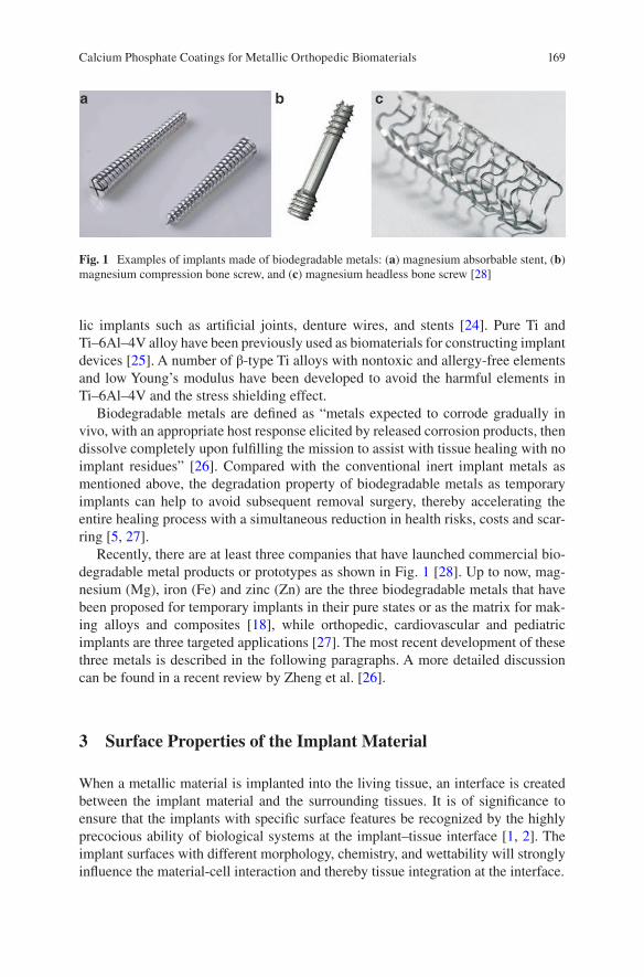
169
lic implants such as artificial joints, denture wires, and stents [24]. Pure Ti and Ti–6Al–4V alloy have been previously used as biomaterials for constructing implant devices [25]. A number of β-type Ti alloys with nontoxic and allergy-free elements and low Young’s modulus have been developed to avoid the harmful elements in Ti–6Al–4V and the stress shielding effect.
Biodegradable metals are defined as “metals expected to corrode gradually in vivo, with an appropriate host response elicited by released corrosion products, then dissolve completely upon fulfilling the mission to assist with tissue healing with no implant residues” [26]. Compared with the conventional inert implant metals as mentioned above, the degradation property of biodegradable metals as temporary implants can help to avoid subsequent removal surgery, thereby accelerating the entire healing process with a simultaneous reduction in health risks, costs and scar-ring [5, 27].
Recently, there are at least three companies that have launched commercial bio-degradable metal products or prototypes as shown in Fig. 1 [28]. Up to now, mag-nesium (Mg), iron (Fe) and zinc (Zn) are the three biodegradable metals that have been proposed for temporary implants in their pure states or as the matrix for mak-ing alloys and composites [18], while orthopedic, cardiovascular and pediatric implants are three targeted applications [27]. The most recent development of these three metals is described in the following paragraphs. A more detailed discussion can be found in a recent review by Zheng et al. [26].
3 Surface Properties of the Implant Material
When a metallic material is implanted into the living tissue, an interface is created between the implant material and the surrounding tissues. It is of significance to ensure that the implants with specific surface features be recognized by the highly precocious ability of biological systems at the implant–tissue interface [1, 2]. The implant surfaces with different morphology, chemistry, and wettability will strongly influence the material-cell interaction and thereby tissue integration at the interface.
Fig. 1 Examples of implants made of biodegradable metals: (a) magnesium absorbable stent, (b) magnesium compression bone screw, and (c) magnesium headless bone screw [28]
Calcium Phosphate Coatings for Metallic Orthopedic Biomaterials
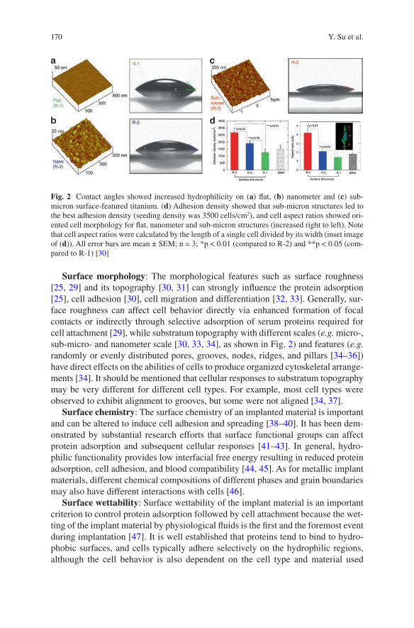
170
Surface morphology: The morphological features such as surface roughness [25, 29] and its topography [30, 31] can strongly influence the protein adsorption [25], cell adhesion [30], cell migration and differentiation [32, 33]. Generally, sur-face roughness can affect cell behavior directly via enhanced formation of focal contacts or indirectly through selective adsorption of serum proteins required for cell attachment [29], while substratum topography with different scales (e.g. micro-, sub-micro- and nanometer scale [30, 33, 34], as shown in Fig. 2) and features (e.g. randomly or evenly distributed pores, grooves, nodes, ridges, and pillars [34–36]) have direct effects on the abilities of cells to produce organized cytoskeletal arrange-ments [34]. It should be mentioned that cellular responses to substratum topography may be very different for different cell types. For example, most cell types were observed to exhibit alignment to grooves, but some were not aligned [34, 37].
Surface chemistry: The surface chemistry of an implanted material is important and can be altered to induce cell adhesion and spreading [38–40]. It has been dem-onstrated by substantial research efforts that surface functional groups can affect protein adsorption and subsequent cellular responses [41–43]. In general, hydro-philic functionality provides low interfacial free energy resulting in reduced protein adsorption, cell adhesion, and blood compatibility [44, 45]. As for metallic implant materials, different chemical compositions of different phases and grain boundaries may also have different interactions with cells [46].
Surface wettability: Surface wettability of the implant material is an important criterion to control protein adsorption followed by cell attachment because the wet-ting of the implant material by physiological fluids is the first and the foremost event during implantation [47]. It is well established that proteins tend to bind to hydro-phobic surfaces, and cells typically adhere selectively on the hydrophilic regions, although the cell behavior is also dependent on the cell type and material used
Fig. 2 Contact angles showed increased hydrophilicity on (a) flat, (b) nanometer and (c) sub- micron surface-featured titanium. (d) Adhesion density showed that sub-micron structures led to the best adhesion density (seeding density was 3500 cells/cm2), and cell aspect ratios showed ori-ented cell morphology for flat, nanometer and sub-micron structures (increased right to left). Note that cell aspect ratios were calculated by the length of a single cell divided by its width (inset image of (d)). All error bars are mean ± SEM; n = 3; *p < 0.01 (compared to R-2) and **p < 0.05 (com-pared to R-1) [30]
Y. Su et al.
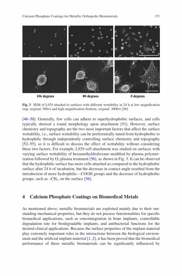
171
[48–50]. Generally, few cells can adhere to superhydrophobic surfaces, and cells typically showed a round morphology upon attachment [51]. However, surface chemistry and topography are the two most important factors that affect the surface wettability, i.e., surface wettability can be preferentially tuned from hydrophobic to hydrophilic through independently controlling surface chemistry and topography [52–55], so it is difficult to discuss the effect of wettability without considering these two factors. For example, L929 cell attachment was studied on surfaces with varying surface wettability of hexamethyldisiloxane modified by plasma polymer-ization followed by O2 plasma treatment [56], as shown in Fig. 3. It can be observed that the hydrophilic surface has more cells attached as compared to the hydrophobic surface after 24 h of incubation, but the decrease in contact angle resulted from the introduction of more hydrophilic—COOH groups and the decrease of hydrophobic groups, such as –CH3, on the surface [56].
4 Calcium Phosphate Coatings on Biomedical Metals
As mentioned above, metallic biomaterials are exploited mainly due to their out-standing mechanical properties, but they do not possess functionalities for specific biomedical applications, such as osteointegration in bone implants, controllable degradation rate for biodegradable implants, and antibacterial functions for the desired clinical applications. Because the surface properties of the implant material play extremely important roles in the interactions between the biological environ-ment and the artificial implant material [1, 2], it has been proved that the biomedical performance of these metallic biomaterials can be significantly influenced by
Fig. 3 SEM of L929 attached to surfaces with different wettability in 24 h at low magnification (top, original: 500×) and high magnification (bottom, original: 3000×) [56]
Calcium Phosphate Coatings for Metallic Orthopedic Biomaterials
172
surface treatments, such as polishing, oxidation, passivation, coating modification, ion implantation, etc. [38, 57]. Compared with other routines, surface modification with biocompatible and biofunctional coatings can not only improve the surface biocompatibility for the controlled implant/tissue interfacial response, but also sup-ply the controllable degradation rate and various biofunctions [7, 58].
Because bone tissue is a natural composite of inorganic CaP-based ceramics and organic proteins [59], CaPs have a great advantage that they would not be recog-nized as foreign materials in the body and thus have intrinsic biocompatibility. In addition, CaPs are also known to support osteoblast adhesion and proliferation [3]. Therefore, CaPs have numerous featured clinical orthopedic applications, such as total and partial hip components, cement for defect bone fillings, and coating mate-rials on metallic implants. Based on the chemical composition, synthetic CaPs for biomedical applications are mainly hydroxyapatite (HA, Ca10(PO4)6(OH)2), alpha- or beta-tricalcium phosphate (α- or β-TCP, Ca3(PO4)2), biphasic calcium phosphates (BCPs) for mixtures of HA and β-TCP, dicalcium phosphate dihydrate (DCPD, CaHPO4·2H2O), anhydrous calcium phosphate (ADCP, CaHPO4), and octacalcium phosphate (OCP, Ca8(HPO4)2(PO4)4·5H2O). The biomedical performance of CaP ceramics is closely related to their solubility. CaP ceramics have different solubility, and the comparative extent of dissolution is: DCPD > ADCP > OCP > α-TCP > β- TCP > HA [5]. The dissolution of BCPs depends on the β-TCP/HA ratio; the higher the ratio, the higher the extent of dissolution [60], which is also the general trend for different CaP ceramics [5].
CaP coatings were developed onto the surface of metallic implants to combine the mechanical strength of metals with the excellent biological properties of CaP ceramics. Many methods have been developed to deposit CaP coatings on metal implants: plasma-spraying, biomimetic precipitation, sputtering, sol–gel, electro-phoretic and electrochemical deposition, and ion beam dynamic mixing deposition [5–7, 47]. In the following sections, various functions, including biocompatibility—osteointegration, corrosion resistance, and antibacterial properties, of CaP coatings on biomedical metals are discussed.
4.1 Biocompatibility: Osteointegration
Biocompatibility is the ability of the materials to perform in the presence of an appropriate host for a specific application [61], which is required for all biomedical materials, including metallic implant materials. In early studies, biocompatibility was simply equated to biologically inactivity and chemically inertness, and thus no harmful effect on the human tissues. However, with recent developments in biotech-nology, biological activity is required for particular applications, such as temporary implants, drug and gene delivery systems.
In the case of bone implants, it is generally accepted that osteoprogenitor cells migrate to the implant site and differentiate into osteoblasts that make bone. The requirement for biocompatibility is that the material should integrate with the bone,
Y. Su et al.
173
i.e., osteointegration [62]. SS and Ti alloys have been commonly used in the clinics for fracture fixation, and new bone formation can be observed on the surface of the fixation devices, especially those made of Ti alloys because of their good biocom-patibility. A thin non-mineral layer was generally generated between metallic implants and bones, but there was still no true adhesion observed at the implant/bone interface [63]. In this case, the bond associated with osteointegration is attrib-uted to mechanical interlocking of the metallic surface asperities and pores in the bone [64]. In order to make metallic biomaterials biologically bond to bones, sur-face functionalization methods have been proposed to improve bone conductivity or bioactivity.
It has been well-recognized that CaP coatings can lead to faster biological fixa-tion and better clinical success rates in the long-term than uncoated implants due to the superior initial rate of osseointegration [8, 65–67]. Among numerous surface modification methods, plasma-spraying is the only method that has been used for Ti dental implants in clinical practice, due to its high deposition rate and the ability to coat large areas [68]. However, plasma-spraying coating has some serious concerns, such as the poor adhesion of the thick coating, phase change during the high- temperature coating process, and particle release and delamination during clinical applications [47, 68–70]. In order to overcome these drawbacks, biomimetic pre-cipitation has drawn more attention when compared to the other methods. Inspired by the natural CaP mineralization process, the precipitation process is conducted in a physiological environment at low temperatures and the deposited coating is bio-logically identical to bone apatite [8, 69, 71]. For example, a homogeneous bone- like carbonated apatitic (BCA) biomimetic coating was applied onto dense Ti6Al4V alloys and porous Ta cylinders, respectively (Fig. 4a), by immersion into simulated body fluid at 37 °C and then at 50 °C for 24 h [8]. The in vivo implantation test in the femoral diaphysis of adult female goats showed that the bone contact was always significantly higher for the BCA-coated implants than the corresponding non-coated ones (Fig. 4b, c), which indicates that the BCA coating enhances bone integration of these two metallic implants.
As mentioned above, bone can be regarded as composites of the organic matrix strengthened by the inorganic CaP phase (carbonated HA) [59], so the development of organic–inorganic composite coatings inspired by the unique nano-composite structure of bone tissue have become a hot topic for implant surface functionaliza-tion. In addition, there are clinical problems related to poor adhesion and thus lim-ited osteoconductivity of current CaP coatings [72], together with uncontrollable loading efficiency or release kinetics of the superficially adsorbed biomolecules [73, 74]. Hence, biomolecule–CaP composite coatings can supply superior proper-ties over the individual components. For example, the ductile properties of collagen can compensate for the poor fracture toughness of CaPs [4], and also promote CaP coating adhesion, cell adhesion and thus fixation of the metallic implant [68, 75]; the osteoconductivity and bone regeneration at the tissue–implant interface can be improved greatly by immobilizing growth factors such as bone morphogenetic pro-tein- 2 (BMP-2) and TGF-β to the CaP coating [9, 10]; and a CaP coating can help to delay and sustain growth factor and DNA delivery [76, 77].
Calcium Phosphate Coatings for Metallic Orthopedic Biomaterials
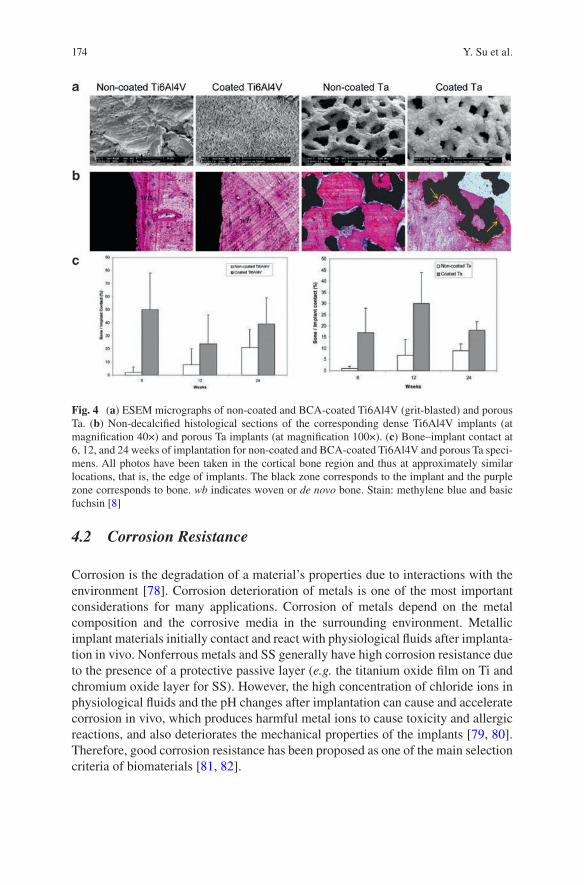
174
4.2 Corrosion Resistance
Corrosion is the degradation of a material’s properties due to interactions with the environment [78]. Corrosion deterioration of metals is one of the most important considerations for many applications. Corrosion of metals depend on the metal composition and the corrosive media in the surrounding environment. Metallic implant materials initially contact and react with physiological fluids after implanta-tion in vivo. Nonferrous metals and SS generally have high corrosion resistance due to the presence of a protective passive layer (e.g. the titanium oxide film on Ti and chromium oxide layer for SS). However, the high concentration of chloride ions in physiological fluids and the pH changes after implantation can cause and accelerate corrosion in vivo, which produces harmful metal ions to cause toxicity and allergic reactions, and also deteriorates the mechanical properties of the implants [79, 80]. Therefore, good corrosion resistance has been proposed as one of the main selection criteria of biomaterials [81, 82].
Fig. 4 (a) ESEM micrographs of non-coated and BCA-coated Ti6Al4V (grit-blasted) and porous Ta. (b) Non-decalcified histological sections of the corresponding dense Ti6Al4V implants (at magnification 40×) and porous Ta implants (at magnification 100×). (c) Bone–implant contact at 6, 12, and 24 weeks of implantation for non-coated and BCA-coated Ti6Al4V and porous Ta speci-mens. All photos have been taken in the cortical bone region and thus at approximately similar locations, that is, the edge of implants. The black zone corresponds to the implant and the purple zone corresponds to bone. wb indicates woven or de novo bone. Stain: methylene blue and basic fuchsin [8]
Y. Su et al.
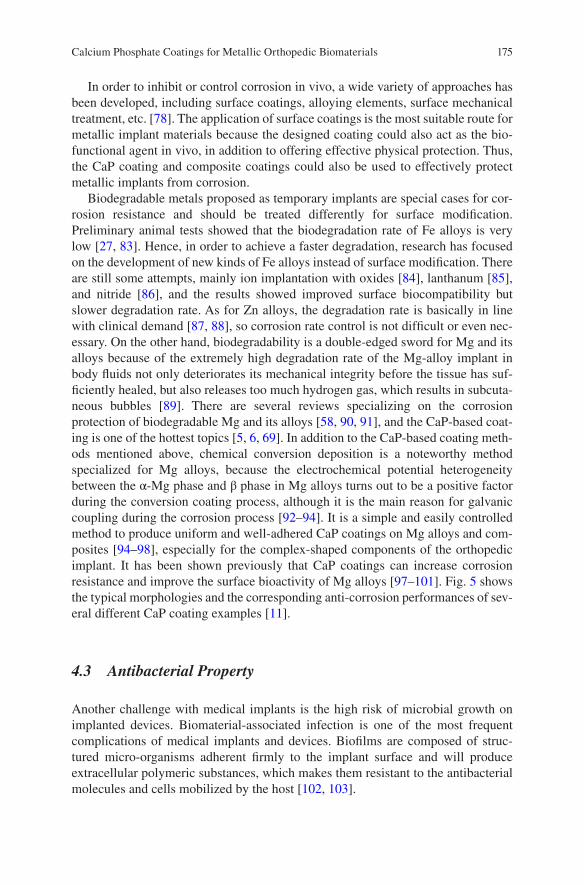
175
In order to inhibit or control corrosion in vivo, a wide variety of approaches has been developed, including surface coatings, alloying elements, surface mechanical treatment, etc. [78]. The application of surface coatings is the most suitable route for metallic implant materials because the designed coating could also act as the bio-functional agent in vivo, in addition to offering effective physical protection. Thus, the CaP coating and composite coatings could also be used to effectively protect metallic implants from corrosion.
Biodegradable metals proposed as temporary implants are special cases for cor-rosion resistance and should be treated differently for surface modification. Preliminary animal tests showed that the biodegradation rate of Fe alloys is very low [27, 83]. Hence, in order to achieve a faster degradation, research has focused on the development of new kinds of Fe alloys instead of surface modification. There are still some attempts, mainly ion implantation with oxides [84], lanthanum [85], and nitride [86], and the results showed improved surface biocompatibility but slower degradation rate. As for Zn alloys, the degradation rate is basically in line with clinical demand [87, 88], so corrosion rate control is not difficult or even nec-essary. On the other hand, biodegradability is a double-edged sword for Mg and its alloys because of the extremely high degradation rate of the Mg-alloy implant in body fluids not only deteriorates its mechanical integrity before the tissue has suf-ficiently healed, but also releases too much hydrogen gas, which results in subcuta-neous bubbles [89]. There are several reviews specializing on the corrosion protection of biodegradable Mg and its alloys [58, 90, 91], and the CaP-based coat-ing is one of the hottest topics [5, 6, 69]. In addition to the CaP-based coating meth-ods mentioned above, chemical conversion deposition is a noteworthy method specialized for Mg alloys, because the electrochemical potential heterogeneity between the α-Mg phase and β phase in Mg alloys turns out to be a positive factor during the conversion coating process, although it is the main reason for galvanic coupling during the corrosion process [92–94]. It is a simple and easily controlled method to produce uniform and well-adhered CaP coatings on Mg alloys and com-posites [94–98], especially for the complex-shaped components of the orthopedic implant. It has been shown previously that CaP coatings can increase corrosion resistance and improve the surface bioactivity of Mg alloys [97–101]. Fig. 5 shows the typical morphologies and the corresponding anti-corrosion performances of sev-eral different CaP coating examples [11].
4.3 Antibacterial Property
Another challenge with medical implants is the high risk of microbial growth on implanted devices. Biomaterial-associated infection is one of the most frequent complications of medical implants and devices. Biofilms are composed of struc-tured micro-organisms adherent firmly to the implant surface and will produce extracellular polymeric substances, which makes them resistant to the antibacterial molecules and cells mobilized by the host [102, 103].
Calcium Phosphate Coatings for Metallic Orthopedic Biomaterials
176
In order to develop an antibacterial surface preventing biomedical implant- related infections, the first strategy to be explored was the local delivery of biocides, with the development of bactericidal coatings that release antimicrobials or kill micro-organisms by contact [104, 105]. Various synthetic approaches based on immobilization or the release of bactericidal substances have been extensively explored to produce bactericidal coatings [106, 107]. However, they are not com-pletely satisfactory for biomedical applications because of antibiotic resistance and impairing peri-implant bone growth. A preferred solution is to develop a non- conventional antimicrobial biomolecule composite coating with CaP, which can inhibit bacterial colonization and concomitantly promote osteoblast functions
Fig. 5 (a) The surface morphologies of (i) CaP, (ii) HA and (iii) fluorine post-treated CaP (F-CaP) coatings. (b) Hydrogen volume and pH evolution as a function of immersion time in the immersion test in SBF. (c) Mineralization morphologies and the corresponding appearance photographs (after removing corrosion products) of the uncoated and coated samples immersed in SBF for 7 days [11]
Y. Su et al.
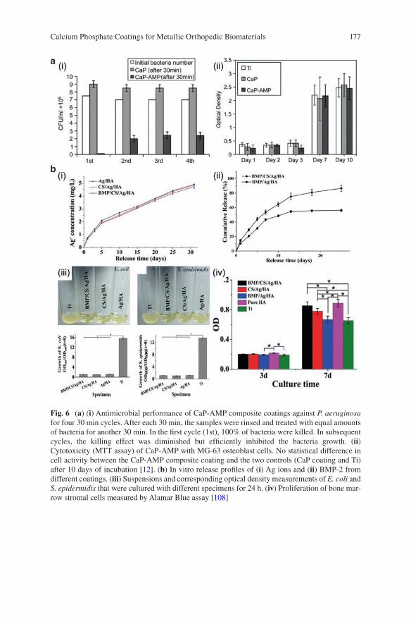
177
Fig. 6 (a) (i) Antimicrobial performance of CaP-AMP composite coatings against P. aeruginosa for four 30 min cycles. After each 30 min, the samples were rinsed and treated with equal amounts of bacteria for another 30 min. In the first cycle (1st), 100% of bacteria were killed. In subsequent cycles, the killing effect was diminished but efficiently inhibited the bacteria growth. (ii) Cytotoxicity (MTT assay) of CaP-AMP with MG-63 osteoblast cells. No statistical difference in cell activity between the CaP-AMP composite coating and the two controls (CaP coating and Ti) after 10 days of incubation [12]. (b) In vitro release profiles of (i) Ag ions and (ii) BMP-2 from different coatings. (iii) Suspensions and corresponding optical density measurements of E. coli and S. epidermidis that were cultured with different specimens for 24 h. (iv) Proliferation of bone mar-row stromal cells measured by Alamar Blue assay [108]
Calcium Phosphate Coatings for Metallic Orthopedic Biomaterials
178
through its interactions with proteins, bacteria and tissue-forming cells. Kazemzadeh- Narbat et al. [12] developed a CaP-AMP composite coating on a Ti surface, and found that the composite coating has a stable antimicrobial performance to Gram- positive (S. aureus) and Gram-negative (P. aeruginosa) bacteria, while it showed no cytotoxicity with osteoblast-like cells, as shown in Fig. 6a.
In addition to antimicrobial biomolecules, some antimicrobial elements such as silver (Ag), copper (Cu), Zn, and fluorine (F) can be added to CaP, usually HA, to obtain antimicrobial coatings [13–17]. As one of the most stable antimicrobial agents, Ag could effectively control bacteria adhesion and prevent biofilm forma-tion for its broad antibacterial spectrum and oligodynamic bactericidal activity, and bacterial resistance against Ag is minimal [109]. Many previous studies have revealed that Ag-doped HA coatings [13, 110–112] synthesized through thermal spray [110], magnetron sputtering [112], sol-gel methods [111] and electrochemical deposition [13] have unique antimicrobial properties. However, the release rate of these antimicrobial agents was too fast in one-layer coatings, limiting the anti- infection effects in the early stage of peri-implantation. Multi-layer coatings were preferred to encourage the prolonged release of antimicrobial agents during the implantation [113]. Saidin et al. [114] applied the polydopamine as an intermediate layer for silver nanoparticles and HA immobilization on SS316L, and the Ag+ ions were slowly released up to 7 days, suggesting that a long-term antibacterial activity could be achieved. Because Ag nanoparticles are easy to agglomerate during the coating process, which will lead to a large increase in local Ag concentration and thus potentially affect cell activity, Xie et al. [108] introduced BMP-2 into the Ag nanoparticle contained HA coatings on Ti surfaces by combining electrochemical deposition of Ag and electrostatic immobilization of BMP-2 and a stabilizing agent of chitosan (CS). The multilayered composite coatings can not only realize the uni-form distribution and sustained release of Ag nanoparticles to retain the antibacte-rial activity, but also CS facilitates the immobilization and sustained release of BMP-2 to exhibit high osteoinductivity, as shown in Fig. 6b.
5 Conclusion
In order to obtain specific functionalities on the metallic implant materials for orthopedic applications, surface modifications with CaP coatings are of particular interest and are required in the development of high-performance metallic implant materials. This chapter generally introduces several significant biofunctions of CaP coatings on metallic implant materials. However, while numerous in vitro studies have made great progress their translation to in vivo studies and similar clinical outcomes is not favorable, and the biological performance of CaP coatings differ considerably in terms of composition, microstructure, solubility, thickness, metallic substrate, etc. Therefore, it is necessary to establish the correlation of CaP coating properties to biological response. In addition, much more advanced biofunctions
Y. Su et al.
179
should be continually explored and loaded on these intrinsically biocompatible coatings to extend their biomedical applications.
Acknowledgements This work was supported by National Institutes of Health [grant number AR52379, AR49286, and AR61821]. The content is solely the responsibility of the authors and does not necessarily represent the official views of the National Institutes of Health.
References
1. Nel AE, et al. Understanding biophysicochemical interactions at the nano-bio interface. Nat Mater. 2009;8(7):543–57.
2. Planell JA, et al. Materials surface effects on biological interactions. In: Shastri V, Altankov G, Lendlein A, editors. Advances in regenerative medicine: role of nanotechnology, and engi-neering principles. Dordrecht: Springer; 2010. p. 233–52.
3. Anselme K. Osteoblast adhesion on biomaterials. Biomaterials. 2000;21(7):667–81. 4. Fan Y, Duan K, Wang R. A composite coating by electrolysis-induced collagen self-assembly
and calcium phosphate mineralization. Biomaterials. 2005;26(14):1623–32. 5. Dorozhkin SV. Calcium orthophosphate coatings on magnesium and its biodegradable alloys.
Acta Biomater. 2014;10(7):2919–34. 6. Shadanbaz S, Dias GJ. Calcium phosphate coatings on magnesium alloys for biomedical
applications: a review. Acta Biomater. 2012;8(1):20–30. 7. Surmenev RA, Surmeneva MA, Ivanova AA. Significance of calcium phosphate coatings for
the enhancement of new bone osteogenesis—a review. Acta Biomater. 2014;10(2):557–79. 8. Barrere F, et al. Osteointegration of biomimetic apatite coating applied onto dense and porous
metal implants in femurs of goats. J Biomed Mater Res B Appl Biomater. 2003;67((1):655–65. 9. Alam MI, et al. Evaluation of ceramics composed of different hydroxyapatite to tricalcium
phosphate ratios as carriers for rhBMP-2. Biomaterials. 2001;22(12):1643–51. 10. Liu Y, De GK, Hunziker EB. BMP-2 liberated from biomimetic implant coatings induces and
sustains direct ossification in an ectopic rat model. Bone. 2005;36(5):745–57. 11. Su Y, et al. Enhancing the corrosion resistance and surface bioactivity of a calcium- phosphate
coating on a biodegradable AZ60 magnesium alloy via a simple fluorine post-treatment method. RSC Adv. 2015;5(69):56001–10.
12. Kazemzadeh-Narbat M, et al. Antimicrobial peptides on calcium phosphate-coated titanium for the prevention of implant-associated infections. Biomaterials. 2010;31(36):9519–26.
13. Bir F, et al. Electrochemical depositions of fluorohydroxyapatite doped by Cu 2+, Zn 2+, Ag+ on stainless steel substrates. Appl Surf Sci. 2012;258(18):7021–30.
14. Huang Y, et al. Osteoblastic cell responses and antibacterial efficacy of Cu/Zn co- substituted hydroxyapatite coatings on pure titanium using electrodeposition method. RSC Adv. 2015;5(22):17076–86.
15. Chung RJ, et al. Antimicrobial effects and human gingival biocompatibility of hydroxyapa-tite sol–gel coatings. J Biomed Mater Res B Appl Biomater. 2006;76(1):169–78.
16. Ge X, et al. Antibacterial coatings of fluoridated hydroxyapatite for percutaneous implants. J Biomed Mater Res A. 2010;95((2):588–99.
17. Lee JS, Murphy WL. Functionalizing calcium phosphate biomaterials with antibacterial sil-ver particles. Adv Mater. 2013;25(8):1173–9.
18. Ratner BD, et al. Biomaterials science: an introduction to materials in medicine. New York: Academic Press; 2004. p. 10–1.
19. Crubezy E, et al. False teeth of the Roman world. Nature. 1998;391(6662):29. 20. Niinomi M, Nakai M, Hieda J. Development of new metallic alloys for biomedical applica-
tions. Acta Biomater. 2012;8(11):3888–903.
Calcium Phosphate Coatings for Metallic Orthopedic Biomaterials
180
21. Smethurst E. A new stainless steel alloy for surgical implants compared to 316 S12. Biomaterials. 1981;2(2):116–9.
22. Talha M, Behera CK, Sinha OP. A review on nickel-free nitrogen containing austenitic stainless steels for biomedical applications. Mater Sci Eng C Mater Biol Appl. 2013;33(7):3563–75.
23. Yan Y, Neville A, Dowson D. Tribo-corrosion properties of cobalt-based medical implant alloys in simulated biological environments. Wear. 2007;263(SI2):1105–11.
24. Narushima T, et al. Precipitates in biomedical Co-Cr alloys. JOM. 2013;65(4):489–504. 25. Deligianni DD, et al. Effect of surface roughness of the titanium alloy Ti–6Al–4V on human
bone marrow cell response and on protein adsorption. Biomaterials. 2001;22(11):1241–51. 26. Zheng YF, Gu XN, Witte F. Biodegradable metals. Mater Sci Eng R Rep. 2014;77:1–34. 27. Hermawan H. Biodegradable metals: from concept to applications. Heidelberg: Springer;
2012. 28. Paramitha D, et al. Monitoring degradation products and metal ions in vivo. Sawston:
Woodhead Publishing; 2016. p. 19. 29. Deligianni DD, et al. Effect of surface roughness of hydroxyapatite on human bone mar-
row cell adhesion, proliferation, differentiation and detachment strength. Biomaterials. 2000;22(1):87–96.
30. Khang D, et al. The role of nanometer and sub-micron surface features on vascular and bone cell adhesion on titanium. Biomaterials. 2008;29(8):970–83.
31. Anselme K, Bigerelle M. Topography effects of pure titanium substrates on human osteoblast long-term adhesion. Acta Biomater. 2005;1(2):211–22.
32. Zinger O, et al. Differential regulation of osteoblasts by substrate microstructural features. Biomaterials. 2005;26(14):1837–47.
33. Haq F, et al. Nano-and micro-structured substrates for neuronal cell development. J Biomed Nanotechnol. 2005;1(3):313–9.
34. Flemming RG, et al. Effects of synthetic micro- and nano-structured surfaces on cell behav-ior. Biomaterials. 1999;20(6):573–88.
35. Benoit DS, Anseth KS. The effect on osteoblast function of colocalized RGD and PHSRN epitopes on PEG surfaces. Biomaterials. 2005;26(25):5209–20.
36. Curtis AS, et al. Substratum nanotopography and the adhesion of biological cells. Are sym-metry or regularity of nanotopography important? Biophys Chem. 2001;94(3):275–83.
37. Rajnicek A, Britland S, McCaig C. Contact guidance of CNS neurites on grooved quartz: influence of groove dimensions, neuronal age and cell type. J Cell Sci. 1997;110(Pt 23):2905–13.
38. Roach P, et al. Modern biomaterials: a review—bulk properties and implications of surface modifications. J Mater Sci Mater Med. 2007;18(7):1263–77.
39. Stevens MM. Exploring and engineering the cell-surface interface. Science. 2005;310(5751):1135–8.
40. Puleo DA, Nanci A. Understanding and controlling the bone—implant interface. Biomaterials. 1999;20(23):2311–21.
41. Tidwell CD, et al. Endothelial cell growth and protein adsorption on terminally functional-ized, self-assembled monolayers of alkanethiolates on gold. Langmuir. 1997;13(13):3404–13.
42. Ohya Y, Matsunami H, Ouchi T. Cell growth on the porous sponges prepared from poly (depsipeptide-co-lactide) having various functional groups. J Biomater Sci Polym Ed. 2004;15(1):111–23.
43. Thevenot P, Hu W, Tang L. Surface chemistry influences implant biocompatibility. Curr Top Med Chem. 2008;8(4):270–80.
44. Wang Y, et al. Effects of the chemical structure and the surface properties of polymeric bio-materials on their biocompatibility. Pharm Res. 2004;21(8):1362–73.
45. Wang J, et al. Surface characterization and blood compatibility of poly(ethylene terephthal-ate) modified by plasma surface grafting. Surf Coat Technol. 2005;196(1):307–11.
46. Geetha M, et al. Ti based biomaterials, the ultimate choice for orthopaedic implants—a review. Prog Mater Sci. 2009;54(3):397–425.
Y. Su et al.
181
47. Paital SR, Dahotre NB. Calcium phosphate coatings for bio-implant applications: materials, performance factors, and methodologies. Mater Sci Eng R Rep. 2009;66(1–3):1–70.
48. Arima Y, Iwata H. Effect of wettability and surface functional groups on protein adsorp-tion and cell adhesion using well-defined mixed self-assembled monolayers. Biomaterials. 2007;28(20):3074–82.
49. Ponsonnet L, et al. Relationship between surface properties (roughness, wettability) of tita-nium and titanium alloys and cell behaviour. Mater Sci Eng C. 2003;23(4):551–60.
50. Higuchi A, et al. Chemically modified polysulfone hollow fibers with vinylpyrrolidone hav-ing improved blood compatibility. Biomaterials. 2002;23(13):2659–66.
51. Song W, Mano JF. Interactions between cells or proteins and surfaces exhibiting extreme wettabilities. Soft Matter. 2013;9(11):2985–99.
52. Yin H, et al. CO2-induced tunable and reversible surface wettability of honeycomb structured porous films for cell adhesion. Adv Mater Interfaces. 2016;3(7):1500623.
53. Lai Y, et al. In situ surface-modification-induced superhydrophobic patterns with reversible wettability and adhesion. Adv Mater. 2013;25(12):1682–6.
54. Zhu X, et al. Effects of topography and composition of titanium surface oxides on osteoblast responses. Biomaterials. 2004;25(18):4087–103.
55. Ner D, McCarthy TJ. Ultrahydrophobic surfaces. Effects of topography length scales on wet-tability. Langmuir. 2000;16(20):7777–82.
56. Wei J, et al. Adhesion of mouse fibroblasts on hexamethyldisiloxane surfaces with wide range of wettability. J Biomed Mater Res B Appl Biomater. 2007;81B(1):66–75.
57. Hanawa T. In vivo metallic biomaterials and surface modification. Mater Sci Eng A. 1999;267(2):260–6.
58. Wang J, et al. Surface modification of magnesium alloys developed for bioabsorb-able orthopedic implants: a general review. J Biomed Mater Res B Appl Biomater. 2012;100B(6):1691–701.
59. LeGeros RZ. Calcium phosphates in oral biology and medicine. Monogr Oral Sci. 1990;15:1–201.
60. LeGeros RZ, et al. Biphasic calcium phosphate bioceramics: preparation, properties and applications. J Mater Sci Mater Med. 2003;14(3):201–9.
61. Ksander GA. Definitions in Biomaterials, progress in biomedical engineering, vol. 4. Ann Plast Surg. 1988;21(3):291.
62. Hallab NJ, Jacobs JJ. Orthopedic applications. In: Hoffman AS, Schoen FJ, Lemons JE, Hoffman AS, Schoen FJ, Lemons JE, editors. Biomaterials science: an introduction to mate-rials in medicine. 3rd ed. Cambridge, MA: Academic Press; 2013. p. 841–82.
63. Thomsen P, et al. Structure of the interface between rabbit cortical bone and implants of gold, zirconium and titanium. J Mater Sci Mater Med. 1997;8(11):653–65.
64. Liu X, Chu P, Ding C. Surface modification of titanium, titanium alloys, and related materials for biomedical applications. Mater Sci Eng R Rep. 2004;47(3–4):49–121.
65. Morris HF, et al. Periodontal-type measurements associated with hydroxyapatite-coated and non-HA-coated implants: uncovering to 36 months. Ann Periodontol. 2000;5(1):56–67.
66. Geurs NC, et al. Influence of implant geometry and surface characteristics on progressive osseointegration. Int J Oral Maxillofac Implants. 2002;17(6):811–5.
67. Le Guéhennec L, et al. Surface treatments of titanium dental implants for rapid osseointegra-tion. Dent Mater. 2007;23(7):844–54.
68. de Jonge LT, et al. Organic–inorganic surface modifications for titanium implant surfaces. Pharm Res. 2008;25(10):2357–69.
69. Oliveira AL, Mano JF, Reis RL. Nature-inspired calcium phosphate coatings: present status and novel advances in the science of mimicry. Curr Opin Solid State Mater Sci. 2003;7(4–5):309–18.
70. Yang Y, Kim K, Ong J. A review on calcium phosphate coatings produced using a sputtering process? An alternative to plasma spraying. Biomaterials. 2005;26(3):327–37.
Calcium Phosphate Coatings for Metallic Orthopedic Biomaterials
182
71. Bigi A, et al. Nanocrystalline hydroxyapatite coatings on titanium: a new fast biomimetic method. Biomaterials. 2005;26(19):4085–9.
72. de Jonge LT, et al. The osteogenic effect of electrosprayed nanoscale collagen/calcium phos-phate coatings on titanium. Biomaterials. 2010;31(9):2461–9.
73. Goodman SB, et al. The future of biologic coatings for orthopaedic implants. Biomaterials. 2013;34(13):3174–83.
74. Siebers MC, et al. Transforming growth factor-beta1 release from a porous electrostatic spray deposition-derived calcium phosphate coating. Tissue Eng. 2006;12(9):2449–56.
75. Rammelt S, et al. Coating of titanium implants with collagen, RGD peptide and chondroitin sulfate. Biomaterials. 2006;27(32):5561–71.
76. He J, et al. Collagen-infiltrated porous hydroxyapatite coating and its osteogenic properties: in vitro and in vivo study. J Biomed Mater Res A. 2012;100((7):1706–15.
77. Choi S, Murphy WL. Sustained plasmid DNA release from dissolving mineral coatings. Acta Biomater. 2010;6(9):3426–35.
78. Shaw BA, Kelly RG. What is corrosion? Electrochem Soc Interface. 2006;15(1):24–7. 79. Walczak J, Shahgaldi F, Heatley F. In vivo corrosion of 316L stainless-steel hip
implants: morphology and elemental compositions of corrosion products. Biomaterials. 1998;19(1–3):229–37.
80. Hench LL, Ethridge EC. Biomaterials—the interfacial problem. In: Brown JHU, Dickson JF, editors. Advances in biomedical engineering. New York: Academic Press; 1975. p. 35–150.
81. Mahyudin F, Hermawan H. Biomaterials and medical devices: a perspective from an emerg-ing country. Advanced Structured Materials. Switzerland: Springer; 2016.
82. Dee KC, Puleo DA, Bizios R. An introduction to tissue-biomaterial interactions. Hoboken, NJ: John Wiley & Sons; 2003.
83. Peuster M, et al. Long-term biocompatibility of a corrodible peripheral iron stent in the por-cine descending aorta. Biomaterials. 2006;27(28):4955–62.
84. Zhu S, et al. Biocompatibility of Fe–O films synthesized by plasma immersion ion implanta-tion and deposition. Surf Coat Technol. 2009;203(10–11):1523–9.
85. Zhu S, et al. Corrosion resistance and blood compatibility of lanthanum ion implanted pure iron by MEVVA. Appl Surf Sci. 2009;256(1):99–104.
86. Chen C, et al. The microstructure and properties of commercial pure iron modified by plasma nitriding. Solid State Ionics. 2008;179(21–26):971–4.
87. Bowen PK, Drelich J, Goldman J. Zinc exhibits ideal physiological corrosion behavior for bioabsorbable stents. Adv Mater. 2013;25(18):2577–82.
88. Vojtěch D, et al. Mechanical and corrosion properties of newly developed biodegradable Zn-based alloys for bone fixation. Acta Biomater. 2011;7(9):3515–22.
89. Kuhlmann J, et al. Fast escape of hydrogen from gas cavities around corroding magnesium implants. Acta Biomater. 2013;9(10):8714–21.
90. Hornberger H, Virtanen S, Boccaccini AR. Biomedical coatings on magnesium alloys—a review. Acta Biomater. 2012;8(7):2442–55.
91. Wu G, Ibrahim JM, Chu PK. Surface design of biodegradable magnesium alloys—a review. Surf Coat Technol. 2013;233:2–12.
92. Zeng R, et al. Corrosion resistance of calcium-modified zinc phosphate conversion coatings on magnesium–aluminium alloys. Corros Sci. 2014;88:452–9.
93. Li GY, et al. Growth of zinc phosphate coatings on AZ91D magnesium alloy. Surf Coat Technol. 2006;201(3–4):1814–20.
94. Su Y, et al. Improvement of the biodegradation property and biomineralization ability of magnesium–hydroxyapatite composites with dicalcium phosphate dihydrate and hydroxy-apatite coatings. ACS Biomater Sci Eng. 2016;2(5):818–28.
95. Chen XB, Birbilis N, Abbott TB. A simple route towards a hydroxyapatite–Mg(OH)2 conver-sion coating for magnesium. Corros Sci. 2011;53(6):2263–8.
96. Song Y, et al. Formation mechanism of phosphate conversion film on Mg–8.8Li alloy. Corros Sci. 2009;51(1):62–9.
Y. Su et al.
183
97. Su Y, Li G, Lian J. A chemical conversion hydroxyapatite coating on AZ60 magnesium alloy and its electrochemical corrosion behaviour. Int J Electrochem Sci. 2012;7(11):11497–511.
98. Su Y, et al. Composite microstructure and formation mechanism of calcium phosphate con-version coating on magnesium alloy. J Electrochem Soc. 2016;163(9):G138–43.
99. Su Y, et al. Preparation and corrosion behavior of calcium phosphate and hydroxyapatite conversion coatings on AM60 magnesium alloy. J Electrochem Soc. 2013;160(11):C536–41.
100. Xu L, et al. In vitro and in vivo evaluation of the surface bioactivity of a calcium phosphate coated magnesium alloy. Biomaterials. 2009;30(8):1512–23.
101. Song Y, et al. A novel phosphate conversion film on Mg–8.8Li alloy. Surf Coat Technol. 2009;203(9):1107–13.
102. Donlan RM, Costerton JW. Biofilms: survival mechanisms of clinically relevant microorgan-isms. Clin Microbiol Rev. 2002;15(2):167–93.
103. Hook AL, et al. Combinatorial discovery of polymers resistant to bacterial attachment. Nat Biotechnol. 2012;30(9):868–75.
104. Zhao L, et al. Antibacterial coatings on titanium implants. J Biomed Mater Res B Appl Biomater. 2009;91(1):470–80.
105. Stigter M, Groot KD, Layrolle P. Incorporation of tobramycin into biomimetic hydroxyapa-tite coating on titanium. Biomaterials. 2002;23(20):4143–53.
106. Klibanov AM. Permanently microbicidal materials coatings. J Mater Chem. 2007; 17(24):2479.
107. Kohnen W, et al. Development of a long-lasting ventricular catheter impregnated with a com-bination of antibiotics. Biomaterials. 2003;24(26):4865–9.
108. Xie C, et al. Silver nanoparticles and growth factors incorporated hydroxyapatite coatings on metallic implant surfaces for enhancement of osteoinductivity and antibacterial properties. ACS Appl Mater Interfaces. 2014;6(11):8580–9.
109. Marambio-Jones C, Hoek EM. A review of the antibacterial effects of silver nanoma-terials and potential implications for human health and the environment. J Nanopart Res. 2010;12(5):1531–51.
110. Roy M, et al. Mechanical, in vitro antimicrobial, and biological properties of plasma-sprayed silver-doped hydroxyapatite coating. ACS Appl Mater Interfaces. 2012;4(3):1341–9.
111. Chen W, et al. Antibacterial and osteogenic properties of silver-containing hydroxyapatite coatings produced using a sol gel process. J Biomed Mater Res A. 2007;82((4):899–906.
112. Chen W, et al. In vitro anti-bacterial and biological properties of magnetron co-sputtered silver-containing hydroxyapatite coating. Biomaterials. 2006;27(32):5512–7.
113. Kazemzadeh-Narbat M, et al. Multilayered coating on titanium for controlled release of antimicrobial peptides for the prevention of implant-associated infections. Biomaterials. 2013;34(24):5969–77.
114. Saidin S, et al. Polydopamine as an intermediate layer for silver and hydroxyapatite immo-bilisation on metallic biomaterials surface. Mater Sci Eng C. 2013;33(8):4715–24.
115. Suchanek W, Yoshimura M. Processing and properties of hydroxyapatite-based biomaterials for use as hard tissue replacement implants. J Mater Res. 1998;13(1):94–117.
Calcium Phosphate Coatings for Metallic Orthopedic Biomaterials

Part IIPolymer Biomaterials
187© Springer International Publishing AG, part of Springer Nature 2017B. Li, T. Webster (eds.), Orthopedic Biomaterials, https://doi.org/10.1007/978-3-319-73664-8_8
Collagen-Based Scaffolds for Bone Tissue Engineering Applications
Madhura P. Nijsure and Vipuil Kishore
Keywords Bone · Collagen · Scaffolds · Biomaterial · Tissue engineering · Hydrogels · Freeze drying · Electrospinning · Electrochemical fabrication · Composites · Crosslinking · Porosity · Alignment · In vitro · In vivo
1 Introduction
Bone is a complex tissue mainly comprised of hydroxyapatite (HA) [Ca10(PO4)2(OH)2] (50–70%), an organic matrix which is predominantly type I collagen (20–40%), water (5–10%), lipids (<3%), and small amounts of carbonate and magnesium [1]. It gives the human body its shape, provides physical support to various organs, serves as the primary source of calcium and phosphorous, and forms a part of the musculoskeletal system which facilitates locomotion. Bone tissue has different lev-els of hierarchical organization. At the molecular level, tropocollagen molecules assemble to form anisotropically oriented collagen fibrils with HA nanocrystals fill-ing the interstitial spaces between individual collagen fibrils as shown in Fig. 1 [2]. The bone microstructure consists of many closely packed collagen fibrils that are arranged in concentric circles called lamellae, to form the basic unit of the bone macrostructure called the osteon. At the center of each osteon is the haversian canal, which contains blood vessels and nerves. Mature bone cells, or osteocytes are embedded within the osteon and form a complex canalicular network to maintain cell-cell communication and preserve the structural integrity of the bone tissue. The bone matrix also harbors proteins like osteopontin, fibronectin and bone sialopro-tein, which are recognized by the integrins on cell surfaces and play an important
M. P. Nijsure Department of Chemical Engineering, Florida Institute of Technology, Melbourne, FL, USA
V. Kishore (*) Department of Chemical Engineering, Florida Institute of Technology, Melbourne, FL, USA
Department of Biomedical Engineering, Florida Institute of Technology, Melbourne, FL, USAe-mail: [email protected]
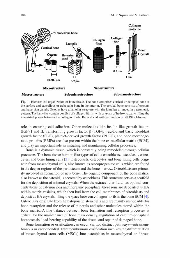
188
role in ensuring cell adhesion. Other molecules like insulin-like growth factors (IGF) I and II, transforming growth factor β (TGF-β), acidic and basic fibroblast growth factor (FGF), platelet-derived growth factor (PDGF), and bone morphoge-netic proteins (BMPs) are also present within the bone extracellular matrix (ECM), and play an important role in initiating and maintaining cellular processes.
Bone is a dynamic tissue, which is constantly being remodeled through cellular processes. The bone tissue harbors four types of cells: osteoblasts, osteoclasts, osteo-cytes, and bone lining cells [3]. Osteoblasts, osteocytes and bone lining cells origi-nate from mesenchymal cells, also known as osteoprogenitor cells which are found in the deeper regions of the periosteum and the bone marrow. Osteoblasts are primar-ily involved in formation of new bone. The organic component of the bone matrix, also known as the osteoid, is secreted by osteoblasts. This structure acts as a scaffold for the deposition of mineral crystals. When the extracellular fluid has optimal con-centrations of calcium ions and inorganic phosphate, these ions are deposited as HA within matrix vesicles, which then bud from the cell membranes of osteoblasts and deposit as HA crystals filling the space between collagen fibrils in the bone ECM [4]. Osteoclasts originate from hematopoietic stem cells and are mainly responsible for bone resorption and the release of minerals and other molecules stored within the bone matrix. A fine balance between bone formation and resorption processes is critical for the maintenance of bone mass density, regulation of calcium-phosphate homeostasis, load-bearing capability of the tissue, and repair of damaged bone.
Bone formation or ossification can occur via two distinct pathways—intramem-branous or endochondral. Intramembranous ossification involves the differentiation of mesenchymal stem cells (MSCs) into osteoblasts in mesenchymal or fibrous
Fig. 1 Hierarchical organization of bone tissue. The bone comprises cortical or compact bone at the surface and cancellous or trabecular bone in the interior. The cortical bone consists of osteons and haversian canals. Osteons have a lamellar structure with the lamellae arranged in a geometric pattern. The lamellae contain bundles of collagen fibrils, with crystals of hydroxyapatite filling the interstitial places between the collagen fibrils. Reproduced with permission [2] © 1998 Elsevier
M. P. Nijsure and V. Kishore
189
connective tissue. The newly formed osteoblasts secrete the uncalcified bone matrix or the ‘osteoid’. This process is catalyzed by the enzyme alkaline phosphatase. The osteoid is calcified by the addition of calcium salts and other minerals. The calcified osteoid grows around blood vessels to form the vascularized bone tissue. Flat bones like the mandible, clavicle and many cranial bones are formed via intramembranous ossification. Most other bones in the body are formed via endochondral ossification. This involves the differentiation of embryonic MSCs to chondrocytes, which forms a cartilaginous template that is eventually calcified. Intramembranous and endo-chondral ossification are fundamental processes that are initiated during the early stages of fetal development, and are tightly regulated by several molecules like the parathyroid hormone (PTH), Indian hedgehog (IHH), bone morphogenetic proteins (BMP), and growth factors like the vascular endothelial growth factor (VEGF) and fibroblast growth factor (FGF). Fracture healing recapitulates many of the processes involved in intramembranous and endochondral ossification, which leads to com-plete bone regeneration without the formation of scar tissue.
Bone development and maintenance involves complex signaling pathways that critically control the rates of bone formation and resorption, in a way that ensures that the right amount of bone is formed with the right structure, in the right place [5]. At this level of intricacy, there are several factors that can disrupt the processes involved and cause damage to healthy bone tissue. Bone disorders are a significant problem with over 500,000 bone graft procedures performed each year in the United States alone, costing an estimated 2.5 billion dollars [6]. Bone infections or physical trauma are common forms of bone disorders which can result in significant loss of bone tissue. Perhaps the most predominant cause of bone disorders is osteoporosis, a progressive bone degenerative disease that is characterized by decreased bone mass and structurally weak bones resulting in non-healing fractures that cause extreme pain and discomfort. Surgery is usually the only treatment option for severe osteoporotic fractures. However, surgical repair of an osteoporotic bone is challeng-ing, mainly because of the weakened native tissue which fails to provide mechanical support to traditional bone grafts [7]. Similar surgical complications are encoun-tered while treating bone tumors and primary bone cancer, which, although rare, are very severe bone disorders. While bone fractures have an inherent ability to self- heal in 6–8 weeks, in cases of severe fractures associated with osteoporosis, bone regeneration can take excruciatingly long times and yet may not be fully satisfac-tory. Delayed unions and non-unions are very common resulting in significant pain and reduced functionality of the injured bone tissue. Further, in pathological frac-tures, where the inherent capacity of the bone to remodel and heal is compromised, bone-grafting procedures are required to make up for the significant loss of bone tissue that has occurred because of a disease.
Traditional treatment options for large-sized pathological fractures involve the use of autografts and allografts. From a biological stand point, freshly harvested autografts have the highest capability of supporting bone regeneration, growth, and subsequent vascularization. Evidently, autografts are currently the gold standard for bone substitution despite several limitations like difficulty in harvesting enough healthy bone from a second surgery, donor site morbidity, and pain. Given these
Collagen-Based Scaffolds for Bone Tissue Engineering Applications
190
limitations, allografts are often used as alternatives to autografts. Allografts can be obtained from cadavers or living donors and are available in various forms that include powders, cortical chips, and cancellous cubes [8]. The main advantage of allografts is that they are readily available in various shapes and sizes. However, allografts need careful processing to free them of disease transmitting agents with-out affecting the inherent osteogenic properties of the grafts. Since allografts are not genetically matched before implantation, there is also high risk of an immunogenic response. Further, allografts are not as effective as autografts in inducing osteogen-esis in the osteoprogenitor cells present in the recipient bone. Therefore, in order to overcome the limitations associated with autografts and allografts, there is a need for an alternative method for the treatment of bone defects.
Over the past three decades, BTE has gained considerable interest amongst sci-entists and researchers for the repair, regeneration, and restoration of native bone tissue. In this chapter, we first present a brief overview on BTE and the use of col-lagen type I as a biomaterial of preferred choice for the generation of bone scaf-folds. Following this, some of the most common scaffold fabrication methodologies that are currently employed by researchers for the development of collagen-based scaffolds are described with emphasis on presenting a comprehensive summary of the studies in the literature that employ these fabrication methods for BTE applica-tions. This chapter also highlights studies that investigated the in vivo response to collagen-based scaffolds for bone regeneration. Advantages and limitations of FDA approved collagen-based scaffolds that are currently used in the clinic for bone healing applications are also discussed. Finally, current challenges in the field of BTE have been identified and the authors’ view on a few promising future research areas is presented.
2 Bone Tissue Engineering
Tissue engineering is an interdisciplinary field at the interface of life sciences and engineering that combines a scaffold, cells, and bioactive molecules for the devel-opment of biological grafts that aid in the repair, replacement, and regeneration of diseased or damaged tissues. A scaffold acts as a three-dimensional framework onto which the cells attach, proliferate, differentiate, and synthesize de novo matrix for tissue regeneration. BTE mandates the development of a scaffold that provides the appropriate physicochemical, structural, and mechanical cues to initiate the in vivo processes of bone development (i.e., intramembranous or endochondral ossification or both) via cell-mediated scaffold remodeling. It is important that the newly formed bone is healthy, integrates well with the native tissue, and offers adequate mechani-cal support. In this context, the fundamental requirements from a scaffold for BTE applications include the following characteristics: (1) biocompatible: must be non- toxic post implantation, (2) biodegradable: the degrading byproducts from the scaf-fold must not be toxic, (3) porosity: sufficient pore size and distribution to allow for cell migration and population within the core of the scaffold, as well as efficient
M. P. Nijsure and V. Kishore
191
vascularization, (4) mechanically competent: must be able to withstand daily in vivo loads post implantation, (5) osteoconductive/osteoinductive: must provide bioactive cues to stimulate cell-mediated mineralization and osseointegration with the host tissue, and (6) sterilizable: easy sterilization to prevent infection post implantation. Additionally, the scaffold degradation rate must match the rate of new bone forma-tion to ensure seamless regeneration of a functional bone tissue.
Scaffolds can be modeled as acellular or cellular systems [9]. An acellular scaf-fold has no additional cellular component and is directly implanted into the defect site. Such scaffolds rely on the surrounding host cells to populate the scaffolds and initiate the scaffold remodeling process. On the other hand, a cellular scaffold is seeded with cells and cultured in vitro for a specific period of time prior to implanta-tion. Several different cell types have been used to populate the scaffolds for BTE. These include embryonic stem cells, adult stem cells isolated from various sources (e.g., bone marrow, adipose tissue, cord blood), differentiated osteoprogeni-tor cells, and platelet-rich plasma aspirates [10]. The use of induced pluripotent stem cells has also garnered attention as an attractive cell source for the develop-ment of bone tissue engineered constructs [11]. For the cell-seeded approach, sev-eral studies have focused on the development of biomimetic scaffolds that provide the physicochemical (e.g., composition, hydrophilicity), structural (e.g. topography, surface roughness), and mechanical (e.g., matrix stiffness) cues to the cells and stimulate tissue-specific cell differentiation and maturation prior to scaffold implan-tation [12, 13]. Additionally, bioactive factors (e.g., RGD peptides (Arg-Gly-Asp sequences which serve as cell attachment sites), growth factors) have been incorpo-rated in the culture system to further augment cellular responses [14, 15]. While priming the scaffolds with cells prior to implantation is meritorious because the presence of cells can expedite the healing process, these cells need to be derived from the patient to avoid immunological complications and hence this is generally a tedious and time-consuming process. Incorporation of cells also introduces an additional level of complexity that can complicate the regulatory FDA approval process. Development of strategies to allow for intraoperative cell seeding of scaf-folds has been previously suggested as means to simplify the process by minimizing in vitro culture time and yet providing cell-seeded scaffolds to maximize bone regeneration in vivo [10].
A plethora of different materials, both synthetic and natural, have been used for the generation of scaffolds for BTE applications. Synthetic polymers like polygly-colic acid (PGA), polylactic acid (PLA), poly-ε-caprolactone (PCL), and polypro-pylene fumarates have been extensively investigated due to their tunable mechanical and degradation properties, high mechanical strength, and ease of processing. However, most synthetic polymers are associated with poor cell attachment. Further, the degradation products from synthetic polymers like PCL may make the environ-ment acidotic and hence biocompatibility can be a cause of concern [16]. Natural polymers such as collagen, chitosan, glycosaminoglycans (GAGs), and silk are also commonly used to prepare scaffolds for bone regeneration [2–4]. Notably, since collagen type I makes up the organic component of native bone tissue, it is the
Collagen-Based Scaffolds for Bone Tissue Engineering Applications
192
material of preferred choice and has been extensively investigated as a biomaterial for BTE applications.
Collagen is the most ubiquitous protein found in the human body and is present in a number of tissues that include bone, tendon, ligaments, muscles, cartilage, skin, blood vessels, intervertebral discs, and cornea. While there are around 25 different types of collagen, collagen type I is the most widely used biomaterial for tissue engineering applications. A single collagen molecule (tropocollagen) is rod-like and measures around 300 nm in length and 1.5 nm in diameter with an approximate molecular weight of 300 kDa. Collagen has multiple levels of organization. The primary structure of collagen type I is a (Gly-X-Y-)n tripeptide sequence that repeats itself along the length of the ~1000 amino acid chain. Glycine is the most common amino acid found at every third residue in the collagen molecule, typically followed by Proline (X), the second most common amino acid in the molecule. The third resi-due in the tripeptide sequence is usually 4-hydroxyproline (Y), but may occasion-ally be replaced by some other amino acid. Repetitions of this tripeptide sequence form the left-handed α-helical chains that constitute the secondary structure of col-lagen. Two identical α1 chains and one α2 chain, each with about 1000 amino acids, are linked to one another and stabilized via hydrogen bonds to form a right handed, triple helix structure that constitutes the tertiary structure of the tropocollagen mol-ecule. In the final level of organization, tropocollagen molecules self-assemble to form highly oriented collagen microfibrils with diameter ranging from 10 nm up to 500 nm and periodic D-banding of ~67 nm.
The advantages of using collagen as a biomaterial for BTE applications include high biocompatibility, low immunogenicity, and the fact that it presents a natural environment to the cells. Further, unlike synthetic materials, the structure of colla-gen is comprised of several cell-binding amino acid sequences (e.g., RGD) that help in integrin mediated cell attachment without the need for surface modification. Other benefits such as facile isolation and easy conjugation with other bioactive moieties (e.g., growth factors) also make collagen a biomaterial of preferred choice for BTE applications. On the other hand, the use of collagen is associated with cer-tain challenges that include weak mechanical properties, susceptibility to rapid deg-radation in vivo, possible denaturation during processing, and risk of disease transmission from the source [17].
2.1 Crosslinking Techniques for Collagen Scaffolds
One approach to improve the mechanical and degradation properties of collagen scaffolds is to crosslink them via physical or chemical mechanisms. Crosslinking strengthens the interactions between the α-helices or between individual molecules of collagen and helps improve the mechanical properties of the collagen scaffold. The degree of crosslinking is a function of various parameters that include the num-ber of amino acid residues involved, stability of the cross-link, and the bond energy
M. P. Nijsure and V. Kishore
193
associated with every cross-link [18]. Some of the most commonly used collagen cross-linking methods in the BTE realm are briefly discussed in this section.
Ultraviolet Radiation: Photochemical crosslinking via exposure of collagen scaffolds to ultraviolet (UV) radiation produces free radicals on the nuclei of aro-matic amino acid residues such as tyrosine and phenylalanine, which then bond to generate crosslinks within the collagen structure [19]. Biocompatible photoinitia-tors such as riboflavin (vitamin B12) are commonly used to enhance the efficiency of UV crosslinking and further improve the mechanical properties of collagen scaf-folds [20]. Other photoinitiators such as Irgacure 2959 and Rose Bengal have also been studied for the crosslinking of collagen-based scaffolds [21, 22]. Several crosslinking parameters such as UV light intensity, distance between the UV light source and the collagen scaffold surface, type of photoinitiator used, and the dura-tion of crosslinking can be modulated to improve the efficiency of the UV crosslink-ing process. While photochemical crosslinking using UV is a reliable method to improve the mechanical properties of collagen scaffolds, the crosslinking induced by this method is not uniform, and in many cases, occurs only on the surface of the scaffold resulting in heterogeneous mechanical properties throughout the scaffold structure [18]. Moreover, due to limited aromatic residues in the collagen structure, only a few crosslinks can be enabled [23]. It is also likely that prolonged exposure to UV radiation can result in fragmentation and denaturation of the collagen scaf-fold which may have a detrimental effect on the cellular response [24].
Dehydrothermal Treatment: Dehydrothermal (DHT) crosslinking is another physical crosslinking method that is routinely used to improve the mechanical prop-erties of collagen scaffolds [25, 26]. In this process, the collagen scaffold is placed under vacuum and dehydrated by applying an elevated temperature in the range of 60–180 °C for a stipulated amount of time [27]. The dehydration of collagen results in the formation of intermolecular amide bonds via condensation reactions. The cross-links usually form between the carboxyl groups of aspartate or glutamate resi-dues and the amino groups of lysine or hydroxylysine residues [18]. The duration of exposure and temperature can be modulated to better control the cross-linking den-sity and mechanical properties of the scaffold. Although DHT treatment has been shown to be an effective way to sterilize collagen scaffolds, one major drawback associated with DHT crosslinking is that the use of high temperatures can denature the scaffold and consequently increase the susceptibility to enzymatic degradation [18, 24].
Glutaraldehyde: Glutaraldehyde (GTA) (CH2(CH2CHO)2) is a conventional chemical agent typically used as a fixative but has also been used to cross-link col-lagen scaffolds. GTA produces intramolecular cross-links in collagen via a conden-sation polymerization reaction, which is initiated by the formation of a Schiff base between an aldehyde group from GTA and an amine group on the collagen molecule [28]. This reaction occurs fairly quickly over the surface of the scaffold. Depending upon scaffold thickness, penetration of GTA in the scaffold and subsequent cross- linking can take a longer time. GTA crosslinking may be carried out either by immersing the scaffold in a solution of GTA in physiological buffers or by passing GTA vapors through the scaffold structure at 37 °C. GTA is water soluble and is
Collagen-Based Scaffolds for Bone Tissue Engineering Applications
194
available at a lower price as compared to other cross-linking agents and hence is used extensively to cross-link biological tissue [29]. GTA can also form polymeric chains, which enables the linking of amine residues that are spaced far away from each other. One significant disadvantage associated with GTA cross-linking is the introduction of several free aldehyde groups that may block the cell binding sites on the collagen scaffold and thereby interfere with cell attachment. Quenching the scaffold in glycine or l-glutamic acid solution helps circumvent this problem by neutralizing the aldehyde groups but the cytotoxicity of the residual aldehyde that may be released into the in vivo environment can still be a significant concern [30].
Genipin: Genipin, a naturally derived cross-linking agent, was first introduced by Sung et al. as an alternative to GTA for chemical cross-linking of collagen scaffolds [31]. It is an aglycone derived from an iridoid glycoside called geniposide, which is isolated from the fruits of Gardenia jasminoides Ellis. While the exact mechanism of crosslinking between genipin and collagen is not entirely clear, it is proposed that the amine group from the protein binds with the ester group present in the genipin molecule. Genipin crosslinking is generally performed by immersing the collagen scaffold in a solution of genipin with ethanol/water or a buffer like PBS and incubat-ing it over a period of time at room temperature or 37 °C. Sung et al. performed an in vitro study using 3T3 fibroblasts to compare the cytotoxicity of genipin with GTA and reported that genipin was about 10,000 times less cytotoxic than GTA [32]. The mechanical strength achieved by genipin cross-linking was also comparable to that achieved by GTA [31]. Fessel et al. carried out a study to assess the dose and time- dependent effects of genipin and found that while genipin may be associated with some degree of cytotoxicity, it has the potential to be delivered as a therapeutic for tissue repair [33]. Due to its high crosslinking efficiency and low cytotoxicity com-pared to GTA, genipin is commonly used by researchers for the development of mechanically strong and resilient collagen-based scaffolds for musculoskeletal tis-sue engineering applications [34, 35].
Carbodiimides: 1-Ethyl-3-(3-dimethyl aminopropyl) carbodiimide (EDC), a zero-length crosslinker, is frequently used to crosslink collagen based scaffolds via the formation of amide bonds between carboxylic acid and primary amine groups on the collagen structure. The only by-product of this reaction is water soluble urea, which can be easily washed off from the scaffold [36]. Other ECM components like GAGs, if present in the scaffold, can also be crosslinked by the same mechanism. EDC crosslinking is most efficient at an acidic pH (pH ~5.5) in suitable reaction buffers such as 4-morpholinoethanesulfonic (MES) acid. N-hydroxysuccinimide (NHS) or its water-soluble form sulfo (NHS) is often used with EDC to improve the efficiency of crosslinking. EDC couples NHS to carboxyl groups, forming an NHS ester, which gives a stable intermediate that allows for conjugation with primary amines at physiological pH values. EDC-NHS is highly benign with negligible cytotoxicity and hence is the most extensively used crosslinking technique to obtain mechanically robust collagen scaffolds for a variety of tissue engineering applications.
In addition to the most common crosslinking agents discussed here, a variety of other chemical reagents have been explored as cross-linkers for collagen-based
M. P. Nijsure and V. Kishore
195
scaffolds. Some of these include aldehydes such as formaldehyde and starch dialde-hyde, isocyanates like hexamethyl diisocyanate, epoxides like ethylene glycol diglycidyl ether and disodium tetraborate, and quinones such as nordihydroguai-aretic acid [37]. Recently, phenolic compounds like tannic acid and gallic acid have spurred a lot of interest because of their ability to cross-link collagen via hydrogen bonding and hydrophobic interactions, as well as their anti-cancerous properties [38–41]. While crosslinking helps enhance the mechanical properties of a collagen scaffold and modulate the time required for scaffold degradation, it is important to consider the limitations associated with the use of crosslinking agents. For example, it has been shown that crosslinking can reduce the number of cell attachment sites and thereby decrease cell adhesion, spreading, and proliferation [42]. Further, most crosslinking agents are associated with some level of cytotoxicity that can impact cellular response. Uquillas et al. showed that human MSCs proliferate better on uncrosslinked collagen fibers compared to genipin crosslinked fibers [43]. Moreover, crosslinking can also negatively impact host responses to the scaffold post implan-tation by modulating the in vivo scaffold remodeling process [44]. Specifically, collagen-based materials that were cross-linked with common chemical agents like EDC-NHS, GTA, and genipin showed less cell infiltration in vivo as compared to un-crosslinked scaffolds [7]. To circumvent these negative effects of cross-linkers, researchers often resort to combining collagen with other organic or inorganic com-ponents that can integrate well within the fibrillar structure of collagen and improve the mechanical properties of the scaffold by reinforcing the collagen framework. Combining collagen with other materials such as HA and GAGs also allows to bet-ter mimic the composition of the native bone ECM.
2.2 Collagen-Based Composite Materials
Composites are heterogeneous materials made of two or more constituent materials with significantly different chemical and physical properties. The resultant compos-ite has physical and chemical properties that are intermediate to the constituent materials. Since the native bone itself is a true composite of collagen and HA, collagen- based composite materials are of great interest for orthopedic applications. Collagen scaffolds can be combined with a wide variety of materials found in the native bone ECM. Biological molecules such as GAGs and chitosan are often incor-porated within collagen matrices to provide compositional cues to cells and initiate appropriate signaling pathways that trigger bone-remodeling processes. Further, to mimic the native composition of the bone ECM, inorganic components such as HA, calcium phosphates, and bioactive glasses are combined with collagen to generate mechanically robust and bioactive scaffolds for BTE. Scaffolds made of synthetic materials (e.g., PLA, PCL) are also combined with collagen to enhance cell attach-ment and cytocompatibility. Some of the most common materials that are combined with collagen for the fabrication of BTE scaffolds are elaborated in this section.
Collagen-Based Scaffolds for Bone Tissue Engineering Applications
196
Ceramics and Bioactive Glasses: Ceramics have been used as fillers for bone defects since the 1970s. Calcium phosphates like HA (Ca10(PO4)6(OH)2), β-tricalcium phosphate (β-TCP), and their derivatives are examples of commonly used ceramics that are combined with collagen for BTE applications [45]. HA-collagen composite scaffolds are a particularly attractive alternative for bone graft substitutes because they recapitulate the chemical composition of native bone [46]. Composite scaffolds made up of HA and collagen have been shown to enhance bone formation as compared to collagen-only scaffolds [46]. Further, HA crystals reinforce the polymer network and make the polymeric scaffold stronger and more bioactive [47]. α-TCP and β-TCP are other forms of calcium phosphate that are used to reinforce polymeric networks. One limitation with the use of calcium phos-phates is that crystalline forms of these materials have exceedingly long degradation times ranging from several months to even years [45].
Bioactive glasses are another class of glass-ceramic materials that have been extensively investigated for bone regeneration applications. The grandfather com-position of bioactive glasses (45S5 Bioglass), discovered by Dr. Larry Hench in 1969, was the first bioactive ceramic material shown to bond to both bone and soft tissue [48]. Bioglass 45S5 (BG) is an osteostimulative glass ceramic composed of 46.1 mol% SiO2, 24.4 mol% Na2O, 26.9 mol% CaO, and 2.6 mol% P2O5. The osteo-stimulative property of BG is attributed to the dissolution of silica, calcium, and phosphate ions, which leads to the formation of a hydroxycarbonate apatite (HCA) layer on the surface of the glass. The HCA layer interacts with collagen fibrils and the surrounding tissue via interfacial bonds resulting in effective integration of BG with native bone. Previous work has also shown that the dissolution of ions from BG stimulates osteoblast proliferation and differentiation via upregulation of genes responsible for osteogenesis [49]. The presence of silicon in bioactive glasses gives them an important advantage over calcium phosphates, mainly because silicon has been shown to be involved in the early stages of bone formation and mineralization [50, 51]. Oonishi et al. have shown that BG when implanted in a critical sized bone defect in a rabbit model resulted in significantly faster bone restoration compared to HA [52]. It is important to note that any variation in the compositional makeup of BG will alter the rate of ionic dissolution and result in loss of bioactivity, suggesting that the osteostimulative properties of BG are highly dependent on the composition. Due to its osteoconductive and osteostimulative properties, BG has been combined with collagen in numerous studies to generate composite scaffolds for BTE applica-tions [53].
Glycosaminoglycans: Glycosaminoglycans (GAGs) are a linear chain of repeat-ing disaccharide units found predominantly in the ECM. One of the sugars in the disaccharide unit is an amino sugar and the other is modified with some type of a negatively charged group that determines the functionality of the molecule. Some commonly found GAGs are heparin, chondroitin sulfate, dermatan sulfate, heparan sulfate, keratan sulfate, and hyaluronan. These molecules generally do not exist by themselves, but are covalently associated with proteins to form ‘proteoglycans’. GAGs have an effect on various cellular processes that include adhesion, migration, proliferation, and differentiation. They are known to modulate these processes by
M. P. Nijsure and V. Kishore
197
either directly interacting with the cell membrane proteins or via an indirect mecha-nism that involves growth factor sequestration to enhance the bioactivity of growth factors [54–56]. For BTE applications, chondroitin sulfate and hyaluronan are most commonly used with collagen to make composite collagen-GAG scaffolds. A recent study by Matthews et al. showed that higher osteoblastic gene expression in bone marrow derived human MSCs was observed in the presence of hyaluronic acid com-pared to chondroitin sulfate suggesting that hyaluronic acid may be a better choice from a BTE perspective [57]. It has also been shown that the concentration of col-lagen and GAG in the scaffold affects osteoblast activity [58, 59]. Most collagen- GAG scaffolds are crosslinked with EDC-NHS or other chemical agents to improve the mechanical properties of the scaffold [60, 61].
Other Biopolymers: Collagen has been successfully combined with a variety of other natural and synthetic polymers to improve the mechanical properties of the scaffold. Some naturally derived polymers like chitosan and silk fibroin have shown considerable potential towards BTE applications. Chitosan is a deacylated deriva-tive of chitin, a high molecular weight biopolymer commonly found in shells of marine crustaceans and cell walls of fungi [62]. The cationic nature of chitosan facilitates the interactions with anionic GAGs, proteoglycans, and other negatively charged molecules. Further, the degradation products of chitosan evoke minimal foreign body responses with little to no fibrous encapsulation [62]. In a recent study, Wang et al. have shown that chitosan-collagen composites can potentially be used as matrices for cell encapsulation and delivery or in situ gel forming materials for tissue repair [63]. Collagen-chitosan-nano HA injectable scaffolds have also shown promising results towards bone tissue regeneration [64]. Composites of chitosan and collagen compositionally mimic the osteoid in the native bone, and hence pro-vide a good model for the study of osteoblast differentiation in BTE [65].
Silk fibroin is another material that has been investigated for BTE applications [66, 67]. Silk fibroin is a natural block copolymer composed of hydrophobic and hydrophilic blocks of amino acids, found in silk extracted from silk worms. In a recent study, Chen et al. combined silk fibroin with collagen-HA scaffolds to enhance the mechanical properties of the collagen-HA scaffold while simultane-ously retaining the biocompatibility of the material [68]. Several other naturally derived biopolymers like gelatin and alginate have been investigated for BTE appli-cations [69, 70]. However, most of these biopolymers need to be combined with a second, preferably inorganic phase like HA or other calcium phosphates to achieve reasonable mechanical properties, because stand-alone biopolymer scaffolds are mechanically weak.
Combining collagen with synthetic polymers such as poly (ε-caprolactone) (PCL), poly (l-lactic acid) (PLLA), poly (lactic-co-glycolic acid) (PLGA) and poly (l-lactic acid)-co-poly (ε-caprolactone) (P(LLA-CL)) enhances the mechanical properties of the scaffold and simultaneously improves the affinity of synthetic polymers towards cells [18]. While these composites have shown some promising results towards guided bone tissue regeneration in dental implants, there are some concerns about the cytotoxicity of the degradation products of synthetic polymers, which may limit their applications towards healing critical sized bone defects [71].
Collagen-Based Scaffolds for Bone Tissue Engineering Applications
198
3 Collagen-Based Scaffold Fabrication Methods for Bone Tissue Engineering
An array of different scaffold fabrication methods has been developed to synthesize collagen-based scaffolds for BTE applications (Table 1). In this section, the work-ing principle behind some of the most common fabrication methods is described with emphasis on highlighting the findings of a few relevant studies that demon-strate the applicability of the resultant scaffolds for bone repair and regeneration.
3.1 Hydrogels
Collagen molecules when exposed to physiological conditions can self-assemble to form hydrogels via a process called fibrillogenesis (Fig. 2). In this process, an acidic soluble monomeric collagen solution (eight parts) is mixed with 10× PBS (one part) and the pH is neutralized to 7.4 by the addition of 0.1 N NaOH (one part). This mixture is then incubated at 37 °C for 1 h to enable the creation of a fibrous network and form a collagen hydrogel. Collagen hydrogels have been shown to promote adhesion, migration, and proliferation of bone marrow stromal cells (BMSCs) and also initiate the commitment of BMSCs to the osteoblastic lineage in the presence of ascorbic acid, β-glycerophosphate and dexamethasone in cell culture media [72]. Further, it is also possible to synthesize multi-phase collagen-based hydrogels by simply mixing secondary components such as HA, tricalcium phosphates, chitosan, or GAGs with collagen prior to the gelation process. Hayrapetyan et al. have shown that composite hydrogels of collagen and nano-HA (nHA) enhance osteogenic gene expression as compared to hydrogels without nHA [73]. These hydrogels are also used in injectable form for the delivery of drugs and growth factors for BTE applica-tions [74]. However, the sheer volume of water within these hydrogels renders them mechanically weak and structurally unstable for BTE applications. It is crucial for a tissue engineered scaffold to provide sufficient mechanical strength to facilitate cell proliferation and growth and also provide a framework for cells to lay down a new matrix. To address this concern, researchers have resorted to other fabrication methods that can yield mechanically superior collagen scaffolds for BTE applications.
3.2 Plastic Compression
The conventional process of collagen gelation described in the previous section, gives a mechanically weak collagen gel where the randomly oriented collagen fibrils entrap almost all of the original liquid volume. Brown et al. developed the process of unconfined plastic compression to strengthen the collagen gel by
M. P. Nijsure and V. Kishore
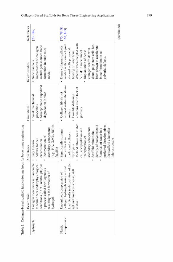
199
Tabl
e 1
Col
lage
n-ba
sed
scaf
fold
fab
rica
tion
met
hods
for
bon
e tis
sue
engi
neer
ing
Des
crip
tion
Adv
anta
ges
Lim
itatio
nsIn
viv
o st
udie
sR
efer
ence
s
Hyd
roge
lsC
olla
gen
mon
omer
s se
lf a
ssem
ble
to f
orm
fibe
rs u
nder
phy
siol
ogic
al
cond
ition
s (3
7 °C
, neu
tral
pH
) vi
a a
proc
ess
calle
d fib
rillo
gene
sis
resu
lting
in th
e fo
rmat
ion
of
hydr
ogel
.
• E
asy
to f
orm
• A
llow
s fo
r ce
ll en
caps
ulat
ion
• In
corp
orat
ion
of
seco
ndar
y co
mpo
nent
s (e
.g.,
HA
, GA
Gs,
BG
) is
fe
asib
le
• W
eak
mec
hani
cal
prop
ertie
s•
Susc
eptib
le to
exp
edite
d de
grad
atio
n in
viv
o
• Su
bcut
aneo
us
impl
anta
tion
of c
olla
gen
mat
rix
gels
indu
ced
bone
fo
rmat
ion
in n
ude
mic
e m
odel
.
[73,
149
]
Plas
tic
com
pres
sion
Unc
onfin
ed c
ompr
essi
on o
f co
llage
n hy
drog
els
usin
g a
fixed
lo
ad. R
esul
ts in
deh
ydra
tion
of th
e ge
l and
pro
duce
s a
dens
e, s
tiff
mat
rix.
• Si
gnifi
cant
ly s
tron
ger
and
stif
fer
than
tr
aditi
onal
col
lage
n hy
drog
els
• M
etho
d al
low
s fo
r vi
able
ce
ll en
caps
ulat
ion
and
inco
rpor
atio
n of
se
cond
ary
com
pone
nts
• Sc
affo
ld m
imic
s th
e de
nsity
of
nativ
e os
teoi
d•
Rem
oval
of
wat
er in
a
pref
erre
d di
rect
ion
give
s th
e sc
affo
ld a
lam
ella
r m
icro
stru
ctur
e
• C
olla
gen
fibri
ls n
ot
alig
ned
with
in th
e de
nse
mat
rix
• Po
ssib
le d
iffu
sion
co
ncer
ns d
ue to
lack
of
poro
sity
• D
ense
col
lage
n sc
affo
lds
seed
ed w
ith m
esen
chym
al
stro
mal
cel
ls p
rom
oted
he
alin
g of
larg
e bo
ne
defe
cts
whe
n co
uple
d w
ith
VE
GF
in m
ice
mod
el.
• Im
plan
tatio
n of
den
se
colla
gen
scaf
fold
s w
ith
dent
al p
ulp
stem
cel
ls h
as
been
sho
wn
to a
ccel
erat
e bo
ne f
orm
atio
n in
rat
ca
lvar
ial d
efec
ts.
[75,
78,
81,
16
2, 1
63]
(con
tinue
d)
Collagen-Based Scaffolds for Bone Tissue Engineering Applications
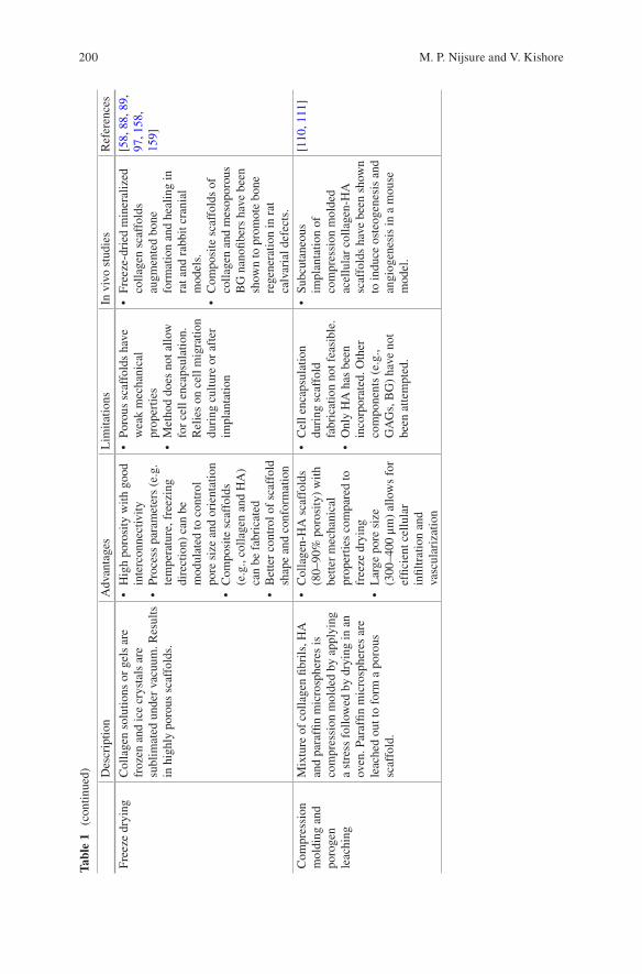
200
Tabl
e 1
(con
tinue
d) Des
crip
tion
Adv
anta
ges
Lim
itatio
nsIn
viv
o st
udie
sR
efer
ence
s
Free
ze d
ryin
gC
olla
gen
solu
tions
or
gels
are
fr
ozen
and
ice
crys
tals
are
su
blim
ated
und
er v
acuu
m. R
esul
ts
in h
ighl
y po
rous
sca
ffol
ds.
• H
igh
poro
sity
with
goo
d in
terc
onne
ctiv
ity•
Proc
ess
para
met
ers
(e.g
. te
mpe
ratu
re, f
reez
ing
dire
ctio
n) c
an b
e m
odul
ated
to c
ontr
ol
pore
siz
e an
d or
ient
atio
n•
Com
posi
te s
caff
olds
(e
.g.,
colla
gen
and
HA
) ca
n be
fab
rica
ted
• B
ette
r co
ntro
l of
scaf
fold
sh
ape
and
conf
orm
atio
n
• Po
rous
sca
ffol
ds h
ave
wea
k m
echa
nica
l pr
oper
ties
• M
etho
d do
es n
ot a
llow
fo
r ce
ll en
caps
ulat
ion.
R
elie
s on
cel
l mig
ratio
n du
ring
cul
ture
or
afte
r im
plan
tatio
n
• Fr
eeze
-dri
ed m
iner
aliz
ed
colla
gen
scaf
fold
s au
gmen
ted
bone
fo
rmat
ion
and
heal
ing
in
rat a
nd r
abbi
t cra
nial
m
odel
s.•
Com
posi
te s
caff
olds
of
colla
gen
and
mes
opor
ous
BG
nan
ofibe
rs h
ave
been
sh
own
to p
rom
ote
bone
re
gene
ratio
n in
rat
ca
lvar
ial d
efec
ts.
[58,
88,
89,
97
, 158
, 15
9]
Com
pres
sion
m
oldi
ng a
nd
poro
gen
leac
hing
Mix
ture
of
colla
gen
fibri
ls, H
A
and
para
ffin
mic
rosp
here
s is
co
mpr
essi
on m
olde
d by
app
lyin
g a
stre
ss f
ollo
wed
by
dryi
ng in
an
oven
. Par
affin
mic
rosp
here
s ar
e le
ache
d ou
t to
form
a p
orou
s sc
affo
ld.
• C
olla
gen-
HA
sca
ffol
ds
(80–
90%
por
osity
) w
ith
bette
r m
echa
nica
l pr
oper
ties
com
pare
d to
fr
eeze
dry
ing
• L
arge
por
e si
ze
(300
–400
μm
) al
low
s fo
r ef
ficie
nt c
ellu
lar
infil
trat
ion
and
vasc
ular
izat
ion
• C
ell e
ncap
sula
tion
duri
ng s
caff
old
fabr
icat
ion
not f
easi
ble.
• O
nly
HA
has
bee
n in
corp
orat
ed. O
ther
co
mpo
nent
s (e
.g.,
GA
Gs,
BG
) ha
ve n
ot
been
atte
mpt
ed.
• Su
bcut
aneo
us
impl
anta
tion
of
com
pres
sion
mol
ded
acel
lula
r co
llage
n-H
A
scaf
fold
s ha
ve b
een
show
n to
indu
ce o
steo
gene
sis
and
angi
ogen
esis
in a
mou
se
mod
el.
[110
, 111
]
M. P. Nijsure and V. Kishore
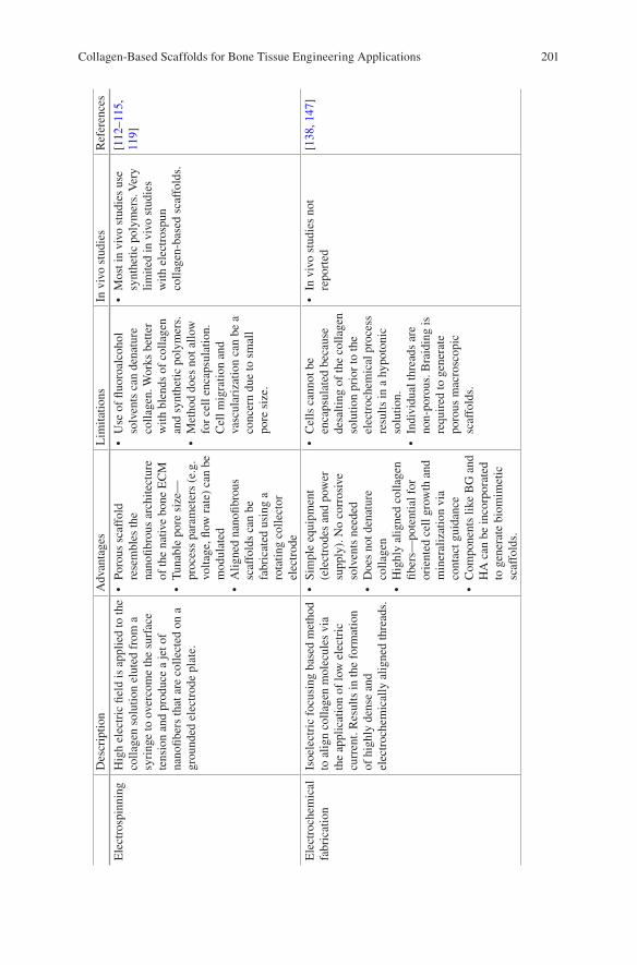
201
Des
crip
tion
Adv
anta
ges
Lim
itatio
nsIn
viv
o st
udie
sR
efer
ence
s
Ele
ctro
spin
ning
Hig
h el
ectr
ic fi
eld
is a
pplie
d to
the
colla
gen
solu
tion
elut
ed f
rom
a
syri
nge
to o
verc
ome
the
surf
ace
tens
ion
and
prod
uce
a je
t of
nano
fiber
s th
at a
re c
olle
cted
on
a gr
ound
ed e
lect
rode
pla
te.
• Po
rous
sca
ffol
d re
sem
bles
the
nano
fibro
us a
rchi
tect
ure
of th
e na
tive
bone
EC
M•
Tun
able
por
e si
ze—
proc
ess
para
met
ers
(e.g
. vo
ltage
, flow
rat
e) c
an b
e m
odul
ated
• A
ligne
d na
nofib
rous
sc
affo
lds
can
be
fabr
icat
ed u
sing
a
rota
ting
colle
ctor
el
ectr
ode
• U
se o
f flu
oroa
lcoh
ol
solv
ents
can
den
atur
e co
llage
n. W
orks
bet
ter
with
ble
nds
of c
olla
gen
and
synt
hetic
pol
ymer
s.•
Met
hod
does
not
allo
w
for
cell
enca
psul
atio
n.
Cel
l mig
ratio
n an
d va
scul
ariz
atio
n ca
n be
a
conc
ern
due
to s
mal
l po
re s
ize.
• M
ost i
n vi
vo s
tudi
es u
se
synt
hetic
pol
ymer
s. V
ery
limite
d in
viv
o st
udie
s w
ith e
lect
rosp
un
colla
gen-
base
d sc
affo
lds.
[112
–115
, 11
9]
Ele
ctro
chem
ical
fa
bric
atio
nIs
oele
ctri
c fo
cusi
ng b
ased
met
hod
to a
lign
colla
gen
mol
ecul
es v
ia
the
appl
icat
ion
of lo
w e
lect
ric
curr
ent.
Res
ults
in th
e fo
rmat
ion
of h
ighl
y de
nse
and
elec
troc
hem
ical
ly a
ligne
d th
read
s.
• Si
mpl
e eq
uipm
ent
(ele
ctro
des
and
pow
er
supp
ly).
No
corr
osiv
e so
lven
ts n
eede
d•
Doe
s no
t den
atur
e co
llage
n•
Hig
hly
alig
ned
colla
gen
fiber
s—po
tent
ial f
or
orie
nted
cel
l gro
wth
and
m
iner
aliz
atio
n vi
a co
ntac
t gui
danc
e•
Com
pone
nts
like
BG
and
H
A c
an b
e in
corp
orat
ed
to g
ener
ate
biom
imet
ic
scaf
fold
s.
• C
ells
can
not b
e en
caps
ulat
ed b
ecau
se
desa
lting
of
the
colla
gen
solu
tion
prio
r to
the
elec
troc
hem
ical
pro
cess
re
sults
in a
hyp
oton
ic
solu
tion.
• In
divi
dual
thre
ads
are
non-
poro
us. B
raid
ing
is
requ
ired
to g
ener
ate
poro
us m
acro
scop
ic
scaf
fold
s.
• In
viv
o st
udie
s no
t re
port
ed[1
38, 1
47]
Collagen-Based Scaffolds for Bone Tissue Engineering Applications
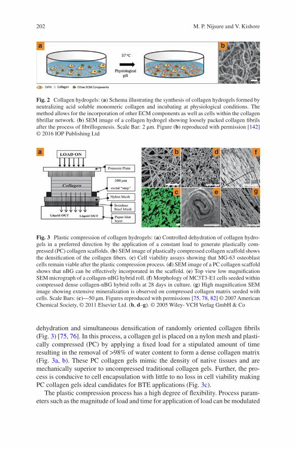
202
dehydration and simultaneous densification of randomly oriented collagen fibrils (Fig. 3) [75, 76]. In this process, a collagen gel is placed on a nylon mesh and plasti-cally compressed (PC) by applying a fixed load for a stipulated amount of time resulting in the removal of >98% of water content to form a dense collagen matrix (Fig. 3a, b). These PC collagen gels mimic the density of native tissues and are mechanically superior to uncompressed traditional collagen gels. Further, the pro-cess is conducive to cell encapsulation with little to no loss in cell viability making PC collagen gels ideal candidates for BTE applications (Fig. 3c).
The plastic compression process has a high degree of flexibility. Process param-eters such as the magnitude of load and time for application of load can be modulated
Fig. 2 Collagen hydrogels: (a) Schema illustrating the synthesis of collagen hydrogels formed by neutralizing acid soluble monomeric collagen and incubating at physiological conditions. The method allows for the incorporation of other ECM components as well as cells within the collagen fibrillar network. (b) SEM image of a collagen hydrogel showing loosely packed collagen fibrils after the process of fibrillogenesis. Scale Bar: 2 μm. Figure (b) reproduced with permission [142] © 2016 IOP Publishing Ltd
Fig. 3 Plastic compression of collagen hydrogels: (a) Controlled dehydration of collagen hydro-gels in a preferred direction by the application of a constant load to generate plastically com-pressed (PC) collagen scaffolds. (b) SEM image of plastically compressed collagen scaffold shows the densification of the collagen fibers. (c) Cell viability assays showing that MG-63 osteoblast cells remain viable after the plastic compression process. (d) SEM image of a PC collagen scaffold shows that nBG can be effectively incorporated in the scaffold. (e) Top view low magnification SEM micrograph of a collagen-nBG hybrid roll. (f) Morphology of MC3T3-E1 cells seeded within compressed dense collagen-nBG hybrid rolls at 28 days in culture. (g) High magnification SEM image showing extensive mineralization is observed on compressed collagen matrix seeded with cells. Scale Bars: (c)—50 μm. Figures reproduced with permissions [75, 78, 82] © 2007 American Chemical Society, © 2011 Elsevier Ltd. (b, d–g). © 2005 Wiley- VCH Verlag GmbH & Co
M. P. Nijsure and V. Kishore
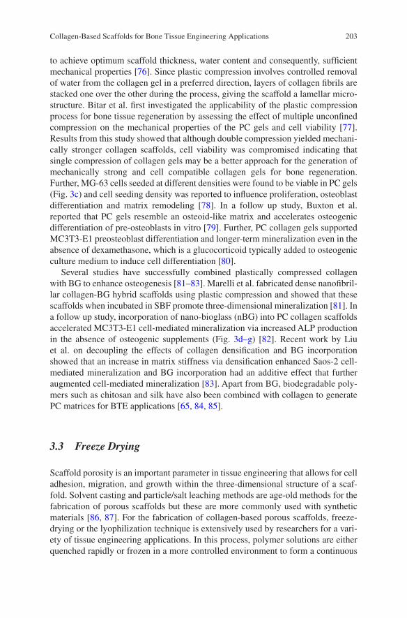
203
to achieve optimum scaffold thickness, water content and consequently, sufficient mechanical properties [76]. Since plastic compression involves controlled removal of water from the collagen gel in a preferred direction, layers of collagen fibrils are stacked one over the other during the process, giving the scaffold a lamellar micro-structure. Bitar et al. first investigated the applicability of the plastic compression process for bone tissue regeneration by assessing the effect of multiple unconfined compression on the mechanical properties of the PC gels and cell viability [77]. Results from this study showed that although double compression yielded mechani-cally stronger collagen scaffolds, cell viability was compromised indicating that single compression of collagen gels may be a better approach for the generation of mechanically strong and cell compatible collagen gels for bone regeneration. Further, MG-63 cells seeded at different densities were found to be viable in PC gels (Fig. 3c) and cell seeding density was reported to influence proliferation, osteoblast differentiation and matrix remodeling [78]. In a follow up study, Buxton et al. reported that PC gels resemble an osteoid-like matrix and accelerates osteogenic differentiation of pre-osteoblasts in vitro [79]. Further, PC collagen gels supported MC3T3-E1 preosteoblast differentiation and longer-term mineralization even in the absence of dexamethasone, which is a glucocorticoid typically added to osteogenic culture medium to induce cell differentiation [80].
Several studies have successfully combined plastically compressed collagen with BG to enhance osteogenesis [81–83]. Marelli et al. fabricated dense nanofibril-lar collagen-BG hybrid scaffolds using plastic compression and showed that these scaffolds when incubated in SBF promote three-dimensional mineralization [81]. In a follow up study, incorporation of nano-bioglass (nBG) into PC collagen scaffolds accelerated MC3T3-E1 cell-mediated mineralization via increased ALP production in the absence of osteogenic supplements (Fig. 3d–g) [82]. Recent work by Liu et al. on decoupling the effects of collagen densification and BG incorporation showed that an increase in matrix stiffness via densification enhanced Saos-2 cell- mediated mineralization and BG incorporation had an additive effect that further augmented cell-mediated mineralization [83]. Apart from BG, biodegradable poly-mers such as chitosan and silk have also been combined with collagen to generate PC matrices for BTE applications [65, 84, 85].
3.3 Freeze Drying
Scaffold porosity is an important parameter in tissue engineering that allows for cell adhesion, migration, and growth within the three-dimensional structure of a scaf-fold. Solvent casting and particle/salt leaching methods are age-old methods for the fabrication of porous scaffolds but these are more commonly used with synthetic materials [86, 87]. For the fabrication of collagen-based porous scaffolds, freeze- drying or the lyophilization technique is extensively used by researchers for a vari-ety of tissue engineering applications. In this process, polymer solutions are either quenched rapidly or frozen in a more controlled environment to form a continuous
Collagen-Based Scaffolds for Bone Tissue Engineering Applications
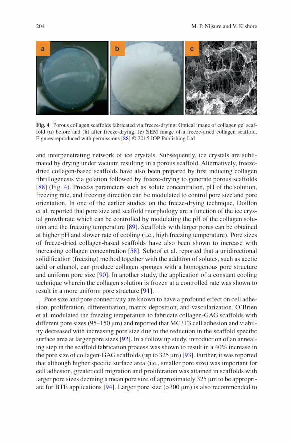
204
and interpenetrating network of ice crystals. Subsequently, ice crystals are subli-mated by drying under vacuum resulting in a porous scaffold. Alternatively, freeze- dried collagen-based scaffolds have also been prepared by first inducing collagen fibrillogenesis via gelation followed by freeze-drying to generate porous scaffolds [88] (Fig. 4). Process parameters such as solute concentration, pH of the solution, freezing rate, and freezing direction can be modulated to control pore size and pore orientation. In one of the earlier studies on the freeze-drying technique, Doillon et al. reported that pore size and scaffold morphology are a function of the ice crys-tal growth rate which can be controlled by modulating the pH of the collagen solu-tion and the freezing temperature [89]. Scaffolds with larger pores can be obtained at higher pH and slower rate of cooling (i.e., high freezing temperature). Pore sizes of freeze-dried collagen-based scaffolds have also been shown to increase with increasing collagen concentration [58]. Schoof et al. reported that a unidirectional solidification (freezing) method together with the addition of solutes, such as acetic acid or ethanol, can produce collagen sponges with a homogenous pore structure and uniform pore size [90]. In another study, the application of a constant cooling technique wherein the collagen solution is frozen at a controlled rate was shown to result in a more uniform pore structure [91].
Pore size and pore connectivity are known to have a profound effect on cell adhe-sion, proliferation, differentiation, matrix deposition, and vascularization. O’Brien et al. modulated the freezing temperature to fabricate collagen-GAG scaffolds with different pore sizes (95–150 μm) and reported that MC3T3 cell adhesion and viabil-ity decreased with increasing pore size due to the reduction in the scaffold specific surface area at larger pore sizes [92]. In a follow up study, introduction of an anneal-ing step in the scaffold fabrication process was shown to result in a 40% increase in the pore size of collagen-GAG scaffolds (up to 325 μm) [93]. Further, it was reported that although higher specific surface area (i.e., smaller pore size) was important for cell adhesion, greater cell migration and proliferation was attained in scaffolds with larger pore sizes deeming a mean pore size of approximately 325 μm to be appropri-ate for BTE applications [94]. Larger pore size (>300 μm) is also recommended to
Fig. 4 Porous collagen scaffolds fabricated via freeze-drying: Optical image of collagen gel scaf-fold (a) before and (b) after freeze-drying. (c) SEM image of a freeze-dried collagen scaffold. Figures reproduced with permissions [88] © 2015 IOP Publishing Ltd
M. P. Nijsure and V. Kishore
205
allow for vascularization, a key event in the progression of osteogenesis towards enhanced mineralization [95].
Weak mechanical properties of porous scaffolds are a major concern. Therefore, crosslinking of freeze-dried collagen/collagen-GAG scaffolds is essential to improve stability, reduce antigenicity, and enhance mechanical properties of the scaffolds [96]. Another method by which the mechanical properties of freeze-dried collagen scaffolds have been improved is via the incorporation of HA to reinforce the collagen structure [97]. Cunniffe et al. compared two different fabrication meth-ods to develop collagen-nano HA scaffolds: (1) a suspension method where nano HA particles were suspended in a collagen slurry prior to the freeze-drying process, and (2) an immersion method wherein collagen scaffolds were immersed in a nano HA suspension after freeze-drying [98]. Collagen-nano HA scaffolds fabricated using the suspension method were found to be more reproducible and stiffer com-pared to those fabricated using the immersion method. In a similar study, Ryan et al. assessed the effects of HA incorporation into porous collagen-GAG scaffolds before and after freeze drying and found that coating the scaffold with HA after freeze dry-ing supported greater cell-mediated calcium production [99]. Precipitation of HA within a freeze-dried collagen scaffold using an SBF immersion technique has also been employed for the fabrication of collagen-HA scaffolds with excellent mechan-ical and biological properties [100]. A combination of freeze-drying and salt leach-ing processes has been employed to fabricate a 3D porous collagen-HA-PLCL scaffold that better supported Saos-2 osteoblast cell growth and differentiation com-pared to PLCL scaffold alone [101]. In more recent work, collagen-HA microsphere composite scaffolds have demonstrated promise for drug delivery and bone regen-eration applications [102].
Freeze drying has also been used for the fabrication of scaffolds that combine collagen and other calcium phosphates such as tricalcium phosphate (TCP) and bioactive glasses to generate mechanically competent scaffolds with enhanced osteogenic activity for BTE applications [103–108]. In a recent study, Mooyen et al. employed freeze-drying to compare three different calcium phosphates (HA, TCP, and bicalcium phosphate (BCP)) by mixing them individually with BG in a chitosan:collagen matrix and reported that the compressive modulus and bone regeneration potential of BCP scaffolds were significantly higher than HA and TCP suggesting a differential response depending on the type of calcium phos-phate [109].
3.4 Compression Molding and Porogen Leaching
Compression molding is a recently developed method for the fabrication HA rein-forced collagen scaffolds to overcome some of the limitations associated with the freeze-drying method such as poor mechanical properties and relatively small pore size [110, 111]. In this method, an acid soluble collagen solution is neutralized and subjected to gelation via incubation at 37 °C. The collagen gel is then disrupted
Collagen-Based Scaffolds for Bone Tissue Engineering Applications
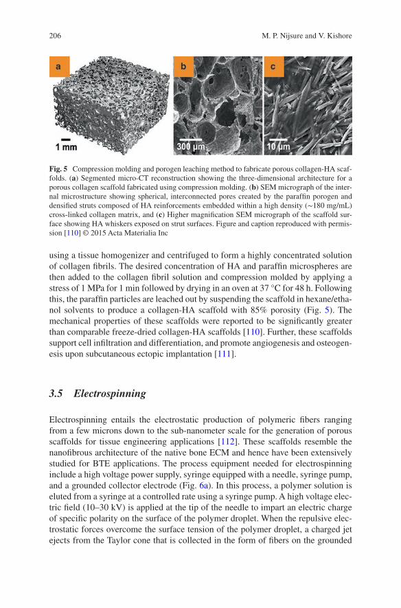
206
using a tissue homogenizer and centrifuged to form a highly concentrated solution of collagen fibrils. The desired concentration of HA and paraffin microspheres are then added to the collagen fibril solution and compression molded by applying a stress of 1 MPa for 1 min followed by drying in an oven at 37 °C for 48 h. Following this, the paraffin particles are leached out by suspending the scaffold in hexane/etha-nol solvents to produce a collagen-HA scaffold with 85% porosity (Fig. 5). The mechanical properties of these scaffolds were reported to be significantly greater than comparable freeze-dried collagen-HA scaffolds [110]. Further, these scaffolds support cell infiltration and differentiation, and promote angiogenesis and osteogen-esis upon subcutaneous ectopic implantation [111].
3.5 Electrospinning
Electrospinning entails the electrostatic production of polymeric fibers ranging from a few microns down to the sub-nanometer scale for the generation of porous scaffolds for tissue engineering applications [112]. These scaffolds resemble the nanofibrous architecture of the native bone ECM and hence have been extensively studied for BTE applications. The process equipment needed for electrospinning include a high voltage power supply, syringe equipped with a needle, syringe pump, and a grounded collector electrode (Fig. 6a). In this process, a polymer solution is eluted from a syringe at a controlled rate using a syringe pump. A high voltage elec-tric field (10–30 kV) is applied at the tip of the needle to impart an electric charge of specific polarity on the surface of the polymer droplet. When the repulsive elec-trostatic forces overcome the surface tension of the polymer droplet, a charged jet ejects from the Taylor cone that is collected in the form of fibers on the grounded
Fig. 5 Compression molding and porogen leaching method to fabricate porous collagen-HA scaf-folds. (a) Segmented micro-CT reconstruction showing the three-dimensional architecture for a porous collagen scaffold fabricated using compression molding. (b) SEM micrograph of the inter-nal microstructure showing spherical, interconnected pores created by the paraffin porogen and densified struts composed of HA reinforcements embedded within a high density (∼180 mg/mL) cross-linked collagen matrix, and (c) Higher magnification SEM micrograph of the scaffold sur-face showing HA whiskers exposed on strut surfaces. Figure and caption reproduced with permis-sion [110] © 2015 Acta Materialia Inc
M. P. Nijsure and V. Kishore
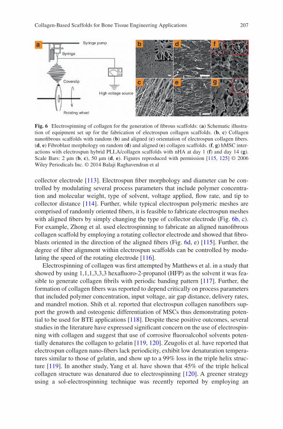
207
collector electrode [113]. Electrospun fiber morphology and diameter can be con-trolled by modulating several process parameters that include polymer concentra-tion and molecular weight, type of solvent, voltage applied, flow rate, and tip to collector distance [114]. Further, while typical electrospun polymeric meshes are comprised of randomly oriented fibers, it is feasible to fabricate electrospun meshes with aligned fibers by simply changing the type of collector electrode (Fig. 6b, c). For example, Zhong et al. used electrospinning to fabricate an aligned nanofibrous collagen scaffold by employing a rotating collector electrode and showed that fibro-blasts oriented in the direction of the aligned fibers (Fig. 6d, e) [115]. Further, the degree of fiber alignment within electrospun scaffolds can be controlled by modu-lating the speed of the rotating electrode [116].
Electrospinning of collagen was first attempted by Matthews et al. in a study that showed by using 1,1,1,3,3,3 hexafluoro-2-propanol (HFP) as the solvent it was fea-sible to generate collagen fibrils with periodic banding pattern [117]. Further, the formation of collagen fibers was reported to depend critically on process parameters that included polymer concentration, input voltage, air gap distance, delivery rates, and mandrel motion. Shih et al. reported that electrospun collagen nanofibers sup-port the growth and osteogenic differentiation of MSCs thus demonstrating poten-tial to be used for BTE applications [118]. Despite these positive outcomes, several studies in the literature have expressed significant concern on the use of electrospin-ning with collagen and suggest that use of corrosive fluoroalcohol solvents poten-tially denatures the collagen to gelatin [119, 120]. Zeugolis et al. have reported that electrospun collagen nano-fibers lack periodicity, exhibit low denaturation tempera-tures similar to those of gelatin, and show up to a 99% loss in the triple helix struc-ture [119]. In another study, Yang et al. have shown that 45% of the triple helical collagen structure was denatured due to electrospinning [120]. A greener strategy using a sol-electrospinning technique was recently reported by employing an
Fig. 6 Electrospinning of collagen for the generation of fibrous scaffolds: (a) Schematic illustra-tion of equipment set up for the fabrication of electrospun collagen scaffolds. (b, c) Collagen nanofibrous scaffolds with random (b) and aligned (c) orientation of electrospun collagen fibers. (d, e) Fibroblast morphology on random (d) and aligned (e) collagen scaffolds. (f, g) hMSC inter-actions with electrospun hybrid PLLA/collagen scaffolds with nHA at day 1 (f) and day 14 (g). Scale Bars: 2 μm (b, c), 50 μm (d, e). Figures reproduced with permission [115, 125] © 2006 Wiley Periodicals Inc. © 2014 Balaji Raghavendran et al
Collagen-Based Scaffolds for Bone Tissue Engineering Applications
208
ethanol- water solvent in lieu of fluoroalcohols to synthesize mechanically robust collagen-HA composite fibers with potential for BTE applications [121]. Further, Qiao et al. recently compared the biofunctionality of electrospun collagen/poly-dl- lactic acid (PDLLA) scaffolds with that of gelatin/PDLLA scaffolds and showed that greater cell proliferation and osteogenic differentiation was observed on colla-gen scaffolds suggesting that any electrospinning induced collagen denaturation did not have any effect on the biofunctionality of the scaffolds [122].
The use of collagen in blended formulations can minimize the potential detri-mental effects of electrospinning on the integrity of collagen [123]. To take advan-tage of the benefits of both natural and synthetic materials, electrospinning of collagen blended with synthetic polymers such as PCL, PLA, and PLGA have been extensively investigated to fabricate hybrid scaffolds for BTE applications [124–126]. For example, scaffolds fabricated by electrospinning a solution of PLLA- collagen and nHA were shown to effectively harbor mesenchymal stromal cells and independently support osteogenic differentiation without relying on media supple-ments or growth factors (Fig. 6f, g) [125]. Modified electrospinning methods such as emulsion electrospinning and coaxial electrospinning have been employed to fabricate core-shell nanofibers instead of the conventional blended nanofibers for the controlled release of growth factors that can positively influence scaffold mechanics and osteogenic cellular response [127–129].
Electrospinning has also been employed for the fabrication of biomimetic min-eralized collagen fibers via co-precipitation of collagen and nano-hydroxyapatite (nHA) to enhance cell-mediated mineralization [130, 131]. In a different approach to incorporate nHA, a co-electrospinning-electrospraying approach was employed wherein collagen dissolved in non-denaturing water based solvents was electrospun to generate fibers and the nHA was simultaneously electrosprayed onto the collagen fibers to obtain a collagen nanofiber mesh with significantly lower fiber diameters (30 nm) embedded with HA crystals [132]. In order to address the limitations of small pore size in electrospun scaffolds, Phipps et al. included sacrificial water- soluble polyethylene oxide (PEO) fibers within electrospun PCL/collagen/nHA scaffolds and showed that the sacrificial fibers increased scaffold pore size and enhanced MSC infiltration into the scaffolds [133]. Electrospinning of collagen with other bioceramics such as amorphous calcium phosphate, beta-tricalcium phosphate, and BG have also yielded scaffolds with potential for bone regeneration applications [134–137].
3.6 Electrochemical Fabrication
Electrochemical fabrication is a collagen densification process that relies on the principles of isoelectric focusing to yield highly oriented and densely packed col-lagen threads. This method was first developed by Cheng et al. in 2008 for the synthesis of anisotropic collagen bundles for tendon tissue engineering applications
M. P. Nijsure and V. Kishore
209
[138]. The process requires minimal equipment that includes the collagen solution, a pair of electrodes, and a low voltage power supply. Further, unlike electrospinning, the electrochemical process can be carried out under physiological conditions using low electric current and without the use of corrosive solvents. In this process, a desalted collagen solution is loaded between two stainless steel wire electrodes and an electric field (2–30 V) is applied. In the presence of an electric field, a non- linear pH gradient ranging from acidic (pH ~3) to basic (pH ~11) develops between the two electrodes due to the electrolysis of the aqueous collagen solution [139]. The pH gradient triggers the amphoteric collagen molecules close to the anode to assume a positive charge and the ones close to the cathode to assume a negative charge. Since the electrodes have a like charge, the collagen molecules repel away from the electrodes and self-assemble along the isoelectric point where the net charge is zero resulting in the formation of electrochemically aligned collagen (ELAC) threads. The mechanical properties of genipin crosslinked ELAC threads have been shown to be on par with native tendons [43]. Further, it has been previously shown that MSCs can sense the aligned collagen topography of ELAC threads and differentiate towards the tendon lineage without the addition of any external growth factors [34, 140]. An automated fabrication method has been developed to synthesize ELAC threads of sufficient length such that they can be braided to form macroscopic scaf-folds for tendon regeneration applications [140].
The application of the electrochemical fabrication method is not limited to tendons alone. Several studies have investigated the feasibility of the electro-chemical fabrication method to develop biomimetic collagen-based scaffolds for a variety of tissue engineering applications including cartilage [141], cornea [142], nerve [143], and blood vessels [144]. Recent work has shown that it is feasible to incorporate additional components (e.g., GAGs, elastin) within the collagen network to form hybrid scaffolds by simply mixing the component with collagen prior to the electrochemical process [144–146]. Our laboratory has recently shown that it is feasible to incorporate 45S5 bioactive glass within ELAC threads to mimic the compositional (40% organic and 60% inorganic) and structural aspects of native bone (aligned and densely packed collagen fibers) (Fig. 7a) [147]. Results of this work showed that tissue-level (60% w/w) BG can be successfully incorporated without disturbing the overall collagen alignment within ELAC (Fig. 7b, c). Saos-2 cells appeared to orient along the long axis of the BG incorporated ELAC thread (Fig. 7d) and rapidly proliferate in culture (Fig. 7f). Extensive mineralization that increased progressively with time was observed on BG incorporated ELAC threads when incubated in simulated body fluid confirming that these threads exhibit bone bioactivity (Fig. 7e) [148]. Finally, BG incorporation enhanced Saos-2 cell mediated mineralization on ELAC threads (Fig. 7g). Together, outcomes of this first study demonstrate that electrochemical fabrication is a promising technique for the development of bio-mimetic collagen-based scaffolds for BTE applications.
Collagen-Based Scaffolds for Bone Tissue Engineering Applications
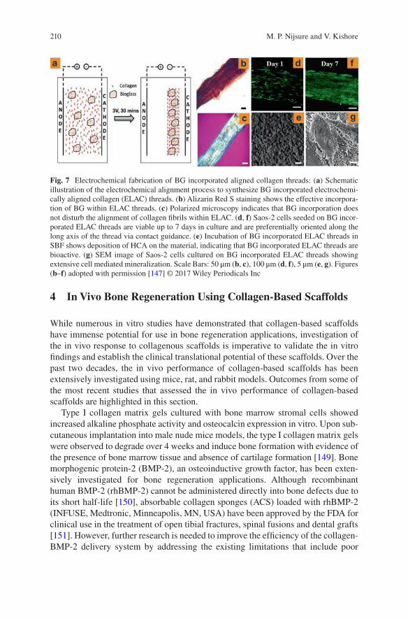
210
4 In Vivo Bone Regeneration Using Collagen-Based Scaffolds
While numerous in vitro studies have demonstrated that collagen-based scaffolds have immense potential for use in bone regeneration applications, investigation of the in vivo response to collagenous scaffolds is imperative to validate the in vitro findings and establish the clinical translational potential of these scaffolds. Over the past two decades, the in vivo performance of collagen-based scaffolds has been extensively investigated using mice, rat, and rabbit models. Outcomes from some of the most recent studies that assessed the in vivo performance of collagen-based scaffolds are highlighted in this section.
Type I collagen matrix gels cultured with bone marrow stromal cells showed increased alkaline phosphate activity and osteocalcin expression in vitro. Upon sub-cutaneous implantation into male nude mice models, the type I collagen matrix gels were observed to degrade over 4 weeks and induce bone formation with evidence of the presence of bone marrow tissue and absence of cartilage formation [149]. Bone morphogenic protein-2 (BMP-2), an osteoinductive growth factor, has been exten-sively investigated for bone regeneration applications. Although recombinant human BMP-2 (rhBMP-2) cannot be administered directly into bone defects due to its short half-life [150], absorbable collagen sponges (ACS) loaded with rhBMP-2 (INFUSE, Medtronic, Minneapolis, MN, USA) have been approved by the FDA for clinical use in the treatment of open tibial fractures, spinal fusions and dental grafts [151]. However, further research is needed to improve the efficiency of the collagen- BMP- 2 delivery system by addressing the existing limitations that include poor
Fig. 7 Electrochemical fabrication of BG incorporated aligned collagen threads: (a) Schematic illustration of the electrochemical alignment process to synthesize BG incorporated electrochemi-cally aligned collagen (ELAC) threads. (b) Alizarin Red S staining shows the effective incorpora-tion of BG within ELAC threads. (c) Polarized microscopy indicates that BG incorporation does not disturb the alignment of collagen fibrils within ELAC. (d, f) Saos-2 cells seeded on BG incor-porated ELAC threads are viable up to 7 days in culture and are preferentially oriented along the long axis of the thread via contact guidance. (e) Incubation of BG incorporated ELAC threads in SBF shows deposition of HCA on the material, indicating that BG incorporated ELAC threads are bioactive. (g) SEM image of Saos-2 cells cultured on BG incorporated ELAC threads showing extensive cell mediated mineralization. Scale Bars: 50 μm (b, c), 100 μm (d, f), 5 μm (e, g). Figures (b–f) adopted with permission [147] © 2017 Wiley Periodicals Inc
M. P. Nijsure and V. Kishore
211
mechanical properties, need for very high doses of BMP-2 due to its poor affinity with collagen, accompanying high costs and undesirable side effects due to uncon-trolled release of BMP-2 [152–154]. Visser et al. modified the structure of rhBMP-2 by incorporating an additional collagen binding peptide to increase rhBMP-2 affin-ity to collagen and thereby attain sustained rhBMP-2 release from ACS [151]. Results from an ectopic bone formation assay in a rat model demonstrated that the modified rhBMP-2 maintained its osteoinductive properties and induced new bone formation at lower doses compared to unmodified rhBMP-2. In another study, Hou et al. combined chitosan microspheres with ACS to attain controlled delivery of rhBMP-2 [155]. Implantation of this composite scaffold into a segmental defect in a rabbit model resulted in enhanced new bone formation compared to ACS alone and ACS directly loaded with rhBMP-2 without the chitosan microspheres. The controlled release of rhBMP-2 has also been attained by incorporating the protein into a porous collagen-HA scaffold via a lyophilization process. These scaffolds when implanted into a critical-sized calvarial defect in a rat model induced bone regeneration and healing using 30 times less with rhBMP-2 compared to the cur-rently used ACS-BMP-2 system (INFUSE) demonstrating the potential of these scaffolds to be used as a more efficient rhBMP-2 delivery platform for bone repair (Fig. 8) [156].
Implantation of freeze-dried mineralized collagen-based scaffolds without cells and growth factors has shown promising results for bone formation and regenera-tion [88, 157–159]. Ren et al. have shown that implantation of freeze-dried mineral-ized collagen-GAG scaffolds into rabbit cranial defect models resulted in better bone healing compared to non-mineralized scaffolds [158]. More importantly, bone formation via mineralized collagen-GAG scaffolds was also observed in the absence of cells and exogenous growth factors. Albeit the presence of cells and growth fac-tors (rh-BMP-2) significantly augmented bone formation post implantation of the mineralized collagen-GAG scaffolds, the researchers suggest that optimization of scaffold properties can result in adequate bone regeneration via efficient cellular recruitment from the surrounding tissue without ex vivo culturing of cells on the scaffold or incorporation of any chemical factors. In another study, Lyons et al. evaluated two different freeze-dried collagen-based scaffolds—collagen-GAG and collagen-calcium phosphate—for bone repair in a rat cranial defect model. Both scaffolds were assessed with and without MSCs cultured prior to implantation [159]. Results showed that collagen-calcium phosphate scaffolds yielded signifi-cantly higher amounts of mineralized tissue compared to the collagen-GAG scaf-folds 8 weeks post implantation. More importantly, the cell-free scaffolds in both groups showed better healing of the defect with higher bone formation compared to MSC-seeded constructs. The researchers attribute this differential outcome to the enhanced M1 macrophage activity observed in the cell-seeded constructs resulting in poor healing confined only to the periphery of the scaffold compared to a more homogenous mineralization observed throughout the scaffold structure when scaf-folds were implanted without cells. Composite scaffolds of collagen and mesopo-rous BG nanofibers have been shown to promote the differentiation and mineralization of MG63 osteoblast-like cells and promote bone regeneration in a rat
Collagen-Based Scaffolds for Bone Tissue Engineering Applications
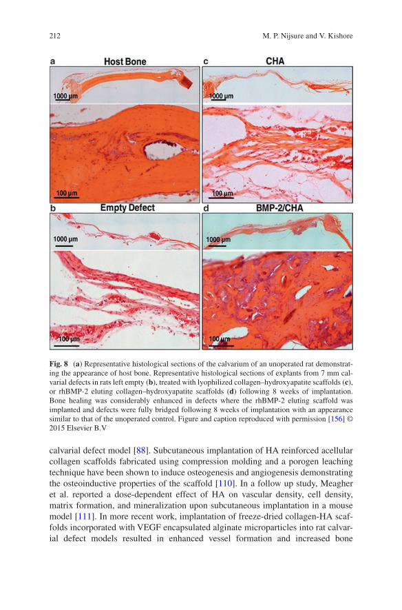
212
calvarial defect model [88]. Subcutaneous implantation of HA reinforced acellular collagen scaffolds fabricated using compression molding and a porogen leaching technique have been shown to induce osteogenesis and angiogenesis demonstrating the osteoinductive properties of the scaffold [110]. In a follow up study, Meagher et al. reported a dose-dependent effect of HA on vascular density, cell density, matrix formation, and mineralization upon subcutaneous implantation in a mouse model [111]. In more recent work, implantation of freeze-dried collagen-HA scaf-folds incorporated with VEGF encapsulated alginate microparticles into rat calvar-ial defect models resulted in enhanced vessel formation and increased bone
Fig. 8 (a) Representative histological sections of the calvarium of an unoperated rat demonstrat-ing the appearance of host bone. Representative histological sections of explants from 7 mm cal-varial defects in rats left empty (b), treated with lyophilized collagen–hydroxyapatite scaffolds (c), or rhBMP-2 eluting collagen–hydroxyapatite scaffolds (d) following 8 weeks of implantation. Bone healing was considerably enhanced in defects where the rhBMP-2 eluting scaffold was implanted and defects were fully bridged following 8 weeks of implantation with an appearance similar to that of the unoperated control. Figure and caption reproduced with permission [156] © 2015 Elsevier B.V
M. P. Nijsure and V. Kishore
213
regeneration compared to scaffolds without VEGF suggesting that the sustained release of VEGF can augment angiogenesis and bone repair [160]. Together, the outcomes from these studies suggest that implantation of cell-free mineralized scaf-folds is a meritorious approach for bone repair and regeneration.
On the other hand, cell-based tissue engineering approaches for bone repair have also yielded promising results. Villa et al. employed collagen-HA scaffolds and bone marrow stromal cells to examine the effect of a cell attachment period prior to implantation on the healing of bone defects and found that scaffolds implanted into a mouse calvarial model immediately after cell loading yielded bet-ter results in terms of mineralization compared to ones incubated with cells over-night prior to implantation [161]. MSC-seeded dense collagen scaffolds cultured in vitro for 5 days and then implanted into femoral defects in a mouse model showed no mineralization; however, administration of VEGF 4 days post implantation of MSC- seeded dense collagen scaffolds resulted in rapid mineralization and integra-tion with the native bone tissue [162]. Implantation of dense collagen scaffolds seeded with mesenchymal dental pulp stem cells into critical-sized rat calvarial defect model has been shown to accelerate bone formation with significant increases in mineralized tissue volume compared to acellular scaffolds demonstrat-ing that cell- seeded dense collagen scaffolds are viable candidates for bone healing applications [163].
5 FDA Approved Collagen-Based Materials
A variety of collagen-based biomaterials have been approved by the FDA, and are routinely used in surgeries as fillers or scaffolds for bone regeneration. Collagraft™ was the first collagen-based implant that was approved by the FDA in 1993. Introduced by Zimmer (Collagen Matrix), Collagraft™ is a mixture of purified fibrillar collagen and a HA-tricalcium phosphate that is mixed with aspirated bone marrow at the time of surgery and used to fill large defects (not more than 30 mL in volume). Collagraft™ is manufactured by casting slurry of bovine collagen and calcium phosphate in a shape, freezing and crosslinking via a dehydrothermal treat-ment followed by sterilization, and sold as strips. These strips are required to be soaked in freshly aspirated bone marrow from the patient at the time of surgery before implantation. Collagraft™ is effectively resorbed and replaced with the bone during the healing process. Healos® is another bone graft substitute that is composi-tionally similar to Collagraft™. Healos® is approved by the FDA and is used in lumbar fusions. DePuy, manufacturers of Healos® have also introduced an inject-able version of the product which facilitates minimally invasive surgeries and com-plete filling of the defect. Collagraft™ and Healos® do not independently promote osteogenesis. They depend on cells present in the bone marrow aspirate to initiate bone formation and the local cells at the site of the defect for integration with the native tissue. They are not incorporated with growth factors to promote bone forma-tion and healing [164]. On the other hand, the INFUSE® Bone Graft (Medtronic
Collagen-Based Scaffolds for Bone Tissue Engineering Applications
214
Sofamor Danek, Inc., USA) is composed of rhBMP-2 on an ACS. INFUSE® was the first rhBMP-2 containing product to be approved by the FDA for the treatment of spinal disc diseases and tibial fractures. OssiMend® Strips, Pads, Putty are some of the other resorbable collagen-mineral scaffolds that are used for orthopedic and spinal surgeries. Despite the advances in the development of materials such as the ones mentioned above, they have failed to become the primary choice from sur-geons. The primary reason behind this is the fact that these materials are mainly used as fillers, and are ineffective for independent, load bearing applications. Moreover, it is inadvisable to use these materials in patients with pre-existing medi-cal conditions like bacterial infections or malignancy. Specifically, Collagraft™ cannot be used with patients with osteomyelitis at the site of surgery. Diabetics and pregnant women are also advised against using Collagraft™. INFUSE® poses simi-lar risks and cannot be used in fractures secondary to malignancy because of the presence of rhBMP-2. Further, INFUSE® uses high doses of rhBMP-2 because the growth factor has low affinity to collagen resulting in an initial bolus dose of the growth factor at the surgical site [153]. This uncontrolled release has been associ-ated with several complications like heterotopic ossification, osteolysis, increased neurological deficits, retrograde ejaculation, or cancer. Therefore, there is a still need for functional and mechanically resilient bone graft substitutes that can aug-ment bone formation with minimal associated risks.
6 Conclusions and Future Outlook
BTE has been extensively investigated in the last few decades to primarily address the ever-increasing demand for bone-grafts fueled by the rising prevalence of bone and joint disorders. BTE has made significant strides towards the development of better, more sophisticated alternatives for bone grafts. Over the years, collagen- based scaffolds have demonstrated immense promise for use in BTE applications. FDA approved collagen-based materials are regularly used as bone grafts in clinical practice with satisfactory results. However, these materials are predominantly used as fillers and can only be used for specific applications. INFUSE, an FDA approved collagen sponge, is the market leader in the field of bone grafts but complications associated with the bolus release of rhBMP-2 limit its widespread use [153]. Recent work on the development of strategies for the controlled release of BMP-2 to negate the limitations of INFUSE and yet attain comparable bone healing outcomes has yielded promising results [154–156]. Nevertheless, the use of growth factors must to be carefully regulated due to potential side effects that include postoperative inflammation, swelling and ectopic bone formation [165]. Further, the adverse effects of growth factors are also documented in diseased models. For example, premature administration of VEGF in cancer patients during treatment has been shown to lead to tumor recurrence [166]. Therefore, there is significant room for research and development of collagen-based scaffolds using growth-factor free approaches for BTE.
M. P. Nijsure and V. Kishore
215
Physicochemical properties of the scaffolds (i.e., composition, structure, matrix stiffness) have been shown to have a profound effect on cell adhesion, proliferation and differentiation [12, 167, 168]. Bioactive scaffolds that mimic the native bone ECM may provide the desired physicochemical cues to drive material-directed osteogenic differentiation and mineralization without the use of external growth factors or chemicals. Research in this field has undoubtedly made some significant advancements—most notably, the development of hybrid collagen-based scaffolds (e.g., collagen and HA) that mimic multiple aspects of the bone ECM. Many of the studies that use collagen-based hybrid scaffolds have also progressed to animal tri-als. Although these scaffolds have shown successful bone regeneration in vivo, very little work has been done on diseased models—which is a significant roadblock that must be addressed before advancing to clinical trials. Another limitation to these studies is that the animal models utilize intentionally introduced defects that are usually smaller than realistic defects caused by trauma or tissue debridement. Further, despite the use of techniques such as cross-linking and combination with inorganic materials, a highly porous and mechanically strong collagen-based scaf-fold that can vascularize and integrate with the surrounding tissue for use in load- bearing BTE applications is still elusive [10].
Development of a scaffold that truly mimics all the physicochemical aspects of the native bone tissue is a momentous task because perfecting one aspect usually means compromising the other. While numerous studies in the literature have com-bined collagen with HA and other inorganic constituents to resemble the composi-tional properties of the native bone ECM, few studies have attempted to recreate the aligned collagen microstructure found in native bone. Development of strategies to align collagen molecules and fibrils can help generate scaffolds with anisotropic mechanical properties similar to that of native bone. The aligned collagen topogra-phy may also govern cellular response by directing cellular alignment via contact guidance [34, 169]. Additionally, incorporation of bioactive molecules (e.g., HA, BG, calcium phosphates) within the aligned collagen structure can aid in stimulat-ing osteoblast differentiation and promote the deposition of a cell-mediated miner-alized matrix oriented in a preferred direction akin to that found in native bone [170]. Future studies need to focus on devising novel biomimetic strategies that can yield mechanically competent collagen-based scaffolds for the repair and regenera-tion of damaged or diseased bone in load-bearing BTE applications with minimal use of growth factors.
Furthermore, it is important to note that majority of bone regeneration strategies studied so far either focus on biomaterial development, cell-based therapies or the use of growth factors. In reality, all of these are delicately interconnected. In gen-eral, a more holistic approach, that understands the mechanisms involved in all three factors listed above, is necessary to achieve bone formation, without negatively impacting the natural processes involved. This chapter highlights the advantages and limitations of some of the most promising scaffold fabrication technologies. We elaborated on strategies that have been tried in animal models and a few others which have been approved by the FDA. Finally, possible future directions that can be pursued while devising strategies for bone tissue regeneration are discussed.
Collagen-Based Scaffolds for Bone Tissue Engineering Applications
216
A comprehensive comparison between existing scaffold fabrication techniques and an analyses of possible improvisations can pave the way towards the development of fully functional scaffolds for bone tissue regeneration.
References
1. Clarke B. Normal bone anatomy and physiology. Clin J Am Soc Nephrol. 2008;3(Suppl 3):S131–9.
2. Rho J, Kuhn-Spearing L, Zioupos P. Mechanical properties and the hierarchical structure of bone. Med Eng Phys. 1998;20:92–102.
3. Downey PA, Siegel MI. Bone biology and the clinical implications for osteoporosis. Phys Ther. 2006;86:77.
4. Orimo H. The mechanism of mineralization and the role of alkaline phosphatase in health and disease. J Nippon Med Sch. 2010;77:4–12.
5. US Department of Health and Human Services. Bone health and osteoporosis: a report of the Surgeon General. Rockville, MD: US Department of Health and Human Services, Office of the Surgeon General; 2004. p. 87.
6. Desai BM. Osteobiologics. Am J Orthop (Belle Mead NJ). 2007;36:8–11. 7. Delgado LM, Bayon Y, Pandit A, Zeugolis DI. To cross-link or not to cross-link? Cross-
linking associated foreign body response of collagen-based devices. Tissue Eng B Rev. 2015;21:298–313.
8. Oryan A, Alidadi S, Moshiri A, Maffulli N. Bone regenerative medicine: classic options, novel strategies, and future directions. J Orthop Surg Res. 2014;9:18.
9. Burg KJ, Porter S, Kellam JF. Biomaterial developments for bone tissue engineering. Biomaterials. 2000;21:2347–59.
10. Amini AR, Laurencin CT, Nukavarapu SP. Bone tissue engineering: recent advances and challenges. Crit Rev Biomed Eng. 2012;40:363–408.
11. de Peppo GM, Marolt D. Modulating the biochemical and biophysical culture environment to enhance osteogenic differentiation and maturation of human pluripotent stem cell-derived mesenchymal progenitors. Stem Cell Res Ther. 2013;4:106.
12. Engler AJ, Sen S, Sweeney HL, Discher DE. Matrix elasticity directs stem cell lineage speci-fication. Cell. 2006;126:677–89.
13. Resende RR, Fonseca EA, Tonelli FM, Sousa BR, Santos AK, Gomes KN, Guatimosim S, Kihara AH, Ladeira LO. Scale/topography of substrates surface resembling extracellular matrix for tissue engineering. J Biomed Nanotechnol. 2014;10:1157–93.
14. Moore NM, Lin NJ, Gallant ND, Becker ML. Synergistic enhancement of human bone mar-row stromal cell proliferation and osteogenic differentiation on BMP-2-derived and RGD peptide concentration gradients. Acta Biomater. 2011;7:2091–100.
15. Park JS, Yang HN, Jeon SY, Woo DG, Na K, Park K. Osteogenic differentiation of human mesenchymal stem cells using RGD-modified BMP-2 coated microspheres. Biomaterials. 2010;31:6239–48.
16. Hakkarainen M, Höglund A, Odelius K, Albertsson A. Tuning the release rate of acidic deg-radation products through macromolecular design of caprolactone-based copolymers. J Am Chem Soc. 2007;129:6308–12.
17. Ferreira AM, Gentile P, Chiono V, Ciardelli G. Collagen for bone tissue regeneration. Acta Biomater. 2012;8:3191–200.
18. Cunniffe GM, O'Brien FJ. Collagen scaffolds for orthopedic regenerative medicine. JOM. 2011;63:66.
M. P. Nijsure and V. Kishore
217
19. Davidenko N, Bax DV, Schuster CF, Farndale RW, Hamaia SW, Best SM, Cameron RE. Optimisation of UV irradiation as a binding site conserving method for crosslinking collagen-based scaffolds. J Mater Sci Mater Med. 2016;27:14.
20. Ahearne M, Yang Y, Then KY, Liu KK. Non-destructive mechanical characterisation of UVA/riboflavin crosslinked collagen hydrogels. Br J Ophthalmol. 2008;92:268–71.
21. Ibusuki S, Halbesma GJ, Randolph MA, Redmond RW, Kochevar IE, Gill TJ. Photochemically cross-linked collagen gels as three-dimensional scaffolds for tissue engineering. Tissue Eng. 2007;13:1995–2001.
22. Suri S, Schmidt CE. Photopatterned collagen–hyaluronic acid interpenetrating polymer net-work hydrogels. Acta Biomater. 2009;5:2385–97.
23. Friess W. Collagen–biomaterial for drug delivery. Eur J Pharm Biopharm. 1998;45:113–36. 24. Weadock KS, Miller EJ, Bellincampi LD, Zawadsky JP, Dunn MG. Physical crosslink-
ing of collagen fibers: comparison of ultraviolet irradiation and dehydrothermal treatment. J Biomed Mater Res. 1995;29:1373–9.
25. Gorham S, Light N, Diamond A, Willins M, Bailey A, Wess T, Leslie N. Effect of chemical modifications on the susceptibility of collagen to proteolysis. II. Dehydrothermal crosslink-ing. Int J Biol Macromol. 1992;14:129–38.
26. Drexler JW, Powell HM. Dehydrothermal crosslinking of electrospun collagen. Tissue Eng C Methods. 2010;17:9–17.
27. Haugh MG, Jaasma MJ, O'Brien FJ. The effect of dehydrothermal treatment on the mechanical and structural properties of collagen‐GAG scaffolds. J Biomed Mater Res A. 2009;89:363–9.
28. Kawahara J, Ishikawa K, Uchimaru T, Takaya H. Chemical cross-linking by glutaraldehyde between amino groups: its mechanism and effects. In: Anonymous polymer modification. New York: Springer; 1997. p. 119–31.
29. Jorge-Herrero E, Fernandez P, Turnay J, Olmo N, Calero P, Garcı́a R, Freile I, Castillo- Olivares J. Influence of different chemical cross-linking treatments on the properties of bovine pericardium and collagen. Biomaterials. 1999;20:539–45.
30. Scotchford C, Cascone M, Downes S, Giusti P. Osteoblast responses to collagen-PVA bioartificial polymers in vitro: the effects of cross-linking method and collagen content. Biomaterials. 1998;19:1–11.
31. Sung HW, Huang RN, Huang LL, Tsai CC, Chiu CT. Feasibility study of a natural crosslink-ing reagent for biological tissue fixation. J Biomed Mater Res. 1998;42:560–7.
32. Sung H, Huang R, Huang LL, Tsai C. In vitro evaluation of cytotoxicity of a naturally occurring cross-linking reagent for biological tissue fixation. J Biomater Sci Polym Ed. 1999;10:63–78.
33. Fessel G, Cadby J, Wunderli S, van Weeren R, Snedeker JG. Dose-and time-dependent effects of genipin crosslinking on cell viability and tissue mechanics—toward clinical appli-cation for tendon repair. Acta Biomater. 2014;10:1897–906.
34. Kishore V, Bullock W, Sun X, Van Dyke WS, Akkus O. Tenogenic differentiation of human MSCs induced by the topography of electrochemically aligned collagen threads. Biomaterials. 2012;33:2137–44.
35. Yan L, Wang Y, Ren L, Wu G, Caridade SG, Fan J, Wang L, Ji P, Oliveira JM, Oliveira JT. Genipin‐cross‐linked collagen/chitosan biomimetic scaffolds for articular cartilage tissue engineering applications. J Biomed Mater Res A. 2010;95:465–75.
36. Olde Damink LH, Dijkstra PJ, van Luyn MJ, van Wachem PB, Nieuwenhuis P, Feijen J. Cross-linking of dermal sheep collagen using a water-soluble carbodiimide. Biomaterials. 1996;17:765–73.
37. Zeugolis DI, Paul GR, Attenburrow G. Cross‐linking of extruded collagen fibers—a biomi-metic three‐dimensional scaffold for tissue engineering applications. J Biomed Mater Res A. 2009;89:895–908.
38. Cass CA, Burg KJ. Tannic acid cross-linked collagen scaffolds and their anti-cancer potential in a tissue engineered breast implant. J Biomater Sci Polym Ed. 2012;23:281–98.
Collagen-Based Scaffolds for Bone Tissue Engineering Applications
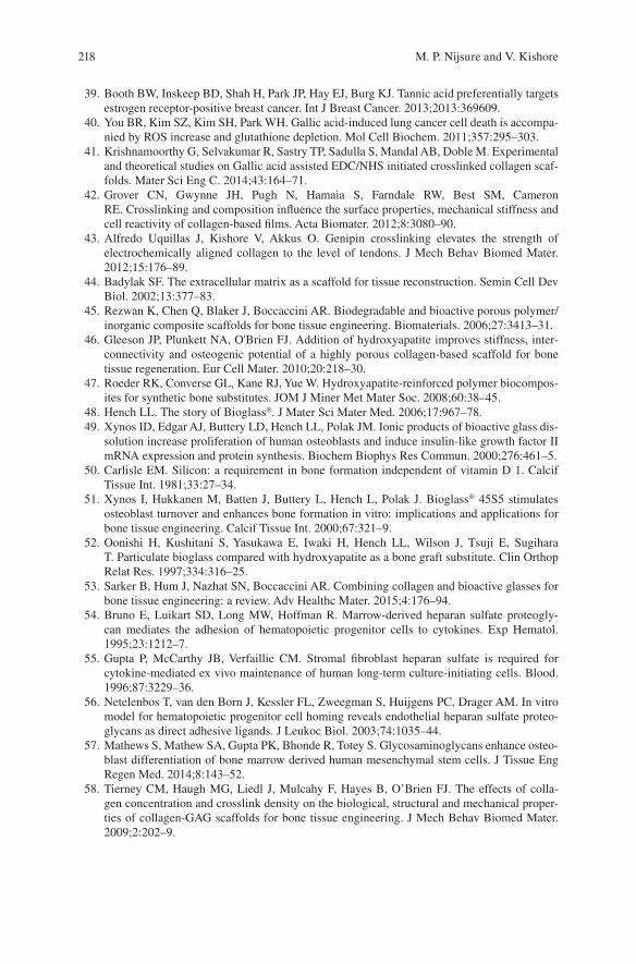
218
39. Booth BW, Inskeep BD, Shah H, Park JP, Hay EJ, Burg KJ. Tannic acid preferentially targets estrogen receptor-positive breast cancer. Int J Breast Cancer. 2013;2013:369609.
40. You BR, Kim SZ, Kim SH, Park WH. Gallic acid-induced lung cancer cell death is accompa-nied by ROS increase and glutathione depletion. Mol Cell Biochem. 2011;357:295–303.
41. Krishnamoorthy G, Selvakumar R, Sastry TP, Sadulla S, Mandal AB, Doble M. Experimental and theoretical studies on Gallic acid assisted EDC/NHS initiated crosslinked collagen scaf-folds. Mater Sci Eng C. 2014;43:164–71.
42. Grover CN, Gwynne JH, Pugh N, Hamaia S, Farndale RW, Best SM, Cameron RE. Crosslinking and composition influence the surface properties, mechanical stiffness and cell reactivity of collagen-based films. Acta Biomater. 2012;8:3080–90.
43. Alfredo Uquillas J, Kishore V, Akkus O. Genipin crosslinking elevates the strength of electrochemically aligned collagen to the level of tendons. J Mech Behav Biomed Mater. 2012;15:176–89.
44. Badylak SF. The extracellular matrix as a scaffold for tissue reconstruction. Semin Cell Dev Biol. 2002;13:377–83.
45. Rezwan K, Chen Q, Blaker J, Boccaccini AR. Biodegradable and bioactive porous polymer/inorganic composite scaffolds for bone tissue engineering. Biomaterials. 2006;27:3413–31.
46. Gleeson JP, Plunkett NA, O'Brien FJ. Addition of hydroxyapatite improves stiffness, inter-connectivity and osteogenic potential of a highly porous collagen-based scaffold for bone tissue regeneration. Eur Cell Mater. 2010;20:218–30.
47. Roeder RK, Converse GL, Kane RJ, Yue W. Hydroxyapatite-reinforced polymer biocompos-ites for synthetic bone substitutes. JOM J Miner Met Mater Soc. 2008;60:38–45.
48. Hench LL. The story of Bioglass®. J Mater Sci Mater Med. 2006;17:967–78. 49. Xynos ID, Edgar AJ, Buttery LD, Hench LL, Polak JM. Ionic products of bioactive glass dis-
solution increase proliferation of human osteoblasts and induce insulin-like growth factor II mRNA expression and protein synthesis. Biochem Biophys Res Commun. 2000;276:461–5.
50. Carlisle EM. Silicon: a requirement in bone formation independent of vitamin D 1. Calcif Tissue Int. 1981;33:27–34.
51. Xynos I, Hukkanen M, Batten J, Buttery L, Hench L, Polak J. Bioglass® 45S5 stimulates osteoblast turnover and enhances bone formation in vitro: implications and applications for bone tissue engineering. Calcif Tissue Int. 2000;67:321–9.
52. Oonishi H, Kushitani S, Yasukawa E, Iwaki H, Hench LL, Wilson J, Tsuji E, Sugihara T. Particulate bioglass compared with hydroxyapatite as a bone graft substitute. Clin Orthop Relat Res. 1997;334:316–25.
53. Sarker B, Hum J, Nazhat SN, Boccaccini AR. Combining collagen and bioactive glasses for bone tissue engineering: a review. Adv Healthc Mater. 2015;4:176–94.
54. Bruno E, Luikart SD, Long MW, Hoffman R. Marrow-derived heparan sulfate proteogly-can mediates the adhesion of hematopoietic progenitor cells to cytokines. Exp Hematol. 1995;23:1212–7.
55. Gupta P, McCarthy JB, Verfaillie CM. Stromal fibroblast heparan sulfate is required for cytokine-mediated ex vivo maintenance of human long-term culture-initiating cells. Blood. 1996;87:3229–36.
56. Netelenbos T, van den Born J, Kessler FL, Zweegman S, Huijgens PC, Drager AM. In vitro model for hematopoietic progenitor cell homing reveals endothelial heparan sulfate proteo-glycans as direct adhesive ligands. J Leukoc Biol. 2003;74:1035–44.
57. Mathews S, Mathew SA, Gupta PK, Bhonde R, Totey S. Glycosaminoglycans enhance osteo-blast differentiation of bone marrow derived human mesenchymal stem cells. J Tissue Eng Regen Med. 2014;8:143–52.
58. Tierney CM, Haugh MG, Liedl J, Mulcahy F, Hayes B, O’Brien FJ. The effects of colla-gen concentration and crosslink density on the biological, structural and mechanical proper-ties of collagen-GAG scaffolds for bone tissue engineering. J Mech Behav Biomed Mater. 2009;2:202–9.
M. P. Nijsure and V. Kishore
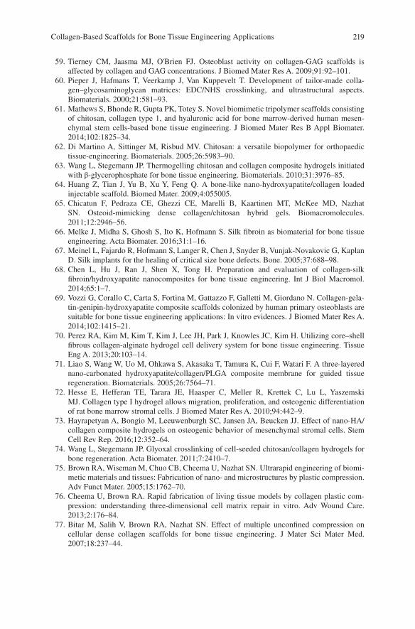
219
59. Tierney CM, Jaasma MJ, O'Brien FJ. Osteoblast activity on collagen‐GAG scaffolds is affected by collagen and GAG concentrations. J Biomed Mater Res A. 2009;91:92–101.
60. Pieper J, Hafmans T, Veerkamp J, Van Kuppevelt T. Development of tailor-made colla-gen–glycosaminoglycan matrices: EDC/NHS crosslinking, and ultrastructural aspects. Biomaterials. 2000;21:581–93.
61. Mathews S, Bhonde R, Gupta PK, Totey S. Novel biomimetic tripolymer scaffolds consisting of chitosan, collagen type 1, and hyaluronic acid for bone marrow‐derived human mesen-chymal stem cells‐based bone tissue engineering. J Biomed Mater Res B Appl Biomater. 2014;102:1825–34.
62. Di Martino A, Sittinger M, Risbud MV. Chitosan: a versatile biopolymer for orthopaedic tissue-engineering. Biomaterials. 2005;26:5983–90.
63. Wang L, Stegemann JP. Thermogelling chitosan and collagen composite hydrogels initiated with β-glycerophosphate for bone tissue engineering. Biomaterials. 2010;31:3976–85.
64. Huang Z, Tian J, Yu B, Xu Y, Feng Q. A bone-like nano-hydroxyapatite/collagen loaded injectable scaffold. Biomed Mater. 2009;4:055005.
65. Chicatun F, Pedraza CE, Ghezzi CE, Marelli B, Kaartinen MT, McKee MD, Nazhat SN. Osteoid-mimicking dense collagen/chitosan hybrid gels. Biomacromolecules. 2011;12:2946–56.
66. Melke J, Midha S, Ghosh S, Ito K, Hofmann S. Silk fibroin as biomaterial for bone tissue engineering. Acta Biomater. 2016;31:1–16.
67. Meinel L, Fajardo R, Hofmann S, Langer R, Chen J, Snyder B, Vunjak-Novakovic G, Kaplan D. Silk implants for the healing of critical size bone defects. Bone. 2005;37:688–98.
68. Chen L, Hu J, Ran J, Shen X, Tong H. Preparation and evaluation of collagen-silk fibroin/hydroxyapatite nanocomposites for bone tissue engineering. Int J Biol Macromol. 2014;65:1–7.
69. Vozzi G, Corallo C, Carta S, Fortina M, Gattazzo F, Galletti M, Giordano N. Collagen‐gela-tin‐genipin‐hydroxyapatite composite scaffolds colonized by human primary osteoblasts are suitable for bone tissue engineering applications: In vitro evidences. J Biomed Mater Res A. 2014;102:1415–21.
70. Perez RA, Kim M, Kim T, Kim J, Lee JH, Park J, Knowles JC, Kim H. Utilizing core–shell fibrous collagen-alginate hydrogel cell delivery system for bone tissue engineering. Tissue Eng A. 2013;20:103–14.
71. Liao S, Wang W, Uo M, Ohkawa S, Akasaka T, Tamura K, Cui F, Watari F. A three-layered nano-carbonated hydroxyapatite/collagen/PLGA composite membrane for guided tissue regeneration. Biomaterials. 2005;26:7564–71.
72. Hesse E, Hefferan TE, Tarara JE, Haasper C, Meller R, Krettek C, Lu L, Yaszemski MJ. Collagen type I hydrogel allows migration, proliferation, and osteogenic differentiation of rat bone marrow stromal cells. J Biomed Mater Res A. 2010;94:442–9.
73. Hayrapetyan A, Bongio M, Leeuwenburgh SC, Jansen JA, Beucken JJ. Effect of nano-HA/collagen composite hydrogels on osteogenic behavior of mesenchymal stromal cells. Stem Cell Rev Rep. 2016;12:352–64.
74. Wang L, Stegemann JP. Glyoxal crosslinking of cell-seeded chitosan/collagen hydrogels for bone regeneration. Acta Biomater. 2011;7:2410–7.
75. Brown RA, Wiseman M, Chuo CB, Cheema U, Nazhat SN. Ultrarapid engineering of biomi-metic materials and tissues: Fabrication of nano- and microstructures by plastic compression. Adv Funct Mater. 2005;15:1762–70.
76. Cheema U, Brown RA. Rapid fabrication of living tissue models by collagen plastic com-pression: understanding three-dimensional cell matrix repair in vitro. Adv Wound Care. 2013;2:176–84.
77. Bitar M, Salih V, Brown RA, Nazhat SN. Effect of multiple unconfined compression on cellular dense collagen scaffolds for bone tissue engineering. J Mater Sci Mater Med. 2007;18:237–44.
Collagen-Based Scaffolds for Bone Tissue Engineering Applications
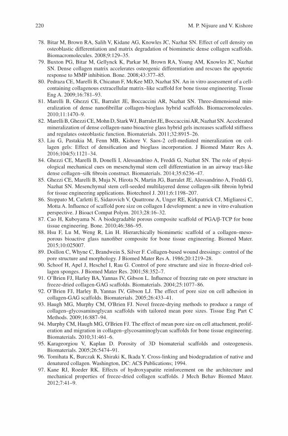
220
78. Bitar M, Brown RA, Salih V, Kidane AG, Knowles JC, Nazhat SN. Effect of cell density on osteoblastic differentiation and matrix degradation of biomimetic dense collagen scaffolds. Biomacromolecules. 2008;9:129–35.
79. Buxton PG, Bitar M, Gellynck K, Parkar M, Brown RA, Young AM, Knowles JC, Nazhat SN. Dense collagen matrix accelerates osteogenic differentiation and rescues the apoptotic response to MMP inhibition. Bone. 2008;43:377–85.
80. Pedraza CE, Marelli B, Chicatun F, McKee MD, Nazhat SN. An in vitro assessment of a cell- containing collagenous extracellular matrix–like scaffold for bone tissue engineering. Tissue Eng A. 2009;16:781–93.
81. Marelli B, Ghezzi CE, Barralet JE, Boccaccini AR, Nazhat SN. Three-dimensional min-eralization of dense nanofibrillar collagen-bioglass hybrid scaffolds. Biomacromolecules. 2010;11:1470–9.
82. Marelli B, Ghezzi CE, Mohn D, Stark WJ, Barralet JE, Boccaccini AR, Nazhat SN. Accelerated mineralization of dense collagen-nano bioactive glass hybrid gels increases scaffold stiffness and regulates osteoblastic function. Biomaterials. 2011;32:8915–26.
83. Liu G, Pastakia M, Fenn MB, Kishore V. Saos‐2 cell‐mediated mineralization on col-lagen gels: Effect of densification and bioglass incorporation. J Biomed Mater Res A. 2016;104(5):1121–34.
84. Ghezzi CE, Marelli B, Donelli I, Alessandrino A, Freddi G, Nazhat SN. The role of physi-ological mechanical cues on mesenchymal stem cell differentiation in an airway tract-like dense collagen–silk fibroin construct. Biomaterials. 2014;35:6236–47.
85. Ghezzi CE, Marelli B, Muja N, Hirota N, Martin JG, Barralet JE, Alessandrino A, Freddi G, Nazhat SN. Mesenchymal stem cell‐seeded multilayered dense collagen‐silk fibroin hybrid for tissue engineering applications. Biotechnol J. 2011;6:1198–207.
86. Stoppato M, Carletti E, Sidarovich V, Quattrone A, Unger RE, Kirkpatrick CJ, Migliaresi C, Motta A. Influence of scaffold pore size on collagen I development: a new in vitro evaluation perspective. J Bioact Compat Polym. 2013;28:16–32.
87. Cao H, Kuboyama N. A biodegradable porous composite scaffold of PGA/β-TCP for bone tissue engineering. Bone. 2010;46:386–95.
88. Hsu F, Lu M, Weng R, Lin H. Hierarchically biomimetic scaffold of a collagen–meso-porous bioactive glass nanofiber composite for bone tissue engineering. Biomed Mater. 2015;10:025007.
89. Doillon C, Whyne C, Brandwein S, Silver F. Collagen‐based wound dressings: control of the pore structure and morphology. J Biomed Mater Res A. 1986;20:1219–28.
90. Schoof H, Apel J, Heschel I, Rau G. Control of pore structure and size in freeze‐dried col-lagen sponges. J Biomed Mater Res. 2001;58:352–7.
91. O’Brien FJ, Harley BA, Yannas IV, Gibson L. Influence of freezing rate on pore structure in freeze-dried collagen-GAG scaffolds. Biomaterials. 2004;25:1077–86.
92. O’Brien FJ, Harley B, Yannas IV, Gibson LJ. The effect of pore size on cell adhesion in collagen-GAG scaffolds. Biomaterials. 2005;26:433–41.
93. Haugh MG, Murphy CM, O'Brien FJ. Novel freeze-drying methods to produce a range of collagen–glycosaminoglycan scaffolds with tailored mean pore sizes. Tissue Eng Part C Methods. 2009;16:887–94.
94. Murphy CM, Haugh MG, O'Brien FJ. The effect of mean pore size on cell attachment, prolif-eration and migration in collagen–glycosaminoglycan scaffolds for bone tissue engineering. Biomaterials. 2010;31:461–6.
95. Karageorgiou V, Kaplan D. Porosity of 3D biomaterial scaffolds and osteogenesis. Biomaterials. 2005;26:5474–91.
96. Tomihata K, Burczak K, Shiraki K, Ikada Y. Cross-linking and biodegradation of native and denatured collagen. Washington, DC: ACS Publications; 1994.
97. Kane RJ, Roeder RK. Effects of hydroxyapatite reinforcement on the architecture and mechanical properties of freeze-dried collagen scaffolds. J Mech Behav Biomed Mater. 2012;7:41–9.
M. P. Nijsure and V. Kishore
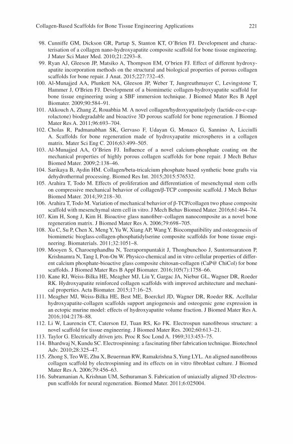
221
98. Cunniffe GM, Dickson GR, Partap S, Stanton KT, O’Brien FJ. Development and charac-terisation of a collagen nano-hydroxyapatite composite scaffold for bone tissue engineering. J Mater Sci Mater Med. 2010;21:2293–8.
99. Ryan AJ, Gleeson JP, Matsiko A, Thompson EM, O’brien FJ. Effect of different hydroxy-apatite incorporation methods on the structural and biological properties of porous collagen scaffolds for bone repair. J Anat. 2015;227:732–45.
100. Al‐Munajjed AA, Plunkett NA, Gleeson JP, Weber T, Jungreuthmayer C, Levingstone T, Hammer J, O'Brien FJ. Development of a biomimetic collagen‐hydroxyapatite scaffold for bone tissue engineering using a SBF immersion technique. J Biomed Mater Res B Appl Biomater. 2009;90:584–91.
101. Akkouch A, Zhang Z, Rouabhia M. A novel collagen/hydroxyapatite/poly (lactide‐co‐ε‐cap-rolactone) biodegradable and bioactive 3D porous scaffold for bone regeneration. J Biomed Mater Res A. 2011;96:693–704.
102. Cholas R, Padmanabhan SK, Gervaso F, Udayan G, Monaco G, Sannino A, Licciulli A. Scaffolds for bone regeneration made of hydroxyapatite microspheres in a collagen matrix. Mater Sci Eng C. 2016;63:499–505.
103. Al-Munajjed AA, O’Brien FJ. Influence of a novel calcium-phosphate coating on the mechanical properties of highly porous collagen scaffolds for bone repair. J Mech Behav Biomed Mater. 2009;2:138–46.
104. Sarikaya B, Aydin HM. Collagen/beta-tricalcium phosphate based synthetic bone grafts via dehydrothermal processing. Biomed Res Int. 2015;2015:576532.
105. Arahira T, Todo M. Effects of proliferation and differentiation of mesenchymal stem cells on compressive mechanical behavior of collagen/β-TCP composite scaffold. J Mech Behav Biomed Mater. 2014;39:218–30.
106. Arahira T, Todo M. Variation of mechanical behavior of β-TCP/collagen two phase composite scaffold with mesenchymal stem cell in vitro. J Mech Behav Biomed Mater. 2016;61:464–74.
107. Kim H, Song J, Kim H. Bioactive glass nanofiber–collagen nanocomposite as a novel bone regeneration matrix. J Biomed Mater Res A. 2006;79:698–705.
108. Xu C, Su P, Chen X, Meng Y, Yu W, Xiang AP, Wang Y. Biocompatibility and osteogenesis of biomimetic bioglass-collagen-phosphatidylserine composite scaffolds for bone tissue engi-neering. Biomaterials. 2011;32:1051–8.
109. Mooyen S, Charoenphandhu N, Teerapornpuntakit J, Thongbunchoo J, Suntornsaratoon P, Krishnamra N, Tang I, Pon‐On W. Physico‐chemical and in vitro cellular properties of differ-ent calcium phosphate‐bioactive glass composite chitosan‐collagen (CaP@ ChiCol) for bone scaffolds. J Biomed Mater Res B Appl Biomater. 2016;105(7):1758–66.
110. Kane RJ, Weiss-Bilka HE, Meagher MJ, Liu Y, Gargac JA, Niebur GL, Wagner DR, Roeder RK. Hydroxyapatite reinforced collagen scaffolds with improved architecture and mechani-cal properties. Acta Biomater. 2015;17:16–25.
111. Meagher MJ, Weiss‐Bilka HE, Best ME, Boerckel JD, Wagner DR, Roeder RK. Acellular hydroxyapatite‐collagen scaffolds support angiogenesis and osteogenic gene expression in an ectopic murine model: effects of hydroxyapatite volume fraction. J Biomed Mater Res A. 2016;104:2178–88.
112. Li W, Laurencin CT, Caterson EJ, Tuan RS, Ko FK. Electrospun nanofibrous structure: a novel scaffold for tissue engineering. J Biomed Mater Res. 2002;60:613–21.
113. Taylor G. Electrically driven jets. Proc R Soc Lond A. 1969;313:453–75. 114. Bhardwaj N, Kundu SC. Electrospinning: a fascinating fiber fabrication technique. Biotechnol
Adv. 2010;28:325–47. 115. Zhong S, Teo WE, Zhu X, Beuerman RW, Ramakrishna S, Yung LYL. An aligned nanofibrous
collagen scaffold by electrospinning and its effects on in vitro fibroblast culture. J Biomed Mater Res A. 2006;79:456–63.
116. Subramanian A, Krishnan UM, Sethuraman S. Fabrication of uniaxially aligned 3D electros-pun scaffolds for neural regeneration. Biomed Mater. 2011;6:025004.
Collagen-Based Scaffolds for Bone Tissue Engineering Applications
222
117. Matthews JA, Wnek GE, Simpson DG, Bowlin GL. Electrospinning of collagen nanofibers. Biomacromolecules. 2002;3:232–8.
118. Shih YV, Chen C, Tsai S, Wang YJ, Lee OK. Growth of mesenchymal stem cells on electro-spun type I collagen nanofibers. Stem Cells. 2006;24:2391–7.
119. Zeugolis DI, Khew ST, Yew ES, Ekaputra AK, Tong YW, Yung LL, Hutmacher DW, Sheppard C, Raghunath M. Electro-spinning of pure collagen nano-fibres–just an expensive way to make gelatin? Biomaterials. 2008;29:2293–305.
120. Yang L, Fitie CF, van der Werf, Kees O, Bennink ML, Dijkstra PJ, Feijen J. Mechanical properties of single electrospun collagen type I fibers. Biomaterials. 2008;29:955–62.
121. Zhou Y, Yao H, Wang J, Wang D, Liu Q, Li Z. Greener synthesis of electrospun collagen/hydroxyapatite composite fibers with an excellent microstructure for bone tissue engineering. Int J Nanomedicine. 2015;10:3203–15.
122. Qiao X, Russell SJ, Yang X, Tronci G, Wood DJ. Compositional and in vitro evaluation of nonwoven type I collagen/poly-dl-lactic acid scaffolds for bone regeneration. J Funct Biomater. 2015;6:667–86.
123. Shojaee, M, Bashur, CA. Compositions including synthetic and natural blends for integra-tion and structural integrity: engineered for different vascular graft applications. Adv Healthc Mater 2017;6(12). https://doi.org/10.1002/adhm.201700001.
124. Ngiam M, Liao S, Patil AJ, Cheng Z, Yang F, Gubler MJ, Ramakrishna S, Chan CK. Fabrication of mineralized polymeric nanofibrous composites for bone graft materials. Tissue Eng A. 2008;15:535–46.
125. Raghavendran HRB, Puvaneswary S, Talebian S, Murali MR, Naveen SV, Krishnamurithy G, McKean R, Kamarul T. A comparative study on in vitro osteogenic priming potential of electron spun scaffold PLLA/HA/Col, PLLA/HA, and PLLA/Col for tissue engineering application. PLoS One. 2014;9:e104389.
126. Ekaputra AK, Zhou Y, Cool SM, Hutmacher DW. Composite electrospun scaffolds for engi-neering tubular bone grafts. Tissue Eng A. 2009;15:3779–88.
127. Wei K, Li Y, Mugishima H, Teramoto A, Abe K. Fabrication of core‐sheath structured fibers for model drug release and tissue engineering by emulsion electrospinning. Biotechnol J. 2012;7:677–85.
128. Su Y, Su Q, Liu W, Lim M, Venugopal JR, Mo X, Ramakrishna S, Al-Deyab SS, El-Newehy M. Controlled release of bone morphogenetic protein 2 and dexamethasone loaded in core–shell PLLACL–collagen fibers for use in bone tissue engineering. Acta Biomater. 2012;8:763–71.
129. Wang J, Cui X, Zhou Y, Xiang Q. Core-shell PLGA/collagen nanofibers loaded with recom-binant FN/CDHs as bone tissue engineering scaffolds. Connect Tissue Res. 2014;55:292–8.
130. Venugopal J, Low S, Choon AT, Sampath Kumar TS, Ramakrishna S. Mineralization of osteoblasts with electrospun collagen/hydroxyapatite nanofibers. J Mater Sci Mater Med. 2008;19:2039–46.
131. Song J, Kim H, Kim H. Electrospun fibrous web of collagen–apatite precipitated nanocom-posite for bone regeneration. J Mater Sci Mater Med. 2008;19:2925–32.
132. Ribeiro N, Sousa SR, Van Blitterswijk CA, Moroni L, Monteiro FJ. A biocomposite of colla-gen nanofibers and nanohydroxyapatite for bone regeneration. Biofabrication. 2014;6:035015.
133. Phipps MC, Clem WC, Grunda JM, Clines GA, Bellis SL. Increasing the pore sizes of bone- mimetic electrospun scaffolds comprised of polycaprolactone, collagen I and hydroxyapatite to enhance cell infiltration. Biomaterials. 2012;33:524–34.
134. Yeo MG, Kim GH. Preparation and characterization of 3D composite scaffolds based on rapid-prototyped PCL/β-TCP struts and electrospun PCL coated with collagen and HA for bone regeneration. Chem Mater. 2011;24:903–13.
135. Hild N, Schneider OD, Mohn D, Luechinger NA, Koehler FM, Hofmann S, Vetsch JR, Thimm BW, Müller R, Stark WJ. Two-layer membranes of calcium phosphate/collagen/PLGA nanofibres: in vitro biomineralisation and osteogenic differentiation of human mesen-chymal stem cells. Nanoscale. 2011;3:401–9.
M. P. Nijsure and V. Kishore
223
136. Sharifi E, Ebrahimi‐Barough S, Panahi M, Azami M, Ai A, Barabadi Z, Kajbafzadeh A, Ai J. In vitro evaluation of human endometrial stem cell‐derived osteoblast‐like cells’ behavior on gelatin/collagen/bioglass nanofibers’ scaffolds. J Biomed Mater Res A. 2016;104:2210–9.
137. Zhang S, Zhang X, Cai Q, Wang B, Deng X, Yang X. Microfibrous β-TCP/collagen scaffolds mimic woven bone in structure and composition. Biomed Mater. 2010;5:065005.
138. Cheng X, Gurkan UA, Dehen CJ, Tate MP, Hillhouse HW, Simpson GJ, Akkus O. An electro-chemical fabrication process for the assembly of anisotropically oriented collagen bundles. Biomaterials. 2008;29:3278–88.
139. Uquillas JA, Akkus O. Modeling the electromobility of type-I collagen molecules in the electrochemical fabrication of dense and aligned tissue constructs. Ann Biomed Eng. 2012;40:1641–53.
140. Younesi M, Islam A, Kishore V, Anderson JM, Akkus O. Tenogenic induction of human MSCs by anisotropically aligned collagen biotextiles. Adv Funct Mater. 2014;24:5762–70.
141. Younesi M, Goldberg VM, Akkus O. A micro-architecturally biomimetic collagen template for mesenchymal condensation based cartilage regeneration. Acta Biomater. 2016;30:212–21.
142. Kishore V, Iyer R, Frandsen A, Nguyen T. In vitro characterization of electrochemically com-pacted collagen matrices for corneal applications. Biomed Mater. 2016;11:055008.
143. Abu-Rub MT, Billiar K, van Es MH, Knoght A, Rodriguez BJ, Zeugolis DI, McMahon S, Windebank AJ, Pandit A. Nano-textured self-assembled aligned collagen hydrogels promote directional neurite guidance and overcome inhibition by myelin associated glycoprotein. Soft Matter. 2011;7:2770–81.
144. Nguyen TU, Bashur CA, Kishore V. Impact of elastin incorporation into electrochemically aligned collagen fibers on mechanical properties and smooth muscle cell phenotype. Biomed Mater. 2016;11:025008.
145. Younesi M, Islam A, Kishore V, Panit S, Akkus O. Fabrication of compositionally and topo-graphically complex robust tissue forms by 3D-electrochemical compaction of collagen. Biofabrication. 2015;7:035001.
146. Kishore V, Paderi JE, Akkus A, Smith KM, Balachandran D, Beaudoin S, Panitch A, Akkus O. Incorporation of a decorin biomimetic enhances the mechanical properties of electro-chemically aligned collagen threads. Acta Biomater. 2011;7:2428–36.
147. Nijsure MP, Pastakia M, Spano J, Fenn MB, Kishore V. Bioglass incorporation improves mechanical properties and enhances cell‐mediated mineralization on electrochemically aligned collagen threads. J Biomed Mater Res A. 2017;105(9):2429–40.
148. Kokubo T, Takadama H. How useful is SBF in predicting in vivo bone bioactivity? Biomaterials. 2006;27:2907–15.
149. Mizuno M, Shindo M, Kobayashi D, Tsuruga E, Amemiya A, Kuboki Y. Osteogenesis by bone marrow stromal cells maintained on type I collagen matrix gels in vivo. Bone. 1997;20:101–7.
150. Kokubo S, Fujimoto R, Yokota S, Fukushima S, Nozaki K, Takahashi K, Miyata K. Bone regeneration by recombinant human bone morphogenetic protein-2 and a novel biodegrad-able carrier in a rabbit ulnar defect model. Biomaterials. 2003;24:1643–51.
151. Visser R, Arrabal PM, Becerra J, Rinas U, Cifuentes M. The effect of an rhBMP-2 absorbable collagen sponge-targeted system on bone formation in vivo. Biomaterials. 2009;30:2032–7.
152. Geiger M, Li R, Friess W. Collagen sponges for bone regeneration with rhBMP-2. Adv Drug Deliv Rev. 2003;55:1613–29.
153. Epstein N. Pros, cons, and costs of INFUSE in spinal surgery. Surg Neurol Int. 2011;2:10. 154. Arrabal PM, Visser R, Santos-Ruiz L, Becerra J, Cifuentes M. Osteogenic molecules for
clinical applications: improving the BMP-collagen system. Biol Res. 2013;46:421–9. 155. Hou J, Wang J, Cao L, Qian X, Xing W, Lu J, Liu C. Segmental bone regeneration using
rhBMP-2-loaded collagen/chitosan microspheres composite scaffold in a rabbit model. Biomed Mater. 2012;7:035002.
156. Quinlan E, Thompson EM, Matsiko A, O’brien FJ, López-Noriega A. Long-term controlled delivery of rhBMP-2 from collagen–hydroxyapatite scaffolds for superior bone tissue regen-eration. J Control Release. 2015;207:112–9.
Collagen-Based Scaffolds for Bone Tissue Engineering Applications
224
157. Calabrese G, Giuffrida R, Forte S, Salvatorelli L, Fabbi C, Figallo E, Gulisano M, Parenti R, Magro G, Colarossi C, Memeo L, Gulino R. Bone augmentation after ectopic implantation of a cell-free collagen-hydroxyapatite scaffold in the mouse. Sci Rep. 2016;6:36399.
158. Ren X, Tu V, Bischoff D, Weisgerber DW, Lewis MS, Yamaguchi DT, Miller TA, Harley BA, Lee JC. Nanoparticulate mineralized collagen scaffolds induce in vivo bone regeneration independent of progenitor cell loading or exogenous growth factor stimulation. Biomaterials. 2016;89:67–78.
159. Lyons FG, Al-Munajjed AA, Kieran SM, Toner ME, Murphy CM, Duffy GP, O’Brien FJ. The healing of bony defects by cell-free collagen-based scaffolds compared to stem cell-seeded tissue engineered constructs. Biomaterials. 2010;31:9232–43.
160. Quinlan E, López‐Noriega A, Thompson EM, Hibbitts A, Cryan SA, O’Brien FJ. Controlled release of vascular endothelial growth factor from spray‐dried alginate microparticles in col-lagen–hydroxyapatite scaffolds for promoting vascularization and bone repair. J Tissue Eng Regen Med. 2017;11:1097–109.
161. Villa MM, Wang L, Rowe DW, Wei M. Effects of cell-attachment and extracellular matrix on bone formation in vivo in collagen-hydroxyapatite scaffolds. PLoS One. 2014;9:e109568.
162. Gao C, Harvey E, Chua M, Chen B, Jiang F, Liu Y, Li A, Wang H, Henderson J, Education P. MSC-seeded dense collagen scaffolds with a bolus dose of VEGF promote healing of large bone defects. Metab Clin Exp. 2013;500:10–5.
163. Chamieh F, Collignon AM, Coyac BR, Lesieur J, Ribes S, Sadoine J, Llorens A, Nicoletti A, Letourneur D, Colombier ML, Nazhat SN, Bouchard P, Chaussain C, Rochefort GY. Accelerated craniofacial bone regeneration through dense collagen gel scaffolds seeded with dental pulp stem cells. Sci Rep. 2016;6:38814.
164. Ducheyne P, Healy K, Hutmacher DE, Grainger DW, Kirkpatrick CJ. Comprehensive bioma-terials. Oxford: Newnes; 2015.
165. James AW, LaChaud G, Shen J, Asatrian G, Nguyen V, Zhang X, Ting K, Soo C. A review of the clinical side effects of bone morphogenetic protein-2. Tissue Eng B Rev. 2016;22:284–97.
166. Kaigler D, Wang Z, Horger K, Mooney DJ, Krebsbach PH. VEGF scaffolds enhance angiogen-esis and bone regeneration in irradiated osseous defects. J Bone Miner Res. 2006;21:735–44.
167. Burdick JA, Vunjak-Novakovic G. Engineered microenvironments for controlled stem cell differentiation. Tissue Eng A. 2008;15:205–19.
168. Ghasemi-Mobarakeh L, Prabhakaran MP, Tian L, Shamirzaei-Jeshvaghani E, Dehghani L, Ramakrishna S. Structural properties of scaffolds: crucial parameters towards stem cells dif-ferentiation. World J Stem Cells. 2015;7:728–44.
169. Almarza AJ, Yang G, Woo SL, Nguyen T, Abramowitch SD. Positive changes in bone marrow–derived cells in response to culture on an aligned bioscaffold. Tissue Eng A. 2008;14:1489–95.
170. Wang JH, Jia F, Gilbert TW, Woo SL. Cell orientation determines the alignment of cell- produced collagenous matrix. J Biomech. 2003;36:97–102.
M. P. Nijsure and V. Kishore
225© Springer International Publishing AG, part of Springer Nature 2017B. Li, T. Webster (eds.), Orthopedic Biomaterials, https://doi.org/10.1007/978-3-319-73664-8_9
Poly(ethylene glycol) and Co-polymer Based- Hydrogels for Craniofacial Bone Tissue Engineering
Arbi M. Aghali
Keywords Poly(ethylene glycol) · Copolymer · Hydrogel · Craniofacial · Bone · Tissue engineering · 3D cell culture · Polymerization · Polymer · Biodegradable · Degradation · Crosslinking
1 Introduction
Poly(ethylene glycol) or PEG is an attractive class of synthetic biomaterial that has been given a wild amount of attention throughout the years (Fig. 1). Specifically, it has been used in the form of 3D elastic hydrogels for tissue engineering and regen-erative medicine fields [1, 2]. When a prepolymer solution of PEG macromers is crosslinked into a 3D network structure of hydrogels, it has great capability to absorb a great amount of water without dissolving, due to the presence of the back-bone’s hydrophilic polymer content [3, 4]. This unique property makes PEG and PEG-copolymers an area of interest to numerous scientists for therapeutic tissue engineering purposes; utilizing them for in situ 3D cell culture and encapsulating growth factors [3, 5].
The crosslinking of PEG hydrogels is crucial during the development of the 3D microstructure. The tie-point of the PEG macromers mainly depends on the hydroxyl groups’ PEG macromer termini [6, 7]. The reactive functional termini of PEG mac-romers are active areas during gelation process reactions [6, 7]. Furthermore, this active area determines the mechanism through which PEG hydrogels are formed. PEG macromers have been easily functionalized using the following vinyl- based PEGs: methacrylate, acrylamide, vinylsulfone, maleimide, and norbornene [2, 8, 9]. The gelation mechanism is chosen based on the PEG macromere end- point. For instance, during the polymerization of thiol-acrylate hydrogels, PEG-di- and meth-acrylate (PEGDA and/or PEGDM), gelation heavily depends on the progress of free radical ligands during the polymerization via chain-growth polymerization
A. M. Aghali (*) Weldon School of Biomedical Engineering, Purdue University, West Lafayette, IN, USAe-mail: [email protected]
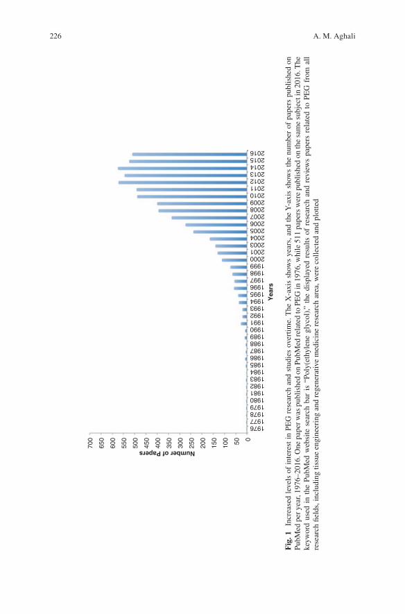
226
700
650
600
550
500
450
400
350
300
250
Number of Papers
Yea
rs
200
150
100 50 0
1976197719781979198019811982198319841985198619871988198919901991199219931994199519961997199819992000200120032004200520062007200820092010201120122013201420152016
Fig
. 1
Incr
ease
d le
vels
of
inte
rest
in
PEG
res
earc
h an
d st
udie
s ov
ertim
e. T
he X
-axi
s sh
ows
year
s, a
nd t
he Y
-axi
s sh
ows
the
num
ber
of p
aper
s pu
blis
hed
on
PubM
ed p
er y
ear,
1976
–201
6. O
ne p
aper
was
pub
lishe
d on
Pub
Med
rela
ted
to P
EG
in 1
976,
whi
le 5
11 p
aper
s w
ere
publ
ishe
d on
the
sam
e su
bjec
t in
2016
. The
ke
ywor
d us
ed i
n th
e Pu
bMed
web
site
sea
rch
bar
is “
Poly
(eth
ylen
e gl
ycol
),” t
he d
ispl
ayed
res
ults
of
rese
arch
and
rev
iew
s pa
pers
rel
ated
to
PEG
fro
m a
ll re
sear
ch fi
elds
, inc
ludi
ng ti
ssue
eng
inee
ring
and
reg
ener
ativ
e m
edic
ine
rese
arch
are
a, w
ere
colle
cted
and
plo
tted
A. M. Aghali
227
[10]. Conversely, the Michael-type addition of step-growth polymerization utilizes the functionality of multi-PEG, e.g. acrylate and maleimide, to click, as long as the value of the vinyl and thiol groups is more than twofolds [9, 11].
Although the previous reactions depend on the functionality of the resultant PEG macromers, the origin and enhanced PEG macromers result in a mesh network of inert gels [2, 12, 13]. Thus, a PEG-hydrogel has limited applications in in situ cell culture and bioengineering, which is due to the limitation of its inherent biological activity. As a result, one must consider engineering the microstructure of PEG- hydrogels in order to enhance the bioactivity of the mesh’s backbone microstructure.
Several approaches in these directions gave promising outcomes that are shown in in situ cell culture studies. Among these directions is immobilizing bioactive molecules, such as the tripeptide Arg-Gly-Asp (RGD), that mediate cell attachment to crosslink PEG hydrogels [9, 13]. Despite the successful incorporation of the pendent peptide into the mesh structure, it sometimes remains challenging for the encapsulated-cells to fully attach to the “tie-point” of the active peptide site [14]. Besides incorporating the pendent peptides of RGD, other approaches have been taken to produce a bioactive PEG-hydrogel inspired by the native microstructure of the extra cellular matrix (ECM), where the majority of the cells are embedded in our body [2]. The 3D microenvironment of human tissues contains rich, vital resources: proteins, polysaccharides, and enzymes that regulate cell viability, migration, proliferation, and differentiation [2, 15–17]. Compared to the resultant PEG- hydrogel, conjugating and/or crosslinking the pendent peptide of RGD is an impor-tant step towards biomimicking a native ECM to truly examine the cell function in situ. In order to build a complex microstructure of PEG-hydrogels, one must under-stand the methods that are necessary to polymerize the PEG precursor as well as the mechanism of building the hydrogel’s mesh network.
One of the common methods used to immobilize bioactive molecules into a mesh network of PEG-hydrogels is using a photopolymerization technique [2, 12]. Photopolymerization applies the properties of lights, such as ultraviolet or cold vis-ible light, to change the soluble properties of a PEG polymer into elastic hydrogels when the PEG precursor is exposed to the light for a period of time [18]. These techniques are used to form the elastic structure of the gel via step-growth polym-erization, chain-growth polymerization, or mixed-mode polymerization [14, 19].
Alongside, the degradation behavior of the hydrogel implant is a critical param-eter to be considered during in vivo cell culturing and implantation. One of the main principles of tissue engineering is that the implanted materials should degrade at the same time of new tissue formation. In order to accomplish this requirement, it is necessary to design hydrogel scaffolds that allow for encapsulated- cell growth and deposition of a new ECM during new tissue formation. Although natural hydrogels have many advantages compared to synthetic hydrogels, e.g. PEG-hydrogels, it remains a major challenge to tune natural hydrogels to fulfill a desire of degradation rate for specific tissue engineering applications. Thus, several researchers have turned to synthetic hydrogels, specifically PEG-hydrogels. Researchers therefore designed different degradation behavior of PEG- and PEG- co- polymer based hydro-gels. The most common approaches are hydrolysis and enzymatic degradation.
Poly(ethylene glycol) and Co-polymer Based-Hydrogels for Craniofacial Bone Tissue…
228
These degradation mechanisms have shown promising outcomes for tissue engi-neering applications.
Thus, in this chapter, we will focus our attentions on PEG-hydrogels for bone tissue engineering applications. The state-of-the-art photopolymerization methods will be discussed, comparing the advantages and disadvantages for the most common photopolymerization techniques in order to develop desirable PEG- hydrogels for bone tissue engineering. We will also discuss the degradation behav-ior of PEG-hydrogels and the effect of the local in vivo response to degradable PEG macromers. Finally, we will shift our interests into the current applications of the PEG-co-polymer; specifically the application of visible light-cured thiol-acrylate hydrogels for craniofacial bone tissue regeneration.
2 2D Versus 3D Cell Culture and Response
Since the beginning of cell culture, scientists established a large database of cell microenvironments and responses to several external cues in vitro. One of the main purposes of the 2D cell culture is to expand our knowledge of cell behavior and growth as well as investigate the response to new therapeutic drugs in vitro. Although a great degree of understanding has been established, and led humanity to countless discoveries and improvements in the quality of daily life, our understanding is mainly based on impractical expectations of 2D cell cultures [20]. The use of rigid biomaterials, e.g. polystyrene and glass, for cell attachment makes the cultured cell display abnormal on petri dish behavior, such as extended and polarized cell mem-branes [20, 21]. Thus, the response of the 2D-cultured cells to external chemical and physical cues may depend on the surface direction cells are facing [20]. This could be a main factor in the cell response to external stimuli. Unlike 2D cell cultures, the cells encounter external chemical and physical cues from all directions in a 3D-culture, due to the equal distribution of the external signaling on the cell mem-brane [21]; Table 1 summarizes the comparison of cell characteristics in 2D- and 3D-culture. Furthermore, in native microenvironments, cells are embedded into 3D ECM that contains several components, such as several types of growth factors. Thus, it is important to improve our knowledge by mimicking the experience that cells encounter in their native microenvironments. This, however, may not be an easy approach to developing a complex microstructure that contains all of the neces-sary elements that mimic the native ECM for specific tissues in vitro. Nevertheless, the growing interest in designing a 3D network to provide mechanical cues and the required soluble growth factors shows promise in advanced cell cultures. Several biomaterials have been utilized to advance the 3D cell culture; among them is the synthetic hydrogel. Particularly, designed PEG-hydrogels and copolymers have been attractive 3D matrices for cell culture and therapeutic release of biomolecules. PEG-hydrogels have unique advantages to engineer and to tune by providing differ-ent adhesive ligands, introducing growth factors into a network structure, and designing the degradation mechanism into an enzymatic or hydrolytic mode.
A. M. Aghali
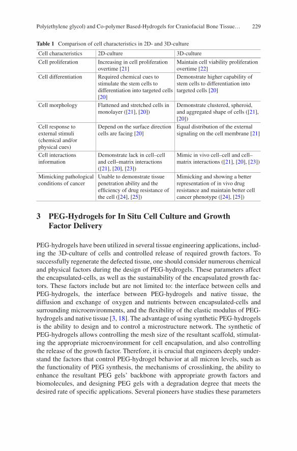
229
3 PEG-Hydrogels for In Situ Cell Culture and Growth Factor Delivery
PEG-hydrogels have been utilized in several tissue engineering applications, includ-ing the 3D-culture of cells and controlled release of required growth factors. To successfully regenerate the defected tissue, one should consider numerous chemical and physical factors during the design of PEG-hydrogels. These parameters affect the encapsulated-cells, as well as the sustainability of the encapsulated growth fac-tors. These factors include but are not limited to: the interface between cells and PEG-hydrogels, the interface between PEG-hydrogels and native tissue, the diffusion and exchange of oxygen and nutrients between encapsulated-cells and surrounding microenvironments, and the flexibility of the elastic modulus of PEG- hydrogels and native tissue [3, 18]. The advantage of using synthetic PEG-hydrogels is the ability to design and to control a microstructure network. The synthetic of PEG-hydrogels allows controlling the mesh size of the resultant scaffold, stimulat-ing the appropriate microenvironment for cell encapsulation, and also controlling the release of the growth factor. Therefore, it is crucial that engineers deeply under-stand the factors that control PEG-hydrogel behavior at all micron levels, such as the functionality of PEG synthesis, the mechanisms of crosslinking, the ability to enhance the resultant PEG gels’ backbone with appropriate growth factors and biomolecules, and designing PEG gels with a degradation degree that meets the desired rate of specific applications. Several pioneers have studies these parameters
Table 1 Comparison of cell characteristics in 2D- and 3D-culture
Cell characteristics 2D-culture 3D-culture
Cell proliferation Increasing in cell proliferation overtime [21]
Maintain cell viability proliferation overtime [22]
Cell differentiation Required chemical cues to stimulate the stem cells to differentiation into targeted cells [20]
Demonstrate higher capability of stem cells to differentiation into targeted cells [20]
Cell morphology Flattened and stretched cells in monolayer ([21], [20])
Demonstrate clustered, spheroid, and aggregated shape of cells ([21], [20])
Cell response to external stimuli (chemical and/or physical cues)
Depend on the surface direction cells are facing [20]
Equal distribution of the external signaling on the cell membrane [21]
Cell interactions information
Demonstrate lack in cell–cell and cell–matrix interactions ([21], [20], [23])
Mimic in vivo cell–cell and cell–matrix interactions ([21], [20], [23])
Mimicking pathological conditions of cancer
Unable to demonstrate tissue penetration ability and the efficiency of drug resistance of the cell ([24], [25])
Mimicking and showing a better representation of in vivo drug resistance and maintain better cell cancer phenotype ([24], [25])
Poly(ethylene glycol) and Co-polymer Based-Hydrogels for Craniofacial Bone Tissue…
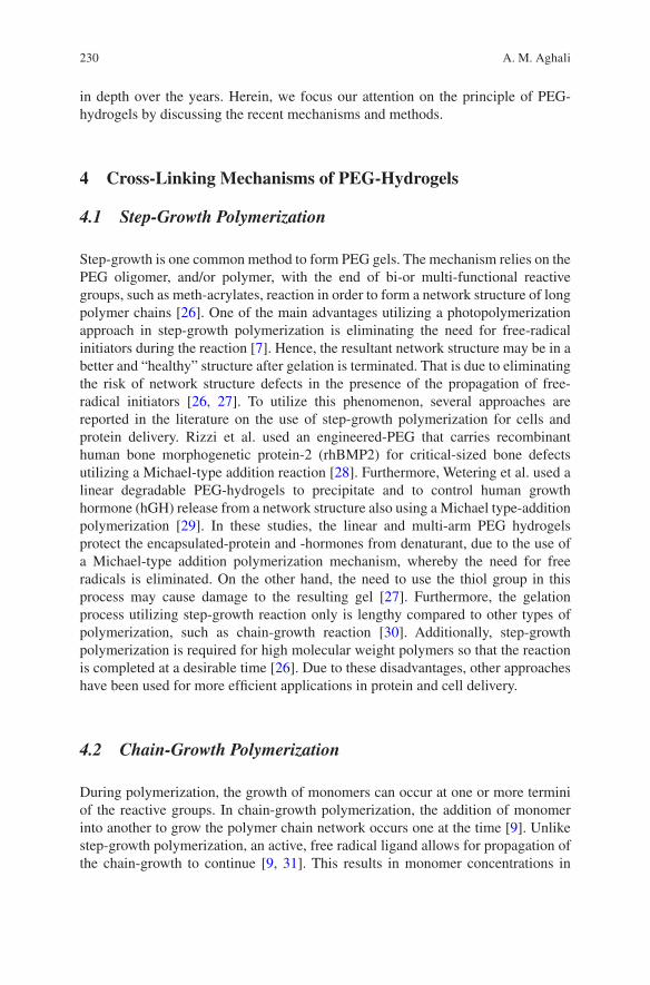
230
in depth over the years. Herein, we focus our attention on the principle of PEG- hydrogels by discussing the recent mechanisms and methods.
4 Cross-Linking Mechanisms of PEG-Hydrogels
4.1 Step-Growth Polymerization
Step-growth is one common method to form PEG gels. The mechanism relies on the PEG oligomer, and/or polymer, with the end of bi-or multi-functional reactive groups, such as meth-acrylates, reaction in order to form a network structure of long polymer chains [26]. One of the main advantages utilizing a photopolymerization approach in step-growth polymerization is eliminating the need for free-radical initiators during the reaction [7]. Hence, the resultant network structure may be in a better and “healthy” structure after gelation is terminated. That is due to eliminating the risk of network structure defects in the presence of the propagation of free- radical initiators [26, 27]. To utilize this phenomenon, several approaches are reported in the literature on the use of step-growth polymerization for cells and protein delivery. Rizzi et al. used an engineered-PEG that carries recombinant human bone morphogenetic protein-2 (rhBMP2) for critical-sized bone defects utilizing a Michael-type addition reaction [28]. Furthermore, Wetering et al. used a linear degradable PEG-hydrogels to precipitate and to control human growth hormone (hGH) release from a network structure also using a Michael type-addition polymerization [29]. In these studies, the linear and multi-arm PEG hydrogels protect the encapsulated-protein and -hormones from denaturant, due to the use of a Michael-type addition polymerization mechanism, whereby the need for free radicals is eliminated. On the other hand, the need to use the thiol group in this process may cause damage to the resulting gel [27]. Furthermore, the gelation process utilizing step-growth reaction only is lengthy compared to other types of polymerization, such as chain-growth reaction [30]. Additionally, step-growth polymerization is required for high molecular weight polymers so that the reaction is completed at a desirable time [26]. Due to these disadvantages, other approaches have been used for more efficient applications in protein and cell delivery.
4.2 Chain-Growth Polymerization
During polymerization, the growth of monomers can occur at one or more termini of the reactive groups. In chain-growth polymerization, the addition of monomer into another to grow the polymer chain network occurs one at the time [9]. Unlike step-growth polymerization, an active, free radical ligand allows for propagation of the chain-growth to continue [9, 31]. This results in monomer concentrations in
A. M. Aghali
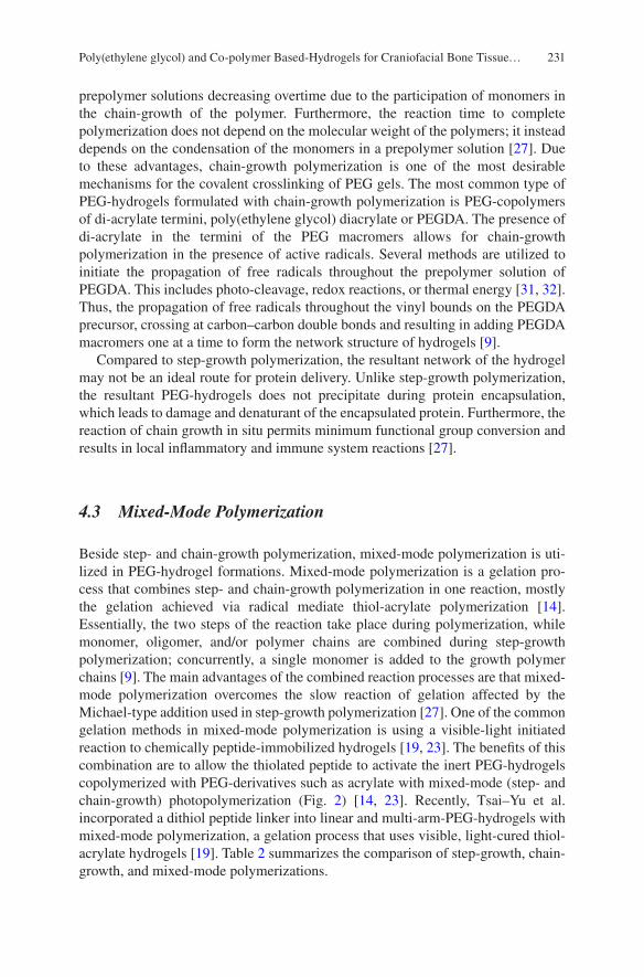
231
prepolymer solutions decreasing overtime due to the participation of monomers in the chain-growth of the polymer. Furthermore, the reaction time to complete polymerization does not depend on the molecular weight of the polymers; it instead depends on the condensation of the monomers in a prepolymer solution [27]. Due to these advantages, chain-growth polymerization is one of the most desirable mechanisms for the covalent crosslinking of PEG gels. The most common type of PEG-hydrogels formulated with chain-growth polymerization is PEG-copolymers of di-acrylate termini, poly(ethylene glycol) diacrylate or PEGDA. The presence of di-acrylate in the termini of the PEG macromers allows for chain-growth polymerization in the presence of active radicals. Several methods are utilized to initiate the propagation of free radicals throughout the prepolymer solution of PEGDA. This includes photo-cleavage, redox reactions, or thermal energy [31, 32]. Thus, the propagation of free radicals throughout the vinyl bounds on the PEGDA precursor, crossing at carbon–carbon double bonds and resulting in adding PEGDA macromers one at a time to form the network structure of hydrogels [9].
Compared to step-growth polymerization, the resultant network of the hydrogel may not be an ideal route for protein delivery. Unlike step-growth polymerization, the resultant PEG-hydrogels does not precipitate during protein encapsulation, which leads to damage and denaturant of the encapsulated protein. Furthermore, the reaction of chain growth in situ permits minimum functional group conversion and results in local inflammatory and immune system reactions [27].
4.3 Mixed-Mode Polymerization
Beside step- and chain-growth polymerization, mixed-mode polymerization is uti-lized in PEG-hydrogel formations. Mixed-mode polymerization is a gelation pro-cess that combines step- and chain-growth polymerization in one reaction, mostly the gelation achieved via radical mediate thiol-acrylate polymerization [14]. Essentially, the two steps of the reaction take place during polymerization, while monomer, oligomer, and/or polymer chains are combined during step-growth polymerization; concurrently, a single monomer is added to the growth polymer chains [9]. The main advantages of the combined reaction processes are that mixed- mode polymerization overcomes the slow reaction of gelation affected by the Michael-type addition used in step-growth polymerization [27]. One of the common gelation methods in mixed-mode polymerization is using a visible-light initiated reaction to chemically peptide-immobilized hydrogels [19, 23]. The benefits of this combination are to allow the thiolated peptide to activate the inert PEG-hydrogels copolymerized with PEG-derivatives such as acrylate with mixed-mode (step- and chain-growth) photopolymerization (Fig. 2) [14, 23]. Recently, Tsai–Yu et al. incorporated a dithiol peptide linker into linear and multi-arm-PEG-hydrogels with mixed-mode polymerization, a gelation process that uses visible, light-cured thiol- acrylate hydrogels [19]. Table 2 summarizes the comparison of step-growth, chain- growth, and mixed-mode polymerizations.
Poly(ethylene glycol) and Co-polymer Based-Hydrogels for Craniofacial Bone Tissue…
232
Fig. 2 Mixed-mode (step-chain) growth mechanism of visible light initiated thiol-acrylate photo-polymerization. A thiyl radical generated by a proton extracted from a photo-excited eosin Y, attacks the vinyl groups present on PEGDA macromers to generate a carbon radical, which propagates through another acrylate to permit chain-transfer events or extracts hydrogen from another thiol to permit a step-growth thiol reaction [23]
Table 2 Comparison of step-growth, chain-growth, and mixed-mode polymerizations
Step-growth PEG-polymerization
Chain-growth PEG-polymerization
Mixed-mode PEG-polymerization
Utilizes Michael-type polyaddition polymerization, and no initiator is required [7]
Requires free-radical initiator to propagate through the C=C bond [9]
Uses mixture of Michael addition and free radical polymerization [31]
Grows in polymer size through matrix [31, 14]
Adds one monomer at the end of active groups of PEG [33]
Mixed matrix and monomer growth in polymerization [31, 19]
Requires long reaction polymerization time that results in high molecular weight of oligomers [7]
High speed polymerization reaction depends on concentrations of co-initiator in pre-polymer solution [14, 19]
High speed photopolymerization reaction based on the presence of co-initiator [31, 14]
The mechanism is constant throughout the reaction, no termination at the end of the oligomer or polymer [9, 31]
Requires a sequence of reactions, imitation, propagation, and termination processes [9]
Mixed between one and more reaction mechanisms [14]
More desirable peptide and biological molecule of the inert PEG hydrogels [27, 29]
Due to the presence of free-radical agents, it may cause damage to protein encapsulation, increasing the possibility of cytotoxicity [23]
Increasing the free-radical agent in prepolymer solution may increase cytotoxicity [23]
A. M. Aghali
233
5 Bioactive Modifications of PEG-Hydrogels for Craniofacial Tissue Engineering Applications
The use of PEG-hydrogels has shown potential in tissue engineering applications. PEG-hydrogels have advanced our understanding of 3D-culture behavior of the encapsulated-cells in vitro due to the primary choice for its use among several researches. However, the inertness of PEG macromers creates a microstructure net-work that may not be ideal for cell attachment in vitro and new tissue formation in vivo [34]. Therefore, several approaches have been studied to improve the bioactiv-ity of PEG-hydrogel-based scaffolds in order to promote cell attachment. The meth-ods to “activate” PEG-hydrogels mainly depend on the heterofunctionality of PEG precursors [13]. One of the common methods to enhance the bioactivity of the inert PEG-hydrogel microstructure is to incorporate the pendent peptides into the gel network. Hern and Hubbell established an advanced yet easy method to functional-ize PEG hydrogels. The authors utilized N-hydroxysuccinimidyl activated esters to introduce acrylate moiety to the N-terminal α-amine of the peptide [35]. The estab-lished method has shown promising applications in PEG-hydrogel polymerization. The pendent peptides can be chemically crosslinked into conjugated PEG-hydrogels such as PEGDA networks through the termini of acrylate or methacrylate [35, 36]. Step-growth and chain-growth photopolymerization are promising polymerization mechanisms to incorporate peptide-forming polyacrylate gels [9, 27]. For example, visible, light-cured thiol-acrylate hydrogels have been used to incorporate RGDS peptides into the network structure of the gel [9, 14, 23]. Recently, Lin et al. incor-porated the bioactive motif of RGDS into thiol-acrylate hydrogel networks through hydrogel crosslinking [19]. Nevertheless, during the copolymerization mechanism of step- and chain-growth photopolymerizations for thiol-acrylate hydrogels, the accessibility of the encapsulated-cells into the bioactive peptide “tie-point” might be affected due to the presence of pendent peptides in the hydrophobic kinetic chain of the resultant polymer network [14]. Another concern is raised here, which is that incorporating pendent peptides into methacrylate may not be efficient, resulting in a loss of the main function of the bioactivated PEG- hydrogels [8, 9]. Thus, other scientists have incorporated several biomolecules to enhance PEG-hydrogel viabil-ity for tissue growth during in vitro studies.
6 Degradation Behavior of PEG-Hydrogel Scaffolds
The microstructure network of PEG-hydrogel provides the essential mechanical support for encapsulated-cells. Furthermore, the mesh size of PEG-based scaffolds allow for nutrient and waste exchange between the encapsulated-cells and surround-ing native tissues through a diffusion mechanism in vivo. However, a significant aspect to be considered when designing PEG-hydrogels for cell encapsulation is the degradation rate of the hydrogels in both applications, in vitro and in vivo. It is
Poly(ethylene glycol) and Co-polymer Based-Hydrogels for Craniofacial Bone Tissue…
234
important to note that the physical properties of the hydrogels change once the hydrogel starts degrading. One should consider the changes in the physical proper-ties of the hydrogel overtime might also affect the encapsulated-cell viability as well as its phenotype. Thus, it is important to understand the mechanism of hydro-gel degradation. In this case, we focus on the mechanisms of PEG-hydrogel degradation.
The degradation of hydrogels occurs through several methods. Specifically, the process of PEG-hydrogel degradation can be either hydrolytic or enzymatic degradation based on its function termini of PEG macromers. For example, in hydrolysis degradation, the hydrogel backbone chains are cleaved and dissociated through the presence of the required water molecule. It is known that PEG macromers alone are not degradable. Therefore, several methods have been used to functionalize PEG macromers, in order to add degradation properties to the hydrogel network. Several reactions may be required in order to design suitable macromers terminal for PEG. The most common methods to obtain hydrolysis degradation are through the addition of degradable ester linkages to create cross-points for desirable reactive double bonds. The method usually utilizes either the addition of lactide or glycolide termini to permit the desirable terminal of the PEG macromers. These termini are later conjugated with di-acrylate or methacrylate. The reaction of thiol-ene during polymerization process—generated either from a free radical agent and/or Michael- type additions—results in alkyl sulfide transfer. This click polymerization leads to thioether ester bonds, a crosslinking point that allows for, for example, PEGDA hydrogel degradation. For instance, Hao et al. designed a visible, light-cured thiol- acrylate hydrogels that resulted in thiolether–ester bonds following the gelation reactions of thiol-acrylate [31]. The degradation of the resultant gels was hydrolytically measured using pseudo first-order degradation kinetics. One of the main advantages of thiol-acrylate based hydrogel is the ability to control the hydrolysis degradation by tuning one of several components that exist in the prepolymer solution. For instance, Emmakah et al. was able to adjust and to control the degradation rate of PEGDA hydrogels (resulting from thiol-acrylate reaction) by controlling the concentrations of acrylate in the prepolymer solution [23]. Furthermore, Hao et al. tuned the degradation of PEG-hydrogels adjusting the co-monomer N-Vinylpyrrolidone (NVP) and/or the concentration of thiol in the prepolymer solution [9]. Interestingly, Lin et al. tuned their degradation gel scaffolds by adjusting the concentrations of the photoencapsulated pendent peptides in the network structure of the gels [19]. Due to these unique advantages, visible, light- cured PEGDA based gels become a desired class of hydrogel scaffolds that serve as cell and protein carriers for the regeneration of missing tissues.
Another degradation mechanism used to create biodegradable PEG-hydrogels is enzymatic degradation. The polymers subjected to enzymatic degradation may have bonds that are hydrolytically biodegradable [37]. For instance, in the previously discussed visible, light-cured thiol-acrylate hydrogels studies, ester linkages as well as ether bonds may allow the crosslinked polymer to be subject to enzymatic degradation under an appropriate physiological condition [37]. However, it is important to note that these biodegradable materials still require sequence-specific
A. M. Aghali
235
enzymatic degradation peptides to be integrated into the network structure of the PEG-hydrogel in order to undergo meaningful degradations. For example, West et al. designed PEG-hydrogels with reactive acrylate termini and matrix metalloproteinase peptides (MMP) were incorporated to the cleavage sequences of a target enzyme [38]. This approach not only allowed for the enzymatic degradation of PEG-hydrogels to take place during cell migration; it also enabled the kinetic release of encapsulated proteins, due to the presence of MMP sensitive linkages [38, 39]. Although enzymatic degradation depends on the engineered macromers and the concentrations of sequence-specific enzymatic peptides added into the prepolymer solution, the encapsulated-cells (as well as the local microenvironment of the tissue) are crucial in the release of the required enzyme to induce degradation. In the case of protein release for therapeutic applications, the degradation of PEG-hydrogels, whether prepared to degrade hydrolytically or enzymatically, may not be controlled once the 3D network structure is set. Thus, it is important to calculate the required concentration of solution to control the release of the protein into the defect loca-tion. Furthermore, it should be considered that the balance between the biodegrada-tion of PEG-hydrogels and new tissue formation in vivo is one of the main principles of tissue engineering and regenerative medicine concepts. Consequently, it is impor-tant to design a PEG-hydrogels that balance degradation and new bone tissue for-mation in vivo.
7 Poly(ethylene glycol) Diacrylate (PEGDA) for Craniofacial Tissue Engineering Applications
PEGDA hydrogels are unique biomaterials widely used as scaffold biomaterials to encapsulate biological cells and/or growth factors, and then implanted in the defect site to facilitate the regenerate of defected tissues. The addition of acrylate into both sides of the PEG macromer termini gives several advantages into resultant PEG hydrogels. These advantages include but are not limited to: the ability of the PEGDA hydrogel to be subject into hydrolytic degradation in the percent of water content [27], ability to simplify and assist the polymerization process under UV light and cold visible light [27, 31], ability to tune the degree of degradation rate, and also tune mechanical properties into a wide range of moduli [23], and finally an ability to enhance encapsulated cell differentiation and attachment by adding peptides (e.g. Cys-Arg-Gly-Asp-Ser (CRGDS)) and growth factors (e.g. BMP2) into a network microstructure [23, 31].
Consequently, PEGDA based-hydrogel is an attractive scaffold for non-load- bearing areas such as craniofacial bone tissues, due to the rapid formation of a 3D network, and also the initiation of a gelation process which requires no high input energy to form the elastic shape of the hydrogels at room temperature. Under the visible light cured process, the gelation of PEGDA hydrogels can be set in the pres-ence of two main components in a prepolymer solution: photoinitiator, e.g. Eosin Y, to initiate the gelation process, and the presence of the vinyl group to utilize the
Poly(ethylene glycol) and Co-polymer Based-Hydrogels for Craniofacial Bone Tissue…
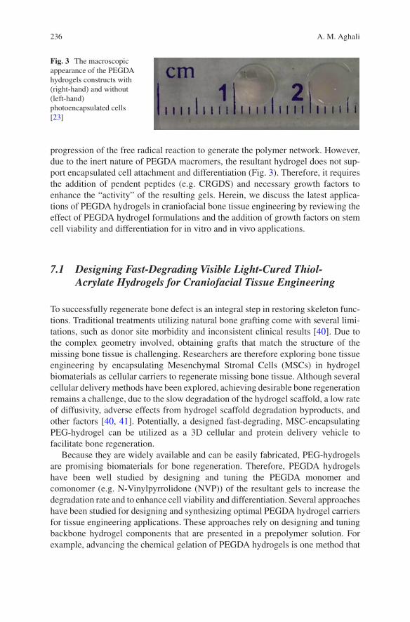
236
progression of the free radical reaction to generate the polymer network. However, due to the inert nature of PEGDA macromers, the resultant hydrogel does not sup-port encapsulated cell attachment and differentiation (Fig. 3). Therefore, it requires the addition of pendent peptides (e.g. CRGDS) and necessary growth factors to enhance the “activity” of the resulting gels. Herein, we discuss the latest applica-tions of PEGDA hydrogels in craniofacial bone tissue engineering by reviewing the effect of PEGDA hydrogel formulations and the addition of growth factors on stem cell viability and differentiation for in vitro and in vivo applications.
7.1 Designing Fast-Degrading Visible Light-Cured Thiol- Acrylate Hydrogels for Craniofacial Tissue Engineering
To successfully regenerate bone defect is an integral step in restoring skeleton func-tions. Traditional treatments utilizing natural bone grafting come with several limi-tations, such as donor site morbidity and inconsistent clinical results [40]. Due to the complex geometry involved, obtaining grafts that match the structure of the missing bone tissue is challenging. Researchers are therefore exploring bone tissue engineering by encapsulating Mesenchymal Stromal Cells (MSCs) in hydrogel biomaterials as cellular carriers to regenerate missing bone tissue. Although several cellular delivery methods have been explored, achieving desirable bone regeneration remains a challenge, due to the slow degradation of the hydrogel scaffold, a low rate of diffusivity, adverse effects from hydrogel scaffold degradation byproducts, and other factors [40, 41]. Potentially, a designed fast-degrading, MSC-encapsulating PEG-hydrogel can be utilized as a 3D cellular and protein delivery vehicle to facilitate bone regeneration.
Because they are widely available and can be easily fabricated, PEG-hydrogels are promising biomaterials for bone regeneration. Therefore, PEGDA hydrogels have been well studied by designing and tuning the PEGDA monomer and comonomer (e.g. N-Vinylpyrrolidone (NVP)) of the resultant gels to increase the degradation rate and to enhance cell viability and differentiation. Several approaches have been studied for designing and synthesizing optimal PEGDA hydrogel carriers for tissue engineering applications. These approaches rely on designing and tuning backbone hydrogel components that are presented in a prepolymer solution. For example, advancing the chemical gelation of PEGDA hydrogels is one method that
Fig. 3 The macroscopic appearance of the PEGDA hydrogels constructs with (right-hand) and without (left-hand) photoencapsulated cells [23]
A. M. Aghali
237
has been explored. Using the photoinitiator, eosin Y, has proven to increase levels of cell survival compared to the ultraviolet-sensitive photoinitiator Irgacure 2959 [9, 42]. Another way to enhance mechanical stiffness is to add a comonomer such as NVP to a prepolymer solution [9, 31]. Also, adding the NVP comonomer to a prepolymer solution has been shown to decrease the gelation time of the elastic hydrogels, such as PEGDA gels [23, 31]. A few other parameters should also be investigated for the design of a desirable hydrogel scaffold for bone tissue engineering use. The visible light-cured thiol-acrylate hydrogels are an attractive class of hydrogels due to their ability to control mechanical stiffness, as well as their fast gelation time [31]. Controlling the mechanical stiffness of the hydrogel scaffolds to match the ECM of the target tissue is one of the important factors to be considered in orthopedic applications. In previous studies, Hao et al. were able to modify the mechanical stiffness of PEGDA hydrogels by decreasing or increasing comonomer NVP in a prepolymer solution [9, 31]. Certainly, the data gathered through oscillation rheometry show that increasing the comonomer, NVP, in a prepolymer solution correspondingly increases the mechanical stiffness of the PEGDA hydrogel scaffolds. However, Hao et al. also concluded that increasing comonomer, NVP, from 0.1% to 1% decreases the cells’ viability [9]. It is obvious that there is a correlation between the mechanical stiffness of the PEGDA hydrogel and the viability of the encapsulated-cells. The balance between these two parameters is critically important for tissue regeneration purposes. Nevertheless, the advances in PEGDA hydrogels were mainly for the 3D-culture of hepatocytes.
Although changing comonomer, NVP, levels is an effective option for obtaining desirable PEGDA hydrogels formula, there are other approaches that could add an extra efficiency in tuning the mechanical stiffness of visible light-cured thiol- acrylate hydrogels. For example, the approach that would rely on decreasing the concentration of PEGDA macromers in a prepolymer solution is yet to be promising for several reasons. It is possible that the resultant stiffness of the hydrogels could match bone tissue stiffness, specifically for non-load bearing area such as craniofacial bone defects; the applications may well fit in defected cranial of infants. Furthermore, decreasing the PEGDA macromers may also increase the viability of photoencapsulated-cells. Emmakah et al. demonstrated that the mechanical stiffness of PEGDA hydrogels indeed decreased by alternating PEGDA macromers in a prepolymer solution [23]. Taking advantage of non-load-bearing areas of the cranium, the low stiffness of PEGDA hydrogels could serve the dual purpose of delivering the highest cellular viability into the defect site while matching the mechanical stiffness of the surrounding native tissues. Decreasing the PEGDA mac-romers in a prepolymer solution results in fast degradation of the hydrogel scaffolds in vitro. This rapid degradation may allow for photoencapsulated-MSCs to be deliv-ered into the defect site to accelerate the regeneration process. In this case scenario, the gelation mechanism of the visible light-cured thiol-acrylate hydrogels occurs under a mixed–mode mechanism of step- and chain-growth polymerization. The presence of a free radical agent plays an important role in the gelation process dur-ing chain-growth polymerization. By adding each PEGDA macromer individually, the polymers show chain-growth overtime [14]. Similar to a previous discussion in
Poly(ethylene glycol) and Co-polymer Based-Hydrogels for Craniofacial Bone Tissue…
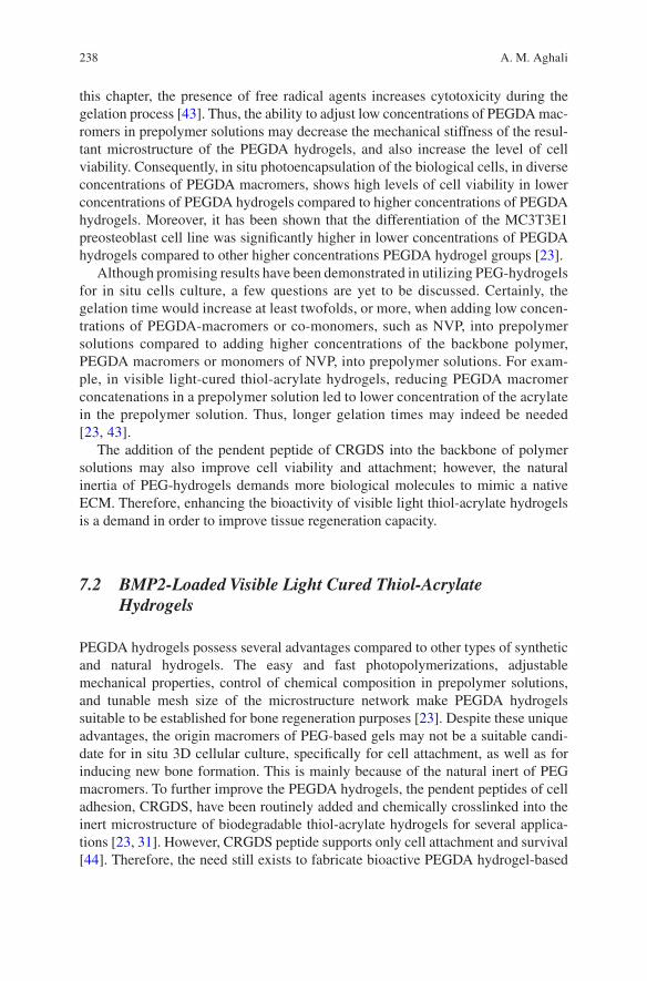
238
this chapter, the presence of free radical agents increases cytotoxicity during the gelation process [43]. Thus, the ability to adjust low concentrations of PEGDA mac-romers in prepolymer solutions may decrease the mechanical stiffness of the resul-tant microstructure of the PEGDA hydrogels, and also increase the level of cell viability. Consequently, in situ photoencapsulation of the biological cells, in diverse concentrations of PEGDA macromers, shows high levels of cell viability in lower concentrations of PEGDA hydrogels compared to higher concentrations of PEGDA hydrogels. Moreover, it has been shown that the differentiation of the MC3T3E1 preosteoblast cell line was significantly higher in lower concentrations of PEGDA hydrogels compared to other higher concentrations PEGDA hydrogel groups [23].
Although promising results have been demonstrated in utilizing PEG-hydrogels for in situ cells culture, a few questions are yet to be discussed. Certainly, the gelation time would increase at least twofolds, or more, when adding low concen-trations of PEGDA-macromers or co-monomers, such as NVP, into prepolymer solutions compared to adding higher concentrations of the backbone polymer, PEGDA macromers or monomers of NVP, into prepolymer solutions. For exam-ple, in visible light-cured thiol-acrylate hydrogels, reducing PEGDA macromer concatenations in a prepolymer solution led to lower concentration of the acrylate in the prepolymer solution. Thus, longer gelation times may indeed be needed [23, 43].
The addition of the pendent peptide of CRGDS into the backbone of polymer solutions may also improve cell viability and attachment; however, the natural inertia of PEG-hydrogels demands more biological molecules to mimic a native ECM. Therefore, enhancing the bioactivity of visible light thiol-acrylate hydrogels is a demand in order to improve tissue regeneration capacity.
7.2 BMP2-Loaded Visible Light Cured Thiol-Acrylate Hydrogels
PEGDA hydrogels possess several advantages compared to other types of synthetic and natural hydrogels. The easy and fast photopolymerizations, adjustable mechanical properties, control of chemical composition in prepolymer solutions, and tunable mesh size of the microstructure network make PEGDA hydrogels suitable to be established for bone regeneration purposes [23]. Despite these unique advantages, the origin macromers of PEG-based gels may not be a suitable candi-date for in situ 3D cellular culture, specifically for cell attachment, as well as for inducing new bone formation. This is mainly because of the natural inert of PEG macromers. To further improve the PEGDA hydrogels, the pendent peptides of cell adhesion, CRGDS, have been routinely added and chemically crosslinked into the inert microstructure of biodegradable thiol-acrylate hydrogels for several applica-tions [23, 31]. However, CRGDS peptide supports only cell attachment and survival [44]. Therefore, the need still exists to fabricate bioactive PEGDA hydrogel-based
A. M. Aghali
239
scaffolds for bone tissue engineering. Despite the effort to design and to fabricate PEG-hydrogels that mimic the ECM, the native assembly of the ECM in bone tissue maintains several essential growth factors for the neighboring cells to function [45]. Consequently, numerous methods have been utilized to mimic the natural architecture of ECM-derived bioactive proteins to develop the inert microstructure of PEG hydrogel-based scaffolds. One of the urgent demands is to modulate osteogenic differentiation of cellular responses in 3D-culture of MSCs in PEGDA hydrogel implants (Fig. 4).
BMP2 is a bioactive protein that has been extensively used in different types of cell culture applications [46]. BMP2 plays important roles in skeleton development and bone formation during embryogenesis [47, 48]. BMP2 is also well-known to induce and to enhance MSCs to differentiate into osteoblast lineages [49]. For example, Bone Marrow Mesenchymal Stromal Cells (BMSCs) require chemical cues, including a l-ascorbic acid agent in the osteogenic culture medium, to induce BMSC to differentiate into a target osteoblast lineage. The addition of BMP2 into
15 wt% PEGDA Hydrogels
Ost
eoge
nic
Med
ium
Bas
al M
ediu
m
Fig. 4 Osteogenic differentiation of the preosteoblasts, MC3T3-E1, cell line photoencapsulated in PEGDA hydrogels. The histological cross section view of Von Kossa and Toluidine Blue double stain demonstrates pericellular mineralization of the preosteoblasts cultured in osteogenic medium (experiment group) compared to photoencapsulated preosteoblasts cultured in basal medium (control group) for 21-days. Von Kossa stained calcium in black, Toluidine Blue stained preosteoblasts, Mc3T3-E1, cell nuclei in blue. Scale bar is 300 μm [23]
Poly(ethylene glycol) and Co-polymer Based-Hydrogels for Craniofacial Bone Tissue…
240
the osteogenic culture medium has proven to further enhance BMSCs’ differentiation into an osteoblast lineage [47]. Therefore, it is important to enhance the activity of the heritage inert of thiol-acrylate hydrogels to photoencapsulated-BMSCs. Several studies were conducted to examine the effect of the encapsulated-BMSCs in hydrogels, with and without BMP2 [49, 50]. In these studies, cell-laden gels were examined for cell viability and differentiation by incubating hydrogel scaffolds in culture medium in situ. The main motivation is to examine the effect of photoencap-sulated-BMP2 in PEG-hydrogels mimicking the real-time application of photoen-capsulating-MSCs in the surgery room and directly implanting into the defect site. Therefore, the suggestion is that, it will allow implanting the PEGDA hydrogel scaffolds and inducing the differentiation of photoencapsulated-BMSCs in a culture medium by adding BMP2 into the microstructure of the PEG network.
The outcomes of these studies are promising. BMP2 can be successfully intro-duced into the network structure of PEGDA hydrogels. For instance, we were able to successfully incorporating recombinant human-BMP2 into visible light- cured thiol-acrylate hydrogels with or without BMSCs [50]. The differentiation of the bioactivity of PEGDA hydrogels increased at least twofold in the presence of BMP2, compared to photoencapsulated-BMSCs in PEGDA hydrogels without BMP2. The results show not only enhanced differentiation of BMSCs into an osteoblast lineage, but also increased cell viability compared to a control group of photoencapsulated-BMSCs without BMP2. These results were surprising, given the nature of the gelation process in the presence of BMP2 encapsulation. In particular, there was a concern that the use of the chain-growth photopolymerization method would damage the protein amino acid microstructure, like previously discussed in this chapter, due to the progression of free radical agent. The process of polymerization using a free radical agent, as well as the polymer-growth mechanism of adding one monomer at a time, might contribute to increased cytotoxicity and also lead to denaturation of BMP2 during the encapsulation process [27]. Due to the use of a dual gelation mechanism, mixed-mode (step- and chain-growth) photopolymerization, it is believed that step-growth polymerization plays a major role in minimizing the damage to BMP2 during the gelation process. One of the unique properties of step-growth polymerization is reducing the propagation of free radicals during a chemical reaction, and “clicking” the oligomer [7]. Consequently, the linear oligomer of PEGDA can be added to form a polymer network without causing defects to the microstructure of the network because of free radical actions [26, 27]. Hence, step-growth photopolymerization might be a logical approach to protect BMP2 from damage during photoencapsulation. Consistent results were obtained by Van de Wetering et al. when linear degradable PEG-hydrogel was used to precipitate and to control hGH release from a network structure that utilized Michael-type addition polymerization [29].
Nonetheless, it has been noted in a pilot study that the functionality of BMP2 to induce BMSCs differentiation seems to be lower in 3D cell culture than in 2D cell culture [23]. This difference could be due to two reasons. First, it is obvious that photoencapsulated-BMSC tend to migrate and to leave a 3D network culture, perhaps due to the force of gravity and/or the affinity of the surface culture plate.
A. M. Aghali
241
Giving all these advantages on using PEGDA hydrogels for 3D cell culture, this might be one of the main reasons that MSCs’ viability decreases overtime, this phenomenon has also seen in a Watson et al. study utilizing hydrogels for bone tissue engineering applications [33]. This could also be a reason behind the fact that BMP2 shows a greater effect on BMSC differentiation in 2D cell culture than in 3D cell culture. Though, another reason could be that the lower concentration of the total photoencapsulated-BMP2 added into a prepolymer solution is indeed denatured due to the chain-growth photopolymerization mechanism, as previously explained in this chapter. The majority of the time, the current outcomes of cell viability and differentiation in 2D-culture has proven to be much better than in 3D-culture although 2D-culture may not mimic the reality of the cells embedded in their native microenvironments. Nevertheless, bioactive and biodegradable visible light-cured thiol-acrylate hydrogels are promising scaffolds to be utilized in bone regeneration applications, particularly in craniofacial bone tissue engineering, due to a low-load bearing area and also because of their successful delivery of BMSCs and other required protein therapy into the defect site.
7.3 Biodegradable Visible Light Cured Thiol-Acrylate Hydrogel as a Stem-Cell Carrier for Craniofacial Bone Tissue Engineering
Cranioplasty is an invasive surgery that is required to repair cranial bone defects and to restore the functions of the skull [51, 52]. Several approaches have been investigated to repair cranium defects. For instance, autografting is considered to be the gold-standard procedure in cranioplasty [53]. This involves using a piece of bone harvested from elsewhere in the patient’s body as a substitute for the missing cranial bone. Autografting implants has several advantages by showing high biocompatibility and the minimal possibility of rejection by the recipient immune system [54, 55]. However, autografting implants also has several drawbacks. The ability to keep the harvested bone graft viable and “alive” before the implant is a key factor [51]. Nevertheless, researchers are using other methods to substitute for missing cranial bone such as an allografting method. Yet, this procedure has shown poor regeneration outcomes, due to several reasons including the rejection by the recipient’s immune system [56, 57], and also high rates of infection even after the donated bone is sterilized [51].
Therefore, researchers are exploring tissue engineering methods to regenerate cranial defects. Using biomaterials as a bone substitute has a number of advantages: these biomaterials are widely available, their degradability removes the need for a second surgery, and they can be shaped to fit irregular defect sites. Several experiments have been conducted in order to develop new classes of biomaterials for craniofacial bone tissue engineering. One of these is a biodegradable hydrogel scaffold for cranial regeneration. Due to the non-load bearing area of cranial defect
Poly(ethylene glycol) and Co-polymer Based-Hydrogels for Craniofacial Bone Tissue…
242
sites, hydrogels show promise as a tool in cranial bone regeneration. There are numerous advantages of biodegradable visible light-cured thiol-acrylate hydrogels to serve as a cell carrier and a substitute implant for craniofacial bone tissue engineering applications. Thus, the use of biodegradable thiol-acrylate hydrogels enhance cranial bone defect repair, and the addition of photoencapsulated-MSCs in PEGDA hydrogels will further improve regeneration of defected bone. Consequently, a study preformed by the authors, where four defects (each defect is 2 mm thickness and 5 mm diameter) were created in a New Zealand White rabbit’s cranium to examine the effect of fast- and slow-degrading PEGDA hydrogels encapsulating bone marrow and dental pulp MSCs (BMSCs and DPSCs) [58]. The encapsulated-MSCs were incubated in basal (BSL) or osteogenic (OST) medium 3 days prior to the surgery. Photoencapsulated-MSCs with high or low polymer content, incubated in BSL or OST medium prior to the surgery, showed an increase in cell viability overtime. Furthermore, cell-laden gels cultured in OST medium demonstrated sig-nificant increases in stem cell differentiation while going into an osteoblast lineage, compared to the ones incubated in BSL medium in vitro. Additionally, the μCT analysis and calcium staining of Von-Kossa MacNeal’s data showed increases new bone regeneration utilizing different hydrogel formulations; where fast degrading PEGDA hydrogels (with lower PEGDA macromer concentration (5 wt%) added into prepolymer solution) demonstrated higher new bone formation compared to slower degrading PEGDA hydrogels (with higher PEGDA macromer concentra-tions (15 wt%) added into prepolymer solution) [58]. Nevertheless, there were no significant differences in new bone formation due to the culture conditions (BSL vs OST medium) prior to the surgery. The results also revealed that BMSC photoen-capsulated in 5 wt% PEGDA hydrogels showed increased new bone formation com-pared to DPSC photoencapsulated in 5 wt% PEGDA hydrogels, and compared to acellular control hydrogel groups. Furthermore, the degradation degree of a lower macromer concentration of PEGDA hydrogel scaffold (5 wt%) with photoencapsu-lated-MSCs was at the highest rate 6 weeks post-implantation, compared to higher macromer concentrations of PEGDA hydrogel scaffold (15 wt%) photoencapsu-lated-MSCs, and also compared to both acellular formulations of PEGDA hydro-gels (5 and 15 wt%) [58].
8 Conclusion and Future Insight
One of the several functions of bone is to provide mechanical support for and pro-tect surrounding soft tissues [22]. If a critical defect occurs in the bone, it demands an immediate act in order for surgeons to effectively repair the defects and possibil-ity save the patient’s life. Thus, successful regeneration of bone defects is essential to restore the skeleton’s functions. Several approaches have been implemented to substitute for the lost bone. Among them is utilizing hydrogel biomaterials as scaffold implants. Hydrogels have shown the ability to substitute for and to transport necessary cells and growth factors into a defect site to enhance the regeneration of
A. M. Aghali
243
missing bone. Although much effort and progress have been made over the years, the optimal design and fabrication of hydrogel scaffolds is yet to be determined.
The PEG-hydrogel is a class of biomaterial that has shown great potential in the fields of tissue engineering and regenerative medicine. Since its discovery, research interests in PEG-hydrogels have been growing significantly (Fig. 1). Although great progress has been made to improve the inert microstructure of PEG-hydrogels and their mimicking of native ECM human tissues, the proper methodology to further improve the resultant network structure of the PEG-hydrogels is still necessary. During the design and engineering of PEG-hydrogels for 3D cell culture and scaffolds, several parameters must be considered to successfully use PEG-hydrogel in 3D cell studies and tissue regeneration. This includes but is not limited to the addition of bioactive molecules and proteins such as cell adhesion motifs, controlling the degradation rate, and tuning mechanical stiffness.
Herein, it has been discussed the ability to design, to tune, and to fabricate PEG- hydrogels for bone tissue engineering applications. The success in designing an ideal PEG-hydrogels for bone tissue engineering use appears promising, particularly in infant patients, for regeneration of bone defects. Based on the literature reviewed in this chapter, in order to improve the applications of biodegradable PEG-hydrogels, and for further investigations, a few points for future consideration are recommended.
Reducing the need for chain-growth polymerization could be a better approach for cell encapsulation during the photoencapsulation processes. Eliminating the need for the chain-growth polymerization method combined with a focus on engineering and advancing step-growth polymerization, could improve cell viability and enhance protein encapsulation. The presence of free radical agents during pho-topolymerization may be a disadvantage in both cell and protein encapsulation [23, 27]. Second, due to the success in several in vitro studies of designing and adjusting bioactive visible light-cured thiol-acrylate hydrogels, exploring and advancing the applications of the resultant bioactive of PEG-hydrogels in combination with bio-logical cells in vivo could be a promising future direction. Furthermore, among PEG-copolymer hydrogels, biodegrading thiol-acrylate hydrogels has several advantages due to the ability to control and to tune mechanical stiffness and degra-dation behavior, it appears that this attractive class of hydrogels is a promising bio-material for bone tissue regeneration applications of cranial critical-sized defects. Finally, this chapter may provide a solid concert for the future building and investi-gation of PEG-hydrogels for bone tissue engineering.
References
1. Davis FF. The origin of pegnology. Adv Drug Deliv Rev. 2002;54:457–8. 2. Zhu J. Bioactive modification of poly(ethylene glycol) hydrogels for tissue engineering.
Biomaterials. 2010;31:4639–56. 3. Cushing MC, Anseth KS. Materials science. hydrogel cell cultures. Science. 2007;316:1133–4.
Poly(ethylene glycol) and Co-polymer Based-Hydrogels for Craniofacial Bone Tissue…

244
4. Mellott MB, Searcy K, Pishko MV. Release of protein from highly cross-linked hydro-gels of poly(ethylene glycol) diacrylate fabricated by Uv polymerization. Biomaterials. 2001;22:929–41.
5. Slaughter BV, Khurshid SS, Fisher OZ, Khademhosseini A, Peppas NA. Hydrogels in regen-erative medicine. Adv Mater. 2009;21:3307–29.
6. Li J, Kao WJ. Synthesis of polyethylene glycol (Peg) derivatives and pegylated-peptide bio-polymer conjugates. Biomacromolecules. 2003;4:1055–67.
7. Malkoch M, Vestberg R, Gupta N, Mespouille L, Dubois P, Mason AF, Hedrick JL, Liao Q, Frank CW, Kingsbury K, Hawker CJ. Synthesis of well-defined hydrogel networks using click chemistry. Chem Commun (Camb). 2006;(26):2774–6.
8. Elbert DL, Hubbell JA. Conjugate addition reactions combined with free-radical cross-linking for the design of materials for tissue engineering. Biomacromolecules. 2001;2:430–41.
9. Hao Y, Shih H, Munoz Z, Kemp A, Lin CC. Visible light cured thiol-vinyl hydrogels with tun-able degradation for 3d cell culture. Acta Biomater. 2014;10:104–14.
10. Ward JH, Peppas NA. Preparation of controlled release systems by free-radical uv polymeriza-tions in the presence of a drug. J Control Release. 2001;71:183–92.
11. Metters A, Hubbell J. Network formation and degradation behavior of hydrogels formed by michael-type addition reactions. Biomacromolecules. 2005;6:290–301.
12. Lutolf MP, Hubbell JA. Synthetic biomaterials as instructive extracellular microenvironments for morphogenesis in tissue engineering. Nat Biotechnol. 2005;23:47–55.
13. Miller JS, Shen CJ, Legant WR, Baranski JD, Blakely BL, Chen CS. Bioactive hydrogels made from step-growth derived peg-peptide macromers. Biomaterials. 2010;31:3736–43.
14. Lin CC. Recent advances in crosslinking chemistry of biomimetic poly(ethylene glycol) hydrogels. RSC Adv. 2015;5:39844–398583.
15. Kawecki M, Labus W, Klama-Baryla A, Kitala D, Kraut M, Glik J, Misiuga M, Nowak M, Bielecki T, Kasperczyk A. A review of decellurization methods caused by an urgent need for quality control of cell-free extracellular matrix’ scaffolds and their role in regenerative medi-cine. J Biomed Mater Res B Appl Biomater. 2017. https://doi.org/10.1002/jbm.b.33865.
16. Leifer CA. Dendritic cells in host response to biologic scaffolds. Semin Immunol. 2017;29:33–40.
17. Leiva O, Ng SK, Chitalia S, Balduini A, Matsuura S, Ravid K. The role of the extracellular matrix in primary myelofibrosis. Blood Cancer J. 2017;7:E525.
18. Hubbell JA. Bioactive biomaterials. Curr Opin Biotechnol. 1999;10:123–9. 19. Lin TY, Bragg JC, Lin CC. Designing visible light-cured thiol-acrylate hydrogels for study-
ing the hippo pathway activation in hepatocellular carcinoma cells. Macromol Biosci. 2016;16:496–507.
20. Caliari SR, Burdick JA. A practical guide to hydrogels for cell culture. Nat Methods. 2016;13:405–14.
21. Baker BM, Chen CS. Deconstructing the third dimension: how 3d culture microenvironments alter cellular cues. J Cell Sci. 2012;125:3015–24.
22. Vo TN, Shah SR, Lu S, Tatara AM, Lee EJ, Roh TT, Tabata Y, Mikos AG. Injectable dual-gell-ing cell-laden composite hydrogels for bone tissue engineering. Biomaterials. 2016;83:1–11.
23. Emmakah AM, Arman H, Bragg J, Greene T, Alvarez M, Childress P, Goebel WS, Kacena M, Lin CC, Chu TM. A fast-degrading thiol-acrylate based hydrogel for cranial regeneration. Biomed Mater. 2017;12(2):025011.
24. Riedl A, Schlederer M, Pudelko K, Stadler M, Walter S, Unterleuthner D, Unger C, Kramer N, Hengstschlager M, Kenner L, Pfeiffer D, Krupitza G, Dolznig H. Comparison of cancer cells in 2d vs 3d culture reveals differences in Akt-Mtor-S6k signaling and drug responses. J Cell Sci. 2017;130:203–18.
25. Imamura Y, Mukohara T, Shimono Y, Funakoshi Y, Chayahara N, Toyoda M, Kiyota N, Takao S, Kono S, Nakatsura T, Minami H. Comparison of 2d- and 3d-culture models as drug-testing platforms in breast cancer. Oncol Rep. 2015;33:1837–43.
A. M. Aghali
245
26. Yokozawa T, Ohta Y. Transformation of step-growth polymerization into living chain-growth polymerization. Chem Rev. 2016;116:1950–68.
27. Lin CC, Anseth KS. Peg hydrogels for the controlled release of biomolecules in regenerative medicine. Pharm Res. 2009;26:631–43.
28. Rizzi SC, Ehrbar M, Halstenberg S, Raeber GP, Schmoekel HG, Hagenmuller H, Muller R, Weber FE, Hubbell JA. Recombinant protein-Co-Peg networks as cell-adhesive and proteolyti-cally degradable hydrogel matrixes. Part II: biofunctional characteristics. Biomacromolecules. 2006;7:3019–29.
29. Van De Wetering P, Metters AT, Schoenmakers RG, Hubbell JA. Poly(ethylene glycol) hydro-gels formed by conjugate addition with controllable swelling, degradation, and release of phar-maceutically active proteins. J Control Release. 2005;102:619–27.
30. Pelegri-O’day EM, Maynard HD. Controlled radical polymerization as an enabling approach for the next generation of protein-polymer conjugates. Acc Chem Res. 2016;49:1777–85.
31. Hao Y, Lin CC. Degradable thiol-acrylate hydrogels as tunable matrices for three-dimensional hepatic culture. J Biomed Mater Res A. 2014;102:3813–27.
32. Stevens KR, Miller JS, Blakely BL, Chen CS, Bhatia SN. Degradable hydrogels derived from Peg-diacrylamide for hepatic tissue engineering. J Biomed Mater Res A. 2015;103:3331–8.
33. Watson BM, Vo TN, Tatara AM, Shah SR, Scott DW, Engel PS, Mikos AG. Biodegradable, phosphate-containing, dual-gelling macromers for cellular delivery in bone tissue engineering. Biomaterials. 2015;67:286–96.
34. Ingavle GC, Gehrke SH, Detamore MS. The bioactivity of agarose-pegda interpenetrating net-work hydrogels with covalently immobilized rgd peptides and physically entrapped aggrecan. Biomaterials. 2014;35:3558–70.
35. Hern DL, Hubbell JA. Incorporation of adhesion peptides into nonadhesive hydrogels useful for tissue resurfacing. J Biomed Mater Res. 1998;39:266–76.
36. Gould ST, Darling NJ, Anseth KS. Small peptide functionalized thiol-ene hydrogels as culture substrates for understanding valvular interstitial cell activation and de novo tissue deposition. Acta Biomater. 2012;8(9):3201.
37. Ulery BD, Nair LS, Laurencin CT. Biomedical applications of biodegradable polymers. J Polym Sci B Polym Phys. 2011;49:832–64.
38. Jennifer L, West JAH. Polymeric biomaterials with degradation sites for proteases involved in cell migration. Macromolecules. 1999;32:241–4.
39. Zisch AH, Lutolf MP, Ehrbar M, Raeber GP, Rizzi SC, Davies N, Schmokel H, Bezuidenhout D, Djonov V, Zilla P, Hubbell JA. Cell-demanded release of Vegf from synthetic, biointeractive cell ingrowth matrices for vascularized tissue growth. FASEB J. 2003;17:2260–2.
40. Petrovic V, Zivkovic P, Petrovic D, Stefanovic V. Craniofacial bone tissue engineering. Oral Surg Oral Med Oral Pathol Oral Radiol. 2012;114:E1–9.
41. Emmakah AM, Arman HE, Bragg JC, Greene T, Alvarez MB, Childress PJ, Goebel WS, Kacena MA, Lin CC, Chu TM. A fast-degrading thiol-acrylate based hydrogel for cranial regeneration. Biomed Mater. 2017;12(2):025011. https://doi.org/10.1088/1748-605X/aa5f3e.
42. Williams CG, Malik AN, Kim TK, Manson PN, Elisseeff JH. Variable cytocompatibility of six cell lines with photoinitiators used for polymerizing hydrogels and cell encapsulation. Biomaterials. 2005;26:1211–8.
43. Mazzoccoli JP, Feke DL, Baskaran H, Pintauro PN. Mechanical and cell viability properties of crosslinked low and high molecular weight poly(ethylene glycol) diacrylate blends. J Biomed Mater Res A. 2010;93:558–66.
44. Singh SP, Schwartz MP, Lee JY, Fairbanks BD, Anseth KS. A peptide functionalized poly(ethylene glycol) (Peg) hydrogel for investigating the influence of biochemical and bio-physical matrix properties on tumor cell migration. Biomater Sci. 2014;2:1024–34.
45. Teodori L, Costa A, Marzio R, Perniconi B, Coletti D, Adamo S, Gupta B, Tarnok A. Native extracellular matrix: a new scaffolding platform for repair of damaged muscle. Front Physiol. 2014;5:218.
Poly(ethylene glycol) and Co-polymer Based-Hydrogels for Craniofacial Bone Tissue…
246
46. Herford AS. The use of recombinant human bone morphogenetic protein-2 (Rhbmp-2) in max-illofacial trauma. Chin J Traumatol. 2017;20:1–3.
47. Beederman M, Lamplot JD, Nan G, Wang J, Liu X, Yin L, Li R, Shui W, Zhang H, Kim SH, Zhang W, Zhang J, Kong Y, Denduluri S, Rogers MR, Pratt A, Haydon RC, Luu HH, Angeles J, Shi LL, He TC. Bmp signaling in mesenchymal stem cell differentiation and bone forma-tion. J Biomed Sci Eng. 2013;6:32–52.
48. Nie X, Luukko K, Kettunen P. Bmp signalling in craniofacial development. Int J Dev Biol. 2006;50:511–21.
49. Scarfi S. Use of bone morphogenetic proteins in mesenchymal stem cell stimulation of carti-lage and bone repair. World J Stem Cells. 2016;8(1):12.
50. Emmakah A. Photoencapsulation of Bmp2 in visible light-cured thiol-acrylate hydrogel for craniofacial bone tissue engineering (Chapter 4). In: Biodegradable visible light-cured thiol-acrylate hydrogels for craniofacial bone tissue engineering (Ph.D. Thesis). Ann Arbor: ProQuest; 2017.
51. Aydin S, Kucukyuruk B, Abuzayed B, Aydin S, Sanus GZ. Cranioplasty: review of materials and techniques. J Neurosci Rural Pract. 2011;2:162–7.
52. Brommeland T, Rydning På N, Pripp AH, Helseth E. Cranioplasty complications and risk fac-tors associated with bone flap resorption. Scand J Trauma Resusc Emerg Med. 2015;23:75.
53. Miller CP, Chiodo CP. Autologous bone graft in foot and ankle surgery. Foot Ankle Clin. 2016;21:825–37.
54. Malhotra A, Pelletier M, Oliver R, Christou C, Walsh WR. Platelet-rich plasma and bone defect healing. Tissue Eng A. 2014;20(19–20):2614–33.
55. Szpalski C, Barr J, Wetterau M, Saadeh PB, Warren SM. Cranial bone defects: current and future strategies. Neurosurg Focus. 2010;29:E8.
56. Abt P, Shaked A. The allograft immune response. Graft. 2003;6:71–9. 57. Klimczak A, Siemionow M. Immune responses in transplantation: application to composite
tissue allograft. Semin Plast Surg. 2007;21:226–33. 58. Emmakah A. Biodegradable thiol-acrylate hydrogel shows promise as a cell carrier for
stromal-cell-assisted cranial regeneration (Chapter 5). In: Biodegradable visible light-cured thiol-acrylate hydrogels for craniofacial bone tissue engineering (Ph.D. Thesis). Ann Arbor: ProQuest; 2017.
A. M. Aghali
247© Springer International Publishing AG, part of Springer Nature 2017B. Li, T. Webster (eds.), Orthopedic Biomaterials, https://doi.org/10.1007/978-3-319-73664-8_10
Peptides as Orthopedic Biomaterials
Derek E. Andreini, Zachary J. Werner, Christopher D. Bell, Malcolm Xing, and Bingyun Li
Keywords Peptide · Antimicrobial · Infection · Drug delivery · Protein · Hydrogel · Antibiotic · Polymer · Tissue engineering · Arthritis · Bone tumor · Biomarker · Osteoporosis · Growth factor
1 Introduction
Peptides are organic chain structures of amino acids, formed via a covalent linkage known as a peptide or amide bond as a result of hydrolysis. The sequence and com-position of a peptide determines its characteristics such as hydrophilicity, isoelectric points, level of protein structures, and activity, among other traits.
Peptide synthesis can be achieved using various methods including fermenta-tion, recombination, chemical synthesis, and enzymatic synthesis. Enzymatic hydrolysis is similar to the generation of peptides within our own bodies via enzymes such as tryptase and other digestive enzymes. Interestingly, the type of hydrolysis is less integral to the production of bioactive peptides in comparison to the initial protein, as the initial protein largely determines the characteristics of the resultant peptides [1].
D. E. Andreini · Z. J. Werner · C. D. Bell Department of Orthopaedics, School of Medicine, West Virginia University, Morgantown, WV, USA
M. Xing Department of Mechanical Engineering, University of Manitoba, Winnipeg, MB, Canada
The Children’s Hospital Research Institute of Manitoba, Winnipeg, Canada, MB
B. Li (*) Department of Orthopaedics, School of Medicine, West Virginia University, Morgantown, WV, USA
Mary Babb Randolph Cancer Center, Morgantown, WV, USAe-mail: [email protected]; http://medicine.hsc.wvu.edu/ortho/li
248
Peptides have been found to present a variety of biological activities such as anti-microbial, anti-hypertensive, immunomodulatory, and antitumor effects [2–4]. Peptides have attracted increasing interest in recent years as therapeutics and commer-cialization of peptide products such as insulin, glucagon-like peptides, and growth factors has changed the face of diabetes mellitus and oncology, to name a few. In orthopedics, the use of peptides in the treatment of arthritis, osteoporosis, bone regen-eration, antimicrobials, and bone tumors among other things, have been examined as possible avenues of therapy. As an example, calcitonin salmon has been used as a therapeutic peptide for over 30 years to treat Paget’s disease of the bone and postmeno-pausal osteoporosis. Calcitonin salmon has been produced both chemically and via recombination [5, 6]. Its continuing use and recognition as a safe and effective therapy warranted research into production of an oral form [5, 6]. This progression from dis-covery of effect to formulation of a commercially available form is a classic pathway and should serve as an example for future research into orthopedic peptides.
However, there exist some substantial barriers to the use of peptides as therapeu-tics, most notably their short or lack of in vivo bioavailability and relative inability to cross lipid bilayers [7]; these challenges are not inherent in only orthopedic pep-tide applications but also in therapeutic peptides in general. Just as natural proteins are digested, often by hydrolysis, to produce peptides with bioactive effects, so can bioactive peptides be broken down via hydrolysis. Consequently, the oral bioavail-ability of peptides remains a barrier to the commercialization of peptide therapies. Furthermore, production of most peptides has not often been cost-effective. Sources conflict as to which method of production holds the key to commercialization, with some touting solution phase chemistry as the key to large scale production, while others purport the answer to be recombination methods [1, 8].
To deal with these challenges, multiple methods have been developed such as click synthesis to modify peptides in order to generate metabolic stability [9]. Cyclization, use of triazole groups as peptide bond mimics, addition of carbohy-drates and polyethylene glycol, and other modifications could serve to improve the efficacy of peptides [9]. The use of recombination techniques is an area of research with great promise for increasing production cost-effectiveness [1].
As of 2015, the therapeutic peptide market was valued at approximately US$20 billion, with a substantial projected increase by 2024. As production costs decrease and the use of peptides becomes more widespread, one can expect peptides to be used in various fields including orthopedics. This chapter will examine a multitude of peptide-based studies, viewed through an orthopedic-centered lens.
2 Pathways for Peptide Delivery
Retaining high bioavailability is a key aspect of delivering peptides in vivo. To accomplish this goal, many pathways have been examined to establish trends in delivery and to weigh the pros and cons of each. We will examine some of the more notable pathways of delivery, such as oral and intravenous administration,
D. E. Andreini et al.
249
self- assembly, surface modification, nanoparticles, hydrogels, and composites as they pertain to the field of orthopedics.
The preferred method of delivery of medical therapeutics is oral administration due to its convenience and relative safety. This method, however, poses challenges when it comes to peptide therapies due to the unfavorable conditions that must be endured to reach the therapeutic targets. Most proteins and peptides are absorbed by diffusion; this method of absorption is hampered for peptides of high molecular weights [10]. The majority of, if not all, peptides need their complex structures to function properly while their structures are susceptible to changes upon exposure to the acidic pH in the stomach which may render them useless [11]. A second pre-ferred mode of delivery is intravenous administration. This route is rife with perils as well since they may be broken down quickly by proteolytic enzymes [11].
The use of nanoparticles can help avoid some of the issues with oral/intravenous administration of peptides. For instance, synthetic nanoparticles such as poly-lactic- co-glycolic acid (PLGA) nanoparticles have been extensively studied; they can be used to shuttle peptides and they may or may not play their own roles in vivo. In a study by Chereddy et al. [12], the use of PLGA nanoparticles along with the antimi-crobial LL-37 peptide was used to treat infection, promote angiogenesis, increase collagen deposition, and promote an antimicrobial environment along with acceler-ated wound healing (Fig. 1). Some studies have also used bio-inspired nanoparticles such as bacteriophages as carriers for antimicrobial peptides. In a study by Karimi et al. [13], bacteriophages specific to Staphylococcus aureus (S. aureus) and some Gram-negative rods, were used to deliver antimicrobial peptides to the infection sites which could be particularly useful in the field of orthopedics because of the prevalence of S. aureus infections.
Some peptides may self-assemble into nanoparticles/capsules. An interesting type of nanoparticles, called branch amphiphilic peptide capsules, were self- assembled from bis(FLIVI)-K-KKKK and bis(FLIVIGSII)-K-KKKK, two branched peptides that were designed to mimic the molecular architecture of diacyl- phosphoglycerides [14]. These peptide nanoparticles could load various therapeutic drugs, fluorescent dyes, radionuclides, and peptides and proteins [14]. By self- assembling antimicrobial peptides on gold nano-dots, one study showed efficacy vs. methicillin resistant S. aureus (MRSA) [15]. The gold nano-dots and antimicrobial peptide complex displayed the efficacy of this combination in the field of wound healing which provides an interesting prospect in the post-surgical treatment of wounds, as well as an interesting prospect in the coating of implants.
Peptides may also be used in surface modification and surface coatings as we have extensively studied [16–28]. An interesting example was seen in a study by Ardura et al. in which hydroxyapatite-based implants were coated with parathyroid hormone (PTHrP) and used to repair tibia defects in diabetic rats [29]. This may have significance in the field of orthopedics due to the poor surgical outcome associ-ated with diabetic patients. The PTHrP coated hydroxyapatite-based implants increased the formation of bone tissue as well as osteocalcin gene expression [29]. Another study demonstrated the properties of polycaprolactone (PCL) scaffolds with a collagen mimicking peptide GFOGER. This combination had the ability to
Peptides as Orthopedic Biomaterials
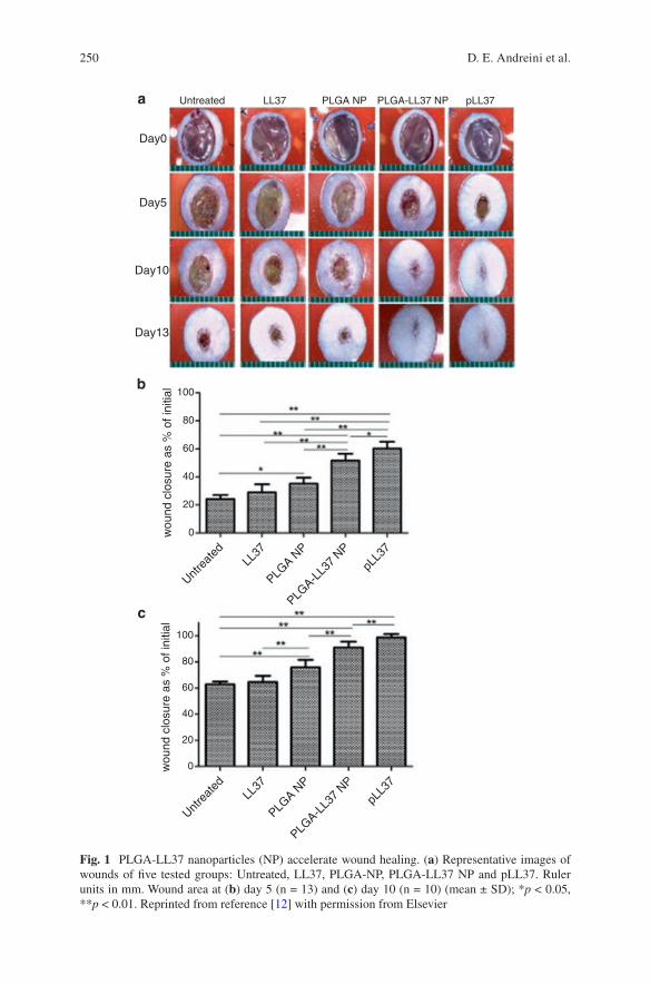
250
Untreated LL37 PLGA NP PLGA-LL37 NP pLL37
Day0
Day5
Day10
Day13
100
a
b
c
80
60
40
20
0wou
nd c
losu
re a
s %
of i
nitia
l
Untre
ated
LL37
PLGA N
P
pLL3
7
PLGA-L
L37
NP
100
80
60
40
20
0wou
nd c
losu
re a
s %
of i
nitia
l
Untre
ated
LL37
PLGA N
P
pLL3
7
PLGA-L
L37
NP
Fig. 1 PLGA-LL37 nanoparticles (NP) accelerate wound healing. (a) Representative images of wounds of five tested groups: Untreated, LL37, PLGA-NP, PLGA-LL37 NP and pLL37. Ruler units in mm. Wound area at (b) day 5 (n = 13) and (c) day 10 (n = 10) (mean ± SD); *p < 0.05, **p < 0.01. Reprinted from reference [12] with permission from Elsevier
D. E. Andreini et al.
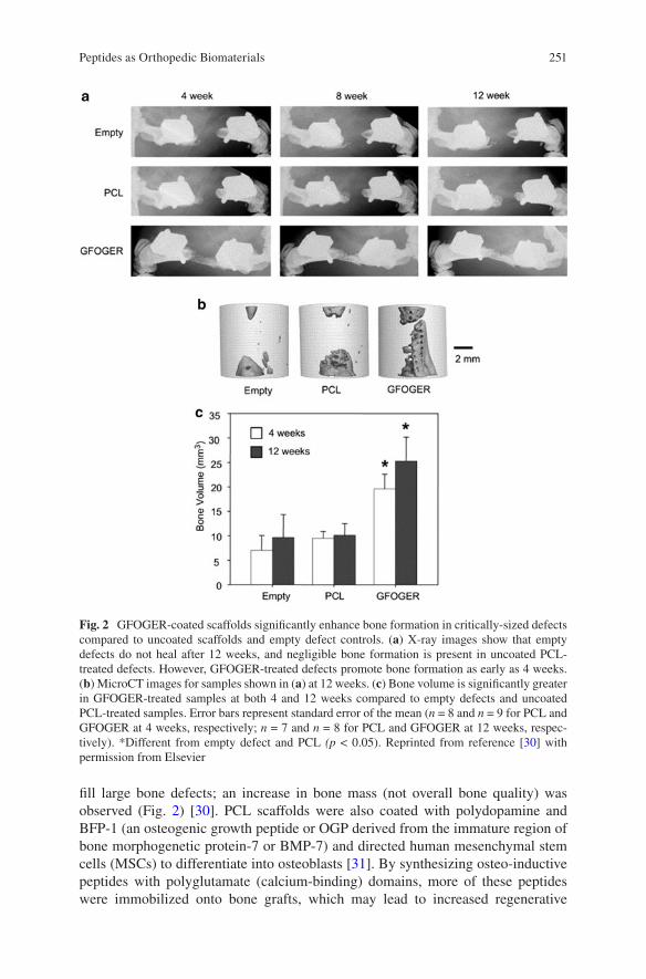
251
fill large bone defects; an increase in bone mass (not overall bone quality) was observed (Fig. 2) [30]. PCL scaffolds were also coated with polydopamine and BFP-1 (an osteogenic growth peptide or OGP derived from the immature region of bone morphogenetic protein-7 or BMP-7) and directed human mesenchymal stem cells (MSCs) to differentiate into osteoblasts [31]. By synthesizing osteo-inductive peptides with polyglutamate (calcium-binding) domains, more of these peptides were immobilized onto bone grafts, which may lead to increased regenerative
Fig. 2 GFOGER-coated scaffolds significantly enhance bone formation in critically-sized defects compared to uncoated scaffolds and empty defect controls. (a) X-ray images show that empty defects do not heal after 12 weeks, and negligible bone formation is present in uncoated PCL- treated defects. However, GFOGER-treated defects promote bone formation as early as 4 weeks. (b) MicroCT images for samples shown in (a) at 12 weeks. (c) Bone volume is significantly greater in GFOGER-treated samples at both 4 and 12 weeks compared to empty defects and uncoated PCL-treated samples. Error bars represent standard error of the mean (n = 8 and n = 9 for PCL and GFOGER at 4 weeks, respectively; n = 7 and n = 8 for PCL and GFOGER at 12 weeks, respec-tively). *Different from empty defect and PCL (p < 0.05). Reprinted from reference [30] with permission from Elsevier
Peptides as Orthopedic Biomaterials
252
capacity of bone while sustaining a controllable, adjustable release of DEGA pep-tide [32]. A similar study using calcium phosphate cement microspheres loaded with peptide P24, a bone morphogenetic protein-2 (BMP-2)-derived peptide, increased the time of release of P24 as well as increasing the proliferation of bone marrow stem cells [33]. Another study reported the use of PLGA scaffolds to immo-bilize P24 on their surfaces which led to enhanced seeding of human adipose derived stem cells, a higher osteogenic differentiation, more calcium mineralization, and better regenerative capacity compared to controls without P24 [34]. P24 was also shown to have a sustained release for 21 days when grafted onto polymer scaffolds, as well as increased alkaline phosphatase activity and osteogenic mRNA expression in rat MSCs [35]. In addition, coating of arg-gly-asp (RGD) peptides has increased the ability of osteoblasts to bind to implant surfaces and proliferate [36], and were able to induce bone marrow stromal cells and increased osteogenic gene transcrip-tion in rat models [37]. However, one study showed that not only would osteoblasts be more active, but osteoclasts would be as well [38].
Hydrogels have been developed from peptides. In a study by Kim et al. [39], scientists created peptide hydrogel scaffolds to mimic collagen and caused chondro-genic differentiation of rabbit bone marrow stem cells.
In addition, composites of peptides with other materials were reported. A com-plex of BMP-2, PLGA, and chitosan microspheres was injected into skull defects in rats and resulted in an increase in osteogenesis [40]. Composites of OGP and cel-lulose hydroxyapatite enhanced osteogenesis capability and improved the repair of rat cranial bone defects [41].
The pathways highlighted in this section exhibit great potential in the field of orthopedics. Whether it be nanoparticles, surface modification, hydrogels, or com-posites, each pathway has advantages and disadvantages. The application will dic-tate the pathway and the route and in vivo fate will dictate translation to clinical use.
3 Peptides for Orthopedic Applications
In this section, the most notable applications of peptide therapies in orthopedics are detailed. Table 1 presents a chart compiling various peptides and their current and potential orthopedic applications.
3.1 Antimicrobial Peptides
Antimicrobial peptides (AMPs) are the focus of a rapidly expanding niche of medi-cal research focused on the treatment of pathogenic organisms as well as microbial resistance. AMPs have been found in fetal tissues which help to bridge the gap between neonatal life and the formation of immunity. Certain AMPs, such as the human defensins, are expressed in the infant gut in utero. Within the respiratory
D. E. Andreini et al.
253
Table 1 Peptides for orthopedic applications
Peptide Application example Reference
BFP-1 Induced human MSCs to differentiate into human osteoblasts
[18]
BMPs Currently being used by orthopedics for procedures such as long bone non-unions, lumbar fusion, and open tibial shaft fractures
[66–68]
Cell penetrating peptides Increased bone tumor targeting and promoted membrane transportation of chemotherapeutic drugs
[102]
Cathelicidins LL-37 suppressed the actions of LPS mediated TNF-α release and was effective against both intra- and extra-cellular S. aureus
[42, 43]
Citrullinated peptide Anti-citrullinated peptide antibodies served as a diagnostic measure, used to diagnose RA, and showed to be a marker in erosive arthritis in systemic lupus erythematosus
[79, 80, 103]
Collagen binding peptide Attachment to hyaluronic acid polymer increased bone formation
[65]
Cross-linked N-terminal telopeptide
May be able to indicate stability of implants [89]
Defensins Alpha-defensin may serve as a synovial fluid biomarker for the diagnosis of periprosthetic joint infection
[78]
d-Glucosamine and collagen peptide
Enhanced restoration of cartilage injuries in rabbits [60]
Dickkopf-1 derived peptides
Vaccination of these peptides promoted bone formation and bone mass in an osteoporosis model
[79]
Heparin mimetic peptide Increased production and activity of angiogenic growth factors such as VEGF
[63]
hLF1-11 Presented antimicrobial properties against Gram-positive, Gram-negative, and MRSA
[47]
IL-17R Served as a decoy receptor to reduce arthritic inflammation
[84]
KLDLKLDLKLDL (KLD12)
Self-assembling peptide created microenvironment conducive to bone formation
[57]
Knottin peptides May serve as diagnostics, therapeutics, and drug delivery vehicles
[104]
Mechano-growth factor E
Presented positive effects on osteoblast proliferation and promoted healing of rat tendon
[74, 105]
Nerve growth factor Anti-nerve growth factor antibody served to reduce arthritic inflammation
[82, 83]
Oliga-aspartic acid residues
Addition of oligo-aspartic acid residues targeted radiogallium to bone tissue
[7]
OP3-4 A combination of OP3-4 and BMP-2 increased bone regeneration
[106, 107]
Osteogenic growth peptide
Promoted new bone formation in New Zealand white rabbits
[108]
(continued)
Peptides as Orthopedic Biomaterials
254
tract, there are also a wide variety of AMPs that make up part of the innate immune system. These peptides can be secreted in saliva or expressed by the epithelium.
AMPs are being studied due to their unique mechanisms of action, high antimi-crobial effects, and relatively low microbial resistance. For instance, human cathe-licidins (e.g., LL-37) are found in neutrophils and macrophages as well as cells that line externally exposed surfaces (e.g., skin, lungs, gastrointestinal epithelium). Upon activation, LL-37 is released into infected tissue by neutrophils and macro-phages. LL-37 has been shown to suppress the actions of lipopolysaccharide (LPS) mediated tissue necrosis factor-alpha (TNF-α) release, to decrease the lethality of endotoxin in animal models [42], and to be effective against both intra- and extra- cellular bacteria [43].
The ability of AMPs to control the mediators of infection is important to their application in orthopedics, which spans from wound treatment to modulating the immune response to direct bacterial eradication. A few examples are discussed below.
AMPs have been studied for wound care and maintenance. The antimicrobial peptide Cys-KRIVKRIKKWLR or Cys-KR12, a motif from the human cathelicidin peptide (LL-37), was immobilized onto nanofiber membranes for wound care using click chemistry (Fig. 3). This AMP displayed antimicrobial activity against patho-genic bacterial strains including S. aureus, S. epidermidis, Pseudomonas aerugi-nosa (P. aeruginosa), and Escherichia coli, enhanced the proliferation of fibroblasts, and facilitated the proliferation and differentiation of keratinocytes [44].
Choe et al. has reported the antimicrobial and immunomodulatory characteristics of IDR-1018 (Figs. 4 and 5), a host defense peptide with a sequence of VRLIVAVRIWRR [45]. In a mouse implant model, IDR-1018 was not only
Table 1 (continued)
Peptide Application example Reference
Parathyroid hormone peptide PTHrP
Stimulated osteoblast proliferation and increased bone healing
[70, 109]
Preptin Increased mineralized bone in treating osteoporosis [110]Procollagen I C-terminal extension peptide
May be able to detect loosening after a total hip arthroplasty
[89]
(RADA)4 Self-assembling peptide created microenvironment conducive to bone formation
[51, 53–55, 60, 111]
RGD peptides Increased osteoblast binding to implant surfaces, enhanced cell interactions, and increased cell-cell adhesion leading to accelerated wound healing
[36, 75, 77]
Silk peptide Used in combination with RADA to create a microenvironment conducive to bone formation
[56]
SMOC1-EC Attaching to hydroxyapatite/β-tricalcium phosphate particles increased bone regeneration
[112]
(VEVSVKVS)2 Addition of phosphate and calcium to this peptide resulted in the production of hydroxyapatite
[65]
WP9QY (W9) peptide A combination of W9 and BMP-2 increased bone regeneration
[106]
D. E. Andreini et al.
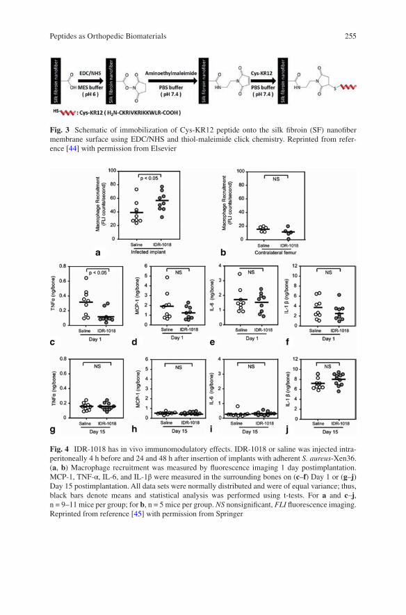
255
Fig. 3 Schematic of immobilization of Cys-KR12 peptide onto the silk fibroin (SF) nanofiber membrane surface using EDC/NHS and thiol-maleimide click chemistry. Reprinted from refer-ence [44] with permission from Elsevier
Fig. 4 IDR-1018 has in vivo immunomodulatory effects. IDR-1018 or saline was injected intra-peritoneally 4 h before and 24 and 48 h after insertion of implants with adherent S. aureus-Xen36. (a, b) Macrophage recruitment was measured by fluorescence imaging 1 day postimplantation. MCP-1, TNF-α, IL-6, and IL-1β were measured in the surrounding bones on (c–f) Day 1 or (g–j) Day 15 postimplantation. All data sets were normally distributed and were of equal variance; thus, black bars denote means and statistical analysis was performed using t-tests. For a and c–j, n = 9–11 mice per group; for b, n = 5 mice per group. NS nonsignificant, FLI fluorescence imaging. Reprinted from reference [45] with permission from Springer
Peptides as Orthopedic Biomaterials
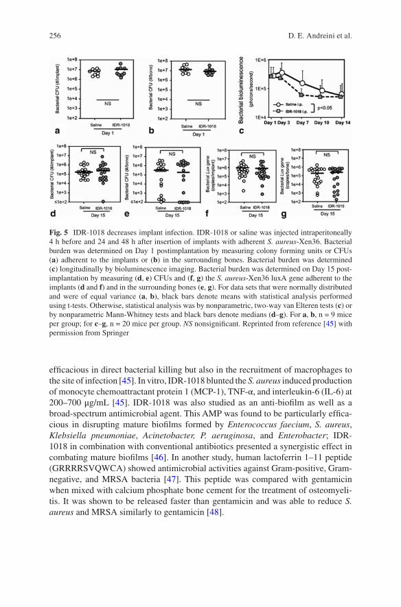
256
efficacious in direct bacterial killing but also in the recruitment of macrophages to the site of infection [45]. In vitro, IDR-1018 blunted the S. aureus induced production of monocyte chemoattractant protein 1 (MCP-1), TNF-α, and interleukin-6 (IL-6) at 200–700 μg/mL [45]. IDR-1018 was also studied as an anti-biofilm as well as a broad-spectrum antimicrobial agent. This AMP was found to be particularly effica-cious in disrupting mature biofilms formed by Enterococcus faecium, S. aureus, Klebsiella pneumoniae, Acinetobacter, P. aeruginosa, and Enterobacter; IDR- 1018 in combination with conventional antibiotics presented a synergistic effect in combating mature biofilms [46]. In another study, human lactoferrin 1–11 peptide (GRRRRSVQWCA) showed antimicrobial activities against Gram-positive, Gram-negative, and MRSA bacteria [47]. This peptide was compared with gentamicin when mixed with calcium phosphate bone cement for the treatment of osteomyeli-tis. It was shown to be released faster than gentamicin and was able to reduce S. aureus and MRSA similarly to gentamicin [48].
Fig. 5 IDR-1018 decreases implant infection. IDR-1018 or saline was injected intraperitoneally 4 h before and 24 and 48 h after insertion of implants with adherent S. aureus-Xen36. Bacterial burden was determined on Day 1 postimplantation by measuring colony forming units or CFUs (a) adherent to the implants or (b) in the surrounding bones. Bacterial burden was determined (c) longitudinally by bioluminescence imaging. Bacterial burden was determined on Day 15 post-implantation by measuring (d, e) CFUs and (f, g) the S. aureus-Xen36 luxA gene adherent to the implants (d and f) and in the surrounding bones (e, g). For data sets that were normally distributed and were of equal variance (a, b), black bars denote means with statistical analysis performed using t-tests. Otherwise, statistical analysis was by nonparametric, two-way van Elteren tests (c) or by nonparametric Mann-Whitney tests and black bars denote medians (d–g). For a, b, n = 9 mice per group; for c–g, n = 20 mice per group. NS nonsignificant. Reprinted from reference [45] with permission from Springer
D. E. Andreini et al.
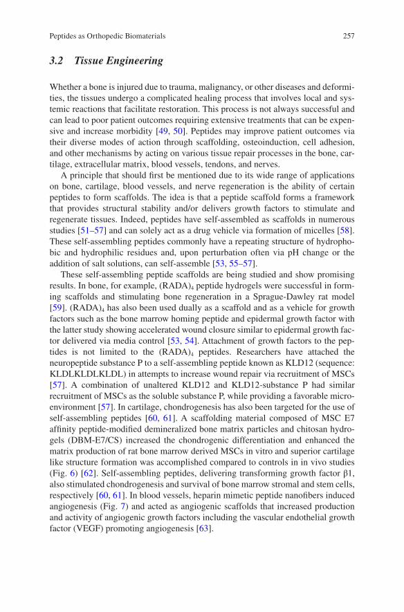
257
3.2 Tissue Engineering
Whether a bone is injured due to trauma, malignancy, or other diseases and deformi-ties, the tissues undergo a complicated healing process that involves local and sys-temic reactions that facilitate restoration. This process is not always successful and can lead to poor patient outcomes requiring extensive treatments that can be expen-sive and increase morbidity [49, 50]. Peptides may improve patient outcomes via their diverse modes of action through scaffolding, osteoinduction, cell adhesion, and other mechanisms by acting on various tissue repair processes in the bone, car-tilage, extracellular matrix, blood vessels, tendons, and nerves.
A principle that should first be mentioned due to its wide range of applications on bone, cartilage, blood vessels, and nerve regeneration is the ability of certain peptides to form scaffolds. The idea is that a peptide scaffold forms a framework that provides structural stability and/or delivers growth factors to stimulate and regenerate tissues. Indeed, peptides have self-assembled as scaffolds in numerous studies [51–57] and can solely act as a drug vehicle via formation of micelles [58]. These self-assembling peptides commonly have a repeating structure of hydropho-bic and hydrophilic residues and, upon perturbation often via pH change or the addition of salt solutions, can self-assemble [53, 55–57].
These self-assembling peptide scaffolds are being studied and show promising results. In bone, for example, (RADA)4 peptide hydrogels were successful in form-ing scaffolds and stimulating bone regeneration in a Sprague-Dawley rat model [59]. (RADA)4 has also been used dually as a scaffold and as a vehicle for growth factors such as the bone marrow homing peptide and epidermal growth factor with the latter study showing accelerated wound closure similar to epidermal growth fac-tor delivered via media control [53, 54]. Attachment of growth factors to the pep-tides is not limited to the (RADA)4 peptides. Researchers have attached the neuropeptide substance P to a self-assembling peptide known as KLD12 (sequence: KLDLKLDLKLDL) in attempts to increase wound repair via recruitment of MSCs [57]. A combination of unaltered KLD12 and KLD12-substance P had similar recruitment of MSCs as the soluble substance P, while providing a favorable micro-environment [57]. In cartilage, chondrogenesis has also been targeted for the use of self-assembling peptides [60, 61]. A scaffolding material composed of MSC E7 affinity peptide-modified demineralized bone matrix particles and chitosan hydro-gels (DBM-E7/CS) increased the chondrogenic differentiation and enhanced the matrix production of rat bone marrow derived MSCs in vitro and superior cartilage like structure formation was accomplished compared to controls in in vivo studies (Fig. 6) [62]. Self-assembling peptides, delivering transforming growth factor β1, also stimulated chondrogenesis and survival of bone marrow stromal and stem cells, respectively [60, 61]. In blood vessels, heparin mimetic peptide nanofibers induced angiogenesis (Fig. 7) and acted as angiogenic scaffolds that increased production and activity of angiogenic growth factors including the vascular endothelial growth factor (VEGF) promoting angiogenesis [63].
Peptides as Orthopedic Biomaterials
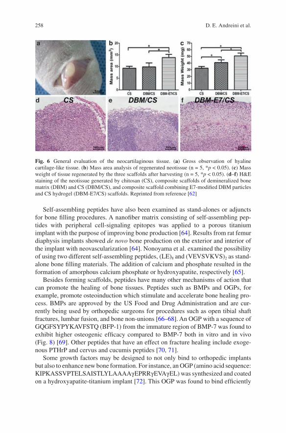
258
Self-assembling peptides have also been examined as stand-alones or adjuncts for bone filling procedures. A nanofiber matrix consisting of self-assembling pep-tides with peripheral cell-signaling epitopes was applied to a porous titanium implant with the purpose of improving bone production [64]. Results from rat femur diaphysis implants showed de novo bone production on the exterior and interior of the implant with neovascularization [64]. Nonoyama et al. examined the possibility of using two different self-assembling peptides, (LE)8 and (VEVSVKVS)2 as stand- alone bone filling materials. The addition of calcium and phosphate resulted in the formation of amorphous calcium phosphate or hydroxyapatite, respectively [65].
Besides forming scaffolds, peptides have many other mechanisms of action that can promote the healing of bone tissues. Peptides such as BMPs and OGPs, for example, promote osteoinduction which stimulate and accelerate bone healing pro-cess. BMPs are approved by the US Food and Drug Administration and are cur-rently being used by orthopedic surgeons for procedures such as open tibial shaft fractures, lumbar fusion, and bone non-unions [66–68]. An OGP with a sequence of GQGFSYPYKAVFSTQ (BFP-1) from the immature region of BMP-7 was found to exhibit higher osteogenic efficacy compared to BMP-7 both in vitro and in vivo (Fig. 8) [69]. Other peptides that have an effect on fracture healing include exoge-nous PTHrP and cervus and cucumis peptides [70, 71].
Some growth factors may be designed to not only bind to orthopedic implants but also to enhance new bone formation. For instance, an OGP (amino acid sequence: KIPKASSVPTELSAISTLYLAAAAγEPRRγEVAγEL) was synthesized and coated on a hydroxyapatite-titanium implant [72]. This OGP was found to bind efficiently
Fig. 6 General evaluation of the neocartilaginous tissue. (a) Gross observation of hyaline cartilage- like tissue. (b) Mass area analysis of regenerated neotissue (n = 5, *p < 0.05). (c) Mass weight of tissue regenerated by the three scaffolds after harvesting (n = 5, *p < 0.05). (d–f) H&E staining of the neotissue generated by chitosan (CS), composite scaffolds of demineralized bone matrix (DBM) and CS (DBM/CS), and composite scaffold combining E7-modified DBM particles and CS hydrogel (DBM-E7/CS) scaffolds. Reprinted from reference [62]
D. E. Andreini et al.
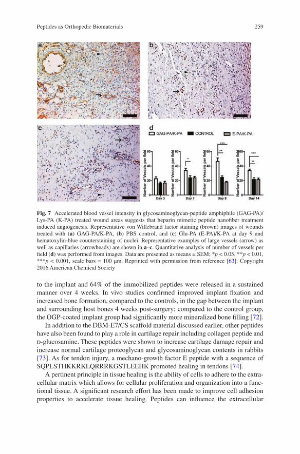
259
to the implant and 64% of the immobilized peptides were released in a sustained manner over 4 weeks. In vivo studies confirmed improved implant fixation and increased bone formation, compared to the controls, in the gap between the implant and surrounding host bones 4 weeks post-surgery; compared to the control group, the OGP-coated implant group had significantly more mineralized bone filling [72].
In addition to the DBM-E7/CS scaffold material discussed earlier, other peptides have also been found to play a role in cartilage repair including collagen peptide and d-glucosamine. These peptides were shown to increase cartilage damage repair and increase normal cartilage proteoglycan and glycosaminoglycan contents in rabbits [73]. As for tendon injury, a mechano-growth factor E peptide with a sequence of SQPLSTHKKRKLQRRRKGSTLEEHK promoted healing in tendons [74].
A pertinent principle in tissue healing is the ability of cells to adhere to the extra-cellular matrix which allows for cellular proliferation and organization into a func-tional tissue. A significant research effort has been made to improve cell adhesion properties to accelerate tissue healing. Peptides can influence the extracellular
Fig. 7 Accelerated blood vessel intensity in glycosaminoglycan-peptide amphiphile (GAG-PA)/Lys-PA (K-PA) treated wound areas suggests that heparin mimetic peptide nanofiber treatment induced angiogenesis. Representative von Willebrand factor staining (brown) images of wounds treated with (a) GAG-PA/K-PA, (b) PBS control, and (c) Glu-PA (E-PA)/K-PA at day 9 and hematoxylin- blue counterstaining of nuclei. Representative examples of large vessels (arrow) as well as capillaries (arrowheads) are shown in a–c. Quantitative analysis of number of vessels per field (d) was performed from images. Data are presented as means ± SEM; *p < 0.05, **p < 0.01, ***p < 0.001, scale bars = 100 μm. Reprinted with permission from reference [63]. Copyright 2016 American Chemical Society
Peptides as Orthopedic Biomaterials
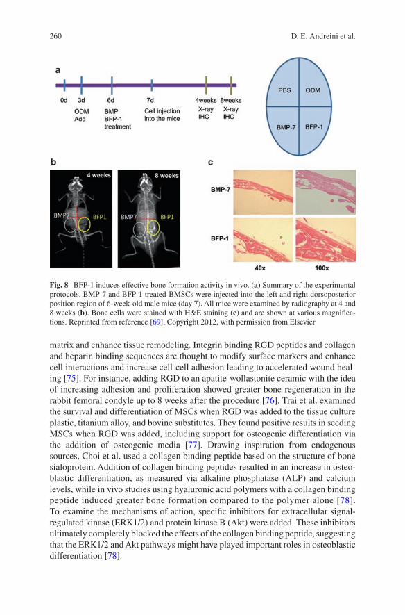
260
matrix and enhance tissue remodeling. Integrin binding RGD peptides and collagen and heparin binding sequences are thought to modify surface markers and enhance cell interactions and increase cell-cell adhesion leading to accelerated wound heal-ing [75]. For instance, adding RGD to an apatite-wollastonite ceramic with the idea of increasing adhesion and proliferation showed greater bone regeneration in the rabbit femoral condyle up to 8 weeks after the procedure [76]. Trai et al. examined the survival and differentiation of MSCs when RGD was added to the tissue culture plastic, titanium alloy, and bovine substitutes. They found positive results in seeding MSCs when RGD was added, including support for osteogenic differentiation via the addition of osteogenic media [77]. Drawing inspiration from endogenous sources, Choi et al. used a collagen binding peptide based on the structure of bone sialoprotein. Addition of collagen binding peptides resulted in an increase in osteo-blastic differentiation, as measured via alkaline phosphatase (ALP) and calcium levels, while in vivo studies using hyaluronic acid polymers with a collagen binding peptide induced greater bone formation compared to the polymer alone [78]. To examine the mechanisms of action, specific inhibitors for extracellular signal- regulated kinase (ERK1/2) and protein kinase B (Akt) were added. These inhibitors ultimately completely blocked the effects of the collagen binding peptide, suggesting that the ERK1/2 and Akt pathways might have played important roles in osteoblastic differentiation [78].
Fig. 8 BFP-1 induces effective bone formation activity in vivo. (a) Summary of the experimental protocols. BMP-7 and BFP-1 treated-BMSCs were injected into the left and right dorsoposterior position region of 6-week-old male mice (day 7). All mice were examined by radiography at 4 and 8 weeks (b). Bone cells were stained with H&E staining (c) and are shown at various magnifica-tions. Reprinted from reference [69], Copyright 2012, with permission from Elsevier
D. E. Andreini et al.
261
3.3 Arthritis
The ability to diagnosis rheumatoid arthritis (RA) earlier in the course of the disease would be a boon for the treatment of RA. Several reviews have been conducted to examine the potential use of anti-cyclic citrullinated peptide (anti-CCP) antibodies, a well-known peptide biomarker, for the early diagnosis of RA [79, 80]. For instance, Barra et al. reviewed five studies that looked at the seroconversion of patients with early inflammatory arthritis and found minimal change in the quantity of anti-CCP antibodies after 5 years of follow-up [30]. However, a larger literature review by Whiting et al. found a positive likelihood ratio of second-generation anti-CCP anti-bodies to be 12.7 and a negative likelihood positive ratio of 0.45 [80]. In other words, the presence of the antibody should rule in RA, but lack of the antibody should not rule it out. Additionally, the study found a sensitivity of 0.67 and a speci-ficity of 0.96, indicating great promise for the biomarker to be used for the diagnosis of RA [67]. Anti-CCP has also been examined for its use in diagnosis of erosive arthritis in patients with systemic lupus erythematosus; anti-CCP was found to be highly specific for erosive arthritis at 0.918, suggesting a pathologic mechanism similar to RA [81].
In terms of treatment of osteoarthritis, various approaches have been taken. Nerve growth factor (NGF) is an important component in peripheral sensitization and canine studies showed that anti-NGF antibodies had positive results [82, 83]. The calcitonin gene-related peptide has also emerged as a possible target [83]. Additionally, interleukin (IL)-17 has been shown to be a player in arthritic bone destruction, activating the nuclear factor kappa-light-chain enhancer of the activated B cell (NF-κB) cascade [84]. As such, researchers generated a truncated IL-17 receptor that reduced the action of both IL-17A and IL-17F, an added benefit com-pared to specific IL-17 inhibitors [84].
3.4 Bone Tumor
Malignant tumors have posed a significant threat to society and are one of the lead-ing causes of death worldwide. Although our medical techniques have greatly evolved to treat cancer/tumor through resection and various chemotherapy agents, unfortunately, most chemotherapies are highly toxic. Orthopedics faces a challenge with a variety of bone tumors including osteosarcoma, chondrosarcoma, Ewing’s sarcoma, fibrosarcoma, and metastatic lesions. Peptides can contribute to bone tumor treatments in several aspects: drug delivery, imaging, diagnosis, and therapy.
Most chemotherapy drugs are nonspecific and affect cells that are rapidly dividing which, unfortunately, includes many healthy human cells, which is why most chemotherapies have adverse effects such as alopecia. Researchers have been look-ing for ideas to specifically target cancer/tumor cells. A copolymer consisting of a
Peptides as Orthopedic Biomaterials
262
chimeric peptide, poly(ethylene glycol), and poly(trimethylene carbonate) (Pep-b- PEG-b-PTMC) was synthesized; this peptide-conjugated diblock copolymer was capable of targeting the bones and pathology-responsive charge reversal that could improve cellular uptake [85]. This dual action of specific targeting and increased drug internalization could mean greater therapeutic efficacy. Pep-b-PEG-b-PTMC has a unique mechanism of action for targeting bone metastatic tumors. In the pres-ence of cathepsin K, which is overexpressed in bone metastatic microenvironments, the Pep-b-PEG-b-PTMC exhibited a negative-to-positive charge conversion that led to enhanced cellular uptake of the peptide specifically at the bone metastatic site. Researchers have taken this concept one step further and attached doxorubicin, a chemotherapeutic agent, to the Pep-b-PEG-b-PTMC and achieved a greater thera-peutic efficacy at bone tumor sites [85].
Certain peptides can also be used for tumor receptor imaging and diagnostic purposes. The principle to complete this task is relatively simple. Different tumors overexpress specific receptors; by targeting these receptors through the injection of radiolabeled peptides, one may be able to assess receptor expression, facilitate early diagnosis, optimize therapy, and monitor tumor progression or regression [86]. An example would be iodine-123 labeled vasoactive intestinal peptide which may tar-get a variety of gastrointestinal tumors. After 1 h post injection, visualization of primary tumors and metastases was achieved [87].
Interestingly, researchers have expanded the idea of peptide specificity for tumor receptors for therapeutic use. Such therapies can act through a variety of mecha-nisms. Peptides can act through an antagonizing fashion to slow the progression of tumor growth or they can be attached to a toxic substance that eliminates the tumor. Wang et al. utilized an interesting approach of photothermal therapy to treat bone tumors. They used an aspartate octapeptide-modified dendritic platinum-copper alloy nanoparticle which has a high affinity toward hydroxyapatite and bone frag-ments. It successfully accumulated efficiently around bone tumors in vivo, depressed tumor growth, and reduced osteoclastic bone destruction through photothermal therapy [88].
3.5 Biomarkers for Diagnostic
In almost all fields of medicine, it is important to diagnose complications before they spiral out of control. In orthopedics, for example, periprosthetic joint infection (PJI) is a primary complication of total joint arthroplasty which can result in devas-tating outcomes such as amputation and even death. Diagnosis and treatment can be complex and challenging, however. Thus, researchers are constantly in search of new ways to help diagnose complications such as PJI. As biomarkers, peptides can contribute to early diagnosis of certain complications.
A biomarker can be any substance or structure that can be determined in the body and can be used to predict a disease. In orthopedics, peptide biomarkers can be used to help diagnose bone related diseases such as RA, discussed previously, and may
D. E. Andreini et al.
263
detect loosening of a hip arthroplasty or infection. For instance, procollagen I C-terminal extension peptide and cross-linked N-terminal telopeptide have been studied for the detection of implant loosening after a total hip arthroplasty. It was found that the serum levels of procollagen I C-terminal extension peptide was sig-nificantly lower in patients with osteoarthritis and those with loosening implants compared to those with stable implants; the levels of cross-linked N-terminal telo-peptide may be able to indicate the stability of an implant [89]. Peptide biomarkers may also be able to help identify PJI. Studies have shown that alpha-defensin, an endogenous peptide of the host-defense innate immunity, could be a useful synovial fluid biomarker for the diagnosis of PJI, and could be more accurate compared to serum biomarkers in the diagnosis of PJI [90].
3.6 Miscellaneous
Osteoporosis is a common malady, especially in post-menopausal women. The Wnt pathway is a known facet of bone formation and regeneration, and as such, inhibi-tors of this pathway offer attractive pharmaceutical targets. Wu et al. vaccinated female mice with dickkopf-1, a Wnt pathway inhibitor, derived peptides, and observed an increase in trabecular bone mass [91]. However, other studies found contrasting results and warrant further examination [91].
Finally, the natural world offers an abundance of inspiration in all areas of sci-ence. Nasri et al. examined the sphere of marine life for possible anti-coagulant peptides. Their review indicated a variety of natural anti-coagulants and bioactive peptides resulting from proteolysis that could hold therapeutic potential [92].
4 Challenges
Great advances have been made in the field of peptides and their application in orthopedics. In vitro and in vivo studies have shown that there are tremendous opportunities but also major challenges. Most peptides have short in vivo half lives, low solubility, and may undergo proteolytic degradation. Numerous barriers, such as the human gastrointestinal tract and immune system, must be evaded. Therefore, how can peptides be made efficacious in the human body? Facing these challenges, scientists and engineers have been striving to enhance the in vivo efficacy of pep-tides by altering amino acid sequences, conjugating peptides with various other molecules, combining peptides to create synergy, and utilizing drug vehicles.
Conjugation, in simple terms, is the process of linking molecules together. Peptides can be conjugated to chemical groups to increase therapeutic efficacy. Poly(ethylene glycol) or PEG, for example, has been shown to prevent destruction of peptides by ultimately shielding the peptides from the immune system and pro-teolytic enzymes. PEGylation also increases the size of the peptide, reducing filtra-
Peptides as Orthopedic Biomaterials
264
tion and excretion by the kidney [93] which increases the amount of peptide present in the body. Although this process seems great in theory, researchers are facing challenges with PEGylating the proper site on peptides [93, 94].
Another promising method to increase the in vivo efficacy of peptides is using them synergistically. Certain peptides, when used in combination, can increase the effects of one another as compared to being used independently. Researchers have shown this to be effective in the laboratory but synergism has yet to be put to the test in humans [95, 96]. An interesting thought would be forming a peptide that acts synergistically with the natural peptides found in the human body. That way, pep-tides could become activated at specific targets, thus increasing therapeutic efficacy.
There has also been significant research in enhancing the bioavailability of pep-tides via the use of permeation enhancers. Intestinal permeation enhancers are one of the most widely tested strategies. Over 250 permeation enhancers have shown improved intestinal permeability in a pre-clinical drug delivery model; however, clinical evaluation has been limited [97]. Multiple other strategies including nano-carriers, liposome encapsulation, and xynelation have also been used [98–100]. They have various mechanisms of action and can enhance the efficacy of peptides by increasing peptide half life and stability which may help peptides survive and penetrate the gastrointestinal epithelium allowing them to be used in clinical applications.
Throughout this book chapter, we have noted many of the positive results for the use of peptides in orthopedics. It is important to note that studies have also shown negative outcomes. In the tissue engineering portion, in particular, we noted several peptides, such as BMPs and OGPs, that had positive effects on the growth of bone. There have also been studies that have not been successful in showing peptide effec-tiveness. For instance, it was hypothesized that an organic bovine-derived hydroxy-apatite (ABM) in combination with a binding peptide (P-15) would promote healing of cortical bone defects based on its capacity to improve the healing of periodontal defects; however, results did not support the hypothesis and it was concluded that ABM/P-15 was not suitable for treating defects in long bones [101].
5 Summary
The application of peptides in orthopedics is rapidly expanding as new research continues to demonstrate their unique capabilities. Their ability to be structurally modified allows them to be highly specific for a multitude of jobs ranging from diagnosing bone tumors to accelerating the bone healing process. The industry has greatly evolved and some peptides, such as BMPs, are already being used clinically. Many others possess great potential and have shown promising results in in vitro and in vivo studies. Challenges lie in making these peptides efficacious within the human body, but advances such as intestinal permeation enhancers and nanocarriers are making peptide therapeutics possible in the near future. With this being said,
D. E. Andreini et al.
265
peptides open a realm of unseen orthopedic advances that will enhance patient outcomes.
Acknowledgement We acknowledge financial support from AO Foundation (Project S-13-15 L was supported by the AO Foundation), Osteosynthesis & Trauma Care Foundation, the West Virginia National Aeronautics and Space Administration Experimental Program to Stimulate Competitive Research (WV NASA EPSCoR), NIH Grant P20GM103434, and the National Institute of General Medical Sciences of the National Institutes of Health under Award Number 2U54GM104942-02. This work was also supported by the Office of the Assistant Secretary of Defense for Health Affairs, through the Peer Reviewed Medical Research Program, Discovery Award under Award No. W81XWH-17-1-0603. Opinions, interpretations, conclusions, and recom-mendations are those of the authors and are not necessarily endorsed by the funding agencies. C.B., D.A., and Z.W. acknowledge fellowships from WVU Intro program. We thank Suzanne Danley for proofreading.
References
1. Li Y. Recombinant production of antimicrobial peptides in Escherichia coli: a review. Protein Expr Purif. 2011;80(2):260–7.
2. Liu M, Wang Y, Liu Y, Ruan R. Bioactive peptides derived from traditional Chinese medicine and traditional Chinese food: a review. Food Res Int. 2016;89:63–73.
3. Singh BP, Vij S, Hati S. Functional significance of bioactive peptides derived from soybean. Peptides. 2014;54:171–9.
4. Vlieghe P, Lisowski V, Martinez J, Khrestchatisky M. Synthetic therapeutic peptides: science and market. Drug Discov Today. 2010;15(1):40–56.
5. Chesnut C, Azria M, Silverman S, Engelhardt M, Olson M, Mindeholm L. Salmon calcitonin: a review of current and future therapeutic indications. Osteoporos Int. 2008;19(4):479–91.
6. Ray MV, Meenan CP, Consalvo AP, Smith CA, Parton DP, Sturmer AM, Shields PP, Mehta NM. Production of salmon calcitonin by direct expression of a glycine-extended precursor in Escherichia coli. Protein Expr Purif. 2002;26(2):249–59.
7. Ogawa K, Ishizaki A, Takai K, Kitamura Y, Kiwada T, Shiba K, Odani A. Development of novel radiogallium-labeled bone imaging agents using oligo-aspartic acid peptides as carri-ers. PLoS One. 2013;8(12):e84335.
8. Andersson L, Blomberg L, Flegel M, Lepsa L, Nilsson B, Verlander M. Large‐scale synthesis of peptides. Pept Sci. 2000;55(3):227–50.
9. Li H, Aneja R, Chaiken I. Click chemistry in peptide-based drug design. Molecules. 2013;18(8):9797–817.
10. Muheem A, Shakeel F, Jahangir MA, Anwar M, Mallick N, Jain GK, Warsi MH, Ahmad FJ. A review on the strategies for oral delivery of proteins and peptides and their clinical perspectives. Saudi Pharm J. 2016;24(4):413–28.
11. Gupta S, Jain A, Chakraborty M, Sahni JK, Ali J, Dang S. Oral delivery of therapeutic pro-teins and peptides: a review on recent developments. Drug Deliv. 2013;20(6):237–46.
12. Chereddy KK, Her CH, Comune M, Moia C, Lopes A, Porporato PE, Vanacker J, Lam MC, Steinstraesser L, Sonveaux P, Zhu H, Ferreira LS, Vandermeulen G, Preat V. PLGA nanoparticles loaded with host defense peptide LL37 promote wound healing. J Control Release. 2014;194:138–47.
13. Karimi M, Mirshekari H, Moosavi Basri SM, Bahrami S, Moghoofei M, Hamblin MR. Bacteriophages and phage-inspired nanocarriers for targeted delivery of therapeutic car-gos. Adv Drug Deliv Rev. 2016;106(Pt A):45–62. PMCID:Pmc5026880
14. Barros SM, Whitaker SK, Sukthankar P, Avila LA, Gudlur S, Warner M, Beltrao EI, Tomich JM. A review of solute encapsulating nanoparticles used as delivery systems with empha-
Peptides as Orthopedic Biomaterials
266
sis on branched amphipathic peptide capsules. Arch Biochem Biophys. 2016;596:22–42. PMCID:Pmc4841695
15. Chen WY, Chang HY, JK L, Huang YC, Harroun SG, Tseng YT, Li YJ, Huang CC, Chang HT. Self‐assembly of antimicrobial peptides on gold nanodots: against multidrug‐resistant bacteria and wound‐healing application. Adv Funct Mater. 2015;25(46):7189–99.
16. Cheng H, Yue K, Kazemzadeh-Narbat M, Liu Y, Khalilpour A, Li B, Zhang YS, Annabi N, Khademhosseini A. Mussel-inspired multifunctional hydrogel coating for prevention of infections and enhanced osteogenesis. ACS Appl Mater Interfaces. 2017;9(13):11428–39.
17. Zhao QH, Li HS, Li BY. Nanoencapsulating living biological cells using electrostatic layer- by- layer self-assembly: Platelets as a model. J Mater Res. 2011;26(2):347–51.
18. Jiang BB, DeFusco E, Li BY. Polypeptide multilayer film co-delivers oppositely-charged drug molecules in sustained manners. Biomacromolecules. 2010;11(12):3630–7.
19. Li HS, Ogle H, Jiang BB, Hagar M, Li BY. Cefazolin embedded biodegradable polypeptide nanofilms promising for infection prevention: a preliminary study on cell responses. J Orthop Res. 2010;28(8):992–9.
20. Li B, Jiang B, Dietz MJ, Smith ES, Clovis NB, Rao KM. Evaluation of local MCP-1 and IL-12 nanocoatings for infection prevention in open fractures. J Orthop Res. 2010;28(1):48–54. PMCID:PMC3886371
21. Li B, Jiang B, Boyce BM, Lindsey BA. Multilayer polypeptide nanoscale coatings incor-porating IL-12 for the prevention of biomedical device-associated infections. Biomaterials. 2009;30(13):2552–8. PMCID:PMC3699876
22. Jiang B, Li B. Tunable drug loading and release from polypeptide multilayer nanofilms. Int J Nanomed. 2009;4:37–53. PMCID:PMC2720742
23. Jiang B, Li B. Polypeptide nanocoatings for preventing dental and orthopaedic device- associated infection: pH-induced antibiotic capture, release, and antibiotic efficacy. J Biomed Mater Res B Appl Biomater. 2009;88((2):332–8.
24. Jiang B, Barnett JB, Li B. Advances in polyelectrolyte multilayer nanofilms as tunable drug delivery systems. Nanotechnol Sci Appl. 2009;2:21.
25. Likibi F, Jiang BB, Li BY. Biomimetic nanocoating promotes osteoblast cell adhesion on biomedical implants. J Mater Res. 2008;23(12):3222–8.
26. Li BY, Haynie DT. Multilayer biomimetics: Reversible covalent stabilization of a nanostruc-tured biofilm. Biomacromolecules. 2004;5(5):1667–70.
27. Li B, Haynie DT, Palath N, Janisch D. Nanoscale biomimetics: fabrication and optimization of stability of peptide-based thin films. J Nanosci Nanotechnol. 2005;5(12):2042–9.
28. Li B, Rozas J, Haynie DT. Structural stability of polypeptide nanofilms under extreme condi-tions. Biotechnol Prog. 2006;22(1):111–7.
29. Ardura JA, Portal-Nunez S, Lozano D, Gutierrez-Rojas I, Sanchez-Salcedo S, Lopez- Herradon A, Mulero F, Villanueva-Penacarrillo ML, Vallet-Regi M, Esbrit P. Local delivery of parathyroid hormone-related protein-derived peptides coated onto a hydroxyapatite- based implant enhances bone regeneration in old and diabetic rats. J Biomed Mater Res A. 2016;104(8):2060–70.
30. Wojtowicz AM, Shekaran A, Oest ME, Dupont KM, Templeman KL, Hutmacher DW, Guldberg RE, Garcia AJ. Coating of biomaterial scaffolds with the collagen-mimetic peptide GFOGER for bone defect repair. Biomaterials. 2010;31(9):2574–82. PMCID:Pmc2813962
31. Gao X, Zhang X, Song J, Xu X, Xu A, Wang M, Xie B, Huang E, Deng F, Wei S. Osteoinductive peptide-functionalized nanofibers with highly ordered structure as biomimetic scaffolds for bone tissue engineering. Int J Nanomed. 2015;10:7109–28. PMCID:Pmc4655957
32. Bain JL, Culpepper BK, Reddy MS, Bellis SL. Comparing variable-length polyglutamate domains to anchor an osteoinductive collagen-mimetic peptide to diverse bone grafting mate-rials. Int J Oral Maxillofac Implants. 2014;29(6):1437–45. PMCID:Pmc4504020
33. Liu R, Wu X, Li J, Liu X, Huang Z, Yuan Y, Gao X, Lin B, Yu B, Chen Y. The promotion of bone tissue regeneration by BMP2-derived peptide P24-loaded calcium phosphate cement microspheres. Ceram Int. 2016;42(2):3177–89.
D. E. Andreini et al.
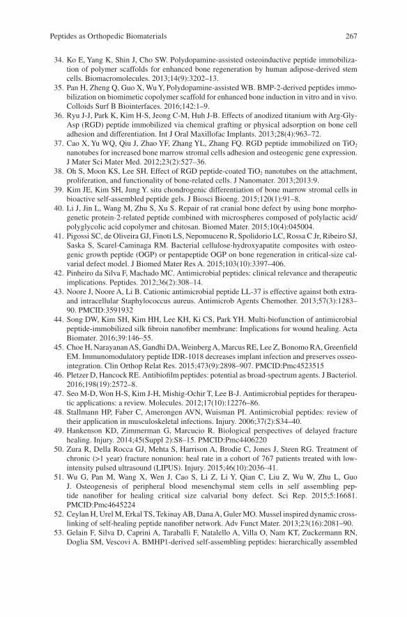
267
34. Ko E, Yang K, Shin J, Cho SW. Polydopamine-assisted osteoinductive peptide immobiliza-tion of polymer scaffolds for enhanced bone regeneration by human adipose-derived stem cells. Biomacromolecules. 2013;14(9):3202–13.
35. Pan H, Zheng Q, Guo X, Wu Y, Polydopamine-assisted WB. BMP-2-derived peptides immo-bilization on biomimetic copolymer scaffold for enhanced bone induction in vitro and in vivo. Colloids Surf B Biointerfaces. 2016;142:1–9.
36. Ryu J-J, Park K, Kim H-S, Jeong C-M, Huh J-B. Effects of anodized titanium with Arg-Gly- Asp (RGD) peptide immobilized via chemical grafting or physical adsorption on bone cell adhesion and differentiation. Int J Oral Maxillofac Implants. 2013;28(4):963–72.
37. Cao X, Yu WQ, Qiu J, Zhao YF, Zhang YL, Zhang FQ. RGD peptide immobilized on TiO2 nanotubes for increased bone marrow stromal cells adhesion and osteogenic gene expression. J Mater Sci Mater Med. 2012;23(2):527–36.
38. Oh S, Moon KS, Lee SH. Effect of RGD peptide-coated TiO2 nanotubes on the attachment, proliferation, and functionality of bone-related cells. J Nanomater. 2013;2013:9.
39. Kim JE, Kim SH, Jung Y. situ chondrogenic differentiation of bone marrow stromal cells in bioactive self-assembled peptide gels. J Biosci Bioeng. 2015;120(1):91–8.
40. Li J, Jin L, Wang M, Zhu S, Xu S. Repair of rat cranial bone defect by using bone morpho-genetic protein-2-related peptide combined with microspheres composed of polylactic acid/polyglycolic acid copolymer and chitosan. Biomed Mater. 2015;10(4):045004.
41. Pigossi SC, de Oliveira GJ, Finoti LS, Nepomuceno R, Spolidorio LC, Rossa C Jr, Ribeiro SJ, Saska S, Scarel-Caminaga RM. Bacterial cellulose-hydroxyapatite composites with osteo-genic growth peptide (OGP) or pentapeptide OGP on bone regeneration in critical-size cal-varial defect model. J Biomed Mater Res A. 2015;103(10):3397–406.
42. Pinheiro da Silva F, Machado MC. Antimicrobial peptides: clinical relevance and therapeutic implications. Peptides. 2012;36(2):308–14.
43. Noore J, Noore A, Li B. Cationic antimicrobial peptide LL-37 is effective against both extra- and intracellular Staphylococcus aureus. Antimicrob Agents Chemother. 2013;57(3):1283–90. PMCID:3591932
44. Song DW, Kim SH, Kim HH, Lee KH, Ki CS, Park YH. Multi-biofunction of antimicrobial peptide-immobilized silk fibroin nanofiber membrane: Implications for wound healing. Acta Biomater. 2016;39:146–55.
45. Choe H, Narayanan AS, Gandhi DA, Weinberg A, Marcus RE, Lee Z, Bonomo RA, Greenfield EM. Immunomodulatory peptide IDR-1018 decreases implant infection and preserves osseo-integration. Clin Orthop Relat Res. 2015;473(9):2898–907. PMCID:Pmc4523515
46. Pletzer D, Hancock RE. Antibiofilm peptides: potential as broad-spectrum agents. J Bacteriol. 2016;198(19):2572–8.
47. Seo M-D, Won H-S, Kim J-H, Mishig-Ochir T, Lee B-J. Antimicrobial peptides for therapeu-tic applications: a review. Molecules. 2012;17(10):12276–86.
48. Stallmann HP, Faber C, Amerongen AVN, Wuisman PI. Antimicrobial peptides: review of their application in musculoskeletal infections. Injury. 2006;37(2):S34–40.
49. Hankenson KD, Zimmerman G, Marcucio R. Biological perspectives of delayed fracture healing. Injury. 2014;45(Suppl 2):S8–15. PMCID:Pmc4406220
50. Zura R, Della Rocca GJ, Mehta S, Harrison A, Brodie C, Jones J, Steen RG. Treatment of chronic (>1 year) fracture nonunion: heal rate in a cohort of 767 patients treated with low- intensity pulsed ultrasound (LIPUS). Injury. 2015;46(10):2036–41.
51. Wu G, Pan M, Wang X, Wen J, Cao S, Li Z, Li Y, Qian C, Liu Z, Wu W, Zhu L, Guo J. Osteogenesis of peripheral blood mesenchymal stem cells in self assembling pep-tide nanofiber for healing critical size calvarial bony defect. Sci Rep. 2015;5:16681. PMCID:Pmc4645224
52. Ceylan H, Urel M, Erkal TS, Tekinay AB, Dana A, Guler MO. Mussel inspired dynamic cross‐linking of self‐healing peptide nanofiber network. Adv Funct Mater. 2013;23(16):2081–90.
53. Gelain F, Silva D, Caprini A, Taraballi F, Natalello A, Villa O, Nam KT, Zuckermann RN, Doglia SM, Vescovi A. BMHP1-derived self-assembling peptides: hierarchically assembled
Peptides as Orthopedic Biomaterials
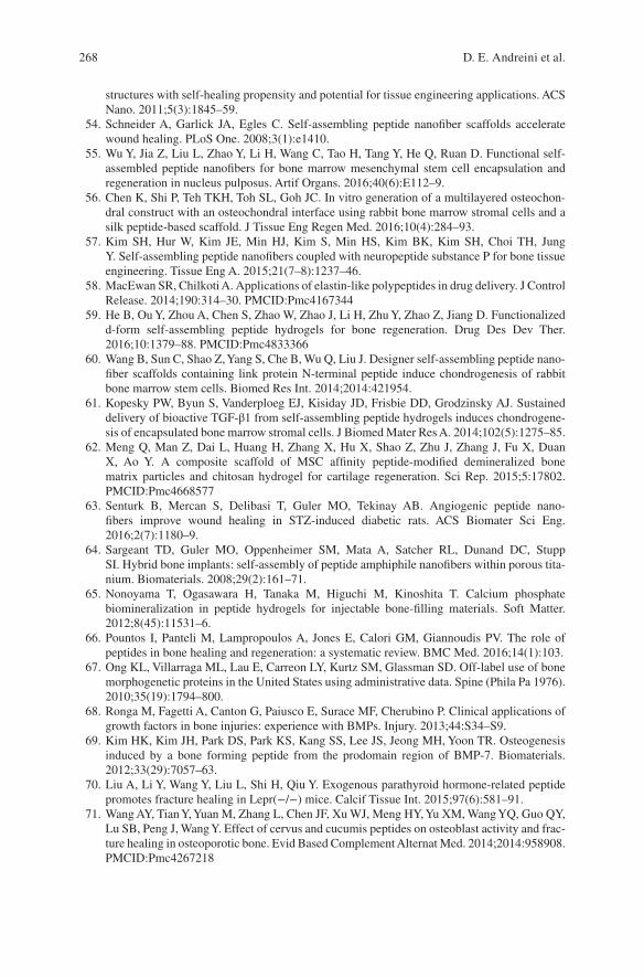
268
structures with self-healing propensity and potential for tissue engineering applications. ACS Nano. 2011;5(3):1845–59.
54. Schneider A, Garlick JA, Egles C. Self-assembling peptide nanofiber scaffolds accelerate wound healing. PLoS One. 2008;3(1):e1410.
55. Wu Y, Jia Z, Liu L, Zhao Y, Li H, Wang C, Tao H, Tang Y, He Q, Ruan D. Functional self‐assembled peptide nanofibers for bone marrow mesenchymal stem cell encapsulation and regeneration in nucleus pulposus. Artif Organs. 2016;40(6):E112–9.
56. Chen K, Shi P, Teh TKH, Toh SL, Goh JC. In vitro generation of a multilayered osteochon-dral construct with an osteochondral interface using rabbit bone marrow stromal cells and a silk peptide‐based scaffold. J Tissue Eng Regen Med. 2016;10(4):284–93.
57. Kim SH, Hur W, Kim JE, Min HJ, Kim S, Min HS, Kim BK, Kim SH, Choi TH, Jung Y. Self-assembling peptide nanofibers coupled with neuropeptide substance P for bone tissue engineering. Tissue Eng A. 2015;21(7–8):1237–46.
58. MacEwan SR, Chilkoti A. Applications of elastin-like polypeptides in drug delivery. J Control Release. 2014;190:314–30. PMCID:Pmc4167344
59. He B, Ou Y, Zhou A, Chen S, Zhao W, Zhao J, Li H, Zhu Y, Zhao Z, Jiang D. Functionalized d-form self-assembling peptide hydrogels for bone regeneration. Drug Des Dev Ther. 2016;10:1379–88. PMCID:Pmc4833366
60. Wang B, Sun C, Shao Z, Yang S, Che B, Wu Q, Liu J. Designer self-assembling peptide nano-fiber scaffolds containing link protein N-terminal peptide induce chondrogenesis of rabbit bone marrow stem cells. Biomed Res Int. 2014;2014:421954.
61. Kopesky PW, Byun S, Vanderploeg EJ, Kisiday JD, Frisbie DD, Grodzinsky AJ. Sustained delivery of bioactive TGF‐β1 from self‐assembling peptide hydrogels induces chondrogene-sis of encapsulated bone marrow stromal cells. J Biomed Mater Res A. 2014;102(5):1275–85.
62. Meng Q, Man Z, Dai L, Huang H, Zhang X, Hu X, Shao Z, Zhu J, Zhang J, Fu X, Duan X, Ao Y. A composite scaffold of MSC affinity peptide-modified demineralized bone matrix particles and chitosan hydrogel for cartilage regeneration. Sci Rep. 2015;5:17802. PMCID:Pmc4668577
63. Senturk B, Mercan S, Delibasi T, Guler MO, Tekinay AB. Angiogenic peptide nano-fibers improve wound healing in STZ-induced diabetic rats. ACS Biomater Sci Eng. 2016;2(7):1180–9.
64. Sargeant TD, Guler MO, Oppenheimer SM, Mata A, Satcher RL, Dunand DC, Stupp SI. Hybrid bone implants: self-assembly of peptide amphiphile nanofibers within porous tita-nium. Biomaterials. 2008;29(2):161–71.
65. Nonoyama T, Ogasawara H, Tanaka M, Higuchi M, Kinoshita T. Calcium phosphate biomineralization in peptide hydrogels for injectable bone-filling materials. Soft Matter. 2012;8(45):11531–6.
66. Pountos I, Panteli M, Lampropoulos A, Jones E, Calori GM, Giannoudis PV. The role of peptides in bone healing and regeneration: a systematic review. BMC Med. 2016;14(1):103.
67. Ong KL, Villarraga ML, Lau E, Carreon LY, Kurtz SM, Glassman SD. Off-label use of bone morphogenetic proteins in the United States using administrative data. Spine (Phila Pa 1976). 2010;35(19):1794–800.
68. Ronga M, Fagetti A, Canton G, Paiusco E, Surace MF, Cherubino P. Clinical applications of growth factors in bone injuries: experience with BMPs. Injury. 2013;44:S34–S9.
69. Kim HK, Kim JH, Park DS, Park KS, Kang SS, Lee JS, Jeong MH, Yoon TR. Osteogenesis induced by a bone forming peptide from the prodomain region of BMP-7. Biomaterials. 2012;33(29):7057–63.
70. Liu A, Li Y, Wang Y, Liu L, Shi H, Qiu Y. Exogenous parathyroid hormone-related peptide promotes fracture healing in Lepr(−/−) mice. Calcif Tissue Int. 2015;97(6):581–91.
71. Wang AY, Tian Y, Yuan M, Zhang L, Chen JF, Xu WJ, Meng HY, Yu XM, Wang YQ, Guo QY, Lu SB, Peng J, Wang Y. Effect of cervus and cucumis peptides on osteoblast activity and frac-ture healing in osteoporotic bone. Evid Based Complement Alternat Med. 2014;2014:958908. PMCID:Pmc4267218
D. E. Andreini et al.
269
72. Lu Y, Lee JS, Nemke B, Graf BK, Royalty K, Illgen R 3rd, Vanderby R Jr, Markel MD, Murphy WL. Coating with a modular bone morphogenetic peptide promotes healing of a bone-implant gap in an ovine model. PLoS One. 2012;7(11):e50378. PMCID:Pmc3503930
73. Hashida M, Miyatake K, Okamoto Y, Fujita K, Matumoto T, Morimatsu F, Sakamoto K, Minami S. Synergistic effects of D-glucosamine and collagen peptides on healing experimen-tal cartilage injury. Macromol Biosci. 2003;3(10):596–603.
74. Zhang B, Luo Q, Kuang D, Ju Y, Song G. Mechano-growth factor E peptide promotes healing of rat injured tendon. Biotechnol Lett. 2016;38(10):1817–25.
75. LeBaron RG, Athanasiou KA. Extracellular matrix cell adhesion peptides: functional appli-cations in orthopedic materials. Tissue Eng. 2000;6(2):85–103.
76. Zhang X, Gu J, Zhang Y, Tan Y, Zhou J, Zhou D. Immobilization of RGD peptide onto the surface of apatite-wollastonite ceramic for enhanced osteoblast adhesion and bone regenera-tion. J Wuhan Univ Technol Mater Sci Ed. 2014;29(3):626–34.
77. Tatrai P, Sagi B, Szigeti A, Szepesi A, Szabo I, Bosze S, Kristof Z, Marko K, Szakacs G, Urban I, Mezo G, Uher F, Nemet K. A novel cyclic RGD-containing peptide polymer improves serum-free adhesion of adipose tissue-derived mesenchymal stem cells to bone implant surfaces. J Mater Sci Mater Med. 2013;24(2):479–88.
78. Choi YJ, Lee JY, Chung CP, Park YJ. Enhanced osteogenesis by collagen-binding peptide from bone sialoprotein in vitro and in vivo. J Biomed Mater Res A. 2013;101((2):547–54.
79. Barra L, Pope J, Bessette L, Haraoui B, Bykerk V. Lack of seroconversion of rheumatoid factor and anti-cyclic citrullinated peptide in patients with early inflammatory arthritis: a systematic literature review. Rheumatology (Oxford). 2011;50(2):311–6.
80. Whiting PF, Smidt N, Sterne JA, Harbord R, Burton A, Burke M, Beynon R, Ben-Shlomo Y, Axford J, Dieppe P. Systematic review: accuracy of anti-citrullinated peptide antibodies for diagnosing rheumatoid arthritis. Ann Intern Med. 2010;152(7):456–64. w155-66
81. Van Steenbergen H, Ajeganova S, Forslind K, Svensson B, Van Der Helm-van Mil A. The effects of rheumatoid factor and anticitrullinated peptide antibodies on bone erosions in rheu-matoid arthritis. Ann Rheum Dis. 2015;74(1):e3.
82. Lascelles BDX, Knazovicky D, Case B, Freire M, Innes JF, Drew AC, Gearing DP. A canine- specific anti-nerve growth factor antibody alleviates pain and improves mobility and function in dogs with degenerative joint disease-associated pain. BMC Vet Res. 2015;11(1):101.
83. Malfait A-M, Miller RJ. Emerging targets for the management of osteoarthritis pain. Curr Osteoporos Rep. 2016;14(6):260–8.
84. Du Y, Tong Y, Mei W, Jia J, Niu M, Cao W, Lou W, Li S, Li Z, Stinson WA. A truncated IL‐17RC peptide ameliorates synovitis and bone destruction of arthritic mice. Adv Healthc Mater. 2016;5(22):2911–21.
85. Wang X, Yang Y, Jia H, Jia W, Miller S, Bowman B, Feng J, Zhan F. Peptide decoration of nanovehicles to achieve active targeting and pathology-responsive cellular uptake for bone metastasis chemotherapy. Biomater Sci. 2014;2(7):961–71. PMCID:Pmc4465575
86. Tang B, Yong X, Xie R, Li QW, Yang SM. Vasoactive intestinal peptide receptor-based imag-ing and treatment of tumors (review). Int J Oncol. 2014;44(4):1023–31.
87. Virgolini I, Raderer M, Kurtaran A, Angelberger P, Banyai S, Yang Q, Li S, Banyai M, Pidlich J, Niederle B, Scheithauer W, Valent P. Vasoactive intestinal peptide-receptor imag-ing for the localization of intestinal adenocarcinomas and endocrine tumors. N Engl J Med. 1994;331(17):1116–21.
88. Wang Y, Yang J, Liu H, Wang X, Zhou Z, Huang Q, Song D, Cai X, Li L, Lin K, Xiao J, Liu P, Zhang Q, Cheng Y. Osteotropic peptide-mediated bone targeting for photothermal treatment of bone tumors. Biomaterials. 2017;114:97–105.
89. Savarino L, Granchi D, Cenni E, Baldini N, Greco M, Giunti A. Systemic cross-linked N-terminal telopeptide and procollagen I C-terminal extension peptide as markers of bone turnover after total hip arthroplasty. J Bone Joint Surg Br. 2005;87(4):571–6.
Peptides as Orthopedic Biomaterials
270
90. Pupaibool J, Fulnecky EJ, Swords RL Jr, Sistrunk WW, Haddow AD. Alpha-defensin-novel synovial fluid biomarker for the diagnosis of periprosthetic joint infection. Int Orthop. 2016;40(12):2447–52.
91. Wu Q, Li RS, Zhao Y, Wang ZX, Tang YC, Zhang J, Liu JN, Tan XY. Vaccination with DKK1-derived peptides promotes bone formation and bone mass in an aged mouse osteopo-rosis model. Calcif Tissue Int. 2014;95(2):153–65.
92. Nasri R, Nasri M. Marine-derived bioactive peptides as new anticoagulant agents: a review. Curr Protein Pept Sci. 2013;14(3):199–204.
93. Roberts M, Bentley M, Harris J. Chemistry for peptide and protein PEGylation. Adv Drug Deliv Rev. 2012;64:116–27.
94. Veronese FM. Peptide and protein PEGylation: a review of problems and solutions. Biomaterials. 2001;22(5):405–17.
95. Liu Z, Tang Y, Kang T, Rao M, Li K, Wang Q, Quan C, Zhang C, Jiang Q, Shen H. Synergistic effect of HA and BMP-2 mimicking peptide on the bioactivity of HA/PMMA bone cement. Colloids Surf B Biointerfaces. 2015;131:39–46.
96. Moore NM, Lin NJ, Gallant ND, Becker ML. Synergistic enhancement of human bone mar-row stromal cell proliferation and osteogenic differentiation on BMP-2-derived and RGD peptide concentration gradients. Acta Biomater. 2011;7(5):2091–100.
97. Renukuntla J, Vadlapudi AD, Patel A, Boddu SH, Mitra AK. Approaches for enhanc-ing oral bioavailability of peptides and proteins. Int J Pharm. 2013;447(1–2):75–93. PMCID:Pmc3680128
98. Malhaire H, Gimel J-C, Roger E, Benoît J-P, Lagarce F. How to design the surface of peptide- loaded nanoparticles for efficient oral bioavailability? Adv Drug Deliv Rev. 2016;106:320–36.
99. Ron-Doitch S, Sawodny B, Kühbacher A, David MMN, Samanta A, Phopase J, Burger- Kentischer A, Griffith M, Golomb G, Rupp S. Reduced cytotoxicity and enhanced bioactivity of cationic antimicrobial peptides liposomes in cell cultures and 3D epidermis model against HSV. J Control Release. 2016;229:163–71.
100. Podust VN, Sim B-C, Kothari D, Henthorn L, Gu C, C-w W, McLaughlin B, Schellenberger V. Extension of in vivo half-life of biologically active peptides via chemical conjugation to XTEN protein polymer. Protein Eng Des Sel. 2013;26(11):743–53.
101. Sarahrudi K, Mousavi M, Grossschmidt K, Sela N, Konig F, Vecsei V, Aharinejad S. Combination of anorganic bovine-derived hydroxyapatite with binding peptide does not enhance bone healing in a critical-size defect in a rabbit model. J Orthop Res. 2008;26(6):759–63.
102. He H, Sun L, Ye J, Liu E, Chen S, Liang Q, Shin MC, Yang VC. Enzyme-triggered, cell pen-etrating peptide-mediated delivery of anti-tumor agents. J Control Release. 2016;240:67–76.
103. Budhram A, Chu R, Rusta-Sallehy S, Ioannidis G, Denburg J, Adachi J, Haaland D. Anti- cyclic citrullinated peptide antibody as a marker of erosive arthritis in patients with systemic lupus erythematosus: a systematic review and meta-analysis. Lupus. 2014;23(11):1156–63.
104. Kintzing JR, Cochran JR. Engineered knottin peptides as diagnostics, therapeutics, and drug delivery vehicles. Curr Opin Chem Biol. 2016;34:143–50.
105. Deng M, Zhang B, Wang K, Liu F, Xiao H, Zhao J, Liu P, Li Y, Lin F, Wang Y. Mechano growth factor E peptide promotes osteoblasts proliferation and bone-defect healing in rabbits. Int Orthop. 2011;35(7):1099–106.
106. Sugamori Y, Mise‐Omata S, Maeda C, Aoki S, Tabata Y, Murali R, Yasuda H, Udagawa N, Suzuki H, Honma M. Peptide drugs accelerate BMP‐2‐induced calvarial bone regen-eration and stimulate osteoblast differentiation through mTORC1 signaling. BioEssays. 2016;38(8):717–25.
107. Uehara T, Mise-Omata S, Matsui M, Tabata Y, Murali R, Miyashin M, Aoki K. Delivery of RANKL-binding peptide OP3-4 promotes BMP-2-induced maxillary bone regeneration. J Dent Res. 2016;95(6):665–72.
108. Zhao Z, Shao L, Zhao H, Zhong Z, Liu J, Hao C. Osteogenic growth peptide accelerates bone healing during distraction osteogenesis in rabbit tibia. J Int Med Res. 2011;39(2):456–63.
D. E. Andreini et al.
271
109. Whitfield JF, Motley P, Willick GE. Parathyroid hormone, its fragments and their analogs for the treatment of osteoporosis. Treat Endocrinol. 2002;1(3):175–90.
110. Amso Z, Kowalczyk R, Watson M, Park Y-E, Callon KE, Musson DS, Cornish J, Brimble MA. Structure activity relationship study on the peptide hormone preptin, a novel bone- anabolic agent for the treatment of osteoporosis. Org Biomol Chem. 2016;14(39):9225–38.
111. Hou T, Li Z, Luo F, Xie Z, Wu X, Xing J, Dong S, Xu JA. composite demineralized bone matrix–self assembling peptide scaffold for enhancing cell and growth factor activity in bone marrow. Biomaterials. 2014;35(22):5689–99.
112. Kim JA, Choi Y-A, Yun H-S, Bae YC, Shin H-I, Park EK. Extracellular calcium-binding peptide- modified ceramics stimulate regeneration of calvarial bone defects. Tissue Eng Regen Med. 2016;13(1):57–65.
Peptides as Orthopedic Biomaterials

Part IIIDegradable Metal Biomaterials
275© Springer International Publishing AG, part of Springer Nature 2017B. Li, T. Webster (eds.), Orthopedic Biomaterials, https://doi.org/10.1007/978-3-319-73664-8_11
Biodegradable Metals for Orthopedic Applications
Ke Yang, Lili Tan, Peng Wan, Xiaoming Yu, and Zheng Ma
Keywords Biodegradable metal · Magnesium alloy · Biofunction · Orthopedics · Antimicrobial · Bone substitute · Bone fixation · Coating · Degradation · Osteogenesis · Tumor
1 Introduction
Metallic biomaterials, such as titanium and its alloys, cobalt based alloys and stain-less steels, have been widely used for orthopedic applications since the middle of last century and continuously play important roles in assisting the repair and replacement of bone tissues that are diseased or damaged. This is because of their excellent combination of mechanical properties, corrosion resistance and biological performance. A major limitation of these currently used metallic biomaterials is the unmatched elastic modulus with that of natural bone tissues, leading to a stress shielding effect that may affect the osseointegration with implants following bone reconstruction. The current inert metallic biomaterials are basically serving as per-manent fixtures, thus a second surgical procedure is usually needed for removal after healing. However, this surgery increases further morbidity and additional cost to the patient.
Therefore, an implant material that is degradable in the physiological environ-ment is desirable. Biodegradable polymers, ceramics and bioactive glasses have then been developed for this purpose. However, their applications are limited due to their lower integrated mechanical properties as well as some biological problems. Therefore, it is crucial to develop a biodegradable metal combined with good mechanical properties and biological performance.
Magnesium (Mg) based materials including pure Mg and Mg alloys were the first metallic materials as a class of biodegradable metals for orthopedic applications and are also the mostly studied biodegradable metals at present. Other biodegradable
K. Yang (*) · L. Tan · P. Wan · X. Yu · Z. Ma Institute of Metal Research, Chinese Academy of Sciences, Shenyang, Liaoning, Chinae-mail: [email protected]; [email protected]; [email protected]; [email protected]; [email protected]
276
metals, such as iron based and zinc based alloys are also being developed. It is inter-esting and worth being noted that all of these biodegradable metals were firstly stud-ied as coronary stent materials and then as orthopedic materials, so most studies on iron based and zinc based alloys are still with the purpose of coronary stent applica-tions. However, the development of Mg alloys for orthopedic applications is much faster than that to be used as coronary stent material, and two orthopedic implant products made of Mg alloys have been granted by CE (Conformite Europeenne) and MFDSSK (Ministry of Food and Drug Safety of South Korea), respectively. Because the degradation of iron based and zinc based alloys are too slow and consequently their biosafety as implant materials with larger volume are still not certain, their study and applications in orthopedics are not as active as those of Mg alloys [1]. Fe, Mg and Zn are all essential trace elements for a healthy human body, for example the recommended daily intake for Mg is 240–420 mg/day, which is approximately 52.5 times higher than those of iron (8–18 mg/day) and zinc (8–11 mg/day) [2]. It is reported that 100–300 mg daily intake of zinc can induce health problems and higher dosage can be even more dangerous [1], thus this should be a concern for zinc based implants. Moreover, the elastic modulus of Mg is much closer to that of natural bones, compared with that of Fe and Zn. Researchers recently concluded that iron may be not suitable for biodegradable coronary stents because the accumulation of corroded products after implantation over 9 months were still retained in the wall of the blood vessel and a mass of degraded flakes could do harm to the wall’s integrity [3, 4]. Whereas, Mg implants have been proven to improve the formation of new bone as bone fixation without major side effects [5, 6].
Therefore, in this chapter the biodegradable Mg alloys for orthopedic applications are reviewed in detail. Over the last 10 years, the degradation behavior of Mg alloys in vitro and in vivo and the relevant affecting factors have been extensively studied and some effective ways to control the degradation rate have also been developed. Moreover, the bio-functions of Mg alloys during degradation have been explored, such as promoting osteogenesis, antimicrobial, inhibiting tumor cell survival which enrich the study of biodegradable Mg alloys and extend their applications from the bone fixation to the bone substitute, the treatment of osteomyelitis, etc. Mg has also been coated on implant materials to improve the bioactivity of implants.
2 Biodegradable Mg Based Metals
Mg is the fourth most abundant mineral in human body. Mg based metals are poten-tial biodegradable materials to be used as a new class of biodegradable implant materials since they possess many advantages over the current used and developed biodegradable materials [7], such as good biological performance, mechanical properties, modulus and density close to bones etc., and become one of the hot spots in metallic biomaterial research for the past over 10 years.
Pure Mg and many Mg alloys including some commercial alloys and newly designed alloys for biomedical applications have been investigated [8, 9]. However,
K. Yang et al.
277
many studies have shown that the degradation rates of Mg alloys as biomedical implant materials are too high, leading to some problems [7], such as osteolysis, gas cavity, early loss of mechanical integrity, etc. The suitable corrosion control method for Mg based metals to coordinate the growth of bone tissue becomes one of the key factors for orthopedic applications. Surface treatment is a kind of easy and effective method to control the degradation rate of Mg based metals such as anodization [7, 10–13], micro-arc oxidation [14–16], electrodeposition [17–20], phosphating [21–23], chemical deposition [24, 25] and alkaline heat treatment [26].
2.1 Biodegradation Reaction
Mg based metals are becoming a promising candidate for medical applications owing to their characteristics of biodegradation and biocompatibility. Some bio-functional properties [27–29] such as antitumor [16, 30, 31], antibacterial [32–34], inductive osteogenesis [35–38] are also believed to be derive from their biodegrada-tion [39, 40]. The biodegradation behavior of Mg based metals mostly depends on the corrosive environment. As to the orthopedic implant, Mg based metals may display a different corrosion behavior in the body environment from the engineering situations, such as industrial atmosphere and ocean air.
Mg degrades in water and the products are Mg(OH)2 and H2. The reaction is as follow [41]:
Mg H O Mg OH H+ ® ( ) +2 2 2
(1)
The polarization curves of Mg in the simulated body fluid (SBF) present a long passivation stage and noble breakdown potential, indicating the formation of pas-sive layer on the surface of Mg, which could protect them from initial corrosion [42]. In vivo study showed that the reaction between the Mg based implant and blood or body fluid can generate crystallized magnesium calcium phosphate on the surface of the Mg [43].
2.2 Key Factors
2.2.1 Effect of Body Environment on Degradation Behavior of Mg Based Metals
The corrosion behavior of Mg based metals mostly depends on the corrosive envi-ronment. The body fluids contain some inorganic ions such as Mg2+, Ca2+, Cl−, HCO3−, SO4
2−, HPO42− and organic compounds such as amino acids and proteins,
where Cl− ions can induce pitting corrosion on Mg alloys. When the concentration of chloride surpass 30 mmol/L, magnesium hydroxide will react with Cl− ions to
Biodegradable Metals for Orthopedic Applications
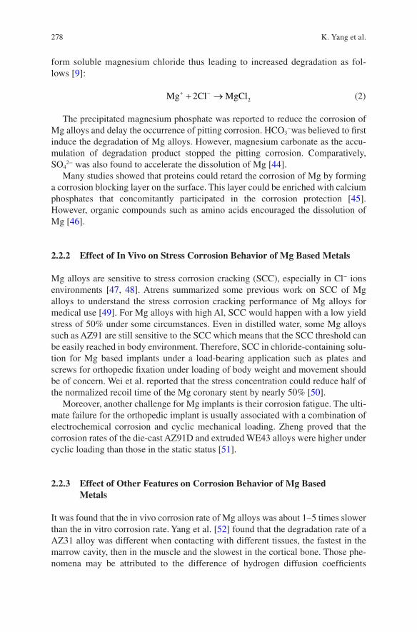
278
form soluble magnesium chloride thus leading to increased degradation as fol-lows [9]:
Mg Cl MgCl+ -+ ®2 2 (2)
The precipitated magnesium phosphate was reported to reduce the corrosion of Mg alloys and delay the occurrence of pitting corrosion. HCO3
−was believed to first induce the degradation of Mg alloys. However, magnesium carbonate as the accu-mulation of degradation product stopped the pitting corrosion. Comparatively, SO4
2− was also found to accelerate the dissolution of Mg [44].Many studies showed that proteins could retard the corrosion of Mg by forming
a corrosion blocking layer on the surface. This layer could be enriched with calcium phosphates that concomitantly participated in the corrosion protection [45]. However, organic compounds such as amino acids encouraged the dissolution of Mg [46].
2.2.2 Effect of In Vivo on Stress Corrosion Behavior of Mg Based Metals
Mg alloys are sensitive to stress corrosion cracking (SCC), especially in Cl− ions environments [47, 48]. Atrens summarized some previous work on SCC of Mg alloys to understand the stress corrosion cracking performance of Mg alloys for medical use [49]. For Mg alloys with high Al, SCC would happen with a low yield stress of 50% under some circumstances. Even in distilled water, some Mg alloys such as AZ91 are still sensitive to the SCC which means that the SCC threshold can be easily reached in body environment. Therefore, SCC in chloride-containing solu-tion for Mg based implants under a load-bearing application such as plates and screws for orthopedic fixation under loading of body weight and movement should be of concern. Wei et al. reported that the stress concentration could reduce half of the normalized recoil time of the Mg coronary stent by nearly 50% [50].
Moreover, another challenge for Mg implants is their corrosion fatigue. The ulti-mate failure for the orthopedic implant is usually associated with a combination of electrochemical corrosion and cyclic mechanical loading. Zheng proved that the corrosion rates of the die-cast AZ91D and extruded WE43 alloys were higher under cyclic loading than those in the static status [51].
2.2.3 Effect of Other Features on Corrosion Behavior of Mg Based Metals
It was found that the in vivo corrosion rate of Mg alloys was about 1–5 times slower than the in vitro corrosion rate. Yang et al. [52] found that the degradation rate of a AZ31 alloy was different when contacting with different tissues, the fastest in the marrow cavity, then in the muscle and the slowest in the cortical bone. Those phe-nomena may be attributed to the difference of hydrogen diffusion coefficients
K. Yang et al.
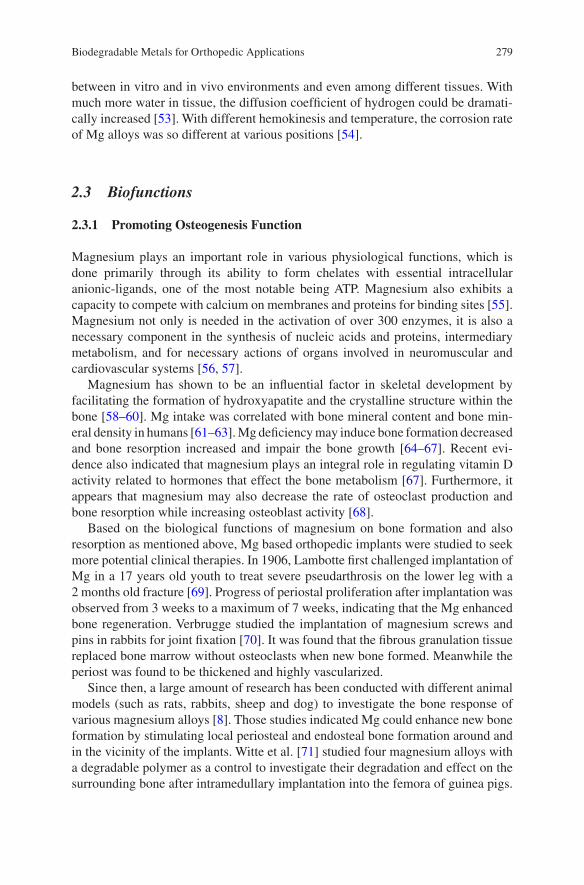
279
between in vitro and in vivo environments and even among different tissues. With much more water in tissue, the diffusion coefficient of hydrogen could be dramati-cally increased [53]. With different hemokinesis and temperature, the corrosion rate of Mg alloys was so different at various positions [54].
2.3 Biofunctions
2.3.1 Promoting Osteogenesis Function
Magnesium plays an important role in various physiological functions, which is done primarily through its ability to form chelates with essential intracellular anionic-ligands, one of the most notable being ATP. Magnesium also exhibits a capacity to compete with calcium on membranes and proteins for binding sites [55]. Magnesium not only is needed in the activation of over 300 enzymes, it is also a necessary component in the synthesis of nucleic acids and proteins, intermediary metabolism, and for necessary actions of organs involved in neuromuscular and cardiovascular systems [56, 57].
Magnesium has shown to be an influential factor in skeletal development by facilitating the formation of hydroxyapatite and the crystalline structure within the bone [58–60]. Mg intake was correlated with bone mineral content and bone min-eral density in humans [61–63]. Mg deficiency may induce bone formation decreased and bone resorption increased and impair the bone growth [64–67]. Recent evi-dence also indicated that magnesium plays an integral role in regulating vitamin D activity related to hormones that effect the bone metabolism [67]. Furthermore, it appears that magnesium may also decrease the rate of osteoclast production and bone resorption while increasing osteoblast activity [68].
Based on the biological functions of magnesium on bone formation and also resorption as mentioned above, Mg based orthopedic implants were studied to seek more potential clinical therapies. In 1906, Lambotte first challenged implantation of Mg in a 17 years old youth to treat severe pseudarthrosis on the lower leg with a 2 months old fracture [69]. Progress of periostal proliferation after implantation was observed from 3 weeks to a maximum of 7 weeks, indicating that the Mg enhanced bone regeneration. Verbrugge studied the implantation of magnesium screws and pins in rabbits for joint fixation [70]. It was found that the fibrous granulation tissue replaced bone marrow without osteoclasts when new bone formed. Meanwhile the periost was found to be thickened and highly vascularized.
Since then, a large amount of research has been conducted with different animal models (such as rats, rabbits, sheep and dog) to investigate the bone response of various magnesium alloys [8]. Those studies indicated Mg could enhance new bone formation by stimulating local periosteal and endosteal bone formation around and in the vicinity of the implants. Witte et al. [71] studied four magnesium alloys with a degradable polymer as a control to investigate their degradation and effect on the surrounding bone after intramedullary implantation into the femora of guinea pigs.
Biodegradable Metals for Orthopedic Applications
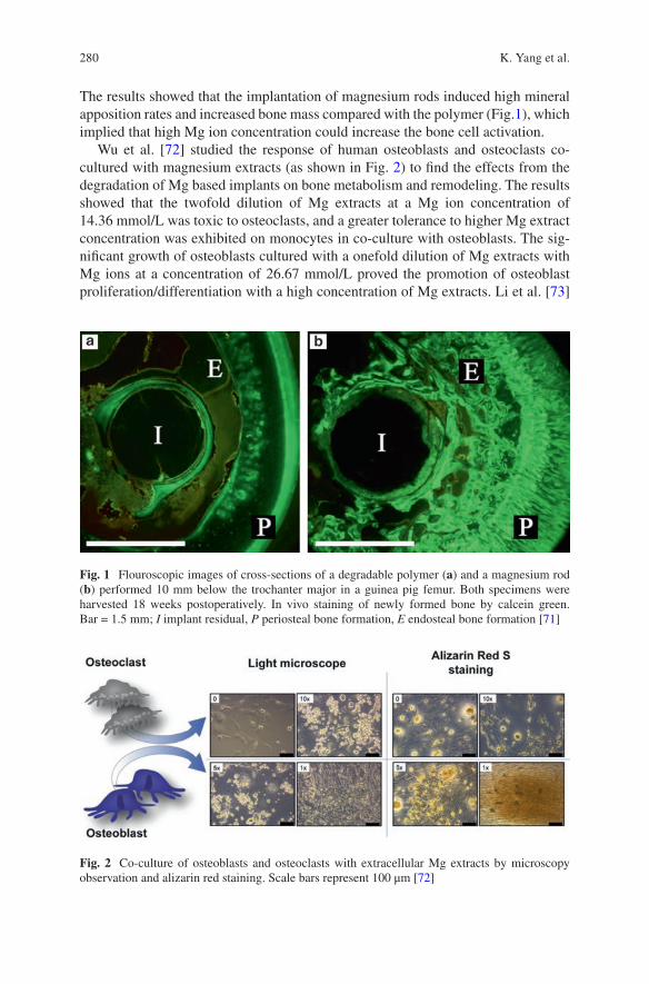
280
The results showed that the implantation of magnesium rods induced high mineral apposition rates and increased bone mass compared with the polymer (Fig.1), which implied that high Mg ion concentration could increase the bone cell activation.
Wu et al. [72] studied the response of human osteoblasts and osteoclasts co- cultured with magnesium extracts (as shown in Fig. 2) to find the effects from the degradation of Mg based implants on bone metabolism and remodeling. The results showed that the twofold dilution of Mg extracts at a Mg ion concentration of 14.36 mmol/L was toxic to osteoclasts, and a greater tolerance to higher Mg extract concentration was exhibited on monocytes in co-culture with osteoblasts. The sig-nificant growth of osteoblasts cultured with a onefold dilution of Mg extracts with Mg ions at a concentration of 26.67 mmol/L proved the promotion of osteoblast proliferation/differentiation with a high concentration of Mg extracts. Li et al. [73]
Fig. 1 Flouroscopic images of cross-sections of a degradable polymer (a) and a magnesium rod (b) performed 10 mm below the trochanter major in a guinea pig femur. Both specimens were harvested 18 weeks postoperatively. In vivo staining of newly formed bone by calcein green. Bar = 1.5 mm; I implant residual, P periosteal bone formation, E endosteal bone formation [71]
Fig. 2 Co-culture of osteoblasts and osteoclasts with extracellular Mg extracts by microscopy observation and alizarin red staining. Scale bars represent 100 μm [72]
K. Yang et al.
281
studied the effects of binary Mg-Ca alloys within bone after implantation in rabbit femoral shafts. Around the Mg-1Ca alloy pins, high activity of osteoblasts and osteocytes were observed. Radiographic examination revealed the gradual degrada-tion of Mg-1Ca alloy pins and also newly formed bone within 90 days. Additionally, the alloying elements were also studied to investigate their influence on biocompatibility and bone formation. For example, Sr has a close physiochemical performance to Ca and also accumulates in the skeleton as a natural bone seeking element [74]. Mg-Sr alloys were developed for orthopedic implants in previous studies [75, 76]. Gu et al. [75] found that the as-rolled Mg–2Sr alloy group showed more bone trabeculae compared with the control group (Fig.3). In the diaphyseal region, it was observed that new bone formed for the Mg-2Sr alloy especially beneath the periosteum (Fig.4). The Mg-2Sr alloy exhibited thicker cortical bone than the control group. Only endosteal new bone formation was observed for the Mg-2Sr alloy (blue arrows in Fig. 4b, d and red arrows in Fig. 4e). Additionally, in
Fig. 3 Representative histology of the cross-sections of the mouse distal femora (metaphysical region) from (a) a negative control without implantation and from (c–d) the as-rolled Mg–2Sr alloy group at week 4 after operation. (b) The outline of a bone tunnel (red dotted circle) could be observed with the Mg–2Sr implant (red arrow). The bone volume around the bone tunnel was more than that in the negative group. (c) A magnified image of (b). The outline of the Mg–2Sr alloy implant (red dotted circle) is clear. The degraded material at the edge of the implant dispersed into the bone tunnel (orange triangle) and new bone was formed adjacent to the implant (blue arrows). (d) A magnified image of the green frame in (c). The degraded material dispersed into the sur-rounding bone and was distributed directly next to it (yellow dots) [75]
Biodegradable Metals for Orthopedic Applications
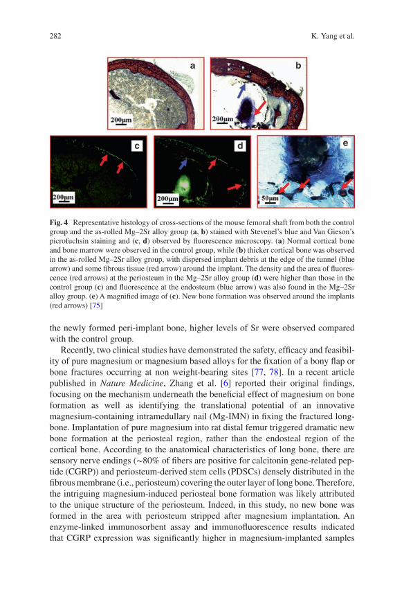
282
the newly formed peri-implant bone, higher levels of Sr were observed compared with the control group.
Recently, two clinical studies have demonstrated the safety, efficacy and feasibil-ity of pure magnesium or magnesium based alloys for the fixation of a bony flap or bone fractures occurring at non weight-bearing sites [77, 78]. In a recent article published in Nature Medicine, Zhang et al. [6] reported their original findings, focusing on the mechanism underneath the beneficial effect of magnesium on bone formation as well as identifying the translational potential of an innovative magnesium- containing intramedullary nail (Mg-IMN) in fixing the fractured long- bone. Implantation of pure magnesium into rat distal femur triggered dramatic new bone formation at the periosteal region, rather than the endosteal region of the cortical bone. According to the anatomical characteristics of long bone, there are sensory nerve endings (∼80% of fibers are positive for calcitonin gene-related pep-tide (CGRP)) and periosteum-derived stem cells (PDSCs) densely distributed in the fibrous membrane (i.e., periosteum) covering the outer layer of long bone. Therefore, the intriguing magnesium-induced periosteal bone formation was likely attributed to the unique structure of the periosteum. Indeed, in this study, no new bone was formed in the area with periosteum stripped after magnesium implantation. An enzyme-linked immunosorbent assay and immunofluorescence results indicated that CGRP expression was significantly higher in magnesium-implanted samples
Fig. 4 Representative histology of cross-sections of the mouse femoral shaft from both the control group and the as-rolled Mg–2Sr alloy group (a, b) stained with Stevenel’s blue and Van Gieson’s picrofuchsin staining and (c, d) observed by fluorescence microscopy. (a) Normal cortical bone and bone marrow were observed in the control group, while (b) thicker cortical bone was observed in the as-rolled Mg–2Sr alloy group, with dispersed implant debris at the edge of the tunnel (blue arrow) and some fibrous tissue (red arrow) around the implant. The density and the area of fluores-cence (red arrows) at the periosteum in the Mg–2Sr alloy group (d) were higher than those in the control group (c) and fluorescence at the endosteum (blue arrow) was also found in the Mg–2Sr alloy group. (e) A magnified image of (c). New bone formation was observed around the implants (red arrows) [75]
K. Yang et al.
283
compared with stainless steel-implanted ones. All of these results suggest that CGRP and its receptor are indispensable in the aforementioned interesting phenomenon.
From the in vitro test, it was firstly found that the entry of magnesium ions medi-ated by two important ion channels could lead to an increase in the content of syn-aptic vesicles (miniscule sacs within the cell where CGRP are stored, Fig. 5 [79]) and consequently increased CGRP release [6]. In the primary isolated PDSCs, CGRP promoted osteogenic differentiation via calcitonin receptor-like receptor- and receptor-activity modifying protein 1-dependent activation of cyclic adenosine monophosphate-responsive element binding protein 1 and Osterix (Fig.5).
2.3.2 Antimicrobial
In the field of orthopedics, 90% of the surgery involves implants placing. Joint replacement, fracture fixation, reconstruction of ligaments and tendons and other implant surgeries have become important means of reconstructing limb function in patients. Metallic materials such as titanium alloy and stainless steel are widely used as biomedical materials with high strength, good corrosion resistance and good biocompatibility. However, the conventional medical metallic materials do not exhibit antibacterial property, even though the implantation is carried out under sterile condition with antibiotic, inevitable bacterial infection cannot be ignored [80–84]. Infection that leads to the failure of implants is a serious and devastating complication which has a big impact on patients and medical costs [85]. Indeed, the infection rate due to orthopedic implants in U.S. was reported to be about 4.3% [86], indicating that the prosthetic joint infection (PJI) is the second common reason for prosthetic joint failure after aseptic loosening [87]. Particularly, the infection rates of about 1.7–3.2%, 2.5–5.6% and 1.3% on hip, knee and shoulder arthroplas-ties may be found respectively [88–90]. The orthopedic implant related infection not only increases the time required for wound healing, but also influences the effectiveness of implantation. Some serious infections may also result in conse-quences including re-operation, amputation, and death in extreme case. As shown in Fig. 6, most of implant-associated infections are caused by Staphylococci (80%). Staphylococcus aureus and Staphylococcus epidermidis account together for 66% infection isolates.
As shown in Fig.7, the reason of infections on implant surfaces is that the implant surfaces are suitable for bacterial colonization and the serum proteins firstly accu-mulate on the surface of implant [91]. The clinical infection problems that can result in serious consequences on the patients are due to the formation of bacterial biofilm firstly.
Surface antibacterial coatings are the common way to impart antibacterial func-tion to implants [80, 83, 92–98]. However, the antibacterial effect has not been well realized up to now. Photocatalysis is another type of antibacterial coating that appears to effectively kill the microorganisms. However, its unstable character and requirement of light affect its performance, besides compatibility issue with the
Biodegradable Metals for Orthopedic Applications
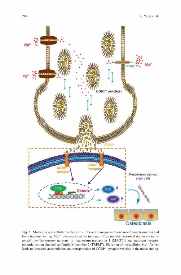
284
Fig. 5 Molecular and cellular mechanisms involved in magnesium-enhanced bone formation and bone fracture healing. Mg2+ releasing from the implant diffuse into the periosteal region are trans-ported into the sensory neurons by magnesium transporter 1 (MAGT1) and transient receptor potential cation channel subfamily M member 7 (TRPM7). Elevation of intracellular Mg2+ further leads to increased accumulation and transportation of CGRP+ synaptic vesicles in the nerve ending.
K. Yang et al.
285
implant matrix. Based on the above discussion, the metallurgical addition of an antibacterial metal element is considered to be an effective approach to introduce antibacterial function to metallic materials. The antibacterial function has already been obtained in bulk materials through addition of copper (Cu) or silver (Ag) into stainless steels, in which the precipitation of Cu-rich phase or Ag particles enables the steel to exhibit strong antibacterial activity [99, 100].
Bacterial infection associated with biodegradable Mg alloy medical devices or implant materials is also a challenge for its future development. David reported the main bacteria for infections are Staphylococcus aureus and Staphylococcus epider-midis, which occupy 34% and 32%, respectively [101]. Robinson et al. [102] and Ren et al. [33] reported that Mg and its alloys also present antibacterial property because of the high pH values of the degradation products. Zeng et al. [103] further investigated the in vivo antibacterial property of Mg alloy on the basis of previous studies and confirmed the antibacterial function of Mg alloy. Liu et al. [35] reported a train of bio-degradable Mg-Cu alloys not only have good cyto-compatibility and osteogenetic effects, but also have long-lasting antibacterial effects against S. aureus due to the synergistic effect of Mg and Cu elements.
In the future, in-depth study and application of surface modification are expected to realize the antibacterial controllability of Mg alloy, which is very important issue for the clinical applications of Mg alloy.
2.3.3 Inhibiting Tumor Cell Survival
Bone cancer is a malignant tumor in the bone, which destroys the normal bone tis-sue. Generally, the main options to treat bone cancer include surgery, chemotherapy, radiation therapy, and cryosurgery. For some people with bone cancer, treatment may remove or destroy the cancer. Unfortunately, recurrence (when cancer comes back after treatment) is a very common concern in patients who have had cancer. Except the treatments mentioned before, is there an alternative option for curing cancer? Recently, some researchers conducted preliminary trials to treat this tough problem using magnesium. Two different interpretations on the mechanism of anti-tumor have been proposed. Li et al. [104] studied the cytotoxic effect of the biodeg-radation of pure Mg and micro-arc oxidation (MAO) coated Mg on cancer cells. The results showed that the high pH values caused by the degradation of Mg in the cul-ture medium exhibited strong cytotoxicity on U2-OS cells. The Mg ion
Fig. 5 (continued) Higher extracellular CGRP binds to CGRP receptor expressed on the surface of periosteum-derived stem cells (PDSCs), which activates the phosphorylation of cAMP response element binding protein (CREB) in the nuclei of PDSCs. The activation of CREB specifically targets Osterix, a known important transcriptional factor for the osteogenic differentiation of stem cells, following with higher osteocalcin (OCN) and alkaline phosphatase (ALP). Through connect-ing these aforementioned signaling pathway elements, PDSCs are promoted to differentiate towards an osteoblastic lineage, presenting significantly more new bone formation in the periosteal region [79]
Biodegradable Metals for Orthopedic Applications
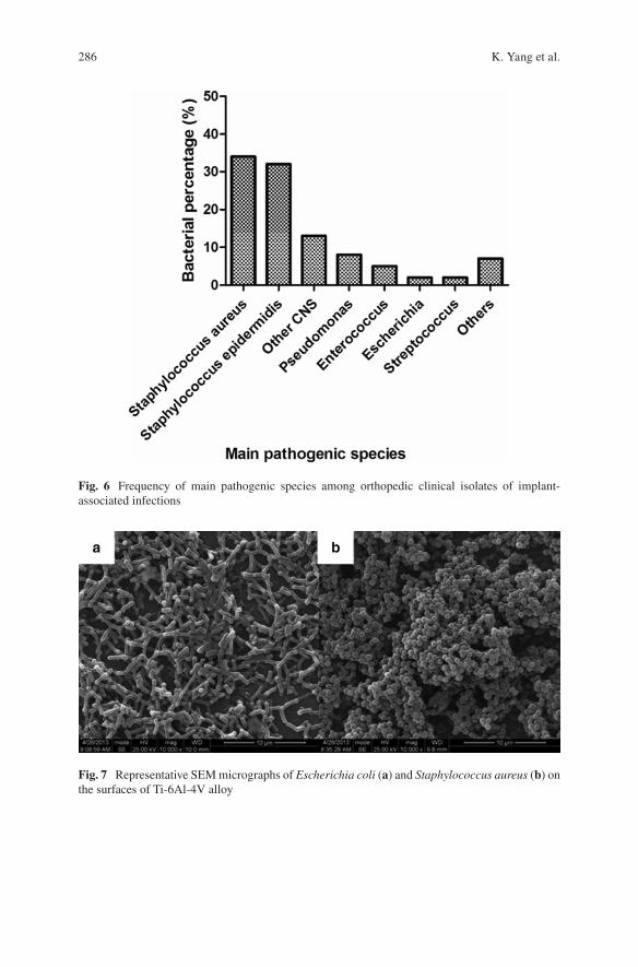
286
Fig. 6 Frequency of main pathogenic species among orthopedic clinical isolates of implant- associated infections
Fig. 7 Representative SEM micrographs of Escherichia coli (a) and Staphylococcus aureus (b) on the surfaces of Ti-6Al-4V alloy
K. Yang et al.
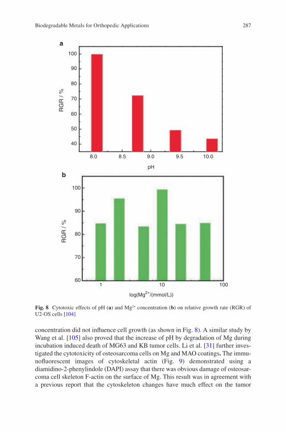
287
concentration did not influence cell growth (as shown in Fig. 8). A similar study by Wang et al. [105] also proved that the increase of pH by degradation of Mg during incubation induced death of MG63 and KB tumor cells. Li et al. [31] further inves-tigated the cytotoxicity of osteosarcoma cells on Mg and MAO coatings. The immu-nofluorescent images of cytoskeletal actin (Fig. 9) demonstrated using a diamidino-2-phenylindole (DAPI) assay that there was obvious damage of osteosar-coma cell skeleton F-actin on the surface of Mg. This result was in agreement with a previous report that the cytoskeleton changes have much effect on the tumor
100
90
80
70
60
100
90
80
70
601 10 100
log(Mg2+/(mmol/L))
pH
50
40
8.0
a
b
8.5 9.0 9.5 10.0
RG
R /
%R
GR
/ %
Fig. 8 Cytotoxic effects of pH (a) and Mg2+ concentration (b) on relative growth rate (RGR) of U2-OS cells [104]
Biodegradable Metals for Orthopedic Applications
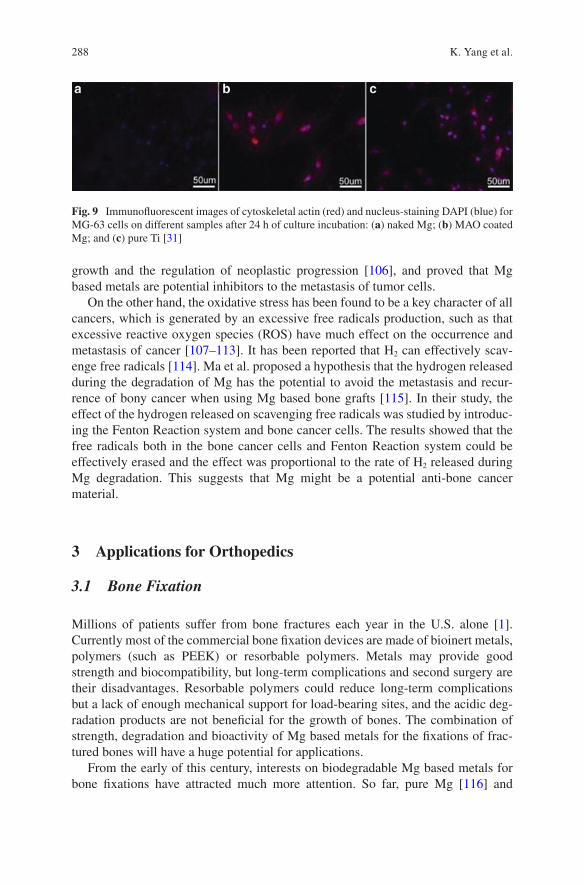
288
growth and the regulation of neoplastic progression [106], and proved that Mg based metals are potential inhibitors to the metastasis of tumor cells.
On the other hand, the oxidative stress has been found to be a key character of all cancers, which is generated by an excessive free radicals production, such as that excessive reactive oxygen species (ROS) have much effect on the occurrence and metastasis of cancer [107–113]. It has been reported that H2 can effectively scav-enge free radicals [114]. Ma et al. proposed a hypothesis that the hydrogen released during the degradation of Mg has the potential to avoid the metastasis and recur-rence of bony cancer when using Mg based bone grafts [115]. In their study, the effect of the hydrogen released on scavenging free radicals was studied by introduc-ing the Fenton Reaction system and bone cancer cells. The results showed that the free radicals both in the bone cancer cells and Fenton Reaction system could be effectively erased and the effect was proportional to the rate of H2 released during Mg degradation. This suggests that Mg might be a potential anti-bone cancer material.
3 Applications for Orthopedics
3.1 Bone Fixation
Millions of patients suffer from bone fractures each year in the U.S. alone [1]. Currently most of the commercial bone fixation devices are made of bioinert metals, polymers (such as PEEK) or resorbable polymers. Metals may provide good strength and biocompatibility, but long-term complications and second surgery are their disadvantages. Resorbable polymers could reduce long-term complications but a lack of enough mechanical support for load-bearing sites, and the acidic deg-radation products are not beneficial for the growth of bones. The combination of strength, degradation and bioactivity of Mg based metals for the fixations of frac-tured bones will have a huge potential for applications.
From the early of this century, interests on biodegradable Mg based metals for bone fixations have attracted much more attention. So far, pure Mg [116] and
Fig. 9 Immunofluorescent images of cytoskeletal actin (red) and nucleus-staining DAPI (blue) for MG-63 cells on different samples after 24 h of culture incubation: (a) naked Mg; (b) MAO coated Mg; and (c) pure Ti [31]
K. Yang et al.
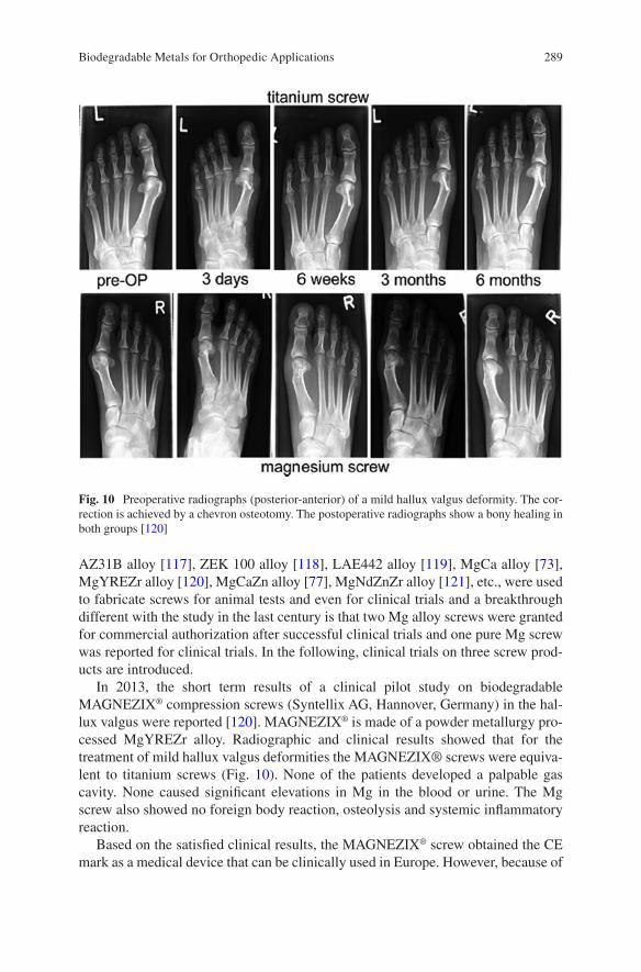
289
AZ31B alloy [117], ZEK 100 alloy [118], LAE442 alloy [119], MgCa alloy [73], MgYREZr alloy [120], MgCaZn alloy [77], MgNdZnZr alloy [121], etc., were used to fabricate screws for animal tests and even for clinical trials and a breakthrough different with the study in the last century is that two Mg alloy screws were granted for commercial authorization after successful clinical trials and one pure Mg screw was reported for clinical trials. In the following, clinical trials on three screw prod-ucts are introduced.
In 2013, the short term results of a clinical pilot study on biodegradable MAGNEZIX® compression screws (Syntellix AG, Hannover, Germany) in the hal-lux valgus were reported [120]. MAGNEZIX® is made of a powder metallurgy pro-cessed MgYREZr alloy. Radiographic and clinical results showed that for the treatment of mild hallux valgus deformities the MAGNEZIX® screws were equiva-lent to titanium screws (Fig. 10). None of the patients developed a palpable gas cavity. None caused significant elevations in Mg in the blood or urine. The Mg screw also showed no foreign body reaction, osteolysis and systemic inflammatory reaction.
Based on the satisfied clinical results, the MAGNEZIX® screw obtained the CE mark as a medical device that can be clinically used in Europe. However, because of
Fig. 10 Preoperative radiographs (posterior-anterior) of a mild hallux valgus deformity. The cor-rection is achieved by a chevron osteotomy. The postoperative radiographs show a bony healing in both groups [120]
Biodegradable Metals for Orthopedic Applications
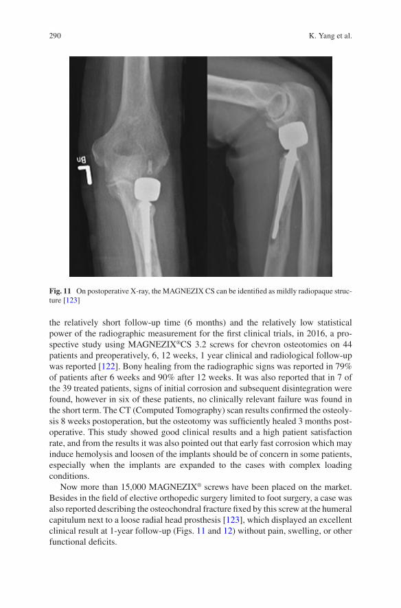
290
the relatively short follow-up time (6 months) and the relatively low statistical power of the radiographic measurement for the first clinical trials, in 2016, a pro-spective study using MAGNEZIX®CS 3.2 screws for chevron osteotomies on 44 patients and preoperatively, 6, 12 weeks, 1 year clinical and radiological follow-up was reported [122]. Bony healing from the radiographic signs was reported in 79% of patients after 6 weeks and 90% after 12 weeks. It was also reported that in 7 of the 39 treated patients, signs of initial corrosion and subsequent disintegration were found, however in six of these patients, no clinically relevant failure was found in the short term. The CT (Computed Tomography) scan results confirmed the osteoly-sis 8 weeks postoperation, but the osteotomy was sufficiently healed 3 months post-operative. This study showed good clinical results and a high patient satisfaction rate, and from the results it was also pointed out that early fast corrosion which may induce hemolysis and loosen of the implants should be of concern in some patients, especially when the implants are expanded to the cases with complex loading conditions.
Now more than 15,000 MAGNEZIX® screws have been placed on the market. Besides in the field of elective orthopedic surgery limited to foot surgery, a case was also reported describing the osteochondral fracture fixed by this screw at the humeral capitulum next to a loose radial head prosthesis [123], which displayed an excellent clinical result at 1-year follow-up (Figs. 11 and 12) without pain, swelling, or other functional deficits.
Fig. 11 On postoperative X-ray, the MAGNEZIX CS can be identified as mildly radiopaque struc-ture [123]
K. Yang et al.
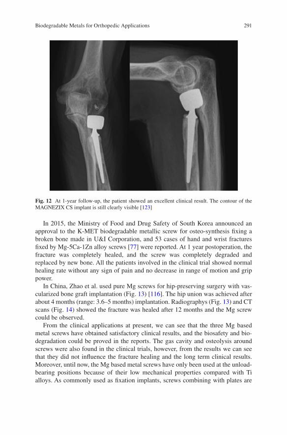
291
In 2015, the Ministry of Food and Drug Safety of South Korea announced an approval to the K-MET biodegradable metallic screw for osteo-synthesis fixing a broken bone made in U&I Corporation, and 53 cases of hand and wrist fractures fixed by Mg-5Ca-1Zn alloy screws [77] were reported. At 1 year postoperation, the fracture was completely healed, and the screw was completely degraded and replaced by new bone. All the patients involved in the clinical trial showed normal healing rate without any sign of pain and no decrease in range of motion and grip power.
In China, Zhao et al. used pure Mg screws for hip-preserving surgery with vas-cularized bone graft implantation (Fig. 13) [116]. The hip union was achieved after about 4 months (range: 3.6–5 months) implantation. Radiographys (Fig. 13) and CT scans (Fig. 14) showed the fracture was healed after 12 months and the Mg screw could be observed.
From the clinical applications at present, we can see that the three Mg based metal screws have obtained satisfactory clinical results, and the biosafety and bio-degradation could be proved in the reports. The gas cavity and osteolysis around screws were also found in the clinical trials, however, from the results we can see that they did not influence the fracture healing and the long term clinical results. Moreover, until now, the Mg based metal screws have only been used at the unload- bearing positions because of their low mechanical properties compared with Ti alloys. As commonly used as fixation implants, screws combining with plates are
Fig. 12 At 1-year follow-up, the patient showed an excellent clinical result. The contour of the MAGNEZIX CS implant is still clearly visible [123]
Biodegradable Metals for Orthopedic Applications
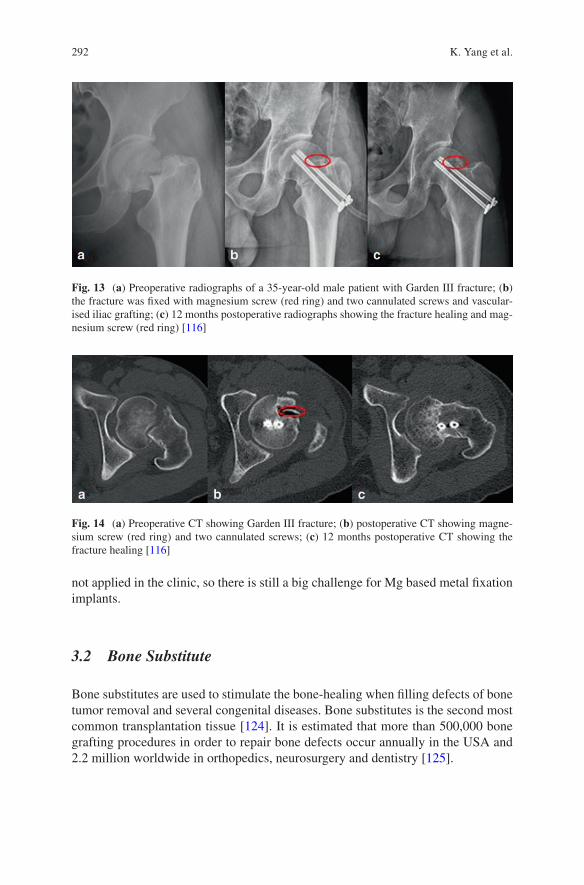
292
not applied in the clinic, so there is still a big challenge for Mg based metal fixation implants.
3.2 Bone Substitute
Bone substitutes are used to stimulate the bone-healing when filling defects of bone tumor removal and several congenital diseases. Bone substitutes is the second most common transplantation tissue [124]. It is estimated that more than 500,000 bone grafting procedures in order to repair bone defects occur annually in the USA and 2.2 million worldwide in orthopedics, neurosurgery and dentistry [125].
Fig. 13 (a) Preoperative radiographs of a 35-year-old male patient with Garden III fracture; (b) the fracture was fixed with magnesium screw (red ring) and two cannulated screws and vascular-ised iliac grafting; (c) 12 months postoperative radiographs showing the fracture healing and mag-nesium screw (red ring) [116]
Fig. 14 (a) Preoperative CT showing Garden III fracture; (b) postoperative CT showing magne-sium screw (red ring) and two cannulated screws; (c) 12 months postoperative CT showing the fracture healing [116]
K. Yang et al.
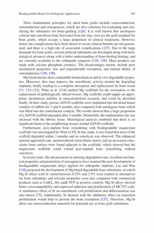
293
Three fundamental principles for ideal bone grafts include osteoconduction, osteoinduction and osteogenesis, which are also criterions for evaluating and clas-sifying the substitutes for bone-grafting [126]. It is well known that autologous cortical and cancellous bone harvested from the iliac crest are the gold standard for bone grafts, which occupy a large proportion of clinical treatments. However, donor-site complications have been shown to occur, clinical benefits are not guaran-teed, and there is a high rate of associated complications [127]. Due to the large demands for bone grafts, several artificial substitutes are developed along with tech-nological advances along with a better understanding of bone-healing biology, and are currently available to the orthopedic surgeons [128, 129]. Main products are made with calcium phosphate ceramics. The disadvantages mainly include poor mechanical properties, low and unpredictable resorption, and limited ability of osteoinduction [126, 130].
Mg based metals show compatible biomechanical and in vivo degradable proper-ties. Moreover, they may improve the osteoblastic activity around the degrading implants, finally leading to a complete absorption and replacement by bone tissue [71, 131–133]. Witte et al. [134] studied Mg scaffolds for the restoration or the replacement of pathologically altered tissues. Mg scaffolds could supply an appro-priate mechanical stability in musculoskeletal research, and could be absorbed finally. In their study, porous AZ91D scaffolds were implanted into the distal femur condyle of rabbits for 3 and 6 months, also compared with autologous bone which was filled into the contralateral condyle. The results showed that a large proportion of a AZ91D scaffold degraded after 3 months. Meanwhile, the implantation site was enclosed with the fibrous tissue. Histological analysis exhibited that there is no significant harm to the neighboring tissues around AZ91D scaffolds.
Furthermore, peri-implant bone remodeling with biodegradable magnesium scaffolds was investigated by Witte [135]. In this study, it was found that most of the scaffold degraded within 3 months and no osteolysis was observed. The enhanced mineral apposition rate, unmineralized extracellular matrix and an increased osteo-clastic bone surface were found adjacent to the scaffolds, which showed that the magnesium scaffolds could extend peri-implant bone remodeling without osteolysis.
In recent years, the advancement in tailoring degradation rate, excellent mechan-ical properties and promotion of osteogenesis have inspired the new development of biodegradable magnesium alloys applied for orthopedic implants. Liu and Wan [136] proposed the development of Mg based degradable bone substitutes, in which Mg-Sr alloys with Sr varied between 0.25% and 2.5% were studied as alternatives for bone substitutes and relevant properties were also compared with commercial products such as CaSO4, HA andβ-TCP as positive controls. Mg-Sr alloys showed better cytocompatibility and improved adhesion and proliferation of MC3T3 cells. A stimulatory effect of Sr on osteoblastic cell proliferation and differentiation was also shown [75]. Additionally, Sr element with the inhibitory effect on osteoclast proliferation would help to prevent the bone resorption [137]. Therefore, Mg-Sr alloys are osteoconduction materials for potential use as bone graft substitutes.
Biodegradable Metals for Orthopedic Applications
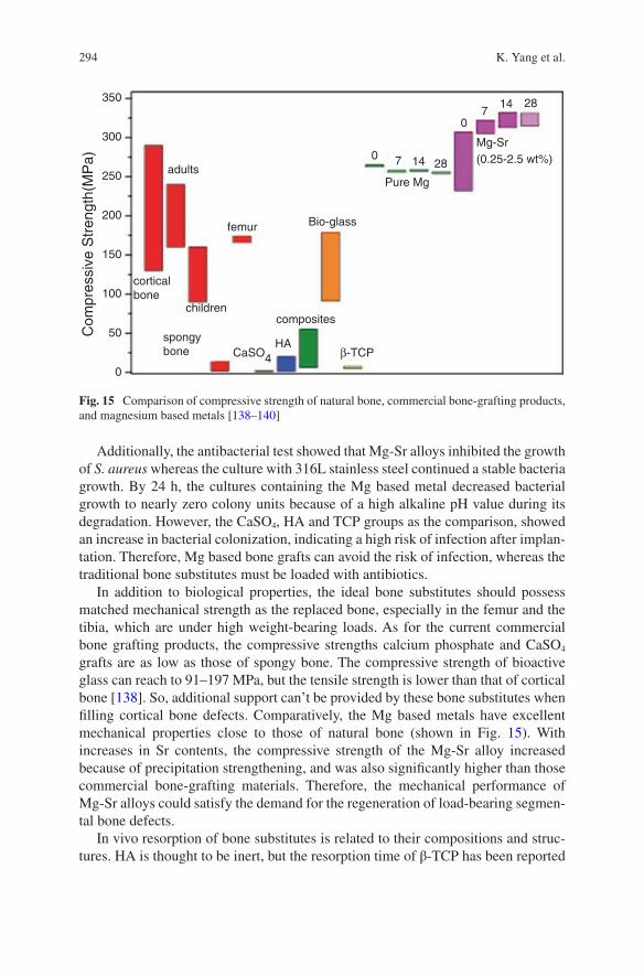
294
Additionally, the antibacterial test showed that Mg-Sr alloys inhibited the growth of S. aureus whereas the culture with 316L stainless steel continued a stable bacteria growth. By 24 h, the cultures containing the Mg based metal decreased bacterial growth to nearly zero colony units because of a high alkaline pH value during its degradation. However, the CaSO4, HA and TCP groups as the comparison, showed an increase in bacterial colonization, indicating a high risk of infection after implan-tation. Therefore, Mg based bone grafts can avoid the risk of infection, whereas the traditional bone substitutes must be loaded with antibiotics.
In addition to biological properties, the ideal bone substitutes should possess matched mechanical strength as the replaced bone, especially in the femur and the tibia, which are under high weight-bearing loads. As for the current commercial bone grafting products, the compressive strengths calcium phosphate and CaSO4 grafts are as low as those of spongy bone. The compressive strength of bioactive glass can reach to 91–197 MPa, but the tensile strength is lower than that of cortical bone [138]. So, additional support can’t be provided by these bone substitutes when filling cortical bone defects. Comparatively, the Mg based metals have excellent mechanical properties close to those of natural bone (shown in Fig. 15). With increases in Sr contents, the compressive strength of the Mg-Sr alloy increased because of precipitation strengthening, and was also significantly higher than those commercial bone-grafting materials. Therefore, the mechanical performance of Mg-Sr alloys could satisfy the demand for the regeneration of load-bearing segmen-tal bone defects.
In vivo resorption of bone substitutes is related to their compositions and struc-tures. HA is thought to be inert, but the resorption time of β-TCP has been reported
350
300
250
200
150
100
50
0
adults
femur
corticalbone
spongybone
composites
Pure Mg
0 7 14 28
07
14 28
Mg-Sr(0.25-2.5 wt%)
Bio-glass
β-TCPHA
Com
pres
sive
Str
engt
h(M
Pa)
CaSO4
children
Fig. 15 Comparison of compressive strength of natural bone, commercial bone-grafting products, and magnesium based metals [138–140]
K. Yang et al.
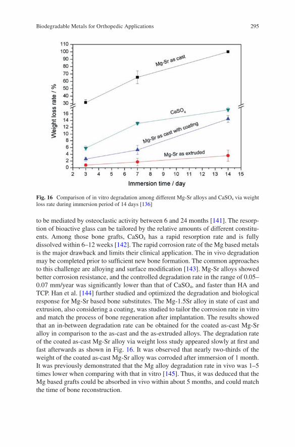
295
to be mediated by osteoclastic activity between 6 and 24 months [141]. The resorp-tion of bioactive glass can be tailored by the relative amounts of different constitu-ents. Among those bone grafts, CaSO4 has a rapid resorption rate and is fully dissolved within 6–12 weeks [142]. The rapid corrosion rate of the Mg based metals is the major drawback and limits their clinical application. The in vivo degradation may be completed prior to sufficient new bone formation. The common approaches to this challenge are alloying and surface modification [143]. Mg-Sr alloys showed better corrosion resistance, and the controlled degradation rate in the range of 0.05–0.07 mm/year was significantly lower than that of CaSO4, and faster than HA and TCP. Han et al. [144] further studied and optimized the degradation and biological response for Mg-Sr based bone substitutes. The Mg-1.5Sr alloy in state of cast and extrusion, also considering a coating, was studied to tailor the corrosion rate in vitro and match the process of bone regeneration after implantation. The results showed that an in-between degradation rate can be obtained for the coated as-cast Mg-Sr alloy in comparison to the as-cast and the as-extruded alloys. The degradation rate of the coated as-cast Mg-Sr alloy via weight loss study appeared slowly at first and fast afterwards as shown in Fig. 16. It was observed that nearly two-thirds of the weight of the coated as-cast Mg-Sr alloy was corroded after immersion of 1 month. It was previously demonstrated that the Mg alloy degradation rate in vivo was 1–5 times lower when comparing with that in vitro [145]. Thus, it was deduced that the Mg based grafts could be absorbed in vivo within about 5 months, and could match the time of bone reconstruction.
Fig. 16 Comparison of in vitro degradation among different Mg-Sr alloys and CaSO4 via weight loss rate during immersion period of 14 days [136]
Biodegradable Metals for Orthopedic Applications
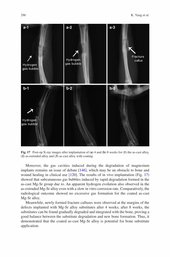
296
Moreover, the gas cavities induced during the degradation of magnesium implants remains an issue of debate [146], which may be an obstacle to bone and wound healing in clinical use [120]. The results of in vivo implantation (Fig. 17) showed that subcutaneous gas bubbles induced by rapid degradation formed in the as-cast Mg-Sr group due to. An apparent hydrogen evolution also observed in the as-extruded Mg-Sr alloy even with a slow in vitro corrosion rate. Comparatively, the radiological outcome showed no excessive gas formation for the coated as-cast Mg-Sr alloy.
Meanwhile, newly formed fracture calluses were observed at the margins of the defects implanted with Mg-Sr alloy substitutes after 4 weeks; after 8 weeks, the substitutes can be found gradually degraded and integrated with the bone, proving a good balance between the substitute degradation and new bone formation. Thus, it demonstrated that the coated as-cast Mg-Sr alloy is potential for bone substitute application.
Fig. 17 Post-op X-ray images after implantation of (a) 4 and (b) 8 weeks for (1) the as-cast alloy, (2) as-extruded alloy and (3) as-cast alloy with coating
K. Yang et al.
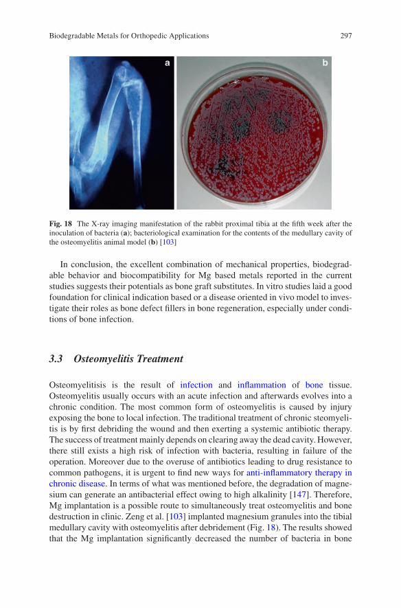
297
In conclusion, the excellent combination of mechanical properties, biodegrad-able behavior and biocompatibility for Mg based metals reported in the current studies suggests their potentials as bone graft substitutes. In vitro studies laid a good foundation for clinical indication based or a disease oriented in vivo model to inves-tigate their roles as bone defect fillers in bone regeneration, especially under condi-tions of bone infection.
3.3 Osteomyelitis Treatment
Osteomyelitisis is the result of infection and inflammation of bone tissue. Osteomyelitis usually occurs with an acute infection and afterwards evolves into a chronic condition. The most common form of osteomyelitis is caused by injury exposing the bone to local infection. The traditional treatment of chronic steomyeli-tis is by first debriding the wound and then exerting a systemic antibiotic therapy. The success of treatment mainly depends on clearing away the dead cavity. However, there still exists a high risk of infection with bacteria, resulting in failure of the operation. Moreover due to the overuse of antibiotics leading to drug resistance to common pathogens, it is urgent to find new ways for anti-inflammatory therapy in chronic disease. In terms of what was mentioned before, the degradation of magne-sium can generate an antibacterial effect owing to high alkalinity [147]. Therefore, Mg implantation is a possible route to simultaneously treat osteomyelitis and bone destruction in clinic. Zeng et al. [103] implanted magnesium granules into the tibial medullary cavity with osteomyelitis after debridement (Fig. 18). The results showed that the Mg implantation significantly decreased the number of bacteria in bone
Fig. 18 The X-ray imaging manifestation of the rabbit proximal tibia at the fifth week after the inoculation of bacteria (a); bacteriological examination for the contents of the medullary cavity of the osteomyelitis animal model (b) [103]
Biodegradable Metals for Orthopedic Applications
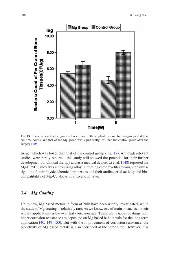
298
tissue, which was lower than that of the control group (Fig. 19). Although relevant studies were rarely reported, this study still showed the potential for their further development for clinical therapy and as a medical device. Li et al. [148] reported the Mg-0.25Cu alloy was a promising alloy in treating osteomyelitis through the inves-tigation of their physicochemical properties and their antibacterial activity and bio-compatibility of Mg-Cu alloys in vitro and in vivo.
3.4 Mg Coating
Up to now, Mg based metals in form of bulk have been widely investigated, while the study of Mg coating is relatively rare. As we know, one of main obstacles to their widely applications is the over fast corrosion rate. Therefore, various coatings with better corrosion resistance are deposited on Mg based bulk metals for the long term application [40, 149–153]. But with the improvement of corrosion resistance, the bioactivity of Mg based metals is also sacrificed at the same time. However, it is
Fig. 19 Bacteria count of per gram of bone tissue in the implant material for two groups at differ-ent time points, and that of the Mg group was significantly less than the control group after the surgery [103]
K. Yang et al.
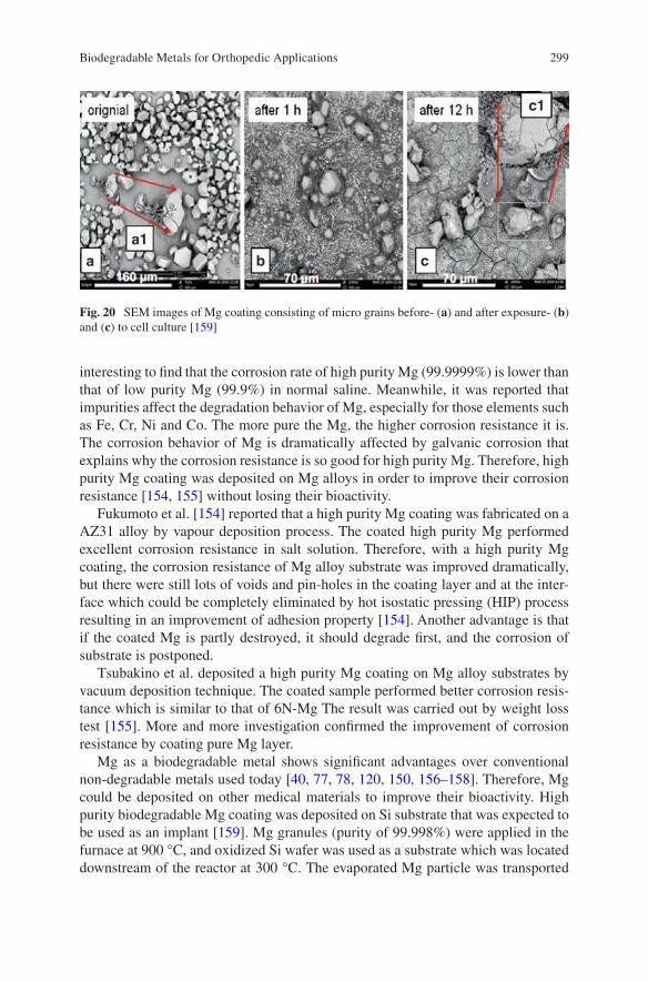
299
interesting to find that the corrosion rate of high purity Mg (99.9999%) is lower than that of low purity Mg (99.9%) in normal saline. Meanwhile, it was reported that impurities affect the degradation behavior of Mg, especially for those elements such as Fe, Cr, Ni and Co. The more pure the Mg, the higher corrosion resistance it is. The corrosion behavior of Mg is dramatically affected by galvanic corrosion that explains why the corrosion resistance is so good for high purity Mg. Therefore, high purity Mg coating was deposited on Mg alloys in order to improve their corrosion resistance [154, 155] without losing their bioactivity.
Fukumoto et al. [154] reported that a high purity Mg coating was fabricated on a AZ31 alloy by vapour deposition process. The coated high purity Mg performed excellent corrosion resistance in salt solution. Therefore, with a high purity Mg coating, the corrosion resistance of Mg alloy substrate was improved dramatically, but there were still lots of voids and pin-holes in the coating layer and at the inter-face which could be completely eliminated by hot isostatic pressing (HIP) process resulting in an improvement of adhesion property [154]. Another advantage is that if the coated Mg is partly destroyed, it should degrade first, and the corrosion of substrate is postponed.
Tsubakino et al. deposited a high purity Mg coating on Mg alloy substrates by vacuum deposition technique. The coated sample performed better corrosion resis-tance which is similar to that of 6N-Mg The result was carried out by weight loss test [155]. More and more investigation confirmed the improvement of corrosion resistance by coating pure Mg layer.
Mg as a biodegradable metal shows significant advantages over conventional non-degradable metals used today [40, 77, 78, 120, 150, 156–158]. Therefore, Mg could be deposited on other medical materials to improve their bioactivity. High purity biodegradable Mg coating was deposited on Si substrate that was expected to be used as an implant [159]. Mg granules (purity of 99.998%) were applied in the furnace at 900 °C, and oxidized Si wafer was used as a substrate which was located downstream of the reactor at 300 °C. The evaporated Mg particle was transported
Fig. 20 SEM images of Mg coating consisting of micro grains before- (a) and after exposure- (b) and (c) to cell culture [159]
Biodegradable Metals for Orthopedic Applications
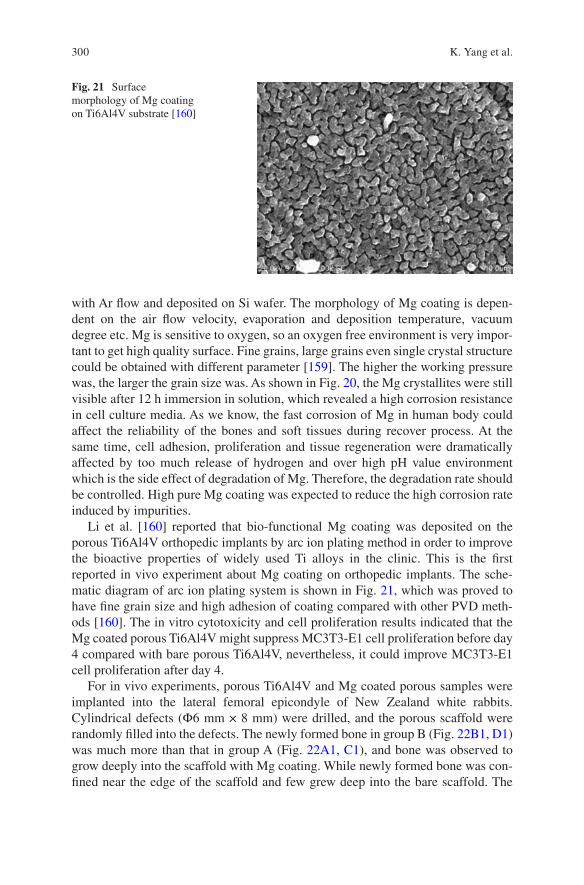
300
with Ar flow and deposited on Si wafer. The morphology of Mg coating is depen-dent on the air flow velocity, evaporation and deposition temperature, vacuum degree etc. Mg is sensitive to oxygen, so an oxygen free environment is very impor-tant to get high quality surface. Fine grains, large grains even single crystal structure could be obtained with different parameter [159]. The higher the working pressure was, the larger the grain size was. As shown in Fig. 20, the Mg crystallites were still visible after 12 h immersion in solution, which revealed a high corrosion resistance in cell culture media. As we know, the fast corrosion of Mg in human body could affect the reliability of the bones and soft tissues during recover process. At the same time, cell adhesion, proliferation and tissue regeneration were dramatically affected by too much release of hydrogen and over high pH value environment which is the side effect of degradation of Mg. Therefore, the degradation rate should be controlled. High pure Mg coating was expected to reduce the high corrosion rate induced by impurities.
Li et al. [160] reported that bio-functional Mg coating was deposited on the porous Ti6Al4V orthopedic implants by arc ion plating method in order to improve the bioactive properties of widely used Ti alloys in the clinic. This is the first reported in vivo experiment about Mg coating on orthopedic implants. The sche-matic diagram of arc ion plating system is shown in Fig. 21, which was proved to have fine grain size and high adhesion of coating compared with other PVD meth-ods [160]. The in vitro cytotoxicity and cell proliferation results indicated that the Mg coated porous Ti6Al4V might suppress MC3T3-E1 cell proliferation before day 4 compared with bare porous Ti6Al4V, nevertheless, it could improve MC3T3-E1 cell proliferation after day 4.
For in vivo experiments, porous Ti6Al4V and Mg coated porous samples were implanted into the lateral femoral epicondyle of New Zealand white rabbits. Cylindrical defects (Ф6 mm × 8 mm) were drilled, and the porous scaffold were randomly filled into the defects. The newly formed bone in group B (Fig. 22B1, D1) was much more than that in group A (Fig. 22A1, C1), and bone was observed to grow deeply into the scaffold with Mg coating. While newly formed bone was con-fined near the edge of the scaffold and few grew deep into the bare scaffold. The
Fig. 21 Surface morphology of Mg coating on Ti6Al4V substrate [160]
K. Yang et al.
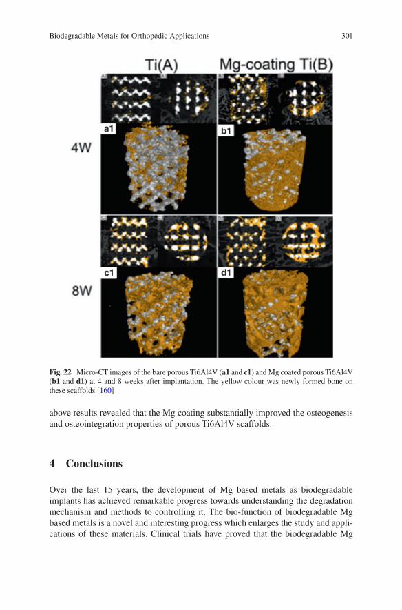
301
above results revealed that the Mg coating substantially improved the osteogenesis and osteointegration properties of porous Ti6Al4V scaffolds.
4 Conclusions
Over the last 15 years, the development of Mg based metals as biodegradable implants has achieved remarkable progress towards understanding the degradation mechanism and methods to controlling it. The bio-function of biodegradable Mg based metals is a novel and interesting progress which enlarges the study and appli-cations of these materials. Clinical trials have proved that the biodegradable Mg
Fig. 22 Micro-CT images of the bare porous Ti6Al4V (a1 and c1) and Mg coated porous Ti6Al4V (b1 and d1) at 4 and 8 weeks after implantation. The yellow colour was newly formed bone on these scaffolds [160]
Biodegradable Metals for Orthopedic Applications
302
based metal implants possess bio-safety and biodegradation characteristics. Some novel applications except for bone fixation have been investigated promoting osteo-genesis, antimicrobial, and inhibiting tumor cell survival. However, a number of fundamental problems are still needed to be resolved. The osteolysis and fast loss of mechanical integrity induced by high degradation are the main problems inhibiting their extensive range of applications. Moreover, the formation of hydrogen gas bub-bles after implantation could be a negative factor for some Mg based metal applica-tions. The greater mechanical properties of Mg based metals over biodegradable polymers have not played a role to extend their applications. The biofunction of Mg based metals also need further research. Therefore, more fundamental and applica-tion research is still needed for the development of Mg based metals to become the new generation of biomedical materials for orthopedic applications.
Acknowledgement The authors thank the financial support from the National Natural Science Foundation of China (No. 81401773, 31500777), National High Technology Research and Development Program of China (No. 2015AA033701), Key Program of China on Biomaterials Research and Tissue and Organ Replacement (No. 2016YFC1101804), CAS-Croucher Funding Scheme for Joint Laboratories (CAS 14303), Hong Kong RGC Collaborative Research Fund (CRF, C4028-14GF) and Institute of Metal Research, Chinese Academy of Sciences (No.2015-ZD01).
References
1. Chen YJ, Xu ZG, Smith CS, et al. Recent advances on the development of magnesium alloys for biodegradable implants. Acta Biomater. 2014;10:4561–73.
2. Trumbo P, Schlicker S, Yates AA, et al. Dietary reference intakes for energy, carbohydrate, fiber, fat, fatty acids, cholesterol, protein and amino acids. J Am Diet Assoc. 2002;102:10.
3. Pierson D, Edick J, Tauscher A, et al. A simplified in vivo approach for evaluating the bioab-sorbable behavior of candidate stent materials. J Biomed Res B. 2012;100B:10.
4. Bowen P, Drelich J, Buxbaum RE, et al. New approaches in evaluating metallic candidates for bioabsorbable stents. Emerg Mater Res. 2012;1:19.
5. Zreiqat H, Howlett CR, Zannettino A, et al. Mechanisms of magnesium-stimulated adhe-sion of osteoblastic cells to commonly used orthopaedic implants. J Biomed Mater Res. 2002;62:175–84.
6. Zhang Y, Xu J, Ruan YC, et al. Implant-derived magnesium induces local neuronal produc-tion of CGRP to improve bone-fracture healing in rats. Nat Med. 2016;22(10):1160–9.
7. Yang K, Tan L. Control of biodegradation of magnesium based metals for medical applica-tions. In: Song G, editor. Corrosion prevention of magnesium alloys. Sawston: Woodhead Publishing Limited; 2013. p. 509–43.
8. Zheng YF, Gu XN, Witte F. Biodegradable metals. Mater Sci Eng R. 2014;77:1–34. 9. Staiger MP, Pietak AM, Huadmai J, et al. Magnesium and its alloys as orthopedic biomateri-
als: a review. Biomaterials. 2006;27:1728–34. 10. Song GL. Control of biodegradation of biocompatable magnesium alloys. Corros Sci.
2007;49:1696–701. 11. Yun YH, Xue DC, Schulz MJ, et al. Corrosion protection of biodegradable magnesium
implants using anodization. Mater Sci Eng C. 2011;31:215–23. 12. Yue TM, Huang KJ. Laser forming of Zr-based coatings on AZ91D magnesium alloy sub-
strates for wear and corrosion resistance improvement. Mater Trans. 2011;52:810–3.
K. Yang et al.
303
13. Kim YK, Lee MH, Prasad MN, et al. Surface characteristics of magnesium alloys treated by anodic oxidation using pulse power. Multi-functional materials and structures, Pts 1 and 2. Adv Mater Res. 2008;47–50:1290–3.
14. Lu P, Cao L, Liu Y, et al. Evaluation of magnesium ions release, biocorrosion, and hemo-compatibility of MAO/PLLA-modified magnesium alloy WE42. J Biomed Mater Res B. 2011;96B:101–9.
15. Xu XH, Lu P, Cao L, et al. Evaluation of magnesium ions release, biocorrosion, and hemo-compatibility of MAO/PLLA-modified magnesium alloy WE42. J Biomed Mater Res B. 2011;96B:101–9.
16. Wang Q, Jin S, Lin X, et al. Cytotoxic effects of biodegradation of pure Mg and MAO-Mg on tumor cells of MG63 and KB. J Mater Sci Technol. 2014;30:487–92.
17. Guan SK, Wen CL, Peng L, et al. Characterization and degradation behavior of AZ31 alloy surface modified by bone-like hydroxyapatite for implant applications. Appl Surf Sci. 2009;255:6433–8.
18. Song YW, Shan DY, Han EH. Electrodeposition of hydroxyapatite coating on AZ91D mag-nesium alloy for biomaterial application. Mater Lett. 2008;62:3276–9.
19. Zhang XN, Song Y, Zhang SX, et al. Electrodeposition of Ca-P coatings on biodegradable Mg alloy: in vitro biomineralization behavior. Acta Biomater. 2010;6:1736–42.
20. Zhang XN, Li JN, Song Y, et al. In vitro responses of human bone marrow stromal cells to a fluoridated hydroxyapatite coated biodegradable Mg-Zn alloy. Biomaterials. 2010;31:5782–8.
21. Xu LP, Pan F, Yu GN, et al. In vitro and in vivo evaluation of the surface bioactivity of a calcium phosphate coated magnesium alloy. Biomaterials. 2009;30:1512–23.
22. Smola B, Joska L, Březina V, et al. Microstructure, corrosion resistance and cytocompatibility of Mg–5Y–4 rare earth–0.5Zr (WE54) alloy. Mater Sci Eng C. 2012;32:659–64.
23. Gray-Munro JE, Seguin C, Strong M. Influence of surface modification on the in vitro corro-sion rate of magnesium alloy AZ31. J Biomed Mater Res A. 2009;91A:221–30.
24. Wei M, Zhang YJ, Zhang GZ. Controlling the biodegradation rate of magnesium using bio-mimetic apatite coating. J Biomed Mater Res B. 2009;89B:408–14.
25. Tan LL, Yan TT, Xiong DS, et al. Fluoride treatment and in vitro corrosion behavior of an AZ31B magnesium alloy. Mater Sci Eng C. 2010;30:740–8.
26. Kirkland N, Waterman J, Birbilis N, et al. Buffer-regulated biocorrosion of pure magnesium. J Mater Sci Mater Med. 2012;23:283–91.
27. Guo Y, Ren L, Liu C, et al. Effect of implantation of biodegradable magnesium alloy on BMP-2 expression in bone of ovariectomized osteoporosis rats. Mater Sci Eng C. 2013;33:4470–4.
28. Zeng J, Ren L, Yuan Y, et al. Short-term effect of magnesium implantation on the osteo-myelitis modeled animals induced by Staphylococcus aureus. J Mater Sci Mater Med. 2013;24:2405–16.
29. Wan P, Wu J, Tan L, et al. Research on super-hydrophobic surface of biodegradable magne-sium alloys used for vascular stents. Mater Sci Eng C. 2013;33:2885–90.
30. Qu X, Jin F, Hao Y, et al. Nonlinear association between magnesium intake and the risk of colorectal cancer. Eur J Gastroenterol Hepatol. 2013;25:309–18.
31. Li M, Ren L, Li LH, et al. Cytotoxic effect on osteosarcoma MG-63 cells by degradation of magnesium. J Mater Sci Technol. 2014;30:888–93.
32. Robinson DA, Griffith RW, Dan S, et al. In vitro antibacterial properties of magnesium metal against Escherichia coli, Pseudomonas aeruginosa and Staphylococcus aureus. Acta Biomater. 2009;6:1869–77.
33. Ren L, Lin X, Tan L, et al. Effect of surface coating on antibacterial behavior of magnesium based metals. Mater Lett. 2011;65:3509–11.
34. Li Y, Liu G, Zhai Z, et al. Antibacterial properties of magnesium in an in vitro and in vivo model of implant-associated MRSA infection. Antimicrob Agents Chemother. 2014;58(12):7586–91.
35. Chen L, Fu X, Pan H, et al. Biodegradable Mg-Cu alloys with enhanced osteogenesis, angio-genesis, and long-lasting antibacterial effects. Sci Rep. 2016;6:27374.
Biodegradable Metals for Orthopedic Applications
304
36. Chen Z, Mao X, Tan L, et al. Osteoimmunomodulatory properties of magnesium scaffolds coated with β-tricalcium phosphate. Biomaterials. 2014;35:8553–65.
37. Zhai Z, Xinhua Q, Li H, et al. The effect of metallic magnesium degradation products on osteoclast-induced osteolysis and attenuation of NF-κB and NFATc1 signaling. Biomaterials. 2014;35:6299–310.
38. Cheng MQ, Wahafu T, Jiang GF, et al. A novel open-porous magnesium scaffold with con-trollable microstructures and properties for bone regeneration. Sci Rep. 2016;6:24134.
39. Zhao D, Witte F, Lu F, et al. Current status on clinical applications of magnesium-based orthopaedic implants: a review from clinical translational perspective. Biomaterials. 2016;112:287–302.
40. Tan L, Yu X, Wan P, et al. Biodegradable materials for bone repairs: a review. J Mater Sci Technol. 2013;29:503–13.
41. Witte F, Hort N, Vogt C, et al. Degradable biomaterials based on magnesium corrosion. Curr Opin Solid State Mater Sci. 2008;12:63–72.
42. Zavgorodniy AV, Borrero-Lopez O, Hoffman M, et al. Mechanical stability of two-step chemically deposited hydroxyapatite coating on Ti substrate: effects of various surface pre-treatments. J Biomed Mater Res B. 2011;99B:58–69.
43. Zhang EL, Xu LP, Yu GN, et al. In vivo evaluation of biodegradable magnesium alloy bone implant in the first 6 months implantation. J Biomed Mater Res A. 2009;90A:882–93.
44. Xin YC, Huo KF, Tao H, et al. Influence of aggressive ions on the degradation behavior of biomedical magnesium alloy in physiological environment. Acta Biomater. 2008;4:2008–15.
45. Witte F, Calliess T, Windhagen H. Biodegradable synthetic implant materials. Clinical appli-cations and immunological aspects. Orthopade. 2008;37:125–30.
46. Yamamoto A, Hiromoto S. Effect of inorganic salts, amino acids and proteins on the degrada-tion of pure magnesium in vitro. Mater Sci Eng C. 2009;29:1559–68.
47. Kannan MB, Dietzel W, Raman RKS, et al. Hydrogen-induced-cracking in magnesium alloy under cathodic polarization. Scripta Mater. 2007;57:579–81.
48. Winzer N, Atrens A, Dietzel W, et al. Magnesium stress corrosion cracking. T Nonferr Metal Soc. 2007;17:S150–S5.
49. Atrens A, Liu M, Abidin NIZ. Corrosion mechanism applicable to biodegradable magnesium implants. Mater Sci Eng B. 2011;176:1609–36.
50. Wu W, Gastaldi D, Yang KT, et al. Finite element analyses for design evaluation of biode-gradable magnesium alloy stents in arterial vessels. Mater Sci Eng B. 2011;176:1733–40.
51. Zheng YF, Gu XN, Zhou WR, et al. Corrosion fatigue behaviors of two biomedical Mg alloys-AZ91D and WE43-In simulated body fluid. Acta Biomater. 2010;6:4605–13.
52. Yang K, Tan L, Ren Y, et al. Study on biodegradation behavior of AZ31 magnesium alloy. Rare Metals Lett. 2009;28:26–30.
53. Das SK, Davis LA. High performance aerospace alloys via rapid solidification processing. Mater Sci Eng. 1988;98:1–12.
54. Mantovani D, Levesque J, Hermawan H, et al. Design of a pseudo-physiological test bench specific to the development of biodegradable metallic biomaterials. Acta Biomater. 2008;4:284–95.
55. Ryan MF. The role of magnesium in clinical biochemistry: an overview. Ann Clin Biochem. 1991;28:8.
56. Rude RK, Gruber HE. Magnesium deficiency and osteoporosis: animal and human observa-tions. J Nutr Biochem. 2004;15:710–6.
57. Noronha JL, Matuschak GM. Magnesium in critical illness: metabolism, assessment and treatment. Intensive Care Med. 2002;28:13.
58. Jones J. Early life nutrition and bone development in children. Nestle NutrWorkshop Series Pediatric. Program. 2011;68:7.
59. New SA, Bolton-Smith C, Grubb DA, et al. Nutritional influences on bone mineraldensity: a cross-sectional study in premenopausal women. Am J Clin Nutr. 1997;65:9.
K. Yang et al.
305
60. Blumenthal NC, Betts F, Posner AS. Stabilization of amorphous calcium phosphateby Mg and ATP. Calcif Tissue Res. 1997;23:6.
61. Yano K, Heilbrun LK, Wasnich RD, et al. The relationship between diet and bone mineral contentof multiple skeletal sites in elderly Japanese-Americanmen and women living in Hawaii. Am J Clin Nutr. 1985;42:12.
62. Freudenheim JL, Johnson NE, Smith EL. Relationships between usual nutrient intake and bone mineral content of women 35-65 years of age: longitudinal and cross sectional analysis. Am J Clin Nutr. 1986;44:4.
63. Tucker KL, Hannan MT, Chen H, et al. Potassium, magnesium, and fruitand vegetable intakes are associated with greater bonemineral density in elderly men and women. Am J Clin Nutr. 1999;69:10.
64. Carpenter TO, Mackowiak SJ, Troiano N, et al. Osteocalcin and itsmessage: relationship to bone histologyin magnesium-deprived rats. Am J Phys. 1992;263:8.
65. Rude RK, Kirchen ME, Gruber HE, et al. Magnesium deficiency-induced osteoporosis in the rat: uncoupling of bone formation and bone resorption. Magnes Res. 1999;12:11.
66. Rude RKKM, Gruber HE, Stasky AA, et al. Magnesium deficiency induces bone loss in the rat. Miner Electrolyte Metab. 1998;24:7.
67. Kenney MAMH, Williams L. Effects of magnesium deficiency on strength, mass and compo-sition of rat femur. Calcif Tissue Int. 1994;54:6.
68. Rude RK, Gruber HE, Norton HJ, et al. Dietary magnesium reduction to 25% of nutrient requirements disrupts bone and mineral metabolism in rat. Bone. 2005;37:9.
69. Lambotte A. L’utilisation du magnésium comme matériel perdu dans l’ostéosynthèse. Bull Mém Soc Nat Chir. 1932;28:1325–34.
70. Verbrugge J. L’utilisation du magnésium dans le traitement chirurgical des fractures. Bull Mém Soc Nat Chir. 1937;59:813–23.
71. Witte F, Kaese V, Haferkamp H, et al. In vivo corrosion of four magnesium alloys and the associated bone response. Biomaterials. 2005;26:3557–63.
72. Wu LL, Feyerabend F, Schilling F. Effects of extracellular magnesium extract on the prolif-eration and differentiation of human osteoblasts and osteoclasts in coculture. Acta Biomater. 2015;27:11.
73. Li ZJ, Gu XN, Lou SQ, et al. The development of binary Mg-Ca alloys for use as biodegrad-able materials within bone. Biomaterials. 2008;29:1329–44.
74. Dahl SG, Allain P, Marie PJ, et al. Incorporation and distribution of strontium in bone. Bone. 2001;28:8.
75. Gu XN, Xie XH, Li N, et al. In vitro and in vivo studies on a Mg-Sr binary alloy system developed as a new kind of biodegradable metal. Acta Biomater. 2012;8:2360–74.
76. Liu C, Wan P, Tan L, et al. Preclinical investigation of an innovative Mg-based bone graft substitute for potential orthopedic applications. J Orthop Transl. 2014;2:139–48.
77. Lee JW, Han HS, Han KJ, et al. Long-term clinical study and multiscale analysis of in vivo biodegradation mechanism of Mg alloy. Proc Natl Acad Sci U S A. 2016;113:716–21.
78. Zhao D, Huang S, Lu F, et al. Vascularized bone grafting fixed by biodegradable magnesium screw for treating osteonecrosis of the femoral head. Biomaterials. 2016;81:84–92.
79. Chen X. Magnesium-based implants: beyond fixators. J Orthop Transl. 2017;10:4. 80. Ewald A, Gluckermann SK, Thull R, et al. Antimicrobial titanium/silver PVD coatings on
titanium. Biomed Eng Online. 2006;5:22. 81. Hendriks JGE, van Horn JR, van der Mei HC, et al. Backgrounds of antibiotic-loaded bone
cement and prosthesis-related infection. Biomaterials. 2004;25:545–56. 82. Harris LG, Mead L, Müller-Oberländer E, et al. Bacteria and cell cytocompatibility studies
on coated medical grade titanium surfaces. J Biomed Mater Res A. 2006;78A:50–8. 83. Yoshinari M, Oda Y, Kato T, et al. Influence of surface modifications to titanium on antibacte-
rial activity in vitro. Biomaterials. 2001;22:2043–8. 84. Kawalec JS, Brown SA, Payer JH, et al. Mixed-metal fretting corrosion of Ti6Al4V and
wrought cobalt alloy. J Biomed Mater Res. 1995;29:867–73.
Biodegradable Metals for Orthopedic Applications
306
85. Song B, Li W, Chen Z, et al. Biomechanical comparison of pure magnesium interfer-ence screw and polylactic acid polymer interference screw in anterior cruciate ligament reconstruction- cadaveric experimental study. J Orthop Transl. 2017;8:32–9.
86. Hetrick EM, Schoenfisch MH. Reducing implant-related infections: active release strategies. Chem Soc Rev. 2006;35:7.
87. Anguita-Alonso P, Hanssen AD, Patel R. Prosthetic-join infections. Expert Rev Anti-Infect Ther. 2005;3:797–804.
88. Hu H, Zhang W, Qiao Y, et al. Antibacterial activity and increased bone marrow stem cell functions of Zn-incorporated TiO2 coatings on titanium. Acta Biomater. 2012;8:12.
89. Zhao LZ, Chu PK, Zhang YM, et al. Antibacterial coatings on titanium implants. J Biomed Mater Res B. 2009;91B:11.
90. Liao JA, Zhu ZM, Mo AC, et al. Deposition of silver nanoparticles on titanium surface for antibacterial effect. Int J Nanomedicine. 2010;5:7.
91. Singh M, Singh RK, Passi D, et al. Management of pediatric mandibular fractures using bioresorbable plating system—efficacy, stability, and clinical outcomes: our experiences and literature review. J Oral Biol Craniofac Res. 2016;6:101–6.
92. Hu H, Zhang W, Qiao Y, et al. Antibacterial activity and increased bone marrow stem cell functions of Zn-incorporated TiO2 coatings on titanium. Acta Biomater. 2012;8:904–15.
93. Zhao LZ, Chu PK, Zhang YM, et al. Antibacterial coatings on titanium implants. J Biomed Mater Res B. 2009;91B:470–80.
94. Liao JA, Zhu ZM, Mo AC, et al. Deposition of silver nanoparticles on titanium surface for antibacterial effect. Int J Nanomedicine. 2010;5:261–7.
95. Song L, Xiao YF, Gan L, et al. The effect of antibacterial ingredients and coating microstruc-ture on the antibacterial properties of plasma sprayed hydroxyapatite coatings. Surf Coat Technol. 2012;206:2986–90.
96. Necula BS, Fratila-Apachitei LE, Zaat SA, et al. In vitro antibacterial activity of porous TiO2-Ag composite layers against methicillin-resistant Staphylococcus aureus. Acta Biomater. 2009;5:3573–80.
97. Zheng YF, Zhang BB, Wang BL, et al. Introduction of antibacterial function into biomedical TiNi shape memory alloy by the addition of element Ag. Acta Biomater. 2011;7:2758–67.
98. Das K, Bose S, Bandyopadhyay A, et al. Surface coatings for improvement of bone cell materials and antimicrobial activities of Ti implants. J Biomed Mater Res B Appl Biomater. 2008;87:455–60.
99. Takeshi Y, Misako T, Masayuki O. Silver dispersed stainless steel with antibacterial property. Tokyo: Kawasaki Steel Corporation; 2002.
100. Nan L, Liu Y, Lü M, et al. Study on antibacterial mechanism of copper-bearing austen-itic antibacterial stainless steel by atomic force microscopy. J Mater Sci Mater Med. 2008;19:3057–62.
101. Campoccia D, Montanaro L, Arciola CR. The significance of infection related to orthopedic devicesand issues of antibiotic resistance. Biomaterials. 2006;27:9.
102. Robinson DA, Griffith RW, Shechtman D, et al. In vitroantibacterial properties of magne-sium metal against Escherichia coli, Pseudomonasaeruginosa and Staphylococcus aureus. Acta Biomater. 2010;6:9.
103. Zeng JH, Ren L, Yuan YJ, et al. Short-term effect of magnesium implantation on the osteo-myelitis modeled animals induced by Staphylococcus aureus. J Mater Sci. 2013;24:2405–16.
104. Zhang Y, Ren L, Li M, et al. Preliminary study on cytotoxic effect of biodegradation of mag-nesium on cancer cells. J Mater Sci Technol. 2012;28:769–72.
105. Wang Q, S Jin XL, Zhang Y, et al. Cytotoxic effects of biodegradation of pure Mg and MAO-Mg on tumor cells of MG63 and KB. J Mater Sci Technol. 2014;39:6.
106. Horita Y, Ohashi K, Mukai M, et al. Suppression of the invasive capacity of rat ascites hepa-toma cells by knockdown of slingshot or LIM kinase. J Biol Chem. 2008;283:9.
107. Cekin E, Ipcioglu OM, Erkul BE, et al. The association of oxidative stress and nasal polypo-sis. J Int Med Res. 2009;37:6.
K. Yang et al.
307
108. Valko M, Rhodes CJ, Moncol J, et al. Free radicals, metals and antioxidants in oxidative stress-induced cancer. Chem Biol Interact. 2006;160:40.
109. Mena S, Ortega A, Estrela JM. Oxidative stress in environmental induced carcinogenesis. Mutat Res. 2009;674:9.
110. Sakashita T, Takanami T, Yanase S, et al. Radiation biology of Caenorhabditis elegans: germ cell response, aging and behavior. J Radiat Res. 2010;51:15.
111. Brown NS, Jones A, Fujiyama C, et al. Thymidine phosphorylase induces carcinoma cell oxidative stress and promotes secretion of angiogenic factors. Cancer Res. 2000;60:5.
112. Inano H, Onoda M. Prevention of radiation-induced mammary tumors. Int J Radiat Oncol Biol Phys. 2002;52:12.
113. Rajagopalan S, Meng XP, Ramasamy S, et al. Reactive oxygen species produced by macrophage- derived foamcells regulate the activity of vascular matrix metallo proteinases in vitro. Implications for therosclerotic plague stability. J Clin Investig. 1996;98:8.
114. Dole M, Wilson FR, Fife WP. Hyperbaric hydrogen therapy: a possible treatment for cancer. Science. 1975;190:152–4.
115. Nan M, Yangmei C, Bangcheng Y. Magnesium metal—a potential biomaterial with antibone cancer properties. J Biomed Mater Res A. 2014;102A:8.
116. Yu XB, Zhao DW, Huang SB, et al. Biodegradable magnesium screws and vascularized iliac grafting for displaced femoral neck fracture in young adults. BMC Musculoskelet Dis. 2015;16:329.
117. Tan LL, Wang Q, Lin X, et al. Loss of mechanical properties in vivo and bone-implant inter-face strength of AZ31B magnesium alloy screws with Si-containing coating. Acta Biomater. 2014;10:2333–40.
118. Dziuba D, Meyer-Lindenberg A, Seitz JM, et al. Long-term in vivo degradation behaviour and biocompatibility of the magnesium alloy ZEK100 for use as a biodegradable bone implant. Acta Biomater. 2013;9:8548–60.
119. Wolters L, Angrisani N, Seitz J, et al. Applicability of degradable magnesium LAE442 alloy plate-screw systems in a rabbit model. Biomed Tech. 2013;58:2.
120. Windhagen H, Radtke K, Weizbauer A, et al. Biodegradable magnesium-based screw clini-cally equivalent to titanium screw in hallux valgus surgery: short term results of the first prospective, randomized, controlled clinical pilot study. Biomed Eng Online. 2013;12:62.
121. Niu JL, Yuan GY, Liao Y, et al. Enhanced biocorrosion resistance and biocompatibility of degradable Mg-Nd-Zn-Zr alloy by brushite coating. Mater Sci Eng C. 2013;33:4833–41.
122. Plaass C, Ettinger S, Sonnow L, et al. Early results using a biodegradable magnesium screw for modified chevron osteotomies. J Orthopaed Res. 2016;34:2207–14.
123. Biber R, Pauser J, Gesslein M, et al. Magnesium-based absorbable metal screws for intra- articular fracture fixation. Case Rep Orthop. 2016;2016:9673174.
124. Van Heest A, Swiontowski M. Bone-graft substitutes. Lancet. 1999;353(Suppl 1):2. 125. Lewandrowski K, Gresser JD, Wise DL, et al. Bioresorbable bone graft substitutes of differ-
ent osteoconductivities: an istologic evaluation of osteointegration of poly (propylene glycol- co- fumaric acid) based cement implants in rats. Biomaterials. 2000;21:8.
126. Giannoudis P, Dinopoulos H, Tsiridis E. Bone substitutes: an update. Injury. 2005;36:8. 127. Calori GM, Mazza E, Colombo M, Ripamonti C. The use of bone-graft substitutes in large
bone defects: any specific needs? Injury. 2011;42:8. 128. Summers BN, Eisenstein S. Donor site pain from the ilium. A complication of lumbar spine
fusion. J Bone Joint Surg Br. 1989;71:4. 129. Younger EM, Chapman MW. Morbidity at bone graft donor sites. J Orthop Trauma. 1989;3:4. 130. Bostman O, Pihlajamaki H. Clinical biocompatibility of biodegradable orthopedic implants
for internal fixation: a review. Biomaterials. 2000;21:7. 131. McBride E. Magnesium screw and nail transfixion in fractures. South Med J. 1938;31:508–15. 132. Verbrugge J. La tolérance du tissu osseux vis-à-vis du magnésium métallique. Presse Med.
1933;55:1112–4.
Biodegradable Metals for Orthopedic Applications
308
133. Witte F, Fischer J, Nellesen J, et al. In vitro and in vivo corrosion measurements of magne-sium alloys. Biomaterials. 2006;27:1013–8.
134. Witte F, Ulrich H, Rudert M, et al. Biodegradable magnesium scaffolds: part I: appropriate inflammatory response. J Biomed Mater Res A. 2007;81A:748–56.
135. Witte F, Ulrich H, Palm C, et al. Biodegradable magnesium scaffolds: part II: peri-implant bone remodeling. J Biomed Mater Res A. 2007;81A:757–65.
136. Liu C, Wan P, Tan LL, et al. Preclinical investigation of an innovative magnesium-based bone graft substitutefor potential orthopaedic applications. J Orthopaed Transl. 2014;2:10.
137. Capuccini C, Torricelli P, Boanini E, et al. Interaction of Sr-doped hydroxyapatite nanocrys-tals with osteoclast and osteoblast-like cells. J Biomed Mater Res A. 2009;89:7.
138. Gheduzzi S, Webb JJC, Miles AW. Mechanical characterisation of three percutaneous verte-broplasty biomaterials. J Mater Sci Mater Med. 2006;17:421–6.
139. An YH, Draughn RA. Mechanical testing of bone and bone-implant interface. Boca Raton: CRC Press; 2000.
140. Morgan EF, Yetkinler DN, Constantz BR, Dauskardt RH. Mechanical properties of carbon-ated apatite bone mineral substitute: strength, fracture and fatigue behavior. J Mater Sci Mater Med. 1997;8:12.
141. Bohner M. Physical and chemical aspects of calcium phosphates used in spinal surgery. Eur Spine J. 2001;10(Suppl 2):8.
142. Peters CL, Hines JL, Bachus KN, et al. Biological effects of calcium sulfate as a bone graft substitute in ovine metaphyseal defects. J Biomed Mater Res A. 2006;76A:7.
143. Tang J, Wang J, Xie X, et al. Surface coating reduces degradation rate of magnesium alloy developed for orthopaedic applications. J Orthopaed Transl. 2013;1:8.
144. Han J, Wan P, Ge Y, et al. Tailoring the degradation and biological response of a magnesium- strontium alloy for potential bone substitute application. Mater Sci Eng C. 2016;58:13.
145. Sanchez AHM, Luthringer BJC, Feyerabend F, et al. Mg and Mg alloys: how comparable are in vitro and in vivo corrosion rates? A review. Acta Biomater. 2015;13:16–31.
146. Kuhlmann J, Bartsch I, Willbold E, et al. Fast escape of hydrogen from gas cavities around corroding magnesium implants. Acta Biomater. 2013;9:8.
147. Robinson DA, Griffith RW, Shechtman D, et al. In vitro antibacterial properties of magne-sium metal against Escherichia coli, Pseudomonas aeruginosa and Staphylococcus aureus. Acta Biomater. 2010;6:1869–77.
148. Yang L, Liu L, Wan P, et al. Biodegradable Mg-Cu alloy implants with antibacterial activity for the treatment of osteomyelitis: in vitro and in vivo evaluations. Biomaterials. 2016;106:14.
149. Paital SR, Dahotre NB. Calcium phosphate coatings for bio-implant applications: materials, performance factors, and methodologies. Mater Sci Eng R Rep. 2009;66:1–70.
150. Lin X, Tan L, Wan P, et al. Characterization of micro-arc oxidation coating post-treated by hydrofluoric acid on biodegradable ZK60 magnesium alloy. Surf Coat Technol. 2013;232:899–905.
151. Lin X, Wang X, Tan L, et al. Effect of preparation parameters on the properties of hydroxy-apatite containing micro-arc oxidation coating on biodegradable ZK60 magnesium alloy. Ceram Int. 2014;40:10043–51.
152. Dorozhkin SV. 7—Surface modification of magnesium and its biodegradable alloys by calcium orthophosphate coatings to improve corrosion resistance and biocompatibility. In: TSNS N, Park I-S, Lee M-H, editors. Surface modification of magnesium and its alloys for biomedical applications. Sawston: Woodhead Publishing; 2015. p. 151–91.
153. Gan J, Tan L, Yang K, et al. Bioactive Ca-P coating with self-sealing structure on pure mag-nesium. J Mater Sci Mater Med. 2013;24:889–901.
154. Fukumoto S, Sugahara K, Yamamoto A, et al. Improvement of corrosion resistance and adhe-sion of coating layer for magnesium alloy coated with high purity magnesium. Mater Trans. 2003;44:518–23.
K. Yang et al.
309
155. Tsubakino H, Yamamoto A, Fukumoto S, et al. High-purity magnesium coating on magne-sium alloys by vapor deposition technique for improving corrosion resistance. Mater Trans. 2003;44:504–10.
156. Cheng P, Han P, Zhao C, et al. High-purity magnesium interference screws promote fibrocar-tilaginous entheses regeneration in the anterior cruciate ligament reconstruction rabbit model via accumulation of BMP-2 and VEGF. Biomaterials. 2016;81:14–26.
157. Zhao D, Witte F, Lu F, et al. Current status on clinical applications of magnesium-based orthopaedic implants: a review from clinical translational perspective. Biomaterials. 2017;112:287–302.
158. Lin X, Tan L, Wang Q, et al. In vivo degradation and tissue compatibility of ZK60 magne-sium alloy with micro-arc oxidation coating in a transcortical model. Mater Sci Eng C Mater Biol Appl. 2013;33:3881–8.
159. Salunke P, Shanov V, Witte F. High purity biodegradable magnesium coating for implant application. Mater Sci Eng B. 2011;176:1711–7.
160. Li X, Gao P, Wan P, et al. Novel bio-functional magnesium coating on porous Ti6Al4V ortho-paedic implants: in vitro and in vivo study. Sci Rep. 2017;7:40755.
Biodegradable Metals for Orthopedic Applications
311© Springer International Publishing AG, part of Springer Nature 2017B. Li, T. Webster (eds.), Orthopedic Biomaterials, https://doi.org/10.1007/978-3-319-73664-8_12
Development of Biodegradable Zn-Based Medical Implants
Yingchao Su, Yadong Wang, Liping Tang, Yufeng Zheng, Yi-Xian Qin, and Donghui Zhu
Y. Su · D. Zhu (*) Department of Biomedical Engineering, University of North Texas, Denton, TX, USAe-mail: [email protected]
Y. Wang Nancy E and Peter C. Meinig School of Biomedical Engineering, Cornell University, Ithaca, NY, USA
L. Tang Department of Bioengineering, University of Texas at Arlington, Arlington, TX, USA
Y. Zheng Department of Materials Science and Engineering, College of Engineering, Peking University, Beijing, China
Y.-X. Qin Department of Biomedical Engineering, Stony Brook University, Stony Brook, NY, USA
Keywords Metallic implants · Biodegradable metals · Pure zinc · Zinc alloys · Microstructures · Mechanical strength · Biodegradation · Biocompatibility · Orthopedics · Osteogenesis · Osteointegration · Bone fixation
1 Introduction
Compared to polymers and ceramics, metals can provide a combination of superior mechanical properties, relative ease in machinability, and good durability. Metallic implant materials are still the first choice for load bearing, hard issue reconstruc-tion and implantable scaffold applications. Up to now, the three most used bio-medical metallic materials are stainless steels (SS), cobalt-chromium (Co-Cr) alloys, and titanium (Ti) alloys [1]. Because of their chemical inertness, these alloys provide improved strength and corrosion resistance when compared to the pure metals. However, after being implanted into living tissue, these inert alloys cannot degrade and will thus remain in the body environment as a foreign object for a long time, which will evoke various physiological responses. For example, the
312
formation of a fibrous capsule caused by their xenogeneic properties can isolate the implant from the body [2]. The “stress shielding” effect is also common and is caused by their much higher Young’s moduli than bone tissue which can lead to bone atrophy and poor bone remodeling [3]. The possible release of toxic ions and particles caused by long-term corrosion or wear processes are additional problems that can result in allergic and inflammatory reactions. Therefore, a secondary sur-gery is necessary to remove these permanent implants after the tissue has healed, which will slow down the entire healing process and simultaneously increase health risks, costs and scarring [4, 5].
Biodegradable metals have been developed with the expectation to degrade and be absorbed gradually in vivo during the tissue healing and growth process, and released corrosion products are also expected to be metabolized by and ultimately excreted from the body [4]. Up until now, magnesium (Mg), iron (Fe) and zinc (Zn) are the three classes of biodegradable metals that have been proposed for temporary implants in their pure states or as a matrix for alloys and composites [4, 6]. It has been found in previous studies that the degradation rate of Mg-based and Fe-based materials is not compatible with that required clinically: (i) Mg-based implants corrode too quickly in the human body, and thus cannot maintain mechanical integrity before the tissue has sufficiently healed [7]; (ii) the biodegradation rate of Fe-based implants is very low in vivo due to the formation of a complex iron phosphate layer [8, 9].
Compared to Mg alloys and Fe alloys, the standard electrode potential of Zn (−0.76 V/SCE) is between that of Mg (−2.37 V/SCE) and Fe (−0.44 V/SCE), so its degradation rate is more likely in line with the clinical demand [10, 11]. In addition, zinc is one of the essential trace elements, and plays essential roles in many enzymes and in cell metabolic activity, proliferation and differentiation [12]. One of the con-cerns is that the tolerable upper intake levels (UL) for Zn is 15–40 mg per day which is much lower than 300–400 mg for Mg [13]. However, Zn has a much slower cor-rosion rate than Mg, so its release rate is expected to be lower than its UL value. The highlighting studies emphasized in this chapter are summarized in Table 1.
2 Pure Zn
Pure Zn is a bluish-white and diamagnetic metal with a hexagonal crystal structure and a density of 7.14 g/cm3, which is slightly lower than iron. Bowen et al. [10] proposed Zn as a promising new biomaterial for bioabsorbable cardiac stents appli-cations. The in vivo degradation results showed that the pure Zn (99.99% + purity) wire sample had relatively uniform corrosion in the abdominal aorta of a Sprague–Dawley rat, as shown in Fig. 1. Average corrosion rates calculated from measured cross-sectional areas are shown in Fig. 1b, and it has been shown that the corrosion rate increased gradually from ~10 to ~50 μm year−1 over the healing time, close to the suggested corrosion rate of 20 μm year−1 for a bioabsorbable metal stent [23]. Liu et al. [24] compared the mechanical properties, in vitro degradation, cytotoxic-ity, and hematolysis of ultra-pure Zn (99.9999%) and high-pure Mg (99.99%) in
Y. Su et al.
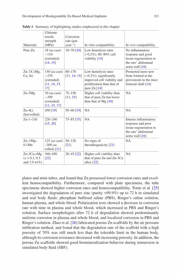
313
plates and mini-tubes, and found that Zn possessed lower corrosion rates and excel-lent hemocompatibility. Furthermore, compared with plate specimens, the tube specimens showed higher corrosion rates and hemocompatibility. Torne et al. [25] investigated the degradation of pure zinc (purity >99.9%) up to 72 h in simulated and real body fluids: phosphate buffered saline (PBS), Ringer’s saline solution, human plasma, and whole blood. Polarization tests showed a decrease in corrosion rate with time in plasma and whole blood, which increased in PBS and Ringer’s solution. Surface morphologies after 72 h of degradation showed predominantly uniform corrosion in plasma and whole blood, and localized corrosion in PBS and Ringer’s solution. Zhao et al. [26] fabricated porous Zn scaffolds by the air pressure infiltration method, and found that the degradation rate of the scaffold with a high porosity of 70% was still much less than the tolerable limit in the human body, although its corrosion resistance decreased with increasing porosity. In addition, the porous Zn scaffolds showed good biomineralization behavior during immersion in simulated body fluid (SBF).
Table 1 Summary of highlighting studies emphasized in this chapter
Materials
Ultimate tensile strength (MPa)
Corrosion rate (μm year−1) In vitro compatibility In vivo compatibility
Pure Zn 18 (as-cast)−110 (extruded) [14, 15]
10–70 [10] Low hemolysis rates (~0.2%); 80–90% cell viability [14]
No inflammatory response and good tissue regeneration in the rats’ abdominal aorta wall [16]
Zn-1X (Mg, Ca, Sr)
150 (as-cast)−270 (extruded) [11, 14, 15, 17]
80–170 [11, 14, 15]
Low hemolysis rates (~0.2%); significantly improved cell viability and proliferation than that of pure Zn [14]
Promoted more new bone formed at the periosteum in the mice femoral shaft [14]
Zn-3Mg 30 (as-cast)−399 (extruded) [11, 15, 17]
75–150 [11, 15]
Higher cell viability than that of pure Zn but lower than that of Mg [18]
NA
Zn-4Li (hot-rolled)
450 [19] 50–60 [19] NA NA
Zn-1~3Al 220–240 [15, 20]
75–85 [15] NA Intense inflammatory response and poor tissue regeneration in the rats’ abdominal aorta wall [16]
Zn–1Mg–0.1Mn
125 (as-cast)–300 (as rolled) [21]
50–120 [21]
No signs of thrombogenicity [21]
NA
Zn-3Cu-xMg (x = 0.1, 0.5 and 1.0 wt%)
360–450 [22]
20–45 [22] Higher cell viability than that of pure Zn and Zn-3Cu alloy [22]
NA
Development of Biodegradable Zn-Based Medical Implants
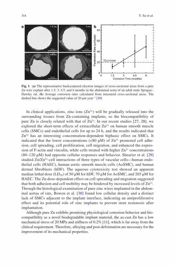
314
In clinical applications, zinc ions (Zn2+) will be gradually released into the surrounding tissues from Zn-containing implants, so the biocompatibility of pure Zn is closely related with that of Zn2+. In our recent studies [27, 28], we explored the short-term effects of extracellular Zn2+ on human smooth muscle cells (SMCs) and endothelial cells for up to 24 h, and the results indicated that Zn2+ has an interesting concentration-dependent biphasic effect on SMCs. It indicated that the lower concentrations (<80 μM) of Zn2+ promoted cell adhe-sion, cell spreading, cell proliferation, cell migration, and enhanced the expres-sion of F-actin and vinculin, while cells treated with higher Zn2+ concentrations (80–120 μM) had opposite cellular responses and behavior. Shearier et al. [29] studied Zn/Zn2+-cell interactions of three types of vascular cells—human endo-thelial cells (HAEC), human aortic smooth muscle cells (AoSMC), and human dermal fibroblasts (hDF). The aqueous cytotoxicity test showed an apparent median lethal dose (LD50) of 50 μM for hDF, 70 μM for AoSMC, and 265 μM for HAEC. The Zn dose-dependent effect on cell spreading and migration suggested that both adhesion and cell mobility may be hindered by increased levels of Zn2+. Through the histological examination of pure zinc wires implanted in the abdom-inal aortas of rats, Bowen et al. [30] found low cellular density and a distinct lack of SMCs adjacent to the implant interface, indicating an antiproliferative effect and its potential role of zinc implants to prevent stent restenosis after implantation.
Although pure Zn exhibits promising physiological corrosion behavior and bio-compatibility as a novel biodegradable implant material, the as-cast Zn has a low mechanical stress of 20 MPa and stiffness of 0.2% [11], which is far away from the clinical requirement. Therefore, alloying and post-deformation are necessary for the improvement of its mechanical properties.
Fig. 1 (a) The representative backscattered electron images of cross-sectional areas from a pure Zn wire explant after 1.5, 3, 4.5, and 6 months in the abdominal aorta of an adult male Sprague–Dawley rat. (b) Average corrosion rates calculated from measured cross-sectional areas. The dashed line shows the suggested value of 20 μm year−1 [10]
Y. Su et al.
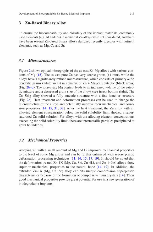
315
3 Zn-Based Binary Alloy
To ensure the biocompatibility and biosafety of the implant materials, commonly used elements (e.g. Al and Cu) in industrial Zn alloys were not considered, and there have been several Zn-based binary alloys designed recently together with nutrient elements, such as Mg, Ca and Sr.
3.1 Microstructures
Figure 2 shows optical micrographs of the as-cast Zn-Mg alloys with various con-tents of Mg [15]. The as-cast pure Zn has very coarse grains (>1 mm), while the alloys have a significantly refined microstructure, which consists of primary α-Zn dendritic grains (white areas) in a matrix of Zn + Mg2Zn11 eutectic (black areas) (Fig. 2b–d). The increasing Mg content leads to an increased volume of the eutec-tic mixture and a decreased grain size of the alloys (see insets bottom right). The Zn–3Mg alloy showed a fully eutectic structure with a fine lamellar structure (Fig. 2e). Heat treatment and deformation processes can be used to change the microstructure of the alloys and potentially improve their mechanical and corro-sion properties [14, 15, 31, 32]. After the heat treatment, the Zn alloy with an alloying element concentration below the solid solubility limit showed a super-saturated Zn solid solution. For alloys with the alloying element concentrations exceeding the solid solubility limit, there are intermetallic particles precipitated at grain boundaries.
3.2 Mechanical Properties
Alloying Zn with a small amount of Mg and Li improves mechanical properties to the level of some Mg alloys and can be further enhanced with severe plastic deformation processing techniques [11, 14, 15, 17, 19]. It should be noted that the deformation treated Zn-1X (Mg, Ca, Sr), Zn-4Li, and Zn-1~3Al alloys show superior mechanical properties to the natural bone [14, 19]. In addition, the extruded Zn-1X (Mg, Ca, Sr) alloy exhibits unique compression superplastic characteristics because of the formation of compressive twin crystals [14]. Their good mechanical properties provide great potential for use in a new generation of biodegradable implants.
Development of Biodegradable Zn-Based Medical Implants
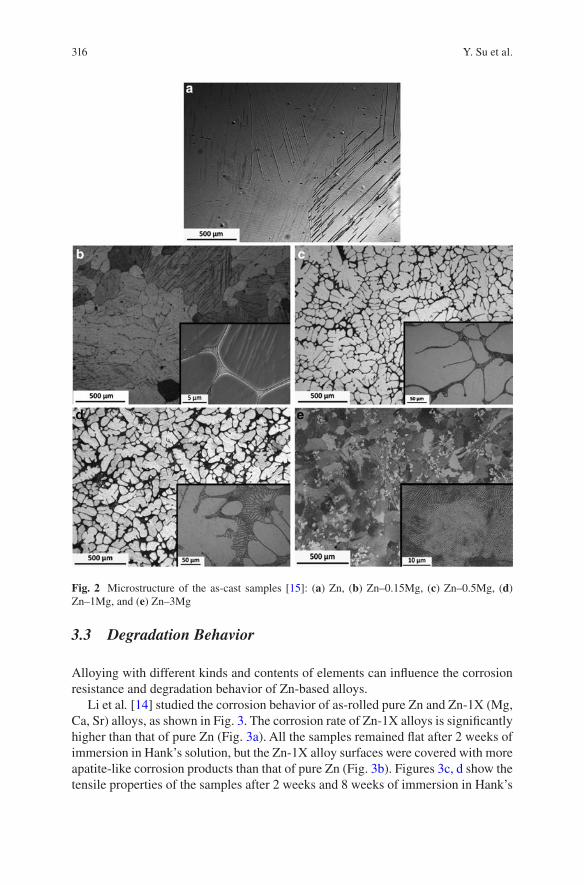
316
3.3 Degradation Behavior
Alloying with different kinds and contents of elements can influence the corrosion resistance and degradation behavior of Zn-based alloys.
Li et al. [14] studied the corrosion behavior of as-rolled pure Zn and Zn-1X (Mg, Ca, Sr) alloys, as shown in Fig. 3. The corrosion rate of Zn-1X alloys is significantly higher than that of pure Zn (Fig. 3a). All the samples remained flat after 2 weeks of immersion in Hank’s solution, but the Zn-1X alloy surfaces were covered with more apatite-like corrosion products than that of pure Zn (Fig. 3b). Figures 3c, d show the tensile properties of the samples after 2 weeks and 8 weeks of immersion in Hank’s
Fig. 2 Microstructure of the as-cast samples [15]: (a) Zn, (b) Zn–0.15Mg, (c) Zn–0.5Mg, (d) Zn–1Mg, and (e) Zn–3Mg
Y. Su et al.
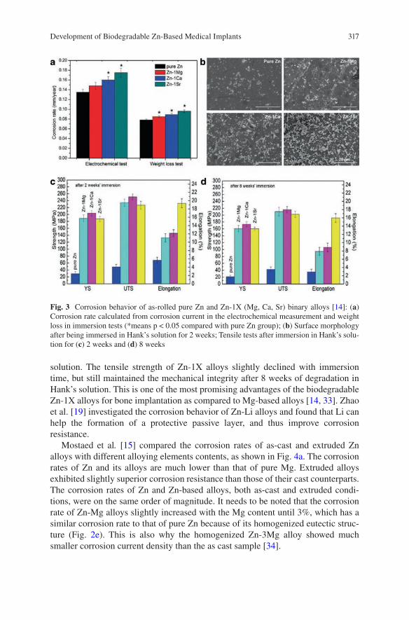
317
solution. The tensile strength of Zn-1X alloys slightly declined with immersion time, but still maintained the mechanical integrity after 8 weeks of degradation in Hank’s solution. This is one of the most promising advantages of the biodegradable Zn-1X alloys for bone implantation as compared to Mg-based alloys [14, 33]. Zhao et al. [19] investigated the corrosion behavior of Zn-Li alloys and found that Li can help the formation of a protective passive layer, and thus improve corrosion resistance.
Mostaed et al. [15] compared the corrosion rates of as-cast and extruded Zn alloys with different alloying elements contents, as shown in Fig. 4a. The corrosion rates of Zn and its alloys are much lower than that of pure Mg. Extruded alloys exhibited slightly superior corrosion resistance than those of their cast counterparts. The corrosion rates of Zn and Zn-based alloys, both as-cast and extruded condi-tions, were on the same order of magnitude. It needs to be noted that the corrosion rate of Zn-Mg alloys slightly increased with the Mg content until 3%, which has a similar corrosion rate to that of pure Zn because of its homogenized eutectic struc-ture (Fig. 2e). This is also why the homogenized Zn-3Mg alloy showed much smaller corrosion current density than the as cast sample [34].
Fig. 3 Corrosion behavior of as-rolled pure Zn and Zn-1X (Mg, Ca, Sr) binary alloys [14]: (a) Corrosion rate calculated from corrosion current in the electrochemical measurement and weight loss in immersion tests (*means p < 0.05 compared with pure Zn group); (b) Surface morphology after being immersed in Hank’s solution for 2 weeks; Tensile tests after immersion in Hank’s solu-tion for (c) 2 weeks and (d) 8 weeks
Development of Biodegradable Zn-Based Medical Implants
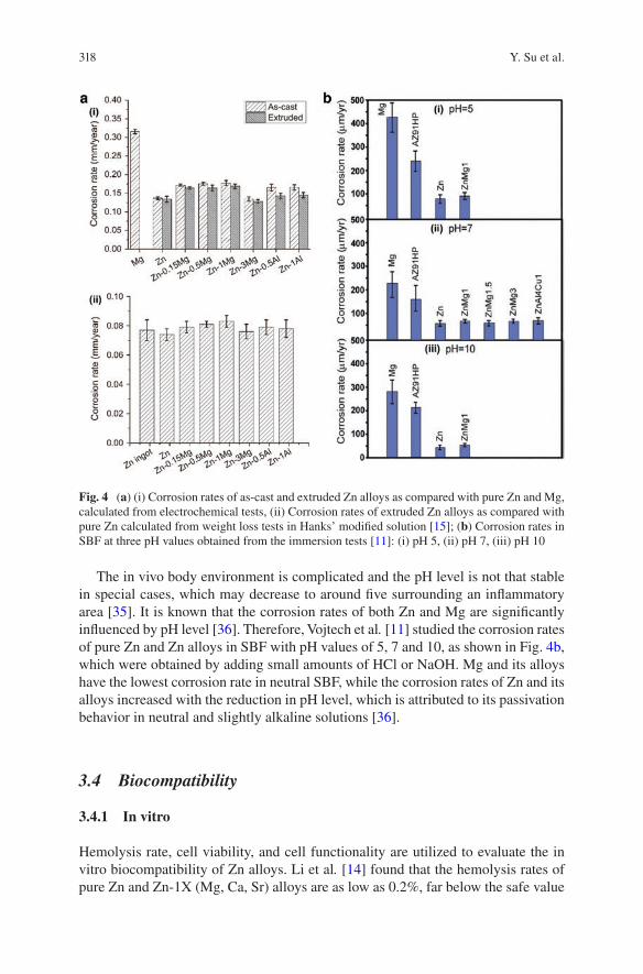
318
The in vivo body environment is complicated and the pH level is not that stable in special cases, which may decrease to around five surrounding an inflammatory area [35]. It is known that the corrosion rates of both Zn and Mg are significantly influenced by pH level [36]. Therefore, Vojtech et al. [11] studied the corrosion rates of pure Zn and Zn alloys in SBF with pH values of 5, 7 and 10, as shown in Fig. 4b, which were obtained by adding small amounts of HCl or NaOH. Mg and its alloys have the lowest corrosion rate in neutral SBF, while the corrosion rates of Zn and its alloys increased with the reduction in pH level, which is attributed to its passivation behavior in neutral and slightly alkaline solutions [36].
3.4 Biocompatibility
3.4.1 In vitro
Hemolysis rate, cell viability, and cell functionality are utilized to evaluate the in vitro biocompatibility of Zn alloys. Li et al. [14] found that the hemolysis rates of pure Zn and Zn-1X (Mg, Ca, Sr) alloys are as low as 0.2%, far below the safe value
Fig. 4 (a) (i) Corrosion rates of as-cast and extruded Zn alloys as compared with pure Zn and Mg, calculated from electrochemical tests, (ii) Corrosion rates of extruded Zn alloys as compared with pure Zn calculated from weight loss tests in Hanks’ modified solution [15]; (b) Corrosion rates in SBF at three pH values obtained from the immersion tests [11]: (i) pH 5, (ii) pH 7, (iii) pH 10
Y. Su et al.
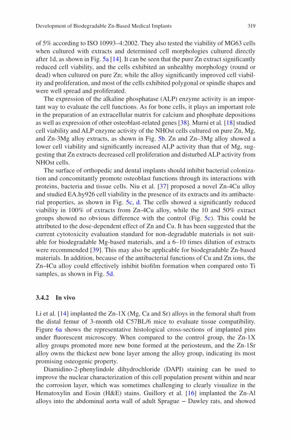
319
of 5% according to ISO 10993–4:2002. They also tested the viability of MG63 cells when cultured with extracts and determined cell morphologies cultured directly after 1d, as shown in Fig. 5a [14]. It can be seen that the pure Zn extract significantly reduced cell viability, and the cells exhibited an unhealthy morphology (round or dead) when cultured on pure Zn; while the alloy significantly improved cell viabil-ity and proliferation, and most of the cells exhibited polygonal or spindle shapes and were well spread and proliferated.
The expression of the alkaline phosphatase (ALP) enzyme activity is an impor-tant way to evaluate the cell functions. As for bone cells, it plays an important role in the preparation of an extracellular matrix for calcium and phosphate depositions as well as expression of other osteoblast-related genes [38]. Murni et al. [18] studied cell viability and ALP enzyme activity of the NHOst cells cultured on pure Zn, Mg, and Zn-3Mg alloy extracts, as shown in Fig. 5b. Zn and Zn–3Mg alloy showed a lower cell viability and significantly increased ALP activity than that of Mg, sug-gesting that Zn extracts decreased cell proliferation and disturbed ALP activity from NHOst cells.
The surface of orthopedic and dental implants should inhibit bacterial coloniza-tion and concomitantly promote osteoblast functions through its interactions with proteins, bacteria and tissue cells. Niu et al. [37] proposed a novel Zn-4Cu alloy and studied EA.hy926 cell viability in the presence of its extracts and its antibacte-rial properties, as shown in Fig. 5c, d. The cells showed a significantly reduced viability in 100% of extracts from Zn-4Cu alloy, while the 10 and 50% extract groups showed no obvious difference with the control (Fig. 5c). This could be attributed to the dose- dependent effect of Zn and Cu. It has been suggested that the current cytotoxicity evaluation standard for non-degradable materials is not suit-able for biodegradable Mg-based materials, and a 6–10 times dilution of extracts were recommended [39]. This may also be applicable for biodegradable Zn-based materials. In addition, because of the antibacterial functions of Cu and Zn ions, the Zn-4Cu alloy could effectively inhibit biofilm formation when compared onto Ti samples, as shown in Fig. 5d.
3.4.2 In vivo
Li et al. [14] implanted the Zn-1X (Mg, Ca and Sr) alloys in the femoral shaft from the distal femur of 3-month old C57BL/6 mice to evaluate tissue compatibility. Figure 6a shows the representative histological cross-sections of implanted pins under fluorescent microscopy. When compared to the control group, the Zn-1X alloy groups promoted more new bone formed at the periosteum, and the Zn-1Sr alloy owns the thickest new bone layer among the alloy group, indicating its most promising osteogenic property.
Diamidino-2-phenylindole dihydrochloride (DAPI) staining can be used to improve the nuclear characterization of this cell population present within and near the corrosion layer, which was sometimes challenging to clearly visualize in the Hematoxylin and Eosin (H&E) stains. Guillory et al. [16] implanted the Zn-Al alloys into the abdominal aorta wall of adult Sprague − Dawley rats, and showed
Development of Biodegradable Zn-Based Medical Implants
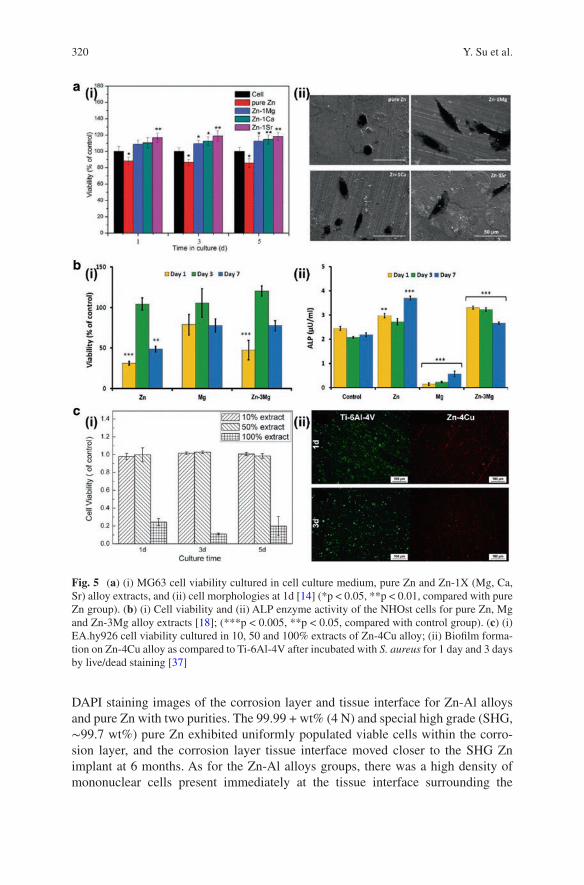
320
DAPI staining images of the corrosion layer and tissue interface for Zn-Al alloys and pure Zn with two purities. The 99.99 + wt% (4 N) and special high grade (SHG, ∼99.7 wt%) pure Zn exhibited uniformly populated viable cells within the corro-sion layer, and the corrosion layer tissue interface moved closer to the SHG Zn implant at 6 months. As for the Zn-Al alloys groups, there was a high density of mononuclear cells present immediately at the tissue interface surrounding the
Fig. 5 (a) (i) MG63 cell viability cultured in cell culture medium, pure Zn and Zn-1X (Mg, Ca, Sr) alloy extracts, and (ii) cell morphologies at 1d [14] (*p < 0.05, **p < 0.01, compared with pure Zn group). (b) (i) Cell viability and (ii) ALP enzyme activity of the NHOst cells for pure Zn, Mg and Zn-3Mg alloy extracts [18]; (***p < 0.005, **p < 0.05, compared with control group). (c) (i) EA.hy926 cell viability cultured in 10, 50 and 100% extracts of Zn-4Cu alloy; (ii) Biofilm forma-tion on Zn-4Cu alloy as compared to Ti-6Al-4V after incubated with S. aureus for 1 day and 3 days by live/dead staining [37]
Y. Su et al.
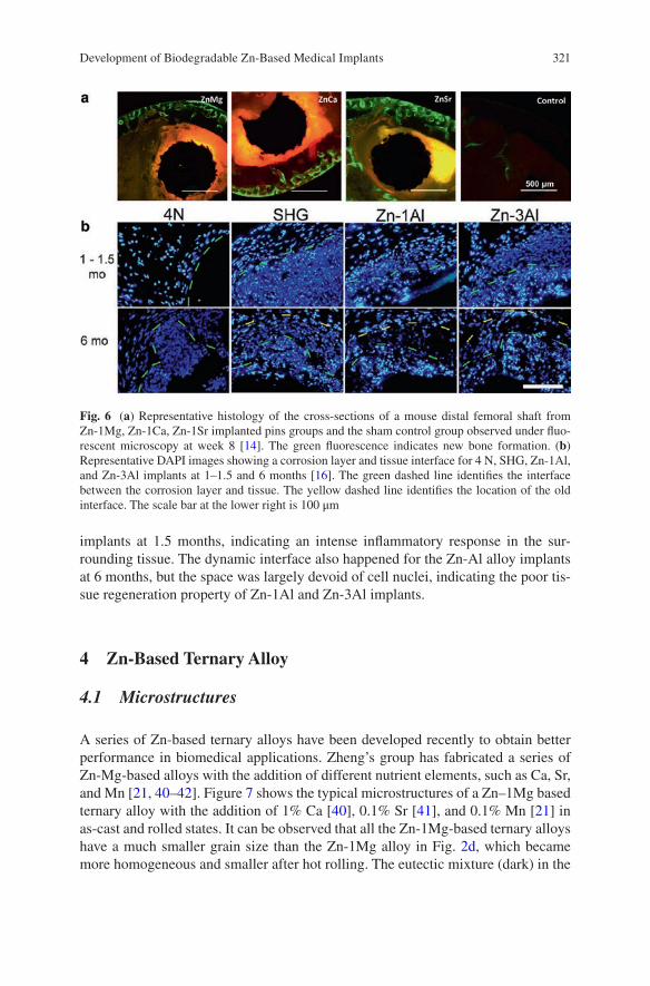
321
implants at 1.5 months, indicating an intense inflammatory response in the sur-rounding tissue. The dynamic interface also happened for the Zn-Al alloy implants at 6 months, but the space was largely devoid of cell nuclei, indicating the poor tis-sue regeneration property of Zn-1Al and Zn-3Al implants.
4 Zn-Based Ternary Alloy
4.1 Microstructures
A series of Zn-based ternary alloys have been developed recently to obtain better performance in biomedical applications. Zheng’s group has fabricated a series of Zn-Mg-based alloys with the addition of different nutrient elements, such as Ca, Sr, and Mn [21, 40–42]. Figure 7 shows the typical microstructures of a Zn–1Mg based ternary alloy with the addition of 1% Ca [40], 0.1% Sr [41], and 0.1% Mn [21] in as-cast and rolled states. It can be observed that all the Zn-1Mg-based ternary alloys have a much smaller grain size than the Zn-1Mg alloy in Fig. 2d, which became more homogeneous and smaller after hot rolling. The eutectic mixture (dark) in the
Fig. 6 (a) Representative histology of the cross-sections of a mouse distal femoral shaft from Zn-1Mg, Zn-1Ca, Zn-1Sr implanted pins groups and the sham control group observed under fluo-rescent microscopy at week 8 [14]. The green fluorescence indicates new bone formation. (b) Representative DAPI images showing a corrosion layer and tissue interface for 4 N, SHG, Zn-1Al, and Zn-3Al implants at 1–1.5 and 6 months [16]. The green dashed line identifies the interface between the corrosion layer and tissue. The yellow dashed line identifies the location of the old interface. The scale bar at the lower right is 100 μm
Development of Biodegradable Zn-Based Medical Implants
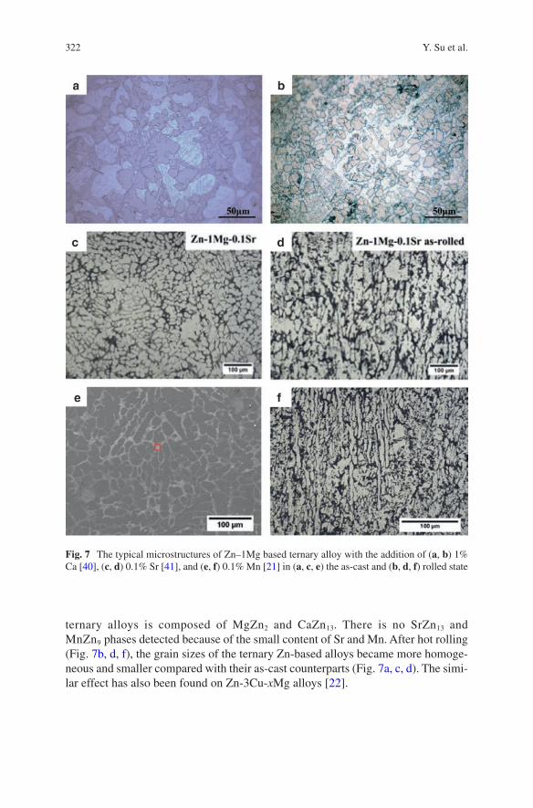
322
ternary alloys is composed of MgZn2 and CaZn13. There is no SrZn13 and MnZn9 phases detected because of the small content of Sr and Mn. After hot rolling (Fig. 7b, d, f), the grain sizes of the ternary Zn-based alloys became more homoge-neous and smaller compared with their as-cast counterparts (Fig. 7a, c, d). The simi-lar effect has also been found on Zn-3Cu-xMg alloys [22].
Fig. 7 The typical microstructures of Zn–1Mg based ternary alloy with the addition of (a, b) 1% Ca [40], (c, d) 0.1% Sr [41], and (e, f) 0.1% Mn [21] in (a, c, e) the as-cast and (b, d, f) rolled state
Y. Su et al.
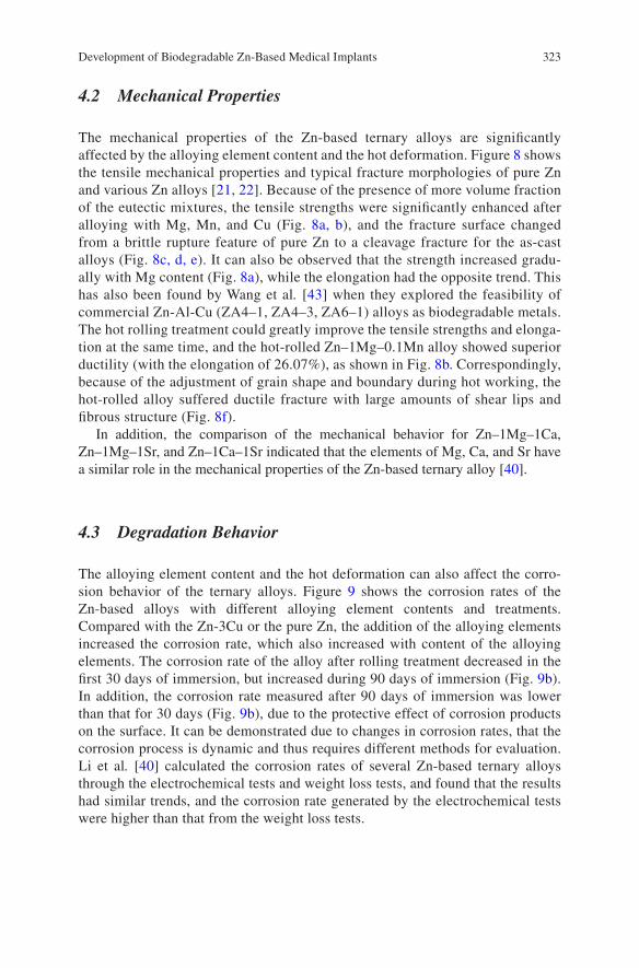
323
4.2 Mechanical Properties
The mechanical properties of the Zn-based ternary alloys are significantly affected by the alloying element content and the hot deformation. Figure 8 shows the tensile mechanical properties and typical fracture morphologies of pure Zn and various Zn alloys [21, 22]. Because of the presence of more volume fraction of the eutectic mixtures, the tensile strengths were significantly enhanced after alloying with Mg, Mn, and Cu (Fig. 8a, b), and the fracture surface changed from a brittle rupture feature of pure Zn to a cleavage fracture for the as-cast alloys (Fig. 8c, d, e). It can also be observed that the strength increased gradu-ally with Mg content (Fig. 8a), while the elongation had the opposite trend. This has also been found by Wang et al. [43] when they explored the feasibility of commercial Zn-Al-Cu (ZA4–1, ZA4–3, ZA6–1) alloys as biodegradable metals. The hot rolling treatment could greatly improve the tensile strengths and elonga-tion at the same time, and the hot-rolled Zn–1Mg–0.1Mn alloy showed superior ductility (with the elongation of 26.07%), as shown in Fig. 8b. Correspondingly, because of the adjustment of grain shape and boundary during hot working, the hot-rolled alloy suffered ductile fracture with large amounts of shear lips and fibrous structure (Fig. 8f).
In addition, the comparison of the mechanical behavior for Zn–1Mg–1Ca, Zn–1Mg–1Sr, and Zn–1Ca–1Sr indicated that the elements of Mg, Ca, and Sr have a similar role in the mechanical properties of the Zn-based ternary alloy [40].
4.3 Degradation Behavior
The alloying element content and the hot deformation can also affect the corro-sion behavior of the ternary alloys. Figure 9 shows the corrosion rates of the Zn-based alloys with different alloying element contents and treatments. Compared with the Zn-3Cu or the pure Zn, the addition of the alloying elements increased the corrosion rate, which also increased with content of the alloying elements. The corrosion rate of the alloy after rolling treatment decreased in the first 30 days of immersion, but increased during 90 days of immersion (Fig. 9b). In addition, the corrosion rate measured after 90 days of immersion was lower than that for 30 days (Fig. 9b), due to the protective effect of corrosion products on the surface. It can be demonstrated due to changes in corrosion rates, that the corrosion process is dynamic and thus requires different methods for evaluation. Li et al. [40] calculated the corrosion rates of several Zn-based ternary alloys through the electrochemical tests and weight loss tests, and found that the results had similar trends, and the corrosion rate generated by the electrochemical tests were higher than that from the weight loss tests.
Development of Biodegradable Zn-Based Medical Implants
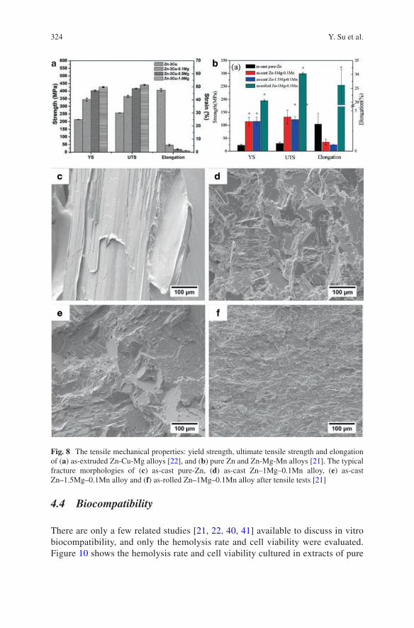
324
4.4 Biocompatibility
There are only a few related studies [21, 22, 40, 41] available to discuss in vitro biocompatibility, and only the hemolysis rate and cell viability were evaluated. Figure 10 shows the hemolysis rate and cell viability cultured in extracts of pure
Fig. 8 The tensile mechanical properties: yield strength, ultimate tensile strength and elongation of (a) as-extruded Zn-Cu-Mg alloys [22], and (b) pure Zn and Zn-Mg-Mn alloys [21]. The typical fracture morphologies of (c) as-cast pure-Zn, (d) as-cast Zn–1Mg–0.1Mn alloy, (e) as-cast Zn–1.5Mg–0.1Mn alloy and (f) as-rolled Zn–1Mg–0.1Mn alloy after tensile tests [21]
Y. Su et al.
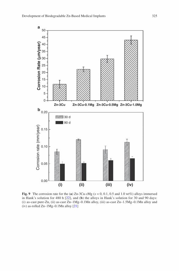
325
50
45
40
35
30
25
20
15
10
5
0
0.20
0.15
30 d
90 d
0.10
0.05
Cor
rosi
on r
ate
(mm
/yea
r)
0.00
Zn-3Cu
(i)
a
b
(ii) (iii) (iv)
Co
rro
sio
n R
ate
(mm
/yea
r)
Zn-3Cu-0.1Mg Zn-3Cu-0.5Mg Zn-3Cu-1.0Mg
Fig. 9 The corrosion rate for the (a) Zn-3Cu-xMg (x = 0, 0.1, 0.5 and 1.0 wt%) alloys immersed in Hank’s solution for 480 h [22], and (b) the alloys in Hank’s solution for 30 and 90 days: (i) as- cast pure-Zn, (ii) as-cast Zn–1Mg–0.1Mn alloy, (iii) as-cast Zn–1.5Mg–0.1Mn alloy and (iv) as- rolled Zn–1Mg–0.1Mn alloy [21]
Development of Biodegradable Zn-Based Medical Implants
326
Zn and Zn-based ternary alloys [22, 40]. It can be observed that the hemolysis rates of pure Zn and Zn-(Mg, Ca, Sr) ternary alloys are lower than 0.5% (Fig. 10a), similar to that of the corresponding Zn-1X (Mg, Ca, Sr) alloys [14], because Mg, Ca and Sr are all nutrient alloying elements. Thus, MG63 cell viability cultured in extracts of the Zn-based ternary alloy showed a significant increase compared to that of the pure Zn and negative control groups (Fig. 10b). This indicates that the addition of the nutrient elements Mg, Ca and Sr can improve hemocompatibility and cytocompatibility.
Compared to the Zn-(Mg, Ca, Sr) ternary alloys, the addition of Cu into the Zn alloy has proven to possess good antibacterial properties and acceptable cytocom-patibility [37]. Moreover, the biocompatibility of the Zn-Cu-xMg alloy increased with Mg addition for 100% extracts (Fig. 10c), i.e., the cytotoxicity of the Zn-Cu alloy can be decreased by the addition of Mg, because more Mg ions would be released through its more rapid degradation process [22]. EA.hy926 cells cultured in 50% extracts exhibited good cell viability, and there was no significant difference in cell viability between different groups, as shown in Fig. 10d, which might be
Fig. 10 (a) Hemolysis rate and (b) MG63 cell viability cultured in extracts of pure Zn and Zn-based ternary alloys [40] (*p < 0.05, **p < 0.01 compared with pure Zn group). The viability of EA.hy926 cells cultured in (c) 100% and (d) 50% extracts of pure Zn and as-extruded Zn-3Cu- xMg (x = 0, 0.1, 0.5 and 1.0 wt%) alloys [22]
Y. Su et al.
327
attributed to the decreasing Cu and Mg ion concentrations in the extract dilution. Wang et al. [43] also found that the cytotoxic effect in 100% extracts of pure Zn and Zn-Al-Cu commercial alloys, but no cytotoxicity was observed after dilution. In addition, both pure Zn and Zn-Al-Cu alloys showed good hemocompatibility, while ZA4–1 and ZA6–1 alloys had significantly improved biocompatibility compared to pure Zn [43].
5 Concluding Remarks and Perspectives
Zn-based metallic biomaterials are still in the initial phase of development and there are only several research groups conducting related research. However, it is becom-ing a much more important issue in the development of high performance metallic biomaterials because of its unique corrosion and mechanical properties. In view of the current research status and clinical requirements, new directions should be con-sidered as follows:
1. Novel alloying elements should be considered to add in the Zn alloys except the aforementioned Mg, Ca, Sr, Mn, and Cu. Ti has a good biocompatibility, and its alloys have been used in practical clinical applications for many years. The addi-tion of a small amount of Ti can refine the grain size and improve the mechanical properties of Zn alloys. Li is one of the important trace elements in the human body, and can potentially improve the tensile strength and dimensional stability of the alloy.
2. Novel structure design, including porous structures, composite structures, ultra-fine or nanocrystalline structures, and glassy structures, could be promising as novel properties for Zn-based biodegradable metals.
3. Surface modification is a universal way for biodegradable metals to adjust the biodegradation rate and enhance surface biocompatibility, and thus is necessary to be applied on Zn-based alloys for biomedical applications.
Acknowledgements This work was supported by National Institutes of Health [grant number HL140562]. The content is solely the responsibility of the authors and does not necessarily represent the official views of the National Institutes of Health.
References
1. Niinomi M, Nakai M, Hieda J. Development of new metallic alloys for biomedical applica-tions. Acta Biomater. 2012;8(11):3888–903.
2. Lhotka C, Szekeres T, Steffan I, Zhuber K, Zweymiiller K. Four-year study of cobalt and chro-mium blood levels in patients managed with two different metal-on-metal total hip replace-ments. J Orthop Res. 2003;21(2):189–95.
3. Niinomi M, Hattori T, Morikawa K, Kasuga T, Suzuki A, Fukui H, Niwa S. Development of low rigidity β-type titanium alloy for biomedical applications. Mater Trans. 2002;43(12):2970–7.
Development of Biodegradable Zn-Based Medical Implants
328
4. Zheng YF, Gu XN, Witte F. Biodegradable metals. Mater Sci Eng R Rep. 2014;77:1–34. 5. Hermawan H. Biodegradable metals: from concept to applications. Heidelberg: Springer;
2012. 6. Mahyudin F, Hermawan H. Biomaterials and medical devices: a perspective from an emerging
country. New York: Springer; 2016. 7. Kuhlmann J, Bartsch I, Willbold E, Schuchardt S, Holz O, Hort N, Höche D, Heineman WR,
Witte F. Fast escape of hydrogen from gas cavities around corroding magnesium implants. Acta Biomater. 2013;9(10):8714–21.
8. Drynda A, Hassel T, Bach FW, Peuster M. In vitro and in vivo corrosion properties of new iron-manganese alloys designed for cardiovascular applications. J Biomed Mater Res B Appl Biomater. 2015;103(3):649–60.
9. Yusop AHM, Daud NM, Nur H, Kadir MRA, Hermawan H. Controlling the degradation kinet-ics of porous iron by poly(lactic-co-glycolic acid) infiltration for use as temporary medical implants. Sci Rep. 2015;5:11194.
10. Bowen PK, Drelich J, Goldman J. Zinc exhibits ideal physiological corrosion behavior for bioabsorbable stents. Adv Mater. 2013;25(18):2577–82.
11. Vojtech D, Kubasek J, Serak J, Novak P. Mechanical and corrosion properties of newly devel-oped biodegradable Zn-based alloys for bone fixation. Acta Biomater. 2011;7(9):3515–22.
12. McCall KA, Huang C, Fierke CA. Function and mechanism of zinc metalloenzymes. J Nutr. 2000;130(5):1437S–46S.
13. Trumbo P, Yates AA, Schlicker S, Poos M. Dietary reference intakes: vitamin A, vitamin K, arsenic, boron, chromium, copper, iodine, iron, manganese, molybdenum, nickel, silicon, vanadium, and zinc. J Am Diet Assoc. 2001;101(3):294–301.
14. Li HF, Xie XH, Zheng YF, Cong Y, Zhou FY, Qiu KJ, Wang X, Chen SH, Huang L, Tian L, Qin L. Development of biodegradable Zn-1X binary alloys with nutrient alloying elements Mg, Ca and Sr. Sci Rep. 2015;5:10719.
15. Mostaed E, Sikora-Jasinska M, Mostaed A, Loffredo S, Demir AG, Previtali B, Mantovani D, Beanland R, Vedani M. Novel Zn-based alloys for biodegradable stent applications: design, development and in vitro degradation. J Mech Behav Biomed Mater. 2016;60:581–602.
16. Guillory RJ, Bowen PK, Hopkins SP, Shearier ER, Earley EJ, Gillette AA, Aghion E, Bocks M, Drelich JW, Goldman J. Corrosion characteristics dictate the long-term inflammatory pro-file of degradable zinc arterial implants. ACS Biomater Sci Eng. 2016;2(12):2355–64.
17. Kubasek J, Vojtěch D. Zn-based alloys as an alternative biodegradable materials. Proc Metal. 2012;5:23–5.
18. Murni NS, Dambatta MS, Yeap SK, Froemming GR, Hermawan H. Cytotoxicity evaluation of biodegradable Zn-3Mg alloy toward normal human osteoblast cells. Mater Sci Eng C Mater Biol Appl. 2015;49:560–6.
19. Zhao S, McNamara CT, Bowen PK, Verhun N, Braykovich JP, Goldman J, Drelich JW. Structural characteristics and in vitro biodegradation of a novel Zn-Li alloy prepared by induction melting and Hot rolling. Metall Mater Trans S. 2017;48(3):1204–15.
20. Bowen PK, Seitz JM, Guillory RJ 2nd, Braykovich JP, Zhao S, Goldman J, Drelich JW. Evaluation of wrought Zn-Al alloys (1, 3, and 5 wt % Al) through mechanical and in vivo testing for stent applications. J Biomed Mater Res B Appl Biomater. 2017;106(1):245–58.
21. Liu X, Sun J, Zhou F, Yang Y, Chang R, Qiu K, Pu Z, Li L, Zheng Y. Micro-alloying with Mn in Zn-Mg alloy for future biodegradable metals application. Mater Design. 2016;94:95–104.
22. Tang Z, Huang H, Niu J, Zhang L, Zhang H, Pei J, Tan J, Yuan G. Design and characterizations of novel biodegradable Zn-Cu-Mg alloys for potential biodegradable implants. Mater Design. 2016;117:84–94.
23. Witte F, Hort N, Feyerabend F, Vogt C. 10—Magnesium (Mg) corrosion: a challenging concept for degradable implants A2—Song, Guang-ling, corrosion of magnesium alloys. Cambridge: Woodhead Publishing; 2011. p. 403–25.
24. Liu XW, Sun JK, Yang YH, Pu ZJ, Zheng YF. In vitro investigation of ultra-pure Zn and its mini-tube as potential bioabsorbable stent material. Mater Lett. 2015;161:53–6.
Y. Su et al.
329
25. Torne K, Larsson M, Norlin A, Weissenrieder J. Degradation of zinc in saline solutions, plasma, and whole blood. J Biomed Mater Res B Appl Biomater. 2016;104(6):1141–51.
26. Zhao LC, Zhang Z, Song YT, Liu SJ, Qi YM, Wang X, Wang QZ, Cui CX. Mechanical proper-ties and in vitro biodegradation of newly developed porous Zn scaffolds for biomedical appli-cations. Mater Design. 2016;108:136–44.
27. Ma J, Zhao N, Zhu D. Bioabsorbable zinc ion induced biphasic cellular responses in vascular smooth muscle cells. Sci Rep. 2016;6:26661.
28. Ma J, Zhao N, Zhu D. Endothelial cellular responses to biodegradable metal zinc. ACS Biomater Sci Eng. 2015;1(11):1174–82.
29. Shearier ER, Bowen PK, He W, Drelich A, Drelich J, Goldman J, Zhao F. In vitro cytotoxicity, adhesion, and proliferation of human vascular cells exposed to zinc. Acs Biomater Sci Eng. 2016;2(4):634–42.
30. Bowen PK, Guillory Ii RJ, Shearier ER, Seitz J-M, Drelich J, Bocks M, Zhao F, Goldman J. Metallic zinc exhibits optimal biocompatibility for bioabsorbable endovascular stents. Mater Sci Eng C. 2015;56:467–72.
31. Gong H, Wang K, Strich R, Zhou JG. In vitro biodegradation behavior, mechanical proper-ties, and cytotoxicity of biodegradable Zn-Mg alloy. J Biomed Mater Res B Appl Biomater. 2015;103(8):1632–40.
32. Shen C, Liu X, Fan B, Lan P, Zhou F, Li X, Wang H, Xiao X, Li L, Zhao S. Mechanical properties, in vitro degradation behavior, hemocompatibility and cytotoxicity evaluation of Zn-1.2 Mg alloy for biodegradable implants. RSC Adv. 2016;6(89):86410–9.
33. Li N, Zheng Y. Novel magnesium alloys developed for biomedical application: a review. J Mater Sci Technol. 2013;29(6):489–502.
34. Dambatta MS, Kurniawan D, Sudin I, Yahaya B, Hermawan H. Influence of homogenization treatment on the degradation behavior of Zn-3Mg alloy in simulated body fluid solution. Proc Inst Mech Eng L. 2016;230(2):615–9.
35. Davis JR. Handbook of materials for medical devices. Novelty: ASM International; 2003. 36. Talbot DE, Talbot JD. Corrosion science and technology. Boca Raton: CRC Press; 2007. 37. Niu J, Tang Z, Huang H, Pei J, Zhang H, Yuan G, Ding W. Research on a Zn-Cu alloy as a
biodegradable material for potential vascular stents application. Mater Sci Eng C Mater Biol Appl. 2016;69:407–13.
38. Lian JB, Stein GS. Concepts of osteoblast growth and differentiation: basis for modulation of bone cell development and tissue formation. Crit Rev Oral Biol Med. 1992;3(3):269–305.
39. Wang J, Witte F, Xi T, Zheng Y, Yang K, Yang Y, Zhao D, Meng J, Li Y, Li W, Chan K, Qin L. Recommendation for modifying current cytotoxicity testing standards for biodegradable magnesium-based materials. Acta Biomater. 2015;21:237–49.
40. Li HF, Yang HT, Zheng YF, Zhou FY, Qiu KJ, Wang X. Design and characterizations of novel biodegradable ternary Zn-based alloys with IIA nutrient alloying elements Mg Ca and Sr. Mater Design. 2015;83:95–102.
41. Liu X, Sun J, Yang Y, Zhou F, Pu Z, Li L, Zheng Y. Microstructure, mechanical properties, in vitro degradation behavior and hemocompatibility of novel Zn–Mg–Sr alloys as biodegrad-able metals. Mater Lett. 2016;162:242–5.
42. Liu X, Sun J, Qiu K, Yang Y, Pu Z, Li L, Zheng Y. Effects of alloying elements (Ca and Sr) on microstructure, mechanical property and in vitro corrosion behavior of biodegradable Zn-1.5 Mg alloy. J Alloys Compd. 2016;664:444–52.
43. Wang C, Yang HT, Li X, Zheng YF. In vitro evaluation of the feasibility of commercial Zn alloys as biodegradable metals. J Mater Sci Technol. 2016;32(9):909–18.
Development of Biodegradable Zn-Based Medical Implants
331© Springer International Publishing AG, part of Springer Nature 2017B. Li, T. Webster (eds.), Orthopedic Biomaterials, https://doi.org/10.1007/978-3-319-73664-8_13
Surface Modification and Coatings for Controlling the Degradation and Bioactivity of Magnesium Alloys for Medical Applications
Ian Johnson, Jiajia Lin, and Huinan Liu
Keywords Magnesium · Coating · Surface modification · Degradation · Biomedical implant · Degradable metal · Anodization · Micro-arc oxidation · Calcium phosphate · Polymer · Dip coating · Spin coating · Bioactive factor
1 Introduction
1.1 Magnesium and the Current Orthopedic Materials
Coated magnesium (Mg) alloys possess many desirable properties that will enable them to supplement the current generation of orthopedic biomaterials. The most common orthopedic implants are generally made from non-degradable alloys such as titanium (Ti), stainless steel, and cobalt-chromium alloys. These alloys have extremely high mechanical strength and fracture toughness, enabling them to with-stand the forces that moving bodies exert on them. They are also biocompatible and non-degradable. Orthopedic implants made from these non-degradable alloys have improved the quality of life for millions of patients for decades, and will likely con-tinue to do so for many more years. However, applications that only require implants temporarily may be better served by Mg alloys.
I. Johnson Dental and Craniofacial Trauma Research, US Army Institute of Surgical Research, Houston, TX, USA
Department of Bioengineering, University of California, Riverside, Riverside, CA, USAe-mail: [email protected]
J. Lin Materials Science and Engineering, University of California, Riverside, CA, USA
H. Liu (*) Department of Bioengineering, University of California, Riverside, Riverside, CA, USA
Materials Science and Engineering, University of California, Riverside, CA, USAe-mail: [email protected]
332
1.2 There Is No Such Thing as Permanent Implants
Non-degradable implants are not permanent. Various phenomena will require their revisions; especially with younger and more active patients. A common challenge with non-degradable implants is encapsulation within fibrous tissue [1]. Encapsulation is the body’s response to foreign objects and impedes osteointegration, which is the formation of a direct bone/implant interface without non-bone tissue in-between. The long term success of orthopedic implants hinges upon their osteointegration [2]. Another challenge is the release of wear debris from biomaterials, which can stimu-late immune responses and is a major cause for implant revision [3]. Around 5% of internal fixators become infected [4], which may necessitate removal of those implants [5]. Other reasons for removing implants are pain, swelling, and sub-cutaneous prom-inence [6]. Non-degradable implants have more opportunities to encounter complica-tions because they reside in the body for long periods of time.
1.3 Why Use Biodegradable Implants?
Certain applications only require implants temporarily. Leaving implants in the body permanently might cause future complications [4], but surgical removal of implants always increases patient morbidity and medical costs [7]. The consequences of surgi-cal removal of implants can include refracture of bone, nerve damage, and infection [6]. Due to these consequences there is still debate among physicians about when non-degradable implants should be surgically removed [7].
Biodegradable implants are a promising alternative that could perform their function for the desired time period, and then be replaced with new healthy tissue as they degrade. The new healthy tissue would no longer need the implant for support after a certain timeframe. This would prevent both the foreign body complications and the need for removal surgery that often accompany non-degradable implants.
Mg is one of the front-runners in the search for new biodegradable materials for implant applications. Much of the research is focused upon orthopedic implants such as screws [8–10]. Other diverse implant applications for Mg include: coronary stents [11], securing myocardial grafts [12], uretal stents [13], intestinal anastomosis rings [14], extraluminal tracheal stents [15], microclips for laryngeal microsurgery [16], and nerve guidance conduits [17]. The reasons for the interest in Mg for such diverse applications are its excellent mechanical and biological properties.
1.4 The Advantages of Magnesium
Many of the challenges with the established biomaterials arise because of the differences between their mechanical properties and natural tissue. The most com-mon metallic biomaterials (e.g. Ti) have a much higher elastic modulus than bone,
I. Johnson et al.
333
which causes stress shielding [18]. Ceramic biomaterials are brittle, making them vulnerable to breakage [19]. Many polymeric biomaterials have insufficient mechanical properties, limiting the support they provide in load bearing applica-tions [20]. Mg alloys have the advantage of possessing mechanical properties similar to cortical bone [21, 22], which enables Mg to be used for load bearing applications while minimizing stress-shielding. Implants made from Mg alloys slowly lose mass and volume until they are gone from the body without the need for removal surgery (Table 1).
Mg also has many advantageous biological properties. Mg degradation products are non-toxic and rapidly cleared from the body [23]. Mg degradation products can also increase cell proliferation and osteogenic differentiation [24]. Mg is osteocon-ductive and improves bone growth on implants in vivo [25, 26]. Mg implants can have better osteointegration than Ti implants [27]. Another advantage of Mg implants is that some are not encapsulated [28, 29], although this is not always the case [30]. A Ca rich mineral phase is deposited upon Mg orthopedic implants after implantation [31], which helps increase mineral apposition rates of surrounding bone tissue [9, 32, 33]. Mg inhibits osteolysis induced by wear particles [34]. Mg ion release may prevent some forms of osteoporosis [35]. Mg can protect against bone cancer [36] and nerve damage [37]. Mg degradation can be bacteriocidal due to the increased pH [38, 39]; its bacteriocidal activities can be improved in alloys such as those containing silver (Ag) [40]. These desirable properties make Mg alloys attractive choices for orthopedic implant applications.
1.5 The Challenges of Magnesium
Despite the many advantages of Mg alloys, there are still challenges that must be resolved before the clinical translation of Mg based implants. Most of these chal-lenges are the result of excessively rapid Mg degradation in vivo [10, 41], which causes undesirable physical and chemical changes. Rapid degradation of Mg implants reduces their mechanical properties too early and may lead to a catastrophic mechani-cal failure. Eroding Mg surfaces are unstable and may limit cell adhesion. Additionally, rapidly degrading surfaces recede from neighboring tissue, creating a gap that can impair tissue ingrowth [42].
Galvanic reactions cause Mg degradation [43–45]. Mg is almost always the anode in galvanic couples and forms a Mg hydroxide (Mg(OH)2) passivation layer at the surface of the alloy. The passivation layer acts as a barrier against electrolyte, which limits the rate of further Mg degradation reactions (Fig. 1a). The protection provided by the passivation layer is limited by its inherent porosity, looseness, and vulnerability to aggressive ions [46]. Aggressive ions such as chloride (Cl−) are common in body fluids and can convert the passivation layer into the much more soluble MgCl2, which is then dissolved [47–49]. Dissolution of the passivation layer enables further Mg degradation reactions to occur (Fig. 1b). The location where Mg is implanted in the body influences its degradation rate; Mg tends to degrade more quickly in the soft tissue or bone marrow than in cortical bone [2–5]. This can cause
Surface Modification and Coatings for Controlling the Degradation and Bioactivity…
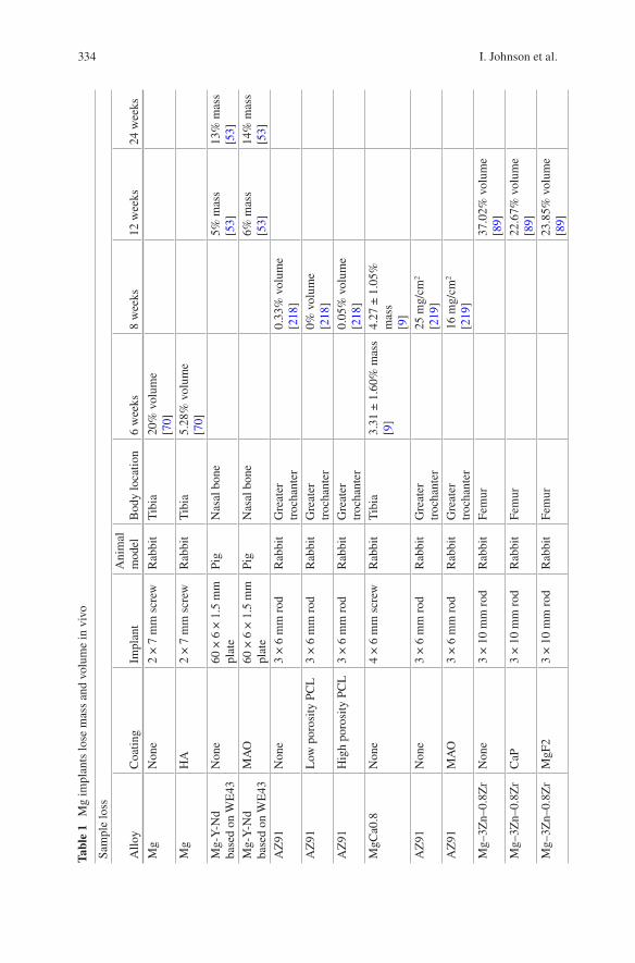
334
Tabl
e 1
Mg
impl
ants
lose
mas
s an
d vo
lum
e in
viv
o
Sam
ple
loss
Allo
yC
oatin
gIm
plan
tA
nim
al
mod
elB
ody
loca
tion
6 w
eeks
8 w
eeks
12 w
eeks
24 w
eeks
Mg
Non
e2
× 7
mm
scr
ewR
abbi
tT
ibia
20%
vol
ume
[70]
Mg
HA
2 ×
7 m
m s
crew
Rab
bit
Tib
ia5.
28%
vol
ume
[70]
Mg-
Y-N
d ba
sed
on W
E43
Non
e60
× 6
× 1
.5 m
m
plat
ePi
gN
asal
bon
e5%
mas
s[5
3]13
% m
ass
[53]
Mg-
Y-N
d ba
sed
on W
E43
MA
O60
× 6
× 1
.5 m
m
plat
ePi
gN
asal
bon
e6%
mas
s[5
3]14
% m
ass
[53]
AZ
91N
one
3 ×
6 m
m r
odR
abbi
tG
reat
er
troc
hant
er0.
33%
vol
ume
[218
]A
Z91
Low
por
osity
PC
L3
× 6
mm
rod
Rab
bit
Gre
ater
tr
ocha
nter
0% v
olum
e[2
18]
AZ
91H
igh
poro
sity
PC
L3
× 6
mm
rod
Rab
bit
Gre
ater
tr
ocha
nter
0.05
% v
olum
e[2
18]
MgC
a0.8
Non
e4
× 6
mm
scr
ewR
abbi
tT
ibia
3.31
± 1
.60%
mas
s[9
]4.
27 ±
1.0
5%
mas
s[9
]A
Z91
Non
e3
× 6
mm
rod
Rab
bit
Gre
ater
tr
ocha
nter
25 m
g/cm
2
[219
]A
Z91
MA
O3
× 6
mm
rod
Rab
bit
Gre
ater
tr
ocha
nter
16 m
g/cm
2
[219
]M
g–3Z
n–0.
8Zr
Non
e3
× 1
0 m
m r
odR
abbi
tFe
mur
37.0
2% v
olum
e[8
9]M
g–3Z
n–0.
8Zr
CaP
3 ×
10
mm
rod
Rab
bit
Fem
ur22
.67%
vol
ume
[89]
Mg–
3Zn–
0.8Z
rM
gF2
3 ×
10
mm
rod
Rab
bit
Fem
ur23
.85%
vol
ume
[89]
I. Johnson et al.
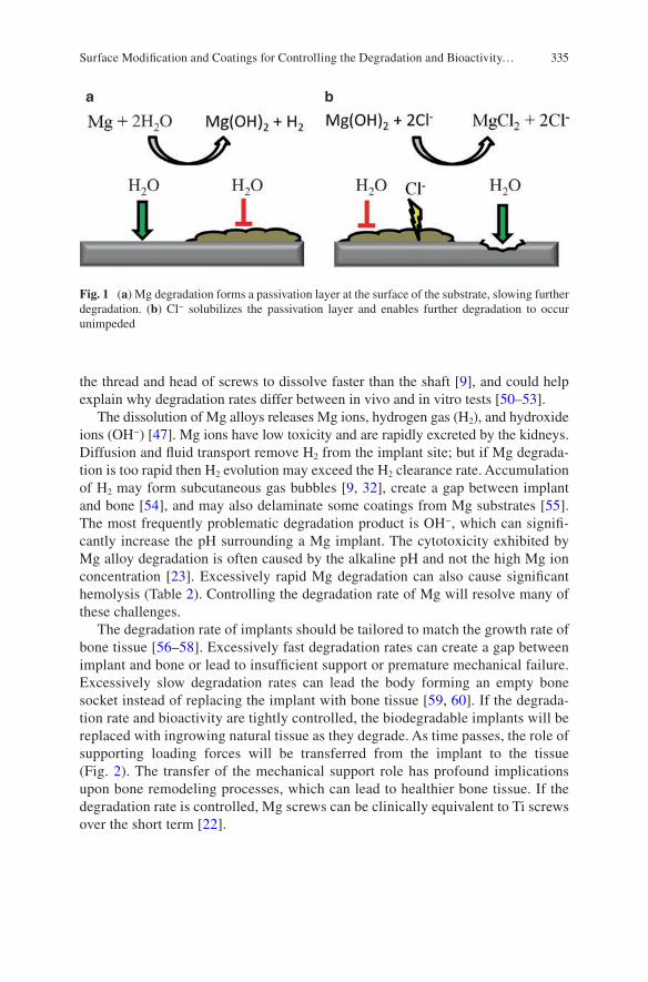
335
the thread and head of screws to dissolve faster than the shaft [9], and could help explain why degradation rates differ between in vivo and in vitro tests [50–53].
The dissolution of Mg alloys releases Mg ions, hydrogen gas (H2), and hydroxide ions (OH−) [47]. Mg ions have low toxicity and are rapidly excreted by the kidneys. Diffusion and fluid transport remove H2 from the implant site; but if Mg degrada-tion is too rapid then H2 evolution may exceed the H2 clearance rate. Accumulation of H2 may form subcutaneous gas bubbles [9, 32], create a gap between implant and bone [54], and may also delaminate some coatings from Mg substrates [55]. The most frequently problematic degradation product is OH−, which can signifi-cantly increase the pH surrounding a Mg implant. The cytotoxicity exhibited by Mg alloy degradation is often caused by the alkaline pH and not the high Mg ion concentration [23]. Excessively rapid Mg degradation can also cause significant hemolysis (Table 2). Controlling the degradation rate of Mg will resolve many of these challenges.
The degradation rate of implants should be tailored to match the growth rate of bone tissue [56–58]. Excessively fast degradation rates can create a gap between implant and bone or lead to insufficient support or premature mechanical failure. Excessively slow degradation rates can lead the body forming an empty bone socket instead of replacing the implant with bone tissue [59, 60]. If the degrada-tion rate and bioactivity are tightly controlled, the biodegradable implants will be replaced with ingrowing natural tissue as they degrade. As time passes, the role of supporting loading forces will be transferred from the implant to the tissue (Fig. 2). The transfer of the mechanical support role has profound implications upon bone remodeling processes, which can lead to healthier bone tissue. If the degradation rate is controlled, Mg screws can be clinically equivalent to Ti screws over the short term [22].
Fig. 1 (a) Mg degradation forms a passivation layer at the surface of the substrate, slowing further degradation. (b) Cl− solubilizes the passivation layer and enables further degradation to occur unimpeded
Surface Modification and Coatings for Controlling the Degradation and Bioactivity…
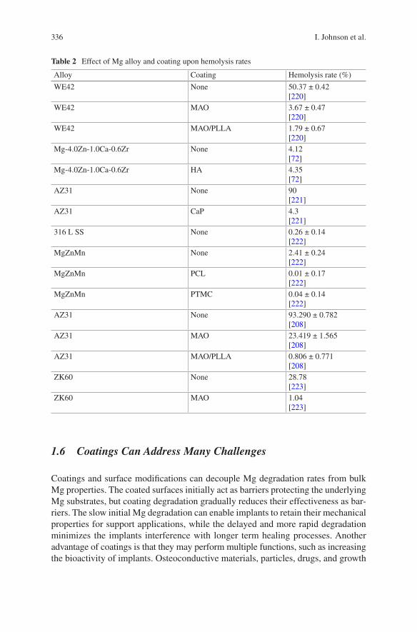
336
1.6 Coatings Can Address Many Challenges
Coatings and surface modifications can decouple Mg degradation rates from bulk Mg properties. The coated surfaces initially act as barriers protecting the underlying Mg substrates, but coating degradation gradually reduces their effectiveness as bar-riers. The slow initial Mg degradation can enable implants to retain their mechanical properties for support applications, while the delayed and more rapid degradation minimizes the implants interference with longer term healing processes. Another advantage of coatings is that they may perform multiple functions, such as increasing the bioactivity of implants. Osteoconductive materials, particles, drugs, and growth
Table 2 Effect of Mg alloy and coating upon hemolysis rates
Alloy Coating Hemolysis rate (%)
WE42 None 50.37 ± 0.42[220]
WE42 MAO 3.67 ± 0.47[220]
WE42 MAO/PLLA 1.79 ± 0.67[220]
Mg-4.0Zn-1.0Ca-0.6Zr None 4.12[72]
Mg-4.0Zn-1.0Ca-0.6Zr HA 4.35[72]
AZ31 None 90[221]
AZ31 CaP 4.3[221]
316 L SS None 0.26 ± 0.14[222]
MgZnMn None 2.41 ± 0.24[222]
MgZnMn PCL 0.01 ± 0.17[222]
MgZnMn PTMC 0.04 ± 0.14[222]
AZ31 None 93.290 ± 0.782[208]
AZ31 MAO 23.419 ± 1.565[208]
AZ31 MAO/PLLA 0.806 ± 0.771[208]
ZK60 None 28.78[223]
ZK60 MAO 1.04[223]
I. Johnson et al.
337
factors may be incorporated into coatings to improve surface bioactivity. The success or failure of implants is often determined by their initial contact with host cells and tissue. Thus, it is critical to engineer coatings to not just control the bulk substrate degradation rate, but also to improve surface bioactivity.
2 Substrate Preparations
The properties of Mg substrates will obviously affect their degradation, bioactivity, and interactions with coatings. Thus alloy bulk composition is a major means of con-trolling Mg implants [32]. Substrate bulk structure also plays a role; solid substrates provide more mechanical strength, but porous substrates may have better coating and cell adhesion and the pores can be filled with bioactive materials [61, 62].
The surfaces of metallic substrates must be prepared for coating processes in order to achieve the best results. The surface roughness of substrates affects their degradation [63, 64], coating adhesion strength, cell adhesion, and bone volume/tissue volume ratio (BV/TV) in vivo [65]. Sandblasted Mg surfaces degrade faster than threaded surfaces, which in turn degrade faster than smooth Mg surfaces [66]. An appropriately rough surface provides a larger surface area for binding and can form mechanical interlocks with coatings. Some preparation processes can alter the chemistry of the surface, which may alter the surface’s affinity for the coating. Different surface preparations have varying effects with different coatings [67, 68]. On unclean surfaces, coatings may bond to grease or particulates instead of the surface, which will weaken the coatings adhesion to those surfaces. Surfaces should be clean and have appropriate roughness in order to ensure strong coating adhesion.
Fig. 2 An idealized plot showing the transfer of support functions from a biodegradable orthope-dic implant to neighboring bone tissue. The increased loading forces upon the bone tissue will cause remodeling processes to strengthen the bone
Surface Modification and Coatings for Controlling the Degradation and Bioactivity…
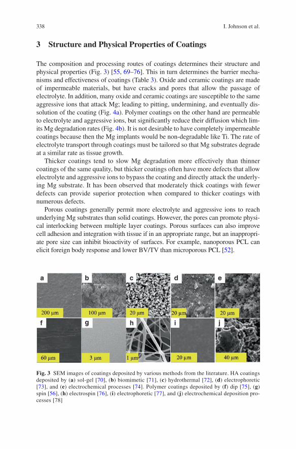
338
3 Structure and Physical Properties of Coatings
The composition and processing routes of coatings determines their structure and physical properties (Fig. 3) [55, 69–76]. This in turn determines the barrier mecha-nisms and effectiveness of coatings (Table 3). Oxide and ceramic coatings are made of impermeable materials, but have cracks and pores that allow the passage of electrolyte. In addition, many oxide and ceramic coatings are susceptible to the same aggressive ions that attack Mg; leading to pitting, undermining, and eventually dis-solution of the coating (Fig. 4a). Polymer coatings on the other hand are permeable to electrolyte and aggressive ions, but significantly reduce their diffusion which lim-its Mg degradation rates (Fig. 4b). It is not desirable to have completely impermeable coatings because then the Mg implants would be non-degradable like Ti. The rate of electrolyte transport through coatings must be tailored so that Mg substrates degrade at a similar rate as tissue growth.
Thicker coatings tend to slow Mg degradation more effectively than thinner coatings of the same quality, but thicker coatings often have more defects that allow electrolyte and aggressive ions to bypass the coating and directly attack the underly-ing Mg substrate. It has been observed that moderately thick coatings with fewer defects can provide superior protection when compared to thicker coatings with numerous defects.
Porous coatings generally permit more electrolyte and aggressive ions to reach underlying Mg substrates than solid coatings. However, the pores can promote physi-cal interlocking between multiple layer coatings. Porous surfaces can also improve cell adhesion and integration with tissue if in an appropriate range, but an inappropri-ate pore size can inhibit bioactivity of surfaces. For example, nanoporous PCL can elicit foreign body response and lower BV/TV than microporous PCL [52].
Fig. 3 SEM images of coatings deposited by various methods from the literature. HA coatings deposited by (a) sol-gel [70], (b) biomimetic [71], (c) hydrothermal [72], (d) electrophoretic [73], and (e) electrochemical processes [74]. Polymer coatings deposited by (f) dip [75], (g) spin [56], (h) electrospin [76], (i) electrophoretic [77], and (j) electrochemical deposition pro-cesses [78]
I. Johnson et al.
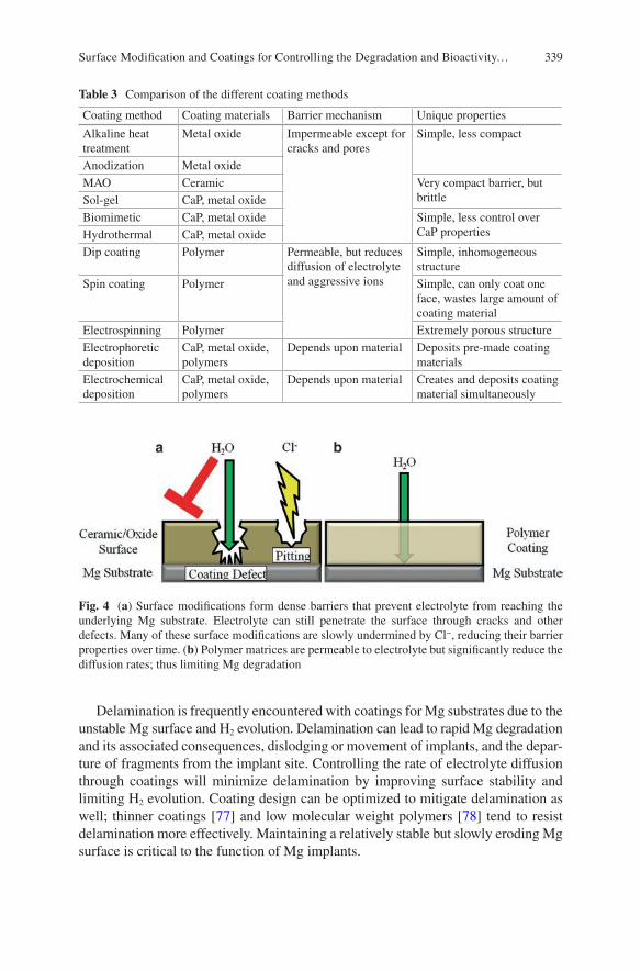
339
Delamination is frequently encountered with coatings for Mg substrates due to the unstable Mg surface and H2 evolution. Delamination can lead to rapid Mg degradation and its associated consequences, dislodging or movement of implants, and the depar-ture of fragments from the implant site. Controlling the rate of electrolyte diffusion through coatings will minimize delamination by improving surface stability and limiting H2 evolution. Coating design can be optimized to mitigate delamination as well; thinner coatings [77] and low molecular weight polymers [78] tend to resist delamination more effectively. Maintaining a relatively stable but slowly eroding Mg surface is critical to the function of Mg implants.
Table 3 Comparison of the different coating methods
Coating method Coating materials Barrier mechanism Unique properties
Alkaline heat treatment
Metal oxide Impermeable except for cracks and pores
Simple, less compact
Anodization Metal oxideMAO Ceramic Very compact barrier, but
brittleSol-gel CaP, metal oxideBiomimetic CaP, metal oxide Simple, less control over
CaP propertiesHydrothermal CaP, metal oxideDip coating Polymer Permeable, but reduces
diffusion of electrolyte and aggressive ions
Simple, inhomogeneous structure
Spin coating Polymer Simple, can only coat one face, wastes large amount of coating material
Electrospinning Polymer Extremely porous structureElectrophoretic deposition
CaP, metal oxide, polymers
Depends upon material Deposits pre-made coating materials
Electrochemical deposition
CaP, metal oxide, polymers
Depends upon material Creates and deposits coating material simultaneously
Fig. 4 (a) Surface modifications form dense barriers that prevent electrolyte from reaching the underlying Mg substrate. Electrolyte can still penetrate the surface through cracks and other defects. Many of these surface modifications are slowly undermined by Cl−, reducing their barrier properties over time. (b) Polymer matrices are permeable to electrolyte but significantly reduce the diffusion rates; thus limiting Mg degradation
Surface Modification and Coatings for Controlling the Degradation and Bioactivity…
340
4 Surface Modification of Magnesium
Surface modifications transform the surfaces of Mg substrates into substances with increased degradation resistance. This differs from deposition coating processes in that the raw materials for the new surface come from the original Mg substrate. The modified surface is generally much more stable than the Mg substrate and acts as barrier against electrolyte and aggressive ions. Mg surfaces can be modified through numerous methods.
4.1 Chemical Surface Modification
The simplest means of creating protective coatings on Mg substrates is passivation, which is the oxidation of Mg to form a barrier oxide or hydroxide barrier layer. Mg forms passivation layers through chemical reactions in most environments, but alkalinity and heat can create even thicker and more protective barrier layers [72, 79–82]. The surfaces of alkaline heat treated substrates often have better cell adhesion [79, 82] and implant/tissue interface strength [83] than polished substrates. The parameters of the alkaline baths and the heat treatments control the thickness, structure, and composition of the oxide layer formed [80]. Alkaline baths without heat treatments tend to create loose and porous barrier layers that are susceptible to aggressive ions. Heat treatments can densify the oxide barrier layer so that it resists attacks by aggressive ions and significantly reduces the Mg degradation rate in physiological fluids [79, 80]. Chemical surface modifications significantly reduce Mg degradation rates, but like many other impermeable barriers they are also impaired by the presence of pores and cracks [84].
The chemical composition of the alkaline bath can be used to tailor the chemical composition of the Mg surface. Some alkaline bath compositions can create sur-face layers that promote more calcium phosphate (CaP) deposition and may there-fore improve osteoconductivity [80]. Incorporating silicon (Si) or strontium phosphates into the surface can improve the protectiveness and durability of the passivation layers [83, 85, 86]. Silicates can enhance mineralization activity of osteoblasts [87] and improve the mechanical strength of bone/implant interfaces [83]. Some species of silicates, like akermanite, have better bioactivity than β-tricalcium phosphate (β-TCP) [88]. These properties have attracted much inter-est in Si as a dopant for coatings. Silicates surfaces may be formed through surface modifications or deposition.
Not all chemical surface modifications occur at alkaline pH; fluoridation [84, 89–91] occurs at highly acidic pH. Fluoridation may have additional benefits beyond controlling Mg degradation. The in vivo bioactivity of fluoridated surfaces may be comparable to hydroxyapatite (HA) coatings [61, 89] and superior to collagen coatings [91]. In some cases, and fluoridated surfaces may even have intrinsic anti- bacterial properties [90].
I. Johnson et al.
341
4.2 Anodization
Anodization is an electrochemical process that creates protective amorphous oxide barriers [92–94]. Greater potential, current, and anodization time generally increase the thickness of the barrier layer; but too much will create cracks in the surface. The cracks undermine the effectiveness of anodized surfaces as barriers. Certain bath compositions are also more prone to sparking, which increases pore formation in the surface. Additionally, the temperature of the electrolytic bath [92] and the composition of the Mg alloy substrate [93] can influence the properties of the anodized surface. Anodized surfaces are more protective if their degradation products have low solubility and strong adherence to their substrate [94].
4.3 Micro-Arc Oxidation
Micro-arc oxidation (MAO) is a surface modification process related to anodiza-tion, but uses higher potentials over shorter times to create ceramic surfaces instead of amorphous oxide surfaces. The ceramic nature of MAO surfaces can provide greater degradation resistance, hardness, crystallinity, and bioactivity than anodized surfaces [95, 96]. The potential during MAO exceeds the breakdown potential of the substrate, creating localized plasma reactions. These plasma reactions can create regions of high heat and pressure that can cause melting, flowing, sintering, anneal-ing, and rapid cooling. The composition of the electrolytic bath can influence the surface composition, surface morphology and roughness, porosity, types of deposits formed during immersion, and the degradation rate [97]. Larger currents for longer times will increase the thickness of MAO surfaces, but may also increase degradation rates due to crack formation [98].
MAO surfaces generally have several layers; a porous outer layer, a compact inner layer, and finally the surface of the substrate [95]. The majority of degradation resistance comes from the compact inner layer [99]. The increased surface rough-ness of the porous outer layer can improve cell adhesion [100]. However, electrolyte and aggressive ions can enter the pores and cracks to react with Mg [101], causing degradation products to accumulate at the coating/substrate interface and lift the MAO surface off of the Mg substrate [102]. The brittleness of MAO surfaces [103] can exacerbate the damage caused by localized degradation.
5 Deposited Coatings
Deposited coatings are made from materials foreign to the Mg substrates, and may be deposited through numerous methods. Such coatings have a vast range of barrier, mechanical, and biological properties; enabling them to be fine-tuned for specific applications.
Surface Modification and Coatings for Controlling the Degradation and Bioactivity…
342
5.1 Calcium Phosphate Coatings
Materials derived from CaP are highly osteoconductive because they mimic the mineral content of bone. However, the role of CaP alone is limited in orthopedic applications due to its inherent brittleness. Coatings can take advantage of the superb osteoconductivity of CaP while the underlying Mg substrates provide the mechanical support needed in orthopedic applications.
The phase of CaP that most closely mimics the mineral content of bone and has the greatest osteoconductivity is hydroxyapatite (HA). It is also the slowest dissolv-ing phase, which improves the barrier properties of coatings. Another frequently investigated phase of CaP is β-tricalcium phosphate (β-TCP), which is osteoconduc-tive and known to induce macrophage activity that is beneficial to implant integration [104]. CaP coatings can increase CaP deposition in simulated body fluid (SBF), which suggests improved osteoconductivity [105]. Incorporation of Si into the CaP coating can further increase CaP deposition [106]. Nano-scale HA (nHA) has even better osteoconductivity than microscale HA [107], but may also provide less protec-tion from degradation to underlying Mg substrates [108]. Rod shaped HA crystals may have better bioactivity than flake shaped HA crystals; such as increased cell proliferation and ALP activity [109]. Mesoporous HA structure can ameliorate damage from residual stress, reduce penetration of electrolyte, and reduce Mg corrosion rate [110]. The wide range of properties for CaP can be fine-tuned for specific applications.
CaP coatings can be deposited through numerous methods such as: plasma spray, sol-gel, chemical deposition [69, 70, 111, 112], biomimetic deposition [69, 113], electrophoretic deposition [71], and electrochemical deposition [72, 106] (Fig. 3). There are two general strategies for depositing CaP coatings: (1) synthesizing CaP first and then depositing it onto the substrate; and (2) synthesizing CaP and deposit-ing it onto the substrate simultaneously. The first strategy offers the most control over the properties of CaP, but requires multiple steps. Furthermore, the properties of the CaP that were painstakingly fine-tuned may be altered during the deposition process. High temperature coating processes such as plasma spray can change the phase of CaP [114], alter the crystallinity of CaP [114], or increase the grain size of CaP. Alternatively, low temperature coating processes often create less adherent coatings without subsequent heat treatment [72]. The second strategy for depositing CaP coatings is often simpler, but provides less control over the properties of CaP in the coating.
Many CaP coatings have weak adhesion strength to their substrates. CaP and metallic substrates have very different thermal expansion coefficients, which can damage the coating or coating/substrate interface initially during high temperature coating processes and sintering, or gradually when the implant is exposed to tem-perature changes and loading cycles in vivo. Both of these challenges are exacer-bated by the inherent brittleness of CaP. A potential resolution is the incorporation of CaP into composites with flexible materials, such as polymers.
I. Johnson et al.
343
5.2 Polymer Coatings
5.2.1 Commonly Used Polymer Coatings
Polymers can be divided into two major categories: natural and synthetic. Natural polymers are derived from natural sources while synthetic polymers are manufactured artificially. The advantage of natural polymers is that they often have good bioactivity. The disadvantages of natural polymers are that they have less consistency between dif-ferent production runs and that they are more likely to carry microbial contamination. Many synthetic polymers are the opposite case. The advantages of synthetic polymers are that they have greater consistency between different production runs and less risk of microbial contamination. A disadvantage of synthetic polymers is that they frequently lack the bioactivity exhibited by some natural polymers.
Examples of natural polymers include chitosan, alginate, collagen, and protein. Chitosan coatings have been investigated for controlling the degradation rate Mg alloys [115–119]. Chitosan is the deacetylated derivative of chitin, which is com-mercially obtained from crustaceans (i.e., crabs and shrimp). Chitosan is more sol-uble than chitin, which is important for processing because both polymers thermally degrade before melting [120]. Chitosan has several unique advantages over other polymers: its insolubility above pH 7 may help further protect Mg substrates [117], it can promote bone growth [121], and it has intrinsic antibacterial properties [122–124]. Chitosan is degraded enzymatically in vivo [125].
Alginate is a polysaccharide that can be used as a coating material for controlling Mg degradation [126, 127]. An advantage of alginate is that it is commercially produced by bacteria or algae; which enables the production to occur in an indus-trial setting and may prevent issues associated with harvesting organisms outside of an industrial setting (i.e., risk of microbial contamination and inconsistency between different production runs). Another advantage is that water is a solvent of alginate, which makes it easier to embed coatings with pharmaceuticals. Finally, alginate can protect implants from the immune system, which may be beneficial for some niche applications. A disadvantage of alginate coating materials is their poor cell adhesion [128]. This challenge may be addressed through the covalent attachment of biologi-cal recognition sites (i.e., RGD) to alginate polymers [129] or dispersion of bioac-tive materials such as HA within the alginate matrix [126].
Other natural polymer or protein based coatings used to control Mg degradation include: collagen [91, 130], albumin [131], phytic acid [132–134], and other pro-teins or peptides [135]. Coatings derived from natural proteins can significantly increase bioactivity, especially when the coating proteins are native to the physio-logical region where the implant is placed. Most proteins carry greater risks of immune responses, although collagen tends to have low antigenicity [136]. Many protein coatings also face more costly mass production, batch to batch variability, and risk of microbial contamination. The immunological and logistical challenges associated with natural polymers can make the readily manufactured and customized synthetic polymers an attractive alternative.
Surface Modification and Coatings for Controlling the Degradation and Bioactivity…
344
Examples of common synthetic polymers include polyesters such as poly lactic acid (PLA), polyglycolic acid (PGA), and polycaprolactone (PCL). The degrada-tion products of these polyesters are natural metabolites, which improves their bio-compatibility and clearance. The polyesters degrade primarily by hydrolysis of their ester bonds by water molecules, though enzyme catalyzed degradation may play a role in vivo.
PLA can be produced as a semicrystalline isomer (PLLA) or an amorphous iso-mer (PDLA). PLLA is more common in nature [137] and more easily metabolized [138], so it is used more frequently than PDLA. PLLA is one of the most commonly used polymers for orthopedic implants because of its high mechanical strength and low immunogenicity. PLA has an additional methyl group that increases its hydro-phobicity and sterically blocks hydrolysis of its ester bonds. These properties enable PLLA coatings to provide significant protection to Mg [78, 139, 140]. However, PLLA is brittle, which limits it use as a load bearing material. It also has limited thermal stability at high temperatures which may complicate the use of some pro-cessing routes [137]. Additionally, PLLA also has an excessively long degradation time and low bioactivity, which can lead to poor bone ingrowth at the implant site [59, 60, 141]. The impaired bone ingrowth may be exhibited by empty bone sockets outlining the original implant site after degradation [60, 142, 143].
PGA was investigated as an orthopedic biomaterial in its own right because of its good mechanical properties, but is now mainly used in copolymers. It is insoluble in most organic solvents because of its highly crystalline structure, which limits the compatible processing methods [138]. An increased occurrence of osteolysis from PGA implants has also been observed in some studies [144], while others have shown an inhibition of osteogenesis by PGA [145]. PGA sutures are also more inflammatory than PLA sutures [146].
PLA and PGA are frequently combined in the copolymer poly(lactic-co-glycolic acid) (PLGA) to address their individual challenges. PLGA is one of the most com-monly used polymers for implants due to its physical properties, biocompatibility, and it is approved by the FDA for certain applications [147, 148]. PLGA is less brittle than PLLA and is soluble in many organic solvents. The degradation rate [149] and water absorption [150] of PLGA can be tailored by altering the PLA:PGA ratio. PLGA coatings have been used to control Mg degradation [55, 151, 152], but may delaminate due to H2 evolution [55]. PLGA also has mediocre cell adhesion [153, 154], which limits bone growth into the implant site. Finally, both PLA and PGA release acidic degradation products which can lower the pH of the local environment.
PCL is another common polyester coating material for Mg [78, 139, 155–157], and one of the earliest biodegradable polymers used for implants in general [158]. PCL coatings can increase the volume of bone growth on Mg substrates [157]. The low melting temperature makes PCL especially easy to process, especially with embedded pharmaceuticals or proteins that are vulnerable to heat or organic solvents. This makes PCL a good choice when drugs or bioactive factors are
I. Johnson et al.
345
incorporated into the coating. However, PCL has an excessively long degradation time and mediocre cell adhesion.
Polyester coatings can chemically interact with Mg substrates during degradation; although the published results are contradictory. Acidic polymer degradation prod-ucts may attack the Mg substrate while the alkaline Mg degradation products attack the polymers. Additionally, Mg(OH)2 in the passivation layer may catalyze polymer hydrolysis; which has been observed as a positive feedback loop for degradation [73]. Contrarily, it has also been observed that dispersed Mg(OH)2 particles may reduce polymer degradation by stabilizing the pH microclimate and disrupting auto-catalyzation of polymer degradation reactions [159]. These contradictory results may be due to differences in experimental design.
5.2.2 Overview of Polymer Properties
One of the greatest strengths of polymers as a class of coating materials is their versatility (Table 4). Polymers possess a vast range of physical, chemical, and bio-logical properties, although polymers alone often have insufficient mechanical properties for many support applications. Numerous methods exist to deposit poly-mer coatings including dip [73, 152], spin [55, 160], electrospin [74, 161], electro-phoretic [75, 162], and electrochemical [76] deposition processes (Fig. 3). The deposition method controls the structure of the coatings; some methods create solid coatings while others create porous coatings. Finally, a large body of knowledge surrounds polymers, their use as biomaterials, and the means to tailor their properties.
Many of a polymer’s physical properties are inter-related; and so altering one property will also alter others. Molecular weight (Mw) influences the viscosity of solutions/melts, the mechanical properties of the polymer matrix [163], the coating adhesion strength [78], polymer degradation rates [164], and degradation rates of underlying Mg substrates [139]. The Mw decreases during degradation, until it is small enough to allow monomers or short polymer chains to be dissolved. A lower Mw can also lead to more autocatalysis of degradation reactions for some polymers because the number of reactive end groups increases. The glass transition tempera-ture (Tg) determines the temperature at which the polymer becomes rubbery and more susceptible to many physical processes; and is influenced by the Mw. The Tg is often reduced concurrently with Mw during degradation, which can make the coat-ing more vulnerable. Both the Mw and Tg affect the crystallinity of polymers, which influences degradation rates, water permeability [165–167], and bioactivity [168]. A more crystalline polymer is generally a more effective barrier to water, but in some cases increased crystallinity is accompanied by crack and void formation that increases water permeability [169]. The interactions between all of the polymer coatings properties must be balanced in order to ensure that Mg implants degrade at the desired rate.
Surface Modification and Coatings for Controlling the Degradation and Bioactivity…
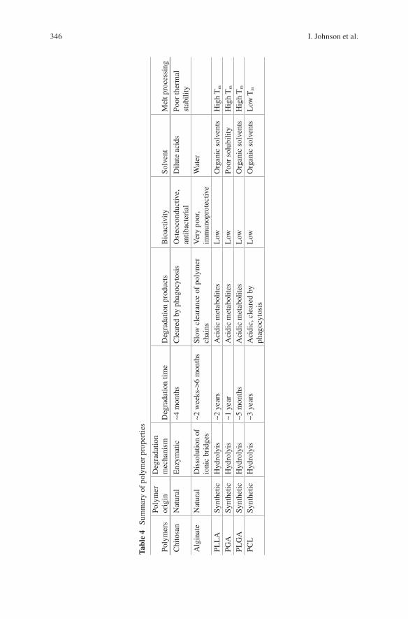
346
Tabl
e 4
Sum
mar
y of
pol
ymer
pro
pert
ies
Poly
mer
sPo
lym
er
orig
inD
egra
datio
n m
echa
nism
Deg
rada
tion
time
Deg
rada
tion
prod
ucts
Bio
activ
itySo
lven
tM
elt p
roce
ssin
g
Chi
tosa
nN
atur
alE
nzym
atic
~4 m
onth
sC
lear
ed b
y ph
agoc
ytos
isO
steo
cond
uctiv
e,
antib
acte
rial
Dilu
te a
cids
Poor
ther
mal
st
abili
tyA
lgin
ate
Nat
ural
Dis
solu
tion
of
ioni
c br
idge
s~2
wee
ks->
6 m
onth
sSl
ow c
lear
ance
of
poly
mer
ch
ains
Ver
y po
or,
imm
unop
rote
ctiv
eW
ater
PLL
ASy
nthe
ticH
ydro
lyis
~2 y
ears
Aci
dic
met
abol
ites
Low
Org
anic
sol
vent
sH
igh
Tm
PGA
Synt
hetic
Hyd
roly
is~1
yea
rA
cidi
c m
etab
olite
sL
owPo
or s
olub
ility
Hig
h T
m
PLG
ASy
nthe
ticH
ydro
lyis
~5 m
onth
sA
cidi
c m
etab
olite
sL
owO
rgan
ic s
olve
nts
Hig
h T
m
PCL
Synt
hetic
Hyd
roly
is~3
yea
rsA
cidi
c, c
lear
ed b
y ph
agoc
ytos
isL
owO
rgan
ic s
olve
nts
Low
Tm
I. Johnson et al.
347
5.2.3 Methods of Depositing Polymer Coatings
Many processes are used to deposit polymer coatings, and each process has its own idiosyncrasies. The coating process used affects the coating structure, and therefore water transport to underlying substrates. Some processes have better compatibility with certain materials and applications than other processes. A thorough under-standing of coating materials and processes is necessary for the creation of reliable protective coatings.
Solvents are commonly used for the processing of polymers. The advantage of using solvents to liquefy polymers is that very little heat is needed; which is useful when polymers thermally degrade while melting, for copolymers whose constitu-ents have different melting points, or when viscosity must be controlled. The disad-vantages of solvent processing routes are that some polymers have low solubility, the solvents can denature drugs or proteins within the polymer, solvent residues can impair bioactivity, and potential vapor hazards during coating processes.
Different solvents can create polymer matrices with vastly different structures [170]. The choice of solvent impacts the thickness, porosity, and crystallinity of coatings. Solvents with slower evaporation rates can increase the crystallinity of coatings because the polymer chains have more time to form crystals [171]. The size, frequency, and interconnectivity of pores in solvent cast coatings is also heav-ily influenced by the choice of solvent [170].
Other coating processes liquefy the polymers with high temperatures instead of solvents. Heating polymers above their Tm enables them to be extruded, molded, or dipped onto substrates. Annealing is a process related to melting that can further reduce water absorption by polymer coatings by increasing their crystallinity. During annealing, the coatings are heated above the polymers Tg but below the Tm, causing the polymer chains to align in a more crystalline arrangement. Excessively high annealing temperatures or long annealing times can lead to crack and void formation, undermining the barrier properties of the coating despite the increased crystallinity.
Dip Coating
Dip coating is the simplest coating process, wastes very little material, and is able to cover complex geometries. It is applied by dipping substrates into a solution/melt. When the coated substrate is withdrawn from the solution/melt, most of the coating material remains in place, but the pull of gravity can increase inhomogeneity (Fig. 3) [73]. The thickness and structure of dip coatings are influenced by solvent evaporation rate, viscosity, coating material concentration, immersion time, and withdrawal speed from the solution or melt.
Surface Modification and Coatings for Controlling the Degradation and Bioactivity…
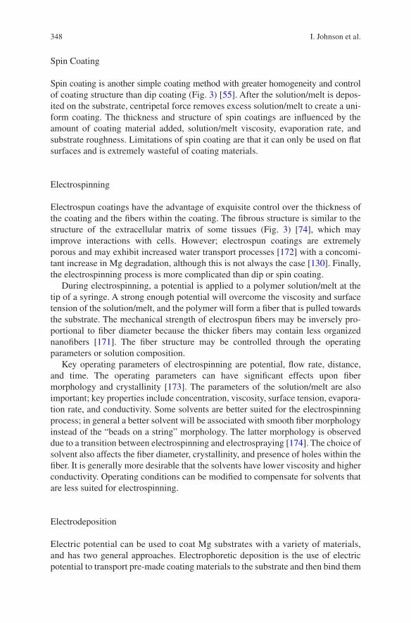
348
Spin Coating
Spin coating is another simple coating method with greater homogeneity and control of coating structure than dip coating (Fig. 3) [55]. After the solution/melt is depos-ited on the substrate, centripetal force removes excess solution/melt to create a uni-form coating. The thickness and structure of spin coatings are influenced by the amount of coating material added, solution/melt viscosity, evaporation rate, and substrate roughness. Limitations of spin coating are that it can only be used on flat surfaces and is extremely wasteful of coating materials.
Electrospinning
Electrospun coatings have the advantage of exquisite control over the thickness of the coating and the fibers within the coating. The fibrous structure is similar to the structure of the extracellular matrix of some tissues (Fig. 3) [74], which may improve interactions with cells. However; electrospun coatings are extremely porous and may exhibit increased water transport processes [172] with a concomi-tant increase in Mg degradation, although this is not always the case [130]. Finally, the electrospinning process is more complicated than dip or spin coating.
During electrospinning, a potential is applied to a polymer solution/melt at the tip of a syringe. A strong enough potential will overcome the viscosity and surface tension of the solution/melt, and the polymer will form a fiber that is pulled towards the substrate. The mechanical strength of electrospun fibers may be inversely pro-portional to fiber diameter because the thicker fibers may contain less organized nanofibers [171]. The fiber structure may be controlled through the operating parameters or solution composition.
Key operating parameters of electrospinning are potential, flow rate, distance, and time. The operating parameters can have significant effects upon fiber morphology and crystallinity [173]. The parameters of the solution/melt are also important; key properties include concentration, viscosity, surface tension, evapora-tion rate, and conductivity. Some solvents are better suited for the electrospinning process; in general a better solvent will be associated with smooth fiber morphology instead of the “beads on a string” morphology. The latter morphology is observed due to a transition between electrospinning and electrospraying [174]. The choice of solvent also affects the fiber diameter, crystallinity, and presence of holes within the fiber. It is generally more desirable that the solvents have lower viscosity and higher conductivity. Operating conditions can be modified to compensate for solvents that are less suited for electrospinning.
Electrodeposition
Electric potential can be used to coat Mg substrates with a variety of materials, and has two general approaches. Electrophoretic deposition is the use of electric potential to transport pre-made coating materials to the substrate and then bind them
I. Johnson et al.
349
to that substrate. Electrochemical deposition on the other hand is the use of electric potential to transport coating material precursors to the substrate where they will react to form the final coating material and bind to the substrate. The key parameters of electrodeposition are the potential, current, time, electrolyte, concentration of coating materials in the electrolyte, charge of polymers or particles, and the mobil-ity of the polymers or particles. Electrodeposition can be used to coat Mg with a variety of materials including ceramics [72, 106], polymers [17, 76], ceramic/poly-mer microspheres [175], and others. However; electrodeposited coatings are often not as homogenous as other methods such as spin coating (Fig. 3) [17, 55], and ensuring homogeneity can be especially difficult for composite coating materials whose constituents have different charges or degrees of mobility under an electric field. Another challenge is that H2 gas evolving during electrodeposition can create void spaces in the coating. These challenges may be addressed by tailoring the oper-ating parameters and electrolyte bath composition.
6 Composite Coatings
Natural bone is a composite material; the unique mechanical and biological properties of bone are enabled by the interplay between the mineral content and the collagenous matrix. No single material possesses the physical and biological properties needed to mimic bone tissue and support injured bones. Thus, composite materials are needed for orthopedic applications.
6.1 Hydroxyapatite Composite Coatings
One of the most frequently investigated composite coatings for orthopedic implants is HA particles dispersed within polymer matrices. The polymer matrix provides a flexible interface between HA and Mg that mitigates the thermal expansion coeffi-cient mismatch. Nano-scale particle size and good dispersion of HA particles throughout the polymer matrix improve both the mechanical strength and the bioac-tivity of the composite material [176–182]. Cell adhesion and mechanical strength of PLGA matrices both increase with increasing HA content until they plateau at around 30 wt.% HA. Increasing HA content beyond 30 wt.% in PLGA matrices has only marginal effect upon cell adhesion, but increases brittleness [178, 179]. The incorpo-ration of HA has been shown to significantly improve cell adhesion to chitosan [115], alginate [126], PLA [183, 184], PLGA [185], and PCL [186]. This improve-ment is not limited to just cell adhesion; improved protein secretion and alkaline phosphatase (ALP) activity are often observed as well [187]. HA composites also improve bone ingrowth at the implant sites in vivo; CaP/PLLA interference screws did not leave behind the empty screw holes [188, 189] in bone tissue that were observed with pure PLLA screws [143, 190].
Surface Modification and Coatings for Controlling the Degradation and Bioactivity…
350
HA particles have profound effects upon diffusion and uptake of electrolyte in polymer matrices. HA particles increase water uptake by polymer matrices [147], but still tend to improve barrier properties of coatings [55]. Electrolyte diffusion through particle/polymer composites is reduced by the filler effect; which is caused by particles increasing the tortuosity of routes taken by diffusing electrolyte or by particles increasing the local rigidity of the polymer matrix surrounding them [191] (Fig. 5a).
Alternatively, polymer interlayers can be used to ameliorate the thermal expan-sion coefficient mismatch between HA and Mg (Fig. 5b). A flexible and elastic interlayer can minimize cracking of the outer HA coating during repeated loading and temperature changes [156]. The combination of coating layers also requires electrolyte to bypass to different barrier mechanisms. Electrolyte must enter through cracks, pores, and voids in the impermeable outer coating. Then the electrolyte must diffuse through the permeable polymer interlayer, but at a significantly reduced dif-fusion rate that limits Mg degradation reactions.
Fig. 5 Composite coatings utilize synergy between different materials. (a) Polymer matrix binds HA particles to Mg substrate, provides a flexible interface, and exhibits a filler effect. (b) Polymer inter-layer provides a flexible interface between HA coating and Mg substrate, and acts as an addi-tional barrier. (c) HA outer coating seals defects in inner coating and prevent aggressive ions from reaching ceramic/oxide surface
I. Johnson et al.
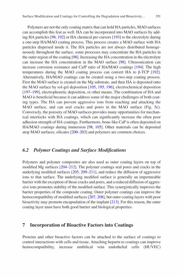
351
Polymers are not the only coating matrix that can hold HA particles, MAO surfaces can accomplish this feat as well. HA can be incorporated into MAO surfaces by add-ing HA particles [98, 192] or HA chemical pre-cursors [193] to the electrolyte during a one-step HA/MAO coating process. This process creates a MAO surface with HA particles dispersed inside it. The HA particles are not always distributed homoge-neously throughout the surface, some processes may concentrate the HA particles in the outer region of the coating [98]. Increasing the HA concentration in the electrolyte can increase the HA concentration in the MAO surface [98]. Ultrasonication can increase corrosion resistance and Ca/P ratio of HA/MAO coatings [194]. The high temperatures during the MAO coating process can convert HA to β-TCP [192]. Alternatively, HA/MAO coatings can be created using a two-step coating process. First the MAO surface is created on the Mg substrate, and then HA is deposited onto the MAO surface by sol-gel deposition [105, 195, 196], electrochemical deposition [197–199], electrophoretic deposition, or other means. The combination of HA and MAO is beneficial because it can address some of the major challenges of both coat-ing types. The HA can prevent aggressive ions from reaching and attacking the MAO surface, and can seal cracks and pores in the MAO surface (Fig. 5c). Conversely, the porosity of MAO surfaces provides many opportunities for mechan-ical interlocks with HA coatings, which can significantly increase the often poor adhesion strength of HA coatings. Furthermore, bone-like CaP is often deposited on HA/MAO coatings during immersion [98, 105]. Other materials can be deposited atop MAO surfaces; silicates [200–203] and polymers are common choices.
6.2 Polymer Coatings and Surface Modifications
Polymers and polymer composites are also used as outer coating layers on top of modified Mg surfaces [204–212]. The polymer coatings seal pores and cracks in the underlying modified surfaces [205, 209–211], and reduce the diffusion of aggressive ions to that surface. The underlying modified surface is generally an impermeable barrier with the exception of those cracks and pores, and a reduced diffusion of aggres-sive ions promotes stability of the modified surface. This synergistically improves the barrier properties of the composite coating. Outer polymer coatings can improve the hemocompatibility of modified surfaces [207, 208], but outer coating layers with poor bioactivity may promote encapsulation of the implant [213]. For this reason, the outer coating layer must have both good barrier and biological properties.
7 Incorporation of Bioactive Factors into Coatings
Proteins and other bioactive factors can be attached to the surface of coatings to control interactions with cells and tissue. Attaching heparin to coatings can improve hemocompatibility, increase umbilical vein endothelial cells (HUVEC)
Surface Modification and Coatings for Controlling the Degradation and Bioactivity…
352
proliferation and inhibit human umbilical artery smooth muscle cells (HUASMC) adhesion [212]. Preferential control over which cells adhere to and proliferate on a surface can improve the biological outcome of implants, such as promoting endo-thelialization of stents.
Coatings can store and release drugs at a controlled rate [215–217]. Common examples of these drugs include growth factors to improve healing at the wound site and antibiotics to prevent colonization of the implant. Storing drugs within coatings can resolve three major challenges facing drug use: (1) transporting drugs to the target site, (2) achieving a therapeutic dose at the target site while minimizing the dose outside the target site, and (3) maintaining a constant dose at the target site over time. Polymers, CaP, and other nanoparticles have long been used for con-trolled storage and release of drugs [218], enabling this technology to be easily translated to coatings.
8 Summary
Coatings have great potential to control Mg degradation and bioactivity because their wide range of physical and biological properties enables them to be tailored to specific functions, and decouple surface properties from bulk properties. A well- controlled Mg degradation rate will prevent many of the challenges associated with rapid deg-radation (i.e., catastrophic mechanical failure, local alkalization, H2 gas bubbles, swelling) and slow degradation (i.e., empty bone sockets). Ideally, functional natu-ral tissue will replace the biodegradable Mg implants over time. The clinical transla-tion of Mg derived implants will lead to improved patient outcome and lower medical costs by preventing the complications associated with the current generation of non-degradable implants.
Acknowledgement The authors thank U.S. National Science Foundation (Award 1512764, 1125801) and National Institutes of Health (Award 1R03AR069373-01) for financial support. The content is solely the responsibility of the authors and does not necessarily represent the official views of the National Science Foundation and National Institutes of Health.
References
1. Jain KK. The handbook of nanomedicine. New York: Springer; 2012. 2. Mavrogenis AF, Dimitriou R, Parvizi J, Babis GC. Biology of implant osseointegration. J
Musculoskelet Neuron. 2009;9(2):61–71. 3. Jiang Y, Jia T, Wooley PH, Yang SY. Current research in the pathogenesis of aseptic implant
loosening associated with particulate wear debris. Acta Orthop Belg. 2013;79(1):1–9. 4. Darouiche RO. Treatment of infections associated with surgical implants. New Engl J Med.
2004;350(14):1422–9. 5. Brady R, Calhoun J, Leid J, Shirtliff M. Infections of orthopaedic implants and devices. In:
Shirtliff M, Leid J, editors. The role of biofilms in device-related infections. Berlin: Springer; 2009. p. 15–55.
I. Johnson et al.
353
6. Richards RH, Palmer JD, Clarke NMP. Observations on removal of metal implants. Injury. 1992;23(1):25–8.
7. Hanson B, van der Werken C, Stengel D. Surgeons’ beliefs and perceptions about removal of orthopaedic implants. BMC Musculoskelet Disord. 2008;9:73.
8. Helmecke P, Ezechieli M, Becher C, Kohler J, Denkena B. Resorbable interference screws made of magnesium based alloy. Biomed Tech (Berl). 2013. https://doi.org/10.1515/bmt-2013-4074.
9. Erdmann N, Angrisani N, Reifenrath J, Lucas A, Thorey F, Bormann D, Meyer-Lindenberg A. Biomechanical testing and degradation analysis of MgCa0.8 alloy screws: a comparative in vivo study in rabbits. Acta Biomater. 2011;7(3):1421–8.
10. Reifenrath J, Angrisani N, Erdmann N, Lucas A, Waizy H, Seitz JM, Bondarenko A, Meyer-Lindenberg A. Degrading magnesium screws ZEK100: biomechanical testing, degradation analysis and soft-tissue biocompatibility in a rabbit model. Biomed Mater. 2013;8(4):045012.
11. Waksman R, Pakala R, Kuchulakanti PK, Baffour R, Hellinga D, Seabron R, Tio FO, Wittchow E, Hartwig S, Harder C, Rohde R, Heublein B, Andreae A, Waldmann K-H, Haverich A. Safety and efficacy of bioabsorbable magnesium alloy stents in porcine coronary arteries. Catheter Cardiovasc Interv. 2006;68(4):607–17.
12. Bauer M, Schilling T, Weidling M, Hartung D, Biskup C, Wriggers P, Wacker F, Bach FW, Haverich A, Hassel T. Geometric adaption of biodegradable magnesium alloy scaffolds to stabilise biological myocardial grafts. Part I. J Mater Sci Mater Med. 2014;25(3):909–16.
13. Lock JY, Wyatt E, Upadhyayula S, Whall A, Nuñez V, Vullev VI, Liu H. Degradation and antibacterial properties of magnesium alloys in artificial urine for potential resorbable ure-teral stent applications. J Biomed Mater Res A. 2014;102(3):781–92.
14. Liu L, Li N, Lei T, Li K, Zhang Y. The in vitro biological properties of Mg-Zn-Sr alloy and superiority for preparation of biodegradable intestinal anastomosis rings. Med Sci Monit. 2014;20:1056–66.
15. Luffy SA, Chou DT, Waterman J, Wearden PD, Kumta PN, Gilbert TW. Evaluation of magnesium-yttrium alloy as an extraluminal tracheal stent. J Biomed Mater Res A. 2014;102(3):611–20.
16. Chng CB, Lau DP, Choo JQ, Chui CK. A bioabsorbable microclip for laryngeal microsur-gery: design and evaluation. Acta Biomater. 2012;8(7):2835–44.
17. Sebaa MA, Dhillon S, Liu H. Electrochemical deposition and evaluation of electrically con-ductive polymer coating on biodegradable magnesium implants for neural applications. J Mater Sci Mater Med. 2013;24(2):307–16.
18. Yan WY, Berthe J, Wen C. Numerical investigation of the effect of porous titanium femoral prosthesis on bone remodeling. Mater Design. 2011;32(4):1776–82.
19. Drosos GI, Babourda E, Magnissalis EA, Giatromanolaki A, Kazakos K, Verettas DA. Mechanical characterization of bone graft substitute ceramic cements. Injury. 2012;43(3):266–71.
20. Sabir MI, Xu XX, Li L. A review on biodegradable polymeric materials for bone tissue engi-neering applications. J Mater Sci. 2009;44(21):5713–24.
21. Brar HS, Platt MO, Sarntinoranont M, Martin PI, Manuel MV. Magnesium as a biodegrad-able and bioabsorbable material for medical implants. JOM. 2009;61(9):31–4.
22. Windhagen H, Radtke K, Weizbauer A, Diekmann J, Noll Y, Kreimeyer U, Schavan R, Stukenborg-Colsman C, Waizy H. Biodegradable magnesium-based screw clinically equiva-lent to titanium screw in hallux valgus surgery: short term results of the first prospective, randomized, controlled clinical pilot study. Biomed Eng Online. 2013;12:62.
23. Zhang Y, Ren L, Li M, Lin X, Zhao HF, Yang K. Preliminary study on cytotoxic effect of biodegradation of magnesium on cancer cells. J Mater Sci Technol. 2012;28(9):769–72.
24. Li RW, Kirkland NT, Truong J, Wang J, Smith PN, Birbilis N, Nisbet DR. The influence of biodegradable magnesium alloys on the osteogenic differentiation of human mesenchymal stem cells. J Biomed Mater Res A. 2014;102(12):4346–57.
25. Park J-W, Kim Y-J, Jang J-H, Song H. Osteoblast response to magnesium ion-incorporated nanoporous titanium oxide surfaces. Clin Oral Implants Res. 2010;21(11):1278–87.
Surface Modification and Coatings for Controlling the Degradation and Bioactivity…
354
26. Janning C, Willbold E, Vogt C, Nellesen J, Meyer-Lindenberg A, Windhagen H, Thorey F, Witte F. Magnesium hydroxide temporarily enhancing osteoblast activity and decreasing the osteoclast number in peri-implant bone remodelling. Acta Biomater. 2010;6(5):1861–8.
27. Castellani C, Lindtner RA, Hausbrandt P, Tschegg E, Stanzl-Tschegg SE, Zanoni G, Beck S, Weinberg AM. Bone-implant interface strength and osseointegration: biodegradable magne-sium alloy versus standard titanium control. Acta Biomater. 2011;7(1):432–40.
28. Waizy H, Diekmann J, Weizbauer A, Reifenrath J, Bartsch I, Neubert V, Schavan R, Windhagen H. In vivo study of a biodegradable orthopedic screw (MgYREZr-alloy) in a rab-bit model for up to 12 months. J Biomater Appl. 2014;28(5):667–75.
29. Zhang EL, Xu LP, Yu GN, Pan F, Yang K. In vivo evaluation of biodegradable magnesium alloy bone implant in the first 6 months implantation. J Biomed Mater Res A. 2009;90A(3):882–93.
30. Witte F, Ulrich H, Rudert M, Willbold E. Biodegradable magnesium scaffolds: Part I: appro-priate inflammatory response. J Biomed Mater Res A. 2007;81A(3):748–56.
31. Xu LP, Yu GN, Zhang E, Pan F, Yang K. In vivo corrosion behavior of Mg-Mn-Zn alloy for bone implant application. J Biomed Mater Res A. 2007;83A(3):703–11.
32. Witte F, Kaese V, Haferkamp H, Switzer E, Meyer-Lindenberg A, Wirth CJ, Windhagen H. In vivo corrosion of four magnesium alloys and the associated bone response. Biomaterials. 2005;26(17):3557–63.
33. Witte F, Ulrich H, Palm C, Willbold E. Biodegradable magnesium scaffolds: Part II: peri-implant bone remodeling. J Biomed Mater Res A. 2007;81A(3):757–65.
34. Zhai Z, Qu X, Li H, Yang K, Wan P, Tan L, Ouyang Z, Liu X, Tian B, Xiao F, Wang W, Jiang C, Tang T, Fan Q, Qin A, Dai K. The effect of metallic magnesium degradation prod-ucts on osteoclast-induced osteolysis and attenuation of NF-kappaB and NFATc1 signaling. Biomaterials. 2014;35(24):6299–310.
35. Stendig-Lindberg G, Koeller W, Bauer A, Rob PM. Experimentally induced prolonged mag-nesium deficiency causes osteoporosis in the rat. Eur J Intern Med. 2004;15(2):97–107.
36. Nan M, Yangmei C, Bangcheng Y. Magnesium metal—a potential biomaterial with anti-bone cancer properties. J Biomed Mater Res A. 2013;102(8):2644–51.
37. Saver JL, Kidwell C, Eckstein M, Starkman S, Investigators F-MPT. Prehospital neuroprotec-tive therapy for acute stroke—results of the field administration of stroke therapy-magnesium (FAST-MAG) pilot trial. Stroke. 2004;35(5):E106–8.
38. Ren L, Lin X, Tan LL, Yang K. Effect of surface coating on antibacterial behavior of magne-sium based metals. Mater Lett. 2011;65(23–24):3509–11.
39. Robinson DA, Griffith RW, Shechtman D, Evans RB, Conzemius MG. In vitro antibacte-rial properties of magnesium metal against Escherichia coli, Pseudomonas aeruginosa and Staphylococcus aureus. Acta Biomater. 2010;6(5):1869–77.
40. Tie D, Feyerabend F, Muller WD, Schade R, Liefeith K, Kainer KU, Willumeit R. Antibacterial biodegradable Mg-Ag alloys. Eur Cell Mater. 2013;25:284–98.
41. Witte F. The history of biodegradable magnesium implants: a review. Acta Biomater. 2010;6(5):1680–92.
42. Witte F, Reifenrath J, Muller PP, Crostack HA, Nellesen J, Bach FW, Bormann D, Rudert M. Cartilage repair on magnesium scaffolds used as a subchondral bone replacement. Materialwiss Werkst. 2006;37(6):504–8.
43. Song GL. Recent progress in corrosion and protection of magnesium alloys. Adv Eng Mater. 2005;7(7):563–86.
44. Lindstrom R, Johansson LG, Thompson GE, Skeldon P, Svensson JE. Corrosion of magne-sium in humid air. Corros Sci. 2004;46(5):1141–58.
45. Mueller WD, de Mele MFL, Nascimento ML, Zeddies M. Degradation of magnesium and its alloys: dependence on the composition of the synthetic biological media. J Biomed Mater Res A. 2009;90A(2):487–95.
46. Song G, Atrens A. Understanding magnesium corrosion—a framework for improved alloy performance. Adv Eng Mater. 2003;5(12):837–58.
47. Song G, Atrens A. Recent insights into the mechanism of magnesium corrosion and research suggestions. Adv Eng Mater. 2007;9(3):177–83.
I. Johnson et al.
355
48. Xin Y, Huo K, Tao H, Tang G, Chu PK. Influence of aggressive ions on the degradation behavior of biomedical magnesium alloy in physiological environment. Acta Biomater. 2008;4(6):2008–15.
49. Johnson I, Perchy D, Liu H. Interactions between aggressive ions and the surface of a mag-nesium-yttrium alloy. Conf Proc IEEE Eng Med Biol Soc. 2012;2012:5670–3.
50. Witte F, Fischer J, Nellesen J, Crostack HA, Kaese V, Pisch A, Beckmann F, Windhagen H. In vitro and in vivo corrosion measurements of magnesium alloys. Biomaterials. 2006;27(7):1013–8.
51. Mueller WD, Nascimento ML, de Mele MFL. Critical discussion of the results from dif-ferent corrosion studies of Mg and Mg alloys for biomaterial applications. Acta Biomater. 2010;6(5):1749–55.
52. Jensen J, Rolfing JH, Svend Le DQ, Kristiansen AA, Nygaard JV, Hokland LB, Bendtsen M, Kassem M, Lysdahl H, Bunger CE. Surface-modified functionalized polycaprolac-tone scaffolds for bone repair: in vitro and in vivo experiments. J Biomed Mater Res A. 2013;102(9):2993–3003.
53. Imwinkelried T, Beck S, Iizuka T, Schaller B. Effect of a plasmaelectrolytic coating on the strength retention of in vivo and in vitro degraded magnesium implants. Acta Biomater. 2013;9(10):8643–9.
54. Zhang S, Zhang X, Zhao C, Li J, Song Y, Xie C, Tao H, Zhang Y, He Y, Jiang Y, Bian Y. Research on an Mg–Zn alloy as a degradable biomaterial. Acta Biomater. 2010;6(2):626–40.
55. Johnson I, Akari K, Liu H. Nanostructured hydroxyapatite/poly(lactic-co-glycolic acid) composite coating for controlling magnesium degradation in simulated body fluid. Nanotechnology. 2013;24(37):375103.
56. Degner J, et al. Electrochemical investigations of magnesium in DMEM with biodegradable polycaprolactone coating as corrosion barrier. Applied Surface Science. 2013;282:264–70.
57. Sung HJ, Meredith C, Johnson C, Galis ZS. The effect of scaffold degradation rate on three-dimensional cell growth and angiogenesis. Biomaterials. 2004;25(26):5735–42.
58. Dumas JE, Prieto EM, Zienkiewicz KJ, Guda T, Wenke JC, Bible J, Holt GE, Guelcher SA. Balancing the rates of new bone formation and polymer degradation enhances healing of weight-bearing allograft/polyurethane composites in rabbit femoral defects. Tissue Eng A. 2014;20(1–2):115–29.
59. Walton M, Cotton NJ. Long-term in vivo degradation of poly-L-lactide (PLLA) in bone. J Biomater Appl. 2007;21(4):395–411.
60. Pihlajamaki H, Bostman O, Tynninen O, Laitinen O. Long-term tissue response to bioabsorb-able poly-L-lactide and metallic screws: an experimental study. Bone. 2006;39(4):932–7.
61. Lalk M, Reifenrath J, Angrisani N, Bondarenko A, Seitz JM, Mueller PP, Meyer-Lindenberg A. Fluoride and calcium-phosphate coated sponges of the magnesium alloy AX30 as bone grafts: a comparative study in rabbits. J Mater Sci Mater Med. 2013;24(2):417–36.
62. Oosterbeek RN, Seal CK, Staiger MP, Hyland MM. Topologically ordered magnesium-bio-polymer hybrid composite structures. J Biomed Mater Res A. 2014;103(1):311–7.
63. Walter R, Kannan MB, He Y, Sandham A. Effect of surface roughness on the in vitro degrada-tion behaviour of a biodegradable magnesium-based alloy. Appl Surf Sci. 2013;279:343–8.
64. Walter R, Kannan MB. Influence of surface roughness on the corrosion behaviour of magne-sium alloy. Mater Design. 2011;32(4):2350–4.
65. Suzuki K, Aoki K, Ohya K. Effects of surface roughness of titanium implants on bone remod-eling activity of femur in rabbits. Bone. 1997;21(6):507–14.
66. Von Der Hoh N, Bormann D, Lucas A, Denkena B, Hackenbroich C, Meyer-Lindenberg A. Influence of different surface machining treatments of magnesium-based resorbable implants on the degradation behavior in rabbits. Adv Eng Mater. 2009;11(5):B47–54.
67. Allen KW, Hatzinikolaou T, Armstrong KB. A comparison of acrylic adhesives for bond-ing aluminum alloys after using various surface preparation methods. Int J Adhes Adhes. 1984;4(3):133–6.
68. Molitor P, Barron V, Young T. Surface treatment of titanium for adhesive bonding to polymer composites: a review. Int J Adhes Adhes. 2001;21(2):129–36.
Surface Modification and Coatings for Controlling the Degradation and Bioactivity…
356
69. Rojaee R, Fathi M, Raeissi K. Controlling the degradation rate of AZ91 magnesium alloy via sol-gel derived nanostructured hydroxyapatite coating. Mat Sci Eng C Mater. 2013;33(7):3817–25.
70. Waterman J, et al. Corrosion resistance of biomimetic calcium phosphate coatings on magne-sium due to varying pretreatment time. Mater Sci Eng B. 2011;176(20):1756–60.
71. Tomozawa M, Hiromoto S. Microstructure of hydroxyapatite-and octacalcium phosphate-coatings formed on magnesium by a hydrothermal treatment at various pH values. Acta Materialia. 2011;59(1):355–63.
72. Rojaee R, Fathi M, Raeissi K. Electrophoretic deposition of nanostructured hydroxyapatite coating on AZ91 magnesium alloy implants with different surface treatments. Appl Surf Sci. 2013;285(Part B):664–73.
73. Guan R-G, Johnson I, Cui T, Zhao T, Zhao Z-Y, Li X, Liu H. Electrodeposition of hydroxy-apatite coating on Mg-4.0Zn-1.0Ca-0.6Zr alloy and in vitro evaluation of degradation, hemo-lysis, and cytotoxicity. J Biomed Mater Res A. 2012;100A:999–1015.
74. Conceicao d, Thiago F, et al. Corrosion protection of magnesium AZ31 alloy using poly (ether imide)[PEI] coatings prepared by the dip coating method: Influence of solvent and substrate pre-treatment. Corr Sci. 2011;53(1):338–46.
75. Abdal-hay A, Barakat NAM, Lim JK. Influence of electrospinning and dip-coating tech-niques on the degradation and cytocompatibility of Mg-based alloy. Coll Surf A Physicochem Eng Aspects. March 2013;420(5):37–45.
76. Sun J, Zhu Y, Meng L, Chen P, Shi T, Liu X, Zheng Y. Electrophoretic deposition of colloidal particles on Mg with cytocompatibility, antibacterial performance, and corrosion resistance. Acta Biomaterialia. Volume. 2016;45(1):387–98.
77. Sebaa M, Nguyen TY, Dhillon S, Garcia S, Liu H. The effects of poly(3, 4-ethylene-dioxythiophene) (PEDOT) coating on magnesium degradation and cytocompatibility with human embryonic stem cells for potential neural applications. J Biomed Mater Res A. 2015;103(1):25–37.
78. Xu LP, Yamamoto A. Characteristics and cytocompatibility of biodegradable polymer film on magnesium by spin coating. Colloid Surface B Biointerfaces. 2012;93:67–74.
79. Li LC, Gao JC, Wang Y. Evaluation of cyto-toxicity and corrosion behavior of alkali-heat-treated magnesium in simulated body fluid. Surf Coat Technol. 2004;185(1):92–8.
80. Gu XN, Zheng W, Cheng Y, Zheng YF. A study on alkaline heat treated Mg-Ca alloy for the control of the biocorrosion rate. Acta Biomater. 2009;5(7):2790–9.
81. Al-Abdullat Y, Tsutsumi S, Nakajima N, Ohta M, Kuwahara H, Ikeuchi K. Surface modifica-tion of magnesium by NaHCO(3) and corrosion behavior in Hank’s solution for new bioma-terial applications. Mater Trans. 2001;42(8):1777–80.
82. Lorenz C, Brunner JG, Kollmannsberger P, Jaafar L, Fabry B, Virtanen S. Effect of surface pre-treatments on biocompatibility of magnesium. Acta Biomater. 2009;5(7):2783–9.
83. Tan L, Wang Q, Lin X, Wan P, Zhang G, Zhang Q, Yang K. Loss of mechanical proper-ties in vivo and bone-implant interface strength of AZ31B magnesium alloy screws with Si-containing coating. Acta Biomater. 2014;10(5):2333–40.
84. Tsn SN, Park IS, Lee MH. Tailoring the composition of fluoride conversion coatings to achieve better corrosion protection of magnesium for biomedical applications. J Mater Chem B. 2014. https://doi.org/10.1039/c3tb21565b.
85. Chen XB, Nisbet DR, Li RW, Smith PN, Abbott TB, Easton MA, Zhang DH, Birbilis N. Controlling initial biodegradation of magnesium by a biocompatible strontium phosphate conversion coating. Acta Biomater. 2014;10(3):1463–74.
86. Ke C, Pohl K, Birbilis N, Chen X-B. Protective strontium phosphate coatings for magnesium biomaterials. Mater Sci Technol. 2014;30(5):521–6.
87. Kim EJ, Bu SY, Sung MK, Choi MK. Effects of silicon on osteoblast activity and bone min-eralization of MC3T3-E1 cells. Biol Trace Elem Res. 2013;152(1):105–12.
88. Sun H, Wu C, Dai K, Chang J, Tang T. Proliferation and osteoblastic differentiation of human bone marrow-derived stromal cells on akermanite-bioactive ceramics. Biomaterials. 2006;27(33):5651–7.
I. Johnson et al.
357
89. Sun JE, Wang JB, Jiang HF, Chen MF, Bi YZ, Liu DB. In vivo comparative property study of the bioactivity of coated Mg-3Zn-0.8Zr alloy. Mat Sci Eng C Mater. 2013;33(6):3263–72.
90. Yan T, Tan L, Zhang B, Yang K. Fluoride conversion coating on biodegradable AZ31B mag-nesium alloy. J Mater Sci Technol. 2014;30:666–74.
91. Zhao N, Workman B, Zhu DH. Endothelialization of novel magnesium-rare earth alloys with fluoride and collagen coating. Int J Mol Sci. 2014;15(4):5263–76.
92. Chai LY, Yu X, Yang ZH, Wang YY, Okido M. Anodizing of magnesium alloy AZ31 in alka-line solutions with silicate under continuous sparking. Corros Sci. 2008;50(12):3274–9.
93. Xue DC, Yun YH, Schulz MJ, Shanov V. Corrosion protection of biodegradable magnesium implants using anodization. Mat Sci Eng C Mater. 2011;31(2):215–23.
94. Murakami K, Hino M, Nakai K, Kobayashi S, Saijo A, Kanadani T. Mechanism of corrosion protection of anodized magnesium alloys. Mater Trans. 2008;49(5):1057–64.
95. Jo JH, Hong JY, Shin KS, Kim HE, Koh YH. Enhancing biocompatibility and corrosion resistance of Mg implants via surface treatments. J Biomater Appl. 2012;27(4):469–76.
96. Fischerauer SF, Kraus T, Wu X, Tangl S, Sorantin E, Hanzi AC, Loffler JF, Uggowitzer PJ, Weinberg AM. In vivo degradation performance of micro-arc-oxidized magnesium implants: a micro-CT study in rats. Acta Biomater. 2013;9(2):5411–20.
97. Seyfoori A, Mirdamadi S, Mehrjoo M, Khavandi A. In-vitro assessments of micro arc oxi-dized ceramic films on AZ31 magnesium implant: degradation and cell-surface response. Prog Nat Sci Mater. 2013;23(4):425–33.
98. Lin X, Wang X, Tan LL, Wan P, Yu XM, Li Q, Yang K. Effect of preparation parameters on the properties of hydroxyapatite containing micro-arc oxidation coating on biodegradable ZK60 magnesium alloy. Ceram Int. 2014;40(7):10043–51.
99. Ghasemi A, Raja VS, Blawert C, Dietzel W, Kainer KU. Study of the structure and corrosion behavior of PEO coatings on AM50 maginesium. alloy by electrochemical impedance spec-troscopy. Surf Coat Techol. 2008;202(15):3513–8.
100. Robinson HJ, Markaki AE, Collier CA, Clyne TW. Cell adhesion to plasma electrolytic oxidation (PEO) titania coatings, assessed using a centrifuging technique. J Mech Behav Biomed Mater. 2011;4(8):2103–12.
101. Sharma AK, Uma Rani R, Giri K. Studies on anodization of magnesium alloy for thermal control applications. Met Finish. 1997;95(3):43–51.
102. Song GL. Corrosion prevention of magnesium alloys. Amsterdam: Elsevier Science; 2013. 103. Dey A, Rani RU, Thota HK, Sharma AK, Bandyopadhyay P, Mukhopadhyay AK.
Microstructural, corrosion and nanomechanical behaviour of ceramic coatings developed on magnesium AZ31 alloy by micro arc oxidation. Ceram Int. 2013;39(3):3313–20.
104. Chen Z, Mao X, Tan L, Friis T, Wu C, Crawford R, Xiao Y. Osteoimmunomodulatory properties of magnesium scaffolds coated with beta-tricalcium phosphate. Biomaterials. 2014;35(30):8553–65.
105. Liu GY, Tang SW, Li DC, Hu J. Self-adjustment of calcium phosphate coating on micro-arc oxidized magnesium and its influence on the corrosion behaviour in simulated body fluids. Corros Sci. 2014;79:206–14.
106. Qiu X, Wan P, Tan LL, Fan XM, Yang K. Preliminary research on a novel bioactive silicon doped calcium phosphate coating on AZ31 magnesium alloy via electrodeposition. Mat Sci Eng C Mater. 2014;36:65–76.
107. Ergun C, Liu HN, Halloran JW, Webster TJ. Increased osteoblast adhesion on nanograined hydroxyapatite and tricalcium phosphate containing calcium titanate. J Biomed Mater Res A. 2007;80A(4):990–7.
108. Sonmez S, Aksakal B, Dikici B. Influence of hydroxyapatite coating thickness and pow-der particle size on corrosion performance of MA8M magnesium alloy. J Alloys Compd. 2014;596:125–31.
109. Guan F, Ma S, Shi X, Ma X, Chi L, Liang S, Cui Y, Wang Z, Yao N, Guan S, Yang B. Biocompatibility of nano-hydroxyapatite/Mg-Zn-Ca alloy composite scaffolds to human umbilical cord mesenchymal stem cells from Wharton’s jelly in vitro. Sci China Life Sci. 2014;57(2):181–7.
Surface Modification and Coatings for Controlling the Degradation and Bioactivity…
358
110. Ye XY, Cai S, Xu GH, Dou Y, Hu HT, Ye XJ, Zhao H, Sun XH. The influence of mesopores on the corrosion resistance of hydroxyapatite coated AZ31 Mg alloy. J Electrochem Soc. 2014;161(3):C145–50.
111. Yang JX, Cui FZ, Lee IS, Zhang Y, Yin QS, Xia H, Yang SX. In vivo biocompatibility and degradation behavior of Mg alloy coated by calcium phosphate in a rabbit model. J Biomater Appl. 2012;27(2):153–64.
112. Shadanbaz S, Walker J, Woodfield TBF, Staiger MP, Dias GJ. Monetite and brushite coated magnesium: in vivo and in vitro models for degradation analysis. J Mater Sci Mater M. 2014;25(1):173–83.
113. Zhang Y, Zhang G, Wei M. Controlling the biodegradation rate of magnesium using biomi-metic apatite coating. J Biomed Mater Res B Appl Biomater. 2009;89((2):408–14.
114. Wang BC, Chang E, Lee TM, Yang CY. Changes in phases and crystallinity of plasma-sprayed hydroxyapatite coatings under heat-treatment—a quantitative study. J Biomed Mater Res. 1995;29(12):1483–92.
115. Hahn BD, Park DS, Choi JJ, Ryu JH, Yoon WH, Choi JH, Kim HE, Kim SG. Aerosol deposi-tion of hydroxyapatite-chitosan composite coatings on biodegradable magnesium alloy. Surf Coat Techol. 2011;205(8–9):3112–8.
116. Bai KF, Zhang Y, Fu ZY, Zhang CL, Cui XZ, Meng EC, Guan SK, Hu JH. Fabrication of chitosan/magnesium phosphate composite coating and the in vitro degradation properties of coated magnesium alloy. Mater Lett. 2012;73:59–61.
117. Gu XN, Zheng YF, Lan QX, Cheng Y, Zhang ZX, Xi TF, Zhang DY. Surface modification of an Mg-1Ca alloy to slow down its biocorrosion by chitosan. Biomed Mater. 2009;4(4):044109.
118. Fekry AM, Ghoneim AA, Ameer MA. Electrochemical impedance spectroscopy of chitosan coated magnesium alloys in a synthetic sweat medium. Surf Coat Techol. 2014;238:126–32.
119. Zhao J, Chen L, Yu K, Chen C, Dai Y, Qiao X, Yan Y. Biodegradation performance of a chi-tosan coated magnesium-zinc-tricalcium phosphate composite as an implant. Biointerphases. 2014;9(3):031004.
120. Kumar MNVR. A review of chitin and chitosan applications. React Funct Polym. 2000;46(1):1–27.
121. Seol YJ, Lee JY, Park YJ, Lee YM, Young-Ku ICR, Lee SJ, Han SB, Chung CP. Chitosan sponges as tissue engineering scaffolds for bone formation. Biotechnol Lett. 2004;26(13):1037–41.
122. Kong M, Chen XG, Xing K, Park HJ. Antimicrobial properties of chitosan and mode of action: a state of the art review. Int J Food Microbiol. 2010;144(1):51–63.
123. Benhabiles S, Salah R, Lounici H, Drouiche N, Goosen MFA, Mameri N. Antibacterial activ-ity of chitin, chitosan and its oligomers prepared from shrimp shell waste. Food Hydrocolloid. 2012;29(1):48–56.
124. Raafat D, von Bargen K, Haas A, Sahl HG. Insights into the mode of action of chitosan as an antibacterial compound. Appl Environ Microbiol. 2008;74(12):3764–73.
125. Kean T, Thanou M. Biodegradation, biodistribution and toxicity of chitosan. Adv Drug Deliv Rev. 2010;62(1):3–11.
126. Sangeetha K, Roy A, Singh S, Lee B, Kumta PN. Novel alginate based coatings on Mg alloys. Mater Sci Eng B Adv. 2011;176(20):1703–10.
127. Kunjukunju S, Roy A, Ramanathan M, Lee B, Candiello JE, Kumta PN. A layer-by-layer approach to natural polymer-derived bioactive coatings on magnesium alloys. Acta Biomater. 2013;9(10):8690–703.
128. Christensen BE. Alginates as biomaterials in tissue engineering. Carbohydr Chem. 2012;37:227–58.
129. Rowley JA, Madlambayan G, Mooney DJ. Alginate hydrogels as synthetic extracellular matrix materials. Biomaterials. 1999;20(1):45–53.
130. Park CH, Pant HR, Kim CS. Effect on corrosion behavior of collagen film/fiber coated Az31 magnesium alloy. Dig J Nanomater Bios. 2013;8(3):1227–34.
131. Wagener V, Killian MS, Turhan CM, Virtanen S. Albumin coating on magnesium via linker molecules-comparing different coating mechanisms. Colloid Surface B Biointerfaces. 2013;103:586–94.
I. Johnson et al.
359
132. Liu JR, Guo YN, Huang WD. Phytic acid conversion coatings on magnesium surface treat-ment with cerium chloride solution. Prot Met Phys Chem+. 2012;48(2):233–7.
133. Pan FS, Yang X, Zhang DF. Chemical nature of phytic acid conversion coating on AZ61 magnesium alloy. Appl Surf Sci. 2009;255(20):8363–71.
134. Yang X, Li L, He J, Guo H, Zhang J. In vitro corrosion and bioactivity study of surface phytic acid modified AZ31 magnesium alloy. Mater Sci Appl. 2014;5(2):59–65.
135. Cui W, Beniash E, Gawalt E, Xu Z, Sfeir C. Biomimetic coating of magnesium alloy for enhanced corrosion resistance and calcium phosphate deposition. Acta Biomater. 2013;9(10):8650–9.
136. Friess W. Collagen—biomaterial for drug delivery. Eur J Pharm Biopharm. 1998;45(2):113–36. 137. Lim LT, Auras R, Rubino M. Processing technologies for poly(lactic acid). Prog Polym Sci.
2008;33(8):820–52. 138. Gunatillake PA, Adhikari R. Biodegradable synthetic polymers for tissue engineering. Eur
Cell Mater. 2003;5:1–16. discussion 16 139. Xu L, Yamamoto A. In vitro degradation of biodegradable polymer-coated magnesium under
cell culture condition. Appl Surf Sci. 2012;258(17):6353–8. 140. Kannan MB, Liyanaarachchi S. Hybrid coating on a magnesium alloy for minimizing the
localized degradation for load-bearing biodegradable mini-implant applications. Mater Chem Phys. 2013;142(1):350–4.
141. Bos RR, Rozema FR, Boering G, Nijenhuis AJ, Pennings AJ, Verwey AB, Nieuwenhuis P, Jansen HW. Degradation of and tissue reaction to biodegradable poly(L-lactide) for use as internal fixation of fractures: a study in rats. Biomaterials. 1991;12(1):32–6.
142. Barber FA, Dockery WD. Long-term absorption of poly-L-lactic acid interference screws. Arthroscopy. 2006;22(8):820–6.
143. Stahelin AC, Weiler A, Rufenacht H, Hoffmann R, Geissmann A, Feinstein R. Clinical deg-radation and biocompatibility of different bioabsorbable interference screws: a report of six cases. Arthroscopy. 1997;13(2):238–44.
144. Fraser RK, Cole WG. Osteolysis after biodegradable pin fixation of fractures in children. J Bone Joint Surg Br. 1992;74(6):929–30.
145. Askar I, Gultan S, Erden E, Yormuk E. Effects of polyglycolic acid bioabsorbable membrane and oxidised cellulose on the osteogenesis in bone defects: an experimental study. Acta Chir Plast. 2002;45(4):131–8.
146. Cutright DE, Beasley JD, Perez B. Histologic comparison of polylactic and polyglycolic acid sutures. Oral Surg Oral Med O. 1971;32(1):165–73.
147. Huang YX, Ren J, Chen C, Ren TB, Zhou XY. Preparation and properties of poly(lactide-co-glycolide) (PLGA)/nano-hydroxyapatite (NHA) scaffolds by thermally induced phase sepa-ration and rabbit MSCs culture on scaffolds. J Biomater Appl. 2008;22(5):409–32.
148. Smith LJ, Swaim JS, Yao C, Haberstroh KM, Nauman EA, Webster TJ. Increased osteoblast cell density on nanostructured PLGA-coated nanostructured titanium for orthopedic applica-tions. Int J Nanomedicine. 2007;2(3):493–9.
149. You Y, Lee SW, Youk JH, Min BM, Lee SJ, Park WH. In vitro degradation behaviour of non-porous ultra-fine poly(glycolic acid)/poly(L-lactic acid) fibres and porous ultra-fine poly(glycolic acid) fibres. Polym Degrad Stab. 2005;90(3):441–8.
150. Lu L, Peter SJ, Lyman MD, Lai HL, Leite SM, Tamada JA, Uyama S, Vacanti JP, Langer R, Mikos AG. In vitro and in vivo degradation of porous poly(DL-lactic-co-glycolic acid) foams. Biomaterials. 2000;21(18):1837–45.
151. Ostrowski NJ, Lee B, Roy A, Ramanathan M, Kumta PN. Biodegradable poly(lactide-co-glycolide) coatings on magnesium alloys for orthopedic applications. J Mater Sci Mater Med. 2013;24(1):85–96.
152. Li JN, Cao P, Zhang XN, Zhang SX, He YH. In vitro degradation and cell attachment of a PLGA coated biodegradable Mg-6Zn based alloy. J Mater Sci. 2010;45(22):6038–45.
153. Lee SJ, Khang G, Lee YM, Lee HB. Interaction of human chondrocytes and NIH/3T3 fibro-blasts on chloric acid-treated biodegradable polymer surfaces. J Biomater Sci Polym Ed. 2002;13(2):197–212.
Surface Modification and Coatings for Controlling the Degradation and Bioactivity…
360
154. Kanczler JM, Oreffo RO. Osteogenesis and angiogenesis: the potential for engineering bone. Eur Cell Mater. 2008;15:100–14.
155. Abdal-hay A, Amna T, Lim JK. Biocorrosion and osteoconductivity of PCL/nHAp composite porous film-based coating of magnesium alloy. Solid State Sci. 2013;18:131–40.
156. Jo JH, Li Y, Kim SM, Kim HE, Koh YH. Hydroxyapatite/poly(epsilon-caprolactone) double coating on magnesium for enhanced corrosion resistance and coating flexibility. J Biomater Appl. 2013;28(4):617–25.
157. Wong K, Yeung K, Lam J, Chu P, Luk K, Cheung K. Reduction of corrosion behavior of magnesium alloy by PCL surface treatment. In: 55th Annual Meeting of the Orthopaedic Research Society, USA; 2009. p. 22–25.
158. Woodruff MA, Hutmacher DW. The return of a forgotten polymer-polycaprolactone in the 21st century. Prog Polym Sci. 2010;35(10):1217–56.
159. Mobedi H, Nekoomanesh M, Orafaei H, Mivehchi H. Studying the degradation of poly(L-lactide) in presence of magnesium hydroxide. Iran Polym J. 2006;15(1):31–9.
160. Zhu B, Xu Y, Sun J, Yang L, Guo C, Liang J, Cao B. Preparation and characterization of aminated hydroxyethyl cellulose-induced biomimetic hydroxyapatite Coatings on the AZ31 magnesium alloy. Metals. 2017;7(6):214.
161. Soujanya GK, Hanas T, Chakrapani VY, Sunil BR, Kumar TS. Electrospun nanofibrous poly-mer coated magnesium alloy for biodegradable implant applications. Procedia Mater Sci. 2014;5:817–23.
162. Sun J, Zhu Y, Meng L, Wei W, Li Y, Liu X, Zheng Y. Controlled release and corrosion protec-tion by self-assembled colloidal particles electrodeposited onto magnesium alloys. J Mater Chem B. 2015;3(8):1667–76.
163. Ikada Y, Tsuji H. Biodegradable polyesters for medical and ecological applications. Macromol Rapid Comm. 2000;21(3):117–32.
164. Park TG. Degradation of poly(lactic-Co-glycolic acid) microspheres—effect of copolymer composition. Biomaterials. 1995;16(15):1123–30.
165. Shogren R. Water vapor permeability of biodegradable polymers. J Environ Polym Degr. 1997;5(2):91–5.
166. Bai H, Huang C, Xiu H, Zhang Q, Deng H, Wang K, Chen F, Fu Q. Significantly improving oxygen barrier properties of polylactide via constructing parallel-aligned shish-kebab-like crystals with well-interlocked boundaries. Biomacromolecules. 2014;15(4):1507–14.
167. Tsuji H, Okino R, Daimon H, Fujie K. Water vapor permeability of poly(lactide)s: effects of molecular characteristics and crystallinity. J Appl Polym Sci. 2006;99(5):2245–52.
168. Park A, Cima LG. In vitro cell response to differences in poly-L-lactide crystallinity. J Biomed Mater Res. 1996;31(1):117–30.
169. Loo SCJ, Ooi CP, Wee SHE, Boey YCF. Effect of isothermal annealing on the hydrolytic degradation rate of poly(lactide-co-glycolide) (PLGA). Biomaterials. 2005;26(16):2827–33.
170. Cao Y, Croll TI, Oconnor AJ, Stevens GW, Cooper-White JJ. Systematic selection of solvents for the fabrication of 3D combined macro- and microporous polymeric scaffolds for soft tis-sue engineering. J Biomater Sci Polym Ed. 2006;17(4):369–402.
171. Asran AS, Salama M, Popescu C, Michler GH. Solvent influences the morphology and mechanical properties of electrospun poly(L-lactic acid) scaffold for tissue engineering applications. Macromol Symp. 2010;294(1):153–61.
172. Shuying G, Zhimei W, Jie R, Chunyan Z. Fabrication and characterization of electrospun poly(L-lactic acid)and poly(L-Lactide-Co-glycolide) mats as wound dressing, bioinformatics and biomedical engineering, ICBBE 2008. In: The 2nd International Conference on, 2008. p. 1514–7.
173. Ero-Phillips O, Jenkins M, Stamboulis A. Tailoring crystallinity of electrospun plla fibres by control of electrospinning parameters. Polymers. 2012;4(3):1331–48.
174. Qin XH, Wu DQ. Effect of different solvents on poly(caprolactone) (PCL) electrospun non-woven membranes. J Therm Anal Calorim. 2012;107(3):1007–13.
175. Johnson I, Tian Q, Liu H. Nanostructured ceramic and ceramic-polymer composites as dual functional interface for bioresorbable metallic implants. MRS Online Proc Library. 2014;1621:39–45.
I. Johnson et al.
361
176. Liu HN, Webster TJ. Mechanical properties of dispersed ceramic nanoparticles in polymer composites for orthopedic applications. Int J Nanomedicine. 2010;5:299–313.
177. Liu HN, Webster TJ. Enhanced biological and mechanical properties of well-dispersed nano-phase ceramics in polymer composites: from 2D to 3D printed structures. Mat Sci Eng C Mater. 2011;31(2):77–89.
178. Wei G, Ma PX. Structure and properties of nano-hydroxyapatite/polymer composite scaf-folds for bone tissue engineering. Biomaterials. 2004;25(19):4749–57.
179. Ebrahimian-Hosseinabadi M, Ashrafizadeh F, Etemadifar M, Venkatraman SS. Evaluating and modeling the mechanical properties of the prepared PLGA/nano-BCP composite scaf-folds for bone tissue engineering. J Mater Sci Technol. 2011;27(12):1105–12.
180. Johnson I, Wang SM, Silken C, Liu H. A systemic study on key parameters affecting nano-composite coatings on magnesium substrates. Acta Biomater. 2016;36:332–49.
181. Tian QM, Liu HN. Electrophoretic deposition and characterization of nanocomposites and nanoparticles on magnesium substrates. Nanotechnology. 2015;26(17):175102.
182. Tian QM, Rivera-Castaneda L, Liu HN. Optimization of of nano-hydroxyapatite/poly(lactic-co-glycolic acid) coatings on magnesium substrates using one-step electrophoretic deposi-tion. Mater Lett. 2017;186:12–6.
183. Akagi H, Iwata M, Ichinohe T, Amimoto H, Hayashi Y, Kannno N, Ochi H, Fujita Y, Harada Y, Tagawa M, Hara Y. Hydroxyapatite/poly-L-lactide acid screws have better biocompat-ibility and femoral burr hole closure than does poly-L-lactide acid alone. J Biomater Appl. 2014;28(6):954–62.
184. Abdal-hay A, Barakat NAM, Lim JK. Hydroxyapatite-doped poly(lactic acid) porous film coating for enhanced bioactivity and corrosion behavior of AZ31 Mg alloy for orthopedic applications. Ceram Int. 2013;39(1):183–95.
185. Lock J, Nguyen TY, Liu H. Nanophase hydroxyapatite and poly(lactide-co-glycolide) com-posites promote human mesenchymal stem cell adhesion and osteogenic differentiation in vitro. J Mater Sci Mater Med. 2012;23(10):2543–52.
186. D’Anto V, Raucci MG, Guarino V, Martina S, Valletta R, Ambrosio L. Behaviour of human mesenchymal stem cells on chemically synthesized HA-PCL scaffolds for hard tissue regen-eration. J Tissue Eng Regen Med. 2013;10(2):E147–54.
187. Ngiam M, Liao SS, Patil AJ, Cheng ZY, Chan CK, Ramakrishna S. The fabrication of nano-hydroxyapatite on PLGA and PLGA/collagen nanofibrous composite scaffolds and their effects in osteoblastic behavior for bone tissue engineering. Bone. 2009;45(1):4–16.
188. Hasegawa S, Ishii S, Tamura J, Furukawa T, Neo M, Matsusue Y, Shikinami Y, Okuno M, Nakamura T. A 5-7 year in vivo study of high-strength hydroxyapatite/poly(L-lactide) com-posite rods for the internal fixation of bone fractures. Biomaterials. 2006;27(8):1327–32.
189. Shikinami Y, Matsusue Y, Nakamura T. The complete process of bioresorption and bone replacement using devices made of forged composites of raw hydroxyapatite particles/poly L-lactide (F-u-HA/PLLA). Biomaterials. 2005;26(27):5542–51.
190. Barber FA, Dockery WD. Long-term absorption of beta-tricalcium phosphate poly-L-lactic acid interference screws. Arthroscopy. 2008;24(4):441–7.
191. Kobayashi M, Rharbi Y, Brauge L, Cao L, Winnik MA. Effect of silica as fillers on polymer interdiffusion in poly(butyl methacrylate) latex films. Macromolecules. 2002;35(19):7387–99.
192. Ma X, Zhu SJ, Wang LG, Ji CX, Ren CX, Guan SK. Synthesis and properties of a bio-composite coating formed on magnesium alloy by one-step method of micro-arc oxidation. J Alloy Compd. 2014;590:247–53.
193. Pan Y, Chen C, Wang D, Zhao T. Effects of phosphates on microstructure and bioactivity of micro-arc oxidized calcium phosphate coatings on Mg–Zn–Zr magnesium alloy. Colloids Surf B Biointerfaces. 2013;109:1–9.
194. Qu L, Li M, Liu M, Zhang E, Ma C. Microstructure and corrosion resistance of ultrasonic micro-arc oxidation biocoatings on magnesium alloy. J Adv Ceram. 2013;2(3):227–34.
195. Liu G, Hu J, Ding Z, Wang C. Bioactive calcium phosphate coating formed on micro-arc oxidized magnesium by chemical deposition. Appl Surf Sci. 2011;257(6):2051–7.
Surface Modification and Coatings for Controlling the Degradation and Bioactivity…
362
196. Tang H, Yu D, Luo Y, Wang F. Preparation and characterization of HA microflowers coating on AZ31 magnesium alloy by micro-arc oxidation and a solution treatment. Appl Surf Sci. 2013;264:816–22.
197. Gao J, Guan S, Chen J, Wang L, Zhu S, Hu J, Ren Z. Fabrication and characterization of rod-like nano-hydroxyapatite on MAO coating supported on Mg–Zn–Ca alloy. Appl Surf Sci. 2011;257(6):2231–7.
198. Zhao QM, Guo X, Dang XQ, Hao JM, Lai JH, Wang KZ. Preparation and properties of composite MAO/ECD coatings on magnesium alloy. Colloid Surface B Biointerfaces. 2013;102:321–6.
199. Alabbasi A, Kannan MB, Blawert C. Dual layer inorganic coating on magnesium for delay-ing the biodegradation for bone fixation implants. Mater Lett. 2014;124:188–91.
200. Razavi M, Fathi M, Savabi O, Beni BH, Razavi SM, Vashaee D, Tayebi L. Coating of biode-gradable magnesium alloy bone implants using nanostructured diopside (CaMgSi2O6). Appl Surf Sci. 2014;288:130–7.
201. Razavi M, Fathi M, Savabi O, Beni BH, Vashaee D, Tayebi L. Nanostructured merwin-ite bioceramic coating on Mg alloy deposited by electrophoretic deposition. Ceram Int. 2014;40(7):9473–84.
202. Razavi M, Fath M, Savabi O, Razavi SM, Beni BH, Vashaee D, Tayebi L. Controlling the degradation rate of bioactive magnesium implants by electrophoretic deposition of akerman-ite coating. Ceram Int. 2014;40(3):3865–72.
203. Razavi M, Fathi M, Savabi O, Razavi SM, Heidari F, Manshaei M, Vashaee D, Tayebi L. In vivo study of nanostructured diopside (CaMgSi2O6) coating on magnesium alloy as biode-gradable orthopedic implants. Appl Surf Sci. 2014;313:60–6.
204. Guo MQ, Cao L, Lu P, Liu Y, Xu XH. Anticorrosion and cytocompatibility behavior of MAO/PLLA modified magnesium alloy WE42. J Mater Sci Mater Med. 2011;22(7):1735–40.
205. Alabbasi A, Mehjabeen A, Kannan MB, Ye Q, Blawert C. Biodegradable polymer for seal-ing porous PEO layer on pure magnesium: an in vitro degradation study. Appl Surf Sci. 2014;301:463–7.
206. Ostrowski N, Lee B, Enick N, Carlson B, Kunjukunju S, Roy A, Kumta PN. Corrosion pro-tection and improved cytocompatibility of biodegradable polymeric layer-by-layer coatings on AZ31 magnesium alloys. Acta Biomater. 2013;9(10):8704–13.
207. Lu P, Cao L, Liu Y, Xu XH, Wu XF. Evaluation of magnesium ions release, biocorrosion, and hemocompatibility of MAO/PLLA-modified magnesium alloy WE42. J Biomed Mater Res B. 2011;96B(1):101–9.
208. Wei Z, Tian P, Liu X, Zhou B. In vitro degradation, hemolysis, and cytocompatibility of PEO/PLLA composite coating on biodegradable AZ31 alloy. J Biomed Mater Res B Appl Biomater. 2015;103(2):342–54.
209. Gnedenkov SV, Sinebryukhov SL, Zavidnaya AG, Egorkin VS, Puz’ AV, Mashtalyar DV, Sergienko VI, Yerokhin AL, Matthews A. Composite hydroxyapatite–PTFE coatings on Mg–Mn–Ce alloy for resorbable implant applications via a plasma electrolytic oxidation-based route. J Taiwan Inst Chem Eng. 2014;45:3104–9.
210. Gnedenkov SV, Sinebryukhov SL, Mashtalyar DV, Egorkin VS, Sidorova MV, Gnedenkov AS. Composite polymer-containing protective coatings on magnesium alloy MA8. Corros Sci. 2014;85(0):52–9.
211. Li L-H, Sankara Narayanan TSN, Kim YK, Kong Y-M, Park IS, Bae TS, Lee MH. Deposition of microarc oxidation–polycaprolactone duplex coating to improve the corrosion resistance of magnesium for biodegradable implants. Thin Solid Films. 2014;562(0):561–7.
212. Wei Z, Tian P, Liu X, Zhou B. Hemocompatibility and selective cell fate of polydopamine-assisted heparinized PEO/PLLA composite coating on biodegradable AZ31 alloy. Colloids Surf B Biointerfaces. 2014;121:451–60.
213. Qi ZR, Zhang Q, Tan LL, Lin X, Yin Y, Wang XL, Yang K, Wang Y. Comparison of degrada-tion behavior and the associated bone response of ZK60 and PLLA in vivo. J Biomed Mater Res A. 2014;102(5):1255–63.
I. Johnson et al.
363
214. Xu X, Lu P, Guo M, Fang M. Cross-linked gelatin/nanoparticles composite coating on micro-arc oxidation film for corrosion and drug release. Appl Surf Sci. 2010;256(8):2367–71.
215. Lu P, Fan HN, Liu Y, Cao L, Wu XF, Xu XH. Controllable biodegradability, drug release behavior and hemocompatibility of PTX-eluting magnesium stents. Colloid Surface B Biointerfaces. 2011;83(1):23–8.
216. Luo XL, Cui XYT. Electrochemical deposition of conducting polymer coatings on magne-sium surfaces in ionic liquid. Acta Biomater. 2011;7(1):441–6.
217. Liu H, Webster TJ. Ceramic/polymer nanocomposites with tunable drug delivery capability at specific disease sites. J Biomed Mater Res A. 2010;93(3):1180–92.
218. Wong HM, et al. A biodegradable polymer-based coating to control the performance of mag-nesium alloy orthopaedic implants. Biomaterials. 2010;31(8):2084–96.
219. Razavi M, et al. Biodegradation, bioactivity and in vivo biocompatibility analysis of plasma electrolytic oxidized (PEO) biodegradable Mg implants. Phys Sci Inter J. 2014;4(5):708.
220. Lu P, et al. Evaluation of magnesium ions release, biocorrosion, and hemocompatibility of MAO/PLLA‐modified magnesium alloy WE42. J Biomed Mater Res B Appl Biomater. 2011;96(1):101–9.
221. Tan L -l, et al. Preparation and characterization of Ca-P coating on AZ31 magnesium alloy. Trans Nonferrous Metals Soc China. 2010;20:s648–54.
222. Wang J, et al. A surface-eroding poly (1, 3-trimethylene carbonate) coating for fully biode-gradable magnesium-based stent applications: toward better biofunction, biodegradation and biocompatibility. Acta Biomater. 2013;9(10):8678–89.
223. Yang X, et al. Enhanced in vitro biocompatibility/bioactivity of biodegradable Mg–Zn–Zr alloy by micro-arc oxidation coating contained Mg2 SiO4. Surf Coat Technol. 2013;233:65–73.
Surface Modification and Coatings for Controlling the Degradation and Bioactivity…
Part IVBiomaterial Implants and Devices
367© Springer International Publishing AG, part of Springer Nature 2017B. Li, T. Webster (eds.), Orthopedic Biomaterials, https://doi.org/10.1007/978-3-319-73664-8_14
Materials for Orthopedic Applications
Roche C. de Guzman
R. C. de Guzman, Ph.D. (*) Bioengineering Program, Department of Engineering, Hofstra University, Hempstead, NY, USAe-mail: [email protected]
Keywords Orthopedic implants · Bone stabilizers · Bone attachment devices · Artificial joints · Artificial ligaments · Spinal devices · Bone grafts · Osteobiologics · Orthopedic device companies · Orthopedic biomaterials
1 Orthopedic Implant Devices for Prolonged and Permanent Contact
This book chapter focuses on clinical orthopedic implant devices and their parts and biomaterial compositions. Medical device implants are functional assemblies that come in contact and interact with the host or patient’s soft tissues, bones, blood, and other internal biological system constituents for limited (<24 h), prolonged (24 h to 30 days), or permanent (>30 days) duration in the body based on the U.S. Food and Drug Administration (FDA) definition. Those specifically used for bone tissues repair are orthopedic implants which potentially pose moderate (class II) to severe (class III) risks, thus requiring FDA 510(k) clearance and premarket approval (PMA), respectively. Generally, orthopedic implants will be left inside the body in prolonged or permanent periods of time after surgical placement. Manufacturing and fabrication of these devices follow strict guidelines to ensure product reproduc-ibility and safety. Companies adhere to FDA, International Organization for Standardization (ISO), and American Society for Testing and Materials (ASTM) standards for medical-grade implants production and testing. A list of the majority of current commercial orthopedic implant manufacturers are summarized below (Table 1) [1–60] Websites and documentations from these companies are invaluable resources of biomaterial and design specifications.
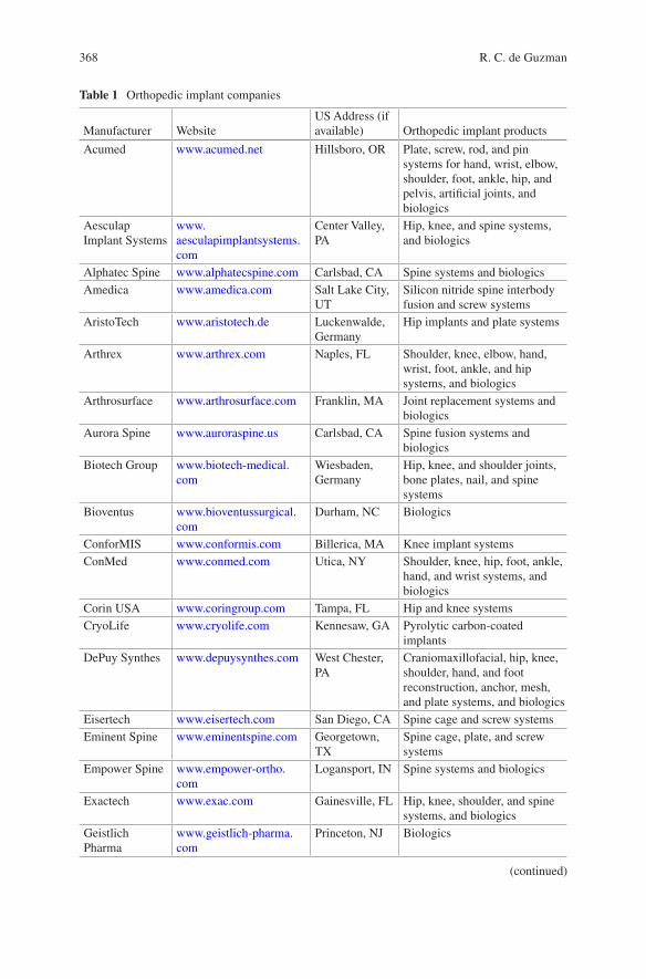
368
Table 1 Orthopedic implant companies
Manufacturer WebsiteUS Address (if available) Orthopedic implant products
Acumed www.acumed.net Hillsboro, OR Plate, screw, rod, and pin systems for hand, wrist, elbow, shoulder, foot, ankle, hip, and pelvis, artificial joints, and biologics
Aesculap Implant Systems
www.aesculapimplantsystems.com
Center Valley, PA
Hip, knee, and spine systems, and biologics
Alphatec Spine www.alphatecspine.com Carlsbad, CA Spine systems and biologicsAmedica www.amedica.com Salt Lake City,
UTSilicon nitride spine interbody fusion and screw systems
AristoTech www.aristotech.de Luckenwalde, Germany
Hip implants and plate systems
Arthrex www.arthrex.com Naples, FL Shoulder, knee, elbow, hand, wrist, foot, ankle, and hip systems, and biologics
Arthrosurface www.arthrosurface.com Franklin, MA Joint replacement systems and biologics
Aurora Spine www.auroraspine.us Carlsbad, CA Spine fusion systems and biologics
Biotech Group www.biotech-medical.com
Wiesbaden, Germany
Hip, knee, and shoulder joints, bone plates, nail, and spine systems
Bioventus www.bioventussurgical.com
Durham, NC Biologics
ConforMIS www.conformis.com Billerica, MA Knee implant systemsConMed www.conmed.com Utica, NY Shoulder, knee, hip, foot, ankle,
hand, and wrist systems, and biologics
Corin USA www.coringroup.com Tampa, FL Hip and knee systemsCryoLife www.cryolife.com Kennesaw, GA Pyrolytic carbon-coated
implantsDePuy Synthes www.depuysynthes.com West Chester,
PACraniomaxillofacial, hip, knee, shoulder, hand, and foot reconstruction, anchor, mesh, and plate systems, and biologics
Eisertech www.eisertech.com San Diego, CA Spine cage and screw systemsEminent Spine www.eminentspine.com Georgetown,
TXSpine cage, plate, and screw systems
Empower Spine www.empower-ortho.com
Logansport, IN Spine systems and biologics
Exactech www.exac.com Gainesville, FL Hip, knee, shoulder, and spine systems, and biologics
Geistlich Pharma
www.geistlich-pharma.com
Princeton, NJ Biologics
(continued)
R. C. de Guzman
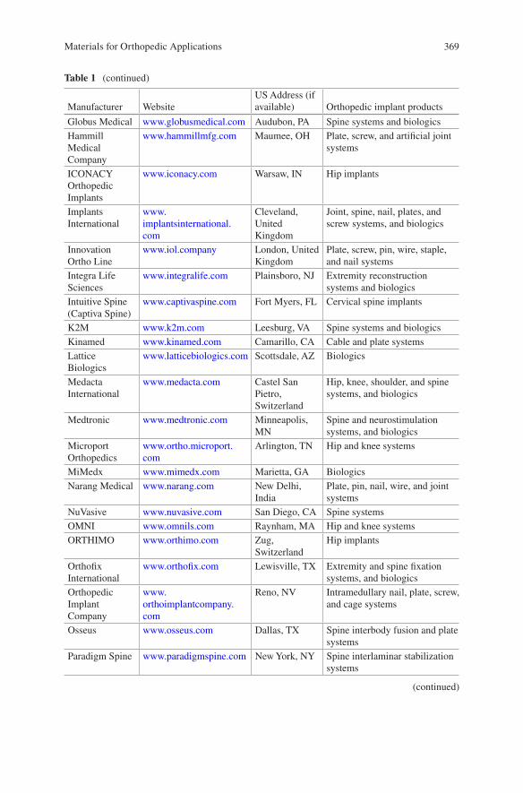
369
Table 1 (continued)
Manufacturer WebsiteUS Address (if available) Orthopedic implant products
Globus Medical www.globusmedical.com Audubon, PA Spine systems and biologicsHammill Medical Company
www.hammillmfg.com Maumee, OH Plate, screw, and artificial joint systems
ICONACY Orthopedic Implants
www.iconacy.com Warsaw, IN Hip implants
Implants International
www.implantsinternational.com
Cleveland, United Kingdom
Joint, spine, nail, plates, and screw systems, and biologics
Innovation Ortho Line
www.iol.company London, United Kingdom
Plate, screw, pin, wire, staple, and nail systems
Integra Life Sciences
www.integralife.com Plainsboro, NJ Extremity reconstruction systems and biologics
Intuitive Spine (Captiva Spine)
www.captivaspine.com Fort Myers, FL Cervical spine implants
K2M www.k2m.com Leesburg, VA Spine systems and biologicsKinamed www.kinamed.com Camarillo, CA Cable and plate systemsLattice Biologics
www.latticebiologics.com Scottsdale, AZ Biologics
Medacta International
www.medacta.com Castel San Pietro, Switzerland
Hip, knee, shoulder, and spine systems, and biologics
Medtronic www.medtronic.com Minneapolis, MN
Spine and neurostimulation systems, and biologics
Microport Orthopedics
www.ortho.microport.com
Arlington, TN Hip and knee systems
MiMedx www.mimedx.com Marietta, GA BiologicsNarang Medical www.narang.com New Delhi,
IndiaPlate, pin, nail, wire, and joint systems
NuVasive www.nuvasive.com San Diego, CA Spine systemsOMNI www.omnils.com Raynham, MA Hip and knee systemsORTHIMO www.orthimo.com Zug,
SwitzerlandHip implants
Orthofix International
www.orthofix.com Lewisville, TX Extremity and spine fixation systems, and biologics
Orthopedic Implant Company
www.orthoimplantcompany.com
Reno, NV Intramedullary nail, plate, screw, and cage systems
Osseus www.osseus.com Dallas, TX Spine interbody fusion and plate systems
Paradigm Spine www.paradigmspine.com New York, NY Spine interlaminar stabilization systems
(continued)
Materials for Orthopedic Applications
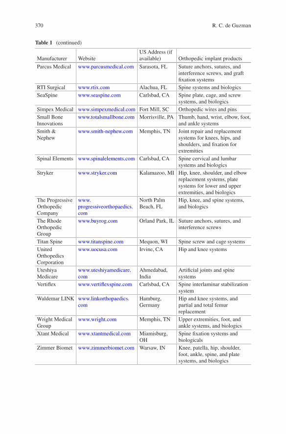
370
Table 1 (continued)
Manufacturer WebsiteUS Address (if available) Orthopedic implant products
Parcus Medical www.parcusmedical.com Sarasota, FL Suture anchors, sutures, and interference screws, and graft fixation systems
RTI Surgical www.rtix.com Alachua, FL Spine systems and biologicsSeaSpine www.seaspine.com Carlsbad, CA Spine plate, cage, and screw
systems, and biologicsSimpex Medical www.simpexmedical.com Fort Mill, SC Orthopedic wires and pinsSmall Bone Innovations
www.totalsmallbone.com Morrisville, PA Thumb, hand, wrist, elbow, foot, and ankle systems
Smith & Nephew
www.smith-nephew.com Memphis, TN Joint repair and replacement systems for knees, hips, and shoulders, and fixation for extremities
Spinal Elements www.spinalelements.com Carlsbad, CA Spine cervical and lumbar systems and biologics
Stryker www.stryker.com Kalamazoo, MI Hip, knee, shoulder, and elbow replacement systems, plate systems for lower and upper extremities, and biologics
The Progressive Orthopedic Company
www.progressiveorthopaedics.com
North Palm Beach, FL
Hip, knee, and spine systems, and biologics
The Rhode Orthopedic Group
www.buyrog.com Orland Park, IL Suture anchors, sutures, and interference screws
Titan Spine www.titanspine.com Mequon, WI Spine screw and cage systemsUnited Orthopedics Corporation
www.uocusa.com Irvine, CA Hip and knee systems
Uteshiya Medicare
www.uteshiyamedicare.com
Ahmedabad, India
Artificial joints and spine systems
Vertiflex www.vertiflexspine.com Carlsbad, CA Spine interlaminar stabilization system
Waldemar LINK www.linkorthopaedics.com
Hamburg, Germany
Hip and knee systems, and partial and total femur replacement
Wright Medical Group
www.wright.com Memphis, TN Upper extremities, foot, and ankle systems, and biologics
Xtant Medical www.xtantmedical.com Miamisburg, OH
Spine fixation systems and biologicals
Zimmer Biomet www.zimmerbiomet.com Warsaw, IN Knee, patella, hip, shoulder, foot, ankle, spine, and plate systems, and biologics
R. C. de Guzman
371
The bulk biomaterial composition of orthopedic implants are metals, ceramics, polymers, composites (containing different material types), and cell and tissue- derived materials. Metallic biomaterials include stainless steels (wrought stainless steel and wrought high nitrogen stainless steel), titanium (pure or unalloyed), titanium alloys (wrought Ti-6Al-4V, wrought Ti-6Al-7Nb, and wrought Ti-15Mo- 5Zr-3Al), cobalt-chromium (Co-Cr) alloys (cast Co-Cr-Mo, wrought Co-Cr-Mo, wrought Co-Cr-W-Ni, wrought Co-Ni-Cr-Mo, forged and cold-formed Co-Cr-Ni- Mo-Fe, and wrought Co-Ni-Cr-Mo-W-Fe), and tantalum. Wrought metals are beaten and shaped by ham-mers and other tools while cast metals are fabricated by pouring liquid metal into a mold and then allowed to cool. The ceramic biomaterials are mostly calcium phos-phate-based forms like hydroxyapatite (HA) and tricalcium phosphate (TCP) to match the natural bone minerals. For high-strength ceramics, high-purity alumina, zirconia-toughened alumina (ZTA), and yttria-stabilized zirconia (YSZ) are material options. Synthetic biomaterial polymers commonly utilized for orthopedic applications are the following: highly-crosslinked ultrahigh molecular weight poly(ethylene) (UHMWPE), poly(L-lactic acid) (PLLA), poly(ether ether ketone) (PEEK), poly(methyl methacry-late) (PMMA), poly(ethylene terephthalate) (PET), and silicone. They generally pro-vide high strength, durability, and resistance to wear and tear.
Orthopedic implants (Table 2) are usually packaged in a system composed of multiple components interacting with one another with the goal of stabilizing the fracture, preserving the motion of joints, avoiding the contact and interaction of other structures that are not essential for the functionality of the implant. Some systems are also adjustable to enable shortening or lengthening of the bone or for application of tension and compression to the system to avoid chronic inflammation and enable better healing and device-to-tissue integration outcomes. Commercial products are often classified based on their applications and properties such as rigid and manmade materials for trauma, arthroplasty, or for spinal applications, and bio-logics which involve natural products. The succeeding list describes the common orthopedic implant systems with representative in vivo X-ray and actual device images of assembled and disassembled views.
1.1 Bone Attachment Devices and Stabilizers
These implants are generally composed of metallic biomaterials because of their strength and rigidity requirements. They are used to affix to the undamaged cortical bone structures for stabilization of fracture and trauma. Their shapes and geometri-cal designs vary depending on the type of bone they support and the degree of load- bearing requirements. They need to withstand physical forces due to gravity, repeated motion, weight of the structures they support, and the inherent local tensile, compressive, shear, and torsional forces within the site of injury and surrounding structures. These structures should also hold up to the biological, biochemical, and electrochemical environment for the prevention of catastrophic failure. Otherwise, failed implants need to be retrieved then replaced which require additional invasive surgery thereby increasing the health risk as well as the associated cost.
Materials for Orthopedic Applications
372
(a) Intramedullary (IM) nail systems [7, 15, 24, 25, 40, 47, 48, 58, 61]
IM nail systems (also called IM rods) are composed of the main IM nail and sup-porting screws to provide interlocking structures (Fig. 1) [7, 15, 25, 47, 58]. The IM nail is an elongated and cylindrical rod that is inserted into the medullary cavity of long bones like the femur, tibia, and humerus for fracture repair management. It spans almost the entire length of the bone and acts as an internal splint that provides stability to the fracture but also allows micromovements leading to indirect healing via callus formation. Other applications of the IM nail system include bone nonunions and malunions, polytrauma, reconstructions following tumor resection, and bone lengthening and shortening procedures. IM nails vary in sizes, shapes,
Table 2 Orthopedic implant components
Orthopedic implants Bulk biomaterials
Bone attachment devices and stabilizers
Intramedullary nail systems
Stainless steel, titanium, titanium alloys, cobalt-chromium alloys, carbon fiber-reinforced PEEK, PLLAPlate systems
Screw systemsPins and wire systemsOther fastening devices
Artificial joints Hip replacement systems
Stainless steel, titanium, titanium alloys, cobalt-chromium alloys, tantalum, zirconia- toughened alumina, pyrocarbon, UHMWPE, silicone
Knee replacement systemsShoulder replacement systemsElbow replacement systemsHand and foot joint replacement systems
Artificial ligaments and tendons
Non-absorbable sutures
Stainless steel, titanium, titanium alloys, PEEK, carbon fiber-reinforced PEEK, PLLA, UHMWPE, PET, nylon, absorbable compositesBone and suture
anchor systemsArtificial spine devices
Intervertebral disc systems
Titanium, titanium alloys, cobalt-chromium alloys, tantalum, silicon nitride, UHMWPE, PEEKVertebral body
replacement systemsInterbody fusion devicesInterspinous process fusion devicesSpinal support devices
Biologics and tissue regeneration inducers
Bone grafts and fillers Calcium phosphate composites, autografts, allografts, collagen, PMMA, BMP-2 and other growth factors
Cartilage and osteochondral graftsOsteogenic inducers
R. C. de Guzman
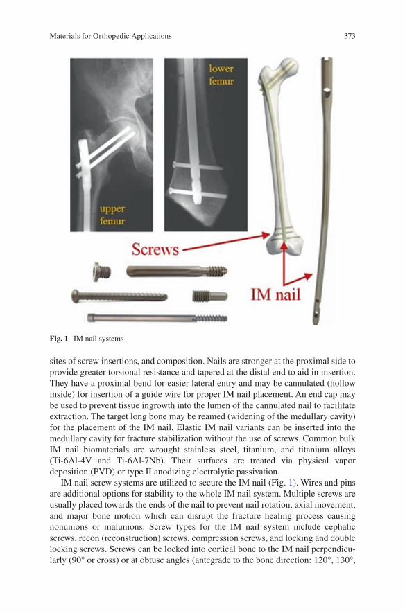
373
sites of screw insertions, and composition. Nails are stronger at the proximal side to provide greater torsional resistance and tapered at the distal end to aid in insertion. They have a proximal bend for easier lateral entry and may be cannulated (hollow inside) for insertion of a guide wire for proper IM nail placement. An end cap may be used to prevent tissue ingrowth into the lumen of the cannulated nail to facilitate extraction. The target long bone may be reamed (widening of the medullary cavity) for the placement of the IM nail. Elastic IM nail variants can be inserted into the medullary cavity for fracture stabilization without the use of screws. Common bulk IM nail biomaterials are wrought stainless steel, titanium, and titanium alloys (Ti-6Al-4V and Ti-6Al-7Nb). Their surfaces are treated via physical vapor deposition (PVD) or type II anodizing electrolytic passivation.
IM nail screw systems are utilized to secure the IM nail (Fig. 1). Wires and pins are additional options for stability to the whole IM nail system. Multiple screws are usually placed towards the ends of the nail to prevent nail rotation, axial movement, and major bone motion which can disrupt the fracture healing process causing nonunions or malunions. Screw types for the IM nail system include cephalic screws, recon (reconstruction) screws, compression screws, and locking and double locking screws. Screws can be locked into cortical bone to the IM nail perpendicu-larly (90° or cross) or at obtuse angles (antegrade to the bone direction: 120°, 130°,
Fig. 1 IM nail systems
Materials for Orthopedic Applications
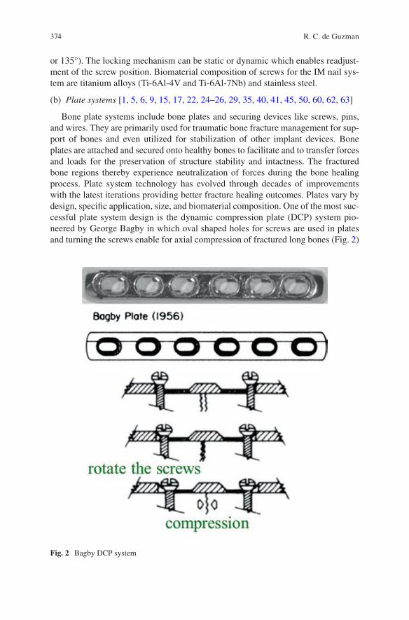
374
or 135°). The locking mechanism can be static or dynamic which enables readjust-ment of the screw position. Biomaterial composition of screws for the IM nail sys-tem are titanium alloys (Ti-6Al-4V and Ti-6Al-7Nb) and stainless steel.
(b) Plate systems [1, 5, 6, 9, 15, 17, 22, 24–26, 29, 35, 40, 41, 45, 50, 60, 62, 63]
Bone plate systems include bone plates and securing devices like screws, pins, and wires. They are primarily used for traumatic bone fracture management for sup-port of bones and even utilized for stabilization of other implant devices. Bone plates are attached and secured onto healthy bones to facilitate and to transfer forces and loads for the preservation of structure stability and intactness. The fractured bone regions thereby experience neutralization of forces during the bone healing process. Plate system technology has evolved through decades of improvements with the latest iterations providing better fracture healing outcomes. Plates vary by design, specific application, size, and biomaterial composition. One of the most suc-cessful plate system design is the dynamic compression plate (DCP) system pio-neered by George Bagby in which oval shaped holes for screws are used in plates and turning the screws enable for axial compression of fractured long bones (Fig. 2)
Fig. 2 Bagby DCP system
R. C. de Guzman
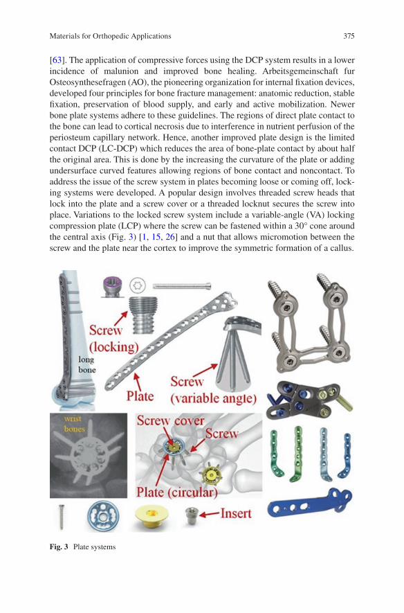
375
[63]. The application of compressive forces using the DCP system results in a lower incidence of malunion and improved bone healing. Arbeitsgemeinschaft fur Osteosynthesefragen (AO), the pioneering organization for internal fixation devices, developed four principles for bone fracture management: anatomic reduction, stable fixation, preservation of blood supply, and early and active mobilization. Newer bone plate systems adhere to these guidelines. The regions of direct plate contact to the bone can lead to cortical necrosis due to interference in nutrient perfusion of the periosteum capillary network. Hence, another improved plate design is the limited contact DCP (LC-DCP) which reduces the area of bone-plate contact by about half the original area. This is done by the increasing the curvature of the plate or adding undersurface curved features allowing regions of bone contact and noncontact. To address the issue of the screw system in plates becoming loose or coming off, lock-ing systems were developed. A popular design involves threaded screw heads that lock into the plate and a screw cover or a threaded locknut secures the screw into place. Variations to the locked screw system include a variable-angle (VA) locking compression plate (LCP) where the screw can be fastened within a 30° cone around the central axis (Fig. 3) [1, 15, 26] and a nut that allows micromotion between the screw and the plate near the cortex to improve the symmetric formation of a callus.
Fig. 3 Plate systems
Materials for Orthopedic Applications
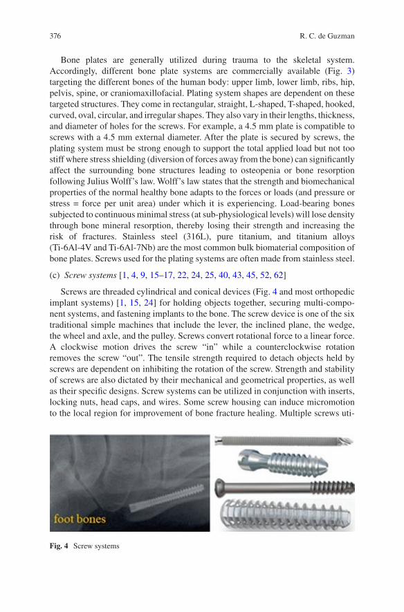
376
Bone plates are generally utilized during trauma to the skeletal system. Accordingly, different bone plate systems are commercially available (Fig. 3) targeting the different bones of the human body: upper limb, lower limb, ribs, hip, pelvis, spine, or craniomaxillofacial. Plating system shapes are dependent on these targeted structures. They come in rectangular, straight, L-shaped, T-shaped, hooked, curved, oval, circular, and irregular shapes. They also vary in their lengths, thickness, and diameter of holes for the screws. For example, a 4.5 mm plate is compatible to screws with a 4.5 mm external diameter. After the plate is secured by screws, the plating system must be strong enough to support the total applied load but not too stiff where stress shielding (diversion of forces away from the bone) can significantly affect the surrounding bone structures leading to osteopenia or bone resorption following Julius Wolff’s law. Wolff’s law states that the strength and biomechanical properties of the normal healthy bone adapts to the forces or loads (and pressure or stress = force per unit area) under which it is experiencing. Load-bearing bones subjected to continuous minimal stress (at sub-physiological levels) will lose density through bone mineral resorption, thereby losing their strength and increasing the risk of fractures. Stainless steel (316L), pure titanium, and titanium alloys (Ti-6Al-4V and Ti-6Al-7Nb) are the most common bulk biomaterial composition of bone plates. Screws used for the plating systems are often made from stainless steel.
(c) Screw systems [1, 4, 9, 15–17, 22, 24, 25, 40, 43, 45, 52, 62]
Screws are threaded cylindrical and conical devices (Fig. 4 and most orthopedic implant systems) [1, 15, 24] for holding objects together, securing multi-compo-nent systems, and fastening implants to the bone. The screw device is one of the six traditional simple machines that include the lever, the inclined plane, the wedge, the wheel and axle, and the pulley. Screws convert rotational force to a linear force. A clockwise motion drives the screw “in” while a counterclockwise rotation removes the screw “out”. The tensile strength required to detach objects held by screws are dependent on inhibiting the rotation of the screw. Strength and stability of screws are also dictated by their mechanical and geometrical properties, as well as their specific designs. Screw systems can be utilized in conjunction with inserts, locking nuts, head caps, and wires. Some screw housing can induce micromotion to the local region for improvement of bone fracture healing. Multiple screws uti-
Fig. 4 Screw systems
R. C. de Guzman
377
lized in conjunction with orthopedic implants prevent rotation and lateral motion of the device.
Screws have varying sizes, thread properties, and bulk material compositions. Screw threads differ in their pitch, lead, spacing, and shapes. Screws that are directly fastened into bones can interact with the cortical bone (cortical screws) or with the cancellous bone (cancellous screws). Cortical screws have closer and shallower pitches while cancellous screws have wider and deeper pitches to engage into softer bone structures. Screws are traditionally driven into the bone by a tap (a small pilot hole) but self-tapping screws are also widely available as orthopedic implants. Self-tapping screws have a cutting flute at their tip that penetrates the bone during the turning process. Some screw systems are named and designed according to the long bone placement (diaphyseal screw, metaphyseal screw, and epiphyseal screw) and the type of bone they are utilized in (such as pedicle or spine screw, malleolar screw, pertrochanter screw, femoral screw, and extremity screw). Other variations to the screw system include locking screws, compression screws, cannulated screws, headless screws, twist-off screws, and interference screws. Locking screws have threaded heads that are secured with a threaded insert, screw cap, or lug nut. Compression screws have continuously variable thread pitch size; widest at the tip and gets finer at the trailing threads. Driving the compression screw allows the screw to penetrate faster at the tip compared to the tail thus providing axial com-pression. Screws can be cannulated (with a hollow lumen) to enable better guidance using a wire to the targeted region and the hollow core of the screw additionally allows native bone infiltration or bone cement and biological injection for stronger bone integration. Accordingly, cannulated screws are employed as fusion screws to merge adjacent bones together such as in spinal fusion and midfoot fusion. Headless screws reduce the risk of soft tissue irritation and interference especially when uti-lized within the articular regions. Twist-off or snap-off screws have an upper section that is removed by bending the weak spot after positioning into the bone. Interference screws are utilized for ligament reconstruction. They are headless and fully threaded. Permanent bulk biomaterials of screws are stainless steel (316L), titanium alloy (Ti-6Al-4V), and PEEK reinforced with carbon fibers. Slowly degrading and resorb-able screws are composed of PLLA. Some screws like the Schanz screws (narrow pin-like partially-threaded screws) can be coated with HA for enhanced fixation into the bone tissue.
(d) Pins and wire systems [1, 6, 25, 35, 46, 50, 60, 64]
Nails, rods, pins, and wires (Fig. 5) [1, 46] are thin cylindrical and elongated implants (mostly) without threads utilized for bone and device stabilization. Nails and rods have the largest diameter. Pins have smaller diameter than nails while wires have the smallest diameter among them. Orthopedic wires are called Kirschner wires (K-wires) which have diameter sizes ranging from 0.7 to <2 mm. Those with greater than 2 mm in diameter are referred to as Steinmann pins. Pins and wires are available at varying lengths and end tips. The three-sided (trocar) tip and the two-sided (chisel or diamond) tips are generally used for drilling into cortical and can-cellous bones, respectively, to create a tap or for wire implant insertion. Blunt or flat
Materials for Orthopedic Applications
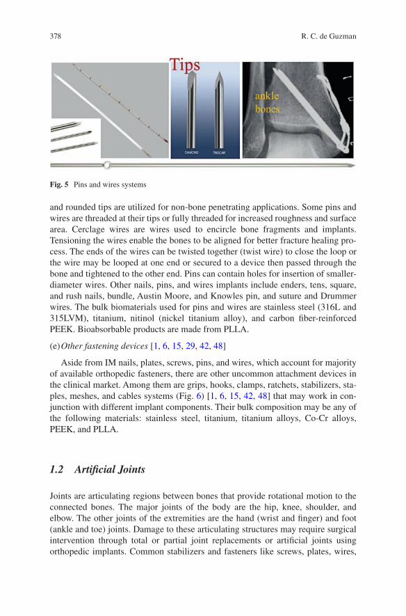
378
and rounded tips are utilized for non-bone penetrating applications. Some pins and wires are threaded at their tips or fully threaded for increased roughness and surface area. Cerclage wires are wires used to encircle bone fragments and implants. Tensioning the wires enable the bones to be aligned for better fracture healing pro-cess. The ends of the wires can be twisted together (twist wire) to close the loop or the wire may be looped at one end or secured to a device then passed through the bone and tightened to the other end. Pins can contain holes for insertion of smaller-diameter wires. Other nails, pins, and wires implants include enders, tens, square, and rush nails, bundle, Austin Moore, and Knowles pin, and suture and Drummer wires. The bulk biomaterials used for pins and wires are stainless steel (316L and 315LVM), titanium, nitinol (nickel titanium alloy), and carbon fiber-reinforced PEEK. Bioabsorbable products are made from PLLA.
(e) Other fastening devices [1, 6, 15, 29, 42, 48]
Aside from IM nails, plates, screws, pins, and wires, which account for majority of available orthopedic fasteners, there are other uncommon attachment devices in the clinical market. Among them are grips, hooks, clamps, ratchets, stabilizers, sta-ples, meshes, and cables systems (Fig. 6) [1, 6, 15, 42, 48] that may work in con-junction with different implant components. Their bulk composition may be any of the following materials: stainless steel, titanium, titanium alloys, Co-Cr alloys, PEEK, and PLLA.
1.2 Artificial Joints
Joints are articulating regions between bones that provide rotational motion to the connected bones. The major joints of the body are the hip, knee, shoulder, and elbow. The other joints of the extremities are the hand (wrist and finger) and foot (ankle and toe) joints. Damage to these articulating structures may require surgical intervention through total or partial joint replacements or artificial joints using orthopedic implants. Common stabilizers and fasteners like screws, plates, wires,
Fig. 5 Pins and wires systems
R. C. de Guzman
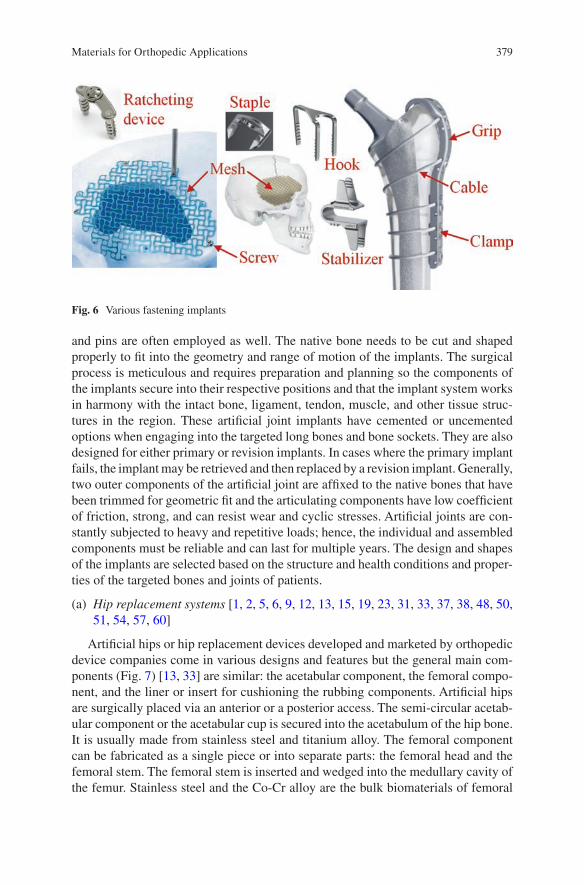
379
and pins are often employed as well. The native bone needs to be cut and shaped properly to fit into the geometry and range of motion of the implants. The surgical process is meticulous and requires preparation and planning so the components of the implants secure into their respective positions and that the implant system works in harmony with the intact bone, ligament, tendon, muscle, and other tissue struc-tures in the region. These artificial joint implants have cemented or uncemented options when engaging into the targeted long bones and bone sockets. They are also designed for either primary or revision implants. In cases where the primary implant fails, the implant may be retrieved and then replaced by a revision implant. Generally, two outer components of the artificial joint are affixed to the native bones that have been trimmed for geometric fit and the articulating components have low coefficient of friction, strong, and can resist wear and cyclic stresses. Artificial joints are con-stantly subjected to heavy and repetitive loads; hence, the individual and assembled components must be reliable and can last for multiple years. The design and shapes of the implants are selected based on the structure and health conditions and proper-ties of the targeted bones and joints of patients.
(a) Hip replacement systems [1, 2, 5, 6, 9, 12, 13, 15, 19, 23, 31, 33, 37, 38, 48, 50, 51, 54, 57, 60]
Artificial hips or hip replacement devices developed and marketed by orthopedic device companies come in various designs and features but the general main com-ponents (Fig. 7) [13, 33] are similar: the acetabular component, the femoral compo-nent, and the liner or insert for cushioning the rubbing components. Artificial hips are surgically placed via an anterior or a posterior access. The semi-circular acetab-ular component or the acetabular cup is secured into the acetabulum of the hip bone. It is usually made from stainless steel and titanium alloy. The femoral component can be fabricated as a single piece or into separate parts: the femoral head and the femoral stem. The femoral stem is inserted and wedged into the medullary cavity of the femur. Stainless steel and the Co-Cr alloy are the bulk biomaterials of femoral
Fig. 6 Various fastening implants
Materials for Orthopedic Applications
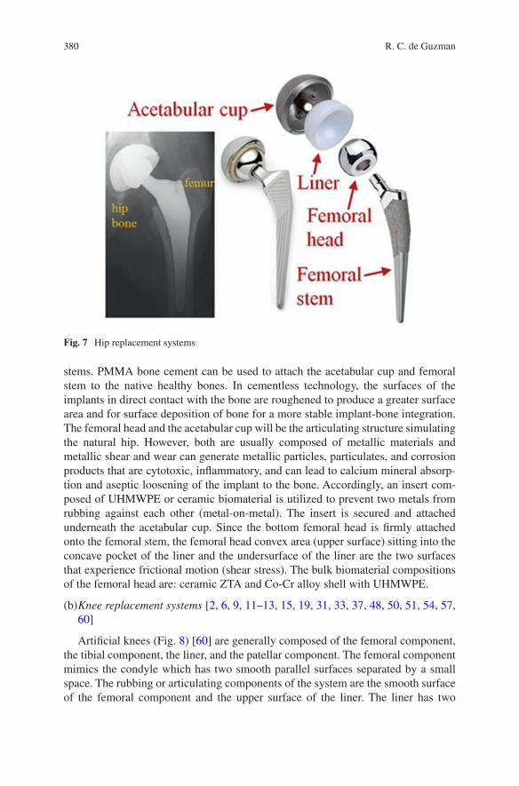
380
stems. PMMA bone cement can be used to attach the acetabular cup and femoral stem to the native healthy bones. In cementless technology, the surfaces of the implants in direct contact with the bone are roughened to produce a greater surface area and for surface deposition of bone for a more stable implant-bone integration. The femoral head and the acetabular cup will be the articulating structure simulating the natural hip. However, both are usually composed of metallic materials and metallic shear and wear can generate metallic particles, particulates, and corrosion products that are cytotoxic, inflammatory, and can lead to calcium mineral absorp-tion and aseptic loosening of the implant to the bone. Accordingly, an insert com-posed of UHMWPE or ceramic biomaterial is utilized to prevent two metals from rubbing against each other (metal-on-metal). The insert is secured and attached underneath the acetabular cup. Since the bottom femoral head is firmly attached onto the femoral stem, the femoral head convex area (upper surface) sitting into the concave pocket of the liner and the undersurface of the liner are the two surfaces that experience frictional motion (shear stress). The bulk biomaterial compositions of the femoral head are: ceramic ZTA and Co-Cr alloy shell with UHMWPE.
(b) Knee replacement systems [2, 6, 9, 11–13, 15, 19, 31, 33, 37, 48, 50, 51, 54, 57, 60]
Artificial knees (Fig. 8) [60] are generally composed of the femoral component, the tibial component, the liner, and the patellar component. The femoral component mimics the condyle which has two smooth parallel surfaces separated by a small space. The rubbing or articulating components of the system are the smooth surface of the femoral component and the upper surface of the liner. The liner has two
Fig. 7 Hip replacement systems
R. C. de Guzman
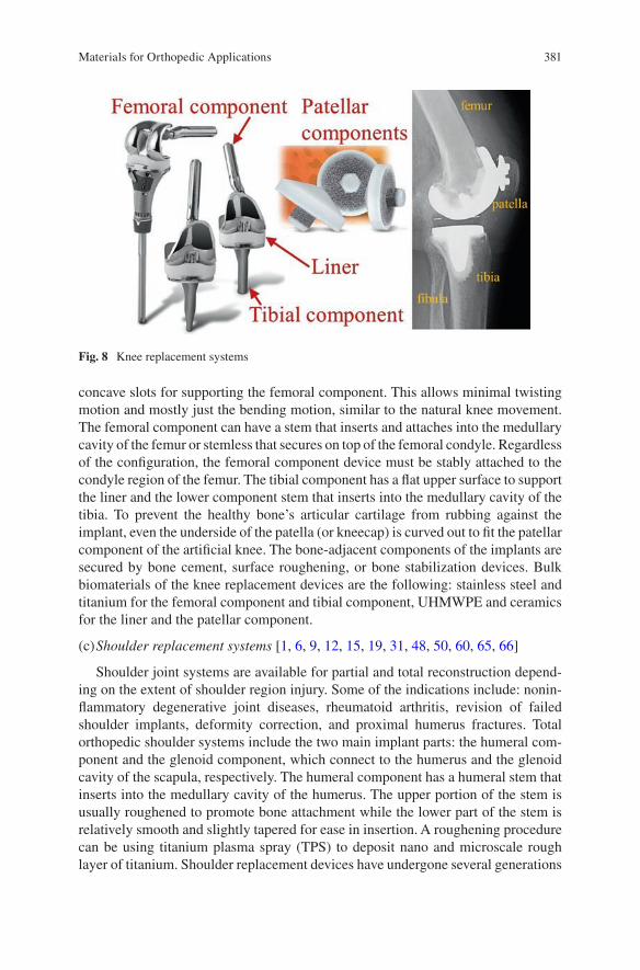
381
concave slots for supporting the femoral component. This allows minimal twisting motion and mostly just the bending motion, similar to the natural knee movement. The femoral component can have a stem that inserts and attaches into the medullary cavity of the femur or stemless that secures on top of the femoral condyle. Regardless of the configuration, the femoral component device must be stably attached to the condyle region of the femur. The tibial component has a flat upper surface to support the liner and the lower component stem that inserts into the medullary cavity of the tibia. To prevent the healthy bone’s articular cartilage from rubbing against the implant, even the underside of the patella (or kneecap) is curved out to fit the patellar component of the artificial knee. The bone-adjacent components of the implants are secured by bone cement, surface roughening, or bone stabilization devices. Bulk biomaterials of the knee replacement devices are the following: stainless steel and titanium for the femoral component and tibial component, UHMWPE and ceramics for the liner and the patellar component.
(c) Shoulder replacement systems [1, 6, 9, 12, 15, 19, 31, 48, 50, 60, 65, 66]
Shoulder joint systems are available for partial and total reconstruction depend-ing on the extent of shoulder region injury. Some of the indications include: nonin-flammatory degenerative joint diseases, rheumatoid arthritis, revision of failed shoulder implants, deformity correction, and proximal humerus fractures. Total orthopedic shoulder systems include the two main implant parts: the humeral com-ponent and the glenoid component, which connect to the humerus and the glenoid cavity of the scapula, respectively. The humeral component has a humeral stem that inserts into the medullary cavity of the humerus. The upper portion of the stem is usually roughened to promote bone attachment while the lower part of the stem is relatively smooth and slightly tapered for ease in insertion. A roughening procedure can be using titanium plasma spray (TPS) to deposit nano and microscale rough layer of titanium. Shoulder replacement devices have undergone several generations
Fig. 8 Knee replacement systems
Materials for Orthopedic Applications
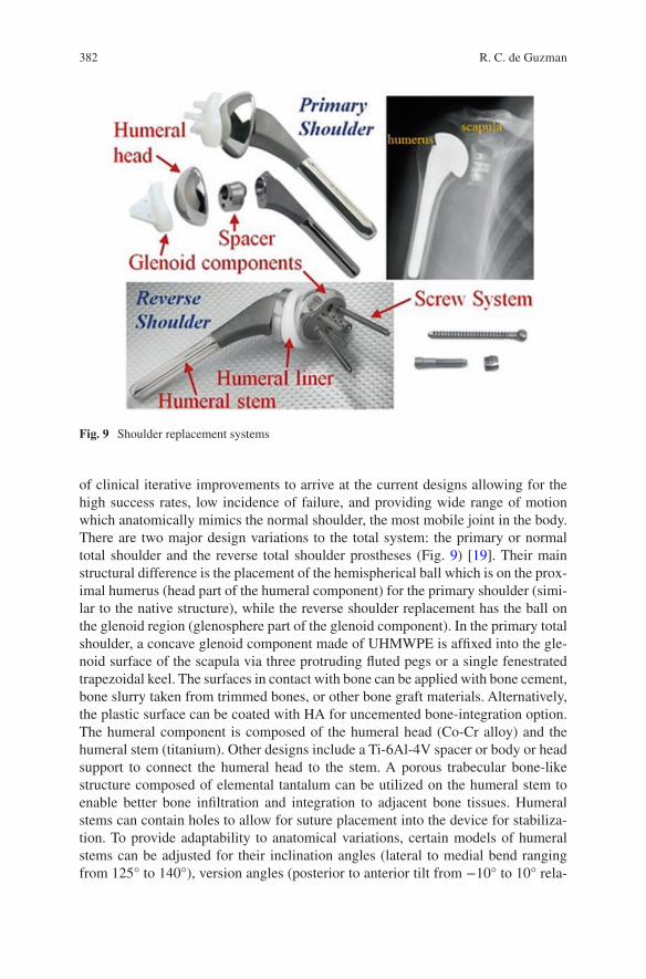
382
of clinical iterative improvements to arrive at the current designs allowing for the high success rates, low incidence of failure, and providing wide range of motion which anatomically mimics the normal shoulder, the most mobile joint in the body. There are two major design variations to the total system: the primary or normal total shoulder and the reverse total shoulder prostheses (Fig. 9) [19]. Their main structural difference is the placement of the hemispherical ball which is on the prox-imal humerus (head part of the humeral component) for the primary shoulder (simi-lar to the native structure), while the reverse shoulder replacement has the ball on the glenoid region (glenosphere part of the glenoid component). In the primary total shoulder, a concave glenoid component made of UHMWPE is affixed into the gle-noid surface of the scapula via three protruding fluted pegs or a single fenestrated trapezoidal keel. The surfaces in contact with bone can be applied with bone cement, bone slurry taken from trimmed bones, or other bone graft materials. Alternatively, the plastic surface can be coated with HA for uncemented bone-integration option. The humeral component is composed of the humeral head (Co-Cr alloy) and the humeral stem (titanium). Other designs include a Ti-6Al-4V spacer or body or head support to connect the humeral head to the stem. A porous trabecular bone-like structure composed of elemental tantalum can be utilized on the humeral stem to enable better bone infiltration and integration to adjacent bone tissues. Humeral stems can contain holes to allow for suture placement into the device for stabiliza-tion. To provide adaptability to anatomical variations, certain models of humeral stems can be adjusted for their inclination angles (lateral to medial bend ranging from 125° to 140°), version angles (posterior to anterior tilt from −10° to 10° rela-
Fig. 9 Shoulder replacement systems
R. C. de Guzman
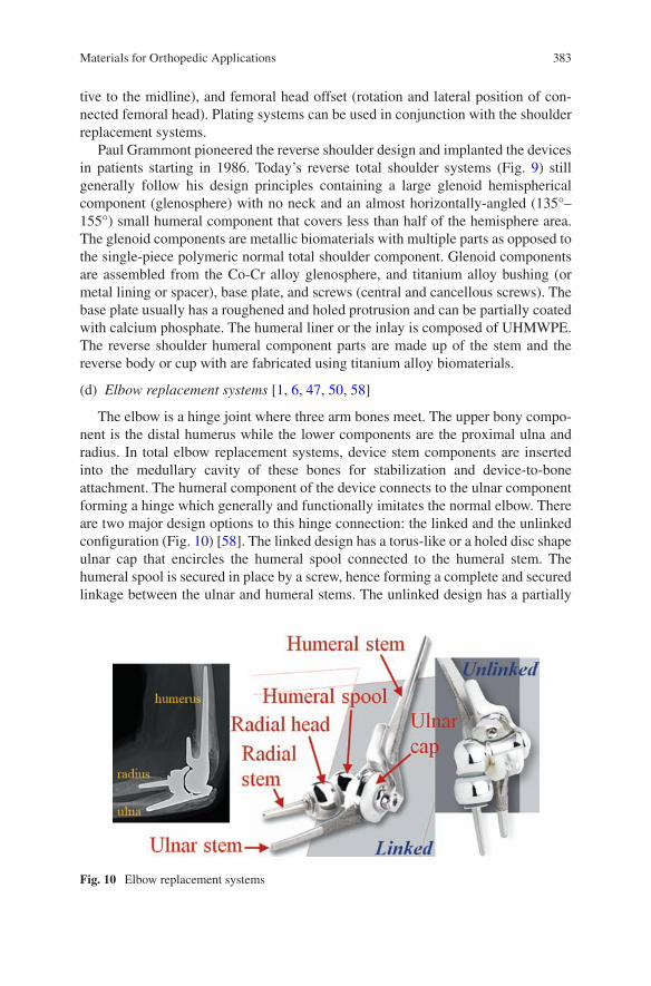
383
tive to the midline), and femoral head offset (rotation and lateral position of con-nected femoral head). Plating systems can be used in conjunction with the shoulder replacement systems.
Paul Grammont pioneered the reverse shoulder design and implanted the devices in patients starting in 1986. Today’s reverse total shoulder systems (Fig. 9) still generally follow his design principles containing a large glenoid hemispherical component (glenosphere) with no neck and an almost horizontally-angled (135°–155°) small humeral component that covers less than half of the hemisphere area. The glenoid components are metallic biomaterials with multiple parts as opposed to the single-piece polymeric normal total shoulder component. Glenoid components are assembled from the Co-Cr alloy glenosphere, and titanium alloy bushing (or metal lining or spacer), base plate, and screws (central and cancellous screws). The base plate usually has a roughened and holed protrusion and can be partially coated with calcium phosphate. The humeral liner or the inlay is composed of UHMWPE. The reverse shoulder humeral component parts are made up of the stem and the reverse body or cup with are fabricated using titanium alloy biomaterials.
(d) Elbow replacement systems [1, 6, 47, 50, 58]
The elbow is a hinge joint where three arm bones meet. The upper bony compo-nent is the distal humerus while the lower components are the proximal ulna and radius. In total elbow replacement systems, device stem components are inserted into the medullary cavity of these bones for stabilization and device-to-bone attachment. The humeral component of the device connects to the ulnar component forming a hinge which generally and functionally imitates the normal elbow. There are two major design options to this hinge connection: the linked and the unlinked configuration (Fig. 10) [58]. The linked design has a torus-like or a holed disc shape ulnar cap that encircles the humeral spool connected to the humeral stem. The humeral spool is secured in place by a screw, hence forming a complete and secured linkage between the ulnar and humeral stems. The unlinked design has a partially
Fig. 10 Elbow replacement systems
Materials for Orthopedic Applications
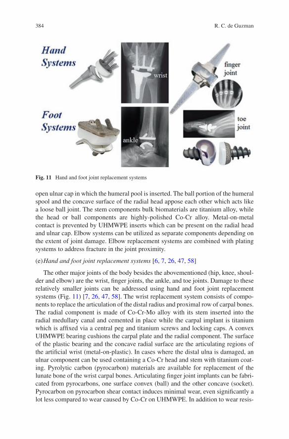
384
open ulnar cap in which the humeral pool is inserted. The ball portion of the humeral spool and the concave surface of the radial head appose each other which acts like a loose ball joint. The stem components bulk biomaterials are titanium alloy, while the head or ball components are highly-polished Co-Cr alloy. Metal-on-metal contact is prevented by UHMWPE inserts which can be present on the radial head and ulnar cap. Elbow systems can be utilized as separate components depending on the extent of joint damage. Elbow replacement systems are combined with plating systems to address fracture in the joint proximity.
(e) Hand and foot joint replacement systems [6, 7, 26, 47, 58]
The other major joints of the body besides the abovementioned (hip, knee, shoul-der and elbow) are the wrist, finger joints, the ankle, and toe joints. Damage to these relatively smaller joints can be addressed using hand and foot joint replacement systems (Fig. 11) [7, 26, 47, 58]. The wrist replacement system consists of compo-nents to replace the articulation of the distal radius and proximal row of carpal bones. The radial component is made of Co-Cr-Mo alloy with its stem inserted into the radial medullary canal and cemented in place while the carpal implant is titanium which is affixed via a central peg and titanium screws and locking caps. A convex UHMWPE bearing cushions the carpal plate and the radial component. The surface of the plastic bearing and the concave radial surface are the articulating regions of the artificial wrist (metal-on-plastic). In cases where the distal ulna is damaged, an ulnar component can be used containing a Co-Cr head and stem with titanium coat-ing. Pyrolytic carbon (pyrocarbon) materials are available for replacement of the lunate bone of the wrist carpal bones. Articulating finger joint implants can be fabri-cated from pyrocarbons, one surface convex (ball) and the other concave (socket). Pyrocarbon on pyrocarbon shear contact induces minimal wear, even significantly a lot less compared to wear caused by Co-Cr on UHMWPE. In addition to wear resis-
Fig. 11 Hand and foot joint replacement systems
R. C. de Guzman
385
tance, pyrocarbon has low coefficient of friction and elastic modulus close to bone, hence can used as an articulating surface in contact with bone and articular cartilage. Microporous pyrocarbon coating enhances bone fixation even without the use of bone cement. Ball and socket finger joint implants are offered in assorted sizes to accommodate for anthropomorphic variations. Finger joint replacements can also be a hinge design. The stem phalange and metacarpal inserts and the hinge joint can be made from flexible silicone elastomer or titanium. Grommets (Fig. 11) supporting the silicone stems are titanium biomaterials.
The ankle joint proper is the articulating region between the distal tibia and the talus of the tarsal bones of the foot. Accordingly, the total ankle replacement system design generally consists of pegged tibial tray and talar (talus) components that attach onto the tibia and talus, respectively. The tibial tray, made from Ti-6Al-4V with plasma sprayed porous titanium coating, holds an UHMWPE insert in place. The concave underside of the polymeric insert articulates onto the Co-Cr alloy talar dome component. Toe joint replacement system designs include a ball and socket configuration with toe phalange and metatarsal implants made from Co-Cr with plasma-sprayed titanium coating on the screw stems and an UHMWPE liner articulating with the smooth and polished head surface or hinged configuration made from bulk biomaterial silicone with titanium grommets. Plate, screw, pins, and wire systems are also often used in conjunction with the joint replacement implants to stabilize the damaged bone structures.
1.3 Artificial Ligaments and Tendons
Ligaments and tendons are strong and flexible collagenous fiber bundles that con-nect bones to bones and muscles, respectively. Ligaments support and stabilize joints such as the knee, that is secured by the anterior cruciate ligament (ACL), posterior cruciate ligament (PCL), medial collateral ligament (MCL), lateral col-lateral ligament (LCL), and other intracapsular and extracapsular ligaments. Artificial ligament and tendon devices are utilized to repair damaged tissue struc-tures that have detached from the intact healthy bones. These implants are also used to stabilize and support surgically-repaired bones and joints.
Knee ligaments, mostly the ACL, are often damaged and torn during sports activ-ities. Hence, these devices maybe classified within the sports medicine or joint reconstruction products section. Aside from tendon allografts for reconstruction of ligaments and tendons, the general design of artificial implants is relatively simple containing a bone anchor that connects to a polymeric material with high tensile strength but very flexible and pliable.
(a) Non-absorbable sutures [6, 15, 32, 43, 52, 67]
Non-absorbable sutures (Fig. 12) [6, 15, 43] act as artificial ligaments and ten-dons. They are usually composed of very high molecular weight inert polymers such as UHMWPE or PET polyesters with cyanoacrylate and nylon. Multiple fibers are braided or weaved together for enhanced tensile strength. Ligament-like sutures
Materials for Orthopedic Applications
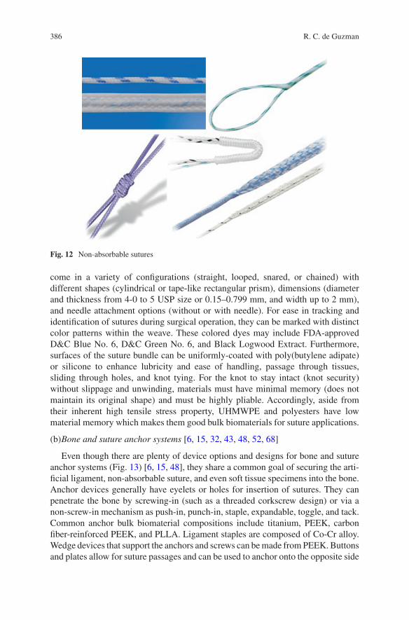
386
come in a variety of configurations (straight, looped, snared, or chained) with different shapes (cylindrical or tape-like rectangular prism), dimensions (diameter and thickness from 4-0 to 5 USP size or 0.15–0.799 mm, and width up to 2 mm), and needle attachment options (without or with needle). For ease in tracking and identification of sutures during surgical operation, they can be marked with distinct color patterns within the weave. These colored dyes may include FDA-approved D&C Blue No. 6, D&C Green No. 6, and Black Logwood Extract. Furthermore, surfaces of the suture bundle can be uniformly-coated with poly(butylene adipate) or silicone to enhance lubricity and ease of handling, passage through tissues, sliding through holes, and knot tying. For the knot to stay intact (knot security) without slippage and unwinding, materials must have minimal memory (does not maintain its original shape) and must be highly pliable. Accordingly, aside from their inherent high tensile stress property, UHMWPE and polyesters have low material memory which makes them good bulk biomaterials for suture applications.
(b) Bone and suture anchor systems [6, 15, 32, 43, 48, 52, 68]
Even though there are plenty of device options and designs for bone and suture anchor systems (Fig. 13) [6, 15, 48], they share a common goal of securing the arti-ficial ligament, non-absorbable suture, and even soft tissue specimens into the bone. Anchor devices generally have eyelets or holes for insertion of sutures. They can penetrate the bone by screwing-in (such as a threaded corkscrew design) or via a non-screw-in mechanism as push-in, punch-in, staple, expandable, toggle, and tack. Common anchor bulk biomaterial compositions include titanium, PEEK, carbon fiber-reinforced PEEK, and PLLA. Ligament staples are composed of Co-Cr alloy. Wedge devices that support the anchors and screws can be made from PEEK. Buttons and plates allow for suture passages and can be used to anchor onto the opposite side
Fig. 12 Non-absorbable sutures
R. C. de Guzman
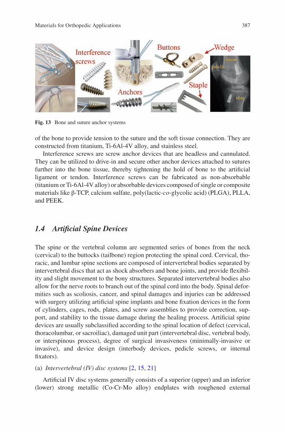
387
of the bone to provide tension to the suture and the soft tissue connection. They are constructed from titanium, Ti-6Al-4V alloy, and stainless steel.
Interference screws are screw anchor devices that are headless and cannulated. They can be utilized to drive-in and secure other anchor devices attached to sutures further into the bone tissue, thereby tightening the hold of bone to the artificial ligament or tendon. Interference screws can be fabricated as non-absorbable (titanium or Ti-6Al-4V alloy) or absorbable devices composed of single or composite materials like β-TCP, calcium sulfate, poly(lactic-co-glycolic acid) (PLGA), PLLA, and PEEK.
1.4 Artificial Spine Devices
The spine or the vertebral column are segmented series of bones from the neck (cervical) to the buttocks (tailbone) region protecting the spinal cord. Cervical, tho-racic, and lumbar spine sections are composed of intervertebral bodies separated by intervertebral discs that act as shock absorbers and bone joints, and provide flexibil-ity and slight movement to the bony structures. Separated intervertebral bodies also allow for the nerve roots to branch out of the spinal cord into the body. Spinal defor-mities such as scoliosis, cancer, and spinal damages and injuries can be addressed with surgery utilizing artificial spine implants and bone fixation devices in the form of cylinders, cages, rods, plates, and screw assemblies to provide correction, sup-port, and stability to the tissue damage during the healing process. Artificial spine devices are usually subclassified according to the spinal location of defect (cervical, thoracolumbar, or sacroiliac), damaged unit part (intervertebral disc, vertebral body, or interspinous process), degree of surgical invasiveness (minimally-invasive or invasive), and device design (interbody devices, pedicle screws, or internal fixators).
(a) Intervertebral (IV) disc systems [2, 15, 21]
Artificial IV disc systems generally consists of a superior (upper) and an inferior (lower) strong metallic (Co-Cr-Mo alloy) endplates with roughened external
Fig. 13 Bone and suture anchor systems
Materials for Orthopedic Applications
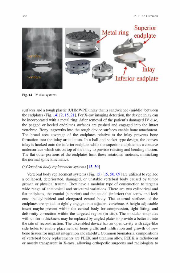
388
surfaces and a tough plastic (UHMWPE) inlay that is sandwiched (middle) between the endplates (Fig. 14) [2, 15, 21]. For X-ray imaging detection, the device inlay can be incorporated with a metal ring. After removal of the patient’s damaged IV disc, the pegged or keeled endplates surfaces are pushed and engaged into the intact vertebrae. Bony ingrowths into the rough device surfaces enable bone attachment. The broad area coverage of the endplates relative to the inlay prevents bone formation into the inlay articulation. In a ball and socket type design, the convex inlay is hooked onto the inferior endplate while the superior endplate has a concave undersurface which sits on top of the inlay to provide twisting and bending motion. The flat outer portions of the endplates limit these rotational motions, mimicking the normal spine kinematics.
(b) Vertebral body replacement systems [15, 50]
Vertebral body replacement systems (Fig. 15) [15, 50, 69] are utilized to replace a collapsed, deteriorated, damaged, or unstable vertebral body caused by tumor growth or physical trauma. They have a modular type of construction to target a wide range of anatomical and structural variations. There are two cylindrical and flat endplates, the cranial (superior) and the caudal (inferior) that screw and lock onto the cylindrical and elongated central body. The external surfaces of the endplates are spiked to tightly engage onto adjacent vertebrae. A height-adjustable insert maybe present within the central body for compression, tight-fitting, and deformity-correction within the targeted region (in situ). The modular endplates with uniform thickness may be replaced by angled plates to provide a better fit into the site of reconstruction. The assembled device has an open cavity with cage-like side holes to enable placement of bone grafts and infiltration and growth of new bone tissues for implant integration and stability. Common biomaterial compositions of vertebral body replacements are PEEK and titanium alloy. PEEK is radiolucent or mostly transparent in X-rays, allowing orthopedic surgeons and radiologists to
Fig. 14 IV disc systems
R. C. de Guzman
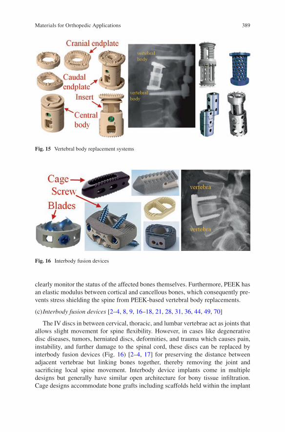
389
clearly monitor the status of the affected bones themselves. Furthermore, PEEK has an elastic modulus between cortical and cancellous bones, which consequently pre-vents stress shielding the spine from PEEK-based vertebral body replacements.
(c) Interbody fusion devices [2–4, 8, 9, 16–18, 21, 28, 31, 36, 44, 49, 70]
The IV discs in between cervical, thoracic, and lumbar vertebrae act as joints that allows slight movement for spine flexibility. However, in cases like degenerative disc diseases, tumors, herniated discs, deformities, and trauma which causes pain, instability, and further damage to the spinal cord, these discs can be replaced by interbody fusion devices (Fig. 16) [2–4, 17] for preserving the distance between adjacent vertebrae but linking bones together, thereby removing the joint and sacrificing local spine movement. Interbody device implants come in multiple designs but generally have similar open architecture for bony tissue infiltration. Cage designs accommodate bone grafts including scaffolds held within the implant
Fig. 15 Vertebral body replacement systems
Fig. 16 Interbody fusion devices
Materials for Orthopedic Applications
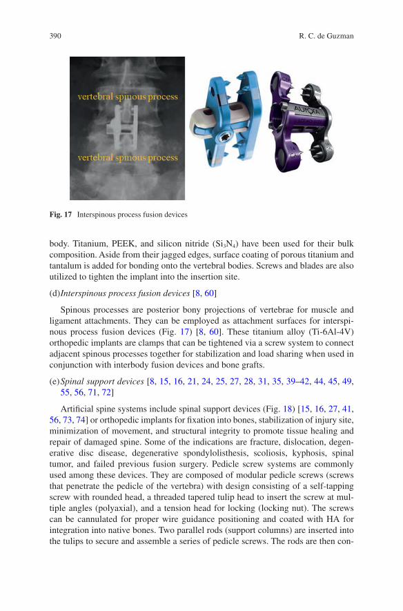
390
body. Titanium, PEEK, and silicon nitride (Si3N4) have been used for their bulk composition. Aside from their jagged edges, surface coating of porous titanium and tantalum is added for bonding onto the vertebral bodies. Screws and blades are also utilized to tighten the implant into the insertion site.
(d) Interspinous process fusion devices [8, 60]
Spinous processes are posterior bony projections of vertebrae for muscle and ligament attachments. They can be employed as attachment surfaces for interspi-nous process fusion devices (Fig. 17) [8, 60]. These titanium alloy (Ti-6Al-4V) orthopedic implants are clamps that can be tightened via a screw system to connect adjacent spinous processes together for stabilization and load sharing when used in conjunction with interbody fusion devices and bone grafts.
(e) Spinal support devices [8, 15, 16, 21, 24, 25, 27, 28, 31, 35, 39–42, 44, 45, 49, 55, 56, 71, 72]
Artificial spine systems include spinal support devices (Fig. 18) [15, 16, 27, 41, 56, 73, 74] or orthopedic implants for fixation into bones, stabilization of injury site, minimization of movement, and structural integrity to promote tissue healing and repair of damaged spine. Some of the indications are fracture, dislocation, degen-erative disc disease, degenerative spondylolisthesis, scoliosis, kyphosis, spinal tumor, and failed previous fusion surgery. Pedicle screw systems are commonly used among these devices. They are composed of modular pedicle screws (screws that penetrate the pedicle of the vertebra) with design consisting of a self-tapping screw with rounded head, a threaded tapered tulip head to insert the screw at mul-tiple angles (polyaxial), and a tension head for locking (locking nut). The screws can be cannulated for proper wire guidance positioning and coated with HA for integration into native bones. Two parallel rods (support columns) are inserted into the tulips to secure and assemble a series of pedicle screws. The rods are then con-
Fig. 17 Interspinous process fusion devices
R. C. de Guzman
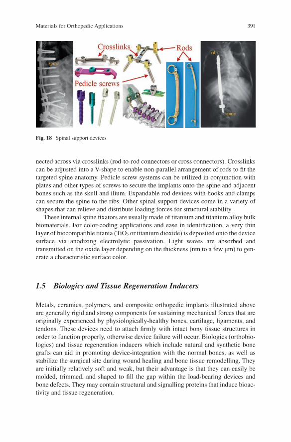
391
nected across via crosslinks (rod-to-rod connectors or cross connectors). Crosslinks can be adjusted into a V-shape to enable non-parallel arrangement of rods to fit the targeted spine anatomy. Pedicle screw systems can be utilized in conjunction with plates and other types of screws to secure the implants onto the spine and adjacent bones such as the skull and ilium. Expandable rod devices with hooks and clamps can secure the spine to the ribs. Other spinal support devices come in a variety of shapes that can relieve and distribute loading forces for structural stability.
These internal spine fixators are usually made of titanium and titanium alloy bulk biomaterials. For color-coding applications and ease in identification, a very thin layer of biocompatible titania (TiO2 or titanium dioxide) is deposited onto the device surface via anodizing electrolytic passivation. Light waves are absorbed and transmitted on the oxide layer depending on the thickness (nm to a few μm) to gen-erate a characteristic surface color.
1.5 Biologics and Tissue Regeneration Inducers
Metals, ceramics, polymers, and composite orthopedic implants illustrated above are generally rigid and strong components for sustaining mechanical forces that are originally experienced by physiologically-healthy bones, cartilage, ligaments, and tendons. These devices need to attach firmly with intact bony tissue structures in order to function properly, otherwise device failure will occur. Biologics (orthobio-logics) and tissue regeneration inducers which include natural and synthetic bone grafts can aid in promoting device-integration with the normal bones, as well as stabilize the surgical site during wound healing and bone tissue remodelling. They are initially relatively soft and weak, but their advantage is that they can easily be molded, trimmed, and shaped to fill the gap within the load- bearing devices and bone defects. They may contain structural and signalling proteins that induce bioac-tivity and tissue regeneration.
Fig. 18 Spinal support devices
Materials for Orthopedic Applications
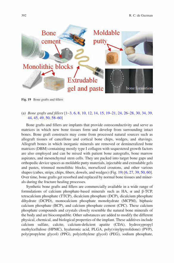
392
(a) Bone grafts and fillers [1–3, 6, 8, 10, 12, 14, 15, 19–21, 24, 26–28, 30, 34, 39, 44, 45, 49, 50, 58–60]
Bone grafts and fillers are implants that provide osteoconductivity and serve as matrices in which new bone tissues form and develop from surrounding intact bones. Bone graft constructs may come from processed natural sources such as allograft tissues of cancellous and cortical bone chips, wedges, and shavings. Allograft bones in which inorganic minerals are removed or demineralized bone matrices (DBM) containing mostly type I collagen with sequestered growth factors are also employed and can be mixed with patient bone autografts, bone marrow aspirates, and mesenchymal stem cells. They are packed into target bone gaps and orthopedic device spaces as moldable putty materials, injectable and extrudable gels and pastes, trimmed monolithic blocks, morselized croutons, and other various shapes (cubes, strips, chips, fibers, dowels, and wedges) (Fig. 19) [6, 27, 39, 50, 60]. Over time, bone grafts get resorbed and replaced by normal bone tissues and miner-als during the fracture healing processes.
Synthetic bone grafts and fillers are commercially available in a wide range of formulations of calcium phosphate-based minerals such as HA, α and β-TCP, tetracalcium phosphate (TTCP), dicalcium phosphate (DCP), dicalcium phosphate dihydrate (DCPD), monocalcium phosphate monohydrate (MCPM), biphasic calcium phosphate (BCP), and calcium phosphate cement (CPC). These calcium phosphate compounds and crystals closely resemble the natural bone minerals of the body and are biocompatible. Other substances are added to modify the different physical, chemical, and biological properties of the implant. These additives include calcium sulfate, calcite, calcium-deficient apatite (CDA), hydroxypropyl methylcellulose (HPMC), hyaluronic acid, PLGA, poly(vinylpyrrolidone) (PVP), poly(propylene glycol) (PPG), poly(ethylene glycol) (PEG), sodium phosphate,
Fig. 19 Bone grafts and fillers
R. C. de Guzman
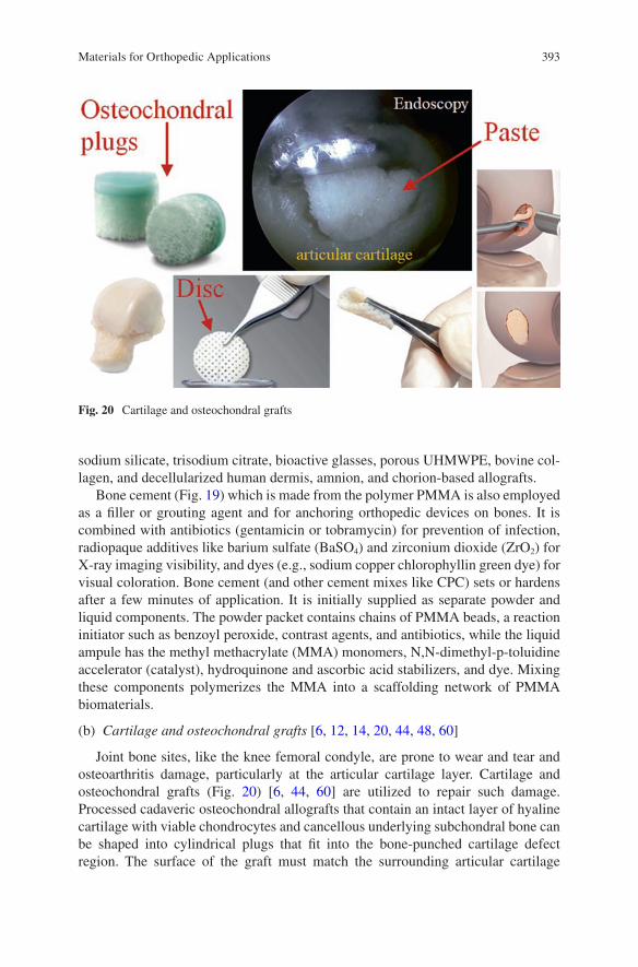
393
sodium silicate, trisodium citrate, bioactive glasses, porous UHMWPE, bovine col-lagen, and decellularized human dermis, amnion, and chorion-based allografts.
Bone cement (Fig. 19) which is made from the polymer PMMA is also employed as a filler or grouting agent and for anchoring orthopedic devices on bones. It is combined with antibiotics (gentamicin or tobramycin) for prevention of infection, radiopaque additives like barium sulfate (BaSO4) and zirconium dioxide (ZrO2) for X-ray imaging visibility, and dyes (e.g., sodium copper chlorophyllin green dye) for visual coloration. Bone cement (and other cement mixes like CPC) sets or hardens after a few minutes of application. It is initially supplied as separate powder and liquid components. The powder packet contains chains of PMMA beads, a reaction initiator such as benzoyl peroxide, contrast agents, and antibiotics, while the liquid ampule has the methyl methacrylate (MMA) monomers, N,N-dimethyl-p-toluidine accelerator (catalyst), hydroquinone and ascorbic acid stabilizers, and dye. Mixing these components polymerizes the MMA into a scaffolding network of PMMA biomaterials.
(b) Cartilage and osteochondral grafts [6, 12, 14, 20, 44, 48, 60]
Joint bone sites, like the knee femoral condyle, are prone to wear and tear and osteoarthritis damage, particularly at the articular cartilage layer. Cartilage and osteochondral grafts (Fig. 20) [6, 44, 60] are utilized to repair such damage. Processed cadaveric osteochondral allografts that contain an intact layer of hyaline cartilage with viable chondrocytes and cancellous underlying subchondral bone can be shaped into cylindrical plugs that fit into the bone-punched cartilage defect region. The surface of the graft must match the surrounding articular cartilage
Fig. 20 Cartilage and osteochondral grafts
Materials for Orthopedic Applications
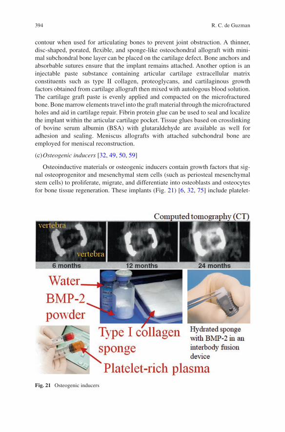
394
contour when used for articulating bones to prevent joint obstruction. A thinner, disc-shaped, porated, flexible, and sponge-like osteochondral allograft with mini-mal subchondral bone layer can be placed on the cartilage defect. Bone anchors and absorbable sutures ensure that the implant remains attached. Another option is an injectable paste substance containing articular cartilage extracellular matrix constituents such as type II collagen, proteoglycans, and cartilaginous growth factors obtained from cartilage allograft then mixed with autologous blood solution. The cartilage graft paste is evenly applied and compacted on the microfractured bone. Bone marrow elements travel into the graft material through the microfractured holes and aid in cartilage repair. Fibrin protein glue can be used to seal and localize the implant within the articular cartilage pocket. Tissue glues based on crosslinking of bovine serum albumin (BSA) with glutaraldehyde are available as well for adhesion and sealing. Meniscus allografts with attached subchondral bone are employed for meniscal reconstruction.
(c) Osteogenic inducers [32, 49, 50, 59]
Osteoinductive materials or osteogenic inducers contain growth factors that sig-nal osteoprogenitor and mesenchymal stem cells (such as periosteal mesenchymal stem cells) to proliferate, migrate, and differentiate into osteoblasts and osteocytes for bone tissue regeneration. These implants (Fig. 21) [6, 32, 75] include platelet-
Fig. 21 Osteogenic inducers
R. C. de Guzman
395
rich plasma (PRP) concentrated from autologous (patient’s) blood and bone marrow, and bone-inducing growth factors, particularly bone morphogenetic protein 2 (BMP-2) and BMP-7. Growth factors released from platelets are thought to promote and enhance bone healing. PRP, and blood and bone marrow aspirate themselves can also be combined with bone grafts to create a bone tissue putty filler with osteoinductive activities. BMP-2 binds to BMP receptors on target progenitor and stem cells and induce a cascade of events leading to new bone formation. BMP-2 (together with excipients: sucrose, glycine, l-glutamic acid, NaCl, and polysorbate 80) is dissolved in water then absorbed into carrier biomaterials like glutaraldehyde- crosslinked bovine type I collagen sponge for extended release over time. The hydrated BMP-2-loaded collagen sponge can be inserted into the chamber of an interbody cage for spinal fusion. Viable cells from allografts can be used clinically in conjunction with bone graft materials for induction of bone growth.
2 Implant Delivery Systems and Surgical Instrumentations
Successful implantation of orthopedic medical devices (prolonged and permanent contact-implants) requires surgical instrumentations and implant delivery systems. These tools are usually classified as limited contact since they only interact with the patient’s internal biological system during the actual surgical operation (and most still need FDA clearance for clinical use). Each of the implant systems previously discussed have their own surgical techniques and strategies utilizing the correct set of instrumentations at specific procedures. For example, IM nail systems for femo-ral fracture management employ instruments for opening the proximal femur (entry portal tube and handle, honeycomb, guide pin, connector, entry and channel ream-ers, T-handle, trocar, and cannulated awl), for fracture reduction and intramedullary reaming (gripper, guide rod, handle, reducer, obturator, ruler, reamer head and shaft, and handles), for nail assembly and insertion (handle, guide bolt, guide bolt wrench, cannulated impactor, percutaneous drill guide, drill sleeves, step and pilot drills, slotted hammer, radiolucent drop, and alignment arm and tower), for proximal and distal locking (drills and guides, trocar and sleeves, screw and hex drivers, depth gauge, connectors, and taps), and for implant removal (reamers, impactors, ham-mers, guide rods and pins, screw drivers, and nail extractor). Surgical, dissection, and power tools are used to expose, trim, and correctly shape the underlying dam-aged and targeted bones. Implant delivery systems enable the orthopedic implants to be placed and secured in their proper locations while avoiding obstructions and preserving the integrity of adjacent tissue and organ structures. Trial devices are for measuring and sizing to ensure that the actual implants fit in place and are func-tional. Finally, wound closure implants (sutures, tissue glues, and staples) and tools (needles, hemostats, scissors, and forceps) seal, repair, and stabilize the surrounding muscles, connective tissues, and skin after surgery.
Materials for Orthopedic Applications
396
3 Conclusion and Future Directions
The detailed list of the current orthopedic implant devices for clinical application shows that these systems utilize only a few selections of biomaterials. Large load- bearing bone stabilizers and artificial bones are made up of strong, tough, and rela-tively-inert materials, mostly passivated metals. Articulating artificial joint bones require an even stronger and wear-resistant materials like wrought cobalt- chromium alloys and zirconia-toughened alumina. Metal-on-metal contact is prevented through an UHMWPE insert. Titanium and its alloys have the widest range of usage due to their corrosion resistance, bone-integration capability, biocompatibility, lower density and lower modulus compared to other metals, and other appealing mechanical properties. Non-metals such as carbon fiber-reinforced PEEK, pyrocar-bon, and silicon nitride are being used for smaller components and have better elas-tic modulus match with native bone structures, thus minimizing stress shielding effects. The progress for the development of new materials for nondegradable ortho-pedic implants is slow because the current systems seem to be already providing sufficient functionalities to achieve the orthopedic surgical goals. However, in the field of biologics and tissue regeneration inducers that employ degradable, absorb-able, and remodelable biomaterials, new biomaterial technologies are constantly churning out. Exciting developments are underway to generate products that will ultimately lead to successful bone healing and repair.
References
1. Acumed Official Site. 2017. www.acumed.net. 2. Aesculap Implant Systems Official Site. 2017. www.aesculapimplantsystems.com. 3. Alphatec Spine Official Site. 2017. www.alphatecspine.com. 4. Amedica Official Site. 2017. www.amedica.com. 5. AristoTech Official Site. 2017. www.aristotech.de. 6. Arthrex Official Site. 2017. www.arthrex.com. 7. Arthrosurface Official Site. 2017. www.arthrosurface.com. 8. Aurora Spine Official Site. 2017. www.auroraspine.us. 9. Biotech Group Official Site. 2017. www.biotech-medical.com. 10. Bioventus Official Site. 2017. www.bioventussurgical.com. 11. ConforMIS Official Site. 2017. www.conformis.com. 12. ConMed Official Site. 2017. www.conmed.com. 13. Corin USA Official Site. 2017. www.coringroup.com. 14. CryoLife Official Site. 2017. www.cryolife.com. 15. DePuy Synthes Official Site. 2017. www.depuysynthes.com. 16. Eisertech Official Site. 2017. www.eisertech.com. 17. Eminent Spine Official Site. 2017. www.eminentspine.com. 18. Empower Spine Official Site. 2017. www.empower-ortho.com. 19. Exactech Official Site. 2017. www.exac.com. 20. Geistlich Pharma Official Site. 2017. www.geistlich-pharma.com. 21. Globus Medical Official Site. 2017. www.globusmedical.com. 22. Hammill Medical Company Official Site. 2017. www.hammillmfg.com.
R. C. de Guzman
397
23. ICONACY Orthopedic Implants Official Site. 2017. www.iconacy.com. 24. Implants International Official Site. 2017. www.implantsinternational.com. 25. Innovation Ortho Line Official Site. 2017. www.iol.company. 26. Integra Life Sciences Official Site. 2017. www.integralife.com. 27. Intuitive Spine (Captiva Spine) Official Site. 2017. www.captivaspine.com. 28. K2M Official Site. 2017. www.k2m.com. 29. Kinamed Official Site. 2017. www.kinamed.com. 30. Lattice Biologics Official Site. 2017. www.latticebiologics.com. 31. Medacta International Official Site. 2017. www.medacta.com. 32. Medtronic Official Site. 2017. www.medtronic.com. 33. Microport Orthopedics Official Site. 2017. www.ortho.microport.com. 34. MiMedx Official Site. 2017. www.mimedx.com. 35. Narang Medical Official Site. 2017. www.narang.com. 36. NuVasive Official Site. 2017. www.nuvasive.com. 37. OMNI Official Site. 2017. www.omnils.com. 38. ORTHIMO Official Site. 2017. www.orthimo.com. 39. Orthofix International Official Site. 2017. www.orthofix.com. 40. Orthopaedic Implant Company Official Site. 2017. www.orthoimplantcompany.com. 41. Osseus Official Site. 2017. www.osseus.com. 42. Paradigm Spine Official Site. 2017. www.paradigmspine.com. 43. Parcus Medical Official Site. 2017. www.parcusmedical.com. 44. RTI Surgical Official Site. 2017. www.rtix.com. 45. SeaSpine Official Site. 2017. www.seaspine.com. 46. Simpex Medical Official Site. 2017. www.simpexmedical.com. 47. Small Bone Innovations Official Site. 2017. www.totalsmallbone.com. 48. Smith & Nephew Official Site. 2017. www.smith-nephew.com. 49. Spinal Elements Official Site. 2017. www.spinalelements.com. 50. Stryker Official Site. 2017. www.stryker.com. 51. The Progressive Orthopaedic Company Official Site. 2017. www.progressiveorthopaedics.
com. 52. The Rhode Orthopedic Group Official Site. 2017. www.buyrog.com. 53. Titan Spine Official Site. 2017. www.titanspine.com. 54. United Orthopedics Corporation Official Site. 2017. www.uocusa.com. 55. Uteshiya Medicare Official Site. 2017. www.uteshiyamedicare.com. 56. Vertiflex Official Site. 2017. www.vertiflexspine.com. 57. Waldemar LINK Official Site. 2017. www.linkorthopaedics.com. 58. Wright Medical Group Official Site. 2017. www.wright.com. 59. Xtant Medical Official Site. 2017. www.xtantmedical.com. 60. Zimmer Biomet Official Site. 2017. www.zimmerbiomet.com. 61. Dilisio MF, Nowinski RJ, Hatzidakis AM, Fehringer EV. Intramedullary nailing of the proxi-
mal humerus: evolution, technique, and results. J Shoulder Elb Surg. 2016;25:e130–8. https://doi.org/10.1016/j.jse.2015.11.016.
62. Harasen G. Orthopedic hardware and equipment for the beginner. Part 2: plates and screws. Can Vet J. 2011;52:1359–60.
63. Hernigou P, Pariat J. History of internal fixation with plates (part 2): new developments after World War II; compressing plates and locked plates. Int Orthop. 2017;41:1489–500. https://doi.org/10.1007/s00264-016-3379-9.
64. Harasen G. Orthopedic hardware and equipment for the beginner: part 1: pins and wires. Can Vet J. 2011;52:1025–6.
65. Middernacht B, Van Tongel A, De Wilde L. A critical review on prosthetic features avail-able for reversed total shoulder arthroplasty. Biomed Res Int. 2016;2016:3256931. https://doi.org/10.1155/2016/3256931.
Materials for Orthopedic Applications
398
66. Baulot E, Sirveaux F, Boileau P. Grammont’s idea: the story of Paul Grammont’s func-tional surgery concept and the development of the reverse principle. Clin Orthop Relat Res. 2011;469:2425–31. https://doi.org/10.1007/s11999-010-1757-y.
67. Swanson NA, Tromovitch TA. Suture materials, 1980s: properties, uses, and abuses. Int J Dermatol. 1982;21:373–8.
68. Jeys L, Korrosis S, Stewart T, Harris NJ. Bone anchors or interference screws? A biomechani-cal evaluation for autograft ankle stabilization. Am J Sports Med. 2004;32:1651–9. https://doi.org/10.1177/0363546504265051.
69. Lukas R, Sram J. Classification-related approach in the surgical treatment of thoracolumbar fractures. Indian J Orthop. 2007;41:327–31. https://doi.org/10.4103/0019-5413.36996.
70. Rao PJ, Pelletier MH, Walsh WR, Mobbs RJ. Spine interbody implants: material selection and modification, functionalization and bioactivation of surfaces to improve osseointegration. Orthop Surg. 2014;6:81–9. https://doi.org/10.1111/os.12098.
71. Techmetals Official Site. 2017. www.techmetals.com. 72. Diamanti MV, Del Curto B, Pedeferri M. Anodic oxidation of titanium: from technical aspects
to biomedical applications. J Appl Biomater Biomech. 2011;9:55–69. https://doi.org/10.5301/JABB.2011.7429.
73. Atici Y, Akman YE, Balioglu MB, Erdogan S. A comparison of the effects of two different techniques on shoulder balance in the treatment of congenital scoliosis: vertical expandable prosthetic titanium rib and dual growing rod. J Craniovertebr Junction Spine. 2015;6:190–4. https://doi.org/10.4103/0974-8237.167880.
74. Sethi A, Lee A, Vaidya R. Lumbar pedicle screw placement: using only AP plane imaging. Indian J Orthop. 2012;46:434–8. https://doi.org/10.4103/0019-5413.98832.
75. McKay B, Sandhu HS. Use of recombinant human bone morphogenetic protein-2 in spinal fusion applications. Spine (Phila Pa 1976). 2002;27:S66–85.
R. C. de Guzman
399© Springer International Publishing AG, part of Springer Nature 2017B. Li, T. Webster (eds.), Orthopedic Biomaterials, https://doi.org/10.1007/978-3-319-73664-8_15
Composite Orthopedic Fixation Devices
Bryant Heimbach and Mei Wei
Keywords Composite · Fixation device · Internal fixation · Implant design · Tissue interaction · Cytotoxicity · Resorbable · Polymer · Metal · Resorbable metal
1 Introduction
The orthopedic industry encompasses a wide range of ailments and conditions, all of which pertain to the musculoskeletal system, including injuries to bones, muscles, tendons, and ligaments [1]. Such injuries often require an orthopedic implant to ensure proper healing. Although the field of orthopedics has been quickly growing in recent decades – increasing from 17.9 to 24.2% of the total surgeries performed from 2001 to 2011 in the US alone [2] – orthopedic procedures have been utilized for thousands of years to aid the healing of various musculoskeletal defects [3]. In total, the market for orthopedic devices is expected to grow to $41.2 billion annually by 2019, making it one of the most in demand and profitable medical fields currently [4]. This relatively recent spike in activity in the field of orthopedics stems from two main points: the general population is ever increasing in age, specifically the baby boomer generation is aging and requiring more medical treatment, and technologi-cal advances are allowing for a better understanding of the associated injuries and for higher quality orthopedic surgeries and implants to be utilized. Of particular interest within the entire scope of orthopedics is the trauma fixation market, which is expected to account for $9.4 billion of the entire orthopedic market by 2020 [5].
B. Heimbach Department of Biomedical Engineering, University of Connecticut, Storrs, CT, USA
M. Wei (*) Department of Biomedical Engineering, University of Connecticut, Storrs, CT, USA
Institute of Material Science (IMS), University of Connecticut, Storrs, CT, USA
Department of Materials Science and Engineering, University of Connecticut, Storrs, CT, USAe-mail: [email protected]
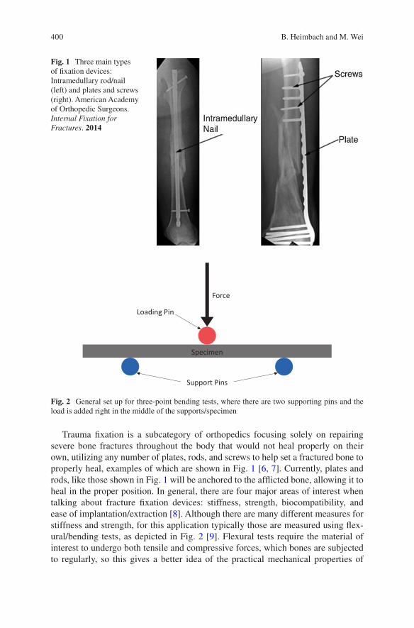
400
Trauma fixation is a subcategory of orthopedics focusing solely on repairing severe bone fractures throughout the body that would not heal properly on their own, utilizing any number of plates, rods, and screws to help set a fractured bone to properly heal, examples of which are shown in Fig. 1 [6, 7]. Currently, plates and rods, like those shown in Fig. 1 will be anchored to the afflicted bone, allowing it to heal in the proper position. In general, there are four major areas of interest when talking about fracture fixation devices: stiffness, strength, biocompatibility, and ease of implantation/extraction [8]. Although there are many different measures for stiffness and strength, for this application typically those are measured using flex-ural/bending tests, as depicted in Fig. 2 [9]. Flexural tests require the material of interest to undergo both tensile and compressive forces, which bones are subjected to regularly, so this gives a better idea of the practical mechanical properties of
Fig. 1 Three main types of fixation devices: Intramedullary rod/nail (left) and plates and screws (right). American Academy of Orthopedic Surgeons. Internal Fixation for Fractures. 2014
Specimen
Force
Support Pins
Loading Pin
Fig. 2 General set up for three-point bending tests, where there are two supporting pins and the load is added right in the middle of the supports/specimen
B. Heimbach and M. Wei
401
fixation devices compared to tensile tests [10]. With regards to biocompatibility, since the current standard for fixation devices relies on metals, the goal is to have the implant be inert in vivo [8]. However, as discussed in this chapter, with different materials it is possible to achieve better tissue integration and also implant resorp-tion (i.e., the implant will be safely absorbed in the body, leaving no long-term trace). As such, this chapter will delve into the development, the current practices, and current research on internal bone fixation devices.
2 Development of Internal Fixation Devices
2.1 Implant Design
Although current products for internal fixation include plates, rods, and screws, one of the earliest forms relied on metal wires to fix fractured bones [11]. In 1775, Jean Francois, a French surgeon, utilized brass wires wrapped around a fractured long bone to set it correctly [12]. However, due to the materials used and the medical practices of the time, the patient suffered severe inflammation and gangrene and died two days later. Not surprisingly, there was a delay in further developments of internal fixation until technological advances allowed for higher quality medical care for patients. In particular, the nineteenth century discoveries of anesthesia, anti-sepsis, and X-ray radiographs enabled surgeons to perform procedures with greater patient comfort, infection resistance, and accuracy, respectively.
The first fracture fixation using the more familiar plate and screw system was attempted by a German surgeon named Hansmann [11]. His internal/external fixa-tion hybrid design included a plate fixed with screws that both protruded from the wound for easier removal of the implant. However, the protruding design led to a greatly increased risk of infection. As such, the next major step in trauma fixation came when, in 1895, Lane et al. [13] used a steel plate and screws to fix a fractured long bone internally. However, due to his use of corrosion-prone steel, this plate setup was abandoned because of the extreme inflammation and discomfort it caused. In 1909, Lambotte et al. sought to improve the corrosion resistance of the implants by gold-plating the steel plate and screws [14]. Lambotte also believed that the fixa-tion plate should be relatively flexible to avoid catastrophic failure, and, as such, his material of choice was a relatively soft steel [15]. Despite the improved corrosion resistance, this early fixation device was abandoned shortly thereafter due to the aforementioned soft steel having insufficient strength to support bone healing [16].
In the first half of the twentieth century, Peterson [15] noted the deficiencies in the internal fixation market. Most of the negative aspects of the fixation devices at the time stemmed from improper design, metal property variations, and manufac-turing discrepancies. As such, William O’Neill Sherman of the United States sought to address these issues to greatly improve the fixation device products [17]. His design featured both plate and screws made of vanadium steel alone, which greatly
Composite Orthopedic Fixation Devices
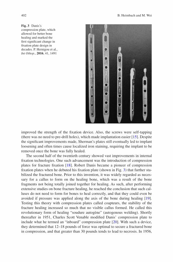
402
improved the strength of the fixation device. Also, the screws were self-tapping (there was no need to pre-drill holes), which made implantation easier [15]. Despite the significant improvements made, Sherman’s plates still eventually led to implant loosening and often times cause localized iron staining, requiring the implant to be removed once the bone was fully healed.
The second half of the twentieth century showed vast improvements in internal fixation technologies. One such advancement was the introduction of compression plates for fracture fixation [18]. Robert Danis became a pioneer of compression fixation plates when he debuted his fixation plate (shown in Fig. 3) that further sta-bilized the fractured bone. Prior to this invention, it was widely regarded as neces-sary for a callus to form on the healing bone, which was a result of the bone fragments not being totally joined together for healing. As such, after performing extensive studies on bone fracture healing, he reached the conclusion that such cal-luses do not need to form for bones to heal correctly, and that they could even be avoided if pressure was applied along the axis of the bone during healing [19]. Testing this theory with compression plates called coapteurs, the stability of the fracture healing increased so much that no visible callus formed. He called this revolutionary form of healing “soudure autogène” (autogenous welding). Shortly thereafter in 1951, Charles Scott Venable modified Danis’ compression plate to include what he termed an “inboard” compression plate [20]. With such a device, they determined that 12–18 pounds of force was optimal to secure a fractured bone in compression, and that greater than 30 pounds tends to lead to necrosis. In 1956,
Fig. 3 Danis’s compression plate, which allowed for better bone healing and marked the first significant change in fixation plate design in decades. P. Hernigou et al., Int Othop., 2016, 41, 1491
B. Heimbach and M. Wei
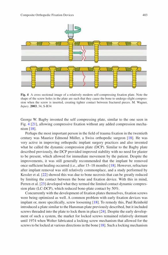
403
George W. Bagby invented the self compressing plate, similar to the one seen in Fig. 4 [21], allowing compressive fixation without any added compression mecha-nism [18].
Perhaps the most important person in the field of trauma fixation in the twentieth century was Maurice Edmond Müller, a Swiss orthopedic surgeon [18]. He was very active in improving orthopedic implant surgery practices and also invented what he called the dynamic compression plate (DCP). Similar to the Bagby plate described previously, the DCP provided improved stability with no need for plaster to be present, which allowed for immediate movement by the patient. Despite the improvements, it was still generally recommended that the implant be removed once sufficient healing occurred (i.e., after 15–18 months) [18]. However, refracture after implant removal was still relatively commonplace, and a study performed by Kessler et al. [22] showed this was due to bone necrosis that can be greatly reduced by limiting the contact between the bone and fixation device. With this in mind, Perren et al. [23] developed what they termed the limited contact dynamic compres-sion plate (LC-DCP), which reduced bone-plate contact by 50%.
Concurrently with the development of fixation plates themselves, fixation screws were being optimized as well. A common problem with early fixation devices was implant or, more specifically, screw loosening [18]. To remedy this, Paul Reinhold introduced a plate similar to the Hansman plate previously described, but it included screws threaded into the plate to lock them in place [24]. Despite the early develop-ment of such a system, the market for locked screws remained relatively dormant until 1974 when Wolter fabricated a locking screw mechanism that allowed for the screws to be locked at various directions in the bone [18]. Such a locking mechanism
Fig. 4 A cross sectional image of a relatively modern self-compressing fixation plate. Note the shape of the screw holes in the plate are such that they cause the bone to undergo slight compres-sion when the screw is inserted, creating tighter contact between fractured pieces. M. Wagner, Injury. 2003, 34, S-B34
Composite Orthopedic Fixation Devices
404
causes the entire plate and screw system to act as one, and thus be more stable, rather than the screws acting individually.
2.2 Tissue Interactions and Cytotoxicity
In the early twentieth century, orthopedic implants were still in their infancy, with very little research being done on tissue interactions with implants. To this end, in 1926 Zierold performed many studies on corrosion of metals in dogs [15]. He observed that iron and steel rapidly disintegrated in vivo and negatively affected the surrounding bone as a result. He also noted that copper, nickel, zinc and aluminum alloys all caused discoloration of bone, however gold, silver, and lead showed no interactions with body tissue at all as they are noble metals with excellent corrosion resistance [25]. The latter materials are all too soft for use as plates and screws, but are useful for plating other metals or as wires [15]. Also, the release of the afore-mentioned nickel, zinc, and aluminum ions can cause cell toxicity [26], which will be further discussed later. Stainless steel showed more positive interactions with the body and was introduced in the 1920s, but was largely rejected when it first hit the market. In 1947, titanium and its alloys were introduced to the market, and initial tests proved it to be very inert with exceptional corrosion resistance [27].
3 Current Metal Fixation Plates
Taking all the research and work done since the first fixation plate made by Hansmann in the nineteenth century, the consensus in the orthopedic field is that fixation plates must have the following general properties to be effective: mechani-cally strong (resists fracture), ductile (can undergo plastic deformation), stiff (resist movement), corrosion resistant, and biocompatible [28]. By far, the two most com-mon materials currently used in the clinical setting for fracture fixation devices are electropolished stainless steel (EPSS) and titanium [26]. Electropolishing is a pro-cess orthopedic stainless steel undergoes involving the removal of surface metal ions one-by-one to leave a microscopically smooth surface [29]. In short, stainless steel is submerged in an electrolytic solution and kept anodic while an electrical current is applied. When connected to a nearby cathodic metal conductor, the sur-face metal ions are removed, leaving a smooth surface. The benefits of performing electropolishing on stainless steel include significantly improved resistance to cor-rosion as well as reducing nickel ions leaching into local tissue [30]. However, such a process is not necessary for titanium fixation plates due to its naturally exquisite corrosion resistance [26].
Both EPSS and titanium are used in two forms, known as annealed and cold worked [26]. Cold working involves plastically deforming the metal below its recrystallization temperature (i.e., the temperature in which the material deforms),
B. Heimbach and M. Wei
405
which results in the formation of stressed grains within the metal [31]. This results in the metal having a higher strength, but being less ductile [32]. On the contrary, annealing involves heating the metal to the recrystallization temperature and letting it slowly cool, which replaces the stressed grains with stress-free grains and makes the material more ductile with a lower strength [32]. Typically, annealed EPSS and titanium are used in non-load-bearing applications, such as craniofacial fixation, and cold worked EPSS and titanium are used in load-bearing applications due to the increased strength of the materials [26]. Generally, EPSS is more ductile than tita-nium, allowing for more on-the-spot adjustments to be made by the surgeon during implantation. However, this is remedied by shaping titanium plates into more ana-tomically correct shapes ahead of implantation. An important note is that while on-the-spot contouring is commonplace, special care must be taken to not bend the implant in the wrong spot, as this could have detrimental effects to the threads on the implant and could greatly hinder the ability of the screws to lock properly [33].
Another benefit of using EPSS lies in the implantation process itself, where the torsional properties offer preferential handling while implanting the fixation plate. While the torsional strengths of EPSS and titanium are largely the same [34], the torsional displacement to failure is vastly different [26]. Since titanium has a much higher torsional strain to failure than steel, it is harder to feel when the screw is “bot-tomed out”. As such, extra care is needed to avoid stripping titanium screws rather than EPSS screws. However, this can be easily avoided by using a torque wrench when screwing in the fixation screws, which allows the surgeon to apply precisely the correct amount of torque for either EPSS or titanium.
Perhaps the biggest benefit of using titanium implants is its relatively low elastic modulus. The elastic modulus of titanium is about half that of EPSS, with titanium and EPSS having an elastic modulus of 110 and 210 GPa, respectively [35]. This drastic decrease in modulus has profound effects on the long-term health of bone tissue surrounding the implant. The modulus of titanium is closer to that of natural bone, which has an elastic modulus ranging from 10 to 30 GPa [36]. This signifi-cantly minimizes the phenomenon known as stress shielding, which occurs with many different types of orthopedic implants due to their modulus being significantly higher than that of bone [37]. When a relatively stiff fixation device is anchored onto a bone, the device takes on the functional load that would otherwise be transferred through the bone. Since bone is a dynamic material that responds to external mechanical stimuli [38], the resulting decrease of loading on the bone results in localized bone resorption surrounding the fixation device, as pictured in Fig. 5 [37, 39]. This results in greatly weakened bone tissue, which increases the risk for future fractures and can thus lead to the need for a second surgery to remove the implant. Although the stress shielding is not absent when using titanium as the fixa-tion material, the severity of stress shielding is typically much less than when using EPSS [26].
Another area in which titanium excels as a fixation device is in its surface proper-ties. As previously mentioned, EPSS is stainless steel that has been electropolished, and, as a result, has zero micro-sized defects on its surface [29]. While this is needed to avoid corrosion, this is typically detrimental in regards to tissue integration and
Composite Orthopedic Fixation Devices
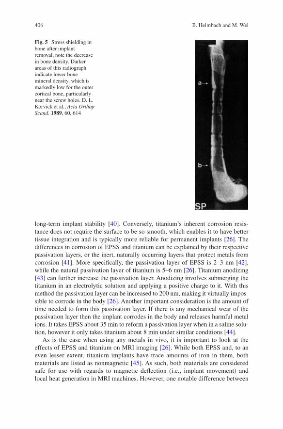
406
long-term implant stability [40]. Conversely, titanium’s inherent corrosion resis-tance does not require the surface to be so smooth, which enables it to have better tissue integration and is typically more reliable for permanent implants [26]. The differences in corrosion of EPSS and titanium can be explained by their respective passivation layers, or the inert, naturally occurring layers that protect metals from corrosion [41]. More specifically, the passivation layer of EPSS is 2–3 nm [42], while the natural passivation layer of titanium is 5–6 nm [26]. Titanium anodizing [43] can further increase the passivation layer. Anodizing involves submerging the titanium in an electrolytic solution and applying a positive charge to it. With this method the passivation layer can be increased to 200 nm, making it virtually impos-sible to corrode in the body [26]. Another important consideration is the amount of time needed to form this passivation layer. If there is any mechanical wear of the passivation layer then the implant corrodes in the body and releases harmful metal ions. It takes EPSS about 35 min to reform a passivation layer when in a saline solu-tion, however it only takes titanium about 8 min under similar conditions [44].
As is the case when using any metals in vivo, it is important to look at the effects of EPSS and titanium on MRI imaging [26]. While both EPSS and, to an even lesser extent, titanium implants have trace amounts of iron in them, both materials are listed as nonmagnetic [45]. As such, both materials are considered safe for use with regards to magnetic deflection (i.e., implant movement) and local heat generation in MRI machines. However, one notable difference between
Fig. 5 Stress shielding in bone after implant removal, note the decrease in bone density. Darker areas of this radiograph indicate lower bone mineral density, which is markedly low for the outer cortical bone, particularly near the screw holes. D. L. Korvick et al., Acta Orthop Scand. 1989, 60, 614
B. Heimbach and M. Wei
407
the two implant materials is the imaging interference they can cause. Since EPSS has a higher magnetic susceptibility than titanium, it is known to cause more image distortion than the titanium alternative, and the amount of distortion is directly correlated to the mass of the implant (i.e., distortion can be decreased by reducing the mass of the implant) [26].
One of the most important aspects of internal fixation devices is the biocom-patibility of the implant; regardless of any other favorable properties the implant might exhibit, it will never be used clinically if it is not safe for in vivo use. Although it is well known that metal particles cause adverse effects in vivo, cur-rent fixation plate technologies have greatly reduced the occurrence of metal par-ticles escaping into the body [26]. However, especially when using EPSS, the passivation layers are not perfect and defects can form, which leads to the release of metal ions. EPSS is an alloy containing nickel (Ni), chromium (Cr), and cobalt (Co), all of which have been linked to the hindrance of DNA repair and are thought to play a role in the development of neurodegenerative disorders [46]. Also, Cr in particular is known to have detrimental effects on sperm quantity and can cause abnormalities in sperm as well [47]. Furthermore, Cr has been shown to have a negative effect on renal function, causing necrosis of epithelial cells within the tubules [48]. It has also been shown that leached metal particles can be passed from mother to fetus via the umbilical cord [49], adding to the risks associated with metal fixation devices. Although titanium and its alloys suffer from debris production as well, implants made from titanium produce far less wear particles, and the impact they have on the body is much less severe [26]. The most typical effect these particles have in vivo is the discoloration of surrounding tissue, but the relatively thick passivation layer and the quick regeneration time of this layer makes titanium almost totally inert in the body [50].
Although many improvements have been made to fixation devices in the past century, current products still suffer from two major drawbacks: long-term stress shielding [36], which can cause embrittlement of bone and thus lead to future frac-tures and/or the need for a second surgery, and metal ion leaching [26], which can lead to inflammation as well as negative effects throughout the body. Because of these serious drawbacks, there has been significant interest in developing a fixation device that matches, but does not exceed, the stiffness of natural bone and safely degrades in vivo, which would eliminate the problem of long-term metal ion leaching.
4 Composite Fixation Devices
As previously mentioned, the functionality of metals as fixation plates has improved greatly in the past century, however, there are still some key drawbacks of using metals for bone fracture fixation. In particular, metal fixation devices still cause stress shielding due to their high modulus and metal ions slowly leach out from the implant site, both of which cause increased patient discomfort and often lead to the
Composite Orthopedic Fixation Devices
408
need for a second surgery [51]. Also, the mechanical properties of composite mate-rials are tailorable, which allows for more patient-specific care depending on the location and severity of the fracture [52]. Given how tailorable composites can be, they are generally made for broad applications: non-load-bearing applications (i.e., maxillofacial fractures) and load-bearing applications (i.e., long bone fractures). Adding to these benefits, composites can be made to fully degrade in vivo while the bone heals, completely eliminating the need for a second surgery [51].
4.1 Non-Load-Bearing Composites
Although there are other applications for non-load-bearing fixation devices, they are primarily used for maxillofacial fractures [14]. As such, this section will focus mainly on that particular aspect, however the same principles can be applied to other non-load-bearing fixation applications. The idea of resorbable fixation plates for maxillofacial applications started in 1971 [53] when research demonstrated that bones in the face do not undergo the same loading as long bones, and thus do not require the same type of rigid fixation as long bone fractures [54]. However, these ideas did not come to fruition until decades later when superior materials were developed.
Currently, the overwhelming majority of maxillofacial fixation plates are made of some combination of polylactic acid (PLA) and polyglycolic acid (PGA) [14], which are aliphatic polyesters derived from α-hydroxy acids known for their ability to degrade safely in vivo [55, 56]. While the chemical makeup of PLA and PGA are similar, they exhibit different mechanical and degradation properties that make them better suited for different applications. PLA has a tensile modulus and strength of ~3 GPa and ~50 MPa, respectively, while PGA has a modulus and strength of ~7 GPa and 40 MPa, respectively [57]. In addition, PLA loses its mechanical integ-rity after 1–2 years, whereas PGA typically loses its mechanical integrity after about 6 weeks [14]. This vast difference in degradation rates allows for the synthesis of copolymers with tailorable degradation rates. By varying ratios of lactic acid and glycolic acid blocks, copolymers (PLGA) can be synthesized with varying degrada-tion rates ranging from a few weeks to a couple of years [58, 59]. PLA, PGA, and PLGA have a wide range of uses, both in the field of biomaterials and elsewhere, but for the application of fixation devices the targeted degradation time in vivo is gener-ally between 1 and 2 years [14]. The eventual degradation of the implant coupled with the significantly lower modulus means that the issue of stress shielding is totally eliminated. There are many different resorbable fixation systems on the mar-ket currently, see Tables 1 and 2 [14], which shows a few of the popular options, but they all have some combination of PLA and PGA to provide the optimal degrada-tion time.
As previously mentioned, the materials used for resorbable bone fixation plates have significantly lower strength and modulus values than similar parts made from titanium and stainless steel. To make up for these deficiencies, resorbable fixation
B. Heimbach and M. Wei
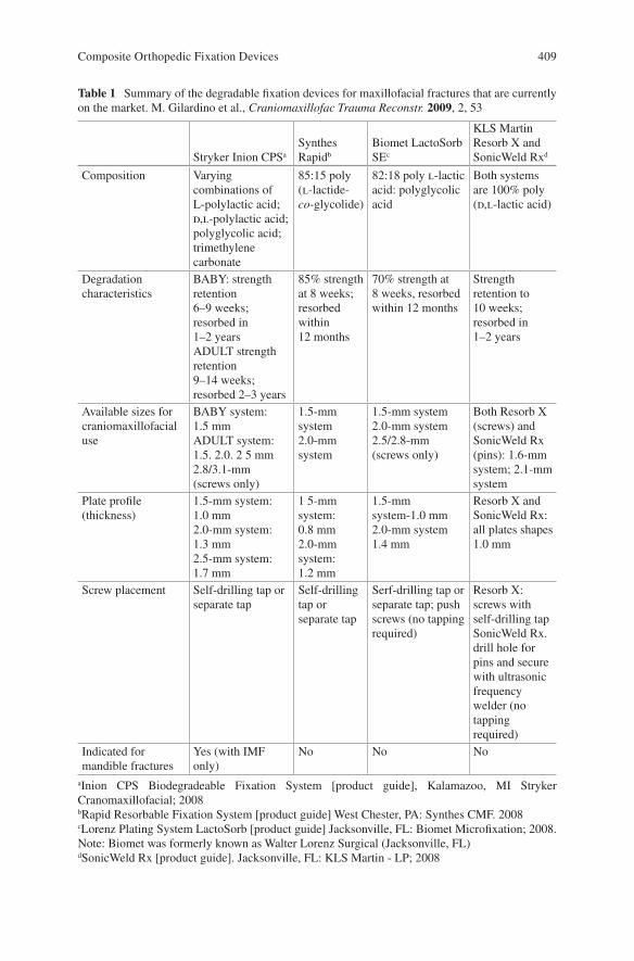
409
Table 1 Summary of the degradable fixation devices for maxillofacial fractures that are currently on the market. M. Gilardino et al., Craniomaxillofac Trauma Reconstr. 2009, 2, 53
Stryker Inion CPSa
Synthes Rapidb
Biomet LactoSorb SEc
KLS Martin Resorb X and SonicWeld Rxd
Composition Varying combinations of L-polylactic acid; d,l-polylactic acid; polyglycolic acid; trimethylene carbonate
85:15 poly (l-lactide- co-glycolide)
82:18 poly l-lactic acid: polyglycolic acid
Both systems are 100% poly (d,l-lactic acid)
Degradation characteristics
BABY: strength retention 6–9 weeks; resorbed in 1–2 yearsADULT strength retention 9–14 weeks; resorbed 2–3 years
85% strength at 8 weeks; resorbed within 12 months
70% strength at 8 weeks, resorbed within 12 months
Strength retention to 10 weeks; resorbed in 1–2 years
Available sizes for craniomaxillofacial use
BABY system: 1.5 mmADULT system: 1.5. 2.0. 2 5 mm2.8/3.1-mm (screws only)
1.5-mm system2.0-mm system
1.5-mm system2.0-mm system2.5/2.8-mm (screws only)
Both Resorb X (screws) and SonicWeld Rx (pins): 1.6-mm system; 2.1-mm system
Plate profile (thickness)
1.5-mm system: 1.0 mm2.0-mm system: 1.3 mm2.5-mm system: 1.7 mm
1 5-mm system: 0.8 mm2.0-mm system: 1.2 mm
1.5-mm system-1.0 mm2.0-mm system 1.4 mm
Resorb X and SonicWeld Rx: all plates shapes 1.0 mm
Screw placement Self-drilling tap or separate tap
Self-drilling tap or separate tap
Serf-drilling tap or separate tap; push screws (no tapping required)
Resorb X: screws with self-drilling tapSonicWeld Rx. drill hole for pins and secure with ultrasonic frequency welder (no tapping required)
Indicated for mandible fractures
Yes (with IMF only)
No No No
aInion CPS Biodegradeable Fixation System [product guide], Kalamazoo, MI Stryker Cranomaxillofacial; 2008bRapid Resorbable Fixation System [product guide] West Chester, PA: Synthes CMF. 2008cLorenz Plating System LactoSorb [product guide] Jacksonville, FL: Biomet Microfixation; 2008. Note: Biomet was formerly known as Walter Lorenz Surgical (Jacksonville, FL)dSonicWeld Rx [product guide]. Jacksonville, FL: KLS Martin - LP; 2008
Composite Orthopedic Fixation Devices
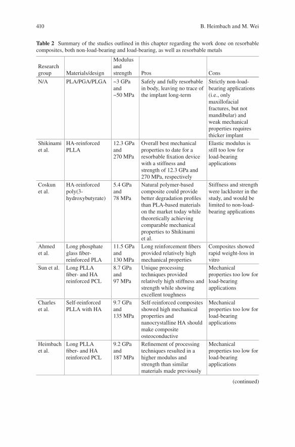
410
Table 2 Summary of the studies outlined in this chapter regarding the work done on resorbable composites, both non-load-bearing and load-bearing, as well as resorbable metals
Research group Materials/design
Modulus and strength Pros Cons
N/A PLA/PGA/PLGA ~3 GPa and ~50 MPa
Safely and fully resorbable in body, leaving no trace of the implant long-term
Strictly non-load- bearing applications (i.e., only maxillofacial fractures, but not mandibular) and weak mechanical properties requires thicker implant
Shikinami et al.
HA-reinforced PLLA
12.3 GPa and 270 MPa
Overall best mechanical properties to date for a resorbable fixation device with a stiffness and strength of 12.3 GPa and 270 MPa, respectively
Elastic modulus is still too low for load-bearing applications
Coskun et al.
HA-reinforced poly(3- hydroxybutyrate)
5.4 GPa and 78 MPa
Natural polymer-based composite could provide better degradation profiles than PLA-based materials on the market today while theoretically achieving comparable mechanical properties to Shikinami et al.
Stiffness and strength were lackluster in the study, and would be limited to non-load- bearing applications
Ahmed et al.
Long phosphate glass fiber- reinforced PLA
11.5 GPa and 130 MPa
Long reinforcement fibers provided relatively high mechanical properties
Composites showed rapid weight-loss in vitro
Sun et al. Long PLLA fiber- and HA reinforced PCL
8.7 GPa and 97 MPa
Unique processing techniques provided relatively high stiffness and strength while showing excellent toughness
Mechanical properties too low for load-bearing applications
Charles et al.
Self-reinforced PLLA with HA
9.7 GPa and 135 MPa
Self-reinforced composites showed high mechanical properties and nanocrystalline HA should make composite osteoconductive
Mechanical properties too low for load-bearing applications
Heimbach et al.
Long PLLA fiber- and HA reinforced PCL
9.2 GPa and 187 MPa
Refinement of processing techniques resulted in a higher modulus and strength than similar materials made previously
Mechanical properties too low for load-bearing applications
(continued)
B. Heimbach and M. Wei
411
devices are typically thicker than their metal counterparts, as seen in Fig. 6 [14]. Metal fixation devices are typically ≤1 mm thick, while resorbable plates are typi-cally closer to 1.5 mm in thickness, often reaching 2 mm in thickness [60]. Although this dimensional increase seems minor, this slight increase can make the implant more visible when present in areas of tighter skin [61]. However, this inconvenience is only temporary, and the implant will eventually resorb and be invisible.
Another criticism of resorbable fixation devices is their mechanical shortcom-ings regarding brittleness and torsional strength [14]. As mentioned previously, there is often a need to adjust the shape of fixation devices in situ [26], and this can be made difficult when using resorbable polymeric fixation devices due to their brittle nature. For this reason, resorbable plates require mild heating to make them more pliable and able to conform to complex bone shapes [62]. There have been resorbable plates made that enable the surgeon to adjust the shape of the implant without the addition of heat, but these are rarely used because they have difficulty retaining their new shape, adversely affecting the healing properties [63]. Also, such plates are typically made from PGA, which does not retain its mechanical integrity for long enough to provide sufficient support for bone healing. The relatively low torsional strength of resorbable plates indicates they are unable to be fastened to the bone as tightly as metal fixation devices [14]. As such, these plates are only capable of providing mild compression at the fracture site, which can result in micro- movements of the bone [53]. Despite this, the eventual avoidance of stress shielding
Table 2 (continued)
Research group Materials/design
Modulus and strength Pros Cons
Heimbach et al.
Degummed SF and HA reinforced PLA
13.7 GPa and 437 MPa
Use of silk fibroin exhibited nearly the highest modulus for a resorbable composite and the highest strength value for such a material
Samples tended to fail due to delamination and the modulus should be increased slightly for use in load-bearing applications
Yuka et al. Phosphate glass fiber-reinforced oligolactide
15–20 GPa and 140–200 MPa
Composites effectively exhibited the highest stiffness for such a material
Composites suffered from rapid disintegration in vitro and the strength remained too low for load-bearing applications
N/A Resorbable metals (i.e., magnesium)
45 GPa and 200–250 MPa
Magnesium provides nearly perfect mechanical properties and degrades into safe byproducts in vivo
Degradation often occurs too quickly and the resulting H2 gas pockets can cause serious inflammation and patient discomfort
Composite Orthopedic Fixation Devices
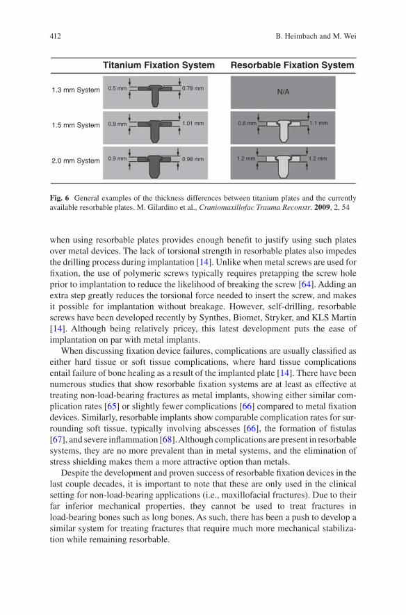
412
when using resorbable plates provides enough benefit to justify using such plates over metal devices. The lack of torsional strength in resorbable plates also impedes the drilling process during implantation [14]. Unlike when metal screws are used for fixation, the use of polymeric screws typically requires pretapping the screw hole prior to implantation to reduce the likelihood of breaking the screw [64]. Adding an extra step greatly reduces the torsional force needed to insert the screw, and makes it possible for implantation without breakage. However, self-drilling, resorbable screws have been developed recently by Synthes, Biomet, Stryker, and KLS Martin [14]. Although being relatively pricey, this latest development puts the ease of implantation on par with metal implants.
When discussing fixation device failures, complications are usually classified as either hard tissue or soft tissue complications, where hard tissue complications entail failure of bone healing as a result of the implanted plate [14]. There have been numerous studies that show resorbable fixation systems are at least as effective at treating non-load-bearing fractures as metal implants, showing either similar com-plication rates [65] or slightly fewer complications [66] compared to metal fixation devices. Similarly, resorbable implants show comparable complication rates for sur-rounding soft tissue, typically involving abscesses [66], the formation of fistulas [67], and severe inflammation [68]. Although complications are present in resorbable systems, they are no more prevalent than in metal systems, and the elimination of stress shielding makes them a more attractive option than metals.
Despite the development and proven success of resorbable fixation devices in the last couple decades, it is important to note that these are only used in the clinical setting for non-load-bearing applications (i.e., maxillofacial fractures). Due to their far inferior mechanical properties, they cannot be used to treat fractures in load- bearing bones such as long bones. As such, there has been a push to develop a similar system for treating fractures that require much more mechanical stabiliza-tion while remaining resorbable.
1.3 mm System
1.5 mm System
2.0 mm System 0.9 mm
0.9 mm
0.5 mm 0.78 mm
1.01 mm 0.8 mm
1.2 mm 1.2 mm
1.1 mm
N/A
Titanium Fixation System Resorbable Fixation System
0.98 mm
Fig. 6 General examples of the thickness differences between titanium plates and the currently available resorbable plates. M. Gilardino et al., Craniomaxillofac Trauma Reconstr. 2009, 2, 54
B. Heimbach and M. Wei
413
4.2 Composites for Load-Bearing Fractures
As stated previously, there is currently no clinically accepted option for bioresorb-able fixation devices for load-bearing fractures (i.e., fractures in long bones) [69]. As such, rather than giving details on the current clinical materials/practices, this section will focus on giving an overview of the current research on high perfor-mance composites for fracture fixation. Owing to the established biosafety and mechanical properties of previously discussed polymers, many resorbable load-bearing composites focus on polymer-based materials [70]. Also, there has been relatively recent interest in the use of biodegradable metals (i.e., magnesium) due to their mechanical properties being much closer to those of natural bone compared to titanium and EPSS and their ability to fully degrade in the body.
4.2.1 Resorbable Polymer-Based Composites
One of the earliest attempts at making a viable resorbable fixation device for load- bearing applications came from Shikinami and Okuno [71], and it remains one of the most successful composites for such a device to date. To improve the inherent mechanical properties of PLA, they used unique processing methods to forge a composite of poly-L-lactic acid (PLLA) with hydroxyapatite (HA) micro-sized par-ticle reinforcement. In short, small granules of PLLA with HA were precipitated out of a suspension of PLLA and HA in dichloromethane (DCM) by adding ethanol drop-wise to the suspension. The resulting granules containing PLLA and HA were then extruded into a thick billet, followed by hot pressing at 103 °C (i.e., above the Tg and below the Tm of PLLA [72]) to make a thinner billet. This process ensures homogenous distribution of HA within the matrix, and also helps to align the poly-mer chains of PLLA, which adds to the mechanical integrity of the composite. The PLLA/HA composite blocks could then be milled into useful shapes that are typical of fixation devices, as seen in Fig. 7. Shikinami et al. investigated varying amounts of HA in the composite material, including 20, 30, 40, and 50 wt% HA, and all compared against a control containing only PLLA prepared the same way.
Using these preparation methods, particle-reinforced composites were made to have a maximum flexural modulus and strength of 12.3 GPa and 270 MPa, respec-tively. This compares very favorably to the flexural properties of non-reinforced PLA, which generally has a modulus and strength of ~3 GPa and ≤100 MPa [73], respectively. Degradation tests were performed in phosphate buffered saline (PBS) on the composite samples to determine if the degradation profile was appropriate for internal fixation. In vitro results indicate that the composite bars retain sufficient bending strength for a time period necessary for proper bone healing, remaining above 200 MPa after 6 months in PBS. It is important to note, however, that although they were able to achieve a relatively high flexural modulus of 12.3 GPa, this for-mulation contained 50 wt% HA, and such a high HA content caused a drastic decrease in torsional and impacts strengths. As such, future tests were completed
Composite Orthopedic Fixation Devices
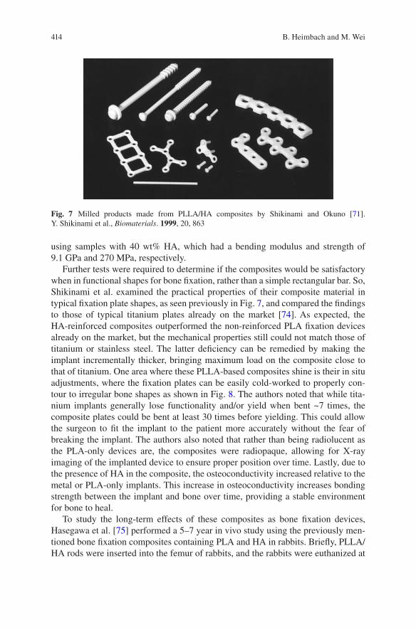
414
using samples with 40 wt% HA, which had a bending modulus and strength of 9.1 GPa and 270 MPa, respectively.
Further tests were required to determine if the composites would be satisfactory when in functional shapes for bone fixation, rather than a simple rectangular bar. So, Shikinami et al. examined the practical properties of their composite material in typical fixation plate shapes, as seen previously in Fig. 7, and compared the findings to those of typical titanium plates already on the market [74]. As expected, the HA-reinforced composites outperformed the non-reinforced PLA fixation devices already on the market, but the mechanical properties still could not match those of titanium or stainless steel. The latter deficiency can be remedied by making the implant incrementally thicker, bringing maximum load on the composite close to that of titanium. One area where these PLLA-based composites shine is their in situ adjustments, where the fixation plates can be easily cold-worked to properly con-tour to irregular bone shapes as shown in Fig. 8. The authors noted that while tita-nium implants generally lose functionality and/or yield when bent ~7 times, the composite plates could be bent at least 30 times before yielding. This could allow the surgeon to fit the implant to the patient more accurately without the fear of breaking the implant. The authors also noted that rather than being radiolucent as the PLA-only devices are, the composites were radiopaque, allowing for X-ray imaging of the implanted device to ensure proper position over time. Lastly, due to the presence of HA in the composite, the osteoconductivity increased relative to the metal or PLA-only implants. This increase in osteoconductivity increases bonding strength between the implant and bone over time, providing a stable environment for bone to heal.
To study the long-term effects of these composites as bone fixation devices, Hasegawa et al. [75] performed a 5–7 year in vivo study using the previously men-tioned bone fixation composites containing PLA and HA in rabbits. Briefly, PLLA/HA rods were inserted into the femur of rabbits, and the rabbits were euthanized at
Fig. 7 Milled products made from PLLA/HA composites by Shikinami and Okuno [71]. Y. Shikinami et al., Biomaterials. 1999, 20, 863
B. Heimbach and M. Wei

415
2, 3, and 4 years after implantation. After 4 years, the rabbits were examined after they died of natural causes. The authors noted that although the implant could still be seen in X-rays after the entire length of the study, degradation was very apparent and some of the implants were almost completely resorbed. However, the degrada-tion profile could change depending on implant location and shape [76]. Lastly, the authors noted there was no sign of infection or inflammation at any point during the study, concluding these composites appear to be safe and effective bone fixation devices. However, it is important to note that although these composites showed great improvements over non-reinforced PLA/PGA fixation devices, the fixation plates still require further improvements in mechanical properties to be suitable for load-bearing applications. When used as a plate and screw system, the highest load- bearing location these composites would be suitable for would be for mandible fractures.
In the last decade, several groups have been working to further improve the prop-erties of degradable composites for load-bearing fixation devices. One such study used poly(3-hydroxybutyrate) (P3HB) and its copolymers with 3-hydroxyvalerate (HV) (PHBV8 and PHBV22) to make HA-reinforced composites for fracture fixa-
Fig. 8 Cold working capabilities of the PLLA/HA composites made by Shikinami and Okuno [74]. Y. Shikinami et al., Biomaterials. 2001, 22, 3205
Composite Orthopedic Fixation Devices
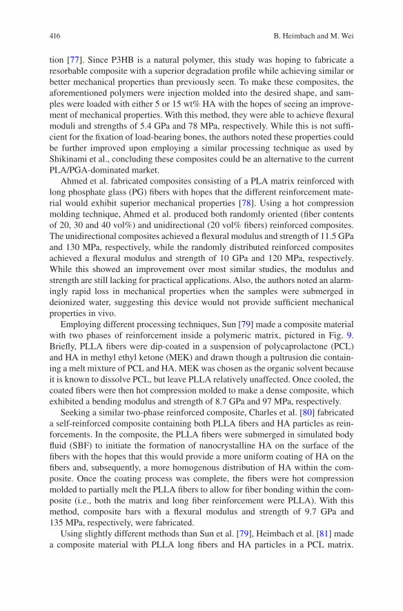
416
tion [77]. Since P3HB is a natural polymer, this study was hoping to fabricate a resorbable composite with a superior degradation profile while achieving similar or better mechanical properties than previously seen. To make these composites, the aforementioned polymers were injection molded into the desired shape, and sam-ples were loaded with either 5 or 15 wt% HA with the hopes of seeing an improve-ment of mechanical properties. With this method, they were able to achieve flexural moduli and strengths of 5.4 GPa and 78 MPa, respectively. While this is not suffi-cient for the fixation of load-bearing bones, the authors noted these properties could be further improved upon employing a similar processing technique as used by Shikinami et al., concluding these composites could be an alternative to the current PLA/PGA-dominated market.
Ahmed et al. fabricated composites consisting of a PLA matrix reinforced with long phosphate glass (PG) fibers with hopes that the different reinforcement mate-rial would exhibit superior mechanical properties [78]. Using a hot compression molding technique, Ahmed et al. produced both randomly oriented (fiber contents of 20, 30 and 40 vol%) and unidirectional (20 vol% fibers) reinforced composites. The unidirectional composites achieved a flexural modulus and strength of 11.5 GPa and 130 MPa, respectively, while the randomly distributed reinforced composites achieved a flexural modulus and strength of 10 GPa and 120 MPa, respectively. While this showed an improvement over most similar studies, the modulus and strength are still lacking for practical applications. Also, the authors noted an alarm-ingly rapid loss in mechanical properties when the samples were submerged in deionized water, suggesting this device would not provide sufficient mechanical properties in vivo.
Employing different processing techniques, Sun [79] made a composite material with two phases of reinforcement inside a polymeric matrix, pictured in Fig. 9. Briefly, PLLA fibers were dip-coated in a suspension of polycaprolactone (PCL) and HA in methyl ethyl ketone (MEK) and drawn though a pultrusion die contain-ing a melt mixture of PCL and HA. MEK was chosen as the organic solvent because it is known to dissolve PCL, but leave PLLA relatively unaffected. Once cooled, the coated fibers were then hot compression molded to make a dense composite, which exhibited a bending modulus and strength of 8.7 GPa and 97 MPa, respectively.
Seeking a similar two-phase reinforced composite, Charles et al. [80] fabricated a self-reinforced composite containing both PLLA fibers and HA particles as rein-forcements. In the composite, the PLLA fibers were submerged in simulated body fluid (SBF) to initiate the formation of nanocrystalline HA on the surface of the fibers with the hopes that this would provide a more uniform coating of HA on the fibers and, subsequently, a more homogenous distribution of HA within the com-posite. Once the coating process was complete, the fibers were hot compression molded to partially melt the PLLA fibers to allow for fiber bonding within the com-posite (i.e., both the matrix and long fiber reinforcement were PLLA). With this method, composite bars with a flexural modulus and strength of 9.7 GPa and 135 MPa, respectively, were fabricated.
Using slightly different methods than Sun et al. [79], Heimbach et al. [81] made a composite material with PLLA long fibers and HA particles in a PCL matrix.
B. Heimbach and M. Wei
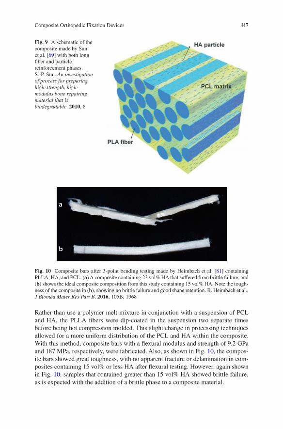
417
Rather than use a polymer melt mixture in conjunction with a suspension of PCL and HA, the PLLA fibers were dip-coated in the suspension two separate times before being hot compression molded. This slight change in processing techniques allowed for a more uniform distribution of the PCL and HA within the composite. With this method, composite bars with a flexural modulus and strength of 9.2 GPa and 187 MPa, respectively, were fabricated. Also, as shown in Fig. 10, the compos-ite bars showed great toughness, with no apparent fracture or delamination in com-posites containing 15 vol% or less HA after flexural testing. However, again shown in Fig. 10, samples that contained greater than 15 vol% HA showed brittle failure, as is expected with the addition of a brittle phase to a composite material.
Fig. 9 A schematic of the composite made by Sun et al. [69] with both long fiber and particle reinforcement phases. S.-P. Sun. An investigation of process for preparing high-strength, high- modulus bone repairing material that is biodegradable. 2010, 8
Fig. 10 Composite bars after 3-point bending testing made by Heimbach et al. [81] containing PLLA, HA, and PCL. (a) A composite containing 23 vol% HA that suffered from brittle failure, and (b) shows the ideal composite composition from this study containing 15 vol% HA. Note the tough-ness of the composite in (b), showing no brittle failure and good shape retention. B. Heimbach et al., J Biomed Mater Res Part B. 2016, 105B, 1968
Composite Orthopedic Fixation Devices
418
Building from the work previously discussed, Heimbach et al. [82] investigated the use of silk fibroin (SF) as a reinforcement material for a resorbable composite. SF is known to have mechanical properties that are superior to most bioresorbable polymers, having a tensile modulus and strength of ~20 GPa and ~700 MPa [83], respectively. Using a design of experiments in conjunction with similar processing methods employed by Heimbach et al. [81], it was determined that a PLA matrix was superior to a PCL matrix when using SF as the long-fiber reinforcement type. Subsequently, a study was done to determine the optimal amount of HA for an SF-reinforced composite. In this particular study, it was found that the optimal amount of HA in the final composite was 14 vol%, where the resulting composite bar had a flexural modulus and strength of 13.7 GPa and 437 MPa, respectively. The flexural modulus achieved is in the middle of the range for cortical bone, and the 437 MPa flexural strength represents the highest such value for a bioresorbable composite. Also, the flexural strength is more than double most estimates for the strength of cortical bone, which should remove any concern of material failure for bone fixation. Also, in addition to increasing the flexural modulus and strength, it was shown that the addition of HA actually increased the flexural toughness of the composite bars by providing important crack deflection, which helps in preventing delamination. All of these mechanical benefits over the similarly made PLLA/HA composites shows great promise for SF-based fixation devices, which could change the scope of bioresorbable fixation devices for load-bearing applications.
Yuka et al. fabricated degradable composites using phosphate glass fibers in a methacrylate modified oligolactide matrix [84]. In short, dianhydro-D-glucitol bis[di(lactoyl)methacrylate] macromer was used as the network forming compo-nent of the matrix, and phosphate glass fibers were soaked in a mixture of the mac-romer, 2-hydroxyethyl methacrylate (HEMA), and dibenzoyl peroxide. The coated fibers were then placed in a mold and cured at 100 °C for 1 h, resulting in a dense, glass fiber-reinforced composite. Also, calcium carbonate was added to some com-posites to act as a pH regulator during degradation due to the fibers drastically low-ering the local pH to dangerous levels for cells. The results indicate that while the calcium carbonate did indeed help regulate and maintain a safe pH, it had severely detrimental effects on the mechanical properties of the composites. Without the addition of calcium carbonate the flexural modulus and strength were 15–20 GPa and 140–200 MPa, respectively. However, when calcium carbonate was added, the strength decreased to 80–130 MPa. Also, while the absence of calcium carbonate generally resulted in fibrous fracture modes, the presence of calcium carbonate resulted in all composites failing catastrophically. Lastly, the authors also noted that the degradation rate of the composites was far too rapid for in vivo fixation, losing much of its integrity in a few weeks.
Despite the evident improvements of the resorbable fixation devices currently on the market, there are still more improvements necessary before a solution can be used for load-bearing applications in the clinical setting. Taking everything into consideration (i.e., mechanical properties, processability, biocompatibility, etc.) Shikinami et al. provided the most comprehensive solution, but the composites made with HA-reinforced PLLA still had insufficient stiffness for use in load-
B. Heimbach and M. Wei

419
bearing applications. One such solution, using phosphate glass fibers, provided an appropriate modulus of 15–20 GPa, but the strength and brittleness of the compos-ites are cause for concern. As such, researchers have looked towards different solu-tions to create a material with appropriate mechanical properties, including composites that are only partially resorbable and resorbable metals, such as magnesium.
4.2.2 Partially Resorbable Composites
Partially resorbable composites are being investigated as way to provide an implant that degrades until it is no longer functional (i.e., will not cause stress shielding in the long-run like metals), but provides better mechanical properties than fully resorbable composites. Typically this involves reinforcing a degradable polymer with carbon fibers (CF), polyamide (PA) fibers, or bioactive glass (BG) fibers. One such example used a PLLA matrix reinforced with braided BG fibers to fabricate a partially resorbable composite [85]. For this composite, the braided BG fibers were dipped in a PLLA solution and subsequently hot pressed to achieve minimal poros-ity. While the tensile properties compared favorably to natural bone, achieving a tensile strength and modulus of 194 MPa and 22.1 GPa, respectively, the bending properties were not sufficient. Also, this composite suffered from fast degradation due to relatively poor bonding between the fiber and the matrix. There are also some concerns of long-term inflammation around the implant site because partially resorbable composites never completely resorb.
4.2.3 Resorbable Metals
Another attractive alternative to the traditional metal fixation devices is the use of resorbable metals, most notably magnesium (Mg). Magnesium is known to degrade safely in vivo [86] as well as have an elastic modulus and strength of 45 GPa [87] and 200–250 MPa [88], respectively, giving Mg mostly ideal properties for a fixa-tion device. The byproducts of magnesium degradation include magnesium hydrox-ide (Mg(OH)2) and hydrogen gas (H2) [86]. Mg(OH)2 is used in medicine [89] as an antacid and is safely processed by the liver and flushed out of the body by the kid-neys [90], and the H2 byproduct is safely removed from the body through the lungs [91]. While the byproducts are inherently safe, they become an irritant when mag-nesium is used as an implant due to the rapid degradation of magnesium in vivo [92]. When magnesium degradation occurs too quickly, H2 gas builds up at the implant site and can cause severe inflammation and irritation.
Due to the rapid degradation of magnesium in vivo, magnesium alloys have been investigated as a means to control the degradation rate [93]. One such alloy, called LAE442, relies on grain size reduction to achieve a slower degradation rate [90]. LAE442 contains 90 wt% Mg, 4 wt% Li, 4 wt% A1, and 2 wt% rare earth elements, and combined with extrusion processing methods has been shown to have smaller
Composite Orthopedic Fixation Devices
420
grains, which leads to more controlled degradation rates. Similarly, alloying Mg with zinc (Zn) has also been investigated as a means to reduce grain size. One such Zn-Mg alloy was made by Gong et al. [94] using a simple melt stirring process, where Mg was added to Zn in weight fractions ranging from 0.5 to 3 wt%. In this case, the presence of the more noble Zn safely reduced the degradation rate while maintaining good biocompatibility and complete degradation of the implant. However, special care must be taken when alloying Mg with other metals, as many metals’ ions are harmful when released in the body as previously discussed.
Magnesium can also be processed into fibers, commonly termed magnesium alloy wires (MAW), allowing magnesium-reinforced composites to be fabricated [95]. Typically these composites are made of the degradable polymers previously discussed, i.e., polylactic acid. One such composite was made by alternately stack-ing layers of PLA and MAW, and subsequently hot pressing the layers into a dense composite [96]. This composite achieved a bending strength of 190 MPa, and with the presence of a PLA matrix the degradation rate is slowed to a safe rate. While Mg-based fixation devices show great promise, the hydrogen gas formation remains a concern even for alloyed magnesium. Also, the strength of magnesium-based materials will need to increase before they can be safely used for load-bearing appli-cations, as they are currently about as strong as bone, but should be stronger than bone to provide adequate fixation properties for several months after implantation while the material degrades.
5 Conclusions
This chapter outlined the important aspects of the current state of internal fixation devices as well as current research to help improve the fixation products on the market. Current fixation devices are almost entirely dominated by stainless steel and titanium due to their superior mechanical properties and nearly total inertness within the body, whereas titanium is virtually 100% inert in vivo. However, these metal devices cause stress shielding and metal ion leaching over time, contributing to future fractures and severe patient discomfort. As such, in the last couple decades, there has been increased interest in developing totally resorbable fixation devices that will completely degrade over time and eliminate the drawbacks of metals cur-rently in use. Such materials involve some combination of PLA and PGA to tailor the degradation rate, and while these materials have seen success clinically, they are limited to non-load-bearing applications, such as maxillofacial fractures. Ample research is continuing to focus on making a viable load-bearing fixation device that is totally resorbable, but such efforts have, thus far, fallen short. One group was able to increase the modulus and strength of PLA through unique processing methods and reinforcement with HA, but the stiffness of the composite was still not sufficient for load-bearing applications. There is also significant work being done to make magnesium-based materials clinically acceptable. Magnesium, which is known to degrade in vivo, has been shown to have great mechanical and biocompatibility
B. Heimbach and M. Wei
421
properties, but the release of hydrogen gas when degrading is still concerning. While there is still no clinically accepted product for load-bearing fixation, this is a massive market that has yet to be tapped. Millions of bone fixation surgeries are performed every year, and it is estimated that trauma fixation will account for $9 billion by 2020. Given the detrimental long-term side effects of current fixation products, a viable resorbable option would revolutionize the industry and provide better care for millions each year while also saving money as it would eliminate the need for a second surgery.
References
1. Orthopaedics. American Academy of Orthopaedic Surgeons; 2007. http://orthoinfo.aaos.org/topic.cfm?topic=a00099. Accessed Oct 2017.
2. Weiss AJ, Elixhauser A. Trends in Operating Room Procedures in U.S. Hospitals, 2001–2011. Healthcare Cost and Utilization Project; 2014. https://hcup-us.ahrq.gov/reports/statbriefs/sb171-Operating-Room-Procedure-Trends.jsp. Accessed Mar 2014.
3. Swarup I, O'Donnell JF. An overview of the history of orthopedic surgery. Am J Orthop. 2016;45(7):434–8.
4. Dyrda L. 10 predictions for the global orthopedic device market. Becker's Healthcare; 2014. http://www.beckersspine.com/orthopedic-a-spine-device-a-implant-news/item/21361-10-pre-dictions-for-the-global-orthopedic-. Accessed 30 June 2014.
5. Wood M. Orthopedic trauma fixation devices market to hit $9.4B by 2020 — DePuy Synthes, Stryker, Zimmer Biomet & more lead space. Becker’s Healthcare; 2016. http://www.beckersspine.com/orthopedic-a-spine-device-a-implant-news/item/34547-orthopedic-trauma-fixation-devices-market-to-hit-9-4b-by-2020-depuy-synthes-stryker-zimmer-biomet-more-lead-space.html. Accessed 13 Dec 2016.
6. Zamanian K, Freeze D. U.S. Orthopedic Trauma Device Market to Exceed $8 Billion by 2020. iData Research Inc.; 2014. https://www.meddeviceonline.com/doc/u-s-orthopedic-trauma-device-market-to-exceed-eight-billion-dollars-0001. Accessed 5 July 2014.
7. American Academy of Orthopedic Surgeons. Internal Fixation for Fractures. American Academy of Orthopedic Surgeons; 2014. http://orthoinfo.aaos.org/topic.cfm?topic=a00196. Accessed Mar 2014.
8. Cohn MR, Unnanuntana A, Pannu TJ, Warner SJ, Lane JM. Materials in fracture fixation. In Ducheyne P, Healy K, Hutmacher DE, GraingerDW, Kirkpatrick CJ (Eds.) Comprehensive biomaterials II, 2nd Edition ed., vol. 7, Elsevier; 2017, pp. 278–297.
9. Kopeliovich D. Flexural strength tests of ceramics. SubsTech: Substances and Technologies; 2012. http://www.substech.com/dokuwiki/doku.php?id=flexural_strength_tests_of_ceramics. Accessed 01 June 2012.
10. Lenthe GH v, Voide R, Boyd SK, Müller R. Tissue modulus calculated from beam theory is biased by bone size and geometry: Implications for the use of three-point bending tests to determine bone tissue modulus. Bone. 2008;43(4):717–23.
11. Lešić AR, Zagorac S, Bumbaširević V, Bumbaširević MŽ. The development of internal fixa-tion- historical overview. Acta Chir Iugosl. 2012;59(3):9–13.
12. Greenhagen RM, Johnson AR, Joseph A. Internal Fixation: a Historical Review. Clin Podiatr Med Surg. 2011;28(4):607–18.
13. Lane WA. Some Remarks on the Treatment of Fractures. Br Med J. 1895;1(1790):861–3. 14. Gilardino M, Chen E, Bartlett S. Choice of Internal Rigid Fixation Materials in the Treatment
of Facial Fractures. Craniomaxillofacial Trauma and Reconstruction. 2009;2(01):049–60.
Composite Orthopedic Fixation Devices
422
15. Hernigou P, Pariat J. History of internal fixation (part 1): early developments with wires and plates before World War II. Int Orthop. 2016a;41(6):1273–83.
16. Uhthoff HK, Poitras P, Backman DS. Internal plate fixation of fractures: short history and recent developments. J Orthop Sci. 2006;11(2):118–26.
17. Sherman WO. Vanadium steel bone plates and screws. Surg Gynecol Obstet. 1912; 14(6):629–34.
18. Hernigou P, Pariat J. History of internal fixation with plates (part 2): new developments after World War II; compressing plates and locked plates. Int Orthop. 2016b;41(7):1489–500.
19. Danis R. Theorie et pratique de l’osteosynthese. Paris: Masson; 1949. 20. Venable CS. An Impacting Bone Plate To Attain Closed Coaptation. Ann Surg.
1951;133(6):808–13. 21. Wagner M. General principles for the clinical use of the LCP. Injury. 2003;34(2):31–42. 22. Kessler SB, Deiler S, Schiffl-Deiler M, Uhthoff HK, Schweiberer L. Refractures: a conse-
quence of impaired local bone viability. Arch Orthop Trauma Surg. 1992;111(2):96–101. 23. Perren SM, Mane K, Pohler O, Predieri M, Steinemann S, Gautier E. The limited contact
dynamic compression plate (LC-DCP). Arch Orthop Trauma Surg. 1990;109(6):304–10. 24. Cronier P, Pietu G, Dujardin C, Bigorre N, Ducellier F, Gerard R. The concept of locking
plates. Orthop Traumatol Surg Res. 2010;96(4):S17–36. 25. The Editors of Encyclopaedia Britannica. noble metal. Britannica, inc.; 2017. https://www.
britannica.com/science/noble-metal. 26. Hayes JS, Richards RG. The use of titanium and stainless steel in fracture fixation. Expert Rev
Med Devices. 2010;7(6):843–53. 27. Leventhal GS. Titanium: a metal for surgery. J Bone Joint Surg. 1951;33(2):473–4. 28. Smith KG. Chapter 13: Orthopaedic Biomaterials. University of Pennsylvania; 2017. http://
cal.vet.upenn.edu/projects/saortho/chapter_13/13mast.htm. 29. Delstar Metal Finishing, Inc. Electropolishing; 2017. https://www.delstar.com/electropolishing. 30. Hansen DC. Metal Corrosion in the Human Body: The Ultimate Bio-Corrosion Scenario.
Electrochem Soc Interf. 2008:31–4. 31. Bodycote. Recrystallization; 2017. http://www.bodycote.com/en-GB/services/heat-treatment/
annealing-normalising/recrystallisation.aspx. 32. Cold Work & Annealing Process. 2017. https://sites.google.com/site/coldworkannealingprocess/. 33. Wagner M, Frigg R. Internal fixators: concepts and cases using LCP and LISS. Davos-Platz:
AO Publishing; 2006. 34. Zardiackas LD, Disegi J, Givan D. Torsional properties of implant grade titanium. J Biomed
Mater Res. 1991;25(3):281–93. 35. Oldani C, Dominguez A. Titanium as a biomaterial for implants. In: Fokter S, (ed) Recent
advances in arthroplasty. InTech; 2012, pp. 149–162. 36. Niinomi M, Liu Y, Nakai M, Liu H, Li H. Biomedical titanium alloys with Young’s moduli
close to that of cortical bone. Regener Biomater. 2016;3(3):173–85. 37. Kennady MC, Tucker MR, Lester GE, Buckley MJ. Stress shielding effect of rigid internal
fixation plates on mandibular bone grafts. Int J Oral Maxillofac Surg. 1989;18(5):307–10. 38. Klein-Nulend J, Bacabac RG, Mullender MG. Mechanobiology of bone tissue. Pathol Biol.
2005;53(10):576–80. 39. Korvick DL, Newbrey JW, Bagby GW, Pettit GD, Lincoln JD. Stress shielding reduced by a
silicon plate-bone interface: A canine experiment. Acta Orthop Scand. 1989;60(5):611–6. 40. Anil S, Anand PS, Alghamdi H, Janse JA. Dental implant surface enhancement and osseoin-
tegration. In Turkyilmaz I (ed), Implant dentistry—a rapidly evolving practice. InTech, 2011, pp. 83–108.
41. JohnsonDiversity. Passivation of Stainless Steel. 2007. https://wine.appstate.edu/sites/wine.appstate.edu/files/Diversey_PassivationofStainlessSteel.pdf.
42. Shih C-C, Shih C-M, Su Y-Y, Su LH-J, Chang M-S, Lin S-J. Effect of surface oxide proper-ties on corrosion resistance of 316L stainless steel for biomedical applications. Corros Sci. 2004;46(2):427–41.
43. Disegi JA. Anodizing titanium for space applications. In Proceedings of the 1997 16 Southern Biomedical Engineering Conference, 1997.
B. Heimbach and M. Wei
423
44. Hanawa T. Metal ion release from metal implants. Mater Sci Eng C. 2004;24(6–8):745–52. 45. Kumar R, Lerski RA, Gandy S, Clift BA, Abboud RJ. Safety of Orthopedic Implants in Magnetic
Resonance Imaging: An Experimental Verification. J Orthop Res. 2006;24(9):1799–802. 46. Olivieri G, Novakovic M, Savaskan E, Meier F, Baysang G, Brockhaus M, Müller-Spahn
F. The effects of β-estradiol on SHSY5Y neuroblastoma cells during heavy metal induced oxidative stress, neurotoxicity and β-amyloid secretion. Neuroscience. 2002;113(4):849–55.
47. Elbetieha A, Al-Hamood MH. Long-term exposure of male and female mice to trivalent and hexavalent chromium compounds: effect on fertility. Toxicology. 1997;116(1–3):39–47.
48. Wedeen R, Qian L. Chromium-induced kidney disease. Environ Health Perspect. 1991;92:71–4. 49. Kanojia RK, Junaid M, Murthy RC. Embryo and fetotoxicity of hexavalent chromium: a long-
term study. Toxicol Lett. 1998;95(3):165–72. 50. Kasai Y, Iida R, Uchida A. Metal Concentrations in the Serum and Hair of Patients With
Titanium Alloy Spinal Implants. Spine. 2003;28(12):1320–6. 51. Ramakrishna S, Mayer J, Wintermantel E, Leong KW. Biomedical applications of polymer-
composite materials: a review. Compos Sci Technol. 2001;61(9):1189–224. 52. Scholz M-S, Blanchfield JP, Bloom LD, Coburn BH, Elkington M, Fuller JD, Gilbert ME,
Muflahi SA, Pernice MF, Rae SI, Trevarthen JA, White SC, Weaver PM, Bond IP. The use of composite materials in modern orthopaedic medicine and prosthetic devices: A review. Compos Sci Technol. 2011;71(16):1791–803.
53. Chacon GE, Dillard FM, Clelland N, Rashid R. Comparison of Strains Produced by Titanium and Poly D, L-Lactide Acid Plating Systems to In Vitro Forces. J Oral Maxillofac Surg. 2005;63(7):968–72.
54. Zambito RF. Biomechanics of the facial skeleton. J Oral Maxillofac Surg. 1992;50(11):1250. 55. Lim L-T, Cink K, Vanyo T. Processing of Poly(Lactic Acid). Poly(Lactic Acid). 2010:189–215. 56. Singh V, Tiwari M. Structure-Processing-Property Relationship of Poly(Glycolic Acid) for
Drug Delivery Systems 1: Synthesis and Catalysis. Int J Polym Sci. 2010:1–23. 57. Jamshidian M, Tehrany EA, Imran M, Jacquot M, Desobry S. Poly-Lactic Acid: Production,
Applications, Nanocomposites, and Release Studies. Compr Rev Food Sci Food Saf. 26 August 2010;9(5):552–71.
58. Makadia HK, Siegel SJ. Poly Lactic-co-Glycolic Acid (PLGA) as Biodegradable Controlled Drug Delivery Carrier. Polymers. 2011;3(4):1377–97.
59. Lu L, Peter SJ, Lyman MD, Lai H-L, Leite SM, Tamada JA, Uyama S, Vananti JP, Langer R, Mikos AG. In vitro and in vivo degradation of porous poly(DL-lactic-co-glycolic acid) foams. Biomaterials. 2000;21(18):1837–45.
60. Edwards RC, Kiely KD, Eppley BL. The fate of resorbable poly-L-lactic/polyglycolic acid (Lactosorb) bone fixation devices in orthognathic surgery. J Oral Maxillofac Surg. 2001;59, 2001(1)
61. Gosain AK, Song L, Corrao MA, Pintar FA. Biomechanical Evaluation of Titanium, Biodegradable Plate and Screw, and Cyanoacrylate Glue Fixation Systems in Craniofacial Surgery. Plast Reconst Surg. 1998;101(3):582–91.
62. Eppley B. Repair of midfacial fractures with resorbable plates and screws. Oper Tech Otolaryngol Head Neck Surg. 2002;13(4):287–92.
63. Törmälä P, Vasenius J, Vainionpää S, Laiho J, Pohjonen T, Rokkanen P. Ultra-high-strength absorbable self-reinforced polyglycolide (SR-PGA) composite rods for internal fixation of bone fractures: In vitro and in vivo study. J Biomed Mater Res A. 1991;25(1):1–22.
64. Shetty V, Caputo AA, Kelso I. Torsion-axial force characteristics of SR-PLLA screws. J Cranio-Maxillofac Surg. 1997;25(1):19–23.
65. Park CH, Kim HS, Lee JH, Hong SM, Ko YG, Lee OJ. Resorbable Skeletal Fixation Systems for Treating Maxillofacial Bone Fractures. Arch Otolaryngol Head Neck Surg. 2011;137(2):125–39.
66. Bell R, Kindsfater C. The use of biodegradable plates and screws to stabilize facial fractures. Int J Oral Maxillofac Surg. 2006;64:31–9.
67. Landes C, Ballon A. Five-Year Experience Comparing Resorbable to Titanium Miniplate Osteosyntheses in Cleft-lip and Palate Orthognathic Surgery. Cleft Palate Craniofac J. 2006;43:67–74.
Composite Orthopedic Fixation Devices
424
68. Hollier LH, Rogers N, Berzin E, Stal S. Resorbable Mesh in the Treatment of Orbital Floor Fractures. J Craniofac Surg. 2001;12(3):242–6.
69. Sun S-P, Wei M, Olson JR, Shaw MT. A modified pultrusion process for preparing composites reinforced with continuous fibers and aligned hydroxyapatite nano needles. Polym Compos. 2014;36(5):931–8.
70. Tan L, Yu X, Wan P, Yang K. Biodegradable Materials for Bone Repairs: A Review. J Mater Sci Technol. 2013;29(6):503–13.
71. Shikinami Y, Okuno M. Bioresorbable devices made of forged composites of hydroxyapa-tite (HA) particles and poly-L-lactide (PLLA): Part I. Basic characteristics. Biomaterials. 1999;20(9):859–77.
72. Harris AM, Lee EC. Improving mechanical performance of injection molded PLA by control-ling crystallinity. J Appl Polym Sci. 2007;107(4):2246–55.
73. Perego G, Cella GD, Bastioli C. Effect of molecular weight and crystallinity on poly(lactic acid) mechanical properties. J Appl Polym Sci. 1996;59(1):37–43.
74. Shikinami Y, Okuno M. Bioresorbable devices made of forged composites of hydroxyapatite (HA) particles and poly L-lactide (PLLA). Part II: practical properties of miniscrews and mini-plates. Biomaterials. 2001;22(23):3197–211.
75. Hasegawa S, Ishii S, Tamura J, Furukawa T, Neo M, Matsusue Y, Shikinami Y, Okuno M, Nakamura T. A 5–7 year in vivo study of high-strength hydroxyapatite/poly(L-lactide) com-posite rods for the internal fixation of bone fractures. Biomaterials. 2006;27(8):1327–32.
76. Chang Y-S, Oka M, Nakamura T, Gu H-O. Bone remodeling around implanted ceramics. J Biomed Mater Res. 1996;30(1):117–24.
77. Coskun S, Korkusuz F, Hasirci V. Hydroxyapatite reinforced poly(3-hydroxybutyrate) and poly(3-hydroxybutyrate-co-3-hydroxyvalerate) based degradable composite bone plate. J Biomater Sci Polym Ed. 2005;16(12):1485–502.
78. Ahmed I, Jones IA, Parsons AJ, Bernard J, Farmer J, Scotchford CA, Walker GS, Rudd CD. Composites for bone repair: phosphate glass fibre reinforced PLA with varying fibre architecture. J Mater Sci Mater Med. 2011;22(8):1825–34.
79. S.-P. Sun, An investigation of process for preparing high-strength, high-modulus bone repair-ing material that is biodegradable. In: Shaw MT, Wei M, Parnas RS, (eds), University of Connecticut, 2010, pp. 1–152.
80. Charles LF, Kramer ER, Shaw MT, Olson JR, Wei M. Self-reinforced composites of hydroxyapatite- coated PLLA fibers: Fabrication and mechanical characterization. J Mech Behav Biomed Mater. 2013;17:269–77.
81. Heimbach B, Grassie K, Shaw MT, Olson JR, Wei M. Effect of hydroxyapatite concentration on high-modulus composite for biodegradable bone-fixation devices. J Biomed Mater Res B Appl Biomater. 2017;105B:1963–1971.
82. Heimbach B, Tonyali B, Zhang D, Wei M. Hydroxyapatite and silk fibroin in dense composites for resorbable bone fixation devices. 2017b. Manuscript submitted for publication.
83. Altman GH, Diaz F, Jakuba C, Calabro T, Horan RL, Chen J, Lu H, Richmond J, Kaplan D. Silk-based biomaterials. Biomaterials. 2003;24(3):401–16.
84. Yuka H, Kobayashi LS, Brauer DS, Rüssel C. Mechanical properties of a degradable phos-phate glass fibre reinforced polymer composite for internal fracture fixation. Mater Sci Eng C. 2010;30(7):1003–7.
85. Kharazi AZ, Fathi MH, Bahmani F, Fanian H. Partially resorbable composite bone plate with controlled degradation rate, desired mechanical properties and bioactivity. Polym Degrad Stab. 2011;96(12):2055–63.
86. Zhao D, Wang T, Haogland W, Benson D, Dong Z, Chen S, Chou D-T, Hong D, Wu J, Kumta PN, Heineman WR. Visual H2 sensor for monitoring biodegradation of magnesium implants in vivo. Acta Biomater. 2016;45:399–409.
87. Total Materia. Mechanical properties of magnesium and magnesium alloys. Total Materia; 2002. http://www.totalmateria.com/page.aspx?ID=CheckArticle&site=ktn&NM=41.
88. The American Foundry Society Technical Dept. Magnesium alloys. American Foundry Society, 2006. http://www.afsinc.org/files/images/magnes.pdf.
B. Heimbach and M. Wei
425
89. National Center for Biotechnology Information. MAGNESIUM HYDROXIDE. U.S. National Library of Medicine; 2004. https://pubchem.ncbi.nlm.nih.gov/compound/magnesium_hydroxide.
90. Witte F, Fischer J, Nellesen J, Vogt C, Donath T, Beckmann F. In vivo corrosion and corrosion protection of magnesium alloy LAE442☆. Acta Biomater. 2010;6(5):1792–9.
91. Noviana D, Paramitha D, Ulum MF, Hermawan H. The effect of hydrogen gas evolution of magnesium implant on the postimplantation mortality of rats. J Orthop Transl. 2016;5:9–15.
92. Mordike BL, Ebert T. Magnesium: Properties — applications — potential. Mater Sci Eng A. 2001;302(1):37–45.
93. Sheikh Z, Najeeb S, Khurshid Z, Verma V, Rashid H, Glogauer M. Biodegradable Materials for Bone Repair and Tissue Engineering Applications. Materials. 2015;8:5744–94.
94. Gong H, Wang K, Strich R, Zhou JG. In vitro biodegradation behavior, mechanical properties, and cytotoxicity of biodegradable Zn-Mg alloy. J Biomed Mater Res Part B: Appl Biomater. 2015;103(8):1632–40.
95. Li X, Guo C, Liu X, Liu L, Bai J, Xue F, Lin P, Chu C. Impact behaviors of poly-lactic acid based biocomposite reinforced with unidirectional high-strength magnesium alloy wires. Prog Nat Sci Mater Int. 2014;24(5):472–8.
96. Li X, Chu CL, Liu L, Liu XK, Bai J, Guo C, Xue F, Lin PH, Chu PK. Biodegradable poly- lactic acid based-composite reinforced unidirectionally with high-strength magnesium alloy wires. Biomaterials. 2015;49:135–44.
Composite Orthopedic Fixation Devices
427© Springer International Publishing AG, part of Springer Nature 2017B. Li, T. Webster (eds.), Orthopedic Biomaterials, https://doi.org/10.1007/978-3-319-73664-8_16
PEEK Titanium Composite (PTC) for Spinal Implants
Erik I. Waldorff, Samuel Fang, Nianli Zhang, Livia Visai, Marcello Imbriani, Emanuele Magalini, Eleonora Preve, Pierfrancesco Robotti, Andrew L. Raines, Evan Goldberg, Jiechao Jiang, Kirk C. McGilvray, Jeremiah Easley, Howard B. Seim, Christian M. Puttlitz, and James T. Ryaby
Keywords Interbody device · Spinal fusion · ACDF · PEEK titanium composite · PEEK · Titanium · Nano structure · Cervical spine · Lumbar spine · Osteo-integration · Growth-factors · Ovine spine fusion model
E. I. Waldorff (*) · S. Fang · N. Zhang · J. T. Ryaby Orthofix, Inc., Lewisville, TX, USAe-mail: [email protected]
L. Visai Department of Molecular Medicine, Center for Health Technologies (CHT), INSTM UdR of Pavia, University of Pavia, Pavia, Italy
Department of Occupational Medicine, Toxicology and Environmental Risks, Istituti Clinici Scientifici (ICS) Maugeri, IRCCS, Pavia, Italy
M. Imbriani Department of Occupational Medicine, Toxicology and Environmental Risks, Istituti Clinici Scientifici (ICS) Maugeri, IRCCS, Pavia, Italy
Department of Public Health, Experimental Medicine and Forensics, University of Pavia, Pavia, Italy
E. Magalini · E. Preve · P. Robotti Eurocoating S.p.A, Trento, Italy
A. L. Raines · E. Goldberg Translational Testing and Training Laboratories, Inc., T3 Labs, Atlanta, GA, USA
J. Jiang Department of Material Science, University of Texas at Arlington, Arlington, TX, USA
K. C. McGilvray · C. M. Puttlitz Orthopaedic Bioengineering Research Laboratory (OBRL), Department of Mechanical Engineering, Colorado State University, Fort Collins, CO, USA
J. Easley · H. B. Seim Preclinical Surgical Research Laboratory (PSRL), Colorado State University, Fort Collins, CO, USA
428
1 Introduction
Since the development of the posterior lumbar interbody fusion (PLIF) and anterior approach for anterior cervical discectomy and fusion (ACDF) [1–4], many different fusion substrates such as grafts and devices have been explored. This includes auto-grafts [5], allografts [6], and interbody spacers made from polyether-ether-ketone (PEEK) [7], porous tantalum [8], and titanium [29]. Autografts used to be the stan-dard due to their high fusion rate, however, disadvantages associated with them include donor site morbidity with potential pain and numbness at the donor site [9, 10]. Allografts do not possess the autograft disadvantage of donor site morbidity, but have been associated with the risk of infection, disease transmission, and issues with histocompatibility [9]. In addition, a meta-analysis for one- and two-level ACDF comparing autografts and allografts showed a statistically superior fusion rate for autografts [6]. However, other studies have found no difference in fusion rates between autografts and allografts for multi-level ACDFs [11]. PEEK devices have been found to be the new gold standard for the treatment of lumbar and cervi-cal disc disease [12, 13], showing similar fusion rates as autografts for PLIF and ACDF [14–16]. Despite possessing the advantages of radiolucency for radiographic determination of fusion, this may simultaneously make dislodgement and subsid-ence difficult to determine for PEEK devices. Another disadvantage of PEEK is that it is bioinert, which limits incorporation into the fusion mass and the subsequent implant stability [17–19]. Hence, in order to improve on the PEEK device fusion rate, stability, bone apposition and anchoring, new porous devices have been devel-oped such as porous tantalum and titanium [8, 29]. These devices possess similar stiffness as PEEK, which has a stiffness in the range between cancellous and corti-cal bone [20, 21], thus avoiding stress shielding.
The concept of changing the material, shape and surface of the implants builds on the fact that integration of the implant device with the native tissue is dependent on its interactions with undifferentiated stem cells and osteoblasts [22–27] and is influ-enced by its surface properties [28]. These surface properties include topography, porosity, chemistry, surface energy, and surface charge [22, 28]. Modifications to optimize the surface properties of implant materials have been performed with the goal of facilitating new bone growth around and within the surgical area and assimi-lation with the device [22]. In general, the topographical character of roughness of titanium is associated with long-term cell adhesion, and surface topography and chemistry impact proliferation and differentiation [22, 29]. The integration of the substrate material with the biological environment of the surgical area is enhanced by higher porosity and larger pore sizes [30], with data from in vivo titanium models of osteogenesis indicating that pore sizes in the range of 300–400 μm are optimal [30]. Many interbody fusion devices have thus incorporated the concept of porous or roughened metals using various titanium or tantalum alloys (Titan Spine, Mequon, WI; Medtronic, Minneapolis, MN; Zimmer, Inc., Warsaw, IN). By using these alloys in a porous form, the mechanical properties of the devices can approach that of tra-becular bone, thus avoiding stress shielding [31]. However, common for all of these devices is the use of the alloy throughout the device. Thus, despite possessing a
E. I. Waldorff et al.
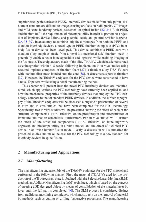
429
superior osteogenic surface to PEEK, interbody devices made from only porous tita-nium or tantalum are difficult to image, causing artifacts on radiographs, CT images and MRI scans hindering perfect assessment of spinal fusion [32–34]. Both PEEK and titanium fulfill the requirement of biocompatibility in order to prevent host rejec-tion of implants, device failure, and potential costly and painful revision surgeries [26, 35–39]. In an attempt to combine only the advantages from both the PEEK and titanium interbody devices, a novel type of PEEK titanium composite (PTC) inter-body fusion device has been developed. This device combines a PEEK core with titanium alloy endplates made from a novel 3-dimensional (3D) titanium mesh to potentially enable a better bone apposition and ingrowth while enabling imaging of the fusion site. The endplates are made of the alloy Ti6Al4V, which has demonstrated osseointegration within 4–8 weeks following implantation in in vivo studies using textured implants composed of titanium foam [37], a titanium alloy Ti6Al4V core with titanium fiber-mesh bonded onto the core [38], or dense versus porous titanium [39]. However, the Ti6Al4V endplates for the PTC device were constructed to have a novel D pattern while using a novel manufacturing method.
This chapter will present how the novel PTC interbody devices are manufac-tured, which applications the PTC technology have currently been applied to, and how the mechanical properties of the interbody devices that employ the PTC tech-nology compare to that of standard PEEK devices. In addition, the surface topogra-phy of the Ti6Al4V endplates will be discussed alongside a presentation of several in vitro and in vivo studies that have been completed for the PTC technology. Specifically, two in vitro studies will be presented showing the effect of each of the structural components (PEEK, Ti6Al4V) on the proliferation and differentiation of immature and mature osteoblasts. Furthermore, two in vivo studies will illustrate the effect of the structural components (PEEK, Ti6Al4V) on bone ingrowth/ongrowth and biocompatibility in a rabbit model, and the effect of a clinical PTC device in an ovine lumbar fusion model. Lastly, a discussion will summarize the presented studies and make the case for the PTC technology as a new standard for interbody devices in spine fusion.
2 Manufacturing and Applications
2.1 Manufacturing
The manufacturing and assembly of the Ti6Al4V endplates for the PTC is novel and performed in the following manner. First, the material (Ti6Al4V) used for the pro-duction of the Ti porous raw plate is obtained with the Selective Laser Melting (SLM) method, an Additive Manufacturing (AM) technique, which is based on the concept of creating a 3D designed object by means of consolidation of the material layer by layer until the full part is completed [40]. The SLM process is considered distinct from traditional machining techniques, which mostly rely on the removal of material by methods such as cutting or drilling (subtractive processes). The manufacturing
PEEK Titanium Composite (PTC) for Spinal Implants
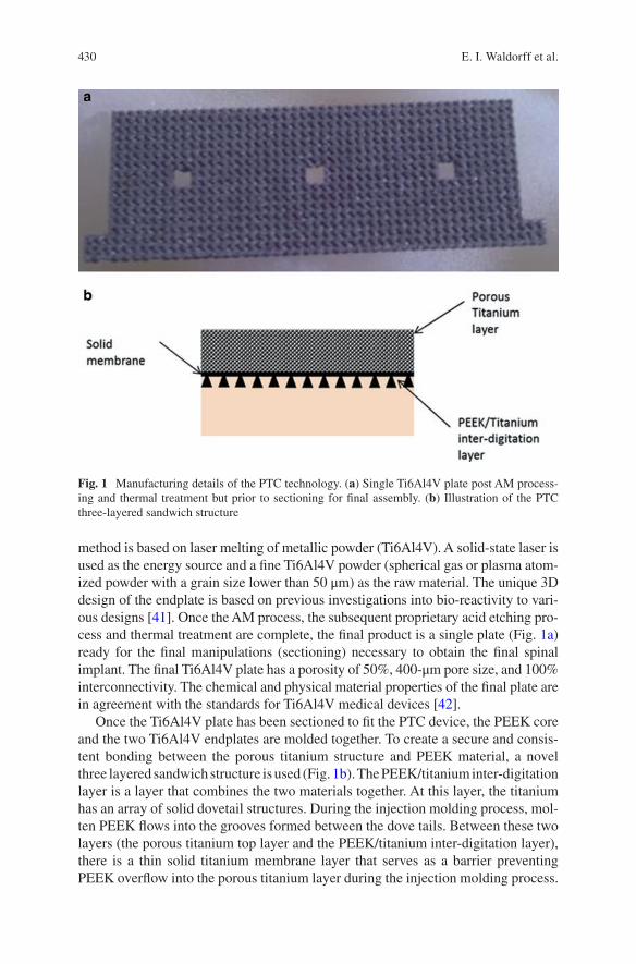
430
method is based on laser melting of metallic powder (Ti6Al4V). A solid- state laser is used as the energy source and a fine Ti6Al4V powder (spherical gas or plasma atom-ized powder with a grain size lower than 50 μm) as the raw material. The unique 3D design of the endplate is based on previous investigations into bio- reactivity to vari-ous designs [41]. Once the AM process, the subsequent proprietary acid etching pro-cess and thermal treatment are complete, the final product is a single plate (Fig. 1a) ready for the final manipulations (sectioning) necessary to obtain the final spinal implant. The final Ti6Al4V plate has a porosity of 50%, 400-μm pore size, and 100% interconnectivity. The chemical and physical material properties of the final plate are in agreement with the standards for Ti6Al4V medical devices [42].
Once the Ti6Al4V plate has been sectioned to fit the PTC device, the PEEK core and the two Ti6Al4V endplates are molded together. To create a secure and consis-tent bonding between the porous titanium structure and PEEK material, a novel three layered sandwich structure is used (Fig. 1b). The PEEK/titanium inter- digitation layer is a layer that combines the two materials together. At this layer, the titanium has an array of solid dovetail structures. During the injection molding process, mol-ten PEEK flows into the grooves formed between the dove tails. Between these two layers (the porous titanium top layer and the PEEK/titanium inter- digitation layer), there is a thin solid titanium membrane layer that serves as a barrier preventing PEEK overflow into the porous titanium layer during the injection molding process.
Fig. 1 Manufacturing details of the PTC technology. (a) Single Ti6Al4V plate post AM process-ing and thermal treatment but prior to sectioning for final assembly. (b) Illustration of the PTC three-layered sandwich structure
E. I. Waldorff et al.
431
After the molding, the PEEK material solidifies and forms a strong mechanical bond between the titanium endplates and the PEEK core.
2.2 PTC Applications
The specific PTC technology incorporating the novel manufacturing of endplates made of porous Ti6Al4V (Sect. 2.1) was developed by Orthofix, Inc. (Lewisville, Texas, USA) and has since been applied to several standard spinal fixation interbody devices available. Specifically, the PTC technology has been applied to a standard lumbar interbody device (FORZA® PTC Spacer System), a standard cervical inter-body device (CONSTRUX® Mini PTC Spacer System), and a standalone lumbar interbody device (PILLAR® SA PTC Spacer System). Figure 2 illustrates the visual difference between the PTC devices and their standard PEEK device equivalent.
Similar to the standard PEEK interbody devices (Fig. 2b, d, f), the PTC devices (Fig. 2a, c, e) are also intended to be used with autograft and/or allograft both within the intended hallow core or surrounding the device. In addition, the PTC devices have the same indication as the standard PEEK interbody devices (Table 1).
3 Mechanical Properties
3.1 Methods
3.1.1 Testing Setup
To investigate the comparative strength of a PTC interbody device and its equivalent PEEK device, the CONSTRUX Mini PTC cervical interbody device and the CONSTRUX Mini PEEK device were tested under axial compression, torsion and compression-shear loads in accordance with ASTM standard F2077 (Test methods for intervertebral body fusion devices) [43]. These testing modes are used as an industrial standard to characterize the mechanical performance of interbody devices enabling results between various devices to be compared. In accordance with ASTM F2077, a total of 12 devices (6 CONSTRUX Mini PTC, 6 CONSTRUX Mini PEEK) were tested for each testing mode. The size of the implant was chosen to represent a worst-case scenario, i.e., a scenario where the implant size most prone to failure under loading was chosen. This was done for both CONSTRUX Mini PTC and CONSTRUX Mini PEEK. Based on prior analysis for all testing modes (data not shown) the implant with a foot print of 12 × 12 mm was chosen as the worst case for both implants while the height was 6 mm and 5 mm for the CONSTRUX Mini PTC and CONSTRUX Mini PEEK, respectively, as CONSTRUX Mini PTC has no 5 mm offering. Using a 858 MiniBionix hydraulic testing frame (MTC corporation, Eden Prairie, MN), all tests were performed at room temperature in air per ASTM
PEEK Titanium Composite (PTC) for Spinal Implants
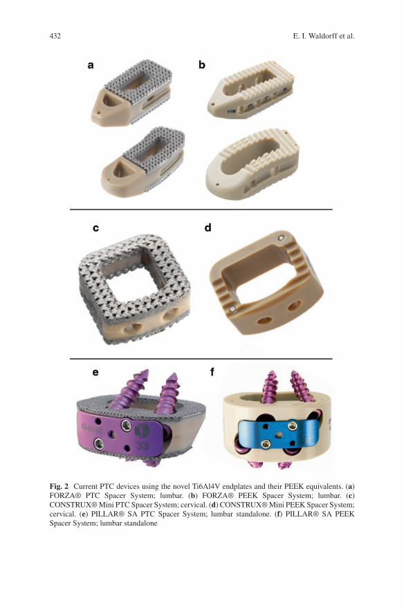
432
Fig. 2 Current PTC devices using the novel Ti6Al4V endplates and their PEEK equivalents. (a) FORZA® PTC Spacer System; lumbar. (b) FORZA® PEEK Spacer System; lumbar. (c) CONSTRUX® Mini PTC Spacer System; cervical. (d) CONSTRUX® Mini PEEK Spacer System; cervical. (e) PILLAR® SA PTC Spacer System; lumbar standalone. (f) PILLAR® SA PEEK Spacer System; lumbar standalone
E. I. Waldorff et al.
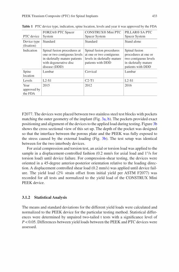
433
F2077. The devices were placed between two stainless steel test blocks with pockets matching the outer geometry of the implant (Fig. 3a, b). The pockets provided exact positioning and alignment of the devices to the applied load during testing. Figure 3b shows the cross sectional view of this set up. The depth of the pocket was designed so that the interface between the porous plate and the PEEK was fully exposed to the stress caused by the external loading (Fig. 3b). The test setup was identical between for the two interbody devices.
For axial compression and torsion test, an axial or torsion load was applied to the sample in a displacement-controlled fashion (0.2 mm/s for axial load and 1°/s for torsion load) until device failure. For compression-shear testing, the devices were oriented in a 45-degree anterior-posterior orientation relative to the loading direc-tion. A displacement controlled shear load (0.2 mm/s) was applied until device fail-ure. The yield load (2% strain offset from initial yield per ASTM F2077) was recorded for all tests and normalized to the yield load of the CONSTRUX Mini PEEK device.
3.1.2 Statistical Analysis
The means and standard deviations for the different yield loads were calculated and normalized to the PEEK device for the particular testing method. Statistical differ-ences were determined by unpaired two-tailed t tests with a significance level of P < 0.05. Differences between yield loads between the PEEK and PTC devices were assessed.
Table 1 PTC device type, indication, spine location, levels and year it was approved by the FDA
PTC deviceFORZA® PTC Spacer System
CONSTRUX® Mini PTC Spacer System
PILLAR® SA PTC Spacer System
Device type (fixation)
Standard Standard Stand alone
Indication Spinal fusion procedures at one or two contiguous levels in skeletally mature patients with degenerative disc disease (DDD)
Spinal fusion procedures at one or two contiguous levels in skeletally mature patients with DDD
Spinal fusion procedures at one or two contiguous levels in skeletally mature patients with DDD
Spine location
Lumbar Cervical Lumbar
Levels L2-S1 C2-T1 L2-S1Year approved by the FDA
2015 2012 2016
PEEK Titanium Composite (PTC) for Spinal Implants
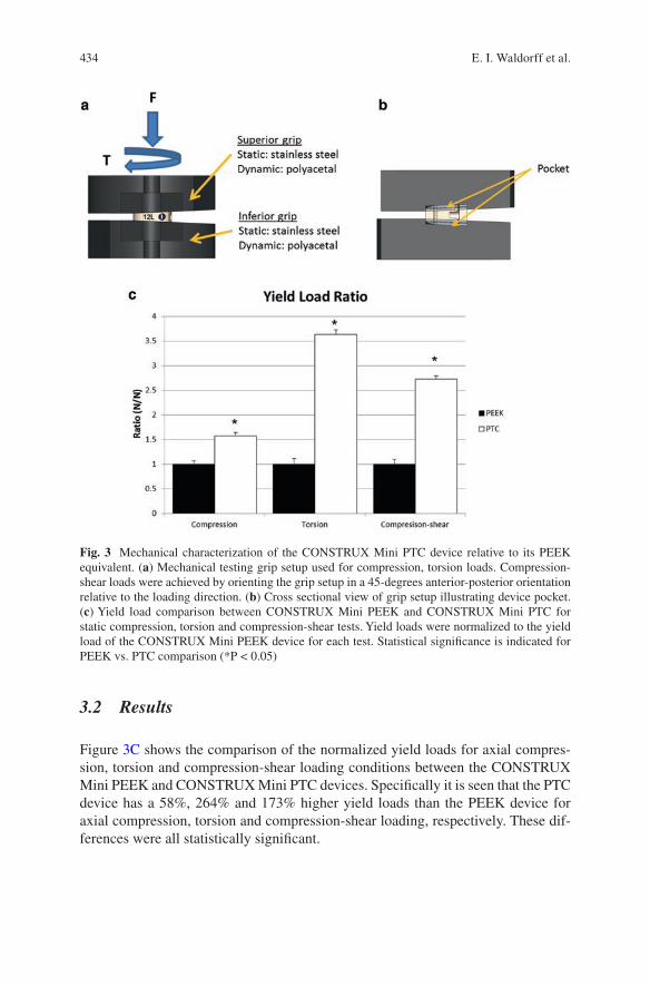
434
3.2 Results
Figure 3C shows the comparison of the normalized yield loads for axial compres-sion, torsion and compression-shear loading conditions between the CONSTRUX Mini PEEK and CONSTRUX Mini PTC devices. Specifically it is seen that the PTC device has a 58%, 264% and 173% higher yield loads than the PEEK device for axial compression, torsion and compression-shear loading, respectively. These dif-ferences were all statistically significant.
Fig. 3 Mechanical characterization of the CONSTRUX Mini PTC device relative to its PEEK equivalent. (a) Mechanical testing grip setup used for compression, torsion loads. Compression-shear loads were achieved by orienting the grip setup in a 45-degrees anterior-posterior orientation relative to the loading direction. (b) Cross sectional view of grip setup illustrating device pocket. (c) Yield load comparison between CONSTRUX Mini PEEK and CONSTRUX Mini PTC for static compression, torsion and compression-shear tests. Yield loads were normalized to the yield load of the CONSTRUX Mini PEEK device for each test. Statistical significance is indicated for PEEK vs. PTC comparison (*P < 0.05)
E. I. Waldorff et al.
435
4 Surface Topographic Characterization
As part of the manufacturing process (Sect. 2.1) the Ti6Al4V endplates also undergo a proprietary acid etching process which generates a micro- and nano-scale surface texture to the individual struts within the porous endplates. Manipulation of the surface at a micro- or nano-scale can alter the Ti6Al4V surface roughness [44] which in turn has been shown to make the local osteogenic environment more favor-able [45, 46]. To examine the Ti6Al4V surface topography, the micro-roughness of a typical PTC endplate single strut of the porous titanium plate was examined. In addition, an examination of the PEEK titanium inter-digestion layer was done to investigate the interface between the PEEK core and the Ti6Al4V endplates. Finally, the PTC endplate struts were examined for the presence of nano-scale structures. The information presented on the PTC endplate surface topography examinations has previously been presented in part as an abstract at a scientific conference [47].
4.1 Methods
For the examination, a single PTC interbody spacer was used (FORZA PTC Spacer System). The surface morphology and the micro-roughness of one single strut of the porous Ti6Al4V PTC endplate were investigated using atomic force microscopy (AFM) on a Park XE 70 AFM system using contact mode. AFM measures the sam-ple surface structure using atomic force between the tip and sample via a probe directly interacting with a sample surface. The probe tip is made from SiO2 mounted onto a cantilever. A probe motion sensor senses the spacing between the tip apex and the sample and provides a correction signal to control the piezoelectric scanner movement. Near-field forces between the tip and sample were detected by a laser beam deflection system. Surface Roughness including (1) Peak to Valley Roughness (Rpv), (2) Root Mean Square Roughness (Rq), (3) Roughness Average (Ra) and (4) Ten Points Roughness Average (Rz) were obtained using an XEI Image Processing Program for SPM data.
The PEEK titanium inter-digestion layer was examined using scanning electron microscopy (SEM) on a Hitachi S-3000N Variable Pressure Scanning Electron Microscope. Secondary electron (SE) imaging was used to characterize the surface morphology of the porous Ti6Al4V structure in a high-vacuum mode. Back scat-tered electron (BSE) imaging of the PTC implant (side view) was used to study the interface structure between the Ti6Al4V structure and PEEK in a low vacuum mode (30 Pa). An accelerating voltage of 25 kV was used for the SEM studies.
The nanostructure on the surface of one single strut of the porous Ti6Al4V PTC endplate was examined using high-resolution SEM in a Hitachi S-4800 field- emission SEM microscope from the top view direction. For SE imaging, an accel-erating voltage of 5 kV and 20 kV were used to characterize the nanostructure.
PEEK Titanium Composite (PTC) for Spinal Implants
436
4.2 Results
Figure 4 presents two typical 3D AFM images taken from two distinct locations showing the morphology of the convex and concave region on the surface of a single strut (Fig. 4a, b, respectively). Seven areas on the surface from the single strut were examined. The micro-roughness measurements over these areas showed that the measured average Peak to Valley Roughness (Rpv) is about 7.83 μm, the average Root Mean Square Roughness (Rq) is about 1.77 μm, the Roughness Average (Ra) is about 1.45 μm and the Ten Points Roughness Average (Rz) is 7.57 μm (Table 2).
SEM images of the PTC device from the top view direction obtained at a low magnification (25×) for an overview presented a very well defined structure (Fig. 5a), while the SEM images obtained at a large magnification (3000×) presents a well determined honeycomb like porous structure on the surface (Fig. 5d). SEM images from the side view along both X and Y directions shown in Fig. 5a revealed
Fig. 4 3D AFM images of Ti6Al4V strut of the PTC device taken from the (a) convex and (b) concave regions
Table 2 Surface roughness examination of a single strut of the porous Ti6Al4V PTC endplate. Seven locations were examined for Peak to Valley Roughness (Rpv), Root Mean Square Roughness (Rq), Roughness Average (Ra) and Ten Points Roughness Average (Rz)
Area Rpv (μm) Rq (μm) Ra (μm) Rz (μm)
# 1 7.793 1.194 0.954 7.288# 2 8.645 1.854 1.427 8.632# 3 7.012 1.074 0.87 5.884# 4 9.051 2.39 1.904 9.041#5 6.952 2.013 1.717 6.937# 6 8.118 2.35 2.082 8.102# 7 7.229 1.484 1.179 7.117Avg. 7.829 1.766 1.448 7.572St.Dev. 0.821 0.530 0.471 1.088
E. I. Waldorff et al.
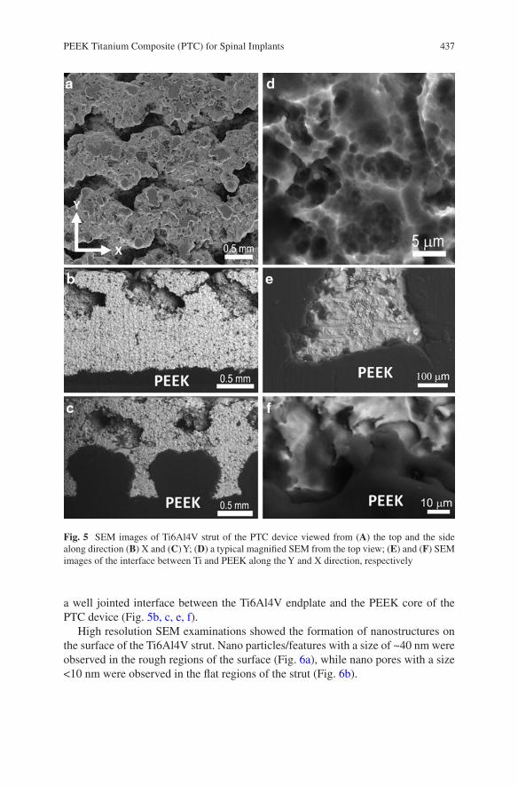
437
a well jointed interface between the Ti6Al4V endplate and the PEEK core of the PTC device (Fig. 5b, c, e, f).
High resolution SEM examinations showed the formation of nanostructures on the surface of the Ti6Al4V strut. Nano particles/features with a size of ~40 nm were observed in the rough regions of the surface (Fig. 6a), while nano pores with a size <10 nm were observed in the flat regions of the strut (Fig. 6b).
Fig. 5 SEM images of Ti6Al4V strut of the PTC device viewed from (A) the top and the side along direction (B) X and (C) Y; (D) a typical magnified SEM from the top view; (E) and (F) SEM images of the interface between Ti and PEEK along the Y and X direction, respectively
PEEK Titanium Composite (PTC) for Spinal Implants
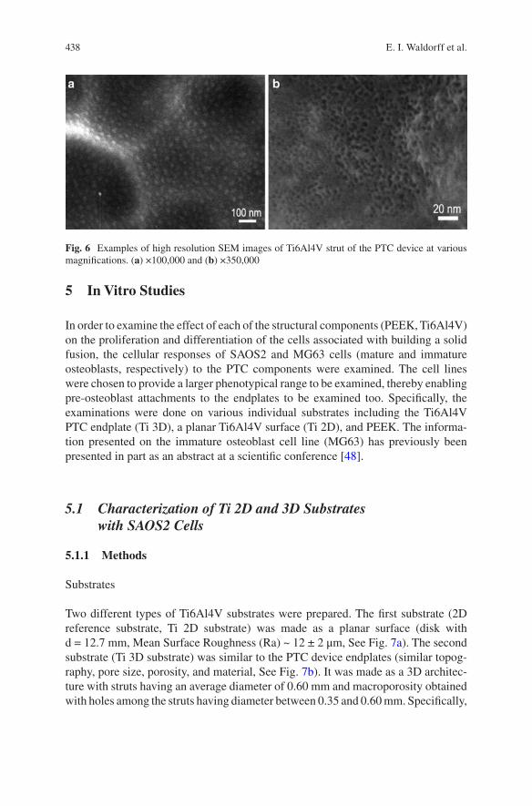
438
5 In Vitro Studies
In order to examine the effect of each of the structural components (PEEK, Ti6Al4V) on the proliferation and differentiation of the cells associated with building a solid fusion, the cellular responses of SAOS2 and MG63 cells (mature and immature osteoblasts, respectively) to the PTC components were examined. The cell lines were chosen to provide a larger phenotypical range to be examined, thereby enabling pre-osteoblast attachments to the endplates to be examined too. Specifically, the examinations were done on various individual substrates including the Ti6Al4V PTC endplate (Ti 3D), a planar Ti6Al4V surface (Ti 2D), and PEEK. The informa-tion presented on the immature osteoblast cell line (MG63) has previously been presented in part as an abstract at a scientific conference [48].
5.1 Characterization of Ti 2D and 3D Substrates with SAOS2 Cells
5.1.1 Methods
Substrates
Two different types of Ti6Al4V substrates were prepared. The first substrate (2D reference substrate, Ti 2D substrate) was made as a planar surface (disk with d = 12.7 mm, Mean Surface Roughness (Ra) ~ 12 ± 2 μm, See Fig. 7a). The second substrate (Ti 3D substrate) was similar to the PTC device endplates (similar topog-raphy, pore size, porosity, and material, See Fig. 7b). It was made as a 3D architec-ture with struts having an average diameter of 0.60 mm and macroporosity obtained with holes among the struts having diameter between 0.35 and 0.60 mm. Specifically,
Fig. 6 Examples of high resolution SEM images of Ti6Al4V strut of the PTC device at various magnifications. (a) ×100,000 and (b) ×350,000
E. I. Waldorff et al.
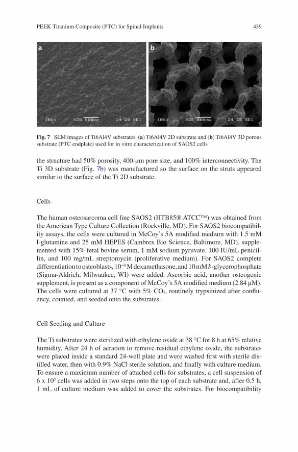
439
the structure had 50% porosity, 400-μm pore size, and 100% interconnectivity. The Ti 3D substrate (Fig. 7b) was manufactured so the surface on the struts appeared similar to the surface of the Ti 2D substrate.
Cells
The human osteosarcoma cell line SAOS2 (HTB85® ATCC™) was obtained from the American Type Culture Collection (Rockville, MD). For SAOS2 biocompatibil-ity assays, the cells were cultured in McCoy’s 5A modified medium with 1.5 mM l-glutamine and 25 mM HEPES (Cambrex Bio Science, Baltimore, MD), supple-mented with 15% fetal bovine serum, 1 mM sodium pyruvate, 100 IU/mL penicil-lin, and 100 mg/mL streptomycin (proliferative medium). For SAOS2 complete differentiation to osteoblasts, 10−8 M dexamethasone, and 10 mM b- glycerophosphate (Sigma-Aldrich, Milwaukee, WI) were added. Ascorbic acid, another osteogenic supplement, is present as a component of McCoy’s 5A modified medium (2.84 μM). The cells were cultured at 37 °C with 5% CO2, routinely trypsinized after conflu-ency, counted, and seeded onto the substrates.
Cell Seeding and Culture
The Ti substrates were sterilized with ethylene oxide at 38 °C for 8 h at 65% relative humidity. After 24 h of aeration to remove residual ethylene oxide, the substrates were placed inside a standard 24-well plate and were washed first with sterile dis-tilled water, then with 0.9% NaCl sterile solution, and finally with culture medium. To ensure a maximum number of attached cells for substrates, a cell suspension of 6 x 10⁵ cells was added in two steps onto the top of each substrate and, after 0.5 h, 1 mL of culture medium was added to cover the substrates. For biocompatibility
Fig. 7 SEM images of Ti6Al4V substrates. (a) Ti6Al4V 2D substrate and (b) Ti6Al4V 3D porous substrate (PTC endplate) used for in vitro characterization of SAOS2 cells
PEEK Titanium Composite (PTC) for Spinal Implants
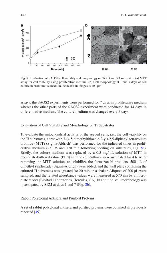
440
assays, the SAOS2 experiments were performed for 7 days in proliferative medium whereas the other parts of the SAOS2 experiment were conducted for 14 days in differentiative medium. The culture medium was changed every 3 days.
Evaluation of Cell Viability and Morphology on Ti Substrates
To evaluate the mitochondrial activity of the seeded cells, i.e., the cell viability on the Ti substrates, a test with 3-(4,5-dimethylthiazole-2-yl)-2,5-diphenyl tetrazolium bromide (MTT) (Sigma-Aldrich) was performed for the indicated times in prolif-erative medium (25, 95 and 170 min following seeding on substrates, Fig. 8a). Briefly, the culture medium was replaced by a 0.5 mg/mL solution of MTT in phosphate- buffered saline (PBS) and the cell cultures were incubated for 4 h. After removing the MTT solution, to solubilize the formazan bi-products, 500 μL of dimethyl sulphoxide (Sigma-Aldrich) were added, and the well plate containing the cultured Ti substrates was agitated for 20 min on a shaker. Aliquots of 200 μL were sampled, and the related absorbance values were measured at 570 nm by a micro-plate reader (BioRad Laboratories, Hercules, CA). In addition, cell morphology was investigated by SEM at days 1 and 7 (Fig. 8b).
Rabbit Polyclonal Antisera and Purified Proteins
A set of rabbit polyclonal antisera and purified proteins were obtained as previously reported [49].
Fig. 8 Evaluation of SAOS2 cell viability and morphology on Ti 2D and 3D substrates. (a) MTT assay for cell viability using proliferative medium. (b) Cell morphology at 1 and 7 days of cell culture in proliferative medium. Scale bar in images is 100 μm
E. I. Waldorff et al.
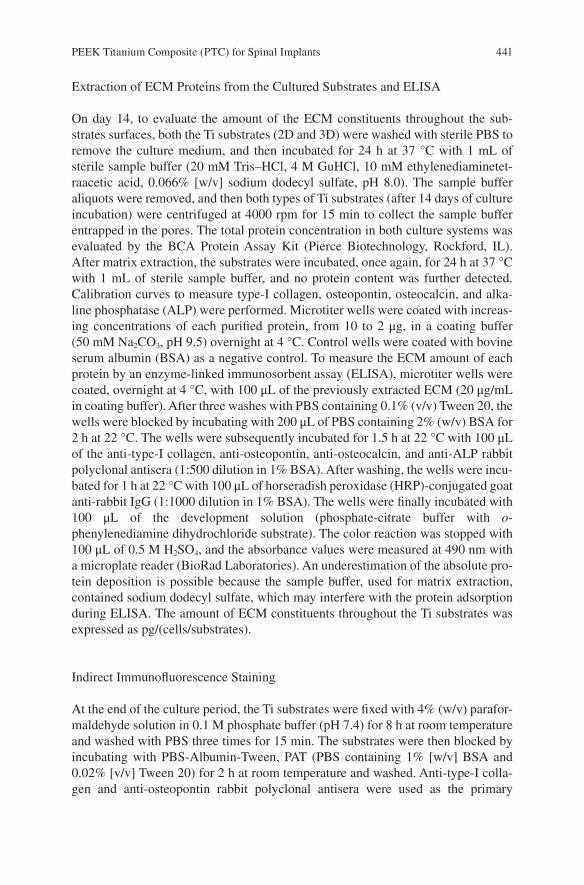
441
Extraction of ECM Proteins from the Cultured Substrates and ELISA
On day 14, to evaluate the amount of the ECM constituents throughout the sub-strates surfaces, both the Ti substrates (2D and 3D) were washed with sterile PBS to remove the culture medium, and then incubated for 24 h at 37 °C with 1 mL of sterile sample buffer (20 mM Tris–HCl, 4 M GuHCl, 10 mM ethylenediaminetet-raacetic acid, 0.066% [w/v] sodium dodecyl sulfate, pH 8.0). The sample buffer aliquots were removed, and then both types of Ti substrates (after 14 days of culture incubation) were centrifuged at 4000 rpm for 15 min to collect the sample buffer entrapped in the pores. The total protein concentration in both culture systems was evaluated by the BCA Protein Assay Kit (Pierce Biotechnology, Rockford, IL). After matrix extraction, the substrates were incubated, once again, for 24 h at 37 °C with 1 mL of sterile sample buffer, and no protein content was further detected. Calibration curves to measure type-I collagen, osteopontin, osteocalcin, and alka-line phosphatase (ALP) were performed. Microtiter wells were coated with increas-ing concentrations of each purified protein, from 10 to 2 μg, in a coating buffer (50 mM Na2CO3, pH 9.5) overnight at 4 °C. Control wells were coated with bovine serum albumin (BSA) as a negative control. To measure the ECM amount of each protein by an enzyme-linked immunosorbent assay (ELISA), microtiter wells were coated, overnight at 4 °C, with 100 μL of the previously extracted ECM (20 μg/mL in coating buffer). After three washes with PBS containing 0.1% (v/v) Tween 20, the wells were blocked by incubating with 200 μL of PBS containing 2% (w/v) BSA for 2 h at 22 °C. The wells were subsequently incubated for 1.5 h at 22 °C with 100 μL of the anti-type-I collagen, anti-osteopontin, anti-osteocalcin, and anti-ALP rabbit polyclonal antisera (1:500 dilution in 1% BSA). After washing, the wells were incu-bated for 1 h at 22 °C with 100 μL of horseradish peroxidase (HRP)-conjugated goat anti-rabbit IgG (1:1000 dilution in 1% BSA). The wells were finally incubated with 100 μL of the development solution (phosphate-citrate buffer with o- phenylenediamine dihydrochloride substrate). The color reaction was stopped with 100 μL of 0.5 M H2SO4, and the absorbance values were measured at 490 nm with a microplate reader (BioRad Laboratories). An underestimation of the absolute pro-tein deposition is possible because the sample buffer, used for matrix extraction, contained sodium dodecyl sulfate, which may interfere with the protein adsorption during ELISA. The amount of ECM constituents throughout the Ti substrates was expressed as pg/(cells/substrates).
Indirect Immunofluorescence Staining
At the end of the culture period, the Ti substrates were fixed with 4% (w/v) parafor-maldehyde solution in 0.1 M phosphate buffer (pH 7.4) for 8 h at room temperature and washed with PBS three times for 15 min. The substrates were then blocked by incubating with PBS-Albumin-Tween, PAT (PBS containing 1% [w/v] BSA and 0.02% [v/v] Tween 20) for 2 h at room temperature and washed. Anti-type-I colla-gen and anti-osteopontin rabbit polyclonal antisera were used as the primary
PEEK Titanium Composite (PTC) for Spinal Implants
442
antibody with a dilution equal to 1:500 in PAT. The same dilution was performed with anti-FN rabbit polyclonal IgG. Incubation with the primary antibodies was made overnight at 48 °C, whereas the negative controls were incubated overnight at 4 °C with PAT. The substrates and the negative controls were washed and incubated with Alexa Fluor 488 goat anti-rabbit IgG (HþL) (Molecular Probes) at a dilution of 1:750 in PAT for 1 h at room temperature. At the end of the incubation, the sub-strates were washed in PBS, counterstained with a solution of propidium iodide (2 μg/mL) to target the cellular nuclei, and then washed. The images were taken by blue excitation (bandpass, 450–480 nm; dichromatic mirror, DM500; barrier filter, BA515) with a fluorescence microscope (BX51; Olympus, Tokyo, Japan) equipped with a digital image capture system (Olympus) at 20× magnification. The fluores-cence background of the negative controls was negligible.
ALP Activity
ALP activity was determined using a colorimetric end point assay as previously described [50]. Briefly, an aliquot (1 mL) of 0.3 M p-nitrophenyl phosphate (PNPP, dissolved in glycine buffer, pH 10.5) was added to each substrate at 37 °C. After incubation, the reaction was stopped by the addition of 100 mL 5 M NaOH. Standards of PNPP in concentrations ranging from 0 to 50 mM were freshly prepared from dilutions of a 500 mM stock solution and incubated for 10 min with 7 U of ALP (Sigma-Aldrich) previously dissolved in 500 mL of ddH2O. The absorbance reading was performed at 405 nm with a microplate reader (BioRad Laboratories) using 100 mL of standard or sample placed into individual wells of a 96-well plate. Samples were run in triplicate and compared against a calibration curve of p- nitrophenol standards. The enzyme activity was expressed as nanomoles of p- nitrophenol produced per minute per milligram of enzyme.
Statistical Analysis
A total of 30 Ti porous substrates were used for each repeated experiment (15 Ti 2D substrates and 15 Ti 3D substrates). Each experiment was repeated three times. Results are expressed as the mean ± standard deviation. Statistical differences were determined by unpaired two-tailed t tests with a significance level of P < 0.05.
5.1.2 Results
SAOS2 Cell Viability and Morphology
To evaluate the cell viability on Ti 2D and Ti 3D substrates during the culture period, a MTT test was performed (Fig. 8a). Interestingly, a higher cell attachment and proliferation was observed for the Ti 3D porous substrate relative to the Ti 2D
E. I. Waldorff et al.
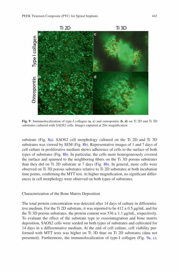
443
substrate (Fig. 8a). SAOS2 cell morphology cultured on the Ti 2D and Ti 3D substrates was viewed by SEM (Fig. 8b). Representative images of 1 and 7 days of cell culture in proliferative medium shows adherence of cells to the surface of both types of substrates (Fig. 8b). In particular, the cells more homogeneously covered the surface and spanned to the neighboring fibers on the Ti 3D porous substrates than they did on Ti 2D substrate at 7 days (Fig. 8b). In general, more cells were observed on Ti 3D porous substrates relative to Ti 2D substrates at both incubation time points, confirming the MTT test. At higher magnification, no significant differ-ences in cell morphology were observed on both types of substrates.
Characterization of the Bone Matrix Deposition
The total protein concentration was detected after 14 days of culture in differentia-tive medium. For the Ti 2D substrate, it was reported to be 412 ± 0.5 μg/mL and for the Ti 3D porous substrates, the protein content was 536 ± 1.1 μg/mL, respectively. To evaluate the effect of the substrate type to osseointegration and bone matrix deposition, SAOS2 cells were seeded on both types of substrates and cultivated for 14 days in a differentiative medium. At the end of cell culture, cell viability per-formed with MTT tests was higher on Ti 3D than on Ti 2D substrates (data not presented). Furthermore, the immunolocalization of type-I collagen (Fig. 9a, c),
Fig. 9 Immunolocalization of type-I collagen (a, c) and osteopontin (b, d) on Ti 2D and Ti 3D substrates cultured with SAOS2 cells. Images captured at 20× magnification
PEEK Titanium Composite (PTC) for Spinal Implants
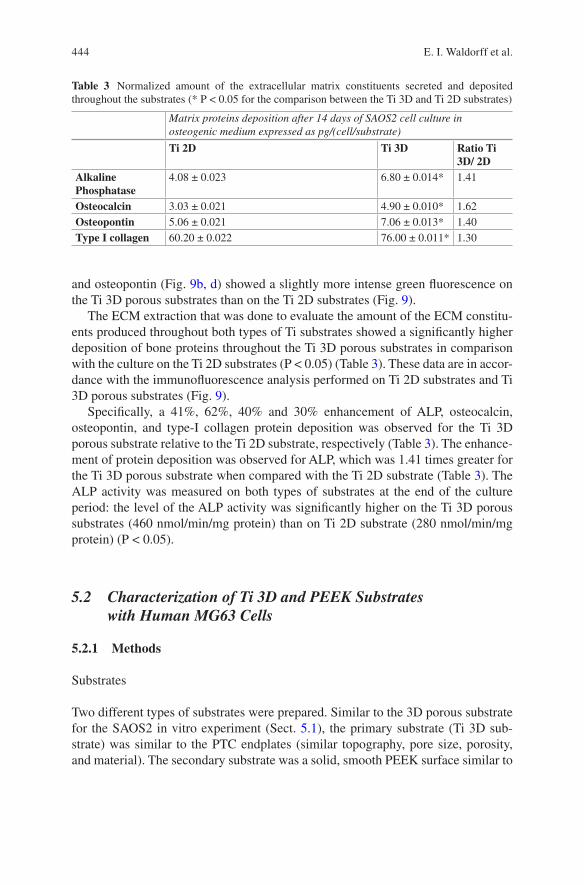
444
and osteopontin (Fig. 9b, d) showed a slightly more intense green fluorescence on the Ti 3D porous substrates than on the Ti 2D substrates (Fig. 9).
The ECM extraction that was done to evaluate the amount of the ECM constitu-ents produced throughout both types of Ti substrates showed a significantly higher deposition of bone proteins throughout the Ti 3D porous substrates in comparison with the culture on the Ti 2D substrates (P < 0.05) (Table 3). These data are in accor-dance with the immunofluorescence analysis performed on Ti 2D substrates and Ti 3D porous substrates (Fig. 9).
Specifically, a 41%, 62%, 40% and 30% enhancement of ALP, osteocalcin, osteopontin, and type-I collagen protein deposition was observed for the Ti 3D porous substrate relative to the Ti 2D substrate, respectively (Table 3). The enhance-ment of protein deposition was observed for ALP, which was 1.41 times greater for the Ti 3D porous substrate when compared with the Ti 2D substrate (Table 3). The ALP activity was measured on both types of substrates at the end of the culture period: the level of the ALP activity was significantly higher on the Ti 3D porous substrates (460 nmol/min/mg protein) than on Ti 2D substrate (280 nmol/min/mg protein) (P < 0.05).
5.2 Characterization of Ti 3D and PEEK Substrates with Human MG63 Cells
5.2.1 Methods
Substrates
Two different types of substrates were prepared. Similar to the 3D porous substrate for the SAOS2 in vitro experiment (Sect. 5.1), the primary substrate (Ti 3D sub-strate) was similar to the PTC endplates (similar topography, pore size, porosity, and material). The secondary substrate was a solid, smooth PEEK surface similar to
Table 3 Normalized amount of the extracellular matrix constituents secreted and deposited throughout the substrates (* P < 0.05 for the comparison between the Ti 3D and Ti 2D substrates)
Matrix proteins deposition after 14 days of SAOS2 cell culture in osteogenic medium expressed as pg/(cell/substrate)
Ti 2D Ti 3D Ratio Ti 3D/ 2D
Alkaline Phosphatase
4.08 ± 0.023 6.80 ± 0.014* 1.41
Osteocalcin 3.03 ± 0.021 4.90 ± 0.010* 1.62Osteopontin 5.06 ± 0.021 7.06 ± 0.013* 1.40Type I collagen 60.20 ± 0.022 76.00 ± 0.011* 1.30
E. I. Waldorff et al.
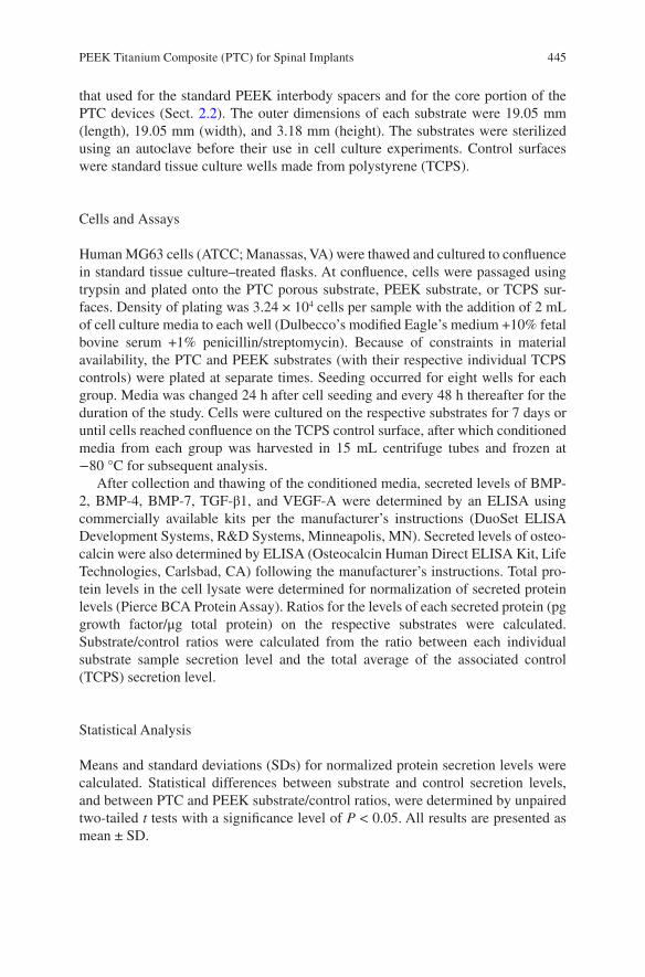
445
that used for the standard PEEK interbody spacers and for the core portion of the PTC devices (Sect. 2.2). The outer dimensions of each substrate were 19.05 mm (length), 19.05 mm (width), and 3.18 mm (height). The substrates were sterilized using an autoclave before their use in cell culture experiments. Control surfaces were standard tissue culture wells made from polystyrene (TCPS).
Cells and Assays
Human MG63 cells (ATCC; Manassas, VA) were thawed and cultured to confluence in standard tissue culture–treated flasks. At confluence, cells were passaged using trypsin and plated onto the PTC porous substrate, PEEK substrate, or TCPS sur-faces. Density of plating was 3.24 × 10⁴ cells per sample with the addition of 2 mL of cell culture media to each well (Dulbecco’s modified Eagle’s medium +10% fetal bovine serum +1% penicillin/streptomycin). Because of constraints in material availability, the PTC and PEEK substrates (with their respective individual TCPS controls) were plated at separate times. Seeding occurred for eight wells for each group. Media was changed 24 h after cell seeding and every 48 h thereafter for the duration of the study. Cells were cultured on the respective substrates for 7 days or until cells reached confluence on the TCPS control surface, after which conditioned media from each group was harvested in 15 mL centrifuge tubes and frozen at −80 °C for subsequent analysis.
After collection and thawing of the conditioned media, secreted levels of BMP- 2, BMP-4, BMP-7, TGF-β1, and VEGF-A were determined by an ELISA using commercially available kits per the manufacturer’s instructions (DuoSet ELISA Development Systems, R&D Systems, Minneapolis, MN). Secreted levels of osteo-calcin were also determined by ELISA (Osteocalcin Human Direct ELISA Kit, Life Technologies, Carlsbad, CA) following the manufacturer’s instructions. Total pro-tein levels in the cell lysate were determined for normalization of secreted protein levels (Pierce BCA Protein Assay). Ratios for the levels of each secreted protein (pg growth factor/μg total protein) on the respective substrates were calculated. Substrate/control ratios were calculated from the ratio between each individual substrate sample secretion level and the total average of the associated control (TCPS) secretion level.
Statistical Analysis
Means and standard deviations (SDs) for normalized protein secretion levels were calculated. Statistical differences between substrate and control secretion levels, and between PTC and PEEK substrate/control ratios, were determined by unpaired two-tailed t tests with a significance level of P < 0.05. All results are presented as mean ± SD.
PEEK Titanium Composite (PTC) for Spinal Implants
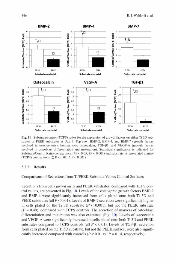
446
5.2.2 Results
Comparisons of Secretions from Ti/PEEK Substrate Versus Control Surfaces
Secretions from cells grown on Ti and PEEK substrates, compared with TCPS con-trol values, are presented in Fig. 10. Levels of the osteogenic growth factors BMP-2 and BMP-4 were significantly increased from cells plated onto both Ti 3D and PEEK substrates (all P ≤ 0.01). Levels of BMP-7 secretion were significantly higher in cells plated on the Ti 3D substrate (P < 0.001), but not the PEEK substrate (P = 0.49), compared with TCPS controls. The secretion of markers of osteoblast differentiation and maturation was also examined (Fig. 10). Levels of osteocalcin and VEGF-A were significantly increased in cells plated onto both Ti 3D and PEEK substrates compared to TCPS controls (all P < 0.01). Levels of TGF-β1 secretion from cells plated on the Ti 3D substrate, but not the PEEK surface, were also signifi-cantly increased compared with controls (P < 0.01 vs. P = 0.14, respectively).
Fig. 10 Substrate/control (TCPS) ratios for the expression of growth factors on either Ti 3D sub-strates or PEEK substrates at Day 7. Top row: BMP-2, BMP-4, and BMP-7 (growth factors involved in osteogenesis); bottom row: osteocalcin, TGF-β1, and VEGF-A (growth factors involved in osteoblast differentiation and maturation). Statistical significance is indicated for Substrate/Control Ratio comparisons (*P < 0.05, †P < 0.001) and substrate vs. associated control (TCPS) comparisons (◻ P < 0.01, ∆ P < 0.001)
E. I. Waldorff et al.
447
Comparisons of Secretions from Ti 3D Versus PEEK Surfaces
The substrate/control ratios for each of the osteogenic growth factors measured are presented in Fig. 10. Increases in ratios for BMP-2, BMP-4, and BMP-7 (2.3-, 2.1- and 2.6-fold, respectively) were significantly greater (P < 0.001, P = 0.04, P < 0.001, respectively) for the Ti 3D substrate than the PEEK substrate, suggesting an enhanced osteogenic response for the Ti 3D porous substrate. Figure 10 presents substrate/control ratio data for each of the growth factors associated with osteoblast differentiation and maturation. The increase in the respective substrate/control ratios was significantly greater for the Ti 3D substrate than the PEEK substrate for osteocalcin (2.3-fold, P < 0.001), TGF-β1 (8.2-fold, P = 0.007), and VEGF-A (2.5- fold, P < 0.001).
6 In Vivo Animal Studies
Based on the in vitro evidence that the PTC endplate leads to an increased osteo-genic environment (Sect. 5) an in vivo examination of the components of the PEEK and PTC devices was performed in a rabbit model. This was done to determine bone ingrowth capability into the pores of the PTC endplate and to examine biocompat-ibility of the PTC components. Lastly, an in vivo large animal (ovine) study was performed to examine the fusion capability of a full clinical PTC device. This large animal study would furthermore give insight into how the PTC device differentiated itself from a standard PEEK interbody device with respect to fusion quality and fusion mass generation. The information presented on the two animal models have previously been presented in part as abstracts at scientific conferences [51, 52].
6.1 Characterization of Ti 3D and PEEK Substrates in a Rabbit Animal Model
6.1.1 Methods
Substrates for Implantation
The implants used for this in vivo experiment were 3.3-mm cylindrical rods (3.1- mm diameter) made of either Ti6Al4V (porous substrate, with 50% poros-ity, 400- μm pore size, and 100% interconnectivity) or PEEK (solid, smooth surface) which were similar in properties to the endplates and PEEK core of the PTC interbody devices (Sect. 2.2), respectively. Similar to the 3D porous sub-strate used for both in vitro experiments (Sect. 5), the Ti6Al4V implant is refer-enced as the Ti 3D substrate.
PEEK Titanium Composite (PTC) for Spinal Implants
448
Animals
A total of 13 New Zealand white rabbits ≥9 months of age were evaluated in this study. The local Institutional Animal Care and Use Committee (IACUC) of T3Labs (380 Northyards Blvd NW, Atlanta, GA 30313) reviewed and approved this study (study code: OF01B). Per the approved protocol, animals were handled and main-tained in accordance with the requirement of the Animal Welfare Act and its amend-ments [53]; procedures conformed to standards of the Guide for the Care and Use of Laboratory Animals [54]. Animals were observed at least once daily.
Surgery
Animals were assigned to 1 of 6 cohorts: 1) baseline, Ti 3D substrate (n = 2); 2) 4-week, Ti 3D substrate (n = 2); 3) 8-week, Ti 3D substrate (n = 2); 4) baseline, PEEK substrate (n = 3); 5) 4-week, PEEK substrate (n = 2); and 6) 8-week, PEEK substrate (n = 2). Each animal was scheduled to receive 4 implants of similar mate-rial, resulting in 2 implants per leg. Due to surgical complications, 2 of the baseline animals (PEEK group) only received implants unilaterally. Thus, the total number of inserted substrates was 8 for each time point and implant material combination (i.e., a total of 24 Ti 3D and 24 PEEK substrates). On the day of implantation, sedated animals were incised on the medial side of the tibia and fasciae were dis-sected. The right and left tibia of each rabbit was used. Drill bits (diameter, 2.5–3.1 mm) were used to predrill holes with saline irrigation. A proximal hole was placed 3 mm distal to the epiphysial growth plate; a distal hole was placed approxi-mately 10 mm distal to the proximal hole, but within the metaphyseal region. Holes were sized to ensure that substrates were flush with the periosteal surface. Substrates were inserted using the press-fit technique, oriented perpendicularly to the long axis of the bone. Incisions were sutured in 2 layers and bandaged; correct substrate posi-tioning was confirmed radiographically.
Assessment
Animals were euthanized at protocol-directed time points. Bilateral tibias were har-vested and immersed in 10% neutral buffered formalin and sent for histological, morphometric, and microscopic analysis (Alizée Pathology LLC, Thurmont, MD, USA). Implant sites were embedded in methylmethacrylate and sectioned longitu-dinally, achieving the largest possible cross section of the implants in order to avoid a false high ingrowth percentage. A single section from each specimen, which included the center axial cut of two implants, was chosen for bone ingrowth evalu-ation. Unstained slides were etched and stained with hematoxylin and eosin. Tibial Ti 3D porous substrates (proximal and distal) were evaluated for bone ingrowth into the top cortical interface of the implant area. This region of interest was defined as
E. I. Waldorff et al.
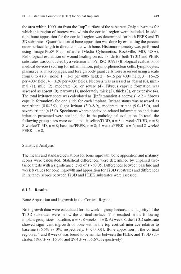
449
the area within 1000 μm from the “top” surface of the substrate. Only substrates for which this region of interest was within the cortical region were included. In addi-tion, bone apposition for the cortical region was determined for both PEEK and Ti 3D substrates. Quantification of bone apposition was done by evaluating the percent outer surface length in direct contact with bone. Histomorphometry was performed using Image-Pro® Plus software (Media Cybernetics, Rockville, MD, USA). Pathological evaluation of wound healing on each slide for both Ti 3D and PEEK substrates was conducted by a veterinarian. Per ISO 10993 (Biological evaluation of medical devices) scoring for inflammation, polymorphonuclear cells, lymphocytes, plasma cells, macrophages, and foreign body giant cells were assessed using a scale from 0 to 4 (0 = none; 1 = 1–5 per 400× field; 2 = 6–15 per 400× field; 3 = 16–25 per 400× field; 4 = ≥26 per 400× field). Necrosis was assessed as absent (0), mini-mal (1), mild (2), moderate (3), or severe (4). Fibrous capsule formation was assessed as absent (0), narrow (1), moderately thick (2), thick (3), or extensive (4). The total irritancy score was calculated as ([inflammation + necrosis] × 2 + fibrous capsule formation) for one slide for each implant. Irritant status was assessed as nonirritant (0.0–2.9), slight irritant (3.0–8.9), moderate irritant (9.0–15.0), and severe irritant (>15.0). Specimens where nondevice-related inflammation and tissue irritation presented were not included in the pathological evaluation. In total, the following group sizes were evaluated: baseline/Ti 3D, n = 8; 4-weeks/Ti 3D, n = 8; 8-weeks/Ti 3D, n = 8; baseline/PEEK, n = 8; 4-weeks/PEEK, n = 6; and 8-weeks/PEEK, n = 8.
Statistical Analysis
The means and standard deviations for bone ingrowth, bone apposition and irritancy scores were calculated. Statistical differences were determined by unpaired two- tailed t tests with a significance level of P < 0.05. Differences between baseline and week 8 values for bone ingrowth and apposition for Ti 3D substrates and differences in irritancy scores between Ti 3D and PEEK substrates were assessed.
6.1.2 Results
Bone Apposition and Ingrowth in the Cortical Region
No ingrowth data were calculated for the week-4 group because the majority of the Ti 3D substrates were below the cortical surface. This resulted in the following implant group sizes: baseline, n = 8; 8-weeks, n = 8. At week 8, the Ti 3D substrate showed significant ingrowth of bone within the top cortical interface relative to baseline (36.5% vs 0%, respectively, P < 0.001). Bone apposition in the cortical region at 4 and 8 weeks was found to be similar between the PEEK and Ti 3D sub-strates (19.6% vs. 16.3% and 29.4% vs. 35.6%, respectively).
PEEK Titanium Composite (PTC) for Spinal Implants
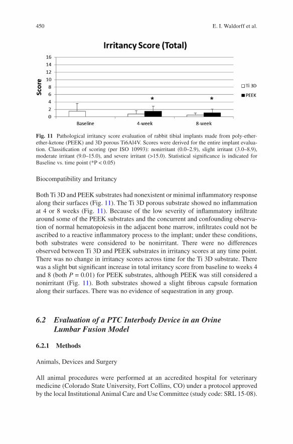
450
Biocompatibility and Irritancy
Both Ti 3D and PEEK substrates had nonexistent or minimal inflammatory response along their surfaces (Fig. 11). The Ti 3D porous substrate showed no inflammation at 4 or 8 weeks (Fig. 11). Because of the low severity of inflammatory infiltrate around some of the PEEK substrates and the concurrent and confounding observa-tion of normal hematopoiesis in the adjacent bone marrow, infiltrates could not be ascribed to a reactive inflammatory process to the implant; under these conditions, both substrates were considered to be nonirritant. There were no differences observed between Ti 3D and PEEK substrates in irritancy scores at any time point. There was no change in irritancy scores across time for the Ti 3D substrate. There was a slight but significant increase in total irritancy score from baseline to weeks 4 and 8 (both P = 0.01) for PEEK substrates, although PEEK was still considered a nonirritant (Fig. 11). Both substrates showed a slight fibrous capsule formation along their surfaces. There was no evidence of sequestration in any group.
6.2 Evaluation of a PTC Interbody Device in an Ovine Lumbar Fusion Model
6.2.1 Methods
Animals, Devices and Surgery
All animal procedures were performed at an accredited hospital for veterinary medicine (Colorado State University, Fort Collins, CO) under a protocol approved by the local Institutional Animal Care and Use Committee (study code: SRL 15-08).
Fig. 11 Pathological irritancy score evaluation of rabbit tibial implants made from poly-ether- ether-ketone (PEEK) and 3D porous Ti6Al4V. Scores were derived for the entire implant evalua-tion. Classification of scoring (per ISO 10993): nonirritant (0.0–2.9), slight irritant (3.0–8.9), moderate irritant (9.0–15.0), and severe irritant (>15.0). Statistical significance is indicated for Baseline vs. time point (*P < 0.05)
E. I. Waldorff et al.
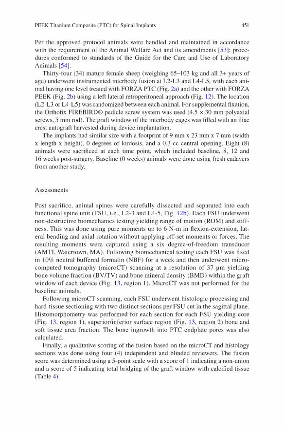
451
Per the approved protocol animals were handled and maintained in accordance with the requirement of the Animal Welfare Act and its amendments [53]; proce-dures conformed to standards of the Guide for the Care and Use of Laboratory Animals [54].
Thirty-four (34) mature female sheep (weighing 65–103 kg and all 3+ years of age) underwent instrumented interbody fusion at L2-L3 and L4-L5, with each ani-mal having one level treated with FORZA PTC (Fig. 2a) and the other with FORZA PEEK (Fig. 2b) using a left lateral retroperitoneal approach (Fig. 12). The location (L2-L3 or L4-L5) was randomized between each animal. For supplemental fixation, the Orthofix FIREBIRD® pedicle screw system was used (4.5 × 30 mm polyaxial screws, 5 mm rod). The graft window of the interbody cages was filled with an iliac crest autograft harvested during device implantation.
The implants had similar size with a footprint of 9 mm x 23 mm x 7 mm (width x length x height), 0 degrees of lordosis, and a 0.3 cc central opening. Eight (8) animals were sacrificed at each time point, which included baseline, 8, 12 and 16 weeks post-surgery. Baseline (0 weeks) animals were done using fresh cadavers from another study.
Assessments
Post sacrifice, animal spines were carefully dissected and separated into each functional spine unit (FSU, i.e., L2-3 and L4-5, Fig. 12b). Each FSU underwent non- destructive biomechanics testing yielding range of motion (ROM) and stiff-ness. This was done using pure moments up to 6 N-m in flexion-extension, lat-eral bending and axial rotation without applying off-set moments or forces. The resulting moments were captured using a six degree-of-freedom transducer (AMTI, Watertown, MA). Following biomechanical testing each FSU was fixed in 10% neutral buffered formalin (NBF) for a week and then underwent micro-computed tomography (microCT) scanning at a resolution of 37 μm yielding bone volume fraction (BV/TV) and bone mineral density (BMD) within the graft window of each device (Fig. 13, region 1). MicroCT was not performed for the baseline animals.
Following microCT scanning, each FSU underwent histologic processing and hard-tissue sectioning with two distinct sections per FSU cut in the sagittal plane. Histomorphometry was performed for each section for each FSU yielding core (Fig. 13, region 1), superior/inferior surface region (Fig. 13, region 2) bone and soft tissue area fraction. The bone ingrowth into PTC endplate pores was also calculated.
Finally, a qualitative scoring of the fusion based on the microCT and histology sections was done using four (4) independent and blinded reviewers. The fusion score was determined using a 5-point scale with a score of 1 indicating a non-union and a score of 5 indicating total bridging of the graft window with calcified tissue (Table 4).
PEEK Titanium Composite (PTC) for Spinal Implants
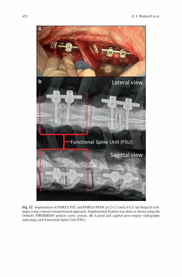
452
Fig. 12 Implantation of FORZA PTC and FORZA PEEK at L2-L3 and L4-L5. (a) Surgical tech-nique using a lateral retroperitoneal approach. Supplemental fixation was done as shown using the Orthofix FIREBIRD® pedicle screw system. (b) Lateral and sagittal post-surgery radiographs indicating each Functional Spine Unit (FSU)
E. I. Waldorff et al.
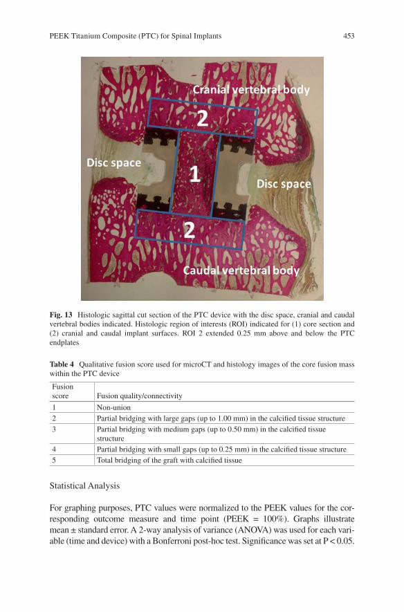
453
Statistical Analysis
For graphing purposes, PTC values were normalized to the PEEK values for the cor-responding outcome measure and time point (PEEK = 100%). Graphs illustrate mean ± standard error. A 2-way analysis of variance (ANOVA) was used for each vari-able (time and device) with a Bonferroni post-hoc test. Significance was set at P < 0.05.
Fig. 13 Histologic sagittal cut section of the PTC device with the disc space, cranial and caudal vertebral bodies indicated. Histologic region of interests (ROI) indicated for (1) core section and (2) cranial and caudal implant surfaces. ROI 2 extended 0.25 mm above and below the PTC endplates
Table 4 Qualitative fusion score used for microCT and histology images of the core fusion mass within the PTC device
Fusion score Fusion quality/connectivity
1 Non-union2 Partial bridging with large gaps (up to 1.00 mm) in the calcified tissue structure3 Partial bridging with medium gaps (up to 0.50 mm) in the calcified tissue
structure4 Partial bridging with small gaps (up to 0.25 mm) in the calcified tissue structure5 Total bridging of the graft with calcified tissue
PEEK Titanium Composite (PTC) for Spinal Implants
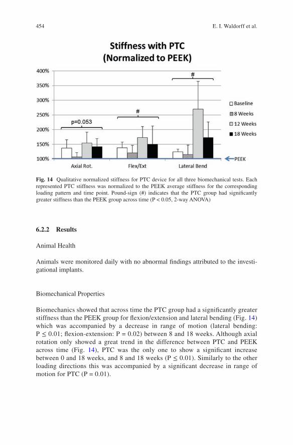
454
6.2.2 Results
Animal Health
Animals were monitored daily with no abnormal findings attributed to the investi-gational implants.
Biomechanical Properties
Biomechanics showed that across time the PTC group had a significantly greater stiffness than the PEEK group for flexion/extension and lateral bending (Fig. 14) which was accompanied by a decrease in range of motion (lateral bending: P ≤ 0.01; flexion-extension: P = 0.02) between 8 and 18 weeks. Although axial rotation only showed a great trend in the difference between PTC and PEEK across time (Fig. 14), PTC was the only one to show a significant increase between 0 and 18 weeks, and 8 and 18 weeks (P ≤ 0.01). Similarly to the other loading directions this was accompanied by a significant decrease in range of motion for PTC (P = 0.01).
Fig. 14 Qualitative normalized stiffness for PTC device for all three biomechanical tests. Each represented PTC stiffness was normalized to the PEEK average stiffness for the corresponding loading pattern and time point. Pound-sign (#) indicates that the PTC group had significantly greater stiffness than the PEEK group across time (P < 0.05, 2-way ANOVA)
E. I. Waldorff et al.
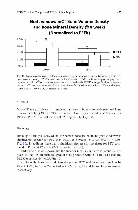
455
MicroCT
MicroCT analysis showed a significant increase in bone volume density and bone mineral density (43% and 24%, respectively) in the graft window at 8 weeks for PTC vs. PEEK (P = 0.04 and P = 0.02, respectively; Fig. 15).
Histology
Histological analyses showed that the percent bone present in the graft window was significantly greater for PTC than PEEK at 8 weeks (51% vs. 36%, P = 0.05; Fig. 16). In addition, there was a significant decrease in soft tissue for PTC com-pared to PEEK at 12 weeks (29% vs. 42%, P < 0.05).
Furthermore, it was shown that the superior (cranial) and inferior (caudal) end-plates of the PTC implant had greater bone presence with less soft tissue than the PEEK endplates (P < 0.05, Fig. 17).
Additionally bone ingrowth into the porous PTC endplates was found to be 47.4 ± 3.2%, 46.3 ± 4.7%, and 41.4 ± 2.6% at 8, 12 and 16 weeks post-surgery, respectively
Fig. 15 Normalized microCT outcome measures for graft window of implant devices: Normalized bone volume density (BV/TV) and bone mineral density (BMD) at 8 weeks post-surgery. Each represented microCT outcome measure was normalized to the PEEK average for the correspond-ing microCT outcome measure and time point. Asterisks (*) indicate significant difference between PEEK and PTC (P < 0.05, Bonferroni post-hoc)
PEEK Titanium Composite (PTC) for Spinal Implants
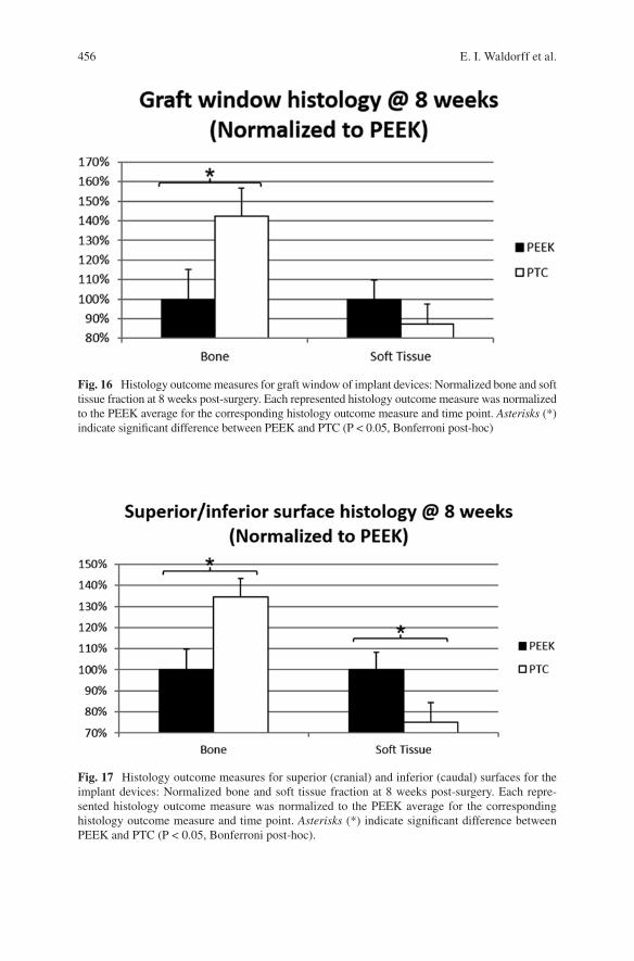
456
Fig. 16 Histology outcome measures for graft window of implant devices: Normalized bone and soft tissue fraction at 8 weeks post-surgery. Each represented histology outcome measure was normalized to the PEEK average for the corresponding histology outcome measure and time point. Asterisks (*) indicate significant difference between PEEK and PTC (P < 0.05, Bonferroni post-hoc)
Fig. 17 Histology outcome measures for superior (cranial) and inferior (caudal) surfaces for the implant devices: Normalized bone and soft tissue fraction at 8 weeks post-surgery. Each repre-sented histology outcome measure was normalized to the PEEK average for the corresponding histology outcome measure and time point. Asterisks (*) indicate significant difference between PEEK and PTC (P < 0.05, Bonferroni post-hoc).
E. I. Waldorff et al.
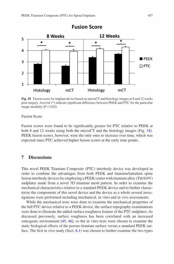
457
Fusion Score
Fusion scores were found to be significantly greater for PTC relative to PEEK at both 8 and 12 weeks using both the microCT and the histology images (Fig. 18). PEEK fusion scores, however, were the only ones to increase over time, which was expected since PTC achieved higher fusion scores at the early time points.
7 Discussions
This novel PEEK Titanium Composite (PTC) interbody device was developed in order to combine the advantages from both PEEK and titanium/tantalum spine fusion interbody devices by employing a PEEK center with titanium alloy (Ti6Al4V) endplates made from a novel 3D titanium mesh pattern. In order to examine the mechanical characteristics relative to a standard PEEK device and to further charac-terize the components of this novel device and the device as a whole several inves-tigations were performed including mechanical, in vitro and in vivo assessments.
While the mechanical tests were done to examine the mechanical properties of the full PTC device relative to a PEEK device, the surface topography examinations were done to illustrate the added surface roughness feature of the PTC endplates. As discussed previously, surface roughness has been correlated with an increased osteogenic environment [45, 46], so the in vitro tests were chosen to examine the static biological effects of the porous titanium surface versus a standard PEEK sur-face. The first in vivo study (Sect. 6.1) was chosen to further examine the two types
Fig. 18 Fusion score for implant device based on microCT and histology images at 8 and 12 weeks post-surgery. Asterisk (*) indicate significant difference between PEEK and PTC for the particular image modality (P < 0.02)
PEEK Titanium Composite (PTC) for Spinal Implants
458
of surfaces in a native biological environment while being subject to loading due to normal animal activity. Lastly, the large animal in vivo study (Sect. 6.2) was per-formed to examine the fusion capability of a full clinical PTC device and give insight into how a PTC device differentiate itself from a standard PEEK interbody device with respect to fusion quality and fusion mass generation.
The mechanical testing results (Sect. 3) indicate that the PTC device has higher yield loads for all testing modes when compared to a standard marketed PEEK device. This indicates that the composite structure has a robust bonding between the porous titanium endplates and its PEEK core (Fig. 3c), which was supported by the inter-digestion layer examination in Sect. 4 (Fig. 5). From a mechanical perspective, the PTC device is therefore expected to perform similarly to PEEK in an in vivo setting as was shown in Sect. 6.2. One potential limitation to the mechanical testing was that the shallow pocket may have constrained the expansion experienced by the device during compression. However, this configuration gave an even higher stress at the interface between the porous titanium layer and the PEEK core for the PTC device which created a worst case testing scenario for the interface which still revealed higher yield loads than the standard PEEK device.
The surface typography AFM examination of an individual Ti6Al4V strut from the PTC endplate showed a micro-roughness range from 1.77 to 7.83 μm depending on the surface toughness parameter, which would give expectations of an increased osteogenic environment at the endplate [45, 46]. The surface roughness was further-more correlated with SEM images of the strut surfaces, which showed two types of nano-structures were present in the sample depending on the roughness. Finally, the SEM images of the PTC also showed a solid joint of the PEEK core and the Ti6Al4V endplate plate at the inter-digitation layer, which correlated well with the mechani-cal results in Sect. 3.
Based on the surface roughness of the individual Ti6Al4V struts found in Sect. 4, the in vitro studies set out to show that this would lead to an increased osteogenic environment. Specifically, the first in vitro test of the Ti 3D PTC endplates involved the human SAOS2 cell line which was selected as it exhibits several fundamental osteoblast characteristics [55] and represents a widely used model for the in vitro study of osteoblasts. Previously, it has been reported that an increase in bone forma-tion depends on the enhancement of ECM synthesis [56]. The examined compo-nents of the ECM included ALP, type-I collagen, osteopontin, and osteocalcin, which are implicated in bone formation and remodeling. ALP makes phosphate available for calcification, while bone type-I collagen, designated [alfa1(I)2alfa2], comprises 85–90% of the total organic bone matrix, and its synthesis is upregulated at the proliferation stage and downregulated during the subsequent stages [57, 58]. Osteopontin, a glycosylated phosphoprotein, plays an important role in cell attach-ment [59] and calcification of mineralized tissue [60]; osteocalcin, a member of the bone Gla protein family [61], is the latest of the secreted ECM protein and consti-tutes 1–2% of the total bone protein. As it was shown, cell seeding and cultivation on Ti 3D porous substrates showed a significant increase in the ECM components produced by mature SAOS2 osteoblasts relative to the Ti 2D substrates (Table 3, Fig. 9). Specifically, the 30% increase in type-I collagen is similar to what others
E. I. Waldorff et al.
459
have shown using commercially pure titanium plasma sprayed substrates (~30% relative to 2D Ti substrate at 96 h in culture) [62]. In view of the increases in ECM components, and paired with the observation that the 3D porous surface had higher cell attachment and proliferation (Fig. 8a), the 3D porous substrate would be expected to be a better substrate (relative to a planar 2D substrate) for increasing osteoblast maturation and bone formation in vivo. For the in vitro tests involving the SAOS2 cell line, the increase in calcium deposition was consistent with the increase in ALP expression for the Ti 3D porous substrates relative to the Ti 2D substrates (Table 3). The positive correlation between ALP and relative surface roughness (Ti 2D vs. Ti 3D) is also consistent with what has previously been shown for smooth vs. sand blasted (Ti 2D) vs. plasma sprayed (Ti 2.5D) titanium surface [62], or machined vs. rough Ti6Al4V surfaces [63]. We hypothesize that the expression of the membrane- bound ALP protein on the osteoblasts initiates the mineralization of the matrix, which is supported by previous in vivo studies which have shown significant expressions of ALP in osteoblasts [64], an in in vitro differentiation studies with osteoblast-like cell lines [65]. The high expression of ALP and of osteopontin may therefore suggest that the osteoblasts on the Ti 3D porous substrate are more dif-ferentiated than on the Ti 2D substrate and have already initiated bone ECM deposition.
Electing to examine the response of a second cell line (human MG63 cells) to the Ti 3D PTC endplate was due to the SAOS2 cell line being a more mature osteoblas-tic phenotype [66]. The MG63 cell line is an immature osteoblast [66] which would provide a larger phenotypical range to be examined, thereby enabling pre-osteoblast attachment to the Ti 3D substrate to be examined too. As the results indicate osteo-conduction, as measured by the secretion of growth factors involved in the creation and maturation of bony tissue [25, 26] which was significantly improved with the Ti 3D porous substrate compared with PEEK alone and importantly for each substrate relative to controls (Fig. 10). The percent increase in secreted growth factors from human MG63 cells (relative to TCPS control) for the Ti 3D substrate was further-more found to be slightly higher than that presented in previous studies examining rough 2D Ti6Al4V surfaces (310% vs. ~260% for BMP-2, 340% vs. ~180% for BMP-4, 330% vs. ~240% for BMP-7, and 310% vs. ~210% for osteocalcin) [29]. Relative to other 3D Ti6Al4V substrate of similar porosity and pore size, the percent increase in secreted growth factors were similar for BMP-2, BMP-4, osteocalcin and VEGF-A [67]. Altogether, this may indicate that although the standard PEEK or a rough 2D titanium surface may provide an increase in osteoconduction, the Ti 3D endplate could potentially provide a surface substrate with an even better osteocon-ductive potential.
Paralleling the two in vitro tests, the in vivo examination of the PEEK and Ti 3D components of the PTC device (Sect. 6.1) showed the Ti 3D porous substrate having a significant bone ingrowth capability at week 8, in addition to similar bone apposi-tion relative to the PEEK implant. The amount of ingrowth at week 8 (36.5%) was found to be similar to what other studies have shown using similar porosity and pore sizes for porous Ti6Al4V substrates albeit in different implant locations (qualita-tively the same at 8 weeks in the rabbit cranium) [68] and species (18–25% at
PEEK Titanium Composite (PTC) for Spinal Implants
460
12 weeks in the goat vertebrae) [69]. The significant bone ingrowth was most likely due to its porous, irregular surface, offering many points of bone contact. As shown in the in vitro tests (Sect. 5) and the literature, such porous surfaces have been asso-ciated with signaling environments that are favorable for enhancing the osteoblast maturation required for fusion of the implant with surrounding bone [29]. The rough surface of the Ti 3D porous substrate (Sect. 4), like other roughened titanium alloy surfaces and unlike the solid PEEK surface, would therefore be expected to favor-ably influence osteoconduction and osteomaturation [22, 29]. Furthermore, it was noted that the bone apposition was lower at 8 weeks compared to 4 weeks for both implants. This was expected due to extensive remodeling between week 4 and week 8. In addition, the in vivo examinations showed the Ti 3D porous substrate having similar biocompatibility as PEEK, which was expected (Fig. 11). Note that the in vivo study presented in Sect. 6.1 has certain limitations, which include the speci-men transplant locations for the in vivo evaluation of the device components (Sect. 6.1). Several of the Ti 3D cylindrical porous substrates were placed in a region void of trabecular bone leading to no bone ingrowth in the medullary region of the implant as it would be expected since bone ingrowth only occurs if several criteria are fulfilled including the need for the implant be in close contact with the host bone [70]. Thus, the evaluation of only the implant region in contact with cortical bone provided a more fair assessment of the ingrowth capabilities of the implant, which is in accordance with what has been done in other studies examining bone ingrowth in implants spanning the cortex and medullary space [71–73].
Lastly, the large animal in vivo study (Sect. 6.2) showed that relative to a stan-dard PEEK interbody device, the PTC device led to a significant reduction in range of motion and significant increase in stiffness. These biomechanical findings were reinforced by the presence of significantly more bone in the graft window, ingrowth into the novel endplates and significantly higher fusion scores. In addition, the radiolucent PEEK mid-portion of the PTC implant allowed for plain radiographic determination of bone graft maturation and solidification through its central core (Fig. 12b) as expected.
In all, the novel endplates of the PTC device composite structure provides an enhanced expression of growth factors from immature and mature osteoblast in vitro, indicating a favorable environment for osteoblast recruitment, maturation and bone repair. This improvement in osteogenic environment for the Ti 3D end-plates may be due to the proven surface roughness and strut nano-structures. The increased osteogenic environment has also been seen for roughened 2D titanium surfaces [29]. However, the nature of the 2-D surface does not allow for efficient anchoring of the adjacent bone relative to surfaces such as a 3D mesh through which bone can grow, evidenced by the significant osteointegration response pro-vided by the Ti 3D endplate. Thus, by combining an osteoconductive surface with a 3D geometry, the resulting amount of bony ingrowth on the Ti 3D endplate gives the novel PTC interbody device the potential for better bone ongrowth and ingrowth relative to a standard PEEK device as indicated in the ovine in vivo study (Sect. 6.2).
E. I. Waldorff et al.
461
8 Conclusions
The PTC technology has been successfully applied to several standard PEEK inter-body devices and subsequently been approved by the FDA. The endplate compo-nents of the novel PTC interbody device provide solid substrates that are biocompatible and topographically designed to provide a favorable biochemical environment for the formation of new bone tissue ingrowth within a surgical site relative to a standard PEEK device. In addition, the PTC interbody device provides a PEEK/Titanium composite as structurally sound as a standard PEEK device and with a radiolucent PEEK mid-portion allowing for plain radiographic determination of fusion through its core. The combination of the wealth of data gathered on the PTC components (mechanical, surface typography, in vitro, and the initial in vivo study) and the increased structural integrity of the fusion mass when using a PTC interbody device in a large animal model, gives credence to the notion that the PTC interbody device could lead to a faster and more robust intervertebral fusion relative to a standard PEEK device in a clinical setting.
Acknowledgements We are grateful to G. Mazzini (Istituto di Genetica Molecolare CNR, and Dipartimento di Biologia & Biotecnologie “L. Spallanzani” Università di Pavia, Italy), D. Picenoni (Politecnico di Milano, Milano, Italy), and G. Bianchi (Eurocoating Spa, Trento, Italy), respec-tively for their technical assistance in the immunofluorescent and scanning electron microscopic studies and for active participation in conceiving the Additive Manufacturing in vitro study. The first in vitro study involving SAOS2 cells was part of a “Biosintering” research project co- sponsored by Provincia Autonoma di Trento.
References
1. Smith GW, Robinson RA. The treatment of certain cervical-spine disorders by anterior removal of the intervertebral disc and interbody fusion. J Bone Joint Surg Am. 1958;40-A(3):607–24.
2. Briggs H, Milligan PR. Chip fusion of the low back following exploration of the spinal canal. J Bone Joint Surg Am. 1944;26(1):125–30.
3. Jaslow I. Intercorporal bone graft in spinal fusion after disc removal. Surg Gynecol Obstet. 1946;82:215–8.
4. Cloward RB. The treatment of ruptured lumbar intervertebral discs by vertebral body fusion: I. Indications, operative technique, after care. J Neurosurg. 1953;10(2):154–68.
5. Anderson DG, Albert TJ. Bone grafting, implants, and plating options for anterior cervical fusions. Orthop Clin North Am. 2002;33(2):317–28.
6. Floyd T, Ohnmeiss D. A meta-analysis of autograft versus allograft in anterior cervical fusion. Eur Spine J. 2000;9(5):398–403.
7. Lemcke J, Al-Zain F, Meier U, Suess O. Polyetheretherketone (PEEK) spacers for ante-rior cervical fusion: A retrospective comparative effectiveness clinical trial. Open Orthop J. 2011;5:348–53.
8. Lofgren H, Engquist M, Hoffmann P, Sigstedt B, Vavruch L. Clinical and radiological evalu-ation of Trabecular Metal and the Smith-Robinson technique in anterior cervical fusion for degenerative disease: a prospective, randomized, controlled study with 2-year follow-up. European spine journal: official publication of the European Spine Society, the European
PEEK Titanium Composite (PTC) for Spinal Implants
462
Spinal Deformity Society, and the European Section of the Cervical Spine Research. Society. 2010;19(3):464–73.
9. Samartzis D, Shen FH, Goldberg EJ, An HS. Is autograft the gold standard in achieving radio-graphic fusion in one-level anterior cervical discectomy and fusion with rigid anterior plate fixation? Spine. 2005;30(15):1756–61.
10. Silber JS, Anderson DG, Daffner SD, Brislin BT, Leland JM, Hilibrand AS, et al. Donor site morbidity after anterior iliac crest bone harvest for single-level anterior cervical discectomy and fusion. Spine. 2003;28(2):134–9.
11. Samartzis D, Shen FH, Matthews DK, Yoon ST, Goldberg EJ, An HS. Comparison of allograft to autograft in multilevel anterior cervical discectomy and fusion with rigid plate fixation. Spine J. 2003;3(6):451–9.
12. Cho DY, Liau WR, Lee WY, Liu JT, Chiu CL, Sheu PC. Preliminary experience using a polyetheretherketone (PEEK) cage in the treatment of cervical disc disease. Neurosurgery. 2002;51(6):1343–9. discussion 9–50.
13. Rousseau M-A, Lazennec J-Y, Saillant G. Circumferential arthrodesis using PEEK cages at the lumbar spine. Clin Spine Surg. 2007;20(4):278–81.
14. Zhou J, Xia Q, Dong J, Li X, Zhou X, Fang T, et al. Comparison of stand-alone polyetherether-ketone cages and iliac crest autografts for the treatment of cervical degenerative disc diseases. Acta Neurochir. 2011;153(1):115–22.
15. Chou YC, Chen DC, Hsieh WA, Chen WF, Yen PS, Harnod T, et al. Efficacy of anterior cervi-cal fusion: comparison of titanium cages, polyetheretherketone (PEEK) cages and autogenous bone grafts. J Clin Neurosci. 2008;15(11):1240–5.
16. Lin B, Yu H, Chen Z, Huang Z, Zhang W. Comparison of the PEEK cage and an autologous cage made from the lumbar spinous process and laminae in posterior lumbar interbody fusion. BMC Musculoskelet Disord. 2016;17(1):374.
17. Kurtz SM, Devine JN. PEEK biomaterials in trauma, orthopedic, and spinal implants. Biomaterials. 2007;28(32):4845–69.
18. Abdullah MR, Goharian A, Abdul Kadir MR, Wahit MU. Biomechanical and bioactivity con-cepts of polyetheretherketone composites for use in orthopedic implants-a review. J Biomed Mater Res A. 2015;103(11):3689–702.
19. Ma R, Tang T. Current strategies to improve the bioactivity of PEEK. Int J Mol Sci. 2014;15(4):5426–45.
20. Ratner BD. Biomaterials science: an introduction to materials in medicine. 2nd ed. Amsterdam: Elsevier/Academic Press; 2004. p. 851.
21. Cohen RA. porous tantalum trabecular metal: basic science. Am J Orthop. 2002;31(4):216–7. 22. Anselme K, Ponche A, Bigerelle M. Relative influence of surface topography and surface
chemistry on cell response to bone implant materials. Part 2: biological aspects. Proc Inst Mech Eng H J Eng Med. 2010;224(12):1487–507.
23. Albrektsson T, Johansson C. Osteoinduction, osteoconduction and osseointegration. European spine journal: official publication of the European Spine Society, the European Spinal Deformity Society, and the European Section of the Cervical Spine Research. Society. 2001;10(Suppl 2):S96–101.
24. Miron RJ, Zhang YF. Osteoinduction: a review of old concepts with new standards. J Dent Res. 2012;91(8):736–44.
25. Clarkin CE, Gerstenfeld LC. VEGF and bone cell signalling: an essential vessel for communi-cation? Cell Biochem Funct. 2013;31(1):1–11.
26. Jayakumar P, Di Silvio L. Osteoblasts in bone tissue engineering. Proc Inst Mech Eng H J Eng Med. 2010;224(12):1415–40.
27. Ochsner PE. Osteointegration of orthopaedic devices. Semin Immunopathol. 2011;33(3): 245–56.
28. Ponche A, Bigerelle M, Anselme K. Relative influence of surface topography and surface chemistry on cell response to bone implant materials. Part 1: physico-chemical effects. Proc Inst Mech Eng H J Eng Med. 2010;224(12):1471–86.
E. I. Waldorff et al.
463
29. Olivares-Navarrete R, Gittens RA, Schneider JM, Hyzy SL, Haithcock DA, Ullrich PF, et al. Osteoblasts exhibit a more differentiated phenotype and increased bone morphoge-netic protein production on titanium alloy substrates than on poly-ether-ether-ketone. Spine J. 2012;12(3):265–72.
30. Karageorgiou V, Kaplan D. Porosity of 3D biomaterial scaffolds and osteogenesis. Biomaterials. 2005;26(27):5474–91.
31. Sevilla P, Aparicio C, Planell JA, Gil FJ. Comparison of the mechanical properties between tantalum and nickel–titanium foams implant materials for bone ingrowth applications. J Alloys Compunds. 2007;439(1–2):67–73.
32. Levi AD, Choi WG, Keller PJ, Heiserman JE, Sonntag VK, Dickman CA. The radiographic and imaging characteristics of porous tantalum implants within the human cervical spine. Spine. 1998;23(11):1245–50. Discussion 51.
33. Rudisch A, Kremser C, Peer S, Kathrein A, Judmaier W, Daniaux H. Metallic artifacts in mag-netic resonance imaging of patients with spinal fusion. A comparison of implant materials and imaging sequences. Spine. 1998;23(6):692–9.
34. Wang JC, Yu WD, Sandhu HS, Tam V, Delamarter RB. A comparison of magnetic resonance and computed tomographic image quality after the implantation of tantalum and titanium spi-nal instrumentation. Spine. 1998;23(15):1684–8.
35. Nuss KM, von Rechenberg B. Biocompatibility issues with modern implants in bone - a review for clinical orthopedics. Open Orthop J. 2008;2:66–78.
36. Shapiro IM, Hickok NJ, Parvizi J, Stewart S, Schaer TP. Molecular engineering of an orthopae-dic implant: from bench to bedside. Eur Cell Mater. 2012;23:362–70.
37. Baril E, Lefebvre LP, Hacking SA. Direct visualization and quantification of bone growth into porous titanium implants using micro computed tomography. J Mater Sci Mater Med. 2011;22(5):1321–32.
38. Jasty M, Bragdon C, Burke D, O'Connor D, Lowenstein J, Harris WH. In vivo skeletal responses to porous-surfaced implants subjected to small induced motions. J Bone Joint Surg Am. 1997;79(5):707–14.
39. de Vasconcellos LMR, dOM V, Graca MLA, dVLG O, Carvalho YR, Cairo CAA. Porous titanium scaffolds produced by powder metallurgy for biomedical applications. Mater Res. 2008;11(3):275–80.
40. Murr LE, Quinones SA, Gaytan SM, Lopez MI, Rodela A, Martinez EY, et al. Microstructure and mechanical behavior of Ti-6Al-4V produced by rapid-layer manufacturing, for biomedical applications. J Mech Behav Biomed Mater. 2009;2(1):20–32.
41. Biemond JE, Hannink G, Jurrius AM, Verdonschot N, Buma P. In vivo assessment of bone ingrowth potential of three-dimensional e-beam produced implant surfaces and the effect of additional treatment by acid etching and hydroxyapatite coating. J Biomater Appl. 2012;26(7):861–75.
42. ASTM F2924 - Standard Specification for Additive Manufacturing Titanium-6 Aluminum-4 Vanadium with Powder Bed Fusion. 2014.
43. ASTM F2077. Test Methods For Intervertebral Body Fusion Devices. 2011. 44. Chuang YM, Jack KS, Cheng HH, Whittaker AK, Blakey I. Using directed self assembly of
block copolymer nanostructures to modulate nanoscale surface roughness: Towards a novel lithographic process. Adv Funct Mater. 2013;23(2):173–83.
45. Hu X, Park S-H, Gil ES, Xia X-X, Weiss AS, Kaplan DL. The influence of elasticity and sur-face roughness on myogenic and osteogenic-differentiation of cells on silk-elastin biomateri-als. Biomaterials. 2011;32(34):8979–89.
46. Gittens RA, Olivares-Navarrete R, Schwartz Z, Boyan BD. Implant osseointegration and the role of microroughness and nanostructures: lessons for spine implants. Acta Biomater. 2014;10(8):3363–71.
47. Fang S, Jiang J. Micro-and Nano-scale surface topographic characterization of a novel PEEK Titanium Structural Composite. Society for Biomaterials annual meeting; April 6–10, 2017; Minneapolis, Minneapolis, USA.
PEEK Titanium Composite (PTC) for Spinal Implants
464
48. Waldorff EI, Raines AL, Patel N, Ryaby JT. An In-vitro evaluation of bone formation response to the PEEK Titanium Composite (PTC) device components. American Association of Neurological Surgeons (AANS) Annual Scientific Meeting; Electronic poster #1383, April 5–9, 2014; San Francisco, California, USA.
49. Saino E, Grandi S, Quartarone E, Maliardi V, Galli D, Bloise N, et al. In vitro calcified matrix deposition by human osteoblasts onto a zinc-containing bioactive glass. Eur Cell Mater. 2011; 21:59–72.
50. Holtorf HL, Datta N, Jansen JA, Mikos AG. Scaffold mesh size affects the osteoblastic dif-ferentiation of seeded marrow stromal cells cultured in a flow perfusion bioreactor. J Biomed Mater Res A. 2005;74((2):171–80.
51. Waldorff EI, Easley J, Puttlitz C, Seim H, Zhang N, Ryaby JT, et al. Evaluation of a novel PEEK Titanium Composite (PTC) interbody cage in an ovine lumbar interbody fusion. Orthopaedic Research Society (ORS); Spine Implants, Paper #: 0088, March 19–22, 2017; San Diego, California, USA.
52. Waldorff EI, Goldberg E, Ryaby JT. An In-vivo evaluation of bone adaptation to the PEEK Titanium Composite (PTC) device endplates. American Association of Neurological Surgeons (AANS) Annual Scientific Meeting; Electronic poster #1384, April 5–9, 2014; San Francisco, California, USA.
53. US Food Administration FDA. Guidance for industry and FDA staff: General considerations for animal studies for cardiovascular devices. Washington, DC: US Department of Health and Human Services; 2010.
54. Institute of Laboratory Animal Research. Guide for the care and use of laboratory animals. 8th ed. Washington, DC: Institute of Laboratory Animal Research; 2011.
55. Anderson HC, Hsu HHT, Raval P, Reynold PR, Gurley DJ, Aguilera MX, et al. Bone-inducing agent in Saos-2 cell extracts and secretions. Cells Mater. 1998;8:89–98.
56. Manolagas SC. Birth and death of bone cells: basic regulatory mechanisms and implications for the pathogenesis and treatment of osteoporosis. Endocr Rev. 2000;21(2):115–37.
57. Owen TA, Aronow M, Shalhoub V, Barone LM, Wilming L, Tassinari MS, et al. Progressive development of the rat osteoblast phenotype in vitro: reciprocal relationships in expression of genes associated with osteoblast proliferation and differentiation during formation of the bone extracellular matrix. J Cell Physiol. 1990;143(3):420–30.
58. Quarles LD, Yohay DA, Lever LW, Caton R, Wenstrup RJ. Distinct proliferative and differenti-ated stages of murine MC3T3-E1 cells in culture: an in vitro model of osteoblast development. J Bone Miner Res. 1992;7(6):683–92.
59. van Dijk S, D'Errico JA, Somerman MJ, Farach-Carson MC, Butler WT. Evidence that a non-RGD domain in rat osteopontin is involved in cell attachment. J Bone Miner Res. 1993;8(12):1499–506.
60. Denhardt DT, Guo X. Osteopontin: a protein with diverse functions. FASEB J. 1993;7(15): 1475–82.
61. Aubin JE, Liu F. The osteobalst lineage. In: Bilezkian JP, Raisz LG, Rodan GA, editors. Principles of Bone Biology. San Diego, CA: Academic Press; 1996. p. 51–67.
62. Postiglione L, Di Domenico G, Ramaglia L, Montagnani S, Salzano S, Di Meglio F, et al. Behavior of SaOS-2 cells cultured on different titanium surfaces. J Dent Res. 2003;82(9):692–6.
63. Shapira L, Klinger A, Tadir A, Wilensky A, Halabi A. Effect of a niobium-containing titanium alloy on osteoblast behavior in culture. Clin Oral Implants Res. 2009;20(6):578–82.
64. Zernik J, Twarog K, Upholt WB. Regulation of ALP and alpha 2(I) procollagen synthesis during early intramembranous bone formation in the rat mandible. Differentiation. 1990; 44(3):207–15.
65. Gerstenfeld LC, Chipman SD, Glowacki J, Lian JB. Expression of differentiated function by mineralizing cultures of chicken osteoblasts. Dev Biol. 1987;122(1):49–60.
66. Czekanska EM, Stoddart MJ, Richards RG, Hayes JS. In search of an osteoblast cell model for in vitro research. Eur Cell Mater. 2012;24:1–17.
E. I. Waldorff et al.
465
67. Cheng A, Humayun A, Cohen DJ, Boyan BD, Schwartz Z. Additively manufactured 3D porous Ti-6Al-4V constructs mimic trabecular bone structure and regulate osteoblast proliferation, differentiation and local factor production in a porosity and surface roughness dependent man-ner. Biofabrication. 2014;6(4):045007.
68. Li X, Luo Y, Wang C, Zhang W, Li Y. Fabrication and in vivo evaluation of Ti6Al4V implants with controlled porous structure and complex shape. Front Mech Eng. 2012;7(1):66–71.
69. Li JP, Habibovic P, van den Doel M, Wilson CE, de Wijn JR, van Blitterswijk CA, et al. Bone ingrowth in porous titanium implants produced by 3D fiber deposition. Biomaterials. 2007;28(18):2810–20.
70. An YH, Friedman RJ. Animal models in orthopaedic research. Boca Raton: CRC; 1999. p. 604.
71. Brentel AS, de Vasconcellos LM, Oliveira MV, Graca ML, de Vasconcellos LG, Cairo CA, et al. Histomorphometric analysis of pure titanium implants with porous surface versus rough surface. J Appl Oral Sci. 2006;14(3):213–8.
72. Suzuki K, Aoki K, Ohya K. Effects of surface roughness of titanium implants on bone remod-eling activity of femur in rabbits. Bone. 1997;21(6):507–14.
73. Vasconcellos LM, Leite DO, Oliveira FN, Carvalho YR, Cairo CA. Evaluation of bone ingrowth into porous titanium implant: histomorphometric analysis in rabbits. Braz Oral Res. 2010;24(4):399–405.
PEEK Titanium Composite (PTC) for Spinal Implants
467© Springer International Publishing AG, part of Springer Nature 2017B. Li, T. Webster (eds.), Orthopedic Biomaterials, https://doi.org/10.1007/978-3-319-73664-8_17
Advances in Bearing Materials for Total Artificial Hip Arthroplasty
Rohit Khanna
Keywords Artificial hip joint · Bearing material · Metallic biomaterial · Polyethylene · Alumina-zirconia composite · Ceramic/metal hybrid · Oxinium · Alumina coatings · Cold spraying · Cold metal transfer · Micro-arc oxidation · Biomaterial · Total hip arthroplasty
1 Introduction
Total hip arthroplasty (THA) is one of the success stories of modern medicine that restores mobility, diminishes pain and improves the quality of life of millions of patients. Unfortunately, the wear of total hip prostheses over time generates debris that activates an innate immune response, ultimately leading to periprosthetic oste-olysis, which is the primary cause of hip implant failure. According to a recent study, there will be an estimated 3.48 million knee replacements needed by 2030, an increase of approximately 673% as compared to today’s number of procedures [1]. Artificial hip replacements are estimated to increase by 174%, up from its current total procedures performed to 572,000 procedures per year in 2030. Current develop-ments in the field of artificial hip joints are generally focused on using a short stem for minimally invasive surgery [2, 3], development of new Ti alloys to improve their mechanical strength and biocompatibility of mainly Ti alloys [4–7], to provide bio-activity to stems by depositing calcium phosphate coatings [8–12] or by simple alkali and heat treatments [13–17], and enhancing the wear resistance and mechanical reli-ability of the articulating surfaces in order to minimize or eliminate polyethylene wear debris-induced osteolysis, brittle fracture of ceramics and/or hypersensitivity caused by the release of metal ions [18–27]. Periprosthetic osteolysis is the primary cause of hip implant failure which is the result of the activation of an innate immune response caused by wear of bearing materials during long lasting total hip prostheses. Taken up by macrophages and multi-nucleated giant cells, the presence of wear
R. Khanna (*) Department of Mechanical Engineering, The University of Texas at San Antonio, San Antonio, TX, USA
468
debris particles may cause the release of cytokines, thereby resulting in inflammation which further activates osteoclasts at the bone-implant interface eventually leading to implant loosening and failure. One of the primary strategies to avoid implant revision is to eliminate the release of wear debris by improving the wear resistance and mechanical reliability of bearing couples that would ultimately enhance the longevity of the implant. Despite progressive attempts over the last few decades, currently available hip replacement joints last about 10–15 years. This relatively short implant life span is problematic for patients under 60 years and about 44% of this population demands a joint implant life expectancy of up to 20–25 years [28]. The demand for reliable hip joints is relatively high for young and active patients to maintain their work and life style comfortably. In this regard, this chapter is mainly focused on describing the evolution of materials and technologies developed to impart high wear resistance and reliability to bearing surfaces of artificial hip joints.
2 History of the Development of Artificial Hip Joints
During 1955–1965, metal-on-metal (MoM) bearings were fabricated using large ball diameters (32, 35, and 41.5 mm). However, the use of MoM bearings declined in the 1970s for some years after Sir John Charnley introduced a total hip replace-ment (THR) device based on metal-on-polymer (MoP) materials composed of a small metal ball and a cemented polyethylene (PE) cup in 1963 [29]. Although this new tribocouple device received widespread acceptance, it was revealed over 6–8 years of clinical studies that implants with PE cups failed mainly due to oste-olysis, a result of a destructive reaction by the body in the presence of PE wear debris [30]. Anticipating the issue of ‘polyethylene disease’, Pierre Boutin, a French surgeon, began implementing the use of alumina ceramic-on-ceramic (CoC) hip implants in clinical trials in the 1970s [31]. Since then, CoC devices have continu-ously been used in total hip arthroplasty (THA). These developments also made ceramic-on-polyethylene (CoP) combinations as competitive bearing alternative along with MoM and CoC over the 1963–1973 time period. Currently, the most frequently used artificial hip joints are composed of an acetabular cup, femoral head and stem, all of which are typically made of cast Co-Cr alloy. The lining of the acetabular cup is made of ultra-high molecular weight polyethylene (UHMWPE). Alternative materials are dense alumina ceramic or alumina-zirconia composite for the femoral head and Ti-6Al-4 V alloys for the stem, respectively.
3 Ultra-high Molecular Weight Polyethylene
Polyethylene (PE) wear debris-mediated osteolysis is widely known as one of the most formidable challenges in hip arthroplasty [32, 33]. To improve its wear resis-tance, PE is commonly exposed to γ-irradiation (100 kGy) in air or in presence of
R. Khanna
469
acetylene to form cross-linked PE (XLPE). However, improvement of PE’s wear resistance comes at the cost of reducing its ultimate tensile strength as a result of the generation of free radicals within the polymer and thereby decreasing in its molecu-lar weight as well as accelerating the oxidative aging of PE [34]. To overcome these problems, XLPE is stabilized by post re-melting or annealing and by the addition of antioxidants such as vitamin E to eliminate free radicals, resulting in increased wear resistance as compared to conventional PEs [18, 19]. In some cases, the wear per-formance of XLPE has been significantly improved by covering its surface with a super-lubricious layer mimicking articular cartilage such as Poly(2- Methacryloyloxyethyl phosphorylocholine) (PMPC) [20]. Using an in vitro hip simulator, it was reported that a thin layer (~100–200 nm) of chemically-bonded MPC polymer on the XLPE surface via photo-induced graft polymerization dra-matically reduces the wear up to 70 million cycles [35]. Furthermore, a layer of MPC polymer-grafted onto vitamin E-blended XLPE liner was shown to prevent bacterial infection [36]. Wear debris induced osteolysis and inflammatory responses are suppressed by this new design of PMPC-grafted XLPE which is attributed to the bio-inertness of bio-inspired MPC polymers [35]. Although this kind of artificial hip joint has been implanted in more than 20,000 patients since 2011 [35], long- term clinical reports will determine its efficacy. Nevertheless, the release of PE wear debris seems to be unavoidable during the long-term bearing operations in young and active THA patients.
4 Metallic Materials
Metallic materials such as cobalt-chromium-molybdenum (CoCrMo) and Ti alloys are commonly used in THA due to their superior mechanical strength, fracture toughness and ductility. Typically, CoCrMo alloys and Ti alloys are used as the stem of artificial hip joints. A Co-Cr alloy used as the head in the MoM artificial hip joint model has demonstrated mechanical reliability due to high mechanical strength and fracture toughness, but it tends to produce metal debris over the long-term, releasing metal ions that cause inflammation and blackening of periprosthetic tissue termed as metallosis. Incidents of metal sensitivity were reported to affect ~10–15% of the general population [37–39] and were higher among patients with failed joints. The Ti-6Al-4 V alloy is the most commonly used alloy for stem and acetabular cement-less components of THR due to its low density, high mechanical strength, excellent corrosion resistance, and biocompatibility with bone [40]. Compared with Co-Cr alloys, the elastic modulus of ~110 GPa for a Ti alloy offers a more physiologically uniform stress distribution at the bone-implant interface. However, the release of potentially harmful metal ions such as aluminum (Al) and vanadium (V) from the Ti alloy has been reported to be associated with long term health problems such as peripheral neuropathy, osteomalacia and Alzheimer disease [41, 42].
Over the last few decades, vanadium-free Ti implants such as ∝ + β Ti-6Al-7Nb alloy (ISO 5832-11), near β alloys, such as the Ti-13Nb-13Zr alloy (ASTM
Advances in Bearing Materials for Total Artificial Hip Arthroplasty
470
F1713- 96) and the Ti-12Mo-6Zr-2Fe alloy (ASTM F1813-97), with improved bio-compatibility have been developed by incorporating biocompatible elements such as Ta, Zr or Nb [4–7]. Metastable β type Ti-15Mo-5Zr-3Al and ∝ + β type Ti-6Al- 2Nb-1Ta alloys have been clinically developed for both cemented and cementless types artificial hip joints. A new Ti-15Zr-4Nb-4Ta alloy with excellent mechanical properties and biocompatibility has been developed for artificial hip joint applications [7]. To overcome stress shielding effects, recent research on Ti alloy development has focused on controlling processing to reduce the elastic mod-ulus while retaining high biocompatibility and mechanical strength. In this regard, a metastable β type Ti alloy such as Ti-35Nb-7Zr-5Ta alloys with an elastic modulus of 55 GPa has been developed [43]. Nevertheless, Ti alloys are not used for manu-facturing of femoral head due to their poor wear resistance. To overcome this issue, thermal oxidation treatments have been applied to a Ti alloy to form oxides to improve surface hardness [44, 45], laser surface treatments to alter its surface micro-structures [46] and/or friction stir processing to change its metallic properties through localized plastic deformation [47]. However, these treatments do not pro-vide superior wear resistance, which limit their use as the bearing surfaces of artifi-cial hip joints.
5 Ceramics
5.1 Alumina
Alumina ceramics are most widely used in THA as femoral heads due to their bio- inertness, high wear resistance and chemical durability. In terms of design, the sur-face finish of materials used for manufacturing of femoral heads or cups is an important requirement. Advances in alumina processing have revealed that an excellent surface finish can be achieved using high purity alumina with <0.5 wt% magnesium oxide as the sintering aid and compaction using hot-isostatic pressing prior to sintering to obtain a dense microstructure of fine-grained pure α-alumina with improved mechanical properties. As per ASTM F603, medical grade alumina for orthopedic implants use should have a bulk density of >3.94 gm/cc, grain size of <4.5 μm and flexural strength of >400 MPa. Compared with MoP, artificial hip joints with CoP couple have shown a ~25–30% reduction in wear rate in hip simula-tor and clinical studies [48, 49]. Using an alumina-on-alumina couple, wear in THA was the lowest at ~0.01–0.1 mm3/million cycles as compared with MoP, CoP or MoM combinations [49, 50]. Since its inception by Boutin in 1970s, more than 2.5 million femoral heads of alumina and 100,000 liners have been implanted world-wide. Although, incidences of fracture of alumina ceramics in THA are rare (0.14% reported in the USA in the mid-1990s), the uncertainty about risk of brittle fracture, rim chipping, squeaking [51] (audible noise) and stripe wear [52, 53] in artificial hip joints with alumina CoC couple are mainly due to improper positioning [54] and
R. Khanna
471
cannot be eliminated. Squeaking in THA articulations with alumina CoC have been reported especially in some young patients aged 40 or under, despite high survivor-ship up to 97.4% at 10 years [55, 56]. Squeaking could be due to impingement of femoral neck on the rim of the ceramic cup, due to a difference in diameters of femoral heads, edge loading effects due to improper positioning during surgery or could also be due to micro-separation between the femoral head and liner of the cup, all of which could increase friction in the case of CoC bearing couples and hip dis-location, which leads to revision surgery. Current trends to increase the diameters of ceramic balls to 32, 36 mm or larger tend to make a positive effect. Nevertheless, the risk of catastrophic fracture of alumina cannot be eliminated.
5.2 Zirconia
To improve the mechanical reliability of the head, partially stabilized zirconia and yttria-stabilized tetragonal zirconia polycrystal (Y-TZP) ceramics with almost dou-ble the fracture toughness of ~6–10 MPa√m and flexural strength of ~1000 MPa than alumina, were introduced as alternatives in the 1980s. Improved mechanical properties in zirconia are attributed to stress-induced transformation toughening mechanisms. Briefly, as a crack propagates, zirconia undergoes phase transforma-tion from tetragonal to monoclinic leading to a 3–4% volume expansion in the zir-conia grains, resulting in compressive stress to slow or arrest the crack, thereby increasing the toughness. Despite some good clinical results with seven [57] and ten [58] years of follow up, several controversial hip simulator and clinical reports have been published over 15 years of clinical use in patients [59, 60]. Unfortunately, a worldwide recall concluded in 2001 led to a sudden halt of manufacturing and clini-cal use of zirconia after many zirconia heads manufactured by the St. Gobain com-pany fractured in vivo due to a change in sintering procedure. Even though, transformation toughening led to high strength and toughness of designed Y-TZP heads, the spontaneous transformation to monoclinic polymorph in the presence of body fluid results in roughening and micro-crack formation on the surface of the head, thereby enhancing wear and eventual fracture as reported in in vivo studies [60]. This phenomenon is often referred as low temperature hydrothermal ageing. Close examinations of more than 100 retrieved Zr femoral heads revealed extensive cratering in addition to considerable monoclinic phase [59]. Further, 8 and 9 years of follow up revealed up to 85% monoclinic phase and dramatically higher surface roughness of up to 250 nm on the Prozyr heads retrieved from Sydney [61, 62]. These critical issues almost restricted the use of Zr femoral heads in the US and EU markets. Although, zirconia is commonly used in dentistry due to its aesthetics and high mechanical properties, its microstructure and processing steps must be care-fully examined before use. Hydrothermal ageing is the Achilles’ heel of zirconia, limiting its longevity.
Advances in Bearing Materials for Total Artificial Hip Arthroplasty
472
5.3 Silicon nitride
Silicon nitride is a non-oxide ceramic material with high strength and toughness and has been used as bearings and turbine blades for more than 50 years. In the medical field, it has been used as a cervical spacer and spinal fusion device [63] since 2008, with few adverse reports among 25,000 implanted spinal cages [64]. Silicon nitride has been recently considered as bearing materials in artificial hip and knee replace-ments due to its high biocompatibility, moderate Vickers hardness of 12–13 GPa, Young’s modulus of 300 GPa, high fracture toughness of 10–12 MPa √m and flex-ural strength of ~1 GPa with a typical grain size of 0.6 μm after alloying with small amounts of yttria and alumina [65]. Exceptional strength and toughness of silicon nitride is derived from its asymmetric needle-like interlocking grains surrounded by a thin glassy phase at the grain boundary which dissipates energy as cracks propa-gate [66]. Silicon nitride has also been used as a wear resistant coating by PVD or CVD methods [67, 68]. However, coatings are non-stoichiometric, not fully crystal-line and do not resemble similar strength and toughness as polycrystalline materi-als, which limited their use as coatings for implants. Bulk silicon nitrides in articulation against itself and Co-Cr materials have shown wear rates that are com-parable to those of an alumina-on-alumina couple, which are the lowest among currently used bearing couples [69]. However, a recent hip simulator study indi-cated that self-mated silicon nitride couples have comparable wear performance to that of self-mated alumina for up to 3 million cycles but some self-mated silicon nitride couples showed increased wear at the end of 5 million cycles as compared to alumina CoC [70]. This transition in wear regime from a fluid film to lubrication was attributed to the formation and disruption of a tribo-chemical film composed of a gelatinous silicic acid. Silicon nitrides articulating against conventional PE or XLPE revealed similar wear performance as that of CoCr or alumina heads. There is some discrepancy between hip simulator and in vivo studies for some femoral heads, further long-term clinical studies of retrieved heads of silicon nitride and hip simulator studies by others might be necessary before confirming the potential use of silicon nitride as a bearing material for hip replacements.
5.4 Alumina-Zirconia Composites
Despite the long clinical history of alumina and zirconia in THR, both materials pose potential drawbacks. Attempts to overcome these weaknesses have been made by combining alumina’s hardness with zirconia’s toughness leading to the development of Zirconia-toughened alumina (ZTA), which was first commercial-ized by CeramTec by the trade name of BIOLOX® Delta around the year 2000. ZTA is an alumina matrix composite containing ~75% fine grained alumina of ~0.5–0.6 μm in diameter and ~25% Y-TZP with a grain size of 1 μm or smaller to obtain a flexural strength of ~1200 MPa and a fracture toughness of ~6.5 MPa√m.
R. Khanna
473
The flexural strength and fracture toughness of ZTA are significantly higher than that of alumina, while retaining superior chemical and hydrothermal stability like alumina. Superior mechanical strength and toughness of ZTA is attributed to the stress-induced transformation toughening mechanism offered by an optimal amount of fine grained zirconia dispersed throughout the ZTA microstructure. Additional toughening to alumina is provided by crack deflection at the boundaries of platelet-like alumina grains with a magneto plumbite structure that are formed by solid solutions with a small amount of SrO and Cr2O3 additives during high temperature sintering.
This unique combination of transformation toughening and crack deflection mechanisms provides exceptional durability to BIOLOX® delta which is not achieved by any other ceramic material used in the body. The addition of alu-mina to zirconia slows down the kinetics of hydrothermal ageing which is a potential advantage over monolithic zirconia. Laboratory hip simulator wear tests on the ZTA-on- ZTA couple revealed that the wear performance of ZTA CoC was better than that of alumina CoC [71]. Moreover, more strip wear was revealed on alumina CoC as compared with ZTA CoC tested under the same tribological parameters. However, up to 30% monoclinic zirconia was detected on the surface of ZTA which shows that the transformation from tetragonal to monoclinic zirconia happened during the articulation between the ZTA cup and the ball [72]. In vivo wear results are more realistic as compared to hip wear simulator results. Even though BIOLOX delta components have been clinically used for more than 12 years and have been implanted in more than 6 million patients, according to CeramTec company web information, more longer term clinical reports will determine the efficacy of this new ceramic composite for long lasting hip prostheses.
Alumina toughened zirconia (ATZ) is another alumina-zirconia composite bearing material containing 80% Y-TZP and 20% alumina which has been recently developed and manufactured as Ceramys® by Mathys Orthopedics [73] in Germany in 2010. ATZ Ceramys is composed of 61% tetragonal zirconia, 17% cubic zirconia, ~1% monoclinic zirconia and the remaining alumina which forms a fine-grained alumina dispersed in the zirconia matrix with an average grain size of ~0.4 μm for both zirconia and alumina. ATZ revealed high flexural strength of more than 1200 MPa, moderate hardness of 1500 HV and fracture toughness of 7.4 MPa√m [23]. In addition, ATZ is reported to have improved wear perfor-mance with a wear rate of 0.06 mm3/million cycles as compared with the 0.74 mm3/million cycles for monolithic alumina heads in the CoC configuration [24]. In addition to critical hydrothermal ageing effect of zirconia, there remains major concerns with the variation in manufacturing steps of zirconia-based materials by different manufacturers which needs to be carefully assessed every time before implantation in the human body. Nevertheless, even composite ceramics are brittle and liable to fracture.
Advances in Bearing Materials for Total Artificial Hip Arthroplasty
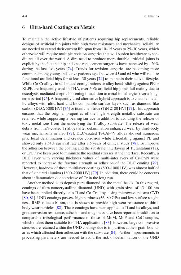
474
6 Ultra-hard Coatings on Metals
To maintain the active lifestyle of patients requiring hip replacements, reliable designs of artificial hip joints with high wear resistance and mechanical reliability are needed to extend their current life span from 10–15 years to 25–30 years, which otherwise will require multiple revision surgeries that will burden healthcare expen-ditures all over the world. A dire need to produce more durable artificial joints is explicit by the fact that hip and knee replacement surgeries have increased by ~20% during the last five years [74]. Trends for revision surgeries are becoming more common among young and active patients aged between 45 and 64 who will require functional artificial hips for at least 30 years [74] to maintain their active lifestyle. While Co-Cr alloys in self-mated configurations or alloy heads sliding against PE or XLPE are frequently used in THA, over 50% artificial hip joints fail mainly due to osteolysis-mediated aseptic loosening in addition to metal ion allergies over a long- term period [75]. A frequently used alternative hybrid approach is to coat the metal-lic alloys with ultra-hard and biocompatible surface layers such as diamond-like carbon (DLC; 5000 HV) [76] or titanium nitride (TiN 2100 HV) [77]. This approach ensures that the original properties of the high strength metallic substrate are retained while supporting a bearing surface in addition to avoiding the release of toxic metal ions from the underlying the Ti alloy substrate. The release of wear debris from TiN-coated Ti alloys after delamination enhanced wear by third-body wear mechanisms in vivo [77]. DLC-coated Ti-6Al-4V alloys showed numerous pits, local delamination and crevice corrosion while articulating against PE and showed only a 54% survival rate after 8.5 years of clinical study [78]. To improve the adhesion between the coating and the substrate, interlayers of Ti, tantalum (Ta), or CrC have been used to minimize the residual stresses at the interface. Recently, a DLC layer with varying thickness values of multi-interlayers of Cr-Cr2N were reported to increase the fracture strength or adhesion of the DLC coating [79]. However, hardness of these multilayer coatings (800–1000 HV) was almost half of that of sintered alumina (1800–2000 HV) [79]. In addition, there could be concerns about inflammation due to release of Cr in the long run.
Another method is to deposit pure diamond on the metal heads. In this regard, coatings of ultra-nanocrystalline diamond (UND) with grain sizes of ~3–100 nm have been applied directly onto Ti and Co-Cr alloys using microwave plasma CVD [80, 81]. UND coatings possess high hardness (56–80 GPa) and low surface rough-ness, RMS value <10 nm, that is shown to provide high wear resistance to third- body wear particles [82]. These coatings have been applied to Ti and its alloys, and good corrosion resistance, adhesion and toughness have been reported in addition to comparable tribological performance to those of MoM, MoP and CoC couples, which makes them suitable for THA applications [83]. However, large compressive stresses are retained within the UND coatings due to impurities at their grain bound-aries which affected their adhesion with the substrate [84]. Further improvements in processing parameters are needed to avoid the risk of delamination of the UND
R. Khanna
475
coatings which will govern their clinical use. In a nutshell, further improvements are needed in these coating technologies to meet high wear resistance, mechanical reliability and adhesion requirements for long lasting total hip prostheses.
7 Oxinium™
A promising approach of a dense oxide layer on metal substrate combines high mechanical strength and toughness of the underlying metal with advantages of an oxide layer with bio-inertness, high corrosion and wear resistance as an articulating surface. If native TiO2 layer on the surface of high mechanical strength Ti alloys was at least a few microns thick and wear resistant for long lasting hip prostheses or bulk ceramics were not inherently brittle, there could have been no interventions to deposit alternative wear resistant materials on metals over the last few decades. These drawbacks have spurred alternative explorations of bio-inert oxide ceramic layers on metallic substrates, adopting a hybrid approach by wedding superior wear resistance of ceramics with superior toughness of metals.
A layer of monoclinic zirconia ~5 μm thick formed on the surface of Zr- 2.5% Nb alloy by heat treatment of the alloy at 500°C [25] has been successfully applied to a femoral head commercialized as Oxinium™ (OxZr; Smith & Nephew, Memphis, USA). OxZr is not a coating, but a surface transformed layer formed by oxygen diffusion hardening treatment which is expected to provide improved resis-tance under load bearing operations. Compared to monolithic zirconia, thin zirconia layer on the Zr-Nb alloy avoids catastrophic failure of implant. In vitro hip simula-tor studies have shown remarkable reductions in wear of OxZr by ~45% articulating against XLPE for total hip and knee arthroplasty as compared with Co-Cr alloys [26, 85]. Although OxZr heads are being routinely used especially for young and active patients, some clinical studies have reported extensive damage of OxZr heads articulating against XLPE [86, 87], indicating poor mechanical reliability of the joint. Moreover, the OxZr head has only a 5 μm thick layer of zirconia formed on the Zr-Nb alloy which is not expected to last up to 25–30 years to meet the demands of durable artificial hip joints needed for patients aged 40 or younger. Nevertheless, OxZr is still in clinical use, patients will need to undergo regular check-up to ensure the good condition of implant in their body. From the materials design perspective, it is intriguing to reveal the reasons for the good adhesion between OxZr layer and the metal substrate given that they are incompatible materials due to significant dif-ferences in their physical, chemical and mechanical properties. However, it has not been clarified in the literature yet despite more than 8 years of clinical use of OxZr heads. What would be an ideal design of a strong interface between ceramic and metal has not been revealed yet and is a fundamental gap in knowledge. Once this gap is filled, it would lead to new knowledge in methodologies needed for designing reliable artificial hips with an extended lifespan of more than 25–30 years.
Advances in Bearing Materials for Total Artificial Hip Arthroplasty
476
8 Rationale for the Design of a New Kind of Ceramic/Metal Hybrid Artificial Joint
With increasing ageing population and demands for active and young patients aged 40 and under, the life span of artificial joints is expected to be more than 25–30 years. To meet these demands, the focus is to design and develop new kinds of artificial joints with high wear resistance and mechanical reliability.
8.1 Selection and Design of Materials
Materials used to design a future generation of durable femoral heads or cups made of ceramic/metal hybrids should meet the demands of high wear resistance at the bearing surface, supported by a metallic material which can sustain high toughness. These demands have not been met by any of the currently used materials for artifi-cial joints including Oxinium™, as discussed in Sect. 7. To meet these demands, a promising ceramic/metal hybrid design was recently proposed [88–91] in which better wear resistance might be obtained if zirconia is replaced with the alumina as an articulating surface because the latter has higher hardness. Mechanical reliability of the articulating surface might increase if the Zr-Nb alloy substrate is replaced by a Ti-6Al-4V alloy because the latter has higher mechanical strength and fracture toughness than that of the former or Co-Cr alloy, commonly used as a head in THA. Furthermore, an alumina layer formed on the tough Ti alloy is expected to offer better mechanical reliability as compared with monolithic alumina which is liable to catastrophic fracture. In addition, alumina shows better long-term in vivo stability than zirconia. Oxinium™ is composed of only a ~5 μm thick layer of monolithic zirconia on the Zr-Nb alloy. Therefore, formation of a dense α-alumina layer with a thickness of 5 μm or more is expected to last longer than Oxinium™. In addition to the requirement for high wear resistance, a good adhesion between the alumina layer and the Ti alloy is critical for the reliability of an alumina/Ti alloy hybrid for efficient load transfer mechanism during operations of the artificial hip.
It is technically challenging to fabricate dense and pure α-alumina layers on the Ti alloy given that alumina and the Ti alloy are very incompatible with each other due to significant differences in their coefficient of thermal expansion (∝Alumina = 7.5 × 10⁻⁶/K and ∝Ti-6Al-4V = 9.1–9.8 × 10⁻⁶/K) and mechanical properties (Hardness, HAlumina = 2100 HV, HTi alloy = 350 HV; fracture toughness, KIc, Alumina = ~3–4 MPa√m, KIc, Ti alloy = 75 MPa√m) which could result in the residual stresses at the interface between them. High residual stresses could lead to cracks at the interface and sub-sequent delamination of the alumina layer. Although the ideal design of a strong interface between a ceramic and metal has not been fully revealed yet, it was recently proposed that the formation of an intermediate AlTi type of bonding layer with metallurgical bond-like characteristics might tend to minimize the residual stresses
R. Khanna
477
at the alumina-Ti interface and could also enhance the mechanical reliability of the joint as well [88–91]. The cross-sectional view of a newly proposed alumina/Ti alloy hybrid (ATH) artificial hip joint model is shown schematically in Fig. 1a. This kind of designed hybrid could be used for both the cup and head in alumina-on- alumina type of contact configuration, as shown in Fig. 1b. The rationale behind this configuration is that an alumina CoC combination has shown the lowest wear rate (0.01 mm3/million cycles) among the currently used materials in THA. Hence, it is expected that the wear of ATH-on-ATH could be similar as well. Compared with monolithic alumina, the ATH design could offer better mechanical reliability to artificial hips since the bearing surface is supported by a tough Ti alloy. The pro-posed ATH head could also be used in articulation against a conventional PE or XLPE liner.
8.2 Rationale for the New Design of an Artificial Hip Joint
Advanced implant designs are focused on reducing wear of bearing surfaces by increasing the diameter of heads. Despite being successful in this regard, all MoM, MoP, CoC couples share common issues of edge loading or impingement of taper joint of the stem with the rim of the cup, both of which result in the release of a large amount of wear debris and thereby leading to high revision rates. Edge loading of the cup is reported in case the contact patch between ball and cup extends to the rim of the cup, resulting in increases in local stress and more wear at the rim. It could also be the loss of lubrication due to a lack of synovial fluid between contacting surfaces [92]. Almost 70% of the MoP implants have been reported to be associated with impingement related rim damage [93]. For CoC implants, incidences of wear of rim have been reported to enhance third body wear, leading to catastrophic frac-ture of the ceramic part [94]. Evidences of metal wear debris have been reported for both MoM and CoC implant designs which clearly indicate the wear of the taper joint and neck-cup impingement [95, 96]. To overcome the major issue of wear of the taper joint, an alternative design is proposed in which a single part for both the stem and head could be made of the Ti alloy. The head portion of Ti alloy could be
Fig. 1. Cross-sectional views of an alumina/Ti alloy (ATH) hybrid model (a) and ATH-on-ATH configuration (b) of an artificial hip joint
Advances in Bearing Materials for Total Artificial Hip Arthroplasty
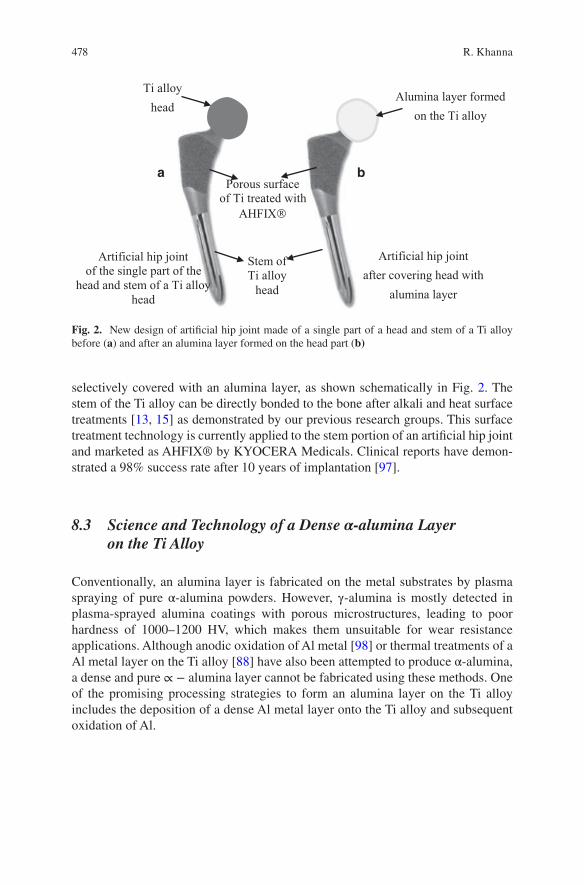
478
selectively covered with an alumina layer, as shown schematically in Fig. 2. The stem of the Ti alloy can be directly bonded to the bone after alkali and heat surface treatments [13, 15] as demonstrated by our previous research groups. This surface treatment technology is currently applied to the stem portion of an artificial hip joint and marketed as AHFIX® by KYOCERA Medicals. Clinical reports have demon-strated a 98% success rate after 10 years of implantation [97].
8.3 Science and Technology of a Dense α-alumina Layer on the Ti Alloy
Conventionally, an alumina layer is fabricated on the metal substrates by plasma spraying of pure α-alumina powders. However, γ-alumina is mostly detected in plasma-sprayed alumina coatings with porous microstructures, leading to poor hardness of 1000–1200 HV, which makes them unsuitable for wear resistance applications. Although anodic oxidation of Al metal [98] or thermal treatments of a Al metal layer on the Ti alloy [88] have also been attempted to produce α-alumina, a dense and pure ∝ − alumina layer cannot be fabricated using these methods. One of the promising processing strategies to form an alumina layer on the Ti alloy includes the deposition of a dense Al metal layer onto the Ti alloy and subsequent oxidation of Al.
Ti alloyhead
Alumina layer formed on the Ti alloy
Stem ofTi alloy
head
Porous surface of Ti treated with
AHFIX
Artificial hip jointof the single part of the
head and stem of a Ti alloyhead
Artificial hip jointafter covering head with
alumina layer
a b
Fig. 2. New design of artificial hip joint made of a single part of a head and stem of a Ti alloy before (a) and after an alumina layer formed on the head part (b)
R. Khanna
479
8.3.1 Formation of Al Layer on the Ti Alloy Substrate
In order to form ~5–10 μm thick dense α-alumina layers, at least a couple of microns thick layer of Al metal is needed to form on the Ti alloy, which is not yet possible with conventional Al deposition techniques such as PVD [99], arc ion plating [100], and sputtering [101]. Ideally, a method of forming a thick layer of Al on the Ti alloy substrate should be chosen with minimal or no chemical reaction with the substrate during Al layer formation, which otherwise might lead to the formation of thick layer of AlTi intermetallic compounds containing several cracks or pores [102] and leading to delamination of an Al layer. To address these needs, a cold spraying (CS) technique is used to deposit thick layers of an Al metal on soft metals such as Al alloys [103, 104] at temperatures much lower than the melting point of Al (Tm = 660°C). The CS technique allows the deposition of a thick metal coating on a metallic substrate by accelerating small particles (<50 μm) to high velocities (500–1500 m/sec) by a supersonic jet of compressed gas at a temperature below the melt-ing point of the material to be deposited. In the field of biomaterials, for the first time, dense and thick layers of pure Al with thickness values from 250 to 1000 μm were formed on a Ti-6Al-4 V alloy by CS of Al particles in N2 or He gas atmosphere at varying pressures of 1–3 MPa and at a temperature of 380°C [88].
Cold sprayed Al layers (CS-Al) on the Ti alloy formed dense microstructures both in He or N2 gas atmosphere at an optimal pressure of 3 MPa and a temperature of 380°C. However, CS-Al layers formed in He atmosphere showed larger cracks or gaps at the interface as a result of higher critical velocities of Al particles (~972.5 m/s) [88]. CS-Al layers formed in N2 gas atmosphere also showed poor adhesion as shown by gaps at the interface as shown in Fig. 3a. Nevertheless, these samples showed relatively better adhesion than those treated in He atmosphere which could be due to lower critical velocity of 552.1 m/s in a N2 gas atmosphere. These kinds of gaps could arise due to a significant difference in materials properties of Al and Ti alloy or massive plastic deformation within CS-Al layer that might have been caused by ballistic impacts during CS, thereby resulting in accumulation of residual stresses at the interface and ultimately leading to cracks at the interface [89].
8.3.2 Formation of Reaction Layer at the Alumina-Ti Alloy Interface
The formation of a reaction layer of AlTi type of intermetallic compounds at the interface between the CS-Al layer and the Ti alloy substrate could be a promising solution to improve the adhesion and minimize the residual stresses at their inter-face. In this regard, heat treating the CS-Al layer/Ti alloy at 640°C for 1 h in air or an Ar gas atmosphere formed a dense and crack-free reaction layer ~2 μm thick at the interface as shown in Fig. 3b. This reaction layer could be formed by solid state diffusion of Al into Ti, according to equation shown below since Al has a lower melting point (Tm = 660°C) as compared with the Ti alloy.
Advances in Bearing Materials for Total Artificial Hip Arthroplasty
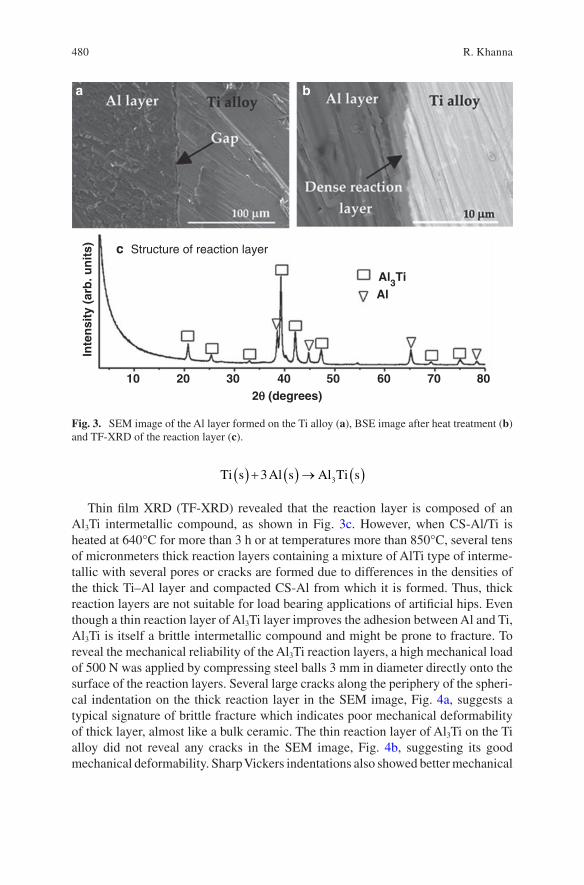
480
Ti s Al s Al Ti s( ) + ( ) → ( )3 3
Thin film XRD (TF-XRD) revealed that the reaction layer is composed of an Al3Ti intermetallic compound, as shown in Fig. 3c. However, when CS-Al/Ti is heated at 640°C for more than 3 h or at temperatures more than 850°C, several tens of micronmeters thick reaction layers containing a mixture of AlTi type of interme-tallic with several pores or cracks are formed due to differences in the densities of the thick Ti–Al layer and compacted CS-Al from which it is formed. Thus, thick reaction layers are not suitable for load bearing applications of artificial hips. Even though a thin reaction layer of Al3Ti layer improves the adhesion between Al and Ti, Al3Ti is itself a brittle intermetallic compound and might be prone to fracture. To reveal the mechanical reliability of the Al3Ti reaction layers, a high mechanical load of 500 N was applied by compressing steel balls 3 mm in diameter directly onto the surface of the reaction layers. Several large cracks along the periphery of the spheri-cal indentation on the thick reaction layer in the SEM image, Fig. 4a, suggests a typical signature of brittle fracture which indicates poor mechanical deformability of thick layer, almost like a bulk ceramic. The thin reaction layer of Al3Ti on the Ti alloy did not reveal any cracks in the SEM image, Fig. 4b, suggesting its good mechanical deformability. Sharp Vickers indentations also showed better mechanical
Structure of reaction layer
10 20 30 40 50 60 70 802q (degrees)
Inte
nsi
ty (
arb
. un
its)
Al3TiAl
a b
c
Fig. 3. SEM image of the Al layer formed on the Ti alloy (a), BSE image after heat treatment (b) and TF-XRD of the reaction layer (c).
R. Khanna
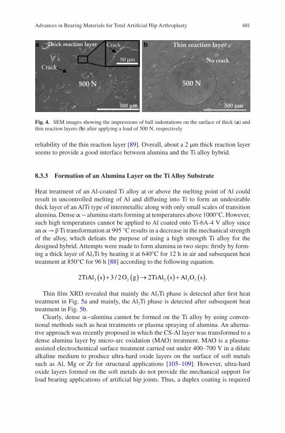
481
reliability of the thin reaction layer [89]. Overall, about a 2 μm thick reaction layer seems to provide a good interface between alumina and the Ti alloy hybrid.
8.3.3 Formation of an Alumina Layer on the Ti Alloy Substrate
Heat treatment of an Al-coated Ti alloy at or above the melting point of Al could result in uncontrolled melting of Al and diffusing into Ti to form an undesirable thick layer of an AlTi type of intermetallic along with only small scales of transition alumina. Dense ∝ − alumina starts forming at temperatures above 1000°C. However, such high temperatures cannot be applied to Al coated onto Ti-6A-4 V alloy since an ∝ → β Ti transformation at 995 °C results in a decrease in the mechanical strength of the alloy, which defeats the purpose of using a high strength Ti alloy for the designed hybrid. Attempts were made to form alumina in two steps: firstly by form-ing a thick layer of Al3Ti by heating it at 640°C for 12 h in air and subsequent heat treatment at 850°C for 96 h [88] according to the following equation.
2 3 2 23 2 2 2 3TiAl s O g TiAl s Al O s( ) + ( ) → ( ) + ( )/ .
Thin film XRD revealed that mainly the Al3Ti phase is detected after first heat treatment in Fig. 5a and mainly, the Al2Ti phase is detected after subsequent heat treatment in Fig. 5b.
Clearly, dense ∝−alumina cannot be formed on the Ti alloy by using conven-tional methods such as heat treatments or plasma spraying of alumina. An alterna-tive approach was recently proposed in which the CS-Al layer was transformed to a dense alumina layer by micro-arc oxidation (MAO) treatment. MAO is a plasma- assisted electrochemical surface treatment carried out under 400–700 V in a dilute alkaline medium to produce ultra-hard oxide layers on the surface of soft metals such as Al, Mg or Zr for structural applications [105–109]. However, ultra-hard oxide layers formed on the soft metals do not provide the mechanical support for load bearing applications of artificial hip joints. Thus, a duplex coating is required
Fig. 4. SEM images showing the impressions of ball indentations on the surface of thick (a) and thin reaction layers (b) after applying a load of 500 N, respectively
Advances in Bearing Materials for Total Artificial Hip Arthroplasty
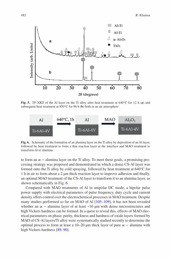
482
to form an ∝ − alumina layer on the Ti alloy. To meet these goals, a promising pro-cessing strategy was proposed and demonstrated in which a dense CS-Al layer was formed onto the Ti alloy by cold spraying, followed by heat treatment at 640°C for 1 h in air to form about a 2 μm thick reaction layer to improve adhesion and finally, an optimal MAO treatment of the CS-Al layer to transform it to an alumina layer, as shown schematically in Fig. 6.
Compared with MAO treatments of Al in unipolar DC mode, a bipolar pulse power supply with electrical parameters of pulse frequency, duty cycle and current density offers control over the electrochemical processes in MAO treatment. Despite many studies performed so far on MAO of Al [105–109], it has not been revealed whether an ∝ − alumina layer of at least ~10 μm with dense microstructures and high Vickers hardness can be formed. In a quest to reveal this, effects of MAO elec-trical parameters on phase, purity, thickness and hardness of oxide layers formed by MAO of CS-Al layers/Ti alloy were systematically studied recently to determine the optimal process to form at least a 10–20 μm thick layer of pure ∝ − alumina with high Vickers hardness [89, 90].
10 20 30 40 50 60 70 80
Al2Ti
Al3Ti
α- Al2O3
TiO2
2θ (degrees)
Inte
nsity
(arb
. Uni
ts)
b
a
Fig. 5. TF-XRD of the Al layer on the Ti alloy after heat treatment at 640°C for 12 h (a) and subsequent heat treatment at 850°C for 96 h (b) both in an air atmosphere
Fig. 6. Schematic of the formation of an alumina layer on the Ti alloy by deposition of an Al layer, followed by heat treatment to form a thin reaction layer at the interface and MAO treatment to transform Al to alumina
R. Khanna
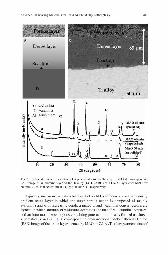
483
Typically, micro-arc oxidation treatment of an Al layer forms a phase and density gradient oxide layer in which the outer porous region is composed of mainly γ-alumina and with increasing depth, a mixed ∝ and γ-alumina denser regions are formed in which amounts of γ-alumina decreases and that of ∝ − alumina increases, and an innermost dense regions containing pure ∝ − alumina is formed as shown schematically in Fig. 7a. A corrosponding cross-sectional back-scattered electron (BSE) image of the oxide layer formed by MAO of CS-Al/Ti after treatment time of
Fig. 7. Schematic view of a section of a processed alumina/Ti alloy model (a), corresponding BSE image of an alumina layer on the Ti alloy (b), TF-XRDs of a CS-Al layer after MAO for 30 min (c), 60 min before (d) and after polishing (e), respectively
Advances in Bearing Materials for Total Artificial Hip Arthroplasty
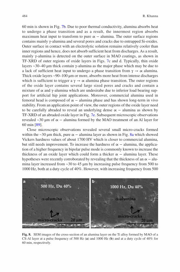
484
60 min is shown in Fig. 7b. Due to poor thermal conductivity, alumina absorbs heat to undergo a phase transition and as a result, the innermost region absorbs maximum heat input to transform to pure ∝ − alumina. The outer surface regions contains mainly γ-alumina and several pores and cracks due to entrapped Si-oxides. Outer surface in contact with an electrolytic solution remains relatively cooler than inner regions and hence, does not absorb sufficient heat from discharges. As a result, mainly γ-alumina is detected on the outer surface in MAO coatings, as shown in TF-XRD of outer regions of oxide layers in Figs. 7c and d. Typically, thin oxide layers ~30–40 μm thick contain γ-alumina as the major phase which may be due to a lack of sufficient heat input to undergo a phase transition from γ → ∝ alumina. Thick oxide layers ~90–100 μm or more, absorbs more heat from intense discharges which is sufficient to trigger a γ → ∝ alumina phase transition. The outer regions of the oxide layer contains several large sized pores and cracks and contain a mixture of ∝ and γ-alumina which are undesirabe due to inferior load bearing sup-port for artificial hip joint applications. Moreover, commercial alumina used in femoral head is composed of ∝ − alumina phase and has shown long-term in vivo stability. From an application point of view, the outer regions of the oxide layer need to be carefully abraded to reveal an underlying dense ∝ − alumina as shown by TF-XRD of an abraded oxide layer in Fig. 7e. Subsequent microscopic observations revealed ~30 μm of ∝ − alumina formed by the MAO treatment of an Al layer for 60 min [89].
Close microscopic observations revealed several small micro-cracks formed within the ~30 μm thick, pure ∝ − alumina layer as shown in Fig. 8a which showed Vickers hardness values of about 1700 HV which is closer to commercial alumina, but still needs improvement. To increase the hardness of ∝ − alumina, the applica-tion of a higher frequency in bipolar pulse mode is commonly known to increase the thickness of an oxide layer which could form a thicker ∝ − alumina layer. These hypotheses were recently corroborated by revealing that the thickness of an ∝ − alu-mina layer increased from ~30 to 45 μm by increasing pulse frequency from 500 to 1000 Hz, both at a duty cycle of 40%. However, with increasing frequency from 500
Fig. 8. SEM images of the cross-section of an alumina layer on the Ti alloy formed by MAO of a CS-Al layer at a pulse frequency of 500 Hz (a) and 1000 Hz (b) and at a duty cycle of 40% for 60 min, respectively.
R. Khanna
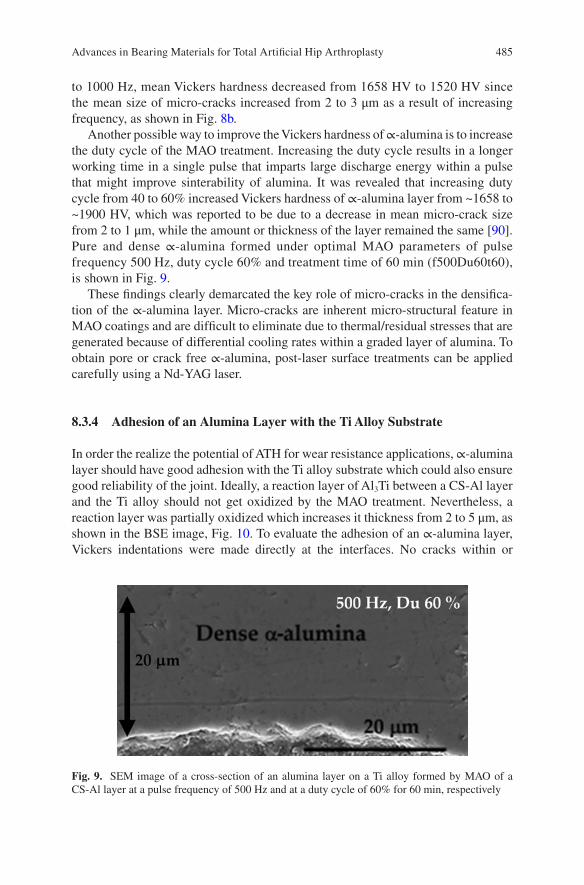
485
to 1000 Hz, mean Vickers hardness decreased from 1658 HV to 1520 HV since the mean size of micro-cracks increased from 2 to 3 μm as a result of increasing frequency, as shown in Fig. 8b.
Another possible way to improve the Vickers hardness of ∝-alumina is to increase the duty cycle of the MAO treatment. Increasing the duty cycle results in a longer working time in a single pulse that imparts large discharge energy within a pulse that might improve sinterability of alumina. It was revealed that increasing duty cycle from 40 to 60% increased Vickers hardness of ∝-alumina layer from ~1658 to ~1900 HV, which was reported to be due to a decrease in mean micro-crack size from 2 to 1 μm, while the amount or thickness of the layer remained the same [90]. Pure and dense ∝-alumina formed under optimal MAO parameters of pulse frequency 500 Hz, duty cycle 60% and treatment time of 60 min (f500Du60t60), is shown in Fig. 9.
These findings clearly demarcated the key role of micro-cracks in the densifica-tion of the ∝-alumina layer. Micro-cracks are inherent micro-structural feature in MAO coatings and are difficult to eliminate due to thermal/residual stresses that are generated because of differential cooling rates within a graded layer of alumina. To obtain pore or crack free ∝-alumina, post-laser surface treatments can be applied carefully using a Nd-YAG laser.
8.3.4 Adhesion of an Alumina Layer with the Ti Alloy Substrate
In order the realize the potential of ATH for wear resistance applications, ∝-alumina layer should have good adhesion with the Ti alloy substrate which could also ensure good reliability of the joint. Ideally, a reaction layer of Al3Ti between a CS-Al layer and the Ti alloy should not get oxidized by the MAO treatment. Nevertheless, a reaction layer was partially oxidized which increases it thickness from 2 to 5 μm, as shown in the BSE image, Fig. 10. To evaluate the adhesion of an ∝-alumina layer, Vickers indentations were made directly at the interfaces. No cracks within or
Fig. 9. SEM image of a cross-section of an alumina layer on a Ti alloy formed by MAO of a CS-Al layer at a pulse frequency of 500 Hz and at a duty cycle of 60% for 60 min, respectively
Advances in Bearing Materials for Total Artificial Hip Arthroplasty
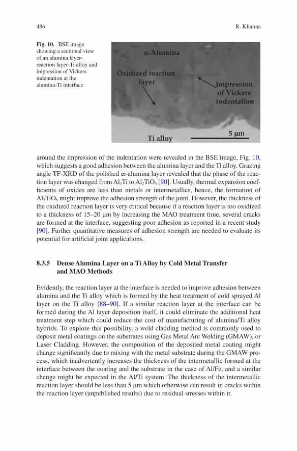
486
around the impression of the indentation were revealed in the BSE image, Fig. 10, which suggests a good adhesion between the alumina layer and the Ti alloy. Grazing angle TF-XRD of the polished ∝-alumina layer revealed that the phase of the reac-tion layer was changed from Al3Ti to Al2TiO5 [90]. Usually, thermal expansion coef-ficients of oxides are less than metals or intermetallics, hence, the formation of Al2TiO5 might improve the adhesion strength of the joint. However, the thickness of the oxidized reaction layer is very critical because if a reaction layer is too oxidized to a thickness of 15–20 μm by increasing the MAO treatment time, several cracks are formed at the interface, suggesting poor adhesion as reported in a recent study [90]. Further quantitative measures of adhesion strength are needed to evaluate its potential for artificial joint applications.
8.3.5 Dense Alumina Layer on a Ti Alloy by Cold Metal Transfer and MAO Methods
Evidently, the reaction layer at the interface is needed to improve adhesion between alumina and the Ti alloy which is formed by the heat treatment of cold sprayed Al layer on the Ti alloy [88–90]. If a similar reaction layer at the interface can be formed during the Al layer deposition itself, it could eliminate the additional heat treatment step which could reduce the cost of manufacturing of alumina/Ti alloy hybrids. To explore this possibility, a weld cladding method is commonly used to deposit metal coatings on the substrates using Gas Metal Arc Welding (GMAW), or Laser Cladding. However, the composition of the deposited metal coating might change significantly due to mixing with the metal substrate during the GMAW pro-cess, which inadvertently increases the thickness of the intermetallic formed at the interface between the coating and the substrate in the case of Al/Fe, and a similar change might be expected in the Al/Ti system. The thickness of the intermetallic reaction layer should be less than 5 μm which otherwise can result in cracks within the reaction layer (unpublished results) due to residual stresses within it.
Oxidized reaction layer
Ti alloy
Impression of Vickers indentation
α-Alumina
5 µm
Fig. 10. BSE image showing a sectional view of an alumina layer- reaction layer-Ti alloy and impression of Vickers indentation at the alumina-Ti interface
R. Khanna
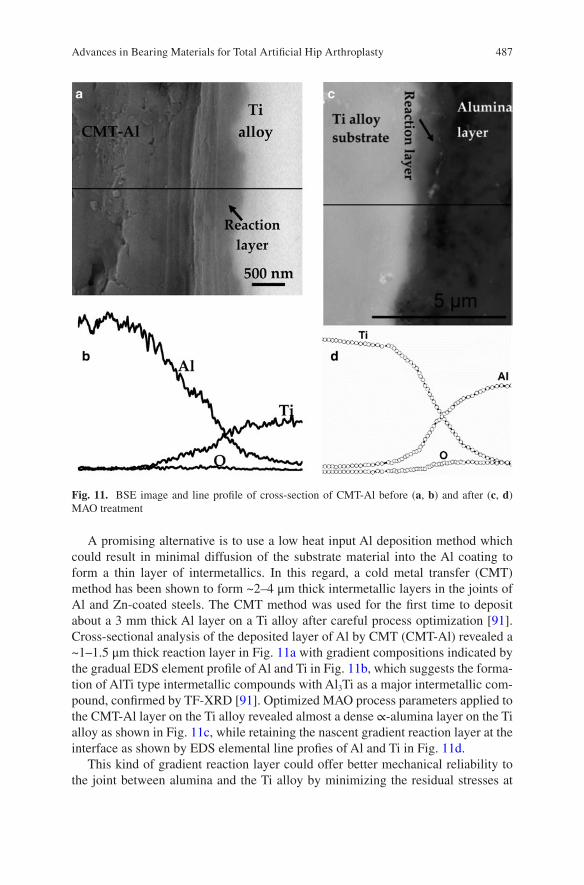
487
A promising alternative is to use a low heat input Al deposition method which could result in minimal diffusion of the substrate material into the Al coating to form a thin layer of intermetallics. In this regard, a cold metal transfer (CMT) method has been shown to form ~2–4 μm thick intermetallic layers in the joints of Al and Zn-coated steels. The CMT method was used for the first time to deposit about a 3 mm thick Al layer on a Ti alloy after careful process optimization [91]. Cross-sectional analysis of the deposited layer of Al by CMT (CMT-Al) revealed a ~1–1.5 μm thick reaction layer in Fig. 11a with gradient compositions indicated by the gradual EDS element profile of Al and Ti in Fig. 11b, which suggests the forma-tion of AlTi type intermetallic compounds with Al3Ti as a major intermetallic com-pound, confirmed by TF-XRD [91]. Optimized MAO process parameters applied to the CMT-Al layer on the Ti alloy revealed almost a dense ∝-alumina layer on the Ti alloy as shown in Fig. 11c, while retaining the nascent gradient reaction layer at the interface as shown by EDS elemental line profies of Al and Ti in Fig. 11d.
This kind of gradient reaction layer could offer better mechanical reliability to the joint between alumina and the Ti alloy by minimizing the residual stresses at
Fig. 11. BSE image and line profile of cross-section of CMT-Al before (a, b) and after (c, d) MAO treatment
Advances in Bearing Materials for Total Artificial Hip Arthroplasty
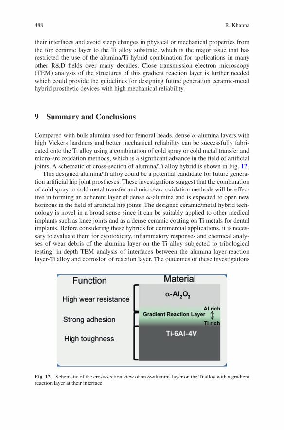
488
their interfaces and avoid steep changes in physical or mechanical properties from the top ceramic layer to the Ti alloy substrate, which is the major issue that has restricted the use of the alumina/Ti hybrid combination for applications in many other R&D fields over many decades. Close transmission electron microscopy (TEM) analysis of the structures of this gradient reaction layer is further needed which could provide the guidelines for designing future generation ceramic-metal hybrid prosthetic devices with high mechanical reliability.
9 Summary and Conclusions
Compared with bulk alumina used for femoral heads, dense ∝-alumina layers with high Vickers hardness and better mechanical reliability can be successfully fabri-cated onto the Ti alloy using a combination of cold spray or cold metal transfer and micro-arc oxidation methods, which is a significant advance in the field of artificial joints. A schematic of cross-section of alumina/Ti alloy hybrid is shown in Fig. 12.
This designed alumina/Ti alloy could be a potential candidate for future genera-tion artificial hip joint prostheses. These investigations suggest that the combination of cold spray or cold metal transfer and micro-arc oxidation methods will be effec-tive in forming an adherent layer of dense ∝-alumina and is expected to open new horizons in the field of artificial hip joints. The designed ceramic/metal hybrid tech-nology is novel in a broad sense since it can be suitably applied to other medical implants such as knee joints and as a dense ceramic coating on Ti metals for dental implants. Before considering these hybrids for commercial applications, it is neces-sary to evaluate them for cytotoxicity, inflammatory responses and chemical analy-ses of wear debris of the alumina layer on the Ti alloy subjected to tribological testing; in-depth TEM analysis of interfaces between the alumina layer-reaction layer-Ti alloy and corrosion of reaction layer. The outcomes of these investigations
Fig. 12. Schematic of the cross-section view of an ∝-alumina layer on the Ti alloy with a gradient reaction layer at their interface
R. Khanna
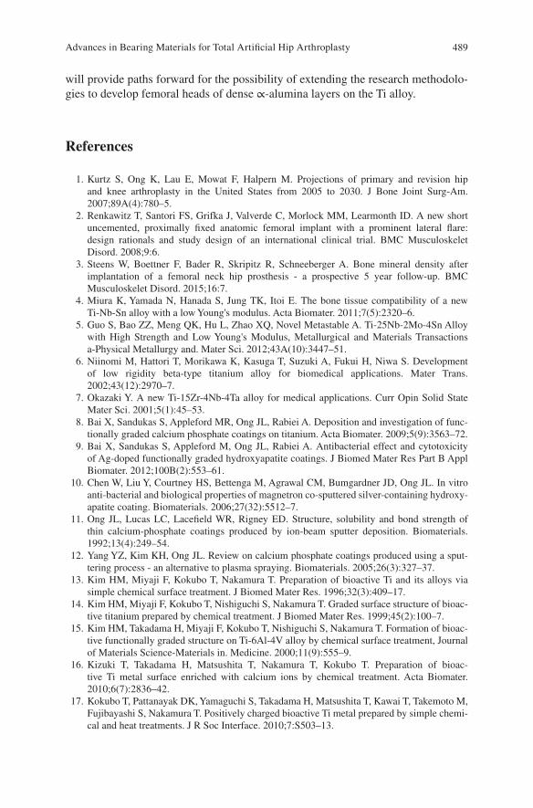
489
will provide paths forward for the possibility of extending the research methodolo-gies to develop femoral heads of dense ∝-alumina layers on the Ti alloy.
References
1. Kurtz S, Ong K, Lau E, Mowat F, Halpern M. Projections of primary and revision hip and knee arthroplasty in the United States from 2005 to 2030. J Bone Joint Surg-Am. 2007;89A(4):780–5.
2. Renkawitz T, Santori FS, Grifka J, Valverde C, Morlock MM, Learmonth ID. A new short uncemented, proximally fixed anatomic femoral implant with a prominent lateral flare: design rationals and study design of an international clinical trial. BMC Musculoskelet Disord. 2008;9:6.
3. Steens W, Boettner F, Bader R, Skripitz R, Schneeberger A. Bone mineral density after implantation of a femoral neck hip prosthesis - a prospective 5 year follow-up. BMC Musculoskelet Disord. 2015;16:7.
4. Miura K, Yamada N, Hanada S, Jung TK, Itoi E. The bone tissue compatibility of a new Ti-Nb-Sn alloy with a low Young's modulus. Acta Biomater. 2011;7(5):2320–6.
5. Guo S, Bao ZZ, Meng QK, Hu L, Zhao XQ, Novel Metastable A. Ti-25Nb-2Mo-4Sn Alloy with High Strength and Low Young's Modulus, Metallurgical and Materials Transactions a-Physical Metallurgy and. Mater Sci. 2012;43A(10):3447–51.
6. Niinomi M, Hattori T, Morikawa K, Kasuga T, Suzuki A, Fukui H, Niwa S. Development of low rigidity beta-type titanium alloy for biomedical applications. Mater Trans. 2002;43(12):2970–7.
7. Okazaki Y. A new Ti-15Zr-4Nb-4Ta alloy for medical applications. Curr Opin Solid State Mater Sci. 2001;5(1):45–53.
8. Bai X, Sandukas S, Appleford MR, Ong JL, Rabiei A. Deposition and investigation of func-tionally graded calcium phosphate coatings on titanium. Acta Biomater. 2009;5(9):3563–72.
9. Bai X, Sandukas S, Appleford M, Ong JL, Rabiei A. Antibacterial effect and cytotoxicity of Ag-doped functionally graded hydroxyapatite coatings. J Biomed Mater Res Part B Appl Biomater. 2012;100B(2):553–61.
10. Chen W, Liu Y, Courtney HS, Bettenga M, Agrawal CM, Bumgardner JD, Ong JL. In vitro anti-bacterial and biological properties of magnetron co-sputtered silver-containing hydroxy-apatite coating. Biomaterials. 2006;27(32):5512–7.
11. Ong JL, Lucas LC, Lacefield WR, Rigney ED. Structure, solubility and bond strength of thin calcium-phosphate coatings produced by ion-beam sputter deposition. Biomaterials. 1992;13(4):249–54.
12. Yang YZ, Kim KH, Ong JL. Review on calcium phosphate coatings produced using a sput-tering process - an alternative to plasma spraying. Biomaterials. 2005;26(3):327–37.
13. Kim HM, Miyaji F, Kokubo T, Nakamura T. Preparation of bioactive Ti and its alloys via simple chemical surface treatment. J Biomed Mater Res. 1996;32(3):409–17.
14. Kim HM, Miyaji F, Kokubo T, Nishiguchi S, Nakamura T. Graded surface structure of bioac-tive titanium prepared by chemical treatment. J Biomed Mater Res. 1999;45(2):100–7.
15. Kim HM, Takadama H, Miyaji F, Kokubo T, Nishiguchi S, Nakamura T. Formation of bioac-tive functionally graded structure on Ti-6Al-4V alloy by chemical surface treatment, Journal of Materials Science-Materials in. Medicine. 2000;11(9):555–9.
16. Kizuki T, Takadama H, Matsushita T, Nakamura T, Kokubo T. Preparation of bioac-tive Ti metal surface enriched with calcium ions by chemical treatment. Acta Biomater. 2010;6(7):2836–42.
17. Kokubo T, Pattanayak DK, Yamaguchi S, Takadama H, Matsushita T, Kawai T, Takemoto M, Fujibayashi S, Nakamura T. Positively charged bioactive Ti metal prepared by simple chemi-cal and heat treatments. J R Soc Interface. 2010;7:S503–13.
Advances in Bearing Materials for Total Artificial Hip Arthroplasty
490
18. Oral E, Christensen SD, Malhi AS, Wannomae KK, Muratoglu OK. Wear resistance and mechanical properties of highly cross-linked, ultrahigh-molecular weight polyethylene doped with vitamin E. J Arthroplasty. 2006;21(4):580–91.
19. Oral E, Muratoglu OK. Vitamin E diffused, highly crosslinked UHMWPE: a review. Int Orthop. 2011;35(2):215–23.
20. Moro T, Kawaguchi H, Ishihara K, Kyomoto M, Karita T, Ito H, Nakamura K, Takatori Y. Wear resistance of artificial hip joints with poly(2-methacryloyloxyethyl phosphorylcho-line) grafted polyethylene: Comparisons with the effect of polyethylene cross-linking and ceramic femoral heads. Biomaterials. 2009;30(16):2995–3001.
21. Kyomoto M, Moro T, Iwasaki Y, Miyaji F, Kawaguchi H, Takatori Y, Nakamura K, Ishihara K. Superlubricious surface mimicking articular cartilage by grafting poly(2- methacryloyloxyethyl phosphorylcholine) on orthopaedic metal bearings. J Biomed Mater Res A. 2009;91A(3):730–41.
22. Clarke IC, Manaka M, Green DD, Williams P, Pezzotti G, Kim YH, Ries M, Sugano N, Sedel L, Delauney C, Ben Nissan B, Donaldson T, Gustafson GA. Current status of zirconia used in total hip implants. J Bone Joint Surg Am. 2003;85A:73–84.
23. Begand S, Oberbach T, Glien W. Investigations of the mechanical properties of an alu-mina toughened zirconia ceramic for an application in joint prostheses. Bioceramics. 2005;17(284–286):1019–22.
24. Al-Hajjar M, Jennings LM, Begand S, Oberbach T, Delfosse D, Fisher J. Wear of novel ceramic-on-ceramic bearings under adverse and clinically relevant hip simulator conditions. J Biomed Mater Res Part B Appl Biomater. 2013;101(8):1456–62.
25. Hobbs LW, Rosen VB, Mangin SP, Treska M, Hunter G. Oxidation microstructures and inter-faces in the oxidized zirconium knee. Int J Appl Ceram Technol. 2005;2(3):221–46.
26. Good V, Ries M, Barrack RL, Widding K, Hunter G, Heuer D. Reduced wear with oxidized zirconium femoral heads. J Bone Joint Surg Am. 2003;85A:105–10.
27. Burger W, Richter HG. High strength and toughness alumina matrix composites by trans-formation toughening and 'in situ' platelet reinforcement (ZPTA) - The new generation of bioceramics. Bioceramics. 2000;192-1:545–8.
28. Brown AS. Hip new world. ASME Mechanical Engineering Magazine; 2006. pp. 28–33. 29. Charnley J, Kamangar A, Longfield MD. Optimum size of prosthetic heads in relation to
wear of plastic sockets in total replacement of hip. Med Biol Eng. 1969;7(1):31. 30. Amstutz HC, Campbell P, Kossovsky N, Clarke IC. Mechanism and clinical-significance of
wear debris-induced osteolysis. Clin Orthop Relat Res. 1992;276:7–18. 31. Boutin P. Total arthroplasty of the hip by fritted alumina prosthesis. Experimental study and
1st clinical applications. Orthop Traumatol Surg Res. 2014;100(1):15–21. 32. Harris WH. The problem is osteolysis. Clin Orthop Relat Res. 1995;311:46–53. 33. Kim YH, Kim JS, Park JW, Joo JH. Periacetabular Osteolysis is the Problem in Contemporary
Total Hip Arthroplasty in Young Patients. J Arthroplasty. 2012;27(1):74–81. 34. Lewis G. Properties of crosslinked ultra-high-molecular-weight polyethylene. Biomaterials.
2001;22(4):371–401. 35. Ishihara K. Highly lubricated polymer interfaces for advanced artificial hip joints through
biomimetic design. Polym J. 2015;47(9):585–97. 36. Kyomoto M, Shobuike T, Moro T, Yamane S, Takatori Y, Tanaka S, Miyamoto H, Ishihara
K. Prevention of bacterial adhesion and biofilm formation on a vitamin E-blended, cross- linked polyethylene surface with a poly(2-methacryloyloxyethyl phosphorylcholine) layer. Acta Biomater. 2015;24:24–34.
37. Skipor AK, Campbell PA, Patterson LM, Anstutz HC, Schmalzried TP, Jacobs JJ. Serum and urine metal levels in patients with metal-on-metal surface arthroplasty, Journal of Materials Science-Materials in. Medicine. 2002;13(12):1227–34.
38. Catelas I, Wimmer MA. New Insights into Wear and Biological Effects of Metal-on-Metal Bearings. J Bone Joint Surg Am. 2011;93A:76–83.
R. Khanna
491
39. Basketter DA, Briaticovangosa G, Kaestner W, Lally C, Bontinck WJ. Nickel, cobalt and chromium in consumer products - a role in allergic contact-dermatitis. Contact Dermatitis. 1993;28(1):15–25.
40. Head WC, Bauk DJ, Emerson RH. Titanium as the material of choice for cementless femoral components in total hip-arthroplasty. Clin Orthop Relat Res. 1995;311:85–90.
41. Walker PR, Leblanc J, Sikorska M. Effects of aluminum and other cations on the structure of brain and liver chromatin. Biochemistry. 1989;28(9):3911–5.
42. Rao S, Ushida T, Tateishi T, Okazaki Y, Asao S. Effect of Ti, Al, and V ions on the relative growth rate of fibroblasts (L929) and osteoblasts (MC3T3-E1) cells. Biomed Mater Eng. 1996;6(2):79–86.
43. Long M, Crooks R, Rack HJ. High-cycle fatigue performance of solution-treated metastable- beta titanium alloys. Acta Mater. 1999;47(2):661–9.
44. Guleryuz H, Cimenoglu H. Surface modification of a Ti-6Al-4V alloy by thermal oxidation. Surf Coatings Technol. 2005;192(2–3):164–70.
45. Guleryuz H, Cimenoglu H. Effect of thermal oxidation on corrosion and corrosion-wear behaviour of a Ti-6A1-4V alloy. Biomaterials. 2004;25(16):3325–33.
46. Singh R, Kurella A, Dahotre NB. Laser surface modification of Ti-6Al-4V: Wear and corro-sion characterization in simulated biofluid. J Biomater Appl. 2006;21(1):49–73.
47. Li B, Shen Y, Hu W, Luo L. Surface modification of Ti-6Al-4V alloy via friction-stir pro-cessing: Microstructure evolution and dry sliding wear performance. Surf Coatings Technol. 2014;239:160–70.
48. Oonishi H, Clarke IC, Good V, Amino H, Ueno M, Masuda S, Oomamiuda K, Ishimaru H, Yamamoto M, Tsuji E. Needs of bioceramics to longevity of total joint arthroplasty. Bioceramics. 2003;15(240–2):735–54.
49. Sedel L. Evolution of alumina-on-alumina implants—a review. Clin Orthop Relat Res. 2000;379:48–54.
50. Sedel L. Clinical applications of ceramic-ceramic combinations in joint replacement. In: Kokubo T, editor. Bioceramics and their clinical applications. USA: Woohhead publishing limited; 2008. p. 688–98.
51. Jarrett CA, Ranawat AS, Bruzzone M, Blum YC, Rodriguez JA, Ranawat CS. The Squeaking Hip: A Phenomenon of Ceramic-on-Ceramic Total Hip Arthroplasty. J Bone Joint Surg Am. 2009;91A(6):1344–9.
52. Hannouche D, Zaoui A, Zadegan F, Sedel L, Nizard R. Thirty years of experience with alumina- on-alumina bearings in total hip arthroplasty. Int Orthop. 2011;35(2):207–13.
53. Clarke IC, Manley MT, Implant Wear Symposium Engn W. How do alternative bearing sur-faces influence wear behavior? J Am Acad Orthop Surg. 2008;16:S86–93.
54. Tipper JL, Hatton A, Nevelos JE, Ingham E, Doyle C, Streicher R, Nevelos AB, Fisher J. Alumina-alumina artificial hip joints. Part II: Characterisation of the wear debris from in vitro hip joint simulations. Biomaterials. 2002;23(16):3441–8.
55. Bizot P, Banallec L, Sedel L, Nizard R. Alumina-on-alumina total hip prostheses in patients 40 years of age or younger. Clin Orthop Relat Res. 2000;379:68–76.
56. Bizot P, Larrouy M, Witvoet J, Sedel L, Nizard R. Press-fit metal-backed alumina sockets - A minimum 5-year followup study. Clin Orthop Relat Res. 2000;379:134–42.
57. Kim YH, Kim JS, Cho SH. A comparison of polyethylene wear in hips with cobalt-chrome or zirconia heads - A prospective. Randomised study. J Bone Joint Surg Br. 2001;83B(5):742–50.
58. Wroblewski M, Siney PD, Nagai H, Fleming PA. Wear of ultra-high-molecular-weight polyethylene cup articulating with 22.225 mm zirconia diameter head in cemented total hip arthroplasty. J Orthop Sci. 2004;9(3):253–5.
59. Skyrme AD, Richards S, John A, Chia M, Walter WK, Walter WL, Zicat B. Polyethylene wear rates with Zirconia and cobalt chrome heads in the ABG hip. Hip Int. 2005;15(2):63–70.
60. Piconi C, Maccauro G, Pilloni L, Burger W, Muratori F, Richter HG. On the fracture of a zirconia ball head. J Mater Sci Mater Med. 2006;17(3):289–300.
Advances in Bearing Materials for Total Artificial Hip Arthroplasty
492
61. Kurtz SM, Kocagoz S, Arnholt C, Huet R, Ueno M, Walter WL. Advances in zirconia toughened alumina biomaterials for total joint replacement. J Mech Behav Biomed Mater. 2014;31:107–16.
62. Green DD et al. Zirconia ceramic femoral heads in the USA- retrieved zirconia heads-2 to 10 years out., 49th Annual Meeting of the Orthopaedic Research Society, New Orleans, LA, 2003.
63. Bal BS, Rahaman MN. Orthopedic applications of silicon nitride ceramics. Acta Biomater. 2012;8(8):2889–98.
64. McEntire BJ, Bal BS, Rahaman MN, Chevalier J, Pezzotti G. Ceramics and ceramic coatings in orthopaedics. J Eur Ceram Soc. 2015;35(16):4327–69.
65. Chen FC, Ardell AJ. Fracture toughness of ceramics and semi-brittle alloys using a miniatur-ized disk-bend test. Mater Res Innov. 2000;3(5):250–62.
66. Roebben G, Sarbu C, Lube T, Van der Biest O. Quantitative determination of the volume fraction of intergranular amorphous phase in sintered silicon nitride. Mater Sci Eng A. 2004;370(1–2):453–8.
67. Olofsson J, Pettersson M, Teuscher N, Heilmann A, Larsson K, Grandfield K, Persson C, Jacobson S, Engqvist H. Fabrication and evaluation of SixNy coatings for total joint replace-ments. J Mater Sci Mater Med. 2012;23(8):1879–89.
68. Pettersson M, Berlind T, Schmidt S, Jacobson S, Hultman L, Persson C, Engqvist H. Structure and composition of silicon nitride and silicon carbon nitride coatings for joint replacements. Surf Coatings Technol. 2013;235:827–34.
69. Bal BS, Khandkar A, Lakshminarayanan R, Clarke I, Hoffman AA, Rahaman MN. Fabrication and Testing of Silicon Nitride Bearings in Total Hip Arthroplasty Winner of the 2007 "HAP" PAUL Award. J Arthroplasty. 2009;24(1):110–6.
70. McEntire BJ, Lakshminarayanan R, Ray DA, Clarke IC, Puppulin L, Pezzotti G. Silicon Nitride Bearings for Total Joint Arthroplasty. Lubricants. 2016;4(4):35.
71. Green D, Donaldson T, Williams P, Pezzotti G, Clarke I. Long term strip wear rates of 3rd and 4th generation ceramic-on-ceramic under microseparation. San Diego, California: Ann Meet Ortho Res Soc; 2007. p. 1776.
72. Clarke I, Gustafson A. The design of ceramics for joint replacement. In: Kokubo T, edi-tor. Bioceramics and their clinical applications. Cambridge: Woodhead Publishing Limited; 2008. p. 106–32.
73. Begand S, Oberbach T, Glien W. ATZ - A new material with a high potential in joint replace-ment. Bioceramics. 2005;17(284–286):983–6.
74. Kremers HM, Larson DR, Crowson CS, Kremers WK, Washington RE, Steiner CA, Jiranek WA, Berry DJ. Prevalence of Total Hip and Knee Replacement in the United States. J Bone Joint Surg Am. 2015;97A(17):1386–97.
75. Y. Abu-Amer, I. Darwech, J.C. Clohisy, Aseptic loosening of total joint replacements: mech-anisms underlying osteolysis and potential therapies, Arthritis Research & Therapy 9 (2007).
76. Narayan RJ. Nanostructured diamondlike carbon thin films for medical applications. Mater Sci Eng C. 2005;25(3):405–16.
77. Pappas MJ, Makris G, Buechel FF. Titanium nitride ceramic film against polyethylene - a 48-million cycle wear test. Clin Orthop Relat Res. 1995;317:64–70.
78. Hauert R, Falub CV, Thorwarth G, Thorwarth K, Affolter C, Stiefel M, Podleska LE, Taeger G. Retrospective lifetime estimation of failed and explanted diamond-like carbon coated hip joint balls. Acta Biomater. 2012;8(8):3170–6.
79. Choudhury D, Lackner JM, Major L, Morita T, Sawae Y, Bin Mamat A, Stavness I, Roy CK, Krupka I. Improved wear resistance of functional diamond like carbon coated Ti-6Al-4V alloys in an edge loading conditions. J Mech Behav Biomed Mater. 2016;59:586–95.
80. Catledge SA, Vohra YK. Effect of nitrogen addition on the microstructure and mechani-cal properties of diamond films grown using high-methane concentrations. J Appl Phys. 1999;86(1):698–700.
R. Khanna
493
81. Catledge SA, Vaid R, Diggins P, Weimer JJ, Koopman M, Vohra YK. Improved adhesion of ultra-hard carbon films on cobalt-chromium orthopaedic implant alloy. J Mater Sci Mater Med. 2011;22(2):307–16.
82. Papo MJ, Catledge SA, Vohra YK. Mechanical wear behavior of nanocrystalline and mul-tilayer diamond coatings on temporomandibular joint implants. J Mater Sci Mater Med. 2004;15(7):773–7.
83. Amaral M, Abreu CS, Oliveira FJ, Gomes JR, Silva RF. Tribological characterization of NCD in physiological fluids. Diam Relat Mater. 2008;17(4–5):848–52.
84. Vila M, Amaral M, Oliveira FJ, Silva RF, Fernandes AJS, Soares MR. Residual stress mini-mum in nanocrystalline diamond films. Appl Phys Lett. 2006;89(9):093109.
85. Ries MD, Salehi A, Widding K, Hunter G. Polyethylene wear performance of oxidized zir-conium and cobalt-chromium knee components under abrasive conditions. J Bone Joint Surg Am. 2002;84A:129–35.
86. Evangelista GT, Fulkerson E, Kummer E, Di Cesare PE. Surface damage to an Oxinium femoral head prosthesis after dislocation. J Bone Joint Surg Br. 2007;89B(4):535–7.
87. Jaffe WL, Strauss EJ, Cardinale M, Herrera L, Kummer FJ. Surface Oxidized Zirconium Total Hip Arthroplasty Head Damage Due to Closed Reduction. J Arthroplasty. 2009;24(6):898–902.
88. Khanna R, Matsushita T, Kokubo T, Takadama H. Formation of Alumina Layer on Ti alloy for Artificial Hip Joint. Key Eng Mater. 2014;614:200.
89. Khanna R, Kokubo T, Matsushita T, Nomura Y, Nose N, Oomori Y, Yoshida T, Wakita K, Takadama H. Novel artificial hip joint: A layer of alumina on Ti-6Al-4V alloy formed by Micro-arc oxidation. Mater Sci Eng C. 2015;55:393–400.
90. Khanna R, Kokubo T, Matsushita T, Takadama H. Fabrication of dense α-alumina layer on Ti-6Al-4V alloy hybrid for bearing surfaces of artificial hip joint. Mater Sci Eng C Mater Biol Appl. 2016;69:1229–39.
91. Khanna R, Rajeev G, Takadama H, Rao Bakshi S. Fabrication of dense alumina layer on Ti alloy hybrid by cold metal transfer and micro-arc oxidation methods. J Mater Res. 2017;32:1–10.
92. Angadji A, Royle M, Collins SN, Shelton JC. Influence of cup orientation on the wear perfor-mance of metal-on-metal hip replacements. Proc Inst Mech Eng H. 2009;223(4):449–57.
93. Elkins JM, O'Brien MK, Stroud NJ, Pedersen DR, Callaghan JJ, Brown TD. Hard-on-hard total hip impingement causes extreme contact stress concentrations. Clin Orthop Relat Res. 2011;469(2):454–63.
94. Barrack RL, Burak C, Skinner HB. Concerns about ceramics in THA. Clin Orthop Relat Res. 2004;429:73–9.
95. Langton DJ, Jameson SS, Joyce TJ, Gandhi JN, Sidaginamale R, Mereddy P, Lord J, Nargol AV. Accelerating failure rate of the ASR total hip replacement. J Bone Joint Surg Br. 2011;93(8):1011–6.
96. Mao X, Tay GH, Godbolt DB, Crawford RW. Pseudotumor in a well-fixed metal-on- polyethylene uncemented hip arthroplasty. J Arthroplast. 2012;27(3):493.e13–7.
97. So K, Kaneuji A, Matsumoto T, Matsuda S, Akiyama H. Is the Bone-bonding Ability of a Cementless Total Hip Prosthesis Enhanced by Alkaline and Heat Treatments? Clin Orthop Relat Res. 2013;471(12):3847–55.
98. Briggs EP, Walpole AR, Wilshaw PR, Karlsson M, Palsgard E. Formation of highly adherent nano-porous alumina on Ti-based substrates: a novel bone implant coating. J Mater Sci Mater Med. 2004;15(9):1021–9.
99. Varlese FA, Tului M, Sabbadini S, Pellissero F, Sebastiani M, Bemporad E. Optimized coat-ing procedure for the protection of TiAl intermetallic alloy against high temperature oxida-tion. Intermetallics. 2013;37:76–82.
100. Zhang K, Wang QM, Sun C, Wang FH. Preparation and oxidation resistance of a crack-free Al diffusion coating on Ti22Al26Nb. Corros Sci. 2007;49(9):3598–609.
Advances in Bearing Materials for Total Artificial Hip Arthroplasty
494
101. Chu MS, Wu SK. The improvement of high temperature oxidation of Ti-50Al by sputtering Al film and subsequent interdiffusion treatment. Acta Mater. 2003;51(11):3109–20.
102. Novoselova T, Celotto S, Morgan R, Fox P, O'Neill W. Formation of TiAl intermetallics by heat treatment of cold-sprayed precursor deposits. J Alloys Compd. 2007;436(1–2):69–77.
103. Balani K, Laha T, Agarwal A, Karthikeyan J, Munroe N. Effect of carrier gases on microstruc-tural and electrochemical behavior of cold-sprayed 1100 aluminum coating. Surf Coatings Technol. 2005;195(2–3):272–9.
104. Kang K, Won J, Bae G, Ha S, Lee C. Interfacial bonding and microstructural evolution of Al in kinetic spraying. J Mater Sci. 2012;47(11):4649–59.
105. Yerokhin AL, Nie X, Leyland A, Matthews A, Dowey SJ. Plasma electrolysis for surface engineering. Surf Coatings Technol. 1999;122(2–3):73–93.
106. Nie X, Leyland A, Song HW, Yerokhin AL, Dowey SJ, Matthews A. Thickness effects on the mechanical properties of micro-arc discharge oxide coatings on aluminium alloys. Surf Coatings Technol. 1999;116:1055–60.
107. Sundararajan G, Krishna LR. Mechanisms underlying the formation of thick alumina coat-ings through the MAO coating technology. Surf Coatings Technol. 2003;167(2–3):269–77.
108. Hussein RO, Nie X, Northwood DO. Influence of process parameters on electrolytic plasma discharging behaviour and aluminum oxide coating microstructure. Surf Coatings Technol. 2010;205(6):1659–67.
109. Yerokhin AL, Shatrov A, Samsonov V, Shashkov P, Pilkington A, Leyland A, Matthews A. Oxide ceramic coatings on aluminium alloys produced by a pulsed bipolar plasma electro-lytic oxidation process. Surf Coatings Technol. 2005;199(2–3):150–7.
R. Khanna
495© Springer International Publishing AG, part of Springer Nature 2017B. Li, T. Webster (eds.), Orthopedic Biomaterials, https://doi.org/10.1007/978-3-319-73664-8_18
Bone Grafts and Bone Substitutes for Bone Defect Management
Wenhao Wang and Kelvin W. K. Yeung
Keywords Bone defect · Segmental bone defect · Orthopedic trauma · Bone regeneration · Musculoskeletal healing · Bone grafting · Bone substitute · Autologous bone graft · Allogenic bone graft · Bone ceramic · Bone cement · Bioactive glass · Bone growth factors · Bioinorganic ions · 3D printing · Tissue engineering
1 Introduction
Bone grafting is one of the most commonly used surgical methods to augment bone regeneration in orthopedic procedures [1]. In 2000, annual bone-grafting procedures been performed worldwide have exceeded two million [2]. This makes it the second most frequent tissue transplantation following blood transfusion [3]. Autologous bone is considered the gold standard of available clinical biological materials, since it combines all necessary properties required in bone regeneration in terms of osteoconduction, osteoinduction, and osteogenesis [4]. However, there remain concerns of limited supply and donor site complications. Bone allografts dominantly share the second most popular option for orthopedic surgeons; nearly one-third of all bone grafts used in North America are allografts [5], since they are available in various forms and large quantities. They are primarily osteoconduc-tive, while reduced osteoinductivity is retained only in demineralized bone matrix (DBM) preparations [6]. Nevertheless, inferior healing was observed compared to the use of autologous grafts and potential for transmission of infectious agents or even diseases were also reported [7, 8]. More importantly, the available amount of natural bone graft that is traditionally used is far from sufficient to meet the
W. Wang · K. W. K. Yeung (*) Department of Orthopaedics and Traumatology, The University of Hong Kong, Pokfulam, Hong Kong, China
Shenzhen Key Laboratory for Innovative Technology in Orthopaedic Trauma, The University of Hong Kong Shenzhen Hospital, Shenzhen, Chinae-mail: [email protected]
496
clinical demands, especially in light of the impending global pandemic of aging and obesity [9].
To address these limitations, the emergence of synthetic bone substitutes in recent decades have provided tremendous alternatives and options, since the bone grafts and substitutes (BGS) are one of the most promising markets in the orthope-dic industry. It has also been reported that the revenue from the global BGS market was over two billion U.S. dollars in 2013 [10]. Bone grafting procedures are gradu-ally shifting from using natural grafts to using synthetic bone substitutes and bio-logical factors [10]. Among these synthetic bone substitutes and biological factors, the most widely used (either alone or in combination) are calcium phosphate (CaP)-based biomaterials (e.g. hydroxyapatite (HAp), CaP cements and ceramics), and recombinant human bone morphological proteins (rhBMPs, e.g. rhBMP-2 and rhBMP-7) [11]. The former bone substitutes are generally osteoconductive only and are mainly applied in the reconstruction of large bone defects; the rhBMPs are basi-cally osteoinductive and are capable of enhancing fracture healing [1]. However, clinical applications of BMPs as off-label drugs have been a concern due to supra-physiological dosage, adverse clinical outcomes and cost issues [10, 12, 13]. In addition, the application of stem cell therapy and natural bioinorganic ions as well as musculoskeletal tissue engineering approaches have been extensively investi-gated [14–18].
2 Bone Grafts and Substitutes for Bone Defect Treatments
Bone grafts and substitutes (Fig. 1) mainly serve the combined functions of mechan-ical support and osteoregeneration [19, 20], which involve three important biologi-cal properties: osteoconduction, osteoinduction and osteogenesis [21]. Osteoconduction refers to the ability to support the attachment of osteoblast and osteoprogenitor cells, and allow the migration and ingrowth of these cells within the three-dimensional architecture of the graft [21]. Osteoinduction is the possess by
Fig. 1 (a) A typical bone defect site after the debridement of the necrotic tissue and (b) the repre-sentatives of the bone grafts and substitutes: black arrow, cancellous autograft mixed with allograft; dotted arrow, bone substitute; red arrow, BMP-7; white arrow, bone marrow aspirate (Reprinted from [24], Copyright (2011), with permission from Elsevier)
W. Wang and K. W. K. Yeung
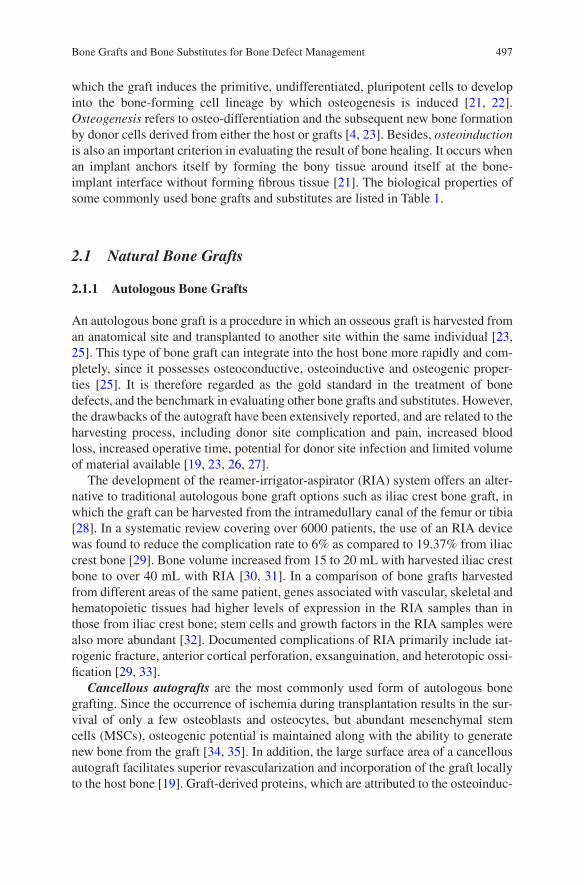
497
which the graft induces the primitive, undifferentiated, pluripotent cells to develop into the bone-forming cell lineage by which osteogenesis is induced [21, 22]. Osteogenesis refers to osteo-differentiation and the subsequent new bone formation by donor cells derived from either the host or grafts [4, 23]. Besides, osteoinduction is also an important criterion in evaluating the result of bone healing. It occurs when an implant anchors itself by forming the bony tissue around itself at the bone-implant interface without forming fibrous tissue [21]. The biological properties of some commonly used bone grafts and substitutes are listed in Table 1.
2.1 Natural Bone Grafts
2.1.1 Autologous Bone Grafts
An autologous bone graft is a procedure in which an osseous graft is harvested from an anatomical site and transplanted to another site within the same individual [23, 25]. This type of bone graft can integrate into the host bone more rapidly and com-pletely, since it possesses osteoconductive, osteoinductive and osteogenic proper-ties [25]. It is therefore regarded as the gold standard in the treatment of bone defects, and the benchmark in evaluating other bone grafts and substitutes. However, the drawbacks of the autograft have been extensively reported, and are related to the harvesting process, including donor site complication and pain, increased blood loss, increased operative time, potential for donor site infection and limited volume of material available [19, 23, 26, 27].
The development of the reamer-irrigator-aspirator (RIA) system offers an alter-native to traditional autologous bone graft options such as iliac crest bone graft, in which the graft can be harvested from the intramedullary canal of the femur or tibia [28]. In a systematic review covering over 6000 patients, the use of an RIA device was found to reduce the complication rate to 6% as compared to 19.37% from iliac crest bone [29]. Bone volume increased from 15 to 20 mL with harvested iliac crest bone to over 40 mL with RIA [30, 31]. In a comparison of bone grafts harvested from different areas of the same patient, genes associated with vascular, skeletal and hematopoietic tissues had higher levels of expression in the RIA samples than in those from iliac crest bone; stem cells and growth factors in the RIA samples were also more abundant [32]. Documented complications of RIA primarily include iat-rogenic fracture, anterior cortical perforation, exsanguination, and heterotopic ossi-fication [29, 33].
Cancellous autografts are the most commonly used form of autologous bone grafting. Since the occurrence of ischemia during transplantation results in the sur-vival of only a few osteoblasts and osteocytes, but abundant mesenchymal stem cells (MSCs), osteogenic potential is maintained along with the ability to generate new bone from the graft [34, 35]. In addition, the large surface area of a cancellous autograft facilitates superior revascularization and incorporation of the graft locally to the host bone [19]. Graft-derived proteins, which are attributed to the osteoinduc-
Bone Grafts and Bone Substitutes for Bone Defect Management
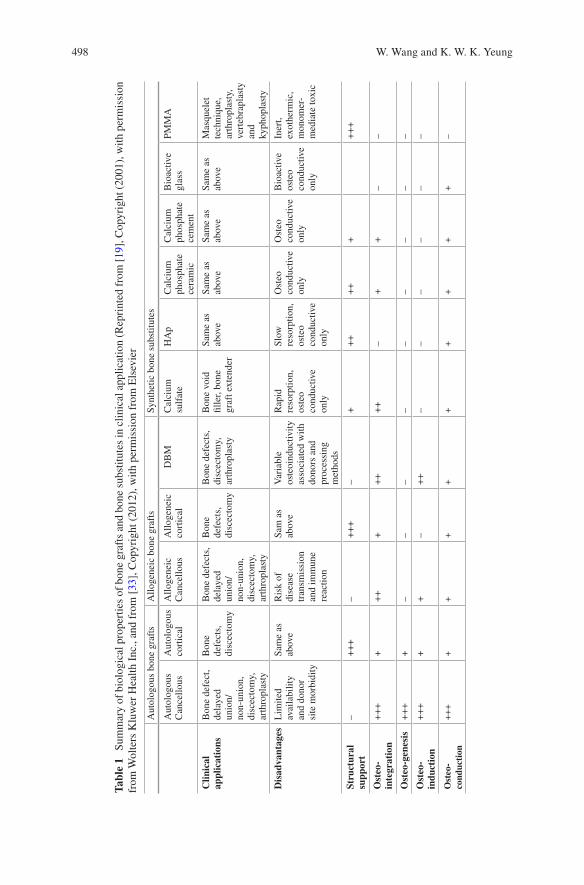
498
Tabl
e 1
Sum
mar
y of
bio
logi
cal p
rope
rtie
s of
bon
e gr
afts
and
bon
e su
bstit
utes
in c
linic
al a
pplic
atio
n (R
epri
nted
fro
m [
19],
Cop
yrig
ht (
2001
), w
ith p
erm
issi
on
from
Wol
ters
Klu
wer
Hea
lth I
nc.,
and
from
[33
], C
opyr
ight
(20
12),
with
per
mis
sion
fro
m E
lsev
ier
Aut
olog
ous
bone
gra
fts
Allo
gene
ic b
one
graf
tsSy
nthe
tic b
one
subs
titut
es
Aut
olog
ous
Can
cello
usA
utol
ogou
s co
rtic
alA
lloge
neic
C
ance
llous
Allo
gene
ic
cort
ical
DB
MC
alci
um
sulf
ate
HA
pC
alci
um
phos
phat
e ce
ram
ic
Cal
cium
ph
osph
ate
cem
ent
Bio
activ
e gl
ass
PMM
A
Clin
ical
ap
plic
atio
nsB
one
defe
ct,
dela
yed
unio
n/no
n-un
ion,
di
scec
tom
y,
arth
ropl
asty
Bon
e de
fect
s,
disc
ecto
my
Bon
e de
fect
s,
dela
yed
unio
n/no
n-un
ion,
di
scec
tom
y,
arth
ropl
asty
Bon
e de
fect
s,
disc
ecto
my
Bon
e de
fect
s,
disc
ecto
my,
ar
thro
plas
ty
Bon
e vo
id
fille
r, bo
ne
graf
t ext
ende
r
Sam
e as
ab
ove
Sam
e as
ab
ove
Sam
e as
ab
ove
Sam
e as
ab
ove
Mas
quel
et
tech
niqu
e,
arth
ropl
asty
, ve
rteb
rapl
asty
an
d ky
phop
last
y
Dis
adva
ntag
esL
imite
d av
aila
bilit
y an
d do
nor
site
mor
bidi
ty
Sam
e as
ab
ove
Ris
k of
di
seas
e tr
ansm
issi
on
and
imm
une
reac
tion
Sam
as
abov
eV
aria
ble
oste
oind
uctiv
ity
asso
ciat
ed w
ith
dono
rs a
nd
proc
essi
ng
met
hods
Rap
id
reso
rptio
n,
oste
o co
nduc
tive
only
Slow
re
sorp
tion,
os
teo
cond
uctiv
e on
ly
Ost
eo
cond
uctiv
e on
ly
Ost
eo
cond
uctiv
e on
ly
Bio
activ
e os
teo
cond
uctiv
e on
ly
Iner
t, ex
othe
rmic
, m
onom
er-
med
iate
toxi
c
Stru
ctur
al
supp
ort
–+
++
–+
++
–+
++
++
++
++
Ost
eo-
inte
grat
ion
++
++
++
++
++
+–
++
––
Ost
eo-g
enes
is+
++
+–
––
––
––
––
Ost
eo-
indu
ctio
n+
++
++
–+
+–
––
––
–
Ost
eo-
cond
ucti
on+
++
++
++
++
++
+–
W. Wang and K. W. K. Yeung
499
tion of the graft, are also preserved and present when the autografts are appropri-ately treated [19, 25]. In the early phase of autograft transplantation, MSCs contribute to the rapid formation of hematoma and inflammation, aiding in the cre-ation of fibrous granulation tissue. Meanwhile, macrophages slowly eliminate the necrotic graft tissue and neovascularization occurs. Next, during the incorporation of the autograft, seams of osteoid are produced by a line of osteoblasts surrounding the necrotic tissue; this is concurrent with the formation of new bone by accumu-lated hematopoietic cells within the transplanted bone [19, 23, 25]. This process, which leads to the complete resorption and replacement of the graft, usually takes 6–12 months [36].
Cortical autografts possess excellent structural integrity and are mechanically supportive, due to their limited number of osteoprogenitor cells [23]. Unlike the autologous cancellous graft, the creeping substitution of a cortical autograft is pri-marily mediated by osteoclasts, following the rapid formation of hematoma and the inflammatory response that occurs in the early phase of bone regeneration. The revascularization and remodeling processes are hampered by the dense architecture [25]. Consequently, the appositional bone growth over a necrotic core is the primary means by which the cortical autograft is incorporated following osteoclast resorp-tion [37, 38]. This process may take years, depending on the graft size and implanta-tion site [19, 25].
2.1.2 Allogeneic Bone Grafts
In allogeneic bone grafting, bony tissue from one individual is harvested and trans-planted to a genetically different individual of the same species [23, 25]. In light of the limitations of autologous bone grafts, a bone allograft is considered the best alternative. It has been used effectively in clinical practice in many circumstances, especially for patients with poor healing potential, established non-unions, and extensive comminution after fractures [25, 34]. The allograft may be machined and customized; it is therefore available in a variety of forms, including cortical, cancel-lous and highly processed bone derivatives (i.e., a demineralized bone matrix) [23]. Compared to autografts, allografts are immunogenic and demonstrate a higher fail-ure rate, which may be due to the activation of major histocompatibility complex (MHC) antigens [8]. If failure occurs, the initial osteoinduction phase is destroyed by an immune response and inflammatory cells, which quickly surround the neo-vascular tissue and cause the necrosis of osteoprogenitor cells [39–41]. The exact mechanism of immune responses in bone allograft incorporation is not clear; stud-ies have found that allograft acceptance is improved when the allograft is modified to diminish differences in immunogenicity, thereby reducing immunogenicity [25]. While the risk of viral transmission was once an issue, it has been significantly improved by the development of modern tissue banks [19] and improvement in processing technology [42]. For these reasons, the application of fresh allografts is always limited and preserved, modified allografts are usually preferred in clinical practices [43].
Bone Grafts and Bone Substitutes for Bone Defect Management
500
Cancellous allografts are the most common types of commercial allogeneic grafts and are supplied predominately in the form of cuboid blocks [23]. Due to the weak mechanical property they confer and their relatively poor ability to promote healing, preserved, modified cancellous allografts are used primarily in spinal fusion augmentation, as filler material for cavitary skeletal defects, and similar situ-ations [19, 25]. Compared to autografts, a similar but slower sequence of events occurs during incorporation of allografts [25]. However, osteointegration may be delayed by a host inflammatory response which leads to the formation of fibrous tissue around the graft, this was found in less than 10% of cases [44]. Meanwhile, the allografts remain entrapped and are never completely resorbed many years after transplantation [19, 26].
Cortical allografts confer rigid mechanical properties and are mainly applied in spinal augmentation for filling large skeletal defects where immediate loading-bear-ing resistance is required [23]. Frozen or freeze-dried products that are free of mar-row and blood are commonly transplanted, in the light of possible immune responses and for safety [25]. The incorporation of a cortical allograft is also preceded by creeping substitution, which is similar to its autogenous counterpart. In general, the process is initiated by osteoclastic resorption, and followed by a process of osteo-conduction resulting in the sporadic formation of new appositional bone [25, 34].
Demineralized bone matrix (DBM) is a kind of highly processed allograft deriv-ative, in which at least 40% of the mineral content of the bone matrix is removed by mild acid, while collagens, non-collagenous proteins, and growth factors remain [45]. DBM is mainly used for filling bone defects, due to inferior structural integrity and mechanical properties [46]. The osteoconductivity of the DBM is conferred by providing a framework for cell population and the generation of new bone after the demineralization treatment [19]. The osteoinductive property of DBM is mainly determined by the remaining growth factors, which are directly correlated with preparation methods. Much of the commercially available DBM uses 0.5–0.6 M of hydrochloric acid as a demineralizing agent. The incorporation of the DBM is simi-lar to that of the autogenous graft, with growth factors triggering an endochondral ossification cascade and culminating in new bone formation at the site of implanta-tion [19].
2.2 Synthetic Bone Graft Substitutes
As discussed above, the serious shortage of natural bone grafts and the little chance of supply meeting demand in an aging population [47] have triggered the tremen-dous growth in the bone graft and substitute (BGS) market [48]. Calcium sulfate, calcium phosphate (CaP) ceramics, CaP cements, bioactive glass, and combinations thereof are the most commonly available synthetic bone substitutes [49].
W. Wang and K. W. K. Yeung
501
2.2.1 Calcium Sulfate
Calcium sulfate, also known as plaster of Paris, is a kind of osteoconductive and biodegradable ceramic that has been used to fill void defects since 1892 [50]. It is prepared by heating gypsum with a patented alphahemihydrate crystal structure and can be made in different forms, such as hard pellets or injectable viscous fluids that harden in vivo [23]. Although lacking a macroporous structure, calcium sulfate still has a rapid resorption rate and weak internal strength. This implies that it can only be used to fill small bone defects with rigid internal fixation; the ingrowth of neo-vascular and new bone occurs during resorption of the graft [51]. Niu et al. [52] reported that the fusion rate of calcium sulfate was not optimal in spinal arthrodesis, primarily due to faster degradation than bone deposition in the early phase of bone regeneration. However, easy preparation and a relatively low cost have made cal-cium sulfate a useful choice when combined with other synthetic bone substitutes and/or growth factors [47].
One promising approach is to load antibiotics to this biomaterial. From June 2015 to November 2015, Glombitza and Steinhausen [53] used vancomycin-loaded calcium sulfate/hydroxyapatite to treat chronic osteomyelitis caused by multi-resis-tant bacterial for 7 patients. Rapid control of infection was achieved in 6 patients. However, as can be expected, new bone did not replace the composite in a uniform manner. More recently, Jing et al. [54] used calcium sulfate to modify the traditional Masquelet technique, which is a commonly used method for treating massive bone defects, in the hope of rendering the technique a one-step surgery. This case report described an open fracture of the calcaneus at the right foot that was reconstructed. They found the formation of the induced membrane with the implantation of cal-cium sulfate by X-ray images and a computed tomography scan. However, this trial was then stopped by the patient and the calcium sulfate was replaced by autologous iliac crest bone grafts; and further characterization of the induced membrane and bone regeneration was not possible [54].
2.2.2 Calcium Phosphate Ceramics (CaP Ceramics)
Calcium phosphate ceramics are constituted by calcium hydroxyapatites. These are chemical compositions similar to the mineral phase of calcified tissues [49]. They are synthetic mineral salts and are usually produced by sintering at high tempera-tures with the exclusion of water vapor and subsequently molded by high-pressure compaction [51]. Common commercially available forms include porous implants, non-porous dense implants and granular particles with pores. As they are bioabsorb-able ceramics with excellent osteoconductivity, CaP ceramics have received great attention and have been examined extensively in clinical studies [55–59]. Unlike the calcium-to-phosphate (Ca/P) ratio of biphasic calcium phosphate (BCP), it is pos-sible to identify the ratio of HAp and tricalcium phosphate (TCP), which are being most widely used in orthopedics. Several key parameters of CaP ceramics, such as absorption rate and mechanical properties, are strictly related to the Ca/P ratios. In
Bone Grafts and Bone Substitutes for Bone Defect Management
502
addition, the crystal and porous structure is a very important factor in choosing CaP ceramics.
Hydroxyapatite (HAp) is a natural occurring mineral form of calcium apatite with the formula of Ca10[PO4]6[OH]2. It comprises about 50% of the weight of the bone, which accounts for its excellent osteoconductive and osteointegrative proper-ties [23, 34]. HAp has similar initial mechanical properties compared to cancellous bone—it is brittle and weak under tension and shear but resistant to compressive loads [49], and may decrease by 30–40% in situ after being implanted for several months [60]. The macroporosity (pore with diameters >100 μm) and pore intercon-nectivity of synthetic HAp allow for the adhesion, proliferation, and differentiation of osteoprogenitor cells, as well as the revascularization, and subsequently ingrowth of new bone, when implanted in vivo [61, 62]. However, the relatively high Ca/P ratio and crystallinity delay the resorption rate of HAp; this process is predeter-mined by giant cells and macrophages [63]. It has been demonstrated that when porous hydroxyapatite cylinders were implanted in the cancellous bone of rabbits, only a 5.4% volume reduction was observed after 6 months, whereas the number for tricalcium phosphate ceramic was 85.4% under the same conditions [61]. Consequently, the decrease in the aforementioned mechanical properties would mean the remaining hydroxyapatite grafts within the host bone would compromise the intrinsic strength of the bone at the callus site [51]. Therefore, HAp alone is more often applied as a coating on implants and external fixator pins or in sites with low mechanical stress [34, 64].
The recent development of nanocrystalline HAp (nano-HAp) may help in over-coming these drawbacks, since it confers a larger surface to volume ratio. This great surface both significantly reduced the sintering temperature of HAp ceramics and led to the increased resorption rate [65]. However, this increase is not noticeable in clinical observation [66]. Efforts have also been made to enhance the mechanical performance of nano-HAp by incorporating carbon nanotubes (CNTs) [65, 67, 68]. While the addition of CNTs increased the open porosity from about 2.52% (pure nano-HAp) to a maximum of 7.93% (with an additional 2 wt.% of CNTs), fracture toughness with a value of 1.88 MPa m1/2 (similar to that of the human cancellous bone) was achieved when the additional amount was 1 wt.% [68]. Enhanced bone formation was also observed in a rabbit distal femur bone defect model, whereas toxicity was not exhibited in the liver or kidney. Nevertheless, the resorption rate of this nanocomposite was not fully investigated and the enhanced mechanical proper-ties are insufficient to extend the application of HAp in the clinic.
Tricalcium phosphate (TCP), especially the rhombohedral β-form, β-tricalcium phosphate (β-TCP), has attracted increased attention since it was first reported in 1920 by Albee [69]. With the chemical formula of Ca3(PO4)2, β-TCP has a Ca/P ratio of 1.5. This ratio, which is lower than that of hydroxyapatite, may partially accelerate its degradation and absorption [35]. Like HAp, TCP has even more inter-connected porous structures that can directly benefit fibrovascular invasion and bony replacement [34], but at the same time weaken mechanical properties [70]. A portion of TCP would inevitably convert into hydroxyapatite after implantation due to the thermodynamically unstable physiological pH. While this would partially
W. Wang and K. W. K. Yeung
503
hamper the degradation of TCP [71], the bulk would be resorbed by phagocytosis after 6–24 months, with some remaining for years [72]. This makes the TCP effec-tive for filling bone defects caused by trauma and benign tumors; however, its unpredictable biodegradation profile means it is not a favored bone-graft substitute [46].
Recent research has begun to focus on enhanced angiogenesis, in which the tri-calcium phosphate was applied to augment bone defects [73, 74]. By comparing the in vitro neovascularization capacity of four different types of CaP ceramics, namely HAp, BCP-1 (HAp: β-TCP = 70/30), BCP-2 (HAp: β-TCP = 30/70) and β-TCP, they found that human umbilical vein endothelial cells (HUVECs) demonstrated significantly up-regulated proliferation and angiogenesis when cultured with BCP-2, which contain a higher amount of the β-TCP phase, and pure β-TCP [73]. In the mouse intramuscular implantation model, CaP ceramics containing a larger amount of β-TCP also induced higher microvessel density [73]. Several hypotheses have been proposed to explain the mechanism, such as the porous structure [75–77], the effects of ionic transfer upon degradation of CaP ceramics and homeostasis [78–80], and potential strains imposed on CaP during degradation [81, 82]. Nevertheless, the mechanism has not been fully investigated and further study is required.
Biphasic calcium phosphate (BCP) is another widely used commercial ceramic obtained by mixing hydroxyapatite and tricalcium phosphate in different concentra-tions for the purpose of combining the advantages of both calcium salts [83]. By adjusting the formulation, the dissolution rate and mechanical properties can be controlled within the desired range and subsequently applied in bulk or as an implant coating [84].
2.2.3 Calcium Phosphate Cements (CPC)
Unlike CaP ceramics, calcium phosphate cements (CPCs) usually involve two com-pounds, one of which is an aqueous curing agent. They were invented by Brown and Chow in the 1980s [85, 86] for the purpose of extending the adaptability and mold-ability of CaP bone substitutes. They were approved by the U.S. Food and Drug Administration (FDA) [49] in 1996. They can be injected to fill defects in various shapes; they are subsequently solidified by mixing with an aqueous phase through isothermic reaction. Self-hardened CPCs are generally highly microporous, bio-compatible, and mechanically supportive with low bending strength [87]. However, they can only degrade one layer at a time, as predetermined by the dissolution in human in vivo physiological conditions and osteoclast resorption activity. As a result, an ingrowth of neovascular and bone tissue is theoretically hampered com-pared to the CaP ceramics that support interconnected macroporosity [49]. Apatitic CPCs and brushite CPCs can be identified according to their composition. Their properties, with regard to feasibility, setting reaction and biodegradation rates, are highly related to their compositions. Apatitic CPCs are viscous, indicating relatively poor injectability; however, a setting reaction can occur at the physiological pH value and the mechanical properties are slightly stronger than brushite CPCs. Due
Bone Grafts and Bone Substitutes for Bone Defect Management
504
to the low crystalline structure of the calcium-deficient-hydroxyapatite obtained after hardening, a higher degradation rate was demonstrated but still incomplete [88]. The brushite CPCs are feasible for injection and solidify quickly at a low pH value (< 6) [87]. While they demonstrate higher degradability, unpredictable degra-dation was reported due to the favorable kinetic transformation to hydroxyapatite [71]. Based on their flow behavior before setting, CPCs are clinically favored for bone replacement, especially in percutaneous vertebroplasty [89–91] and kypho-plasty [92, 93], but not as bone substitutes.
Like CaP ceramics, the preparation of nanostructured CaP was developed in order to promote the mechanical properties and biological performances of CPCs. Even though the up-regulated cell attachment and proliferation, as well as the in vivo bone regeneration, was achieved over the course of several studies [94–96], the motivation of applying nanostructured CPCs is mainly attributed to the fact that the native architecture of bone tissue is at the nano-scale [97–100]; however, the cellu-lar and molecular mechanism has not been fully elaborated [95]. The incorporation of fibers, which is also inspired by the hierarchical nanostructure of bone, is another approach that is being widely investigated to enhance the mechanical strength of CPCs [101]. However, there is still insufficient evidence that these modifications benefit clinical practice [102].
Phase separation, which refers to the separation of the powder and liquid compo-nents during injection, is another important concern associated with the clinical application of CPCs [103]. Given the abundant research over the past two decades, several methods have achieved clinical success in some applications by weakening other crucial properties of CPCs [104–108]. However, recent research has tended to elucidate the relationship of the critical parameters of CPCs by theoretical calcula-tions and analysis alone, due to the extremely difficult isolation of those parameters by solely experimental work [109–115]. Since these studies are not yet reflected in real experimental practice, which would affect the clinical application of CPCs, they will not be highlighted in this review [116].
2.2.4 Bioactive Glass
Bioactive glass, also known as bioglass, refers to a group of synthetic silicate-based ceramics. It was originally constituted of silicon dioxide (SiO2), sodium oxide (Na2O), calcium oxide (CaO), and phosphorus pentoxide (P2O5) when first devel-oped in the 1970s [117]. This was later modified to a more stable composition, by the addition of potassium oxide (K2O), magnesium oxide (MgO), and boric oxide (B2O); the key component, silicate, constitutes 45–52% of its weight [34]. The opti-mized constitutions led to a strong physical bonding between bioglass and host bone. This phenomenon, called bioactivity, was first found on BGS [118]. This bone-binding property is believed to be caused by leaching and the accumulation of silicon ions when exposed to body fluids upon implantation and the subsequent formation of hydroxyapatite coating on the surface of bioglass [119]. This thin hydroxyapatite coating absorbs proteins and attracts osteoprogenitor cells. In
W. Wang and K. W. K. Yeung
505
addition, this biological apatite layer is partially replaced by bone through a creep substitution process in long-term implantation [120]. The porosity and relatively fast resorption rate in the first two weeks of implantation allows an ingrowth of neovascular following deposition of the new bone [11, 35]. One study has demon-strated that bioglass fiber scaffolds can be completely resorbed in 6 months in vivo with little inflammatory response [121]. Like the other ceramics, the mechanical properties of bioglass were reported to be brittle and weak. Therefore, it has been applied primarily in the reconstruction of facial defects [122, 123] when combined with growth factors [124, 125].
Bioglass 45S5 (46.1 mol.% SiO2, 24.4 mol.% Na2O, 26.9 mol.% CaO and 2.6 mol.% P2O5, now sold by NovaBone Products LLC, US) and S53P4 (53.8 mol.% SiO2, 22.7 mol.% Na2O, 21.8 mol.% CaO and 1.7 mol.% P2O5, now sold by BonAlive Biomaterials, Finland) are the two most recognized commercially avail-able bioglasses that can be used as bone graft substitutes. They are made using the standard melt-quenching technique under high temperature (usually above 1300 °C); thus, they cannot be fabricated into amorphous scaffolds due to the crystallization that occurs during sintering at that temperature. One exception is 13–93, with a composition of 54.6 mol.% SiO2, 6 mol.% Na2O, 22.1 mol.% CaO, 1.7 mol.% P2O5, 7.9 mol.% K2O and 7.7 mol.% MgO; this composition does not crystallize during sintering. However, the bioactivity of 13–93 was significantly reduced in the form of prolonging the formation of hydroxyapatite layer in the stimulated body fluid (SBF) immersion tests, from 8 h on the surface of Bioglass 45S5 to 7 days on the 13–93 [126]. Several clinical trials demonstrated similarly good contact with the host bone when the S53P4 and Bioglass 45S5 was applied to treat bone defects, respectively [127–129], whereas reduced resorption of S53P4 was exhibited due to the higher silica content [123, 130]. Additionally, inferior healing results were also reported when compared to autologous grafts [131, 132].
The development of sol-gel processing offers another route to produce bioactive glass with a porous structure ranging from mesopores to macropores [133–135], in which 58S (60 mol.% SiO2, 36 mol.% CaO and 4 mol.% P2O5) and 77S (80 mol.% SiO2, 16 mol.% CaO and 4 mol.% P2O5) are representatives. In a study involving the management of critical-sized defects at the femoral condyle of rabbits, the bone regeneration ability and in vivo degradation of melt-derived Bioglass 45S5 and sol-gel-derived bioglass 77S and 58S were compared [136]. Due to the nanoporosity and enhanced surface area, the sol-gel-derived bioglass demonstrated faster degra-dation speed compared to Bioglass 45S5 between 4 and 24 weeks after implanta-tion, while the bone defect filled with Bioglass 45S5 contained more bone than those filled with 77S or 58S at 8 weeks post-operation; they then equalized after implantation for 12 weeks [136]. It seems the fast degradation of bioglass may lead to an elevated pH value and accumulated ions in the microenvironment; since this is not favored by cells, it thus jeopardized the bone ingrowth [123].
Bone Grafts and Bone Substitutes for Bone Defect Management
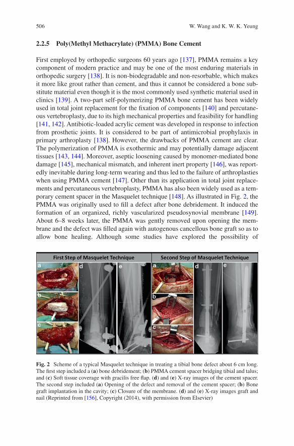
506
2.2.5 Poly(Methyl Methacrylate) (PMMA) Bone Cement
First employed by orthopedic surgeons 60 years ago [137], PMMA remains a key component of modern practice and may be one of the most enduring materials in orthopedic surgery [138]. It is non-biodegradable and non-resorbable, which makes it more like grout rather than cement, and thus it cannot be considered a bone sub-stitute material even though it is the most commonly used synthetic material used in clinics [139]. A two-part self-polymerizing PMMA bone cement has been widely used in total joint replacement for the fixation of components [140] and percutane-ous vertebroplasty, due to its high mechanical properties and feasibility for handling [141, 142]. Antibiotic-loaded acrylic cement was developed in response to infection from prosthetic joints. It is considered to be part of antimicrobial prophylaxis in primary arthroplasty [138]. However, the drawbacks of PMMA cement are clear. The polymerization of PMMA is exothermic and may potentially damage adjacent tissues [143, 144]. Moreover, aseptic loosening caused by monomer-mediated bone damage [145], mechanical mismatch, and inherent inert property [146], was report-edly inevitable during long-term wearing and thus led to the failure of arthroplasties when using PMMA cement [147]. Other than its application in total joint replace-ments and percutaneous vertebroplasty, PMMA has also been widely used as a tem-porary cement spacer in the Masquelet technique [148]. As illustrated in Fig. 2, the PMMA was originally used to fill a defect after bone debridement. It induced the formation of an organized, richly vascularized pseudosynovial membrane [149]. About 6–8 weeks later, the PMMA was gently removed upon opening the mem-brane and the defect was filled again with autogenous cancellous bone graft so as to allow bone healing. Although some studies have explored the possibility of
Fig. 2 Scheme of a typical Masquelet technique in treating a tibial bone defect about 6 cm long. The first step included a (a) bone debridement; (b) PMMA cement spacer bridging tibial and talus; and (c) Soft tissue coverage with gracilis free flap. (d) and (e) X-ray images of the cement spacer. The second step included (a) Opening of the defect and removal of the cement spacer; (b) Bone graft implantation in the cavity; (c) Closure of the membrane. (d) and (e) X-ray images graft and nail (Reprinted from [156], Copyright (2014), with permission from Elsevier)
W. Wang and K. W. K. Yeung
507
combining periosteum and bone graft [150, 151], or biodegradable biomaterials [54, 152–154] as the “space filler” in the hope of streamlining the Masquelet tech-nique into a single-stage technique, PMMA is still the primary option for a cement spacer [155].
3 The Adoption of Growth Factors on Bone Defect Management
Most bone graft substitutes, especially synthetic ceramics and cements, do not pos-sess any osteoinductive property. The ability of those bone substitutes to enhance bone healing mainly relies on osteoconductive means [23]. In general, the osteocon-duction of a bone substitute would facilitate migration and support the attachment of progenitor cells, which would then secrete growth factors to stimulate bone for-mation [34]. However, if the ideal environment for callus formation is disturbed and the secretion of growth factors is missing, the environment is thereby predisposed to a delayed union or even non-union [157]. The presence of osteoinductive factors during bone healing is also critically important. Therefore, direct application of growth factors, some of which are involved in the natural healing process of bone injury, has also been extensively studied and accepted as a kind of therapeutic strat-egy in the clinic [158]. It must be noted that only a few biological factors, such as BMPs, fibroblast growth factors (FGF) vascular endothelial growth factors (VEGF), PTH and platelet-rich plasma (PRP), have undergone rigorous preclinical tests and clinical trials (see Table 2) [159].
3.1 Bone Morphogenetic Proteins (BMPs)
Bone morphogenetic proteins (BMPs), especially BMP-2 (including recombinant human BMP-2, rhBMP-2), and BMP-7 (including recombinant human BMP-7, rhBMP-7), are members of the transforming growth factor beta (TGF-β) superfam-ily with superior osteoinductive properties. They are possibly the most extensively investigated growth factors in treating skeletal defects [159]. BMP-2 is able to induce osteoblastic differentiation from mesenchymal stem cells, and BMP-7 can directly promote angiogenesis. The largest trial in the use of BMPs was in treating open tibial fractures [162]. This trial, known as BMP-2 Evaluation in Surgery for Tibial Trauma (BESTT), involved multiple clinical centers. In the trial, 450 patients were randomly divided into three groups. One group received BMP-2 at 0.75 mg/mL, the second group received 1.5 mg/mL, and the third was the control group. An intramedullary nail was applied universally. Twelve months after surgery, patients treated with 1.5 mg/mL rhBMP-2 displayed quicker bone callus formation and wound closure with lower infection and less pain, compared to the control group.
Bone Grafts and Bone Substitutes for Bone Defect Management
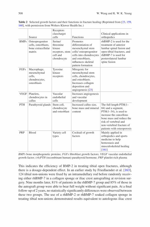
508
This indicates the efficiency of BMP-2 in treating tibial open fractures, although there is a dosage-dependent effect. In an earlier study by Friedlaender et al. [163], 124 tibial non-unions were fixed by an intramedullary rod before randomly receiv-ing either rhBMP-7 in a collagen sponge or iliac crest autografting at revision sur-gery. Nine months later, 81% of patients in the rhBMP-7 group and 85% of those in the autograft group were able to bear full weight without significant pain. At a final follow-up of 2 years, no statistically significantly differences were observed between these two groups. The use of a rhBMP-2 or rhBMP-7 soaked collagen sponge in treating tibial non-unions demonstrated results equivalent to autologous iliac crest
Table 2 Selected growth factors and their functions in fracture healing (Reprinted from [23, 159, 160], with permission from Wolters Kluwer Health Inc.)
Source
Receptors class/target cells Functions
Clinical applications in orthopedics
BMPs Osteoprogenitor cells, osteoblasts, bone extracellular matrix
Serine/threonine kinase receptors, stem cell and chondrocyte
Promotes differentiation of mesenchymal stem cells/ osteoprogenitor cells into chondrocytes and osteoblasts, influences skeletal pattern formation
rhBMP-2 is used for the treatment of anterior lumbar spinal fusion and open tibial fractures, and rhBMP-7 is used for posterolateral lumbar spine fusion
FGFs Macrophage, mesenchymal cells, chondrocytes, osteoblasts
Tyrosine kinase receptors
Mitogenic for mesenchymal stem cells, chondrocytes, and osteoblasts.Increases collagen deposition and angiogenesis [23]
VEGF Platelets, chondrocytes in callus
Vascular endothelial cells
Increases angiogenesis and vascular development
PTH Parathyroid glands Stem cell, chondrocyte and osteoblast
Increased callus size, bone mass and mineral content
The full length PTH(1–84) and a segment, PTH(1–34), is used to increase the cancellous bone mass and reduce the risk of vertebral and non-vertebral fracture of patients with osteoporosis
PRP Blood Variety cell types
Cocktail of growth factors
Mainly applied in orthopedics and sports medicine to help hemostasis and musculoskeletal healing [161]
BMPs bone morphogenetic proteins; FGFs fibroblast growth factors; VEGF vascular endothelial growth factor; (rh)PTH (recombinant human) parathyroid hormone; PRP platelet-rich plasma
W. Wang and K. W. K. Yeung
509
grafting, while also reducing persistent donor pain. After being tested in numerous animal models [164] and clinical trials [165–168], rhBMP-2 (INFUSE™, Medtronic, US) has been approved by the FDA and the European Medicines Evaluation Agency (EMEA) for application in anterior lumbar spinal fusion and open tibial fractures [26, 157], while rhBMP-7 (OP-1™, Stryker, US) has received approval in treatment of posterolateral lumbar spine fusion [167, 168]. However, since commercially available forms of BMPs lack osteoconductivity, they are always combined with an osteoconductive carrier, such as collagen, allograft, or even an autologous bone graft, to enhance efficiency.
Off-label usage has increased dramatically, triggered by the clinical evidence of quicker bone formation stimulated by BMPs; this was reported to account for 85% of lumbar fusion procedures in 2008 [169]. Other than the approved application in tibial non-union, the studies in treating other long-bone non-unions, such as humerus pseudarthrosis [170], lower-limb pseudarthrosis [171–173], clavicle [174] and ulna [175], have also been reported sporadically; results were poor or relied on insuffi-cient evidence [176]. In a prospective and randomized clinical trial reported by Ekrol et al. in 2008 [177], 30 patients with symptomatic malunion of the distal radius received a corrective osteotomy, either autogenous iliac crest bone grafting (AICBG, 16 patients) or direct application of rhBMP-7 (without any carrier, 14 patients). Due to the loss of fixation, an external fixation system was applied in 4 patients from the rhBMP-7 group and 6 patients in the AICBG group, respectively, before the internal fixation system was used in the remaining patients (10 patients in each group). Although this change makes the result difficult to explain, inferior healing and union percentage was demonstrated in the group receiving rhBMP-7 treatment. It was believed that their results would have been significantly different if a carrier had been applied. Several researchers have also applied BMPs to improve foot or ankle arthrodesis fusion in patients with poor surgical healing [178–180] and an effective adjuvant effect was exhibited [181]; however, there remains a lack of randomized controlled trials.
It is generally accepted that the equivalent clinical outcome would be achieved if BMPs were used to treat some complex bone defects, such as spinal fusion and tibial open fractures, rather than iliac crest autologous bone grafts, however, the high rate of complications remains a concern [176]. BMPs are especially soluble proteins and have a tendency to dissipate from their intended locations [23], which can lead to several complications. As demonstrated in the previous literature, there tends to be a dose-dependent effect in the application of BMPs [182]. The dissipa-tion of proteins dilutes their local concentration, and, in turn, their efficiency. In addition, BMPs can influence several cell types and organs, which subsequently cause heterotopic bone formation. Boraiah et al. reported ten cases of ectopic bone formation out of 17 complex proximal tibia fractures treated with rhBMP-2; four of them needed extra surgical excision [183]. In some extreme conditions, such as one case reported by Ritting et al., the use of BMP-2 in an ulnar non-union in a 9-year-old patient led to a persistent inflammatory response and finally caused osteolysis [184]. In addition, cost effectiveness is another important issue when using BMPs [185].
Bone Grafts and Bone Substitutes for Bone Defect Management
510
3.2 Fibroblast Growth Factors (FGFs)
Twenty-two members of the fibroblast growth factors family and four fibroblast growth factor receptors (FGFRs) have been identified and are secreted by mono-cytes, macrophages, mesenchymal stem cells, osteoblasts, and chondrocytes, start-ing with the early stages of fracture healing and lasting throughout the entire healing process [186]. While the role of FGFs in fracture healing is not well understood, it has been demonstrated that FGFs both play a critical role in angiogenesis [187–189] and have potent mitogenic effects on mesenchymal progenitor cells [190]; all of these are mediated by FGFs/FGFRs signaling. Among all these FGFs and FGFRs, numerous studies have found that FGF1, FGF2 and FGFR1–3 are closely related to bone regeneration [191–194]. Furthermore, these studies have found that FGFR1 and FGFR2 have stronger expressions in osteoprogenitors and osteoblasts, whereas FGFR3 is more closely related to chondrogenesis [195]. Hence, the efficacy of FGF2 in treating bone defects was investigated by numerous in vivo animal studies [196, 197], including two non-human primate studies [198, 199]. Results also showed it promoted fracture healing, although this effect is dose- and time-depen-dent [195, 200]. Kawaguchi et al. performed a representative clinical trial of rhFGF in treating tibial shaft fractures in 70 patients [201]. After fixation by an intramedul-lary nailing system, patients were randomly injected with either a gelatin hydrogel (placebo, 24 patients), 0.8 mg rhFGF-2 in a gelatin hydrogel (low dosage group, 23 patients), or 2.4 mg rhFGF-2 in a gelatin hydrogel (high dosage group, 23 patients) at the fracture site. Radiographic analysis demonstrated accelerated fracture healing and higher facture unions in both rhFGF treated groups compared to the hydrogel-only group, while no difference between the low dosage group and high dosage group was displayed. However, due to our limited understanding of the spatiotem-poral expression patterns of FGF/FGFR signaling in fracture healing, further stud-ies are required before clinical trials may begin. In addition, the results of FGFs in treating bone fractures compared to autologous and BMPs are still missing.
3.3 Vascular Endothelial Growth Factor (VEGF)
Local vascularity at the fracture site is recognized as one of the most significant parameters affecting bone regeneration. There are two main hormonal pathways controlling angiogenesis, the VEGF pathway and the angiopoietin pathway; the VEGF is dominant [202, 203]. Except for angiogenesis, VEGF has also been dem-onstrated to be osteogenic [204]. In the bone fracture healing process, VEGF is initially released from hematoma and promotes the development of endothelial cells to induce vascular invasion [23] under the hypoxia environment [205]. Consequently, during the endochondral ossification process, VEGF is secreted by hypertrophic chondrocytes in the epiphyseal growth plate to promote the blood vessel invasion of cartilage and blood flow that facilitates new bone formation [204, 206]. Numerous
W. Wang and K. W. K. Yeung
511
animal studies have shown the effectiveness of exogenous VEGF in promoting bone fracture healing [207–211]. In one study reported by Kaigler et al. [208], rodents with critical-sized cranial bone defect were treated by either bioglass alone or VEGF-containing bioglass. Increased vascularization and bone quality were observed in the VEGF-containing group, but no significant difference was found when the quantity of the newly formed bone was compared. A similar result was documented in other research published from the same laboratory [209], which implied that VEGF tends to contribute to bone maturation but does not enhance the amount of new bone formation [204]. In a rabbit model, either VEGF or an auto-graft was compared to a carrier-alone group in treating experimental fracture non-unions [210]. Compared to the control group, significant new bone formation and enhanced mechanical properties were observed from a radiological evaluation and bio-mechanical testing, respectively, while no significant difference was demon-strated in the blood flow or vascularity. All the evidence points to the importance of the collaboration of angiogenesis and osteoinductive factors in bone regeneration [212]. Although the cornerstone role of VEGF in angiogenesis during fracture heal-ing has been confirmed and promising bone regeneration outcomes have been dem-onstrated in preclinical research, VEGF is in fact very unstable and short-lived in vivo, so a gene delivery vehicle is usually employed. In addition, there is a risk of haemangiomas or recurrence of tumors that are stimulated by VEGF, especially for patients who have had radiotherapy or tumor excision. The application of VEGF in clinical trials and its direct effect on human fracture healing is strictly limited [211]; the application of VEGF must be very accurate in terms of dosology [204].
3.4 Parathyroid Hormone (PTH)
Parathyroid hormone (PTH) is a naturally occurring endocrine containing 84 amino acids. It functions as a mediator of calcium and phosphate homeostasis in humans [213]. It has also been demonstrated to increase bone mass, bone strength, and reduce bone loss; the structure-function analysis of PTH has suggested that these activities are mainly attributed to the N-terminal fragment (encompassing amino acids 1–34 and called PTH(1–34)) [214]. Thus, there are two PTH-derived products available nowadays, the full-length protein PTH(1–84), with a commercial name of Natpara™ (Shire-NPS Pharmaceuticals, US), and a segment of protein PTH(1–34), which was licensed by the FDA in 2002 under the name Teriparatide (Forteo™, Lilly LLC, US) [213]. They have been developed as a drug to increase the cancel-lous bone mass and reduce the risk of vertebral and non-vertebral fracture of patients with osteoporosis. Although the detailed mechanism is not yet fully understood, it was found that several signaling pathways were involved. The anabolic effect of PTH was exerted mainly through inhibiting the apoptosis of pre-osteoblasts; this, in turn, increased osteoblast function and lifespan, thus increasing the number of these bone-making cells [215].
Bone Grafts and Bone Substitutes for Bone Defect Management
512
Since PTH increases bone mass and prevents fracture in osteoporotic bone [216], a growing number of studies have suggested the ability of PTH to accelerate frac-ture healing even though most of the studies were focused on animals. In a dia-physial femoral fracture model involving 270 male Sprague Dawley rats, either a placebo or 5 μg/kg or 30 μg/kg PTH(1–34) was injected daily subcutaneously for 35 days [217]. Significantly, torsional strength, stiffness, bone mineral content, bone mineral density, and cartilage formation were observed in the callus from the group treated with 30 μg/kg PTH compared to that of the control group over 21 days; no difference in osteoclast density was detected. Other animal experiments con-firmed the positive effects of PTH on fracture healing in different species, locations and under various pathological conditions [218]. In short, these studies conducted on animal models confirmed that intermittent treatment with PTH has anabolic effects on bone and thus leads to recovery of bone mass and increased mechanical property; however, continuous exposure to PTH causes bone loss [214, 219–222].
Aspenberg et al. conducted a prospective, randomized clinical trial employing 102 postmenopausal female patients with distal radial fractures in 2010 [223]. They were randomized to receive a placebo, a 20 μg (ordinary osteoporosis dosage) or 40 μg PTH injection daily (double dosage). No difference was found between the 20 μg group and the 40 μg group, however, shorter times for the first radiographic evidence of cortical bridging were documented, which were 9.1, 7.4, and 8.8 weeks in the placebo, 20 μg group, and 40 μg group, respectively. Further analysis demon-strated that PTH would mainly increase early callus formation with a dose-depen-dent pattern, whereas the cortical bridging is not necessarily stimulated by PTH [224]. In another study involving pelvic ramus fractures in 65 osteoporotic women, radiographic bridging of cortical bone was found to be shortened from 12.6 weeks in the control group to 7.8 weeks in the PTH(1–84)-treated group [225]. More recently, a randomized clinical trial was performed to examine the effect of Teriparatide in treating elderly patients with a pertrochanteric hip fracture as com-pared to those using risedronate, which is a bisphosphonate drug [226, 227]. In 171 patients, 86 received 20 μg Teriparatide every day and others received 35 mg rise-dronate once per week, starting two weeks after surgery. After 78 weeks, several outcomes were comprehensively analyzed, including the BMD at the lumbar spine (LS), femoral neck (FN) and total hip (TH), functionality (through timed up-and-go (TUG) test), hip pain (Charnley score and 100 mm visual analog scale (VAS)), qual-ity of life, radiology outcomes, and safety. A significantly greater increase in LS and FN BMD, less pain, and a faster TUG results were recorded when patients were treated with Teriparatide as compared to those with risedronate [227]. In conclu-sion, there is little doubt that PTH has a positive influence on fracture healing; however, it must be noted that PTH is not a differentiation factor and is unlikely to help if fracture healing has not already properly begun. Additionally, the robust evidence observed in animal studies has not been demonstrated beyond a reasonable doubt in humans [214].
W. Wang and K. W. K. Yeung
513
3.5 Platelet-Rich Plasma (PRP)
The investigation of platelet-rich plasma (PRP) for bone regeneration represents attempts to harness the power of the cascade of growth factors released by the aggregation and degranulation of platelets in a native fracture hematoma [228]. PRP is mainly produced by using commercially available devices to isolate and concen-trate platelets from peripheral blood. It is the plasma fraction of autologous blood having a platelet concentration above baseline [229]. It contains various key mito-genic and chemotactic growth factors, including platelet-derived growth factor (PDGF), insulin-like growth factor (IGF), fibroblast growth factors (FGFs), trans-forming growth factor-beta (TGF-β), and VEGF [230]. For those patients receiving conservative orthopedic treatment caused by aging and degeneration, such as knee pain and tennis elbow, PRP is frequently used and demonstrates good clinical out-comes [231–233]. However, when investigating the effects of PRP on bone healing, especially in humans, the clinical results are conflicting and strong supportive evi-dence is lacking [26]. Calori et al. (2008) conducted a prospective, randomized trial comparing the treatment effect of rhBMP-7 and PRP in 120 patients with long bone non-unions [234]. They found a union occurring in 68.3% of cases (41 of 60 patients) in the PRP-treated group, and 86.7% of cases (52 of 60 patients) in the rhBMP-7 group. The mean time to clinical healing was 4 months in the PRP group compared to 3.5 months in the rhBMP-7 group. These results implied significantly inferior healing when treated with PRP. Another study investigated the efficacy of PRP in treating 132 patients with delayed union when long bone fractures were surgically treated at the Military Medical Institute in Warsaw between 2009 and 2012 [235]. A bone union was established in 108 patients (81.8%) after PRP admin-istration, whereas 24 patients (18.2%) showed no improvement. They also con-cluded that the location-dependent efficacy of PRP following 100% union (on average, 3.5 months) was exhibited at the proximal tibial, whereas the union at the proximal humerous was only 63.64% (on average, 3.2 months). A more recently report described the efficacy of PRP in treating the non-union of long bone fractures among 94 patients [236]. Autologous PRP (> 2,000,000 platelets/μL) with a dose of 15–20 mL was injected directly into the defect sites and the bridging was radiologi-cally evaluated by X-ray at monthly intervals for 4 months. Union occurred in 82 patients (87.23%) at the end of 4 months and no complication was documented. Nonetheless, the negative effect of PRP on bone healing was not rare [237, 238]. Ranly et al. reported that PRP may inhibit bone formation through the prevention of osteoinduction in mice models [239, 240].
While faster bone healing was demonstrated in this limited number of human clinical trials involving the usage of PRP to treat orthopedic defects, its efficacy was still found to be inferior to that of BMPs. Nevertheless, it is still insufficient to sup-port its routine use in orthopedic trauma; well planned, randomized control trials are still needed [241, 242]. Meanwhile, it must be noted that platelet activity is influ-enced by many factors related to the individual whose blood is collected [243];
Bone Grafts and Bone Substitutes for Bone Defect Management
514
therefore, the standardized concentration and biological quantification of PRP in treating bone healing requires further study.
4 The Adoption of Bioinorganic Ions on Bone Regeneration
Safety issues have become a concern as the result of negative attention and adverse events regarding off-label usage of growth factors [10, 12, 244]. Alternatively, incorporation and/or local delivery of bioinorganic ions, which is also a natural but safer approach, has been highlighted [245]. Inspired by observing nutritional defi-ciency or excess, bioinorganic ions have long been applied in a variety of therapies, even when little was known of their mechanisms [18]. In recent years, the role of metallic ions in the human body has been gradually unraveled (see Table 3 and Fig. 3). Bioinorganic ions, such as silicon, magnesium, strontium, zinc, and copper, can still be regarded as essential cofactors of enzymes, coenzymes or prosthetic groups. Additionally, they are actively involved in ion channels or in the process of secondary signaling, either on direct stimulation or as an analog [18]. Incorporation of these ions confers low cost, longer shelf life and perhaps lower risk compared to growth factors [246]. While the therapeutic use of bioinorganic ions, especially some heavy metal ions, seems counter-intuitive, the words of Paracelsus are perti-nent: “Everything is poisonous and nothing is non-toxic, only the dose makes some-thing not poisonous” [247]. Consequently, the challenge in using bioinorganic ions in bone healing is also quite clear and has been described succinctly by Ash and Stone: “It is indeed a narrow path between poison and nutrition” [248].
4.1 Silicon (Si)
Silicon is the second most abundant element on earth. Since silicate (a silicate is a silicon-containing anion) is rich in foods and water, deficiency in humans is rare and its pathology is unknown. But in an animal model, chickens on a silicon-depleted diet showed deformed bone development, low collagen formation, and stunted growth [268]. Research found that silicon is rich in bone and connective tissue as an integral component of glycosaminoglycan and their protein complexes [269], which may subsequently affect bone formation and maintenance [270]. In research per-formed by Carlisle, an electron micro-probe was applied to locate silicon in the tibial bones of young mice and rats. Silicon was detected in the early stages of the bio-mineralization process at an active calcification site, increasing in parallel with calcium at low calcium concentrations, and diminishing when the mineral composi-tion approached hydroxyapatite [271]. These observations have confirmed that sili-con is associated with calcium in bone metabolism [272].
While testing the effect of aqueous silicon on cellular activity, dose-dependent enhancement of osteoblast proliferation, differentiation, and collagen production
W. Wang and K. W. K. Yeung
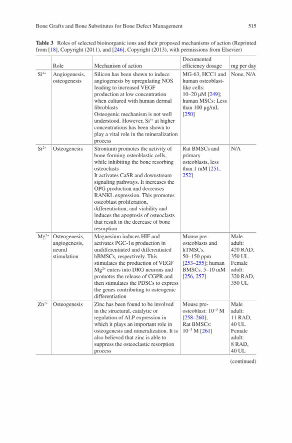
515
Table 3 Roles of selected bioinorganic ions and their proposed mechanisms of action (Reprinted from [18], Copyright (2011), and [246], Copyright (2013), with permissions from Elsevier)
Role Mechanism of actionDocumented efficiency dosage mg per day
Si4+ Angiogenesis, osteogenesis
Silicon has been shown to induce angiogenesis by upregulating NOS leading to increased VEGF production at low concentration when cultured with human dermal fibroblastsOsteogenic mechanism is not well understood. However, Si4+ at higher concentrations has been shown to play a vital role in the mineralization process
MG-63, HCC1 and human osteoblast-like cells: 10–20 μM [249]; human MSCs: Less than 100 μg/mL [250]
None, N/A
Sr2+ Osteogenesis Strontium promotes the activity of bone-forming osteoblastic cells, while inhibiting the bone resorbing osteoclastsIt activates CaSR and downstream signaling pathways. It increases the OPG production and decreases RANKL expression. This promotes osteoblast proliferation, differentiation, and viability and induces the apoptosis of osteoclasts that result in the decrease of bone resorption
Rat BMSCs and primary osteoblasts, less than 1 mM [251, 252]
N/A
Mg2+ Osteogenesis, angiogenesis, neural stimulation
Magnesium induces HIF and activates PGC-1α production in undifferentiated and differentiated hBMSCs, respectively. This stimulates the production of VEGFMg2+ enters into DRG neurons and promotes the release of CGPR and then stimulates the PDSCs to express the genes contributing to osteogenic differentiation
Mouse pre-osteoblasts and hTMSCs, 50–150 ppm [253–255]; human BMSCs, 5–10 mM [256, 257]
Male adult:420 RAD, 350 ULFemale adult:320 RAD, 350 UL
Zn2+ Osteogenesis Zinc has been found to be involved in the structural, catalytic or regulation of ALP expression in which it plays an important role in osteogenesis and mineralization. It is also believed that zinc is able to suppress the osteoclastic resorption process
Mouse pre-osteoblast: 10−5 M [258–260];Rat BMSCs: 10−5 M [261]
Male adult:11 RAD, 40 ULFemale adult:8 RAD, 40 UL
(continued)
Bone Grafts and Bone Substitutes for Bone Defect Management
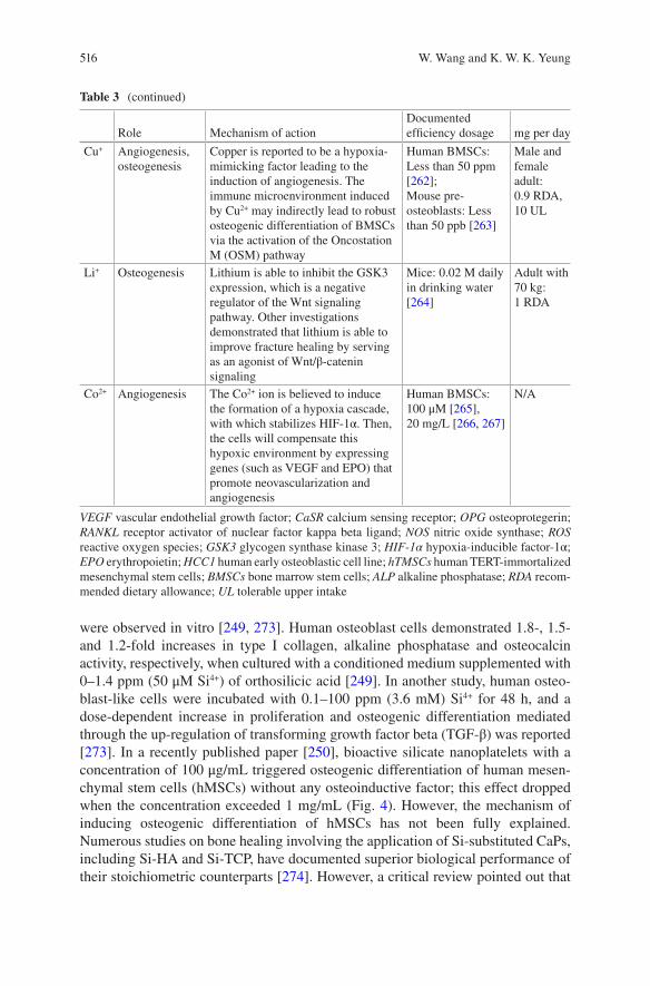
516
were observed in vitro [249, 273]. Human osteoblast cells demonstrated 1.8-, 1.5- and 1.2-fold increases in type I collagen, alkaline phosphatase and osteocalcin activity, respectively, when cultured with a conditioned medium supplemented with 0–1.4 ppm (50 μM Si4+) of orthosilicic acid [249]. In another study, human osteo-blast-like cells were incubated with 0.1–100 ppm (3.6 mM) Si4+ for 48 h, and a dose-dependent increase in proliferation and osteogenic differentiation mediated through the up-regulation of transforming growth factor beta (TGF-β) was reported [273]. In a recently published paper [250], bioactive silicate nanoplatelets with a concentration of 100 μg/mL triggered osteogenic differentiation of human mesen-chymal stem cells (hMSCs) without any osteoinductive factor; this effect dropped when the concentration exceeded 1 mg/mL (Fig. 4). However, the mechanism of inducing osteogenic differentiation of hMSCs has not been fully explained. Numerous studies on bone healing involving the application of Si-substituted CaPs, including Si-HA and Si-TCP, have documented superior biological performance of their stoichiometric counterparts [274]. However, a critical review pointed out that
Table 3 (continued)
Role Mechanism of actionDocumented efficiency dosage mg per day
Cu+ Angiogenesis, osteogenesis
Copper is reported to be a hypoxia-mimicking factor leading to the induction of angiogenesis. The immune microenvironment induced by Cu2+ may indirectly lead to robust osteogenic differentiation of BMSCs via the activation of the Oncostation M (OSM) pathway
Human BMSCs: Less than 50 ppm [262];Mouse pre-osteoblasts: Less than 50 ppb [263]
Male and female adult:0.9 RDA, 10 UL
Li+ Osteogenesis Lithium is able to inhibit the GSK3 expression, which is a negative regulator of the Wnt signaling pathway. Other investigations demonstrated that lithium is able to improve fracture healing by serving as an agonist of Wnt/β-catenin signaling
Mice: 0.02 M daily in drinking water [264]
Adult with 70 kg:1 RDA
Co2+ Angiogenesis The Co2+ ion is believed to induce the formation of a hypoxia cascade, with which stabilizes HIF-1α. Then, the cells will compensate this hypoxic environment by expressing genes (such as VEGF and EPO) that promote neovascularization and angiogenesis
Human BMSCs: 100 μM [265], 20 mg/L [266, 267]
N/A
VEGF vascular endothelial growth factor; CaSR calcium sensing receptor; OPG osteoprotegerin; RANKL receptor activator of nuclear factor kappa beta ligand; NOS nitric oxide synthase; ROS reactive oxygen species; GSK3 glycogen synthase kinase 3; HIF-1α hypoxia-inducible factor-1α; EPO erythropoietin; HCC1 human early osteoblastic cell line; hTMSCs human TERT-immortalized mesenchymal stem cells; BMSCs bone marrow stem cells; ALP alkaline phosphatase; RDA recom-mended dietary allowance; UL tolerable upper intake
W. Wang and K. W. K. Yeung
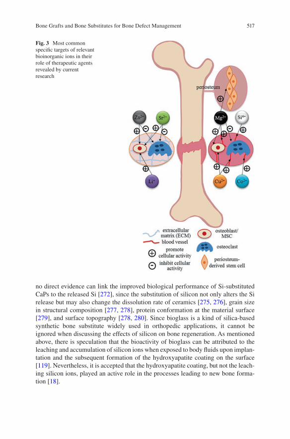
517
no direct evidence can link the improved biological performance of Si-substituted CaPs to the released Si [272], since the substitution of silicon not only alters the Si release but may also change the dissolution rate of ceramics [275, 276], grain size in structural composition [277, 278], protein conformation at the material surface [279], and surface topography [278, 280]. Since bioglass is a kind of silica-based synthetic bone substitute widely used in orthopedic applications, it cannot be ignored when discussing the effects of silicon on bone regeneration. As mentioned above, there is speculation that the bioactivity of bioglass can be attributed to the leaching and accumulation of silicon ions when exposed to body fluids upon implan-tation and the subsequent formation of the hydroxyapatite coating on the surface [119]. Nevertheless, it is accepted that the hydroxyapatite coating, but not the leach-ing silicon ions, played an active role in the processes leading to new bone forma-tion [18].
Fig. 3 Most common specific targets of relevant bioinorganic ions in their role of therapeutic agents revealed by current research
Bone Grafts and Bone Substitutes for Bone Defect Management
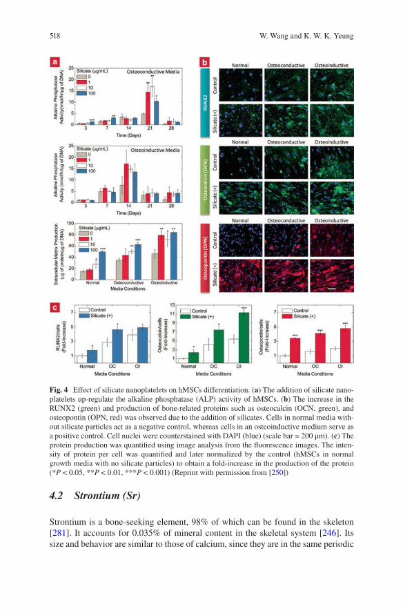
518
4.2 Strontium (Sr)
Strontium is a bone-seeking element, 98% of which can be found in the skeleton [281]. It accounts for 0.035% of mineral content in the skeletal system [246]. Its size and behavior are similar to those of calcium, since they are in the same periodic
Fig. 4 Effect of silicate nanoplatelets on hMSCs differentiation. (a) The addition of silicate nano-platelets up-regulate the alkaline phosphatase (ALP) activity of hMSCs. (b) The increase in the RUNX2 (green) and production of bone-related proteins such as osteocalcin (OCN, green), and osteopontin (OPN, red) was observed due to the addition of silicates. Cells in normal media with-out silicate particles act as a negative control, whereas cells in an osteoinductive medium serve as a positive control. Cell nuclei were counterstained with DAPI (blue) (scale bar = 200 μm). (c) The protein production was quantified using image analysis from the fluorescence images. The inten-sity of protein per cell was quantified and later normalized by the control (hMSCs in normal growth media with no silicate particles) to obtain a fold-increase in the production of the protein (*P < 0.05, **P < 0.01, ***P < 0.001) (Reprint with permission from [250])
W. Wang and K. W. K. Yeung
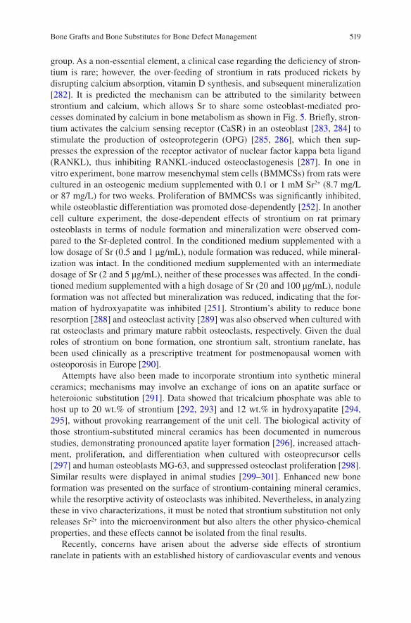
519
group. As a non-essential element, a clinical case regarding the deficiency of stron-tium is rare; however, the over-feeding of strontium in rats produced rickets by disrupting calcium absorption, vitamin D synthesis, and subsequent mineralization [282]. It is predicted the mechanism can be attributed to the similarity between strontium and calcium, which allows Sr to share some osteoblast-mediated pro-cesses dominated by calcium in bone metabolism as shown in Fig. 5. Briefly, stron-tium activates the calcium sensing receptor (CaSR) in an osteoblast [283, 284] to stimulate the production of osteoprotegerin (OPG) [285, 286], which then sup-presses the expression of the receptor activator of nuclear factor kappa beta ligand (RANKL), thus inhibiting RANKL-induced osteoclastogenesis [287]. In one in vitro experiment, bone marrow mesenchymal stem cells (BMMCSs) from rats were cultured in an osteogenic medium supplemented with 0.1 or 1 mM Sr2+ (8.7 mg/L or 87 mg/L) for two weeks. Proliferation of BMMCSs was significantly inhibited, while osteoblastic differentiation was promoted dose-dependently [252]. In another cell culture experiment, the dose-dependent effects of strontium on rat primary osteoblasts in terms of nodule formation and mineralization were observed com-pared to the Sr-depleted control. In the conditioned medium supplemented with a low dosage of Sr (0.5 and 1 μg/mL), nodule formation was reduced, while mineral-ization was intact. In the conditioned medium supplemented with an intermediate dosage of Sr (2 and 5 μg/mL), neither of these processes was affected. In the condi-tioned medium supplemented with a high dosage of Sr (20 and 100 μg/mL), nodule formation was not affected but mineralization was reduced, indicating that the for-mation of hydroxyapatite was inhibited [251]. Strontium’s ability to reduce bone resorption [288] and osteoclast activity [289] was also observed when cultured with rat osteoclasts and primary mature rabbit osteoclasts, respectively. Given the dual roles of strontium on bone formation, one strontium salt, strontium ranelate, has been used clinically as a prescriptive treatment for postmenopausal women with osteoporosis in Europe [290].
Attempts have also been made to incorporate strontium into synthetic mineral ceramics; mechanisms may involve an exchange of ions on an apatite surface or heteroionic substitution [291]. Data showed that tricalcium phosphate was able to host up to 20 wt.% of strontium [292, 293] and 12 wt.% in hydroxyapatite [294, 295], without provoking rearrangement of the unit cell. The biological activity of those strontium-substituted mineral ceramics has been documented in numerous studies, demonstrating pronounced apatite layer formation [296], increased attach-ment, proliferation, and differentiation when cultured with osteoprecursor cells [297] and human osteoblasts MG-63, and suppressed osteoclast proliferation [298]. Similar results were displayed in animal studies [299–301]. Enhanced new bone formation was presented on the surface of strontium-containing mineral ceramics, while the resorptive activity of osteoclasts was inhibited. Nevertheless, in analyzing these in vivo characterizations, it must be noted that strontium substitution not only releases Sr2+ into the microenvironment but also alters the other physico-chemical properties, and these effects cannot be isolated from the final results.
Recently, concerns have arisen about the adverse side effects of strontium ranelate in patients with an established history of cardiovascular events and venous
Bone Grafts and Bone Substitutes for Bone Defect Management
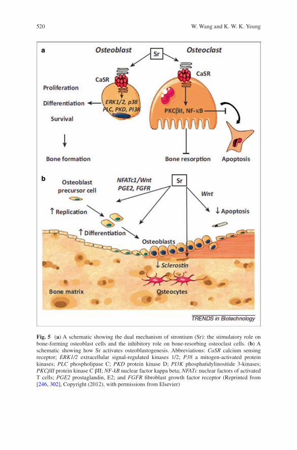
520
Fig. 5 (a) A schematic showing the dual mechanism of strontium (Sr): the stimulatory role on bone-forming osteoblast cells and the inhibitory role on bone-resorbing osteoclast cells. (b) A schematic showing how Sr activates osteoblastogenesis. Abbreviations: CaSR calcium sensing receptor; ERK1/2 extracellular signal-regulated kinases 1/2; P38 a mitogen-activated protein kinases; PLC phospholipase C; PKD protein kinase D; PI3K phosphatidylinositide 3-kinases; PKCβII protein kinase C βII; NF-kB nuclear factor kappa beta; NFATc nuclear factors of activated T cells; PGE2 prostaglandin, E2; and FGFR fibroblast growth factor receptor (Reprinted from [246, 302], Copyright (2012), with permissions from Elsevier)
W. Wang and K. W. K. Yeung
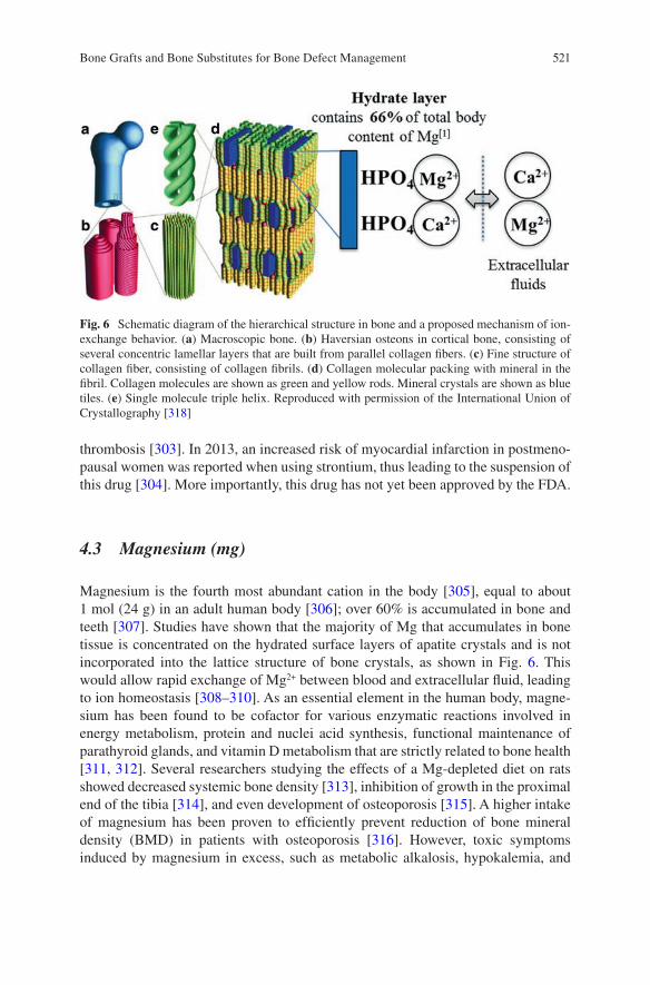
521
thrombosis [303]. In 2013, an increased risk of myocardial infarction in postmeno-pausal women was reported when using strontium, thus leading to the suspension of this drug [304]. More importantly, this drug has not yet been approved by the FDA.
4.3 Magnesium (mg)
Magnesium is the fourth most abundant cation in the body [305], equal to about 1 mol (24 g) in an adult human body [306]; over 60% is accumulated in bone and teeth [307]. Studies have shown that the majority of Mg that accumulates in bone tissue is concentrated on the hydrated surface layers of apatite crystals and is not incorporated into the lattice structure of bone crystals, as shown in Fig. 6. This would allow rapid exchange of Mg2+ between blood and extracellular fluid, leading to ion homeostasis [308–310]. As an essential element in the human body, magne-sium has been found to be cofactor for various enzymatic reactions involved in energy metabolism, protein and nuclei acid synthesis, functional maintenance of parathyroid glands, and vitamin D metabolism that are strictly related to bone health [311, 312]. Several researchers studying the effects of a Mg-depleted diet on rats showed decreased systemic bone density [313], inhibition of growth in the proximal end of the tibia [314], and even development of osteoporosis [315]. A higher intake of magnesium has been proven to efficiently prevent reduction of bone mineral density (BMD) in patients with osteoporosis [316]. However, toxic symptoms induced by magnesium in excess, such as metabolic alkalosis, hypokalemia, and
Fig. 6 Schematic diagram of the hierarchical structure in bone and a proposed mechanism of ion-exchange behavior. (a) Macroscopic bone. (b) Haversian osteons in cortical bone, consisting of several concentric lamellar layers that are built from parallel collagen fibers. (c) Fine structure of collagen fiber, consisting of collagen fibrils. (d) Collagen molecular packing with mineral in the fibril. Collagen molecules are shown as green and yellow rods. Mineral crystals are shown as blue tiles. (e) Single molecule triple helix. Reproduced with permission of the International Union of Crystallography [318]
Bone Grafts and Bone Substitutes for Bone Defect Management
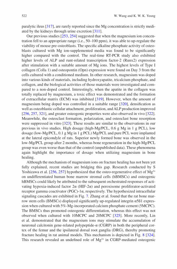
522
paralytic ileus [317], are rarely reported since the Mg concentration is strictly medi-ated by the kidneys through urine excretion [311].
Our previous studies [253, 254] suggested that when the magnesium ion concen-tration fell to an appropriate range (i.e., 50–100 ppm), it was able to up-regulate the viability of mouse pre-osteoblasts. The specific alkaline phosphate activity of osteo-blasts cultured with Mg ion-supplemented media was found to be significantly higher compared with the control. The real-time RT-PCR study also exhibited higher levels of ALP and runt-related transcription factor-2 (Runx2) expression after stimulation with a suitable amount of Mg ions. The highest levels of Type I collagen (Colla 1) and osteopontin (Opn) expression were found on Day 3 from the cells cultured with a conditioned medium. In other research, magnesium was doped into various kinds of materials, including hydroxyapatite, tricalcium phosphate, and collagen, and the biological activities of those materials were investigated and com-pared to a non-doped control. Interestingly, when the apatite in the collagen was totally replaced by magnesium, a toxic effect was demonstrated and the formation of extracellular matrix (ECM) was inhibited [319]. However, when the amount of magnesium being doped was controlled in a suitable range [320], densification as well as osteoblastic cellular attachment, proliferation, and ALP production improved [256, 257, 321], and greater osteogenic properties were also observed in vivo [322]. Meanwhile, the osteoclast formation, polarization, and osteoclast bone resorption were suppressed in vitro [323]. These results are similar to the observations in our previous in vivo studies. High dosage (high-Mg/PCL, 0.6 g Mg in 1 g PCL), low dosage (low-Mg/PCL, 0.1 g Mg in 1 g PCL) Mg/PCL and pure PCL were implanted at the lateral epicondyle of rats. Superior newly formed bone was observed in the low-Mg/PCL group after 2 months, whereas bone regeneration in the high-Mg/PCL group was even worse than that of the control (unpublished data). These phenomena again highlight the importance of dosage when utilizing magnesium in bone healing.
Although the mechanism of magnesium ions on fracture healing has not been yet fully explained, recent studies are bridging this gap. Research conducted by S Yoshizawa et al. [256, 257] hypothesized that the osteo-regenerative effect of Mg2+ on undifferentiated human bone marrow stromal cells (hBMSCs) and osteogenic hBMSCs could likely be attributed to the subsequent orchestrated responses of acti-vating hypoxia-induced factor 2α (HIF-2α) and peroxisome proliferator-activated receptor gamma coactivator (PGC)-1α, respectively. The hypothesized intracellular signaling cascades are exhibited in Fig. 7. Zhang et al. found that the rat bone mar-row stem cells (BMSCs) displayed significantly up-regulated integrin α5ß1 expres-sion when cultured with 5%-Mg-incorporated calcium phosphate cement (5MCPC). The BMSCs thus promoted osteogenic differentiation, whereas this effect was not observed when cultured with 10MCPC and 20MCPC [325]. More recently, Lin et al. demonstrated that the magnesium ions may stimulate the accumulation of neuronal calcitonin gene-related polypeptide-α (CGRP) in both the peripheral cor-tex of the femur and the ipsilateral dorsal root ganglia (DRG), thereby promoting fracture healing in rat animal models. This mechanism is depicted in Fig. 8 [324]. This research revealed an undefined role of Mg2+ in CGRP-mediated osteogenic
W. Wang and K. W. K. Yeung
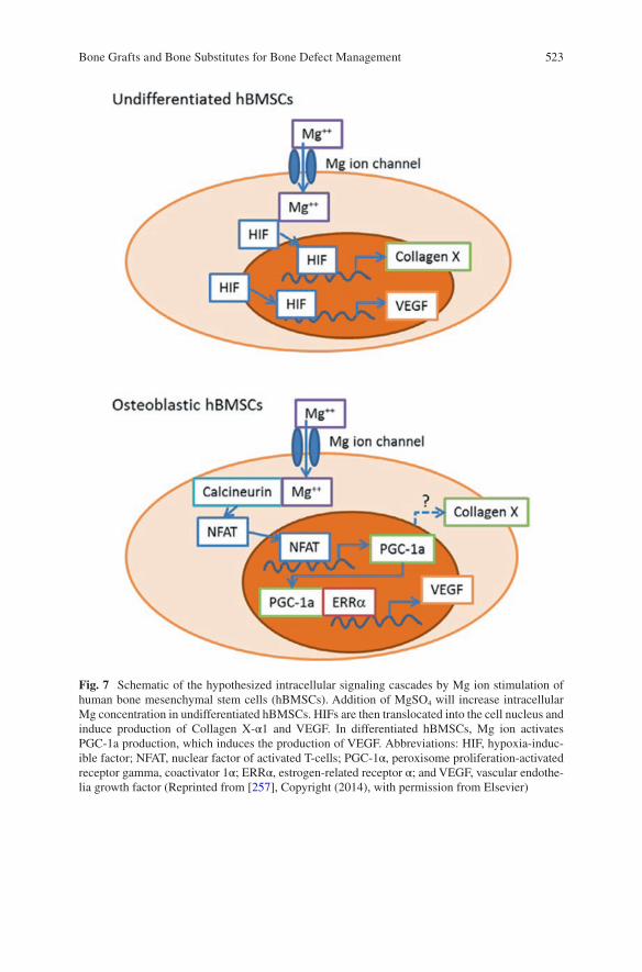
523
Fig. 7 Schematic of the hypothesized intracellular signaling cascades by Mg ion stimulation of human bone mesenchymal stem cells (hBMSCs). Addition of MgSO4 will increase intracellular Mg concentration in undifferentiated hBMSCs. HIFs are then translocated into the cell nucleus and induce production of Collagen X-α1 and VEGF. In differentiated hBMSCs, Mg ion activates PGC-1a production, which induces the production of VEGF. Abbreviations: HIF, hypoxia-induc-ible factor; NFAT, nuclear factor of activated T-cells; PGC-1α, peroxisome proliferation-activated receptor gamma, coactivator 1α; ERRα, estrogen-related receptor α; and VEGF, vascular endothe-lia growth factor (Reprinted from [257], Copyright (2014), with permission from Elsevier)
Bone Grafts and Bone Substitutes for Bone Defect Management
524
Fig. 8 Schematic diagram showing (a) diffusion of Mg2+ across the bone toward the periosteum, which is innervated by DGR sensory neurons and enriched with PDSCs undergoing osteogenic differentiation into new bone. (b) The released Mg2+ enters DRG neurons via Mg2+ transporters or channels and promotes CGRP-vesicle accumulation and exocytosis. The DRG-released CGRP, in turn, activates the CGRP receptor in PDSCs, which triggers phosphorylation of CREB1 via cAMP and promotes the expression of genes contributing to osteogenic differentiation. Abbreviations: DGR, dorsal root ganglia; PDSCs, periosteum-derived stem cells; CREB1, cAMP-responsive ele-ment binding protein 1; cAMP: cyclic adenosine monophosphate (Reprinted by permission from Macmillan Publishers Ltd: Nature Medicine [324], copyright (2016))
W. Wang and K. W. K. Yeung
525
differentiation. In another study, while investigating the long-term in vivo degrada-tion mechanism of the Mg alloy, Lee et al. found that the existence of Mg may facilitate the crystallization of calcium phosphate in a rabbit femoral condyle defect model [326]. All these recent findings again highlighted the importance of magne-sium in fracture healing and suggest the therapeutic potential in the orthopedic clinics.
4.4 Zinc (Zn)
Zinc is also an essential trace element in the human body with a total weight of about 1.4–2.3 g. This number is between 150–250 μg/g in bone ash (0.015–0.025 wt.%), which is higher than other tissues [327]. It is involved in the structural, catalytic, or regulatory action of several important metalloenzymes, including alka-line phosphatase (ALP). It was found that ALP not only generates phosphates by hydrolyzing pyrophosphates, but also creates an alkaline environment that favors the precipitation and subsequent mineralization of these phosphates onto the extra-cellular matrix, which were produced by osteoblasts [246]. A far as we know, ALP is a zinc enzyme with three closely spaced metal ions (two Zn ions and one Mg ion) presented at the active center [328]. Further investigation suggested that inactivation of ALP is caused by the dissociation of an active center Zn; preventing the dissocia-tion of this active center Zn can stabilize the enzyme and increase its half-life [329]. Given its important role in the skeletal system, zinc deficiency is reportedly associ-ated with decreased bone age [18], whereas high zinc levels may lead to the sup-pression of the immune system, reduction of high-density lipoprotein (HDL) cholesterol, and hypocupremia by retarding the intestinal absorption of copper [317, 330]. These findings support some cell culture experiments. Yamaguchi et al. [258] showed significantly increased Runx2, OPG, and regucalcin mRNA expressions in osteoblastic MC3T3-E1 cells when zinc supplementation was in the concentration of 10−5–10−4 M (0.65 mg/L–6.5 mg/L). Kwun et al. [259] observed a negative effect of zinc deficiency on the osteogenic activity of the same cell type, whereby bone marker gene transcription and ECM mineralization were reduced through inhibited and delayed Runx2 expression and inhibition of ALP activity in osteoblasts, respec-tively. However, these regulation effects were not displayed when rat bone marrow stem cells were cultured with Zn2+ supplemented (1*10−5 and 4*10−5 M, eq. to 0.65 mg/L and 2.6 mg/L) osteogenic medium [261]. Suppression effects of zinc on bone resorption and osteoclastogenesis from bone marrow-derived osteoclasts were recently shown in the tissue culture system [331].
Zinc has also been found to stabilize the crystal lattice of β-tricalcium phosphate, thus making the dissolution of TCP predictable and complete [292]. In the rabbit femoral defect model, zinc-containing HA/TCP either with a high concentration (about 0.6 wt.%, high-Zn-HA/TCP) or a low concentration (about 0.3 wt.%, low-Zn-HA/TCP) was applied. Low-Zn-HA/TCP demonstrated increased bone apposi-tion, and high-Zn-HA/TCP led to increased resorption of the host bone [332].
Bone Grafts and Bone Substitutes for Bone Defect Management
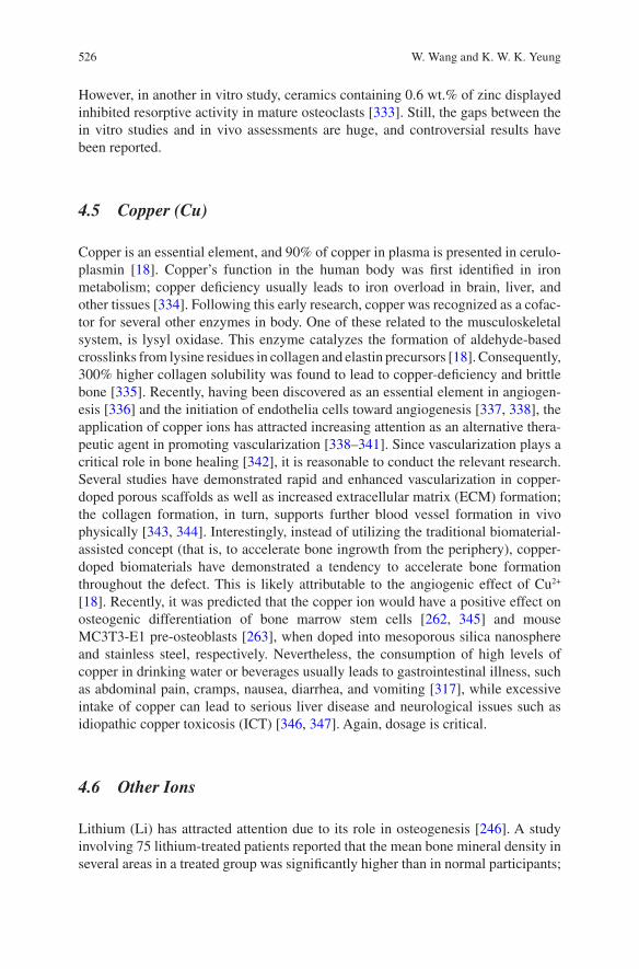
526
However, in another in vitro study, ceramics containing 0.6 wt.% of zinc displayed inhibited resorptive activity in mature osteoclasts [333]. Still, the gaps between the in vitro studies and in vivo assessments are huge, and controversial results have been reported.
4.5 Copper (Cu)
Copper is an essential element, and 90% of copper in plasma is presented in cerulo-plasmin [18]. Copper’s function in the human body was first identified in iron metabolism; copper deficiency usually leads to iron overload in brain, liver, and other tissues [334]. Following this early research, copper was recognized as a cofac-tor for several other enzymes in body. One of these related to the musculoskeletal system, is lysyl oxidase. This enzyme catalyzes the formation of aldehyde-based crosslinks from lysine residues in collagen and elastin precursors [18]. Consequently, 300% higher collagen solubility was found to lead to copper-deficiency and brittle bone [335]. Recently, having been discovered as an essential element in angiogen-esis [336] and the initiation of endothelia cells toward angiogenesis [337, 338], the application of copper ions has attracted increasing attention as an alternative thera-peutic agent in promoting vascularization [338–341]. Since vascularization plays a critical role in bone healing [342], it is reasonable to conduct the relevant research. Several studies have demonstrated rapid and enhanced vascularization in copper-doped porous scaffolds as well as increased extracellular matrix (ECM) formation; the collagen formation, in turn, supports further blood vessel formation in vivo physically [343, 344]. Interestingly, instead of utilizing the traditional biomaterial-assisted concept (that is, to accelerate bone ingrowth from the periphery), copper-doped biomaterials have demonstrated a tendency to accelerate bone formation throughout the defect. This is likely attributable to the angiogenic effect of Cu2+ [18]. Recently, it was predicted that the copper ion would have a positive effect on osteogenic differentiation of bone marrow stem cells [262, 345] and mouse MC3T3-E1 pre-osteoblasts [263], when doped into mesoporous silica nanosphere and stainless steel, respectively. Nevertheless, the consumption of high levels of copper in drinking water or beverages usually leads to gastrointestinal illness, such as abdominal pain, cramps, nausea, diarrhea, and vomiting [317], while excessive intake of copper can lead to serious liver disease and neurological issues such as idiopathic copper toxicosis (ICT) [346, 347]. Again, dosage is critical.
4.6 Other Ions
Lithium (Li) has attracted attention due to its role in osteogenesis [246]. A study involving 75 lithium-treated patients reported that the mean bone mineral density in several areas in a treated group was significantly higher than in normal participants;
W. Wang and K. W. K. Yeung
527
this was possibly due to a lower bone turnover in lithium-treated patients [348]. Another case-control study compared 231,778 fracture cases and found that the cur-rent use of lithium showed a decreased risk of fracture, while an increased risk of fracture was observed among past users [349]. The mechanism of lithium behind osteogenesis is predicted by inhibiting glycogen synthase kinase 3 (GSK3), which is a negative regulator of the Wnt signaling pathway [350, 351]. In addition, Li+ has been shown to activate β-catenin signaling by mediating osteoblast proliferation, differentiation, and maturation [352] during bone and cartilage fracture healing [264]. The excess intake of lithium was found to cause stomach or intestinal symp-toms and nervous system problems [353].
Cobalt (Co) is an integral part of vitamin B12, which stimulates the production of red blood cells [248]. Like copper, cobalt was recently shown to stimulate angio-genesis [245]. Significantly up-regulated VEGF was expressed when bone marrow stem cells were treated in a 100 μM CoCl2 supplemented culture medium, and these CoCl2-treated cells subsequently promoted vascularization and osteogenesis when implanted in vivo with a collagen scaffold [265]. This effect was recently found to associate with the hypoxia-mimicking capacity of Co ions. Studies dem-onstrated that mesoporous bioactive glass (MBG) scaffolds doped with a suitable amount of cobalt induced the hypoxia cascade, by which hypoxia inducible fac-tor-1 (HIF-1) was activated [266] and stabilized [267]. This increased the expres-sion of HIF-α target genes, such as VEGF and erythropoietin (EPO) [354], thus leading to a higher degree of vascularization. Nevertheless, cobalt intoxication has become a concern in recent years due to the wide use of metal hip prostheses, in which most of the metal-on-metal articulations are made of cobalt-chromium alloy [354, 355]. Several randomized, prospective trials [356–358] demonstrated that this was highly related to the elevated serum cobalt concentration caused by the debris upon wearing (see Fig. 9), which raised it at most 50 times higher as com-pared to the ceramic-on-polyethylene/ceramic control group. The symptoms
Fig. 9 A case of extreme cobalt toxicity in total hip replacement surgery. (a) After incision of the skin and soft tissue, clear metallic black fluid was observed; (b) soft tissue and peripheral bone were stained black with the metal debris after draining the fluid (Reprint from [355], with permis-sion from Wolters Kluwer Health Inc.)
Bone Grafts and Bone Substitutes for Bone Defect Management
528
included but were not limited to bone tissue absorption, neurological toxicity, weight loss, reduced mobility, and pain [359]. Furthermore, patients generally felt improved after changing the metal hip implants to non-metallic ones or undergoing cobalt chelation therapy [354, 360].
5 Conclusion and Future Directions
Large segmental bone defects may result in delayed union or even non-union if improperly treated. Hence, surgical interventions together with bone grafting tech-niques are commonly considered in the treatment process. Even though the emer-gence of various synthetic bone substitutes offers various options, the treatment outcome cannot be compared to the approach of autologous bone graft in terms of bone healing quality and time. One of the issues leading to inferior bone regenera-tion when synthetic substitutes are used is due to inferior osteoinductivity. The incorporation of recombinant human growth factors (e.g. rhBMP-2) with bone allograft and other substitutes have been considered and widely applied clinically. Their clinical outcomes have been extensively reported as well. The efficacy of the treatment has been approved. Post-operative complications and the controversy of off-label applications and high application costs have been also documented. The complications can be attributed to the uncontrolled release of growth factor that collaterally interferes with the un-targeting cells. Alternatively, the incorporation of bioinorganic ions such as magnesium, strontium, silicon, copper, and cobalt into bone graft materials provides an economical and feasible solution for bone defect repair. The safety issues related to the use of these bioinorganic ions has been investigated by a number of studies over these years. When the therapeutic effect and working mechanisms of these ions have been clearly understood, it may be possible to implement a human clinical trial. With additional new discoveries, bioinorganic ions can be considered for use in the combination of growth factors for bone defect treatment that may induce synergistic effect in terms of new bone formation.
The 3D–printing technology in particular to the capability to reproduce the microarchitecture of bony tissue has been advanced by the latest development of biomaterials and therefore shed light on the next generation of synthetic bone sub-stitutes [361]. In addition, when the 3D printed scaffolds are fabricated together with mesenchymal stem cells, this approach may induce new bone formation in the treatment of bone defects. However, challenges including suboptimal resolution, relatively slow printing speed and limited selection of bio-inks are concerned. When all these issues have been resolved, it is believed that the demand for bone graft and autograft will become lesser in the future.
W. Wang and K. W. K. Yeung
529
References
1. Dimitriou R, Jones E, McGonagle D, Giannoudis PV. Bone regeneration: current concepts and future directions. BMC Med. 2011;9:66.
2. Lewandrowski K-U, Gresser JD, Wise DL, Trantolo DJ. Bioresorbable bone graft substitutes of different osteoconductivities: a histologic evaluation of osteointegration of poly (propyl-ene glycol-co-fumaric acid)-based cement implants in rats. Biomaterials. 2000;21:757–64.
3. Campana V, Milano G, Pagano E, Barba M, Cicione C, Salonna G, Lattanzi W, Logroscino G. Bone substitutes in orthopaedic surgery: from basic science to clinical practice. J Mater Sci Mater Med. 2014;25:2445–61.
4. Bauer TW, Muschler GF. Bone graft materials: an overview of the basic science. Clin Orthop Relat Res. 2000;371:10–27.
5. LONG WGDE, Einhorn TA, Koval K, McKee M, Smith W, Sanders R, Watson T. Bone grafts and bone graft substitutes in orthopaedic trauma surgery: a critical analysis. J Bone Joint Surg Am. 2007;89:649–58.
6. Fillingham Y, Jacobs J. Bone grafts and their substitutes. Bone Joint J. 2016;98:6–9. 7. C.f.D. Control. Transmission of HIV through bone transplantation: case report and public
health recommendations. MMWR Morb Mortal Wkly Rep. 1988;37:597–9. 8. Stevenson S, Horowitz M. The response to bone allografts. J Bone Joint Surg. 1992;74:939–50. 9. Alex Jahangir MA, Nunley RM, Mehta S, Sharan A, TWHP. Fellows. Bone-graft substitutes
in orthopaedic surgery. AAOS. 2008;2:1–5. 10. GlobalData, MediPoint: bone grafts and substitutes—global analysis and market forecasts.
2014. 11. Kurien T, Pearson RG, Scammell BE. Bone graft substitutes currently available in orthopae-
dic practice: the evidence for their use. Bone Joint J. 2013;95-b:583–97. 12. FDA, FDA Public Health Notification. Life-threatenning complications associated with
recombinant human bone morphologenetic protein in cervicla spine fusion, July 1, 2008. 13. FDA, AMPLIFY™ rhBMP-2 Matrix: Orthopaedic and Rehabilitation Devices Advisory
Pannel Presentation., July 27, 2010. 14. Hoffman MD, Xie C, Zhang X, Benoit DS. The effect of mesenchymal stem cells delivered
via hydrogel-based tissue engineered periosteum on bone allograft healing. Biomaterials. 2013;34:8887–98.
15. Long T, Zhu Z, Awad HA, Schwarz EM, Hilton MJ, Dong Y. The effect of mesenchymal stem cell sheets on structural allograft healing of critical sized femoral defects in mice. Biomaterials. 2014;35:2752–9.
16. Griffin KS, Davis KM, Mckinley TO, Anglen JO, Chu TMG, Boerckel JD, Kacena MA. Evolution of bone grafting: bone grafts and tissue engineering strategies for vascular-ized bone regeneration. Clin Rev Bone Miner Metab. 2015;13:232–44.
17. Bhumiratana S, Bernhard JC, Alfi DM, Yeager K, Eton RE, Bova J, Gimble JM, Lopez MJ, Eisig SB, Vunjak-Novakovic G. Tissue-engineered autologous grafts for facial bone recon-struction. Sci Transl Med. 2016;8:343ra383.
18. Habibovic P, Barralet JE. Bioinorganics and biomaterials: bone repair. Acta Biomater. 2011;7:3013–26.
19. Khan SN, Cammisa FP, Sandhu HS, Diwan AD, Girardi FP, Lane JM. The biology of bone grafting. J Am Acad Orthop Surg. 2005;13:77–86.
20. Seth Greenwald DPA, Boden SD, Goldberg VM, Yaszemski M, Heim CS. Bone-graft substi-tutes: facts, fictions and applications, AAOS 75th Annual Meeting, 2008.
21. Albrektsson T, Johansson C. Osteoinduction, osteoconduction and osseointegration. Eur Spine J. 2001;10:S96–101.
22. Wilson-Hench J. Osteoinduction. Prog Biomed Eng. 1987;4:29. 23. Roberts TT, Rosenbaum AJ. Bone grafts, bone substitutes and orthobiologics: the bridge
between basic science and clinical advancements in fracture healing. Organogenesis. 2012;8:114–24.
Bone Grafts and Bone Substitutes for Bone Defect Management
530
24. Giannoudis PV, Faour O, Goff T, Kanakaris N, Dimitriou R. Masquelet technique for the treatment of bone defects: tips-tricks and future directions. Injury. 2011;42:591–8.
25. Lieberman JR, Friedlaender GE. Chapter IV. biology of bone grafts, bone regeneration and repair, Springer; 2005. p. 1.
26. Flynn J. Fracture repair and bone grafting, OKU 10: Orthopaedic Knowledge Update. 2011;11–21.
27. Chiarello E, Cadossi M, Tedesco G, Capra P, Calamelli C, Shehu A, Giannini S. Autograft, allograft and bone substitutes in reconstructive orthopedic surgery. Aging Clin Exp Res. 2013;25:101–3.
28. Kovar FM, Wozasek GE. Bone graft harvesting using the RIA (reaming irrigation aspirator) system—a quantitative assessment. Wien Klin Wochenschr. 2011;123:285–90.
29. Dimitriou R, Mataliotakis GI, Angoules AG, Kanakaris NK, Giannoudis PV. Complications following autologous bone graft harvesting from the iliac crest and using the RIA: a system-atic review. Injury. 2011;42(Suppl 2):S3–15.
30. Belthur MV, Conway JD, Jindal G, Ranade A, Herzenberg JE. Bone graft harvest using a new intramedullary system. Clin Orthop Relat Res. 2008;466:2973–80.
31. Pape H-C, Tarkin IS. Reamer irrigator aspirator: a new technique for bone graft harvesting from the Intramedullary Canal. Oper Tech Orthop. 2008;18:108–13.
32. Sagi HC, Young ML, Gerstenfeld L, Einhorn TA, Tornetta P. Qualitative and quantitative differences between bone graft obtained from the medullary canal (with a reamer/irrigator/aspirator) and the iliac crest of the same patient. J Bone Joint Surg Am. 2012;94:2128–35.
33. Mauffrey C, Barlow BT, Smith W. Management of segmental bone defects. J Am Acad Orthop Surg. 2015;23:143–53.
34. Bhatt RA, Rozental TD. Bone graft substitutes. Hand Clin. 2012;28:457–68. 35. Torres J, Tamimi F, Alkhraisat M, Prados-Frutos JC, Lopez-Cabarcos E, Chapter IV. Bone
substitutes, implant dentistry—the most promising discipline of dentistry. InTech; 2011. 36. Burchardt H. Biology of bone transplantation. Orthop Clin North Am. 1987;18:187–96. 37. Heiple KG, Chase SW, Herndon CH. A comparative study of the healing process following
different types of bone transplantation. J Bone Joint Surg. 1963;45:1593–616. 38. Abbott LC, Schottstaedt ER, Saunders JBDC, Bost FC. The evaluation of cortical and cancel-
lous bone as grafting material. J Bone Joint Surg. 1947;29:381–414. 39. Stevenson S. The immune response to osteochondral allografts in dogs. J Bone Joint Surg.
1987;69:573–82. 40. Stevenson S, Li XQ, Martin B. The fate of cancellous and cortical bone after transplantation
of fresh and frozen tissue-antigen-matched and mismatched osteochondral allografts in dogs. J Bone Joint Surg. 1991;73:1143–56.
41. DoNon I. Studies on the antigenicity of bone. 1984. 42. Voggenreiter G, Ascherl R, Blümel G, Schmit-Neuerburg K. Effects of preservation and ster-
ilization on cortical bone grafts. Arch Orthop Trauma Surg. 1994;113:294–6. 43. Urist M. Bone transplants and implants, fundamental and clinical bone. Physiology. 1980. 44. Kotz R, Poitout DG. Biomechanics and biomaterials in orthopedics. Springer Science &
Business Media; 2013. 45. Boyce T, Edwards J, Scarborough N. Allograft bone: the influence of processing on safety
and performance. Orthop Clin North Am. 1999;30:571–81. 46. Finkemeier CG. Bone-grafting and bone-graft substitutes. J Bone Joint Surg. 2002;84:454–64. 47. Greenwald AS, Boden SD, Barrack RL, Bostrom MP, Goldberg VM, Yaszemski M, Heim
CS. The evolving role of bone-graft substitutes, Proceedings of the American Academy of Orthopaedic Surgeons 77th Annual Meeting, 2010, p. 6.
48. Wu S, Liu X, Yeung KWK, Liu C, Yang X. Biomimetic porous scaffolds for bone tissue engineering. Mater Sci Eng R Rep. 2014;80:1–36.
49. Zwingenberger S, Nich C, Valladares RD, Yao Z, Stiehler M, Goodman SB. Recommendations and considerations for the use of biologics in orthopedic surgery. BioDrugs. 2012;26:245–56.
50. Dreesmann H. Ueber Knochenplombirung. Deutsch Med Wochenschr. 1892;19:445–6.
W. Wang and K. W. K. Yeung
531
51. Carson JS, Bostrom MP. Synthetic bone scaffolds and fracture repair. Injury. 2007;38(Suppl 1):S33–7.
52. Chi-Chien N, Tsung-Ting T, Tsai-Sheng F, Po-Liang L, Lih-Huei C, Wen-Jer C. A com-parison of posterolateral lumbar fusion comparing autograft, autogenous laminectomy bone with bone marrow aspirate, and calcium sulphate with bone marrow aspirate: a prospective randomized study. Spine. 2009;34:2715–9.
53. Glombitza M, Steinhausen E. Treatment of chronic osteomyelitis of the lower limb with a new injectable, vancomycin-loaded, calcium sulfate/hydroxyapatite composite. Bone Joint J. 2016;98:39.
54. Jiang N, Qin CH, Ma YF, Wang L, Yu B. Possibility of one-stage surgery to reconstruct bone defects using the modified Masquelet technique with degradable calcium sulfate as a cement spacer: a case report and hypothesis. Biomed Rep. 2016;4:374–8.
55. Oonishi H, Iwaki Y, Kin N, Kushitani S, Murata N, Wakitani S, Imoto K. Hydroxyapatite in revision of total hip replacements with massive acetabular defects: 4- to 10-year clinical results. Bone Joint J. 1997;79:87–92.
56. Schwartz C, Bordei R. Biphasic phospho-calcium ceramics used as bone substitutes are effi-cient in the management of severe acetabular bone loss in revision total hip arthroplasties. Eur J Orthop Surg Traumatol. 2005;15:191–6.
57. Nich C, Sedel L. Bone substitution in revision hip replacement. Int Orthop. 2006;30:525–31. 58. Gaasbeek RDA, Toonen HG, Heerwaarden RJ, Van Pieter B. Mechanism of bone incorpo-
ration of β -TCP bone substitute in open wedge tibial osteotomy in patients. Biomaterials. 2005;26:6713–9.
59. Scheer JH, Adolfsson LE. Tricalcium phosphate bone substitute in corrective osteotomy of the distal radius. Injury. 2009;40:262–7.
60. Bucholz RW, Carlton A, Holmes RE. Hydroxyapatite and tricalcium phosphate bone graft substitutes. Orthop Clin North Am. 1987;18:323–34.
61. Eggli PS, Müller W, Schenk RK. Porous hydroxyapatite and tricalcium phosphate cylinders with two different pore size ranges implanted in the cancellous bone of rabbits. A compara-tive histomorphometric and histologic study of bony ingrowth and implant substitution. Clin Orthop Relat Res. 1988;(232):127–38.
62. Huec JCL, Schaeverbeke T, Clement D, Faber J, Rebeller AL. Influence of porosity on the mechanical resistance of hydroxyapatite ceramics under compressive stress. Biomaterials. 1995;16:113–8.
63. Wenisch S, Stahl JP, Horas U, Heiss C, Kilian O, Trinkaus K, Hild A, Schnettler R. In vivo mechanisms of hydroxyapatite ceramic degradation by osteoclasts: fine structural micros-copy. J Biomed Mater Res A. 2003;67:713–8.
64. Tonino AJ, van der Wal BC, Heyligers IC, Grimm B. Bone remodeling and hydroxyapatite resorption in coated primary hip prostheses. Clin Orthop Relat Res. 2009;467:478–84.
65. Kattimani VS, Kondaka S Lingamaneni KP. Hydroxyapatite―past, present, and future in bone regeneration. Bone Tissue Regen Insights. 2016;9.
66. Dubok VA. Bioceramics―yesterday, today, tomorrow, powder metallurgy and metal. Ceramics. 2000;39:381–94.
67. Li H, Zhao Q, Li B, Kang J, Yu Z, Li Y, Song X, Liang C, Wang H. Fabrication and proper-ties of carbon nanotube-reinforced hydroxyapatite composites by a double in situ synthesis process. Carbon NY. 2016;101:159–67.
68. Mukherjee S, Nandi SK, Kundu B, Chanda A, Sen S, Das PK. Enhanced bone regeneration with carbon nanotube reinforced hydroxyapatite in animal model. J Mech Behav Biomed Mater. 2016;60:243–55.
69. Albee FH. Studies in bone growth triple calcium phosphate as a stimulus to osteogenesis. Ann Surg. 1920;71:32–9.
70. Ogose A, Kondo N, Umezu H, Hotta T, Kawashima H, Tokunaga K, Ito T, Kudo N, Hoshino M, Gu W. Histological assessment in grafts of highly purified beta-tricalcium phosphate (OSferion ®;) in human bones. Biomaterials. 2006;27:1542–9.
Bone Grafts and Bone Substitutes for Bone Defect Management
532
71. Buchanan FJ. Degradation rate of bioresorbable materials: prediction and evaluation. Elsevier; 2008.
72. Bohner M. Physical and chemical aspects of calcium phosphates used in spinal surgery. Eur Spine J. 2001;10:S114–21.
73. Chen Y, Wang J, Zhu XD, Tang ZR, Yang X, Tan YF, Fan YJ, Zhang XD. Enhanced effect of beta-tricalcium phosphate phase on neovascularization of porous calcium phosphate ceram-ics: in vitro and in vivo evidence. Acta Biomater. 2015;11:435–48.
74. Malhotra A, Habibovic P. Calcium phosphates and angiogenesis: implications and advances for bone regeneration. Trends Biotechnol. 2016;34:983–92.
75. Klenke FM, Liu Y, Yuan H, Hunziker EB, Siebenrock KA, Hofstetter W. Impact of pore size on the vascularization and osseointegration of ceramic bone substitutes in vivo. J Biomed Mater Res A. 2008;85:777–86.
76. Bai F, Wang Z, Lu J, Liu J, Chen G, Lv R, Wang J, Lin K, Zhang J, Huang X. The correlation between the internal structure and vascularization of controllable porous bioceramic materi-als in vivo: a quantitative study. Tissue Eng Part A. 2010;16:3791–803.
77. Xiao X, Wang W, Liu D, Zhang H, Gao P, Geng L, Yuan Y, Lu J, Wang Z. The promotion of angiogenesis induced by three-dimensional porous beta-tricalcium phosphate scaffold with different interconnection sizes via activation of PI3K/Akt pathways. Sci Rep. 2015;5:9409.
78. Barrère F, van Blitterswijk CA, de Groot K. Bone regeneration: molecular and cellular inter-actions with calcium phosphate ceramics. Int J Nanomed. 2006;1:317.
79. Shanahan CM, Crouthamel MH, Kapustin A, Giachelli CM. Arterial calcification in chronic kidney disease: key roles for calcium and phosphate. Circ Res. 2011;109:697–711.
80. Di Marco GS, König M, Stock C, Wiesinger A, Hillebrand U, Reiermann S, Reuter S, Amler S, Köhler G, Buck F. High phosphate directly affects endothelial function by downregulating annexin II. Kidney Int. 2013;83:213–22.
81. Sandino C, Checa S, Prendergast PJ, Lacroix D. Simulation of angiogenesis and cell differen-tiation in a CaP scaffold subjected to compressive strains using a lattice modeling approach. Biomaterials. 2010;31:2446–52.
82. Jufri NF, Mohamedali A, Avolio A, Baker MS. Mechanical stretch: physiological and patho-logical implications for human vascular endothelial cells. Vasc Cell. 2015;7:8.
83. Daculsi G, LeGeros R, Nery E, Lynch K, Kerebel B. Transformation of biphasic calcium phosphate ceramics in vivo: ultrastructural and physicochemical characterization. J Biomed Mater Res. 1989;23:883–94.
84. Williams DF. There is no such thing as a biocompatible material. Biomaterials. 2014;35:10009–14.
85. Brown W, Chow L. A new calcium-phosphate setting cement. J Dent Res. Am Assoc Dental Research; 1983. p. 672.
86. Brown WE. A new calcium phosphate, water-setting cement. W. E. Brown Cements Research Progress; 1987. pp. 351–79.
87. Alkhraisat MH, Rueda C, Jerez LB, Tamimi Marino F, Torres J, Gbureck U, Lopez Cabarcos E. Effect of silica gel on the cohesion, properties and biological performance of brushite cement. Acta Biomater. 2010;6:257–65.
88. Ishikawa K. Calcium phosphate cement. Advances in Calcium Phosphate Biomaterials. Springer; 2014, pp. 199–227.
89. Verron E, Pissonnier ML, Lesoeur J, Schnitzler V, Fellah BH, Pascal-Moussellard H, Pilet P, Gauthier O, Bouler JM. Vertebroplasty using bisphosphonate-loaded calcium phosphate cement in a standardized vertebral body bone defect in an osteoporotic sheep model. Acta Biomater. 2014;10:4887–95.
90. Nakano M, Kawaguchi Y, Kimura T, Hirano N. Transpedicular vertebroplasty after intraver-tebral cavity formation versus conservative treatment for osteoporotic burst fractures. Spine J. 2014;14:39–48.
W. Wang and K. W. K. Yeung
533
91. Tarsuslugil SM, O’Hara RM, Dunne NJ, Buchanan FJ, Orr JF, Barton DC, Wilcox RK. Development of calcium phosphate cement for the augmentation of traumatically frac-tured porcine specimens using vertebroplasty. J Biomech. 2013;46:711–5.
92. Maestretti G, Sutter P, Monnard E, Ciarpaglini R, Wahl P, Hoogewoud H, Gautier E. A pro-spective study of percutaneous balloon kyphoplasty with calcium phosphate cement in trau-matic vertebral fractures: 10-year results. Eur Spine J. 2014;23:1354–60.
93. Zaryanov AV, Park DK, Khalil JG, Baker KC, Fischgrund JS. Cement augmentation in verte-bral burst fractures. Neurosurg Focus. 2014;37:E5.
94. Dorozhkin SV. Nanosized and nanocrystalline calcium orthophosphates. Acta Biomater. 2010;6:715–34.
95. Zhou C, Hong Y, Zhang X. Applications of nanostructured calcium phosphate in tissue engi-neering. Biomater Sci. 2013;1:1012.
96. Wang P, Zhao L, Liu J, Weir MD, Zhou X, Xu HH. Bone tissue engineering via nanostruc-tured calcium phosphate biomaterials and stem cells. Bone Res. 2014;2:14017.
97. Alivisatos A. Naturally aligned nanocrystals. Science. 2000;289(80):736–7. 98. Tang R, Wang L, Orme CA, Bonstein T, Bush PJ, Nancollas GH. Dissolution at the nanoscale:
self‐preservation of biominerals. Angew Chem. 2004;116:2751–5. 99. Olszta MJ, Cheng X, Jee SS, Kumar R, Kim Y-Y, Kaufman MJ, Douglas EP, Gower LB. Bone
structure and formation: a new perspective. Mater Sci Eng R Rep. 2007;58:77–116. 100. Kim DW, Cho I-S, Kim JY, Jang HL, Han GS, Ryu H-S, Shin H, Jung HS, Kim H, Hong
KS. Simple large-scale synthesis of hydroxyapatite nanoparticles: in situ observation of crys-tallization process. Langmuir. 2009;26:384–8.
101. Geffers M, Groll J, Gbureck U. Reinforcement strategies for load-bearing calcium phosphate biocements. Materials. 2015;8:2700–17.
102. O’Hara RM, Orr JF, Buchanan FJ, Wilcox RK, Barton DC, Dunne NJ. Development of a bovine collagen—apatitic calcium phosphate cement for potential fracture treatment through vertebroplasty. Acta Biomater. 2012;8:4043–52.
103. Sugawara A, Asaoka K, Ding S-J. Calcium phosphate-based cements: clinical needs and recent progress. J Mater Chem B. 2013;1:1081–9.
104. Keating J, Hajducka C, Harper J. Minimal internal fixation and calcium-phosphate cement in the treatment of fractures of the tibial plateau. Bone Joint J. 2003;85:68–73.
105. Ishiguro S, Kasai Y, Sudo A, Iida K, Uchida A. Percutaneous vertebroplasty for osteoporotic compression fractures using calcium phosphate cement. J Orthop Surg. 2010;18:346–51.
106. Nakano M, Hirano N, Zukawa M, Suzuki K, Hirose J, Kimura T, Kawaguchi Y. Vertebroplasty using calcium phosphate cement for osteoporotic vertebral fractures: study of outcomes at a minimum follow-up of two years. Asian Spine J. 2012;6:34–42.
107. Yin X, Li J, Xu J, Huang Z, Rong K, Fan C. Clinical assessment of calcium phosphate cement to treat tibial plateau fractures. J Biomater Appl. 2013;28:199–206.
108. Nakamura T, Matsumine A, Asanuma K, Matsubara T, Sudo A. Treatment of bone defect with calcium phosphate cement subsequent to tumor curettage in pediatric patients. Oncol Lett. 2016;11:247–52.
109. Benbow J, Bridgwater J. Paste flow and extrusion. 1993. 110. Yaras P, Kalyon D, Yilmazer U. Flow instabilities in capillary flow of concentrated suspen-
sions. Rheol Acta. 1994;33:48–59. 111. Coussot P, Ancey C. Rheophysical classification of concentrated suspensions and granular
pastes. Phys Rev E. 1999;59:4445. 112. Rough S, Wilson D, Bridgwater J. A model describing liquid phase migration within an
extruding microcrystalline cellulose paste. Chem Eng Res Des. 2002;80:701–14. 113. Bohner M, Baroud G. Injectability of calcium phosphate pastes. Biomaterials.
2005;26:1553–63. 114. Patel MJ. Theoretical aspects of paste formulation for extrusion. University of Cambridge;
2008.
Bone Grafts and Bone Substitutes for Bone Defect Management
534
115. Habib MAM. Investigation and electromechanical solution for the limited injectability of the hydraulic calcium phosphate paste. Université de Sherbrooke; 2010.
116. O’Neill R, McCarthy HO, Montufar EB, Ginebra MP, Wilson DI, Lennon A, Dunne N. Critical review: injectability of calcium phosphate pastes and cements. Acta Biomater. 2017;50:1–19.
117. Hench LL, Splinter RJ, Allen WC, Greenlee TK. Bonding mechanism at interface of ceramic prosthetic materials. J Biomed Mater Res. 1971;5:117–41.
118. Hench LL, Paschall HA. Direct chemical bond of bioactive glass-ceramic materials to bone and muscle. J Biomed Mater Res. 1973;7:25–42.
119. Välimäki V-V, Aro H. Molecular basis for action of bioactive glasses as bone graft substitute. Scand J Surg. 2006;95:95–102.
120. Neo M, Nakamura T, Ohtsuki C, Kasai R, Kokubo T, Yamamuro T. Ultrastructural study of the A‐W GC‐bone interface after long‐term implantation in rat and human bone. J Biomed Mater Res. 1994;28:365–72.
121. Moimas L, Biasotto M, Lenarda RD, Olivo A, Schmid C. Rabbit pilot study on the resorb-ability of three-dimensional bioactive glass fibre scaffolds. Acta Biomater. 2006;2:191–9.
122. Azenha MR, Lacerda SAD, Marão HF, Filho OP, Filho OM. Evaluation of crystallized bio-silicate in the reconstruction of Calvarial defects. J Maxillofac Oral Surgl. 2015;14:1–7.
123. Jones JR. Review of bioactive glass: from Hench to hybrids. Acta Biomater. 2013;9:4457–86. 124. Liu W-C, Robu IS, Patel R, Leu MC, Velez M, Chu T-MG. The effects of 3D bioactive glass
scaffolds and BMP-2 on bone formation in rat femoral critical size defects and adjacent bones. Biomed Mater. 2014;9:045013.
125. Chu TMG, Leu MC, Robu IS, Liu WC, Valez M. Effects of bioactive glass scaffold and BMP-2 in segmental defects. 2013.
126. Watts S, Hill R, O’Donnell M, Law R. Influence of magnesia on the structure and properties of bioactive glasses. J Non-Cryst Solids. 2010;356:517–24.
127. Lindfors N, Hyvönen P, Nyyssönen M, Kirjavainen M, Kankare J, Gullichsen E, Salo J. Bioactive glass S53P4 as bone graft substitute in treatment of osteomyelitis. Bone. 2010;47:212–8.
128. Gaisser DM, Hench LL. Clinical applications of bioactive glass: orthopaedics. An introduc-tion to bioceramics. World Scientific; 2013. pp. 151–8.
129. Lindfors NC, Koski I, Heikkilä JT, Mattila K, Aho AJ. A prospective randomized 14‐year follow‐up study of bioactive glass and autogenous bone as bone graft substitutes in benign bone tumors. J Biomed Mater Res B Appl Biomater. 2010;94:157–64.
130. Hupa L, Karlsson KH, Hupa M, Aro HT. Comparison of bioactive glasses in vitro and in vivo. Glass Technol Part A. 2010;51:89–92.
131. Frantzén J, Rantakokko J, Aro HT, Hein J, Kajander S, Gullichsen E, Kotilainen E, Lindfors NC. Instrumented spondylodesis in degenerative spondylolisthesis with bioactive glass and autologous bone: a prospective 11-year follow-up. Clin Spine Surg. 2011;24:455–61.
132. Pernaa K, Koski I, Mattila K, Gullichsen E, Heikkila J, Aho A, Lindfors N. Bioactive glass S53P4 and autograft bone in treatment of depressed tibial plateau fractures-a prospective randomized 11-year follow-up. J Long-Term Eff Med Implants. 2011;21(2):139–48.
133. Li R, Clark A, Hench L. An investigation of bioactive glass powders by sol‐gel processing. J Appl Biomater. 1991;2:231–9.
134. Brinker CJ, Scherer GW. Sol-gel science: the physics and chemistry of sol-gel processing. Boston: Academic; 2013.
135. Hench LL. The story of bioglass. J Mater Sci Mater Med. 2006;17:967–78. 136. Wheeler D, Eschbach E, Hoellrich R, Montfort M, Chamberland D. Assessment of resorb-
able bioactive material for grafting of critical‐size cancellous defects. J Orthop Res. 2000;18:140–8.
137. Judet J, Judet R. The use of an artificial femoral head for arthroplasty of the hip joint. J Bone Joint Surg Br Vol. 1950;32:166–73.
W. Wang and K. W. K. Yeung
535
138. Webb J, Spencer R. The role of polymethylmethacrylate bone cement in modern orthopaedic surgery. J Bone Joint Surg Br. 2007;89:851–7.
139. Hernández L, Gurruchaga M, Goni I. Injectable acrylic bone cements for vertebroplasty based on a radiopaque hydroxyapatite. Formulation and rheological behaviour. J Mater Sci Mater Med. 2009;20:89–97.
140. Kühn K-D, Breusch S, Malchau H. Properties of bone cement: what is bone cement? Berlin: Springer Medizin; 2005.
141. Galibert P, Deramond H, Rosat P, Le Gars D. Preliminary note on the treatment of vertebral angioma by percutaneous acrylic vertebroplasty. Neurochirurgie. 1986;33:166–8.
142. McGraw JK, Lippert JA, Minkus KD, Rami PM, Davis TM, Budzik RF. Prospective evalua-tion of pain relief in 100 patients undergoing percutaneous vertebroplasty: results and follow-up. J Vasc Interv Radiol. 2002;13:883–6.
143. Larsson S. Cement augmentation in fracture treatment. Scand J Surg. 2006;95:111–8. 144. Ahn DK, Choi DJ, Lee S, Kim KS, Kim TW, Chun TH. Spinal cord injury caused by bone
cement after percutaneous Vertebroplasty-one case of long-term follow-up and the result of delayed removal. J Korean Orthop Assoc. 2009;44:386–90.
145. Kindt‐Larsen T, Smith DB, Jensen JS. Innovations in acrylic bone cement and application equipment. J Appl Biomater. 1995;6:75–83.
146. Charnley J. Low friction arthroplasty of the hip: theory and practice. Springer Science & Business Media; 2012.
147. Kenny S, Buggy M. Bone cements and fillers: a review. J Mater Sci Mater Med. 2003;14:923–38.
148. Masquelet AC, Begue T. The concept of induced membrane for reconstruction of long bone defects. Orthop Clin North Am. 2010;41:27–37. table of contents.
149. Masquelet AC. The evolution of the induced membrane technique: current status and future directions. Tech Orthop. 2016;31:3–8.
150. Knothe Tate ML, Ritzman TF, Schneider E, Knothe UR. Testing of a new one-stage bone-transport surgical procedure exploiting the periosteum for the repair of long-bone defects. J Bone Joint Surg Am. 2007;89:307–16.
151. Christou C, Oliver RA, Yu Y, Walsh WR. The Masquelet technique for membrane induction and the healing of ovine critical sized segmental defects. PLoS One. 2014;9:e114122.
152. Gugala Z, Gogolewski S. Healing of critical-size segmental bone defects in the sheep tibiae using bioresorbable polylactide membranes. Injury. 2002;33:71–6.
153. Bosemark P, Perdikouri C, Pelkonen M, Isaksson H, Tägil M. The masquelet induced mem-brane technique with BMP and a synthetic scaffold can heal a rat femoral critical size defect. J Orthop Res. 2015;33:488–95.
154. Pobloth AM, Schell H, Petersen A, Beierlein K, Kleber C, Schmidt‐Bleek K, Duda GN. Tubular open‐porous β‐TCP‐PLCL scaffolds as guiding structure for segmental bone defect regeneration in a novel sheep model. J Tissue Eng Regen Med. 2017;8.
155. Tarchala M, Harvey EJ, Barralet J. Biomaterial-stabilized soft tissue healing for healing of critical-sized bone defects: the Masquelet technique. Adv Healthc Mater. 2016;5:630–40.
156. Ronga M, Ferraro S, Fagetti A, Cherubino M, Valdatta L, Cherubino P. Masquelet technique for the treatment of a severe acute tibial bone loss. Injury. 2014;45(Suppl 6):S111–5.
157. Harwood PJ, Ferguson DO. (ii) An update on fracture healing and non-union. Orthop Trauma. 2015;29:228–42.
158. Daniel Mark F, James Min-Leong W, Conor C, Khan WS. Preclinical and clinical studies on the use of growth factors for bone repair: a systematic review. Curr Stem Cell Res Ther. 2013;8:260–8.
159. Einhorn TA, Gerstenfeld LC. Fracture healing: mechanisms and interventions. Nat Rev Rheumatol. 2015;11:45–54.
160. Lieberman JR, Daluiski A, Einhorn TA. The role of growth factors in the repair of bone. J Bone Joint Surg Am. 2002;84:1032–44.
Bone Grafts and Bone Substitutes for Bone Defect Management
536
161. Foster TE, Puskas BL, Mandelbaum BR, Gerhardt MB, Rodeo SA. Platelet-rich plasma from basic science to clinical applications. Am J Sports Med. 2009;37:2259–72.
162. Govender S, Csimma C, Genant HK, Valentin-Opran A, Amit Y, Arbel R, Aro H, Atar D, Bishay M, Börner MG. Recombinant human bone morphogenetic protein-2 for treatment of open tibial fractures: a prospective, controlled, randomized study of four hundred and fifty patients. J Bone Joint Surg. 2002;84:2123–34.
163. Friedlaender GE, Perry CR, Cole JD, Cook SD, Cierny G, Muschler GF, Zych GA, Calhoun JH, Laforte AJ, Yin S. Osteogenic protein-1 (bone morphogenetic protein-7) in the treatment of tibial nonunions. J Bone Joint Surg Am. 2001;83-a(suppl 1):S151–8.
164. Mauffrey C, Seligson D, Lichte P, Pape H, Al-Rayyan M. Bone graft substitutes for articular support and metaphyseal comminution: what are the options? Injury. 2011;42:S35–9.
165. Dimar JR, Glassman SD, Burkus KJ, Carreon LY. Clinical outcomes and fusion success at 2 years of single-level instrumented posterolateral fusions with recombinant human bone morphogenetic protein-2/compression resistant matrix versus iliac crest bone graft. Spine. 2006;31:2534–9.
166. Jones AL, Bucholz RW, Bosse MJ, Mirza SK, Lyon TR, Webb LX, Pollak AN, Golden JD, Valentin-Opran A. Recombinant human BMP-2 and allograft compared with autogenous bone graft for reconstruction of diaphyseal tibial fractures with cortical defects. J Bone Joint Surg Am. 2006;88:1431–41.
167. Kanakaris NK, Calori GM, Verdonk R, Burssens P, De Biase P, Capanna R, Vangosa LB, Cherubino P, Baldo F, Ristiniemi J. Application of BMP-7 to tibial non-unions: a 3-year multicenter experience. Injury. 2008;39:S83–90.
168. Vaccaro AR, Lawrence JP, Patel T, Katz LD, Anderson DG, Fischgrund JS, Krop J, Fehlings MG, Wong D. The safety and efficacy of OP-1 (rhBMP-7) as a replacement for iliac crest autograft in posterolateral lumbar arthrodesis: a long-term (> 4 years) pivotal study. Spine. 2008;33:2850–62.
169. Kaito T. Biologic enhancement of spinal fusion with bone morphogenetic proteins: current position based on clinical evidence and future perspective. J Spine Surg. 2016;2:357–8.
170. Bong MR, Capla EL, Egol KA, Sorkin AT, Distefano M, Buckle R, Chandler RW, Koval KJ. Osteogenic protein-1 (bone morphogenic protein-7) combined with various adjuncts in the treatment of humeral diaphyseal nonunions. Bull Hosp Jt Dis. 2005;63:20–3.
171. Dimitriou R, Dahabreh Z, Katsoulis E, Matthews S, Branfoot T, Giannoudis P. Application of recombinant BMP-7 on persistent upper and lower limb non-unions. Injury. 2005;36:S51–9.
172. Moghaddam A, Elleser C, Biglari B, Wentzensen A, Zimmermann G. Clinical application of BMP 7 in long bone non-unions. Arch Orthop Trauma Surg. 2010;130:71–6.
173. Ronga M, Baldo F, Zappalà G, Cherubino P, BIOS Group. Recombinant human bone mor-phogenetic protein-7 for treatment of long bone non-union: an observational, retrospective, non-randomized study of 105 patients. Injury. 2006;37:S51–6.
174. Evans RO, Goldberg JA, Bruce WJ, Walsh W. Reoperated clavicular nonunion treated with osteogenic protein 1 and electrical stimulation. J Shoulder Elb Surg. 2004;13:573–5.
175. Clark RR, McKinley TO. Bilateral olecranon epiphyseal fracture non-union in a competitive athlete. Iowa Orthop J. 2010;30:179.
176. Courvoisier A, Sailhan F, Laffenetre O, Obert L, French Study Group of B.M.P.i.O.S. Bone morphogenetic protein and orthopaedic surgery: can we legitimate its off-label use? Int Orthop. 2014;38:2601–5.
177. Ekrol I, Hajducka C, Court-Brown C, McQueen MM. A comparison of RhBMP-7 (OP-1) and autogenous graft for metaphyseal defects after osteotomy of the distal radius. Injury. 2008;39:S73–82.
178. Bibbo C, Patel DV, Haskell MD. Recombinant bone morphogenetic protein-2 (rhBMP-2) in high-risk ankle and hindfoot fusions. Foot Ankle Int. 2009;30:597–603.
179. Schuberth JM, DiDomenico LA, Mendicino RW. The utility and effectiveness of bone mor-phogenetic protein in foot and ankle surgery. J Foot Ankle Surg. 2009;48:309–14.
W. Wang and K. W. K. Yeung
537
180. El-Amin SF, Hogan MV, Allen AA, Hinds J, Laurencin CT. The indications and use of bone morphogenetic proteins in foot, ankle, and tibia surgery. Foot Ankle Clin. 2010;15:543–51.
181. Fourman MS, Borst EW, Bogner E, Rozbruch SR, Fragomen AT. Recombinant human BMP-2 increases the incidence and rate of healing in complex ankle arthrodesis. Clin Orthop Relat Res. 2014;472:732–9.
182. Cowan CM, Aghaloo T, Chou Y-F, Walder B, Zhang X, Soo C, Ting K, Wu B. MicroCT evaluation of three-dimensional mineralization in response to BMP-2 doses in vitro and in critical sized rat calvarial defects. Tissue Eng. 2007;13:501–12.
183. Boraiah S, Ohawkes P. Complications of recombinant human BMP-2 for treating complex tibial plateau fractures: a preliminary report. Clin Orthop Relat Res. 2009;467:3257–62.
184. Ritting AW, Weber EW, Lee MC. Exaggerated inflammatory response and bony resorption from BMP-2 use in a pediatric forearm nonunion. J Hand Surg. 2012;37:316–21.
185. Tannoury C, An HS. Complications with use of bone morphogenetic protein-2 (BMP-2) in spine surgery. Spine J. 2014;14(3):552–9.
186. Dimitriou R, Tsiridis E, Giannoudis PV. Current concepts of molecular aspects of bone heal-ing. Injury. 2005;36:1392–404.
187. Collin-Osdoby P, Rothe L, Bekker S, Anderson F, Huang Y, Osdoby P. Basic fibroblast growth factor stimulates osteoclast recruitment, development, and bone pit resorption in association with angiogenesis in vivo on the chick chorioallantoic membrane and activates isolated avian osteoclast resorption in vitro. J Bone Miner Res. 2002;17:1859–71.
188. Hayek A, Culler FL, Beattie GM, Lopez AD, Cuevas P, Baird A. An in vivo model for study of the angiogenic effects of basic fibroblast growth factor. Biochem Biophys Res Commun. 1987;147:876–80.
189. Montesano R, Vassalli JD, Baird A, Guillemin R, Orci L. Basic fibroblast growth factor induces angiogenesis in vitro. Proc Natl Acad Sci. 1986;83:7297–301.
190. Coutu DL, Moira FO, Jacques G. Inhibition of cellular senescence by developmentally regu-lated FGF receptors in mesenchymal stem cells. Blood. 2011;117:6801–12.
191. Pacicca D, Patel N, Lee C, Salisbury K, Lehmann W, Carvalho R, Gerstenfeld L, Einhorn T. Expression of angiogenic factors during distraction osteogenesis. Bone. 2003;33:889–98.
192. Haque T, Amako M, Nakada S, Lauzier D, Hamdy R. An immunohistochemical analysis of the temporal and spatial expression of growth factors FGF 1, 2 and 18, IGF 1 and 2, and TGFß1 during distraction osteogenesis. Histol Histopathol. 2007;22(2):119–28.
193. Schmid GJ, Kobayashi C, Sandell LJ, Ornitz DM. Fibroblast growth factor expression during skeletal fracture healing in mice. Dev Dyn. 2009;238:766–74.
194. Su N, Sun Q, Li C, Lu X, Qi H, Chen S, Yang J, Du X, Zhao L, He Q. Gain-of-function muta-tion in FGFR3 in mice leads to decreased bone mass by affecting both osteoblastogenesis and osteoclastogenesis. Hum Mol Genet. 2010;19(7):1199–210.
195. Du X, Xie Y, Xian CJ, Chen L. Role of FGFs/FGFRs in skeletal development and bone regen-eration. J Cell Physiol. 2012;227:3731–43.
196. Chen WJ, Jingushi S, Aoyama I, Anzai J, Hirata G, Tamura M, Iwamoto Y. Effects of FGF-2 on metaphyseal fracture repair in rabbit tibiae. J Bone Miner Metab. 2004;22:303–9.
197. Nakamura T, Hara Y, Tagawa M, Tamura M, Yuge T, Fukuda H, Nigi H. Recombinant human basic fibroblast growth factor accelerates fracture healing by enhancing callus remodeling in experimental dog tibial fracture. J Bone Miner Res. 1998;13:942–9.
198. Kawaguchi H, Nakamura K, Tabata Y, Ikada Y, Aoyama I, Anzai J, Nakamura T, Hiyama Y, Tamura M. Acceleration of fracture healing in nonhuman primates by fibroblast growth fac-tor-2. J Clin Endocrinol Metab. 2001;86:875–80.
199. Radomsky ML, Aufdemorte TB, Swain LD, Fox WC, Spiro RC, Poser JW. Novel formula-tion of fibroblast growth factor-2 in a hyaluronan gel accelerates fracture healing in nonhu-man primates. J Orthop Res. 1999;17:607–14.
200. Fei Y, Gronowicz G, Hurley MM. Fibroblast growth factor-2, bone homeostasis and fracture repair. Curr Pharm Des. 2013;19:3354–63.
Bone Grafts and Bone Substitutes for Bone Defect Management
538
201. Kawaguchi H, Oka H, Jingushi S, Izumi T, Fukunaga M, Sato K, Matsushita T, Nakamura K. A local application of recombinant human fibroblast growth factor 2 for tibial shaft frac-tures: a randomized, placebo-controlled trial. J Bone Miner Res. 2010;25:2735–43.
202. Tsiridis E, Upadhyay N, Giannoudis P. Molecular aspects of fracture healing: which are the important molecules? Injury. 2007;38(Suppl 1):S11–25.
203. Gerstenfeld LC, Cullinane DM, Barnes GL, Graves DT, Einhorn TA. Fracture healing as a post-natal developmental process: molecular, spatial, and temporal aspects of its regulation. J Cell Biochem. 2003;88:873–84.
204. Keramaris NC, Calori GM, Nikolaou VS, Schemitsch EH, Giannoudis PV. Fracture vascular-ity and bone healing: a systematic review of the role of VEGF. Injury. 2008;39:S45–57.
205. Wan C, Gilbert SR, Wang Y, Cao X, Shen X, Ramaswamy G, Jacobsen KA, Alaql ZS, Eberhardt AW, Gerstenfeld LC, Einhorn TA, Deng L, Clemens TL. Activation of the hypoxia-inducible factor-1alpha pathway accelerates bone regeneration. Proc Natl Acad Sci U S A. 2008;105:686–91.
206. Eckardt H, Bundgaard KG, Christensen KS, Lind M, Hansen ES, Hvid I. Effects of locally applied vascular endothelial growth factor (VEGF) and VEGF-inhibitor to the rabbit tibia during distraction osteogenesis. J Orthop Res. 2003;21:335–40.
207. Geiger F, Lorenz H, Xu W, Szalay K, Kasten P, Claes L, Augat P, Richter W. VEGF produc-ing bone marrow stromal cells (BMSC) enhance vascularization and resorption of a natural coral bone substitute. Bone. 2007;41:516–22.
208. Kaigler D, Wang Z, Horger K, Mooney DJ, Krebsbach PH. VEGF scaffolds enhance angiogen-esis and bone regeneration in irradiated osseous defects. J Bone Miner Res. 2006;21:735–44.
209. Kent LJ, Darnell K, Zhuo W, Krebsbach PH, Mooney DJ. Coating of VEGF-releasing scaffolds with bioactive glass for angiogenesis and bone regeneration. Biomaterials. 2006;27:3249–55.
210. Eckardt H, Ding M, Lind M, Hansen ES, Christensen KS, Hvid I. Recombinant human vas-cular endothelial growth factor enhances bone healing in an experimental nonunion model. J Bone Joint Surg Br. 2005;87:1434–8.
211. García JR, Clark AY, García AJ. Integrin-specific hydrogels functionalized with VEGF for vascularization and bone regeneration of critical-size bone defects. J Biomed Mater Res A. 2016;104(4):889–900.
212. Hankenson KD, Dishowitz M, Gray C, Schenker M. Angiogenesis in bone regeneration. Injury. 2011;42:556–61.
213. Babu S, Sandiford NA, Vrahas M. Use of Teriparatide to improve fracture healing: what is the evidence? World J Orthop. 2015;6:457–61.
214. Per A. Annotation: parathyroid hormone and fracture healing. Acta Orthop. 2013;84:4–6. 215. Jilka RL. Molecular and cellular mechanisms of the anabolic effect of intermittent PTH. Bone.
2007;40:1434–46. 216. Neer RM, Arnaud CD, Zanchetta JR, Prince R, Gaich GA, Reginster JY, Hodsman AB,
Eriksen EF, Ish-Shalom S, Genant HK. Effect of parathyroid hormone (1-34) on fractures and bone mineral density in postmenopausal women with osteoporosis. N Engl J Med. 2001;344:1434–41.
217. Alkhiary YM, Gerstenfeld LC, Elizabeth K, Michael W, Masahiko S, Mitlak BH, Einhorn TA. Enhancement of experimental fracture-healing by systemic administration of recombi-nant human parathyroid hormone (PTH 1-34). J Bone Joint Surg Am. 2005;87:731–41.
218. Ralf S, Per A. Parathyroid hormone—a drug for orthopedic surgery? Acta Orthop Scand. 2004;75:654–62.
219. Wronski T, Yen C-F, Qi H, Dann L. Parathyroid hormone is more effective than estrogen or bisphosphonates for restoration of lost bone mass in ovariectomized rats. Endocrinology. 1993;132:823–31.
220. Jerome C, Burr D, Van Bibber T, Hock J, Brommage R. Treatment with human parathy-roid hormone (1-34) for 18 months increases cancellous bone volume and improves tra-becular architecture in ovariectomized cynomolgus monkeys (Macaca Fascicularis). Bone. 2001;28:150–9.
W. Wang and K. W. K. Yeung
539
221. Sato M, Westmore M, Ma YL, Schmidt A, Zeng QQ, Glass EV, Vahle J, Brommage R, Jerome CP, Turner CH. Teriparatide [PTH (1–34)] strengthens the proximal femur of ovariectomized nonhuman primates despite increasing porosity. J Bone Miner Res. 2004;19:623–9.
222. Ellegaard M, Jorgensen NR, Schwarz P. Parathyroid hormone and bone healing. Calcif Tissue Int. 2010;87:1–13.
223. Aspenberg P, Genant HK, Johansson T, Nino AJ, See K, Krohn K, Garcia-Hernandez PA, Recknor CP, Einhorn TA, Dalsky GP, Mitlak BH, Fierlinger A, Lakshmanan MC. Teriparatide for acceleration of fracture repair in humans: a prospective, randomized, double-blind study of 102 postmenopausal women with distal radial fractures. J Bone Miner Res. 2010;25:404–14.
224. Aspenberg P, Johansson T. Teriparatide improves early callus formation in distal radial fractures: analysis of a subgroup of patients within a randomized trial. Acta Orthop. 2010;81:234–6.
225. Peichl P, Holzer LA, Maier R, Holzer G. Parathyroid hormone 1-84 accelerates fracture-healing in pubic bones of elderly osteoporotic women. J Bone Joint Surg. 2011;93:1583–7.
226. Aspenberg P, Malouf J, Tarantino U, García-Hernández PA, Corradini C, Overgaard S, Stepan JJ, Borris L, Lespessailles E, Frihagen F. Effects of Teriparatide compared with Risedronate on recovery after Pertrochanteric hip fracture. J Bone Joint Surg Am. 2016;98:1868–78.
227. Malouf-Sierra J, Tarantino U, Garcia-Hernandez PA, Corradini C, Overgaard S, Stepan JJ, Borris L, Lespessailles E, Frihagen F, Papavasiliou K, Petto H, Aspenberg P, Caeiro JR, Marin F. Effect of Teriparatide or Risedronate in elderly patients with a recent Pertrochanteric hip fracture: final results of a 78-week randomized clinical trial. J Bone Miner Res. 2017;32(5):1040–51.
228. Nauth A, Ristevski B, Li R, Schemitsch EH. Growth factors and bone regeneration: how much bone can we expect? Injury. 2011;42:574–9.
229. Marx RE. Platelet-rich plasma (PRP): what is PRP and what is not PRP? Implant Dent. 2001;10:225–8.
230. Sampson S, Gerhardt M, Mandelbaum B. Platelet rich plasma injection grafts for musculo-skeletal injuries: a review. Curr Rev Musculoskelet Med. 2008;1:165–74.
231. Mandeep D, Sandeep P, Kamal B. Platelet-rich plasma intra-articular knee injections for the treatment of degenerative cartilage lesions and osteoarthritis. Knee Surg Sports Traumatol Arthrosc. 2011;19:528–35.
232. Mishra A, Pavelko T. Treatment of chronic elbow Tendinosis with buffered platelet-rich plasma. Am J Sports Med. 2006;34:1774–8.
233. Gosens T, Peerbooms JC, Van LW, den Oudsten BL. Ongoing positive effect of platelet-rich plasma versus corticosteroid injection in lateral epicondylitis: a double-blind randomized controlled trial with 2-year follow-up. Am J Sports Med. 2011;39:1200–8.
234. Calori GM, Tagliabue L, Gala L, D’Imporzano M, Peretti G, Albisetti W. Application of rhBMP-7 and platelet-rich plasma in the treatment of long bone non-unions. Injury. 2008;39:1391–402.
235. Gołos J, Waliński T, Piekarczyk P, Kwiatkowski K. Results of the use of platelet rich plasma in the treatment of delayed union of long bones. Ortop Traumatol Rehabil. 2013;16:397–406.
236. Malhotra R, Kumar V, Garg B, Singh R, Jain V, Coshic P, Chatterjee K. Role of autologous platelet-rich plasma in treatment of long-bone nonunions: a prospective study. Musculoskelet Surg. 2015;99:243–8.
237. Oryan A, Alidadi S, Moshiri A. Platelet-rich plasma for bone healing and regeneration. Expert Opin Biol Ther. 2016;16:213–32.
238. Roffi A, Di Matteo B, Krishnakumar GS, Kon E, Filardo G. Platelet-rich plasma for the treatment of bone defects: from pre-clinical rational to evidence in the clinical practice. A systematic review. Int Orthop. 2016;41:221–37.
239. Ranly DM, Jacquelyn MM, Todd K, Lohmann CH, Timothy M, Cochran DL, Zvi S, Boyan BD. Platelet-derived growth factor inhibits demineralized bone matrix-induced intramuscular cartilage and bone formation. A study of immunocompromised mice. J Bone Joint Surg Am. 2005;87:2052–64.
Bone Grafts and Bone Substitutes for Bone Defect Management
540
240. Ranly D, Lohmann C, Boyan BD, Schwartz Z. Platelet-rich plasma inhibits demineralized bone matrix-induced bone formation in nude mice. J Bone Joint Surg Am. 2007;89:139–47.
241. Alsousou J, Thompson M, Hulley P, Noble A, Willett K. The biology of platelet-rich plasma and its application in trauma and orthopaedic surgery. Bone Joint J. 2009;91:987–96.
242. Griffin XL, Smith CM, Costa ML. The clinical use of platelet-rich plasma in the promotion of bone healing: a systematic review. Injury. 2009;40:158–62.
243. Han B, Woodell-May J, Ponticiello M, Yang Z, Nimni M. The effect of thrombin activation of platelet-rich plasma on demineralized bone matrix osteoinductivity. J Bone Joint Surg. 2009;91:1459–70.
244. Beitzel K, Allen D, Apostolakos J, Russell RP, McCarthy MB, Gallo GJ, Cote MP, Mazzocca AD. US definitions, current use, and FDA stance on use of platelet-rich plasma in sports medicine. J Knee Surg. 2015;28:29–34.
245. Thompson KH, Chris O. Boon and bane of metal ions in medicine. Science. 2003;300(80):936–9.
246. Bose S, Fielding G, Tarafder S, Bandyopadhyay A. Understanding of dopant-induced osteogenesis and angiogenesis in calcium phosphate ceramics. Trends Biotechnol. 2013;31:594–605.
247. Madea B. Verkehrsmedizin. Fahreignung, Fahrsicherheit, Unfallrekonstruktion, blood alco-hol levels. 2007.
248. Stone R, Ash C. A question of dose. Science. 2003;300(80). 249. Reffitt DM, Ogston N, Jugdaohsingh R, Cheung HFJ, Evans BAJ, Thompson RPH, Powell
JJ, Hampson GN. Orthosilicic acid stimulates collagen type 1 synthesis and osteoblastic dif-ferentiation in human osteoblast-like cells in vitro. Bone. 2003;32:127–35.
250. Gaharwar AK, Mihaila SM, Swami A, Patel A, Sant S, Reis RL, Marques AP, Gomes ME, Khademhosseini A. Bioactive silicate nanoplatelets for osteogenic differentiation of human mesenchymal stem cells. Adv Mater. 2013;25:3329–36.
251. Verberckmoes SC, Broe ME, De PCD. Haese, dose-dependent effects of strontium on osteo-blast function and mineralization. Kidney Int. 2003;64:534–43.
252. Li Y, Li J, Zhu S, Luo E, Feng G, Chen Q, Hu J. Effects of strontium on proliferation and differentiation of rat bone marrow mesenchymal stem cells. Biochem Biophys Res Commun. 2012;418:725–30.
253. Wong HM, Yeung KW, Lam KO, Tam V, Chu PK, Luk KD, Cheung K. A biodegradable polymer-based coating to control the performance of magnesium alloy orthopaedic implants. Biomaterials. 2010;31:2084–96.
254. Wong HM, Wu S, Chu PK, Cheng SH, Luk KD, Cheung KM, Yeung KW. Low-modulus Mg/PCL hybrid bone substitute for osteoporotic fracture fixation. Biomaterials. 2013;34:7016–32.
255. Wang W, Wong H, Leung F, Cheung K, Yeung K. Magnesium ions enriched decellularized bone allografts for bone tissue engineering. Tissue Eng Part A. 2015;S232.
256. Yoshizawa S, Brown A, Barchowsky A, Sfeir C. Role of magnesium ions on osteogenic response in bone marrow stromal cells. Connect Tissue Res. 2014;55(Suppl 1):155–9.
257. Yoshizawa S, Brown A, Barchowsky A, Sfeir C. Magnesium ion stimulation of bone marrow stromal cells enhances osteogenic activity, simulating the effect of magnesium alloy degrada-tion. Acta Biomater. 2014;10:2834–42.
258. Yamaguchi M, Goto M, Uchiyama S, Nakagawa T. Effect of zinc on gene expression in osteoblastic MC3T3-E1 cells: enhancement of Runx2, OPG, and regucalcin mRNA expres-sions. Mol Cell Biomech. 2008;312:157–66.
259. Kwun IS, Cho RA, YELomeda HI, Shin JY, Choi YH, Kang JH. Beattie, zinc deficiency suppresses matrix mineralization and retards osteogenesis transiently with catch-up possibly through Runx 2 modulation. Bone. 2010;46:732–41.
260. Wang W, Li TL, Wong HM, Chu PK, Kao RY, Wu S, Leung FK, Wong TM, To MK, Cheung KM, Yeung KW. Development of novel implants with self-antibacterial performance through in-situ growth of 1D ZnO nanowire. Colloids Surf B Biointerfaces. 2016;141:623–33.
W. Wang and K. W. K. Yeung
541
261. Popp JR, Love BJ, Goldstein AS. Effect of soluble zinc on differentiation of osteoprogenitor cells. J Biomed Mater Res A. 2007;81A:766–9.
262. Wu C, Zhou Y, Xu M, Han P, Chen L, Chang J, Xiao Y. Copper-containing mesoporous bio-active glass scaffolds with multifunctional properties of angiogenesis capacity, osteostimula-tion and antibacterial activity. Biomaterials. 2013;34:422–33.
263. Ren L, Wong HM, Yan CH, Yeung KW, Yang K. Osteogenic ability of Cu-bearing stainless steel. J Biomed Mater Res B Appl Biomater. 2015;103:1433–44.
264. Chen Y, Whetstone HC, Lin AC, Nadesan P, Wei Q, Poon R, Alman BA. Beta-catenin signal-ing plays a disparate role in different phases of fracture repair: implications for therapy to improve bone healing. PLoS Med. 2007;4:1216–29.
265. Wei F, Crawford R, Yin X. Enhancing in vivo vascularized bone formation by cobalt chloride-treated bone marrow stromal cells in a tissue engineered periosteum model. Biomaterials. 2010;31:3580–9.
266. Wu C, Zhou Y, Fan W, Han P, Chang J, Yuen J, Zhang M, Xiao Y. Hypoxia-mimicking meso-porous bioactive glass scaffolds with controllable cobalt ion release for bone tissue engineer-ing. Biomaterials. 2012;33:2076–85.
267. Quinlan E, Partap S, Azevedo MM, Jell G, Stevens MM, O’Brien FJ. Hypoxia-mimicking bioactive glass/collagen glycosaminoglycan composite scaffolds to enhance angiogenesis and bone repair. Biomaterials. 2015;52:358–66.
268. Carlisle EM. Biochemical and morphological changes associated with long bone abnormali-ties in silicon deficiency. J Nutr. 1980;110:1046–56.
269. Mertz W. Trace elements in human and animal nutrition. New York: Academic; 1986. 270. Nielsen FH. Micronutrients in parenteral nutrition: boron, silicon, and fluoride.
Gastroenterology. 2009;137:S55–60. 271. Carlisle EM. Silicon: a possible factor in bone calcification. Science. 1970;167(80):279–80. 272. Bohner M. Silicon-substituted calcium phosphates—a critical view. Biomaterials.
2009;30:6403–6. 273. Keeting PE, Oursler MJ, Wiegand KE, Bonde SK, Spelsberg TC, Riggs BL. Zeolite A
increases proliferation, differentiation and TGF-beta production in normal adult human osteoblast-like cells in vitro. J Bone Miner Res. 1992;7:1281–9.
274. Pietak AM, Reid JW, Stott MJ, Sayer M. Silicon substitution in the calcium phosphate bioc-eramics. Biomaterials. 2007;28:4023–32.
275. Botelho CM, Brooks RA, Spence G, Mcfarlane I, Lopes MA, Best SM, Santos JD, Rushton N, Bonfield W. Differentiation of mononuclear precursors into osteoclasts on the surface of Si-substituted hydroxyapatite. J Biomed Mater Res A. 2006;78:709–20.
276. Guth K, Buckland T, Hing KA. Silicon dissolution from microporous silicon substituted hydroxyapatite and its effect on osteoblast behaviour. Key Eng Mater. 2006;309-311:117–20.
277. Porter AE, Best SM, William B. Ultrastructural comparison of hydroxyapatite and sil-icon-substituted hydroxyapatite for biomedical applications. J Biomed Mater Res A. 2004;68A:133–41.
278. Porter AE, Patel N, Skepper JN, Best SM, Bonfield W. Effect of sintered silicate-substi-tuted hydroxyapatite on remodelling processes at the bone-implant interface. Biomaterials. 2004;25:3303–14.
279. Kawai T, Ogata S, Bonfield W, Best S, Ohtsuki C, Santos JD, Lopes MA, Brooks RA, Rushton N, Botelho CM. In vitro analysis of protein adhesion to phase pure hydroxyapatite and silicon substituted hydroxyapatite. Key Eng Mater. 2005;284-286:461–4.
280. Curtis A, Wilkinson C. Topographical control of cells. Biomaterials. 1997;18:1573–83. 281. Skoryna SC. Metabolic aspects of the pharmacologic use of trace elements in human subjects
with specific reference to stable strontium. Trace Subst Environ Health. 1984;18:23. 282. Jung C, Jung J. The nature of the injury to the calcifying mechanism in rickets due to stron-
tium. Biochem J. 1935;29:2640–5. 283. Coulombe J, Faure H, Robin B, Ruat M. In vitro effects of strontium ranelate on the extracel-
lular calcium-sensing receptor. Biochem Biophys Res Commun. 2004;323:1184–90.
Bone Grafts and Bone Substitutes for Bone Defect Management
542
284. Brown EM. Is the calcium receptor a molecular target for the actions of strontium on bone? Osteoporosis Int. 2003;14(suppl 3):S25–34.
285. Kostenuik PJ, Shalhoub V. Osteoprotegerin: a physiological and pharmacological inhibitor of bone resorption. Curr Pharm Des. 2001;7:613–35.
286. Peng S, Liu XS, Zhou G, Li Z, Luk KD, Guo XE, Lu WW. Osteoprotegerin deficiency attenu-ates strontium-mediated inhibition of osteoclastogenesis and bone resorption. J Bone Miner Res. 2011;26:1272–82.
287. Steeve Kwan T, Jean-Pierre P, Francois M, Judith C, Johanne MP. Strontium ranelate inhibits key factors affecting bone remodeling in human osteoarthritic subchondral bone osteoblasts. Bone. 2011;49:559–67.
288. Baron R, Tsouderos Y. In vitro effects of S12911-2 on osteoclast function and bone marrow macrophage differentiation. Eur J Pharmacol. 2002;450:11–7.
289. Hurtel-Lemaire AS, Mentaverri R, Caudrillier A, Cournarie F, Wattel A, Kamel S, Terwilliger EF, Brown EM, Brazier M. The calcium-sensing receptor is involved in strontium Ranelate-induced osteoclast apoptosis. J Biol Chem. 2009;284:575–84.
290. Meunier PJ, Christian R, Ego S, Sergio O, Badurski JE, Spector TD, Jorge C, Adam B, Ernst-Martin L, Stig PN. The effects of strontium ranelate on the risk of vertebral fracture in women with postmenopausal osteoporosis. N Engl J Med. 2004;350:459–68.
291. Boivin G, Deloffre P, Perrat B, Panczer G, Boudeulle M, Mauras Y, Allain P, Tsouderos Y, Meunier PJ. Strontium distribution and interactions with bone mineral in monkey iliac bone after strontium salt (S 12911) administration. J Bone Miner Res. 1996;11:1302–11.
292. Bigi A, Foresti E, Gandolfi M, Gazzano M, Roveri N. Isomorphous substitutions in β-tricalcium phosphate: the different effects of zinc and strontium. J Inorg Biochem. 1997;66:259–65.
293. Saint-Jean SJ, Camiré CL, Nevsten P, Hansen S, Ginebra MP. Study of the reactiv-ity and in vitro bioactivity of Sr-substituted alpha-TCP cements. J Mater Sci Mater Med. 2005;16:993–1001.
294. Verberckmoes SC, Behets GJ, Oste L, Bervoets AR, Lamberts LV, Drakopoulos M, Somogyi A, Cool P, Dorriné W, Broe MED. Effects of strontium on the physicochemical characteris-tics of hydroxyapatite. Calcif Tissue Int. 2004;75:405–15.
295. Wang X, Ye J. Variation of crystal structure of hydroxyapatite in calcium phosphate cement by the substitution of strontium ions. J Mater Sci Mater Med. 2008;19:1183–6.
296. Christoffersen J, Christoffersen MR, Kolthoff N, Bärenholdt O. Effects of strontium ions on growth and dissolution of hydroxyapatite and on bone mineral detection. Bone. 1997;20:47–54.
297. Xue W, Moore JL, Hosick HL, Bose S, Bandyopadhyay A, Lu WW, Cheung KMC, Luk KDK. Osteoprecursor cell response to strontium-containing hydroxyapatite ceramics. J Biomed Mater Res A. 2006;79:804–14.
298. Capuccini C, Torricelli P, Sima F, Boanini E, Ristoscu C, Bracci B, Socol G, Fini M, Mihailescu IN, Bigi A. Strontium-substituted hydroxyapatite coatings synthesized by pulsed-laser deposition: in vitro osteoblast and osteoclast response. Acta Biomater. 2008;4:1885–93.
299. Wong CT, Lu WW, Chan WK, Cheung KMC, Luk KDK, Lu DS, Rabie ABM, Deng LF, Leong JCY. In vivo cancellous bone remodeling on a strontium-containing hydroxyapatite (sr-HA) bioactive cement. J Biomed Mater Res A. 2004;68A:513–21.
300. Gorustovich AA, Steimetz T, Cabrini RL, López JMP. Osteoconductivity of strontium-doped bioactive glass particles: a histomorphometric study in rats. J Biomed Mater Res A. 2009;92:232–7.
301. Luo X, Barbieri D, Zhang Y, Yan Y, Bruijn JD, Yuan H. Strontium-containing apatite/poly lactide composites favoring osteogenic differentiation and in vivo bone formation. ACS Biomater Sci Eng. 2015;1:85–93.
302. Saidak Z, Marie PJ. Strontium signaling: molecular mechanisms and therapeutic implications in osteoporosis. Pharmacol Ther. 2012;136:216–26.
303. Strontium ranelate (Protos) and risk of adverse events. A.G. Department of Health; 2014.
W. Wang and K. W. K. Yeung
543
304. Bolland MJ, Grey A. A comparison of adverse event and fracture efficacy data for strontium ranelate in regulatory documents and the publication record. BMJ Open. 2014;4:1–8.
305. Wolf FI, Cittadini A. Chemistry and biochemistry of magnesium. Mol Asp Med. 2003;24:3–9. 306. Wallach S. Magnesium:its biologic significance. Med Phys. 1982;9:588–9. 307. Vormann J. Magnesium: nutrition and metabolism. Mol Asp Med. 2003;24:27–37. 308. Neuman WF, Neuman MW. The nature of the mineral phase of bone. Chem Rev.
1953;53:1–45. 309. Neuman WF, Mulryan BJ. Synthetic hydroxyapatite crystals. IV Magnesium incorporation.
Calcif Tissue Res. 1971;7:133–8. 310. Glimcher M. The nature of the mineral phase in bone: biological and clinical implications, In:
Aviloi L, Krane SM (Eds.) Metabolic bone disease & clinically related disorders. Academic; 1998. p. 23–50.
311. Saris N-EL, Mervaala E, Karppanen H, Khawaja JA, Lewenstam A. Magnesium: an update on physiological, clinical and analytical aspects. Clin Chim Acta. 2000;294:1–26.
312. Classen HG, Baier S, Schimatschek HF, Classen CU. Clinically relevant interactions between hormones and magnesium metabolism—a review. Magnesium B. 1995;17.
313. Del Barrio RA, Giro G, Belluci MM, Pereira RM, Orrico SR. Effect of severe dietary mag-nesium deficiency on systemic bone density and removal torque of osseointegrated implants. Int J Oral Maxillofac Surg. 2010;25:1125–30.
314. Bernick S, Hungerford GF. Effect of dietary magnesium deficiency on bones and teeth of rats. J Dent Res. 1965;44:1317–24.
315. Stendig-Lindberg G, Koeller W, Bauer A, Rob PM. Experimentally induced prolonged mag-nesium deficiency causes osteoporosis in the rat. Cell Mol Biol Lett. 2004;15:97–107.
316. Velazguez J, Jimenez A, Chomon B, Villa T. Magnesium supplementation and bone turnover. Nutr Rev. 1999;57:227.
317. Otten JJ, Hellwig JP, Meyers LD. Dietary reference intakes: the essential guide to nutrient requirements. National Academies Press; 2006.
318. Zhou H, Burger C, Sics I, Hsiao BS, Chu B, Graham L, Glimcher MJ. Small-angle X-ray study of the three-dimensional collagen/mineral superstructure in intramuscular fish bone. J Appl Crystallogr. 2007;40:666–8.
319. Serre C, Papillard M, Chavassieux P, Voegel J, Boivin G. Influence of magnesium substitu-tion on a collagen–apatite biomaterial on the production of a calcifying matrix by human osteoblasts. J Biomed Mater Res. 1998;42:626–33.
320. Suchanek WL, Byrappa K, Shuk P, Riman RE, Janas VF, TenHuisen KS. Preparation of mag-nesium-substituted hydroxyapatite powders by the mechanochemical–hydrothermal method. Biomaterials. 2004;25:4647–57.
321. Xue W, Dahlquist K, Banerjee A, Bandyopadhyay A, Bose S. Synthesis and character-ization of tricalcium phosphate with Zn and Mg based dopants. J Mater Sci Mater Med. 2008;19:2669–77.
322. Landi E, Logroscino G, Proietti L, Tampieri A, Sandri M, Sprio S. Biomimetic Mg-substituted hydroxyapatite: from synthesis to in vivo behaviour. J Mater Sci Mater Med. 2008;19:239–47.
323. Zhai Z, Qu X, Li H, Yang K, Wan P, Tan L, Ouyang Z, Liu X, Tian B, Xiao F, Wang W, Jiang C, Tang T, Fan Q, Qin A, Dai K. The effect of metallic magnesium degradation prod-ucts on osteoclast-induced osteolysis and attenuation of NF-kappaB and NFATc1 signaling. Biomaterials. 2014;35:6299–310.
324. Zhang Y, Xu J, Ruan YC, Yu MK, O'Laughlin M, Wise H, Chen D, Tian L, Shi D, Wang J, Chen S, Feng JQ, Chow DH, Xie X, Zheng L, Huang L, Huang S, Leung K, Lu N, Zhao L, Li H, Zhao D, Guo X, Chan K, Witte F, Chan HC, Zheng Y, Qin L. Implant-derived magnesium induces local neuronal production of CGRP to improve bone-fracture healing in rats. Nat Med. 2016;22:1160–9.
325. Zhang J, Ma X, Lin D, Shi H, Yuan Y, Tang W, Zhou H, Guo H, Qian J, Liu C. Magnesium modification of a calcium phosphate cement alters bone marrow stromal cell behavior via an integrin-mediated mechanism. Biomaterials. 2015;53:251–64.
Bone Grafts and Bone Substitutes for Bone Defect Management
544
326. Lee J-W, Han H-S, Han K-J, Park J, Jeon H, Ok M-R, Seok H-K, Ahn J-P, Lee KE, Lee D-H. Long-term clinical study and multiscale analysis of in vivo biodegradation mechanism of Mg alloy. Proc Natl Acad Sci. 2016;113:716–21.
327. Calhoun NR, Smith JC Jr, Becker KL. The role of zinc in bone metabolism. Clin Orthop Relat Res. 1974;103:212–34.
328. Coleman JE. Structure and mechanism of alkaline phosphatase. Annu Rev Biophys Biomol Struct. 1992;21:441–83.
329. Hall SL, Dimai HP, Farley JR. Effects of zinc on human skeletal alkaline phosphatase activity in vitro. Calcif Tissue Int. 1999;64:163–72.
330. Peter H, Amanda P, Fink JK, Sandy W, Zachary L, Brewer GJ. Myelopolyneuropathy and pancytopenia due to copper deficiency and high zinc levels of unknown origin II. The denture cream is a primary source of excessive zinc. Neurotoxicology. 2009;30:996–9.
331. Masayoshi Y. Role of nutritional zinc in the prevention of osteoporosis. Mol Cell Biomech. 2010;338:241–54.
332. Kawamura H, Ito A, Miyakawa S, Layrolle P, Ojima K, Ichinose N, Tateishi T. Stimulatory effect of zinc‐releasing calcium phosphate implant on bone formation in rabbit femora. J Biomed Mater Res. 2000;50:184–90.
333. Yamada Y, Ito A, Kojima H, Sakane M, Miyakawa S, Uemura T, Legeros RZ. Inhibitory effect of Zn2+ in zinc-containing beta-tricalcium phosphate on resorbing activity of mature osteoclasts. J Biomed Mater Res A. 2008;84:344–52.
334. Lee GR, Nacht S, Lukens JN, Cartwright GE. Iron metabolism in copper-deficient swine. J Clin Invest. 1968;47:2058–69.
335. Rucker RB, Riggins RS, Laughlin R, Chan MM, Chen M, Tom K. Effects of nutritional cop-per deficiency on the biomechanical properties of bone and arterial elastin metabolism in the chick. J Nutr. 1975;105:1062–70.
336. Harris ED. A requirement for copper in angiogenesis. Nutr Rev. 2004;62:60–4. 337. Hu GF. Copper stimulates proliferation of human endothelial cells under culture. J Cell
Biochem. 1998;69:326–35. 338. Gerard C, Ljbarralet B. The stimulation of angiogenesis and collagen deposition by copper.
Biomaterials. 2010;31:824–31. 339. Jake B, Uwe G, Pamela H, Elke V, Catherine G, Doillon CJ. Angiogenesis in calcium phos-
phate scaffolds by inorganic copper ion release. Tissue Eng Part A. 2009;15:1601–9. 340. Li QF, Ding XQ, Kang YJ. Copper promotion of angiogenesis in isolated rat aortic ring: role
of vascular endothelial growth factor. J Nutr Biochem. 2014;25:44–9. 341. Natalia MS, Ewa S, Krishna Prasad V, Monika U, Jan N, Mateusz W, Marta K, Slawomir J,
André C. Nanoparticles of copper stimulate angiogenesis at systemic and molecular level. Int J Mol Sci. 2015;16:4838–49.
342. Lieberman JR, Friedlaender GE. Chapter II. Fracture repair, bone regeneration and repair. Springer; 2005. p. 1.
343. Lydia F, Suneeta M, Lyann U, Wen Z, Diane R, Stefan V, Daniel L, Jorg M, Francis I, Olopade OI. X-ray fluorescence microscopy reveals large-scale relocalization and extracellular trans-location of cellular copper during angiogenesis. Proc Natl Acad Sci. 2007;104:2247–52.
344. Lüthen F, Bergemann C, Bulnheim U, Prinz C, Neumann HG, Podbielski A, Bader R, Rychly J. A dual role of copper on the surface of bone implants. Mater Sci Forum, Trans Tech Publ. 2010;600–5.
345. Shi M, Chen Z, Farnaghi S, Friis T, Mao X, Xiao Y, Wu C. Copper-doped mesoporous silica nanospheres, a promising immunomodulatory agent for inducing osteogenesis. Acta Biomater. 2016;30:334–44.
346. Ferenci P. Review article: diagnosis and current therapy of Wilson’s disease. Aliment Pharmacol Ther. 2004;19:157–65.
347. Ricardo U, Alejandro M, Magdalena A. Estimating risk from copper excess in human popula-tions. Am J Clin Nutr. 2008;88:867S–71S.
W. Wang and K. W. K. Yeung
545
348. Ali Z, Omrani GR, Masoud Mousavi N. Lithium’s effect on bone mineral density. Bone. 2009;44:331–4.
349. Wilting I, Vries FD, Thio BMKS, Cooper C, Heerdink ER, Leufkens HGM, Nolen WA, Egberts ACG, Staa TPV. Lithium use and the risk of fractures. Bone. 2007;40:1252–8.
350. Hedgepeth CM, Conrad LJ, Zhang J, Huang HC, Lee VM, Klein PS. Activation of the Wnt signaling pathway: a molecular mechanism for lithium action. Dev Biol. 1997;185:82–91.
351. Chalecka-Franaszek E, Chuang DM. Lithium activates the serine/threonine kinase Akt-1 and suppresses glutamate-induced inhibition of Akt-1 activity in neurons. Proc Natl Acad Sci. 1999;96:8745–50.
352. Wang W, Zhao L, Wu K, Ma Q, Mei S, Chu PK, Wang Q, Zhang Y. The role of integrin-linked kinase/β-catenin pathway in the enhanced MG63 differentiation by micro/nano-textured topography. Biomaterials. 2013;34:631–40.
353. Heller JL, Zieve D. Lithium toxicity. MedlinePlus; 2015. 354. Pelclova D, Sklensky M, Janicek P, Lach K. Severe cobalt intoxication following hip replace-
ment revision: clinical features and outcome. Clin Toxicol (Phila). 2012;50:262–5. 355. Griffiths J, Colvin A, Yates P, Meyerkort D, Kop A, Prosser G. Extreme cobalt toxicity: bear-
ing the brunt of a failed ceramic liner. JBJS Case Connect. 2015;5:e92. 356. Brodner W, Bitzan P, Meisinger V, Kaider A, Gottsauner-Wolf F, Kotz R. Elevated serum
cobalt with metal-on-metal articulating surfaces. J Bone Joint Surg Br. 1997;79:316–21. 357. Schaffer AW, Schaffer A, Pilger A, Engelhardt C, Zweymueller K, Ruediger HW. Increased
blood cobalt and chromium after total hip replacement. J Toxicol Clin Toxicol. 1999;37:839–44.
358. Lhotka C, Szekeres T, Steffan I, Zhuber K, Zweymüller K. Four‐year study of cobalt and chromium blood levels in patients managed with two different metal‐on‐metal total hip replacements. J Orthop Res. 2003;21:189–95.
359. Steens W, von Foerster G, Katzer A. Severe cobalt poisoning with loss of sight after ceramic-metal pairing in a hip—a case report. Acta Orthop. 2006;77:830–2.
360. Mao X, Wong AA, Crawford RW. Cobalt toxicity—an emerging clinical problem in patients with metal-on-metal hip prostheses. Med J Aust. 2011;194:649–51.
361. Sears NA, Seshadri DR, Dhavalikar PS, Cosgriff-Hernandez E. A review of three-dimen-sional printing in tissue engineering. Tissue Eng Part B Rev. 2016;22:298–310.
Bone Grafts and Bone Substitutes for Bone Defect Management
547© Springer International Publishing AG, part of Springer Nature 2017B. Li, T. Webster (eds.), Orthopedic Biomaterials, https://doi.org/10.1007/978-3-319-73664-8_19
Novel Composites for Human Meniscus Replacement
Adijat Omowumi Inyang, Tamer Abdalrahman, and Christopher Leonard Vaughan
Keywords Meniscus · Composites · Fiber · Matrix · Mold · Meniscal prosthesis · Stainless steel · Wear · Tensile · Compression
1 Introduction
The menisci are an essential part in the knee, by settling the joint and distributing the force over the articulating surfaces [1, 2]. Consequently, the upkeep of the native menisci is indispensable for the proper functioning of the knee. The knee transmits significant forces of up to 3–5 times body weight, of which the meniscus is known to carry anywhere between 45 and 75% of such load [3–5]. This increases the con-tact area thereby shielding the underlying cartilage from experiencing high com-pressive stress [6, 7]. A meniscal replacement possessing similar biomechanical behavior therefore is expected to support recurrent stress from the femoral condyle during flexion-extension motions [8]. Furthermore, its load distribution capabilities are crucial so as to spread the load over a wide area such that the joint space is pre-served. The mechanical performance of materials plays a major role in materials development. This is used for quality assessment and quality guarantee, to predict the material behavior under operating conditions different from those of the test and is also utilized in computations during design [9]. This is particularly relevant to composites designed for load-bearing applications.
One of the causes of the failure of meniscal devices is the incorrect choice of material used in their design [10]. This lack of required material properties eventu-ally leads to breakage, wear and tear. A material that will serve as a replacement for the meniscus must be able to accommodate high stresses and hence the need to have
A. O. Inyang (*) · C. L. Vaughan Division of Biomedical Engineering, Department of Human Biology, Faculty of Health Sciences, University of Cape Town, Observatory, South Africae-mail: [email protected]; [email protected]
T. Abdalrahman Mechanobiology Laboratory, Division of Biomedical Engineering, Department of Human Biology, Faculty of Health Sciences, University of Cape Town, Observatory, South Africae-mail: [email protected]
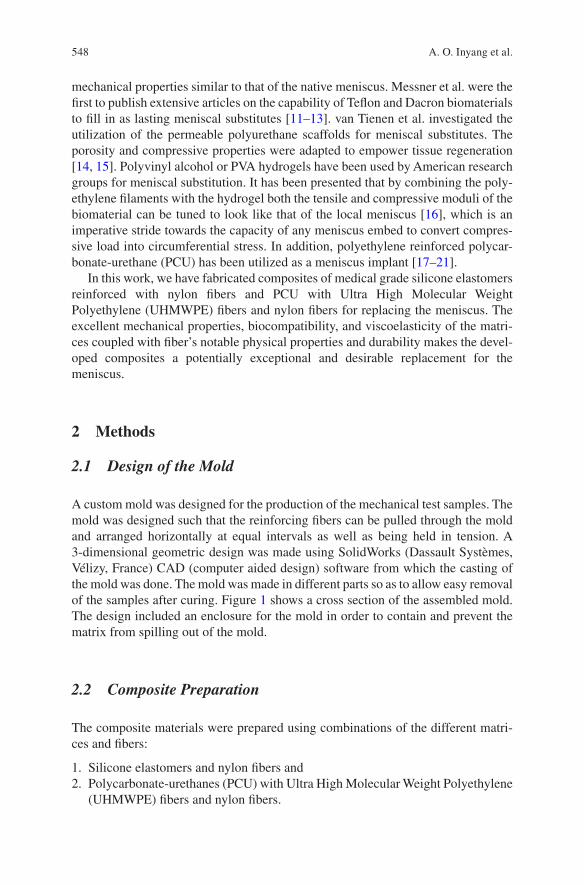
548
mechanical properties similar to that of the native meniscus. Messner et al. were the first to publish extensive articles on the capability of Teflon and Dacron biomaterials to fill in as lasting meniscal substitutes [11–13]. van Tienen et al. investigated the utilization of the permeable polyurethane scaffolds for meniscal substitutes. The porosity and compressive properties were adapted to empower tissue regeneration [14, 15]. Polyvinyl alcohol or PVA hydrogels have been used by American research groups for meniscal substitution. It has been presented that by combining the poly-ethylene filaments with the hydrogel both the tensile and compressive moduli of the biomaterial can be tuned to look like that of the local meniscus [16], which is an imperative stride towards the capacity of any meniscus embed to convert compres-sive load into circumferential stress. In addition, polyethylene reinforced polycar-bonate-urethane (PCU) has been utilized as a meniscus implant [17–21].
In this work, we have fabricated composites of medical grade silicone elastomers reinforced with nylon fibers and PCU with Ultra High Molecular Weight Polyethylene (UHMWPE) fibers and nylon fibers for replacing the meniscus. The excellent mechanical properties, biocompatibility, and viscoelasticity of the matri-ces coupled with fiber’s notable physical properties and durability makes the devel-oped composites a potentially exceptional and desirable replacement for the meniscus.
2 Methods
2.1 Design of the Mold
A custom mold was designed for the production of the mechanical test samples. The mold was designed such that the reinforcing fibers can be pulled through the mold and arranged horizontally at equal intervals as well as being held in tension. A 3-dimensional geometric design was made using SolidWorks (Dassault Systèmes, Vélizy, France) CAD (computer aided design) software from which the casting of the mold was done. The mold was made in different parts so as to allow easy removal of the samples after curing. Figure 1 shows a cross section of the assembled mold. The design included an enclosure for the mold in order to contain and prevent the matrix from spilling out of the mold.
2.2 Composite Preparation
The composite materials were prepared using combinations of the different matri-ces and fibers:
1. Silicone elastomers and nylon fibers and 2. Polycarbonate-urethanes (PCU) with Ultra High Molecular Weight Polyethylene
(UHMWPE) fibers and nylon fibers.
A. O. Inyang et al.
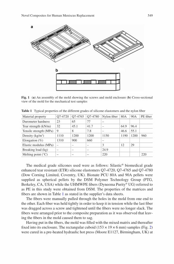
549
The medical grade silicones used were as follows: Silastic® biomedical grade enhanced tear resistant (ETR) silicone elastomers Q7-4720, Q7-4765 and Q7-4780 (Dow Corning Limited, Coventry, UK). Bionate PCU 80A and 90A pellets were supplied as spherical pellets by the DSM Polymer Technology Group (PTG, Berkeley, CA, USA) while the UHMWPE fibers (Dyneema Purity® UG) referred to as PE in this study were obtained from DSM. The properties of the matrices and fibers are shown in Table 1 as stated in the supplier’s data sheets.
The fibers were manually pulled through the holes in the mold from one end to the other. Each fiber was held tightly in order to keep it in tension while the last fiber was dragged across a screw and tightened until the fibers were no longer slack. The fibers were arranged prior to the composite preparation as it was observed that leav-ing the fibers in the mold caused them to sag.
Having put in the fibers, the mold was filled with the mixed matrix and thereafter fixed into its enclosure. The rectangular cuboid (153 × 19 × 6 mm) samples (Fig. 2) were cured in a pre-heated hydraulic hot press (Moore E1127, Birmingham, UK) at
Fig. 1 (a) An assembly of the mold showing the screws and mold enclosure (b) Cross-sectional view of the mold for the mechanical test samples
Table 1 Typical properties of the different grades of silicone elastomers and the nylon fiber
Material property Q7-4720 Q7-4765 Q7-4780 Nylon fiber 80A 90A PE fiber
Durometer hardness 23 65 77 –Tear strength (kN/m) 32 45.1 41.7 – 64.9 96.4Tensile strength (MPa) 9 8 7.8 – 46.6 55.1Density (kg/m3) 1110 1200 1200 1150 1190 1200 960Elongation (%) 1310 900 660 –Elastic modulus (MPa) – – – 3 12 29Breaking load (kg) – – – 24.9Melting point (°C) – – – 220 220
Novel Composites for Human Meniscus Replacement
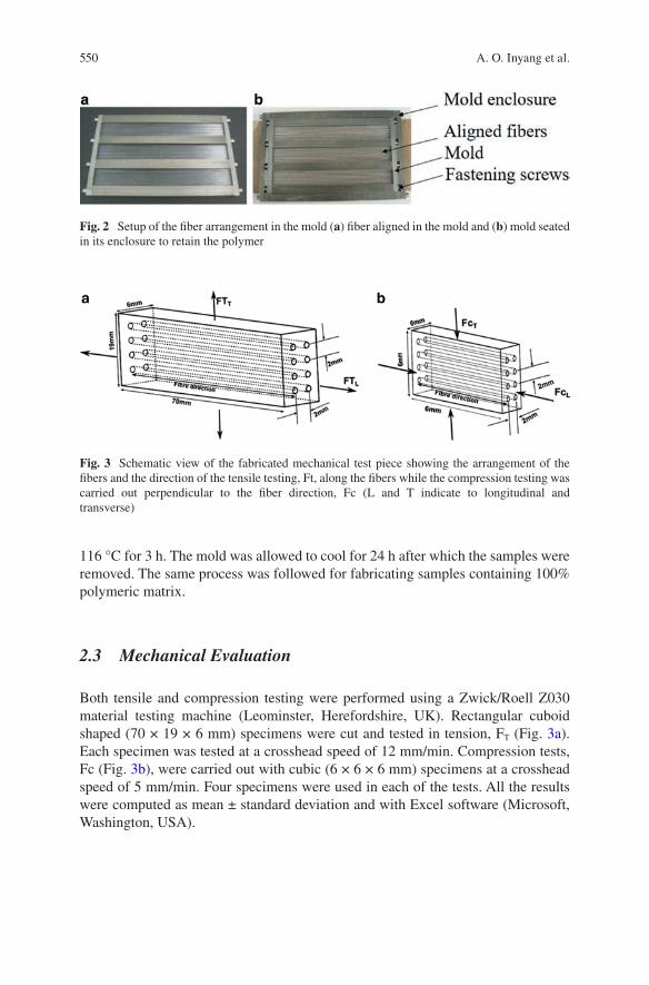
550
116 °C for 3 h. The mold was allowed to cool for 24 h after which the samples were removed. The same process was followed for fabricating samples containing 100% polymeric matrix.
2.3 Mechanical Evaluation
Both tensile and compression testing were performed using a Zwick/Roell Z030 material testing machine (Leominster, Herefordshire, UK). Rectangular cuboid shaped (70 × 19 × 6 mm) specimens were cut and tested in tension, FT (Fig. 3a). Each specimen was tested at a crosshead speed of 12 mm/min. Compression tests, Fc (Fig. 3b), were carried out with cubic (6 × 6 × 6 mm) specimens at a crosshead speed of 5 mm/min. Four specimens were used in each of the tests. All the results were computed as mean ± standard deviation and with Excel software (Microsoft, Washington, USA).
Fig. 2 Setup of the fiber arrangement in the mold (a) fiber aligned in the mold and (b) mold seated in its enclosure to retain the polymer
Fig. 3 Schematic view of the fabricated mechanical test piece showing the arrangement of the fibers and the direction of the tensile testing, Ft, along the fibers while the compression testing was carried out perpendicular to the fiber direction, Fc (L and T indicate to longitudinal and transverse)
A. O. Inyang et al.
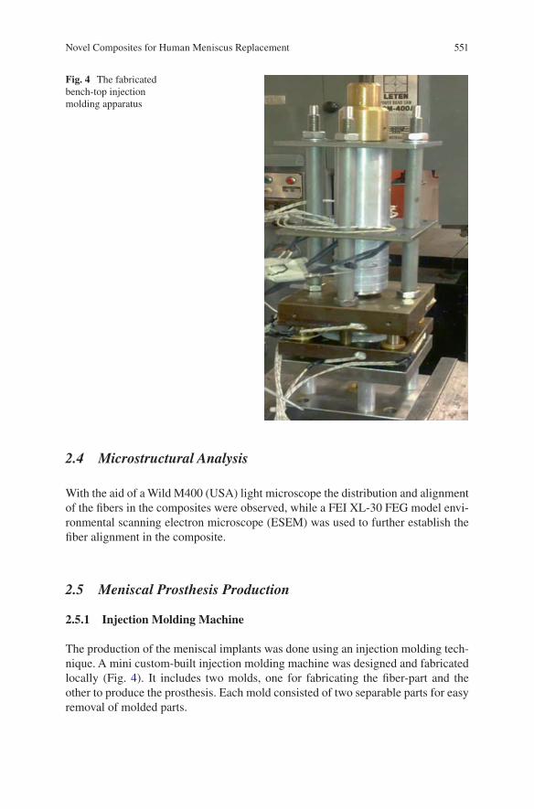
551
2.4 Microstructural Analysis
With the aid of a Wild M400 (USA) light microscope the distribution and alignment of the fibers in the composites were observed, while a FEI XL-30 FEG model envi-ronmental scanning electron microscope (ESEM) was used to further establish the fiber alignment in the composite.
2.5 Meniscal Prosthesis Production
2.5.1 Injection Molding Machine
The production of the meniscal implants was done using an injection molding tech-nique. A mini custom-built injection molding machine was designed and fabricated locally (Fig. 4). It includes two molds, one for fabricating the fiber-part and the other to produce the prosthesis. Each mold consisted of two separable parts for easy removal of molded parts.
Fig. 4 The fabricated bench-top injection molding apparatus
Novel Composites for Human Meniscus Replacement
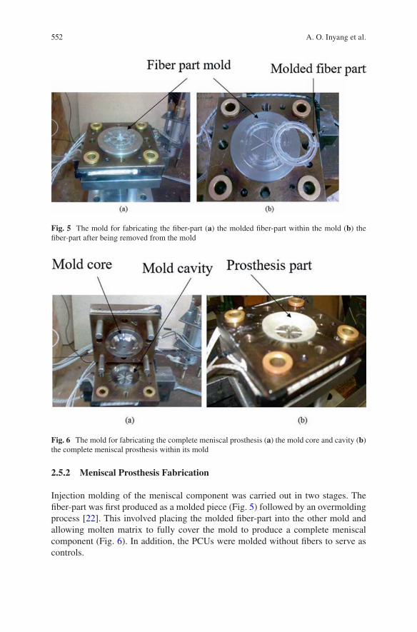
552
2.5.2 Meniscal Prosthesis Fabrication
Injection molding of the meniscal component was carried out in two stages. The fiber-part was first produced as a molded piece (Fig. 5) followed by an overmolding process [22]. This involved placing the molded fiber-part into the other mold and allowing molten matrix to fully cover the mold to produce a complete meniscal component (Fig. 6). In addition, the PCUs were molded without fibers to serve as controls.
Fig. 5 The mold for fabricating the fiber-part (a) the molded fiber-part within the mold (b) the fiber-part after being removed from the mold
Fig. 6 The mold for fabricating the complete meniscal prosthesis (a) the mold core and cavity (b) the complete meniscal prosthesis within its mold
A. O. Inyang et al.
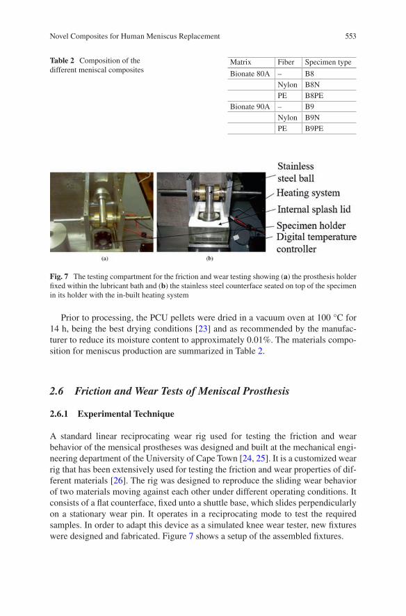
553
Prior to processing, the PCU pellets were dried in a vacuum oven at 100 °C for 14 h, being the best drying conditions [23] and as recommended by the manufac-turer to reduce its moisture content to approximately 0.01%. The materials compo-sition for meniscus production are summarized in Table 2.
2.6 Friction and Wear Tests of Meniscal Prosthesis
2.6.1 Experimental Technique
A standard linear reciprocating wear rig used for testing the friction and wear behavior of the mensical prostheses was designed and built at the mechanical engi-neering department of the University of Cape Town [24, 25]. It is a customized wear rig that has been extensively used for testing the friction and wear properties of dif-ferent materials [26]. The rig was designed to reproduce the sliding wear behavior of two materials moving against each other under different operating conditions. It consists of a flat counterface, fixed unto a shuttle base, which slides perpendicularly on a stationary wear pin. It operates in a reciprocating mode to test the required samples. In order to adapt this device as a simulated knee wear tester, new fixtures were designed and fabricated. Figure 7 shows a setup of the assembled fixtures.
Table 2 Composition of the different meniscal composites
Matrix Fiber Specimen type
Bionate 80A – B8Nylon B8NPE B8PE
Bionate 90A – B9Nylon B9NPE B9PE
Fig. 7 The testing compartment for the friction and wear testing showing (a) the prosthesis holder fixed within the lubricant bath and (b) the stainless steel counterface seated on top of the specimen in its holder with the in-built heating system
Novel Composites for Human Meniscus Replacement
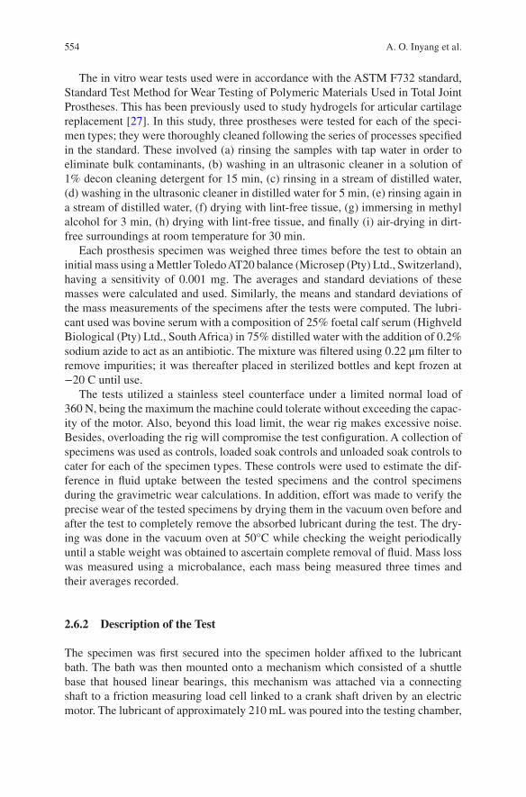
554
The in vitro wear tests used were in accordance with the ASTM F732 standard, Standard Test Method for Wear Testing of Polymeric Materials Used in Total Joint Prostheses. This has been previously used to study hydrogels for articular cartilage replacement [27]. In this study, three prostheses were tested for each of the speci-men types; they were thoroughly cleaned following the series of processes specified in the standard. These involved (a) rinsing the samples with tap water in order to eliminate bulk contaminants, (b) washing in an ultrasonic cleaner in a solution of 1% decon cleaning detergent for 15 min, (c) rinsing in a stream of distilled water, (d) washing in the ultrasonic cleaner in distilled water for 5 min, (e) rinsing again in a stream of distilled water, (f) drying with lint-free tissue, (g) immersing in methyl alcohol for 3 min, (h) drying with lint-free tissue, and finally (i) air-drying in dirt-free surroundings at room temperature for 30 min.
Each prosthesis specimen was weighed three times before the test to obtain an initial mass using a Mettler Toledo AT20 balance (Microsep (Pty) Ltd., Switzerland), having a sensitivity of 0.001 mg. The averages and standard deviations of these masses were calculated and used. Similarly, the means and standard deviations of the mass measurements of the specimens after the tests were computed. The lubri-cant used was bovine serum with a composition of 25% foetal calf serum (Highveld Biological (Pty) Ltd., South Africa) in 75% distilled water with the addition of 0.2% sodium azide to act as an antibiotic. The mixture was filtered using 0.22 μm filter to remove impurities; it was thereafter placed in sterilized bottles and kept frozen at −20 C until use.
The tests utilized a stainless steel counterface under a limited normal load of 360 N, being the maximum the machine could tolerate without exceeding the capac-ity of the motor. Also, beyond this load limit, the wear rig makes excessive noise. Besides, overloading the rig will compromise the test configuration. A collection of specimens was used as controls, loaded soak controls and unloaded soak controls to cater for each of the specimen types. These controls were used to estimate the dif-ference in fluid uptake between the tested specimens and the control specimens during the gravimetric wear calculations. In addition, effort was made to verify the precise wear of the tested specimens by drying them in the vacuum oven before and after the test to completely remove the absorbed lubricant during the test. The dry-ing was done in the vacuum oven at 50°C while checking the weight periodically until a stable weight was obtained to ascertain complete removal of fluid. Mass loss was measured using a microbalance, each mass being measured three times and their averages recorded.
2.6.2 Description of the Test
The specimen was first secured into the specimen holder affixed to the lubricant bath. The bath was then mounted onto a mechanism which consisted of a shuttle base that housed linear bearings, this mechanism was attached via a connecting shaft to a friction measuring load cell linked to a crank shaft driven by an electric motor. The lubricant of approximately 210 mL was poured into the testing chamber,
A. O. Inyang et al.
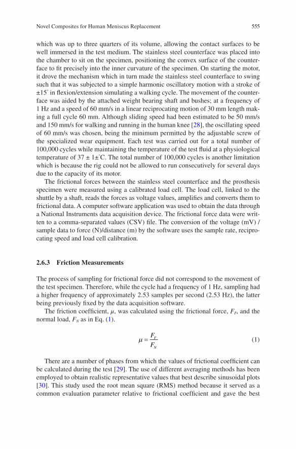
555
which was up to three quarters of its volume, allowing the contact surfaces to be well immersed in the test medium. The stainless steel counterface was placed into the chamber to sit on the specimen, positioning the convex surface of the counter-face to fit precisely into the inner curvature of the specimen. On starting the motor, it drove the mechanism which in turn made the stainless steel counterface to swing such that it was subjected to a simple harmonic oscillatory motion with a stroke of ±15° in flexion/extension simulating a walking cycle. The movement of the counter-face was aided by the attached weight bearing shaft and bushes; at a frequency of 1 Hz and a speed of 60 mm/s in a linear reciprocating motion of 30 mm length mak-ing a full cycle 60 mm. Although sliding speed had been estimated to be 50 mm/s and 150 mm/s for walking and running in the human knee [28], the oscillating speed of 60 mm/s was chosen, being the minimum permitted by the adjustable screw of the specialized wear equipment. Each test was carried out for a total number of 100,000 cycles while maintaining the temperature of the test fluid at a physiological temperature of 37 ± 1±°C. The total number of 100,000 cycles is another limitation which is because the rig could not be allowed to run consecutively for several days due to the capacity of its motor.
The frictional forces between the stainless steel counterface and the prosthesis specimen were measured using a calibrated load cell. The load cell, linked to the shuttle by a shaft, reads the forces as voltage values, amplifies and converts them to frictional data. A computer software application was used to obtain the data through a National Instruments data acquisition device. The frictional force data were writ-ten to a comma-separated values (CSV) file. The conversion of the voltage (mV) /sample data to force (N)/distance (m) by the software uses the sample rate, recipro-cating speed and load cell calibration.
2.6.3 Friction Measurements
The process of sampling for frictional force did not correspond to the movement of the test specimen. Therefore, while the cycle had a frequency of 1 Hz, sampling had a higher frequency of approximately 2.53 samples per second (2.53 Hz), the latter being previously fixed by the data acquisition software.
The friction coefficient, μ, was calculated using the frictional force, FF, and the normal load, FN as in Eq. (1).
m =
F
FF
N (1)
There are a number of phases from which the values of frictional coefficient can be calculated during the test [29]. The use of different averaging methods has been employed to obtain realistic representative values that best describe sinusoidal plots [30]. This study used the root mean square (RMS) method because it served as a common evaluation parameter relative to frictional coefficient and gave the best
Novel Composites for Human Meniscus Replacement
556
description of the entire process [29]. The RMS is a statistical measure of the ampli-tude of a varying quantity which is especially useful when the values alternate between positive and negative. Given a set of n values {x1, x2, x3, …., xn}, the root mean square can be calculated using the following formula:
x
nxrms
i
n
i==å1
0
2
(2)
In analyzing the data, groups of cycles were represented by the RMS frictional coefficient thereby reducing the complex data pattern to a simpler numerical repre-sentative value. In order to process the data and generate textual and graphical rep-resentations of the results, computer programs written in Microsoft C# 4.0, Matlab and MySQL were used.
2.6.4 Wear Measurements
The wear mass was evaluated gravimetrically and the mass loss obtained from the difference of the final and initial masses was used taking into account the lubricant uptake. The wear behavior was then characterized using the parameter, wear factor, WF (mm3/Nm), which was calculated as follows:
V
mL = r
(3)
W
V
FdFL=
(4)
where VL is the volume loss in mm3, m is the mass loss is in kg, ρ is the density in kg/m3, F is the applied load in N and d is the sliding distance in m.
2.7 Surface Characterization
A microstructural analysis was done on a Nova NanoSem 230 scanning electron microscope (SEM), (FEI, Holland, Netherlands) to analyze the surface morphology of the specimens after testing. The specimens were coated with carbon for this observation. Also, control specimens were evaluated.
A. O. Inyang et al.
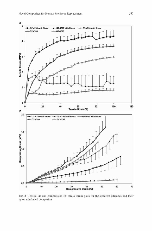
557
Fig. 8 Tensile (a) and compression (b) stress–strain plots for the different silicones and their nylon reinforced composites
Novel Composites for Human Meniscus Replacement
558
3 Results and Discussion
3.1 Tensile and Compression Tests
The stress-strain plots for both tension and compression tests for the silicones and their nylon reinforced composites are shown in Fig. 8.
The composite with the optimum properties has its tensile modulus increased significantly from 10.7 ± 2.9 to 114.6 ± 20.9 MPa when reinforced with 5% v/v nylon fibers. This value is within the circumferential tensile modulus of the native meniscus. Unlike the tensile modulus, the compressive modulus of the composite was found to reduce from 2.5 ± 0.6 to 0.7 ± 0.3 MPa when fibers were incorporated; which is closer to the aggregate compressive modulus of the native meniscus. The optimum tensile modulus was observed with composites of silicone elastomer Q7-4780 which increased from 10.7 ± 2.9 MPa for 100% polymeric matrix samples to 114.6 ± 20.9 MPa for composites with reinforced fibers. Its compressive modulus on the other hand reduced from 2.5 ± 0.6 to 0.74 ± 0.3 MPa for samples without fibers and with fibers, respectively.
In the nylon reinforced composites, an increase in the tensile modulus was observed as compared to their unreinforced analogue, and this follows a similar trend as described by a previous research group [16]. In comparison with the com-posite of Q7-4780 which had the highest tensile modulus, Q7-4765 had a lower modulus of approximately 43% while that of Q7-4720 was the least at approxi-mately 15%.
The lowest compressive modulus value was measured for the composite of Q7-4780 which decreased from 2.5 ± 0.6 to 0.7 ± 0.3 MPa when fibers were incor-porated. Although this value is higher than the aggregate compressive modulus of the native meniscus, which is 0.22 MPa [31], this reduction suggests that nylon reinforced silicones can be fashioned to mimic the desired properties of the native meniscus.
In this study, both B8 and B9 displayed characteristic elastomeric stress-strain behavior that is typical of these materials and have also been observed in previous studies for similar PCU materials [32]. The tensile stress-strain curve of B9 showed a slightly higher yield point before undergoing a period of further elongation. The unreinforced PCU materials permitted more strain prior to failure than their fiber-reinforced counterparts (Fig. 9).
The empirically determined tensile modulus of composite of PCU is summarized in Table 3. Conversely, the value of ~18 MPa obtained for the tensile modulus of B9 in the current tests, was lower than 29 MPa given by the supplier.
From the mechanical tests for the different composites, the PCU composites pro-vided excellent mechanical properties more suitable for the meniscus than the sili-cone composites. Therefore, further tests including friction and wear were conducted on the PCU composite samples.
A. O. Inyang et al.
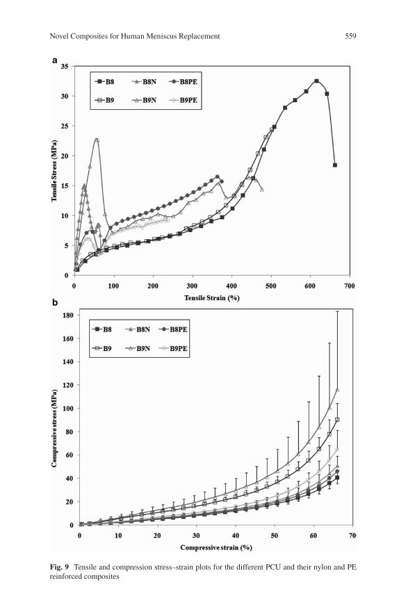
559
Fig. 9 Tensile and compression stress–strain plots for the different PCU and their nylon and PE reinforced composites
Novel Composites for Human Meniscus Replacement
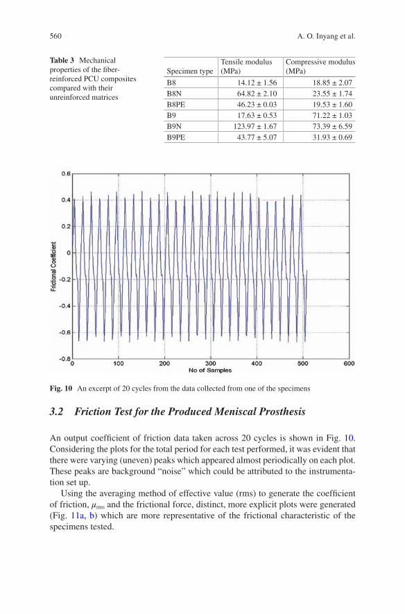
560
3.2 Friction Test for the Produced Meniscal Prosthesis
An output coefficient of friction data taken across 20 cycles is shown in Fig. 10. Considering the plots for the total period for each test performed, it was evident that there were varying (uneven) peaks which appeared almost periodically on each plot. These peaks are background “noise” which could be attributed to the instrumenta-tion set up.
Using the averaging method of effective value (rms) to generate the coefficient of friction, μrms and the frictional force, distinct, more explicit plots were generated (Fig. 11a, b) which are more representative of the frictional characteristic of the specimens tested.
Table 3 Mechanical properties of the fiber-reinforced PCU composites compared with their unreinforced matrices
Specimen typeTensile modulus (MPa)
Compressive modulus (MPa)
B8 14.12 ± 1.56 18.85 ± 2.07B8N 64.82 ± 2.10 23.55 ± 1.74B8PE 46.23 ± 0.03 19.53 ± 1.60B9 17.63 ± 0.53 71.22 ± 1.03B9N 123.97 ± 1.67 73.39 ± 6.59B9PE 43.77 ± 5.07 31.93 ± 0.69
Fig. 10 An excerpt of 20 cycles from the data collected from one of the specimens
A. O. Inyang et al.
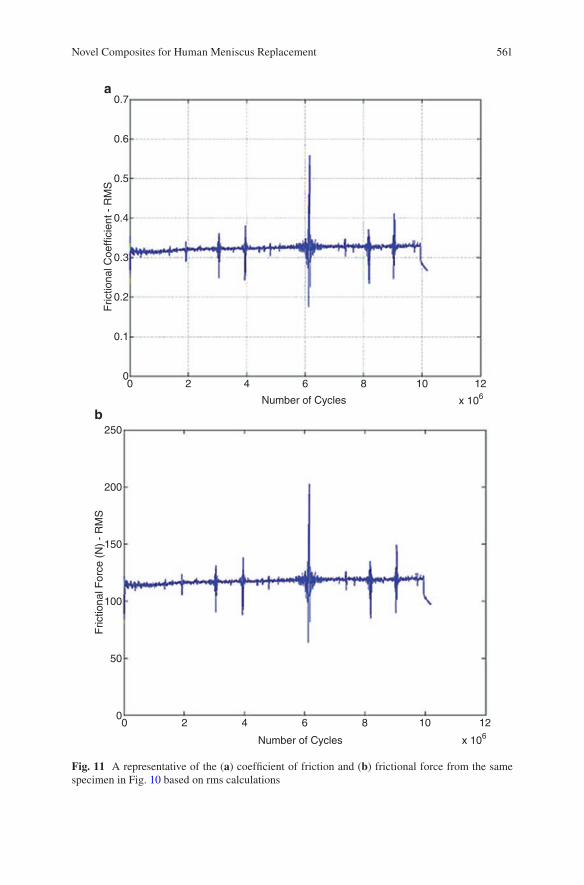
561
0.7
0.6
0.5
0.4
0.3
0.2
0.1
00
250
200
150
100
50
00 2 4 6 8 10 12
x 106Number of Cycles
2 4 6 8
a
b
10 12
Number of Cycles x 106
Fric
tiona
l Coe
ffici
ent -
RM
SF
rictio
nal F
orce
(N
) -
RM
S
Fig. 11 A representative of the (a) coefficient of friction and (b) frictional force from the same specimen in Fig. 10 based on rms calculations
Novel Composites for Human Meniscus Replacement
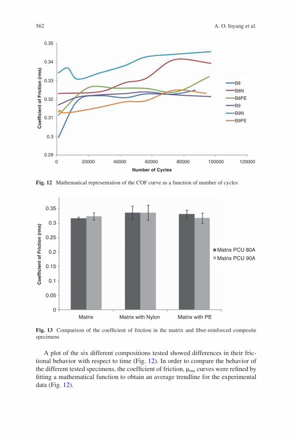
562
A plot of the six different compositions tested showed differences in their fric-tional behavior with respect to time (Fig. 12). In order to compare the behavior of the different tested specimens, the coefficient of friction, μrms curves were refined by fitting a mathematical function to obtain an average trendline for the experimental data (Fig. 12).
0.35
0.34
0.33
0.32
0.31
0.3
0.29
0 20000 40000 60000 80000 100000 120000
B9PE
B9N
B9
B8PE
B8N
B8
Number of Cycles
Co
effi
cien
t o
f F
rict
ion
(rm
s)
Fig. 12 Mathematical representation of the COF curve as a function of number of cycles
0.35
0.3
0.25
0.2
0.15
0.1
0.05
Matrix Matrix with Nylon Matrix with PE
Matrix PCU 80A
Matrix PCU 90A
Co
effi
cien
t o
f F
rict
ion
(rm
s)
0
Fig. 13 Comparison of the coefficient of friction in the matrix and fiber-reinforced composite specimens
A. O. Inyang et al.
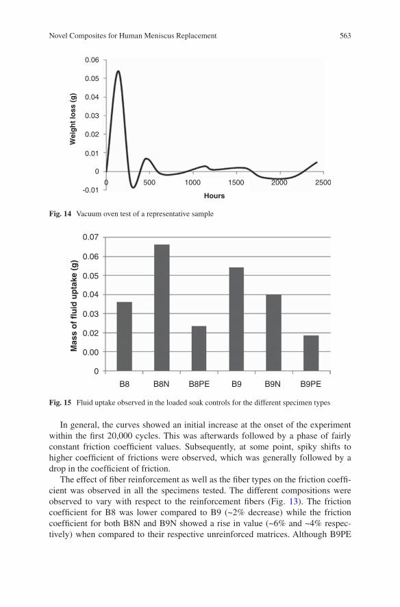
563
In general, the curves showed an initial increase at the onset of the experiment within the first 20,000 cycles. This was afterwards followed by a phase of fairly constant friction coefficient values. Subsequently, at some point, spiky shifts to higher coefficient of frictions were observed, which was generally followed by a drop in the coefficient of friction.
The effect of fiber reinforcement as well as the fiber types on the friction coeffi-cient was observed in all the specimens tested. The different compositions were observed to vary with respect to the reinforcement fibers (Fig. 13). The friction coefficient for B8 was lower compared to B9 (~2% decrease) while the friction coefficient for both B8N and B9N showed a rise in value (~6% and ~4% respec-tively) when compared to their respective unreinforced matrices. Although B9PE
0.06
0.05
0.04
0.03
0.02
0.01
0
-0.010 500 1000 1500 2000 2500
Hours
Wei
gh
t lo
ss (
g)
Fig. 14 Vacuum oven test of a representative sample
0.07
0.06
0.05
0.04
0.03
0.02
0.00
0
B8 B8N B8PE B9 B9N B9PE
Mas
s o
f fl
uid
up
take
(g
)
Fig. 15 Fluid uptake observed in the loaded soak controls for the different specimen types
Novel Composites for Human Meniscus Replacement
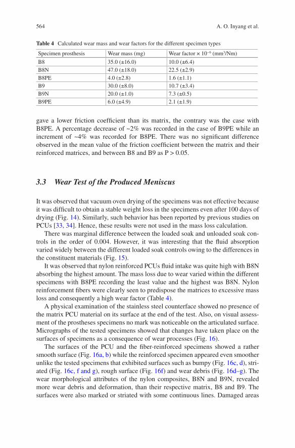
564
gave a lower friction coefficient than its matrix, the contrary was the case with B8PE. A percentage decrease of ~2% was recorded in the case of B9PE while an increment of ~4% was recorded for B8PE. There was no significant difference observed in the mean value of the friction coefficient between the matrix and their reinforced matrices, and between B8 and B9 as P > 0.05.
3.3 Wear Test of the Produced Meniscus
It was observed that vacuum oven drying of the specimens was not effective because it was difficult to obtain a stable weight loss in the specimens even after 100 days of drying (Fig. 14). Similarly, such behavior has been reported by previous studies on PCUs [33, 34]. Hence, these results were not used in the mass loss calculation.
There was marginal difference between the loaded soak and unloaded soak con-trols in the order of 0.004. However, it was interesting that the fluid absorption varied widely between the different loaded soak controls owing to the differences in the constituent materials (Fig. 15).
It was observed that nylon reinforced PCUs fluid intake was quite high with B8N absorbing the highest amount. The mass loss due to wear varied within the different specimens with B8PE recording the least value and the highest was B8N. Nylon reinforcement fibers were clearly seen to predispose the matrices to excessive mass loss and consequently a high wear factor (Table 4).
A physical examination of the stainless steel counterface showed no presence of the matrix PCU material on its surface at the end of the test. Also, on visual assess-ment of the prostheses specimens no mark was noticeable on the articulated surface. Micrographs of the tested specimens showed that changes have taken place on the surfaces of specimens as a consequence of wear processes (Fig. 16).
The surfaces of the PCU and the fiber-reinforced specimens showed a rather smooth surface (Fig. 16a, b) while the reinforced specimen appeared even smoother unlike the tested specimens that exhibited surfaces such as bumpy (Fig. 16c, d), stri-ated (Fig. 16c, f and g), rough surface (Fig. 16f) and wear debris (Fig. 16d–g). The wear morphological attributes of the nylon composites, B8N and B9N, revealed more wear debris and deformation, than their respective matrix, B8 and B9. The surfaces were also marked or striated with some continuous lines. Damaged areas
Table 4 Calculated wear mass and wear factors for the different specimen types
Specimen prosthesis Wear mass (mg) Wear factor × 10−6 (mm3/Nm)
B8 35.0 (±16.0) 10.0 (±6.4)B8N 47.0 (±18.0) 22.5 (±2.9)B8PE 4.0 (±2.8) 1.6 (±1.1)B9 30.0 (±8.0) 10.7 (±3.4)B9N 20.0 (±1.0) 7.3 (±0.5)B9PE 6.0 (±4.9) 2.1 (±1.9)
A. O. Inyang et al.
565
Fig. 16 SEM surface morphology of the specimen types as observed under the SEM. Untested specimen of (a) matrix (b) reinforced matrix and tested specimens of (c) B8 (d) B8N (e) B8PE (f) B9 (g) B9N (h) B9PE
Novel Composites for Human Meniscus Replacement
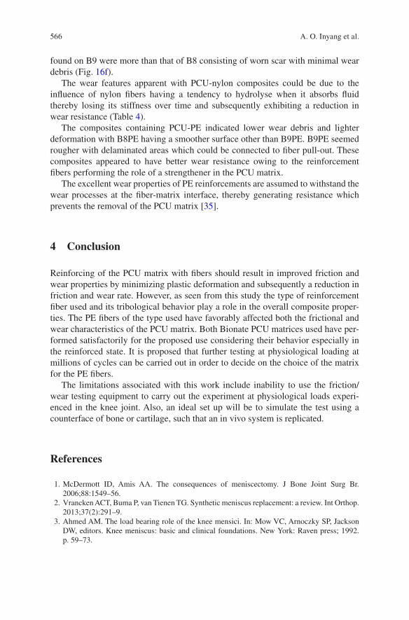
566
found on B9 were more than that of B8 consisting of worn scar with minimal wear debris (Fig. 16f).
The wear features apparent with PCU-nylon composites could be due to the influence of nylon fibers having a tendency to hydrolyse when it absorbs fluid thereby losing its stiffness over time and subsequently exhibiting a reduction in wear resistance (Table 4).
The composites containing PCU-PE indicated lower wear debris and lighter deformation with B8PE having a smoother surface other than B9PE. B9PE seemed rougher with delaminated areas which could be connected to fiber pull-out. These composites appeared to have better wear resistance owing to the reinforcement fibers performing the role of a strengthener in the PCU matrix.
The excellent wear properties of PE reinforcements are assumed to withstand the wear processes at the fiber-matrix interface, thereby generating resistance which prevents the removal of the PCU matrix [35].
4 Conclusion
Reinforcing of the PCU matrix with fibers should result in improved friction and wear properties by minimizing plastic deformation and subsequently a reduction in friction and wear rate. However, as seen from this study the type of reinforcement fiber used and its tribological behavior play a role in the overall composite proper-ties. The PE fibers of the type used have favorably affected both the frictional and wear characteristics of the PCU matrix. Both Bionate PCU matrices used have per-formed satisfactorily for the proposed use considering their behavior especially in the reinforced state. It is proposed that further testing at physiological loading at millions of cycles can be carried out in order to decide on the choice of the matrix for the PE fibers.
The limitations associated with this work include inability to use the friction/wear testing equipment to carry out the experiment at physiological loads experi-enced in the knee joint. Also, an ideal set up will be to simulate the test using a counterface of bone or cartilage, such that an in vivo system is replicated.
References
1. McDermott ID, Amis AA. The consequences of meniscectomy. J Bone Joint Surg Br. 2006;88:1549–56.
2. Vrancken ACT, Buma P, van Tienen TG. Synthetic meniscus replacement: a review. Int Orthop. 2013;37(2):291–9.
3. Ahmed AM. The load bearing role of the knee mensici. In: Mow VC, Arnoczky SP, Jackson DW, editors. Knee meniscus: basic and clinical foundations. New York: Raven press; 1992. p. 59–73.
A. O. Inyang et al.
567
4. Aufderheide AC, Athanasiou KA. Mechanical stimulation toward tissue engineering of the knee meniscus. Ann Biomed Eng. 2004;32:1161–74.
5. Pangborn CA, Athanasiou KA. Knee meniscus, biomechanics of Wiley encyclopaedia of bio-mechanical engineering. New York: Wiley; 2006.
6. Fan RSP, Ryu RKN. Meniscal lesions: diagnosis and treatment. Medsc Orthop Sports Med. 2000;4(2).
7. Vedi V, Williams A, Tennant SJ, et al. Meniscal movement. An in-vivo study using dynamic MRI. J Bone Joint Surg Br. 1999;81(1):37–41.
8. Stone KR. Meniscus replacement. Clin Sports Med. 1996;15(3):557–71. 9. Turner S. General principles and perspectives. In: Hodgkinson JM, editor. Mechanical testing
of advanced fibre composites. Boca Raton, FL: CRC; 2000. p. 4–35. 10. Shriram D, Kumar GP, Cui F et al. Evaluating the effects of material properties of artificial
meniscal implant in the human knee joint using finite element analysis. Sci Rep. 2017;7. 11. Messner K. Meniscal substitution with a Teflon-periosteal composite graft: a rabbit experi-
ment. Biomaterials. 1994;15(3):223–30. 12. Messner K, Lohmander LS, Gillquist J. Cartilage mechanics and morphology, synovitis and
proteoglycan fragments in rabbit joint fluid after prosthetic meniscal substitution. Biomaterials. 1993;14(3):163–8.
13. Sommerlath K, Gallino M, Gillquist J. Biomechanical characteristics of different artificial substitutes for rabbit medial meniscus and effect of prosthesis size on knee cartilage. Clin Biomech (Bristol, Avon). 1992;7:97–103.
14. Klompmaker J, Jansen HW, Veth RP, et al. Porous implants for knee joint meniscus reconstruc-tion: a preliminary study on the role of pore sizes in ingrowth and differentiation of fibrocarti-lage. Clin Mater. 1993;14(1):1–11.
15. Tienen TG, Heijkants RG, de Groot JH, et al. Meniscal replacement in dogs. Tissue regenera-tion in two different materials with similar properties. J Biomed Mater Res B Appl Biomater. 2006;76(2):389–96.
16. Holloway JL, Lowman AM, Palmese GR. Mechanical evaluation of poly(vinyl alcohol)-based fibrous composites as biomaterials for meniscal tissue replacement. Acta Biomater. 2010;6(12):4716–24.
17. Elsner JJ, Portnoy S, Zur G, et al. Design of a free-floating polycarbonate-urethane menis-cal implant using finite element modeling and experimental validation. J Biomech Eng. 2010;132(9):095001.
18. Kon E, Filardo G, Tschon M, et al. Tissue engineering for total meniscal substitution: animal study in sheep model-results at 12 months. Tissue Eng Part A. 2012;18(15–16):1573–82.
19. Kelly BT, Potter HG, Deng XH, et al. Meniscal allograft transplantation in the sheep knee: evaluation of chondroprotective effects. Am J Sports Med. 2006;34(9):1464–77.
20. Linder-Ganz E, Elsner JJ, Danino A, et al. A novel quantitative approach for evaluating contact mechanics of meniscal replacements. J Biomech Eng. 2010;132(2):024501.
21. Zur G, Linder-Ganz E, Elsner JJ, et al. Chondroprotective effects of a polycarbonate-urethane meniscal implant: histopathological results in a sheep model. Knee Surg Sports Traumatol Arthrosc. 2010;19(2):255–63.
22. Bryce DM. Plastic injection molding: manufacturing process fundamentals. Society of Manufacturing Engineers; 1996. p. 174.
23. Geary C, Birkinshaw C, Jones E. Characterisation of Bionate polycarbonate polyurethanes for orthopaedic applications. J Mater Sci Mater Med. 2008;19:3355–63.
24. Hohl MW. The wear behaviour of UHMWPE and ion implanted UHMWPE against different counterfaces. MSc Thesis, University of Cape Town. 1998.
25. Marcus K. Micromechanisms of polymer sliding wear. PhD Thesis, University of Cape Town. 1992.
26. Klaas NV, Marcus K, Kellock C. The tribological behaviour of glass filled polytetrafluoroeth-ylene. Tribol Int. 2005;38:824–33.
Novel Composites for Human Meniscus Replacement
568
27. Katta JK, Marcolongo M, Lowman A, et al. Friction and wear behaviour of poly(vinyl alco-hol)/poly(vinyl pyrrolidone) hydrogels for articular cartilage replacement. J Biomed Mater Res A. 2007;83(2):471–9.
28. Covert RJ, Ott RD, DN K. Friction characteristics of a potential articular cartilage biomaterial. Wear. 2003;255:1064–106.
29. Živić F, Babić M, Mitrović A, et al. Interpretation of the friction coefficient during reciprocat-ing sliding of Ti6Al4V alloy against Al2O3. Tribol Ind. 2011;33(1):36–42.
30. Nechak L, Berger S, Aubry E. A polynomial chaos approach to the robust analysis of the dynamic behaviour of friction systems. Eur J Mech A Solids. 2011;30(4):594–607.
31. Scholes SC, Unsworth A, Jones E. Polyurethane unicondylar knee prostheses: simulator wear tests and lubrication studies. Phys Med Biol. 2007;52:197–212.
32. St John K, Gupta M. Evaluation of the wear performance of a polycarbonate-urethane ace-tabular component in a hip joint simulator and comparison with UHMWPE and cross-linked UHMWPE. J Biomater Appl. 2012;27(1):55–65.
33. Wang J, Gu M. Wear properties and mechanisms of nylon and carbon-fiber-reinforced nylon in dry and wet conditions. J Appl Polym Sci. 2004;93:789–95.
34. Alejandro AJ, Athanasiou KA. Design characteristics for the tissue engineering of cartilagi-nous tissues. Ann Biomed Eng. 2004;32(1):2–17.
35. De Nardo L, Farè S, Di Matteo V, Cipolla E, Saino E, Visai L, Speziale P, Tanzi MC. New heparinizable modified poly(carbonate urethane) surfaces diminishing bacterial colonization. J Mater Sci Mater Med. 2007;18(11):2109–15.
A. O. Inyang et al.
569© Springer International Publishing AG, part of Springer Nature 2017B. Li, T. Webster (eds.), Orthopedic Biomaterials, https://doi.org/10.1007/978-3-319-73664-8_20
Biomaterial-Mediated Drug Delivery in Primary and Metastatic Cancers of the Bone
Patrick F. Forde and Katie B. Ryan
Keywords Biomaterial · Metastases · Bone tissue · Polymer · Bone cancer · Sarcoma · Bisphosphonate · Targeted delivery · Drug delivery · Inorganic · Calcium phosphate
1 Introduction
Cancer of the bone includes primary bone tumors and metastatic lesions. Primary bone cancers, which originate in the bone may be classified as benign or malignant. They only account for 0.2% of all cancers [1], but their incidence has increased in the last decade [2]. Bone metastasis occurs more frequently and arises when cancer cells spread from a primary, distant site and metastasize to the bone, where the cells may lay dormant before proliferating to form a cancerous lesion. Metastatic spread-ing to the bone is commonly seen in many cancer types and is particularly prevalent in those patients with advanced breast and prostate cancer, with ~ 70% exhibiting metastatic spreading to the bone [3, 4].
Tumor growth alters the functions of bone-resorbing (osteoclasts) and bone-forming (osteoblasts) cells, and extensively modifies the bone microenvironment resulting in considerable skeletal destruction. Bone cancer is characterised by symptoms such as pain, fracture, hypercalcemia, and spinal cord compression, giv-ing rise to significant patient morbidity [4–7]. Primary cancers may be cured in certain cases with complex multi-modal treatment [1, 8]. However, prognostic out-comes in secondary bone cancer are poorer and depend on primary tumor origin. Median-survival times from diagnosis of bone metastasis have been reported as
P. F. Forde Cork Cancer Research Centre, Western Gateway Building, University College Cork, Cork, Irelande-mail: [email protected]
K. B. Ryan (*) School of Pharmacy, University College Cork, Cork, Irelande-mail: [email protected]
570
12–53 months and 19–25 months in prostate and breast cancers, respectively [9, 10]. Bone metastases represent a major source of morbidity in late stage breast can-cer patients, with only 20–30% of patients projected to achieve 5 year survival after metastatic diagnosis [11].
Treatment of primary and metastatic bone cancer is extremely challenging as a result of the bone physiology and the tumor microenvironment. As with most cancers, early detection, before it has spread, increases the chances of successful treatment by surgery, multi-drug chemotherapy, local irradiation or combination treatments. Treatments have generally been more effective in combating certain primary tumors. If cancer is diagnosed after it has metastasized, treatments are much less successful [12] and palliative approaches generally involving multidisciplinary management are informed by the disease origin [13, 14]. In the case of metastatic spreading to bone, preservation of skeletal integrity, limiting further spreading and bone destruction are key tenets of the treatment regimen. Drugs that inhibit osteoclast-mediated bone resorption (denosumab, bisphosphonates) comprise part of the standard of care for patients with skeletal metastases [15]. These drugs decrease skeletal morbidity but are not curative nor do they have a significant impact on survival; indeed, a high propor-tion of patients exhibit a deterioration in their conditions [16]. Currently, administra-tion of therapeutic agents represents an important pillar in the management of primary and metastatic disease. However many promising drugs at the preclinical stage have seen their clinical utility limited by unacceptable side-effect profiles and sub-thera-peutic concentrations at the disease site. These limitations have prompted researchers to investigate new therapeutic targets and novel, biomaterial-based drug delivery approaches. In particular the clinical translation of a number of medicinal products (Doxil/Caelyx®, Abraxane® and Genexol-PM®) indicated for primary and metastatic disease highlighted the capacity for biomaterials and nanomedicines in particular, to improve drug pharmacokinetics, enhance selective disease targeting and therapeutic efficacy. These benefits offer much potential to advance the treatment of primary and metastatic bone cancer. Many of the biomaterials investigated for drug delivery in the treatments of bone and metastatic cancers of the bone have also been evaluated for their bone regenerative potential. Biomaterial scaffolds are being developed to mimic the native biological architecture and to provide appropriate cues (physical, chemical or mechanical) to promote bone tissue regeneration. Biomaterials for this purpose have been extensively reviewed elsewhere and are beyond the scope of this chapter. Biomaterials are also being increasingly investigated to develop more complex, 3-D models to aid understanding of the mechanisms underpinning the progression and treatment of cancer. These bioengineered cancer models are giving rise to more pre-dictive systems for preclinical research, better screening of drug treatments and the development of better diagnostic tools [17–19].
This chapter examines the bone remodelling process and how the development of cancer in the bone environment can co-opt many of the normal physiological processes to ensure colonisation and growth in the bone tissue environment. The different types of cancer that occur in the bone are described and current treatment strategies and limitations are presented. In the second part of the chapter we explore the variety of biomaterials employed as carriers for diagnostic and therapeutic car-
P. F. Forde and K. B. Ryan
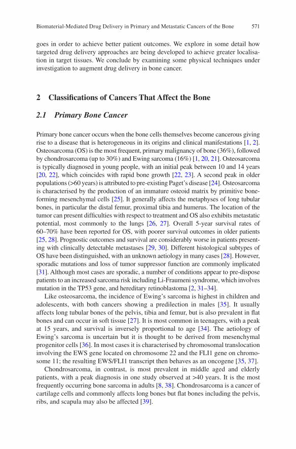
571
goes in order to achieve better patient outcomes. We explore in some detail how targeted drug delivery approaches are being developed to achieve greater localisa-tion in target tissues. We conclude by examining some physical techniques under investigation to augment drug delivery in bone cancer.
2 Classifications of Cancers That Affect the Bone
2.1 Primary Bone Cancer
Primary bone cancer occurs when the bone cells themselves become cancerous giving rise to a disease that is heterogeneous in its origins and clinical manifestations [1, 2]. Osteosarcoma (OS) is the most frequent, primary malignancy of bone (36%), followed by chondrosarcoma (up to 30%) and Ewing sarcoma (16%) [1, 20, 21]. Osteosarcoma is typically diagnosed in young people, with an initial peak between 10 and 14 years [20, 22], which coincides with rapid bone growth [22, 23]. A second peak in older populations (>60 years) is attributed to pre-existing Paget’s disease [24]. Osteosarcoma is characterised by the production of an immature osteoid matrix by primitive bone-forming mesenchymal cells [25]. It generally affects the metaphyses of long tubular bones, in particular the distal femur, proximal tibia and humerus. The location of the tumor can present difficulties with respect to treatment and OS also exhibits metastatic potential, most commonly to the lungs [26, 27]. Overall 5-year survival rates of 60–70% have been reported for OS, with poorer survival outcomes in older patients [25, 28]. Prognostic outcomes and survival are considerably worse in patients present-ing with clinically detectable metastases [29, 30]. Different histological subtypes of OS have been distinguished, with an unknown aetiology in many cases [28]. However, sporadic mutations and loss of tumor suppressor function are commonly implicated [31]. Although most cases are sporadic, a number of conditions appear to pre-dispose patients to an increased sarcoma risk including Li-Fraumeni syndrome, which involves mutation in the TP53 gene, and hereditary retinoblastoma [2, 31–34].
Like osteosarcoma, the incidence of Ewing’s sarcoma is highest in children and adolescents, with both cancers showing a predilection in males [35]. It usually affects long tubular bones of the pelvis, tibia and femur, but is also prevalent in flat bones and can occur in soft tissue [27]. It is most common in teenagers, with a peak at 15 years, and survival is inversely proportional to age [34]. The aetiology of Ewing’s sarcoma is uncertain but it is thought to be derived from mesenchymal progenitor cells [36]. In most cases it is characterised by chromosomal translocation involving the EWS gene located on chromosome 22 and the FLI1 gene on chromo-some 11; the resulting EWS/FLI1 transcript then behaves as an oncogene [35, 37].
Chondrosarcoma, in contrast, is most prevalent in middle aged and elderly patients, with a peak diagnosis in one study observed at >40 years. It is the most frequently occurring bone sarcoma in adults [8, 38]. Chondrosarcoma is a cancer of cartilage cells and commonly affects long bones but flat bones including the pelvis, ribs, and scapula may also be affected [39].
Biomaterial-Mediated Drug Delivery in Primary and Metastatic Cancers of the Bone
572
2.2 Bone Metastatic Disease
Cancer metastasis involves the translocation of tumor cells from the primary site to a distant site(s) where they colonise and develop new lesion(s) [40]. Breast, prostate and lung are the most frequent sites of primary tumor origin. Bone is the commonest site associated with metastases from breast cancer and the third most common tis-sue affected by metastatic disease [3, 11, 41]. Metastasis to bone represents a major cause for morbidity and is characteristic of an aggressive cancer, a decreased time to relapse and poor prognostic [40]. Metastases frequently occur in the heavily vas-cularized regions of the axial skeleton, particularly the red bone marrow and the proximal ends of the long bones [42]. The interplay between disseminated tumor cells (DTCs) and bone microenvironment plays a crucial role in metastatic develop-ment. Bone metastases are categorised as osteolytic (bone destructive), osteoblastic (bone forming) or mixed depending on the bone remodelling process impacted and radiological appearance [43, 44]. Irrespective of whether the metastases are lytic or blastic in appearance, they can cause serious skeletal complications termed skeletal-related events (SREs), the most common including the need for radiotherapy and pathological fractures [13]. Osteolysis is characterised by osteoclast mediated destruction of bone resulting in bone fragility and increased predisposition to frac-ture, particularly in load-bearing bones (femur, pelvis). Patients with multiple myeloma, melanoma, and non-small cell lung cancer present with osteolytic lesions [5, 9, 45]. Metastases arising from breast cancer are predominantly osteolytic, although a portion exhibit osteoblastic or mixed lesions [9, 46]. Prostate carcinoma principally results in osteoblastic metastases that occur as a result of induced osteo-blast proliferation, differentiation and deposition of new bone [9].
3 Bone Biology and Remodelling
Bone is a highly vascular, hard, connective substance that forms the basis of the skeletal system. It possesses a limited regenerative potential and is continuously undergoing a remodeling process to maintain mineral homeostasis, repair damaged tissue and preserve skeletal integrity (Fig. 1) [47, 48]. The skeleton fulfils many important functions: it provides the structural framework for the body, which is necessary for movement, and also protects the major organs. In addition to its physi-cal roles, bone assumes important biochemical and biological functions. It is a res-ervoir for calcium (Ca), helping to balance levels of the mineral in the blood and is also a repository for cells of the immune system [49, 50].
The mechanical competence of this tough but flexible tissue is a consequence of its composition and structural arrangement both at the nano- and macro- scale [51]. The majority of the bone organic phase is composed of type I collagen, which works to dissipate the energy of forces thereby preventing fractures. There is also an abun-dance of non-collagenous proteins include growth factors, cytokines, proteogly-cans, and glycoproteins that contribute to the biological function of bone. Other
P. F. Forde and K. B. Ryan
573
organic components include osteoid, secreted by osteoblasts, which also contributes to the flexibility and strength of bone. Collagen fibres are reinforced with inorganic deposits of the nanocrystalline calcium phosphate (CaP) mineral, hydroxyapatite (HA) (Ca10(PO4)6OH2), which contributes to the hardness and compression resis-tance of bone. The architectural orientation of the collagen fibres together with the apatite crystals imbues bone tissue with its anisotropic character, its fracture tough-ness and compressive strength [50–52]. Bone tissue is arranged either in a compact or trabecular pattern. The dense, outer layer is composed of compact (cortical) bone consisting of cylindrical, structural units called osteons. These consist of concentri-cally arranged lamellae of collagen fibres around a central haversian canal that car-ries blood vessels and nerve fibres. The alternating alignment of the collagen in neighboring fibres helps the bone withstand torsional stress. Trabecular (cancellous)
Fig. 1 A simplified representation of the bone remodeling process. Maintenance of bone integrity is the result of the finely-balanced, intricate crosstalk between the key cell players, namely osteo-clasts and osteoblasts. Mesenchymal stem cells (MSC) differentiate into pre-osteoblasts and osteo-blasts. Osteoblasts form bone-lining cells or undergo terminal differentiation to form osteocytes, which are entombed in the bone. Osteoblasts play an innate role in new bone formation through the deposition of type I collagen that is subsequently mineralised. Haematopoietic stem cells (HSC) differentiate into bone resorbing osteoclasts through the myeloid pathway. Growth factors and cal-cium are released due to the bone resorption process. The interaction between osteoblasts and osteo-clasts is mediated by a number of important signalling factors. Cells of the osteoblast lineage, osteoblast/stromal cells are responsible for the production two factors essential in inducing osteo-clasts from precursors (i) receptor activator of NF-κB ligand (RANKL) and (ii) macrophage colony stimulating factor (M-CSF). These molecules bind to their cognate receptors on osteoclasts precur-sors, which have been shown to mediate osteoclast activation. Osteoclastogenesis can be inhibited by OPG, a soluble decoy receptor for RANKL. Figure based on the work by Sartawi et al. (2017) [54] and Weilbaecher et al. (2011) [6]. The figure was re-drawn and adapted by permission from Macmillan Publishers Ltd. [Nature Reviews Cancer] Weilbaecher et al. (2011) [6], copyright (2011)
Biomaterial-Mediated Drug Delivery in Primary and Metastatic Cancers of the Bone
574
bone is less dense and highly vascular exhibiting a honeycomb or spongy architec-ture. It is filled with red bone marrow that provides a rich nutritive environment and is a source of hematopoietic cells [53].
Many cell types and signalling pathways are implicated in bone remodelling and homeostasis. The maintenance of bone integrity is a finely balanced process that involves the production of bone matrix by mesenchymal stem cell (MSC)-derived osteoblasts coupled with its resorption by haematopoietic stem cell (HSC)-derived osteoclasts (Fig. 1) [54]. MSCs differentiate along the osteoblast lineage under the influence of transforming growth factor-β (TGFβ), bone morphogenetic proteins (BMPs) and WNT proteins [6]. Osteoblasts secrete an extracellular matrix termed osteoid that is primarily composed of type I collagen. This is subsequently mineral-ized to form the calcified bone matrix. As osteoblasts mature, a portion become embedded in this osteoid matrix; these cells are referred to as osteoid osteocytes or pre-osteocytes [55]. Alternatively, osteoblasts may undergo apoptosis or become quiescent bone-lining cells. Osteocytes are terminally differentiated osteoblasts and account for 90–95% of all bone cells in adult bone. They can live for up to decades within the mineralized bone environment [56]. Once embedded in bone, they undergo morphological changes and develop a dendritic network that extends to the mineralisation front and beyond to either the vascular space or bone surface. Once thought to only have a passive role, osteocytes are increasingly recognized to play a central role in bone metabolism and maintaining bone quality [57–60]. Bone lining cells are also osteoblastic in origin. They assume multiple roles, forming a canopy over remodeling sites, separating bone and bone marrow and acting as a communi-cation channel with osteocytes [61].
Osteoclasts are multinucleated cells that adhere to bone through integrin binding and secrete acid, collagenases and proteases to demineralize the bone matrix and breakdown the proteinaceous components such as collagen type I. During bone resorption, growth factors and Ca2+ are released [6]. The lining on the inner (endos-teum) and outer (periosteum) bone surfaces also contain cell populations implicated in the remodeling process [62]. Bone remodelling capacity requires the action of osteoclasts, which control the resorption, and osteoblasts, which induce the forma-tion of new bone. The intricate balance between these processes relies on cross-talk between the two key cell types and is mediated by key signaling factors. Osteoblasts and their precursors (stromal cells) are important producers of Receptor Activator of Nuclear Factor-κB Ligand (RANKL) and Macrophage Colony Stimulating Factor (M-CSF) that regulate osteoclastogenesis. RANKL binds to its cognate receptor, Receptor-Activator of Nuclear Factor-κB (RANK) on osteoclast precursors thereby helping to control their differentiation [58, 63]. Conversely, osteoprotegerin (OPG), which is produced by a variety of cells including osteoblasts, is a soluble decoy receptor for RANKL and exhibits the capacity to limit osteoclastogenesis through inhibition of RANK mediated nuclear factor κB (NF-κB) activation [64, 65]. The RANKL/OPG ratio is crucial in regulating osteoclast formation and activity.
The interplay with other cells and the impact of osteotropic factors add a layer of complexity to the process described above. Osteotropic factors, including parathy-roid hormone (PTH), 1,25-dihydroxyvitamin D3, interleukin (IL)-1 and prostaglan-din E-2, indirectly induce osteoclast formation by increasing RANKL expression
P. F. Forde and K. B. Ryan
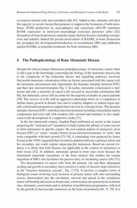
575
on marrow stromal cells and osteoblasts [66, 67]. Added to this, immune cells have the capacity to secrete factors that promote or suppress the formation of both osteo-blasts (TGFβ production by macrophages) and osteoclasts (M-CSF stimulates RANK expression in monocyte–macrophage osteoclast precursor cells) [32]. Disruption of bone homeostasis underlies many skeletal diseases including osteopo-rosis and arthritis. Indeed the pivotal involvement of RANKL in bone destruction has prompted the development/introduction of recombinant OPG and antibodies against RANKL as potential treatments for bone metastases [66].
4 The Pathophysiology of Bone Metastatic Disease
Despite the clinical impact Metastases:pathophysiology: of metastatic cancer, there is still a gap in the knowledge concerning the biology of the metastatic process due to the complexity of the molecular factors and signalling pathways involved. Successful metastatic colonisation relies on factors associated with the cancer cell, the metastatic environment and, importantly, the dynamic interplay between DTCs and their new microenvironment, Fig. 2. In reality, metastatic colonization is inef-ficient and only a minority of cancer cells succeed in successful colonisation [68, 69], but metastatic cancer still accounts for the majority of deaths in cancer patients [70]. The success of cells with an aggressive phenotype relies on a competence to initiate tumor growth at distant sites and to contrive adaptive or indeed organ-spe-cific colonization programs to support their survival in a foreign tissue. The dynamic interplay between DTCs with their microenvironment including extracellular matrix components and cross talk with resident cells (stromal and immune) is also impli-cated in the development of a supportive niche [71].
In the late nineteenth century, Stephen Paget published an article in the Lancet proposing the “seed and soil” hypothesis to help explain the affinity of some cancers to form metastases in specific organs: the non-random pattern of metastasis arose because DTCs or “seeds,” would colonize tissue microenvironments, or “soils,” that were compatible with their growth [72–74]. A contending view proposed by James Ewing in the 1920s suggested that circulatory patterns between a primary tumor and the secondary site could explain organ-specific metastasis. Based on current evi-dence it is likely that both theories are applicable in the context of metastases to bone tissue [12]. In addition, metastatic spread to bone may occur because the fenestrated sinusoidal vasculature of the bone marrow that enables the routine migration of HSCs also facilitates the passive entry of circulating cancer cells [71].
The dissemination of cancer cells from the primary site and their subsequent seeding and growth in secondary site(s) involves a series of discrete steps referred to as the “invasion metastasis cascade”, Fig. 2 [72]. It involves a complex series of biological events involving local invasion of primary tumor cells into surrounding tissues, intravasation into the circulation, survival and spread in the circulation, tumor cell homing and arrest at distant sites, extravasation into parenchyma at distant sites, dormancy, reactivation and re-initiation of proliferation programmes, followed by the growth of macroscopic metastases in the bone environment [44, 71, 75]. It is
Biomaterial-Mediated Drug Delivery in Primary and Metastatic Cancers of the Bone
576
well established that primary tumor cells can selectively and actively pre-condition the bone microenvironment “soil” in advance of their arrival forming pre-metastatic niches. It is proposed that tumor-secreted factors and extracellular vesicles shed from tumors can instruct the metastatic site to adapt for future colonization by DTCs thereby rendering it receptive to localisation and colonisation [76]. The evidence for a pre-metastatic niche in bone is predominantly based on endocrine-like effects [6]. Tumor cells may produce factors [heparanase, parathyroid hormone related-protein (PTHrP)] that promote bone resorption or factors such as osteopontin that mobilise bone-marrow derived cells to the pre-metastatic site. Subsequently, these cells can release factors that act as chemoattractants for circulating tumor cells [6, 40, 77].
Tumor progression begins with cell exit from the primary site either through an epithelial-to-mesenchymal transition (EMT) or by other means that facilitate cell escape as single cells or clusters [78]. This cytokine-induced process reactivates
Escape from the Primary site and invade into circulation
Thrive in bone microenvironment
Bone derivedgrowth factors
Platelet
Angiogenesis
P2Y2
EMT
Tumor cell NK cell Osteoclast Osteoblast Osteocyte Macrophage Adipocyte
Adhesion of tumorcells to the bone
RANKL CXCR7, IL-11,IL-8, IGFBP2,DDR1 etc.
RANK
ECMdegradation
Intravasation
Osteolytic factors:PTHrp, interleukins,Src, microRNAs etc.
Osteoblastic factors:ET1, BMP, FGF,PDGF etc.
Integrins, Cadherins,hAJ etc.
PDGFR, CCL5 etc.
CXCR4TGF-β, IGFs, FGFs etc
SDF-1
M1-M2macrophagepolarization
Lipidtrafficking
Survive in circulation
Home to bonea
b
c
d
Fig. 2 Simplified schematic representing key stages involved in metastatic spread of cancer from the primary site to the bone tissue. (a) Cancer cells acquire a metastatic phenotype, escape from the primary tumor site and intravasate into the circulation, (b) Disseminated cancer cells must survive in the circulation and avoid a number of stresses, in particular removal by the immune cells (e.g. NK cells), before they invade secondary sites, (c) Cancer cells home to the bone and invade tissue under the influence of key signalling factors. In the bone they remain quiescent or begin to proliferate, colonise the local microenvironment and induce their own blood supply, (d) Cancer cells co-opt many of the normal physiological processes to ensure their survival. They interfere with key cells implicated in bone-remodelling and can stimulate osteoclastogenesis (directly or indirectly) and/or osteoblast activity depending on the nature of the tumor. Reprinted from [44], with permission from Elsevier
P. F. Forde and K. B. Ryan

577
developmental EMT programs in cancer cells, imbuing them with pro-metastatic traits that help them exit the primary site and spread [79]. Intravasation involves cancer cell entry predominantly into the blood, but also into the lymphatic circula-tion. This process is influenced by a number of factors, including molecular changes, and the mechanical and structural aspects of the vasculature [72, 75]. Following successful intravasation, cancer cells can spread widely through the venous and arterial circulation to reach their distant site, but they must withstand a variety of stresses including hemodynamic shear forces and removal by immune cells, in par-ticular natural killer cells [75].
The homing and localisation of tumor cells to the bone depend both on traits innate to the tumor and on signals produced by the bone metastatic niche including chemokines, growth factors and integrins [80, 81]. Osteoblasts and bone marrow stromal cells may attract DTCs to bone in a manner that recapitulates the physiolog-ical recruitment of HSCs [6, 82]. Expression of chemokine receptor type 4 (CXCR4) on breast and prostate cancer cells facilitates their homing and localisation to the bone marrow in response to the chemotactic signal CXCL12 (also known as SDF-1) that is expressed in high levels by osteoblasts and bone marrow stromal cells [81, 83–85]. This similarity to HSC homing suggests that the tumor cells can occupy the HSC niche thereby subverting functional physiological processes [86]. Tumor cell surface integrins play a vital role in cancer cell binding to bone extracellular matrix (ECM) proteins. For example the αvβ3 integrin expressed by breast and prostate cancer cells facilitates binding to osteopontin and α4β1 (VLA-4) a receptor for vas-cular cell adhesion molecule 1 (VCAM1) produced by the bone marrow stroma [87–90]. Selectins have also been implicated in tumor extravasation (E-selectin) and DTC adhesion [91–93]. Circulating cancer cells exploit E-selectin adhesion mecha-nisms to ensure cell capture from the bulk blood flow by “tethering”, which is fol-lowed by “rolling” on the endothelial surface. These interactions are mediated by ligands on the surface of circulating cells that recognise E-selectin [94, 95].
Instructive environmental cues not only promote localisation but also regulate cell fate including quiescence, survival and proliferation [96]. Disseminated tumor cells may reside as clinically undetectable single cells or micro metastases in specialized niches that might otherwise be occupied by tissue-resident cell populations. Progression through proliferation to the macro-metastatic form is generally associated with the pos-sibility of clinical detection. Cells can occupy different states of dormancy including one where they are neither undergoing apoptosis nor proliferation, or alternatively active proliferation is balanced by active apoptosis [12]. The dormant state may occur in response to signals in the bone microenvironment or may be due to a lack of expo-sure to those signals normally encountered in the resident site of the primary tumor. Dormancy enables DTCs to escape elimination by drug treatment [97, 98]. Dormancy-inducing signals in the bone microenvironment include TGF-β2, present in the bone marrow that induces a dormant state in head-and-neck squamous carcinoma cells [99], and BMP7, produced by bone stromal cells and demonstrated to induce dormancy in prostate cancer cells [100]. Cells may persist in a protracted period of dormancy, before they become activated under the influence of contextual ECM cues [98]. Local envi-ronmental and niche cues not only play important roles in cell expansion, but, together with the DTC’s capacity to evade the action of immune cells, they also support their
Biomaterial-Mediated Drug Delivery in Primary and Metastatic Cancers of the Bone
578
persistence in a foreign microenvironment [101]. Production of CXCL12 in the bone microenvironment can support the survival of cells inhabiting the bone marrow includ-ing the Src-dependant survival of CXCR4 positive breast cancer cells [71, 102].
During metastatic growth, cancer cells depend on interactions with their micro-environmental niche and cross-talk with stromal cells, including hematopoietic and mesenchymal stem/progenitor cells, in addition to cells of the innate and adaptive immune system [44, 49]. The ECM is an important component of the niche that can be modified to support metastatic colonization. The invasion and growth of DTCs is quite disruptive, particularly to the intricate cellular cross-talk between osteoclasts and osteoblasts. Interference with these cross-talk mechanisms involves a large number of genes and proteins that gives rise to either osteolytic or osteoblastic lesions, depending on the remodelling process implicated [103]. Tumor cells resid-ing in the bone marrow secrete factors [PTHrP, interleukins (IL-6, IL-8, IL-11), matrix metalloproteinases (MMPs)] that primarily mediate their activity by stimu-lating osteoclastogenesis (either directly or indirectly) through the activation of the RANKL/RANK pathway or by altering OPG production [104–107].
Osteolysis and tumor growth is also exacerbated by the activation of the Jagged 1-Notch signalling pathway leading to increased IL-6 and tumor production of transcrip-tion factors RUNX2, GLI2 and hypoxia induced growth factor 1α (HIF1α) [6, 108]. The disruption is exacerbated by tumor cell (breast, lung, multiple myeloma) secretion of various factors (e.g. activin A, DKK-1, sclerostin, noggin) that inhibit osteoblast differ-entiation and activity [15]. The combined impairment of the osteoblast response together with osteoclast stimulation gives rise predominantly to osteolytic lesions [42]. Continued osteoclast stimulation mediates resorption of the bone matrix and further interferes with normal bone remodelling through the release of pro-tumorigenic growth factors (TGF-β), minerals (Ca2+) and matricellular proteins that activate feedback signaling pathways in tumor cells, resulting in a positive loop of bone breakdown and tumor proliferation. This “vicious cycle” leads to excessive osteolysis and tumor growth [43, 109–113].
Osteoblastic metastases, conversely, are believed to be caused by the cancer-cell production of factors that stimulate osteoblast proliferation, differentiation and forma-tion of hard, sclerotic bone [43]. Tumor cells produce a variety of factors including BMPs, WNTs and TGFβ that regulate stem cell differentiation along the osteoblast lineage [6].
5 Diagnosis and Treatment
Treatment is informed by diagnosis, which is complex and relies on careful exami-nation of the patient’s presenting symptoms (bone pain is the most common pre-senting symptom), clinical history, together with multimodal clinical investigation that typically involves imaging and laboratory tests. Routine imaging includes X-ray and further investigation may involve magnetic resonance imaging (MRI), computerized tomography (CT) or positron emission tomography (PET) scans, depending on tumor location, difficulty associated with diagnosis and availability of services (PET). Tumor biopsy and molecular biomarkers for different sarcomas are
P. F. Forde and K. B. Ryan
579
used to increase diagnostic accuracy, support tumor subtyping and devise better treatment strategies [21]. There are no defined diagnostic laboratory tests for bone sarcoma although measurement of alkaline phosphatase (ALP), lactate dehydroge-nase and erythrocyte sedimentation rate may have prognostic value [114, 115].
Some low-grade primary cancers can be treated with surgery. However, primary cancers including OS often require complex, multi-modal treatments [1, 8] involving a multidisciplinary approach that relies on the expertise of oncologists, surgeons, pathologists, and radiologists. Treatment of some cancers and high-grade tumors com-bines the use of surgery, radiation and multi-drug chemotherapy regimens, the compo-sition of which varies depending on disease, treatment stage and response. Management of some bone sarcomas, especially fast growing tumors requires preoperative chemo-therapy prior to surgical removal of all detectable disease followed by post-operative chemotherapy [39, 116]. First-line chemotherapy protocols in OS patients include a combination of drugs referred to as MAP (methotrexate, doxorubicin and cisplatin). Ifosfamide and/or etopside may also be added, although the addition of a fourth drug has not demonstrated a significantly enhanced clinical outcome [2, 31, 117, 118]. Incorporation of cytotoxic chemotherapy into therapeutic regimens increased cure rates from <20% to current levels of ~60–70% [23]. Whilst significant advancement in the development of multimodal therapies corresponded with an increase in long-term survival of osteosarcoma and Ewing’s patients, there has been no significant improve-ment in 5-year survival rate in more recent decades [117, 119, 120]. Additionally, patients with recurrent episodes or metastatic disease have much poorer outcomes [2].
Successful treatment of metastatic disease is generally not a realistic ambition. Treatment strategies informed by the site of the primary tumor are employed. Multidisciplinary approaches may be used to shrink, stop or slow tumor growth or for palliation of symptoms [13, 14]. Due to the high incidence and devastating impact of metastatic bone disease, maintaining bone health in cancer patients is an important clini-cal priority. Anti-resorptive agents including bisphosphonates and denosumab are the standard of care to prevent or delay bone metastases and minimise bone loss in meta-static breast and prostate cancers, also being treated with hormonal and chemotherapy treatment. Bisphosphonates have also shown promising anti-tumor and anti-myeloma effects in their own right [6]. Bisphosphonates are analogues of endogenous pyrophos-phate that localise in bone with high affinity for the mineral surface [43]. They become internalised by osteoclasts, induce their apoptosis and lead to a reduction in bone resorp-tion. Bisphosphonate molecular structure influences the biochemical mechanism of action and potency. Nitrogen-containing bisphosphonates are more potent and act through the mevalonate pathway to inhibit osteoclast activity whilst non-nitrogen con-taining drugs exert their action through their metabolism to ATP analogues [91, 103, 121, 122]. Bisphosphonates (e.g. clodronate, pamidronate and zoledronic acid) have reduced the bone loss in metastatic breast and prostate patients undergoing hormonal and chemotherapy treatment and increased the time to first SRE [123, 124]. In particular, the third-generation bisphosphonate, zoledronic acid is used in cancer patients to reduce skeletal-related events [125]. Denosumab is a fully human monoclonal antibody that binds to both soluble and membrane bound RANKL with high affinity and specificity, preventing the RANKL-RANK interaction, thereby inhibiting osteoclast-mediated bone
Biomaterial-Mediated Drug Delivery in Primary and Metastatic Cancers of the Bone
580
resorption [91, 126–128]. Despite treatment, 30–50% of patients still exhibit deteriora-tion in their condition including skeletal complications and new bone metastases [66].
Emerging treatment strategies also include immunomodulation approaches. A liposomal formulation of mifamurtide (muramyl tripeptide phosphatidyl ethanol-amine, MTP-PE, marketed as Mepact®) is indicated in high-grade resectable, non-metastatic OS after macroscopically complete surgical resection. This immuno-stimulatory agent is used in combination with post-operative multi-agent chemotherapy. Expression of ganglioside GD2, a glycosphingolipid on the cell sur-face of some tumors, has also been targeted with immunotherapy approaches including anti-GD2-CAR engineered T cells. A humanised anti GD-2 monoclonal antibody has been evaluated in clinical trials involving OS, Ewing’s patient in addi-tion to those with neuroblastoma and melanoma [120]. Agents that inhibit key sig-nalling pathways are also under evaluation, e.g. tyrosine kinase inhibitors. Examples include dasatinib, which inhibits SRC, a key signalling molecule in tumor genesis and bone metabolism. Sorafenib tosylate, an inhibitor of the ras signalling pathway has also been investigated in Phase II clinical trials in relapsed patients with unre-sectable high-grade OS after failure of standard multimodal therapy. Others poten-tial treatment approaches include endothelin receptor antagonists and cathepsin K inhibitors [129]. The current state-of-the-art of these strategies particularly in OS has been reviewed elsewhere [23, 28, 120, 130].
The use of radiation is limited in OS and chondrosarcoma but shows positive responses in Ewing’s sarcoma [2, 38] whilst experimental approaches e.g. chemoem-bolization or angio-embolization, thermal ablation, radiofrequency ablation, and cryotherapy have also been investigated [28]. Local external-beam radiotherapy has been used effectively for palliation of bone pain in metastases secondary to breast cancer. Radiopharmaceuticals, such as strontium-89 and samarium-153, have also been employed to relieve the pain associated with osteoblastic or mixed lesions [131]. Radium-223, an alpha-particle emitter that mimics Ca, is taken up in areas of high bone turnover including bone metastases producing a targeted cytotoxic effect [129].
6 Application of Biomaterials in Primary and Metastatic Cancers Affecting the Bone
6.1 Biomaterials in Drug Delivery
6.1.1 Drug Delivery in Primary and Metastatic Cancers Affecting the Bone
An enhanced understanding of cancer biology and the bone microenvironment has given rise to many of the current and emerging treatments. A wide variety of signal-ling pathways, bone turnover homeostatic mechanisms and immunoregulatory net-works implicated in localisation of circulating tumor cells and aberrant tissue growth in the bone environment represent potential targets [53]. Currently, the man-agement of primary and in particular metastatic disease is limited by a lack of an
P. F. Forde and K. B. Ryan
581
efficient method of drug delivery to the required site [132]. This is largely due to the challenging nature of targeting drugs to bone as a result of the unique composition and structure of the tissue [133]. Many of the current therapeutic candidates that have shown promise are limited by toxicity and unfavourable side-effect profiles, whilst others have demonstrated sub-optimal responses [133, 134]. Non-specific distribution, anatomical differences in the vasculature across different tissues, a reduced cardiac output to bone (<10%) compared to many soft-tissues (30% to the liver), drug loss by metabolism or excretion and poor uptake at the target site have contributed to this [135]. To help address these limitations, biomaterials are being designed to exert spatiotemporal control over the delivery of drugs and biological compounds to treat disease and direct tissue specific responses. Many biomaterials have shown promise as drug-delivery systems (DDS) in the loading and controlled release of existing or novel drug cargoes, Fig. 3. These include polymers, ceramics (calcium phosphate), metals, self-assembled molecular complexes, lipids (lipo-somes) and sol-gels among others [134, 136, 137].
In particular, the use of nano-sized drug delivery carriers for bone applications is an area of keen interest [138–140]. There is a strong rationale for this formulation approach including but not limited to:
• Enhanced penetration across cell membranes allowing for a more targeted deliv-ery while also decreasing the propensity of the drug to be cleared by the body [139].
• The provision of an increased surface area, which allows for enhanced drug load-ing, as well as augmenting the solubility of a number of hydrophobic drugs [139, 141].
• A similar size range to the natural components of bone, allowing materials in the• nano-size range to potentially access sites of bone disease and provide sustained
and local drug release [140, 142].• The ability to attach bone-specific targeting moieties to achieve local drug deliv-
ery by modifying the surface of these nanoparticles (NPs) [139, 140].
Despite promising research results, many nanomaterial-based DDS investigated for bone cancer applications are still in their infancy and thus, there is insufficient information available on their safety and efficacy, which is a limiting factor to their clinical evaluation [133].
6.1.2 Polymeric Biomaterials in Drug Delivery
Polymeric systems can be utilised as carriers for chemotherapeutic cargoes by means of drug encapsulation or adsorption on a particulate carrier. Alternatively, the drug may be conjugated to a soluble carrier. Polymer mediated drug delivery offers a number of advantages over the administration of the free drug including protection of the therapeutic cargo, controlled distribution and localisation of drug, increased circulation times, spatiotemporal drug release, decreased drug side-effect profile and immunogenicity [134, 143]. Drug release from encapsulated systems may occur by swelling-controlled release, polymer degradation or drug-diffusion from the
Biomaterial-Mediated Drug Delivery in Primary and Metastatic Cancers of the Bone
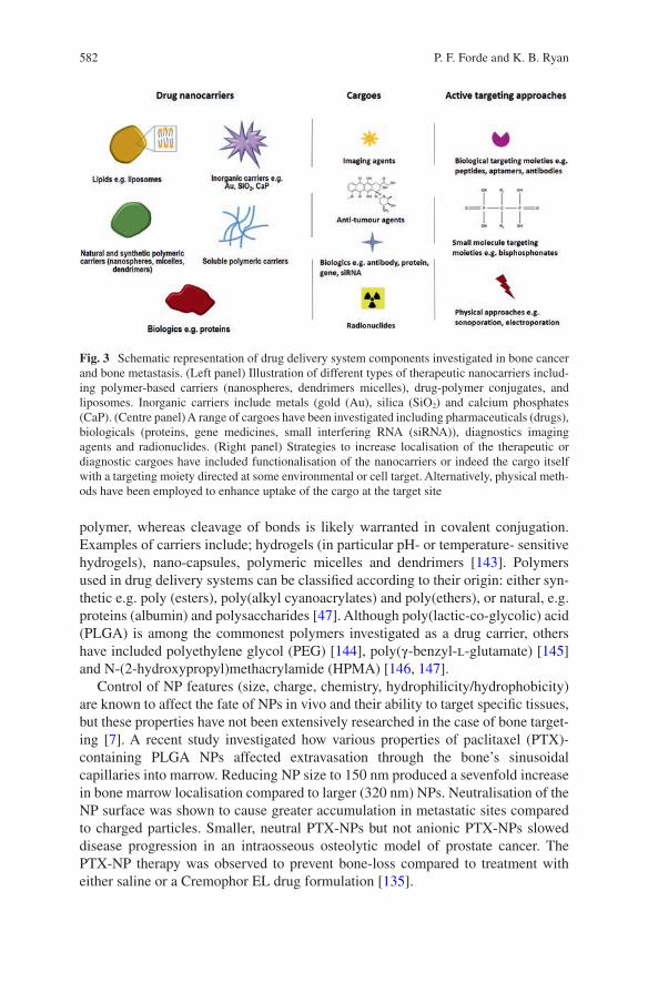
582
polymer, whereas cleavage of bonds is likely warranted in covalent conjugation. Examples of carriers include; hydrogels (in particular pH- or temperature- sensitive hydrogels), nano-capsules, polymeric micelles and dendrimers [143]. Polymers used in drug delivery systems can be classified according to their origin: either syn-thetic e.g. poly (esters), poly(alkyl cyanoacrylates) and poly(ethers), or natural, e.g. proteins (albumin) and polysaccharides [47]. Although poly(lactic-co-glycolic) acid (PLGA) is among the commonest polymers investigated as a drug carrier, others have included polyethylene glycol (PEG) [144], poly(γ-benzyl-l-glutamate) [145] and N-(2-hydroxypropyl)methacrylamide (HPMA) [146, 147].
Control of NP features (size, charge, chemistry, hydrophilicity/hydrophobicity) are known to affect the fate of NPs in vivo and their ability to target specific tissues, but these properties have not been extensively researched in the case of bone target-ing [7]. A recent study investigated how various properties of paclitaxel (PTX)-containing PLGA NPs affected extravasation through the bone’s sinusoidal capillaries into marrow. Reducing NP size to 150 nm produced a sevenfold increase in bone marrow localisation compared to larger (320 nm) NPs. Neutralisation of the NP surface was shown to cause greater accumulation in metastatic sites compared to charged particles. Smaller, neutral PTX-NPs but not anionic PTX-NPs slowed disease progression in an intraosseous osteolytic model of prostate cancer. The PTX-NP therapy was observed to prevent bone-loss compared to treatment with either saline or a Cremophor EL drug formulation [135].
Fig. 3 Schematic representation of drug delivery system components investigated in bone cancer and bone metastasis. (Left panel) Illustration of different types of therapeutic nanocarriers includ-ing polymer-based carriers (nanospheres, dendrimers micelles), drug-polymer conjugates, and liposomes. Inorganic carriers include metals (gold (Au), silica (SiO2) and calcium phosphates (CaP). (Centre panel) A range of cargoes have been investigated including pharmaceuticals (drugs), biologicals (proteins, gene medicines, small interfering RNA (siRNA)), diagnostics imaging agents and radionuclides. (Right panel) Strategies to increase localisation of the therapeutic or diagnostic cargoes have included functionalisation of the nanocarriers or indeed the cargo itself with a targeting moiety directed at some environmental or cell target. Alternatively, physical meth-ods have been employed to enhance uptake of the cargo at the target site
P. F. Forde and K. B. Ryan
583
Dendrimers are multi-branched, 3-D polymeric structures that have shown prom-ise in drug delivery. In the context of treatment of cancers affecting the bone their structure contains interior cavities, which provide for the encapsulation of hydro-phobic drug molecules, and they have surface functional groups that facilitate the conjugation of targeting or drug moieties [143, 148]. The application of dendrimer technology was demonstrated through the synthesis of a heterobifunctional PEG-dendrimer (β-glutamic acid) structure to enhance drug-loading and retain cytotoxic activity of the poorly-soluble PTX cargo, whilst simultaneously ensuring binding to the HA mineral component of bone through coupling of an ALN targeting moiety [149].
6.1.3 Inorganic Biomaterials in Drug Delivery
Inorganic materials including ceramics e.g. calcium phosphates (CaP) and metals (gold, iron) have been investigated for drug delivery, imaging and diagnostic appli-cations [150]. Inorganic materials usually exhibit significantly longer biodegrada-tion times than polymers or in some cases do not degrade at all, which in turn impacts drug loading and release mechanisms [133]. In particular, the chemical similarity of inorganic CaP to the mineral content of bone makes them promising materials in drug delivery, Table 1. They are biocompatible, bioactive, osteoconduc-tive and in some cases bioresorbable. Alteration of the compositional ratio of cal-cium to phosphate (Ca/P) gives rise to different materials, whilst differences in specific chemical (charge, chemistry) and physical (roughness) material properties can influence biological phenomena, namely cell adhesion and differentiation [151]. The most commonly investigated CaP materials for bone delivery include calcium hydroxyapatite (cHA) and alpha- or beta-tricalcium phosphate (α-, β-TCP) and biphasic mixtures of HA and β-TCP, which possess different solubility and break-down behaviours [152]. There are many forms of CaP e.g. cements, granules and scaffolds and they have been widely applied as coatings for metal implants to enhance osseointegration of bone prostheses and in bone-filling applications [151, 153, 154]. Combined action systems are based on a CaP biomaterial that is impreg-nated with a chemotherapeutic agent and injected after the excision of a tumor in osteosarcoma to fill the bone defect. The rationale behind these systems is to maxi-mise the concentration of the chemotherapeutic agent in order to minimise the risk of recurrence, while the local administration is intended to minimise the toxic side-effects and increases patient’s tolerance to the treatment [152, 155].
A comparative study investigating the impact of two CaP ceramics, HA and β-TCP, in porous block form, on the delivery of methotrexate (MTX) showed that both types of CaP demonstrated steady MTX release up to 12 days. However, the extent of MTX loading (centrifugal method) and release was higher for ceramic blocks composed of β-TCP compared to HA samples [156]. Another study demon-strated that HA nanocrystal properties can be tailored to control drug adsorption and desorption kinetics. Alteration of crystalline morphology (plate-, needle-shaped) and differences in physico-chemical properties of HA were shown to impact the
Biomaterial-Mediated Drug Delivery in Primary and Metastatic Cancers of the Bone
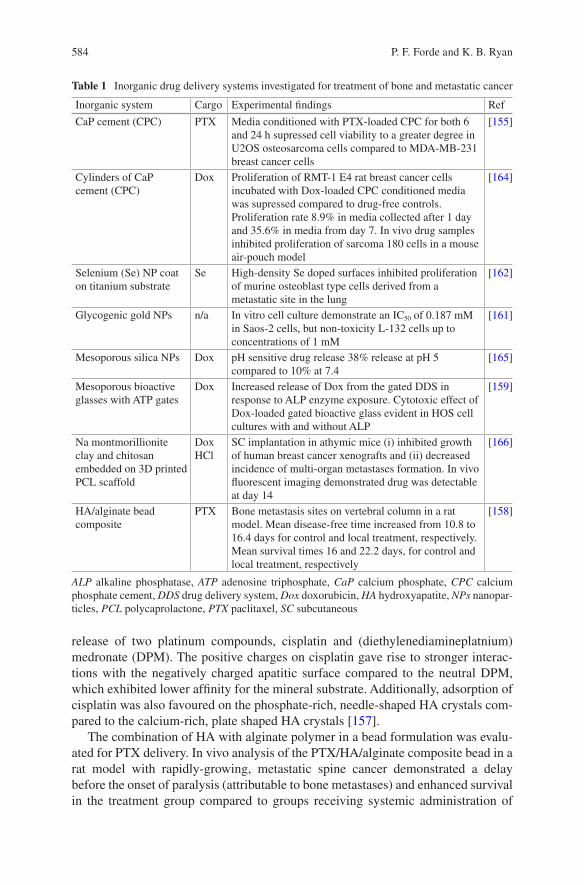
584
release of two platinum compounds, cisplatin and (diethylenediamineplatnium)medronate (DPM). The positive charges on cisplatin gave rise to stronger interac-tions with the negatively charged apatitic surface compared to the neutral DPM, which exhibited lower affinity for the mineral substrate. Additionally, adsorption of cisplatin was also favoured on the phosphate-rich, needle-shaped HA crystals com-pared to the calcium-rich, plate shaped HA crystals [157].
The combination of HA with alginate polymer in a bead formulation was evalu-ated for PTX delivery. In vivo analysis of the PTX/HA/alginate composite bead in a rat model with rapidly-growing, metastatic spine cancer demonstrated a delay before the onset of paralysis (attributable to bone metastases) and enhanced survival in the treatment group compared to groups receiving systemic administration of
Table 1 Inorganic drug delivery systems investigated for treatment of bone and metastatic cancer
Inorganic system Cargo Experimental findings Ref
CaP cement (CPC) PTX Media conditioned with PTX-loaded CPC for both 6 and 24 h supressed cell viability to a greater degree in U2OS osteosarcoma cells compared to MDA-MB-231 breast cancer cells
[155]
Cylinders of CaP cement (CPC)
Dox Proliferation of RMT-1 E4 rat breast cancer cells incubated with Dox-loaded CPC conditioned media was supressed compared to drug-free controls. Proliferation rate 8.9% in media collected after 1 day and 35.6% in media from day 7. In vivo drug samples inhibited proliferation of sarcoma 180 cells in a mouse air-pouch model
[164]
Selenium (Se) NP coat on titanium substrate
Se High-density Se doped surfaces inhibited proliferation of murine osteoblast type cells derived from a metastatic site in the lung
[162]
Glycogenic gold NPs n/a In vitro cell culture demonstrate an IC50 of 0.187 mM in Saos-2 cells, but non-toxicity L-132 cells up to concentrations of 1 mM
[161]
Mesoporous silica NPs Dox pH sensitive drug release 38% release at pH 5 compared to 10% at 7.4
[165]
Mesoporous bioactive glasses with ATP gates
Dox Increased release of Dox from the gated DDS in response to ALP enzyme exposure. Cytotoxic effect of Dox-loaded gated bioactive glass evident in HOS cell cultures with and without ALP
[159]
Na montmorillionite clay and chitosan embedded on 3D printed PCL scaffold
Dox HCl
SC implantation in athymic mice (i) inhibited growth of human breast cancer xenografts and (ii) decreased incidence of multi-organ metastases formation. In vivo fluorescent imaging demonstrated drug was detectable at day 14
[166]
HA/alginate bead composite
PTX Bone metastasis sites on vertebral column in a rat model. Mean disease-free time increased from 10.8 to 16.4 days for control and local treatment, respectively. Mean survival times 16 and 22.2 days, for control and local treatment, respectively
[158]
ALP alkaline phosphatase, ATP adenosine triphosphate, CaP calcium phosphate, CPC calcium phosphate cement, DDS drug delivery system, Dox doxorubicin, HA hydroxyapatite, NPs nanopar-ticles, PCL polycaprolactone, PTX paclitaxel, SC subcutaneous
P. F. Forde and K. B. Ryan
585
PTX or untreated controls. No therapeutic effect was observed in animals receiving systemic PTX, even at 30-fold higher doses [158].
Other inorganic biomaterials composed of Ca and phosphorous include the bio-active glasses. The bone regeneration capacity of these glasses, like the CaP dis-cussed above, is well established and they have also been investigated in bone cancer. A smart, stimuli-responsive DDS was created through the addition of ade-nosine triphosphate (ATP) molecular gates on a mesoporous bioactive glass sub-strate in a bid to tailor doxorubicin (Dox) release in response to elevated levels of the enzyme, ALP. Increased serum ALP is reputed to be of prognostic value in some osteosarcomas. In the absence of ALP, drug release was only ~ 25% at 24 h, while in the presence of ALP, release reached almost 100% at the same time point. The increase was attributed to the opening of the ATP molecular gates in response to ALP [159]. A number of other inorganic nanomaterials have attractive characteris-tics that have underscored their biomedical potential, although they have been less extensively investigated in bone cancer applications. Gold NPs offer the prospect of multivalent coordination of both drug and targeting moieties on the surface, whilst the inherent surface plasmon resonance effect expands the repertoire of applications to include photothermal therapy and diagnostics [160]. Although research to date focusing on bone cancer applications is scarce, one study observed glycogenic gold NPs induced cell death in an Saos-2 osteosarcoma cell line while the formulation was non-toxic in a human embryonic lung cell line (L-132), even at higher doses [161].
Numerous strategies have been investigated to develop anticancer orthopedic materials that could both restore bone and prevent cancer growth, particularly for use in patients who undergo bone cancer resection procedures. Studies have exam-ined the release of anti-cancer agents from the implant surface, or from drug carriers on the device surface. The chemo-preventive properties of the metalloid selenium (Se) as a coating on titanium orthopedic materials have also been explored. Nanoclusters of Se on a titanium substrate inhibited the proliferation of cancerous osteoblasts, while encouraging healthy osteoblast function [162, 163]. Although ini-tial results demonstrated the anti-cancer potential of this orthopedic implantable biomaterial and the potential for such surfaces in bone cancer resection is clear, more extensive research is required before this technology and many others dis-cussed above could be considered as clinical candidates or indeed translated to the clinic.
6.2 Targeted-Drug Delivery
6.2.1 Increasing Successful Localisation
In the past decade there has been a significant interest in the development of drug delivery systems to target therapeutic agents directly to the desired site of action and hence, minimise off-target side-effects. Efforts to increase the successful and selec-tive targeting of drug-delivery systems to bone cancers has sought to exploit both
Biomaterial-Mediated Drug Delivery in Primary and Metastatic Cancers of the Bone
586
active and passive delivery mechanisms. Passive delivery of drug carriers involves the exploitation of local physiological or pathological conditions to achieve prefer-ential accumulation at the target site. In the bone cancer context, this particularly involves utilising the leaky tumor neovasculature and poor lymphatic drainage though the “enhanced permeability and retention” (EPR) effect [167, 168]. Generally, exploitation of this effect relies on the judicious design of drug carriers that are larger than the gaps that exist between endothelial cells in healthy tissue (2–10 nm) and in liver (~100 nm) but below the size of gaps seen in tumors (in the region of 500 nm) thus leading to preferential accumulation in tumor tissue [169]. This strategy is more pertinent in the case of advanced lesions as opposed to early-stage lesions (microme-tastases) that lack a developed leaky vasculature and angiogenic activity [170]. Debate exists regarding the exact effectiveness of the EPR contribution to enhancing drug accumulation. Clearer elucidation is necessary given the variation in character-istics (perfusion, and interstitial fluid pressure) between and within tumors, and the lack of experimental data particularly in metastatic disease [169, 171, 172].
Active targeting approaches, typically designed to exploit hallmarks of the can-cer (e.g. overexpression of surface receptors on cancer cells) and its microenviron-ment to achieve selective localisation, are also a keen area of research. The development of drug and drug-carriers functionalised with targeting moieties not only offers the prospect to target drug to bone thereby increasing uptake efficiency at target tissues and reduced off-target effects but it also extends the capacity to sustain drug at therapeutic levels, and deliver agents that otherwise would be pro-hibitively toxic or difficult to deliver [132, 137, 138, 152]. The advantages conferred by active targeting might be even greater in the case of therapeutics posing greater delivery challenges such as siRNA [169].
6.2.2 Smart Drug Delivery
Smart delivery systems are being investigated to enhance the site-specific localisa-tion and activation and to optimise drug release profile at the intended target site, thereby enhancing cell specificity and cell uptake [143, 168, 173, 174]. Drugs may be conjugated directly or via a degradable or non-degradable linker onto the poly-mer backbone or carrier. Delivery systems can be designed to contain linkers that are subject to the influence of a trigger at the target site to initiate site-specific drug release. Triggers may be biological (biomarker, environmental pH or enzymes in the microenvironment) or external stimuli including thermal, ultrasound, radio-fre-quency and electromagnetic [175]. One smart delivery system employed the HPMA copolymer for the delivery of TNP-470, an anti-angiogenic agent. TNP-470 was conjugated by means of a Glycine-Glycine-Proline-Norleucine linker, making it subject to cleavage by cathepsin K, a protease expressed at resorption sites and overexpressed in bone metastases [147]. This polymer system achieved dual-target-ing, with passive targeting occurring via the EPR effect and active targeting facili-tated by the osteotropic ALN that was also bound to the HPMA polymer. Study results showed significant inhibition of osteosarcoma growth in a mouse model
P. F. Forde and K. B. Ryan
587
showing promise for further investigation [147, 176]. Other biological stimuli employed to trigger drug release include differences in physiological pH between healthy and diseased tissue. Notably, the existence of a lower pH in the tumor envi-ronment is seen as one way to achieve selective drug delivery. A number of tech-nologies have been developed based on this premise. Liposomal carriers formulated with pH sensitive lipids (1,2-dioleoylglycero-3-phosphatidylethanolamine (DOPE)) were designed to destabilise and preferentially release the drug cargo upon exposure to an acidic pH resembling that in the tumor microenvironment [177]. Self-assembled micelles composed of the doxorubicin-poly (ethylene glycol)-alendro-nate (DOX-hyd-PEG-ALN) copolymer were investigated for DOX delivery in bone metastatic disease. Conjugation of the hydrophilic and hydrophobic segment of the amphiphilic copolymer via a hydrazone bond endowed the carrier with pH respon-sive properties. In vitro release studies confirmed faster Dox release at pH 5 com-pared to pH 7.4. In vivo imaging demonstrated that a larger quantity of drug accumulated in the bone metastatic tumor tissue after administration in the DOX-hyd-PEG-ALN micelle formulation compared to the free drug. This formulation also reduced drug in the kidney and heart. Functional studies in tumor-bearing nude mice showed enhanced anti-tumor activities and improved metrics of bone quality (bone mineral density and bone volume fraction) in animals administered with a DOX-hyd-PEG-ALN micelle compared with free DOX controls [178].
6.2.3 Targeting Moieties
A number of different classes of targeting compounds have been investigated to increase the chances of successful localisation of DDS to various targets in the bone environment. In the case of bone cancer, possible targets include cell-surface bio-markers (e.g. integrins, adhesion molecules and antigens) and tissue matrix compo-nents. Although tetracyclines have long been established as bone-seeking agents, they have been less extensively investigated in bone cancer research compared to another class of osteotropic agents, the bisphosphonates [179]. Active targeting approaches have been long-heralded for their potential to address challenges related to poor drug localisation and off-target side-effects. Indeed, studies have shown that targeting moi-eties might address the former issues, but some improvements have only been modest and in some cases therapeutic effects were not clinically significant.
The use of bisphosphonates as targeting moieties has received much research focus, Table 2. In particular, they have a strong affinity for HA, which they tend to maintain after conjugation to carriers and the uptake in bone metastatic lesions can be considerably higher than in healthy bone tissues [144, 180, 181]. Moreover, recent evidence of the anti-cancer effect of bisphosphonates further underscores its promise and broadens its potential in bone cancer treatment [182, 183]. Bisphosphonates have been conjugated to a wide range of cargoes, including small molecule chemotherapeutics, proteins, fluorophores, radionuclides and drug nano-carriers for diverse applications such as diagnostics, imaging and treatment [145, 182]. In one study a PLGA polymeric core was used as a carrier for Dox, and coated
Biomaterial-Mediated Drug Delivery in Primary and Metastatic Cancers of the Bone
588
with a phospholipid monolayer to reduce drug diffusion. A densely packed alen-dronic acid corona was used to both stabilize the NP and exploit bone targeting [184]. Another study utilising PLGA-PEG NPs, again targeted to the bone using ALN, achieved spatiotemporal control over the delivery of bortezomib: in vivo tests in murine models of multiple myeloma demonstrated that tumor progression was inhibited and pre-treatment had a positive impact on the bone microenvironment resulting in enhanced bone strength and volume [138]. A more recent polymer nan-otechnology includes coordination polymer nanoparticles (CPNs) based on the self-assembly of metal ions and organic bridging ligands. One study investigated NP based on the chelation of Zn2 + with the cisplatin prodrug cis,cis,trans-diamminedi-chlorodisuccinato-platinum (DSP). The NP was coated with PEG and targeted to bone with ALN. The targeted NP demonstrated a higher affinity for HA in vitro and bone in vivo versus non-targeted controls. In vivo studies in a mouse model of bone metastasis from breast cancer established by intra-tibia injection of MDA-MB-231 showed preferential accumulation in tumor tissue, decreased tumor growth and reduced bone destruction [185].
Other potent aminobisphosphonates including zolendronic acid and pamidronate (PAM) that have established roles as adjunctive therapies in the clinical management of bone metastases, have also been investigated for their bone-homing properties. Poly(lactic acid) (PLA) NPs loaded with Dox and functionalised with PAM demon-strated enhanced accumulation in bone tumors and prolonged retention compared to non-targeted NPs in vivo. Treatment attenuated OS progression in a murine model of focal malignant osteolysis compared to non-targeted controls. This study provided formative data on the performance of a targeted DDS in terms of its biocompatibility, biodistribution and treatment potential in a dog model with naturally occurring OS. The study has added significance because the dog model has greater anatomical relevance to human disease compared to smaller rodent models. Nuclear scintigra-phy and histopathology confirmed the targeting and anti-cancer capacity of the nano-medicine. Hematologic and biochemical assessment following intravenous infusion indicated a good safety profile, even with NP dosing in the gram scale range [186].
The presence of HA binding sites in a number of non-collagenous proteins (osteopontin, osteoclacin) has prompted interest in bioactive molecules based on peptide sequences that can recapitulate bone-binding behaviour. Peptides composed of repetitive sequences of the amino acids, aspartic acid or glutamic acid have shown promise for bone-specific applications [187]. Aspartic acid, in both linear and dendritic forms, has been used to target PEG-PLGA NPs [188, 189].
In the context of bone cancer research, targeting of DDS to cell-surface markers is less prolific and at an earlier stage compared to that described for bisphosphonates. A selection of targeting approaches directed at various biological targets beyond bisphosphonate-HA is outlined in Table 3. The integrin family of cell surface glyco-proteins are fundamental in the cross-talk between the cell and ECM, and play key roles in cell growth and migration. Progression and metastasis of cancer is intricately linked with alterations in integrin expression [192]. Consequently, targeting integrins which are known to be overexpressed offers the prospect of selective targeting and treatment. In particular, the αvβ3 integrin, which is upregulated in most cancer cells,
P. F. Forde and K. B. Ryan
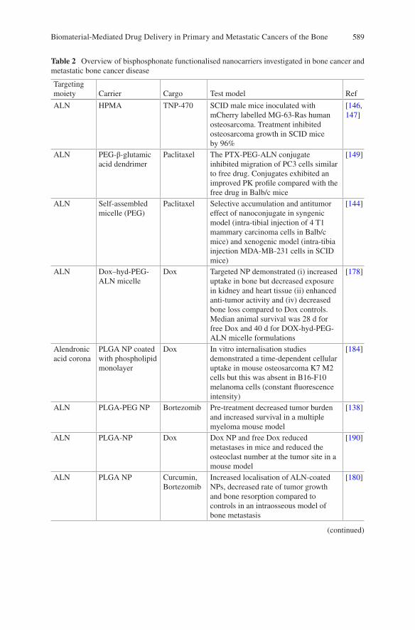
589
Table 2 Overview of bisphosphonate functionalised nanocarriers investigated in bone cancer and metastatic bone cancer disease
Targeting moiety Carrier Cargo Test model Ref
ALN HPMA TNP-470 SCID male mice inoculated with mCherry labelled MG-63-Ras human osteosarcoma. Treatment inhibited osteosarcoma growth in SCID mice by 96%
[146, 147]
ALN PEG-β-glutamic acid dendrimer
Paclitaxel The PTX-PEG-ALN conjugate inhibited migration of PC3 cells similar to free drug. Conjugates exhibited an improved PK profile compared with the free drug in Balb/c mice
[149]
ALN Self-assembled micelle (PEG)
Paclitaxel Selective accumulation and antitumor effect of nanoconjugate in syngenic model (intra-tibial injection of 4 T1 mammary carcinoma cells in Balb/c mice) and xenogenic model (intra-tibia injection MDA-MB-231 cells in SCID mice)
[144]
ALN Dox–hyd-PEG-ALN micelle
Dox Targeted NP demonstrated (i) increased uptake in bone but decreased exposure in kidney and heart tissue (ii) enhanced anti-tumor activity and (iv) decreased bone loss compared to Dox controls. Median animal survival was 28 d for free Dox and 40 d for DOX-hyd-PEG-ALN micelle formulations
[178]
Alendronic acid corona
PLGA NP coated with phospholipid monolayer
Dox In vitro internalisation studies demonstrated a time-dependent cellular uptake in mouse osteosarcoma K7 M2 cells but this was absent in B16-F10 melanoma cells (constant fluorescence intensity)
[184]
ALN PLGA-PEG NP Bortezomib Pre-treatment decreased tumor burden and increased survival in a multiple myeloma mouse model
[138]
ALN PLGA-NP Dox Dox NP and free Dox reduced metastases in mice and reduced the osteoclast number at the tumor site in a mouse model
[190]
ALN PLGA NP Curcumin, Bortezomib
Increased localisation of ALN-coated NPs, decreased rate of tumor growth and bone resorption compared to controls in an intraosseous model of bone metastasis
[180]
(continued)
Biomaterial-Mediated Drug Delivery in Primary and Metastatic Cancers of the Bone
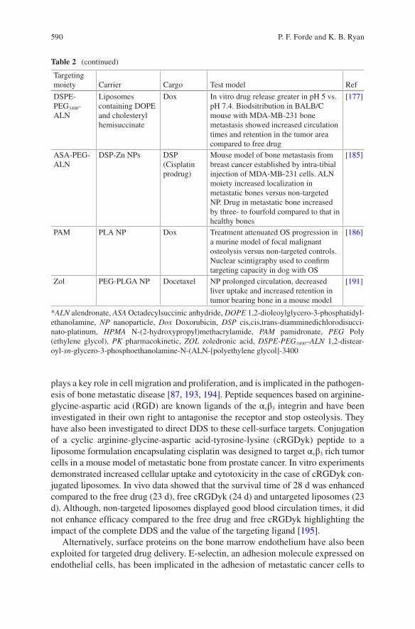
590
plays a key role in cell migration and proliferation, and is implicated in the pathogen-esis of bone metastatic disease [87, 193, 194]. Peptide sequences based on arginine-glycine-aspartic acid (RGD) are known ligands of the αvβ3 integrin and have been investigated in their own right to antagonise the receptor and stop osteolysis. They have also been investigated to direct DDS to these cell-surface targets. Conjugation of a cyclic arginine-glycine-aspartic acid-tyrosine-lysine (cRGDyk) peptide to a liposome formulation encapsulating cisplatin was designed to target αvβ3 rich tumor cells in a mouse model of metastatic bone from prostate cancer. In vitro experiments demonstrated increased cellular uptake and cytotoxicity in the case of cRGDyk con-jugated liposomes. In vivo data showed that the survival time of 28 d was enhanced compared to the free drug (23 d), free cRGDyk (24 d) and untargeted liposomes (23 d). Although, non-targeted liposomes displayed good blood circulation times, it did not enhance efficacy compared to the free drug and free cRGDyk highlighting the impact of the complete DDS and the value of the targeting ligand [195].
Alternatively, surface proteins on the bone marrow endothelium have also been exploited for targeted drug delivery. E-selectin, an adhesion molecule expressed on endothelial cells, has been implicated in the adhesion of metastatic cancer cells to
Table 2 (continued)
Targeting moiety Carrier Cargo Test model Ref
DSPE-PEG3400-ALN
Liposomes containing DOPE and cholesteryl hemisuccinate
Dox In vitro drug release greater in pH 5 vs. pH 7.4. Biodsitribution in BALB/C mouse with MDA-MB-231 bone metastasis showed increased circulation times and retention in the tumor area compared to free drug
[177]
ASA-PEG-ALN
DSP-Zn NPs DSP (Cisplatin prodrug)
Mouse model of bone metastasis from breast cancer established by intra-tibial injection of MDA-MB-231 cells. ALN moiety increased localization in metastatic bones versus non-targeted NP. Drug in metastatic bone increased by three- to fourfold compared to that in healthy bones
[185]
PAM PLA NP Dox Treatment attenuated OS progression in a murine model of focal malignant osteolysis versus non-targeted controls. Nuclear scintigraphy used to confirm targeting capacity in dog with OS
[186]
Zol PEG-PLGA NP Docetaxel NP prolonged circulation, decreased liver uptake and increased retention in tumor bearing bone in a mouse model
[191]
*ALN alendronate, ASA Octadecylsuccinic anhydride, DOPE 1,2-dioleoylglycero-3-phosphatidyl-ethanolamine, NP nanoparticle, Dox Doxorubicin, DSP cis,cis,trans-diamminedichlorodisucci-nato-platinum, HPMA N-(2-hydroxypropyl)methacrylamide, PAM pamidronate, PEG Poly (ethylene glycol), PK pharmacokinetic, ZOL zoledronic acid, DSPE-PEG3400–ALN 1,2-distear-oyl-sn-glycero-3-phosphoethanolamine-N-(ALN-[polyethylene glycol]-3400
P. F. Forde and K. B. Ryan
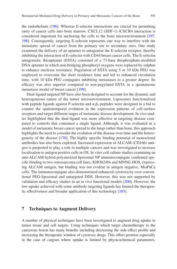
591
the endothelium [196]. Whereas E-selectin interactions are crucial for permitting entry of cancer cells into bone marrow, CXCL12 (SDF-1) /CXCR4 interaction is considered important for anchoring the cells to the bone microenvironment [197, 198]. Consequently, targeting E-selectin represents one way to interfere with the metastatic spread of cancer from the primary site to secondary sites. One study examined the delivery of an aptamer to antagonise the E-selectin receptor, thereby inhibiting the interaction of E-selectin with CD44 breast cancer cells. The E-selectin antagonistic thioaptamer (ESTA) consisted of a 73-base thiophosphate-modified DNA aptamer in which non-bridging phosphoryl oxygens were replaced by sulphur to enhance nuclease resistance. Pegylation of ESTA using 5 or 10 kDa PEG was employed to overcome the short residence time and led to enhanced circulation time, with 10 kDa PEG conjugates inhibiting metastases to a greater degree. Its efficacy was also superior compared to non-pegylated ESTA in a spontaneous metastasis model of breast cancer [199].
Dual-ligand targeted NP have also been designed to account for the dynamic and heterogeneous nature of the tumor microenvironment. Liposomes functionalised with peptide ligands against P-selectin and αvβ3 peptides were designed in a bid to counter the spatiotemporal evolution in the expression patterns of cell-surface receptors and target different stages of metastatic disease development. In vivo stud-ies highlighted that the dual-ligand was more effective at targeting disease com-pared to controls that contained a single ligand. Although, it was evaluated in a model of metastatic breast cancer spread to the lungs rather than bone, this approach highlights the need to consider the evolution of the disease over time and the hetero-geneity of the disease [170]. The highly specific binding potential of monoclonal antibodies has also been explored. Increased expression of ALCAM (CD166) anti-gen is purported to play a role in multiple cancers and was investigated to increase localisation to antigen positive cells in OS. In vitro cell culture studies examining an anti-ALCAM-hybrid polymerized liposomal NP immunoconjugate confirmed spe-cific binding in two osteosarcoma cell lines, KHOS240s and MNNG-HOS, express-ing ALCAM antigen, but binding was not evident in antigen negative, MiaPaCa cells. The immunoconjugate also demonstrated enhanced cytotoxicity over conven-tional PEG-liposomal and untargeted DDS. However, this was not supported by validation and efficacy studies in an in vivo functional models [200]. However, the low uptake achieved with some antibody targeting ligands has limited the therapeu-tic effectiveness and broader application of this technology [103].
7 Techniques to Augment Delivery
A number of physical techniques have been investigated to augment drug uptake in tumor tissue and cell targets. Using techniques which target chemotherapy to the cancerous lesion has many benefits including decreasing the side-effect profile and increasing the therapeutic window of cytotoxic drugs. This offers promise especially in the case of cargoes where uptake is limited by physicochemical parameters.
Biomaterial-Mediated Drug Delivery in Primary and Metastatic Cancers of the Bone
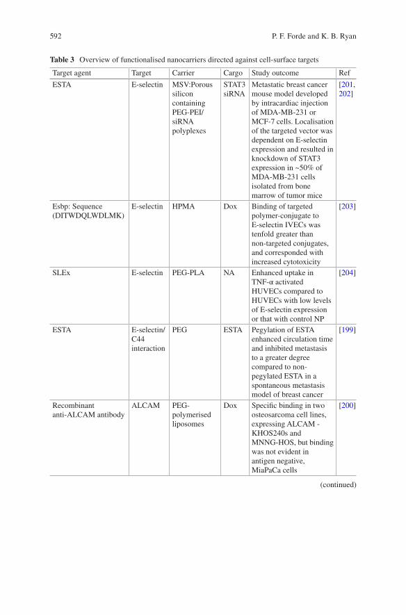
592
Table 3 Overview of functionalised nanocarriers directed against cell-surface targets
Target agent Target Carrier Cargo Study outcome Ref
ESTA E-selectin MSV:Porous silicon containing PEG-PEI/siRNA polyplexes
STAT3 siRNA
Metastatic breast cancer mouse model developed by intracardiac injection of MDA-MB-231 or MCF-7 cells. Localisation of the targeted vector was dependent on E-selectin expression and resulted in knockdown of STAT3 expression in ~50% of MDA-MB-231 cells isolated from bone marrow of tumor mice
[201, 202]
Esbp: Sequence (DITWDQLWDLMK)
E-selectin HPMA Dox Binding of targeted polymer-conjugate to E-selectin IVECs was tenfold greater than non-targeted conjugates, and corresponded with increased cytotoxicity
[203]
SLEx E-selectin PEG-PLA NA Enhanced uptake in TNF-α activated HUVECs compared to HUVECs with low levels of E-selectin expression or that with control NP
[204]
ESTA E-selectin/C44 interaction
PEG ESTA Pegylation of ESTA enhanced circulation time and inhibited metastasis to a greater degree compared to non-pegylated ESTA in a spontaneous metastasis model of breast cancer
[199]
Recombinant anti-ALCAM antibody
ALCAM PEG-polymerised liposomes
Dox Specific binding in two osteosarcoma cell lines, expressing ALCAM - KHOS240s and MNNG-HOS, but binding was not evident in antigen negative, MiaPaCa cells
[200]
(continued)
P. F. Forde and K. B. Ryan
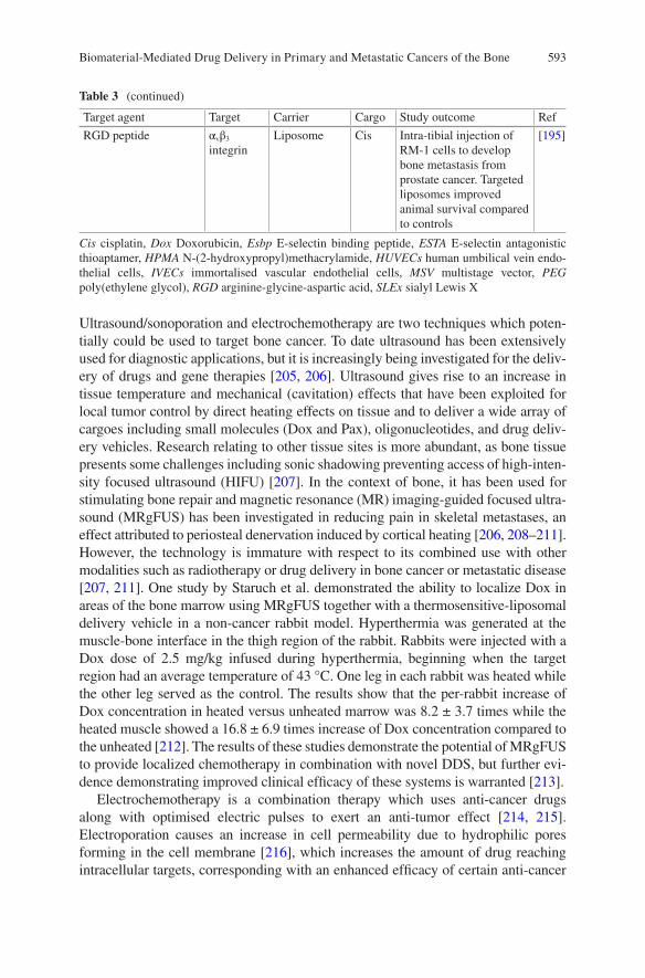
593
Ultrasound/sonoporation and electrochemotherapy are two techniques which poten-tially could be used to target bone cancer. To date ultrasound has been extensively used for diagnostic applications, but it is increasingly being investigated for the deliv-ery of drugs and gene therapies [205, 206]. Ultrasound gives rise to an increase in tissue temperature and mechanical (cavitation) effects that have been exploited for local tumor control by direct heating effects on tissue and to deliver a wide array of cargoes including small molecules (Dox and Pax), oligonucleotides, and drug deliv-ery vehicles. Research relating to other tissue sites is more abundant, as bone tissue presents some challenges including sonic shadowing preventing access of high-inten-sity focused ultrasound (HIFU) [207]. In the context of bone, it has been used for stimulating bone repair and magnetic resonance (MR) imaging-guided focused ultra-sound (MRgFUS) has been investigated in reducing pain in skeletal metastases, an effect attributed to periosteal denervation induced by cortical heating [206, 208–211]. However, the technology is immature with respect to its combined use with other modalities such as radiotherapy or drug delivery in bone cancer or metastatic disease [207, 211]. One study by Staruch et al. demonstrated the ability to localize Dox in areas of the bone marrow using MRgFUS together with a thermosensitive-liposomal delivery vehicle in a non-cancer rabbit model. Hyperthermia was generated at the muscle-bone interface in the thigh region of the rabbit. Rabbits were injected with a Dox dose of 2.5 mg/kg infused during hyperthermia, beginning when the target region had an average temperature of 43 °C. One leg in each rabbit was heated while the other leg served as the control. The results show that the per-rabbit increase of Dox concentration in heated versus unheated marrow was 8.2 ± 3.7 times while the heated muscle showed a 16.8 ± 6.9 times increase of Dox concentration compared to the unheated [212]. The results of these studies demonstrate the potential of MRgFUS to provide localized chemotherapy in combination with novel DDS, but further evi-dence demonstrating improved clinical efficacy of these systems is warranted [213].
Electrochemotherapy is a combination therapy which uses anti-cancer drugs along with optimised electric pulses to exert an anti-tumor effect [214, 215]. Electroporation causes an increase in cell permeability due to hydrophilic pores forming in the cell membrane [216], which increases the amount of drug reaching intracellular targets, corresponding with an enhanced efficacy of certain anti-cancer
Table 3 (continued)
Target agent Target Carrier Cargo Study outcome Ref
RGD peptide αvβ3 integrin
Liposome Cis Intra-tibial injection of RM-1 cells to develop bone metastasis from prostate cancer. Targeted liposomes improved animal survival compared to controls
[195]
Cis cisplatin, Dox Doxorubicin, Esbp E-selectin binding peptide, ESTA E-selectin antagonistic thioaptamer, HPMA N-(2-hydroxypropyl)methacrylamide, HUVECs human umbilical vein endo-thelial cells, IVECs immortalised vascular endothelial cells, MSV multistage vector, PEG poly(ethylene glycol), RGD arginine-glycine-aspartic acid, SLEx sialyl Lewis X
Biomaterial-Mediated Drug Delivery in Primary and Metastatic Cancers of the Bone
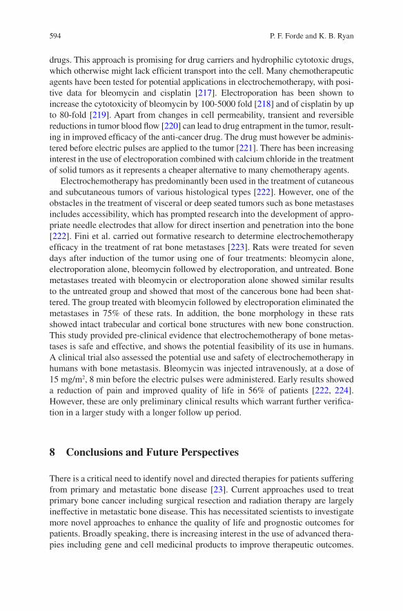
594
drugs. This approach is promising for drug carriers and hydrophilic cytotoxic drugs, which otherwise might lack efficient transport into the cell. Many chemotherapeutic agents have been tested for potential applications in electrochemotherapy, with posi-tive data for bleomycin and cisplatin [217]. Electroporation has been shown to increase the cytotoxicity of bleomycin by 100-5000 fold [218] and of cisplatin by up to 80-fold [219]. Apart from changes in cell permeability, transient and reversible reductions in tumor blood flow [220] can lead to drug entrapment in the tumor, result-ing in improved efficacy of the anti-cancer drug. The drug must however be adminis-tered before electric pulses are applied to the tumor [221]. There has been increasing interest in the use of electroporation combined with calcium chloride in the treatment of solid tumors as it represents a cheaper alternative to many chemotherapy agents.
Electrochemotherapy has predominantly been used in the treatment of cutaneous and subcutaneous tumors of various histological types [222]. However, one of the obstacles in the treatment of visceral or deep seated tumors such as bone metastases includes accessibility, which has prompted research into the development of appro-priate needle electrodes that allow for direct insertion and penetration into the bone [222]. Fini et al. carried out formative research to determine electrochemotherapy efficacy in the treatment of rat bone metastases [223]. Rats were treated for seven days after induction of the tumor using one of four treatments: bleomycin alone, electroporation alone, bleomycin followed by electroporation, and untreated. Bone metastases treated with bleomycin or electroporation alone showed similar results to the untreated group and showed that most of the cancerous bone had been shat-tered. The group treated with bleomycin followed by electroporation eliminated the metastases in 75% of these rats. In addition, the bone morphology in these rats showed intact trabecular and cortical bone structures with new bone construction. This study provided pre-clinical evidence that electrochemotherapy of bone metas-tases is safe and effective, and shows the potential feasibility of its use in humans. A clinical trial also assessed the potential use and safety of electrochemotherapy in humans with bone metastasis. Bleomycin was injected intravenously, at a dose of 15 mg/m2, 8 min before the electric pulses were administered. Early results showed a reduction of pain and improved quality of life in 56% of patients [222, 224]. However, these are only preliminary clinical results which warrant further verifica-tion in a larger study with a longer follow up period.
8 Conclusions and Future Perspectives
There is a critical need to identify novel and directed therapies for patients suffering from primary and metastatic bone disease [23]. Current approaches used to treat primary bone cancer including surgical resection and radiation therapy are largely ineffective in metastatic bone disease. This has necessitated scientists to investigate more novel approaches to enhance the quality of life and prognostic outcomes for patients. Broadly speaking, there is increasing interest in the use of advanced thera-pies including gene and cell medicinal products to improve therapeutic outcomes.
P. F. Forde and K. B. Ryan

595
However, these approaches share many common challenges with small molecule and biological drugs. Some of which include the failure to reach the disease site in sufficient concentrations to exert a therapeutic effect, whilst doubt remain regarding the efficacy of some agents in heterogeneous and rapidly evolving cancers. Strategies that have been successful in treating larger, well-vascularised tumors may be inef-fective in disseminated tumor cells [7]. Additionally, due to tumor heterogeneity, treatments aimed at single genetic targets are less likely to be successful and trans-lated to the clinic [130, 225].
The wide array of biomaterial technologies investigated highlights the flexibility and preclinical potential. Biomaterial formulations have been investigated to aid in the delivery of drugs with troublesome physiochemical properties (poor solubility, poor uptake) and protect drugs from premature degradation or removal. Multifunctional DDS offer the prospect to co-deliver various therapeutic agents, which can act synergistically to enhance the therapeutic effect or they may involve co-delivery of multiple functionalities in a single platform (treatment, imaging, diagnostic capabilities) [226]. In the case of metastatic spreading to the bone, bio-material based delivery systems offer the potential to intervene at multiple points in the metastatic cascade including dissemination, tumor cell circulation, extravasa-tion and colonisation of distant sites in order to combat spreading, although most biomaterial research has focused on treating the disease in the bone. Active-targeting approaches have predominantly been focused on exploiting the osteotropic proper-ties of bisphosphonates to achieve greater localisation of the drug cargoes to the bone environment. It must be remembered that localisation of the DDS to the target does not guarantee penetration into the tumor, or indeed that effective quantities of the drug are released and sufficient uptake into the cell occurs.
Despite some promising preclinical data, additional research is needed to develop effective and robust biomaterial delivery platforms to ensure effective targeting and treatment of primary and metastatic bone disease [7]. To date, many design strate-gies are simplistic and do not take account of the heterogeneous and dynamic nature of the tumor microenvironment, which are hallmarks of many aggressive cancers that metastasise to the bone. Another critical consideration impacting the clinical translation of novel biomaterial DDS includes the use of appropriate and robust experimental models for evaluating the safety and efficacy of these treatment strate-gies [186]. Bone cancer has proved challenging to model in vitro because of the complexity and dynamic nature (involvement of various cell types and signalling factors throughout different stages) of the disease. Clinically relevant animal mod-els are also required to better understand the potential of novel DDS and to decouple the impact of physicochemical properties of the DDS and biological phenomena to ensure more effective design and targeting. Lastly, increasing pressure from funding and reimbursement agencies to deliver cost-effective treatments for patients together with an increasing drive towards personalised medicine approaches further enforces the need for versatile and novel drug delivery strategies.
Acknowledgements The authors would like to thank Dr. Christian Waeber for his helpful com-ments during the preparation of this chapter.
Biomaterial-Mediated Drug Delivery in Primary and Metastatic Cancers of the Bone
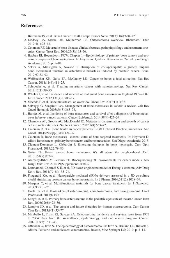
596
References
1. Biermann JS, et al. Bone Cancer. J Natl Compr Cancer Netw. 2013;11(6):688–723. 2. Lindsey BA, Markel JE, Kleinerman ES. Osteosarcoma overview. Rheumatol Ther.
2017;4(1):25–43. 3. Coleman RE. Metastatic bone disease: clinical features, pathophysiology and treatment strat-
egies. Cancer Treat Rev. 2001;27(3):165–76. 4. Hauben EI, Hogendoorn PCW. Chapter 1—Epidemiology of primary bone tumors and eco-
nomical aspects of bone metastases. In: Heymann D, editor. Bone cancer. 2nd ed. San Diego: Academic; 2015. p. 5–10.
5. Sekita A, Matsugaki A, Nakano T. Disruption of collagen/apatite alignment impairs bone mechanical function in osteoblastic metastasis induced by prostate cancer. Bone. 2017;97:83–93.
6. Weilbaecher KN, Guise TA, McCauley LK. Cancer to bone: a fatal attraction. Nat Rev Cancer. 2011;11(6):411–25.
7. Schroeder A, et al. Treating metastatic cancer with nanotechnology. Nat Rev Cancer. 2012;12(1):39–50.
8. Whelan J, et al. Incidence and survival of malignant bone sarcomas in England 1979–2007. Int J Cancer. 2012;131(4):E508–17.
9. Macedo F, et al. Bone metastases: an overview. Oncol Rev. 2017;11(1):321. 10. Selvaggi G, Scagliotti GV. Management of bone metastases in cancer: a review. Crit Rev
Oncol Hematol. 2005;56(3):365–78. 11. Harries M, et al. Incidence of bone metastases and survival after a diagnosis of bone metas-
tases in breast cancer patients. Cancer Epidemiol. 2014;38(4):427–34. 12. Chambers AF, Groom AC, MacDonald IC. Metastasis: dissemination and growth of cancer
cells in metastatic sites. Nat Rev Cancer. 2002;2(8):563–72. 13. Coleman R, et al. Bone health in cancer patients: ESMO Clinical Practice Guidelines. Ann
Oncol. 2014;25(suppl_3):iii124–37. 14. Coleman R. Bone metastases—current status of bone-targeted treatments. In: Heymann D,
editor. Bone cancer : primary bone cancers and bone metastases. San Diego: Academic; 2015. 15. Clément-Demange L, Clézardin P. Emerging therapies in bone metastasis. Curr Opin
Pharmacol. 2015;22:79–86. 16. Guise TA. Breast cancer bone metastases: it’s all about the neighborhood. Cell.
2013;154(5):957–9. 17. Alemany-Ribes M, Semino CE. Bioengineering 3D environments for cancer models. Adv
Drug Deliv Rev. 2014;79(Supplement C):40–9. 18. Lamhamedi-Cherradi S-E, et al. 3D tissue-engineered model of Ewing’s sarcoma. Adv Drug
Deliv Rev. 2014;79–80:155–71. 19. Fitzgerald KA, et al. Nanoparticle-mediated siRNA delivery assessed in a 3D co-culture
model simulating prostate cancer bone metastasis. Int J Pharm. 2016;511(2):1058–69. 20. Marques C, et al. Multifunctional materials for bone cancer treatment. Int J Nanomed.
2014;9:2713–25. 21. Evola FR, et al. Biomarkers of osteosarcoma, chondrosarcoma, and Ewing sarcoma. Front
Pharmacol. 2017;8:150. 22. Longhi A, et al. Primary bone osteosarcoma in the pediatric age: state of the art. Cancer Treat
Rev. 2006;32(6):423–36. 23. Lamplot JD, et al. The current and future therapies for human osteosarcoma. Curr Cancer
Ther Rev. 2013;9(1):55–77. 24. Mirabello L, Troisi RJ, Savage SA. Osteosarcoma incidence and survival rates from 1973
to 2004: data from the surveillance, epidemiology, and end results program. Cancer. 2009;115(7):1531–43.
25. Ottaviani G, Jaffe N. The epidemiology of osteosarcoma. In: Jaffe N, Bruland OS, Bielack S, editors. Pediatric and adolescent osteosarcoma. Boston, MA: Springer US; 2010. p. 3–13.
P. F. Forde and K. B. Ryan
597
26. Guijarro MV, Ghivizzani SC, Gibbs CP. Animal models in osteosarcoma. Front Oncol. 2014;4:189.
27. Arndt CAS, Crist WM. Common musculoskeletal tumors of childhood and adolescence. N Engl J Med. 1999;341(5):342–52.
28. Luetke A, et al. Osteosarcoma treatment—where do we stand? A state of the art review. Cancer Treat Rev. 2014;40(4):523–32.
29. Kager L, et al. Primary metastatic osteosarcoma: presentation and outcome of patients treated on neoadjuvant cooperative osteosarcoma study group protocols. J Clin Oncol. 2003;21(10):2011–8.
30. Mialou V, et al. Metastatic osteosarcoma at diagnosis. Cancer. 2005;104(5):1100–9. 31. Durfee RA, Mohammed M, Luu HH. Review of osteosarcoma and current management.
Rheumatol Ther. 2016;3(2):221–43. 32. Kansara M, et al. Translational biology of osteosarcoma. Nat Rev Cancer. 2014;14(11):722–35. 33. Cesare AJ, Reddel RR. Alternative lengthening of telomeres: models, mechanisms and impli-
cations. Nat Rev Genet. 2010;11(5):319–30. 34. Poos K, et al. Structuring osteosarcoma knowledge: an osteosarcoma-gene association data-
base based on literature mining and manual annotation. Database (Oxford). 2014;2014. 35. Bone sarcomas: ESMO Clinical Practice Guidelines for diagnosis, treatment and follow-up†.
Ann Oncol. 2014;25(suppl_3):iii113–iii123. 36. Heymann D, Redini F. Bone sarcomas: pathogenesis and new therapeutic approaches. IBMS
BoneKey. 2011;8(9):402–14. 37. Toomey EC, Schiffman JD, Lessnick SL. Recent advances in the molecular pathogenesis of
Ewing’s sarcoma. Oncogene. 2010;29(32):4504–16. 38. Hogendoorn PCW, et al. Bone sarcomas: ESMO Clinical Practice Guidelines for diagnosis,
treatment and follow-up. Ann Oncol. 2010;21(suppl_5):v204–13. 39. Gerrand C, et al. UK guidelines for the management of bone sarcomas. Clin Sarcoma Res.
2016;6(1):7. 40. Chaffer CL, Weinberg RA. A perspective on cancer cell metastasis. Science.
2011;331(6024):1559–64. 41. Vincenzi B, et al. Bone metastases in soft tissue sarcoma: a survey of natural history, prog-
nostic value and treatment options. Clin Sarcoma Res. 2013;3(1):6. 42. Käkönen S-M, Mundy GR. Mechanisms of osteolytic bone metastases in breast carcinoma.
Cancer. 2003;97(S3):834–9. 43. Mundy GR. Metastasis: metastasis to bone: causes, consequences and therapeutic opportuni-
ties. Nat Rev Cancer. 2002;2(8):584–93. 44. Krzeszinski JY, Wan Y. New therapeutic targets for cancer bone metastases. Trends Pharmacol
Sci. 2015;36(6):360–73. 45. Coleman RE. Skeletal complications of malignancy. Cancer. 1997;80(8 Suppl):1588–94. 46. Paterson AH, et al. Double-blind controlled trial of oral clodronate in patients with bone
metastases from breast cancer. J Clin Oncol. 1993;11(1):59–65. 47. Ahern E, Doody T, Ryan KB. Bioinspired nanomaterials for bone tissue engineering. In:
Tiwari A, Tiwari A, editors. Bioengineered nanomaterials. Boca Raton; London; New York: CRC, Taylor & Francis Group; 2014. p. 369–412.
48. Raggatt LJ, Partridge NC. Cellular and molecular mechanisms of bone remodeling. J Biol Chem. 2010;285(33):25103–8.
49. Ren G, Esposito M, Kang Y. Bone metastasis and the metastatic niche. J Mol Med. 2015;93(11):1203–12.
50. Stevens MM. Biomaterials for bone tissue engineering. Mater Today. 2008;11(5):18–25. 51. Kimura Y, et al. Alteration of osteoblast arrangement via direct attack by cancer cells: new
insights into bone metastasis. Sci Rep. 2017;7:44824. 52. Landis WJ. The strength of a calcified tissue depends in part on the molecular struc-
ture and organization of its constituent mineral crystals in their organic matrix. Bone. 1995;16(5):533–44.
Biomaterial-Mediated Drug Delivery in Primary and Metastatic Cancers of the Bone
598
53. Msaouel P, et al. Bone microenvironment-targeted manipulations for the treatment of osteoblastic metastasis in castration-resistant prostate cancer. Expert Opin Investig Drugs. 2013;22(11):1385–400.
54. Sartawi Z, et al. Sphingosine 1-phosphate (S1P) signalling: role in bone biology and potential therapeutic target for bone repair. Pharmacol Res. 2017;125(Part B):232–45.
55. Prideaux M, Findlay DM, Atkins GJ. Osteocytes: the master cells in bone remodelling. Curr Opin Pharmacol. 2016;28:24–30.
56. Schaffler MB, et al. Osteocytes: master orchestrators of bone. Calcif Tissue Int. 2014;94(1):5–24.
57. Bonewald LF. The amazing osteocyte. J Bone Miner Res. 2011;26(2):229–38. 58. Lynch ME, Fischbach C. Biomechanical forces in the skeleton and their relevance to bone
metastasis: biology and engineering considerations. Adv Drug Deliv Rev. 2014;79–80:119–34. 59. Bellido T. Osteocyte apoptosis induces bone resorption and impairs the skeletal response to
weightlessness. IBMS BoneKey. 2007;4(9):252–6. 60. Sekita A, et al. Synchronous disruption of anisotropic arrangement of the osteocyte network
and collagen/apatite in melanoma bone metastasis. J Struct Biol. 2017;197(3):260–70. 61. Hauge EM, et al. Cancellous bone remodeling occurs in specialized compartments lined by
cells expressing osteoblastic markers. J Bone Miner Res. 2001;16(9):1575–82. 62. Dwek JR. The periosteum: what is it, where is it, and what mimics it in its absence? Skelet
Radiol. 2010;39(4):319–23. 63. Suda T, et al. Modulation of osteoclast differentiation and function by the new members of
the tumor necrosis factor receptor and ligand families. Endocr Rev. 1999;20(3):345–57. 64. Boyce BF, Xing L. Biology of RANK, RANKL, and osteoprotegerin. Arthritis Res Ther.
2007;9(Suppl 1):S1. 65. Wright HL, et al. RANK, RANKL and osteoprotegerin in bone biology and disease. Curr Rev
Muscoskelet Med. 2009;2(1):56–64. 66. Roodman GD. Mechanisms of bone metastasis. N Engl J Med. 2004;350(16):1655–64. 67. Yasuda H, et al. Osteoclast differentiation factor is a ligand for osteoprotegerin/osteoclasto-
genesis-inhibitory factor and is identical to TRANCE/RANKL. Proc Natl Acad Sci U S A. 1998;95(7):3597–602.
68. Malanchi I, et al. Interactions between cancer stem cells and their niche govern metastatic colonization. Nature. 2012;481(7379):85–9.
69. Massague J, Obenauf AC. Metastatic colonization by circulating tumour cells. Nature. 2016;529(7586):298–306.
70. Mlecnik B, et al. The tumor microenvironment and immunoscore are critical determinants of dissemination to distant metastasis. Sci Transl Med. 2016;8(327):327ra26.
71. Lambert AW, Pattabiraman DR, Weinberg RA. Emerging biological principles of metastasis. Cell. 2017;168(4):670–91.
72. Gupta GP, Massagué J. Cancer metastasis: building a framework. Cell. 2006;127(4):679–95. 73. Paget S. The distribution of secondary growths in cancer of the breast. Lancet.
1889;133(3421):571–3. 74. Fidler IJ. The pathogenesis of cancer metastasis: the ‘seed and soil’ hypothesis revisited. Nat
Rev Cancer. 2003;3(6):453–8. 75. Valastyan S, Weinberg RA. Tumor metastasis: molecular insights and evolving paradigms.
Cell. 2011;147(2):275–92. 76. Peinado H, et al. Pre-metastatic niches: organ-specific homes for metastases. Nat Rev Cancer.
2017;17(5):302–17. 77. McAllister SS, et al. Systemic endocrine instigation of indolent tumor growth requires osteo-
pontin. Cell. 2008;133(6):994–1005. 78. Thiery JP, Lim CT. Tumor dissemination: an EMT affair. Cancer Cell. 2013;23(3):272–3. 79. Vanharanta S, Massagué J. Origins of metastatic traits. Cancer Cell. 2013;24(4):410–21. 80. Guo W, Giancotti FG. Integrin signalling during tumour progression. Nat Rev Mol Cell Biol.
2004;5(10):816–26. 81. Balkwill F. Cancer and the chemokine network. Nat Rev Cancer. 2004;4(7):540–50.
P. F. Forde and K. B. Ryan
599
82. Geminder H, et al. A possible role for CXCR4 and its ligand, the CXC chemokine stro-mal cell-derived factor-1, in the development of bone marrow metastases in neuroblastoma. J Immunol. 2001;167(8):4747–57.
83. Muller A, et al. Involvement of chemokine receptors in breast cancer metastasis. Nature. 2001;410(6824):50–6.
84. Sun Y-X, et al. Skeletal localization and neutralization of the SDF-1(CXCL12)/CXCR4 axis blocks prostate cancer metastasis and growth in osseous sites in vivo. J Bone Miner Res. 2005;20(2):318–29.
85. Balkwill F. The significance of cancer cell expression of the chemokine receptor CXCR4. Semin Cancer Biol. 2004;14(3):171–9.
86. Lehr JE, Pienta KJ. Preferential adhesion of prostate cancer cells to a human bone marrow endothelial cell line. J Natl Cancer Inst. 1998;90(2):118–23.
87. Schneider JG, Amend SH, Weilbaecher KN. Integrins and bone metastasis: Integrating tumor cell and stromal cell interactions. Bone. 2011;48(1):54–65.
88. Clezardin P. Integrins in bone metastasis formation and potential therapeutic implications. Curr Cancer Drug Targets. 2009;9(7):801–6.
89. Nakamura I, et al. Involvement of αvβ3 integrins in osteoclast function. J Bone Miner Metab. 2007;25(6):337–44.
90. Mori Y, et al. Anti-α4 integrin antibody suppresses the development of multiple myeloma and associated osteoclastic osteolysis. Blood. 2004;104(7):2149–54.
91. Esposito M, Kang Y. Targeting tumor–stromal interactions in bone metastasis. Pharmacol Ther. 2014;141(2):222–33.
92. Sipkins DA, et al. In vivo imaging of specialized bone marrow endothelial microdomains for tumor engraftment. Nature. 2005;435(7044):969–73.
93. Natoni A, Macauley MS, O’Dwyer ME. Targeting selectins and their ligands in cancer. Front Oncol. 2016;6:93.
94. Burdick MM, et al. Expression of E-selectin ligands on circulating tumor cells: cross-regula-tion with cancer stem cell regulatory pathways? Front Oncol. 2012;2:103.
95. Dimitroff CJ, et al. Rolling of human bone-metastatic prostate tumor cells on human bone marrow endothelium under shear flow is mediated by E-selectin. Cancer Res. 2004;64(15):5261–9.
96. Ghajar CM. Metastasis prevention by targeting the dormant niche. Nat Rev Cancer. 2015;15(4):238–47.
97. Lewis Q, Penelope DO, Ingunn H. Bone metastasis: molecular mechanisms impli-cated in tumour cell dormancy in breast and prostate cancer. Curr Cancer Drug Targets. 2015;15(6):469–80.
98. Giancotti FG. Mechanisms governing metastatic dormancy and reactivation. Cell. 2013;155(4):750–64.
99. Bragado P, et al. TGFβ2 dictates disseminated tumour cell fate in target organs through TGFβ-RIII and p38α/β signalling. Nat Cell Biol. 2013;15(11):1351–61.
100. Kobayashi A, et al. Bone morphogenetic protein 7 in dormancy and metastasis of prostate cancer stem-like cells in bone. J Exp Med. 2011;208(13):2641–55.
101. Obenauf AC, Massagué J. Surviving at a distance: organ specific metastasis. Trends Cancer. 2015;1(1):76–91.
102. Zhang XHF, et al. Latent bone metastasis in breast cancer tied to Src-dependent survival signals. Cancer Cell. 2009;16(1):67–78.
103. Nadar RA, et al. Bisphosphonate-functionalized imaging agents, anti-tumor agents and nano-carriers for treatment of bone cancer. Adv Healthc Mater. 2017;6(8):1601119–n/a.
104. Guise TA, et al. Evidence for a causal role of parathyroid hormone-related protein in the pathogenesis of human breast cancer-mediated osteolysis. J Clin Invest. 1996;98(7):1544–9.
105. Yin JJ, et al. TGF-β signaling blockade inhibits PTHrP secretion by breast cancer cells and bone metastases development. J Clin Invest. 1999;103(2):197–206.
106. Lynch CC. Matrix metalloproteinases as master regulators of the vicious cycle of bone metas-tasis. Bone. 2011;48(1):44–53.
Biomaterial-Mediated Drug Delivery in Primary and Metastatic Cancers of the Bone
600
107. Kang Y, et al. A multigenic program mediating breast cancer metastasis to bone. Cancer Cell. 2003;3(6):537–49.
108. Sethi N, et al. Tumor-derived Jagged1 promotes osteolytic bone metastasis of breast cancer by engaging Notch signaling in bone cells. Cancer Cell. 2011;19(2):192–205.
109. Canon JR, et al. Inhibition of RANKL blocks skeletal tumor progression and improves survival in a mouse model of breast cancer bone metastasis. Clin Exp Metastasis. 2008;25(2):119–29.
110. Ikushima H, Miyazono K. TGFβ signalling: a complex web in cancer progression. Nat Rev Cancer. 2010;10(6):415–24.
111. Korpal M, et al. Imaging transforming growth factor-[beta] signaling dynamics and therapeu-tic response in breast cancer bone metastasis. Nat Med. 2009;15(8):960–6.
112. Wang H, et al. Bone-in-culture array as a platform to model early-stage bone metastases and discover anti-metastasis therapies. Nat Commun. 2017;8:15045.
113. Suva LJ, et al. Bone metastasis: mechanisms and therapeutic opportunities. Nat Rev Endocrinol. 2011;7(4):208–18.
114. Dai X, et al. Review of therapeutic strategies for osteosarcoma, chondrosarcoma, and Ewing’s sarcoma. Med Sci Monit. 2011;17(8):Ra177–90.
115. Seibel MJ. Clinical use of markers of bone turnover in metastatic bone disease. Nat Clin Pract Oncol. 2005;2(10):504–17.
116. Mavrogenis AF, Ruggieri P. Chapter 34—Therapeutic approaches for bone sarcomas A2—Heymann, Dominique. In: Bone cancer. 2nd ed. San Diego: Academic; 2015. p. 407–14.
117. Whelan J, et al. EURAMOS collaborators. EURAMOS-1, an international randomised study for osteosarcoma: results from pre-randomisation treatment. Ann Oncol. 2015;26:407–14.
118. Anninga JK, et al. Chemotherapeutic adjuvant treatment for osteosarcoma: where do we stand? Eur J Cancer. 2011;47(16):2431–45.
119. Heare T, Hensley MA, Dell’Orfano S. Bone tumors: osteosarcoma and Ewing’s sarcoma. Curr Opin Pediatr. 2009;21(3):365–72.
120. Hattinger CM, et al. Advances in emerging drugs for osteosarcoma. Expert Opin Emerg Drugs. 2015;20(3):495–514.
121. Kohno N. Treatment of breast cancer with bone metastasis: bisphosphonate treatment—cur-rent and future. Int J Clin Oncol. 2008;13(1):18–23.
122. Roelofs AJ, et al. Molecular mechanisms of action of bisphosphonates: current status. Clin Cancer Res. 2006;12(20):6222s–30s.
123. Rosen LS, et al. Long-term efficacy and safety of zoledronic acid in the treatment of skeletal metastases in patients with nonsmall cell lung carcinoma and other solid tumors. Cancer. 2004;100(12):2613–21.
124. Clemons MJ, et al. Phase II trial evaluating the palliative benefit of second-line zoledronic acid in breast cancer patients with either a skeletal-related event or progressive bone metasta-ses despite first-line bisphosphonate therapy. J Clin Oncol. 2006;24(30):4895–900.
125. Akiyama T, Dass CR, Choong PFM. Novel therapeutic strategy for osteosarcoma targeting osteoclast differentiation, bone-resorbing activity, and apoptosis pathway. Mol Cancer Ther. 2008;7(11):3461–9.
126. Lacey DL, et al. Bench to bedside: elucidation of the OPG–RANK–RANKL pathway and the development of denosumab. Nat Rev Drug Discov. 2012;11(5):401–19.
127. Gül G, et al. A comprehensive review of denosumab for bone metastasis in patients with solid tumors. Curr Med Res Opin. 2016;32(1):133–45.
128. Lewiecki EM. RANK ligand inhibition with denosumab for the management of osteoporosis. Expert Opin Biol Ther. 2006;6(10):1041–50.
129. Vignani F, et al. Skeletal metastases and impact of anticancer and bone-targeted agents in patients with castration-resistant prostate cancer. Cancer Treat Rev. 2016;44:61–73.
130. Botter SM, Neri D, Fuchs B. Recent advances in osteosarcoma. Curr Opin Pharmacol. 2014;16:15–23.
131. Body J-J, et al. Systematic review and meta-analysis on the proportion of patients with breast cancer who develop bone metastases. Crit Rev Oncol Hematol. 2017;115:67–80.
P. F. Forde and K. B. Ryan
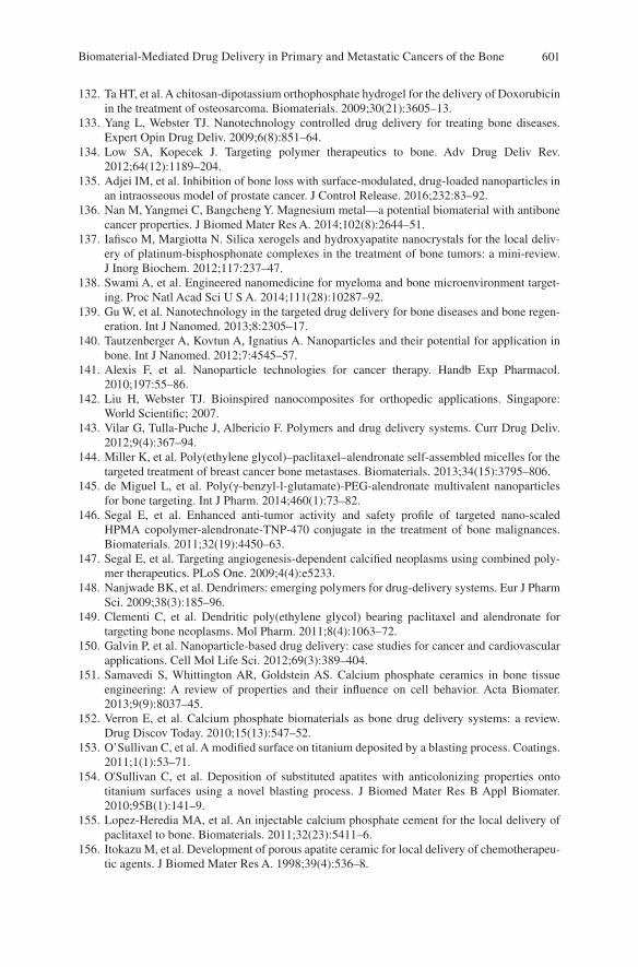
601
132. Ta HT, et al. A chitosan-dipotassium orthophosphate hydrogel for the delivery of Doxorubicin in the treatment of osteosarcoma. Biomaterials. 2009;30(21):3605–13.
133. Yang L, Webster TJ. Nanotechnology controlled drug delivery for treating bone diseases. Expert Opin Drug Deliv. 2009;6(8):851–64.
134. Low SA, Kopecek J. Targeting polymer therapeutics to bone. Adv Drug Deliv Rev. 2012;64(12):1189–204.
135. Adjei IM, et al. Inhibition of bone loss with surface-modulated, drug-loaded nanoparticles in an intraosseous model of prostate cancer. J Control Release. 2016;232:83–92.
136. Nan M, Yangmei C, Bangcheng Y. Magnesium metal—a potential biomaterial with antibone cancer properties. J Biomed Mater Res A. 2014;102(8):2644–51.
137. Iafisco M, Margiotta N. Silica xerogels and hydroxyapatite nanocrystals for the local deliv-ery of platinum-bisphosphonate complexes in the treatment of bone tumors: a mini-review. J Inorg Biochem. 2012;117:237–47.
138. Swami A, et al. Engineered nanomedicine for myeloma and bone microenvironment target-ing. Proc Natl Acad Sci U S A. 2014;111(28):10287–92.
139. Gu W, et al. Nanotechnology in the targeted drug delivery for bone diseases and bone regen-eration. Int J Nanomed. 2013;8:2305–17.
140. Tautzenberger A, Kovtun A, Ignatius A. Nanoparticles and their potential for application in bone. Int J Nanomed. 2012;7:4545–57.
141. Alexis F, et al. Nanoparticle technologies for cancer therapy. Handb Exp Pharmacol. 2010;197:55–86.
142. Liu H, Webster TJ. Bioinspired nanocomposites for orthopedic applications. Singapore: World Scientific; 2007.
143. Vilar G, Tulla-Puche J, Albericio F. Polymers and drug delivery systems. Curr Drug Deliv. 2012;9(4):367–94.
144. Miller K, et al. Poly(ethylene glycol)–paclitaxel–alendronate self-assembled micelles for the targeted treatment of breast cancer bone metastases. Biomaterials. 2013;34(15):3795–806.
145. de Miguel L, et al. Poly(γ-benzyl-l-glutamate)-PEG-alendronate multivalent nanoparticles for bone targeting. Int J Pharm. 2014;460(1):73–82.
146. Segal E, et al. Enhanced anti-tumor activity and safety profile of targeted nano-scaled HPMA copolymer-alendronate-TNP-470 conjugate in the treatment of bone malignances. Biomaterials. 2011;32(19):4450–63.
147. Segal E, et al. Targeting angiogenesis-dependent calcified neoplasms using combined poly-mer therapeutics. PLoS One. 2009;4(4):e5233.
148. Nanjwade BK, et al. Dendrimers: emerging polymers for drug-delivery systems. Eur J Pharm Sci. 2009;38(3):185–96.
149. Clementi C, et al. Dendritic poly(ethylene glycol) bearing paclitaxel and alendronate for targeting bone neoplasms. Mol Pharm. 2011;8(4):1063–72.
150. Galvin P, et al. Nanoparticle-based drug delivery: case studies for cancer and cardiovascular applications. Cell Mol Life Sci. 2012;69(3):389–404.
151. Samavedi S, Whittington AR, Goldstein AS. Calcium phosphate ceramics in bone tissue engineering: A review of properties and their influence on cell behavior. Acta Biomater. 2013;9(9):8037–45.
152. Verron E, et al. Calcium phosphate biomaterials as bone drug delivery systems: a review. Drug Discov Today. 2010;15(13):547–52.
153. O’Sullivan C, et al. A modified surface on titanium deposited by a blasting process. Coatings. 2011;1(1):53–71.
154. O'Sullivan C, et al. Deposition of substituted apatites with anticolonizing properties onto titanium surfaces using a novel blasting process. J Biomed Mater Res B Appl Biomater. 2010;95B(1):141–9.
155. Lopez-Heredia MA, et al. An injectable calcium phosphate cement for the local delivery of paclitaxel to bone. Biomaterials. 2011;32(23):5411–6.
156. Itokazu M, et al. Development of porous apatite ceramic for local delivery of chemotherapeu-tic agents. J Biomed Mater Res A. 1998;39(4):536–8.
Biomaterial-Mediated Drug Delivery in Primary and Metastatic Cancers of the Bone
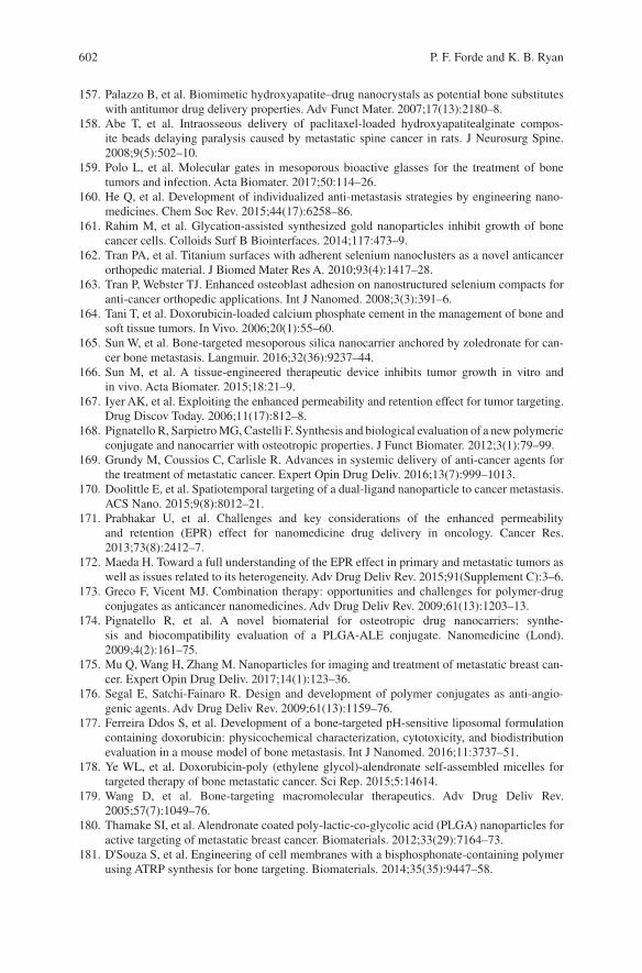
602
157. Palazzo B, et al. Biomimetic hydroxyapatite–drug nanocrystals as potential bone substitutes with antitumor drug delivery properties. Adv Funct Mater. 2007;17(13):2180–8.
158. Abe T, et al. Intraosseous delivery of paclitaxel-loaded hydroxyapatitealginate compos-ite beads delaying paralysis caused by metastatic spine cancer in rats. J Neurosurg Spine. 2008;9(5):502–10.
159. Polo L, et al. Molecular gates in mesoporous bioactive glasses for the treatment of bone tumors and infection. Acta Biomater. 2017;50:114–26.
160. He Q, et al. Development of individualized anti-metastasis strategies by engineering nano-medicines. Chem Soc Rev. 2015;44(17):6258–86.
161. Rahim M, et al. Glycation-assisted synthesized gold nanoparticles inhibit growth of bone cancer cells. Colloids Surf B Biointerfaces. 2014;117:473–9.
162. Tran PA, et al. Titanium surfaces with adherent selenium nanoclusters as a novel anticancer orthopedic material. J Biomed Mater Res A. 2010;93(4):1417–28.
163. Tran P, Webster TJ. Enhanced osteoblast adhesion on nanostructured selenium compacts for anti-cancer orthopedic applications. Int J Nanomed. 2008;3(3):391–6.
164. Tani T, et al. Doxorubicin-loaded calcium phosphate cement in the management of bone and soft tissue tumors. In Vivo. 2006;20(1):55–60.
165. Sun W, et al. Bone-targeted mesoporous silica nanocarrier anchored by zoledronate for can-cer bone metastasis. Langmuir. 2016;32(36):9237–44.
166. Sun M, et al. A tissue-engineered therapeutic device inhibits tumor growth in vitro and in vivo. Acta Biomater. 2015;18:21–9.
167. Iyer AK, et al. Exploiting the enhanced permeability and retention effect for tumor targeting. Drug Discov Today. 2006;11(17):812–8.
168. Pignatello R, Sarpietro MG, Castelli F. Synthesis and biological evaluation of a new polymeric conjugate and nanocarrier with osteotropic properties. J Funct Biomater. 2012;3(1):79–99.
169. Grundy M, Coussios C, Carlisle R. Advances in systemic delivery of anti-cancer agents for the treatment of metastatic cancer. Expert Opin Drug Deliv. 2016;13(7):999–1013.
170. Doolittle E, et al. Spatiotemporal targeting of a dual-ligand nanoparticle to cancer metastasis. ACS Nano. 2015;9(8):8012–21.
171. Prabhakar U, et al. Challenges and key considerations of the enhanced permeability and retention (EPR) effect for nanomedicine drug delivery in oncology. Cancer Res. 2013;73(8):2412–7.
172. Maeda H. Toward a full understanding of the EPR effect in primary and metastatic tumors as well as issues related to its heterogeneity. Adv Drug Deliv Rev. 2015;91(Supplement C):3–6.
173. Greco F, Vicent MJ. Combination therapy: opportunities and challenges for polymer-drug conjugates as anticancer nanomedicines. Adv Drug Deliv Rev. 2009;61(13):1203–13.
174. Pignatello R, et al. A novel biomaterial for osteotropic drug nanocarriers: synthe-sis and biocompatibility evaluation of a PLGA-ALE conjugate. Nanomedicine (Lond). 2009;4(2):161–75.
175. Mu Q, Wang H, Zhang M. Nanoparticles for imaging and treatment of metastatic breast can-cer. Expert Opin Drug Deliv. 2017;14(1):123–36.
176. Segal E, Satchi-Fainaro R. Design and development of polymer conjugates as anti-angio-genic agents. Adv Drug Deliv Rev. 2009;61(13):1159–76.
177. Ferreira Ddos S, et al. Development of a bone-targeted pH-sensitive liposomal formulation containing doxorubicin: physicochemical characterization, cytotoxicity, and biodistribution evaluation in a mouse model of bone metastasis. Int J Nanomed. 2016;11:3737–51.
178. Ye WL, et al. Doxorubicin-poly (ethylene glycol)-alendronate self-assembled micelles for targeted therapy of bone metastatic cancer. Sci Rep. 2015;5:14614.
179. Wang D, et al. Bone-targeting macromolecular therapeutics. Adv Drug Deliv Rev. 2005;57(7):1049–76.
180. Thamake SI, et al. Alendronate coated poly-lactic-co-glycolic acid (PLGA) nanoparticles for active targeting of metastatic breast cancer. Biomaterials. 2012;33(29):7164–73.
181. D'Souza S, et al. Engineering of cell membranes with a bisphosphonate-containing polymer using ATRP synthesis for bone targeting. Biomaterials. 2014;35(35):9447–58.
P. F. Forde and K. B. Ryan
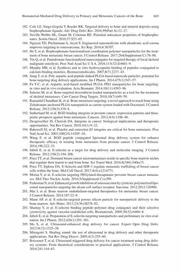
603
182. Cole LE, Vargo-Gogola T, Roeder RK. Targeted delivery to bone and mineral deposits using bisphosphonate ligands. Adv Drug Deliv Rev. 2016;99(Part A):12–27.
183. Neville-Webbe HL, Gnant M, Coleman RE. Potential anticancer properties of bisphospho-nates. Semin Oncol. 2010;37:S53–65.
184. Nguyen TD, Pitchaimani A, Aryal S. Engineered nanomedicine with alendronic acid corona improves targeting to osteosarcoma. Sci Rep. 2016;6:36707.
185. He Y, et al. Bisphosphonate-functionalized coordination polymer nanoparticles for the treat-ment of bone metastatic breast cancer. J Control Release. 2017;264(Supplement C):76–88.
186. Yin Q, et al. Pamidronate functionalized nanoconjugates for targeted therapy of focal skeletal malignant osteolysis. Proc Natl Acad Sci U S A. 2016;113(32):E4601–9.
187. Murphy MB, et al. Synthesis and in vitro hydroxyapatite binding of peptides conjugated to calcium-binding moieties. Biomacromolecules. 2007;8(7):2237–43.
188. Jiang T, et al. Poly aspartic acid peptide-linked PLGA based nanoscale particles: potential for bone-targeting drug delivery applications. Int J Pharm. 2014;475(1):547–57.
189. Fu Y-C, et al. Aspartic acid-based modified PLGA–PEG nanoparticles for bone targeting: in vitro and in vivo evaluation. Acta Biomater. 2014;10(11):4583–96.
190. Salerno M, et al. Bone-targeted doxorubicin-loaded nanoparticles as a tool for the treatment of skeletal metastases. Curr Cancer Drug Targets. 2010;10(7):649–59.
191. Ramanlal Chaudhari K, et al. Bone metastasis targeting: a novel approach to reach bone using Zoledronate anchored PLGA nanoparticle as carrier system loaded with Docetaxel. J Control Release. 2012;158(3):470–8.
192. Sutherland M, et al. RGD-binding integrins in prostate cancer: expression patterns and thera-peutic prospects against bone metastasis. Cancers. 2012;4(4):1106–46.
193. Desgrosellier JS, Cheresh DA. Integrins in cancer: biological implications and therapeutic opportunities. Nat Rev Cancer. 2010;10(1):9–22.
194. Bakewell SJ, et al. Platelet and osteoclast β3 integrins are critical for bone metastasis. Proc Natl Acad Sci. 2003;100(24):14205–10.
195. Wang F, et al. RGD peptide conjugated liposomal drug delivery system for enhance therapeutic efficacy in treating bone metastasis from prostate cancer. J Control Release. 2014;196:222–33.
196. Jubeli E, et al. E-selectin as a target for drug delivery and molecular imaging. J Control Release. 2012;158(2):194–206.
197. Price TT, et al. Dormant breast cancer micrometastases reside in specific bone marrow niches that regulate their transit to and from bone. Sci Transl Med. 2016;8(340):340ra73.
198. Price TT, Sipkins DA. E-Selectin and SDF-1 regulate metastatic trafficking of breast cancer cells within the bone. Mol Cell Oncol. 2017;4(4):e1214771.
199. Morita Y, et al. E-selectin targeting PEGylated-thioaptamer prevents breast cancer metasta-ses. Mol Ther Nucleic Acids. 2016;5(Supplement C):e399.
200. Federman N, et al. Enhanced growth inhibition of osteosarcoma by cytotoxic polymerized lipo-somal nanoparticles targeting the alcam cell surface receptor. Sarcoma. 2012;2012:126906.
201. Mai J, et al. Bone marrow endothelium-targeted therapeutics for metastatic breast cancer. J Control Release. 2014;187:22–9.
202. Mann AP, et al. E-selectin-targeted porous silicon particle for nanoparticle delivery to the bone marrow. Adv Mater. 2011;23(36):H278–82.
203. Shamay Y, et al. E-selectin binding peptide–polymer–drug conjugates and their selective cytotoxicity against vascular endothelial cells. Biomaterials. 2009;30(32):6460–8.
204. Jubeli E, et al. Preparation of E-selectin-targeting nanoparticles and preliminary in vitro eval-uation. Int J Pharm. 2012;426(1):291–301.
205. Mo S, et al. Ultrasound-enhanced drug delivery for cancer. Expert Opin Drug Deliv. 2012;9(12):1525–38.
206. Mitragotri S. Healing sound: the use of ultrasound in drug delivery and other therapeutic applications. Nat Rev Drug Discov. 2005;4(3):255–60.
207. Boissenot T, et al. Ultrasound-triggered drug delivery for cancer treatment using drug deliv-ery systems: From theoretical considerations to practical applications. J Control Release. 2016;241:144–63.
Biomaterial-Mediated Drug Delivery in Primary and Metastatic Cancers of the Bone
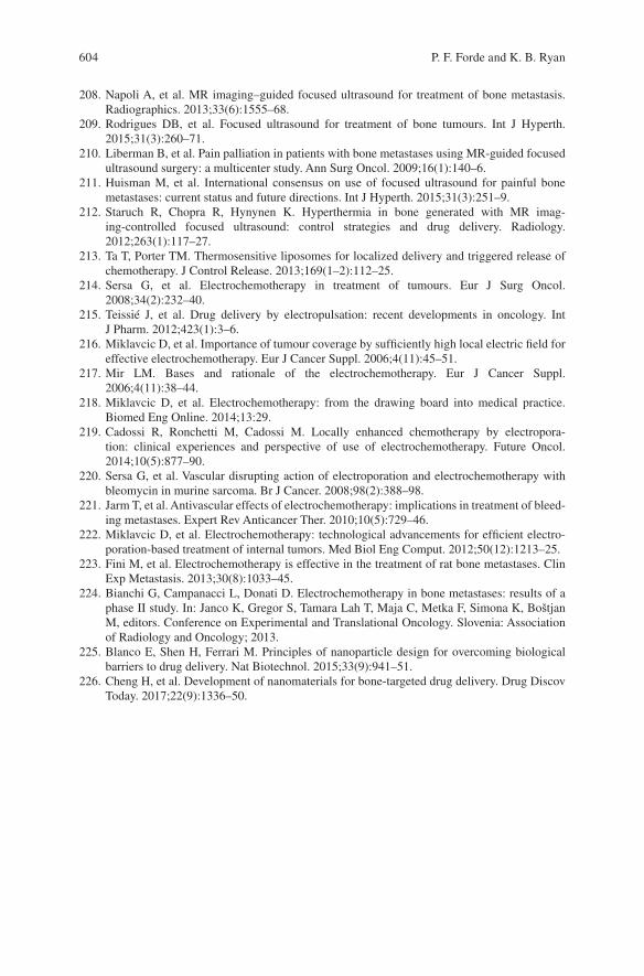
604
208. Napoli A, et al. MR imaging–guided focused ultrasound for treatment of bone metastasis. Radiographics. 2013;33(6):1555–68.
209. Rodrigues DB, et al. Focused ultrasound for treatment of bone tumours. Int J Hyperth. 2015;31(3):260–71.
210. Liberman B, et al. Pain palliation in patients with bone metastases using MR-guided focused ultrasound surgery: a multicenter study. Ann Surg Oncol. 2009;16(1):140–6.
211. Huisman M, et al. International consensus on use of focused ultrasound for painful bone metastases: current status and future directions. Int J Hyperth. 2015;31(3):251–9.
212. Staruch R, Chopra R, Hynynen K. Hyperthermia in bone generated with MR imag-ing-controlled focused ultrasound: control strategies and drug delivery. Radiology. 2012;263(1):117–27.
213. Ta T, Porter TM. Thermosensitive liposomes for localized delivery and triggered release of chemotherapy. J Control Release. 2013;169(1–2):112–25.
214. Sersa G, et al. Electrochemotherapy in treatment of tumours. Eur J Surg Oncol. 2008;34(2):232–40.
215. Teissié J, et al. Drug delivery by electropulsation: recent developments in oncology. Int J Pharm. 2012;423(1):3–6.
216. Miklavcic D, et al. Importance of tumour coverage by sufficiently high local electric field for effective electrochemotherapy. Eur J Cancer Suppl. 2006;4(11):45–51.
217. Mir LM. Bases and rationale of the electrochemotherapy. Eur J Cancer Suppl. 2006;4(11):38–44.
218. Miklavcic D, et al. Electrochemotherapy: from the drawing board into medical practice. Biomed Eng Online. 2014;13:29.
219. Cadossi R, Ronchetti M, Cadossi M. Locally enhanced chemotherapy by electropora-tion: clinical experiences and perspective of use of electrochemotherapy. Future Oncol. 2014;10(5):877–90.
220. Sersa G, et al. Vascular disrupting action of electroporation and electrochemotherapy with bleomycin in murine sarcoma. Br J Cancer. 2008;98(2):388–98.
221. Jarm T, et al. Antivascular effects of electrochemotherapy: implications in treatment of bleed-ing metastases. Expert Rev Anticancer Ther. 2010;10(5):729–46.
222. Miklavcic D, et al. Electrochemotherapy: technological advancements for efficient electro-poration-based treatment of internal tumors. Med Biol Eng Comput. 2012;50(12):1213–25.
223. Fini M, et al. Electrochemotherapy is effective in the treatment of rat bone metastases. Clin Exp Metastasis. 2013;30(8):1033–45.
224. Bianchi G, Campanacci L, Donati D. Electrochemotherapy in bone metastases: results of a phase II study. In: Janco K, Gregor S, Tamara Lah T, Maja C, Metka F, Simona K, Boštjan M, editors. Conference on Experimental and Translational Oncology. Slovenia: Association of Radiology and Oncology; 2013.
225. Blanco E, Shen H, Ferrari M. Principles of nanoparticle design for overcoming biological barriers to drug delivery. Nat Biotechnol. 2015;33(9):941–51.
226. Cheng H, et al. Development of nanomaterials for bone-targeted drug delivery. Drug Discov Today. 2017;22(9):1336–50.
P. F. Forde and K. B. Ryan
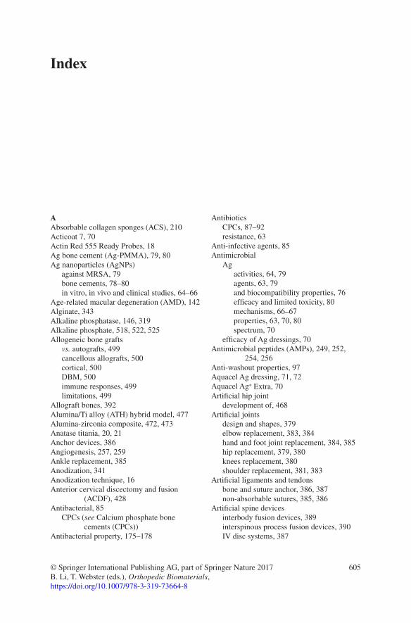
605© Springer International Publishing AG, part of Springer Nature 2017B. Li, T. Webster (eds.), Orthopedic Biomaterials, https://doi.org/10.1007/978-3-319-73664-8
AAbsorbable collagen sponges (ACS), 210Acticoat 7, 70Actin Red 555 Ready Probes, 18Ag bone cement (Ag-PMMA), 79, 80Ag nanoparticles (AgNPs)
against MRSA, 79bone cements, 78–80in vitro, in vivo and clinical studies, 64–66
Age-related macular degeneration (AMD), 142Alginate, 343Alkaline phosphatase, 146, 319Alkaline phosphate, 518, 522, 525Allogeneic bone grafts
vs. autografts, 499cancellous allografts, 500cortical, 500DBM, 500immune responses, 499limitations, 499
Allograft bones, 392Alumina/Ti alloy (ATH) hybrid model, 477Alumina-zirconia composite, 472, 473Anatase titania, 20, 21Anchor devices, 386Angiogenesis, 257, 259Ankle replacement, 385Anodization, 341Anodization technique, 16Anterior cervical discectomy and fusion
(ACDF), 428Antibacterial, 85
CPCs (see Calcium phosphate bone cements (CPCs))
Antibacterial property, 175–178
AntibioticsCPCs, 87–92resistance, 63
Anti-infective agents, 85Antimicrobial
Agactivities, 64, 79agents, 63, 79and biocompatibility properties, 76efficacy and limited toxicity, 80mechanisms, 66–67properties, 63, 70, 80spectrum, 70
efficacy of Ag dressings, 70Antimicrobial peptides (AMPs), 249, 252,
254, 256Anti-washout properties, 97Aquacel Ag dressing, 71, 72Aquacel Ag+ Extra, 70Artificial hip joint
development of, 468Artificial joints
design and shapes, 379elbow replacement, 383, 384hand and foot joint replacement, 384, 385hip replacement, 379, 380knees replacement, 380shoulder replacement, 381, 383
Artificial ligaments and tendonsbone and suture anchor, 386, 387non-absorbable sutures, 385, 386
Artificial spine devicesinterbody fusion devices, 389interspinous process fusion devices, 390IV disc systems, 387
Index
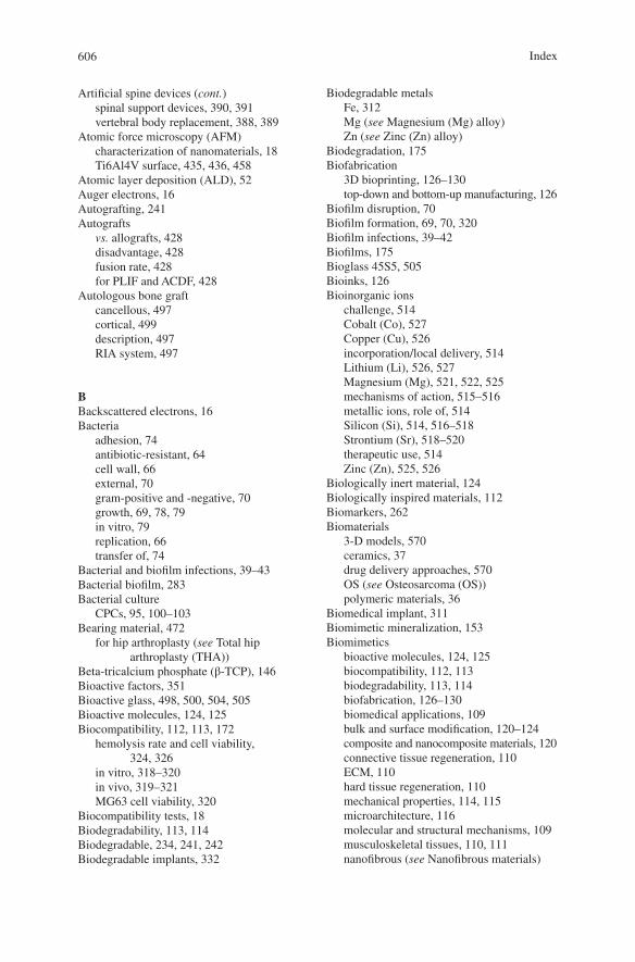
606
Artificial spine devices (cont.)spinal support devices, 390, 391vertebral body replacement, 388, 389
Atomic force microscopy (AFM)characterization of nanomaterials, 18Ti6Al4V surface, 435, 436, 458
Atomic layer deposition (ALD), 52Auger electrons, 16Autografting, 241Autografts
vs. allografts, 428disadvantage, 428fusion rate, 428for PLIF and ACDF, 428
Autologous bone graftcancellous, 497cortical, 499description, 497RIA system, 497
BBackscattered electrons, 16Bacteria
adhesion, 74antibiotic-resistant, 64cell wall, 66external, 70gram-positive and -negative, 70growth, 69, 78, 79in vitro, 79replication, 66transfer of, 74
Bacterial and biofilm infections, 39–43Bacterial biofilm, 283Bacterial culture
CPCs, 95, 100–103Bearing material, 472
for hip arthroplasty (see Total hip arthroplasty (THA))
Beta-tricalcium phosphate (β-TCP), 146Bioactive factors, 351Bioactive glass, 498, 500, 504, 505Bioactive molecules, 124, 125Biocompatibility, 112, 113, 172
hemolysis rate and cell viability, 324, 326
in vitro, 318–320in vivo, 319–321MG63 cell viability, 320
Biocompatibility tests, 18Biodegradability, 113, 114Biodegradable, 234, 241, 242Biodegradable implants, 332
Biodegradable metalsFe, 312Mg (see Magnesium (Mg) alloy)Zn (see Zinc (Zn) alloy)
Biodegradation, 175Biofabrication
3D bioprinting, 126–130top-down and bottom-up manufacturing, 126
Biofilm disruption, 70Biofilm formation, 69, 70, 320Biofilm infections, 39–42Biofilms, 175Bioglass 45S5, 505Bioinks, 126Bioinorganic ions
challenge, 514Cobalt (Co), 527Copper (Cu), 526incorporation/local delivery, 514Lithium (Li), 526, 527Magnesium (Mg), 521, 522, 525mechanisms of action, 515–516metallic ions, role of, 514Silicon (Si), 514, 516–518Strontium (Sr), 518–520therapeutic use, 514Zinc (Zn), 525, 526
Biologically inert material, 124Biologically inspired materials, 112Biomarkers, 262Biomaterials
3-D models, 570ceramics, 37drug delivery approaches, 570OS (see Osteosarcoma (OS))polymeric materials, 36
Biomedical implant, 311Biomimetic mineralization, 153Biomimetics
bioactive molecules, 124, 125biocompatibility, 112, 113biodegradability, 113, 114biofabrication, 126–130biomedical applications, 109bulk and surface modification, 120–124composite and nanocomposite materials, 120connective tissue regeneration, 110ECM, 110hard tissue regeneration, 110mechanical properties, 114, 115microarchitecture, 116molecular and structural mechanisms, 109musculoskeletal tissues, 110, 111nanofibrous (see Nanofibrous materials)
Index
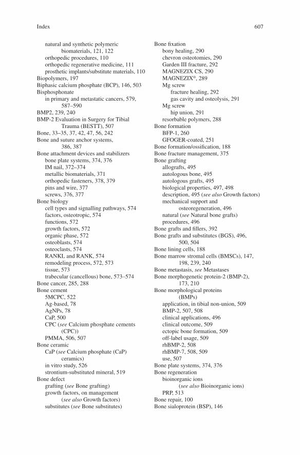
607
natural and synthetic polymeric biomaterials, 121, 122
orthopedic procedures, 110orthopedic regenerative medicine, 111prosthetic implants/substitute materials, 110
Biopolymers, 197Biphasic calcium phosphate (BCP), 146, 503Bisphosphonate
in primary and metastatic cancers, 579, 587–590
BMP2, 239, 240BMP-2 Evaluation in Surgery for Tibial
Trauma (BESTT), 507Bone, 33–35, 37, 42, 47, 56, 242Bone and suture anchor systems,
386, 387Bone attachment devices and stabilizers
bone plate systems, 374, 376IM nail, 372–374metallic biomaterials, 371orthopedic fasteners, 378, 379pins and wire, 377screws, 376, 377
Bone biologycell types and signalling pathways, 574factors, osteotropic, 574functions, 572growth factors, 572organic phase, 572osteoblasts, 574osteoclasts, 574RANKL and RANK, 574remodeling process, 572, 573tissue, 573trabecular (cancellous) bone, 573–574
Bone cancer, 285, 288Bone cement
5MCPC, 522Ag-based, 78AgNPs, 78CaP, 500CPC (see Calcium phosphate cements
(CPC))PMMA, 506, 507
Bone ceramicCaP (see Calcium phosphate (CaP)
ceramics)in vitro study, 526strontium-substituted mineral, 519
Bone defectgrafting (see Bone grafting)growth factors, on management
(see also Growth factors)substitutes (see Bone substitutes)
Bone fixationbony healing, 290chevron osteotomies, 290Garden III fracture, 292MAGNEZIX CS, 290MAGNEZIX®, 289Mg screw
fracture healing, 292gas cavity and osteolysis, 291
Mg screwhip union, 291
resorbable polymers, 288Bone formation
BFP-1, 260GFOGER-coated, 251
Bone formation/ossification, 188Bone fracture management, 375Bone grafting
allografts, 495autologous bone, 495autologous grafts, 495biological properties, 497, 498description, 495 (see also Growth factors)mechanical support and
osteoregeneration, 496natural (see Natural bone grafts)procedures, 496
Bone grafts and fillers, 392Bone grafts and substitutes (BGS), 496,
500, 504Bone lining cells, 188Bone marrow stromal cells (BMSCs), 147,
198, 239, 240Bone metastasis, see MetastasesBone morphogenetic protein-2 (BMP-2),
173, 210Bone morphological proteins
(BMPs)application, in tibial non-union, 509BMP-2, 507, 508clinical applications, 496clinical outcome, 509ectopic bone formation, 509off-label usage, 509rhBMP-2, 508rhBMP-7, 508, 509use, 507
Bone plate systems, 374, 376Bone regeneration
bioinorganic ions (see also Bioinorganic ions)
PRP, 513Bone repair, 100Bone sialoprotein (BSP), 146
Index
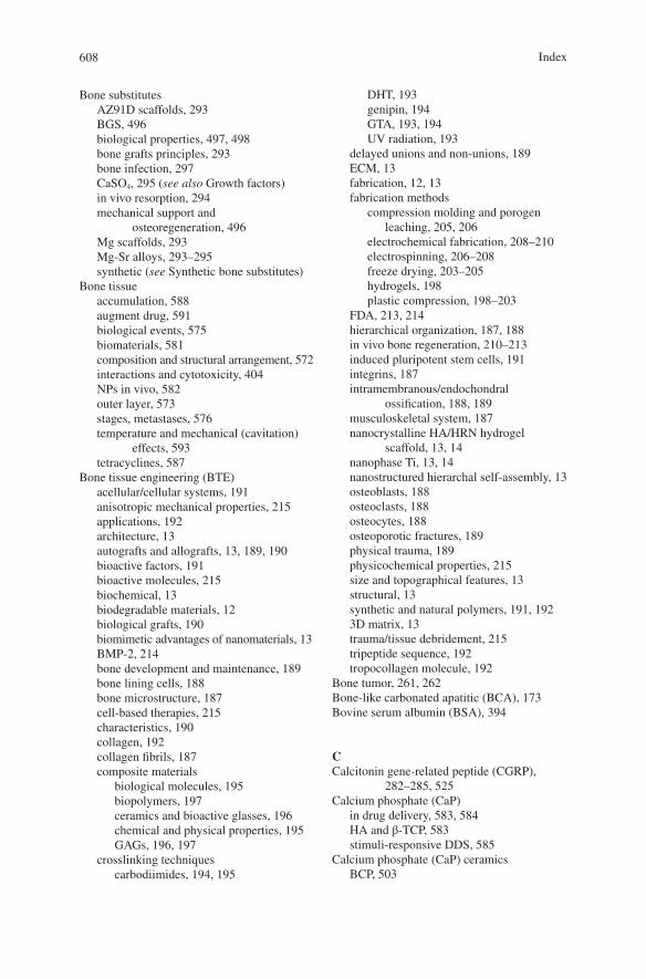
608
Bone substitutesAZ91D scaffolds, 293BGS, 496biological properties, 497, 498bone grafts principles, 293bone infection, 297CaSO4, 295 (see also Growth factors)in vivo resorption, 294mechanical support and
osteoregeneration, 496Mg scaffolds, 293Mg-Sr alloys, 293–295synthetic (see Synthetic bone substitutes)
Bone tissueaccumulation, 588augment drug, 591biological events, 575biomaterials, 581composition and structural arrangement, 572interactions and cytotoxicity, 404NPs in vivo, 582outer layer, 573stages, metastases, 576temperature and mechanical (cavitation)
effects, 593tetracyclines, 587
Bone tissue engineering (BTE)acellular/cellular systems, 191anisotropic mechanical properties, 215applications, 192architecture, 13autografts and allografts, 13, 189, 190bioactive factors, 191bioactive molecules, 215biochemical, 13biodegradable materials, 12biological grafts, 190biomimetic advantages of nanomaterials, 13BMP-2, 214bone development and maintenance, 189bone lining cells, 188bone microstructure, 187cell-based therapies, 215characteristics, 190collagen, 192collagen fibrils, 187composite materials
biological molecules, 195biopolymers, 197ceramics and bioactive glasses, 196chemical and physical properties, 195GAGs, 196, 197
crosslinking techniquescarbodiimides, 194, 195
DHT, 193genipin, 194GTA, 193, 194UV radiation, 193
delayed unions and non-unions, 189ECM, 13fabrication, 12, 13fabrication methods
compression molding and porogen leaching, 205, 206
electrochemical fabrication, 208–210electrospinning, 206–208freeze drying, 203–205hydrogels, 198plastic compression, 198–203
FDA, 213, 214hierarchical organization, 187, 188in vivo bone regeneration, 210–213induced pluripotent stem cells, 191integrins, 187intramembranous/endochondral
ossification, 188, 189musculoskeletal system, 187nanocrystalline HA/HRN hydrogel
scaffold, 13, 14nanophase Ti, 13, 14nanostructured hierarchal self-assembly, 13osteoblasts, 188osteoclasts, 188osteocytes, 188osteoporotic fractures, 189physical trauma, 189physicochemical properties, 215size and topographical features, 13structural, 13synthetic and natural polymers, 191, 1923D matrix, 13trauma/tissue debridement, 215tripeptide sequence, 192tropocollagen molecule, 192
Bone tumor, 261, 262Bone-like carbonated apatitic (BCA), 173Bovine serum albumin (BSA), 394
CCalcitonin gene-related peptide (CGRP),
282–285, 525Calcium phosphate (CaP)
in drug delivery, 583, 584HA and β-TCP, 583stimuli-responsive DDS, 585
Calcium phosphate (CaP) ceramicsBCP, 503
Index
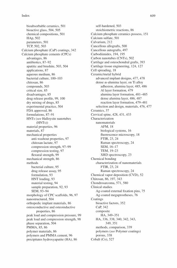
609
bioabsorbable ceramics, 501bioactive glass, 504, 505chemical compositions, 501HAp, 502parameters, 501TCP, 502, 503
Calcium phosphate (CaP) coatings, 342Calcium phosphate cements (CPCs)
advantages, 86antibiotics, 87–92apatitic and brushite, 503, 504applications, 87aqueous medium, 86bacterial culture, 100–103chitosan, 86compounds, 503critical size, 85disadvantages, 85drug release profile, 99, 100dry mixing of drugs, 85experimental practice, 504FDA approved, 86formulations, 87–91HNTs (see Halloysite nanotubes
(HNTs))material properties, 96materials, 87mechanical properties
anti-washout properties, 97chitosan lactate, 97compression strength, 97–99compression testing, 97flexural strength, 99
mechanical strength, 86methods
bacterial culture, 95drug release assay, 95formulation, 93HNT loading, 93material testing, 94sample preparation, 92, 93SEM, 93–94
morphology of CPC scaffolds, 96, 97nanostructured, 504orthopedic implant materials, 86osteoconductive and osteoinductive
properties, 86peak load and compression pressure, 99peak load and compression strength, 98phase separation, 504PMMA, 85, 86polymer materials, 86polymers and PMMA cement, 96precipitates hydroxyapatite (HA), 86
self-hardened, 503stoichiometric reactions, 86
Calcium phosphate ceramics possess, 151Calcium sulfate, 501Calvarium, 212Cancellous allografts, 500Cancellous autografts, 497Carbodiimides, 194, 195Carbon nanotubes (CNTs), 502Cartilage and osteochondral grafts, 393Cartilage tissue engineering, 124, 127Cell spreading, 18Ceramic/metal hybrid
advanced implant designs, 477, 478dense ∝-alumina layer, on Ti alloy
adhesion, alumina layer, 485, 486Al layer formation, 479alumina layer formation, 481–485dense alumina layer, 486, 487reaction layer formation, 479–481
selection and design, materials, 476, 477Ceramics, 37Cervical spine, 428, 431, 433Characterization
nanomaterialsAFM, 18biological systems, 16fluorescence microscopy, 18FTIR, 23, 24Raman spectroscopy, 24SEM, 16–17TEM, 19–23XRD spectroscopy, 23
Chemical bondingcharacterization of nanomaterials
FTIR, 23, 24Raman spectroscopy, 24
Chemical vapor deposition (CVD), 52Chitosan, 86, 197, 343Chondrosarcoma, 571, 580Clinical studies
Ag-coated external fixation pins, 75Ag-coated megaprostheses, 76
Coatingsbioactive factors, 352CaP, 342composite
HA, 349–351HA, 336, 338, 340, 342, 343,
349, 351methods, comparison, 339polymers (see Polymer coatings)porous, 338
Cobalt (Co), 527
Index
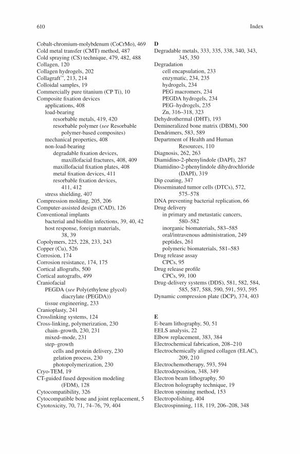
610
Cobalt-chromium-molybdenum (CoCrMo), 469Cold metal transfer (CMT) method, 487Cold spraying (CS) technique, 479, 482, 488Collagen, 120Collagen hydrogels, 202Collagraft™, 213, 214Colloidal samples, 19Commercially pure titanium (CP Ti), 10Composite fixation devices
applications, 408load-bearing
resorbable metals, 419, 420resorbable polymer (see Resorbable
polymer-based composites)mechanical properties, 408non-load-bearing
degradable fixation devices, maxillofacial fractures, 408, 409
maxillofacial fixation plates, 408metal fixation devices, 411resorbable fixation devices,
411, 412stress shielding, 407
Compression molding, 205, 206Computer-assisted design (CAD), 126Conventional implants
bacterial and biofilm infections, 39, 40, 42host response, foreign materials,
38, 39Copolymers, 225, 228, 233, 243Copper (Cu), 526Corrosion, 174Corrosion resistance, 174, 175Cortical allografts, 500Cortical autografts, 499Craniofacial
PEGDA (see Poly(ethylene glycol) diacrylate (PEGDA))
tissue engineering, 233Cranioplasty, 241Crosslinking systems, 124Cross-linking, polymerization, 230
chain–growth, 230, 231mixed–mode, 231step–growth
cells and protein delivery, 230gelation process, 230photopolymerization, 230
Cryo-TEM, 19CT-guided fused deposition modeling
(FDM), 128Cytocompatibility, 326Cytocompatible bone and joint replacement, 5Cytotoxicity, 70, 71, 74–76, 79, 404
DDegradable metals, 333, 335, 338, 340, 343,
345, 350Degradation
cell encapsulation, 233enzymatic, 234, 235hydrogels, 234PEG macromers, 234PEGDA hydrogels, 234PEG–hydrogels, 235Zn, 316–318, 323
Dehydrothermal (DHT), 193Demineralized bone matrix (DBM), 500Dendrimers, 583, 589Department of Health and Human
Resources, 110Diagnosis, 262, 263Diamidino-2-phenylindole (DAPI), 287Diamidino-2-phenylindole dihydrochloride
(DAPI), 319Dip coating, 347Disseminated tumor cells (DTCs), 572,
575–578DNA preventing bacterial replication, 66Drug delivery
in primary and metastatic cancers, 580–582
inorganic biomaterials, 583–585oral/intravenous administration, 249peptides, 261polymeric biomaterials, 581–583
Drug release assayCPCs, 95
Drug release profileCPCs, 99, 100
Drug-delivery systems (DDS), 581, 582, 584, 585, 587, 588, 590, 591, 593, 595
Dynamic compression plate (DCP), 374, 403
EE-beam lithography, 50, 51EELS analysis, 22Elbow replacement, 383, 384Electrochemical fabrication, 208–210Electrochemically aligned collagen (ELAC),
209, 210Electrochemotherapy, 593, 594Electrodeposition, 348, 349Electron beam lithography, 50Electron holography technique, 19Electron spinning method, 153Electropolishing, 404Electrospinning, 118, 119, 206–208, 348
Index
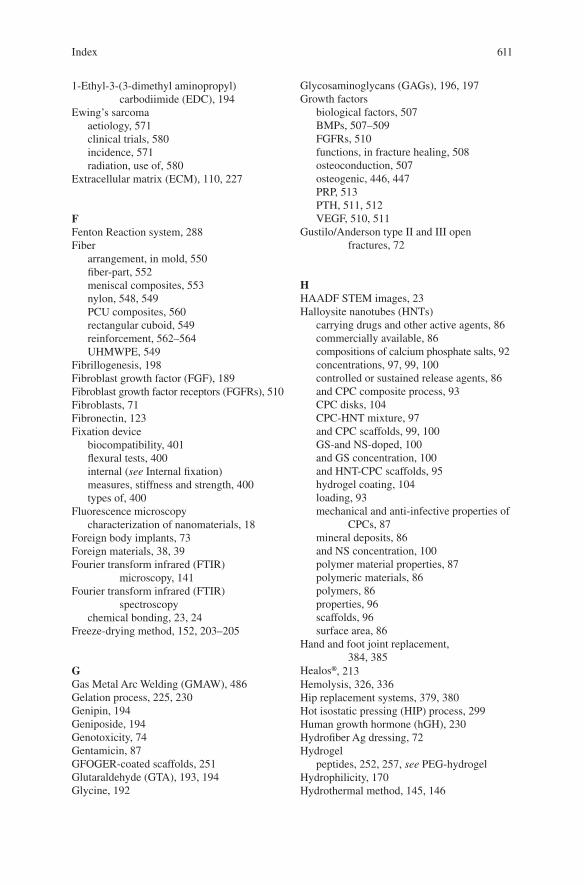
611
1-Ethyl-3-(3-dimethyl aminopropyl) carbodiimide (EDC), 194
Ewing’s sarcomaaetiology, 571clinical trials, 580incidence, 571radiation, use of, 580
Extracellular matrix (ECM), 110, 227
FFenton Reaction system, 288Fiber
arrangement, in mold, 550fiber-part, 552meniscal composites, 553nylon, 548, 549PCU composites, 560rectangular cuboid, 549reinforcement, 562–564UHMWPE, 549
Fibrillogenesis, 198Fibroblast growth factor (FGF), 189Fibroblast growth factor receptors (FGFRs), 510Fibroblasts, 71Fibronectin, 123Fixation device
biocompatibility, 401flexural tests, 400internal (see Internal fixation)measures, stiffness and strength, 400types of, 400
Fluorescence microscopycharacterization of nanomaterials, 18
Foreign body implants, 73Foreign materials, 38, 39Fourier transform infrared (FTIR)
microscopy, 141Fourier transform infrared (FTIR)
spectroscopychemical bonding, 23, 24
Freeze-drying method, 152, 203–205
GGas Metal Arc Welding (GMAW), 486Gelation process, 225, 230Genipin, 194Geniposide, 194Genotoxicity, 74Gentamicin, 87GFOGER-coated scaffolds, 251Glutaraldehyde (GTA), 193, 194Glycine, 192
Glycosaminoglycans (GAGs), 196, 197Growth factors
biological factors, 507BMPs, 507–509FGFRs, 510functions, in fracture healing, 508osteoconduction, 507osteogenic, 446, 447PRP, 513PTH, 511, 512VEGF, 510, 511
Gustilo/Anderson type II and III open fractures, 72
HHAADF STEM images, 23Halloysite nanotubes (HNTs)
carrying drugs and other active agents, 86commercially available, 86compositions of calcium phosphate salts, 92concentrations, 97, 99, 100controlled or sustained release agents, 86and CPC composite process, 93CPC disks, 104CPC-HNT mixture, 97and CPC scaffolds, 99, 100GS-and NS-doped, 100and GS concentration, 100and HNT-CPC scaffolds, 95hydrogel coating, 104loading, 93mechanical and anti-infective properties of
CPCs, 87mineral deposits, 86and NS concentration, 100polymer material properties, 87polymeric materials, 86polymers, 86properties, 96scaffolds, 96surface area, 86
Hand and foot joint replacement, 384, 385
Healos®, 213Hemolysis, 326, 336Hip replacement systems, 379, 380Hot isostatic pressing (HIP) process, 299Human growth hormone (hGH), 230Hydrofiber Ag dressing, 72Hydrogel
peptides, 252, 257, see PEG-hydrogelHydrophilicity, 170Hydrothermal method, 145, 146
Index
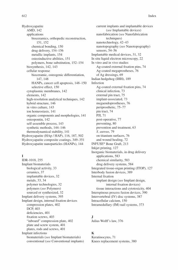
612
HydroxyapatiteAMD, 142applications
bioceramics, orthopedic reconstruction, 151, 152
chemical bonding, 150drug delivery, 154–156metallic implants, 154osteoinductive abilities, 151polymers, bone substitution, 152–154
biosynthesis, 142, 143cellular response
bioceramic, osteogenic differentiation, 147, 148
HANPs, cancer cell apoptosis, 148–150selective effect, 150
cytoplasmic membranes, 142elements, 142high-resolution analytical techniques, 142hybrid structure, 146in vitro culture, 143ion homeostasis, 141organic components and morphologies, 141osteopontin, 142self-assemble process, 143synthetic methods, 144–146thermodynamical stability, 141
Hydroxyapatite (HAp / HAP), 116, 187, 502Hydroxyapatite composite coatings, 349–351Hydroxyapatite nanoparticles (HANPs), 144
IIDR-1018, 255Implant biomaterials
biological activity, 33ceramics, 37implantable devices, 32metals, 33, 34polymer technologies, 32polymers (see Polymers)sourced or synthesized, 32
Implant delivery systems, 395Implant design, internal fixation devices
compression plates, 402DCP, 403deficiencies, 401fixation screws, 403“inboard” compression plate, 402plate and screw system, 401plates, rods and screws, 401
Implant infectionsbiomaterials (see Implant biomaterials)conventional (see Conventional implants)
current implants and implantable devices (see Implantable devices)
nanofabrication (see Nanofabrication techniques)
nanotechnology, 42–43nanotopography (see Nanotopography)sensors, 54–56
Implantable medical devices, 31, 32In situ liquid electron microscopy, 22In vitro and in vivo studies
Ag-coated external fixation pins, 74Ag-coated megaprostheses, 76of Ag dressings, 69
Indian hedgehog (IHH), 189Infection
Ag-coated external fixation pins, 74clinical infection, 73external pin tract, 75implant-associated, 73megaendoprostheses, 76periprosthetic, 75–77pin tract, 74PJI, 71post-operative, 77preventing, 80prevention and treatment, 63S. aureus, 79on titanium surfaces, 76and wound healing, 72
INFUSE® Bone Graft, 213Inkjet printing, 127Inorganic biomaterials, in drug delivery
applications, 583chemical similarity, 583drug delivery systems, 584
Integrated tissue-organ printing (ITOP), 127Interbody fusion devices, 389Internal fixation
implant design (see Implant design, internal fixation devices)
tissue interactions and cytotoxicity, 404Interspinous process fusion devices, 390Intervertebral (IV) disc systems, 387Intracellular calcium, 150Intramedullary (IM) nail systems, 373
JJulius Wolff’s law, 376
KKeratinocytes, 71Knees replacement systems, 380
Index
613
LLamellae, 187Laser-induced forward transfer (LIFT)-based
bioprinting systems, 129Limited contact DCP (LC-DCP), 375Lithium (Li), 526, 527Lumbar spine, 428, 429, 431
See also PEEK titanium composite (PTC)
MMagnesium (Mg)
advantages, 333ALP activity, osteoblasts, 522biodegradable implants, 332bone crystals, 521in CGRP-mediated osteogenic
differentiation, 522–525coatings, 338degradation
coatings and surface modifications, 336galvanic reactions, 333H2 and OH-, 335implant and bone growth, 335
hypothesized intracellular signaling, 522, 523
intake, 521ion-exchange behavior, mechanism of, 521orthopedic implants, 331substrates preparation, 337surface modifications
anodization, 341chemical, 340MAO, 341
Magnesium (Mg) alloyadvantages, 276biodegradation reaction, 277biofunctions
antimicrobial, 283, 285osteogenesis, 279, 280, 283–285tumor cell survival, 285, 288
CE and MFDSSK, 276corrosion behavior
body fluids, 277in vivo and in vitro, 278SCC, 278
hemolysis, 336orthopedics
bone fixation, 288, 290, 291bone substitutes, 292–297coating, 298, 300osteomyelitisis, 297, 298
SBF, 277surface treatment, 277
Magnesium (Mg) coatingcorrosion resistance, 299HIP, 299morphology, 300porous Ti6Al4V, 300, 301Si, 299vacuum deposition technique, 299
Magnesium-containing intramedullary nail (Mg-IMN), 282
Masquelet technique, 501, 506, 507Matrix metalloproteases (MMPs), 113Matrix, PCU, 550, 552, 553, 558, 562,
564–566Mechanical properties, 85Mechanical strength, 311, 312, 315, 323, 324Megaprostheses
Agclinical studies, 76in vitro and in vivo studies, 76
Meniscus replacementcomposite preparation, 548, 549design, mold, 548, 549distribution capabilities, 547experimental technique, friction and wear
behavior, 553, 554friction test
compositions, 562effective value (rms) method, 560, 561fiber reinforcement, 562–564friction coefficient, 555groups of cycles, 556output coefficient, friction data, 560sampling process, 555surface characterization, 556
injection molding machine, 551mechanical evaluation, 550mechanical properties, 548microstructural analysis, 551porosity and compressive properties, 548prosthesis fabrication, 552, 553tensile and compression tests
elastomeric stress-strain behavior, 558fiber-reinforced PCU composites,
559, 560nylon reinforced composites, 558optimum tensile modulus, 558Q7-4780, composite of, 558stress-strain plots, 557, 558
test description, meniscal prosthesis, 554, 555
wear testloaded soak and unloaded soak
controls, 563, 564measurements, 556
Index
614
Meniscus replacement (cont.)nylon reinforcement fibers, 564stainless steel counterface, physical
examination, 564, 565vacuum oven drying, 563, 564
Mesenchymal stem cells (MSCs), 146, 188Mesenchymal stromal cells (MSCs), 236Mesoporous bioactive glass (MBG), 527Metal fixation plates
electropolishing, 404EPSS, 404–407long-term stress shielding, 407properties, 404titanium, 404–406
Metallic biomaterialCoCrMo alloys, 469Ti alloys, 469, 470
Metallic implantsantimicrobial performance, 177biodegradable metals, 169biomedical application, 168, 169CaP coatings
antibacterial property, 175–178biocompatibility—osteointegration,
172, 173biomedical applications, 171bone tissue, 172ceramics, 172corrosion resistance, 174, 175in vitro studies, 178methods, 172
ceramic and polymeric materials, 167ESEM micrographs, 174SEM, 171surface chemistry, 170surface modification, 172, 173, 175, 178surface morphologies, 170, 176surface wettability, 170, 171
Metalsultra-hard coatings, 474, 475
Metastasesaugment delivery, 593, 594biomaterials, in drug delivery
DDS, 581, 582drug delivery system, 582formulation approach, 581inorganic materials, 583–585limitations, 581nanocarriers, therapeutic, 582polymer-based carriers, 582polymeric biomaterials, 581–583
breast cancer, 572diagnosis and treatment
bisphosphonates and denosumab, 579
immunomodulation approaches, 580multidisciplinary approaches, 579radiation, use of, 580signalling pathways, 580
lung cancer, 572pathophysiology
clinical impact, 575colonisation, 575ECM, 578homing and localisation, tumor cells, 577instructive environmental, 577osteoblastic metastases, 578osteolysis, 578pre-metastatic niche, in bone, 576“seed and soil” hypothesis, 575selectins, 577stages, spreading, 576tumor cell surface integrins, 577tumor progression, 576
prostate carcinoma, 572spreading, to bone, 569treatment, 570
Methylmethacrylate (MMA) monomer, 85MG63 cells, 9, 105%-Mg-incorporated calcium phosphate
cement (5MCPC), 522Mg-Zn-Ca alloy, 24Micro-arc oxidation (MAO) treatment, 24,
341, 351, 481–485, 487, 488Microarchitecture, 116Micro-CT, 129Microorganisms, 38, 40, 41Microstructures, 315, 316, 321, 322Monolayer cell culture, 714-Morpholinoethanesulfonic (MES) acid, 194Multi-drug resistance bacteria (MDR), 55Musculoskeletal healing, 496, 508, 526
NNano-amorphous calcium phosphate, 17Nano-bioglass (nBG), 203Nanocrystalline Ag dressing, 72, 73Nanofabrication techniques
deposition techniques, 52–54nanolithography, 49–52self-assembly, 53, 55
Nanofibrous materialsartificial scaffolds, 117, 118electrospinning, 118, 119phase separation, 119self-assembly, 117
Nano-hydroxyapatite (HA)applications, 6
Index
615
Nanolithography, 49–52Nanomaterials
applications, 4–6biomimetic feature and physical and
chemical properties, 8bone tissue engineering, 12characterization (see Characterization)coatings, 5and nano-sized topography, 4nanostructured ECM, 9and nanotechnology, 3orthopedic implants (see Orthopedic
implants)physiochemical properties, 9properties, 5scaffolding, 5surface, 9–12toxicological effect, 14
Nanometer, 44, 45, 47, 49, 50Nanoparticles (NPs)
Ag (see Ag nanoparticles (AgNPs))Nano-scale HA (nHA), 342Nano-scale-textured hydroxyapatite, 42Nano-size
ceramic particles, 9materials, 6–9structures, 4topography/materials, 4
Nanotechnologyadvantages, 5and nanomaterials, 3–6applications, 3, 4, 6concept of, 3definition, 3implant infections, 42–43medical diagnostic tools, 4STM, 4transforming drug delivery, 4
Nanotopographybacterial attachment, 47–49cellular functions, 46, 47protein adsorption, 43–46
National Center for Health Statistics (NCHS), 5Natural bone grafts
allogeneicvs. autografts, 499cancellous, 500cortical, 500DBM, 500immune responses, 499limitations, 499
autologouscancellous, 497cortical, 499
description, 497RIA system, 497
Natural polymers, 119Neocartilaginous tissue, 258Neomycin sulfate (NS), 92Nerve growth factor (NGF), 261Next-generation antibiofilm
carboxymethylcellulose Ag-containing wound dressing (NGAD), 68
N-hydroxysuccinimide (NHS), 194N–Vinylpyrrolidone (NVP), 236, 237
OOrthopedic biomaterial, 367, 371, 372Orthopedic device company, 368–370Orthopedic fasteners, 378, 379Orthopedic implant
ceramic biomaterials, 371components, 371FDA, 367manufacturers, 368–370metallic biomaterials, 371
Orthopedic applicationsAg (see Silver (Ag))nanomaterials
bone tissue engineering, 12–13toxicological effect, 14
Orthopedic implantsapplications, 6average lifetime, 6biomimetic feature and physical and
chemical properties, 8cell behavior, 9conventional implant materials, 5factors, 6MG63 cells, 9, 10nano-sized materials, 6–9osseointegration, 5osteoblast to proliferate, 6surface properties, 6surveys, 6
Orthopedics, 319Osseointegration, 5, 9Osteoblasts, 90, 91, 97, 104, 188Osteoblasts viability, 15Osteocalcin (OCN), 146Osteoclasts, 188Osteoconduction, 495, 496, 500, 507Osteoconductivity, 9, 342Osteocytes, 188Osteogenesis, 495, 497, 515, 516,
526, 527
Index
616
Osteogenesis function, Mgbone formation, 279CGRP, 283–285clinical therapies, 279degradable polymer, 280Mg-1Ca, 281Mg-2Sr, 281, 282osteoblasts and osteoclasts, 280skeletal development, 279
Osteogenic growth peptide (OGP), 252, 258Osteogenic inducers, 394, 395Osteoid, 188, 189Osteoinduction, 495–499, 513Osteoinductivity, 151Osteo-integration, 173, 429, 443, 460Osteolysis, 572, 578, 588, 590Osteomyelitisis, 297, 298Osteon, 187Osteopontin, 142Osteoporosis, 248, 263Osteoprogenitor cells, 188Osteosarcoma (OS)
clinical trials, 580first-line chemotherapy protocols, 579histological subtypes, 571multidisciplinary approach, 579prognostic outcomes and survival, 571radiation, use of, 580treatment attenuated OS progression,
588, 590Ovine spine fusion model
animals, devices and surgery, 450, 451assessments, 451biomechanical properties, 454health, animal, 454histological analyses, 455, 456MicroCT analysis, 455statistical analysis, 453
Oxidative stress, 288Oxinium™, 475, 476
PParathyroid hormone (PTH)
anabolic effect, 511animal experiments, 512bone mass and prevents fracture, in
osteoporotic bone, 512on fracture healing, 512functions, 511randomized clinical trial, 512
Parathyroid hormone (PTHrP), 249PEEK titanium composite (PTC)
advantages, 457
applications, 431, 432human MG63 cells, Ti 3D and PEEK
substrates3D porous substrate, 444, 445cells and assays, 445means and standard deviations (SDs), 445secretions from Ti 3D vs. PEEK
surfaces, 447secretions from Ti/PEEK vs. control
surfaces, 446in vitro tests, 459ingrowth, bone, 460limitation, to mechanical testing, 458manufacturing, 429–431mechanical properties
axial, torsion and compression-shear loading conditions, 434
means and standard deviations, 433testing setup, 431, 433, 434
mechanical tests, 457osteoblasts, 459osteopontin, 458ovine lumbar fusion model (see Ovine
lumbar fusion model)rabbit animal model, Ti 3D and PEEK
substratesassessment, 448, 449biocompatibility and irritancy, 450bone apposition and ingrowth, in
cortical region, 449evaluation, 448for implantation, 447in vivo animal studies, 447means and standard deviations, 449surgery, 448
SAOS2 cells, with Ti 2D and 3D substratesALP activity, 442bone matrix deposition,
characterization of, 443, 444cell seeding and culture, 439, 440cell viability and morphology, 440ECM proteins, cultured substrates and
ELISA, 441human osteosarcoma cell line
SAOS2, 439in vitro studies, 438indirect immunofluorescence staining,
441, 442rabbit polyclonal antisera and purified
proteins, 440statistical analysis, 442Ti6Al4V, 438, 439viability and morphology, SAOS2 cell,
440, 442, 443
Index
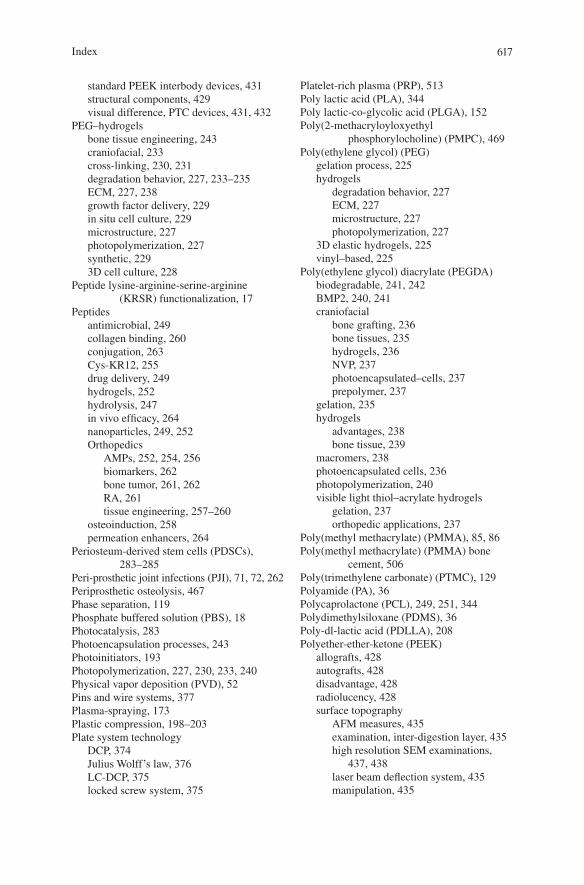
617
standard PEEK interbody devices, 431structural components, 429visual difference, PTC devices, 431, 432
PEG–hydrogelsbone tissue engineering, 243craniofacial, 233cross-linking, 230, 231degradation behavior, 227, 233–235ECM, 227, 238growth factor delivery, 229in situ cell culture, 229microstructure, 227photopolymerization, 227synthetic, 2293D cell culture, 228
Peptide lysine-arginine-serine-arginine (KRSR) functionalization, 17
Peptidesantimicrobial, 249collagen binding, 260conjugation, 263Cys-KR12, 255drug delivery, 249hydrogels, 252hydrolysis, 247in vivo efficacy, 264nanoparticles, 249, 252Orthopedics
AMPs, 252, 254, 256biomarkers, 262bone tumor, 261, 262RA, 261tissue engineering, 257–260
osteoinduction, 258permeation enhancers, 264
Periosteum-derived stem cells (PDSCs), 283–285
Peri-prosthetic joint infections (PJI), 71, 72, 262Periprosthetic osteolysis, 467Phase separation, 119Phosphate buffered solution (PBS), 18Photocatalysis, 283Photoencapsulation processes, 243Photoinitiators, 193Photopolymerization, 227, 230, 233, 240Physical vapor deposition (PVD), 52Pins and wire systems, 377Plasma-spraying, 173Plastic compression, 198–203Plate system technology
DCP, 374Julius Wolff’s law, 376LC-DCP, 375locked screw system, 375
Platelet-rich plasma (PRP), 513Poly lactic acid (PLA), 344Poly lactic-co-glycolic acid (PLGA), 152Poly(2-methacryloyloxyethyl
phosphorylocholine) (PMPC), 469Poly(ethylene glycol) (PEG)
gelation process, 225hydrogels
degradation behavior, 227ECM, 227microstructure, 227photopolymerization, 227
3D elastic hydrogels, 225vinyl–based, 225
Poly(ethylene glycol) diacrylate (PEGDA)biodegradable, 241, 242BMP2, 240, 241craniofacial
bone grafting, 236bone tissues, 235hydrogels, 236NVP, 237photoencapsulated–cells, 237prepolymer, 237
gelation, 235hydrogels
advantages, 238bone tissue, 239
macromers, 238photoencapsulated cells, 236photopolymerization, 240visible light thiol–acrylate hydrogels
gelation, 237orthopedic applications, 237
Poly(methyl methacrylate) (PMMA), 85, 86Poly(methyl methacrylate) (PMMA) bone
cement, 506Poly(trimethylene carbonate) (PTMC), 129Polyamide (PA), 36Polycaprolactone (PCL), 249, 251, 344Polydimethylsiloxane (PDMS), 36Poly-dl-lactic acid (PDLLA), 208Polyether-ether-ketone (PEEK)
allografts, 428autografts, 428disadvantage, 428radiolucency, 428surface topography
AFM measures, 435examination, inter-digestion layer, 435high resolution SEM examinations,
437, 438laser beam deflection system, 435manipulation, 435
Index
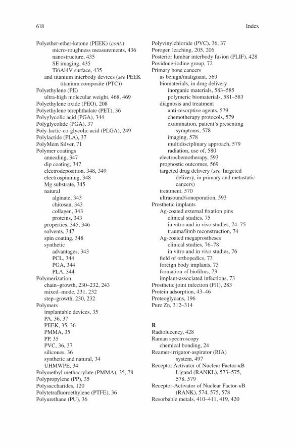
618
Polyether-ether-ketone (PEEK) (cont.)micro-roughness measurements, 436nanostructure, 435SE imaging, 435Ti6Al4V surface, 435
and titanium interbody devices (see PEEK titanium composite (PTC))
Polyethylene (PE)ultra-high molecular weight, 468, 469
Polyethylene oxide (PEO), 208Polyethylene terephthalate (PET), 36Polyglycolic acid (PGA), 344Polyglycolide (PGA), 37Poly-lactic-co-glycolic acid (PLGA), 249Polylactide (PLA), 37PolyMem Silver, 71Polymer coatings
annealing, 347dip coating, 347electrodeposition, 348, 349electrospinning, 348Mg substrate, 345natural
alginate, 343chitosan, 343collagen, 343proteins, 343
properties, 345, 346solvents, 347spin coating, 348synthetic
advantages, 343PCL, 344PGA, 344PLA, 344
Polymerizationchain–growth, 230–232, 243mixed–mode, 231, 232step–growth, 230, 232
Polymersimplantable devices, 35PA, 36, 37PEEK, 35, 36PMMA, 35PP, 35PVC, 36, 37silicones, 36synthetic and natural, 34UHMWPE, 34
Polymethyl methacrylate (PMMA), 35, 78Polypropylene (PP), 35Polysaccharides, 120Polytetrafluoroethylene (PTFE), 36Polyurethane (PU), 36
Polyvinylchloride (PVC), 36, 37Porogen leaching, 205, 206Posterior lumbar interbody fusion (PLIF), 428Povidone-iodine group, 72Primary bone cancers
as benign/malignant, 569biomaterials, in drug delivery
inorganic materials, 583–585polymeric biomaterials, 581–583
diagnosis and treatmentanti-resorptive agents, 579chemotherapy protocols, 579examination, patient’s presenting
symptoms, 578imaging, 578multidisciplinary approach, 579radiation, use of, 580
electrochemotherapy, 593prognostic outcomes, 569targeted drug delivery (see Targeted
delivery, in primary and metastatic cancers)
treatment, 570ultrasound/sonoporation, 593
Prosthetic implantsAg-coated external fixation pins
clinical studies, 75in vitro and in vivo studies, 74–75trauma/limb reconstruction, 74
Ag-coated megaprosthesesclinical studies, 76–78in vitro and in vivo studies, 76
field of orthopedics, 73foreign body implants, 73formation of biofilms, 73implant-associated infections, 73
Prosthetic joint infection (PJI), 283Protein adsorption, 43–46Proteoglycans, 196Pure Zn, 312–314
RRadiolucency, 428Raman spectroscopy
chemical bonding, 24Reamer-irrigator-aspirator (RIA)
system, 497Receptor Activator of Nuclear Factor-κB
Ligand (RANKL), 573–575, 578, 579
Receptor-Activator of Nuclear Factor-κB (RANK), 574, 575, 578
Resorbable metals, 410–411, 419, 420
Index
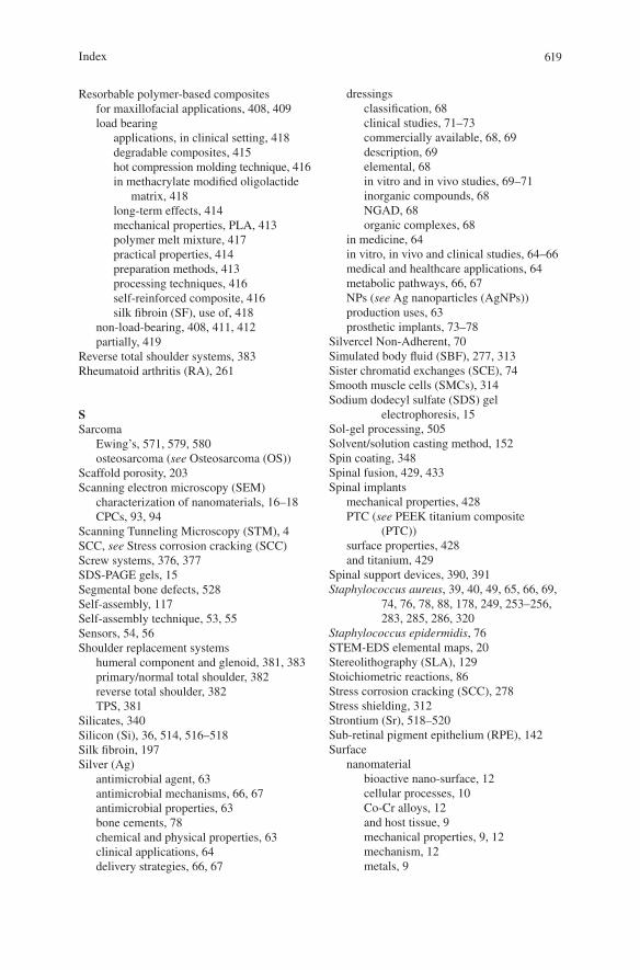
619
Resorbable polymer-based compositesfor maxillofacial applications, 408, 409load bearing
applications, in clinical setting, 418degradable composites, 415hot compression molding technique, 416in methacrylate modified oligolactide
matrix, 418long-term effects, 414mechanical properties, PLA, 413polymer melt mixture, 417practical properties, 414preparation methods, 413processing techniques, 416self-reinforced composite, 416silk fibroin (SF), use of, 418
non-load-bearing, 408, 411, 412partially, 419
Reverse total shoulder systems, 383Rheumatoid arthritis (RA), 261
SSarcoma
Ewing’s, 571, 579, 580osteosarcoma (see Osteosarcoma (OS))
Scaffold porosity, 203Scanning electron microscopy (SEM)
characterization of nanomaterials, 16–18CPCs, 93, 94
Scanning Tunneling Microscopy (STM), 4SCC, see Stress corrosion cracking (SCC)Screw systems, 376, 377SDS-PAGE gels, 15Segmental bone defects, 528Self-assembly, 117Self-assembly technique, 53, 55Sensors, 54, 56Shoulder replacement systems
humeral component and glenoid, 381, 383primary/normal total shoulder, 382reverse total shoulder, 382TPS, 381
Silicates, 340Silicon (Si), 36, 514, 516–518Silk fibroin, 197Silver (Ag)
antimicrobial agent, 63antimicrobial mechanisms, 66, 67antimicrobial properties, 63bone cements, 78chemical and physical properties, 63clinical applications, 64delivery strategies, 66, 67
dressingsclassification, 68clinical studies, 71–73commercially available, 68, 69description, 69elemental, 68in vitro and in vivo studies, 69–71inorganic compounds, 68NGAD, 68organic complexes, 68
in medicine, 64in vitro, in vivo and clinical studies, 64–66medical and healthcare applications, 64metabolic pathways, 66, 67NPs (see Ag nanoparticles (AgNPs))production uses, 63prosthetic implants, 73–78
Silvercel Non-Adherent, 70Simulated body fluid (SBF), 277, 313Sister chromatid exchanges (SCE), 74Smooth muscle cells (SMCs), 314Sodium dodecyl sulfate (SDS) gel
electrophoresis, 15Sol-gel processing, 505Solvent/solution casting method, 152Spin coating, 348Spinal fusion, 429, 433Spinal implants
mechanical properties, 428PTC (see PEEK titanium composite
(PTC))surface properties, 428and titanium, 429
Spinal support devices, 390, 391Staphylococcus aureus, 39, 40, 49, 65, 66, 69,
74, 76, 78, 88, 178, 249, 253–256, 283, 285, 286, 320
Staphylococcus epidermidis, 76STEM-EDS elemental maps, 20Stereolithography (SLA), 129Stoichiometric reactions, 86Stress corrosion cracking (SCC), 278Stress shielding, 312Strontium (Sr), 518–520Sub-retinal pigment epithelium (RPE), 142Surface
nanomaterialbioactive nano-surface, 12cellular processes, 10Co-Cr alloys, 12and host tissue, 9mechanical properties, 9, 12mechanism, 12metals, 9
Index
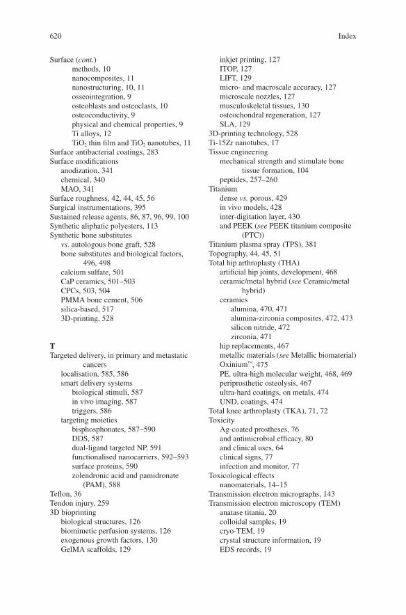
620
Surface (cont.)methods, 10nanocomposites, 11nanostructuring, 10, 11osseointegration, 9osteoblasts and osteoclasts, 10osteoconductivity, 9physical and chemical properties, 9Ti alloys, 12TiO2 thin film and TiO2 nanotubes, 11
Surface antibacterial coatings, 283Surface modifications
anodization, 341chemical, 340MAO, 341
Surface roughness, 42, 44, 45, 56Surgical instrumentations, 395Sustained release agents, 86, 87, 96, 99, 100Synthetic aliphatic polyesters, 113Synthetic bone substitutes
vs. autologous bone graft, 528bone substitutes and biological factors,
496, 498calcium sulfate, 501CaP ceramics, 501–503CPCs, 503, 504PMMA bone cement, 506silica-based, 5173D-printing, 528
TTargeted delivery, in primary and metastatic
cancerslocalisation, 585, 586smart delivery systems
biological stimuli, 587in vivo imaging, 587triggers, 586
targeting moietiesbisphosphonates, 587–590DDS, 587dual-ligand targeted NP, 591functionalised nanocarriers, 592–593surface proteins, 590zolendronic acid and pamidronate
(PAM), 588Teflon, 36Tendon injury, 2593D bioprinting
biological structures, 126biomimetic perfusion systems, 126exogenous growth factors, 130GelMA scaffolds, 129
inkjet printing, 127ITOP, 127LIFT, 129micro- and macroscale accuracy, 127microscale nozzles, 127musculoskeletal tissues, 130osteochondral regeneration, 127SLA, 129
3D-printing technology, 528Ti-15Zr nanotubes, 17Tissue engineering
mechanical strength and stimulate bone tissue formation, 104
peptides, 257–260Titanium
dense vs. porous, 429in vivo models, 428inter-digitation layer, 430and PEEK (see PEEK titanium composite
(PTC))Titanium plasma spray (TPS), 381Topography, 44, 45, 51Total hip arthroplasty (THA)
artificial hip joints, development, 468ceramic/metal hybrid (see Ceramic/metal
hybrid)ceramics
alumina, 470, 471alumina-zirconia composites, 472, 473silicon nitride, 472zirconia, 471
hip replacements, 467metallic materials (see Metallic biomaterial)Oxinium™, 475PE, ultra-high molecular weight, 468, 469periprosthetic osteolysis, 467ultra-hard coatings, on metals, 474UND, coatings, 474
Total knee arthroplasty (TKA), 71, 72Toxicity
Ag-coated prostheses, 76and antimicrobial efficacy, 80and clinical uses, 64clinical signs, 77infection and monitor, 77
Toxicological effectsnanomaterials, 14–15
Transmission electron micrographs, 143Transmission electron microscopy (TEM)
anatase titania, 20colloidal samples, 19cryo-TEM, 19crystal structure information, 19EDS records, 19
Index
621
EELS analysis, 22EELS records, 19electron holography technique, 19hydration layer, 22in situ liquid electron microscopy, 22liquid state, 19mesoporous TiO2 coating, 22metal oxides, 21, 22metallic implants, 19morphology, 22organic materials/hydrated, 19osteoblast cells, 20, 21STEM-EDS elemental maps, 203D object, 193D tomography with HR-STEM, 222D projection image of 3D object, 19
Trauma fixationcomposite (see Composite fixation devices)metal (see Metal fixation plates)plates, rods and screws, 400
Traumatic injuries, 71, 72Tricalcium phosphate (TCP), 205, 502, 503Tumor cell apoptosis, 148Tumor cell survival, 285, 2882D vs. 3D cell culture, 228, 229
UUltrahigh molecular weight polyethylene
(UHMWPE), 34Ultra-nanocrystalline diamond (UND),
474, 475Ultrasonication, 351Ultraviolet (UV) radiation, 193Urgotol SSD, 71
VVascular endothelial growth factor (VEGF),
189, 510, 511Vertebral body replacement systems, 388, 389
Visible light-based projection stereolithography (VL-PSL), 129
Visible light–cured thiol–acrylate hydrogelsBMP2, 239–241gelation, 237orthopedic applications, 237
XX-ray diffraction (XRD), 141
characterization of nanomaterials, 23
YYoung's modulus, 115
ZZinc (Zn), 276, 525, 526Zinc (Zn) alloys
binarybiocompatibility, 318–320degradation, 316–318mechanical properties, 315microstructures, 315, 316
biocompatibility, 320, 321ternary
biocompatibility, 324, 326degradation, 323, 325mechanical properties, 323, 324microstructures, 321, 322
Zirconiaand alumina, 472ATZ, 473hydrothermal ageing, 471manufacturing and clinical use, 471mechanical properties, 471monoclinic, 473monolithic, 475Oxinium™, 476and yttria-stabilized tetragonal zirconia
polycrystal, 471
Index