resquake: a tele-operative rescue robot
TRANSCRIPT
1
mopdboeafdbdr
Asawcrtbmbvctl
imb
J
Downlo
S. Ali A. Moosavian1
Associate Professore-mail: [email protected]
Arash KalantariGraduate Student
e-mail: [email protected]
Hesam SemsarilarGraduate Student
e-mail: [email protected]
Ehsan AboosaeedanGraduate Student
e-mail: [email protected]
Ehsan MihankhahGraduate Student
e-mail: [email protected]
Advanced Robotics and Automated Systems(ARAS) Laboratory,
Department of Mechanical Engineering,Khaje Nasir Toosi University of Technology,
P.O. Box 19395-1999,Tehran 19991 43344, Iran
ResQuake: A Tele-OperativeRescue RobotThe design procedure of ResQuake as a tele-operative rescue robot and its dynamicsanalysis, manufacturing procedure, control system, and slip estimation for performanceimprovement are discussed. First, the general task to be performed by the robot is de-fined, and various mechanisms to form the basic structure of the robot are discussed.Choosing the appropriate mechanisms, geometric dimensions, and mass properties aredetailed to develop kinematic and dynamic models for the system. Next, the strength ofeach component is analyzed to finalize its shape, and the mechanism models are pre-sented. Then, the control system is briefly described, which includes the operator’s PC asthe master processor, and the laptop installed on the robot as the slave processor. Finally,slip coefficients of tracks are identified and validated by experimental tests to improve thesystem tracking performance. ResQuake has participated with distinction in several res-cue robot leagues. �DOI: 10.1115/1.3179117�
Keywords: mobile robots, tele-operative, locomotion mechanisms, control architecture,slippage estimation
Introduction
Mobile manipulators, which consist of a platform and one orore manipulators, have an unlimited workspace. Therefore, vari-
us legged, wheeled, tracked, and flying systems have been pro-osed, and successfully put into practice. Such systems are used inifferent kinds of fields such as fire fighting, forestry, deactivatingombs, toxic waste cleanup, transportation of materials, space on-rbit services, and similar applications in which human health isndangered �1�. So, it is expected that mobile robots, whetherutonomous or tele-operative, play a more important role in dif-erent fields of human life. However, in a mobile robotic system,ynamic forces affect the motion of the base and the manipulators,ased on the action and reaction principle. Therefore, kinematics,ynamics, and control of such systems have received extensiveesearch attention �2–5�.
Earthquake is a natural incident, which threatens human life.ftershocks occurring a while after the main earthquake cause
econdary collapses and may take victims away from the searchnd rescue personnel. In order to minimize the risks for rescuers,hile increasing victim survival rates, exploiting fielding teams of
ollaborative robots is a good alternative. The mission for theobots and their operators would be to find victims, determineheir situation, and then report their findings based on a map of theuilding �6,7�. This information will immediately be given to hu-an rescue teams. Further expectations of rescue robots such as
eing able to autonomously search collapsed structures, findingictims and ascertain their conditions, delivering sustenance andommunications to the victims, and emplacing sensors �acoustic,hermal, seismic, etc.� are ongoing research subjects. Neverthe-ess, the basic capability of rescue robots is their maneuverability
1Corresponding author.Contributed by the Mechanism and Robotics Committee of ASME for publication
n the JOURNAL OF MECHANICAL DESIGN. Manuscript received July 21, 2008; finalanuscript received May 7, 2009; published online July 20, 2009. Review conducted
y Ashitava Ghosal.
ournal of Mechanical Design Copyright © 20
aded 21 Jul 2009 to 217.218.44.131. Redistribution subject to ASME
in destructed areas, which thoroughly depends on their locomo-tion system and their dimensions. Various rescue robots were de-signed and manufactured so far �8,9�.
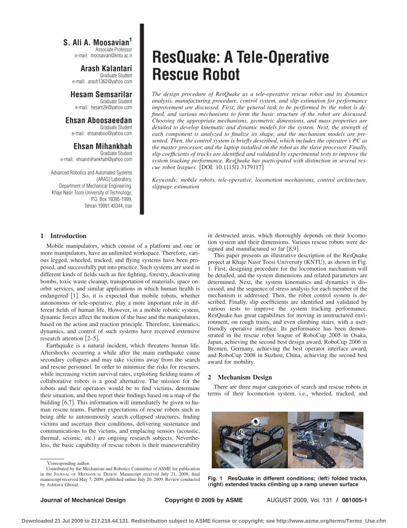
This paper presents an illustrative description of the ResQuakeproject at Khaje Nasir Toosi University �KNTU�, as shown in Fig.1. First, designing procedure for the locomotion mechanism willbe detailed, and the system dimensions and related parameters aredetermined. Next, the system kinematics and dynamics is dis-cussed, and the sequence of stress analysis for each member of themechanism is addressed. Then, the robot control system is de-scribed. Finally, slip coefficients are identified and validated byvarious tests to improve the system tracking performance.ResQuake has great capabilities for moving in unstructured envi-ronment, on rough trains, and even climbing stairs, with a user-friendly operative interface. Its performance has been demon-strated in the rescue robot league of RoboCup 2005 in Osaka,Japan, achieving the second best design award, RoboCup 2006 inBremen, Germany, achieving the best operator interface award,and RoboCup 2008 in Suzhou, China, achieving the second bestaward for mobility.
2 Mechanism DesignThere are three major categories of search and rescue robots in
terms of their locomotion system, i.e., wheeled, tracked, and
Fig. 1 ResQuake in different conditions; „left… folded tracks,
„right… extended tracks climbing up a ramp uneven surfaceAUGUST 2009, Vol. 131 / 081005-109 by ASME
license or copyright; see http://www.asme.org/terms/Terms_Use.cfm
lfldcTmss
�mtqetcvmwr
crcstppwdu
o
Fs
0
Downlo
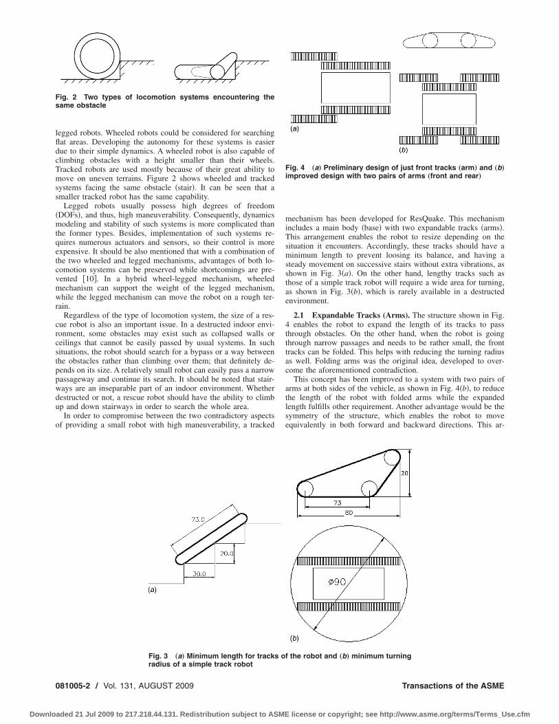
egged robots. Wheeled robots could be considered for searchingat areas. Developing the autonomy for these systems is easierue to their simple dynamics. A wheeled robot is also capable oflimbing obstacles with a height smaller than their wheels.racked robots are used mostly because of their great ability toove on uneven terrains. Figure 2 shows wheeled and tracked
ystems facing the same obstacle �stair�. It can be seen that amaller tracked robot has the same capability.
Legged robots usually possess high degrees of freedomDOFs�, and thus, high maneuverability. Consequently, dynamicsodeling and stability of such systems is more complicated than
he former types. Besides, implementation of such systems re-uires numerous actuators and sensors, so their control is morexpensive. It should be also mentioned that with a combination ofhe two wheeled and legged mechanisms, advantages of both lo-omotion systems can be preserved while shortcomings are pre-ented �10�. In a hybrid wheel-legged mechanism, wheeledechanism can support the weight of the legged mechanism,hile the legged mechanism can move the robot on a rough ter-
ain.Regardless of the type of locomotion system, the size of a res-
ue robot is also an important issue. In a destructed indoor envi-onment, some obstacles may exist such as collapsed walls oreilings that cannot be easily passed by usual systems. In suchituations, the robot should search for a bypass or a way betweenhe obstacles rather than climbing over them; that definitely de-ends on its size. A relatively small robot can easily pass a narrowassageway and continue its search. It should be noted that stair-ays are an inseparable part of an indoor environment. Whetherestructed or not, a rescue robot should have the ability to climbp and down stairways in order to search the whole area.
In order to compromise between the two contradictory aspectsf providing a small robot with high maneuverability, a tracked
ig. 2 Two types of locomotion systems encountering theame obstacle
Fig. 3 „a… Minimum length for track
radius of a simple track robot81005-2 / Vol. 131, AUGUST 2009
aded 21 Jul 2009 to 217.218.44.131. Redistribution subject to ASME
mechanism has been developed for ResQuake. This mechanismincludes a main body �base� with two expandable tracks �arms�.This arrangement enables the robot to resize depending on thesituation it encounters. Accordingly, these tracks should have aminimum length to prevent loosing its balance, and having asteady movement on successive stairs without extra vibrations, asshown in Fig. 3�a�. On the other hand, lengthy tracks such asthose of a simple track robot will require a wide area for turning,as shown in Fig. 3�b�, which is rarely available in a destructedenvironment.
2.1 Expandable Tracks (Arms). The structure shown in Fig.4 enables the robot to expand the length of its tracks to passthrough obstacles. On the other hand, when the robot is goingthrough narrow passages and needs to be rather small, the fronttracks can be folded. This helps with reducing the turning radiusas well. Folding arms was the original idea, developed to over-come the aforementioned contradiction.
This concept has been improved to a system with two pairs ofarms at both sides of the vehicle, as shown in Fig. 4�b�, to reducethe length of the robot with folded arms while the expandedlength fulfills other requirement. Another advantage would be thesymmetry of the structure, which enables the robot to moveequivalently in both forward and backward directions. This ar-
f the robot and „b… minimum turning
Fig. 4 „a… Preliminary design of just front tracks „arm… and „b…improved design with two pairs of arms „front and rear…
s o
Transactions of the ASME
license or copyright; see http://www.asme.org/terms/Terms_Use.cfm
r
wo�st
iossdcst
acmcbapdmmwgtt
s
Fr
J
Downlo
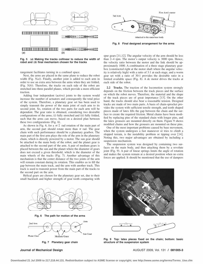
angement facilitates turning in a confined space.Next, the arms are placed in the same plane to reduce the robot
idth �Fig. 5�a��. Finally, another joint is added to each arm inrder to use an extra area between the arms when they are folded,Fig. 5�b��. Therefore, the tracks on each side of the robot aretretched into three parallel planes, which provide a more efficientraction.
Adding four independent �active� joints to the system wouldncrease the number of actuators and consequently the total pricef the system. Therefore, a planetary gear set has been used toimply transmit the power of the main joint of each arm to itsecond joint. So, rotation of the two parts for each arm will beependent. The gear ratio is obtained, considering two desirableonfigurations of the arms; �i� fully stretched and �ii� fully folded,uch that the arms can move, based on a desired plan betweenhese two configurations �Fig. 6�.
As shown in Fig. 6, for a � /2 rad rotation of the main part ofrm, the second part should rotate more than � rad. The gearhain with such performance should be a planetary gearbox. Theain part of the first arm plays the role of the arm in the planetary
hain, which is directly powered by a motor. The sun gear shoulde attached to the main body of the robot, and the planet gear isttached to the second part of the arm. A pair of medium gears islaced between the sun and the planet where the diameter of gearsoes not exceed a given threshold, which is the diameter of theain wheels of the tracks �Fig. 7�. Another advantage of thisechanism is that the center distance of the two joints of the armill remain constant during its rotation. This enables us to fill theap between the main track, and the arm with another track. Thisrack is used to transmit power from the main part of the tracks tohe second part on the arm.
Helical gears are chosen for the planetary gear set, due to theirmall backlash and higher strength of gear tooth comparing with
ig. 5 „a… Making the tracks collinear to reduce the width ofobot and „b… final mechanism chosen for the tracks
Fig. 6 The path for motion of the arms
Fig. 7 Planetary gear chain
ournal of Mechanical Design
aded 21 Jul 2009 to 217.218.44.131. Redistribution subject to ASME
spur gears �11,12�. The angular velocity of the arm should be lessthan 2–4 rpm. The motor’s output velocity is 3000 rpm. Hence,the velocity ratio between the motor and the link should be ap-proximately 1000. A combination of a three stage planetary gear-box �constructed right at the motor shaft where the angular veloc-ity is relatively high� with a ratio of 3:1 at each stage, and a wormgear set with a ratio of 30:1 provides the desirable ratio in alimited available space �Fig. 8�. A dc motor drives the tracks ateach side of the robot.
2.2 Tracks. The traction of the locomotion system stronglydepends on the friction between the track pieces and the surfaceon which the robot moves. Therefore, the material and the shapeof the track pieces are of great importance �13�. On the otherhand, the tracks should also bear a reasonable tension. Designedtracks are made of two main parts. A basis of chain-sprocket pro-vides the system with sufficient tensile strength, and tooth shapedpieces made of latex fills the gap between the chain and the sur-face to create the required friction. Metal chains have been modi-fied by replacing pins of the standard chain with longer pins, andthe latex grousers are mounted directly on them. Figure 9 showsmodified chains and how the grousers are mounted on these pins.
One of the most important problems caused by base movement,when the system undergoes a fast maneuver or tries to climb aslopped terrain, is the instability problem or tipping over �14�.Noting this, two major advantages are obtained by including asuspension mechanism.
The suspension system was designed by containing two sur-faces on the main body, and then attaching them by a revolutejoint �Fig. 9�. A pair of linear springs limits the angle of rotationand makes the system remain at a desired position when no extraforces are applied. It should be mentioned that the use of dampers
Fig. 8 Final designed arrangement for the arms
Fig. 9 Top: latex pieces fixed on the chain; bottom: basic
structure of the suspension systemAUGUST 2009, Vol. 131 / 081005-3
license or copyright; see http://www.asme.org/terms/Terms_Use.cfm
wts
mcdptmnuds
3
cittc1
l
P
CCCddddGGHHLL
erm
0
Downlo
as not needed because the friction of the sliding bearings used ashe so-called joints was enough to limit any extra shaking of theprings.
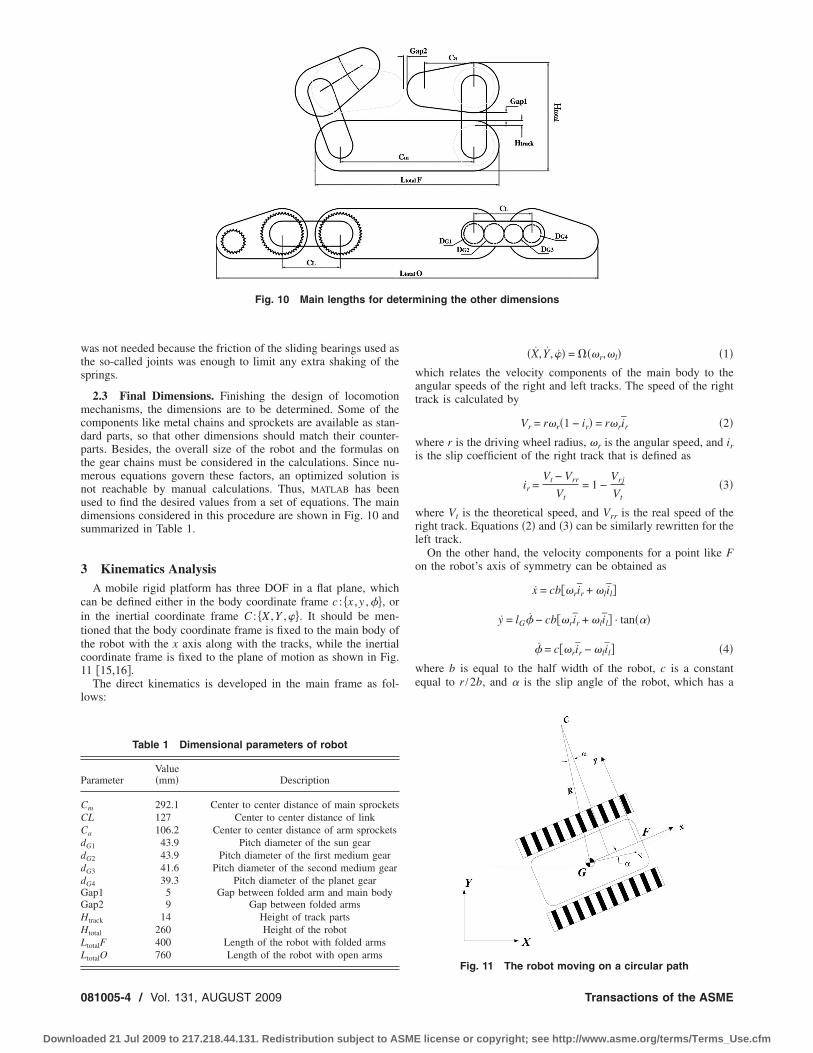
2.3 Final Dimensions. Finishing the design of locomotionechanisms, the dimensions are to be determined. Some of the
omponents like metal chains and sprockets are available as stan-ard parts, so that other dimensions should match their counter-arts. Besides, the overall size of the robot and the formulas onhe gear chains must be considered in the calculations. Since nu-
erous equations govern these factors, an optimized solution isot reachable by manual calculations. Thus, MATLAB has beensed to find the desired values from a set of equations. The mainimensions considered in this procedure are shown in Fig. 10 andummarized in Table 1.
Kinematics AnalysisA mobile rigid platform has three DOF in a flat plane, which
an be defined either in the body coordinate frame c : �x ,y ,��, orn the inertial coordinate frame C : �X ,Y ,��. It should be men-ioned that the body coordinate frame is fixed to the main body ofhe robot with the x axis along with the tracks, while the inertialoordinate frame is fixed to the plane of motion as shown in Fig.1 �15,16�.
The direct kinematics is developed in the main frame as fol-ows:
Table 1 Dimensional parameters of robot
arameterValue�mm� Description
m 292.1 Center to center distance of main sprocketsL 127 Center to center distance of link
a 106.2 Center to center distance of arm sprockets
G1 43.9 Pitch diameter of the sun gear
G2 43.9 Pitch diameter of the first medium gear
G3 41.6 Pitch diameter of the second medium gear
G4 39.3 Pitch diameter of the planet gearap1 5 Gap between folded arm and main bodyap2 9 Gap between folded arms
track 14 Height of track parts
total 260 Height of the robot
totalF 400 Length of the robot with folded arms
totalO 760 Length of the robot with open arms
Fig. 10 Main lengths for det
81005-4 / Vol. 131, AUGUST 2009
aded 21 Jul 2009 to 217.218.44.131. Redistribution subject to ASME
�X,Y,�� = ���r,�l� �1�which relates the velocity components of the main body to theangular speeds of the right and left tracks. The speed of the righttrack is calculated by
Vr = r�r�1 − ir� = r�rir �2�
where r is the driving wheel radius, �r is the angular speed, and iris the slip coefficient of the right track that is defined as
ir =Vt − Vrr
Vt= 1 −
Vrj
Vt�3�
where Vt is the theoretical speed, and Vrr is the real speed of theright track. Equations �2� and �3� can be similarly rewritten for theleft track.
On the other hand, the velocity components for a point like Fon the robot’s axis of symmetry can be obtained as
x = cb��rir + �lil�
y = lG� − cb��rir + �lil� · tan���
� = c��rir − �lil� �4�
where b is equal to the half width of the robot, c is a constantequal to r /2b, and � is the slip angle of the robot, which has a
ining the other dimensions
Fig. 11 The robot moving on a circular path
Transactions of the ASME
license or copyright; see http://www.asme.org/terms/Terms_Use.cfm
nsrMcBrrg
Itt
F
R
wgct
Ss
w
Kr
Is
J
Downlo
onzero value in the presence of side slippage. Lateral or sidelippage happens mainly due to the centrifugal force exerted to theobot when moving on a curved path with a relatively high speed.
aximum longitudinal speed of the chosen platform does not ex-eed 0.3 m/s, which will result in a negligible centrifugal force.esides, the design of the track’s treads, as explained in Sec. 2.2,
esults in a large lateral friction force, which in turn helps theobot to not slip laterally. Therefore, the lateral slippage is ne-lected, and Eq. �4� is rewritten as
x = cb��rir + �lil� �5a�
y = lG� �5b�
� = c��rir − �lil� �5c�
t should be mentioned that Eq. �5c� yields a positive � for coun-erclockwise rotations. These components can be transferred intohe inertial frame F as
X = x cos � − y sin � �6a�
Y = x sin � + y cos � �6b�
� = � �6c�
rom Eq. �6� we can write
Y cos � − X sin � = y �7�
eplacing from Eq. �5� in Eq. �7�, yields
− X sin � + Y cos � − lG� = 0 �8�
hich describes a nonholonomic constraint. It cannot be inte-rated analytically to result in an algebraic constraint between theonfiguration variables of the platform, namely x, y, and �. Equa-ion �8� can be written in the matrix form
A�q�q = 0 �9a�
A = �− sin � cos � − lG � �9b�
ubstituting Eq. �5� into Eq. �6�, direct kinematics can be pre-ented as
d
dt�X
Y
�� = J�r
�l �10�
here J is a 3�2 Jacobian matrix as
J = �rir
2�cos � −
2lG sin �
B� ril
2�cos � +
2lG sin �
B�
rir
2�sin � +
2lG cos �
B� ril
2�sin � −
2lG cos �
B�
r
Bir −
r
Bil
��11�
eeping the first two equations of Eq. �10� and displaying theotation matrix explicitly, we can write
X
Y = cos � − sin �
sin � cos �� rir
2
ril
2
rirlG
B−
rillG
B��r
�l �12�
t can be seen that if in Eq. �12�, lG is set to be equal to zero, the
econd matrix will be singular. This is because all points forournal of Mechanical Design
aded 21 Jul 2009 to 217.218.44.131. Redistribution subject to ASME
which lG=0 cannot move in the lateral direction. Note that the slipcoefficients for the right �outer� and left �inner� tracks, which areir and il, respectively, have been defined to make the kinematicmodel more realistic and precise. These coefficients must be iden-tified using experimental tests, which will be presented in Sec. 7.
4 Dynamics AnalysisIn a mobile robotic system, whether wheeled, legged or even
free flying in space, dynamic forces affect the motion of the baseand the manipulators, based on the action and reaction principle.Dynamics and control of such systems have been discussed inprevious works �17,18�. What mostly makes the dynamics oftracked mobile robots different from other types is the large con-tact area of the tracks with the surface and consequently greatamount of friction forces. In this analysis, it has been assumedthat the geometrical center and center of gravity of the robot areidentical. We have also neglected side slippage of the robot.
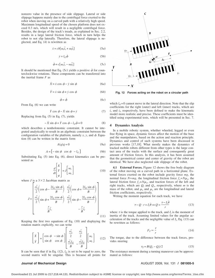
4.1 External Forces. Figure 12 shows the free body diagramof the robot moving on a curved path in a horizontal plane. Ex-ternal forces exerted on the robot include gravity force mg, thenormal force N=mg, the longitudinal friction force fx=N�x, thelateral friction force fy =N�y, and traction forces of the left andright tracks, which are Ql and Qr, respectively, where m is themass of the robot, and �x and �y are the longitudinal and lateralfriction coefficients, respectively.
Writing the moment equation for each track, we have
− Q · r = It ⇒ Q = − It
r�13�
where is the torque applied to the track, and It is the moment ofinertia of the track. Assuming limited values for the angular ac-celeration of the tracks and the negligible value of It, Eq. �13� canbe rewritten as follows:
FT
r�14�
The torque, due to the difference between the track forces, pro-vides steering
T = B�Qr − Ql�/2 �15�The resistance moment during a turning maneuver can be approxi-
Fig. 12 Forces acting on the robot on a circular path
mated as follows:
AUGUST 2009, Vol. 131 / 081005-5
license or copyright; see http://www.asme.org/terms/Terms_Use.cfm
Tr
jbL
wepm
R
E
wdttEnv
wo
E
N
w
Fl
w
0
Downlo
f = 0.5fyl2 �16�
his moment always acts in the opposite direction of the robototation, hence
f = − 0.5 sign���fyl2 �17�
4.2 Dynamics Model. As shown in Sec. 3, the system is sub-ected to a single nonholonomic constraint, which was describedy Eq. �8�. So, to derive the equations of motion, we use theagrange equations as follows:
d
dt� �L
� qi� −
�L
�qi= f i − aij� j �18�
here q= �XF YF �F � are the generalized coordinates, f is thexternally applied forces and moments, � is the Lagrange multi-lier, and L is the system Lagrangian. Assuming mass and mo-ent of inertia of the tracks to be negligible, L is equal to
L = 12m�X2 + Y2� + 1
2 I�2 �19�
eplacing Eq. �19� into Eq. �18� yields
mX = FX − �a1 �20a�
mY = FY − �a2 �20b�
I� = T − f − �a3 �20c�
quation �20� can be rearranged in the following form:
M�q�q + V�q, q� = E�q� + G�q� − AT�q�� �21�
here M�q� is a 3�3 inertia matrix, V�q , q� includes velocityependent forces, E�q� is a 3�2 input transformation matrix, ishe two-dimensional input torque of the left and right tracks, G ishe friction and gravity terms, and � is the Lagrange multiplier.quation �9� shows that the constraint velocity is always in theullspace of A�q�, so it is possible to define two independentelocities such that
q = S�q� �22�
here = �r l �T and the matrix S�q� contains the base vectorsf the nullspace of A. Accordingly, the Jacobian matrix given in
q. �11� can be chosen as matrix S, by substituting ir= il=1.Multiplying Eq. �21� by matrix S yields
STM�q�q = + STG�q� �23�
ext, differentiating Eq. �22� and replacing into Eq. �24� gives
M� + V� = + G� �24�
here
M� = STMS
V� = ST�MS + V�
G� = STG �25�
inally, Eq. �24� can be expressed in the working space as fol-ows:
Mq1 + V = JF1−T + G �26a�
here q1= �X Y �T, and
M = JF1−TSTMSJF1
−1 �26b�
V = J−T�STMSJ−1 + STMSJ−1�q1 �26c�
F1 F1 F181005-6 / Vol. 131, AUGUST 2009
aded 21 Jul 2009 to 217.218.44.131. Redistribution subject to ASME
G = JF1−TSTG �26d�
which describes the system dynamics model, and can be used forsimulation purposes, or to design model-based controllers. Thismodel can be also used for motor selection, while in Sec. 4.3, wewill use a simplified model for this purpose.
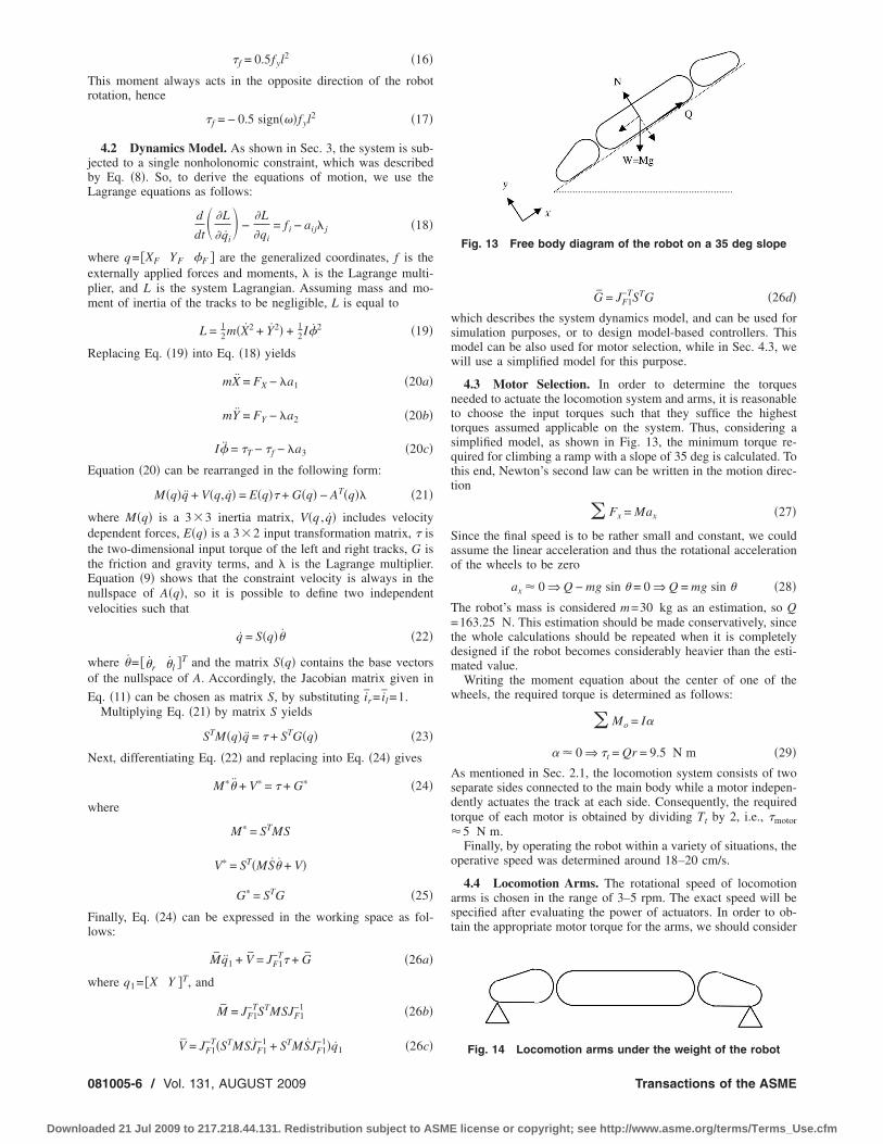
4.3 Motor Selection. In order to determine the torquesneeded to actuate the locomotion system and arms, it is reasonableto choose the input torques such that they suffice the highesttorques assumed applicable on the system. Thus, considering asimplified model, as shown in Fig. 13, the minimum torque re-quired for climbing a ramp with a slope of 35 deg is calculated. Tothis end, Newton’s second law can be written in the motion direc-tion
� Fx = Max �27�
Since the final speed is to be rather small and constant, we couldassume the linear acceleration and thus the rotational accelerationof the wheels to be zero
ax 0 ⇒ Q − mg sin = 0 ⇒ Q = mg sin �28�
The robot’s mass is considered m=30 kg as an estimation, so Q=163.25 N. This estimation should be made conservatively, sincethe whole calculations should be repeated when it is completelydesigned if the robot becomes considerably heavier than the esti-mated value.
Writing the moment equation about the center of one of thewheels, the required torque is determined as follows:
� Mo = I�
� 0 ⇒ t = Qr = 9.5 N m �29�As mentioned in Sec. 2.1, the locomotion system consists of twoseparate sides connected to the main body while a motor indepen-dently actuates the track at each side. Consequently, the requiredtorque of each motor is obtained by dividing Tt by 2, i.e., motor 5 N m.
Finally, by operating the robot within a variety of situations, theoperative speed was determined around 18–20 cm/s.
4.4 Locomotion Arms. The rotational speed of locomotionarms is chosen in the range of 3–5 rpm. The exact speed will bespecified after evaluating the power of actuators. In order to ob-tain the appropriate motor torque for the arms, we should consider
Fig. 13 Free body diagram of the robot on a 35 deg slope
Fig. 14 Locomotion arms under the weight of the robot
Transactions of the ASME
license or copyright; see http://www.asme.org/terms/Terms_Use.cfm
tas
Fw
we
R
w=de
J
Downlo
he most critical case that the system may encounter. This case isssumed, as shown in Fig. 14, and the motor torque is determineduch that the robot is able to lift its own weight.
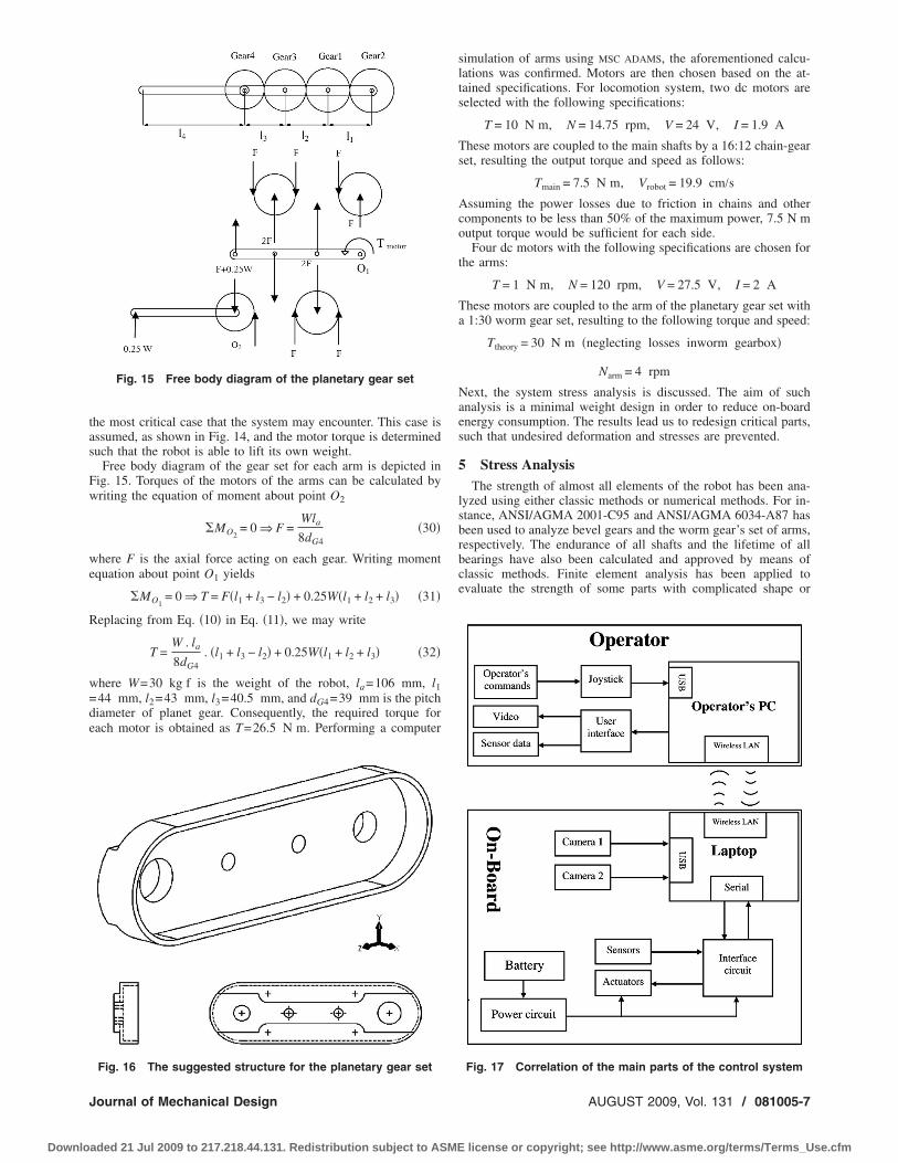
Free body diagram of the gear set for each arm is depicted inig. 15. Torques of the motors of the arms can be calculated byriting the equation of moment about point O2
�MO2= 0 ⇒ F =
Wla
8dG4�30�
here F is the axial force acting on each gear. Writing momentquation about point O1 yields
�MO1= 0 ⇒ T = F�l1 + l3 − l2� + 0.25W�l1 + l2 + l3� �31�
eplacing from Eq. �10� in Eq. �11�, we may write
T =W . la
8dG4. �l1 + l3 − l2� + 0.25W�l1 + l2 + l3� �32�
here W=30 kg f is the weight of the robot, la=106 mm, l144 mm, l2=43 mm, l3=40.5 mm, and dG4=39 mm is the pitchiameter of planet gear. Consequently, the required torque forach motor is obtained as T=26.5 N m. Performing a computer
Fig. 15 Free body diagram of the planetary gear set
Fig. 16 The suggested structure for the planetary gear set
ournal of Mechanical Design
aded 21 Jul 2009 to 217.218.44.131. Redistribution subject to ASME
simulation of arms using MSC ADAMS, the aforementioned calcu-lations was confirmed. Motors are then chosen based on the at-tained specifications. For locomotion system, two dc motors areselected with the following specifications:
T = 10 N m, N = 14.75 rpm, V = 24 V, I = 1.9 A
These motors are coupled to the main shafts by a 16:12 chain-gearset, resulting the output torque and speed as follows:
Tmain = 7.5 N m, Vrobot = 19.9 cm/sAssuming the power losses due to friction in chains and othercomponents to be less than 50% of the maximum power, 7.5 N moutput torque would be sufficient for each side.
Four dc motors with the following specifications are chosen forthe arms:
T = 1 N m, N = 120 rpm, V = 27.5 V, I = 2 A
These motors are coupled to the arm of the planetary gear set witha 1:30 worm gear set, resulting to the following torque and speed:
Ttheory = 30 N m �neglecting losses inworm gearbox�
Narm = 4 rpm
Next, the system stress analysis is discussed. The aim of suchanalysis is a minimal weight design in order to reduce on-boardenergy consumption. The results lead us to redesign critical parts,such that undesired deformation and stresses are prevented.
5 Stress AnalysisThe strength of almost all elements of the robot has been ana-
lyzed using either classic methods or numerical methods. For in-stance, ANSI/AGMA 2001-C95 and ANSI/AGMA 6034-A87 hasbeen used to analyze bevel gears and the worm gear’s set of arms,respectively. The endurance of all shafts and the lifetime of allbearings have also been calculated and approved by means ofclassic methods. Finite element analysis has been applied toevaluate the strength of some parts with complicated shape or
Fig. 17 Correlation of the main parts of the control system
AUGUST 2009, Vol. 131 / 081005-7
license or copyright; see http://www.asme.org/terms/Terms_Use.cfm
umNd
B
MLCRWDN
S
NNNMNPERPOF
0
Downlo
nder considerable applied forces. In such cases, the classicethod is applied for preliminary design, and then using Patran/astran, the finite element method has been applied to finalize theesign. For instance, the part shown in Fig. 16 is the arm for the
Table 2 Laptop features
rand HP
odel nc4000CD 12.1”PU 1.6 mobileAM 512 MBeight 1.6 kgimensions 2.8�28�23.3 cm3
etworking Wireless LAN 802.11a /b /g+Ethernet LAN
Table 3 Microcontroller features
pecification ATMega128
o. of I/O 53o. of 10 bit A/D 8o. of serial ports 2achine frequency 16 MHzumber of internal interrupts 8rogram memory �kbyte� 128EPROM �kbyte� 4AM �kbyte� 4rogrammer port ISPutput current ��A� 40,000eed voltage 2.7–5.5
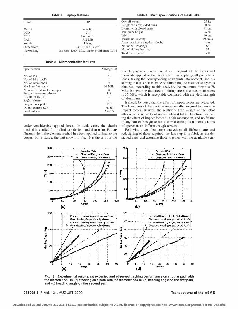
Fig. 18 Experimental results; „a… expected and othe diameter of 3 m, „b… tracking on a path with the
and „d… heading angle on the second path81005-8 / Vol. 131, AUGUST 2009
aded 21 Jul 2009 to 217.218.44.131. Redistribution subject to ASME
planetary gear set, which must resist against all the forces andmoments applied to the robot’s arm. By applying all predictableloads, taking the corresponding constraints into account, and as-suming that this part is made of aluminum, the result of analysis isobtained. According to this analysis, the maximum stress is 78MPa. By ignoring the effect of pitting stress, the maximum stressis 35 MPa, which is acceptable compared with the yield strengthof aluminum.
It should be noted that the effect of impact forces are neglected.The latex parts of the tracks were especially designed to damp theimpact forces. Besides, the relatively little weight of the robotalleviates the intensity of impact when it falls. Therefore, neglect-ing the effect of impact forces is a fair assumption, and no failurein any part of ResQuake has occurred during its numerous hoursof operation on different rough terrains.
Following a complete stress analysis of all different parts andredesigning of those required, the last step is to fabricate the de-signed parts and assemble those together with the available stan-
Table 4 Main specifications of ResQuake
Overall weight 25 kgLength with expanded arms 80 cmLength with closed arms 41 cmMinimum height 26 cmWidth 40 cmMaximum velocity 19 cm/sArms maximum angular velocity 4 rpmNo. of ball bearings 82No. of sliding bearings 32Total no. of parts 688
rved tracking performance on circular path withameter of 4 m, „c… heading angle on the first path,
bsedi
Transactions of the ASME
license or copyright; see http://www.asme.org/terms/Terms_Use.cfm
dw�
c
6
satpBaartcttaw
j
J
Downlo
ard elements to achieve ResQuake as a versatile mobile robot,hich can move on uneven fields and even climb up the stairs
Fig. 1�.Next, a brief review of the control system and performance
haracteristics of the robot will be discussed.
Control SystemThe hardware of the control system, as shown in Fig. 17, con-
ists of various devices, i.e., processors �an operator desktop PC,n on-board laptop, and microcontroller�, sensors �pyrometer, po-entiometer, and cameras�, electronic circuits �the interface board,ower, and drivers�, and nine lithium-polymer on-board batteries.asic characteristics of the on-board laptop and microcontrollerre detailed in Tables 2 and 3. The operator’s desktop PC is useds the master processor, and the laptop installed on top of theobot, as shown in Fig. 1, is used as the slave processor. Joints ofhe arms are equipped with a sensor, such that the operator canontrol the position of each arm separately. The operator selectshe configuration of the arms based on the shape of the obstaclehat the robot faces. An autonomous stair climbing algorithm haslso been recently planned and implemented on ResQuake, whichill be reported in a future publication.The robot is remotely operated using either a keyboard or a
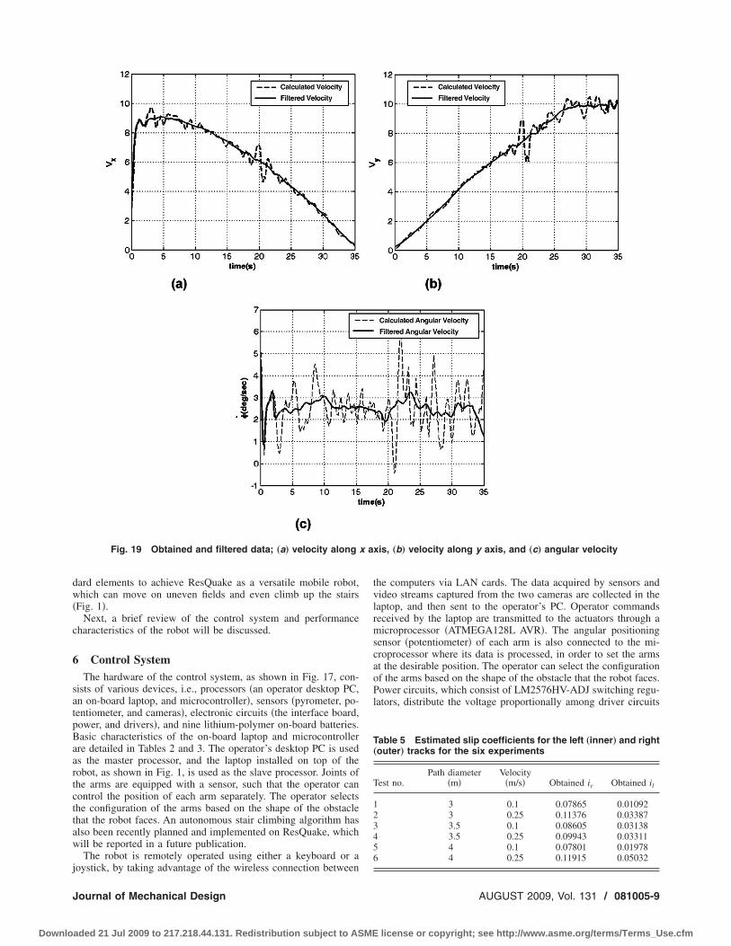
Fig. 19 Obtained and filtered data; „a… velocity along
oystick, by taking advantage of the wireless connection between
ournal of Mechanical Design
aded 21 Jul 2009 to 217.218.44.131. Redistribution subject to ASME
the computers via LAN cards. The data acquired by sensors andvideo streams captured from the two cameras are collected in thelaptop, and then sent to the operator’s PC. Operator commandsreceived by the laptop are transmitted to the actuators through amicroprocessor �ATMEGA128L AVR�. The angular positioningsensor �potentiometer� of each arm is also connected to the mi-croprocessor where its data is processed, in order to set the armsat the desirable position. The operator can select the configurationof the arms based on the shape of the obstacle that the robot faces.Power circuits, which consist of LM2576HV-ADJ switching regu-lators, distribute the voltage proportionally among driver circuits
Table 5 Estimated slip coefficients for the left „inner… and right„outer… tracks for the six experiments
Test no.Path diameter
�m�Velocity
�m/s� Obtained ir Obtained il
1 3 0.1 0.07865 0.010922 3 0.25 0.11376 0.033873 3.5 0.1 0.08605 0.031384 3.5 0.25 0.09943 0.033115 4 0.1 0.07801 0.019786 4 0.25 0.11915 0.05032
xis, „b… velocity along y axis, and „c… angular velocity
x aAUGUST 2009, Vol. 131 / 081005-9
license or copyright; see http://www.asme.org/terms/Terms_Use.cfm
ac4
7
bimmisrestaTd
rmtcm
elo
0
Downlo
nd other electrical devices. Powered by battery cells that are fullyharged �4.2 V, 10 A h�, the whole system operates for more thanh. Other specifications of the robot are listed in Table 4.
Slip Estimation for Performance ImprovementKinematics of the robot was developed in Sec. 3. As mentioned
efore, the slip coefficients for the right and left tracks, which arer and il, respectively, were included to make the kinematic modelore realistic and precise, which must be identified using experi-ental tests. In this section, a procedure is described, which was
mplemented to identify the slip coefficients for paths with con-tant curvature �19�. Six tests have been performed that includeobot movement on three curves, with two different velocities onach one. The test arena was paved with polished stone and is theame through all the experiments. Position and heading angle ofhe robot were extracted every 0.2 s by means of processing im-ges captured from two cameras, mounted on top of the test arena.he results obtained from the two tests of circular paths, withiameters of 3 m and 4 m, are shown in Fig. 18.
The apparent difference between the expected and observedeal paths in all tests is mostly because of neglecting slippage inotion planning. To identify the slip coefficients, first, the posi-
ion and heading angle data has been differentiated to yield thealculated linear and angular velocities of the robot. Due to nu-
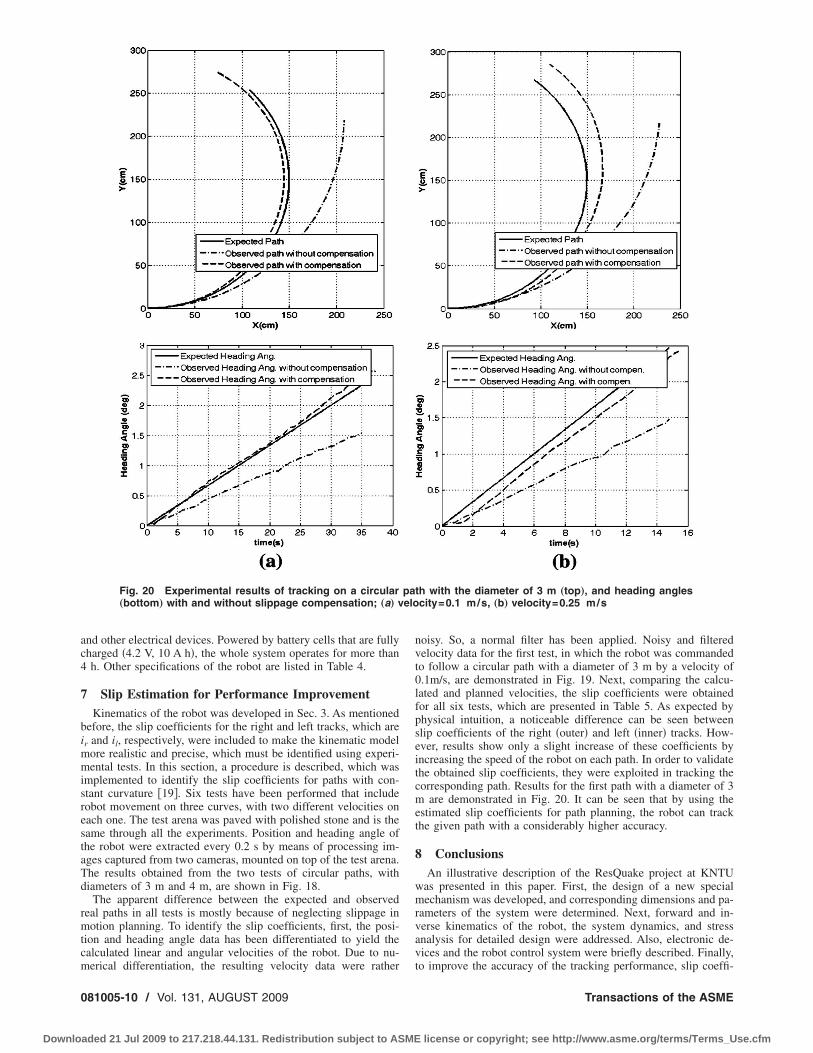
Fig. 20 Experimental results of tracking on a circular„bottom… with and without slippage compensation; „a… v
erical differentiation, the resulting velocity data were rather
81005-10 / Vol. 131, AUGUST 2009
aded 21 Jul 2009 to 217.218.44.131. Redistribution subject to ASME
noisy. So, a normal filter has been applied. Noisy and filteredvelocity data for the first test, in which the robot was commandedto follow a circular path with a diameter of 3 m by a velocity of0.1m/s, are demonstrated in Fig. 19. Next, comparing the calcu-lated and planned velocities, the slip coefficients were obtainedfor all six tests, which are presented in Table 5. As expected byphysical intuition, a noticeable difference can be seen betweenslip coefficients of the right �outer� and left �inner� tracks. How-ever, results show only a slight increase of these coefficients byincreasing the speed of the robot on each path. In order to validatethe obtained slip coefficients, they were exploited in tracking thecorresponding path. Results for the first path with a diameter of 3m are demonstrated in Fig. 20. It can be seen that by using theestimated slip coefficients for path planning, the robot can trackthe given path with a considerably higher accuracy.
8 ConclusionsAn illustrative description of the ResQuake project at KNTU
was presented in this paper. First, the design of a new specialmechanism was developed, and corresponding dimensions and pa-rameters of the system were determined. Next, forward and in-verse kinematics of the robot, the system dynamics, and stressanalysis for detailed design were addressed. Also, electronic de-vices and the robot control system were briefly described. Finally,
th with the diameter of 3 m „top…, and heading anglescity=0.1 m/s, „b… velocity=0.25 m/s
pa
to improve the accuracy of the tracking performance, slip coeffi-
Transactions of the ASME
license or copyright; see http://www.asme.org/terms/Terms_Use.cfm
cerccolbiS
R
J
Downlo
ients of the left and right tracks were identified, based on severalxperimental studies. To do this, position and heading angle of theobot were instantaneously extracted from images captured by twoameras mounted on top of the test region. Obtained slip coeffi-ients were validated by utilizing them to plan the robot motionn circular paths. ResQuake participated in the rescue roboteague of RoboCup 2005 in Osaka, Japan, achieving the secondest design award, RoboCup 2006 in Bremen, Germany, achiev-ng the best operator interface award, and RoboCup 2008 inuzhou, China, achieving the second best award for mobility.
eferences�1� Murphy, R., 2004, “Trial by Fire—Activities of the Rescue Robots at the
World Trade Center From 11–21 September 2001,” IEEE Rob. Autom. Mag.,11�3�, pp. 50–61.
�2� Chen, C., Ostrovskaya, S., and Angeles, J., 2008, “The Kinematics of WheeledMobile Robots With Dual-Wheel Transmission Units,” ASME J. Mech. Des.,130, p. 011004.
�3� Moosavian, S., Ali, A., and Papadopoulos, E., 2007, “Free-Flying Robots inSpace: An Overview of Dynamics Modeling, Planning and Control,” Robotica,25�5�, pp. 537–547.
�4� Ben-Tzvi, P., Goldenberg, A. A., and Zu, J. W., 2008, “Design and Analysis ofa Hybrid Mobile Robot Mechanism With Compounded Locomotion and Ma-nipulation Capability,” ASME J. Mech. Des., 130, p. 072302.
�5� Chen, C., and Angeles, J., 2007, “Optimum Kinematics Design of Drives forWheeled Mobile Robots Based on Cam-Roller Pairs,” ASME J. Mech. Des.,129, pp. 7–16.
�6� Burgard, W., Moors, M., Stachniss, C., and Schneider, F., 2005, “CoordinatedMulti-Robot Exploration,” IEEE Trans. Rob. Autom., 21�3�, pp. 376–378.
�7� Moosavian, S., Ali, A., Semsarilar, H., and Kalantari, A., 2006, “Design and
Manufacturing of a Mobile Rescue Robot,” Proceedings of the IEEE/RSJ In-ournal of Mechanical Design
aded 21 Jul 2009 to 217.218.44.131. Redistribution subject to ASME
ternational Conference on Intelligent Robots and Systems �IROS 2006�, China.�8� Matthies, L., Xiong, Y., Hogg Zhu, R., Rankin, A., and Kennedy, B., 2000, A
Portable, Autonomous, Urban Reconnaissance Robot, Jet Propulsion Labora-tory, California Institute of Technology, Pasadena, CA.
�9� Yim, M., Duff, D. G., and Roufas, K., 2000, Modular Reconfigurable Robots:An Approach to Urban Search and Rescue, Xerox Palo Alto Research Center,Palo Alto, CA.
�10� Moosavian, S., Ali, A., and Mozdbaran, A., 2009, “Dynamics, Motion Plan-ning and Control of Wheel-Legged Robots for Superior Field Navigations,”Robot Vision: Strategies, Algorithms and Motion Planning, Nova Science Pub-lishers Inc., Hauppauge, New York, Chap. 8.
�11� Shigley, J. E., and Mischke, C. R., 2003, Mechanical Engineering Design, 6thed., McGraw-Hill, New York.
�12� Tuan Le, A., 2000, “Modeling and Control of Tracked Vehicles,” Ph.D. thesis,University of Sidney, Australia.
�13� Wong, J. Y., 2001, Theory of Ground Vehicles, 3rd ed., Wiley, New York.�14� Moosavian, S., Ali, A., and Alipour, K., 2007, On the Dynamic Tip-Over
Stability of Wheeled Mobile Manipulators,” Int. J. Rob. Autom., 22�4�, pp.322–328.
�15� Martínez, J. L., Mandow, A., Morales, J., Pedraza, S., and García-Cerezo, A.,2005, “Approximating Kinematics for Tracked Mobile Robots,” Int. J. Robot.Res., 24�10�, pp. 867–878.
�16� Shiller, Z., and Serate, W., 1995, “Trajectory Planning of Tracked Vehicles,”ASME J. Dyn. Syst., Meas., Control, 117�4�, pp. 619–624.
�17� Moosavian, S., Ali, A., and Papadopoulos, E., 2004, “Explicit Dynamics ofSpace Free-Flyers With Multiple Manipulators Via SPACEMAPL,” Adv. Rob.,18�2�, pp. 223–244.
�18� Moosavian, S., Ali, A., Rastegari, R., and Papadopoulos, E., 2005, “MultipleImpedance Control for Space Free-Flying Robots,” J. Guid. Control Dyn.,28�5�, pp. 939–947.
�19� Moosavian, S., Ali, A., and Kalantari, A., 2008, “Experimental Slip Estimationfor Exact Kinematics Modeling and Control of a Tracked Mobile Robot,”Proceedings of the IEEE/RSJ International Conference on Intelligent Robots
and Systems �IROS 2008�, France.AUGUST 2009, Vol. 131 / 081005-11
license or copyright; see http://www.asme.org/terms/Terms_Use.cfm