novel drone design using an optimization software with 3d
TRANSCRIPT
Citation: MohamedZain, A.O.; Chua,
H.; Yap, K.; Uthayasurian, P.; Jiehan,
T. Novel Drone Design Using an
Optimization Software with 3D
Model, Simulation, and Fabrication
in Drone Systems Research. Drones
2022, 6, 97. https://doi.org/10.3390/
drones6040097
Academic Editors: Andrzej
Łukaszewicz, Wojciech Giernacki,
Zbigniew Kulesza, Jaroslaw Pytka
and Andriy Holovatyy
Received: 12 February 2022
Accepted: 11 March 2022
Published: 14 April 2022
Publisher’s Note: MDPI stays neutral
with regard to jurisdictional claims in
published maps and institutional affil-
iations.
Copyright: © 2022 by the authors.
Licensee MDPI, Basel, Switzerland.
This article is an open access article
distributed under the terms and
conditions of the Creative Commons
Attribution (CC BY) license (https://
creativecommons.org/licenses/by/
4.0/).
drones
Article
Novel Drone Design Using an Optimization Software with 3DModel, Simulation, and Fabrication in Drone Systems ResearchAhmed. O. MohamedZain 1,*, Huangshen Chua 2, Kianmeng Yap 1,*, Pavithren Uthayasurian 3 and Teoh Jiehan 3
1 Research Centre for Human-Machine Collaboration, Department of Computing and Information Sys-tems,School of Engineering and Technology, Sunway University, Bandar Sunway, Petaling Jaya 47500, Malaysia
2 Department of Mechatronics Engineering, School of Engineering, UOW Malaysia KDU Penang Univer-sityCollege, Jalan Anson, George Town 10400, Malaysia; [email protected]
3 School of Electrical and Electronics Engineering, University of Wollongong Ma-laysia KDU, GlenmarieCampus, Shah Alam 40150, Malaysia; [email protected] (P.U.); [email protected] (T.J.)
* Correspondence: [email protected] (A.O.M.); [email protected] (K.Y.)
Abstract: This paper presents the design of a small size Unmanned Aerial Vehicle (UAV) using the3DEXPERIENCE software. The process of designing the frame parts involves many methods toensure the parts can meet the requirements while conforming to safety and industry standards. Thedesign steps start with the selection of materials that can be used for the drone, which are polylacticacid (PLA), acrylonitrile styrene acrylate (ASA), and acrylonitrile butadiene styrene (ABS). The droneframe consists of four main parts, which are the center top cover (50 g), the side top cover (10 g),the middle cover (30 g), and the drone’s arm (80 g). A simulation was carried out to determine thestress, displacement, and weight of the drone’s parts. Additionally, a trade-off study was conductedto finalize the shapes of the parts and the various inputs based on their priorities. The outcome of thisnew design can be represented in design concepts, which involve the use of the snap hook functionto assemble two body parts together, namely the middle cover and the center top cover, without theneed of an additional fastener.
Keywords: UAV; polylactic acid; acrylonitrile styrene acrylate; acrylonitrile butadiene styrene;trade-off study
1. Introduction
A drone is an aircraft without a human pilot inside and it is also known as an Un-manned Aerial Vehicle. It has many functions and applications such as for medical trans-port [1], health care service [2], high-rise firefighting [3], drone monitoring applicationfor marine megafauna [4], and many other usages in our current modern society. Thisresearch presents a new design concept and creative 3D design idea of a drone that wasdesigned with the 3DEXPERIENCE software. The main reason for using 3DExperiencesoftware for this project is that it is a software that emphasizes having a collaborativeenvironment. Since this project has included a few people, and each with a different role, ithas been convenient to use the software for project sharing and discussion all within theplatform, especially during the current COVID-19 pandemic situation. The platform itselfhas a variety of applications within it, which include software for 3D modelling (CATIAand SOLIDWORKS), simulation (SIMULIA), social and collaborative (ENOVIA) as well asinformation intelligence (NETVIBES) [5]. Therefore, each user can have roles such as projectmanager, simulation engineer, and 3D designer and use the applications according to theirroles. With that, the tasks can be distributed easily based on different roles, the projectmodels and files can be seen and shared by everyone in the group, and the project timelinecan be managed within the platform, which allows easy tracking of the project. All thesecan be done within the same software, which makes the software a good choice for a groupproject that requires much collaboration. Three dimensional designing through simulation
Drones 2022, 6, 97. https://doi.org/10.3390/drones6040097 https://www.mdpi.com/journal/drones
Drones 2022, 6, 97 2 of 24
rather than creating a prototype can reduce the cost for a designer. Since it is a 3D design,engineers can come up with more advanced engineering knowledge and technology. Thisprocess is necessary to ensure the parts are able to meet the requirements while conformingto safety and industry standards. While using 3DModelling, the applications used arePart Design and Assembly Design. This research concentrates on the design phase of thedrone. The various designing steps included in this phase are discussed. The objectivesof this research are to simulate a drone frame to optimize the bottom cover, to study andcompare concept shapes of the top cover, arm, leg bracket, and bottom cover of a droneusing a trade-off study, and to analyze the force that is generated by the motors in order todetermine how much the drone can handle.
Researchers have a lot of interest in designing the parts of a drone and the design isdependent on the application of the drone, where there are many factors to be consideredsuch as speed-motor selection and airframe selection [6]. In this research project, the designof the drone has been made for parcel delivery purposes, which consists of four DC motors.The single motor has a thrust of 5227 Ibs/g. The researchers in [7] studied and analyzedthe efficiency of a small quadrotor using air-foils. In this work, the modelling and controldesign were demonstrated through a series of repeated flights. The researchers in [8]analyzed the aerodynamic interaction between rotors of a micro-quadcopter. Equation (1)was used to calculate the Reynolds number [8], where Re represents the Reynolds number,ρ represents the density of air, Ω represents the rotor angular velocity, and µ represents thedynamic viscosity of air.
Re =ρΩRc
µ(1)
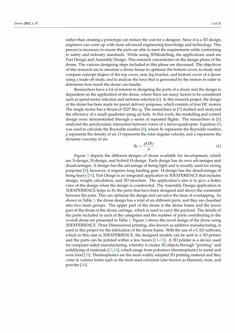
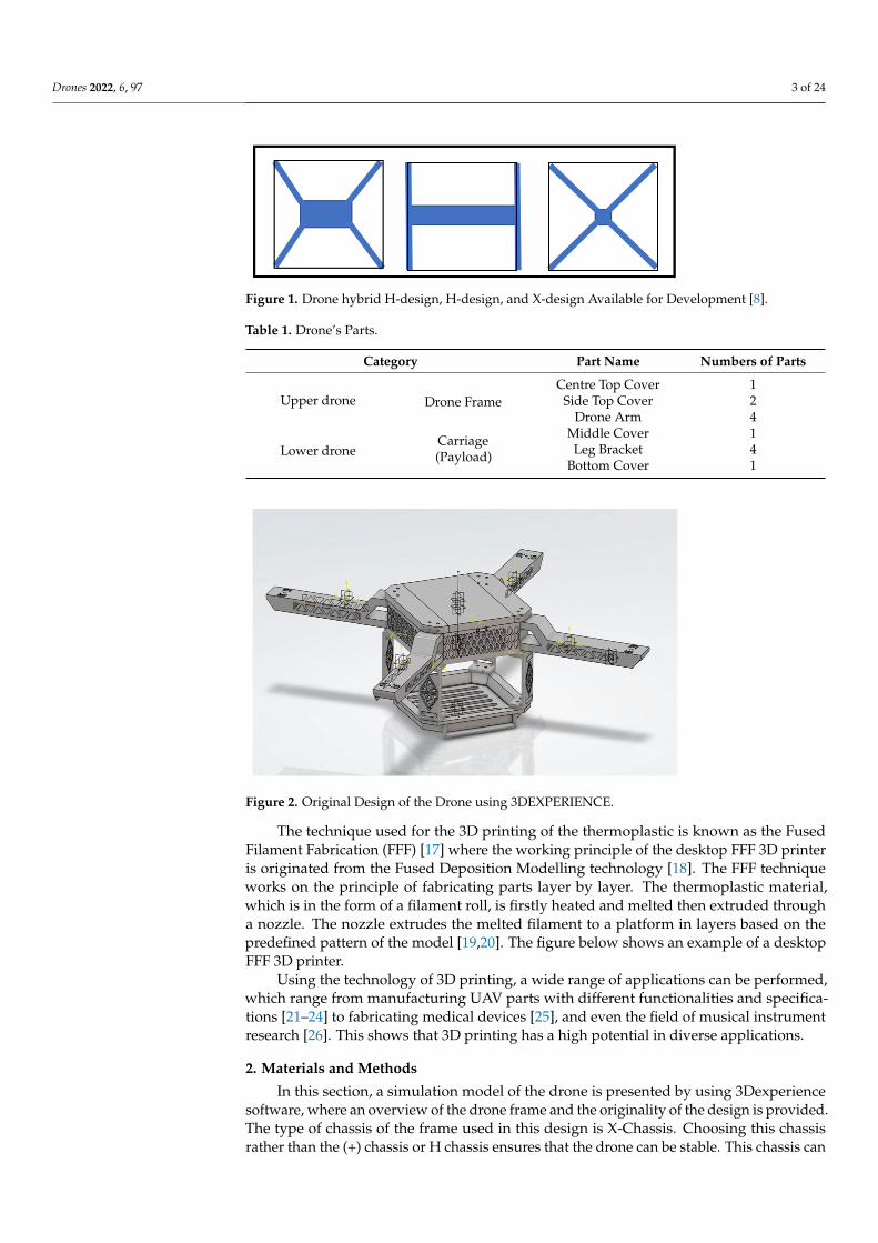
Figure 1 depicts the different designs of drone available for development, whichare X-design, H-design, and hybrid H-design. Each design has its own advantages anddisadvantages. X-design has the advantage of being light and is usually used for racingpurposes [9]; however, it requires long landing gear. H-design has the disadvantage ofbeing heavy [10]. Part Design is an integrated application in 3DEXPERIENCE that includesdesign, weight calculation, and 3D structure. The application’s aim is to give a betterview of the design when the design is constructed. The Assembly Design application in3DEXPERIENCE helps to fix the parts that have been designed and shows the constraintbetween the parts. This can optimize the design and can solve the issue of overlapping. Asshown in Table 1, the drone design has a total of six different parts, and they are classifiedinto two main groups. The upper part of the drone is the drone frame and the lowerpart of the drone is the drone carriage, which is used to carry the payload. The details ofthe parts included in each of the categories and the number of parts contributing to theoverall drone are presented in Table 1. Figure 2 shows the novel design of the drone using3DEXPERIENCE. Three Dimensional printing, also known as additive manufacturing, isused in this project for the fabrication of the drone frame. With the use of a CAD software,which in this case is 3DEXPERIENCE, the designed models can be sent to a 3D printerand the parts can be printed within a few hours [11–13]. A 3D printer is a device usedfor computer-aided manufacturing, whereby it creates 3D objects through “printing” andsolidifying of materials [11,14], which range from polymers (thermoplastic) to metal andeven food [15]. Thermoplastics are the most widely adopted 3D printing material and theycome in various forms such as the most used extrusion (also known as filament), resin, andpowder [16].
Drones 2022, 6, 97 3 of 24Drones 2022, 6, x FOR PEER REVIEW 3 of 25
Figure 1. Drone hybrid H-design, H-design, and X-design Available for Development [8].
The technique used for the 3D printing of the thermoplastic is known as the Fused Filament Fabrication (FFF) [17] where the working principle of the desktop FFF 3D printer is originated from the Fused Deposition Modelling technology [18]. The FFF technique works on the principle of fabricating parts layer by layer. The thermoplastic material, which is in the form of a filament roll, is firstly heated and melted then extruded through a nozzle. The nozzle extrudes the melted filament to a platform in layers based on the predefined pattern of the model [19,20]. The figure below shows an example of a desktop FFF 3D printer.
Using the technology of 3D printing, a wide range of applications can be performed, which range from manufacturing UAV parts with different functionalities and specifica-tions [21–24] to fabricating medical devices [25], and even the field of musical instrument research [26]. This shows that 3D printing has a high potential in diverse applications.
Table 1. Drone’s Parts.
Category Part Name Numbers of Parts
Upper drone Drone Frame Centre Top Cover 1
Side Top Cover 2 Drone Arm 4
Lower drone Carriage (Payload)
Middle Cover 1 Leg Bracket 4
Bottom Cover 1
Figure 2. Original Design of the Drone using 3DEXPERIENCE.
2. Materials and Methods In this section, a simulation model of the drone is presented by using 3Dexperience
software, where an overview of the drone frame and the originality of the design is pro-vided. The type of chassis of the frame used in this design is X-Chassis. Choosing this
Figure 1. Drone hybrid H-design, H-design, and X-design Available for Development [8].
Table 1. Drone’s Parts.
Category Part Name Numbers of Parts
Upper drone Drone FrameCentre Top Cover 1
Side Top Cover 2Drone Arm 4
Lower droneCarriage(Payload)
Middle Cover 1Leg Bracket 4
Bottom Cover 1
Drones 2022, 6, x FOR PEER REVIEW 3 of 25
Figure 1. Drone hybrid H-design, H-design, and X-design Available for Development [8].
The technique used for the 3D printing of the thermoplastic is known as the Fused Filament Fabrication (FFF) [17] where the working principle of the desktop FFF 3D printer is originated from the Fused Deposition Modelling technology [18]. The FFF technique works on the principle of fabricating parts layer by layer. The thermoplastic material, which is in the form of a filament roll, is firstly heated and melted then extruded through a nozzle. The nozzle extrudes the melted filament to a platform in layers based on the predefined pattern of the model [19,20]. The figure below shows an example of a desktop FFF 3D printer.
Using the technology of 3D printing, a wide range of applications can be performed, which range from manufacturing UAV parts with different functionalities and specifica-tions [21–24] to fabricating medical devices [25], and even the field of musical instrument research [26]. This shows that 3D printing has a high potential in diverse applications.
Table 1. Drone’s Parts.
Category Part Name Numbers of Parts
Upper drone Drone Frame Centre Top Cover 1
Side Top Cover 2 Drone Arm 4
Lower drone Carriage (Payload)
Middle Cover 1 Leg Bracket 4
Bottom Cover 1
Figure 2. Original Design of the Drone using 3DEXPERIENCE.
2. Materials and Methods In this section, a simulation model of the drone is presented by using 3Dexperience
software, where an overview of the drone frame and the originality of the design is pro-vided. The type of chassis of the frame used in this design is X-Chassis. Choosing this
Figure 2. Original Design of the Drone using 3DEXPERIENCE.
The technique used for the 3D printing of the thermoplastic is known as the FusedFilament Fabrication (FFF) [17] where the working principle of the desktop FFF 3D printeris originated from the Fused Deposition Modelling technology [18]. The FFF techniqueworks on the principle of fabricating parts layer by layer. The thermoplastic material,which is in the form of a filament roll, is firstly heated and melted then extruded througha nozzle. The nozzle extrudes the melted filament to a platform in layers based on thepredefined pattern of the model [19,20]. The figure below shows an example of a desktopFFF 3D printer.
Using the technology of 3D printing, a wide range of applications can be performed,which range from manufacturing UAV parts with different functionalities and specifica-tions [21–24] to fabricating medical devices [25], and even the field of musical instrumentresearch [26]. This shows that 3D printing has a high potential in diverse applications.
2. Materials and Methods
In this section, a simulation model of the drone is presented by using 3Dexperiencesoftware, where an overview of the drone frame and the originality of the design is provided.The type of chassis of the frame used in this design is X-Chassis. Choosing this chassisrather than the (+) chassis or H chassis ensures that the drone can be stable. This chassis can
Drones 2022, 6, 97 4 of 24
hover longer compared to other chassis and it is easy to control and maneuver. The suitablelocation for the center of gravity is in the middle of the drone, which will make controllingthe drone easier and will make the drone more stable. Therefore, the components’ weightwill be distributed on the drone based on the most suitable position for the center of gravity.The momentum theory represents the basic understanding of the drone motion, where thethrust is calculated based on this theory [26].
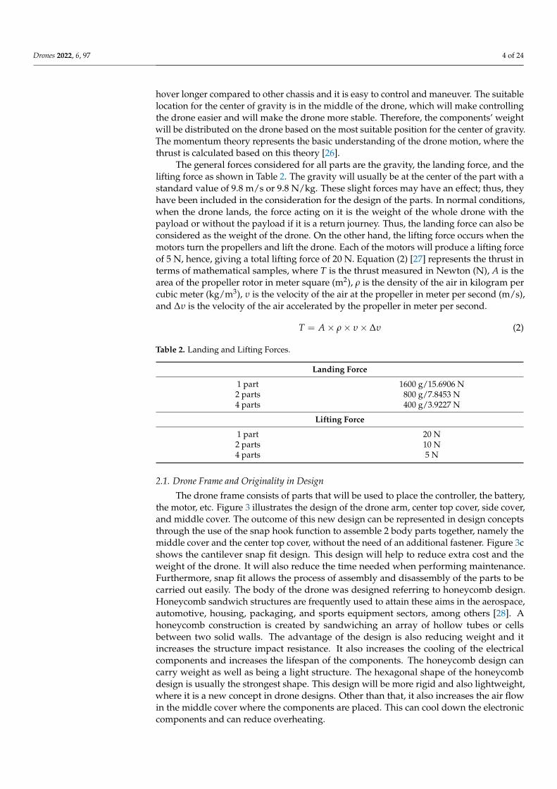
The general forces considered for all parts are the gravity, the landing force, and thelifting force as shown in Table 2. The gravity will usually be at the center of the part with astandard value of 9.8 m/s or 9.8 N/kg. These slight forces may have an effect; thus, theyhave been included in the consideration for the design of the parts. In normal conditions,when the drone lands, the force acting on it is the weight of the whole drone with thepayload or without the payload if it is a return journey. Thus, the landing force can also beconsidered as the weight of the drone. On the other hand, the lifting force occurs when themotors turn the propellers and lift the drone. Each of the motors will produce a lifting forceof 5 N, hence, giving a total lifting force of 20 N. Equation (2) [27] represents the thrust interms of mathematical samples, where T is the thrust measured in Newton (N), A is thearea of the propeller rotor in meter square (m2), ρ is the density of the air in kilogram percubic meter (kg/m3), υ is the velocity of the air at the propeller in meter per second (m/s),and ∆υ is the velocity of the air accelerated by the propeller in meter per second.
T = A × ρ × υ × ∆υ (2)
Table 2. Landing and Lifting Forces.
Landing Force
1 part 1600 g/15.6906 N2 parts 800 g/7.8453 N4 parts 400 g/3.9227 N
Lifting Force
1 part 20 N2 parts 10 N4 parts 5 N
2.1. Drone Frame and Originality in Design
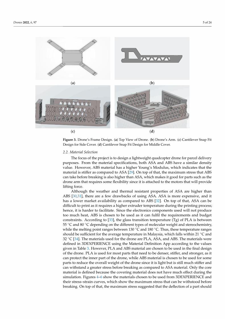
The drone frame consists of parts that will be used to place the controller, the battery,the motor, etc. Figure 3 illustrates the design of the drone arm, center top cover, side cover,and middle cover. The outcome of this new design can be represented in design conceptsthrough the use of the snap hook function to assemble 2 body parts together, namely themiddle cover and the center top cover, without the need of an additional fastener. Figure 3cshows the cantilever snap fit design. This design will help to reduce extra cost and theweight of the drone. It will also reduce the time needed when performing maintenance.Furthermore, snap fit allows the process of assembly and disassembly of the parts to becarried out easily. The body of the drone was designed referring to honeycomb design.Honeycomb sandwich structures are frequently used to attain these aims in the aerospace,automotive, housing, packaging, and sports equipment sectors, among others [28]. Ahoneycomb construction is created by sandwiching an array of hollow tubes or cellsbetween two solid walls. The advantage of the design is also reducing weight and itincreases the structure impact resistance. It also increases the cooling of the electricalcomponents and increases the lifespan of the components. The honeycomb design cancarry weight as well as being a light structure. The hexagonal shape of the honeycombdesign is usually the strongest shape. This design will be more rigid and also lightweight,where it is a new concept in drone designs. Other than that, it also increases the air flowin the middle cover where the components are placed. This can cool down the electroniccomponents and can reduce overheating.
Drones 2022, 6, 97 5 of 24
Drones 2022, 6, x FOR PEER REVIEW 5 of 25
where the components are placed. This can cool down the electronic components and can reduce overheating.
(a) (b)
(c) (d)
Figure 3. Drone’s Frame Design. (a) Top View of Drone. (b) Drone’s Arm. (c) Cantilever Snap Fit Design for Side Cover. (d) Cantilever Snap Fit Design for Middle Cover.
2.2. Material Selection The focus of the project is to design a lightweight quadcopter drone for parcel deliv-
ery purposes. From the material specifications, both ASA and ABS have a similar density value. However, ABS material has a higher Young’s Modulus, which indicates that the material is stiffer as compared to ASA [29]. On top of that, the maximum stress that ABS can take before breaking is also higher than ASA, which makes it good for parts such as the drone arm that requires some flexibility since it is attached to the motors that will provide lifting force.
Although the weather and thermal resistant properties of ASA are higher than ABS [30,31], there are a few drawbacks of using ASA. ASA is more expensive, and it has a lower market availability as compared to ABS [32]. On top of that, ASA can be difficult to print as it requires a higher extruder temperature during the printing process; hence, it is harder to facilitate. Since the electronics components used will not produce too much heat, ABS is chosen to be used as it can fulfil the requirements and budget constraints. Accord-ing to [33], the glass transition temperature (Tg) of PLA is between 55 and 80 °C depend-ing on the different types of molecular weight and stereochemistry, while the melting point ranges between 130 and 180 °C. Thus, these temperature ranges should be sufficient for the average temperature in Malaysia, which falls within 21 and 32 °C [34]. The mate-rials used for the drone are PLA, ASA, and ABS. The materials were defined in 3DEXPE-RIENCE using the Material Definition App according to the values given in Table 3. How-ever, PLA and ABS material are chosen to be used in the final design of the drone. PLA is used for most parts that need to be denser, stiffer, and stronger, as it can protect the inner part of the drone, while ABS material is chosen to be used for some parts to reduce the overall weight of the drone since it is light but is still much stiffer and can withstand a greater stress before breaking as compared to ASA material. Only the core material is de-fined because the covering material does not have much effect during the simulation. Fig-ures 4–6 show the materials chosen to be used from 3DEXPERIENCE and their stress–strain curves, which show the maximum stress that can be withstood before breaking. On
Figure 3. Drone’s Frame Design. (a) Top View of Drone. (b) Drone’s Arm. (c) Cantilever Snap FitDesign for Side Cover. (d) Cantilever Snap Fit Design for Middle Cover.
2.2. Material Selection
The focus of the project is to design a lightweight quadcopter drone for parcel deliverypurposes. From the material specifications, both ASA and ABS have a similar densityvalue. However, ABS material has a higher Young’s Modulus, which indicates that thematerial is stiffer as compared to ASA [29]. On top of that, the maximum stress that ABScan take before breaking is also higher than ASA, which makes it good for parts such as thedrone arm that requires some flexibility since it is attached to the motors that will providelifting force.
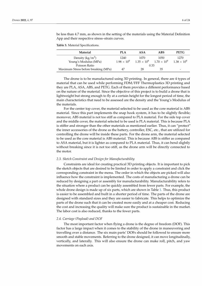
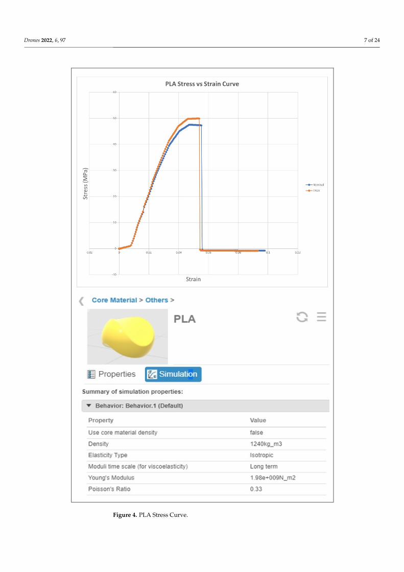
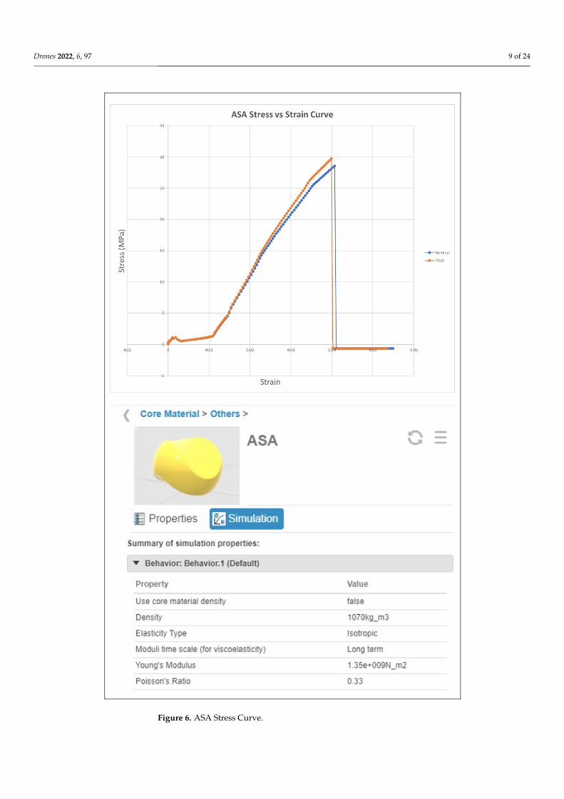
Although the weather and thermal resistant properties of ASA are higher thanABS [30,31], there are a few drawbacks of using ASA. ASA is more expensive, and ithas a lower market availability as compared to ABS [32]. On top of that, ASA can bedifficult to print as it requires a higher extruder temperature during the printing process;hence, it is harder to facilitate. Since the electronics components used will not producetoo much heat, ABS is chosen to be used as it can fulfil the requirements and budgetconstraints. According to [33], the glass transition temperature (Tg) of PLA is between55 C and 80 C depending on the different types of molecular weight and stereochemistry,while the melting point ranges between 130 C and 180 C. Thus, these temperature rangesshould be sufficient for the average temperature in Malaysia, which falls within 21 C and32 C [34]. The materials used for the drone are PLA, ASA, and ABS. The materials weredefined in 3DEXPERIENCE using the Material Definition App according to the valuesgiven in Table 3. However, PLA and ABS material are chosen to be used in the final designof the drone. PLA is used for most parts that need to be denser, stiffer, and stronger, as itcan protect the inner part of the drone, while ABS material is chosen to be used for someparts to reduce the overall weight of the drone since it is light but is still much stiffer andcan withstand a greater stress before breaking as compared to ASA material. Only the corematerial is defined because the covering material does not have much effect during thesimulation. Figures 4–6 show the materials chosen to be used from 3DEXPERIENCE andtheir stress–strain curves, which show the maximum stress that can be withstood beforebreaking. On top of that, the maximum stress suggested that the deflection of a part should
Drones 2022, 6, 97 6 of 24
be less than 4.7 mm, as shown in the setting of the materials using the Material DefinitionApp and their respective stress–strain curves.
Table 3. Material Specifications.
Material PLA ASA ABS PETG
Density (kg/m3) 1240 1070 1050 1270Young’s Modulus (MPa) 1.98 × 10⁹ 1.35 × 10⁹ 1.70 × 10⁹ 1.38 × 10⁹
Poisson Ratio 0.33Maximum Stress before breaking (MPa) 47 28 35 -
The drone is to be manufactured using 3D printing. In general, there are 4 types ofmaterial that can be used while performing FDM/FFF Thermoplastics 3D printing andthey are PLA, ASA, ABS, and PETG. Each of them provides a different performance basedon the nature of the material. Since the objective of this project is to build a drone that islightweight but strong enough to fly at a certain height for the longest period of time, themain characteristics that need to be assessed are the density and the Young’s Modulus ofthe materials.
For the center top cover, the material selected to be used as the core material is ABSmaterial. Since this part implements the snap hook system, it has to be slightly flexible;moreover, ABS material is not too stiff as compared to PLA material. For the side top coverand the middle cover, the material selected to be used is PLA material. This is because PLAis stiffer and stronger than the other materials as mentioned earlier. Thus, it can “protect”the inner accessories of the drone as the battery, controller, ESC, etc., that are utilized forcontrolling the drone will be inside these parts. For the drone arm, the material selectedto be used as the core material is ABS material. This is because ABS is stiffer as comparedto ASA material, but it is lighter as compared to PLA material. Thus, it can bend slightlywithout breaking since it is not too stiff, as the drone arm will be directly connected tothe motor.
2.3. Sketch Constraint and Design for Manufacturability
Constraints are ideal for creating practical 3D printing objects. It is important to pickthe sketch objects that are desired to be limited in order to apply a constraint and click thecorresponding constraint in the menu. The order in which the objects are picked will alsoinfluence how the constraint is implemented. The costs of manufacturing a drone can bereduced by designing a part or assembly for manufacturability. Manufacturability refers tothe situation where a product can be quickly assembled from fewer parts. For example, thewhole drone design is made up of six parts, which are shown in Table 1. Thus, this productis easier to be assembled and built in a shorter period of time. The parts of the drone aredesigned with standard sizes and they are easier to fabricate. This helps to optimize theparts of the drone such that it can be created more easily and at a cheaper cost. Reducingthe cost and increasing the quality will make sure the product is sustainable in the market.The labor cost is also reduced, thanks to the fewer parts.
2.4. Carriage (Payload) and DOF
The most important factor when flying a drone is the degree of freedom (DOF). Thisfactor has a large impact when it comes to the stability of the drone in maneuvering andtravelling over a distance. The six main parts’ DOFs should be followed to ensure moresmooth and stable movements. Referring to the drone designed, it can move longitudinally,vertically, and laterally. This will also ensure the drone can make roll, pitch, and yawmovements on each axis.
Drones 2022, 6, 97 7 of 24Drones 2022, 6, x FOR PEER REVIEW 7 of 25
Figure 4. PLA Stress Curve. Figure 4. PLA Stress Curve.
Drones 2022, 6, 97 8 of 24Drones 2022, 6, x FOR PEER REVIEW 8 of 25
Figure 5. ABS Stress Curve. Figure 5. ABS Stress Curve.
Drones 2022, 6, 97 9 of 24Drones 2022, 6, x FOR PEER REVIEW 9 of 25
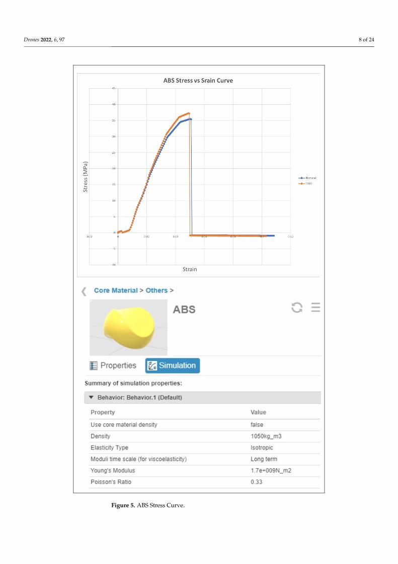
Figure 6. ASA Stress Curve.
Figure 6. ASA Stress Curve.
Drones 2022, 6, 97 10 of 24
3. System Simulation
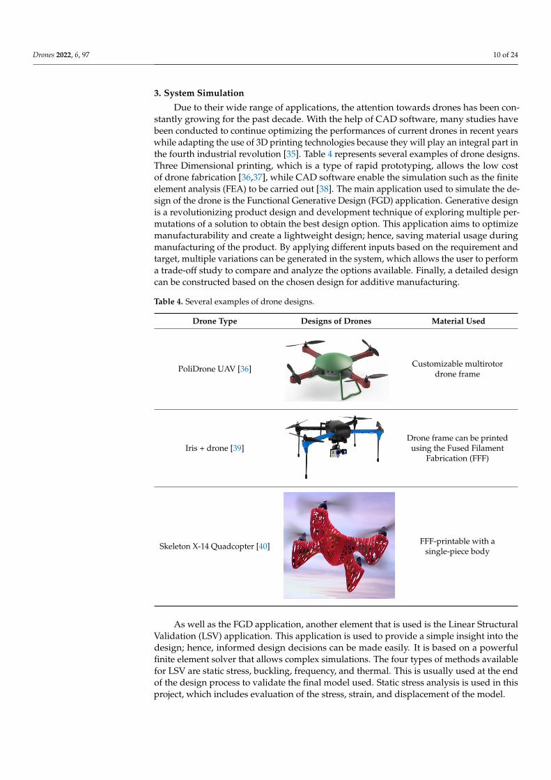
Due to their wide range of applications, the attention towards drones has been con-stantly growing for the past decade. With the help of CAD software, many studies havebeen conducted to continue optimizing the performances of current drones in recent yearswhile adapting the use of 3D printing technologies because they will play an integral part inthe fourth industrial revolution [35]. Table 4 represents several examples of drone designs.Three Dimensional printing, which is a type of rapid prototyping, allows the low costof drone fabrication [36,37], while CAD software enable the simulation such as the finiteelement analysis (FEA) to be carried out [38]. The main application used to simulate the de-sign of the drone is the Functional Generative Design (FGD) application. Generative designis a revolutionizing product design and development technique of exploring multiple per-mutations of a solution to obtain the best design option. This application aims to optimizemanufacturability and create a lightweight design; hence, saving material usage duringmanufacturing of the product. By applying different inputs based on the requirement andtarget, multiple variations can be generated in the system, which allows the user to performa trade-off study to compare and analyze the options available. Finally, a detailed designcan be constructed based on the chosen design for additive manufacturing.
Table 4. Several examples of drone designs.
Drone Type Designs of Drones Material Used
PoliDrone UAV [36]
Drones 2022, 6, x FOR PEER REVIEW 11 of 25
Table 4. Several examples of drone designs.
Drone Type Designs of Drones Material Used
PoliDrone UAV [36]
Customizable multirotor drone frame
Iris + drone [39]
Drone frame can be printed using the Fused Filament
Fabrication (FFF)
Skeleton X-14 Quadcopter [40]
FFF-printable with a single-piece body
Restrain/Connection For the center top cover, restraining is performed using a “clamp” at both inner sides
of the part as shown in Figure 7a. The two sides will be attached to the middle cover using a snap hook system; therefore, it should be fixed throughout the flight. For the side top cover, restraining is performed using a “clamp” where the four holes at the sides are clamped as shown in Figure 7b. The four holes will be bolted to the middle cover; hence, the degree of freedom should be fixed as it is undesired for the part to move. For the middle cover, restraining is performed using a “clamp” at the eight holes, which are at each of the corners as well as at the side of the middle part that will be connected to the top cover using the snap hook system as shown in Figure 7c. The eight holes will be bolted to the leg bracket and the drone arm as well as the side top cover; thus, the degree of freedom should be fixed as it is undesired for the part to move. As well as that, the sides where the snap hook system is applied are clamped as well because they will be connected to the center top cover.
Customizable multirotordrone frame
Iris + drone [39]
Drones 2022, 6, x FOR PEER REVIEW 11 of 25
Table 4. Several examples of drone designs.
Drone Type Designs of Drones Material Used
PoliDrone UAV [36]
Customizable multirotor drone frame
Iris + drone [39]
Drone frame can be printed using the Fused Filament
Fabrication (FFF)
Skeleton X-14 Quadcopter [40]
FFF-printable with a single-piece body
Restrain/Connection For the center top cover, restraining is performed using a “clamp” at both inner sides
of the part as shown in Figure 7a. The two sides will be attached to the middle cover using a snap hook system; therefore, it should be fixed throughout the flight. For the side top cover, restraining is performed using a “clamp” where the four holes at the sides are clamped as shown in Figure 7b. The four holes will be bolted to the middle cover; hence, the degree of freedom should be fixed as it is undesired for the part to move. For the middle cover, restraining is performed using a “clamp” at the eight holes, which are at each of the corners as well as at the side of the middle part that will be connected to the top cover using the snap hook system as shown in Figure 7c. The eight holes will be bolted to the leg bracket and the drone arm as well as the side top cover; thus, the degree of freedom should be fixed as it is undesired for the part to move. As well as that, the sides where the snap hook system is applied are clamped as well because they will be connected to the center top cover.
Drone frame can be printedusing the Fused Filament
Fabrication (FFF)
Skeleton X-14 Quadcopter [40]
Drones 2022, 6, x FOR PEER REVIEW 11 of 25
Table 4. Several examples of drone designs.
Drone Type Designs of Drones Material Used
PoliDrone UAV [36]
Customizable multirotor drone frame
Iris + drone [39]
Drone frame can be printed using the Fused Filament
Fabrication (FFF)
Skeleton X-14 Quadcopter [40]
FFF-printable with a single-piece body
Restrain/Connection For the center top cover, restraining is performed using a “clamp” at both inner sides
of the part as shown in Figure 7a. The two sides will be attached to the middle cover using a snap hook system; therefore, it should be fixed throughout the flight. For the side top cover, restraining is performed using a “clamp” where the four holes at the sides are clamped as shown in Figure 7b. The four holes will be bolted to the middle cover; hence, the degree of freedom should be fixed as it is undesired for the part to move. For the middle cover, restraining is performed using a “clamp” at the eight holes, which are at each of the corners as well as at the side of the middle part that will be connected to the top cover using the snap hook system as shown in Figure 7c. The eight holes will be bolted to the leg bracket and the drone arm as well as the side top cover; thus, the degree of freedom should be fixed as it is undesired for the part to move. As well as that, the sides where the snap hook system is applied are clamped as well because they will be connected to the center top cover.
FFF-printable with asingle-piece body
As well as the FGD application, another element that is used is the Linear StructuralValidation (LSV) application. This application is used to provide a simple insight into thedesign; hence, informed design decisions can be made easily. It is based on a powerfulfinite element solver that allows complex simulations. The four types of methods availablefor LSV are static stress, buckling, frequency, and thermal. This is usually used at the endof the design process to validate the final model used. Static stress analysis is used in thisproject, which includes evaluation of the stress, strain, and displacement of the model.
Drones 2022, 6, 97 11 of 24
Restrain/Connection
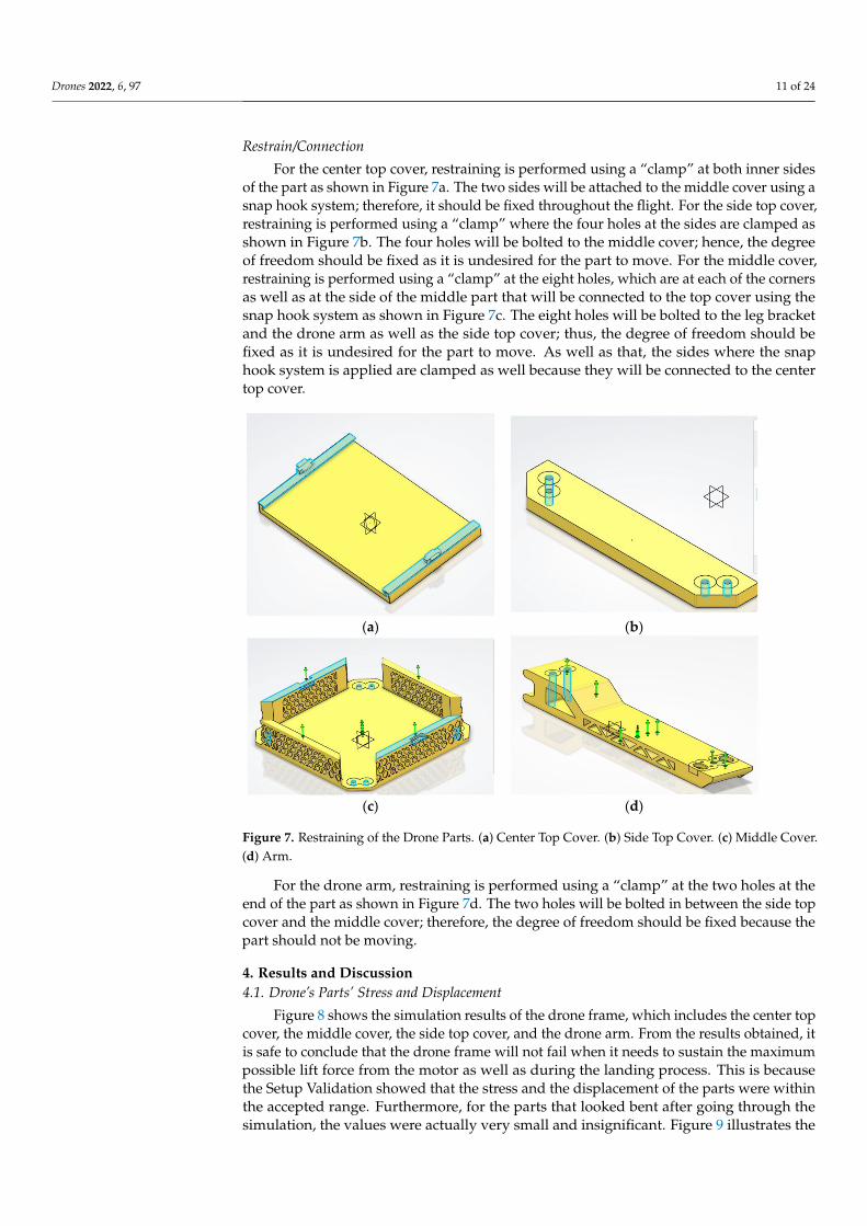
For the center top cover, restraining is performed using a “clamp” at both inner sidesof the part as shown in Figure 7a. The two sides will be attached to the middle cover using asnap hook system; therefore, it should be fixed throughout the flight. For the side top cover,restraining is performed using a “clamp” where the four holes at the sides are clamped asshown in Figure 7b. The four holes will be bolted to the middle cover; hence, the degreeof freedom should be fixed as it is undesired for the part to move. For the middle cover,restraining is performed using a “clamp” at the eight holes, which are at each of the cornersas well as at the side of the middle part that will be connected to the top cover using thesnap hook system as shown in Figure 7c. The eight holes will be bolted to the leg bracketand the drone arm as well as the side top cover; thus, the degree of freedom should befixed as it is undesired for the part to move. As well as that, the sides where the snaphook system is applied are clamped as well because they will be connected to the centertop cover.
Drones 2022, 6, x FOR PEER REVIEW 12 of 25
(a) (b)
(c) (d)
Figure 7. Restraining of the Drone Parts. (a) Center Top Cover. (b) Side Top Cover. (c) Middle Cover. (d) Arm.
For the drone arm, restraining is performed using a “clamp” at the two holes at the end of the part as shown in Figure 7d. The two holes will be bolted in between the side top cover and the middle cover; therefore, the degree of freedom should be fixed because the part should not be moving.
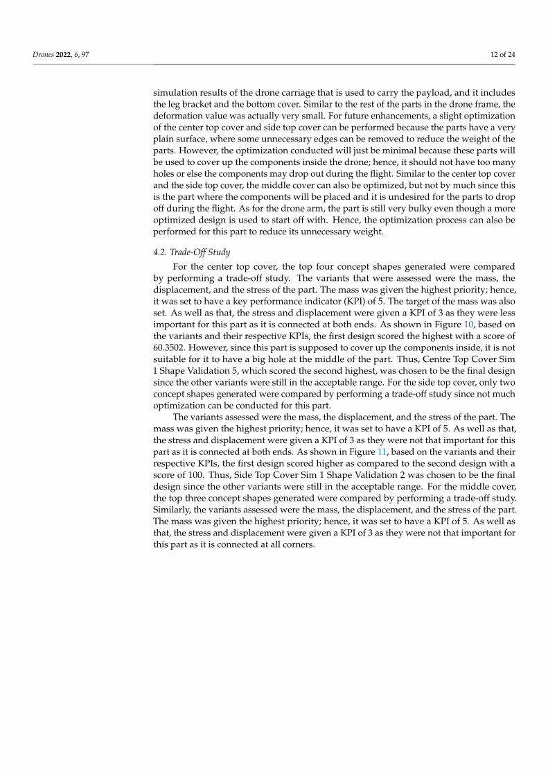
4. Results and Discussion 4.1. Drone’s Parts’ Stress and Displacement
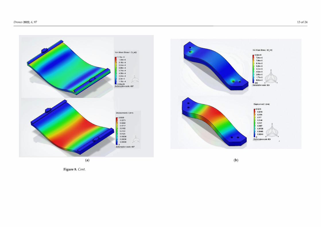
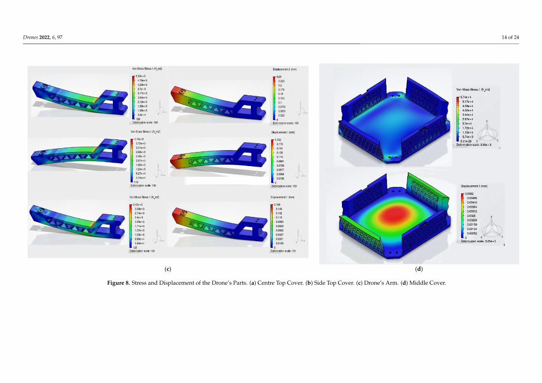
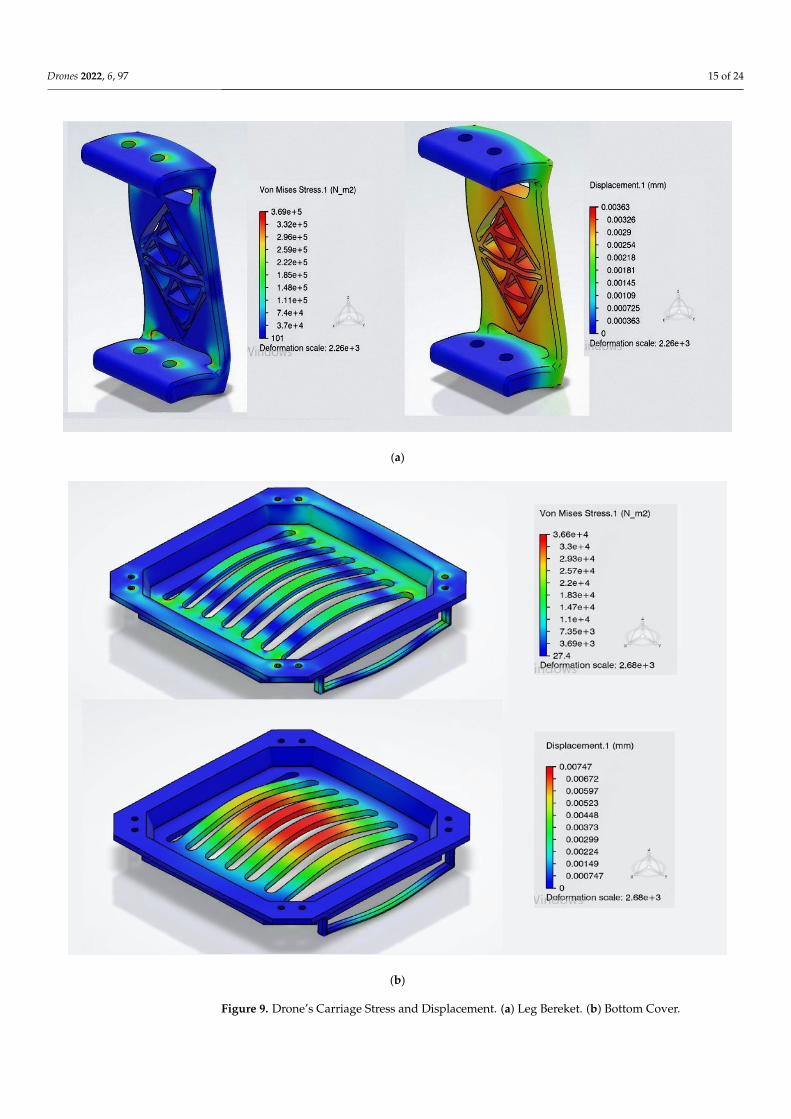
Figure 8 shows the simulation results of the drone frame, which includes the center top cover, the middle cover, the side top cover, and the drone arm. From the results ob-tained, it is safe to conclude that the drone frame will not fail when it needs to sustain the maximum possible lift force from the motor as well as during the landing process. This is because the Setup Validation showed that the stress and the displacement of the parts were within the accepted range. Furthermore, for the parts that looked bent after going through the simulation, the values were actually very small and insignificant. Figure 9 illustrates the simulation results of the drone carriage that is used to carry the payload, and it includes the leg bracket and the bottom cover. Similar to the rest of the parts in the drone frame, the deformation value was actually very small. For future enhancements, a slight optimization of the center top cover and side top cover can be performed because the parts have a very plain surface, where some unnecessary edges can be removed to reduce the weight of the parts. However, the optimization conducted will just be minimal because these parts will be used to cover up the components inside the drone; hence, it should not have too many holes or else the components may drop out during the flight. Similar to the center top cover and the side top cover, the middle cover can also be opti-mized, but not by much since this is the part where the components will be placed and it is undesired for the parts to drop off during the flight. As for the drone arm, the part is still very bulky even though a more optimized design is used to start off with. Hence, the optimization process can also be performed for this part to reduce its unnecessary weight.
Figure 7. Restraining of the Drone Parts. (a) Center Top Cover. (b) Side Top Cover. (c) Middle Cover.(d) Arm.
For the drone arm, restraining is performed using a “clamp” at the two holes at theend of the part as shown in Figure 7d. The two holes will be bolted in between the side topcover and the middle cover; therefore, the degree of freedom should be fixed because thepart should not be moving.
4. Results and Discussion4.1. Drone’s Parts’ Stress and Displacement
Figure 8 shows the simulation results of the drone frame, which includes the center topcover, the middle cover, the side top cover, and the drone arm. From the results obtained, itis safe to conclude that the drone frame will not fail when it needs to sustain the maximumpossible lift force from the motor as well as during the landing process. This is becausethe Setup Validation showed that the stress and the displacement of the parts were withinthe accepted range. Furthermore, for the parts that looked bent after going through thesimulation, the values were actually very small and insignificant. Figure 9 illustrates the
Drones 2022, 6, 97 12 of 24
simulation results of the drone carriage that is used to carry the payload, and it includesthe leg bracket and the bottom cover. Similar to the rest of the parts in the drone frame, thedeformation value was actually very small. For future enhancements, a slight optimizationof the center top cover and side top cover can be performed because the parts have a veryplain surface, where some unnecessary edges can be removed to reduce the weight of theparts. However, the optimization conducted will just be minimal because these parts willbe used to cover up the components inside the drone; hence, it should not have too manyholes or else the components may drop out during the flight. Similar to the center top coverand the side top cover, the middle cover can also be optimized, but not by much since thisis the part where the components will be placed and it is undesired for the parts to dropoff during the flight. As for the drone arm, the part is still very bulky even though a moreoptimized design is used to start off with. Hence, the optimization process can also beperformed for this part to reduce its unnecessary weight.
4.2. Trade-Off Study
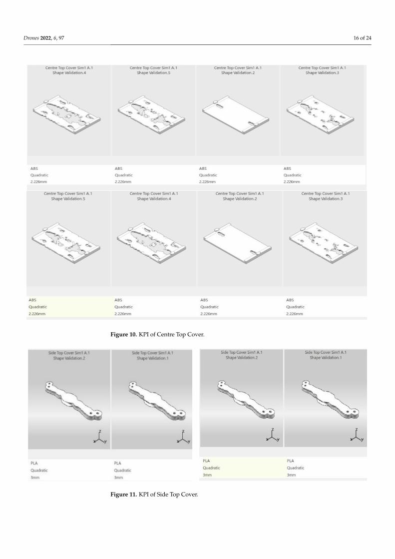
For the center top cover, the top four concept shapes generated were comparedby performing a trade-off study. The variants that were assessed were the mass, thedisplacement, and the stress of the part. The mass was given the highest priority; hence,it was set to have a key performance indicator (KPI) of 5. The target of the mass was alsoset. As well as that, the stress and displacement were given a KPI of 3 as they were lessimportant for this part as it is connected at both ends. As shown in Figure 10, based onthe variants and their respective KPIs, the first design scored the highest with a score of60.3502. However, since this part is supposed to cover up the components inside, it is notsuitable for it to have a big hole at the middle of the part. Thus, Centre Top Cover Sim1 Shape Validation 5, which scored the second highest, was chosen to be the final designsince the other variants were still in the acceptable range. For the side top cover, only twoconcept shapes generated were compared by performing a trade-off study since not muchoptimization can be conducted for this part.
The variants assessed were the mass, the displacement, and the stress of the part. Themass was given the highest priority; hence, it was set to have a KPI of 5. As well as that,the stress and displacement were given a KPI of 3 as they were not that important for thispart as it is connected at both ends. As shown in Figure 11, based on the variants and theirrespective KPIs, the first design scored higher as compared to the second design with ascore of 100. Thus, Side Top Cover Sim 1 Shape Validation 2 was chosen to be the finaldesign since the other variants were still in the acceptable range. For the middle cover,the top three concept shapes generated were compared by performing a trade-off study.Similarly, the variants assessed were the mass, the displacement, and the stress of the part.The mass was given the highest priority; hence, it was set to have a KPI of 5. As well asthat, the stress and displacement were given a KPI of 3 as they were not that important forthis part as it is connected at all corners.
Drones 2022, 6, 97 13 of 24Drones 2022, 6, x FOR PEER REVIEW 13 of 25
(a) (b)
Figure 8. Cont.
Drones 2022, 6, 97 14 of 24Drones 2022, 6, x FOR PEER REVIEW 14 of 25
(c) (d)
Figure 8. Stress and Displacement of the Drone’s Parts. (a) Centre Top Cover. (b) Side Top Cover. (c) Drone’s Arm. (d) Middle Cover. Figure 8. Stress and Displacement of the Drone’s Parts. (a) Centre Top Cover. (b) Side Top Cover. (c) Drone’s Arm. (d) Middle Cover.
Drones 2022, 6, 97 15 of 24
Drones 2022, 6, x FOR PEER REVIEW 15 of 25
(a)
(b)
Figure 9. Drone’s Carriage Stress and Displacement. (a) Leg Bereket. (b) Bottom Cover. Figure 9. Drone’s Carriage Stress and Displacement. (a) Leg Bereket. (b) Bottom Cover.
Drones 2022, 6, 97 16 of 24
Drones 2022, 6, x FOR PEER REVIEW 17 of 25
As shown in Figure 15, based on the variants and their respective KPIs, the third design scored the highest with a score of 84.4588. The stress and the displacement were within the acceptable range as well. Furthermore, it was not the lightest design, the stress was lower as compared to the first design, and it had the smallest displacement. Therefore, Bottom Cover Sim 1 Shape Validation 1 scored the highest among the three designs and it was chosen to be used as the final design.
Figure 10. KPI of Centre Top Cover.
Figure 11. KPI of Side Top Cover.
Figure 10. KPI of Centre Top Cover.
Drones 2022, 6, x FOR PEER REVIEW 17 of 25
As shown in Figure 15, based on the variants and their respective KPIs, the third design scored the highest with a score of 84.4588. The stress and the displacement were within the acceptable range as well. Furthermore, it was not the lightest design, the stress was lower as compared to the first design, and it had the smallest displacement. Therefore, Bottom Cover Sim 1 Shape Validation 1 scored the highest among the three designs and it was chosen to be used as the final design.
Figure 10. KPI of Centre Top Cover.
Figure 11. KPI of Side Top Cover. Figure 11. KPI of Side Top Cover.
Drones 2022, 6, 97 17 of 24
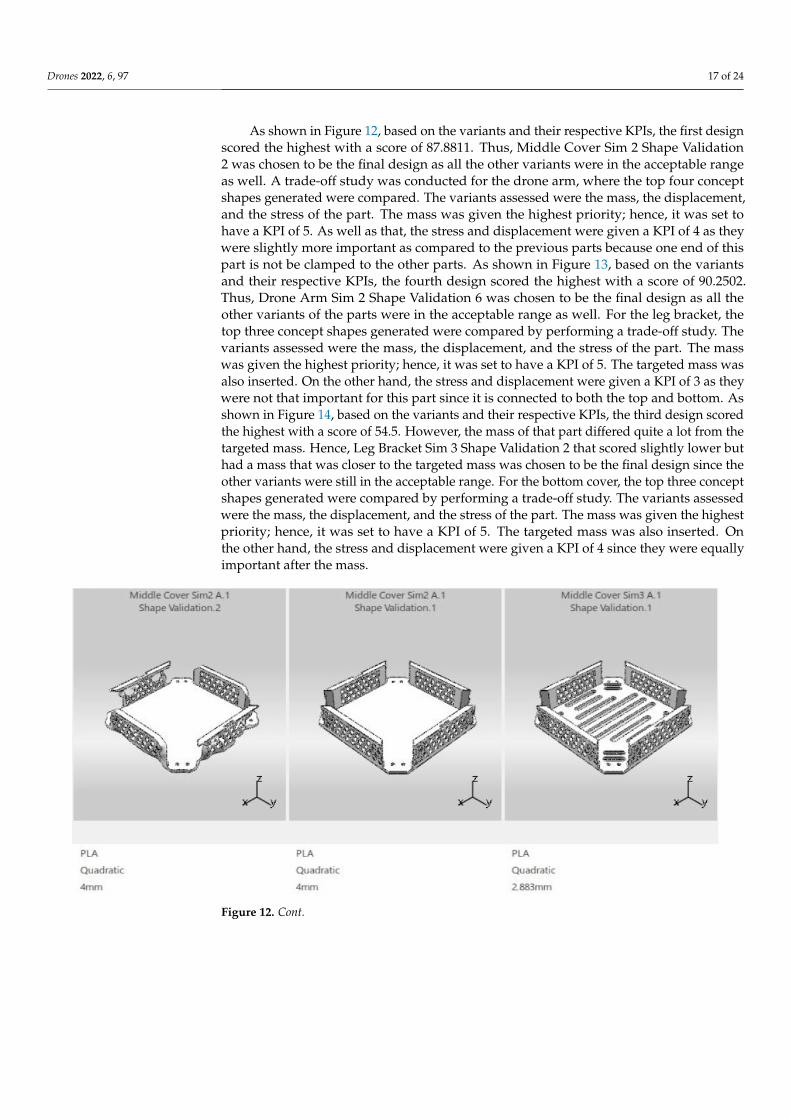
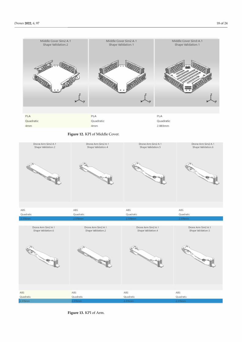
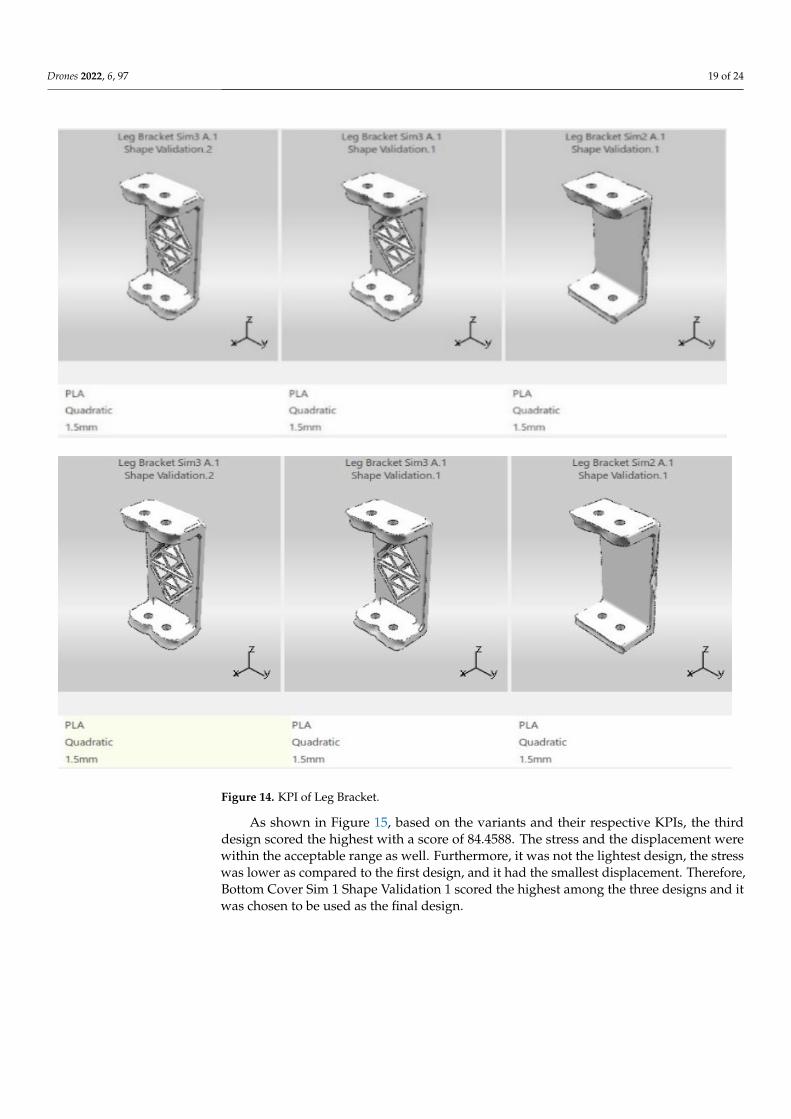
As shown in Figure 12, based on the variants and their respective KPIs, the first designscored the highest with a score of 87.8811. Thus, Middle Cover Sim 2 Shape Validation2 was chosen to be the final design as all the other variants were in the acceptable rangeas well. A trade-off study was conducted for the drone arm, where the top four conceptshapes generated were compared. The variants assessed were the mass, the displacement,and the stress of the part. The mass was given the highest priority; hence, it was set tohave a KPI of 5. As well as that, the stress and displacement were given a KPI of 4 as theywere slightly more important as compared to the previous parts because one end of thispart is not be clamped to the other parts. As shown in Figure 13, based on the variantsand their respective KPIs, the fourth design scored the highest with a score of 90.2502.Thus, Drone Arm Sim 2 Shape Validation 6 was chosen to be the final design as all theother variants of the parts were in the acceptable range as well. For the leg bracket, thetop three concept shapes generated were compared by performing a trade-off study. Thevariants assessed were the mass, the displacement, and the stress of the part. The masswas given the highest priority; hence, it was set to have a KPI of 5. The targeted mass wasalso inserted. On the other hand, the stress and displacement were given a KPI of 3 as theywere not that important for this part since it is connected to both the top and bottom. Asshown in Figure 14, based on the variants and their respective KPIs, the third design scoredthe highest with a score of 54.5. However, the mass of that part differed quite a lot from thetargeted mass. Hence, Leg Bracket Sim 3 Shape Validation 2 that scored slightly lower buthad a mass that was closer to the targeted mass was chosen to be the final design since theother variants were still in the acceptable range. For the bottom cover, the top three conceptshapes generated were compared by performing a trade-off study. The variants assessedwere the mass, the displacement, and the stress of the part. The mass was given the highestpriority; hence, it was set to have a KPI of 5. The targeted mass was also inserted. Onthe other hand, the stress and displacement were given a KPI of 4 since they were equallyimportant after the mass.
Drones 2022, 6, x FOR PEER REVIEW 18 of 25
Figure 12. KPI of Middle Cover.
Figure 12. Cont.
Drones 2022, 6, 97 18 of 24
Drones 2022, 6, x FOR PEER REVIEW 18 of 25
Figure 12. KPI of Middle Cover.
Figure 12. KPI of Middle Cover.
Drones 2022, 6, x FOR PEER REVIEW 18 of 25
Figure 12. KPI of Middle Cover.
Drones 2022, 6, x FOR PEER REVIEW 19 of 25
Figure 13. KPI of Arm.
Figure 13. KPI of Arm.
Drones 2022, 6, 97 19 of 24
Drones 2022, 6, x FOR PEER REVIEW 19 of 25
Figure 13. KPI of Arm.
Drones 2022, 6, x FOR PEER REVIEW 20 of 25
Figure 14. KPI of Leg Bracket.
Figure 14. KPI of Leg Bracket.
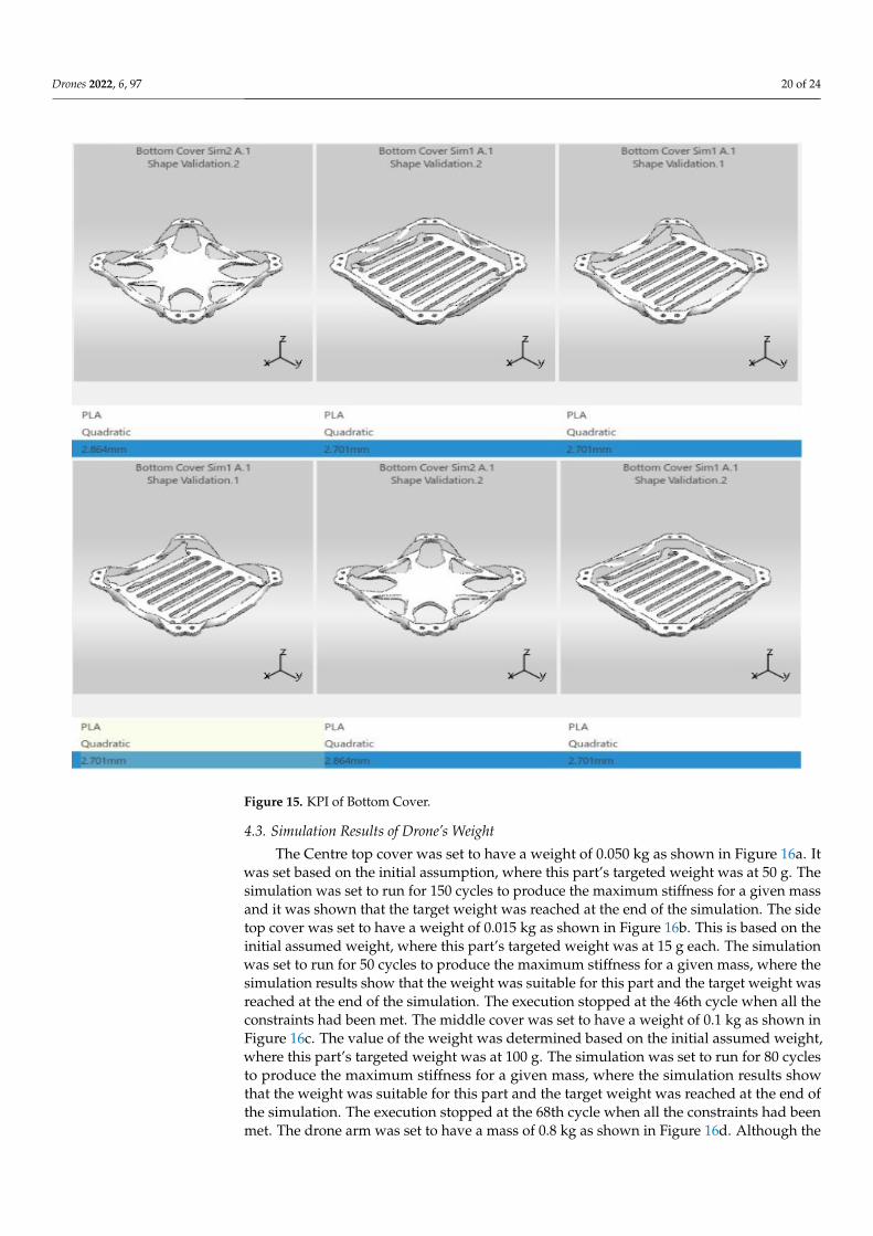
As shown in Figure 15, based on the variants and their respective KPIs, the thirddesign scored the highest with a score of 84.4588. The stress and the displacement werewithin the acceptable range as well. Furthermore, it was not the lightest design, the stresswas lower as compared to the first design, and it had the smallest displacement. Therefore,Bottom Cover Sim 1 Shape Validation 1 scored the highest among the three designs and itwas chosen to be used as the final design.
Drones 2022, 6, 97 20 of 24
Drones 2022, 6, x FOR PEER REVIEW 20 of 25
Figure 14. KPI of Leg Bracket.
Figure 15. KPI of Bottom Cover.
4.3. Simulation Results of Drone’s Weight
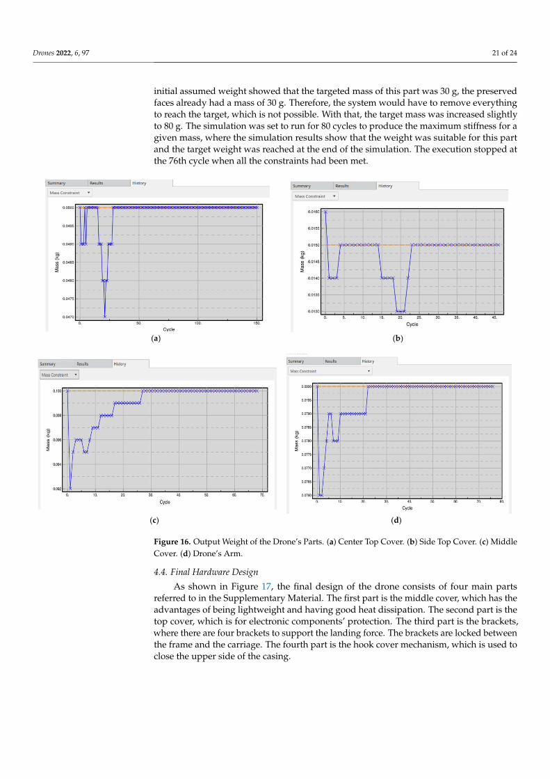
The Centre top cover was set to have a weight of 0.050 kg as shown in Figure 16a. Itwas set based on the initial assumption, where this part’s targeted weight was at 50 g. Thesimulation was set to run for 150 cycles to produce the maximum stiffness for a given massand it was shown that the target weight was reached at the end of the simulation. The sidetop cover was set to have a weight of 0.015 kg as shown in Figure 16b. This is based on theinitial assumed weight, where this part’s targeted weight was at 15 g each. The simulationwas set to run for 50 cycles to produce the maximum stiffness for a given mass, where thesimulation results show that the weight was suitable for this part and the target weight wasreached at the end of the simulation. The execution stopped at the 46th cycle when all theconstraints had been met. The middle cover was set to have a weight of 0.1 kg as shown inFigure 16c. The value of the weight was determined based on the initial assumed weight,where this part’s targeted weight was at 100 g. The simulation was set to run for 80 cyclesto produce the maximum stiffness for a given mass, where the simulation results showthat the weight was suitable for this part and the target weight was reached at the end ofthe simulation. The execution stopped at the 68th cycle when all the constraints had beenmet. The drone arm was set to have a mass of 0.8 kg as shown in Figure 16d. Although the
Drones 2022, 6, 97 21 of 24
initial assumed weight showed that the targeted mass of this part was 30 g, the preservedfaces already had a mass of 30 g. Therefore, the system would have to remove everythingto reach the target, which is not possible. With that, the target mass was increased slightlyto 80 g. The simulation was set to run for 80 cycles to produce the maximum stiffness for agiven mass, where the simulation results show that the weight was suitable for this partand the target weight was reached at the end of the simulation. The execution stopped atthe 76th cycle when all the constraints had been met.
Drones 2022, 6, x FOR PEER REVIEW 21 of 25
Figure 15. KPI of Bottom Cover.
4.3. Simulation Results of Drone’s Weight The Centre top cover was set to have a weight of 0.050 kg as shown in Figure 16a. It
was set based on the initial assumption, where this part’s targeted weight was at 50 g. The simulation was set to run for 150 cycles to produce the maximum stiffness for a given mass and it was shown that the target weight was reached at the end of the simulation. The side top cover was set to have a weight of 0.015 kg as shown in Figure 16b. This is based on the initial assumed weight, where this part’s targeted weight was at 15 g each. The simulation was set to run for 50 cycles to produce the maximum stiffness for a given mass, where the simulation results show that the weight was suitable for this part and the target weight was reached at the end of the simulation. The execution stopped at the 46th cycle when all the constraints had been met. The middle cover was set to have a weight of 0.1 kg as shown in Figure 16c. The value of the weight was determined based on the initial assumed weight, where this part’s targeted weight was at 100 g. The simulation was set to run for 80 cycles to produce the maximum stiffness for a given mass, where the simu-lation results show that the weight was suitable for this part and the target weight was reached at the end of the simulation. The execution stopped at the 68th cycle when all the constraints had been met. The drone arm was set to have a mass of 0.8 kg as shown in Figure 16d. Although the initial assumed weight showed that the targeted mass of this part was 30 g, the preserved faces already had a mass of 30 g. Therefore, the system would have to remove everything to reach the target, which is not possible. With that, the target mass was increased slightly to 80 g. The simulation was set to run for 80 cycles to produce the maximum stiffness for a given mass, where the simulation results show that the weight was suitable for this part and the target weight was reached at the end of the sim-ulation. The execution stopped at the 76th cycle when all the constraints had been met.
(a) (b)
Drones 2022, 6, x FOR PEER REVIEW 22 of 25
(c) (d)
Figure 16. Output Weight of the Drone’s Parts. (a) Center Top Cover. (b) Side Top Cover. (c) Middle Cover. (d) Drone’s Arm.
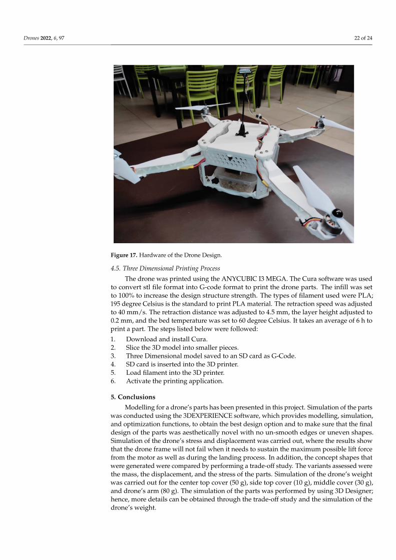
4.4. Final Hardware Design As shown in Figure 17, the final design of the drone consists of four main parts re-
ferred to in the Supplementary Material. The first part is the middle cover, which has the advantages of being lightweight and having good heat dissipation. The second part is the top cover, which is for electronic components’ protection. The third part is the brackets, where there are four brackets to support the landing force. The brackets are locked be-tween the frame and the carriage. The fourth part is the hook cover mechanism, which is used to close the upper side of the casing.
Figure 17. Hardware of the Drone Design.
4.5. Three Dimensional Printing Process The drone was printed using the ANYCUBIC I3 MEGA. The Cura software was used
to convert stl file format into G-code format to print the drone parts. The infill was set to 100% to increase the design structure strength. The types of filament used were PLA; 195 degree Celsius is the standard to print PLA material. The retraction speed was adjusted
Figure 16. Output Weight of the Drone’s Parts. (a) Center Top Cover. (b) Side Top Cover. (c) MiddleCover. (d) Drone’s Arm.
4.4. Final Hardware Design
As shown in Figure 17, the final design of the drone consists of four main partsreferred to in the Supplementary Material. The first part is the middle cover, which has theadvantages of being lightweight and having good heat dissipation. The second part is thetop cover, which is for electronic components’ protection. The third part is the brackets,where there are four brackets to support the landing force. The brackets are locked betweenthe frame and the carriage. The fourth part is the hook cover mechanism, which is used toclose the upper side of the casing.
Drones 2022, 6, 97 22 of 24
Drones 2022, 6, x FOR PEER REVIEW 22 of 25
(c) (d)
Figure 16. Output Weight of the Drone’s Parts. (a) Center Top Cover. (b) Side Top Cover. (c) Middle Cover. (d) Drone’s Arm.
4.4. Final Hardware Design As shown in Figure 17, the final design of the drone consists of four main parts re-
ferred to in the Supplementary Material. The first part is the middle cover, which has the advantages of being lightweight and having good heat dissipation. The second part is the top cover, which is for electronic components’ protection. The third part is the brackets, where there are four brackets to support the landing force. The brackets are locked be-tween the frame and the carriage. The fourth part is the hook cover mechanism, which is used to close the upper side of the casing.
Figure 17. Hardware of the Drone Design.
4.5. Three Dimensional Printing Process The drone was printed using the ANYCUBIC I3 MEGA. The Cura software was used
to convert stl file format into G-code format to print the drone parts. The infill was set to 100% to increase the design structure strength. The types of filament used were PLA; 195 degree Celsius is the standard to print PLA material. The retraction speed was adjusted
Figure 17. Hardware of the Drone Design.
4.5. Three Dimensional Printing Process
The drone was printed using the ANYCUBIC I3 MEGA. The Cura software was usedto convert stl file format into G-code format to print the drone parts. The infill was setto 100% to increase the design structure strength. The types of filament used were PLA;195 degree Celsius is the standard to print PLA material. The retraction speed was adjustedto 40 mm/s. The retraction distance was adjusted to 4.5 mm, the layer height adjusted to0.2 mm, and the bed temperature was set to 60 degree Celsius. It takes an average of 6 h toprint a part. The steps listed below were followed:
1. Download and install Cura.2. Slice the 3D model into smaller pieces.3. Three Dimensional model saved to an SD card as G-Code.4. SD card is inserted into the 3D printer.5. Load filament into the 3D printer.6. Activate the printing application.
5. Conclusions
Modelling for a drone’s parts has been presented in this project. Simulation of the partswas conducted using the 3DEXPERIENCE software, which provides modelling, simulation,and optimization functions, to obtain the best design option and to make sure that the finaldesign of the parts was aesthetically novel with no un-smooth edges or uneven shapes.Simulation of the drone’s stress and displacement was carried out, where the results showthat the drone frame will not fail when it needs to sustain the maximum possible lift forcefrom the motor as well as during the landing process. In addition, the concept shapes thatwere generated were compared by performing a trade-off study. The variants assessed werethe mass, the displacement, and the stress of the parts. Simulation of the drone’s weightwas carried out for the center top cover (50 g), side top cover (10 g), middle cover (30 g),and drone’s arm (80 g). The simulation of the parts was performed by using 3D Designer;hence, more details can be obtained through the trade-off study and the simulation of thedrone’s weight.
Drones 2022, 6, 97 23 of 24
Supplementary Materials: The following supporting information can be downloaded at: https://www.mdpi.com/article/10.3390/drones6040097/s1, Figure S1: Dimention of drone Leg breaket;Figure S2: Dimention of drone side top cover. Figure S3: Dimention of drone arm, Figure S4: Dimen-tion of drone midell cover, Figure S5: 3D printer model, Figure S6: Side top cover, meddle cover andcenter top cover of the drone, Figure S7: Description of 3D printed parts.
Author Contributions: Methodology, A.O.M. and H.C.; software, P.U.; validation, K.Y. and H.C.;formal analysis, T.J.; investigation, T.J.; writing—original draft preparation, A.O.M., H.C., P.U. andT.J.; writing—review and editing, A.O.M. and K.Y.; supervision, K.Y. and H.C.; funding acquisition,K.Y. and H.C. All authors have read and agreed to the published version of the manuscript.
Funding: This research was funded by [Sunway University postgraduate studentship and Schoolof Engineering UOW Malaysia KDU Penang University Colleg e, Postgraduate & Research Centre(PGRC)]. And the APC was funded by [Sunway University postgraduate studentship and School of En-gineering UOW Malaysia KDU Penang University College, Postgraduate & Research Centre (PGRC)].
Institutional Review Board Statement: Not applicable.
Informed Consent Statement: Not applicable.
Acknowledgments: We would like to acknowledge the support of Sunway University postgraduatestudentship and School of Engineering UOW Malaysia KDU Penang University College , Postgradu-ate & Research Centre (PGRC). Additionally, we would like to acknowledge the help in 3D printingand fabrication by: Lee Wei Hou, Chan Lap Foong, Seerla Kanagarajoo, Betharajoo, and SimonAnandaraj Doss.
Conflicts of Interest: The authors declare no conflict of interest.
References1. Oakey, A.; Waters, T.; Zhu, W.; Royall, P.; Cherrett, T.; Courtney, P.; Majoe, D.; Jelev, N. Quantifying the Effects of Vibration on
Medicines in Transit Caused by Fixed-Wing and Multi-Copter Drones. Drones 2021, 5, 22. [CrossRef]2. Hiebert, B.; Nouvet, E.; Jeyabalan, V.; Donelle, L. The Application of Drones in Healthcare and Health-Related Services in North
America: A Scoping Review. Drones 2020, 4, 30. [CrossRef]3. Akhloufi, M.; Couturier, A.; Castro, N. Unmanned Aerial Vehicles for Wildland Fires: Sensing, Perception, Cooperation and
Assistance. Drones 2021, 5, 15. [CrossRef]4. Barreto, J.; Cajaíba, L.; Teixeira, J.; Nascimento, L.; Giacomo, A.; Barcelos, N.; Fettermann, T.; Martins, A. Drone-Monitoring:
Improving the Detectability of Threatened Marine Megafauna. Drones 2021, 5, 14. [CrossRef]5. A Game Changer for Business and Innovation. Available online: https://www.3ds.com/3dexperience (accessed on
28 February 2022).6. Royo, P.; Pastor, E.; Barrado, C.; Cuadrado, R.; Barrao, F.; Garcia, A. Hardware Design of a Small UAS Helicopter for Remote
Sensing Operations. Drones 2017, 1, 3. [CrossRef]7. Dawkins, J.; Devries, L. Modeling, Trim Analysis, and Trajectory Control of a Micro-Quadrotor with Wings. Drones 2018, 2, 21.
[CrossRef]8. Shukla, D.; Komerath, N. Multirotor Drone Aerodynamic Interaction Investigation. Drones 2018, 2, 43. [CrossRef]9. Castiblanco, J.M.; Garcia-Nieto, S.; Simarro, R.; Salcedo, J. Experimental study on the dynamic behaviour of drones designed for
racing competitions. Int. J. Micro Air Veh. 2021, 13, 17568293211005757. [CrossRef]10. Basson, C.; Hansraj, S.; Stopforth, R.; Mooney, P.; Phillips, R.; Van Niekerk, T.; Du Preez, K. A Review of Collaborated Educational
Drone Development and Design at the BRICS 2018 Future Skills Challenge. In Proceedings of the 2019 Southern AfricanUniversities Power Engineering Conference/Robotics and Mechatronics/Pattern Recognition Association of South Africa(SAUPEC/RobMech/PRASA), Bloemfontein, South Africa, 28–30 January 2019; pp. 17–22. [CrossRef]
11. Jo, B.W.; Song, C.S. Thermoplastics and Photopolymer Desktop 3D Printing System Selection Criteria Based on TechnicalSpecifications and Performances for Instructional Applications. Technologies 2021, 9, 91. [CrossRef]
12. Horvath, J.; Cameron, R. The Desktop 3D Printer. In 3D Print with MatterControl; Springer: Berkeley, CA, USA, 2015; pp. 3–13.[CrossRef]
13. Kacmarcik, J.; Spahic, D.; Varda, K.; Porca, E.; Zaimovic-Uzunovic, N. An investigation of geometrical accuracy of desktop 3Dprinters using CMM. IOP Conf. Series: Mater. Sci. Eng. 2018, 393, 012085. [CrossRef]
14. 3D Printing Third Edition. Available online: https://lib.hpu.edu.vn/handle/123456789/31244 (accessed on 27 February 2022).15. Shahrubudin, N.; Lee, T.; Ramlan, R. An Overview on 3D Printing Technology: Technological, Materials, and Applications.
Procedia Manuf. 2019, 35, 1286–1296. [CrossRef]16. Arefin, A.; Khatri, N.; Kulkarni, N.; Egan, P. Polymer 3D Printing Review: Materials, Process, and Design Strategies for Medical
Applications. Polymers 2021, 13, 1499. [CrossRef]
Drones 2022, 6, 97 24 of 24
17. Antreas, K.; Piromalis, D. Employing a Low-Cost Desktop 3D Printer: Challenges, and How to Overcome Them by Tuning KeyProcess Parameters. Int. J. Mech. Appl. 2021, 10, 11–19. [CrossRef]
18. Harynska, A.; Carayon, I.; Kosmela, P.; Szeliski, K.; Łapinski, M.; Pokrywczynska, M.; Kucinska-Lipka, J.; Janik, H. A com-prehensive evaluation of flexible FDM/FFF 3D printing filament as a potential material in medical application. Eur. Polym. J.2020, 138, 109958. [CrossRef]
19. Krishnanand; Soni, S.; Taufik, M. Design and assembly of fused filament fabrication (FFF) 3D printers. Mater. Today Proc.2020, 46, 5233–5241. [CrossRef]
20. Vasudevarao, B.; Natarajan, D.P.; Henderson, M. Sensitivity of Rp Surface Finish to Process. In Proceedings of the 2000International Solid Freeform Fabrication Symposium, Austin, TX, USA, 25–27 July 2000; pp. 251–258.
21. Galatas, A.; Hassanin, H.; Zweiri, Y.; Seneviratne, L. Additive Manufactured Sandwich Composite/ABS Parts for UnmannedAerial Vehicle Applications. Polymers 2018, 10, 1262. [CrossRef]
22. Bishay, P.L.; Burg, E.; Akinwunmi, A.; Phan, R.; Sepulveda, K. Development of a New Span-Morphing Wing Core Design. Designs2019, 3, 12. [CrossRef]
23. Sharma, V. Advances in Drone Communications, State-of-the-Art and Architectures. Drones 2019, 3, 21. [CrossRef]24. Muralidharan, N.; Pratheep, V.; Shanmugam, A.; Hariram, A.; Dinesh, P.; Visnu, B. Structural analysis of mini drone developed
using 3D printing technique. Mater. Today Proc. 2021, 46, 8748–8752. [CrossRef]25. Negrelli, V. “From earth to heaven”: How professional 3D Printing and Windform® GT material helped in the construction of
drone and medical devices. Reinf. Plast. 2017, 61, 179–183. [CrossRef]26. Kantaros, A.; Diegel, O. 3D printing technology in musical instrument research: Reviewing the potential. Rapid Prototyp. J.
2018, 24, 1511–1523. [CrossRef]27. Shen, C.H.; Albert, F.Y.C.; Ang, C.K.; Teck, D.J.; Chan, K.P. Theoretical development and study of takeoff constraint thrust
equation for a drone. In Proceedings of the 2017 IEEE 15th Student Conference on Research and Development (SCOReD), WilayahPersekutuan Putrajaya, Malaysia, 13–14 December 2017; pp. 18–22. [CrossRef]
28. Research and Development in Modern Materials. Available online: https://blogs.deakin.edu.au/remstep/materials-activities/honeycomb-structures/ (accessed on 1 January 2022).
29. Amza, C.G.; Zapciu, A.; Eyþórsdóttir, A.; Björnsdóttir, A.; Borg, J. Mechanical properties of 3D printed composites with ABS/ASAsubstrate and glass fiber inserts. In Proceedings of the MATEC Web of Conferences, Kursk, Russia, 1 November 2019; Volume 290,p. 04002. [CrossRef]
30. Afshar, A.; Wood, R. Development of Weather-Resistant 3D Printed Structures by Multi-Material Additive Manufacturing.J. Compos. Sci. 2020, 4, 94. [CrossRef]
31. Butt, J.; Bhaskar, R. Investigating the effects of annealing on the mechanical properties of FFF-printed thermoplastics. J. Manuf.Mater. Process. 2020, 4, 94. [CrossRef]
32. Comparing 3D Printing Filament Features: ABS vs. ASA Filament. Available online: https://www.makeshap-er.com/2020/01/24/3d-printing-filament-features-abs-vs-asa-filament/ (accessed on 28 February 2022).
33. Iannace, S.; Sorrentino, L.; Di Maio, E. Biodegradable Biomedical Foam Scaffolds; Woodhead Publishing Limited: Federico II, Italy,2014; pp. 163–187. [CrossRef]
34. Malaysian Information Climate. Available online: https://www.malaysia.gov.my/portal/content/144 (accessed on28 February 2022).
35. Rayna, T.; Striukova, L. From rapid prototyping to home fabrication: How 3D printing is changing business model innovation.Technol. Forecast. Soc. Chang. 2016, 102, 214–224. [CrossRef]
36. Brischetto, S.; Torre, R. Preliminary Finite Element Analysis and Flight Simulations of a Modular Drone Built through FusedFilament Fabrication. J. Compos. Sci. 2021, 5, 293. [CrossRef]
37. Kantaros, A.; Piromalis, D.; Tsaramirsis, G.; Papageorgas, P.; Tamimi, H. 3D Printing and Implementation of Digital Twins:Current Trends and Limitations. Appl. Syst. Innov. 2022, 5, 7. [CrossRef]
38. Kantaros, A.; Karalekas, D. FBG Based In Situ Characterization of Residual Strains in FDM Process. Conf. Proc. Soc. Exp. Mech.Ser. 2014, 8, 333–337. [CrossRef]
39. 3D Robotics IRIS + RTF Kit (433). Available online: https://www.megapixel.cz/3d-robotics-iris-433 (accessed on 2 March 2022).40. Skeleton X-14 Quadcopter. Available online: https://cults3d.com/en/3d-model/gadget/skeleton-x-14-quadcopter (accessed on
2 March 2022).