geophysical and geotechnical investigations to support the restoration project of the roman ‘villa...
TRANSCRIPT
© 2012 European Association of Geoscientists & Engineers 145
Near Surface Geophysics, 2012, 10, 145-160 doi:10.3997/1873-0604.2011038
Geophysical and geotechnical investigations to support the restoration project of the Roman ‘Villa del Casale’, Piazza Armerina, Sicily, Italy
P. Capizzi, R. Martorana*, P. Messina and P.L. Cosentino
Dipartimento di Scienze della Terra e del Mare, University of Palermo, via Archirafi 26, 90123 Palermo, Italy
Received March 2011, revision accepted August 2011
ABSTRACTA multidisciplinary geophysical and geotechnical study, including some non-invasive geophysical applications, was carried out during the restoration of the ‘Villa del Casale’, a Roman villa discov-ered near Piazza Armerina (Sicily, Italy) in 1929, famous for its Roman floor mosaics. The project aims were to characterize the geology of the subsoil and provide information for solving the main building structural problems including the subsidence of some parts of the floor and the detachment of the tesserae (i.e., the tiles) of the mosaics. Another goal was the detailed study of the underground structures of the Corridor of the Great Hunt, a part of the villa strongly affected by subsidence and detachment of mosaics.
The acquisition of geotechnical and geophysical surveys, including core drillings, time-domain electromagnetic (TDEM) soundings, downhole seismic logs and a seismic refraction profile, allowed the reconstruction of the geometry of geological formations below the villa to be ascer-tained, especially with regard to the top of the bedrock. The results suggest the presence of a buried riverbed that has been identified as the main cause of the villa floor subsidence.
The study of the Corridor of the Great Hunt involved full 3D electrical resistivity tomography (ERT) and 3D ground-penetrating radar (GPR) data acquisition using 100 MHz, 400 MHz and 1600 MHz antennas, as well as the above mentioned refraction seismic profile. Data acquisition required the use of special non-invasive sensors to avoid any damage to the mosaics. The integrated inversion of all the data and the comparison between the resulting 3D resistivity model and 400 MHz GPR depth-slices allowed the identification of many shallow anomalies to be identified, including some pipes for water drainage and a reinforced concrete basement placed under the floor during a previous restoration intervention. 100 MHz GPR profiles validated the results of the seis-mic refraction profile model. Finally, 1600 MHz GPR depth-slices, in the most subsided zone, allowed the location of air bubbles under the mosaic to be identified.
This work shows that the integrated use of different geophysical techniques for archaeological purposes, especially if constrained by direct explorations, greatly reduced the intrinsic uncertainties of each method. Moreover, customizing standard geophysical equipment to avoid any damage is essential when working on protected cultural heritage.
supporting the villa needs. The interest of ‘Villa del Casale’ is mainly due to the spectacular floor mosaics. Unfortunately in some areas of the villa a differential subsidence occurred in the ground. This has caused the lowering of the floor of some rooms and the consequent detachment of the mosaics from the base layer underneath. The most serious subsidence occurred in the southern part of the Corridor of the Great Hunt, where the gaps in the floor reached values of more than one metre. Consequently, a new restoration plan was prepared by the Sicilian Restoration Centre, including the consolidation of the architectural structures as well as the restoration of the mosaics themselves. The plan
INTRODUCTIONPiazza Armerina (Fig. 1) is a very important archaeological site in Sicily and many excavations have been carried out here during the last century. The well-known ‘Villa del Casale’ is one of the most important findings, which was covered by a mud alluvium until 1929, when archaeological excavations began. New recent searches and excavations have begun because many experts argue that such a kind of Roman villa might not be isolated: on the contrary it is likely to be surrounded by many other houses

P. Capizzi et al.146
© 2012 European Association of Geoscientists & Engineers, Near Surface Geophysics, 2012, 10, 145-160
cation and location of air pockets below the mosaics caused by both the detachment of the mosaic coat from its base and dry climatic conditions of the site.
Different geophysical techniques have been widely used in archaeological applications, mainly aimed at detecting and map-ping near-surface buried structures and cavities but also at char-acterizing the foundation subsoil of buildings, in order to miti-gate problems of stability and to facilitate preservation. In most cases, integrated use of different geophysical methods (e.g.,
provided a preliminary phase of diagnostic studies, including geotechnical and geophysical surveys.
The main issues to be addressed by the diagnostic studies, preliminary to the restoration, were the geological and geotech-nical characterization of the site, with the aim, amongst other things, of detecting the causes of subsidence affecting some floors of the villa. The second main objective was to identify potential structures buried below some areas particularly affected by subsidence. Finally, an unusual aim was the detailed identifi-
FIGURE 1
Geographic location and aerial
view of the Roman ‘Villa del
Casale’, near the town of Piazza
Armerina, Sicily, Italy. The five
main groups of rooms are indi-
cated: 1) main entrance and ther-
mal baths; 2) peristilium with
dining room and guest room;
3) private rooms and basilica;
4) triclinium and elliptic court-
yard and 5) Corridor of the Great
Hunt.
FIGURE 2
Topographic sitemap with the
location of the geophysical and
geotechnical surveys carried out
nearby the ‘Villa del Casale’ of
Piazza Armerina. The main
archaeological buildings and the
ancient aqueducts are also indi-
cated. Topographic values are in
metres.

Investigations supporting a villa restoration project 147
© 2012 European Association of Geoscientists & Engineers, Near Surface Geophysics, 2012, 10, 145-160
by Gino Vinicio Gentili after which the current roof in glass and steel was built to cover the villa (Gentili 1959).
Archaeological notesThe villa can be divided into four main groups of rooms: 1) main entrance and thermal baths; 2) peristyle with dining room and guest room; 3) private rooms and basilica and 4) triclinium and elliptic courtyard (see Fig. 1). They lie at three different topo-graphic levels. The higher ground to the east is occupied by the Great Basilica, the private apartments and the Corridor of the Great Hunt, the middle ground is occupied by the peristyle, guest rooms, the entrance area, the elliptical peristyle and the triclini-um, while the lower ground to the west is dedicated to the ther-mal baths (Carandini et al. 1982).
The mosaics are the prime reason for the fame of the ‘Villa Romana del Casale’. One of the rooms with particularly interest-ing mosaics is the Corridor of the Great Hunt, with hunting scenes from Africa, an allegory of India or Arabia and the embar-kation of the animals for transport to the Coliseum in Rome (Baum-vom Felde 2003). This corridor separates the public spaces to the east, the peristyle, the thermal baths and the guest rooms, from the Great Basilica and the private apartments to the west. Its floor is elevated approximately 2 m above the level of the peristyle. Entry from the peristyle is by three stairways, two of which are aligned with the northern and southern parts of the portico and one in the centre, just opposite the entrance of the Great Basilica. The corridor is about 66 m × 5 m with apses in both ends.
The ‘Villa Romana del Casale’ received its water supply from two aqueducts (Fig. 2). One entered from the north and fed the piscina or pool of the baths. There are several remaining parts of this aqueduct along the entrance to the villa. The other aqueduct entered from the east, feeding a reservoir behind the triclinium. From here the water was channelled into a path, crossing the corridor of the Great Hunt, passing under the southern portico of the peristyle and leading towards the pool in the peristyle and to the latrines.
The debris from the landslide that covered the villa in the 12th century, has likely contributed to cause the subsidence of the soil under the southern part of the corridor, creating a deep collapse. The mosaic in this part of the corridor is very well preserved partly because the subsoil subsided very slowly and partly because the huge weight on top of the mosaic helped to keep each individual glass tile (tessera) fixed.
Geology and hydrogeologyThe archaeological site is located at the border of an alluvial-detritic plain, in a piedmont position. The Plio-Pleistocenic out-cropping lithotypes are mostly represented by a sand-marl-aren-ite complex in transgression over the lower Pliocenic carbonate marls (Trubi), which are on top of the underlying evaporitic series. The most common lithologies are Plio-Pleistocenic deposits, composed of sandstone and yellowish sands with len-
Hesse 1999; Piro et al. 2000) was found to be more effective than using a single one (e.g., Senos Mattias and Almeida 1992; Drahor 2006). In these cases, compared interpretations of differ-ent kinds of geophysical data helped to eliminate the intrinsic ambiguities of each single inversion. Among others, buildings and archaeological remains of the Roman era have often been investigated with geophysical techniques (Sambuelli et al. 1999; Piro et al. 2003; Cardarelli and Di Filippo 2009). Other studies have also been undertaken for the geophysical characterization and monitoring of monuments (Bavusi et al. 2009; Masini et al. 2010; Nuzzo and Quarta 2010). The use of resistivity tomogra-phy and ground-penetrating radar (GPR) surveys generally pro-vides good target location for the recognition of buried archaeo-logical structures (Goodman 1994; Savvaidis et al. 1999; Carrara et al. 2001; Goodman et al. 2002; Rizzo et al. 2005; Martino et al. 2006; Capizzi et al. 2007; Piscitelli et al. 2007). Furthermore, in case of indoor surveys, these two techniques are particularly non-invasive (Dabas et al. 2000; Vega Perez et al. 2000; Cardarelli et al. 2002; Tsokas et al. 2008; Cosentino et al. 2009a; Cosentino et al. 2009b; Pringle et al. 2009).
In the site of the ‘Villa del Casale’, in order to calibrate strati-graphic, hydrological and geotechnical characterization of the site and to identify potential buried geological and morphologi-cal structures – responsible for the stability problems – seven core drillings were performed and the information obtained was used to calibrate results of two downhole seismic surveys, seven time-domain electromagnetic (TDEM) soundings and one seis-mic refraction profile (see Fig. 2 for locations).
In the Corridor of the Great Hunt, the aim to validate assump-tions regarding the subsidence and to locate in detail buried structures, such as voids and water pipes, was addressed by car-rying out high resolution geophysical surveys. These consist of integrated 3D electrical resistivity tomography and GPR profiles and time-slice images using 100 MHz and 400 MHz antennas (see Fig. 9 for locations).
Finally, the part of the corridor mostly suffering from subsidence (and consequently from the detachment of the mosaic tiles) was investigated in detail by GPR profiles using a 1600 MHz antenna.
Historical outlineThe ‘Villa Romana del Casale’ (one of the UNESCO world her-itage sites) is located about 5 km outside the town of Piazza Armerina (Italy) (Fig. 1). It was built, covering an area of about 3500 m2, between 330–360 AD on the remains of an older villa, its period of splendour being during the 4th and 5th centuries AD.
The building was badly damaged during the domination of the Vandals and the Visigoths, between 468–535 AD but it remained in use, at least in part, during the later Byzantine and Arab period. The site was finally abandoned when a landslide buried the villa in the 12th century and surviving inhabitants set-tled in the present town of Piazza Armerina.The villa was re-discovered in the 19th century but the latest major excavations were carried out during the period 1950–1960
P. Capizzi et al.148
© 2012 European Association of Geoscientists & Engineers, Near Surface Geophysics, 2012, 10, 145-160
main deformations, in fact, are located according to the natural and/or artificial drainage axes of superficial and/or groundwa-ters.
GEOPHYSICAL SURVEYS TO CHARACTERIZE THE SUBSOILThe restoration project of the villa has required the geological, hydrogeological and geotechnical characterization of the founda-tion subsoil to be characterized. A series of seven geotechnical cores was carried out to reconstruct the stratigraphy of the areas around the villa. Furthermore, a phase of geophysical investiga-tions was undertaken to recognize and verify the lateral extent of the geological bedrock (Fig. 2). In particular, the aim was to reconstruct the top of the Pliocene bedrock, in order to obtain the values of some important mechanical parameters of rocks in the subsoil and to better understand the reasons for subsidence.
Core drillingIn order to allow the reconstruction of the archaeological strati-graphy, seven continuous core drillings were performed (Fig. 4). These predominantly showed that the Pliocene bedrock was covered by a thick alluvial fan. In particular, the following sequence was identified from bottom to top:
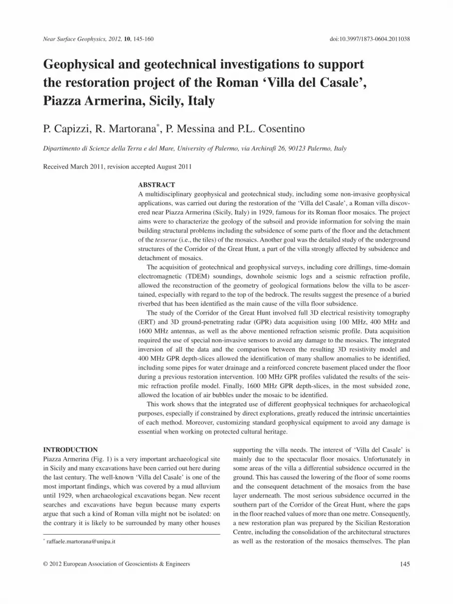
ticular and layered quartzarenite and bio-calcarenite intercala-tions, vertically passing to silt and gray sandy clay (Di Geronimo et al. 1978). Such terrains have recently been covered by some metres of detritus, made up of inhomogeneous elements. In some areas various sandy debris, including anthropological remains (red brickworks, pottery, terracotta, etc.) are evident (Fig. 3).
Generally, the permeability is a function of cementation rate and grain size. Some silty and pelitic levels cause vertical and lateral permeability variations, so that the underground water circulation is irregular.
Because the villa lies at different topographic levels, on strongly heterogeneous detritic terrains discontinuously covering consistent arenites; differential ground failures have occurred, leading in turn to significant local deformations. The subsidence of the floor, which occurred mainly in the corridor of the Great Hunt (see Fig. 9) and in rooms adjacent to it, was probably due to variations of underground tensional conditions, in particular to the differences between the reactions of loosely cemented sandy materials and more consistent silty-clayey formations. In this area underwater outflow probably caused a washing of the thin-nest sediment portion and consequently an increase of porosity, thus speeding up the consolidation of the shallowest layer, under the floor, so starting deformation processes of the floor. The
FIGURE 3
Top: sketch of the geology of the area
around the ‘Villa del Casale’ of Piazza
Armerina. Bottom: geological section
(see top for location) (from Graziano
and Scalone 2007).

Investigations supporting a villa restoration project 149
© 2012 European Association of Geoscientists & Engineers, Near Surface Geophysics, 2012, 10, 145-160
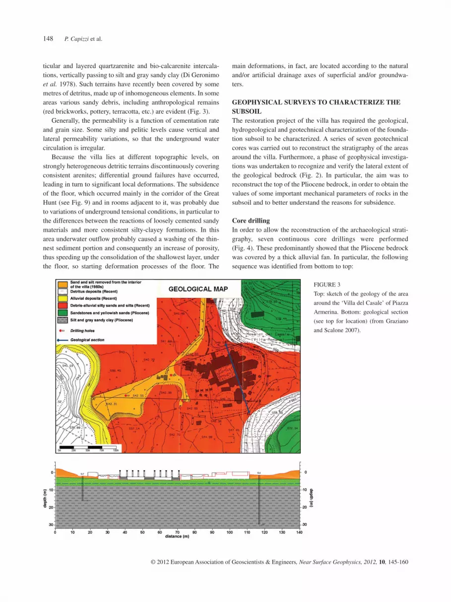
Seismic surveysIn order to characterize the seismic velocity of the rocks evi-denced by the drilling cores, two seismic downhole surveys were carried out in the garden of the villa at S4 and S6 locations, located less than 30 m from the Corridor of the Great Hunt (see Fig. 2 for location). D4 results (Fig. 5) show a longitudinal wave velocity value vp ranging from 400–1400 m/s, having a near constant velocity gradient down to a depth of about 6–7 m (ele-vation about 541–542 m), which corresponds to the lithological transition between silty sands and silty clays, in which velocity decreases; then velocity increases again almost linearly with depth down to about 16–17 m. At a depth greater than 17 m (lit-tle saturated sands, after the analysis of the geotechnical cores) the velocity is frequently variable (probably due to different thin layers). Shear-wave velocity v
s ranged from 200–420 m/s, with
the velocity gradient changing again at the transition between sands and clays (about 7 m).
D6 results (Fig. 5) showed values of vp on a wider range
(400–2200 m/s) than those of D4. The velocity in the first ten metres (400–900 m/s) shows some reversals correlated to the different degrees of consistency of soils, also evidenced by the drillings. At a depth of 11–12 m (elevation 542–543 m) there is a sharp increase of v
p near the transition between silty sands and
clayey-silts. The shear-wave velocity graph showed a linear trend with a low velocity gradient (v
s from 300–420 m/s). Knowledge
of values of vp and v
s allowed the estimation of the Poisson
modulus versus depth.
1 sandstone and yellowish sands and silts vertically passing to silt and grey sandy clays (Pliocene);2 alluvial fan characterized by detrital-alluvial silty sands and sandy silt (recent);3 debris characterized by sand and silt deriving from the removal of debris inside the villa (1950s);4 scree (recent);5 fluvial deposits (recent).
In cores S4 and S7, nearest to the villa, the thickness of the allu-vial deposits above the geological formation is 0.90 m and 2.50 m below present ground level (bgl), respectively. These data seem to confirm the hypothesis that the walls of the buildings rest directly on the sandy portion of the Pliocene formation. The maximum thickness of the alluvial layer was found in surveys carried down-stream, (S1, S2 and S3) and ranges from 1 m to about 4 m. Here the alluvial layer is located under the land-over resulting from the removal of debris from the villa, carried out in the 1950s. This latter has a thickness of about 5–6 m. Survey S5 was performed ahead of the villa in the final size of the hanging riverbed in the direction of a small latrine inside the villa: it is located on the ideal extension of the upstream small valley, towards the depres-sion of the Corridor of the Great Hunt. Under a 4.80 m thick layer of alluvial material, a very thick peat layer was found, followed at depth 7.50 m by sandy silts rich in organic matter. The sandy-silty and clayey substrate is found at a depth of 13 m, substantiating the hypothesis of an ancient riverbed under the villa.
FIGURE 4
Stratigraphy of the cores drilled
around the ‘Villa del Casale’ (see
Fig. 2 for location).
P. Capizzi et al.150
© 2012 European Association of Geoscientists & Engineers, Near Surface Geophysics, 2012, 10, 145-160
Data have been interpreted using the well-known generalized reciprocal method (GRM), which is a technique for delineating undulating refractors from in-line seismic refraction data consist-ing of forward and reverse traveltimes. The GRM method employs a refractor velocity analysis and time-depth calculations, consider-ing the optimum spacing between two geophones, in which the upward travelling segments of the rays to each geophone emerge from near the same point on the refractor (Palmer 1981).The inter-pretation, characterized by a simple two-layer model (Fig. 6), shows an unconsolidated layer (v
p = 750 m/s), with a thickness
ranging from 4.9–6.1 m, interpreted as the alluvial fan, covering a basement (v
p = 1400 m/s, elevation ranging from 542.2–543.5 m),
characterized by a seismic velocity comparable with that of silty clay and then interpreted as the Pliocene autochthonous formation.
In order to laterally correlate the velocity models obtained by the downholes and then to obtain a detailed pattern of the bedrock below the Corridor of the Great Hunt, a seismic refraction survey was carried out throughout the mosaic of the floor of the corridor (see Fig. 2 for location, Fig. 10c). A 48 channels seismometer ABEMTM Terraloc MK6 equipment was used, equipped with an 8 kg sledgehammer as a seismic source. A 2 m geophone spacing was chosen, connecting 31 geophones for a total length of 60 m, acquiring first arrival data from five source points located at dif-ferent offsets. In order to avoid any minimal damage to the tesserae, geophones were simply placed on the floor but the use of appropriate base tripods and the relative peacefulness of the site, together with a multiple stacking acquisition, helped to achieve a good signal-to-noise ratio.
FIGURE 5
Plot of vp and v
s velocities versus
depth, obtained from seismic
data inversion of downhole data.
FIGURE 6
Refraction seismic survey carried
out in the Corridor of the Great
Hunt (see Fig. 2 for location
map). Top: traveltime data
obtained by picking first arrivals.
Bottom: inverse 2D seismic
model. The segments with arrow-
heads indicate two slight depres-
sions in the base.
Investigations supporting a villa restoration project 151
© 2012 European Association of Geoscientists & Engineers, Near Surface Geophysics, 2012, 10, 145-160
loop configuration, with square or rectangular loops and side lengths ranging from 10–25 m, depending on the available space. Current intensities equal to 4A and time windows ranging from 2048–4096 microseconds were chosen. Data processing involved a preliminary application of a notch filter to remove noise associ-ated with nearby 50 Hz power lines, followed by selective stack-ing and a further smoothing filtering to remove additional back-ground noise.
Some TDEM surveys were located almost in coincidence or very near to the drilling wells and inversions were performed by fixing the values of layer thickness in agreement with the corre-sponding stratigraphic columns. The inversions of the remaining TDEM surveys were executed by choosing the inverse model of the nearest TDEM survey as the initial model.
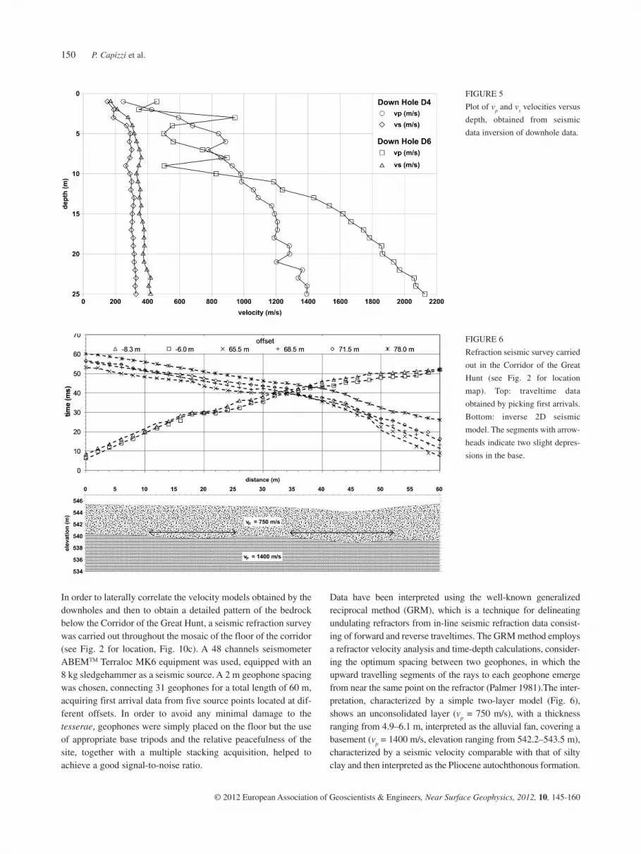
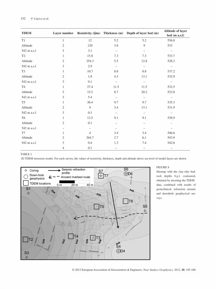
Apparent resistivity curves and related inverse models are shown in Fig. 7. In addition, the numerical values of resistivity, thickness, depth and altitude at sea level of each layer are shown in Table 1. Sounding T1 is located near drilling S2. Unfortunately, in this case data are affected by the classical electromagnetic noise
The inversion results of the refraction seismic data were consist-ent with the models obtained from the downhole data, consider-ing the different direction the wave travels in each method and the natural anisotropy of the longitudinal wave velocity in the sedimentary overburden. In particular, we can see two slight depressions in the base: the first between the coordinates 11 m and 25 m and the second, more pronounced, between 35–52 m, practically below the main subsidence of the floor.
TDEM surveysIn order to obtain the vertical distribution of the electrical resis-tivity and to obtain additional information for extending the results of the geotechnical drillings to those areas that are not accessible by drillers, seven TDEM surveys were carried out (Fig. 2 for location).
A portable TEM-FASTTM 48 HPC instrument was chosen, as this was easy and quick to use and at the same time it is highly performing and allows fast measurements (Barsukov et al. 2007). Data acquisition was performed by using a coincident
FIGURE 7
TDEM soundings. For each
sounding plot of apparent resis-
tivity versus time, the inverse
models of resistivity are shown.
TDEM location map is also
shown.
P. Capizzi et al.152
© 2012 European Association of Geoscientists & Engineers, Near Surface Geophysics, 2012, 10, 145-160
FIGURE 8
Sitemap with the clay-silty bed-
rock depths b.g.l. contoured,
obtained by inverting the TDEM
data, combined with results of
geotechnical, refraction seismic
and downhole geophysical sur-
veys.
TDEM Layer number Resistivity (Wm) Thickness (m) Depth of layer bed (m)Altitude of layer
bed (m a.s.l)
T1 1 12 5.2 5.2 536.8
Altitude 2 120 3.8 9 533
542 m a.s.l 3 3.1 – – –
T2 1 15.8 7.3 7.3 533.7
Altitude 2 354.3 5.5 12.8 528.2
542 m a.s.l 3 2.9 – – –
T3 1 10.7 8.8 8.8 537.2
Altitude 2 1.8 4.3 13.1 532.9
542 m a.s.l 3 0.1 – – –
T4 1 27.4 11.5 11.5 532.5
Altitude 2 15.2 8.7 20.2 523.8
542 m a.s.l 3 5.4 – – –
T5 1 36.4 9.7 9.7 535.3
Altitude 2 9 3.4 13.1 531.9
542 m a.s.l 3 0.1 – – –
T6 1 13.5 9.1 9.1 538.9
Altitude 2 0.1 – – –
542 m a.s.l – – – – –
T7 1 4 3.4 3.4 546.6
Altitude 2 264.7 2.7 6.1 543.9
542 m a.s.l 3 0.4 1.3 7.4 542.6
4 0.1 – – –
TABLE 1
1D TDEM inversion results. For each survey, the values of resistivity, thickness, depth and altitude above sea level of model layers are shown
Investigations supporting a villa restoration project 153
© 2012 European Association of Geoscientists & Engineers, Near Surface Geophysics, 2012, 10, 145-160
clays. Sounding T7 was carried out near drilling S7. The inverse model, obtained using results of the drilling as constraint, shows a conductive layer recognized as debris, followed at 3.4 m depth by a resistive layer (compacted sands) and at 6 m by a highly conduc-tive layer (<1 Wm), recognized as silt and clay.
In this way, for each TDEM survey, the depth of the silty-clayey base was recognized. This information, together with that obtained from wells drilling and seismic surveys, allowed the interpretation of a bedrock topographic map to be generated (Fig. 8) of the conductive, almost impermeable base, character-ized by sandy silts, silts and clayey silts. This map highlights an ancient buried riverbed that caused a differentiated consolidation of sediments during dry periods in the past.
HIGH-RESOLUTION GEOPHYSICS IN THE CORRIDOR OF THE GREAT HUNTThe second objective in the Corridor of the Great Hunt was to locate buried structures below the floor and to confirm and vali-date assumptions regarding the subsidence and the detachment of the tesserae of the mosaic. For these purposes a series of non-invasive geophysical investigations supported by a detailed digi-tal topographic survey (Fig. 9), obtained using digital laser scan-ning (Villa 2007) was then undertaken. In particular, electrical resistivity and ground penetrating radar investigations were car-ried out on the floor of the corridor (Capizzi et al. 2008). These are now discussed in more detail.
3D electrical resistivity tomographyA 3D electrical resistivity tomography (3D-ERT) was carried out along the Corridor of the Great Hunt (see Fig. 9 for location), using a multichannel resistivity-meter, the Micro-Resistivity System 256 (MRS-256TM, GF Instruments). This is designed for
induced by power lines, probably caused by alarm devices installed in this zone. Despite this, the inverse model is in good agreement with the results of the drilling. It shows a conductive layer, recognized as the debris detected by the drilling, followed at 5.2 m depth by a resistive layer (coarse sands) and at 9 m by a highly conductive layer (3.1 Wm) correlated with silt and sandy clays. Sounding T2 was carried out in the open space between drillings S1 and S3. Again, although with less intensity, noise induced by power lines was still present in the data. The inverse model shows a conductive layer probably due to debris, followed at 7.5 m depth by a resistive layer, related to sands including sand-stone blocks and at 12.8 m by a conductive layer (2.9 Wm) corre-lated with silt and clay. Sounding T3 was carried out within the elliptical peristyle, not far from drilling S4. In the model a layer characterized by relatively low resistivity (about 10 Wm) can be interpreted as sand and silt, followed at 8.8 m by a highly conduc-tive horizon (1.8 Wm) related to silt and clay. The model obtained by inversion of sounding T4, carried out in the forecourt of the monumental entrance, shows a layer of resistivity equal to 27.4 Wm (probably sands), followed at 11.5 m by a conductive layer, 15.2 Ωm (maybe sandy silt) and finally a conductive base at 20 m depth related to silt and clay. Sounding T5 is located within the Great Peristyle. This interpretation indicates an overburden (36.4 Wm) linked with sands and gravels, followed at 9.7 m by a layer of 9 Wm resistivity interpreted as sands and silts and at 13.1 m a highly conductive horizon (<1 Wm) related to clayey silts. Sounding T6, in the Great Hall of the apses, is problematic because of the logistical difficulties encountered during the acqui-sition. Indeed, the presence of a metallic structure covering the villa and the small size of the loop caused a decrease in the detail of the inverse model. However, this indicates a highly conductive basement at about 9 m depth probably identifiable with silt and
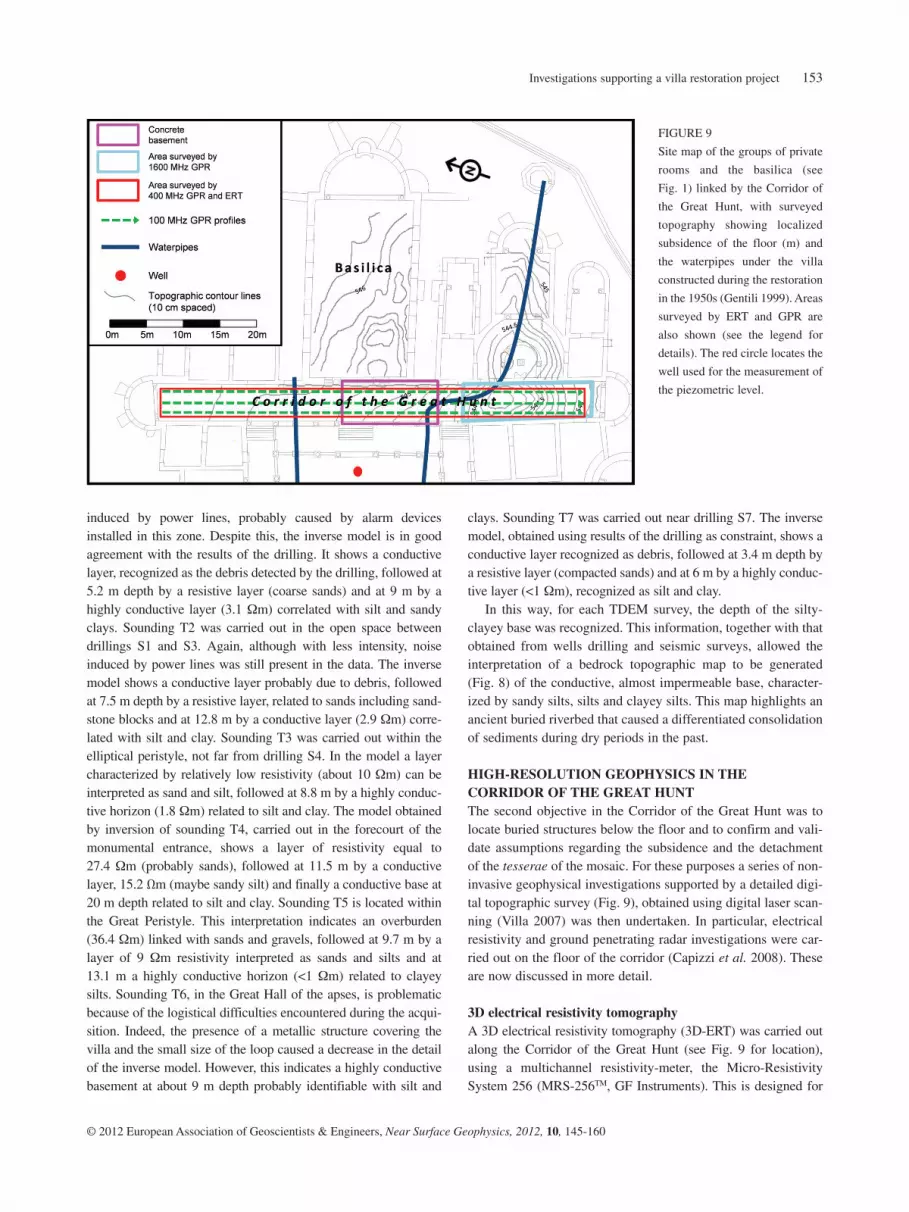
FIGURE 9
Site map of the groups of private
rooms and the basilica (see
Fig. 1) linked by the Corridor of
the Great Hunt, with surveyed
topography showing localized
subsidence of the floor (m) and
the waterpipes under the villa
constructed during the restoration
in the 1950s (Gentili 1999). Areas
surveyed by ERT and GPR are
also shown (see the legend for
details). The red circle locates the
well used for the measurement of
the piezometric level.
P. Capizzi et al.154
© 2012 European Association of Geoscientists & Engineers, Near Surface Geophysics, 2012, 10, 145-160
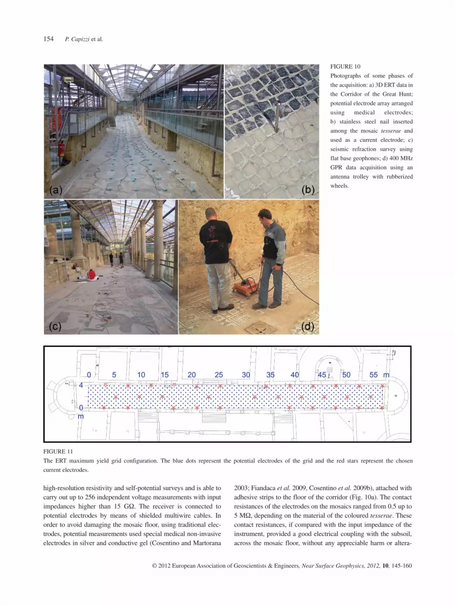
2003; Fiandaca et al. 2009, Cosentino et al. 2009b), attached with adhesive strips to the floor of the corridor (Fig. 10a). The contact resistances of the electrodes on the mosaics ranged from 0.5 up to 5 MW, depending on the material of the coloured tesserae. These contact resistances, if compared with the input impedance of the instrument, provided a good electrical coupling with the subsoil, across the mosaic floor, without any appreciable harm or altera-
high-resolution resistivity and self-potential surveys and is able to carry out up to 256 independent voltage measurements with input impedances higher than 15 GW. The receiver is connected to potential electrodes by means of shielded multiwire cables. In order to avoid damaging the mosaic floor, using traditional elec-trodes, potential measurements used special medical non-invasive electrodes in silver and conductive gel (Cosentino and Martorana
FIGURE 11
The ERT maximum yield grid configuration. The blue dots represent the potential electrodes of the grid and the red stars represent the chosen
current electrodes.
FIGURE 10
Photographs of some phases of
the acquisition: a) 3D ERT data in
the Corridor of the Great Hunt;
potential electrode array arranged
using medical electrodes;
b) stainless steel nail inserted
among the mosaic tesserae and
used as a current electrode; c)
seismic refraction survey using
flat base geophones; d) 400 MHz
GPR data acquisition using an
antenna trolley with rubberized
wheels.
Investigations supporting a villa restoration project 155
© 2012 European Association of Geoscientists & Engineers, Near Surface Geophysics, 2012, 10, 145-160
soil resistivity consists of several regions that are internally approximately homogenous and separated by sharp boundaries (Loke et al. 2003).
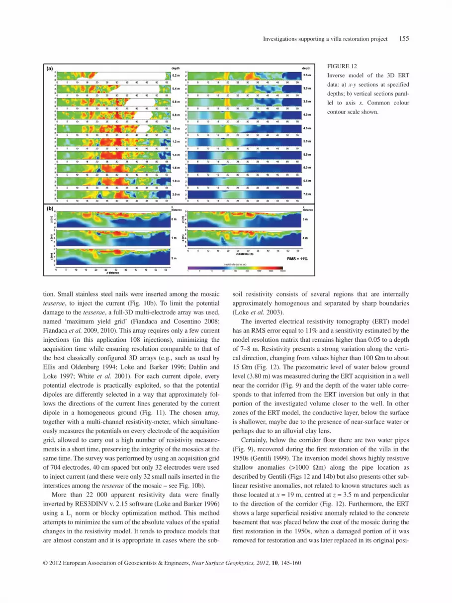
The inverted electrical resistivity tomography (ERT) model has an RMS error equal to 11% and a sensitivity estimated by the model resolution matrix that remains higher than 0.05 to a depth of 7–8 m. Resistivity presents a strong variation along the verti-cal direction, changing from values higher than 100 Wm to about 15 Wm (Fig. 12). The piezometric level of water below ground level (3.80 m) was measured during the ERT acquisition in a well near the corridor (Fig. 9) and the depth of the water table corre-sponds to that inferred from the ERT inversion but only in that portion of the investigated volume closer to the well. In other zones of the ERT model, the conductive layer, below the surface is shallower, maybe due to the presence of near-surface water or perhaps due to an alluvial clay lens.
Certainly, below the corridor floor there are two water pipes (Fig. 9), recovered during the first restoration of the villa in the 1950s (Gentili 1999). The inversion model shows highly resistive shallow anomalies (>1000 Wm) along the pipe location as described by Gentili (Figs 12 and 14b) but also presents other sub-linear resistive anomalies, not related to known structures such as those located at x = 19 m, centred at z = 3.5 m and perpendicular to the direction of the corridor (Fig. 12). Furthermore, the ERT shows a large superficial resistive anomaly related to the concrete basement that was placed below the coat of the mosaic during the first restoration in the 1950s, when a damaged portion of it was removed for restoration and was later replaced in its original posi-
tion. Small stainless steel nails were inserted among the mosaic tesserae, to inject the current (Fig. 10b). To limit the potential damage to the tesserae, a full-3D multi-electrode array was used, named ‘maximum yield grid’ (Fiandaca and Cosentino 2008; Fiandaca et al. 2009, 2010). This array requires only a few current injections (in this application 108 injections), minimizing the acquisition time while ensuring resolution comparable to that of the best classically configured 3D arrays (e.g., such as used by Ellis and Oldenburg 1994; Loke and Barker 1996; Dahlin and Loke 1997; White et al. 2001). For each current dipole, every potential electrode is practically exploited, so that the potential dipoles are differently selected in a way that approximately fol-lows the directions of the current lines generated by the current dipole in a homogeneous ground (Fig. 11). The chosen array, together with a multi-channel resistivity-meter, which simultane-ously measures the potentials on every electrode of the acquisition grid, allowed to carry out a high number of resistivity measure-ments in a short time, preserving the integrity of the mosaics at the same time. The survey was performed by using an acquisition grid of 704 electrodes, 40 cm spaced but only 32 electrodes were used to inject current (and these were only 32 small nails inserted in the interstices among the tesserae of the mosaic – see Fig. 10b).
More than 22 000 apparent resistivity data were finally inverted by RES3DINV v. 2.15 software (Loke and Barker 1996) using a L1 norm or blocky optimization method. This method attempts to minimize the sum of the absolute values of the spatial changes in the resistivity model. It tends to produce models that are almost constant and it is appropriate in cases where the sub-
FIGURE 12
Inverse model of the 3D ERT
data: a) x-y sections at specified
depths; b) vertical sections paral-
lel to axis x. Common colour
contour scale shown.

P. Capizzi et al.156
© 2012 European Association of Geoscientists & Engineers, Near Surface Geophysics, 2012, 10, 145-160
the antennas and to avoid any possible removal of tesserae not well fixed. The antenna trolleys had rubberized wheels, further wrapped with thin soft layers, in order to minimize any possible mechanical contact effect.
The GPR 2D profiles were acquired using a GSSI SirTM 3000 System with 100 MHz, 400 MHz and 1600 MHz antenna frequen-cies, so as to obtain different depths of penetration depending on the particular studied problems. 100 MHz and 400 MHz antennas were used in the whole corridor to investigate various aspects of the subsoil, especially linked to the causes of subsidence, whereas 1600 MHz antenna was used only in the subsidence area to inves-
tion (Fig. 9, Gentili 1999). The anomaly is not uniform but it pre-sents a more resistive portion in the middle part, perhaps because of a reinforcement of that side of the concrete basement.
GPR profiles and time-slice imagesIn many parts below the mosaic floor, the failures caused detach-ments and small voids, while some small bulges of the mosaic floors are probably linked to rainwater seepage through the pro-tection structure.
Using a georadar on the mosaic floor, preventive measures were taken in order to allow the totally non-invasive carriage of
FIGURE 13
3D GPR model of the 400 MHz
GPR data: a) x-y sections at
speci fied depths; b) vertical sec-
tions parallel to axis x. Common
colour scale bar shown
FIGURE 14
Comparison of ERT and
400 MHz GPR results in the
Corridor of the Great Hunt.
a) Depth-slice (z = 1.3 m) of the
ERT inverse model. b) Vertical
section (y = 2 m) of the ERT
inverse model. c) Depth-slice
(z = 1.3 m) of the 400 MHz GPR
data. d) Vertical section (y = 2 m)
of the GPR 3D model obtained
from 400 MHz data. The blue
lines in (b–c) represent interpret-
ed water pipe locations and the
pink rectangle represents the
interpreted area of concrete rein-
forcement.

Investigations supporting a villa restoration project 157
© 2012 European Association of Geoscientists & Engineers, Near Surface Geophysics, 2012, 10, 145-160
analysis window was of 2 ns along the time axis and of 0.05 m along the distance axis. In each model the scale of the amplitudes was normalized to the maximum value recorded.
In the upper and lower parts of the GPR model (Fig. 13), acquired in the corridor with a 400 MHz antenna, two main GPR facies are evident. The upper facies is characterized by a low intensity signal, while in the lower one a more high intensity signal and diffraction hyperbola are present. In the central zone of the corridor, the transition of the two facies is less evident for shallow reflections, due to the presence of water pipes and the bed of reinforced concrete on which mosaic has been relocated, during a previous restoration. The effect of the reinforced con-crete is more evident in the time-slices obtained from the 400 MHz data. The slice corresponding to a depth of 1.3 m and the vertical section corresponding to y = 2 m are shown as an example in Fig. 14(c,d), compared with a correspondent slice and section of the ERT model (Fig. 14a,b). They also clearly present a high reflecting zone quite well coincident with the location of the concrete basement (Gentili 1999). Other anoma-lies are probably related to the water pipes.
In every 400 MHz GPR vertical section a regular pattern is clearly visible (Fig. 13b), very similar to the topographic drop of the pavement, even in the side with a deep deformation of the floor. This suggested that the cause of deformation could be deeper, so additional GPR profiles (100 MHz antenna) were also acquired. The analysis of 100 MHz antenna profiles acquired in the corridor (Fig. 15) highlights also the multiple reflections derived from the reinforced concrete slab. Moreover, at an eleva-tion of about 539 m a.s.l., a reflection surface is visible in the whole section with a pattern in good agreement with that recog-nized in the seismic refraction section and interpreted as the top of the silty-clayey bedrock. This information supports the hypothesis of the presence of a buried riverbed, in significant correlation (both in position and in direction) with the axis of the feature.
In the subsided area a number of radar profiles at high fre-quency (1600 MHz) was also acquired (see Fig. 9 for location), in the longitudinal (18 m) and transverse (4.5 m) directions with respect to the corridor. The obtained radar sections have a high
tigate and locate detachment zones (bubbles) due to the deforma-tion of the floor (see Fig. 9 for profile locations).
The trace spacing used for 100 MHz, 400 MHz and 1600 MHz acquisition was respectively 0.03 m, 0.02 m and 0.01 m.
Using a 400 MHz antenna, 11 longitudinal profiles were acquired along the corridor, laterally spaced by 40 cm, so cover-ing an area of 58 m × 4 m, with an acquisition range of 100 ns and a penetration depth of approximately 4–5 m. Furthermore, the 100 MHz antenna was also used to acquire three profiles, 58 m long and spaced by 2 m. The collapsed area in the corridor was investigated in detail using a 1600 MHz antenna, acquiring longitudinal and transversal profiles on a high-density grid (18 m × 4.5 m with space among profiles equal to 25 cm). The following processes were carried out for each profile using the software ReflexWTM, applying the following sequence: • background removal, to eliminate temporally consistent noise
from the whole profile and to emphasize signals that vary later-ally;
• frequency filter, to suppress noise when it differs from the signal in its frequency content (the frequency bands applied were respec-tively 80–600 MHz, for 400 MHz antenna; 30–200 MHz, for 100 MHz antenna; 400–2200 MHz, for 1600 MHz antenna);
• running average, to suppress trace dependent noise and to emphasize horizontally coherent energy;
• envelope, only for time-slice computation, to obtain a measure of the reflectivity strength, which is proportional to the square root of the energy of the signal at an instant of time.
Moreover, a static correction was performed, by means of the digital topographic relief, in order to refer the acquired data to the same datum level.
400 MHz and 1600 MHz data were processed to construct two 3D models of amplitude of the radar signals (Goodman et al. 1995, Goodman et al. 2002), which can be represented in form of horizontal slices at a chosen depth or vertical sections. Data matrices were calculated using a proper MATLABTM 7.7 script. The appropriate analysis window was chosen depending on the shape and size of expected anomalies. In this case, for 400 MHz data we chose an analysis window of 5 ns along the time axis and 0.05 m along the distance axis. For 1600 MHz data the chosen
FIGURE 15
GPR profile acquired in the Corridor of the Great Hunt using 100 MHz antenna. The refraction surface obtained from the 2D seismic refraction model
(see Fig. 6) is superimposed (white dotted line), showing a quite good agreement with the reflective layer of the GPR section. The white rectangle
highlights the multiple reflections derived from the reinforced concrete slab.
P. Capizzi et al.158
© 2012 European Association of Geoscientists & Engineers, Near Surface Geophysics, 2012, 10, 145-160
helped to obtain a geophysical 3D model that allowed the recon-struction of the geometry of geological formations below the villa, thanks to a detailed topographic correction through accu-rate digital topographic surveys, providing a source of valuable information for designing the restoration of the villa.
In particular, some DH and TDEM surveys were carried out in the same position as some drilling cores in order to constrain the data inversion to the stratigraphic columns, thus increasing the geological consistency of the geophysical models. The mod-els obtained were used as starting models for the nearest TDEM sounding to laterally constrain the inverse model, minimizing the variation in thickness of the layers of near models, so increasing the robustness of the inversion. The depth values of the layers of downhole models were used to constrain the inversion of the seismic refraction profile carried out along the Corridor of the Great Hunt, to provide a geological interpretation of the results. The limited number of shots, since it was not allowed to use the sledgehammer in the corridor, did not permit data interpretation with tomographic methods. However, the interpretation by the GRM method allowed the reconstruction of the bedrock pattern. Finally, for each survey (geotechnical and geophysical) the depth of the roof of the silty-clayey bedrock was deduced and, using this information, the map of the pattern was plotted for the stud-ied area, where a linear depression due to an ancient riverbed is visible. The geological and geophysical 3D model of the subsoil of the villa will be crucial to the project managers to identify the possible causes of subsidence of the ground and to predict its time evolution, in terms of both amplitude and trend of deforma-tions. Accordingly, it will be possible to plan actions aiming to reduce deformations or, at least, to stop the deformation process.
The area of the corridor, strongly affected by subsidence, was further investigated using high resolution GPR and ERT methods, geo-referenced by topographic optical and digital surveys. The use of the maximum yield grid array allowed to carry out a totally non-invasive 3D electrical resistivity tomography inside the villa since this array allows to apply a limited number of small current elec-trodes (positioned at the gaps among the tiles) in spite of a large
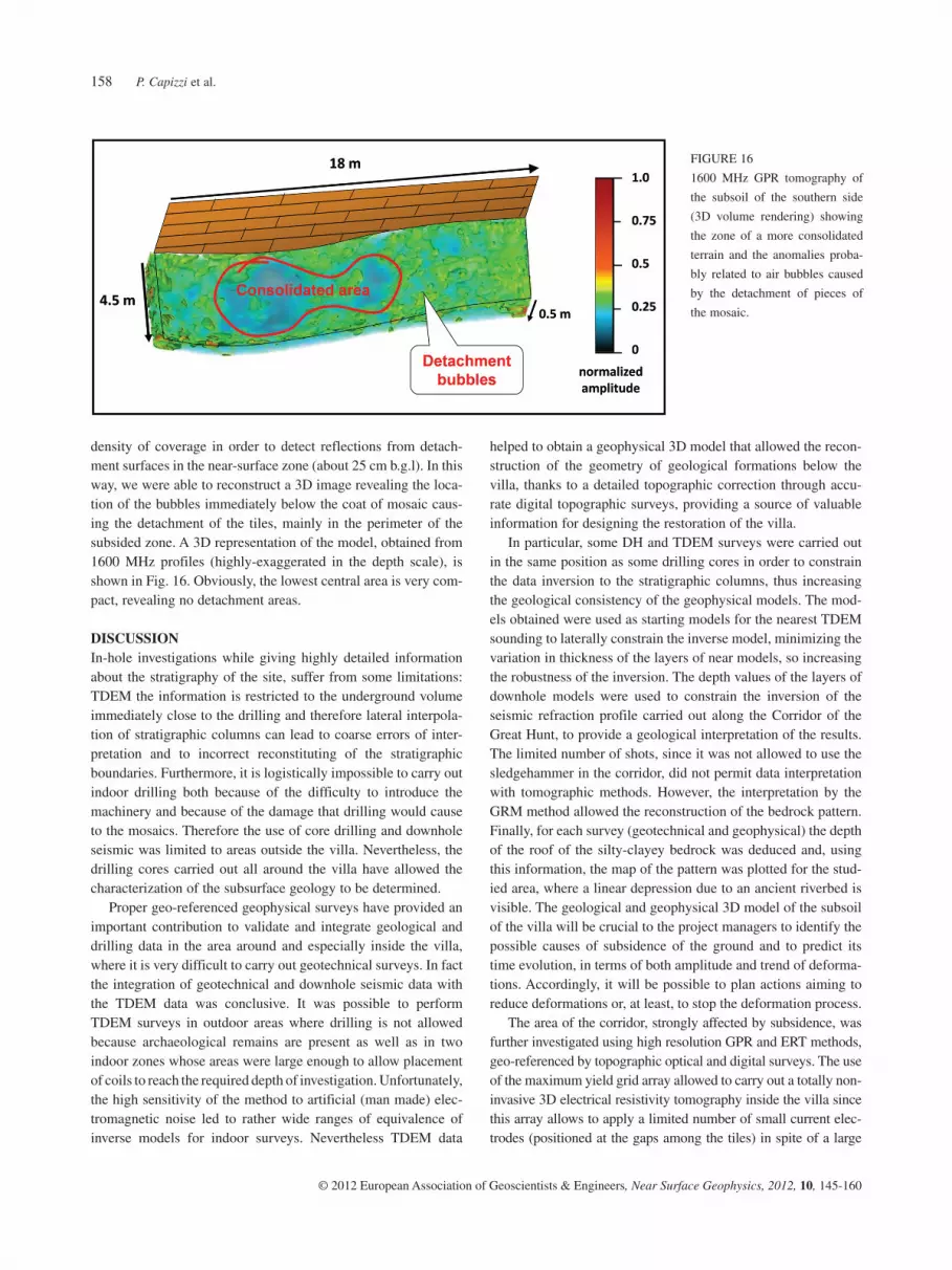
density of coverage in order to detect reflections from detach-ment surfaces in the near-surface zone (about 25 cm b.g.l). In this way, we were able to reconstruct a 3D image revealing the loca-tion of the bubbles immediately below the coat of mosaic caus-ing the detachment of the tiles, mainly in the perimeter of the subsided zone. A 3D representation of the model, obtained from 1600 MHz profiles (highly-exaggerated in the depth scale), is shown in Fig. 16. Obviously, the lowest central area is very com-pact, revealing no detachment areas.
DISCUSSIONIn-hole investigations while giving highly detailed information about the stratigraphy of the site, suffer from some limitations: TDEM the information is restricted to the underground volume immediately close to the drilling and therefore lateral interpola-tion of stratigraphic columns can lead to coarse errors of inter-pretation and to incorrect reconstituting of the stratigraphic boundaries. Furthermore, it is logistically impossible to carry out indoor drilling both because of the difficulty to introduce the machinery and because of the damage that drilling would cause to the mosaics. Therefore the use of core drilling and downhole seismic was limited to areas outside the villa. Nevertheless, the drilling cores carried out all around the villa have allowed the characterization of the subsurface geology to be determined.
Proper geo-referenced geophysical surveys have provided an important contribution to validate and integrate geological and drilling data in the area around and especially inside the villa, where it is very difficult to carry out geotechnical surveys. In fact the integration of geotechnical and downhole seismic data with the TDEM data was conclusive. It was possible to perform TDEM surveys in outdoor areas where drilling is not allowed because archaeological remains are present as well as in two indoor zones whose areas were large enough to allow placement of coils to reach the required depth of investigation. Unfortunately, the high sensitivity of the method to artificial (man made) elec-tromagnetic noise led to rather wide ranges of equivalence of inverse models for indoor surveys. Nevertheless TDEM data
FIGURE 16
1600 MHz GPR tomography of
the subsoil of the southern side
(3D volume rendering) showing
the zone of a more consolidated
terrain and the anomalies proba-
bly related to air bubbles caused
by the detachment of pieces of
the mosaic.

Investigations supporting a villa restoration project 159
© 2012 European Association of Geoscientists & Engineers, Near Surface Geophysics, 2012, 10, 145-160
restoration of archaeological sites. Only in this way the final interpretation can acquire high reliability to provide the restora-tion managers with useful instruments for a consolidation and restoration plan.
AKNOWLEDGEMENTSWe thank G. Meli, head of the Restoration Centre of Sicily and Project Restorer of the ‘Villa del Casale’ for his support and afi-nancial grant. We also thank PhD G. Fiandaca and PhD I. Razo Amoroz for their appreciable collaboration during the last part of the surveys. Finally, we would like to thank Prof. B. Villa for his valuable topographic support and restorer L. Pellegrino for her valuable suggestions in mosaic management.
REFERENCESBarsukov P.O., Fainberg E.B. and Khabensky E.O. 2007. Shallow inves-
tigation by TEM-FAST technique: Methodology and case histories. In: Methods of Geochemistry and Geophysics (ed. V.V. Spichak), pp. 55–77. Elsevier.
Baum-vom Felde P.C. 2003. Die geometrischen Mosaiken der Villa bei Piazza Armerina. Kovac.
Bavusi M., Giocoli A., Rizzo E. and Lapenna V. 2009. Geophysical characterisation of Carlo’s V Castle (Crotone, Italy). Journal of Applied Geophysics 67, 386–401.
Capizzi P., Cosentino P.L., Fiandaca G., Martorana R., Messina P. and Vassallo S. 2007. Geophysical investigations at the Himera archaeo-logical site, northern Sicily. Near Surface Geophysics 5, 417–426.
Capizzi P., Fiandaca G., Martorana R., Messina P., Razo Amoroz I. and Cosentino P.L. 2008. Integrated full 3D geoelectrical and GPR tomog-raphies in the Ambulatory of the roman ‘Villa del Casale’ (Piazza Armerina). Near Surface meeting, Krakow, Poland, Expanded Abstracts, A18.
Carandini A., Ricci A. and de Vos M. 1982. Filosofiana. The Villa of Piazza Armerina: The Image of a Roman Aristocrat at the Time of Costantine. Flaccovio.
Cardarelli E. and Di Filippo G. 2009. Integrated geophysical methods for the characterisation of an archaeological site (Massenzio Basilica – Roman forum, Rome, Italy). Journal of Applied Geophysics 68, 508–521.
Cardarelli E., Godio A., Morelli G., Sambuelli L., Santarato G. and Socco L. 2002. Integrated geophysical surveys to investigate the Scarsella vault of St. John’s Baptistery Florence. The Leading Edge 21, 467–470.
Carrara E., Carrozzo M.T. and Fedi M. 2001. Resistivity and radar sur-veys at the archaeological site of Ercolano. Journal of Environmental and Engineering Geophysics 6, 123–132.
Cosentino P., Capizzi P., Fiandaca G., Martorana R. and Messina P. 2009a. Advances in microgeophysics for engineering and cultural heritage. Journal of Earth Science 20, 629–639.
Cosentino P.L., Casas A., Capizzi P., Diaz Y., Fiandaca G., Garcia E., Himi M., Martorana R. and Sala R. 2009b. Integrated geophysical surveys in the Tarragona Cathedral. Near Surface meeting, Dublin, Ireland, Expanded Abstracts, A04.
Cosentino P. and Martorana R. 2003. High-resolution micro-geophysics: Electrical tomography for walls. 3rd Asamblea Hispano-Portuguesa de Geodesia y Geofísica, Valencia, Spain, Expanded Abstracts, 1794–1798.
Dabas M., Camerlynck C. and Freixas I Camps P. 2000. Case history – Simultaneous use of electrostatic quadrupole and GPR in urban con-text: Investigation of the basement of the Cathedral of Girona (Catalunya, Spain). Geophysics 65, 526–532.
number of non-invasive electrodes for potential measurements. In this way, it was possible to obtain a detailed three-dimensional model of electrical resistivity beneath the floor of the corridor.
Resistivity tomography highlighted a sharp vertical transition of electrical resistivity, interpreted, according to the piezometric datum of a nearby well, as the transition from unsaturated to saturated sediments.
The integrated use of the GPR method, using special devices for carrying the antennas to avoid damage to the tiles, allowed to obtain detailed time-slices and the correlation of GPR and ERT anomalies. In particular, the comparison between the ERT and 400 MHz GPR depth-slice models, allowed the highlighting of subsurface anomalies that are present in both models with simi-lar geometry. Some of these are readily explicable by the his-torically known drainage channels and others are probably caused by non documented ducts or pipes. A further subsurface anomaly with rectangular geometry is very clear in both models, corresponding to the metal bars positioned under the floor in the central area of the corridor, when in the 1950s the mosaic was removed, restored and then replaced on a base of reinforced concrete.
The analysis of 100 MHz GPR sections highlights a surface that can be correlated with that shown by the 2D seismic refrac-tion model.
Finally, 1600 MHz GPR depth-slices in the highly subsided zone allowed the location of air bubbles below the tiles of the mosaic.
High resolution geophysical investigations carried out in the Corridor of the Great Hunt allowed the achievement of detailed geophysical three-dimensional models of the underground below the floor. Results helped to detect and map the main structures below the floor, including the pattern of the detachment zones and the shape of the less cohesive zones, so furnishing a tool for a successive consolidation plan.
CONCLUSIONSThe geophysical and geotechnical investigations in the ‘Villa del Casale’ provide an important contribution to the research of the knowledge both of the geology of the site and the geometric and building characteristics of the foundation of the monument. Particular information was obtained on the thickness and litho-logical composition of the overburden, genesis of the subsidence in the central part of the building and location of the main struc-tures below the Corridor of the Great Hunt.
This study showed that the geotechnical and geophysical multidisciplinary approach is essential to obtain a reliable sub-surface imaging, in archaeological areas where access is limited. The use of technical devices, for conducting indoor completely non-invasive geophysical methods, is critical when investigating cultural heritages to avoid any damage to structures.
The geological-geophysical approach and, in particular, the strategy of multi-disciplinary and multi-scale geophysical imag-ing, should become standard practice in studies for supporting

P. Capizzi et al.160
© 2012 European Association of Geoscientists & Engineers, Near Surface Geophysics, 2012, 10, 145-160
Masini N., Persico R. and Rizzo E. 2010. Some examples of GPR pros-pecting for monitoring of the monumental heritage. Journal of Geophysical and Engineering 7, 190–199.
Nuzzo L. and Quarta T. 2010. Near-surface geophysical investigations inside the cloister of the historical palace ‘Palazzo dei Celestini’ in Lecce, Italy. Journal of Geophysical and Engineering 7, 200–210.
Palmer D. 1981. An introduction to the generalized reciprocal method of seismic refraction interpretation. Geophysics 46, 1508–1518.
Piro S., Goodman D. and Nishimura Y. 2003. The study and characterisa-tion of Emperor Traiano’s Villa (Altipiani di Arcinazzo-Roma) using high resolution integrated geophysical surveys. Archaeological Prospection 10, 1–25.
Piro S., Mauriello P. and Cammarano F. 2000. Quantitative integration of geophysical methods for archaeological prospection. Archaeological Prospection 7, 203–213.
Piscitelli S., Rizzo E., Cristallo F., Lapenna V., Crocco L., Persico R. and Soldovieri F. 2007. GPR and microwave tomography for detecting shallow cavities in the historical area of ‘Sassi of Matera’ (southern Italy). Near Surface Geophysics 5, 275–284.
Pringle J.K., Lenham J.W. and Reynolds J.M. 2009. GPR investigations to characterize Medieval and Roman foundations under existing shop premises: A case study from Chester, Cheshire, UK. Near Surface Geophysics 7, 93–100.
Rizzo E., Chianese D. and Lapenna V. 2005. Magnetic, GPR and geoe-lectrical measurements for studying the archaeological site of ‘Masseria Nigro’ (Viggiano, southern Italy). Near Surface Geophysics 3, 13–19.
Sambuelli L., Socco L.V. and Brecciaroli L. 1999. Acquisition and pro-cessing of electric, magnetic and GPR data on a Roman site (Victimulae, Salussola, Biella). Journal of Applied Geophysics 41, 189–204.
Savvaidis A., Tsokas G.N., Liritzis Y. and Apostolou M. 1999. The loca-tion and mapping of ancient ruins on the castle of Lefkas (Greece) by resistivity and GPR methods. Archaeological Prospection 6, 63–73.
Senos Mattias M. and Almeida F. 1992. A geophysical survey on the archaeological site of Mugardos (NW Iberian Peninsula). Journal of Applied Geophysics 29, 119–124.
Tsokas G.N., Tsourlos P.I., Vargemezis G. and Novack M. 2008. Non-destructive electrical resistivity tomography for indoor investigation: The Case of Kapnikarea Church in Athens. Archaeological Prospection 15, 47–61.
Vega Pérez G., Canas J.A., Pujades L.G., Clapés J., Caselles O., García F. and Osorio R. 2000. GPR survey to confirm the location of ancient structures under the Valencian Cathedral (Spain). Journal of Applied Geophysics 43, 167–174.
Villa B. 2007. Il rilievo della Villa Romana del Casale. In: I Quaderni di Palazzo Montalbo. I Grandi Restauri. N. 1. Progetto di recupero e conservazione della Villa Romana del Casale di Piazza Armerina (ed. G. Meli), pp. 74–78. Regione Siciliana (in Italian).
White R.M.S., Collins S., Denne R., Hee R. and Brown P. 2001. A new survey design for 3D IP modelling at Copper Hill. Exploration Geophysics 32, 152–155.
Dahlin T. and Loke M.H. 1997. Quasi-3D resistivity imaging-mapping of three dimensional structures using two dimensional DC resistivity techniques. Proceedings of the 3rd Meeting of the Environmental and Engineering Geophysical Society, Expanded Abstracts, 143–146.
Di Geronimo I., Ghisetti F., Lentini F. and Vezzani L. 1978. Lineamenti neotettonici della Sicilia orientale. Memorie della Società Geologica Italiana 19, 543–549 (in Italian).
Drahor M.G. 2006. Integrated geophysical studies in the upper part of Sardis archaeological site, Turkey. Journal of Applied Geophysics 59, 205–223.
Dunbabin K. 1978. The Mosaics of Roman North Africa. Clarendon Press.
Ellis R.G. and Oldenburg D.W. 1994. The pole-pole 3-D DC-resistivity inverse problem: A conjugate gradient approach. Geophysical Journal International 119, 187–194.
Fiandaca G. and Cosentino P.L. 2008 The new ‘Maximum Yield Grid’ (MYG) array in 3D resistivity tomography. Near Surface 2008, Krakow, Poland, Expanded Abstracts, P28.
Fiandaca G., Martorana R., Messina P. and Cosentino P.L. 2009. 3D ERT for the study of an ancient wall covered by precious mosaics. Near Surface 2009, Dublin, Ireland, Expanded Abstracts, A08.
Fiandaca G., Martorana R., Messina P. and Cosentino P.L. 2010. The MYG methodology to carry out 3D electrical resistivity tomography on media covered by vulnerable surfaces of artistic value. Il Nuovo Cimento B 125, 711–718.
Gentili G.V. 1959. La Villa Erculia di Piazza Armerina. I mosaici figu-rati. Sidera Milan.
Gentili G.V. 1999. La Villa Romana di Piazza Armerina Palazzo Erculio. Fondazione Don Carlo.
Goodman D. 1994. Ground-penetrating radar simulation in engineering and archaeology. Geophysics 59, 224–232.
Goodman D., Nishimura Y. and Rogers J.D. 1995. GPR time slices in archaeological prospection. Archaeological Prospection 2, 85–89.
Goodman D., Piro S. and Nishimura Y. 2002. GPR time slices of the Villa of Emperor Trajanus, Arcinazzo, Italy. 9th International GPR Conference, Santa Barbara, California, USA, Expanded Abstracts, 268–272.
Graziano G. and Scalone E. 2007. Studio geologico dell’area. Progetto di recupero e conservazione della Villa Romana del Casale di Piazza Armerina. In: I Quaderni di Palazzo Montalbo. I Grandi Restauri. N. 1. Progetto di recupero e conservazione della Villa Romana del Casale di Piazza Armerina (ed. G. Meli), pp. 92–96. Regione Siciliana (in Italian).
Hesse A. 1999. Multi-parametric survey for archaeology: How and why, or how and why not? Journal of Applied Geophysics 41, 157–168.
Loke M.H., Acworth I. and Dalhin T. 2003. A comparison of smooth and blocky inversion methods in 2-D electrical imaging surveys. Exploration Geophysics 34, 182–187.
Loke M.H. and Barker R.D. 1996. Practical techniques for 3D resistivity surveys and data inversion. Geophysical Prospecting 44, 499–523.
Martino L., Bonomo N., Lascano E., Osella A. and Ratto N. 2006. Electrical and GPR prospecting at Palo Blanco archaeological site, northwestern Argentina. Geophysics 71, 193–199.