•cyber security for smart grid communications ... - piazza
TRANSCRIPT

A Publication of the IEEE Communications Society®
•Cyber Security for Smart GridCommunications
•Ultimate Technologies and Advances forFuture Smart Grid: UTASG
Free ComSoc Tutorial:
Converged Core Networks
See Page 9
IEEE
M A G A Z I N E
January 2013, Vol. 51, No. 1
www.comsoc.org

Previous Page | Contents | Zoom in | Zoom out | Front Cover | Search Issue | Next PageIEEE
Communications qqM
Mq
qM
MqM
Qmags®THE WORLD’S NEWSSTAND
Previous Page | Contents | Zoom in | Zoom out | Front Cover | Search Issue | Next PageIEEE
Communications qqM
Mq
qM
MqM
Qmags®THE WORLD’S NEWSSTAND
THIS MONTH’S DIGITAL DELIVERY OF IEEE COMMUNICATIONS MAGAZINE
SUPPORTED BY:
Previous Page | Contents | Zoom in | Zoom out | Front Cover | Search Issue | Next PageIEEE
Communications qqM
Mq
qM
MqM
Qmags®THE WORLD’S NEWSSTAND
Previous Page | Contents | Zoom in | Zoom out | Front Cover | Search Issue | Next PageIEEE
Communications qqM
Mq
qM
MqM
Qmags®THE WORLD’S NEWSSTAND

A Publication of the IEEE Communications Society®
Free ComSoc Tutorial:
Converged Core Networks
See Page 9
IEEE
M A G A Z I N E
January 2013, Vol. 51, No. 1
www.comsoc.org
•Cyber Security for Smart GridCommunications
•Ultimate Technologies and Advances forFuture Smart Grid: UTASG
Contents | Zoom in | Zoom out Search Issue | Next PageFor navigation instructions please click here
Contents | Zoom in | Zoom out Search Issue | Next PageFor navigation instructions please click here

Previous Page | Contents | Zoom in | Zoom out | Front Cover | Search Issue | Next PageIEEE
Communications qqM
Mq
qM
MqM
Qmags®THE WORLD’S NEWSSTAND
Previous Page | Contents | Zoom in | Zoom out | Front Cover | Search Issue | Next PageIEEE
Communications qqM
Mq
qM
MqM
Qmags®THE WORLD’S NEWSSTAND
______________

MP1800A 32G Multi-Channel BERT
You Designed It Right.
We Can Prove It.
Cloud computing and video streaming are driving increases
in server and storage transmission speeds. The transmission
capacity of core networks is increasing rapidly to support these
demands. The MP1800A SQA is a modular BERT with built-in
Pattern Pulse Generator (PPG), Error Detector (ED), and Jitter
Modulation Source to support 32G multi-channel BERT test.
Also, boost your BERT with Anritsu’s compact MP1825B 4Tap
Emphasis handling bit rates up to 28.1Gbit/s.
Signal Quality Analyzer
USA/Canada 1-800-ANRITSU Europe 44 1582-433433 Japan 81 (46) 223-1111 Asia-Pacific (852) 2301-4980 South America 55 (11) 3283-2511
© 2012 Anritsu Company
Signal Integrity Solutions
Visit us at: www.anritsuco.com/IEEE-proveitto learn more and download our FREE WhitepaperSignal Integrity Test Solution for High-Speed Interconnects
Scan the QR code to view detailsdirectly on your smartphone
Visit us at DesignCon 2013Booth 501
Previous Page | Contents | Zoom in | Zoom out | Front Cover | Search Issue | Next PageIEEE
Communications qqM
Mq
qM
MqM
Qmags®THE WORLD’S NEWSSTAND
Previous Page | Contents | Zoom in | Zoom out | Front Cover | Search Issue | Next PageIEEE
Communications qqM
Mq
qM
MqM
Qmags®THE WORLD’S NEWSSTAND
Director of MagazinesSteve Gorshe, PMC-Sierra, Inc. (USA)
Editor-in-ChiefSean Moore, Centripetal Networks (USA)
Associate Editor-in-ChiefOsman S. Gebizlioglu, Huawei Tech. Co., Ltd. (USA)
Senior Technical EditorsTom Chen, Swansea University (UK)
Nim Cheung, ASTRI (China)Nelson Fonseca, State Univ. of Campinas (Brazil)
Peter T. S. Yum, The Chinese U. Hong Kong (China)
Technical EditorsSonia Aissa, Univ. of Quebec (Canada)
Paolo Bellavista, DEIS (Italy)Tee-Hiang Cheng, Nanyang Tech. U. (Rep. Singapore)
Mischa Dohler, CTTC (Spain)Stefano Galli, ASSIA, Inc. (USA)
Admela Jukan, Tech. Univ. Carolo-Wilhelmina zuBraunschweig (Germany)
Vimal Kumar Khanna, mCalibre Technologies (India)Janusz Konrad, Boston University (USA)
Myung J. Lee, City Univ. of New York (USA)D. Manivannan, Univ. of Kentucky (USA)
Deep Medhi, Univ. of Missouri-Kansas City (USA)Nader F. Mir, San Jose State Univ. (USA)
Amitabh Mishra, Johns Hopkins University (USA)Seshradi Mohan, University of Arkansas (USA)
Tom Oh, Rochester Institute of Tech. (USA)Glenn Parsons, Ericsson Canada (Canada)
Joel Rodrigues, Univ. of Beira Interior (Portugal)Jungwoo Ryoo, The Penn. State Univ.-Altoona (USA)
Antonio Sánchez Esguevillas, Telefonica (Spain)Charalabos Skianis, Univ. of Aegean (Greece)
Danny Tsang, Hong Kong U. of Sci. & Tech. (China)Chonggang Wang, InterDigital Commun., LLC (USA)Alexander M. Wyglinski, Worcester Poly. Institute (USA)Jun Zheng, Nat’l. Mobile Commun. Research Lab (China)
Series EditorsAd Hoc and Sensor Networks
Edoardo Biagioni, U. of Hawaii, Manoa (USA)Silvia Giordano, Univ. of App. Sci. (Switzerland)
Automotive Networking and ApplicationsWai Chen, Telcordia Technologies, Inc (USA)
Luca Delgrossi, Mercedes-Benz R&D N.A. (USA)Timo Kosch, BMW Group (Germany)
Tadao Saito, University of Tokyo (Japan)Consumer Communicatons and Networking
Madjid Merabti, Liverpool John Moores U. (UK)Mario Kolberg, University of Sterling (UK)
Ali Begen, Cisco (Canada)Design & Implementation
Vijay K. Gurbani, Bell Labs/Alcatel Lucent (USA)Salvatore Loreto, Ericsson Research (Finland)
Saverio Niccolini, NEC Laboratories Europe (Germany)Integrated Circuits for Communications
Charles Chien (USA)Zhiwei Xu, SST Communication Inc. (USA)
Network and Service Management SeriesGeorge Pavlou, U. College London (UK)
Aiko Pras, U. of Twente (The Netherlands)Networking Testing Series
Yingdar Lin, National Chiao Tung University (Taiwan)Erica Johnson, University of New Hampshire (USA)Tom McBeath, Spirent Communications Inc. (USA)
Eduardo Joo, Empirix Inc. (USA)Topics in Optical Communications
Osman Gebizlioglu, Huawei Technologies (USA)John Spencer, Optelian (USA)
Vijay Jain, Sterlite Network Limited (India)Topics in Radio Communications
Joseph B. Evans, U. of Kansas (USA)Zoran Zvonar, MediaTek (USA)
StandardsYoichi Maeda, TTC (Japan)
Mostafa Hashem Sherif, AT&T (USA)Columns
Book ReviewsPiotr Cholda, AGH U. of Sci. & Tech. (Poland)
History of CommunicationsSteve Weinsten (USA)
Regulatory and Policy IssuesJ. Scott Marcus, WIK (Germany)
Jon M. Peha, Carnegie Mellon U. (USA)Technology Leaders' Forum
Steve Weinstein (USA)Very Large Projects
Ken Young, Telcordia Technologies (USA)
Publications StaffJoseph Milizzo, Assistant Publisher
Eric Levine, Associate PublisherSusan Lange, Online Prod uction Manager
Jennifer Porcello, Production SpecialistCatherine Kemelmacher, Associate Editor
2 IEEE Communications Magazine • January 2013
IEEE
M A G A Z I N E JANUARY 2013, Vol. 51, No. 1
www.comsoc.org/commag
CYBER SECURITY FORSMART GRID COMMUNICATIONS: PART II
GUEST EDITORS: ROSE QINGYANG HU, YI QIAN, HSIAO-HWA CHEN,AND HUSSEIN T. MOUFTAH
GUEST EDITORIAL
NON-REPUDIATION IN NEIGHBORHOOD AREA NETWORKS FOR SMART GRIDZHIFENG XIAO, YANG XIAO, AND DAVID HUNG-CHANG DU
BAD DATA INJECTION IN SMART GRID: ATTACK AND DEFENSEMECHANISMSYI HUANG, MOHAMMAD ESMALIFALAK, HUY NGUYEN, RONG ZHENG, ZHU HAN,HUSHENG LI, AND LINGYANG SONG
WAKE: KEY MANAGEMENT SCHEME FOR WIDE-AREA MEASUREMENTSYSTEMS IN SMART GRIDYEE WEI LAW, MARIMUTHU PALANISWAMI, GINA KOUNGA, AND ANTHONY LO
COMMUNICATION SECURITY FOR SMART GRID DISTRIBUTION NETWORKSELIAS BOU-HARB, CLAUDE FACHKHA, MAKAN POURZANDI, MOURAD DEBBABI,AND CHADI ASSI
ENERGY FOOTPRINT FRAMEWORK: A PATHWAY TOWARD SMART GRIDSUSTAINABILITYDAVIDSON BOCCARDO, LEONARDO RIBEIRO, RODRIGO CANAAN, LUIZ CARMO,LUCI PIRMEZ, RAPHAEL MACHADO, CHARLES PRADO, AND TIAGO NASCIMENTO
ON SMART GRID CYBERSECURITY STANDARDIZATION: ISSUES OF DESIGNINGWITH NISTIR 7628ALDAR C-F. CHAN AND JIANYING ZHOU
ULTIMATE TECHNOLOGIES AND ADVANCES FORFUTURE SMART GRID: UTASG
GUEST EDITORS: JOSÉ NEUMAN DE SOUZA, PASCAL LORENZ, AND ABBAS JAMALIPOUR
GUEST EDITORIAL
SMART GRID FORENSIC SCIENCE: APPLICATIONS, CHALLENGES, AND OPENISSUESMELIKE EROL-KANTARCI AND HUSSEIN T. MOUFTAH
THE ROLE OF THE RPL ROUTING PROTOCOL FOR SMART GRIDCOMMUNICATIONSEMILIO ANCILLOTTI, RAFFAELE BRUNO, AND MARCO CONTI
SERVICE-ORIENTED MIDDLEWARE FOR SMART GRID: PRINCIPLE,INFRASTRUCTURE, AND APPLICATIONLIANG ZHOU AND JOEL J. P. C. RODRIGUES
STANDARIZATION OF SMART GRID IN ITU-TGYU MYOUNG LEE AND DAVID H. SU
LEARNING AUTOMATA AS A UTILITY FOR POWER MANAGEMENT INSMART GRIDSSUDIP MISRA, P. VENKATA KRISHNA, V. SARITHA, AND MOHAMMAD S. OBAIDAT
58
1618
27
34
42
50
6668
75
84
90
98
PRESIDENT’S PAGE
CONFERENCE CALENDAR
GLOBAL COMMUNICATIONS NEWSLETTER
68
11
®
Previous Page | Contents | Zoom in | Zoom out | Front Cover | Search Issue | Next PageIEEE
Communications qqM
Mq
qM
MqM
Qmags®THE WORLD’S NEWSSTAND
Previous Page | Contents | Zoom in | Zoom out | Front Cover | Search Issue | Next PageIEEE
Communications qqM
Mq
qM
MqM
Qmags®THE WORLD’S NEWSSTAND

AMI
Smart Energy, Connected Home and Automation Solutions
Front-end Modules (FEMs)
Power Amplifi ersPart POUT Gain P1 dB Package Frequency Band (MHz)
Number Function (dBm) (dB) (dBm) (mm) 450 915 2400
SE2433T 2-Stage Power Amplifier 24 22 24 QFN 2.5 x 2
Visit Us at Distributech Booth 733 in San Diego, CA January 29–31, 2013
LNA
Balun
PA
■ ® ■ ■ ■ ■ ■
Part POUT Tx Gain Rx Gain ICC Tx Package Frequency Band (MHz)Number Function (dBm) (dB) (dB) (mA) (mm) < 170 410–470 868–930 2400–2500
SKY66100 Tx / Rx Front-end Module with Rx / Tx Bypass 20–27 30 -0.5 110–300 MCM 4 x 4
SKY65367-11 High Power Tx / Rx Front-end Module with Rx / Tx Bypass 30 35 -0.5 600 MCM 4 x 4
SKY65338 Tx / Rx Front-end Module 27 32 – 315 MCM 8 x 8
SKY65342-11 High Power Tx / Rx Front-end Module with Rx Bypass 29 34 -0.6 650 MCM 8 x 8
SKY65378 Low Power Front-end Module with Tx Bypass and LNA – – 14–17 3–7 (1) QFN 4 x 4
SKY65346-21 Tx / Rx Front-end Module with LNA 26 35 13.7 200 MCM 5 x 5
SKY65313-21 Tx / Rx Front-end Module with LNA 30.5 28 16.6 695 MCM 6 x 6
SKY65364 High Power Tx / Rx Front-end Module with LNA, PA, Tx / Rx Bypass, HD Filter
30.5 30 15 730 MCM 6 x 6
SE2435L High Power Tx / Rx Front-end Module with LNA 30 28 16 550 QFN 4 x 4
SE2442L High Power Tx / Rx Front-end Module with Rx Bypass 30 28 -0.7 550 QFN 4 x 4
SE2438T Low Power Tx / Rx Front-end Module with LNA 10–14 16 12.3 20–33 QFN 3 x 3
SE2431L Tx / Rx Front-end Module with LNA 20 23 12 110 QFN 3 x 4
SE2432L Tx / Rx Front-end Module with LNA 20 22 11.5 110 QFN 3 x 4
SE2436L High Power Tx / Rx Front-end Module with LNA 27 28 11.5 400 QFN 4 x 4
1. SKY65378: Icc Rx gain value shown.
Skyworks’ Green™ products are compliant to all applicable materials legislation and are halogen-free. For additional information, please refer to Skyworks Definition of Green™, document number SQ04-0074. New products indicated in blue, bold are continually being introduced at Skyworks.
Previous Page | Contents | Zoom in | Zoom out | Front Cover | Search Issue | Next PageIEEE
Communications qqM
Mq
qM
MqM
Qmags®THE WORLD’S NEWSSTAND
Previous Page | Contents | Zoom in | Zoom out | Front Cover | Search Issue | Next PageIEEE
Communications qqM
Mq
qM
MqM
Qmags®THE WORLD’S NEWSSTAND
________________
__________________
2013 Communications SocietyElected Officers
Vijay K. Bhargava, PresidentSergio Benedetto, President-Elect
Leonard Cimini, VP–Technical ActivitiesAbbas Jamalipour VP–Conferences
Nelson Fonseca, VP–Member RelationsVincent Chan, VP–Publications
Alex Gelman, VP-Standards Activities
Members-at-LargeClass of 2013
Gerhard Fettweis, Stefano GalliRobert Shapiro, Moe Win
Class of 2014Merrily Hartman, Angel Lozano
John S. Thompson, Chengshan XiaoClass of 2015
Nirwan Ansari, Stefano BregniHans-Martin Foisel, David G. Michelson
2013 IEEE OfficersPeter W. Staecker, President
J. Roberto B. de Marca, President-ElectMarko Delimar, Secretary
John T. Barr, TreasurerGordon W. Day, Past-President
E. James Prendergast, Executive DirectorDoug Zuckerman, Director, Division III
IEEE COMMUNICATIONS MAGAZINE (ISSN 0163-6804) is published monthly by The Institute ofElectrical and Electronics Engineers, Inc.Headquarters address: IEEE, 3 Park Avenue, 17thFloor, New York, NY 10016-5997, USA; tel:+1(212) 705-8900; http://www.comsoc.org/commag.Responsibility for the contents rests upon authors ofsigned articles and not the IEEE or its members.Unless otherwise specified, the IEEE neitherendorses nor sanctions any positions or actionsespoused in IEEE Communications Magazine.
ANNUAL SUBSCRIPTION: $27 per year print subscrip-tion. $16 per year digital subscription. Non-member printsubscription: $400. Single copy price is $25.
EDITORIAL CORRESPONDENCE: Address to: Editor-in-Chief, Steve Gorshe, PMC-Sierra, Inc., 10565 S.W.Nimbus Avenue, Portland, OR 97223; tel: +1(503) 431-7440, e-mail: [email protected].
COPYRIGHT AND REPRINT PERMISSIONS:Abstracting is permitted with credit to the source. Librariesare permitted to photocopy beyond the limits of U.S.Copyright law for private use of patrons: those post-1977articles that carry a code on the bottom of the first page pro-vided the per copy fee indicated in the code is paid throughthe Copyright Clearance Center, 222 Rosewood Drive,Danvers, MA 01923. For other copying, reprint, or republi-cation permission, write to Director, Publishing Services,at IEEE Headquarters. All rights reserved. Copyright © 2012by The Institute of Electrical and Electronics Engineers, Inc.
POSTMASTER: Send address changes to IEEECommunications Magazine, IEEE, 445 Hoes Lane,Piscataway, NJ 08855-1331. GST Registration No.125634188. Printed in USA. Periodicals postage paid at NewYork, NY and at additional mailing offices. Canadian PostInternational Publications Mail (Canadian Distribution)Sales Agreement No. 40030962. Return undeliverableCanadian addresses to: Frontier, PO Box 1051, 1031 HelenaStreet, Fort Eire, ON L2A 6C7
SUBSCRIPTIONS, orders, address changes — IEEEService Center, 445 Hoes Lane, Piscataway, NJ08855-1331, USA; tel: +1(732) 981-0060; e-mail:[email protected].
ADVERTISING: Advertising is accepted at the dis-cretion of the publisher. Address correspondence to:Advertising Manager, IEEE Communications Magazine,3 Park Avenue, 17th Floor, New York, NY 10016.
SUBMISSIONS: The magazine welcomes tutorial orsurvey articles that span the breadth of communica-tions. Submissions will normally be approximately 4500words, with few mathematical formulas, accompaniedby up to six figures and/or tables, with up to 10 careful-ly selected references. Electronic submissions are pre-ferred, and should be sumitted through ManuscriptCentral: http://mc.manuscriptcentral.com/commag-ieee.Submission instructions can be found at the following:http://www.comsoc.org/commag/paper-submission-guidelines.For further information contact Sean Moore, AssociateEditor-in-Chief ([email protected]). All submissionswill be peer reviewed.
4 IEEE Communications Magazine • January 2013
A MULTI-AGENT SYSTEM ARCHITECTURE FOR SMART GRID MANAGEMENTAND FORECASTING OF ENERGY DEMAND IN VIRTUAL POWER PLANTSLUIS HERNÁNDEZ, CARLOS BALADRÓN, JAVIER M. AGUIAR, BELÉN CARRO,ANTONIO SÁNCHEZ-ESGUEVILLAS, JAIME LLORET, DAVID CHINARRO,JORGE J. GOMEZ-SANZ, AND DIANE COOK
ENERGY MANAGEMENT SYSTEMS: STATE OF THE ART AND EMERGINGTRENDSSAIMA AMAN, YOGESH SIMMHAN, AND VIKTOR K. PRASANNA
SMILAY: AN INFORMATION FLOW MANAGEMENT FRAMEWORK FORMICROGRID APPLICATIONSSAMI SOUIHI, SAID HOCEINI, ABDELHAMID MELLOUK, BRICE AUGUSTIN,AND NADJIB AIT SAADI
ACCEPTED FROM OPEN CALLMULTIHOMING IN IPV6 MOBILE NETWORKS: PROGRESS, CHALLENGES,AND SOLUTIONSROMAIN KUNTZ, JULIEN MONTAVONT, AND THOMAS NOEL
ENABLING INFRASTRUCTURE AS A SERVICE (IAAS) ON IP NETWORKS:FROM DISTRIBUTED TO VIRTUALIZED CONTROL PLANEKIM-KHOA NGUYEN, MOHAMED CHERIET, AND MATHIEU LEMAY
106
136
114
120
128
CALL FOR PAPERS
QUANTUM COMMUNICATIONS: RESEARCH AND IMPLEMENTATION CHALLENGES
When crossing the borders towards nano-level electrical circuits, engineers face new quan-tum phenomena, such as superposition and entanglement, which do not have analogs in theclassical domain. Exploiting these strange quantum mechanical effects enables fundamen-tally new communications solutions which will revolutionize communication networks fromthe personal to the global-satellite scale.
Manufacturers and service providers in the communication industry place particular R&Demphasis on emerging technological solutions that may lead to practical applications andbenefits. As an example of this, Quantum Key Distribution protocols now appearing on themarket can replace theoretically vulnerable public key security systems. This is only the begin-ning of a new era of products exploiting quantum-based authentication, fingerprinting, andother security functions.
Quantum information theory predicts that the capacity, and thus achievable transmissionrates, of quantum links can exceed classical limits. Recent successful experiments prove thatquantum information transmission is possible over typical optical fibers used by telecom pro-viders and over free-space links. However, to build entire quantum networks, the repeaterfunctionality, which challenges the so called No-cloning theorem, has to be developed. Weare currently making the first steps of a transition between classical networks and quantumsystems. Both approaches will have to peacefully co-exist during the next decade; there iseven some possibility that they may be able to support and enhance each other.
This IEEE Communications Magazine feature topic is intended to present to the Magazine'saudience a concise, tutorial-oriented reference of the state-of-the-art, current and futureresearch challenges, and trends for quantum communications. To achieve this goal, the fea-ture topic expects original papers that survey emerging issues and the corresponding imple-mentation techniques in quantum communications networks. Original research contributionsare considered if the authors can present the results in a tutorial fashion that is accessible tonon-experts. The submitted materials should not be currently under review by any other jour-nal/magazine/conference.
Manuscript Deadline: January 15, 2013
Notification of acceptance: April 1, 2013
Final Manuscript Due: June 1, 2013
Publication: August 2013
For additional information about this and other planned Feature Topics please visit
www.comsoc.org/commag/call-for-papers
Previous Page | Contents | Zoom in | Zoom out | Front Cover | Search Issue | Next PageIEEE
Communications qqM
Mq
qM
MqM
Qmags®THE WORLD’S NEWSSTAND
Previous Page | Contents | Zoom in | Zoom out | Front Cover | Search Issue | Next PageIEEE
Communications qqM
Mq
qM
MqM
Qmags®THE WORLD’S NEWSSTAND
__________
____________
______________

Visit cree.com/rf to sign up for the RF
enewsletter and request samples,
or call us at +1 866 924 3645
Cree has developed a portfolio of GaN RF components that
deliver game-changing performance to meet the demands of
today’s high frequency, high power satellite communication
uplink and point-to-point radio equipment.
Our innovative product line includes the industry’s first
commercial GaN HEMT MMIC and a line of fully matched
transistors up through 100 watts for C and X-Band.
The record-breaking efficiency of Cree®
GaN HEMT devices enables solid-state
amplifiers to address applications
traditionally supported by older GaAs and
TWT technology. It all adds up to lower
energy costs for satellite transmission
operators and lower capital expenses
—Cree is changing the game.
HIGH EFFICIENCY. HIGH POWER.HIGH PERFORMANCE.
GaN HEMT FOR SATCOM
25 W, GaN MMIC for C-Band and X-Band 2x more linear efficiency than GaAs50 matched
100 W, IM GaN HEMT for X-Band for 7.9–8.4 GHz25% linear power added efficiency 50 matched
50 W, IM GaN HEMT for X-Band for 7.9–8.4 GHz25% linear power added efficiency 50 matched
100 W IM G N HEMT f
Previous Page | Contents | Zoom in | Zoom out | Front Cover | Search Issue | Next PageIEEE
Communications qqM
Mq
qM
MqM
Qmags®THE WORLD’S NEWSSTAND
Previous Page | Contents | Zoom in | Zoom out | Front Cover | Search Issue | Next PageIEEE
Communications qqM
Mq
qM
MqM
Qmags®THE WORLD’S NEWSSTAND
IEEE Communications Magazine • January 20136
THE PRESIDENT’S PAGE
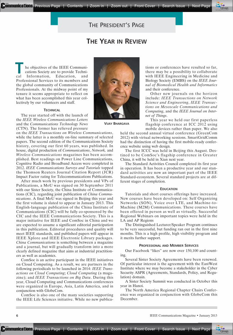
THE YEAR IN REVIEW
he objectives of the IEEE Communi-cations Society are to provide Techni-
cal Information, Education, andProfessional Services to its members andthe global community of CommunicationsProfessionals. At the midway point of mytenure it seems appropriate to reflect onwhat has been accomplished this year col-lectively by our volunteers and staff.
TECHNICAL
The year started off with the launch ofthe IEEE Wireless Communications Lettersand the Communications Technology News(CTN). The former has relieved pressureon the IEEE Transactions on Wireless Communications,while the latter is a monthly on-line summary of selectedpapers. The second edition of the Communications Societyhistory, covering our first 60 years, was published. Inhouse, digital production of Communications, Network, andWireless Communications magazines has been accom-plished. Best readings on Power Line Communications,Cognitive Radio and Broadband Access were completed in2012. IEEE Communications Surveys and Tutorials toppedthe Thomson Reuters Journal Citation Report (JCR)Impact Factor rating for Telecommunications Publications.
After much work by previous presidents and VPs ofPublications, a MoU was signed on 30 September 2011with our Sister Society, the China Institute of Communica-tions (CIC), regarding joint publication of China Commu-nications. A final MoU was signed in Beijing this year andthe first volume is slated to appear in January 2013. ThisEnglish-language publication of the China Institute ofCommunications (CIC) will be fully co-sponsored by theCIC and the IEEE Communications Society. This is amajor initiative for IEEE and ComSoc in China and weare expected to assume a significant editorial participationin this publication. Editorial procedures and quality willmeet IEEE standards, and published papers will appear inIEEE Xplore and IEEE Electronic Library packages.China Communications is something between a magazineand a journal, but will gradually transform into a moreclearly defined magazine that aims at industrial practition-ers as well as academics.
ComSoc is an active participant in the IEEE initiativeson Cloud Computing. As a result, we are partners in thefollowing periodicals to be launched in 2014: IEEE Trans-actions on Cloud Computing; Cloud Computing (a maga-zine); and IEEE Transactions on Big Data. During thisyear, Cloud Computing and Communications conferenceswere organized in Europe, Asia, Latin America, and inconjunction with GlobeCom.
ComSoc is also one of the many societies supportingthe IEEE Life Sciences initiative. While no new publica-
tions or conferences have resulted so far,there may be a possibility to collaboratewith IEEE Engineering in Medicine andBiology Society (EMBS) on the IEEE Jour-nal of Biomedical Health and Informaticsand their conference.
Other new journals on the horizoninclude: IEEE Transactions on NetworkScience and Engineering, IEEE Transac-tions on Mesoscale Communications andComputing, and the IEEE Journal on Inter-net of Things.
This year we held our first paperlessflagship conference at ICC 2012 usingmobile devices rather than paper. We also
held the second annual virtual conference (GreenCom2012) with virtual networking sessions. SmartGridCommhad the distinction of having the first mobile-ready confer-ence website using web design.
The first ICCC was held in Beijing this August. Des-tined to be ComSoc’s flagship conference in GreaterChina, it will be held in Xian next year.
The Standard Activities Council completed its first yearin operation. It has been a productive year and our stan-dard activities are now an important part of the IEEEStandard-ecosystem. Several standard projects are at dif-ferent stages of completion.
EDUCATION
Tutorials and short courses offerings have increased.New courses have been developed on: Self OrganizingNetworks (SON), Voice over LTE, and Machine-to-Machine (M2M) Communications. These courses havebeen offered in person as well as virtually. SuccessfulRegional Webinars on important topics were held in theLA and AP Regions
The Distinguished Lecturer/Speaker Program continuesto be very successful, but funding ran out in the first ninemonths. This is a high profile, high visibility program andit merits further support.
PROFESSIONAL AND MEMBER SERVICES
Our Facebook “likes” are now over 150,100 and count-ing.
Several Sister Society Agreements have been renewed.Of particular interest is the agreement with the EastWestInstitute where we may become a stakeholder in the CyberSecurity ASPR (Agreements, Standards, Policy, and Regu-lation) domain.
A Sister Society Summit was conducted in October thisyear in Hanoi.
The North America Regional Chapter Chairs Confer-ence was organized in conjunction with GlobeCom thisDecember.
T
VIJAY BHARGAVA
Previous Page | Contents | Zoom in | Zoom out | Front Cover | Search Issue | Next PageIEEE
Communications qqM
Mq
qM
MqM
Qmags®THE WORLD’S NEWSSTAND
Previous Page | Contents | Zoom in | Zoom out | Front Cover | Search Issue | Next PageIEEE
Communications qqM
Mq
qM
MqM
Qmags®THE WORLD’S NEWSSTAND
IEEE Communications Magazine • January 2013 7
GOVERNANCE
We had our first WebEX-enabled Board of GovernorsOperating Committee (OpCom) meeting in September.This Committee is a subset of the BoG and manages theSociety’s business between formal BoG meetings. It wentwell but there is room for improvement.
ComSoc released its Vision 2020 Report.We added a new elected ComSoc Officer, VP Stan-
dards Activities, and added a new appointed directorresponsible for Standardization Program Develop-ment.
CHALLENGES
From the above it can be seen that we did many goodthings to meet the objectives of the society and the goalsthat were set for this year. The credit for this goes to ourvolunteer leaders and staff. However, these accomplish-ments have been somewhat diminished because of thelooming budget deficit. To improve the situation we needto enhance on-line ad revenues and find ways to increasethem.
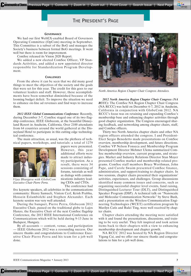
2012 IEEE Global Communications Conference: Recently,during December 3-7, ComSoc staged one of its two flag-ship conference, IEEE Globecom, at the beautiful Disney-land Resort in Anaheim, California. Over 2100 attendantsfrom 64 countries around the world gathered at the Dis-neyland Hotel to participate in this cutting edge technolog-ical conference.
The main attraction, as usual, was the plethora of tech-nical papers, workshops, and tutorials: a total of 1279
papers were presented.However, this yearadditional efforts weremade to attract indus-try participation. As aresult, there were 34sessions consisting offorums, tutorials as wellas dialogs with commu-nications industry lead-ing CEOs and CTOs.
The conference hadfive keynote speakers, all celebrities in the communicationscommunity: Henry Samueli, Vinton Cerf, Krish Prabhu,Hossein Eslambolchi and Stephen Alexander. Eachkeynote session was very well attended.
During the banquet, Pierre Perra, Globecom 2012Executive Chair, passed on the traditional globe to LajosHanzo, the Executive Chair of the next ComSoc flagshipConference, the 2013 IEEE International Conference onCommunications which will be held during 9-13 June inBudapest, Hungary.
By all accounts — content, venue, and participation— IEEE Globecom 2012 was a resounding success. Oursincere thanks and congratulations to Conference Exec-utive Chair Pierre Perra and his team for a job welldone.
2012 North America Region Chapter Chair Congress (NARCCC): The ComSoc NA Region Chapter Chair Congress(NA RCCC) was held on December 6-7, 2012 in Anaheim,California in conjunction with GlobeCom 2012. NARCCC’s focus was on retaining and expanding ComSoc’smembership base and enhancing chapter activities throughgood chapter organization. The Congress encouraged shar-ing feedback, and networking among chapter chairs, staff,and ComSoc officers.
Thirty two North America chapter chairs and other NAregion officers attended the congress. I and President-Elect Sergio Benedetto made presentations on ComSocoverview, membership development, and future directions.ComSoc VP Nelson Fonseca and Membership ProgramDevelopment Director Mehmet Ulema summarized Com-Soc membership overview, current programs, and strate-gies. Market and Industry Relations Director Stan Moyerpresented ComSoc market and membership related pro-grams. ComSoc staff members Bruce Worthman, JohnPape, and Carole Swaim presented ComSoc finance,administration, and support/training to chapter chairs. Intwo sessions, chapter chairs presented their organizations’activities, experiences, and challenges. Group discusssionsidentified many common issues and concerns, such asorganizing successful chapter level events, fund raising,Distinguished Lecturer Tour (DLT), and DistinguishedSpeaker Program (DSP). A technical talk on “Nanoscaleand Molecular Communication Networks” by Steve Bush,and a presentation on the Wireless Communication Engi-neering Technologies (WCET) certification program byMarilyn Catis and Rulei Ting, were well received by chap-ter chairs.
Chapter chairs attending the meeting were satisfiedwith it and found the presentations, discussions, and train-ing to be very useful. They felt inspired and took actionitems back to their chapters with a view to enhancingmembership development and chapter growth.
NA RCCC 2012 was hosted by NA Region DirectorYigang Cai, and we offer our sincere thanks and congratu-lations to him for a job well done.
THE PRESIDENT’S PAGE
North America Region Chapter Chair Congress Attendees.
Vijay Bhargava with GlobeComExecutive Chair Pierre Perra.
Previous Page | Contents | Zoom in | Zoom out | Front Cover | Search Issue | Next PageIEEE
Communications qqM
Mq
qM
MqM
Qmags®THE WORLD’S NEWSSTAND
Previous Page | Contents | Zoom in | Zoom out | Front Cover | Search Issue | Next PageIEEE
Communications qqM
Mq
qM
MqM
Qmags®THE WORLD’S NEWSSTAND

IEEE Communications Magazine • January 20138
2013J A N U A R Y
• COMSNETS 2013 - 5th Int’l. Confer-ence on Communication Systems andNetworks, 7-10 Jan.Bangalore, India.http://www.comsnets.org/
® IEEE CCNC 2013 - IEEE ConsumerCommunications & Networking Con-ference, 11-14 Jan.Las Vegas, NV.http://www.ieee-ccnc.org/
• ICACT 2013 - 15th Int’l. Conferenceon Advanced Communication Tech-nology, 27-30 Jan.Phoenix Park, Korea.http://www.icact.org/
• ICNC 2012 - Int’l. Conference on Com-puting, Networking, and Communica-tions 2013, 28-31 Jan.San Diego, CA.http://www.conf-icnc.org/2013/
F E B R U A R Y
• NCC 2013 - National Conference onCommunications, 15-17 Feb.New Delhi, India.http://www.ncc.org.in/ncc2013/
® IEEE CogSIMA - IEEE Int’l. Multi-Dis-ciplinary Conference on CognitiveMethods in Situation Awareness andDecision Support, 26-28 Feb.San Diego, CA.http://cogsima2013.org/
M A R C H
® OFC/NFOEC 2013 - Optical FiberCommunication Conference, 17-21Oct.Anaheim, CA.http://www.ofcnfoec.org/
® IEEE ISPLC 2013 - IEEE Int’l. Sympo-sium on Power Line Communicationsand Its Applications, 24-27 MarchJohannesburg, South Africa.http://www.ujtrg.co.za/isplc/
A P R I L
• COMCOMAP 2013 - Computing, Com-munications and Applications Confer-ence 2013, 1-4 AprilHong Kong.http://comcomap.net/2013/
® IEEE WCNC 2013 - IEEE WirelessCommunications and NetworkingConference, 7-10 AprilShanghai, China.http://www.ieee-wcnc.org/2013/
® IEEE LANMAN 2013 - 19th IEEE Int’l.Workshop on Local and MetropolitanArea Networks, 10-12 AprilBrussels, Belgium.http://www.ieee-lanman.org/
® IEEE INFOCOM 2013 - IEEE Int’l.Conference on Computer Communi-cation, 14-19 AprilTurin, Italy.http://infocom.di.unimi.it/
• WTS 2013 - Wireless Telecommunica-tions Symposium, 17-19 AprilPhoenix, AZ.http://www.csupomona.edu/~wtsi/
• ITU-K 2013 - ITU Kaleidoscope 2013:Building Sustainable Communities, 22-24 AprilKyoto, Japan.http://www.itu.int/ITU-T/uni/kaleidoscope/2013/index.html
IEEE RFID 2013 - 2013 IEEE Int’l. Confer-ence on RFID, 30 April-2 MayOrlando, FL.http://2013.ieee-rfid.org/
• WMNC 2013 - 6th Joint IFIP Wirelessand Mobile Networking Conference, 23-25 AprilDubai, United Arab Emirateshttp://wmnc2013.org/
• IEEE RFID 2013 - 2013 IEEE Int’l. Con-ference on RFID, 30 April-2 MayOrlando, FL.http://2013.ieee-rfid.org/
M A Y
• ICT 2013 - 20th Int’l. Conference onTelecommunications, 6-8 MayCasablanca, Morocco.http://www.ict-2013.org/
® IEEE CQR 2013 - 2013 Int’l. Commu-nications Quality and Reliability Work-shop, 14-16 MayMarco Island, FL.http://www.ieee-cqr.org/
® IFIP/IEEE IM 2013 - IFIP/IEEE Intl.Symposium on Integrated NetworkManagement, 27-31 MayGhent, Belgium.http://www.ieee-im.org/
J U N E
® IEEE ICC 2013 - 2013 IEEE Int’l. Con-ference on Communications, 9-13JuneBudapest, Hungary.http://www.ieee-icc.org/2013/
• SACONET 2013 - 4th Int’l. Conferenceon Smart Communications in NetworkTechnologies, 17-19 JuneParis, France.http://www.lissi.fr/saconet2013/doku.php/start
• ICCIT - Int’l. Conference on Communi-cations and Information Technology, 19-21 JuneBeirut, Lebanon.www.iccit-conf.org
® IEEE CTW 2012 - 2013 IEEE Commu-nication Theory Workshop, 23-26JunePhuket, Thailand.http://www.ieee-ctw.org/
® IEEE SECON - IEEE Int’l. Conferenceon Sensing, Communication, and Net-working, 24-27 JuneNew Orleans, LA.http://www.ieee-secon.org/
J U L Y
• BLACKSEACOM 2013 - Int’l. Black SeaConference on Communications andNetworking 2013, 1-4 JulyBatumi, Georgia.http://www.blackseacom.net/
• ICUFN 2013- 5th Int’l. Conference onUbiquitous and Future Networks, 2-5JulyDa Nang, Vietnam.http://www.icufn.org/main/
® Communications Society portfolio events are indicated with a diamond before the listing;• Communications Society technically co-sponsored conferences are indicated with a bullet beforethe listing. Individuals with information about upcoming conferences, calls for papers, meeting announce-ments, and meeting reports should send this information to: IEEE Communications Society, 3 ParkAvenue, 17th Floor, New York, NY 10016; e-mail: [email protected]; fax: +1-212-705-8996. Itemssubmitted for publication will be included on a space-available basis.
Updated on the Communications Society’s World Wide Web sitewww.comsoc.org/confs
CONFERENCE CALENDAR
Previous Page | Contents | Zoom in | Zoom out | Front Cover | Search Issue | Next PageIEEE
Communications qqM
Mq
qM
MqM
Qmags®THE WORLD’S NEWSSTAND
Previous Page | Contents | Zoom in | Zoom out | Front Cover | Search Issue | Next PageIEEE
Communications qqM
Mq
qM
MqM
Qmags®THE WORLD’S NEWSSTAND
____________
_________

For other sponsor opportunities, please contact Eric Levine,Associate Publisher Phone: 212-705-8920, E-mail: [email protected]
This presentation covers the Evolved Packet Core (EPC), a new all-IP mobile core network supporting LTE and other access networks to deliver new customer services as mobile data traffic rises.EPC, in conjunction with common IMS (IP Multimedia Subsystem) forms the converged core network supporting IP based consumer multimedia applications with QoS and policy, mobility across various access networks as well as common authentication/authorization, security and charging. Evolution of key legacy services such as voice and messaging to the all-IP converged core network are also addressed.
Converged Core Networks ANDSERVICES
g
Previous Page | Contents | Zoom in | Zoom out | Front Cover | Search Issue | Next PageIEEE
Communications qqM
Mq
qM
MqM
Qmags®THE WORLD’S NEWSSTAND
Previous Page | Contents | Zoom in | Zoom out | Front Cover | Search Issue | Next PageIEEE
Communications qqM
Mq
qM
MqM
Qmags®THE WORLD’S NEWSSTAND
______________
________________________________________________

Previous Page | Contents | Zoom in | Zoom out | Front Cover | Search Issue | Next PageIEEE
Communications qqM
Mq
qM
MqM
Qmags®THE WORLD’S NEWSSTAND
Previous Page | Contents | Zoom in | Zoom out | Front Cover | Search Issue | Next PageIEEE
Communications qqM
Mq
qM
MqM
Qmags®THE WORLD’S NEWSSTAND
___________________________________
Global Communications Newsletter • January 2013
January 2013
1
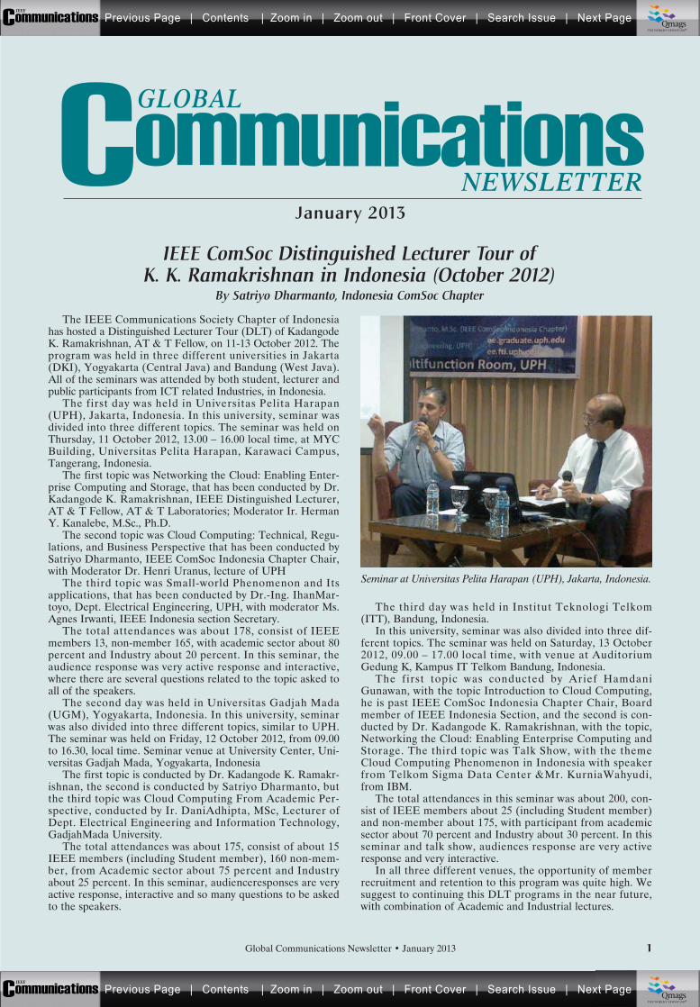
The IEEE Communications Society Chapter of Indonesiahas hosted a Distinguished Lecturer Tour (DLT) of KadangodeK. Ramakrishnan, AT & T Fellow, on 11-13 October 2012. Theprogram was held in three different universities in Jakarta(DKI), Yogyakarta (Central Java) and Bandung (West Java).All of the seminars was attended by both student, lecturer andpublic participants from ICT related Industries, in Indonesia.
The first day was held in Universitas Pelita Harapan(UPH), Jakarta, Indonesia. In this university, seminar wasdivided into three different topics. The seminar was held onThursday, 11 October 2012, 13.00 – 16.00 local time, at MYCBuilding, Universitas Pelita Harapan, Karawaci Campus,Tangerang, Indonesia.
The first topic was Networking the Cloud: Enabling Enter-prise Computing and Storage, that has been conducted by Dr.Kadangode K. Ramakrishnan, IEEE Distinguished Lecturer,AT & T Fellow, AT & T Laboratories; Moderator Ir. HermanY. Kanalebe, M.Sc., Ph.D.
The second topic was Cloud Computing: Technical, Regu-lations, and Business Perspective that has been conducted bySatriyo Dharmanto, IEEE ComSoc Indonesia Chapter Chair,with Moderator Dr. Henri Uranus, lecture of UPH
The third topic was Small-world Phenomenon and Itsapplications, that has been conducted by Dr.-Ing. IhanMar-toyo, Dept. Electrical Engineering, UPH, with moderator Ms.Agnes Irwanti, IEEE Indonesia section Secretary.
The total attendances was about 178, consist of IEEEmembers 13, non-member 165, with academic sector about 80percent and Industry about 20 percent. In this seminar, theaudience response was very active response and interactive,where there are several questions related to the topic asked toall of the speakers.
The second day was held in Universitas Gadjah Mada(UGM), Yogyakarta, Indonesia. In this university, seminarwas also divided into three different topics, similar to UPH.The seminar was held on Friday, 12 October 2012, from 09.00to 16.30, local time. Seminar venue at University Center, Uni-versitas Gadjah Mada, Yogyakarta, Indonesia
The first topic is conducted by Dr. Kadangode K. Ramakr-ishnan, the second is conducted by Satriyo Dharmanto, butthe third topic was Cloud Computing From Academic Per-spective, conducted by Ir. DaniAdhipta, MSc, Lecturer ofDept. Electrical Engineering and Information Technology,GadjahMada University.
The total attendances was about 175, consist of about 15IEEE members (including Student member), 160 non-mem-ber, from Academic sector about 75 percent and Industryabout 25 percent. In this seminar, audienceresponses are veryactive response, interactive and so many questions to be askedto the speakers.
The third day was held in Institut Teknologi Telkom(ITT), Bandung, Indonesia.
In this university, seminar was also divided into three dif-ferent topics. The seminar was held on Saturday, 13 October2012, 09.00 – 17.00 local time, with venue at AuditoriumGedung K, Kampus IT Telkom Bandung, Indonesia.
The first topic was conducted by Arief HamdaniGunawan, with the topic Introduction to Cloud Computing,he is past IEEE ComSoc Indonesia Chapter Chair, Boardmember of IEEE Indonesia Section, and the second is con-ducted by Dr. Kadangode K. Ramakrishnan, with the topic,Networking the Cloud: Enabling Enterprise Computing andStorage. The third topic was Talk Show, with the themeCloud Computing Phenomenon in Indonesia with speakerfrom Telkom Sigma Data Center &Mr. KurniaWahyudi,from IBM.
The total attendances in this seminar was about 200, con-sist of IEEE members about 25 (including Student member)and non-member about 175, with participant from academicsector about 70 percent and Industry about 30 percent. In thisseminar and talk show, audiences response are very activeresponse and very interactive.
In all three different venues, the opportunity of memberrecruitment and retention to this program was quite high. Wesuggest to continuing this DLT programs in the near future,with combination of Academic and Industrial lectures.
IEEE ComSoc Distinguished Lecturer Tour of K. K. Ramakrishnan in Indonesia (October 2012)
By Satriyo Dharmanto, Indonesia ComSoc Chapter
Seminar at Universitas Pelita Harapan (UPH), Jakarta, Indonesia.
GLOBAL
NEWSLETTER
Previous Page | Contents | Zoom in | Zoom out | Front Cover | Search Issue | Next PageIEEE
Communications qqM
Mq
qM
MqM
Qmags®THE WORLD’S NEWSSTAND
Previous Page | Contents | Zoom in | Zoom out | Front Cover | Search Issue | Next PageIEEE
Communications qqM
Mq
qM
MqM
Qmags®THE WORLD’S NEWSSTAND
Global Communications Newsletter • January 20132
As a chairman of IEEE IRAQ Section, I have urged mycolleagues in IEEE IRAQ Section to work for the establish-ment of new ComSoc chapter in IRAQ. Members signed apetition and submitted it to the IEEE to get the confirmation.And on 22 Sept. 2011, the confirmation for the establishmentof this new section was received. Many activities have beenplanned to diffuse awareness about the importance of thisnew chapter, mainly in Iraqi Universities, and many ministriesand private communication companies, and throughout thecomplete Iraqi scientific community. The chapter has set upthe activities detailed in the following.
Scientific workshop “The Status of the Communicationand Information Security in IRAQ” in cooperation with“AL Najef Technical College”, The Ministry of Communica-tion ,the Institute of Media and Communication, and“Omnia Communication company”. In his opening speech,the Chair of the chapter talked about:’ Status of the securityof the communication system inside Iraq, especially after2003”.
The Second Iraqi Communication Conference was held incooperation with the Ministry of Communications. The Com-Soc Chapter members sat on the scientific committee andreviewing board of this conference. And they organized aworkshop on the “Status of the security of communication sys-tem in IRAQ”.
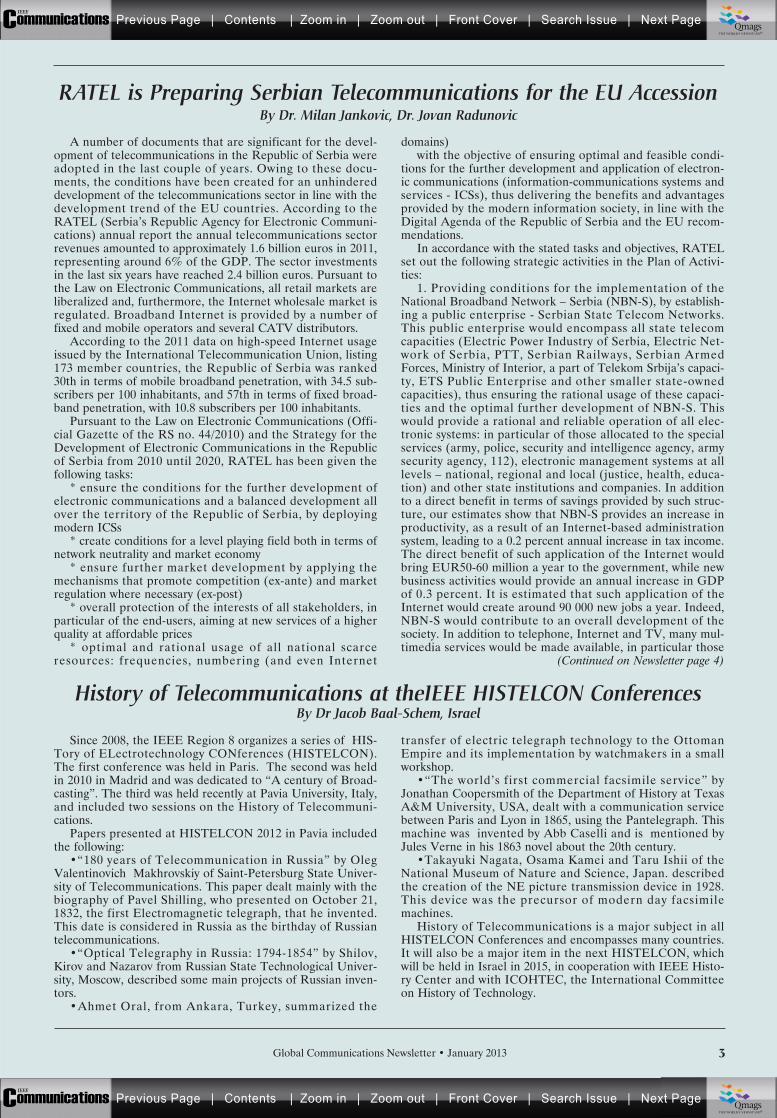
Another scientific workshop was held in cooperation withEngineering College in Kirkuk City and “Kilmat Private Com-pany” on “ The Current Status of Infrastructure of Commu-nication Systems and Their Securities in IRAQ. It was heldon15 March 2012 in Kirkuk City.
Babylon University hosted the “Second International Sci-entific Conference. The main topic the conference coveredwas the new communication systems and their applications.Most of the ComSoc Chapter members participated in thisconference.as reviewers of the submitted papers in the confer-ence.
Moreover, another workshop was held in Al Muthana Uni-versity on “E-Government and Its Future in Iraq” in coopera-tion with Science College on 4 Jan. 2012. The Iraqi ChapterChair was the main speaker in this workshop. He spokeabout the “Applicability of the E-Government and its Rela-tion to the Existing Communication Infrastructure inside Iraqafter 2003.
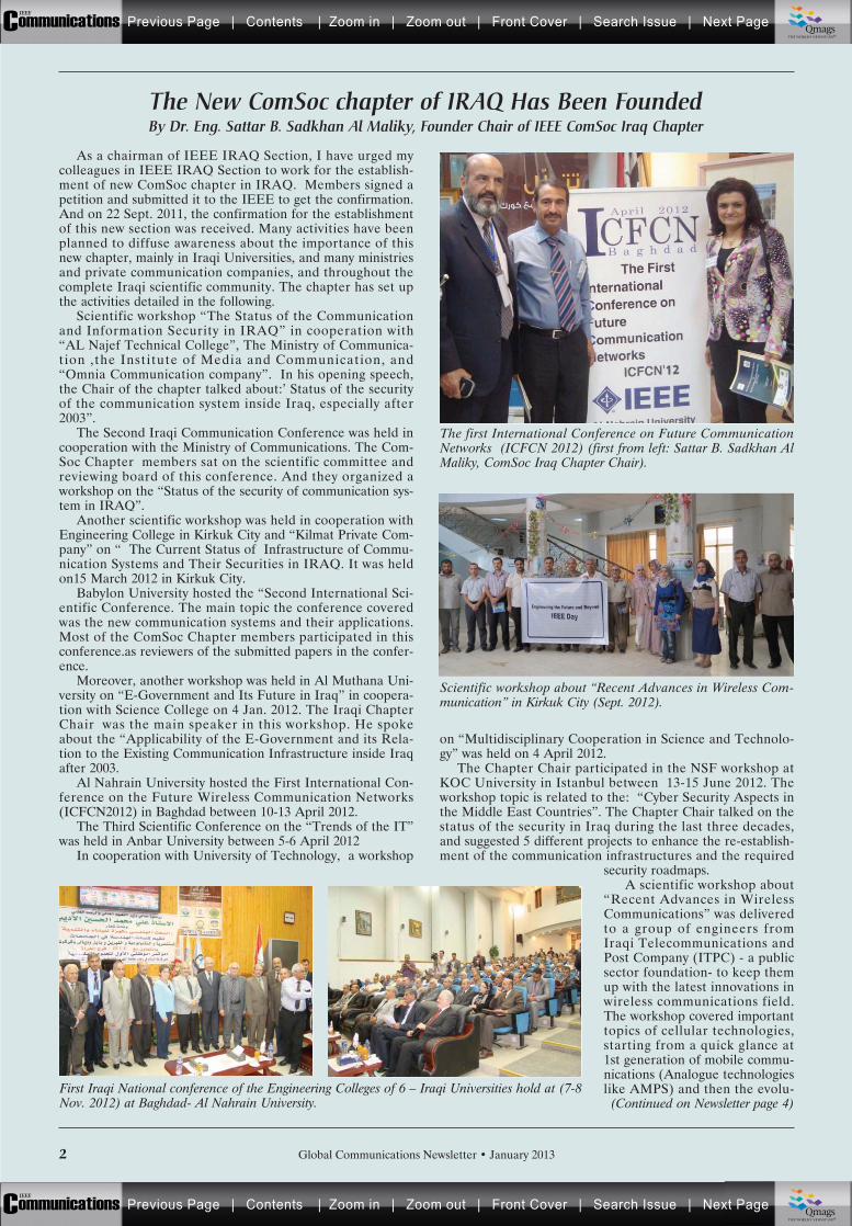
Al Nahrain University hosted the First International Con-ference on the Future Wireless Communication Networks(ICFCN2012) in Baghdad between 10-13 April 2012.
The Third Scientific Conference on the “Trends of the IT”was held in Anbar University between 5-6 April 2012
In cooperation with University of Technology, a workshop
on “Multidisciplinary Cooperation in Science and Technolo-gy” was held on 4 April 2012.
The Chapter Chair participated in the NSF workshop atKOC University in Istanbul between 13-15 June 2012. Theworkshop topic is related to the: “Cyber Security Aspects inthe Middle East Countries”. The Chapter Chair talked on thestatus of the security in Iraq during the last three decades,and suggested 5 different projects to enhance the re-establish-ment of the communication infrastructures and the required
security roadmaps.A scientific workshop about
“Recent Advances in WirelessCommunications” was deliveredto a group of engineers fromIraqi Telecommunications andPost Company (ITPC) - a publicsector foundation- to keep themup with the latest innovations inwireless communications field.The workshop covered importanttopics of cellular technologies,starting from a quick glance at1st generation of mobile commu-nications (Analogue technologieslike AMPS) and then the evolu-
The New ComSoc chapter of IRAQ Has Been FoundedBy Dr. Eng. Sattar B. Sadkhan Al Maliky, Founder Chair of IEEE ComSoc Iraq Chapter
(Continued on Newsletter page 4)
The first International Conference on Future CommunicationNetworks (ICFCN 2012) (first from left: Sattar B. Sadkhan AlMaliky, ComSoc Iraq Chapter Chair).
Scientific workshop about “Recent Advances in Wireless Com-munication” in Kirkuk City (Sept. 2012).
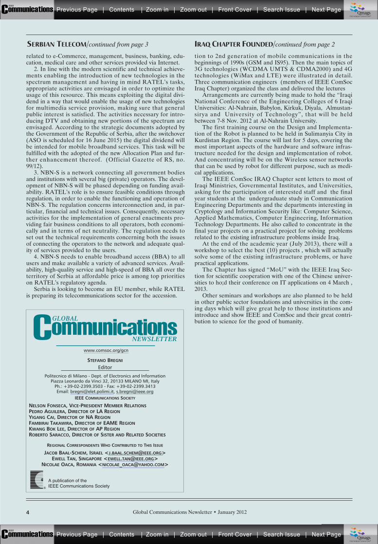
First Iraqi National conference of the Engineering Colleges of 6 – Iraqi Universities hold at (7-8Nov. 2012) at Baghdad- Al Nahrain University.
Previous Page | Contents | Zoom in | Zoom out | Front Cover | Search Issue | Next PageIEEE
Communications qqM
Mq
qM
MqM
Qmags®THE WORLD’S NEWSSTAND
Previous Page | Contents | Zoom in | Zoom out | Front Cover | Search Issue | Next PageIEEE
Communications qqM
Mq
qM
MqM
Qmags®THE WORLD’S NEWSSTAND
Global Communications Newsletter • January 2013 3
RATEL is Preparing Serbian Telecommunications for the EU AccessionBy Dr. Milan Jankovic, Dr. Jovan Radunovic
A number of documents that are significant for the devel-opment of telecommunications in the Republic of Serbia wereadopted in the last couple of years. Owing to these docu-ments, the conditions have been created for an unhindereddevelopment of the telecommunications sector in line with thedevelopment trend of the EU countries. According to theRATEL (Serbia’s Republic Agency for Electronic Communi-cations) annual report the annual telecommunications sectorrevenues amounted to approximately 1.6 billion euros in 2011,representing around 6% of the GDP. The sector investmentsin the last six years have reached 2.4 billion euros. Pursuant tothe Law on Electronic Communications, all retail markets areliberalized and, furthermore, the Internet wholesale market isregulated. Broadband Internet is provided by a number offixed and mobile operators and several CATV distributors.
According to the 2011 data on high-speed Internet usageissued by the International Telecommunication Union, listing173 member countries, the Republic of Serbia was ranked30th in terms of mobile broadband penetration, with 34.5 sub-scribers per 100 inhabitants, and 57th in terms of fixed broad-band penetration, with 10.8 subscribers per 100 inhabitants.
Pursuant to the Law on Electronic Communications (Offi-cial Gazette of the RS no. 44/2010) and the Strategy for theDevelopment of Electronic Communications in the Republicof Serbia from 2010 until 2020, RATEL has been given thefollowing tasks:
* ensure the conditions for the further development ofelectronic communications and a balanced development allover the territory of the Republic of Serbia, by deployingmodern ICSs
* create conditions for a level playing field both in terms ofnetwork neutrality and market economy
* ensure further market development by applying themechanisms that promote competition (ex-ante) and marketregulation where necessary (ex-post)
* overall protection of the interests of all stakeholders, inparticular of the end-users, aiming at new services of a higherquality at affordable prices
* optimal and rational usage of all national scarceresources: frequencies, numbering (and even Internet
domains)with the objective of ensuring optimal and feasible condi-
tions for the further development and application of electron-ic communications (information-communications systems andservices - ICSs), thus delivering the benefits and advantagesprovided by the modern information society, in line with theDigital Agenda of the Republic of Serbia and the EU recom-mendations.
In accordance with the stated tasks and objectives, RATELset out the following strategic activities in the Plan of Activi-ties:
1. Providing conditions for the implementation of theNational Broadband Network – Serbia (NBN-S), by establish-ing a public enterprise - Serbian State Telecom Networks.This public enterprise would encompass all state telecomcapacities (Electric Power Industry of Serbia, Electric Net-work of Serbia, PTT, Serbian Railways, Serbian ArmedForces, Ministry of Interior, a part of Telekom Srbija’s capaci-ty, ETS Public Enterprise and other smaller state-ownedcapacities), thus ensuring the rational usage of these capaci-ties and the optimal further development of NBN-S. Thiswould provide a rational and reliable operation of all elec-tronic systems: in particular of those allocated to the specialservices (army, police, security and intelligence agency, armysecurity agency, 112), electronic management systems at alllevels – national, regional and local (justice, health, educa-tion) and other state institutions and companies. In additionto a direct benefit in terms of savings provided by such struc-ture, our estimates show that NBN-S provides an increase inproductivity, as a result of an Internet-based administrationsystem, leading to a 0.2 percent annual increase in tax income.The direct benefit of such application of the Internet wouldbring EUR50-60 million a year to the government, while newbusiness activities would provide an annual increase in GDPof 0.3 percent. It is estimated that such application of theInternet would create around 90 000 new jobs a year. Indeed,NBN-S would contribute to an overall development of thesociety. In addition to telephone, Internet and TV, many mul-timedia services would be made available, in particular those
(Continued on Newsletter page 4)
Since 2008, the IEEE Region 8 organizes a series of HIS-Tory of ELectrotechnology CONferences (HISTELCON).The first conference was held in Paris. The second was heldin 2010 in Madrid and was dedicated to “A century of Broad-casting”. The third was held recently at Pavia University, Italy,and included two sessions on the History of Telecommuni-cations.
Papers presented at HISTELCON 2012 in Pavia includedthe following:
•“180 years of Telecommunication in Russia” by OlegValentinovich Makhrovskiy of Saint-Petersburg State Univer-sity of Telecommunications. This paper dealt mainly with thebiography of Pavel Shilling, who presented on October 21,1832, the first Electromagnetic telegraph, that he invented.This date is considered in Russia as the birthday of Russiantelecommunications.
•“Optical Telegraphy in Russia: 1794-1854” by Shilov,Kirov and Nazarov from Russian State Technological Univer-sity, Moscow, described some main projects of Russian inven-tors.
•Ahmet Oral, from Ankara, Turkey, summarized the
transfer of electric telegraph technology to the OttomanEmpire and its implementation by watchmakers in a smallworkshop.
•“The world’s first commercial facsimile service” byJonathan Coopersmith of the Department of History at TexasA&M University, USA, dealt with a communication servicebetween Paris and Lyon in 1865, using the Pantelegraph. Thismachine was invented by Abb Caselli and is mentioned byJules Verne in his 1863 novel about the 20th century.
•Takayuki Nagata, Osama Kamei and Taru Ishii of theNational Museum of Nature and Science, Japan. describedthe creation of the NE picture transmission device in 1928.This device was the precursor of modern day facsimilemachines.
History of Telecommunications is a major subject in allHISTELCON Conferences and encompasses many countries.It will also be a major item in the next HISTELCON, whichwill be held in Israel in 2015, in cooperation with IEEE Histo-ry Center and with ICOHTEC, the International Committeeon History of Technology.
History of Telecommunications at theIEEE HISTELCON ConferencesBy Dr Jacob Baal-Schem, Israel
Previous Page | Contents | Zoom in | Zoom out | Front Cover | Search Issue | Next PageIEEE
Communications qqM
Mq
qM
MqM
Qmags®THE WORLD’S NEWSSTAND
Previous Page | Contents | Zoom in | Zoom out | Front Cover | Search Issue | Next PageIEEE
Communications qqM
Mq
qM
MqM
Qmags®THE WORLD’S NEWSSTAND
4
STEFANO BREGNI
Editor
Politecnico di Milano - Dept. of Electronics and InformationPiazza Leonardo da Vinci 32, 20133 MILANO MI, Italy
Ph.: +39-02-2399.3503 - Fax: +39-02-2399.3413Email: [email protected], [email protected]
IEEE COMMUNICATIONS SOCIETY
NELSON FONSECA, VICE-PRESIDENT MEMBER RELATIONSPEDRO AGUILERA, DIRECTOR OF LA REGIONYIGANG CAI, DIRECTOR OF NA REGIONFAMBIRAI TAKAWIRA, DIRECTOR OF EAME REGIONKWANG BOK LEE, DIRECTOR OF AP REGIONROBERTO SARACCO, DIRECTOR OF SISTER AND RELATED SOCIETIES
REGIONAL CORRESPONDENTS WHO CONTRIBUTED TO THIS ISSUE
JACOB BAAL-SCHEM, ISRAEL <[email protected]>EWELL TAN, SINGAPORE <[email protected]>
NICOLAE OACA, ROMANIA <[email protected]>
®
A publication of the IEEE Communications Society
www.comsoc.org/gcn
Global Communications Newsletter • January 2012
IRAQ CHAPTER FOUNDED/continued from page 2SERBIAN TELECOM/continued from page 3
related to e-Commerce, management, business, banking, edu-cation, medical care and other services provided via Internet.
2. In line with the modern scientific and technical achieve-ments enabling the introduction of new technologies in thespectrum management and having in mind RATEL’s tasks,appropriate activities are envisaged in order to optimize theusage of this resource. This means exploiting the digital divi-dend in a way that would enable the usage of new technologiesfor multimedia service provision, making sure that generalpublic interest is satisfied. The activities necessary for intro-ducing DTV and obtaining new portions of the spectrum areenvisaged. According to the strategic documents adopted bythe Government of the Republic of Serbia, after the switchover(ASO is scheduled for 16 June 2015) the digital dividend willbe intended for mobile broadband services. This task will befulfilled with the adopted of the new Allocation Plan and fur-ther enhancement thereof. (Official Gazette of RS, no.99/12).
3. NBN-S is a network connecting all government bodiesand institutions with several big (private) operators. The devel-opment of NBN-S will be phased depending on funding avail-ability. RATEL’s role is to ensure feasible conditions throughregulation, in order to enable the functioning and operation ofNBN-S. The regulation concerns interconnection and, in par-ticular, financial and technical issues. Consequently, necessaryactivities for the implementation of general enactments pro-viding fair business conditions to all operators, both economi-cally and in terms of net neutrality. The regulation needs toset out the technical requirements concerning both the issuesof connecting the operators to the network and adequate qual-ity of services provided to the users.
4. NBN-S needs to enable broadband access (BBA) to allusers and make available a variety of advanced services. Avail-ability, high-quality service and high-speed of BBA all over theterritory of Serbia at affordable price is among top prioritieson RATEL’s regulatory agenda.
Serbia is looking to become an EU member, while RATELis preparing its telecommunications sector for the accession.
tion to 2nd generation of mobile communications in thebeginnings of 1990s (GSM and IS95). Then the main topics of3G technologies (WCDMA UMTS & CDMA2000) and 4Gtechnologies (WiMax and LTE) were illustrated in detail.Three communication engineers (members of IEEE ComSocIraq Chapter) organized the class and delivered the lectures
Arrangements are currently being made to hold the “IraqiNational Conference of the Engineering Colleges of 6 IraqiUniversities: Al-Nahrain, Babylon, Kirkuk, Diyala, Almustan-sirya and University of Technology”, that will be heldbetween 7-8 Nov. 2012 at Al-Nahrain University.
The first training course on the Design and Implementa-tion of the Robot is planned to be held in Sulimanyia City inKurdistan Region. The course will last for 5 days, covering themost important aspects of the hardware and software infras-tructure needed for the design and implementation of robot.And concentrating will be on the Wireless sensor networksthat can be used by robot for different purpose, such as medi-cal applications.
The IEEE ComSoc IRAQ Chapter sent letters to most ofIraqi Ministries, Governmental Institutes, and Universities,asking for the participation of interested staff and the finalyear students at the undergraduate study in CommunicationEngineering Departments and the departments interesting inCryptology and Information Security like: Computer Science,Applied Mathematics, Computer Engineering, InformationTechnology Departments. He also called to concentrate in thefinal year projects on a practical project for solving problemsrelated to the existing infrastructure problems inside Iraq.
At the end of the academic year (July 2013), there will aworkshop to select the best (10) projects , which will actuallysolve some of the existing infrastructure problems, or havepractical applications.
The Chapter has signed “MoU” with the IEEE Iraq Sec-tion for scientific cooperation with one of the Chinese univer-sities to ho;d their conference on IT applications on 4 March ,2013.
Other seminars and workshops are also planned to be heldin other public sector foundations and universities in the com-ing days which will give great help to those institutions andintroduce and show IEEE and ComSoc and their great contri-bution to science for the good of humanity.GLOBAL
NEWSLETTER
Previous Page | Contents | Zoom in | Zoom out | Front Cover | Search Issue | Next PageIEEE
Communications qqM
Mq
qM
MqM
Qmags®THE WORLD’S NEWSSTAND
Previous Page | Contents | Zoom in | Zoom out | Front Cover | Search Issue | Next PageIEEE
Communications qqM
Mq
qM
MqM
Qmags®THE WORLD’S NEWSSTAND
________________
__________________________
_____________________

For other sponsor opportunities, please contact Eric LevineAssociate Publisher Phone: 212-705-8920, E-mail: [email protected]
The tutorial begins with an overview of the wireless industry, enablers for B3G systems, and the motivation for voice services in future wireless systems. An overview of VoIP describes the vocoder and VoIP packets and challenges, including unique problems for OFDMA systems. Scheduling algorithms are covered. The final section on performance results describes how to evaluate the performance of a VoIP system and then provides performance results for LTE, UMB, and 802.16 systems.
OFDMA Systems
EnhancementsVoIPfor
,g
Previous Page | Contents | Zoom in | Zoom out | Front Cover | Search Issue | Next PageIEEE
Communications qqM
Mq
qM
MqM
Qmags®THE WORLD’S NEWSSTAND
Previous Page | Contents | Zoom in | Zoom out | Front Cover | Search Issue | Next PageIEEE
Communications qqM
Mq
qM
MqM
Qmags®THE WORLD’S NEWSSTAND
_________________________________________________
______________
mart grid is a term referring to the next generationpower grid in which electricity distribution and man-
agement is upgraded by incorporating advanced two-waydigital technology and communication capabilities forimproved control, efficiency, reliability, and safety. A com-munication infrastructure is an essential part of the successof the emerging smart grid. A scalable and pervasive com-munication infrastructure is crucial in both the constructionand operation of a smart grid. To ensure the correct func-tioning of a smart grid, it is essential that communicationsare secured, devices are protected from physical attack, andprivacy is respected. Communications require authentica-tion and confidentiality, devices require protection fromphysical attacks, and the system as a whole must be robust.Authorization will be vital to support secure remote config-uration and multihoming scenarios. The privacy of smartgrid customers needs to be protected.
Most of the frameworks for smart grids have alreadybeen defined by the industry, academia, and governments;nevertheless, there are still many important issues in cybersecurity for smart grid communications, which need to beresolved before smart grids can be operationally ready forthe market. We planned this feature topic to help addressthat need, and would like to focus on recent advances aswell as survey papers in cyber security for smart grid com-munications.
The responses to our Call for Papers on this featuretopic were overwhelming, with 36 articles submitted fromaround the globe. During the review process, each paperwas assigned to and reviewed by at least three experts inthe relevant area, with a rigorous two-round review pro-cess. Part I of this feature topic, which consisted of sevenexcellent articles addressing various aspects of cyber secu-rity for smart grid communications, was published in theAugust 2012 issue of IEEE Communications Magazine.Part II accommodates another six outstanding articles cov-ering different aspects of cyber security for smart gridcommunications related to various attacks, key manage-ment, security for power distribution networks, smart gridsustainability, and smart grid cyber security standardiza-
tion.The first article, “Non-Repudiation in Neighborhood
Area Networks for Smart Grid,” by Xiao et al., presents amutual inspection strategy to enable non-repudiation andaccountability in neighborhood area networks on smartmeter readings. The goal of this scheme is to discoverproblematic meters that report inaccurate reading values.
In the second article, “Bad Data Injection in SmartGrid: Attack and Defense Mechanisms,” Huang et al. dis-cuss the important security problem of bad data injectionin smart grids. They present a detailed problem formula-tion, and then, from the defenders’ point of view, theystudy the quickest detection techniques to detect a baddata injection attack as quickly as possible.
The third article, “WAKE: A Key Management Schemefor Wide-Area Measurement Systems” by Law et al., pre-sents a comprehensive key management scheme, WAKE,targeting a concrete set of security objectives derived fromNIST’s security impact level ratings. For security objectivesinvolving unicast, WAKE employs industry-standard secu-rity protocols. For security objectives involving multicast,they show that the scheme standardized by the Interna-tional Electrotechnical Commission is inadequate, andidentify multicast authentication as a requirement.
Bou-Harb et al., in the fourth article, “CommunicationSecurity for Smart Grid Distribution Networks,” focus onthe communication security aspect, which deals with thedistribution component of the smart grid. They target thenetwork security of the advanced metering infrastructurecoupled with the data communication toward the transmis-sion infrastructure, and discuss the security and feasibilityaspects of possible communication mechanisms that couldbe adopted on that subpart of the grid.
In the fifth article, “Energy Footprint Framework: APathway Toward Smart Grid Sustainability,” Boccardo etal. propose two architectures, clustered and distributed, forlabeling the energy source provided to the smart grid, forthe integration of renewable, low-polluting, distributedenergy resources in the power grid, which is an importantstep toward sustainable development.
IEEE Communications Magazine • January 201316
S
CYBER SECURITY FOR SMART GRID COMMUNICATIONS: PART II
GUEST EDITORIAL
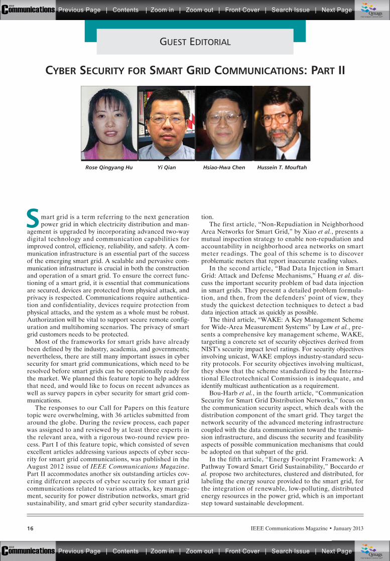
Rose Qingyang Hu Yi Qian Hsiao-Hwa Chen Hussein T. Mouftah
Previous Page | Contents | Zoom in | Zoom out | Front Cover | Search Issue | Next PageIEEE
Communications qqM
Mq
qM
MqM
Qmags®THE WORLD’S NEWSSTAND
Previous Page | Contents | Zoom in | Zoom out | Front Cover | Search Issue | Next PageIEEE
Communications qqM
Mq
qM
MqM
Qmags®THE WORLD’S NEWSSTAND
IEEE Communications Magazine • January 2013 17
Finally, Chan and Zhou present the sixth and last arti-cle, “On Smart Grid Cybersecurity Standardization: Issuesof Designing with NISTIR 7628.” In this article, theauthors use the electric vehicle charging infrastructure as acase example to study the effectiveness of the NISTIR7628 framework in defining security requirements forsmart grid applications. They show that the NISTIR 7628security framework might still be insufficient to specify therequirements of a secure smart grid system. Then theyindicate that cyber-physical device authentication and EVlocation privacy are a promising direction for futureresearch in smart grid cyber security.
In closing, we would like to thank all the authors fortheir excellent contributions. We also thank the reviewersfor their dedication in reviewing the papers and providingvaluable comments and suggestions for refining the qualityof the articles. We appreciate the advice and support fromDr. Steve Gorshe, Editor-in-Chief of IEEE Communica-tions Magazine, and Joseph Milizzo, Jennifer Porcello, andCathy Kemelmacher for their help throughout the publica-tion process. Finally, we hope that the readership will findthis feature topic interesting and stay tuned for new devel-opments in this research area.
BIOGRAPHIESROSE QINGYANG HU [S’95, M’98, SM’06] ([email protected]) received herB.S.E.E. degree from the University of Science and Technology of China, herM.S. in mechanical engineering from the Polytechnic Institute of New YorkUniversity, and her Ph.D. degree in electrical engineering from the Universi-ty of Kansas. From January 2002 to June 2004 she was an assistant profes-sor with the Department of Electrical and Computer Engineering atMississippi State University. She also had more than 10 years of R&D expe-rience in the telecommunications industry as a technical manager, seniorwireless system architect, and senior research scientist working on next-generation wireless, satellite, and optical system design, optimization, andperformance evaluation. Currently she is an associate professor with theDepartment of Electrical and Computer Engineering at Utah State Universi-ty. Her current research interests include next-generation wireless commu-nication and network design and optimization, green radio, sensornetworks, multimedia QoS/QoE, wireless system modeling, and perfor-mance analysis. She has published extensively and holds numerous patentsin the above research areas. She is currently serving on the editorial boardsof IEEE Wireless Communications, Security and Communication NetworksJournal, and Wireless Communications and Mobile Computing Journal, andhas also been a guest editor for IEEE Communications Magazine, IEEE Wire-less Communications, and IEEE Network. She is a member of Phi Kappa Phiand Epsilon Pi Epsilson Honor Societies.
YI QIAN [M’95, SM’07] ([email protected]) is an associate professor in theDepartment of Computer and Electronics Engineering, University ofNebraska-Lincoln (UNL). Prior to joining UNL, he worked in the telecom-munications industry, academia, and government. Some of his previous
professional positions include serving as a senior member of scientificstaff and technical advisor at Nortel Networks, a senior systems engi-neer and technical advisor at several startup companies, an assistantprofessor at the University of Puerto Rico at Mayaguez, and a seniorresearcher at the National Institute of Standards and Technology. Hisresearch interests include information assurance and network security,network design, network modeling, simulation and performance analy-sis for next generation wireless networks, wireless ad hoc and sensornetworks, vehicular networks, broadband satellite networks, optical net-works, high-speed networks, and the Internet. He has a successful trackrecord in leading research teams and publishing research results inleading scientific journals and conferences. Several of his recent journalarticles on wireless network design and wireless network security areamong the most accessed papers in the IEEE Digital Library. He is amember of ACM.
HSIAO-HWA CHEN [S’89, M’91, SM’00, F’10] ([email protected]) is currentlya Distinguished Professor in the Department of Engineering Science,National Cheng Kung University, Taiwan. He obtained his B.Sc. and M.Sc.degrees from Zhejiang University, China, and a Ph.D. degree from the Uni-versity of Oulu, Finland, in 1982, 1985 and 1991, respectively. He hasauthored or co-authored over 400 technical papers in major internationaljournals and conferences, and six books and more than ten book chaptersin the areas of communications. He has served as the general chair, TPCchair and symposium chair for many international conferences. He servedor is serving as an Editor or/and Guest Editor for numerous technical jour-nals. He is the Editor-in-Chief of IEEE Wireless Communications and thefounding Editor-in-Chief of Wiley’s Security and Communication NetworksJournal (www.interscience.wiley.com/journal/security). He is the recipient ofthe best paper award in IEEE WCNC 2008 and a recipient of IEEE RadioCommunications Committee Outstanding Service Award in 2008. He is aFellow of IET, and a Fellow of BCS.
HUSSEIN T. MOUFTAH [S’74, M’75, SM’80, F’90] ([email protected]) joinedthe School of Information Technology and Engineering (SITE) of the Univer-sity of Ottawa in 2002 as a Tier 1 Canada Research Chair Professor, wherehe became a University Distinguished Professor in 2006. Previously, he waswith the ECE Department at Queen’s University (1979–2002), where he wasprior to his departure a full professor and the Department’s associate head.He has six years of industrial experience, mainly at Bell Northern Researchof Ottawa (now Nortel Networks). He served as Editor-in-Chief of IEEECommunications Magazine (1995–97) and IEEE ComSoc Director of Maga-zines (1998–99), Chair of the Awards Committee (2002–03), Director ofEducation (2006–07), and member of the Board of Governors (1997–99and 2006–07). He has been a Distinguished Speaker of the IEEE Communi-cations Society (2000–2007). He is the author or coauthor of 7 books, 48book chapters and more than 1000 technical papers, 12 patents, and 140industrial reports. He is the joint holder of 12 Best Paper and/or Outstand-ing Paper Awards. He has received numerous prestigious awards, such asthe 2007 Royal Society of Canada Thomas W. Eadie Medal, the 2007–2008University of Ottawa Award for Excellence in Research, the 2008 ORIONLeadership Award of Merit, the 2006 IEEE Canada McNaughton GoldMedal, the 2006 EIC Julian Smith Medal, the 2004 IEEE ComSoc EdwinHoward Armstrong Achievement Award, the 2004 George S. Glinski Awardfor Excellence in Research of the U of O Faculty of Engineering, the 1989Engineering Medal for Research and Development of the Association ofProfessional Engineers of Ontario (PEO), and the Ontario DistinguishedResearcher Award of the Ontario Innovation Trust. He is a Fellow of theCanadian Academy of Engineering (2003), the Engineering Institute ofCanada (2005), and the Royal Society of Canada RSC Academy of Science(2008).
GUEST EDITORIAL
Previous Page | Contents | Zoom in | Zoom out | Front Cover | Search Issue | Next PageIEEE
Communications qqM
Mq
qM
MqM
Qmags®THE WORLD’S NEWSSTAND
Previous Page | Contents | Zoom in | Zoom out | Front Cover | Search Issue | Next PageIEEE
Communications qqM
Mq
qM
MqM
Qmags®THE WORLD’S NEWSSTAND
___________
___________
_________
_________
IEEE Communications Magazine • January 201318 0163-6804/13/$25.00 © 2013 IEEE
INTRODUCTION
Smart grid [1–3] has become one of the researchhotspots in recent years. A smart grid not onlydelivers electricity from the power provider tosubscribers, but it also enables two-way digitalcommunications to gather, distribute, and act oninformation about the behavior of all partici-pants. The goal of replacing traditional powergrids with smart grid is to save energy, reducecost, and increase reliability and transparency.
The traditional power grid does not possessthe property of non-repudiation. Back in the20th century, power providers employed meterreaders to do door-to-door meter readings.There are many drawbacks of artificial meterreading, such as high time cost and labor cost,low accuracy, and error-prone reading. Addition-ally, there is no evidence pointing to a cheaterwho falsifies or manipulates the reading data.For instance, if a meter is tampered with and thereading value is less than the actual amount, thepower company is unable to detect the theftbehavior. Advanced metering infrastructure(AMI) is being developed to tackle some ofthese issues. The goal of AMI is to provide auto-matic measurement and transmission of meterreadings. However, AMI cannot ensure non-repudiation of meter readings as well. The rootproblem lies in the method of collecting thereading values of smart meters. In order to
acquire the service amount of each subscriber,the power provider must rely on the digital com-munication network for data transmission. Sincethe reading value is generated on the subscriberend, an attacker or energy thief still has multiplemeans to tamper with it. The most commonmethods [4] of energy theft include meteringtampering, meter switching, wire partial bypassof the meter inside the meter enclosure, com-plete bypass of the meter from the low-voltagegrid, and direct connection to the primary volt-age grid with a pirate distribution transformer.The original reading may be altered before it issent to the provider. Since the smart meter maybe the only source for the power provider toacquire the service amount, whether the meterreading is accurate or falsified, the powerprovider has no means to prove the correctnessof the meter’s reading report.
A straightforward solution is to physicallysecure the smart meter. Other people whoattempt to break the box may trigger an alarmor leave an undeniable trace on the box. Howev-er, this does not solve the root problem: the ser-vice amount can only be obtained via the meteron the subscriber end, and the power providercannot obtain this information directly throughthe power grid.
In this article, we address non-repudiation interms of accountability, which assigns responsibili-ty to each smart meter, whether it is accurate ornot. We adopt a mutual inspection strategy toensure non-repudiation. Following this strategy,we install two smart meters with one electric wireconnecting the subscriber and the provider. Thismeans that for each individual wire, there is onesmart meter on each end; one represents the sub-scriber’s reading, and the other represents theprovider’s reading. In a normal situation, althoughthese two meters measure the same wire, theirreadings are not the same due to:• Power loss during power transfer• Measuring errors caused by communication
delays and synchronization issues• Dynamic factors caused by the environment
(e.g., temperature)Additionally, the remarkable difference betweenreadings can be caused by a meter that is com-
ABSTRACT
Lack of non-repudiation is a major barrier ofbuilding a trustworthy smart grid. In currentpower systems, bills are generated based on theamount of service consumed by residential orcommercial users. However, meter readings maynot be trustworthy due to malicious behavior(e.g., energy theft) or external attacks. The rootcause is that power providers have no means toobtain the reading value other than receiving itfrom the users. To resolve this issue, we presenta mutual inspection strategy, which enables non-repudiation on meter readings for smart grid.The goal of our scheme is to discover problem-atic meters that report inaccurate reading values.
CYBER SECURITY FOR SMART GRIDCOMMUNICATIONS: PART 2
Zhifeng Xiao and Yang Xiao, University of Alabama
David Hung-Chang Du, University of Minnesota
Non-Repudiation in Neighborhood AreaNetworks for Smart Grid
Previous Page | Contents | Zoom in | Zoom out | Front Cover | Search Issue | Next PageIEEE
Communications qqM
Mq
qM
MqM
Qmags®THE WORLD’S NEWSSTAND
Previous Page | Contents | Zoom in | Zoom out | Front Cover | Search Issue | Next PageIEEE
Communications qqM
Mq
qM
MqM
Qmags®THE WORLD’S NEWSSTAND
IEEE Communications Magazine • January 2013 19
promised or out of order. In our strategy, thereadings are exchanged between the powerprovider and the subscriber in order to resolve adispute (if there is any). If the dispute lies in arange that is acceptable for both ends, the ser-vice continues to be delivered; however, if thedispute exceeds a certain threshold, the servicewill be terminated and further investigation willbegin. In the mutual inspection strategy, two dis-trusted parties can inspect each other to realizenon-repudiation in smart grid.
Mutual inspection requires that the quantityof smart meters is doubled, and this increaseseems to incur high expense. However, the esti-mated annual loss due to energy theft is $6 bil-lion dollars in the United States [4]. There werearound 22 million smart meters deployed in theUnited States by the end of 2011. To fully adoptmutual inspection, the number of smart meterswill be doubled. The market price of a smartmeter is around $100. Therefore, the hardwarecost will be less than $3 billion. In addition, thecost of deployment and maintenance should beconsidered. If the strategy saves the $6 billionloss or at least the majority, the saved money inone year may entirely cover the investment. Thereturn on investment is considerable because thecountry can save up to $6 billion per year in thefuture.
This article is based on our preliminary workpresented at a conference [12], and we havemade substantial new contributions. The contri-butions of this article are listed below. We for-malize the non-repudiation problem in smartgrid. Based on our knowledge, this is the firsttime the non-repudiation problem in smart gridhas been addressed. We adopt mutual inspec-tion and design a protocol to realize non-repu-diation in smart grid so that any misbehaviorand malicious operation that compromisespower readings will eventually be detected.Mutual inspection can stop all theft behaviorrelying on meter compromising and wirebypassing. We consider three kinds of structure:centralized structure, point-to-point (P2P)structure, and hybrid structure, and discuss howmutual inspection is applied to the three envi-ronments. We conduct both numeric analysisand simulation to evaluate the proposedscheme.
The rest of this article is structured as fol-lows. Related works are reviewed in the nextsection. Then some background knowledge ofthe smart grid, smart grid architecture, and thebilling mechanism are introduced. Furthermore,the problem statement and mutual inspectionprotocol are presented. Finally, the evaluationand conclusions are included.
RELATED WORKSecurity has been a significant concern for smartgrid [5–7, 11–13]. Smart grids have leveragedmany hardware and software technologies, suchas smart meters, sensors, and advanced commu-nication networks. Although these techniquesbring many exciting features to smart grid, theyalso introduce new vulnerabilities that may beexploited by adversaries. We briefly introducethe smart grid security issues in four aspects.
TRUST
A smart grid is a heterogeneous environmentcontaining various devices, such as smart meters,appliances, collectors, and backend servers. Atrust relation is expected before real data can beexchanged and processed. The issue discussed inthis article falls into this category.
PRIVACYSmart metering and load management is incor-porated into smart grid. However, since the sub-scriber’s power consumption pattern is revealedto the provider, the customer’s privacy, especial-ly lifestyle, may be disclosed. For instance, it iseasy to tell whether the customer is at home ornot. With careful analysis, it is even possible tofigure out which appliance is in use. This kind ofinformation may be used by criminals.
DEVICE SECURITYDevices in smart grid should be protected physi-cally and cryptographically. A recent studyshowed how a smart meter was compromised ina security incident, which incurs the loss ofcipher keys and memory data.
SECURITY MANAGEMENTThe scale of smart grid keeps increasing; thus,more and more devices will join in. Handling thesecurity management issues such as key genera-tion, update, and revoke is a challenge.
In this article, our focus is on non-repudia-tion, which is the foundation of a trustworthysmart grid. Without non-repudiation, energytheft is hard to control at root. McLaughlin et al.[6] demonstrate that not only is energy theft pos-sible in the AMI system, but the AMI commodi-ty devices can also be taken advantage of byadversaries in order to perform a number ofattacks. There are three classes of attacksdepending on when and where meter reading ismanipulated. They include:• While it is recorded• While it is at rest in the meter• As it is in flight across the networkToday’s energy theft detection models generallyfall into two categories [7]: peer comparison andcharacteristic analysis. Peer comparison modelsgroup residential and commercial customerswith similar homes and businesses in similargeographical and environmental settings. If acustomer’s actual usage deviates from theexpected usage, it may indicate incorrectness ofenergy metering. Characteristic analysis, on theother hand, attempts to model the consumptionpattern for an account; thus, any anomalies notfollowing the pattern may be indicative of ener-gy theft. In this area, machine learning tech-niques (e.g., support vector machines [SVMs][8]) can be leveraged for building fundamentalpatterns and detecting anomalies. However,these analytical methods cannot be used as evi-dence of energy theft, because a deviation fromexpected normal usage can be caused by multi-ple reasons other than energy theft. For exam-ple, one needs to consider the trend of energyusage in the entire area or other legitimatechanges. In this article, our method differs fromthe early analytical methods in that we aim to
Smart metering and
load management is
incorporated into
smart grid. However,
since the subscriber’s
power consumption
pattern is revealed to
the provider, the
customer’s privacy,
especially the living
style, may be dis-
closed. For instance,
it is easy to tell
whether the cus-
tomer is at home
or not.
Previous Page | Contents | Zoom in | Zoom out | Front Cover | Search Issue | Next PageIEEE
Communications qqM
Mq
qM
MqM
Qmags®THE WORLD’S NEWSSTAND
Previous Page | Contents | Zoom in | Zoom out | Front Cover | Search Issue | Next PageIEEE
Communications qqM
Mq
qM
MqM
Qmags®THE WORLD’S NEWSSTAND
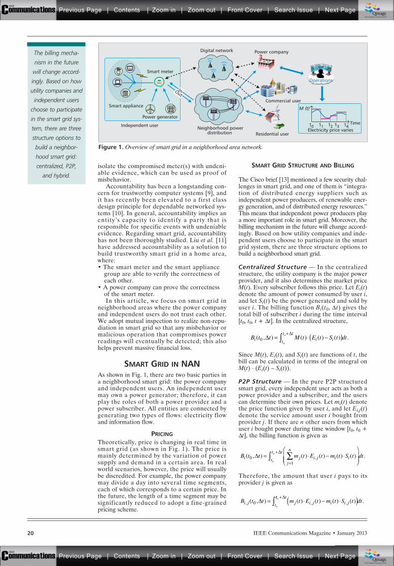
IEEE Communications Magazine • January 201320
isolate the compromised meter(s) with undeni-able evidence, which can be used as proof ofmisbehavior.
Accountability has been a longstanding con-cern for trustworthy computer systems [9], andit has recently been elevated to a first classdesign principle for dependable networked sys-tems [10]. In general, accountability implies anentity’s capacity to identify a party that isresponsible for specific events with undeniableevidence. Regarding smart grid, accountabilityhas not been thoroughly studied. Liu et al. [11]have addressed accountability as a solution tobuild trustworthy smart grid in a home area,where:• The smart meter and the smart appliance
group are able to verify the correctness ofeach other.
• A power company can prove the correctnessof the smart meter. In this article, we focus on smart grid in
neighborhood areas where the power companyand independent users do not trust each other.We adopt mutual inspection to realize non-repu-diation in smart grid so that any misbehavior ormalicious operation that compromises powerreadings will eventually be detected; this alsohelps prevent massive financial loss.
SMART GRID IN NANAs shown in Fig. 1, there are two basic parties ina neighborhood smart grid: the power companyand independent users. An independent usermay own a power generator; therefore, it canplay the roles of both a power provider and apower subscriber. All entities are connected bygenerating two types of flows: electricity flowand information flow.
PRICINGTheoretically, price is changing in real time insmart grid (as shown in Fig. 1). The price ismainly determined by the variation of powersupply and demand in a certain area. In realworld scenarios, however, the price will usuallybe discredited. For example, the power companymay divide a day into several time segments,each of which corresponds to a certain price. Inthe future, the length of a time segment may besignificantly reduced to adopt a fine-grainedpricing scheme.
SMART GRID STRUCTURE AND BILLING
The Cisco brief [13] mentioned a few security chal-lenges in smart grid, and one of them is “integra-tion of distributed energy suppliers such asindependent power producers, of renewable ener-gy generation, and of distributed energy resources.”This means that independent power producers playa more important role in smart grid. Moreover, thebilling mechanism in the future will change accord-ingly. Based on how utility companies and inde-pendent users choose to participate in the smartgrid system, there are three structure options tobuild a neighborhood smart grid.
Centralized Structure — In the centralizedstructure, the utility company is the major powerprovider, and it also determines the market priceM(t). Every subscriber follows this price. Let Ei(t)denote the amount of power consumed by user i,and let Si(t) be the power generated and sold byuser i. The billing function Bi(t0, Dt) gives thetotal bill of subscriber i during the time interval[t0, t0, t + Dt]. In the centralized structure,
Since M(t), Ei(t), and Si(t) are functions of t, thebill can be calculated in terms of the integral onM(t) . (Ei(t) – Si(t)).
P2P Structure — In the pure P2P structuredsmart grid, every independent user acts as both apower provider and a subscriber, and the userscan determine their own prices. Let mi(t) denotethe price function given by user i, and let Ei,j(t)denote the service amount user i bought fromprovider j. If there are n other users from whichuser i bought power during time window [t0, t0 +Dt], the billing function is given as
Therefore, the amount that user i pays to itsprovider j is given as
( )=+
B t t M t E t S t dt( , ) ( ) ( ) ( ) .i i it
t t0
0
0
B t t m t E t m t S ti j i j i ij
n
( , ) ( ) ( ) ( ) ( ),01
==
+
t
t tdt
0
0 .
B t t m t E t m t S ti j j i j i i jt, , ,( , ) ( ) ( ) ( ) ( )00
= ( )tt tdt0 + .
Figure 1. Overview of smart grid in a neighborhood area network.
11 12 13 14
Operations
Power company
Commercial user
M (t)
Time10Electricity price varies
Residential user
Smart meter
Neighborhood powerdistribution
Digital network
Smart appliance
Power generator
Independent user
InOut
The billing mecha-
nism in the future
will change accord-
ingly. Based on how
utility companies and
independent users
choose to participate
in the smart grid sys-
tem, there are three
structure options to
build a neighbor-
hood smart grid:
centralized, P2P,
and hybrid.
Previous Page | Contents | Zoom in | Zoom out | Front Cover | Search Issue | Next PageIEEE
Communications qqM
Mq
qM
MqM
Qmags®THE WORLD’S NEWSSTAND
Previous Page | Contents | Zoom in | Zoom out | Front Cover | Search Issue | Next PageIEEE
Communications qqM
Mq
qM
MqM
Qmags®THE WORLD’S NEWSSTAND

IEEE Communications Magazine • January 2013 21
Hybrid Structure — In the hybrid structure,the power company is still the major providerand determines the market price; however, inde-pendent users can set their own price as well.Therefore, it is straightforward to give the billingfunction as
In this situation, the total bill of user i should bethe sum of the amount paid to the power compa-ny (the first term in parentheses) and the amountpaid to other independent users (the secondterm), minus the money that user i makes fromother users. If we treat the power company asanother independent user, the hybrid structurebecomes a special form of the P2P structure.
PROBLEM STATEMENT
TERMS AND DEFINITIONSBased on the mutual inspection strategy, for asubscriber S there are two meters, MS and MP,to record its service amount at both ends of thewire connecting the subscriber S and theprovider P.
Definition 1: The power demand function P(t)gives the power service amount of a subscriberat time t. Obviously, P(t) depends on the condi-tion of all power appliances. A concrete modelof P(t) will be given in the next section.
Definition 2: The power loss function l(P)defines the power line loss during transmissiongiven that the power demand is P. According toelectricity knowledge, we have l(P(t)) = (P(t)2 .R)/V2, where R is the wire resistance and V is thetransmission voltage. R is dependent on thecable material, cable length, and environmentfactors like temperature. In this article, we ruleout the variability of resistance and consider Ras a constant. Therefore, l is a function of powerdemand P of a subscriber.
Definition 3: The bill difference (i.e., dispute)function b(t0, Dt) gives the bill difference (start-ing from t0) between two end smart meters con-nected by the same power line during a timewindow Dt. Let M(t) denote the price function,which can be either the market price or theindependent power seller’s price. Therefore, b(t0,Dt) can be given as
The first term is the bill due to power loss; thisis considered the main part of bill differences.However, there are other factors affecting thebill difference, including measuring error, com-munication delay, and synchronization issue.Therefore, before we can have further informa-tion to express these factors, we use a(t0, Dt) torepresent all of them.
PROBLEM FORMULATIONIn order to resolve the dispute, Ms and Mpexchange billing data constantly; however, thereshould be a proper time window that determines
how frequently they exchange. If the time win-dow is too large (e.g., once per month/day/hour),the power provider undertakes a higher riskbecause there may be large disputes accumulat-ed before the provider can recognize them. Onthe contrary, if the time window is very small,the power provider can be notified before it suf-fers more losses. Unfortunately, there is a highcommunication overhead that will underminethe system performance. Therefore, we need todetermine an optimal time window in order tomaximize the time window without bringing anunbearable overhead. The Time Window Maxi-mization (TWM) problem is formulized as fol-lows:
Time Window Maximization (TWM) problem:Given t0, maximize Dt s.t. b(t0, Dt) £ b0; H(Dt)H0, in which b0 is a predefined dispute thresh-old. H(Dt) is the throughput function that is con-strained by a threshold H0.
SOLUTION SKETCHThe TWM problem aims at maximizing Dt withtwo constraints. An intuitive solution to thisproblem is that the maximal Dt can be deter-mined by the intersection of the solution sets forthe two constraints. Suppose that constraintsb(t0, Dt) £ b0 and H(Dt) £ H0 have solution setsW1 and W2. If W1 « W2 = W* = , no optimalD t can be found. This means that b0, or H0should be adjusted in order to generate a satis-factory Dt. If W1 « W2 = W* , an optimal Dtcan be obtained. According to the oppositeinfluences of Dt on bill difference and through-put, we can determine that an optimal Dt canalways be found if W1 « W2 .
DESIGN OF ACCOUNTABLENEIGHBORHOOD SMART GRID
PROTOCOL OVERVIEWWe designed a protocol to ensure that if theactual bill difference between two smart metersMP and MS exceeds threshold b0, the trust rela-tionship will break, and the service will be termi-nated immediately.
There are only two roles in this protocol.They are smart meter MP (representing theprovider reading) and smart meter MS (repre-senting the subscriber reading). The powerprovider and the subscriber do not trust eachother because the smart meters may be compro-mised or attacked.
PROTOCOL DETAILWe assume that one subscriber can only haveone power provider during a certain amount oftime aside from the electricity produced byhome power generators. We also assume thatthe AMI system has already employed public-key infrastructure (PKI) to establish the authen-tication framework. Under this assumption,there is a certificate authority (CA) acting as atrusted third party.
When a new independent user k joins thesmart grid, it follows the protocol until the elec-tricity is cut off or the service is shut down dueto the detection of anomaly. The protocol can bedescribed as follows:
B t t M t E tm t E t
m t Si i
j i j
i i( , ) ( ) ( )
( ) ( )
( )
,0 = +
(( )tdt
j
n
t
t t
=
+
10
0
R
VM t P t dt t t
t
t t
22
00
0 ( ) ( ) ( , ).+
+
There is a high com-
munication overhead
that will undermine
the system perfor-
mance. Therefore,
we need to deter-
mine an optimal
time window in
order to maximize
the time window
without bringing an
unbearable
overhead.
Previous Page | Contents | Zoom in | Zoom out | Front Cover | Search Issue | Next PageIEEE
Communications qqM
Mq
qM
MqM
Qmags®THE WORLD’S NEWSSTAND
Previous Page | Contents | Zoom in | Zoom out | Front Cover | Search Issue | Next PageIEEE
Communications qqM
Mq
qM
MqM
Qmags®THE WORLD’S NEWSSTAND
IEEE Communications Magazine • January 201322
•User k joins the neighborhood smart gridsystem by registering itself at the CA and thenstarts to produce electricity with a power genera-tor. User k needs to request a certificate fromthe CA for authentication purposes.
•If the self-produced electricity cannot meetthe power demand, user k becomes a power sub-scriber that will find a power provider in theneighborhood and will then negotiate a bill dif-ference threshold b0 with its power provider (i.e.,power company in centralized architecture,other independent users who have extra electric-ity to sell in P2P/hybrid architecture). Once theprovider is determined, an authentication pro-cess will be initiated by the subscriber via ahandshake protocol. The outcome of the authen-tication process is that:
–The two parties are authenticated to eachother.–A secret key is securely distributedbetween the subscriber and the provider forthe future use of encryption/hashing.For example, SSL protocol establishes a
secure channel between two parties to ensuremultiple security properties.
•If the self-produced electricity is more thanthe power demand, user k becomes a powerprovider because it has extra power to sell. Theaction to be taken depends on the type of archi-tecture:
–In centralized architecture, user k followsthe price made by the utility company. Itonly needs to send extra electricity back tothe power grid. This can mean that thepower company will buy the electricity fromsome home users and then sell to otherones.–In P2P/hybrid architecture, user k broad-casts its own price to the entire neighbor-hood smart grid. If there is a request tosubscribe, user k will start delivering powerservice after authentication by the sub-scriber.•Both the power provider and the subscriber
will maintain a service record in which eachentry is a four-tuple ei = <type, tsi, Rk(tsi), part-ner>. Type indicates the role of the recordowner (i.e., provider/subscriber); tsi is the time -stamp of entry i; Rk(tsi)is the incoming/outgoingreading measured by the meter k at tsi; partnerindicates the other side of the service. Based onthe record, the provider and the subscriber areable to compute the bill during a time window.Depending on the structure of the neighborhoodsmart grid, the billing function differs. Given twoentries ei and ej, in order to calculate the bill,there is one condition: the two fields “type” and“partner” do not change in ei, ej and the entriesbetween ei and ej. This condition ensures thatservice is continuously delivered during tsi andtsj. We let b(ei, ej) denote the bill.
•After the bill is computed, a billing messagewill be constructed as follows: Mbill = b(ei,ej)ÔeiÔejÔ nonceÔMACbill. b(ei, ej) represents thebill; ei and ej are used to recompute the bill forverification purposes; a nonce value is adoptedto prevent replay attack. A message authentica-tion code (i.e., MACbill) that covers the previousthree fields is attached so that the receiver cancheck the integrity of the bill message. Then
Mbill will be encrypted and transmitted through asecure channel. We let the bill exchange processfollow a request-response pattern. When it istime to exchange a bill message, the providersends a request message that contains its ownbill. Upon receiving it, the subscriber first com-putes its bill based on ei and ej in the requestmessage, and then sends a respond bill messageback to the provider.
•We studied two approaches to exchange thebilling information. First, two meters can follow aconstant time window so that bill messages areexchanged periodically. Second, the time window isoptimized in terms of system overhead (i.e., thethroughput in this case). We have formalized theTWM problem. To adopt the optimized time win-dow strategy, a meter needs to compute the timewindow length every time it receives a bill message.
•After the bill message is received, user k isable to calculate the actual bill difference; this isthe result of the subscriber’s bill after subtract-ing the provider’s bill. Possible cases are dis-cussed below:
–If the actual bill difference is larger than 0and less than the threshold b0, the differ-ence is minor and acceptable.–If the difference exceeds b0, there are fourpossibilities: first, the subscriber manipu-lates the bill data and attempts to pay lessthan the amount it should; second, theprovider manipulates the bill data andattempts to charge more; third, both theprovider and the subscriber misbehave;fourth, both the provider and the subscriberhave no problem, and the cause is fromoutside (e.g., environment factors). The lastcase is the source of a false alarm, which isevaluated in later sections. No matter whatthe reason may be, the service is terminat-ed, and further investigations are initiated.–However, if the actual difference is lessthan 0, there must be some problems withthe meters because the provider is unableto provide less energy than the amount thesubscriber has consumed. A report is filedbased on the incident. The mutual inspection scheme is scalable and
easy to implement. The scheme can easily be tai-lored to fit the three kinds of structures dis-cussed earlier because by nature the powerservice, no matter which structure it adopts,involves two parties (i.e., the provider and thesubscriber), while mutual inspection targets toprovide accountability between the two parties.In addition, the implementation is feasible. Thesmart meter software needs to update to accom-modate the protocol, and the update can bedone remotely through the Internet. The schemeis also scalable in terms of message overhead.Current AMI requires smart meters to reportreading values at regular intervals; our schemekeeps this, but the message quantity is doubledsince we adopt a request-response process. Everytime a new meter joins, message overheadincreases, but the overall complexity is linear.
SECURITY ANALYSISConfidentiality — Confidentiality can be pro-vided by both symmetric and asymmetric encryp-tion. During authentication, data is encrypted by
Current AMI requires
smart meters report
reading value at reg-
ular intervals; our
scheme keeps it but
the message quantity
doubled since we
adopt a request-
response process.
Every time a new
meter joins, message
overhead increases,
but the overall com-
plexity is linear.
Previous Page | Contents | Zoom in | Zoom out | Front Cover | Search Issue | Next PageIEEE
Communications qqM
Mq
qM
MqM
Qmags®THE WORLD’S NEWSSTAND
Previous Page | Contents | Zoom in | Zoom out | Front Cover | Search Issue | Next PageIEEE
Communications qqM
Mq
qM
MqM
Qmags®THE WORLD’S NEWSSTAND
IEEE Communications Magazine • January 2013 23
the public key of the other end. Once authenti-cation is accomplished, a session key is negotiat-ed to establish a secure channel through whichevery message is encrypted.
Integrity — Integrity is ensured by the MACattached to each bill message. In addition, theoriginal entries are included in the message incase the other side needs the bill to be recom-puted. In the real world, MAC may use varioushash functions (e.g., SHA-1) as its implementa-tion.
Accountability — Accountability can beensured when:• Misbehavior can be detected.• Any misbehavior can be traced back to a
responsible entity.In our context, it means that when excessive billdifference is detected, which party (provider orsubscriber) misbehaved should be able to bedetermined. Currently, the mutual inspectionstrategy can only achieve the first goal, leavingthe second goal to further manual investigation.
Spoofing Attack — A user’s identity is boundwith its public key certificate, which is signedand issued by a CA. If the CA is trustworthy,certificates cannot be forged. Therefore, it isunlikely to impersonate other users withoutbreaking the CA.
Replay Attack — Replay attack can be prevent-ed by adopting a unique nonce value, which is bynature a pseudo random number. Each nonce isonly for one-time use, making replay attack inef-fective.
Man-in-the-Middle Attack — A man-in-the-middle (MITM) attack can be performed whenthe attacker can take over the communicationwithout being detected by the two ends. In ourprotocol, an MITM attacker has no means tobreak into the communication in the process ofboth handshake (authentication) and billexchange. Since data is encrypted by public key(during handshake) or session key (during billexchange), an attacker can only capture thecipher text rather than become a middle man bymanipulating the message.
EVALUATION
In this section, we attempt to make the problemmore concrete with stronger assumptions inorder to evaluate the method.
POWER DEMAND FUNCTIONTo define the power demand function, weassume that each smart appliance has twomodes, on and off. Once an appliance is on, thecapacity is fixed. Power demand function P(t)gives the service amount of a subscriber at timet. Obviously, P(t) depends on the modes of allpower appliances. P(t) can be calculated as
where dk(t) = 1 if appliance k is on and 0 other-wise, and pk stands for the capacity of appliancek. There are K appliances in total. Based on theassumption, we know that P(t) is a piecewisefunction of time t.
BILL DIFFERENCE FUNCTIONThe bill difference function defines how timewindow Dt affects the bill difference. The pricefunction M(t) could be either a continuous func-tion or a piecewise function, which means thatthere are two cases.
Case 1 — M(t) is a continuous function. In thiscase, M(t) is a continuous function, and P(t), aswe have assumed, is a piecewise function. Thebill difference function can be transformed tobecome
in which tu+1 = t0 + Dt. This means there are (u+ 1) segments of P(t) in total between [t0, Dt +t0]. Since M(t) is continuous, it is difficult tosolve constraint b(t0, Dt) £ b0. However, we canadopt Newton’s method to find an approximatesolution.
Case 2 — M(t) is a piecewise function. In thiscase, both M(t) and P(t) are piecewise functions.Then the previous equation can be transformedto
in which tq+1 = t0 + Dt, meaning that there are(q + 1) segments in total between [t0, Dt + t0].Since both M(t) and P(t) are known piecewisefunctions, we can solve constraint b(t0, Dt) £ b0to find an optimal Dt.
NUMERICAL EVALUATIONIn order to get a better understanding of theperformance, in this subsection, we assume thatthere is no limitation on the data transmissionrate, but we also assume that the smart gridemploys IEEE 802.11 as the communicationstandard. Based on [14], there is a throughputlimit in IEEE 802.11 standards. We only consid-er ideal one-hop and one-way communication, inwhich only two nodes are involved; one is thesender, the other is the receiver. In our problem,the actual data traffic depends on the time win-dow Dt. When Dt is large, the data traffic is verylow and vice versa. In the extreme case, when Dtapproaches 0, the data traffic can achieve fullspeed.
Based on physics, wire resistance R can becalculated by R =(r . L)/S, where r stands forthe resistivity, L is the wire length, and S repre-sents the cross sectional area. Given that mostpower wires are made of copper, we let r = 3.06¥ 10−7 (Wm). Wire length varies. As a casestudy, we let L = 100 (m), and S =1.6 ¥ 10−5
(m2). Based on the parameter setting, we have R= 1.9125 (W). The voltage is 110 V, which is thestandard voltage in North America.
P t d t pk kk
K
( ) ( ) ,==1
b t tR
VP t M t dti t
t
i
u
i
i( , ) ( ) ( )0 22
0
1= +
=+ ( , ),t t0
b t tR
V
t t
M t P t
i i
i ii
( , )( ) ( )
0 21
20
=( )+
=
t t+ ( , ),0
In our protocol, an
MITM attacker has
no means to break
into the communica-
tion in the process of
both handshake and
bill exchange. Since
data is encrypted by
public key or session
key, an attacker can
only capture the
cipher text rather
than become a mid-
dle man by manipu-
lating the message.
Previous Page | Contents | Zoom in | Zoom out | Front Cover | Search Issue | Next PageIEEE
Communications qqM
Mq
qM
MqM
Qmags®THE WORLD’S NEWSSTAND
Previous Page | Contents | Zoom in | Zoom out | Front Cover | Search Issue | Next PageIEEE
Communications qqM
Mq
qM
MqM
Qmags®THE WORLD’S NEWSSTAND
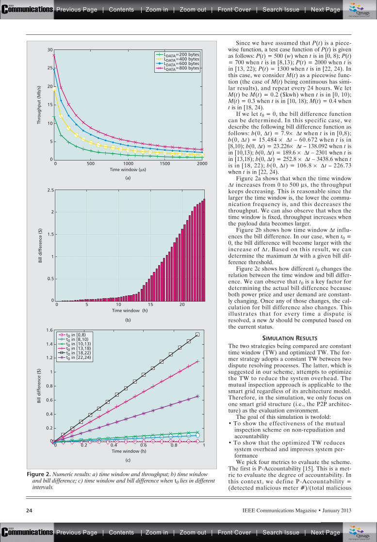
IEEE Communications Magazine • January 201324
Since we have assumed that P(t) is a piece-wise function, a test case function of P(t) is givenas follows: P(t) = 500 (w) when t is in [0, 8); P(t)= 700 when t is in [8,13); P(t) = 2000 when t isin [13, 22); P(t) = 1300 when t is in [22, 24). Inthis case, we consider M(t) as a piecewise func-tion (the case of M(t) being continuous has simi-lar results), and repeat every 24 hours. We letM(t) be M(t) = 0.2 ($kwh) when t is in [0, 10);M(t) = 0.3 when t is in [10, 18); M(t) = 0.4 whent is in [18, 24).
If we let t0 = 0, the bill difference functioncan be determined. In this specific case, wedescribe the following bill difference function asfollows: b(0, Dt) = 7.9¥ Dt when t is in [0,8);b(0, D t) = 15.484 ¥ D t – 60.672 when t is in[8,10); b(0, Dt) = 23.226¥ Dt – 138.092 when t isin [10,13); b(0, Dt) = 189.6 ¥ Dt – 2301 when t isin [13,18); b(0, Dt) = 252.8 ¥ Dt – 3438.6 when tis in [18, 22); b(0, D t) = 106.8 ¥ D t – 226.73when t is in [22, 24).
Figure 2a shows that when the time windowDt increases from 0 to 500 ms, the throughputkeeps decreasing. This is reasonable since thelarger the time window is, the lower the commu-nication frequency is, and this decreases thethroughput. We can also observe that when thetime window is fixed, throughput increases whenthe payload data becomes larger.
Figure 2b shows how time window Dt influ-ences the bill difference. In our case, when t0 =0, the bill difference will become larger with theincrease of D t. Based on this result, we candetermine the maximum Dt with a given bill dif-ference threshold.
Figure 2c shows how different t0 changes therelation between the time window and bill differ-ence. We can observe that t0 is a key factor fordetermining the actual bill difference becauseboth power price and user demand are constant-ly changing. Once any of those changes, the cal-culation for bill difference also changes. Thisillustrates that for every time a dispute isresolved, a new Dt should be computed based onthe current status.
SIMULATION RESULTSThe two strategies being compared are constanttime window (TW) and optimized TW. The for-mer strategy adopts a constant TW between twodispute resolving processes. The latter, which issuggested in our scheme, attempts to optimizethe TW to reduce the system overhead. Themutual inspection approach is applicable to thesmart grid regardless of its architecture model.Therefore, in the simulation, we only focus onone smart grid structure (i.e., the P2P architec-ture) as the evaluation environment.
The goal of this simulation is twofold:• To show the effectiveness of the mutual
inspection scheme on non-repudiation andaccountability
• To show that the optimized TW reducessystem overhead and improves system per-formanceWe pick four metrics to evaluate the scheme.
The first is P-Accountability [15]. This is a met-ric to evaluate the degree of accountability. Inthis context, we define P-Accountability =(detected malicious meter #)/(total malicious
Figure 2. Numeric results: a) time window and throughput; b) time windowand bill difference; c) time window and bill difference when t0 lies in differentintervals.
Time window (μs)
(a)
(b)
5000
5
0
Thro
ughp
ut (
Mb/
s)
10
15
20
25
30
1000 1500 2000
Time window (h)
(c)
0.20
0.2
0
Bill
diff
eren
ce (
$)
0.4
0.6
0.8
1
1.6
1.2
1.4
0.4 0.6 10.8
Time window (h)50
0.5
0
Bill
diff
eren
ce (
$)
1
1.5
2
2.5
10 15 20
LDATA=200 bytesLDATA=400 bytesLDATA=600 bytesLDATA=800 bytes
t0 in [0,8)t0 in [8,10)t0 in [10,13)t0 in [13,18)t0 in [18,22)t0 in [22,24)
Previous Page | Contents | Zoom in | Zoom out | Front Cover | Search Issue | Next PageIEEE
Communications qqM
Mq
qM
MqM
Qmags®THE WORLD’S NEWSSTAND
Previous Page | Contents | Zoom in | Zoom out | Front Cover | Search Issue | Next PageIEEE
Communications qqM
Mq
qM
MqM
Qmags®THE WORLD’S NEWSSTAND
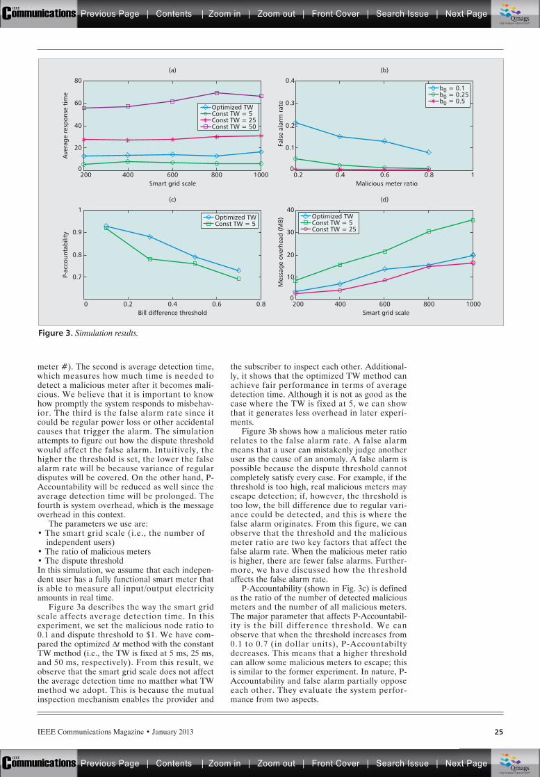
IEEE Communications Magazine • January 2013 25
meter #). The second is average detection time,which measures how much time is needed todetect a malicious meter after it becomes mali-cious. We believe that it is important to knowhow promptly the system responds to misbehav-ior. The third is the false alarm rate since itcould be regular power loss or other accidentalcauses that trigger the alarm. The simulationattempts to figure out how the dispute thresholdwould affect the false alarm. Intuitively, thehigher the threshold is set, the lower the falsealarm rate will be because variance of regulardisputes will be covered. On the other hand, P-Accountability will be reduced as well since theaverage detection time will be prolonged. Thefourth is system overhead, which is the messageoverhead in this context.
The parameters we use are:• The smart grid scale (i.e., the number of
independent users)• The ratio of malicious meters• The dispute thresholdIn this simulation, we assume that each indepen-dent user has a fully functional smart meter thatis able to measure all input/output electricityamounts in real time.
Figure 3a describes the way the smart gridscale affects average detection time. In thisexperiment, we set the malicious node ratio to0.1 and dispute threshold to $1. We have com-pared the optimized Dt method with the constantTW method (i.e., the TW is fixed at 5 ms, 25 ms,and 50 ms, respectively). From this result, weobserve that the smart grid scale does not affectthe average detection time no matther what TWmethod we adopt. This is because the mutualinspection mechanism enables the provider and
the subscriber to inspect each other. Additional-ly, it shows that the optimized TW method canachieve fair performance in terms of averagedetection time. Although it is not as good as thecase where the TW is fixed at 5, we can showthat it generates less overhead in later experi-ments.
Figure 3b shows how a malicious meter ratiorelates to the false alarm rate. A false alarmmeans that a user can mistakenly judge anotheruser as the cause of an anomaly. A false alarm ispossible because the dispute threshold cannotcompletely satisfy every case. For example, if thethreshold is too high, real malicious meters mayescape detection; if, however, the threshold istoo low, the bill difference due to regular vari-ance could be detected, and this is where thefalse alarm originates. From this figure, we canobserve that the threshold and the maliciousmeter ratio are two key factors that affect thefalse alarm rate. When the malicious meter ratiois higher, there are fewer false alarms. Further-more, we have discussed how the thresholdaffects the false alarm rate.
P-Accountability (shown in Fig. 3c) is definedas the ratio of the number of detected maliciousmeters and the number of all malicious meters.The major parameter that affects P-Accountabil-ity is the bill difference threshold. We canobserve that when the threshold increases from0.1 to 0.7 (in dollar units), P-Accountabiltydecreases. This means that a higher thresholdcan allow some malicious meters to escape; thisis similar to the former experiment. In nature, P-Accountability and false alarm partially opposeeach other. They evaluate the system perfor-mance from two aspects.
Figure 3. Simulation results.
Smart grid scale
(c)
(a)
400200
20
0
Ave
rage
res
pons
e ti
me
40
60
80
600 800 1000Malicious meter ratio
(d)
(b)
0.40.2
0.1
0
Fals
e al
arm
rat
e
0.2
0.3
0.4
0.6 0.8 1
Bill difference threshold0.20
0.7P-ac
coun
tabi
lity
0.8
0.9
1
0.4 0.6 0.8Smart grid scale
400200
10
0
Mes
sage
ove
rhea
d (M
B)
20
30
40
600 800 1000
Optimized TWConst TW = 5Const TW = 25Const TW = 50
Optimized TWConst TW = 5Const TW = 25
Optimized TWConst TW = 5
b0 = 0.1b0 = 0.25b0 = 0.5
Previous Page | Contents | Zoom in | Zoom out | Front Cover | Search Issue | Next PageIEEE
Communications qqM
Mq
qM
MqM
Qmags®THE WORLD’S NEWSSTAND
Previous Page | Contents | Zoom in | Zoom out | Front Cover | Search Issue | Next PageIEEE
Communications qqM
Mq
qM
MqM
Qmags®THE WORLD’S NEWSSTAND
IEEE Communications Magazine • January 201326
Overhead is another performance issue. Inthe experiment, we measured the message over-head as the metric to evaluate the optimized andconstant TW methods. It can be observed thatthe optimized TW method performs rather wellwhen compared to the constant TW method. Itintroduces relatively low overhead while stillmaintaining low average detection time (Fig. 3d).This is the trade-off we have attempted to make.
CONCLUSIONSIn this article, we have proposed a mutualinspection strategy to enable non-repudiationand accountability in neighborhood smart grid.Our strategy is scalable and easy to implement.Evaluation results show that the mutual inspec-tion can achieve decent performance when com-bined with the optimized time window method.
ACKNOWLEDGMENTThis work is supported in part by the U.S.National Science Foundation (NSF) under grantnumbers CNS-0737325, CNS-0716211, CCF-0829827, and CNS- 1059265.
REFERENCES[1] H. Farhangi, “The Path of the Smart Grid,” IEEE Power
and Energy Mag., vol. 8, no. 1, 2009, pp. 18–28.[2] X. I. E. Kai et al., “The Vision of Future Smart Grid,”
Electric Power, vol. 41, no. 6, 2008, pp. 19–22.[3] M. Amin and B. F. Wollenberg, “Toward A Smart Grid:
Power Delivery for the 21st Century,” IEEE Power andEnergy Mag., vol. 3, no. 5, 2005, pp. 34–41.
[4] Accenture Inc., “Achieving High Performance With TheftAnalytics — Leveraging Smart Grid Employments toEnhance Revenue Protection,” 2011, http://www.accen-ture.com/SiteCollectionDocuments/PDF/Accenture-Achieving-High-Performance-with-Theft-Analytics.pdf
[5] P. McDaniel and S. McLaughlin, “Security and PrivacyChallenges in the Smart Grid,” IEEE Security & Privacy,vol. 7, no. 3, 2009, pp. 75–77.
[6] S. McLaughlin, D. Podkuiko, and P. McDaniel, “EnergyTheft in the Advanced Metering Infrastructure,” CriticalInformation Infrastructures Security Lecture Notes inComputer Science, 2010, volume 6027/2010, 176-187,DOI: 10.1007/978-3-642- 14379-3_15
[7] M. Madrazo, “Today’s Energy Theft Detection ModelsHelp Protect Revenues While Enhancing NeighborhoodSafety,” http://www.pipelineandgasjournal.com/today’s-energy-theft-detection-models-help-protect-rev-enues-while-enhancing-neighborhood-safety vol. 237,no. 7, July 2010.
[8] S.S.S.R. Depuru, L. Wang, and V. Devabhaktuni, “Sup-port Vector Machine Based Data Classification forDetection of Electricity Theft,” Power Sys. Conf. andExpo., 2011.
[9] Dept. of Defense, “Trusted Computer System EvaluationCriteria,” tech. rep. 5200.28-STD, 1985.
[10] A. R. Yumerefendi and J. S. Chase, “The Role ofAccountability in Dependable Distributed Systems,”Proc. HotDep, 2005.
[11] J. Liu, Y. Xiao, and J. Gao, “Accountability in SmartGrids,” IEEE Consumer Commun. and Networking Conf.2011, Smart Grids Special Session.
[12] Z. Xiao, Y. Xiao, and D. Du, “Building AccountableSmart Grids in Neighborhood Area Networks,” Proc.IEEE GLOBECOM 2011.
[13] Cisco Smart Grid Security Solutions Brief, 2009 CiscoSystems, Inc. http://www.cisco.com/web/strategy/docs/energy/CiscoSmartGridSecurity_solutions_brief_c22-556936.pdf
[14] Y. Xiao and J. Rosdahl, “Throughput and Delay Limitsof IEEE 802.11,” IEEE Commun. Letters, vol. 6, 2002,pp. 355–57.
[15] Z. Xiao and Y. Xiao, “P-Accountable Networked Sys-tems,” IEEE INFOCOM Commun. Wksps., 2010, pp. 1–5.
BIOGRAPHIESZHIFENG XIAO [S’11–12] ([email protected]) is a Ph.D.candidate in the Department of Computer Science at theUniversity of Alabama. He received his Bachelor’s degree incomputer science from Shandong University, China, in2008. His research interests are in design and analysis ofsecure distributed and Internet systems.
YANG XIAO [SM’04] ([email protected]) worked in industryas a medium access control architect involving IEEE802.11 standard enhancement work before he joinedacademia. He is currently with the Department of Com-puter Science at the University of Alabama. He was a vot-ing member of the IEEE 802.11 Working Group from 2001to 2004. His research areas are security and communica-tions/networks. He has published more than 200 refereedjournal papers ( including 50 IEEE/ACM transactionspapers), and over 200 refereed conference papers andbook chapters related to these research areas. He currentlyserves as Editor-in-Chief for International Journal of Secu-rity and Networks and International Journal of Sensor Net-works.
DAVID H. C. DU [F‘98] ([email protected]) received his B.S.degree in mathematics from National Tsing-Hua Universi-ty, Taiwan in 1974, and M.S. and Ph.D. degrees in com-puter science from the University of Washington, Seattle,in 1980 and 1981, respectively. He is currently the QwestChair Professor at the Computer Science and EngineeringDepartment, University of Minnesota, Minneapolis. Heserved as a program director at the National ScienceFoundation from 2006 to 2008. His research interestsinclude cyber security, sensor networks, multimedia com-puting, mass storage systems, high-speed networking,database design, and CAD for VLSI circuits. He hasauthored and co-authored more than 240 technicalpapers, including 110 referred journal publications inthese research areas. He currently serves on the editorialboards of several journals. He has also served as Confer-ence Chair and Program Committee Chair of several con-ferences in parallel processing, security, multimedia,networking, and database.
In the experiment,
we measured the
message overhead as
the metric to evalu-
ate the optimized
time window
method and the
constant time win-
dow method. It can
be observed that the
optimized time win-
dow method per-
forms rather well
when compared to
the constant time
window method.
Previous Page | Contents | Zoom in | Zoom out | Front Cover | Search Issue | Next PageIEEE
Communications qqM
Mq
qM
MqM
Qmags®THE WORLD’S NEWSSTAND
Previous Page | Contents | Zoom in | Zoom out | Front Cover | Search Issue | Next PageIEEE
Communications qqM
Mq
qM
MqM
Qmags®THE WORLD’S NEWSSTAND
____________________________________
_____________
__________
_________
_____________________________________________________
____________________________________________________________________
IEEE Communications Magazine • January 2013 270163-6804/13/$25.00 © 2013 IEEE
INTRODUCTION
The smart grid [1, 2] has been envisioned toimprove the robustness and efficiency of tradi-tional power grid networks with the aid of mod-ern communication technologies. It is enabled bythe technological advances in sensing, measure-ment, and control devices capable of two-waycommunications among system managers (e.g.,independent system operator [ISO]), electricityproduction, transmission, distribution, and con-sumption parts of power grids by exchanginginformation about the grid states to systemusers, operators, and automated devices. Stateestimation is a key function in building real-timemodels of electricity networks in energy manage-ment centers (EMC) [3]. A real-time model is aquasi-static mathematical representation of thecurrent conditions in an interconnected power
network [3]. This mathematical representation isusually obtained from measured and telemetereddata every few seconds to the energy controlcenter (ECC). Real-time models of the networkcan be used by ISO to make optimal decisionswith respect to technical constraints such astransmission line congestion, voltage, and tran-sient stability. In practice, it is not economical oreven feasible to measure all possible states in thenetwork; thus, state estimation is a useful toolfor estimating those quantities from a limited setof measurements. Two kinds of information areusually used for state estimation in power sys-tems:• Analog data of the system such as Megavar
flows on all major lines, P and Q loading ofgenerators and transformers, and voltagemagnitudes at most of the buses of the sys-tem
• The on/off status of switching devices suchas circuit breakers, disconnect switches, andtransformer taps that determine the net-work topologyDue to the importance of state estimation,
the negative effects of injecting bad measure-ment data have been studied in literature [4].Bad data may be due to unintended measure-ment abnormalities or topology errors, or injec-tion by malicious attacks. For instance, [5] is thepioneering work in studying bad data injectionattacks that cannot be detected (called stealthattacks), and it shows that an attacker can carryout such stealth attacks by corrupting the powerflow measurements at remote terminal units(RTUs), tampering with the heterogeneous com-munication network or breaking into the super-visory control and data acquisition (SCADA)system through the control center office LAN.Note that a SCADA system or wide area mea-surement system (WAMS) gathers informationof the power network (measurements values,breakers’ status, etc.) at specific times and loca-tions. Control centers use the collected informa-tion for different purposes such as running astate estimation problem. In [6], the authorsdemonstrate the feasibility of carrying out unde-
ABSTRACT
In modern smart grid networks, the tradition-al power grid is empowered by technologicaladvances in sensing, measurement, and controldevices with two-way communications betweenthe suppliers and consumers. The smart gridintegration helps the power grid networks to besmarter, but it also increases the risk of attacksbecause of the existing obsolete cyber-infra-structure. In this article, we focus on bad datainjection attacks for smart grid. The basic prob-lem formulation is presented, and the specialtype of stealth attack is discussed. Then weinvestigate the strategies of defenders andattackers, respectively. Specifically, from thedefender’s perspective, an adaptive cumulativesum test is able to determine the possible exis-tence of adversaries at the control center asquickly as possible. From the attacker’s point ofview, independent component analysis isemployed for the attackers to make inferencesthrough phasor observations without priorknowledge of the power grid topology. Theinferred structural information can then be usedto launch stealth attacks.
CYBER SECURITY FOR SMART GRIDCOMMUNICATIONS: PART 2
Yi Huang, Mohammad Esmalifalak, Huy Nguyen, Rong Zheng, and Zhu Han, University of Houston
Husheng Li, Peking University
Lingyang Song, University of Tennessee
Bad Data Injection in Smart Grid: Attack and Defense Mechanisms
Previous Page | Contents | Zoom in | Zoom out | Front Cover | Search Issue | Next PageIEEE
Communications qqM
Mq
qM
MqM
Qmags®THE WORLD’S NEWSSTAND
Previous Page | Contents | Zoom in | Zoom out | Front Cover | Search Issue | Next PageIEEE
Communications qqM
Mq
qM
MqM
Qmags®THE WORLD’S NEWSSTAND
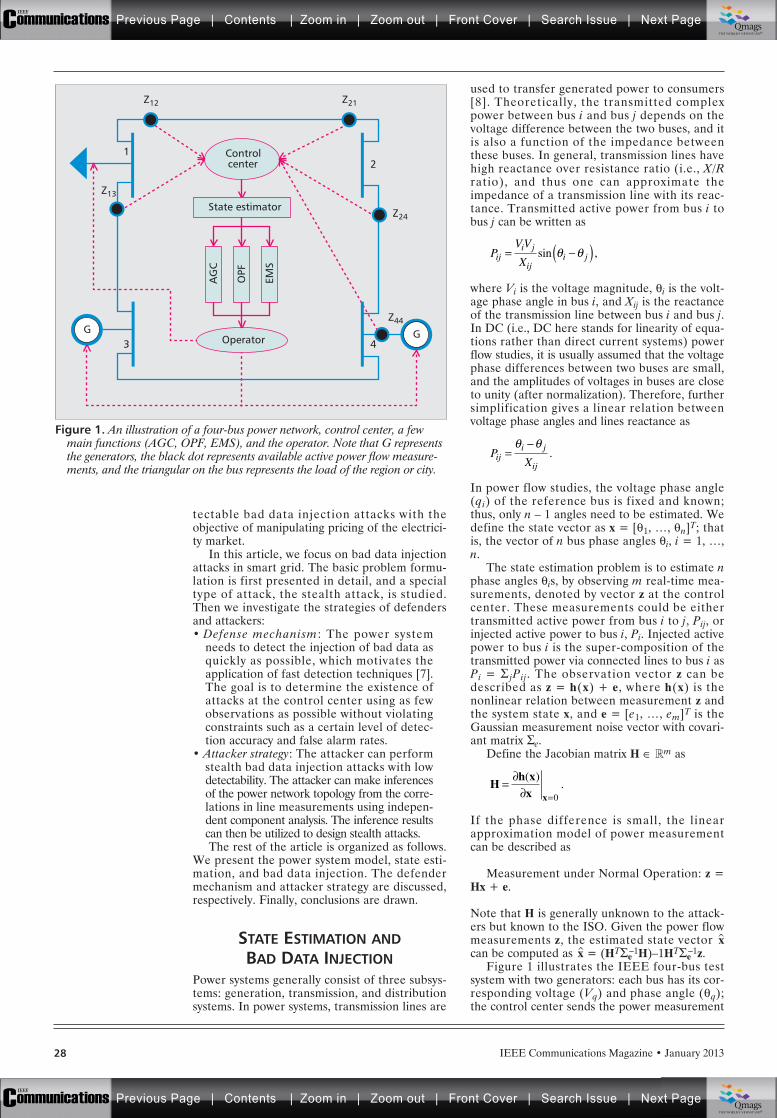
IEEE Communications Magazine • January 201328
tectable bad data injection attacks with theobjective of manipulating pricing of the electrici-ty market.
In this article, we focus on bad data injectionattacks in smart grid. The basic problem formu-lation is first presented in detail, and a specialtype of attack, the stealth attack, is studied.Then we investigate the strategies of defendersand attackers:• Defense mechanism: The power system
needs to detect the injection of bad data asquickly as possible, which motivates theapplication of fast detection techniques [7].The goal is to determine the existence ofattacks at the control center using as fewobservations as possible without violatingconstraints such as a certain level of detec-tion accuracy and false alarm rates.
• Attacker strategy: The attacker can performstealth bad data injection attacks with lowdetectability. The attacker can make inferencesof the power network topology from the corre-lations in line measurements using indepen-dent component analysis. The inference resultscan then be utilized to design stealth attacks.The rest of the article is organized as follows.
We present the power system model, state esti-mation, and bad data injection. The defendermechanism and attacker strategy are discussed,respectively. Finally, conclusions are drawn.
STATE ESTIMATION ANDBAD DATA INJECTION
Power systems generally consist of three subsys-tems: generation, transmission, and distributionsystems. In power systems, transmission lines are
used to transfer generated power to consumers[8]. Theoretically, the transmitted complexpower between bus i and bus j depends on thevoltage difference between the two buses, and itis also a function of the impedance betweenthese buses. In general, transmission lines havehigh reactance over resistance ratio (i.e., X/Rratio), and thus one can approximate theimpedance of a transmission line with its reac-tance. Transmitted active power from bus i tobus j can be written as
where Vi is the voltage magnitude, qi is the volt-age phase angle in bus i, and Xij is the reactanceof the transmission line between bus i and bus j.In DC (i.e., DC here stands for linearity of equa-tions rather than direct current systems) powerflow studies, it is usually assumed that the voltagephase differences between two buses are small,and the amplitudes of voltages in buses are closeto unity (after normalization). Therefore, furthersimplification gives a linear relation betweenvoltage phase angles and lines reactance as
In power flow studies, the voltage phase angle(qi) of the reference bus is fixed and known;thus, only n – 1 angles need to be estimated. Wedefine the state vector as x = [q1, …, qn]T; thatis, the vector of n bus phase angles qi, i = 1, …,n.
The state estimation problem is to estimate nphase angles qis, by observing m real-time mea-surements, denoted by vector z at the controlcenter. These measurements could be eithertransmitted active power from bus i to j, Pij, orinjected active power to bus i, Pi. Injected activepower to bus i is the super-composition of thetransmitted power via connected lines to bus i asPi = S jPij. The observation vector z can bedescribed as z = h(x) + e, where h(x) is thenonlinear relation between measurement z andthe system state x, and e = [e1, …, em]T is theGaussian measurement noise vector with covari-ant matrix Se.
Define the Jacobian matrix H ΠRm as
If the phase difference is small, the linearapproximation model of power measurementcan be described as
Measurement under Normal Operation: z =Hx + e.
Note that H is generally unknown to the attack-ers but known to the ISO. Given the power flowmeasurements z, the estimated state vector x̂can be computed as x̂ = (HTSe
–1H)–1HTSe–1z.
Figure 1 illustrates the IEEE four-bus testsystem with two generators: each bus has its cor-responding voltage (Vq) and phase angle (qq);the control center sends the power measurement
PVV
Xiji j
iji j= ( )sin ,
PXiji j
ij= .
Hh xx x
==
( ).
0
Figure 1. An illustration of a four-bus power network, control center, a fewmain functions (AGC, OPF, EMS), and the operator. Note that G representsthe generators, the black dot represents available active power flow measure-ments, and the triangular on the bus represents the load of the region or city.
G
EMS
G43
21
OPF
AG
CState estimator
Controlcenter
Operator
Z21Z12
Z13
Z24
Z44
Previous Page | Contents | Zoom in | Zoom out | Front Cover | Search Issue | Next PageIEEE
Communications qqM
Mq
qM
MqM
Qmags®THE WORLD’S NEWSSTAND
Previous Page | Contents | Zoom in | Zoom out | Front Cover | Search Issue | Next PageIEEE
Communications qqM
Mq
qM
MqM
Qmags®THE WORLD’S NEWSSTAND
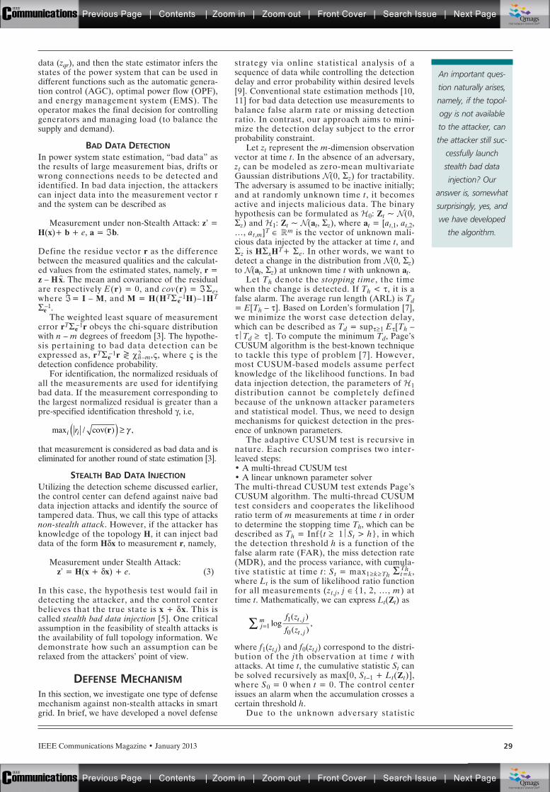
IEEE Communications Magazine • January 2013 29
data (zqr), and then the state estimator infers thestates of the power system that can be used indifferent functions such as the automatic genera-tion control (AGC), optimal power flow (OPF),and energy management system (EMS). Theoperator makes the final decision for controllinggenerators and managing load (to balance thesupply and demand).
BAD DATA DETECTIONIn power system state estimation, “bad data” asthe results of large measurement bias, drifts orwrong connections needs to be detected andidentified. In bad data injection, the attackerscan inject data into the measurement vector rand the system can be described as
Measurement under non-Stealth Attack: z’ =H(x)+ b + e, a = ¡b.
Define the residue vector r as the differencebetween the measured qualities and the calculat-ed values from the estimated states, namely, r =z – Hx̂. The mean and covariance of the residualare respectively E(r) = 0, and cov(r) = ¡Se,where ¡= I – M, and M = H(HTS e
–1H)–1HT
Se–1.
The weighted least square of measurementerror rTSe
–1r obeys the chi-square distributionwith n – m degrees of freedom [3]. The hypothe-sis pertaining to bad data detection can beexpressed as, rTSe
–1r >< c2n–m,V, where V is the
detection confidence probability.For identification, the normalized residuals of
all the measurements are used for identifyingbad data. If the measurement corresponding tothe largest normalized residual is greater than apre-specified identification threshold g, i.e,
that measurement is considered as bad data and iseliminated for another round of state estimation [3].
STEALTH BAD DATA INJECTIONUtilizing the detection scheme discussed earlier,the control center can defend against naive baddata injection attacks and identify the source oftampered data. Thus, we call this type of attacksnon-stealth attack. However, if the attacker hasknowledge of the topology H, it can inject baddata of the form Hdx to measurement r, namely,
Measurement under Stealth Attack: z’ = H(x + dx) + e. (3)
In this case, the hypothesis test would fail indetecting the attacker, and the control centerbelieves that the true state is x + dx. This iscalled stealth bad data injection [5]. One criticalassumption in the feasibility of stealth attacks isthe availability of full topology information. Wedemonstrate how such an assumption can berelaxed from the attackers’ point of view.
DEFENSE MECHANISMIn this section, we investigate one type of defensemechanism against non-stealth attacks in smartgrid. In brief, we have developed a novel defense
strategy via online statistical analysis of asequence of data while controlling the detectiondelay and error probability within desired levels[9]. Conventional state estimation methods [10,11] for bad data detection use measurements tobalance false alarm rate or missing detectionratio. In contrast, our approach aims to mini-mize the detection delay subject to the errorprobability constraint.
Let zt represent the m-dimension observationvector at time t. In the absence of an adversary,zt can be modeled as zero-mean multivariateGaussian distributions N(0, Sz) for tractability.The adversary is assumed to be inactive initially;and at randomly unknown time t, it becomesactive and injects malicious data. The binaryhypothesis can be formulated as H0: Zt ~ N(0,Sz) and H1: Zt ~ N(at, Sz), where at = [at,1, at,2,…, at,m]T Œ Rm is the vector of unknown mali-cious data injected by the attacker at time t, andSz is HSxHT+ Se. In other words, we want todetect a change in the distribution from N(0, Sz)to N(at, Sz) at unknown time t with unknown at.
Let Th denote the stopping time, the timewhen the change is detected. If Th < t, it is afalse alarm. The average run length (ARL) is Td= E[Th – t]. Based on Lorden’s formulation [7],we minimize the worst case detection delay,which can be described as Td = supt 1 Et[Th –tÔTd t]. To compute the minimum Td, Page’sCUSUM algorithm is the best-known techniqueto tackle this type of problem [7]. However,most CUSUM-based models assume perfectknowledge of the likelihood functions. In baddata injection detection, the parameters of H1distribution cannot be completely definedbecause of the unknown attacker parametersand statistical model. Thus, we need to designmechanisms for quickest detection in the pres-ence of unknown parameters.
The adaptive CUSUM test is recursive innature. Each recursion comprises two inter-leaved steps:• A multi-thread CUSUM test• A linear unknown parameter solverThe multi-thread CUSUM test extends Page’sCUSUM algorithm. The multi-thread CUSUMtest considers and cooperates the likelihoodratio term of m measurements at time t in orderto determine the stopping time Th, which can bedescribed as Th = Inf{t 1ÔSt > h}, in whichthe detection threshold h is a function of thefalse alarm rate (FAR), the miss detection rate(MDR), and the process variance, with cumula-tive statistic at time t: St = max1 k Th S Th
t=k,where Lt is the sum of likelihood ratio functionfor all measurements (zt,j, j Œ{1, 2, …, m) attime t. Mathematically, we can express Lt(Zt) as
where f1(zt,j) and f0(zt,j) correspond to the distri-bution of the jth observation at time t withattacks. At time t, the cumulative statistic St canbe solved recursively as max[0, St–1 + Lt(Zt)],where S0 = 0 when t = 0. The control centerissues an alarm when the accumulation crosses acertain threshold h.
Due to the unknown adversary statistic
max / cov( ) ,i ir r( )
jm t j
t j
f z
f z=11
0log
( )
( ),,
,
An important ques-
tion naturally arises,
namely, if the topol-
ogy is not available
to the attacker, can
the attacker still suc-
cessfully launch
stealth bad data
injection? Our
answer is, somewhat
surprisingly, yes, and
we have developed
the algorithm.
Previous Page | Contents | Zoom in | Zoom out | Front Cover | Search Issue | Next PageIEEE
Communications qqM
Mq
qM
MqM
Qmags®THE WORLD’S NEWSSTAND
Previous Page | Contents | Zoom in | Zoom out | Front Cover | Search Issue | Next PageIEEE
Communications qqM
Mq
qM
MqM
Qmags®THE WORLD’S NEWSSTAND
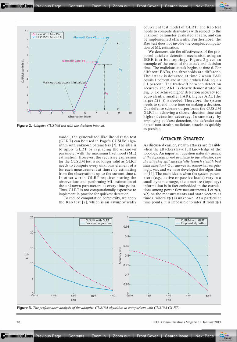
IEEE Communications Magazine • January 201330
model, the generalized likelihood ratio test(GLRT) can be used in Page’s CUSUM algo-rithm with unknown parameters [7]. The idea isto apply GLRT by replacing the unknownparameter with the maximum likelihood (ML)estimation. However, the recursive expressionfor the CUSUM test is no longer valid as GLRTneeds to compute every unknown element of afor each measurement at time t by estimatingfrom the observations up to the current time t.In other words, GLRT requires storing theobservations and performing ML-estimation ofthe unknown parameters at every time point.Thus, GLRT is too computationally expensive toimplement in practice for quickest detection.
To reduce computation complexity, we applythe Rao test [7], which is an asymptotically
equivalent test model of GLRT. The Rao testneeds to compute derivatives with respect to theunknown parameter evaluated at zero, and canbe implemented efficiently. Furthermore, theRao test does not involve the complex computa-tion of ML estimation.
We demonstrate the effectiveness of the pro-posed quickest detection mechanism using anIEEE four-bus topology. Figure 2 gives anexample of the onset of the attack and decisiontime. The malicious attack begins at time 6. Fordifferent FARs, the thresholds are different.The attack is detected at time 7 when FARequals 1 percent and at time 8 when FAR equals0.1 percent. The trade-off between detectionaccuracy and ARL is clearly demonstrated inFig. 3. To achieve higher detection accuracy (orequivalently, smaller FAR), higher ARL (thelarger E(Td)) is needed. Therefore, the systemneeds to spend more time on making a decision.Our defense scheme outperforms the CUSUMGLRT in achieving a shorter decision time andhigher detection accuracy. In summary, byemploying quickest detection, the defender candetect non-stealth malicious attacks as quicklyas possible.
ATTACKER STRATEGYAs discussed earlier, stealth attacks are feasiblewhen the attackers have full knowledge of thetopology. An important question naturally arises:if the topology is not available to the attacker, canthe attacker still successfully launch stealth baddata injection? Our answer is, somewhat surpris-ingly, yes, and we have developed the algorithmin [14]. The main idea is when the system param-eters (e.g., active or passive loads) vary in asmall dynamic range, the structure (topology)information is in fact embedded in the correla-tions among power flow measurements. Let z(t),x(t) be the measurements and state vectors attime t, where x(t) is unknown. At a particulartime point t, it is impossible to infer H from z(t)
Figure 2. Adaptive CUSUM test with the decision interval.
1
0
CU
SUM
sta
tist
ic S
n
2
3
4
5
6
7
8
9
10
Malicious data attack is initialized
Alarmed! Case #1
Alarmed! Case #2
h1
h2
Case #1: FAR=1%Case #2: FAR=0.1%
Observation index21 3 4 5 76 8 9 10
Figure 3. The performance analysis of the adaptive CUSUM algorithm in comparison with CUSUM GLRT.
FAR10-810-10
5
0
E(T D
)
10
15
20
25
10-6 10-4 10-2
FAR10-810-10
0.7
0
Acc
urac
y ra
te
0.65
0.75
0.85
0.8
0.95
1
0.9
10-6 10-4 10-2
CUSUM with GLRTProposed algorithm
CUSUM with GLRTProposed algorithm
Previous Page | Contents | Zoom in | Zoom out | Front Cover | Search Issue | Next PageIEEE
Communications qqM
Mq
qM
MqM
Qmags®THE WORLD’S NEWSSTAND
Previous Page | Contents | Zoom in | Zoom out | Front Cover | Search Issue | Next PageIEEE
Communications qqM
Mq
qM
MqM
Qmags®THE WORLD’S NEWSSTAND
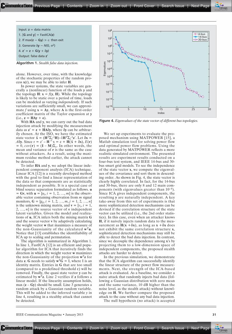
IEEE Communications Magazine • January 2013 31
alone. However, over time, with the knowledgeof the stochastic properties of the random pro-cess x(t), we may be able to infer H.
In power systems, the state variables are gen-erally a (nonlinear) function of the loads y andthe topology H: x = f(y, H). While the topologyis likely to be static over a period of time, loadscan be modeled as varying independently. If suchvariations are sufficiently small, we can approxi-mate f using x = Ay, where A is the first-ordercoefficient matrix of the Taylor expansion at y(i.e., z = HAy + e).
With HA and y, we can carry out the bad datainjection attack by modifying the measurementdata as z’ = z + HAdy, where dy can be arbitrar-ily chosen. At the ISO, we have the estimatedstate vector x̂ = (HTSe
–1H)–1HTSe–1z’. Let dx =
Ady. Since r = z’ – H^x = z + H( x̂ + dx), E(r)= 0, cov(r) = (I – M)Se. In other words, themean and variance of r is the same as the casewithout attackers. As a result, using the maxi-mum residue method earlier, the attack cannotbe detected.
To infer HA and y, we adopt the linear inde-pendent component analysis (ICA) technique.Linear ICA [12] is a recently developed methodwith the goal to find a linear representation ofthe data so that components are as statisticallyindependent as possible. It is a special case ofblind source separation formulated as follows. u= Gv, with u = [ui, i = 1, 2, …, m] is the observ-able vector containing observation from m signalmonitors, G = [gij, i = 1, 2, …, m, j = 1, 2, …, n]is the unknown mixing matrix, and v = [vi, i = 1,2, …, n] is the source vector of n independentlatent variables. Given the model and realiza-tions of u, ICA infers both the mixing matrix Gand the source vector v by adaptively calculatingthe weight vector w that maximizes a measure ofthe non-Gaussianity of the calculated wTu.Notice that [13] establishes the identifiability ofICA up to scaling and permutation.
The algorithm is summarized in Algorithm 1.In line 1, FastICA [12] is an efficient and popu-lar algorithm for ICA that iteratively finds thedirection in which the weight vector w maximizesthe non-Gaussianity of the projection wTz fordata z. G needs to satisfy wTG = I, where I is anidentity matrix. Entries in G that are too small(compared to a predefined threshold e) will beremoved. Finally, the quasi state vector y can beestimated by wTz. Line 2 verifies if z follows alinear model. If the linearity assumption holds,max (z – Gy) should be small. Line 3 generates arandom attack by a Gaussian random variable.This will be added to the inferred variable y inline 4, resulting in a stealthy attack that cannotbe detected.
We set up experiments to evaluate the pro-posed mechanism using MATPOWER [15], aMatlab simulation tool for solving power flowand optimal power flow problems. Using thedata generated by MATPOWER reflects a morerealistic simulated environment. The presentedresults are experiment results conducted on afour-bus test system, and IEEE 14-bus and 30-bus smart grid models. To see the independenceof the state vector x, we compute the eigenval-ues of the covariance and sort them in descend-ing order. As shown in Fig. 4, the state vector isclearly highly correlated. In fact, for the 14-busand 30-bus, there are only 8 and 12 main com-ponents (with eigenvalues greater than 10–4).Since ICA gives independent components, theresulting y are naturally independent. A keytake-away from this set of experiments is thatmore sophisticated detection mechanisms can bedevised if the correlation structure of the statevector can be utilized (i.e., the 2nd order statis-tics). In this case, even when an attacker knowsH, if it naively injects random data to the mea-surement as H(x +dx), as long as x +dx doesnot exhibit the same correlation structure x,sophisticated detection mechanisms may still beable to detect the bad data injection. In contrast,since we decouple the dependence among x’s byprojecting them to a low-dimension space ofindependent components, the proposed stealthattacks are harder to detect.
In the previous simulation, we demonstratethat the ICA algorithm can successfully identifythe linear structure of the power flow measure-ments. Next, the strength of the ICA-basedattack is evaluated. As a baseline, we consider anaive attack that randomly injects bad data (fol-lowing a Gaussian distribution with zero meanand the same variance, 10 dB higher than thenoise level, as the stealth attack) without knowl-edge on H. We further compare the proposedattack to the case without any bad data injection.
The null hypothesis (no attack) is accepted
Algorithm 1. Stealth false data injection.
Input: z = data matrix
1. [G and y] = FastICA(z)
2. If max(z − Gy) > Œ then exit
3. Generate dy ~ N(0, s2)
4. z¢ = z + G(y + dy)
Output: false data z¢
Figure 4. Eigenvalues of the state vector of different bus topologies.
Index50
10-14
10-16Ei
genv
alue
s
10-12
10-10
10-8
10-6
10-4
10-2
100
102
104
10 15 20 25 30
4-bus14-bus30-bus
Previous Page | Contents | Zoom in | Zoom out | Front Cover | Search Issue | Next PageIEEE
Communications qqM
Mq
qM
MqM
Qmags®THE WORLD’S NEWSSTAND
Previous Page | Contents | Zoom in | Zoom out | Front Cover | Search Issue | Next PageIEEE
Communications qqM
Mq
qM
MqM
Qmags®THE WORLD’S NEWSSTAND
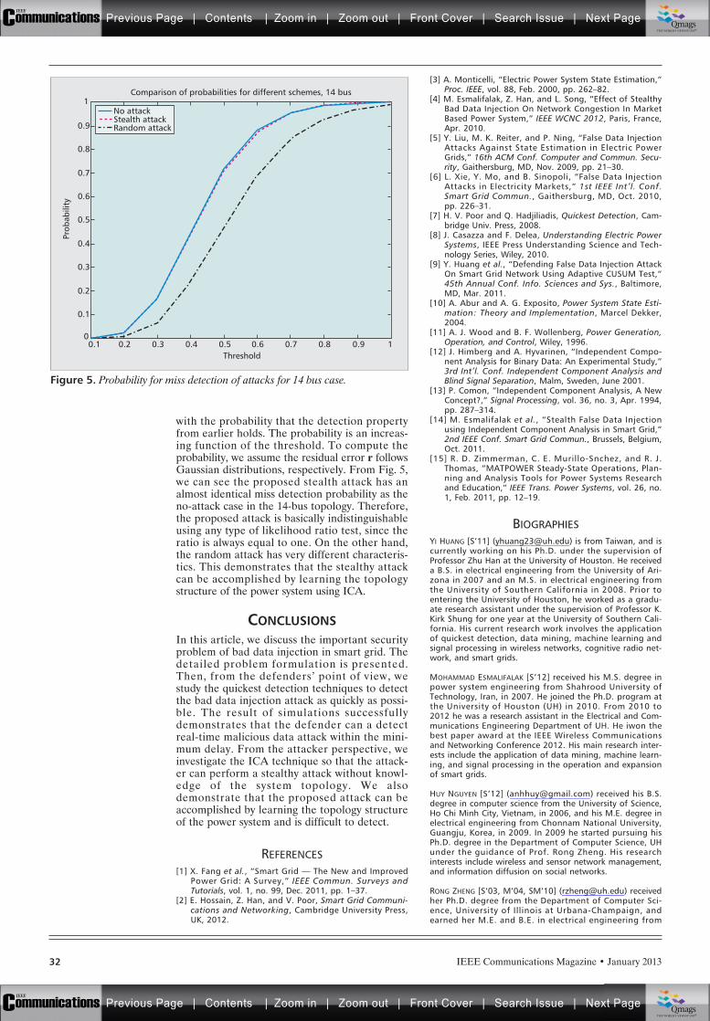
IEEE Communications Magazine • January 201332
with the probability that the detection propertyfrom earlier holds. The probability is an increas-ing function of the threshold. To compute theprobability, we assume the residual error r followsGaussian distributions, respectively. From Fig. 5,we can see the proposed stealth attack has analmost identical miss detection probability as theno-attack case in the 14-bus topology. Therefore,the proposed attack is basically indistinguishableusing any type of likelihood ratio test, since theratio is always equal to one. On the other hand,the random attack has very different characteris-tics. This demonstrates that the stealthy attackcan be accomplished by learning the topologystructure of the power system using ICA.
CONCLUSIONSIn this article, we discuss the important securityproblem of bad data injection in smart grid. Thedetailed problem formulation is presented.Then, from the defenders’ point of view, westudy the quickest detection techniques to detectthe bad data injection attack as quickly as possi-ble. The result of simulations successfullydemonstrates that the defender can a detectreal-time malicious data attack within the mini-mum delay. From the attacker perspective, weinvestigate the ICA technique so that the attack-er can perform a stealthy attack without knowl-edge of the system topology. We alsodemonstrate that the proposed attack can beaccomplished by learning the topology structureof the power system and is difficult to detect.
REFERENCES[1] X. Fang et al., “Smart Grid — The New and Improved
Power Grid: A Survey,” IEEE Commun. Surveys andTutorials, vol. 1, no. 99, Dec. 2011, pp. 1–37.
[2] E. Hossain, Z. Han, and V. Poor, Smart Grid Communi-cations and Networking, Cambridge University Press,UK, 2012.
[3] A. Monticelli, “Electric Power System State Estimation,”Proc. IEEE, vol. 88, Feb. 2000, pp. 262–82.
[4] M. Esmalifalak, Z. Han, and L. Song, “Effect of StealthyBad Data Injection On Network Congestion In MarketBased Power System,” IEEE WCNC 2012, Paris, France,Apr. 2010.
[5] Y. Liu, M. K. Reiter, and P. Ning, “False Data InjectionAttacks Against State Estimation in Electric PowerGrids,” 16th ACM Conf. Computer and Commun. Secu-rity, Gaithersburg, MD, Nov. 2009, pp. 21–30.
[6] L. Xie, Y. Mo, and B. Sinopoli, “False Data InjectionAttacks in Electricity Markets,” 1st IEEE Int’l. Conf.Smart Grid Commun., Gaithersburg, MD, Oct. 2010,pp. 226–31.
[7] H. V. Poor and Q. Hadjiliadis, Quickest Detection, Cam-bridge Univ. Press, 2008.
[8] J. Casazza and F. Delea, Understanding Electric PowerSystems, IEEE Press Understanding Science and Tech-nology Series, Wiley, 2010.
[9] Y. Huang et al., “Defending False Data Injection AttackOn Smart Grid Network Using Adaptive CUSUM Test,”45th Annual Conf. Info. Sciences and Sys., Baltimore,MD, Mar. 2011.
[10] A. Abur and A. G. Exposito, Power System State Esti-mation: Theory and Implementation, Marcel Dekker,2004.
[11] A. J. Wood and B. F. Wollenberg, Power Generation,Operation, and Control, Wiley, 1996.
[12] J. Himberg and A. Hyvarinen, “Independent Compo-nent Analysis for Binary Data: An Experimental Study,”3rd Int’l. Conf. Independent Component Analysis andBlind Signal Separation, Malm, Sweden, June 2001.
[13] P. Comon, “Independent Component Analysis, A NewConcept?,” Signal Processing, vol. 36, no. 3, Apr. 1994,pp. 287–314.
[14] M. Esmalifalak et al., “Stealth False Data Injectionusing Independent Component Analysis in Smart Grid,”2nd IEEE Conf. Smart Grid Commun., Brussels, Belgium,Oct. 2011.
[15] R. D. Zimmerman, C. E. Murillo-Snchez, and R. J.Thomas, “MATPOWER Steady-State Operations, Plan-ning and Analysis Tools for Power Systems Researchand Education,” IEEE Trans. Power Systems, vol. 26, no.1, Feb. 2011, pp. 12–19.
BIOGRAPHIESYI HUANG [S’11] ([email protected]) is from Taiwan, and iscurrently working on his Ph.D. under the supervision ofProfessor Zhu Han at the University of Houston. He receiveda B.S. in electrical engineering from the University of Ari-zona in 2007 and an M.S. in electrical engineering fromthe University of Southern California in 2008. Prior toentering the University of Houston, he worked as a gradu-ate research assistant under the supervision of Professor K.Kirk Shung for one year at the University of Southern Cali-fornia. His current research work involves the applicationof quickest detection, data mining, machine learning andsignal processing in wireless networks, cognitive radio net-work, and smart grids.
MOHAMMAD ESMALIFALAK [S’12] received his M.S. degree inpower system engineering from Shahrood University ofTechnology, Iran, in 2007. He joined the Ph.D. program atthe University of Houston (UH) in 2010. From 2010 to2012 he was a research assistant in the Electrical and Com-munications Engineering Department of UH. He iwon thebest paper award at the IEEE Wireless Communicationsand Networking Conference 2012. His main research inter-ests include the application of data mining, machine learn-ing, and signal processing in the operation and expansionof smart grids.
HUY NGUYEN [S’12] ([email protected]) received his B.S.degree in computer science from the University of Science,Ho Chi Minh City, Vietnam, in 2006, and his M.E. degree inelectrical engineering from Chonnam National University,Guangju, Korea, in 2009. In 2009 he started pursuing hisPh.D. degree in the Department of Computer Science, UHunder the guidance of Prof. Rong Zheng. His researchinterests include wireless and sensor network management,and information diffusion on social networks.
RONG ZHENG [S’03, M’04, SM’10] ([email protected]) receivedher Ph.D. degree from the Department of Computer Sci-ence, University of Illinois at Urbana-Champaign, andearned her M.E. and B.E. in electrical engineering from
Figure 5. Probability for miss detection of attacks for 14 bus case.
Threshold
Comparison of probabilities for different schemes, 14 bus
0.20.1
0.1
0
Prob
abili
ty
0.2
0.3
0.4
0.5
0.6
0.7
0.8
0.9
1
0.3 0.4 0.5 0.6 0.7 0.8 0.9 1
No attackStealth attackRandom attack
Previous Page | Contents | Zoom in | Zoom out | Front Cover | Search Issue | Next PageIEEE
Communications qqM
Mq
qM
MqM
Qmags®THE WORLD’S NEWSSTAND
Previous Page | Contents | Zoom in | Zoom out | Front Cover | Search Issue | Next PageIEEE
Communications qqM
Mq
qM
MqM
Qmags®THE WORLD’S NEWSSTAND
__________
___________
________

IEEE Communications Magazine • January 2013 33
Tsinghua University, P.R. China. She is on the faculty of theDepartment of Computer Science, UH, since 2004, current-ly as an associate professor. Her research interests includenetwork monitoring and diagnosis, cyber physical systems,and sequential learning and decision theory. She receivedthe National Science Foundation CAREER Award in 2006.She serves on the technical program committees of leadingnetworking conferences including INFOCOM, ICDCS, andICNP. She served as a guest editor for EURASIP Journal onAdvances in Signal Processing, Special Issue on WirelessLocation Estimation and Tracking, and Elsevier’s ComputerCommunications Special Issue on Cyber Physical Systems;and was Program Co-Chair of WASA’12 and CPSCom’12.
ZHU HAN [S’01, M’04, SM’09] ([email protected])received his B.S. degree in electronic engineering fromTsinghua University in 1997, and M.S. and Ph.D. degrees inelectrical engineering from the University of Maryland, Col-lege Park, in 1999 and 2003, respectively. From 2000 to2002 he was an R&D engineer at JDSU, Germantown,Maryland. From 2003 to 2006 he was a research associateat the University of Maryland. From 2006 to 2008 he wasan assistant professor at Boise State University, Idaho. Cur-rently, he is an assistant professor in the Electrical andComputer Engineering Department at UH. His researchinterests include wireless resource allocation and manage-ment, wireless communications and networking, game the-ory, wireless multimedia, security, and smart gridcommunication. He is an Associate Editor of IEEE Transac-tions on Wireless Communications since 2010. He was thewinner of the IEEE Fred W. Ellersick Prize in 2011. He wasan NSF CAREER award recipient 2010. He was the coauthorof papers that won the best paper awards at IEEE Interna-
tional Conference on Communications 2009, 7th Interna-tional Symposium on Modeling and Optimization inMobile, Ad Hoc, and Wireless Networks 2009, and IEEEWireless Communication and Networking Conference 2012.
HUSHENG LI [S’00, M’05] ([email protected]) receivedB.S. and M.S. degrees in electronic engineering fromTsinghua University, Beijing, China, in 1998 and 2000,respectively, and his Ph.D. degree in electrical engineeringfrom Princeton University, New Jersey, in 2005. From 2005to 2007 he worked as a senior engineer at Qualcomm Inc,San Diego, California. In 2007, he joined the EECS Depart-ment of the University of Tennessee, Knoxville, as an assis-tant professor. His research is mainly focused on wirelesscommunications and smart grid. He was the recipient ofthe Best Paper Award of the EURASIP Journal of WirelessCommunications and Networks, 2005 (together with hisPh.D. advisor, Prof. H. V. Poor), the best demo award ofGLOBECOM 2010, and the Best Paper Award of ICC 2011.
LINGYANG SONG [S’03, M’06, SM’12] ([email protected]) received his Ph.D. from the University of York,United Kingdom, in 2007, where he received the K. M.Stott Prize for excellent research. He worked as a postdoc-toral research fellow at the University of Oslo, Norway, andHarvard University, until rejoining Philips Research U.K. inMarch 2008. In May 2009, he joined the School of Elec-tronics Engineering and Computer Science, Peking Universi-ty, China, as a full professor. He is a co-inventor of anumber of patents (standard contributions), and author orco-author of over 100 journal and conference papers. Hereceived the best paper awards in three international con-ferences.
Previous Page | Contents | Zoom in | Zoom out | Front Cover | Search Issue | Next PageIEEE
Communications qqM
Mq
qM
MqM
Qmags®THE WORLD’S NEWSSTAND
Previous Page | Contents | Zoom in | Zoom out | Front Cover | Search Issue | Next PageIEEE
Communications qqM
Mq
qM
MqM
Qmags®THE WORLD’S NEWSSTAND
____________________
_______________
_____________
_____________
IEEE Communications Magazine • January 201334 0163-6804/13/$25.00 © 2013 IEEE
INTRODUCTION
The smart grid is, according to IEEE Standard2030, “the integration of power, communica-tions, and information technologies for animproved electric power infrastructure servingloads while providing for an ongoing evolutionof end-use applications.” One of its chief objec-
tives is to prevent cascading failures, like the2003 North American and Italian blackouts,which affected more than 50 million people ineach incident. During the North American black-out, the Midwest independent system operatorhad only non-real-time data to work with, andwas not able to identify the location and signifi-cance of transmission line breaker operationsreported by their energy management system(EMS) ( https://reports.energy.gov/BlackoutFi-nal-Web.pdf). For the Italian blackout, the Ital-ian operator GRTN did not act with an adequatesense of urgency due to its lack of real-time dataon the Swiss network (http://www.rae.gr/cases/C13/italy/UCTErept.pdf). These events highlightthe importance of enhancing the situationalawareness of the EMS with real-time wide-areavoltage and current measurements. Thisenhanced situational awareness has many advan-tages, including improved operation planning,optimized transmission assets utilization, systemstabilization, and disturbances containment. Thesystem providing this capability is called thewide-area measurement system (WAMS) orwide-area monitoring system. A WAMS is essen-tially a high-speed network of phasor measure-ment units, the sole objective of which is toreport voltage and current phasor measurements(amplitude, frequency, and phase). Givenenough real-time phasors, the state of the grid(voltage and phase angle of each bus) can betracked.
Motivation: There are significant governmen-tal and commercial initiatives on developingWAMS-related technologies, but the cyber secu-rity issues remain inadequately addressed. Forexample, the North American SynchroPhasorInitiative has published a series of specificationson their WAMS data sharing infrastructure,NASPInet, but members of the group have yetto agree on a concrete key management stan-dard. The International Electrotechnical Com-mission (IEC) 61850-90-5 working group has
ABSTRACT
A wide-area measurement system (WAMS)is a system that provides a time-synchronizedview of electrical conditions over a large geo-graphical area, thereby enhancing the situa-tional awareness of the energy managementsystem of a power grid. With this enhanced sit-uational awareness, utilities would be able toreact promptly to contingencies, and preventlarge-scale blackouts. To secure WAMS com-munications, we propose WAMS key manage-ment (WAKE), a comprehensive keymanagement scheme targeting a concrete setof security objectives derived from NIST’ssecurity impact level ratings. For security objec-tives involving unicast, WAKE employs indus-try-standard security protocols. For securityobjectives involving multicast, we show thescheme standardized by the IEC is inadequate,and identify multicast authentication as arequirement. We investigate two recent multi-cast authentication schemes designed for powergrid communications: TV-HORS and tunablesigning and verification (TSV), which suppos-edly improves on TV-HORS. We show thatTSV is vulnerable, and propose a patched ver-sion of TSV called TSV+. Systematic compari-son of TV-HORS and TSV+ shows thatTV-HORS provides significantly more efficientsigning and verification for the same securitylevel at the expense of signature size. Conse-quently, TV-HORS is chosen as part of WAKEfor multicast authentication.
CYBER SECURITY FOR SMART GRIDCOMMUNICATIONS: PART 2
Yee Wei Law, Marimuthu Palaniswami, The University of Melbourne
Gina Kounga, The University of Oxford
Anthony Lo, Delft University of Technology
WAKE: Key Management Scheme forWide-Area Measurement Systems inSmart Grid
Previous Page | Contents | Zoom in | Zoom out | Front Cover | Search Issue | Next PageIEEE
Communications qqM
Mq
qM
MqM
Qmags®THE WORLD’S NEWSSTAND
Previous Page | Contents | Zoom in | Zoom out | Front Cover | Search Issue | Next PageIEEE
Communications qqM
Mq
qM
MqM
Qmags®THE WORLD’S NEWSSTAND
__________________________
________
________________
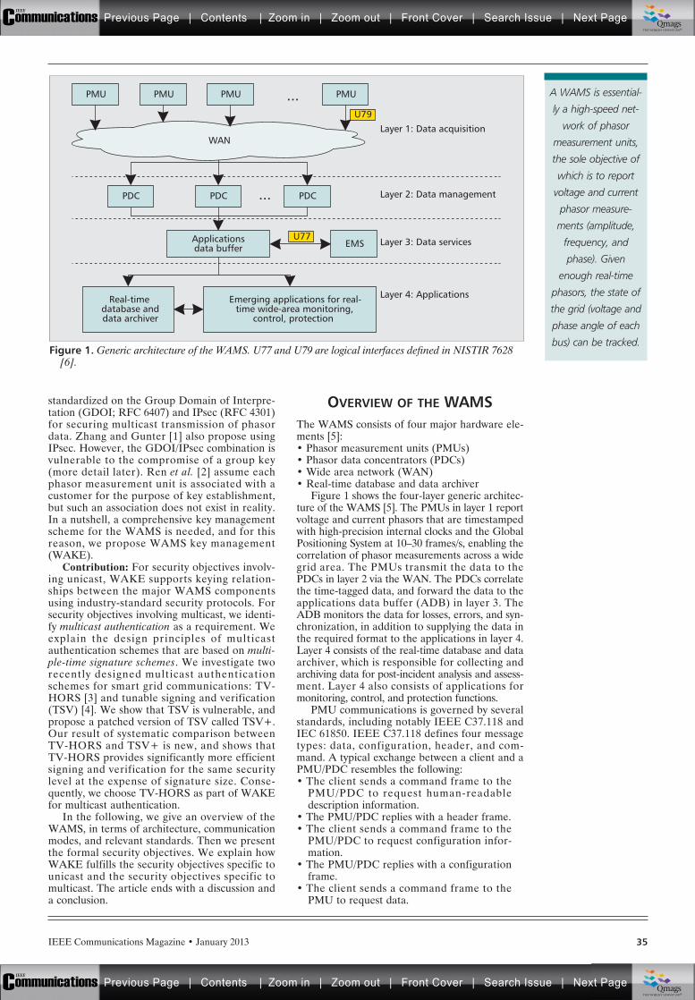
IEEE Communications Magazine • January 2013 35
standardized on the Group Domain of Interpre-tation (GDOI; RFC 6407) and IPsec (RFC 4301)for securing multicast transmission of phasordata. Zhang and Gunter [1] also propose usingIPsec. However, the GDOI/IPsec combination isvulnerable to the compromise of a group key(more detail later). Ren et al. [2] assume eachphasor measurement unit is associated with acustomer for the purpose of key establishment,but such an association does not exist in reality.In a nutshell, a comprehensive key managementscheme for the WAMS is needed, and for thisreason, we propose WAMS key management(WAKE).
Contribution: For security objectives involv-ing unicast, WAKE supports keying relation-ships between the major WAMS componentsusing industry-standard security protocols. Forsecurity objectives involving multicast, we identi-fy multicast authentication as a requirement. Weexplain the design principles of multicastauthentication schemes that are based on multi-ple-time signature schemes. We investigate tworecently designed multicast authenticationschemes for smart grid communications: TV-HORS [3] and tunable signing and verification(TSV) [4]. We show that TSV is vulnerable, andpropose a patched version of TSV called TSV+.Our result of systematic comparison betweenTV-HORS and TSV+ is new, and shows thatTV-HORS provides significantly more efficientsigning and verification for the same securitylevel at the expense of signature size. Conse-quently, we choose TV-HORS as part of WAKEfor multicast authentication.
In the following, we give an overview of theWAMS, in terms of architecture, communicationmodes, and relevant standards. Then we presentthe formal security objectives. We explain howWAKE fulfills the security objectives specific tounicast and the security objectives specific tomulticast. The article ends with a discussion anda conclusion.
OVERVIEW OF THE WAMSThe WAMS consists of four major hardware ele-ments [5]:• Phasor measurement units (PMUs)• Phasor data concentrators (PDCs)• Wide area network (WAN)• Real-time database and data archiver
Figure 1 shows the four-layer generic architec-ture of the WAMS [5]. The PMUs in layer 1 reportvoltage and current phasors that are time stampedwith high-precision internal clocks and the GlobalPositioning System at 10–30 frames/s, enabling thecorrelation of phasor measurements across a widegrid area. The PMUs transmit the data to thePDCs in layer 2 via the WAN. The PDCs correlatethe time-tagged data, and forward the data to theapplications data buffer (ADB) in layer 3. TheADB monitors the data for losses, errors, and syn-chronization, in addition to supplying the data inthe required format to the applications in layer 4.Layer 4 consists of the real-time database and dataarchiver, which is responsible for collecting andarchiving data for post-incident analysis and assess-ment. Layer 4 also consists of applications formonitoring, control, and protection functions.
PMU communications is governed by severalstandards, including notably IEEE C37.118 andIEC 61850. IEEE C37.118 defines four messagetypes: data, configuration, header, and com-mand. A typical exchange between a client and aPMU/PDC resembles the following:• The client sends a command frame to the
PMU/PDC to request human-readabledescription information.
• The PMU/PDC replies with a header frame.• The client sends a command frame to the
PMU/PDC to request configuration infor-mation.
• The PMU/PDC replies with a configurationframe.
• The client sends a command frame to thePMU to request data.
Figure 1. Generic architecture of the WAMS. U77 and U79 are logical interfaces defined in NISTIR 7628[6].
Applicationsdata buffer
Real-timedatabase anddata archiver
Emerging applications for real-time wide-area monitoring,
control, protection
PMU
PDC PDC
EMS
PDC
PMU PMU
WAN
PMU
Layer 1: Data acquisition
Layer 2: Data management
Layer 3: Data services
Layer 4: Applications
U79
U77
...
...
A WAMS is essential-
ly a high-speed net-
work of phasor
measurement units,
the sole objective of
which is to report
voltage and current
phasor measure-
ments (amplitude,
frequency, and
phase). Given
enough real-time
phasors, the state of
the grid (voltage and
phase angle of each
bus) can be tracked.
Previous Page | Contents | Zoom in | Zoom out | Front Cover | Search Issue | Next PageIEEE
Communications qqM
Mq
qM
MqM
Qmags®THE WORLD’S NEWSSTAND
Previous Page | Contents | Zoom in | Zoom out | Front Cover | Search Issue | Next PageIEEE
Communications qqM
Mq
qM
MqM
Qmags®THE WORLD’S NEWSSTAND
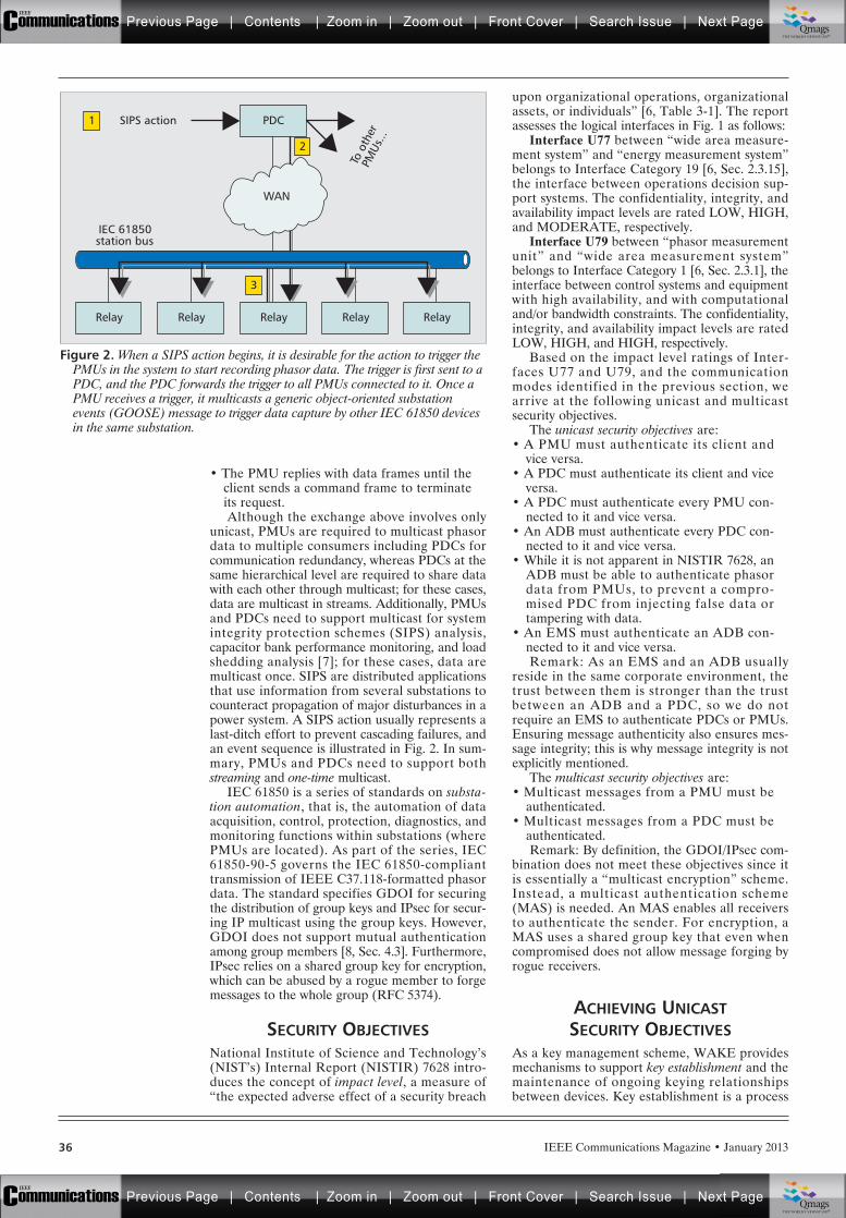
IEEE Communications Magazine • January 201336
• The PMU replies with data frames until theclient sends a command frame to terminateits request.Although the exchange above involves only
unicast, PMUs are required to multicast phasordata to multiple consumers including PDCs forcommunication redundancy, whereas PDCs at thesame hierarchical level are required to share datawith each other through multicast; for these cases,data are multicast in streams. Additionally, PMUsand PDCs need to support multicast for systemintegrity protection schemes (SIPS) analysis,capacitor bank performance monitoring, and loadshedding analysis [7]; for these cases, data aremulticast once. SIPS are distributed applicationsthat use information from several substations tocounteract propagation of major disturbances in apower system. A SIPS action usually represents alast-ditch effort to prevent cascading failures, andan event sequence is illustrated in Fig. 2. In sum-mary, PMUs and PDCs need to support bothstreaming and one-time multicast.
IEC 61850 is a series of standards on substa-tion automation, that is, the automation of dataacquisition, control, protection, diagnostics, andmonitoring functions within substations (wherePMUs are located). As part of the series, IEC61850-90-5 governs the IEC 61850-complianttransmission of IEEE C37.118-formatted phasordata. The standard specifies GDOI for securingthe distribution of group keys and IPsec for secur-ing IP multicast using the group keys. However,GDOI does not support mutual authenticationamong group members [8, Sec. 4.3]. Furthermore,IPsec relies on a shared group key for encryption,which can be abused by a rogue member to forgemessages to the whole group (RFC 5374).
SECURITY OBJECTIVESNational Institute of Science and Technology’s(NIST’s) Internal Report (NISTIR) 7628 intro-duces the concept of impact level, a measure of“the expected adverse effect of a security breach
upon organizational operations, organizationalassets, or individuals” [6, Table 3-1]. The reportassesses the logical interfaces in Fig. 1 as follows:
Interface U77 between “wide area measure-ment system” and “energy measurement system”belongs to Interface Category 19 [6, Sec. 2.3.15],the interface between operations decision sup-port systems. The confidentiality, integrity, andavailability impact levels are rated LOW, HIGH,and MODERATE, respectively.
Interface U79 between “phasor measurementunit” and “wide area measurement system”belongs to Interface Category 1 [6, Sec. 2.3.1], theinterface between control systems and equipmentwith high availability, and with computationaland/or bandwidth constraints. The confidentiality,integrity, and availability impact levels are ratedLOW, HIGH, and HIGH, respectively.
Based on the impact level ratings of Inter-faces U77 and U79, and the communicationmodes identified in the previous section, wearrive at the following unicast and multicastsecurity objectives.
The unicast security objectives are:• A PMU must authenticate its client and
vice versa.• A PDC must authenticate its client and vice
versa.• A PDC must authenticate every PMU con-
nected to it and vice versa.• An ADB must authenticate every PDC con-
nected to it and vice versa.• While it is not apparent in NISTIR 7628, an
ADB must be able to authenticate phasordata from PMUs, to prevent a compro-mised PDC from injecting false data ortampering with data.
• An EMS must authenticate an ADB con-nected to it and vice versa.Remark: As an EMS and an ADB usually
reside in the same corporate environment, thetrust between them is stronger than the trustbetween an ADB and a PDC, so we do notrequire an EMS to authenticate PDCs or PMUs.Ensuring message authenticity also ensures mes-sage integrity; this is why message integrity is notexplicitly mentioned.
The multicast security objectives are:• Multicast messages from a PMU must be
authenticated.• Multicast messages from a PDC must be
authenticated.Remark: By definition, the GDOI/IPsec com-
bination does not meet these objectives since itis essentially a “multicast encryption” scheme.Instead, a multicast authentication scheme(MAS) is needed. An MAS enables all receiversto authenticate the sender. For encryption, aMAS uses a shared group key that even whencompromised does not allow message forging byrogue receivers.
ACHIEVING UNICASTSECURITY OBJECTIVES
As a key management scheme, WAKE providesmechanisms to support key establishment and themaintenance of ongoing keying relationshipsbetween devices. Key establishment is a process
Figure 2. When a SIPS action begins, it is desirable for the action to trigger thePMUs in the system to start recording phasor data. The trigger is first sent to aPDC, and the PDC forwards the trigger to all PMUs connected to it. Once aPMU receives a trigger, it multicasts a generic object-oriented substationevents (GOOSE) message to trigger data capture by other IEC 61850 devicesin the same substation.
Relay Relay Relay
PDC
To o
ther
PMU
s...
SIPS action
WAN
Relay Relay
IEC 61850station bus
3
2
1
Previous Page | Contents | Zoom in | Zoom out | Front Cover | Search Issue | Next PageIEEE
Communications qqM
Mq
qM
MqM
Qmags®THE WORLD’S NEWSSTAND
Previous Page | Contents | Zoom in | Zoom out | Front Cover | Search Issue | Next PageIEEE
Communications qqM
Mq
qM
MqM
Qmags®THE WORLD’S NEWSSTAND
IEEE Communications Magazine • January 2013 37
whereby a shared secret key becomes availableto two or more parties, for subsequent crypto-graphic use, including the building of secure(encrypted and authenticated) channels. WAKEuses an asymmetric-key cryptosystem to boot-strap key establishment. Asymmetric-key cryp-tosystems such as public-key infrastructure (PKI)and identity-based encryption (IBE) are scalablealthough computationally expensive, becausethey require only one key pair per device regard-less of the network size.
WAKE uses PKI. PKI is an industry-stan-dard asymmetric-key cryptosystem, with stan-dards including X.509 and RFC 5280. In PKI, acertification authority (CA) vouches for a pub-lic/private key pair, when it signs the public key(and related attributes), thus creating a certifi-cate. A CA can vouch for other CAs which canvouch for yet other CAs and so on such thatthe CAs form a certification hierarchy. The trustanchor is the root CA of a certification hierar-chy. In WAKE, the grid operator acts as thetrust anchor, and follows the X.509 PKI Certifi-cate Policy and Certification Practices Frame-work in RFC 3647 to protect the system privatekey. Every device is pre-configured with aunique public/private key pair, with the publickey being grid operator-certified. An intrusiondetection and response system is assumed to bemonitoring critical devices; when the systemconcludes that a device is no longer trustwor-thy, it revokes the device’s certificate via a cer-tificate revocation list broadcast to the wholenetwork.
A secure channel is established between twodevices via the Diffie-Hellman key establishmentprotocol, either in the form of Internet KeyExchange version 2 (IKEv2; RFC 5996) as partof IPsec, or in the form of transport layer securi-ty (TLS; RFC 5246). In a secure channel, mes-sages are encrypted with a block cipher andauthenticated with message authentication codes.For the block cipher, AES is recommended(FIPS 197), since it is among the most efficientin software [9], and increasingly more communi-cations hardware supports AES acceleration. Formessage authentication codes, CMAC is recom-mended (NIST SP 800-38B), because it is securefor variable-length messages (unlike CBC-MAC), and being block cipher-based, it can takeadvantage of hardware AES acceleration.
Every PMU is pre-configured with the con-nection detail (IP address, port, etc.) of thedownstream PDC and ADB; every PDC is pre-configured with the connection detail of thedownstream ADB; and the ADB is preconfig-ured with the connection detail of the EMS.
A PMU maintains a secure channel with thedownstream PDC and the ADB. Through thesecure channel, the PMU sends phasor data tothe PDC. For each phasor data frame, the PDCverifies the message authentication code. Uponsuccessful verification, the PDC appends its ownmessage authentication code to the data frame.
The PDC maintains a secure channel with theADB, and relays the phasor data to the ADB.For each phasor data frame, the ADB verifiesfirst the PDC-generated message authenticationcode, then the PMU-generated message authen-tication code. Upon successful verification, the
ADB replaces the codes with its own messageauthentication code.
The ADB maintains a secure channel with theEMS, and relays the phasor data to the EMS. Foreach phasor data frame, the EMS verifies themessage authentication code, and only acceptsthe phasor data upon successful verification.
ACHIEVING MULTICASTSECURITY OBJECTIVES
For one-time multicast, messages are signedusing a conventional digital signature schemesuch as Digital Signature Algorithm (DSA; FIPS186-3). For streaming multicast, messages aresigned using an MAS. In the following, the gen-eral principles of an MAS are first introduced,followed by a study of two schemes.
At the core of every MAS lies a signature(generation and verification) scheme. There aretwo types of signature schemes:
Unlimited-time signature schemes: Conven-tional digital signature algorithms can sign a prac-tically unlimited number of distinct messages witha private key, but they have high computation andmemory requirements. The simplest MAS that isbased on this type of scheme appends a signatureto every multicast message, incurring a prohibitivecomputational cost for streaming multicast. Toreduce computational cost, the latest researchfocuses on signature amortization (i.e., spreadingthe cost of signature verification across manypackets). Since a number of packets will have tobe assembled before their collective signature canbe verified, the incurred delay violates the real-time requirements of the WAMS.
Multiple-time signature schemes (MTSS,including one-time signature schemes): AnMTSS can sign a fixed number of distinct mes-sages using a public/private key pair. Althoughthey generally produce longer signatures atlower security levels, they have much lower com-putation and memory requirements than unlim-ited-time schemes. An MTSS typically consists ofthe following components:• A private key tuple, a public key tuple, and
a non-invertible function mapping the pri-vate key tuple to the public key tuple
• An indexing function that, based on themessage to be signed, selects elements ofthe private key to be used for signaturegeneration
• A function mapping the selected private keyelements to the signature
• A function mapping the signature to ele-ments of the public keyConstructing an MAS from an MTSS requires
two main components.One-way chains: Since a key pair can generate
only a fixed number of signatures, to sign a mes-sage stream of unlimited length, the key pair mustbe refreshed once its security limit is reached. Let{si} be a one-way chain, where si = H(si+1), i = 0,1, …, and H is a one-way hash function. Supposewe use one key pair per epoch; then we can use sias the private key for the ith epoch (i 1), whileany sj, "j < i can be used as the public key. Sup-pose each key is a tuple of t elements; then a totalof t one-way chains are needed.
As a key manage-
ment scheme, WAKE
provides mechanisms
to support key
establishment and
the maintenance of
ongoing keying rela-
tionships between
devices. Key estab-
lishment is a process
whereby a shared
secret key becomes
available to two or
more parties, for
subsequent crypto-
graphic use.
Previous Page | Contents | Zoom in | Zoom out | Front Cover | Search Issue | Next PageIEEE
Communications qqM
Mq
qM
MqM
Qmags®THE WORLD’S NEWSSTAND
Previous Page | Contents | Zoom in | Zoom out | Front Cover | Search Issue | Next PageIEEE
Communications qqM
Mq
qM
MqM
Qmags®THE WORLD’S NEWSSTAND
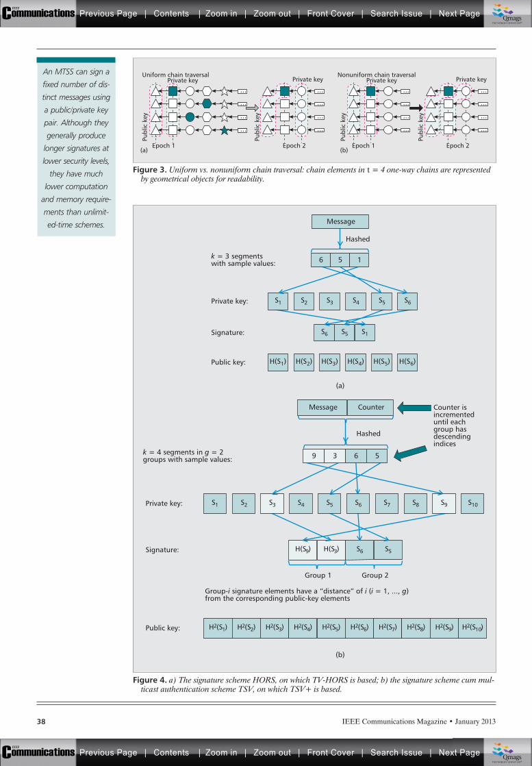
IEEE Communications Magazine • January 201338
Figure 4. a) The signature scheme HORS, on which TV-HORS is based; b) the signature scheme cum mul-ticast authentication scheme TSV, on which TSV+ is based.
(a)
(b)
Message
Message Counter
Hashed
Hashed
Group 2
6
S1Private key:
S1
H(S9) H(S3) S6 S5
S2 S3 S4 S5 S6 S7 S8 S9 S10Private key:
Signature:
Counter isincrementeduntil eachgroup hasdescendingindices
Group-i signature elements have a “distance” of i (i = 1, ..., g)from the corresponding public-key elements
H2(S1) H2(S2) H2(S3) H2(S4) H2(S5) H2(S6) H2(S7) H2(S8) H2(S9) H2(S10)Public key:
k = 3 segmentswith sample values:
k = 4 segments in g = 2groups with sample values:
Signature:
S2 S3 S4 S5 S6
H(S1)Public key: H(S2) H(S3) H(S4) H(S5) H(S6)
S6 S5 S1
5 1
9 3 6 5
Group 1
Figure 3. Uniform vs. nonuniform chain traversal: chain elements in t = 4 one-way chains are representedby geometrical objects for readability.
Private keyUniform chain traversal Nonuniform chain traversal
Publ
ic k
ey
Epoch 2
...
...
...
...
Private key
Publ
ic k
ey
Epoch 1
...
...
...
...
Private key
Publ
ic k
ey
Epoch 2
...
...
...
...
Private key
Publ
ic k
eyEpoch 1
(a) (b)
...
...
...
...
...
......
......
An MTSS can sign a
fixed number of dis-
tinct messages using
a public/private key
pair. Although they
generally produce
longer signatures at
lower security levels,
they have much
lower computation
and memory require-
ments than unlimit-
ed-time schemes.
Previous Page | Contents | Zoom in | Zoom out | Front Cover | Search Issue | Next PageIEEE
Communications qqM
Mq
qM
MqM
Qmags®THE WORLD’S NEWSSTAND
Previous Page | Contents | Zoom in | Zoom out | Front Cover | Search Issue | Next PageIEEE
Communications qqM
Mq
qM
MqM
Qmags®THE WORLD’S NEWSSTAND
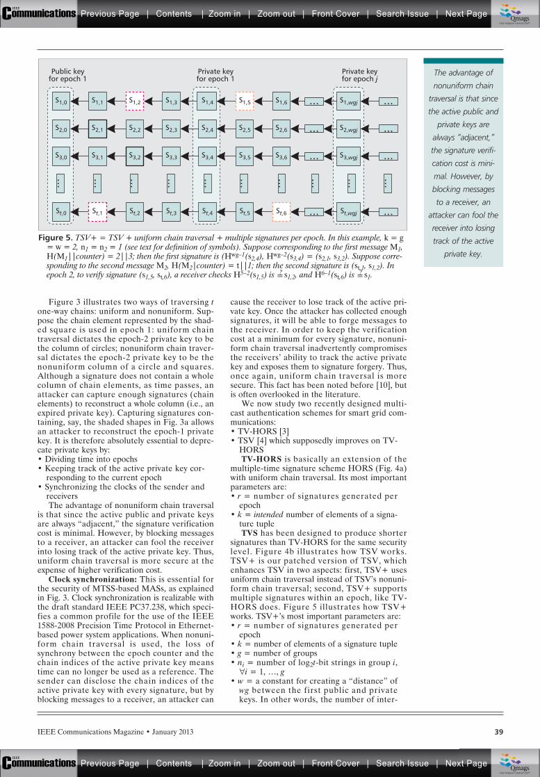
IEEE Communications Magazine • January 2013 39
Figure 3 illustrates two ways of traversing tone-way chains: uniform and nonuniform. Sup-pose the chain element represented by the shad-ed square is used in epoch 1: uniform chaintraversal dictates the epoch-2 private key to bethe column of circles; nonuniform chain traver-sal dictates the epoch-2 private key to be thenonuniform column of a circle and squares.Although a signature does not contain a wholecolumn of chain elements, as time passes, anattacker can capture enough signatures (chainelements) to reconstruct a whole column (i.e., anexpired private key). Capturing signatures con-taining, say, the shaded shapes in Fig. 3a allowsan attacker to reconstruct the epoch-1 privatekey. It is therefore absolutely essential to depre-cate private keys by:• Dividing time into epochs• Keeping track of the active private key cor-
responding to the current epoch• Synchronizing the clocks of the sender and
receiversThe advantage of nonuniform chain traversal
is that since the active public and private keysare always “adjacent,” the signature verificationcost is minimal. However, by blocking messagesto a receiver, an attacker can fool the receiverinto losing track of the active private key. Thus,uniform chain traversal is more secure at theexpense of higher verification cost.
Clock synchronization: This is essential forthe security of MTSS-based MASs, as explainedin Fig. 3. Clock synchronization is realizable withthe draft standard IEEE PC37.238, which speci-fies a common profile for the use of the IEEE1588-2008 Precision Time Protocol in Ethernet-based power system applications. When nonuni-form chain traversal is used, the loss ofsynchrony between the epoch counter and thechain indices of the active private key meanstime can no longer be used as a reference. Thesender can disclose the chain indices of theactive private key with every signature, but byblocking messages to a receiver, an attacker can
cause the receiver to lose track of the active pri-vate key. Once the attacker has collected enoughsignatures, it will be able to forge messages tothe receiver. In order to keep the verificationcost at a minimum for every signature, nonuni-form chain traversal inadvertently compromisesthe receivers’ ability to track the active privatekey and exposes them to signature forgery. Thus,once again, uniform chain traversal is moresecure. This fact has been noted before [10], butis often overlooked in the literature.
We now study two recently designed multi-cast authentication schemes for smart grid com-munications:• TV-HORS [3]• TSV [4] which supposedly improves on TV-
HORSTV-HORS is basically an extension of the
multiple-time signature scheme HORS (Fig. 4a)with uniform chain traversal. Its most importantparameters are:• r = number of signatures generated per
epoch• k = intended number of elements of a signa-
ture tupleTVS has been designed to produce shorter
signatures than TV-HORS for the same securitylevel. Figure 4b illustrates how TSV works.TSV+ is our patched version of TSV, whichenhances TSV in two aspects: first, TSV+ usesuniform chain traversal instead of TSV’s nonuni-form chain traversal; second, TSV+ supportsmultiple signatures within an epoch, like TV-HORS does. Figure 5 illustrates how TSV+works. TSV+’s most important parameters are:• r = number of signatures generated per
epoch• k = number of elements of a signature tuple• g = number of groups• ni = number of log2t-bit strings in group i,
"i = 1, …, g• w = a constant for creating a “distance” of
wg between the first public and privatekeys. In other words, the number of inter-
Figure 5. TSV+ = TSV + uniform chain traversal + multiple signatures per epoch. In this example, k = g= w = 2, n1 = n2 = 1 (see text for definition of symbols). Suppose corresponding to the first message M1,H(M1||counter) = 2||3; then the first signature is (Hwg–1(s2,4), Hwg–2(s3,4) = (s2,1, s3,2). Suppose corre-sponding to the second message M2, H(M2|counter) = t||1; then the second signature is (st,1, s1,2). Inepoch 2, to verify signature (s1,5, st,6), a receiver checks H5–2(s1,5) is =? s1,2, and H6–1(st,6) is =? s1.
Private keyfor epoch j
Private keyfor epoch 1
Public keyfor epoch 1
S1,wgj ...S1,6 ...S1,5S1,4S1,3S1,2S1,1S1,0
S2,wgj ...S2,6 ...S2,5S2,4S2,3S2,2S2,1S2,0
S3,wgj ..................... ............
S3,6 ...S3,5S3,4S3,3S3,2S3,1S3,0
St,wgj ...St,6 ...St,5St,4St,3St,2St,1St,0
The advantage of
nonuniform chain
traversal is that since
the active public and
private keys are
always “adjacent,”
the signature verifi-
cation cost is mini-
mal. However, by
blocking messages
to a receiver, an
attacker can fool the
receiver into losing
track of the active
private key.
Previous Page | Contents | Zoom in | Zoom out | Front Cover | Search Issue | Next PageIEEE
Communications qqM
Mq
qM
MqM
Qmags®THE WORLD’S NEWSSTAND
Previous Page | Contents | Zoom in | Zoom out | Front Cover | Search Issue | Next PageIEEE
Communications qqM
Mq
qM
MqM
Qmags®THE WORLD’S NEWSSTAND
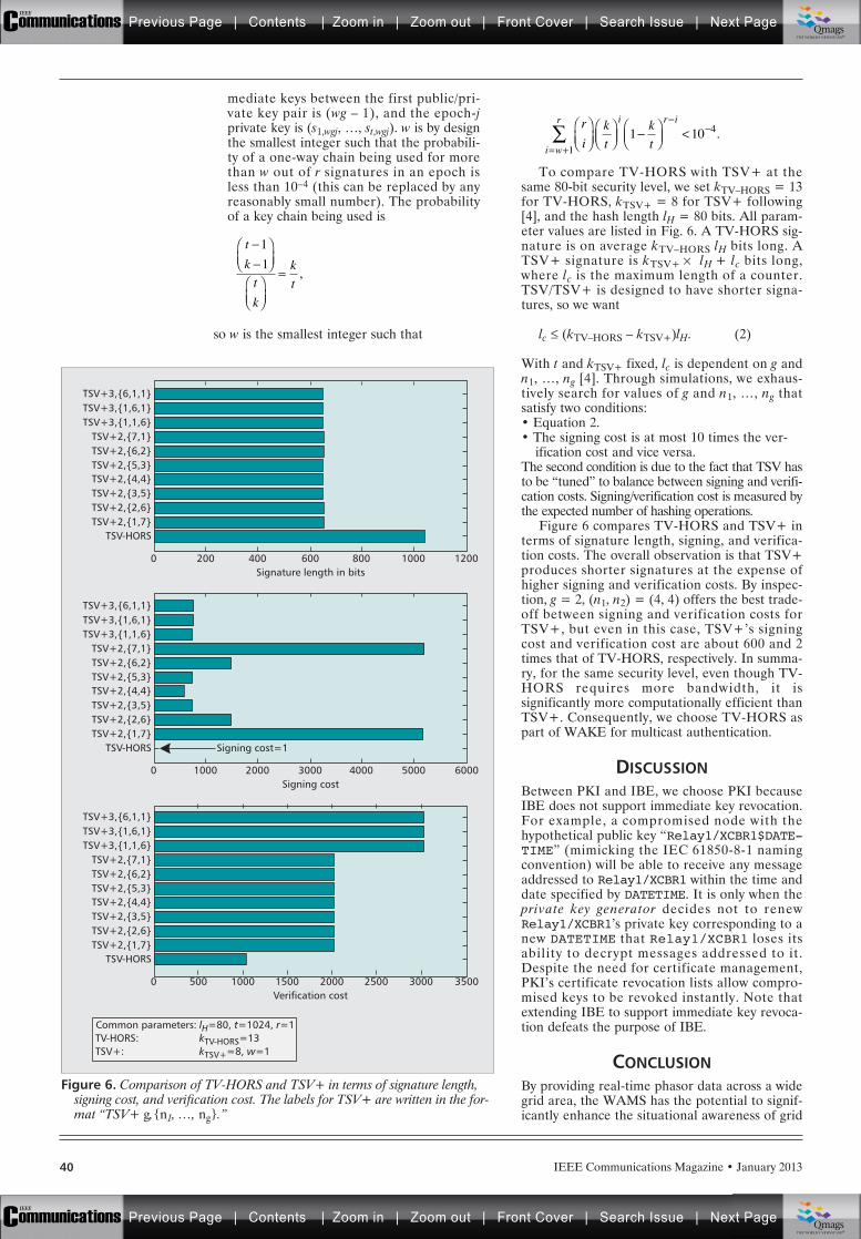
mediate keys between the first public/pri-vate key pair is (wg – 1), and the epoch-jprivate key is (s1,wgj, …, st,wgj). w is by designthe smallest integer such that the probabili-ty of a one-way chain being used for morethan w out of r signatures in an epoch isless than 10–4 (this can be replaced by anyreasonably small number). The probabilityof a key chain being used is
so w is the smallest integer such that
To compare TV-HORS with TSV+ at thesame 80-bit security level, we set kTV–HORS = 13for TV-HORS, kTSV+ = 8 for TSV+ following[4], and the hash length lH = 80 bits. All param-eter values are listed in Fig. 6. A TV-HORS sig-nature is on average kTV–HORS lH bits long. ATSV+ signature is kTSV+ ¥ lH + lc bits long,where lc is the maximum length of a counter.TSV/TSV+ is designed to have shorter signa-tures, so we want
lc £ (kTV–HORS – kTSV+)lH. (2)
With t and kTSV+ fixed, lc is dependent on g andn1, …, ng [4]. Through simulations, we exhaus-tively search for values of g and n1, …, ng thatsatisfy two conditions:• Equation 2.• The signing cost is at most 10 times the ver-
ification cost and vice versa.The second condition is due to the fact that TSV hasto be “tuned” to balance between signing and verifi-cation costs. Signing/verification cost is measured bythe expected number of hashing operations.
Figure 6 compares TV-HORS and TSV+ interms of signature length, signing, and verifica-tion costs. The overall observation is that TSV+produces shorter signatures at the expense ofhigher signing and verification costs. By inspec-tion, g = 2, (n1, n2) = (4, 4) offers the best trade-off between signing and verification costs forTSV+, but even in this case, TSV+’s signingcost and verification cost are about 600 and 2times that of TV-HORS, respectively. In summa-ry, for the same security level, even though TV-HORS requires more bandwidth, it issignificantly more computationally efficient thanTSV+. Consequently, we choose TV-HORS aspart of WAKE for multicast authentication.
DISCUSSIONBetween PKI and IBE, we choose PKI becauseIBE does not support immediate key revocation.For example, a compromised node with thehypothetical public key “Relay1/XCBR1$DATE-TIME” (mimicking the IEC 61850-8-1 namingconvention) will be able to receive any messageaddressed to Relay1/XCBR1 within the time anddate specified by DATETIME. It is only when theprivate key generator decides not to renewRelay1/XCBR1’s private key corresponding to anew DATETIME that Relay1/XCBR1 loses itsability to decrypt messages addressed to it.Despite the need for certificate management,PKI’s certificate revocation lists allow compro-mised keys to be revoked instantly. Note thatextending IBE to support immediate key revoca-tion defeats the purpose of IBE.
CONCLUSIONBy providing real-time phasor data across a widegrid area, the WAMS has the potential to signif-icantly enhance the situational awareness of grid
t
k
t
k
k
t=
1
1,
r
ik
t
k
ti w
r i r i
<= +1
41 10 .
IEEE Communications Magazine • January 201340
Figure 6. Comparison of TV-HORS and TSV+ in terms of signature length,signing cost, and verification cost. The labels for TSV+ are written in the for-mat “TSV+ g,{n1, …, ng}.”
Signature length in bits2000
TSV-HORSTSV+2,{1,7}TSV+2,{2,6}TSV+2,{3,5}TSV+2,{4,4}TSV+2,{5,3}TSV+2,{6,2}TSV+2,{7,1}
TSV+3,{1,1,6}TSV+3,{1,6,1}TSV+3,{6,1,1}
400 600 800 1000 1200
Common parameters:TV-HORS:TSV+:
lH=80, t=1024, r=1kTV-HORS=13kTSV+=8, w=1
Signing cost
Signing cost=1
10000
TSV-HORSTSV+2,{1,7}TSV+2,{2,6}TSV+2,{3,5}TSV+2,{4,4}TSV+2,{5,3}TSV+2,{6,2}TSV+2,{7,1}
TSV+3,{1,1,6}TSV+3,{1,6,1}TSV+3,{6,1,1}
2000 3000 4000 5000 6000
Verification cost5000
TSV-HORSTSV+2,{1,7}TSV+2,{2,6}TSV+2,{3,5}TSV+2,{4,4}TSV+2,{5,3}TSV+2,{6,2}TSV+2,{7,1}
TSV+3,{1,1,6}TSV+3,{1,6,1}TSV+3,{6,1,1}
1000 1500 2000 2500 35003000
Previous Page | Contents | Zoom in | Zoom out | Front Cover | Search Issue | Next PageIEEE
Communications qqM
Mq
qM
MqM
Qmags®THE WORLD’S NEWSSTAND
Previous Page | Contents | Zoom in | Zoom out | Front Cover | Search Issue | Next PageIEEE
Communications qqM
Mq
qM
MqM
Qmags®THE WORLD’S NEWSSTAND

IEEE Communications Magazine • January 2013 41
operators, and thereby reduce blackouts. Tosecure real-time transmission of these data, wepropose the key management scheme WAKE.From NIST’s security impact level ratings, wearrive at a concrete set of security objectives forWAKE. For security objectives involving unicast,WAKE supports keying relationships betweenthe major WAMS components using industry-standard security protocols. For security objec-tives involving multicast, we identify multicastauthentication as the primary challenge. Ourresult of systematic comparison between TV-HORS and TSV+ is new, and shows that TV-HORS provides significantly more efficientsigning and verification for the same securitylevel at the expense of signature size. Conse-quently, WAKE employs TV-HORS for multi-cast authentication.
ACKNOWLEDGMENTYee Wei Law is partly supported by the Institutefor a Broadband-Enabled Society, the ARCunder Discovery Project grant DP1095452, andthe EC under contract FP7-ICT-2009-5-257992,“SmartSantander.”
REFERENCES[1] J. Zhang and C. A. Gunter, “Application-Aware Secure
Multicast for Power Grid Communications,” Int’l. J.Security and Networks, vol. 6, no. 1, 2011, pp. 40–52.
[2] W. Ren et al., “BVS: A Lightweight Forward and Back-ward Secure Scheme for PMU Communications inSmart Grid,” Int’l. J. Digital Multimedia Broadcasting,vol. 2011, 2011, article ID 382147, 9 pages.
[3] Q. Wang et al., “Time Valid Onetime Signature forTime-Critical Multicast Data Authentication,” IEEE INFO-COM 2009, Apr. 2009, pp. 1233–41.
[4] Q. Li and G. Cao, “Multicast Authentication in theSmart Grid with Onetime Signature,” IEEE Trans. SmartGrid, vol. 2, no. 4, 2011, pp. 686–96.
[5] C. Martinez et al., “Phasor Data Requirements for RealTime Wide-Area Monitoring, Control and ProtectionApplications,” EIPP – Real Time Task Team, WhitePaper, Jan. 2005.
[6] NIST, “Guidelines for Smart Grid Cyber Security,” IR7628, Aug. 2010.
[7] M. Adamiak and R. Hunt, “Application of Phasor Mea-surement Units for Disturbance Recording,” 10th Annu-al Georgia Tech Fault and Disturbance Analysis Conf.,2007.
[8] C. Meadows and P. Syverson, “Formalizing GDOI GroupKey Management Requirements in NPATRL,” Proc. 8th
ACM Conf. Computer and Commun. Security, 2001,pp. 235–44.
[9] Y. W. Law, J. Doumen, and P. Hartel, “Survey andBenchmark of Block Ciphers for Wireless Sensor Net-works,” ACM Trans. Sensor Networks, vol. 2, no. 1,Feb. 2006, pp. 65–93.
[10] A. Perrig, “The BiBa One-Time Signature and BroadcastAuthentication Protocol,” Proc. 8th ACM Conf. Com-puter and Commun, Security, 2001, pp. 28–37.
BIOGRAPHIESYEE WEI LAW ([email protected]) received his Ph.D.degree from the University of Twente in 2005. Since 2006,he has been a research fellow with the ARC Research Net-work on Intelligent Sensors, Sensor Networks and Informa-tion Processing, Department of Electrical and ElectronicEngineering, University of Melbourne. He is a member ofthe Smart Grid Australia Research Working Group, and in2011, he gained professional certification as an Associateof the International Information System Security Certifica-tion Consortium. His research interests range from wirelesssensor networks to smart grids, and especially the securityaspects of these technologies.
MARIMUTHU PALANISWAMI [F] ([email protected])received his Ph.D. degree from the University of Newcastle,and is a professor at the University of Melbourne. He haspublished more than 320 refereed papers, and a significantproportion of them appeared in prestigious IEEE journalsand conferences. He was given a Foreign Specialist Awardby the Ministry of Education, Japan, in recognition of hiscontributions to the field of machine learning. His academ-ic excellence is recognized by several invited presentationsof plenary/keynote lectures, and he is a panel member forseveral top international conferences. He has been an Asso-ciate Editor for journals/transactions including IEEE Transac-tions on Neural Networks. His research interests includeSVMs, sensors and sensor networks, machine learning,neural networks, pattern recognition, signal processing,control, and smart grids.
GINA KOUNGA ([email protected]) received her M.Sc.in computer science from INSA Lyon, France, in 2004, andher Ph.D. in 2008 while working at DOCOMO Euro-Labs.From 2005 to 2008, she worked on security of ad hoc net-works at DOCOMO Euro-Labs, Munich, Germany. She thenworked for HP Labs Bristol and EADS UK on privacy andsecurity of critical national infrastructures. She is now aresearch assistant at the University of Oxford.
ANTHONY LO [SM] ([email protected]) received combinedB.S. and B.E., and Ph.D. degrees in 1992 and 1996 from LaTrobe University. He is currently an assistant professor atDelft University of Technology, and prior to his currentappointment, he was a research engineer at Ericsson Euro-Lab working on UMTS/HSDPA. His research interestsinclude M2M communications, smart grids, and the wire-less network cloud.
Our result of system-
atic comparison
between TV-HORS
and TSV+ is new,
and shows that TV-
HORS provides sig-
nificantly more
efficient signing and
verification for the
same security level at
the expense of sig-
nature size. Conse-
quently, WAKE
employs TV-HORS
for multicast
authentication.
Previous Page | Contents | Zoom in | Zoom out | Front Cover | Search Issue | Next PageIEEE
Communications qqM
Mq
qM
MqM
Qmags®THE WORLD’S NEWSSTAND
Previous Page | Contents | Zoom in | Zoom out | Front Cover | Search Issue | Next PageIEEE
Communications qqM
Mq
qM
MqM
Qmags®THE WORLD’S NEWSSTAND
___________
_____________
______________
_____________
IEEE Communications Magazine • January 201342 0163-6804/13/$25.00 © 2013 IEEE
INTRODUCTION
The current electrical grid is perhaps the great-est engineering achievement of the 20th century.However, it is increasingly outdated and over-burdened, leading to costly blackouts andburnouts. For this and various other reasons,transformation efforts are underway to make thecurrent electrical grid smarter.
The smart grid could be referred to as themodernization of the current electric grid for thepurpose of enabling bidirectional flows of infor-mation and electricity in order to achieve numer-ous goals; it will provide consumers with diversechoices on how, when, and how much electricity
they use. It is self-healing in case of distur-bances, such as physical and cyber attacks andnatural disasters. Moreover, the smart grid’sinfrastructure will be able to link and utilize awide array of energy sources including renew-able energy producers and mobile energy stor-age. Additionally, this infrastructure aims atproviding better power quality and more effi-cient delivery of electricity. Indeed, all thesegoals could not be achieved and realized withouta communication technology infrastructure thatwill gather, assemble, and synthesize data pro-vided by smart meters, electrical vehicles, sen-sors, and computer and information technologysystems.
CYBER SECURITY MOTIVATIONHistory has proven that industrial control sys-tems were in fact vulnerable to and victims ofcyber attacks. In March 2007, Idaho NationalLaboratory conducted an experiment in whichphysical damage was caused to a diesel genera-tor through the exploitation of a security flaw inits control system. Additionally, during the Rus-sian-Georgian war in 2008, cyber attacks widelybelieved to have originated in Russia broughtdown the Georgian electric grid during the Rus-sian army’s advance through the country. Besidesthat, in April 2009, the Wall Street Journal report-ed that cyber spies had penetrated the U.S. elec-trical grid and left behind software programsthat could be used to disrupt the system. Lastbut very significant, in 2010, Stuxnet, a largecomplex piece of malware with many differentcomponents and functionalities, targetedSiemens industrial control systems and exploitedfour zero-day vulnerabilities running Windowsoperating systems. As a result, 60 percent of Ira-nian nuclear infrastructure was targeted, hencetriggering genuine fear over the commencementof cyber warfare.
It is therefore of utmost importance toaddress the cyber security aspect of the smartgrid, specifically the area concerned with thecommunication mechanisms that deal with thedistribution subpart.
The rest of the article is organized as follows.We pinpoint some related work in our area ofconcern, and then illustrate and describe thesmart grid architecture. We thoroughly elaborate
ABSTRACT
The operation and control of the next gener-ation electrical grids will depend on a complexnetwork of computers, software, and communi-cation technologies. Being compromised by amalicious adversary would cause significant dam-age, including extended power outages anddestruction of electrical equipment. Moreover,the implementation of the smart grid will includethe deployment of many new enabling technolo-gies such as advanced sensors and metering, andthe integration of distributed generationresources. Such technologies and various otherswill require the addition and utilization of multi-ple communication mechanisms and infrastruc-tures that may suffer from serious cybervulnerabilities. These need to be addressed inorder to increase the security and thus the great-est adoption and success of the smart grid. Inthis article, we focus on the communicationsecurity aspect, which deals with the distributioncomponent of the smart grid. Consequently, wetarget the network security of the advancedmetering infrastructure coupled with the datacommunication toward the transmission infra-structure. We discuss the security and feasibilityaspects of possible communication mechanismsthat could be adopted on that subpart of thegrid. By accomplishing this, the correlated vul-nerabilities in these systems could be remediat-ed, and associated risks may be mitigated for thepurpose of enhancing the cyber security of thefuture electric grid.
CYBER SECURITY FOR SMART GRIDCOMMUNICATIONS: PART 2
Elias Bou-Harb, Claude Fachkha, Makan Pourzandi, Mourad Debbabi, and Chadi Assi, Concordia University
Communication Security for Smart GridDistribution Networks
Previous Page | Contents | Zoom in | Zoom out | Front Cover | Search Issue | Next PageIEEE
Communications qqM
Mq
qM
MqM
Qmags®THE WORLD’S NEWSSTAND
Previous Page | Contents | Zoom in | Zoom out | Front Cover | Search Issue | Next PageIEEE
Communications qqM
Mq
qM
MqM
Qmags®THE WORLD’S NEWSSTAND
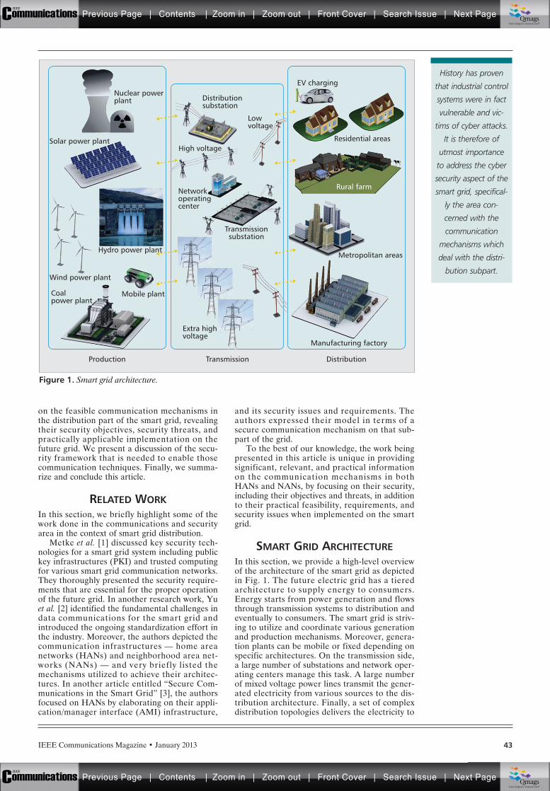
IEEE Communications Magazine • January 2013 43
on the feasible communication mechanisms inthe distribution part of the smart grid, revealingtheir security objectives, security threats, andpractically applicable implementation on thefuture grid. We present a discussion of the secu-rity framework that is needed to enable thosecommunication techniques. Finally, we summa-rize and conclude this article.
RELATED WORKIn this section, we briefly highlight some of thework done in the communications and securityarea in the context of smart grid distribution.
Metke et al. [1] discussed key security tech-nologies for a smart grid system including publickey infrastructures (PKI) and trusted computingfor various smart grid communication networks.They thoroughly presented the security require-ments that are essential for the proper operationof the future grid. In another research work, Yuet al. [2] identified the fundamental challenges indata communications for the smart grid andintroduced the ongoing standardization effort inthe industry. Moreover, the authors depicted thecommunication infrastructures — home areanetworks (HANs) and neighborhood area net-works (NANs) — and very briefly listed themechanisms utilized to achieve their architec-tures. In another article entitled “Secure Com-munications in the Smart Grid” [3], the authorsfocused on HANs by elaborating on their appli-cation/manager interface (AMI) infrastructure,
and its security issues and requirements. Theauthors expressed their model in terms of asecure communication mechanism on that sub-part of the grid.
To the best of our knowledge, the work beingpresented in this article is unique in providingsignificant, relevant, and practical informationon the communication mechanisms in bothHANs and NANs, by focusing on their security,including their objectives and threats, in additionto their practical feasibility, requirements, andsecurity issues when implemented on the smartgrid.
SMART GRID ARCHITECTUREIn this section, we provide a high-level overviewof the architecture of the smart grid as depictedin Fig. 1. The future electric grid has a tieredarchitecture to supply energy to consumers.Energy starts from power generation and flowsthrough transmission systems to distribution andeventually to consumers. The smart grid is striv-ing to utilize and coordinate various generationand production mechanisms. Moreover, genera-tion plants can be mobile or fixed depending onspecific architectures. On the transmission side,a large number of substations and network oper-ating centers manage this task. A large numberof mixed voltage power lines transmit the gener-ated electricity from various sources to the dis-tribution architecture. Finally, a set of complexdistribution topologies delivers the electricity to
Figure 1. Smart grid architecture.
EV charging
Residential areas
Rural farm
Metropolitan areas
Manufacturing factory
DistributionTransmissionProduction
High voltageSolar power plant
Hydro power plant
Wind power plant
Coalpower plant
Mobile plant
Lowvoltage
Distributionsubstation
Nuclear powerplant
Transmissionsubstation
Networkoperatingcenter
Extra highvoltage
Rural farm
History has proven
that industrial control
systems were in fact
vulnerable and vic-
tims of cyber attacks.
It is therefore of
utmost importance
to address the cyber
security aspect of the
smart grid, specifical-
ly the area con-
cerned with the
communication
mechanisms which
deal with the distri-
bution subpart.
Previous Page | Contents | Zoom in | Zoom out | Front Cover | Search Issue | Next PageIEEE
Communications qqM
Mq
qM
MqM
Qmags®THE WORLD’S NEWSSTAND
Previous Page | Contents | Zoom in | Zoom out | Front Cover | Search Issue | Next PageIEEE
Communications qqM
Mq
qM
MqM
Qmags®THE WORLD’S NEWSSTAND
IEEE Communications Magazine • January 201344
regions, neighbors, and premises for utilizationand consumption.
In this article, our interest lies in the distribu-tion part of the smart grid. More specifically, weare concerned with the communication networksof that subpart of the grid, the HAN and theNAN. These networks are critical for data com-munications between the utility and end users.HANs are composed of three components: first,the smart in-house devices that provide demand-side management such as energy efficiency man-agement and demand response; second, thesmart meter that collects data from smart devicesand invokes certain actions depending on theinformation it retrieves from the grid; and third,the HAN gateway, which refers to the functionthat links the HAN with the NAN. This gatewaycan also represent the physical device dedicatedto performing this functionality. On the otherhand, a NAN connects multiple HANs to localaccess points where transmission lines carry thedata out toward the utility.
COMMUNICATION MECHANISMSIn this section, we focus on the communicationsecurity aspect that deals with the distributionand consumption components of the smart grid.In the remainder of this section, we follow thesubsequent methodology. First, we pinpoint themost applicable and utilized communicationmechanisms that could be adopted on that sub-part of the grid by introducing their technologyand use. Second, we discuss their security objec-tives including confidentiality, integrity, authenti-cation, and authorization. Third, we elaborateon their threats and vulnerabilities. Finally, wediscuss their feasibility in the context of theirimplementation and security on smart gridHANs and NANs.
HAN COMMUNICATION MECHANISMSThe AMI is the key element in smart grid HANs[4]. It is dubbed the convergence of the powergrid, the communication infrastructure, and thesupporting information architecture. It refers tothe systems that measure, collect, and analyzeenergy usage from advanced smart devices,including in-home devices as well as electricvehicle charging, through various communicationmedia, for the purpose of forwarding the data tothe grid. Thus, this critical communication infra-structure ought to be discussed and investigated.
Wireless LAN — 802.11 is a set of standardsdeveloped for wireless local area networks(WLANs). It specifies an interface between awireless device and a base station (access point)or between two wireless devices (peer-to-peer).
802.11 provides confidentiality by implement-ing the advanced encryption standard (AES).Integrity is achieved through the AES-CBC-MAC algorithm [5], while authentication isimplemented using the Wi-Fi Protected Accessstandards. IEEE 802.11 by default does not offerauthorization mechanisms.
The protocol suffers from significant securitythreats. It is vulnerable to traffic analysis, a tech-nique that allows the attacker to determine theload on the communication medium by monitor-
ing and analyzing the number and size of pack-ets being transmitted. It is also susceptible topassive and active eavesdropping where anattacker can listen to the wireless connection aswell as actively inject messages into the commu-nication medium. Moreover, 802.11 is vulnerableto man-in-the-middle, session hijacking, andreplay attacks.
On one hand, it can be declared that theWLAN (802.11) technology may be a feasiblesolution in a HAN. As a result, all smartdevices should be equipped with an embeddedWLAN adapter. Those devices would directlycommunicate with a WLAN home gateway thatcould also be a WLAN enabled smart meter.The authentication mechanism is performedaccording on a one-to-one basis between thesmart device and the gateway. On the otherhand, it can be claimed that 802.11 may not bea suitable communication mechanism for aHAN. This statement can be based on the sig-nificant negative consequences that wouldresult if a 802.11-based HAN network wasmaliciously attacked. For example, suppose theWLAN session is hijacked; then the attackerwould manipulate the smart devices and corre-sponding output data, and hence forward falsi-fied information to the grid. More simply,assume an attacker was able to jam a WLANcommunication by generating random data.This would cause a serious issue with the avail-ability of the HAN network, causing denial ofservice (DoS) that affects not only the func-tionality of the concerned network, but otherdependent smart grid networks as well, includ-ing NANs. Furthermore, presume that anattacker was capable of performing traffic anal-ysis on the WLAN traffic in a HAN. Conse-quently, the confidentiality of the informationwould be targeted since the attacker couldinfer HAN consumption loads of various smartdevices. In conclusion, we believe that WLAN,with its open standards, high throughput,strong home market penetration, good eco-nomics, and relatively secure communication,is a suitable choice in a HAN.
ZigBee — ZigBee is a specification for a com-munication protocol using small low-power digi-tal radios based on the IEEE 802.15.4 standard.It is more specifically known as low-rate wirelesspersonal area networks (LR-WPANs). Confiden-tiality of a Zigbee network is established thoughutilizing the AES algorithm. Moreover, frameintegrity is achieved by generating integritycodes. ZigBee devices authenticate by employingpredefined keys. Additionally, ZigBee networksprovide security countermeasures against mes-sage replays by ensuring freshness of transmittedframes. The 802.15.4 protocol is vulnerable tojamming. This threat aims to weaken the avail-ability of system services. Another threat is char-acterized by message capturing and tampering,which are difficult to avoid in LR-WPANs, sincethe cost of sufficient physical protection defeatsthe important low cost design goal of such net-works. A further threat is exhaustion; a compro-mised coordinator node can lure a large numberof nodes to associate with it by appearing to be acoordinator with high link quality. Consequently,
AMI is the key ele-
ment in smart grid
HANs [4]. It is
dubbed as the con-
vergence of the
power grid, the
communication infra-
structure and the
supporting informa-
tion architecture. It
refers to the systems
that measure, collect,
and analyze energy
usage from
advanced smart
devices
Previous Page | Contents | Zoom in | Zoom out | Front Cover | Search Issue | Next PageIEEE
Communications qqM
Mq
qM
MqM
Qmags®THE WORLD’S NEWSSTAND
Previous Page | Contents | Zoom in | Zoom out | Front Cover | Search Issue | Next PageIEEE
Communications qqM
Mq
qM
MqM
Qmags®THE WORLD’S NEWSSTAND
IEEE Communications Magazine • January 2013 45
it can force all the devices to stay active for mostof the time, resulting in quick battery depletionsat those devices.
In 2007 a large stakeholder communityassembled the ZigBee Alliance to tackle theAMI and develop what is known as ZigBeeSmart Energy. Hence, this extensively advocatesthe feasibility of adopting the ZigBee technologyas a HAN communication infrastructure. As aresult, a ZigBee gateway device supporting twocommunication streams joining the utility AMIcentral database to smart devices in the HANneed to be placed and configured. The gatewaycan also act as a trust center and firewall in theZigBee network implementation to protectassets from the grid side. To complete the net-work topology, in-house smart devices equippedwith ZigBee modules should be configured andauthenticated. However, a core security threat isif, for instance, an adversary were able to com-promise a HAN coordinator ZigBee node. As aresult, this node would be able to maliciouslycontrol all aspects of other smart device nodes,tamper with their transmitted data, falsely redi-rect their communications, or even deplete theirbatteries for a complete system failure. Addi-tionally, suppose an attacker was capable of jam-ming or flooding the ZigBee HAN network.Consequently, this would trigger a drastic avail-ability problem that halts the network which willpropagate, negatively affecting all other seg-ments of the grid’s communications and func-tionality. In summary, we believe that ZigBee,with its extremely low cost (e.g., less than $10),low power consumption, unlicensed spectrumuse, and already available relatively secure“smart energy” products, is an extremely effec-tive and efficient communication choice in aHAN.
Mobile Communications and Femtocells —Femtocells are cellular network access pointsthat connect in-house user equipment (UE) tomobile operators’ core network infrastructureusing residential digital subscriber line (DSL),cable broadband connections, or optical fibers.The technologies behind femtocells are cellularsuch as Universal Mobile TelecommunicationsSystem (UMTS) and Long Term Evolution(LTE). One key driver of femtocells is thedemand for higher indoor data rates, which canbe achieved through establishing high-perfor-mance radio frequency links with a femtocell.Additionally, these devices can significantly pro-vide power savings to indoor UE since the pathloss and the required transmitting power tointerface with a femtocell are significantly lessthan to communicate with an outdoor base sta-tion. This fact renders the applicable feasibilityof mobile communications and femtocells inHANs.
In a femtocell networking environment, confi-dentiality and integrity of the transmitted dataare guaranteed by using end-to-end IPsec. More-over, authentication can be realized by usingeither the Extensible Authentication Protocol-Transport Layer Security (EAP-TLS) or theEAP-Subscriber Identity Module (SIM).
In femtocell networks, there are three mainsecurity concerns or threats. The first is charac-
terized by network and service availability. Sincethe link between the femtocell and the core net-work is IP-based, DoS and other flooding attacksare viable. The second is depicted by fraud andservice theft, where an adversary can connect toa femtocell and make illegal use of it. The thirdthreat targets privacy and confidentiality, wherethe femtocell network is subject to the samesecurity issues of regular IP-based networksincluding fabrication and modification of data.
The adoption of mobile femtocells as a HANcommunication mechanism could be a practical,reasonable, and sufficient solution. This is espe-cially true in rural HANs where other communi-cation infrastructures are unavailable but asatisfactory Internet link is accessible. Hence, ifthis architecture is realizable, smart devices(including, at least, the smart meter) should beequipped with a cellular SIM card. The authen-tication could be achieved using EAP-SIM [6]between the smart devices and the femtocell.Alternatively, smart in-house devices canauthenticate to the smart meter, and then thelatter can relay the communication to the fem-tocell. In order to enable access to the femto-cell, two access methods could be utilized:closed access and open access [7]. Issues in thedeployment of the mobile femtocell technologyin HANs could be rendered in three obstacles.First, there is concern with the use of femtocellsin homes with regard to their possible associat-ed health issues [8]. Second, there is the chal-lenge related to the ability of determiningfemtocell location. This estimation is necessaryfor smart grid operators to determine HANlocations for network planning and access con-trol, which could be hard to achieve using fem-tocells. Third, there is a security concern by gridoperators who question the transfer of sensitiveHAN data through the public Internet as atransmission medium toward the NAN andeventually the grid. In conclusion, we believethat cellular femtocells, with their relatively highprice (e.g., > $100), possible indoor healthissues, various implementation and security con-cerns, and limited device access, are not a suit-able communication choice in a HAN.
Note that the distribution part of the smartgrid (HANs and NANs) with corresponding pos-sible threats are focused on and illustrated inFig. 2.
NAN COMMUNICATION MECHANISMSThe NAN is the HAN complementary networkthat completes the distribution subpart of thesmart grid. A NAN is the next immediate tier,and its infrastructure is critical since it interre-lates and connects multiple HANs collectivelyfor the purpose of accumulating energy con-sumption information from households (theHANs) in the neighborhood and delivering thedata to the utility company. Thus, the communi-cation infrastructure responsible for such tasks isvery significant to address.
WiMAX — The IEEE 802.16 standard, referredto as Worldwide Interoperability for MicrowaveAccess (WiMAX), defines the air interface andmedium access control protocol for a wirelessmetropolitan area network (WMAN).
Femtocells are cellu-
lar network access
points that connect
in-house user equip-
ments (UEs) to
mobile operators’
core network infra-
structure using resi-
dential DSL, cable
broadband connec-
tions, or optical
fibers. The technolo-
gies behind femto-
cells are cellular such
as UMTS and LTE.
Previous Page | Contents | Zoom in | Zoom out | Front Cover | Search Issue | Next PageIEEE
Communications qqM
Mq
qM
MqM
Qmags®THE WORLD’S NEWSSTAND
Previous Page | Contents | Zoom in | Zoom out | Front Cover | Search Issue | Next PageIEEE
Communications qqM
Mq
qM
MqM
Qmags®THE WORLD’S NEWSSTAND
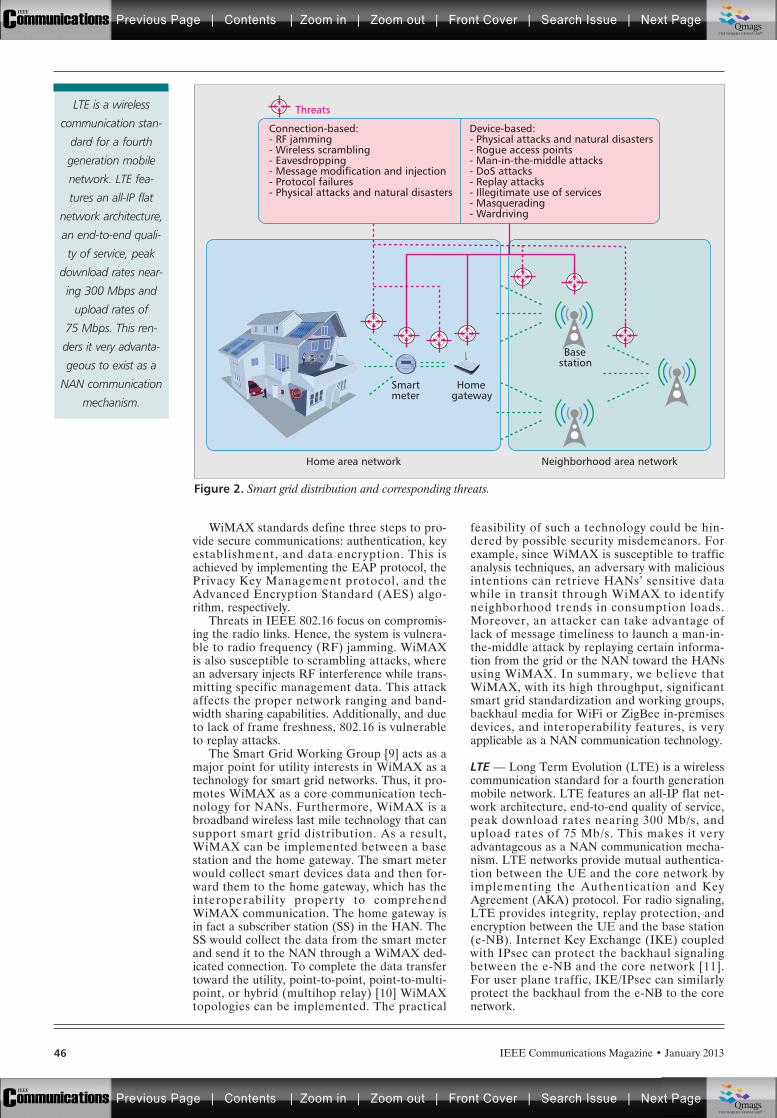
IEEE Communications Magazine • January 201346
WiMAX standards define three steps to pro-vide secure communications: authentication, keyestablishment, and data encryption. This isachieved by implementing the EAP protocol, thePrivacy Key Management protocol, and theAdvanced Encryption Standard (AES) algo-rithm, respectively.
Threats in IEEE 802.16 focus on compromis-ing the radio links. Hence, the system is vulnera-ble to radio frequency (RF) jamming. WiMAXis also susceptible to scrambling attacks, wherean adversary injects RF interference while trans-mitting specific management data. This attackaffects the proper network ranging and band-width sharing capabilities. Additionally, and dueto lack of frame freshness, 802.16 is vulnerableto replay attacks.
The Smart Grid Working Group [9] acts as amajor point for utility interests in WiMAX as atechnology for smart grid networks. Thus, it pro-motes WiMAX as a core communication tech-nology for NANs. Furthermore, WiMAX is abroadband wireless last mile technology that cansupport smart grid distribution. As a result,WiMAX can be implemented between a basestation and the home gateway. The smart meterwould collect smart devices data and then for-ward them to the home gateway, which has theinteroperability property to comprehendWiMAX communication. The home gateway isin fact a subscriber station (SS) in the HAN. TheSS would collect the data from the smart meterand send it to the NAN through a WiMAX ded-icated connection. To complete the data transfertoward the utility, point-to-point, point-to-multi-point, or hybrid (multihop relay) [10] WiMAXtopologies can be implemented. The practical
feasibility of such a technology could be hin-dered by possible security misdemeanors. Forexample, since WiMAX is susceptible to trafficanalysis techniques, an adversary with maliciousintentions can retrieve HANs’ sensitive datawhile in transit through WiMAX to identifyneighborhood trends in consumption loads.Moreover, an attacker can take advantage oflack of message timeliness to launch a man-in-the-middle attack by replaying certain informa-tion from the grid or the NAN toward the HANsusing WiMAX. In summary, we believe thatWiMAX, with its high throughput, significantsmart grid standardization and working groups,backhaul media for WiFi or ZigBee in-premisesdevices, and interoperability features, is veryapplicable as a NAN communication technology.
LTE — Long Term Evolution (LTE) is a wirelesscommunication standard for a fourth generationmobile network. LTE features an all-IP flat net-work architecture, end-to-end quality of service,peak download rates nearing 300 Mb/s, andupload rates of 75 Mb/s. This makes it veryadvantageous as a NAN communication mecha-nism. LTE networks provide mutual authentica-tion between the UE and the core network byimplementing the Authentication and KeyAgreement (AKA) protocol. For radio signaling,LTE provides integrity, replay protection, andencryption between the UE and the base station(e-NB). Internet Key Exchange (IKE) coupledwith IPsec can protect the backhaul signalingbetween the e-NB and the core network [11].For user plane traffic, IKE/IPsec can similarlyprotect the backhaul from the e-NB to the corenetwork.
Figure 2. Smart grid distribution and corresponding threats.
Basestation
Home area network Neighborhood area network
Smartmeter
Homegateway
Connection-based:- RF jamming- Wireless scrambling- Eavesdropping- Message modification and injection- Protocol failures- Physical attacks and natural disasters
Device-based:- Physical attacks and natural disasters- Rogue access points- Man-in-the-middle attacks- DoS attacks- Replay attacks- Illegitimate use of services- Masquerading- Wardriving
ThreatsLTE is a wireless
communication stan-
dard for a fourth
generation mobile
network. LTE fea-
tures an all-IP flat
network architecture,
an end-to-end quali-
ty of service, peak
download rates near-
ing 300 Mbps and
upload rates of
75 Mbps. This ren-
ders it very advanta-
geous to exist as a
NAN communication
mechanism.
Previous Page | Contents | Zoom in | Zoom out | Front Cover | Search Issue | Next PageIEEE
Communications qqM
Mq
qM
MqM
Qmags®THE WORLD’S NEWSSTAND
Previous Page | Contents | Zoom in | Zoom out | Front Cover | Search Issue | Next PageIEEE
Communications qqM
Mq
qM
MqM
Qmags®THE WORLD’S NEWSSTAND
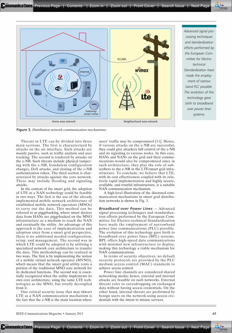
IEEE Communications Magazine • January 2013 47
Threats in LTE can be divided into threemain sections. The first is characterized byattacks on the air interface. Such attacks aremainly passive, such as traffic analysis and usertracking. The second is rendered by attacks onthe e-NB. Such threats include physical tamper-ing with the e-NB, fraudulent configurationchanges, DoS attacks, and cloning of the e-NBauthentication token. The third section is char-acterized by attacks against the core network.These may include flooding and signalingattacks.
In the context of the smart grid, the adoptionof LTE as a NAN technology could be feasiblein two ways. The first is the use of the alreadyimplemented mobile network architecture ofestablished mobile network operators (MNOs)to carry out the data. This method can bereferred to as piggybacking, where smart devicesdata from HANs are piggybacked on the MNOinfrastructure as a medium to reach the NANand eventually the utility. An advantage of thisapproach is the ease of implementation andadoption since from a smart grid perspective,there is no additional needed configuration,setup, and management. The second way inwhich LTE could be adopted is by utilizing aspecialized network core architecture to transferthe data. This methodology can be realized intwo ways. The first is by implementing the notionof a mobile virtual network operator (MVNO),which means that the smart grid utility rents aportion of the traditional MNO core network forits dedicated functions. The second way is essen-tially recognized when the utility implements itsown core architecture, using the same LTE tech-nologies as the MNO, but totally decoupledfrom it.
One critical security issue that may thwartLTE as a NAN communication mechanism isthe fact that the e-NB is the main location where
users’ traffic may be compromised [11]. Hence,if various attacks on the e-NB are successful,they could give attackers full control of the e-NBand its signaling to various nodes. In this case,HANs and NANs on the grid and their commu-nications would also be compromised since insuch architecture, they play the role of sub-scribers to the e-NB in the LTE/smart grid infra-structure. To conclude, we believe that LTE,with its cost effectiveness coupled with its rela-tively rapid implementation and highly secure,available, and trustful infrastructure, is a suitableNAN communication mechanism.
A high-level illustration of the discussed com-munication mechanisms in smart grid distribu-tion networks is shown in Fig. 3.
Broadband over Power Lines — Advancedsignal processing techniques and standardiza-tion efforts performed by the European Com-mittee for Electro-technical Standardizationhave made the employment of narrowbandpower line communications (PLC) possible.The evolution of this technology gave birth tobroadband over power lines (BPL) systems.BPL offers high-speed data communicationswith minimal new infrastructure to deploy,making this technology a viable mechanism forNAN communications.
In terms of security objectives, no defaultsecurity protocols are provided by the PLCmedium access control (MAC) standards toachieve access control.
Power line channels are considered sharednetworking media; hence, external and internalattacks are feasible on such networks. Externalthreats refer to eavesdropping on exchangeddata without having access credentials. On theother hand, internal threats are performed bybenign users on the network using access cre-dentials with the intent to misuse services.
Figure 3. Distribution network-communication mechanisms.
Neighborhood area networkHome area network
Internet
Gateway/smart meter
PLC/BPL
Femtocell
Advanced signal pro-
cessing techniques
and standardization
efforts performed by
the European Com-
mittee for Electro-
technical
Standardization have
made the employ-
ment of narrow
band PLC possible.
The evolution of this
technology gave
birth to broadband
over power lines
systems.
Previous Page | Contents | Zoom in | Zoom out | Front Cover | Search Issue | Next PageIEEE
Communications qqM
Mq
qM
MqM
Qmags®THE WORLD’S NEWSSTAND
Previous Page | Contents | Zoom in | Zoom out | Front Cover | Search Issue | Next PageIEEE
Communications qqM
Mq
qM
MqM
Qmags®THE WORLD’S NEWSSTAND
IEEE Communications Magazine • January 201348
PLC is a system that could potentially beused in NANs on the smart grid. Many stan-dards such as ITU G.Hn and IEEE P1901exist. We believe that a harmonized PLC stan-dard is possible by interoperating these sys-tems for a better implementation of the BPLfor smart grid. However, a major obstacle forsuch adoption is rendered by the fact thatelectric transformers block the transmissionfrequency of the BPL. This limits BPL to smallcoverage range within the low voltage grid(neighborhood) and requires other retransmis-sion mechanisms to allow the full data transferto the utility. From a security perspective, anattacker may be able to launch a man-in-the-middle attack by forging his/her identity, andstanding between a HAN and NAN communi-cation using BPL. Moreover, an adversary cantake advantage of the use of copper wiring inPLC to sniff the data. In summary, we consid-er that the BPL technology is unlikely toemerge as a leading broadband tool for smartgrid NANs, but instead wil l remain as anoption for NAN communication in the futuresmart grid.
In the subsequent section, we present a dis-cussion on the security framework needed toenable the above mentioned communicationtechniques to be employed for smart grid appli-cations.
SECURITY FRAMEWORK DISCUSSIONCurrently, there is a lack of adequate work insecurity schemes and frameworks for AMI, espe-cially in authentication methods. To the best ofour knowledge, there are very limited realisticapproaches [12] to solving the scalability prob-lem of smart meter authentications, regardless ofwhich communication technology is utilized.
Cryptographic methods such as digital certifi-cates require a momentous overhead in compari-son with data packet processing. In addition,cryptographic operations contribute to extensivecomputational cost. In the context of the smartgrid, a smart meter routinely sends a meterreading message within a period of 500 ms [13].Nowadays, for PKI-based schemes, generating adigital signature every 500 ms is not an issueusing a commodity computer. Conversely, for alegacy power grid that interconnects numerousbuildings, the number of meter reading messagesthat require verification by the NAN gatewaymight be noticeably larger than its capacity.Although digital signing and message verificationcan certainly achieve secure communications, webelieve that conventional cryptographic opera-tions make such security frameworks neitherscalable nor affordable.
We assert that the security frameworkrequired to enable the discussed communicationtechniques to be employed for smart grid appli-cations should be based on the following designobjectives:• Device authentication: The identity and
legality of the smart meters and their asso-ciated consumers should be verified asreceiving the proper utility services.
• Data confidentiality: The smart meter read-ings and management control messages
should be confidential to conceal both con-sumers’ and utilities’ privacy.
• Message integrity: The smart grid should beable to verify that any meter messages aredelivered unaltered in an AMI.
• Prevent potential cyber attacks: Smartmeters should be guaranteed to obtainsecure communication with the AMI net-work, even if an individual smart meter iscompromised.
• Facilitating communication overhead: Theproposed framework should be efficient interms of communication overhead and pro-cessing latency.
CONCLUSIONIn this article, we have investigated applicablecommunication mechanisms that could be adopt-ed on smart grid distribution networks. To tacklethe cyber security of such infrastructures, we havepinpointed their security objectives and threats.We have further elaborated on their practical fea-sibility in terms of their technical implementation,possible obstacles, and core security issues, andattacks on smart grid HANs and NANs.
We believe it is critical to continue discussing,designing, and implementing solutions for suchmechanisms for the purpose of enhancing thecyber security of the future electric grid andhence accomplishing consumers’ utmost trust insuch a major grid transformation.
REFERENCES[1] A. R. Metke and R. L. Ekl. “Security Technology for
Smart Grid Networks,” IEEE Trans. Smart Grid, vol. 1,no. 1, June 2010, pp. 99–107.
[2] R. Yu et al., “Cognitive Radio Based Hierarchical Com-munications Infrastructure for Smart Grid,” IEEE Net-work, vol. 25, no. 5, Sept.–Oct. 2011, pp. 6–14.
[3] J. Naruchitparames, M. H. Gunes, and C. Y. Evrenosoglu,“Secure Communications in the Smart Grid,” 2011 IEEEConsumer Commun. and Networking Conf., Jan. 2011,pp. 1171–75.
[4] U.S. Dept. of Energy, AMI System Security Require-ments, 2008, http://energy.gov/sites/prod/files/oeprod/DocumentsandMedia/14-AMI System Security Require-ments updated.pdf.
[5] A. Mishra et al., “Security Issues in IEEE 802.11 WirelessLocal Area Networks: A Survey,” Wireless Commun. andMobile Computing, vol. 4, no. 8, 2004, pp. 821–33.
[6] H. Haverinen and J. Salowey, Eds., “Extensible Authenti-cation Protocol Method for Global System for MobileCommunications (GSM) Subscriber Identity Modules(EAP-SIM)),” 2006, http://merlot.tools.ietf.org/html/rfc4186.
[7] V. Chandrasekhar, J. Andrews, and A. Gatherer, “Fem-tocell Networks: A Survey,” IEEE Commun. Mag., vol.46, no. 9, Sept. 2008, pp. 59–67.
[8] J. Zhang and G. de la Roche, Front Matter, (Wiley,2009), pp. i–xxix.
[9] The WiMAX Forum, Technical Activities and WorkingGroups), 2011, http://www.wimaxforum.org/about/technical-activities-and-working-groups.
[10] NIST, “Guide to Securing WiMAX Wireless Communi-cations: Recommendations of the National Institute ofStandards and Technology,” 2010, http://csrc.nist.gov/publications/nistpubs/800-127/sp800-127.pdf.
[11] R. Blom et al., Security in the Evolved Packet System,2011.
[12] Y. Yan, Y. Qian, and H. Sharif, “A Secure and ReliableIn-Network Collaborative Communication Scheme forAdvanced Metering Infrastructure in Smart Grid,” IEEEWCNC ’11, Mar. 2011, pp. 909–14.
[13] R. E. Castellanos and P. Millan. Design of A WirelessCommunications Network for Advanced Metering Infra-structure in A Utility in Colombia,” 2012 IEEE Colom-bian Commun. Conf. May 2012, pp. 1–6.
We believe it is criti-
cal to continue dis-
cussing, designing,
and implementing
solutions for such
mechanisms for the
purpose of enhanc-
ing the cyber security
of the future electric
grid and hence
accomplishing con-
sumers’ utmost trust
in such a major gird
transformation.
Previous Page | Contents | Zoom in | Zoom out | Front Cover | Search Issue | Next PageIEEE
Communications qqM
Mq
qM
MqM
Qmags®THE WORLD’S NEWSSTAND
Previous Page | Contents | Zoom in | Zoom out | Front Cover | Search Issue | Next PageIEEE
Communications qqM
Mq
qM
MqM
Qmags®THE WORLD’S NEWSSTAND
________________________________________
____
_____________________
IEEE Communications Magazine • January 2013 49
BIOGRAPHIESELIAS BOU-HARB ([email protected]) is a networksecurity researcher pursuing his Ph.D. in computer sci-ence at Concordia University, Montreal, Canada. Previ-ously, he completed his M.A.Sc. degree in informationsystems security at the Concordia Institute for Informa-tion Systems Engineering. He is also a member of theNational Cyber Forensic and Training Alliance (NCFTA),Canada. His research interests focus on the broad areaof cyber security, including operational cyber securityfor critical infrastructure, LTE 4G mobile network securi-ty, VoIP attacks and countermeasures, and cyber scan-ning campaigns.
CLAUDE FACHKHA ([email protected]) is a securityresearcher at NCFTA Canada. In 2008, he received his Bach-elor of Engineering in computer and communication fromNotre Dame University. Two years later, he received hisMaster of Engineering in information systems security fromConcordia University, where he is currently pursuing hisPh.D. degree in the Faculty of Electrical and ComputerEngineering. His current research interests are in the areasof network traffic analysis and large-scale cyber threats
MAKAN POURZANDI ([email protected]) is aresearcher at Ericsson, Canada. He received his Ph.D.degree in computer science from the University of Lyon,France, and his M.Sc. degree in computer science fromÉcole Normale Supérieure de Lyon, France. His currentresearch interests include security, cloud computing, soft-ware security engineering, cluster computing, and compo-nent-based methods for secure software development.
MOURAD DEBBABI ([email protected]) holds Ph.D.and M.Sc. degrees in computer science from Paris-XI OrsayUniversity, France. He has published more than 70 research
papers in international journals and conferences on com-puter security, formal semantics, mobile and embeddedplatforms, Java technology security and acceleration, cryp-tographic protocol specification, design, and analysis, mali-cious code detection, programming languages, typetheory, and specification and verification of safety-criticalsystems. He is a full professor and the director of the Con-cordia Institute for Information Systems Engineering, Con-cordia University, Montreal, Quebec, Canada. He has servedas a senior scientist at the Panasonic Information and Net-work Technologies Laboratory, Princeton, New Jersey; asso-ciate professor at the Computer Science Department ofLaval University, Quebec, Canada; senior scientist at Gener-al Electric Research Center, New York; research associate atthe Computer Science Department of Stanford University,Palo Alto, California; and permanent researcher at the BullCorporate Research Center, Paris, France.
CHADI ASSI ([email protected]) received his B.Eng.degree from the Lebanese University, Beirut, Lebanon, in1997 and his Ph.D. degree from the City University of NewYork (CUNY) in April 2003. He is currently an associateprofessor with the Concordia Institute for Information Sys-tems Engineering, Concordia University. Before joiningConcordia University in August 2003 as an assistant pro-fessor, he was a visiting scientist for one year with NokiaResearch Center, Boston, Massachusetts, where he workedon quality of service in passive optical access networks. Heis an Associate Editor for Wiley’s Wireless Communicationsand Mobile Computing. His research interests include opti-cal networks, multihop wireless and ad hoc networks, andsecurity. He received the prestigious Mina Rees Disserta-tion Award from CUNY in August 2002 for his research onwavelength-division multiplexing optical networks. He ison the Editorial Board of IEEE Communications Surveys &Tutorials and serves as an Associate Editor for IEEE Com-munications Letters.
Previous Page | Contents | Zoom in | Zoom out | Front Cover | Search Issue | Next PageIEEE
Communications qqM
Mq
qM
MqM
Qmags®THE WORLD’S NEWSSTAND
Previous Page | Contents | Zoom in | Zoom out | Front Cover | Search Issue | Next PageIEEE
Communications qqM
Mq
qM
MqM
Qmags®THE WORLD’S NEWSSTAND
_____________
_______________
__________________
_______________
_______________
IEEE Communications Magazine • January 201350 0163-6804/13/$25.00 © 2013 IEEE
INTRODUCTION
Smart grid may be conceptualized in distinctways, but they basically come from traditionalelectric power grids through the addition of a setof features aiming for reliability, safety, powerefficiency, and sustainability. Sustainable devel-opment allows the current population to meettheir needs without endangering the ability offuture generations to meet their own needs[1–3]. Given such a definition, sustainable pro-duction of electricity refers to a gradual increasein the production capacity of the power gridswhile keeping the waste output at levels that canbe eliminated through natural processes, keepingthe human health risk at the lowest possiblelevel and producing electricity using raw materi-als by using environmental resources at the low-est possible level.
An opportunity that comes with the develop-ment of smart grid is the distributed generationof electricity. This scenario allows the existenceof thousands of local suppliers, including smallgenerators, which can sell some of their produc-tion to the energy distribution network (in Brazil,experimental projects for end users’ generationforesee the use of solar panels in their residencesin the cities of Parintis/AM and Buzios/RJ). Theadoption of distributed generation is directlyassociated with sustainability, since small suppli-ers can rely on “renewable” energy sources suchas sunlight, wind, and rain, which are consideredmore environmentally friendly than traditionalcentralized energy sources. Another advantage isrelated to the grid costs since the generation iscloser to the end users, reducing costs introducedby centralized power plants, and long transmis-sion and distribution lines.
This article aims to provide a framework forfootprinting the energy provided to the smartgrid by each supplier and its respective sustain-ability index, associated with the supplier’s pro-duction method. Given a certain area composedof a set of suppliers and consumers, we candetermine the compound sustainability index byaveraging the indices of all suppliers, weightedby the amount of power provided to the grid byeach supplier. This compound index should becalculated periodically to account for variationsin energy production. Since smart grid may alsoface cyber security attacks, which may compro-mise the framework [4], we also utilize crypto-graphic schemes to guarantee informationsecurity in such a way that the label cannot befaked or altered in an unnoticed manner, andalso that sensitive information, such as theamount of power provided to the grid, cannot beaccessed by unauthorized parties.
More specifically, we propose two energy foot-printing architectures, which calculate the com-pound sustainability index and implement securitymeasures in different ways. One architecture doesthese tasks in a distributed manner, and the otheruses a structure of hierarchical clusters.
ABSTRACT
According to the World Commission on Envi-ronment and Development, sustainable develop-ment allows the population to meet the needs ofthe present while preserving the environment forfuture generations to meet their own needs. Theintegration of renewable, low-polluting, dis-tributed energy resources in the power grid is animportant step toward sustainable development.In this article , we propose two architectures,clustered and distributed, for labeling the energysource provided to the smart grid. A label con-tains the energy amount provided to the smartgrid and its sustainability index. Labels frommultiple energy sources can be compounded anddisplayed to end users accordingly with thearchitecture used to inform how sustainable theproduction process of the energy being renderedto the consumers in a given area is. The compre-hension of how sustainable the energy produc-tion is can entail a change of mind in consumersand energy distributors. We also evaluate botharchitectures according to the the sustainabilityindex accuracy and generated network traffic.
CYBER SECURITY FOR SMART GRIDCOMMUNICATIONS: PART 2
Davidson Boccardo, Leonardo Ribeiro, Rodrigo Canaan, Luiz Carmo, Luci Pirmez, Raphael Machado,
Charles Prado, and Tiago Nascimento, National Institute of Metrology, Quality and Technology
Energy Footprint Framework: A Pathway Toward Smart GridSustainability
Previous Page | Contents | Zoom in | Zoom out | Front Cover | Search Issue | Next PageIEEE
Communications qqM
Mq
qM
MqM
Qmags®THE WORLD’S NEWSSTAND
Previous Page | Contents | Zoom in | Zoom out | Front Cover | Search Issue | Next PageIEEE
Communications qqM
Mq
qM
MqM
Qmags®THE WORLD’S NEWSSTAND
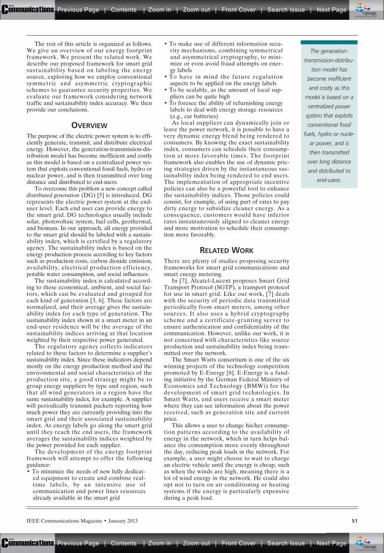
IEEE Communications Magazine • January 2013 51
The rest of this article is organized as follows.We give an overview of our energy footprintframework. We present the related work. Wedescribe our proposed framework for smart gridsustainability based on labeling the energysource, exploring how we employ conventionalsymmetric and asymmetric cryptographicschemes to guarantee security properties. Weevaluate our framework considering networktraffic and sustainability index accuracy. We thenprovide our conclusions.
OVERVIEWThe purpose of the electric power system is to effi-ciently generate, transmit, and distribute electricalenergy. However, the generation-transmission-dis-tribution model has become inefficient and costlyas this model is based on a centralized power sys-tem that exploits conventional fossil fuels, hydro ornuclear power, and is then transmitted over longdistance and distributed to end-users.
To overcome this problem a new concept calleddistributed generation (DG) [5] is introduced. DGrepresents the electric power system at the end-user level. Each end user can provide energy tothe smart grid. DG technologies usually includesolar, photovoltaic system, fuel cells, geothermal,and biomass. In our approach, all energy providedto the smart grid should be labeled with a sustain-ability index, which is certified by a regulatoryagency. The sustainability index is based on theenergy production process according to key factorssuch as production costs, carbon dioxide emission,availability, electrical production efficiency,potable water consumption, and social influences.
The sustainability index is calculated accord-ing to these economical, ambient, and social fac-tors, which can be evaluated and grouped foreach kind of generation [3, 6]. These factors arenormalized, and their average gives the sustain-ability index for each type of generation. Thesustainability index shown at a smart meter in anend-user residence will be the average of thesustainability indices arriving at that locationweighted by their respective power generated.
The regulatory agency collects indicatorsrelated to these factors to determine a supplier’ssustainability index. Since these indicators dependmostly on the energy production method and theenvironmental and social characteristics of theproduction site, a good strategy might be togroup energy suppliers by type and region, suchthat all wind generators in a region have thesame sustainability index, for example. A supplierwill periodically transmit packets reporting howmuch power they are currently providing into thesmart grid and their associated sustainabilityindex. As energy labels go along the smart griduntil they reach the end users, the frameworkaverages the sustainability indices weighted bythe power provided for each supplier.
The development of the energy footprintframework will attempt to offer the followingguidance:• To minimize the needs of new fully dedicat-
ed equipment to create and combine real-time labels, by an intensive use ofcommunication and power lines resourcesalready available in the smart grid
• To make use of different information secu-rity mechanisms, combining symmetricaland asymmetrical cryptography, to mini-mize or even avoid fraud attempts on ener-gy labels
• To have in mind the future regulationaspects to be applied on the energy labels
• To be scalable, as the amount of local sup-pliers can be quite high
• To foresee the ability of refurnishing energylabels to deal with energy storage resources(e.g., car batteries)As local suppliers can dynamically join or
leave the power network, it is possible to have avery dynamic energy blend being rendered toconsumers. By knowing the exact sustainabilityindex, consumers can schedule their consump-tion at more favorable times. The footprintframework also enables the use of dynamic pric-ing strategies driven by the instantaneous sus-tainability index being rendered to end users.The implementation of appropriate incentivepolicies can also be a powerful tool to enhancethe sustainability indices. Those policies couldconsist, for example, of using part of rates to paydirty energy to subsidize cleaner energy. As aconsequence, customers would have inferiorrates instantaneously aligned to cleaner energyand more motivation to schedule their consump-tion more favorably.
RELATED WORKThere are plenty of studies proposing securityframeworks for smart grid communications andsmart energy metering.
In [7], Alcatel-Lucent proposes Smart GridTransport Protocol (SGTP), a transport protocolfor use in smart grid. Like our work, [7] dealswith the security of periodic data transmittedperiodically from smart meters, among othersources. It also uses a hybrid cryptographyscheme and a certificate-granting server toensure authentication and confidentiality of thecommunication. However, unlike our work, it isnot concerned with characteristics like sourceproduction and sustainability index being trans-mitted over the network.
The Smart Watts consortium is one of the sixwinning projects of the technology competitionpromoted by E-Energy [8]. E-Energy is a fund-ing initiative by the German Federal Ministry ofEconomics and Technology (BMWi) for thedevelopment of smart grid technologies. InSmart Watts, end users receive a smart meterwhere they can see information about the powerreceived, such as generation site and currentprice.
This allows a user to change his/her consump-tion patterns according to the availability ofenergy in the network, which in turn helps bal-ance the consumption more evenly throughoutthe day, reducing peak loads in the network. Forexample, a user might choose to wait to chargean electric vehicle until the energy is cheap, suchas when the winds are high, meaning there is alot of wind energy in the network. He could alsoopt not to turn on air conditioning or heatingsystems if the energy is particularly expensiveduring a peak load.
The generation-
transmission-distribu-
tion model has
become inefficient
and costly as this
model is based on a
centralized power
system that exploits
conventional fossil
fuels, hydro or nucle-
ar power, and is
then transmitted
over long distance
and distributed to
end-users.
Previous Page | Contents | Zoom in | Zoom out | Front Cover | Search Issue | Next PageIEEE
Communications qqM
Mq
qM
MqM
Qmags®THE WORLD’S NEWSSTAND
Previous Page | Contents | Zoom in | Zoom out | Front Cover | Search Issue | Next PageIEEE
Communications qqM
Mq
qM
MqM
Qmags®THE WORLD’S NEWSSTAND
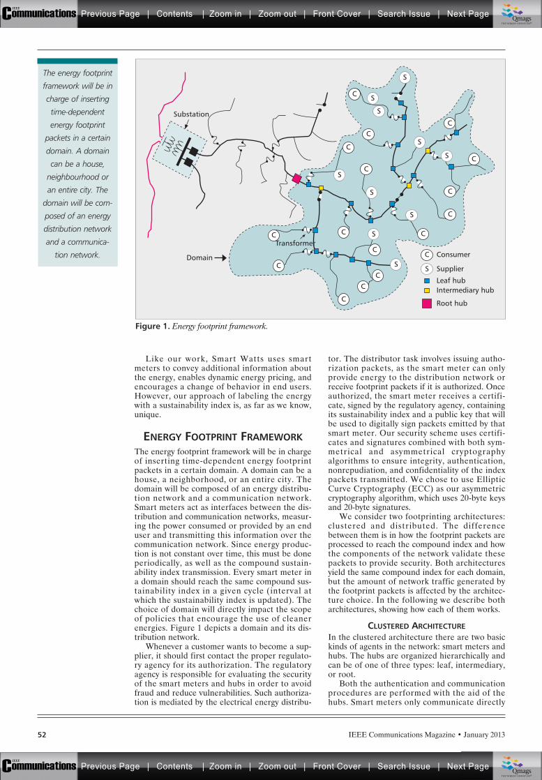
IEEE Communications Magazine • January 201352
Like our work, Smart Watts uses smartmeters to convey additional information aboutthe energy, enables dynamic energy pricing, andencourages a change of behavior in end users.However, our approach of labeling the energywith a sustainability index is, as far as we know,unique.
ENERGY FOOTPRINT FRAMEWORKThe energy footprint framework will be in chargeof inserting time-dependent energy footprintpackets in a certain domain. A domain can be ahouse, a neighborhood, or an entire city. Thedomain will be composed of an energy distribu-tion network and a communication network.Smart meters act as interfaces between the dis-tribution and communication networks, measur-ing the power consumed or provided by an enduser and transmitting this information over thecommunication network. Since energy produc-tion is not constant over time, this must be doneperiodically, as well as the compound sustain-ability index transmission. Every smart meter ina domain should reach the same compound sus-tainability index in a given cycle (interval atwhich the sustainability index is updated). Thechoice of domain will directly impact the scopeof policies that encourage the use of cleanerenergies. Figure 1 depicts a domain and its dis-tribution network.
Whenever a customer wants to become a sup-plier, it should first contact the proper regulato-ry agency for its authorization. The regulatoryagency is responsible for evaluating the securityof the smart meters and hubs in order to avoidfraud and reduce vulnerabilities. Such authoriza-tion is mediated by the electrical energy distribu-
tor. The distributor task involves issuing autho-rization packets, as the smart meter can onlyprovide energy to the distribution network orreceive footprint packets if it is authorized. Onceauthorized, the smart meter receives a certifi-cate, signed by the regulatory agency, containingits sustainability index and a public key that willbe used to digitally sign packets emitted by thatsmart meter. Our security scheme uses certifi-cates and signatures combined with both sym-metrical and asymmetrical cryptographyalgorithms to ensure integrity, authentication,nonrepudiation, and confidentiality of the indexpackets transmitted. We chose to use EllipticCurve Cryptography (ECC) as our asymmetriccryptography algorithm, which uses 20-byte keysand 20-byte signatures.
We consider two footprinting architectures:clustered and distributed. The differencebetween them is in how the footprint packets areprocessed to reach the compound index and howthe components of the network validate thesepackets to provide security. Both architecturesyield the same compound index for each domain,but the amount of network traffic generated bythe footprint packets is affected by the architec-ture choice. In the following we describe botharchitectures, showing how each of them works.
CLUSTERED ARCHITECTUREIn the clustered architecture there are two basickinds of agents in the network: smart meters andhubs. The hubs are organized hierarchically andcan be of one of three types: leaf, intermediary,or root.
Both the authentication and communicationprocedures are performed with the aid of thehubs. Smart meters only communicate directly
Figure 1. Energy footprint framework.
Substation
Domain
S
C
CC
C
C
C
C
C
C
C
C
CC
C
C
CTransformer
C
S
S
S
S
S
S
S
S
Consumer
Supplier
Leaf hubIntermediary hub
Root hub
S
S
The energy footprint
framework will be in
charge of inserting
time-dependent
energy footprint
packets in a certain
domain. A domain
can be a house,
neighbourhood or
an entire city. The
domain will be com-
posed of an energy
distribution network
and a communica-
tion network.
Previous Page | Contents | Zoom in | Zoom out | Front Cover | Search Issue | Next PageIEEE
Communications qqM
Mq
qM
MqM
Qmags®THE WORLD’S NEWSSTAND
Previous Page | Contents | Zoom in | Zoom out | Front Cover | Search Issue | Next PageIEEE
Communications qqM
Mq
qM
MqM
Qmags®THE WORLD’S NEWSSTAND
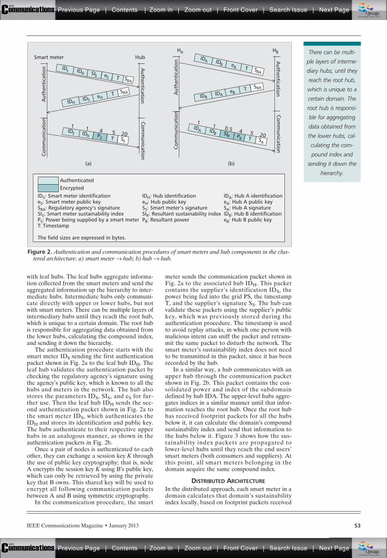
IEEE Communications Magazine • January 2013 53
with leaf hubs. The leaf hubs aggregate informa-tion collected from the smart meters and send theaggregated information up the hierarchy to inter-mediate hubs. Intermediate hubs only communi-cate directly with upper or lower hubs, but notwith smart meters. There can be multiple layers ofintermediary hubs until they reach the root hub,which is unique to a certain domain. The root hubis responsible for aggregating data obtained fromthe lower hubs, calculating the compound index,and sending it down the hierarchy.
The authentication procedure starts with thesmart meter IDS sending the first authenticationpacket shown in Fig. 2a to the leaf hub IDH. Theleaf hub validates the authentication packet bychecking the regulatory agency’s signature usingthe agency’s public key, which is known to all thehubs and meters in the network. The hub alsostores the parameters IDS, SIS, and eS for fur-ther use. Then the leaf hub IDH sends the sec-ond authentication packet shown in Fig. 2a tothe smart meter IDS, which authenticates theIDH and stores its identification and public key.The hubs authenticate to their respective upperhubs in an analogous manner, as shown in theauthentication packets in Fig. 2b.
Once a pair of nodes is authenticated to eachother, they can exchange a session key K throughthe use of public key cryptography; that is, nodeA encrypts the session key K using B’s public key,which can only be retrieved by using the privatekey that B owns. This shared key will be used toencrypt all following communication packetsbetween A and B using symmetric cryptography.
In the communication procedure, the smart
meter sends the communication packet shown inFig. 2a to the associated hub IDH. This packetcontains the supplier’s identification IDS, thepower being fed into the grid PS, the timestampT, and the supplier’s signature SS. The hub canvalidate these packets using the supplier’s publickey, which was previously stored during theauthentication procedure. The timestamp is usedto avoid replay attacks, in which one person withmalicious intent can sniff the packet and retrans-mit the same packet to disturb the network. Thesmart meter’s sustainability index does not needto be transmitted in this packet, since it has beenrecorded by the hub.
In a similar way, a hub communicates with anupper hub through the communication packetshown in Fig. 2b. This packet contains the con-solidated power and index of the subdomaindefined by hub IDA. The upper-level hubs aggre-gates indices in a similar manner until that infor-mation reaches the root hub. Once the root hubhas received footprint packets for all the hubsbelow it, it can calculate the domain’s compoundsustainability index and send that information tothe hubs below it. Figure 3 shows how the sus-tainability index packets are propagated tolower-level hubs until they reach the end users’smart meters (both consumers and suppliers). Atthis point, all smart meters belonging in thedomain acquire the same compound index.
DISTRIBUTED ARCHITECTUREIn the distributed approach, each smart meter in adomain calculates that domain’s sustainabilityindex locally, based on footprint packets received
Figure 2. Authentication and communication procedures of smart meters and hub components in the clus-tered architecture: a) smart meter Æ hub; b) hub Æ hub.
(a)
Authenticated
Aut
hent
icat
ion
Com
mun
icat
ion
HubSmart meter
Authentication
Com
munication
IDS
1IDH
1PS
4T5
SS
20
IDs IDH SIS eS T SRA
IDHIDS
eHT SRA
(b)
Aut
hent
icat
ion
Com
mun
icat
ion
HBHA
Authentication
Com
munication
IDA
1
IDB
1SIR0.5
PR
4T5
SA
20
IDA IDB eA T SRA
IDBIDA
eBT SRA
EncryptedIDS: Smart meter identificationeS: Smart meter public keySRA: Regulatory agency’s signatureSIS: Smart meter sustainability indexPS: Power being supplied by a smart meterT: Timestamp
The field sizes are expressed in bytes.
IDH: Hub identificationeH: Hub public keySS: Smart meter’s signatureSIR: Resultant sustainability indexPR: Resultant power
IDA: Hub A identificationeA: Hub A public keySA: Hub A signatureIDB: Hub B identificationeB: Hub B public key
There can be multi-
ple layers of interme-
diary hubs, until they
reach the root hub,
which is unique to a
certain domain. The
root hub is responsi-
ble for aggregating
data obtained from
the lower hubs, cal-
culating the com-
pound index and
sending it down the
hierarchy.
Previous Page | Contents | Zoom in | Zoom out | Front Cover | Search Issue | Next PageIEEE
Communications qqM
Mq
qM
MqM
Qmags®THE WORLD’S NEWSSTAND
Previous Page | Contents | Zoom in | Zoom out | Front Cover | Search Issue | Next PageIEEE
Communications qqM
Mq
qM
MqM
Qmags®THE WORLD’S NEWSSTAND
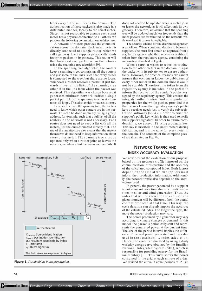
IEEE Communications Magazine • January 201354
from every other supplier in the domain. Theauthentication of these packets is also made in adistributed manner, locally to the smart meter.Since it is not reasonable to assume each smartmeter has a physical connection to all others, wepropose the following communication architecture.
A network of routers provides the communi-cation across the domain. Each smart meter isdirectly connected to a single router, which wecall a gateway. Each supplier periodically sendsfootprint packets to its gateway. This router willthen broadcast each packet across the networkusing the spanning tree algorithm [9].
In the spanning tree algorithm, the routerskeep a spanning tree, comprising all the routersand just some of the links, such that every routeris connected to the tree, but there are no loops.Whenever a router receives a packet, it just for-wards it over all its links of the spanning treeother than the link from which the packet wasreceived. This algorithm was chosen because itgenerates minimum network traffic: a singlepacket per link of the spanning tree, as it elimi-nates all loops. This also avoids broadcast storms.
In order to create the spanning tree, the routersneed to know which other routers are in the net-work. This can be done implicitly, using a groupaddress, for example, such that a full list of all therouters in the network is not necessary. Eachrouter does not need to keep a list with all themeters, just the ones connected directly to it. Theuse of this architecture also means that the metersthemselves do not need to keep information aboutevery other meter. The spanning tree must beupdated only when a router joins or leaves thenetwork, or when a link between routers fails. It
does not need to be updated when a meter joinsor leaves the network, as it will affect only its owngateway. Therefore, we assume that the spanningtree will be updated much less frequently than theindex packets are transmitted, so the network traf-fic overhead it causes is negligible.
The security scheme for the distributed approachis as follows. When a customer decides to become asupplier, s/he must first obtain an approval from aregulatory agency. S/he then receives a certificatetoken from the regulatory agency, containing theinformation described in Fig. 4a.
When a supplier wishes to report its produc-tion to the other meters in the domain, it signsthe packet with its private key to ensure authen-ticity. However, for practical reasons, we cannotassume that each meter knows the public keys ofevery other meter in the domain since it wouldnot be scalable. Therefore, the token from theregulatory agency is included in the packet toinform the receiver of the sender’s public key,signed by the regulatory agency. This ensures theintegrity, authentication, and nonrepudiationproperties for the whole packet, provided thatthe receiver knows the regulatory agency’s publickey: a receiver needs just to verify the sub-regis-tration authority (SRA) in order to trust thesupplier’s public key, which is then used to verifythe supplier’s signature. In order to ensure confi-dentiality, we encrypt PS using a domain key.This key is inserted in the smart meters duringfabrication, and it is the same for every meter inthe domain. The contents of the complete pack-et are illustrated in Fig. 4b.
NETWORK TRAFFIC ANDINDEX ACCURACY EVALUATION
We now present the evaluation of our proposalbased on the network traffic imposed on thecommunication infrastructure and the accuracyof the calculated compound index. Both factorsdepend on the rate at which suppliers mustinform their production information. Additional-ly, the network traffic also depends on the archi-tecture used.
In general, the power generated by a supplieris not constant over time due to climatic varia-tions in solar and wind generation. Thus, theindex that will be shown to the end user at agiven moment will be different from the actualcontent produced at that time. This way, thecycle duration can directly impact the accuracyof the calculated index. The longer the cycle, themore the power production may vary.
The power produced by a generator may varyaccording to climate changes or demand. In thismodel, the packet is periodically sent and repre-sents the generated power at the current time.The size of the period interval implies the differ-ence of the real power generated and the valueused in the sustainability index calculation.Hence, the error is estimated by using a dailyworkday energy curve obtained by the BrazilianNational Integrated System (SIN), which isresponsible for providing energy for the Brazil-ian territory [10]. This curve shows the powerconsumed in the grid at each minute of a day.We divided the curve in equal periods of 15, 30,Figure 3. Sustainability index propagation.
IDSource
1IDDest
1SIR0.5
TSI package:
Authenticated
IDSource: Source identificationIDDest: Destination identificationSIR: Resultant sustainability indexT: TimestampSH: Hub’s signature
The field sizes are expressed in bytes.
5SH
20
Com
munication
Com
mun
icat
ion
SI package
...
...
Smart meter
SI package
SI package
SI package
Leaf hubIntermediary hubRoot hub
Previous Page | Contents | Zoom in | Zoom out | Front Cover | Search Issue | Next PageIEEE
Communications qqM
Mq
qM
MqM
Qmags®THE WORLD’S NEWSSTAND
Previous Page | Contents | Zoom in | Zoom out | Front Cover | Search Issue | Next PageIEEE
Communications qqM
Mq
qM
MqM
Qmags®THE WORLD’S NEWSSTAND
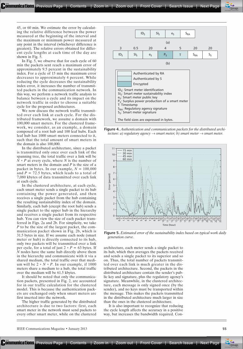
IEEE Communications Magazine • January 2013 55
45, or 60 min. We estimate the error by calculat-ing the relative difference between the powermeasured at the beginning of the interval andthe maximum or minimum power measured atany point in the interval (whichever difference isgreatest). The relative errors obtained for differ-ent cycle lengths at each time of the day areshown in Fig. 5.
In Fig. 5, we observe that for each cycle of 60min the packets sent reach a maximum error ofapproximately 9.5 percent in the sustainabilityindex. For a cycle of 15 min the maximum errordecreases to approximately 4 percent. Whilereducing the cycle decreases the sustainabilityindex error, it increases the number of transmit-ted packets in the communication network. Inthis way, we perform a network traffic analysis tobalance between a cycle and its impact on thenetwork traffic in order to choose a suitablecycle for the proposed architectures.
We now discuss the network traffic transmit-ted over each link at each cycle. For the dis-tributed framework, we assume a domain with100,000 smart meters. For the clustered frame-work, we consider, as an example, a domaincomposed of a root hub and 100 leaf hubs. Eachleaf hub has 1000 smart meters connected to it,such that the total amount of smart meters inthe domain is also 100,000.
In the distributed architecture, since a packetis transmitted only once over each link of thespanning tree, the total traffic over a link will beN * P at every cycle, where N is the number ofsmart meters in the domain and P is the size of apacket in bytes. In our example, N = 100,000and P = 72.5 bytes, which leads to a total of7,080 kbytes of data transmitted over each linkat each cycle.
In the clustered architecture, at each cycle,each smart meter sends a single packet to its hubcontaining the power generated, and thenreceives a single packet from the hub containingthe resulting sustainability index of the domain.Similarly, each hub (except the root hub) sends asingle packet to the upper hub in the hierarchyand receives a single packet from its respectivehub. You can view the size of each packet trans-ferred in Figs. 2a and 2b. For simplicity, we takeP to be the size of the largest packet, the com-munication packet shown in Fig. 2b, which is31.5 bytes in size. If we assume each node (smartmeter or hub) is directly connected to its hub,only two packets will be transmitted over a linkper cycle, for a total of just 2 * P = 63 bytes. IfN nodes have the same hub directly above themin the hierarchy and communicate with it via ashared medium, the total traffic over that medi-um will be 2 * N * P. In our example, if 1000meters share a medium to a hub, the total trafficover the medium will be 61.5 kbytes.
It should be noted that only the communica-tion packets, presented in Fig. 2, are accountedfor in our traffic calculation for the clusteredmodel. This is because the authentication pack-ets are exchanged only when smart meters arefirst inserted into the network.
The higher traffic generated by the distributedarchitecture is due to two factors: first, eachsmart meter in the network must send packets toevery other smart meter, while on the clustered
architecture, each meter sends a single packet toits hub, which then averages the packets receivedand sends a single packet to its superior and soon. Thus, the total number of packets transmit-ted over each link is much greater in the dis-tributed architecture. Second, the packets in thedistributed architecture contain the sender’s pub-lic key and signature, plus the regulatory agency’ssignature. Meanwhile, in the clustered architec-ture, each message is only signed once (by thesender), and no keys must be transported withinthe message. This makes the packets transmittedin the distributed architecture much larger in sizethan the ones in the clustered architecture.
It is also important to recognize that reducingthe cycle length affects the accuracy in a positiveway, but increases the bandwidth required. Con-
Figure 4. Authentication and communication packets for the distributed archi-tecture: a) regulatory agency Æ smart meter; b) smart meter Æ smart meter.
IDS: Smart meter identificationSIS: Smart meter sustainability indexeS: Smart meter public keyPS: Surplus power production of a smart meterT: TimestampSRA: Regulatory agency signatureSS: Smart meter signature
The field sizes are expressed in bytes.
Authenticated by RA
IDS SIS eS
(a)
(b)
SRA
IDS SIS eS PS T SRA SS
3 0.5 20 4 5 20 20
Authenticated by S
Encrypted
Figure 5. Estimated error of the sustainability index based on typical work dailygeneration curve.
Time (hour)
1
Erro
r (p
erce
nt)
0
2
3
4
5
6
7
8
9
10
11
00.
5 11.
5 22.
5 33.
5 44.
5 55.
5 66.
5 77.
5 88.
5 99.
510
10.5 11
11.5 12
12.5 13
13.5 14
14.5 15
15.5 16
16.5 17
17.5 18
18.5 19
19.5 20
20.5 21
21.5 22
22.5 23
23.5
15 min30 min45 min60 min
Previous Page | Contents | Zoom in | Zoom out | Front Cover | Search Issue | Next PageIEEE
Communications qqM
Mq
qM
MqM
Qmags®THE WORLD’S NEWSSTAND
Previous Page | Contents | Zoom in | Zoom out | Front Cover | Search Issue | Next PageIEEE
Communications qqM
Mq
qM
MqM
Qmags®THE WORLD’S NEWSSTAND
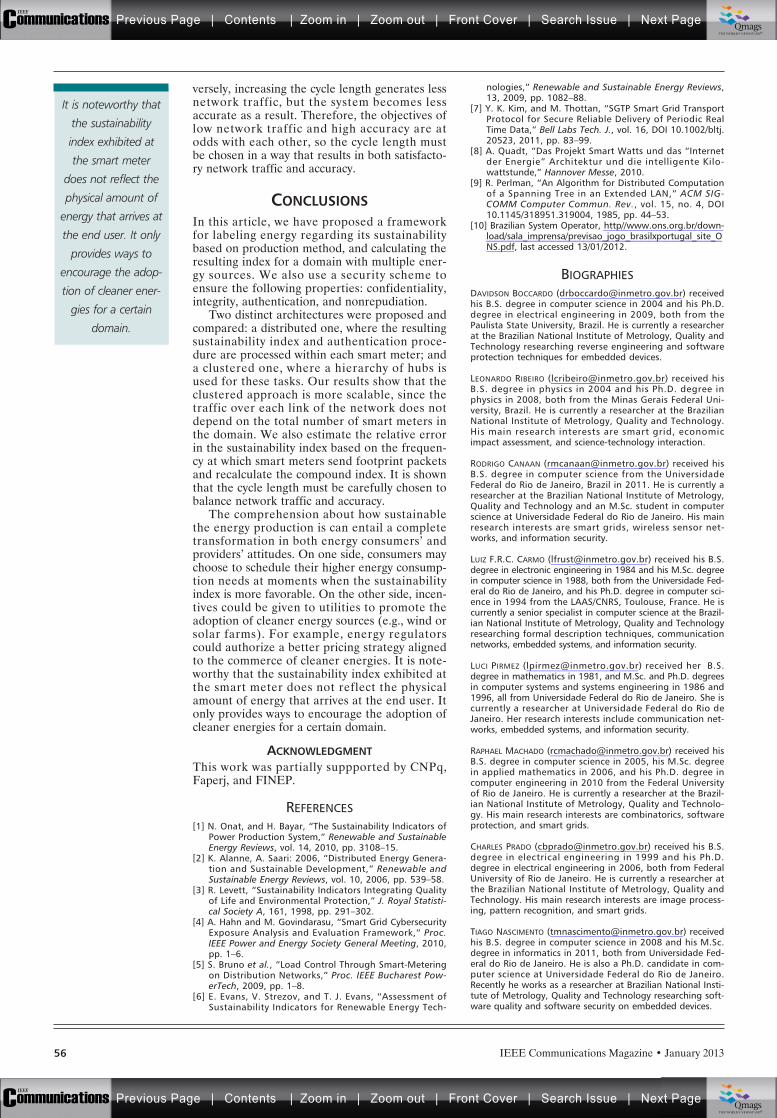
IEEE Communications Magazine • January 201356
versely, increasing the cycle length generates lessnetwork traffic, but the system becomes lessaccurate as a result. Therefore, the objectives oflow network traffic and high accuracy are atodds with each other, so the cycle length mustbe chosen in a way that results in both satisfacto-ry network traffic and accuracy.
CONCLUSIONSIn this article, we have proposed a frameworkfor labeling energy regarding its sustainabilitybased on production method, and calculating theresulting index for a domain with multiple ener-gy sources. We also use a security scheme toensure the following properties: confidentiality,integrity, authentication, and nonrepudiation.
Two distinct architectures were proposed andcompared: a distributed one, where the resultingsustainability index and authentication proce-dure are processed within each smart meter; anda clustered one, where a hierarchy of hubs isused for these tasks. Our results show that theclustered approach is more scalable, since thetraffic over each link of the network does notdepend on the total number of smart meters inthe domain. We also estimate the relative errorin the sustainability index based on the frequen-cy at which smart meters send footprint packetsand recalculate the compound index. It is shownthat the cycle length must be carefully chosen tobalance network traffic and accuracy.
The comprehension about how sustainablethe energy production is can entail a completetransformation in both energy consumers’ andproviders’ attitudes. On one side, consumers maychoose to schedule their higher energy consump-tion needs at moments when the sustainabilityindex is more favorable. On the other side, incen-tives could be given to utilities to promote theadoption of cleaner energy sources (e.g., wind orsolar farms). For example, energy regulatorscould authorize a better pricing strategy alignedto the commerce of cleaner energies. It is note-worthy that the sustainability index exhibited atthe smart meter does not reflect the physicalamount of energy that arrives at the end user. Itonly provides ways to encourage the adoption ofcleaner energies for a certain domain.
ACKNOWLEDGMENTThis work was partially suppported by CNPq,Faperj, and FINEP.
REFERENCES[1] N. Onat, and H. Bayar, “The Sustainability Indicators of
Power Production System,” Renewable and SustainableEnergy Reviews, vol. 14, 2010, pp. 3108–15.
[2] K. Alanne, A. Saari: 2006, “Distributed Energy Genera-tion and Sustainable Development,” Renewable andSustainable Energy Reviews, vol. 10, 2006, pp. 539–58.
[3] R. Levett, “Sustainability Indicators Integrating Qualityof Life and Environmental Protection,” J. Royal Statisti-cal Society A, 161, 1998, pp. 291–302.
[4] A. Hahn and M. Govindarasu, “Smart Grid CybersecurityExposure Analysis and Evaluation Framework,” Proc.IEEE Power and Energy Society General Meeting, 2010,pp. 1–6.
[5] S. Bruno et al., “Load Control Through Smart-Meteringon Distribution Networks,” Proc. IEEE Bucharest Pow-erTech, 2009, pp. 1–8.
[6] E. Evans, V. Strezov, and T. J. Evans, “Assessment ofSustainability Indicators for Renewable Energy Tech-
nologies,” Renewable and Sustainable Energy Reviews,13, 2009, pp. 1082–88.
[7] Y. K. Kim, and M. Thottan, “SGTP Smart Grid TransportProtocol for Secure Reliable Delivery of Periodic RealTime Data,” Bell Labs Tech. J., vol. 16, DOI 10.1002/bltj.20523, 2011, pp. 83–99.
[8] A. Quadt, “Das Projekt Smart Watts und das “Internetder Energie” Architektur und die intelligente Kilo-wattstunde,” Hannover Messe, 2010.
[9] R. Perlman, “An Algorithm for Distributed Computationof a Spanning Tree in an Extended LAN,” ACM SIG-COMM Computer Commun. Rev., vol. 15, no. 4, DOI10.1145/318951.319004, 1985, pp. 44–53.
[10] Brazilian System Operator, http//www.ons.org.br/down-load/sala_imprensa/previsao_jogo_brasilxportugal_site_ONS.pdf, last accessed 13/01/2012.
BIOGRAPHIESDAVIDSON BOCCARDO ([email protected]) receivedhis B.S. degree in computer science in 2004 and his Ph.D.degree in electrical engineering in 2009, both from thePaulista State University, Brazil. He is currently a researcherat the Brazilian National Institute of Metrology, Quality andTechnology researching reverse engineering and softwareprotection techniques for embedded devices.
LEONARDO RIBEIRO ([email protected]) received hisB.S. degree in physics in 2004 and his Ph.D. degree inphysics in 2008, both from the Minas Gerais Federal Uni-versity, Brazil. He is currently a researcher at the BrazilianNational Institute of Metrology, Quality and Technology.His main research interests are smart grid, economicimpact assessment, and science-technology interaction.
RODRIGO CANAAN ([email protected]) received hisB.S. degree in computer science from the UniversidadeFederal do Rio de Janeiro, Brazil in 2011. He is currently aresearcher at the Brazilian National Institute of Metrology,Quality and Technology and an M.Sc. student in computerscience at Universidade Federal do Rio de Janeiro. His mainresearch interests are smart grids, wireless sensor net-works, and information security.
LUIZ F.R.C. CARMO ([email protected]) received his B.S.degree in electronic engineering in 1984 and his M.Sc. degreein computer science in 1988, both from the Universidade Fed-eral do Rio de Janeiro, and his Ph.D. degree in computer sci-ence in 1994 from the LAAS/CNRS, Toulouse, France. He iscurrently a senior specialist in computer science at the Brazil-ian National Institute of Metrology, Quality and Technologyresearching formal description techniques, communicationnetworks, embedded systems, and information security.
LUCI PIRMEZ ([email protected]) received her B.S.degree in mathematics in 1981, and M.Sc. and Ph.D. degreesin computer systems and systems engineering in 1986 and1996, all from Universidade Federal do Rio de Janeiro. She iscurrently a researcher at Universidade Federal do Rio deJaneiro. Her research interests include communication net-works, embedded systems, and information security.
RAPHAEL MACHADO ([email protected]) received hisB.S. degree in computer science in 2005, his M.Sc. degreein applied mathematics in 2006, and his Ph.D. degree incomputer engineering in 2010 from the Federal Universityof Rio de Janeiro. He is currently a researcher at the Brazil-ian National Institute of Metrology, Quality and Technolo-gy. His main research interests are combinatorics, softwareprotection, and smart grids.
CHARLES PRADO ([email protected]) received his B.S.degree in electrical engineering in 1999 and his Ph.D.degree in electrical engineering in 2006, both from FederalUniversity of Rio de Janeiro. He is currently a researcher atthe Brazilian National Institute of Metrology, Quality andTechnology. His main research interests are image process-ing, pattern recognition, and smart grids.
TIAGO NASCIMENTO ([email protected]) receivedhis B.S. degree in computer science in 2008 and his M.Sc.degree in informatics in 2011, both from Universidade Fed-eral do Rio de Janeiro. He is also a Ph.D. candidate in com-puter science at Universidade Federal do Rio de Janeiro.Recently he works as a researcher at Brazilian National Insti-tute of Metrology, Quality and Technology researching soft-ware quality and software security on embedded devices.
It is noteworthy that
the sustainability
index exhibited at
the smart meter
does not reflect the
physical amount of
energy that arrives at
the end user. It only
provides ways to
encourage the adop-
tion of cleaner ener-
gies for a certain
domain.
Previous Page | Contents | Zoom in | Zoom out | Front Cover | Search Issue | Next PageIEEE
Communications qqM
Mq
qM
MqM
Qmags®THE WORLD’S NEWSSTAND
Previous Page | Contents | Zoom in | Zoom out | Front Cover | Search Issue | Next PageIEEE
Communications qqM
Mq
qM
MqM
Qmags®THE WORLD’S NEWSSTAND
____________________________________________
______________
_______________
___
_______________
____________
______________
_______________
______________
________________

FOR COMMUNICATIONS PROFESSIONALS
www.comsoc.org/training
CONTINUING EDUCATION
ComSoc Online Training:- Convenient, affordable, and immediate- Relevant for wireless engineering professionals- Self-directed when you review the recording
ComSoc In-Person Training:- Custom tailored for your specific needs- Save time and money with on-site training options- Promote teamwork and cross-train
2013 SCHEDULE
Wed, January 16, 2013 - Online CourseWireless Communications Engineering - Current Practice
Wed, January 23, 2013 - Online CourseVoLTE: Convergence of IMS-based Voice and LTE
Mon, January 28, 2013 - Online Course2 for 1 Deal: January Virtual 5 Day Training PLUS Spring 2013 WCET Exam Seat
Mon, January 28, 2013 - Online Course5-Day Wireless Communications Engineering Intermediate Fundamentals Review & Current Practices
Wed, February 6, 2013 - In Person Course Overview of Machine-to-Machine (M2M) for Engineers & Managers
Tue, February 12, 2013 - Online CourseSelf Organizing Networks
Previous Page | Contents | Zoom in | Zoom out | Front Cover | Search Issue | Next PageIEEE
Communications qqM
Mq
qM
MqM
Qmags®THE WORLD’S NEWSSTAND
Previous Page | Contents | Zoom in | Zoom out | Front Cover | Search Issue | Next PageIEEE
Communications qqM
Mq
qM
MqM
Qmags®THE WORLD’S NEWSSTAND
IEEE Communications Magazine • January 201358 0163-6804/13/$25.00 © 2013 IEEE
INTRODUCTION
Leveraging information and communicationtechnologies (ICT) to coordinate events andallocate resources for the electric power grid,the envisioned smart grid would be fundamen-tal to the integration of distributed renewableenergy sources, implementation of demand sidemanagement, and support of emerging trans-portation options such as electric vehicles(EVs), which in turn are essential to achievinggoals such as energy efficiency and diversity,and a low carbon footprint. However, it is wide-ly agreed that cybersecurity has been an areafalling short of expectation in the smart grid [2,3, 4, 5, 13]. Not only are many smart griddesigns — especially smart meters — vulnera-ble to various malicious attacks [10]; in general,it is also unclear what the proper securityrequirements for a smart grid application sce-nario should be. Unlike other aspects wherestandards in the original power grid are typical-ly well developed and readily upgradable forthe smart grid (e.g., those on islanding or microgrids), there is a lack of standards on cyberse-
curity to inform or guide smart grid designersin what should be implemented or included in asecure design, or how to assess the security of aparticular design.
Among existing smart grid standardizationefforts, the Interoperability Framework andRoadmap of NIST (National Institute of Stan-dards and Technology) in the United States,along with its NISTIR 7628, “Guidelines forCyber Security in the Smart Grid” [2], have themost comprehensive coverage of cybersecurityissues in the smart grid, and are relatively matureand well documented. IEEE P2030, “Guide forSmart Grid Interoperability of Energy Technolo-gy and Information Technology Operation withthe Electric Power System (EPS), and End-UseApplications and Loads” is also based on thesame framework. Other ongoing standardizationefforts [1, 4, 5] typically have only a small por-tion devoted to cybersecurity. International Elec-trotechnical Commission (IEC) 62351 addressesonly cybersecurity of substation systems, in par-ticular, IEC 60870 and IEC 61850, whereas inthe smart grid, the communication systems andassociated integration normally extend to theconsumer side (e.g., the concept of smart build-ings), which is usually less protected physically.
The NIST documents represent smart gridoperations as a number of actors, grouped intoseven domains, with defined interfaces betweenpairs of actors. The NISTIR 7628 covers bothtop-down and bottom-up approaches to riskassessments and security analyses. In the top-down approach, these actor interfaces aregrouped into different categories. Interfaces inthe same category have similar security require-ments. The security requirements of each cate-gory are extensively expressed in NISTIR 7628.According to NISTIR 7628, the interfaces andtheir desired security requirements are extractedfrom a fairly comprehensive set of use cases inthe utility or power industry. Nonetheless, thereis still a considerable gap between using theNISTIR 7628 framework and designing a securesmart grid subsystem. In particular, there areattacks that may not be adequately covered bythe security requirements obtained from the
ABSTRACT
Cybersecurity is an important but usually notadequately addressed area in the smart grid. Itsstandardization is also relatively immature. TheNISTIR 7628 seems to be a comprehensive doc-ument for security designers/practitioners insmart grid research and practice. However, theNISTIR 7628 security framework might still beinsufficient to specify the requirements of asecure smart grid system. More specifically, theEV charging infrastructure is used to study theeffectiveness of the NISTIR 7628 framework inspecifying security criteria, and the resultingsecurity assurance. Two weaknesses, one inaddressing node or device authentication andthe other in location privacy of EV owners, arefound for a system satisfying all the securityrequirements stipulated by the NISTIR 7628,thus illustrating the subtlety of applying the NIS-TIR 7628.
CYBER SECURITY FOR SMART GRIDCOMMUNICATIONS: PART 2
Aldar C-F. Chan and Jianying Zhou, Institute for Infocomm Research
On Smart Grid CybersecurityStandardization: Issues of Designingwith NISTIR 7628
Previous Page | Contents | Zoom in | Zoom out | Front Cover | Search Issue | Next PageIEEE
Communications qqM
Mq
qM
MqM
Qmags®THE WORLD’S NEWSSTAND
Previous Page | Contents | Zoom in | Zoom out | Front Cover | Search Issue | Next PageIEEE
Communications qqM
Mq
qM
MqM
Qmags®THE WORLD’S NEWSSTAND
IEEE Communications Magazine • January 2013 59
NISTIR 7628 framework. Although it is men-tioned that this kind of vulnerability should beincluded in the bottom-up approach, identifyingsuch attacks has to rely on the designer’s imagi-nation and experience. In fact, the bottom-upapproach of NISTIR 7628 is fairly vague indefining attacks or security concerns. Evenworse, more often than not, the attackers are farmore creative in constructing an attack than thesecurity designers or engineers. In other words,vulnerabilities could still possibly be found in adesign satisfying the systematic (top-down) NIS-TIR 7628 requirements, particularly when nodetail has been given in NISTIR 7628 on how toadequately fulfill these high-level requirements.It is fair to say that no clear framework or guide-lines are available in the bottom-up securityrequirement analysis, although the NISTIR 7628top-down framework has already taken into con-sideration the essence of some known bottom-upproblems.
This article uses the EV charging infra-structure as a case example to study the effec-tiveness of the NISTIR 7628 framework indefining security requirements for smart gridapplications, aiming to illustrate the difficultyand subtlety of security standardization in thesmart grid. Electric vehicles, an emerging trans-portation option, would form a new load draw-ing a significant amount of power from the grid— for the current state of the art, EV chargingwould take about 3.6–7.2 kW, whereas thepower consumption of a typical U.S. householdin the summer is roughly 3 kW, implying thatcharging an EV would be equivalent to adding anew household to the electric grid — as well asa new resource to the grid to accommodatepeak power surges. Utility operators tend tosupport EV charging at off-peak times when thepower grid assets and resources are underuti-lized. During peak times, EVs could formmobile storage devices to sell back electricity tothe grid to fill the shortfall of power generationamid demand surges. This operation modelstrongly relies on reliable information exchangedbetween different parties to coordinate eventshappening in the grid, implying that the smartgrid is a necessity for such EV deployment. Onthe other hand, according to Europe 2030,adopting EVs is the key and inevitable means tocurb climate change or maintain a low carbonfootprint. Consequently, it is clear that the EVecosystem would form a significant part of thesmart grid. Hence, the EV ecosystem should berepresentative as an example to assess the effec-tiveness of NISTIR 7628.
Besides demonstrating how to apply the NIS-TIR 7628 framework to designing secure smartgrid applications, the main contribution of thisarticle is a critical assessment of the effective-ness of NISTIR 7628 for stipulating the securityrequirements of a smart grid design and thelevel of its security assurance. The rest of thisarticle is organized as follows. We give a briefoverview of NISTIR 7628 and apply the NISTIR7628 framework to the EV ecosystem. We showattacks that may not be adequately covered byNISTIR 7628, particularly when extra effort isnot applied in assessing the security of the result-ing design or only cybersecurity is considered.
NISTIR 7628: A BRIEF OVERVIEW
NISTIR 7628 [2] is part of NIST’s effort to con-solidate all U.S. standard activities, “The NISTFramework and Roadmap for Smart Grid Inter-operability Standards, Release 1.0” [3], whichhas identified eight priorities to implement aneffective smart grid: demand response and con-sumer energy efficiency, wide-area situationalawareness, energy storage, electric transporta-tion, advanced metering infrastructure, distribu-tion grid management, cybersecurity, andnetwork communications.
The three-volume report of NISTIR 7628presents an analytical framework organizationscan use to develop effective cybersecurity strate-gies tailored to their particular combinations ofsmart-grid-related characteristics, risks, and vul-nerabilities. Recognizing that the power grid ischanging from a relatively closed system to acomplex, highly interconnected environment,NISTIR 7628 reports methods for assessing risksin the smart grid, and then identifies and appliesappropriate security requirements to mitigatethese risks. The security requirements could beseen as guidelines for developing smart gridsecurity strategies, systems, and components.
The NISTIR 7628 guidelines are developedbased on risk assessment analyses of a numberof selected smart grid use cases, salient to thetask of determining security requirements. Eachuse case documents system interactions andbehaviors occurring in a smart grid applicationscenario. Each use case is reviewed from a high-level overall functional perspective that includesidentifying assets, vulnerabilities, threats, andpotential impacts. The output is used as thebaseline for selecting security requirements andidentifying gaps in guidance and standards relat-ed to the security requirements.
Bottom-up and top-down approaches areused in the risk assessment. The bottom-upapproach focuses on specific, not so well definedproblems that need to be addressed on a case-by-case basis and require designers’ experienceto identify nontrivial requirements. In the top-down approach, logical interface diagrams areused to identify security requirements. A logicalinterface is a connection linking actors, eachbelonging to one of the seven smart grid domains(bulk generation, transmission, distribution, cus-tomer, markets, operations, and service provider)as specified in [3]. A domain is a high-levelgrouping of actors (which could be organiza-tions, buildings, individuals, systems, or devices)with similar objectives and relying on or partici-pating in similar types of applications. Acrossthe seven domains, numerous actors capture,transmit, store, edit, and process the informationnecessary for smart grid applications. To enablesmart grid functionalities, actors in a domainoften interact with actors in other domains. Atotal of 46 actors have been identified in [3].
A logical reference model, showing logicalinterfaces linking actors and suggesting the typesof information exchanged, is to break down thesmart grid domains into more granular details,without defining concrete interface specificationsand data types. It serves as a vehicle for identify-ing, organizing, prioritizing, and communicating
The bottom-up
approach focuses on
specific, not so well
defined problems
that need to be
addressed on a case-
by-case basis and
require designers’
experience to identi-
fy nontrivial require-
ments. In the
top-down approach,
logical interface dia-
grams are used to
identify security
requirements.
Previous Page | Contents | Zoom in | Zoom out | Front Cover | Search Issue | Next PageIEEE
Communications qqM
Mq
qM
MqM
Qmags®THE WORLD’S NEWSSTAND
Previous Page | Contents | Zoom in | Zoom out | Front Cover | Search Issue | Next PageIEEE
Communications qqM
Mq
qM
MqM
Qmags®THE WORLD’S NEWSSTAND
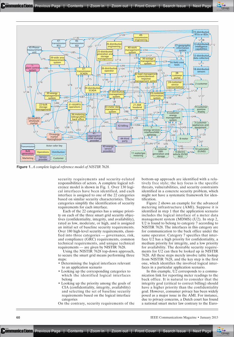
IEEE Communications Magazine • January 201360
security requirements and security-relatedresponsibilities of actors. A complete logical ref-erence model is shown in Fig. 1. Over 130 logi-cal interfaces have been identified, and eachinterface is assigned to one of the 22 categoriesbased on similar security characteristics. Thesecategories simplify the identification of securityrequirements for each interface.
Each of the 22 categories has a unique priori-ty on each of the three smart grid security objec-tives (confidentiality, integrity, and availability),rated as low, moderate, or high, and is assignedan initial set of baseline security requirements.Over 180 high-level security requirements, classi-fied into three categories — governance, risk,and compliance (GRC) requirements, commontechnical requirements, and unique technicalrequirements — are given by NISTIR 7628.
Using the NISTIR 7628 top-down approach,to secure the smart grid means performing threesteps:• Determining the logical interfaces relevant
to an application scenario• Looking up the corresponding categories to
which the identified logical interfacesbelong
• Looking up the priority among the goals ofCIA (confidentiality, integrity, availability)and selecting the set of baseline securityrequirements based on the logical interfacecategories
On the contrary, security requirements of the
bottom-up approach are identified with a rela-tively free style; the key focus is the specificthreats, vulnerabilities, and security constraintsidentified in a concrete security problem, whichmight not have a systematic framework for iden-tification.
Figure 2 shows an example for the advancedmetering infrastructure (AMI). Suppose it isidentified in step 1 that the application scenarioincludes the logical interface of a meter datamanagement system (MDMS) (U2). In step 2,U2 is found to belong to category 7 according toNISTIR 7628. The interfaces in this category arefor communication to the back office under thesame operator. Category 7 specifies that inter-face U2 has a high priority for confidentiality, amedium priority for integrity, and a low priorityfor availability. The desirable security require-ments for U2 can then be looked up in NISTIR7628. All these steps merely involve table lookupfrom NISTIR 7628, and the key step is the firstone, which identifies the involved logical inter-faces in a particular application scenario.
In this example, U2 corresponds to a commu-nication link for reporting meter readings to theback office. It is natural to consider that theintegrity goal (critical to correct billing) shouldhave a higher priority than the confidentialitygoal. However, consumer privacy has been widelyposed as a major issue in the AMI. For instance,due to privacy concerns, a Dutch court has founda national smart meter law contrary to the Euro-
Figure 1. A complete logical reference model of NISTIR 7628.
2-customer
8-meter
10-submeter(EUMD)
11-water/gasmetering
9-customerpremisedisplay
46-transmission
IED
47-transmission
RTU45-Phasor
measurementunit
1-plant control
system
20-ISO/RTOwholesale
market
19-energymarket
clearinghouse
Transmission
Marketing
Bulkgeneration
6-electricvehicle (EVSE/
PEV)
3-customerappliances and
equipment
5-customerenergy
managementsystem
7-energy servicesinterface/HAN
gateway
4-customerDER:
generation andstorage
15-distributionRTUs or IEDs
12-distributiondata collectors
18-distributionsensors
44-thirdparty
21-AMIheadend
31-ISO/RTOoperations
29-distributionSCADA
28-distributionoperator
26-distributionengineering
49-transmissionengineering
40-workmanagement
system
36-outagemanagement
system
38-customer
portal
23-customerinformation
system
27-distributionmanagement
system
25-distributedgeneration and
storagemanagement
37-transmission
SCADA
39-wide areameasurement
system
30-energymanagement
system
22-bulkstorage
management33-meter datamanagement
system34-meteringbilling/utilityback office
32-load managementsystem/demand-
responsemanagement system 24-customer
servicerepresentative
43-energyservice
providers
41-aggregator/retail energy
provider
42-billing
16-field crewtools
13-distributedintelligencecapabilities
17-geographicinformation
system
Operations
Actor color key
Distribution
CustomerServiceprovider
U108
U111
U105
U131
U137
U127
U129
U112
U39
U40
U35
U50
U43
U125U113
U101
U104
U114
U109
U117
U135U136
U100U115
U116
U134U110
U126U124
U119
U108
U102
U14
U24
U38
U44
U120
U130U128 U47
U46U45U95
U18
U84
U25 U96
U92
U21
U33
U37
U31
U29
U34
U30
U36U12
U28
U59
U22
U88
U98U54U63
U57
U15
U51U55
U56
U10
U65
U11
U13
U99U27
U67
U81
U85U82
U78
U87U83U97
U89U66
U90
U52
U53U93
U58U91
U17
U72
U74
U16
U80U77
U79
U70
U20
U75
U32
U6
U5
U8
U0
U4
U3
U7
U2
U1
U60
U49
U62
U41U42
U48
Previous Page | Contents | Zoom in | Zoom out | Front Cover | Search Issue | Next PageIEEE
Communications qqM
Mq
qM
MqM
Qmags®THE WORLD’S NEWSSTAND
Previous Page | Contents | Zoom in | Zoom out | Front Cover | Search Issue | Next PageIEEE
Communications qqM
Mq
qM
MqM
Qmags®THE WORLD’S NEWSSTAND
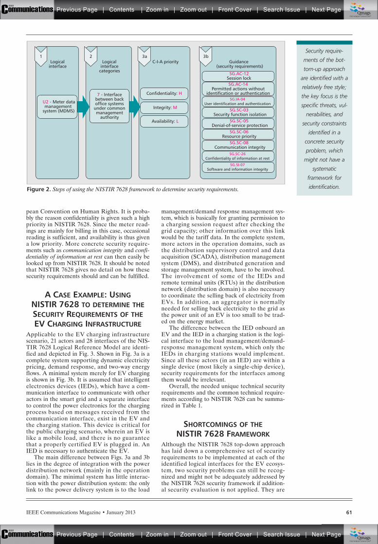
IEEE Communications Magazine • January 2013 61
pean Convention on Human Rights. It is proba-bly the reason confidentiality is given such a highpriority in NISTIR 7628. Since the meter read-ings are mainly for billing in this case, occasionalreading is sufficient, and availability is thus givena low priority. More concrete security require-ments such as communication integrity and confi-dentiality of information at rest can then easily belooked up from NISTIR 7628. It should be notedthat NISTIR 7628 gives no detail on how thesesecurity requirements should and can be fulfilled.
A CASE EXAMPLE: USINGNISTIR 7628 TO DETERMINE THESECURITY REQUIREMENTS OF THEEV CHARGING INFRASTRUCTURE
Applicable to the EV charging infrastructurescenario, 21 actors and 28 interfaces of the NIS-TIR 7628 Logical Reference Model are identi-fied and depicted in Fig. 3. Shown in Fig. 3a is acomplete system supporting dynamic electricitypricing, demand response, and two-way energyflows. A minimal system merely for EV chargingis shown in Fig. 3b. It is assumed that intelligentelectronics devices (IEDs), which have a com-munication interface to communicate with otheractors in the smart grid and a separate interfaceto control the power electronics for the chargingprocess based on messages received from thecommunication interface, exist in the EV andthe charging station. This device is critical forthe public charging scenario, wherein an EV islike a mobile load, and there is no guaranteethat a properly certified EV is plugged in. AnIED is necessary to authenticate the EV.
The main difference between Figs. 3a and 3blies in the degree of integration with the powerdistribution network (mainly in the operationdomain). The minimal system has little interac-tion with the power distribution system: the onlylink to the power delivery system is to the load
management/demand response management sys-tem, which is basically for granting permission toa charging session request after checking thegrid capacity; other information over this linkwould be the tariff data. In the complete system,more actors in the operation domains, such asthe distribution supervisory control and dataacquisition (SCADA), distribution managementsystem (DMS), and distributed generation andstorage management system, have to be involved.The involvement of some of the IEDs andremote terminal units (RTUs) in the distributionnetwork (distribution domain) is also necessaryto coordinate the selling back of electricity fromEVs. In addition, an aggregator is normallyneeded for selling back electricity to the grid asthe power unit of an EV is too small to be trad-ed on the energy market.
The difference between the IED onboard anEV and the IED in a charging station is the logi-cal interface to the load management/demand-response management system, which only theIEDs in charging stations would implement.Since all these actors (in an IED) are within asingle device (most likely a single-chip device),security requirements for the interfaces amongthem would be irrelevant.
Overall, the needed unique technical securityrequirements and the common technical require-ments according to NISTIR 7628 can be summa-rized in Table 1.
SHORTCOMINGS OF THENISTIR 7628 FRAMEWORK
Although the NISTIR 7628 top-down approachhas laid down a comprehensive set of securityrequirements to be implemented at each of theidentified logical interfaces for the EV ecosys-tem, two security problems can still be recog-nized and might not be adequately addressed bythe NISTIR 7628 security framework if addition-al security evaluation is not applied. They are
Figure 2. Steps of using the NISTIR 7628 framework to determine security requirements.
2Logical
interfacecategories
3aC-I-A priority
3bGuidance
(security requirements)
SG.AC-12Session lock
SG.IA-04User identification and authentication
SG.SC-03Security function isolation
SG.SC-05Denial-of-service protection
SG.SC-06Resource priority
SG.SC-08Communication integrity
SG.SC-26Confidentiality of information at rest
SG.SI-07Software and information integrity
SG.AC-14Permitted actions without
identification or authentication
1Logical
interface
7 - Interfacebetween backoffice systems
under commonmanagement
authority
U2 - Meter datamanagement
system (MDMS)
Confidentiality: H
Integrity: M
Availability: L
Security require-
ments of the bot-
tom-up approach
are identified with a
relatively free style;
the key focus is the
specific threats, vul-
nerabilities, and
security constraints
identified in a
concrete security
problem, which
might not have a
systematic
framework for
identification.
Previous Page | Contents | Zoom in | Zoom out | Front Cover | Search Issue | Next PageIEEE
Communications qqM
Mq
qM
MqM
Qmags®THE WORLD’S NEWSSTAND
Previous Page | Contents | Zoom in | Zoom out | Front Cover | Search Issue | Next PageIEEE
Communications qqM
Mq
qM
MqM
Qmags®THE WORLD’S NEWSSTAND
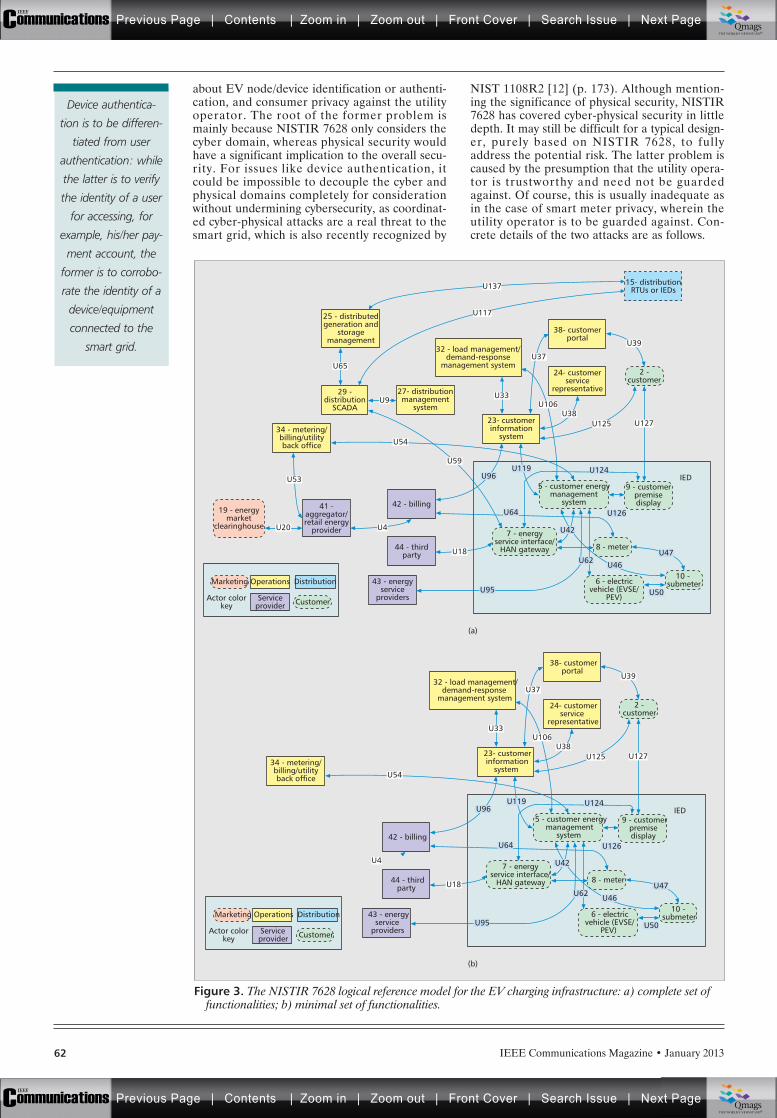
IEEE Communications Magazine • January 201362
about EV node/device identification or authenti-cation, and consumer privacy against the utilityoperator. The root of the former problem ismainly because NISTIR 7628 only considers thecyber domain, whereas physical security wouldhave a significant implication to the overall secu-rity. For issues like device authentication, itcould be impossible to decouple the cyber andphysical domains completely for considerationwithout undermining cybersecurity, as coordinat-ed cyber-physical attacks are a real threat to thesmart grid, which is also recently recognized by
NIST 1108R2 [12] (p. 173). Although mention-ing the significance of physical security, NISTIR7628 has covered cyber-physical security in littledepth. It may still be difficult for a typical design-er, purely based on NISTIR 7628, to fullyaddress the potential risk. The latter problem iscaused by the presumption that the utility opera-tor is trustworthy and need not be guardedagainst. Of course, this is usually inadequate asin the case of smart meter privacy, wherein theutility operator is to be guarded against. Con-crete details of the two attacks are as follows.
Figure 3. The NISTIR 7628 logical reference model for the EV charging infrastructure: a) complete set offunctionalities; b) minimal set of functionalities.
(a)
(b)
IED
15- distributionRTUs or IEDs
38- customerportal
24- customerservice
representative
23- customerinformation
system
42 - billing
44 - thirdparty
43 - energyservice
providers
41 -aggregator/retail energy
provider
29 -distribution
SCADA
27- distributionmanagement
system
34 - metering/billing/utilityback office
19 - energymarket
clearinghouse
Marketing
Customer
Operations
Serviceprovider
Actor colorkey
Distribution
9 - customerpremisedisplay
8 - meter
2 -customer
10 - submeter
7 - energyservice interface/
HAN gateway
6 - electricvehicle (EVSE/
PEV)
5 - customer energymanagement
system
25 - distributedgeneration and
storagemanagement
32 - load management/demand-response
management system
U127
U39
U38
U42
U62 U46
U50
U47
U33
U37U65
U54
U18
U95
U64
U96
U59
U53
U20
U9
U4
U125
U119 U124
U126
U117
U137
U106
IED
38- customerportal
24- customerservice
representative
23- customerinformation
system
42 - billing
44 - thirdparty
43 - energyservice
providers
34 - metering/billing/utilityback office
Marketing
Customer
Operations
Serviceprovider
Actor colorkey
Distribution
9 - customerpremisedisplay
8 - meter
2 -customer
10 - submeter
7 - energyservice interface/
HAN gateway
6 - electricvehicle (EVSE/
PEV)
5 - customer energymanagement
system
32 - load management/demand-response
management system
U127
U39
U38
U42
U62 U46
U50
U47
U33
U37
U54
U18
U95
U64
U96
U4
U125
U119 U124
U126
U106
Device authentica-
tion is to be differen-
tiated from user
authentication: while
the latter is to verify
the identity of a user
for accessing, for
example, his/her pay-
ment account, the
former is to corrobo-
rate the identity of a
device/equipment
connected to the
smart grid.
Previous Page | Contents | Zoom in | Zoom out | Front Cover | Search Issue | Next PageIEEE
Communications qqM
Mq
qM
MqM
Qmags®THE WORLD’S NEWSSTAND
Previous Page | Contents | Zoom in | Zoom out | Front Cover | Search Issue | Next PageIEEE
Communications qqM
Mq
qM
MqM
Qmags®THE WORLD’S NEWSSTAND

IEEE Communications Magazine • January 2013 63
EV DEVICE IDENTIFICATION/AUTHENTICATION
Device authentication is to be differentiatedfrom user authentication: while the latter is toverify the identity of a user for accessing, forexample, his/her payment account, the former isto corroborate the identity of a device/equip-ment connected to the smart grid. The typicalchallenge-response protocol is the main cyberse-curity defence for device identification/ authenti-cation in EV charging. In a desirable situation,when the IED onboard an EV passes the chal-lenge-response protocol with the charging sta-tion as the verifier, it means that the EV has avalid registration and is eligible for charging ifthe user identity and billing account also passverification. In other words, a stolen EV with itsregistration and certificate revoked — as initiat-ed by its original owner — should not be able togain access to the power grid for charging, eventhough the car thief uses his/her own useraccount to pay the charging cost. Ideally, a stolenEV plugged into the grid for charging should beimmobilized promptly by the charging station,and the stolen EV could then be recovered. Tocharge a stolen car, the car thief has to performfar more work, at least replacing the EV’s IED.
However, consider a kind of substitutionattack against the charging infrastructure withdevice authentication over a wireless link, asshown in Fig. 4. Now the car thief uses the IEDof another EV with a valid certificate and regis-tration to run the challenge-response authentica-tion protocol over the wireless link, whileplugging in the stolen EV to the charging sta-tion. Since the keys and certificates of the IEDin the second EV are still valid, they will passthe device authentication test. If the car thief’sbilling account also has sufficient funds, a charg-ing session would start to charge the stolen EV,rather than the second EV. Charging a stolenEV would go undetected in this way, whichmight have serious repercussions, such as poten-tial car bombing using EV batteries and irre-sponsive loads in demand response (DR).
Linking or binding a user’s identity with his/her EV’s identity may not work either since thesecond EV could be owned by the car thief whohas a valid user identity linked to the EV’s iden-tity. Instead, it causes inconvenience to EV own-ers. For the same reason, the requirement to tapa smart card at the charging station for verifica-tion would not work either. This substitutionattack applies to all existing charging stationsusing wireless authentication protocols. Indeed,this problem is not entirely new. For instance, aremote computer, storing valid credentials, couldlog into a legitimate user’s bank account, but theuser behind the computer may not be theaccount owner. In fact, this substitution attack isvery similar to the man-in-the-middle attack[11]. Similarly, including physical features is thekey to thwarting this kind of attack. This attackwould only be thwarted if device authenticationis performed over the charging cable, which pro-vides the inherent guarantee that whoever passesthe challenge-response authentication in thecyber domain is also the one who is plugged inat the concerned charging station.
The problem of using a wireless medium is Table 1. NISTIR 7628 security requirements for the EV charging infrastructure.
(a) Unique security requirements
SG.AC-12 Session Lock
SG.AC-14 Permitted Actions without Identification or Authentication
SG.IA-04 User Identification and Authentication
SG.IA-05 Device Identification and Authentication
SG.SC-03 Security Function Isolation
SG.SC-05 Denial of Service Protection
SG.SC-06 Resource Priority
SG.SC-07 Boundary Protection
SG.SC-08 Communication Integrity
SG.SC-09 Communication Confidentiality
SG.SC-26 Confidentiality of Information at Rest
SG.SI-07 Software and Information Integrity
(b) Common security requirements
SG.AC-06 Separation of Duties
SG.AC-07 Least Privilege
SG.AC-08 Unsuccessful Login Attempt
SG.AC-09 Smart Grid Information System Use Notification
SG.AC-16 Wireless Access Restrictions
SG.AC-21 Passwords
SG.AU-02 Auditable Events
SG.AU-03 Content of Audit Records
SG.AU-04 Audit Storage Capacity
SG.AU-15 Audit Generation
SG.AU-16 Non-Repudiation
SG.CM-07 Configuration for Least Functionality
SG.CM-08 Component Inventory
SG.SA-10 Developer Security Testing
SG.SA-11 Supply Chain Protection
SG.SC-02 Communications Partitioning
SG.SC-11 Cryptographic Key Establishment and Management
SG.SC-12 Use of Validated Cryptography
SG.SC-15 Public Key Infrastructure Certificates
SG.SC-16 Mobile Code
SG.SC-18 System Connection
SG.SC-19 Security Roles
SG.SC-20 Message Authenticity
SG.SC-21 Secure Name/Address Resolution Service
SG.SC-22 Fail in Known State
SG.SC-30 Smart Grid Information System Partitioning
SG.SI-02 Flaw Remediation
SG.SI-08 Information Input Validation
SG.SI-09 Error Handling
Previous Page | Contents | Zoom in | Zoom out | Front Cover | Search Issue | Next PageIEEE
Communications qqM
Mq
qM
MqM
Qmags®THE WORLD’S NEWSSTAND
Previous Page | Contents | Zoom in | Zoom out | Front Cover | Search Issue | Next PageIEEE
Communications qqM
Mq
qM
MqM
Qmags®THE WORLD’S NEWSSTAND
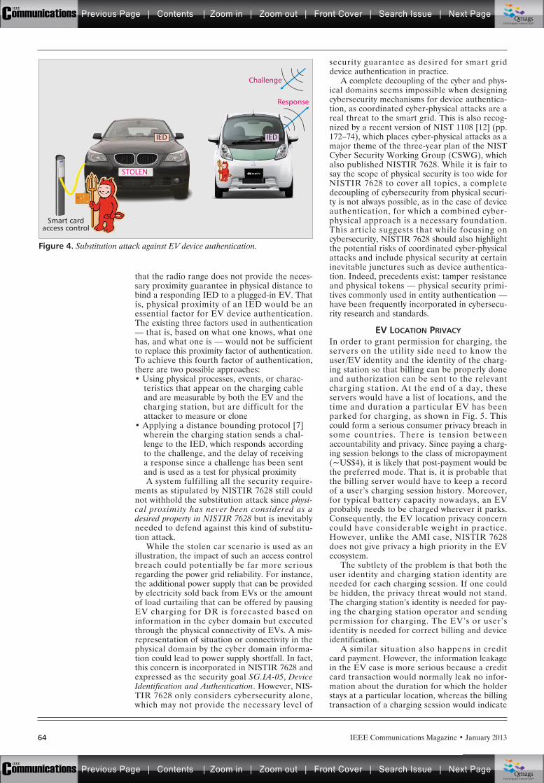
IEEE Communications Magazine • January 201364
that the radio range does not provide the neces-sary proximity guarantee in physical distance tobind a responding IED to a plugged-in EV. Thatis, physical proximity of an IED would be anessential factor for EV device authentication.The existing three factors used in authentication— that is, based on what one knows, what onehas, and what one is — would not be sufficientto replace this proximity factor of authentication.To achieve this fourth factor of authentication,there are two possible approaches:• Using physical processes, events, or charac-
teristics that appear on the charging cableand are measurable by both the EV and thecharging station, but are difficult for theattacker to measure or clone
• Applying a distance bounding protocol [7]wherein the charging station sends a chal-lenge to the IED, which responds accordingto the challenge, and the delay of receivinga response since a challenge has been sentand is used as a test for physical proximityA system fulfilling all the security require-
ments as stipulated by NISTIR 7628 still couldnot withhold the substitution attack since physi-cal proximity has never been considered as adesired property in NISTIR 7628 but is inevitablyneeded to defend against this kind of substitu-tion attack.
While the stolen car scenario is used as anillustration, the impact of such an access controlbreach could potentially be far more seriousregarding the power grid reliability. For instance,the additional power supply that can be providedby electricity sold back from EVs or the amountof load curtailing that can be offered by pausingEV charging for DR is forecasted based oninformation in the cyber domain but executedthrough the physical connectivity of EVs. A mis-representation of situation or connectivity in thephysical domain by the cyber domain informa-tion could lead to power supply shortfall. In fact,this concern is incorporated in NISTIR 7628 andexpressed as the security goal SG.IA-05, DeviceIdentification and Authentication. However, NIS-TIR 7628 only considers cybersecurity alone,which may not provide the necessary level of
security guarantee as desired for smart griddevice authentication in practice.
A complete decoupling of the cyber and phys-ical domains seems impossible when designingcybersecurity mechanisms for device authentica-tion, as coordinated cyber-physical attacks are areal threat to the smart grid. This is also recog-nized by a recent version of NIST 1108 [12] (pp.172–74), which places cyber-physical attacks as amajor theme of the three-year plan of the NISTCyber Security Working Group (CSWG), whichalso published NISTIR 7628. While it is fair tosay the scope of physical security is too wide forNISTIR 7628 to cover all topics, a completedecoupling of cybersecurity from physical securi-ty is not always possible, as in the case of deviceauthentication, for which a combined cyber-physical approach is a necessary foundation.This article suggests that while focusing oncybersecurity, NISTIR 7628 should also highlightthe potential risks of coordinated cyber-physicalattacks and include physical security at certaininevitable junctures such as device authentica-tion. Indeed, precedents exist: tamper resistanceand physical tokens — physical security primi-tives commonly used in entity authentication —have been frequently incorporated in cybersecu-rity research and standards.
EV LOCATION PRIVACYIn order to grant permission for charging, theservers on the utility side need to know theuser/EV identity and the identity of the charg-ing station so that billing can be properly doneand authorization can be sent to the relevantcharging station. At the end of a day, theseservers would have a list of locations, and thetime and duration a particular EV has beenparked for charging, as shown in Fig. 5. Thiscould form a serious consumer privacy breach insome countries. There is tension betweenaccountability and privacy. Since paying a charg-ing session belongs to the class of micropayment(~US$4), it is likely that post-payment would bethe preferred mode. That is, it is probable thatthe billing server would have to keep a recordof a user’s charging session history. Moreover,for typical battery capacity nowadays, an EVprobably needs to be charged wherever it parks.Consequently, the EV location privacy concerncould have considerable weight in practice.However, unlike the AMI case, NISTIR 7628does not give privacy a high priority in the EVecosystem.
The subtlety of the problem is that both theuser identity and charging station identity areneeded for each charging session. If one couldbe hidden, the privacy threat would not stand.The charging station’s identity is needed for pay-ing the charging station operator and sendingpermission for charging. The EV’s or user’sidentity is needed for correct billing and deviceidentification.
A similar situation also happens in creditcard payment. However, the information leakagein the EV case is more serious because a creditcard transaction would normally leak no infor-mation about the duration for which the holderstays at a particular location, whereas the billingtransaction of a charging session would indicate
Figure 4. Substitution attack against EV device authentication.
IED
STOLEN
Response
Challenge
Smart cardaccess control
IED
Previous Page | Contents | Zoom in | Zoom out | Front Cover | Search Issue | Next PageIEEE
Communications qqM
Mq
qM
MqM
Qmags®THE WORLD’S NEWSSTAND
Previous Page | Contents | Zoom in | Zoom out | Front Cover | Search Issue | Next PageIEEE
Communications qqM
Mq
qM
MqM
Qmags®THE WORLD’S NEWSSTAND
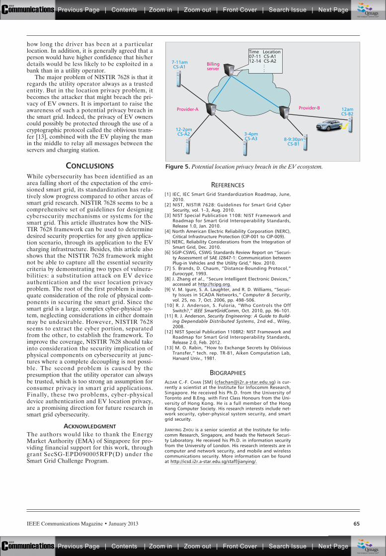
IEEE Communications Magazine • January 2013 65
how long the driver has been at a particularlocation. In addition, it is generally agreed that aperson would have higher confidence that his/herdetails would be less likely to be exploited in abank than in a utility operator.
The major problem of NISTIR 7628 is that itregards the utility operator always as a trustedentity. But in the location privacy problem, itbecomes the attacker that might breach the pri-vacy of EV owners. It is important to raise theawareness of such a potential privacy breach inthe smart grid. Indeed, the privacy of EV ownerscould possibly be protected through the use of acryptographic protocol called the oblivious trans-fer [13], combined with the EV playing the manin the middle to relay all messages between theservers and charging station.
CONCLUSIONSWhile cybersecurity has been identified as anarea falling short of the expectation of the envi-sioned smart grid, its standardization has rela-tively slow progress compared to other areas ofsmart grid research. NISTIR 7628 seems to be acomprehensive set of guidelines for designingcybersecurity mechanisms or systems for thesmart grid. This article illustrates how the NIS-TIR 7628 framework can be used to determinedesired security properties for any given applica-tion scenario, through its application to the EVcharging infrastructure. Besides, this article alsoshows that the NISTIR 7628 framework mightnot be able to capture all the essential securitycriteria by demonstrating two types of vulnera-bilities: a substitution attack on EV deviceauthentication and the user location privacyproblem. The root of the first problem is inade-quate consideration of the role of physical com-ponents in securing the smart grid. Since thesmart grid is a large, complex cyber-physical sys-tem, neglecting considerations in either domainmay be undesirable. However, NISTIR 7628seems to extract the cyber portion, separatedfrom the other, to establish the framework. Toimprove the coverage, NISTIR 7628 should takeinto consideration the security implication ofphysical components on cybersecurity at junc-tures where a complete decoupling is not possi-ble. The second problem is caused by thepresumption that the utility operator can alwaysbe trusted, which is too strong an assumption forconsumer privacy in smart grid applications.Finally, these two problems, cyber-physicaldevice authentication and EV location privacy,are a promising direction for future research insmart grid cybersecurity.
ACKNOWLEDGMENTThe authors would like to thank the EnergyMarket Authority (EMA) of Singapore for pro-viding financial support for this work, throughgrant SecSG-EPD090005RFP(D) under theSmart Grid Challenge Program.
REFERENCES[1] IEC, IEC Smart Grid Standardization Roadmap, June,
2010.[2] NIST, NISTIR 7628: Guidelines for Smart Grid Cyber
Security, vol. 1–3, Aug. 2010.[3] NIST Special Publication 1108: NIST Framework and
Roadmap for Smart Grid Interoperability Standards,Release 1.0, Jan. 2010.
[4] North American Electric Reliability Corporation (NERC),Critical Infrastructure Protection (CIP-001 to CIP-009).
[5] NERC, Reliability Considerations from the Integration ofSmart Grid, Dec. 2010.
[6] SGIP-CSWG, CSWG Standards Review Report on “Securi-ty Assessment of SAE J2847-1: Communication betweenPlug-in Vehicles and the Utility Grid,” Nov. 2010.
[7] S. Brands, D. Chaum, “Distance-Bounding Protocol,”Eurocrypt, 1993.
[8] J. Zhang et al., “Secure Intelligent Electronic Devices,”accessed at http://tcipg.org.
[9] V. M. Igure, S. A. Laughter, and R. D. Williams, “Securi-ty Issues in SCADA Networks,” Computer & Security,vol. 25, no. 7, Oct. 2006, pp. 498–506.
[10] R. J. Anderson, S. Fuloria, “Who Controls the OffSwitch?,” IEEE SmartGridComm, Oct. 2010, pp. 96–101.
[11] R. J. Anderson, Security Engineering: A Guide to Build-ing Dependable Distributed Systems, 2nd ed., Wiley,2008.
[12] NIST Special Publication 1108R2: NIST Framework andRoadmap for Smart Grid Interoperability Standards,Release 2.0, Feb. 2012.
[13] M. O. Rabin, “How to Exchange Secrets by ObliviousTransfer,” tech. rep. TR-81, Aiken Computation Lab,Harvard Univ., 1981.
BIOGRAPHIESALDAR C.-F. CHAN [SM] ([email protected]) is cur-rently a scientist at the Institute for Infocomm Research,Singapore. He received his Ph.D. from the University ofToronto and B.Eng. with First Class Honours from the Uni-versity of Hong Kong. He is a full member of the HongKong Computer Society. His research interests include net-work security, cyber-physical system security, and smartgrid security.
JIANYING ZHOU is a senior scientist at the Institute for Info-comm Research, Singapore, and heads the Network Securi-ty Laboratory. He received his Ph.D. in information securityfrom the University of London. His research interests are incomputer and network security, and mobile and wirelesscommunications security. More information can be foundat http://icsd.i2r.a-star.edu.sg/staff/jianying/.
Figure 5. Potential location privacy breach in the EV ecosystem.
Billingserver
Provider-A Provider-B 12amCS-B2
8-9:30pmCS-B1
3-4pmCS-A3
12-2pmCS-A2
7-11amCS-A1
Time Location07-11 CS-A112-14 CS-A2 : :
Previous Page | Contents | Zoom in | Zoom out | Front Cover | Search Issue | Next PageIEEE
Communications qqM
Mq
qM
MqM
Qmags®THE WORLD’S NEWSSTAND
Previous Page | Contents | Zoom in | Zoom out | Front Cover | Search Issue | Next PageIEEE
Communications qqM
Mq
qM
MqM
Qmags®THE WORLD’S NEWSSTAND
______________
n light of current worldwide efforts to achieve energyefficiency, intensify usage of renewable energy sources,
and reduce CO2 emissions, current electricity networksface many challenges, stemming from increasing demandfor electrical energy, as well as variable and distributedproduction. Hence, an evolution to so-called smart grids isinevitable. The smart grid is a complex end-to-end system,composed of multiple interconnected power subsystems,interrelated to each other through diverse protocols withadditional layers of technology (energy, communications,control/automation, and IT). Developing the smart gridthus has become an urgent global priority, as its economic,environmental, and societal benefit will be enjoyed by gen-erations to come. The feature topic is to address the ulti-mate technologies required for underlying ICTarchitectures, monitoring and management improvementsfor smart grid systems, and highlighting these to the IEEECommunications Magazine readership. Eight papers thatcover broadly the selected areas were kept for publicationfrom 26 evaluated, taking into account the high-qualityresearch and practical initiatives in the field.
In the first article, “Smart Grid Forensic Science: Appli-cations, Challenges, and Open Issues” by Melike Erol-Kantarci et al. , the authors introduce the emergingapplication areas of smart grid forensic science, discussingthe challenges and outlining the open issues in the domain.The contribution from this article can be viewed as aroadmap for future smart grid forensic studies, emergingas a powerful security component in the power system.
In the second article, “The Role of the RPL RoutingProtocol in Smart Grid Communications” by Emilio Ancil-lotti et al., the authors present an overview of the routingprotocol for low-power and lossy networks, and provide acritical analysis of its advantages and potential limits inadvanced metering infrastructure applications.
In the third article, “Service-Oriented Middleware forSmart Grid: Principle, Infrastructure, and Application” by
Liang Zhou et al., detailed an efficient, integrated, andgeneral middleware for heterogeneous services in a smartgrid.
In the fourth article, “Standardization of Smart Grid inITU-T” by Gyu Myoung Lee et al., presents the key resultsof ITU-T FG-Smart including the characteristics of asmart grid, the role of ICT for smart grids, and the func-tional analysis of smart grid architecture.
The fifth article, “Learning Automata as a Utility forPower Management in Smart Grids” by Sudip Misra et al.,proposes using learning automata (LA), a computationallearning utility, for efficient power management in smartgrids (LAPM).
The sixth article, “A Multi-Agent-System Architecturefor Smart Grid Management and Forecasting of EnergyDemand in Virtual Power Plants” by Luis Hernández etal., presents a multi-agent system model for virtual powerplants, a new power plant concept in which generation nolonger occurs in big installations.
The seventh article, “Energy Management Systems:State of the Art and Emerging Trends” by Saima Aman etal., introduces a survey of the state of the art in energymanagement systems, applications, and frameworks.
Finally, the last article, “SMILAY: An InformationFlow Management Framework for Microgrid Applica-tions” by Sami Souihi et al., proposes a new deployableframework called SMILAY based on a hierarchical archi-tecture and a service-specific overlay network.
BIOGRAPHIESJOSÉ NEUMAN DE SOUZA ([email protected]) is a full professor at the FederalUniversity of Ceara in the Computer Science Department. He received aPh.D. degree from Pierre and Marie Curie University (PARIS VI/MASI Labora-tory), France, in 1994 and spent a year (2008–2009) at the National Labo-ratory for Scientific Computing — LNCC, Petropolis, Rio de Janeiro, Brazil,developing senior post-doctorate activities. He is an area editor for the fol-lowing international scientific journals: Computer Networks, ComputerCommunications, and Journal of Networks and Computer Applications(Elsevier); and International Journal of Network Management (Wiley). From
IEEE Communications Magazine • January 201366
I
ULTIMATE TECHNOLOGIES AND ADVANCES FOR
FUTURE SMART GRID: UTASG
GUEST EDITORIAL
José Neumande Souza
Pascal Lorenz Abbas Jamalipour
Previous Page | Contents | Zoom in | Zoom out | Front Cover | Search Issue | Next PageIEEE
Communications qqM
Mq
qM
MqM
Qmags®THE WORLD’S NEWSSTAND
Previous Page | Contents | Zoom in | Zoom out | Front Cover | Search Issue | Next PageIEEE
Communications qqM
Mq
qM
MqM
Qmags®THE WORLD’S NEWSSTAND
_________

IEEE Communications Magazine • January 2013 67
1999 to 2005 he was a board member (Directory) of the Brazilian Comput-er Networks National Laboratory (LARC). He has been a First Class InvitedProfessor at UMR CNRS 8144 PRISM-Universite de Versailles Saint Quentin-en-Yvelines, France (2001); UMR CNRS 7030 LIPN-Universite de Paris 13,France (2005, 2006, 2008, 2009); IMAGINE Lab-University of Ottawa,Ontario, Canada (2007); and IBISC Lab-Universite d’Evry Val d’Essonne,Evry, France (2011). He has been as well a CNRS invited researcher at LABRILaboratory-Bordeaux 1 University, France (2010). Since 1999 he has beenthe Brazilian representative to IFIP TC6 (communication systems).
PASCAL LORENZ [SM] ([email protected]) received his M.Sc. (1990) and Ph.D.(1994) from the University of Nancy, France. Between 1990 and 1995 hewas a research engineer at WorldFIP Europe and Alcatel-Alsthom. He hasbeen a professor at the University of Haute-Alsace, France, since 1995.His research interests include QoS, wireless networks, and high-speednetworks. He is the author/co-author of three books, three patents, and200 international publications in refereed journals and conferences. Hewas a Editor on the IEEE Communications Magazine Editorial Board(2000–2006), Chair of Vertical Issues in Communication Systems Techni-cal Committee Cluster (2008–2009), Chair of the Communications Sys-tems Integration and Modeling Technical Committee (2003–2009), andChair of the Communicat ions Software Technical Committee(2008–2010). He has served as Co-Program Chair of IEEE WCNC ’12 andICC ’04, tutorial chair of VTC ’13 Spring and WCNC ’10, track chair of
PIMRC ’12, and Symposium Co-Chair at GLOBECOM ’07–’11 and ICC’08–’10. He has served as Co-Guest Editor for special issues of IEEE Com-munications Magazine, IEEE Network, IEEE Wireless Communications,Telecommunications Systems, and LNCS. He is an IARIA fellow and mem-ber of many international program committees. He has organized manyconferences, chaired several technical sessions, and given tutorials atmajor international conferences.
ABBAS JAMALIPOUR [S’86, M’91, SM’00, F’07] ([email protected])received his Ph.D. degree from Nagoya University, Japan. He is the Profes-sor of Ubiquitous Mobile Networking with the School of Electrical andInformation Engineering, University of Sydney, NSW, Australia. He is a Fel-low of the Institute of Electrical, Information, and Communication Engi-neers (IEICE) and the Institution of Engineers Australia, an IEEEDistinguished Lecturer, and a Technical Editor of several scholarly journals.He has been a Chair of several international conferences, including IEEE ICCand IEEE GLOBECOM, General Chair of the 2010 IEEE Wireless Communica-tions and Networking Conference, as well as being the technical programchair of IEEE PIMRC ’12 and IEEE ICC ’14. He is Vice President — Confer-ences and a member of the Board of Governors of IEEE ComSoc. He is therecipient of several prestigious awards, including the 2010 IEEE ComSocHarold Sobol Award for Exemplary Service to Meetings and Conferences,the 2006 IEEE ComSoc Distinguished Contribution to Satellite Communica-tions Award, and the 2006 IEEE ComSoc Best Tutorial Paper Award.
GUEST EDITORIAL
Previous Page | Contents | Zoom in | Zoom out | Front Cover | Search Issue | Next PageIEEE
Communications qqM
Mq
qM
MqM
Qmags®THE WORLD’S NEWSSTAND
Previous Page | Contents | Zoom in | Zoom out | Front Cover | Search Issue | Next PageIEEE
Communications qqM
Mq
qM
MqM
Qmags®THE WORLD’S NEWSSTAND
_____________
_________
IEEE Communications Magazine • January 201368 0163-6804/13/$25.00 © 2013 IEEE
INTRODUCTION
SMART GRID, ATTACKS AND NATURALDISASTERS
Information and communication technologies(ICT) are the primary enablers of the smart gridwhile carrying the risk of increasing security vul-nerabilities of the grid, and allowing attackers toeasily access the power system to either manipu-late internal operation or steal state secrets andintellectual property. Attacks may initiate fromvarious parts of the power system including
smart meters, advanced metering infrastructure(AMI), electric transportation infrastructure(e.g., plug-in hybrid electric vehicle, PHEV,charging stations), energy storage subsystem,wide area measurement and situational aware-ness component distribution automation subsys-tem, or supervisory control and data acquisition(SCADA) network, and target vital componentsof the smart grid.
Several serious cyber attacks have beenreported even before implementation of thesmart grid. For instance, in [1], Amin reportedthat back in 2003, an SQL server worm disabledthe safety monitoring system of a nuclear powerplant in Oak Harbor, Ohio, for several hours.The same article includes information on anoth-er incident from CIA reports which state thathackers intended to disrupt the power supply ofseveral foreign overseas cities in past years. Inthose incidents, the attackers and their motivesare still unknown due to lack of forensic analysiscapabilities. Meanwhile, the impact, coverage,and frequency of similar attacks are anticipatedto increase in the smart grid setting. Therefore,forensic analysis of attacks becomes a significantresearch and development area for smart gridresearchers.
Smart grid forensic studies cover disasteraftermath as well, since the vulnerabilities of thephysical security of the power grid may yieldmore serious failures than some attacks arecapable of. In [2], Kwasinski has discussed thedamage to the power grid caused by the recentearthquake in Japan, which was followed by agiant tsunami. The author’s findings after thedisaster in Japan give significant insights on thephysical security of the power grid infrastructure.
DIGITAL FORENSICSSmart grid forensic studies can benefit fromthe diverse literature in the field of digitalforensic science. Digital forensics refers tomathematical, statistical, and computer sciencemethods employed to digital data in order tocollect, identify, analyze, and interpret digitalevidence. Today, the advanced digital forensic
ABSTRACT
Smart grid forensic science is a newly flour-ishing research area that is tightly coupled withcyber and physical security of the smart grid.Post-mortem analysis of a power system after acyber attack or natural disaster generally pro-vides the most accurate comprehension of thereal-world vulnerabilities of the system and helpsto protect the grid against similar attacks in thefuture as well as avoid failures during disasters.Besides increasing the security level of the smartgrid, smart grid forensics aids evidence collec-tion for the service of criminal justice. Forinstance, data extracted from smart meters anddata collectors can provide evidence to legalproceedings in electricity theft matters. Further-more, authentication and timestamping audiorecordings using power grid frequency have beenemployed in several recent academic studies, aswell as by the Metropolitan Police ForensicAudio Laboratory in London. Briefly, smart gridforensic science is emerging as a powerful secu-rity component of the power system. On theother hand, storage and processing of the enor-mous amount of data introduce significant chal-lenges together with the privacy issue. In thisarticle, we introduce the emerging applicationareas of smart grid forensic science, discuss thechallenges, and outline the open issues in thetopic. This article aims to serve as a roadmap forfuture smart grid forensic studies.
ULTIMATE TECHNOLOGIES AND ADVANCES FORFUTURE SMART GRID — UTASG
Melike Erol-Kantarci and Hussein T. Mouftah, University of Ottawa
Smart Grid Forensic Science:Applications, Challenges, and Open Issues
Previous Page | Contents | Zoom in | Zoom out | Front Cover | Search Issue | Next PageIEEE
Communications qqM
Mq
qM
MqM
Qmags®THE WORLD’S NEWSSTAND
Previous Page | Contents | Zoom in | Zoom out | Front Cover | Search Issue | Next PageIEEE
Communications qqM
Mq
qM
MqM
Qmags®THE WORLD’S NEWSSTAND
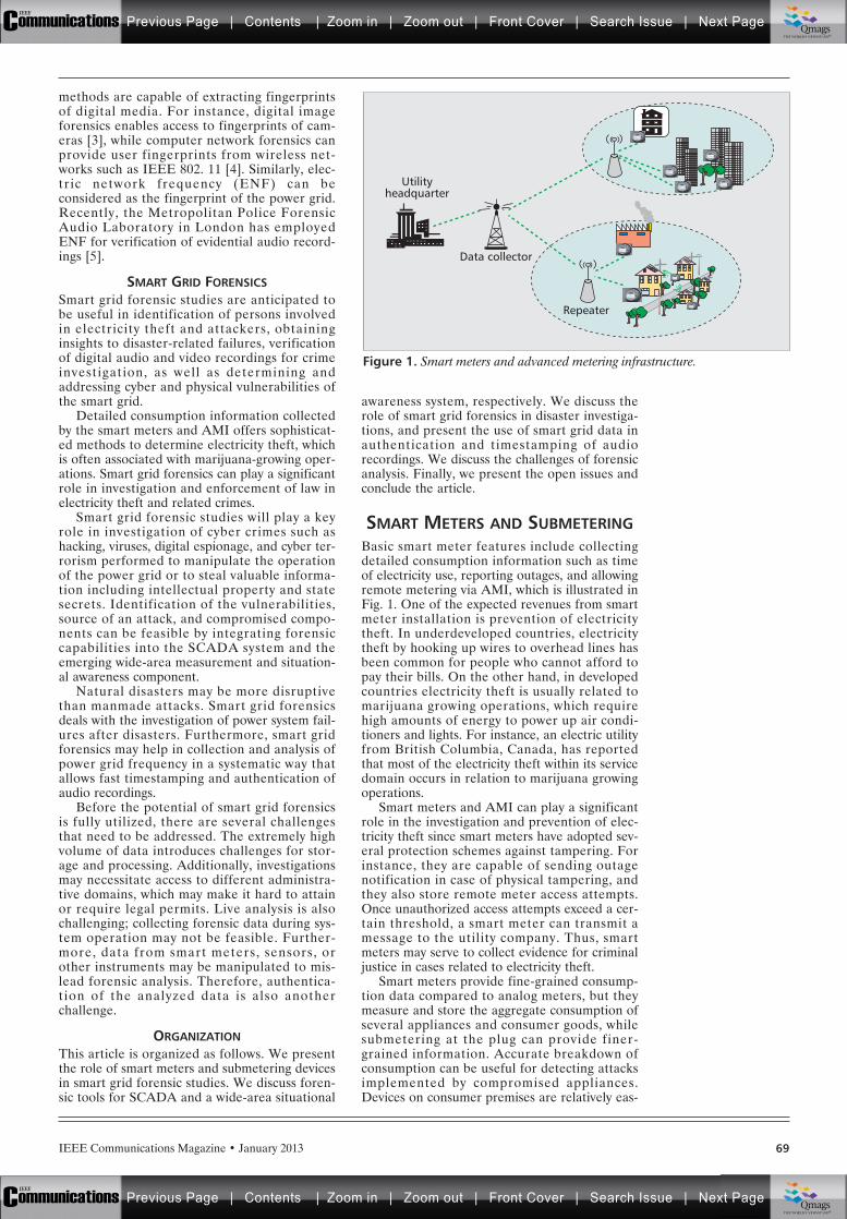
IEEE Communications Magazine • January 2013 69
methods are capable of extracting fingerprintsof digital media. For instance, digital imageforensics enables access to fingerprints of cam-eras [3], while computer network forensics canprovide user fingerprints from wireless net-works such as IEEE 802. 11 [4]. Similarly, elec-tric network frequency (ENF) can beconsidered as the fingerprint of the power grid.Recently, the Metropolitan Police ForensicAudio Laboratory in London has employedENF for verification of evidential audio record-ings [5].
SMART GRID FORENSICSSmart grid forensic studies are anticipated tobe useful in identification of persons involvedin electricity theft and attackers, obtaininginsights to disaster-related failures, verificationof digital audio and video recordings for crimeinvestigation, as well as determining andaddressing cyber and physical vulnerabilities ofthe smart grid.
Detailed consumption information collectedby the smart meters and AMI offers sophisticat-ed methods to determine electricity theft, whichis often associated with marijuana-growing oper-ations. Smart grid forensics can play a significantrole in investigation and enforcement of law inelectricity theft and related crimes.
Smart grid forensic studies will play a keyrole in investigation of cyber crimes such ashacking, viruses, digital espionage, and cyber ter-rorism performed to manipulate the operationof the power grid or to steal valuable informa-tion including intellectual property and statesecrets. Identification of the vulnerabilities,source of an attack, and compromised compo-nents can be feasible by integrating forensiccapabilities into the SCADA system and theemerging wide-area measurement and situation-al awareness component.
Natural disasters may be more disruptivethan manmade attacks. Smart grid forensicsdeals with the investigation of power system fail-ures after disasters. Furthermore, smart gridforensics may help in collection and analysis ofpower grid frequency in a systematic way thatallows fast timestamping and authentication ofaudio recordings.
Before the potential of smart grid forensicsis fully utilized, there are several challengesthat need to be addressed. The extremely highvolume of data introduces challenges for stor-age and processing. Additionally, investigationsmay necessitate access to different administra-tive domains, which may make it hard to attainor require legal permits. Live analysis is alsochallenging; collecting forensic data during sys-tem operation may not be feasible. Further-more, data from smart meters, sensors, orother instruments may be manipulated to mis-lead forensic analysis. Therefore, authentica-tion of the analyzed data is also anotherchallenge.
ORGANIZATIONThis article is organized as follows. We presentthe role of smart meters and submetering devicesin smart grid forensic studies. We discuss foren-sic tools for SCADA and a wide-area situational
awareness system, respectively. We discuss therole of smart grid forensics in disaster investiga-tions, and present the use of smart grid data inauthentication and timestamping of audiorecordings. We discuss the challenges of forensicanalysis. Finally, we present the open issues andconclude the article.
SMART METERS AND SUBMETERINGBasic smart meter features include collectingdetailed consumption information such as timeof electricity use, reporting outages, and allowingremote metering via AMI, which is illustrated inFig. 1. One of the expected revenues from smartmeter installation is prevention of electricitytheft. In underdeveloped countries, electricitytheft by hooking up wires to overhead lines hasbeen common for people who cannot afford topay their bills. On the other hand, in developedcountries electricity theft is usually related tomarijuana growing operations, which requirehigh amounts of energy to power up air condi-tioners and lights. For instance, an electric utilityfrom British Columbia, Canada, has reportedthat most of the electricity theft within its servicedomain occurs in relation to marijuana growingoperations.
Smart meters and AMI can play a significantrole in the investigation and prevention of elec-tricity theft since smart meters have adopted sev-eral protection schemes against tampering. Forinstance, they are capable of sending outagenotification in case of physical tampering, andthey also store remote meter access attempts.Once unauthorized access attempts exceed a cer-tain threshold, a smart meter can transmit amessage to the utility company. Thus, smartmeters may serve to collect evidence for criminaljustice in cases related to electricity theft.
Smart meters provide fine-grained consump-tion data compared to analog meters, but theymeasure and store the aggregate consumption ofseveral appliances and consumer goods, whilesubmetering at the plug can provide finer-grained information. Accurate breakdown ofconsumption can be useful for detecting attacksimplemented by compromised appliances.Devices on consumer premises are relatively eas-
Figure 1. Smart meters and advanced metering infrastructure.
Repeater
Utilityheadquarter
Data collector
Previous Page | Contents | Zoom in | Zoom out | Front Cover | Search Issue | Next PageIEEE
Communications qqM
Mq
qM
MqM
Qmags®THE WORLD’S NEWSSTAND
Previous Page | Contents | Zoom in | Zoom out | Front Cover | Search Issue | Next PageIEEE
Communications qqM
Mq
qM
MqM
Qmags®THE WORLD’S NEWSSTAND
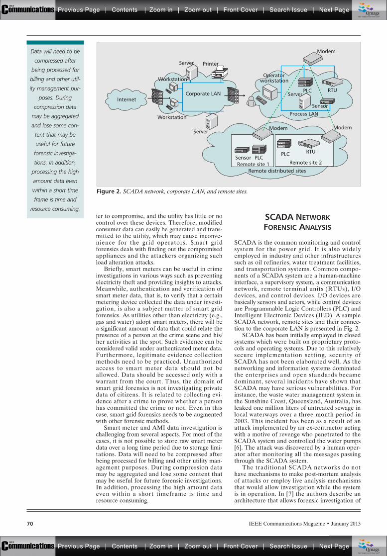
IEEE Communications Magazine • January 201370
ier to compromise, and the utility has little or nocontrol over these devices. Therefore, modifiedconsumer data can easily be generated and trans-mitted to the utility, which may cause inconve-nience for the grid operators. Smart gridforensics deals with finding out the compromisedappliances and the attackers organizing suchload alteration attacks.
Briefly, smart meters can be useful in crimeinvestigations in various ways such as preventingelectricity theft and providing insights to attacks.Meanwhile, authentication and verification ofsmart meter data, that is, to verify that a certainmetering device collected the data under investi-gation, is also a subject matter of smart gridforensics. As utilities other than electricity (e.g.,gas and water) adopt smart meters, there will bea significant amount of data that could relate thepresence of a person at the crime scene and his/her activities at the spot. Such evidence can beconsidered valid under authenticated meter data.Furthermore, legitimate evidence collectionmethods need to be practiced. Unauthorizedaccess to smart meter data should not beallowed. Data should be accessed only with awarrant from the court. Thus, the domain ofsmart grid forensics is not investigating privatedata of citizens. It is related to collecting evi-dence after a crime to prove whether a personhas committed the crime or not. Even in thiscase, smart grid forensics needs to be augmentedwith other forensic methods.
Smart meter and AMI data investigation ischallenging from several aspects. For most of thecases, it is not possible to store raw smart meterdata over a long time period due to storage limi-tations. Data will need to be compressed afterbeing processed for billing and other utility man-agement purposes. During compression datamay be aggregated and lose some content thatmay be useful for future forensic investigations.In addition, processing the high amount dataeven within a short timeframe is time andresource consuming.
SCADA NETWORKFORENSIC ANALYSIS
SCADA is the common monitoring and controlsystem for the power grid. It is also widelyemployed in industry and other infrastructuressuch as oil refineries, water treatment facilities,and transportation systems. Common compo-nents of a SCADA system are a human-machineinterface, a supervisory system, a communicationnetwork, remote terminal units (RTUs), I/Odevices, and control devices. I/O devices arebasically sensors and actors, while control devicesare Programmable Logic Controllers (PLC) andIntelligent Electronic Devices (IED). A sampleSCADA network, remote sites and their connec-tion to the corporate LAN is presented in Fig. 2.
SCADA has been initially employed in closedsystems which were built on proprietary proto-cols and operating systems. Due to this relativelysecure implementation setting, security ofSCADA has not been elaborated well. As thenetworking and information systems dominatedthe enterprises and open standards becamedominant, several incidents have shown thatSCADA may have serious vulnerabilities. Forinstance, the waste water management system inthe Sunshine Coast, Queensland, Australia, hasleaked one million liters of untreated sewage inlocal waterways over a three-month period in2003. This incident has been as a result of anattack implemented by an ex-contractor actingwith a motive of revenge who penetrated to theSCADA system and controlled the water pumps[6]. The attack was discovered by a human oper-ator after monitoring all the messages passingthrough the SCADA system.
The traditional SCADA networks do nothave mechanisms to make post-mortem analysisof attacks or employ live analysis mechanismsthat would allow investigation while the systemis in operation. In [7] the authors describe anarchitecture that allows forensic investigation of
Figure 2. SCADA network, corporate LAN, and remote sites.
Server
Server
Server
Printer
Modem
RTU
RTU
PLC
PLC
Remote distributed sites
Remote site 2Remote site 1PLC
Corporate LAN
WorkstationOperator
workstation
Workstation
Internet
Process LANSensor
Sensor
ModemModem
Data will need to be
compressed after
being processed for
billing and other util-
ity management pur-
poses. During
compression data
may be aggregated
and lose some con-
tent that may be
useful for future
forensic investiga-
tions. In addition,
processing the high
amount data even
within a short time
frame is time and
resource consuming.
Previous Page | Contents | Zoom in | Zoom out | Front Cover | Search Issue | Next PageIEEE
Communications qqM
Mq
qM
MqM
Qmags®THE WORLD’S NEWSSTAND
Previous Page | Contents | Zoom in | Zoom out | Front Cover | Search Issue | Next PageIEEE
Communications qqM
Mq
qM
MqM
Qmags®THE WORLD’S NEWSSTAND

IEEE Communications Magazine • January 2013 71
SCADA network incidents for an industrial set-ting. The main focus of the authors has been dis-covering the identity of the perpetrator and thecauses of the security breach. To this end,“forensic agents” have been placed at strategiclocations that send synopses of the packets to adata warehouse for post-processing and storage.By this method, the authors have been able toreconstruct network events and obtain SCADAnetwork history. This approach has several draw-backs since it includes additional agents anddata warehouse, which may increase the costwhile those components may as well introducesecurity vulnerabilities.
Forensic readiness of SCADA is a newresearch and development field. Very few stud-ies have attempted to provide forensic capabili-ties to SCADA in a general factory setting (e.g.,[7]). When the extremely large scale of the smartgrid is considered, those mechanisms do notscale. In the smart grid, a scalable solution thatis able to collect adequate evidence from theSCADA system for conclusive proof of a securi-ty breach is an open issue. Furthermore, liveanalysis of the SCADA system is highly challeng-ing since any outside attempt to mimic theattacker behavior may cause adverse effects onthe stability of the power grid.
WIDE AREA SYSTEMFORENSIC ANALYSIS
The ability of the smart grid to improve the reli-ability and visualization of the power grid willmostly depend on wide area measurement andsituational awareness systems. The North Ameri-can SynchroPhasor Initiative (NASPI), which isa collaborative effort of the U.S. Department ofEnergy (DoE), the North American ElectricReliability Corporation (NERC), and severalelectric utilities, aims to realize this vision bydeploying a large number of phasor measure-ment units (PMUs) and other wide area mea-surement instruments to the U.S. power grid.Currently, the U.S. power grid houses approxi-mately 200 PMUs, most of which are installed insubstations and power plants, and over 600 addi-tional PMUs are planned to be installed through2013 [8].
PMUs provide timestamped and synchro-nized phasor measurements, which are basicallyphase vectors representing the magnitude andthe phase angle of voltage, current, and frequen-cy signals. The difference between the phaseangles of two nodes implies power flow from thenode with higher phase angle toward the nodewith less phase angle, and the power flowincreases with this difference. If the power flowexceeds a certain threshold, the power grid maybecome unstable; therefore, monitoring phasorsis vital. Time synchronization of phasors is fur-ther necessary to obtain a complete view of thegrid at a specific time. For this purpose, phasorsare synchronized by the Global Positioning Sys-tem (GPS), and synchronized phasors are calledsynchrophasors. PMUs take 30 to 60 measure-ments every second, providing higher-resolutionmeasurements than SCADA, which is capable ofproviding samples every few seconds. Data from
multiple PMUs are collected and time-aligned atthe phasor data concentrators (PDCs), as seenin Fig. 3. In general, several PDCs may be pre-sent at the utility level while a super-PDC isaccommodated at the regional independent sys-tem operator (ISO) level. The ISO stores syn-chrophasor measurements from multiple utilities.
Synchronized measurements are particularlyimportant for real-time control operations andfine-tuned power system planning of the largeinterconnections with time differences betweenregions. Synchrophasors also play a significantrole in forensic analysis of grid disturbances.Pre-disturbance and post-disturbance real-timepictures of an interconnection can provideinsights to failures. Furthermore, forensic analy-sis of PMU data may reveal the location of com-promised nodes if the failure is due to an attack.
Traditionally, wide area power systems havebeen a target of load-based attacks, which selectthe node with the heaviest load as the victim.However, recent research has reported thatnodes which are able to cause more severe cas-cading failures have been selected by attackersin recent incidents [9]. Furthermore, GPS spoof-ing attacks may provide falsified timestamps toPMUs in order to mislead the control decisionsof the grid operators. Forensic analysis of widearea situational awareness (WASA) systems mayhelp in identification of those attacks as well asdetermining the sources of attacks. The signifi-cance of forensic analysis for WASA will bemore pronounced with the adoption of intermit-tent renewable energy generators and PHEVs.The distributed power resources and mobilestorage are more likely to be compromised andexploited by attackers to disrupt power grid sta-bility.
In summary, PMUs may provide valuableforensic information while their security requirescareful handling. At present, security standardsfor the PMU network are not clearly defined,although NERC’s critical infrastructure protec-tion standards (CIP-002 through CIP-009) areconsidered to be applicable in the future. Stor-age of the extremely large amount of PMU datais also challenging. In [8], storage required for
Figure 3. PMUs, PDCs, storage and a super-PDC under utility and ISOdomains.
ISO domainUtility domain
UtilityPDC
LocalPDC
Data storage
LocalPDC
PMU
PMU
PMU
PMU
PMU
PMU
SuperPDC
Data storage
Previous Page | Contents | Zoom in | Zoom out | Front Cover | Search Issue | Next PageIEEE
Communications qqM
Mq
qM
MqM
Qmags®THE WORLD’S NEWSSTAND
Previous Page | Contents | Zoom in | Zoom out | Front Cover | Search Issue | Next PageIEEE
Communications qqM
Mq
qM
MqM
Qmags®THE WORLD’S NEWSSTAND
IEEE Communications Magazine • January 201372
PMU measurements over a year has been calcu-lated to be around 60 Tbytes/ISO consideringthat 10 utilities are collected under an ISO, eachhaving 40 PMUs. PMU data will need to becompressed and archived, so forensic studies callfor sophisticated compression techniques as wellas enhanced data processing techniques to per-form analysis over the archived data.
DISASTER FORENSIC ANALYSISThe power grid as well as other critical infras-tructures are built to withstand moderate naturaldisasters, but they may fail under a severe disas-ter. The damage to the Japanese power gridafter the earthquake and tsunami in March 2011has been investigated by Kwasinski in his recentarticle [2]. The author reports that the Japanesepower grid in the coastal region was destroyed,largely by the tsunami. However, electricity out-age spanned a much larger region where eventhe lightly damaged inland power grid was notable to distribute electricity. Furthermore,although many houses had solar panels, thosepanels were not utilized due to regulations thatforbid their usage under outages.1
Forensic analysis of the disaster in Japanreveals that the centralized power generationand distribution, and lack of microgrids madethe Japanese power grid more vulnerable. Theauthor’s findings after Hurricane Katrina weresimilar, where even small damages to the powerinfrastructure caused outages in large regions.
The smart grid is introducing a number ofenhancements in the control of the power gridthat are anticipated to improve the physicalsecurity of the power grid. On the other hand,control of the grid is becoming more dependenton communication systems, which means thatphysical security of the communication systemsis equally important as the security of the powergrid assets. For this reason, smart grid forensicstudies dealing with disaster aftermath shouldalso include investigating damages to the com-munication system. It is also important to beable to collect information seconds before a fail-ure. Event logging in critical assets similar toflight recorders are disaster forensic tools still tobe developed. Furthermore, recent research hasshown that networks of smart microgridsincrease the survivability of the power grid [10].The investigation of impacts of diasters onmicrogrid networks is an open issue.
AUDIO/VIDEO AUTHENTICATION ANDTIMESTAMPING
Digital audio and video recordings include anadditional frequency component around 60 Hzin Americas and 50 Hz in most parts of the restof the world. This component is a result of thenominal frequency of the power grid, which iscalled ENF. Recording devices powered bymains receive ENF from the power socket, whilebattery-powered recording devices are affectedby the electromagnetic fields emanating fromnearby power lines.
Due to variations in load and generation,ENF deviates around its nominal value. Being a
random signal, it serves as the fingerprint of thepower grid. ENF is clearly observed in the fre-quency domain of the down-sampled signals andcan be filtered by a bandpass filter around thenominal value of the power grid frequency. Inforensic analysis, this fingerprint is compared tothe historical pattern database of the ENF sig-nal, which can be retrieved from another pieceof equipment in the same network. With thistechnique, the time of audio recordings longerthan approximately 10 minutes can be resolved.Besides, authenticity of a recording can be deter-mined since any manipulation of the signal suchas copying and pasting impact the ENF signaland cause abrupt phase changes. ENF has beenused by the Metropolitan Police Forensic AudioLaboratory in London for evidential recordingsin several cases [5].
Smart-grid-aided audio authentication andtimestamping experience similar challenges tothe above mentioned applications due to theirdata-intensive nature. The ENF pattern databaserequires additional storage as well as processingcapabilities. However, different from smartmeter or WASA data, collection of ENF signalsdoes not enforce any security and privacy mea-sures since anyone with a digital recorder isalready able to observe the signal.
CHALLENGES OFSMART GRID FORENSICS
Privacy and security are equally important andchallenging issues in most of the smart gridforensic studies. Particularly, metering and sub-metering data may reveal private informationsuch as health, mental, and economic conditions,as well as the activities and choices of a person.Recent research has presented that it is possibleto obtain a detailed picture of the activities in aproperty, including the absence or presence ofpeople, the number of individuals in the proper-ty, sleep cycles, meal times, and shower times[11, 12]. Forensic methods should not violate theprivacy of citizens, yet be effective to provideevidence in case of a criminal act. It is highlyimportant that data is not made available unlessa legal warrant is present.
Evidential data call for secure and large stor-age, which is challenging in terms of cost. Rawmetering data and smart grid measurementsrequire a large space over a long period of time.Therefore, old data is archived after compres-sion and aggregation. The aggregated data maylose some content that is useful for forensicanalysis. In this case, deriving associations fromdata may be challenging and require sophisticat-ed data processing algorithms.
Forensic analysis generally relies on accurateclocks on devices, while WASA systems may beprone to timestamp attacks. These attacks caneasily be implemented by GPS spoofing and set-ting PMU clocks incorrectly. Incorrectly times-tamped measurements may mislead thesubstation automation and the decisions of gridoperators, and further challenge forensic analy-sis.
The challenges on the SCADA system arethe difficulty of performing live analysis and the
1 Regulations forbid theutilization of distributedenergy sources during out-age because this may riskthe safety of utility workers.
Forensic analysis of
the disaster in Japan
reveals that the cen-
tralized power gen-
eration and
distribution, and lack
of microgrids had
made the Japanese
power grid more vul-
nerable. The author’s
findings after Hurri-
cane Katrina have
been similar where
even small damages
to the power infra-
structure had caused
outage in large
regions.
Previous Page | Contents | Zoom in | Zoom out | Front Cover | Search Issue | Next PageIEEE
Communications qqM
Mq
qM
MqM
Qmags®THE WORLD’S NEWSSTAND
Previous Page | Contents | Zoom in | Zoom out | Front Cover | Search Issue | Next PageIEEE
Communications qqM
Mq
qM
MqM
Qmags®THE WORLD’S NEWSSTAND
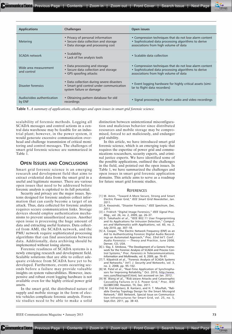
IEEE Communications Magazine • January 2013 73
scalability of forensic methods. Logging allSCADA messages and control actions in a cen-tral data warehouse may be feasible for an indus-trial plant; however, in the power system, itwould generate excessive communication over-head and challenge transmission of critical moni-toring and control messages. The challenges ofsmart grid forensic science are summarized inTable 1.
OPEN ISSUES AND CONCLUSIONSSmart grid forensic science is an emergingresearch and development field that aims toextract evidential data from the smart grid in auseful and legitimate manner. There are variousopen issues that need to be addressed beforeforensic analysis is exploited to its full potential.
Security and privacy are the major issues. Sys-tems designed for forensic analysis collect infor-mation that can easily become a target of anattack. Thus, data collected for forensic analysisrequires secure communication links. Storagedevices should employ authentication mecha-nisms to prevent unauthorized access. Anotheropen issue is processing the huge amount ofdata and extracting useful features. Data collect-ed from AMI, the SCADA network, and thePMU network require sophisticated processingalgorithms that can find associations betweendata. Additionally, data archiving should beimplemented without losing alarms.
Forensic readiness of SCADA systems is anewly emerging research and development field.Scalable solutions that are able to collect ade-quate evidence from SCADA have yet to bedeveloped. Furthermore, events occurring sec-onds before a failure may provide valuableinsights on system vulnerabilities. However, inex-pensive and robust event logging hardware is notavailable even for the highly critical power gridassets.
In the smart grid, the distributed nature ofsupply and mobile storage in the form of elec-tric vehicles complicate forensic analysis. Foren-sic studies need to be able to make a solid
distinction between unintentional misconfigura-tion and malicious behavior since distributedresources and mobile storage may be compro-mised, forced to act maliciously, and endangergrid stability.
In this article, we have introduced smart gridforensic science, which is an emerging topic thatrequires the expertise of power grid and commu-nications researchers, security experts, and crimi-nal justice experts. We have identified some ofthe possible applications, outlined the challengesin the field, and pointed out the open issues. InTable 1, we have summarized the challenges andopen issues in smart grid forensic applicationdomains. This article aims to serve as a roadmapfor future smart grid forensic studies.
REFERENCES[1] M. Amin, “Toward A More Secure, Strong and Smart
Electric Power Grid,” IEEE Smart Grid Newsletter, Jan.2011.
[2] A. Kwasinski, “Disaster Forensics,” IEEE Spectrum, Dec.2011.
[3] J. Fridrich “Digital Image Forensics,” IEEE Signal Proc.Mag., vol. 26, no. 2, 2009, pp. 26–37.
[4] D. Takahashi et al., “IEEE 802.11 User Fingerprintingand Its Applications for Intrusion Detection,” Comput-ers and Mathematics with Applications, vol. 60, no. 2,July 2010, pp. 307–18.
[5] A. Cooper, “The Electric Network Frequency (ENF) as anAid to Authenticating Forensic Digital Audio Record-ings-an Automated Approach,” Proc. 33rd Int’l. Conf.:Audio Forensics — Theory and Practice, June 2008,Denver, CO, USA.
[6] J. Slay, E. Sitnikova, “The Development of a Generic Frame-work for the Forensic Analysis of SCADA and Process Con-trol Systems,” Proc. Forensics in Telecommunications,Information and Multimedia, vol. 8, 2009, pp. 76–81.
[7] T. Kilpatrick et al., “Forensic Analysis of SCADA Systemsand Networks,” Int’l. J. Security and Networks, vol. 3,no. 2, 2008, pp. 95–102.
[8] M. Patel et al., “Real-Time Application of Synchropha-sors for Improving Reliability,” Oct. 2010, http://www.nerc.com/filez/rapirtf.html; last accessed on Jan. 2012.
[9] W. Wang et al., “Risk-aware Attacks and CatastrophicCascading Failures in U.S. Power Grid,” Proc. IEEEGLOBECOM, Houston, TX, Dec. 2011.
[10] M. Erol-Kantarci, B. Kantarci, and H. T. Mouftah, “Reli-able Overlay Topology Design for the Smart MicrogridNetwork,” IEEE Network, Special Issue on Communica-tion Infrastructures for Smart Grid, vol. 25, no. 5,Sept./Oct. 2011, pp. 38–43.
Table 1. A summary of applications, challenges and open issues in smart grid forensic science.
Applications Challenges Open issues
Metering• Privacy of personal information• Secure data collection and storage• Data storage and processing cost
• Compression techniques that do not lose alarm content• Sophisticated data processing algorithms to deriveassociations from high volume of data
SCADA network • Scalability• Lack of live analysis tools • Scalable data collection
Wide area measurementand control
• Data processing and storage• Secure data collection and storage• GPS spoofing attacks
• Compression techniques that do not lose alarm content• Sophisticated data processing algorithms to deriveassociations from high volume of data
Disaster forensics• Data collection during severe disasters• Smart grid control under communicationsystem failure or damage
• Event logging hardware for highly critical assets (simi-lar to flight data recorders)
Audio/video authenticationby ENF
• Obtaining pattern database for oldrecordings • Signal processing for short audio and video recordings
Previous Page | Contents | Zoom in | Zoom out | Front Cover | Search Issue | Next PageIEEE
Communications qqM
Mq
qM
MqM
Qmags®THE WORLD’S NEWSSTAND
Previous Page | Contents | Zoom in | Zoom out | Front Cover | Search Issue | Next PageIEEE
Communications qqM
Mq
qM
MqM
Qmags®THE WORLD’S NEWSSTAND

IEEE Communications Magazine • January 201374
[11] Y. Yan et al., “A Survey on Cyber Security for SmartGrid Communications,” IEEE Commun. Surveys & Tuto-rials, vo. 14, no. 4, 2012.
[12] M. A. Lisovich, D. K. Mulligan, and S. B. Wicker, “Infer-ring Personal Information from Demand-Response Sys-tems,” IEEE Security & Privacy, vol. 8, no. 1, Jan.–Feb.2010, pp. 11–20.
BIOGRAPHIES
MELIKE EROL-KANTARCI (melike. [email protected]) is apostdoctoral fellow at the School of Electrical Engineeringand Computer Science, University of Ottawa. She receivedM. Sc. and Ph.D. degrees from the Department of Comput-er Engineering, Istanbul Technical University, Turkey, in2004 and 2009, respectively. During her Ph.D. studies, shewas a Fulbright visiting researcher at the Department ofComputer Science, University of California at Los Angeles.She received her B.Sc. degree from the Department of Con-trol and Computer Engineering of Istanbul Technical Uni-versity, in 2001. Her main research interests are wireless
sensor networks, smart grid communications, cyber-physi-cal systems, and underwater sensor networks. She has over40 refereed journal articles and conference papers.
HUSSEIN MOUFTAH [F] ([email protected]) joined theSchool of Information Technology and Engineering, Univer-sity of Ottawa in September 2002 as a Canada ResearchChair Professor. Previously he was with the ECE Depart-ment at Queen’s University (1979–2002), where he wasprior to his departure a full professor and the departmentassociate head. He has three years of industrial experiencemainly at BNR of Ottawa, now Nortel Networks(1977–1979). He served as Editor-in-Chief of IEEE Commu-nications Magazine and IEEE ComSoc Director of Maga-zines, Chair of the Awards Committee, and Director ofEducation. He has been a Distinguished Speaker of IEEEComSoc (2000–2007). He is the author or coauthor ofeight books, 57 book chapters, and more than 1200 tech-nical papers and 12 patents in this area. He is a Fellow ofthe Canadian Academy of Engineering, the EngineeringInstitute of Canada, and the Royal Society of Canada RSC:The Academy of Science.
Previous Page | Contents | Zoom in | Zoom out | Front Cover | Search Issue | Next PageIEEE
Communications qqM
Mq
qM
MqM
Qmags®THE WORLD’S NEWSSTAND
Previous Page | Contents | Zoom in | Zoom out | Front Cover | Search Issue | Next PageIEEE
Communications qqM
Mq
qM
MqM
Qmags®THE WORLD’S NEWSSTAND
____________
_________________
IEEE Communications Magazine • January 2013 750163-6804/13/$25.00 © 2013 IEEE
1 These storage systemscan be batteries collocatedwith the renewable powergenerators deployed atcustomers’ premises, orEV batteries, which maysupply back to the gridpart of their stored energyif necessary.
INTRODUCTIONIn these years we are witnessing a rapid transfor-mation of current electric power systems to meetthe increasing demand for higher resilience, effi-ciency, adaptability, and sustainability [1, 2].Indeed, utility companies recognize that the con-
ventional hierarchical, unidirectional, and cen-tralized model for electricity production, distribu-tion, and control adopted in the past is notsuitable to meet those goals, as well as to addressthe numerous challenges posed by undergoingtransformations in technologies, regulations, andlifestyles. More specifically, the major trends thatare driving the evolution of the next-generationelectricity grid toward a smart grid include [1]:• The widespread deployment of renewable
distributed energy resources, or DER (e.g.,micro-generators at residential customers’premises or small-scale wind and solarfarms)
• The need of a more active role for con-sumers, who should better control theirelectricity usage in response to variableenergy supply conditions and/or prices
• The large-scale integration of electric vehi-cles without overloading the electric grid
• The integration of widely dispersed batterystorage systems1
There is a wide consensus that to support theaforementioned new usage scenarios, a smartgrid must deploy a large-scale dedicated commu-nication infrastructure to enable a two-way flowof information between consumers, providers,and grid devices [3, 4]. For instance, a two-waycommunication network, commonly refereed toas advanced metering infrastructure (AMI), isneeded to interconnect the smart meters (i.e.,electricity meters that incorporate networkingand data management functionalities) installedat end customers’ premises with control centersand data aggregators (Fig. 1 provides an illustra-tive example). Then AMI systems can contributein several ways to the realization of the smartgrid vision. First, a utility company can use theAMI network as a data acquisition network tomonitor power quality, or how much electricityis produced/stored by DER units and consumedby household appliances. The utility can exploitall those smart metering data to proactivelyidentify failure conditions and anomalies, andtake appropriate countermeasures, or to imple-ment sophisticated techniques to regulate elec-tricity usage patterns (e.g., dynamic pricing orscheduling of residential loads). In a more gen-eral view, an extended version of the AMI net-work is foreseen to interconnect large numbers
ABSTRACT
Advanced communication/networking tech-nologies should be integrated in next-generationpower systems (a.k.a. smart grids) to improvetheir resilience, efficiency, adaptability, and sus-tainability. Many believe that the smart grid com-munication infrastructure will emerge from theinterconnection of a large number of small-scalenetworks organized into a hierarchical architec-ture covering larger geographic areas. In this arti-cle, first we carry out a thorough analysis of thekey components of the smart grid communicationarchitecture, discussing the different networktopologies and communication technologies thatcould be employed. Special emphasis is given tothe advanced metering infrastructure, which willbe used to interconnect the smart metersdeployed at customers’ premises with data aggre-gators and control centers. The design of scal-able, reliable, and efficient networking solutionsfor AMI systems is an important research prob-lem because these networks are composed ofthousands of resource-constrained embeddeddevices usually interconnected with communica-tion technologies that can provide only low-band-width and unreliable links. The IPv6 RoutingProtocol for Low Power and Lossy Networks wasrecently standardized by the IETF to specificallymeet the requirements of typical AMI applica-tions. In this article we present a thoroughoverview of the protocol, and we critically ana-lyze its advantages and potential limits in AMIapplications. We also conduct a performanceevaluation of RPL using a Contiki-based proto-type of the RPL standard and a network emula-tor. Our results indicate that although averageperformance may appear reasonable for AMInetworks, a few RPL nodes may suffer fromsevere unreliability issues and experience highpacket loss rates due to the selection of subopti-mal paths with highly unreliable links.
ULTIMATE TECHNOLOGIES AND ADVANCES FORFUTURE SMART GRID — UTASG
Emilio Ancillotti, Raffaele Bruno, and Marco Conti, IIT, National Research Council of Italy
The Role of the RPL Routing Protocol forSmart Grid Communications
Previous Page | Contents | Zoom in | Zoom out | Front Cover | Search Issue | Next PageIEEE
Communications qqM
Mq
qM
MqM
Qmags®THE WORLD’S NEWSSTAND
Previous Page | Contents | Zoom in | Zoom out | Front Cover | Search Issue | Next PageIEEE
Communications qqM
Mq
qM
MqM
Qmags®THE WORLD’S NEWSSTAND
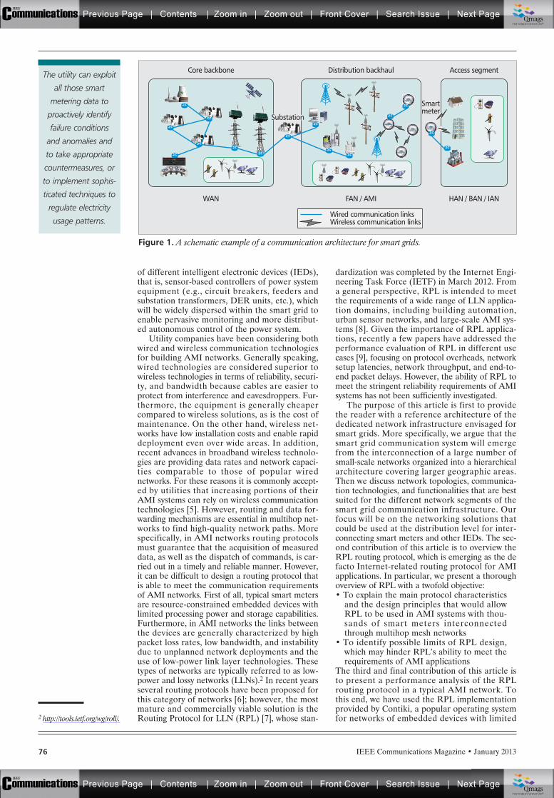
76 IEEE Communications Magazine • January 2013
of different intelligent electronic devices (IEDs),that is, sensor-based controllers of power systemequipment (e.g., circuit breakers, feeders andsubstation transformers, DER units, etc.), whichwill be widely dispersed within the smart grid toenable pervasive monitoring and more distribut-ed autonomous control of the power system.
Utility companies have been considering bothwired and wireless communication technologiesfor building AMI networks. Generally speaking,wired technologies are considered superior towireless technologies in terms of reliability, securi-ty, and bandwidth because cables are easier toprotect from interference and eavesdroppers. Fur-thermore, the equipment is generally cheapercompared to wireless solutions, as is the cost ofmaintenance. On the other hand, wireless net-works have low installation costs and enable rapiddeployment even over wide areas. In addition,recent advances in broadband wireless technolo-gies are providing data rates and network capaci-ties comparable to those of popular wirednetworks. For these reasons it is commonly accept-ed by utilities that increasing portions of theirAMI systems can rely on wireless communicationtechnologies [5]. However, routing and data for-warding mechanisms are essential in multihop net-works to find high-quality network paths. Morespecifically, in AMI networks routing protocolsmust guarantee that the acquisition of measureddata, as well as the dispatch of commands, is car-ried out in a timely and reliable manner. However,it can be difficult to design a routing protocol thatis able to meet the communication requirementsof AMI networks. First of all, typical smart metersare resource-constrained embedded devices withlimited processing power and storage capabilities.Furthermore, in AMI networks the links betweenthe devices are generally characterized by highpacket loss rates, low bandwidth, and instabilitydue to unplanned network deployments and theuse of low-power link layer technologies. Thesetypes of networks are typically referred to as low-power and lossy networks (LLNs).2 In recent yearsseveral routing protocols have been proposed forthis category of networks [6]; however, the mostmature and commercially viable solution is theRouting Protocol for LLN (RPL) [7], whose stan-
dardization was completed by the Internet Engi-neering Task Force (IETF) in March 2012. Froma general perspective, RPL is intended to meetthe requirements of a wide range of LLN applica-tion domains, including building automation,urban sensor networks, and large-scale AMI sys-tems [8]. Given the importance of RPL applica-tions, recently a few papers have addressed theperformance evaluation of RPL in different usecases [9], focusing on protocol overheads, networksetup latencies, network throughput, and end-to-end packet delays. However, the ability of RPL tomeet the stringent reliability requirements of AMIsystems has not been sufficiently investigated.
The purpose of this article is first to providethe reader with a reference architecture of thededicated network infrastructure envisaged forsmart grids. More specifically, we argue that thesmart grid communication system will emergefrom the interconnection of a large number ofsmall-scale networks organized into a hierarchicalarchitecture covering larger geographic areas.Then we discuss network topologies, communica-tion technologies, and functionalities that are bestsuited for the different network segments of thesmart grid communication infrastructure. Ourfocus will be on the networking solutions thatcould be used at the distribution level for inter-connecting smart meters and other IEDs. The sec-ond contribution of this article is to overview theRPL routing protocol, which is emerging as the defacto Internet-related routing protocol for AMIapplications. In particular, we present a thoroughoverview of RPL with a twofold objective:• To explain the main protocol characteristics
and the design principles that would allowRPL to be used in AMI systems with thou-sands of smart meters interconnectedthrough multihop mesh networks
• To identify possible limits of RPL design,which may hinder RPL’s ability to meet therequirements of AMI applications
The third and final contribution of this article isto present a performance analysis of the RPLrouting protocol in a typical AMI network. Tothis end, we have used the RPL implementationprovided by Contiki, a popular operating systemfor networks of embedded devices with limited2 http://tools.ietf.org/wg/roll/.
Figure 1. A schematic example of a communication architecture for smart grids.
Smartmeter
Access segmentDistribution backhaulCore backbone
HAN / BAN / IANFAN / AMIWAN
Substation
Wired communication linksWireless communication links
The utility can exploit
all those smart
metering data to
proactively identify
failure conditions
and anomalies and
to take appropriate
countermeasures, or
to implement sophis-
ticated techniques to
regulate electricity
usage patterns.
Previous Page | Contents | Zoom in | Zoom out | Front Cover | Search Issue | Next PageIEEE
Communications qqM
Mq
qM
MqM
Qmags®THE WORLD’S NEWSSTAND
Previous Page | Contents | Zoom in | Zoom out | Front Cover | Search Issue | Next PageIEEE
Communications qqM
Mq
qM
MqM
Qmags®THE WORLD’S NEWSSTAND
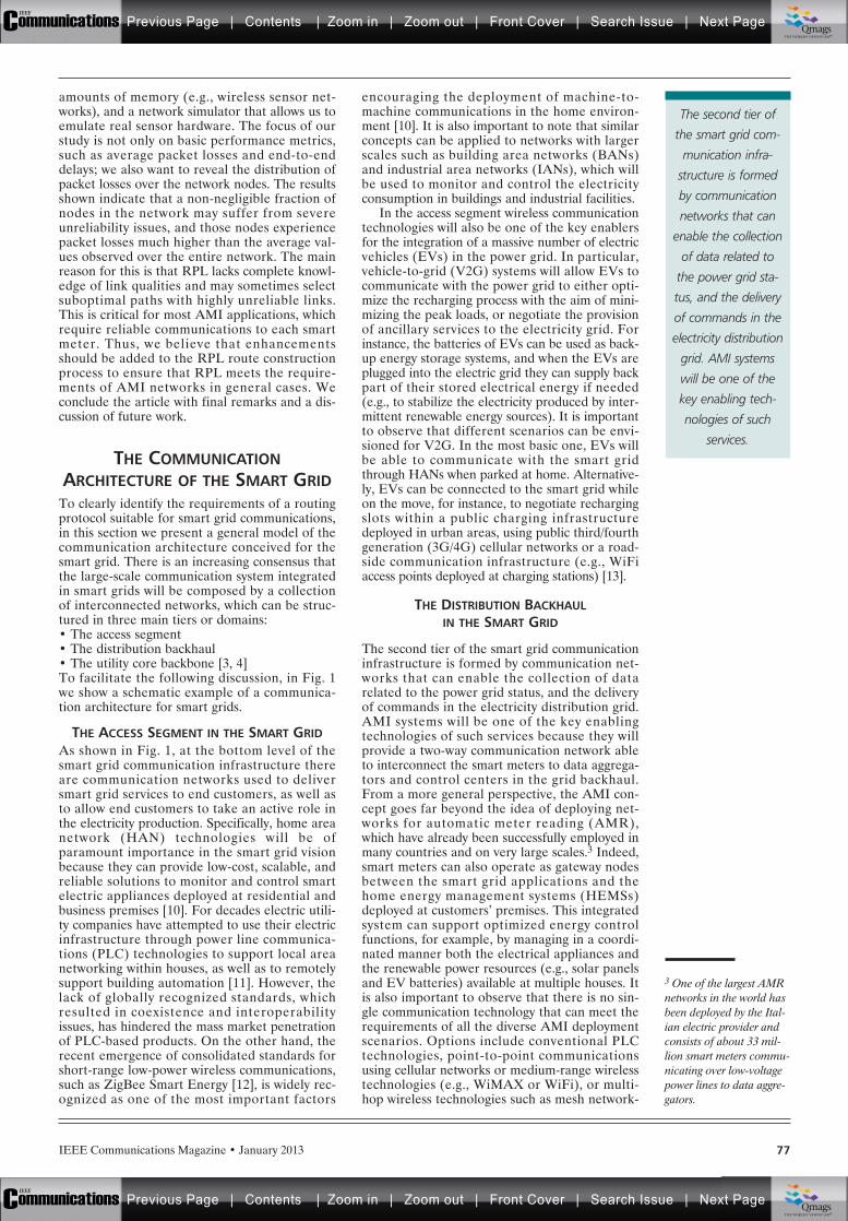
77IEEE Communications Magazine • January 2013
amounts of memory (e.g., wireless sensor net-works), and a network simulator that allows us toemulate real sensor hardware. The focus of ourstudy is not only on basic performance metrics,such as average packet losses and end-to-enddelays; we also want to reveal the distribution ofpacket losses over the network nodes. The resultsshown indicate that a non-negligible fraction ofnodes in the network may suffer from severeunreliability issues, and those nodes experiencepacket losses much higher than the average val-ues observed over the entire network. The mainreason for this is that RPL lacks complete knowl-edge of link qualities and may sometimes selectsuboptimal paths with highly unreliable links.This is critical for most AMI applications, whichrequire reliable communications to each smartmeter. Thus, we believe that enhancementsshould be added to the RPL route constructionprocess to ensure that RPL meets the require-ments of AMI networks in general cases. Weconclude the article with final remarks and a dis-cussion of future work.
THE COMMUNICATIONARCHITECTURE OF THE SMART GRID
To clearly identify the requirements of a routingprotocol suitable for smart grid communications,in this section we present a general model of thecommunication architecture conceived for thesmart grid. There is an increasing consensus thatthe large-scale communication system integratedin smart grids will be composed by a collectionof interconnected networks, which can be struc-tured in three main tiers or domains:• The access segment• The distribution backhaul• The utility core backbone [3, 4]To facilitate the following discussion, in Fig. 1we show a schematic example of a communica-tion architecture for smart grids.
THE ACCESS SEGMENT IN THE SMART GRIDAs shown in Fig. 1, at the bottom level of thesmart grid communication infrastructure thereare communication networks used to deliversmart grid services to end customers, as well asto allow end customers to take an active role inthe electricity production. Specifically, home areanetwork (HAN) technologies will be ofparamount importance in the smart grid visionbecause they can provide low-cost, scalable, andreliable solutions to monitor and control smartelectric appliances deployed at residential andbusiness premises [10]. For decades electric utili-ty companies have attempted to use their electricinfrastructure through power line communica-tions (PLC) technologies to support local areanetworking within houses, as well as to remotelysupport building automation [11]. However, thelack of globally recognized standards, whichresulted in coexistence and interoperabilityissues, has hindered the mass market penetrationof PLC-based products. On the other hand, therecent emergence of consolidated standards forshort-range low-power wireless communications,such as ZigBee Smart Energy [12], is widely rec-ognized as one of the most important factors
encouraging the deployment of machine-to-machine communications in the home environ-ment [10]. It is also important to note that similarconcepts can be applied to networks with largerscales such as building area networks (BANs)and industrial area networks (IANs), which willbe used to monitor and control the electricityconsumption in buildings and industrial facilities.
In the access segment wireless communicationtechnologies will also be one of the key enablersfor the integration of a massive number of electricvehicles (EVs) in the power grid. In particular,vehicle-to-grid (V2G) systems will allow EVs tocommunicate with the power grid to either opti-mize the recharging process with the aim of mini-mizing the peak loads, or negotiate the provisionof ancillary services to the electricity grid. Forinstance, the batteries of EVs can be used as back-up energy storage systems, and when the EVs areplugged into the electric grid they can supply backpart of their stored electrical energy if needed(e.g., to stabilize the electricity produced by inter-mittent renewable energy sources). It is importantto observe that different scenarios can be envi-sioned for V2G. In the most basic one, EVs willbe able to communicate with the smart gridthrough HANs when parked at home. Alternative-ly, EVs can be connected to the smart grid whileon the move, for instance, to negotiate rechargingslots within a public charging infrastructuredeployed in urban areas, using public third/fourthgeneration (3G/4G) cellular networks or a road-side communication infrastructure (e.g., WiFiaccess points deployed at charging stations) [13].
THE DISTRIBUTION BACKHAULIN THE SMART GRID
The second tier of the smart grid communicationinfrastructure is formed by communication net-works that can enable the collection of datarelated to the power grid status, and the deliveryof commands in the electricity distribution grid.AMI systems will be one of the key enablingtechnologies of such services because they willprovide a two-way communication network ableto interconnect the smart meters to data aggrega-tors and control centers in the grid backhaul.From a more general perspective, the AMI con-cept goes far beyond the idea of deploying net-works for automatic meter reading (AMR),which have already been successfully employed inmany countries and on very large scales.3 Indeed,smart meters can also operate as gateway nodesbetween the smart grid applications and thehome energy management systems (HEMSs)deployed at customers’ premises. This integratedsystem can support optimized energy controlfunctions, for example, by managing in a coordi-nated manner both the electrical appliances andthe renewable power resources (e.g., solar panelsand EV batteries) available at multiple houses. Itis also important to observe that there is no sin-gle communication technology that can meet therequirements of all the diverse AMI deploymentscenarios. Options include conventional PLCtechnologies, point-to-point communicationsusing cellular networks or medium-range wirelesstechnologies (e.g., WiMAX or WiFi), or multi-hop wireless technologies such as mesh network-
The second tier of
the smart grid com-
munication infra-
structure is formed
by communication
networks that can
enable the collection
of data related to
the power grid sta-
tus, and the delivery
of commands in the
electricity distribution
grid. AMI systems
will be one of the
key enabling tech-
nologies of such
services.
3 One of the largest AMRnetworks in the world hasbeen deployed by the Ital-ian electric provider andconsists of about 33 mil-lion smart meters commu-nicating over low-voltagepower lines to data aggre-gators.
Previous Page | Contents | Zoom in | Zoom out | Front Cover | Search Issue | Next PageIEEE
Communications qqM
Mq
qM
MqM
Qmags®THE WORLD’S NEWSSTAND
Previous Page | Contents | Zoom in | Zoom out | Front Cover | Search Issue | Next PageIEEE
Communications qqM
Mq
qM
MqM
Qmags®THE WORLD’S NEWSSTAND
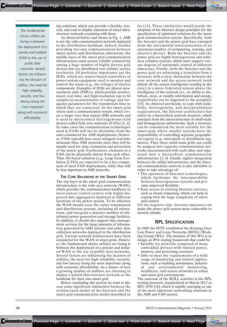
78 IEEE Communications Magazine • January 2013
ing solutions, which can provide a flexible, low-cost, and easy-to-deploy extension of wired infra-structure networks coexisting with them.
As observed before and shown in Fig. 1, AMIis not the only communication network deployedin the distribution backhaul. Indeed, besidesproviding two-way communications betweensmart meters and distribution substations, themiddle layer of the smart grid communicationinfrastructure must ensure reliable connectivityamong a huge number of highly diverse griddevices that are distributed over utilities’ serviceterritories. Of particular importance are theIEDs, which are sensor-based controllers ofpower system equipment used to monitor andcontrol the status (e.g., the voltage) of electriccomponents. Examples of IEDs are phasor mea-surement units (PMUs), which provide synchro-nized, real-time, and high-resolution (up to 60samples/s) measurements of voltage and fre-quency parameters for the transmission lines towhich they are connected. In the smart gridvision such a communication system, which cov-ers a larger area than typical AMI networks andis used to interconnect heterogeneous fielddevices called field area networks (FANs) [3, 4].In some cases the communication technologiesused in FANs will not be dissimilar from theones considered for AMI deployments. Howev-er, FANs typically have more stringent real-timedemands than AMI networks since they will bemainly used for state estimation and protectionof the power grid. Furthermore, elements in aFAN can be physically distant from each other.Thus, 4G-based solutions (e.g., Long Term Evo-lution [LTE]) are expected to be a key compo-nent of most FAN deployments, while they willbe less important in AMI networks.
THE CORE BACKBONE IN THE SMART GRIDThe top layer in the smart grid communicationinfrastructure is the wide area network (WAN),which provides the communication backbone tointerconnect control centers with highly dis-persed data aggregators deployed at differentlocations of the power system. To be effectivethe WAN should cover the entire transmissionand distribution systems, including all substa-tions, and integrate a massive number of dis-tributed power generation and storage facilities.In addition, it should also support data manage-ment services for the large amounts of informa-tion generated by AMI systems and other datacollection networks deployed in the distributiongrid. Various network architectures have beenconsidered for the WAN in smart grids. Howev-er, the fundamental choice utilities are facing isbetween the deployment of a private and isolat-ed WAN or the use of public data networks.Several factors are influencing the decision ofutilities, the need for high reliability, security,and low latency being the most important alongwith economic affordability. As a matter of fact,a growing number of utilities are choosing todeploy a hybrid fiber/wireless network as thebackbone for their own smart grid.
Before concluding this section we want to dis-cuss some significant similarities between thearchitectural model of the Internet and thesmart grid communication model described so
far [14]. These similarities would justify theadoption of the Internet design principles for thespecification of optimized solutions for the smartgrid communication system. Specifically, boththe Internet and the power grid have emergedfrom the incremental interconnection of anenormous number of (computing, sensing, andelectric) devices. Both the Internet and thepower grid are highly heterogeneous and wide-area complex systems, which must support vari-ous degrees of autonomic control at differenttimescales. Finally, both the Internet and thepower grid are witnessing a transition from astructure with a clear distinction between thecore network and the access network (withalmost all the system intelligence residing in thecore) to a more federated system where theintelligence of the network (i.e., its ability to dis-tribute, store, or modify information and energy,respectively) can be migrated to the periphery[15]. As observed previously, to cope with scala-bility, heterogeneity, and decentralizationrequirements, the Internet architecture hasrelied on a hierarchical network structure, whichemerged from the interconnection of small-scaleand homogeneous subnetworks. Such a structurecan be considered the most suitable for thesmart grid, where smaller systems have theresponsibility of controlling separate geographi-cal regions (e.g., microgrids or distribution seg-ments). Then these small-scale grids can easilybe mapped into separate communication net-works interconnected with each other and orga-nized into a hierarchical communicationinfrastructure [3, 4]. Finally, tighter integrationbetween the utility infrastructure and the Inter-net communication network is also advisable inorder to take advantage of:• The openness of Internet technologies,
which facilitates the interoperabilitybetween heterogeneous systems and pro-vides improved flexibility
• Easy access to existing Internet services,such as cloud computing, which can help incoping with the huge complexity of smartgrid control
On the negative side, Internet openness canmake the power grid system more vulnerable tosecurity attacks.
RPL SPECIFICATIONIn 2008 the IETF established the Routing OverLow Power and Lossy Networks (ROLL) Work-ing Group (WG). The mission of this WG is todesign an IPv6 routing framework that could be:• Suitable for networks composed of many
embedded devices with limited power,memory, and processing resources
• Able to meet the requirements of a widerange of monitoring and control applica-tions, such as building automation, industri-al and environmental monitoring,healthcare, and sensor networks in urbanand smart grid environments
The outcome of the ROLL activities is the RPLrouting protocol, standardized in March 2012 asRFC 6550 [16], which is rapidly emerging as oneof the most important networking solutions inthe AMI and FAN sectors.
The fundamental
choice utilities are
facing is between
the deployment of a
private and isolated
WAN or the use of
public data
networks. Several
factors are influenc-
ing the decision of
utilities, the need for
high reliability,
security, and low
latency being the
most important
along with economic
affordability.
Previous Page | Contents | Zoom in | Zoom out | Front Cover | Search Issue | Next PageIEEE
Communications qqM
Mq
qM
MqM
Qmags®THE WORLD’S NEWSSTAND
Previous Page | Contents | Zoom in | Zoom out | Front Cover | Search Issue | Next PageIEEE
Communications qqM
Mq
qM
MqM
Qmags®THE WORLD’S NEWSSTAND

79IEEE Communications Magazine • January 2013
In the following we present the main designprinciples on which RPL is built, and we describethe most important RPL mechanisms and fea-tures. This overview is essential to point out themain advantages and disadvantages of this rout-ing protocol, as well as to correctly interpret theexperimental results shown earlier.
RPL DESIGN PRINCIPLESThe design principles of the RPL routing proto-col directly stem from the type of networks andtraffic patterns for which RPL should be opti-mized. More specifically, RPL is designed tooperate in large-scale networks made up of tinydevices communicating over low-power and low-cost communication technologies. For these rea-sons, the main goals of RPL are to:• Minimize the memory requirements (i.e.,
the storage space for maintaining routinginformation and routing tables)
• Adopt low-complexity routing and data for-warding mechanisms to facilitate thedeployment on simple microcontrollers withconstrained capabilities
• Reduce the routing signaling overheads tolower both the bandwidth usage and energyconsumption
• Distribute compact routing information tosupport link layer technologies with restrict-ed frame sizes
• Efficiently discover links and peers in orderto be suitable for networks that do not havea predefined topology (e.g., multihop radionetworks)
Furthermore, RPL is primarily optimized for therouting requirements of data acquisition net-works, where most traffic is multipoint-to-point;that is, it flows from RPL nodes toward a singlenetwork aggregation point (i.e., the sink in thejargon of sensor networks). On the other hand,less efficient routing is supported for point-to-multipoint traffic (i.e., from a central controlpoint to a subset of RPL nodes), while only basicrouting support is provided for point-to-pointtraffic (i.e., between two RPL peering nodes),which is assumed to be unlikely. However, thereare application scenarios for smart grids wheredata traffic characteristics are different. In partic-ular, in many AMI applications traffic is intrinsi-cally bidirectional. A typical example is the caseof utility companies that wish to proactivelyrequest smart meters to report the current and/orplanned electricity consumption of householdappliances in order to forecast future loads, aswell as to modify the schedule of householdactivities. Another example is dynamic electricitypricing, where the utility may need to periodicallysend updated energy prices to individual HEMSsto enable demand response applications.
DAG, DODAG, AND RPL INSTANCESThe goal of RPL is to build a network topologyon top of an LLN that includes multiple partiallyoverlapping link-layer broadcast domains. Tominimize the network state information, RPLbuilds multiple “destination-oriented” directedacyclic graphs (DODAGs), each one rooted at adifferent sink (also called border router, gateway,or DODAG root), which are tree-based networktopologies where all the links are oriented in
such a way that no cycles exist. It is important tonote that each RPL node (i.e., a device that usesRPL) can be part of at most one DODAG. Thisimplies that DODAGs are not overlapping, andtheir union, called a DAG, is a partition coveringthe entire network topology. In order to accountfor different routing requirements within thesame communication network, RPL introducesthe concept of an RPL instance. Basically, allDODAGs within the same instance share thesame routing metrics and constraints, and multi-ple RPL instances can run independent of eachother within a single network topology. Forinstance, RPL instances can enable traffic priori-tization through the differentiation of traffic for-warding techniques. Figure 2 provides anexample of how RPL nodes form DODAGs byselecting suitable parent nodes, and how multipleDODAGs form an RPL instance.
The main feature that differentiates RPLinstances is the objective function, which specifieshow routing metrics and optimization objectivesare used to select parent nodes in a DODAG,that is, how routes are constructed to meet theapplication quality of service (QoS) requirements[17]. Furthermore, the objective function is alsoused to compute the rank value of a node. Gen-erally speaking, the node rank represents the vir-tual coordinates of that node (i.e., its distance tothe DODAG root with respect to a given met-ric). Although the rank value of an RPL node isnot necessarily equivalent to the cost of the net-work path from that node to the DODAG root,it is reasonable to expect that QoS-aware routingmetrics will be commonly used in the rank com-putation to enforce QoS. It is important to notethat, independent of the specific formulation ofthe objective function, rank values must mono-tonically decrease as a DODAG is followedtoward the sink to allow the efficient use of gra-dient-based forwarding. An example of a feasiblerank assignment is also depicted in Fig. 2. Final-ly, RPL restricts the ability of a node to changeits membership (i.e., rank and preferred parentnode) in the DODAG to limit routing instabilityand loops.
In the following sections we describe themost important RPL mechanisms in more detail.
DODAG CONSTRUCTION FORMULTIPOINT-TO-POINT ROUTES
To build a DODAG, a root node advertises itspresence by periodically sending control mes-sages, called DODAG information object (DIO)packets, as options of IPv6 router advertise-ments, which are transmitted using multicastframes.4 In addition, DIO messages include thecommon configuration attributes that all RPLnodes should adopt in the DODAG. Uponreceiving DIO messages, each RPL node learnsthe set of its neighbors and their rank values.Then, using the OF associated to the RPLinstance to which the advertised DODAGbelongs, each RPL node can compute its rankvalue from the rank values of its neighbors. Fur-thermore, the OF specifies how the RPL nodeshould select the preferred parent node within itsparent set (i.e., the set of its neighbors with alower rank). The preferred parent is used as the
A typical example is
the case of utility
companies that wish
to proactively
request smart meters
to report the current
and/or planned elec-
tricity consumption
of household appli-
ances in order to
forecast future loads,
as well as to modify
the schedule of
household activities.
4 The RPL specificationassumes the allocation ofa new permanent IPv6multicast address with alink-local scope for RPLnodes called all-RPL-nodes.
Previous Page | Contents | Zoom in | Zoom out | Front Cover | Search Issue | Next PageIEEE
Communications qqM
Mq
qM
MqM
Qmags®THE WORLD’S NEWSSTAND
Previous Page | Contents | Zoom in | Zoom out | Front Cover | Search Issue | Next PageIEEE
Communications qqM
Mq
qM
MqM
Qmags®THE WORLD’S NEWSSTAND
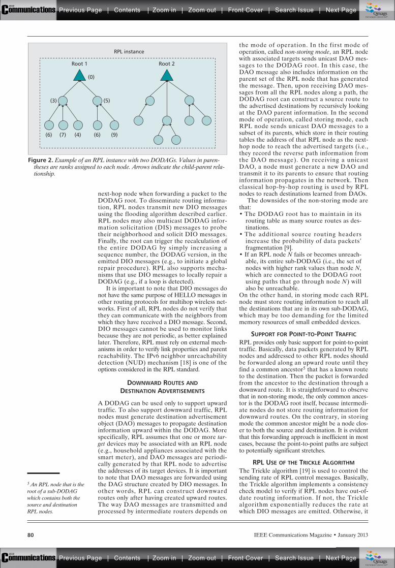
80 IEEE Communications Magazine • January 2013
next-hop node when forwarding a packet to theDODAG root. To disseminate routing informa-tion, RPL nodes transmit new DIO messagesusing the flooding algorithm described earlier.RPL nodes may also multicast DODAG infor-mation solicitation (DIS) messages to probetheir neighborhood and solicit DIO messages.Finally, the root can trigger the recalculation ofthe entire DODAG by simply increasing asequence number, the DODAG version, in theemitted DIO messages (e.g., to initiate a globalrepair procedure). RPL also supports mecha-nisms that use DIO messages to locally repair aDODAG (e.g., if a loop is detected).
It is important to note that DIO messages donot have the same purpose of HELLO messages inother routing protocols for multihop wireless net-works. First of all, RPL nodes do not verify thatthey can communicate with the neighbors fromwhich they have received a DIO message. Second,DIO messages cannot be used to monitor linksbecause they are not periodic, as better explainedlater. Therefore, RPL must rely on external mech-anisms in order to verify link properties and parentreachability. The IPv6 neighbor unreachabilitydetection (NUD) mechanism [18] is one of theoptions considered in the RPL standard.
DOWNWARD ROUTES ANDDESTINATION ADVERTISEMENTS
A DODAG can be used only to support upwardtraffic. To also support downward traffic, RPLnodes must generate destination advertisementobject (DAO) messages to propagate destinationinformation upward within the DODAG. Morespecifically, RPL assumes that one or more tar-get devices may be associated with an RPL node(e.g., household appliances associated with thesmart meter), and DAO messages are periodi-cally generated by that RPL node to advertisethe addresses of its target devices. It is importantto note that DAO messages are forwarded usingthe DAG structure created by DIO messages. Inother words, RPL can construct downwardroutes only after having created upward routes.The way DAO messages are transmitted andprocessed by intermediate routers depends on
the mode of operation. In the first mode ofoperation, called non-storing mode, an RPL nodewith associated targets sends unicast DAO mes-sages to the DODAG root. In this case, theDAO message also includes information on theparent set of the RPL node that has generatedthe message. Then, upon receiving DAO mes-sages from all the RPL nodes along a path, theDODAG root can construct a source route tothe advertised destinations by recursively lookingat the DAO parent information. In the secondmode of operation, called storing mode, eachRPL node sends unicast DAO messages to asubset of its parents, which store in their routingtables the address of that RPL node as the next-hop node to reach the advertised targets (i.e.,they record the reverse path information fromthe DAO message). On receiving a unicastDAO, a node must generate a new DAO andtransmit it to its parents to ensure that routinginformation propagates in the network. Thenclassical hop-by-hop routing is used by RPLnodes to reach destinations learned from DAOs.
The downsides of the non-storing mode arethat:• The DODAG root has to maintain in its
routing table as many source routes as des-tinations.
• The additional source routing headersincrease the probability of data packets’fragmentation [9].
• If an RPL node N fails or becomes unreach-able, its entire sub-DODAG (i.e., the set ofnodes with higher rank values than node N,which are connected to the DODAG rootusing paths that go through node N) willalso be unreachable.
On the other hand, in storing mode each RPLnode must store routing information to reach allthe destinations that are in its own sub-DODAG,which may be too demanding for the limitedmemory resources of small embedded devices.
SUPPORT FOR POINT-TO-POINT TRAFFICRPL provides only basic support for point-to-pointtraffic. Basically, data packets generated by RPLnodes and addressed to other RPL nodes shouldbe forwarded along an upward route until theyfind a common ancestor5 that has a known routeto the destination. Then the packet is forwardedfrom the ancestor to the destination through adownward route. It is straightforward to observethat in non-storing mode, the only common ances-tor is the DODAG root itself, because intermedi-ate nodes do not store routing information fordownward routes. On the contrary, in storingmode the common ancestor might be a node clos-er to both the source and destination. It is evidentthat this forwarding approach is inefficient in mostcases, because the point-to-point paths are subjectto potentially significant stretches.
RPL USE OF THE TRICKLE ALGORITHMThe Trickle algorithm [19] is used to control thesending rate of RPL control messages. Basically,the Trickle algorithm implements a consistencycheck model to verify if RPL nodes have out-of-date routing information. If not, the Tricklealgorithm exponentially reduces the rate atwhich DIO messages are emitted. Otherwise, it
Figure 2. Example of an RPL instance with two DODAGs. Values in paren-theses are ranks assigned to each node. Arrows indicate the child-parent rela-tionship.
RPL instance
(0)
(5)
Root 1
(3)
(6) (7) (4) (6) (9)
Root 2
5 An RPL node that is theroot of a sub-DODAGwhich contains both thesource and destinationRPL nodes.
Previous Page | Contents | Zoom in | Zoom out | Front Cover | Search Issue | Next PageIEEE
Communications qqM
Mq
qM
MqM
Qmags®THE WORLD’S NEWSSTAND
Previous Page | Contents | Zoom in | Zoom out | Front Cover | Search Issue | Next PageIEEE
Communications qqM
Mq
qM
MqM
Qmags®THE WORLD’S NEWSSTAND
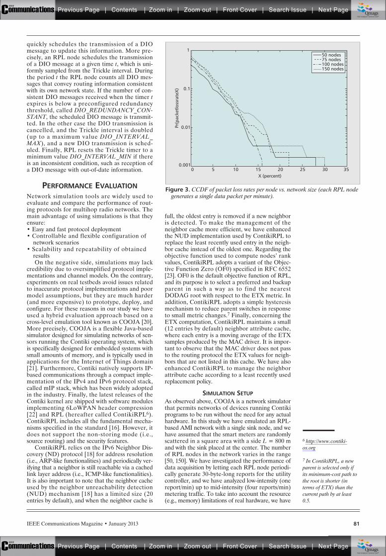
81IEEE Communications Magazine • January 2013
quickly schedules the transmission of a DIOmessage to update this information. More pre-cisely, an RPL node schedules the transmissionof a DIO message at a given time t, which is uni-formly sampled from the Trickle interval. Duringthe period t the RPL node counts all DIO mes-sages that convey routing information consistentwith its own network state. If the number of con-sistent DIO messages received when the timer texpires is below a preconfigured redundancythreshold, called DIO_REDUNDANCY_CON-STANT, the scheduled DIO message is transmit-ted. In the other case the DIO transmission iscancelled, and the Trickle interval is doubled(up to a maximum value DIO_INTERVAL_MAX), and a new DIO transmission is sched-uled. Finally, RPL resets the Trickle timer to aminimum value DIO_INTERVAL_MIN if thereis an inconsistent condition, such as reception ofa DIO message with out-of-date information.
PERFORMANCE EVALUATIONNetwork simulation tools are widely used toevaluate and compare the performance of rout-ing protocols for multihop radio networks. Themain advantage of using simulations is that theyensure:• Easy and fast protocol deployment• Controllable and flexible configuration of
network scenarios• Scalability and repeatability of obtained
resultsOn the negative side, simulations may lack
credibility due to oversimplified protocol imple-mentations and channel models. On the contrary,experiments on real testbeds avoid issues relatedto inaccurate protocol implementations and poormodel assumptions, but they are much harder(and more expensive) to prototype, deploy, andconfigure. For these reasons in our study we haveused a hybrid evaluation approach based on across-level emulation tool known as COOJA [20].More precisely, COOJA is a flexible Java-basedsimulator designed for simulating networks of sen-sors running the Contiki operating system, whichis specifically designed for embedded systems withsmall amounts of memory, and is typically used inapplications for the Internet of Things domain[21]. Furthermore, Contiki natively supports IP-based communications through a compact imple-mentation of the IPv4 and IPv6 protocol stack,called mIP stack, which has been widely adoptedin the industry. Finally, the latest releases of theContiki kernel are shipped with software modulesimplementing 6LoWPAN header compression[22] and RPL (hereafter called ContikiRPL6).ContikiRPL includes all the fundamental mecha-nisms specified in the standard [16]. However, itdoes not support the non-storing mode (i.e.,source routing) and the security features.
ContikiRPL relies on the IPv6 Neighbor Dis-covery (ND) protocol [18] for address resolution(i.e., ARP-like functionalities) and periodically ver-ifying that a neighbor is still reachable via a cachedlink layer address (i.e., ICMP-like functionalities).It is also important to note that the neighbor cacheused by the neighbor unreachability detection(NUD) mechanism [18] has a limited size (20entries by default), and when the neighbor cache is
full, the oldest entry is removed if a new neighboris detected. To make the management of theneighbor cache more efficient, we have enhancedthe NUD implementation used by ContikiRPL toreplace the least recently used entry in the neigh-bor cache instead of the oldest one. Regarding theobjective function used to compute nodes’ rankvalues, ContikiRPL adopts a variant of the Objec-tive Function Zero (OF0) specified in RFC 6552[23]. OF0 is the default objective function of RPL,and its purpose is to select a preferred and backupparent in such a way as to find the nearestDODAG root with respect to the ETX metric. Inaddition, ContikiRPL adopts a simple hysteresismechanism to reduce parent switches in responseto small metric changes.7 Finally, concerning theETX computation, ContikiRPL maintains a small(12 entries by default) neighbor attribute cache,where each entry is a moving average of the ETXsamples produced by the MAC driver. It is impor-tant to observe that the MAC driver does not passto the routing protocol the ETX values for neigh-bors that are not listed in this cache. We have alsoenhanced ContikiRPL to manage the neighborattribute cache according to a least recently usedreplacement policy.
SIMULATION SETUPAs observed above, COOJA is a network simulatorthat permits networks of devices running Contikiprograms to be run without the need for any actualhardware. In this study we have emulated an RPL-based AMI network with a single sink node, and wehave assumed that the smart meters are randomlyscattered in a square area with a side L = 800 mand with the sink placed at the center. The numberof RPL nodes in the network varies in the range[50, 150]. We have investigated the performance ofdata acquisition by letting each RPL node periodi-cally generate 30-byte-long reports for the utilitycontroller, and we have analyzed low-intensity (onereport/min) up to mid-intensity (four reports/min)metering traffic. To take into account the resource(e.g., memory) limitations of real hardware, we have
6 http://www.contiki-os.org
7 In ContikiRPL, a newparent is selected only ifits minimum-cost path tothe root is shorter (interms of ETX) than thecurrent path by at least0.5.
Figure 3. CCDF of packet loss rates per node vs. network size (each RPL nodegenerates a single data packet per minute).
X (percent)50
0.01
0.001
Pr(p
acke
tlos
srat
eX) 0.1
1
10 15 20 25 30 35
50 nodes75 nodes100 nodes150 nodes
Previous Page | Contents | Zoom in | Zoom out | Front Cover | Search Issue | Next PageIEEE
Communications qqM
Mq
qM
MqM
Qmags®THE WORLD’S NEWSSTAND
Previous Page | Contents | Zoom in | Zoom out | Front Cover | Search Issue | Next PageIEEE
Communications qqM
Mq
qM
MqM
Qmags®THE WORLD’S NEWSSTAND
__________
___
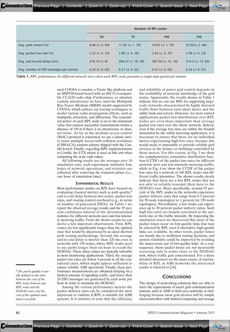
82 IEEE Communications Magazine • January 2013
used COOJA to emulate a Tmote Sky platform andan MSP430-based board with an 802.15.4-compati-ble CC2420 radio chip. Furthermore, to simulaterealistic interference we have used the MultipathRay-Tracer Medium (MRM) model supported byCOOJA, which utilizes ray-tracing techniques tomodel various radio propagation effects, such asmultipath, refraction, and diffraction. The transmit-ted power of each RPL node is set to the minimumvalue that ensures successful transmissions within adistance of 150 m if there is no interference or chan-nel noise. As far as the medium access control(MAC) protocol is concerned, we use a classic carri-er sense multiple access with collision avoidance(CSMA/CA) random scheme shipped with the Con-tiki kernel. Finally, regarding RPL implementationin Contiki, the ETX metric is used as link cost whencomputing the node rank values.
All following results are the averages over 10simulation runs, each experiment simulates fourhours of network operations, and statistics arecollected after removing the transient phase (i.e.,one hour of simulation time).
EXPERIMENTAL RESULTSMost performance studies on RPL have focused onevaluating classical metrics such as path quality,8end-to-end delay between two nodes, packet lossrates, and routing control overhead (e.g., in termsof number of generated DIOs). In Table 1 wereport the observed average results and the 95 per-cent confidence interval of the aforementionedstatistics for different network sizes and low-intensi-ty metering traffic. From the shown results we canderive a few important observations. First, RPLroutes are not significantly longer than the optimalones that would be discovered by an ideal shortestpath routing methodology. Second, the averageend-to-end delay is shorter than 320 ms even innetworks with 150 nodes, where RPL nodes needto use paths longer than six hops to reach theDODAG. These delay values are typically tolerablein most monitoring applications. Third, the averagepacket loss rates are below 4 percent in all the con-sidered cases, which might appear sufficient toensure reliable AMI operations. Finally, these per-formance measurements are obtained relaying on alimited amount of signaling traffic, and fewer than20 DIO messages are generated by each node perhour in order to maintain the DODAG.
Among the various performance metrics thepacket delivery rates can be considered the mostimportant to validate if RPL is suitable for AMIsystems. It is intuitive to note that the efficiency
and reliability of power grid control depends onthe availability of accurate knowledge of the gridstatus. Apparently, the results shown in Table 1indicate that we can use RPL for supporting large-scale networks characterized by highly directedtraffic flows between each smart meter and theutility back-end servers. However, for most controlapplications packet loss distributions over RPLnodes are even more important than averagepacket loss rates over the whole network. Indeed,even if the average loss rates are within the boundsdemanded by the utility metering application, it isnecessary to ensure that there are no individualmeters experiencing high loss rates, because thiswould make it impossible to provide reliable gridservices to the homes or buildings controlled bythose meters. For this reason, in Fig. 3 we showthe complementary cumulative distribution func-tion (CCDF) of the packet loss rates for differentnetwork sizes and low-intensity metering traffic,while in Fig. 4 we show the CCDF of the packetloss rates for a network of 100 RPL nodes and dif-ferent traffic intensities. The shown results clearlyindicate that there are a few RPL nodes that arenot able to reliably transmit their data to theDODAG root. More specifically, around 95 per-cent of the RPL nodes in the networks experiencepacket delivery rates that range from 0.5 percent(in 50-node topologies) to 1 percent (in 150-nodetopologies). Nevertheless, a few nodes can experi-ence up to 30 percent packet delivery ratios. Suchhigh loss rates are loosely correlated to the net-work size or the traffic intensity. By inspecting thesimulation traces we discovered that most of thepacket losses occur on low-quality links that maybe selected by RPL even if alternative high-qualitylinks are available. In other words, packet lossesare mostly due to inefficient routing decisions, andsystem reliability could be improved by avoidingthe unnecessary use of low-quality links. As a con-sequence, those packet losses are not necessarilyoccurring only in nodes close to the DODAGsink, where traffic gets concentrated. For a moredetailed discussion on the main causes of unrelia-bility of RPL in AMI networks the interestedreader is referred to [24].
CONCLUSIONSThe design of networking solutions that are able tomeet the equirements of smart grid communicationsystems, such as AMI or field area networks, is chal-lenging because most grid devices will be simplemicrocontrollers with limited computing and storage
8 The patch quality is usu-ally defined as the ratiobetween the cost of theRPL route between anyRPL node and theDODAG root, and thecost of the optimal mini-mum-cost path.
Table 1. RPL performance for different network sizes when each RPL node generates a single data packet per minute.
Number of RPL nodes
50 75 100 150
Avg. path stretch (%) 8.66 (± 0. 94) 11.82 (± 1. 19) 19.07 (± 1. 70) 22.02(± 2. 84)
Avg. packet loss rate (%) 2.22 (± 0. 33) 2.80 (± 0. 26) 2.82 (± 0. 27) 3.36 (± 0. 23)
Avg. end-to-end delays (ms) 218.72 (± 8) 284.37 (± 18. 20) 307.54 (± 12. 10) 314.3 (± 13. 03)
Avg. number of DIO messages per minute 0.25 (± 0. 02) 0.31 (± 0. 02) 0.31 (± 0. 03) 0.32 (± 0. 01)
Previous Page | Contents | Zoom in | Zoom out | Front Cover | Search Issue | Next PageIEEE
Communications qqM
Mq
qM
MqM
Qmags®THE WORLD’S NEWSSTAND
Previous Page | Contents | Zoom in | Zoom out | Front Cover | Search Issue | Next PageIEEE
Communications qqM
Mq
qM
MqM
Qmags®THE WORLD’S NEWSSTAND
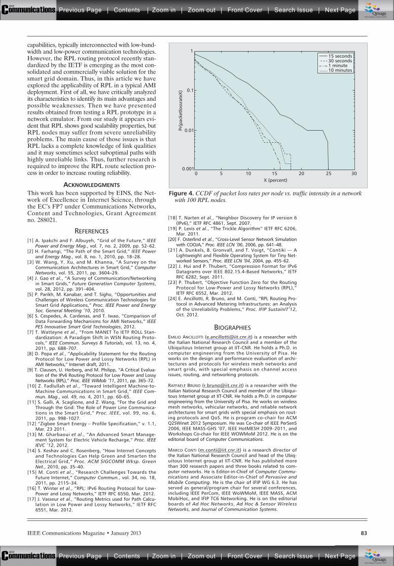
83IEEE Communications Magazine • January 2013
capabilities, typically interconnected with low-band-width and low-power communication technologies.However, the RPL routing protocol recently stan-dardized by the IETF is emerging as the most con-solidated and commercially viable solution for thesmart grid domain. Thus, in this article we haveexplored the applicability of RPL in a typical AMIdeployment. First of all, we have critically analyzedits characteristics to identify its main advantages andpossible weaknesses. Then we have presentedresults obtained from testing a RPL prototype in anetwork emulator. From our study it appears evi-dent that RPL shows good scalability properties, butRPL nodes may suffer from severe unreliabilityproblems. The main cause of those issues is thatRPL lacks a complete knowledge of link qualitiesand it may sometimes select suboptimal paths withhighly unreliable links. Thus, further research isrequired to improve the RPL route selection pro-cess in order to increase routing reliability.
ACKNOWLEDGMENTSThis work has been supported by EINS, the Net-work of Excellence in Internet Science, throughthe EC’s FP7 under Communications Networks,Content and Technologies, Grant Agreementno. 288021.
REFERENCES[1] A. Ipakchi and F. Albuyeh, “Grid of the Future,” IEEE
Power and Energy Mag., vol. 7, no. 2, 2009, pp. 52–62. [2] H. Farhangi, “The Path of the Smart Grid,” IEEE Power
and Energy Mag., vol. 8, no. 1, 2010, pp. 18–28. [3] W. Wang, Y. Xu, and M. Khanna, “A Survey on the
Communication Architectures in Smart Grid,” ComputerNetworks, vol. 55, 2011, pp. 3604–29.
[4] J. Gao et al., “A Survey of Communication/Networkingin Smart Grids,” Future Generation Computer Systems,vol. 28, 2012, pp. 391–404.
[5] P. Parikh, M. Kanabar, and T. Sighu, “Opportunities andChallenges of Wireless Communication Technologies forSmart Grid Applications,” Proc. IEEE Power and EnergySoc. General Meeting ’10, 2010.
[6] S. Cespedes, A. Cardenas, and T. Iwao, “Comparison ofData Forwarding Mechanisms for AMI Networks,” IEEEPES Innovative Smart Grid Technologies, 2012.
[7] T. Watteyne et al., “From MANET To IETF ROLL Stan-dardization: A Paradigm Shift in WSN Routing Proto-cols,” IEEE Commun. Surveys & Tutorials, vol. 13, no. 4,2011, pp. 688–707.
[8] D. Popa et al., “Applicability Statement for the RoutingProtocol for Low Power and Lossy Networks (RPL) inAMI Networks,” Internet draft, 2011.
[9] T. Clausen, U. Herberg, and M. Philipp, “A Critical Evalua-tion of the IPv6 Routing Protocol for Low Power and LossyNetworks (RPL),” Proc. IEEE WiMob ’11, 2011, pp. 365–72.
[10] Z. Fadlullah et al., “Toward Intelligent Machine-to-Machine Communications in Smart Grid,” IEEE Com-mun. Mag., vol. 49, no. 4, 2011, pp. 60–65.
[11] S. Galli, A. Scaglione, and Z. Wang, “For the Grid andThrough the Grid: The Role of Power Line Communica-tions in the Smart Grid,” Proc. IEEE, vol. 99, no. 6,2011, pp. 998–1027.
[12] “Zigbee Smart Energy – Profile Specification,” v. 1.1,Mar. 23 2011.
[13] M. Gharbaoui et al., “An Advanced Smart Manage-ment System for Electric Vehicle Recharge,” Proc. IEEEIEVC ’12, 2012.
[14] S. Keshav and C. Rosenberg, “How Internet Conceptsand Technologies Can Help Green and Smarten theElectrical Grid,” Proc. ACM SIGCOMM Wksp. GreenNet., 2010, pp. 35–40.
[15] M. Conti et al., “Research Challenges Towards theFuture Internet,” Computer Commun., vol. 34, no. 18,2011, pp. 2115–34.
[16] T. Winter et al., “RPL: IPv6 Routing Protocol for Low-Power and Lossy Networks,” IETF RFC 6550, Mar. 2012.
[17] J. Vasseur et al., “Routing Metrics used for Path Calcu-lation in Low Power and Lossy Networks,” IETF RFC6551, Mar. 2012.
[18] T. Narten et al., “Neighbor Discovery for IP version 6(IPv6),” IETF RFC 4861, Sept. 2007.
[19] P. Levis et al., “The Trickle Algorithm” IETF RFC 6206,Mar. 2011.
[20] F. Osterlind et al., “Cross-Level Sensor Network Simulationwith COOJA,” Proc. IEEE LCN ’06, 2006, pp. 641–48.
[21] A. Dunkels, B. Gronvall, and T. Voigt, “Contiki — ALightweight and Flexible Operating System for Tiny Net-worked Sensors,” Proc. IEEE LCN ’04, 2004, pp. 455–62.
[22] J. Hui and P. Thubert, “Compression Format for IPv6Datagrams over IEEE 802.15.4-Based Networks,” IETFRFC 6282, Sept. 2011.
[23] P. Thubert, “Objective Function Zero for the RoutingProtocol for Low-Power and Lossy Networks (RPL),”IETF RFC 6552, Mar. 2012.
[24] E. Ancillotti, R. Bruno, and M. Conti, “RPL Routing Pro-tocol in Advanced Metering Infrastructures: an Analysisof the Unreliability Problems,” Proc. IFIP SustainIT’12,Oct. 2012.
BIOGRAPHIESEMILIO ANCILLOTTI ([email protected]) is a researcher withthe Italian National Research Council and a member of theUbiquitous Internet group at IIT-CNR. He holds a Ph.D. incomputer engineering from the University of Pisa. Heworks on the design and performance evaluation of archi-tectures and protocols for wireless mesh networks andsmart grids, with special emphasis on channel accessissues, routing, and networking protocols.
RAFFAELE BRUNO ([email protected]) is a researcher with theItalian National Research Council and member of the Ubiqui-tous Internet group at IIT-CNR. He holds a Ph.D. in computerengineering from the University of Pisa. He works on wirelessmesh networks, vehicular networks, and reliable networkarchitectures for smart grids with special emphasis on rout-ing protocols and QoS. He is program co-chair for ACMQ2SWinet 2012 Symposium. He was Co-chair of IEEE PerSenS2006, IEEE MASS-GHS ’07, IEEE HotMESH 2009–2011, andWorkshops Co-chair for IEEE WOWMoM 2012. He is on theeditorial board of Computer Communications.
MARCO CONTI ([email protected]) is a research director ofthe Italian National Research Council and head of the Ubiq-uitous Internet group at IIT-CNR. He has published morethan 300 research papers and three books related to com-puter networks. He is Editor-in-Chief of Computer Commu-nications and Associate Editor-in-Chief of Pervasive andMobile Computing. He is the chair of IFIP WG 6.3. He hasserved as general/program chair for several conferences,including IEEE PerCom, IEEE WoWMoM, IEEE MASS, ACMMobiHoc, and IFIP TC6 Networking. He is on the editorialboards of Ad Hoc Networks, Ad Hoc & Sensor WirelessNetworks, and Journal of Communication Systems.
Figure 4. CCDF of packet loss rates per node vs. traffic intensity in a networkwith 100 RPL nodes.
X (percent)50
0.01
0.001
Pr(p
acke
tlos
srat
eX) 0.1
1
10 15 20 25 30
15 seconds30 seconds1 minute10 minutes
Previous Page | Contents | Zoom in | Zoom out | Front Cover | Search Issue | Next PageIEEE
Communications qqM
Mq
qM
MqM
Qmags®THE WORLD’S NEWSSTAND
Previous Page | Contents | Zoom in | Zoom out | Front Cover | Search Issue | Next PageIEEE
Communications qqM
Mq
qM
MqM
Qmags®THE WORLD’S NEWSSTAND
___________
_________
__________
IEEE Communications Magazine • January 201384 0163-6804/13/$25.00 © 2013 IEEE
INTRODUCTION
Recent years have witnessed the power industryintegrating its distribution system with communi-cation networks and control techniques to forma data-flow-based framework, commonly called asmart grid. Such integration not only moves thetraditional power generation and transmissionsystem to an advanced intelligent communica-tion system, but also brings heterogeneous ser-vice provision (e.g., multimedia applications) tothese data networks. Actually, supporting differ-ent kinds of services over smart grids has beenone of the hot topics in the network and com-munication communities. For example, as shown
in Fig. 1, a classical intelligent smart grid plat-form has defined an overlay architecture for pro-viding heterogeneous services [1].
To provide heterogeneous services with quali-ty of service (QoS) guarantee, technologies (i.e.,wireless communications and multimedia signalprocessing) have incorporated into the smartgrid. Moreover, the middleware should be devel-oped as a bridge between system and operator.A fundamental part of middleware is the wide-area monitoring system including sensor net-works, WiFi, satellite communications, cellularnetwork, the Internet, and so on [2, 3]. Impor-tantly, the information of the system state is theinput of the middleware, which enables systemoperators to dynamically assign power to usersaccording to their requests via the communica-tions networks. Unlike the middleware in tradi-tional wireless/wired networks, in the smart grid,it extends the role of arrangement to users’applications [4].
From the QoS enhancement aspect, applica-tion implementations have high efficiencystrengths. However, the power consumption ofapplication provision is much higher than that ofpure software implementations. The reason isthat flexible application provisions yield highercomputation complexity, which causes a consid-erable increase of power consumption [5].Recently, there is a new trend: the energy assign-ment problem is transformed to distributedresource allocation or scheduling at the applica-tion level [6]. To this end, for an energy-con-strained system, at least in theory, we can satisfydifferent users’ requirements using softwareimplementations such as middleware.
As the smart grid becomes a reality, heteroge-neous service provisions are also expected togrow exponentially. Users’ satisfaction or qualityof experience (QoE) will also certainly face sub-stantial user access and huge applications’ com-putation. Therefore, the role of middleware istotally different from the traditional pure soft-ware tool from the aspects of both the user andthe system [7]. To the best of our knowledge,
ABSTRACT
The current smart grid is undergoing a dras-tic change in order to deal with increasinglydiversified and various service requests from thehuge number of users. The next-generationsmart grid, characterized by service-orientedmiddleware, will be upgraded by jointly employ-ing the technologies in the areas of communica-tions, control, and computing. To design ageneral middleware, an efficient design principleplays a fundamental role, while reliable commu-nication infrastructure and heterogeneous appli-cations lead to sustainability and stability. In thisarticle, we propose an integrated and efficientmiddleware for heterogeneous services in asmart grid. Specifically, we first develop a mutu-al application access control principle that keepsusers obtaining a satisfying assignment. Next, acollaborative and dynamic information exchangeinfrastructure is proposed for different smartmeters, and a local information collector isdesigned to implement the communication andcomputing through power management mes-sages. Finally, we present four steps to design aflexible service-oriented middleware for hetero-geneous applications. Numerical simulationresults are provided to demonstrate the efficien-cy of the proposed middleware.
ULTIMATE TECHNOLOGIES AND ADVANCES FORFUTURE SMART GRID — UTASG
Liang Zhou, Nanjing University of Posts and Telecommunications
Joel J. P. C. Rodrigues, Instituto de Telecomunicações, University of Beria Interior
Service-Oriented Middleware for Smart Grid: Principle, Infrastructure, andApplication
Previous Page | Contents | Zoom in | Zoom out | Front Cover | Search Issue | Next PageIEEE
Communications qqM
Mq
qM
MqM
Qmags®THE WORLD’S NEWSSTAND
Previous Page | Contents | Zoom in | Zoom out | Front Cover | Search Issue | Next PageIEEE
Communications qqM
Mq
qM
MqM
Qmags®THE WORLD’S NEWSSTAND
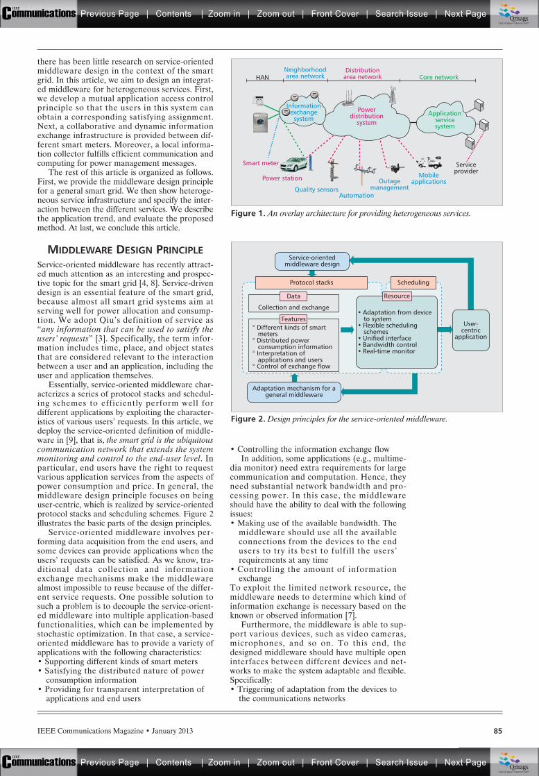
IEEE Communications Magazine • January 2013 85
there has been little research on service-orientedmiddleware design in the context of the smartgrid. In this article, we aim to design an integrat-ed middleware for heterogeneous services. First,we develop a mutual application access controlprinciple so that the users in this system canobtain a corresponding satisfying assignment.Next, a collaborative and dynamic informationexchange infrastructure is provided between dif-ferent smart meters. Moreover, a local informa-tion collector fulfills efficient communication andcomputing for power management messages.
The rest of this article is organized as follows.First, we provide the middleware design principlefor a general smart grid. We then show heteroge-neous service infrastructure and specify the inter-action between the different services. We describethe application trend, and evaluate the proposedmethod. At last, we conclude this article.
MIDDLEWARE DESIGN PRINCIPLEService-oriented middleware has recently attract-ed much attention as an interesting and prospec-tive topic for the smart grid [4, 8]. Service-drivendesign is an essential feature of the smart grid,because almost all smart grid systems aim atserving well for power allocation and consump-tion. We adopt Qiu’s definition of service as“any information that can be used to satisfy theusers’ requests” [3]. Specifically, the term infor-mation includes time, place, and object statesthat are considered relevant to the interactionbetween a user and an application, including theuser and application themselves.
Essentially, service-oriented middleware char-acterizes a series of protocol stacks and schedul-ing schemes to efficiently perform well fordifferent applications by exploiting the character-istics of various users’ requests. In this article, wedeploy the service-oriented definition of middle-ware in [9], that is, the smart grid is the ubiquitouscommunication network that extends the systemmonitoring and control to the end-user level. Inparticular, end users have the right to requestvarious application services from the aspects ofpower consumption and price. In general, themiddleware design principle focuses on beinguser-centric, which is realized by service-orientedprotocol stacks and scheduling schemes. Figure 2illustrates the basic parts of the design principles.
Service-oriented middleware involves per-forming data acquisition from the end users, andsome devices can provide applications when theusers’ requests can be satisfied. As we know, tra-ditional data collection and informationexchange mechanisms make the middlewarealmost impossible to reuse because of the differ-ent service requests. One possible solution tosuch a problem is to decouple the service-orient-ed middleware into multiple application-basedfunctionalities, which can be implemented bystochastic optimization. In that case, a service-oriented middleware has to provide a variety ofapplications with the following characteristics:• Supporting different kinds of smart meters• Satisfying the distributed nature of power
consumption information• Providing for transparent interpretation of
applications and end users
• Controlling the information exchange flowIn addition, some applications (e.g., multime-
dia monitor) need extra requirements for largecommunication and computation. Hence, theyneed substantial network bandwidth and pro-cessing power. In this case, the middlewareshould have the ability to deal with the followingissues:• Making use of the available bandwidth. The
middleware should use all the availableconnections from the devices to the endusers to try its best to fulfill the users’requirements at any time
• Controlling the amount of informationexchange
To exploit the limited network resource, themiddleware needs to determine which kind ofinformation exchange is necessary based on theknown or observed information [7].
Furthermore, the middleware is able to sup-port various devices, such as video cameras,microphones, and so on. To this end, thedesigned middleware should have multiple openinterfaces between different devices and net-works to make the system adaptable and flexible.Specifically:• Triggering of adaptation from the devices to
the communications networks
Figure 1. An overlay architecture for providing heterogeneous services.
HAN
Serviceprovider
Applicationservicesystem
Core networkDistribution
area networkNeighborhoodarea network
Informationexchange
system
Quality sensorsAutomation
Outagemanagement
Mobileapplications
Powerdistribution
system
Smart meter
Power station
Figure 2. Design principles for the service-oriented middleware.
° Different kinds of smart meters° Distributed power consumption information° Interpretation of applications and users° Control of exchange flow
Service-orientedmiddleware design
Adaptation mechanism for ageneral middleware
SchedulingProtocol stacks
• Adaptation from device to system• Flexible scheduling schemes• Unified interface• Bandwidth control• Real-time monitor
ResourceData
Collection and exchange
FeaturesUser-
centricapplication
Previous Page | Contents | Zoom in | Zoom out | Front Cover | Search Issue | Next PageIEEE
Communications qqM
Mq
qM
MqM
Qmags®THE WORLD’S NEWSSTAND
Previous Page | Contents | Zoom in | Zoom out | Front Cover | Search Issue | Next PageIEEE
Communications qqM
Mq
qM
MqM
Qmags®THE WORLD’S NEWSSTAND
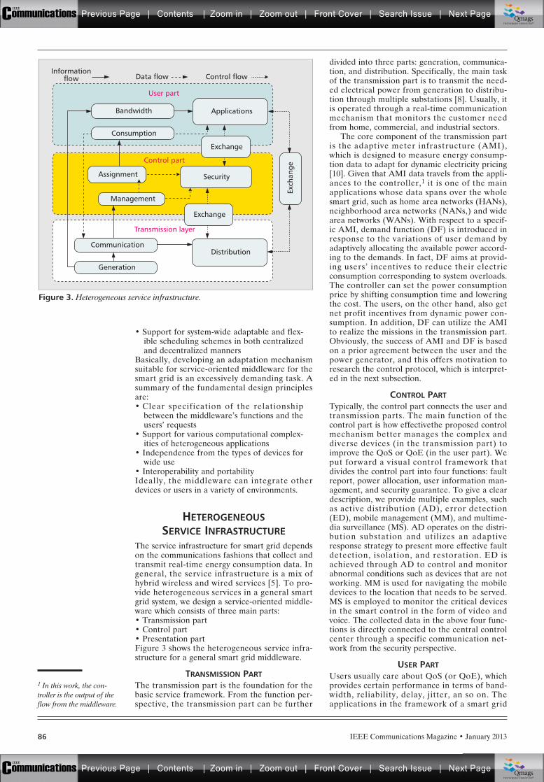
• Support for system-wide adaptable and flex-ible scheduling schemes in both centralizedand decentralized manners
Basically, developing an adaptation mechanismsuitable for service-oriented middleware for thesmart grid is an excessively demanding task. Asummary of the fundamental design principlesare:• Clear specification of the relationship
between the middleware’s functions and theusers’ requests
• Support for various computational complex-ities of heterogeneous applications
• Independence from the types of devices forwide use
• Interoperability and portabilityIdeally, the middleware can integrate otherdevices or users in a variety of environments.
HETEROGENEOUSSERVICE INFRASTRUCTURE
The service infrastructure for smart grid dependson the communications fashions that collect andtransmit real-time energy consumption data. Ingeneral, the service infrastructure is a mix ofhybrid wireless and wired services [5]. To pro-vide heterogeneous services in a general smartgrid system, we design a service-oriented middle-ware which consists of three main parts:• Transmission part• Control part• Presentation partFigure 3 shows the heterogeneous service infra-structure for a general smart grid middleware.
TRANSMISSION PARTThe transmission part is the foundation for thebasic service framework. From the function per-spective, the transmission part can be further
divided into three parts: generation, communica-tion, and distribution. Specifically, the main taskof the transmission part is to transmit the need-ed electrical power from generation to distribu-tion through multiple substations [8]. Usually, itis operated through a real-time communicationmechanism that monitors the customer needfrom home, commercial, and industrial sectors.
The core component of the transmission partis the adaptive meter infrastructure (AMI),which is designed to measure energy consump-tion data to adapt for dynamic electricity pricing[10]. Given that AMI data travels from the appli-ances to the controller,1 it is one of the mainapplications whose data spans over the wholesmart grid, such as home area networks (HANs),neighborhood area networks (NANs,) and widearea networks (WANs). With respect to a specif-ic AMI, demand function (DF) is introduced inresponse to the variations of user demand byadaptively allocating the available power accord-ing to the demands. In fact, DF aims at provid-ing users’ incentives to reduce their electricconsumption corresponding to system overloads.The controller can set the power consumptionprice by shifting consumption time and loweringthe cost. The users, on the other hand, also getnet profit incentives from dynamic power con-sumption. In addition, DF can utilize the AMIto realize the missions in the transmission part.Obviously, the success of AMI and DF is basedon a prior agreement between the user and thepower generator, and this offers motivation toresearch the control protocol, which is interpret-ed in the next subsection.
CONTROL PARTTypically, the control part connects the user andtransmission parts. The main function of thecontrol part is how effectivethe proposed controlmechanism better manages the complex anddiverse devices (in the transmission part) toimprove the QoS or QoE (in the user part). Weput forward a visual control framework thatdivides the control part into four functions: faultreport, power allocation, user information man-agement, and security guarantee. To give a cleardescription, we provide multiple examples, suchas active distribution (AD), error detection(ED), mobile management (MM), and multime-dia surveillance (MS). AD operates on the distri-bution substation and utilizes an adaptiveresponse strategy to present more effective faultdetection, isolation, and restoration. ED isachieved through AD to control and monitorabnormal conditions such as devices that are notworking. MM is used for navigating the mobiledevices to the location that needs to be served.MS is employed to monitor the critical devicesin the smart control in the form of video andvoice. The collected data in the above four func-tions is directly connected to the central controlcenter through a specific communication net-work from the security perspective.
USER PARTUsers usually care about QoS (or QoE), whichprovides certain performance in terms of band-width, reliability, delay, jitter, an so on. Theapplications in the framework of a smart grid
IEEE Communications Magazine • January 201386
Figure 3. Heterogeneous service infrastructure.
User part
Control part
Transmission layer
Exch
ange
Applications
Control flowData flow
Distribution
Bandwidth
Consumption
Communication
Generation
Informationflow
Exchange
Assignment
Management
Security
Exchange
1 In this work, the con-troller is the output of theflow from the middleware.
Previous Page | Contents | Zoom in | Zoom out | Front Cover | Search Issue | Next PageIEEE
Communications qqM
Mq
qM
MqM
Qmags®THE WORLD’S NEWSSTAND
Previous Page | Contents | Zoom in | Zoom out | Front Cover | Search Issue | Next PageIEEE
Communications qqM
Mq
qM
MqM
Qmags®THE WORLD’S NEWSSTAND
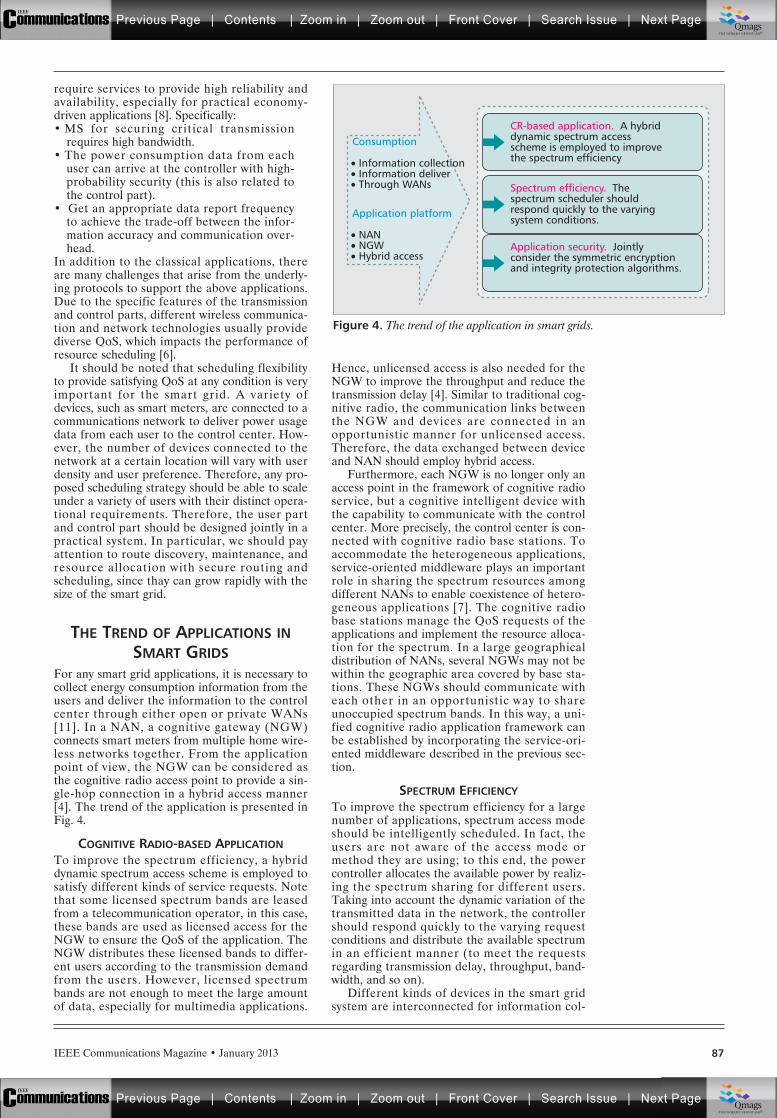
IEEE Communications Magazine • January 2013 87
require services to provide high reliability andavailability, especially for practical economy-driven applications [8]. Specifically:• MS for securing critical transmission
requires high bandwidth.• The power consumption data from each
user can arrive at the controller with high-probability security (this is also related tothe control part).
• Get an appropriate data report frequencyto achieve the trade-off between the infor-mation accuracy and communication over-head.
In addition to the classical applications, thereare many challenges that arise from the underly-ing protocols to support the above applications.Due to the specific features of the transmissionand control parts, different wireless communica-tion and network technologies usually providediverse QoS, which impacts the performance ofresource scheduling [6].
It should be noted that scheduling flexibilityto provide satisfying QoS at any condition is veryimportant for the smart grid. A variety ofdevices, such as smart meters, are connected to acommunications network to deliver power usagedata from each user to the control center. How-ever, the number of devices connected to thenetwork at a certain location will vary with userdensity and user preference. Therefore, any pro-posed scheduling strategy should be able to scaleunder a variety of users with their distinct opera-tional requirements. Therefore, the user partand control part should be designed jointly in apractical system. In particular, we should payattention to route discovery, maintenance, andresource allocation with secure routing andscheduling, since thay can grow rapidly with thesize of the smart grid.
THE TREND OF APPLICATIONS INSMART GRIDS
For any smart grid applications, it is necessary tocollect energy consumption information from theusers and deliver the information to the controlcenter through either open or private WANs[11]. In a NAN, a cognitive gateway (NGW)connects smart meters from multiple home wire-less networks together. From the applicationpoint of view, the NGW can be considered asthe cognitive radio access point to provide a sin-gle-hop connection in a hybrid access manner[4]. The trend of the application is presented inFig. 4.
COGNITIVE RADIO-BASED APPLICATIONTo improve the spectrum efficiency, a hybriddynamic spectrum access scheme is employed tosatisfy different kinds of service requests. Notethat some licensed spectrum bands are leasedfrom a telecommunication operator, in this case,these bands are used as licensed access for theNGW to ensure the QoS of the application. TheNGW distributes these licensed bands to differ-ent users according to the transmission demandfrom the users. However, licensed spectrumbands are not enough to meet the large amountof data, especially for multimedia applications.
Hence, unlicensed access is also needed for theNGW to improve the throughput and reduce thetransmission delay [4]. Similar to traditional cog-nitive radio, the communication links betweenthe NGW and devices are connected in anopportunistic manner for unlicensed access.Therefore, the data exchanged between deviceand NAN should employ hybrid access.
Furthermore, each NGW is no longer only anaccess point in the framework of cognitive radioservice, but a cognitive intelligent device withthe capability to communicate with the controlcenter. More precisely, the control center is con-nected with cognitive radio base stations. Toaccommodate the heterogeneous applications,service-oriented middleware plays an importantrole in sharing the spectrum resources amongdifferent NANs to enable coexistence of hetero-geneous applications [7]. The cognitive radiobase stations manage the QoS requests of theapplications and implement the resource alloca-tion for the spectrum. In a large geographicaldistribution of NANs, several NGWs may not bewithin the geographic area covered by base sta-tions. These NGWs should communicate witheach other in an opportunistic way to shareunoccupied spectrum bands. In this way, a uni-fied cognitive radio application framework canbe established by incorporating the service-ori-ented middleware described in the previous sec-tion.
SPECTRUM EFFICIENCYTo improve the spectrum efficiency for a largenumber of applications, spectrum access modeshould be intelligently scheduled. In fact, theusers are not aware of the access mode ormethod they are using; to this end, the powercontroller allocates the available power by realiz-ing the spectrum sharing for different users.Taking into account the dynamic variation of thetransmitted data in the network, the controllershould respond quickly to the varying requestconditions and distribute the available spectrumin an efficient manner (to meet the requestsregarding transmission delay, throughput, band-width, and so on).
Different kinds of devices in the smart gridsystem are interconnected for information col-
Figure 4. The trend of the application in smart grids.
• Information collection• Information deliver• Through WANs
Consumption
• NAN• NGW• Hybrid access
Application platform
CR-based application. A hybriddynamic spectrum accessscheme is employed to improvethe spectrum efficiency
Spectrum efficiency. Thespectrum scheduler shouldrespond quickly to the varyingsystem conditions.
Application security. Jointlyconsider the symmetric encryptionand integrity protection algorithms.
Previous Page | Contents | Zoom in | Zoom out | Front Cover | Search Issue | Next PageIEEE
Communications qqM
Mq
qM
MqM
Qmags®THE WORLD’S NEWSSTAND
Previous Page | Contents | Zoom in | Zoom out | Front Cover | Search Issue | Next PageIEEE
Communications qqM
Mq
qM
MqM
Qmags®THE WORLD’S NEWSSTAND
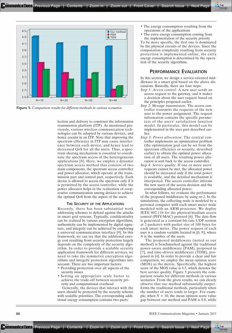
IEEE Communications Magazine • January 201388
lection and delivery to construct the informationtransmission platform (ITP). As mentioned pre-viously, various wireless communication tech-nologies can be adopted by various devices, andhence coexist in an ITP. Note that improving thespectrum efficiency in ITP may cause interfer-ence between each device, and hence lead todecreased QoS for all the users. Thus, a spec-trum sharing mechanism is essential to coordi-nate the spectrum access of the heterogeneousapplications [8]. Here, we employ a dynamicspectrum access method that consists of twomain components, the spectrum access controllerand power allocator, which operate at the trans-mission part and control part, respectively. Eachdevice is allowed to access the spectrum only if itis permitted by the access controller, while thepower allocator helps in the realization of coop-erative communication among devices to achievethe optimal QoS from the aspect of the users.
THE SECURITY OF THE APPLICATIONSRecently, there has been substantial workaddressing schemes to defend against the attacksin smart grid systems. Typically, confidentialitycan be realized by various encryption algorithms,authenticity can be implemented by digital signa-ture, and integrity can be achieved by employinga universal communication interface [9]. In thisframework, we can see that the additional ener-gy cost resulting from security protection largelydepends on the complexity of the security algo-rithm. In order to provide a scalable securityapplication framework for different services, weneed to take the symmetric encryption algo-rithms and integrity protection algorithms intoaccount. There are two important factors:• Providing protection over all aspects of the
security issues• Setting an appropriate scale factor to
achieve the trade-off between security pri-ority and computational overheadGenerally, the devices that interact with the
users should be protected by the security schemewith scalable priorities. The corresponding addi-tional energy consumption contains two parts:
• The energy consumption resulting from theoperations of the applications
• The extra energy consumption coming fromthe implementation of the security priority
To be more specific, the first one is dominatedby the physical circuits of the devices. Since thecomputation complexity resulting from securityprotection is implemented online, the extraenergy consumption is determined by the opera-tion of the security algorithms.
PERFORMANCE EVALUATIONIn this section, we design a service-oriented mid-dleware in a smart grid based on the above dis-cussions. Basically, there are four steps:Step 1: Access control: A new user sends an
access request to the gateway, and it makesa decision about the user request based onthe principles proposed earlier.
Step 2: Message transmission: The access con-troller transmits the requests of the newuser to the power assignment. The requestinformation contains the specific parame-ters of the users’ satisfaction functionmodel. In particular, this model can beimplemented in the user part described ear-lier.
Step 3: Power allocation: The central con-troller implements an optimization problem(the optimization goal can be set from thespectrum efficiency or security, describedearlier) to obtain the optimal power alloca-tion of all users. The resulting power allo-cation is sent back to the access controller.
Step 4: Service quality: If one or more users’requests cannot be met, the allocated powershould be increased only if the total poweris available, and the detailed mechanism isinterpreted. The access controller informsthe new users of the access decision and thecorresponding allocated power. In what follows, we evaluate the performance
of the proposed middleware by using ns-2. In thesimulations, the collecting node is modeled by apersonal computer with each smart meter nodemodeled with an ARM processor. We deployIEEE 802.11b for the physical/medium accesscontrol (PHY/MAC) protocol [6]. The data flowis generated as a constant-bit-rate UDP sessionat 2 packets/s with packet size of 100 bytes foreach smart meter. The power request of eachuser is a random variable located in [0, N], whereN is the number of the users.
The proposed middleware (noted as ourmethod) is benchmarked against the traditionalpower-aware middleware (PAM), proposed in[7], and time-driven middleware (TDM), pro-posed in [4]. In order to provide a clear and faircomparison, we employ the mean opinion score(MOS) as the metric. Specifically, the highestscore of the MOS value is 4.5, which denotes thebest service quality. Figure 5 presents the com-parison results for different methods in variousscenarios. From the given results, we can clearlyobserve that our method substantially outper-forms the traditional methods, particularly whenthe number of users tends to larger. For exam-ple, when N = 10, the mean opinion score valuegap between our method and PAM is 0.8, while
Figure 5. Comparison results for different methods in various scenarios.
N=10
2.7
2.5
2.9
3.1
3.3
3.5
3.7
3.9
4.1
4.3
4.5 Our methodPAMTDM
N=20 N=30 N=40
Previous Page | Contents | Zoom in | Zoom out | Front Cover | Search Issue | Next PageIEEE
Communications qqM
Mq
qM
MqM
Qmags®THE WORLD’S NEWSSTAND
Previous Page | Contents | Zoom in | Zoom out | Front Cover | Search Issue | Next PageIEEE
Communications qqM
Mq
qM
MqM
Qmags®THE WORLD’S NEWSSTAND
IEEE Communications Magazine • January 2013 89
it increases to 1.3 when N = 40. Therefore,these simulation results are consistent with ourtheoretical analysis, and again verify the validityof the proposed middleware.
CONCLUSIONSIn this article, we present an efficient, integrat-ed, and general middleware for heterogeneousservices in the smart grid. First, we develop amutual application access control principle thatmeans users can obtain a satisfying power assign-ment. Next, a collaborative and dynamic infor-mation exchange infrastructure is providedbetween different devices, and a local informa-tion exchange mechanism is designed to realizeefficient communication and computing forpower management messages. Finally, we pro-pose four steps to design a service-oriented mid-dleware, and numerical simulation results arepresented to verify the validly of the proposedmiddleware. For future work, we will focus onapplying the proposed middleware to the practi-cal smart grid or Internet of things.
ACKNOWLEDGMENTSThis work is partially supported by the NSF ofChina (Grant No. 61201165), by the ProjectFunded by the Priority Academic ProgramDevelopment of Jiangsu Higher Education Insti-tutions, by the NUPT Foundation (Grant No.NY211032), by the Instituto de Telecomuni-cações, Next Generation Networks and Applica-tions Group (NetGNA), Portugal, and byNational Funding from the FCT – Fundaçãopara a Ciência e a Tecnologia through the PEst-OE/EEI/LA0008/2011 Project, Portugal.
REFERENCES[1] http://www.techcn.com.cn/index.php?edition-view-
143092-3.[2] M. Qiu et al., “Energy Efficient Security Algorithm for
Power Grid Wide Area Monitoring System,” IEEE Trans.Smart Grid, vol. 2, no. 4, Nov. 2011, pp. 715–23.
[3] M. Qiu, H. Su, and M. Chen, “Balance of SecurityStrength and Energy for PMU Monitoring System inSmart Grid,” IEEE Commun. Mag., vol. 50, no. 5, , May2012 pp. 142–49.
[4] R. Yu et al., “Cognitive Radio based Hierarchical Com-munications Infrastructure for Smart Grid,” IEEE Net-work, vol. 25, no. 5, Sept./Oct. 2011, pp. 6–14.
[5] Y. Zhang et al., “Cognitive Machine-to-Machine Com-munications: Visions and Potentials for the SmartGrid,” to appear, IEEE Network.
[6] Y. Zhang et al., “Home M2M Networks: Architectures,Standards, and QoS Improvement,” IEEE Commun.Mag., vol. 49, no. 4, Apr. 2011, pp. 44–52.
[7] L. Zhou, J. Rodrigues, and L. Oliveira, “QoE-DFivenPower Scheduling in Smart Grid: Architecture, Strategy,and Methodology,” IEEE Commun. Mag., vol. 50, no. 5,May 2012, pp. 136–41.
[8] L. Zhou and H.-C. Chao, “Multimedia Traffic SecurityArchitecture for Internet of Things,” IEEE Network, vol.25, no. 3, May/June 2011, pp. 35–40.
[9] C.-F. Lai et al., “Adaptive Body Posture Analysis Using Col-laborative Multi-Sensors for Elderly Falling Detection,” IEEEIntelligent Systems, vol. 24, no. 6, 2010, pp. 20–30.
[10] H. Wang et al., “Resource-Aware Secure ECG HealthcareMonitoring through Body Sensor Networks,” IEEE WirelessCommun., vol. 17, no. 1, Feb. 2010, pp. 12–19.
[11] L. Zhou et al., “Context-Aware Middleware for MultimediaService in Heterogeneous Networks,” IEEE Intelligent Sys-tems, vol. 25, no. 2, Mar./Apr. 2010, pp. 40–47.
BIOGRAPHIESLIANG ZHOU [M’09] ([email protected]) received his Ph.D.degree major in electronic engineering from both EcoleNormale Superieure (ENS), Cachan, France, and ShanghaiJiao Tong University, China, in 2009. He is a professor inthe Key Laboratory of Broadband Wireless Communicationand Sensor Network Technology, Nanjing University ofPosts and Telecommunications, Ministry of Education,China. His research interests are in the area of multimediacommunications and computing.
JOEL J. P. C. RODRIGUES [S’01, M’06, SM’06] ([email protected])is a professor at the University of Beira Interior, Portugal,and researcher at the Instituto de Telecomunicações, Portu-gal. He is the leader of NetGNA Research Group (http://net-gna.it.ubi.pt), the Vice-Chair of the IEEE ComSoc TechnicalCommittees on eHealth and Communications Software,and Member Representative of ComSoc on the IEEE Bio-metrics Council. He is the Editor-in-Chief of the Internation-al Journal on E-Health and Medical Communications andRecent Patents on Telecommunications, and an editorialboard member for several journals. He has been GeneralChair and TPC Chair of many international conferences. Hehas authored or coauthored over 220 papers in refereedinternational journals and conferences, a book, and twopatents. He has been awarded the Outstanding LeadershipAward of IEEE GLOBECOM 2010 as CSSMA Symposium Co-Chair and several best papers awards. He is a licensed pro-fessional engineer (as senior member), a member of theInternet Society, an IARIA fellow, and a senior member ofACM.
Each device is
allowed to access
the spectrum only if
it is permitted by the
access controller,
while the power
allocator helps in the
realization of cooper-
ative communication
among the devices
to achieve the opti-
mal QoS from the
aspect of the users.
Previous Page | Contents | Zoom in | Zoom out | Front Cover | Search Issue | Next PageIEEE
Communications qqM
Mq
qM
MqM
Qmags®THE WORLD’S NEWSSTAND
Previous Page | Contents | Zoom in | Zoom out | Front Cover | Search Issue | Next PageIEEE
Communications qqM
Mq
qM
MqM
Qmags®THE WORLD’S NEWSSTAND
_____
___________
________
___________
IEEE Communications Magazine • January 201390 0163-6804/13/$25.00 © 2013 IEEE
INTRODUCTIONAmong smart grid research and developmentcommunities, there is currently no globally agreeddefinition for the “smart grid.” However, it hasalready been recognized that the smart grid is anew electricity network, which highly integratesthe advanced sensing and measurement tech-nologies, information and communication tech-nologies (ICTs), analytical and decision-makingtechnologies, and automatic control technologieswith the current power grid infrastructure [1–3].
Efficient and reliable transmission and distri-bution of electricity is a fundamental require-ment for providing societies and economies withessential energy resources. As large parts of theinfrastructure are relatively old compared to theadvances in electronics and digital technology, itis a good time to incorporate those advances inthe power infrastructure. In addition, there is astrong political and regulatory push for morecompetition and lower energy prices, higherenergy efficiency, and increased use of renewableenergy like solar, wind, biomasses, and water.
The general goals of smart grid are to ensurea transparent, sustainable, and environment-friendly system operation that is cost- and ener-gy-efficient, secure, and safe. Aging equipment,dispersed generations, as well as load increasemight lead to highly utilized equipment duringpeak load conditions. If the upgrade of the powergrid should be reduced to a minimum, new waysof operating power systems need to be found andestablished. In many countries, regulators andliberalization are forcing utilities to reduce costsfor the transmission and distribution of electricalenergy. Therefore, new methods (mainly basedon the efforts of modern ICTs) to operate power
systems are required to guarantee a sustainable,secure, and competitive energy supply.
To be helpful for developing Recommenda-tions to support smart grid from a telecommuni-cations/ICT perspective, the InternationalTelecommunication Union — Telecommunica-tion Standardization Sector (ITU-T) establishedan ITU-T Focus Group on Smart Grid (FG-Smart) in February 2010, which successfully con-cluded in December 2011 with the developmentof five deliverables [4]: Smart Grid Overview,Use Cases for Smart Grid, Requirements ofCommunication for Smart Grid, Smart GridArchitecture, and Terminology. The goal of FG-Smart was to gather basic information on thesmart grid and provide a road map for futurestandardization activities of the ITU. This articleintroduces key results of studies by FG-Smartincluding characteristics of smart grid, role ofICT in smart grid, functional analysis of smartgrid architecture, recent standardization activi-ties in ITU-T related to smart grid, and recom-mendations for future standardization activities.
CHARACTERISTICS OF SMART GRIDA way of characterizing the smart grid is by look-ing at its functions in three different areas: smartgrid services/applications, communication, andphysical equipment, as shown in Fig. 1. Smart gridservices/applications refers to systems, includingcomputers, programs, databases, people, andoperational support to manage the applications.Communication refers to the information struc-tures and networking that enables communica-tions between services/applications and entities inthe physical equipment. Physical equipment refersto the devices, sensors, and controllers that pro-vide information to the smart grid services/appli-cations, and receive commands to effect controlof devices in the physical equipment.
Smart grid has the following fundamentalcharacteristics:• Use of information, computing, and net-
working technologies to support the envi-sioned smart grid services: energydistribution management, energy trading,grid monitoring and management, distribut-ed renewable energy integration, electricvehicles charging, distributed energy stor-age, and smart metering infrastructure.
ABSTRACT
To be helpful in developing Recommendationsto support smart grid, the ITU-T Focus Group onSmart Grid has produced documents on use case,requirements, and architecture for smart gridfrom the ICT perspective. This article introduceskey results in these documents, including conceptsand objectives of smart grid, an architectureoverview of smart grid, and functional models toaccomplish smart grid functions. This article alsodiscusses challenges for future standardization.
ULTIMATE TECHNOLOGIES AND ADVANCES FORFUTURE SMART GRID — UTASG
Gyu Myoung Lee, Telecom SudParis
David H. Su, National Institute of Standards and Technology
Standarization of Smart Grid in ITU-T
Previous Page | Contents | Zoom in | Zoom out | Front Cover | Search Issue | Next PageIEEE
Communications qqM
Mq
qM
MqM
Qmags®THE WORLD’S NEWSSTAND
Previous Page | Contents | Zoom in | Zoom out | Front Cover | Search Issue | Next PageIEEE
Communications qqM
Mq
qM
MqM
Qmags®THE WORLD’S NEWSSTAND
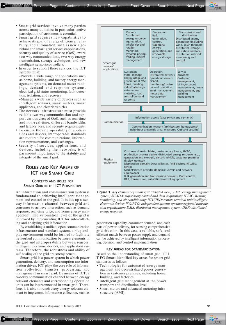
IEEE Communications Magazine • January 2013 91
• Smart grid services involve many partiesacross many domains; in particular, activeparticipation of customers is essential.
• Smart grid requires new capabilities toachieve its goal of energy efficiency, relia-bility, and automation, such as new algo-rithms for smart grid services/applications,security and quality of service (QoS)-awaretwo-way communications, two-way energytransmission, storage techniques, and newintelligent sensors/controllers.
• In order to support these services, the ICTsystems must:–Provide a wide range of applications suchas home, building, and factory energy man-agement systems, on demand meter read-ings, demand and response systems,electrical grid status monitoring, fault detec-tion, isolation, and recovery–Manage a wide variety of devices such asintelligent sensors, smart meters, smartappliances, and electric vehicles
• The network infrastructure must providereliable two-way communication and sup-port various class of QoS, such as real-timeand non-real-time, different bandwidthsand latency, loss, and security requirements.
• To ensure the interoperability of applica-tions and devices, interoperable standardsare required for communications, informa-tion representations, and exchanges.
• Security of services, applications, anddevices, including the networks, is ofparamount importance to the stability andintegrity of the smart grid.
ROLES AND KEY AREAS OFICT FOR SMART GRID
CONCEPTS AND ROLES FORSMART GRID IN THE ICT PERSPECTIVE
An information and communication system isfundamental to achieving intelligent manage-ment and control in the grid. It builds up a two-way information channel between grid andconsumer to achieve interaction, such as demandresponse, real-time price, and home energy man-agement. The automation level of the grid isimproved by implementing ICT for auto-collect-ing and analyzing grid information.
By establishing a unified, open communicationinfrastructure and standard system, a plug-and-play environment could be formed to facilitatenetworked communication between elements inthe grid and interoperability between sensors,intelligent electronic devices, and application sys-tems. Therefore, the robustness and ability ofself-healing of the grid are strengthened.
Smart grid is a power system in which powergeneration, delivery, and consumption are infor-mation-driven. ICT plays the core role of informa-tion collection, transfer, processing, andmanagement in smart grid. By means of ICT, atwo-way communication channel between energyrelevant elements and corresponding operationunits can be interconnected in smart grid. There-fore, it is able to reach every energy relevant ele-ment to implement information collection, such as
generation capability, consumer demand, and eachpart of power delivery, for sensing comprehensivegrid situation. In this case, a reliable, safe, andefficient match between power supply and demandcan be achieved by intelligent information process-ing, decision, and control implementation.
KEY AREAS FOR STANDARDIZATIONBased on the understanding of smart grid, ITU-T FG-Smart identified key areas for smart gridstandards as follows:• Technologies for automated energy man-
agement and decentralized power genera-tion in customer premises, including home,building, and factories
• Intelligent grid management at the powertransport and distribution level
• Smart meters and advanced metering infra-structure (AMI)
Figure 1. Key elements of smart grid (detailed view). EMS: energy managementsystem; SCADA: supervisory control and data acquisition; HVAC: heating,ventilating, and air conditioning; RTU/IED: remote terminal unit/intelligentelectronic device; ISO/RTO: independent systems operator/regional transmis-sion organization; DMS: distributed management system; DER: distributedenergy resource.
Distributed energygeneration (includingwind, solar, thermal);distributed storage,substation and localdistribution networkmonitoring andcontrol
Transmission anddistribution:Distributed
energy resourceaggregation,wholesaler andretailermarketing,dynamic pricing,trading, marketmanagement
Markets:Bulkgeneration,control,traditionalenergygeneration, andrenewableenergy storage
Generation:
Customermanagement,billing/accountmanagement, homemanagement, andbuildingmanagement
Serviceprovider:Store, manage
energy usage andgeneration (EMS);home, building,industrial energyautomation;metering, loadcontrol/demandresponse
Customer domain: Meter, customer appliance, HVAC,production process device, distributed energy resource (e.g.,generation and storage), electric vehicle, customer premisesdisplay, gatewayDistribution domain: Data collector, field devices, RTU/IED,sensorMarket/service provider domains: Servers and networkequipmentsBulk generation and transmission domains: Plant control,DER, transmission, substation/control equipment
Information access (data syntax and semantic)
Communication
Physicalequipment
Communication network (architecture: home/access/neighbour area/wide area; measures: QoS and security)
Customer:
Smart gridservices/applications
Distributed networkoperation: variousSCADA,monitoring/controlgeneral operation:asset management,meter datamanagement
Operation:
Previous Page | Contents | Zoom in | Zoom out | Front Cover | Search Issue | Next PageIEEE
Communications qqM
Mq
qM
MqM
Qmags®THE WORLD’S NEWSSTAND
Previous Page | Contents | Zoom in | Zoom out | Front Cover | Search Issue | Next PageIEEE
Communications qqM
Mq
qM
MqM
Qmags®THE WORLD’S NEWSSTAND
IEEE Communications Magazine • January 201392
• Information and communication infra-structure to provide energy intelligence,control, and security
• Applications and services for coordinationof the energy system on the business level
• Security control and management with thedifferent level of requirements for smartgrid
KEY APPLICATIONS AND PLATFORM INSMART GRID
Here, we present the key applications in smartgrid and the platform to support those applica-tions from ICT.
Energy distribution management: The goal ofthis application is to make the energy distributionsystem more intelligent, reliable, and self-repair-ing and self-optimizing. This application enablesthe monitoring and display of grid system compo-nents and performance across interconnectionsand over large geographic areas in near realtime. It includes the deployment of ubiquitousnetworked sensors, the software system to under-stand and ultimately optimize the managementof grid network components, behavior, and per-formance, as well as to anticipate, prevent, orrespond to problems before disruptions can arise.
Distributed renewable energy integration: Thegoal of this application is to integrate distributedrenewable energy generation facilities, includingthe use of renewable resources (i.e., wind, solar,thermal power, etc.), as part of total energysources. This application includes the projectionof expected demand, the prediction of alternativegeneration capacities, and the integration of dis-tributed generation into the distribution grid.Energy generation in a customer and micro-gridenvironment will require bidirectional meteringand bidirectional energy distribution networks,which will be supported by smart grid.
Distributed energy storage: In order to evenlydistribute the demand and consequently lower theneed for peak generation facilities, this applica-tion enables new storage capabilities of energy ina distributed fashion and mechanisms for feedingenergy back into the energy distribution system.
Electric vehicles and grid interaction: Thisapplication refers to enabling large-scale integra-tion of plug-in electric vehicles (PEVs) into thetransportation system. The major challenge issupport of PEV charging and the establishmentof charging infrastructure, including the powerdistribution capacity to prevent overloading ofcircuits and the charging facility; also, the infor-mation system to manage the energy distribu-tion, and acustomer interface such as accountingand billing, need to be in place.
Grid monitoring and management: Thisapplication aims to enable demand response(DR)1 and consumer energy efficiency. WithDR, the power supply and demand can be large-ly balanced. To this end, business, industrial, andresidential customers have the ability to cutenergy usage during times of peak demand.
Smart metering infrastructure: This applica-tion enables the AMI and provides customersreal-time (or near-real-time) pricing of electrici-ty, and can help utilities achieve necessary loadreductions. It requires a two-way network
between advanced meters and utility businesssystems to enable the collection and distributionof information to customers and other parties,such as the competitive retail supplier or theutility itself. Utilities also rely on AMI to imple-ment residential DR and serve as the mainmechanism for implementing dynamic pricing.
In order to support the above smart gridapplications, it is essential to add and integratecomputing and communication technologies andservices with the existing electricity deliveryinfrastructure. To this end, the ICT platform isrequired to provide bidirectional flows of energy,and two-way communication and control capa-bilities, enabling new functionalities and applica-tions, including smart metering for homes andbusinesses. Generally speaking, the platform forsmart grid consists of the following.
Connected electrical grid/communication net-works: The electrical grid needs to be integratedwith an advanced digital communication networkinfrastructure to enable intelligent control anddistribution of energy.
Distributed, intelligent, secured grid controland management: On top of the connected elec-trical grid and communication network, dis-tributed and intelligent grid control andmanagement plays a critical role to enable allthe key applications discussed above. To be spe-cific, energy intelligence, and secured and QoS-aware control and data planes need to be inplace to meet the requirements of applicationsin smart grid. Because the smart grid will includenetworks from the diverse information technolo-gy, telecommunications, and energy sectors,security shall also be required to ensure that acompromise in one network does not compro-mise security in other interconnected systems.
ARCHITECTURE OVERVIEW FORSMART GRID FROM THE
ICT PERSPECTIVE
ITU-T FG-Smart developed a simplified domainmodel based on the NIST 7 domain model [1]. Thissimplified domain model is composed of five domains: • Grid domain (bulk generation, distribution
and transmission)• Smart metering (AMI)• Customer domain (smart appliances, elec-
tric vehicles, premises networks (home/building/industrial area metwork))
• Communication network• Service provider domain (markets, opera-
tors, service providers)Figure 2 shows the simplified reference archi-
tecture that has the above five key domains.There are five reference points from the net-work to the other four domains, and betweenthe smart metering and customer domains.These reference points represent external inter-faces between various domains for smart gridthat should be the focal point of standardizationefforts.• Reference point 1 — between grid domain
and network: Enables exchange of informa-tion and control signals between devices in thegrid domain and the service providers domain
1 Demand response: Asmart grid feature thatallows consumers toreduce or change theirelectrical use patterns dur-ing peak demand, usuallyin exchange for a finan-cial incentive.
By establishing a uni-
fied, open communi-
cation infrastructure
and standard system,
the ‘plug and play’
environment could
be formed to facili-
tate the networked
communication
between elements in
grid and the interop-
erability between
sensors, intelligent
electronic devices
and application
systems.
Previous Page | Contents | Zoom in | Zoom out | Front Cover | Search Issue | Next PageIEEE
Communications qqM
Mq
qM
MqM
Qmags®THE WORLD’S NEWSSTAND
Previous Page | Contents | Zoom in | Zoom out | Front Cover | Search Issue | Next PageIEEE
Communications qqM
Mq
qM
MqM
Qmags®THE WORLD’S NEWSSTAND
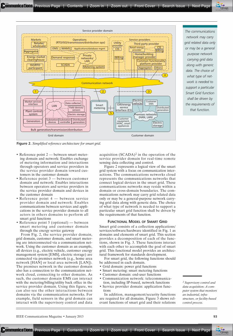
IEEE Communications Magazine • January 2013 93
• Reference point 2 — between smart meter-ing domain and network: Enables exchangeof metering information and interactionsthrough operators and service providers inthe service provider domain toward cus-tomers in the customer domain
• Reference point 3 — between customerdomain and network: Enables interactionsbetween operators and service providers inthe service provider domain and devices inthe customer domain
• Reference point 4 — between serviceprovider domain and network: Enablescommunications between services and appli-cations in the service provider domain to allactors in others domains to perform allsmart grid functions
• Reference point 5 (optional) — betweensmart metering and customer domainthrough the energy service gatewayFrom Fig. 2, the service provider domain,
grid domain, customer domain, and smart meter-ing are interconnected via a communication net-work. Using the customer domain as an example,all devices (e.g., electric vehicle, customer energymanagement system [EMS], electric storage) areconnected via premises network (e.g., home areanetwork [HAN] or local area network [LAN]).The premises network in the customer domainalso has a connection to the communication net-work cloud, connecting to other domains. Assuch, the customer domain EMS can interactwith the metering/billing/utility back office in theservice provider domain. Using this figure, wecan also see the other interactions betweendomains via the communication networks. Forexample, field sensors in the grid domain caninteract with the supervisory control and data
acquisition (SCADA)2 in the operation of theservice provider domain for real-time remotesensing data collecting and control.
Figure 2 represents a logical view of the smartgrid system with a focus on communication inter-actions. The communications networks cloudrepresents the communications networks thatconnect logical devices in the smart grid. Thesecommunications networks may reside within adomain or cross-domain boundaries. The com-munications network may carry grid related dataonly or may be a general-purpose network carry-ing grid data along with generic data. The choiceof what type of network is needed to support aparticular smart grid function shall be driven bythe requirements of that function.
FUNCTIONAL MODEL OF SMART GRIDSmart grid consists of a collection applications/services/software/hardware identified in Fig. 1 asdomains and elements of smart grid. This sectionprovides a decomposition of each of the func-tions, shown in Fig. 3. These functions interactwith each other to accomplish the goal of smartgrid. This functional model provides an architec-tural framework for standards development.
For smart grid, the following functions shouldbe addressed in each domain.• Grid domain: power grid functions• Smart metering: smart metering functions• Customer domain: end-user functions• Communication network: telecommunica-
tion, including IP-based, network functions• Service provider domain: application func-
tionsIn addition, management/security functions
are required for all domains. Figure 3 shows rel-evant functions of smart grid and their relations
Figure 2. Simplified reference architecture for smart grid.
4
3
5
2
Grid domain Customer domain
Bulk generation/transmission/distribution
1
CIS
Aggregator
Aggregator
Others
BillingCISEMS
SCADAMetering system
Demand response
WAMS Applications/database mgmt
Utilityprovider
Billing
Retailer/wholesaler
ISO/RTOparticipant
Energy marketclearinghouse
Retail energyprovider
Data collectorLAN
Premises networks(HAN, LAN)
Electric storage
Field devices/sensors
Smartmetering
GW/energyservice
interface (ES)
Electricvehicle
CustomerEMS
Electricstorage
Distributedgeneration
Customerequipment,HVAC, smartappliances
Market servicesinterface
Plant controlsystem
Generators Distributedgeneration
Substationcontroller
Substationdevices
Home/buildingmanager provider
Common functionalityplatform provider
Service providersOperations(RTO/ISO/transmission/distribution ops)
Markets
Service provider domain
Third-party provider
Privatenetworks/
LAN
Communication network
2 Supervisory control anddata acquisition: A com-puter system that monitorsan industrial, infra-structure, or facility-basedcontrol process.
The communications
network may carry
grid related data only
or may be a general
purpose network
carrying grid data
along with generic
data. The choice of
what type of net-
work is needed to
support a particular
Smart Grid function
shall be driven by
the requirements of
that function.
Previous Page | Contents | Zoom in | Zoom out | Front Cover | Search Issue | Next PageIEEE
Communications qqM
Mq
qM
MqM
Qmags®THE WORLD’S NEWSSTAND
Previous Page | Contents | Zoom in | Zoom out | Front Cover | Search Issue | Next PageIEEE
Communications qqM
Mq
qM
MqM
Qmags®THE WORLD’S NEWSSTAND
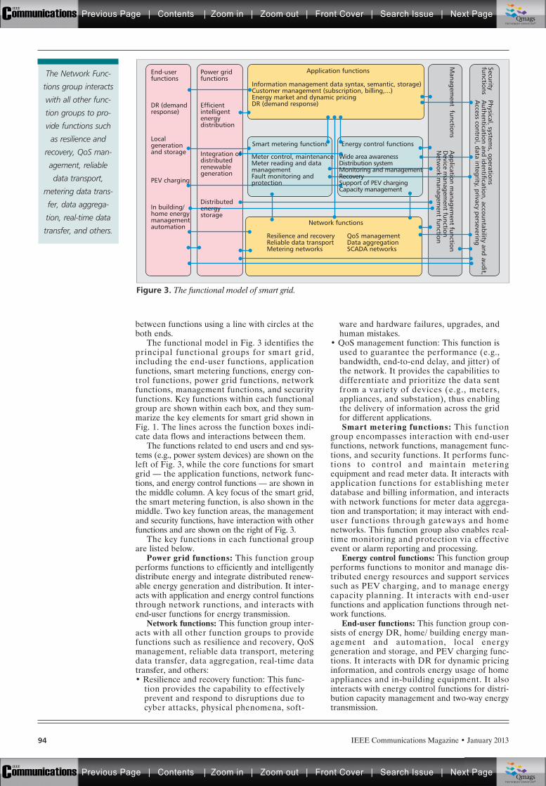
IEEE Communications Magazine • January 201394
between functions using a line with circles at theboth ends.
The functional model in Fig. 3 identifies theprincipal functional groups for smart grid,including the end-user functions, applicationfunctions, smart metering functions, energy con-trol functions, power grid functions, networkfunctions, management functions, and securityfunctions. Key functions within each functionalgroup are shown within each box, and they sum-marize the key elements for smart grid shown inFig. 1. The lines across the function boxes indi-cate data flows and interactions between them.
The functions related to end users and end sys-tems (e.g., power system devices) are shown on theleft of Fig. 3, while the core functions for smartgrid — the application functions, network func-tions, and energy control functions — are shown inthe middle column. A key focus of the smart grid,the smart metering function, is also shown in themiddle. Two key function areas, the managementand security functions, have interaction with otherfunctions and are shown on the right of Fig. 3.
The key functions in each functional groupare listed below.
Power grid functions: This function groupperforms functions to efficiently and intelligentlydistribute energy and integrate distributed renew-able energy generation and distribution. It inter-acts with application and energy control functionsthrough network runctions, and interacts withend-user functions for energy transmission.
Network functions: This function group inter-acts with all other function groups to providefunctions such as resilience and recovery, QoSmanagement, reliable data transport, meteringdata transfer, data aggregation, real-time datatransfer, and others:• Resilience and recovery function: This func-
tion provides the capability to effectivelyprevent and respond to disruptions due tocyber attacks, physical phenomena, soft-
ware and hardware failures, upgrades, andhuman mistakes.
• QoS management function: This function isused to guarantee the performance (e.g.,bandwidth, end-to-end delay, and jitter) ofthe network. It provides the capabilities todifferentiate and prioritize the data sentfrom a variety of devices (e.g., meters,appliances, and substation), thus enablingthe delivery of information across the gridfor different applications.Smart metering functions: This function
group encompasses interaction with end-userfunctions, network functions, management func-tions, and security functions. It performs func-tions to control and maintain meteringequipment and read meter data. It interacts withapplication functions for establishing meterdatabase and billing information, and interactswith network functions for meter data aggrega-tion and transportation; it may interact with end-user functions through gateways and homenetworks. This function group also enables real-time monitoring and protection via effectiveevent or alarm reporting and processing.
Energy control functions: This function groupperforms functions to monitor and manage dis-tributed energy resources and support servicessuch as PEV charging, and to manage energycapacity planning. It interacts with end-userfunctions and application functions through net-work functions.
End-user functions: This function group con-sists of energy DR, home/ building energy man-agement and automation, local energygeneration and storage, and PEV charging func-tions. It interacts with DR for dynamic pricinginformation, and controls energy usage of homeappliances and in-building equipment. It alsointeracts with energy control functions for distri-bution capacity management and two-way energytransmission.
Figure 3. The functional model of smart grid.
End-userfunctions
DR (demandresponse)
Localgenerationand storage
PEV charging
In building/home energymanagementautomation
Power gridfunctions
Information management data syntax, semantic, storage)Customer management (subscription, billing,...)Energy market and dynamic pricingDR (demand response)
Application functions
Network functions
Resilience and recoveryReliable data transportMetering networks
QoS managementData aggregationSCADA networks
Efficientintelligentenergydistribution
Meter control, maintenanceMeter reading and datamanagementFault monitoring andprotection
Wide area awarenessDistribution systemMonitoring and managementRecoverySupport of PEV chargingCapacity management
Smart metering functions Energy control functions
Application m
anagement function
Device m
anagement function
Netw
ork managem
ent function
Securityfunctions
Physical, systems, operations
Authentication and identification, accountability and audit,
Access control, data integrity, privacy persevering
Managem
ent functions
Integration ofdistributedrenewablegeneration
Distributedenergystorage
The Network Func-
tions group interacts
with all other func-
tion groups to pro-
vide functions such
as resilience and
recovery, QoS man-
agement, reliable
data transport,
metering data trans-
fer, data aggrega-
tion, real-time data
transfer, and others.
Previous Page | Contents | Zoom in | Zoom out | Front Cover | Search Issue | Next PageIEEE
Communications qqM
Mq
qM
MqM
Qmags®THE WORLD’S NEWSSTAND
Previous Page | Contents | Zoom in | Zoom out | Front Cover | Search Issue | Next PageIEEE
Communications qqM
Mq
qM
MqM
Qmags®THE WORLD’S NEWSSTAND
IEEE Communications Magazine • January 2013 95
Application functions: This function groupconsists of functions for application system infor-mation management (e.g., data syntax, semantic,and storage), customer information management(e.g., billing, user subscription), energy market,and dynamic pricing as well as energy DR man-agement and control. This function group inter-acts with end-user functions, smart meteringfunctions, energy control functions, managementfunctions, and security functions. This functionmay interact with end-user functions, energycontrol functions, and power grid functions tomanage environmental parameters.
Management functions: This function groupconsists of functions for management of systemsin all function blocks. This function group inter-acts with all other function groups and coversvarious system management functions, includingapplication management, device management,and network management: • Application management function: This func-
tion performs the functions to help the oper-ator manage the key aspects of applications.It monitors various applications and helpsapplication providers to ensure that theirapplications meet end users’ expectations.
• Device management function: This functionenables communication with a vast array ofdevices in the field and substations, whetherheterogeneous or homogeneous. Devicemanagement provides an efficient way tonormalize and transmit data to and fromthese devices.
• Network management function: This func-tion provides management of the communi-cations network to ensure availability andstability. It is also responsible for keepingtrack of network resources and how theyare assigned, configuring resources in thenetwork to support a given service, andadjusting configuration parameters in thenetwork for better quality.Security functions: This function group inter-
acts with all other function groups in terms ofphysical security, system security, and operationsecurity. This function group covers varioussecurity aspects; examples of applications aredescribed below:• Identification and authentication function:
This function is the process of verifying theidentity of a user, process, or device as aprerequisite for granting access to resourcesin a smart grid system.
• Audit and accountability function: Thisfunction enables the review and examina-tion of the information record and activitiesrelated to smart grid to determine the ade-quacy of security requirements and ensurecompliance with the established securitypolicy and procedures.
• Access control function: This functionensures that only authorized personnel orusers have access to use various utilitiesand services in the grid system.
• Data integrity function: The function isresponsible for data integrity in smart gridvia cryptography and validation mechanisms.
• Privacy preserving function: This function isdesigned to provide privacy considerationswith respect to the smart grid.
More detailed requirements and description ofsecurity functions can be found in [5].
CHALLENGES FORSMART GRID STANDARDIZATION
SMART GRID STANDARDS FROMINTERNATIONAL STANDARDS DEVELOPING
ORGANIZATIONS
From the analysis in previous sections on keyareas of ICT for smart grid and smart grid func-tional models, we can classify smart grid stan-dards into several categories:• Grid management: standards for control
and management of power generation,transmission, and distribution, including thefunctions and operations of components forthese systems such as sensors, controllers,and meters
• Information management: standards forexchange of data between the smart gridsubsystems, components, and applicationsor services, including syntax and semanticsrules, timing, frequency, and volume ofinformation to be exchanged
• Communications and networking: standardsfor communication network to transferinformation for smart grid functions, includ-ing the transmission media and transportfunctions
• Applications and services: standards forinvocation, termination, and recovery ofsmart grid applications and services
Security and privacy: standards related to thephysical security and cyber security of smartgrid systems, and the privacy of data gener-ated and collectedThere are many international standards devel-
opment organizations besides the ITU-T, whichis the focus of this article, that have developedand are developing standards related to smartgrid. These include the International Elec-trotehnical Commission (IEC) [2], IEEE [6], andInternet Engineering Task Force (IETF). Thereare also regional and national SDOs that focuson regional and national needs. Furthermore,there are public consortia for development spec-ifications and implementation agreements onspecific topics. Table 1 shows the areas of cover-age by these international SDOs.
The U.S. Congress recognized having inter-operable standards is a major issue for the futuredevelopment of smart grid, and it tasked theNational Institute of Science and Technology(NIST) under the Energy Independence andSecurity Act (EISA) of 2007 to coordinate devel-opment of standards to achieve interoperabilityof smart grid devices and systems. In the NISTFramework and Roadmap for Smart Grid Interop-erability Standards [1], a set of standards applica-ble to the smart grid and standards needingfurther harmonization were identified. NISTestablished the Smart Grid InteroperabilityPanel (SGIP) [7] to coordinate with all SDOs onthe harmonization and development of smartgrid standards. Similarly, the European Commis-sion issued a smart grid mandate M/490 [8] forthe European SDOs to develop or update a set
Information manage-
ment standards
cover the exchange
of data between the
Smart Grid subsys-
tems, components,
and applications or
services, including
syntax and semantics
rules, timing, fre-
quency, and volume
of information to be
exchanged.
Previous Page | Contents | Zoom in | Zoom out | Front Cover | Search Issue | Next PageIEEE
Communications qqM
Mq
qM
MqM
Qmags®THE WORLD’S NEWSSTAND
Previous Page | Contents | Zoom in | Zoom out | Front Cover | Search Issue | Next PageIEEE
Communications qqM
Mq
qM
MqM
Qmags®THE WORLD’S NEWSSTAND

IEEE Communications Magazine • January 201396
of consistent standards that will achieve interop-erability and enable or facilitate the implementa-tion in Europe [3].
CURRENT ITU-T STUDY GROUPS ACTIVITIESITU-T organizes its standardization activitiesinto Study Groups (SGs) [9], and each groupfocuses on a set of issues in the form of Ques-tions. Table 2 shows the areas related to smartgrid in terms of Questions being addressed byeach SG. We can see that ITU-T has mainlybeen involved in various technical areas forsmart grid including machine-to-machine (M2M)communication, smart metering, vehicle commu-nication, home networking, and energy savingnetworks for developing Recommendations.
WORK ITEMS FOR FUTURE STANDARDIZATIONFrom the activities of ITU-T FG-Smart, several gapsin standardization have been identified as follows:• Many data models and communication pro-
tocols applicable to smart grid are alreadystudied or are works in progress in mostareas. Harmonization of existing standardsmay be necessary.
• There were no formal standards on require-ments for the smart grid network, HAN,neighborhood area network (NAN), andwide area network (WAN).
• Network architectures of HAN and WANare well studied in correspondent SDOs;however, additional work for smart grid isnecessary. In addition, no activities havebeen identified in the NAN area.
• Even though there are many communica-tion standards that are applicable to smartgrid applications, there is a need to developintegration specifications on how to utilizethese standards into a system that best sat-isfies the requirements of smart grid.Based on the gaps identified, the following
work items are recommended.• Develop generic network architecture mod-
els for smart grid networks, including:–Architectures for AMI to develop architec-ture models and associated procedures forconfiguring and managing the metering net-work–Architectures for home energy manage-ment networks–Architectures for power grid communica-tions networks, including communicationwithin transmission/distribution substations,
and between substations and control cen-ters, as well as QoS and security manage-ment of such networks.
• Develop system integration specification ofsmart grid applications enabling end-to-endcommunications between applications at theutility’s business office and smart grid devices.
• Many smart grid applications fit the M2Mcommunication model. There are moves bymany SDOs working on M2M standards tojointly expand their effort in the smart gridarea. ITU-T should participate in this activity.
• Coordination is recommended to be donewith other SDOs such as IEC, IEEE, andother regional organizations such as theCEN-CENELEC-ETSI Smart Grid Coordi-nation Group (SGCG) to avoid duplicationof efforts and improve interoperability.The ITU’s Telecommunication Standardiza-
tion Advisory Group (TSAG) at its meeting ofJanuary 2012 established the Joint CoordinationActivity on Smart Grid and Home Networking(JCA-SG&HN) [10]. This will be responsible forthe stimulation and coordination of all networkaspects of smart grid and related communication(e.g., smart meters, home energy management,and data concentrator) standardization activitiesacross the ITU and relevant bodies (e.g., SDOs,fora, regional/national organizations, andacademia) in this standardization area includinghome networking.
CONCLUSIONIn this article, we have presented the efforts andkey results of ITU-T FG-Smart including charac-teristics of smart grid, the role of ICT in smartgrid, and a functional analysis of smart grid archi-tecture. From the recent standardization activitiesin ITU-T related to smart grid, we have identifiedseveral gaps and new work items for future stan-dardization. Specifically from the ICT perspective,we wish to stimulate valuable discussions amongexperts for developing standards on smart grid.
ACKNOWLEDGMENTThe authors are grateful to all our colleagues inITU-T FG-Smart for the collaboration and theircontributions to develop smart grid deliverables.
REFERENCES[1] NIST, “NIST Framework and Roadmap for Smart Grid
Interoperability Standards, Release 2.0,” Feb. 2012.
Table 1. Coverage of smart grid standards by international SDOs.
International SDOs Gridmanagement
Informationmanagement
Communicationsand networking
Applicationsand services
Securityand privacy
IEC (International Electrotechnical Commission) ÷ ÷
IEEE (IEEE Standards Association) ÷ ÷ ÷ ÷
IETF (Internet Engineering Task Force) ÷ ÷
ITU-T ÷ ÷ ÷
NOTE: Entry marked with ÷ indicates the SDO has major work in the area, and a blank indicates minor activities.
Previous Page | Contents | Zoom in | Zoom out | Front Cover | Search Issue | Next PageIEEE
Communications qqM
Mq
qM
MqM
Qmags®THE WORLD’S NEWSSTAND
Previous Page | Contents | Zoom in | Zoom out | Front Cover | Search Issue | Next PageIEEE
Communications qqM
Mq
qM
MqM
Qmags®THE WORLD’S NEWSSTAND
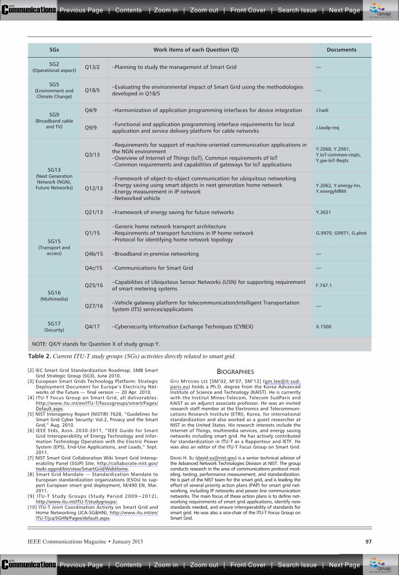
IEEE Communications Magazine • January 2013 97
[2] IEC Smart Grid Standardization Roadmap, SMB SmartGrid Strategic Group (SG3), June 2010.
[3] European Smart Grids Technology Platform: StrategicDeployment Document for Europe’s Electricity Net-works of the Future — final version — 20 Apr. 2010.
[4] ITU-T Focus Group on Smart Grid, all deliverables:http://www.itu.int/en/ITU-T/focusgroups/smart/Pages/Default.aspx.
[5] NIST Interagency Report (NISTIR) 7628, “Guidelines forSmart Grid Cyber Security: Vol.2, Privacy and the SmartGrid,” Aug. 2010.
[6] IEEE Stds, Assn. 2030-2011, “IEEE Guide for Smart Grid Interoperability of Energy Technology and Infor-mation Technology Operation with the Electric PowerSystem (EPS), End-Use Applications, and Loads,” Sept.2011.
[7] NIST Smart Grid Collaboration Wiki Smart Grid Interop-erability Panel (SGIP) Site, http://collaborate.nist.gov/twiki-sggrid/bin/view/SmartGrid/WebHome.
[8] Smart Grid Mandate — Standardization Mandate toEuropean standardization organizations (ESOs) to sup-port European smart grid deployment, M/490 EN, Mar.2011.
[9] ITU-T Study Groups (Study Period 2009~2012),http://www.itu.int/ITU-T/studygroups/.
[10] ITU-T Joint Coordination Activity on Smart Grid andHome Networking (JCA-SG&HN), http://www.itu.int/en/ITU-T/jca/SGHN/Pages/default.aspx.
BIOGRAPHIESGYU MYOUNG LEE [SM’02, M’07, SM’12] ([email protected]) holds a Ph.D. degree from the Korea AdvancedInstitute of Science and Technology (KAIST). He is currentlywith the Institut Mines-Telecom, Telecom SudParis andKAIST as an adjunct associate professor. He was an invitedresearch staff member at the Electronics and Telecommuni-cations Research Institute (ETRI), Korea, for internationalstandardization and also worked as a guest researcher atNIST in the United States. His research interests include theInternet of Things, multimedia services, and energy savingnetworks including smart grid. He has actively contributedfor standardization in ITU-T as a Rapporteur and IETF. Hewas also an editor of the ITU-T Focus Group on Smart Grid.
DAVID H. SU ([email protected]) is a senior technical advisor ofthe Advanced Network Technologies Division at NIST. The groupconducts research in the area of communications protocol mod-eling, testing, performance measurement, and standardization.He is part of the NIST team for the smart grid, and is leading theeffort of several priority action plans (PAP) for smart grid net-working, including IP networks and power line communicationnetworks. The main focus of these action plans is to define net-working requirements of smart grid applications, identify newstandards needed, and ensure interoperability of standards forsmart grid. He was also a vice-chair of the ITU-T Focus Group onSmart Grid.
Table 2. Current ITU-T study groups (SGs) activities directly related to smart grid.
SGs Work items of each Question (Q) Documents
SG2(Operational aspect)
Q13/2 –Planning to study the management of Smart Grid —
SG5(Environment andClimate Change)
Q18/5 –Evaluating the environmental impact of Smart Grid using the methodologiesdeveloped in Q18/5 —
SG9(Broadband cable
and TV)
Q4/9 –Harmonization of application programming interfaces for device integration J.hadi
Q9/9 –Functional and application programming interface requirements for localapplication and service delivery platform for cable networks
J.lasdp-req
SG13(Next GenerationNetwork (NGN),
Future Networks)
Q3/13
–Requirements for support of machine-oriented communication applications inthe NGN environment–Overview of Internet of Things (IoT), Common requirements of IoT–Common requirements and capabilities of gateways for IoT applications
Y.2060, Y.2061,Y.IoT-common-reqts,Y.gw-IoT-Reqts
Q12/13
–Framework of object-to-object communication for ubiquitous networking–Energy saving using smart objects in next generation home network–Energy measurement in IP network–Networked vehicle
Y.2062, Y.energy-hn,Y.energyMRM
Q21/13 –Framework of energy saving for future networks Y.3021
SG15(Transport and
access)
Q1/15–Generic home network transport architecture–Requirements of transport functions in IP home network–Protocol for identifying home network topology
G.9970, G9971, G.phnt
Q4b/15 –Broadband in-premise networking —
Q4c/15 –Communications for Smart Grid —
SG16(Multimedia)
Q25/16 –Capabilities of Ubiquitous Sensor Networks (USN) for supporting requirementof smart metering systems
F.747.1
Q27/16 –Vehicle gateway platform for telecommunication/Intelligent TransportationSystem (ITS) services/applications —
SG17(Security)
Q4/17 –Cybersecurity Information Exchange Techniques (CYBEX) X.1500
NOTE: QX/Y stands for Question X of study group Y.
Previous Page | Contents | Zoom in | Zoom out | Front Cover | Search Issue | Next PageIEEE
Communications qqM
Mq
qM
MqM
Qmags®THE WORLD’S NEWSSTAND
Previous Page | Contents | Zoom in | Zoom out | Front Cover | Search Issue | Next PageIEEE
Communications qqM
Mq
qM
MqM
Qmags®THE WORLD’S NEWSSTAND
____________
_________
______
______________________
__________________
INTRODUCTION
An electric grid, in general terms, refers to theelectrical network of transmission lines, trans-formers, and anything that is used to deliverelectricity from a power plant to the requiredplaces. The electricity grids that serve consumershave evolved over more than 100 years. Howev-er, the present electricity distribution system isfacing many challenges due to growth in popula-tion and their increased use of power for varioussystems. In recent times, power consumption byend users has increased manifold. Coupled withit are the constraining factors such as the soaringprices of electricity, the reduction in power pro-duction, and an ever increasing debt, which havemade the efficient distribution and utilization ofelectricity an important concern. To overcomeall these problems, smart grids are considered tobe very helpful. One of the important character-istics of a smart grid is controlling the powerconsumption of end users by developing knowl-
edge of their power consumption and corre-sponding prices. This will help in the power pro-duction as well, as end users try to control theirpower consumption based on the price they payfor units of electricity consumed. Smart metersin a smart grid-based deployment can help powerproducers and distributors to serve end users ina cost-effective manner, thereby helping in par-tially addressing the issue of power inadequacy.
An extensive study has been undertaken tomeet the quality of service (QoS) requirementsin terms of delay, cost, and packet delivery ratio[1] in communication systems, which can beadopted in smart grid communication systems aswell. The energy delivery network used to dis-tribute electricity and information automaticallyin a bidirectional fashion is described as a smartgrid. A smart grid is used to deliver real-timeinformation and is helpful in stabilizing powerproduction at the device level [2]. In such sys-tems quality of experience (QoE) [1, 2] is con-sidered to be an important criterion along withQoS. Normally, QoE represents the customersatisfaction index, which depends on QoS.
The structure of a smart grid is fundamental-ly hierarchical [3]. In this article, we develop onthis hierarchical concept and deploy learningautomata (LA) in the different levels of hierar-chy. Our architecture consists of an LA-basedmain power station (LAMPS) as a root, differentLA-based transmission units (LTUs) at the nextlevel, different LA-based distribution substations(LDS) at the level next to it, and finally, at theleaf level, different smart meters installed inhouses along with various appliances.
The next generation of smart grids is expect-ed to meet the challenges of demand and supplyof power, energy management, and secure com-munications. One of the serious issues of powermanagement is unauthorized use of power, orsimply stated, power theft. This happens in dif-ferent ways: illegal use by unauthorized connec-tions, non-payment of electricity bills, scams, andso on [4]. Another important issue of powermanagement is effective distribution of power toserve the various needs of consumers. In thisarticle, we propose an LA-based power manage-
IEEE Communications Magazine • January 201398 0163-6804/13/$25.00 © 2013 IEEE
ABSTRACT
The rapid growth of smart grid systemsdemands efficient management of smart gridservices. Smart grids are expected to enable thedelivery and management of electricity in amore reliable, efficient, economical, and securedmanner. Thus, the development of effectivepower management solutions for smart grids tomeet these challenges is an important area ofresearch in recent times. In this article, we pro-pose using learning automata (LA), a computa-tional learning utility, for efficient powermanagement in smart grids (LAPM). The pro-posed system, LAPM, helps in identifying theelectricity required for various distribution sub-stations and controls the usage of power by vari-ous devices (i.e., preventing unauthorized use ofpower). The use of LA enables performing adynamic analysis of power usage and providingdecision making for its effective usage. The sys-tem is evaluated on a real-life-resembling envi-ronment, with respect to parameters such aspower utilization and customer satisfaction.
ULTIMATE TECHNOLOGIES AND ADVANCES FORFUTURE SMART GRID — UTASG
Sudip Misra, Indian Institute of Technology, Kharagpur
P. Venkata Krishna and V. Saritha, VIT University
Mohammad S. Obaidat, Monmouth University
Learning Automata as a Utility forPower Management in Smart Grids
Previous Page | Contents | Zoom in | Zoom out | Front Cover | Search Issue | Next PageIEEE
Communications qqM
Mq
qM
MqM
Qmags®THE WORLD’S NEWSSTAND
Previous Page | Contents | Zoom in | Zoom out | Front Cover | Search Issue | Next PageIEEE
Communications qqM
Mq
qM
MqM
Qmags®THE WORLD’S NEWSSTAND
IEEE Communications Magazine • January 2013 99
ment system (LAPM) for smart grids. The pro-posed system, LAPM, attempts to address thefollowing:• How can we prevent unauthorized use of
power?• How can we perform power management at
different levels: distribution substations,transmission unit, and main power station?The unauthorized use of power can be con-
trolled by introducing unique code in smartmeters. Next, we present LA-based power man-agement for decision making of power distribu-tion based on the analysis done at differentlevels of hierarchical smart grid environment.
The rest of the article is organized as follows.We first provide an introduction of LA. We pre-sent related work. We present the proposed sys-tem and illustrate it. Sample data is consideredto illustrate our proposed work. The results ofthe study using the system are shown. Finally, weconclude the article.
LEARNING AUTOMATALearning automata [5–8] is a self-operatinglearning model, where “learning” refers to theprocess of gaining knowledge during the execu-tion of a simple machine/code (automaton), andusing the gained knowledge to decide on actionsto be taken in the future. This model has threemain components: the automaton, the environ-ment, and the reward/penalty structure.
An automaton refers to a self-learning sys-tem. The medium in which this machine func-tions is called the environment. The automatoncontinuously performs actions on the environ-ment; the environment responds to these actions.This response may be either positive or negative,and it serves as the feedback to the automaton,which, in effect, leads to the automaton eithergetting rewarded or penalized. Over a period oftime, the automaton learns the characteristics ofthe environment and identifies “optimal” actionsthat can be performed on the environment. Acomprehensive overview of LA can be found inthe classic text by Narendra and Thathachar [6]and the recent book chapter by Oommen andMisra [7].
AUTOMATONThe LA can be represented as a quintuple rep-resented as {Q, a(t), b(t), F, H}, where [5, 6, 8]:• Q: is the finite set of internal states Q =
{q1, q2, q3 … qn}, where qn is the state ofthe automaton at instant t.
• a(t): is a finite set of actions performed bythe automaton. a(t) = {a1, a2 …. an},where an is the action performed by theautomaton at instant t.
• b(t): is a finite set of responses from theenvironment. b(t) = {b1, b2, b3 … bn},where bn is the response from the environ-ment at an instant t.
• F: is a mapping function. It maps the cur-rent state and input to the next state of theautomaton. Q ¥ b Æ Q.
• H: is a mapping function. It maps the cur-rent state and response from the environ-ment to determine the next action to beperformed.
ENVIRONMENT
The environment corresponds to the medium inwhich the automaton functions. Mathematically,an environment can be abstracted by a triple{a(t), b(t), C(t)}. a, b have already been definedearlier. C is defined as follows [6, 8]. C(t) = {c1 ,c2, …, cr} is a set of penalty probabilities, whereelement ci Œ C corresponds to an input action ai.
We now provide a few important definitionsused in the field of LA. Given an action proba-bility vector P(t) at time t, the average penalty,M(t), is defined as [5, 6, 8]:
(1)
The average penalty for the “pure-chance”automaton is given by [5, 6, 8]:
(2)
As t Æ , if the average penalty M(t) < M0, atleast asymptotically, the automaton is generallyconsidered to be better than the pure-chanceautomaton. E[M(t)] is given by [5, 6, 8]:
E[M(t)] = E{E[b(t)|P(t)]} = E[b(t)]. (3)
RELATED WORKIn this section, we present some of the worksrelated to power management in smart grids. Anadaptive multi-agent-based approach for powermanagement was introduced in [7]. The authorsused a reinforcement learning scheme for powermanagement. This study was limited for renew-able energy sources. In [10], a secure and effi-cient power management scheme is discussed forsmart grids. This study presents the well-knownproblem of distributed denial of service in thecontext of the smart grid environments.
In another study, presented in [4], analysis ofelectricity theft was undertaken by the authors.The analysis presents results pertaining to theincreasing theft in around 102 countries world-wide. It was suggested by the authors that elec-tricity theft can be controlled by developingtechnological as well as managerial solutions.
Another study concerning electricity theft,available in [11], was based on the concept of aGenetic Algorithm (GA) and Support VectorMachine (SVM). This study was done for non-technical loss (NTL) analysis of Tenaga NasionalBerhad (TNB) in Malaysia. The NTL analysiswas done with an objective of determining thesuspected customers to be inspected.
A number of other works on power manage-ment, as such, exists in the literature — the abovementioned are only a few that have been men-tioned, in order to maintain the brevity of the arti-cle. The approaches in the literature are aimed, ingeneral, at identifying the suspected users, andthereby, controlling the distribution of the power.
==
Mr
c1
.ii
r
01
= = =
= = = × =
=
=
=
M t E t P t t P t
t t t
c p t
( ) ( ) ( ) Pr ( ) 1 ( )
Pr ( ) 1 ( ) Pr ( )
( ).
ii
r
i
i ii
r
1
1
The Automaton con-
tinuously performs
actions on the Envi-
ronment, the Envi-
ronment responds to
these actions. This
response may be
either positive or
negative and it
serves as the feed-
back to the Automa-
ton, which, in effect,
leads to the Automa-
ton either getting
rewarded or
penalized.
Previous Page | Contents | Zoom in | Zoom out | Front Cover | Search Issue | Next PageIEEE
Communications qqM
Mq
qM
MqM
Qmags®THE WORLD’S NEWSSTAND
Previous Page | Contents | Zoom in | Zoom out | Front Cover | Search Issue | Next PageIEEE
Communications qqM
Mq
qM
MqM
Qmags®THE WORLD’S NEWSSTAND
IEEE Communications Magazine • January 2013100
However, in our approach, theft of electricity iscontrolled effectively by using the concept of accesscode in the smart meters of the respective homes.
LA-BASED POWER MANAGEMENTThis section introduces the multilevel hierarchi-cal network architecture used in LA-based powermanagement (LAPM) for smart grids, based onthe sensor network architecture described in [12].The first level or root in this hierarchical networkis the LA-based main power station (LAMPS).In the second level are the LA-based transmis-sion units (LTUs), which receive power from themain power station. In the next level of the hier-archy are the LA-based distribution substations(LDSs), which distribute the power to the nextlevel in the hierarchy, which involves smartmeters installed in houses, and the last level issmart meters of appliances, as shown in Fig. 1.
In Fig. 1, when LAMPS supplies power toLTUs, LAMPS, acting as an automaton, adjuststhe power supply according to the requirementsbased on learning the system. An LTU acts as anenvironment, where the action is used to calculatethe performance of the system, and generates theperformance parameter value (power utilizationfactor) and sends it to the automaton to evaluatewhether a reward/penalty for the action needs tobe carried out on the selected action. This processis done in a nested fashion where the LAMPS,LTUs, and LDSs play their respective roles.
The smart meter of an appliance communi-cates the power consumed by it to the smartmeter at the house. The smart meter at eachhouse computes the total power consumed by itand communicates the data to its respective LDS.
Hierarchical networks involve formation of acluster and its head for better coordination [13]. Inthis article, the appliances being used at eachhouse behave as nodes at the leaf level. The smartmeters at a house are akin to the cluster heads; theLDSs, LTUs, and LAMPS are akin to the head ofcluster heads (HCH), collecting the data from therespective cluster heads and sending them to theabove level in the hierarchy. It is necessary to con-sider that a node at a lower level should not beallowed to access data at a node at a higher levelto avoid unauthorized use. Hence, in this article,smart meters of appliances are not permitted toaccess the data at the smart meter of a house. Asmart meter at a house cannot access the data atan LDS, and so on, for the next higher levels. Toachieve this property of access in the network, theaccess code is introduced, and the access code oflower-level nodes is derived from the access codeof higher-level nodes based on work discussed in[12, 13]. A sample cluster of appliances with anaccess code at each house is shown in Fig. 2. Thisaccess code is used for accessing the appliancesand detecting power theft. The access code is vali-dated by the cluster head. If the access code of anyappliance is not valid with respect to its clusteraccess code, the power supply is prohibited, andthe appliance cannot be accessed. In this way, theaccess code can be used to protect the appliancesfrom theft. Also, an access code can be used todetect the unauthorized use of power. The LDScomputes the power consumed by all the houses inits range based on the information received fromthe smart meter at houses and compares this value
to the actual power supplied by it. If there is a dif-ference between these two values, there is a possi-bility of unauthorized use of power.
The inactive appliances are shown with red col-ored cross marks on them in Fig. 2, and the activeappliances are shown in the automatic/regularmode. It can be observed that each house is allo-cated an access code for effective management ofpower. All the appliances work only with the accesscode of the respective smart meter. According tothe proposed system, in our example the laptop ofhouse 2 cannot be used in house 3 without theacceptance of both owners. A special mode needsto be given in this regard. From Fig. 2, it can beobserved that the washing machine is not shown inhouse 2. If the owner of house 2 buys a new wash-ing machine, a smart meter is associated with thecode of its cluster. Similarly, if the owner of house3 wants to sell the induction stove to the owner ofhouse 2, the smart meter characteristics such as theassociated access code needs to be changed.
The lower-level layers send the power con-sumption information to the higher-level layers,and, when required, the higher-level layers maysend the request for power consumption infor-mation from the lower-level layers. The LDS,LTU, and LAMPS maintain two data structures:• A table for storing the data received by the
lower level layers, Trec• A table for storing the data sent to the high-
er-level layers, TsentBoth the tables have three fields, ID, Info, andTime, as shown in Fig. 3. In the case of TableTrec, the ID is the identifier of the house, thedistribution substation, or the transmission unitfrom which the data is received. The amount ofpower consumed and the time at which the dataare received are stored as additional informationin the table. In the case of Table Tsent, the ID isthe identifier of the house, distribution substa-tion, or transmission unit, to which the request issent, and the Info field is the request for theinformation regarding the power consumptionand the time at which the request is sent.
We also consider that the LDSs, LTUs, andLAMPS maintain information of their childinformation in the form of a list, and parentinformation, as shown in Fig 3. The child list isthe house IDs to which the power is distributed,and the parent is the transmission unit informa-tion in the case of LDSs.
If any meter tampering is done at any house,the respective LDS should be able to detect thefault. When a particular house does not sendinformation to its respective distribution substa-tion, the LDS can request information from thehouse and set a time limit. If the information isnot received from the corresponding house, theLDS declares that some fault exists in a particu-lar house, and action needs to be taken such asrepairing the smart meter.
In our system, four time periods, T0, T1, T2,and T3, are assumed for a day in order to ana-lyze the LAPM. These time periods may be con-sidered to be equal or unequal. The LDS canmanage the power supply at different time peri-ods, the LTU adjusts the power supply amongdifferent distribution substations, and the mainpower station adjusts the power supply amongdifferent transmission units on learning.
The smart meter of
the appliance
communicates the
power consumed by
it to the smart meter
at the house.
The smart meter
at each house
computes the total
power consumed by
it and communicates
the data to
respective LDS.
Previous Page | Contents | Zoom in | Zoom out | Front Cover | Search Issue | Next PageIEEE
Communications qqM
Mq
qM
MqM
Qmags®THE WORLD’S NEWSSTAND
Previous Page | Contents | Zoom in | Zoom out | Front Cover | Search Issue | Next PageIEEE
Communications qqM
Mq
qM
MqM
Qmags®THE WORLD’S NEWSSTAND
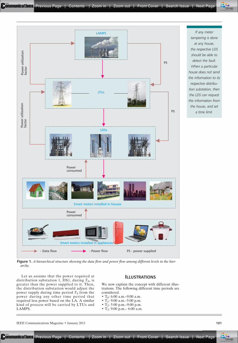
IEEE Communications Magazine • January 2013 101
Let us assume that the power required atdistribution substation 1, DS1, during T0, isgreater than the power supplied to it. Then,the distribution substation would adjust thepower supply during time period T0 from thepower during any other time period thatrequired less power based on the LA. A similarkind of process will be carried by LTUs andLAMPS.
ILLUSTRATIONS
We now explain the concept with different illus-trations. The following different time periods areconsidered.• T0: 6:00 a.m.–9:00 a.m.• T1: 9:00 a.m.–5:00 p.m.• T2: 5:00 p.m.–9:00 p.m.• T3: 9:00 p.m.– 6:00 a.m.
Figure 1. A hierarchical structure showing the data flow and power flow among different levels in the hier-archy.
PS
PS
Powerconsumed
Pow
er u
tiliz
atio
nfa
ctor
Pow
er u
tiliz
atio
nfa
ctor
LAMPS
LTUs
LDSs
Smart meters installed in houses
Powerconsumed
- Data flow - Power flow PS - power supplied
Smart meters installed in appliances
If any meter
tampering is done
at any house,
the respective LDS
should be able to
detect the fault.
When a particular
house does not send
the information to its
respective distribu-
tion substation, then
the LDS can request
the information from
the house, and set
a time limit.
Previous Page | Contents | Zoom in | Zoom out | Front Cover | Search Issue | Next PageIEEE
Communications qqM
Mq
qM
MqM
Qmags®THE WORLD’S NEWSSTAND
Previous Page | Contents | Zoom in | Zoom out | Front Cover | Search Issue | Next PageIEEE
Communications qqM
Mq
qM
MqM
Qmags®THE WORLD’S NEWSSTAND
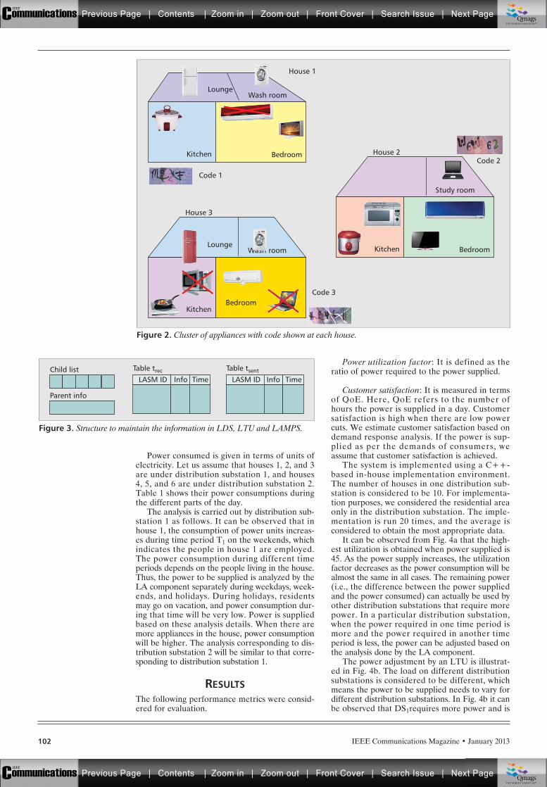
IEEE Communications Magazine • January 2013102
Power consumed is given in terms of units ofelectricity. Let us assume that houses 1, 2, and 3are under distribution substation 1, and houses4, 5, and 6 are under distribution substation 2.Table 1 shows their power consumptions duringthe different parts of the day.
The analysis is carried out by distribution sub-station 1 as follows. It can be observed that inhouse 1, the consumption of power units increas-es during time period T1 on the weekends, whichindicates the people in house 1 are employed.The power consumption during different timeperiods depends on the people living in the house.Thus, the power to be supplied is analyzed by theLA component separately during weekdays, week-ends, and holidays. During holidays, residentsmay go on vacation, and power consumption dur-ing that time will be very low. Power is suppliedbased on these analysis details. When there aremore appliances in the house, power consumptionwill be higher. The analysis corresponding to dis-tribution substation 2 will be similar to that corre-sponding to distribution substation 1.
RESULTSThe following performance metrics were consid-ered for evaluation.
Power utilization factor: It is defined as theratio of power required to the power supplied.
Customer satisfaction: It is measured in termsof QoE. Here, QoE refers to the number ofhours the power is supplied in a day. Customersatisfaction is high when there are low powercuts. We estimate customer satisfaction based ondemand response analysis. If the power is sup-plied as per the demands of consumers, weassume that customer satisfaction is achieved.
The system is implemented using a C++-based in-house implementation environment.The number of houses in one distribution sub-station is considered to be 10. For implementa-tion purposes, we considered the residential areaonly in the distribution substation. The imple-mentation is run 20 times, and the average isconsidered to obtain the most appropriate data.
It can be observed from Fig. 4a that the high-est utilization is obtained when power supplied is45. As the power supply increases, the utilizationfactor decreases as the power consumption will bealmost the same in all cases. The remaining power(i.e., the difference between the power suppliedand the power consumed) can actually be used byother distribution substations that require morepower. In a particular distribution substation,when the power required in one time period ismore and the power required in another timeperiod is less, the power can be adjusted based onthe analysis done by the LA component.
The power adjustment by an LTU is illustrat-ed in Fig. 4b. The load on different distributionsubstations is considered to be different, whichmeans the power to be supplied needs to vary fordifferent distribution substations. In Fig. 4b it canbe observed that DS1requires more power and is
Figure 2. Cluster of appliances with code shown at each house.
LoungeWash room
Kitchen Bedroom
Code 1
Code 3
Code 2
House 1
House 2
House 3
Study room
Kitchen BedroomLounge
Wash room
KitchenBedroom
Figure 3. Structure to maintain the information in LDS, LTU and LAMPS.
Child list Table trec
Parent info
LASM ID Info Time
Table tsent
LASM ID Info Time
Previous Page | Contents | Zoom in | Zoom out | Front Cover | Search Issue | Next PageIEEE
Communications qqM
Mq
qM
MqM
Qmags®THE WORLD’S NEWSSTAND
Previous Page | Contents | Zoom in | Zoom out | Front Cover | Search Issue | Next PageIEEE
Communications qqM
Mq
qM
MqM
Qmags®THE WORLD’S NEWSSTAND
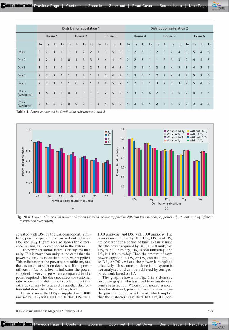
IEEE Communications Magazine • January 2013 103
adjusted with DS5 by the LA component. Simi-larly, power adjustment is carried out betweenDS2 and DS4. Figure 4b also shows the differ-ence in using an LA component in the system.
The power utilization factor is ideally less thanunity. If it is more than unity, it indicates that thepower required is more than the power supplied.This indicates that the power is not sufficient, andthe customer satisfaction decreases. If the powerutilization factor is low, it indicates the powersupplied is very large when compared to thepower required. This does not affect the customersatisfaction in this distribution substation, but thisextra power may be required by another distribu-tion substation where there is heavy load.
Let us assume that DS1 is supplied with 1000units/day, DS2 with 1000 units/day, DS3 with
1000 units/day, and DS4 with 1000 units/day. Thepower consumption by DS1, DS2, DS3, and DS4are observed for a period of time. Let us assumethat the power required by DS1 is 1200 units/day,DS2 is 900 units/day, DS3 is 950 units/day, andDS4 is 1100 units/day. Then the amount of extrapower supplied to DS2 or DS3 can be suppliedto DS1 or DS4, where the power is suppliedeffectively. This cannot be done if the system isnot analyzed and can be achieved by our pro-posed work based on LA.
The graph shown in Fig. 5 is a demandresponse graph, which is used to estimate cus-tomer satisfaction. When the response is morethan the demand, power cut need not occur —the power supplied is sufficient, which impliesthat the customer is satisfied. Initially, it is con-
Table 1. Power consumed in distribution substations 1 and 2.
Distribution substation 1 Distribution substation 2
House 1 House 2 House 3 House 4 House 5 House 6
T0 T1 T2 T3 T0 T1 T2 T3 T0 T1 T2 T3 T0 T1 T2 T3 T0 T1 T2 T3 T0 T1 T2 T3
Day 1 2 2 1 1 1 1 2 2 3 3 5 3 1 2 6 1 2 2 2 4 3 5 4 6
Day 2 1 2 1 1 0 1 3 3 2 4 4 2 0 2 5 1 1 2 3 3 2 4 4 5
Day 3 1 3 1 1 1 1 2 2 4 3 6 3 1 3 5 1 2 2 4 5 3 4 3 5
Day 4 2 3 2 1 1 1 2 1 1 2 4 3 2 3 6 1 2 3 4 4 3 5 3 6
Day 5 2 2 1 1 1 0 2 1 2 0 5 2 1 2 6 1 3 2 2 3 2 5 4 6
Day 6(weekend) 1 5 1 1 0 1 3 1 0 2 5 2 5 3 5 4 2 3 3 6 2 4 3 5
Day 7(weekend) 3 5 2 0 0 0 0 1 3 4 6 2 4 3 6 4 2 4 4 6 2 3 3 5
Figure 4. Power utilization: a) power utilization factor vs. power supplied in different time periods; b) power adjustment among differentdistribution substations.
Power supplied (number of units)
(a)
45
0.2
Pow
er u
tiliz
atio
n fa
ctor
0
0.4
0.6
0.8
1
1.2
50 55 60 65 70 75
Distribution substations
(b)
DS1
0.2
Pow
er u
tiliz
atio
n fa
ctor
0
0.4
0.8
0.6
1
1.2
1.4
DS2 DS3 DS4 DS5
Without LA T0With LA T0Without LA T1With LA T1
Without LA T2With LA T2Without LA T3With LA T3
T0T1T2T3
Previous Page | Contents | Zoom in | Zoom out | Front Cover | Search Issue | Next PageIEEE
Communications qqM
Mq
qM
MqM
Qmags®THE WORLD’S NEWSSTAND
Previous Page | Contents | Zoom in | Zoom out | Front Cover | Search Issue | Next PageIEEE
Communications qqM
Mq
qM
MqM
Qmags®THE WORLD’S NEWSSTAND
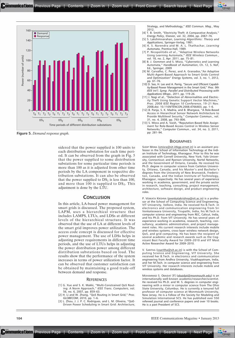
IEEE Communications Magazine • January 2013104
sidered that the power supplied is 100 units toeach distribution substation for each time peri-od. It can be observed from the graph in Fig. 5that the power supplied to some distributionsubstations for some particular time periods ismore than 100 as it is adjusted from other timeperiods by the LA component in respective dis-tribution substations. It can also be observedthat the power supplied to DS1 is less than 100,and more than 100 is supplied to DS5. Thisadjustment is done by the LTU.
CONCLUSIONIn this article, LA-based power management forsmart grids is discussed. The proposed system,LAPM, uses a hierarchical structure thatincludes LAMPS, LTUs, and LDSs at differentlevels of the hierarchical structure. It wasobserved that the use of LA at different levels ofthe smart grid improves power utilization. Theaccess code concept is discussed for effectivepower management. The use of LDSs helps inadjusting power requirements in different timeperiods, and the use of LTUs helps in adjustingthe power distribution power among differentdistribution substations based on load. Theresults show that the performance of the systemincreases in terms of power utilization factor. Itcan be observed that customer satisfaction canbe obtained by maintaining a good trade-offbetween demand and response.
REFERENCES[1] G. Xue and S. K. Makki, “Multi-Constrained QoS Rout-
ing: A Norm Approach,” IEEE Trans. Computers, vol.56, no. 6, 2007, pp. 859–63.
[2] H. Li and W. Zhang, “QoS Routing in Smart Grid,” Proc.GLOBECOM, 2010, pp. 1–6.
[3] L. Zhou, J. J. P. C. Rodrigues, and L. M. Oliveira, “QoE-Driven Power Scheduling in Smart Grid: Architecture,
Strategy, and Methodology,” IEEE Commun. Mag., May2012.
[4] T. B. Smith, “Electricity Theft: A Comparative Analysis,”Energy Policy, Elsevier, vol. 32, 2004, pp. 2067–76.
[5] S. Lakshmivarahan, Learning Algorithms: Theory andApplications, Springer-Verlag, 1981.
[6] K. S. Narendra and M. A. L. Thathachar, LearningAutomata, Prentice-Hall, 1989.
[7] P. Nicopolitidis et al., “Adaptive Wireless NetworksUsing Learning Automata,” IEEE Wireless Commun.,vol. 18, no. 2, Apr. 2011, pp. 75–81.
[8] B. J. Oommen and S. Misra, “Cybernetics and LearningAutomata,” Handbook of Automation, Ch. 12, S. Nof,Ed., Springer, 2009
[9] M. Carvalho, C. Perez, and A. Granados,”An AdaptiveMulti-Agent-Based Approach to Smart Grids Controland Optimization” Energy Systems, vol. 3, no. 1, 2012,pp. 61–76.
[10] D. Seo, H. Lee and A. Perrig, “Secure and Efficient Capabil-ity-Based Power Management in the Smart Grid,” Proc. 9thIEEE Int’l. Symp. Parallel and Distributed Processing withApplications Wksps., 2011, pp. 119–26.
[11] J. Nagi et al., “Detection of Abnormalities and Electric-ity Theft Using Genetic Support Vector Machines,”Proc. 2008 IEEE Region 10 Conference, 19–21 Nov.2008,doi: 10.1109/TENCON.2008.4766403, pp. 1–6.
[12] B. Panja, S. K. Madria, and B. Bhargava, “A Role-BasedAccess in Hierarchical Sensor Network Architecture toProvide Multilevel Security,” Computer Commun., vol.31, no. 4, 2008, pp. 793–806.
[13] S. Misra and A. Vaish, “Reputation-Based Role Assign-ment for Role-Based Access Control in Wireless SensorNetworks,” Computer Commun., vol. 34, no. 3, 2011,pp: 281–94.
BIOGRAPHIESSUDIP MISRA ([email protected]) is an assistant pro-fessor in the School of Information Technology at the Indi-an Institute of Technology, Kharagpur. Prior to this he wasassociated with Cornell University, New York; Yale Univer-sity, Connecticut; and Ryerson University, Nortel Networks,and the Government of Ontario, Canada. He received hisPh.D. degree in computer science from Carleton Universi-ty, Ottawa, Canada, and his Master’s and Bachelor’sdegrees from the University of New Brunswick, Frederic-ton, Canada, and the Indian Institute of Technology,Kharagpur, respectively. He has several years of experienceworking in academia, government, and the private sectorin research, teaching, consulting, project management,architecture, software design, and product engineeringroles.
P. VENKATA KRISHNA ([email protected]) is a profes-sor at the School of Computing Science and Engineering,VIT University, Vellore, India. He received his B.Tech. inelectronics and communication engineering from SriVenkateswara University, Tirupathi, India, his M.Tech incomputer science and engineering from REC, Calicut, India,and his Ph.D. from VIT University. He has several years ofexperience working in academia, research, teaching, con-sultancy, academic administration, and project manage-ment roles. His current research interests include mobileand wireless systems, cross-layer wireless network design,QoS, and grid computing. He has been the recipient ofseveral academic and research awards such as the Cog-nizant Best Faculty Award for 2009–2010 and VIT MostActive Researcher Award for 2009–2010.
V. SARITHA ([email protected]) is with the School of Com-puting Science and Engineering, VIT University. Shereceived her B.Tech. in electronics and communicationengineering from Andhra University, Visakhapatnam, India,and her M.Tech. in computer science and engineering fromVIT University. Her research interests include mobile andwireless systems and databases.
MOHAMMAD S. OBAIDAT [F] ([email protected]) is aninternationally well-known academic/researcher/scientist.He received his Ph.D. and M. S. degrees in computer engi-neering with a minor in computer science from The OhioState University, Columbus. He is currently a tenured fullprofessor of computer science at Monmouth University,New Jersey. He is a Fellow of the Society for Modeling andSimulation International SCS. He has published over 550refereed journal and conference papers and over 10 books.He is a past President of SCS.
Figure 5. Demand response graph.
T0
DS1
20
Pow
er (
num
ber
of u
nits
)
0
40
60
80
100
120
140
160
T1 T2 T3 T0 T1 T2 T3 T0 T1 T2 T3 T0 T1 T2 T3 T0 T1 T2 T3
DemandResponse
DS2 DS3
Time periods of different distribution substations
DS4 DS5
Previous Page | Contents | Zoom in | Zoom out | Front Cover | Search Issue | Next PageIEEE
Communications qqM
Mq
qM
MqM
Qmags®THE WORLD’S NEWSSTAND
Previous Page | Contents | Zoom in | Zoom out | Front Cover | Search Issue | Next PageIEEE
Communications qqM
Mq
qM
MqM
Qmags®THE WORLD’S NEWSSTAND
_____________
______________
_________
______________

Previous Page | Contents | Zoom in | Zoom out | Front Cover | Search Issue | Next PageIEEE
Communications qqM
Mq
qM
MqM
Qmags®THE WORLD’S NEWSSTAND
Previous Page | Contents | Zoom in | Zoom out | Front Cover | Search Issue | Next PageIEEE
Communications qqM
Mq
qM
MqM
Qmags®THE WORLD’S NEWSSTAND
______________________________________
IEEE Communications Magazine • January 2013106 0163-6804/13/$25.00 © 2013 IEEE
INTRODUCTIONFollowing the principles of “green” trends, andthe restrictions imposed by the ever increasingdemand and prices of oil and other fuels, powergeneration and distribution systems have beenconstantly evolving in recent years into more
sustainable models compatible with environmen-tal protection. This will be the key to achieve asustainable (energy) economy in accordance withthe provisions of the Treaty of Lisbon.
In addition, energy markets are facing a setof global challenges. These include:• Global deregulation.• Innovative elements gradually being inte-
grated into the energy grid, such as dis-tributed energy resources (DER) ordistributed generation (DG) [1]: compact,sometimes mobile, energy generationdevices (diesel engines, fuel cells, thin filmphotovoltaics, and mini wind turbines)
• The imminent massive irruption of electricvehicles
• Increasing consumer involvement: con-sumers modifying their behavior accordingto green trends and financial savings [2]Moreover, utilities have been encouraged
through government policies to incorporate newsmart devices. For example, smart meters aredeployed at users’ homes, and data collectorsare installed in electric substations. Additionally,smart homes allow autonomous control of elec-tric devices [3, 4].
This increasing intelligence of power gridnodes has led to the concept of smart grids:intelligent power grids capable of performingautonomous adaptation of their elements inorder to optimize resource consumption (e.g.,minimize energy transport due to localized pro-duction, reshape demand through the usage ofautomated devices in smart homes).
ABSTRACT
Recent technological advances in the powergeneration and information technologies areasare helping to change the modern electricitysupply system in order to comply with higherenergy efficiency and sustainability standards.Smart grids are an emerging trend that intro-duce intelligence in the power grid to optimizeresource usage. In order for this intelligence tobe effective, it is necessary to retrieve enoughinformation about the grid operation togetherwith other context data such as environmentalvariables, and intelligently modify the behaviorof the network elements accordingly. This articlepresents a multi-agent system model for virtualpower plants, a new power plant concept inwhich generation no longer occurs in big instal-lations, but is the result of the cooperation ofsmaller and more intelligent elements. The pro-posed model is not only focused on the manage-ment of the different elements, but includes aset of agents embedded with artificial neural net-works for collaborative forecasting of disaggre-gated energy demand of domestic end users, theresults of which are also shown in this article.
ULTIMATE TECHNOLOGIES AND ADVANCES FORFUTURE SMART GRID — UTASG
Luis Hernández, CIEMAT (Centro de Investigaciones Energéticas, Medioambientales y Tecnológicas)
Carlos Baladrón, Javier M. Aguiar, Belén Carro, and Antonio Sánchez-Esguevillas,
Universidad de Valladolid
Jaime Lloret, Universidad Politécnica de Valencia
David Chinarro, Universidad de San Jorge
Jorge J. Gomez-Sanz, Universidad Complutense de Madrid
Diane Cook, Washington State University
A Multi-Agent System Architecture forSmart Grid Management andForecasting of Energy Demand inVirtual Power Plants
Previous Page | Contents | Zoom in | Zoom out | Front Cover | Search Issue | Next PageIEEE
Communications qqM
Mq
qM
MqM
Qmags®THE WORLD’S NEWSSTAND
Previous Page | Contents | Zoom in | Zoom out | Front Cover | Search Issue | Next PageIEEE
Communications qqM
Mq
qM
MqM
Qmags®THE WORLD’S NEWSSTAND
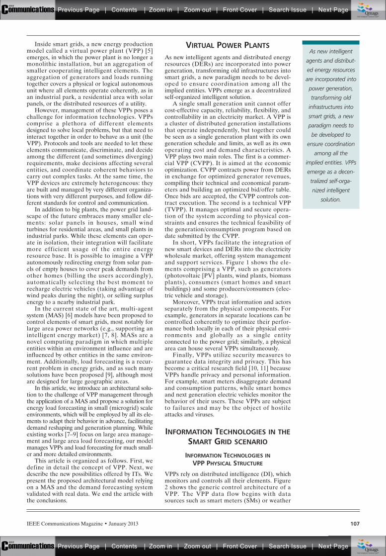
IEEE Communications Magazine • January 2013 107
Inside smart grids, a new energy productionmodel called a virtual power plant (VPP) [5]emerges, in which the power plant is no longer amonolithic installation, but an aggregation ofsmaller cooperating intelligent elements. Theaggregation of generators and loads runningtogether covers a physical or logical autonomousunit where all elements operate coherently, as inan industrial park, a residential area with solarpanels, or the distributed resources of a utility.
However, management of these VPPs poses achallenge for information technologies. VPPscomprise a plethora of different elementsdesigned to solve local problems, but that need tointeract together in order to behave as a unit (theVPP). Protocols and tools are needed to let theseelements communicate, discriminate, and decideamong the different (and sometimes diverging)requirements, make decisions affecting severalentities, and coordinate coherent behaviors tocarry out complex tasks. At the same time, theVPP devices are extremely heterogeneous: theyare built and managed by very different organiza-tions with very different purposes, and follow dif-ferent standards for control and communication.
In addition to big plants, the power grid land-scape of the future embraces many smaller ele-ments: solar panels in houses, small windturbines for residential areas, and small plants inindustrial parks. While these elements can oper-ate in isolation, their integration will facilitatemore efficient usage of the entire energyresource base. It is possible to imagine a VPPautonomously redirecting energy from solar pan-els of empty houses to cover peak demands fromother homes (billing the users accordingly),automatically selecting the best moment torecharge electric vehicles (taking advantage ofwind peaks during the night), or selling surplusenergy to a nearby industrial park.
In the current state of the art, multi-agentsystem (MAS) [6] models have been proposed tocontrol elements of smart grids, most notably forlarge area power networks (e.g., supporting anintelligent energy market) [7, 8]. MASs are anovel computing paradigm in which multipleentities within an environment influence and areinfluenced by other entities in the same environ-ment. Additionally, load forecasting is a recur-rent problem in energy grids, and as such manysolutions have been proposed [9], although mostare designed for large geographic areas.
In this article, we introduce an architectural solu-tion to the challenge of VPP management throughthe application of a MAS and propose a solution forenergy load forecasting in small (microgrid) scaleenvironments, which will be employed by all its ele-ments to adapt their behavior in advance, facilitatingdemand reshaping and generation planning. Whileexisting works [7–9] focus on large area manage-ment and large area load forecasting, our modelmanages VPPs and load forecasting for much small-er and more detailed environments.
This article is organized as follows. First, wedefine in detail the concept of VPP. Next, wedescribe the new possibilities offered by ITs. Wepresent the proposed architectural model relyingon a MAS and the demand forecasting systemvalidated with real data. We end the article withthe conclusions.
VIRTUAL POWER PLANTS
As new intelligent agents and distributed energyresources (DERs) are incorporated into powergeneration, transforming old infrastructures intosmart grids, a new paradigm needs to be devel-oped to ensure coordination among all theimplied entities. VPPs emerge as a decentralizedself-organized intelligent solution.
A single small generation unit cannot offercost-effective capacity, reliability, flexibility, andcontrollability in an electricity market. A VPP isa cluster of distributed generation installationsthat operate independently, but together couldbe seen as a single generation plant with its owngeneration schedule and limits, as well as its ownoperating cost and demand characteristics. AVPP plays two main roles. The first is a commer-cial VPP (CVPP). It is aimed at the economicoptimization. CVPP contracts power from DERsin exchange for optimized generator revenues,compiling their technical and economical param-eters and building an optimized bid/offer table.Once bids are accepted, the CVPP controls con-tract execution. The second is a technical VPP(TVPP). It manages optimal and secure opera-tion of the system according to physical con-straints and ensures the technical feasibility ofthe generation/consumption program based ondate submitted by the CVPP.
In short, VPPs facilitate the integration ofnew smart devices and DERs into the electricitywholesale market, offering system managementand support services. Figure 1 shows the ele-ments comprising a VPP, such as generators(photovoltaic [PV] plants, wind plants, biomassplants), consumers (smart homes and smartbuildings) and some producers/consumers (elec-tric vehicle and storage).
Moreover, VPPs treat information and actorsseparately from the physical components. Forexample, generators in separate locations can becontrolled coherently to optimize their perfor-mance both locally in each of their physical envi-ronments and globally as a single entityconnected to the power grid; similarly, a physicalarea can house several VPPs simultaneously.
Finally, VPPs utilize security measures toguarantee data integrity and privacy. This hasbecome a critical research field [10, 11] becauseVPPs handle privacy and personal information.For example, smart meters disaggregate demandand consumption patterns, while smart homesand next generation electric vehicles monitor thebehavior of their users. These VPPs are subjectto failures and may be the object of hostileattacks and viruses.
INFORMATION TECHNOLOGIES IN THESMART GRID SCENARIO
INFORMATION TECHNOLOGIES INVPP PHYSICAL STRUCTURE
VPPs rely on distributed intelligence (DI), whichmonitors and controls all their elements. Figure2 shows the generic control architecture of aVPP. The VPP data flow begins with datasources such as smart meters (SMs) or weather
As new intelligent
agents and distribut-
ed energy resources
are incorporated into
power generation,
transforming old
infrastructures into
smart grids, a new
paradigm needs to
be developed to
ensure coordination
among all the
implied entities. VPPs
emerge as a decen-
tralized self-orga-
nized intelligent
solution.
Previous Page | Contents | Zoom in | Zoom out | Front Cover | Search Issue | Next PageIEEE
Communications qqM
Mq
qM
MqM
Qmags®THE WORLD’S NEWSSTAND
Previous Page | Contents | Zoom in | Zoom out | Front Cover | Search Issue | Next PageIEEE
Communications qqM
Mq
qM
MqM
Qmags®THE WORLD’S NEWSSTAND
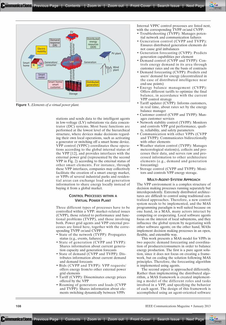
IEEE Communications Magazine • January 2013108
stations and sends data to the intelligent agentsin low-voltage (LV) substations via data concen-trator (DC) systems. Most basic functions areperformed at the lowest level of the hierarchicalstructure, where devices make decisions regard-ing their own local operations, such as activatinga generator or switching off a smart home device.VPP control (VPPC) coordinates these opera-tions according to the global internal status ofthe VPP [12], and provides interfaces with theexternal power grid (represented by the secondVPP in Fig. 2) according to the external status ofother smart elements. For instance, throughthese VPP interfaces, companies may collectivelyfacilitate the creation of a smart energy market,or VPPs of several industrial parks and residen-tial areas can exchange load and generationinformation to share energy locally instead ofbuying it from a global market.
CONTROL PROCESSES WITHIN AVIRTUAL POWER PLANT
Three different types of processes have to becontrolled within a VPP: market-related issues(CVPP), those related to performance and func-tional problems (TVPP), and those involvingboth. Power grid agents and VPP external pro-cesses are listed here, together with the corre-sponding TVPP or/and CVPP:• State of the network (TVPP): Propagates
status (e.g., events, failures)• State of generation (CVPP and TVPP):
Shares information about current genera-tion capacity and generation forecasts
• State of demand (CVPP and TVPP): Dis-tributes information about current demandand demand forecasts
• Bids (CVPP and TVPP): VPP requests/offers energy from/to other external powergrid elements
• Tariff (CVPP): Disseminates energy pricesoffered by the VPP
• Roaming of generators and loads (CVPPand TVPP): Shares information about ele-ments switching dynamically between VPPs
Internal VPPC control processes are listed next,with the corresponding TVPP or/and CVPP:• Troubleshooting (TVPP): Manages poten-
tial network and communication failures• Generation control (CVPP and TVPP):
Ensures distributed generation elements donot cause grid imbalances
• Generation forecasting (CVPP): Predictsgeneration capabilities per element
• Demand control (CVPP and TVPP): Con-trols energy demand in its area throughcustomer rates and on the basis of contracts
• Demand forecasting (CVPP): Predicts endusers’ demand for energy (decentralized inthe case of distributed intelligence nearend-use points)
• Energy balance management (CVPP):Offers different tariffs to optimize the finalbalance, in accordance with the currentVPP control strategy
• Tariff updater (CVPP): Informs customers,in real time, about rates set by the energybalance manager
• Customer control (CVPP and TVPP): Man-ages customer services
• Network stability control (TVPP): Monitorsand controls VPP grid performance, quali-ty, reliability, and safety parameters
• Communication with other VPPs (CVPPand TVPP): Communicates bidirectionallywith other elements
• Weather station control (TVPP): Managesmeteorological station(s), collects and pro-cesses their data, and serves raw and pro-cessed information to other architectureelements (e.g., demand and generationforecasting)
• Storage control (CVPP and TVPP): Moni-tors and controls VPP energy storage.
MULTI-AGENT-SYSTEM APPROACHThe VPP environment is a complex structure ofdecision making processes running separately butinterdependently. Extremely distributed architec-tures are difficult to control using traditional cen-tralized approaches. Therefore, a new controlsystem needs to be implemented, and the MASprogramming paradigm is well suited because onone hand, in a MAS, many actors interact bycompeting or cooperating. Local software agentsfocus on the interest of local subsystems, and theyinfluence the global system by negotiating withother software agents; on the other hand, MASsimplement decision making processes in an open,flexible, and extensible way.
This work presents a MAS model for VPPs intwo aspects: demand forecasting and coordina-tion of producers/consumers in order to balanceenergy production. The first is a pure agent solu-tion, since it does not focus on creating a frame-work, but on coding the solution following MASprinciples. Therefore, the forecasting algorithmis implemented using agents.
The second aspect is approached differently.Rather than implementing the distributed algo-rithm, a MAS framework is created implement-ing a model of the different roles and tasksinvolved in a VPP, and specifying the behaviorof each agent. The design of this framework isaccomplished using an agent-oriented software
Figure 1. Elements of a virtual power plant.
EV
PV plant
Windplant
Storage
Demandresponse
(DR)Electricmobility
Distributedgeneration
Smartmeter
Smarthome
Generation/consumer
Gen
erat
ion/
cons
umer
Generation
Distributedenergy
resources(DER)
Smart home/smart
customer
VPP
Gen
erat
ion/
cons
umer
Previous Page | Contents | Zoom in | Zoom out | Front Cover | Search Issue | Next PageIEEE
Communications qqM
Mq
qM
MqM
Qmags®THE WORLD’S NEWSSTAND
Previous Page | Contents | Zoom in | Zoom out | Front Cover | Search Issue | Next PageIEEE
Communications qqM
Mq
qM
MqM
Qmags®THE WORLD’S NEWSSTAND
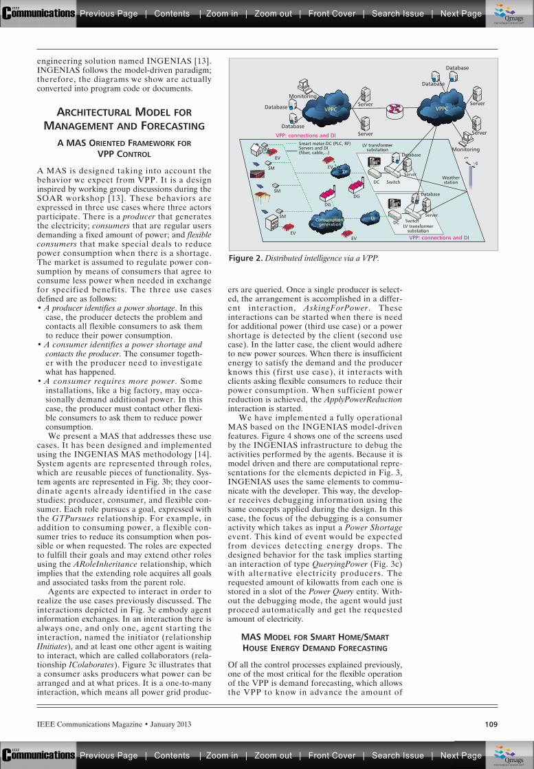
IEEE Communications Magazine • January 2013 109
engineering solution named INGENIAS [13].INGENIAS follows the model-driven paradigm;therefore, the diagrams we show are actuallyconverted into program code or documents.
ARCHITECTURAL MODEL FORMANAGEMENT AND FORECASTING
A MAS ORIENTED FRAMEWORK FORVPP CONTROL
A MAS is designed taking into account thebehavior we expect from VPP. It is a designinspired by working group discussions during theSOAR workshop [13]. These behaviors areexpressed in three use cases where three actorsparticipate. There is a producer that generatesthe electricity; consumers that are regular usersdemanding a fixed amount of power; and flexibleconsumers that make special deals to reducepower consumption when there is a shortage.The market is assumed to regulate power con-sumption by means of consumers that agree toconsume less power when needed in exchangefor specified benefits. The three use casesdefined are as follows:• A producer identifies a power shortage. In this
case, the producer detects the problem andcontacts all flexible consumers to ask themto reduce their power consumption.
• A consumer identifies a power shortage andcontacts the producer. The consumer togeth-er with the producer need to investigatewhat has happened.
• A consumer requires more power . Someinstallations, like a big factory, may occa-sionally demand additional power. In thiscase, the producer must contact other flexi-ble consumers to ask them to reduce powerconsumption.We present a MAS that addresses these use
cases. It has been designed and implementedusing the INGENIAS MAS methodology [14].System agents are represented through roles,which are reusable pieces of functionality. Sys-tem agents are represented in Fig. 3b; they coor-dinate agents already identified in the casestudies: producer, consumer, and flexible con-sumer. Each role pursues a goal, expressed withthe GTPursues relationship. For example, inaddition to consuming power, a flexible con-sumer tries to reduce its consumption when pos-sible or when requested. The roles are expectedto fulfill their goals and may extend other rolesusing the ARoleInheritance relationship, whichimplies that the extending role acquires all goalsand associated tasks from the parent role.
Agents are expected to interact in order torealize the use cases previously discussed. Theinteractions depicted in Fig. 3c embody agentinformation exchanges. In an interaction there isalways one, and only one, agent starting theinteraction, named the initiator (relationshipIInitiates), and at least one other agent is waitingto interact, which are called collaborators (rela-tionship IColaborates). Figure 3c illustrates thata consumer asks producers what power can bearranged and at what prices. It is a one-to-manyinteraction, which means all power grid produc-
ers are queried. Once a single producer is select-ed, the arrangement is accomplished in a differ-ent interaction, AskingForPower. Theseinteractions can be started when there is needfor additional power (third use case) or a powershortage is detected by the client (second usecase). In the latter case, the client would adhereto new power sources. When there is insufficientenergy to satisfy the demand and the producerknows this (first use case), it interacts withclients asking flexible consumers to reduce theirpower consumption. When sufficient powerreduction is achieved, the ApplyPowerReductioninteraction is started.
We have implemented a fully operationalMAS based on the INGENIAS model-drivenfeatures. Figure 4 shows one of the screens usedby the INGENIAS infrastructure to debug theactivities performed by the agents. Because it ismodel driven and there are computational repre-sentations for the elements depicted in Fig. 3,INGENIAS uses the same elements to commu-nicate with the developer. This way, the develop-er receives debugging information using thesame concepts applied during the design. In thiscase, the focus of the debugging is a consumeractivity which takes as input a Power Shortageevent. This kind of event would be expectedfrom devices detecting energy drops. Thedesigned behavior for the task implies startingan interaction of type QueryingPower (Fig. 3c)with alternative electricity producers. Therequested amount of kilowatts from each one isstored in a slot of the Power Query entity. With-out the debugging mode, the agent would justproceed automatically and get the requestedamount of electricity.
MAS MODEL FOR SMART HOME/SMARTHOUSE ENERGY DEMAND FORECASTING
Of all the control processes explained previously,one of the most critical for the flexible operationof the VPP is demand forecasting, which allowsthe VPP to know in advance the amount of
Figure 2. Distributed intelligence via a VPP.
VPP: connections and DI
VPP: connections and DI
Database
Server
Server
Server
Server
Monitoring
EV
Monitoring
Database
Database
Servers and DI(fiber, cable,...)
Database
VPPC VPPC
SMSmart meter-DC (PLC, RF)
SM
SM
Consumption/generation
LV
LV
SM
EVEV
EV
DG
DG
DC Switch
Server
Database
LV transformersubstation
DC SwitchServer
Database
Weatherstation
LV transformersubstation
Previous Page | Contents | Zoom in | Zoom out | Front Cover | Search Issue | Next PageIEEE
Communications qqM
Mq
qM
MqM
Qmags®THE WORLD’S NEWSSTAND
Previous Page | Contents | Zoom in | Zoom out | Front Cover | Search Issue | Next PageIEEE
Communications qqM
Mq
qM
MqM
Qmags®THE WORLD’S NEWSSTAND
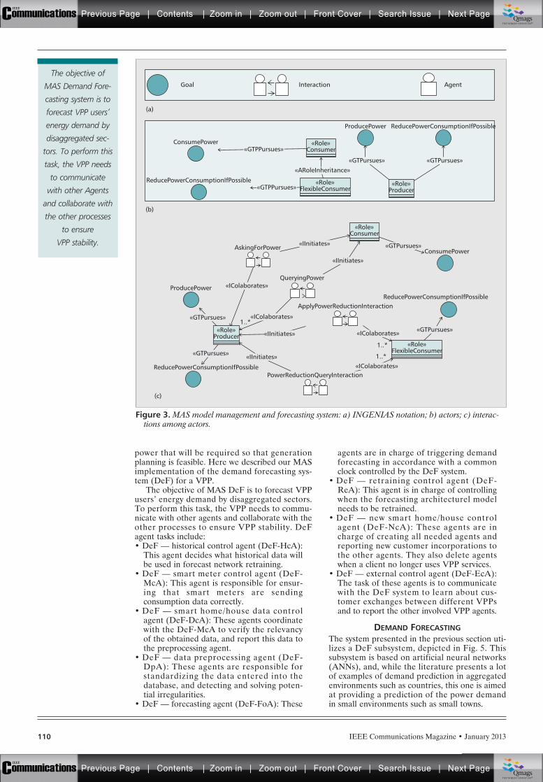
IEEE Communications Magazine • January 2013110
power that will be required so that generationplanning is feasible. Here we described our MASimplementation of the demand forecasting sys-tem (DeF) for a VPP.
The objective of MAS DeF is to forecast VPPusers’ energy demand by disaggregated sectors.To perform this task, the VPP needs to commu-nicate with other agents and collaborate with theother processes to ensure VPP stability. DeFagent tasks include:• DeF — historical control agent (DeF-HcA):
This agent decides what historical data willbe used in forecast network retraining.
• DeF — smart meter control agent (DeF-McA): This agent is responsible for ensur-ing that smart meters are sendingconsumption data correctly.
• DeF — smart home/house data controlagent (DeF-DcA): These agents coordinatewith the DeF-McA to verify the relevancyof the obtained data, and report this data tothe preprocessing agent.
• DeF — data preprocessing agent (DeF-DpA): These agents are responsible forstandardizing the data entered into thedatabase, and detecting and solving poten-tial irregularities.
• DeF — forecasting agent (DeF-FoA): These
agents are in charge of triggering demandforecasting in accordance with a commonclock controlled by the DeF system.
• DeF — retraining control agent (DeF-ReA): This agent is in charge of controllingwhen the forecasting architecturel modelneeds to be retrained.
• DeF — new smart home/house controlagent (DeF-NcA): These agents are incharge of creating all needed agents andreporting new customer incorporations tothe other agents. They also delete agentswhen a client no longer uses VPP services.
• DeF — external control agent (DeF-EcA):The task of these agents is to communicatewith the DeF system to learn about cus-tomer exchanges between different VPPsand to report the other involved VPP agents.
DEMAND FORECASTINGThe system presented in the previous section uti-lizes a DeF subsystem, depicted in Fig. 5. Thissubsystem is based on artificial neural networks(ANNs), and, while the literature presents a lotof examples of demand prediction in aggregatedenvironments such as countries, this one is aimedat providing a prediction of the power demandin small environments such as small towns.
Figure 3. MAS model management and forecasting system: a) INGENIAS notation; b) actors; c) interac-tions among actors.
ConsumePower
(a)
(b)
(c)
Goal Interaction Agent
ConsumePower
ProducePower
ReducePowerConsumptionIfPossible
ReducePowerConsumptionIfPossible
ProducePower
ReducePowerConsumptionIfPossible
«GTPPursues»
«GTPPursues»«Role»
FlexibleConsumer
«ARoleInheritance»
«GTPursues»
ReducePowerConsumptionIfPossible
«GTPursues»
«Role»Consumer
«IInitiates»
«IInitiates»
«IInitiates»
«IInitiates»
«IColaborates»
«IColaborates»
«IColaborates»
«IColaborates»
1..*
1..*
1..*
«GTPursues»
«GTPursues»
«GTPursues»
«GTPursues»
«Role»Consumer
«Role»Producer
«Role»Producer
QueryingPower
AskingForPower
PowerReductionQueryInteraction
ApplyPowerReductionInteraction
«Role»FlexibleConsumer
The objective of
MAS Demand Fore-
casting system is to
forecast VPP users’
energy demand by
disaggregated sec-
tors. To perform this
task, the VPP needs
to communicate
with other Agents
and collaborate with
the other processes
to ensure
VPP stability.
Previous Page | Contents | Zoom in | Zoom out | Front Cover | Search Issue | Next PageIEEE
Communications qqM
Mq
qM
MqM
Qmags®THE WORLD’S NEWSSTAND
Previous Page | Contents | Zoom in | Zoom out | Front Cover | Search Issue | Next PageIEEE
Communications qqM
Mq
qM
MqM
Qmags®THE WORLD’S NEWSSTAND
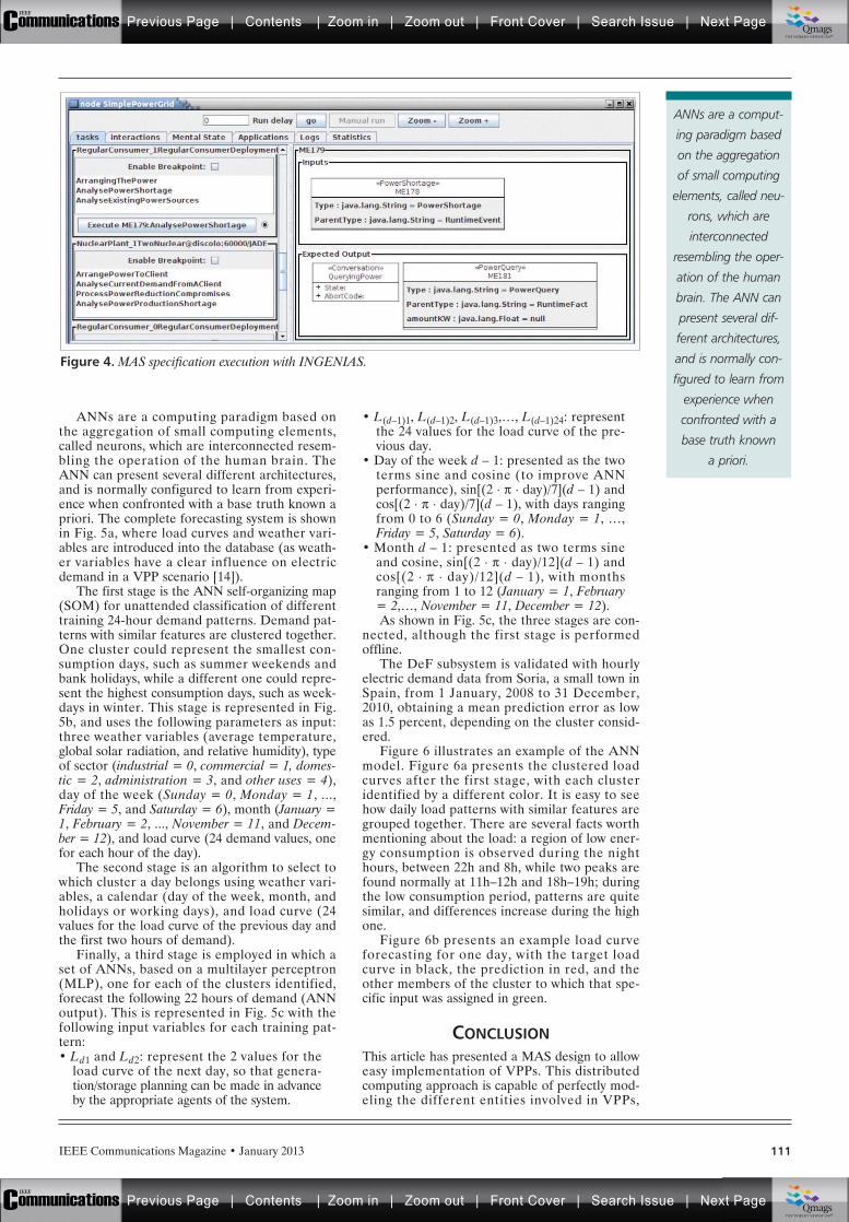
IEEE Communications Magazine • January 2013 111
ANNs are a computing paradigm based onthe aggregation of small computing elements,called neurons, which are interconnected resem-bling the operation of the human brain. TheANN can present several different architectures,and is normally configured to learn from experi-ence when confronted with a base truth known apriori. The complete forecasting system is shownin Fig. 5a, where load curves and weather vari-ables are introduced into the database (as weath-er variables have a clear influence on electricdemand in a VPP scenario [14]).
The first stage is the ANN self-organizing map(SOM) for unattended classification of differenttraining 24-hour demand patterns. Demand pat-terns with similar features are clustered together.One cluster could represent the smallest con-sumption days, such as summer weekends andbank holidays, while a different one could repre-sent the highest consumption days, such as week-days in winter. This stage is represented in Fig.5b, and uses the following parameters as input:three weather variables (average temperature,global solar radiation, and relative humidity), typeof sector (industrial = 0, commercial = 1, domes-tic = 2, administration = 3, and other uses = 4),day of the week (Sunday = 0, Monday = 1, ...,Friday = 5, and Saturday = 6), month (January =1, February = 2, ..., November = 11, and Decem-ber = 12), and load curve (24 demand values, onefor each hour of the day).
The second stage is an algorithm to select towhich cluster a day belongs using weather vari-ables, a calendar (day of the week, month, andholidays or working days), and load curve (24values for the load curve of the previous day andthe first two hours of demand).
Finally, a third stage is employed in which aset of ANNs, based on a multilayer perceptron(MLP), one for each of the clusters identified,forecast the following 22 hours of demand (ANNoutput). This is represented in Fig. 5c with thefollowing input variables for each training pat-tern:• Ld1 and Ld2: represent the 2 values for the
load curve of the next day, so that genera-tion/storage planning can be made in advanceby the appropriate agents of the system.
• L(d–1)1, L(d–1)2, L(d–1)3,…, L(d–1)24: representthe 24 values for the load curve of the pre-vious day.
• Day of the week d – 1: presented as the twoterms sine and cosine (to improve ANNperformance), sin[(2 . p . day)/7](d – 1) andcos[(2 . p . day)/7](d – 1), with days rangingfrom 0 to 6 (Sunday = 0, Monday = 1, …,Friday = 5, Saturday = 6).
• Month d – 1: presented as two terms sineand cosine, sin[(2 . p . day)/12](d – 1) andcos[(2 . p . day)/12](d – 1), with monthsranging from 1 to 12 (January = 1, February= 2,…, November = 11, December = 12).As shown in Fig. 5c, the three stages are con-
nected, although the first stage is performedoffline.
The DeF subsystem is validated with hourlyelectric demand data from Soria, a small town inSpain, from 1 January, 2008 to 31 December,2010, obtaining a mean prediction error as lowas 1.5 percent, depending on the cluster consid-ered.
Figure 6 illustrates an example of the ANNmodel. Figure 6a presents the clustered loadcurves after the first stage, with each clusteridentified by a different color. It is easy to seehow daily load patterns with similar features aregrouped together. There are several facts worthmentioning about the load: a region of low ener-gy consumption is observed during the nighthours, between 22h and 8h, while two peaks arefound normally at 11h–12h and 18h–19h; duringthe low consumption period, patterns are quitesimilar, and differences increase during the highone.
Figure 6b presents an example load curveforecasting for one day, with the target loadcurve in black, the prediction in red, and theother members of the cluster to which that spe-cific input was assigned in green.
CONCLUSIONThis article has presented a MAS design to alloweasy implementation of VPPs. This distributedcomputing approach is capable of perfectly mod-eling the different entities involved in VPPs,
Figure 4. MAS specification execution with INGENIAS.
ANNs are a comput-
ing paradigm based
on the aggregation
of small computing
elements, called neu-
rons, which are
interconnected
resembling the oper-
ation of the human
brain. The ANN can
present several dif-
ferent architectures,
and is normally con-
figured to learn from
experience when
confronted with a
base truth known
a priori.
Previous Page | Contents | Zoom in | Zoom out | Front Cover | Search Issue | Next PageIEEE
Communications qqM
Mq
qM
MqM
Qmags®THE WORLD’S NEWSSTAND
Previous Page | Contents | Zoom in | Zoom out | Front Cover | Search Issue | Next PageIEEE
Communications qqM
Mq
qM
MqM
Qmags®THE WORLD’S NEWSSTAND
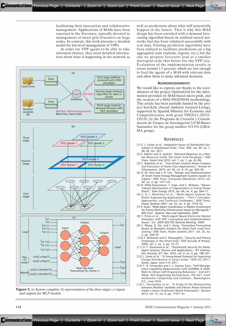
IEEE Communications Magazine • January 2013112
facilitating their interaction and collaborativemanagement. Applications of MASs have beenreported in the literature, typically devoted tomanagement of smart grid structures on largescales. In contrast, this work presents a detailedmodel for low-level management of VPPs.
In order for VPP agents to be able to takeinformed choices, they need detailed informa-tion about what is happening in the network as
well as predictions about what will potentiallyhappen in the future. That is why this MASdesign has been enriched with a demand fore-casting algorithm based on artificial neural net-works that has been validated successfully withreal data. Existing prediction algorithms havebeen utilized to facilitate predictions on a bigaggregated scale (nations, regions, etc.), but theone we propose forecasts load at a smallermicrogrid scale that better fits the VPP size.Evaluation of the implementation results inerrors around 1.5 percent, which are low enoughto feed the agents of a MAS with relevant dataand allow them to make informed decisions.
ACKNOWLEDGMENTSWe would like to express our thanks to the coor-dinators of the project OptimaGrid for the infor-mation provided on MAS-based micro-grids, andthe creators of a MAS INGENIAS methodology.This article has been partially funded by the pro-ject SociAAL (Social Ambient Assisted Living),supported by Spanish Ministry for Economy andCompetitiveness, with grant TIN2011-28335-C02-01, by the Programa de Creación y Consoli-dación de Grupos de Investigación UCM-BancoSantander for the group number 921354 (GRA-SIA group).
REFERENCES[1] E. J. Coster et al., Integration Issues of Distributed Gen-
eration in Distribution Grids,” Proc. IEEE, vol. 99, no. 1,28–39, Jan. 2011.
[2] F. Rahimi and A. Ipakchi, “Demand Response as a Mar-ket Resource Under the Smart Grid Paradigm,” IEEETrans. Smart Grid 2010, vol. 1, no. 1, pp. 82–88.
[3] C. Baladrón et al., “User-Driven Context Aware Creationand Execution of Home Care Applications,” Annals ofTelecommun. 2010, vol. 65, no. 9–10, pp. 545–56.
[4] D.-M. Han and J.-H. Lim, “Design and Implementationof Smart Home Energy Management Systems based onZigbee,” IEEE Trans. Consumer Electronics 2010, vol.56, no. 3, pp. 1417–25.
[5] B. Wille-Haussmann, T. Erge, and C. Wittwer, “Decen-tralized Optimization of Cogeneration in Virtual PowerPlants,“ Solar Energy 2010, vol. 84, no. 4, pp. 604–11.
[6] S. D. J. McArthur et al., “Multi-Agent Systems forPower Engineering Applications — Part I: Concepts,Approaches, and Technical Challenges,” IEEE Trans.Power Systems 2007, vol. 22, no. 4, pp. 1743–52.
[7] R. Duan, “Multi-Agent Coordination in Market Environmentfor Future Electricity Infrastructure based on Microgrids,”IEEE Conf.: Systems, Man and Cybernetics, 2009.
[8] T. Pinto et al., “Multi-Agent Based Electricity MarketSimulator with VPP: Conceptual and ImplementationIssues,” Inc: 2009 IEEE PES General Meeting, 2009.
[9] Y. Wang, Q. Xia, and C. Kang, “Secondary ForecastingBased on Deviation Analysis for Short-Term Load Fore-casting,” IEEE Trans. Power Systems 2011, vol. 26, no.2, pp. 500–07.
[10] P. McDaniel and S. McLaughlin, “Security and PrivacyChallenges in the Smart Grid,” IEEE Security & Privacy,2009, vol. 7, no. 3, pp. 75–77.
[11] H. F. Rashvand et al., “Distributed Security for Multi-Agent Systems: Review and Applications,” IET Informa-tion Security, IET, Dec. 2010, vol. 4, no. 4, pp. 188–201.
[12] J. Lloret et al., “A Group-based Protocol for ImprovingEnergy Distribution in Smart Grids,” IEEE ICC 2011,Kyoto, Japan, June 5–9, 2011.
[13] C. R. Fernandez and J. J. Gomez Sanz, “Self-Manage-ment Capability Requirements with SelfMML & INGE-NIAS to Attain Self-Organizing Behaviors,” 2nd Int’l.Wksp. Self-Organizing Architectures, 7th Int’l. Conf.Autonomic Computing and Commun., Washington,D.C., June 2010.
[14] L. Hernández et al., “A Study of the Relationshipbetween Weather Variables and Electric Power Demandinside a Smart Grid/Smart World Framework,” Sensors2012, vol. 12, no. 9, pp. 11571–91.
Figure 5. a) System complete; b) representation of the three stages; c) inputsand outputs for MLP models.
STLF cluster n
STLF cluster 1 STLF cluster 2
STLF cluster n
STLF cluster 1 STLF cluster 2
Load
Output
Hidden
Next day loadforecasting for cluster n
Month
Dayof
week
Input
Dataprocessing
First stage (offline):clustered with SOM
paradigm
Second stage (online):algorithm to select a
cluster
Third stage (online):demand forecast with
MLP paradigm
Database
Thirdstage
Red line: Forecasting processBlack line: Input data
(a)
(b)
(c)
Load curve
Dataprocessing
Weathervariables
file
On-line
Off-lin
e
On-line
Secondstage
Firststage
Load
Ld1Ld2
Ld3
Ld22
Ld23
Ld24
L(d-1)1L(d-1)2L(d-1)3
L(d-1)22L(d-1)23
L(d-1)24
sin(2⋅π⋅day/7)
cos(2⋅π⋅day/7)
sin(2⋅π⋅month/12)
cos(2⋅π⋅month/12)
Previous Page | Contents | Zoom in | Zoom out | Front Cover | Search Issue | Next PageIEEE
Communications qqM
Mq
qM
MqM
Qmags®THE WORLD’S NEWSSTAND
Previous Page | Contents | Zoom in | Zoom out | Front Cover | Search Issue | Next PageIEEE
Communications qqM
Mq
qM
MqM
Qmags®THE WORLD’S NEWSSTAND
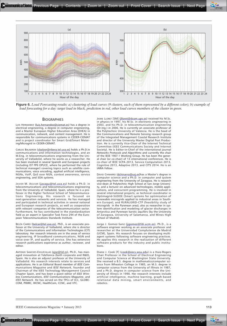
IEEE Communications Magazine • January 2013 113
BIOGRAPHIESLUIS HERNANDEZ ([email protected]) has a degree inelectrical engineering, a degree in computer engineering,and a Master European Higher Education Area (EHEA) incommunication, network, and content management. He isresponsible for communications systems in CEDER-CIEMATand is project coordinator for Smart Grid/Smart Meter-ing/Microgrid in CEDER-CIEMAT.
CARLOS BALADRON ([email protected]) holds a Ph.D.incommunications and information technologies, and anM.Eng. in telecommunications engineering from the Uni-versity of Valladolid, where he works as a researcher. Hehas been involved in several Spanish and European projects(including IST FP6 OPUCE, where he performed the role oftechnical manager) covering topics such as satellite com-munications, voice encoding, applied artificial intelligence,NGNs, VoIP, QoS over NGN, context awareness, serviceengineering, and SOA systems.
JAVIER M. AGUIAR ([email protected]) holds a Ph.D. intelecommunications and telecommunications engineeringfrom the University of Valladolid, Spain, where he is a pro-fessor in the Higher Technical School of Telecommunica-tions Engineering. His research is focused onnext-generation networks and services. He has managedand participated in technical activities in several nationaland European research projects, as well as cooperationwith relevant companies of the telecommunication sector.Furthermore, he has contributed in the standardizationfield as an expert in Specialist Task Force 294 of the Euro-pean Telecommunications Standards Institute.
BELÉN CARRO ([email protected]), PhD., is an associate pro-fessor at the University of Valladolid, where she is directorof the Communications and Information Technologies (CIT)laboratory. Her research interests are in the areas of serviceengineering, IP broadband communications, NGN andvoice over IP, and quality of service. She has extensiveresearch publications experience as author, reviewer, andeditor.
ANTONIO SANCHES-ESGUEVILLAS ([email protected]), Ph.D., has man-aged innovation at Telefonica (both corporate and R&D),Spain. He is also an adjunct professor at the University ofValladolid. His research interests relate to services andapplications. He is an Editorial Board member of IEEE Com-munications Magazine and IEEE Network, founder andChairman of the IEEE Technology Management CouncilChapter Spain, and has been a guest editor of IEEE Wire-less Communications, IEEE Communications Magazine, andIEEE Network. He has served on the TPCs of ICC, GLOBE-COM, PIMRC, WCNC, HealthCom, CCNC, and VTC.
JAIME LLORET [SM] ([email protected]) received his M.Sc.in physics in 1997, his M.Sc. in electronic engineering in2003, and his Ph.D. in telecommunication engineering(Dr.Ing.) in 2006. He is currently an associate professor atthe Polytechnic University of Valencia. He is the head ofthe Communications and Remote Sensing research groupof the Integrated Management Coastal Research Instituteand director of the University Master Digital Post Produc-tion. He is currently Vice-Chair of the Internet TechnicalCommittee (IEEE Communications Society and InternetSociety). He is Editor-in-Chief of the international journalNetworks Protocols and Algorithms and currently the chairof the IEEE 1907.1 Working Group. He has been the gener-al chair (or co-chair) of 13 international conferences. He isco-chair of IEEE SCPA 2013, Service Computation 2013,Cognitive 2013, Adaptive 2013, and CITS 2014. He is anIARIA Fellow.
DAVID CHINARRO ([email protected])has a Master’s degree incomputer science and a Ph.D. in computer and systemengineering from the University of Zaragoza. He is researchvice-dean at Polytechnic High School at San Jorge Universi-ty, and a lecturer on advanced technologies, mobile appli-cations, and concurrent programming. He is involved inseveral international projects; as technical coordinator inOptimagrid-SUDOE (Smart systems for optimization ofrenewable microgrids applied to industrial areas in South-ern Europe); and RURALGRID-CTP (feasibility study ofmicrogrids in the Pyrenean area); also as researcher in sys-tem identification and modeling of glacier discharges inAntarctica and Pyrenean karstic aquifers (by the Universityof Zaragoza, University of Salamanca, and Mines HighSchool of Madrid).
Jorge J. Gomez-Sanz ([email protected]), Ph.D., is asoftware engineer working as an associate professor andresearcher at the Universidad Complutense de Madrid(UCM), Spain. His research focuses on developing multi-agent systems following software engineering practices.He applies this research in the realization of differentsoftware products for the industry and public institu-tions.
Diane J. Cook [F] ([email protected]) is a Huie-RogersChair Professor in the School of Electrical Engineeringand Computer Science at Washington State University.She received a B.S. degree in mathematics/computer sci-ence from Wheaton College in 1985, an M.S. degree incomputer science from the University of Illinois in 1987,and a Ph.D. degree in computer science from the Uni-versity of Illinois in 1990. Her research interests includeartificial intelligence, machine learning, graph-basedrelat ional data mining, smart environments, androbotics.
Figure 6. Load Forecasting results: a) clustering of load curves (9 clusters, each of them represented by a different color); b) example ofload forecasting for a day: target load in black, prediction in red, other load curves members of the cluster in green.
Hour of the day
(a)
200
100
kWh
300
400
500
600
700
800
900
21 3 4 5 6 7 8 9 10 11 12 13 14 15 16 17 18 19 20 21 22 23 24Hour of the day
(b)
400
500
300
kWh
600
700
21 3 4 5 6 7 8 9 10 11 12 13 14 15 16 17 18 19 20 21 22 23 24
Previous Page | Contents | Zoom in | Zoom out | Front Cover | Search Issue | Next PageIEEE
Communications qqM
Mq
qM
MqM
Qmags®THE WORLD’S NEWSSTAND
Previous Page | Contents | Zoom in | Zoom out | Front Cover | Search Issue | Next PageIEEE
Communications qqM
Mq
qM
MqM
Qmags®THE WORLD’S NEWSSTAND
______________
______________
___________
__________
______ ___________
____________
_________
___________
IEEE Communications Magazine • January 2013114 0163-6804/13/$25.00 © 2013 IEEE
INTRODUCTION
There is a growing worldwide interest in the evo-lution of the smart grid, a modern power grid thatsupports bidirectional communication betweenenergy providers and consumers for fine-grainedmetering, control, and feedback. One of the keyfeatures of the smart grid is enhanced energy effi-ciency and manageability of available resources.Energy management (EM) systems, often inte-grated with home automation systems, play animportant role in controlling home energy con-sumption. These systems provide an infrastructureto the consumers to understand, control, andoptimize energy consumption. For example, EMsystems can help consumers avoid consumptionduring peak hours and thus benefit from financialincentives offered by the utility. Widespreadadoption of EM systems by consumers will even-tually lead to more efficient consumption behav-ior and will benefit the utility as well. The role ofEM systems in a smart grid is illustrated in Fig. 1.
EM systems have been around for a couple ofdecades, but until recently, they required special-ized instrumentation and manual configuration.They also relied on extensive interaction with thecustomer to be useful. These factors posed an
entry barrier, which prevented their large-scaleadoption. This scenario is changing rapidlybecause of several technological advances. First,the growth in non-intrusive load monitoring(NILM) techniques is now making it possible tocollect energy consumption data down to thelevel of appliances. The disaggregated energydata thus collected is more meaningful to theconsumers. Second, due to the pervasive avail-ability of sensors, it has become easier to collectdifferent dimensions of data, including ambienttemperature, humidity, and lighting, that can beintegrated by EM systems to provide more con-textual information and thus increase their effec-tiveness. Third, cloud computing and mobileplatforms have made it possible to perform large-scale analytics on sensor data and offer advancedreal-time feedback to the consumers. Finally, thegrowing popularity of social networks, like Face-book, has made it easier to incorporate compara-tive and persuasive features into EM systems tomotivate behavioral changes in consumers.
This article reviews the state of the art in EMsystems and identifies emerging trends in thisdomain. Research into methods for energy con-sumption management is well established [7],and our article supplements existing work. In1981, McDougall et al. published an extensivereview of energy consumption modeling andfeedback techniques [3]. More recently,Froehlich et al. [6] offered a detailed review offeedback methods for energy management andconcluded that providing consumers withdetailed feedback on their consumption patternswill help them make more informed decisionsabout their energy consumption.
REQUIREMENTS FOR EM SYSTEMSEM systems must provide advanced and versatilefunctionality while keeping the installation sim-ple and running cost low. The systems shouldintegrate with users’ daily activities and offeractionable feedback. We define below the keyrequirements for EM systems that will facilitateeffortless energy monitoring and control.
MONITORINGThe system must provide energy consumptioninformation at various temporal granularitiessuch as 15 min, hourly, daily, and weekly. Fisch-
ABSTRACT
The electric grid is radically evolving andtransforming into the smart grid, which is char-acterized by improved energy efficiency andmanageability of available resources. Energymanagement (EM) systems, often integratedwith home automation systems, play an impor-tant role in the control of home energy con-sumption and enable increased consumerparticipation. These systems provide consumerswith information about their energy consump-tion patterns and help them adopt energy-effi-cient behavior. The new generation EM systemsleverage advanced analytics and communicationtechnologies to offer consumers actionable infor-mation and control features, while ensuring easeof use, availability, security, and privacy. In thisarticle, we present a survey of the state of the artin EM systems, applications, and frameworks.We define a set of requirements for EM systemsand evaluate several EM systems in this context.We also discuss emerging trends in this area.
ULTIMATE TECHNOLOGIES AND ADVANCES FORFUTURE SMART GRID — UTASG
Saima Aman, Yogesh Simmhan, and Viktor K. Prasanna, University of Southern California
Energy Management Systems: State ofthe Art and Emerging Trends
Previous Page | Contents | Zoom in | Zoom out | Front Cover | Search Issue | Next PageIEEE
Communications qqM
Mq
qM
MqM
Qmags®THE WORLD’S NEWSSTAND
Previous Page | Contents | Zoom in | Zoom out | Front Cover | Search Issue | Next PageIEEE
Communications qqM
Mq
qM
MqM
Qmags®THE WORLD’S NEWSSTAND
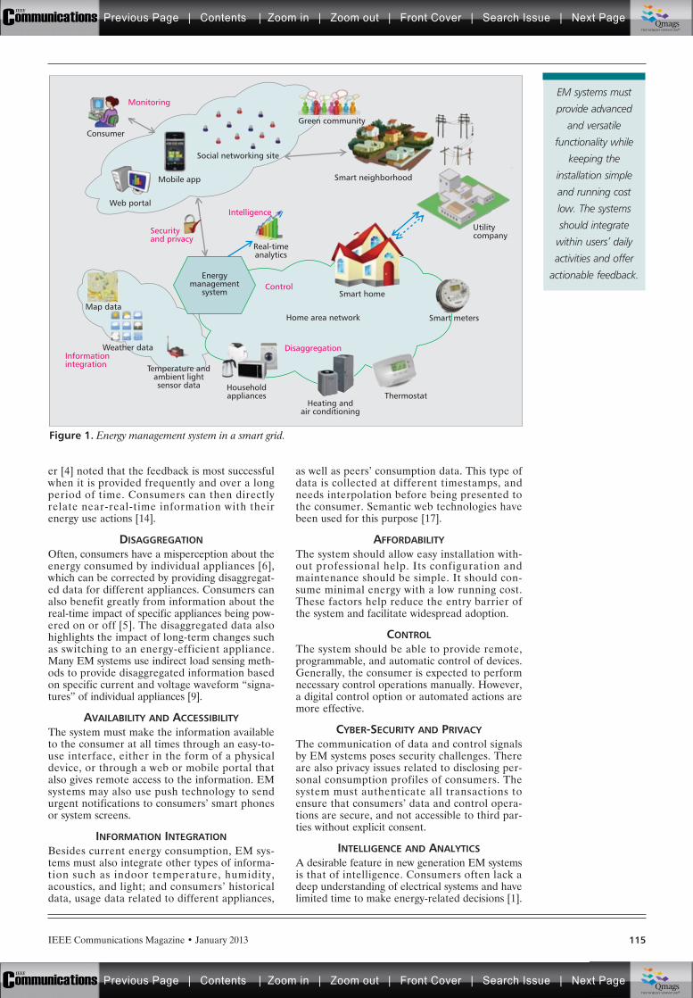
IEEE Communications Magazine • January 2013 115
er [4] noted that the feedback is most successfulwhen it is provided frequently and over a longperiod of time. Consumers can then directlyrelate near-real-time information with theirenergy use actions [14].
DISAGGREGATIONOften, consumers have a misperception about theenergy consumed by individual appliances [6],which can be corrected by providing disaggregat-ed data for different appliances. Consumers canalso benefit greatly from information about thereal-time impact of specific appliances being pow-ered on or off [5]. The disaggregated data alsohighlights the impact of long-term changes suchas switching to an energy-efficient appliance.Many EM systems use indirect load sensing meth-ods to provide disaggregated information basedon specific current and voltage waveform “signa-tures” of individual appliances [9].
AVAILABILITY AND ACCESSIBILITYThe system must make the information availableto the consumer at all times through an easy-to-use interface, either in the form of a physicaldevice, or through a web or mobile portal thatalso gives remote access to the information. EMsystems may also use push technology to sendurgent notifications to consumers’ smart phonesor system screens.
INFORMATION INTEGRATIONBesides current energy consumption, EM sys-tems must also integrate other types of informa-tion such as indoor temperature, humidity,acoustics, and light; and consumers’ historicaldata, usage data related to different appliances,
as well as peers’ consumption data. This type ofdata is collected at different timestamps, andneeds interpolation before being presented tothe consumer. Semantic web technologies havebeen used for this purpose [17].
AFFORDABILITYThe system should allow easy installation with-out professional help. Its configuration andmaintenance should be simple. It should con-sume minimal energy with a low running cost.These factors help reduce the entry barrier ofthe system and facilitate widespread adoption.
CONTROLThe system should be able to provide remote,programmable, and automatic control of devices.Generally, the consumer is expected to performnecessary control operations manually. However,a digital control option or automated actions aremore effective.
CYBER-SECURITY AND PRIVACYThe communication of data and control signalsby EM systems poses security challenges. Thereare also privacy issues related to disclosing per-sonal consumption profiles of consumers. Thesystem must authenticate all transactions toensure that consumers’ data and control opera-tions are secure, and not accessible to third par-ties without explicit consent.
INTELLIGENCE AND ANALYTICSA desirable feature in new generation EM systemsis that of intelligence. Consumers often lack adeep understanding of electrical systems and havelimited time to make energy-related decisions [1].
Figure 1. Energy management system in a smart grid.
Smart neighborhood
Green community
Social networking site
Mobile app
Web portal
Consumer
Utilitycompany
Home area network
Smart home
Real-timeanalytics
Map data
Weather data
Temperature andambient lightsensor data Household
appliancesHeating and
air conditioning
Thermostat
Smart meters
Control
Disaggregation
Intelligence
Monitoring
Securityand privacy
Informationintegration
Energymanagement
system
EM systems must
provide advanced
and versatile
functionality while
keeping the
installation simple
and running cost
low. The systems
should integrate
within users’ daily
activities and offer
actionable feedback.
Previous Page | Contents | Zoom in | Zoom out | Front Cover | Search Issue | Next PageIEEE
Communications qqM
Mq
qM
MqM
Qmags®THE WORLD’S NEWSSTAND
Previous Page | Contents | Zoom in | Zoom out | Front Cover | Search Issue | Next PageIEEE
Communications qqM
Mq
qM
MqM
Qmags®THE WORLD’S NEWSSTAND
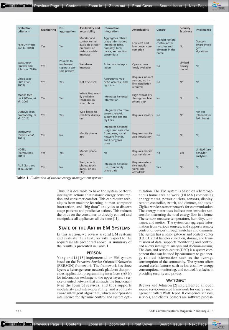
IEEE Communications Magazine • January 2013116
Thus, it is desirable to have the system performintelligent actions that balance energy consump-tion and consumer comfort. This can require tech-niques from machine learning, human–computerinteraction, and “big data” analytics to discernusage patterns and predictive actions. This reducesthe onus on the consumer to directly control andmanipulate all appliances all the time [11].
STATE OF THE ART IN EM SYSTEMSIn this section, we review several EM systemsand evaluate their features with respect to therequirements presented above. A summary ofthe results is presented in Table 1.
PERSONYang and Li [15] implemented an EM systembased on the Pervasive Service-Oriented Networks(PERSON) framework. The framework has threelayers: a heterogeneous network platform that pro-vides application programming interfaces (APIs)for information exchange to the upper layers; a ser-vice-oriented network that abstracts the functionali-ty in the form of services, and thus supportsmodularity and inter-operability; and a context-aware intelligent algorithm, which incorporatesintelligence for dynamic control and system opti-
mization. The EM system is based on a heteroge-neous home area network (HHAN) comprisingenergy meter, power outlets, sensors, display,remote controller, switch, and dimmer, and uses aZigBee wireless sensor network for communication.The energy meter uses indirect non-intrusive sen-sors for measuring the total energy flow in a home.The sensors measure temperature, humidity, lumi-nance, and motion. The system can aggregate infor-mation from various sources, and supports remotecontrol of devices through switches and dimmers.The system has a home gateway and control center(HGCC) that handles collection, storage, and trans-mission of data, supports monitoring and control,and allows intelligent analysis and decision-making.The data and service center (DSC) is a system com-ponent that can be used by consumers to get ener-gy related information such as the averageconsumption of the community. The system offersseveral useful features such as low cost, low energyconsumption, monitoring, and control, but lacks inproviding security and privacy.
WATTDEPOTBrewer and Johnson [2] implemented an opensource service-oriented framework for energy man-agement called WattDepot. It comprises sensors,services, and clients. Sensors are software process-
Table 1. Evaluation of various energy management systems.
Evaluationcriteria Æ Monitoring Dis-
aggregationAvailability andaccessibility
Informationintegration Affordability Control Security
& privacy Intelligence
PERSON (Yangand Li, 2010) Yes Yes
Monitor andcontrol centeravailable at userpremises; noweb or mobileinterface
Aggregates others’usage information;integrates temp,humidity, lumi-nance, and motionsensor data
Low cost andlow power con-sumption
Manual remotecontrol of theswitches anddimmers in thehome.
No
Context-aware intelli-gentalgorithm
WattDepot(Brewer andJohnson, 2010)
Yes
Possible toimplement,separate sen-sors present
Web-basedinterface
Automatic interpo-lation
Open source,freely available No
Limitedprivacymodel
No
ViridiScope(Kim et al.,2009)
Yes Yes Not discussedAggregates mag-netic, acoustic, andlight info
Requires indirectsensors; no in-line installationrequired
No No No
Mobile feed-back (Weiss, etal., 2009
Yes Yes
Interactive; read-ily availablefeedback onsmartphone
Integrates historicalinformation
High availabilitythrough mobilephone app
No No No
DEHEMS (Sun-dramoorthy, etal., 2011)
Yes YesWeb-based UI,real-time displayunit
Integrates info fromsensors, electricsupply and gas sup-ply lines
Requires sensors No NoNot yet(planned for3rd phase)
EnergyWiz(Petkov, et al.,2011)
Yes No Mobile phoneapp
Integrates historicalusage, and user infofrom peers, socialnetwork friends,and EnergyWizusers
Requires mobileapp installation No No No
NOBEL(Karnouskos,2011)
Yes Yes Mobile phoneapp No Requires mobile
app installation No YesLimited (userbehavioranalytics)
ALIS (Bartram,et al., 2010) Yes No
Web, smart-phone, touchpanel, art dis-play
Integrates historicaluse, communityusage data
Requires exten-sive installa-tions; lessaffordable
Yes No No
Previous Page | Contents | Zoom in | Zoom out | Front Cover | Search Issue | Next PageIEEE
Communications qqM
Mq
qM
MqM
Qmags®THE WORLD’S NEWSSTAND
Previous Page | Contents | Zoom in | Zoom out | Front Cover | Search Issue | Next PageIEEE
Communications qqM
Mq
qM
MqM
Qmags®THE WORLD’S NEWSSTAND
IEEE Communications Magazine • January 2013 117
es that request data from different energy meters;servers collect data from the sensors over theInternet; and the clients request data from theservers for display or for use by higher-level ser-vices. WattDepot provides services for collection,aggregation, analysis, and visualization of energydata. The consumers can configure the source tobe monitored and the type of data displayed, andcan get near-real-time feedback. It uses a simpleprivacy model. All sensors that transmit data for aparticular source share the same access informa-tion corresponding to that source’s owner. All datarequests are authenticated before being stored onthe server. Each source can be labeled as public orprivate. Anyone can access data from a publicsource, while only the source’s owner can accessdata from a private source. The main limitations ofWattDepot are lack of intelligence and absence ofany programmable or automatic control.
VIRIDISCOPEKim et al. [9] developed ViridiScope for fine-grainedmonitoring of domestic energy consumption. It pro-vides real-time appliance-level energy use estimationwithout the need for external calibration. It does thisby means of indirect magnetic, acoustic, or light sen-sors placed near each appliance. Data is collectedfrom heterogeneous sensors, and a machine-learningalgorithm is used to learn and estimate the energyconsumption of every appliance. This is a self-cali-brating method that requires little human interven-tion, but it does require a sensor to be deployed witheach and every device. The system is easy to installand run long-term and supports information integra-tion from various sources. However, it does not pro-vide manual, programmable, or intelligent control ofdevices, and also offers no security feature.
MOBILE-BASED FEEDBACK SYSTEMWeiss et al. [14] implemented a mobile phoneapplication to monitor and measure appliance-spe-cific energy consumption based on the data collect-ed by a smart meter. The application can bedownloaded from the Internet, and requires nofurther configuration. It provides current energyusage, historical usage, device inventory, and mea-surement. The consumer can perform remote mea-surement and control of any appliance, and getresults in near real time. The application is linkedto the smart meter through an information gate-way that gets data from the smart meter every sec-ond, and parses and stores it in an SQL database.The gateway’s functionality can be accessedthrough a web server, and the meter readings canbe accessed through URLs. A device’s consump-tion is measured by turning the device on andobserving the change in consumption data collect-ed in real time by the smart meter. The informa-tion is then added to the device inventory, whichmaintains information about all previously mea-sured devices. The main limitations of the systemare lack of a security mechanism without any userauthentication, no support for remotely controllingor programming the devices, and no embeddedintelligence for automatic operation.
DEHEMSSundramoorthy et al. [12] proposed a Digital HomeEnergy Management System (Dehems) that col-lects user experiences and preferences, and pro-
vides useful feedback to consumers. Dehems sensesdata from electrical and gas supply lines, individualappliances, and ambient sensors. The data is thenaggregated by means of the Dehems gateway andcommunicated to the server, which sends it to theweb service. Dehems supports display of real-timeof energy use, historical use, energy-saving tips, andcomparison with average use of all system users.The system development involves three cycles ofrequirement gathering, design, implementation,deployment, and behavior assessment. Currently, itis in the second cycle. Repeated cycles would allowthe system to understand energy use behavior andevaluate the efficacy of various persuasive tech-niques, and make corresponding improvements inthe next phase. The main features of the currentcycle are relative comparisons with similar house-holds, disaggregated appliance-specific feedback,support for setting goals and targets for the con-sumer, provision of energy-saving tips and environ-mental facts, and a Facebook account forinformation sharing. An intelligent reasoning tool isplanned for the third cycle that will automaticallydetect energy use patterns and generate corre-sponding personalized energy-saving tips. The sys-tem does not currently provide any kind of securityand privacy, or control for individual devices.
ENERGYWIZPetkov et al. [10] introduced EnergyWiz, a mobileapplication that provides information about energyuse and comparison with other individuals, includ-ing neighbors, social network friends, and otherEnergyWiz users. The main goal of the system is toprovide different kinds of comparisons to the con-sumer and motivate behavior change. It providesfive types of comparative feedback: live data, his-torical data, neighbor data, challenge, and ranking.The feedback is available in different energy con-sumption units (kilowatts per hour, kilograms ofCO2, and money). EnergyWiz is Facebook-enabled, and allows monitoring and sharing ofenergy information in a social context. Consumerscan challenge friends on Facebook in energy savingcompetitions and get a ranking among friends onFacebook who use EnergyWiz. The system uses adistributed architecture that facilitates informationcollection, management, and consumption at dif-ferent sites. The energy consumption data is col-lected by an application/manager interface (AMI)and is stored on the server in a relational databaseserver. The main limitation of the system is lack ofsupport for privacy and security, especially whenthe data is shared on social networking sites. Thesystem does not provides device-specific disaggre-gated information or control of devices. Also, nointelligence is embedded in the system for any kindof automatic operation.
NOBELKarnouskos [8] proposed a system to crowdsource high-quality energy use data and contextinformation from mobile phone consumers. Thisdata can then be utilized in building decisionsupport systems, and for profile analytics andprediction. The prototype energy crowdsourcingsystem (part of the NOBEL project for smartcity neighborhoods) provides detailed consump-tion data as well as device-specific disaggregatedinformation. The data is stored locally and par-
Consumers often
lack a deep under-
standing of electrical
systems and have
limited time to make
energy-related deci-
sions [1]. Thus, it is
desirable to have the
system perform intel-
ligent actions that
balance energy con-
sumption and con-
sumer comfort.
Previous Page | Contents | Zoom in | Zoom out | Front Cover | Search Issue | Next PageIEEE
Communications qqM
Mq
qM
MqM
Qmags®THE WORLD’S NEWSSTAND
Previous Page | Contents | Zoom in | Zoom out | Front Cover | Search Issue | Next PageIEEE
Communications qqM
Mq
qM
MqM
Qmags®THE WORLD’S NEWSSTAND
IEEE Communications Magazine • January 2013118
tially synchronized with a backend system. Itconnects the mobile user to Internet hosted ser-vices coupled with an enterprise system. TheInternet hosted services include an energy ser-vice manager, notification, billing, analytics, andmetering. The enterprise system consists of adevice manager, a business data manager, trust-ed third party interaction, as well as a securitymanager that performs authentication for alltransactions. However, with individual user pro-files being contributed by different consumers,there is a need to provide support for privacy.The system lacks information integration fromvarious sources and relies entirely on the con-sumer for sourcing information.
ALISBartram et al. [1] developed an Adaptive LivingInterface System (ALIS) to serve as an informa-tion backbone for their net-zero solar poweredhome. ALIS is a distributed system that consistsof energy dashboards, monitoring and awarenesstools, device controls, and a feedback system.The consumer is provided both historical andpredicted usage information. The system is madeavailable through personal computers, smart-phones, embedded touch panels, and a light-based informative art display. On a personalcomputer, the consumer has access to a high-level house dashboard for detailed consumptioninformation, an analytical resource usage inter-face, and a neighborhood bulletin for sharingand comparing their energy conservation tech-niques with others in the local community. On asmartphone, the consumer has access to simpli-fied versions of what is available on a personalcomputer, and additional alerts about energyconsumption status and thresholds. Three touchpanels are embedded in the house to serve ascontrol panels as well as dynamic feedback dis-plays. Finally, an aesthetically motivated Ambi-ent Canvas provides feedback on net-zeroperformance, water consumption, and progresstoward a performance goal. The system uses sev-eral units for display (kilowatts per hour, dollars,and grams of CO2), different display methods(numerical and graphical), time scales, andusage types. It also has added support for moti-vational factors including social interaction, per-sonal milestones, and community involvement.The main limitation of the system is that itrequires extensive installation, which makes itless affordable. It also lacks intelligence and sup-port for security and privacy.
EMERGING TRENDSWe are witnessing rapid advances in technologythat will significantly impact the design andimplementation of future EM systems. Thehome automation infrastructure is increasinglybecoming complex and enabling several func-tions such as information acquisition, decision-making, and actuation. Future EM systems needto be fully integrated with the home automationsystem, support control of appliances, and offeradvanced features such as security surveillanceusing sensors such as thermostats and motiondetectors. The main challenges in this regard areinteroperability and security. The EM system
would in essence serve as a central control systemin a digital home. The system would communi-cate with other devices and sensors throughwireless protocols such as ZigBee without requir-ing physical wiring.
Mobility is an important issue in EM systems.Future EM systems are expected to provide ver-satile mobile functionalities. In the EM domain,mobile devices can serve as a tool for real-timecommunication with consumers, whose behavioradjusts to near-real-time impulses received abouttheir energy consumption, carbon footprint, andcurrent energy tariffs. A mobile device can pro-vide value-added services such as recommenda-tion for an energy-efficient appliance, selectedbased on analytics performed on fine-grainedappliance-specific consumption profiles. Mobiledevices can also be used for crowdsourcing user-collected information. The information may bemeasured directly by the user or passively col-lected from the user’s context such as location.This information can be used intelligently forseveral goals. For example, the sensory informa-tion such as a user’s location and activity can becorrelated with their behavior, and aggregatedon a large scale for insight into a neighborhood’senergy usage trends.
EM systems can serve as a useful tool towardactive demand side energy management, one ofthe fundamental goals of smart grid [16]. Itinvolves influencing the consumers’ energy usebehavior, to either turn on/off or rescheduleappliances. This requires better understanding ofenergy use within homes and their impact onoverall consumption in the smart grid. The utili-ty can send real-time curtailment notifications tothe EM system on which the users are expectedto act. Future EM systems may have embeddedintelligence that could automate decision makingand control of household appliances in responseto demand response or price signals from theutility. The direct communication channel pre-sent through the EM system may also be used byother entities besides the utility such as by asocial network provider for communicatingsocial and comparative messages.
The user interface is another important factorthat would govern the success of an EM system.Weiser’s [13] vision is that of a pervasive futurecomputing environment where sensing, comput-ing, and response are carried out without con-sumer intervention and in a non-intrusive way.For EM systems to be effective, they shouldincreasingly conform to this paradigm. One wayto implement this is to embed learning and intel-ligence into EM systems so that they absorb auser’s preferences and comfort level, and usethis to perform automatic control of devices.System developers will also benefit from theinterface guidelines regarding persuasivenessbeing developed by Medland et al. [10].
EM systems may also integrate informationabout gas and water consumption along withelectricity consumption. Many of the EM sys-tems may be adopted by local utility companiesand offered to customers at subsidized prices tomake them more affordable. The utilities mayalso offer energy efficiency tips to the consumersthrough the EM system. In the long term, thishelps the utilities meet their sustainability and
Future EM systems
need to be fully
integrated with the
home automation
system, support
control of appliances
and offer advanced
features such as
security surveillance
using sensors such as
thermostats and
motion detectors.
Previous Page | Contents | Zoom in | Zoom out | Front Cover | Search Issue | Next PageIEEE
Communications qqM
Mq
qM
MqM
Qmags®THE WORLD’S NEWSSTAND
Previous Page | Contents | Zoom in | Zoom out | Front Cover | Search Issue | Next PageIEEE
Communications qqM
Mq
qM
MqM
Qmags®THE WORLD’S NEWSSTAND
IEEE Communications Magazine • January 2013 119
energy efficiency goals, while making their oper-ations more reliable and cost effective.
EM systems can also be used to assess what-ifscenarios, where the consumers can evaluatefine-grained effects of behavior changes, such asrescheduling an appliance’s running time. EMsystems should also provide a framework forgoal setting and allow consumers to track theirprogress toward their self-specified goals relatedto behavior change.
Security and privacy will potentially be a criti-cal challenge for future EM systems since thedata collected and analyzed by EM systems cannow be used to monitor, infer, and devise useractions. Since the data will also be shared amongpeers through social networking sites and othercommunication means, extra precautions arerequired to tackle attacks.
CONCLUSIONSThere is a high level of heterogeneity in modernhome infrastructures, which poses several chal-lenges to developing approaches for smart energymanagement in homes. Current EM systems arefundamentally different in design and operationfrom before, even as they share the common goalof optimizing home energy usage. Smart EM sys-tems are able to communicate and interact withboth customers and energy devices to help adaptthe home energy consumption to the availableenergy supply. Here, we present the state of theart in EM systems whose main thrust is to moti-vate behavior change in consumers, througheither real-time consumption monitoring, ubiqui-tous sensing, or contextual comparisons withneighbors, social network friends, and other simi-lar users. Future EM systems will need to morecarefully address security and privacy issues,which are currently inadequately handled. Thereis also a need to offer built-in intelligence basedon analytics and learning for providing moreinsight into consumer behavior and for automaticoperation. Smart EM systems integrated withhome automation systems are a key componentof the smart grid cyber-physical system, and areessential to bring its multitude of benefits tofruition. Emerging trends point to a futurebeyond isolated consumer engagement towarddynamic communities that smartly and collective-ly manage their energy consumption and shareinformation with each other to achieve a mutualgoal of energy sustainability.
REFERENCES[1] L. Bartram, J. Rodgers, and K. Muise, “Chasing the
Negawatt: Visualization for Sustainable Living,” IEEEComputer Graphics and Applications, vol. 30, issue 3,2010.
[2] R. Brewer and P. Johnson, “WattDepot: An OpenSource Software Ecosystem for Enterprise-Scale EnergyData Collection, Storage, Analysis, and Visualization,”IEEE SmartGridComm, 2010.
[3] G. H. G. McDougall et al., “Consumer Energy Research:A Review,” J. Consumer Research, vol. 8, no. 3, 1981,pp. 343–54.
[4] C. Fischer, “Feedback on Household Electricity Con-sumption: A Tool for Saving Energy,” Energy Efficiency,vol. 1, no. 1, 2008, pp. 79–104.
[5] G. Fitzpatrick, and G. Smith, “Technology-Enabled Feed-back on Domestic Energy Consumption: Articulating aSet of Design Concerns,” IEEE Pervasive Computing,vol. 8, no. 1, 2009, pp. 63–65.
[6] J. Froehlich, L. Findlater, and J. Landay. “The Design ofEco-Feedback Technology,” Proc. CHI, Atlanta, GA, Apr.10–15, 2010.
[7] M. Hazas, A. Friday, and J. Scott, “Look Back beforeLeaping Forward: Four Decades of Domestic EnergyInquiry,” IEEE Pervasive Computing, vol. 10, no. 1,2011, pp. 13–19.
[8] S. Karnouskos, “Crowdsourcing Information via MobileDevices as a Migration Enabler Towards the Smart-Grid,” IEEE SmartGridComm, 2011.
[9] Y. Kim et al., “ViridiScope: Design and Implementationof a Fine Grained Power Monitoring System forHomes,” Int’l. Conf. Ubiquitous Computing, 2009.
[10] R. C. Medland, M. Foth and P. Petkov. “ConnectingPeople and Resource Consumption in Real Time,” IEEEPervasive Computing, vol. 10, no. 1, 2011, pp. 63–65.
[11] J. Paradiso et al., “Guest Editors’ Introduction: SmartEnergy Systems,” IEEE Pervasive Computing, vol. 10,no. 1, 2011.
[12] V. Sundramoorthy et al., “Domesticating Energy-Moni-toring Systems: Challenges and Design Concerns,” IEEEPervasive Computing, vol. 10, no. 1, 2011, pp. 20–27.
[13] M. Weiser, “The Computer for the 21st Century,” Per-vasive Computing (reprinted from 1991 Scientific Amer-ican), Jan./Mar. 2002, pp. 18–25.
[14] M. Weiss et al., “Handy feedback: Connecting SmartMeters with Mobile Phones,” Proc. Int’l. Conf. Mobileand Ubiquitous Multimedia, 2009.
[15] G. Yang and V. O. K. Li, “Energy Management Systemand Pervasive Service-Oriented Networks,” IEEE Smart-GridComm, 2010.
[16] Y. Simmhan et al., “Towards Data-driven Demand-Response Optimization in a Campus Microgrid,”BuildSys Wksp. Embedded Sensing Systems For Energy-Efficiency in Buildings, 2011.
[17] Y. Simmhan, Q. Zhou and V. K. Prasanna, “SemanticInformation Integration for Smart Grid Applications,” inGreen IT: Technologies and Applications (Springer,2011), pp. 361–80.
BIOGRAPHIESSAIMA AMAN [M] ([email protected]) is a Ph.D. student incomputer science and research assistant at the Center forEnergy Informatics, University of Southern California, LosAngeles. Her current research is focused on applying dataanalytics to the problem of dynamic demand response insmart grids, including both direct building controls andvoluntary curtailment by consumers, to achieve reliable andefficient grid operations. She received her M.S. in comput-er science from the University of Ottawa, Canada, andB.Tech. in computer engineering from Aligarh Muslim Uni-versity, India. She is a member of AAAI.
YOGESH SIMMHAN [M] ([email protected]) is a researchassistant professor at the Electrical Engineering Departmentand associate director of the Center for Energy Informatics,University of Southern California, Los Angeles. His researcharea is on distributed data and computing systems thatspans cloud and distributed computing, high-performancecomputing, distributed data and metadata management,and software architectures for large-scale applications ineScience and eEngineering. His current research is on dis-tributed and adaptive software infrastructure for the ener-gy informatics domain, and he serves as a project managerin the Los Angeles Smart Grid Project. He has a Ph.D. incomputer science from Indiana University and was previ-ously with Microsoft Research. He is an ACM member.
VIKTOR K. PRASANNA ([email protected]) is Charles Lee Pow-ell Chair in Engineering, and a professor of electrical engi-neering and Computer Science at the University ofSouthern California, Los Angeles, and serves as the directorof the Center for Energy Informatics. He is the executivedirector of the USC-Infosys Center for Advanced SoftwareTechnologies (CAST). He is an associate member of theCenter for Applied Mathematical Sciences (CAMS). He alsoserves as an associate director of the USC-Chevron Centerof Excellence for Research and Academic Training on Inter-active Smart Oilfield Technologies (CiSoft) at USC. Hisresearch interests include high-performance computing,parallel and distributed systems, reconfigurable computing,cloud computing, and embedded systems. He received hisB.S. in electronics engineering from Bangalore University,his M.S. from the School of Automation, Indian Institute ofScience, and his Ph.D. in computer science from Pennsylva-nia State University.
Emerging trends
point to a future
beyond isolated con-
sumer engagement
towards dynamic
communities that
smartly and collec-
tively manage their
energy consumption
and share informa-
tion with each other
to achieve a mutual
goal of energy
sustainability.
Previous Page | Contents | Zoom in | Zoom out | Front Cover | Search Issue | Next PageIEEE
Communications qqM
Mq
qM
MqM
Qmags®THE WORLD’S NEWSSTAND
Previous Page | Contents | Zoom in | Zoom out | Front Cover | Search Issue | Next PageIEEE
Communications qqM
Mq
qM
MqM
Qmags®THE WORLD’S NEWSSTAND
__________
___________
_________
IEEE Communications Magazine • January 2013120 0163-6804/13/$25.00 © 2013 IEEE
INTRODUCTION
The main role of a power grid is to connectenergy producers (macro grid), such as nuclearand thermal plants, solar panels, and wind tur-bines, with electricity consumers (individuals,industries, etc.) [1]. In traditional power grids,electricity flows in one direction only: from pro-ducers to consumers. At any time, to avoidblackouts, the quantity of electricity requestedby consumers must be equal to the amountinjected into the network. This balance betweensupply and demand up to now has beenachieved in two ways: by predicting the powerconsumption based on historical data, or bycontinuously adjusting production. The increase
of electricity hours, especially during peakdemand, and the integration of renewable ener-gies calls into question this current manage-ment of power grids.
Smart grid is an intelligent power grid basedon new information and communication tech-nologies [2]. The goal is to ensure a balancebetween supply and demand for electricity at alltimes, and provide a safe, sustainable, and com-petitive supply. In this kind of grid, electricityflows in both directions: not only from producersto consumers, but also from consumers to pro-ducers.
A small intelligent grid located in a smartgrid is called a microgrid [2]. This grid can becomposed of one or more buildings with thecapability of producing electricity. A microgrid isconnected to the global smart grid, but can oper-ate independently.
In order to make appropriate decisions toensure good user-centric performance, an intelli-gent microgrid needs a certain amount of infor-mation [3]. This information can be raw (e.g.,unit producer price, provider capacity, or neigh-borhood needs) or refined, as in the definitionof consumers’ preferences. All this informationcreates the so-called information flow. One ofthe remaining open problems is how to controland manage this flow to improve the real-timeabilities of microgrid applications.
Two approaches for solving this problem existin the literature [3]: centralized and decentral-ized ones. Because of its resilience, robustness,and default tolerance, the second one is betteradapted to our needs [4].
In previous works [5, 6], an informationmanagement mechanism has been proposed foran autonomic network use case. In this article,our goal is to use the same tools for managingthe microgrid information flow by proposing anew framework called SMILAY. This frame-work is designed to provide a true real-timecapability in the context of the microgrid. SMI-
ABSTRACT
The micro grid is a small intelligent electricitynetwork (power grid) that uses computer tech-nology to optimize production, distribution, andconsumption and can operate independently bymanaging “intelligently” its own expenses andproduction capacity. The main objective is toensure the best user perception without anyhuman monitoring based on effective needs andbetter use. To do so, we need a control mecha-nism to drive the microgrid. In this article, wepropose a new easily deployable frameworkcalled SMILAY based on two key ideas: a hier-archical architecture and a service-specific over-lay network (SSON). SMILAY works bydeploying SMIBOXES over all the buildings ofthe microgrid and interconnecting them throughan overlay network. A multicriteria selectionmechanism is used to design a small set of SMI-BOXES in charge of the information flow man-agement. Our simulation results show that theproposed approach provides fast convergencetime performance of the information flow com-pared to other related approaches using mini-mum network capacity.
ULTIMATE TECHNOLOGIES AND ADVANCES FORFUTURE SMART GRID — UTASG
Sami Souihi, Said Hoceini, Abdelhamid Mellouk, Brice Augustin, and Nadjib Ait Saadi,
Networks and Telecommunications Department and LiSSi Laboratory, IUT C/V, University of Paris Est-
Creteil VdM (UPEC)
SMILAY: An Information FlowManagement Framework forMicroGrid Applications
Previous Page | Contents | Zoom in | Zoom out | Front Cover | Search Issue | Next PageIEEE
Communications qqM
Mq
qM
MqM
Qmags®THE WORLD’S NEWSSTAND
Previous Page | Contents | Zoom in | Zoom out | Front Cover | Search Issue | Next PageIEEE
Communications qqM
Mq
qM
MqM
Qmags®THE WORLD’S NEWSSTAND
IEEE Communications Magazine • January 2013 121
LAY is also easily deployable. In fact, the keyidea of our proposal is based on the fact thateach smart building in the microgrid needsonly to set up a special box called SMIBOXand plug it to both electricity and computernetworks. To avoid the complexity of the physi-cal network due to the number of mediumaccess technologies like WiFi, power line com-munications (PLC), Long and Term Evolution(LTE), and the number of network providers,all boxes in the microgrid are interconnectedthrough an overlay network. This latter isbased on two key ideas:• A hierarchical peer-to-peer architecture to
improve the system reactivity• A service-specific overlay network (SSON)
to reduce the noise (noise means unneces-sary information that the system does notnecessarily need) in the information flowThe article is structured as follows. In the
next section, we present microgrid networks. Weintroduce our approach, the SMILAY architec-ture. Then we present the performance evalua-tion results. Finally, we end with a conclusionand some perspectives.
MICROGRIDA microgrid is a subnetwork connected to aglobal grid [2], but designed to operate indepen-dently by managing “intelligently” its ownexpenses and production capacity to ensure the“adapted” level of service. Its localized natureallows it to respond efficiently and accurately toenergy needs, and ensures adequate levels ofquality, safety, reliability, and availability. Toreach this kind of independence, a microgridneeds its own control system. A control systemregulates the level of micro network communica-tions between its various components (e.g.,source of production, storage, consumptionpoints) and allows a better integration of inter-mittent renewable energy by adjusting, in realtime, supply and demand for electricity on themicrogrid. The control system also ensures coor-dinated operations between the microgrid andthe macro grid.
Conceived originally for isolated areas whereit is difficult to convey electricity, microgridshave exceeded their original framework. Manu-facturers, hospitals, and other large consumersof electricity are currently interested in the rela-tive simplicity of implementation and the bene-fits shown. Common interests promise a brightfuture for microgrids and reserve a place in thedevelopment of intelligent networks. Such a sys-tem requires a lot of information to achieve itsobjectives. This information must be managedand disseminated to all the boxes of the micro-grid. We now define in the next section themeaning of the term “information.”
INFORMATIONSmart grids’ and microgrids’ information isdescribed in [7] as all measured and monitoredinformation. We suggest here that this kind ofinformation is necessary but not sufficient toallow microgrid control algorithms to make thebest decision in order to improve the user per-ception and adapt parameters automatically to
its needs. In addtion to the monitored informa-tion, a microgrid control mechanism needslearned information such as consumer prefer-ences, user-centric performance, and providerreliability. Examples of information taken intoaccount in SMILAY are:• Smart grids and microgrids topology (pro-
ducers, consumers, transit network, etc.)• Characteristics of each provider (reliability,
capacity, price, “green” behaviors, etc.)• Characteristics of each consumer (needs,
preferences, etc.)• Users’ preferences (e.g., a consumer can
prefer “clean” energy, or might prefer thecheapest one)
INFORMATION FLOWThe information flow is responsible for informa-tion management and selection strategies. Itmust be created and maintained autonomously,continuously, and dynamically. However, themost crucial factor is to have an entirely dis-tributed information flow. To do so, informationmust be stored (physically and logically) in dif-ferent parts of the network.
To achieve the above objectives, the informa-tion flow must satisfy the following goals:• Information must be collected in real time
using various monitoring tools and sensors.• The analysis of information should lead to
learning new pieces of information, basedon inductive or deductive tools.
• Information must be shared among differ-ent boxes.However, information dissemination in the
network remains an open problem. The bestapproach in terms of time required to dissemi-nate information over all system componentssuggests that information should be preferablydistributed among all network boxes. Unfortu-nately, it is impractical in real life due to thenetwork financial and energy consumption costsinduced by this mechanism. Two types of meth-ods solve this problem: centralized [7] anddecentralized ones [4].
INFORMATION DISSEMINATION MECHANISMSCentralized approaches [7], based on only oneaggregator to manage and provide information,are the best in terms of real-time ability. In fact,the system has only one complete database anddoes not need any synchronization mechanism.In addition, to retrieve up-to-date information,any microgrid control application just has to callthe aggregator to have the last update instance.However, the drawback of this approach is stilllinked with its performance bottlenecks, faulttolerance problems, and, more especially, linkfailures between the microgrid controller andthe aggregator. In [8], the authors propose tostore all information in a cloud system. Thesemechanisms improve the fault tolerance capabili-ty, but it is still inefficient in some cases such asa failure between the aggregator and the micro-grid controller.
On the other hand, decentralized approachesare divided into two types: reactive and proac-tive. The first one consists in requesting theinformation only when it is needed. Thisapproach is the most popular in the literature. In
The information flow
is responsible for
information manage-
ment and selection
strategies. It must be
created and main-
tained autonomous-
ly, continuously, and
dynamically. Howev-
er, the most crucial
factor is to have an
entirely distributed
information flow. To
do so, information
must be stored
(physically and logi-
cally) in different
parts of the network.
Previous Page | Contents | Zoom in | Zoom out | Front Cover | Search Issue | Next PageIEEE
Communications qqM
Mq
qM
MqM
Qmags®THE WORLD’S NEWSSTAND
Previous Page | Contents | Zoom in | Zoom out | Front Cover | Search Issue | Next PageIEEE
Communications qqM
Mq
qM
MqM
Qmags®THE WORLD’S NEWSSTAND
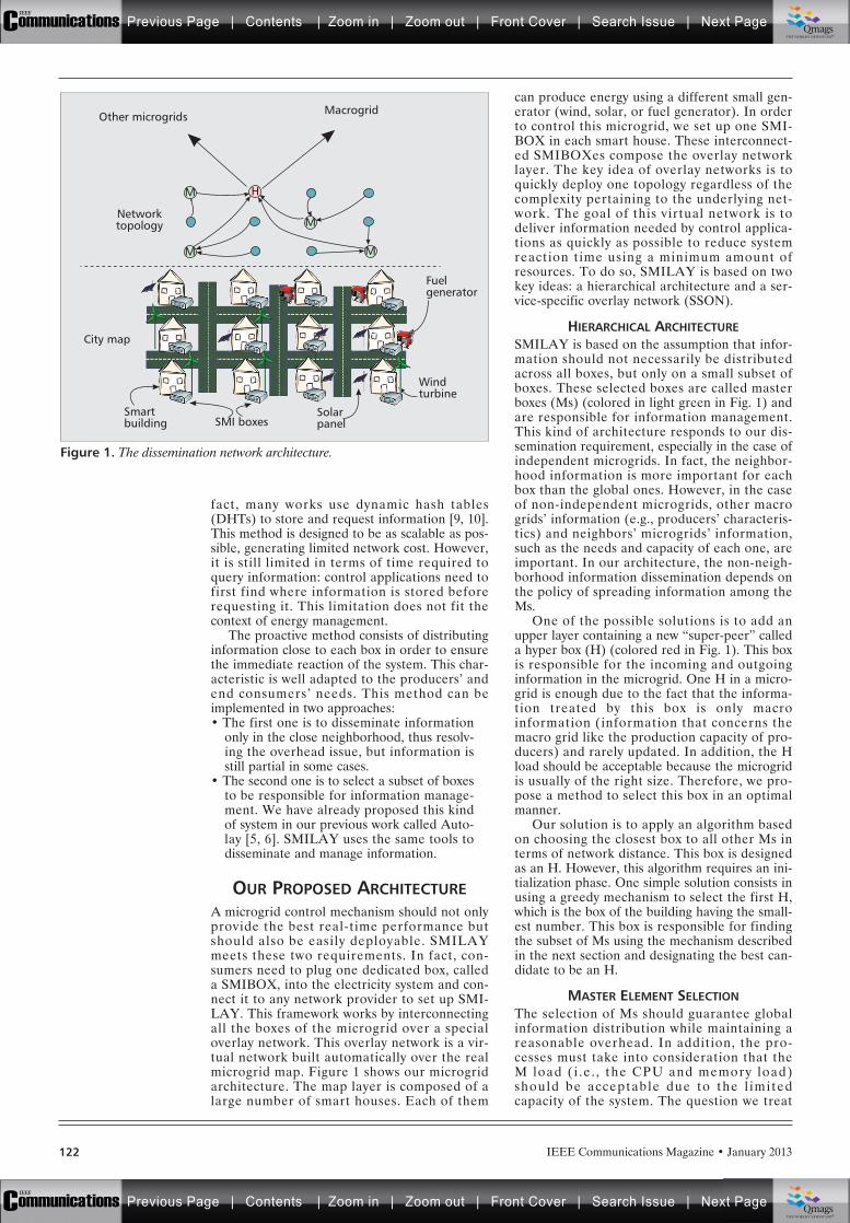
fact, many works use dynamic hash tables(DHTs) to store and request information [9, 10].This method is designed to be as scalable as pos-sible, generating limited network cost. However,it is still limited in terms of time required toquery information: control applications need tofirst find where information is stored beforerequesting it. This limitation does not fit thecontext of energy management.
The proactive method consists of distributinginformation close to each box in order to ensurethe immediate reaction of the system. This char-acteristic is well adapted to the producers’ andend consumers’ needs. This method can beimplemented in two approaches:• The first one is to disseminate information
only in the close neighborhood, thus resolv-ing the overhead issue, but information isstill partial in some cases.
• The second one is to select a subset of boxesto be responsible for information manage-ment. We have already proposed this kindof system in our previous work called Auto-lay [5, 6]. SMILAY uses the same tools todisseminate and manage information.
OUR PROPOSED ARCHITECTUREA microgrid control mechanism should not onlyprovide the best real-time performance butshould also be easily deployable. SMILAYmeets these two requirements. In fact, con-sumers need to plug one dedicated box, calleda SMIBOX, into the electricity system and con-nect it to any network provider to set up SMI-LAY. This framework works by interconnectingall the boxes of the microgrid over a specialoverlay network. This overlay network is a vir-tual network built automatically over the realmicrogrid map. Figure 1 shows our microgridarchitecture. The map layer is composed of alarge number of smart houses. Each of them
can produce energy using a different small gen-erator (wind, solar, or fuel generator). In orderto control this microgrid, we set up one SMI-BOX in each smart house. These interconnect-ed SMIBOXes compose the overlay networklayer. The key idea of overlay networks is toquickly deploy one topology regardless of thecomplexity pertaining to the underlying net-work. The goal of this virtual network is todeliver information needed by control applica-tions as quickly as possible to reduce systemreaction time using a minimum amount ofresources. To do so, SMILAY is based on twokey ideas: a hierarchical architecture and a ser-vice-specific overlay network (SSON).
HIERARCHICAL ARCHITECTURESMILAY is based on the assumption that infor-mation should not necessarily be distributedacross all boxes, but only on a small subset ofboxes. These selected boxes are called masterboxes (Ms) (colored in light green in Fig. 1) andare responsible for information management.This kind of architecture responds to our dis-semination requirement, especially in the case ofindependent microgrids. In fact, the neighbor-hood information is more important for eachbox than the global ones. However, in the caseof non-independent microgrids, other macrogrids’ information (e.g., producers’ characteris-tics) and neighbors’ microgrids’ information,such as the needs and capacity of each one, areimportant. In our architecture, the non-neigh-borhood information dissemination depends onthe policy of spreading information among theMs.
One of the possible solutions is to add anupper layer containing a new “super-peer” calleda hyper box (H) (colored red in Fig. 1). This boxis responsible for the incoming and outgoinginformation in the microgrid. One H in a micro-grid is enough due to the fact that the informa-tion treated by this box is only macroinformation (information that concerns themacro grid like the production capacity of pro-ducers) and rarely updated. In addition, the Hload should be acceptable because the microgridis usually of the right size. Therefore, we pro-pose a method to select this box in an optimalmanner.
Our solution is to apply an algorithm basedon choosing the closest box to all other Ms interms of network distance. This box is designedas an H. However, this algorithm requires an ini-tialization phase. One simple solution consists inusing a greedy mechanism to select the first H,which is the box of the building having the small-est number. This box is responsible for findingthe subset of Ms using the mechanism describedin the next section and designating the best can-didate to be an H.
MASTER ELEMENT SELECTIONThe selection of Ms should guarantee globalinformation distribution while maintaining areasonable overhead. In addition, the pro-cesses must take into consideration that theM load ( i .e . , the CPU and memory load)should be acceptable due to the l imitedcapacity of the system. The question we treat
IEEE Communications Magazine • January 2013122
Figure 1. The dissemination network architecture.
MacrogridOther microgrids
Networktopology
Windturbine
Fuelgenerator
SolarpanelSMI boxes
Smartbuilding
City map
M
MM
M H
Previous Page | Contents | Zoom in | Zoom out | Front Cover | Search Issue | Next PageIEEE
Communications qqM
Mq
qM
MqM
Qmags®THE WORLD’S NEWSSTAND
Previous Page | Contents | Zoom in | Zoom out | Front Cover | Search Issue | Next PageIEEE
Communications qqM
Mq
qM
MqM
Qmags®THE WORLD’S NEWSSTAND
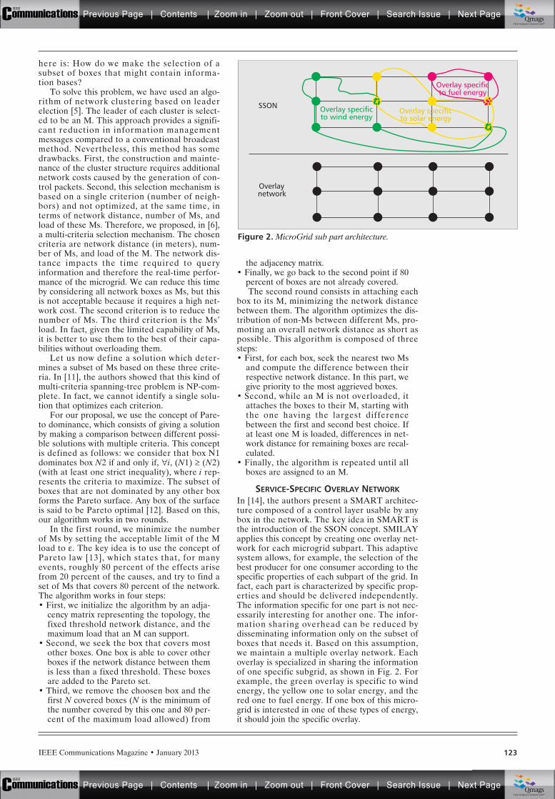
here is: How do we make the selection of asubset of boxes that might contain informa-tion bases?
To solve this problem, we have used an algo-rithm of network clustering based on leaderelection [5]. The leader of each cluster is select-ed to be an M. This approach provides a signifi-cant reduction in information managementmessages compared to a conventional broadcastmethod. Nevertheless, this method has somedrawbacks. First, the construction and mainte-nance of the cluster structure requires additionalnetwork costs caused by the generation of con-trol packets. Second, this selection mechanism isbased on a single criterion (number of neigh-bors) and not optimized, at the same time, interms of network distance, number of Ms, andload of these Ms. Therefore, we proposed, in [6],a multi-criteria selection mechanism. The chosencriteria are network distance (in meters), num-ber of Ms, and load of the M. The network dis-tance impacts the time required to queryinformation and therefore the real-time perfor-mance of the microgrid. We can reduce this timeby considering all network boxes as Ms, but thisis not acceptable because it requires a high net-work cost. The second criterion is to reduce thenumber of Ms. The third criterion is the Ms’load. In fact, given the limited capability of Ms,it is better to use them to the best of their capa-bilities without overloading them.
Let us now define a solution which deter-mines a subset of Ms based on these three crite-ria. In [11], the authors showed that this kind ofmulti-criteria spanning-tree problem is NP-com-plete. In fact, we cannot identify a single solu-tion that optimizes each criterion.
For our proposal, we use the concept of Pare-to dominance, which consists of giving a solutionby making a comparison between different possi-ble solutions with multiple criteria. This conceptis defined as follows: we consider that box N1dominates box N2 if and only if, "i, (N1) (N2)(with at least one strict inequality), where i rep-resents the criteria to maximize. The subset ofboxes that are not dominated by any other boxforms the Pareto surface. Any box of the surfaceis said to be Pareto optimal [12]. Based on this,our algorithm works in two rounds.
In the first round, we minimize the numberof Ms by setting the acceptable limit of the Mload to e. The key idea is to use the concept ofPareto law [13], which states that, for manyevents, roughly 80 percent of the effects arisefrom 20 percent of the causes, and try to find aset of Ms that covers 80 percent of the network.The algorithm works in four steps: • First, we initialize the algorithm by an adja-
cency matrix representing the topology, thefixed threshold network distance, and themaximum load that an M can support.
• Second, we seek the box that covers mostother boxes. One box is able to cover otherboxes if the network distance between themis less than a fixed threshold. These boxesare added to the Pareto set.
• Third, we remove the choosen box and thefirst N covered boxes (N is the minimum ofthe number covered by this one and 80 per-cent of the maximum load allowed) from
the adjacency matrix. • Finally, we go back to the second point if 80
percent of boxes are not already covered.The second round consists in attaching each
box to its M, minimizing the network distancebetween them. The algorithm optimizes the dis-tribution of non-Ms between different Ms, pro-moting an overall network distance as short aspossible. This algorithm is composed of threesteps:• First, for each box, seek the nearest two Ms
and compute the difference between theirrespective network distance. In this part, wegive priority to the most aggrieved boxes.
• Second, while an M is not overloaded, itattaches the boxes to their M, starting withthe one having the largest differencebetween the first and second best choice. Ifat least one M is loaded, differences in net-work distance for remaining boxes are recal-culated.
• Finally, the algorithm is repeated until allboxes are assigned to an M.
SERVICE-SPECIFIC OVERLAY NETWORKIn [14], the authors present a SMART architec-ture composed of a control layer usable by anybox in the network. The key idea in SMART isthe introduction of the SSON concept. SMILAYapplies this concept by creating one overlay net-work for each microgrid subpart. This adaptivesystem allows, for example, the selection of thebest producer for one consumer according to thespecific properties of each subpart of the grid. Infact, each part is characterized by specific prop-erties and should be delivered independently.The information specific for one part is not nec-essarily interesting for another one. The infor-mation sharing overhead can be reduced bydisseminating information only on the subset ofboxes that needs it. Based on this assumption,we maintain a multiple overlay network. Eachoverlay is specialized in sharing the informationof one specific subgrid, as shown in Fig. 2. Forexample, the green overlay is specific to windenergy, the yellow one to solar energy, and thered one to fuel energy. If one box of this micro-grid is interested in one of these types of energy,it should join the specific overlay.
IEEE Communications Magazine • January 2013 123
Figure 2. MicroGrid sub part architecture.
SSON
Overlaynetwork
Overlay specificto wind energy
Overlay specificto solar energy
Overlay specificto fuel energy
Previous Page | Contents | Zoom in | Zoom out | Front Cover | Search Issue | Next PageIEEE
Communications qqM
Mq
qM
MqM
Qmags®THE WORLD’S NEWSSTAND
Previous Page | Contents | Zoom in | Zoom out | Front Cover | Search Issue | Next PageIEEE
Communications qqM
Mq
qM
MqM
Qmags®THE WORLD’S NEWSSTAND
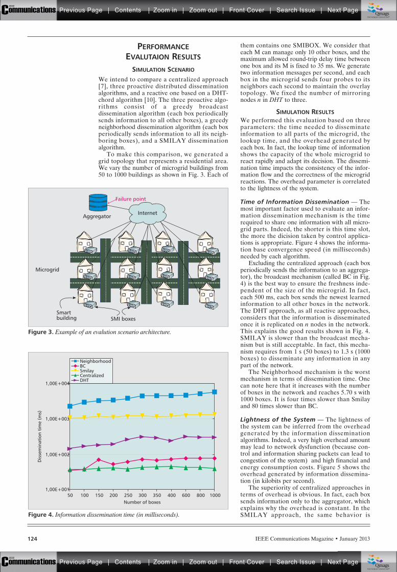
PERFORMANCEEVALUTAION RESULTS
SIMULATION SCENARIO
We intend to compare a centralized approach[7], three proactive distributed disseminationalgorithms, and a reactive one based on a DHT-chord algorithm [10]. The three proactive algo-rithms consist of a greedy broadcastdissemination algorithm (each box periodicallysends information to all other boxes), a greedyneighborhood dissemination algorithm (each boxperiodically sends information to all its neigh-boring boxes), and a SMILAY disseminationalgorithm.
To make this comparison, we generated agrid topology that represents a residential area.We vary the number of microgrid buildings from50 to 1000 buildings as shown in Fig. 3. Each of
them contains one SMIBOX. We consider thateach M can manage only 10 other boxes, and themaximum allowed round-trip delay time betweenone box and its M is fixed to 35 ms. We generatetwo information messages per second, and eachbox in the microgrid sends four probes to itsneighbors each second to maintain the overlaytopology. We fixed the number of mirroringnodes n in DHT to three.
SIMULATION RESULTSWe performed this evaluation based on threeparameters: the time needed to disseminateinformation to all parts of the microgrid, thelookup time, and the overhead generated byeach box. In fact, the lookup time of informationshows the capacity of the whole microgrid toreact rapidly and adapt its decision. The dissemi-nation time impacts the consistency of the infor-mation flow and the correctness of the microgridreactions. The overhead parameter is correlatedto the lightness of the system.
Time of Information Dissemination — Themost important factor used to evaluate an infor-mation dissemination mechanism is the timerequired to share one information with all micro-grid parts. Indeed, the shorter is this time slot,the more the dicision taken by control applica-tions is appropriate. Figure 4 shows the informa-tion base convergence speed (in milliseconds)needed by each algorithm.
Excluding the centralized approach (each boxperiodically sends the information to an aggrega-tor), the broadcast mechanism (called BC in Fig.4) is the best way to ensure the freshness inde-pendent of the size of the microgrid. In fact,each 500 ms, each box sends the newest learnedinformation to all other boxes in the network.The DHT approach, as all reactive approaches,considers that the information is disseminatedonce it is replicated on n nodes in the network.This explains the good results shown in Fig. 4.SMILAY is slower than the broadcast mecha-nism but is still acceptable. In fact, this mecha-nism requires from 1 s (50 boxes) to 1.3 s (1000boxes) to disseminate any information in anypart of the network.
The Neighborhood mechanism is the worstmechanism in terms of dissemination time. Onecan note here that it increases with the numberof boxes in the network and reaches 5.70 s with1000 boxes. It is four times slower than Smilayand 80 times slower than BC.
Lightness of the System — The lightness ofthe system can be inferred from the overheadgenerated by the information disseminationalgorithms. Indeed, a very high overhead amountmay lead to network dysfunction (because con-trol and information sharing packets can lead tocongestion of the system) and high financial andenergy consumption costs. Figure 5 shows theoverhead generated by information dissemina-tion (in kilobits per second).
The superiority of centralized approaches interms of overhead is obvious. In fact, each boxsends information only to the aggregator, whichexplains why the overhead is constant. In theSMILAY approach, the same behavior is
IEEE Communications Magazine • January 2013124
Figure 3. Example of an evalution scenario architecture.
Microgrid
SMI boxesSmartbuilding
Aggregator
Failure point
Internet
Figure 4. Information dissemination time (in milliseconds).
Number of boxes50
1,00E+002
Dis
sem
inat
ion
tim
e (m
s)
1,00E+001
1,00E+004
1,00E+003
100 150 200 250 300 350 400 600 800 1000
NeighborhoodBCSmilayCentralizedDHT
Previous Page | Contents | Zoom in | Zoom out | Front Cover | Search Issue | Next PageIEEE
Communications qqM
Mq
qM
MqM
Qmags®THE WORLD’S NEWSSTAND
Previous Page | Contents | Zoom in | Zoom out | Front Cover | Search Issue | Next PageIEEE
Communications qqM
Mq
qM
MqM
Qmags®THE WORLD’S NEWSSTAND
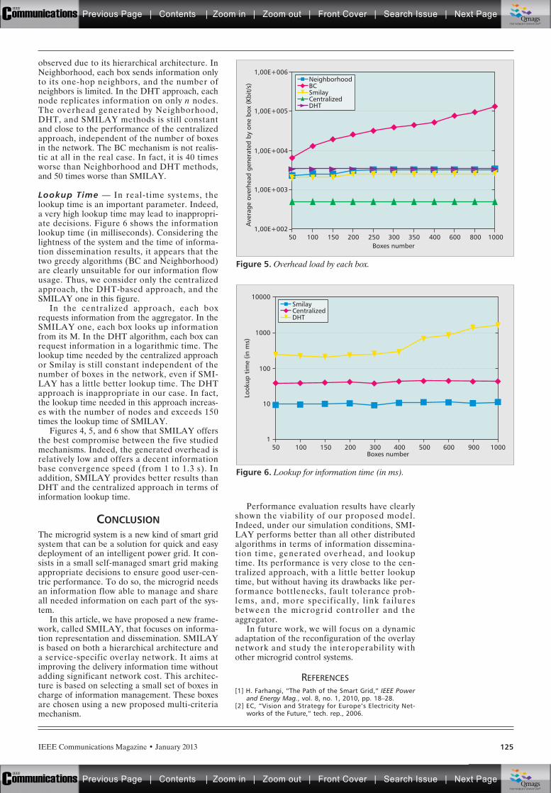
IEEE Communications Magazine • January 2013 125
observed due to its hierarchical architecture. InNeighborhood, each box sends information onlyto its one-hop neighbors, and the number ofneighbors is limited. In the DHT approach, eachnode replicates information on only n nodes.The overhead generated by Neighborhood,DHT, and SMILAY methods is still constantand close to the performance of the centralizedapproach, independent of the number of boxesin the network. The BC mechanism is not realis-tic at all in the real case. In fact, it is 40 timesworse than Neighborhood and DHT methods,and 50 times worse than SMILAY.
Lookup Time — In real-time systems, thelookup time is an important parameter. Indeed,a very high lookup time may lead to inappropri-ate decisions. Figure 6 shows the informationlookup time (in milliseconds). Considering thelightness of the system and the time of informa-tion dissemination results, it appears that thetwo greedy algorithms (BC and Neighborhood)are clearly unsuitable for our information flowusage. Thus, we consider only the centralizedapproach, the DHT-based approach, and theSMILAY one in this figure.
In the centralized approach, each boxrequests information from the aggregator. In theSMILAY one, each box looks up informationfrom its M. In the DHT algorithm, each box canrequest information in a logarithmic time. Thelookup time needed by the centralized approachor Smilay is still constant independent of thenumber of boxes in the network, even if SMI-LAY has a little better lookup time. The DHTapproach is inappropriate in our case. In fact,the lookup time needed in this approach increas-es with the number of nodes and exceeds 150times the lookup time of SMILAY.
Figures 4, 5, and 6 show that SMILAY offersthe best compromise between the five studiedmechanisms. Indeed, the generated overhead isrelatively low and offers a decent informationbase convergence speed (from 1 to 1.3 s). Inaddition, SMILAY provides better results thanDHT and the centralized approach in terms ofinformation lookup time.
CONCLUSIONThe microgrid system is a new kind of smart gridsystem that can be a solution for quick and easydeployment of an intelligent power grid. It con-sists in a small self-managed smart grid makingappropriate decisions to ensure good user-cen-tric performance. To do so, the microgrid needsan information flow able to manage and shareall needed information on each part of the sys-tem.
In this article, we have proposed a new frame-work, called SMILAY, that focuses on informa-tion representation and dissemination. SMILAYis based on both a hierarchical architecture anda service-specific overlay network. It aims atimproving the delivery information time withoutadding significant network cost. This architec-ture is based on selecting a small set of boxes incharge of information management. These boxesare chosen using a new proposed multi-criteriamechanism.
Performance evaluation results have clearlyshown the viability of our proposed model.Indeed, under our simulation conditions, SMI-LAY performs better than all other distributedalgorithms in terms of information dissemina-tion time, generated overhead, and lookuptime. Its performance is very close to the cen-tralized approach, with a little better lookuptime, but without having its drawbacks like per-formance bottlenecks, fault tolerance prob-lems, and, more specifically, l ink failuresbetween the microgrid controller and theaggregator.
In future work, we will focus on a dynamicadaptation of the reconfiguration of the overlaynetwork and study the interoperability withother microgrid control systems.
REFERENCES[1] H. Farhangi, “The Path of the Smart Grid,” IEEE Power
and Energy Mag., vol. 8, no. 1, 2010, pp. 18–28. [2] EC, “Vision and Strategy for Europe’s Electricity Net-
works of the Future,” tech. rep., 2006.
Figure 5. Overhead load by each box.
Boxes number50
1,00E+004
Ave
rage
ove
rhea
d ge
nera
ted
by o
ne b
ox (
Kbit
/s)
1,00E+002
1,00E+006
1,00E+003
1,00E+005
100 150 200 250 300 350 400 600 800 1000
NeighborhoodBCSmilayCentralizedDHT
Figure 6. Lookup for information time (in ms).
Boxes number100
10
Look
up t
ime
(in m
s)
1
100
1000
10000
50 150 200 300 400 500 600 900 1000
SmilayCentralizedDHT
Previous Page | Contents | Zoom in | Zoom out | Front Cover | Search Issue | Next PageIEEE
Communications qqM
Mq
qM
MqM
Qmags®THE WORLD’S NEWSSTAND
Previous Page | Contents | Zoom in | Zoom out | Front Cover | Search Issue | Next PageIEEE
Communications qqM
Mq
qM
MqM
Qmags®THE WORLD’S NEWSSTAND
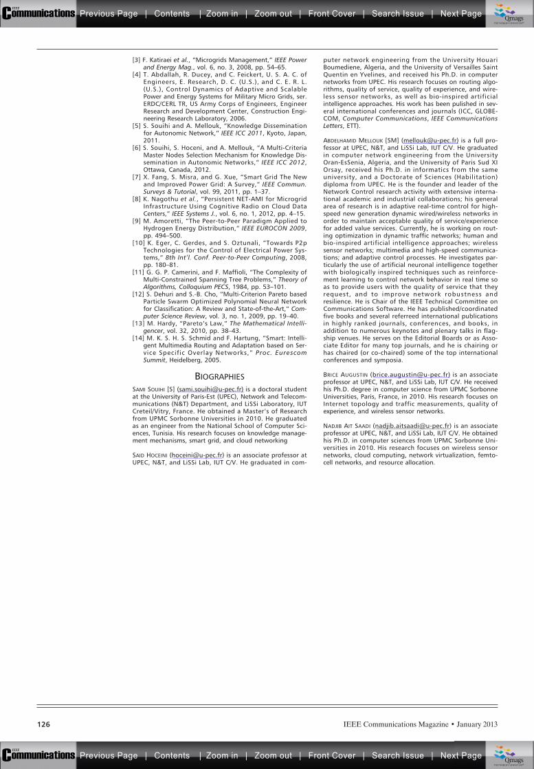
IEEE Communications Magazine • January 2013126
[3] F. Katiraei et al., “Microgrids Management,” IEEE Powerand Energy Mag., vol. 6, no. 3, 2008, pp. 54–65.
[4] T. Abdallah, R. Ducey, and C. Feickert, U. S. A. C. ofEngineers, E. Research, D. C. (U.S.), and C. E. R. L.(U.S.), Control Dynamics of Adaptive and ScalablePower and Energy Systems for Military Micro Grids, ser.ERDC/CERL TR, US Army Corps of Engineers, EngineerResearch and Development Center, Construction Engi-neering Research Laboratory, 2006.
[5] S. Souihi and A. Mellouk, “Knowledge Disseminationfor Autonomic Network,” IEEE ICC 2011, Kyoto, Japan,2011.
[6] S. Souihi, S. Hoceni, and A. Mellouk, “A Multi-CriteriaMaster Nodes Selection Mechanism for Knowledge Dis-semination in Autonomic Networks,” IEEE ICC 2012,Ottawa, Canada, 2012.
[7] X. Fang, S. Misra, and G. Xue, “Smart Grid The Newand Improved Power Grid: A Survey,” IEEE Commun.Surveys & Tutorial, vol. 99, 2011, pp. 1–37.
[8] K. Nagothu et al., “Persistent NET-AMI for MicrogridInfrastructure Using Cognitive Radio on Cloud DataCenters,” IEEE Systems J., vol. 6, no. 1, 2012, pp. 4–15.
[9] M. Amoretti, “The Peer-to-Peer Paradigm Applied toHydrogen Energy Distribution,” IEEE EUROCON 2009,pp. 494–500.
[10] K. Eger, C. Gerdes, and S. Oztunali, “Towards P2pTechnologies for the Control of Electrical Power Sys-tems,” 8th Int’l. Conf. Peer-to-Peer Computing, 2008,pp. 180–81.
[11] G. G. P. Camerini, and F. Maffioli, “The Complexity ofMulti-Constrained Spanning Tree Problems,” Theory ofAlgorithms, Colloquium PECS, 1984, pp. 53–101.
[12] S. Dehuri and S.-B. Cho, “Multi-Criterion Pareto basedParticle Swarm Optimized Polynomial Neural Networkfor Classification: A Review and State-of-the-Art,” Com-puter Science Review, vol. 3, no. 1, 2009, pp. 19–40.
[13] M. Hardy, “Pareto’s Law,” The Mathematical Intelli-gencer, vol. 32, 2010, pp. 38–43.
[14] M. K. S. H. S. Schmid and F. Hartung, “Smart: Intelli-gent Multimedia Routing and Adaptation based on Ser-vice Specific Overlay Networks,” Proc. EurescomSummit, Heidelberg, 2005.
BIOGRAPHIESSAMI SOUIHI [S] ([email protected]) is a doctoral studentat the University of Paris-Est (UPEC), Network and Telecom-munications (N&T) Department, and LiSSi Laboratory, IUTCreteil/Vitry, France. He obtained a Master’s of Researchfrom UPMC Sorbonne Universities in 2010. He graduatedas an engineer from the National School of Computer Sci-ences, Tunisia. His research focuses on knowledge manage-ment mechanisms, smart grid, and cloud networking
SAID HOCEINI ([email protected]) is an associate professor atUPEC, N&T, and LiSSi Lab, IUT C/V. He graduated in com-
puter network engineering from the University HouariBoumediene, Algeria, and the University of Versailles SaintQuentin en Yvelines, and received his Ph.D. in computernetworks from UPEC. His research focuses on routing algo-rithms, quality of service, quality of experience, and wire-less sensor networks, as well as bio-inspired artificialintelligence approaches. His work has been pulished in sev-eral international conferences and journals (ICC, GLOBE-COM, Computer Communications, IEEE CommunicationsLetters, ETT).
ABDELHAMID MELLOUK [SM] ([email protected]) is a full pro-fessor at UPEC, N&T, and LiSSi Lab, IUT C/V. He graduatedin computer network engineering from the UniversityOran-EsSenia, Algeria, and the University of Paris Sud XIOrsay, received his Ph.D. in informatics from the sameuniversity, and a Doctorate of Sciences (Habilitation)diploma from UPEC. He is the founder and leader of theNetwork Control research activity with extensive interna-tional academic and industrial collaborations; his generalarea of research is in adaptive real-time control for high-speed new generation dynamic wired/wireless networks inorder to maintain acceptable quality of service/experiencefor added value services. Currently, he is working on rout-ing optimization in dynamic traffic networks; human andbio-inspired artificial intelligence approaches; wirelesssensor networks; multimedia and high-speed communica-tions; and adaptive control processes. He investigates par-ticularly the use of artificial neuronal intelligence togetherwith biologically inspired techniques such as reinforce-ment learning to control network behavior in real time soas to provide users with the quality of service that theyrequest, and to improve network robustness andresilience. He is Chair of the IEEE Technical Committee onCommunications Software. He has published/coordinatedfive books and several referreed international publicationsin highly ranked journals, conferences, and books, inaddition to numerous keynotes and plenary talks in flag-ship venues. He serves on the Editorial Boards or as Asso-ciate Editor for many top journals, and he is chairing orhas chaired (or co-chaired) some of the top internationalconferences and symposia.
BRICE AUGUSTIN ([email protected]) is an associateprofessor at UPEC, N&T, and LiSSi Lab, IUT C/V. He receivedhis Ph.D. degree in computer science from UPMC SorbonneUniversities, Paris, France, in 2010. His research focuses onInternet topology and traffic measurements, quality ofexperience, and wireless sensor networks.
NADJIB AIT SAADI ([email protected]) is an associateprofessor at UPEC, N&T, and LiSSi Lab, IUT C/V. He obtainedhis Ph.D. in computer sciences from UPMC Sorbonne Uni-versities in 2010. His research focuses on wireless sensornetworks, cloud computing, network virtualization, femto-cell networks, and resource allocation.
Previous Page | Contents | Zoom in | Zoom out | Front Cover | Search Issue | Next PageIEEE
Communications qqM
Mq
qM
MqM
Qmags®THE WORLD’S NEWSSTAND
Previous Page | Contents | Zoom in | Zoom out | Front Cover | Search Issue | Next PageIEEE
Communications qqM
Mq
qM
MqM
Qmags®THE WORLD’S NEWSSTAND
_________
_____________
______________
____________
__________

FOR COMMUNICATIONS PROFESSIONALS
www.comsoc.org/training
CONTINUING EDUCATION
ComSoc Online Training:- Convenient, affordable, and immediate- Relevant for wireless engineering professionals- Self-directed when you review the recording
ComSoc In-Person Training:- Custom tailored for your specific needs- Save time and money with on-site training options- Promote teamwork and cross-train
2013 SCHEDULE
Wed, January 16, 2013 - Online CourseWireless Communications Engineering - Current Practice
Wed, January 23, 2013 - Online CourseVoLTE: Convergence of IMS-based Voice and LTE
Mon, January 28, 2013 - Online Course2 for 1 Deal: January Virtual 5 Day Training PLUS Spring 2013 WCET Exam Seat
Mon, January 28, 2013 - Online Course5-Day Wireless Communications Engineering Intermediate Fundamentals Review & Current Practices
Wed, February 6, 2013 - In Person Course Overview of Machine-to-Machine (M2M) for Engineers & Managers
Tue, February 12, 2013 - Online CourseSelf Organizing Networks
Previous Page | Contents | Zoom in | Zoom out | Front Cover | Search Issue | Next PageIEEE
Communications qqM
Mq
qM
MqM
Qmags®THE WORLD’S NEWSSTAND
Previous Page | Contents | Zoom in | Zoom out | Front Cover | Search Issue | Next PageIEEE
Communications qqM
Mq
qM
MqM
Qmags®THE WORLD’S NEWSSTAND
IEEE Communications Magazine • January 2013128 0163-6804/13/$25.00 © 2013 IEEE
INTRODUCTION
With the increasing popularity of wireless net-works, current trends observed worldwide showthat interest in mobile computing spreads simul-taneously. Host mobility is commonly managedby the Mobile IPv6 protocol (MIPv6) whichallows movements across IPv6 networks toremain transparent to the applications. However,when a group of mobile users form a mobile net-work (e.g. when located in the same vehicle), ithas been demonstrated that MIPv6 is unable tomaintain the communication between the nodeslocated in the moving network and a single cor-respondent [1]. From these limitations has beendefined the Network Mobility Basic Support(NEMO BS [2]) protocol. This protocol ensuressessions continuity for a whole IPv6 mobile net-work. It is based on the same mechanisms asMIPv6 but a single network entity, known as themobile router, is in charge of the mobility opera-tions on behalf of all the nodes located in themoving network.
Recently, there has been a burgeoning ofinterest in multihoming for redundancy, loadsharing, and performance purposes. Multihom-ing refers to a situation where a node is reach-able through multiple paths, either because thisnode has several network interfaces connectedto various access networks, or because the sub-net in which the node is located is multihomeditself. Multihoming is particularly relevant forwireless communication which suffers variousrestrictions: limited bandwidth, fluctuating radiochannel condition, etc. The practical MIPv6 mul-tihoming scenario is composed of a multi-inter-faced mobile node which benefits from thevarious access networks that it could connect to
thanks to the Multiple Care-of Addresses regis-tration protocol (MCoA [3]). Although the samescenario could be applied to NEMO BS, it is notsatisfactory when considering the redundancygoal of multihoming: this scenario does notaddress the failure of the mobile router itself.Whereas the case of a failing mobile node onlyaffects its user and could not be helped no mat-ter what the solutions are, the case of a failingmobile router will affect all nodes of the mobilenetwork. As envisioned for fixed networks, suchan incident should be overcome by providing themobile network with multiple cooperatingmobile routers. This requires the definition ofnew mechanisms in order to enable cooperationbetween these various mobile routers.
The purpose of this article is to present themotivations and advantages that both operatorsand mobile users could expect from a mobilenetwork served by multiple mobile routers. Wealso give a series of requirements that we believea practical solution should comply with and com-pare them with the solutions proposed so far.Based on this analysis, we finally present a newprotocol that tends to address all of theserequirements. This protocol has been evaluatedthrough experimentation over a real testbed.
NETWORK MOBILITY BASIC SUPPORTThe Network Mobility Basic Support (NEMOBS [2]) protocol was adopted by the IETF in2005. Operated on the Mobile Router (MR), itensures session continuity and reachability whilemoving transparently to the Mobile NetworkNodes (MNNs) which are the nodes located inthe mobile network (Fig. 1).
The MR interconnecting the mobile networkto the Internet is identified with an IPv6 HomeAddress (HoA). In its home network, the MRacts as a legacy IPv6 router and routes all thetraffic from or to the Internet using the tradi-tional IPv6 routing mechanisms. When connect-ing to another IPv6 network, the MR acquires anew temporary address, known as Care-ofAddress (CoA), that represents its current loca-tion in the Internet topology. The MR registersthis address to its Home Agent (HA), a networkentity located in the home network of the MR.As the MR moves from one IPv6 network toanother, the HA maintains a binding betweenthe HoA, the CoA, and the prefix advertised in
ABSTRACT
In this article we present how all the benefitsof multihoming could be obtained in a mobileIPv6 network with multiple mobile routers.Along with the motivations and problems thatarise in such a situation, we define a set ofrequirements that potential solutions shouldconsider. After a brief overview of the currentstate of the art, we present a new protocol thatbrings all of the envisioned benefits of multi-homing while remaining fully transparent to theend-nodes located in the mobile network.
ACCEPTED FROM OPEN CALL
Romain Kuntz, Julien Montavont and Thomas Noel, University of Strasbourg
Multihoming in IPv6 Mobile Networks:Progress, Challenges, and Solutions
Previous Page | Contents | Zoom in | Zoom out | Front Cover | Search Issue | Next PageIEEE
Communications qqM
Mq
qM
MqM
Qmags®THE WORLD’S NEWSSTAND
Previous Page | Contents | Zoom in | Zoom out | Front Cover | Search Issue | Next PageIEEE
Communications qqM
Mq
qM
MqM
Qmags®THE WORLD’S NEWSSTAND
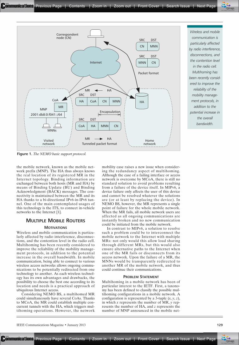
IEEE Communications Magazine • January 2013 129
the mobile network, known as the mobile net-work prefix (MNP). The HA thus always knowsthe real location of its registered MR in theInternet topology. Binding information areexchanged between both hosts (MR and HA) bymeans of Binding Update (BU) and BindingAcknowledgment (BACK) messages. The con-nectivity is maintained between the MR and itsHA thanks to a bi-directional IPv6-in-IPv6 tun-nel. One of the main contemplated usages ofthis technology is the ITS, to connect in-vehiclenetworks to the Internet [1].
MULTIPLE MOBILE ROUTERS
MOTIVATIONSWireless and mobile communication is particu-larly affected by radio interference, disconnec-tions, and the contention level in the radio cell.Multihoming has been recently considered toimprove the reliability of the mobility manage-ment protocols, in addition to the potentialincrease in the overall bandwidth. In mobilecommunication, being able to connect to variouswireless access networks allows ongoing commu-nications to be potentially redirected from onetechnology to another. As each wireless technol-ogy has its own advantages and drawbacks, thepossibility to choose the best one according to itslocation and needs is a practical approach ofubiquitous Internet access.
Considering NEMO BS, a multihomed MRcould simultaneously have several CoAs. Thanksto MCoA, the MR could establish multiple con-current tunnels with the HA, which triggers mul-tihoming operations. However, the network
mobility case raises a new issue when consider-ing the redundancy aspect of multihoming.Although the case of a failing interface or accessnetwork is overcome by MCoA, there is still nostandard solution to avoid problems resultingfrom a failure of the device itself. In MIPv6, adevice failure only affects the user of this deviceand cannot be resolved whatever the solutionsare (or at least by replacing the device). InNEMO BS, however, the MR represents a singlepoint of failure for the whole mobile network.When the MR fails, all mobile network users areaffected as all ongoing communications areinstantly broken and no new communicationcould be initiated from the mobile network.
In contrast to MIPv6, a solution to resolvesuch a problem could be to interconnect themobile network to the Internet with multipleMRs: not only would this allow load sharingthrough different MRs, but this would alsoensure alternative paths to the Internet whenone of the MR fails or disconnects from itsaccess network. Upon the failure of a MR, theMNNs would be transparently redirected toanother MR of the mobile network, and thuscould continue their communications.
PROBLEM STATEMENTMultihoming in a mobile network has been ofparticular interest to the IETF. First, a taxono-my has been defined to classify the possible mul-tihoming configurations in a mobile network. Aconfiguration is represented by a 3-tuple (x, y, z),in which x represents the number of MR, y rep-resents the number of HA, and z represents thenumber of MNP announced in the mobile net-
Figure 1. The NEMO basic support protocol.
MR HA
HA
CN MNN
SRC DST
Internet
Correspondentnode (CN)
MR HA Homenetwork
Visitednetwork Tunneled packet format
MNN CN
Packet format
SRC DST
HA CoACoA
MNP
2001:db8:0:f041::/64
SRC DST
CN MNN
CoAMNNs
HA
SRC DST
MNN CN
EncapsulationMR
Wireless and mobile
communication is
particularly affected
by radio interference,
disconnections, and
the contention level
in the radio cell.
Multihoming has
been recently consid-
ered to improve the
reliability of the
mobility manage-
ment protocols, in
addition to the
potential increase in
the overall
bandwidth.
Previous Page | Contents | Zoom in | Zoom out | Front Cover | Search Issue | Next PageIEEE
Communications qqM
Mq
qM
MqM
Qmags®THE WORLD’S NEWSSTAND
Previous Page | Contents | Zoom in | Zoom out | Front Cover | Search Issue | Next PageIEEE
Communications qqM
Mq
qM
MqM
Qmags®THE WORLD’S NEWSSTAND
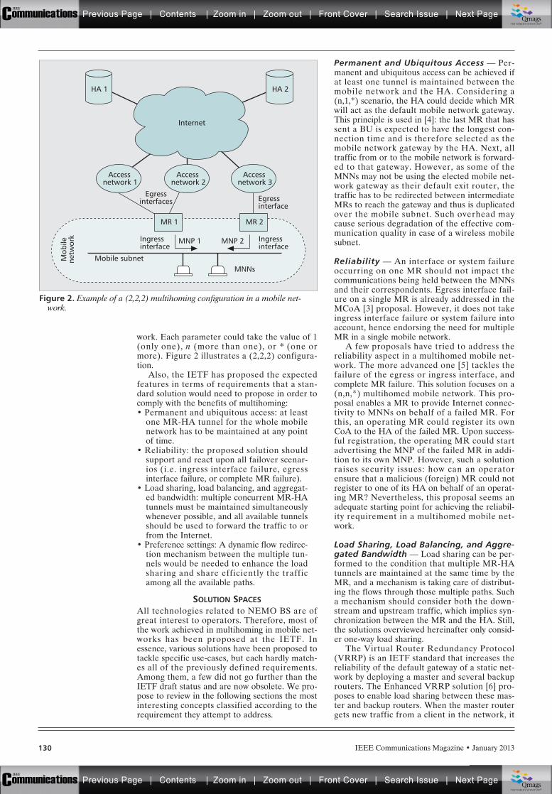
work. Each parameter could take the value of 1(only one), n (more than one), or * (one ormore). Figure 2 illustrates a (2,2,2) configura-tion.
Also, the IETF has proposed the expectedfeatures in terms of requirements that a stan-dard solution would need to propose in order tocomply with the benefits of multihoming:• Permanent and ubiquitous access: at least
one MR-HA tunnel for the whole mobilenetwork has to be maintained at any pointof time.
• Reliability: the proposed solution shouldsupport and react upon all failover scenar-ios (i.e. ingress interface failure, egressinterface failure, or complete MR failure).
• Load sharing, load balancing, and aggregat-ed bandwidth: multiple concurrent MR-HAtunnels must be maintained simultaneouslywhenever possible, and all available tunnelsshould be used to forward the traffic to orfrom the Internet.
• Preference settings: A dynamic flow redirec-tion mechanism between the multiple tun-nels would be needed to enhance the loadsharing and share efficiently the trafficamong all the available paths.
SOLUTION SPACESAll technologies related to NEMO BS are ofgreat interest to operators. Therefore, most ofthe work achieved in multihoming in mobile net-works has been proposed at the IETF. Inessence, various solutions have been proposed totackle specific use-cases, but each hardly match-es all of the previously defined requirements.Among them, a few did not go further than theIETF draft status and are now obsolete. We pro-pose to review in the following sections the mostinteresting concepts classified according to therequirement they attempt to address.
Permanent and Ubiquitous Access — Per-manent and ubiquitous access can be achieved ifat least one tunnel is maintained between themobile network and the HA. Considering a(n,1,*) scenario, the HA could decide which MRwill act as the default mobile network gateway.This principle is used in [4]: the last MR that hassent a BU is expected to have the longest con-nection time and is therefore selected as themobile network gateway by the HA. Next, alltraffic from or to the mobile network is forward-ed to that gateway. However, as some of theMNNs may not be using the elected mobile net-work gateway as their default exit router, thetraffic has to be redirected between intermediateMRs to reach the gateway and thus is duplicatedover the mobile subnet. Such overhead maycause serious degradation of the effective com-munication quality in case of a wireless mobilesubnet.
Reliability — An interface or system failureoccurring on one MR should not impact thecommunications being held between the MNNsand their correspondents. Egress interface fail-ure on a single MR is already addressed in theMCoA [3] proposal. However, it does not takeingress interface failure or system failure intoaccount, hence endorsing the need for multipleMR in a single mobile network.
A few proposals have tried to address thereliability aspect in a multihomed mobile net-work. The more advanced one [5] tackles thefailure of the egress or ingress interface, andcomplete MR failure. This solution focuses on a(n,n,*) multihomed mobile network. This pro-posal enables a MR to provide Internet connec-tivity to MNNs on behalf of a failed MR. Forthis, an operating MR could register its ownCoA to the HA of the failed MR. Upon success-ful registration, the operating MR could startadvertising the MNP of the failed MR in addi-tion to its own MNP. However, such a solutionraises security issues: how can an operatorensure that a malicious (foreign) MR could notregister to one of its HA on behalf of an operat-ing MR? Nevertheless, this proposal seems anadequate starting point for achieving the reliabil-ity requirement in a multihomed mobile net-work.
Load Sharing, Load Balancing, and Aggre-gated Bandwidth — Load sharing can be per-formed to the condition that multiple MR-HAtunnels are maintained at the same time by theMR, and a mechanism is taking care of distribut-ing the flows through those multiple paths. Sucha mechanism should consider both the down-stream and upstream traffic, which implies syn-chronization between the MR and the HA. Still,the solutions overviewed hereinafter only consid-er one-way load sharing.
The Virtual Router Redundancy Protocol(VRRP) is an IETF standard that increases thereliability of the default gateway of a static net-work by deploying a master and several backuprouters. The Enhanced VRRP solution [6] pro-poses to enable load sharing between these mas-ter and backup routers. When the master routergets new traffic from a client in the network, it
IEEE Communications Magazine • January 2013130
Figure 2. Example of a (2,2,2) multihoming configuration in a mobile net-work.
HA 2
Internet
Egressinterfaces Egress
interface
Ingressinterface
Ingressinterface
HA 1
MR 2MR 1
Mobile subnetMNNs
Mob
ilene
twor
k MNP 1 MNP 2
Accessnetwork 1
Accessnetwork 2
Accessnetwork 3
Previous Page | Contents | Zoom in | Zoom out | Front Cover | Search Issue | Next PageIEEE
Communications qqM
Mq
qM
MqM
Qmags®THE WORLD’S NEWSSTAND
Previous Page | Contents | Zoom in | Zoom out | Front Cover | Search Issue | Next PageIEEE
Communications qqM
Mq
qM
MqM
Qmags®THE WORLD’S NEWSSTAND
IEEE Communications Magazine • January 2013 131
can redirect it to a backup router by sending anICMP redirect message to the client. Whenevera router fails, the traffic that was handled by thisrouter is redirected to another one by changingthe relationship between the IP address of therouter and its link-layer address in the cache ofthe clients. This ensures a smooth change oftheir default router at the layer 2. However thissolution only considers the load sharing of theupstream traffic.
As overviewed previously, the authors of [5]present how the CoA of a neighbor MR couldbe bound to the HoA of a failed MR. The pro-posal presented in [7] extends this scheme tosupport load sharing. This proposal focuses on a(n,1,1) mobile network. One MR is configuredas primary MR and all the non-primary MRs areseen as virtual interfaces of the primary one. Asa result, both the primary MR and the HA havemultiple distinct paths available to forward thetraffic between the Internet and the mobile net-work: through the tunnel bound with the realinterface of the primary MR or via one of its vir-tual interface. All the MNNs select the primaryMR as their default gateway. The primary MRtakes care of forwarding the traffic among all theavailable (real or virtual) interfaces. Althoughthis solution does not address the failure of theprimary MR, it proposes an interesting schemefor load sharing. However, a packet sent througha virtual interface is encapsulated by the primaryMR before being sent again on the mobile sub-net to a non-primary MR. Such overhead mayseriously degrade the quality of effective com-munication in the case of a wireless mobile sub-net.
Load sharing may also be achieved at the HAlevel [8]. In this proposal, the tunnel latency isconsidered to dynamically redirect the trafficfrom one tunnel to another in a (n,n,*) scenario.First, each MR in the mobile network can dis-cover, authenticate, and register to its HA aneighbor MR. The HA can therefore maintain alist of alternative tunnels across different HAand MR to reach its own MR. The HA can thenperform load sharing between the MR-HA tun-nel and alternative tunnels. However, this pro-posal does not consider the upstream traffic andthus the default router selection on the MNNs.
Preference Settings — The previous sectionoverviewed various solutions to share the trafficamong multiple MR-HA tunnels. However, nosynchronization between the MR and the HAhas been considered so far. However, adminis-trators of the mobile network may have require-ments for bi-directional communications. Thisendorses the need for a protocol between theMR and HA involved in the management of thesame mobile network, that would take care ofnegotiating and enforcing the tunnel preferencesfor each flow on each tunnel endpoint. TheIETF has standardized Flow Bindings [9] whichallows a MR to map flows to a specific CoA andto advertise this binding to its HA.
Summary — Most of the proposals address thefirst requirement by maintaining at least oneMR-HA tunnel during the lifetime of the net-work. Most of them propose a failover mecha-
nism to ensure session continuity upon a tunnelfailure. However, load sharing is hardly consid-ered. It is actually tightly related with preferencesettings, as both the HA and the MR must besynchronized in terms of routing policies toaccurately distribute the inbound and outboundtraffic. As no solution considers preference set-tings in a multihomed mobile network, the fourthrequirement is barely reached. Based on thisanalysis, we have proposed a new approachwhich is presented in the next section.
PROPOSED SOLUTION
SOLUTION OVERVIEWOur first work on this topic has been proposedin [10] and focuses on a (*,1,1) scenario. In thisprevious article, we address the case of thedefault router selection for the MNNs, i.e. towhich MR a MNN would send its upstream traf-fic. The idea lying behind our proposal is basedon neighbor discovery and remains compliantwith legacy IPv6 nodes. By omitting the link-layer option in router advertisements, a MNNshould first resolve the link-layer address of thedefault router before initiating a communicationwith a remote host. Upon reception of the corre-sponding neighbor solicitation, a neighbor adver-tisement is sent to the MNN. It includes thelink-layer address of the MR that was selected totake in charge that MNN. Dynamic redirection(e.g. due to egress interface failure) is achievedthrough the emission of an unsolicited neighboradvertisement in order to update the link-layeraddress of the default router in the neighborcache of MNNs.
However, our previous work suffers from onemajor limitation: in the case of exclusive down-stream communication, the MNN will never bedelegated to a MR as our previous protocol onlyreacts upon transmissions initiated by the MNN.In the present article, we extend this work forboth upstream and downstream traffic. Insteadof waiting for the resolution of the link-layeraddress of the default router, we propose toreact upon the Duplicate Address Detection(DAD) which is a mandatory process of the IPv6stateless autoconfiguration mechanism. Thisenables default router assignment as soon as theMNN connects to the mobile subnet. By thismeans, the MNN will always be assigned to aMR prior to any communication, whether thecommunication is initiated by the MNN or aremote host. Also, this solution still remains fullycompliant with legacy IPv6 mobile networknodes.
First, all MRs in the mobile subnet are con-figured with a role. The Master MR (which isunique in the mobile subnet) is in charge of thetransmission of RAs and the delegation ofMNNs. The Slave MRs monitor the status of theMaster MR and elect a new Master in case offailure of the former. A MR periodicallyannounces its status through a new definedNeighbor Router Advertisement (NRA) mes-sage. This message contains, among others, theingress interface link-local IPv6 address, the roleand the currently used bandwidth ratio of theoriginator MR. The Master MR could thereforemaintain a list of available Slave MRs. Finally,
Load sharing can be
performed to the
condition that
multiple MR-HA
tunnels are
maintained at the
same time by the
MR, and a mecha-
nism is taking care
of distributing the
flows through those
multiple paths.
Previous Page | Contents | Zoom in | Zoom out | Front Cover | Search Issue | Next PageIEEE
Communications qqM
Mq
qM
MqM
Qmags®THE WORLD’S NEWSSTAND
Previous Page | Contents | Zoom in | Zoom out | Front Cover | Search Issue | Next PageIEEE
Communications qqM
Mq
qM
MqM
Qmags®THE WORLD’S NEWSSTAND
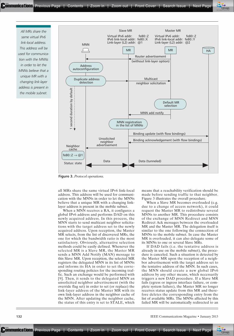
IEEE Communications Magazine • January 2013132
all MRs share the same virtual IPv6 link-localaddress. This address will be used for communi-cation with the MNNs in order to let the MNNsbelieve that a unique MR with a changing link-layer address is present in the mobile subnet.
When a MNN receives a RA, it configures aglobal IPv6 address and performs DAD on thisnewly acquired address. In this process, theMNN starts to send multicast neighbor solicita-tions with the target address set to the newlyacquired address. Upon reception, the MasterMR selects, from the list of discovered MRs, theone for which the bandwidth ratio is the mostsatisfactory. Obviously, alternative selectionmethods could be easily defined. Whenever theselected MR is a Slave MR, the Master MRsends a MNN Add Notify (MAN) message tothis Slave MR. Upon reception, the selected MRregisters the delegated MNN in its list of MNNsand informs its HA in order to set the corre-sponding routing policies for the incoming traf-fic. Such an exchange would be performed with[9]. Then, it sends to the delegated MNN anunsolicited neighbor advertisement (with theoverride flag set) in order to set (or replace) thelink-layer address of the Master MR with itsown link-layer address in the neighbor cache ofthe MNN. After updating the neighbor cache,the status of this entry is set to STALE, which
means that a reachability verification should bemade before sending traffic to that neighbor.Figure 3 illustrates the overall procedure.
When a Slave MR becomes overloaded (e.g.due to a change of access network), it couldrequest the Master MR to redistribute severalMNNs to another MR. This procedure consistsof the exchange of MNN Redirect and MNNRedirect Ack messages between the overloadedMR and the Master MR. The delegation itself issimilar to the one following the connection ofMNNs to the mobile subnet. In case the MasterMR is overloaded, it can also delegate some ofits MNNs to one or several Slave MRs.
If DAD fails (i.e. the tentative address isalready in use on the mobile subnet), the proce-dure is canceled. Such a situation is detected bythe Master MR upon the reception of a neigh-bor advertisement with the target address set tothe tentative address of the MNN. In such cases,the MNN should create a new global IPv6address by any other means, which necessarilytriggers a new DAD procedure. If a Slave MRfails (egress or ingress interface failure, or com-plete system failure), the Master MR no longerreceives status update from this MR and there-fore deletes the corresponding entry from thelist of available MRs. The MNNs affected by thisfailed MR will be automatically redirected to an
Figure 3. Protocol operations.
Neighborcache
Status: state
fe80::Z → @1
Unsolicitedneighbor
advertisement
Data Data (tunneled)
Binding update (with flow bindings)
Binding acknowledgement (with flow bindings)
Router advertisement(without link-layer option)
Multicastneighbor solicitation
MNN add notify
1 se
cond
dur
atio
n by
def
ault
HA
MNN
MR
Slave MR
Virtual IPv6 addr: fe80::ZIPv6 link-local addr: fe80::XLink-layer (L2) addr: @1
Master MR
Virtual IPv6 addr: fe80::ZIPv6 link-local addr: fe80::YLink-layer (L2) addr: @2
MR
Addressautoconfiguration
Default MRselection
Duplicate addressdetection
MNN registrationin the list of MNNs
All MRs share the
same virtual IPv6
link-local address.
This address will be
used for communica-
tion with the MNNs
in order to let the
MNNs believe that a
unique MR with a
changing link-layer
address is present in
the mobile subnet.
Previous Page | Contents | Zoom in | Zoom out | Front Cover | Search Issue | Next PageIEEE
Communications qqM
Mq
qM
MqM
Qmags®THE WORLD’S NEWSSTAND
Previous Page | Contents | Zoom in | Zoom out | Front Cover | Search Issue | Next PageIEEE
Communications qqM
Mq
qM
MqM
Qmags®THE WORLD’S NEWSSTAND
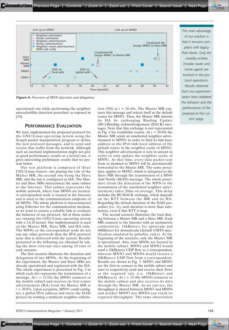
IEEE Communications Magazine • January 2013 133
operational one while performing the neighborunreachability detection procedure as exposed in[10].
PERFORMANCE EVALUATIONWe have implemented the proposed protocol forthe GNU/Linux operating system using theScapy6 packet manipulation program to definethe new protocol messages, and to send andreceive that traffic from the network. Althoughsuch an userland implementation might not giveas good performance results as a kernel one, itgives interesting preliminary results that we pre-sent below.
Our test platform is composed of threeGNU/Linux routers: one playing the role of theMaster MR, the second one being the SlaveMR, and the last is configured as HA. The Mas-ter and Slave MRs interconnect the same subnetto the Internet. This subnet represents themobile network, where four MNNs are located.A correspondent node is located in the Internetand is used as the communication endpoint ofall MNNs. The whole platform is interconnectedusing Ethernet for the communication medium,as we want to ensure a reliable link to evaluatethe behavior of our protocol. All of those nodesare running the GNU/Linux operating systemwith a 2.6.26 kernel. Our implementation is usedon the Master MR, Slave MR, and HA only.The MNNs or the correspondent node do notrun any other protocols than the IPv6 protocolsuite that is delivered with the system. Resultspresented in the following are obtained by tak-ing the most relevant ones among 10 runs ofeach scenario.
The first scenario illustrates the detection anddelegation of two MNNs. At the beginning ofthe experiment, the Master and Slave MRs arealready operational and registered with the HA.The whole experiment is presented in Fig. 4 inwhich each dot represents the transmission of amessage. At t = 12.02s the MNN1 connects tothe mobile subnet and receives its first routeradvertisement (RA) from the Master MR at t = 20.07s. Upon reception, MNN1 could config-ure a global IPv6 address and starts the DADprocess by sending a multicast neighbor solicita-
tion (NS) at t = 20.68s. The Master MR cap-tures this message and selects itself as the defaultrouter for MNN1. Then, the Master MR informsits HA by exchanging Binding Update(BU)/Binding Acknowledgement (BACK) mes-sages. Note that this exchange is not representedin Fig. 4 for readability reason. At t = 20.89s theMaster MR sends an unsolicited neighbor adver-tisement to MNN1 in order to bind its link-layeraddress to the IPv6 link-local address of thedefault router in the neighbor cache of MNN1.This neighbor advertisement is sent in unicast inorder to only update the neighbor cache ofMNN1. At that time, every data packet sentfrom or destined to MNN1 will be automaticallyforwarded to the Master MR. The same proce-dure applies to MNN2, which is delegated to theSlave MR through the transmission of a MNNAdd Notify (MAN) message. The whole proce-dure (from the detection of the MNN to thetransmission of the unsolicited neighbor adver-tisement) takes 20ms on average. This delayincludes the BU/BACK exchange, which dependson the RTT between the MR and its HA.Regarding the default duration of the DAD pro-cedure (i.e. 1s), such duration is more than satis-factory, even if that RTT is large.
The second scenario illustrates the load shar-ing between a Master MR and a Slave MR. EachMR connects to the Internet with an asymmetricconnectivity: 16kBytes/s for upstream and48kBytes/s for downstream (default UMTS spec-ification emulated by ip6tables rules). At thebeginning of the scenario, only the Master MRis operational. Also, four MNNs are located inthe mobile subnet. MNN1 and MNN2 wouldsend a 10kBytes/s UDP flow to a correspondent,whereas MNN3 and MNN4 would receive a40kBytes/s UDP flow from a correspondent.Results are shown in Fig. 5. MNN1 and MNN3are the first to connect to the mobile subnet andstart to respectively send and receive their flowsat the required rate (i.e. 10kBytes/s and40kBytes/s). At t = 25.86s MNN4 connects tothe mobile subnet and also receives its datathrough the Master MR. As we can see, thethroughput is shared between MNN3 and MNN4and neither MNN3 nor MNN4 can reach itsrequired throughput. The same observation
Figure 4. Overview of MNN detection and delegation.
Time (seconds)
Link up on MNN2Link up on MNN1
1210
MNN1
MNN2
SlaveMRR
14 16 18
DAD onlocal addr
Unsolicited NA(assign MNN1 to Master MR)
Unsolicited NA(assign MNN2 to Slave MR)
DAD onglobal addr
20 22 24 26 28 30 32
Neighbor solicitationRouter solicitationNeighbor advertisementRouter advertisementNeighbor router advertisementMNN add notify
MasterMRR
The main advantage
of our solution is
that it remains com-
pliant with legacy
IPv6 clients. Only the
mobility entities
(mobile router and
home agent) are
involved in the pro-
tocol operations.
Results obtained
from our experimen-
tation have validated
the behavior and the
performance of the
proposal at this cur-
rent stage.
Previous Page | Contents | Zoom in | Zoom out | Front Cover | Search Issue | Next PageIEEE
Communications qqM
Mq
qM
MqM
Qmags®THE WORLD’S NEWSSTAND
Previous Page | Contents | Zoom in | Zoom out | Front Cover | Search Issue | Next PageIEEE
Communications qqM
Mq
qM
MqM
Qmags®THE WORLD’S NEWSSTAND
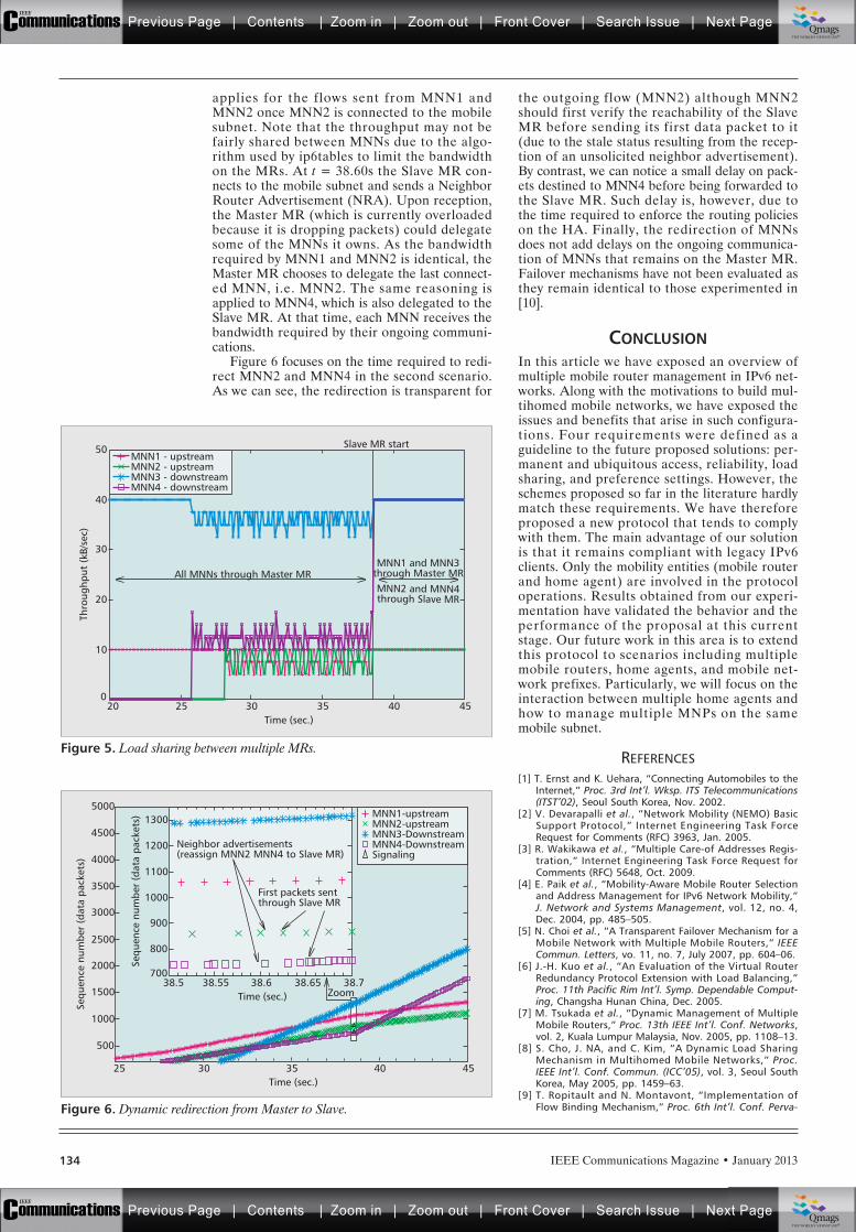
applies for the flows sent from MNN1 andMNN2 once MNN2 is connected to the mobilesubnet. Note that the throughput may not befairly shared between MNNs due to the algo-rithm used by ip6tables to limit the bandwidthon the MRs. At t = 38.60s the Slave MR con-nects to the mobile subnet and sends a NeighborRouter Advertisement (NRA). Upon reception,the Master MR (which is currently overloadedbecause it is dropping packets) could delegatesome of the MNNs it owns. As the bandwidthrequired by MNN1 and MNN2 is identical, theMaster MR chooses to delegate the last connect-ed MNN, i.e. MNN2. The same reasoning isapplied to MNN4, which is also delegated to theSlave MR. At that time, each MNN receives thebandwidth required by their ongoing communi-cations.
Figure 6 focuses on the time required to redi-rect MNN2 and MNN4 in the second scenario.As we can see, the redirection is transparent for
the outgoing flow (MNN2) although MNN2should first verify the reachability of the SlaveMR before sending its first data packet to it(due to the stale status resulting from the recep-tion of an unsolicited neighbor advertisement).By contrast, we can notice a small delay on pack-ets destined to MNN4 before being forwarded tothe Slave MR. Such delay is, however, due tothe time required to enforce the routing policieson the HA. Finally, the redirection of MNNsdoes not add delays on the ongoing communica-tion of MNNs that remains on the Master MR.Failover mechanisms have not been evaluated asthey remain identical to those experimented in[10].
CONCLUSIONIn this article we have exposed an overview ofmultiple mobile router management in IPv6 net-works. Along with the motivations to build mul-tihomed mobile networks, we have exposed theissues and benefits that arise in such configura-tions. Four requirements were defined as aguideline to the future proposed solutions: per-manent and ubiquitous access, reliability, loadsharing, and preference settings. However, theschemes proposed so far in the literature hardlymatch these requirements. We have thereforeproposed a new protocol that tends to complywith them. The main advantage of our solutionis that it remains compliant with legacy IPv6clients. Only the mobility entities (mobile routerand home agent) are involved in the protocoloperations. Results obtained from our experi-mentation have validated the behavior and theperformance of the proposal at this currentstage. Our future work in this area is to extendthis protocol to scenarios including multiplemobile routers, home agents, and mobile net-work prefixes. Particularly, we will focus on theinteraction between multiple home agents andhow to manage multiple MNPs on the samemobile subnet.
REFERENCES[1] T. Ernst and K. Uehara, “Connecting Automobiles to the
Internet,” Proc. 3rd Int’l. Wksp. ITS Telecommunications(ITST’02), Seoul South Korea, Nov. 2002.
[2] V. Devarapalli et al., “Network Mobility (NEMO) BasicSupport Protocol,” Internet Engineering Task ForceRequest for Comments (RFC) 3963, Jan. 2005.
[3] R. Wakikawa et al., “Multiple Care-of Addresses Regis-tration,” Internet Engineering Task Force Request forComments (RFC) 5648, Oct. 2009.
[4] E. Paik et al., “Mobility-Aware Mobile Router Selectionand Address Management for IPv6 Network Mobility,”J. Network and Systems Management, vol. 12, no. 4,Dec. 2004, pp. 485–505.
[5] N. Choi et al., “A Transparent Failover Mechanism for aMobile Network with Multiple Mobile Routers,” IEEECommun. Letters, vo. 11, no. 7, July 2007, pp. 604–06.
[6] J.-H. Kuo et al., “An Evaluation of the Virtual RouterRedundancy Protocol Extension with Load Balancing,”Proc. 11th Pacific Rim Int’l. Symp. Dependable Comput-ing, Changsha Hunan China, Dec. 2005.
[7] M. Tsukada et al., “Dynamic Management of MultipleMobile Routers,” Proc. 13th IEEE Int’l. Conf. Networks,vol. 2, Kuala Lumpur Malaysia, Nov. 2005, pp. 1108–13.
[8] S. Cho, J. NA, and C. Kim, “A Dynamic Load SharingMechanism in Multihomed Mobile Networks,” Proc.IEEE Int’l. Conf. Commun. (ICC’05), vol. 3, Seoul SouthKorea, May 2005, pp. 1459–63.
[9] T. Ropitault and N. Montavont, “Implementation ofFlow Binding Mechanism,” Proc. 6th Int’l. Conf. Perva-
IEEE Communications Magazine • January 2013134
Figure 5. Load sharing between multiple MRs.
Time (sec.)2520
10
0
Thro
ughp
ut (
kB/s
ec)
20
30
40
50
30 35 40
MNN1 and MNN3through Master MRAll MNNs through Master MR
Slave MR start
MNN2 and MNN4through Slave MR
45
MNN1 - upstreamMNN2 - upstreamMNN3 - downstreamMNN4 - downstream
Figure 6. Dynamic redirection from Master to Slave.
Time (sec.)3025
500
Sequ
ence
num
ber
(dat
a pa
cket
s)
1000
1500
2000
2500
3000
3500
4000
4500
5000
35 40 45
Time (sec.) Zoom38.5538.5
800
700
Sequ
ence
num
ber
(dat
a pa
cket
s)
900
1000
1100
1200
1300
38.6
Neighbor advertisements(reassign MNN2 MNN4 to Slave MR)
First packets sentthrough Slave MR
38.65 38.7
MNN1-upstreamMNN2-upstreamMNN3-DownstreamMNN4-DownstreamSignaling
Previous Page | Contents | Zoom in | Zoom out | Front Cover | Search Issue | Next PageIEEE
Communications qqM
Mq
qM
MqM
Qmags®THE WORLD’S NEWSSTAND
Previous Page | Contents | Zoom in | Zoom out | Front Cover | Search Issue | Next PageIEEE
Communications qqM
Mq
qM
MqM
Qmags®THE WORLD’S NEWSSTAND

IEEE Communications Magazine • January 2013 135
sive Computing and Commun. (PERCOM’08), HongKong China, Mar. 2008, pp. 342–47.
[10] R. Kuntz, J. Montavont, and T. Noel, “Multiple MobileRouters in NEMO: How Neighbor Discovery Can AssistDefault Router Selection,” Proc. 19th Annual IEEE Int’l.Symp. Personal Indoor and Mobile Radio Commun.(PIMRC’08), Cannes France, Sept. 2008.
BIOGRAPHIESROMAIN KUNTZ ([email protected]) received Ph.D. in comput-er science in 2010 from the University of Strasbourg,France. He is now a researcher in Toyota InfoTechnologyCenter in Mountain View, USA. After receiving his M.Sc. incomputer science in 2004, he has worked for 3 years as aresearch engineer in Keio University in Japan. His researchinterests include mobility management over IPv6 networks,and MAC protocols for wireless sensor networks.
JULIEN MONTAVONT ([email protected]) received hisPh.D. in computer science from University of Strasbourg in2006. Since September 2007, he is an associate professorat the University of Strasbourg and a member of the Net-work Research team of the LSIIT laboratory (UMR CNRS7005). His expertise and research interests include architec-tures and protocols for mobility management over IPv6networks, and new MAC and routing protocols for wirelesssensor networks.
THOMAS NOEL ([email protected]) is professor at University ofStrasbourg, France since 2006. His research activitiesinclude several aspects of wireless communications net-works and telecommunications systems. He is particularlyinterested in: network mobility, self-organized mobile net-works, mobile network architecture and protocols, wirelesssensor networks, ubiquituous computing and multicast andgroup communications.
Previous Page | Contents | Zoom in | Zoom out | Front Cover | Search Issue | Next PageIEEE
Communications qqM
Mq
qM
MqM
Qmags®THE WORLD’S NEWSSTAND
Previous Page | Contents | Zoom in | Zoom out | Front Cover | Search Issue | Next PageIEEE
Communications qqM
Mq
qM
MqM
Qmags®THE WORLD’S NEWSSTAND
_________ _________
_____________
IEEE Communications Magazine • January 2013136 0163-6804/13/$25.00 © 2013 IEEE
ACCEPTED FROM OPEN CALL
Kim-Khoa Nguyen and Mohamed Cheriet, École de Technologie Supérieure, University of Quebec
Mathieu Lemay, Inocybe Technologies
Enabling Infrastructure as a Service(IaaS) on IP Networks: From Distributedto Virtualized Control Plane
INTRODUCTION
Nowadays, converged communications is consid-ered the main evolutionary stream in thetelecommunications industry, allowing underlyinginfrastructure to run multiple services and acces-sible over multiple devices. As more services areenabled on communication equipments, the linebetween software applications and communica-tions applications is blurring. Traditional commu-nications applications such as point-to-pointconference or multi-cast are now requirements ofbusiness or entertainment software [1].
The aforementioned situation has an importantimpact on network and software solutions. Archi-tects of network solutions will be required to
understand the underlying network architectures,devices, and protocols that will be used to accessservices. Additional frameworks and tools will berequired to abstract details of the network envi-ronment. Application developers will also need tounderstand the protocols that will be used withintheir applications. These requirements will eventu-ally lead to a convergence of network controlplane architectures and software solutions.
In addition, the deployment of new servicesentailed the introduction of new protocols, and linkbandwidth has upgraded from megabit to gigabitrates on the Internet. New devices and protocolsalso increase the number of interfaces in networkelements. Additional overhead resulting from morecontrol traffic among an increasing number ofpeers results in difficulty of scalability, highly avail-ability, and robustness to the control plane. Itappears that traditional network elements (e.g. IProuters) with centralized control plane architectureswill not be able to meet new control requirements.Distributed control plane (DCP) architectures [2]are emerging solutions and have been widely usedin core networks. However, the complexity and flex-ibility of new services, such as cloud computing andsmart grids, impose new challenges on the design ofnetwork control plane architectures.
In order to satisfy tremendous demands ofresources from new applications, cloud computingis used to power next generation data centers andto enable service providers to lease data centercapabilities for deploying applications dependingon user requirements. As cloud applications havevarious configurations, deployment requirements,description and finding, quantifying and allocatingresources are essential in order to deliver on-demand services, particularly in large scale systems.
Today, ISPs are faced with an increased com-petition in the “bit-pipe” [1], a business modelbased purely on connectivity as a utility, withboth lower revenue and lower margins. The bit-pipe model, rather than emphasizing contentand services, is driven by operational excellence.Infrastructure consolidation, process automation,and operational outsourcing are key mechanismsto reduce ISPs’ operating costs, driven by IPtechnology. New services, such as cloud comput-ing with a huge number of resources to be man-aged, have placed the ISPs on the path of a new
ABSTRACT
Infrastructure as a Service (IaaS) is consid-ered a prominent model for IP based servicedelivery. As grid and cloud computing havebecome a stringent demand for today’s Internetservices, IaaS is required for providing services,particularly “private cloud,” regardless of physi-cal infrastructure locations. However, enablingIaaS on traditional Internet Service Provider(ISP) network infrastructures is challengingbecause IaaS requires a high abstraction level ofnetwork architectures, protocols, and devices.Network control plane architecture plays there-fore an essential role in this transition, particu-larly with respect to new requirements ofscalability, reliability, and flexibility. In this arti-cle we review the evolutionary trend of networkelement control planes from monolithic to dis-tributed architectures according to networkgrowth, and then present a new virtualizationoriented architecture that allows infrastructureproviders and service providers to achieve ser-vice delivery independently and transparently toend users based on virtualized network controlplanes. As a result, current ISP infrastructureswill be able to support new services, such asheavy resource consuming data center applica-tions. We also show how to use network virtual-ization for providing cloud computing and datacenter services in a flexible manner on thenationwide CANARIE network infrastructure.
Previous Page | Contents | Zoom in | Zoom out | Front Cover | Search Issue | Next PageIEEE
Communications qqM
Mq
qM
MqM
Qmags®THE WORLD’S NEWSSTAND
Previous Page | Contents | Zoom in | Zoom out | Front Cover | Search Issue | Next PageIEEE
Communications qqM
Mq
qM
MqM
Qmags®THE WORLD’S NEWSSTAND
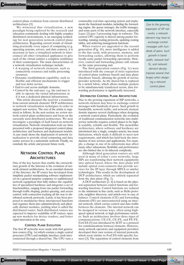
IEEE Communications Magazine • January 2013 137
control plane evolution from current distributedarchitectures [3].
We witnessed that virtualization, a newparadigm being explored by the research andeducation community dealing with highly complexdistributed environments, is an emerging technol-ogy for next generation network control planearchitectures. Regarding current trends of virtual-izing practically every aspect of computing (e.g.operating systems, servers, and data centers), it isnecessary to have a virtualized network to inter-connect all other virtualized appliances to giveeach of the virtual entities a complete semblanceof their counterparts. The main characteristics ofa network virtualization technique include:• A warping of network elements, such as
connectivity resources and traffic processingresources.
• Dynamic establishment capability, such asflexible and efficient mechanisms to triggerand tear down service.
• End-to-end across multiple domains.• Control by the end-user, e.g. the end-user is
able to operate the virtual infrastructure asif it was a dedicated physical infrastructure.This article discusses the need for a transition
from current network elements’ DCP architecturesto network virtualization techniques in order tosupport new services. The rest of the article is orga-nized as follows. In the next section, we review net-work control plane architectures and focus on thecurrently used distributed architecture. We nextinvestigate a paradigm of IaaS based on networkvirtualization. Network virtualization tools are thenpresented with a proposed integrated control planearchitecture and business and deployment models.A case study shows the deployment of network vir-tualization to provide cloud computing and datacenter services in a nationwide network. Finally, weconclude the article and present future work.
NETWORK CONTROL PLANEARCHITECTURES
One of the key factors that enable the extraordi-nary growth of the Internet is the evolution of net-work element architectures. As an essential elementof the Internet, the IP router has developed fromsimplistic packet manipulating software implement-ed on a general purpose computer to sophisticatednetwork equipment that fully utilizes the capabili-ties of specialized hardware and integrates a set offunctionalities, ranging from raw packet forwardingthrough traffic shaping, packet queuing, and accesscontrol, with connection tracking all the way to dis-tributed network protocols. Lately, it has been pro-posed to modularize these interspersed functionsand organize them into administratively and physi-cally distinct modules, yielding what is called thedistributed router. Such distributed routers areexpected to improve scalability of IP routers, openup new markets for device vendors, and fosterrapid innovation in the area.
CONTROL PLANE EVOLUTIONThe first IP networks were made with first genera-tion routers (Fig. 1a) which contain a single centralprocessor (CPU) and multiple interface cards inter-connected through a shared bus. The CPU runs a
commodity real-time operating system and imple-ments the functional modules, including the forward-ing engine, the queue manager, the traffic manager,and some parts of the network interface, especiallyLayer 2/Layer 3 processing logic in software. Thecentral CPU capacity is shared among packet for-warding, running routing protocols, updating routingtables, and achieving management functions.
When routers are upgraded to the secondgeneration (Fig. 1b), more intelligence is addedto the line cards, with processor, memory, andforwarding caches, allowing them to performlocally some packet forwarding operations. How-ever, control and forwarding planes still remainon the same processing unit.
The third generation routers (Fig. 1c) wereintroduced with the concept of strict separationof control plane (software based) and data plane(hardware based), allowing the growth of serviceprovider networks. As the shared bus is replacedby a switch fabric, which allows multiple packetsto be simultaneously transferred across, data for-warding performance is significantly increased.
DISTRIBUTED CONTROL PLANE ARCHITECTUREDue to the growing expansion of ISP networks, anetwork element may have to exchange controlmessages with hundreds of peers. Such growth inbandwidth, network traffic, and network elementdensity imposes several challenges when designinga network control plane. Particularly, the evolutionof traditional communication networks into multi-service networks requires control planes to be high-ly scalable, reliable and flexible. The monolithicarchitecture, where software and hardware areintertwined into a single, complex system, has manylimitations, which made it difficult to meet newrequirements, and which has held back the intro-duction of new services and applications. For exam-ple, a change in one of its subsystems may affectmany other subsystems; flexibility and performanceare also limited due to its inherent complexity.
Although third generation routers are stillused in many of today’s core networks, largeISPs are transforming their network equipmentsinto optical based, where the data plane willinclude optical cross-connects that provide ser-vices for the IP layer through MPLS or similartechnologies. This results in the development ofDCP architectures, which are entirely separatedfrom the data plane (Fig. 2).
A DCP architecture [3, 4] is based on the phys-ical separation between control functions and for-warding functions. Control functions are reducedto the minimum in line cards, such as Hello proto-cols, neighbor discovery, and switch-over in case offailures. Control elements (CE) and forwardingelements (FE) are interconnected using an inter-nal network, which carries control and data trafficbetween the elements. The internal network canbe designed in various ways, often using high-speed optical network or high performance switch-es. Such an architecture involves three types ofcommunications: CE-CE, CE-FE, and FE-FE.ForCES [5] was introduced by IETF as a protocolfor communications between elements. However,many network operators and equipment providersdeveloped their own version of internal protocols,which seem similar to ForCES with specific fea-tures [3]. The separation of control elements from
Due to the growing
expansion of ISP net-
works, a network
element may have to
exchange control
messages with hun-
dreds of peers. Such
growth in band-
width, network traf-
fic, and network
element density
imposes several chal-
lenges when design-
ing a network
control plane.
Previous Page | Contents | Zoom in | Zoom out | Front Cover | Search Issue | Next PageIEEE
Communications qqM
Mq
qM
MqM
Qmags®THE WORLD’S NEWSSTAND
Previous Page | Contents | Zoom in | Zoom out | Front Cover | Search Issue | Next PageIEEE
Communications qqM
Mq
qM
MqM
Qmags®THE WORLD’S NEWSSTAND
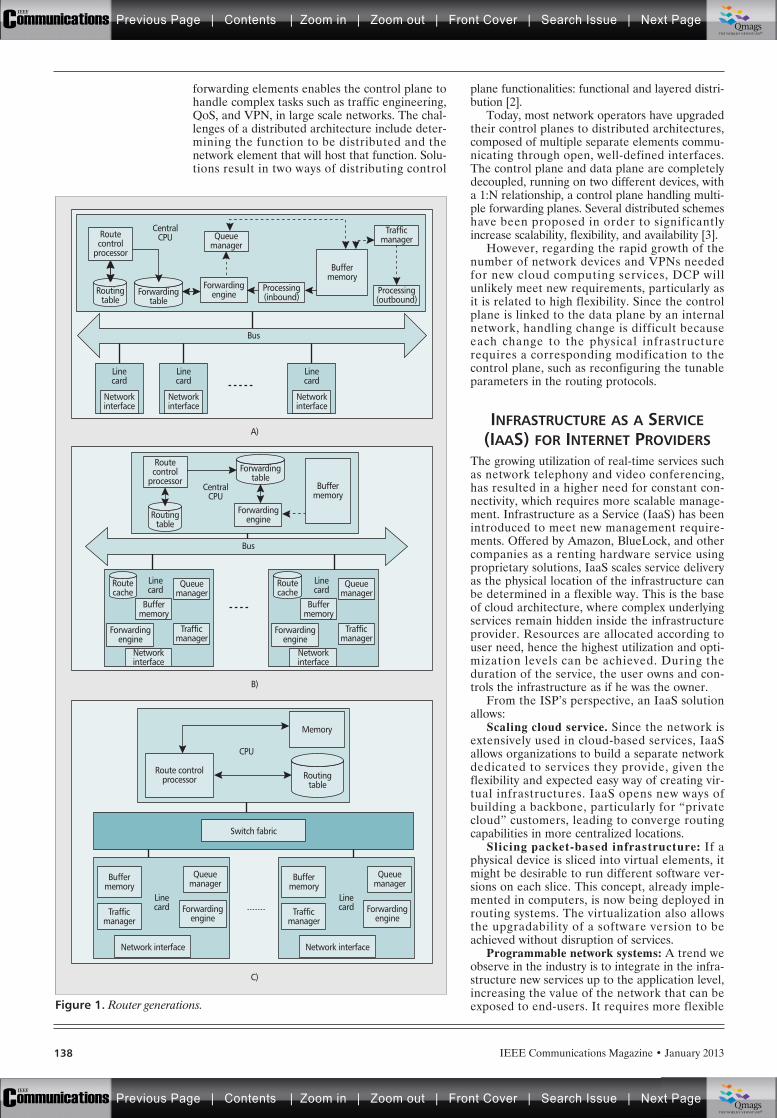
IEEE Communications Magazine • January 2013138
forwarding elements enables the control plane tohandle complex tasks such as traffic engineering,QoS, and VPN, in large scale networks. The chal-lenges of a distributed architecture include deter-mining the function to be distributed and thenetwork element that will host that function. Solu-tions result in two ways of distributing control
plane functionalities: functional and layered distri-bution [2].
Today, most network operators have upgradedtheir control planes to distributed architectures,composed of multiple separate elements commu-nicating through open, well-defined interfaces.The control plane and data plane are completelydecoupled, running on two different devices, witha 1:N relationship, a control plane handling multi-ple forwarding planes. Several distributed schemeshave been proposed in order to significantlyincrease scalability, flexibility, and availability [3].
However, regarding the rapid growth of thenumber of network devices and VPNs neededfor new cloud computing services, DCP willunlikely meet new requirements, particularly asit is related to high flexibility. Since the controlplane is linked to the data plane by an internalnetwork, handling change is difficult becauseeach change to the physical infrastructurerequires a corresponding modification to thecontrol plane, such as reconfiguring the tunableparameters in the routing protocols.
INFRASTRUCTURE AS A SERVICE(IAAS) FOR INTERNET PROVIDERS
The growing utilization of real-time services suchas network telephony and video conferencing,has resulted in a higher need for constant con-nectivity, which requires more scalable manage-ment. Infrastructure as a Service (IaaS) has beenintroduced to meet new management require-ments. Offered by Amazon, BlueLock, and othercompanies as a renting hardware service usingproprietary solutions, IaaS scales service deliveryas the physical location of the infrastructure canbe determined in a flexible way. This is the baseof cloud architecture, where complex underlyingservices remain hidden inside the infrastructureprovider. Resources are allocated according touser need, hence the highest utilization and opti-mization levels can be achieved. During theduration of the service, the user owns and con-trols the infrastructure as if he was the owner.
From the ISP’s perspective, an IaaS solutionallows:
Scaling cloud service. Since the network isextensively used in cloud-based services, IaaSallows organizations to build a separate networkdedicated to services they provide, given theflexibility and expected easy way of creating vir-tual infrastructures. IaaS opens new ways ofbuilding a backbone, particularly for “privatecloud” customers, leading to converge routingcapabilities in more centralized locations.
Slicing packet-based infrastructure: If aphysical device is sliced into virtual elements, itmight be desirable to run different software ver-sions on each slice. This concept, already imple-mented in computers, is now being deployed inrouting systems. The virtualization also allowsthe upgradability of a software version to beachieved without disruption of services.
Programmable network systems: A trend weobserve in the industry is to integrate in the infra-structure new services up to the application level,increasing the value of the network that can beexposed to end-users. It requires more flexibleFigure 1. Router generations.
Linecard
Networkinterface
ForwardingengineForwarding
tableRouting
table
Switch fabric
Routingtable
Memory
CPU
Route controlprocessor
A)
B)
C)
Linecard
Networkinterface
Linecard
Networkinterface
Bus
Bus
TrafficmanagerQueue
managerRoutecontrol
processor
CentralCPU
CentralCPU
Processing(outbound)
Processing(inbound)
Buffermemory
Buffermemory
Forwardingtable
Routingtable
Routecache
Forwardingengine
Forwardingengine
Forwardingengine
Networkinterface
Network interface
Queuemanager
Queuemanager
Buffermemory
Buffermemory
Linecard
Linecard
Trafficmanager
Trafficmanager
Forwardingengine
Network interface
Queuemanager
Buffermemory
LinecardTraffic
manager
Routecontrol
processor
Routecache
Forwardingengine
Networkinterface
Queuemanager
Buffermemory
Linecard
Trafficmanager
Previous Page | Contents | Zoom in | Zoom out | Front Cover | Search Issue | Next PageIEEE
Communications qqM
Mq
qM
MqM
Qmags®THE WORLD’S NEWSSTAND
Previous Page | Contents | Zoom in | Zoom out | Front Cover | Search Issue | Next PageIEEE
Communications qqM
Mq
qM
MqM
Qmags®THE WORLD’S NEWSSTAND
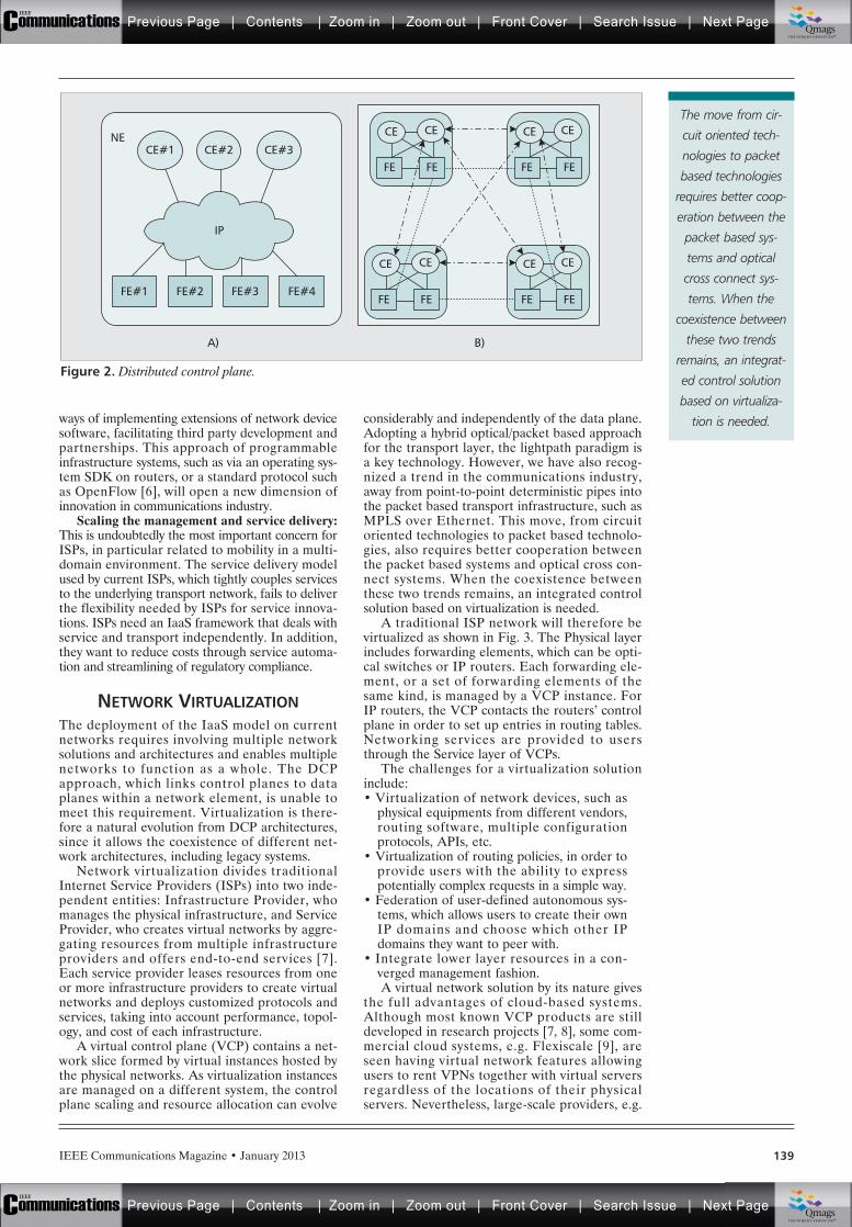
IEEE Communications Magazine • January 2013 139
ways of implementing extensions of network devicesoftware, facilitating third party development andpartnerships. This approach of programmableinfrastructure systems, such as via an operating sys-tem SDK on routers, or a standard protocol suchas OpenFlow [6], will open a new dimension ofinnovation in communications industry.
Scaling the management and service delivery:This is undoubtedly the most important concern forISPs, in particular related to mobility in a multi-domain environment. The service delivery modelused by current ISPs, which tightly couples servicesto the underlying transport network, fails to deliverthe flexibility needed by ISPs for service innova-tions. ISPs need an IaaS framework that deals withservice and transport independently. In addition,they want to reduce costs through service automa-tion and streamlining of regulatory compliance.
NETWORK VIRTUALIZATIONThe deployment of the IaaS model on currentnetworks requires involving multiple networksolutions and architectures and enables multiplenetworks to function as a whole. The DCPapproach, which links control planes to dataplanes within a network element, is unable tomeet this requirement. Virtualization is there-fore a natural evolution from DCP architectures,since it allows the coexistence of different net-work architectures, including legacy systems.
Network virtualization divides traditionalInternet Service Providers (ISPs) into two inde-pendent entities: Infrastructure Provider, whomanages the physical infrastructure, and ServiceProvider, who creates virtual networks by aggre-gating resources from multiple infrastructureproviders and offers end-to-end services [7].Each service provider leases resources from oneor more infrastructure providers to create virtualnetworks and deploys customized protocols andservices, taking into account performance, topol-ogy, and cost of each infrastructure.
A virtual control plane (VCP) contains a net-work slice formed by virtual instances hosted bythe physical networks. As virtualization instancesare managed on a different system, the controlplane scaling and resource allocation can evolve
considerably and independently of the data plane.Adopting a hybrid optical/packet based approachfor the transport layer, the lightpath paradigm isa key technology. However, we have also recog-nized a trend in the communications industry,away from point-to-point deterministic pipes intothe packet based transport infrastructure, such asMPLS over Ethernet. This move, from circuitoriented technologies to packet based technolo-gies, also requires better cooperation betweenthe packet based systems and optical cross con-nect systems. When the coexistence betweenthese two trends remains, an integrated controlsolution based on virtualization is needed.
A traditional ISP network will therefore bevirtualized as shown in Fig. 3. The Physical layerincludes forwarding elements, which can be opti-cal switches or IP routers. Each forwarding ele-ment, or a set of forwarding elements of thesame kind, is managed by a VCP instance. ForIP routers, the VCP contacts the routers’ controlplane in order to set up entries in routing tables.Networking services are provided to usersthrough the Service layer of VCPs.
The challenges for a virtualization solutioninclude:• Virtualization of network devices, such as
physical equipments from different vendors,routing software, multiple configurationprotocols, APIs, etc.
• Virtualization of routing policies, in order toprovide users with the ability to expresspotentially complex requests in a simple way.
• Federation of user-defined autonomous sys-tems, which allows users to create their ownIP domains and choose which other IPdomains they want to peer with.
• Integrate lower layer resources in a con-verged management fashion.A virtual network solution by its nature gives
the full advantages of cloud-based systems.Although most known VCP products are stilldeveloped in research projects [7, 8], some com-mercial cloud systems, e.g. Flexiscale [9], areseen having virtual network features allowingusers to rent VPNs together with virtual serversregardless of the locations of their physicalservers. Nevertheless, large-scale providers, e.g.
Figure 2. Distributed control plane.
B)A)
CE
CE#3CE#2CE#1
FE#1 FE#2
IP
FE#3 FE#4
NECE
FEFE
CE CE
FEFE
CE CE
FEFE
CE CE
FEFE
The move from cir-
cuit oriented tech-
nologies to packet
based technologies
requires better coop-
eration between the
packet based sys-
tems and optical
cross connect sys-
tems. When the
coexistence between
these two trends
remains, an integrat-
ed control solution
based on virtualiza-
tion is needed.
Previous Page | Contents | Zoom in | Zoom out | Front Cover | Search Issue | Next PageIEEE
Communications qqM
Mq
qM
MqM
Qmags®THE WORLD’S NEWSSTAND
Previous Page | Contents | Zoom in | Zoom out | Front Cover | Search Issue | Next PageIEEE
Communications qqM
Mq
qM
MqM
Qmags®THE WORLD’S NEWSSTAND
IEEE Communications Magazine • January 2013140
Amazon or Google, might still be concernedabout performance issues when expanding theirservices to public utilization. As a result, no net-work virtualization feature has yet been imple-mented in their public cloud products. Thus, webelieve that for the time being, a virtual networkis more appropriate for medium-and-small enter-prise customers. Incoming products from hard-ware providers, such as Juniper Networks’ ControlSystem (JSC1200) or Cisco’ IOS XR, fully sup-port virtualization features. However, they focuson hardware virtualization of the point of pres-ence (POP), while a cloud-based system needs amore flexible solution at the software level.
In addition, there is a difference betweenpublic cloud and private cloud services. Publiccloud services, e.g. Amazon EC2, do not allowusers to reconfigure their networks of virtualservers because of performance and securityissues. However, private cloud services willpotentially be provided with virtual networksolutions. For example, Amazon Virtual PrivateCloud will allow users to have complete controlover their virtual networking environment [10].
VIRTUALIZED NETWORKCONTROL PLANE ARCHITECTURE
A VCP architecture for a network element isshown in Fig. 4. It is built on top of network ele-ments (e.g. optical cross-connect) used as thedata plane. The proposed architecture has beenused to develop a set of VCP software, includingUCLP (User-Controlled LightPaths) [11]. TheLookup Service is used to find the differentinstances of network elements in the network.Network Service Access Point (NSAP) advertisesits service instantiation through a well-knownprocess described by an OSGi implementationsuch as a Web Services Description Language(WSDL) pointer or Universal Description, Dis-covery and Integration (UDDI) database. Whena client application wants to use a NSAP service,it sends user requests to the NSAP using the
Simple Object Access Protocol (SOAP) adoptedfor Web Services. The requests are then convert-ed into procedure calls within the NSAP whichthen performs the calls on its local ServiceAccess Point, where commands are executedwith the help of the other components within thesystem. The Traffic Engineering Service imple-ments a set of methods to create end-to-endconnections. It supports concatenating, partition-ing, receiving requests, and using and releasingpaths. There are two types of users. Normalusers may invoke a connection request to createa new end-to-end connection, and the adminis-trator may perform administrative functions,such as adding new paths, deleting paths accord-ing to changes in the physical layer, and the allo-cating new resources (i.e. network elements).Finally, the Network Element Service encapsu-lates the communication protocol required tocommunicate with the managed network device.
In a traditional networking environment, rout-ing protocols assemble routing tables used to findavailable resources for routing a new connectionthrough a given network. However, no standard isavailable for inter-domain routing in optical net-works and full knowledge of network topology asnormally used for intra-domain routing is notappropriate for customer-managed networking.Therefore, when the control plane is implementedfor an optical network, an ad-hoc path searchingmechanism can be used based on a static database,which is updated by the Lookup Service.
In order to provide interfaces to upper layers,the NSAP defines management services in thecontext of Web Services standards, based onXML and SOAP. The XML-based SOAP proto-col is used for remote method invocation. Thereis also a service directory where VCPs can regis-ter their list of services specified in terms of XMLschemas. Client applications search this directoryto find desired services and corresponding VCPs.
Such a VCP can be hosted by a server sepa-rately from the network element it manages.This allows the control plane to be implementedusing robust software platforms, e.g. J2EE/OSGi.
COMPARISON OF DISTRIBUTED ANDVIRTUAL CONTROL PLANE
Regarding the complexity in the management ofDCP due to command line interfaces, VCPoffers a clear advantage as it allows both end-user and administrator to configure the networkthrough a user-friendly GUI interface with dif-ferent access levels, thus reducing the risk oferrors committed by users. The scalability of thedistributed model depends on the capacity ofdevices, while a VCP running on a dedicatedserver is able to manage many devices or evenmultiple networks. This significantly reduces thecapital and operational expenditures (CAPEX/OPEX) of network providers. In addition, aDCP based on hardware components is morecostly than a VCP, which is software-based.
As VCP is programmable, drivers can easilybe added in order to control a wide range ofdevices and support traffic engineering features,which is inextensible in the DCP model. Similar-ly, security mechanisms can be implemented in aVCP for authentication, access control, and user
Figure 3. Virtualized control plane network.
User VPN
Virt#1 Virt#2Virt#3
Virt#N
Servicenetwork
Physicalnetwork
FE#1 FE#2 FE#3 FE#N
Physical link
Previous Page | Contents | Zoom in | Zoom out | Front Cover | Search Issue | Next PageIEEE
Communications qqM
Mq
qM
MqM
Qmags®THE WORLD’S NEWSSTAND
Previous Page | Contents | Zoom in | Zoom out | Front Cover | Search Issue | Next PageIEEE
Communications qqM
Mq
qM
MqM
Qmags®THE WORLD’S NEWSSTAND
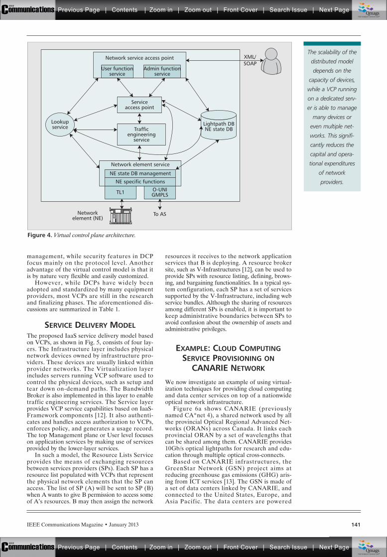
IEEE Communications Magazine • January 2013 141
management, while security features in DCPfocus mainly on the protocol level. Anotheradvantage of the virtual control model is that itis by nature very flexible and easily customized.
However, while DCPs have widely beenadopted and standardized by many equipmentproviders, most VCPs are still in the researchand finalizing phases. The aforementioned dis-cussions are summarized in Table 1.
SERVICE DELIVERY MODELThe proposed IaaS service delivery model basedon VCPs, as shown in Fig. 5, consists of four lay-ers. The Infrastructure layer includes physicalnetwork devices owned by infrastructure pro-viders. These devices are usually linked withinprovider networks. The Virtualization layerincludes servers running VCP software used tocontrol the physical devices, such as setup andtear down on-demand paths. The BandwidthBroker is also implemented in this layer to enabletraffic engineering services. The Service layerprovides VCP service capabilities based on IaaS-Framework components [12]. It also authenti-cates and handles access authorization to VCPs,enforces policy, and generates a usage record.The top Management plane or User level focuseson application services by making use of servicesprovided by the lower-layer services.
In such a model, the Resource Lists Serviceprovides the means of exchanging resourcesbetween services providers (SPs). Each SP has aresource list populated with VCPs that representthe physical network elements that the SP canaccess. The list of SP (A) will be sent to SP (B)when A wants to give B permission to access someof A’s resources. B may then assign the network
resources it receives to the network applicationservices that B is deploying. A resource brokersite, such as V-Infrastructures [12], can be used toprovide SPs with resource listing, defining, brows-ing, and bargaining functionalities. In a typical sys-tem configuration, each SP has a set of servicessupported by the V-Infrastructure, including webservice bundles. Although the sharing of resourcesamong different SPs is enabled, it is important tokeep administrative boundaries between SPs toavoid confusion about the ownership of assets andadministrative privileges.
EXAMPLE: CLOUD COMPUTINGSERVICE PROVISIONING ON
CANARIE NETWORK
We now investigate an example of using virtual-ization techniques for providing cloud computingand data center services on top of a nationwideoptical network infrastructure.
Figure 6a shows CANARIE (previouslynamed CA*net 4), a shared network used by allthe provincial Optical Regional Advanced Net-works (ORANs) across Canada. It links eachprovincial ORAN by a set of wavelengths thatcan be shared among them. CANARIE provides10Gb/s optical lightpaths for research and edu-cation through multiple optical cross-connects.
Based on CANARIE infrastructures, theGreenStar Network (GSN) project aims atreducing greenhouse gas emissions (GHG) aris-ing from ICT services [13]. The GSN is made ofa set of data centers linked by CANARIE, andconnected to the United States, Europe, andAsia Pacific. The data centers are powered
Figure 4. Virtual control plane architecture.
To ASNetworkelement (NE)
Lightpath DBNE state DB
Lookupservice
Serviceaccess point
O-UNIGMPLS
Trafficengineering
service
XML/SOAP
Admin functionservice
User functionservice
Network service access point
TL1
NE specific functions
NE state DB management
Network element service
The scalability of the
distributed model
depends on the
capacity of devices,
while a VCP running
on a dedicated serv-
er is able to manage
many devices or
even multiple net-
works. This signifi-
cantly reduces the
capital and opera-
tional expenditures
of network
providers.
Previous Page | Contents | Zoom in | Zoom out | Front Cover | Search Issue | Next PageIEEE
Communications qqM
Mq
qM
MqM
Qmags®THE WORLD’S NEWSSTAND
Previous Page | Contents | Zoom in | Zoom out | Front Cover | Search Issue | Next PageIEEE
Communications qqM
Mq
qM
MqM
Qmags®THE WORLD’S NEWSSTAND
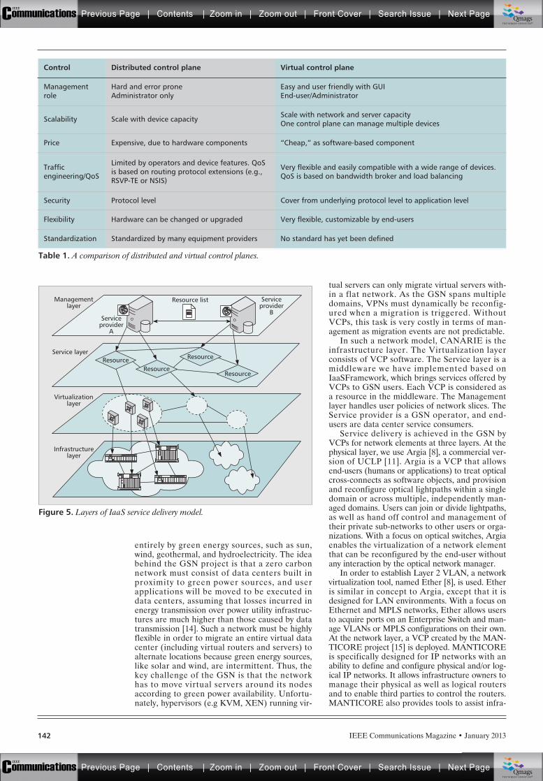
IEEE Communications Magazine • January 2013142
entirely by green energy sources, such as sun,wind, geothermal, and hydroelectricity. The ideabehind the GSN project is that a zero carbonnetwork must consist of data centers built inproximity to green power sources, and userapplications will be moved to be executed indata centers, assuming that losses incurred inenergy transmission over power utility infrastruc-tures are much higher than those caused by datatransmission [14]. Such a network must be highlyflexible in order to migrate an entire virtual datacenter (including virtual routers and servers) toalternate locations because green energy sources,like solar and wind, are intermittent. Thus, thekey challenge of the GSN is that the networkhas to move virtual servers around its nodesaccording to green power availability. Unfortu-nately, hypervisors (e.g KVM, XEN) running vir-
tual servers can only migrate virtual servers with-in a flat network. As the GSN spans multipledomains, VPNs must dynamically be reconfig-ured when a migration is triggered. WithoutVCPs, this task is very costly in terms of man-agement as migration events are not predictable.
In such a network model, CANARIE is theinfrastructure layer. The Virtualization layerconsists of VCP software. The Service layer is amiddleware we have implemented based onIaaSFramework, which brings services offered byVCPs to GSN users. Each VCP is considered asa resource in the middleware. The Managementlayer handles user policies of network slices. TheService provider is a GSN operator, and end-users are data center service consumers.
Service delivery is achieved in the GSN byVCPs for network elements at three layers. At thephysical layer, we use Argia [8], a commercial ver-sion of UCLP [11]. Argia is a VCP that allowsend-users (humans or applications) to treat opticalcross-connects as software objects, and provisionand reconfigure optical lightpaths within a singledomain or across multiple, independently man-aged domains. Users can join or divide lightpaths,as well as hand off control and management oftheir private sub-networks to other users or orga-nizations. With a focus on optical switches, Argiaenables the virtualization of a network elementthat can be reconfigured by the end-user withoutany interaction by the optical network manager.
In order to establish Layer 2 VLAN, a networkvirtualization tool, named Ether [8], is used. Etheris similar in concept to Argia, except that it isdesigned for LAN environments. With a focus onEthernet and MPLS networks, Ether allows usersto acquire ports on an Enterprise Switch and man-age VLANs or MPLS configurations on their own.At the network layer, a VCP created by the MAN-TICORE project [15] is deployed. MANTICOREis specifically designed for IP networks with anability to define and configure physical and/or log-ical IP networks. It allows infrastructure owners tomanage their physical as well as logical routersand to enable third parties to control the routers.MANTICORE also provides tools to assist infra-
Figure 5. Layers of IaaS service delivery model.
Infrastructurelayer
ResourceResource
ResourceResource
Serviceprovider
B
Resource list
Serviceprovider
A
Managementlayer
Service layer
Virtualizationlayer
Table 1. A comparison of distributed and virtual control planes.
Control Distributed control plane Virtual control plane
Managementrole
Hard and error proneAdministrator only
Easy and user friendly with GUIEnd-user/Administrator
Scalability Scale with device capacity Scale with network and server capacityOne control plane can manage multiple devices
Price Expensive, due to hardware components “Cheap,” as software-based component
Trafficengineering/QoS
Limited by operators and device features. QoSis based on routing protocol extensions (e.g.,RSVP-TE or NSIS)
Very flexible and easily compatible with a wide range of devices.QoS is based on bandwidth broker and load balancing
Security Protocol level Cover from underlying protocol level to application level
Flexibility Hardware can be changed or upgraded Very flexible, customizable by end-users
Standardization Standardized by many equipment providers No standard has yet been defined
Previous Page | Contents | Zoom in | Zoom out | Front Cover | Search Issue | Next PageIEEE
Communications qqM
Mq
qM
MqM
Qmags®THE WORLD’S NEWSSTAND
Previous Page | Contents | Zoom in | Zoom out | Front Cover | Search Issue | Next PageIEEE
Communications qqM
Mq
qM
MqM
Qmags®THE WORLD’S NEWSSTAND
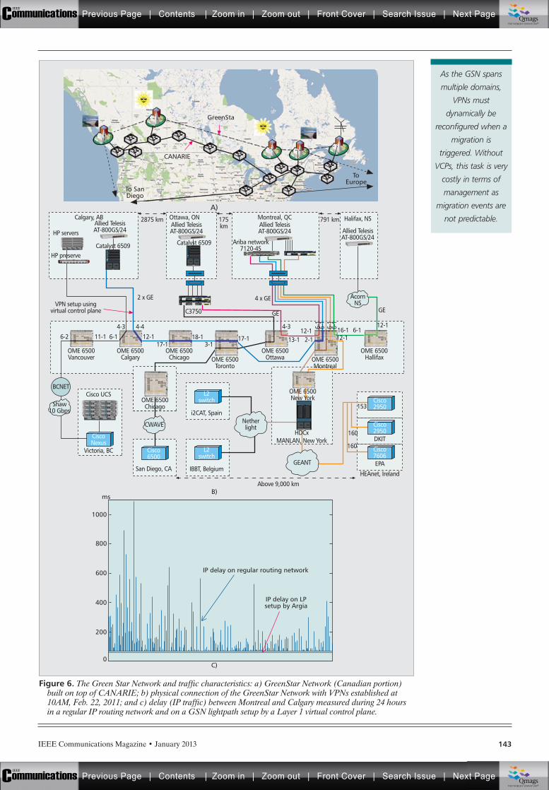
IEEE Communications Magazine • January 2013 143
Figure 6. The Green Star Network and traffic characteristics: a) GreenStar Network (Canadian portion)built on top of CANARIE; b) physical connection of the GreenStar Network with VPNs established at10AM, Feb. 22, 2011; and c) delay (IP traffic) between Montreal and Calgary measured during 24 hoursin a regular IP routing network and on a GSN lightpath setup by a Layer 1 virtual control plane.
200
0
400
600
800
1000
msB)
C)
IP delay on regular routing network
IP delay on LPsetup by Argia
GEGE
12-16-1
6-2 6-111-1 12-117-1 3-1
18-1 17-1 13-1
4-34-3 4-412-1
12-12-1
OME 6500Hallifax
OME 6500Ottawa
OME 6500New York
OME 6500Chicago
OME 6500Chicago
OME 6500Calgary
OME 6500Vancouver OME 6500
Montreal
HDCxMANLAN, New York
OME 6500Toronto
16-1
2 x GE 4 x GEVPN setup using
virtual control plane
Halifax, NS
Allied TelesisAT-800GS/24
Allied TelesisAT-800GS/24
Montreal, QCAllied TelesisAT-800GS/24
Allied TelesisAT-800GS/24HP servers
HP preserve
Ottawa, ONCalgary, AB
Catalyst 6509
2875 km
Catalyst 6509
C3750
ToEurope
GreenSta
CANARIE
To SanDiego
A)
175km
791 km
Above 9,000 km
AcornNS
Shaw10 Gbps
BCNET
CWAVE
GEANT
153
Netherlight
CiscoNexus
L2switch
i2CAT, Spain
L2switch
IBBT, Belgium
Cisco UCS
Victoria, BC Cisco6500
Cisco2950
Cisco2950DKIT
Cisco7606EPA
HEAnet, IrelandSan Diego, CA
Ariba network7120-4S
6-1
6-1
6-1
6-1
160
160
As the GSN spans
multiple domains,
VPNs must
dynamically be
reconfigured when a
migration is
triggered. Without
VCPs, this task is very
costly in terms of
management as
migration events are
not predictable.
Previous Page | Contents | Zoom in | Zoom out | Front Cover | Search Issue | Next PageIEEE
Communications qqM
Mq
qM
MqM
Qmags®THE WORLD’S NEWSSTAND
Previous Page | Contents | Zoom in | Zoom out | Front Cover | Search Issue | Next PageIEEE
Communications qqM
Mq
qM
MqM
Qmags®THE WORLD’S NEWSSTAND
IEEE Communications Magazine • January 2013144
structure users in the creation and management ofIP networks using router resources of one or moreinfrastructure owners.
As shown in Fig. 6b, data centers of the GSNare linked by several types of equipments, includ-ing optical cross-connects in the core CANARIEnetwork, Layer 2 switch of local networks, and IProuters. Therefore, reconfiguring and setting up aVPN within such a network is very challenging. Inaddition, the VPN needs to be flexible, i.e. itstopology can be changed dynamically. VCPs allowGSN operators to enable user-controlled trafficengineering. Thus, networks within a single domainor across multiple independent domains can beself-provisioned and dynamically reconfigured. Forexample, an optical connection is set up as follows.When a path is requested between Montreal andCalgary, as shown in Fig. 6b, resource objects rep-resenting ports on each switch are defined. Next, aVCP (i.e. Argia) creates a link object representingan optical connection between two switches. Thena path is allocated. When the path is required on aSONET network (e.g. CANARIE core network),VCP deals with the 10GE WAN PHY protocol.After the 10GE WAN PHY signal is converted toa 10GW LAN PHY signal in Calgary, it goes tothe Allied Telesis switch. The path allows virtualservers to be migrated from Calgary to Montrealas on the same LAN environment.
Figure 6c compares the delay of IP trafficbetween Montreal and Calgary nodes in the GSNwhen regular IP routing and VCP are used toestablish a connection. Data is collected during aperiod of 24 hours. In the regular IP routing ser-vice, data packets going through each intermediateswitch need to be processed and sometimes con-verted by OEO (optical-electrical-optical) modules.This results in high delay that, in peak load peri-ods, does not meet requirements for live migra-tions. VCP offers a more stable lightpath betweentwo nodes compared to regular IP routing.
As the CANARIE network is composed ofmultiple federated domains, each domain includesa set of network devices, and VCPs are imple-mented on each domain to export availableResource Lists. Since the VCPs cover threeunderlying layers, GSN users get full control of allnetwork elements. Network topology can there-fore be reconfigured according to user require-ments in a very flexible manner (e.g. changed atleast two times a day) in order to move data cen-ters following green power availabilities.
CONCLUSIONAlong with the growing demand for new serviceson the Internet, the network control plane hasevolved in ISP networks through many genera-tions. Distributed control plane architectures arebeing widely used. However, they are facing issuesof scalability and the flexibility requirements ofnew cloud computing services. Therefore, webelieve that network virtualization is a more appro-priate solution, particularly in cases of very elasticnetworks as shown in this article. The virtualizedcontrol plane architecture we presented has beenused in a number of research and educational pro-jects and proven to be a flexible and efficient tool.
Our future work will address evolving such net-work virtualization tools, driven by the needs of
new complex networks, and implementing advancedoptimization techniques for traffic management.
REFERENCES[1] A. Cuevas et al., “The IMS Service Platform: A Solution
for Next Generation Network Operators to Be MoreThan Bit Pipes,” IEEE Commun. Mag., vol. 44, no. 8,2006, pp. 75–81.
[2] K.-K. Nguyen et al., “Towards A Distributed ControlPlane Architecture for Next Generation Routers,” Proc.ECUMN’07, 2007, pp. 173–82.
[3] K.-K. Nguyen, B. Jaumard, and A. Agarwal, “A Distribut-ed and Scalable Routing Table Manager for Next Gen-eration IP Router,” IEEE Network, vol. 22, no. 2, Mar.2008, pp. 6–14.
[4] Császár et al., “Converging the Evolution of RouterArchitectures and IP Networks,” IEEE Network Mag.,vol. 21, no. 4, 2007, pp. 8–14.
[5] A. Doria et al., “RFC 5810: Forwarding and Control Ele-ment Separation (ForCES) Protocol Specification,” IETFDraft, IETF — Network Working Group, 2010.
[6] N. McKeown et al., “OpenFlow: Enabling Innovation inCampus Networks,” ACM SIGCOMM Comp. Commun.Review, vol. 38, issue 2, 2008, pp. 69–74.
[7] N. M. Mosharaf Kabir Chowdhury and R. Boutaba,“Network Virtualization: State of the Art and ResearchChallenges,” IEEE Commun. Mag., vol. 47, no. 7, 2009,pp. 20–26.
[8] S. Figuerola and M. Lemay, “Infrastructure Services forOptical Networks [Invited],” J. Opt. Commun. and Net-working, vol. 1, no. 2, 2009, pp. A247–A257.
[9] FlexiScale Inc., “Flexiscale Cloud Computing,”http://www.flexiscale.com.
[10] Amazon Inc., “Amazon Virtual Private Cloud (AmazonVPC),” http://aws.amazon.com/vpc/.
[11] E. Grasa et al., “UCLPv2: A Network VirtualizationFramework Built on Web Services,” IEEE Commun.Mag., vol. 46, no. 3, 2008, pp. 126–34.
[12] M. Lemay, “An Introduction to IaaS Framework,”8/2008. http://www.iaasframework.com/.
[13] The GreenStar Network Project. http://greenstarnet-work.com.
[14] S. Figuerola et al., “Converged Optical Network Infras-tructures in Support of Future Internet and Grid Ser-vices Using IaaS to Reduce GHG Emissions,” J.Lightwave Tech., vol. 27, no. 12, 2009, pp. 1941–46.
[15] E Grasa et al., “The MANTICORE Project: Providingusers with a Logical IP Network Service,” Proc. TERENANet. Conf., 5/2008.
BIOGRAPHIESKIM-KHOA NGUYEN ([email protected]) is a ResearchFellow in the Automation Engineering Department at theÉcole de Technologie Supérieure (University of Quebec). He iskey architect of the GreenStar Network project and a mem-ber of the Synchromedia Consortium. Since 2008 he hasbeen with the Optimization of Communication NetworksResearch Laboratory at Concordia University. His researchincludes green ICT, cloud computing, smart grid, router archi-tectures and wireless networks. He holds a Ph.D. in Electricaland Computer Engineering from Concordia University.
MATHIEU LEMAY holds a degree in electrical engineeringfrom the École de Technologies Supérieure (2005) and amaster’s in optical networks (2007). He is currently a Ph.D.candidate at the Synchromedia Consortium of ETS. He isthe Founder, President, and CEO of Inocybe TechnologiesInc. He is currently involved in Green IT and he is leadingthe IaaS Framework Open Source initiative. His mainresearch themes are virtualization, network segmentation,service-oriented architectures and distributed systems.
MOHAMED CHERIET is a Full Professor in the Automation Engi-neering Department at the École de Technologie Supérieure(University of Quebec). He is co-founder of the Laboratoryfor Imagery, Vision and Artificial Intelligence (LIVIA), andfounder and director of the Synchromedia Consortium since1998. He serves on the editorial boards of Pattern Recogni-tion (PR), the International Journal of Document Analysisand Recognition (IJDAR), and the International Journal ofPattern Recognition and Artificial Intelligence (IJPRAI). He isa member of IAPR, a senior member of the IEEE and theFounder and Premier Chair of the IEEE Montreal Chapter ofComputational Intelligent Systems (CIS).
Distributed control
plane architectures
are being widely
used. However, they
are facing issues of
scalability and the
flexibility require-
ments of new cloud
computing services.
Therefore, we
believe that network
virtualization is a
more appropriate
solution.
Previous Page | Contents | Zoom in | Zoom out | Front Cover | Search Issue | Next PageIEEE
Communications qqM
Mq
qM
MqM
Qmags®THE WORLD’S NEWSSTAND
Previous Page | Contents | Zoom in | Zoom out | Front Cover | Search Issue | Next PageIEEE
Communications qqM
Mq
qM
MqM
Qmags®THE WORLD’S NEWSSTAND
________________
______________

Beyond Copper. Beyond 100G. Beyond Next Gen. 750+ Technical Presentations/550+ Exhibits: Cloud and Data Center Networking • Space Division Multiplexing • 100G/400G Network Design and Optimization • 1Tb and Beyond Optical Networking • Wavelength Agile Access Networks • Flexible Grid Networks • Virtualization and Software Defined Networks (SDN) • High-Speed Photonic Integration for Coherent Detection • Convergence of Optical and Wireless Networks • And More!
www.ofcnfoec.orgAdvancing optical solutions in telecom, datacom, computing and more!
Register for
Your Full Conference
Package by
19 February
and Save Up to $115!
Sponsored by:Technical Conference 17-21 March Exposition 19-21 MarchAnaheim Convention CenterAnaheim, CA USA
Previous Page | Contents | Zoom in | Zoom out | Front Cover | Search Issue | Next PageIEEE
Communications qqM
Mq
qM
MqM
Qmags®THE WORLD’S NEWSSTAND
Previous Page | Contents | Zoom in | Zoom out | Front Cover | Search Issue | Next PageIEEE
Communications qqM
Mq
qM
MqM
Qmags®THE WORLD’S NEWSSTAND

The Next Big Thing Is Here
/SamsungMobileUSA
Previous Page | Contents | Zoom in | Zoom out | Front Cover | Search Issue | Next PageIEEE
Communications qqM
Mq
qM
MqM
Qmags®THE WORLD’S NEWSSTAND
Previous Page | Contents | Zoom in | Zoom out | Front Cover | Search Issue | Next PageIEEE
Communications qqM
Mq
qM
MqM
Qmags®THE WORLD’S NEWSSTAND