cyber 2017 proceedings - thinkmind.org
TRANSCRIPT
CYBER 2017
The Second International Conference on Cyber-Technologies and Cyber-Systems
ISBN: 978-1-61208-605-7
November 12 - 16, 2017
Barcelona, Spain
CYBER 2017 Editors
Rainer Falk, Siemens AG, Corporate Technology, Deutschland
Steve Chan, MIT, USA
Juan-Carlos Bennett, SPAWAR Systems Center Pacific, USA
1 / 90
CYBER 2017
Forward
The Second International Conference on Cyber-Technologies and Cyber-Systems (CYBER2017), held between November 12 - 16, 2017, in Barcelona, Spain, continues the inauguralevent covering many aspects related to cyber-systems and cyber-technologies considering theissues mentioned above and potential solutions. It is also intended to illustrate appropriatecurrent academic and industry cyber-system projects, prototypes, and deployed products andservices.
The increased size and complexity of the communications and the networkinginfrastructures are making it difficult the investigation of the resiliency, security assessment,safety and crimes. Mobility, anonymity, counterfeiting, are characteristics that add morecomplexity in Internet of Things and Cloud-based solutions. Cyber-physical systems exhibit astrong link between the computational and physical elements. Techniques for cyber resilience,cyber security, protecting the cyber infrastructure, cyber forensic and cyber crime have beendeveloped and deployed. Some of new solutions are nature-inspired and social-inspired leadingto self-secure and self-defending systems. Despite the achievements, security and privacy,disaster management, social forensics, and anomalies/crimes detection are challenges withincyber-systems.
The event was very competitive in its selection process and very well perceived by theinternational scientific and industrial communities. As such, it has attracted excellentcontributions and active participation from all over the world. We were very pleased to receivea large amount of top quality contributions.
The conference had the following tracks:
Cyber security
Cyber crime
Cyber infrastructure
We take here the opportunity to warmly thank all the members of the CYBER 2017 technicalprogram committee, as well as all the reviewers. The creation of such a high quality conferenceprogram would not have been possible without their involvement. We also kindly thank all theauthors that dedicated much of their time and effort to contribute to CYBER 2017. We trulybelieve that, thanks to all these efforts, the final conference program consisted of top qualitycontributions.
We also gratefully thank the members of the CYBER 2017 organizing committee for theirhelp in handling the logistics and for their work that made this professional meeting a success.
We hope that CYBER 2017 was a successful international forum for the exchange of ideasand results between academia and industry and to promote further progress in the field ofcyber-technologies and cyber-systems.
2 / 90
We also hope that Barcelona, Spain, provided a pleasant environment during theconference and everyone saved some time to enjoy the unique charm of the city.
CYBER 2017 Chairs
CYBER Steering Committee
Carla Merkle Westphall, Federal University of Santa Catarina (UFSC), BrazilCong-Cong Xing, Nicholls State University, USAJean-Marc Robert, Polytechnique Montréal, CanadaSteve Chan, Massachusetts Institute of Technology (MIT), USAJan Richling, South Westphalia University of Applied Sciences, GermanyDuminda Wijesekera , George Mason University, USAFrancesco Buccafurri, University Mediterranea of Reggio Calabria, ItalySyed Naqvi, Birmingham City University, UK
CYBER Industry/Research Advisory Committee
Rainer Falk, Siemens AG, Corporate Technology, GermanyCristina Serban, AT&T Security Research Center, Middletown, USAJuan-Carlos Bennett, SSC Pacific, USABernard Lebel, Thales Research & Technologies, CanadaBarbara Re, University of Camerino, ItalyAysajan Abidin, imec-COSIC | KU Leuven, BelgiumDaniel Kaestner, AbsInt GmbH, GermanyGeorge Yee, Carleton University / Aptusinnova Inc., CanadaYao Yiping, National University of Defence Technology - Hunan, ChinaThomas Klemas, SimSpace Corporation, USA
3 / 90

CYBER 2017Committee
CYBER Steering Committee
Carla Merkle Westphall, Federal University of Santa Catarina (UFSC), BrazilCong-Cong Xing, Nicholls State University, USAJean-Marc Robert, Polytechnique Montréal, CanadaSteve Chan, Massachusetts Institute of Technology (MIT), USAJan Richling, South Westphalia University of Applied Sciences, GermanyDuminda Wijesekera , George Mason University, USAFrancesco Buccafurri, University Mediterranea of Reggio Calabria, ItalySyed Naqvi, Birmingham City University, UK
CYBER Industry/Research Advisory Committee
Rainer Falk, Siemens AG, Corporate Technology, GermanyCristina Serban, AT&T Security Research Center, Middletown, USAJuan-Carlos Bennett, SSC Pacific, USABernard Lebel, Thales Research & Technologies, CanadaBarbara Re, University of Camerino, ItalyAysajan Abidin, imec-COSIC | KU Leuven, BelgiumDaniel Kaestner, AbsInt GmbH, GermanyGeorge Yee, Carleton University / Aptusinnova Inc., CanadaYao Yiping, National University of Defence Technology - Hunan, ChinaThomas Klemas, SimSpace Corporation, USA
CYBER 2017 Technical Program Committee
Aysajan Abidin, imec-COSIC | KU Leuven, BelgiumKhalid Alemerien, Tafila Technical University, JordanHannan Azhar, Canterbury Christ Church University, UKLiz Bacon, University of Greenwich, Old Royal Naval College, UKPooneh Bagheri Zadeh, Leeds Beckett University, UKMorgan Barbier, GREYC - ENSICAEN, FranceJuan-Carlos Bennett, SSC Pacific, USAPaul Bogdan, University of Southern California, USADavid Brosset, Naval Academy Research Institute, FranceFrancesco Buccafurri, University Mediterranea of Reggio Calabria, ItalySteve Chan, Massachusetts Institute of Technology (MIT), USAAlbert M. K. Cheng, University of Houston, USAMichal Choras, University of Science and Technology, UTP Bydgoszcz, Poland
4 / 90

Jana Dittmann, Otto-von-Guericke-University Magdeburg, GermanyLevent Ertaul, California State University, USARainer Falk, Siemens AG, Corporate Technology, GermanyRoberto Ferreira Júnior, Federal University of Rio de Janeiro, BrazilDaniel Fischer, Technische Universität Ilmenau, GermanySteven Furnell, University of Plymouth, UKMartin Grothe, complexium GmbH, GermanyYuan Xiang Gu, Irdeto, CanadaChunhui Guo, Illinois Institute of Technology, USAFlavio E. A. Horita, University of São Paulo, BrazilShaohan Hu, IBM Research, USAVincenzo Iovino, University of Luxembourg, LuxembourgShareeful Islam, University of East London, UKDaniel Kaestner, AbsInt GmbH, GermanyTahar Kechadi, University College Dublin (UCD), IrelandYvon Kermarrec, IMT Atlantique / Ecole Navale, FranceThomas Klemas, SimSpace Corporation, USABernard Lebel, Thales Research & Technologies, CanadaPetra Leimich, Edinburgh Napier University, UKRafal Leszczyna, Politechnika Gdańska, PolandJing-Chiou Liou, Kean University, USAJane W. S. Liu, Institute of Information Science | Academia Sinica, TaiwanMirco Marchetti, University of Modena and Reggio Emilia, ItalyKeith Martin, Royal Holloway, University of London, UKCarla Merkle Westphall, Federal University of Santa Catarina (UFSC), BrazilSyed Naqvi, Birmingham City University, UKSerena Nicolazzo, University Mediterranea of Reggio Calabria, ItalyAntonino Nocera, University Mediterranea of Reggio Calabria, ItalyNadia Noori, University of Agder, Norway /Joshua C. Nwokeji, Gannon University, USAFlavio Oquendo, IRISA (UMR CNRS) - University of South Brittany, FranceRisat Pathan, Chalmers University of Technology, SwedenCarlos J. Perez-del-Pulgar, University of Malaga, SpainKhandaker A. Rahman, Saginaw Valley State University, USABarbara Re, University of Camerino, ItalyAntonio J. Reinoso, Alfonso X University, SpainJan Richling, South Westphalia University of Applied Sciences, GermanyJean-Marc Robert, Polytechnique Montréal, CanadaChristophe Rosenberger, ENSICAEN, FranceGordon Russell, Edinburgh Napier University, ScotlandCristina Serban, AT&T Security Research Center, Middletown, USAThar Baker Shamsa, Liverpool John Moores University, UKSandeep Shukla, Virginia Tech, USAAngelo Spognardi, Sapienza University of Rome, Italy
5 / 90

Kuo-Feng Ssu, National Cheng Kung University, TaiwanMarco Steger, Virtual Vehicle research center, Graz, AustriaEniye Tebekaemi, George Mason University, USAElochukwu Anthony Ukwandu, Edinburgh Napier University, ScotlandDuminda Wijesekera , George Mason University, USACong-Cong Xing, Nicholls State University, USAGeorge Yee, Carleton University / Aptusinnova Inc., CanadaYao Yiping, National University of Defence Technology - Hunan, ChinaXiao Zhang, Palo Alto Networks, USAPiotr Zwierzykowski, Poznan University of Technology, Poland
6 / 90

Copyright Information
For your reference, this is the text governing the copyright release for material published by IARIA.
The copyright release is a transfer of publication rights, which allows IARIA and its partners to drive the
dissemination of the published material. This allows IARIA to give articles increased visibility via
distribution, inclusion in libraries, and arrangements for submission to indexes.
I, the undersigned, declare that the article is original, and that I represent the authors of this article in
the copyright release matters. If this work has been done as work-for-hire, I have obtained all necessary
clearances to execute a copyright release. I hereby irrevocably transfer exclusive copyright for this
material to IARIA. I give IARIA permission or reproduce the work in any media format such as, but not
limited to, print, digital, or electronic. I give IARIA permission to distribute the materials without
restriction to any institutions or individuals. I give IARIA permission to submit the work for inclusion in
article repositories as IARIA sees fit.
I, the undersigned, declare that to the best of my knowledge, the article is does not contain libelous or
otherwise unlawful contents or invading the right of privacy or infringing on a proprietary right.
Following the copyright release, any circulated version of the article must bear the copyright notice and
any header and footer information that IARIA applies to the published article.
IARIA grants royalty-free permission to the authors to disseminate the work, under the above
provisions, for any academic, commercial, or industrial use. IARIA grants royalty-free permission to any
individuals or institutions to make the article available electronically, online, or in print.
IARIA acknowledges that rights to any algorithm, process, procedure, apparatus, or articles of
manufacture remain with the authors and their employers.
I, the undersigned, understand that IARIA will not be liable, in contract, tort (including, without
limitation, negligence), pre-contract or other representations (other than fraudulent
misrepresentations) or otherwise in connection with the publication of my work.
Exception to the above is made for work-for-hire performed while employed by the government. In that
case, copyright to the material remains with the said government. The rightful owners (authors and
government entity) grant unlimited and unrestricted permission to IARIA, IARIA's contractors, and
IARIA's partners to further distribute the work.
7 / 90
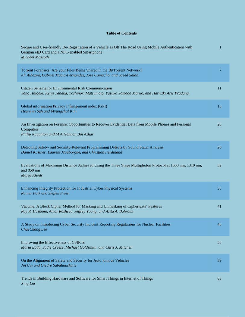
Table of Contents
Secure and User-friendly De-Registration of a Vehicle as Off The Road Using Mobile Authentication withGerman eID Card and a NFC-enabled SmartphoneMichael Massoth
1
Torrent Forensics: Are your Files Being Shared in the BitTorrent Network?Ali Alhazmi, Gabriel Macia-Fernandez, Jose Camacho, and Saeed Salah
7
Citizen Sensing for Environmental Risk CommunicationYang Ishigaki, Kenji Tanaka, Yoshinori Matsumoto, Yasuko Yamada Maruo, and Harrizki Arie Pradana
11
Global information Privacy Infringement index (GPI)Hyunmin Suh and Myungchul Kim
13
An Investigation on Forensic Opportunities to Recover Evidential Data from Mobile Phones and PersonalComputersPhilip Naughton and M A Hannan Bin Azhar
20
Detecting Safety- and Security-Relevant Programming Defects by Sound Static AnalysisDaniel Kastner, Laurent Mauborgne, and Christian Ferdinand
26
Evaluations of Maximum Distance Achieved Using the Three Stage Multiphoton Protocol at 1550 nm, 1310 nm,and 850 nmMajed Khodr
32
Enhancing Integrity Protection for Industrial Cyber Physical SystemsRainer Falk and Steffen Fries
35
Vaccine: A Block Cipher Method for Masking and Unmasking of Ciphertexts’ FeaturesRay R. Hashemi, Amar Rasheed, Jeffrey Young, and Azita A. Bahrami
41
A Study on Introducing Cyber Security Incident Reporting Regulations for Nuclear FacilitiesChaeChang Lee
48
Improving the Effectiveness of CSIRTsMaria Bada, Sadie Creese, Michael Goldsmith, and Chris J. Mitchell
53
On the Alignment of Safety and Security for Autonomous VehiclesJin Cui and Giedre Sabaliauskaite
59
Trends in Building Hardware and Software for Smart Things in Internet of ThingsXing Liu
65
1 / 2 8 / 90

RF Fingerprinting for 802.15.4 Devices: Combining Convolutional Neural Networks and RF-DNABernard Lebel, Louis N. Belanger, Mohammad Amin Haji Bagheri Fard, and Jean-Yves Chouinard
70
Integrating Autonomous Vehicle Safety and SecurityGiedre Sabaliauskaite and Jin Cui
75
Powered by TCPDF (www.tcpdf.org)
2 / 2 9 / 90
Secure and User-friendly De-Registration of a Vehicle as Off The Road UsingMobile Authentication with German eID Card and a NFC-enabled Smartphone
Michael MassothDepartment of Computer Science
Hochschule Darmstadt – University of Applied SciencesDarmstadt, Germany
E-mail: [email protected]
Abstract— Digitization is as important to public administrationas it is to the economy. Therefore, the German authoritiescurrently see an enormous need for action for digitization andcybersecurity. Provided by the German electronic identity(eID) solution, every German citizen has the ability to identifyhimself against various electronic and mobile governmentservices. In this paper, we will present a new approach for amobile de-registration of a vehicle as off the road. The newmobile de-registration service of a vehicle as off the road issecure and user-friendly. The new approach implements astrong two-factor authentication with German eID card andthe corresponding 6-digits personal identification number(PIN), whereby a Near Field Communication (NFC) enabledAndroid smartphone will be used as ubiquitous NFC cardreader.
Keywords-mobile authentication; identity management; strongtwo-factor authentication; high trust level.
I. INTRODUCTION AND MOTIVATION
Digital identities have gained more and more importancedue to the rapid increase of digitalization within ouradministration, business, industry, and information society.In this paper, we present a new mobile e-governmentapplication using the new German National Identity Cardwith the electronic identity (eID) function for Internet use.In cooperation with the Hessian Ministry of the Interior(Government of the Federal State of Hessen) [10], as well asAUTHADA GmbH [11] and the ekom21 KGRZ Hessen[12], a secure and user-friendly de-registration of a car asoff the road mobile e-government service will be presented.
The consumer research company GfK [13] determinedin May 2015 that only 5% of all Germans used their eIDfunction of the National Identity Card for onlineauthentication services within the past 12 months [6]. Mostprobably, there are two main reasons for that disappointingresult: First, there are only few services (164 in total, 2015-05) with eID support available on the market. Thus, theGerman citizen may not see a significant benefit in usingeID. Second, for the online authentication, there is a specialeID card reader needed, which costs between 30 and 160Euros. For eID card holders, the need of an expensive cardreader may be the biggest barrier. We will overcome thisbarrier and present a new approach where an NFC-enabledAndroid smartphone is used as ubiquitous eID card reader.
In order to demonstrate a significant benefit for the
citizens and users, we implemented the new approach for avery popular and useful online service, namely, the de-registration of a vehicle as off the road. Therefore, anAndroid app and a Website were implemented in order to beable to carry out the complete process of the vehicle de-registration in a mobile and user-friendly way in order toprovide the Hessian citizens the possibility to avoid theannoying paperwork and the long waiting time. The de-registration of a vehicle as off the road is also a good best-practice example of an electronic government service withrequired trust level “high”. The paper is structured asfollows. In Section II, some definitions of terms are given.Section III shows the stationary Internet-based de-registration of a vehicle as off the road. Following this,Section IV introduces the new German National IdentityCard with eID function for Internet use. The stationaryonline authentication process is shown in Section V. InSection VI, the new mobile authentication process ispresented in detail. Section VII ends this paper with aconclusion and outlook on future work.
II. DEFINITIONS AND FUNDAMENTALS
Electronic government (e-government) [1] is the use ofelectronic communications devices, computers and theInternet to provide public services to citizens and otherpersons in a country or region. Electronic authentication [2]is the process of establishing confidence in user identities,electronically presented to an information system. Digitalauthentication or e-authentication may be usedsynonymously when referring to the authentication processthat confirms or certifies a person's identity and works.
AUTHADA ID Service [5] is a server operated by thecompany AUTHADA GmbH. This provides theauthentication process via an API, or a softwaredevelopment kit (SDK). The AUTHADA ID service servesas an interface to a certified e-ID server, which is authorizedto read the data from the personal ID card. Within theimplemented representational state transfer (REST) server[5], a Java library was included, which contains the calls tothe AUTHADA service. Near field communication (NFC)[3] is a set of communication protocols which allow thecommunication between two devices by bringing themwithin 4 cm of each other. Quick Response Code (QR code)[4] is a machine-readable optical label that containsinformation about the item to which it is attached. A QRcode uses four standardized encoding modes (numeric,
1Copyright (c) IARIA, 2017. ISBN: 978-1-61208-605-7
CYBER 2017 : The Second International Conference on Cyber-Technologies and Cyber-Systems
10 / 90
alphanumeric, byte/binary, and kanji) to efficiently storedata. Representational state transfer (REST) [5] relies on astateless, client-server, cacheable communications protocol -- and in virtually all cases, the Hypertext Transfer Protocol(HTTP) over Transport Layer Security (TLS) 1.2 is used,also known as HTTP Secure (HTTPS). REST is often usedin mobile applications, social networking Web sites,mashup tools and automated business processes. The RESTstyle emphasizes that interactions between clients andservices is enhanced by having a limited number ofoperations (verbs). Flexibility is provided by assigningresources (nouns) their own unique universal resourceindicators (URIs).
III. INTERNET-BASED DE-REGISTRATION OF AVEHICLE AS OF THE ROAD
Since January 1st 2015, it is possible to request the de-registration of a motor vehicle (car) as off the road online.
The following prerequisites are hereby necessary:
New German National Identity card (Figure 5) withactivated online eID function for Internet use and acorrespondent card reader.
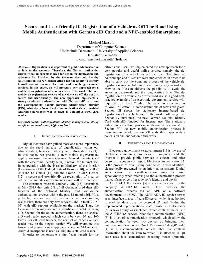
Certificate of approval Part I ("vehicle registration", inGerman “Fahrzeugschein”) with concealed securitycode, see Figure 1.
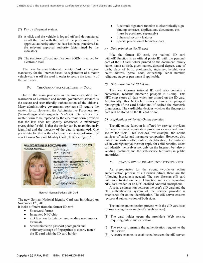
License plates (front and back) with new stamped chainwith concealed security code (vehicles which have beenregistered or re-registered since January 1st, 2015), seeFigure 3.
Figure 1. Certificate of Approval Part I ("vehicle registration") withconcealed (left) and uncovered (right) security code.
The application is as follows:
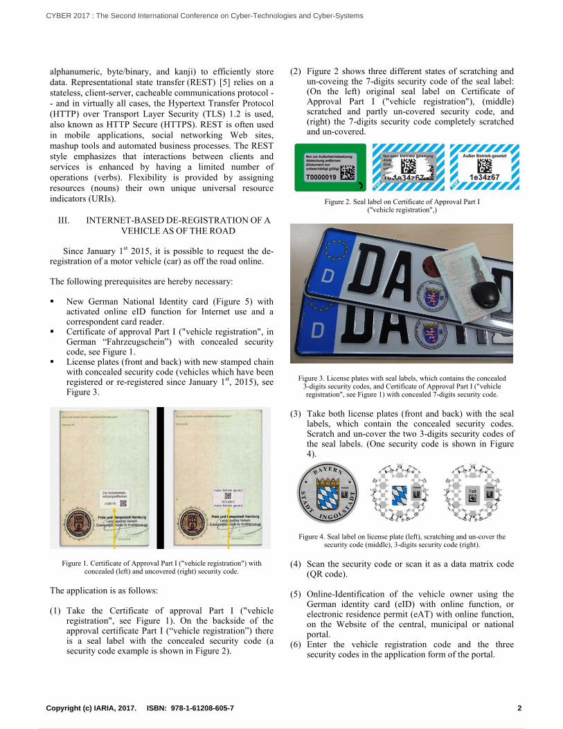
(1) Take the Certificate of approval Part I ("vehicleregistration", see Figure 1). On the backside of theapproval certificate Part I (“vehicle registration”) thereis a seal label with the concealed security code (asecurity code example is shown in Figure 2).
(2) Figure 2 shows three different states of scratching andun-coveing the 7-digits security code of the seal label:(On the left) original seal label on Certificate ofApproval Part I ("vehicle registration"), (middle)scratched and partly un-covered security code, and(right) the 7-digits security code completely scratchedand un-covered.
Figure 2. Seal label on Certificate of Approval Part I("vehicle registration",)
Figure 3. License plates with seal labels, which contains the concealed3-digits security codes, and Certificate of Approval Part I ("vehicleregistration", see Figure 1) with concealed 7-digits security code.
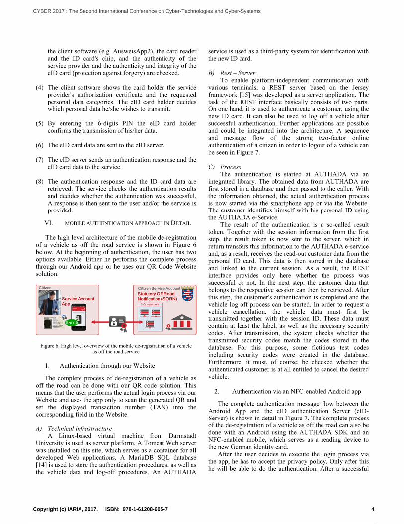
(3) Take both license plates (front and back) with the seallabels, which contain the concealed security codes.Scratch and un-cover the two 3-digits security codes ofthe seal labels. (One security code is shown in Figure4).
Figure 4. Seal label on license plate (left), scratching and un-cover thesecurity code (middle), 3-digits security code (right).
(4) Scan the security code or scan it as a data matrix code(QR code).
(5) Online-Identification of the vehicle owner using theGerman identity card (eID) with online function, orelectronic residence permit (eAT) with online function,on the Website of the central, municipal or nationalportal.
(6) Enter the vehicle registration code and the threesecurity codes in the application form of the portal.
2Copyright (c) IARIA, 2017. ISBN: 978-1-61208-605-7
CYBER 2017 : The Second International Conference on Cyber-Technologies and Cyber-Systems
11 / 90
(7) Pay by ePayment system.
(8) A click and the vehicle is logged off and de-registeredas off the road with the date of the processing in theapproval authority after the data has been transferred tothe relevant approval authority (determined by theindicator).
(9) The statutory off road notification (SORN) is served byelectronic mail.
The new German National Identity Card is thereforemandatory for the Internet-based de-registration of a motorvehicle (car) as off the road in order to secure the identity ofthe car owner.
IV. THE GERMAN NATIONAL IDENTITY CARD
One of the main problems in the implementation andrealization of electronic and mobile government services isthe secure and user-friendly authentication of the citizens.Many administrative government services still require thewritten form. However, the Administrative Procedure Act(Verwaltungsverfahrensgesetz VwVfG) §3a allows thewritten form to be replaced by the electronic form providedthat the law does not specify otherwise. A mandatoryprerequisite for this is that the sender can be unambiguouslyidentified and the integrity of the data is guaranteed. Onepossibility for this is the electronic identity-proof using thenew German National Identity Card (eID), see Figure 5.
Figure 5. German National eID Card
The new German National Identity Card was introduced onNovember 1st, , 2010.It looks different from the former ID card
● Smartcard format● Integrated NFC-chip● eID function for Internet use, vending machines or
terminals● Stored biometric passport photograph and
voluntary storage of fingerprints to clearly matchthe ID card with the ID card holder
● Electronic signature function to electronically signbinding contracts, applications, documents, etc.(must be purchased separately)
● Enhanced security features● Special protection of biometric data
A) Data printed on the ID card
Like the former ID card, the national ID cardwith eID function is an official photo ID with the personaldata of the ID card holder printed on the document: familyname, name at birth, given names, doctoral degree, date ofbirth, place of birth, photograph, signature, height, eyescolor, address, postal code, citizenship, serial number,religious, stage or pen name if applicable.
B) Data stored in the NFC-Chip
The new German national ID card also contains acontactless, readable biometric passport NFC-chip. ThisNFC-chip stores all data which are printed on the ID card.Additionally, this NFC-chip stores a biometric passportphotograph of the card holder and, if desired the biometricfingerprints. The cardholder decides whether the fingerprintdata will be stored on the ID card or not.
C) Applications of the eID Online Function
The eID online function is offered by service providersthat wish to make registration procedures easier and moresecure for users. This includes, for example, the onlineservices of banks and insurance companies. However, alsopublic authorities offer online identification, for instancewhen you register your car or apply for child benefits. Userscan identify themselves not only on the Internet, but also atvending machines and the self-service terminals in publicauthorities.
V. STATIONARY ONLINE AUTHENTICATION PROCESS
As prerequisites for the strong two-factor onlineauthentication process of a German citizen there are thefollowing ingredients needed: The new German eID cardwith an activated online eID function and a correspondingNFC card reader, or an NFC-enabled Android-smartphone.
A secure connection between the user's eID card and theeID authentication system of the service provider isestablished for online identification. The eID server ensuresreciprocal authentication of both sides.
The online authentication process with the eID card is asfollows (using the example of a Web service):
(1) The card holder opens the provider's Web servicerequiring online authentication.
(2) The service transmits the authentication request to theeID server.
(3) A secure channel is established between the eID server,
3Copyright (c) IARIA, 2017. ISBN: 978-1-61208-605-7
CYBER 2017 : The Second International Conference on Cyber-Technologies and Cyber-Systems
12 / 90
the client software (e.g. AusweisApp2), the card readerand the ID card's chip, and the authenticity of theservice provider and the authenticity and integrity of theeID card (protection against forgery) are checked.
(4) The client software shows the card holder the serviceprovider's authorization certificate and the requestedpersonal data categories. The eID card holder decideswhich personal data he/she wishes to transmit.
(5) By entering the 6-digits PIN the eID card holderconfirms the transmission of his/her data.
(6) The eID card data are sent to the eID server.
(7) The eID server sends an authentication response and theeID card data to the service.
(8) The authentication response and the ID card data areretrieved. The service checks the authentication resultsand decides whether the authentication was successful.A response is then sent to the user and/or the service isprovided.
VI. MOBILE AUTHENTICATION APPROACH IN DETAIL
The high level architecture of the mobile de-registrationof a vehicle as off the road service is shown in Figure 6below. At the beginning of authentication, the user has twooptions available. Either he performs the complete processthrough our Android app or he uses our QR Code Websitesolution.
Figure 6. High level overview of the mobile de-registration of a vehicleas off the road service
1. Authentication through our Website
The complete process of de-registration of a vehicle asoff the road can be done with our QR code solution. Thismeans that the user performs the actual login process via ourWebsite and uses the app only to scan the generated QR andset the displayed transaction number (TAN) into thecorresponding field in the Website.
A) Technical infrastructureA Linux-based virtual machine from Darmstadt
University is used as server platform. A Tomcat Web serverwas installed on this site, which serves as a container for alldeveloped Web applications. A MariaDB SQL database[14] is used to store the authentication procedures, as well asthe vehicle data and log-off procedures. An AUTHADA
service is used as a third-party system for identification withthe new ID card.
B) Rest – ServerTo enable platform-independent communication with
various terminals, a REST server based on the Jerseyframework [15] was developed as a server application. Thetask of the REST interface basically consists of two parts.On one hand, it is used to authenticate a customer, using thenew ID card. It can also be used to log off a vehicle aftersuccessful authentication. Further applications are possibleand could be integrated into the architecture. A sequenceand message flow of the strong two-factor onlineauthentication of a citizen in order to logout of a vehicle canbe seen in Figure 7.
C) ProcessThe authentication is started at AUTHADA via an
integrated library. The obtained data from AUTHADA arefirst stored in a database and then passed to the caller. Withthe information obtained, the actual authentication processis now started via the smartphone app or via the Website.The customer identifies himself with his personal ID usingthe AUTHADA e-Service.
The result of the authentication is a so-called resulttoken. Together with the session information from the firststep, the result token is now sent to the server, which inreturn transfers this information to the AUTHADA e-serviceand, as a result, receives the read-out customer data from thepersonal ID card. This data is then stored in the databaseand linked to the current session. As a result, the RESTinterface provides only here whether the process wassuccessful or not. In the next step, the customer data thatbelongs to the respective session can then be retrieved. Afterthis step, the customer's authentication is completed and thevehicle log-off process can be started. In order to request avehicle cancellation, the vehicle data must first betransmitted together with the session ID. These data mustcontain at least the label, as well as the necessary securitycodes. After transmission, the system checks whether thetransmitted security codes match the codes stored in thedatabase. For this purpose, some fictitious test codesincluding security codes were created in the database.Furthermore, it must, of course, be checked whether theauthenticated customer is at all entitled to cancel the desiredvehicle.
2. Authentication via an NFC-enabled Android app
The complete authentication message flow between theAndroid App and the eID authentication Server (eID-Server) is shown in detail in Figure 7. The complete processof the de-registration of a vehicle as off the road can also bedone with an Android using the AUTHADA SDK and anNFC-enabled mobile, which serves as a reading device tothe new German identity card.
After the user decides to execute the login process viathe app, he has to accept the privacy policy. Only after thishe will be able to do the authentication. After a successful
4Copyright (c) IARIA, 2017. ISBN: 978-1-61208-605-7
CYBER 2017 : The Second International Conference on Cyber-Technologies and Cyber-Systems
13 / 90
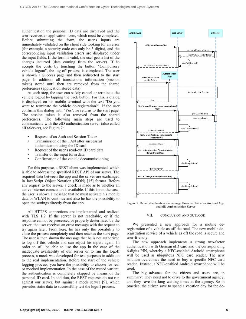
authentication the personal ID data are displayed and theuser receives an application form, which must be completed.Before submitting the form, the user's inputs areimmediately validated on the client side looking for an error(for example, a security code can only be 3 digits), and thecorresponding input validation errors are displayed underthe input fields. If the form is valid, the user gets a list of thecharges incurred (data coming from the server). If heaccepts the costs by touching the button "Compulsoryvehicle logout", the log-off process is completed. The useris shown a Success page and then redirected to the startpage. In addition, all transactions information (sessiontoken) stored until then are removed from the sharedpreferences (application stored data).
At each step, the user can safely cancel or terminate thevehicle logout by tapping the back button. For this, a dialogis displayed on his mobile terminal with the text "Do youwant to terminate the vehicle de-registration?". If the userconfirms this dialog with "Yes", he returns to the start page.The session token is also removed from the sharedpreferences. The following main steps are used tocommunicate with the eID authentication server (also calledeID-Server), see Figure 7:
• Request of an Auth and Session Token• Transmission of the TAN after successful
authentication using the ID card• Request of the user's read-out ID card data• Transfer of the input form data• Confirmation of the vehicle decommissioning
For this purpose, a REST client was implemented, whichis able to address the specified REST API of our server. Therequired data between the app and the server are exchangedin JavaScript Object Notation (JSON) [15] format. Beforeany request to the server, a check is made as to whether anactive Internet connection is available. If this is not the case,the user is shown a message that he must activate his mobiledata or WLAN to continue and also he has the possibility toopen the settings directly from the app.
All HTTPS connections are implemented and realizedwith TLS 1.2. If the server is not reachable, or if theresponse cannot be processed or properly desterilized by theserver, the user receives an error message with the request totry again later. From here, he has only the possibility toclose the process completely and then reaches the start page.The user is then shown the message that he is not authorizedto log off this vehicle and can adjust his inputs again. Inorder to still be able to use the app in the case of theinadequate availability of our server or to run the logoffprocess, a mock was developed for test purposes in additionto the real implementation. Before the start of the vehiclelogging process, you have the possibility to choose for realor mocked implementation. In the case of the muted variant,the authentication is completely skipped by means of thepersonal ID card. In addition, the REST requests do not runagainst our server, but against a mock server [9], whichprovides static data to successfully test the logoff process.
Figure 7. Detailed authentication message flowchart between Android Appand eID Authentication Server
VII. CONCLUSION AND OUTLOOK
We presented a new approach for a mobile de-registration of a vehicle as off the road. The new mobile de-registration service of a vehicle as off the road is secure anduser-friendly.
The new approach implements a strong two-factorauthentication with German eID card and the corresponding6-digits PIN, whereby a NFC-enabled Android smartphonewill be used as ubiquitous NFC card reader. The newsolution overcomes the need to buy a specific NFC cardreader. Instead, a NFC-enabled Android smartphone will beused.
The big advance for the citizen and users are, insummary: They need not to drive to the government agency,and they save the long waiting times at the agency. So inpractice, the citizen save to spend a vacation day for the de-
5Copyright (c) IARIA, 2017. ISBN: 978-1-61208-605-7
CYBER 2017 : The Second International Conference on Cyber-Technologies and Cyber-Systems
14 / 90
registration of a vehicle as off the road and the Statutory OffRoad Notification (SORN). The mobile de-registrationservice allows the citizens to register their vehicle as off theroad (SORN) easily via an Android Smartphone App. Indoing so, the electronic identity (eID) of their German eIDcard will be transmitted via NFC directly via the Androidsmartphone. Just a few clicks later, the user has registeredhis/her vehicle as off the road (SORN).
Therefore, here is what the citizen and user needs, indetail: An Android smartphone with enabled NFCfunctionality, the German eID card with activated online-function and the associated 6-digit PIN, as well as thenumber/registration plates and vehicle registration license(after 01.01.2015) with three security codes.
The user will find the three security codes on the back ofthe vehicle registration license, and under the vehicle seallabels on the license plates (front and back).
A strong two-factor authentication ensures the necessarysafety and unambiguous identification of the vehicle owner.
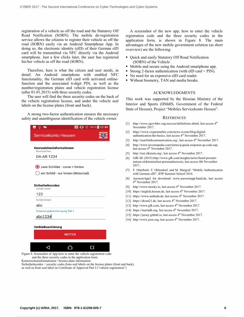
A screenshot of the new app, how to enter the vehicleregistration code and the three security codes in theapplication form, is shown in Figure 8. The mainadvantages of the new mobile government solution (as shortoverview) are the following:
Quick and easily Statutory Off Road Notification(SORN) of the Vehicle
Mobile and secure using the Android smartphone app. Strong 2-factor authentication (with eID card + PIN). No need for an expensive eID card reader. Without biometry, TAN and media breaks.
ACKNOWLEDGMENTS
This work was supported by the Hessian Ministry of the
Interior and Sports (HMdIS, Government of the Federal
State of Hessen), Project “Mobiles Servicekonto Hessen”.
REFERENCES
[1] http://www.egov4dev.org/success/definitions.shtml, last access 4th
November 2017.
[2] https://www.cryptomathic.com/news-events/blog/digital-authentication-the-basics, last access 4th November 2017.
[3] http://nearfieldcommunication.org/, last access 4th November 2017.
[4] http://www.investopedia.com/terms/q/quick-response-qr-code.asp,last access 4th November 2017.
[5] http://rest.elkstein.org/, last access 4th November 2017.
[6] GfK SE (2015) http://www.gfk.com/insights/news/fuenf-prozent-nutzen-elektronischen-personalausweis, last access 4th November2017.
[7] F. Otterbein, T. Ohlendorf, and M. Margraf: “Mobile Authenticationwith German eID”, IFIP Summer School 2016.
[8] AusweisApp2 for download: www.ausweisapp.bund.de, last access4th November 2017.
[9] http://www.mocky.io, last access 4th November 2017.
[10] https://english.hessen.de, last access 4th November 2017.
[11] https://www.authada.de, last access 4th November 2017.
[12] https://ekom21.de, last access 4th November 2017.
[13] http://www.gfk.com, last access 4th November 2017.
[14] https://mariadb.org, last access 4th November 2017.
[15] https://jersey.github.io, last access 4th November 2017.
[16] http://www.json.org, last access 4th November 2017.
Figure 8. Screenshot of App how to enter the vehicle registration codeand the three security codes in the application form.
Kennzeicheninformationen =license plate informationSicherheitscodes = security codes from seal labels on the license plates (front and back),as well as from seal label on Certificate of Approval Part I (“vehicle registration”)
6Copyright (c) IARIA, 2017. ISBN: 978-1-61208-605-7
CYBER 2017 : The Second International Conference on Cyber-Technologies and Cyber-Systems
15 / 90
Torrent Forensics: Are your Files Being Shared in theBitTorrent Network?
Ali Alhazmi
Department of Information SystemsJazan University
Jazan, Saudi Arabia 45142Email: [email protected]
Jose Camacho
Network Engineering and Security Group, CITIC-UGRUniversity of GranadaGranada, Spain 18071
Email: [email protected]
Gabriel Macia-Fernandez
Network Engineering and Security Group, CITIC-UGRUniversity of GranadaGranada, Spain 18071Email: [email protected]
Saeed Salah
Department of Computer ScienceAl-Quds University
Abu Dees, Palestine 20002Email: [email protected]
Abstract—BitTorrent is the most common protocol forfile sharing nowadays. Due to its distributed nature,monitoring BitTorrent is a difficult task. Under thisperception of anonymity, BitTorrent has motivated therise of criminal activities such as copyright infringementor the sharing of stolen secret documents. This work-in-progress paper focuses on identifying whether a givenresource has been shared in the BitTorrent network.We have termed this problem torrent forensics. Wepropose a methodology to solve this problem as wellas the design of an operational system to implementthe solution. The system is run in two different phases.First, we monitor the network and collect .torrent filesthat describe the resources being shared. Second, adetection module analyzes a given resource and decidesif it was observed in the network. We carry out prelim-inary experiments to support the hypotheses for thedesign of the system.
Keywords–BitTorrent; P2P; Torrent Forensics.
I. IntroductionRecently, Recently, peer-to-peer (P2P) has become
popular for sharing-files around the world. P2P networksare often used to share diverse digital contents such asmovies, music, books, and software. According to Cisco’sestimation in 2015, P2P file-sharing users consumed 5,965petabytes of traffic per month, which was about 15% ofall the Internet traffic [1]. BitTorrent is the most commonP2P file sharing nowadays. It is estimated to be responsiblefor more than 50% of file-sharing bandwidth and 3.35%of all total bandwidth [2]. There are millions of userssharing a huge amount of resources everyday. According to[3], BitTorrent had 15-27 million concurrent users at anytime in 2013. In addition, BitTorrent Inc. claims that morethan 170 million people use BitTorrent products everymonth [4].
The widespread popularity of BitTorrent has attractedthe attention of many researchers, with the aim of studying
the nature of shared resources and developing monitoringmethodologies to understand the traffic evolution [5]–[8]. Bauer et al. [9] proposed active methods to monitorextremely large BitTorrent swarms using trackers. Theydeveloped an active probing framework called BitStalkerthat identifies active peers and collects concrete forensicevidences showing that they were involved in the sharingof a particular resource. Additionally, there exist someworks focused on crawling torrent-discovery sites [7]. In theprevious reference work, five of the most popular torrent-discovery sites were crawled over a nine-month period,identifying 4.6M of torrents and 38,996 trackers. They alsoobtained peer lists from the Vuze and Mainline DistributedHash Tables (DHTs) in order to investigate the nature ofthe exchanged contents. Authors of [10] worked on large-scale monitoring of BitTorrent, crawling resources fromtwo torrent-discovery sites: Pirate Bay and Mininova. Theycollected 148M of IP addresses and 2M resources over 103days in order to identify content providers and highly-active users. Other works focus on the crawling of MainlineDHT [5] [11]. Authors in [11] collected 10M magnet linksand received over 264M get peers messages from morethan 57M unique peers over 10 days in order to providestatistical information. In their resultsthey found that, forexample, Russian and China were playing dominant rolesin Mainline DHT, contributing 35% of peers, and that 5%Internet users using Mainline came from Europe.
The major contribution of this work-in-progress paperis different from those in the mentioned works. It focuseson the specific problem of identifying whether a givenresource has been shared in the BitTorrent network. Wehave termed this problem torrent forensics, due to itsforensic nature. To our knowledge, there is no previouspublished research on this topic. From a cyber securityperspective, many participants can take advantage of asolution to this problem. The most widespread interestcomes from end users, who may be interested in identifying
7Copyright (c) IARIA, 2017. ISBN: 978-1-61208-605-7
CYBER 2017 : The Second International Conference on Cyber-Technologies and Cyber-Systems
16 / 90
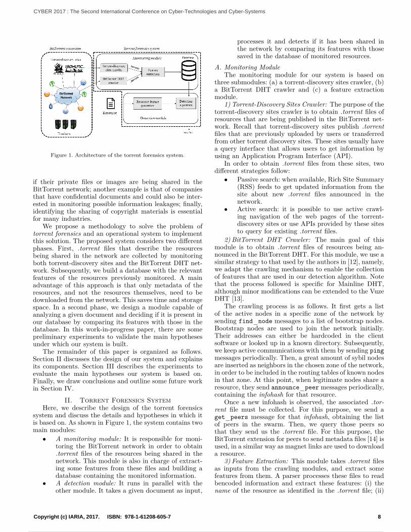
Figure 1. Architecture of the torrent forensics system.
if their private files or images are being shared in theBitTorrent network; another example is that of companiesthat have confidential documents and could also be inter-ested in monitoring possible information leakages; finally,identifying the sharing of copyright materials is essentialfor many industries.
We propose a methodology to solve the problem oftorrent forensics and an operational system to implementthis solution. The proposed system considers two differentphases. First, .torrent files that describe the resourcesbeing shared in the network are collected by monitoringboth torrent-discovery sites and the BitTorrent DHT net-work. Subsequently, we build a database with the relevantfeatures of the resources previously monitored. A mainadvantage of this approach is that only metadata of theresources, and not the resources themselves, need to bedownloaded from the network. This saves time and storagespace. In a second phase, we design a module capable ofanalyzing a given document and deciding if it is present inour database by comparing its features with those in thedatabase. In this work-in-progress paper, there are somepreliminary experiments to validate the main hypothesesunder which our system is built.
The remainder of this paper is organized as follows.Section II discusses the design of our system and explainsits components. Section III describes the experiments toevaluate the main hypotheses our system is based on.Finally, we draw conclusions and outline some future workin Section IV.
II. Torrent Forensics SystemHere, we describe the design of the torrent forensics
system and discuss the details and hypotheses in which itis based on. As shown in Figure 1, the system contains twomain modules:• A monitoring module: It is responsible for moni-
toring the BitTorrent network in order to obtain.torrent files of the resources being shared in thenetwork. This module is also in charge of extract-ing some features from these files and building adatabase containing the monitored information.
• A detection module: It runs in parallel with theother module. It takes a given document as input,
processes it and detects if it has been shared inthe network by comparing its features with thosesaved in the database of monitored resources.
A. Monitoring ModuleThe monitoring module for our system is based on
three submodules: (a) a torrent-discovery sites crawler, (b)a BitTorrent DHT crawler and (c) a feature extractionmodule.
1) Torrent-Discovery Sites Crawler: The purpose of thetorrent-discovery sites crawler is to obtain .torrent files ofresources that are being published in the BitTorrent net-work. Recall that torrent-discovery sites publish .torrentfiles that are previously uploaded by users or transferredfrom other torrent discovery sites. These sites usually havea query interface that allows users to get information byusing an Application Program Interface (API).
In order to obtain .torrent files from these sites, twodifferent strategies follow:• Passive search: when available, Rich Site Summary
(RSS) feeds to get updated information from thesite about new .torrent files announced in thenetwork.
• Active search: it is possible to use active crawl-ing navigation of the web pages of the torrent-discovery sites or use APIs provided by these sitesto query for existing .torrent files.
2) BitTorrent DHT Crawler: The main goal of thismodule is to obtain .torrent files of resources being an-nounced in the BitTorrent DHT. For this module, we use asimilar strategy to that used by the authors in [12], namely,we adapt the crawling mechanism to enable the collectionof features that are used in our detection algorithm. Notethat the process followed is specific for Mainline DHT,although minor modifications can be extended to the VuzeDHT [13].
The crawling process is as follows. It first gets a listof the active nodes in a specific zone of the network bysending find node messages to a list of bootstrap nodes.Bootstrap nodes are used to join the network initially.Their addresses can either be hardcoded in the clientsoftware or looked up in a known directory. Subsequently,we keep active communications with them by sending pingmessages periodically. Then, a great amount of sybil nodesare inserted as neighbors in the chosen zone of the network,in order to be included in the routing tables of known nodesin that zone. At this point, when legitimate nodes share aresource, they send announce peer messages periodically,containing the infohash for that resource.
Once a new infohash is observed, the associated .tor-rent file must be collected. For this purpose, we send aget peers message for that infohash, obtaining the listof peers in the swarm. Then, we query those peers sothat they send us the .torrent file. For this purpose, theBitTorrent extension for peers to send metadata files [14] isused, in a similar way as magnet links are used to downloada resource.
3) Feature Extraction: This module takes .torrent filesas inputs from the crawling modules, and extract somefeatures from them. A parser processes these files to readbencoded information and extract these features: (i) thename of the resource as identified in the .torrent file; (ii)
8Copyright (c) IARIA, 2017. ISBN: 978-1-61208-605-7
CYBER 2017 : The Second International Conference on Cyber-Technologies and Cyber-Systems
17 / 90
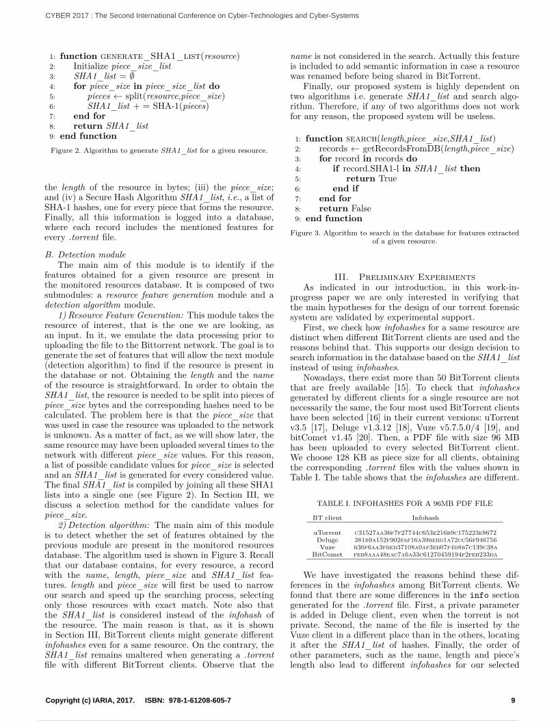
1: function generate SHA1 list(resource)2: Initialize piece size list3: SHA1 list = ∅4: for piece size in piece size list do5: pieces ← split(resource,piece size)6: SHA1 list + = SHA-1(pieces)7: end for8: return SHA1 list9: end functionFigure 2. Algorithm to generate SHA1 list for a given resource.
the length of the resource in bytes; (iii) the piece size;and (iv) a Secure Hash Algorithm SHA1 list, i.e., a list ofSHA-1 hashes, one for every piece that forms the resource.Finally, all this information is logged into a database,where each record includes the mentioned features forevery .torrent file.
B. Detection moduleThe main aim of this module is to identify if the
features obtained for a given resource are present inthe monitored resources database. It is composed of twosubmodules: a resource feature generation module and adetection algorithm module.
1) Resource Feature Generation: This module takes theresource of interest, that is the one we are looking, asan input. In it, we emulate the data processing prior touploading the file to the Bittorrent network. The goal is togenerate the set of features that will allow the next module(detection algorithm) to find if the resource is present inthe database or not. Obtaining the length and the nameof the resource is straightforward. In order to obtain theSHA1 list, the resource is needed to be split into pieces ofpiece size bytes and the corresponding hashes need to becalculated. The problem here is that the piece size thatwas used in case the resource was uploaded to the networkis unknown. As a matter of fact, as we will show later, thesame resource may have been uploaded several times to thenetwork with different piece size values. For this reason,a list of possible candidate values for piece size is selectedand an SHA1 list is generated for every considered value.The final SHA1 list is compiled by joining all these SHA1lists into a single one (see Figure 2). In Section III, wediscuss a selection method for the candidate values forpiece size.
2) Detection algorithm: The main aim of this moduleis to detect whether the set of features obtained by theprevious module are present in the monitored resourcesdatabase. The algorithm used is shown in Figure 3. Recallthat our database contains, for every resource, a recordwith the name, length, piece size and SHA1 list fea-tures. length and piece size will first be used to narrowour search and speed up the searching process, selectingonly those resources with exact match. Note also thatthe SHA1 list is considered instead of the infohash ofthe resource. The main reason is that, as it is shownin Section III, BitTorrent clients might generate differentinfohashes even for a same resource. On the contrary, theSHA1 list remains unaltered when generating a .torrentfile with different BitTorrent clients. Observe that the
name is not considered in the search. Actually this featureis included to add semantic information in case a resourcewas renamed before being shared in BitTorrent.
Finally, our proposed system is highly dependent ontwo algorithms i.e. generate SHA1 list and search algo-rithm. Therefore, if any of two algorithms does not workfor any reason, the proposed system will be useless.
1: function search(length,piece size,SHA1 list)2: records ← getRecordsFromDB(length,piece size)3: for record in records do4: if record.SHA1-l in SHA1 list then5: return True6: end if7: end for8: return False9: end function
Figure 3. Algorithm to search in the database for features extractedof a given resource.
III. Preliminary ExperimentsAs indicated in our introduction, in this work-in-
progress paper we are only interested in verifying thatthe main hypotheses for the design of our torrent forensicsystem are validated by experimental support.
First, we check how infohashes for a same resource aredistinct when different BitTorrent clients are used and thereasons behind that. This supports our design decision tosearch information in the database based on the SHA1 listinstead of using infohashes.
Nowadays, there exist more than 50 BitTorrent clientsthat are freely available [15]. To check that infohashesgenerated by different clients for a single resource are notnecessarily the same, the four most used BitTorrent clientshave been selected [16] in their current versions: uTorrentv3.5 [17], Deluge v1.3.12 [18], Vuze v5.7.5.0/4 [19], andbitComet v1.45 [20]. Then, a PDF file with size 96 MBhas been uploaded to every selected BitTorrent client.We choose 128 KB as piece size for all clients, obtainingthe corresponding .torrent files with the values shown inTable I. The table shows that the infohashes are different.
TABLE I. INFOHASHES FOR A 96MB PDF FILE
BT client Infohash
uTorrent c31527aa36f7f27744c653e216b9c175223e8672Deluge 381b9a152f902faf16a39bebd1a72cc56f946756Vuze b36f6aa3fbed37108a0af3eb07f4d8b7c139c38a
BitComet feb8aaa48eac7a6a33c61270459194f2feb233da
We have investigated the reasons behind these dif-ferences in the infohashes among BitTorrent clients. Wefound that there are some differences in the info sectiongenerated for the .torrent file. First, a private parameteris added in Deluge client, even when the torrent is notprivate. Second, the name of the file is inserted by theVuze client in a different place than in the others, locatingit after the SHA1 list of hashes. Finally, the order ofother parameters, such as the name, length and piece’slength also lead to different infohashes for our selected
9Copyright (c) IARIA, 2017. ISBN: 978-1-61208-605-7
CYBER 2017 : The Second International Conference on Cyber-Technologies and Cyber-Systems
18 / 90
BitTorrent clients. In conclusion, these minor differencesin the info section lead to different infohashes. Yet, inall our experiments, we have checked that the SHA1 listfor all the pieces remains the same with all the clients.Therefore, infohashes cannot be used for torrent forensics,while the SHA1 list can.
The second hypothesis that this paper is interested tovalidate is with regard to the need of generating differentSHA1 lists for every piece size in the ‘document featuregeneration’ module. The selection of a value for the piecesize is a matter of optimizing the transfer speed for thedownload of the resource. According to the recommen-dation in [21], a torrent should have 1000-1500 pieces inorder to get reasonably small torrent file pieces and anefficient download. In many clients, there is an auto-sizeoption that generates .torrent files choosing the piece sizeparameter automatically. In our experiment, we check ifall the BitTorrent clients implement the auto-size optionin a similar way or they differ. We upload a file of size 175MB to the same selected BitTorrent clients except Delugebecause it does not have the auto-size option. The resultsfrom this experiment show that Vuze splits our file by128 KB while uTorrent and BitComet choose to split it by256KB even though the size of the file is the same. Thus, weconfirm the need to generate different SHA1 lists for everypossible piece size in the ‘document feature generation’module.
Finally, regarding the initialization of the piece sizecandidate list parameter in Figure 2, we consider
that a good set of values are those offered to the usersby these set of BitTorrent clients, i.e., the set givenby j · 16KB, j ∈ [1, 11] (most common clients) andj · 48 KB, j ∈ [1, 7] (only Vuze client).
IV. Conclusions and Future WorkIn this paper, we have suggested a methodology and
designed a system to identify whether a given resourcehas been shared in the BitTorrent network. The systemis based on two main modules:(i) a monitoring module tocrawl the network and obtain .torrent files of shared re-sources, extracting features and saving them in a database;and (ii) a detection module, that finds if a given resourcehas been observed during the monitoring of the network.
Our system is currently a prototype that shows thefeasibility of a partial solution for the Torrent Forensicsproblem. Some scale experiments should be done to com-plete the conclusions obtained in this paper. In addition,as future work, we plan to deal with the problem when theresources are modified before being shared in the network.
AcknowledgmentThis work is supported by Jazan University through
the Saudi Arabian Cultural Mission in Spain, the SpanishMinistry of Economy, and FEDER funds through projectTIN2014-60346-R.
References[1] “White paper: Cisco vni forecast and methodology
2015-2020,” http://www.cisco.com/c/en/us/solutions/collateral/service-provider/visual-networking-index-vni/complete-white-paper-c11-481360.html, [retrieved: September,2017].
[2] M. Scanlon and H. Shen, “An analysis of bittorrent cross-swarm peer participation and geolocational distribution,” inComputer Communication and Networks (ICCCN), 2014 23rdInternational Conference on. IEEE, 2014, pp. 1–6.
[3] L. Wang and J. Kangasharju, “Measuring large-scale dis-tributed systems: case of bittorrent mainline dht,” in Peer-to-Peer Computing (P2P), 2013 IEEE Thirteenth InternationalConference on. IEEE, 2013, pp. 1–10.
[4] “Bittorrent.” [Online]. Available: http://www.bittorrent.com/company/about [retrieved: September, 2017].
[5] R. A. Rodrıguez-Gomez, G. Macia-Fernandez, L. Sanchez-Casado, and P. Garcıa-Teodoro, “Analysis and modelling ofresources shared in the bittorrent network,” Transactions onEmerging Telecommunications Technologies, vol. 26, no. 10,2015, pp. 1189–1200.
[6] N. Andrade, E. Santos-Neto, F. Brasileiro, and M. Ripeanu,“Resource demand and supply in bittorrent content-sharingcommunities,” Computer Networks, vol. 53, no. 4, 2009, pp.515–527.
[7] C. Zhang, P. Dhungel, D. Wu, and K. W. Ross, “Unravelingthe bittorrent ecosystem,” IEEE Transactions on Parallel andDistributed Systems, vol. 22, no. 7, 2011, pp. 1164–1177.
[8] P. K. Hoong, I. K. Tan, and C. Y. Keong, “Bittorrent networktraffic forecasting with arma,” arXiv preprint arXiv:1208.1896,2012.
[9] K. Bauer, D. McCoy, D. Grunwald, and D. Sicker, “Bitstalker:Accurately and efficiently monitoring bittorrent traffic,” inInformation Forensics and Security, 2009. WIFS 2009. FirstIEEE International Workshop on. IEEE, 2009, pp. 181–185.
[10] S. L. Blond, A. Legout, F. L. Fessant, W. Dabbous, and M. A.Kaafar, “Spying the world from your laptop–identifying andprofiling content providers and big downloaders in bittorrent,”arXiv preprint arXiv:1004.0930, 2010.
[11] Z. Xinxing, T. Zhihong, and Z. Luchen, “A measurementstudy on mainline dht and magnet link,” in Data Science inCyberspace DSC, IEEE International Conference on. IEEE,2016, pp. 11–19.
[12] R. A. Rodrıguez-Gomez, G. Macia-Fernandez, P. Garcıa-Teodoro, M. Steiner, and D. Balzarotti, “Resource monitoringfor the detection of parasite p2p botnets,” Computer Networks,vol. 70, 2014, pp. 302–311.
[13] S. Wolchok and J. a. Halderman, “Crawling bittorrent dhtsfor fun and profit,” Proc 4th USENIX Workshop on OffensiveTechnologies, 2010, pp. 1–8.
[14] G. Hazel and A. Norberg, “Bittorrent specification. extensionfor peers to send metadata files,” 2017. [Online]. Available: http://bittorrent.org/beps/bep 0009.html [retrieved: September,2017].
[15] “Bittorrent clients.” [Online]. Available: http://en.wikipedia.org/wiki/BitTorrent client [retrieved: September, 2017].
[16] W. Mazurczyk and P. Kopiczko, “Understanding bittorrentthrough real measurements,” China Communications, vol. 10,no. 11, 2013, pp. 107–118.
[17] “utorrent.” [Online]. Available: http://www.utorrent.com/[retrieved: September, 2017].
[18] “Deluge.” [Online]. Available: http://deluge-torrent.org/[retrieved: September, 2017].
[19] “Vuze.” [Online]. Available: http://www.vuze.com/ [retrieved:September, 2017].
[20] “Bitcomet.” [Online]. Available: https://www.bitcomet.com/en/downloads [retrieved: September, 2017].
[21] “Torrent piece size.” [Online]. Available: http://wiki.vuze.com/w/Torrent Piece Size [retrieved: September, 2017].
10Copyright (c) IARIA, 2017. ISBN: 978-1-61208-605-7
CYBER 2017 : The Second International Conference on Cyber-Technologies and Cyber-Systems
19 / 90
Citizen Sensing for Environmental Risk Communication Action Research on PM2.5 Air Quality Monitoring in East Asia
Yang Ishigaki and Kenji Tanaka Graduate School of Informatics and Engineering
University of Electro-Communications Tokyo, Japan
Email: [email protected]
Harrizki Arie Pradana STMIK Atma Luhur Pangkalpinang
Bangka Island, Indonesia Email: [email protected]
Yoshinori Matsumoto Faculty of Science and Technology
Keio University Kanagawa, Japan
Email: [email protected]
Yasuko Yamada Maruo Department of Environment and Energy
Tohoku Institute of Technology Miyagi, Japan
Email: [email protected]
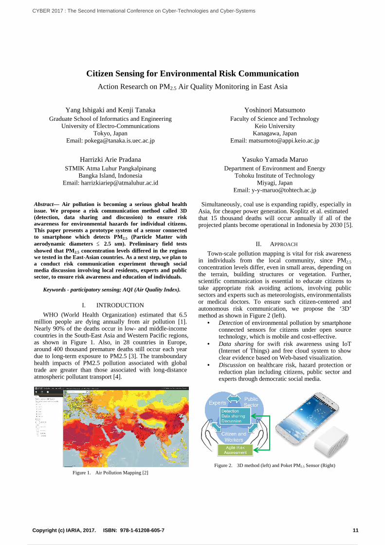
Abstract— Air pollution is becoming a serious global health issue. We propose a risk communication method called 3D (detection, data sharing and discussion) to ensure risk awareness for environmental hazards for individual citizens. This paper presents a prototype system of a sensor connected to smartphone which detects PM2.5 (Particle Matter with aerodynamic diameters ≤ 2.5 um). Preliminary field tests showed that PM2.5 concentration levels differed in the regions we tested in the East-Asian countries. As a next step, we plan to a conduct risk communication experiment through social media discussion involving local residents, experts and public sector, to ensure risk awareness and education of individuals.
Keywords - participatory sensing; AQI (Air Quality Index).
I. INTRODUCTION
WHO (World Health Organization) estimated that 6.5 million people are dying annually from air pollution [1]. Nearly 90% of the deaths occur in low- and middle-income countries in the South-East Asia and Western Pacific regions, as shown in Figure 1. Also, in 28 countries in Europe, around 400 thousand premature deaths still occur each year due to long-term exposure to PM2.5 [3]. The transboundary health impacts of PM2.5 pollution associated with global trade are greater than those associated with long-distance atmospheric pollutant transport [4].
Figure 1. Air Pollution Mapping [2]
Simultaneously, coal use is expanding rapidly, especially in Asia, for cheaper power generation. Koplitz et al. estimated that 15 thousand deaths will occur annually if all of the projected plants become operational in Indonesia by 2030 [5].
II. APPROACH
Town-scale pollution mapping is vital for risk awareness in individuals from the local community, since PM2.5 concentration levels differ, even in small areas, depending on the terrain, building structures or vegetation. Further, scientific communication is essential to educate citizens to take appropriate risk avoiding actions, involving public sectors and experts such as meteorologists, environmentalists or medical doctors. To ensure such citizen-centered and autonomous risk communication, we propose the ‘3D’ method as shown in Figure 2 (left).
• Detection of environmental pollution by smartphone connected sensors for citizens under open source technology, which is mobile and cost-effective.
• Data sharing for swift risk awareness using IoT (Internet of Things) and free cloud system to show clear evidence based on Web-based visualization.
• Discussion on healthcare risk, hazard protection or reduction plan including citizens, public sector and experts through democratic social media.
Figure 2. 3D method (left) and Poket PM2.5 Sensor (Right)
11Copyright (c) IARIA, 2017. ISBN: 978-1-61208-605-7
CYBER 2017 : The Second International Conference on Cyber-Technologies and Cyber-Systems
20 / 90
FANLED
PD
PM2.5
Amplifier
USB Encoder
Figure 3. Principle of Pocket PM2.5 Sensor Module
We developed ‘Pocket PM2.5 Sensor’ as shown in Figure 2 (right) to demonstrate the 3D in real situation. A free App is capable to generate log data in CSV (Comma-Separated Values) or Google KML (Keyhole Markup Language) format, including GPS (Global Positioning System) information. The sensor has a laser LED (Light Emitting Diode), a PD (photodiode) sensor, a fan, amplifier and USB (Universal Serial Bus) encoder, as shown in Figure 3.
III. PRELIMINARY RESULTS FROM FIELD EXPERIMENTS
A. Mobile Sensing
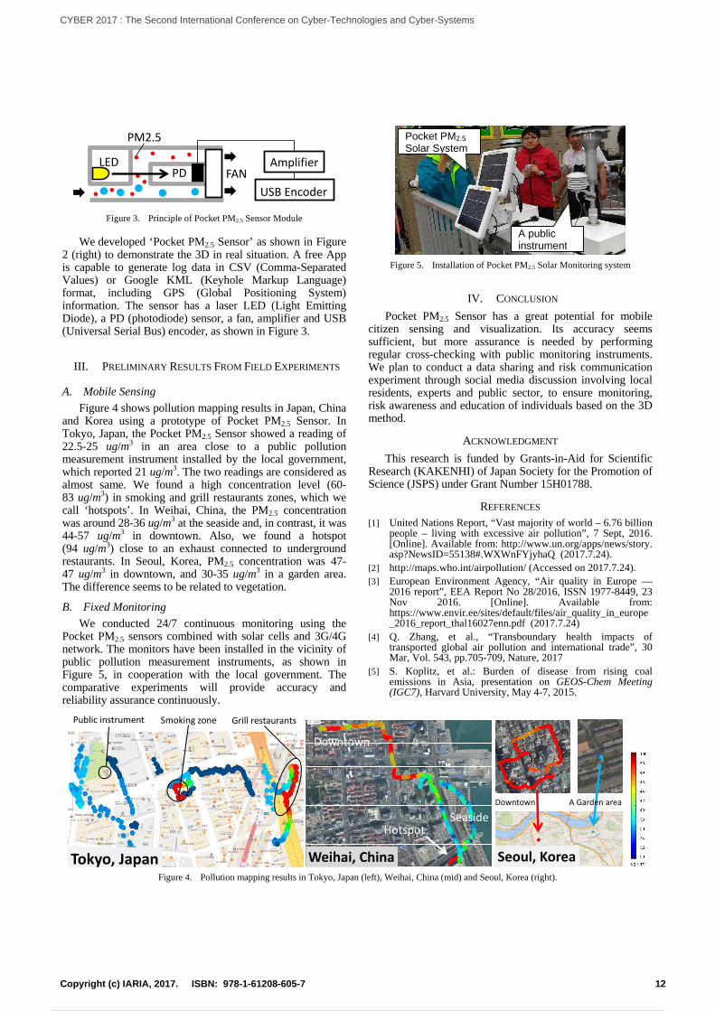
Figure 4 shows pollution mapping results in Japan, China and Korea using a prototype of Pocket PM2.5 Sensor. In Tokyo, Japan, the Pocket PM2.5 Sensor showed a reading of 22.5-25 ug/m3 in an area close to a public pollution measurement instrument installed by the local government, which reported 21 ug/m3. The two readings are considered as almost same. We found a high concentration level (60- 83 ug/m3) in smoking and grill restaurants zones, which we call ‘hotspots’ . In Weihai, China, the PM2.5 concentration was around 28-36 ug/m3 at the seaside and, in contrast, it was 44-57 ug/m3 in downtown. Also, we found a hotspot (94 ug/m3) close to an exhaust connected to underground restaurants. In Seoul, Korea, PM2.5 concentration was 47- 47 ug/m3 in downtown, and 30-35 ug/m3 in a garden area. The difference seems to be related to vegetation.
B. Fixed Monitoring
We conducted 24/7 continuous monitoring using the Pocket PM2.5 sensors combined with solar cells and 3G/4G network. The monitors have been installed in the vicinity of public pollution measurement instruments, as shown in Figure 5, in cooperation with the local government. The comparative experiments will provide accuracy and reliability assurance continuously.
Figure 5. Installation of Pocket PM2.5 Solar Monitoring system
IV. CONCLUSION
Pocket PM2.5 Sensor has a great potential for mobile citizen sensing and visualization. Its accuracy seems sufficient, but more assurance is needed by performing regular cross-checking with public monitoring instruments. We plan to conduct a data sharing and risk communication experiment through social media discussion involving local residents, experts and public sector, to ensure monitoring, risk awareness and education of individuals based on the 3D method.
ACKNOWLEDGMENT
This research is funded by Grants-in-Aid for Scientific Research (KAKENHI) of Japan Society for the Promotion of Science (JSPS) under Grant Number 15H01788.
REFERENCES [1] United Nations Report, “Vast majority of world – 6.76 billion
people – living with excessive air pollution”, 7 Sept, 2016. [Online]. Available from: http://www.un.org/apps/news/story. asp?NewsID=55138#.WXWnFYjyhaQ (2017.7.24).
[2] http://maps.who.int/airpollution/ (Accessed on 2017.7.24). [3] European Environment Agency, “Air quality in Europe —
2016 report”, EEA Report No 28/2016, ISSN 1977-8449, 23 Nov 2016. [Online]. Available from: https://www.envir.ee/sites/default/files/air_quality_in_europe_2016_report_thal16027enn.pdf (2017.7.24)
[4] Q. Zhang, et al., “Transboundary health impacts of transported global air pollution and international trade”, 30 Mar, Vol. 543, pp.705-709, Nature, 2017
[5] S. Koplitz, et al.: Burden of disease from rising coal emissions in Asia, presentation on GEOS-Chem Meeting (IGC7), Harvard University, May 4-7, 2015.
Public instrument Grill restaurants
Tokyo, Japan
Smoking zone
Downtown
SeasideHotspot
Weihai, China Seoul, Korea
Downtown A Garden area
Figure 4. Pollution mapping results in Tokyo, Japan (left), Weihai, China (mid) and Seoul, Korea (right).
A public instrument
Pocket PM2.5 Solar System
12Copyright (c) IARIA, 2017. ISBN: 978-1-61208-605-7
CYBER 2017 : The Second International Conference on Cyber-Technologies and Cyber-Systems
21 / 90
Global Information Privacy Infringement Index (GPI)
Hyunmin Suh and Myungchul Kim School of Computing
Korea Advanced Institute of Science and Technology
Daejeon, Republic of Korea
e-mail: {hyunmin088, mck}@kaist.ac.kr
Abstract - The proliferation of the Internet has attracted
much attention with regard to the leakage of online
private/personal information, as exposed information is
being used for criminal purposes. In this regard, a
criterion for information privacy must be clarified for
governments and other public institutions as well as
private enterprises in order to curtail information privacy
violations and criminal activity. In order to apply such an
information privacy criterion, we propose a global-scale
information privacy infringement index, known as the
Global Information Privacy Infringement Index (GPI).
The GPI examines the level of information privacy
infringement by measuring the factors, such as types,
records, sources, characteristics, and actions based on
infringed records for each country. Our approach can be
a useful guide for governments, the public and private
enterprises in their efforts to enhance information privacy.
Keywords-information privacy; information privacy
infringement; index.
I. INTRODUCTION
The number of Internet users stands at nearly 3.4
billion as of July, 2016, meaning that 40 percent of the
world population is currently connected to the Internet
[1]. The emergence of the Internet of Things (IoT) has
also contributed to the rapid proliferation of mobile
Internet users such that the Internet has now become
absolutely inseparable tool from the lives of people.
Despite the great benevolent intention of the Internet,
the leakage of online private/personal information has
been a significant issue around the world. The security
burden of protecting personal information applies to all
countries. Currently, companies in the US are
experiencing losses of more than 525 million US dollars
annually due to cybercrime based on malicious codes
[2]. The increase in cybercrime has had profound effects
on consumers. The largest infringes of information
amount to more than 130 million user accounts. The
potential targets of phishing attacks are mostly online
brands such as PayPal and EBay, an online payment
provider and online auction site, respectively [2].
The importance of maintaining reasonable
expectations of privacy does not literally mean only
preserving personal information, but also, the respecting
human rights. For instance, the Identity Card Act [3]
was proposed in the UK in 2006. The Identity Card Act
was proposed to facilitate a reliable and secure record of
individual registrations in the UK. It also promises a
useful means for individuals to prove their identities.
Initially, it was created to protect Britain against
terrorism, organized crime, and to prevent identity theft,
illegal immigration and illegal employment. However,
the Identity Card Act was repealed due to criticism
related to privacy and human rights issues. Privacy
campaigner, who stood against the Act, argued that the
identity database is a likely target for abuse. For instance,
members of the witness protection program, celebrities
and victims of domestic violence can be targeted as
vulnerable groups in that their personal information can
be stolen and sold. Moreover, on 2 February 2005, the
UK Parliament’s Joint Committee on Human Rights
challenged the compatibility of the Bill in consideration
of Article 8 of the European Convention on Human
Rights and Article 14, both from the Human Rights Act
1998 [4]. Thus, many in Britain believed that Identity
Cards Act was in violation of the right to privacy and
the right to non-discrimination, as encompassed in the
Human Rights Act.
In South Korea, three major credit card companies
were targeted by malicious outsiders, leading to the
leakage of 104 million instances of information,
specifically cardholders’ personal and financial
information, in 2013 [5]. After this major leak from the
card companies, billions stolen from NongHyup Bank,
one of the major banks in South Korea, it was assumed
that hackers used pharming attack with the victims’
personal information [6]. According to Statistics Korea
(KOSTAT), 152,151 records were reported as
undergoing an information privacy infringement in
2015. These instances are classified into unauthorized
collections of personal information, unauthorized
abuses of personal information, illegal uses of personal
identification numbers, cases not subject to the law, and
others. In the records, the illegal use of personal
identification numbers accounts for the largest
proportion of information privacy infringements, at
77,598 records, i.e., 51 percent of the entire number of
records [7].
13Copyright (c) IARIA, 2017. ISBN: 978-1-61208-605-7
CYBER 2017 : The Second International Conference on Cyber-Technologies and Cyber-Systems
22 / 90
Therefore, it is essential to make the conditions of
the online environment safer and more secure by
encouraging the involvement of the public and of the
government. In this regard, a criterion pertaining to
information privacy must be clarified by the government,
public and private enterprises in order to curtail online
privacy violations and criminal activity. In order to
apply a criterion of privacy, we propose an information
privacy index, which works on a global scale, known as
the GPI. The GPI examines the level of information
privacy by measuring the factors such as types, records,
sources, characteristics, and actions based on infringed
records which have occurred in the country. This
approach can be a useful guide to the public and to
government and private organizations as they attempt to
enhance information privacy.
The contributions of this paper are as follows:
First, we propose the GPI as a means of measuring
the level of information privacy for each country. With
regard to the GPI, we successfully quantified the level
of information privacy, making it much easier for people
to increase their self-awareness of information privacy
in their country of residence.
Second, we attempt to provide an empirical analysis
on the basis of publicly available data. In this way, we
do not provide any ambiguous or estimated data about
the privacy level in near future but rather give
information about the present based on the publicly
disclosed records.
Last, we demonstrate the GPI for five countries as
case studies by applying our method using infringed
records from around the globe.
This paper is organized as follows. Section II
consists of the basic concepts of the GPI. In this section,
we clarify the definition and provide background
information. Related work with regard to the GPI is
presented in Section III. In Section IV, a description of
GPI is given in detail. The GPI is measured and
evaluated in Section V. We finalize the paper in Section
VI.
II. BASIC CONCEPTS
This section presents the definition of privacy and
information privacy and background information
related to GPI.
A. Privacy, Information Privacy and Personal
Information
Privacy is ambiguous in that includes a broad range
of concepts, such as freedom of thought, control over
personal information, and others. According to the
United Nation (UN), “Privacy can be defined as the
presumption that individuals should have an area of
autonomous development, interaction and liberty, a
‘private sphere’ with or without interaction with others,
free from State intervention and from excessive
unsolicited intervention by other uninvited individuals.
The right to privacy is also the ability of individuals to
determine who holds information about them and how
that information is used” [8].
Privacy has become a controversial issue which has
a profound impact around the globe. Protecting privacy
is now a subjective goal for nearly every nation, with
numerous statutes, constitutional rights, and judicial
decisions affecting these efforts. Most nations around
the globe note privacy in their constitutions for the
protection of citizens. Even if privacy is not mentioned
in constitutions, many countries are aware of the
importance of constitutional rights to privacy, including
Canada, France, Germany, Japan, and India [9].
Information privacy is an emerging topic with the
advent of the Internet, as personal information is
digitalized on the Internet for many purposes. The
definition of information privacy must encompass an
important feature to refer also to the privacy of
digitalized personal data which is stored on a computer
system. Information privacy concerns the collection and
dissemination of data, technology, legal and political
issues surrounding them.
There is great ambiguity in the way ‘personal
information’ is used. In the context of privacy or
academic research, personal information refers to
information that is sensitive and any information that
can designate or identify a person [10]. Personal
information, under the law of South Korea, is defined as
a personal information related to a natural person whom
he or she must be alive. Personal information means an
information that can designate or identify an alive
person. If collected information does not identify a
person, it still counts as a personal information when
collected information can be easily combined with other
information [11]. In the European Union Directive,
“personal data shall mean any information relating to an
identifiable person is one who can be identified, directly
or indirectly, in particular by reference to an
identification number or to one or more factors specific
to his physical, physiological, mental, economic,
cultural or social identity [12].” Personal information
can appear in online and offline environments. This
paper focuses on digitalized personal information that is
acquired, stored on, abused, and/or removed from a
computer system.
B. Personal Identification Number
The definition of a ‘personal identification number’
[13] differs for each country. Such numbers are termed
national identification number, national identity number,
national insurance number, personal identification
number, or resident registration number. The
governments of many countries use personal
14Copyright (c) IARIA, 2017. ISBN: 978-1-61208-605-7
CYBER 2017 : The Second International Conference on Cyber-Technologies and Cyber-Systems
23 / 90
identification number as means of tracking citizens and
permanent/temporary residents. Personal identification
numbers can be given to foreigners for guidance and to
differentiate them from citizens. Moreover, personal
identification numbers can be used for tracking for the
purposes of employment, taxation, governmental
benefits, health care, and other government related
functions. They are not widely used in relation to
violations of human rights, but some countries still
maintain the system for convenience in managing
citizens.
Various personal identification number systems are
implemented among countries; however, most nations
issue an identification number when citizens are born or
when they reach a certain age (or legal age). For
noncitizens, identification numbers can be issued when
they enter the country and/or when they are granted a
temporary/permanent resident permit, but the numbers
will be issued with a different logic from that used with
citizens. Many countries have attempted to issue
identification numbers for singular purposes, but many
of these efforts have been halted due to strong resistance
from human rights movements. In fact, personal
identification number system is still used in some
countries.
C. A Comparison of Personal Identification Number
Systems
As noted above, personal identification number
systems vary across among countries. In this subsection,
we provide more detailed information about the
personal identification number among five countries;
the United States, the United Kingdom, Germany, Japan,
and South Korea. In addition, we analyze the domain of
personal identification number in five sector; Passport
Issuance, Driver License, Taxation, Social Insurance,
and Finance summarized in Table 1. These five sectors
are critical in that each nation uses a different approach
to authenticate users and collect personal information.
The United States developed its Social Security
Number (SSN) [14] system for the organization of
social security related benefits. However, the number is
now used for other purposes, working as a personal
identification number system. For passport issuance, a
person needs to prove his or her citizenship (such as
proof of birth, certification of citizenship, or
certification of naturalization), and the SSN must be
given [15]. For a driver’s license, proof of birth and
identification documents must be given along with the
SSN [16]. For taxation, four types of taxation numbers
exist; Taxpayer Identification Number (TIN), Employer
Identification Number (EIN), Individual Taxpayer
Identification Number (ITIN), and Preparer Taxpayer
Identification Number (PTIN) [17]. For finance, the
SSN is not necessarily a required condition.
In the United Kingdom, there is no official personal
identification number system and legal requirement to
possess any types of identification document to prove
one’s identity. However, there is the National Insurance
Number (NIN) [18], which is issued to all citizens in the
United Kingdom for the purpose of insurance. The NIN
is issued when legal age is turned 16. The NIN is not
mandatory to possess, and driver’s license is generally
used as proof of identity. In order to issue a driver’s
license, proof of identification must be submitted such
as proof of birth or a passport. When applying online,
the driver’s license issuing institution may collect the
NIN [19]. For taxation, the NIN is needed in order to
issue a Unique Tax Reference (UTR). Employers collect
the NINs of employees for taxation related purposes
[20]. For finance, the NIN is rarely used, whereas
driver’s licenses and passports are mostly used as proof
of address and identity [21].
In Germany, there is the Neuer Personalausweis
(nPA), but it does not function as a personal
identification number. The nPA, which is known as an
ID card system, is heavily regulated in terms of its usage.
Almost every sector issues a unique number that each
sector such as passport, driver license, taxation, social
insurance, and finance has its own unique number. The
nPA is used as an authentication method but storing or
wiring nPA information with the unique number is
regulated. This ID card system nPA is implemented in
2010 that is an electronic high-tech ID card using, for
instance, Radio-Frequency ID (RFID), cryptographic
technique, secure storage, and others. Validation using
the nPA lasts 10 years, and a new number is issued when
the card is lost or reissued. The collection of the nPA by
private institution is illegal. For the protection of
personal information, there is no unified number that
grants access to social security services in Germany.
There are unique numbers for each social security
services wiring these numbers with the nPA is illegal
[22][23].
My Number [24] of Japan is a newly emerging
personal identification number system which started in
2016. My Number is a 12 digits number issued to all
residents of Japan, including temporary and permanent
residents with valid permits. The previous personal
identification number system was only used for taxation,
social insurance, and medical insurance purposes.
However, the Japanese government has stepped forward
to centralize the system with a number for nearly every
sector, to eventually become a unique number for the
entire system. Thus, My Number will be used for
taxation, social security, driver’s license, and a passport
[25].
In South Korea, the Resident Registration Number
(RRN) [26] is a 13-digit number issued to all residents
of the country. The system started on November of 1968
15Copyright (c) IARIA, 2017. ISBN: 978-1-61208-605-7
CYBER 2017 : The Second International Conference on Cyber-Technologies and Cyber-Systems
24 / 90
for the purpose of identifying spies. The RRN is used in
nearly every sector not only as an authentication method
but also as a key number with which to make inquiries
into the system. Even up to August of 2012, the RRN
was ruthlessly collected by public and private
institutions for convenience [27]. There are critical
problems which have long occurred in South Korea
associated with the extensive use of the RRN. First, the
South Korean government has implemented an e-
government system and there are at least 1,100
information systems under 47 administrative agencies
which are linked in a single integrated government
network [28]. These distributed information systems are
integrated instantly when the RRN is entered into the
system. Thus, personal information in every sector can
be easily acquired by the government which can lead to
the serious problem of state surveillance. Secondly, the
meaningless collection of the RRN by private
companies has led to many accidents, such as leakages
of RRN. Moreover, the most critical problem related to
the RRN is that leaked RRNs cannot be changed during
the course of one’s lifetime once they are issued.
TABLE I. A COMPARISON OF PERSONAL IDENTIFICATION
NUMBER SYSTEMS
Taxation Passport Driver’s License
Social Insurance
Finance
Change of Personal
Identification Number
U.S (SSN) Δ O O O Δ
Cannot be changed (except in cases of error)
U.K (NIN) O X X O X
Cannot be changed
Germany (nPA)
X X X X X Changed in
every 10 years
Japan (My
Number) O O O O X
Cannot be changed
South Korea (RRN)
O O O O O Cannot be changed
* O: Must, Δ: Optional, X: Not required
III. RELATED WORKS
In this section, we briefly survey the works that are
relevant to the GPI.
A. The Breach Level Index
The Breach Level Index [29] aims to provide the
overall breach severity level by tracking publicly known
breaches to allow organizations to measure their own
risk assessment. The Breach Level Index does not set an
upper limit, but the largest breach scores are 10 thus far.
The Index is in logarithmic (base 10) scales used similar
to the scales for volcanoes and earthquakes [30][31].
However, the Breach Level Index is designed to provide
a risk assessment tool specifically targeting enterprises.
The GPI tends to complement the weaknesses of the
Breach Level Index to provide a national level scale to
acknowledge the level of information privacy
infringement.
B. The Global Cybersecurity Index
The Global Cybersecurity Index [32] is a project that
aims to measure each nation’s level of commitment to
cybersecurity. The final goal of the GCI is to advocate
for a global culture of cybersecurity and its integration
in terms of information and communication
technologies. The Global Cybersecurity Index covers
the five areas of legal measures, technical measures,
organizational measures, capacity building, and
cooperation. These five areas have a profound impact on
cybersecurity with regard to assessing national
capabilities as they form the building blocks of national
capabilities. The GCI covers various fields but their
global ranking of cybersecurity index is relatively
impractical. The GCI only focuses on the existence of
national structures in place rather than actual
cybersecurity level for a particular country. Ironically,
the GCI has reported that the United States of America
is placed at first in their cybersecurity index; however,
the U.S. is happened to be the country with highest
number of cybersecurity related accidents according to
the Breach Level Index. GPI scale aims to provide
information based on infringed records that focuses
more on evidence rather than the infrastructure. Thus,
GPI is based on the fact itself as well as the details
occurred in the specific country.
C. The Global Conflict Risk Index
The Global Conflict Risk Index (GCRI) [33] was
developed by the Joint Research Center. The GCRI is
designed to assist with decision making about long-term
conflict risk by providing accessible and objective open
sources. The contributions of the GCRI are described as
follow: It clarifies the definitions of ‘risk’ and ‘risk
conflict’ which derived from existing methodologies of
conflict research. In addition, five risk areas for each
state are presented for a quick overview of the structural
conditions of the state. Moreover, it provides an
evaluation and an assessment of a particular country’s
risk. The GCRI is focused on the risk that can occur in
a certain country. However, the GPI is more focused on
infringement level as opposed to the level of risk in a
country.
D. The Crime Rate
The crime rate represents the number of offenses per
certain number of people. The Federal Bureau of
Investigation (FBI) [34] releases crime statistics,
dividing the number of crimes by 100,000 inhabitants.
The GPI has benchmarked the concept of the crime rate
as the number of infringed records per the number of
data production. Moreover, we attempt to provide a
16Copyright (c) IARIA, 2017. ISBN: 978-1-61208-605-7
CYBER 2017 : The Second International Conference on Cyber-Technologies and Cyber-Systems
25 / 90
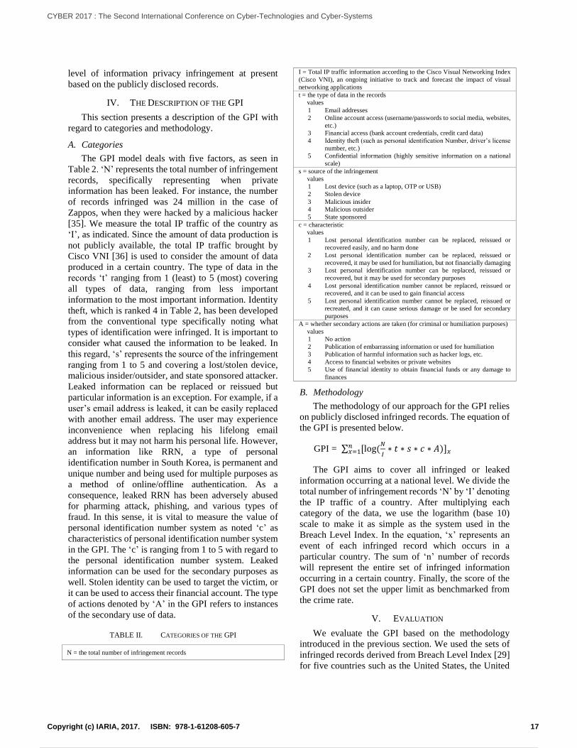
level of information privacy infringement at present
based on the publicly disclosed records.
IV. THE DESCRIPTION OF THE GPI
This section presents a description of the GPI with
regard to categories and methodology.
A. Categories
The GPI model deals with five factors, as seen in
Table 2. ‘N’ represents the total number of infringement
records, specifically representing when private
information has been leaked. For instance, the number
of records infringed was 24 million in the case of
Zappos, when they were hacked by a malicious hacker
[35]. We measure the total IP traffic of the country as
‘I’, as indicated. Since the amount of data production is
not publicly available, the total IP traffic brought by
Cisco VNI [36] is used to consider the amount of data
produced in a certain country. The type of data in the
records ‘t’ ranging from 1 (least) to 5 (most) covering
all types of data, ranging from less important
information to the most important information. Identity
theft, which is ranked 4 in Table 2, has been developed
from the conventional type specifically noting what
types of identification were infringed. It is important to
consider what caused the information to be leaked. In
this regard, ‘s’ represents the source of the infringement
ranging from 1 to 5 and covering a lost/stolen device,
malicious insider/outsider, and state sponsored attacker.
Leaked information can be replaced or reissued but
particular information is an exception. For example, if a
user’s email address is leaked, it can be easily replaced
with another email address. The user may experience
inconvenience when replacing his lifelong email
address but it may not harm his personal life. However,
an information like RRN, a type of personal
identification number in South Korea, is permanent and
unique number and being used for multiple purposes as
a method of online/offline authentication. As a
consequence, leaked RRN has been adversely abused
for pharming attack, phishing, and various types of
fraud. In this sense, it is vital to measure the value of
personal identification number system as noted ‘c’ as
characteristics of personal identification number system
in the GPI. The ‘c’ is ranging from 1 to 5 with regard to
the personal identification number system. Leaked
information can be used for the secondary purposes as
well. Stolen identity can be used to target the victim, or
it can be used to access their financial account. The type
of actions denoted by ‘A’ in the GPI refers to instances
of the secondary use of data.
TABLE II. CATEGORIES OF THE GPI
N = the total number of infringement records
I = Total IP traffic information according to the Cisco Visual Networking Index
(Cisco VNI), an ongoing initiative to track and forecast the impact of visual
networking applications
t = the type of data in the records
values
1 Email addresses
2 Online account access (username/passwords to social media, websites,
etc.)
3 Financial access (bank account credentials, credit card data)
4 Identity theft (such as personal identification Number, driver’s license
number, etc.)
5 Confidential information (highly sensitive information on a national
scale)
s = source of the infringement
values
1 Lost device (such as a laptop, OTP or USB)
2 Stolen device
3 Malicious insider
4 Malicious outsider
5 State sponsored
c = characteristic
values
1 Lost personal identification number can be replaced, reissued or
recovered easily, and no harm done
2 Lost personal identification number can be replaced, reissued or
recovered, it may be used for humiliation, but not financially damaging
3 Lost personal identification number can be replaced, reissued or
recovered, but it may be used for secondary purposes
4 Lost personal identification number cannot be replaced, reissued or
recovered, and it can be used to gain financial access
5 Lost personal identification number cannot be replaced, reissued or
recreated, and it can cause serious damage or be used for secondary
purposes
A = whether secondary actions are taken (for criminal or humiliation purposes)
values
1 No action
2 Publication of embarrassing information or used for humiliation
3 Publication of harmful information such as hacker logs, etc.
4 Access to financial websites or private websites
5 Use of financial identity to obtain financial funds or any damage to
finances
B. Methodology
The methodology of our approach for the GPI relies
on publicly disclosed infringed records. The equation of
the GPI is presented below.
GPI = ∑ [log(𝑁
𝐼∗ 𝑡 ∗ 𝑠 ∗ 𝑐 ∗ 𝐴)]𝑥
𝑛𝑥=1
The GPI aims to cover all infringed or leaked
information occurring at a national level. We divide the
total number of infringement records ‘N’ by ‘I’ denoting
the IP traffic of a country. After multiplying each
category of the data, we use the logarithm (base 10)
scale to make it as simple as the system used in the
Breach Level Index. In the equation, ‘x’ represents an
event of each infringed record which occurs in a
particular country. The sum of ‘n’ number of records
will represent the entire set of infringed information
occurring in a certain country. Finally, the score of the
GPI does not set the upper limit as benchmarked from
the crime rate.
V. EVALUATION
We evaluate the GPI based on the methodology
introduced in the previous section. We used the sets of
infringed records derived from Breach Level Index [29]
for five countries such as the United States, the United
17Copyright (c) IARIA, 2017. ISBN: 978-1-61208-605-7
CYBER 2017 : The Second International Conference on Cyber-Technologies and Cyber-Systems
26 / 90
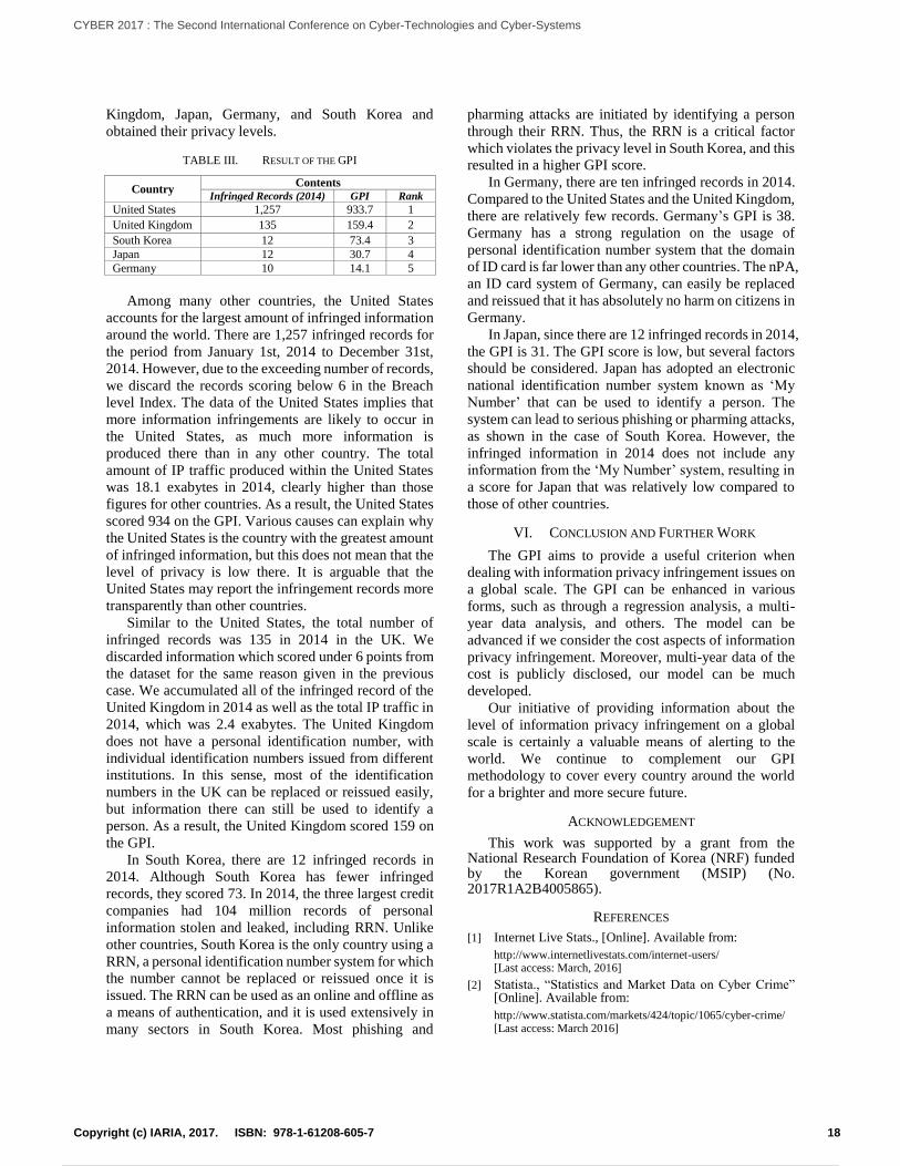
Kingdom, Japan, Germany, and South Korea and
obtained their privacy levels.
TABLE III. RESULT OF THE GPI
Country Contents
Infringed Records (2014) GPI Rank
United States 1,257 933.7 1
United Kingdom 135 159.4 2
South Korea 12 73.4 3
Japan 12 30.7 4
Germany 10 14.1 5
Among many other countries, the United States
accounts for the largest amount of infringed information
around the world. There are 1,257 infringed records for
the period from January 1st, 2014 to December 31st,
2014. However, due to the exceeding number of records,
we discard the records scoring below 6 in the Breach
level Index. The data of the United States implies that
more information infringements are likely to occur in
the United States, as much more information is
produced there than in any other country. The total
amount of IP traffic produced within the United States
was 18.1 exabytes in 2014, clearly higher than those
figures for other countries. As a result, the United States
scored 934 on the GPI. Various causes can explain why
the United States is the country with the greatest amount
of infringed information, but this does not mean that the
level of privacy is low there. It is arguable that the
United States may report the infringement records more
transparently than other countries.
Similar to the United States, the total number of
infringed records was 135 in 2014 in the UK. We
discarded information which scored under 6 points from
the dataset for the same reason given in the previous
case. We accumulated all of the infringed record of the
United Kingdom in 2014 as well as the total IP traffic in
2014, which was 2.4 exabytes. The United Kingdom
does not have a personal identification number, with
individual identification numbers issued from different
institutions. In this sense, most of the identification
numbers in the UK can be replaced or reissued easily,
but information there can still be used to identify a
person. As a result, the United Kingdom scored 159 on
the GPI.
In South Korea, there are 12 infringed records in
2014. Although South Korea has fewer infringed
records, they scored 73. In 2014, the three largest credit
companies had 104 million records of personal
information stolen and leaked, including RRN. Unlike
other countries, South Korea is the only country using a
RRN, a personal identification number system for which
the number cannot be replaced or reissued once it is
issued. The RRN can be used as an online and offline as
a means of authentication, and it is used extensively in
many sectors in South Korea. Most phishing and
pharming attacks are initiated by identifying a person
through their RRN. Thus, the RRN is a critical factor
which violates the privacy level in South Korea, and this
resulted in a higher GPI score.
In Germany, there are ten infringed records in 2014.
Compared to the United States and the United Kingdom,
there are relatively few records. Germany’s GPI is 38.
Germany has a strong regulation on the usage of
personal identification number system that the domain
of ID card is far lower than any other countries. The nPA,
an ID card system of Germany, can easily be replaced
and reissued that it has absolutely no harm on citizens in
Germany.
In Japan, since there are 12 infringed records in 2014,
the GPI is 31. The GPI score is low, but several factors
should be considered. Japan has adopted an electronic
national identification number system known as ‘My
Number’ that can be used to identify a person. The
system can lead to serious phishing or pharming attacks,
as shown in the case of South Korea. However, the
infringed information in 2014 does not include any
information from the ‘My Number’ system, resulting in
a score for Japan that was relatively low compared to
those of other countries.
VI. CONCLUSION AND FURTHER WORK
The GPI aims to provide a useful criterion when
dealing with information privacy infringement issues on
a global scale. The GPI can be enhanced in various
forms, such as through a regression analysis, a multi-
year data analysis, and others. The model can be
advanced if we consider the cost aspects of information
privacy infringement. Moreover, multi-year data of the
cost is publicly disclosed, our model can be much
developed.
Our initiative of providing information about the
level of information privacy infringement on a global
scale is certainly a valuable means of alerting to the
world. We continue to complement our GPI
methodology to cover every country around the world
for a brighter and more secure future.
ACKNOWLEDGEMENT
This work was supported by a grant from the National Research Foundation of Korea (NRF) funded by the Korean government (MSIP) (No. 2017R1A2B4005865).
REFERENCES
[1] Internet Live Stats., [Online]. Available from:
http://www.internetlivestats.com/internet-users/ [Last access: March, 2016]
[2] Statista., “Statistics and Market Data on Cyber Crime” [Online]. Available from:
http://www.statista.com/markets/424/topic/1065/cyber-crime/ [Last access: March 2016]
18Copyright (c) IARIA, 2017. ISBN: 978-1-61208-605-7
CYBER 2017 : The Second International Conference on Cyber-Technologies and Cyber-Systems
27 / 90
[3] The Guardian., [Online]. Available from:
http://www.theguardian.com/commentisfree/libertycentral/2009/jan/15/identity-cards-act [Last access: March, 2016]
[4] European Commision. “UK’s ID Cards Bill wins parliamentary vote despite Human Rights concerns” [Online]. Available from:
http://ec.europa.eu/idabc/servlets/Docee17.pdf?id=21693 [Last access: March, 2016]
[5] Joongangdaily., [Online]. Available from:
http://koreajoongangdaily.joins.com/news/article/article.aspx?aid=2983762 [Last access: March, 2016]
[6] Koreabang., [Online]. Available from:
http://www.koreabang.com/2014/stories/hackers-steal-billions-from-nonghyup-bank-is-not-responsible.html [Last access: March, 2016]
[7] Statistics Korea., [Online]. Available from:
http://www.index.go.kr/potal/main/EachDtlPageDetail.do?idx_cd=1366 [Last access: March, 2016]
[8] Techopedia., “Information Privacy.” [Online]. Available from: https://www.techopedia.com/definition/10380/
information-privacy [Last access: April, 2016]
[9] D., Solove, “Understanding Privacy,” Harvard University Press, 2008.
[10] H., Nissenbaum, “Privacy in Context: Technology, Policy, and the Integrity of Social Life,” Stanford University Press, 2010.
[11] Ministry of Interior., “Persoanl Information Protection Act, Article 2,” [Online]. Available from:
https://www.privacy.go.kr/eng/laws_policies_list.do [Last access: April, 2016]
[12] Data Protection Commissioner (DPC), “EU Directive 95/46/EC – The Data Protection Directive, Chapter 1 – General Provision,” 2016.
[13] Record Union., “What is a national identification number?,” [Online]. Available from:
http://helpdesk.recordunion.com/FAQ/what-is-a-national-identification-number [Last access: April, 2016]
[14] Social Security., “The Story of the Social Security Number,” [Online]. Available from:
https://www.ssa.gov/policy/docs/ssb/v69n2/v69n2p55.html [Last access: April, 2016]
[15] U.S. Passports & International Travel, “First Time Applicants,” 2016 [Online]. Available from: https://travel.state.gov/content/passports/en/passports/first-time.html [Last access: April, 2016]
[16] California Department of Motor Vehicles. “Social Security Number (FFDL 8),” 2016 [Online]. Available from: https://www.dmv.ca.gov/portal/dmv/detail/pubs/brochures/fast_facts/ffdl08 [Last access: April, 2016]
[17] Internal Revenue Service, “Taxpayer Identification Number (TIN),” 2016 [Online]. Available from: https://www.irs.gov/individuals/international-taxpayers/taxpayer-identification-numbers-tin [Last access: May, 2016]
[18] UK Government, “National Insurance,” [Online]. Available from: https://www.gov.uk/national-insurance/your-national-insurance-number [Last access: May, 2016]
[19] UK Government, “Apply for your first provisional driving license,” 2016 [Online]. Available from: https://www.gov.uk/apply-first-provisional-driving-licence [Last access: May, 2016]
[20] Unique Taxpayer Reference Government, “How to get u UTR Number if Self Employed,” [Online]. Available from: http://utr.org.uk/home [Last access: May, 2016]
[21] Barclays, “Identification for bank accounts,” 2016 [Online]. Available from: http://www.barclays.co.uk/validid [Last access: May, 2016]
[22] German-way.com, “The Identity Card –der Ausweis,” [Online]. Available from: http://www.german-way.com/for-expats/living-in-germany/the-identity-card-der-ausweis/ [Last access: May, 2016]
[23] M., Margraf, “The New German ID Card,” [Online]. Available from: http://www.personalausweisportal.de/SharedDocs/Downloads/EN/Paper_new_German_ID-card.pdf?__blob=publicationFile
[24] Cabinet Secretariat, [Online]. Available from: http://www.
gov-online.go.jp/tokusyu/mynumber/ad/?sec1_kojin_2-2 [Last access: May, 2016]
[25] M., King, “My Number system: a worring glimpse of the future,” 2015 [Online]. Available from: http://www.japantoday.com/category/opinions/view/my-number-system-a-worrying-glimpse-of-the-future [Last access: May, 2016]
[26] OECD, “Information on Tax Identification Numbers Section,” [Online]. Available from: https://search.oecd.org/tax/automaticexchange/tinsandtaxresidency/taxidentificationnumberstins/Korea-TIN.pdf [Last access: May, 2016]
[27] Koreabang, “Korean Government Reorganizes National ID System After Leaks,” 2014 [Online]. Available from: http://www.koreabang.com/2014/stories/korean-government-reorganizes-resident-registration-number-system.html [Last access: May, 2016]
[28] Ministry of Public Administration and Security, “e-Government in South Korea” [Online]. Available from: http://unpan1.un.org/intradoc/groups/public/documents/UNGC/UNPAN043625.pdf [Last access: May, 2016]
[29] BreachlevelIndex.com, [Online]. Available from:
http://breachlevelindex.com/#!breach-database [Last access: May, 2016]
[30] S., Huler, “Defining the Wind: The Beaufort Scale and How a 19th-Century Admiral Turned into Poetry,” 2014.
[31] Melaragno, M., “Severe Storm Engineering for Structural Design, ” 1996.
[32] The Global Cybersecurity Index, [Online]. Available from: http://www.itu.int/en/ITU-D/Cybersecurity/Pages/GCI.aspx [Last access: May, 2016]
[33] The Global Conflict Risk Index, “The Global Conflict Risk Index (GCRI) a Quantitative Model,” 2014.
[34] FBI., “FBI Releases 2014 Crime Statistics” [Online]. Available from:
https://www.fbi.gov/news/pressrel/press-releases/fbi-releases-2014-crime-statistics [Last access: May, 2016]
[35] CNN Money., “Zappos hacked, 24 million accounts accessed” [Online]. Available from:
http://money.cnn.com/2012/01/16/technology/zappos_hack/ [Last access: May, 2016]
[36] Cisco.com., “The Zettabyte Era – trends and Analysis” [Online]. Available from: http://www.cisco.com/c/en/us/solutions/collateral/service-provider/visual-networking-index-vni/VNI_Hyperconnectivity_WP.html [Last access: May, 2016]
19Copyright (c) IARIA, 2017. ISBN: 978-1-61208-605-7
CYBER 2017 : The Second International Conference on Cyber-Technologies and Cyber-Systems
28 / 90
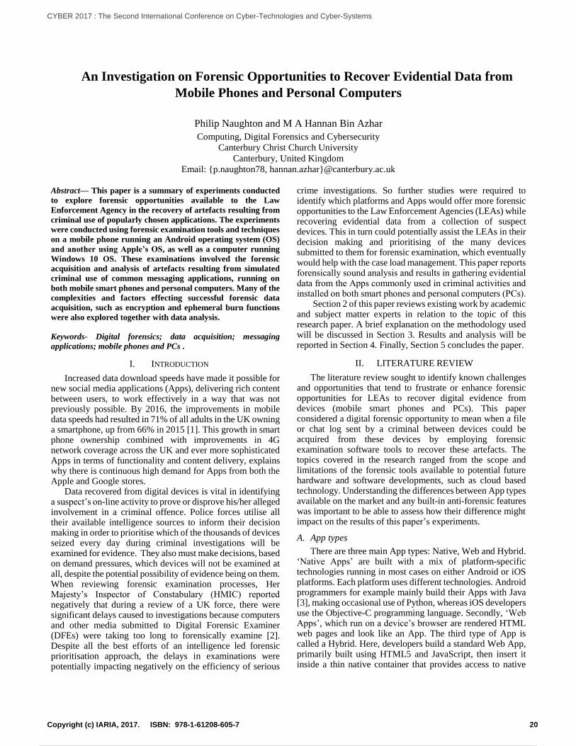
An Investigation on Forensic Opportunities to Recover Evidential Data from
Mobile Phones and Personal Computers
Philip Naughton and M A Hannan Bin Azhar
Computing, Digital Forensics and Cybersecurity
Canterbury Christ Church University
Canterbury, United Kingdom
Email: {p.naughton78, hannan.azhar}@canterbury.ac.uk
Abstract— This paper is a summary of experiments conducted
to explore forensic opportunities available to the Law
Enforcement Agency in the recovery of artefacts resulting from
criminal use of popularly chosen applications. The experiments
were conducted using forensic examination tools and techniques
on a mobile phone running an Android operating system (OS)
and another using Apple’s OS, as well as a computer running
Windows 10 OS. These examinations involved the forensic
acquisition and analysis of artefacts resulting from simulated
criminal use of common messaging applications, running on
both mobile smart phones and personal computers. Many of the
complexities and factors effecting successful forensic data
acquisition, such as encryption and ephemeral burn functions
were also explored together with data analysis.
Keywords- Digital forensics; data acquisition; messaging
applications; mobile phones and PCs .
I. INTRODUCTION
Increased data download speeds have made it possible for new social media applications (Apps), delivering rich content between users, to work effectively in a way that was not previously possible. By 2016, the improvements in mobile data speeds had resulted in 71% of all adults in the UK owning a smartphone, up from 66% in 2015 [1]. This growth in smart phone ownership combined with improvements in 4G network coverage across the UK and ever more sophisticated Apps in terms of functionality and content delivery, explains why there is continuous high demand for Apps from both the Apple and Google stores.
Data recovered from digital devices is vital in identifying a suspect’s on-line activity to prove or disprove his/her alleged involvement in a criminal offence. Police forces utilise all their available intelligence sources to inform their decision making in order to prioritise which of the thousands of devices seized every day during criminal investigations will be examined for evidence. They also must make decisions, based on demand pressures, which devices will not be examined at all, despite the potential possibility of evidence being on them. When reviewing forensic examination processes, Her Majesty’s Inspector of Constabulary (HMIC) reported negatively that during a review of a UK force, there were significant delays caused to investigations because computers and other media submitted to Digital Forensic Examiner (DFEs) were taking too long to forensically examine [2]. Despite all the best efforts of an intelligence led forensic prioritisation approach, the delays in examinations were potentially impacting negatively on the efficiency of serious
crime investigations. So further studies were required to identify which platforms and Apps would offer more forensic opportunities to the Law Enforcement Agencies (LEAs) while recovering evidential data from a collection of suspect devices. This in turn could potentially assist the LEAs in their decision making and prioritising of the many devices submitted to them for forensic examination, which eventually would help with the case load management. This paper reports forensically sound analysis and results in gathering evidential data from the Apps commonly used in criminal activities and installed on both smart phones and personal computers (PCs).
Section 2 of this paper reviews existing work by academic and subject matter experts in relation to the topic of this research paper. A brief explanation on the methodology used will be discussed in Section 3. Results and analysis will be reported in Section 4. Finally, Section 5 concludes the paper.
II. LITERATURE REVIEW
The literature review sought to identify known challenges and opportunities that tend to frustrate or enhance forensic opportunities for LEAs to recover digital evidence from devices (mobile smart phones and PCs). This paper considered a digital forensic opportunity to mean when a file or chat log sent by a criminal between devices could be acquired from these devices by employing forensic examination software tools to recover these artefacts. The topics covered in the research ranged from the scope and limitations of the forensic tools available to potential future hardware and software developments, such as cloud based technology. Understanding the differences between App types available on the market and any built-in anti-forensic features was important to be able to assess how their difference might impact on the results of this paper’s experiments.
A. App types
There are three main App types: Native, Web and Hybrid. ‘Native Apps’ are built with a mix of platform-specific technologies running in most cases on either Android or iOS platforms. Each platform uses different technologies. Android programmers for example mainly build their Apps with Java [3], making occasional use of Python, whereas iOS developers use the Objective-C programming language. Secondly, ‘Web Apps’, which run on a device’s browser are rendered HTML web pages and look like an App. The third type of App is called a Hybrid. Here, developers build a standard Web App, primarily built using HTML5 and JavaScript, then insert it inside a thin native container that provides access to native
20Copyright (c) IARIA, 2017. ISBN: 978-1-61208-605-7
CYBER 2017 : The Second International Conference on Cyber-Technologies and Cyber-Systems
29 / 90
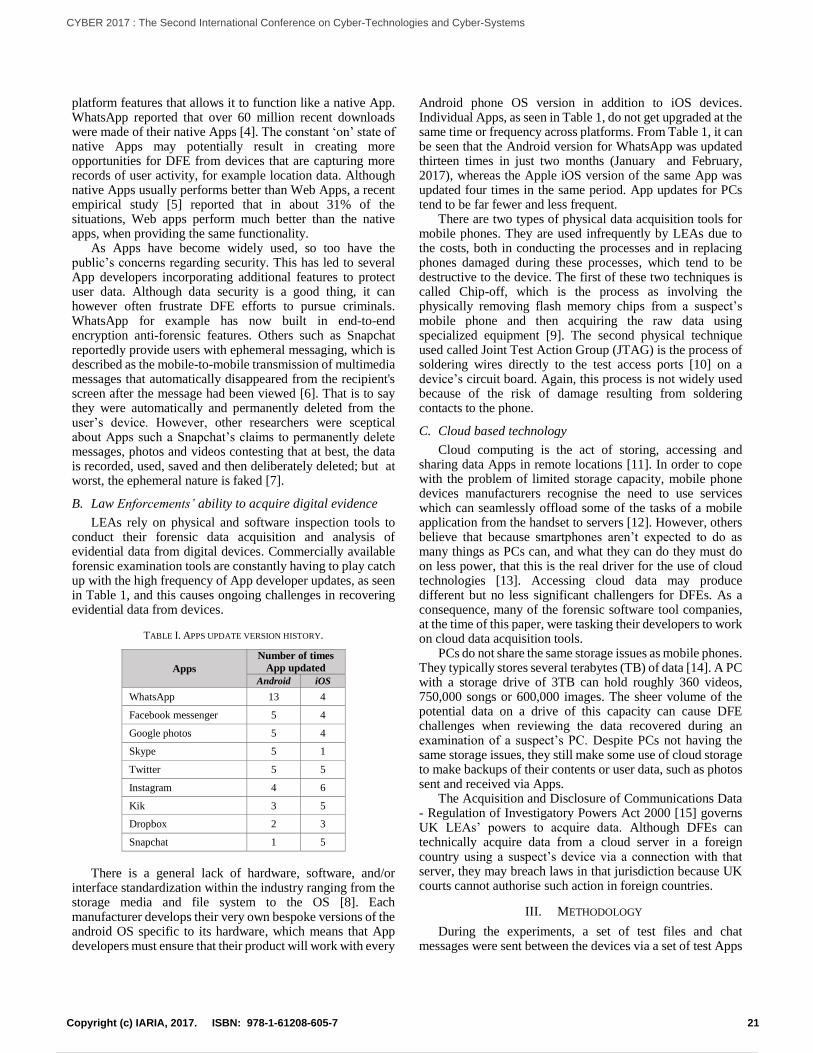
platform features that allows it to function like a native App. WhatsApp reported that over 60 million recent downloads were made of their native Apps [4]. The constant ‘on’ state of native Apps may potentially result in creating more opportunities for DFE from devices that are capturing more records of user activity, for example location data. Although native Apps usually performs better than Web Apps, a recent empirical study [5] reported that in about 31% of the situations, Web apps perform much better than the native apps, when providing the same functionality.
As Apps have become widely used, so too have the public’s concerns regarding security. This has led to several App developers incorporating additional features to protect user data. Although data security is a good thing, it can however often frustrate DFE efforts to pursue criminals. WhatsApp for example has now built in end-to-end encryption anti-forensic features. Others such as Snapchat reportedly provide users with ephemeral messaging, which is described as the mobile-to-mobile transmission of multimedia messages that automatically disappeared from the recipient's screen after the message had been viewed [6]. That is to say they were automatically and permanently deleted from the user’s device. However, other researchers were sceptical about Apps such a Snapchat’s claims to permanently delete messages, photos and videos contesting that at best, the data is recorded, used, saved and then deliberately deleted; but at worst, the ephemeral nature is faked [7].
B. Law Enforcements’ ability to acquire digital evidence
LEAs rely on physical and software inspection tools to conduct their forensic data acquisition and analysis of evidential data from digital devices. Commercially available forensic examination tools are constantly having to play catch up with the high frequency of App developer updates, as seen in Table 1, and this causes ongoing challenges in recovering evidential data from devices.
TABLE I. APPS UPDATE VERSION HISTORY.
Apps
Number of times
App updated
Android iOS
WhatsApp 13 4
Facebook messenger 5 4
Google photos 5 4
Skype 5 1
Twitter 5 5
Instagram 4 6
Kik 3 5
Dropbox 2 3
Snapchat 1 5
There is a general lack of hardware, software, and/or
interface standardization within the industry ranging from the storage media and file system to the OS [8]. Each manufacturer develops their very own bespoke versions of the android OS specific to its hardware, which means that App developers must ensure that their product will work with every
Android phone OS version in addition to iOS devices. Individual Apps, as seen in Table 1, do not get upgraded at the same time or frequency across platforms. From Table 1, it can be seen that the Android version for WhatsApp was updated thirteen times in just two months (January and February, 2017), whereas the Apple iOS version of the same App was updated four times in the same period. App updates for PCs tend to be far fewer and less frequent.
There are two types of physical data acquisition tools for mobile phones. They are used infrequently by LEAs due to the costs, both in conducting the processes and in replacing phones damaged during these processes, which tend to be destructive to the device. The first of these two techniques is called Chip-off, which is the process as involving the physically removing flash memory chips from a suspect’s mobile phone and then acquiring the raw data using specialized equipment [9]. The second physical technique used called Joint Test Action Group (JTAG) is the process of soldering wires directly to the test access ports [10] on a device’s circuit board. Again, this process is not widely used because of the risk of damage resulting from soldering contacts to the phone.
C. Cloud based technology
Cloud computing is the act of storing, accessing and sharing data Apps in remote locations [11]. In order to cope with the problem of limited storage capacity, mobile phone devices manufacturers recognise the need to use services which can seamlessly offload some of the tasks of a mobile application from the handset to servers [12]. However, others believe that because smartphones aren’t expected to do as many things as PCs can, and what they can do they must do on less power, that this is the real driver for the use of cloud technologies [13]. Accessing cloud data may produce different but no less significant challengers for DFEs. As a consequence, many of the forensic software tool companies, at the time of this paper, were tasking their developers to work on cloud data acquisition tools.
PCs do not share the same storage issues as mobile phones. They typically stores several terabytes (TB) of data [14]. A PC with a storage drive of 3TB can hold roughly 360 videos, 750,000 songs or 600,000 images. The sheer volume of the potential data on a drive of this capacity can cause DFE challenges when reviewing the data recovered during an examination of a suspect’s PC. Despite PCs not having the same storage issues, they still make some use of cloud storage to make backups of their contents or user data, such as photos sent and received via Apps.
The Acquisition and Disclosure of Communications Data - Regulation of Investigatory Powers Act 2000 [15] governs UK LEAs’ powers to acquire data. Although DFEs can technically acquire data from a cloud server in a foreign country using a suspect’s device via a connection with that server, they may breach laws in that jurisdiction because UK courts cannot authorise such action in foreign countries.
III. METHODOLOGY
During the experiments, a set of test files and chat messages were sent between the devices via a set of test Apps
21Copyright (c) IARIA, 2017. ISBN: 978-1-61208-605-7
CYBER 2017 : The Second International Conference on Cyber-Technologies and Cyber-Systems
30 / 90
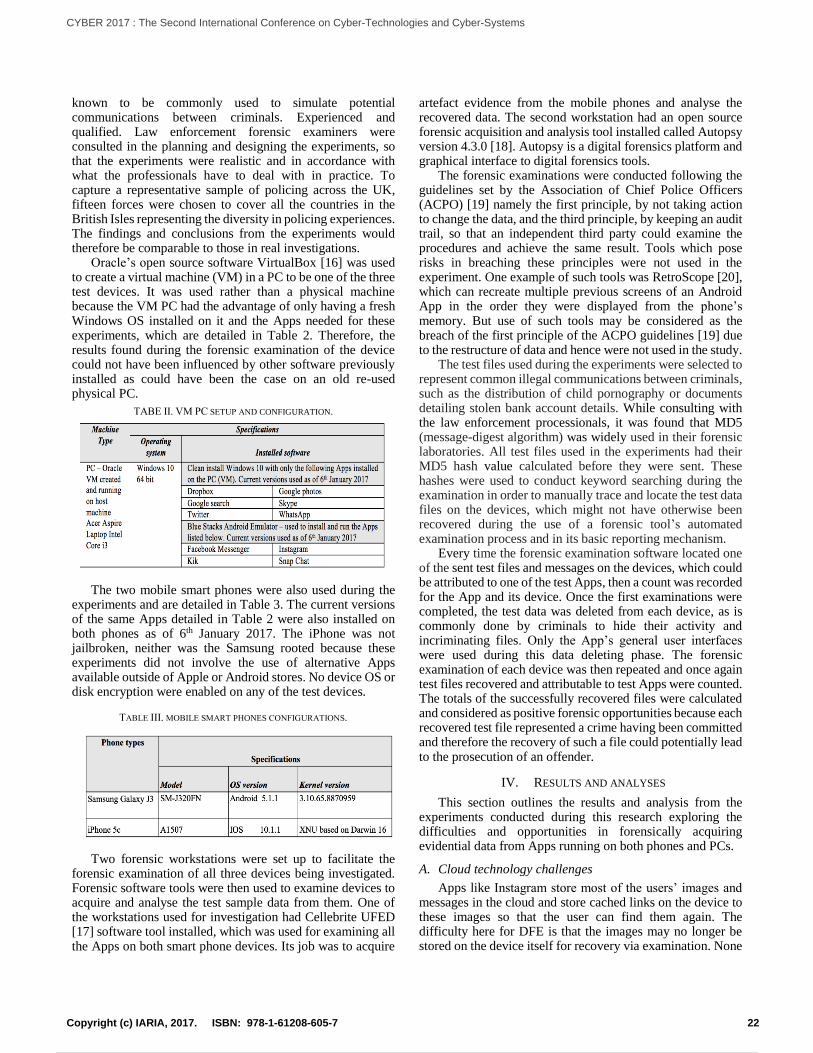
known to be commonly used to simulate potential communications between criminals. Experienced and qualified. Law enforcement forensic examiners were consulted in the planning and designing the experiments, so that the experiments were realistic and in accordance with what the professionals have to deal with in practice. To capture a representative sample of policing across the UK, fifteen forces were chosen to cover all the countries in the British Isles representing the diversity in policing experiences. The findings and conclusions from the experiments would therefore be comparable to those in real investigations.
Oracle’s open source software VirtualBox [16] was used to create a virtual machine (VM) in a PC to be one of the three test devices. It was used rather than a physical machine because the VM PC had the advantage of only having a fresh Windows OS installed on it and the Apps needed for these experiments, which are detailed in Table 2. Therefore, the results found during the forensic examination of the device could not have been influenced by other software previously installed as could have been the case on an old re-used physical PC.
TABE II. VM PC SETUP AND CONFIGURATION.
The two mobile smart phones were also used during the experiments and are detailed in Table 3. The current versions of the same Apps detailed in Table 2 were also installed on both phones as of 6th January 2017. The iPhone was not jailbroken, neither was the Samsung rooted because these experiments did not involve the use of alternative Apps available outside of Apple or Android stores. No device OS or disk encryption were enabled on any of the test devices.
TABLE III. MOBILE SMART PHONES CONFIGURATIONS.
Two forensic workstations were set up to facilitate the forensic examination of all three devices being investigated. Forensic software tools were then used to examine devices to acquire and analyse the test sample data from them. One of the workstations used for investigation had Cellebrite UFED [17] software tool installed, which was used for examining all the Apps on both smart phone devices. Its job was to acquire
artefact evidence from the mobile phones and analyse the recovered data. The second workstation had an open source forensic acquisition and analysis tool installed called Autopsy version 4.3.0 [18]. Autopsy is a digital forensics platform and graphical interface to digital forensics tools.
The forensic examinations were conducted following the guidelines set by the Association of Chief Police Officers (ACPO) [19] namely the first principle, by not taking action to change the data, and the third principle, by keeping an audit trail, so that an independent third party could examine the procedures and achieve the same result. Tools which pose risks in breaching these principles were not used in the experiment. One example of such tools was RetroScope [20], which can recreate multiple previous screens of an Android App in the order they were displayed from the phone’s memory. But use of such tools may be considered as the breach of the first principle of the ACPO guidelines [19] due to the restructure of data and hence were not used in the study.
The test files used during the experiments were selected to represent common illegal communications between criminals, such as the distribution of child pornography or documents detailing stolen bank account details. While consulting with the law enforcement processionals, it was found that MD5 (message-digest algorithm) was widely used in their forensic laboratories. All test files used in the experiments had their MD5 hash value calculated before they were sent. These hashes were used to conduct keyword searching during the examination in order to manually trace and locate the test data files on the devices, which might not have otherwise been recovered during the use of a forensic tool’s automated examination process and in its basic reporting mechanism.
Every time the forensic examination software located one of the sent test files and messages on the devices, which could be attributed to one of the test Apps, then a count was recorded for the App and its device. Once the first examinations were completed, the test data was deleted from each device, as is commonly done by criminals to hide their activity and incriminating files. Only the App’s general user interfaces were used during this data deleting phase. The forensic examination of each device was then repeated and once again test files recovered and attributable to test Apps were counted. The totals of the successfully recovered files were calculated and considered as positive forensic opportunities because each recovered test file represented a crime having been committed and therefore the recovery of such a file could potentially lead to the prosecution of an offender.
IV. RESULTS AND ANALYSES
This section outlines the results and analysis from the experiments conducted during this research exploring the difficulties and opportunities in forensically acquiring evidential data from Apps running on both phones and PCs.
A. Cloud technology challenges
Apps like Instagram store most of the users’ images and messages in the cloud and store cached links on the device to these images so that the user can find them again. The difficulty here for DFE is that the images may no longer be stored on the device itself for recovery via examination. None
22Copyright (c) IARIA, 2017. ISBN: 978-1-61208-605-7
CYBER 2017 : The Second International Conference on Cyber-Technologies and Cyber-Systems
31 / 90
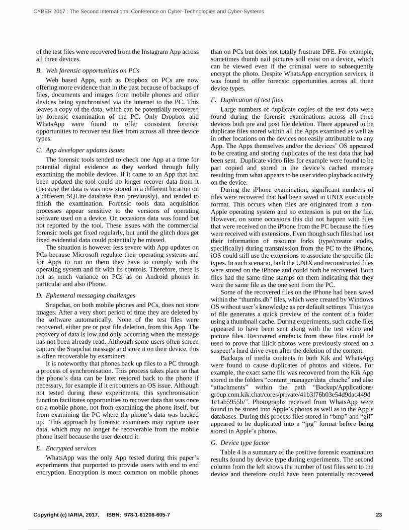
of the test files were recovered from the Instagram App across all three devices.
B. Web forensic opportunities on PCs
Web based Apps, such as Dropbox on PCs are now offering more evidence than in the past because of backups of files, documents and images from mobile phones and other devices being synchronised via the internet to the PC. This leaves a copy of the data, which can be potentially recovered by forensic examination of the PC. Only Dropbox and WhatsApp were found to offer consistent forensic opportunities to recover test files from across all three device types.
C. App developer updates issues
The forensic tools tended to check one App at a time for potential digital evidence as they worked through fully examining the mobile devices. If it came to an App that had been updated the tool could no longer recover data from it (because the data is was now stored in a different location on a different SQLite database than previously), and tended to finish the examination. Forensic tools data acquisition processes appear sensitive to the versions of operating software used on a device. On occasions data was found but not reported by the tool. These issues with the commercial forensic tools get fixed regularly, but until the glitch does get fixed evidential data could potentially be missed.
The situation is however less severe with App updates on PCs because Microsoft regulate their operating systems and for Apps to run on them they have to comply with the operating system and fit with its controls. Therefore, there is not as much variance on PCs as on Android phones in particular and also iPhone.
D. Ephemeral messaging challenges
Snapchat, on both mobile phones and PCs, does not store images. After a very short period of time they are deleted by the software automatically. None of the test files were recovered, either pre or post file deletion, from this App. The recovery of data is low and only occurring when the message has not been already read. Although some users often screen capture the Snapchat message and store it on their device, this is often recoverable by examiners.
It is noteworthy that phones back up files to a PC through a process of synchronisation. This process takes place so that the phone’s data can be later restored back to the phone if necessary, for example if it encounters an OS issue. Although not tested during these experiments, this synchronisation function facilitates opportunities to recover data that was once on a mobile phone, not from examining the phone itself, but from examining the PC where the phone’s data was backed up. This approach by forensic examiners may capture user data, which may no longer be recoverable from the mobile phone itself because the user deleted it.
E. Encrypted services
WhatsApp was the only App tested during this paper’s experiments that purported to provide users with end to end encryption. Encryption is more common on mobile phones
than on PCs but does not totally frustrate DFE. For example, sometimes thumb nail pictures still exist on a device, which can be viewed even if the criminal were to subsequently encrypt the photo. Despite WhatsApp encryption services, it was found to offer forensic opportunities across all three device types.
F. Duplication of test files
Large numbers of duplicate copies of the test data were found during the forensic examinations across all three devices both pre and post file deletion. There appeared to be duplicate files stored within all the Apps examined as well as in other locations on the devices not easily attributable to any App. The Apps themselves and/or the devices’ OS appeared to be creating and storing duplicates of the test data that had been sent. Duplicate video files for example were found to be part copied and stored in the device’s cached memory resulting from what appears to be user video playback activity on the device.
During the iPhone examination, significant numbers of files were recovered that had been saved in UNIX executable format. This occurs when files are originated from a non-Apple operating system and no extension is put on the file. However, on some occasions this did not happen with files that were received on the iPhone from the PC because the files were received with extensions. Even though such files had lost their information of resource forks (type/creator codes, specifically) during transmission from the PC to the iPhone, iOS could still use the extensions to associate the specific file types. In such scenario, both the UNIX and reconstructed files were stored on the iPhone and could both be recovered. Both files had the same time stamps on them indicating that they were the same file as the one sent from the PC.
Some of the recovered files on the iPhone had been saved within the “thumbs.db” files, which were created by Windows OS without user’s knowledge as per default settings. This type of file generates a quick preview of the content of a folder using a thumbnail cache. During experiments, such cache files appeared to have been sent along with the test video and picture files. Recovered artefacts from these files could be used to prove that illicit photos were previously stored on a suspect’s hard drive even after the deletion of the content.
Backups of media contents in both Kik and WhatsApp were found to cause duplicates of photos and videos. For example, the exact same file was recovered from the Kik App stored in the folders “content_manager/data_chache” and also “attachments” within the path “Backup/Applications/ group.com.kik.chat/cores/private/41b3f76b03e54d9dac449d1c1ab5955b/”. Photographs received from WhatsApp were found to be stored into Apple’s photos as well as in the App’s databases. During this process files stored in “bmp” and “gif” appeared to be duplicated into a “jpg” format before being stored in Apple’s photos.
G. Device type factor
Table 4 is a summary of the positive forensic examination results found by device type during experiments. The second column from the left shows the number of test files sent to the device and therefore could have been potentially recovered
23Copyright (c) IARIA, 2017. ISBN: 978-1-61208-605-7
CYBER 2017 : The Second International Conference on Cyber-Technologies and Cyber-Systems
32 / 90
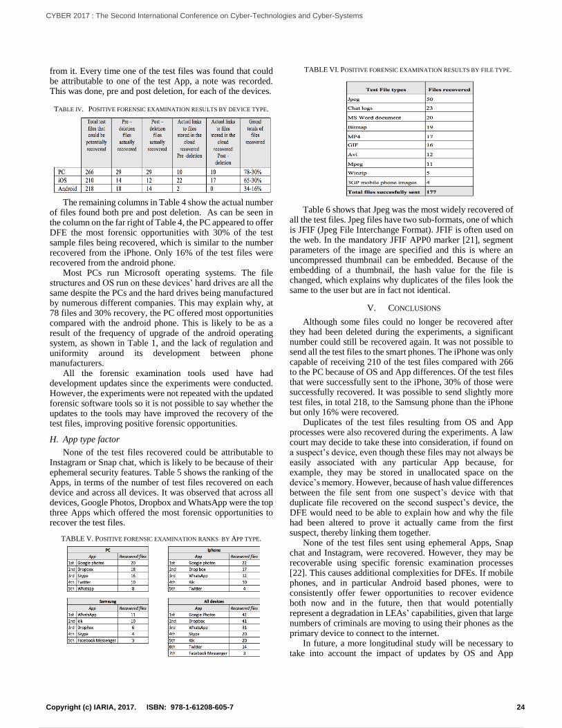
from it. Every time one of the test files was found that could be attributable to one of the test App, a note was recorded. This was done, pre and post deletion, for each of the devices.
TABLE IV. POSITIVE FORENSIC EXAMINATION RESULTS BY DEVICE TYPE.
The remaining columns in Table 4 show the actual number of files found both pre and post deletion. As can be seen in the column on the far right of Table 4, the PC appeared to offer DFE the most forensic opportunities with 30% of the test sample files being recovered, which is similar to the number recovered from the iPhone. Only 16% of the test files were recovered from the android phone.
Most PCs run Microsoft operating systems. The file structures and OS run on these devices’ hard drives are all the same despite the PCs and the hard drives being manufactured by numerous different companies. This may explain why, at 78 files and 30% recovery, the PC offered most opportunities compared with the android phone. This is likely to be as a result of the frequency of upgrade of the android operating system, as shown in Table 1, and the lack of regulation and uniformity around its development between phone manufacturers.
All the forensic examination tools used have had development updates since the experiments were conducted. However, the experiments were not repeated with the updated forensic software tools so it is not possible to say whether the updates to the tools may have improved the recovery of the test files, improving positive forensic opportunities.
H. App type factor
None of the test files recovered could be attributable to Instagram or Snap chat, which is likely to be because of their ephemeral security features. Table 5 shows the ranking of the Apps, in terms of the number of test files recovered on each device and across all devices. It was observed that across all devices, Google Photos, Dropbox and WhatsApp were the top three Apps which offered the most forensic opportunities to recover the test files.
TABLE V. POSITIVE FORENSIC EXAMINATION RANKS BY APP TYPE.
TABLE VI. POSITIVE FORENSIC EXAMINATION RESULTS BY FILE TYPE.
Table 6 shows that Jpeg was the most widely recovered of all the test files. Jpeg files have two sub-formats, one of which is JFIF (Jpeg File Interchange Format). JFIF is often used on the web. In the mandatory JFIF APP0 marker [21], segment parameters of the image are specified and this is where an uncompressed thumbnail can be embedded. Because of the embedding of a thumbnail, the hash value for the file is changed, which explains why duplicates of the files look the same to the user but are in fact not identical.
V. CONCLUSIONS
Although some files could no longer be recovered after they had been deleted during the experiments, a significant number could still be recovered again. It was not possible to send all the test files to the smart phones. The iPhone was only capable of receiving 210 of the test files compared with 266 to the PC because of OS and App differences. Of the test files that were successfully sent to the iPhone, 30% of those were successfully recovered. It was possible to send slightly more test files, in total 218, to the Samsung phone than the iPhone but only 16% were recovered.
Duplicates of the test files resulting from OS and App processes were also recovered during the experiments. A law court may decide to take these into consideration, if found on a suspect’s device, even though these files may not always be easily associated with any particular App because, for example, they may be stored in unallocated space on the device’s memory. However, because of hash value differences between the file sent from one suspect’s device with that duplicate file recovered on the second suspect’s device, the DFE would need to be able to explain how and why the file had been altered to prove it actually came from the first suspect, thereby linking them together.
None of the test files sent using ephemeral Apps, Snap chat and Instagram, were recovered. However, they may be recoverable using specific forensic examination processes [22]. This causes additional complexities for DFEs. If mobile phones, and in particular Android based phones, were to consistently offer fewer opportunities to recover evidence both now and in the future, then that would potentially represent a degradation in LEAs’ capabilities, given that large numbers of criminals are moving to using their phones as the primary device to connect to the internet.
In future, a more longitudinal study will be necessary to take into account the impact of updates by OS and App
24Copyright (c) IARIA, 2017. ISBN: 978-1-61208-605-7
CYBER 2017 : The Second International Conference on Cyber-Technologies and Cyber-Systems
33 / 90
developers on the tools. It will be worth conducting a statistical analysis to determine if the ability to retrieve data is related to the number of updates of the operating platform made by the developer. Establishing whether the OS continues to create and save duplicate files to the cloud despite the auto save function being disabled would be useful. Knowing the effects that such an action may have on the numbers of recoverable duplicate files and their storage locations, such as cache, would be helpful.
REFERENCES
[1] OFCOM, “Communications Market Report (UK)”, 2016, Available online: https://www.ofcom.org.uk/__data/assets/pdf_file/0024/26826/cmr_uk_2016.pdf, Last accessed September 2017.
[2] HMIC, “National Child Protection Inspections”, 2014, Available online:https://www.justiceinspectorates.gov.uk/hmicfrs/wp-content/uploads/greater-manchester-national-child-protection-inspection.pdf, Last accesed September 2017.
[3] S. Bommisetty, R. Tamma, and H. Mahalik, “Practical Mobile
Forensics”, Packt Publishing, 2014.
[4] AppBrain, “WhatsApp Inc. summary”, Available online: http://www. appbrain.com/dev/WhatsApp+Inc./, Last accessed September 2017.
[5] Y. Ma, X. Liu; Yi. Liu; Yu. Liu and G. Huang “A Tale of Two Fashions: An Empirical Study on the Performance of Native Apps and Web Apps on Android”, IEEE Transactions on Mobile Computing, ISSN: 1536-1233, doi: 10.1109/TMC. 2017.2756633, in press.
[6] J. B. Bayer, N. B. Ellison, S. Y. Schoenebeck and E. B. Falk, “Sharing the Small Moments: Ephemeral Social Interaction on Snapchat”, Information, Communication & Society, vol. 19, pp. 956-977, 2016.
[7] F. Roesner, B. T. Gill and T. Kohno, “Sex, Lies, or Kittens? Investigating the Use of Snapchat’s Self-Destructing Messages”, Financial Cryptography and Data Security, Lecture Notes in Computer Science, vol. 8437. Springer, 2014.
[8] J. Lessard and G. C. Kessler, “Android Forensics: Simplifying Cell Phone Examinations”, Small Scale Digital Device Forensics Journal, vol. 4, no. 1, pp. 1-12, ISSN: 1941-6164, September 2010.
[9] V. Rao and A.S.N. Chakravarthy, “Survey on Android Forensic Tools and Methodologies”, International Journal of Computer Applications, vol. 154, no. 8, pp.17-21, 2016.
[10] M. F. Breeuwsma, Forensic imaging of embedded systems using JTAG (boundary-scan), Digital Investigation, vol. 3, pp. 32–42, 2006.
[11] D. T. Hoang, C. Lee, D. Niyato and P. Wang, “A survey of mobile cloud computing: architecture, applications, and approaches”, Wireless Communications and Mobile Computing, vol. 13, pp. 1587-1611, 2013.
[12] K. Yang, S. Ou and H. Chen, “On effective offloading services for resource-constrained mobile devices running heavier mobile Internet applications”, IEEE Communications Magazine, vol. 46, pp. 56-63, January 2008.
[13] M. Lai, J. Wang, T. Song, N. Liu, Z. Qi and W. Zhou, “VSP: A Virtual Smartphone Platform to Enhance the Capability of Physical Smartphone”, IEEE Trustcom, BigDataSE & ISPA, pp.1434-1441, August 2016.
[14] A. Klein, “Hard Drive Stats for Q2 2017”, Available online: https://www.backblaze.com/blog/hard-drive-failure-stats-q2-2017/,Last accessed September 2017.
[15] Legistlation.gov.uk. “Regulation of Investigatory Powers Act 2000”, 2000, Available online: http://www.legislation.gov.uk/ ukpga/2000/23/contents, Last accessed September 2017.
[16] VirtualBox tool, Available online: https://www.virtualbox.org, Last accessed September 2017.
[17] Cellebrite UFED tool, Available online: http://www.cellebrite.com/Mobile-Forensics/Solutions, Last accessed September 2017.
[18] Autopsy tool, Available online: https://www.sleuthkit.org, Last accessed September 2017.
[19] Association Of Chief Police Officers, “ACPO Good Practice Guide for Digital Evidence v5”, 2012, Available online: http://www.digital-detective.net/digital-forensics-documents/ACPO_Good_Practice_Guide_for_Digital_Evidence_v5.pdf, Last accessed September 2017.
[20] B. Saltaformaggio, R. Bhatia, X. Zhang, D. Xu., G. Richard III, “Screen after Previous Screens: Spatial-Temporal Recreation of Android App Displays from Memory Images”. In Proc. 25th USENIX Security Symposium (Security'16), Austin, TX, 2016.
[21] Jpeg file format, Available online: https://www.w3.org/Graphics/JPEG/jfif3.pdf, Last accessed September 2017.
[22] M. A. H. B. Azhar, and T. Barton, "Forensic Analysis of Secure Ephemeral Messaging Applications on Android Platforms" In: Jahankhani H. et al. (eds) Global Security, Safety and Sustainability - The Security Challenges of the Connected World. ICGS3 2017. Communications in Computer and Information Science, vol. 630, pp. 27-41, Springer, 2017.
25Copyright (c) IARIA, 2017. ISBN: 978-1-61208-605-7
CYBER 2017 : The Second International Conference on Cyber-Technologies and Cyber-Systems
34 / 90
Detecting Safety- and Security-Relevant Programming Defectsby Sound Static Analysis
Daniel Kastner, Laurent Mauborgne, Christian Ferdinand
AbsInt GmbHScience Park 1, 66123 Saarbrucken, Germany
Email: [email protected], [email protected], [email protected]
Abstract—Static code analysis has evolved to be a standardtechnique in the development process of safety-critical software.It can be applied to show compliance to coding guidelines,and to demonstrate the absence of critical programming errors,including runtime errors and data races. In recent years, securityconcerns have become more and more relevant for safety-criticalsystems, not least due to the increasing importance of highly-automated driving and pervasive connectivity. While in thepast, sound static analyzers have been primarily applied todemonstrate classical safety properties they are well suited alsoto address data safety, and to discover security vulnerabilities.This article gives an overview and discusses practical experience.
Keywords–static analysis; abstract interpretation; runtime er-rors; security vulnerabilities; functional safety; cybersecurity.
I. INTRODUCTION
Some years ago, static analysis meant manual reviewof programs. Nowadays, automatic static analysis tools aregaining popularity in software development as they offer atremendous increase in productivity by automatically checkingthe code under a wide range of criteria. Many software devel-opment projects are developed according to coding guidelines,such as MISRA C [1], SEI CERT C [2], or CWE (CommonWeakness Enumeration) [3], aiming at a programming stylethat improves clarity and reduces the risk of introducing bugs.Compliance checking by static analysis tools has becomecommon practice.
In safety-critical systems, static analysis plays a particularlyimportant role. A failure of a safety-critical system maycause high costs or even endanger human beings. With thegrowing size of software-implemented functionality, prevent-ing software-induced system failures becomes an increasinglyimportant task. One particularly dangerous class of errors areruntime errors which include faulty pointer manipulations,numerical errors such as arithmetic overflows and divisionby zero, data races, and synchronization errors in concurrentsoftware. Such errors can cause software crashes, invalidateseparation mechanisms in mixed-criticality software, and area frequent cause of errors in concurrent and multi-core appli-cations. At the same time, these defects are also at the rootof many security vulnerabilities, including exploits based onbuffer overflows, dangling pointers, or integer errors.
In safety-critical software projects, obeying coding guide-lines such as MISRA C is strongly recommended by all currentsafety standards, including DO-178C [4], IEC-61508 [5], ISO-26262 [6], and EN-50128 [7]. In addition, all of them considerdemonstrating the absence of runtime errors explicitly as a ver-ification goal. This is often formulated indirectly by addressingruntime errors (e.g., division by zero, invalid pointer accesses,arithmetic overflows) in general, and additionally consider-ing corruption of content, synchronization mechanisms, and
freedom of interference in concurrent execution. Semantics-based static analysis has become the predominant technologyto detect runtime errors and data races.
Abstract interpretation is a formal methodology forsemantics-based static program analysis [8]. It supports formalsoundness proofs (it can be proven that no error is missed) andscales to real-life industry applications. Abstract interpretation-based static analyzers provide full control and data coverageand allow conclusions to be drawn that are valid for allprogram runs with all inputs. Such conclusions may be thatno timing or space constraints are violated, or that runtimeerrors or data races are absent: the absence of these errorscan be guaranteed [9]. Nowadays, abstract interpretation-basedstatic analyzers that can detect stack overflows and violationsof timing constraints [10] and that can prove the absence ofruntime errors and data races [11][12], are widely used fordeveloping and verifying safety-critical software.
In the past, security properties have mostly been rele-vant for non-embedded and/or non-safety-critical programs.Recently due to increasing connectivity requirements (cloud-based services, car-to-car communication, over-the-air updates,etc.), more and more security issues are rising in safety-criticalsoftware as well. Security exploits like the Jeep Cherokeehacks [13] which affect the safety of the system are becom-ing more and more frequent. In consequence, safety-criticalsoftware development faces novel challenges which previouslyonly have been addressed in other industry domains.
On the other hand, as outlined above, safety-critical soft-ware is developed according to strict guidelines which effec-tively reduce the relevant subset of the programming languageused and improve software verifiability. As an example dy-namic memory allocation and recursion often are forbidden orused in a very limited way. In consequence, for safety-criticalsoftware much stronger code properties can be shown than fornon-safety-critical software, so that also security vulnerabilitiescan be addressed in a more powerful way.
The topic of this article is to show that some classesof defects can be proven to be absent in the software sothat exploits based on such defects can be excluded. Onthe other hand, additional syntactic checks and semanticalanalyses become necessary to address security properties thatare orthogonal to safety requirements. Throughout the articlewe will focus on software aspects only, without addressingsafety or security properties at the hardware level. While wefocus on the programming language C, the basic analysistechniques described in this article are applicable to otherprogramming languages as well.
The article is structured as follows: Section II discusses therelation between safety and security requirements. The role ofcoding standards is discussed in Section II-A, a classification
26Copyright (c) IARIA, 2017. ISBN: 978-1-61208-605-7
CYBER 2017 : The Second International Conference on Cyber-Technologies and Cyber-Systems
35 / 90
of vulnerabilities is given in Section II-B, and Section II-Cfocuses on the analysis complexity of safety and security prop-erties. Section III gives an overview of abstract interpretationand its application to runtime error analysis, using the soundanalyzer Astree as an example. Section IV gives an overview ofcontrol and data flow analysis with emphasis on two advancedanalysis techniques: program slicing (cf. Section IV-A) andtaint analysis (cf. Section IV-B). Section V concludes.
II. SECURITY IN SAFETY-CRITICAL SYSTEMS
Functional safety and security are aspects of dependability,in addition to reliability and availability. Functional safety isusually defined as the absence of unreasonable risk to life andproperty caused by malfunctioning behavior of the software.The main goals of information security or cybersecurity (forbrevity denoted as “security” in this article) traditionally areto preserve confidentiality (information must not be disclosedto unauthorized entities), integrity (data must not be modifiedin an unauthorized or undetected way), and availability (datamust be accessible and usable upon demand).
In safety-critical systems, safety and security properties areintertwined. A violation of security properties can endangerthe functional safety of the system: an information leak couldprovide the basis for a successful attack on the system, anda malicious data corruption or denial-of-service attack maycause the system to malfunction. Vice versa, a violation ofsafety goals can compromise security: buffer overflows belongto the class of critical runtime errors whose absence have tobe demonstrated in safety-critical systems. At the same time,an undetected buffer overflow is one of the main securityvulnerabilities which can be exploited to read unauthorizedinformation, to inject code, or to cause the system to crash [14].To emphasize this, in a safety-critical system the definition offunctional safety can be adapted to define cybersecurity asabsence of unreasonable risk to life and property caused bymalicious misusage of the software.
The convergence of safety and security properties alsobecomes apparent in the increasing role of data in safety-critical systems. There are many well-documented incidentswhere harm was caused by erroneous data, corrupted data,or inappropriate use of data – examples include the TurkishAirlines A330 incident (2015), the Mars Climate Orbitercrash (1999), or the Cedars Sinai Medical Centre CT scannerradiation overdose (2009) [15]. The reliance on data in safety-critical systems has significantly grown in the past few years,cf. e.g., data used for decision-support systems, data used insensor fusion for highly automatic driving, or data providedby car-to-car communication or downloaded from a cloud. Asa consequence of this there are ongoing activities to providespecific guidance for handling data in safety-critical systems[15]. At the same time, these data also represent safety-relevanttargets for security attacks.
A. Coding Guidelines
The MISRA C standard [1] has originally been developedwith a focus on automotive industry but is now widely rec-ognized as a coding guideline for safety-critical systems ingeneral. Its aim is to avoid programming errors and enforcea programming style that enables the safest possible use ofC. A particular focus is on dealing with undefined/unspecified
behavior of C and on preventing runtime errors. As a conse-quence, it is also directly applicable to security-relevant code.
The most prominent coding guidelines targeting securityaspects are the ISO/IEC TS 17961 [16], the SEI CERT CCoding Standard [2], and the MITRE Common WeaknessEnumeration CWE [3].
The ISO/IEC TS 17961 C Secure Coding Rules [16]specifies rules for secure coding in C. It does not primarilyaddress developers but rather aims at establishing requirementsfor compilers and static analyzers. MISRA C:2012 Addendum2 [17] compares the ISO/IEC TS 17961 rule set with MISRAC:2012. Only 4 of the C Secure rules are not covered by thefirst edition of MISRA C:2012 [1], however, with Amendment1 to MISRA C:2012 [18] all of them are covered as well. Thisillustrates the strong overlap between the safety- and security-oriented coding guidelines.
The SEI CERT C Coding Standard belongs to the CERTSecure Coding Standards [19]. While emphasizing the securityaspect CERT C [2] also targets safety-critical systems: itaims at “developing safe, reliable and secure systems”. CERTdistinguishes between rules and recommendations where rulesare meant to provide normative requirements and recommenda-tions are meant to provide general guidance; the book version[2] describes the rules only. A particular focus is on eliminatingundefined behaviors that can lead to exploitable vulnerabilities.In fact, almost half of the CERT rules (43 of 99 rules) aretargeting undefined behaviors according to the C norm.
The Common Weakness Enumeration CWE is a softwarecommunity project [3] that aims at creating a catalog of soft-ware weaknesses and vulnerabilities. The goal of the project isto better understand flaws in software and to create automatedtools that can be used to identify, fix, and prevent thoseflaws. There are several catalogues for different programminglanguages, including C. In the latter one, once again, manyrules are associated with undefined or unspecified behaviors.
B. Vulnerability ClassificationMany rules are shared between the different coding guide-
lines, but there is no common structuring of security vul-nerabilities. The CERT Secure C roughly structures its rulesaccording to language elements, whereas ISO/IEC TS 17961and CWE are structured as a flat list of vulnerabilities. In thefollowing we list some of the most prominent vulnerabilitieswhich are addressed in all coding guidelines and which belongto the most critical ones at the C programming level. Thepresentation follows the overview given in [14].
1) Stack-based Buffer Overflows: An array declared aslocal variable in C is stored on the runtime stack. A C programmay write beyond the end of the array due to index valuesbeing too large or negative, or due to invalid increments ofpointers pointing into the array. A runtime error then hasoccurred whose behavior is undefined according to the Csemantics. As a consequence the program might crash withbus error or segmentation fault, but typically adjacent memoryregions will be overwritten. An attacker can exploit this bymanipulating the return address or the frame pointer bothof which are stored on the stack, or by indirect pointeroverwriting, and thereby gaining control over the executionflow of the program. In the first case the program will jumpto code injected by the attacker into the overwritten buffer
27Copyright (c) IARIA, 2017. ISBN: 978-1-61208-605-7
CYBER 2017 : The Second International Conference on Cyber-Technologies and Cyber-Systems
36 / 90
instead of executing an intended function return. In caseof overflows on array read accesses confidential informationstored on the stack (e.g., through temporary local variables)might be leaked. An example of such an exploit is the well-known W32.Blaster.Worm [20].
2) Heap-based Buffer Overflows: Heap memory is dy-namically allocated at runtime, e.g., by calling malloc()or calloc() implementations provided by dynamic memoryallocation libraries. There may be read or write operationsto dynamically allocated arrays that access beyond the arrayboundaries, similarly to stack-allocated arrays. In case of aread access information stored on the heap might be leaked– a prominent example is the Heartbleed bug in OpenSSL(cf. CERT vulnerability 720951 [21]). Via write operationsattackers may inject code and gain control over programexecution, e.g., by overwriting management information ofthe dynamic memory allocator stored in the accessed memorychunk.
3) General Invalid Pointer Accesses: Buffer overflows arespecial cases of invalid pointer accesses, which are listedhere as separate points due to the large number of attacksbased on them. However, any invalid pointer access in generalis a security vulnerability – other examples are null pointeraccesses or dangling pointer accesses. Accessing such a pointeris undefined behavior which can cause the program to crash,or behave erratically. A dangling pointer points to a memorylocation that has been deallocated either implicitly (e.g., datastored in the stack frame of a function after its return) or ex-plicitly by the programmer. A concrete example of a danglingpointer access is the double free vulnerability where alreadyfreed memory is freed a second time. This can be exploitedby an attacker to overwrite arbitrary memory locations andexecute injected code [14].
4) Uninitialized Memory Accesses: Automatic variablesand dynamically allocated memory have indeterminate valueswhen not explicitly initialized. Accessing them is undefinedbehavior. Uninitialized variables can also be used for securityattacks, e.g., in CVE-2009-1888 [22] potentially uninitializedvariables passed to a function were exploited to bypass theaccess control list and gain access to protected files [2].
5) Integer Errors: Integer errors are not exploitable vulner-abilities by themselves, but they can be the cause of criticalvulnerabilities like stack- or heap-based buffer overflows.Examples of integer errors are arithmetic overflows, or invalidcast operations. If, e.g., a negative signed value is used as anargument to a memcpy() call, it will be interpreted as a largeunsigned value, potentially resulting in a buffer overflow.
6) Format String Vulnerabilities : A format string is copiedto the output stream with occurrences of %-commands repre-senting arguments to be popped from the stack and expandedinto the stream. A format string vulnerability occurs, if attack-ers can supply the format string because it enables them tomanipulate the stack, once again making the program write toarbitrary memory locations.
7) Concurrency Defects: Concurrency errors may lead toconcurrency attacks which allow attackers to violate confiden-tiality, integrity and availability of systems [23]. In a racecondition the program behavior depends on the timing ofthread executions. A special case is a write-write or read-write data race where the same shared variable is accessed
by concurrent threads without proper synchronization. In aTime-of-Check-to-Time-of-Use (TOCTOU) race condition thechecking of a condition and its use are not protected by acritical section. This can be exploited by an attacker, e.g., bychanging the file handle between the accessibility check andthe actual file access. In general, attacks can be run either bycreating a data race due to missing lock-/unlock protections,or by exploiting existing data races, e.g., by triggering threadinvocations.
Most of the vulnerabilities described above are based onundefined behaviors, and among them buffer overflows seemto play the most prominent role for real-live attacks. Mostof them can be used for denial-of-service attacks by crashingthe program or causing erroneous behavior. They can also beexploited to inject code and cause the program to execute it,and to extract confidential data from the system. It is worthnoticing that from the perspective of a static analyzer mostexploits are based on potential runtime errors: when using anunchecked value as an index in an array the error will onlyoccur if the attacker manages to provide an invalid index value.The obvious conclusion is that safely eliminating all potentialruntime errors due to undefined behaviors in the programsignificantly reduces the risk for security vulnerabilities.
C. Analysis Complexity
While semantics-based static program analysis is widelyused for safety properties, there is practically no such ana-lyzer dedicated to specific security properties. This is mostlyexplained by the difference in complexity between safety andsecurity properties. From a semantical point of view, a safetyproperty can always be expressed as a trace property. Thismeans that to find all safety issues, it is enough to look ateach trace of execution in isolation.
This is not possible any more for security properties. Mostof them can only be expressed as set of traces properties, orhyperproperties [24]. A typical example is non-interference[25]: to express that the final value of a variable x can onlybe affected by the initial value of y and no other variable, onemust consider each pair of possible execution traces with thesame initial value for y, and check that the final value of x isthe same for both executions. It was proven in [24] that anyother definition (tracking assignments, etc) considering onlyone execution trace at a time would miss some cases or addfalse dependencies. This additional level of sets has directconsequences on the difficulty to track security propertiessoundly.
Other examples of hyperproperties are secure informationflow policies, service level agreements (which describe accept-able availability of resources in term of mean response time orpercentage uptime), observational determinism (whether a sys-tem appears deterministic to a low-level user), or quantitativeinformation flow.
Finding expressive and efficient abstractions for such prop-erties is a young research field (see [26]), which is the reasonwhy no sound analysis of such properties appear in industrialstatic analyzers yet. The best solution using the current stateof the art consists of using dedicated safety properties as anapproximation of the security property in question, such as thetaint propagation described in Section IV-B.
28Copyright (c) IARIA, 2017. ISBN: 978-1-61208-605-7
CYBER 2017 : The Second International Conference on Cyber-Technologies and Cyber-Systems
37 / 90
III. PROVING THE ABSENCE OF DEFECTS
In safety-critical systems, the use of dynamic memoryallocation and recursions typically is forbidden or only usedin limited ways. This simplifies the task of static analysissuch that for safety-critical embedded systems it is possibleto formally prove the absence of runtime errors, or report allpotential runtime errors which still exist in the program. Suchanalyzers are based on the theory of abstract interpretation [8],a mathematically rigorous formalism providing a semantics-based methodology for static program analysis.
A. Abstract InterpretationThe semantics of a programming language is a formal
description of the behavior of programs. The most precise se-mantics is the so-called concrete semantics, describing closelythe actual execution of the program on all possible inputs. Yetin general, the concrete semantics is not computable. Evenunder the assumption that the program terminates, it is toodetailed to allow for efficient computations. The solution is tointroduce an abstract semantics that approximates the concretesemantics of the program and is efficiently computable. Thisabstract semantics can be chosen as the basis for a staticanalysis. Compared to an analysis of the concrete semantics,the analysis result may be less precise but the computationmay be significantly faster.
A static analyzer is called sound if the computed resultshold for any possible program execution. Abstract interpreta-tion supports formal correctness proofs: it can be proved thatan analysis will terminate and that it is sound, i.e., that itcomputes an over-approximation of the concrete semantics.Imprecision can occur, but it can be shown that they willalways occur on the safe side. In runtime error analysis, sound-ness means that the analyzer never omits to signal an error thatcan appear in some execution environment. If no potential erroris signaled, definitely no runtime error can occur: there are nofalse negatives. If a potential error is reported, the analyzercannot exclude that there is a concrete program executiontriggering the error. If there is no such execution, this is afalse alarm (false positive). This imprecision is on the safeside: it can never happen that there is a runtime error whichis not reported.
B. AstreeIn the following we will concentrate on the sound static
runtime error analyzer Astree [12][27]. It reports programdefects caused by unspecified and undefined behaviors ac-cording to the C norm (ISO/IEC 9899:1999 (E)), programdefects caused by invalid concurrent behavior, violations ofuser-specified programming guidelines, and computes programproperties relevant for functional safety. Users are notifiedabout: integer/floating-point division by zero, out-of-boundsarray indexing, erroneous pointer manipulation and derefer-encing (buffer overflows, null pointer dereferencing, danglingpointers, etc.), data races, lock/unlock problems, deadlocks,integer and floating-point arithmetic overflows, read accessesto uninitialized variables, unreachable code, non-terminatingloops, violations of optional user-defined static assertions,violations of coding rules (MISRA C, ISO/IEC TS 17961,CERT, CWE) and code metric thresholds.
Astree computes data and control flow reports containinga detailed listing of accesses to global and static variables
sorted by functions, variables, and processes and containing asummary of caller/called relationships between functions. Theanalyzer can also report each effectively shared variable, thelist of processes accessing it, and the types of the accesses(read, write, read/write).
The C99 standard does not fully specify data type sizes,endianness nor alignment which can vary with different targetsor compilers. Astree is informed about these target ABIsettings by a dedicated configuration file in XML format andtakes the specified properties into account.
The design of the analyzer aims at reaching the zero falsealarm objective, which was accomplished for the first timeon large industrial applications at the end of November 2003.For keeping the initial number of false alarms low, a highanalysis precision is mandatory. To achieve high precisionAstree provides a variety of predefined abstract domains,e.g.: The interval domain approximates variable values byintervals, the octagon domain [28] covers relations of theform x ± y ≤ c for variables x and y and constants c. Thememory domain empowers Astree to exactly analyze pointerarithmetic and union manipulations. It also supports a type-safe analysis of absolute memory addresses. With the filterdomain digital filters can be precisely approximated. Floating-point computations are precisely modeled while keeping trackof possible rounding errors.
To deal with concurrency defects, Astree implements asound low-level concurrent semantics [29] which providesa scalable sound abstraction covering all possible threadinterleavings. The interleaving semantics enables Astree, inaddition to the classes of runtime errors found in sequentialprograms, to report data races, and lock/unlock problems, i.e.,inconsistent synchronization. The set of shared variables doesnot need to be specified by the user: Astree assumes that everyglobal variable can be shared, and discovers which ones areeffectively shared, and on which ones there is a data race. Aftera data race, the analysis continues by considering the valuesstemming from all interleavings. Since Astree is aware of alllocks held for every program point in each concurrent thread,Astree can also report all potential deadlocks.
Thread priorities are exploited to reduce the amount ofspurious interleavings considered in the abstraction and toachieve a more precise analysis. A dedicated task prioritydomain supports dynamic priorities, e.g., according to thePriority Ceiling Protocol used in OSEK systems [30]. Astreeincludes a built-in notion of mutual exclusion locks, on topof which actual synchronization mechanisms offered by op-erating systems can be modeled (such as POSIX mutexes orsemaphores).
Programs to be analyzed are seldom run in isolation; theyinteract with an environment. In order to soundly report allruntime errors, Astree must take the effect of the environmentinto account. In the simplest case the software runs directlyon the hardware, in which case the environment is limited toa set of volatile variables, i.e., program variables that can bemodified by the environment concurrently, and for which arange can be provided to Astree by formal directives writtenmanually, or generated by a dedicated wrapper generator. Moreoften, the program is run on top of an operating system, whichit can access through function calls to a system library. Whenanalyzing a program using a library, one possible solution is to
29Copyright (c) IARIA, 2017. ISBN: 978-1-61208-605-7
CYBER 2017 : The Second International Conference on Cyber-Technologies and Cyber-Systems
38 / 90
include the source code of the library with the program. This isnot always convenient (if the library is complex), nor possible,if the library source is not available, or not fully written in C, orultimately relies on kernel services (e.g., for system libraries).An alternative is to provide a stub implementation, i.e., towrite, for each library function, a specification of its possibleeffect on the program. Astree provides stub libraries for theARINC 653 standard, and the OSEK/AUTOSAR standards.In case of OSEK systems, Astree parses the OIL (OSEKImplementation Language) configuration file and generates thecorresponding C implementation automatically.
Practical experience on avionics and automotive industryapplications are given in [12][31]. They show that industry-sized programs of millions of lines of code can be analyzedin acceptable time with high precision for runtime errors anddata races.
IV. CONTROL AND DATA FLOW ANALYSIS
Safety standards such as DO-178C and ISO-26262 requireto perform control and data flow analysis as a part of softwareunit or integration testing and in order to verify the softwarearchitectural design. Investigating control and data flow is alsosubject of the Data Safety guidance [15], and it is a prerequisitefor analyzing confidentiality and integrity properties as a partof a security case. Technically, any semantics-based staticanalysis is able to provide information about data and controlflow, since this is the basis of the actual program analysis.However, data and control flow analysis has many aspects, andfor some of them, tailored analysis mechanisms are needed.
Global data and control flow analysis gives a summary ofvariable accesses and function invocations throughout programexecution. In its standard data and control flow reports Astreecomputes the number of read/write accesses for every global orstatic variable and lists the location of each access along withthe function from which the access is made and the thread inwhich the function is executed. The control flow is describedby listing all callers and callees for every C function alongwith the threads in which they can be run. Indirect variableaccesses via pointers as well as function pointer call targetsare fully taken into account.
More sophisticated information can be provided by twodedicated analysis methods: program slicing and taint analysis.Program slicing [32] aims at identifying the part of the programthat can influence a given set of variables at a given programpoint. Applied to a result value, e.g., it shows which functions,which statements, and which input variables contribute to itscomputation. Taint analysis tracks the propagation of specificdata values through program execution. It can be used, e.g.,to determine program parts affected by corrupted data froman insecure source. In the following we give a more detailedoverview of both techniques.
A. Program SlicingA slicing criterion of a program P is a tuple (s, V ) where
s is a statement and V is a set of variables in P . Intuitively, aslice is a subprogram of P which has the same behavior thanP with respect to the slicing criterion (s, V ). Computing astatement-minimal slice is an undecidable problem, but usingstatic analysis approximative slices can be computed. As anexample, Astree provides a program slicer which can producesound and compact slices by exploiting the invariants from
Astree’s core analysis including points-to information for vari-able and function pointers. A dynamic slice does not contain allstatements potentially affecting the slicing criterion, but onlythose relevant for a specific subset of program executions, e.g.,only those in which an error value can result.
Computing sound program slices is relevant for demon-strating safety and security properties. It can be used to showthat certain parts of the code or certain input variables mightinfluence or cannot influence a program section of interest.B. Taint Analysis
In literature, taint analysis is often mentioned in combina-tion with unsound static analyzers, since it allows to efficientlydetect potential errors in the code, e.g., array-index-out-of-bounds accesses, or infeasible library function parameters [2],[16]. Inside a sound runtime error analyzer this is not neededsince typically more powerful abstract domains can track allundefined or unspecified behaviors. Inside a sound analyzer,taint analysis is primarily a technique for analyzing securityproperties. Its advantage is that users can flexibly specify taints,taint sources, and taint sinks, so that application-specific dataand control flow requirements can be modeled.
In order to be able to leverage this efficient family ofanalyses in sound analyzers, one must formally define theproperties that may be checked using such techniques. Then itis possible to prove that a given implementation is sound withrespect to that formal definition, leading to clean and welldefined analysis results. Taint analysis consists of discoveringdata dependencies using the notion of taint propagation. Taintpropagation can be formalized using a non-standard semanticsof programs, where an imaginary taint is associated to someinput values. Considering a standard semantics using a suc-cessor relation between program states, and considering thata program state is a map from memory locations (variables,program counter, etc.) to values in V , the tainted semanticsrelates tainted states which are maps from the same memorylocations to V × {taint, notaint}, and such that if we projecton V we get the same relation as with the standard semantics.
To define what happens to the taint part of the tainted value,one must define a taint policy. The taint policy specifies:
Taint sources which are a subset of input values or variablessuch that in any state, the values associated with that inputvalues or variables are always tainted.
Taint propagation describes how the tainting gets propa-gated. Typical propagation is through assignment, butmore complex propagation can take more control flowinto account, and may not propagate the taint through allarithmetic or pointer operations.
Taint cleaning is an alternative to taint propagation, describ-ing all the operations that do not propagate the taint. Inthis case, all assignments not containing the taint cleaningwill propagate the taint.
Taint sinks is an optional set of memory locations. This hasno semantical effect, except to specify conditions whenan alarm should be emitted when verifying a program (analarm must be emitted if a taint sink may become taintedfor a given execution of the program).
A sound taint analyzer will compute an over-approximationof the memory locations that may be mapped to a tainted valueduring program execution. The soundness requirement ensuresthat no taint sink warning will be overlooked by the analyzer.
30Copyright (c) IARIA, 2017. ISBN: 978-1-61208-605-7
CYBER 2017 : The Second International Conference on Cyber-Technologies and Cyber-Systems
39 / 90
The tainted semantics can easily be extended to a mix ofdifferent hues of tainting, corresponding to an extension ofthe taint set associated with values. Then propagation can getmore complex, with tainting not just being propagated but alsochanging hue depending on the instruction. Such extensionslead to a rather flexible and powerful data dependency analysis,while remaining scalable.
V. CONCLUSION
In this article, we have given an overview of code-leveldefects and vulnerabilities relevant for functional safety andsecurity. We have shown that many security attacks can betraced back to behaviors undefined or unspecified accordingto the C semantics. By applying sound static runtime erroranalyzers, a high degree of security can be achieved forsafety-critical software since the absence of such defectscan be proven. In addition, security hyperproperties requireadditional analyses to be performed which, by nature, havea high complexity. We have given two examples of scalablededicated analyses, program slicing and taint analysis. Appliedas extensions of sound static analyzers, they allow to furtherincrease confidence in the security of safety-critical embeddedsystems.
ACKNOWLEDGMENT
This work was funded within the project ARAMiS II bythe German Federal Ministry for Education and Research withthe funding ID 01—S16025. The responsibility for the contentremains with the authors.
REFERENCES
[1] MISRA (Motor Industry Software Reliability Association) WorkingGroup, MISRA-C:2012 Guidelines for the use of the C language incritical systems, MISRA Limited, Mar. 2013.
[2] Software Engineering Institute SEI – CERT Division, SEI CERT CCoding Standard – Rules for Developing Safe, Reliable, and SecureSystems. Carnegie Mellon University, 2016.
[3] The MITRE Corporation, “CWE – Common Weakness Enumeration.”[Online]. Available: https://cwe.mitre.org [retrieved: Sep. 2017].
[4] Radio Technical Commission for Aeronautics, “RTCA DO-178C. Soft-ware Considerations in Airborne Systems and Equipment Certification,”2011.
[5] IEC 61508, “Functional safety of electrical/electronic/programmableelectronic safety-related systems,” 2010.
[6] ISO 26262, “Road vehicles – Functional safety,” 2011.[7] CENELEC EN 50128, “Railway applications – Communication, sig-
nalling and processing systems – Software for railway control andprotection systems,” 2011.
[8] P. Cousot and R. Cousot, “Abstract interpretation: aunified lattice model for static analysis of programs byconstruction or approximation of fixpoints,” in Proc. ofPOPL’77. ACM Press, 1977, pp. 238–252. [Online]. Available:http://www.di.ens.fr/˜cousot/COUSOTpapers/POPL77.shtml [retrieved:Sep. 2017].
[9] D. Kastner, “Applying Abstract Interpretation to Demonstrate Func-tional Safety,” in Formal Methods Applied to Industrial ComplexSystems, J.-L. Boulanger, Ed. London, UK: ISTE/Wiley, 2014.
[10] J. Souyris, E. Le Pavec, G. Himbert, V. Jegu, G. Borios, and R. Heck-mann, “Computing the worst case execution time of an avionicsprogram by abstract interpretation,” in Proceedings of the 5th IntlWorkshop on Worst-Case Execution Time (WCET) Analysis, 2005, pp.21–24.
[11] D. Delmas and J. Souyris, “ASTREE: from Research to Industry,” inProc. 14th International Static Analysis Symposium (SAS2007), ser.LNCS, no. 4634, 2007, pp. 437–451.
[12] D. Kastner, A. Mine, L. Mauborgne, X. Rival, J. Feret, P. Cousot,A. Schmidt, H. Hille, S. Wilhelm, and C. Ferdinand, “Finding AllPotential Runtime Errors and Data Races in Automotive Software,” inSAE World Congress 2017. SAE International, 2017.
[13] Wired.com, “The jeep hackers are back to prove carhacking can get much worse,” 2016. [Online]. Avail-able: https://www.wired.com/2016/08/jeep-hackers-return-high-speed-steering-acceleration-hacks/ [retrieved: Sep. 2017]
[14] Y. Younan, W. Joosen, and F. Piessens, “Code injection in c andc++ : A survey of vulnerabilities and countermeasures,” DepartementComputerwetenschappen, Katholieke Universiteit Leuven, Tech. Rep.,2004.
[15] SCSC Data Safety Initiative Working Group [DSIWG], “Data Safety(Version 2.0) [SCSC-127B],” Safety-Critical Systems Club, Tech. Rep.,Jan 2017.
[16] ISO/IEC, “Information Technology – Programming Languages, TheirEnvironments and System Software Interfaces – Secure Coding Rules(ISO/IEC TS 17961),” Nov 2013.
[17] MISRA (Motor Industry Software Reliability Association) WorkingGroup, MISRA-C:2012 – Addendum 2. Coverage of MISRA C:2012against ISO/IEC TS 17961:2013 ”C Secure”, MISRA Limited, Apr.2016.
[18] MISRA (Motor Industry Software Reliability Association) WorkingGroup , MISRA-C:2012 Amendment 1 – Additional security guidelinesfor MISRA C:2012, MISRA Limited, Apr. 2016.
[19] CERT – Software Engineering Institute, Carnegie Mellon University,“SEI CERT Coding Standards Website.” [Online]. Available:https://www.securecoding.cert.org [retrieved: Sep. 2017].
[20] Wikipedia, “Blaster (computer worm).” [Online]. Available:https://en.wikipedia.org/wiki/Blaster (computer worm) [retrieved: Sep.2017].
[21] CERT – Vulnerability Notes Database, “Vulnerability NoteVU#720951 – OpenSSL TLS heartbeat extension readoverflow discloses sensitive information.” [Online]. Available:http://www.kb.cert.org/vuls/id/720951 [retrieved: Sep. 2017].
[22] NIST – National Vulnerability Database, “CVE-2009-1888:SAMBA ACLs Uninitialized Memory Read.” [Online]. Available:https://nvd.nist.gov/vuln/detail/CVE-2009-1888 [retrieved: Sep. 2017].
[23] J. Yang, A. Cui, J. Gallagher, S. Stolfo, and S. Sethumadhavan,“Concurrency attacks,” in In the Fourth USENIX Workshop on HotTopics in Parallelism (HOTPAR12), 2012.
[24] M. R. Clarkson and F. B. Schneider, “Hyperproperties,” Journal ofComputer Security, vol. 18, 2010, pp. 1157–1210.
[25] A. Sabelfeld and A. C. Myers, “Language-based information-flowsecurity,” IEEE Journal on Selected Areas in Communications, vol. 21,no. 1, 2003, pp. 5–19.
[26] M. Assaf, D. A. Naumann, J. Signoles, E. Totel, and F. Tronel,“Hypercollecting semantics and its application to static analysisof information flow,” CoRR, vol. abs/1608.01654, 2016. [Online].Available: http://arxiv.org/abs/1608.01654 [retrieved: Sep. 2017].
[27] A. Mine, L. Mauborgne, X. Rival, J. Feret, P. Cousot, D. Kastner,S. Wilhelm, and C. Ferdinand, “Taking Static Analysis to the NextLevel: Proving the Absence of Run-Time Errors and Data Races withAstree,” Embedded Real Time Software and Systems Congress ERTS2.
[28] A. Mine, “The Octagon Abstract Domain,” Higher-Order and SymbolicComputation, vol. 19, no. 1, 2006, pp. 31–100.
[29] A. Mine, “Static analysis of run-time errors in embedded real-timeparallel C programs,” Logical Methods in Computer Science (LMCS),vol. 8, no. 26, Mar. 2012, p. 63.
[30] OSEK/VDX, OSEK/VDX Operating System. Version 2.2.3.,http://www.osek-vdx.org, 2005.
[31] A. Mine and D. Delmas, “Towards an Industrial Use of Sound StaticAnalysis for the Verification of Concurrent Embedded Avionics Soft-ware,” in Proc. of the 15th International Conference on EmbeddedSoftware (EMSOFT’15). IEEE CS Press, Oct. 2015, pp. 65–74.
[32] M. Weiser, “Program slicing,” in Proceedings of the 5th InternationalConference on Software Engineering, ser. ICSE ’81. IEEE Press, 1981,pp. 439–449.
31Copyright (c) IARIA, 2017. ISBN: 978-1-61208-605-7
CYBER 2017 : The Second International Conference on Cyber-Technologies and Cyber-Systems
40 / 90
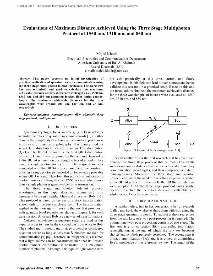
Evaluations of Maximum Distance Achieved Using the Three Stage Multiphoton
Protocol at 1550 nm, 1310 nm, and 850 nm
Majed Khodr
Electrical, Electronics and Communications Department
American University of Ras Al Khaimah
Ras Al Khaimah, UAE
e-mail: [email protected]
Abstract—This paper presents an initial investigation of
practical realization of quantum secure communication using
the three-stage multi-photon tolerant protocols. The secret raw
key was optimized and used to calculate the maximum
achievable distance at three different wavelengths, i.e., 1550 nm,
1310 nm, and 850 nm assuming lossless fiber optics channel
length. The maximum achievable distances for the three
wavelengths were around 200 km, 140 km, and 25 km,
respectively.
Keywords-quantum communication; fiber channel; three
stage protocol; multi-photon.
I. INTRODUCTION
Quantum cryptography is an emerging field in network
security that relies on quantum mechanics proofs [1, 2] rather
than on the complexity of solving a mathematical problem as
in the case of classical cryptography. It is mainly used for
secret key distribution, called quantum key distribution
(QKD). The BB’84 protocol is the first QKD distribution
protocol [1] and it was proposed by Bennett and Brassard in
1984. BB’84 is based on encoding the bits of a random key
using a single photon for each bit. The major drawbacks
associated with the BB’84 protocol are due to the constraint
of using a single photon per encoded bit to provide a provably
secure QKD scheme. Therefore, this protocol is vulnerable to
photon number splitting attacks (PNS) in cases where more
than a single photon is generated per bit transmission.
The three stage multi-photon tolerant protocol
investigated in this paper does not require any prior
agreement between a sender Alice and a receiver Bob [3-5].
This protocol is based on the use of unitary transformation
known only to the party applying them. The transformation
applied to the message in transit is the key that provides it
with quantum level security. As shown in Figure 1, for each
transmission, Alice and Bob use a new set of transformations.
Coherent non-decoying quantum states are used in this
paper in order to transfer the encoded bits from Alice to Bob.
The studied multi-photon, multi-stage protocol is considered
quantum secure as long as less than 𝑁 photons are used for
communication [5] [6]. Therefore, in this paper, it is assumed
that a light source can be constructed such that its Poisson
photon-number distribution is truncated to a maximum
number of photons. Although, this type of light source does
not exit practically at this time, current and future
developments in this field can lead to such sources and hence
validate this research in a practical setup. Based on this and
the formulations obtained, the maximum achievable distance
for the three wavelengths of interest were evaluated at: 1550
nm, 1310 nm, and 850 nm.
Figure 1. Schematic of the three-stage protocol [3].
Significantly, this is the first research that has ever been
done on the three stage protocol that estimates key results
such as maximum distance that can be achieved at three key
communication wavelengths, and then compares the data to
existing results. Moreover, the three stage multi-photon
protocol eliminates the need for the sifting step that is needed
in the BB’84 protocol. In section II, the BB’84 formulations
were adopted to fit the three stage protocol under study.
Section III include the theoretical data and results obtained,
while section IV is the conclusion.
II. FORMULATION METHOD
A sender, Alice, has in her possession a list of symbols
(called raw key); she wishes to share them with Bob using the
three stage quantum protocol. To extract a short secret key
from the raw key, one-way post-processing is required. The
optimal one–way post processing consists of two steps. The
first step is error correction (EC), also called information
reconciliation, at the end of which the raw key becomes
shorter and symbols perfectly correlated. The second step is
privacy amplification (PA), and it is aimed at diminishing
Eve’s knowledge of the reference raw key. The length of the
32Copyright (c) IARIA, 2017. ISBN: 978-1-61208-605-7
CYBER 2017 : The Second International Conference on Cyber-Technologies and Cyber-Systems
41 / 90
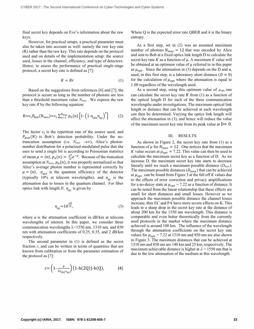
final secret key depends on Eve’s information about the raw
keys.
However, for practical setups, a practical parameter must
also be taken into account as well: namely the raw key rate
(R) rather than the raw key. This rate depends on the protocol
used and on details of the implementation setup: the source
used, losses in the channel, efficiency, and type of detectors.
Hence, to assess the performance of practical single-stage
protocol, a secret key rate is defined as [7]:
𝐾 = 𝑅𝑟 (1)
Based on the suggestions from references [6] and [7], the
protocol is secure as long as the number of photons are less
than a threshold maximum value Nmax. . We express the raw
key rate R by the following equation:
R=sPBob(Nmax)=s ∑ pA(n) [1- (1-det
qc)
n
] Nmaxn=1 (2)
The factor 𝑠 is the repetition rate of the source used, and
𝑃𝐵𝑜𝑏(𝑁) is Bob’s detection probability. Under the no-
truncation assumption (i.e. Nmax ), Alice’s photon-
number distribution for a polarized-modulated pulse that she
uses to send a single bit is according to Poissonian statistics
of mean 𝜇 = ⟨𝑛⟩, 𝑝𝐴(𝑛) = 𝜇𝑛
𝑛!𝑒−𝜇. Because of the truncation
assumption at Nmax, 𝑝𝐴(𝑛), it was properly normalized so that
Alice’s average photon number is represented correctly by
𝜇 = ⟨𝑛⟩. 𝑑𝑒𝑡
is the quantum efficiency of the detector
(typically 10% at telecom wavelengths), and 𝑞𝑐
is the
attenuation due to losses in the quantum channel. For fiber
optics link with length 𝐷, 𝑞𝑐
is given by
qc
=10-αD
10 , (3)
where is the attenuation coefficient in dB/km at telecom
wavelengths of interest. In this paper, we consider three
communication wavelengths =1550 nm, 1310 nm, and 850
nm with attenuation coefficients of 0.25, 0.35, and 2 dB/km
respectively.
The second parameter in (1) is defined as the secret
fraction r, and can be written in terms of quantities that are
known from calibration or from the parameter estimation of
the protocol as [7]:
r= (1-μ
2detqc
) {1-h(2Q)}-h(Q), (4)
Where Q is the expected error rate QBER and h is the binary
entropy.
As a first step, set in (2) was an assumed maximum
number of photons 𝑁𝑚𝑎𝑥 = 12 that was encoded by Alice
and sent to Bob at a fixed optics link length D to calculate the
secret key rate 𝐾 as a function of µ. A maximum K value will
be obtained at an optimum value of µ referred to in this paper
as 𝜇𝑜𝑝𝑡. Since the attenuation in (3) depends on the D and α,
used, in this first step, is a laboratory short distance (𝐷 ≈ 0)
for the calculation of 𝜇𝑜𝑝𝑡 where the attenuation is equal to
1.00 regardless of the wavelength used.
As a second step, using this optimum value of µopt, one
can calculate the secret key rate 𝐾 from (1) as a function of
the optical length D for each of the three communication
wavelengths under investigations. The maximum optical link
length or distance that can be achieved at each wavelength
can then be determined. Varying the optics link length will
affect the attenuation in (3), and hence will reduce the value
of the maximum secret key rate from its peak value at D≈ 0.
III. RESULTS
As shown in Figure 2, the secret key rate from (1) as a function of 𝜇 for 𝑁𝑚𝑎𝑥 = 12 . One notices that the maximum 𝐾 value occurs at 𝜇𝑜𝑝𝑡 = 7.22. This value can then be used to
calculate the maximum secret key as a function of D. As we increase D, the maximum secret key rate starts to decrease linearly until we reach a maximum possible distance (Dmax.). The maximum possible distances (𝐷𝑚𝑎𝑥) that can be achieved at 𝜇𝑜𝑝𝑡 can be found from Figure 3 at the fall off K values due
to the effects of error correction and privacy amplifications for a no-decoy state at 𝜇𝑜𝑝𝑡 = 7.22 as a function of distance. It
can be noted from the linear relationship that these effects are small for short distances and small losses. However as we approach the maximum possible distance the channel losses increase; thus EC and PA have more severe effects on K. This leads to a sharp drop in the secret key rate at the distance of about 200 km for the 1550 nm wavelength. This distance is comparable and even better theoretically from the currently used protocols in the market where the maximum distance achieved is around 100 km. The influence of the wavelength through the attenuation coefficients on the secret key rate values for 𝜇𝑜𝑝𝑡 = 7.22 at 1310 nm and 850 nm are also shown
in Figure 3. The maximum distances that can be achieved at 1310 nm and 850 nm are 140 km and 25 km, respectively. The maximum achievable distance is higher at = 1550 nm that is due to the low attenuation of the medium at this wavelength.
33Copyright (c) IARIA, 2017. ISBN: 978-1-61208-605-7
CYBER 2017 : The Second International Conference on Cyber-Technologies and Cyber-Systems
42 / 90
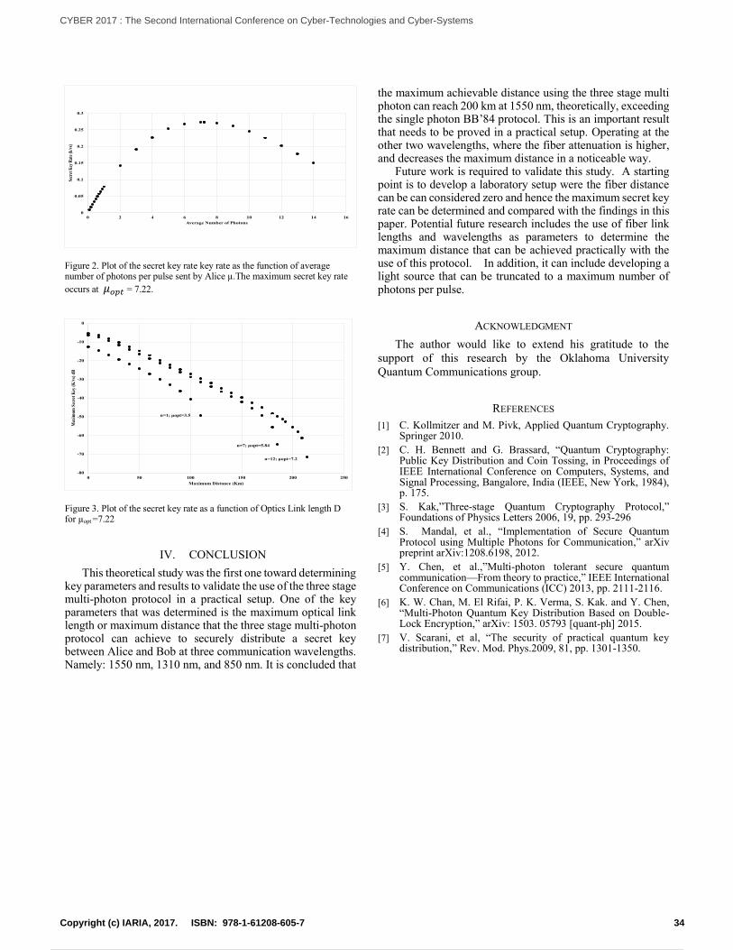
Figure 2. Plot of the secret key rate key rate as the function of average number of photons per pulse sent by Alice µ.The maximum secret key rate
occurs at 𝜇𝑜𝑝𝑡 = 7.22.
Figure 3. Plot of the secret key rate as a function of Optics Link length D for µopt =7.22
IV. CONCLUSION
This theoretical study was the first one toward determining key parameters and results to validate the use of the three stage multi-photon protocol in a practical setup. One of the key parameters that was determined is the maximum optical link length or maximum distance that the three stage multi-photon protocol can achieve to securely distribute a secret key between Alice and Bob at three communication wavelengths. Namely: 1550 nm, 1310 nm, and 850 nm. It is concluded that
the maximum achievable distance using the three stage multi photon can reach 200 km at 1550 nm, theoretically, exceeding the single photon BB’84 protocol. This is an important result that needs to be proved in a practical setup. Operating at the other two wavelengths, where the fiber attenuation is higher, and decreases the maximum distance in a noticeable way.
Future work is required to validate this study. A starting point is to develop a laboratory setup were the fiber distance can be can considered zero and hence the maximum secret key rate can be determined and compared with the findings in this paper. Potential future research includes the use of fiber link lengths and wavelengths as parameters to determine the maximum distance that can be achieved practically with the use of this protocol. In addition, it can include developing a light source that can be truncated to a maximum number of photons per pulse.
ACKNOWLEDGMENT
The author would like to extend his gratitude to the
support of this research by the Oklahoma University
Quantum Communications group.
REFERENCES
[1] C. Kollmitzer and M. Pivk, Applied Quantum Cryptography. Springer 2010.
[2] C. H. Bennett and G. Brassard, “Quantum Cryptography: Public Key Distribution and Coin Tossing, in Proceedings of IEEE International Conference on Computers, Systems, and Signal Processing, Bangalore, India (IEEE, New York, 1984), p. 175.
[3] S. Kak,”Three-stage Quantum Cryptography Protocol,” Foundations of Physics Letters 2006, 19, pp. 293-296
[4] S. Mandal, et al., “Implementation of Secure Quantum Protocol using Multiple Photons for Communication,” arXiv preprint arXiv:1208.6198, 2012.
[5] Y. Chen, et al.,”Multi-photon tolerant secure quantum communication—From theory to practice,” IEEE International Conference on Communications (ICC) 2013, pp. 2111-2116.
[6] K. W. Chan, M. El Rifai, P. K. Verma, S. Kak. and Y. Chen, “Multi-Photon Quantum Key Distribution Based on Double-Lock Encryption,” arXiv: 1503. 05793 [quant-ph] 2015.
[7] V. Scarani, et al, “The security of practical quantum key distribution,” Rev. Mod. Phys.2009, 81, pp. 1301-1350.
0
0.05
0.1
0.15
0.2
0.25
0.3
0 2 4 6 8 10 12 14 16
Secr
et K
ey R
ate
(k/v
s)
Average Number of Photons
-80
-70
-60
-50
-40
-30
-20
-10
0
0 50 100 150 200 250
Max
imu
m S
ecre
t K
ey (
K/v
s) d
B
Maximum Distance (Km)
n=1; μopt=3.5
n=12; μopt=7.2
n=7; μopt=5.84
34Copyright (c) IARIA, 2017. ISBN: 978-1-61208-605-7
CYBER 2017 : The Second International Conference on Cyber-Technologies and Cyber-Systems
43 / 90
Enhancing Integrity Protection for Industrial Cyber Physical Systems
Rainer Falk and Steffen Fries
Corporate Technology
Siemens AG
Munich, Germany
e-mail: {rainer.falk|steffen.fries}@siemens.com
Abstract—Cyber physical systems are technical systems that
are operated and controlled using information technology.
Protecting the integrity of cyber physical systems is a highly
important security objective to ensure the correct and reliable
operation and to ensure high availability. A comprehensive
protection concept of the system integrity involves several axes:
the component level ranging from sensors/actuator devices up
to control and supervisory systems, planning and configuration
management, and the system life cycle. It allows detecting
integrity violations on system level reliably by analyzing
integrity measurements from a multitude of independent
integrity sensors, capturing and analyzing integrity
measurements of the physical world, on the field level, and of
control and supervisory systems.
Keywords–system integrity, device integrity; cyber physical
systems; Internet of Things, embedded security; cyber security.
I. INTRODUCTION
With ubiquitous machine-oriented communication, e.g., the Internet of Things and interconnected cyber physical systems (CPS), the integrity of technical systems is becoming an increasingly important security objective. Information technology (IT) security mechanisms have been known for many years, and are applied in smart devices (Internet of Things, Cyber Physical Systems, industrial and energy automation systems, operation technology) [1]. Such mechanisms target authentication, system and communication integrity and confidentiality of data in transit or at rest. System integrity takes a broader approach where not only the integrity of individual components (device integrity) and of communication is addressed, but where integrity shall be ensured at the system level of interconnected devices. This purpose is in particular challenging for dynamically changing cyber physical systems, that come with the industrial Internet of Things (IIoT) and Industrie 4.0. Cyber systems will become more open and dynamic to support flexible production down to lot size 1 (plug-and-work reconfiguration of manufacturing equipment), and flexible adaptation to changing needs (market demand, individualized products).
The flexibility starts on the device level where smart devices allow for upgrading and enhancing device functionality by downloadable apps. But also the system of interconnected machines is reconfigured according to changing needs.
Classical approaches for protecting device and system integrity target at preventing any changes, and compare the current configuration to a fixed reference policy. More flexible approaches are needed to protect integrity for flexibly reconfigurable and self-adapting CPSs.
This paper describes an integrated, holistic approach for ensuring CPS integrity. After summarizing system security requirements coming from relevant industrial security standard IEC62443 [1] in Section II, an overview for protecting device integrity and system integrity is described in Sections III and IV. The presented approach for integrity monitoring is an extensible framework to include integrity information from IT-based functions and the physical world of a CPS. This allows integrating integrity information from the digital and the physical world. A new approach for integrity monitoring of encrypted communications is described in Section V. An approach for evaluation in an operational security management setting is outlined in Section VI. Related work is summarized in Section VII, and Section VIII concludes the paper.
II. SYSTEM INTEGRITY REQUIREMENTS
A. Overview IEC62443 Industrial Security Standard
The international industrial security standard IEC 62443 is a security requirements framework defined by the International Electrotechnical Commission (IEC) and can be applied to different automation domains, including energy automation, process automation, building automation, and others. The standard has been created to address the specific requirements of industrial automation and control systems. It covers both organizational and technical aspects of security. In the set of corresponding documents, security requirements are defined, which target the solution operator and the integrator but also the product vendor.
As shown in Figure 1, different parts of the standard are grouped into four clusters covering
common definitions and metrics;
requirements on setup of a security organization (ISMS
related, comparable to ISO 27001 [2]), as well as
solution supplier and service provider processes;
technical requirements and methodology for security on
system-wide level, and
35Copyright (c) IARIA, 2017. ISBN: 978-1-61208-605-7
CYBER 2017 : The Second International Conference on Cyber-Technologies and Cyber-Systems
44 / 90
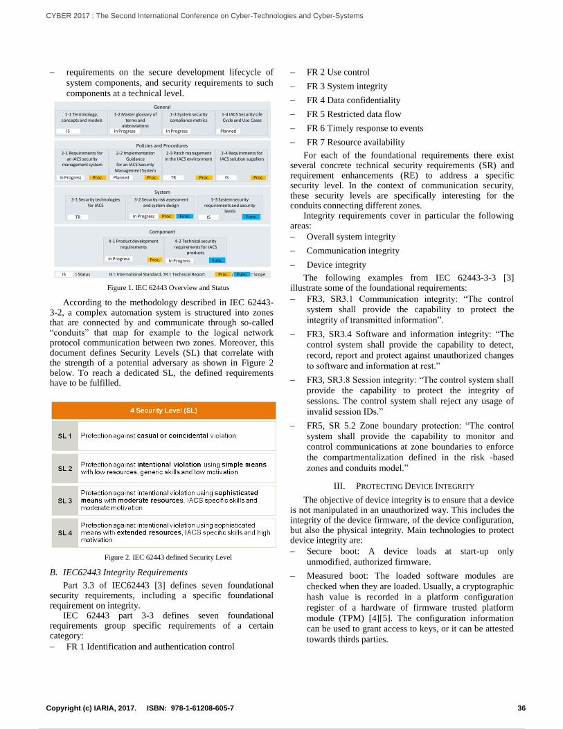
requirements on the secure development lifecycle of
system components, and security requirements to such
components at a technical level.
Figure 1. IEC 62443 Overview and Status
According to the methodology described in IEC 62443-3-2, a complex automation system is structured into zones that are connected by and communicate through so-called “conduits” that map for example to the logical network protocol communication between two zones. Moreover, this document defines Security Levels (SL) that correlate with the strength of a potential adversary as shown in Figure 2 below. To reach a dedicated SL, the defined requirements have to be fulfilled.
Figure 2. IEC 62443 defined Security Level
B. IEC62443 Integrity Requirements
Part 3.3 of IEC62443 [3] defines seven foundational security requirements, including a specific foundational requirement on integrity.
IEC 62443 part 3-3 defines seven foundational requirements group specific requirements of a certain category:
FR 1 Identification and authentication control
FR 2 Use control
FR 3 System integrity
FR 4 Data confidentiality
FR 5 Restricted data flow
FR 6 Timely response to events
FR 7 Resource availability
For each of the foundational requirements there exist several concrete technical security requirements (SR) and requirement enhancements (RE) to address a specific security level. In the context of communication security, these security levels are specifically interesting for the conduits connecting different zones.
Integrity requirements cover in particular the following areas:
Overall system integrity
Communication integrity
Device integrity
The following examples from IEC 62443-3-3 [3] illustrate some of the foundational requirements:
FR3, SR3.1 Communication integrity: “The control
system shall provide the capability to protect the
integrity of transmitted information”.
FR3, SR3.4 Software and information integrity: “The
control system shall provide the capability to detect,
record, report and protect against unauthorized changes
to software and information at rest.”
FR3, SR3.8 Session integrity: “The control system shall
provide the capability to protect the integrity of
sessions. The control system shall reject any usage of
invalid session IDs.”
FR5, SR 5.2 Zone boundary protection: “The control
system shall provide the capability to monitor and
control communications at zone boundaries to enforce
the compartmentalization defined in the risk -based
zones and conduits model.”
III. PROTECTING DEVICE INTEGRITY
The objective of device integrity is to ensure that a device is not manipulated in an unauthorized way. This includes the integrity of the device firmware, of the device configuration, but also the physical integrity. Main technologies to protect device integrity are:
Secure boot: A device loads at start-up only
unmodified, authorized firmware.
Measured boot: The loaded software modules are
checked when they are loaded. Usually, a cryptographic
hash value is recorded in a platform configuration
register of a hardware of firmware trusted platform
module (TPM) [4][5]. The configuration information
can be used to grant access to keys, or it can be attested
towards thirds parties.
Component
System
Policies and Procedures
General
1-1 Terminology, concepts and models
1-2 Master glossary of terms and
abbreviations
1-3 System security compliance metrics
3-1 Security technologies for IACS
2-3 Patch management in the IACS environment
4-2 Technical security requirements for IACS
products
4-1 Product development requirements
3-2 Security risk assessment and system design
2-1 Requirements for an IACS security
management system
2-4 Requirements for IACS solution suppliers
3-3 System security requirements and security
levels
IS In Progress In Progress
1-4 IACS Security Life Cycle and Use Cases
Planned
2-2 Implementation Guidance
for an IACS Security Management System
In Progress Planned TR ISProc.
Func.
Proc. Proc. Proc.
Proc. Func.
Func.TR In Progress
In Progress
IS
In Progress
Proc.
Proc. Func. = Scope IS = Status /IS = International Standard, TR = Technical Report
36Copyright (c) IARIA, 2017. ISBN: 978-1-61208-605-7
CYBER 2017 : The Second International Conference on Cyber-Technologies and Cyber-Systems
45 / 90
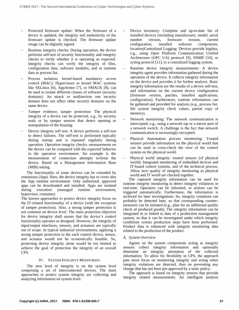
Protected firmware update: When the firmware of a
device is updated, the integrity and authenticity of the
firmware update is checked. The firmware update
image can be digitally signed.
Runtime integrity checks: During operation, the device
performs self-test of security functionality and integrity
checks to verify whether it is operating as expected.
Integrity checks can verify the integrity of files,
configuration data, software modules, and or runtime
data as process list.
Process isolation, kernel-based mandatory access
control (MAC): Hypervisors or kernel MAC systems
like SELinux [6], AppArmor [7], or SMACK [8], can
be used to isolate different classes of software (security
domains). An attack or malfunction one security
domain does not affect other security domains on the
same device.
Tamper evidence, tamper protection: The physical
integrity of a device can be protected, e.g., by security
seals or by tamper sensors that detect opening or
manipulation of the housing.
Device integrity self test: A device performs a self-test
to detect failures. The self-test is performed typically
during startup and is repeated regularly during
operation. Operation integrity checks: measurements on
the device can be compared with the expected behavior
in the operative environment. An example is the
measurement of connection attempts to/from the
device. Based on a Management Information Base
(MIB) setting.
The functionality of some devices can be extended by extensions (App). Here, the device integrity has to cover also the App runtime environment: Only authorized, approved apps can be downloaded and installed. Apps are isolated during execution (managed runtime environment, hypervisor, container) The known approaches to protect device integrity focus on
the IT-related functionality of a device (with the exception
of tamper protection). Also, a strong tamper protection is
not common on device level. The main protection objective
for device integrity shall ensure that the device’s control
functionality operates as designed. However, the integrity of
input/output interfaces, sensors, and actuators are typically
out of scope. In typical industrial environments, applying a
strong tamper protection to the each control device, sensor,
and actuator would not be economically feasible. So,
protecting device integrity alone would be too limited to
achieve the goal of protection the integrity of an overall
CPS.
IV. SYSTEM INTEGRITY MONITORING
The next level of integrity is on the system level comprising a set of interconnected devices. The main approaches to protect system integrity are collecting and analyzing information on system level:
Device inventory: Complete and up-to-date list of
installed devices (including manufacturer, model, serial
number version, firmware version, current
configuration, installed software components,
location)Centralized Logging: Devices provide logdata,
e.g., using Open Platform Communication Unified
Architecture (OPC UA) protocol [9], SNMP [10], or
syslog protocol [11], to a centralized logging system.
Runtime device integrity measurements: A device
integrity agent provides information gathered during the
operation of the device. It collects integrity information
on the device and provides it for further analysis. Basic
integrity information are the results of a device self-test,
and information on the current device configuration
(firmware version, patches, installed applications,
configuration). Furthermore, runtime information can
be gathered and provided for analysis (e.g., process list,
file system integrity check values, partial copy of
memory).
Network monitoring: The network communication is
intercepted, e.g., using a network tap or a mirror port of
a network switch. A challenge is the fact that network
communication is increasingly encrypted.
Physical Automation process monitoring: Trusted
sensors provide information on the physical world that
can be used to cross-check the view of the control
system on the physical world.
Physical world integrity: trusted sensors (of physical world). Integrated monitoring of embedded devices and IT-based control systems, and of the technical process. Allow now quality of integrity monitoring as physical world and IT world are checked together.
The captured integrity information can be used for runtime integrity monitoring to detect integrity violations in real-time. Operators can be informed, or actions can be triggered automatically. Furthermore, the information is archived for later investigations. So, integrity violations can probably be detected later, so that corresponding counter-measures can be initiated (e.g., plan for an additional quality check of produced goods). The integrity information can be integrated in or linked to data of a production management system, so that it can be investigated under which integrity conditions certain production steps have been performed. Product data is enhanced with integrity monitoring data related to the production of the product.
A. System Overview
Agents on the system components acting as integrity sensors collect integrity information and optionally determine an integrity attestation of the collected information. To allow for flexibility in CPS, the approach puts more focus on monitoring integrity and acting when integrity violations are detected, than on preventing any change that has not been pre-approved by a static policy.
The approach is based on integrity sensors that provide integrity related measurements. An intelligent analysis
37Copyright (c) IARIA, 2017. ISBN: 978-1-61208-605-7
CYBER 2017 : The Second International Conference on Cyber-Technologies and Cyber-Systems
46 / 90
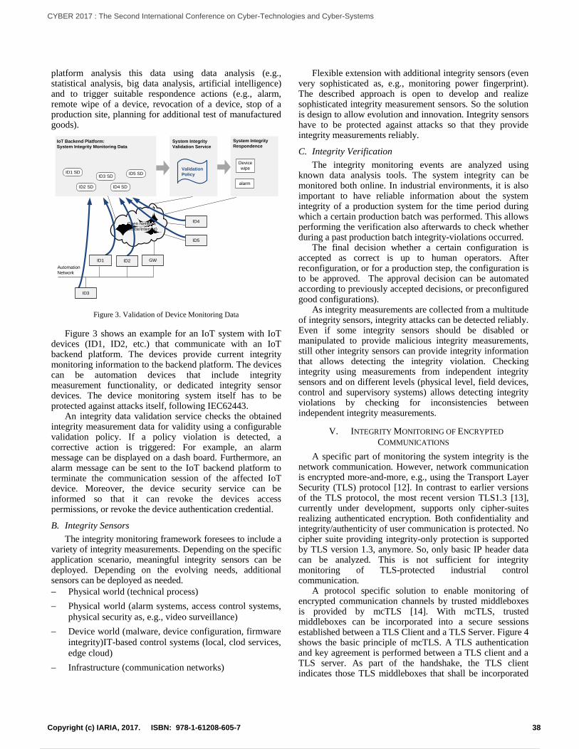
platform analysis this data using data analysis (e.g., statistical analysis, big data analysis, artificial intelligence) and to trigger suitable respondence actions (e.g., alarm, remote wipe of a device, revocation of a device, stop of a production site, planning for additional test of manufactured goods).
Open Network
(Office/Internet)
Automation
Network
IoT Backend Platform:
System Integrity Monitoring Data
ID1 SD
ID2 SD
ID3 SD
ID4 SD
ID5 SD
System Integrity
Validation Service
System Integrity
Respondence
Validation
Policy
Device
wipe
alarm
ID1
ID3
ID2 GW
ID4
ID5
Figure 3. Validation of Device Monitoring Data
Figure 3 shows an example for an IoT system with IoT devices (ID1, ID2, etc.) that communicate with an IoT backend platform. The devices provide current integrity monitoring information to the backend platform. The devices can be automation devices that include integrity measurement functionality, or dedicated integrity sensor devices. The device monitoring system itself has to be protected against attacks itself, following IEC62443.
An integrity data validation service checks the obtained integrity measurement data for validity using a configurable validation policy. If a policy violation is detected, a corrective action is triggered: For example, an alarm message can be displayed on a dash board. Furthermore, an alarm message can be sent to the IoT backend platform to terminate the communication session of the affected IoT device. Moreover, the device security service can be informed so that it can revoke the devices access permissions, or revoke the device authentication credential.
B. Integrity Sensors
The integrity monitoring framework foresees to include a variety of integrity measurements. Depending on the specific application scenario, meaningful integrity sensors can be deployed. Depending on the evolving needs, additional sensors can be deployed as needed.
Physical world (technical process)
Physical world (alarm systems, access control systems,
physical security as, e.g., video surveillance)
Device world (malware, device configuration, firmware
integrity)IT-based control systems (local, clod services,
edge cloud)
Infrastructure (communication networks)
Flexible extension with additional integrity sensors (even very sophisticated as, e.g., monitoring power fingerprint). The described approach is open to develop and realize sophisticated integrity measurement sensors. So the solution is design to allow evolution and innovation. Integrity sensors have to be protected against attacks so that they provide integrity measurements reliably.
C. Integrity Verification
The integrity monitoring events are analyzed using known data analysis tools. The system integrity can be monitored both online. In industrial environments, it is also important to have reliable information about the system integrity of a production system for the time period during which a certain production batch was performed. This allows performing the verification also afterwards to check whether during a past production batch integrity-violations occurred.
The final decision whether a certain configuration is accepted as correct is up to human operators. After reconfiguration, or for a production step, the configuration is to be approved. The approval decision can be automated according to previously accepted decisions, or preconfigured good configurations).
As integrity measurements are collected from a multitude of integrity sensors, integrity attacks can be detected reliably. Even if some integrity sensors should be disabled or manipulated to provide malicious integrity measurements, still other integrity sensors can provide integrity information that allows detecting the integrity violation. Checking integrity using measurements from independent integrity sensors and on different levels (physical level, field devices, control and supervisory systems) allows detecting integrity violations by checking for inconsistencies between independent integrity measurements.
V. INTEGRITY MONITORING OF ENCRYPTED
COMMUNICATIONS
A specific part of monitoring the system integrity is the network communication. However, network communication is encrypted more-and-more, e.g., using the Transport Layer Security (TLS) protocol [12]. In contrast to earlier versions of the TLS protocol, the most recent version TLS1.3 [13], currently under development, supports only cipher-suites realizing authenticated encryption. Both confidentiality and integrity/authenticity of user communication is protected. No cipher suite providing integrity-only protection is supported by TLS version 1.3, anymore. So, only basic IP header data can be analyzed. This is not sufficient for integrity monitoring of TLS-protected industrial control communication.
A protocol specific solution to enable monitoring of encrypted communication channels by trusted middleboxes is provided by mcTLS [14]. With mcTLS, trusted middleboxes can be incorporated into a secure sessions established between a TLS Client and a TLS Server. Figure 4 shows the basic principle of mcTLS. A TLS authentication and key agreement is performed between a TLS client and a TLS server. As part of the handshake, the TLS client indicates those TLS middleboxes that shall be incorporated
38Copyright (c) IARIA, 2017. ISBN: 978-1-61208-605-7
CYBER 2017 : The Second International Conference on Cyber-Technologies and Cyber-Systems
47 / 90
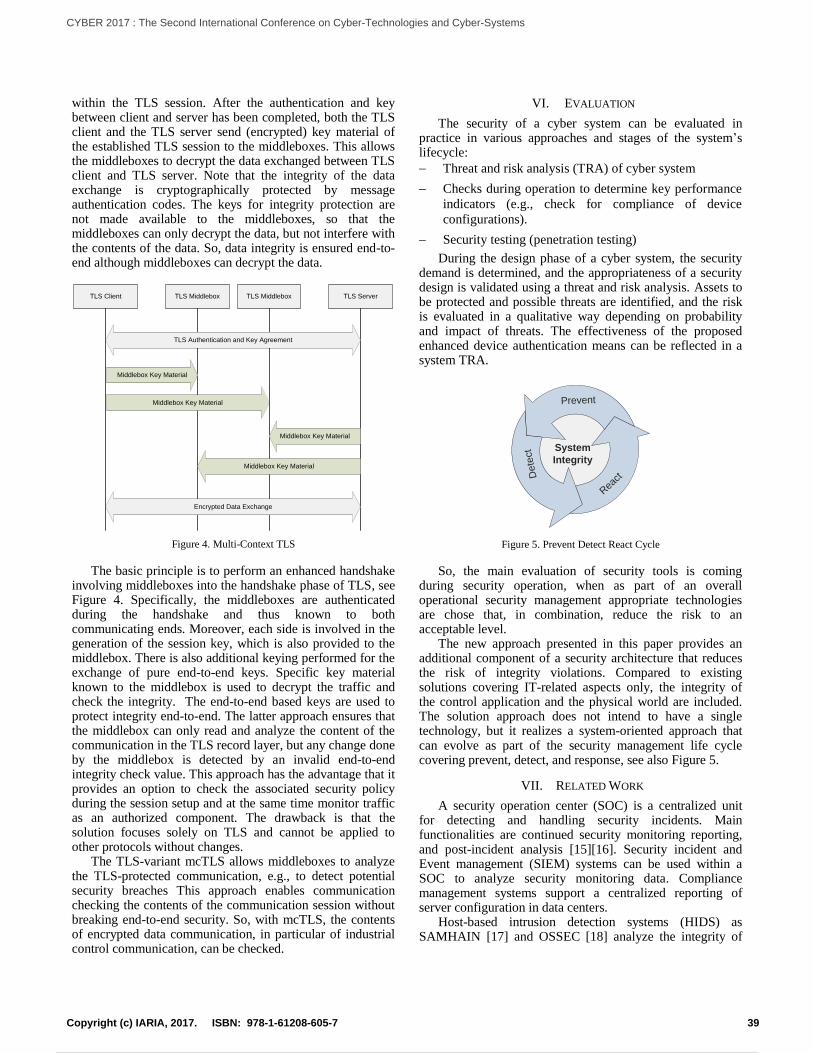
within the TLS session. After the authentication and key between client and server has been completed, both the TLS client and the TLS server send (encrypted) key material of the established TLS session to the middleboxes. This allows the middleboxes to decrypt the data exchanged between TLS client and TLS server. Note that the integrity of the data exchange is cryptographically protected by message authentication codes. The keys for integrity protection are not made available to the middleboxes, so that the middleboxes can only decrypt the data, but not interfere with the contents of the data. So, data integrity is ensured end-to-end although middleboxes can decrypt the data.
TLS Client TLS ServerTLS Middlebox TLS Middlebox
TLS Authentication and Key Agreement
Middlebox Key Material
Middlebox Key Material
Middlebox Key Material
Middlebox Key Material
Encrypted Data Exchange
Figure 4. Multi-Context TLS
The basic principle is to perform an enhanced handshake involving middleboxes into the handshake phase of TLS, see Figure 4. Specifically, the middleboxes are authenticated during the handshake and thus known to both communicating ends. Moreover, each side is involved in the generation of the session key, which is also provided to the middlebox. There is also additional keying performed for the exchange of pure end-to-end keys. Specific key material known to the middlebox is used to decrypt the traffic and check the integrity. The end-to-end based keys are used to protect integrity end-to-end. The latter approach ensures that the middlebox can only read and analyze the content of the communication in the TLS record layer, but any change done by the middlebox is detected by an invalid end-to-end integrity check value. This approach has the advantage that it provides an option to check the associated security policy during the session setup and at the same time monitor traffic as an authorized component. The drawback is that the solution focuses solely on TLS and cannot be applied to other protocols without changes.
The TLS-variant mcTLS allows middleboxes to analyze the TLS-protected communication, e.g., to detect potential security breaches This approach enables communication checking the contents of the communication session without breaking end-to-end security. So, with mcTLS, the contents of encrypted data communication, in particular of industrial control communication, can be checked.
VI. EVALUATION
The security of a cyber system can be evaluated in practice in various approaches and stages of the system’s lifecycle:
Threat and risk analysis (TRA) of cyber system
Checks during operation to determine key performance
indicators (e.g., check for compliance of device
configurations).
Security testing (penetration testing)
During the design phase of a cyber system, the security demand is determined, and the appropriateness of a security design is validated using a threat and risk analysis. Assets to be protected and possible threats are identified, and the risk is evaluated in a qualitative way depending on probability and impact of threats. The effectiveness of the proposed enhanced device authentication means can be reflected in a system TRA.
Dete
ct
Rea
ct
Prevent
System
Integrity
Figure 5. Prevent Detect React Cycle
So, the main evaluation of security tools is coming during security operation, when as part of an overall operational security management appropriate technologies are chose that, in combination, reduce the risk to an acceptable level.
The new approach presented in this paper provides an additional component of a security architecture that reduces the risk of integrity violations. Compared to existing solutions covering IT-related aspects only, the integrity of the control application and the physical world are included. The solution approach does not intend to have a single technology, but it realizes a system-oriented approach that can evolve as part of the security management life cycle covering prevent, detect, and response, see also Figure 5.
VII. RELATED WORK
A security operation center (SOC) is a centralized unit for detecting and handling security incidents. Main functionalities are continued security monitoring reporting, and post-incident analysis [15][16]. Security incident and Event management (SIEM) systems can be used within a SOC to analyze security monitoring data. Compliance management systems support a centralized reporting of server configuration in data centers.
Host-based intrusion detection systems (HIDS) as SAMHAIN [17] and OSSEC [18] analyze the integrity of
39Copyright (c) IARIA, 2017. ISBN: 978-1-61208-605-7
CYBER 2017 : The Second International Conference on Cyber-Technologies and Cyber-Systems
48 / 90
hosts and report the results to a backend security monitoring system. Network based intrusion detection systems (NIDS) capture the network traffic, e.g., using a network tap or a mirroring port of a network switch, and analyze the traffic. Examples are SNORT [19] and Suricata [20].
Two main strategies can be followed by an intrusion detection system (IDS): Known malicious activities can be looked for (signature based detection), or any change compared to a learned reference network policy is detected (anomaly detection).
An “automotive thin profile” of the Trusted Platform Module TPM 2.0 has been specified [21]. A vehicle is composed of multiple control units that are equipped with TPMs. A rich TPM manages a set of thin TPMs, so that the vehicle can be represented by a vehicle TPM to the external world. The vehicle’s rich TPM can check the integrity of the vehicle by verifying attestations provided by thin TPMs.
Approaches to utilize the context information on the CPS operation, device capabilities, device context to enhance the authentication of a single device, have been described by the authors of this paper in previous work [22]. The effect of an integrity attack on the degradation of a control system has been investigated by Mo and Sinopoli [23].
VIII. CONCLUSION
Ensuring system integrity is an essential security feature for cyber physical systems and the Internet of Things. The security design principle of “defense in depth” basically means that multiple layers of defenses are designed. This design principle can not only be applied at the system level, but also at the level of a single security mechanism.
This paper proposed a framework for ensuring system integrity in flexibly adaptable cyber physical systems. With new concepts for flexible automation systems coming with Industrial IoT / Industrie 4.0, the focus of system integrity has to move from preventing changes to device and system configuration in having transparency on the device and system configuration and checking it for compliance. This paper focused on integrity of devices, communication, and cyber systems. Integrity in a broader sense covers the whole life cycle, including development, secure procurement, secure manufacturing, and supply chain security.
REFERENCES
[1] IEC 62443, “Industrial Automation and Control System Security” (formerly ISA99), available from: http://isa99.isa.org/Documents/Forms/AllItems.aspx 2017.09.26
[2] ISO/IEC 27001, “Information technology – Security techniques – Information security management systems – Requirements”, October 2013, available from: https://www.iso.org/standard/54534.html 2017.09.26
[3] IEC62443-3-3:2013, “Industrial communication networks – Network and system security – Part 3-3: System security requirements and security levels”, Edition 1.0, August 2013
[4] Trusted Computing Group: “TPM Main Specification”, Version 1.2, , available from http://www.trustedcomputinggroup.org/resources/tpm_main_specification 2017.09.26
[5] Trusted Computing Group, “Trusted Platform Module Library Specification, Family 2.0”, 2014, available from
http://www.trustedcomputinggroup.org/resources/tpm_library_specification 2017.09.26
[6] SELinux, “Security Enhanced Linux”, available online: https://selinuxproject.org/page/Main_Page 2017.09.26
[7] AppArmor, “AppArmor Security Project”, available online: http://wiki.apparmor.net/index.php/Main_Page 2017.09.26
[8] SMACK, “Simplified Mandatory Access Control Kernel”, available online: https://www.kernel.org/doc/html/latest/admin-guide/LSM/Smack.html 2017.09.26
[9] OPC Foundation, “OPC Unified Architecture (UA)”, available online: https://opcfoundation.org/about/opc-technologies/opc-ua/ 2017.09.26
[10] J. Case, R. Mundy, et al., “Introduction and Applicability Statements for Internet Standard Management Framework”, RFC3410, available online: https://tools.ietf.org/html/rfc3410 2017.09.26
[11] R. Gerhards, “The Syslog Protocol”, RFC5424, March 2009, available online: https://tools.ietf.org/html/rfc5424 2017.09.26
[12] T. Dierks and E. Rescorla, “The Transport Layer Security (TLS) Protocol Version 1.2”, RFC 5246, Aug. 2008, available from http://tools.ietf.org/html/rfc5246 2017.09.26
[13] E. Rescorla: “The Transport Layer Security (TLS) Protocol Version 1.3”, Internet draft (work in progres), September 2017, available online: https://tlswg.github.io/tls13-spec/draft-ietf-tls-tls13.html 2017.09.26
[14] D. Naylor, K. Schomp, et al., “Multi-Context TLS (mcTLS), Enabling Secure In-Network Functionality in TLS,” available from http://mctls.org/ 2017.09.26
[15] B. Rothke, “Building a Security Operations Center (SoC)”, RSA Conference, 2012, available from https://www.rsaconference.com/writable/presentations/file_upload/tech-203.pdf 2017.09.26
[16] McAffee Foundstone® Professional Services, “Creating and Maintaining a SoC”, Intel Security Whitepaper, available from: https://www.mcafee.com/us/resources/white-papers/foundstone/wp-creating-maintaining-soc.pdf 2017.09.26
[17] R. Wichmann, “The Samhain HIDS”, fact sheet, 2011, available from http://la-samhna.de/samhain/samhain_leaf.pdf 2017.09.26
[18] OSSEC, “Open Source HIDS SECurity”, web site, 2010 - 2015, available from http://ossec.github.io/ 2017.09.26
[19] “SNORT”, web site, available from https://www.snort.org/ 2017.09.26
[20] “Suricata”, web site, available from https://suricata-ids.org/ 2017.09.26
[21] Trusted Computing Group, “TCG TPM 2.0 Automotive Thin Profile”, level 00, version 1.0, 2015, available from http://www.trustedcomputinggroup.org/resources/tcg_tpm_20_library_profile_for_automotivethin 2017.09.26
[22] R. Falk and S. Fries, “Advanced Device Authentication: Bringing Multi-Factor Authentication and Continuous Authentication to the Internet of Things”, The First International Conference on Advances in Cyber-Technologies and Cyber-Systems, CYBER 2016, October 9 - 13, 2016 - Venice, Italy , available from http://www.thinkmind.org/index.php?view=article&articleid=cyber_2016_4_20_80029 2017.09.26
[23] Y. Mo and B. Sinopoli, “On the Performance Degradation of Cyber-Physical Systems Under Stealthy Integrity Attacks”, IEEE Transactions on Automatic Control 61.9 (2016): 2618-2624.
40Copyright (c) IARIA, 2017. ISBN: 978-1-61208-605-7
CYBER 2017 : The Second International Conference on Cyber-Technologies and Cyber-Systems
49 / 90
Vaccine: A Block Cipher Method for
Masking and Unmasking of Ciphertexts’ Features
Ray R. Hashemi
Amar Rasheed
Jeffrey Young
Department of Computer Science
Armstrong State University,
Savannah, GA, USA
e-mails: {rayhashemi, amarrasheed,
alanyoung7}@gmail.com
Azita A. Bahrami
IT Consultation
Savannah, GA, USA
e-mail: [email protected]
Abstract— A ciphertext inherits some properties of the plaintext, which is considered as a source of vulnerability and, therefore, it may be decrypted through a vigorous datamining process. Masking the ciphertext is the solution to the problem. In this paper, we have developed a new block cipher technique named Vaccine for which the block size is random and each block is further divided into segments of random size. Each byte within a segment is instantiated using a dynamic multi-instantiation approach, which means (i) the use of Vaccine does not produce the same masked outcome for the same given ciphertext and key and (ii) the options for masking different occurrences of a byte is extremely high. Two sets (100 members in each) of 1K long plaintexts of natural (borrowed from natural texts) and synthesized (randomly generated from 10 characters to increase the frequency of characters in the plaintext) are built. For each plaintext, two ciphertexts are generated using Advanced Encryption System (AES-128) and Data Encryption Standard (DES) algorithms. Vaccine and two well-known masking approaches of Cipher Block Chaining (CBC), and Cipher Feedback (CFB) are applied separately on each ciphertext. On average: (a) the Hamming distance between masked and unmasked occurrences of a byte using Vaccine is 0.72 bits higher than using the CBC, and CFB, and (b) Vaccine throughput is also 3.4 times and 1.8 times higher than the throughput for CBC and CFB, correspondingly, and (c) Vaccine masking strength is 1.5% and 1.8% higher than the masking strength for CBC and CFB, respectively.
Keywords- Cyber Security; Masking and Unmasking Ciphertext; Variable-Block Cipher Vaccination; Masking Strength
I. INTRODUCTION
Protecting sensitive electronic documents and
electronic messages from unintended eyes is a critical task.
Such protections are often provided by applying encryption.
However, the encrypted text (ciphertext) is often vulnerable
to datamining. For example, let us consider the plaintext
message of: “The center is under an imminent attack”. The
plaintext may be converted into the following ciphertext
using, for instance, a simple displacement encryption
algorithm: “xligirxvmwyrhivermqqmrirxexxego”. The
features of the plaintext are also inherited by the
ciphertext—a point of vulnerability.
To explain it further, word “attack” is among the key words related to security. The characteristics of the word are: (i) length is six, (ii) the first and the fourth characters are the same, and (iii) the second and the third characters are the same. Using these characteristics, one can mine the given ciphertext and isolate the subtext of “exxego” that stands for “attack" which, in turn, may lead to decryption of the entire message. More sophisticated encryption modes, such as CBC and CFB [1][2][3] are not exempt from the inherited-features problem. The Block cipher techniques that employ CBC/CFB encryption mode to produce distinct ciphertexts are vulnerable to information leakage. In the case of CBC/CFB employing the same Initial text Vector (IV) with the same encryption key for multiple encryption operations could reveal information about the first block of plaintext, and about any common prefix shared by two plaintext messages. In CBC mode, the IV must, in addition, be unpredictable at encryption time; in particular, the (previously) common practice of re-using the last ciphertext block of a message as the IV for the next message is insecure (for example, this method was used by SSL 2.0). If an attacker knows the IV (or the previous block of ciphertext) before he specifies the next plaintext, he can check his guess about plaintext of some block that was encrypted with the same key before (this is known as the TLS CBC IV attack) [4]. The logical solution for inherited-features problem is to mask the ciphertext using a masking mechanism that is dynamic and supports a high degree of multi-instantiations for each byte. A dynamic masking mechanism does not produce the same masked outcome for the same given ciphertext and the same key. The high degree of multi-instantiation masking mechanism replaces the n occurrences of a given byte in the ciphertext with m new bytes such that m is either equal to n or extremely close to n. The literature addresses many of these masking techniques [5][6]. Our goal is to introduce a masking mechanism named Vaccine that can mask the inherited features of a ciphertext in the eye of a data miner while providing for transformation of masked ciphertext into its original form, when needed. Vaccine will be dynamic and support a high
41Copyright (c) IARIA, 2017. ISBN: 978-1-61208-605-7
CYBER 2017 : The Second International Conference on Cyber-Technologies and Cyber-Systems
50 / 90
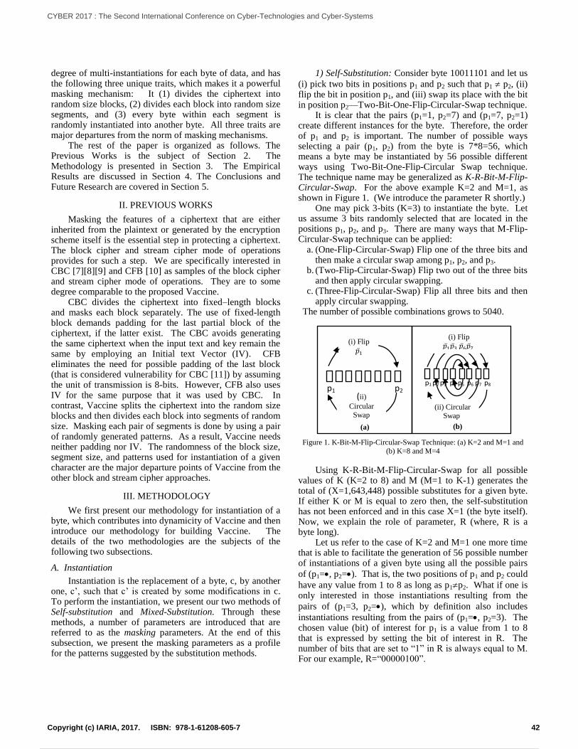
(a)
p1 p2
(i) Flip
𝑝 1
(ii) Circular
Swap
p1 p2 p3 p4 p5 p6 p7 p8
(i) Flip
𝑝 1𝑝 3 𝑝 6𝑝 7
(ii) Circular
Swap
(b)
degree of multi-instantiations for each byte of data, and has the following three unique traits, which makes it a powerful masking mechanism: It (1) divides the ciphertext into random size blocks, (2) divides each block into random size segments, and (3) every byte within each segment is randomly instantiated into another byte. All three traits are major departures from the norm of masking mechanisms. The rest of the paper is organized as follows. The Previous Works is the subject of Section 2. The Methodology is presented in Section 3. The Empirical Results are discussed in Section 4. The Conclusions and Future Research are covered in Section 5.
II. PREVIOUS WORKS
Masking the features of a ciphertext that are either inherited from the plaintext or generated by the encryption scheme itself is the essential step in protecting a ciphertext. The block cipher and stream cipher mode of operations provides for such a step. We are specifically interested in CBC [7][8][9] and CFB [10] as samples of the block cipher and stream cipher mode of operations. They are to some degree comparable to the proposed Vaccine. CBC divides the ciphertext into fixed–length blocks and masks each block separately. The use of fixed-length block demands padding for the last partial block of the ciphertext, if the latter exist. The CBC avoids generating the same ciphertext when the input text and key remain the same by employing an Initial text Vector (IV). CFB eliminates the need for possible padding of the last block (that is considered vulnerability for CBC [11]) by assuming the unit of transmission is 8-bits. However, CFB also uses IV for the same purpose that it was used by CBC. In contrast, Vaccine splits the ciphertext into the random size blocks and then divides each block into segments of random size. Masking each pair of segments is done by using a pair of randomly generated patterns. As a result, Vaccine needs neither padding nor IV. The randomness of the block size, segment size, and patterns used for instantiation of a given character are the major departure points of Vaccine from the other block and stream cipher approaches.
III. METHODOLOGY
We first present our methodology for instantiation of a byte, which contributes into dynamicity of Vaccine and then introduce our methodology for building Vaccine. The details of the two methodologies are the subjects of the following two subsections.
A. Instantiation
Instantiation is the replacement of a byte, c, by another one, c’, such that c’ is created by some modifications in c. To perform the instantiation, we present our two methods of Self-substitution and Mixed-Substitution. Through these methods, a number of parameters are introduced that are referred to as the masking parameters. At the end of this subsection, we present the masking parameters as a profile for the patterns suggested by the substitution methods.
1) Self-Substitution: Consider byte 10011101 and let us
(i) pick two bits in positions p1 and p2 such that p1 p2, (ii) flip the bit in position p1, and (iii) swap its place with the bit in position p2—Two-Bit-One-Flip-Circular-Swap technique. It is clear that the pairs (p1=1, p2=7) and (p1=7, p2=1) create different instances for the byte. Therefore, the order of p1 and p2 is important. The number of possible ways selecting a pair (p1, p2) from the byte is 7*8=56, which means a byte may be instantiated by 56 possible different ways using Two-Bit-One-Flip-Circular Swap technique. The technique name may be generalized as K-R-Bit-M-Flip-Circular-Swap. For the above example K=2 and M=1, as shown in Figure 1. (We introduce the parameter R shortly.) One may pick 3-bits (K=3) to instantiate the byte. Let us assume 3 bits randomly selected that are located in the positions p1, p2, and p3. There are many ways that M-Flip-Circular-Swap technique can be applied:
a. (One-Flip-Circular-Swap) Flip one of the three bits and then make a circular swap among p1, p2, and p3.
b. (Two-Flip-Circular-Swap) Flip two out of the three bits and then apply circular swapping.
c. (Three-Flip-Circular-Swap) Flip all three bits and then apply circular swapping.
The number of possible combinations grows to 5040.
Figure 1. K-Bit-M-Flip-Circular-Swap Technique: (a) K=2 and M=1 and
(b) K=8 and M=4
Using K-R-Bit-M-Flip-Circular-Swap for all possible values of K (K=2 to 8) and M (M=1 to K-1) generates the total of (X=1,643,448) possible substitutes for a given byte. If either K or M is equal to zero then, the self-substitution has not been enforced and in this case X=1 (the byte itself). Now, we explain the role of parameter, R (where, R is a byte long). Let us refer to the case of K=2 and M=1 one more time that is able to facilitate the generation of 56 possible number of instantiations of a given byte using all the possible pairs
of (p1=, p2=). That is, the two positions of p1 and p2 could
have any value from 1 to 8 as long as p1p2. What if one is only interested in those instantiations resulting from the
pairs of (p1=3, p2=), which by definition also includes
instantiations resulting from the pairs of (p1=, p2=3). The chosen value (bit) of interest for p1 is a value from 1 to 8 that is expressed by setting the bit of interest in R. The number of bits that are set to “1” in R is always equal to M. For our example, R=“00000100”.
42Copyright (c) IARIA, 2017. ISBN: 978-1-61208-605-7
CYBER 2017 : The Second International Conference on Cyber-Technologies and Cyber-Systems
51 / 90
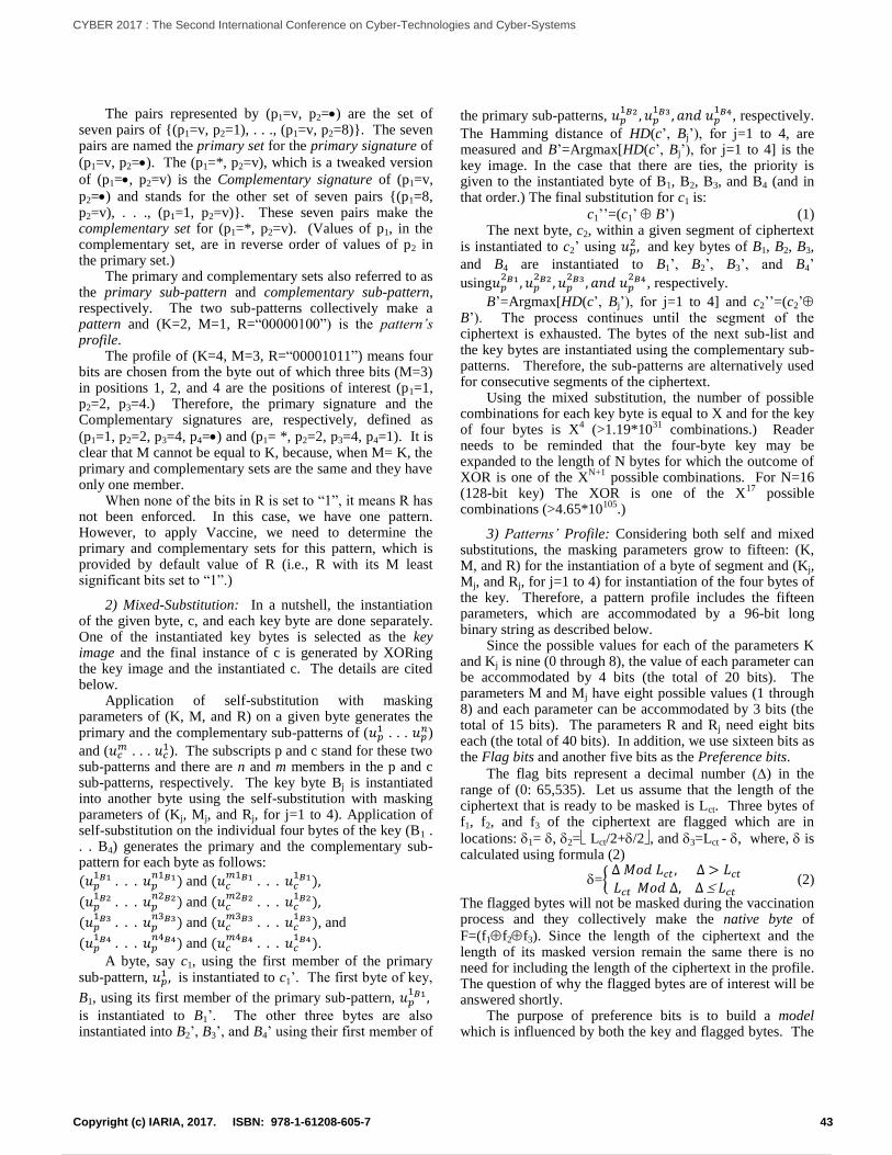
The pairs represented by (p1=v, p2=) are the set of seven pairs of {(p1=v, p2=1), . . ., (p1=v, p2=8)}. The seven pairs are named the primary set for the primary signature of
(p1=v, p2=). The (p1=*, p2=v), which is a tweaked version
of (p1=, p2=v) is the Complementary signature of (p1=v,
p2=) and stands for the other set of seven pairs {(p1=8, p2=v), . . ., (p1=1, p2=v)}. These seven pairs make the complementary set for (p1=*, p2=v). (Values of p1, in the complementary set, are in reverse order of values of p2 in the primary set.) The primary and complementary sets also referred to as the primary sub-pattern and complementary sub-pattern, respectively. The two sub-patterns collectively make a pattern and (K=2, M=1, R=“00000100”) is the pattern’s profile. The profile of (K=4, M=3, R=“00001011”) means four bits are chosen from the byte out of which three bits (M=3) in positions 1, 2, and 4 are the positions of interest (p1=1, p2=2, p3=4.) Therefore, the primary signature and the Complementary signatures are, respectively, defined as
(p1=1, p2=2, p3=4, p4=) and (p1= *, p2=2, p3=4, p4=1). It is clear that M cannot be equal to K, because, when M= K, the primary and complementary sets are the same and they have only one member. When none of the bits in R is set to “1”, it means R has not been enforced. In this case, we have one pattern. However, to apply Vaccine, we need to determine the primary and complementary sets for this pattern, which is provided by default value of R (i.e., R with its M least significant bits set to “1”.)
2) Mixed-Substitution: In a nutshell, the instantiation of the given byte, c, and each key byte are done separately. One of the instantiated key bytes is selected as the key image and the final instance of c is generated by XORing the key image and the instantiated c. The details are cited below. Application of self-substitution with masking parameters of (K, M, and R) on a given byte generates the primary and the complementary sub-patterns of (𝑢𝑝
1 . . . 𝑢𝑝𝑛)
and (𝑢𝑐𝑚 . . . 𝑢𝑐
1). The subscripts p and c stand for these two sub-patterns and there are n and m members in the p and c sub-patterns, respectively. The key byte Bj is instantiated into another byte using the self-substitution with masking parameters of (Kj, Mj, and Rj, for j=1 to 4). Application of self-substitution on the individual four bytes of the key (B1 . . . B4) generates the primary and the complementary sub-pattern for each byte as follows:
(𝑢𝑝1𝐵1 . . . 𝑢𝑝
𝑛1𝐵1) and (𝑢𝑐𝑚1𝐵1 . . . 𝑢𝑐
1𝐵1),
(𝑢𝑝1𝐵2 . . . 𝑢𝑝
𝑛2𝐵2) and (𝑢𝑐𝑚2𝐵2 . . . 𝑢𝑐
1𝐵2),
(𝑢𝑝1𝐵3 . . . 𝑢𝑝
𝑛3𝐵3) and (𝑢𝑐𝑚3𝐵3 . . . 𝑢𝑐
1𝐵3), and
(𝑢𝑝1𝐵4 . . . 𝑢𝑝
𝑛4𝐵4) and (𝑢𝑐𝑚4𝐵4 . . . 𝑢𝑐
1𝐵4). A byte, say c1, using the first member of the primary sub-pattern, 𝑢𝑝
1 , is instantiated to c1’. The first byte of key,
B1, using its first member of the primary sub-pattern, 𝑢𝑝1𝐵1 ,
is instantiated to B1’. The other three bytes are also instantiated into B2’, B3’, and B4’ using their first member of
the primary sub-patterns, 𝑢𝑝1𝐵2 , 𝑢𝑝
1𝐵3 , 𝑎𝑛𝑑 𝑢𝑝1𝐵4, respectively.
The Hamming distance of HD(c’, Bj’), for j=1 to 4, are measured and B’=Argmax[HD(c’, Bj’), for j=1 to 4] is the key image. In the case that there are ties, the priority is given to the instantiated byte of B1, B2, B3, and B4 (and in that order.) The final substitution for c1 is:
c1’’=(c1’ B’) (1) The next byte, c2, within a given segment of ciphertext is instantiated to c2’ using 𝑢𝑝
2 , and key bytes of B1, B2, B3,
and B4 are instantiated to B1’, B2’, B3’, and B4’
using𝑢𝑝2𝐵1 , 𝑢𝑝
2𝐵2 , 𝑢𝑝2𝐵3 , 𝑎𝑛𝑑 𝑢𝑝
2𝐵4 , respectively.
B’=Argmax[HD(c’, Bj’), for j=1 to 4] and c2’’=(c2’ B’). The process continues until the segment of the ciphertext is exhausted. The bytes of the next sub-list and the key bytes are instantiated using the complementary sub-patterns. Therefore, the sub-patterns are alternatively used for consecutive segments of the ciphertext. Using the mixed substitution, the number of possible combinations for each key byte is equal to X and for the key of four bytes is X
4 (>1.19*10
31 combinations.) Reader
needs to be reminded that the four-byte key may be expanded to the length of N bytes for which the outcome of XOR is one of the X
N+1 possible
combinations. For N=16
(128-bit key) The XOR is one of the X17
possible combinations (>4.65*10
105.)
3) Patterns’ Profile: Considering both self and mixed substitutions, the masking parameters grow to fifteen: (K, M, and R) for the instantiation of a byte of segment and (Kj, Mj, and Rj, for j=1 to 4) for instantiation of the four bytes of the key. Therefore, a pattern profile includes the fifteen parameters, which are accommodated by a 96-bit long binary string as described below. Since the possible values for each of the parameters K and Kj is nine (0 through 8), the value of each parameter can be accommodated by 4 bits (the total of 20 bits). The parameters M and Mj have eight possible values (1 through 8) and each parameter can be accommodated by 3 bits (the total of 15 bits). The parameters R and Rj need eight bits each (the total of 40 bits). In addition, we use sixteen bits as the Flag bits and another five bits as the Preference bits.
The flag bits represent a decimal number () in the range of (0: 65,535). Let us assume that the length of the ciphertext that is ready to be masked is Lct. Three bytes of f1, f2, and f3 of the ciphertext are flagged which are in
locations: 1= , 2= Lct/2+/2, and 3=Lct - , where, is calculated using formula (2)
={ ∆ 𝑀𝑜𝑑 𝐿𝑐𝑡 , ∆ > 𝐿𝑐𝑡𝐿𝑐𝑡 𝑀𝑜𝑑 ∆, ∆ 𝐿𝑐𝑡
(2)
The flagged bytes will not be masked during the vaccination process and they collectively make the native byte of
F=(f1f2f3). Since the length of the ciphertext and the length of its masked version remain the same there is no need for including the length of the ciphertext in the profile. The question of why the flagged bytes are of interest will be answered shortly. The purpose of preference bits is to build a model which is influenced by both the key and flagged bytes. The
43Copyright (c) IARIA, 2017. ISBN: 978-1-61208-605-7
CYBER 2017 : The Second International Conference on Cyber-Technologies and Cyber-Systems
52 / 90
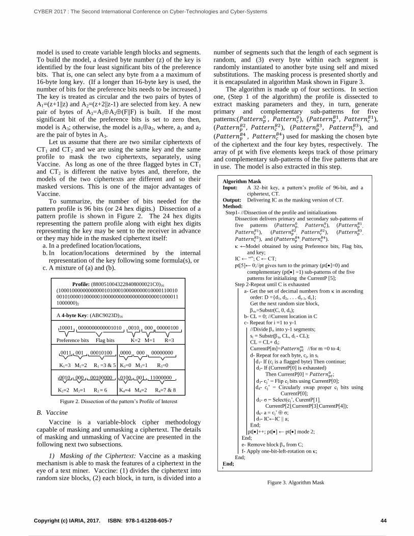
model is used to create variable length blocks and segments. To build the model, a desired byte number (z) of the key is identified by the four least significant bits of the preference bits. That is, one can select any byte from a a maximum of 16-byte long key. (If a longer than 16-byte key is used, the number of bits for the preference bits needs to be increased.) The key is treated as circular and the two pairs of bytes of A1=(z+1||z) and A2=(z+2||z-1) are selected from key. A new
pair of bytes of A3=A1A2(F||F) is built. If the most significant bit of the preference bits is set to zero then,
model is A3; otherwise, the model is a1a2, where, a1 and a2 are the pair of bytes in A3. Let us assume that there are two similar ciphertexts of CT1 and CT2 and we are using the same key and the same profile to mask the two ciphertexts, separately, using Vaccine. As long as one of the three flagged bytes in CT1 and CT2 is different the native bytes and, therefore, the models of the two ciphertexts are different and so their masked versions. This is one of the major advantages of Vaccine. To summarize, the number of bits needed for the pattern profile is 96 bits (or 24 hex digits.) Dissection of a pattern profile is shown in Figure 2. The 24 hex digits representing the pattern profile along with eight hex digits representing the key may be sent to the receiver in advance or they may hide in the masked ciphertext itself:
a. In a predefined location/locations, b. In location/locations determined by the internal
representation of the key following some formula(s), or c. A mixture of (a) and (b).
Figure 2. Dissection of the pattern’s Profile of Interest
B. Vaccine
Vaccine is a variable-block cipher methodology capable of masking and unmasking a ciphertext. The details of masking and unmasking of Vaccine are presented in the following next two subsections.
1) Masking of the Ciphertext: Vaccine as a masking mechanism is able to mask the features of a ciphertext in the eye of a text miner. Vaccine: (1) divides the ciphertext into random size blocks, (2) each block, in turn, is divided into a
number of segments such that the length of each segment is random, and (3) every byte within each segment is randomly instantiated to another byte using self and mixed substitutions. The masking process is presented shortly and it is encapsulated in algorithm Mask shown in Figure 3. The algorithm is made up of four sections. In section one, (Step 1 of the algorithm) the profile is dissected to extract masking parameters and they, in turn, generate primary and complementary sub-patterns for five patterns:(𝑃𝑎𝑡𝑡𝑒𝑟𝑛𝑝
0 , 𝑃𝑎𝑡𝑡𝑒𝑟𝑛𝑐0), (𝑃𝑎𝑡𝑡𝑒𝑟𝑛𝑝
𝐵1 , 𝑃𝑎𝑡𝑡𝑒𝑟𝑛𝑐𝐵1),
(𝑃𝑎𝑡𝑡𝑒𝑟𝑛𝑝𝐵2 , 𝑃𝑎𝑡𝑡𝑒𝑟𝑛𝑐
𝐵2), (𝑃𝑎𝑡𝑡𝑒𝑟𝑛𝑝𝐵3, 𝑃𝑎𝑡𝑡𝑒𝑟𝑛𝑐
𝐵3), and
(𝑃𝑎𝑡𝑡𝑒𝑟𝑛𝑝𝐵4
, 𝑃𝑎𝑡𝑡𝑒𝑟𝑛𝑐𝐵4) used for masking the chosen byte
of the ciphertext and the four key bytes, respectively. The array of pt with five elements keeps track of those primary and complementary sub-patterns of the five patterns that are in use. The model is also extracted in this step.
Figure 3. Algorithm Mask
Algorithm Mask
Input: A 32–bit key, a pattern’s profile of 96-bit, and a
ciphertext, CT. Output: Delivering IC as the masking version of CT.
Method:
Step1- //Dissection of the profile and initializations Dissection delivers primary and secondary sub-patterns of
five patterns (𝑃𝑎𝑡𝑡𝑒𝑟𝑛𝑝0
, 𝑃𝑎𝑡𝑡𝑒𝑟𝑛𝑐0), (𝑃𝑎𝑡𝑡𝑒𝑟𝑛𝑝
𝐵1,
𝑃𝑎𝑡𝑡𝑒𝑟𝑛𝑐𝐵1), (𝑃𝑎𝑡𝑡𝑒𝑟𝑛𝑝
𝐵2, 𝑃𝑎𝑡𝑡𝑒𝑟𝑛𝑐
𝐵2), (𝑃𝑎𝑡𝑡𝑒𝑟𝑛𝑝𝐵3
,
𝑃𝑎𝑡𝑡𝑒𝑟𝑛𝑐𝐵3), and (𝑃𝑎𝑡𝑡𝑒𝑟𝑛𝑝
𝐵4, 𝑃𝑎𝑡𝑡𝑒𝑟𝑛𝑐
𝐵4).
←Model obtained by using Preference bits, Flag bits,
and key; IC ← “”; C ← CT;
pt[5]← 0;//pt gives turn to the primary (pt[]=0) and
complementary (pt[] =1) sub-patterns of the five patterns for initializing the CurrentP [5];
Step 2-Repeat until C is exhausted
a- Get the set of decimal numbers from in ascending order: D ={d1, d2, . . . dy-1, dy};
Get the next random size block,
n,=Substr(C, 0, dy); b- CL = 0; //Current location in C
c- Repeat for i =1 to y-1
//Divide n into y-1 segments;
si = Substr(n, CL, di - CL);
CL = CL+ di;
CurrentP[m]=𝑃𝑎𝑡𝑡𝑒𝑟𝑛𝑝𝑡𝑚 //for m =0 to 4;
d- Repeat for each byte, cj, in si
d1- If (cj is a flagged byte) Then continue;
d2- If (CurrentP[0] is exhausted)
Then CurrentP[0] = 𝑃𝑎𝑡𝑡𝑒𝑟𝑛𝑝𝑡0 ;
d3- cj’ = Flip cj bits using CurrentP[0];
d4- cj’ = Circularly swap proper cj bits using CurrentP[0];
d5- σ = Select(cj’, CurentP[1],
CurrentP[2],CurrentP[3],CurrentP[4]);
d6- a = cj’ σ;
d7- IC←IC || a;
End;
pt[]++; pt[] ← pt[] mode 2;
End;
e- Remove block n from C;
f- Apply one-bit-left-rotation on ;
End;
End;
Profile: (8800510043228408000021C0)16
(10001000000000000101000100000000010000110010
001010000100000010000000000000000000001000011
1000000)2
A 4-byte Key: (ABC9023D)16
10001 0000000000001010 0010 000 00000100
Preference bits Flag bits K=2 M=1 R=3
0011 001 00010100 0000 000 00000000
K1=3 M1=2 R1 =3 & 5 K3=0 M3=1 R3=0
0010 000 00100000 0100 001 11000000
K2=2 M2=1 R2 = 6 K4=4 M4=2 R4=7 & 8
44Copyright (c) IARIA, 2017. ISBN: 978-1-61208-605-7
CYBER 2017 : The Second International Conference on Cyber-Technologies and Cyber-Systems
53 / 90
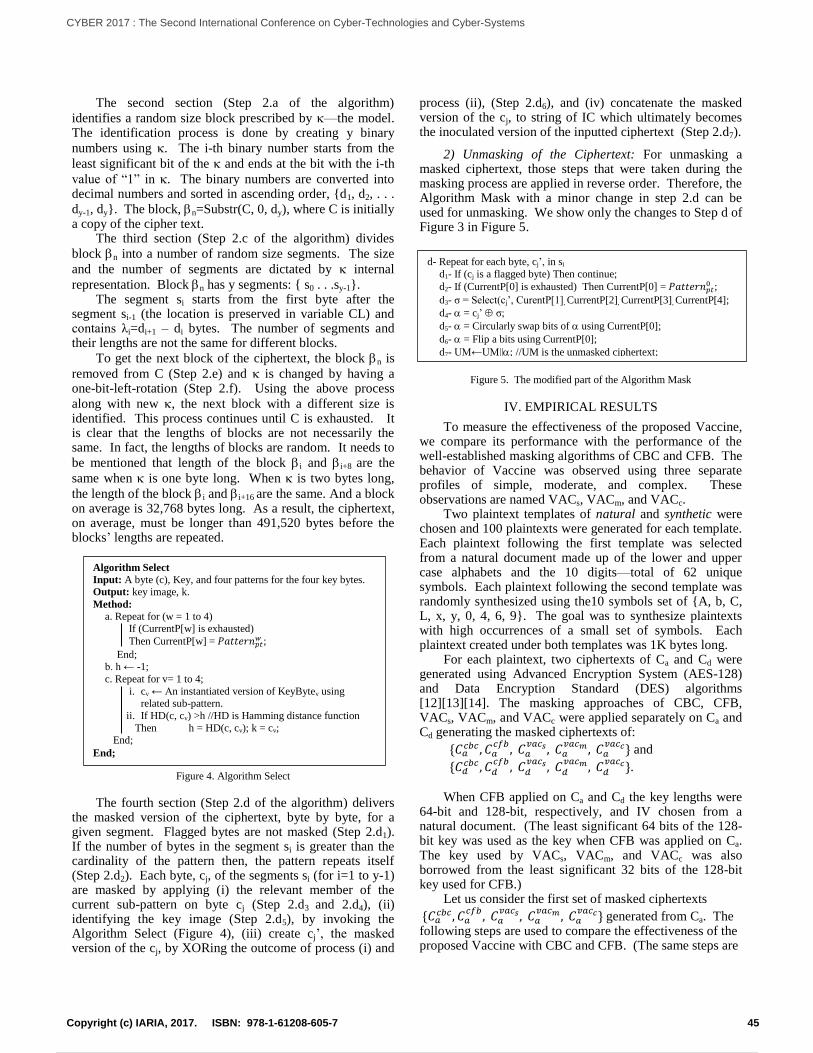
The second section (Step 2.a of the algorithm)
identifies a random size block prescribed by —the model. The identification process is done by creating y binary
numbers using . The i-th binary number starts from the
least significant bit of the and ends at the bit with the i-th
value of “1” in . The binary numbers are converted into decimal numbers and sorted in ascending order, {d1, d2, . . .
dy-1, dy}. The block, n=Substr(C, 0, dy), where C is initially a copy of the cipher text. The third section (Step 2.c of the algorithm) divides
block n into a number of random size segments. The size
and the number of segments are dictated by internal
representation. Block n has y segments: { s0 . . .sy-1}. The segment si starts from the first byte after the segment si-1 (the location is preserved in variable CL) and contains λi=di+1 – di bytes. The number of segments and their lengths are not the same for different blocks.
To get the next block of the ciphertext, the block n is
removed from C (Step 2.e) and is changed by having a one-bit-left-rotation (Step 2.f). Using the above process
along with new , the next block with a different size is identified. This process continues until C is exhausted. It is clear that the lengths of blocks are not necessarily the same. In fact, the lengths of blocks are random. It needs to
be mentioned that length of the block i and i+8 are the
same when is one byte long. When is two bytes long,
the length of the block i and i+16 are the same. And a block on average is 32,768 bytes long. As a result, the ciphertext, on average, must be longer than 491,520 bytes before the blocks’ lengths are repeated.
Figure 4. Algorithm Select
The fourth section (Step 2.d of the algorithm) delivers the masked version of the ciphertext, byte by byte, for a given segment. Flagged bytes are not masked (Step 2.d1). If the number of bytes in the segment si is greater than the cardinality of the pattern then, the pattern repeats itself (Step 2.d2). Each byte, cj, of the segments si (for i=1 to y-1) are masked by applying (i) the relevant member of the current sub-pattern on byte cj (Step 2.d3 and 2.d4), (ii) identifying the key image (Step 2.d5), by invoking the Algorithm Select (Figure 4), (iii) create cj’, the masked version of the cj, by XORing the outcome of process (i) and
process (ii), (Step 2.d6), and (iv) concatenate the masked version of the cj, to string of IC which ultimately becomes the inoculated version of the inputted ciphertext (Step 2.d7).
2) Unmasking of the Ciphertext: For unmasking a masked ciphertext, those steps that were taken during the masking process are applied in reverse order. Therefore, the Algorithm Mask with a minor change in step 2.d can be used for unmasking. We show only the changes to Step d of Figure 3 in Figure 5.
Figure 5. The modified part of the Algorithm Mask
IV. EMPIRICAL RESULTS
To measure the effectiveness of the proposed Vaccine, we compare its performance with the performance of the well-established masking algorithms of CBC and CFB. The behavior of Vaccine was observed using three separate profiles of simple, moderate, and complex. These observations are named VACs, VACm, and VACc. Two plaintext templates of natural and synthetic were chosen and 100 plaintexts were generated for each template. Each plaintext following the first template was selected from a natural document made up of the lower and upper case alphabets and the 10 digits—total of 62 unique symbols. Each plaintext following the second template was randomly synthesized using the10 symbols set of {A, b, C, L, x, y, 0, 4, 6, 9}. The goal was to synthesize plaintexts with high occurrences of a small set of symbols. Each plaintext created under both templates was 1K bytes long. For each plaintext, two ciphertexts of Ca and Cd were generated using Advanced Encryption System (AES-128) and Data Encryption Standard (DES) algorithms [12][13][14]. The masking approaches of CBC, CFB, VACs, VACm, and VACc were applied separately on Ca and Cd generating the masked ciphertexts of:
{𝐶𝑎𝑐𝑏𝑐 , 𝐶𝑎
𝑐𝑓𝑏, 𝐶𝑎
𝑣𝑎𝑐𝑠 , 𝐶𝑎𝑣𝑎𝑐𝑚 , 𝐶𝑎
𝑣𝑎𝑐𝑐} and
{𝐶𝑑𝑐𝑏𝑐 , 𝐶𝑑
𝑐𝑓𝑏, 𝐶𝑑
𝑣𝑎𝑐𝑠 , 𝐶𝑑𝑣𝑎𝑐𝑚 , 𝐶𝑑
𝑣𝑎𝑐𝑐}. When CFB applied on Ca and Cd the key lengths were 64-bit and 128-bit, respectively, and IV chosen from a natural document. (The least significant 64 bits of the 128-bit key was used as the key when CFB was applied on Ca. The key used by VACs, VACm, and VACc was also borrowed from the least significant 32 bits of the 128-bit key used for CFB.) Let us consider the first set of masked ciphertexts
{𝐶𝑎𝑐𝑏𝑐, 𝐶𝑎
𝑐𝑓𝑏, 𝐶𝑎
𝑣𝑎𝑐𝑠 , 𝐶𝑎𝑣𝑎𝑐𝑚 , 𝐶𝑎
𝑣𝑎𝑐𝑐} generated from Ca. The following steps are used to compare the effectiveness of the proposed Vaccine with CBC and CFB. (The same steps are
d- Repeat for each byte, cj’, in si
d1- If (cj is a flagged byte) Then continue;
d2- If (CurrentP[0] is exhausted) Then CurrentP[0] = 𝑃𝑎𝑡𝑡𝑒𝑟𝑛𝑝𝑡0 ;
d3- σ = Select(cj’, CurentP[1], CurrentP[2], CurrentP[3], CurrentP[4];
d4- = cj’ σ;
d5- = Circularly swap bits of using CurrentP[0];
d6- = Flip a bits using CurrentP[0];
d7- UM←UM||; //UM is the unmasked ciphertext;
End;
Algorithm Select
Input: A byte (c), Key, and four patterns for the four key bytes. Output: key image, k.
Method:
a. Repeat for (w = 1 to 4) If (CurrentP[w] is exhausted)
Then CurrentP[w] = 𝑃𝑎𝑡𝑡𝑒𝑟𝑛𝑝𝑡𝑤 ;
End; b. h ← -1;
c. Repeat for v= 1 to 4;
i. cv ← An instantiated version of KeyBytev using related sub-pattern.
ii. If HD(c, cv) >h //HD is Hamming distance function
Then h = HD(c, cv); k = cv; End;
End;
45Copyright (c) IARIA, 2017. ISBN: 978-1-61208-605-7
CYBER 2017 : The Second International Conference on Cyber-Technologies and Cyber-Systems
54 / 90
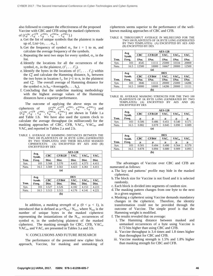
also followed to compare the effectiveness of the proposed Vaccine with CBC and CFB using the masked ciphertexts
of {𝐶𝑑𝑐𝑏𝑐, 𝐶𝑑
𝑐𝑓𝑏, 𝐶𝑑
𝑣𝑎𝑐𝑠 , 𝐶𝑑𝑣𝑎𝑐𝑚 , 𝐶𝑑
𝑣𝑎𝑐𝑐}.) a. Get the list of unique symbols that the plaintext is made
up of, List={1 . . . m }.
b. Get the frequency of symbol i, for i = 1 to m, and calculate the average frequency of the symbols.
c. Repeating the next two steps for every symbol, i, in the list.
d. Identify the locations for all the occurrences of the
symbol, i, in the plaintext, (ℓi1 . . . ℓ
in).
e. Identify the bytes in the locations of (ℓi1 . . . ℓ
in) within
the 𝐶𝑎 and calculate the Hamming distance, hj, between
the two bytes in location ℓj, for j=1 to n, in the plaintext and 𝐶𝑎
. The overall average of Hamming distance for
the symbol i is hi =Average(h1 . . . hn), f. Concluding that the underline masking methodology
with the highest average values of the Hamming distances have a superior performance.
The outcome of applying the above steps on the
ciphertexts of {𝐶𝑎𝑐𝑏𝑐 , 𝐶𝑎
𝑐𝑓𝑏, 𝐶𝑎
𝑣𝑎𝑐𝑠 , 𝐶𝑎𝑣𝑎𝑐𝑚 , 𝐶𝑎
𝑣𝑎𝑐𝑐} and
{𝐶𝑑𝑐𝑏𝑐, 𝐶𝑑
𝑐𝑓𝑏, 𝐶𝑑
𝑣𝑎𝑐𝑠 , 𝐶𝑑𝑣𝑎𝑐𝑚 , 𝐶𝑑
𝑣𝑎𝑐𝑐} are shown in Table 1.a
and Table 1.b. We have also used the system clock to calculate the average throughput (in millisecond) for the masking approaches of CBC, CFB, VACs, VACm, and VACc and reported in Tables 2.a and 2.b.
TABLE I. AVERAGE OF HAMMING DISTANCES BETWEEN THE TWO 100 PLAINTEXTS OF 1K BYTE LONG (GENERATED BY TWO TEMPLATES) AND THEIR RELATED MASKED CIPHERTEXTS: (A) ENCRYPTED BY AES AND (B) ENCRYPTED BY DES
Tem.
Avg.
Symb.
Freq.
AES-128
CBC CFB128 VACs VACm VACc
Dist. Dist. Dist. Dist. Dist.
Syn. 103 3.568 3.570 4.415 4.373 4.411
Natu. 16.5 3.569 3.561 4.423 4.361 4.411
(a)
Tem.
Avg.
Symb.
Freq.
DES
CBC CFB64 VACs VACm VACc
Dist. Dist. Dist. Dist. Dist.
Syn. 103 3.527 3.526 4.182 4.153 4.223
Natu. 16.5 3.513 3.515 4.176 4.141 4.221
(b)
In addition, a masking strength of (0 < < 1), is
introduced that is defined as =Ninst / Nocc, where Ninst is the number of unique bytes in the masked ciphertext representing the instantiations of the Nocc occurrences of
symbol i in the underlying plaintext of the masked ciphertext. The masking strength for CBC, CFB, VACs, VACm, and VACc are presented in Tables 3.a and 3.b.
V. CONCLUSIONS AND FUTURE RESEARCH
The performance of the presented new cipher block approach, Vaccine, for masking and unmasking of
ciphertexts seems superior to the performance of the well-known masking approaches of CBC and CFB.
TABLE II. THROUGHPUT AVERAGE IN MILISECOND FOR THE TWO 100 PLAINTEXTS OF 1K BYTE LONG (GENERATED BY TWO TEMPLATES): (A) ENCRYPTED BY AES AND (B) ENCRYPTED BY DES
Tem.
Avg
Symb.
Freq.
AES-128
CBC CFB128 VACs VACm VACc
TPut. TPut. TPut. TPut. TPut.
Syn. 103 4545 11111 25000 33334 20000
Natu. 16.5 12500 10000 16667 20000 12500
(a)
Tem.
Avg
Symb.
Freq.
DES
CBC CFB64 VACs VACm VACc
TPut. TPut. TPut. TPut. TPut.
Syn. 103 3846 11111 20000 25000 14286
Natu. 16.5 10000 10000 14286 20000 11111
(b)
TABLE III. AVERAGE MASKING STRENGTH FOR THE TWO 100 PLAINTEXTS OF 1K BYTE LONG (GENERATED BY TWO TEMPLATES): (A) ENCRYPTED BY AES AND (B) ENCRYPTED BY DES
Tem.
Avg.
Symb.
Freq.
AES-128
CBC CFB128 VACs VACm VACc
Syn. 103 0.506 0.486 0.451 0.540 0.571
Natu. 16.5 0.882 0.878 0.845 0.890 0.889
(a)
Tem.
Avg.
Symb.
Freq.
DES
CBC CFB64 VACs VACm VACc
Syn. 103 0.501 0.494 0.490 0.564 0.570
Natu. 16.5 0.878 0.894 0.880 0.909 0.893
(b)
The advantages of Vaccine over CBC and CFB are numerated as follows: a. The key and patterns’ profile may hide in the masked
ciphertext. b. The block size for Vaccine is not fixed and it is selected
randomly. c. Each block is divided into segments of random size. d. The masking pattern changes from one byte to the next
in a given segment. e. Masking a ciphertext using Vaccine demands mandatory
changes in the ciphertext. Therefore, the identity transformation could not be provided through the outcome of Vaccine. The simple proof is that the Hamming weight is modified.
f. The results revealed that on average: i. The Hamming distance between masked and
unmasked occurrences of a byte using Vaccine is 0.72 bits higher than using CBC and CFB.
ii. Vaccine throughput is 3.4 times and 1.8 times higher than throughput for CBC and CFB.
iii. Vaccine masking strength is 1.5% and 1.8% higher than masking strength for CBC and CFB.
46Copyright (c) IARIA, 2017. ISBN: 978-1-61208-605-7
CYBER 2017 : The Second International Conference on Cyber-Technologies and Cyber-Systems
55 / 90
iv. VACm masking strength is 3.6% and 3.7% higher than masking strength for CBC and CFB. And VACc masking strength is 3.9% and 4.2% higher than masking strength for CBC and CFB.
As the future research, building a new version of Vaccine is in progress to make the throughput and the masking strength of the methodology even higher. In addition, the use of Vaccine in a parallel processing environment also will be investigated. In addition, a feasibility study for using Vaccine as an authentication method is in progress.
REFERENCES
[1] A. A. Rasheed, M. Cotter, B. Smith, D. Levan, and S. Phoha, “Dynamically Reconfigurable AES Cryptographic Core for Small, Power Limited Mobile Sensors", The 35th IEEE International Performance Computing and Communication Conference and Workshop, pp. 1-7, 2016.
[2] G. P. Saggese, A. Mazzeo, N. Mazzocca and A. G. M. Strollo, “An FPGA-based performance analysis of the unrolling, tiling, and pipelining of the AES algorithm”, LNCS 2778, pp. 292-302, 2003.
[3] N. Pramstaller and J. Wolkerstorfer, “A Universal and Efficient AES Co-processor for Field Programmable Logic Arrays”, Lecture Notes in Computer Science, Springer, Vol.3203, pp. 565-574, 2004.
[4] B. Moeller. Security of CBC Cipher suites in SSL/TLS: Problems and Countermeasures. [Online]. Available from: https://www.openssl.org/~bodo/tls-cbc.txt
[5] W. Stallings, “Cryptography and Network Security: Principles and Practice”, Pearson, 2014.
[6] C. A. Henk and V. Tilborg, “Fundamentals of Cryptology: “A Professional Reference and Interactive Tutorial”, Springer Science & Business Media, 2006.
[7] N. Feruson, B. Schneier, and T. Kohno, “Cryptography Engineering: Design Principles and Practical Applications”, Indianapolis: Wiley Publishing, Inc., pp. 63-64, 2010.
[8] W. F. Ehrsam, C. H. W. Meyer, J. L. Smith, and L. W. Tuchman, "Message Verification and Transmission Error Detection by Block Chaining", US Patent 4074066, 1976.
[9] C. Kaufman, R. Perlman, and M. Speciner, “Network Security”, 2nd ed., Upper Saddle River, NJ: Prentice Hall, p. 319, 2002.
[10] National Institute of Standards and Technology (NIST), Advanced Encryption Standard (AES), Federal Information Processing Standards Publications 197 (FIPS197), Nov. 2001.
[11] S. Vaudenay, “Security Flaws Induced by CBC Padding — Applications to SSL, IPSEC, WTLS....”, Lecture Notes in Computer Science, Springer, vol. 2332, pp. 534-546, 2002.
[12] H. Kuo-Tsang, C. Jung-Hui, and S. Sung-Shiou, "A Novel Structure with Dynamic Operation Mode for Symmetric-Key Block Ciphers", International Journal of Network Security & Its Applications, Vol. 5, No. 1, p. 19, 2013.
[13] H. Feistel, “Cryptography and Computer Privacy", Scientific American, Vol. 228, No. 5, pp 15–23, 1973.
[14] F. Charot, and E. Yahya, and C. Wagner, “Efficient Modular-Pipelined AES Implementation in Counter Mode on ALTERA FPGA”, (FPL 2003), Lisbon, Portugal, pp. 282-291, 2003.
47Copyright (c) IARIA, 2017. ISBN: 978-1-61208-605-7
CYBER 2017 : The Second International Conference on Cyber-Technologies and Cyber-Systems
56 / 90
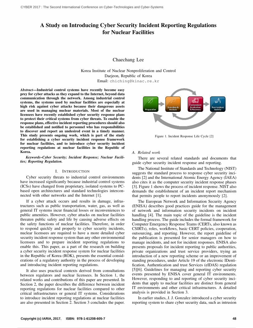
A Study on Introducing Cyber Security Incident Reporting Regulationsfor Nuclear Facilities
Chaechang Lee
Korea Institute of Nuclear Nonproliferation and ControlDaejeon, Republic of Korea
Email: [email protected]
Abstract—Industrial control systems have recently become easyprey for cyber attacks as they expand to the Internet, beyond datacommunication through the network. Among industrial controlsystems, the systems used by nuclear facilities are especially athigh risk against cyber attacks because their dangerous assetsare used in managing nuclear materials. Most of the nuclearlicensees have recently established cyber security response plansto protect their critical systems from cyber threats. To enable theresponse plans, effective incident reporting procedures should alsobe established and notified to personnel who has responsibilitiesto discover and report an undesired event in a timely manner.This study presents ongoing work, which is part of the studyfor establishing a cyber security incident response frameworkfor nuclear facilities, and to introduce cyber security incidentreporting regulations at nuclear facilities in the Republic ofKorea.
Keywords–Cyber Security; Incident Response; Nuclear Facili-ties; Reporting Regulation.
I. INTRODUCTION
Cyber security threats to industrial control environmentshave increased significantly because industrial control systems(ICSs) have changed from proprietary, isolated systems to PC-based open architectures and standard technologies intercon-nected with other networks and the Internet [1].
If a cyber attack occurs and results in damage, infras-tructures such as public transportation, water, gas, as well asgeneral IT systems incur financial losses or inconveniences topublic amenities. However, cyber attacks on nuclear facilitiesthreaten public safety and life by causing adverse effects onthe safety functions of nuclear facilities. Therefore, in orderto respond quickly and properly to cyber security incidents,nuclear licensees are required to have a more detailed cybersecurity incident response system than any other environmentallicensees and to prepare incident reporting regulations toenable this. This paper, as a part of the research on buildinga cyber security incident response system for nuclear facilitiesin the Republic of Korea (ROK), presents the essential consid-erations of a regulatory authority in the process of developingand introducing incident reporting regulations.
It also uses practical contexts derived from consultationsbetween regulators and nuclear licensees. In Section 1, therelated works and contributions of this paper are presented. InSection 2, the paper describes the difference between incidentreporting regulations for nuclear facilities compared to othercritical infrastructures or general IT systems. Considerationsto introduce incident reporting regulations at nuclear facilitiesare also presented in Section 2. Section 3 concludes the paper.
Figure 1. Incident Response Life Cycle [2]
A. Related workThere are several related standards and documents that
guide cyber security incident response and reporting.The National Institute of Standards and Technology (NIST)
suggests the standard process to response cyber security inci-dents [2] and the International Atomic Energy Agency (IAEA)also cites it as the computer security incident response phases[3]. Figure 1 shows the process of incident response. NIST alsodemands the establishment of an incident report mechanismthat permits people to report incidents anonymously [2].
The European Network and Information Security Agency(ENISA) describes good practices guide for the managementof network and information security incidents on incidenthandling [4]. The main topic of the guideline is the incidenthandling process. The guide includes the formal framework forComputer Emergency Response Teams (CERTs, also known asCSIRTs), roles, workflows, basic CERT policies, cooperation,outsourcing, and reporting. However, the report guideline ofthe publication is presented for senior managers on how tomanage incidents, and not for incident responses. ENISA alsopresents proposals for incident reporting to public authorities,private organizations and trust service providers, trying anintroduction of a new reporting scheme or an improvement ofstanding procedures, under Article 19 of the electronic IDenti-fication, Authentication and trust Services (eIDAS) regulation[5][6]. Guidelines for managing and reporting cyber securityevents presented by ENISA cover general IT environments.However, responding to and reporting of cyber security inci-dents that apply to nuclear facilities are distinct from generalIT environments and other critical infrastructures. A detailedanalysis is provided in Section 3.
In earlier studies, J. J. Gonzalez introduced a cyber securityreporting system to share cyber security data, such as intrusion
48Copyright (c) IARIA, 2017. ISBN: 978-1-61208-605-7
CYBER 2017 : The Second International Conference on Cyber-Technologies and Cyber-Systems
57 / 90
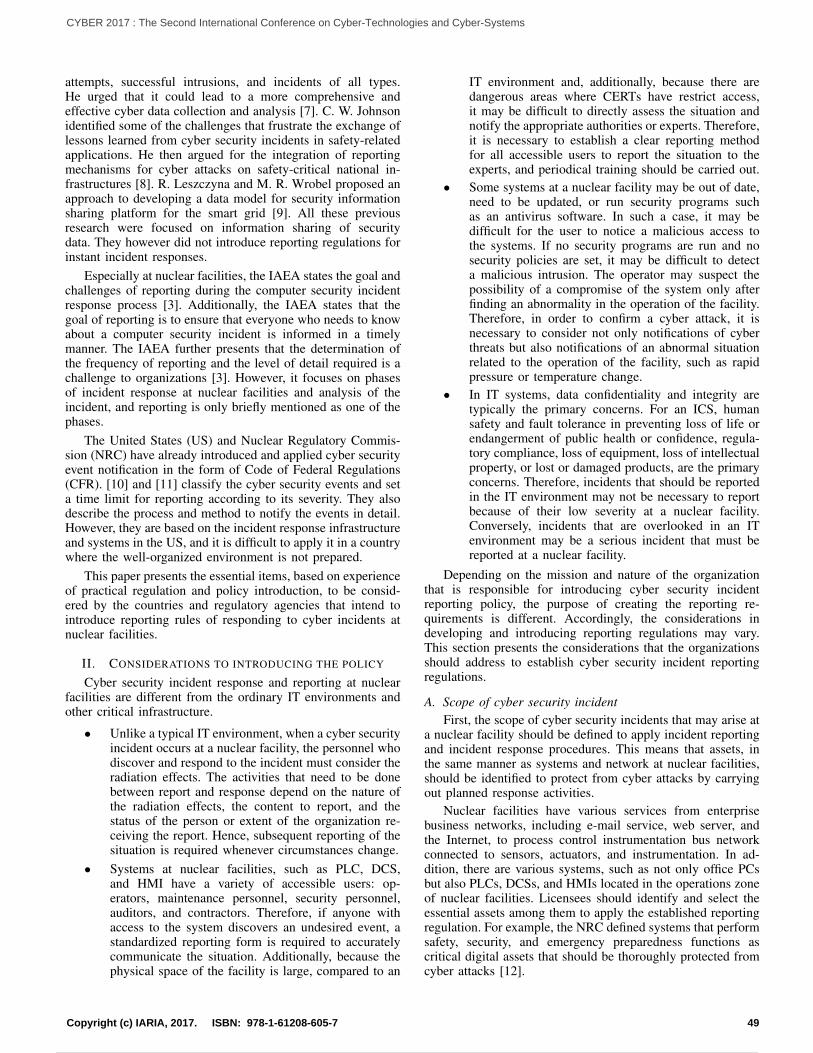
attempts, successful intrusions, and incidents of all types.He urged that it could lead to a more comprehensive andeffective cyber data collection and analysis [7]. C. W. Johnsonidentified some of the challenges that frustrate the exchange oflessons learned from cyber security incidents in safety-relatedapplications. He then argued for the integration of reportingmechanisms for cyber attacks on safety-critical national in-frastructures [8]. R. Leszczyna and M. R. Wrobel proposed anapproach to developing a data model for security informationsharing platform for the smart grid [9]. All these previousresearch were focused on information sharing of securitydata. They however did not introduce reporting regulations forinstant incident responses.
Especially at nuclear facilities, the IAEA states the goal andchallenges of reporting during the computer security incidentresponse process [3]. Additionally, the IAEA states that thegoal of reporting is to ensure that everyone who needs to knowabout a computer security incident is informed in a timelymanner. The IAEA further presents that the determination ofthe frequency of reporting and the level of detail required is achallenge to organizations [3]. However, it focuses on phasesof incident response at nuclear facilities and analysis of theincident, and reporting is only briefly mentioned as one of thephases.
The United States (US) and Nuclear Regulatory Commis-sion (NRC) have already introduced and applied cyber securityevent notification in the form of Code of Federal Regulations(CFR). [10] and [11] classify the cyber security events and seta time limit for reporting according to its severity. They alsodescribe the process and method to notify the events in detail.However, they are based on the incident response infrastructureand systems in the US, and it is difficult to apply it in a countrywhere the well-organized environment is not prepared.
This paper presents the essential items, based on experienceof practical regulation and policy introduction, to be consid-ered by the countries and regulatory agencies that intend tointroduce reporting rules of responding to cyber incidents atnuclear facilities.
II. CONSIDERATIONS TO INTRODUCING THE POLICY
Cyber security incident response and reporting at nuclearfacilities are different from the ordinary IT environments andother critical infrastructure.
• Unlike a typical IT environment, when a cyber securityincident occurs at a nuclear facility, the personnel whodiscover and respond to the incident must consider theradiation effects. The activities that need to be donebetween report and response depend on the nature ofthe radiation effects, the content to report, and thestatus of the person or extent of the organization re-ceiving the report. Hence, subsequent reporting of thesituation is required whenever circumstances change.
• Systems at nuclear facilities, such as PLC, DCS,and HMI have a variety of accessible users: op-erators, maintenance personnel, security personnel,auditors, and contractors. Therefore, if anyone withaccess to the system discovers an undesired event, astandardized reporting form is required to accuratelycommunicate the situation. Additionally, because thephysical space of the facility is large, compared to an
IT environment and, additionally, because there aredangerous areas where CERTs have restrict access,it may be difficult to directly assess the situation andnotify the appropriate authorities or experts. Therefore,it is necessary to establish a clear reporting methodfor all accessible users to report the situation to theexperts, and periodical training should be carried out.
• Some systems at a nuclear facility may be out of date,need to be updated, or run security programs suchas an antivirus software. In such a case, it may bedifficult for the user to notice a malicious access tothe systems. If no security programs are run and nosecurity policies are set, it may be difficult to detecta malicious intrusion. The operator may suspect thepossibility of a compromise of the system only afterfinding an abnormality in the operation of the facility.Therefore, in order to confirm a cyber attack, it isnecessary to consider not only notifications of cyberthreats but also notifications of an abnormal situationrelated to the operation of the facility, such as rapidpressure or temperature change.
• In IT systems, data confidentiality and integrity aretypically the primary concerns. For an ICS, humansafety and fault tolerance in preventing loss of life orendangerment of public health or confidence, regula-tory compliance, loss of equipment, loss of intellectualproperty, or lost or damaged products, are the primaryconcerns. Therefore, incidents that should be reportedin the IT environment may not be necessary to reportbecause of their low severity at a nuclear facility.Conversely, incidents that are overlooked in an ITenvironment may be a serious incident that must bereported at a nuclear facility.
Depending on the mission and nature of the organizationthat is responsible for introducing cyber security incidentreporting policy, the purpose of creating the reporting re-quirements is different. Accordingly, the considerations indeveloping and introducing reporting regulations may vary.This section presents the considerations that the organizationsshould address to establish cyber security incident reportingregulations.
A. Scope of cyber security incidentFirst, the scope of cyber security incidents that may arise at
a nuclear facility should be defined to apply incident reportingand incident response procedures. This means that assets, inthe same manner as systems and network at nuclear facilities,should be identified to protect from cyber attacks by carryingout planned response activities.
Nuclear facilities have various services from enterprisebusiness networks, including e-mail service, web server, andthe Internet, to process control instrumentation bus networkconnected to sensors, actuators, and instrumentation. In ad-dition, there are various systems, such as not only office PCsbut also PLCs, DCSs, and HMIs located in the operations zoneof nuclear facilities. Licensees should identify and select theessential assets among them to apply the established reportingregulation. For example, the NRC defined systems that performsafety, security, and emergency preparedness functions ascritical digital assets that should be thoroughly protected fromcyber attacks [12].
49Copyright (c) IARIA, 2017. ISBN: 978-1-61208-605-7
CYBER 2017 : The Second International Conference on Cyber-Technologies and Cyber-Systems
58 / 90
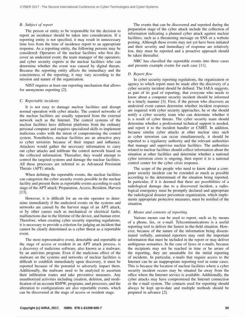
B. Subject of report
The person or entity to be responsible for the decision toreport an incidence should be taken into consideration. If areporting entity is not specified, it may result in unnecessarytime loss from the time of incidence report to an appropriateresponse. As a reporting entity, the following persons may beconsidered: Operators of the nuclear facilities who first dis-cover an undesired event; the team manager of the operators;and cyber security experts at the nuclear facilities who candetermine whether the event was caused by digital threats.Because the reporting entity affects the immediacy and theconcreteness of the reporting, it may vary according to themission and nature of the organization.
NIST requires at least one reporting mechanism that allowsfor anonymous reporting [2].
C. Reportable incidents
It is not easy to damage nuclear facilities and disruptnormal operation with cyber attacks. The control networks ofthe nuclear facilities are usually separated from the externalnetwork such as the Internet. The control systems of thenuclear facilities have different platforms from the ordinarypersonal computer and requires specialized skills to implementmalicious codes with the intent of compromising the controlsystem. Nonetheless, nuclear facilities are an attractive preyto cyber terrorists because of their impact and influence.Attackers would gather the necessary information to carryout cyber attacks and infiltrate the control network based onthe collected information. Thereafter, they would attempt tocontrol the targeted systems and damage the nuclear facilities.All these processes are referred to as Advanced PersistentThreats (APT) attack.
When defining the reportable events, the nuclear facilitiescan categorize the cyber security events possible in the nuclearfacility and present them as reportable events according to eachstage of the APT attack: Preparation, Access, Resident, Harvest[13].
However, it is difficult for an on-site operator to deter-mine immediately if the undesired events on the systems andnetworks are caused by the harvest stage of an APT attack,or by other causes such as mechanical or electrical faults,malfunctions due to the lifetime of the device, and human error.Therefore, when creating cyber security reporting regulations,it is necessary to provide a criterion for judging an incident thatcannot be clearly determined as a cyber threat as a reportableevent.
The most representative event, detectable and reportable atthe stage of access or resident in an APT attack process, isa discovery of malicious software, also known as a malware,by an antivirus program. Even if the malicious effect of themalware on the systems and networks of nuclear facilities isdifficult to establish immediately upon discovery, it must bereported because of the potential to adversely impact them.Additionally, the malware need to be analyzed to ascertaintheir infiltration routes and take preventive measures. Anyunauthorized activities including creation, deletion, and modi-fication of an account ID/PW, programs, and processes, and thealteration to configurations are also reportable events, whichcan be discovered at the stage of access or resident stage.
The events that can be discovered and reported during thepreparation stage of the cyber attack include the collection ofinformation indicating a planned cyber attack against nuclearfacilities, such as a threatening message on SNS or a websiteposting. Although these events may not yet have been initiatedand their severity and immediacy of response are relativelylow, they must be reported and a proactive approach shouldbe taken thereafter.
NRC has classified the reportable events into three casesand presents example events for each case [11].
D. Report flowIn cyber security reporting regulations, the organization or
agency to which report must be made after the discovery of acyber security incident should be defined. The IAEA suggests,as part of its goal of reporting, that everyone who needs toknow about a computer security incident should be informedin a timely manner [3]. First, if the person who discovers anundesired event cannot determine whether incident responsesare required with cyber security approaches, he or she shouldnotify a cyber security team who can determine whether itis a result of cyber threats. The cyber security team shoulddetermine whether a professional technical support is needed,and report it to the incident handler or CSIRT. In addition,because similar cyber attacks at other nuclear sites suchas cyber terrorism can occur simultaneously, it should bereported to a regulatory authority and the relevant authoritiesthat manage and supervise nuclear facilities. The authoritiesrelated to nuclear facilities should collect information about thesituation at other facilities and determine whether a nationalcyber terrorism crisis is ongoing, then report it to a nationalcontrol center for the cyber crisis response.
The scope of the people who need to know about a com-puter security incident can be extended as much as possibleaccording to the determinant of the situation being reported.In particular, if it is deemed that there are possibilities of aradiological damage due to a discovered incident, a radio-logical emergency must be promptly declared and appropriatethe radiological disaster prevention organization, which imple-ments appropriate protective measures, must be notified of thesituation.
E. Means and contents of reportingVarious means can be used to report, such as by means
of a phone, fax, or e-mail. Telecommunications is a usefulreporting tool to deliver the fastest in-the-field situation. How-ever, because of the nature of the information being dissem-inated verbally, untrained reporters may omit the importantinformation that must be included in the report or may deliverambiguous semantics. In the case of faxes or e-mails, becausethe recipients may not be reached in time or be aware ofthe reporting, they are unsuitable for the initial reportingof incidents. In particular, e-mails that require access to theInternet can be an inappropriate reporting tool in some cases.This is because the location of nuclear facilities where a cybersecurity incident occurs may be situated far away from theoffice where the Internet service is available. Additionally, thecyber attacks may have compromised the Internet connectionor the e-mail system. The contacts used for reporting shouldalways be kept up-to-date and multiple methods should beprepared in advance [2].
50Copyright (c) IARIA, 2017. ISBN: 978-1-61208-605-7
CYBER 2017 : The Second International Conference on Cyber-Technologies and Cyber-Systems
59 / 90
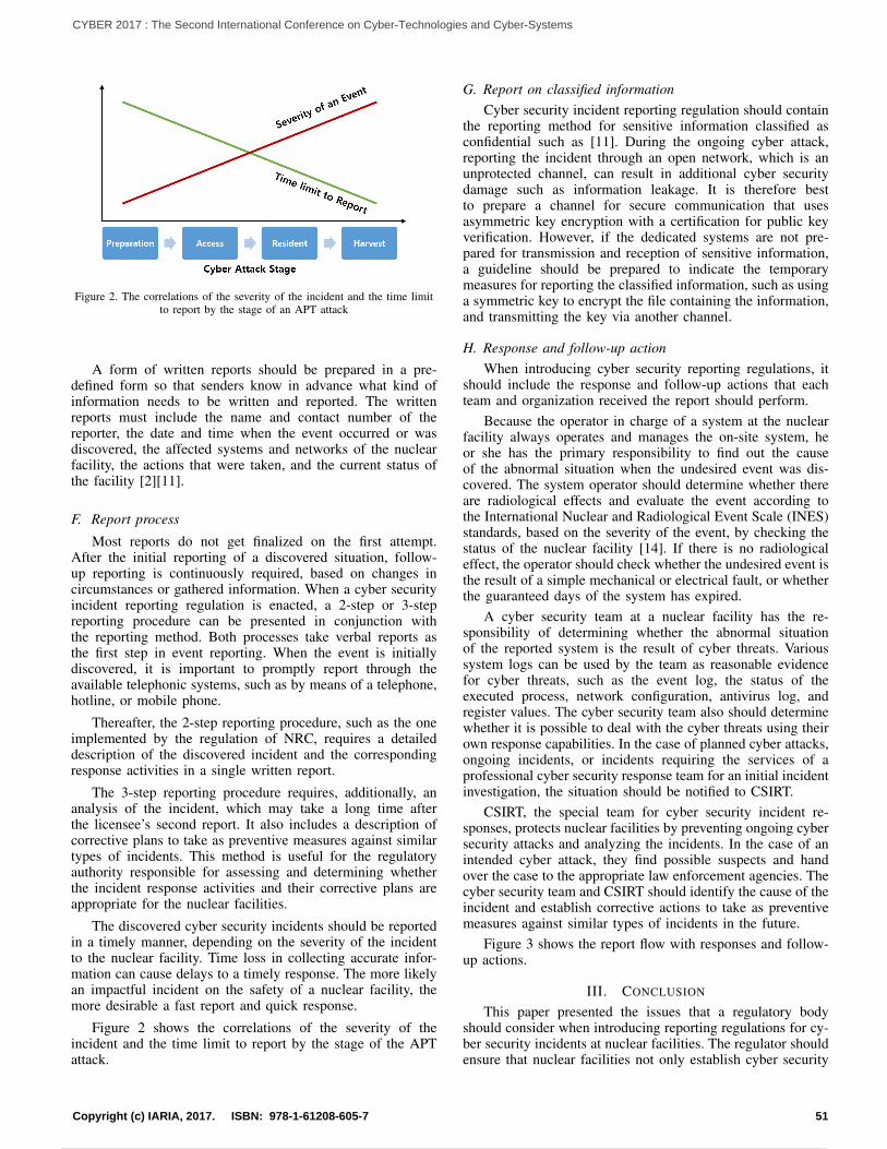
Figure 2. The correlations of the severity of the incident and the time limitto report by the stage of an APT attack
A form of written reports should be prepared in a pre-defined form so that senders know in advance what kind ofinformation needs to be written and reported. The writtenreports must include the name and contact number of thereporter, the date and time when the event occurred or wasdiscovered, the affected systems and networks of the nuclearfacility, the actions that were taken, and the current status ofthe facility [2][11].
F. Report process
Most reports do not get finalized on the first attempt.After the initial reporting of a discovered situation, follow-up reporting is continuously required, based on changes incircumstances or gathered information. When a cyber securityincident reporting regulation is enacted, a 2-step or 3-stepreporting procedure can be presented in conjunction withthe reporting method. Both processes take verbal reports asthe first step in event reporting. When the event is initiallydiscovered, it is important to promptly report through theavailable telephonic systems, such as by means of a telephone,hotline, or mobile phone.
Thereafter, the 2-step reporting procedure, such as the oneimplemented by the regulation of NRC, requires a detaileddescription of the discovered incident and the correspondingresponse activities in a single written report.
The 3-step reporting procedure requires, additionally, ananalysis of the incident, which may take a long time afterthe licensee’s second report. It also includes a description ofcorrective plans to take as preventive measures against similartypes of incidents. This method is useful for the regulatoryauthority responsible for assessing and determining whetherthe incident response activities and their corrective plans areappropriate for the nuclear facilities.
The discovered cyber security incidents should be reportedin a timely manner, depending on the severity of the incidentto the nuclear facility. Time loss in collecting accurate infor-mation can cause delays to a timely response. The more likelyan impactful incident on the safety of a nuclear facility, themore desirable a fast report and quick response.
Figure 2 shows the correlations of the severity of theincident and the time limit to report by the stage of the APTattack.
G. Report on classified informationCyber security incident reporting regulation should contain
the reporting method for sensitive information classified asconfidential such as [11]. During the ongoing cyber attack,reporting the incident through an open network, which is anunprotected channel, can result in additional cyber securitydamage such as information leakage. It is therefore bestto prepare a channel for secure communication that usesasymmetric key encryption with a certification for public keyverification. However, if the dedicated systems are not pre-pared for transmission and reception of sensitive information,a guideline should be prepared to indicate the temporarymeasures for reporting the classified information, such as usinga symmetric key to encrypt the file containing the information,and transmitting the key via another channel.
H. Response and follow-up actionWhen introducing cyber security reporting regulations, it
should include the response and follow-up actions that eachteam and organization received the report should perform.
Because the operator in charge of a system at the nuclearfacility always operates and manages the on-site system, heor she has the primary responsibility to find out the causeof the abnormal situation when the undesired event was dis-covered. The system operator should determine whether thereare radiological effects and evaluate the event according tothe International Nuclear and Radiological Event Scale (INES)standards, based on the severity of the event, by checking thestatus of the nuclear facility [14]. If there is no radiologicaleffect, the operator should check whether the undesired event isthe result of a simple mechanical or electrical fault, or whetherthe guaranteed days of the system has expired.
A cyber security team at a nuclear facility has the re-sponsibility of determining whether the abnormal situationof the reported system is the result of cyber threats. Varioussystem logs can be used by the team as reasonable evidencefor cyber threats, such as the event log, the status of theexecuted process, network configuration, antivirus log, andregister values. The cyber security team also should determinewhether it is possible to deal with the cyber threats using theirown response capabilities. In the case of planned cyber attacks,ongoing incidents, or incidents requiring the services of aprofessional cyber security response team for an initial incidentinvestigation, the situation should be notified to CSIRT.
CSIRT, the special team for cyber security incident re-sponses, protects nuclear facilities by preventing ongoing cybersecurity attacks and analyzing the incidents. In the case of anintended cyber attack, they find possible suspects and handover the case to the appropriate law enforcement agencies. Thecyber security team and CSIRT should identify the cause of theincident and establish corrective actions to take as preventivemeasures against similar types of incidents in the future.
Figure 3 shows the report flow with responses and follow-up actions.
III. CONCLUSION
This paper presented the issues that a regulatory bodyshould consider when introducing reporting regulations for cy-ber security incidents at nuclear facilities. The regulator shouldensure that nuclear facilities not only establish cyber security
51Copyright (c) IARIA, 2017. ISBN: 978-1-61208-605-7
CYBER 2017 : The Second International Conference on Cyber-Technologies and Cyber-Systems
60 / 90
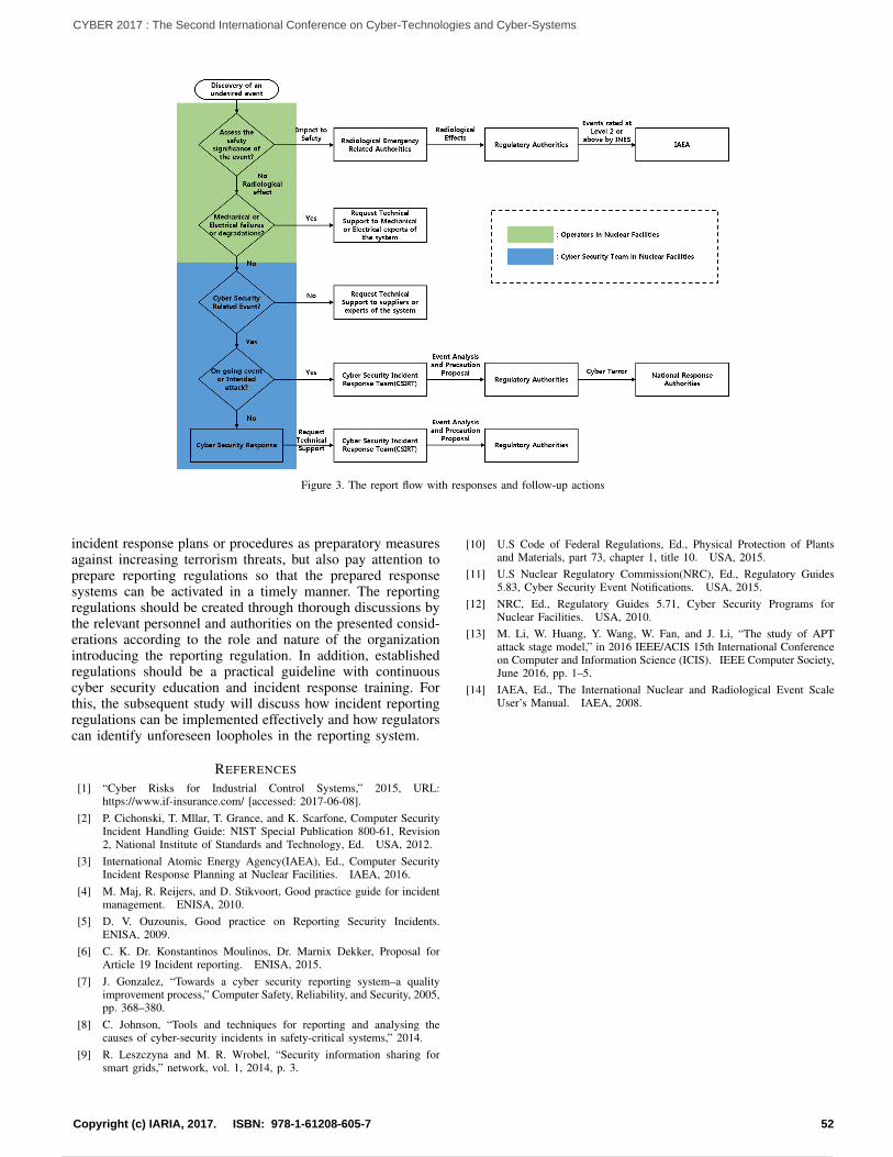
Figure 3. The report flow with responses and follow-up actions
incident response plans or procedures as preparatory measuresagainst increasing terrorism threats, but also pay attention toprepare reporting regulations so that the prepared responsesystems can be activated in a timely manner. The reportingregulations should be created through thorough discussions bythe relevant personnel and authorities on the presented consid-erations according to the role and nature of the organizationintroducing the reporting regulation. In addition, establishedregulations should be a practical guideline with continuouscyber security education and incident response training. Forthis, the subsequent study will discuss how incident reportingregulations can be implemented effectively and how regulatorscan identify unforeseen loopholes in the reporting system.
REFERENCES
[1] “Cyber Risks for Industrial Control Systems,” 2015, URL:https://www.if-insurance.com/ [accessed: 2017-06-08].
[2] P. Cichonski, T. Mllar, T. Grance, and K. Scarfone, Computer SecurityIncident Handling Guide: NIST Special Publication 800-61, Revision2, National Institute of Standards and Technology, Ed. USA, 2012.
[3] International Atomic Energy Agency(IAEA), Ed., Computer SecurityIncident Response Planning at Nuclear Facilities. IAEA, 2016.
[4] M. Maj, R. Reijers, and D. Stikvoort, Good practice guide for incidentmanagement. ENISA, 2010.
[5] D. V. Ouzounis, Good practice on Reporting Security Incidents.ENISA, 2009.
[6] C. K. Dr. Konstantinos Moulinos, Dr. Marnix Dekker, Proposal forArticle 19 Incident reporting. ENISA, 2015.
[7] J. Gonzalez, “Towards a cyber security reporting system–a qualityimprovement process,” Computer Safety, Reliability, and Security, 2005,pp. 368–380.
[8] C. Johnson, “Tools and techniques for reporting and analysing thecauses of cyber-security incidents in safety-critical systems,” 2014.
[9] R. Leszczyna and M. R. Wrobel, “Security information sharing forsmart grids,” network, vol. 1, 2014, p. 3.
[10] U.S Code of Federal Regulations, Ed., Physical Protection of Plantsand Materials, part 73, chapter 1, title 10. USA, 2015.
[11] U.S Nuclear Regulatory Commission(NRC), Ed., Regulatory Guides5.83, Cyber Security Event Notifications. USA, 2015.
[12] NRC, Ed., Regulatory Guides 5.71, Cyber Security Programs forNuclear Facilities. USA, 2010.
[13] M. Li, W. Huang, Y. Wang, W. Fan, and J. Li, “The study of APTattack stage model,” in 2016 IEEE/ACIS 15th International Conferenceon Computer and Information Science (ICIS). IEEE Computer Society,June 2016, pp. 1–5.
[14] IAEA, Ed., The International Nuclear and Radiological Event ScaleUser’s Manual. IAEA, 2008.
52Copyright (c) IARIA, 2017. ISBN: 978-1-61208-605-7
CYBER 2017 : The Second International Conference on Cyber-Technologies and Cyber-Systems
61 / 90
Improving the Effectiveness of CSIRTs
Maria Bada*1 Sadie Creese* Michael Goldsmith* and Chris J. Mitchell†
* University of Oxford, Global Cyber Security Capacity Centre, Oxford, UK † University of London, Royal Holloway, London, UK
E-mail: {maria.bada | sadie.creese | michael.goldsmith}@cs.ox.ac.uk | [email protected]
Abstract-This paper reports on research designed to measure
the effectiveness of national Computer Security Incident
Response Teams (CSIRTs). Specifically, our aim is to identify:
1) the ways in which a CSIRT might be considered to be
effective; 2) the issues which may limit the performance of a
CSIRT; and 3) approaches towards developing CSIRT
effectiveness metrics. A primary motive for doing so is to
enable more effective CSIRTs to be implemented, focusing on
activities with the maximum impact on threat mitigation. The
research was conducted using both online survey and
interviews, in two phases. The study participants were experts
within the existing CSIRT community. In total, 46 participants
responded to the survey, from 27 countries in Europe, Africa,
South and North America, and Asia. Three experts working
for CSIRTs in the UK and USA were also interviewed.
Questions asked during the interviews and the online survey
queried the personal knowledge and experience of participants
regarding CSIRTs. In our analysis, issues such as cooperation,
data-sharing and trust are discussed as crucial components of
an effective CSIRT. Existing measurement approaches for
computer security incident response are presented, before a set
of suggested direct and indirect measures of the effectiveness of
a CSIRT is defined.
Keywords-Cybersecurity; CSIRT; Metrics; Effectiveness.
I. INTRODUCTION
This paper considers the problem of assessing the effectiveness of Computer Security Incident Response Teams (CSIRTs). In order to be able to tackle any kind of cybersecurity incident, it is imperative for an incident response capacity to be available at least in some organisational form, in particular as a CSIRT.
The name Computer Emergency Response Team is the historic designation for the first such response team (CERT/CC) [1], established at Carnegie Mellon University (CMU). The term CERT is now a registered service mark of Carnegie Mellon University that is licensed to other teams around the world. Some teams have taken on the more generic name of CSIRT, in particular to clarify that they are involved with the task of handling computer security incidents rather than other technical support work. CSIRTs [2] have as their main responsibility detecting and informing a wider public about vulnerabilities, making patches available to organisations and to the general public, providing technical assistance in dealing with computer incidents, and coordinating responses in emergencies. CSIRTs can operate on a nationwide basis, either inside or
outside of the governmental sector. Apart from their main mission, CSIRTs need to be able to adapt to a continuous changing environment and have the flexibility to deal with unexpected incidents. Today’s challenges have an impact on the effectiveness of CSIRTs. CSIRTs need effective methods to collaborate and share information, efficient mechanisms to triage incoming information, and policies and procedures that are well-established and understood. Their effectiveness can be affected by a variety of factors [3].
Before considering ways of improving the effectiveness of a CSIRT, it is vital to understand how to assess its effectiveness. Issues such as cooperation, data-sharing and trust are crucial in order for a CSIRT to accomplish high levels of performance. In this paper, we will try to describe the factors which can enhance the capacity of a national CSIRT and improve its processes.
In Section II, we describe existing measurement approaches for computer security incident response before defining a set of measures. Following more information on issues such as cooperation, data-sharing and trust is provided, which are crucial in order a CSIRT to accomplish high levels of performance. In Section III, related work internationally is presented while section IV describes the methodology. Section V presents our results and finally section VI describes our conclusions.
The results presented in this paper are intended to be particularly valuable for CSIRT experts, Chief Information Officers (CIOs), Chief Information Security officers (CISOs), Senior Agency Information Security Officers (SAISOs), Information System Security Officers (ISSOs), and Community Support Officers (CSOs) and (CISOs).
The measures presented can be used both within government and industry contexts.
II. METRICS TO ASSESS THE EFFECTIVENESS OF A CSIRT
Well-defined metrics are essential to determine which security practices are worth investing in. Every CSIRT will need to develop mechanisms to evaluate the effectiveness of its practice. This should be done in conjunction with its management and its constituency [4]. Effectiveness, as well as efficiency measures address two aspects of security control implementation results: the robustness of the result itself (effectiveness) and the timeliness of the result (efficiency). These measures can provide important information for security decision makers in order to improve the performance of CSIRTs, and they help in determining the effectiveness of security controls.
53Copyright (c) IARIA, 2017. ISBN: 978-1-61208-605-7
CYBER 2017 : The Second International Conference on Cyber-Technologies and Cyber-Systems
62 / 90
By measuring the effectiveness of information security, there can be [5]:
a) Increases in accountability: Measuring
effectiveness can help in identifying specific security
controls that are implemented incorrectly or are ineffective.
b) Improvements in Information Security
Effectiveness: Measuring information security can
determine the effectiveness of implemented information
security processes and procedures by interrelating the results
of various activities and events to security controls and
investments.
c) Demonstration of Compliance: Organisations can
demonstrate compliance with applicable laws and
regulations by maintaining an information security
measurement program.
The International Telecommunication Union (ITU) [6], is helping countries to establish National Computer Incident Response Teams (CIRTs), which serve as a national focus point for coordinating cybersecurity incident response to cyber-attacks in the country. The objective of the Assessment of a CSIRT is to define the readiness to implement a national CSIRT. Part of this assessment includes the incident response capabilities of a country and the existence of an intrusion detection service offered to the constituents.
In order to improve the effectiveness of a CSIRT, it is vital to understand how to assess its effectiveness. Following we will be providing more information on issues such as cooperation, data-sharing and trust which are crucial in order a CSIRT to accomplish high levels of performance [3], [4], [7], [8].
A. Cooperation
The OECD report (2005) [9], describes the importance of international cooperation for fostering a culture of security and the role of regional facilitating interactions and exchanges. Moreover, national CSIRTs can help foster a cybersecurity culture by providing activities for awareness and education to the public, educating national stakeholders on the impact of virtual activities to their organisations, and the implications of their activities for cyber and information security. International cooperation is considered an integral part of the activities of a national CSIRT, and a number of countries have already established operational networks through which they exchange information and good practice. Most countries cooperate at the regional (European TF-CSIRT and EGC, APCERT) or global level (FIRST).
ENISA [10] while discussing the subject of the effectiveness of CSIRTs, has focused on possible barriers that can inhibit it. Specifically, four areas of benefit from a possible cooperation were identified: Incident Handling; Project establishment; Resource and information sharing; Social networking.
B. Information sharing
ENISA [10] has dealt with the issue of threat and incident information exchange and sharing practices used
among CSIRTs in Europe, especially, but not limited to, national/governmental CSIRTs. ENISA identified the functional and technical gaps that limit threat intelligence exchanges between national/governmental CSIRTs and their counterparts in Europe, as well as other CSIRTs within their respective countries.
Interactions between CSIRTs can include asking other teams for advice, disseminating knowledge of problems, and working cooperatively to resolve an incident affecting one or more of CSIRT constituencies. Response teams have to decide what kinds of agreements can exist between them in order to share but still safeguard information, as well as which information can be disclosed and to whom. A peer agreement refers to simple cooperation between CSIRTs, where a team contacts another and asks for help and advice [11].
ENISA [7] presented a variety of issues which can hinder information sharing. The main barriers to cooperation between CSIRTs are: a) poor quality of information; b) poor management of information sharing; c) misaligned incentives stemming from reputational risks; d) uncertainty about senior level awareness of cybersecurity; and e) the disincentive for private sector organisations to disclose information because of possible reputational damage. ENISA defines basic requirements for improved communications interoperable with existing solutions in order to improve information sharing. Better utilization of current communication tools and practices is needed. Local detection of incidents accompanied by trusted forms of information exchange, can ultimately lead to improved prevention of cyber incidents on a global scale.
The Information Sharing Framework (ISF, MACCSA, 2013) [8] provides guidance on establishing the capability to increase an organisation’s cyber Situational Awareness, enabled by sharing information across a trusted community of interest to achieve Collaborative Cyber Situational Awareness (CCSA).
C. Trust
CSIRT cooperation is based on trust. Without trust, national/governmental CSIRTs will be less willing to share information and less open to work together on incident response and handling when needed. Measuring trust and defining criteria by which to measure a CSIRT trustworthiness is an ongoing challenge, particularly when the aim of the cooperation is to exchange and share sensitive information. Key criteria that national CSIRTs look for include: technical expertise with a proven track record; membership in CERT initiatives; ability to respond quickly and act on security threats; and a stable team [3].
Trust can be one of the biggest obstacles to enhanced and effective communication between CSIRTs but also between CSIRTs and other stakeholders. Lack of trust between stakeholders can lead to a lack of sharing of security incident information. This component is of vital importance for cooperation and information sharing, as discussed above.
According to Messenger (2005) [12], trust in public/private partnerships has a very significant role which can be enhanced through frequency of contact between
54Copyright (c) IARIA, 2017. ISBN: 978-1-61208-605-7
CYBER 2017 : The Second International Conference on Cyber-Technologies and Cyber-Systems
63 / 90
counterpart individuals, identification and sharing of common intentions and objectives, or technical credibility of technical staff.
According to the Information Sharing Framework [8], Trust depends on an AAA Model: Authentication (Are you who you claim you are?), Authorisation (Do you have permission to undertake the activities?) and Accountability (Can you evidence compliance in any court of law?).
D. Resources
The effectiveness of CSIRTs can be limited as a result of growing work load and limited resources [13], [14]. It seems obvious, but a national incident response team without a steady source of funding will not be able to function beyond the short term [15]. The typical work overload situation in a CSIRT, limits its effectiveness [14]. A CSIRT that has over-stretched its resources over a long time period must be prepared to go through a worse-before-better scenario to escape the “Capability Trap”. Such a transition process can be quite painful to the CSIRT and its surrounding environment, for example, through adjustments to scope of service to release resources for improvement [13].
III. RELATED WORK
The key to security metrics is obtaining measurements that have the following ideal characteristics: they should measure organisationally meaningful things; they should be reproducible; they should be objective and unbiased; they should be able to measure some type of progression towards a goal.
There are existing publications which refer to how we can measure the performance and create accountability for the capabilities of a CSIRT. The NIST Special Publication 800-55 Revision 1 (2008) [16] defined measurement types for information security such as implementation, effectiveness/efficiency, and impact. The authors established that these are not just measurement types but they are actually purposes or the drive for measuring information security. In another NIST publication, NIST Special Publication 800-61 Revision 1 [17] possible metrics were proposed: a) the number of incidents handled; b) time per incident; c) objective assessment of each incident; and d) subjective assessment of each incident. These metrics are very practical but suggest only a small portion of possible metrics and measurement types for measuring CSIRT.
A technical report from Carnegie Mellon's Software Engineering Institute [18] measured incident management based on common functions and processes within CSIRT work flow. Sritapan, et al. [19] developed a metrics framework for incident response to serve as an internal analysis, in order to support the incident reporting improvement and strengthen the security posture for an organisation’ s mission.
The OECD report on Improving the Evidence Base for Information Security and Privacy Policies [20] indicates that many CSIRTs already generate statistics based on their daily activities, including statistics on the number of alerts and warnings issued or incidents handled.
The OECD report [21] presents the ability of CSIRTs to report data about their constituencies, the size of the networks and users under their responsibility, organisational capacity and incidents, as well as information on the quality of these responses.
ENISA [22] also released a report which, “builds upon the current practice of CERTs with responsibilities for ICS networks, and also on the earlier work of ENISA on a baseline capabilities scheme for national/ governmental (n/g) CERTs,” without prescribing which entity should provide these services for the EU. The good practice guide divides ICS-CERC provisions into four categories: mandate capabilities; technical operational capabilities; organisational operational capabilities and co-operational capabilities.
IV. METHODOLOGY
A focus group was conducted, with participation of 15 experts working in both academia and industry. The research itself was conducted using an online survey and interviews, in two phases, a pilot phase and the main survey phase.
Questions asked during the interviews and online survey, solicit the personal knowledge and experience of participants regarding CSIRTs. Prior to taking part in the study, participants were required to read and sign a consent form that informed them of the project, its goals and how their information and feedback would be treated and used. All data were anonymised immediately following its collection, and information was treated as confidential. This project has been reviewed by, and received ethics clearance through, the University of Oxford Central University Research Ethics Committee (Ref No: SSD/CUREC1A/14-127, Annex C).
A. Pilot Phase
An online tool-survey was developed using Qualtrics [23]. During the pilot phase, the online survey consisted of 51 questions on various factors determining the effectiveness of CSIRTs, and participants were required to answer the questionnaire through a web link.
B. Main Research Phase
After the pilot phase, feedback from participants was collected, which resulted in the survey consisting of 19 questions. Furthermore, during this phase three interviews were conducted in order to gain a deeper insight on the experience of experts working for CSIRTs, and on the level of cybersecurity capacity of a nation, region or organisation.
C. Participants
The participants who took part in the study are experts within the existing CSIRT community, currently working in a CSIRT environment or who have done so in the past, or have been involved in the creation of a CSIRT. In total, 46 participants responded to the survey, from 27 different countries in Europe, Africa, the Americas, and Asia. Also, three experts working for CSIRTs in the UK and USA were interviewed.
55Copyright (c) IARIA, 2017. ISBN: 978-1-61208-605-7
CYBER 2017 : The Second International Conference on Cyber-Technologies and Cyber-Systems
64 / 90
V. RESULTS
This section presents the results from the research described above.
Regarding the type of the constituency the participants have worked for, the majority stated that their constituency was a government or a commercial organisation. Some participants stated that they have worked for the Internet Society, a non-governmental organisation, a research group, an academic organisation or a coordination centre.
A. Training
A very important aspect of measuring the effectiveness of a CSIRT is the training provided to its members. Our findings indicated that the training is provided for most experts working for a CSIRT. When considering the types of training provided to employees working for a CSIRT, the responses referred to training on operational, technical issues as well as on forensics and conducting CSIRT exercises.
Training on communication and legal issues is less commonly provided. Moreover, some participants mentioned other areas of training provided, such as tools for operationalising a CSIRT, threat intelligence resources, policies and procedures as well as TRANSITS courses. Usually, CSIRT programs are made up of qualified experts, but lack full-time staff. Most of the training provided focuses on operational, technical issues as well as on forensics and conducting CSIRT exercises [3]. Consistent training of CSIRT staff, as well as the continuous building of a network of experts who can provide advice and help, is necessary.
B. Type of services provided
Our findings indicate that most of the services provided are reactive, including incident handling, alerts and warnings, and vulnerability handing; although proactive services, such as security audit/assessments and dissemination, are also provided. Lastly, a significant volume of security quality management services are provided, such as awareness, education and training. Other noteworthy services provided, as indicated by the participants, include monitoring; the applicability of Audit Law and the protection of the critical infrastructure and situational awareness services.
C. Security incidents
According to our results, most frequent classes of security incident are: malicious code; unauthorised access; and spam. Less frequent incident types include: denial of service attacks; improper usage; scans/probes/attempted access; data breach; ransomware and destructive malware. Some other security incidents referred to by participants are website defacement; computers in botnet; phishing; and fraud attempts.
Although security experts claim that they can identify security incidents within hours, it typically takes about a month to work through the entire process of incident investigation, service restoration and verification. The identification of a security incident is only a small part of the overall process of handling that incident. Investment is critical for effective cyber incident response programs. Also,
a crucial aspect is that usually management is largely unaware of cybersecurity threats [24].
D. Cooperation and Trust
International cooperation is widely regarded as an integral part of the activities of national CSIRTs, and several countries have already established operational networks through which they exchange information and good practice. Most countries cooperate at the regional (e.g., European TF-CSIRT and EGC, APCERT) or global level (e.g., FIRST). ENISA [22], while discussing the subject of the effectiveness of CSIRTs, addressed the topic of multi various cooperation between CSIRTs. From our research, we found that cooperation is strongest at a national level, less evident in the context of cooperation between EU member States, and at its lowest level for cooperation at an international level.
As trust is not inherent, CSIRTs can go about establishing a first bond of trust in three ways: necessity, opportunity [25] and through trusted introducers. As indicated at the latest paper of the Global Public Policy Institute (GPPi) [24], ‘Necessity drives cooperation, and if cooperation leads to a positive outcome it builds trust’.
E. Metrics
In this section, we present results of our findings regarding possible ways of measuring the effectiveness of CSIRTs. The metrics identified from our research and suggested by stakeholders could be categorised in six categories: a) impact measures; b) incident response quality; c) incident prevention; d) situational awareness capability; e) measures on general capability of CSIRTs; f) outreach mission.
a) Impact measures: These measures are used in order
to assess the impact of a CSIRT’s mission. Examples of
these measures are: 1) the volume of information output by
the CSIRT (advisories, bulletins, reports) or 2) the amount
of information reported to constituency about computer
security issues or ongoing activity.
b) Incident Response Quality: Examples of measuring
incident response quality are: 1) digital forensics capability;
2) well-defined processes with identified steps, stakeholders
and escalation lists; 3) the number of high impact incidents
measured in dollars or damage; 4) re-occurring incidents
that were already handled; 5) the speed of initial response to
an event; 6) the speed of identification of incident nature /
attack characteristics (estimated time); ability to achieve
normal work flow through attack status in face of incidents
(indication of skills/adequate capabilities); 7) stakeholder
level of awareness (communications ability); 8) percentage
of security incidents that were managed in accordance with
established policies, procedures, and processes (Incident
Management Procedures) [26], [27]; 9) percentage of
incidents reported within required time frame per applicable
incident category [15]; 10) percentage of successful attacks
handled in accordance with policy, defined procedures, and
in-place processes in a disciplined repeatable, predictable
manner (this assumes that well-defined processes for
56Copyright (c) IARIA, 2017. ISBN: 978-1-61208-605-7
CYBER 2017 : The Second International Conference on Cyber-Technologies and Cyber-Systems
65 / 90
incident management exist) [24]; 11) ability to cooperate
with other CSIRT teams in support of investigations and
prosecutions (the latter requiring the evidence capability)
[3], [4].
c) Incident prevention: Examples of measuring
incident prevention quality are metrics such as: 1) the
number of vulnerability exploits for organisations and/or
individuals in the target audience for the CSIRT; 2) the
percentage of security incidents that exploited existing
vulnerabilities with known solutions, patches, or
workarounds and 3) the mean times between incidents (high
performers have long mean times).
d) Situational Awareness Capability: This capability
can me measured by looking at: 1) access to threat and
attack data feeds; 2) the synthesis of data feeds into single
data model (indicator of fusion capability); 3) the support
for threat and attack intelligence capability; 4) the
translation into information for distribution to stakeholder
community; 5) the translation into actionable information
for incident response; 6) the integration of feedback into
refinement of architectures and best practices; 7) the
involvement in disaster recovery planning [28].
e) Measures on general capability of CSIRTs: As
mentioned above there are other capabilities which define
the effectiveness of a CSIRT. These are: 1) the existence of
enough funding [29]; 2) the existence or possible access to
specialised legal and PR experts among staff members [14];
3) the existence or possible access to specialised personnel
in reverse engineering or digital forensics; 4) the security
posture of the organisation; 5) the effectiveness of a
Government to support a CSIRT policy; 6) the existence of
a portal on CSIRTs; 7) the number of staff members with
[X] years of incident handling experience.
f) Outreach Mission: Metrics such as: 1) the promotion of stakeholder awareness on existing national CSIRTs and their responsibilities and 2) training in specialised technical aspects [3] are also identified as crucial factors regarding the effectiveness of CSIRTs.
g) Other Measures: The current research has also identified other essential qualities that could reinforce the effectiveness of a CSIRT. These are: a) the collaboration with law enforcement agencies; b) capacity-building programmes; c) public-private partnerships; d) career tracks for all staff members; e) establishment of national regional and international centres for a coordinated response in real time and training CSIRT; and f) the presence of pre-established channels of communication prior to actual incident responses.
Awareness and education is also a central and ongoing process for a CSIRT. Therefore, the improvement of awareness of CSIRTs in target audience is crucial. This might be done by various ways, such as via web sites, conferences and white papers.
Also, better communication, information sharing and cooperation between CSIRTs can lead to better performance. Therefore, by improving the means of communication to
target audience through multiple communication channels can improve the effectiveness of CSIRTs [9], [30].
In order to enhance the flow of vulnerability information to CSIRTs and improve the use of information provided by CSIRTs trust is of vital importance. Improving trust in and between CSIRTs can ensure that (a) as much information is provided to CSIRTs as possible, and (b) take-up (action on) of information provided by a CSIRT is maximised.
Moreover, having a good legal framework and establishing collaboration with law enforcement agencies can enhance sharing of data. A possible approach might be to draft regulation and/or legislation to make organisations take action on CSIRT warnings and/or increase their liability so they feel obliged to take warnings seriously. Better enforcement of existing legislation (including data privacy legislation) could also enforce organisations to take privacy and security into consideration.
VI. CONCLUSION
Further research in this field would be highly desirable. Improving the effectiveness of CSIRTs is likely to be a long-term process. Experts working in CSIRTs need to share their knowledge and experience with a wider network of experts in order to enhance their capabilities.
As shown in this study, better communication, information sharing and cooperation between CSIRTs can lead to better performance. The suggested steps in order to improve the effectiveness of CSIRTs include, improvement of awareness of CSIRTs in target audience, improvement of the flow of vulnerability information to CSIRTs, improving use of information provided by CSIRTs, improving trust in CSIRTs to ensure that as much information is provided as possible, better enforcement of existing legislation and of course existence of enough resources.
Limitations and future research Our research was subject to a number of limitations.
First, our sample involved 46 participants, from 27 countries in Europe, Africa, the Americas and Asia. Although we tried to cover a broad range of countries at various levels of development, a larger sample would provide more accurate data. Second, the majority of participants have current or previous experience in national CSIRTs and less in organisational CSIRTs. This can partly be explained by the nature of the experts that were contacted. Future research might usefully explore the effectiveness of CSIRTs in the private sector.
REFERENCES
[1] Computer Emergency Response Team, CERT. [Online]. Available:
http://www.cert.org/ [Accessed 5 June 2017]. [2] Organisation for Economic Co-operation and Development (OECD):
“Studies in Risk Management, Norway Information Security”, 2006.
[Online]. Available from: http://www.oecd.org/norway/36100106.pdf [Accessed 24 June 2017].
[3] European Network and Information Security Agency (ENISA):
“Deployment of Baseline Capabilities of National/ Governmental CERTs”, 2012. [Online]. Available:
https://www.sbs.ox.ac.uk/cybersecurity-capacity/content/deployment-
baseline-capabilities-nationalgovernmental-certs [Accessed 10 June 2017].
57Copyright (c) IARIA, 2017. ISBN: 978-1-61208-605-7
CYBER 2017 : The Second International Conference on Cyber-Technologies and Cyber-Systems
66 / 90
[4] S. Bradshaw, “Combatting Cyber Threats: CSIRTs and Fostering International Cooperation on Cybersecurity”, Centre for International Governance Innovation and Chatham House, Paper Series: No. 23 – December 2015. [Online]. Available: https://www.cigionline.org/sites/default/files/gcig_no23web_0.pdf [Accessed 9 June 2017].
[5] National Institute of Standards and Technology (NIST): “Special Publication 800-55 Revision 1, Performance Measurement Guide for Information Security”, E. Chew, M. Swanson, K. Stine, N. Bartol, A. Brown, and W. Robinson, July 2008. Available: http://csrc.nist.gov/publications/nistpubs/800-55-Rev1/SP800-55-rev1.pdf [Accessed 10 June 2017].
[6] F. Wamala, “National Cybersecurity Strategy Guide”, International Telecommunication Union (ITU), September 2011. [Online]. Available: http://www.itu.int/ITU-D/cyb/cybersecurity/docs/ITUNationalCybersecurityStrategyGuide.pdf [Accessed 30 May 2017].
[7] European Network and Information Security Agency (ENISA): “Incentives and Barriers to Information Sharing”, 2010. [Online]. Available: https://www.enisa.europa.eu/publications/incentives-and-barriers-to-information-sharing/ [Accessed 15 June 2017].
[8] Multinational Alliance for Collaborative Cyber Situational Awareness (MACCSA): “Information Sharing Framework (ISF), version 2.4”, 20 November 2013. [Online]. Available: https://www.terena.org/mail-archives/refeds/pdfjJz1CRtYC4.pdf [Accessed 10 May 2017].
[9] Organisation for Economic Co-operation and Development (OECD): “The Promotion of a Culture of Security for Information Systems and Networks in OECD Countries, Working Party on Information Security and Privacy”, December 2005. [Online]. Available: http://www.oecd.org/internet/ieconomy/35884541.pdf [Accessed 2 May 2017].
[10] European Network and Information Security Agency (ENISA): “Detect, SHARE, Protect - Solutions for Improving Threat Data Exchange among CERTs”, 2013. [Online]. Available: https://www.enisa.europa.eu/activities/cert/support/data-sharing [Accessed 4 May 2017].
[11] N. Brownlee and E. Guttman, “Expectations for Computer Security Incident Response. Best Current Practice”, ISF, Network Working Group RFC 2350, June 1998. [Online]. Available: http://tools.ietf.org/html/draft-ietf-grip-framework-irt-04 [Accessed 24 June 2017].
[12] M. Messenger, “Why would I tell you? Perceived influences for disclosure decisions by senior professionals in inter organisation sharing forums”, Unpublished Masters dissertation, University of London Birkbeck School of Management and Organisational Psychology, 2005.
[13] W. Johannes, J. Gonzalez, and K. P. Kossakowski, “Limits to Effectiveness in Computer Security Incident Response Teams”, In 23rd International Conference of the System Dynamics Society, V. 11, Oxford, pp. 55-74, 2004. Available: http://scholarworks.lib.csusb.edu/ciima/vol11/iss3/5 [Accessed 24 May 2017].
[14] M. Nurul, Y. Zahri, A. Aswami, and N. Azlan, “CSIRT Management Workflow: Practical Guide for Critical Infrastructure Organizations”, Proceedings of the 10th European Conference on Information Systems Management: ECISM 2016, Portugal September, pp.138-146, 2016.
[15] Organization of American States (OAS): “Best Practices for Establishing a National CSIRT”, 2016. [Online]. Available: https://www.sites.oas.org/cyber/Documents/2016%20-%20Best%20Practices%20CSIRT.pdf [Accessed 2 May 2017].
[16] National Institute of Standards and Technology (NIST): “Special Publication 800-55 Revision 1”, 2008. [Online]. Available: http://csrc.nist.gov/publications/nistpubs/800-55-Rev1/SP800-55-rev1.pdf [Accessed 17 June 2017].
[17] National Institute of Standards and Technology (NIST): “Special Publication 800-61 Revision 2, Computer Security Incident Handling
Guide”, Recommendations of the National Institute of Standards and Technology, P., Cichonski, T., Millar, and T.G.K., Scarfone, August 2012. [Online]. Available: http://csrc.nist.gov/publications/nistpubs/800-61rev2/SP800-61rev2.pdf [Accessed 24 June 2017].
[18] Software Engineering Institute (SEI): “Incident Management Capability Metrics Version 0.1”, 2007. [Online]. Available: http://resources.sei.cmu.edu/library/asset-view.cfm?AssetID=8379 [Accessed 12 May 2017].
[19] V. Sritapan, S.W. Zhu, and C. E. Tapie Rohm Jr., “Developing a Metrics Framework for the Federal Government in Computer Security Incident Response”, 2011. [Online]. Available: http://scholarworks.lib.csusb.edu/cgi/viewcontent.cgi?article=1170&context=ciima [Accessed 16 June 2017].
[20] Organisation for Economic Co-operation and Development (OECD): “Improving the Evidence Base for Information Security and Privacy Policies: Understanding the Opportunities and Challenges related to Measuring Information Security, Privacy and the Protection of Children Online”, OECD Digital Economy Papers, no. 214, OECD, 2012, Paris.
[21] Organisation for Economic Co-operation and Development (OECD): “Directorate for Science, Technology and Industry, Committee for Information, Computer and Communications Policy. Improving the International Comparability of Statistics Produced by Computer Security Incident Response Teams”, 18 June 2014.
[22] European Network and Information Security Agency (ENISA): “Good practice guide for CERTs in the area of Industrial Control Systems - Computer Emergency Response Capabilities considerations for ICS”, December 2013. [Online]. Available: http://www.enisa.europa.eu/activities/cert/support/baseline-capabilities/ics-cerc/good-practice-guide-for-certs-in-the-area-of-industrial-control-systems/at_download/fullReport [Accessed 5 June 2017].
[23] Qualtrics, http://www.qualtrics.com/
[24] I. Skierka, M. Hohmann, R. Morgus, and T. Maurer, “CSIRT Basics for Policy-Makers: The History, Types & Culture of Computer Security Incident Response Teams”, Global Public Policy Institute (GPPi), April 29, 2015. [Online]. Available: http://www.digitaldebates.org/fileadmin/media/cyber/CSIRT_Basics_for_Policy-Makers_May_2015_WEB_09-15.pdf [Accessed 18 May 2017].
[25] K. Silicki and M. Maj, “Barriers to CSIRTs cooperation. Challenge in practice”, the CLOSER Project, 20th FIRST Annual Conference, Vancouver, Canada, 2008.
[26] Carnegie Mellon University, “CERT’s Podcasts: Security for Business Leaders”, Show Notes, 2008. [Online]. Available: http://resources.sei.cmu.edu/asset_files/Podcast/2008_016_102_67465.pdf [Accessed 19 June 2017].
[27] CC. Chiu and KS. Lin, “Importance-Performance Analysis Based Evaluation Method for Security Incident Management Capability”, In: Nguyen N., Tojo S., Nguyen L., Trawiński B. (eds) Intelligent Information and Database Systems, ACIIDS, pp. 180-194, 2017. Lecture Notes in Computer Science, vol 10192. Springer.
[28] T. Pahi, M. Leitner, and F. Skopik, “Analysis and Assessment of Situational Awareness Models for National Cyber Security Centers,” In Proceedings of the 3rd International Conference on Information Systems Security and Privacy (ICISSP), SCITEPRESS, pp. 334-345, 2017. ISBN 978-989-758-209-7. DOI: 10.5220/0006149703340345
[29] Ponemon Institute LLC, “Cyber Security Incident Response – Are we as prepared as we think?”, January 2014. [Online]. Available: http://www.lancope.com/ponemon-incident-response/ [Accessed 19 June 2017].
[30] European Network and Information Security Agency (ENISA): “CERT cooperation and its further facilitation by relevant stakeholders”, 2006. [Online]. Available: CERT_cooperation_ENISA.pdf [Accessed 11 June 2017]
58Copyright (c) IARIA, 2017. ISBN: 978-1-61208-605-7
CYBER 2017 : The Second International Conference on Cyber-Technologies and Cyber-Systems
67 / 90
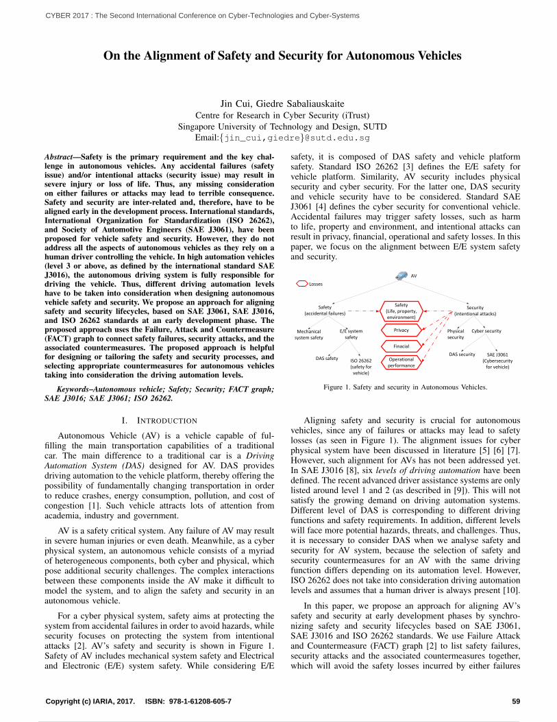
On the Alignment of Safety and Security for Autonomous Vehicles
Jin Cui, Giedre SabaliauskaiteCentre for Research in Cyber Security (iTrust)
Singapore University of Technology and Design, SUTDEmail:{jin_cui,giedre}@sutd.edu.sg
Abstract—Safety is the primary requirement and the key chal-lenge in autonomous vehicles. Any accidental failures (safetyissue) and/or intentional attacks (security issue) may result insevere injury or loss of life. Thus, any missing considerationon either failures or attacks may lead to terrible consequence.Safety and security are inter-related and, therefore, have to bealigned early in the development process. International standards,International Organization for Standardization (ISO 26262),and Society of Automotive Engineers (SAE J3061), have beenproposed for vehicle safety and security. However, they do notaddress all the aspects of autonomous vehicles as they rely on ahuman driver controlling the vehicle. In high automation vehicles(level 3 or above, as defined by the international standard SAEJ3016), the autonomous driving system is fully responsible fordriving the vehicle. Thus, different driving automation levelshave to be taken into consideration when designing autonomousvehicle safety and security. We propose an approach for aligningsafety and security lifecycles, based on SAE J3061, SAE J3016,and ISO 26262 standards at an early development phase. Theproposed approach uses the Failure, Attack and Countermeasure(FACT) graph to connect safety failures, security attacks, and theassociated countermeasures. The proposed approach is helpfulfor designing or tailoring the safety and security processes, andselecting appropriate countermeasures for autonomous vehiclestaking into consideration the driving automation levels.
Keywords–Autonomous vehicle; Safety; Security; FACT graph;SAE J3016; SAE J3061; ISO 26262.
I. INTRODUCTION
Autonomous Vehicle (AV) is a vehicle capable of ful-filling the main transportation capabilities of a traditionalcar. The main difference to a traditional car is a DrivingAutomation System (DAS) designed for AV. DAS providesdriving automation to the vehicle platform, thereby offering thepossibility of fundamentally changing transportation in orderto reduce crashes, energy consumption, pollution, and cost ofcongestion [1]. Such vehicle attracts lots of attention fromacademia, industry and government.
AV is a safety critical system. Any failure of AV may resultin severe human injuries or even death. Meanwhile, as a cyberphysical system, an autonomous vehicle consists of a myriadof heterogeneous components, both cyber and physical, whichpose additional security challenges. The complex interactionsbetween these components inside the AV make it difficult tomodel the system, and to align the safety and security in anautonomous vehicle.
For a cyber physical system, safety aims at protecting thesystem from accidental failures in order to avoid hazards, whilesecurity focuses on protecting the system from intentionalattacks [2]. AV’s safety and security is shown in Figure 1.Safety of AV includes mechanical system safety and Electricaland Electronic (E/E) system safety. While considering E/E
safety, it is composed of DAS safety and vehicle platformsafety. Standard ISO 26262 [3] defines the E/E safety forvehicle platform. Similarity, AV security includes physicalsecurity and cyber security. For the latter one, DAS securityand vehicle security have to be considered. Standard SAEJ3061 [4] defines the cyber security for conventional vehicle.Accidental failures may trigger safety losses, such as harmto life, property and environment, and intentional attacks canresult in privacy, financial, operational and safety losses. In thispaper, we focus on the alignment between E/E system safetyand security.
Safety(Life, property, environment)
Privacy
Finacial
Operational performance
Safety(accidental failures)
Security(intentional attacks)
Mechanical system safety
E/E system safety
DAS safety ISO 26262(safety for
vehicle)
Physical security
Cyber security
DAS security SAE J3061(Cybersecurity
for vehicle)
AV
Losses
Figure 1. Safety and security in Autonomous Vehicles.
Aligning safety and security is crucial for autonomousvehicles, since any of failures or attacks may lead to safetylosses (as seen in Figure 1). The alignment issues for cyberphysical system have been discussed in literature [5] [6] [7].However, such alignment for AVs has not been addressed yet.In SAE J3016 [8], six levels of driving automation have beendefined. The recent advanced driver assistance systems are onlylisted around level 1 and 2 (as described in [9]). This will notsatisfy the growing demand on driving automation systems.Different level of DAS is corresponding to different drivingfunctions and safety requirements. In addition, different levelswill face more potential hazards, threats, and challenges. Thus,it is necessary to consider DAS when we analyse safety andsecurity for AV system, because the selection of safety andsecurity countermeasures for an AV with the same drivingfunction differs depending on its automation level. However,ISO 26262 does not take into consideration driving automationlevels and assumes that a human driver is always present [10].
In this paper, we propose an approach for aligning AV’ssafety and security at early development phases by synchro-nizing safety and security lifecycles based on SAE J3061,SAE J3016 and ISO 26262 standards. We use Failure Attackand Countermeasure (FACT) graph [2] to list safety failures,security attacks and the associated countermeasures together,which will avoid the safety losses incurred by either failures
59Copyright (c) IARIA, 2017. ISBN: 978-1-61208-605-7
CYBER 2017 : The Second International Conference on Cyber-Technologies and Cyber-Systems
68 / 90

or attacks, thereby guaranteeing the safety of autonomousvehicles. Moreover, this alignment is helpful to design ortailor the safety and security processes for autonomous vehicleconsidering the driving automation levels, and to support safetyand security analysis.
The rest of the paper is organized as follow: we introducethe preliminary information in Section II, and explore AV’ssafety and security alignment in Section III. Finally, weconclude our work in Section IV.
II. PRELIMINARY
To demonstrate our alignment method, we give somepreliminary information in this section.
A. Dynamic Driving Task
The driving task is the function required to operate avehicle in on-road traffic and includes operational functions(basic vehicle motion control), tactical functions (planningand execution for event/object avoidance and expedited routefollowing) and strategic functions (route and destination timingand selection) [8]. The Dynamic Driving Task (DDT) [8]includes the operational and tactical functions, such as (withoutlimitation):
1. Lateral vehicle motion control via steering (opera-tional);
2. Longitudinal vehicle motion control via accelerationand deceleration (operational);
3. Monitoring the driving environment via object andevent detection, recognition, classification, and re-sponse preparation (operational and tactical);
4. Object and event response execution (operational andtactical);
5. Maneuver planning (tactical);
6. Enhancing conspicuity via lighting, signaling and ges-turing, etc. (tactical).
Because the subtasks 3 and 4 are all related to object andevent detection and response, they are collectively referred toas OEDR.
When a DDT fails, the response to either re-perform theDDT or reduce the risk of crash is considered as DDT-fallback.An example of this is when the adaptive cruise control on acar experiences a system failure that causes the feature to stopperforming its intended function. The driver will perform theDDT-fallback by resuming performance of the complete DDT.
B. Levels of driving automation
Driving Automation System, DAS, is the hardware andsoftware that are collectively capable of performing the entireDDT on a sustained basis, which is the key property thatcan replace a human driver for AV. The levels of drivingautomation are also classified by the requirements on DAS,which include [8]:
• Level 1, the DAS performs either the longitudinal orthe lateral vehicle motion control (subtask 1 or 2 ofthe DDT).
• Level 2, the DAS performs both the longitudinal andthe lateral vehicle motion control (subtasks 1 and 2of the DDT simultaneously).
• Level 3, the DAS also performs the OEDR (subtask 3and 4 of the DDT).
• Level 4, the DAS also performs DDT-fallback.
• Level 5, the DAS is unlimited by Operational DesignDomain (ODD).
Here, the ODD is a specific operating domain in which anautomated function or system is designed to properly operate,including but not limited to roadway types, speed range,geography, traffic, environmental conditions (e.g., weather,daytime/nighttime), and other domain constraints [11]. Forexample, we can design a ODD like this: road way is fixed asexpress way, the vehicle can hold a speed lower than 35km/hdriving in the daytime only.
Perform complete DDT and DDT-
fallback without ODD limit?
Perform complete DDT and DDT-
fallback with ODD limit?
Perform complete DDT, but no DDT-
fallback?
Perform both longitudinal and lateral vehicle
motion control?
Perform either longitudinal or lateral vehicle
motion control?
Perform none of DDT or DDT-
fallback?Level 5
Level 4
Level 3 Level 2
Level 1
Level 0Yes
Yes
Yes Yes
Yes
Yes
No
No
No
No
No
Figure 2. Levels of driving automation.
Figure 2 shows the levels of driving automation and thecorresponding features. For the low driving automation (level 0to level 2), a driver is needed to perform part or all driving task;while for high automation (level 3 to level 5), DAS can replacethe driver to perform the complete DDT. The conventionalcars in our daily life are at level 0, No Driving Automation.The human driver is necessary to perform the driving task andto respond to all the fallback. Level 1 is Driver Assistance,which means a DAS can perform either lateral or longitudinalcontrol for the car. When the DAS performs both lateral andlongitudinal control, such automation is in level 2, i.e., PartialDriving Automation.
For the level 3, i.e., Conditional Driving Automation, DAScan perform the whole DDT. But a user of the vehicle who isable to operate the vehicle is expected to be able to resumeDDT performance when a DDT system failure occurs or whenthe DAS is about to leave its ODD. If the DAS also canperform DDT-fallback but with limited ODD, this division ofrole corresponds to level 4, i.e., High Driving Automation. TheFull Driving Automation (level 5) is the situation when DAScan perform complete DDT and DDT-fallback, and meanwhile,the corresponding ODD is unlimited.
60Copyright (c) IARIA, 2017. ISBN: 978-1-61208-605-7
CYBER 2017 : The Second International Conference on Cyber-Technologies and Cyber-Systems
69 / 90
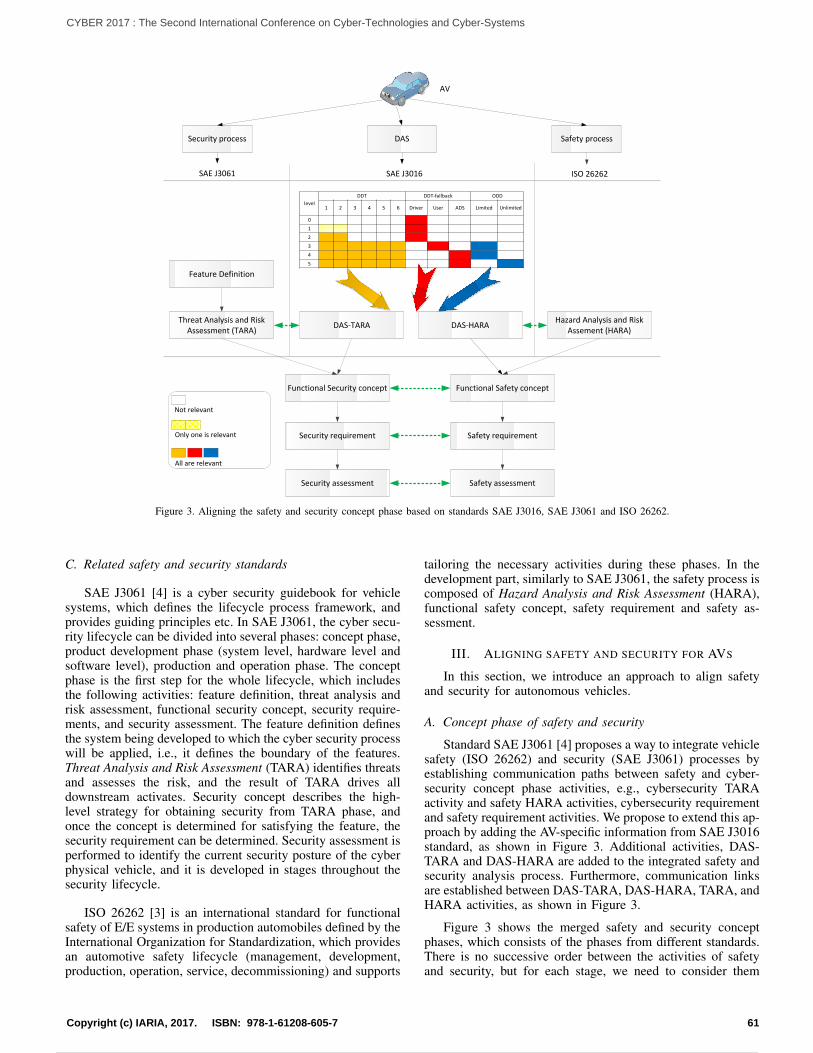
SAE J3061 SAE J3016 ISO 26262
DAS-TARAThreat Analysis and Risk Assessment (TARA)
Hazard Analysis and Risk Assement (HARA)
AV
Security process Safety process
Feature Definition
Functional Security concept Functional Safety concept
Security requirement Safety requirement
Security assessment Safety assessment
Only one is relevant
All are relevant
Not relevant
levelDDT DDT-fallback ODD
1 2 3 4 5 6 Driver User ADS Limited Unlimited
0
1
2
3
4
5
DAS-HARA
DAS
Figure 3. Aligning the safety and security concept phase based on standards SAE J3016, SAE J3061 and ISO 26262.
C. Related safety and security standards
SAE J3061 [4] is a cyber security guidebook for vehiclesystems, which defines the lifecycle process framework, andprovides guiding principles etc. In SAE J3061, the cyber secu-rity lifecycle can be divided into several phases: concept phase,product development phase (system level, hardware level andsoftware level), production and operation phase. The conceptphase is the first step for the whole lifecycle, which includesthe following activities: feature definition, threat analysis andrisk assessment, functional security concept, security require-ments, and security assessment. The feature definition definesthe system being developed to which the cyber security processwill be applied, i.e., it defines the boundary of the features.Threat Analysis and Risk Assessment (TARA) identifies threatsand assesses the risk, and the result of TARA drives alldownstream activates. Security concept describes the high-level strategy for obtaining security from TARA phase, andonce the concept is determined for satisfying the feature, thesecurity requirement can be determined. Security assessment isperformed to identify the current security posture of the cyberphysical vehicle, and it is developed in stages throughout thesecurity lifecycle.
ISO 26262 [3] is an international standard for functionalsafety of E/E systems in production automobiles defined by theInternational Organization for Standardization, which providesan automotive safety lifecycle (management, development,production, operation, service, decommissioning) and supports
tailoring the necessary activities during these phases. In thedevelopment part, similarly to SAE J3061, the safety process iscomposed of Hazard Analysis and Risk Assessment (HARA),functional safety concept, safety requirement and safety as-sessment.
III. ALIGNING SAFETY AND SECURITY FOR AVS
In this section, we introduce an approach to align safetyand security for autonomous vehicles.
A. Concept phase of safety and security
Standard SAE J3061 [4] proposes a way to integrate vehiclesafety (ISO 26262) and security (SAE J3061) processes byestablishing communication paths between safety and cyber-security concept phase activities, e.g., cybersecurity TARAactivity and safety HARA activities, cybersecurity requirementand safety requirement activities. We propose to extend this ap-proach by adding the AV-specific information from SAE J3016standard, as shown in Figure 3. Additional activities, DAS-TARA and DAS-HARA are added to the integrated safety andsecurity analysis process. Furthermore, communication linksare established between DAS-TARA, DAS-HARA, TARA, andHARA activities, as shown in Figure 3.
Figure 3 shows the merged safety and security conceptphases, which consists of the phases from different standards.There is no successive order between the activities of safetyand security, but for each stage, we need to consider them
61Copyright (c) IARIA, 2017. ISBN: 978-1-61208-605-7
CYBER 2017 : The Second International Conference on Cyber-Technologies and Cyber-Systems
70 / 90
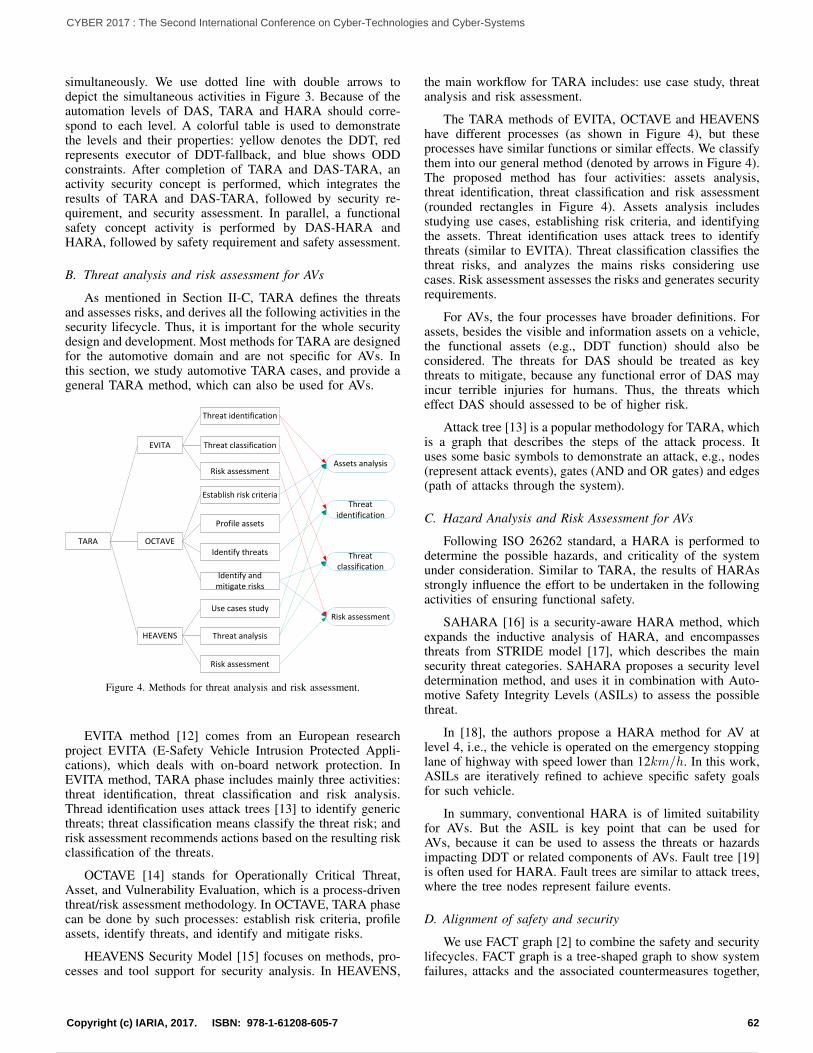
simultaneously. We use dotted line with double arrows todepict the simultaneous activities in Figure 3. Because of theautomation levels of DAS, TARA and HARA should corre-spond to each level. A colorful table is used to demonstratethe levels and their properties: yellow denotes the DDT, redrepresents executor of DDT-fallback, and blue shows ODDconstraints. After completion of TARA and DAS-TARA, anactivity security concept is performed, which integrates theresults of TARA and DAS-TARA, followed by security re-quirement, and security assessment. In parallel, a functionalsafety concept activity is performed by DAS-HARA andHARA, followed by safety requirement and safety assessment.
B. Threat analysis and risk assessment for AVs
As mentioned in Section II-C, TARA defines the threatsand assesses risks, and derives all the following activities in thesecurity lifecycle. Thus, it is important for the whole securitydesign and development. Most methods for TARA are designedfor the automotive domain and are not specific for AVs. Inthis section, we study automotive TARA cases, and provide ageneral TARA method, which can also be used for AVs.
TARA
EVITA
OCTAVE
HEAVENS
Threat classification
Threat identification
Establish risk criteria
Profile assets
Identify threats
Identify and mitigate risks
Use cases study
Threat analysis
Risk assessment
Assets analysis
Threat identification
Threat classification
Risk assessment
Risk assessment
Figure 4. Methods for threat analysis and risk assessment.
EVITA method [12] comes from an European researchproject EVITA (E-Safety Vehicle Intrusion Protected Appli-cations), which deals with on-board network protection. InEVITA method, TARA phase includes mainly three activities:threat identification, threat classification and risk analysis.Thread identification uses attack trees [13] to identify genericthreats; threat classification means classify the threat risk; andrisk assessment recommends actions based on the resulting riskclassification of the threats.
OCTAVE [14] stands for Operationally Critical Threat,Asset, and Vulnerability Evaluation, which is a process-driventhreat/risk assessment methodology. In OCTAVE, TARA phasecan be done by such processes: establish risk criteria, profileassets, identify threats, and identify and mitigate risks.
HEAVENS Security Model [15] focuses on methods, pro-cesses and tool support for security analysis. In HEAVENS,
the main workflow for TARA includes: use case study, threatanalysis and risk assessment.
The TARA methods of EVITA, OCTAVE and HEAVENShave different processes (as shown in Figure 4), but theseprocesses have similar functions or similar effects. We classifythem into our general method (denoted by arrows in Figure 4).The proposed method has four activities: assets analysis,threat identification, threat classification and risk assessment(rounded rectangles in Figure 4). Assets analysis includesstudying use cases, establishing risk criteria, and identifyingthe assets. Threat identification uses attack trees to identifythreats (similar to EVITA). Threat classification classifies thethreat risks, and analyzes the mains risks considering usecases. Risk assessment assesses the risks and generates securityrequirements.
For AVs, the four processes have broader definitions. Forassets, besides the visible and information assets on a vehicle,the functional assets (e.g., DDT function) should also beconsidered. The threats for DAS should be treated as keythreats to mitigate, because any functional error of DAS mayincur terrible injuries for humans. Thus, the threats whicheffect DAS should assessed to be of higher risk.
Attack tree [13] is a popular methodology for TARA, whichis a graph that describes the steps of the attack process. Ituses some basic symbols to demonstrate an attack, e.g., nodes(represent attack events), gates (AND and OR gates) and edges(path of attacks through the system).
C. Hazard Analysis and Risk Assessment for AVs
Following ISO 26262 standard, a HARA is performed todetermine the possible hazards, and criticality of the systemunder consideration. Similar to TARA, the results of HARAsstrongly influence the effort to be undertaken in the followingactivities of ensuring functional safety.
SAHARA [16] is a security-aware HARA method, whichexpands the inductive analysis of HARA, and encompassesthreats from STRIDE model [17], which describes the mainsecurity threat categories. SAHARA proposes a security leveldetermination method, and uses it in combination with Auto-motive Safety Integrity Levels (ASILs) to assess the possiblethreat.
In [18], the authors propose a HARA method for AV atlevel 4, i.e., the vehicle is operated on the emergency stoppinglane of highway with speed lower than 12km/h. In this work,ASILs are iteratively refined to achieve specific safety goalsfor such vehicle.
In summary, conventional HARA is of limited suitabilityfor AVs. But the ASIL is key point that can be used forAVs, because it can be used to assess the threats or hazardsimpacting DDT or related components of AVs. Fault tree [19]is often used for HARA. Fault trees are similar to attack trees,where the tree nodes represent failure events.
D. Alignment of safety and security
We use FACT graph [2] to combine the safety and securitylifecycles. FACT graph is a tree-shaped graph to show systemfailures, attacks and the associated countermeasures together,
62Copyright (c) IARIA, 2017. ISBN: 978-1-61208-605-7
CYBER 2017 : The Second International Conference on Cyber-Technologies and Cyber-Systems
71 / 90
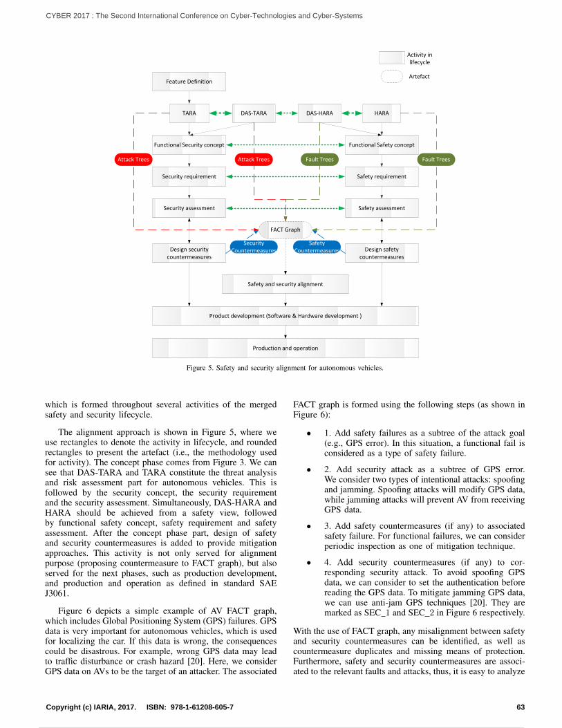
TARA DAS-TARA HARA
Feature Definition
Functional Security concept Functional Safety concept
Security requirement Safety requirement
Security assessment Safety assessment
Design safety countermeasures
Design security countermeasures
Product development (Software & Hardware development )
Production and operation
SecurityCountermeasures
Attack Trees Attack Trees Fault Trees
SafetyCountermeasures
Safety and security alignment
FACT Graph
Activity in lifecycle
Artefact
DAS-HARA
Fault Trees
Figure 5. Safety and security alignment for autonomous vehicles.
which is formed throughout several activities of the mergedsafety and security lifecycle.
The alignment approach is shown in Figure 5, where weuse rectangles to denote the activity in lifecycle, and roundedrectangles to present the artefact (i.e., the methodology usedfor activity). The concept phase comes from Figure 3. We cansee that DAS-TARA and TARA constitute the threat analysisand risk assessment part for autonomous vehicles. This isfollowed by the security concept, the security requirementand the security assessment. Simultaneously, DAS-HARA andHARA should be achieved from a safety view, followedby functional safety concept, safety requirement and safetyassessment. After the concept phase part, design of safetyand security countermeasures is added to provide mitigationapproaches. This activity is not only served for alignmentpurpose (proposing countermeasure to FACT graph), but alsoserved for the next phases, such as production development,and production and operation as defined in standard SAEJ3061.
Figure 6 depicts a simple example of AV FACT graph,which includes Global Positioning System (GPS) failures. GPSdata is very important for autonomous vehicles, which is usedfor localizing the car. If this data is wrong, the consequencescould be disastrous. For example, wrong GPS data may leadto traffic disturbance or crash hazard [20]. Here, we considerGPS data on AVs to be the target of an attacker. The associated
FACT graph is formed using the following steps (as shown inFigure 6):
• 1. Add safety failures as a subtree of the attack goal(e.g., GPS error). In this situation, a functional fail isconsidered as a type of safety failure.
• 2. Add security attack as a subtree of GPS error.We consider two types of intentional attacks: spoofingand jamming. Spoofing attacks will modify GPS data,while jamming attacks will prevent AV from receivingGPS data.
• 3. Add safety countermeasures (if any) to associatedsafety failure. For functional failures, we can considerperiodic inspection as one of mitigation technique.
• 4. Add security countermeasures (if any) to cor-responding security attack. To avoid spoofing GPSdata, we can consider to set the authentication beforereading the GPS data. To mitigate jamming GPS data,we can use anti-jam GPS techniques [20]. They aremarked as SEC 1 and SEC 2 in Figure 6 respectively.
With the use of FACT graph, any misalignment between safetyand security countermeasures can be identified, as well ascountermeasure duplicates and missing means of protection.Furthermore, safety and security countermeasures are associ-ated to the relevant faults and attacks, thus, it is easy to analyze
63Copyright (c) IARIA, 2017. ISBN: 978-1-61208-605-7
CYBER 2017 : The Second International Conference on Cyber-Technologies and Cyber-Systems
72 / 90
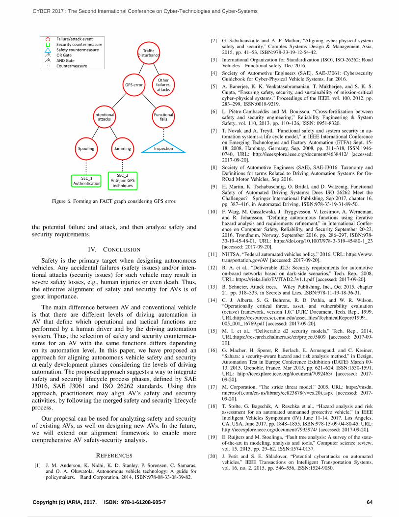
TrafficDisturbance
GPS error
Inten onala acks
Spoofing
SEC_1Authen ca on
Jamming
SEC_2An -jam GPStechniques
Func onalfails
Inspec on
Otherfailures,a acks
Failure/a ack eventSecurity countermeasureSafety countermeasureOR GateAND GateCountermeasure
Figure 6. Forming an FACT graph considering GPS error.
the potential failure and attack, and then analyze safety andsecurity requirements.
IV. CONCLUSION
Safety is the primary target when designing autonomousvehicles. Any accidental failures (safety issues) and/or inten-tional attacks (security issues) for such vehicle may result insevere safety losses, e.g., human injuries or even death. Thus,the effective alignment of safety and security for AVs is ofgreat importance.
The main difference between AV and conventional vehicleis that there are different levels of driving automation inAV that define which operational and tactical functions areperformed by a human driver and by the driving automationsystem. Thus, the selection of safety and security countermea-sures for an AV with the same functions differs dependingon its automation level. In this paper, we have proposed anapproach for aligning autonomous vehicle safety and securityat early development phases considering the levels of drivingautomation. The proposed approach suggests a way to integratesafety and security lifecycle process phases, defined by SAEJ3016, SAE J3061 and ISO 26262 standards. Using thisapproach, practitioners may align AV’s safety and securityactivities, by following the merged safety and security lifecycleprocess.
Our proposal can be used for analyzing safety and securityof existing AVs, as well on designing new AVs. In the future,we will extend our alignment framework to enable morecomprehensive AV safety-security analysis.
REFERENCES
[1] J. M. Anderson, K. Nidhi, K. D. Stanley, P. Sorensen, C. Samaras,and O. A. Oluwatola, Autonomous vehicle technology: A guide forpolicymakers. Rand Corporation, 2014, ISBN:978-08-33-08-39-82.
[2] G. Sabaliauskaite and A. P. Mathur, “Aligning cyber-physical systemsafety and security,” Complex Systems Design & Management Asia,2015, pp. 41–53, ISBN:978-33-19-12-54-42.
[3] International Organization for Standardization (ISO), ISO-26262: RoadVehicles - Functional safety, Dec 2016.
[4] Society of Automotive Engineers (SAE), SAE-J3061: CybersecurityGuidebook for Cyber-Physical Vehicle Systems, Jan 2016.
[5] A. Banerjee, K. K. Venkatasubramanian, T. Mukherjee, and S. K. S.Gupta, “Ensuring safety, security, and sustainability of mission-criticalcyber–physical systems,” Proceedings of the IEEE, vol. 100, 2012, pp.283–299, ISSN:0018-9219.
[6] L. Pietre-Cambacedes and M. Bouissou, “Cross-fertilization betweensafety and security engineering,” Reliability Engineering & SystemSafety, vol. 110, 2013, pp. 110–126, ISSN: 0951-8320.
[7] T. Novak and A. Treytl, “Functional safety and system security in au-tomation systems-a life cycle model,” in IEEE International Conferenceon Emerging Technologies and Factory Automation (ETFA) Sept. 15-18, 2008, Hamburg, Germany, Sep. 2008, pp. 311–318, ISSN:1946-0740, URL: http://ieeexplore.ieee.org/document/4638412/ [accessed:2017-09-20].
[8] Society of Automotive Engineers (SAE), SAE-J3016: Taxonomy andDefinitions for terms Related to Driving Automation Systems for On-ROad Motor Vehicles, Sep 2016.
[9] H. Martin, K. Tschabuschnig, O. Bridal, and D. Watzenig, FunctionalSafety of Automated Driving Systems: Does ISO 26262 Meet theChallenges? Springer International Publishing, Sep 2017, chapter 16,pp. 387–416, in Automated Driving, ISBN:978-33-19-31-89-50.
[10] F. Warg, M. Gassilewski, J. Tryggvesson, V. Izosimov, A. Werneman,and R. Johansson, “Defining autonomous functions using iterativehazard analysis and requirements refinement,” in International Confer-ence on Computer Safety, Reliability, and Security September 20-23,2016, Trondheim, Norway, September 2016, pp. 286–297, ISBN:978-33-19-45-48-01, URL: https://doi.org/10.1007/978-3-319-45480-1 23[accessed: 2017-09-20].
[11] NHTSA, “Federal automated vehicles policy,” 2016, URL: https://www.transportation.gov/AV [accessed: 2017-09-20].
[12] R. A. et al., “Deliverable d2.3: Security requirements for automotiveon-board networks based on dark-side scenarios,” Tech. Rep., 2008,URL: https://rieke.link/EVITAD2.3v1.1.pdf [accessed: 2017-09-20].
[13] B. Schneier, Attack trees. Wiley Publishing, Inc., Oct 2015, chapter21, pp. 318–333, in Secrets and Lies, ISBN:978-11-19-18-36-31.
[14] C. J. Alberts, S. G. Behrens, R. D. Pethia, and W. R. Wilson,“Operationally critical threat, asset, and vulnerability evaluation(octave) framework, version 1.0,” DTIC Document, Tech. Rep., 1999,URL:https://resources.sei.cmu.edu/asset files/TechnicalReport/1999005 001 16769.pdf [accessed: 2017-09-20].
[15] M. I. et al., “Deliverable d2 security models,” Tech. Rep., 2014,URL:https://research.chalmers.se/en/project/5809 [accessed: 2017-09-20].
[16] G. Macher, H. Sporer, R. Berlach, E. Armengaud, and C. Kreiner,“Sahara: a security-aware hazard and risk analysis method,” in Design,Automation Test in Europe Conference Exhibition (DATE) March 09-13, 2015, Grenoble, France, Mar 2015, pp. 621–624, ISSN:1530-1591,URL: http://ieeexplore.ieee.org/document/7092463/ [accessed: 2017-09-20].
[17] M. Corporation, “The stride threat model,” 2005, URL: https://msdn.microsoft.com/en-us/library/ee823878(v=cs.20).aspx [accessed: 2017-09-20].
[18] T. Stolte, G. Bagschik, A. Reschka et al., “Hazard analysis and riskassessment for an automated unmanned protective vehicle,” in IEEEIntelligent Vehicles Symposium (IV) June 11-14, 2017, Los Angeles,CA, USA, June 2017, pp. 1848–1855, ISBN:978-15-09-04-80-45, URL:http://ieeexplore.ieee.org/document/7995974/ [accessed: 2017-09-20].
[19] E. Ruijters and M. Stoelinga, “Fault tree analysis: A survey of the state-of-the-art in modeling, analysis and tools,” Computer science review,vol. 15, 2015, pp. 29–62, ISSN:1574-0137.
[20] J. Petit and S. E. Shladover, “Potential cyberattacks on automatedvehicles,” IEEE Transactions on Intelligent Transportation Systems,vol. 16, no. 2, 2015, pp. 546–556, ISSN:1524-9050.
64Copyright (c) IARIA, 2017. ISBN: 978-1-61208-605-7
CYBER 2017 : The Second International Conference on Cyber-Technologies and Cyber-Systems
73 / 90
Trends in Building Hardware and Software for Smart Things in Internet of Things
Xing LiuDept. of Computer Science and Information Technology
Kwantlen Polytechnic UniversitySurrey, Canada
Email: [email protected]
Abstract—Internet of Things (IoT) is considered to be anotherrevolution in information technology. Previous revolutionsbuilt a global network of computers for people to communicatedigitally. IoT aims to connect the things globally and thesethings are frequently physical objects. In order to realize thefull potential of IoT, the things need to be smart. Hardwareand software resources are required to instantiate thesmartness. This paper examines the essential smartnessattributes for IoT things and the hardware and software forimplementing the attributes. Industrial trends in IoT hardwareand software design are reviewed.
Keywords - Internet of Things; IoT; smart things; smartness;implementation; hardware; software.
I. INTRODUCTION
Internet of Things (IoT) is one of the most importantrevolutions in technology in decades. IoT strives to connectthe physical objects (things) globally. In an IoT system, thethings communicate with each other and with human beingsand act autonomously. In this sense, the things havesmartness in addition to their common daily functionalities.For example, the common functionality of a door lock is“lock the door with a latch”. The smartness part of an IoT-enabled door lock would be “remotely controllable over theInternet” and “able to recognize the owner and unlock thedoor” [1].
In order to equip the things with smartness, specifichardware and software are required. Most of the hardwarecan be built into a single integrated electronic circuit chipcalled System-on-Chip (SoC). These SoCs are named IoTprocessors. Special software has to run on IoT processors inorder to empower the things with real smartness. In the caseit is not feasible for a single IoT processor to carry all theneeded hardware, a so-called IoT hardware platform (board)can be developed instead.
Although the attributes that define smartness vary greatlywith the types of things, many attributes are commonlyshared. Ideally, these attributes should be provided by IoTprocessors or IoT hardware platforms. However, no up-to-date systematic research has been conducted on whatsmartness really means for IoT things and what hardwareand software are needed to realize such smartness. Results ofsmartness research can be useful for guiding the design andevaluation of smart products.
This paper gives a brief overview of Internet of Things inSection II. Then the paper identifies the general smartnessattributes expected for IoT smart things in Section III.
Hardware and software for implementing the smartnessattributes are discussed in Section IV. Section V reviews thecurrent industrial trends in hardware and software design forIoT processors and hardware platforms. Conclusions aregiven in Section VI.
II. INTERNET OF THINGS
A. Physical Objects and IoT Things
IoT is essentially a network of connected physical objectsor things. The things exist with reasons. For example, amicrowave is for heating up food. An air-conditioner is forcooling down a room. Traditionally, most things operatelocally and are standalone. People need to be in closeproximity in order to operate the objects.
B. The Internet
The Internet connects the things together. It provides thecommunication medium for the things. The thingscommunicate and collaborate with each other via theInternet. Human beings can remotely access and control thethings through the Internet. Wired or wireless links can beused to connect to the things. Wired links can be Ethernet,cable or telephone lines. Wireless links can be satellite,cellular, Wi-Fi, Bluetooth, or other new technologies beingdeveloped.
C. The Cloud
The Cloud is where IoT data is stored, visualized andanalyzed. The Cloud also works like a “control center”which relays messages and commands between things andbetween things and humans. The Cloud is also used tomanage things, create control policies, and call upon otherCloud services. The “elasticity” of the cloud makes it ahighly suitable candidate for hosting IoT platforms [2].
D. Smart Homes and Smart Cities
Smart homes and smart cities [3] are two mainapplication domains of IoT. In a smart home, connectedthings can be lamps, microwaves, fridges, ovens, heaters,ventilation systems, TVs and motion sensors. A smart cityhas many more connected things, such as cars, utility meters,parking meters, traffic cameras, power sources, wastecollectors, street lights, just to name a few.
E. Smart Things
Connected things in an IoT system need to be smart[1][4]. For example, lights should turn on automatically
65Copyright (c) IARIA, 2017. ISBN: 978-1-61208-605-7
CYBER 2017 : The Second International Conference on Cyber-Technologies and Cyber-Systems
74 / 90
when people are present and should turn off when peoplemove away. Doors should open automatically when the rightperson wants to get in. Alerts should be sent to home ownerswhen there is a home invasion. Ventilation fans shouldchange speed based on room occupancy to maintain airquality. Traffic cameras should work together to route streettraffic and provide parking availability information. Trafficlights should inform car drivers or even directly interact withcars regarding upcoming color changes to avoid unnecessarybraking. All these observations lead to the concept ofsmartness.
III. SMARTNESS ATTRIBUTES
Under what condition is an IoT thing smart? What are theattributes that make a thing smart? This section derives theseattributes from common sense. Smart things should havesome or all of these smartness attributes built-in based on thespecific applications. These attributes will determine whathardware and software are required to make things smart andthe feasibility of doing so in a practical design.
A. Aware of Environment
In an IoT system, the things should be aware of itssurroundings. They should monitor what is going on aroundthem. Parameters to monitor can be temperature, humidity,radiation, presence, proximity and darkness. Other awarenessincludes what other physical objects are doing and theirimpacts to the IoT system.
B. Able to Memorize
The things should have memory. They should memorizewhat has happened to themselves and to other related things.Information should be saved somewhere and can be recalledwhen needed. The things should decide what to memorize,how much to memorize and for how long. For example,should temperature be stored? How frequently shouldtemperature be sampled? How many data points should bestored in memory?
C. Able to Communicate
The things should be able to communicate. They shouldbe able to interact with each other and with human beings.They should be able to report their status when requested andaccept commands whenever required and respond in proper“language” and “manners”. For example, a thing should beable to tell other things if it is switched on or off when asked,and start taking an action when it is asked to.
D. Able to Make Decisions
The things should be able to decide what they should doand how to do it. For example, should a door lock grantaccess to someone? If in doubt for any reason, the door lockshould initiate an inquiry to the right party; and based on theresponses received, it then decides the correct operations totake.
E. Able to Act
The things should be able to take actions. Examples maybe start moving, turning off a switch, opening a door, playing
music, turning on a heater, starting a fan, sending a message,or sounding an alarm.
F. Able to Perform Many Tasks at the Same Time
The things should be able to perform many tasks at thesame time. These tasks may run concurrently. They shouldknow which tasks are more important and have priority, andprioritize the tasks given to them. They should be able toswitch between tasks based on operating conditions withoutlosing information.
G. Able to Work Autonomously
The things should be able to work without supervision.They should know when to start, to interact, to adjust, topause, or to stop. They should know how to protectthemselves and protect others in the system.
H. Able to Learn from Experience
The things should be able to improve themselves basedon what happened to them in the past, perhaps based on thedata stored in local memory. They should learn frommistakes. They should be able to optimize and negotiate. Anexample of this is a smart robotic vacuum controller. Basedon the impact it had against the wall in the past when itreturned to the base charging station, it will work out the bestmoment to start slowing down. The robotic vacuum will findthe new location of the charging station if the owner hasmoved it and use the new location next time. Anotherexample is the smart heating controller which will work withthe motion sensor to learn what times the owner usually goesto work. It will develop a flexible schedule to turn off theheating in advance (e.g. 30 minutes) to reduce energyconsumption, instead of a pre-set fixed time.
I. Able to Predict into the Future
The things should be able to foresee what is going tohappen to themselves and assist in predicting what willhappen in the overall IoT system. They should also helphuman beings in predicting what will happen in theenvironment. An example of this case is predicting thebreakdown of a smart device. If a smart device learns whathappened inside a sister device before breaking down, forexample, the sister device temperature pattern, then the smartdevice can predict its own breakdown time and notifymaintenance personnel to replace it ahead of time.
J. Protection of Self and the Whole System
The things should know how to fight against physical orvirtual attacks to themselves. They should not create securityholes and propagate viruses. They should not do anything todamage the credibility of the overall IoT system.
K. Energy Consciousness
The things should be able to manage power consumptionthemselves. They should be power conscious. They shouldknow when to do the work, when to sleep and do nothing.They should try to harvest energy from the surroundingswhenever and wherever possible.
66Copyright (c) IARIA, 2017. ISBN: 978-1-61208-605-7
CYBER 2017 : The Second International Conference on Cyber-Technologies and Cyber-Systems
75 / 90
L. Self-Imaging and Twinning
A thing should establish and store a model of itself. Thisincludes storing necessary parameters that can fully describeits own static and dynamic status and behavior. This mayinclude mathematical models and statistical tools whichassists in establishing the models. The model together withstatus information works as an image (twin) of the real thingand can be used to conduct simulations locally or can beuploaded into the Cloud for further simulation, visualizationand examination. The twin image can be sent to whoeverneeds it. An example of this is a smart engine which storesits design model and running states. These states and themodel will enable users to conduct simulations andpotentially help create maintenance schedules and diagnosethe causes of problems.
There can be more smartness attributes than listed abovedepending on the applications in the real world. The list cangrow as time goes on as well.
IV. IMPLEMENTING THE SMARTNESS ATTRIBUTES
In order to equip the IoT things with the above smartnessattributes, electronic components, computing hardware andsoftware are required [5].
A. Sensors
Sensors power the things with awareness. Typically,sensors measure temperature, humidity, speed, motion,acceleration, height, position, distance, PH values, flow rate,brightness, color, radiation, sound, images, or a combinationof these variables. Sensors can be chemical, mechanical,electrical, optical, or some other forms. They can bestandalone components or can be integrated into electronicchips or into circuit boards. Sensors can be cameras wheninputs are images or videos. Sensors are microphones wheninputs are audio signals.
B. Local Memory
Memorization is achieved using digital storage such asRead Only Memory (ROM), Random Access Memory(RAM), flash memory, Secure Digital (SD) cards, ormagnetic tapes. Memorization also includes properorganization of data for easy storage and retrieval, such asappropriate file systems and databases.
C. Communication Interfaces
Interfaces for communications among IoT things can be“traditional”, such as analog/digital converter, serial/parallelcommunication ports, such as General-Purpose Input/Output(GPIO) [6], Universal Asynchronous Receiver-Transmitter(UART) [7], Inter-Integrated Circuit (I2C) [8], UniversalSerial Bus (USB) [9] and Serial Peripheral Interface (SPI)[10]. Interfaces can also be computer networks, such asEthernet for wired communications. Wirelesscommunication interfaces are more important for IoT things.Wireless interfaces can be satellite, cellular, Wi-Fi,Bluetooth, and ZigBee etc.
D. Local Control Logic
Local control logic enables thing autonomy. This can bealgorithms for automatic control systems, adaptive controlalgorithms, optimal control algorithms, path planningalgorithms, pattern recognition algorithms, and decisionmaking algorithms.
E. Actuators
Actuators generate motion, movements, and initiatesignal transmission. Actuators can be electrical motors,pneumatic devices, hydraulic devices and signal transmitters.
F. Analytics and Machine Learning Software
Such software is located locally inside the things, orremotely in the Cloud. These are typically mathematicaltools for data analytics which can be descriptive, prescriptiveor predictive. They can also be artificial intelligence andmachine learning algorithms.
G. Multitasking or Multithreading
This is typically software that enables task concurrencylocally inside the things, frequently implemented as part ofthe functionalities found inside an operating system.
H. Security Software
Security is extremely important for IoT things. There isneed to have access control to the electronics and mechanicalcomponents of the things. Software in the things need to beimmune to viruses. Communication information needs to beencrypted. Security algorithms can be embedded at differentlevels of the IoT system, such as in the electronics and incommunication protocols.
I. Energy Management and Harvesting
Circuit modules are used for power management andenergy harvesting. Power management modules optimize theuse of power in power sources. Circuit modules are used toharvest energy from lights, heat sources, motion, andelectromagnetic signals etc.
J. Digital Twinning and Device Shadows
Parameters, mathematical or statistical models, and statusinformation of physical objects are used to build the twinimage of a device. The image is also called a device shadow.The image can be stored in local memory. It can be used todiagnose problems, answer queries, perform simulations andprovide predictions. Twin images can be loaded to the Cloudfor further analysis or can be shared among devices.
V. INDUSTRIAL TRENDS IN IOT HARDWARE AND
SOFTWARE IMPLEMENTATION
The actual hardware and software implementation of IoTthings with the above smartness attributes depend on thetechnologies available and the cost allowed. The idealsolution is that all attributes are implemented on a single SoCmodule. This will minimize interference, powerconsumption, and thing sizes. The implementation can alsobe several electronic chips installed on a circuit board. In this
67Copyright (c) IARIA, 2017. ISBN: 978-1-61208-605-7
CYBER 2017 : The Second International Conference on Cyber-Technologies and Cyber-Systems
76 / 90
case, the implementation is called an IoT hardware platform.Some attributes may not be feasible to be integrated andtherefore have to remain separate. Software also has to becarefully designed and implemented to realize the smartnessattributes. A thing essentially makes an embedded system.
A. IoT Processors
An IoT processor is a SoC device designed for IoTapplications. It is very much like a microcontroller and hasmost functionalities that a microcontroller has, plus manyother functionalities.
Components of IoT processors generally includecomputing power, memory, on-chip sensors, input/outputinterfaces, wired and wireless networking interfaces, securitymeasures, IoT operating systems (OSes), and powermanagement modules. Companies that are making IoTprocessors include ARM (Cortex-M23 and Cortex– M33)[11], Qualcomm (Snapdragon processors and LTE modems)[12], Texas Instruments (CC3320) [13], and Cypress (PSoC6) [14].
B. IoT Boards or “IoT Hardware Platforms”
IoT boards, also called IoT hardware platforms, usuallyhave more functionalities than what IoT processors have. Anexample is the mangOH Red [15] jointly developed by SierraWireless and its partners. The mangOH Red is smaller than acredit card. It has built-in Wi-Fi b/g/n and Bluetooth 4.2 BLE(Bluetooth Low Energy) and built-in light, accelerometer,gyroscope, temperature and pressure sensors. However, ithas only sockets for 2G to 4G and LTE-M (Long TermEvolution Category M1) and NB-IoT (NarrowBand IoT)wireless modules. It can connect to the AirVantage IoTcloud Platform. Legato is the Linux based open sourcedevelopment tool.
Raspberry Pi is another popular IoT hardware platform[16]. A Raspberry Pi has memory (RAM and a SD memorycard), networking interface (Ethernet, Wi-Fi, and Bluetooth),Input/Output ports (USB, Camera interface, video interface,audio interface, GPIO pins which can be used as UART, I2C,and SPI). By default, a Raspberry Pi runs a Linux-type OScalled Raspbian [17]. Numerous smartness attributes can bereadily implemented locally using the C, JavaScript, Java, orPython programming languages. Other OSes, such as theWindows 10 IoT Core [18], can also run on a Raspberry Pi.
C. IoT OSes
An OS is usually multithreading, has a task scheduler,and can frequently run real-time. For example, the ARMmbed OS [19] is an open-source embedded operating systemdesigned to run in the things of an IoT system, specifically,on IoT processors. It is modular and configurable to reducememory usage. The ARM mbed OS provides drivers forsensors, I/O devices and networking. It also provides cloudmanagement services and security services. The ARM mbedOS is designed for ARM Cortex-M microcontrollers. OtherIoT OSes include Contiki [20], Google Brillo (now calledAndroid Things) [21], RIOT OS [22], and Windows 10 IoT[18]. Common features of IoT OSes include support for
network communications, sensor interface, security, multi-tasking, and real-time.
D. Other Software
Signal processing software processes data from sensors,such as software for digital filters. System identification andmodelling software build models for the things. Automaticcontrol system algorithms and control software control thethings. There are software that process audio and videosignals and for pattern recognition. Web software nowenables the Web interface for the things. Most such IoTsoftware are based traditional software, with customizationto support contemporary hardware, novel programminglanguages, and real-time applications. An example isOpenCV [23].
E. IoT Software Platforms
IoT software platforms are frequently called IoTplatforms. They are the upper-level software in an IoTsystem. An IoT platform is a cloud-based software servicethat connects the things, collects data, manages the things,visualizes data, and performs data analytics. Additionalsmartness for the things is provided by IoT platforms. IoTplatforms are also called middleware. Example commercialplatforms are Amazon IoT [24], Microsoft Azure [25], andXively [26].
F. Other Emerging Technologies
As the communication medium between IoT things andthe Cloud, wireless communication networks are criticallyimportant. For this reason, tremendous efforts have beenplaced on developing new wireless communication networksthat are suitable for IoT applications. Numerous newwireless technologies are on the horizon. These include NB-IoT [27], LTE-M [28], 6LoWPAN [29], Sigfox [30], BLE[31], and Bluetooth mesh networking (BLE-Mesh) [32].Characteristics of these new technologies are low powerconsumption, small data packets and low data transmissionoverheads. However, IoT involves almost every aspect of theIoT ecosystem. Therefore, other technologies are also beingdeveloped. These include new sensor technologies, newsoftware technologies, and new security technologies, aswell as new applications.
VI. CONCLUSIONS
This paper has discussed the attributes that can make theIoT things smart, as well as hardware and software resourcesessential for implementing these attributes. Current industrialefforts in building powerful hardware and software forimplementing smart things are also reviewed. Majortechnologies and products are identified.
REFERENCES
[1] G. Kortuem, F. Kawsar, D. Fitton, and V. Sundramoorthy,“Smart objects as building blocks for the Internet of Things”,IEEE Internet Computing, vol.14, no.1, pp. 44-51, 2010.
[2] Y. Karam et al., “Security Support for Intention DrivenElastic Cloud Computing”, The Sixth UKSim/AMSS
68Copyright (c) IARIA, 2017. ISBN: 978-1-61208-605-7
CYBER 2017 : The Second International Conference on Cyber-Technologies and Cyber-Systems
77 / 90
European Symposium on Computer Modeling and Simulation(EMS), 14-16 Nov., 2012.
[3] A. Zanella, N. Bui, A. Castellani, L. Vangelista, and M. Zorzi,Internet of Things for Smart Cities, IEEE Internet of ThingsJournal, vol.1, no.1, pp.22-32, 2014.
[4] G. Fortino, A. Rovella, W. Russo, and C. Savaglio, “On theclassication of cyberphysical smart objects in the Internet ofThings, Proceedings of the 5th International Workshop onNetworks of Cooperating Objects for Smart Cities(UBICITEC 2014), pp.86-94, Berlin, Germany, Apr 14, 2014.
[5] M. Beigl and H. Gellersen, “Smart-Its: An EmbeddedPlatform for Smart Objects”, Smart Objects Conference(sOc), Grenoble, France. May 15-17, 2003.
[6] Adafruit, The GPIO Connector. [Online]. Available from:https://learn.adafruit.com/adafruits-raspberry-pi-lesson-4-gpio-setup/the-gpio-connector. 2017.11.02.
[7] Cypress, Universal Asynchronous Receiver Transmitter(UART). [Online]. Available from:http://www.cypress.com/file/132486/download. 2017.11.02.
[8] I2C-bus.org, I2C – What’s That? [Online]. Available from:https://www.i2c-bus.org/. 2017.11.02.
[9] usb.org, USB 3.2 Specification. [Online]. Available from:http://www.usb.org/developers/docs/. 2017.11.02.
[10] Texas Instruments, Serial Peripheral Interface (SPI). [Online].Available from:http://www.ti.com/lit/ug/sprugp2a/sprugp2a.pdf/. 2017.11.02.
[11] ZigBee Allaince, ARM Accelerates Secure IoT from Chip toCloud. [Online]. Available from: http://www.zigbee.org/arm-accelerates-secure-iot-from-chip-to-cloud/. 2017.09.29.
[12] Qualcomm, Internet of Things. Available from:https://www.qualcomm.com/solutions/internet-of-things.[Online]. Available from: http://www.zigbee.org/arm-accelerates-secure-iot-from-chip-to-cloud/. 2017.0.9.29.
[13] J. Wyatt and B. Fankem, SimpleLink Wi-Fi CC3220 andCC3120 Product Overview. [Online]. Available from:https://training.ti.com/simplelink-wi-fi-cc3220-and-cc3120-product-overview. 2017.09.29.
[14] Cypress, Welcome to the PSOC 6 Community. [Online].Available from:https://community.cypress.com/community/psoc-6.2017.11.02.
[15] Wavefront, Sierra Wireless launches mangOH Red opensource platform for industrial IoT devices. [Online]. Availablefrom: http://wavefront.ca/sierra-wireless-launches-mangoh-red-open-source-platform-industrial-iot-devices/. 2017.11.02.
[16] Raspberry Pi Foundation, Raspberrry Pi Hardware Guide,[Online]. Available from:https://www.raspberrypi.org/learning/hardware-guide/.2017.11.02.
[17] Raspberry Pi Foundation, Raspbian, [Online]. Available from:https://www.raspberrypi.org/downloads/raspbian/.2017.11.02.
[18] Microsoft, Windows 10 IoT Core - The operating system builtfor your Internet of Things. [Online]. Available from:https://developer.microsoft.com/en-us/windows/iot.2017.11.02.
[19] ARM, mBed OS. [Online]. Available from:https://www.mbed.com/en/platform/mbed-os/. 2017.09.27.
[20] Contiki-os.org, Contiki: The Open Source OS for the Internetof Things. [Online]. Available from: http://www.contiki-os.org/. 2017.09.27.
[21] developer.android.com, Android Things, [Online]. Availablefrom: https://developer.android.com/things/index.html.2017.11.02.
[22] riot-os.org, RIOT: The friendly Operating System for theInternet of Things. [Online]. Available from: https://riot-os.org/. 2017.11.02.
[23] opencv.org, OpenCV. [Online]. Available from:https://opencv.org/. 2017.11.02.
[24] Amazon, AWS IoT. [Online]. Available from:https://aws.amazon.com/iot-platform/. 2017.11.02.
[25] Microsoft, Azure IoT Suite. [Online]. Available from:https://www.microsoft.com/en-us/internet-of-things/azure-iot-suite. 2017.11.02.
[26] LogMeIn, Profit from the Connected Product Conversationwith the Xively IoT Platform. [Online]. Available from:https://www.xively.com/xively-iot-platform. 2017.11.02.
[27] 3GPP, Standardization of NB-IOT completed. [Online].Available from: http://www.3gpp.org/news-events/3gpp-news/1785-nb_iot_complete. 2017.11.02.
[28] GSMA, Long Term Evolution for Machines: LTE-M.[Online]. Available from: https://www.gsma.com/iot/mobile-iot-technology-lte-m/. 2017.11.02.
[29] IETF, 6lowpan Status Pages. [Online]. Available from:https://tools.ietf.org/wg/6lowpan/charters. 2017.11.02.
[30] Sigfox, the world’s leading Internet of things (IoT)connectivity service. [Online]. Available from:https://www.sigfox.com/en. 2017.11.02.
[31] Cypress, Bluetooth® Low Energy (BLE) Profiles andServices. [Online]. Available from:http://www.cypress.com/documentation/software-and-drivers/bluetooth-low-energy-ble-profiles-and-services.2017.11.02.
[32] Bluetooth SIG, Inc, Bluetooth LE: mesh. [Online]. Availablefrom: https://www.bluetooth.com/what-is-bluetooth-technology/how-it-works/le-mesh. 2017.11.02.
69Copyright (c) IARIA, 2017. ISBN: 978-1-61208-605-7
CYBER 2017 : The Second International Conference on Cyber-Technologies and Cyber-Systems
78 / 90
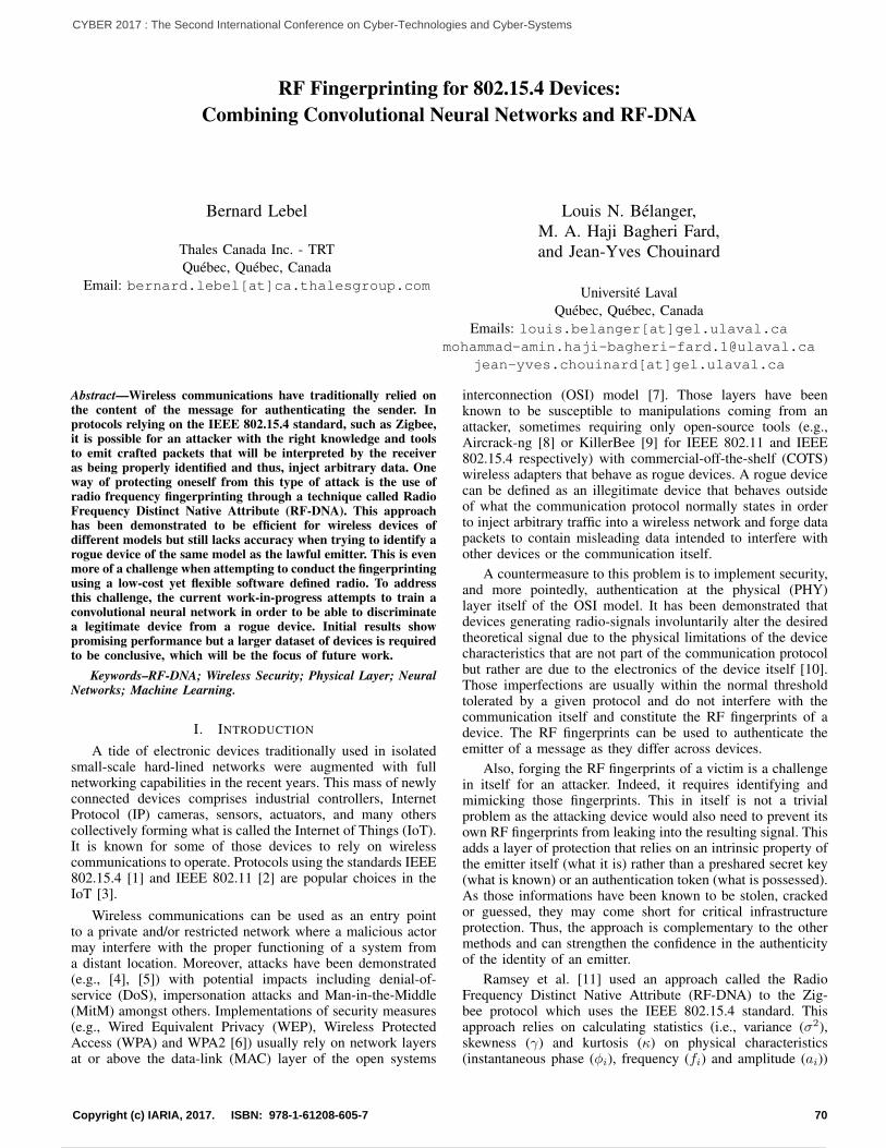
RF Fingerprinting for 802.15.4 Devices:Combining Convolutional Neural Networks and RF-DNA
Bernard Lebel
Thales Canada Inc. - TRTQuebec, Quebec, Canada
Email: bernard.lebel[at]ca.thalesgroup.com
Louis N. Belanger,M. A. Haji Bagheri Fard,and Jean-Yves Chouinard
Universite LavalQuebec, Quebec, Canada
Emails: louis.belanger[at][email protected]
jean-yves.chouinard[at]gel.ulaval.ca
Abstract—Wireless communications have traditionally relied onthe content of the message for authenticating the sender. Inprotocols relying on the IEEE 802.15.4 standard, such as Zigbee,it is possible for an attacker with the right knowledge and toolsto emit crafted packets that will be interpreted by the receiveras being properly identified and thus, inject arbitrary data. Oneway of protecting oneself from this type of attack is the use ofradio frequency fingerprinting through a technique called RadioFrequency Distinct Native Attribute (RF-DNA). This approachhas been demonstrated to be efficient for wireless devices ofdifferent models but still lacks accuracy when trying to identify arogue device of the same model as the lawful emitter. This is evenmore of a challenge when attempting to conduct the fingerprintingusing a low-cost yet flexible software defined radio. To addressthis challenge, the current work-in-progress attempts to train aconvolutional neural network in order to be able to discriminatea legitimate device from a rogue device. Initial results showpromising performance but a larger dataset of devices is requiredto be conclusive, which will be the focus of future work.
Keywords–RF-DNA; Wireless Security; Physical Layer; NeuralNetworks; Machine Learning.
I. INTRODUCTION
A tide of electronic devices traditionally used in isolatedsmall-scale hard-lined networks were augmented with fullnetworking capabilities in the recent years. This mass of newlyconnected devices comprises industrial controllers, InternetProtocol (IP) cameras, sensors, actuators, and many otherscollectively forming what is called the Internet of Things (IoT).It is known for some of those devices to rely on wirelesscommunications to operate. Protocols using the standards IEEE802.15.4 [1] and IEEE 802.11 [2] are popular choices in theIoT [3].
Wireless communications can be used as an entry pointto a private and/or restricted network where a malicious actormay interfere with the proper functioning of a system froma distant location. Moreover, attacks have been demonstrated(e.g., [4], [5]) with potential impacts including denial-of-service (DoS), impersonation attacks and Man-in-the-Middle(MitM) amongst others. Implementations of security measures(e.g., Wired Equivalent Privacy (WEP), Wireless ProtectedAccess (WPA) and WPA2 [6]) usually rely on network layersat or above the data-link (MAC) layer of the open systems
interconnection (OSI) model [7]. Those layers have beenknown to be susceptible to manipulations coming from anattacker, sometimes requiring only open-source tools (e.g.,Aircrack-ng [8] or KillerBee [9] for IEEE 802.11 and IEEE802.15.4 respectively) with commercial-off-the-shelf (COTS)wireless adapters that behave as rogue devices. A rogue devicecan be defined as an illegitimate device that behaves outsideof what the communication protocol normally states in orderto inject arbitrary traffic into a wireless network and forge datapackets to contain misleading data intended to interfere withother devices or the communication itself.
A countermeasure to this problem is to implement security,and more pointedly, authentication at the physical (PHY)layer itself of the OSI model. It has been demonstrated thatdevices generating radio-signals involuntarily alter the desiredtheoretical signal due to the physical limitations of the devicecharacteristics that are not part of the communication protocolbut rather are due to the electronics of the device itself [10].Those imperfections are usually within the normal thresholdtolerated by a given protocol and do not interfere with thecommunication itself and constitute the RF fingerprints of adevice. The RF fingerprints can be used to authenticate theemitter of a message as they differ across devices.
Also, forging the RF fingerprints of a victim is a challengein itself for an attacker. Indeed, it requires identifying andmimicking those fingerprints. This in itself is not a trivialproblem as the attacking device would also need to prevent itsown RF fingerprints from leaking into the resulting signal. Thisadds a layer of protection that relies on an intrinsic property ofthe emitter itself (what it is) rather than a preshared secret key(what is known) or an authentication token (what is possessed).As those informations have been known to be stolen, crackedor guessed, they may come short for critical infrastructureprotection. Thus, the approach is complementary to the othermethods and can strengthen the confidence in the authenticityof the identity of an emitter.
Ramsey et al. [11] used an approach called the RadioFrequency Distinct Native Attribute (RF-DNA) to the Zig-bee protocol which uses the IEEE 802.15.4 standard. Thisapproach relies on calculating statistics (i.e., variance (σ2),skewness (γ) and kurtosis (κ) on physical characteristics(instantaneous phase (φi), frequency (fi) and amplitude (ai))
70Copyright (c) IARIA, 2017. ISBN: 978-1-61208-605-7
CYBER 2017 : The Second International Conference on Cyber-Technologies and Cyber-Systems
79 / 90
of subregions of an incoming signal.
Additionally, Ramsey et al. [11] demonstrated that it ispossible to use a COTS software-defined radio (SDR) toobtain satisfactory results for discriminating an impersonatorfrom a legitimate device. A SDR is a device capable ofacquiring a radio-signal in a wide range of frequencies andwhich delegates the processing of this signal to a softwareimplementation rather than using specialized hardware to doso. This allows a user to have access to a wide range ofprotocols and frequencies using a single device. It requiresa software implementation of the protocol stack and thatthe communication occurs within the SDR frequency rangeand bandwidth. SDR vary greatly in terms of price rangebut some solutions, such as the USRP B200mini from EttusResearch [12] are fairly low-cost when compared to high-endlab equipment and have a smaller size factor. One concern ofusing a SDR for acquiring the signal to extract its RF-DNAis to ensure sufficient bandwidth can be achieved to capturethe hardware-specific variations. The results obtained in [11]supported that a low-cost SDR, such as the B200mini, wasenough to discriminate devices based on the comparison oftheir RF-DNA. The true verification rate (TVR) (i.e., how oftena packet was accepted when it came from a legitimate device)neared 100% while the rogue acceptance rate (RAR) (i.e., howoften the spoofing devices were accepted as legitimate ones)dropped to 0% for devices that were of different models. Tomaintain a TVR of >90% in the case where the devices wereof the same model, the RAR ranged between 32% and 54%.
The current work seeks to lower the RAR while main-taining or increasing the TVR in the event of a rogue deviceusing the same model as a legitimate one to communicatewith another station using the IEEE 802.15.4 standard. Theproposed approach seeks to improve the performance of thedecision model from [11] that combined a multiple discrim-inant analysis/maximum likelihood (MDA/ML) process fordimensionality reduction and Bayesian decision criteria forclassification. Instead, it is proposed to train a convolutionalneural network (CNN) [13], [14] to recognize the deviceswithout requiring that the dimensionality be reduced.
A CNN is a machine learning model that works by attempt-ing to train a set of filters used for convolutions on the inputsignal to highlight the most discriminant features that can bespatially distributed in that signal. The response to the inputsignal of each filter at each location across the signal is theoutput of a convolutional layer (CL). This output is then passedto a subsampling layer which is responsible of reducing thenumber of outputs by pooling a given region together using agiven function (e.g., maximum value or the average of values).One or more fully-connected layer make for the last layers ofnetwork and are responsible for the classification itself.
CNNs have been demonstrated to be robust to data transla-tion and are able to take into account a level of spatial distri-bution of a dataset [15], [16], [17], [18]. This may constitutean advantage in the context of RF fingerprinting as signals aredistributed in time and slight spatial translations may occur inthe captured data. The ongoing work and preliminary resultsaim at validating the use of CNN in that context.
The next section presents the methodology used for ac-quiring RF signals for analysis and the extraction of featuresfollowing the RF-DNA methodology and the structure of
the CNN used for analysis. Section III describes preliminaryresults obtained in the ongoing work. Section IV summarizesthe preliminary results, discuss implications and research con-cerns. Finally, section V presents future work and next steps.
II. METHODOLOGY
The emitting devices were 4 Atmel RZUSBStick, or RZ forshort. This device is capable of sending Zigbee packets con-taining arbitrary data and is also able to communicate throughthe Zigbee protocol [9]. Arbitrary data was sent periodically ata frequency of 40 packets/sec on channel 26 (i.e., 2.480 GHz).The acquisition was conducted through a USRP B200minifrom Ettus Research at a center frequency of 2.480 GHz witha bandwidth of 20 MHz. The data collection was conductedin a RF shielded box to prevent outside interferences withthe measurements. Each device was placed at the exact samelocation for each data collection.
The raw signal from the IEEE 802.15.4 preambles of eachcommunication was extracted. Following the work done byRamsey et al. [11], the preambles were split into 32 equalregions, each comprising 80 samples per region plus the fullpreamble itself of 2560 samples, for a total of 33 subregionsper preamble captured. For each sample, the instantaneousphase (φi), instantaneous frequency (fi) and instantaneousamplitude (ai) were evaluated. Their variance (σ2), skewness(γ) and kurtosis (κ) were calculated for each subregion. Thisamounted to a total of 297 features per preamble composedof 33 subregions × 3 RF characteristics × 3 statistics. Thenumber of preambles collected is presented in Table I.
TABLE I. SAMPLES PER DEVICE.
RZUSBStick1 RZUSBStick2 RZUSBStick3 RZUSBStick4
Preambles 7148 7094 6832 7086
Extracted features were standardized following (1). Stan-dardization is required to constrain values of features within acomparable range.
zi =xi − x
s2(1)
zi is the standardized score, xi the input value, x the meanand s2 the variance. To apply the standardization, the featuresare structured along a 3 × 33 × 3 matrix as presented in (2)for each collected preamble.
[σ21φ
σ21f
σ21a
]. . .
[σ233φ
σ233f
σ233a
][γ1φ γ1f γ1a
]. . .
[γ33φ γ33f γ33a
][κ1φ κ1f κ1a
]. . .
[κ33φ κ33f κ33a
] (2)
The values s2 and x are calculated along all collectedpreambles for the 33 subregions. The result is two matricescontaining the s2 and x values for the 33 subregions acrossall collected preambles. The resulting matrix is shown in (3)for x. s2 follows the same structure.σ2
φ σ2f σ2
a
γφ γf γaκφ κf κa
(3)
71Copyright (c) IARIA, 2017. ISBN: 978-1-61208-605-7
CYBER 2017 : The Second International Conference on Cyber-Technologies and Cyber-Systems
80 / 90
The set of features for each of the 33 subregions per pream-ble was standardized according to its RF characteristics andstatistics.
A. Convolutional Neural Network
The 297 standardized features were passed on to a CNNconstituted of 2 CL with 32 3 × 1 filters and 64 3 × 1filters. Each CL output was connected to a subsampling layer(3× 1 average pooling function with 2-step strides). The lastsubsampling layer was followed by a fully connected layerof 1024 neurons trained with a 0.75 dropout chance beforeconnecting to the output layer. Optimization was conductedusing the adaptive moment estimation (ADAM) optimizer witha learning rate of 0.01. Batch size was set at 128 preambles permini-batch. The implemented model is presented in Figure 1.
III. PRELIMINARY RESULTS
Collected results were analyzed according to two scenarios.Scenario 1 explored training a CNN to discriminate betweenthe 4 known devices. This scenario is meant to demonstratethe general performance of a CNN in the context of RF-DNA.Scenario 2 seeks to replicate the case where an algorithm istrained to be specialized in recognizing if a given preamblebelongs to a specific device.
A. Scenario 1: Differentiation
The collected preambles were randomized. The full datasetwas divided with 80% used for training, 10% for validation and10% for testing. The output layer has 4 classes, one for eachknown device. The resulting confusion matrix is reported inTable II. The calculated accuracy is 95.86%.
TABLE II. CONFUSION MATRIX FOR INTERDEVICECLASSIFICATION.
Input Labels
RZ1 RZ2 RZ3 RZ4
Predicted
RZ1 0.947 0.006 0.002 0.037
RZ2 0.013 0.951 0.018 0.007
RZ3 0.002 0.031 0.975 0.004
RZ4 0.038 0.012 0.006 0.953
The high accuracy obtained for this task demonstratesthat CNNs are especially well adapted for ingesting RF-DNAinputs for device classification. Work is still in progress toestablish a baseline based on current literature to achievea comparison between the proposed approach and the onedescribed in [11]. However, the represented case in Scenario 1is valid only if an algorithm can be trained on all knowndevices and is expected to find the correct match in a pool ofdevices that was used during training. In practice, this methodis ineffective in the context of rogue device identification as theattacking device is usually not known before the attack occurs.This nullifies the chances that the model can be trained with allexpected devices in a certain area. This problem is addressedin the next scenario.
B. Scenario 2: One vs All
This scenario aims at filling the gap from the previous onewhere a model was trained to identify if a preamble originatesfrom one unique device or not. 80% of the dataset was usedfor training, 10% for validation and 10% for testing. In thefirst phase, all preambles from one device were considered asbeing ”Good” (approx. 25% of the total dataset) and preamblesfrom the remaining devices were considered as ”Bad” (approx.75% of the total dataset), generating an output layer of 2classes. During training, labels were balanced according to theproportion of the dataset they represented to compensate forthe unbalanced dataset. Results are reported in Table III.
TABLE III. CONFUSION MATRIX FOR ONE-VS-OTHERSCLASSIFICATION.
Others RZ1 Others RZ2
Others 0.986 0.063 Others 0.991 0.080
RZ1 0.013 0.937 RZ2 0.009 0.920
Acc = 0.973 Acc = 0.972
Others RZ3 Others RZ4
Others 0.994 0.046 Others 0.977 0.046
RZ3 0.006 0.954 RZ4 0.023 0.954
Acc = 0.984 Acc = 0.987
As the training set contained samples from each device, ithas been postulated that the predictor would be confused if anew device was introduced and requested predictive measures,showing proof of overfitting. To test this hypothesis, a test wasconducted by training the expert systems on the dataset butwithholding all data from RZ4. The test dataset was evaluatedusing inputs only from RZ4. If the system did not overfit,attribution would show nearly only others attribution. Duringa subsequent phase of the ongoing work, the results will becompiled for test cases where RZ1, RZ2 or RZ3 is excludedinstead of RZ4. Results are presented in Table IV.
TABLE IV. CONFUSION MATRIX FOR ONE-VS-OTHERS WITH ANEW DEVICE (RZ4) EXCLUDED FROM TRAINING SET.
RZ4 RZ4
RZ4 0.168 RZ4 0.878
RZ1 0.832 RZ2 0.122
Acc = 0.168 Acc = 0.878
RZ4
RZ4 0.955
RZ3 0.045
Acc = 0.955
As the results show, the trained model is achieving anaccuracy of 95.5% for RZ3 but lower than 87.8% for RZ2 andis very poor (16.8%) for RZ1. The results from introducing anew device during the test phase demonstrate that the modelhas trouble differentiating devices that may have a more similar
72Copyright (c) IARIA, 2017. ISBN: 978-1-61208-605-7
CYBER 2017 : The Second International Conference on Cyber-Technologies and Cyber-Systems
81 / 90
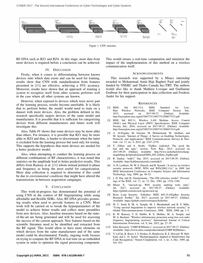
Figure 1. CNN structure.
RF-DNA such as RZ1 and RZ4. At this stage, more data frommore devices is required before a conclusion can be achieved.
IV. DISCUSSION
Firstly, when it comes to differentiating between knowndevices onto which data exists and can be used for training,results show that CNN with standardization from featurespresented in [11] are effective, achieving a 95% accuracy.Moreover, results have shown that an approach of training asystem to recognize itself from other systems performs wellin the case where all other systems are known.
However, when exposed to devices which were never partof the learning process, results become unreliable. It is likelythat to perform better, the model would need to train on adataset with more devices. Also, the problem defined in thisresearch specifically targets devices of the same model andmanufacturer. It is possible that it is sufficient for categorizingdevices from different manufacturers and future work willinvestigate this.
Also, Table IV shows that some devices may be more alikethan others. For instance, it is possible that RZ1 may be morealike to RZ4 and thus, is harder to discriminate when the latteris excluded from the learning process but used only for testing.This supports the hypothesis that more devices are needed fora better predictive model.
Also, when attempting to conduct the learning process ondifferent combinations of RF characteristics, it was noted thatstatistics on the amplitude lead to better predictive results. Thisdiffers from Ramsey et al. [11] whom instead pointed to phaseand frequency as being the most useful for categorization.More data collection is required to determine if this couldbe due to environmental conditions that might have altered thetransmissions in-between acquisition campaigns.
V. CONCLUSION
This work-in-progress has demonstrated the potential ofusing CNN in the context of RF fingerprinting while usingaffordable and flexible SDRs. Also, RF-DNA provides promis-ing results when used to provide features to a CNN. Morework will be carried on to tweak the hyperparameters of themodel to achieve better results and collect more preamblesfrom new devices. Also, baseline measures based on the state-of-the-art are being generated and will be used for assessingthe success of the current approach. New features based on thescientific literature need to be identified and extracted fromthe RF signal. This would allow to have more elements onwhich devices from the same manufacturer and of the samemodel could be discriminated. Finally, ongoing work focuseson trying to compute the RF-DNA in real time on an embeddedsystem in order to optimize the signal processing component.
This would ensure a real-time computation and minimize theimpact of the implementation of this method on a wirelesscommunication itself.
ACKNOWLEDGMENTS
This research was supported by a Mitacs internshipawarded to Mohammad Amin Haji Bagheri Fard and jointlyfunded by NSERC and Thales Canada Inc./TRT. The authorswould also like to thank Mathieu Lvesque and GuillaumeGodbout for their participation in data collection and FredericAudet for his support.
REFERENCES
[1] IEEE Std 802.15.4, IEEE Standard for Low-Rate Wireless Networks, IEEE Computer Society Std.,2015, accessed on 2017-09-27. [Online]. Available:http://ieeexplore.ieee.org/iel7/6677511/6677512/06677513.pdf
[2] IEEE Std 802.11, Wireless LAN Medium Access Control(MAC) and Physical Layer (PHY) Specifications, IEEE ComputerSociety Std., 2016, accessed on 2017-09-27. [Online]. Available:http://ieeexplore.ieee.org/iel7/6837412/6837413/06837414.pdf
[3] A. Al-Fuqaha, M. Guizani, M. Mohammadi, M. Aledhari, andM. Ayyash, “Internet of Things: A Survey on Enabling Technologies,Protocols, and Applications,” IEEE Communications Surveys & Tuto-rials, vol. 17, no. 4, 2015, pp. 2347–2376.
[4] T. Zillner and S. Strobl, “ZigBee exploited: The good thebad and the ugly,” version, Tech. Rep., 2015, accessed on2017-09-29. [Online]. Available: http://www.sicherheitsforschung-magdeburg.de/uploads/journal/MJS 045 Zillner ZigBee.pdf
[5] R. Sankar, “mdk3,” Sep. 2015, accessed on 2017-09-29. [Online].Available: http://kalilinuxtutorials.com/mdk3/
[6] A. H. Lashkari, M. M. S. Danesh, and B. Samadi, “A survey on wirelesssecurity protocols (WEP, WPA and WPA2/802.11i),” in 2009 2ndIEEE International Conference on Computer Science and InformationTechnology, Aug. 2009, pp. 48–52.
[7] J. D. Day and H. Zimmermann, “The OSI reference model,” Proceed-ings of the IEEE, vol. 71, no. 12, Dec. 1983, pp. 1334–1340.
[8] Mister X, “aircrack-ng: WiFi security auditing tools suite,”Jul. 2017, accessed on 2017-09-27. [Online]. Available:https://github.com/aircrack-ng/aircrack-ng
[9] River Loop Security, “killerbee: IEEE 802.15.4/ZigBee SecurityResearch Toolkit,” Jul. 2017, accessed on 2017-09-27. [Online].Available: https://github.com/riverloopsec/killerbee
[10] W. C. Suski II, M. A. Temple, M. J. Mendenhall, and R. F. Mills,“Using spectral fingerprints to improve wireless network security,” inGlobal Telecommunications Conference, 2008. IEEE, 2008, pp. 1–5.
[11] B. W. Ramsey, T. D. Stubbs, B. E. Mullins, M. A. Temple, andM. A. Buckner, “Wireless infrastructure protection using low-cost radiofrequency fingerprinting receivers,” International Journal of CriticalInfrastructure Protection, vol. 8, Jan. 2015, pp. 27–39.
[12] Ettus Research, “USRP B200mini-i,” accessed on 2017-09-27. [Online].Available: https://www.ettus.com/product/details/USRP-B200mini-i
[13] Y. LeCun, B. Boser, J. S. Denker, D. Henderson, R. E. Howard, W. Hub-bard, and L. D. Jackel, “Backpropagation Applied to Handwritten ZipCode Recognition,” Neural Computation, vol. 1, no. 4, Dec. 1989, pp.541–551.
73Copyright (c) IARIA, 2017. ISBN: 978-1-61208-605-7
CYBER 2017 : The Second International Conference on Cyber-Technologies and Cyber-Systems
82 / 90
[14] Y. LeCun and Y. Bengio, “The handbook of brain theory and neuralnetworks,” M. A. Arbib, Ed. Cambridge, MA, USA: MIT Press, 1998,ch. Convolutional Networks for Images, Speech, and Time Series, pp.255–258.
[15] P. Y. Simard, D. Steinkraus, and J. C. Platt, “Best practices forconvolutional neural networks applied to visual document analysis,” in7th International Conference on Document Analysis and Recognition.Proceedings, vol. 2. Washington, DC, USA: IEEE Computer Society,2003, pp. 958–963.
[16] D. C. Ciresan, U. Meier, L. M. Gambardella, and J. Schmidhuber,“Convolutional Neural Network Committees for Handwritten CharacterClassification,” in 2011 International Conference on Document Analysisand Recognition, Sep. 2011, pp. 1135–1139.
[17] S. Lawrence, C. L. Giles, A. C. Tsoi, and A. D. Back, “Face recognition:a convolutional neural-network approach,” IEEE Transactions on NeuralNetworks, vol. 8, no. 1, Jan. 1997, pp. 98–113.
[18] A. Krizhevsky, I. Sutskever, and G. E. Hinton, “ImageNet Classificationwith Deep Convolutional Neural Networks,” in Advances in Neural In-formation Processing Systems 25, F. Pereira, C. J. C. Burges, L. Bottou,and K. Q. Weinberger, Eds. Curran Associates, Inc., 2012, pp. 1097–1105.
74Copyright (c) IARIA, 2017. ISBN: 978-1-61208-605-7
CYBER 2017 : The Second International Conference on Cyber-Technologies and Cyber-Systems
83 / 90
Integrating Autonomous Vehicle Safety and Security
Giedre Sabaliauskaite
Centre for Research in Cyber Security (iTrust)Singapore University of Technology and Design
Singapore 487372Email: [email protected]
Jin Cui
Centre for Research in Cyber Security (iTrust)Singapore University of Technology and Design
Singapore 487372Email: [email protected]
Abstract—Safety and security are two inter-dependent key prop-erties of autonomous vehicles. They are aimed at protecting thevehicles from accidental failures and intentional attacks, whichcould lead to injuries and loss of lives. The selection of safety andsecurity countermeasures for autonomous vehicles depends on thedriving automation levels, defined by the international standardSAE J3016. However, current vehicle safety standards ISO 26262do not take the driving automation levels into consideration. Wepropose an approach for integrating autonomous vehicle safetyand security processes, which is compliant with the internationalstandards SAE J3016, SAE J3061, and ISO 26262, and whichconsiders driving automation levels. It uses the Six-Step Modelas a backbone for achieving integration and alignment amongsafety and security processes and artefacts. The Six-Step Modelincorporates six hierarchies of autonomous vehicles, namely,functions, structure, failures, attack, safety countermeasures, andsecurity countermeasures. It ensures the consistency among thesehierarchies throughout the entire autonomous vehicle’s life-cycle.
Keywords–Autonomous vehicle; safety; security; ISO 26262;SAE J3016; SAE J3061; Six-Step Model; attack tree; fault tree.
I. INTRODUCTION
Autonomous Vehicles (AVs), the self-driving vehicles,are safety-critical Cyber-Physical Systems (CPS) – complexengineering systems, which integrate embedded computingtechnology into physical phenomena. Safety and security aretwo key properties of CPSs, which share the same goal –protecting the system from undesirable events: failures (safety)and intentional attacks (security) [1].
Ensuring the safety of autonomous vehicles, i.e., reducingthe number of traffic crashes to prevent injuries and save lives,is a top priority in autonomous vehicle development. Safetyand security are interdependent (e.g., security attacks can causesafety failures, or security countermeasures may weaken CPSsafety and vice versa), therefore they have to be aligned in theearly system development phases to ensure the required levelof protection [1][2].
Although AVs could be considered to be smaller and/orless complex systems as compared to other CPSs, such as,e.g., power plants or water treatment systems, they face someunique challenges, which have to be taken into considerationwhen analyzing their safety and security.
Firstly, there are six different levels of driving automationranging from no driving automation (level 0) to full drivingautomation (level 5), as described by the international standardSAE J3016 [3]. The levels describe who (human driver or
automated system) performs the driving tasks and monitors thedriving environments under certain environmental conditions.Thus, AV safety and security depend on the driving automationlevels and the environmental conditions.
Secondly, the AV domain is relatively new, and therefore,there are no international standards for AV safety and secu-rity yet. Currently, the ISO 26262 standard, which describesfunctional safety of road vehicles, is being used for AV safetyanalysis [4]. However, it is not sufficient for AVs, as arguedin [5][6]. ISO 26262 addresses the safety of each function, oritem, of the vehicle separately, since the driver is responsiblefor everything what falls outside the item. However, in AV,it is necessary to ensure safety at all times, especially at thehigh automation levels, when there is no driver in the vehicle[5]. Thus, hazard analysis of AVs should have the broaderscope and should analyze AVs functions together. Warg et al.proposed an approach to extend ISO 26262 and to add genericoperational situation and hazard trees for comprehensive AVsafety analysis [5].
To address vehicle security needs, the SAE J3061 standardhas been developed [7]. It defines cyber-security lifecycle ofcyber-physical vehicle systems. However, the security lifecy-cle, defined in SAE J3061, is analogous to the vehicle safetylifecycle described in ISO 26262, and therefore, it is notsufficient for AV cyber-security analysis.
How can we analyze AV safety and security throughout itsentire life-cycle in a consistent way, and provide required levelof protection?
In our previous work, we proposed a Six-Step Model formodeling and analysis of CPS safety and security [8][9].It incorporates six dimensions (hierarchies) of CPS, namely,functions, structure, failures, safety countermeasures, cyber-attacks, and security countermeasures. Furthermore, it usesrelationship matrices to model inter-dependencies betweenthese dimensions. The Six-Step Model enables comprehensiveanalysis of CPS safety and security, as it utilizes systemfunctions and structure as a knowledge base for understandingthe effect of failures and attacks on the system.
In this paper, we propose an approach for AV safety andsecurity analysis, which uses the Six-Step Model as a backbonefor integrating and maintaining consistency among safety andsecurity processes and artefacts. The Six-Step Model consol-idated safety and security artefacts, developed throughout theentire AV life-cycle. The proposed approach is compliant withthe international standards SAE J3016, SAE J3061, and ISO26262.
75Copyright (c) IARIA, 2017. ISBN: 978-1-61208-605-7
CYBER 2017 : The Second International Conference on Cyber-Technologies and Cyber-Systems
84 / 90
The remainder of this paper is structured as follows.Section II describes preliminaries. The proposed approach isexplained in Section III, and a Six-Step Model example isincluded in Section IV. Finally, Section V concludes the paperand describes our future work.
II. PRELIMINARIES
A. Autonomous Vehicles’ Main Terms and DefinitionsThe real-time operational and tactical functions required
to operate the vehicle in on-road traffic include lateral andlongitudinal vehicle motion control, monitoring the drivingenvironment, object and event response execution, maneuverplanning, and enhancing conspicuity via lighting, signaling,etc. [3]. These functions are collectively called the DynamicDriving Task (DDT) [3]. AVs perform entire or part of DDTdepending of their automation level.
SAE International (SAE) has developed an internationalstandard, SAE J3016 [3], to describe various levels of vehicleautomation. The standard has been widely adopted by inter-national organizations, such as the National Highway TrafficSafety Administration (NHTSA) [10].
There are six driving automation levels [3][10]:
• Level 0 – the human driver performs entire DDT.• Level 1 – an automated system on the vehicle can
assist the human driver to perform either the lateral orthe longitudinal vehicle motion, while driver monitorsthe driving environment and performs the rest of DDT.
• Level 2 – an automated system performs the lateraland the longitudinal vehicle motion, while driver mon-itors the driving environment and performs the rest ofDDT.
• Level 3 – an automated system can perform entireDDT, but the human driver must be ready to take backcontrol when the automated system requests.
• Level 4 – there is no human driver; an automated sys-tem conducts the entire DDT, but it can operate onlyin certain environments and under certain conditions.
• Level 5 – there is no human driver; an automatedsystem performs entire DDT in all environments andunder all conditions that a human driver could performthem.
Level 3-5 vehicles are called the highly automated ve-hicles, since their automated systems (not a human driver)are responsible for monitoring the driving environment [10].Furthermore, level 1-4 vehicles are designed to operate only incertain environments and under certain conditions, while level5 vehicles - in all environments and under all conditions.
AV functions can be grouped into three main categories:perception (perception of the external environment/contextin which vehicle operates), decision & control (decisionsand control of vehicle motion, with respect to the externalenvironment/context that is perceived), and vehicle platformmanipulation (sensing, control and actuation of the vehicle,with the intention of achieving desired motion) [11][12]. Astandard for describing AV functions and functional interfaces,SAE J3131, is currently under development.
AV structural architecture consists of two main systems:a) cognitive driving intelligence, which implements perception
and decision & control functions, and b) vehicle platform,which is responsible for vehicle platform manipulation [11].Each system consists of components, which belong to four ma-jor groups: hardware, software, communication, and human-machine interface [12][13].
B. A Six-Step ModelIn our earlier work [8][9], we proposed a Six-Step Model
to enable comprehensive CPS safety and security analysis (seeFigure 1) . The model is constructed using the following sixsteps:
1) The first step is aimed at modeling the functionalhierarchy of the system. The functions are defined us-ing the Goal Tree (GT), which is constructed startingwith the goal (functional objective) and then definingfunctions and sub-functions, needed for achieving thisgoal. A relationship matrix, F-F, is used to define therelationships between functions, which can be high,medium, low, or very low.
2) In the second step, system’s structural hierarchy is de-fined using the Success Tree (ST) to describe system’sstructure as a collection of sub-systems and units.Furthermore, the relationships between structure andfunctions are defined using a relationship matrix S-F,as shown in Figure 1.
3) The third step is focused on safety hazard analysis.In this step, system’s failures are identified and addedto the model. In addition, the relationships betweenfailures, system structure and functions are identified,and the corresponding relationship matrices – B-B,B-S, and B-F – are added to the model.
4) The fourth step focuses on security threat analysis.In this step, attacks are identified and added tothe model along with the relationship matrices todescribe relationships between attacks, failures, struc-ture and functions. Relationship matrix A-B (attacks– failures) is used to determine which failures couldbe triggered by a successful attack. In the originalversion of the Six-Step Model [9], safety countermea-sures have been identified in step 4, while attacks - instep 5. However, we decided to switch the places ofthese two steps in order to tackle system vulnerability(hazard and threat) analysis first, before moving to thecountermeasure selection, as safety countermeasurescan be used to detect and mitigate both the failuresand the attacks. Thus, it is convenient to have attackidentified before designing safety countermeasures.
5) In the fifth step, safety countermeasures are addedto the model and their relationships are identified.Matrices X-A and X-B show the coverage of attacksand failures by safety countermeasures, where whiterhombus indicates that the countermeasure provideslow protection from attack/failure; gray rhombus -medium protection; black rhombus - full protection(see Figure 1).
6) Finally, in the last step, security countermeasuresare added to the model and their relationships areestablished. Similarly to matrices X-A and X-B fromthe previous step, two new matrices Z-A and Z-B are added to define the coverage of attacks andfailures by security countermeasures. The security
76Copyright (c) IARIA, 2017. ISBN: 978-1-61208-605-7
CYBER 2017 : The Second International Conference on Cyber-Technologies and Cyber-Systems
85 / 90
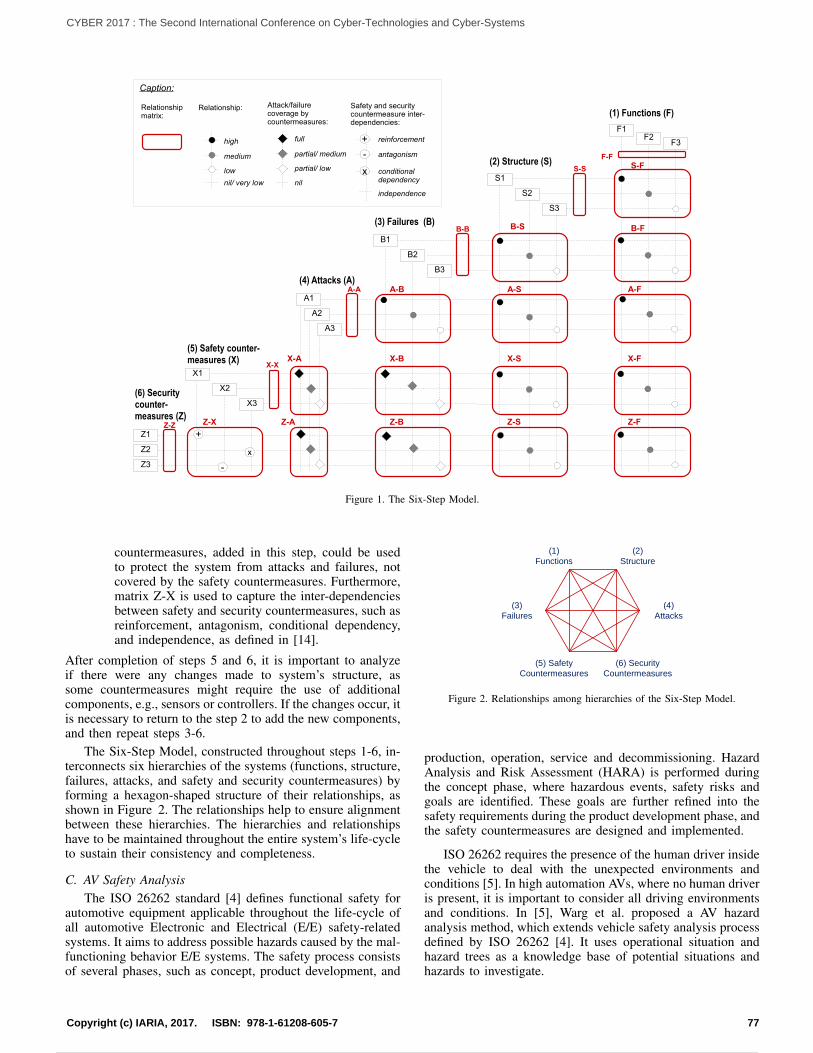
(1) Functions (F)
F1F2
F3
(2) Structure (S)
S1
S2
S3
(3) Failures (B)
B1
B2
B3
(5) Safety counter-measures (X)
X1
X2
X3
(4) Attacks (A)
(6) Security counter-measures (Z)
Caption:
Attack/failure coverage by countermeasures:
full
partial/ medium
partial/ low
nil
Relationship:
high
medium
low
nil/ very low
Relationship matrix:
Safety and securitycountermeasure inter-dependencies:
reinforcement
antagonism
independence
+
-
+
-
conditional dependency
x
A1
A2
A3
Z1
Z2
Z3
S-F
B-S B-F
A-B A-S A-F
X-B X-S X-FX-A
Z-B Z-S Z-FZ-AZ-X
F-F
S-S
B-B
A-A
X-X
Z-Z
NEW
x
Figure 1. The Six-Step Model.
countermeasures, added in this step, could be usedto protect the system from attacks and failures, notcovered by the safety countermeasures. Furthermore,matrix Z-X is used to capture the inter-dependenciesbetween safety and security countermeasures, such asreinforcement, antagonism, conditional dependency,and independence, as defined in [14].
After completion of steps 5 and 6, it is important to analyzeif there were any changes made to system’s structure, assome countermeasures might require the use of additionalcomponents, e.g., sensors or controllers. If the changes occur, itis necessary to return to the step 2 to add the new components,and then repeat steps 3-6.
The Six-Step Model, constructed throughout steps 1-6, in-terconnects six hierarchies of the systems (functions, structure,failures, attacks, and safety and security countermeasures) byforming a hexagon-shaped structure of their relationships, asshown in Figure 2. The relationships help to ensure alignmentbetween these hierarchies. The hierarchies and relationshipshave to be maintained throughout the entire system’s life-cycleto sustain their consistency and completeness.
C. AV Safety AnalysisThe ISO 26262 standard [4] defines functional safety for
automotive equipment applicable throughout the life-cycle ofall automotive Electronic and Electrical (E/E) safety-relatedsystems. It aims to address possible hazards caused by the mal-functioning behavior E/E systems. The safety process consistsof several phases, such as concept, product development, and
(1)
Functions
(2)
Structure
(3)
Failures
(4)
Attacks
(5) Safety
Countermeasures
(6) Security
Countermeasures
Figure 2. Relationships among hierarchies of the Six-Step Model.
production, operation, service and decommissioning. HazardAnalysis and Risk Assessment (HARA) is performed duringthe concept phase, where hazardous events, safety risks andgoals are identified. These goals are further refined into thesafety requirements during the product development phase, andthe safety countermeasures are designed and implemented.
ISO 26262 requires the presence of the human driver insidethe vehicle to deal with the unexpected environments andconditions [5]. In high automation AVs, where no human driveris present, it is important to consider all driving environmentsand conditions. In [5], Warg et al. proposed a AV hazardanalysis method, which extends vehicle safety analysis processdefined by ISO 26262 [4]. It uses operational situation andhazard trees as a knowledge base of potential situations andhazards to investigate.
77Copyright (c) IARIA, 2017. ISBN: 978-1-61208-605-7
CYBER 2017 : The Second International Conference on Cyber-Technologies and Cyber-Systems
86 / 90
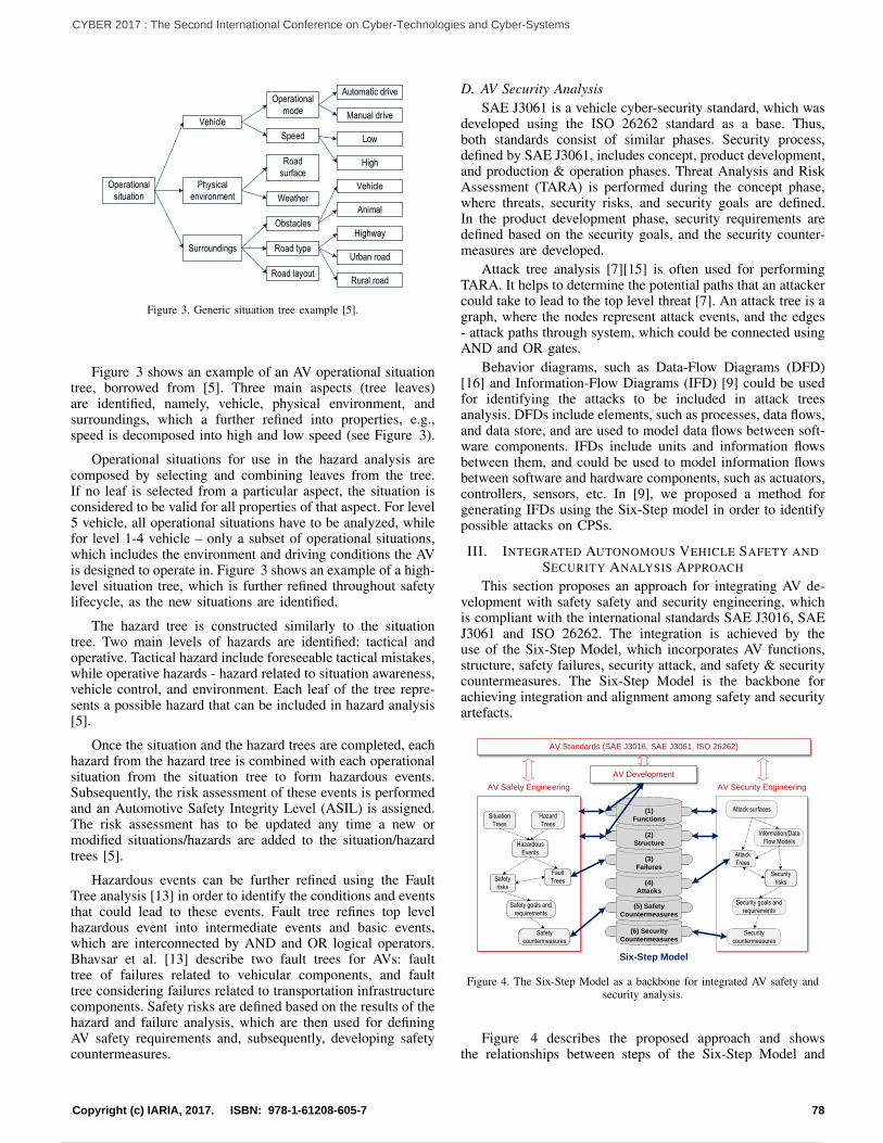
Operational
situation
Vehicle
Physical
environment
Surroundings
Operational
mode
Speed
Road
surface
Weather
Obstacles
Road type
Road layout
Automatic drive
Manual drive
Low
High
Vehicle
Animal
Highway
Urban road
Rural road
Figure 3. Generic situation tree example [5].
Figure 3 shows an example of an AV operational situationtree, borrowed from [5]. Three main aspects (tree leaves)are identified, namely, vehicle, physical environment, andsurroundings, which a further refined into properties, e.g.,speed is decomposed into high and low speed (see Figure 3).
Operational situations for use in the hazard analysis arecomposed by selecting and combining leaves from the tree.If no leaf is selected from a particular aspect, the situation isconsidered to be valid for all properties of that aspect. For level5 vehicle, all operational situations have to be analyzed, whilefor level 1-4 vehicle – only a subset of operational situations,which includes the environment and driving conditions the AVis designed to operate in. Figure 3 shows an example of a high-level situation tree, which is further refined throughout safetylifecycle, as the new situations are identified.
The hazard tree is constructed similarly to the situationtree. Two main levels of hazards are identified: tactical andoperative. Tactical hazard include foreseeable tactical mistakes,while operative hazards - hazard related to situation awareness,vehicle control, and environment. Each leaf of the tree repre-sents a possible hazard that can be included in hazard analysis[5].
Once the situation and the hazard trees are completed, eachhazard from the hazard tree is combined with each operationalsituation from the situation tree to form hazardous events.Subsequently, the risk assessment of these events is performedand an Automotive Safety Integrity Level (ASIL) is assigned.The risk assessment has to be updated any time a new ormodified situations/hazards are added to the situation/hazardtrees [5].
Hazardous events can be further refined using the FaultTree analysis [13] in order to identify the conditions and eventsthat could lead to these events. Fault tree refines top levelhazardous event into intermediate events and basic events,which are interconnected by AND and OR logical operators.Bhavsar et al. [13] describe two fault trees for AVs: faulttree of failures related to vehicular components, and faulttree considering failures related to transportation infrastructurecomponents. Safety risks are defined based on the results of thehazard and failure analysis, which are then used for definingAV safety requirements and, subsequently, developing safetycountermeasures.
D. AV Security AnalysisSAE J3061 is a vehicle cyber-security standard, which was
developed using the ISO 26262 standard as a base. Thus,both standards consist of similar phases. Security process,defined by SAE J3061, includes concept, product development,and production & operation phases. Threat Analysis and RiskAssessment (TARA) is performed during the concept phase,where threats, security risks, and security goals are defined.In the product development phase, security requirements aredefined based on the security goals, and the security counter-measures are developed.
Attack tree analysis [7][15] is often used for performingTARA. It helps to determine the potential paths that an attackercould take to lead to the top level threat [7]. An attack tree is agraph, where the nodes represent attack events, and the edges- attack paths through system, which could be connected usingAND and OR gates.
Behavior diagrams, such as Data-Flow Diagrams (DFD)[16] and Information-Flow Diagrams (IFD) [9] could be usedfor identifying the attacks to be included in attack treesanalysis. DFDs include elements, such as processes, data flows,and data store, and are used to model data flows between soft-ware components. IFDs include units and information flowsbetween them, and could be used to model information flowsbetween software and hardware components, such as actuators,controllers, sensors, etc. In [9], we proposed a method forgenerating IFDs using the Six-Step model in order to identifypossible attacks on CPSs.
III. INTEGRATED AUTONOMOUS VEHICLE SAFETY ANDSECURITY ANALYSIS APPROACH
This section proposes an approach for integrating AV de-velopment with safety safety and security engineering, whichis compliant with the international standards SAE J3016, SAEJ3061 and ISO 26262. The integration is achieved by theuse of the Six-Step Model, which incorporates AV functions,structure, safety failures, security attack, and safety & securitycountermeasures. The Six-Step Model is the backbone forachieving integration and alignment among safety and securityartefacts.
AV Safety Engineering AV Security Engineering
Situation
Trees
Hazard
Trees
Hazardous
Events
Fault
Trees
Safety goals and
requirements
Safety
countermeasures
(5) Safety
Countermeasures
(6) Security
Countermeasures
(4)
Attacks
(3)
Failures
(2)
Structure
(1)
Functions
Six-Step Model
Safety
risks
Attack surfaces
Attack
Trees
Security goals and
requirements
Security
countermeasures
Security
risks
Information/Data
Flow Models
AV Standards (SAE J3016, SAE J3061, ISO 26262)
AV Development
Figure 4. The Six-Step Model as a backbone for integrated AV safety andsecurity analysis.
Figure 4 describes the proposed approach and showsthe relationships between steps of the Six-Step Model and
78Copyright (c) IARIA, 2017. ISBN: 978-1-61208-605-7
CYBER 2017 : The Second International Conference on Cyber-Technologies and Cyber-Systems
87 / 90
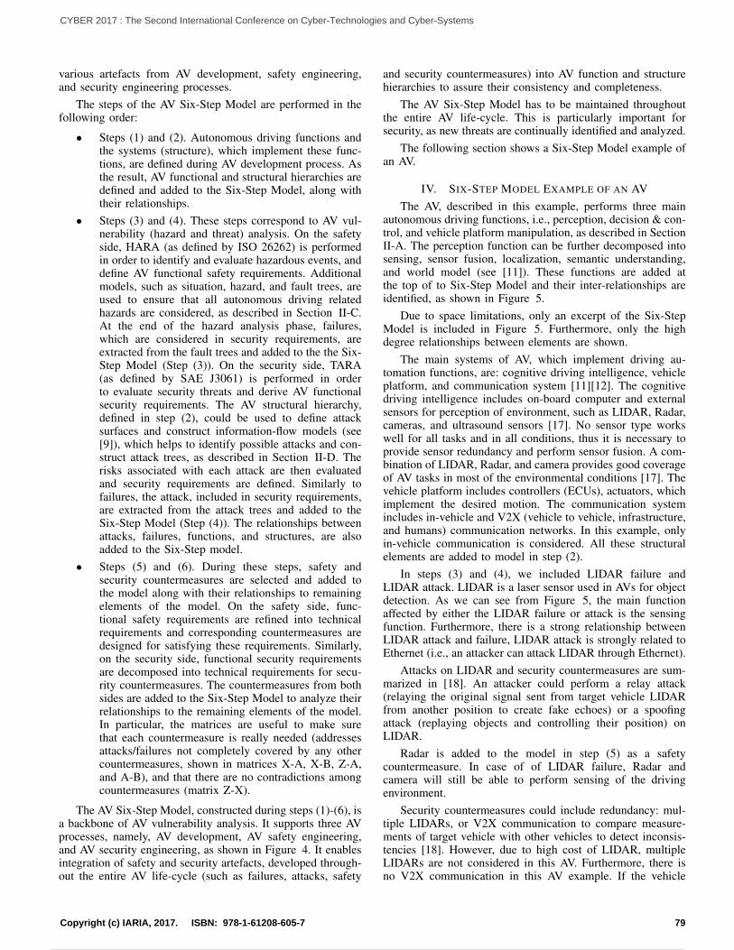
various artefacts from AV development, safety engineering,and security engineering processes.
The steps of the AV Six-Step Model are performed in thefollowing order:
• Steps (1) and (2). Autonomous driving functions andthe systems (structure), which implement these func-tions, are defined during AV development process. Asthe result, AV functional and structural hierarchies aredefined and added to the Six-Step Model, along withtheir relationships.
• Steps (3) and (4). These steps correspond to AV vul-nerability (hazard and threat) analysis. On the safetyside, HARA (as defined by ISO 26262) is performedin order to identify and evaluate hazardous events, anddefine AV functional safety requirements. Additionalmodels, such as situation, hazard, and fault trees, areused to ensure that all autonomous driving relatedhazards are considered, as described in Section II-C.At the end of the hazard analysis phase, failures,which are considered in security requirements, areextracted from the fault trees and added to the the Six-Step Model (Step (3)). On the security side, TARA(as defined by SAE J3061) is performed in orderto evaluate security threats and derive AV functionalsecurity requirements. The AV structural hierarchy,defined in step (2), could be used to define attacksurfaces and construct information-flow models (see[9]), which helps to identify possible attacks and con-struct attack trees, as described in Section II-D. Therisks associated with each attack are then evaluatedand security requirements are defined. Similarly tofailures, the attack, included in security requirements,are extracted from the attack trees and added to theSix-Step Model (Step (4)). The relationships betweenattacks, failures, functions, and structures, are alsoadded to the Six-Step model.
• Steps (5) and (6). During these steps, safety andsecurity countermeasures are selected and added tothe model along with their relationships to remainingelements of the model. On the safety side, func-tional safety requirements are refined into technicalrequirements and corresponding countermeasures aredesigned for satisfying these requirements. Similarly,on the security side, functional security requirementsare decomposed into technical requirements for secu-rity countermeasures. The countermeasures from bothsides are added to the Six-Step Model to analyze theirrelationships to the remaining elements of the model.In particular, the matrices are useful to make surethat each countermeasure is really needed (addressesattacks/failures not completely covered by any othercountermeasures, shown in matrices X-A, X-B, Z-A,and A-B), and that there are no contradictions amongcountermeasures (matrix Z-X).
The AV Six-Step Model, constructed during steps (1)-(6), isa backbone of AV vulnerability analysis. It supports three AVprocesses, namely, AV development, AV safety engineering,and AV security engineering, as shown in Figure 4. It enablesintegration of safety and security artefacts, developed through-out the entire AV life-cycle (such as failures, attacks, safety
and security countermeasures) into AV function and structurehierarchies to assure their consistency and completeness.
The AV Six-Step Model has to be maintained throughoutthe entire AV life-cycle. This is particularly important forsecurity, as new threats are continually identified and analyzed.
The following section shows a Six-Step Model example ofan AV.
IV. SIX-STEP MODEL EXAMPLE OF AN AVThe AV, described in this example, performs three main
autonomous driving functions, i.e., perception, decision & con-trol, and vehicle platform manipulation, as described in SectionII-A. The perception function can be further decomposed intosensing, sensor fusion, localization, semantic understanding,and world model (see [11]). These functions are added atthe top of to Six-Step Model and their inter-relationships areidentified, as shown in Figure 5.
Due to space limitations, only an excerpt of the Six-StepModel is included in Figure 5. Furthermore, only the highdegree relationships between elements are shown.
The main systems of AV, which implement driving au-tomation functions, are: cognitive driving intelligence, vehicleplatform, and communication system [11][12]. The cognitivedriving intelligence includes on-board computer and externalsensors for perception of environment, such as LIDAR, Radar,cameras, and ultrasound sensors [17]. No sensor type workswell for all tasks and in all conditions, thus it is necessary toprovide sensor redundancy and perform sensor fusion. A com-bination of LIDAR, Radar, and camera provides good coverageof AV tasks in most of the environmental conditions [17]. Thevehicle platform includes controllers (ECUs), actuators, whichimplement the desired motion. The communication systemincludes in-vehicle and V2X (vehicle to vehicle, infrastructure,and humans) communication networks. In this example, onlyin-vehicle communication is considered. All these structuralelements are added to model in step (2).
In steps (3) and (4), we included LIDAR failure andLIDAR attack. LIDAR is a laser sensor used in AVs for objectdetection. As we can see from Figure 5, the main functionaffected by either the LIDAR failure or attack is the sensingfunction. Furthermore, there is a strong relationship betweenLIDAR attack and failure, LIDAR attack is strongly related toEthernet (i.e., an attacker can attack LIDAR through Ethernet).
Attacks on LIDAR and security countermeasures are sum-marized in [18]. An attacker could perform a relay attack(relaying the original signal sent from target vehicle LIDARfrom another position to create fake echoes) or a spoofingattack (replaying objects and controlling their position) onLIDAR.
Radar is added to the model in step (5) as a safetycountermeasure. In case of of LIDAR failure, Radar andcamera will still be able to perform sensing of the drivingenvironment.
Security countermeasures could include redundancy: mul-tiple LIDARs, or V2X communication to compare measure-ments of target vehicle with other vehicles to detect inconsis-tencies [18]. However, due to high cost of LIDAR, multipleLIDARs are not considered in this AV. Furthermore, there isno V2X communication in this AV example. If the vehicle
79Copyright (c) IARIA, 2017. ISBN: 978-1-61208-605-7
CYBER 2017 : The Second International Conference on Cyber-Technologies and Cyber-Systems
88 / 90
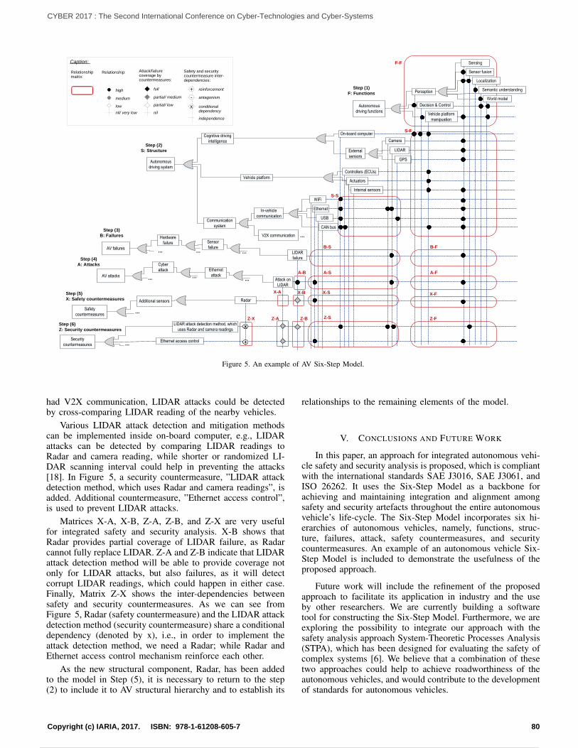
Autonomous
driving functions
Perception
Decision & Control
Vehicle platform
manipuation
Sensing
Sensor fusion
Localization
Semantic understanding
World model
Autonomous
driving system
Cognitive driving
intelligence
Vehicle platform
Communication
system
On-board computer
External
sensors
Camera
LIDAR
GPS
Controllers (ECUs)
Internal sensors
Actuators
V2X communication
In-vehicle
communication
WiFi
Ethernet
USB
CAN bus
AV failures
Hardware
failure Sensor
failureLIDAR
failure
AV attacks
Cyber
attack Ethernet
attackAttack on
LIDAR
Safety
countermeasures
Security
countermeasures
...
...
Additional sensors
...
LIDAR attack detection method, which
uses Radar and camera readings
...
Step (1)
F: Functions
Step (2)
S: Structure
Step (3)
B: Failures
Step (4)
A: Attacks
Step (5)
X: Safety countermeasures
Step (6)
Z: Security countermeasures
......
......
Radar
Ethernet access control
xx
++
F-F
S-S
S-F
...
B-S B-F
A-S A-FA-B
X-B X-S X-FX-A
Z-X Z-A Z-B Z-S Z-F
Caption:
Attack/failure coverage by countermeasures:
full
partial/ medium
partial/ low
nil
Relationship:
high
medium
low
nil/ very low
Relationship matrix:
Safety and securitycountermeasure inter-dependencies:
reinforcement
antagonism
independence
+
-
conditional dependency
x
Figure 5. An example of AV Six-Step Model.
had V2X communication, LIDAR attacks could be detectedby cross-comparing LIDAR reading of the nearby vehicles.
Various LIDAR attack detection and mitigation methodscan be implemented inside on-board computer, e.g., LIDARattacks can be detected by comparing LIDAR readings toRadar and camera reading, while shorter or randomized LI-DAR scanning interval could help in preventing the attacks[18]. In Figure 5, a security countermeasure, ”LIDAR attackdetection method, which uses Radar and camera readings”, isadded. Additional countermeasure, ”Ethernet access control”,is used to prevent LIDAR attacks.
Matrices X-A, X-B, Z-A, Z-B, and Z-X are very usefulfor integrated safety and security analysis. X-B shows thatRadar provides partial coverage of LIDAR failure, as Radarcannot fully replace LIDAR. Z-A and Z-B indicate that LIDARattack detection method will be able to provide coverage notonly for LIDAR attacks, but also failures, as it will detectcorrupt LIDAR readings, which could happen in either case.Finally, Matrix Z-X shows the inter-dependencies betweensafety and security countermeasures. As we can see fromFigure 5, Radar (safety countermeasure) and the LIDAR attackdetection method (security countermeasure) share a conditionaldependency (denoted by x), i.e., in order to implement theattack detection method, we need a Radar; while Radar andEthernet access control mechanism reinforce each other.
As the new structural component, Radar, has been addedto the model in Step (5), it is necessary to return to the step(2) to include it to AV structural hierarchy and to establish its
relationships to the remaining elements of the model.
V. CONCLUSIONS AND FUTURE WORK
In this paper, an approach for integrated autonomous vehi-cle safety and security analysis is proposed, which is compliantwith the international standards SAE J3016, SAE J3061, andISO 26262. It uses the Six-Step Model as a backbone forachieving and maintaining integration and alignment amongsafety and security artefacts throughout the entire autonomousvehicle’s life-cycle. The Six-Step Model incorporates six hi-erarchies of autonomous vehicles, namely, functions, struc-ture, failures, attack, safety countermeasures, and securitycountermeasures. An example of an autonomous vehicle Six-Step Model is included to demonstrate the usefulness of theproposed approach.
Future work will include the refinement of the proposedapproach to facilitate its application in industry and the useby other researchers. We are currently building a softwaretool for constructing the Six-Step Model. Furthermore, we areexploring the possibility to integrate our approach with thesafety analysis approach System-Theoretic Processes Analysis(STPA), which has been designed for evaluating the safety ofcomplex systems [6]. We believe that a combination of thesetwo approaches could help to achieve roadworthiness of theautonomous vehicles, and would contribute to the developmentof standards for autonomous vehicles.
80Copyright (c) IARIA, 2017. ISBN: 978-1-61208-605-7
CYBER 2017 : The Second International Conference on Cyber-Technologies and Cyber-Systems
89 / 90
REFERENCES[1] G. Sabaliauskaite and A. P. Mathur, Aligning Cyber-Physical System
Safety and Security. Cham: Springer International Publishing, 2015,pp. 41–53. [Online]. Available: https://doi.org/10.1007/978-3-319-12544-2 4
[2] L. Pietre-Cambacedes and M. Bouissou, “Cross-fertilization betweensafety and security engineering,” Reliability Engineering & SystemSafety, vol. 110, 2013, pp. 110 – 126.
[3] SAE J3016: Taxonomy and Definitions for Terms Related to On-RoadMotor Vehicle Automated Driving Systems. SAE International, Sep.2016.
[4] ISO26262-2:2011, Road Vehicles – Functional Safety – Part2: Manage-ment of Functional Safety. International Organization of Standardiza-tion, ISO, 2011.
[5] F. Warg et al., Defining Autonomous Functions Using IterativeHazard Analysis and Requirements Refinement. Cham: SpringerInternational Publishing, 2016, pp. 286–297. [Online]. Available:https://doi.org/10.1007/978-3-319-45480-1 23
[6] A. Abdulkhaleq et al., “A systematic approach based on stpa for devel-oping a dependable architecture for fully automated driving vehicles,”Procedia Engineering, vol. 179, no. Supplement C, 2017, pp. 41 – 51.
[7] SAE J3061: Cybersecurity Guidebook for Cyber-Physical Vehicle Sys-tems. SAE International, Jan. 2016.
[8] G. Sabaliauskaite, S. Adepu, and A. Mathur, “A six-step model forsafety and security analysis of cyber-physical systems,” in the 11th In-ternational Conference on Critical Information Infrastructures Security(CRITIS), Oct 2016.
[9] G. Sabaliauskaite and S. Adepu, “Integrating six-step model withinformation flow diagrams for comprehensive analysis of cyber-physicalsystem safety and security,” in 2017 IEEE 18th International Sympo-sium on High Assurance Systems Engineering (HASE), Jan 2017, pp.41–48.
[10] Automated Driving Systems 2.0. A Vision for Safety. NationalHighway Traffic Safety Administration, NHTSA, U.S. Department ofTransportation, Sep. 2017.
[11] S. Behere and M. Torngren, “A functional referencearchitecture for autonomous driving,” Inf. Softw. Technol.,vol. 73, no. C, May 2016, pp. 136–150. [Online]. Available:http://dx.doi.org/10.1016/j.infsof.2015.12.008
[12] S. Kato, E. Takeuchi, Y. Ishiguro, Y. Ninomiya, K. Takeda, andT. Hamada, “An open approach to autonomous vehicles,” IEEE Micro,vol. 35, no. 6, Nov 2015, pp. 60–68.
[13] P. Bhavsar, P. Das, M. Paugh, K. Dey, and M. Chowdhury, “Risk anal-ysis of autonomous vehicles in mixed traffic streams,” TransportationResearch Record: Journal of the Transportation Research Board, vol.2625, 2017, pp. 51–61.
[14] L. Pietre-Cambacedes and M. Bouissou, “Modeling safety and securityinterdependencies with bdmp (boolean logic driven markov processes),”in 2010 IEEE International Conference on Systems, Man and Cyber-netics, Oct 2010, pp. 2852–2861.
[15] B. Schneier, Attack Trees. Wiley Publishing, Inc., Indianapolis,Indiana, 2015, in Book, Secrets and Lies.
[16] Z. Ma and C. Schmittner, “Threat modeling for automotive securityanalysis,” Advanced Science and Technology Letters, vol. 139, 2016,pp. 333–339.
[17] “Beyond the Headlights: ADAS and Autonomous Sensing,” 2016,URL: http://woodsidecap.com/wp-content/uploads/2016/12/20160927-Auto-Vision-Systems-Report FINAL.pdf [accessed: 2017-09-18].
[18] J. Petit, B. Stottelaar, M. Feiri, and F. Kargl, “Remote Attacks onAutomated Vehicles Sensors: Experiments on Camera and LiDAR,” inBlack Hat Europe, Nov. 2015.
81Copyright (c) IARIA, 2017. ISBN: 978-1-61208-605-7
CYBER 2017 : The Second International Conference on Cyber-Technologies and Cyber-Systems
Powered by TCPDF (www.tcpdf.org)
90 / 90