geodesic spline interface for haptic curve rendering
TRANSCRIPT
Geodesic Spline Interface forHaptic Curve Rendering
Monica Bordegoni, Member, IEEE, Francesco Ferrise, Mario Covarrubias, and Michele Antolini
Abstract—Several haptic devices have been developed in recent years in order to reproduce the sensation of physical contact with
virtual objects. Many of these devices are point-based, and some haptic interfaces behave like small surfaces that conform to a virtual
shape. None of these allow a full-hand contact with the shape, and they are, in general, too small to render big surfaces. The simulation
of tasks, such as the exploration of aesthetic surfaces made by industrial designers in order to check the quality of prototypes, require
full-hand contact with the shape on a one-to-one scaled representation of the object. These explorations follow trajectories that can be
approximated with planar or geodesic curves. In this paper, we describe the design and implementation of a linear haptic device that is
able to render these trajectories. The device is part of a multimodal system including stereoscopic visualization that allows visual
representation of the entire surface. Industrial designers use the system for checking the quality of shapes while exploiting their manual
and visual skills. The system has been tested by industrial designers and the results are reported in this paper.
Index Terms—Haptic strip, curve rendering, virtual prototyping, mixed reality, multimodal interfaces, industrial design.
Ç
1 INTRODUCTION
THE analysis of the styling workflow in typical productdesign companies has revealed a set of common
practices. Even now the conceptual creation and evaluationof new products with high aesthetic value consist of theextensive use of physical mock-ups. Despite being ratherexpensive and time-consuming, this practice is commonlyused mainly for the following reasons: first, designers havethe need to physically touch and interact with object surfacesin order to evaluate at best their aesthetic quality, and,second, tools for digital design (Computer Aided Styling—CAS) are still too technical and do not specifically addressdesigners’ skills and ways of working [1]. CAS tools haveeffective functionalities such as reflection and porcupinelines that support designers in the evaluation of surfacequalities. Conversely, the manipulation of control points formodeling surfaces is neither intuitive nor effective.
We propose to augment CAS tools functionalities andpotentialities, by integrating the visual representation ofmodels with the sense of touch. This is today made possibleby exploiting the capabilities of haptic technologies. This newinteraction modality, combined with common visualization,would allow designers to evaluate shapes through the senseof touch as well. In this way, the manual skills of designerscan be exploited by offering them a modality to operate whichis very close to their habits and usual way of working.
This paper presents a haptic interface integrated with aCAS tool for the evaluation of aesthetic surface qualitythrough the sense of touch. The interface consists of a haptic
strip that simulates characteristic curves, which we candefine as aesthetic features—belonging to a surface. Thestrip is actuated and conforms to a selected curve on ashape. It has been developed within the context of theEuropean project SATIN—Sound And Tangible Interfacefor Novel product design (www.satin-project.eu).
This paper is organized as follows: Section 2 presents anoverview of related works. Section 3 describes the stripconception at the basis of the system. Section 4 presents thesystem architecture focusing on the visualization system.Section 5 describes, in detail, the haptic interface for curverendering, and its components. In Section 6, we present theintegrated system and results of users’ tests. Finally, Section 7draws conclusions.
2 RELATED WORKS
2.1 Limits of Available Haptic Devices
Haptic devices are mainly divided in two groups: tactileand force-feedback displays [2], [3]. Usually, tactile-feed-back devices have pin arrays or vibrators that stimulate theskin, and, commonly, force-feedback displays are poweredby electric motors or other actuators in order to exert forceson user’s hands. Simulating the contact with a surfacethrough a point-based force-feedback single or multipoint,with three or more degrees of freedom, does not allow us tocompletely reproduce the complex phenomenon of thesense of touch [4]. Point-based devices communicate forcesand usually do not create correct tactile cues on the wholehand. Sometimes, they introduce an additional mediumbetween the hand and the surface. The tactile displays, likefor example [5], [6], [7], are different from force feedbackdevices in that they correctly provide local cutaneous cues,however they are not useful in representing large-scalegeometries, being so limited in dimension that they alsocreate kinesthetic cues. In [8], an attempt to overcome thisdifference among tactile and force displays is presented,with a device that uses airborne ultrasound technology,
IEEE TRANSACTIONS ON HAPTICS, VOL. 4, NO. 2, APRIL-JUNE 2011 111
. The authors are with the Dipartimento di Meccanica, Politecnico diMilano, via La Masa 1, 20156 Milano, Italy.E-mail: {monica.bordegoni, francesco.ferrise}@polimi.it,{mario.covarrubias, michele.antolini}@mail.polimi.it.
Manuscript received 24 Jan. 2010; revised 19 Nov. 2010; accepted 28 Nov.2010; published online 3 Feb. 2011.Recommended for acceptance by V. Hayward.For information on obtaining reprints of this article, please send e-mail to:[email protected], and reference IEEECS Log Number TH-2010-01-0002.Digital Object Identifier no. 10.1109/ToH.2011.1.
1939-1412/11/$26.00 � 2011 IEEE Published by the IEEE CS, RAS, & CES
providing the user’s hand with both spatial and kinestheticcues on shapes. The main limit is that the device producesweak force in order for users to feel a constant pressure, justsufficient for vibratory sensation. Another interestingcontribution in returning to users the full-hand contactwith a shape is represented by the second generation ofTangible User Interfaces (TUIs) as described in [9]. Withrespect to this technology, the haptic strip described in thispaper is an output device that can adapt its shape to adigital surface, and is not only an input device used forchanging the geometry of a shape. A similar differenceexists between the haptic strip and several input deviceslike those distributed by Infusion Systems [10], andMeasurand [11] that are mainly flexible strips that can beused to manipulate a shape without the provision of anyrealistic force feedback from the surface to the user.
2.2 Haptic Representation of Geometries andInfluence of Visual Cues on Haptic Exploration
Regarding the specific problem of representing shapes,several research works in the field of haptics haveaddressed the problem of correctly representing curvesand curvature information, overcoming the limits of thepoint-based devices by also providing cutaneous informa-tion to fingers. In [12], an attempt to produce the illusion ofa haptic shape using only the communication of the localtangency of the curve on one or more fingertips ispresented. This device does not provide enough kinestheticcues, especially, for large curves. Frisoli et al. in [13]describe a haptic device that is the combination of a point-based device to provide kinesthetic cues and a fingertiphaptic device that provides cutaneous cues. In [14],Provancher et al. describe an attempt to communicatecurves and curvatures through a contact location feedbackon the fingertips. The main limitation of these three works isthat users interact with the shape using only a part of thehand, mainly one or more fingers, but not the whole hand.Some research activities have addressed the limits ofhuman perception and discrimination of curvatures in awhole hand exploration like those reported in [15], [16]. Thehaptic strip we have developed is an attempt in developinga haptic device that tries to exactly reproduce the shape of acurve, by deforming a physical continuous strip, in order togive users the full-hand contact with the virtual surface. It istherefore a device that is able to communicate both tactileand kinesthetic cues with a whole hand interaction. Thehaptic device is part of a multimodal interaction environ-ment that includes a 3D visualization. The influence of thevisual cues on haptic exploration has been largely studiedand documented in [17], [18], where it is demonstrated thatthe modality with the highest accuracy is predominant in amultimodal system. Recently, Plaisier et al. [19] havestudied the influence of the visualization channel in hapticexploration. In particular, it has been demonstrated thattactile searching strategies change according to the quantityof visual cues provided. With the full visual feedbackcondition the search movement between two targets usuallyfollows the shortest path. A similar result will be obtainedin the exploration described in the next section, where wewill demonstrate through a simple study that designersfollow geodesic trajectories in evaluating the quality of thesurface, where geodesic trajectories are defined as theshortest path between two points laying on a surface.
3 STRIP INTERFACE CONCEPTION
This section presents the motivations underlying theconceptual development of the haptic strip. The context ofuse of this system is the design review of newly conceivedproducts. In the process of creating new products shapes,designers often need to touch the surfaces, in order to checkand evaluate their aesthetic quality. In fact, some importantlocal and global continuity aspects may be very difficult toperceive or appreciate using only a computer screen. Inaddition, the images, even if displayed in a stereoscopicview, may be misleading. The ability to touch and feel theobjects that designers produce during the design processallows them to better evaluate the shapes in terms of theirgeometric properties.
The idea of proposing a new design tool having a novelinterface based on haptic technology was generated by theobservation that designers of aesthetic products create andmanipulate shapes on the basis of curves: characteristiccurves, aesthetic curves, etc. The concept of curve as a basisfor shape generation and modification is not only used indigital modeling, but also in physical modeling.
In order to clarify the role and importance of curves intypical design processes, we report some examples of useof physical profiles typical of some of the end-usercompanies participating to our project: Italdesign-Giugiaro(www.italdesign.it), a company for car design, and Alessi(www.alessi.com), a company for the design of householdproducts.
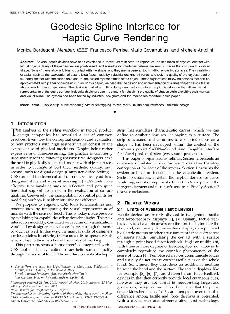
Currently, during styling activities at Italdesign-Giu-giaro, the evaluation of a model is made taking into accountthe fundamental curves of the model. Designers use aphysical design strip on the drawing to modify a sketch in avirtual room (Fig. 1a), but also to check/modify a physicalmodel (Fig. 1b). So, even if a designer deals with 3D shapes,it is clear that the evaluation and modification of thoseshapes is done based on fundamental curves.
Another example concerns the use of a physical flexibleprofile in Alessi design process. Figs. 2a, 2b, 2c, and 2d showthe way in which a designer interacts with 2D drawings anda flexible curvilinear strip in order to get shapes from the2D template and directly compare them with physicalprototype (Figs. 2e, 2f, and 2g). The appreciation of thenew profile shape is done visually as well as physically (bytouch). Satisfactory profiles may then be inserted into theoriginal 2D drawings (Figs. 2h, 2i, and 2j).
In addition, during the observation of designers way ofworking and of manually interacting with physical shapes,we have also analyzed the trajectories followed during theinspection of a surface. Fig. 3 shows some examples. These
112 IEEE TRANSACTIONS ON HAPTICS, VOL. 4, NO. 2, APRIL-JUNE 2011
Fig. 1. Model evaluation using the design strip on the 2D model and on aphysical model (courtesy of Italdesign-Giugiaro).
trajectories have been visually observed, recorded, and
acquired through a tracking system and the related curves
have been extracted and plotted (Fig. 4). We decided to
attach the sensor at the back of the hand, and not to track
single or multiple fingers, because we observed that
designers used different strategies to explore the surfaces
to evaluate the quality. Some of them used the fingers, some
others the palm or the back of the hand and the aim of the
observations was to roughly understand the exploration
strategy in evaluating the quality of the surface.We observed that from a geometrical point of view,
these trajectories are mathematically represented as geo-
desic curves. A geodesic curve is defined as the shortest
path between two points in a curved space, for which the
tangent vector field is parallel along this curve. In order to
show the concept of using a strip to render a linear curve,
we have chosen a cylinder since it is known that geodesics
on a cylinder are either straight lines (parallel to the axis of
the cylinder), circles (parallel to the base of the cylinder),
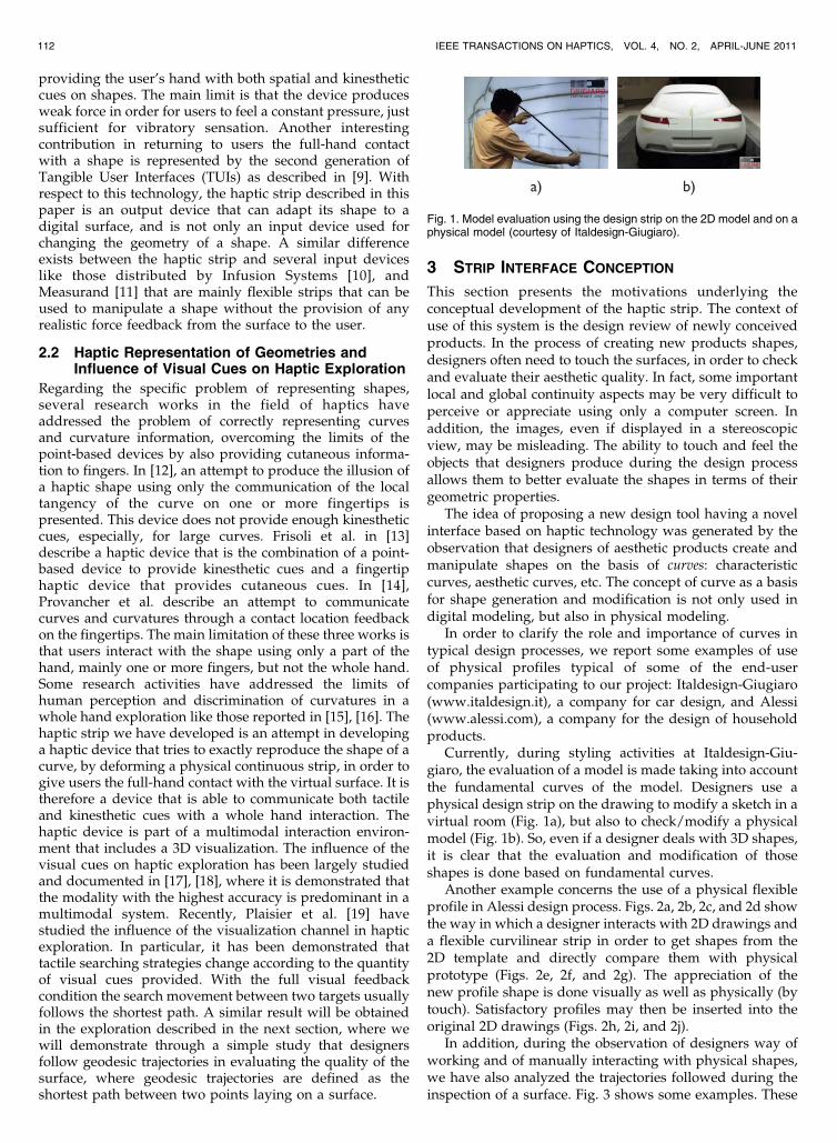
or helixes.Fig. 5 shows both the plastic strip and the cylinder onto
which the strip is developed. Fig. 5a shows a geodesic
determined on the cylinder as a circle. Fig. 5b shows the case
of a general geodesic on a cylinder. The geodesic was indeedpart of the helix connecting its beginning point to its endpoint.
A geodesic is a particular curve on a surface that has acurvature that depends only on the surface. This is animportant property of geodesics, which makes themattractive from a surface description or reconstructionpoint of view [20]. Geodesics can be used in a mechanismto check if a portion of a surface has constant Gaussiancurvature. Additionally, geodesics are useful in determin-ing the geometrical properties of a surface [21]. This findsapplications in geometric modeling and reverse engineer-ing, where a representation of a surface can be developedbased on its geodesic.
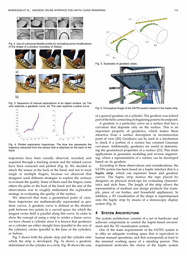
According to these observations and considerations, theSATIN system has been based on a haptic interface that is ahaptic strip, which can represent linear and geodesiccurves. The haptic strip mimics the tape placed bydesigners on physical mock-ups for evaluating character-istics and style lines. The length of the strip allows therepresentation of medium size design products (for exam-ple, piece of car bodies, and household appliances). Inaddition, a 3D visualization of the shape is superimposedonto the haptic strip by means of a stereoscopic displaysystem (Fig. 6).
4 SYSTEM ARCHITECTURE
The system architecture consists of a set of hardware andsoftware components to control the haptic-based environ-ment and the 3D visualization system.
One of the main requirements of the SATIN system isto offer an adequate working space that is equivalent tohuman manual operations, and that corresponds at least tothe minimal working space of a standing person. Thisrequirement motivates the choice of the haptic system
BORDEGONI ET AL.: GEODESIC SPLINE INTERFACE FOR HAPTIC CURVE RENDERING 113
Fig. 2. Use of a physical flexible profile for simulating some modificationsof the shape of a product (courtesy of Alessi).
Fig. 3. Sequence of manual explorations of an object surface. (a) Theuser explores a geodesic curve. (b) The user explores a plane curve.
Fig. 4. Plotted exploration trajectories. The blue line represents thetrajectory extracted from the sensor that is attached on the back of thehand.
Fig. 5. Examples of geodesic strips.
Fig. 6. Conceptual image of the SATIN system based on the haptic strip.
setup consisting of two MOOG-HapticMaster robots,positioned in a parallel configuration, that provide a wideworking space and appropriate force feedback [22], [23].The two robots hold the haptic strip.
The main requirement for the visualization system is toprovide an adequate working space suitable for hosting thehaptic system setup. In particular, the system is required toallow users to see their hands when operating the hapticinterface, as well as observing the virtual object beingmanipulated. This implies that the visual and the hapticworking spaces are colocated.
We have considered several solutions for the visualiza-tion system, including Head Mounted Displays (HMDs)and projection systems. The first kind of solution has beendiscarded mainly because even light and less cumbersomeHMDs have been recently developed [24], they are stillconsidered uncomfortable and obtrusive by designers.
Consequently, we have decided to implement a visua-lization system based on projection technology. In order toobtain the colocation of the virtual scene and the hapticdevice, the main problem we had to address was having aprojection path that was not occluded by the haptic devicein the whole working space. Several solutions have beenstudied and tested both in simulation and through realtests, before reaching the final configuration [25].
The final solution, named Direct Visuohaptic DisplaySystem (DVHDS), is a display system based on mirrorsand screens for projecting an image over the haptic workingspace. The DVHDS system consists of a DLP projector, amirror, a half-silvered mirror, and a rear-projection screen.The projector is located in a position that is above and onthe back with respect to the haptic system. This positionallows the user to stand in front of the visualization systemwithout the problem of creating a shadow with his head,
thus occluding the image projected by the projector. Thedisplay system is also designed in a way that itscomponents do not interfere with the haptic workspace.So, the user can freely move his hands within the interactionspace, and is able to interact with the system by grabbingand manipulating the physical interface that is positionedunder the half-silvered mirror or using other specific inputdevices to control the application.
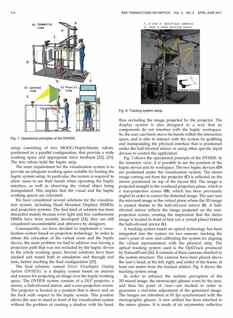
Fig. 7 shows the operational principle of the DVHDS. Inthe isometric view, it is possible to see the position of thehaptic device and its workspace. The two haptic devices (D)are positioned under the visualization system. The stereoimage coming out from the projector (C) is reflected on themirror positioned on top of the layout (G). The image isprojected straight to the overhead projection plane, which isa rear-projection screen (H), which has been previouslyangled in order to correct the distorted image. The user seesthe mirrored image in the virtual plane where the 3D imageis created thanks to the half-silvered mirror (I). A half-silvered mirror reflects the image projected on the rear-projection screen, creating the impression that the stereoimage is located in front of him (on a virtual plane) behindthe half-silvered mirror (L).
A tracking system based on optical technology has beenintegrated into the system for two reasons: tracking theuser’s point of view and calibrating the system for aligningthe virtual representation with the physical strip. Theoptical tracking system used is the OptiTrack producedby NaturalPoint [26]. It consists of three cameras attached tothe system structure. The cameras have been placed abovethe user’s head; at the left, right, and center of the frame, atleast one meter from the tracked artifact. Fig. 8 shows thetracking system setup.
In order to enhance the realistic perception of the3D mixed image, the stereoscopic glasses worn by the user,and thus his point of view—are tracked in order toguarantee a real-time adjustment of the generated image.The images are refreshed at 85 fps synchronized with thestereographic glasses. A new artifact has been attached tothe stereo glasses. It is made of six asymmetric reflective
114 IEEE TRANSACTIONS ON HAPTICS, VOL. 4, NO. 2, APRIL-JUNE 2011
Fig. 7. Operational principles of the DVHDS.
Fig. 8. Tracking system setup.
spheres that improve considerably the tracking results.With this setup, the artifact appears beyond the user’s headso there are no occlusions even if the user is leaned over themirror.
The colocation of the real strip and virtual model does notonly depend on the head tracking for the correct perceptionof the stereo viewing but also on the location of thevisualization device, i.e., the location of the display. Sincethe visualization system uses reflective and semitransparentsurfaces to merge the virtual space with the physical space, acalibration process has been defined to correctly computethe location of the virtual plane with respect to the physicalworking space. The user sees the reflected image of the rear-projection screen in the half-silvered mirror. If the positionsof the user’s head and of the mirrored image of the rear-projection screen are known, we can calibrate the systemwith the simplified assumption of using the reflected imageof the screen as a real stereo screen.
5 HAPTIC STRIP INTERFACE
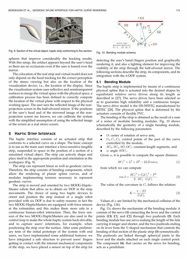
The haptic interface consists of an actuated strip thatconforms to a selected curve on a shape. The basic conceptis to use as the main user interface a force-sensitive tangiblestrip, suspended in space in the position of a section of asimulated virtual object. The strip can actively shape andplace itself in the appropriate position and orientation in theworkspace (Fig. 9).
The strip can represent linear as well as geodesic curves.Therefore, the strip consists of bending components, whichallow the rendering of planar spline curves, and ofmodules implementing torsions necessary to representgeodesic curves.
The strip is moved and oriented by two MOOG-Haptic-Master robots that allow us to obtain six DOF in the stripmovements. The choice of using two haptic devices toorient and position the strip instead of a single robotprovided with six DOF is due to safety reasons; in fact thetwo MOOG-HapticMasters are equipped with force sensorsat the extremities and this makes them more safe in acontinuous human-robot interaction. Then, the force sen-sors of the two MOOG-HapticMasters are also used in thecontrol loop to make the whole haptic system back-drivable,and to capture users’ intentions, for example, whenpositioning the strip over the surface. After some prelimin-ary tests of the initial prototype of the system with endusers, we have implemented some additional features: wehave integrated a safe structure to prevent users’ fingersgetting in contact with the internal mechanical componentsof the strip, we have placed a sensor on top of the strip for
detecting the user’s hand/fingers position and graphicallyrendering it, and also a lighting element for improving thevisibility of the strip through the half-silvered mirror. Thefollowing sections describe the strip, its components, and itsintegration with the 6-DOF system.
5.1 Bending Module
The haptic strip is implemented by means of a continuousphysical spline that is actuated into the desired shapes byequidistant relative servo drives along its length asdescribed in [27]. The servo drives have been selected soas to guarantee high reliability and a continuous torque.The servo drive model is the HS-5955TG manufactured byHITEC [28]. The physical spline that is deformed by theactuators consists of flexible PVC.
The bending of the strip is obtained as the result of a sumof a series of modular bending modules. Fig. 10 showsschematically the geometry of a single bending module,described by the following parameters:
. O: center of rotation of servo arm,
. C0; C1; C2: control points of the part of the curvecontrolled by the module,
. SC0; SC2; SO;OC1: constant-length segments, and
. �: angle SOC1.
Given �, it is possible to compute the square distance:
SC12 ¼ L2 þD2 � 2LD cos�; ð1Þ
from which we can compute
cos � ¼ SC12 þ C0C1
2 � P 2
2 � SC1 � C0C1: ð2Þ
The value of the curvature in C1 follows the relation:
K ¼ �� 2�
C0C2: ð3Þ
Values of � are limited by the mechanical collision of thedevice (Fig. 11b).
Fig. 11c shows the mechanism of the bending module: itconsists of the servo (1) connecting the lever and the controlpoints (C0, C1, and C2) through two pushrods (2). Eachbending module has one servo making the length of the linkcarrying it longer and shorter, and the two pushrods endingon its lever form the V-shaped mechanism that controls thebending of that section of the plastic strip (3) symmetrically.The pushrods are linked through spherical joints to thelever and the shafts attached on each single control point.The component (4), that carries on the servo for bending,acts as a pendulum.
BORDEGONI ET AL.: GEODESIC SPLINE INTERFACE FOR HAPTIC CURVE RENDERING 115
Fig. 9. Section of the virtual object; haptic strip conforming to the section.Fig. 10. Bending module schema.
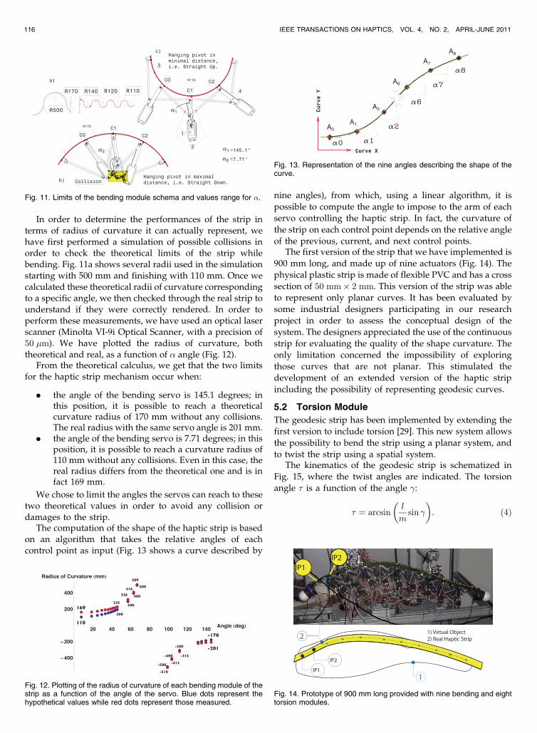
In order to determine the performances of the strip interms of radius of curvature it can actually represent, wehave first performed a simulation of possible collisions inorder to check the theoretical limits of the strip whilebending. Fig. 11a shows several radii used in the simulationstarting with 500 mm and finishing with 110 mm. Once wecalculated these theoretical radii of curvature correspondingto a specific angle, we then checked through the real strip tounderstand if they were correctly rendered. In order toperform these measurements, we have used an optical laserscanner (Minolta VI-9i Optical Scanner, with a precision of50 �m). We have plotted the radius of curvature, boththeoretical and real, as a function of � angle (Fig. 12).
From the theoretical calculus, we get that the two limitsfor the haptic strip mechanism occur when:
. the angle of the bending servo is 145.1 degrees; inthis position, it is possible to reach a theoreticalcurvature radius of 170 mm without any collisions.The real radius with the same servo angle is 201 mm.
. the angle of the bending servo is 7.71 degrees; in thisposition, it is possible to reach a curvature radius of110 mm without any collisions. Even in this case, thereal radius differs from the theoretical one and is infact 169 mm.
We chose to limit the angles the servos can reach to thesetwo theoretical values in order to avoid any collision ordamages to the strip.
The computation of the shape of the haptic strip is basedon an algorithm that takes the relative angles of eachcontrol point as input (Fig. 13 shows a curve described by
nine angles), from which, using a linear algorithm, it is
possible to compute the angle to impose to the arm of each
servo controlling the haptic strip. In fact, the curvature of
the strip on each control point depends on the relative angle
of the previous, current, and next control points.The first version of the strip that we have implemented is
900 mm long, and made up of nine actuators (Fig. 14). The
physical plastic strip is made of flexible PVC and has a cross
section of 50 mm� 2 mm. This version of the strip was able
to represent only planar curves. It has been evaluated by
some industrial designers participating in our research
project in order to assess the conceptual design of the
system. The designers appreciated the use of the continuous
strip for evaluating the quality of the shape curvature. The
only limitation concerned the impossibility of exploring
those curves that are not planar. This stimulated the
development of an extended version of the haptic strip
including the possibility of representing geodesic curves.
5.2 Torsion Module
The geodesic strip has been implemented by extending the
first version to include torsion [29]. This new system allows
the possibility to bend the strip using a planar system, and
to twist the strip using a spatial system.The kinematics of the geodesic strip is schematized in
Fig. 15, where the twist angles are indicated. The torsion
angle � is a function of the angle �:
� ¼ arcsinl
msin �
� �: ð4Þ
116 IEEE TRANSACTIONS ON HAPTICS, VOL. 4, NO. 2, APRIL-JUNE 2011
Fig. 12. Plotting of the radius of curvature of each bending module of thestrip as a function of the angle of the servo. Blue dots represent thehypothetical values while red dots represent those measured.
Fig. 13. Representation of the nine angles describing the shape of thecurve.
Fig. 14. Prototype of 900 mm long provided with nine bending and eighttorsion modules.
Fig. 11. Limits of the bending module schema and values range for �.
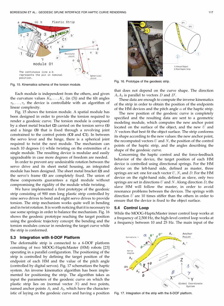
Each module is independent from the others, and giventhe curvature values K0; . . . ; Kn (in (3)) and the tilt angles�0; . . . ; �n the device is controllable with an algorithm oflinear complexity.
Fig. 15 shows the torsion module. A spatial module hasbeen designed in order to provide the torsion required torender a geodesic curve. The torsion module is composedby a sheet metal bracket (2) carried on the torsion servo (1)and a hinge (3) that is fixed through a revolving jointconstrained to the control points (C0 and C1). In betweenthe servo lever and the hinge, there is a spherical jointrequired to twist the next module. The mechanism canreach 10 degrees (�) while twisting on the extremities of asingle module. The resulting device is modular and easilyupgradeable in case more degrees of freedom are needed.
In order to prevent any undesirable rotation between theservo drive and its sheet metal housing, an integratedmodule has been designed. The sheet metal bracket (2) andthe servo’s frame (1) are completely fixed. The union ofthese components guarantees a rigid module withoutcompromising the rigidity of the module while twisting.
We have implemented a first prototype of the geodesicstrip consisting of 900 mm long plastic strip controlled bynine servo drives to bend and eight servo drives to providetorsion. The strip mechanism works quite well in bendingand in twist rotation. It is worth noticing that it is necessary touse some springs in order to balance the mechanism. Fig. 16shows the geodesic prototype reaching the target positionusing the geodesic trajectory concept: the bending and thetorsion modules concur in rendering the target curve whilethe strip is conformed.
5.3 Integration with 6-DOF Platform
The deformable strip is connected to a 6-DOF platformconsisting of two MOOG-HapticMaster (HM) robots [23]operating in a parallel configuration. The positioning of thestrip is controlled by defining the target position of theendpoint of each HM and the value of the pitch angle(controlled by digital servos). Fig. 17 schematizes the hapticsystem. An inverse kinematics algorithm has been imple-mented for positioning the strip. The algorithm takes asinput the parameters of the geodesic curve on which theplastic strip lies on (normal vector N) and two points,named anchor points A1 and A2, which have the character-istic of laying on the geodesic curve and having a position
that does not depend on the curve shape. The directionA1A2 is parallel to vectors D and D0.
These data are enough to compute the inverse kinematicsof the strip in order to obtain the position of the endpointsof the HM devices and the pitch angle � of the haptic strip.
The new position of the geodesic curve is completelyspecified and the resulting data are sent to a geometricmodeling module, which computes the new anchor pointlocated on the surface of the object, and the new U andN vectors that best fit the object surface. The strip conformsits shape according to the new values: the new anchor point,the recomputed vectors U and N , the position of the controlpoints of the haptic strip, and the angles describing theshape of the geodesic curve.
Concerning the haptic control and the force-feedbackbehavior of the device, the target position of each HMdevice is controlled using directional springs. For the HMdevice on the left-hand side, defined as master, threesprings are set: one for each vector U;N , and D. For the HMdevice on the right-hand side, defined as slave, only twosprings are set in directions U and N . Along direction D, theslave HM will follow the master, in order to avoidresonance problems between the devices. The springs withdirection U are 10 times stiffer than the others in order toensure that the device is fixed to the object surface.
5.4 Control Loop
While the MOOG-HapticMaster inner control loop works ata frequency of 2,500 Hz, the high-level control loop works ata frequency between 10 and 25 Hz. The main input of the
BORDEGONI ET AL.: GEODESIC SPLINE INTERFACE FOR HAPTIC CURVE RENDERING 117
Fig. 17. Integration of the strip with the 6-DOF platform.
Fig. 15. Kinematics schema of the torsion module.Fig. 16. Prototype of the geodesic strip.
system is the force applied by the user at the extremities ofthe strip. From this force value, it is possible to compute thetranslation and moment vectors needed for the stripmotion. Since the strip is constrained to lay on the surfaceof the virtual object, the geometric engine (thinkCore bythink3) computes the new position and orientation of thestrip reference taking into account such constraint. The newposition of the strip control points and the curvature at eachone is sent by thinkCore to the haptic module, whichexecutes the inverse kinematics algorithm and controls theHapticMaster position and the shape of the haptic strip.
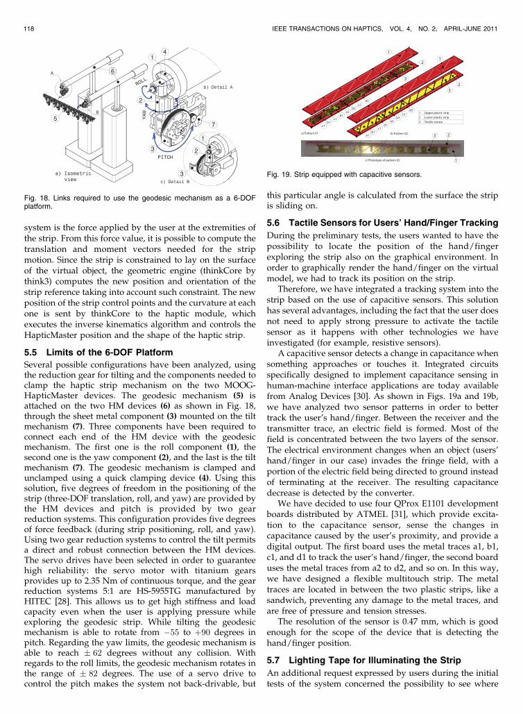
5.5 Limits of the 6-DOF Platform
Several possible configurations have been analyzed, usingthe reduction gear for tilting and the components needed toclamp the haptic strip mechanism on the two MOOG-HapticMaster devices. The geodesic mechanism (5) isattached on the two HM devices (6) as shown in Fig. 18,through the sheet metal component (3) mounted on the tiltmechanism (7). Three components have been required toconnect each end of the HM device with the geodesicmechanism. The first one is the roll component (1), thesecond one is the yaw component (2), and the last is the tiltmechanism (7). The geodesic mechanism is clamped andunclamped using a quick clamping device (4). Using thissolution, five degrees of freedom in the positioning of thestrip (three-DOF translation, roll, and yaw) are provided bythe HM devices and pitch is provided by two gearreduction systems. This configuration provides five degreesof force feedback (during strip positioning, roll, and yaw).Using two gear reduction systems to control the tilt permitsa direct and robust connection between the HM devices.The servo drives have been selected in order to guaranteehigh reliability: the servo motor with titanium gearsprovides up to 2.35 Nm of continuous torque, and the gearreduction systems 5:1 are HS-5955TG manufactured byHITEC [28]. This allows us to get high stiffness and loadcapacity even when the user is applying pressure whileexploring the geodesic strip. While tilting the geodesicmechanism is able to rotate from �55 to þ90 degrees inpitch. Regarding the yaw limits, the geodesic mechanism isable to reach � 62 degrees without any collision. Withregards to the roll limits, the geodesic mechanism rotates inthe range of � 82 degrees. The use of a servo drive tocontrol the pitch makes the system not back-drivable, but
this particular angle is calculated from the surface the stripis sliding on.
5.6 Tactile Sensors for Users’ Hand/Finger Tracking
During the preliminary tests, the users wanted to have thepossibility to locate the position of the hand/fingerexploring the strip also on the graphical environment. Inorder to graphically render the hand/finger on the virtualmodel, we had to track its position on the strip.
Therefore, we have integrated a tracking system into thestrip based on the use of capacitive sensors. This solutionhas several advantages, including the fact that the user doesnot need to apply strong pressure to activate the tactilesensor as it happens with other technologies we haveinvestigated (for example, resistive sensors).
A capacitive sensor detects a change in capacitance whensomething approaches or touches it. Integrated circuitsspecifically designed to implement capacitance sensing inhuman-machine interface applications are today availablefrom Analog Devices [30]. As shown in Figs. 19a and 19b,we have analyzed two sensor patterns in order to bettertrack the user’s hand/finger. Between the receiver and thetransmitter trace, an electric field is formed. Most of thefield is concentrated between the two layers of the sensor.The electrical environment changes when an object (users’hand/finger in our case) invades the fringe field, with aportion of the electric field being directed to ground insteadof terminating at the receiver. The resulting capacitancedecrease is detected by the converter.
We have decided to use four QProx E1101 developmentboards distributed by ATMEL [31], which provide excita-tion to the capacitance sensor, sense the changes incapacitance caused by the user’s proximity, and provide adigital output. The first board uses the metal traces a1, b1,c1, and d1 to track the user’s hand/finger, the second boarduses the metal traces from a2 to d2, and so on. In this way,we have designed a flexible multitouch strip. The metaltraces are located in between the two plastic strips, like asandwich, preventing any damage to the metal traces, andare free of pressure and tension stresses.
The resolution of the sensor is 0.47 mm, which is goodenough for the scope of the device that is detecting thehand/finger position.
5.7 Lighting Tape for Illuminating the Strip
An additional request expressed by users during the initialtests of the system concerned the possibility to see where
118 IEEE TRANSACTIONS ON HAPTICS, VOL. 4, NO. 2, APRIL-JUNE 2011
Fig. 18. Links required to use the geodesic mechanism as a 6-DOFplatform.
Fig. 19. Strip equipped with capacitive sensors.
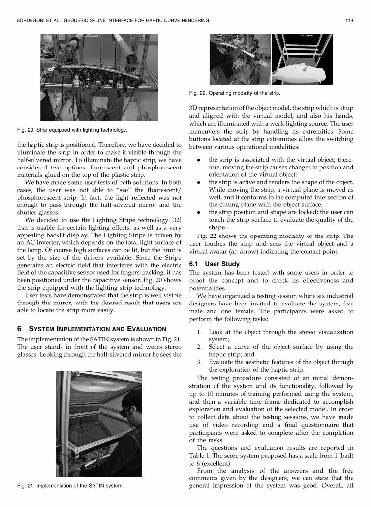
the haptic strip is positioned. Therefore, we have decided toilluminate the strip in order to make it visible through thehalf-silvered mirror. To illuminate the haptic strip, we haveconsidered two options: fluorescent and phosphorescentmaterials glued on the top of the plastic strip.
We have made some user tests of both solutions. In bothcases, the user was not able to “see” the fluorescent/phosphorescent strip. In fact, the light reflected was notenough to pass through the half-silvered mirror and theshutter glasses.
We decided to use the Lighting Stripe technology [32]that is usable for certain lighting effects, as well as a veryappealing backlit display. The Lighting Stripe is driven byan AC inverter, which depends on the total light surface ofthe lamp. Of course high surfaces can be lit, but the limit isset by the size of the drivers available. Since the Stripegenerates an electric field that interferes with the electricfield of the capacitive sensor used for fingers tracking, it hasbeen positioned under the capacitive sensor. Fig. 20 showsthe strip equipped with the lighting strip technology.
User tests have demonstrated that the strip is well visiblethrough the mirror, with the desired result that users areable to locate the strip more easily.
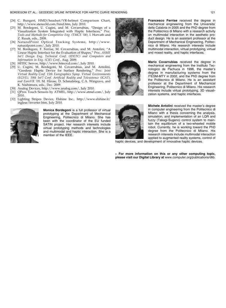
6 SYSTEM IMPLEMENTATION AND EVALUATION
The implementation of the SATIN system is shown in Fig. 21.The user stands in front of the system and wears stereoglasses. Looking through the half-silvered mirror he sees the
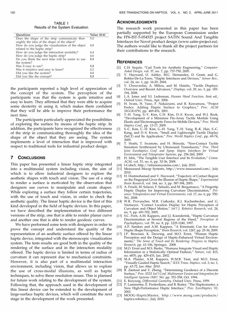
3D representation of the object model, the strip which is lit upand aligned with the virtual model, and also his hands,which are illuminated with a weak lighting source. The usermaneuvers the strip by handling its extremities. Somebuttons located at the strip extremities allow the switchingbetween various operational modalities:
. the strip is associated with the virtual object; there-fore, moving the strip causes changes in position andorientation of the virtual object;
. the strip is active and renders the shape of the object.While moving the strip, a virtual plane is moved aswell, and it conforms to the computed intersection ofthe cutting plane with the object surface;
. the strip position and shape are locked; the user cantouch the strip surface to evaluate the quality of theshape.
Fig. 22 shows the operating modality of the strip. Theuser touches the strip and sees the virtual object and avirtual avatar (an arrow) indicating the contact point.
6.1 User Study
The system has been tested with some users in order toproof the concept and to check its effectiveness andpotentialities.
We have organized a testing session where six industrialdesigners have been invited to evaluate the system, fivemale and one female. The participants were asked toperform the following tasks:
1. Look at the object through the stereo visualizationsystem;
2. Select a curve of the object surface by using thehaptic strip; and
3. Evaluate the aesthetic features of the object throughthe exploration of the haptic strip.
The testing procedure consisted of an initial demon-stration of the system and its functionality, followed byup to 10 minutes of training performed using the system,and then a variable time frame dedicated to accomplishexploration and evaluation of the selected model. In orderto collect data about the testing sessions, we have madeuse of video recording and a final questionnaire thatparticipants were asked to complete after the completionof the tasks.
The questions and evaluation results are reported inTable 1. The score system proposed has a scale from 1 (bad)to 6 (excellent).
From the analysis of the answers and the freecomments given by the designers, we can state that thegeneral impression of the system was good. Overall, all
BORDEGONI ET AL.: GEODESIC SPLINE INTERFACE FOR HAPTIC CURVE RENDERING 119
Fig. 21. Implementation of the SATIN system.
Fig. 22. Operating modality of the strip.
Fig. 20. Strip equipped with lighting technology.
the participants reported a high level of appreciation ofthe concept of the system. The perception of theparticipants was that the system is quite intuitive andeasy to learn. They affirmed that they were able to acquiresome dexterity in using it, which makes them confidentthat they will be able to improve their performance thenext time.
The participants particularly appreciated the possibilitiesof exploring the surface by means of the haptic strip. Inaddition, the participants have recognized the effectivenessof the strip in communicating thoroughly the idea of theshape of the object that they are seeing. The systemimplements a level of interaction that is improved withrespect to traditional tools for industrial product design.
7 CONCLUSIONS
This paper has presented a linear haptic strip integratedinto a multimodal system including vision, the aim ofwhich is to allow industrial designers to explore theaesthetic shapes with touch and vision. The use of a stripto render a surface is motivated by the observation thatdesigners use curves to manipulate and create shapes.While exploring a surface they follow certain trajectories,with the use of touch and vision, in order to check theaesthetic quality. The linear haptic device is the first of thiskind developed in the field of haptic devices. In this paper,we have described the implementation of two differentversions of the strip, one that is able to render planar curveand another one that is able to render geodesic curves.
We have performed some tests with designers in order toprove the concept and understand the quality of therepresentation of an aesthetic surface offered by the linearhaptic device, integrated with the stereoscopic visualizationsystem. The tests results are good both in the quality of therendering of the surface and in the interaction modalityoffered. The haptic device is limited in terms of radius ofcurvature it can represent due to mechanical constraints.However, it is also part of a multimodal interactionenvironment, including vision, that allows us to explorethe use of cross-modal illusions, as well as haptictechniques, to solve these resolution issues. This is plannedfor future work relating to the development of the system.Following that, the approach used in the development ofthis linear device can be extended to the development oflarge-surface haptic devices, which will constitute the nextstage in the development of the work presented.
ACKNOWLEDGMENTS
The research work presented in this paper has beenpartially supported by the European Commission underthe FP6-IST-5-054525 project SATIN Sound And TangibleInterfaces for Novel product design (www.satin-project.eu).The authors would like to thank all the project partners fortheir contributions to the research.
REFERENCES
[1] C.H. Sequin, “Cad Tools for Aesthetic Engineering,” Computer-Aided Design, vol. 37, no. 7, pp. 737-750, 2005.
[2] V. Hayward, O. Ashley, M.C. Hernandez, D. Grant, and G.Robles-De-La-Torre, “Haptic Interfaces and Devices,” Sensor Rev.,vol. 24, no. 1, pp. 16-29, 2004.
[3] V. Chouvardas, A. Miliou, and M. Hatalis, “Tactile Displays:Overview and Recent Advances,” Displays, vol. 29, no. 3, pp. 185-194, 2008.
[4] L.A. Jones and S.J. Lederman, Human Hand Function, first ed.,Oxford Univ. Press, Apr. 2006.
[5] H. Iwata, H. Yano, F. Nakaizumi, and R. Kawamura, “ProjectFeelex: Adding Haptic Surface to Graphics,” Proc. ACMSIGGRAPH, pp. 469-476, 2001.
[6] T.-H. Yang, S.-Y. Kim, C.H. Kim, D.-S. Kwon, and W.J. Book,“Development of a Miniature Pin-Array Tactile Module UsingElastic and Electromagnetic Force for Mobile Devices,” Proc. WorldHaptics Conf., pp. 13-17, 2009.
[7] S.-C. Kim, C.-H. Kim, G.-H. Yang, T.-H. Yang, B.-K. Han, S.-C.Kang, and D.-S. Kwon, “Small and Lightweight Tactile Display(SaLT) and Its Application,” Proc. World Haptics Conf., pp. 69-74,2009.
[8] T. Hoshi, T. Iwamoto, and H. Shinoda, “Non-Contact TactileSensation Synthesized by Ultrasound Transducers,” Proc. ThirdJoint Eurohaptics Conf. and Symp. Haptic Interfaces for VirtualEnvironment and Teleoperator Systems, pp. 256-260, 2009.
[9] H. Ishii, “The Tangible User Interface and Its Evolution,” Comm.ACM, vol. 51, no. 6, pp. 32-36, 2008.
[10] I-CubeX, http://infusionsystems.com/, July 2010.[11] Measurand Mocap Systems, http://www.measurand.com/, July
2010.[12] H. Dostmohamed and V. Hayward, “Trajectory of Contact Region
on the Fingerpad Gives the Illusion of Haptic Shape,” ExperimentalBrain Research, vol. 164, no. 3, pp. 387-394, 2005.
[13] A. Frisoli, M. Solazzi, F. Salsedo, and M. Bergamasco, “A FingertipHaptic Display for Improving Curvature Discrimination,” Pre-sence: Teleoperators and Virtual Environments, vol. 17, no. 6, pp. 550-561, 2008.
[14] W.R. Provancher, M.R. Cutkosky, K.J. Kuchenbecker, and G.Niemeyer, “Contact Location Display for Haptic Perception ofCurvature and Object Motion,” Int’l J. Robotics Research, vol. 24,no. 9, pp. 691-702, 2005.
[15] S.C. Pont, A.M. Kappers, and J.J. Koenderink, “Haptic CurvatureDiscrimination at Several Regions of the Hand,” Perception &Psychophysics, vol. 59, no. 8, pp. 1225-1240, 1997.
[16] A.F. Sanders and A.M. Kappers, “A Kinematic Cue for ActiveHaptic Shape Perception,” Brain Research, vol. 1267, pp. 25-36, 2009.
[17] J.P. Bresciani, K. Drewing, and M.O. Ernst, “Human HapticPerception and the Design of Haptic-Enhanced Virtual Environ-ments,” The Sense of Touch and Its Rendering: Progress in HapticsResearch, pp. 61-106, Springer, 2008.
[18] M.O. Ernst and M.S. Banks, “Humans Integrate Visual and HapticInformation in a Statistically Optimal Fashion,” Nature, vol. 415,no. 6870, pp. 429-433, Jan. 2002.
[19] M.A. Plaisier, A.M. Kappers, W.M.B. Tiest, and M.O. Ernst,“Visually Guided Haptic Search,” IEEE Trans. Haptics, vol. 3, no. 1,pp. 63-72, Jan.-Mar. 2010.
[20] R. Zantout and Y. Zheng, “Determining Geodesics of a DiscreteSurface,” Proc. IEEE Int’l Conf. Multisensor Fusion and Integration forIntelligent Systems (MFI ’94), pp. 551-558, Oct. 1994.
[21] E. Kreyszig, Differential Geometry. Oxford Univ. Press, 1959.[22] P. Lammertse, E. Frederiksen, and B. Ruiter, “The Hapticmaster, a
New High-Performance Haptic Interface,” Proc. EuroHaptics ’02,2002.
[23] MOOG-HapticMaster, http://www.moog.com/products/haptics-robotics/, July 2010.
120 IEEE TRANSACTIONS ON HAPTICS, VOL. 4, NO. 2, APRIL-JUNE 2011
TABLE 1Results of the System Evaluation
[24] C. Bungert, HMD/headset/VR-helmet Comparison Chart,http://www.stereo3d.com/hmd.htm, July 2010.
[25] M. Bordegoni, U. Cugini, and M. Covarrubias, “Design of aVisualization System Integrated with Haptic Interfaces,” Proc.Tools and Methods for Competitive Eng. (TMCE ’08), I. Horvath andZ. Rusak, eds., 2008.
[26] NaturalPoint Optical Tracking Systems, http://www.naturalpoint.com/, July 2010.
[27] M. Bordegoni, F. Ferrise, M. Covarrubias, and M. Antolini, “ALinear Haptic Interface for the Evaluation of Shapes,” Proc. ASMEInt’l Design Eng. Technical Conf. (IDETC) and Computers andInformation in Eng. (CIE) Conf., Aug. 2009.
[28] HITEC Servos, http://www.hitecrcd.com/, July 2010.[29] U. Cugini, M. Bordegoni, M. Covarrubias, and M. Antolini,
“Geodesic Haptic Device for Surface Rendering,” Proc. JointVirtual Reality Conf. 15th Eurographics Symp. Virtual Environments(EGVE), 19th Int’l Conf. Artificial Reality and Telexistence (ICAT),and EuroVR ’09, M. Hirose, D. Schmalstieg, C.A. Wingrave, andK. Nishimura, eds., Dec. 2009.
[30] Analog Devices, http://www.analog.com/, July 2010.[31] QProx Touch Sensors by ATMEL, http://www.atmel.com/, July
2010.[32] Lighting Stripes Device, Elshine Inc., http://www.elshine.it/
inglese/inverter.htm, July 2010.
Monica Bordegoni is a full professor of virtualprototyping at the Department of MechanicalEngineering, Politecnico di Milano. She hasbeen with the coordinator of the EU fundedSATIN project. Her research interests includevirtual prototyping methods and technologiesand multimodal and haptic interaction. She is amember of the IEEE.
Francesco Ferrise received the degree inmechanical engineering from the Universita’della Calabria in 2005 and the PhD degree fromthe Politecnico di Milano with a research activityon multimodal interaction in the aesthetic pro-duct design. He is an assistant professor at theDepartment of Mechanical Engineering, Politec-nico di Milano. His research interests includemultimodal interaction, virtual prototyping, virtualand mixed reality, and haptic interfaces.
Mario Covarrubias received the degree inmechanical engineering from the Instituto Tec-nologico de Pachuca in 1996, the master’sdegree in manufacturing systems from theITESM-MTY in 2002, and the PhD degree fromthe Politecnico di Milano. He is an assistantprofessor at the Department of MechanicalEngineering, Politecnico di Milano. His researchinterests include virtual prototyping, 3D visuali-zation systems, and haptic interfaces.
Michele Antolini received the master’s degreein computer engineering from the Politecnico diMilano with a thesis concerning the analysis,simulation, and implementation of an LQR andfuzzy (Takagi-Sugeno) control system to main-tain the equilibrium of a two-wheeled mobilerobot. Currently, he is working toward the PhDdegree from the Politecnico di Milano. Hisresearch interests include multimodal interactionapplied to augmented reality systems, control of
haptic devices, and development of innovative haptic devices.
. For more information on this or any other computing topic,please visit our Digital Library at www.computer.org/publications/dlib.
BORDEGONI ET AL.: GEODESIC SPLINE INTERFACE FOR HAPTIC CURVE RENDERING 121