developable rational bézier and b-spline surfaces
TRANSCRIPT
~--~---> COMPUTER AIDED
GEOMETRIC DESIGN
EI~SEVI ER Computer Aided Geometric Design 12 (1995) 513-531
Developable rational B6zier and B-spline surfaces Helmut Pottmann a, Gerald Farin b
Institut fiir Geometrie, Technische Universitiit Wien, Wiedner Hauptstrasse 8-10, A-I040 Wien, Austria b Computer Science, Arizona State University, Tempe, AZ 85287, USA
Received March 1994; revised August 1994
Abstract
A constructive geometric approach to developable rational B6zier and B-spline surfaces is presented. It is based on the dual representation in the sense of projective geometry. By the principle of duality, projective algorithms for NURBS curves can be transferred to constructions for developable NURBS surfaces in dual rational B-spline form. We discuss the conversion to the usual tensor product representation of the obtained surfaces and develop algorithms for basic design problems arising in this context.
Keywords: Developable surface; Rational B6zier representation; NURBS; Dual B6zier curve; Principle of duality; projective geometry.
1. Introduct ion
Developable surfaces are special ruled surfaces which can be unfolded or developed onto a plane without stretching or tearing. They are of considerable importance to sheet-metal- or plate-metal-based industries.
The representation of curves and surfaces in NURBS form is now an accepted industry standard. Hence, it is of practical interest to have NURBS descriptions of all curves and surfaces occurring in the design and manufacturing process. Although the basic algorithms for NURBS curves or surfaces are well-understood (cf. (Farin, 1989; Farin, 1992; Hoschek and Lasser, 1992; Piegl, 1991)), research is still necessary to meet special engineering requirements such as dealing with special functional forms. As a contribution towards functional design with NURBS, the present investigation shows a simple way to use or modify known algorithms such that they can serve to handle developable NURBS surfaces.
Most previous approaches to developable surfaces (Aumann, 1991 a; Aumann, 1991 b; Frey and Bindschadler, 1993; Lang and R6schel, 1992) treat them as ruled surfaces and
0167-8396/95/$09.50 (~) 1995 Elsevier Science B.V. All rights reserved SSDI 0167-8396(94) 00031-X

514 H. Pottmann, G. Farin/Computer Aided Geometric Design 12 (1995) 513-531
derive conditions that have to be imposed additionally in order to achieve developability. The main drawback of these schemes is the nonlinearity of the characterizing equations.
In this paper, we follow an idea of Bodduluri and Ravani ( 1992; 1993) and consider a developable rational surface as envelope of the one-parameter set of its tangent planes, i.e. as rational curve in dual projective space. This point of view has several advan- tages, the most important ones being the use of curve schemes and the avoidance of the nonlinear characterization equations of developable rational B6zier surfaces (Lang and R6schel, 1992). We extend the results of Bodduluri and Ravani ( 1992; 1993) in various ways: First, we consider arbitrary NURBS representations and provide a rigorous pro- jective treatment. In order to apply the dual approach, it is necessary to have projectively invariant algorithms for NURBS curves, a topic which has so far been considered as primarily academic, but now gets a new practical aspect. Apart from properties that fol- low immediately by duality, we also show how to convert developable NURBS surfaces from the dual form into a standard tensor product point representation. In this context, we pay particular attention to low degree patches and their application to the solution of some basic design problems such as connecting two curves with a developable surface.
Dual B6zier or B-spline representations have been introduced into CAGD by Hoschek (1983). Although the case of developable surfaces, i.e. dual curves in 3-space, is not mentioned explicitly, Hoschek's work has to be considered as main basis for our paper. Unlike (Bodduluri and Ravani, 1992; Bodduluri and Ravani, 1993), we point to these close connections at appropriate places.
In the present investigation, the fundamentals and the main ideas are described along with some initial results on interpolation and approximation with developable surfaces. The latter subject will be studied in more detail in a separate contribution (Hoschek and Pottmann, 1995).
2. Geometric fundamentals
Developable surfaces can be isometrically mapped (developed) onto the plane. As- suming sufficient differentiability, they are characterized by the property of possessing vanishing Gaussian curvature. All nonflat developable surfaces are envelopes of one- parameter sets of planes. They are either conical surfaces, cylindrical surfaces or tangent surfaces which are formed by the tangents of a twisted curve. Thus, developable surfaces are ruled surfaces, but with the special property that they possess the same tangent plane at all points of the same generator (Goetz, 1970).
For our approach, it will be important to work in the projective extension 1? 3 of real Euclidean 3-space E 3. We use homogeneous cartesian coordinates (x0, x l, x2, x3), collected in the 4-vector X. The one-dimensional subspace of R 4 spanned by X is a point in IP 3. This point will also be denoted by X if no ambiguity can result. For points not at infinity, i.e. x0 4: 0, the corresponding inhomogeneous cartesian coordinates are x = x~/xo , y = x2 / xo , Z = x3 /xo .
Let C ( t ) be a twisted curve in p3. Then, its tangent surface S has the representation
S ( t , u ) = C ( t ) + u C ( t ) ,

H. Pottmann, G. Farin/Computer Aided Geometric Design 12 (1995) 513-531 515
with ~' as first derivative curve of C. Differentiating S with respect to t and u we immediately find the well-known property that the tangent plane of S along a generator (fixed t) is the osculating plane of the line of regression at C(t). An approximation of S along a generator (to t = to) with respect to the second order of differentiation can be done using a quadratic cone with vertex C(to). There is a 2-parameter family of such osculating cones, among them a cone of revolution. A necessary and sufficient condition for a G e join of 2 developable surfaces St, $2 at a ruling t = to is the agreement of the set of osculating cones at the common generator.
A developable surface can also be represented as set of its tangent planes U(t). A simple representation of a plane V: Voxo + vlxl + v2x2 + v3x3 = 0 is based on the homogeneous plane coordinates (vo, vl, L'2, v3) which determine the coordinate vector V. In case of a tangent surface we have
U(t) = C(t) A C(t) A C(t).
U is a curve in dual projective space. This shows that developable surfaces are dual to curves in the sense of projective geometry. More precisely, points, tangents and osculating planes of U correspond to tangent planes, generators, and points on the line of regression C of S, respectively. Dual to plane curves are cones, including the cylinders which are projectively equivalent to cones. Dual to twisted curves U are the tangent surfaces S. Osculating conics of U are dual to osculating cones of S.
If two curves Ul(t) and U2(t) meet with contact of order p (p ~> 1) at a common point X = U(tl) = U(t2) , the developable surfaces SI and $2 which are dual to them also meet with G p continuity (contact of order p) along a common generator. However, this does not imply that the lines of regression of Sl and $2 fo~n a G I' join. An interesting type of continuity between two tangent surfaces is the one where both thc surfaces Si and their lines of regression meet with contact of order two. This join is obtained exactly if the lines of regression meet with curvature and torsion continuity and identical Frenet frames. For more details on various projectively invariant types of geometric continuity, cf. (Pottmann, 1989).
The principle of duality possesses a continuation in the realm of algebraic geometo' (Walker, 1950). An algebraic curve U of order m corresponds to an algebraic devel- opable of class m: Exactly m tangent planes of S (counted algebraically) pass through an arbitrary point X. Rational curves U are dual to rational developable surfaces S. If U is a plane algebraic curve of class n (n tangents passing through a given point), its dual surface S is a cone of order n. A twisted curve U of class n (n osculating planes passing through a given point) corresponds to a tangent surface S whose line of regression is an algebraic curve of order n.
Nondegenerate curves U of order m = 2, i.e. conics, correspond to quadratic cones S. A twisted (hence rational) cubic U (m = 3) determines a rational developable suffbce of class 3. Since U possesses class 3. the edge of regression of S has order 3 and therefore the rational developables of class 3 are exactly the tangent surfaces of twisted cubics. Any rational twisted cubic can be obtained as remaining intersection curve of two quadratic cones with a common generator g (but different vertices and with different tangent planes along g). Therefore, a developable of class 3 can be generated as the envelope of planes which touch two conics CI, C2. These conics have to lie in different

516 H. Pottmann, G. Farin/Computer Aided Geometric Design 12 (1995) 513-531
planes and possess a common tangent, but different points at this tangent (cf. Fig. 8). In the case that the touching points of the common tangent agree, we get a quadratic cone as "connecting" developable surface (Fig. 10). This is dual to the fact that two quadratic cones with a common generator g and a common tangent plane along g intersect in g and in a conic.
Developable surfaces which touch two given surfaces S1, $2 along curves (or pass through two given curves) possess some practical application. As seen from the above remarks, the problem of finding such connecting developable surfaces is dual to finding a surface/surface intersection curve. If the surfaces Si are of algebraic class mi, i = 1,2, the connecting surface S is an algebraic developable of class m = mira2. In general, it will not be rational. The statements remain valid if we replace Si by a planar curve Ci of class mi (cf. the above mentioned special case to ml -- m2 = 2: S consists of the pencil of planes through the common tangent and a developable of class 3 or 2, depending on whether the pencil has multiplicity 1 or 2, respectively).
3. Projective algorithms for rational B~zier and B-spline curves
The present approach to developable rational surfaces is mainly based on the treatment of developable surfaces as one-parameter sets of tangent planes (dual curves) rather than two-parameter sets of points. However, for that it is important to formulate the underlying curve algorithms in a projective way. This will make them amenable to application of the principle of duality. We use only elementary concepts of projective geometry which are helpful in other computer graphics applications as well (Hernam, 1991; Penna and Patterson, 1986).
A rational B-spline curve C may be written in the homogeneous form:
n
C( t ) = ~ Nm( t )D i , ( 1 ) i
i--O
with the normalized B-spline functions N~"(t) of degree m over a given knot vector T (see e.g. (Farin, 1992; Piegl, 1991)). In case of an open NURBS curve, we use the standard convention T = (to . . . . . t,+m+l) with to . . . . . t m < tm+l ~< "'" ~< tn < tn+l . . . . . tn+m+l. Di is the ith control point. I f it is not at infinity, we may write Di = ( wi, WiXi, wiYi, WiZi) with the weight wi and di = ( xi , Yi, Zi) as cartesian coordinate vector.
For n = m, the normalized B-splines over T are the Bernstein polynomials B~'(t) over the interval [tn, t,+l ] and we get the rational Bdzier curve
m
C ( t ) = ~ B~"(t)Bi, (2) t i--q?
with Bdzier points B i. In the sequel, we always parameterize Bdzier curves over the interval [ 0, 1 ], i.e. B~'( t) = ("i') ti( 1 - t) m-i.
Since Di and any multiple ADi, ,,[ 4= O, represent the same point, the NURBS curve is not determined by the points D i alone. A complete description can be based on

H. Pottmann, G. Farin/Computer Aided Geometric Design 12 (1995) 513-531 517
/ /
, F, I / / /
/
Fig. 1. Projective control polygon of a rational B6zier curve.
the representation with weights wi. However, weights are not projectively invariant. Therefore, we will follow an approach by Farin (1983; 1989; 1992) and use f rame points Fi instead. The frame point Fi is represented by the vector
Fi = Di + Di+l, (3)
hence it divides the control polygon leg DiDi+l in the ratio wi+l " wi. One says that the three points Di, Fi, Di+l establish a projective reference frame on the line through D, and Di+j, hence the name "frame points". Given the points D i and the points Fi, we can normalize the homogeneous coordinate vectors D i such that (3) holds. Then ( 1 ) or (2) define a unique curve C. Eq. (3) also shows the projective invariance of the frame points.
Projective versions of the de Casteljau algorithm or the de Boor algorithm involving projective maps from the parameter interval onto the lines of the control polygon, have been presented by Farin ( 1983; 1989; 1992). For our purposes, it is only important that the algorithms are projective (i.e., they use frame points) for obtaining the vectors D, and that they evaluate the homogeneous form (1) or (2).
Note that positivity of the weights is not a projectively invariant property. Therelbre, the usual formulation of the variation diminishing property (which is of affine nature) cannot directly be applied in a projective setting. Using frame points, a projective formulation can be obtained even in the much more general case of TchebycheflJan splincs (Pottmann, 1993). For this, we define a projective control polygon. It consists of those segments of the projective lines DiDi+ I (BiBi+l, respectively) on which the frame points Fi are lying (Fig. 1). Then the projective variation diminishing property reads: A hyperplane 1 ~ C ~,t does not intersect a NURBS curve C more often than its projective control polygon.
A projective representation of second-order properties of a curve C at a point C(t0 ) can be based on conics which possess second-order contact with C at C(to) (osculating conics), if C(to) is regular and not an inflection point, there is a two-parameter set of such conics. We would like to show how to find this set for a rational B6zier curve C. Since the curve can be subdivided with de Casteljau's algorithm, it is sufficient to give a construction of osculating conics Co at the endpoint B0 of a Bezier curve (2).

518 H. Pottmann, G. Farin/Computer Aided Geometric Design 12 (1995) 513-531
o J / " Bo l~0 B~ Z
Fig. 2. Constructing the control points of osculating conics.
Given the B6zier points B0, Bl, B2, the frame points F0, F1 and the degree m of C, a special osculating conic Co can be constructed as follows. Let B0, B,, B2 be the BSzier points of Co. All conics with these B6zier points touch C at B0 and possess the same osculating plane at Bo. For achieving second-order contact we just have to take care that the curvatures at B0 and the orientation of the principal normal are also identical. With denotations as in Fig. 2, the curvature of D at Bo is (cf. (Farin, 1992)):
m - 1 wow2 h K = - - - - (4)
m w~ a 2"
For the moment we assume that the involved B6zier and frame points are not at infinity. We can select an orientation of the osculating plane and consider signed dis- tances a, h. Then, formula (4) can be used to compute a signed curvature (as for planar curves). For second-order contact we have to achieve agreement of this signed curva- ture. We use the known frame point F0 also for the desired conic Co and introduce Fl on the line B1 Be (Fig. 2). Then, the curvature of Co at B0 is
1 w0~2 h t('O --
2 w~ a 2'
and agreement with K is equivalent to w2/~v2 = m / 2 ( m - 1). Using a cross ratio this can be written as
cross ratio(B1B2F1 [~1 ) - m 2 ( m - l)" (5)
Thus, we just have to compute F1 according to (5) in order to obtain the control figure B0, B1, B2; F0,/~1 of a special osculating conic Co. Clearly, the same conic can be represented in other ways, according to a different parameterization or the choice of another segment. Segments on other osculating conics are obtained from Co by application of a perspec t ive col l ineat ion with the tangent BoBI as axis z and center Z E z (Fig. 2). It is a well-known fact from projective geometry, that in this way we get all osculating conics (not segments). Note that both (5) and this construction are projectively invariant and therefore they are valid also if some of the involved points are at infinity. For more details on the use of perspective collineations in connection with osculating conics and G 2 joins of rational B6zier curves, the reader is referred to the excellent treatment in a paper by Geise and Jtittler (1993). Related constructions and

H. Pottmann, G. Farin/Computer Aided Geometric Design 12 (1995)513-531 519
other projective algorithms for rational curves and surfaces, may be found in papers by DeRose (1991), Farin (1983; 1989; 1992), Farin and Worsey (1991), Geise and Jiittler (1993), Goodman (1991), Jiittler (1992) and Pottmann (1991a; 1991b; 1993).
Remark 3.1. The implementation of projective algorithms formulated in terms of cross ratios should not be based on the standard definition of the cross ratio using Euclidean distances. Eq. (5) could be implemented in the following way. Replace the vector B2 by B~ = AB2 such that F1 = Bt + B~. Then, the point Fl which satisfies (5) is given by the vector
m
i~'1 - 2 ( m - 1) B1 + B ~ .
4. Developable surfaces as dual B6zier or B-spline curves
A developable NURBS surface, interpreted as set of its tangent planes, can be written in the homogeneous plane coordinate representation as
U(t) = ~ N]'(t)D 7. i--O
(6)
The vectors D7 are the homogeneous plane coordinate vectors of the control planes DT. To get a geometric input possibility for the vectors DT, we use frame planes F7 with
F7 = DT + Di+ I. (7)
Hence, the frame plane F~ passes through the line of intersection of the control planes D~ and Di+ 1. The influence of the frame planes onto the shape of the surface follows immediately from the well-known effect of changing the frame points of a rational B6zier curve: Moving the frame planes Fi-l, Fi towards the control plane D~ pushes the surface towards Di*.
In the special case of developable rational Bdzier surfaces we write
U(t) = ~ B~"(t)B*, i=O
(8)
and define the frame planes F T from the B~zier planes B~ analogous to (7). The surfaces (8) are the rational-algebraic developable surfaces of class <~ m, written in the geometrically well-suited dual B6zier representation. The surfaces (61) are composed of developable B6zier surfaces, with C m-ui-1 continuity at the generator to the knot ti with multiplicity/zi. This loss in parametric continuity results from the differentiation of (8) which is necessary to convert to the point representation (cf. Section 5). However, the geometric continuity (based on the order of contact) at the knot ti is G m-~' (see Section 2).
The present approach is the spatial counterpart to investigations of Hoschek (1983) on dual B6zier curves in the plane. The connection to the planar case is obtained if we

520 H. Pottmann, G. Farin/Computer Aided Geometric Design 12 (1995) 513-531
Fig. 3. BEzier planes of a developable surface of class 3.
intersect the developable surface U with a plane ce. Dual to the well-known fact that the projection of a NURBS curve is a NURBS curve, we have the intersection property: The planar intersection C of a developable NURBS surface U is a NURBS curve. The control and frame lines of the dual representation of C are the planar intersections of the corresponding control and frame planes in the dual control figure of U.
The interactive design with curves is often based on two projections (for example, top and front view). Dual to this, it is convenient to use two planar intersections when dealing with developable surfaces (Fig. 3). The two reference planes a and/3 have to be different and should be chosen dependent on the application. An important function needed in this context is the following: Given a line g by its intersection points G ~ and G #, construct the intersections u '~ and u t~ of a plane U 3 g if a further intersection point in a o r / 3 is given. Note that this is necessary since the point of intersection of the three planes a, /3, U may be outside the used window. A particularly simple scheme is obtained for parallel planes ce and/3 which implies parallel intersections u ~ and u t~ (Fig. 5).
The implementation can be based on the evaluation of (6) or (8) using the standard recursive algorithms of de Boor or de Casteljau, respectively. In practice, we may be more interested in the generator to a certain parameter value than in the tangent plane. Hence, we will stop the recursive algorithm in the penultimate step. This gives two planes whose intersection is the desired generator (dual to the well-known tangent construction for B6zier or B-spline curves). Particularly, the first two control planes and the last two control planes determine the first and the last generator, respectively. This also shows how to connect two developable surfaces with G 1 continuity.
Dual to the well-known determination of the osculating plane we can state: The planes D 0, D1, D 2 intersect at the point C(to) of the line of regression, and Dn_ 2, Dn_ 1 , D n
H. Pottmann, G. Far in /Computer Aided Geometric Design 12 (1995) 513-531 521
f .
-'!
f j ~ "
1 1 -
\ \
\~ .. i I 1"
\ \
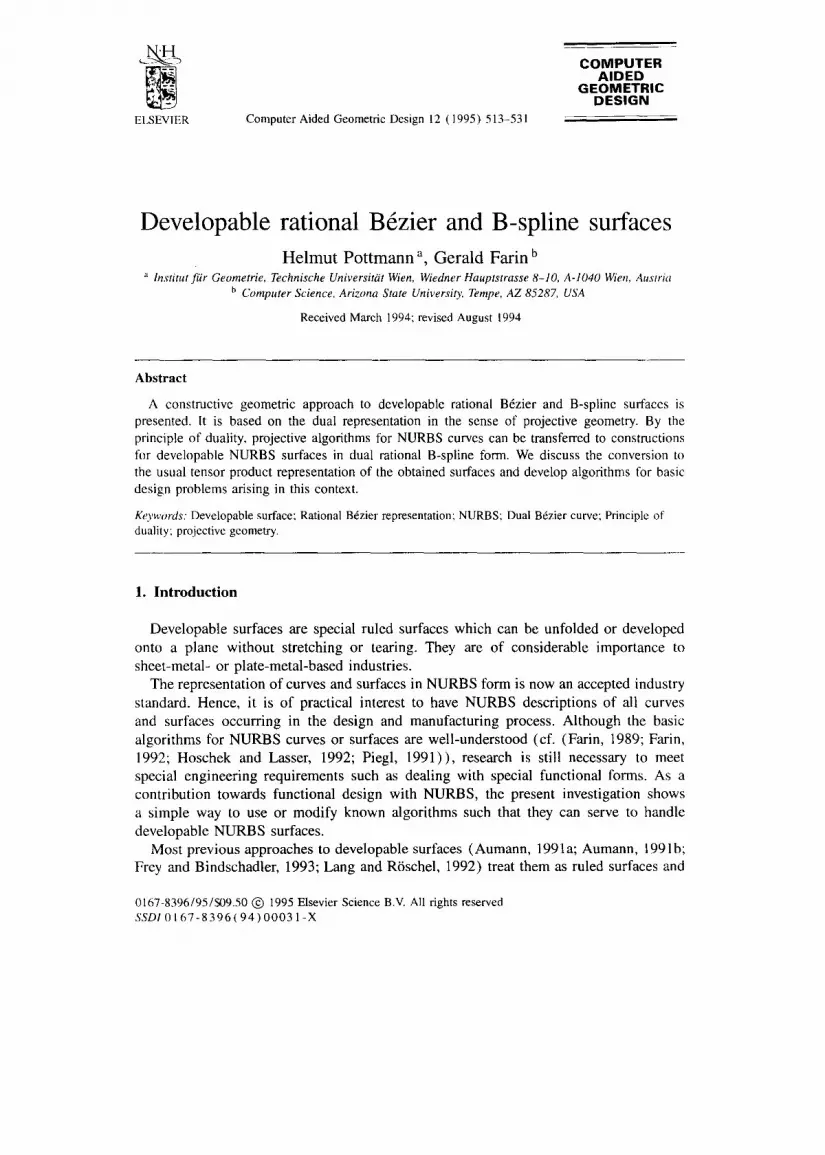
Fig. 4. Developable rational B6zier surface to the B6zier planes from Fig. 3. The frame planes F~ have been computed as planes of symmetry of R'B* ~ i i+1 '
B~ B~ //
/ /
z / /
/
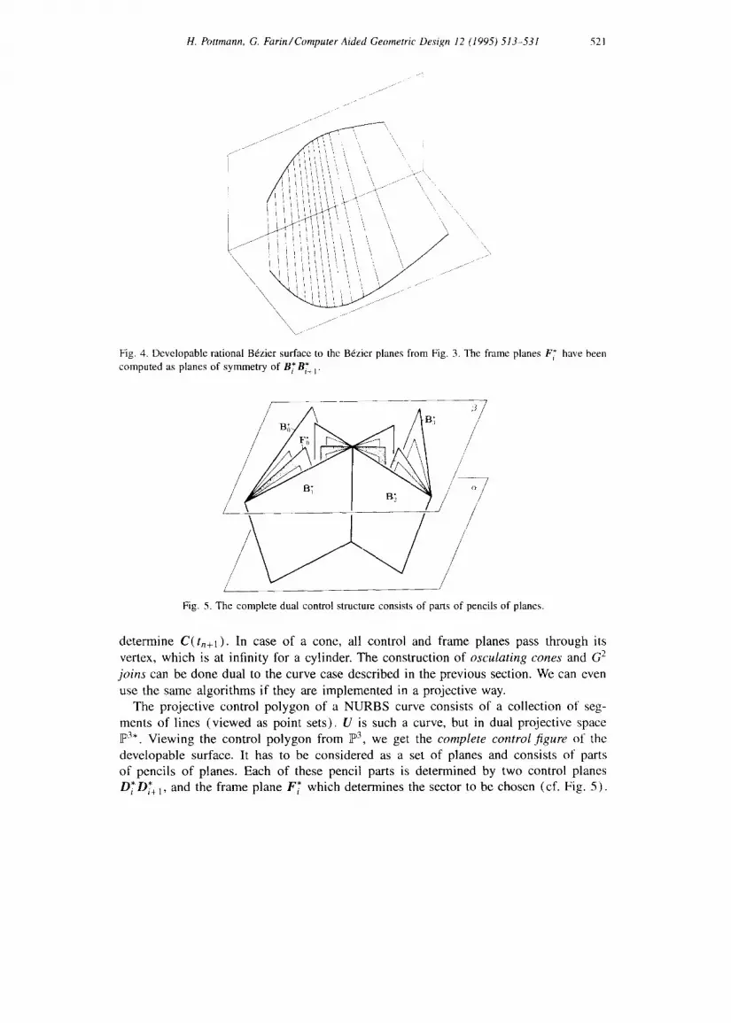
Fig. 5. The complete dual control structure consists of parts of pencils of planes.
determine C(tn+l). In case of a cone, all control and frame planes pass through its vertex, which is at infinity for a cylinder. The construction of osculating cones and G 2 joins can be done dual to the curve case described in the previous section. We can even use the same algorithms if they are implemented in a projective way.
The projective control polygon of a NURBS curve consists of a collection of seg- ments of lines (viewed as point sets). U is such a curve, but in dual projective space F 3.. Viewing the control polygon from ~3, we get the complete control figure of the developable surface. It has to be considered as a set of planes and consists of parts of pencils of planes. Each of these pencil parts is determined by two control planes D~D~.+I, and the frame plane F~ which determines the sector to be chosen (cf. Fig. 5).

522 H. Pottmann, G. Farin/Computer Aided Geometric Design 12 (1995) 513-531
The variation diminishing property now reads: For a developable NURBS surface, the number of tangent planes passing through a given point P does not exceed the number of the planes in the complete dual control structure which pass through P.
As a simple corollary, we get a condition for the convexity of a developable surface. Convexity of a tangent surface is only possible if we consider a part of the surface that does not contain points of the line of regression in its interior. Therefore, we restrict to the part which is parameterized over [ to, tn+l ] and lies in the intersection F of two half spaces (confined by planes a, /3) . Convexity then is equivalent to the property that through any point P E F there are at most 2 tangent planes. Applying the variation diminishing property, we get the convexity condition (cf. Fig. 5): The portion of a developable NURBS surface lying in the intersection F of two half spaces (confined
* * * F* "a,/3 are by planes a,/3) is a convex surface if the planes D o . . . . . Dn; Fo . . . . . n-l , support planes of a convex polyhedron 11 such that each intersection line of consecutive control planes D~ Di+ 1 contains an edge of H. This implies a convexity condition for planar dual NURBS curves. It is somewhat easier to handle than the convexity condition given by Hoschek (1983) which uses weights and is therefore dependent on the origin of the coordinate system.
In our implementation, the program provides defaults for the frame planes F~ as planes of symmetry of D* and Di+ 1 ( for example in Fig. 4). There are two such planes for each i; the selection can either be made interactively or may be based on the assumption of convexity and the above criterion. A pure user selection of the frame planes is only done for the fine tune of the desired shape. This is very similar to the familiar curve design situation where one might start with piecewise polynomial curves, i.e. take Fi as midpoint of OiDi+l .
5. Conversion to the tensor product form
In (Bodduluri and Ravani, 1992; Bodduluri and Ravani, 1993), the conversion from the dual form to a point representation is based on the line of regression and is therefore limited to tangent surfaces and also likely to fail numerically for surfaces which are very close to cylinders or cones. We now show that the dual descriptions (6) and (8) can easily be transformed into the usual rational tensor product representation without making use of the line of regression. For this, we choose two planes a and/3 as in the previous section and compute the intersection lines with the control and frame planes of the developable surface. In each of the two planes we introduce a planar projective coordinate system and in this system the intersection curves have representations of the form (6) and (8), but now D~', F* are line coordinate vectors E ~3. We do not introduce separate denotations for these vectors since there should be no confusion anyway. In each of the two planes we now derive the NURBS or B6zier representation of the intersection curves which are so far given in their dual representations.
Let us first consider the case of a B6zier surface (8), whose intersection with a also has the form (8), but with U(t) , B T, F* E R 3. With the algorithm of de Casteljau we obtain for each t two vectors Ul(t) , Ur(t),

H. Pottmann, G. Farin/Computer Aided Geometric Design 12 (1995) 513-531 523
m - 1 m - 1
U,(t) = ~-] Bm-'(t)B~, Ur(t) = ~_BT-'(t)B;+ I, (9) i--o j--o
representing lines through the curve point C(t) . Hence, the desired rational Bdzier representation is obtained as exterior product C(t) = Ut(t) A Ur(t),
2 m - 2
C(t) = Z B2km-2(t)Bl~' (10) k--0
with
l (m- (m- I)8; A By+,. (ll) ( y2) i y
i "=
We see that C(t) possesses the degree 2m - 2, the curve C is therefore in general a rational algebraic curve of order 2m - 2. Of course, there may occur a degree reduction which shall be discussed later for the important case m = 3.
Using the presented formulae, the intersection curves of the chosen planes with the developable surface possess B6zier points which shall be denoted a s Bi,o, i = 0 . . . . . 2 m - 2 and Bi, l, i = 0 , . . . , 2m - 2. For each parameter value t, we get points on both curves which belong to the same generator. This shows that the B~zier net of the developable rational surface patch confined by the planar intersections and the generators to the end points O, 1 of the parameter interval is formed by the array Bi,j, i = 0 . . . . . 2m - 2, j = O, 1 (Fig. 6). The patch is represented as rational ( 2 m - 2 , 1)-tensorproduct surface
2m--2 1 2m--2 1 S( t ,u) = ~ ~ B i ( t )Bj(u)Bi , j . (12)
i--o j--o
Note that the frame points of the two boundary curves a r e Fi,j = Bi,j + Bi+l,j. Each of the vector sequences Bi,0 and Bi,l is determined up to a common scalar multiple. Hence, the frame points on the lines Bi,oBi,1, namely Fi,o = Bi,o + Bi.1, depend on the chosen multiples. This influences the parameterization of the straight lines on the developable surface patch.
For the derivation of developable patches with nonplanar boundary curves we first consider a representation with planar curves Co, Cl and construct a trimmed patch. In the parameter domain we prescribe as preimages of the desired trim curves two polynomial curve segments, as graphs of the functions uo( t ) ,u l ( t ) , given in B6zier form. With well-known techniques for the composition of B6zier maps (DeRose et al., 1993), the B6zier representation of the resulting trim curves To, Tl on the surface S can be computed. Using degree elevation we can achieve that the B6zier representations of To, TI possess the same degree N. For a parameter value t, we get curve points on the same generator of S. Therefore we just have to connect corresponding B6zier points of To and T1 to obtain the control net of a developable rational (N, 1)-B6zier patch with boundaries To, TI.
The conversion of a dual NURBS surface to the usual NURBS tensor product form proceeds along the same lines as for B6zier surfaces. From the discussions above, we

524 H. Pottmann, G. Farin/Computer Aided Geometric Design 12 (1995) 513-531
B4,1 B3,1 B2~
B o , l ~
B 0 , 0 ~ Bt°
BL0 B2,0 B3,0 Fig. 6. B6zier net of the developable surface patch from Fig. 4.
already know that a NURBS surface (6) may be converted to a NURBS tensor product surface of degree (2m - 2, 1) over a modified knot vector 7 ~ in t-direction. The given surface possesses C m - m - l continuity at a knot tk with multiplicity/zk in the original knot vector T. Then the corresponding knot in the new knot vector T must possess multiplicity/2k = m - 1 +/Zk. In order to obtain the counterparts to formulae (10) and ( l l ) , the well-known product formulae for B-spline functions ((M~rken, 1991)) may be used. We omit the details, but describe another approach: Compute the dual B6zier representation for each segment using well-known algorithms for the B6zier points of a B-spline curve (Farin, 1992; Hoschek and Lasser, 1992). For each of the intersection curves with planes a, fl, use (10) and ( 11 ) to compute the B6zier representation. The conversion to NURBS form over the knot vector 7 ~ again can be based on well-known algorithms, for example on the polar forms of the segments (Seidel, 1989).
Remark 5.1. Eqs. (10 ) - (12 ) and the given extension to nonplanar boundaries provide an explicit solution of a system of nonlinear equations derived by Lang and R6schel (Lang and R6schel, 1992) as characterization of developable (n, 1) B6zier surfaces.
Remark 5.2. The polar form or blossom proved to be an effective tool in connection with the B6zier and B-spline method (cf. e.g. (Hoschek and Lasser, 1992)). Hence, it may be desirable to compute the polar form P(ul . . . . . U2m-2) of the curve C. This can be done directly with the polar form P*(Ul . . . . . urn) of the dual representation as follows. The polar forms PT, P~ of Ut, Ur are obtained by inserting the end points of the parameter interval, i.e. um= 0 or Um = 1, respectively, into P*. The vector product P~ ( ul . . . . . urn- 1 ) A P~ (urn . . . . . Uem-2 ) is multiaffine, reduces to Ut A Ur on its diagonal, but is in general not symmetric. It just has to be symmetrized (Barry, 1992) to get the desired polar form:
1 . e ( u l ..... U2m-2) - Z el (nil ..... Uim-I ) /~ e r (ui . . . . . . Ui2m Z )"
(il,...,i2m-2)Cl (13)

H. Pottmann, G. Farin/Computer Aided Geometric Design 12 (1995) 513-531 525
Here, 1 consists of all partitions of the set { 1 . . . . . 2m - 2} into two sets {i~ . . . . . im-1 } and {i . . . . . . . i2m-2} with m - 1 elements. Since we are using homogeneous coordinates, the normalization factor in (13) may be omitted.
Let us now turn to the important example of developable surfaces of class m = 3. Eq. (10) shows the well-known fact that the planar intersections are in general quartic curves and with (12) the surfaces S are representable as B6zier surfaces of degree (4, 1 ) (Fig. 6),. However, choosing special planes a , fl, the degree can be reduced. If each plane contains a generator g,~,g~ of S without being tangent to S, we get cubic boundary curves and a (3, 1) representation.
A developable surface is not only the envelope of its osculating planes; if it is not a cone or a cylinder, it is also formed by all tangents to the regression curve. For a tangent surface of class 3, the regression curve is a twisted cubic. Keeping in mind that the tangent T ( t ) to a curve B(t ) is formed by T(t) = B( t ) /~ B( t ) , 1 we can write every point of our developable surface as
S(s, t) = B( t ) + sB(t ) . (14)
As s and t trace out all reals, S(s, t) traces out the surface. For the particular case of s ~ ~ , we compute D(~x~, t) = B(t ) . In words: the derivative (or hodograph) of the edge of regression is a curve on the developable. A cubic edge of regression has a quadratic derivative, which is a conic. Thus we have found a conic that lies completely on the developable.
For t --~ c~, this conic touches the edge of regression--easi ly seen by the use of blossoms: if B[ r, s, t] denotes the blossom of a cubic, then its derivative has the blossom expression B [ ~ , t, t] , see (Farin, 1994). For t = oo, we obtain B I e r , c~, oo], a point on the cubic.
It thus seems as if we have found a special conic on our developable surface S. However, it is not at all special: just consider a reparametrization of B by means of a M6bius transformation. It will not change the shape of the cubic nor that of the developable, yet it will produce a new point where the new parameter tends to infinity. Also, it will produce a new derivative conic. Thus for each new parametrization, there will be a new conic on the surface, and we have found the classical result that a tangent surface S of class 3 is covered by a one-parameter family of conics. They lie in the tangent planes of S (osculating planes of the regression curve B).
Let us now consider two of these conics, C l ( t ) and C2(t), say. Each of them, illustrated in Fig. 7, is given by a set of control points {Ai} and {Ci}, respectively, plus a shoulder tangent each (or, alternatively, two frame points each).
Keeping in mind that the two projective B6zier curves with control polygons B0 . . . . . Bn and Bo,aBl . . . . . otnBn are related by a M6bius transformation, we see that A i =
ce i+1 B i + l - o l i n i and Ci = f l i + l B i + l - f l i B i for two reparametrization constants a and ft. Thu,; the cross ratios formed by four points on the edges of B's control polygon are all equal:
I Note that in projective geometry, the derivative B(t) is a point!

526 H. Pottmann, G. Farin/Computer Aided Geometric Design 12 (1995) 513-531
Co A0
B1
~C1
B0
Fig. 7. Conics on developables: two conic segments together with the edge of regression.
- i = 0 , 1 2. ( 1 5 ) cross ratio( Bi, Ai , Ci, Bi+l ) f l - ol'
We can now attack the question: given two arbitrary conic segments C1 (t) and C2(t), can we find a cubic developable surface S(s, t) of the form
S(s , t ) = (1 - s)Cl( t ) + sC2(t)? (16)
In general, the answer is negative, as Fig. 7 illustrates: we would have to find S's edge of regression B(t) . Then the four points Ao, Co, AI,C1 have to be coplanar, namely they have to be in B's osculating plane at B0, spanned by B0, Bn, B2. Similarly, the four points A1, C1, A2, C2 must lie in B's osculating plane at B3.
Suppose then that our two conics meet these coplanarity conditions. Our first aim is to find a control polygon for the edge of regression B(t) . We immediately find B1 as the intersection of the lines through A0, Co and AI, Cz and B2 as the intersection of the two lines through AI, Cn and A2, C2.
Next, we compute the cross ratio formed by the four points B1, B2, A1, C1. We can then find B0 and B3 from the cross ratio condition (15), thus having found the desired control polygon.
Each of our input conics lies in a plane, and the intersection of these two planes must be tangent to either conic. This is thus another condition for the conics. In case it is not met, the conics can be modified such that they both possess the required tangent: we simply have to adjust the weights accordingly (see, e.g., (Farin, 1992, p. 243)). Note that this process is of an approximative nature, in that the original input curves are distorted.
This case where both boundary planes are tangent planes of the developable patch, is of particular interest. The curved boundaries Co C ~, Cl C fl are conics and the surface can be represented as a (2, 1)-surface (cf. Fig. 8). We will now treat the problem to design such developable patches without the help of the regression curve. The conics Co, C1 touch the line a of intersection of their planes ot and fl at points A0, At. They are different if we assume that the given surface is not a degree elevated quadratic cone (cf. Section 2). The simple geometry of the control net can be directly constructed

H. Pottmann, G. Farin / Computer Aided Geometric Design 12 (1995) 513-531 527
a / ~ [ : F o , L = - - -
d d / ) . . . . . , ....
_ 3:,o /
Fig. 8. The geometry of developable rational B6zier patches of degree (2, 1 ).
without the use of the dual form. We can prescribe a,/3 and the generators and tangent planes to t = 0 and t = 1. This yields all B6zier points. Then the conics Co and Ct are determined since they have to touch a. Computing a plane ~- touching both Co and C~ and intersecting it with the control polygon lines gives the essential frame points and allows us to correctly normalize the v e c t o r s Bi,j. The proof of this construction of developable (2, 1)-surfaces: The algorithm of de Casteljau applied to Co and C1 for the same parameter value t yields intersecting tangents because of the well-known projective generation of conics (cf. the "four tangent theorem" (Farin, 1989)). These tangents span the tangent plane of S along the generator to the parameter t.
It should be noted that this direct construction of the B6zier net of a developable (2, 1 )-surface has the following advantage over the use of the edge of regression: it also works, if the patch is part of a quadratic cone.
The maximal algebraic order of a rational (2, 1 )-surface is 4. Using well-known results of algebraic geometry, we conclude that the rational developable (2, 1)-surfaces are of class ~< 3. This shows that the given construction covers all developable (2, 1 )- surfaces. It provides the geometric background of formulae derived by Lang and R6schel (1992).
For parallel planes c~,/3, the line a is at infinity and we get parabolas as boundary curves (cf. Fig. 9). However, note that only one parabola, say Co, may be parameterized as quadratic polynomial curve (with frame points as midpoints of the control polygon legs). The frame points of the other parabola C1 have to be computed such that their connection is parallel to F0,0Fi,0 (Bo.oB:,o). For this we can at first parameterize CI as polynomial curve C~' and then compute the desired tangent Fo,lFl,1 with the linear hodograph of C p (Fig. 9).
6. Interpolation and approximation algorithms
Let us now consider the following interpolation problem: Given curves Co, CI in planes a and fl, respectively, connect the two curves with a developable surface S. As

528 H. Pottmann, G. Farin/ Computer Aided Geometric Design 12 (1995) 513-531
B°'l I B0,0
BI,1
Fig. 9. Control points of a rational (2, 1 )-surface patch confined by parabolas Co, Cl in parallel planes.
Fig. 10. Osculating quadratic cone of the developable surface connecting two planar curves Co, Ct.
mentioned in Section 2, even for rational curves Ci an interpolating rational surface S will in general not exist. Therefore we have to approximate the surface S with developable rational B6zier patches.
The construction of S is well-known: S is the envelope of all planes ~- touching the curves Co and Ct (cf. Fig. 10). The generators g simply connect corresponding touching points P0 and P1. In order to get a smooth surface fitting both curves, some compatibili ty conditions are required: corresponding end tangents have to intersect and inflection points may occur on Ci only pairwise, such that corresponding inflection tangents are intersecting. I f the intersection property of end tangents is not fulfilled, we still obtain a G 1 surface by appending conical surfaces (Fig. 10). However, the resulting surface is in general not G 2.
An osculating quadratic cone F of S along a generator g may be constructed as follows: Select an arbitrary point A on the intersection a of a and fl (but not in T). Then compute those osculating conics Ki of Ci at Pi which touch a at A. The connecting developable surface of K0 and K1 is the desired quadratic cone with easily computable
H. Pottmann, G. FarinlComputer Aided Geometric Design 12 (1995) 513-531 529
V/////lt /I" / / / / / / / .~ ~, ~//L///,I
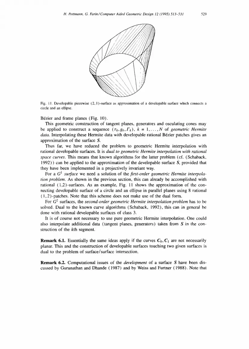
Fig. l 1. Developable piecewise (2, 1 )-surface as approximation of a developable surface which connects a circle and an ellipse.
B6zier and frame planes (Fig. 10). This geometric construction of tangent planes, generators and osculating cones may
be applied to construct a sequence (7"k,gk, Fk) , k = 1 . . . . . N of geometric Hermite data. Interpolating these Hermite data with developable rational B6zier patches gives an approximation of the surface S.
Thus far, we have reduced the problem to geometric Hermite interpolation with rational developable surfaces. It is dual to geometric Hermite interpolation with rational space curves. This means that known algorithms for the latter problem (cf. (Schaback, 1992) ) can be applied to the approximation of the developable surface S, provided that they have been implemented in a projectively invariant way.
For a G 1 surface we need a solution of the first-order geometric Hermite interpola- tion problem. As shown in the previous section, this can already be accomplished with rational (1,2)-surfaces. As an example, Fig. 11 shows the approximation of the con- necting developable surface of a circle and an ellipse in parallel planes using 8 rational ( 1,2)-patches. Note that this scheme does not make use of the dual form.
For G 2 surfaces, the second-order geometric Hermite interpolation problem has to be solved. Dual to the known curve algorithms (Schaback, 1992), this can in general be done with rational developable surfaces of class 3.
It is of course not necessary to use pure geometric Hermite interpolation. One could also interpolate additional data (tangent planes, generators) taken from S in the con- struction of the kth segment.
Remark 6.1. Essentially the same ideas apply if the curves Co, C1 are not necessarily planar. This and the construction of developable surfaces touching two given surfaces is dual to the problem of surface/surface intersection.
Remark 6.2. Computational issues of the development of a surface S have been dis- cussed by Gurunathan and Dhande (1987) and by Weiss and Furtner (1988). Note that
530 H. Pottmann, G. Farin/Computer Aided Geometric Design 12 (1995) 513-531
the deve lopment of a developable BEzier patch will in general not yield rational B6zier curves as images of the boundary curves. The approximate development of skew ruled surfaces is the topic of a paper by A u m a n n (1989) .
7. Conclusion
A s imple and effective way to inc lude developable surfaces into a free-form environ-
men t based on N U R B S has been presented. It shows that the dual B6zier or B-spl ine
form has advantages in the present context and that some less user fr iendly aspects o f this technique may be "hidden" in the system. The approach also demonstrates that
projective a lgori thms may increase the flexibility of geometric design software.
References
Aumann, G. (1989), Approximate development of skew ruled surfaces, Comput. & Graph. 13, 361-366. Aumann, G. (1991a), Interpolation with developable B6zier patches, Computure Aided Geometric Design 8,
409-420. Aumann, G. (1991b), Zum Entwurf abwickelbarer BEzier-Fl~ichen, in: Proc. 3rd Congress of Geometry,
Saloniki 1991, 49-60. Barry, P. (1992), Symmetrizing multiaffine polynomials, in: Lyche, T. and Schumaker, L.L., eds., Mathematical
Methods in CAGD II, Academic Press, New York, 1-7. Bodduluri, R.M.C. and Ravani, B. (1992), Geometric design and fabrication of developable surfaces, ASME
Adv. Design Autom. 2, 243-250. Bodduluri, R.M.C. and Ravani, B. (1993), Design of developable surfaces using duality between plane and
point geometries, Computer-Aided Design 25, 621-632. DeRose, T.D. (1991), Rational BEzier curves and surfaces on projective domains, in: Farin, G., ed., NURBS
for Curve and Surface Design, SLAM, Philadelphia, PA, 35-45. DeRose, T.D., Goldman, R., Hagen, H. and Mann, S. (1993), Functional composition algorithms via
blossoming, ACM Trans. Graph. 12. Farin, G. (1983), Algorithms for rational B6zier curves, Computer-Aided Design 15, 73-77. Farin, G. (1989), Rational curves and surfaces, in: Lyche, T. and Schumaker, L.L., eds., MathematicalMethods
in CAGD, Academic Press, Boston, MA, 215-238. Farin, G. (1992), Curves and Surfaces for Computer Aided Geometric Design, Academic Press, Boston, MA,
3rd ed. Farin, G. and Worsey, A. (1991), Reparameterization and degree elevation for rational B~zier curves, in:
Farin, G., ed., NURBSfor Curve and Surface Design, SIAM, Philadelphia, PA, 47-57. Farin, G. (1994), NURBSfor Rational Curve and Surface Design, A K Peters, Wellesley, MA. Frey, W.H. and Bindschadler, D. (1993), Computer aided design of a class of developable B6zier surfaces,
General Motors R&D Publication 8057. Geise, G. and Jiittler, B. (1993), A geometrical approach to curvature continuous joints of rational curves,
Computer Aided Geometric Design 10, 109-122. Goetz, A. (1970), Introduction to Differential Geometry, Addison-Wesley, Reading, MA. Goodman, T.N.T. ( 1991 ), Joining rational curves smoothly, Computer Aided Geometric Design 8, 443-464. Gurunathan, B. and Dhande, S.G. (1987), Algorithms for development of certain classes of ruled surfaces,
Comput. & Graph. 11, 105-112. Herman, I. (1991), The Use of Projective Geometry in Computer Graphics, Lecture Notes in Computer
Science, Vol. 564, Springer, Berlin. Hoschek, J. (1983), Dual B6zier curves and surfaces, in: Barnhill, R.E. and Boehm, W., eds., Surfaces in
Computer Aided Geometric Design, North-Holland, Amsterdam, 147-156.

H. Pottmann, G. Farin/Computer Aided Geometric Design 12 (1995) 513-531 531
Hoschek, .1. and Lasser, D. (1992), Grundlagen der geometrischen Datenverarbeitung, Teubner, Stuttgart, 2rid ed.
Hoschek, J. and Pottmann, H. (1995), Interpolation and approximation with developable B-spline surfaces, in: Daehlen, M., Lyche, T. and Schumaker, L.L., eds., Mathematical Methods in CAGD IlL
Jiittler, B. (1992), Die Konstruktive Geometrie der rationalen Brzierkurven und -fl~ichen, Diplomarbeit, TH Darmstadt.
Lang, J. and Rrschel, O. (1992), Developable (1, n)-Brzier surfaces, Computer Aided Geometric Design 9, 291 -.298.
MCrken, K. ( 1991 ), Some identities for products and degree raising of splines, Construct. Approx. 7, 195-208. Penna, M. and Patterson, R. (1986), Projective Geometry and its Application to Computer Graphics, Prentice-
Hall, Englewood Cliffs, NJ, 1986. Piegl, L. (1991), On NURBS: A survey, IEEE Comput. Graph. Appl. 11, 55-71. Pottmann, H. (1989), Projectively invariant classes of geometric continuity for CAGD, Computer Aided
Geometric Design 6, 307-321. Pottmann, H. (1991a), A projective algorithm for curvature continuous rational splines, in: Farin, G., ed.,
NURBS fi~r Curve and Surface Design, SIAM, Philadelphia, PA, 141-148. Pottmann, H. (1991b), Locally controllable conic splines with curvature continuity, ACM Trans. Graph. 10,
366-377. Pottmann, H. (1993), The geometry of Tchebycheffian splines, Computer Aided Geometric Design 10, 181
210. Schaback, R. (1992), Rational geometric curve interpolation, in: Lyche, T. and Schumaker, L.L, eds.,
Mathematical Methods in CAGD 1I, Academic Press, Boston, MA, 517-535. Seidel, H.P. (1989), A new multiaffine approach to B-splines, Computer Aided Geometric Design 6, 23 32. Walker, R. (1950), Algebraic Curves, Springer, New York. Weiss, G. and Furtner, P. (1988), Computer-aided treatment of developable surfaces, Comput. & Graph. 12,
39 51.