analysis of structural layouts of geodesic dome ... - mdpi
TRANSCRIPT
�����������������
Citation: Kolpakov, A.; Dolgov, O.;
Korolskiy, V.; Popov, S.; Anchutin, V.;
Zykov, V. Analysis of Structural
Layouts of Geodesic Dome Structures
with Bar Filler Considering Air
Transportation. Buildings 2022, 12,
242. https://doi.org/10.3390/
buildings12020242
Academic Editor: Pierfrancesco
De Paola
Received: 21 January 2022
Accepted: 16 February 2022
Published: 19 February 2022
Publisher’s Note: MDPI stays neutral
with regard to jurisdictional claims in
published maps and institutional affil-
iations.
Copyright: © 2022 by the authors.
Licensee MDPI, Basel, Switzerland.
This article is an open access article
distributed under the terms and
conditions of the Creative Commons
Attribution (CC BY) license (https://
creativecommons.org/licenses/by/
4.0/).
buildings
Article
Analysis of Structural Layouts of Geodesic Dome Structureswith Bar Filler Considering Air TransportationAndrey Kolpakov 1,* , Oleg Dolgov 1, Vladislav Korolskiy 1, Semen Popov 1, Vyacheslav Anchutin 1
and Vadim Zykov 2
1 Moscow Aviation Institute, National Research University, Volokolamskoe Shosse, 4, 125993 Moscow,Moscow Region, Russia; [email protected] (O.D.); [email protected] (V.K.); [email protected] (S.P.);[email protected] (V.A.)
2 All-Russian Research Institute for Fire Protection of the Ministry of the Russian Federation for Civil Defence,Emergencies and Elimination of Consequences of Natural Disasters, mkr. VNIIPO, 12,143903 Balashikha, Moscow Region, Russia; [email protected]
* Correspondence: [email protected]
Abstract: The results are presented from a study of three-layer geodesic dome structures with barfillers under their own weight. An algorithm was developed for selecting the type of structurallayout used and the reference parameters chosen in terms of the technological, strength, and weightcharacteristics. The results of this analysis aim to make it easier for designers to determine theoptimal reference parameters in the initial stage of the designing of geodetic hemispherical domestructures, the construction of which is planned to be carried out in remote areas with harsh climaticconditions. Due to the lack of sufficient ground transport infrastructure, cargo delivery to theseregions is currently possible only with the help of air transport. The importance of this study restson the lack of adequate methods for the determination of the reference parameters for geodesichemispherical dome structures at an early stage of design. In particular, it is common for the issuesregarding the transportation of structural elements as well as those that involve ensuring the strengthand the technological characteristics of the structure to not be considered simultaneously. This studyowes its relevance to the rapid development of the uninhabited territories of the Russian Federationin the context of the global ecological crisis caused by anthropogenic impact on the environment.
Keywords: geodesic dome; technological design; structural layout; finite element method; stress-strain state; weight analysis
1. Introduction
This article is a continuation of the research cycle devoted to the geodesic domestructures featured in a previous article that was published in the journal Quality and Life inDecember 2021 [1].
The Russian Federation ranks first in the world in terms of its area, which is 17,130,000 km2.At the same time, only about 12% of this area is mastered, while there are no traces ofhuman activity in the rest of the territory. As part of the “Strategy for the long-termdevelopment of the Russian Federation with low greenhouse gas emissions until 2050”project implementation, by 2030, there is a plan to reach a level of carbon emissions equalto 67% of 1990 levels, and by 2050, to decrease emissions further to 20% of 1990 levels.
At the same time, there is a plan to build new cities in Siberia, which was officiallyannounced by the Minister of Defense of the Russian Federation, S.K. Shoigu, on 5 August2021. According to this statement, three scientific and industrial centers with a populationof three hundred thousand to one million people are planned to be built in Siberia betweenBratsk and Krasnoyarsk, as well as in the area of Kansk and Lesosibirsk.
The creation of settlements in the Russian Federation is also considered within theframework of the comprehensive scientific and technical program “Connectivity of the
Buildings 2022, 12, 242. https://doi.org/10.3390/buildings12020242 https://www.mdpi.com/journal/buildings
Buildings 2022, 12, 242 2 of 12
territory of the Russian Federation”, selected by the Council for the Priority of Scientificand Technological Development.
In the context of these two initiatives, the general task of ensuring the ecological preser-vation of the territories not affected by anthropogenic impact along with their developmentis highlighted.
This area has a sharply continental climate, which can be characterized by a long winterwith a temperature drop as low as −50 ◦C and a short, hot summer with a temperaturehigh of +30 ◦C. The hot season in the nearest cities lasts from 240 to 250 days a year, andin summer, there is a high load on the power grid because of the high energy costs of airconditioning. Thus, one of the steps necessary to achieve this task is to increase the energyefficiency of the capital buildings. Salosina, Alifanov, and Nenerokomov in their work [2]researched high-porosity open-cell foam in terms of its levels of thermal protection.
It is known that dome buildings in such climatic conditions have up to a one and a halftimes higher level of energy efficiency when compared to classical rectangular buildings.In the work of Pogosyan, Strelets, and Vladimirova [3], the communication gap in thespatial development of the country is highlighted; transport and electronic accessibility islimited. However, in the work of Lutovinov, Pogosyqn, and Lupyan [4], a solution to thecommunication gap is proposed.
The use of dome geodesic structures can provide an alternative solution to this prob-lem, since this can simplify the rapid construction of reliable long-term shelters without theneed for special construction equipment because of the added possibility of transportingthe assembly elements by air to areas that lack a developed transport infrastructure.
At the same time, reducing the mass of such structures will also significantly increasethe maximum range of air transportation. The problems involved in the increasing of themaximum range of aircraft were previously dealt with by Dolgov and Aruvelli [5].
Additionally, another advantage of these kinds of structures is their high stabilityin the event of natural disasters such as earthquakes and hurricanes because of theirgeometric shape.
All of these factors taken together allow us to speak about the relevance of a deeperstudy of dome structures.
2. Literature Review
A large number of domestic and foreign scientists are currently engaged in researchon the strength and the functional characteristics of dome structures. The current researchwas inspired by the work of the following authors:
• Gritsenko, who was engaged in research on the history of the lattice geodesic dome’screation [6].
• Maria, Esipova, Vintural, and Shabanov, who, in their works, investigated the possibil-ity of using geodesic domes in various economical fields [7–10].
• Granev, Kodysh, Mamin, Bobrov, Reutsu, and Kuznichenko, who studied the existinglattice structures in terms of their reliability and manufacturability [11].
• Gorkoltseva, Demidov, Olshanchenko, Shiryaeva, Romanovich, Shanko, Shishkina,and Kaloshina in their works [12–16] investigated the advantages of dome structuresin comparison to those of classical buildings, according to the criteria of energyefficiency, weight, materials cost, air exchange, seismic resistance, wind resistance, andenvironmental friendliness.
• Zhuravlev, Glushko, and Lakhov in their works [17–20] studied the strength character-istics of geodetic structural layouts.
• Lakhova, Gorkoltseva, Miryaeva, and Pilarska in their works [21–24] described variousways of designing lattice domes.
• Chepurnenko conducted a comparative analysis of various designs of wavy domes inorder to identify their advantages and disadvantages [25].
Buildings 2022, 12, 242 3 of 12
• Barbieri, Machado, Barbieri, Lima, Rossot, Guan, Virgin, and Helm calculated thestrength characteristics of dome structures and compared them with the results fromthe experimental data [26,27].
• Jihong, Mingfei, Kaveh, and Talatahari were engaged in the study of dome structuresin terms of their strength characteristics, as well as tasks related to design optimiza-tion [28,29].
Such a wide interest in the subject of the study, as well as the lack of a comparativeanalysis of the varieties of geodesic hemispherical three-layered domes, justifies the rele-vance of the study. In regions with a mild climate, a single-layer structural layout (Figure 1)is usually used. Most often, natural materials are used in the structural elements, namely,the structural frame of the dome structure is made of wooden boards. In such a case, thegeometric characteristics of the thermal insulation material are always limited by the woodblanks’ parameters.
Buildings 2022, 12, x FOR PEER REVIEW 3 of 13
• Lakhova, Gorkoltseva, Miryaeva, and Pilarska in their works [21–24] described
various ways of designing lattice domes.
• Chepurnenko conducted a comparative analysis of various designs of wavy domes
in order to identify their advantages and disadvantages [25].
• Barbieri, Machado, Barbieri, Lima, Rossot, Guan, Virgin, and Helm calculated the
strength characteristics of dome structures and compared them with the results from
the experimental data [26,27].
• Jihong, Mingfei, Kaveh, and Talatahari were engaged in the study of dome struc-
tures in terms of their strength characteristics, as well as tasks related to design op-
timization [28,29].
Such a wide interest in the subject of the study, as well as the lack of a comparative
analysis of the varieties of geodesic hemispherical three-layered domes, justifies the rel-
evance of the study. In regions with a mild climate, a single-layer structural layout (Fig-
ure 1) is usually used. Most often, natural materials are used in the structural elements,
namely, the structural frame of the dome structure is made of wooden boards. In such a
case, the geometric characteristics of the thermal insulation material are always limited
by the wood blanks’ parameters.
Figure 1. Single-layered dome structure without thermal insulation.
As a rule, standard rectangular boards are chosen as the material of structural frame
elements (Figure 2), which have the following geometric characteristics “L”—length,
“h”—height, and “b”—width.
Figure 2. Geometric characteristics of a rectangular board.
Since, in order to achieve greater structural strength, the boards are positioned in
such a way that the narrow and long side “J” looks out of the structure, there is a limita-
Figure 1. Single-layered dome structure without thermal insulation.
As a rule, standard rectangular boards are chosen as the material of structural frameelements (Figure 2), which have the following geometric characteristics “L”—length, “h”—height, and “b”—width.
Buildings 2022, 12, x FOR PEER REVIEW 3 of 13
• Lakhova, Gorkoltseva, Miryaeva, and Pilarska in their works [21–24] described
various ways of designing lattice domes.
• Chepurnenko conducted a comparative analysis of various designs of wavy domes
in order to identify their advantages and disadvantages [25].
• Barbieri, Machado, Barbieri, Lima, Rossot, Guan, Virgin, and Helm calculated the
strength characteristics of dome structures and compared them with the results from
the experimental data [26,27].
• Jihong, Mingfei, Kaveh, and Talatahari were engaged in the study of dome struc-
tures in terms of their strength characteristics, as well as tasks related to design op-
timization [28,29].
Such a wide interest in the subject of the study, as well as the lack of a comparative
analysis of the varieties of geodesic hemispherical three-layered domes, justifies the rel-
evance of the study. In regions with a mild climate, a single-layer structural layout (Fig-
ure 1) is usually used. Most often, natural materials are used in the structural elements,
namely, the structural frame of the dome structure is made of wooden boards. In such a
case, the geometric characteristics of the thermal insulation material are always limited
by the wood blanks’ parameters.
Figure 1. Single-layered dome structure without thermal insulation.
As a rule, standard rectangular boards are chosen as the material of structural frame
elements (Figure 2), which have the following geometric characteristics “L”—length,
“h”—height, and “b”—width.
Figure 2. Geometric characteristics of a rectangular board.
Since, in order to achieve greater structural strength, the boards are positioned in
such a way that the narrow and long side “J” looks out of the structure, there is a limita-
Figure 2. Geometric characteristics of a rectangular board.
Since, in order to achieve greater structural strength, the boards are positioned in sucha way that the narrow and long side “J” looks out of the structure, there is a limitation onthe thickness of the thermal insulation material layer. The layer thickness cannot exceedthe width “b” of the boards used because it is necessary to install the inner skin to fix it. Atthe same time, the use of very wide boards has the potential to significantly increase thecost and mass characteristics of the structure, while the use of more affordable materialswith smaller overall dimensions is more effective.

Buildings 2022, 12, 242 4 of 12
In regions with a harsh climate, where it is necessary to increase the distance betweenthe external and the internal skin of the dome, multilayer structures are used for layingthermal insulation material, in which sectional structures are used as structural elementsinstead of conventional boards (Figure 3).
Buildings 2022, 12, x FOR PEER REVIEW 4 of 13
tion on the thickness of the thermal insulation material layer. The layer thickness cannot
exceed the width “b” of the boards used because it is necessary to install the inner skin to
fix it. At the same time, the use of very wide boards has the potential to significantly in-
crease the cost and mass characteristics of the structure, while the use of more affordable
materials with smaller overall dimensions is more effective.
In regions with a harsh climate, where it is necessary to increase the distance be-
tween the external and the internal skin of the dome, multilayer structures are used for
laying thermal insulation material, in which sectional structures are used as structural
elements instead of conventional boards (Figure 3).
Figure 3. Geometrical characteristics of the sectional structural element.
In this case, the elements of the inner and outer layers of the dome “X” are connected
using the structural elements in “Y”, which keep the layers at a certain distance, thereby
providing the necessary thickness for holding a thicker layer of thermal insulation mate-
rial. An example of such a structural layout is shown in Figure 4.
Figure 4. Two-layer geodesic dome structure.
The disadvantage of using such modular structural elements is their low rigidity,
owing to the fact that they are a set of rectangles that have four sides. It is possible to in-
crease the rigidity by using a structural layout consisting of triangular elements. There
are two variants of geodesic dome structures structural layouts that consist only of tri-
angular elements. They are known and used in many countries.
Figure 3. Geometrical characteristics of the sectional structural element.
In this case, the elements of the inner and outer layers of the dome “X” are connectedusing the structural elements in “Y”, which keep the layers at a certain distance, therebyproviding the necessary thickness for holding a thicker layer of thermal insulation material.An example of such a structural layout is shown in Figure 4.
Buildings 2022, 12, x FOR PEER REVIEW 4 of 13
tion on the thickness of the thermal insulation material layer. The layer thickness cannot
exceed the width “b” of the boards used because it is necessary to install the inner skin to
fix it. At the same time, the use of very wide boards has the potential to significantly in-
crease the cost and mass characteristics of the structure, while the use of more affordable
materials with smaller overall dimensions is more effective.
In regions with a harsh climate, where it is necessary to increase the distance be-
tween the external and the internal skin of the dome, multilayer structures are used for
laying thermal insulation material, in which sectional structures are used as structural
elements instead of conventional boards (Figure 3).
Figure 3. Geometrical characteristics of the sectional structural element.
In this case, the elements of the inner and outer layers of the dome “X” are connected
using the structural elements in “Y”, which keep the layers at a certain distance, thereby
providing the necessary thickness for holding a thicker layer of thermal insulation mate-
rial. An example of such a structural layout is shown in Figure 4.
Figure 4. Two-layer geodesic dome structure.
The disadvantage of using such modular structural elements is their low rigidity,
owing to the fact that they are a set of rectangles that have four sides. It is possible to in-
crease the rigidity by using a structural layout consisting of triangular elements. There
are two variants of geodesic dome structures structural layouts that consist only of tri-
angular elements. They are known and used in many countries.
Figure 4. Two-layer geodesic dome structure.
The disadvantage of using such modular structural elements is their low rigidity,owing to the fact that they are a set of rectangles that have four sides. It is possible toincrease the rigidity by using a structural layout consisting of triangular elements. There aretwo variants of geodesic dome structures structural layouts that consist only of triangularelements. They are known and used in many countries.
3. Materials and Methods
To determine the advantages and the disadvantages of two-layer hemisphericalgeodesic dome structural layouts with a triangular structure, a series of strength cal-culations for different variants using the finite element method was carried out.
The finite element method makes it possible to analyze the stress-strain state ofstructures with a high degree of accuracy. Aabid, Zakuan, Khan, and Ibrahim [30] claimedthat this method allows the analysis of the structures of different scales, which makes thismethod universal.

Buildings 2022, 12, 242 5 of 12
The strength and weight parameters were jointly considered, depending on the amountof change in the thickness of the bar filler and the number of structural elements.
Four variants of the geodesic domes’ structural layout were considered. The structuresunder consideration were spatial three-dimensional three-layer structures consisting ofload-bearing layers in the form of polygonal grids and a bar filler. The structural layoutsunder consideration were divided into two types, which were further divided into twovariants. In the first type, both bearing layers are polygonal grids consisting of triangles(Figure 5), and in the second type, the first layer consists of triangles and the second ofhexagons (Figure 6). In addition to hexagons, pentagons were also present in the model,since this condition was necessary for the closure of the dome structure at the pole.
Buildings 2022, 12, x FOR PEER REVIEW 5 of 13
3. Materials and Methods
To determine the advantages and the disadvantages of two-layer hemispherical
geodesic dome structural layouts with a triangular structure, a series of strength calcula-
tions for different variants using the finite element method was carried out.
The finite element method makes it possible to analyze the stress-strain state of
structures with a high degree of accuracy. Aabid, Zakuan, Khan, and Ibrahim [30]
claimed that this method allows the analysis of the structures of different scales, which
makes this method universal.
The strength and weight parameters were jointly considered, depending on the
amount of change in the thickness of the bar filler and the number of structural elements.
Four variants of the geodesic domes’ structural layout were considered. The struc-
tures under consideration were spatial three-dimensional three-layer structures consist-
ing of load-bearing layers in the form of polygonal grids and a bar filler. The structural
layouts under consideration were divided into two types, which were further divided
into two variants. In the first type, both bearing layers are polygonal grids consisting of
triangles (Figure 5), and in the second type, the first layer consists of triangles and the
second of hexagons (Figure 6). In addition to hexagons, pentagons were also present in
the model, since this condition was necessary for the closure of the dome structure at the
pole.
Figure 5. First variant of the structural layout.
Figure 6. Second variant of the structural layout.
In the first type of structure, two variants differ regarding the orientation of the fill-
er. In the first variant of the first type of structure (Figure 7), the filler is connected only to
the nodal points of the outer bearing layer, and in the second variant of the first type of
structure (Figure 8), the filler is connected to the nodal points of the inner bearing layer.
In the first variant of the second type of structure( Figure 9), the layer consisting of tri-
angles is external, the layer consisting of hexagons is internal, and in the second variant
of the second type of structure (Figure 10), vice versa.
Here are some examples of dome structures, parts of which were transported by air:
• The metal geodesic dome of the US Antarctic Station Amundsen–Scott is located at
the South Pole of the Earth. It was built in 1975 and used to be the main shelter of the
research station. Its service life in the extreme climatic conditions of the South Pole
Figure 5. First variant of the structural layout.
Buildings 2022, 12, x FOR PEER REVIEW 5 of 13
3. Materials and Methods
To determine the advantages and the disadvantages of two-layer hemispherical
geodesic dome structural layouts with a triangular structure, a series of strength calcula-
tions for different variants using the finite element method was carried out.
The finite element method makes it possible to analyze the stress-strain state of
structures with a high degree of accuracy. Aabid, Zakuan, Khan, and Ibrahim [30]
claimed that this method allows the analysis of the structures of different scales, which
makes this method universal.
The strength and weight parameters were jointly considered, depending on the
amount of change in the thickness of the bar filler and the number of structural elements.
Four variants of the geodesic domes’ structural layout were considered. The struc-
tures under consideration were spatial three-dimensional three-layer structures consist-
ing of load-bearing layers in the form of polygonal grids and a bar filler. The structural
layouts under consideration were divided into two types, which were further divided
into two variants. In the first type, both bearing layers are polygonal grids consisting of
triangles (Figure 5), and in the second type, the first layer consists of triangles and the
second of hexagons (Figure 6). In addition to hexagons, pentagons were also present in
the model, since this condition was necessary for the closure of the dome structure at the
pole.
Figure 5. First variant of the structural layout.
Figure 6. Second variant of the structural layout.
In the first type of structure, two variants differ regarding the orientation of the fill-
er. In the first variant of the first type of structure (Figure 7), the filler is connected only to
the nodal points of the outer bearing layer, and in the second variant of the first type of
structure (Figure 8), the filler is connected to the nodal points of the inner bearing layer.
In the first variant of the second type of structure( Figure 9), the layer consisting of tri-
angles is external, the layer consisting of hexagons is internal, and in the second variant
of the second type of structure (Figure 10), vice versa.
Here are some examples of dome structures, parts of which were transported by air:
• The metal geodesic dome of the US Antarctic Station Amundsen–Scott is located at
the South Pole of the Earth. It was built in 1975 and used to be the main shelter of the
research station. Its service life in the extreme climatic conditions of the South Pole
Figure 6. Second variant of the structural layout.
In the first type of structure, two variants differ regarding the orientation of the filler.In the first variant of the first type of structure (Figure 7), the filler is connected only tothe nodal points of the outer bearing layer, and in the second variant of the first type ofstructure (Figure 8), the filler is connected to the nodal points of the inner bearing layer. Inthe first variant of the second type of structure(Figure 9), the layer consisting of trianglesis external, the layer consisting of hexagons is internal, and in the second variant of thesecond type of structure (Figure 10), vice versa.
Here are some examples of dome structures, parts of which were transported by air:
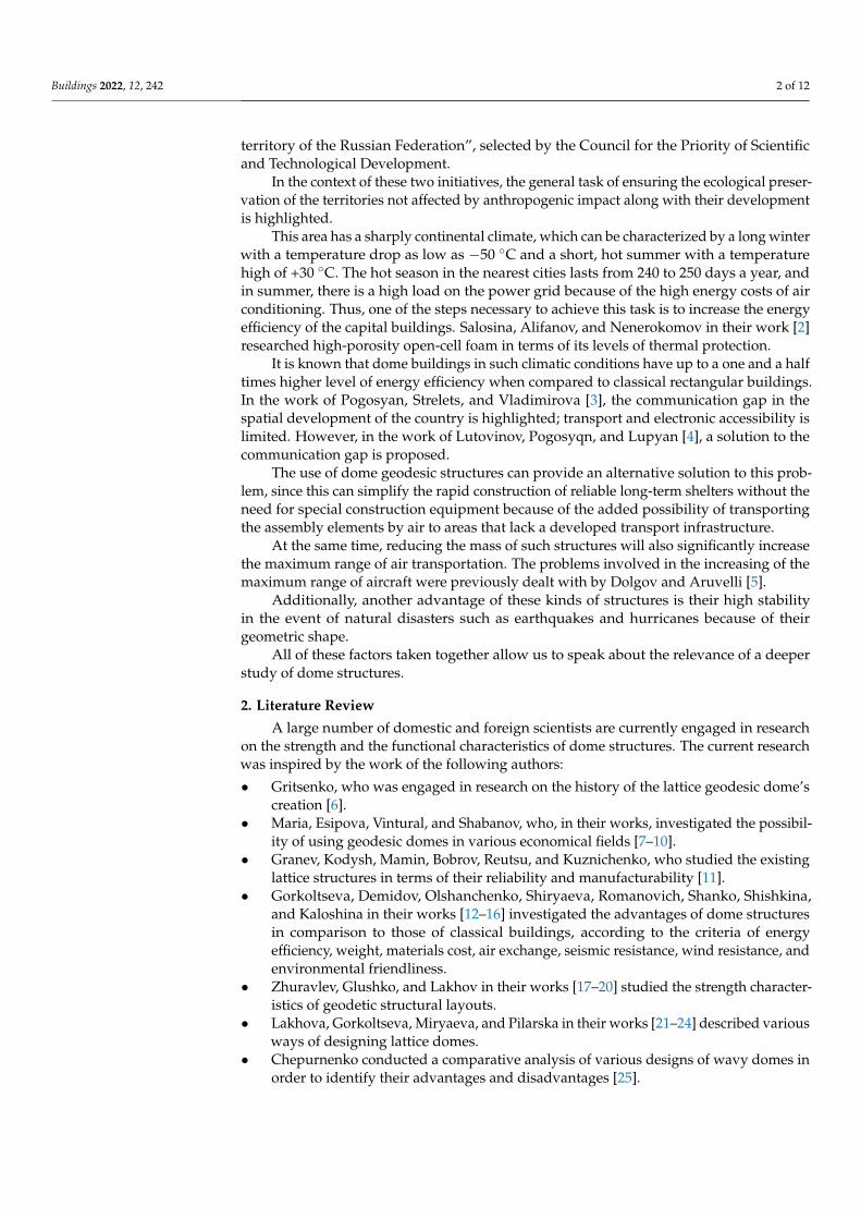
• The metal geodesic dome of the US Antarctic Station Amundsen–Scott is located atthe South Pole of the Earth. It was built in 1975 and used to be the main shelter of theresearch station. Its service life in the extreme climatic conditions of the South Pole wasmore than 30 years. This dome structure was built from elements premanufactured inthe factory and delivered by air transport.
Buildings 2022, 12, 242 6 of 12
Buildings 2022, 12, x FOR PEER REVIEW 6 of 13
was more than 30 years. This dome structure was built from elements premanufac-
tured in the factory and delivered by air transport.
Figure 7. Metal geodesic dome of the US Antarctic Station Amundsen–Scott.
The geodesic dome of the DYE-2 station of the missile strike early detection system
in Greenland, with a diameter of more than 20 m, the construction of which began in the
late 1950s. The construction of this structure was carried out from parts transported ex-
clusively by air transport.
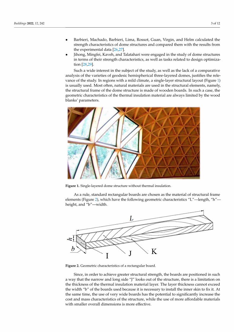
Figure 8. Geodesic dome of the DYE-2 station of the missile strike early detection system in
Greenland.
• As a close analogue to the first type of structure, we may mention the lighting dome
of the Research Institute of Building Physics (NIISF), which was built in Moscow in
1981.
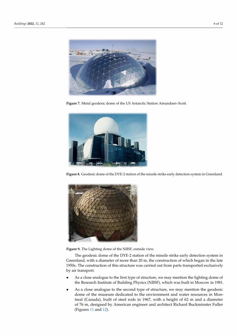
Figure 9. The Lighting dome of the NIISF, outside view.
Figure 7. Metal geodesic dome of the US Antarctic Station Amundsen–Scott.
Buildings 2022, 12, x FOR PEER REVIEW 6 of 13
was more than 30 years. This dome structure was built from elements premanufac-
tured in the factory and delivered by air transport.
Figure 7. Metal geodesic dome of the US Antarctic Station Amundsen–Scott.
The geodesic dome of the DYE-2 station of the missile strike early detection system
in Greenland, with a diameter of more than 20 m, the construction of which began in the
late 1950s. The construction of this structure was carried out from parts transported ex-
clusively by air transport.
Figure 8. Geodesic dome of the DYE-2 station of the missile strike early detection system in
Greenland.
• As a close analogue to the first type of structure, we may mention the lighting dome
of the Research Institute of Building Physics (NIISF), which was built in Moscow in
1981.
Figure 9. The Lighting dome of the NIISF, outside view.
Figure 8. Geodesic dome of the DYE-2 station of the missile strike early detection system in Greenland.
Buildings 2022, 12, x FOR PEER REVIEW 6 of 13
was more than 30 years. This dome structure was built from elements premanufac-
tured in the factory and delivered by air transport.
Figure 7. Metal geodesic dome of the US Antarctic Station Amundsen–Scott.
The geodesic dome of the DYE-2 station of the missile strike early detection system
in Greenland, with a diameter of more than 20 m, the construction of which began in the
late 1950s. The construction of this structure was carried out from parts transported ex-
clusively by air transport.
Figure 8. Geodesic dome of the DYE-2 station of the missile strike early detection system in
Greenland.
• As a close analogue to the first type of structure, we may mention the lighting dome
of the Research Institute of Building Physics (NIISF), which was built in Moscow in
1981.
Figure 9. The Lighting dome of the NIISF, outside view. Figure 9. The Lighting dome of the NIISF, outside view.
The geodesic dome of the DYE-2 station of the missile strike early detection system inGreenland, with a diameter of more than 20 m, the construction of which began in the late1950s. The construction of this structure was carried out from parts transported exclusivelyby air transport.
• As a close analogue to the first type of structure, we may mention the lighting dome ofthe Research Institute of Building Physics (NIISF), which was built in Moscow in 1981.
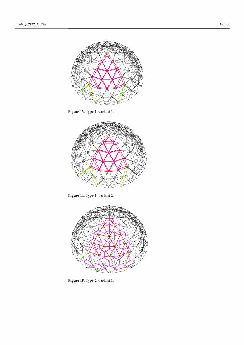
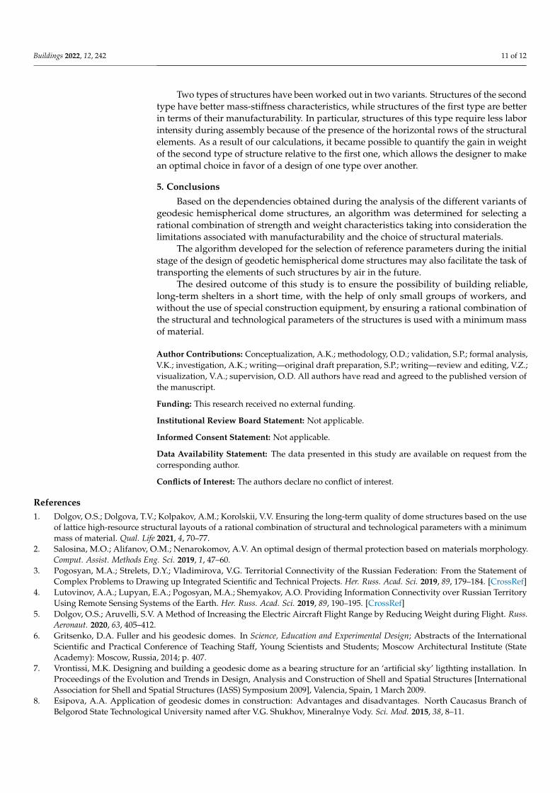
• As a close analogue to the second type of structure, we may mention the geodesicdome of the museum dedicated to the environment and water resources in Mon-treal (Canada), built of steel rods in 1967, with a height of 62 m and a diameterof 76 m, designed by American engineer and architect Richard Buckminster Fuller(Figures 11 and 12).
Buildings 2022, 12, 242 7 of 12Buildings 2022, 12, x FOR PEER REVIEW 7 of 13
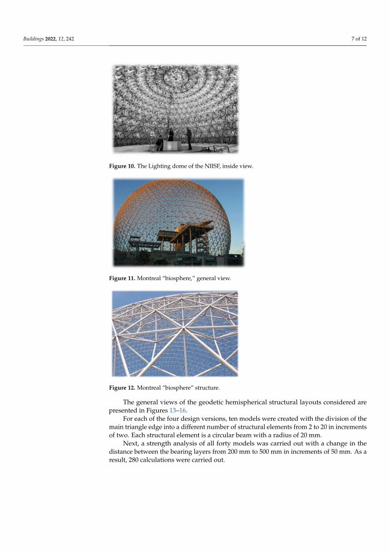
Figure 10. The Lighting dome of the NIISF, inside view.
• As a close analogue to the second type of structure, we may mention the geodesic
dome of the museum dedicated to the environment and water resources in Montreal
(Canada), built of steel rods in 1967, with a height of 62 m and a diameter of 76 m,
designed by American engineer and architect Richard Buckminster Fuller (Figures
11 and 12).
Figure 11. Montreal “biosphere,” general view.
Figure 12. Montreal “biosphere” structure.
The general views of the geodetic hemispherical structural layouts considered are
presented in Figures 13–16.
Figure 10. The Lighting dome of the NIISF, inside view.
Buildings 2022, 12, x FOR PEER REVIEW 7 of 13
Figure 10. The Lighting dome of the NIISF, inside view.
• As a close analogue to the second type of structure, we may mention the geodesic
dome of the museum dedicated to the environment and water resources in Montreal
(Canada), built of steel rods in 1967, with a height of 62 m and a diameter of 76 m,
designed by American engineer and architect Richard Buckminster Fuller (Figures
11 and 12).
Figure 11. Montreal “biosphere,” general view.
Figure 12. Montreal “biosphere” structure.
The general views of the geodetic hemispherical structural layouts considered are
presented in Figures 13–16.
Figure 11. Montreal “biosphere,” general view.
Buildings 2022, 12, x FOR PEER REVIEW 7 of 13
Figure 10. The Lighting dome of the NIISF, inside view.
• As a close analogue to the second type of structure, we may mention the geodesic
dome of the museum dedicated to the environment and water resources in Montreal
(Canada), built of steel rods in 1967, with a height of 62 m and a diameter of 76 m,
designed by American engineer and architect Richard Buckminster Fuller (Figures
11 and 12).
Figure 11. Montreal “biosphere,” general view.
Figure 12. Montreal “biosphere” structure.
The general views of the geodetic hemispherical structural layouts considered are
presented in Figures 13–16.
Figure 12. Montreal “biosphere” structure.
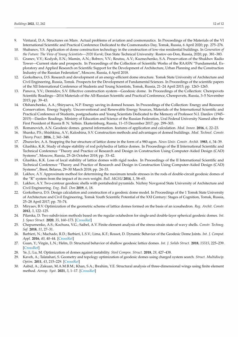
The general views of the geodetic hemispherical structural layouts considered arepresented in Figures 13–16.
For each of the four design versions, ten models were created with the division of themain triangle edge into a different number of structural elements from 2 to 20 in incrementsof two. Each structural element is a circular beam with a radius of 20 mm.
Next, a strength analysis of all forty models was carried out with a change in thedistance between the bearing layers from 200 mm to 500 mm in increments of 50 mm. As aresult, 280 calculations were carried out.
Buildings 2022, 12, 242 8 of 12Buildings 2022, 12, x FOR PEER REVIEW 8 of 13
Figure 13. Type 1, variant 1.
Figure 14. Type 1, variant 2.
Figure 15. Type 2, variant 1.
Figure 13. Type 1, variant 1.
Buildings 2022, 12, x FOR PEER REVIEW 8 of 13
Figure 13. Type 1, variant 1.
Figure 14. Type 1, variant 2.
Figure 15. Type 2, variant 1.
Figure 14. Type 1, variant 2.
Buildings 2022, 12, x FOR PEER REVIEW 8 of 13
Figure 13. Type 1, variant 1.
Figure 14. Type 1, variant 2.
Figure 15. Type 2, variant 1. Figure 15. Type 2, variant 1.

Buildings 2022, 12, 242 9 of 12Buildings 2022, 12, x FOR PEER REVIEW 9 of 13
Figure 16. Type 2, variant 2.
For each of the four design versions, ten models were created with the division of
the main triangle edge into a different number of structural elements from 2 to 20 in in-
crements of two. Each structural element is a circular beam with a radius of 20 mm.
Next, a strength analysis of all forty models was carried out with a change in the
distance between the bearing layers from 200 mm to 500 mm in increments of 50 mm. As
a result, 280 calculations were carried out.
Strength calculations were carried out using the finite element method in the Hy-
perMesh software package in a static solver. Four groups of models were created that
differed in the number of edges per the side of the main triangle from 2 to 20. The model
parameters are given in Table 1.
As mentioned previously, 280 calculations were carried out for each of the models
that was created manually. The use of the highly convenient HyperMesh software
package made it possible to significantly reduce the preparation time of the model.
Depending on the geometric division of the main triangle, the number of structural
elements (beams) changed, but regardless of the division, each beam was divided into 10
finite elements. Thus, the structural elements had the same mesh density. This partition
was dictated primarily by the requirement of mesh convergence.
The final elements of the Bar-type, instead of the Rod-type, were used in the model;
the elements of the Bar-type are able to work not only in tension-compression, but also in
bending.
The structure under its own weight was calculated. For this, the gravity acceleration
was set to 9.8 m/s2. As boundary conditions, a restriction on all degrees of freedom for the
lower row of nodes was used, simulating the presence of a foundation.
Table 1. Parameters for FEM models.
Parameter Value
Dome diameter, m 10
Section view of the structural elements Circle
Structural elements section radius, mm 20
Material Steel
Young’s Modulus, MPa 2100,000
Poisson ratio 0.3
Density, kg/m3 7700
Element type B31—linear spatial beam finite element
4. Results and Discussion
The stress-strain state of the structures was estimated by the values of stresses and
displacements. The stress values for all models do not exceed the yield strength of
Figure 16. Type 2, variant 2.
Strength calculations were carried out using the finite element method in the Hyper-Mesh software package in a static solver. Four groups of models were created that differedin the number of edges per the side of the main triangle from 2 to 20. The model parametersare given in Table 1.
Table 1. Parameters for FEM models.
Parameter Value
Dome diameter, m 10Section view of the structural elements CircleStructural elements section radius, mm 20
Material SteelYoung’s Modulus, MPa 2,100,000
Poisson ratio 0.3Density, kg/m3 7700
Element type B31—linear spatial beam finite element
As mentioned previously, 280 calculations were carried out for each of the modelsthat was created manually. The use of the highly convenient HyperMesh software packagemade it possible to significantly reduce the preparation time of the model.
Depending on the geometric division of the main triangle, the number of structuralelements (beams) changed, but regardless of the division, each beam was divided into10 finite elements. Thus, the structural elements had the same mesh density. This partitionwas dictated primarily by the requirement of mesh convergence.
The final elements of the Bar-type, instead of the Rod-type, were used in the model;the elements of the Bar-type are able to work not only in tension-compression, but alsoin bending.
The structure under its own weight was calculated. For this, the gravity accelerationwas set to 9.8 m/s2. As boundary conditions, a restriction on all degrees of freedom for thelower row of nodes was used, simulating the presence of a foundation.
4. Results and Discussion
The stress-strain state of the structures was estimated by the values of stresses anddisplacements. The stress values for all models do not exceed the yield strength of structuralsteels. The peak values of the displacements were systemized. Figure 17 shows thedependences of the displacement values on the mass of the structure and the wall thickness.

Buildings 2022, 12, 242 10 of 12Buildings 2022, 12, x FOR PEER REVIEW 11 of 13
Figure 17. Summary graph of the peak displacements and the mass of the structure on the reference
parameters of the structural layout for geodesic hemispherical two-layer dome structures with a
core filler.
5. Conclusions
Based on the dependencies obtained during the analysis of the different variants of
geodesic hemispherical dome structures, an algorithm was determined for selecting a
rational combination of strength and weight characteristics taking into consideration the
limitations associated with manufacturability and the choice of structural materials.
The algorithm developed for the selection of reference parameters during the initial
stage of the design of geodetic hemispherical dome structures may also facilitate the task
of transporting the elements of such structures by air in the future.
The desired outcome of this study is to ensure the possibility of building reliable,
long-term shelters in a short time, with the help of only small groups of workers, and
without the use of special construction equipment, by ensuring a rational combination of
the structural and technological parameters of the structures is used with a minimum
mass of material.
Author Contributions: Conceptualization, A.K.; methodology, O.D.; validation, S.P.; formal anal-
ysis, V.K.; investigation, A.K.; writing—original draft preparation, S.P.; writing—review and edit-
Figure 17. Summary graph of the peak displacements and the mass of the structure on the referenceparameters of the structural layout for geodesic hemispherical two-layer dome structures with acore filler.
The parameters accepted in the finite element model correspond to the parametersthat can be used in a real design. Changing the material and the cross-section of structuralelements would yield different results, but this is the topic of another separate study.In this paper, a comparative analysis of the structural layout of domes was carried out.After analyzing the graphs in Figure 17, a rational design can be chosen based on therequirements set.
If the basic requirement is air transportation possibility, then it is advisable to choose adesign that meets all other restrictions with a minimum weight. Judging by the graphs, therational choice in this case is a type 2 structure with a division of six elements per maintriangle, since in this case, the displacements of the structure have extremely low values.The wall thickness should be determined based on the required type of insulation material.So, when using mineral cotton, the minimum thickness would be 350 mm; at the same time,when using polyurethane, it is possible to limit the wall thickness to 200 mm.
Similarly, a design selection can be made that is guided by other requirements.
Buildings 2022, 12, 242 11 of 12
Two types of structures have been worked out in two variants. Structures of the secondtype have better mass-stiffness characteristics, while structures of the first type are betterin terms of their manufacturability. In particular, structures of this type require less laborintensity during assembly because of the presence of the horizontal rows of the structuralelements. As a result of our calculations, it became possible to quantify the gain in weightof the second type of structure relative to the first one, which allows the designer to makean optimal choice in favor of a design of one type over another.
5. Conclusions
Based on the dependencies obtained during the analysis of the different variants ofgeodesic hemispherical dome structures, an algorithm was determined for selecting arational combination of strength and weight characteristics taking into consideration thelimitations associated with manufacturability and the choice of structural materials.
The algorithm developed for the selection of reference parameters during the initialstage of the design of geodetic hemispherical dome structures may also facilitate the task oftransporting the elements of such structures by air in the future.
The desired outcome of this study is to ensure the possibility of building reliable,long-term shelters in a short time, with the help of only small groups of workers, andwithout the use of special construction equipment, by ensuring a rational combination ofthe structural and technological parameters of the structures is used with a minimum massof material.
Author Contributions: Conceptualization, A.K.; methodology, O.D.; validation, S.P.; formal analysis,V.K.; investigation, A.K.; writing—original draft preparation, S.P.; writing—review and editing, V.Z.;visualization, V.A.; supervision, O.D. All authors have read and agreed to the published version ofthe manuscript.
Funding: This research received no external funding.
Institutional Review Board Statement: Not applicable.
Informed Consent Statement: Not applicable.
Data Availability Statement: The data presented in this study are available on request from thecorresponding author.
Conflicts of Interest: The authors declare no conflict of interest.
References1. Dolgov, O.S.; Dolgova, T.V.; Kolpakov, A.M.; Korolskii, V.V. Ensuring the long-term quality of dome structures based on the use
of lattice high-resource structural layouts of a rational combination of structural and technological parameters with a minimummass of material. Qual. Life 2021, 4, 70–77.
2. Salosina, M.O.; Alifanov, O.M.; Nenarokomov, A.V. An optimal design of thermal protection based on materials morphology.Comput. Assist. Methods Eng. Sci. 2019, 1, 47–60.
3. Pogosyan, M.A.; Strelets, D.Y.; Vladimirova, V.G. Territorial Connectivity of the Russian Federation: From the Statement ofComplex Problems to Drawing up Integrated Scientific and Technical Projects. Her. Russ. Acad. Sci. 2019, 89, 179–184. [CrossRef]
4. Lutovinov, A.A.; Lupyan, E.A.; Pogosyan, M.A.; Shemyakov, A.O. Providing Information Connectivity over Russian TerritoryUsing Remote Sensing Systems of the Earth. Her. Russ. Acad. Sci. 2019, 89, 190–195. [CrossRef]
5. Dolgov, O.S.; Aruvelli, S.V. A Method of Increasing the Electric Aircraft Flight Range by Reducing Weight during Flight. Russ.Aeronaut. 2020, 63, 405–412.
6. Gritsenko, D.A. Fuller and his geodesic domes. In Science, Education and Experimental Design; Abstracts of the InternationalScientific and Practical Conference of Teaching Staff, Young Scientists and Students; Moscow Architectural Institute (StateAcademy): Moscow, Russia, 2014; p. 407.
7. Vrontissi, M.K. Designing and building a geodesic dome as a bearing structure for an ‘artificial sky’ ligthting installation. InProceedings of the Evolution and Trends in Design, Analysis and Construction of Shell and Spatial Structures [InternationalAssociation for Shell and Spatial Structures (IASS) Symposium 2009], Valencia, Spain, 1 March 2009.
8. Esipova, A.A. Application of geodesic domes in construction: Advantages and disadvantages. North Caucasus Branch ofBelgorod State Technological University named after V.G. Shukhov, Mineralnye Vody. Sci. Mod. 2015, 38, 8–11.
Buildings 2022, 12, 242 12 of 12
9. Vintural, D.A. Structures on Mars. Actual problems of aviation and cosmonautics. In Proceedings of the Materials of the VIInternational Scientific and Practical Conference Dedicated to the Cosmonautics Day, Tomsk, Russia, 6 April 2020; pp. 275–276.
10. Shabanov, Y.S. Application of dome construction technology in the construction of low-rise residential buildings. In Generation ofthe Future: The View of Young Scientists—2020 Kursk; Don State Technical University: Rostov-on-Don, Russia, 2020; pp. 381–383.
11. Granev, V.V.; Kodysh, E.N.; Mamin, A.N.; Bobrov, V.V.; Reutsu, A.V.; Kuznechenko, S.A. Preservation of the Shukhov RadioTower—Current state and prospects. In Proceedings of the Collection of Scientific Works of the RAASN “Fundamental, Ex-ploratory and Applied Research on Scientific Support for the Development of Architecture, Urban Planning and the ConstructionIndustry of the Russian Federation”, Moscow, Russia, 4 April 2018.
12. Gorkoltseva, D.S. Research and development of an energy-efficient dome structure. Tomsk State University of Architecture andCivil Engineering, Russia, Tomsk. Prospects for the Development of Fundamental Sciences. In Proceedings of the scientific papersof the XII International Conference of Students and Young Scientists, Tomsk, Russia, 21–24 April 2015; pp. 1263–1265.
13. Panova, Y.V.; Demidov, S.V. Effective construction system—Geodesic dome. In Proceedings of the Collection: CherepovetsScientific Readings—2014 Materials of the All-Russian Scientific and Practical Conference, Cherepovets, Russia, 3–5 November2015; pp. 39–43.
14. Olshanchenko, A.A.; Shiryaeva, N.P. Energy saving in domed houses. In Proceedings of the Collection: Energy and ResourceConservation. Energy Supply. Unconventional and Renewable Energy Sources, Materials of the International Scientific andPractical Conference of Students, postgraduates and Young Scientists Dedicated to the Memory of Professor N.I. Danilov (1945–2015)—Danilov Readings. Ministry of Education and Science of the Russian Federation, Ural Federal University Named after theFirst President of Russia B. N. Yeltsin. Ekaterinburg, Russia, 11–15 December 2017; pp. 299–303.
15. Romanovich, A.N. Geodesic domes. general information. features of application and calculation. Mod. Innov. 2016, 6, 22–23.16. Shanko, P.S.; Shishkina, A.V.; Kaloshina, S.V. Construction methods and advantages of domed buildings. Mod. Technol. Constr.
Theory Pract. 2016, 2, 341–348.17. Zhuravlev, A.A. Snapping the bar structure of lattice dome in the form of a 980-agon. News Univ. Constr. Archit. 1983, 6, 34–39.18. Glushko, K.K. Study of shape stability of rod polyhedra of lattice domes. In Proceedings of the II International Scientific and
Technical Conference “Theory and Practice of Research and Design in Construction Using Computer-Aided Design (CAD)Systems”, Moscow, Russia, 25–26 October 2018; pp. 33–42.
19. Glushko, K.K. Loss of local stability of lattice domes with rigid nodes. In Proceedings of the II International Scientific andTechnical Conference “Theory and Practice of Research and Design in Construction Using Computer-Aided Design (CAD)Systems”, Brest, Belarus, 29–30 March 2018; pp. 24–33.
20. Lakhov, A.Y. Approximate method for determining the maximum tensile stresses in the rods of double-circuit geodesic domes ofthe “R” system from the impact of its own weight. Bull. MGSU 2014, 1, 58–65.
21. Lakhov, A.Y. Two-contour geodesic shells with pentahedral pyramids. Nizhny Novgorod State University of Architecture andCivil Engineering. Eng. Bull. Don 2019, 6, 18.
22. Gorkoltseva, D.S. Design calculation and construction of a geodesic dome model. In Proceedings of the 1 Tomsk State Universityof Architecture and Civil Engineering, Tomsk Youth Scientific Potential of the XXI Century: Stages of Cognition, Tomsk, Russia,25–28 April 2017; pp. 70–74.
23. Miryaev, B.V. Optimization of the geometric scheme of lattice domes formed on the basis of an icosahedron. Reg. Archit. Constr.2012, 3, 122–125.
24. Pilarska, D. Two subdivision methods based on the regular octahedron for single-and double-layer spherical geodesic domes. Int.J. Space Struct. 2020, 35, 160–173. [CrossRef]
25. Chepurnenko, A.S.; Kochura, V.G.; Saibel, A.V. Finite element analysis of the stress-strain state of wavy shells. Constr. Technog.Saf. 2018, 11, 27–31.
26. Barbieri, N.; Machado, R.D.; Barbieri, L.S.V.; Lima, K.F.; Rossot, D. Dynamic Behavior of the Geodesic Dome Joints. Int. J. Comput.Appl. 2016, 40, 40–44. [CrossRef]
27. Guan, Y.; Virgin, L.N.; Helm, D. Structural behavior of shallow geodesic lattice domes. Int. J. Solids Struct. 2018, 15515, 225–239.[CrossRef]
28. Ye, J.; Lu, M. Optimization of domes against instability. Steel Compos. Struct. 2018, 28, 427–438.29. Kaveh, A.; Talatahari, S. Geometry and topology optimization of geodesic domes using charged system search. Struct. Multidiscip.
Optim. 2011, 43, 215–229. [CrossRef]30. Aabid, A.; Zakuan, M.A.M.B.M.; Khan, S.A.; Ibrahim, Y.E. Structural analysis of three-dimensional wings using finite element
method. Aerosp. Syst. 2021, 3, 1–17. [CrossRef]