cfd anlysis of pulverised-coal combustion of burner used in furnace with different radiation models
TRANSCRIPT
IOSR Journal of Mechanical and Civil Engineering (IOSR-JMCE)
e-ISSN: 2278-1684 Volume 5, Issue 2 (Jan. - Feb. 2013), PP 25-34 www.iosrjournals.org
www.iosrjournals.org 25 | Page
CFD Anlysis of Pulverised-Coal Combustion of Burner Used In
Furnace with Different Radiation Models
Rajesh Holkar1, Dr. Omprakash. D. Hebbal
2
Department of mechanical engineering, PDA College of engineering, Gulbarga.
Abstract: Pulverized coal is an important fuel for electricity production and will continue to be important for
decades. Since coal is a natural resource that depends on many factors and parameters, it has variable
properties and composition. Combustion chamber designers Endeavour to achieve optimum operating
conditions that give maximum combustion efficiency, together with minimum pollutant formation rate. Modeling
of fossil fuel utility boilers has reached a remarkable development in recent years. Particularly, the application
of computational fluid dynamics (CFD) modeling technology and other advanced mathematical methods offer
opportunities for analysis, optimization and options examination in order to increase the overall efficiency of
the energy facilities. The main objective of the present work was to investigate how the results obtained with two
radiative heat transfer methods, the P1 approximation method, Discrete Transfer and the discrete ordinates
(DO) method using ANSYS FLUENT, fit temperature field in a boiler furnace on pulverized coal, with
implemented over-fire air (OFA) ports. The overall framework of the CFD modeling approach is described. The
numerical modeling results for boiler baseline operating conditions are compared with a test data of temperature measurements. An accuracy analysis of the P1 and DO methods is done on a basis of a comparison
between the numerically obtained and measured temperature profiles. Keywords: Coal combustion, heat transfer, thermal radiation, CFD techique, modelling.
I. Introduction About 70% of power used throughout the world generally comes from thermal power stations.
Increasing industrialization and modernization has put lot of pressure on exploration of fossil fuels such as coal,
oil, and gas etc. on other hand a pollutants emitted by these power plants add to the environment affecting the
habitants, flora and fauna etc. In and around the power plants as we know the pollutants such as CO2, C0, SOx ,
NOx and particulate matter emits due to improper and poor combustion. The combustion is an erotic chemical reaction where the fuel is brunt and heat is released during the
process. Any improvement made such as primary air, secondary air, atomization of liquid fuels, pulverization of
coal, phasing of air supply, would change phase of chemical reaction. This kind of analysis can be done by
experimentation and combustion analysis obtaining appropriate models using computers. experimentation is
very expensive, difficult and time consuming process development of a physical model, monitoring and control
of combustion process is much more cumbersome however availability of high speed computers made easier to
analysis any combustion process easy to analysis any complicated process by using computational fluid
dynamics (CFD) theoretical analysis of combustion process becomes easier, cheaper and time saving. in this
context some of reacher’s like anes kazagić [6], u. schnell[7], w. fiveland [15] and j. m. jones, m.
pourkashanian [17] , s. c. hill, l. d. smoot[22] have worked on building a mathematical models of combustion
for different fuels and pollutant formation etc. still a compressive model is not available for the process of combustion in boilers.
The computational fluid dynamics (CFD) of the pulverized coal combustion field is being developed with the
remarkable progress in the performance of computers. This method, in which the governing equations of the
combustion field are solved using a computer, is capable to provide the detailed information on the distributions
of temperature and chemical species and the behavior of pulverized coal particles over entire combustion field
that cannot be obtained by experiments. In addition, it facilitates the repeated review in arbitrary conditions for
the properties of pulverized coal and the flow field at a relatively low cost. It is, therefore, strongly expected that
the CFD becomes a tool for the development and design of combustion furnaces and burners.
II. Simulation Set Up And Data Input In ANSYS, the governing equations are discretized by using the finite Volume method The pressure
velocity coupling is achieved through the SIMPLE -algorithm.The grid-independent study is done for all cases
.All simulations are run in ANSYS K-ε reliable model. Boundary conditions used are flue gas mass flow rate
and temperature. It is assumed that all particles have attended their terminal velocity and have entered
perpendicular to the tube. The geometry of actual flue gas duct, its internal, tubes created in ANSYS design
modeller. Drawings of duct are used for geometry creation. Meshing is done in ANSYS meshing .Inlet surface
Cfd Anlysis Of Pulverised-Coal Combustion Of Burner Used In Furnace With Different Radiation
www.iosrjournals.org 26 | Page
meshed and volume meshing done with tetrahedral. Further refinement of mesh is done by adaption by using
velocity gradient. Numbers of cells are varying as per geometry dimensions and requirement for grid
independent solution. Simulation is done on existing geometry of duct first by straight vanes and then geometry by adding curved vanes.
Design data used
Table 1 – Proximate and ultimate analysis of the coal
Proximate Analysis (mass fraction, dry):
Volatile matter 0.374
Fixed carbon (char) 0.543
Ash 0.083
Ultimate Analysis (mass fraction, as received):
Carbon 0.7369
Hydrogen 0.0466
Nitrogen 0.0133
Sulphur 0.0086
Oxygen 0.1116
Lower Heating Value 29.64 MJ/kg
Table 2 – Coal properties
Coal properties:
Raw combustible density (dry) 1560 kg/m3
Raw combustible specific heat (dry) 1225 J/kg K
Char density (dry) 1560 kg/m3
Char specific heat (dry) 1225 J/kg K
Ash density (dry) 1000 kg/m3
Ash specific heat (dry) 800 kg/m3
III. Numerical Simulation In this work, a pure two-fluid model for reacting gas-particle flows is performed, using a comprehensive eulerian treatment for both gas phase and particle phase. both velocity slip and temperature slip
between coal particles and gas phase are calculated by solving the momentum equations and energy equations of
gas phase and particle phase respectively. in addition, a modified k--kp two-phase turbulence model, a second-order moment turbulence-chemistry model for nox formation, a general model of pulverized coal
devolatilization and a general model of char combustion were incorporated into the comprehensive model. for
volatile and co combustion as well as radiation heat transfer, the conventional ebu-arrhenius model and the six
heat-flux model were used.
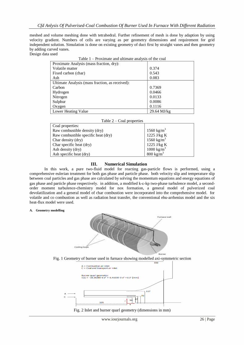
A. Geometry modelling
Fig. 1 Geometry of burner used in furnace showing modelled axi-symmetric section
Fig. 2 Inlet and burner quarl geometry (dimensions in mm)
Cfd Anlysis Of Pulverised-Coal Combustion Of Burner Used In Furnace With Different Radiation
www.iosrjournals.org 27 | Page
The outer furnace wall is cooled by a series of cooling loops, modeled in CFX as a series of cylindrical grooves
of equivalent surface area. The stabilization of the coal flame is achieved by means of a swirl burner. The burner
quarl is an experimental aerodynamic design whose radius is described using a cubic equation in x, where x in this case is the axial distance from the beginning of the quarl
CFX modelling details CFX 13 is both finite-volume based general purpose CFD codes. In CFX 13 the transport equations for
mass and momentum are assembled and solved as a fully coupled system.
Turbulence modelling
The k-epsilon model was used in both codes for the gas phase turbulence
Gas phase combustion
Reaction of combusting species within the gas phase in CFX is handled within a multi-component fluid framework. A single Eulerian gas phase containing reactants and products from all gaseous reactions is used.
The Eddy Dissipation model was used for the gas phase combustion modelling, which assumes that reactions
are fast and that reaction rates are limited by a mixing time determined by the properties of the turbulent eddies,
i.e.
krate
This mixing time appears in the equations for reactants and products limiters,
IK
Kv
I
kAR
,
][min
IKI
I
KvW
IW
kABR
,
][min
where [I] is the molar concentration of species I, WI the species molecular weight and vK,I the stoichiometric
coefficient of species I in elementary reaction K. The minimum of
these limiters determines the rate of the reaction. The magnitude of the limiters is controlled by two model
coefficients, A and B. The default value for A in CFX is 13.0 and this is appropriate for a wide range of combusting flows. However, for swirling, turbulent diffusion flames, Visser [20] recommends a value of 0.6.
This value was therefore used for the CFX simulations.
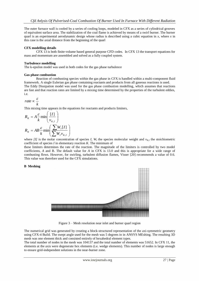
B Meshing
Figure 3 – Mesh resolution near inlet and burner quarl region
The numerical grid was generated by creating a block-structured representation of the axi-symmetric geometry using CFX-4 Build. The swept angle used for the mesh was 5 degrees in in ANSYS MEshing. The resulting 3D
mesh was one element thick and consisted entirely of hexahedral element types.
The total number of nodes in the mesh was 104137 and the total number of elements was 51652. In CFX 11, the
elements at the axis were degenerate hex elements (i.e. wedge elements). This number of nodes is large enough
to ensure grid-independent solutions in the near-burner zone.
Cfd Anlysis Of Pulverised-Coal Combustion Of Burner Used In Furnace With Different Radiation
www.iosrjournals.org 28 | Page
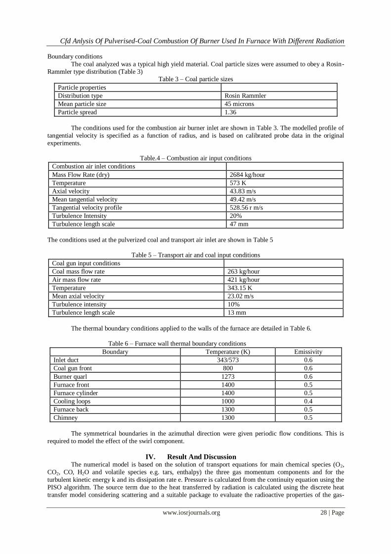
Boundary conditions
The coal analyzed was a typical high yield material. Coal particle sizes were assumed to obey a Rosin-
Rammler type distribution (Table 3) Table 3 – Coal particle sizes
Particle properties
Distribution type Rosin Rammler
Mean particle size 45 microns
Particle spread 1.36
The conditions used for the combustion air burner inlet are shown in Table 3. The modelled profile of
tangential velocity is specified as a function of radius, and is based on calibrated probe data in the original
experiments.
Table.4 – Combustion air input conditions
Combustion air inlet conditions
Mass Flow Rate (dry) 2684 kg/hour
Temperature 573 K
Axial velocity 43.83 m/s
Mean tangential velocity 49.42 m/s
Tangential velocity profile 528.56 r m/s
Turbulence Intensity 20%
Turbulence length scale 47 mm
The conditions used at the pulverized coal and transport air inlet are shown in Table 5
Table 5 – Transport air and coal input conditions
Coal gun input conditions
Coal mass flow rate 263 kg/hour
Air mass flow rate 421 kg/hour
Temperature 343.15 K
Mean axial velocity 23.02 m/s
Turbulence intensity 10%
Turbulence length scale 13 mm
The thermal boundary conditions applied to the walls of the furnace are detailed in Table 6.
Table 6 – Furnace wall thermal boundary conditions
Boundary Temperature (K) Emissivity
Inlet duct 343/573 0.6
Coal gun front 800 0.6
Burner quarl 1273 0.6
Furnace front 1400 0.5
Furnace cylinder 1400 0.5
Cooling loops 1000 0.4
Furnace back 1300 0.5
Chimney 1300 0.5
The symmetrical boundaries in the azimuthal direction were given periodic flow conditions. This is
required to model the effect of the swirl component.
IV. Result And Discussion
The numerical model is based on the solution of transport equations for main chemical species (O2,
CO2, CO, H2O and volatile species e.g. tars, enthalpy) the three gas momentum components and for the
turbulent kinetic energy k and its dissipation rate e. Pressure is calculated from the continuity equation using the
PISO algorithm. The source term due to the heat transferred by radiation is calculated using the discrete heat
transfer model considering scattering and a suitable package to evaluate the radioactive properties of the gas-
Cfd Anlysis Of Pulverised-Coal Combustion Of Burner Used In Furnace With Different Radiation
www.iosrjournals.org 29 | Page
particle mixture. The calculation of the front wall fired boilers was extended compared to the previous projects
by considering the upper section of the furnace where pendent super heater panels exist.
The coal particles are described by a stochastic Lagrangian procedure to integrate the equation of motion and the energy balance, together with the consideration of physical models. The coal evolution is
described in sequence by drying, pyrolysis and char combustion. For volatile release a parallel reaction scheme
is used. For char combustion a first order kinetic rate combined with a diffusion resistance is used, considering
the particle diameter constant. The kinetic rate for char combustion has been considered as a function of
burnout according to k=4. k0 (1-BO)2 which is an approximate fit to data observed in drop tube furnaces.
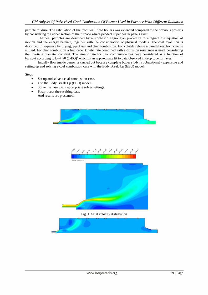
Initially flow inside burner is carried out because complete boiler study is cobutationaly expensive and
setting up and solving a coal combustion case with the Eddy Break Up (EBU) model.
Steps
Set up and solve a coal combustion case.
Use the Eddy Break Up (EBU) model.
Solve the case using appropriate solver settings.
Postprocess the resulting data.
And results are presented.
Fig. 1 Axial velocity distribution
Cfd Anlysis Of Pulverised-Coal Combustion Of Burner Used In Furnace With Different Radiation
www.iosrjournals.org 30 | Page
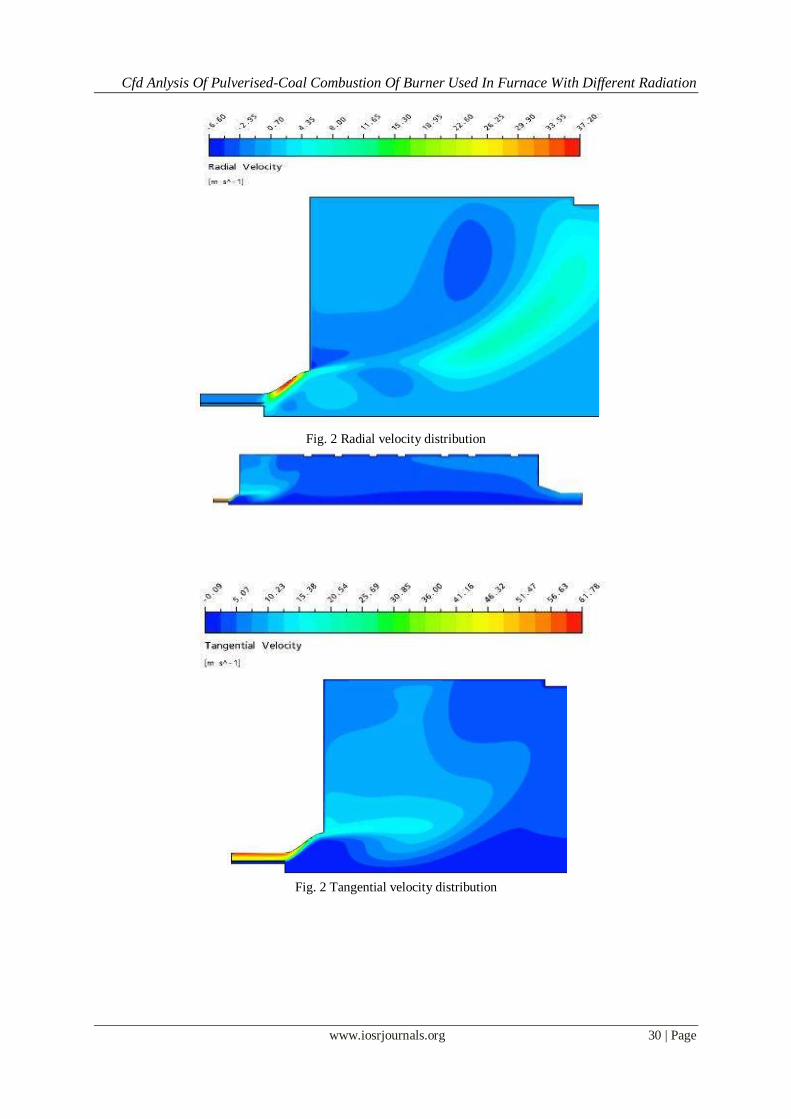
Fig. 2 Radial velocity distribution
Fig. 2 Tangential velocity distribution
Cfd Anlysis Of Pulverised-Coal Combustion Of Burner Used In Furnace With Different Radiation
www.iosrjournals.org 31 | Page
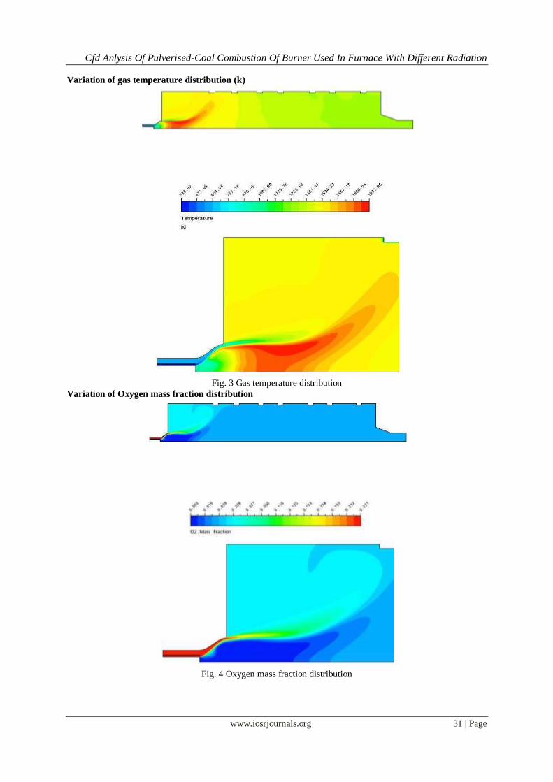
Variation of gas temperature distribution (k)
Fig. 3 Gas temperature distribution
Variation of Oxygen mass fraction distribution
Fig. 4 Oxygen mass fraction distribution
Cfd Anlysis Of Pulverised-Coal Combustion Of Burner Used In Furnace With Different Radiation
www.iosrjournals.org 32 | Page
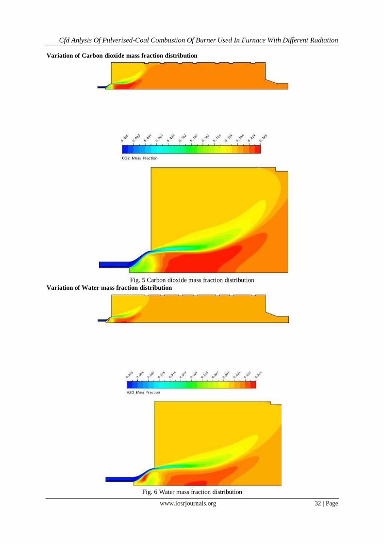
Variation of Carbon dioxide mass fraction distribution
Fig. 5 Carbon dioxide mass fraction distribution
Variation of Water mass fraction distribution
Fig. 6 Water mass fraction distribution
Cfd Anlysis Of Pulverised-Coal Combustion Of Burner Used In Furnace With Different Radiation
www.iosrjournals.org 33 | Page
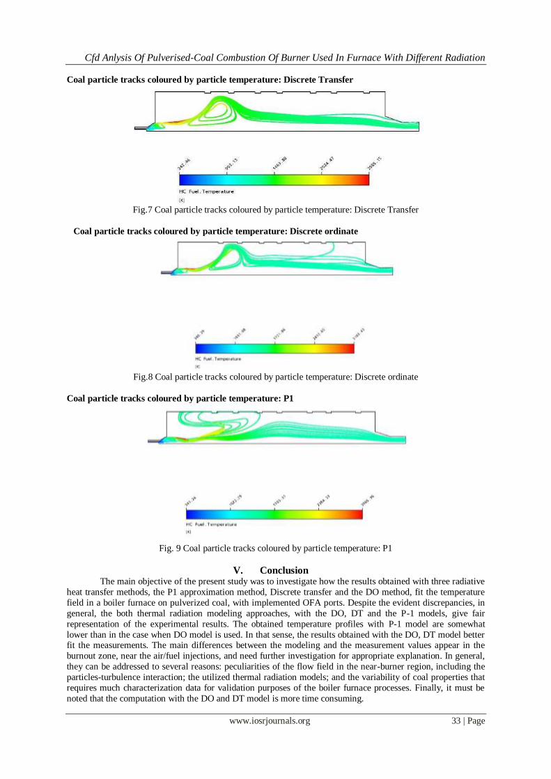
Coal particle tracks coloured by particle temperature: Discrete Transfer
Fig.7 Coal particle tracks coloured by particle temperature: Discrete Transfer
Coal particle tracks coloured by particle temperature: Discrete ordinate
Fig.8 Coal particle tracks coloured by particle temperature: Discrete ordinate
Coal particle tracks coloured by particle temperature: P1
Fig. 9 Coal particle tracks coloured by particle temperature: P1
V. Conclusion The main objective of the present study was to investigate how the results obtained with three radiative
heat transfer methods, the P1 approximation method, Discrete transfer and the DO method, fit the temperature
field in a boiler furnace on pulverized coal, with implemented OFA ports. Despite the evident discrepancies, in
general, the both thermal radiation modeling approaches, with the DO, DT and the P-1 models, give fair
representation of the experimental results. The obtained temperature profiles with P-1 model are somewhat
lower than in the case when DO model is used. In that sense, the results obtained with the DO, DT model better fit the measurements. The main differences between the modeling and the measurement values appear in the
burnout zone, near the air/fuel injections, and need further investigation for appropriate explanation. In general,
they can be addressed to several reasons: peculiarities of the flow field in the near-burner region, including the
particles-turbulence interaction; the utilized thermal radiation models; and the variability of coal properties that
requires much characterization data for validation purposes of the boiler furnace processes. Finally, it must be
noted that the computation with the DO and DT model is more time consuming.
Cfd Anlysis Of Pulverised-Coal Combustion Of Burner Used In Furnace With Different Radiation
www.iosrjournals.org 34 | Page
Reference [1] A. Williams, R. Backreedy, R. Habib, J. M. Jones and M. Pourkashanian, Fuel. 81 (5), 605-618 (2002).
[2] A. Arenillas, R. I. Backreedy, J. M. Jones, J. J. Pis, M. Pourkashanian, F. Rubiera and A. Williams, Fuel. 81 (5), 627-636 (2002).
[3] A. M. Carpenter, IEACR/81. IEA Coal Research, London, 1995.
[4] J. M. Beer, Progress in Energy and Combustion Science. 26, 301-327 (2000).
[5] A. M. Eaton, L. D. Smoot, S. C. Hill and C. N. Eatough, Progress in Energy and Combustion Science. 25, 387-436 (1999).
[6] Anes Kazagić, Izet Smajević, Neven Duić, SELECTION OF SUSTAINABLE TECHNOLOGIES FOR COMBUSTION OF
BOSNIAN COALS, THERMAL SCIENCE YEAR 2010, VOLUME 14, ISSUE 3, PAGES [715 - 727]
[7] U. Schnell, “Numerical modelling of solid fuel combustion processes using advanced CFD-based simulation tools”, Progress in
Computational Fluid Dynamics, Vol. 1, No. 4, pp. 208-218, 2001. [8] Launder, B.E., Priddin, C.H., and Sharma, B.I. J Fluid Engineering 1979, 99, 363
[9] Khalil, E.E. Modeling of Furnace and Combustors, Abacus Press, 1982
[10] Y. A. Zhuravlev, F. K. Sidorov, M. Y. Protsaylo, “Primenenie zonalynogo metoda dlya rascheta teploobmena v topke kotla”,
Teploenergetika, No 11, pp. 35-39, 1980.
[11] M. Y. Protsaylo, Y. A. Zhuravlev, “Issledovanie zonalynyim metodom vliyaniya rezhimnyih parametrov na teploobmen v topke kotla
P-67”, Teploenergetika, No. 4, pp. 13-16, 1983.
[12] Levy, J.M., Chan, L.K., Sarofim, A.F., and Beer, J.M. Eighteenth Symposium (Int.) on Combustion. Pittsburgh, PA, The Combustion
Institute, 1981, 111.
[13] Smith, P.J., Hill, S.C., and Smoot, L.D. Nineteenth Symposium (Int.) on Combustion. Pittsburgh, PA, The Combustion Institute,
1982, 1263.
[14] G. Blokh. Heat Transfer in Steam Boiler Furnaces, London, Hemisphere Publishing, 1988.
[15] P. Ustimenko, K. B. Dzhakupov, V. O. Kroly, Chislennoe modelirovanie aerodinamimki i goreniya v topochnyih i tehnologicheskih
ustroystvah, Izd. “Nauka”, Alma Ata, 1986.
[16] W. Fiveland, A. R. Wessel, “Numerical model for predicting performance of three-dimensional pulverized-fuel fired furnaces”,
Journal of Engeneering for Gas Turbines and Power, Vol. 110(11),mpp. 117-126, 1988.
[17] J. Fan, L. Qian, Y. Ma, P. Sun, K. Cen, “Computational modeling of pulverized coal combustion processes in tangentially fired
furnaces”,mChemical Engineering Journal, Vol. 81(1), pp. 261-269, 2001.
[18] J. M. Jones, M. Pourkashanian, A. Williams, R. K. Chakraborty, J. Sykes, D. Laurence, “Modelling of coal combustion processes – a
review of present status and future needs”, In Proc. 15th Annu. Intern. Pittsburgh Coal Conf. Pittsburgh, 1998; pp. 1-20.
[19] Peters, A.A.F and Weber, R, Mathematical Modeling of a 2.4 MW Swirling Pulverized Coal Flame, Combustion Science and
Technology, 1997, Vol. 122, pp. 131-182.
[20] Badzioch, S., and Hawksley, P.G.W., Kinetics of thermal decomposition of pulverised coal particles, Industrial Engineering
Chemistry Process Design and Development, 9 p.521, 1997.
[21] Visser, B.M., Smart, J.P., van de Kamp and Weber, R., Measurements and predictions of quarl zone properties of swirling pulverized
coal flames, 23rd Symp. (Int.) on Comb., The Combustion Institute, p. 949.
[22] R. K. Boyd, J. H. Kent, “Three-dimensional furnace computer modelling”, Proceedings of the 21st Symposium (Int.) on Combustion,
The Combustion Institute, Pittsburgh, 1986, pp. 265-274.
[23] S. C. Hill, L. D. Smoot, “A comprehensive three-dimensional model for simulation of combustion systems: PCGC-3”, Energy &
Fuels, Vol. 7(6), pp.874-883, 1993.
[24] X. Y. Zhou, C. G. Zheng, Y. Y. Ma, “comparison of several discrete arithmetic schemes for simulating a constrained jet and a lab-
scale tangential fired furnace”, Computer Methods in Applied Mechanics and Engineering, Vol. 130(3-4), pp.279-288, 1996.
[25] A. Bermudez de Castro, J. L. Ferin, “Modelling and numerical solution of a pulverized coal furnace”, Proceedings of the 4th
International Conference on Technologies and Combustion for Clean Environment, Lisbon, Portugal, paper 33.1, 1997, pp. 1 -9.
[26] L. X. Zhou, L. Li, R. X. Li, J. Zhang, “Simulation of 3-d gas-particle flows and coal combustion in a tangentially fired furnace using
a two-fluid-trajectory model”, Powder Technology, Vol. 125(2), pp. 226-233, 2002.
[27] Yin, S. Caillat, J. L. Harion, B. Baudoin, E. Perez, “Investigation of the flow, combustion, heat-transfer and emissions from a 609
mw utility tangentially fired pulverized coal boiler”, Fuel, Vol. 81(8), pp.997-1006, 2002.
[28] W. A. Fiveland, “Three-dimensional radiative heat-transfer solutions by the discrete-ordinates method”, Journal of Thermophysics,
Vol. 2, No. 4, pp. 309-316, Oct. 1988.
[29] He, M. Chen, Q. Yu, S. Liu, L. Fan, S. Sun, J. Xu, W. P. Pan, “Numerical study of the optimum counter -flow mode of air jets in a
large utility furnace”, Computers & Fluids, Vol. 33 (9), pp.1201- 1223, 2004
[30] J. Pallares, I. Arauzo, A. Williams, “Integration of CFD codes and advanced combustion models for quantitative burnout
determination”, Fuel, Vol. 86, No. 15, pp. 2283-2290, Oct. 2007.
[31] H. Knaus, U. Schnell, K.R.G. Hein, “On the modelling of coal combustion in a 550 MWel coal-fired utility boiler”, Progress in
Computational Fluid Dynamics, Vol. 1, No. 4, pp. 194-207, 2001.
[32] C. Ratzel III, J. R. Howell, “Two-dimensional radiation in absorbing-emitting media using the p-n approximation”, Journal of Heat
Transfer, Transactions of the ASME, Vol. 105, pp.333-340, 1983.
[33] R. V. Filkoski, I. J. Petrovski, P. Karas, “Optimisation of pulverized coal combustion by means of CFD/CTA modelling”, Therma l
Science (An International Journal), Vol. 10, No. 3, pp.161-179, 2006.