flow characteristics of ternary blended self-consolidating cement mortars incorporating palm oil...
TRANSCRIPT

Construction and Building Materials 64 (2014) 253–260
Contents lists available at ScienceDirect
Construction and Building Materials
journal homepage: www.elsevier .com/locate /conbui ldmat
Flow characteristics of ternary blended self-consolidating cementmortars incorporating palm oil fuel ash and pulverised burnt clay
http://dx.doi.org/10.1016/j.conbuildmat.2014.04.0570950-0618/� 2014 Elsevier Ltd. All rights reserved.
⇑ Corresponding author. Tel.: +60 75531757; fax: +60 75566157.E-mail address: [email protected] (M. Ismail).
Ibrahim Ogiri Hassan a, Mohammad Ismail a,⇑, Parham Forouzani a, Zaiton Abdul Majid b, Jahangir Mirza c
a UTM Construction Research Centre, Universiti Teknologi Malaysia, 81310 UTM Johor Bahru, Johor, Malaysiab Faculty of Science, Universiti Teknologi Malaysia, 81310 UTM Johor Bahru, Johor, Malaysiac Research Institute of Hydro-Quebec, 1840 Lionel Boulet, Varennes, Quebec J3X 1S1, Canada
h i g h l i g h t s
� Flow characteristics of ternary blended self-consolidating mortar.� Self-consolidating mortar incorporating palm oil fuel ash (POFA) and pulverised burnt clay (PBC).� Effect of high range water reducer (HRWR) on the blend of POFA and PBC.� Flow ability of the various mortars with different mix proportion.� Addition of a blended POFA and PBC prevented the bleeding of the mortars.
a r t i c l e i n f o
Article history:Received 4 July 2013Received in revised form 31 March 2014Accepted 4 April 2014Available online 4 May 2014
Keywords:Flow characteristicsSelf-consolidating mortarPalm oil fuel ashPulverised burnt clayRelative flow area
a b s t r a c t
This article aims at investigating the flow characteristics of self-consolidating cement mortars incorporat-ing palm oil fuel ash (POFA) and pulverised burnt clay (PBC). These mortars were tested with respect totheir flow spread. Fifteen (15) different cement mortar mixtures were prepared containing OrdinaryPortland Cement (OPC) and a blend of POFA and PBC at 0%/0%, 5%/5%, 10%/5%, 10%/10% and 15%/15%as a replacement of OPC. Water-to-binder ratio (W/B) of 0.3, 0.35 and 0.4 were used in all the mortar mix-tures. The flow spreads of the mortars were determined using a standard flow mould and subsequentlythe relative flow areas were measured. The effects of different W/B, high range water reducer (HRWR)dosage and the blend percentage of POFA and PBC on flow characteristics of the various mortars wereanalysed and reported. Results showed that the flow of the mortar increased with the increase inPOFA/PBC content and HRWR dosage while it decreased at higher W/B. Nonetheless, higher dosage ofHRWR resulted in the bleeding of mortar. This study also showed that blended POFA/PBC can be usedup to 30% replacement with a maximum HRWR content of 2.5% to design and produce self-consolidatingcement mortar and concrete.
� 2014 Elsevier Ltd. All rights reserved.
1. Introduction
Self-consolidating concrete (SCC) achieves its compatibilitystate through consolidation of the constituent materials by theaction of natural gravity [1,2]. The chief driver that ensures theattainment of this stable state is the mortar component of theconcrete, which occupies about 70% of the total concrete volume.In fact, the rheological properties and flow ability of fresh concretedepend on the characteristics of its mortar component. In effect,optimum mix design of SCC is achieved by adequately proportion-ing the key constituent materials of the mortar component. Recent
studies have advocated that flow ability of self-consolidatingmortar is affected by W/B, HRWR dosage and the characteristicsof the supplementary cementing materials (SCM). Consequently,understanding the rheological and flow characteristics of self-con-solidating cement mortar (SFCM) is the key to the effective designand the characterisation of the resultant concrete [3–5].
Flow is an important workability characteristic of SCC. Itenables SCC to reach all the nooks and crannies of formwork. It alsopasses through congested reinforcement without any compactionor any form of bleeding or segregation under its self-weight [6,7].The flow characteristic of SFCM is usually obtained by measuringthe flow spread of the mortar [7]. Although the flow characteristicof SFCM depends on the water demand of the SCM and the mixproportion, it is greatly influenced by the addition of an

Table 1Chemical properties of powders used as binder.
Oxide composition PBC (%) POFA (%) OPC (%)
SiO2 68.6 63.7 16.4Al2O3 20.6 3.68 4.24Fe2O3 4.66 6.27 3.53CaO 0.34 5.97 68.3K2O 3.99 9.15 0.22P2O5 – 4.26 –MgO 0.34 4.11 2.39SO3 – 1.59 4.39Cl – 0.5 –TiO2 0.63 0.3 0 < LLDNa2O 0.32 0 < LLD –Mn – 0 < LLD 0.15CO2 0.1 – 0.1
Table 2Physical properties of powders used as binder.
Material Properties
Fine aggregate Specific gravity on saturated surface drybases: 2.55Absorption: 1.8%Total evaporable moisture content: 1.0%Finesse modulus: 2.4Void content: 33.4%
Ordinary Portland Cement(OPC)
Specific gravity: 3.15
Percentage passing 45-lm wet sieve: 98.6%Specific surface area (BET): 5.067 m2/gMedian particle size: 15 lm
Palm oil fuel ash (POFA) Specific gravity: 2.42Percentage passing 45-lm wet sieve: 98.4%Specific surface area (BET): 23.7514 m2/gMedian particle size: 11 lm
Pulverised burnt clay brick(PBC)
Specific gravity: 2.69
Percentage passing 45-lm wet sieve: 96.4%Specific surface area (BET): 2.9791 m2/gMedian particle size: 10 lm
High range water reducer(HRWR)
Specific gravity: 1.10
pH value: 8Solid content: 42%
254 I.O. Hassan et al. / Construction and Building Materials 64 (2014) 253–260
appropriate dosage of HRWR [7]. Previous researches have indi-cated that the addition of SCM such as fly ash, silica fume, rice huskash and ground slate, etc., improves the fluidity and stability ofSCC. These materials are used either as binary [7,9–11] or ternary[8,9] blends in most of the cases. It is in this regard that this paperfocuses on the use of ternary blend incorporating OPC, POFA andPBC to produce SCC.
Palm oil fuel ash (POFA) is generally classified as an agro-indus-trial waste. It is obtained from the processing of agricultural prod-uct, where the generated waste undergoes further processing byburning at a temperature of about 800-1000 �C to generate elec-tricity [12]. In Malaysia alone, about 3 million tons of ash is gener-ated annually. This quantity of ash is usually dumped in landfills oropen fields, thus constituting environmental pollution and healthhazard problems [13,14].
The clay brick production process mainly consists of excavationfrom the borrow pit, followed by crushing, screening, grinding,mixing, extruding, moulding, drying and firing. The most impor-tant operation that directly affects the suitability of the clay brickfor use as pozzolanic material is the firing process. The strength,durability and chemical characteristic of the brick are determinedby the properties of the minerals content and temperature atwhich it is calcined. This temperature normally ranges between800 and 1100 �C [15,16]. Analysis of clay calcined at 600-800 �C,revealed that crystalline structure of illite still exists. On the otherhand, clay calcined above 900 �C shows complete disintegration ofillite. Additionally, significant reductions of anhydrite and quartzas well as growth of plagioclase feldspar were observed. At a calci-nation temperature of 900-1100 �C, pozzolanic activity is primarilyderived from amorphous glassy phase. This phase is associatedwith reduced amount of residual anhydrite, thus, ensuring longterm strength development and better durability [17–20].
Brick remained the second most dominant material in the con-struction of residential houses, accounting for about 25% of thetotal building materials requirement by mass [21,22]. Bricks arelargely classified as waste when broken or damaged from its pro-duction line, construction and demolition sites. Brick and concreteusually constitute up to 75% of construction and demolition wastethat are, in most cases, dumped on open landfills. Hence, they con-tribute significantly to the environmental health hazard [23–26].
Review of literature on SCC revealed that limited research hasbeen conducted on the use of POFA or PBC for its production.Report on the available research shows that the addition of POFAin excess of 20% induces segregation and bleeding [27]. On theother hand, the addition of PBC up to 37.5% improves the rheolog-ical properties [28]. In view of these complimentary characteris-tics, blended POFA and PBC could be used to improve the freshproperties of SFCM and the parent SCC. In fact, no published workexists on the application of the blended POFA and PBC to produceSCC. Hence, investigating the effect of blended POFA and PBC onthe workability or flow characteristics of SCC is an important pre-requisite. But as advocated by past researchers, carrying out flowtest on concrete is often very difficult and time-consuming. Thedifficulty arises from the need to cover a wide range of variablesassociated with numerous trial mixes having relatively large batchsizes [3,5,7].
In this study, the flow characteristic of various mixes of SFCMincorporating a ternary blend of OPC, POFA and PBC is presented.The effects of HRWR dosage, blended POFA and PBC contents andW/B on the flow spread as well as the relative flow area of mortarsare studied. The results of this research would provide usefulperformance data that will facilitate effective and appropriatemix design of SCC incorporating POFA and PBC. This approach is,therefore, very important because it reduces both the volumeand time of laboratory work since it is limited to the mortar com-ponent of the concrete.
2. Experimental
2.1. Constituent materials
Ordinary Portland Type I cement, conforming to ASTM C 150 [29] was used inthis study. Its specific surface area was 5.067 m2/g determined by using BrunauerEmmet and Teller (BET) method. POFA and PBC with a specific gravity of 2.42and 2.69 and BET surface area of 23.751 and 2.979 m2/g, respectively, were used.A well graded pit sand having a fineness modulus of 2.4, a specific gravity of2.55, and absorption value of 1.8% was used. The superplasticizer (SP) used is anASTM C494 [30] class F polycarboxylic-based HRWR. It is amber in colour andhas a specific gravity of 1.10 at 25 �C with a pH value of 8. The major chemicaland physical properties of the constituent materials are given in Tables 1 and 2,respectively.
2.2. Mortar formulation and nomenclature
The formulated mortars were classified into three groups based on the W/B andin accordance with the parent SCCs. The W/B, POFA and PBC contents were thesame as those used in the parent concretes. The same goes for the proportions ofcement, POFA, PBC, sand and water in the respective mortar mixes.
The respective mortars nomenclature was based on the W/B and theproportions of the SCM as present in the parent SCCs. For instance, ‘‘30M1P0:0’’ des-ignation was used for mortar prepared with W/B ratio of 0.3, 0% POFA and 0% PBC.The mix proportion and the designation of the various mortars are presented inTable 3.
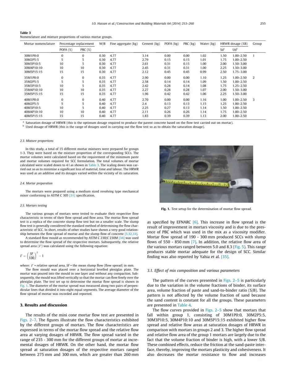
Table 3Nomenclature and mixture proportions of various mortar groups.
Mortar nomenclature Percentage replacement W/B Fine aggregate (kg) Cement (kg) POFA (kg) PBC (kg) Water (kg) HRWR dosage (%B) Group
POFA (%) PBC (%) Sda Udb
30M1P0:0 0 0 0.30 4.77 3.14 0.00 0.00 1.02 1.50 1.00–2.50 130M2P5:5 5 5 0.30 4.77 2.79 0.15 0.15 1.01 1.75 1.00–2.5030M3P10:5 10 5 0.30 4.77 2.61 0.31 0.15 1.00 2.00 1.50–3.0030M4P10:10 10 10 0.30 4.77 2.45 0.31 0.31 1.00 2.25 1.50–3.0030M5P15:15 15 15 0.30 4.77 2.12 0.45 0.45 0.99 2.50 1.75–3.00
35M1P0:0 0 0 0.35 4.77 2.90 0.00 0.00 1.10 1.25 1.00–2.50 235M2P5:5 5 5 0.35 4.77 2.58 0.14 0.14 1.09 1.50 1.00–2.5035M3P10:5 10 5 0.35 4.77 2.42 0.28 0.14 1.08 1.75 1.25–2.5035M4P10:10 10 10 0.35 4.77 2.27 0.28 0.28 1.07 2.00 1.50–3.0035M5P15:15 15 15 0.35 4.77 1.96 0.42 0.42 1.06 2.25 1.50–3.00
40M1P0:0 0 0 0.40 4.77 2.70 0.00 0.00 1.16 1.00 1.00–2.50 340M2P5:5 5 5 0.40 4.77 2.4 0.13 0.13 1.15 1.25 1.00–2.5040M3P10:5 10 5 0.40 4.77 2.25 0.27 0.13 1.14 1.50 1.00–2.5040M4P10:10 10 10 0.40 4.77 2.11 0.26 0.26 1.14 1.75 1.00–2.5040M5P15:15 15 15 0.40 4.77 1.83 0.39 0.39 1.13 2.00 1.00–2.50
a Saturation dosage of HRWR (this is the optimum dosage required to produce the parent concrete based on the flow test carried out on mortar).b Used dosage of HRWR (this is the range of dosages used in carrying out the flow test so as to obtain the saturation dosage).
Fig. 1. Test setup for the determination of mortar flow spread.
I.O. Hassan et al. / Construction and Building Materials 64 (2014) 253–260 255
2.3. Mixture proportions
In this study, a total of 15 different mortar mixtures were prepared for groups1-3. They were based on the mixture proportion of the corresponding SCCs. Themortar volumes were calculated based on the requirement of the minimum pasteand mortar volumes required for SCC formulation. The total volumes of mortarcalculated were scaled down to 4 l as shown in Table 3. The scaling down was car-ried out so as to minimise a significant loss of material, time and labour. The HRWRwas used as an additive and its dosages varied within the vicinity of its saturation.
2.4. Mortar preparation
The mortars were prepared using a medium sized revolving type mechanicalmixer conforming to ASTM C 305 [31] specification.
2.5. Mortars testing
The various groups of mortars were tested to evaluate their respective flowcharacteristic in terms of their flow spread and flow area. The mortar flow spreadtest is a replica of the concrete slump flow test but on a smaller scale. The slumpflow test is generally considered the standard method of determining the flow char-acteristic of SCC. In short, results of other studies have shown a very good relation-ship between the flow spread of mortar and the slump flow of concrete [5,32,33].
A standard flow mould as recommended by ASTM C 230/C 230M [34] was usedto determine the flow spread of the respective mortars. Subsequently, the relativespread area (C) was calculated using the following equation:
C ¼ SF100
� �2
� 1
where: C = relative spread area, SF = the mean slump flow (flow spread) in mm.The flow mould was placed over a horizontal levelled plexiglas plate. The
mortar was poured into the mould in one layer and without any compaction. Sub-sequently, the mould was lifted vertically so that the mortar can flow freely over theplexiglas plate. The test set up to determine the mortar flow spread is shown inFig. 1. The diameter of the mortar spread was measured along two pairs of perpen-dicular lines that divided it into eight equal segments. The average diameter of theflow spread of mortar was recorded and reported.
3. Results and discussion
The results of the mini cone mortar flow test are presented inFigs. 2–7. The figures illustrate the flow characteristics exhibitedby the different groups of mortars. The flow characteristics areexpressed in terms of the mortar flow spread and the relative flowarea at varying dosages of HRWR. The flow spread varied in therange of 235 - 300 mm for the different groups of mortar at incre-mental dosages of HRWR. On the other hand, the mortar flowspread at saturation dosages of the respective mortars rangedbetween 275 mm and 300 mm, which are greater than 260 mm
as specified by EFNARC [6]. This increase in flow spread is theresult of improvement in mortars viscosity and is due to the pres-ence of PBC which was used in the mix as a viscosity modifier.Mortar flow spread of 190 - 300 mm produced SCCs with slumpflows of 550 - 850 mm [7]. In addition, the relative flow area ofthe various mortars ranged between 5.0 and 8.3 (Fig. 5). This rangeproduces stable mortar adequate for the design of SCC. Similarfinding was also reported by Yahia et al. [35].
3.1. Effect of mix composition and various parameters
The pattern of the curves presented in Figs. 2–5 is particularlydue to the variation in the volume fractions of binder, its surfacearea, volume fraction of paste and sand-to-binder ratio (S/B). Thepattern is not affected by the volume fraction of sand becausethe sand content is constant for all the groups. These parametersare presented in Table 4.
The flow curves provided in Figs. 2–5 show that mortars thatfall within group 1, consisting of 30M1P0:0, 30M2P5:5,30M3P10:5, 30M4P10:10 and 30M5P15:15 exhibited higher flowspread and relative flow areas at saturation dosages of HRWR incomparison with mortars in groups 2 and 3. The higher flow spreadand relative flow area of the group 1 mortars are largely due to thefact that the volume fraction of binder is high, with a lower S/B.These combined effects, reduce the friction at the sand-paste inter-face, thereby, improving the mortars plasticity and cohesiveness. Italso decreases the mortar resistance to flow and increases

0.75 1.00 1.25 1.50 1.75 2.00 2.25 2.50 2.75 3.00 3.25240
250
260
270
280
290
300
310
320
Mor
tar
flow
spr
ead
(mm
)
HRWR Content (% of Binder)
0% SCM 10% SCM 15% SCM 20% SCM 30% SCM
Fig. 2. Flow spread of various mortars in group 1.
0.75 1.00 1.25 1.50 1.75 2.00 2.25 2.50 2.75 3.00240
250
260
270
280
290
300
310
320
Mor
tar
flow
spr
ead
(mm
)
HRWR Content (% of Binder)
0% SCM 10% SCM 15% SCM 20% SCM 30% SCM
Fig. 3. Flow spread of various mortars in group 2.
1.00 1.25 1.50 1.75 2.00 2.25 2.50
240
250
260
270
280
290
300
310
320
Mor
tar
flow
spr
ead
(mm
)
HRWR Content (% of Binder)
0% SCM 10% SCM 15% SCM 20% SCM 30% SCM
Fig. 4. Flow spread of various mortars in group 3.
0.75 1.00 1.25 1.50 1.75 2.00 2.25 2.50 2.75 3.00
0
1
2
3
4
5
6
7
8
9
Rel
ativ
e fl
ow a
rea
HRWR dosage (% of Binder)
(a) 30M1P0:0 30M2P5:5 30M3P10:5 30M4P10:10 30M5P15:15
0.75 1.00 1.25 1.50 1.75 2.00 2.25 2.50 2.75 3.000
1
2
3
4
5
6
7
8
9
Rel
ativ
e fl
ow a
rea
HRWR dosage (% of Binder)
(b)
35M1P0:0 35M2P5:5 35M3P10:5 35M4P10:10 35M5P15:15
1.00 1.25 1.50 1.75 2.00 2.25 2.50
0
1
2
3
4
5
6
7
8
9
Rel
ativ
e fl
ow a
rea
HRWR dosage (% of Binder)
(c)
40M1P0:0 40M2P5:5 40M3P10:5 40M4P10:10 40M5P15:15
Fig. 5. (a, b, c) Relative flow area of various mortars in groups 1, 2 and 3.
256 I.O. Hassan et al. / Construction and Building Materials 64 (2014) 253–260
workability [35,36]. On the other hand, group 2 mortars, consistingof 35M1P0:0, 35M2P5:5, 35M3P10:5, 35M4P10:10 and35M5P15:15 contain lower volume fraction of binder with slightlyhigher S/B in comparison with group 1 mortars. Conversely, group3 mortars consisting of 40M1P0:0, 40M2P5:5, 40M3P10:5,40M4P10:10 and 40M5P15:15 contain lower volume fraction ofbinder with much higher S/B in comparison to groups 1 and 2mortars.
It was reported by Okamura and Ozawa [3] that at higher S/B,there is higher amount of water confined by the sand, leading to
240 250 260 270 280 290 300
Saturation flow spread (mm)
Mor
tar
Nom
encl
atur
e
30M1P0:030M2P5:5
30M3P10:530M4P10:1030M5P15:15
35M1P0:035M2P5:5
35M3P10:535M4P10:1035M5P15:15
40M1P0:040M2P5:5
40M3P10:540M4P10:1040M5P15:15
Fig. 6. Saturation flow spread of various mortars in groups 1, 2 and 3.
30M1P0:030M2P5:5
30M3P10:530M4P10:1030M5P15:15
35M1P0:035M2P5:5
35M3P10:535M4P10:1035M5P15:15
40M1P0:040M2P5:5
40M3P10:540M4P10:1040M5P15:15
0.0 0.5 1.0 1.5 2.0 2.5
Saturation dosage of HRWR
Mor
tar
Nom
encl
atur
e
Fig. 7. Saturation dosages of HRWR of various mortars in groups 1, 2 and 3.
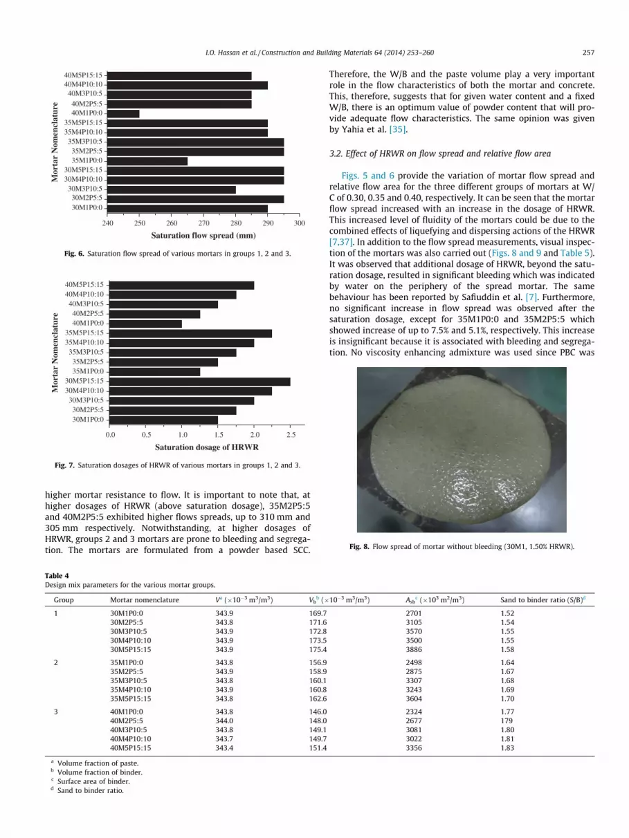
Fig. 8. Flow spread of mortar without bleeding (30M1, 1.50% HRWR).
I.O. Hassan et al. / Construction and Building Materials 64 (2014) 253–260 257
higher mortar resistance to flow. It is important to note that, athigher dosages of HRWR (above saturation dosage), 35M2P5:5and 40M2P5:5 exhibited higher flows spreads, up to 310 mm and305 mm respectively. Notwithstanding, at higher dosages ofHRWR, groups 2 and 3 mortars are prone to bleeding and segrega-tion. The mortars are formulated from a powder based SCC.
Table 4Design mix parameters for the various mortar groups.
Group Mortar nomenclature Va (�10�3 m3/m3) Vbb (�
1 30M1P0:0 343.9 169.730M2P5:5 343.8 171.630M3P10:5 343.9 172.830M4P10:10 343.9 173.530M5P15:15 343.9 175.4
2 35M1P0:0 343.8 156.935M2P5:5 343.9 158.935M3P10:5 343.8 160.135M4P10:10 343.9 160.835M5P15:15 343.8 162.6
3 40M1P0:0 343.8 146.040M2P5:5 344.0 148.040M3P10:5 343.8 149.140M4P10:10 343.7 149.740M5P15:15 343.4 151.4
a Volume fraction of paste.b Volume fraction of binder.c Surface area of binder.d Sand to binder ratio.
Therefore, the W/B and the paste volume play a very importantrole in the flow characteristics of both the mortar and concrete.This, therefore, suggests that for given water content and a fixedW/B, there is an optimum value of powder content that will pro-vide adequate flow characteristics. The same opinion was givenby Yahia et al. [35].
3.2. Effect of HRWR on flow spread and relative flow area
Figs. 5 and 6 provide the variation of mortar flow spread andrelative flow area for the three different groups of mortars at W/C of 0.30, 0.35 and 0.40, respectively. It can be seen that the mortarflow spread increased with an increase in the dosage of HRWR.This increased level of fluidity of the mortars could be due to thecombined effects of liquefying and dispersing actions of the HRWR[7,37]. In addition to the flow spread measurements, visual inspec-tion of the mortars was also carried out (Figs. 8 and 9 and Table 5).It was observed that additional dosage of HRWR, beyond the satu-ration dosage, resulted in significant bleeding which was indicatedby water on the periphery of the spread mortar. The samebehaviour has been reported by Safiuddin et al. [7]. Furthermore,no significant increase in flow spread was observed after thesaturation dosage, except for 35M1P0:0 and 35M2P5:5 whichshowed increase of up to 7.5% and 5.1%, respectively. This increaseis insignificant because it is associated with bleeding and segrega-tion. No viscosity enhancing admixture was used since PBC was
10�3 m3/m3) Asbc (�103 m2/m3) Sand to binder ratio (S/B)d
2701 1.523105 1.543570 1.553500 1.553886 1.58
2498 1.642875 1.673307 1.683243 1.693604 1.70
2324 1.772677 1793081 1.803022 1.813356 1.83

Fig. 9. Flow spread of mortar with bleeding (30M1, 2.0% HRWR).
Fig. 10. Flow spread of mortar with onset of bleeding (40M1, 1.0% HRWR).
258 I.O. Hassan et al. / Construction and Building Materials 64 (2014) 253–260
used as viscosity modifier. This is because all the mortar mixtureswere powder based. Consequently, the saturation dosages of therespective mixtures were found adequate. Notwithstanding, somegroup 3 mortars mixture exhibited evidence of onset of bleeding atthe saturation dosages of HRWR, as seen in specimens 40M1P0:0and 40M2P5:5 (Table 5). This could be attributed to the fact thatat higher W/B, the dispersing action of the HRWR is more pro-nounced due to lower volume fraction of binder and the presenceof excess free water.
Fig. 11. Flow spread of mortar with onset of bleeding (40M5, 2.25% HRWR).
3.3. Effect of W/B
The W/B plays an important role in the fluidity of mortar mix-tures, particularly powder based mixtures. In this study, W/B of0.3, 0.35 and 0.40 were used for investigation. The flow spreadsof mortars were examined for each W/B group at varying percent-ages of blended POFA and PBC corresponding to the saturation dos-ages of HRWR (Fig. 6). It can be seen that group 1 mortars with W/Bof 0.30 exhibited higher flow spread in comparison to groups 2 and3. This higher flow spread exhibited by group 1 mortars is due toits improved plasticity and cohesiveness. On the other hand, group3 mortars exhibited lower plasticity and cohesiveness due toreduced volume fraction of binder and higher S/B. This reducedvolume of binder reduces the viscosity of the paste and increasesinter-particle friction and induces bleeding. Similar results werealso reported by certain authors [3,7,35,36]. As can be seen invisual inspection (Figs. 10 and 11), most of the group 3 mortarsshowed evidence of the onset of bleeding at saturation dosagesof HRWR.
Table 5Visual inspection results for the various mortar groups.
Mortar nomenclature HRWR dosage (%B)
Sda Udb
30M1P0:0 1.50 1.00–230M2P5:5 1.75 1.00–230M3P10:5 2.00 1.50–330M4P10:10 2.25 1.50–330M5P15:15 2.50 1.75–3
35M1P0:0 1.25 1.00–235M2P5:5 1.50 1.00–235M3P10:5 1.75 1.25–235M4P10:10 2.00 1.50–335M5P15:15 2.25 1.50–3
40M1P0:0 1.00 1.00–240M2P5:5 1.25 1.00–240M3P10:5 1.50 1.00–240M4P10:10 1.75 1.00–240M5P15:15 2.00 1.00–2
a Saturation dosage of HRWR.b Used dosage of HRWR.
3.4. Effect of blend of POFA and PBC
Investigations on the microstructure of POFA and PBC carriedout by Hassan et al. [38] showed that POFA has a high BET surfacearea (23.75 m2/g) while PBC has a very low surface area (2.98 m2/g) compared to OPC with BET surface area (5.07 m2/g). The addi-tion of POFA at varying percentages increased the viscosity of themixes. This is particularly due to dispersed arrangement of parti-cles as well as porous and irregularly shaped particles (Fig. 12).Although POFA and PBC carry relatively similar particle size distri-bution (Table 2), the addition of PBC into the mixtures tends to
Physical observation on the flow spread of mortar
.50 Bleeding at and after 2.0% HRWR
.50 No bleeding
.00 No bleeding
.00 No bleeding
.00 No bleeding
.50 Bleeding at and after 1.5% HRWR
.50 Bleeding at and after 1.75% HRWR
.50 Bleeding at and after 2.0% HRWR
.00 Bleeding at and after 2.25% HRWR
.00 Bleeding at and after 2.75% HRWR
.50 Onset of bleeding at 1.0% HRWR
.50 Onset of bleeding at 1.25% HRWR
.50 Bleeding at and after 1.75% HRWR
.50 Bleeding at and after 2.0% HRWR
.50 Bleeding at and after 2.25% HRWR

Fig. 12. SEM image showing dispersed and porous particles of POFA.
Fig. 13. SEM image showing agglomerated particles arrangement of PBC.
I.O. Hassan et al. / Construction and Building Materials 64 (2014) 253–260 259
improve the rheology of the mixtures. This is particularly due toagglomerated particles arrangement and high content of non-por-ous glassy surfaced particles characterised by high calcinationtemperature (Fig. 13). Thus, it reduces the demand for higher per-centages of HRWR while increasing the flow spread. Furthermore,Table 5 shows that the addition of a blend of POFA and PBC pre-vented the bleeding of the mortars at higher dosages of HRWR. Itwas also observed that there is no significant difference in the flowspread because the blend was based predominantly on equal pro-portion of SCM, except for the M3 series which were based on 10%POFA and 5% PBC.
The increased volume fraction and surface area of binderrequires higher dosages of HRWR at higher percentage of POFAto obtain the saturation flow spread. The dosage of HRWR isreduced by the inclusion of PBC. The extent of flow spread alsodepends on the physical and micro-structural characteristics ofthe binder. A comparative assessment carried out by Safiuddinet al. [7] showed that fly ash (FA) and silica fume (SF) have spher-ical and non-porous particles while rice husk ash (RHA) has angu-lar and porous particles. The physical characteristics of FA and SFare responsible for greater flow spread in comparison with RHA.A blend of POFA and PBC has demonstrated similar flow spreadcharacteristics as FA and SF. These results are also in agreementwith the findings of previous research carried out on ternary mix-tures where by, one mineral additive is used to hinder the negativeeffects of the other one, thus yielding a SFCM with the requiredflow characteristics [39].
The HRWR requirement of the binder was higher for lower W/Bfor the same percentage replacement. At 20% and 30% replace-ments, the saturation dosages of HRWR were 2.25/2.5, 2.00/2.25
and 1.75/2.00 for W/B of 0.3, 0.35 and 0.40, respectively. On theother hand, the saturation flow spreads were 295 mm/295 mm,290 mm/290 mm and 290 mm/285 mm, respectively.
3.5. Significance of the flow spread results of mortars
As has been advocated, the flow characteristic of mortar isgreatly influenced by 3 key factors which include; HRWR dosage,powder content and W/B. The results of this investigation are veryuseful for adequate proportioning of HRWR dosage, appropriatecontent of the blend of POFA and PBC and W/B for various SCCmixtures.
4. Conclusions
Based on the results of the study on the flow characteristics ofvarious mortars containing a blend of OPC, POFA and PBC and for-mulation of various SCC mixtures, the following conclusions can bedrawn:
a. The flow spread of mortar increases with the increase dos-age of HRWR due to deflocculating and dispersing behaviourof the powders particles.
b. The flow spread of various mortars did not increase signifi-cantly at higher dosages of HRWR beyond the saturationdosage. Instead, visual inspection identified the manifesta-tion of bleeding at such higher dosages.
c. The mix compositions and parameters, such as, variation inthe volume fractions of binder, its surface area, volume frac-tion of paste and S/B greatly influenced the flow spread ofthe various mortars studied.
d. Group 1 mortars with W/B of 0.30 exhibited higher flowspread than groups 2 and 3 with W/B of 0.35 and 0.4, respec-tively. Group 1 mortars exhibited higher viscosity thangroup 2 due to higher volume fraction of binder and its sur-face area. On the other hand, group 3 mortars exhibitedlower viscosity due to lower volume fraction of binder andlower surface area.
e. The physical and micro-structural characteristics of theSCMs played a very important role in the demand of HRWRin the investigation of various mortars.
f. The addition of a blended POFA and PBC prevented thebleeding of the mortars at higher dosages of HRWR. The flowspread of the mortars increased with the increase percent-age of blended POFA and PBC. However, no significant differ-ence was observed in the flow spread because the blend wasbased on equal proportions of POFA and PBC.
g. A blend of up to 30% (15% POFA and 15% PBC) was foundappropriate for all groups of mortars since there is no signif-icant difference in the flow spread at such higher replace-ment levels. A slight delay in setting time was observed ingroup 1 mortars incorporating 2.5% HRWR. In general, allmortar mixes showed good level of workability in terms ofmixing and handling.
h. The results of flow spread were useful to select appropriatedosages of HRWR for the respective mortars and conse-quently the parent SCCs.
Acknowledgements
The authors wish to express their profound gratitude for thefinancial contribution from MOSTI research Grant No. 03-01-06-SF1217, the research management centre of Universiti Teknologi
260 I.O. Hassan et al. / Construction and Building Materials 64 (2014) 253–260
Malaysia (RMC, UTM) and the technical support provided by thelaboratory technician of the Faculty of Civil Engineering.
References
[1] Vachon M, Daczko J, U.S regulatory work on SCC in proceedings of the firstNorth American conference on the design and use of self-consolidatingconcrete. Evanston, USA; 2002.
[2] ACI-113R. Cement and concrete terminology, ACI: Detroit, USA; 1990.[3] Okamura H, Ozawa K. Mix design for self-compacting concrete. Conc Library
JSCE 1995;25:107–20.[4] Okamura H, Ouchi M. Self-compacting concrete. J Adv Concr Technol
2003;1(1):5–15.[5] Lachemi M, Hossain KMA, Patel R, Shehata M, Bouzoubaa N. Influence of paste/
mortar rheology on the flow characteristics of high-volume fly ashselfconsolidating concrete. Mag Concr Res 2007;59(7):517–28.
[6] EFNARC. Specifications and guidelines for self-compacting concrete. Surrey,UK; 2002.
[7] Safiuddin M, West JS, Soudki KA. Flowing ability of the mortars formulatedfrom self-compacting concretes incorporating rice husk ash. Constr BuildMater 2011;25(2):973–8.
[8] Barbhuiya S. Effects of fly ash and dolomite powder on the properties of self-compacting concrete. Constr Build Mater 2011;25(8):3301–5.
[9] Turk K. Viscosity and hardened properties of self-compacting mortars withbinary and ternary cementitious blends of fly ash and silica fume. Constr BuildMater 2012;37:326–34.
[10] Safiuddin M, West JS, Soudki KA. Properties of freshly mixed self-consolidatingconcretes incorporating rice husk ash as a supplementary cementing material.Constr Build Mater 2012;30:833–42.
[11] Barluenga G, Hernández-Olivares F. Self-levelling cement mortar containinggrounded slate from quarrying waste. Constr Build Mater 2010;24(9):1601–7.
[12] Tangchirapat W, Jaturapitakkul C, Chindaprasirt P. Use of palm oil fuel ash as asupplementary cementitious material for producing high-strength concrete.Constr Build Mater 2009;23(7):2641–6.
[13] Sumadi SR, Hussin MW. Palm oil fuel ash (POFA) as a future partial cementreplacement material in housing construction. J Ferrocement1995;25(1):25–34.
[14] Ismail ME, Hussin MW, Ismail M. Palm oil fuel ash as the future supplementarycementitious material in concrete. Concr Plant Int 2010;3:38–45.
[15] Jordán MM, Boix A, Sanfeliu T, de la Fuente C. Firing transformations ofcretaceous clays used in the manufacturing of ceramic tiles. Appl Clay Sci1999;14(4):225–34.
[16] Pardo F, Meseguer S, Jordán MM, Sanfeliu T, González I. Firing transformationsof Chilean clays for the manufacture of ceramic tile bodies. Appl Clay Sci2011;51(1–2):147–50.
[17] Wild S, Khatib JM, O’Farrell M. Sulphate resistance of mortar, containingground brick clay calcined at different temperatures. Cem Concr Res1997;27(5):697–709.
[18] Sabir BB, Wild S, Bai J. Metakaolin and calcined clays as pozzolans for concrete:a review. Cem Concr Compos 2001;23(6):441–54.
[19] O’Farrell M, Wild S, Sabir BB. Resistance to chemical attack of ground brick–PCmortar: Part II. Synthetic seawater. Cem Concr Res 2000;30(5):757–65.
[20] O’Farrell M, Sabir BB, Wild S. Strength and chemical resistance of mortarscontaining brick manufacturing clays subjected to different treatments. CemConcr Compos 2006;28(9):790–9.
[21] Page I. The rise and fall of claddings, in build, June/July 2007. p. 68–9.[22] RMIT. Scoping study to investigate measures for improving the environmental
sustainability of building materials, 2006, Australian Greenhouse Office,Commonwealth of Australia, Melbourne, Australia; 2006.
[23] P Crowther 23. Building deconstruction in Australia. In: Chini CJKaAR, editor.Overview of deconstruction in selected countries. Florida: University ofFlorida; 2000. p. 1–28.
[24] Formoso C, Soibelman MASCE Lucio, De Cesare Claudia, Isatto Eduardo L.Material waste in building industry: main causes and prevention. J Constr EngManage 2002;128(4):316–25.
[25] Demir I, Orhan M. Reuse of waste bricks in the production line. Build Environ2003;38(12):1451–5.
[26] Kharrufa S. Reduction of building waste in Baghdad Iraq. Build Environ2007;42(5):2053–61.
[27] Safiuddin 27M, Abdus-Salam M, Jumaat M. Key fresh properties of self-consolidating high-strength POFA concrete. J Mater Civil Eng 2013;0(ja).
[28] Heikal M, Zohdy KM, Abdelkreem M. Mechanical, microstructure andrheological characteristics of high performance self-compacting cementpastes and concrete containing ground clay bricks. Constr Build Mater2013;38:101–9.
[29] ASTM C150/C150M. Standard specification for Portland cement, in AnnualBook of ASTM Standards, vol. 04.02 2012, American Society for Testing andMaterials: Philadelphia, USA. p. 9.
[30] ASTM C494/C494M. Standard specification for chemical admixtures forconcrete, in Annual Book of ASTM Standards, vol. 04.02 2013, AmericanSociety for Testing and Materials: Philadelphia, USA. p. 10.
[31] ASTM C305. Standard practice for mechanical mixing of hydraulic cementpastes and mortars of plastic consistency, in Annual Book of ASTM Standards,vol. 04.02 2012, American Society for Testing and Materials: Philadelphia, USA.p. 3.
[32] Safiuddin M, West JS, Soudki KA. Flowing ability of self-consolidating concreteand its binder paste and mortar components incorporating rice husk ash. Can JCiv Eng 2010;37(3):401–12.
[33] Domone P. Mortar tests for self-consolidating concrete. Concr Int2006;28(4):39–45.
[34] ASTM C230/C230M. Standard specification for flow table for use in tests ofhydraulic cement, in Annual Book of ASTM Standards, vol. 04.02 2008,American Society for Testing and Materials: Philadelphia, USA. p. 6.
[35] Yahia A, Tanimura M, Shimoyama Y. Rheological properties of highly flowablemortar containing limestone filler-effect of powder content and W/C ratio.Cem Concr Res 2005;35(3):532–9.
[36] Lane RO, Best JF. Properties and use of fly ash in Portland cement concrete.Concr Int 1982;4(7):81–92.
[37] De Schutter G, Bartos PJM, Domone P, Gibbs J. Self-compactingconcrete. Scotland, UK: Whittles Publishing; 2008. 296.
[38] Hassan IO, Ismail M, Noruzman AH, Yusuf TO, Mehmannavaz T, Usman J.Characterization of some key industrial waste products for sustainableconcrete production. Adv Mater Res 2013;690–693:1091–4.
[39] S�ahmaran M, Christianto HA, Yaman _IÖ. The effect of chemical admixtures andmineral additives on the properties of self-compacting mortars. Cem ConcrCompos 2006;28(5):432–40.