uga design & construction
TRANSCRIPT
UGA DESIGN & CONSTRUCTION SUPPLEMENTAL GENERAL REQUIREMENTS & STANDARDS
CHANGES FROM APRIL 30, 2020 VERSION TO JUNE 15, 2021 VERSION Introduction
• Added Paragraph: “ There are a number of UGA units with facilities located outside of Clarke County that often have needs for performing facility maintenance, renovations, or new construction projects. These include, but are not limited to the College of Agricultural and Environmental Sciences “B” unit facilities, including 4-H and Extension sites, Warnell School of Forestry & Natural Resources “B” unit facilities, Skidaway Institute of Oceanography, the Marine Extension and Georgia Sea Grant, University of Georgia Marine Institute, the Griffin and Tifton campuses, and Wormsloe. The design, construction, and renovation requirements for all of these units are not yet fully reflected in the Standards and Design Professionals and Contractor shall discuss applicability and submit for variances per Section 00 00 05 Variance Requirements & Form on a project by project basis.”
00 00 04 – Environmental
• 1.E. Added: “GEOS, the Georgia EPD Online System: All plans, improvements, and construction activities shall be compliant with the rules and regulations administered by the Georgia Environmental Protection Division Unless otherwise expressly permitted through official variance, agreement, or interpretation certified by the Owner. Any permit applications, reports, and fee payments required by the Georgia EPD shall be submitted through GEOS, the Georgia EPD Online System, a web-based portal. It is the responsibility of the Design Professional, Contractor, and/or reporting agency to ensure that all required materials are submitted to GEOS as required by law. The Owner’s designated Responsible Official (RO) will review and certify receipt of filed materials in GEOS when required, but bears no responsibility for the failure of an engaged Design Professional, Contractor, or other agency to successfully submit such required materials appropriately to GEOS for the Project. Refer to GEOS Training and Technical Assistance site for programs currently included in the online system and a schedule for required GEOS Submittals.”
00 00 05 – Variance Requirement & Form
• 1.D. Added: “For work at UGA's Tifton and Griffin Campuses and all other UGA facilities outside of Clarke County, the Project Manager shall discuss at with the Design Professional and Contractors during the kick off meetings that potential variances of the UGA Standards should be discussed for these locations.”
• Updated Variance Request Form 00 00 07 – Design Professional Design Process Requirements
• 1.D.xv. Added: “Energy Use Intensity (EUI)”
00 00 08 – Design Professional Documentation Requirements & Deliverables
• 1.C.i. Added: “Contract, UGA Building Number” • 1.C.v. Edited “Accurate index with any revised sheets noted as revised” to “Accurate
and complete index of all sheets for the project including clear identification of most up to date sheet version (including set title and date).”
• 1.c.vi. Added new Bullet point: “Include UGA location map showing at least one major road or intersection on cover sheet ( campus maps are available for download at link)
• 1.C.x. Edited: “2007” to “2013” • 1.C.xii. Removed “Hard copy drawings shall be full size black line on white bond
reproductions and be bound. Specifications shall be 8.5”x11” and bound.” 00 00 12 – Client & End User Interface
• 1.A. Edited: “Owners Representative” to “UGA Project Manager” 00 00 13 – Designing Learning Environments
• 6.0 Added: “It is strongly preferred that accessible seating in tiered classrooms be arranged in a distributed manner, i.e. not exclusively located at the front or back of the room.”
01 41 26.04 – Fire Marshal Construction Inspection Requirements
• 1.F.ix.1. Edited: “ 2010” to “current edition of” 01 81 00 – Facility Performance Requirements
• 1.E.i.a. Removed “Design Professional shall be held accountable for meeting 10% or greater energy savings over ASHRAE 90.1 – 2010 Appendix G.”
• 3.A. Edited Table, removed “Mechanical, electrical, and plumbing energy related design complies with ASHRAE Standard 90.1-2010, with exception of programmable power receptacles. “
01 58 00 – UGA Campus Signage Standards
• 4.A. Edited: “shall identified accordance with relevant naming / memorial policies and designed, ordered, and installed only after approval procedures have been completed.” to “shall be identified in accordance with relevant naming / memorial policies and designed, ordered, and installed only after approval procedures have been completed. Development officers should work with OUA when determining appropriate size and design of recognition signage.”
• 4.B. Added New Bullet Point: “Use of Logos” • 4B.i. Added: “Use of the official UGA logo in donor recognition graphics should
conform to the style guide available through the UGA Division of Marking and
Communication Office at http://styleguide.uga.edu/index.php?/entries/logo_guide_and_downloads
• 4.B.ii. Added: “No commercial or corporate logos or other branding imagery is permitted in association with campus donor recognition graphics. In special circumstances, use of logos on interior recognition plaques may be approved by the Office of the President
04 00 00 – General Masonry Requirements
• 3.C.vi. Added: “Interdisciplinary STEM Research Buildings 1 and 2 (Bldg. #s 1131 and 1132)_: Cherokee Brick Velour Flash Holcim 200 Ivory Buff grout”
• 3.C.vii. Added: “Reed Plaza: Cherokee Brick Old Birmingham” • 3C.viii. Added: “Sanford Stadium West End: Boral Bricks Mt. Vernon” • 3.C.ix. Added: “New First Year Residence Hall (Bldg. # 2264): Cherokee Old
Birmingham Holcim Antique Buff” 05 52 00 – Metal Railings
• 1.C. Added: “Final engineering and design of hand rails and guard rails shall be included in the scope of the Design Professional.”
07 00 00 – General Thermal and Moisture Protection Requirements- Roof Drains & Roofs
• 1.B.g. Added: “at least” 08 71 00 – Door Hardware
• 2.A.v. Edited: “lockset or as directed by Project Manager” to “ lockset, (4) for Housing only, or as directed by UGA PM”
• 2.B.ii.c. Added: “Shall be used as Basis of Design for Housing projects” • 2.B.i.a. Added: “Basis of Design”
09 00 00.1 – Custodial Storage
• 1.B.ii. Added: “In buildings where custodial activities are anticipated to be more intensive due to programmatic requirements, Project Manager shall consult with the FMD Services Director to determine the need for a potentially larger Custodial Storage Room and specialized equipment.”
• 1.H.v. Added: “Housing Only: Shelving is Owner-furnished, Owner-installed.” 09 20 00 – Plaster & Gypsum Board
• 2.F. Removed: “F. For UGA Housing Only (New Construction)
i. Abuse resistant, impact-resistant gypsum board for all public spaces, corridors, and student residential rooms.
ii. Joint treatment and wall finish shall be level 5 finish for all painted walls in accordance with the “Recommended Specification: Level s of Gypsum Board Finish” as published by the Gypsum Association and level 4 finish for all painted ceilings.
iii. Joint tape shall be paper tape as approved by abuse-resistant panel manufacturer.
iv. Corner reinforcement shall be galvanized steel with 1 ¼-inch wide fine expanded mesh flanges.”
09 91 23 – Interior Painting
• 2.D.iv. Added: “(For example, student rooms and corridors will always be semi-gloss.)” 10 28 00 – Toilet, Bath, and Laundry Accessories
• 2.D Removed in entirety the previous 2.D “Hand Dryers”. New 2.D is existing “Toilet and Bath Accessories – For UGA Housing Only (New Construction)”
• 2.D.ii.a. Added: “(Owner-furnished/ Owner-installed)” • 2.D.ii.c. Added: “(Owner-furnished/ Owner-installed)” • 2.D.ii.d. Added: “(Owner-furnished/ Owner-installed)” • 2.D.iii.a. Added: “(Owner-furnished/ Owner-installed)” • 2.D.iii.b. Added: “(Owner-furnished/ Owner-installed)”
11 53 13 – Laboratory Fume Hoods
• 1.G. Added: “Fume hood performance shall be scheduled on the mechanical drawings (total hood cfm, including bypass, required to achieve design face velocity).”
14 20 00 – Elevators • Added:
“2.E Video Monitoring System i. Basis of Design: RATH SMARTVIEW Two-Way Elevator Visual
Communication System. ii. System shall meet the ASME A17.1 and B44 2019 code requirements for
visual communicationas well as the requirements for the current adopted edition of the IBC.
iii. System shall provide a secure connection to cloud software and allows for monitoring of the system. The monitoring agency (UGA PD) is able to receive a standard elevator call, and, if no answer, utilize the video monitoring system to view the elevator. If the elevator car is occupied then the monitoring agency can then send a text type message to the display in the car and receive a Yes/No response.
iv. The system shall meet the following requirements:
1. Standard Elevator Phone: For passengers who are able to communicate verbally with emergency personnel.
2. Display: If a passenger is not able to verbally respond, emergency personnel can post a message on the display in the car.
3. Message Response: Ability to provide a YES/NO response back to emergency personnel.
4. One-Way Video: Emergency personnel can view the elevator car to see if someone is in the elevator who cannot verbally respond.
v. System Installation/Configuration Requirements: 1. Single pair 18AWG (shielded or unshielded) wire per elevator in
the traveling cable 2. Internet access via direct network connection 3. 1 Pair Ethernet Extenders per elevator (by system manufacturer) 4. Laptop for system setup and test”
• Added: “2.F Limited Use/Limited Application (LULA) Elevators
i. Requirements a. LULA elevator product and components provided shall be non-
proprietary in nature. b. Design and installation shall comply with ASME A17.1/CSA B44 as
well as accessibility requirements for LULA elevators noted in the current adopted ADA Accessibility Guidelines and ICC A117.1
ii. Basis-of-Design (subject to compliance with requirements): a. Symmetry Elevating Solutions LULA Elevator, or comparable
product by one of the following: b. American Crescent Elevator Mfg. Corp. c. Cambridge Elevating d. Cemcolift, Inc. e. Garaventa Lift. f. Savaria”
21 00 00 – General Fire Suppression Requirements
• 1.E. Added: “Flexible sprinkler piping/heads are not allowed above hard ceilings."
22 00 00 – General Plumbing Requirements • 1.G. Edited: “guards are preferable if they are a viable solution” to “guards shall be
used as the basis of design.” • 1.N. Added: “Installation of residential-type dishwashers is prohibited. In cases
where there is adequate reasoning, a variance must be submitted and approved prior to incorporation into the design. "
22 40 00 –Plumbing Fixtures
• 2.C.iv. Edited: “Moen” to “Delta” 23 00 00 – General Mechanical Requirements (HVAC)
• 1.C.xxv. Added: “FCU (CHW or mini-split) condensate may be drained to the outside but must not create a nuisance on the building enclosure, the site, or hardscape.”
• 1.C.xxvi. Added: “All mechanical rooms containing “cold equipment (equipment utilizing chilled water), or electrical rooms shall be mechanically cooled rather than ventilated.”
• 1.C.xxvii. Added: “Mechanical rooms shall be provided with a hose bibb(s) for maintenance purposes.”
• 1.C.xxviii. Added: “When AHUs are installed in penthouses, the penthouse shall be designed with multiple floor drains, sloped floors, and/or coated with epoxy coating as necessary to mitigate the possibility of water leaks damaging occupied spaces below.”
23 05 53 – Identification For HVAC Piping Equipment
• 3.E. Added to table: Process Water line 23 07 19 – HVAC Piping Insulation
• 2.B. Edited: “ITW” to “John Manville” 23 09 23 – Building Automation and Temperature Control System (BAS)
• 1.Q. Added: For critical applications, in lieu of a "power trunk", provide a minimum 40va, 24vac control transformer from the factory for each terminal unit, to be wired by Division 26 subcontractor in the field with a toggle switch disconnect.
• 1.R. Added: “Control devices shall be provided with disconnects and shall be wired such that any device can be removed from the circuit without causing other devices on the same circuit to be de-energized.”
• 1.S.i Added: "If an MDF/IDF room is served by a mini-split AC unit, a sensor shall be added to the space that connects to the BAS for temperature monitoring only.”
23 36 01– VAV Terminal Units
• 2.E. Added: “Terminal unit air dampers shall be the butterfly-type, and shall not be opposed blade damper type.”
• 2.F. Added: “Alternatively, terminal units may be double wall with fiberglass insulation. Discuss with Project Manager.”
23 64 16.13 – Air-Cooled Water Chillers
• 1.H. Added: “Air-cooled chillers with micro-channel condensers shall be provided with 10 years parts and labor warranty for the condenser.”
23 64 16.16 – Water-Cooled Water Chillers • 2.A.iv. Added: “Trane”
23 73 00 – Indoor Central-Station Air-Handling Units
• 2.A.xiv.h.3. Added: “UV lights dosage shall be increased to account for air-borne pathogens such as COVID-19 in recirculating air systems. Discuss with Project Manager.”
• 2.A.xviii.g. Added: “Ductwork and ERU/ERV layout shall coordinate to allow for proper air distribution across energy recovery medium for maximum benefit."
23 74 00 – Packaged Outdoor HVAC Equipment
• 1.E. Added: “Packaged units that provide both ventilation air and control space temperature shall be provided with the means to automatically maintain space humidity below 60% RH, either with hot gas reheat, or other approved means.”
• 1.G. Added: “Packaged AC equipment shall be provided with integral disconnects.” 26 00 00 – General Electrical Requirements
• 1.C. Edited: “is to” to “shall” • 1.E.viii. Added: “and demand”
26 32 00 – Packaged generator Assemblies
• 2.G. Added: “New generators shall not be specified with attached load banks, however an extra spare 100% circuit shall be provided on all new generators.”
26 41 00 – Facility Lightning Protection
• 1.D. Edited: “lightning Society of America’s” to “ shall be installed in a manner that allows a UL Certification to be obtained”
26 53 16 – Lighting Poles and Standards
• 2.E1.a. Updated E1.a fixture from [L80-011]-[72W32LED4K-T-AC-CS-LE3/LE5-UNV-DMG-SF80-[PH7-001]-BKTX] to current [L80-032]-[55W32LED4K-010]-G3-AC-CS-LE3/LE5-UNV-DMG-SF80-[PH7-001]-BKTX], and updated associated product cutsheet information.
27 05 43 – Underground Ducts & Raceways for Communication Systems
• 2A.ii. Edited: “nylon pull cord installed with a minimum test rating of 200 lbs” to “woven polyester pull tape with minimum test rating of 1500lbs”
31 00 00 – General Excavation Requirements
• Added: “1. GENERAL
A. Related sections: i. 00 00 08 – Design Professional Documentation Requirements
and Deliverables ii. 01 33 00 – Submittal Procedures
iii. 02 40 00 – Demolition B. In order to assist archaeologist for projects in the North Campus
district in Athens, design professional shall provide a separate drawing that shows the extents of excavated areas – in particular showing all utility trenches, footings, other anticipated areas of excavation, and other anticipated subsurface disturbance.
C. For projects in the North Campus district in Athens, Contractor shall provide, as part of the submittal package, a comprehensive excavation plan showing all layback areas and extents of ground disturbance.”
33 00 00 – General Utilities Requirements
• 1.B. Added: “Contractor shall install and make operational the applicable utility revenue meter and notify FMD Utility and Energy Management prior to using any utility where UGA is the utility provider. Any un-metered utility use will be estimated by UGA based on the peak design usage rate applied over the period in which un-metered usage begins until the utility revenue meter is fully functional and FMD-energy services is notified.”
UGA DESIGN & CONSTRUCTION SUPPLEMENTAL GENERAL REQUIREMENTS & STANDARDS TABLE OF CONTENTS JUNE 15, 2021 PAGE 1 OF 7
UGA DESIGN & CONSTRUCTION SUPPLEMENTAL GENERAL REQUIREMENTS & STANDARDS
TABLE OF CONTENTS
Table of Contents Introduction
∗ Changes from April 30, 2020 version to Jun 15, 2021 Supplemental General Requirements (asterisk “*” indicates revised) 00 00 02 – Terms
00 00 03 – Modifications to General Requirements for BOR Contracts 00 00 04 – Environmental *00 00 05 – Variance Requirement & Form 00 00 05.01 – State Fire Marshal Variances 00 00 06 – Access to Existing Documents *00 00 07 – Design Professional Design Process Requirements *00 00 08 – Design Professional Documentation Requirements & Deliverables 00 00 09 – Room & Space Numbering 00 00 10 – BIM Requirements 00 00 10.01 – BIM Execution Plan (BEP) 00 00 11 – Aesthetic Authority *00 00 12 – Client & End User Interface *00 00 13 – Designing Learning Environments 00 00 14 – Contractor Insurance Special Conditions 00 31 31.14 – Seismic Investigations Information UGA Central Campus Probabilistic Seismic Hazard Analysis 00 73 01 – Sole Source / Sole Brand 00 73 39 – Minority Business Enterprise 01 14 00 – Work Restrictions 01 14 13 – Access to Site – Right of Entry 01 29 00 – Payment Procedures 01 29 73 – Schedule of Values 01 31 19.13 – Pre-Construction Meetings 01 31 19.23 – Progress Meetings
01 31 23 – Project Website 01 32 16 – Construction Progress Schedule
01 33 00 – Submittal Procedures 01 35 13.01 – Special Project Procedures – Utility & Systems Outages 01 35 13.02 – Special Project Procedures – Roofing & Hot Work 01 35 23 – Owner Safety Requirements – Safety Barriers 01 35 46 – Indoor Air Quality Procedures – During Construction 01 41 00 – Regulatory Requirements 01 41 26.01 – Right of Way Encroachment / Roadway Ownership
Revised June 15, 2021
Revised June 15, 2021
Revised June 15, 2021
Revised June 15, 2021
UGA DESIGN & CONSTRUCTION SUPPLEMENTAL GENERAL REQUIREMENTS & STANDARDS TABLE OF CONTENTS JUNE 15, 2021 PAGE 2 OF 7
01 41 26.02 – Local Utility Information & Locate 01 41 26.03 – Permit Requirements – Construction Permits
*01 41 26.04 – Fire Marshal Construction Inspection Requirements UGA-354 Plans Transmittal Form
01 41 26.05 – Rock Removal – Rock Blasting 01 41 26.06 – Dining Services 01 45 33 – Special Inspections 01 52 19 – Sanitary Facilities – Toilet Facilities 01 55 00.01 – Roadway, Sidewalks, and Parking Lot Closures 01 55 19 – Temporary Parking Areas
01 55 26 – Traffic Control 01 55 29 – Staging Areas – Storage 01 56 39 – Temporary Tree & Plant Protection *01 58 00 – Campus Signage Standards 01 58 13 – Temporary Project Signage 01 60 00 – Product Requirements 01 65 00 – Product Delivery Requirements 01 74 19 – Construction Waste Management & Disposal 01 75 00 – Starting & Adjusting *01 77 00 – Project Closeout 01 78 46 – Extra Stock Materials
*01 81 00 – Facility Performance Requirements 01 91 13 – General Commissioning Requirements
02 01 00 – Maintenance of Existing Conditions 02 22 00 – Existing Conditions Assessment 02 40 00 – Demolition Standards University of Georgia Campus Planning Principles
Architectural Campus Planning Principles Introduction Existing UGA Building Styles The Application of American Campus Planning Principles to the University of Georgia Campus Building Typology Massing Diagrams Campus Façade Typology Conclusion
Site Campus Planning Principles Introduction Gateways & Edges Site Furnishings Paving Site Safety & Security Stormwater Management Landscape
Revised June 15, 2021
Revised June 15, 2021
Revised June 15, 2021
Revised June 15, 2021
UGA DESIGN & CONSTRUCTION SUPPLEMENTAL GENERAL REQUIREMENTS & STANDARDS TABLE OF CONTENTS JUNE 15, 2021 PAGE 3 OF 7
Division 03 – Concrete 03 00 00 – General Concrete Requirements
Division 04 – Masonry *04 00 00 – General Masonry Requirements Division 05 – Metals
*05 52 00 – Metal Railings
Division 06 – Wood, Plastics, & Composites 06 00 00 – General Wood, Plastics, & Composites Requirements 06 61 00 – Solid Surface Fabrications Division 07 – Thermal & Moisture Protection
*07 00 00 – General Thermal and Moisture Protection Requirements – Roof Drains & Roofs 07 21 19 – Closed-Cell Spray Foam Insulation 07 24 00 – Exterior Insulation and Finish System (EIFS) 07 31 13 – Asphalt Shingles 07 41 10 – Copper & Zinc Sheet Metal Roofing 07 41 20 – Steel Standing Seam Sheet Metal Roofing 07 52 13.11 – Cold Adhesive Applied Atactic – Polypropylene (APP) Modified Bituminous
Membrane Roofing 07 54 23 – Thermoplastic-Polyolefin (TPO) Roofing
07 62 00 – Sheet Metal Flashing and Gutters and Downspouts 07 71 23.13 – Gutter Debris Guards 07 84 00 – Fire Stopping Division 08 – Openings 08 10 00 – Doors and Frames 08 51 13 – Aluminum Windows *08 71 00 – Door Hardware
08 80 00 – Glazing 08 83 00 – Mirrors
Division 09 – Finishes
*09 00 00 – General Finishes Requirements *09 00 00.01 – Custodial Storage 09 20 00 – Plaster & Gypsum Board 09 30 00 – Tiling 09 50 00 – Ceilings 09 60 00 – Flooring 09 68 00 – Carpeting
09 72 00 – Wall Coverings 09 80 00 – Acoustical Treatment *09 91 23 – Interior Painting
Revised June 15, 2021
Revised June 15, 2021
Revised June 15, 2021
Revised June 15, 2021
Revised June 15, 2021
Revised June 15, 2021
UGA DESIGN & CONSTRUCTION SUPPLEMENTAL GENERAL REQUIREMENTS & STANDARDS TABLE OF CONTENTS JUNE 15, 2021 PAGE 4 OF 7
Division 10 – Specialties 10 14 00 – Signage 10 21 13 – Toilet Compartments 10 26 13 – Corner Guards *10 28 00 – Toilet, Bath, and Laundry Accessories 10 44 00 – Fire Protection Specialties
10 73 43 – Transportation Shelters Division 11 – Equipment 11 52 00 – Audio-Visual Equipment 11 52 13 – Projection Screens *11 53 13 – Laboratory Fume Hoods
11 82 26 – Facility Waste Compactors Division 12 – Furnishings
12 00 00 – General Furnishings Requirements 12 05 13 – Fabrics 12 20 00 – Window Treatments 12 36 00 – Countertops 12 46 33 – Interior Waste Receptacles 12 48 26 – Entrance Carpet Tile
12 56 52 – Audio-Visual Furniture 12 93 13 – Bicycle Racks
12 93 23 – Trash, Litter, & Recycling Receptacles 12 93 43.13 – Site Seating 12 93 43.53 – Site Tables Division 13 – Special Construction 13 12 00 – Fountains
13 21 00 – Pre-Fabricated Environmental Rooms 13 34 19 – Metal Building Systems Division 14 – Conveying Equipment
*14 20 00 – Elevators
Division 15 -20 (Not used) Division 21 – Fire Suppression *21 00 00 – General Fire Suppression Requirements Division 22 – Plumbing
*22 00 00 – General Plumbing Requirements 22 07 00 – Plumbing Insulation 22 10 00 – Plumbing Piping 22 15 13 – Compressed Air Piping
Revised June 15, 2021
Revised June 15, 2021
Revised June 15, 2021
Revised June 15, 2021
Revised June 15, 2021
UGA DESIGN & CONSTRUCTION SUPPLEMENTAL GENERAL REQUIREMENTS & STANDARDS TABLE OF CONTENTS JUNE 15, 2021 PAGE 5 OF 7
*22 40 00 – Plumbing Fixtures 22 45 00 – Emergency Plumbing Fixtures 22 52 00 – Domestic Water Heaters 22 52 00.01 – Domestic Water Heaters – Steam-Fired
Division 23 – Heating, Ventilating, & Air Conditioning
*23 00 00 – General Mechanical Requirements (HVAC) 23 05 14 – Variable Frequency Drive 23 05 19 – Meters & Gages
23 05 23 – General-Duty Valves for HVAC Piping 23 05 29 – Hangers & Supports for HVAC Piping & Equipment
*23 05 53 – Identification for HVAC Piping & Equipment 23 05 93 – Testing, Adjusting, & Balancing (TAB) for HVAC
23 07 13 – Duct Insulation *23 07 19 – HVAC Piping Insulation *23 09 23 – Building Automation & Temperature Control Systems (BAS) 23 20 00 – HVAC Piping Schematics 23 21 13 – Hydronic Piping 23 21 23 – Hydronic Pumps
23 22 13 – Steam & Condensate Heating Piping *23 22 16 – Steam & Condensate Heating Piping Specialties
23 25 00 – HVAC Water Treatment 23 31 13 – Duct Work
23 33 13 – Dampers *23 36 01 – VAV Terminal Units
23 41 33 – High Efficiency Particulate Air (HEPA) Filtration 23 52 00 – Heating Boilers
*23 64 16.13 – Air-Cooled Water Chillers *23 64 16.16 – Water-Cooled Water Chillers
23 65 00 – Cooling Towers *23 73 00 – Indoor Central-Station Air-Handling Units *23 74 00 – Packaged Outdoor HVAC Equipment 23 81 29 – Variable Refrigerant Flow (VRF) HVAC Systems
Division 24 and 25 (Not Used) Division 26 – Electrical
*26 00 00 – General Electrical Requirements 26 05 13 – Medium Voltage Cable 26 05 14 – Medium Voltage Cable Installation – Outside Contractor 26 05 19 – Low-Voltage Electrical Power Conductors & Cables 26 05 26 – Grounding & Bonding for Electrical Systems 26 05 33.13 – Conduit for Electrical Systems 26 05 43 – Underground Ducts & Raceways for Electrical Systems
26 09 23 – Lighting Control Devices 26 09 36 – Modular Dimming Controls
Revised June 15, 2021
Revised June 15, 2021
Revised June 15, 2021
Revised June 15, 2021
Revised June 15, 2021
Revised June 15, 2021
Revised June 15, 2021
Revised June 15, 2021
UGA DESIGN & CONSTRUCTION SUPPLEMENTAL GENERAL REQUIREMENTS & STANDARDS TABLE OF CONTENTS JUNE 15, 2021 PAGE 6 OF 7
26 09 43.16 – Addressable Fixture Lighting Control 26 22 00 – Low-Voltage Dry Type Transformers
26 24 13 – Switchgears and Switchboards 26 24 16 – Panelboards 26 24 19 – Motor-Control Centers
*26 32 00 – Packaged Generator Assemblies *26 41 00 – Facility Lightning Protection 26 51 00 – Interior Lighting 26 56 00 – Exterior Lighting *26 56 13 – Lighting Poles & Standards 26 56 16 – Parking Lighting 26 56 19 – Roadway Lighting 26 56 29 – Site & Building Entry Lighting 26 56 33 – Walkway Lighting 26 56 36 – Flood Lighting Division 27 – Communications
*27 00 00 – General Communications Requirements 27 05 26 – Grounding & Bonding for Communication Systems 27 05 29 – Hangers & Supports for Communications Systems 27 05 36 – Cable Trays for Communications Systems *27 05 43 – Underground Ducts & Raceways for Communication Systems 27 05 46 – Utility Poles for Communication Systems 27 05 53 – Identification for Communication Systems 27 08 00 – Commissioning of Communications 27 11 16 – Communications Cabinets, Racks, Frames, & Enclosures
27 11 19 – Communications Termination Blocks & Patch Panels 27 11 23 – Communications Cable Management & Ladder Rack
27 13 13 – Communications Copper Backbone Cabling 27 13 23 – Communications Optical Fiber Backbone Cabling 27 13 23.13 – Communications Optical Fiber Splicing & Terminations 27 13 33 – Communications Coaxial Backbone Cabling 27 13 43.43 – Cable Services Cabling 27 15 00 – Communications Horizontal Cabling
27 20 00.01 – Data Communications – Wireless *27 41 00 – General Audio-Visual System Requirements 27 41 00.01 – Audio-Visual Control System Division 28 – Electronic Safety & Security 28 13 00 – Access Control
28 13 00.01 – Security and Access Control – Legacy System 28 31 00 – Fire Detection & Alarm Divisions 29 and 30 (Not Used)
Revised June 15, 2021
Revised June 15, 2021
Revised June 15, 2021
Revised June 15, 2021
Revised June 15, 2021

UGA DESIGN & CONSTRUCTION SUPPLEMENTAL GENERAL REQUIREMENTS & STANDARDS TABLE OF CONTENTS JUNE 15, 2021 PAGE 7 OF 7
Division 31 - Earthwork *31 00 00 – General Earthwork Requirements
31 23 16.26 – Rock Removal – Rock Blasting Division 32 – Exterior Improvements 32 01 90.23 – Pruning 32 12 16 – Asphalt Paving
32 14 16.13 – Brick Unit Paving – Ungrouted 32 16 23 – Sidewalks
32 17 23 – Pavement Markings 32 31 13 – Chain-Link Fences & Gates 32 32 29 – Timber Retaining Walls 32 32 53 – Stone Retaining Walls 32 39 13 – Manufactured Metal Bollards 32 84 00 – Planting Irrigation 32 90 00 – Planting 32 91 00 – Planting Preparation 32 91 13.16 – Mulching
32 92 00 – Turf & Grasses 32 93 00 – Plants 32 94 13 – Landscape Edging Division 33 – Utilities *33 00 00 – General Utilities Requirements
33 10 00 – Water Utilities – Public Water Distribution System 33 12 13.13 – Water Supply Backflow Preventer Assemblies 33 30 00 – Sanitary Sewerage Utilities – Sanitary Sewer Collection System 33 42 00 – Downspout Conveyance Pipes 33 60 00 – Hydronic and Steam Energy Utilities
33 71 19 – Electrical Underground Ducts & Manholes 33 80 00 – Communications Utilities
Revised June 15, 2021
UGA DESIGN & CONSTRUCTION SUPPLEMENTAL GENERAL REQUIREMENTS & STANDARDS INTRODUCTION JUNE 15, 2021 PAGE 1 OF 1
THE UNIVERSITY OF GEORGIA DESIGN & CONSTRUCTION
SUPPLEMENTAL GENERAL REQUIREMENTS & STANDARDS INTRODUCTION
The design and construction or renovation of a facility for the University of Georgia (UGA) is a complex endeavor. Design Professionals and Contractors that work with UGA for the first time often find it challenging to navigate the system and to understand all of the requirements and nuances related to construction on a UGA campus. The UGA Design & Construction Supplement General Requirement & Standards (Standards) document has been compiled to provide one location and resource for UGA Standards. The Office of University Architects for Facilities Planning (OUA) and the Facilities Management Division are the two main UGA departments that administer construction related projects. Other departments with critical roles in the execution of projects include Enterprise Information Technology Services, Environmental Safety Division, University Housing, and Real Estate and Space Management. The design, construction, and renovation requirements for all of these departments are included in the Standards. Since the OUA interfaces with all of these departments and is responsible for the major construction and renovation projects, the OUA leads the coordination and maintenance of the Standards. There are a number of UGA units with facilities located outside of Clarke County that often have needs for performing facility maintenance, renovations, or new construction projects. These include, but are not limited to the College of Agricultural and Environmental Sciences “B” unit facilities, including 4-H and Extension sites, Warnell School of Forestry & Natural Resources “B” unit facilities, Skidaway Institute of Oceanography, the Marine Extension and Georgia Sea Grant, University of Georgia Marine Institute, the Griffin and Tifton campuses, and Wormsloe. The design, construction, and renovation requirements for all of these units are not yet fully reflected in the Standards and Design Professionals and Contractor shall discuss applicability and submit for variances per Section 00 00 05 Variance Requirements & Form on a project by project basis. The first section, Supplemental General Requirements, focuses on procedural requirements and includes information on Building Information Modeling (BIM). The next section discusses and illustrates planning and design principles. This is followed by design and construction information which is organized around specification section numbers. The content in the Standards are not full specifications but contain pertinent information related to both design and construction that shall be included in the Project. This is not a stand-alone document and procedure manual. All of the Board of Regents of the University System of Georgia (BOR) requirements remain applicable. The purpose of this Standards is to document specific requirements to UGA campuses and this information supplements the BOR requirements. All Design Professionals and Contractors that contract on behalf of the Board of Regents of the University System of Georgia with UGA are required to be in conformance with the Standards. As the Standards is updated there will be multiple dated versions of the Standards.
Revised June 15, 2021

UGA DESIGN & CONSTRUCTION SUPPLEMENTAL GENERAL REQUIREMENTS & STANDARDS INTRODUCTION JUNE 15, 2021 PAGE 2 OF 1
As each project is unique, not every requirement in the Standards is appropriate for every project. For situations when the Design Professional and / or Contractor do not feel adherence to the Standards is appropriate, a request for a variance can be submitted to the Project Manager. The Standards will continue to develop over time and input is always welcome. Please forward any comments to: [email protected]
UGA DESIGN & CONSTRUCTION SUPPLEMENTAL GENERAL REQUIREMENTS & STANDARDS TERMS JUNE 15, 2021 00 00 02-1
00 00 02 TERMS
Athens-Clarke County (ACC) Bid (or Base Bid) BIM (Building Information Modeling) Board of Regents of the University System of Georgia (Board of Regents or BOR) Campus
The term refers to the University of Georgia’s main campus and Health Sciences Campus in Athens, Georgia as well as all other Board of Regents UGA Property.
Center for Teaching and Learning (CTL) Client
For OUA managed projects, the OUA is the Design Professional or Contractor’s Client. For FMD managed projects, the FMD is the Design Professional or Contractor’s Client. The End-User is not the Design Professional or the Contractor’s Client.
Contractor
The term “Contractor” means: General Contractor (GC) or Construction Manager (CM) or Design Builder (DB).
Construction Contingency This term shall also mean Contractor Contingency. Design Bid Build (DBB) Design - Build and/or Design – Builder (DB)
This term shall also mean Contractor. Design & Construction Standards (Standards) Design Professional (DP)
The term “Design Professional” includes: Architects, Engineers, Surveyors, Designers, General Consultants, and other Consultants.
UGA DESIGN & CONSTRUCTION SUPPLEMENTAL GENERAL REQUIREMENTS & STANDARDS TERMS APRIL 30, 2020 00 00 02-2
End-User (Tenant)
The End-User is a person or entity that will occupy the Project at completion of the Work. The End-User is transient in nature and it is not unusual for the End-Users to change throughout the project. The End-User has no contractual relationship with the Contractor or Design Professional. Examples of End-Users include: Academic Units, UGA Departments, and the Dean or other Personnel assigned by the Dean.
Enterprise Information Technology Services (EITS) Environmental Safety Division (ESD) Facilities Management Division (FMD) General Requirements
References to General Requirements “#.#.#.#.” indicates an article or section in the Board of Regents of the University System of Georgia contract.
Georgia State Finance and Investment Commission (GSFIC) Integrated Project Delivery (IPD) Leadership in Energy and Environmental Design (LEED) Office of the University Architects for Facilities Planning (OUA) Overhead Costs and Expenses (General Conditions) Owner’s Representative
For OUA managed projects, the Owner’s Representative, UGA, has delegated OUA as the Using Agency’s Representative. For FMD managed projects, the Owner’s Representative, UGA, has delegated FMD as the Using Agency’s Representative.
Owner’s Testing Agency Project Manager (Owner’s Representative)
Project Manager means an OUA or an FMD Project Manager; it is not referring to the Contractor’s Project Manager.
UGA DESIGN & CONSTRUCTION SUPPLEMENTAL GENERAL REQUIREMENTS & STANDARDS TERMS APRIL 30, 2020 00 00 02-3
State Construction Manual (SCM) UGA Fire Safety (Office of Fire Safety) University of Georgia (UGA) Using Agency’s Representative
For OUA managed projects, the Using Agency, UGA, has delegated OUA as the Using Agency’s Representative. For FMD managed projects, the Using Agency, UGA, has delegated FMD as the Using Agency’s Representative.
UGA DESIGN & CONSTRUCTION SUPPLEMENTAL GENERAL REQUIREMENTS & STANDARDS MODIFICATIONS TO GENERAL REQUIREMENTS OF BOR CONTRACTS JUNE 15, 2021 00 00 03-1
00 00 03 MODIFICATIONS TO GENERAL REQUIREMENTS OF BOR CONTRACTS
1. GENERAL
A. Design Professional Services Requirements: The BOR Design Professional contracts section title ‘Services Requirements’ shall have the same meaning section title as ‘General Requirement’.
B. Copies of Notices: For General Requirements 1.1.5.2, in addition to the Owner and the Owner’s Representative, any notice, request, or demand filed by the Contractor shall also be furnished to: Construction Buyer, Senior Procurement Specialist, University of Georgia Procurement Office, 0301A Business Services, 424 E. Broad Street, Athens, GA 30602.
C. Copies of Contract Documents to Contractor: Replace General Requirements 1.1.7.2 with: “Without charge to the Contractor, the Design Professional shall furnish to the Contractor one set of completed Contract Documents in hardcopy, one set of electronic background and floor and reflected ceiling plan drawings, if requested, one copy in read-only electronic format. Contractor shall pay for any additional requested sets and shall include cost in the Contractor Overhead Cost.”
D. Safety & Security: The costs for all references in the University of Georgia Special Conditions for safety & security shall be included in the Contractor Overhead Cost. This includes, but is not limited to, fencing, barricades, traffic control and temporary signage.
E. State of Georgia Licensed Subcontractors: i. For any mechanical work on this Project, at least one person installing
mechanical work must have a valid and current certification of registration issued by the Georgia State Construction Industry Licensing Board to engage in prescribed mechanical activities.
ii. For any electrical work on this Project, at least one person installing electrical work must have a valid and current certification of registration issued by the Georgia State Construction Industry Licensing Board to engage in prescribed electrical activities.
iii. For any plumbing work on this Project, at least one person installing plumbing work must have a valid and current certification of registration issued by the Georgia State Construction Industry Licensing Board to engage in prescribed plumbing activities.
iv. Utility Contractors must be State of Georgia Licensed and comply with Georgia Code 43-14, HB 1300 and for projects in Athens Clarke County shall be on the Athens Clarke County approved list of utility Contractors.
v. Certified Welders: For any welding work on this Project, all welders installing welding work must have a valid and current year certification of registration issued by the Georgia State Construction Industry Licensing Board to engage in prescribed welding activities. Refer to Section 01 35 13.02 Special Project Procedures – Roofing & Hot Work
F. Fire Marshal Inspections: For General Requirements replace 3.6.4.3.1 in its entirety with the following: “The State Fire Marshal and the University of Georgia Office of Fire Safety may make inspections at any time. It shall be the responsibility of the Contractor to request an inspection at 80% percent completion and at 100% completion and to give notice when all items on the 100% inspection report have been completed. Written
UGA DESIGN & CONSTRUCTION SUPPLEMENTAL GENERAL REQUIREMENTS & STANDARDS MODIFICATIONS TO GENERAL REQUIREMENTS OF BOR CONTRACTS JUNE 15, 2021 00 00 03-2
requests for inspections shall be made to the Owner’s Representative and shall not be made directly to the State Fire Marshal and / or the University of Georgia Office of Fire Safety.”
G. Office for Contract Compliance Specialist (CCS): Delete General Requirements 1.7.5. H. 24 Hour Emergency Contact: Prior to commencing work on site the Contractor shall
forward to the Owner’s Representative the 24 hour contact information for the Project site. If the information changes at any time during the Contract, the Contractor shall immediately provide updated information. This contact information will be shared with the UGA Police Department and other campus units.
I. Cleaning: For General Requirements 3.1.13.1, add following “Periodically during the course of the Work, and at least daily, all debris, trash or unsuitable materials resulting from construction removed from Owner’s property shall be disposed of legally in accordance with all applicable Federal, State and Local laws and codes.” Contractor shall include associated cleaning costs in the Contractor Overhead Cost. Debris shall not be placed in University of Georgia trash containers but instead shall be placed in dumpsters or other facilities provided by the Contractor for this purpose.
J. Read Only Electronic Version: Any references to ‘read-only electronic version’ in the General Requirements and / or in the University of Georgia Special Conditions shall mean the in the latest version of the software format by Adobe and shall be a ‘.pdf’ file format.
K. BIM Model & Instruments of Service: The BIM model constitutes an Instrument of Service as defined by the General Requirements for the Design Professional Contract (CM) 2.1.2.1 (2.1.4.1 in Design Build (DB) Contract; 2.1.2.1 in Design Bid-Build (DBB) Contract). Therefore all items pertaining to Instruments of Service as set forth in section 2.1.2 in CM Contract (2.1.4 in DB Contract; 2.1.2 in DBB Contract) shall apply to the model.
L. Electronic Submittals: For General Requirements 2.2.5.2, 2.2.5.2 (CM), and 2.2.3.2 (GC for DBB) electronic read-only submittals are acceptable. The Contractor and the Design Professional shall stamp and sign the submittals, then scan and distribute the documents including electronic copies to the Owner’s Representative if requested. At the end of the Project, the Contractor shall furnish electronic and hard copies per UGA Design & Construction Standards Section 01 77 00 Project Closeout.
M. Hard Copy Submittals: For General Requirements 2.2.5.2, 2.2.5.2 (CM), and 2.2.3.2 (GC for DBB) if electronic submittals are not used for this Project, then the Contractor shall submit four (4) hard copies of all required submittals to the Design Professional. The approved hard copies shall be distributed with 1 hard copy to the Design Professional; 1 copy to the Owner’s Representative; and 2 copies to Contractor. At the end of the Project the Contractor shall furnish electronic and hard copies per UGA Design & Construction Standards Section 01 77 00 Project Closeout.
N. Operations and Maintenance Data and Instructions and Training: In addition to the General Requirements 6.4.1.2.4, the Contractor shall provide the Owner’s Representative with a read-only electronic version and hardcopies of all written materials related to operations and maintenance per UGA Design & Construction Special Conditions Section 01 77 00 Project Closeout. Training shall be completed prior to Material Completion of the Project.
O. Marked-up Construction Documents: For General Requirements 2.2.2.3 (CM), 2.3.2.3 (DB), and 6.4.1.2.3, in addition to the Design Professional, the Contractor shall also provide the Owner’s Representative with sets of Marked-up (As-Built) Construction Documents as well
UGA DESIGN & CONSTRUCTION SUPPLEMENTAL GENERAL REQUIREMENTS & STANDARDS MODIFICATIONS TO GENERAL REQUIREMENTS OF BOR CONTRACTS JUNE 15, 2021 00 00 03-3
as read-only electronic versions of the Marked-up Construction Documents per UGA Design & Construction Special Conditions Section 01 77 00 Project Closeout.
P. Record Drawings and Final Documents (Record Documents): In General Requirements 2.2.14.1, 2.2.14.1 (DP for CM), 2.2.11 (DP for DBB), 2.1.20.1 (DB), replace in its entirety with “The Design Professional shall, upon final completion of the Project, revise the original drawings and specifications based upon documents incorporated into Change Orders, additional sketches, answered RFI’s and marked up documents provided by the Contractor to show the Project ‘as-built”. The Design Professional shall furnish and deliver to the Owner after the entire work is completed, and not later than sixty (60) calendar days after execution of its Certificate of Final Completion, the Record Drawings. (Record Drawings and Final Documents shall reflect all changes caused by addenda, field changes, change orders or observed changes by the Design Professional, the Contractor or the Subcontractor(s). The Design Professional shall furnish to the Owner, at no additional costs, hard copies and fully conformed and revised electronic copies per UGA Design & Construction Standards Section 01 77 00 Project Closeout. Based upon additional information provided by the Contractor, the Record Drawings and Final Documents (collectively the “Record Documents”) shall show the Design Professional’s understanding of the locations of all utility lines and shall be altered to conform to all changes made in the building during its construction.”
Q. Required Minimum Combined Primary Liability and Excess Umbrella Liability and Limits: For General Requirements 1.5.3.3.5 the umbrella coverage maybe increased in Owner’s sole discretion for Projects that involve hot work. Refer to Section 01 35 13. 02 Special Project Procedures – Roofing & Hot Work.
UGA DESIGN & CONSTRUCTION SUPPLEMENTAL GENERAL REQUIREMENTS & STANDARDS ENVIRONMENTAL JUNE 15, 2021 00 00 04-1
00 00 04 ENVIRONMENTAL
1. GENERAL A. Clean Water Act, Georgia Water Quality Control Act, and Georgia Soil Erosion and
Sedimentation Act: i. This Project is located within a watershed that may drain into waters of the
United States or the State of Georgia. Storm water inlets and storm drainage associated with the Project may drain directly into waters of the United States or the State of Georgia or lands within the State of Georgia. All such waters and lands shall be protected from the discharge of any pollutant. The Contractor shall ensure that all construction activities conducted on the Project site comply with all applicable provisions of the Clean Water Act, the Georgia Water Quality Control Act, the Georgia Soil Erosion and Sedimentation Act, and any rules, regulations, local ordinances and permits promulgated or issued thereunder. The scope of this Project may require coverage under the NPDES Storm Water Discharges Associated with Construction Activities permit and may require a Land Disturbance Activity permit issued by a local issuing authority.
ii. The Contractor shall develop, implement, and maintain a site specific spill response plan for the Project that addresses loading and unloading, storage, and usage of containers and materials with the potential for spillage, leakage, or other discharges and a site specific erosion, sedimentation, and pollution control plan. The Contractor shall maintain environmental spill kits on site at all times and shall insure that site personnel are properly and adequately trained on the use of the spill kits.
iii. The Contractor shall not conduct any construction activities within a twenty-five (25) foot buffer along the banks of any waters of the State of Georgia, unless a variance for this Project has been issued by the Georgia Environmental Protection Division.
iv. The Contractor shall not conduct any construction activities within a fifty (50) foot buffer along the banks of any waters of the State of Georgia that are classified as trout waters, unless a variance for this Project has been issued by the Georgia Environmental Protection Division.
v. The Contractor shall employ Best Management Practices (BMPs) which are consistent with and no less stringent than those practices contained in the most current “Manual for Erosion and Sediment Control in Georgia” published by the State Soil and Water Commission. If BMPs are not functioning as designed, the Contractor shall immediately notify the Owner’s Representative and the Design Professional verbally and in writing. If the BMPs required by the Contract documents are more stringent than those required by the most current “Manual for Erosion and Sediment Control in Georgia”, then the requirements of the Contract shall apply.
vi. The Contractor site superintendent must have a current Georgia Soil and Water Conservation Commission Level 1A Certification. An individual with a current Georgia Soil and Water Conservation Commission Level 1A Certification must be on site at all times that land disturbing activities are being performed.
UGA DESIGN & CONSTRUCTION SUPPLEMENTAL GENERAL REQUIREMENTS & STANDARDS ENVIRONMENTAL JUNE 15, 2021 00 00 04-2
vii. If the Project requires a Land Disturbance Activity Permit, prior to starting any land disturbing activities, the Contractor shall obtain the necessary Land Disturbing Activity Permit from the Local Issuing Authority and shall identify itself as the 24 hour contact. The Contractor shall comply with all requirements of the Local Issuing Authority.
viii. If the Project requires coverage under the NPDES Storm Water Discharges Associated with Construction Activities Permit, the Contractor shall:
a. Sign the NPDES permit Notice of Intent promptly upon request of the Owner or Design Professional and prior to beginning any construction activity on site. The Contractor and Owner shall be joint Primary Permittees. As the entity that has the primary day to day operational control of those activities at the construction site necessary to ensure compliance with Erosion, Sedimentation and Pollution Control Plan requirements and permit conditions, the Contractor shall be the Operator;
b. Insure complete implementation of the Erosion Sedimentation & Pollution Control Plan (Plan).
c. Within 24 hours of the installation of the initial sediment storage requirements and perimeter control BMPs, the Contractor shall notify, in writing (e-mail is acceptable), the Owner’s Representative and the Design Professional stating that the initial installation is complete and ready for inspection. The Design Professional who prepared the erosion, sedimentation and pollution control plan shall issue a letter of compliance or a letter listing deficiencies. The Contractor shall correct any deficiencies documented within two (2) days of receipt of that letter and shall schedule any follow-up inspections necessary to comply with the requirements of the Permit, and insure that a letter of compliance is received from the Design Professional and placed in the site records.
d. Insure daily inspections of vehicle entrances and exits and areas where petroleum products are used, stored, or handled are conducted and documented in a daily inspection report by Level 1A certified personnel. Daily Inspection reports must include:
1) Name of inspector 2) Date of inspection 3) Observations 4) Corrective actions taken 5) Any incidents of noncompliance 6) Signature of certified inspector 7) Where reports do not identify incidents of noncompliance, a
certification that the entrances and exits and areas where petroleum products are used, stored, or handled are in compliance with the Plan and the Permit must be included
8) All daily inspection reports must be retained in the site records. e. Maintain a daily rainfall log indicating the amount of rainfall at the site
during each 24-hour period. The rainfall log must have an entry for each
UGA DESIGN & CONSTRUCTION SUPPLEMENTAL GENERAL REQUIREMENTS & STANDARDS ENVIRONMENTAL JUNE 15, 2021 00 00 04-3
twenty-four hour period from the commencement of construction until the Notice of Termination is properly submitted.
f. Maintain all records required by the Permit on site. The records shall be up to date, in chronological order and readily available for review. The records shall include at a minimum:
1) A field set of As-Built documents indicating any revisions to the civil and erosion sedimentation and pollution control drawings. Any revision on the field set of As-Built drawings must be marked on the Contract documents and shall be signed and dated by the Engineer of record.
2) Completed Notice of Intent (NOI) form with certified mail receipt (request from Design Professional or Owner’s Representative if Contractor doesn’t have a copy).
3) Documentation of fee payment with certified mail receipt (request from Design Professional or Owner’s Representative if Contractor doesn’t have a copy).
4) 7-day inspection letter of compliance from the Design Professional.
5) Daily, weekly, and post ½-inch rain event inspection reports generated by the Contractor and / or the testing agency retained by Owner (“Owner’s Testing Agency”).
6) Rainfall data. 7) Turbidity sampling results with certified mail receipts issued by
the Owner’s Testing Agency (request from Design Professional or Owner’s Representative if Contractor doesn’t have a copy)
8) Summary reports of inspections and violation records with certified mail receipts (request from Design Professional or Owner’s Representative if Contractor doesn’t have a copy). Upon signing the Notice of Termination, provide to the Project Manager an electronic scanned copy of all records a. thru h. listed above.
g. Sign NPDES General Permit Notice of Termination promptly after the Design Professional and / or the Owner’s Testing Agency issue a written statement that the Project site has undergone final stabilization and that all storm water discharges associated with the construction activity that were authorized by the Permit have ceased.
B. Duty to Notify and Correcting the Work i. The Contractor shall immediately document in the site records and notify the
Owner’s Representative with a phone call and in writing, of the receipt of any warnings, citations, notices of permit violations or deficiencies, and / or stop work orders received from the Local Issuing Authority and / or the Georgia Environmental Protection Division and / or the United States Environmental Protection Agency. The Contractor shall immediately provide copies of any written warnings or citations or other noncompliance notices received to the Owner’s Representative. Within 12 hours of receiving any warnings or citations,
UGA DESIGN & CONSTRUCTION SUPPLEMENTAL GENERAL REQUIREMENTS & STANDARDS ENVIRONMENTAL JUNE 15, 2021 00 00 04-4
the Contractor shall inform the Owner’s Representative in writing of the corrective actions that the Contractor shall implement.
ii. The Contractor shall complete corrective action within 24 hours or prior to any impending rain events, whichever is sooner, of receiving any warnings, citations, letters, e-mails, or other notices citing violations or deficiencies, from the Local Issuing Authority, the Georgia Environmental Protection Division, the United States Environmental Protection Agency, Design Professional, or the Owner’s Testing Agency related to the Clean Water Act, the Georgia Water Quality Control Act, the Georgia Soil Erosion and Sedimentation Act, and / or the Land Disturbance Activities Permit or the NPDES Permit.
a. If the appropriate corrective action is beyond the expertise of the Contractor or will involve a change in design, construction, operation, or maintenance, which has a significant effect on a BMP with a hydraulic component, the Contractor must immediately notify the Owner’s Representative and the Design Professional and follow their direction for implementing the corrective action.
b. If the appropriate corrective action is within the expertise of the Contractor and does not involve a change in design, construction, operation, or maintenance, which has a significant effect on a BMP with a hydraulic component, the Contractor shall implement the corrective action, note the change or action taken on the site Plan and have the revision on the site plan signed and dated by the Design Professional on their next visit to the site as being an acceptable and appropriate change or corrective action.
iii. The General Requirements 3.6.2 Correcting the Work is modified as follows related to a corrective action not being completed by the Contractor within 24 hours or prior to any impending rain events, whichever is sooner, of receipt of the warning, citation, or other form of documentation with deficiencies:
a. Any warning or citation issued by the Local Issuing Authority, the Georgia Environmental Protection Division, the United States Environmental Protection Agency, or a deficiency documented in the Owner’s Testing Agency’s report or the Design Professional, which may be issued as an e-mail, shall serve as the Notice of Non-Compliant Work referenced in the General Requirements 3.6.2.1.
b. The General Requirements 3.6.2.6 The Owner’s Right to Correct Work shall be modified so that the ‘after three days written notice’ shall be replaced with ‘after 24 hours or prior to any impending rain events, whichever is sooner, after written notice’.
iv. After completion of the required corrective actions, the Contractor shall contact the Owner’s Representative and the entity that cited the deficiencies and request a re-inspection.
v. Any fines, penalties, or negotiated settlements resulting from the noncompliance with the Clean Water Act, the Georgia Water Quality Control Act, the Georgia Soil Erosion and Sedimentation Act, Land Disturbance Activities Permit, NPDES Permit, or any rules, regulations, local ordinances and permits promulgated or issued thereunder on the part of the Contractor or any
UGA DESIGN & CONSTRUCTION SUPPLEMENTAL GENERAL REQUIREMENTS & STANDARDS ENVIRONMENTAL JUNE 15, 2021 00 00 04-5
Subcontractor shall be paid in full by the Contractor with no cost to the Owner. The Contractor may not use Contractor Contingency or charge the Cost of the Work to pay for any fines, penalties or negotiated settlements.
C. Default and Stop Work / Terminate for Cause i. The issuance of a citation or other noncompliance notice by the Design
Professional, United States Environmental Protection Agency, the Georgia Environmental Protection Division, or a Local Issuing Authority related to the Clean Water Act, the Georgia Water Quality Control Act, or the Georgia Soil Erosion and Sedimentation Act, Land Disturbance Activities Permit, NPDES Permit, or any rules, regulations, local ordinances or permits promulgated or issued thereunder, is sufficient cause for the Owner to stop work for the entire Project at the cost of the Contractor until the citation deficiencies are remediated to the satisfaction of the Owner. For this situation, the General Requirements 5.1.2 Owner’s and Program Manager’s Right to stop work is modified as follows: “The Owner and / or the Owner’s Representative reserves the right, upon the issuance of a citation or other noncompliance notice by the Design Professional, United States Environmental Protection Agency, the Georgia Environmental Protection Division, or a Local Issuing Authority, to immediately stop the work of the entire Project by oral direction, at the Owner’s or Owner’s Representative’s sole discretion, in conjunction with written notice provided to the Contractor within 24 hours. The Contractor shall be solely responsible for all costs incurred by the Contractor in connection with the stop work order including any overtime or other expenses required to achieve the Material Completion and occupancy date. The Contractor may not use Contractor Contingency to offset any costs related to the stop work order. The Contractor will not be granted a time extension for work time lost to a stop work order due to any such citation or other noncompliance notice.”
ii. Non-compliance with any applicable portion of the Clean Water Act, the Georgia Water Quality Control Act, the Georgia Soil Erosion and Sedimentation Act, the Land Disturbance Activities Permit, the NPDES Permit, or any rules, regulations, local ordinances or permits promulgated or issued thereunder, is sufficient cause for the Owner to terminate the Contract for cause per General Requirements 5.3.2 Owner’s Right to Declare Default and / or Terminate Contract for Cause. The Contractor’s failure to correct work for any warnings or citations within the 24 hours is sufficient cause for the Owner to terminate the Contract with cause per General Requirements 5.3.2 Owner’s Right to Declare Default and / or Terminate Contract for Cause.
iii. Contingency or charge the Cost of the Work to pay for any fines, penalties or negotiated settlements.
D. Georgia Environmental Policy Act: In accordance with Georgia state law, a Georgia Environmental Policy Act (GEPA) evaluation was completed and a determination made that the proposed Project will not have any significant adverse environmental impacts. The Contractor, in undertaking this work, becomes a steward of air, land, water, plants, animals and environmental, historical and cultural resources. As such the Contractor shall perform all work in accordance with local, state and federal rules and regulations governing the protection of these resources.
UGA DESIGN & CONSTRUCTION SUPPLEMENTAL GENERAL REQUIREMENTS & STANDARDS ENVIRONMENTAL JUNE 15, 2021 00 00 04-6
E. GEOS, the Georgia EPD Online System: All plans, improvements, and construction activities shall be compliant with the rules and regulations administered by the Georgia Environmental Protection Division Unless otherwise expressly permitted through official variance, agreement, or interpretation certified by the Owner. Any permit applications, reports, and fee payments required by the Georgia EPD shall be submitted through GEOS, the Georgia EPD Online System, a web-based portal. It is the responsibility of the Design Professional, Contractor, and/or reporting agency to ensure that all required materials are submitted to GEOS as required by law. The Owner’s designated Responsible Official (RO) will review and certify receipt of filed materials in GEOS when required, but bears no responsibility for the failure of an engaged Design Professional, Contractor, or other agency to successfully submit such required materials appropriately to GEOS for the Project. Refer to GEOS Training and Technical Assistance site for programs currently included in the online system and a schedule for required GEOS Submittals.
Revised June 15, 2021
UGA DESIGN & CONSTRUCTION SUPPLEMENTAL GENERAL REQUIREMENTS & STANDARDS VARIANCE REQUIREMENT & FORM JUNE 15, 2021 00 00 05-1
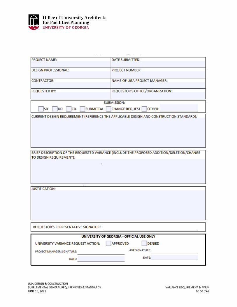
00 00 05 VARIANCE REQUIREMENT & FORM
1. GENERAL
A. If the Design Professional deviates from the University of Georgia Design & Construction Standards (Standards) without written approval, the deviation will be considered an error and a claim may be processed against the Design Professional’s professional liability insurance for reimbursement of the cost to meet the Standards. The amount of the claim may be reimbursed to the Owner through a unilateral change order.
B. If the Contractor is responsible for design / building certain (or all) aspects of the project, and deviates from the Standards without a written approval, the Contractor’s deviation will be considered an error and a claim may be processed against the Contractor’s insurance. If the Contractor makes a change or substitution during the shop drawing and submittal process that is a deviation from the Standards, it is the burden of the Contractor, not the Design Professional, to seek a variance approval. The amount of the claim may be reimbursed to the Owner through a unilateral change order.
C. The Project Variance Request Form must be submitted by the Design Professional and / or Contractor for any deviations from the Standards and approved in writing. Inclusion of a deviation from the Standards, whether in drawings or specifications during any phase of design reviews, including shop drawing and submittal reviews, is not considered a Design Variance approval. It is the Design Professional and / or Contractor’s burden to point out deviations to the Project Manager and to specifically request written variance approval prior to incorporating in the Project. The University of Georgia is not responsible for identifying any deviations from the Standards.
D. For work at UGA's Tifton and Griffin Campuses and all other UGA facilities outside of Clarke County, the Project Manager shall discuss at with the Design Professional and Contractors during the kickoff meetings that potential variances of the UGA Standards should be discussed for these locations.
Revised June 15, 2021
UGA DESIGN & CONSTRUCTION SUPPLEMENTAL GENERAL REQUIREMENTS & STANDARDS VARIANCE REQUIREMENT & FORM JUNE 15, 2021 00 00 05-2
UGA DESIGN & CONSTRUCTION SUPPLEMENTAL GENERAL REQUIREMENTS & STANDARDS STATE FIRE MARSHAL VARIANCES JUNE 15, 2021 00 00 05.01-1
00 00 05.01 STATE FIRE MARSHAL VARIANCES
1. GENERAL
A. If a State Fire Marshal issued variance is needed, the Design Professional shall write a letter on company letterhead to the Associate Vice President for Facilities Planning providing the information required by the current variance request process, available from the Georgia State Fire Marshal’s Office (Office of Insurance and Safety Fire Commissioner, 404-656-2056, www.oci.ga.gov).
B. The Office of University Architects for Facilities Planning (OUA) will confer with the University Fire Safety office regarding the request and, if found acceptable, shall prepare a cover letter and submit it along with the request for variance to the State Fire Marshal’s office.
C. The Design Professional shall not directly submit a variance request to the State Fire Marshal’s office.
UGA DESIGN & CONSTRUCTION SUPPLEMENTAL GENERAL REQUIREMENTS & STANDARDS ACCESS TO EXISTING DOCUMENTS JUNE 15, 2021 00 00 06-1
00 00 06 ACCESS TO EXISTING DOCUMENTS
1. GENERAL
A. To access documents for UGA buildings visit the Facilities Inventory digital plansroom: https://plansroom.fmd.uga.edu/
i. Plansroom - As-built and construction drawings ii. Plansroom - Review documents current and archived
iii. PDF Drawings - Basic simplified floor plans (with room number, use, and square footage.)
iv. AutoCAD Drawings - Basic simplified floor plans (with room number, use, and square footage.)
a. This secure website requires a UGA MyID username and password. Non-UGA visitor access is available upon request. To request access enter your email address on the access page and click the “Request Non-UGA Access” link.
b. Contact Facilities Inventory regarding questions or assistance: [email protected].
UGA DESIGN & CONSTRUCTION SUPPLEMENTAL GENERAL REQUIREMENTS & STANDARDS DESIGN PROFESSIONAL DESIGN PROCESS REQUIREMENTS JUNE 15, 2021 00 00 07-1
00 00 07 DESIGN PROFESSIONAL DESIGN PROCESS REQUIREMENTS
1. GENERAL
A. Related sections: i. 00 00 08 – Design Professional Documentation Requirements & Deliverables
ii. 01 81 00 – Facility Performance Requirements iii. 01 77 00 – Project Closeout
B. There are other Design Professional process requirements included throughout the Standards. At the beginning of most of the Division sections that are listed as ‘General Requirements’, for example “Division 23 00 00 – General Mechanical Requirements” includes additional and more specific design requirements related to mechanical.
C. The Engineer shall request preliminary testing and validation of existing conditions and / or existing system performance to include measurement of existing HVAC system water-flows and air-flows, pot-holing of underground utilities, measurement / metering of power usage as required to minimize construction delays and ensure final system performance. The testing should be performed before starting the design.
D. Design Intent Documentation: The cover sheet of the mechanical, electrical, and plumbing drawings shall indicate design intent (narrative and metrics) descriptions of:
i. Applicable codes standards used. ii. Narrative description of the scope of the work.
iii. State design assumptions. iv. Design ambient and inside conditions. v. State the ventilation procedure used (including design occupancy and persons /
sq. ft.). Refer to ASHRAE 62 - Paragraph 6 “Procedures”. vi. Total connected design load for all services / utilities.
vii. Detailed layer by layer building envelope data used for design. viii. Overall building air balance diagram for all operating conditions.
ix. Individual spaces air balance with overall building diagram. x. Lighting loads for individual spaces and building as a whole. Assumptions and
provisions for future addition / expansion. xi. Spaces and processes requiring 24/7/365 cooling, humidity control, etc.
xii. Building envelope assumptions (walls, roof, partitions, glass U-value and shading coefficient, etc.)
xiii. List maximum noise levels of all HVAC equipment on schedules. xiv. All specific, critical, user defined requirements. xv. Energy Use Intensity (EUI)
E. As soon as locations are determined (as applicable to the Project), the Design Professional shall coordinate with the Project Manager and the Office of Fire Safety for the proposed fire department and emergency vehicle access roads, fire hydrant locations, PIV locations, and Fire Department Connections, and the Office of Fire Safety will coordinate with the local fire department.
F. For Schematic Design the Design Professional shall include mechanical, electrical, and plumbing design narrative with supplemental drawings / outline specifications.
Revised June 15, 2021
Revised June 15, 2021
UGA DESIGN & CONSTRUCTION SUPPLEMENTAL GENERAL REQUIREMENTS & STANDARDS DESIGN PROFESSIONAL DESIGN PROCESS REQUIREMENTS JUNE 15, 2021 00 00 07-2
G. For Design Development (Preliminary Design) the Design Professional shall include mechanical, electrical, and plumbing design drawings / outline specifications, or the first draft of full specifications.
H. During Schematic Design, the Design Professional shall develop a minimum of three completely different design solutions for review. These shall be completely different design approaches, and not be minor variations between schemes.
I. Design Professional shall notify Project Manager of any and all substitution requests and confirm acceptability prior to Design Professional authorizing change.
J. Design specifications shall adhere to the latest CSI numbering format. Individual equipment items shall have specific sections as defined by CSI and shall not be combined together into larger generalized sections.
UGA DESIGN & CONSTRUCTION SUPPLEMENTAL GENERAL REQUIREMENTS & STANDARDS DESIGN PROFESSIONAL DOCUMENTATION REQUIREMENTS & DELIVERABLES JUNE 15, 2021 00 00 08-1
00 00 08 DESIGN PROFESSIONAL DOCUMENTATION REQUIREMENTS & DELIVERABLES
1. GENERAL
A. Related sections: i. 00 00 10 – BIM Requirements
ii. 01 31 23 – Project Website iii. 01 31 26 – Electronic Communication Protocols iv. 01 33 00 – Submittal Procedures v. 01 41 26.06 – Food Service
vi. 01 77 00 – Project Closeout vii. 01 81 00 – Facility Performance Requirements
viii. 27 00 00 – General Communications Requirements B. These are minimum requirements for consistent documentation for the review,
construction, and archiving for all Projects. C. Document Minimum Requirements
i. Project title consistent with Design Professional Contract title, UGA Building Number, and current date on all sheets.
ii. BOR/FMD/OUA Project number and bid number (if applicable) on all sheets.
iii. Type of submittal (examples: Schematic Design, Design Documents, Construction Documents, GMP, BID, As-Builts) and current date on all sheets.
iv. Any changes after construction release shall be shown as Revision 1, 2, 3, etc., and clouded & noted with proper revision reference on all revised sheets and noted on index.
v. Accurate and complete index of all sheets for the project including clear identification of most up to date sheet version (including set title and date).
vi. Include UGA location map showing at least one major road or intersection on cover sheet (campus maps are available for download at (http://www.architects.uga.edu/maps/current)
vii. Building key plan showing location of Work with graphic scale and north arrow on each drawing sheet. Should multiple building numbers exist for different zones or phases of a building, these shall be clearly indicated on the key plan as well.
viii. Sheet size preference is Standard Arch D (24x36). Larger sheet size Arch E1 (30x42) or Arch E (36x48) is acceptable only when necessary and approved by the Project Manager.
ix. Font type shall be TrueType and size shall be a minimum of 12pt when printed to scale.
x. Microsoft Word files shall be 2013 or later. xi. Electronic file names shall be no longer than 15 characters using only
Microsoft acceptable file names and shall be delivered by flash drive. xii. For projects that do not require BIM, AutoCAD files shall be version 2007
or later and be whole and complete with NO Xrefs to symbols or other drawings.
Revised June 15, 2021
UGA DESIGN & CONSTRUCTION SUPPLEMENTAL GENERAL REQUIREMENTS & STANDARDS DESIGN PROFESSIONAL DOCUMENTATION REQUIREMENTS & DELIVERABLES JUNE 15, 2021 00 00 08-2
D. Deliverables i. This section does not replace, but supplements, the standard project
deliverables stated in Section 2 of the Design Professional Contracts, Design-Build Contracts, Design-Bid-Build Contracts, Construction Manager Contracts, and as required for permitting by the BOR.
ii. All drawings and specifications shall be submitted in AutoCAD (.dwg), Revit (.rvt) (depending on if BIM is utilized), Microsoft Word (.doc), and Adobe PDF (.pdf) formats. All PDF files shall be searchable.
iii. Drawings and specifications shall each be submitted both as one PDF binder set and as separate AutoCAD, Microsoft Word and PDF files (as applicable) for each drawing sheet/specification section. All drawing PDF files shall be “flattened” so individual layers can no longer be manipulated to ensure data is protected.
iv. All electronic (.pdf) specifications shall be tabbed and bookmarked, with individual sections hyperlinked back to their listing in the table of contents.
v. UGA Milestone Deliverables: The following list documents minimum UGA deliverable drawing sets for OUA and FMD use in reviewing milestone submissions. All deliverables shall be submitted in electronic format to the Project Manager, who will then distribute contents to reviewing entities. For the intermediate milestone submittals, the percentage complete may vary per project and one of these percentages may also be the GMP set.
a. Site Evaluation & Planning Services – PDF drawings, specifications, and narratives (as applicable, per direction by Project Manager)
b. Schematic Design – PDF drawings, specifications, narratives, Facility Performance Checklist (see 01 81 00), MEP Design Concepts (Narratives and supplemental drawings), Network Drop Spreadsheet*, Dining Services documents (if applicable, see 1.D.vii)
c. Design Development – PDF drawings, specifications, narratives, Facility Performance Checklist (see 01 81 00), MEP Design Concepts (Narratives and supplemental drawings), Network Drop Spreadsheet*, Dining Services documents (if applicable, see 1.D.vii)
d. Additional Intermediate Milestones (as directed by Project Manager) - PDF drawings, specifications, narratives, Facility Performance Checklist (see 01 81 00), MEP Design Concepts (Narratives and supplemental drawings), Network Drop Spreadsheet*, **Dining Services documents (if applicable, see 1.D.vii)
e. 100% Construction Documents - PDF and CAD files, specifications, narratives, Facility Performance Checklist (see 01 81 00), Network Drop Spreadsheet*, ***Dining Services documents (if applicable, see 1.D.viii) plus two (2) full size sets of drawings and specifications are required for UGA Fire Safety. Submit the two sets of drawings and specifications with two copies of the completed “UGA Fire Safety Form 354” to the Project Manager who will forward to UGA Fire Safety. See section 01 41 26.03 Permit Requirements – Construction Permits. If permitted through State Fire Marshal, then one set is required for UGA Fire Safety.
f. Closeout - Refer to 01 77 00 - Project Closeout
UGA DESIGN & CONSTRUCTION SUPPLEMENTAL GENERAL REQUIREMENTS & STANDARDS DESIGN PROFESSIONAL DOCUMENTATION REQUIREMENTS & DELIVERABLES JUNE 15, 2021 00 00 08-3
vi. For projects requiring Commissioning, the Design Professional shall submit a Commissioning Basis of Design document during the schematic design phase which will be updated with each new design submission.
vii. Prior to issuance of Design Development-level documents, the FMD Building Inventory shall have an opportunity to review and request corrections to the proposed room numbering on the plans.
viii. *Network Drop Spreadsheet: Refer to 27 00 00 – General Communications Requirements for template information and requirements.
ix. ** If the project includes food preparation that will require a health department permit, for schematic design, the Design Professional shall email a pdf of the site plan, floor plan with food service area and nearest restrooms, and any food equipment layout related information to the Project Manager. The Project Manager will send the file to ESD for review.
x. ***For 100% Construction Documents, the Design Professional shall prepare one full size set that only includes the information as required in 01 41 26.06 Food Service and forward to the Project Manager who will send it to ESD and also provide a pdf set of that corresponding set for review. Pending any comments, once ready to be submitted for permitting, the Design Professional provide 5 sets of hardcopy sets and one searchable pdf including equipment cut sheets to the Project Manager. This shall include one full bound set of specifications.
xi. Simplified Floor Plan: Within 10 days at the issuance of 100% or “For Construction” Documents, the Design Professional is required to prepare simplified project floor plans (if any). The simplified floor plans shall be a 2D AutoCAD drawing and shall only contain the layers and associate attributes listed in the chart below. The electronic AutoCAD (.dwg) file shall be submitted via e-mail to the Project Manager.
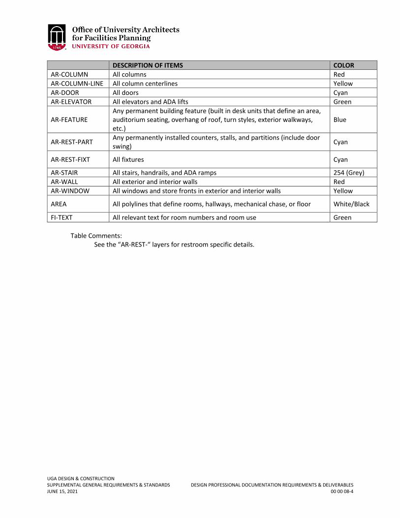
UGA DESIGN & CONSTRUCTION SUPPLEMENTAL GENERAL REQUIREMENTS & STANDARDS DESIGN PROFESSIONAL DOCUMENTATION REQUIREMENTS & DELIVERABLES JUNE 15, 2021 00 00 08-4
Table Comments: See the “AR-REST-“ layers for restroom specific details.
DESCRIPTION OF ITEMS COLOR AR-COLUMN All columns Red AR-COLUMN-LINE All column centerlines Yellow AR-DOOR All doors Cyan AR-ELEVATOR All elevators and ADA lifts Green
AR-FEATURE Any permanent building feature (built in desk units that define an area, auditorium seating, overhang of roof, turn styles, exterior walkways, etc.)
Blue
AR-REST-PART Any permanently installed counters, stalls, and partitions (include door swing) Cyan
AR-REST-FIXT All fixtures Cyan
AR-STAIR All stairs, handrails, and ADA ramps 254 (Grey) AR-WALL All exterior and interior walls Red AR-WINDOW All windows and store fronts in exterior and interior walls Yellow
AREA All polylines that define rooms, hallways, mechanical chase, or floor White/Black
FI-TEXT All relevant text for room numbers and room use Green
UGA DESIGN & CONSTRUCTION SUPPLEMENTAL GENERAL REQUIREMENTS & STANDARDS ROOM & SPACE NUMBERING JUNE 15, 2021 00 00 09-1
00 00 09 ROOM & SPACE NUMBERING
1. GENERAL
A. Related sections: i. 00 00 06 – Access to Existing Documents
B. These numbering conventions have been developed and must be followed throughout all phases of the Project for UGA controlled facilities for the purpose of standardizing room numbers.
C. For new buildings, these standards must be followed as closely as possible. In cases of renovations or additions to existing buildings, the building’s existing numbering system can be extended, or abandoned in order to use the following standards to renumber the entire building including the renovated and/or added space. If the existing numbering system is used, existing room numbers shall not be duplicated. For a list of existing room numbers, refer to Section 00 00 06 Access to Existing Documents for building floor plans with room numbers. In addition, e-mail [email protected] and request an Excel spreadsheet of the existing room numbers related to the Project.
D. The intention is for each facility’s floor and room numbering scheme to be structured so that the numbers flow through the building in a consistent, comprehensible, and user-friendly pattern. The scheme should be clear to the users of the facility, not causing confusion for individuals attempting to locate spaces.
2. FLOOR NUMBERING A. The first character of a room number indicates the floor level of the building. The level
with a “1” as the first character should be the uppermost floor entered at grade or one half flight above grade. Levels below this can use the character “0” (zero), “B” (basement), or “G” (ground), depending upon the arrangement and number of these floors. Buildings located on steeply sloping sites may need to vary from this rule; where necessary, the floor numbered “1” may not in fact be the uppermost floor entered at grade. Where “B” and “0” (zero) are used in the same building, the “B” level will be below the “0” level. The only cases where the floor indicator should be more than one character are buildings with more than nine floors.
B. Large mezzanines shall be numbered as a whole floor. Example: When a mezzanine exists between the first floor and the next whole floor, it will be numbered as the second floor.
C. Usable attic floors and penthouse levels should be numbered as if they are whole floors. For example, a two-story penthouse atop a three floor building will be numbered as the fourth and fifth floors. Do not use prefixes such as “R” for roof level.
3. ROOM NUMBERING A. The guidelines in this section should be followed as closely as possible when assigning
numbers to individual rooms. B. Use 3 or 4 digit numbers (plus optional alpha suffix) consistently throughout the
building. Rooms shall be numbered with a three or four digit number, where the first digit may be optionally replaced with the letter “B” or “G” (see floor numbering above); the length depends upon the size of the building and once chosen shall be consistent throughout the entire building. With an optional letter suffix, the maximum length of a room number is 5 characters.
UGA DESIGN & CONSTRUCTION SUPPLEMENTAL GENERAL REQUIREMENTS & STANDARDS ROOM & SPACE NUMBERING JUNE 15, 2021 00 00 09-2
C. Three digit numbers shall be used for buildings with 9 or fewer floors and 99* or fewer rooms per floor. The first floor will be numbered 100’s; second floor will be 200’s; third floor will be 300’s etc. *The actual number of rooms requiring the use of four-digit room numbering will vary, depending upon how many numbers are skipped and also the number of suites vs. rooms requiring non-suffixed numbers.
D. Ground floor or basement rooms could be numbered 001, 002, etc. or G01, G02, etc. or B01, B02, etc. Note: the following examples use spaces in the room number to clarify and illustrate the numbering scheme; these spaces should not appear in the actual room number. Example: Building with 9 or fewer floors and 99* or fewer rooms per floor G 41 ← indicates room number ↑ indicates floor (ground floor)
3 02 ← indicates room number ↑ indicates floor (third floor)
E. Four digit numbers shall be used for buildings exceeding 9 floors or having more than
99* rooms per floor. Buildings with wings or sections can also use four digit numbers if this makes the numbering scheme easier to navigate. Example: Building with more than 9 floors and 99* or fewer rooms per floor
B0 02 ← indicates room number ↑ indicates floor (basement floor)
01 02 ← indicates room number ↑ indicates floor (first floor)
11 02 ← indicates room number ↑ indicates floor (eleventh floor)
Example: Building with 9 floors or less but more than 99* rooms per floor
B 102 ← indicates room number ↑ indicates floor (basement floor)
1 102 ← indicates room number ↑ indicates floor (first floor)
UGA DESIGN & CONSTRUCTION SUPPLEMENTAL GENERAL REQUIREMENTS & STANDARDS ROOM & SPACE NUMBERING JUNE 15, 2021 00 00 09-3
Example: Building divided into wings or sections
G 1 02 ← indicates room number ↑ ↑ indicates wing or section (numeric only) ∟indicates floor (ground floor)
1 1 02 ← indicates room number ↑ ↑ indicates wing or section (numeric only) ∟indicates floor (first floor)
F. Numbers should flow from one end of the building to the other
i. In a building with only one dividing corridor, room numbers should flow in ascending order from one end of the building to the other. In a building with a more complex corridor system, numbers should flow in ascending order in a clockwise direction through the corridors from the main entrance, or similar location such as elevator lobby.
G. Use odd numbers on one side of a corridor and even numbers on the other side i. Room numbers shall be coordinated so that even numbers are on one side of
a corridor and odd numbers are on the other side. (In more complex designs, or where the availability of numbers is limited, the odd-even format can be abandoned if consecutive numbering results in a more logical scheme.)
H. Skip numbers to maintain succession of room numbering i. In some instances, room numbers on one side of a corridor shall be skipped in
order to maintain succession with the room numbers on the opposite side of the corridor. This may occur, for example, when a suite of rooms or large space is accessed through a single door and there are no other doors on that same side until further down the corridor. This will allow for future renovations that may convert suites or large spaces into separate or small rooms with a corridor door.
I. Skip numbers to allow for future renovations i. When a corridor contains large rooms such as classrooms, meeting rooms,
etc. on both sides of the corridor, room numbers shall be skipped to allow for future renovation of a large space into smaller spaces. Sufficient numbers shall be reserved to allow for the large spaces to be divided into standard size office spaces.
J. Use similar numbering on each floor i. Numbering systems on all floors should be similar as much as possible, even
when the floor plans are significantly different. To the greatest extent possible, and without creating other inconsistencies, rooms with the same digits in the last positions should be located in the same position in the building. Thus, B01, G01, 001, 101, 201, etc., occur in a vertical stack.
K. Use alphabetic suffixes for rooms entered from other rooms (rather than a hallway) i. Rooms entered from a main corridor or lobby are numbered with no letter
suffix. When rooms open off of another room and not from a corridor (such as in a suite of offices), use the number of the first room with a letter suffix (example: Reception 301, Office 301A, Office 301B, Office Storage 301C). Assign suffix letters in the order rooms are encountered and, where possible,
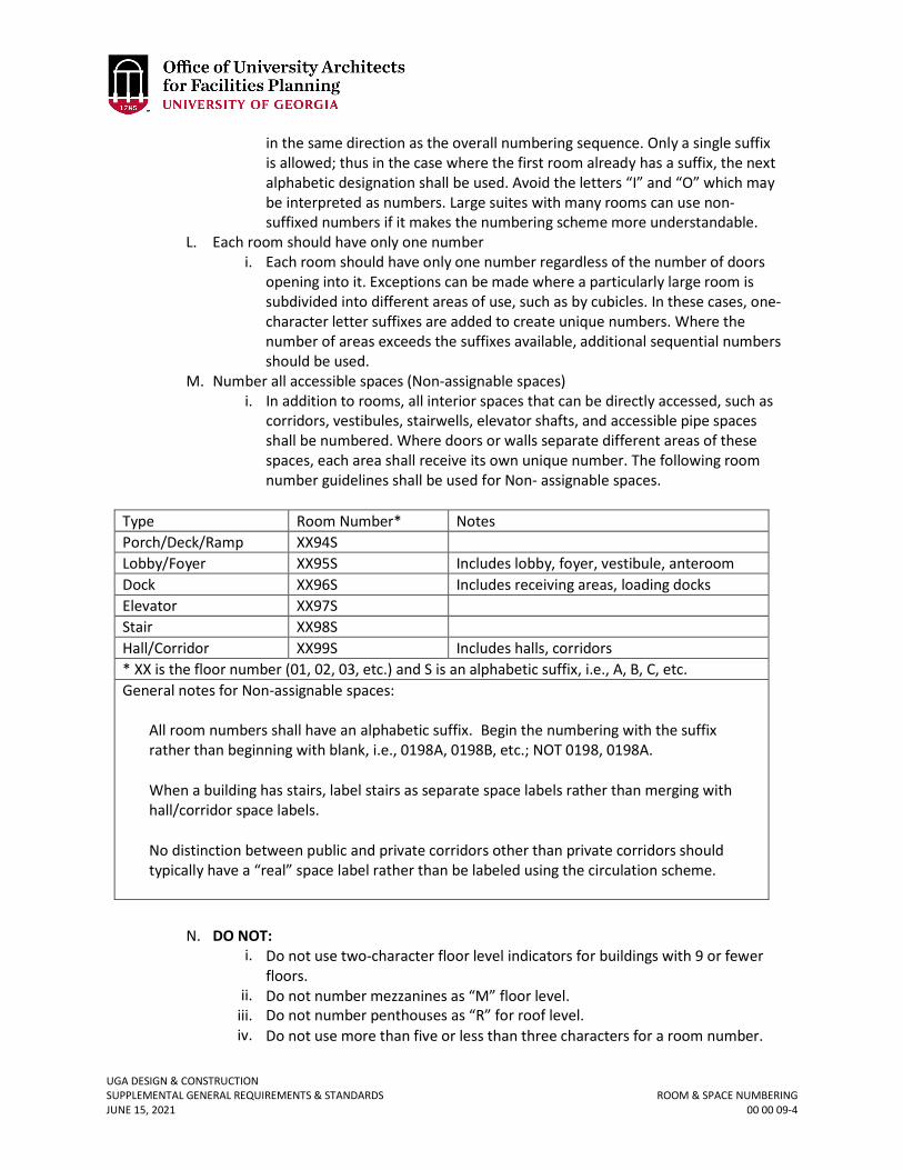
UGA DESIGN & CONSTRUCTION SUPPLEMENTAL GENERAL REQUIREMENTS & STANDARDS ROOM & SPACE NUMBERING JUNE 15, 2021 00 00 09-4
in the same direction as the overall numbering sequence. Only a single suffix is allowed; thus in the case where the first room already has a suffix, the next alphabetic designation shall be used. Avoid the letters “I” and “O” which may be interpreted as numbers. Large suites with many rooms can use non- suffixed numbers if it makes the numbering scheme more understandable.
L. Each room should have only one number i. Each room should have only one number regardless of the number of doors
opening into it. Exceptions can be made where a particularly large room is subdivided into different areas of use, such as by cubicles. In these cases, one-character letter suffixes are added to create unique numbers. Where the number of areas exceeds the suffixes available, additional sequential numbers should be used.
M. Number all accessible spaces (Non-assignable spaces) i. In addition to rooms, all interior spaces that can be directly accessed, such as
corridors, vestibules, stairwells, elevator shafts, and accessible pipe spaces shall be numbered. Where doors or walls separate different areas of these spaces, each area shall receive its own unique number. The following room number guidelines shall be used for Non- assignable spaces.
Type Room Number* Notes Porch/Deck/Ramp XX94S Lobby/Foyer XX95S Includes lobby, foyer, vestibule, anteroom Dock XX96S Includes receiving areas, loading docks Elevator XX97S Stair XX98S Hall/Corridor XX99S Includes halls, corridors * XX is the floor number (01, 02, 03, etc.) and S is an alphabetic suffix, i.e., A, B, C, etc. General notes for Non-assignable spaces:
All room numbers shall have an alphabetic suffix. Begin the numbering with the suffix rather than beginning with blank, i.e., 0198A, 0198B, etc.; NOT 0198, 0198A.
When a building has stairs, label stairs as separate space labels rather than merging with hall/corridor space labels.
No distinction between public and private corridors other than private corridors should typically have a “real” space label rather than be labeled using the circulation scheme.
N. DO NOT:
i. Do not use two-character floor level indicators for buildings with 9 or fewer floors.
ii. Do not number mezzanines as “M” floor level. iii. Do not number penthouses as “R” for roof level. iv. Do not use more than five or less than three characters for a room number.
UGA DESIGN & CONSTRUCTION SUPPLEMENTAL GENERAL REQUIREMENTS & STANDARDS ROOM & SPACE NUMBERING JUNE 15, 2021 00 00 09-5
v. Do not use a letter prefix or suffix to indicate a room type (such as M101 or 101M for a first floor mechanical room).
vi. Do not use letters except as a floor prefix, or suffix for a room accessed through another room (do not number a data room as 1D00).
vii. Do not use periods, hyphens, spaces, or any other non-alphanumeric character in room numbers (do not number a room as 1-16 or 01.14.03).
viii. Do not number internal courtyards and roof areas, unless covered. Exception: The uncovered top level of parking decks used for parking should be assigned numbers.
ix. Do not number rooms on one side of a hallway and then back down the other side.
O. DO: i. Do number all accessible spaces, including stairwells and elevator shafts. ii. Do number all exterior covered spaces, whether walled or not.
iii. Do number all penthouse spaces. 4. STANDARDS FOR PARKING DECKS
A. Standalone parking decks are considered buildings and will have a building number and room numbers to cover all usable space within the structure. This also includes the top uncovered level.
5. CONFLICTS AND SPECIAL CASES A. In the case of conflicts or questions, contact the Project Manager who will coordinate
with FMD.
UGA DESIGN & CONSTRUCTION SUPPLEMENTAL GENERAL REQUIREMENTS & STANDARDS BIM REQUIREMENTS JUNE 15, 2021 00 00 10-1
00 00 10 BIM REQUIREMENTS TABLE OF CONTENTS
Table of Contents 01 1.0 – Purpose, Use and Requirements 02 2.0 – Definitions and Terms 03 3.0 – Process 06
3.1 – Accuracy and Proficiency 06 3.2 – Level of Development (LOD) 07 3.3 – BIM Execution Planning 07 3.4 – Integrated Project Delivery (IPD) Methodology Plan 08
4.0 – Objectives, Application & Deliverables 10
4.1 – Phase 1: Pre-Design/Conceptualization 10 4.2 – Phase 2: Schematic Design 11 4.3 – Phase 3: Preliminary Design (Design Development) 12 4.4 – Phase 4: Construction Documents 15 4.5 – Phase 5: Bidding/Procurement Phase 17 4.6 – Phase 6: Construction Phase 17 4.7 – Phase 7: Project Closeout 18
5.0 – Component Worksheet 19 For the BIM Execution Plan (BEP) refer to Section 00 00 10.01 BIM Execution Plan.
UGA DESIGN & CONSTRUCTION SUPPLEMENTAL GENERAL REQUIREMENTS & STANDARDS BIM REQUIREMENTS JUNE 15, 2021 00 00 10-2
1.0 - PURPOSE, USE AND REQUIREMENTS The purpose of this BIM Section is to establish baseline requirements for Design Professionals and Contractors in their Building Information Modeling (BIM) efforts related to the design and construction of University of Georgia (UGA) facility projects. Where BIM is required as a deliverable, the BIM Team (Design Professional and Contractor on a specific project collaborating on BIM requirements) shall refer to and comply with the requirements of the BIM Standards. BIM is required on all projects with total funding of $5 million or greater. On all other projects BIM is encouraged but not required. The use and application of BIM when required will apply to all phases of the Project’s lifecycle, including master planning, program analysis, project definition and schematic design, design and construction phases, and facility management. BIM is an evolving tool and the BIM Team, through the BIM Execution Plan (BEP; refer to Section 00 00 10.01 BIM Execution Plan) development process, is encouraged to bring forth ideas and suggestions to make the process as efficient and beneficial as possible. As each project is unique, the BIM Execution Plan will be specific and customized to each project. The BIM deliverable does not replace the standard project deliverables as defined in the Design Professional’s and Contractor’s Contracts; BIM is considered an additional deliverable. UGA requires that all design and construction document deliverables for projects are created and derived from the building information models, and expects that information in the model be coordinated, resolved and updated with the 2D Contract Document deliverables. It is UGA’s intent to reuse the BIM models and associated data for continuing lifecycle management of the buildings, including facilities management and future development/redevelopment of those future existing buildings. It is the goal and intention that UGA shall receive deliverables to meet the needs of two separate departments. One objective being the OUA, requiring an accurate As-Built BIM model with final component data to be used for future building renovations, additions and future building planning and management; the other objective being a BIM model and Construction Operations Building Information Exchange (COBie) deliverable for the FMD to capture facility and operations data that will be integrated with Computer Aided Facilities Management (CAFM) software. BIM models shall be provided throughout the design, construction and closeout phases along with corresponding data collection from the BIM models, to be submitted in COBie format to capture and record final close out data. It is not the intent of UGA to require additional, unnecessary, or duplicative modeling efforts, and UGA recognizes that different models may be generated or not depending on each BIM Team entities’ abilities or normal work processes. For example, many fabricators (ductwork, fire sprinkler piping, etc.) use software that can be developed and read in Navisworks. However, the Navisworks information cannot be brought into the Design Professional’s Revit model. UGA ideally desires a complete As-Built Revit model, but does not require and does not want to pay for duplicative work to take the systems modeled in Navisworks and to remodel them in Revit. The Navisworks software will allow the Revit model to be imported into the Navisworks model resulting in a complete As-Built viewable model. UGA can use Navisworks viewing software to look at the entire
UGA DESIGN & CONSTRUCTION SUPPLEMENTAL GENERAL REQUIREMENTS & STANDARDS BIM REQUIREMENTS JUNE 15, 2021 00 00 10-3
model to locate information embedded in the model. In this scenario, UGA will receive as final deliverables both Revit model (missing items that were only modeled in Navisworks) and a Navisworks model (with Revit model imported into it). If the BIM Team is able to originally model all the required items in Revit without duplicating efforts, then for example, one less type of model is required as a deliverable. UGA cannot use the Navisworks model to model future projects after the completion of the current project and will have specific features remodeled in Revit in the future if deemed appropriate for that future project. It is hoped that the software translation issues will be resolved soon and the issue of multiple types of models due to software incompatibilities will disappear. Accepted software is listed below, however, other software shall be considered subject to their capabilities and benefits to the Project. Direct any questions regarding the BIM Standards to the Office of University Architects (OUA):
1. Authoring and Design Software for Architecture, Interior Design and Structure: Revit Architecture, Revit Structure, ArchiCAD, Bentley Architecture, Digital Project, Tekla Structures, Vectorworks Designer.
2. Authoring Software for MEP, FP, and Specialty Consultants: Revit MEP, ArchiCAD MEP, AutoCAD MEP, AutoCAD Architecture. MEP shall use BIM Authoring Software, but may use 3D object-oriented software.
3. Civil Design: AutoDesk Civil 3D, Bentley Inroads 4. Coordination and Spatial Conflict Checking: Navisworks, BIMSight, Solibri Model Checker 5. Model Checking Utilities (Spatial validation and Industry Foundation Class) Solibri, BIMSight,
Navisworks 6. Energy analysis and modeling: DOE2, EcoDesigner, Ecotect, IES-VEware, EnergyPlus, eQuest,
Breen Building Studio, Trane/Trace, Vasari 2.0 – DEFINITIONS AND TERMS These terms and definitions are specified for BIM Requirements. Other general definitions and abbreviations can be found in Section 00 00 02 Terms. Also refer to Section 00 00 03 Modifications to General Requirements of BOR Contracts. Accuracy
The level of detail and the level of precision expected at various points in the Project process are dependent on the required level of design (LOD). Accuracy refers to the placement, sizing, and representation of building components. The scale represents a mixture of 3D and 2D content at the one end to a fully 3D model at the other end that will be used in Interference Checking and As-Built/Record drawings.
As-Built Model A digital representation of a facility produced through BIM during the construction phase of a project that contains data and other relevant information from the design model and tracks changes during construction. These are Construction Models that have been updated throughout the construction process and reflect the final As-Built condition of the Project and includes relevant component data that will be needed for COBie data output. Typically a model
UGA DESIGN & CONSTRUCTION SUPPLEMENTAL GENERAL REQUIREMENTS & STANDARDS BIM REQUIREMENTS JUNE 15, 2021 00 00 10-4
provided by the Contractor that is a concurrent model to the Design Intent/Record Model provided by the Design Professional.
Building Information Model (BIM) An acronym for “Building Information Modeling”, or “Building Information Model” that is a digital representation of the physical and functional characteristics of a facility and a shared resource that forms a basis for decisions during its life-cycle, from conception to demolition.
BIM Deliverables Information (in numerous formats) that may be required by Contract or agreement to be submitted or passed to another party and to UGA.
BIM Execution Plan (BEP) An outline that defines the scope of BIM implementation, identifies the process flow for BIM tasks, defines information exchanges, and the infrastructure needed for support. A plan created from the UGA’s BIM Execution Plan template that is to be submitted within thirty (30) days after Contract award. Refer to Section 00 00 10.01 BIM Execution Plan.
BIM Process A generic name for the practice of performing BIM. This process can be planned or unplanned. The BIM process may also be referred to as the BIM execution process or the BIM project execution process. The BIM project execution planning process suggests diagramming the BIM process using process maps.
BIM Process Maps A diagram of how BIM will be applied on a project. The BIM project execution plan proposes two levels of process maps: BIM overview map and detailed BIM use process maps.
BIM Team All Design Professionals, Contractors, and Consultants charged with delivering BIM information as defined in the BIM Standards, and listed in the BEP for a specific project.
BIM Use A method of applying building information modeling during a facility’s life-cycle to achieve one or more specific objectives.
Computer-Aided Facility Management (CAFM) UGA’s FMD utilizes a CAFM software program to assist with maintenance of facilities. Construction Model
A digital representation of a facility produced through BIM during the construction phase of a project that contains data and other relevant information from the design model and tracks changes during construction. Typically this BIM Model is provided by the Contractor and may be used for quantity take offs, construction sequencing and phasing, clash detection, modeling of delegated design elements, and data tracking of submittal information.
COBie - Construction Operations Building Information Exchange COBie is a standard of information exchange that allows information to be captured during design and construction in a format that can be used during the operations of a building once completed. Final COBie format deliverable will be in (.XLSX) spreadsheet form.
Critical Path Modeling Critical Path Modeling is a method of demonstrating Integrated Project Delivery. It sets a plan within the BIM Team that accounts for the activities of each discipline and how they interact with each other. It builds upon a critical path method for those activities, and allows the Project Team to schedule a complete project.
UGA DESIGN & CONSTRUCTION SUPPLEMENTAL GENERAL REQUIREMENTS & STANDARDS BIM REQUIREMENTS JUNE 15, 2021 00 00 10-5
Design Intent Model A digital representation of a facility produced through BIM to provide design intent for use in construction that is coordinated with other engineering disciplines. This type of BIM model is typical provided by the Design Professional Team and will be used to produce a combination of 3D and 2D information that is then utilized to produce the Contract drawings for construction.
.DWG .DWG is a native AutoCAD file format. It is a widely used file format for exchanging drawing information and 3D information to different programs. While not a database file type, it still has lots of uses for exchanging information.
.GBxml A .GBxml file is a Green Building file type. It is used to run simulations through energy modeling software. It is a widely accepted file format for those types of software.
Interior Design Interior Design is defined as the selection of interior materials, finishes, and furnishings.
Integrated Project Delivery (IPD) Integrated Project Delivery is a collaborative effort by Design Professionals to maximize performance and efficiency in all phases of a project.
Level of Development (LOD) Describes the completeness to which model elements representing components, systems, or assemblies are developed at progressive project phases. This development includes geometric and non-geometric data.
Navisworks Navisworks is software that allows for the viewing of multiple model formats. This ability to “view” these files also allows for Navisworks to simulate the interaction between model files. That includes collision reporting, time lining, and coordination.
.NWC An .NWC file is a Navisworks Cache File that is used by Navisworks to quickly read many other file types. All linked files in Navisworks have an .NWC file created automatically. In addition, Revit will export directly to the very small file type of .NWC for quick access by Navisworks.
.NWD A much larger file than the .NWC, the .NWD file shows a snapshot in time of Navisworks file. No linked files exist but all geometry is included.
Phases The phases of a project can be described in two different ways as the adoption of IPD terminology starts to penetrate the BIM Execution Plan and the IPD Methodology Plan. Below is a list of the traditional names followed by the IPD name:
Pre-Design/Conceptualization Phase Schematic Design/ Criteria Design Phase Design Development/ Preliminary Design/ Detailed Design Phase Construction Documents/Implementation Phase Agency Permit & Bidding/Agency Coordination & Final Buyout Construction Occupancy
Record Model Design Intent Models that have been updated throughout the construction process. These changes and updates have been communicated from the Contractor to the Design Professional
UGA DESIGN & CONSTRUCTION SUPPLEMENTAL GENERAL REQUIREMENTS & STANDARDS BIM REQUIREMENTS JUNE 15, 2021 00 00 10-6
through the comments, annotations, and mark-ups from the As-Built Documents. These typically, but not always, are discipline specific models.
.RVT An .RVT file is a native REVIT file type. It is also the deliverable file format for all projects. This includes all of the Design Professional Team’s models.
Simple Building Information Modeling (SBIM) SBIM is a concept of producing a “light” model that can be used for simulating the building’s performance very early within the design process. SBIM is the process of modeling only the exterior envelope, and the interior volumes to produce a lean model that energy modeling software can use easily.
3.0 – PROCESS In addition to previously stated requirements, Design Professionals and their consultants may use their own in-house standards, components and details that embed the best practices of the firm. BIM shall be created by the BIM Team that includes all geometry, physical characteristics, and component data needed to describe the design intent and Construction Documentation. All drawings and schedules required for assessment, review, bidding, and construction shall be derived from the BIM models either directly (as in schedules, floor plans, elevations, sections, project specific details, etc.) or indirectly (as may be the case with standard details). The process is to include requirements for accuracy and proficiency, Level of Development, BIM Execution Planning, Integrated Project Delivery, interference checking, COBie data management, and other requirements as defined in this section. 3.1 - ACCURACY AND PROFICIENCY BIM models shall provide accurate and correct final information about the building project and its components. Use industry standard and accepted nomenclature or UGA nomenclature (when provided or required) for objects and spaces. Use model checking tools before submission. Objects in BIM should be created and categorized appropriately within the BIM model. System families such as walls, floors, roofs, sweeps, etc. shall be properly created and categorized as what they are. Component families such as furniture, casework, specialty equipment, plumbing equipment, mechanical equipment, etc., shall also be properly created and categorized as to what they are so that component elements can be properly scheduled, quantified, and controlled within the model and have appropriate data associated with those components for latter data capture in the COBie deliverable. Use of generic component models, in-place families and/or groups should be minimized or avoided as much as possible. Modeling of the building and its components should be modeled precisely and accurately as much as possible, yet no less accurate than industry standard construction tolerances for the components being modeled. For objects that are not easily accommodated within the program due to special circumstances, such as complexity or uniqueness, then modeling an approximation of it that conforms closely to its size and look is acceptable along with categorizing it accordingly. All such occurrences should be documented and communicated to the Project Manager in writing. Accuracy and proficiency shall be expected with both 3D and 2D content.
UGA DESIGN & CONSTRUCTION SUPPLEMENTAL GENERAL REQUIREMENTS & STANDARDS BIM REQUIREMENTS JUNE 15, 2021 00 00 10-7
3.2 - LEVEL OF DEVELOPMENT (LOD) Level of Development (LOD) management should be utilized to assign the expected level of development for the Project at the various project phases, along with what team parties are responsible for the specific LOD for each of the components defined in the BEP, at the various project phases. The following are general LOD descriptions:
1. LOD 100: Conceptual Design - Overall building massing 2. LOD 200: Schematic Design and Preliminary Design - Generalized systems and assemblies with
approximate quantities, sizes, shapes, location and orientation for analysis of required systems, including daylight, views and energy.
3. LOD 300: Construction Documents - Detailed systems and elements. Modeling and detailing sufficient enough to meet requirements of the Contract documents for permitting and construction.
4. LOD 400: Shop Drawings for Fabrication and Assembly 5. LOD 500: As-Built & Record Models & Drawings for Maintenance and Operations - Includes UGA
required elements for final model. 3.3 – BIM EXECUTION PLANNING UGA requires a BIM Execution Plan (BEP) that is customized for the specific needs and requirements of each project. Utilize the UGA BEP Template as a starting point for developing each projects BEP. The BEP shall define the uses and responsibilities of BIM on the Project and its detailed process throughout the lifecycle of the Project. Once the plan is approved, the Team is required to follow it, monitor their progress against the plan, and make adjustments to the plan as appropriate. The BIM Execution Plan shall be considered a living document that will continue to change and evolve over the course of the Project. The steps include the following:
1. Within 30 days of Design Professional contract award: A. BIM Execution Plan Overview B. Project Information C. Key Project Contacts D. Project Goals/BIM Uses
i. Data Commissioning ii. Performance Monitoring
E. Organizational Roles/Staffing per phase F. BIM Process Design G. BIM Information Exchanges H. BIM and Facility Data Requirements I. Collaboration Procedures J. Quality Control Reviews K. Technological Infrastructure Needs L. Model Structure M. Project Deliverables Per Phase N. Delivery Strategy/Contract
UGA DESIGN & CONSTRUCTION SUPPLEMENTAL GENERAL REQUIREMENTS & STANDARDS BIM REQUIREMENTS JUNE 15, 2021 00 00 10-8
2. Template: Utilize the UGA BIM Template as the starting point for project specific BEP. When developing the BEP project goals for the BIM model and BIM data, the desired end results should be identified. How will the model be used during the Project and after the Project is completed? What data will need to be captured and delivered in COBie spreadsheet format? How will that data be used by the Owner? How will these objectives start to define how the model and its data are created and defined? 3.4 – INTEGRATED PROJECT DELIVERY (IPD) METHODOLOGY PLAN The BIM Team’s IPD Methodology Plan should be integrated into the BEP and be subject to the same submittal and review time table as the BEP. The IPD Plan must include a high level of integrated design, identification of Project Team members and how they will interact with each other during the Project, and a critical path method using modeling and model information validation. While it is understood that most projects will not be a full IPD project in the strictest sense of the word due to current contract structure, there are however many aspects of IPD methodology that can and should be integrated with BIM. Most notably, the IPD aspects of the planning for and sharing of model information with and between the Design Professional and constituents but also with the Contractors and Subcontractors should be incorporated. A plan for collaboration between the Design Professional and Contractor (and Subcontractor) should be outlined in such a way as to provide for this collaboration to start occurring as soon as feasibly possible within the design and construction phase process. An important aspect of this IPD Methodology Plan is the outlining of how data will be developed and progressed throughout the Project. Outlining and assigning who is responsible for the data and model development at each phase and at what point the data will be handed off to a different party. This will be especially important with regards to how COBie data will be developed and coordinated, this is because multiple parties will be responsible for different data entry at different phases, and all data will have to be integrated at the end into a unified single deliverable for submittal to UGA. A detailed description and mapping of what data will be needed as part of the final delivery is an important part of the BEP & IPD methodology. For example; data fields will be need to be defined for uploading into the Owner’s CAFM program. Required data fields that are available in the BIM model will have to be identified and data that will have to come from other sources will have to be identified. These required data fields will then need to be mapped to their corresponding COBie data fields. It will be necessary to show how required data that can be captured from the BIM model will get from the BIM model(s) to the COBie spreadsheets and finally uploaded into the Owner’s FM database program. In addition, data that was entered into the COBie spreadsheets separately from the model and that need to be re integrated back into the BIM model(s) will need to be identified. If there are multiple models then the data from each model will have to be identified and managed so that data from multiple models can be consolidated together into the required COBie worksheets. This will require a great deal of integrated delivery coordination and planning from the Project Team. The BEP and IPD methodology cannot be delivered in isolation. No one party within the BIM Team can adequately outline the execution plan, while also obtaining the necessary team member commitments
UGA DESIGN & CONSTRUCTION SUPPLEMENTAL GENERAL REQUIREMENTS & STANDARDS BIM REQUIREMENTS JUNE 15, 2021 00 00 10-9
for successful BIM implementation. Full coordination and collaboration by all parties is an absolute necessity. The following aspects of an integrated work plan shall be addressed:
1. Setup of initial BIM Schedules and project parameters within the BIM model to establish and organize the capture of spatial and component data information for future distribution and export.
2. Use Omniclass Table 13 for spatial naming conventions and Omniclass numbers for all spatial data. Where multiple naming options are available determine which Omniclass names will be utilized.
3. Use Omniclass Table 23 for component and product naming conventions and Omniclass numbers for all building components requiring COBie information. Determine which components and products will be tracked and data collected.
4. Determine the specific data required for each space or component and the assignment of spatial, system, component and other data responsibilities and authorship.
A. Spatial data B. FF&E components C. Structural components D. Special Equipment components E. Mechanical Equipment components F. Electrical Equipment components G. Plumbing Equipment & Accessories H. Design phase versus Construction phase data I. Commissioning Data J. Close-out Data K. As-Built / Record model and associated data
5. Coordinate the authorship and responsibility at each phase and establish procedures and schedules for when component data responsibility will transfer to another BIM Team entity. (i.e Mechanical components – initial BIM schedules and project parameters for future data entry established by Architect, then actual modeled components to be originally authored by Mechanical Engineer, transferred to Contractor for submittal phase development by Subcontractor, utilized in clash detection, and final data entry of submitted component data such as make, model, and serial numbers. Then any required data by the Commissioning Provider, and final delivery of all final As-Built modeling and component data into final deliverable formats to the Owner, including BIM Model and COBie spreadsheets.)
6. Recognize and identify separate deliverable requirements for both the OUA and for FMD, and provide plan for meeting separate needs of each owner entity requirements.
A. The OUA will require an As-Built Model sufficiently developed and modeled for use in planning and design of future project additions and alterations to the current project. Due to incompatibilities of software and the desire not to duplicate modeling efforts, the OUA will accept multiple As-Built Models if necessary to document all of the required information. For example, a Revit model (that is missing As-Built ductwork) and a Navisworks model (that has the Revit model imported and includes the ductwork) may be accepted in lieu of one Revit model.
B. In addition to the OUA requirements, FMD will also require As-Built Data in COBie format suitable for integration into their CAFM software.
7. Identify data that may need to be reintegrated into a combined final As-Built Model, if data was not generated from that model.
UGA DESIGN & CONSTRUCTION SUPPLEMENTAL GENERAL REQUIREMENTS & STANDARDS BIM REQUIREMENTS JUNE 15, 2021 00 00 10-10
The workflow and progress of this information gathering, collecting and submitting may vary depending on size and type of project, data desired, abilities of the various parties involved, and contractual relationship of the various parties. It is estimated that a minimum of three to four meetings will be needed to develop the overall strategy, and all key decision makers will need to be involved, including (but not limited to) the Design Professional, Owner’s Representatives, Structural & MEP Engineers, Contractor, major Subcontractors, and Commissioning Provider as early in the process as feasibly possible. It may become necessary to revise and update the BEP as additional parties and stake holders come on board. The BEP shall be revised, updated and resubmitted at each major project phase. 4.0 – OBJECTIVES, APPLICATION & DELIVERABLES The following items are specific BIM deliverables and/or coordination items required at the completion of each phase. These are in addition to the traditional deliverables required by Contract or other deliverables required in the UGA Design and Construction Standards. 4.1 – PRE-DESIGN/CONCEPTUALIZATION
1. Project Objectives and BEP: Provide a written summary description of project objectives as part of the initial BIM Execution Plan (BEP) for review and approval.
2. Programming and Planning Tools: The Design Professional is encouraged to use electronic programming and planning tools that integrate into their BIM software to capture early cost, schedule and program information. Deliverables at the end of Pre-Design shall verify and confirm the program, budget, schedule, and targeted building efficiency. The Design Professional shall use BIM & Planning software for use in supporting comparative costs analysis of various design options.
3. Existing Building Conditions: The Design Professional shall model existing conditions needed to coordinate the extent of the new construction work where work includes additions or alterations. Contact Project Manager for drawing inventory of existing buildings for use as a base reference only. Refer to Section 01 31 00.01 Access to Existing Documents. Unless otherwise specified, the Design Professional is responsible for verification of existing conditions and ensuring that all electronic deliverables are accurate and comply with requirements.
4. Simplified BIM (SBIM) Model: The Design Professional shall develop a simplified BIM model formatted for use in conceptual energy modeling for comparative analysis and other early Pre-Design Conceptualization efforts, this may be in the form of a simplified mass model or other LOD: Level One type of model as appropriate for the early analysis requirements listed in this phase. At least three design options shall be developed and presented; including site information.
5. Site & Topographical Surveys: Topographical surveys shall be received from Project Manager in electronic format in a format that allows for importing into the BIM Team’s BIM software. Exact requirements vary by project and shall be coordinated with the Project Manager. Site information shall be included as part of the Pre-Design Conceptualization phase and coordinated with the required three design options. Any site, environmental or historic building aspects or constraints should be addressed in the Pre-Design Conceptualization models as required.
6. Energy Modeling Requirements: The purpose at this early phase, is to narrow down design strategies to meet project’s energy goals and targets, including the reduction of energy demand
UGA DESIGN & CONSTRUCTION SUPPLEMENTAL GENERAL REQUIREMENTS & STANDARDS BIM REQUIREMENTS JUNE 15, 2021 00 00 10-11
by optimizing building form and orientation and daylight. Comparative energy analysis shall be based on local climate data and actual site conditions for summer and winter. The BIM Team shall utilize the simplified BIM model for use in conceptual energy modeling for comparative analysis, as appropriate for the early analysis software chosen by the BIM Team. At least three design options that meet the Project program and budget shall be compared and results given in “Percent Better” or “Percent Worse”.
7. Visualization: The SBIM model shall be utilized to produce 3D & 2D views of each scheme required as appropriate to demonstrate integration of proposed schemes with the surrounding roads, drives, pedestrian paths, access, and program requirements. Deliverables shall include rendered views as required to communicate early concept design intent.
4.2 – SCHEMATIC DESIGN
1. Project Objectives, BEP & Budget: Provide a written description of project objectives as part of the initial BIM Execution Plan (BEP) for review and approval. Schematic Design defines the optimum design solution to meet UGA’s aesthetic, program, budget and schedule while still being on track for energy, sustainability (if required) and building code requirements. Updated Budget/Cost estimates and updated Schedule shall also be provided at this phase.
2. Program and Space Validation: Provide a program and space validation report that utilizes spatial data, which includes room areas derived from the BIM model. Program verification software (for example: Trelligence Affinity) that integrates with the BIM model is encouraged. Areas shall include assignable areas (ASF) and non-assignable areas. Mechanical, electrical, telecommunications, housekeeping, toilet facilities, corridors and other circulation areas shall be labeled and their areas tabulated. Figures for net floor area and gross area shall be tabulated for compliance with Building Efficiency Target. Gross areas include wall thicknesses and open voids, per floor. In addition provide initial spatial data in COBie format (see COBie Data item below).
3. Existing Building Conditions & Existing Utilities Report: The Design Professional shall continue to model existing conditions needed to coordinate the extent of the new construction work where work includes additions or alterations. Unless otherwise specified, the Design Professional is responsible for verification of existing conditions and ensuring that all electronic deliverables are accurate and comply with requirements. At this phase an existing utilities report should also be provided for impact on schematic design solution.
4. BIM Model: All information required for Schematic Design level of development shall be graphically and alphanumerically correct, included in, and derived from the BIM model. Including, room and building areas and names. Model shall meet UGA’s functional and aesthetic requirements while still meeting budgetary and sustainability demands. BIM model to be sole source of all 2D drawings, being derived from the model. Generic and “place holder” system and component families may be utilized for this model deliverable. The model shall contain a high level of accuracy and proficiency as the design develops. Provide work set organization and coordinate work set management as part of BEP.
5. Site & Topographical Surveys: The site BIM model shall be geo-referenced to the correct coordinate system. Establish protocols and procedures for sharing and coordinating BIM Model origin points so that all consultant models may be correctly loaded into one another’s models for reference, coordination and documentation purposes. Document the procedures for coordination in the BEP. Surveys shall be projected in State plane coordinates Georgia West using the horizontal North American Datum 1983 and the vertical North American Vertical
UGA DESIGN & CONSTRUCTION SUPPLEMENTAL GENERAL REQUIREMENTS & STANDARDS BIM REQUIREMENTS JUNE 15, 2021 00 00 10-12
Geodetic Datum 1988 both in units of feet. Design Professional shall coordinate with Project Manager on contour interval and requirements for surveys. See 02 21 00 Surveys for specific requirements. It is understood that not all BIM programs are compatible with State map coordinate references, if so establish a common origin point between BIM models and Survey / Site information and document in the BEP.
6. Energy Modeling Requirements: BIM Team shall continue development of energy model on the selected scheme for Schematic Design to optimize focus on the most promising energy saving strategies. Document how the model will progress at each phase and which BIM Team member is responsible for the energy model at each phase. (For example, the early phase energy analysis might be performed by the architect utilizing a basic level program such as Revit in conjunction with Green Building Studio, then progress to an energy consultant who might utilize a more advanced program such as Ecotect or IES-VEware, and then finally progress to the Mechanical Engineer who will do final energy modeling using a program like eQuest.) Document a plan for how the energy model will develop in each phase of the Project, identifying responsible parties, software, and integration with the BIM model in the BEP. Information shall include life-cycle cost (LCC) and return on investment (ROI).
7. Visualization: The BIM model shall be utilized to produce 3D & 2D views of each scheme required as appropriate to demonstrate development of the selected scheme for Schematic Design. Deliverables shall include any rendered views as required to communicate Schematic Design intent.
8. Collision Report: At this phase additional models and information may not yet be developed enough for true interference or clash detection. Provide plan for future phase interference and/or clash detection in the BEP.
9. COBie Data: At Schematic Design Phase initial COBie data shall be limited to Facility, Floor and Space information only. COBie Data shall be submitted in spreadsheet format, using the most current version of COBie. The following COBie worksheets shall be provided in the Schematic Design deliverable:
A. COBie Table 6-20 Worksheet 01: Contact (People/Offices/Companies) This worksheet may be generated in the spreadsheet outside of the BIM program
B. COBie Table 6-21 Worksheet 02: Facility (Identification of facility (ies)) This worksheet may be generated in the spreadsheet outside of the BIM program
C. COBie Table 6-22 Worksheet 03: Floor (description of vertical levels) This worksheet may be generated in the spreadsheet outside of or derived from the BIM model
D. COBie Table 6-23 Worksheet 04: Space (Spaces within a floor) This worksheet shall be derived from the BIM model utilizing scheduled rooms from the BIM model, including assignable and non-assignable areas; mechanical, electrical, telecommunications, housekeeping, toilet facilities, corridors and other circulation areas.
Coordinate actual data needed in each worksheet with the OUA and FMD requirements. Document required data necessary in COBie worksheets and document the components which need to have data generated and captured in the BEP. It is not necessary to provide data on all model components only those required. Schedule planning meetings to determine the scope and extents of elements and components that will need to be captured in COBie worksheets, and provide a mapping scheme for migrating data fields in the BIM model to the data fields in the COBie spreadsheets as part of the BEP.
UGA DESIGN & CONSTRUCTION SUPPLEMENTAL GENERAL REQUIREMENTS & STANDARDS BIM REQUIREMENTS JUNE 15, 2021 00 00 10-13
4.3 – PRELIMINARY DESIGN (DESIGN DEVELOPMENT)
1. Project Objectives, BEP & Budget: The BIM Team shall provide a written description of project objectives as part of the initial BIM Execution Plan (BEP) for review and approval. Preliminary Design will show the refinement of the scope of work identified during the Schematic Design Phase. It will also have reconciled the impact of the engineering disciplines on the Schematic Design, and have major structural and MEP systems modeled at this time to demonstrate the integration of the original schematic design concepts with the engineering requirements. Updated Budget/Cost estimates and updated Schedule shall also be provided at this phase. BEP should document the various design models from the BIM Team entities. Use BIM software to extract more accurate figures for cost estimating. Outputs shall be on spreadsheets and submitted at the end of this phase.
2. Program and Space Validation: Provide an updated program and space validation report that utilizes spatial data which includes room areas derived from the BIM model. Verify building efficiency targets. In addition provide spatial data in COBie format (see COBie Data item below)
3. Existing Building Conditions & Existing Utilities Report: The Design Professional shall continue to model existing conditions needed to coordinate the extent of the new construction work where work includes additions or alterations. Unless otherwise specified, the Design Professional is responsible for verification of existing conditions and ensuring that all electronic deliverables are accurate and comply with requirements. At this phase existing utilities should be identified, documented and coordinated with base MEP systems and show how new MEP systems will tie into the existing utilities.
4. BIM Model: All information required for Preliminary Design level of development shall be graphically and alphanumerically correct, included in, and derived from the BIM model. Including, room and building areas and names. Model shall meet UGA’s functional and aesthetic requirements while still meeting budgetary and sustainable, if this is required, demands. BIM model to be sole source of all 2D drawings, being derived from the model. Generic and “place holder” system and component families should be replaced with proposed system and component families. A model to contain a high level of accuracy and proficiency as the design develops. Provide additional scope of work coordination regarding how final building elements are going to be modeled between BIM Team entities and documented in the BEP. For example certain structural elements such as floor slabs can be the responsibility of the Architect or Structural Engineer. In some cases the elements may be duplicated, copy/monitor may be utilized, if so, how and for which elements, document in BEP. Additional modeling Requirements:
A. Architectural Systems Requirement: Architectural Site Plan, existing building elements or conditions, demolished items, new interior and exterior walls (not generic types), ceilings, soffits, sun control elements, floors and roof systems, penthouses and roof structures, fenestration and doors, vertical circulation, built in millwork and architecturally significant equipment, furnishings and fixtures, plumbing fixtures.
B. Structural Engineering Requirements: Foundations, framing, shear and load bearing walls, brick ledges, steel bracing, edge of slab conditions, lintels.
C. HVAC Systems Requirements: Equipment such as fans, VAV’s, compressors, chillers, cooling towers, air handlers, etc.; Distribution ductwork modeled to outside ductwork or duct insulation; Diffusers, louvers, hoods, radiant panels, perimeter units, wall units; Show clearances required for equipment access, removal or repair as invisible solids.
UGA DESIGN & CONSTRUCTION SUPPLEMENTAL GENERAL REQUIREMENTS & STANDARDS BIM REQUIREMENTS JUNE 15, 2021 00 00 10-14
D. Electrical Systems Requirements: Transformers, generators, main distribution panels, switchgear, main IDF’s, conduit and feeders larger than ¾” diameter, outlets, switches, junction boxes, lighting fixtures and controls, fire alarm permanently mounted fixtures, building controls and clearance zones for access.
E. Plumbing, Process Piping & Fire Protection Requirements: Waste/Vent, Supply or Process Piping at or over ¾” (includes any insulation); plumbing fixtures; sprinkler lines larger than ¾” diameter, sprinkler heads, pumps, stand pipes, wall hydrants, connections and risers.
F. Specialty Consultants Requirements: Equipment provided or specified by consultant with rough – in connection points for all utilities and clearances required. Extent of modeling shall be per the BIM Execution Plan.
5. Site & Topographical Surveys: The model shall include topography with level of detail per the BIM Execution Plan. Model should include surrounding areas that affect drainage system or have other impacts. Landscaping elements shall include planted areas, beds and berms, hardscape, site paving and storm water management structures or systems.
6. Energy Modeling Requirements: Continued development of energy model on the selected scheme from Schematic Design to optimize focus on the most promising energy saving strategies is required. Parametric studies to better understand the energy use of each building component are required. Model shall meet any target requirements for sustainability and/or LEED or other third party verification. Model shall include all the design and operating parameters that affect energy consumption after occupancy. Expected occupant numbers and hours, lighting use, equipment use, and other user data shall be included to attain a closer approximation of actual use. Requirements shall include options for Energy Conservation Measures (ECM) to achieve further reductions in water, electricity or energy in the facility. Information shall include life cycle cost (LCC) and return on investment (ROI). Update the plan for how the energy model will be utilized at this and future phases of the Project, identifying responsible parties, software, and integration with the BIM model in the BEP.
7. Collision Report: At this phase additional models and information shall be developed enough for true interference and/or clash detection. Discipline Collision Reports: Collision report shall include; structure against electrical and specialty equipment; ductwork / piping against electrical equipment; ductwork / piping against floors and the building envelope; ductwork / piping against structural framing elements.
8. COBie Data: At Preliminary Design Phase COBie data shall be submitted in spreadsheet format, using the most current version of COBie. The following COBie worksheets shall be provided in the Preliminary Design deliverable:
A. COBie Table 6-20 Worksheet 01: Contact (People/Offices/Companies) B. COBie Table 6-21 Worksheet 02: Facility (Identification of facility (ies)) C. COBie Table 6-22 Worksheet 03: Floor (description of vertical levels) The following worksheets shall be derived from the BIM model utilizing scheduled rooms/elements from the BIM model. D. COBie Table 6-23 Worksheet 04: Space (Spaces within a floor) E. COBie Table 6-26 Worksheet 07: Component ( named components & equipment)
Coordinate actual data needed in each worksheet with the OUA and FMD requirements. Document required data necessary in COBie worksheets and document the components which need to have data generated and captured in the BEP. It is not necessary to provide data on all model components only
UGA DESIGN & CONSTRUCTION SUPPLEMENTAL GENERAL REQUIREMENTS & STANDARDS BIM REQUIREMENTS JUNE 15, 2021 00 00 10-15
those required. Schedule planning meetings to determine the scope and extents of elements and components that will need to be captured in COBie worksheets, and provide a mapping scheme for migrating data fields in the BIM model to the data fields in the COBie spreadsheets as part of the BEP. 4.4 – CONSTRUCTION DOCUMENTS (CONTRACT DOCUMENTS)
1. Project Objectives, BEP & Budget: The BIM Team shall provide a written description of project objectives as part of the initial BIM Execution Plan (BEP) for review and approval. Continued development of the model so that the design intent and scope of work is detailed and annotated, graphically clear for accurate bidding, scheduling and construction purposes. Updated Budget/Cost estimates and updated Schedule shall also be provided at this phase. BEP should document the various design models from the BIM Team entities. Use BIM software to extract more accurate figures for cost estimating. Outputs shall be on spreadsheets and submitted at the end of this phase.
2. Program and Space Validation: Provide an updated program and space validation report that utilizes spatial data which includes room areas derived from the BIM model, and verifies that final design matches original program intent. Verify building efficiency targets. In addition provide spatial data in COBie format (see COBie Data item below).
3. Existing Building Conditions & Existing Utilities Report: The Design Professional shall continue to model existing conditions needed to coordinate the extent of the new construction work where work includes additions or alterations. Unless otherwise specified, the Design Professional is responsible for verification of existing conditions and ensuring that all electronic deliverables are accurate and comply with requirements. At this phase existing utilities shall be identified, documented and coordinated with base MEP systems and show how new MEP systems will tie into the existing utilities.
4. BIM Model: All information required for Construction Documents level of development shall be graphically and alphanumerically correct, included in, and derived from the BIM model, including Room and Building Areas and names. Model shall meet UGA’s functional and aesthetic requirements while still meeting budgetary and sustainable, if this is required, demands. The BIM model to be the sole source of all 2D drawings, being derived from the model. Generic and “place holder” system and component families should be replaced with actual representational system and component families that accurately reflect the desired design intent. The model is to contain a high level of accuracy and proficiency as the model is developed. Maintain parametric links within the model so that plans, sections elevations, custom details, schedules and 3D views are automatically generated and referenced. 2D details and section information should be consistent with and accurately match with corresponding 3D information within the scale being referenced. Do not hide 3D geometry that does not match 2D details and then draw a differing condition in 2D, 3D geometry shall accurately reflect design intent of 2D detailing. Provide additional scope of work coordination regarding how final building elements are going to be modeled between BIM Team entities and document in the BEP. Refine load calculations, wind pressure, daylighting, acoustics, natural ventilation, code issues. Extent of modeling shall be per the BIM Execution Plan. Additional modeling requirements:
A. Architectural Systems Requirement: Architectural Site Plan, existing building elements or conditions, demolished items, new interior and exterior walls (not generic types), ceilings, soffits, sun control elements, floors and roof systems, penthouses and roof
UGA DESIGN & CONSTRUCTION SUPPLEMENTAL GENERAL REQUIREMENTS & STANDARDS BIM REQUIREMENTS JUNE 15, 2021 00 00 10-16
structures, fenestration and doors, vertical circulation, built in millwork and architecturally significant equipment, furnishings and fixtures, plumbing fixtures.
B. Structural Engineering Requirements: Foundations, framing, shear and load bearing walls, brick ledges, steel bracing, edge of slab conditions, lintels.
C. HVAC Systems Requirements: Equipment such as fans, VAV’s, compressors, chillers, cooling towers, air handlers, etc.; Distribution ductwork modeled to outside ductwork or duct insulation; Diffusers, louvers, hoods, radiant panels, perimeter units, wall units; Show clearances required for equipment access, removal or repair as invisible solids.
D. Electrical Systems Requirements: Transformers, generators, main distribution panels, switchgear, main IDF’s, conduit and feeders larger than ¾” diameter, outlets, switches, junction boxes, lighting fixtures and controls, fire alarm permanently mounted fixtures, building controls and clearance zones for access.
E. Plumbing, Process Piping & Fire Protection Requirements: Waste/Vent, Supply or Process Piping at or over ¾” (includes any insulation); plumbing fixtures; sprinkler lines larger than ¾” diameter, sprinkler heads, pumps, stand pipes, wall hydrants, connections and risers.
F. Specialty Consultants Requirements: Equipment provided or specified by consultant with rough – in connection points for all utilities and clearances required. Extent of modeling shall be per the BIM Execution Plan.
5. Site & Topographical Surveys: The model shall include topography with level of detail per the BIM Execution Plan. Model should include surrounding areas that affect drainage system or have other impacts. Landscaping elements shall include planted areas, beds and berms, hardscape, site paving and storm water management structures or systems.
6. Energy Modeling Requirements: Provide comparison of proposed final design to the minimally code-compliant base-case building. Model shall meet any target requirements for sustainability and / or LEED or other third party verification as well as energy performance requirements listed in Section 01 81 00 Facility Performance Requirements. Model shall include all the design and operating parameters that affect energy consumption after occupancy. Expected occupant numbers and hours, lighting use, equipment use, and other user data shall be included to attain a closer approximation of actual use. Requirements shall include options for Energy Conservation Measures (ECM) to achieve further reductions in water, electricity or energy in the facility. Information shall include life cycle cost (LCC) and return on investment (ROI).
7. Collision Report: Pre-Bid Collision Reports. Collision reports to verify that no major unresolved collisions are occurring in the Design Professional Design Intent Models. Discipline Collision Reports: Collision report shall include; structure against electrical and specialty equipment; ductwork / piping against electrical equipment; ductwork / piping against floors and the building envelope; ductwork / piping against structural framing elements.
8. COBie Data: At Construction Document Phase COBie data shall be submitted in spreadsheet format, using the most current version of COBie. The following COBie worksheets shall be provided as part of the Construction Document deliverable:
A. COBie Table 6-20 Worksheet 01: Contact (People/Offices/Companies) B. COBie Table 6-21 Worksheet 02: Facility (Identification of facility (ies)) C. COBie Table 6-22 Worksheet 03: Floor (description of vertical levels) The following worksheets shall be derived from the BIM model utilizing scheduled rooms/elements from the BIM model. D. COBie Table 6-23 Worksheet 04: Space (Spaces within a floor)
UGA DESIGN & CONSTRUCTION SUPPLEMENTAL GENERAL REQUIREMENTS & STANDARDS BIM REQUIREMENTS JUNE 15, 2021 00 00 10-17
E. COBie Table 6-26 Worksheet 07: Component (named components & equipment) Coordinate actual data needed in each worksheet with the OUA and FMD requirements. Document required data necessary in COBie worksheets and document the components which need to have data generated and captured in the BEP. It is not necessary to provide data on all model components only those required. Schedule planning meetings to determine the scope and extents of elements and components that will need to be captured in COBie worksheets, and provide a mapping scheme for migrating data fields in the BIM model to the data fields in the COBie spreadsheets as part of the BEP. 4.5 – BIDDING/PROCUREMENT PHASE
1. General: Depending on how project is to be delivered, additional BIM requirements for model sharing may or may not be required on a project-by-project basis. Document any specific BIM deliverables for this phase in the BEP.
4.6 – CONSTRUCTION PHASE
1. BIM Execution Plan (BEP) Review: The BIM Team and UGA shall review the BEP and make necessary changes and updates to ensure the smooth continual coordination of BIM modeling information and data collection and integration. The BEP shall be updated to include commissioning into the BIM and COBie process.
2. Design Intent Model: The BIM Team shall continuously maintain and update the Design Intent Model(s) with changes from Construction Change Orders and As-Built mark-ups provided by the Contractor(s) during construction. Updated models shall be provided in .RVT format per the BEP for frequency and location.
3. Construction Models: A BIM construction model(s) shall be developed and maintained by the Contractor in .RVT format. The Contractor shall be provided a copy of the Design Professional’s BIM Models(s), the Contractor shall then utilize that model to develop a concurrent construction model that he will develop for Construction Phase needs. The Construction phase model may be developed and modified as required to inform: materials, quantities, sequencing, phasing, clash detection, etc. as required by the Contractor and the Subcontractors. Additional Construction Models shall also be developed for fabrication, coordination and shop drawings. These additional Construction Models may be in other formats other than BIM, if they are in other formats other than .RVT then the Contractor shall review and consolidate those models utilizing Navisworks, and providing a coordinated Navisworks model as a deliverable in .NWD format, during the construction phase at a frequency to be documented in the BEP. As-Built modeling and documentation in the Construction .RVT and .NWD models by the Contractor shall be concurrent with updates to the Design Intent Model(s) by the Design Professional Team. It is not the intent of UGA to require additional, un-necessary, or duplicative modeling efforts, and UGA recognizes that different models may be generated or not depending on each BIM Team entities abilities or normal work processes. UGA in any event would like a consolidated As-Built Model in Navisworks (.NWD) that will consolidate all differing modeling methods into one reference. Discussion among all BIM Team parties is expected in determining final BIM deliverables, and all final deliverables shall be documented in the BEP and agreed to by all parties.
4. COBie Data: At the beginning of the Construction Phase the Contractor shall take over responsibility for the COBie Data for elements and component data. The Design Professional will maintain responsibility for the COBie Data for spatial data (Rooms and Areas) and other general
UGA DESIGN & CONSTRUCTION SUPPLEMENTAL GENERAL REQUIREMENTS & STANDARDS BIM REQUIREMENTS JUNE 15, 2021 00 00 10-18
information. The purpose and intent is for the Contractor to provide the additional data that will come from the shop drawing and product submittal process, delegated design elements, and redesigned systems that are the responsibility of the Contractor and Subcontractors. The following COBie worksheets (1-4) shall be the responsibility of the Design Professional Team and provided as part of the Construction Phase deliverables per the BEP:
A. COBie Table 6-20 Worksheet 01: Contact (People/Offices/Companies) B. COBie Table 6-21 Worksheet 02: Facility (Identification of facility(ies)) C. COBie Table 6-22 Worksheet 03: Floor (description of vertical levels) D. COBie Table 6-23 Worksheet 04: Space (Spaces within a floor) The following COBie worksheets (5-7) shall be derived from the BIM model utilizing scheduled information from the BIM construction model and shall be provided by the Contractor per the BEP. E. COBie Table 6-26 Worksheet 07: Component (named components & equipment)
Coordinate actual data needed in each worksheet with the OUA and FMD requirements. Document required data necessary in COBie worksheets and document the components which need to have data generated and captured in the BEP. It is not necessary to provide data on all model components only those required. Schedule planning meetings to determine the scope and extents of elements and components that will need to be captured in COBie worksheets, and provide a mapping scheme for migrating data fields in the BIM model to the data fields in the COBie spreadsheets as part of the BEP. 4.7 – PROJECT CLOSEOUT
1. Record Model & Drawings: The BIM Team shall provide the final update to the Design Intent BIM Model(s) thus producing the Record BIM Model. Record model to contain all changes from Construction Change Orders and As-Built markups provided by the Contractor throughout the Construction Phase process. Final Record Model shall be provided in .RVT format and .IFC formats. Record drawings will be provided as updated 2D documentation of Contract Drawings in .PDF and .DWG format or as otherwise defined in the Contract and Section 01 77 00 Project Closeout.
2. As-Built Model & Drawings: The Contractor shall provide the final update to the Construction BIM Model(s) thus producing the As-Built BIM Model. As-Built BIM Model(s) to contain all changes from Construction Change Orders and As-Built markups and documentation as recorded by the Contractor throughout the Construction Phase process. Final As-Built Model shall be provided in .RVT format, .IFC format, and .NWD format.
3. COBie Data: The following COBie worksheets (numbered 1-4) shall be the responsibility of the Design Professional Team and shall be provided as part of the Project Closeout Phase deliverables per the BEP:
A. COBie Table 6-20 Worksheet 01: Contact (People/Offices/Companies) B. COBie Table 6-21 Worksheet 02: Facility (Identification of facility(ies)) C. COBie Table 6-22 Worksheet 03: Floor (description of vertical levels) D. COBie Table 6-23 Worksheet 04: Space (Spaces within a floor) The following COBie worksheets (numbered 5-11) shall be derived from the BIM model utilizing scheduled information from the BIM Construction Model(s) and shall be provided by the Contractor as part of the Project Closeout Phase deliverables per the BEP. E. COBie Table 6-24 Worksheet 07: Component (named equipment)
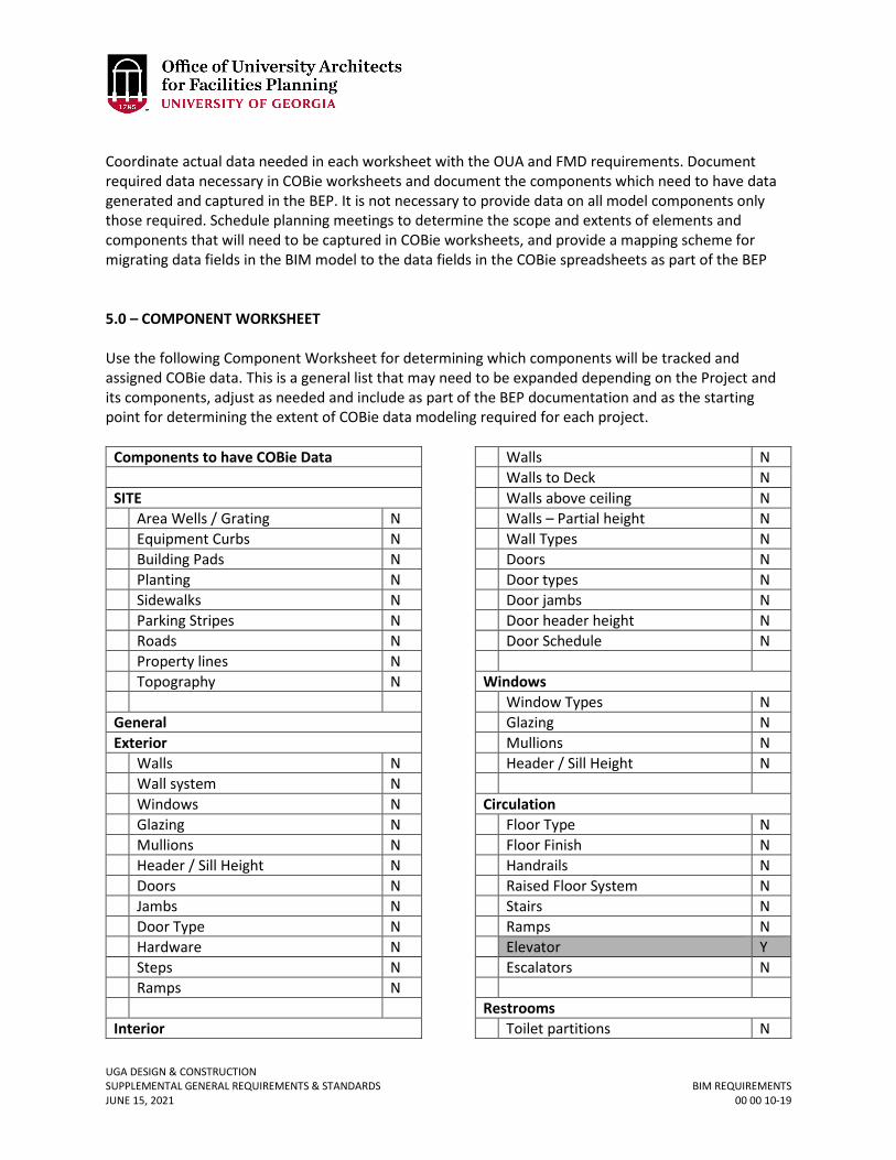
UGA DESIGN & CONSTRUCTION SUPPLEMENTAL GENERAL REQUIREMENTS & STANDARDS BIM REQUIREMENTS JUNE 15, 2021 00 00 10-19
Coordinate actual data needed in each worksheet with the OUA and FMD requirements. Document required data necessary in COBie worksheets and document the components which need to have data generated and captured in the BEP. It is not necessary to provide data on all model components only those required. Schedule planning meetings to determine the scope and extents of elements and components that will need to be captured in COBie worksheets, and provide a mapping scheme for migrating data fields in the BIM model to the data fields in the COBie spreadsheets as part of the BEP 5.0 – COMPONENT WORKSHEET Use the following Component Worksheet for determining which components will be tracked and assigned COBie data. This is a general list that may need to be expanded depending on the Project and its components, adjust as needed and include as part of the BEP documentation and as the starting point for determining the extent of COBie data modeling required for each project.
Components to have COBie Data SITE Area Wells / Grating N Equipment Curbs N Building Pads N Planting N Sidewalks N Parking Stripes N Roads N Property lines N Topography N General Exterior Walls N Wall system N Windows N Glazing N Mullions N Header / Sill Height N Doors N Jambs N Door Type N Hardware N Steps N Ramps N Interior
Walls N Walls to Deck N Walls above ceiling N Walls – Partial height N Wall Types N Doors N Door types N Door jambs N Door header height N Door Schedule N Windows Window Types N Glazing N Mullions N Header / Sill Height N Circulation Floor Type N Floor Finish N Handrails N Raised Floor System N Stairs N Ramps N Elevator Y Escalators N Restrooms Toilet partitions N
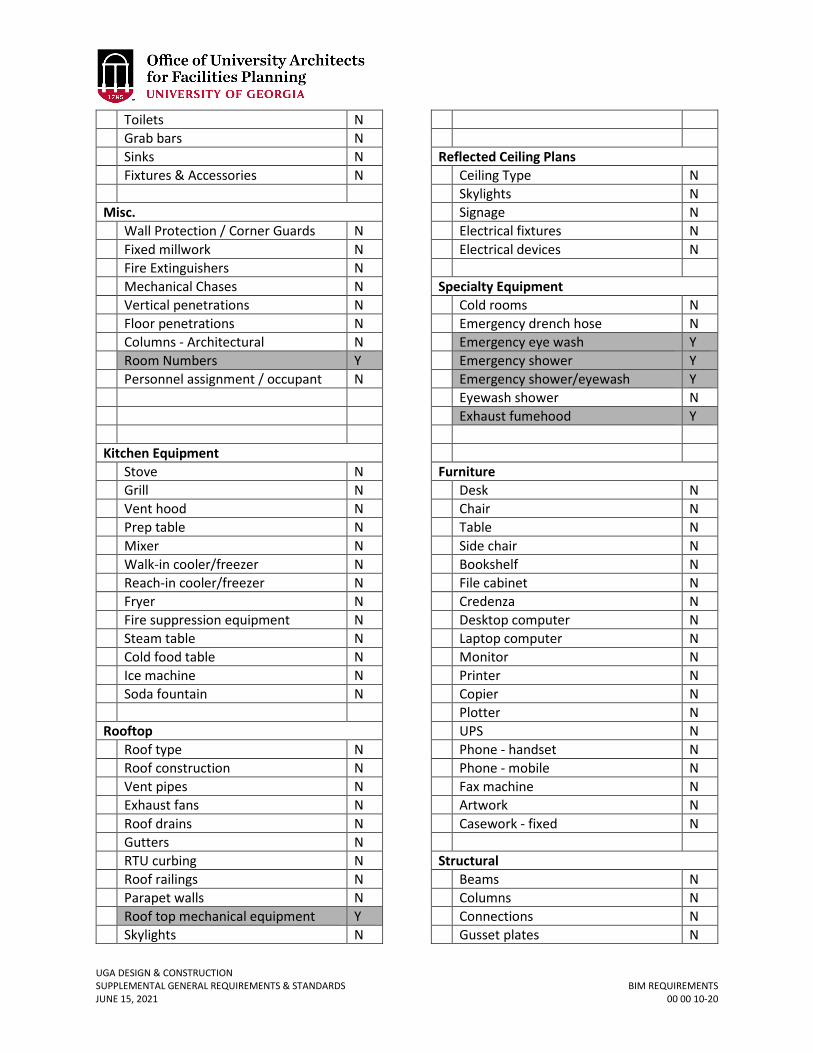
UGA DESIGN & CONSTRUCTION SUPPLEMENTAL GENERAL REQUIREMENTS & STANDARDS BIM REQUIREMENTS JUNE 15, 2021 00 00 10-20
Toilets N Grab bars N Sinks N Fixtures & Accessories N Misc. Wall Protection / Corner Guards N Fixed millwork N Fire Extinguishers N Mechanical Chases N Vertical penetrations N Floor penetrations N Columns - Architectural N Room Numbers Y Personnel assignment / occupant N Kitchen Equipment Stove N Grill N Vent hood N Prep table N Mixer N Walk-in cooler/freezer N Reach-in cooler/freezer N Fryer N Fire suppression equipment N Steam table N Cold food table N Ice machine N Soda fountain N Rooftop Roof type N Roof construction N Vent pipes N Exhaust fans N Roof drains N Gutters N RTU curbing N Roof railings N Parapet walls N Roof top mechanical equipment Y Skylights N
Reflected Ceiling Plans Ceiling Type N Skylights N Signage N Electrical fixtures N Electrical devices N Specialty Equipment Cold rooms N Emergency drench hose N Emergency eye wash Y Emergency shower Y Emergency shower/eyewash Y Eyewash shower N Exhaust fumehood Y Furniture Desk N Chair N Table N Side chair N Bookshelf N File cabinet N Credenza N Desktop computer N Laptop computer N Monitor N Printer N Copier N Plotter N UPS N Phone - handset N Phone - mobile N Fax machine N Artwork N Casework - fixed N Structural Beams N Columns N Connections N Gusset plates N
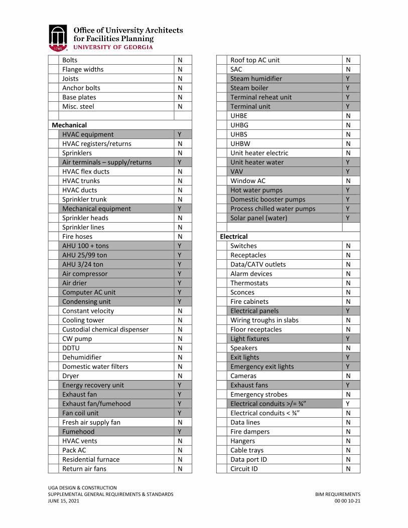
UGA DESIGN & CONSTRUCTION SUPPLEMENTAL GENERAL REQUIREMENTS & STANDARDS BIM REQUIREMENTS JUNE 15, 2021 00 00 10-21
Bolts N Flange widths N Joists N Anchor bolts N Base plates N Misc. steel N Mechanical HVAC equipment Y HVAC registers/returns N Sprinklers N Air terminals – supply/returns Y HVAC flex ducts N HVAC trunks N HVAC ducts N Sprinkler trunk N Mechanical equipment Y Sprinkler heads N Sprinkler lines N Fire hoses N AHU 100 + tons Y AHU 25/99 ton Y AHU 3/24 ton Y Air compressor Y Air drier Y Computer AC unit Y Condensing unit Y Constant velocity N Cooling tower N Custodial chemical dispenser N CW pump N DDTU N Dehumidifier N Domestic water filters N Dryer N Energy recovery unit Y Exhaust fan Y Exhaust fan/fumehood Y Fan coil unit Y Fresh air supply fan N Fumehood Y HVAC vents N Pack AC N Residential furnace N Return air fans N
Roof top AC unit N SAC N Steam humidifier Y Steam boiler Y Terminal reheat unit Y Terminal unit Y UHBE N UHBG N UHBS N UHBW N Unit heater electric N Unit heater water Y VAV Y Window AC N Hot water pumps Y Domestic booster pumps Y Process chilled water pumps Y Solar panel (water) Y Electrical Switches N Receptacles N Data/CATV outlets N Alarm devices N Thermostats N Sconces N Fire cabinets N Electrical panels Y Wiring troughs in slabs N Floor receptacles N Light fixtures Y Speakers N Exit lights Y Emergency exit lights Y Cameras N Exhaust fans Y Emergency strobes N Electrical conduits >/= ¾” Y Electrical conduits < ¾” N Data lines N Fire dampers N Hangers N Cable trays N Data port ID N Circuit ID N
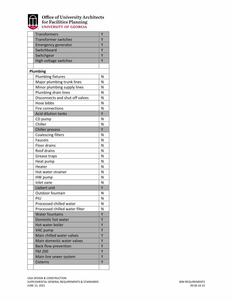
UGA DESIGN & CONSTRUCTION SUPPLEMENTAL GENERAL REQUIREMENTS & STANDARDS BIM REQUIREMENTS JUNE 15, 2021 00 00 10-22
Transformers Y Transformer switches Y Emergency generator Y Switchboard Y Switchgear Y High voltage switches Y Plumbing Plumbing fixtures N Major plumbing trunk lines N Minor plumbing supply lines N Plumbing drain lines N Disconnects and shut off valves N Hose bibbs N Fire connections N Acid dilution tanks Y CD pump N Chiller N Chiller process Y Coalescing filters N Faucets N Floor drains N Roof drains N Grease traps N Heat pump N Heater N Hot water strainer N HW pump N Inlet vane N Liebert unit Y Outdoor fountain N PIU N Processed chilled water N Processed chilled water filter N Water fountains Y Domestic hot water Y Hot water boiler Y VAC pump Y Main chilled water valves Y Main domestic water valves Y Back flow prevention Y FM 200 Y Main line sewer system Y Cisterns Y
UGA DESIGN & CONSTRUCTION SUPPLEMENTAL GENERAL REQUIREMENTS & STANDARDS BIM EXECUTION PLAN (BEP) JUNE 15, 2021 00 00 10.01-1
00 00 10.01 BIM EXECUTION PLAN (BEP)
TABLE OF CONTENTS Table of Contents 01 1.0 – BIM Execution Plan (BEP) Agreement 02 2.0 – Overview 03 3.0 – Project Initiation 03
3.1 – Project Information 03 3.2 – Project Goals and Objectives 03 3.3 – Team Information 04 3.4 – Project Phases/Milestones 05
4.0 – Model Planning 06
4.1 – Model Managers 06 4.2 – Planned Models 08 4.3 – BIM File Names 09 4.4 – Precision and Dimensioning 09 4.5 – Model Attribute Data/COBie Data Planning 10 4.6 – Model level of Detailing 10 4.7 – Modeling Plan 10
4.7.1 – Predesign/Conceptualization 10 4.7.2 – Schematic Design Phase 10 4.7.3 – Preliminary Design (Design Development) 11 4.7.4 – Construction Documents 11 4.7.5 – Bidding Phase 12 4.7.6 – Construction Phase 12 4.7.7 – Close Out (Design Team) 13 4.7.8 – Close Out (Construction Team) 13
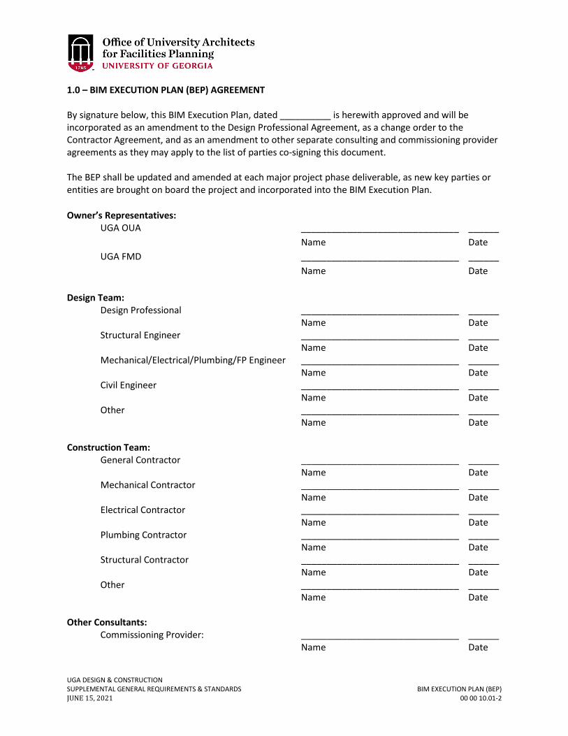
UGA DESIGN & CONSTRUCTION SUPPLEMENTAL GENERAL REQUIREMENTS & STANDARDS BIM EXECUTION PLAN (BEP) JUNE 15, 2021 00 00 10.01-2
1.0 – BIM EXECUTION PLAN (BEP) AGREEMENT By signature below, this BIM Execution Plan, dated __________ is herewith approved and will be incorporated as an amendment to the Design Professional Agreement, as a change order to the Contractor Agreement, and as an amendment to other separate consulting and commissioning provider agreements as they may apply to the list of parties co-signing this document. The BEP shall be updated and amended at each major project phase deliverable, as new key parties or entities are brought on board the project and incorporated into the BIM Execution Plan. Owner’s Representatives:
UGA OUA _______________________________ ______ Name Date UGA FMD _______________________________ ______ Name Date
Design Team:
Design Professional _______________________________ ______ Name Date
Structural Engineer _______________________________ ______ Name Date Mechanical/Electrical/Plumbing/FP Engineer _______________________________ ______ Name Date Civil Engineer _______________________________ ______ Name Date Other _______________________________ ______ Name Date
Construction Team:
General Contractor _______________________________ ______ Name Date
Mechanical Contractor _______________________________ ______ Name Date
Electrical Contractor _______________________________ ______ Name Date Plumbing Contractor _______________________________ ______ Name Date Structural Contractor _______________________________ ______ Name Date Other _______________________________ ______ Name Date
Other Consultants:
Commissioning Provider: _______________________________ ______ Name Date
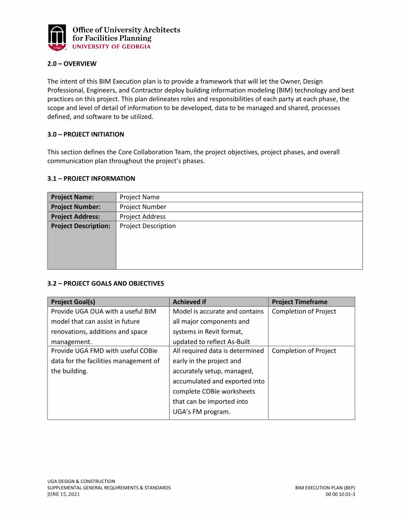
UGA DESIGN & CONSTRUCTION SUPPLEMENTAL GENERAL REQUIREMENTS & STANDARDS BIM EXECUTION PLAN (BEP) JUNE 15, 2021 00 00 10.01-3
2.0 – OVERVIEW The intent of this BIM Execution plan is to provide a framework that will let the Owner, Design Professional, Engineers, and Contractor deploy building information modeling (BIM) technology and best practices on this project. This plan delineates roles and responsibilities of each party at each phase, the scope and level of detail of information to be developed, data to be managed and shared, processes defined, and software to be utilized. 3.0 – PROJECT INITIATION This section defines the Core Collaboration Team, the project objectives, project phases, and overall communication plan throughout the project’s phases. 3.1 – PROJECT INFORMATION
Project Name: Project Name Project Number: Project Number Project Address: Project Address Project Description: Project Description
3.2 – PROJECT GOALS AND OBJECTIVES
Project Goal(s) Achieved if Project Timeframe Provide UGA OUA with a useful BIM model that can assist in future renovations, additions and space management.
Model is accurate and contains all major components and systems in Revit format, updated to reflect As-Built
Completion of Project
Provide UGA FMD with useful COBie data for the facilities management of the building.
All required data is determined early in the project and accurately setup, managed, accumulated and exported into complete COBie worksheets that can be imported into UGA’s FM program.
Completion of Project
UGA DESIGN & CONSTRUCTION SUPPLEMENTAL GENERAL REQUIREMENTS & STANDARDS BIM EXECUTION PLAN (BEP) JUNE 15, 2021 00 00 10.01-4
3.3 – TEAM INFORMATION
Contact
Role/Title Company E-mail Phone Name title company e-mail p. 555-555-555
c. 555-555-5555
Name title company e-mail
p. 555-555-555 c. 555-555-5555
Name title company e-mail
p. 555-555-555 c. 555-555-5555
Name title company e-mail
p. 555-555-555 c. 555-555-5555
Name title company e-mail
p. 555-555-555 c. 555-555-5555
Name title company e-mail
p. 555-555-555 c. 555-555-5555
Name title company e-mail
p. 555-555-555 c. 555-555-5555
Name title company e-mail
p. 555-555-555 c. 555-555-5555
Name title company e-mail
p. 555-555-555 c. 555-555-5555
Name title company e-mail
p. 555-555-555 c. 555-555-5555
Name title company e-mail
p. 555-555-555 c. 555-555-5555
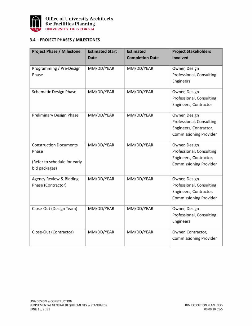
UGA DESIGN & CONSTRUCTION SUPPLEMENTAL GENERAL REQUIREMENTS & STANDARDS BIM EXECUTION PLAN (BEP) JUNE 15, 2021 00 00 10.01-5
3.4 – PROJECT PHASES / MILESTONES
Project Phase / Milestone Estimated Start Date
Estimated Completion Date
Project Stakeholders Involved
Programming / Pre-Design Phase
MM/DD/YEAR MM/DD/YEAR Owner, Design Professional, Consulting Engineers
Schematic Design Phase MM/DD/YEAR MM/DD/YEAR Owner, Design Professional, Consulting Engineers, Contractor
Preliminary Design Phase MM/DD/YEAR MM/DD/YEAR Owner, Design Professional, Consulting Engineers, Contractor, Commissioning Provider
Construction Documents Phase
(Refer to schedule for early bid packages)
MM/DD/YEAR MM/DD/YEAR Owner, Design Professional, Consulting Engineers, Contractor, Commissioning Provider
Agency Review & Bidding Phase (Contractor)
MM/DD/YEAR MM/DD/YEAR Owner, Design Professional, Consulting Engineers, Contractor, Commissioning Provider
Close-Out (Design Team) MM/DD/YEAR MM/DD/YEAR Owner, Design Professional, Consulting Engineers
Close-Out (Contractor) MM/DD/YEAR MM/DD/YEAR Owner, Contractor, Commissioning Provider

UGA DESIGN & CONSTRUCTION SUPPLEMENTAL GENERAL REQUIREMENTS & STANDARDS BIM EXECUTION PLAN (BEP) JUNE 15, 2021 00 00 10.01-6
4.0 – MODEL PLANNING Identify BIM Models that will be created (ie. Design Professional, Structural, MEP, etc.), who the model managers will be from each party responsible, naming convention of BIM files that will be used for final model deliverables, and level of detail utilized at each phase. 4.1 – MODEL MANAGERS Each party—such as the Owner, Design Professional, Contractor, or Subconsultants—that is responsible for contributing modeling content should assign a model manager to the project. The model manager from each party has a number of responsibilities. They include, but are not limited to:
1. Transferring modeling content from one party to another 2. Validating the level of detail and controls as defined for each project phase 3. Validating modeling content during each phase 4. Combining or linking multiple models 5. Participating in design review and model coordination sessions 6. Communicating issues back to the internal and cross-company teams 7. Keeping file naming accurate 8. Managing version control 9. Properly storing the models in the collaborative project management system
Stakeholder
Model Manager
E-mail Phone
company name name [email protected]
p. 555-555-5555
company name name [email protected]
p. 555-555-5555
company name name [email protected]
p. 555-555-5555
company name name [email protected]
p. 555-555-5555
company name name [email protected] p. 555-555-5555
company name name [email protected]
p. 555-555-5555
company name name [email protected]
p. 555-555-5555
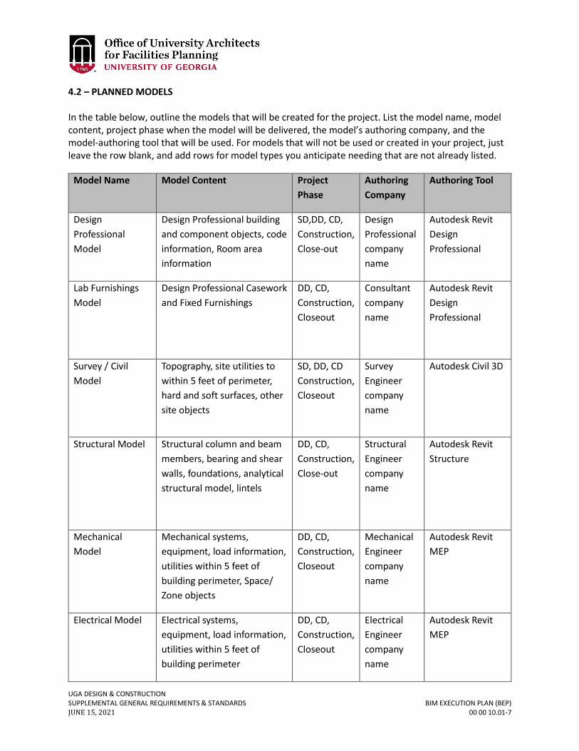
UGA DESIGN & CONSTRUCTION SUPPLEMENTAL GENERAL REQUIREMENTS & STANDARDS BIM EXECUTION PLAN (BEP) JUNE 15, 2021 00 00 10.01-7
4.2 – PLANNED MODELS In the table below, outline the models that will be created for the project. List the model name, model content, project phase when the model will be delivered, the model’s authoring company, and the model-authoring tool that will be used. For models that will not be used or created in your project, just leave the row blank, and add rows for model types you anticipate needing that are not already listed.
Model Name Model Content Project Phase
Authoring Company
Authoring Tool
Design Professional Model
Design Professional building and component objects, code information, Room area information
SD,DD, CD, Construction, Close-out
Design Professional company name
Autodesk Revit Design Professional
Lab Furnishings Model
Design Professional Casework and Fixed Furnishings
DD, CD, Construction, Closeout
Consultant company name
Autodesk Revit Design Professional
Survey / Civil Model
Topography, site utilities to within 5 feet of perimeter, hard and soft surfaces, other site objects
SD, DD, CD Construction, Closeout
Survey Engineer company name
Autodesk Civil 3D
Structural Model Structural column and beam members, bearing and shear walls, foundations, analytical structural model, lintels
DD, CD, Construction, Close-out
Structural Engineer company name
Autodesk Revit Structure
Mechanical Model
Mechanical systems, equipment, load information, utilities within 5 feet of building perimeter, Space/ Zone objects
DD, CD, Construction, Closeout
Mechanical Engineer company name
Autodesk Revit MEP
Electrical Model Electrical systems, equipment, load information, utilities within 5 feet of building perimeter
DD, CD, Construction, Closeout
Electrical Engineer company name
Autodesk Revit MEP
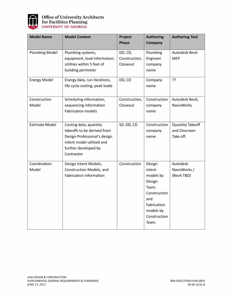
UGA DESIGN & CONSTRUCTION SUPPLEMENTAL GENERAL REQUIREMENTS & STANDARDS BIM EXECUTION PLAN (BEP) JUNE 15, 2021 00 00 10.01-8
Model Name Model Content Project Phase
Authoring Company
Authoring Tool
Plumbing Model Plumbing systems, equipment, load information, utilities within 5 feet of building perimeter
DD, CD, Construction, Closeout
Plumbing Engineer company name
Autodesk Revit MEP
Energy Model Energy data, run iterations, life cycle costing, peak loads
DD, CD
Company name
??
Construction Model
Scheduling information, sequencing information Fabrication models
Construction, Closeout
Construction company name
Autodesk Revit, NavisWorks
Estimate Model Costing data, quantity takeoffs to be derived from Design Professional’s design intent model utilized and further developed by Contractor
SD, DD, CD Construction company name
Quantity Takeoff and Onscreen Take off.
Coordination Model
Design Intent Models, Construction Models, and Fabrication information
Construction Design intent models by Design Taam. Construction and Fabrication models by Construction Team.
Autodesk NavisWorks / (Revit TBD)
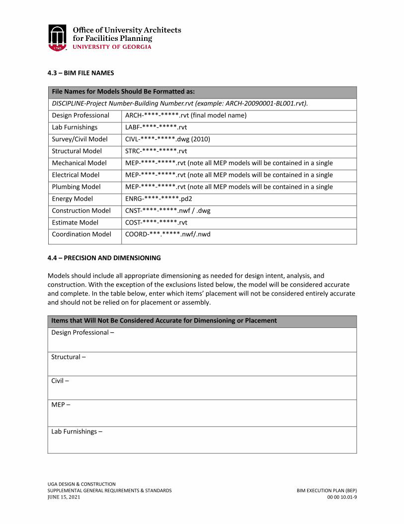
UGA DESIGN & CONSTRUCTION SUPPLEMENTAL GENERAL REQUIREMENTS & STANDARDS BIM EXECUTION PLAN (BEP) JUNE 15, 2021 00 00 10.01-9
4.3 – BIM FILE NAMES
File Names for Models Should Be Formatted as:
DISCIPLINE-Project Number-Building Number.rvt (example: ARCH-20090001-BL001.rvt).
Design Professional
ARCH-****-*****.rvt (final model name)
Lab Furnishings
LABF-****-*****.rvt
Survey/Civil Model CIVL-****-*****.dwg (2010)
Structural Model STRC-****-*****.rvt
Mechanical Model MEP-****-*****.rvt (note all MEP models will be contained in a single Electrical Model MEP-****-*****.rvt (note all MEP models will be contained in a single Plumbing Model MEP-****-*****.rvt (note all MEP models will be contained in a single Energy Model ENRG-****-*****.pd2
Construction Model CNST-****-*****.nwf / .dwg
Estimate Model COST-****-*****.rvt
Coordination Model COORD-***.*****.nwf/.nwd
4.4 – PRECISION AND DIMENSIONING Models should include all appropriate dimensioning as needed for design intent, analysis, and construction. With the exception of the exclusions listed below, the model will be considered accurate and complete. In the table below, enter which items’ placement will not be considered entirely accurate and should not be relied on for placement or assembly.
Items that Will Not Be Considered Accurate for Dimensioning or Placement
Design Professional –
Structural –
Civil –
MEP –
Lab Furnishings –
UGA DESIGN & CONSTRUCTION SUPPLEMENTAL GENERAL REQUIREMENTS & STANDARDS BIM EXECUTION PLAN (BEP) JUNE 15, 2021 00 00 10.01-10
Construction –
4.5 – MODEL ATTRIBUTE DATA / COBIE DATA PLANNING Specify model component COBie data. The Design and Construction Team will be required to add information to the BIMs that will add value to UGA’s facility management systems. In support of COBie, the Project Team is required to utilize and develop COBie schedules within the BIM model that captures data information from the model for export to COBie worksheets. The Design and Construction Team is expected to understand data requirement for all phases of the work, and should show how data capability requirements influence the planning and collaboration for this project. Diagramming and listing expected data requirements and processes, solving workflow dynamics for the collaborative team will address the intent of the BIM Project. Develop detailed component lists along with required data fields for each component to be captured and exported to COBie. Coordinate which parties on the Design and Construction Teams are responsible for delivering data at each phase of the project and how data will be consolidated and delivered so that it meets the requirements for transfer into UGA’s facilities management program. 4.6 – MODELING LEVEL OF DETAIL Specify the level of detail in your models below. The level of detail can be defined by exclusions and/or by object size. The level of detail described here should reflect descriptions listed within the AIA E202. Size: Any object smaller than 1” will not be included in the model. Unless otherwise required to meet requirements of describing design intent and construction documentation requirements. 4.7 – MODELING PLAN AIA form E202 will be utilized as a basis for developing a detailed modeling plan. The following outlines model plan objectives at each phase. Edit and further develop the following outline as required to communicate and coordinate model development to meet the requirements and objectives of the UGA BIM Requirements and Guidelines. 4.7.1 – PRE-DESIGN / CONCEPTUALIZATION Objectives & Responsibilities: Provide initial design based on conceptual parameters established by the Owner; ensure that code and zoning requirements meet project objectives. Provide Program of Requirements and all space considerations for reference in the model. If a BIM model is established at this phase then establish a 3D reference point for future model coordination. Model Roles: Describe what kind of model will be developed and by what program. The role of this model will be to depict the visual concept and general layout of the project along with space requirements, along with other requirements as described in the UGA BIM Standards.
UGA DESIGN & CONSTRUCTION SUPPLEMENTAL GENERAL REQUIREMENTS & STANDARDS BIM EXECUTION PLAN (BEP) JUNE 15, 2021 00 00 10.01-11
4.7.2 – SCHEMATIC DESIGN PHASE Objectives: Provide spatial design based on input from the Conceptualization / Program of Requirement phase; provide initial design for building system and attributes including Design Professional, Structural, and MEP; identify initial coordination issues between building systems and 3D reference point for model coordination; if Contractor has been selected, then Contractor to receive input from suppliers and fabricators regarding system cost, placement, fabrication and scheduling. Model Role & Responsibilities: The Design Professional model will show the general design and layout of the building structure and act as the baseline for all other subsystem designs, such as MEP and Structural models. The subsystem designs are only required to be narratives at this phase. Additional information may be provided by subsystem consultants during this phase as they see fit. The Design Professional model will be used to inform the Energy Models at this phase. Address how model development will meet the requirements of the UGA BIM Requirements and Guidelines. COBie Data: Establish schedules and project parameters in the BIM model that will become the basis for exporting model data to COBie worksheets. Submit initial COBie data worksheets as describing in the UGA BIM Requirements and Guidelines. 4.7.3 – PRELIMINARY DESIGN (DESIGN DEVELOPMENT) Objectives: Provide developed design of building and building systems; resolve coordination issues between building systems; if a Contractor is on board at this phase of the project then a combined (Design Professional/Structural/MEP) Design Intent Model(s) will be provided to the Contractor for use in his development of a Construction Model capable of analyzing schedule, cost, and constructability. Model Roles & Responsibilities: The Design Professional model will continue to act as the baseline for all other subsystem designs. The subsystem designs will be modified accordingly to represent the enhanced design. Once the baseline conceptual structure has been created, the Design Professional’s model manager will send the model to the Subconsultants so they can develop their designs. The Consulting Engineers’ designated model managers will audit and deliver the completed models to the Design Professional’s model manager. The Design Professional’s model manager will review the models to ensure compliance with the phase requirements. Once the models meet the requirements, the Design Professional’s model manager will link or combine cross-disciplinary models. The Design Professional’s model manager should coordinate with the Consulting Engineers’ model managers to eliminate duplicate or redundant objects. The Consulting Engineers’ model managers will use the Design Professional model to revise and complete their designs. Once the models are complete, the Consulting Engineers’ model managers will deliver their models to the Design Professional’s model manager. The Design Professional’s model manager will review the models to ensure compliance with the phase requirements. The Design Professional’s model manager will provide the Contractor’s model manager with the Design Professional model and the Consulting Engineers’ models. Elements or Components that will need to be duplicated between models will be documented and coordinated and a system developed for controlling the display of duplicate elements will be established through the use of work sets or other mutually agreed upon process.
UGA DESIGN & CONSTRUCTION SUPPLEMENTAL GENERAL REQUIREMENTS & STANDARDS BIM EXECUTION PLAN (BEP) JUNE 15, 2021 00 00 10.01-12
COBie Data: Submit updated and additional COBie data worksheets as describing in the UGA BIM Requirements and Guidelines. 4.7.4 – CONSTRUCTION DOCUMENTS (CONTRACT DOCUMENTS) Objectives: Finalize design of the building and all building systems, prepare documentation for agency review, and provide Design Intent Models that are the basis for all Contract Document Drawings, including all plans, elevations, sections, schedules and details needed for use in the construction of the project. Provide the Contractor a combined (Design Professional/Structural/MEP) Design Intent Model(s) that will be utilized in his development of a Construction Model capable of analyzing schedule, cost, phasing and constructability. Model Roles & Responsibilities: All Design Intent Models will be used to reflect the design intent of the project and be the basis for all Contract Document Drawings, these models will become the basis for creating and updating the Record Models and Record Drawings. These models will then be used as the basis for generating the Construction Model(s). The Construction Model will be used for estimating, scheduling, phasing, and constructability analysis. The Construction Model(s) will also become the basis for future development of element and component data needed for the development and gathering of COBie data for periodic export into COBie worksheets. COBie Data: Submit updated and additional COBie data worksheets as describing in the UGA BIM Requirements and Guidelines. Establish a schedule for future periodic COBie data worksheet updates to occur during the construction phase, along with final worksheet delivery at closeout. 4.7.5 – BIDDING PHASE Objective: Revise Design Intent models based on agency feedback on all models. Incorporate feedback into Addenda. Design Team to update all Design Intent Models with Addenda as issued. Model Roles & Responsibilities: The Design Intent Models will be adjusted to reflect agency feedback. The Construction Model will be enhanced and further used for estimating, scheduling, construction sequencing, trade coordination, and constructability analysis. The Design Professional’s model manager will communicate agency comments back to the Design Team. The Consulting Engineers’ model managers will revise their design models accordingly and submit them back to the Design Professional. The Design Professional’s model manager will provide the Contractor’s model manager with the Design Professional model and the Consulting Engineers’ models. COBie Data: No COBie data requirements at this phase. 4.7.6 – CONSTRUCTION PHASE Objective: Update Design Professional and Consulting Engineers’ models based on submittals, RFIs, or owner-directed changes; maintain the Construction Model based on construction activities. The Construction Team will submit RFIs and submittals through the collaborative project management system.
UGA DESIGN & CONSTRUCTION SUPPLEMENTAL GENERAL REQUIREMENTS & STANDARDS BIM EXECUTION PLAN (BEP) JUNE 15, 2021 00 00 10.01-13
Model Roles & Responsibilities: The Design Professional and Consulting Engineers’ Design Intent Models will be revised throughout construction, based on owner directives and As-Built comments. The models will always reflect the revised contract documents with the exception of those items listed as excluded in this BEP. The Construction Model will be used for scheduling analysis, construction sequencing, delegated design component development and trade coordination. Establish and document any departures from concurrent modeling between Design Intent and Construction Models, for example, it may be desirable to maintain the original Design Intent Model as a record of the originally designed mechanical system as designed by the Mechanical Engineers as a reference point for evaluating and comparing any re-designed mechanical systems made by the Mechanical Subcontractor as a result of delegated design responsibilities. The Design Professional’s model manager will work with their Consulting Engineers to answer the RFIs and submittals and adjust the models accordingly. The Contractor’s model manager will update the Construction Model and will work with the Design Professional to develop the Design Professional and Consulting Engineers’ models. COBie Data: Submit updated and additional COBie data worksheets as describing in the UGA BIM Requirements and Guidelines. Establish a schedule for periodic COBie data worksheet updates to occur during the construction phase, along with final worksheet delivery at closeout. Establish a plan for consolidating COBie data that will be exported and generated by multiple models potentially, with multiple party responsibilities that will be acceptable and useable by the Owner’s end-user parties. 4.7.7 – CLOSE-OUT (DESIGN TEAM) Objective: Use the Design Professional and Consulting Engineers’ Design Intent Models for facility management, with the possibility of use in ongoing operations for future additions, renovations, etc. Model Roles & Responsibilities: The Design Professional and Consulting Engineers’ models will be used to represent the actual assembly of the building from construction with the exception of those items listed as excluded in this BEP. If Construction Models are more representative than Design Intent models of actual As-Built components such as mechanical System, then formulate a plan for combining differing models. The Design Professional will deliver the Record Design Intent Model(s) and Record Drawings at the end of the project to the Owner. COBie Data: The Design Team will coordinate with the Construction Team to deliver a coordinated and consolidated COBie worksheet deliverable at closeout. 4.7.8 – CLOSE-OUT (CONSTRUCTION TEAM) Objective: Use the Contractors Construction Model(s) as the basis for all final component data derived from shop drawing submittal process needed for UGA Physical Plant operations and facilities management. Model Roles & Responsibilities: The Contractor’s models will be used to represent the actual assembly of the building from construction, and will be utilized in generating the final As-Built Model and Documents. It will also be used as the basis of COBie data associated with actual product selection as the result of the shop drawing and submittal processes. The Contractor will deliver the As-Built Construction Model(s) and As-Built Documents at the end of the project to the Owner.
UGA DESIGN & CONSTRUCTION SUPPLEMENTAL GENERAL REQUIREMENTS & STANDARDS BIM EXECUTION PLAN (BEP) JUNE 15, 2021 00 00 10.01-14
COBie Data: The Design Team will coordinate with the Construction Team to deliver a coordinated and consolidated COBie worksheet deliverable at closeout.
UGA DESIGN & CONSTRUCTION SUPPLEMENTAL GENERAL REQUIREMENTS & STANDARDS AESTHETIC AUTHORITY JUNE 15, 2021 00 00 11-1
00 00 11 AESTHETIC AUTHORITY
1. GENERAL
A. Aesthetic opinions and evaluations by a Design Professional are advisory only – and not binding on UGA. The OUA reserves the right for final aesthetic judgment.

UGA DESIGN & CONSTRUCTION SUPPLEMENTAL GENERAL REQUIREMENTS & STANDARDS CLIENT & END USER INTERFACE JUNE 15, 2021 00 00 12-1
00 00 12 CLIENT & END USER INTERFACE
For Projects Administered by the OUA or FMD
1. GENERAL A. The Design Professional and Contractor shall take directions that modify the
scope of work only from the UGA Project Manager. The person or entity that will occupy the Project is not authorized to modify the scope of work. For projects administered by OUA, the FMD is not authorized to modify the scope of work. For projects administered by FMD, the OUA is not authorized to modify the scope of work.
Revised June 15, 2021
UGA DESIGN & CONSTRUCTION SUPPLEMENTAL GENERAL REQUIREMENTS & STANDARDS DESIGNING LEARNING ENVIRONMENTS JUNE 15, 2021 00 00 13-1
00 00 13 DESIGNING LEARNING ENVIRONMENTS
1. GENERAL
A. Related sections: i. 09 00 00 – General Finishes Requirements
ii. 09 80 00 – Acoustical Treatment iii. 11 52 00 – Audio Visual Equipment iv. 11 52 13 – Projector Screens v. 12 00 00 – General Furnishings Requirements
vi. 12 46 33 – Interior Waste Receptacles vii. 12 56 52 – Audio-Visual Furniture
viii. 22 00 00 – General Plumbing Requirements ix. 23 00 00 – General Mechanical Requirements (HVAC) x. 26 00 00 – General Electrical Requirements
xi. 26 51 00 – Interior Lighting xii. 27 00 00 – General Communications Requirements
xiii. 27 41 00 – General Audio-Visual Systems Requirements xiv. 27 41 00.01 – Audio-Visual Control System
Table of Contents 1.0 – Foreword 03 2.0 – Background & Scope 04 3.0 – General Considerations 08
3.1 – New Construction vs. Renovation 08 3.2 – Goals 08
4.0 – Classroom General Design Criteria 09
4.1 – Location 09 4.2 – Size & Proportion 09 4.3 – Sight Lines & Viewing Angles 11 4.4 – Seat Spacing 12 4.5 – Doors & Windows 12 4.6 – Finishes 13 4.7 – Furniture & Equipment 13 4.8 – Acoustics 14 4.9 – Accessibility 17 4.10 – Audiovisual Systems 17 4.11 – Lighting / Electrical Systems 18 4.12 – Building Systems 18
5.0 – General Purpose Flat Classrooms 19 5.1 – 10 to 20 Seat Lecture, Seminar, Conference, & Active Learning Classrooms 19
UGA DESIGN & CONSTRUCTION SUPPLEMENTAL GENERAL REQUIREMENTS & STANDARDS DESIGNING LEARNING ENVIRONMENTS JUNE 15, 2021 00 00 13-2
5.2 – 20 to 49 Seat Lecture & Active Learning Classrooms 23 5.3 – 50 to 60 Seat Lecture & Active Learning Classrooms 26 5.4 – 60 to 100 Seat Lecture & Active Learning Classrooms 31
6.0 – General Purpose Tiered Classrooms 35 6.1 – 100 to 120 Seat Lecture / Collaborative Classrooms
35 6.2 – 200 to 280 Seat Lecture Hall 39
7.0 – SCALE-UP Classrooms 42
7.1 – 45 Seat Classroom 43 7.2 – 72 Seat Classroom 44 7.3 – 99 Seat Classroom 45
8.0 – Classroom Design Quick Checklist 46
UGA DESIGN & CONSTRUCTION SUPPLEMENTAL GENERAL REQUIREMENTS & STANDARDS DESIGNING LEARNING ENVIRONMENTS JUNE 15, 2021 00 00 13-3
1.0 - FOREWORD Building and adapting learning spaces to support the continuing change of pedagogy and technology at the University of Georgia (UGA) provides many challenges; however, there are a number of evidence-based reasons to pursue excellence in learning space design. Research has shown that active learning techniques provide clear improvements in learning1, but a majority of the current teaching spaces at UGA don’t easily lend themselves to support these pedagogies. The Georgia Board of Regents has long supported the creation of classrooms with a standard level of quality that includes a “flexibility to respond to future requirements.”2 One of the operative goals is “to develop and implement a well-conceived and consistent concept for how technology requirements can best be accommodated in designing new and renovated facilities.”2 A lack of compliance to these minimum standards creates a clear challenge to effective learning according to research.3 It is vital that all classrooms have appropriate furniture, correctly maintained classroom technology, and proper physical design and maintenance. All of these have been shown to have a direct effect on learning outcomes 3 and student success.
This document has been a joint effort between the UGA Office of University Architects and the Center for Teaching and Learning to provide relevant standards and guidelines for the design and construction of new classroom space and the renovation and maintenance of existing spaces. Outside consultants have been included in this process to ensure that current best practices in the fields of architecture, design, construction, and technology have been brought together with the current research regarding teaching and learning. The result provides clear direction for the effective design and development of learning environments at UGA.
1 Summary of Key Papers on Efficacy of Active Learning (2012). http://cst.yale.edu/sites/default/files/active learning bibliography.pdf 2 Facilities Guidelines For Instructional Technology (2001).
http://www.usg.edu/facilities/documents/facilities_it_guidelines.pdf 3 Making the Case for Space: Three Years of Empirical Research on Learning Environments (2010)
http://www.educause.edu/ero/article/making-case-space-three-years-empirical-research-learning-environments
Space Matters: The Impact of Formal Learning Environments on Student Learning (2010) https://www.bgsu.edu/content/dam/BGSU/master-plan/documents/space-matters.pdf
Minimum Classroom Size and Number of Students Per Classroom (2000/2009) http://sdpl.coe.uga.edu/research/territoriality.html
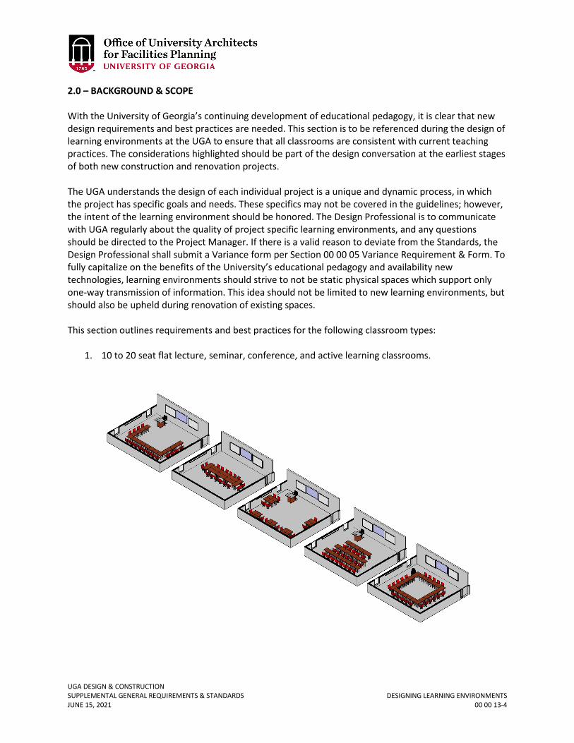
UGA DESIGN & CONSTRUCTION SUPPLEMENTAL GENERAL REQUIREMENTS & STANDARDS DESIGNING LEARNING ENVIRONMENTS JUNE 15, 2021 00 00 13-4
2.0 – BACKGROUND & SCOPE With the University of Georgia’s continuing development of educational pedagogy, it is clear that new design requirements and best practices are needed. This section is to be referenced during the design of learning environments at the UGA to ensure that all classrooms are consistent with current teaching practices. The considerations highlighted should be part of the design conversation at the earliest stages of both new construction and renovation projects. The UGA understands the design of each individual project is a unique and dynamic process, in which the project has specific goals and needs. These specifics may not be covered in the guidelines; however, the intent of the learning environment should be honored. The Design Professional is to communicate with UGA regularly about the quality of project specific learning environments, and any questions should be directed to the Project Manager. If there is a valid reason to deviate from the Standards, the Design Professional shall submit a Variance form per Section 00 00 05 Variance Requirement & Form. To fully capitalize on the benefits of the University’s educational pedagogy and availability new technologies, learning environments should strive to not be static physical spaces which support only one-way transmission of information. This idea should not be limited to new learning environments, but should also be upheld during renovation of existing spaces. This section outlines requirements and best practices for the following classroom types:
1. 10 to 20 seat flat lecture, seminar, conference, and active learning classrooms.
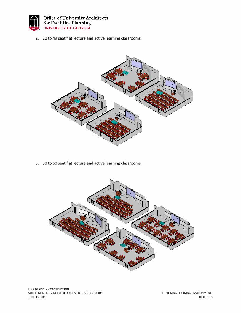
UGA DESIGN & CONSTRUCTION SUPPLEMENTAL GENERAL REQUIREMENTS & STANDARDS DESIGNING LEARNING ENVIRONMENTS JUNE 15, 2021 00 00 13-5
2. 20 to 49 seat flat lecture and active learning classrooms.
3. 50 to 60 seat flat lecture and active learning classrooms.
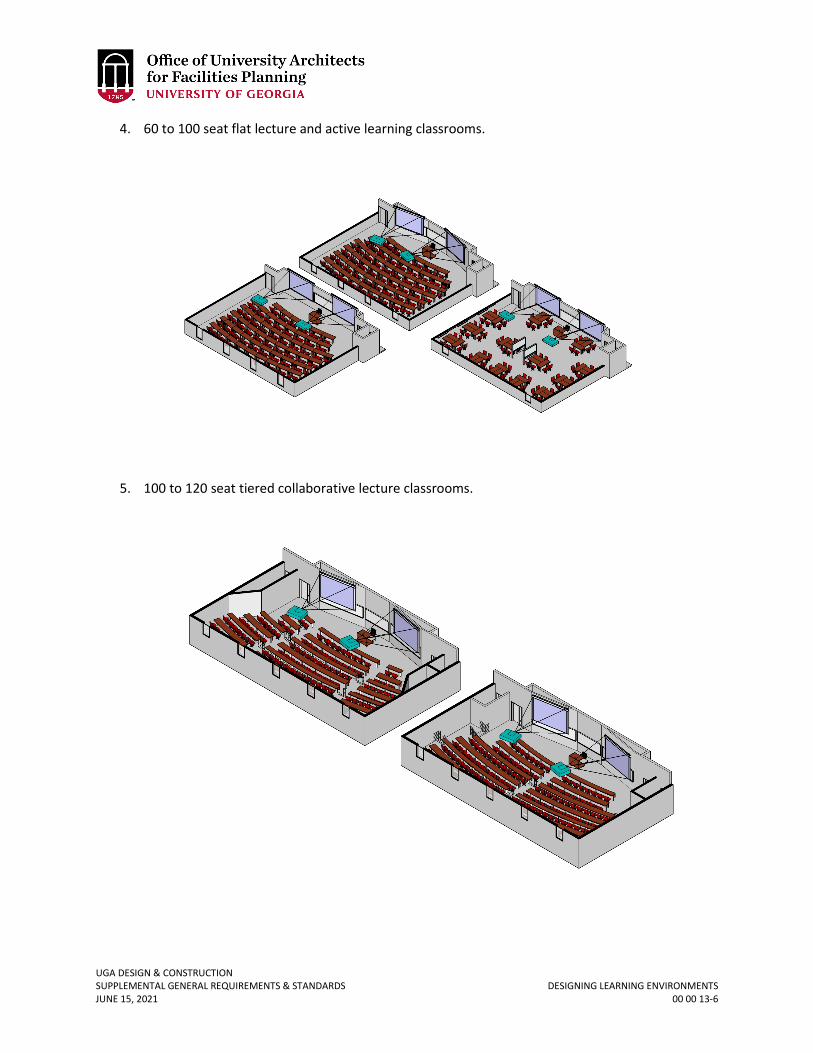
UGA DESIGN & CONSTRUCTION SUPPLEMENTAL GENERAL REQUIREMENTS & STANDARDS DESIGNING LEARNING ENVIRONMENTS JUNE 15, 2021 00 00 13-6
4. 60 to 100 seat flat lecture and active learning classrooms.
5. 100 to 120 seat tiered collaborative lecture classrooms.
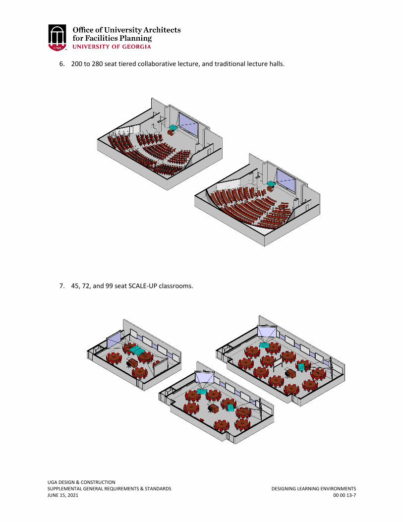
UGA DESIGN & CONSTRUCTION SUPPLEMENTAL GENERAL REQUIREMENTS & STANDARDS DESIGNING LEARNING ENVIRONMENTS JUNE 15, 2021 00 00 13-7
6. 200 to 280 seat tiered collaborative lecture, and traditional lecture halls.
7. 45, 72, and 99 seat SCALE-UP classrooms.
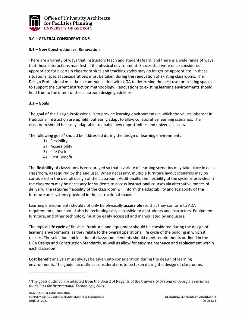
UGA DESIGN & CONSTRUCTION SUPPLEMENTAL GENERAL REQUIREMENTS & STANDARDS DESIGNING LEARNING ENVIRONMENTS JUNE 15, 2021 00 00 13-8
3.0 – GENERAL CONSIDERATIONS 3.1 – New Construction vs. Renovation There are a variety of ways that instructors teach and students learn, and there is a wide range of ways that those interactions manifest in the physical environment. Spaces that were once considered appropriate for a certain classroom sizes and teaching styles may no longer be appropriate. In these situations, special considerations must be taken during the renovation of existing classrooms. The Design Professional must be in communication with UGA to determine the best use for existing spaces to support the current instruction methodology. Renovations to existing learning environments should hold true to the intent of the classroom design guidelines. 3.2 – Goals The goal of the Design Professional is to provide learning environments in which the values inherent in traditional instruction are upheld, but easily adapt to allow collaborative learning scenarios. The classroom should be easily adaptable to enable new opportunities and universal access. The following goals4 should be addressed during the design of learning environments:
1) Flexibility 2) Accessibility 3) Life Cycle 4) Cost Benefit
The flexibility of classrooms is encouraged so that a variety of learning scenarios may take place in each classroom, as required by the end user. When necessary, multiple furniture layout scenarios may be considered in the overall design of the classroom. Additionally, the flexibility of the systems provided in the classroom may be necessary for students to access instructional courses via alternative modes of delivery. The required flexibility of the classroom will inform the adaptability and scalability of the furniture and systems provided in the instructional space. Learning environments should not only be physically accessible (so that they conform to ADA requirements), but should also be technologically accessible to all students and instructors. Equipment, furniture, and other technology must be easily accessed and manipulated by end users. The typical life cycle of finishes, furniture, and equipment should be considered during the design of learning environments, as they relate to the overall operational life cycle of the building in which it resides. The selection and location of classroom elements should meet requirements outlined in the UGA Design and Construction Standards, as well as allow for easy maintenance and replacement within each classroom. Cost benefit analysis must always be taken into consideration during the design of learning environments. The guideline outlines considerations to be taken during the design of classrooms;
4 The goals outlined are adapted from the Board of Regents of the University System of Georgia’s Facilities Guidelines for Instructional Technology, 2001.
UGA DESIGN & CONSTRUCTION SUPPLEMENTAL GENERAL REQUIREMENTS & STANDARDS DESIGNING LEARNING ENVIRONMENTS JUNE 15, 2021 00 00 13-9
however, the extent to which best practices are followed should be determined on a case-by-case basis. The Design Professional should determine if certain recommendations are the most cost efficient solution for each instructional space, or if other options are available that meet the intent of the guideline. 4.0 – CLASSROOM GENERAL DESIGN CRITERIA This portion outlines necessary design characteristics that must be considered during the design of learning environments. The scale of considerations varies from the location of specific classroom within an overall building to providing finish protection in high traffic areas. All considerations intend to help each classroom perform at a high level for UGA. 4.1 – LOCATION Classroom spaces shall be located as close as possible to building entrances and level accesses to improve circulation and reduce noise levels in other parts of the building. Large classrooms shall be located close to primary building entrances. Circulation spaces which support large classrooms should be sized so that they accommodate students waiting in the hallway for the next class session. It may be desirable for smaller classrooms to be located closer to offices and / or related lab spaces. The location of small classrooms should be discussed with end users to determine special requirements for circulation spaces and programmatic adjacencies. When possible, classrooms should be separated from noise generating areas such as mechanical rooms, elevators, vending areas, and restrooms. When separation from these functional areas is not possible, ensure that adequate noise separation is provided. Please refer to the Acoustics Section 4.8 of this guideline. The location of certain classrooms in relation to their solar orientation impacts their access to natural daylight considerably. The Design Professional should discuss with the end user whether natural daylighting is beneficial or should be avoided (i.e. easily controlled). Classrooms with northern exposure may be more easily designed to provide comfortable natural daylighting capabilities while not adversely impacting AV systems, as well as be more energy-efficiency than rooms with windows facing other cardinal directions. Passive solar design features should be considered for rooms where windows face south, east, and west. 4.2 – SIZE & PROPORTION Classrooms must be designed so that they comfortably accommodate the number of students planned for each classroom type, as well as the types and sizes of furnishings anticipated to be used in the space. The UGA Center for Teaching and Learning shall be involved in any discussions that concern classroom functions and / or seating capacities. The Design Professional shall coordinate with the Project Manager to assist with including the UGA Center for Teaching and Learning in design meetings. The following space standards and furnishing types shall be used to estimate the total usable floor area of classrooms during the programming phase of a project:
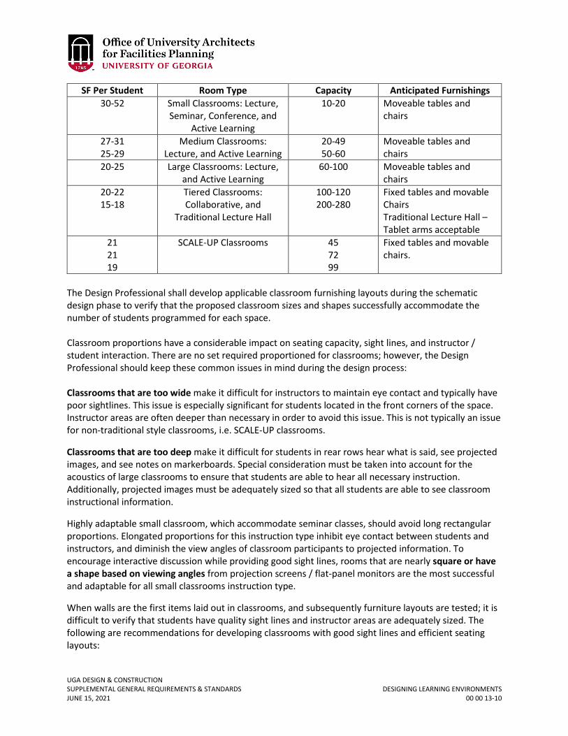
UGA DESIGN & CONSTRUCTION SUPPLEMENTAL GENERAL REQUIREMENTS & STANDARDS DESIGNING LEARNING ENVIRONMENTS JUNE 15, 2021 00 00 13-10
SF Per Student Room Type Capacity Anticipated Furnishings 30-52 Small Classrooms: Lecture,
Seminar, Conference, and Active Learning
10-20 Moveable tables and chairs
27-31 25-29
Medium Classrooms: Lecture, and Active Learning
20-49 50-60
Moveable tables and chairs
20-25 Large Classrooms: Lecture, and Active Learning
60-100 Moveable tables and chairs
20-22 15-18
Tiered Classrooms: Collaborative, and
Traditional Lecture Hall
100-120 200-280
Fixed tables and movable Chairs Traditional Lecture Hall – Tablet arms acceptable
21 21 19
SCALE-UP Classrooms 45 72 99
Fixed tables and movable chairs.
The Design Professional shall develop applicable classroom furnishing layouts during the schematic design phase to verify that the proposed classroom sizes and shapes successfully accommodate the number of students programmed for each space. Classroom proportions have a considerable impact on seating capacity, sight lines, and instructor / student interaction. There are no set required proportioned for classrooms; however, the Design Professional should keep these common issues in mind during the design process: Classrooms that are too wide make it difficult for instructors to maintain eye contact and typically have poor sightlines. This issue is especially significant for students located in the front corners of the space. Instructor areas are often deeper than necessary in order to avoid this issue. This is not typically an issue for non-traditional style classrooms, i.e. SCALE-UP classrooms.
Classrooms that are too deep make it difficult for students in rear rows hear what is said, see projected images, and see notes on markerboards. Special consideration must be taken into account for the acoustics of large classrooms to ensure that students are able to hear all necessary instruction. Additionally, projected images must be adequately sized so that all students are able to see classroom instructional information.
Highly adaptable small classroom, which accommodate seminar classes, should avoid long rectangular proportions. Elongated proportions for this instruction type inhibit eye contact between students and instructors, and diminish the view angles of classroom participants to projected information. To encourage interactive discussion while providing good sight lines, rooms that are nearly square or have a shape based on viewing angles from projection screens / flat-panel monitors are the most successful and adaptable for all small classrooms instruction type.
When walls are the first items laid out in classrooms, and subsequently furniture layouts are tested; it is difficult to verify that students have quality sight lines and instructor areas are adequately sized. The following are recommendations for developing classrooms with good sight lines and efficient seating layouts:

UGA DESIGN & CONSTRUCTION SUPPLEMENTAL GENERAL REQUIREMENTS & STANDARDS DESIGNING LEARNING ENVIRONMENTS JUNE 15, 2021 00 00 13-11
1) Determine number of screens based on seating capacity and classroom type. 2) Determine the general location, size, and orientation of each screen based on the seating
area. 3) Determine the location and size of the instructor area based upon the required
markerboards, projection screens, and other equipment necessary for the classroom type. 4) Make certain the instructor area is large enough to accommodate the instructor
workstation, required equipment, and ample circulation around workstation, markerboard, and seating. Ensure that the instructor station is not directly in the light path of a front-screen projector.
5) Determine optimum width and depth of the seating area based on seat spacing guidelines, provided in each of the typical classroom layout sections.
6) Determine the location and size of access aisles. 7) Draw viewing angles from each screen and make certain all seats provided fall within them. 8) Finally, determine where the walls of the classroom should be located.
4.3 – Sight Lines & Viewing Angles The Design Professional should provide recommendations for existing ceiling height. If the existing ceiling height does not work, the Design Professional should notify the Project Manager to resolve concerns. The Design Professional is responsible for coordinating with the Audio-Visual Consultant to ensure all seats have good sight lines. If any seats have marginal sight lines, the Design Professional must bring this to the attention of the Project Manager. The size of the projected image should follow current industry standards. The farthest viewer should be placed no further than five times the height of the screen. Example: if the screen is six feet tall, the farthest viewer should be no further than 30 feet from the screen. The closest viewer should be no closer than one and a half times the width of the screen. Example: if the screen is six feet wide, the first viewer should be no closer than nine feet from the screen. In flat floor classrooms, the bottom of the projected image is recommended to be a minimum of 48” above the finished floor (AFF); however, 54” AFF is preferred. The Design Professional should keep in mind that combining the 5H screen sizing factor with the 48” AFF image requirement will have a significant impact on the ceiling height of larger learning spaces. Strategies such as favoring wider rooms over deeper rooms (thus reducing the distance to the farthest viewer) and / or routing ductwork around the front-center area of the room such that the ceiling elevation can be raised in the projection screen area should be considered. SCALE-UP classrooms shall have smaller sized projection screens which are located on multiple walls of the classrooms between groups of tables to allow students to see content without having to rotate their seats away from their work surface. 4.4 – Seat Spacing
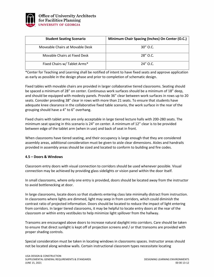
UGA DESIGN & CONSTRUCTION SUPPLEMENTAL GENERAL REQUIREMENTS & STANDARDS DESIGNING LEARNING ENVIRONMENTS JUNE 15, 2021 00 00 13-12
Student Seating Scenario Minimum Chair Spacing (Inches) On Center (O.C.)
Moveable Chairs at Movable Desk 30” O.C.
Movable Chairs at Fixed Desk 28” O.C.
Fixed Chairs w/ Tablet Arms* 24” O.C.
*Center for Teaching and Learning shall be notified of intent to have fixed seats and approve application as early as possible in the design phase and prior to completion of schematic design. Fixed tables with movable chairs are provided in larger collaborative tiered classrooms. Seating should be spaced a minimum of 28” on center. Continuous work surfaces should be a minimum of 18” deep, and should be equipped with modesty panels. Provide 36” clear between work surfaces in rows up to 20 seats. Consider providing 38” clear in rows with more than 21 seats. To ensure that students have adequate knee clearance in the collaborative fixed table scenario, the work surface in the rear of the grouping should have a 4” to 6” overhang. Fixed chairs with tablet arms are only acceptable in large tiered lecture halls with 200-280 seats. The minimum seat spacing in this scenario is 24” on center. A minimum of 12” clear is to be provided between edge of the tablet arm (when in use) and back of seat in front. When classrooms have tiered seating, and their occupancy is large enough that they are considered assembly areas, additional consideration must be given to aisle clear dimensions. Aisles and handrails provided in assembly areas should be sized and located to conform to building and fire codes. 4.5 – Doors & Windows Classroom entry doors with visual connection to corridors should be used whenever possible. Visual connection may be achieved by providing glass sidelights or vision panel within the door itself. In small classrooms, where only one entry is provided, doors should be located away from the instructor to avoid bottlenecking at door. In large classrooms, locate doors so that students entering class late minimally distract from instruction. In classrooms where lights are dimmed, light may seep in from corridors, which could diminish the contrast ratio of projected information. Doors should be located to reduce the impact of light entering from corridors. In larger tiered classrooms, it may be helpful to locate entry doors at the rear of the classroom or within entry vestibules to help minimize light spillover from the hallway. Transoms are encouraged above doors to increase natural daylight into corridors. Care should be taken to ensure that direct sunlight is kept off of projection screens and / or that transoms are provided with proper shading controls. Special consideration must be taken in locating windows in classrooms spaces. Instructor areas should not be located along window walls. Certain instructional classroom types necessitate locating
UGA DESIGN & CONSTRUCTION SUPPLEMENTAL GENERAL REQUIREMENTS & STANDARDS DESIGNING LEARNING ENVIRONMENTS JUNE 15, 2021 00 00 13-13
markerboards and projection surfaces on a majority, if not all, of the classroom walls. When this is a possibility, windows are most conveniently located above and / or below markerboard space. When it is not possible to locate windows in this fashion, the Design Professional should strategize how to provide adequate collaborative equipment without conflicting with window locations. Certain classroom types require blackout capabilities, especially distance learning classrooms. Locate these classrooms accordingly within the building. If windows are provided in these spaces, ensure that adequate window shading is provided. 4.6 – FINISHES Refer to Section 09 00 00 General Finishes Requirements. 4.7 – FURNITURE & EQUIPMENT Refer to Section 12 00 00 General Furnishings Requirements. Instructor Area A minimum of 8’ clear space parallel to the instructor wall (10’ preferred) shall be provided in small and large lecture style classroom layouts. Instructor areas are to accommodate computer-based audio-visual systems. Provide floor and / or wall junction boxes for power / data / audiovisual systems wiring to serve the workstation. The floor junction box should be a minimum of 5 feet from the front wall in small classrooms and a minimum of 6 feet from the front wall in large classrooms. Instructor areas are to accommodate instructors who are standing, seated, or using wheelchairs. Workstation features and location considerations:
1) Workstations should be oriented to maximize eye contact between instructor and students, while allowing students to see projected media.
2) In rooms with one screen, an instructor workstation on the left side of the instructor area, markerboards in the center, and a screen in the right corner is preferred.
3) In large rooms with multiple screens, a workstation located on the left side of the instructor area, near the markerboard, usually works well, but a more central location may be preferable.
4) Provide adequate circulation space around lectern and surrounding equipment / furniture. The minimum clear dimension is 36”; however, 48” is preferred. For larger spaces, 48” is a minimum distance from the front wall.
5) The type / size of the lectern is to be determined by the classroom type. Refer to Section 12 56 52 Audio-Visual Furniture for listing of recommended lectern types and sizes.
Additional Considerations: Consider providing an additional small table within instructor area in large lecture classrooms for disbursement and collection of classroom handouts. Should additional tables and / or equipment (i.e. demonstration table) be required and located within instructor area, include these items in preliminary classroom layout. Carefully locate the required equipment and j-boxes in the instructor area so that tripping hazards are avoided.
UGA DESIGN & CONSTRUCTION SUPPLEMENTAL GENERAL REQUIREMENTS & STANDARDS DESIGNING LEARNING ENVIRONMENTS JUNE 15, 2021 00 00 13-14
Student Seating Refer to Section 12 00 00 General Furnishings Requirements. This section also includes minimum chair spacing information which is critical when initialing laying out classrooms. Interior Waste Receptacles The designer should plan for efficiently sized waste receptacles near exit doors in locations that do not obstruct other room functions. Refer to Section 12 46 33 Interior Waste Receptacles. Provide a large clock that is easy to read and can be seen by instructors and students. Audio-Visual Furniture Using similar lecterns from classroom to classroom simplifies instructor equipment training, and makes classrooms more technologically accessible. Refer to Section 12 56 52 Audio-Visual Furniture. 4.8 – ACOUSTICS Numerous studies over the past several decades have concluded that transmission of the spoken word from talker to listener is of primary importance in any learning environment to enhance learning, minimize listener fatigue, promote the retention of information, and reduce distractions from unwanted noises. As learning pedagogies evolve from traditional models (i.e. a one-to-many delivery paradigm) to more active model (e.g. group discussion / interaction), the transmission of intelligible speech within the room and the overall behavior of a space acoustically becomes even more critical. Additionally, the current trend in architecture towards less “soft goods” in a space (i.e. concrete floors, exposed concrete or metal deck ceilings, etc.), whether to meet sustainability goals or to meet a design aesthetic, can often run counter to a classroom’s acoustical needs and primary functional intent. To address the successful transmission of intelligible speech – whether from instructor to student, student to instructor, or student to student – three separate but related acoustical areas of concern must be addressed:
1) Room acoustics pertaining to surface finishes and room geometry 2) Background noise levels, primarily HVAC systems and 3) Sound isolation from exterior noise intrusion (i.e. from adjacent rooms and lobbies / corridors,
as well as outside noise from traffic, cooling towers, transformers, etc.) If all three of these areas are properly addressed, the dependence on speech reinforcement systems (i.e. lavaliere microphones, digital mixers, etc.) can be eliminated for all but the largest lecture halls. Eliminating speech reinforcement would result in lower initial project costs, as well as simpler operations and maintenance for the entire lifecycle of the classroom. Thus, the Design Professional should consider acoustics a primary design consideration for all learning spaces. Below is an overview of each of the three areas of concern and design criteria and strategies for each:
UGA DESIGN & CONSTRUCTION SUPPLEMENTAL GENERAL REQUIREMENTS & STANDARDS DESIGNING LEARNING ENVIRONMENTS JUNE 15, 2021 00 00 13-15
Room Acoustics Room finishes have the most dramatic impact on the intelligible transmission of speech within most classrooms, as well as the management of the overall noise level in a classroom for active learning spaces where multiple group discussions may be occurring simultaneously.
In general, classrooms and lecture halls should be designed to distribute sound absorbing materials among the major surfaces in the space (floor, ceiling and walls) while balancing other major design considerations such as durability, aesthetics, daylighting and cost. Reverberation times for classrooms should be targeted to meet an RT-60 criteria (i.e. the time it takes for sound to dissipate by 60 decibels) of less than 1 second for most classrooms and closer to 0.6 seconds for distance learning classroom.
A general strategy to achieve this reverberation time for these major surfaces is as follows:
Floors For durability, hard-finish floors may be preferred. Where possible, low-pile carpeting is recommended classroom floor surface area to mainly reduce foot-fall traffic noise and introduce sound absorption to this major surface area, especially for distance learning spaces. Ceiling Acoustical ceiling tile with a noise reduction coefficient (NRC) of at least 0.70 should be at least 50% of the ceiling area for small rooms (10-20 occupants) and as much as 80% to 100% for large rooms (20 – 60 occupants). Rooms with a capacity of 100 or more occupants should use acoustical ceiling tile with a NRC rating of 0.90 over at least 80% of the ceiling area. As a strategy to promote the reflection of speech energy between instructors and students, the Design Professional can consider introducing some reflective ceiling elements (lay-in reflective panels or gypsum-board areas) in strategic locations in the ceiling area in balance with the absorptive areas around the perimeter. Walls Lastly, durable / tackable acoustical wall panels (with 1” thick fiberglass backing behind an acoustical transparent covering) should be considered for at least 25 percent of the room’s wall area. Larger volume spaces are naturally more inclined to result in higher reverberation times. Thus, as rooms get larger, it is increasingly important to control reverberation and echoes (from large area, hard, parallel surfaces) through the use of absorptive room finishes such as acoustical wall panels. Since many rooms contain parallel walls, it is often advisable to apply acoustical wall finishes to adjacent surfaces to address the flutter echoes from these parallel surfaces. Alternately, walls can be designed to be non-parallel to reduce the need for absorptive wall materials.
UGA DESIGN & CONSTRUCTION SUPPLEMENTAL GENERAL REQUIREMENTS & STANDARDS DESIGNING LEARNING ENVIRONMENTS JUNE 15, 2021 00 00 13-16
Background Noise Levels To achieve a proper signal-to-noise ratio in a classroom (where the signal is the spoken word and the noise is the background noise level) the Design Professional must consider the design of the HVAC system (which is the primary contributor to background noise) as part of the acoustical environment of the classroom. Per ASHRAE guidelines classrooms should be designed to meet a background noise criterion of NC-30. Special purpose classrooms (e.g. distance learning, music classrooms, screening rooms, etc.) may require even lower background noise levels. To achieve appropriate background noise levels, classrooms should be designed to be acoustically separated by physical distance and / or enhanced partition design (see the section to follow on sound isolation) from noisy mechanical rooms and primary duct runs. Noise-inducing HVAC equipment such as fan-coil units and VAV boxes should be positioned outside of the classroom envelope (usually outside the room over the hallways) and duct runs should be calculated to be long enough to reduce noise levels at any diffuser to be at least five points below the overall room criteria. Use of duct silencers is to be avoided and used as a last resort. The Design Professional shall discuss the specification of duct silencers with UGA prior to including them in the design. The need for duct silencers shall be supported by calculations to be submitted for review by UGA and Commissioning Provider. Duct cross-sections shall be increased to minimize system pressure drop where duct silencers are the only alternative to achieve desired noise levels. Equipment with the lowest noise signature should be selected, and duct work shall be laid out in such a way that attenuation is maximized. Sound Isolation Another contributor to acoustical distractions which can hamper a student’s ability to maintain focus / attention in a classroom setting is the intrusion of unwanted, outside noise into the classroom. This intrusion can come from adjacent spaces (both vertically and horizontally adjacent), as well as from outside the building (cars, trains, mechanical equipment, etc.). The first, and often easiest and cheapest, sound isolation strategy is to architecturally isolate noisy spaces, such as main mechanical rooms, from noise-sensitive spaces, like classrooms, early in the design process. When physical separation is not possible, enhanced acoustical wall, floor and ceiling constructions must be considered as the next line of defense. Walls between adjacent classrooms should go to structure and have a sound transmission class (STC) rating of at least STC-45. Walls with STC ratings of 50 to 55 should be used between classrooms equipped with sound systems. Typical classroom doors should be STC-30 or more, while noisier classroom types (i.e. music rooms) should have doors with STC-40 or more. With studies showing that some amount of daylight helps to enhance student attention, special consideration should be taken to weigh the benefits of day lit classrooms with the potential distraction from the noise intrusion through the glass. There are many high-STC glazing solutions available, but these solutions can often increase material costs significantly.
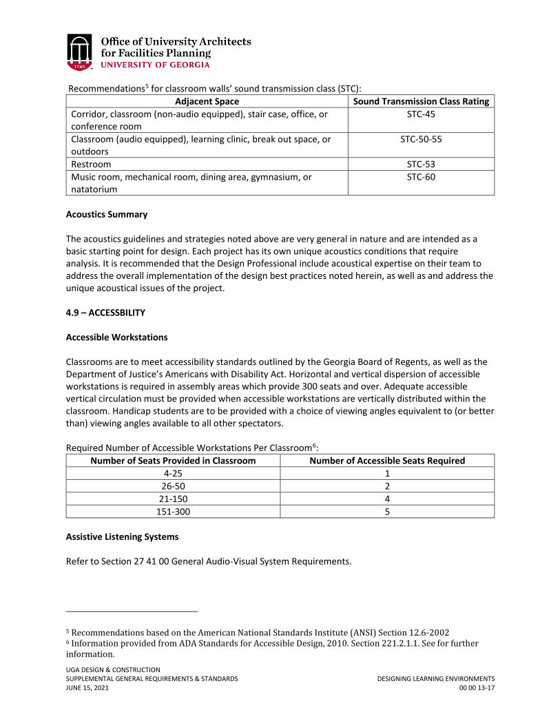
UGA DESIGN & CONSTRUCTION SUPPLEMENTAL GENERAL REQUIREMENTS & STANDARDS DESIGNING LEARNING ENVIRONMENTS JUNE 15, 2021 00 00 13-17
Recommendations5 for classroom walls’ sound transmission class (STC): Adjacent Space Sound Transmission Class Rating
Corridor, classroom (non-audio equipped), stair case, office, or conference room
STC-45
Classroom (audio equipped), learning clinic, break out space, or outdoors
STC-50-55
Restroom STC-53 Music room, mechanical room, dining area, gymnasium, or natatorium
STC-60
Acoustics Summary The acoustics guidelines and strategies noted above are very general in nature and are intended as a basic starting point for design. Each project has its own unique acoustics conditions that require analysis. It is recommended that the Design Professional include acoustical expertise on their team to address the overall implementation of the design best practices noted herein, as well as and address the unique acoustical issues of the project. 4.9 – ACCESSBILITY Accessible Workstations Classrooms are to meet accessibility standards outlined by the Georgia Board of Regents, as well as the Department of Justice’s Americans with Disability Act. Horizontal and vertical dispersion of accessible workstations is required in assembly areas which provide 300 seats and over. Adequate accessible vertical circulation must be provided when accessible workstations are vertically distributed within the classroom. Handicap students are to be provided with a choice of viewing angles equivalent to (or better than) viewing angles available to all other spectators. Required Number of Accessible Workstations Per Classroom6:
Number of Seats Provided in Classroom Number of Accessible Seats Required 4-25 1
26-50 2 21-150 4
151-300 5 Assistive Listening Systems Refer to Section 27 41 00 General Audio-Visual System Requirements.
5 Recommendations based on the American National Standards Institute (ANSI) Section 12.6-2002 6 Information provided from ADA Standards for Accessible Design, 2010. Section 221.2.1.1. See for further information.
UGA DESIGN & CONSTRUCTION SUPPLEMENTAL GENERAL REQUIREMENTS & STANDARDS DESIGNING LEARNING ENVIRONMENTS JUNE 15, 2021 00 00 13-18
4.10 – AUDIOVISUAL SYSTEMS Refer to Section 27 41 00 General Audio-Visual System Requirements. Flat-Panel Monitors Refer to Section 11 52 00 Audio Visual Equipment. Projectors Refer to Section 11 52 00 Audio Visual Equipment. Projector Screens Refer to Section 11 52 13 Projection Screens. Audio Systems Refer to Section 27 41 00 General Audio-Visual System Requirements. 4.11 – LIGHTING / ELECTRICAL SYSTEMS
Lighting Refer to Section 26 51 00 Interior Lighting. Electrical Outlets
Refer to Section 26 00 00 General Electrical Requirements. 4.12 – BUILDING SYSTEMS Building systems shall conform to the Standards. The purpose of this guideline is not to provide technical requirements for building systems, but rather to bring common issues and concerns specific to classrooms, as they relate to building systems, to the attention of the Design Professional. Heating, Ventilation, and Air Conditioning (HVAC) Refer to Section 23 00 00 General Mechanical Requirements (HVAC). Plumbing
Refer to Section 22 00 00 General Plumbing Requirements.
UGA DESIGN & CONSTRUCTION SUPPLEMENTAL GENERAL REQUIREMENTS & STANDARDS DESIGNING LEARNING ENVIRONMENTS JUNE 15, 2021 00 00 13-19
5.0 – GENERAL PURPOSE FLAT CLASSROOM
General purpose flat classrooms are intended to be highly flexible classrooms. The classroom should easily transition from the classic lecture layout to collaborative layout scenarios. Whenever possible, electrical outlets are to be wall mounted. A multiple compartment (power, IT, AV) floor junction box which services the instructor lectern is to be located in the most flexible area, allowing the instructor to connect in all seating layouts to be used in the classroom while minimizing trip hazards. Conversely power, IT and AV connections for the instructor station can be provided from a series of adjacent wall boxes if the teaching station is located within a few feet from a wall in a non-traffic area. It may be desirable to provide canted walls at the instructor wall in classrooms sized to accommodate over 20 students. Canted walls improve the overall acoustics of the room, while also improving sight lines.
The layouts included in the guideline are not to scale, and are to be used for diagrammatic purposes only.
Typical Abbreviations FPM Flat Panel Monitor MB Markerboard
J-BOX Junction Box PS Projector Screen
AFF Above Finished Floor BO Bottom Of
5.1 – 10 TO 20 SEAT LECTURE, SEMINAR, CONFERENCE, & ACTIVE LEARNING CLASSROOMS
Individual tables may be preferred in small classrooms to allow for the most flexibility for seating arrangement. The minimum individual desk size is 30” wide x 24” deep. If double occupant desks are preferred, 60” wide x 24” deep desks are acceptable. In smaller classrooms, consider providing large aisle space to increase the adaptability and accessibility of the room. 3 ft. aisles are the minimum, while 5 ft. aisle are preferred. The following layouts are typical furniture scenarios for a small 10-20 seat flat classroom. The Design Professional is to use the following classroom layouts during the design process as starting point to determine the layout scenarios intended for each similarly sized classroom.
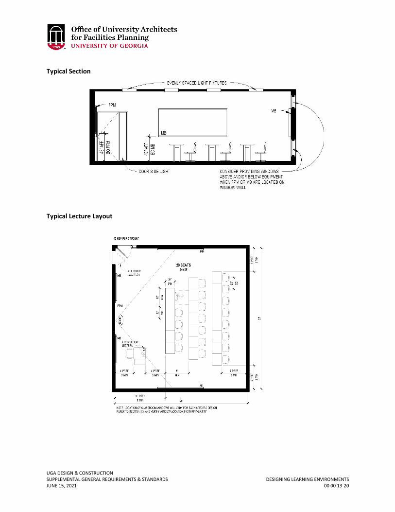
UGA DESIGN & CONSTRUCTION SUPPLEMENTAL GENERAL REQUIREMENTS & STANDARDS DESIGNING LEARNING ENVIRONMENTS JUNE 15, 2021 00 00 13-20
Typical Section
Typical Lecture Layout
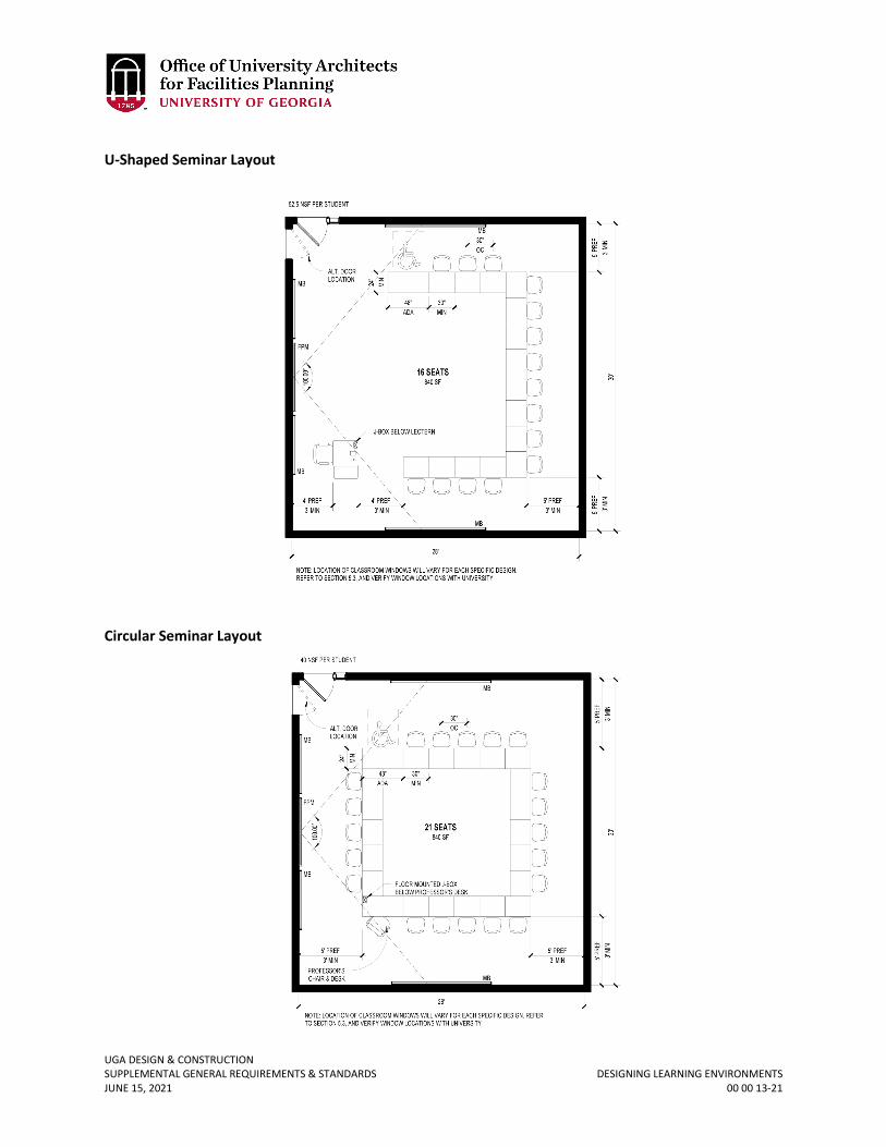
UGA DESIGN & CONSTRUCTION SUPPLEMENTAL GENERAL REQUIREMENTS & STANDARDS DESIGNING LEARNING ENVIRONMENTS JUNE 15, 2021 00 00 13-21
U-Shaped Seminar Layout
Circular Seminar Layout
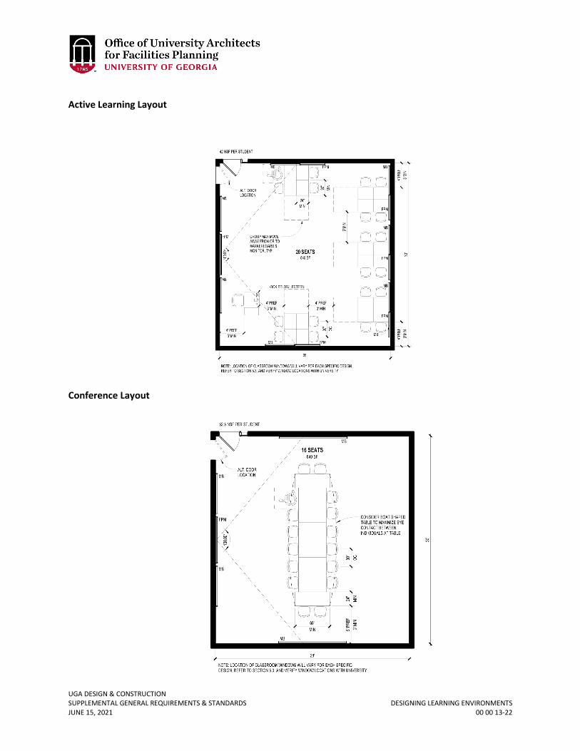
UGA DESIGN & CONSTRUCTION SUPPLEMENTAL GENERAL REQUIREMENTS & STANDARDS DESIGNING LEARNING ENVIRONMENTS JUNE 15, 2021 00 00 13-22
Active Learning Layout
Conference Layout
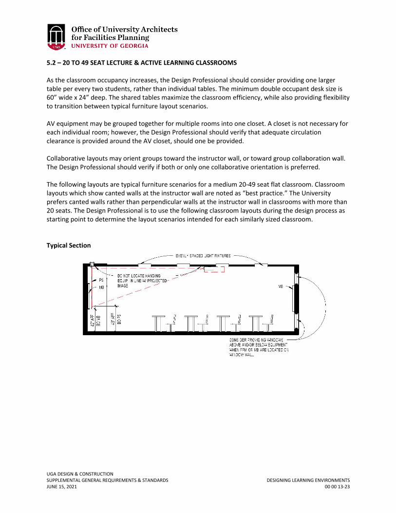
UGA DESIGN & CONSTRUCTION SUPPLEMENTAL GENERAL REQUIREMENTS & STANDARDS DESIGNING LEARNING ENVIRONMENTS JUNE 15, 2021 00 00 13-23
5.2 – 20 TO 49 SEAT LECTURE & ACTIVE LEARNING CLASSROOMS As the classroom occupancy increases, the Design Professional should consider providing one larger table per every two students, rather than individual tables. The minimum double occupant desk size is 60” wide x 24” deep. The shared tables maximize the classroom efficiency, while also providing flexibility to transition between typical furniture layout scenarios. AV equipment may be grouped together for multiple rooms into one closet. A closet is not necessary for each individual room; however, the Design Professional should verify that adequate circulation clearance is provided around the AV closet, should one be provided. Collaborative layouts may orient groups toward the instructor wall, or toward group collaboration wall. The Design Professional should verify if both or only one collaborative orientation is preferred. The following layouts are typical furniture scenarios for a medium 20-49 seat flat classroom. Classroom layouts which show canted walls at the instructor wall are noted as “best practice.” The University prefers canted walls rather than perpendicular walls at the instructor wall in classrooms with more than 20 seats. The Design Professional is to use the following classroom layouts during the design process as starting point to determine the layout scenarios intended for each similarly sized classroom. Typical Section
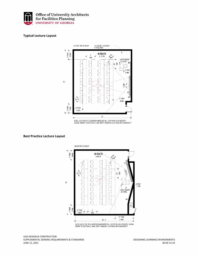
UGA DESIGN & CONSTRUCTION SUPPLEMENTAL GENERAL REQUIREMENTS & STANDARDS DESIGNING LEARNING ENVIRONMENTS JUNE 15, 2021 00 00 13-24
Typical Lecture Layout
Best Practice Lecture Layout
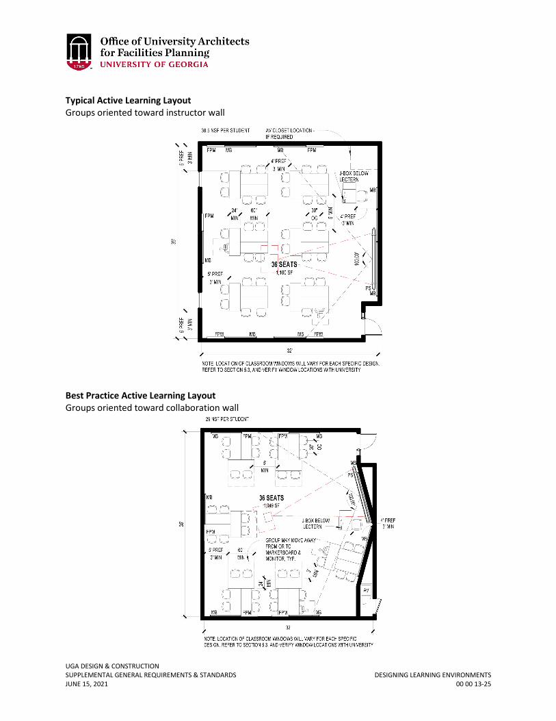
UGA DESIGN & CONSTRUCTION SUPPLEMENTAL GENERAL REQUIREMENTS & STANDARDS DESIGNING LEARNING ENVIRONMENTS JUNE 15, 2021 00 00 13-25
Typical Active Learning Layout Groups oriented toward instructor wall
Best Practice Active Learning Layout Groups oriented toward collaboration wall
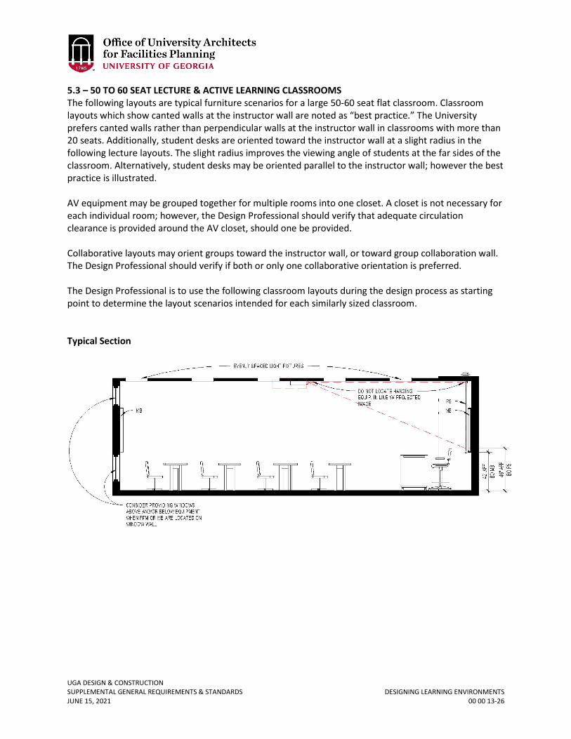
UGA DESIGN & CONSTRUCTION SUPPLEMENTAL GENERAL REQUIREMENTS & STANDARDS DESIGNING LEARNING ENVIRONMENTS JUNE 15, 2021 00 00 13-26
5.3 – 50 TO 60 SEAT LECTURE & ACTIVE LEARNING CLASSROOMS The following layouts are typical furniture scenarios for a large 50-60 seat flat classroom. Classroom layouts which show canted walls at the instructor wall are noted as “best practice.” The University prefers canted walls rather than perpendicular walls at the instructor wall in classrooms with more than 20 seats. Additionally, student desks are oriented toward the instructor wall at a slight radius in the following lecture layouts. The slight radius improves the viewing angle of students at the far sides of the classroom. Alternatively, student desks may be oriented parallel to the instructor wall; however the best practice is illustrated. AV equipment may be grouped together for multiple rooms into one closet. A closet is not necessary for each individual room; however, the Design Professional should verify that adequate circulation clearance is provided around the AV closet, should one be provided. Collaborative layouts may orient groups toward the instructor wall, or toward group collaboration wall. The Design Professional should verify if both or only one collaborative orientation is preferred. The Design Professional is to use the following classroom layouts during the design process as starting point to determine the layout scenarios intended for each similarly sized classroom. Typical Section
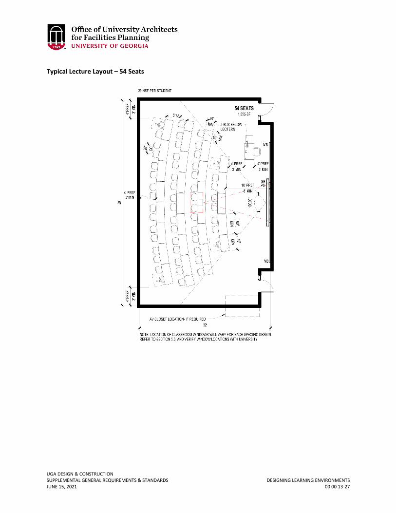
UGA DESIGN & CONSTRUCTION SUPPLEMENTAL GENERAL REQUIREMENTS & STANDARDS DESIGNING LEARNING ENVIRONMENTS JUNE 15, 2021 00 00 13-27
Typical Lecture Layout – 54 Seats
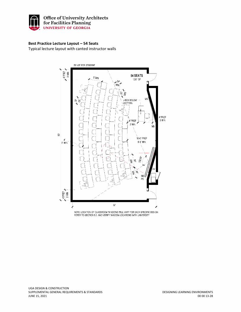
UGA DESIGN & CONSTRUCTION SUPPLEMENTAL GENERAL REQUIREMENTS & STANDARDS DESIGNING LEARNING ENVIRONMENTS JUNE 15, 2021 00 00 13-28
Best Practice Lecture Layout – 54 Seats Typical lecture layout with canted instructor walls
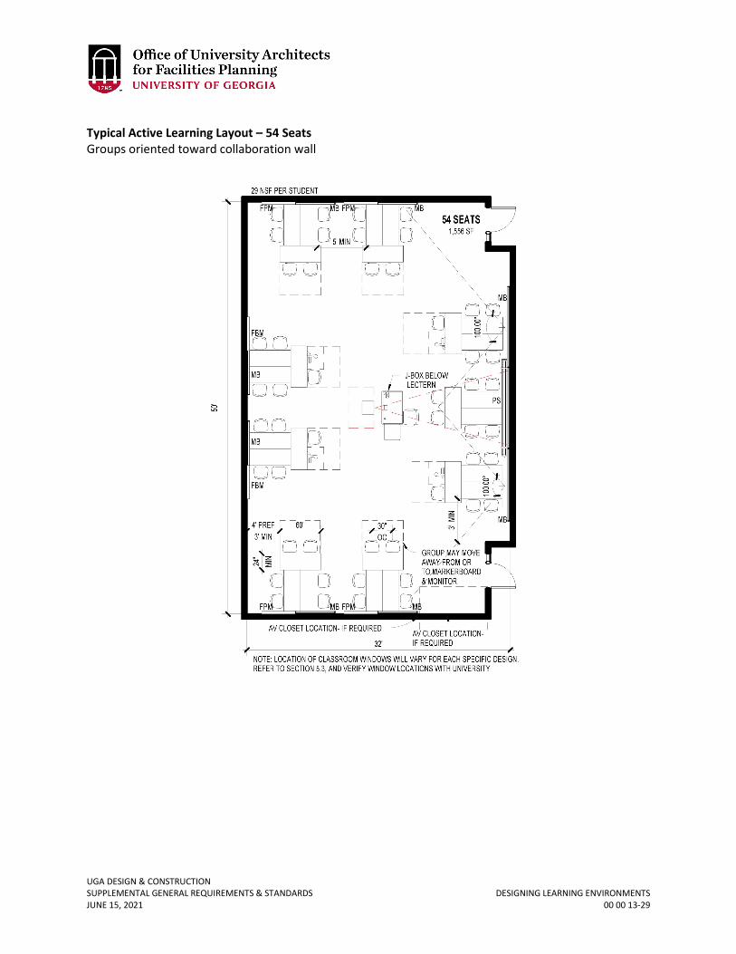
UGA DESIGN & CONSTRUCTION SUPPLEMENTAL GENERAL REQUIREMENTS & STANDARDS DESIGNING LEARNING ENVIRONMENTS JUNE 15, 2021 00 00 13-29
Typical Active Learning Layout – 54 Seats Groups oriented toward collaboration wall
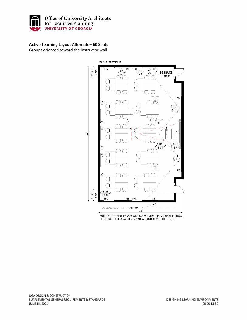
UGA DESIGN & CONSTRUCTION SUPPLEMENTAL GENERAL REQUIREMENTS & STANDARDS DESIGNING LEARNING ENVIRONMENTS JUNE 15, 2021 00 00 13-30
Active Learning Layout Alternate– 60 Seats Groups oriented toward the instructor wall
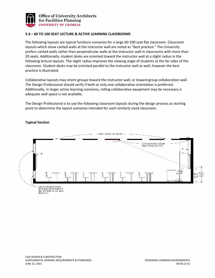
UGA DESIGN & CONSTRUCTION SUPPLEMENTAL GENERAL REQUIREMENTS & STANDARDS DESIGNING LEARNING ENVIRONMENTS JUNE 15, 2021 00 00 13-31
5.4 – 60 TO 100 SEAT LECTURE & ACTIVE LEARNING CLASSROOMS
The following layouts are typical furniture scenarios for a large 60-100 seat flat classroom. Classroom layouts which show canted walls at the instructor wall are noted as “best practice.” The University prefers canted walls rather than perpendicular walls at the instructor wall in classrooms with more than 20 seats. Additionally, student desks are oriented toward the instructor wall at a slight radius in the following lecture layouts. The slight radius improves the viewing angle of students at the far sides of the classroom. Student desks may be oriented parallel to the instructor wall as well; however the best practice is illustrated. Collaborative layouts may orient groups toward the instructor wall, or toward group collaboration wall. The Design Professional should verify if both or only one collaborative orientation is preferred. Additionally, in larger active learning scenarios, rolling collaborative equipment may be necessary is adequate wall space is not available. The Design Professional is to use the following classroom layouts during the design process as starting point to determine the layout scenarios intended for each similarly sized classroom. Typical Section
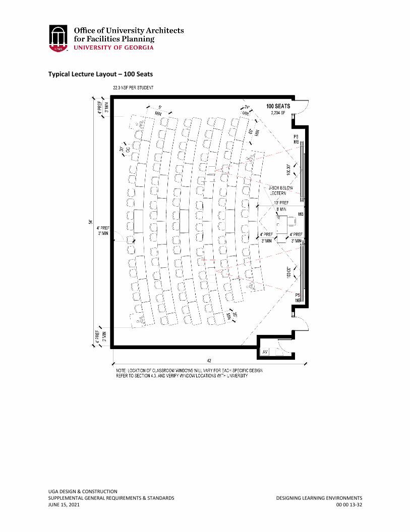
UGA DESIGN & CONSTRUCTION SUPPLEMENTAL GENERAL REQUIREMENTS & STANDARDS DESIGNING LEARNING ENVIRONMENTS JUNE 15, 2021 00 00 13-32
Typical Lecture Layout – 100 Seats
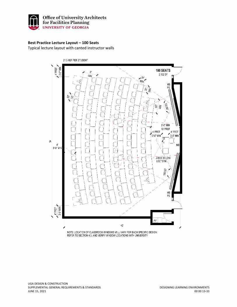
UGA DESIGN & CONSTRUCTION SUPPLEMENTAL GENERAL REQUIREMENTS & STANDARDS DESIGNING LEARNING ENVIRONMENTS JUNE 15, 2021 00 00 13-33
Best Practice Lecture Layout – 100 Seats Typical lecture layout with canted instructor walls
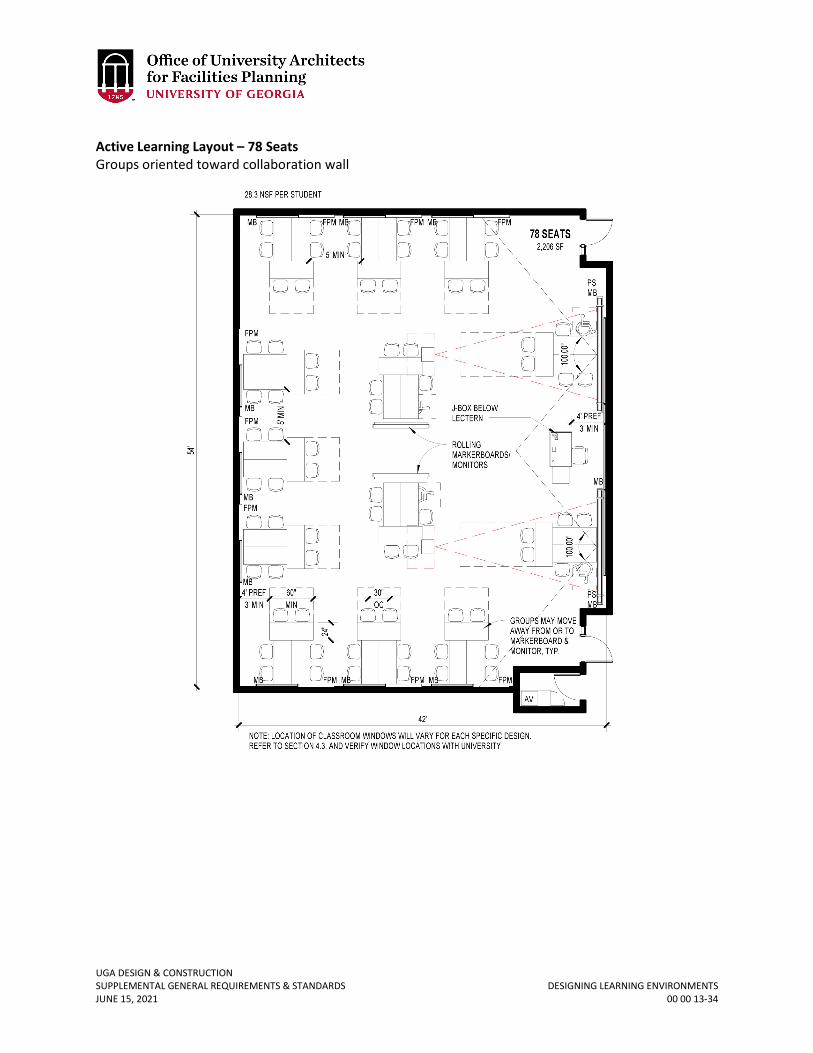
UGA DESIGN & CONSTRUCTION SUPPLEMENTAL GENERAL REQUIREMENTS & STANDARDS DESIGNING LEARNING ENVIRONMENTS JUNE 15, 2021 00 00 13-34
Active Learning Layout – 78 Seats Groups oriented toward collaboration wall
UGA DESIGN & CONSTRUCTION SUPPLEMENTAL GENERAL REQUIREMENTS & STANDARDS DESIGNING LEARNING ENVIRONMENTS JUNE 15, 2021 00 00 13-35
6.0 – GENERAL PURPOSE TIERED CLASSROOMS
A multiple compartment (power, IT, AV) floor junction box which services the instructor lectern is to be located adjacent to the instructor lectern. If the room layout permits, power, IT and AV connections for the instructor station can be provided from a series of adjacent wall boxes if the teaching station is located within a few feet from a wall in a non-traffic area. In the following tiered classroom layouts, the classroom seating is oriented toward the instructor wall at a slight radius. The slight radius improves the viewing angle of students at the far sides of the classroom. Alternately, student seating may be oriented parallel to the instructor wall; however the best practice is illustrated. Rear entry to classroom (on wall opposite the instructor wall) may be desirable in larger classroom types. Rear entry minimizes instruction disruption when students enter the classroom late, and may be helpful in minimizing light spillover into projected images. Providing vestibules at the classroom entry may also assist in minimizing light spillover; this scenario is illustrated in the 200-280 seat lecture hall layout. The overall design of the classroom building may help determine if the entry doors should be located at the instructor wall, or on at the rear wall, and / or if vestibules should be provided. The location and design considerations of entry doors should be studied on a case-by-case basis. It is strongly preferred that accessible seating in tiered classrooms be arranged in a distributed manner, i.e. not exclusively located at the front or back of the room. 6.1 – 100 TO 120 SEAT LECTURE / COLLABORATIVE CLASSROOMS
It may be desirable to provide one center aisle or two center aisles in tiered classrooms. Two center aisles provides more student seating in the areas with maximized view angles, while one center aisle maximizes the number of students that can fit into an area. In collaborative fixed table scenarios, the Design Professional should ensure that there is an overhang provided on the collaborative workspace (rear table in collaborative grouping). The Design Professional is to use the following classroom layouts during the design process as starting point to determine the layout scenarios intended for each similarly sized classroom.
Revised June 15, 2021
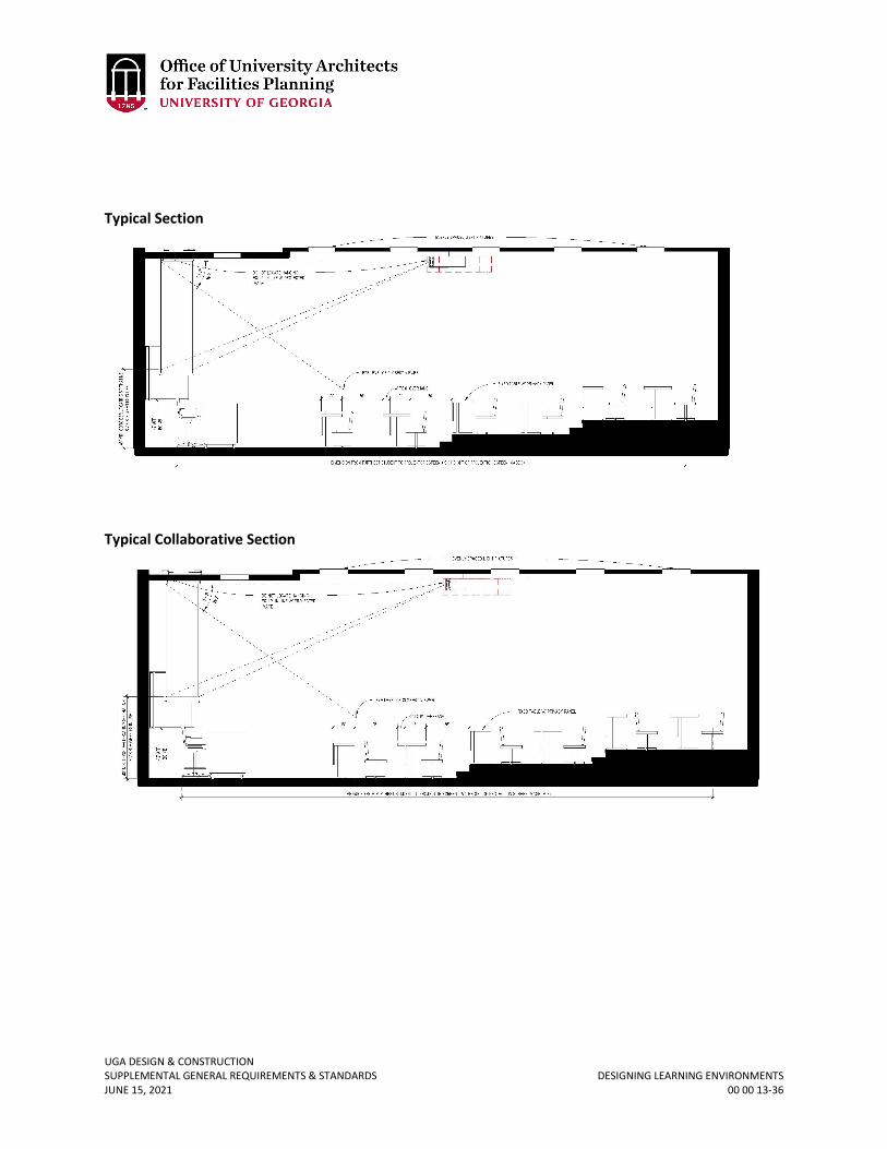
UGA DESIGN & CONSTRUCTION SUPPLEMENTAL GENERAL REQUIREMENTS & STANDARDS DESIGNING LEARNING ENVIRONMENTS JUNE 15, 2021 00 00 13-36
Typical Section
Typical Collaborative Section
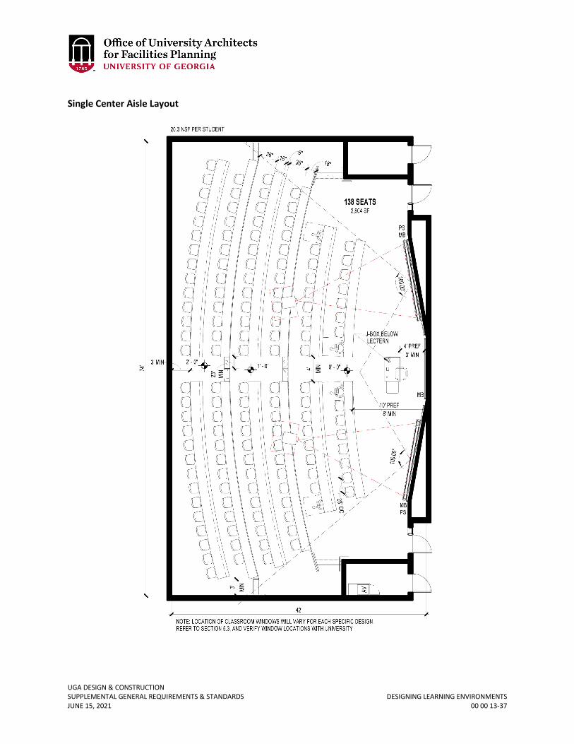
UGA DESIGN & CONSTRUCTION SUPPLEMENTAL GENERAL REQUIREMENTS & STANDARDS DESIGNING LEARNING ENVIRONMENTS JUNE 15, 2021 00 00 13-37
Single Center Aisle Layout
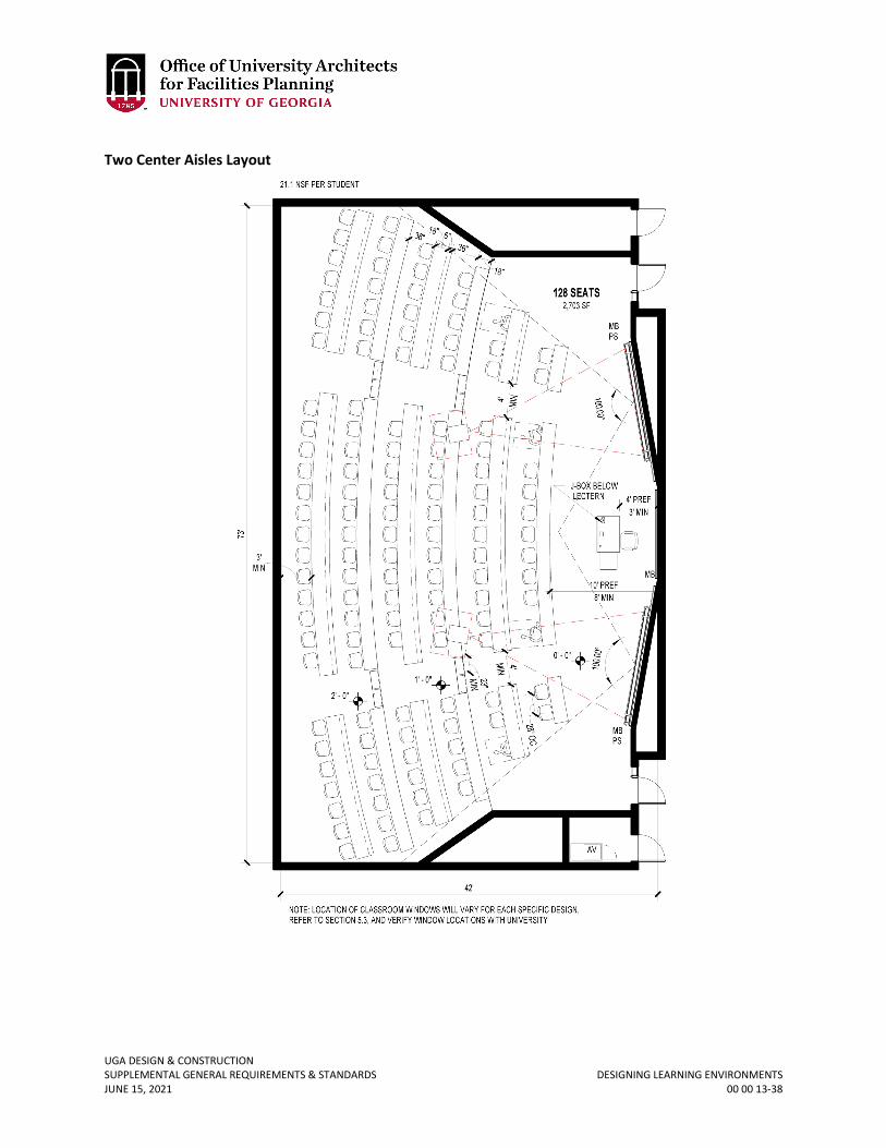
UGA DESIGN & CONSTRUCTION SUPPLEMENTAL GENERAL REQUIREMENTS & STANDARDS DESIGNING LEARNING ENVIRONMENTS JUNE 15, 2021 00 00 13-38
Two Center Aisles Layout
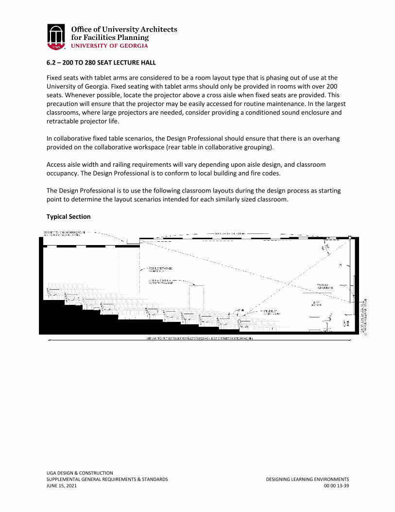
UGA DESIGN & CONSTRUCTION SUPPLEMENTAL GENERAL REQUIREMENTS & STANDARDS DESIGNING LEARNING ENVIRONMENTS JUNE 15, 2021 00 00 13-39
6.2 – 200 TO 280 SEAT LECTURE HALL
Fixed seats with tablet arms are considered to be a room layout type that is phasing out of use at the University of Georgia. Fixed seating with tablet arms should only be provided in rooms with over 200 seats. Whenever possible, locate the projector above a cross aisle when fixed seats are provided. This precaution will ensure that the projector may be easily accessed for routine maintenance. In the largest classrooms, where large projectors are needed, consider providing a conditioned sound enclosure and retractable projector life. In collaborative fixed table scenarios, the Design Professional should ensure that there is an overhang provided on the collaborative workspace (rear table in collaborative grouping). Access aisle width and railing requirements will vary depending upon aisle design, and classroom occupancy. The Design Professional is to conform to local building and fire codes. The Design Professional is to use the following classroom layouts during the design process as starting point to determine the layout scenarios intended for each similarly sized classroom. Typical Section
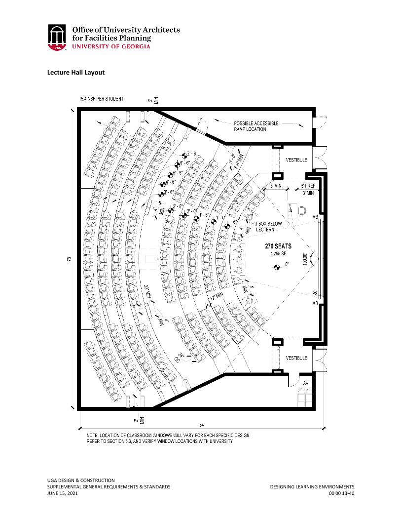
UGA DESIGN & CONSTRUCTION SUPPLEMENTAL GENERAL REQUIREMENTS & STANDARDS DESIGNING LEARNING ENVIRONMENTS JUNE 15, 2021 00 00 13-40
Lecture Hall Layout
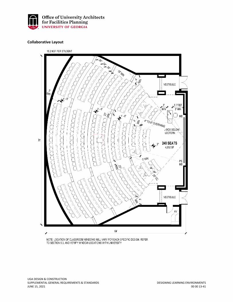
UGA DESIGN & CONSTRUCTION SUPPLEMENTAL GENERAL REQUIREMENTS & STANDARDS DESIGNING LEARNING ENVIRONMENTS JUNE 15, 2021 00 00 13-41
Collaborative Layout
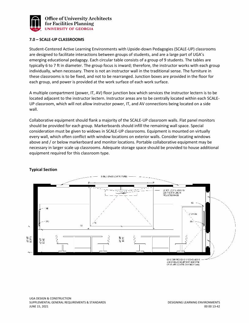
UGA DESIGN & CONSTRUCTION SUPPLEMENTAL GENERAL REQUIREMENTS & STANDARDS DESIGNING LEARNING ENVIRONMENTS JUNE 15, 2021 00 00 13-42
7.0 – SCALE-UP CLASSROOMS
Student-Centered Active Learning Environments with Upside-down Pedagogies (SCALE-UP) classrooms are designed to facilitate interactions between groups of students, and are a large part of UGA’s emerging educational pedagogy. Each circular table consists of a group of 9 students. The tables are typically 6 to 7 ft in diameter. The group focus is inward; therefore, the instructor works with each group individually, when necessary. There is not an instructor wall in the traditional sense. The furniture in these classrooms is to be fixed, and not to be rearranged. Junction boxes are provided in the floor for each group, and power is provided at the work surface of each work surface. A multiple compartment (power, IT, AV) floor junction box which services the instructor lectern is to be located adjacent to the instructor lectern. Instructor areas are to be centrally located within each SCALE-UP classroom, which will not allow instructor power, IT, and AV connections being located on a side wall. Collaborative equipment should flank a majority of the SCALE-UP classroom walls. Flat panel monitors should be provided for each group. Markerboards should infill the remaining wall space. Special consideration must be given to widows in SCALE-UP classrooms. Equipment is mounted on virtually every wall, which often conflict with window locations on exterior walls. Consider locating windows above and / or below markerboard and monitor locations. Portable collaborative equipment may be necessary in larger scale up classrooms. Adequate storage space should be provided to house additional equipment required for this classroom type. Typical Section
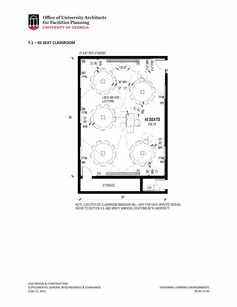
UGA DESIGN & CONSTRUCTION SUPPLEMENTAL GENERAL REQUIREMENTS & STANDARDS DESIGNING LEARNING ENVIRONMENTS JUNE 15, 2021 00 00 13-43
7.1 – 45 SEAT CLASSROOM
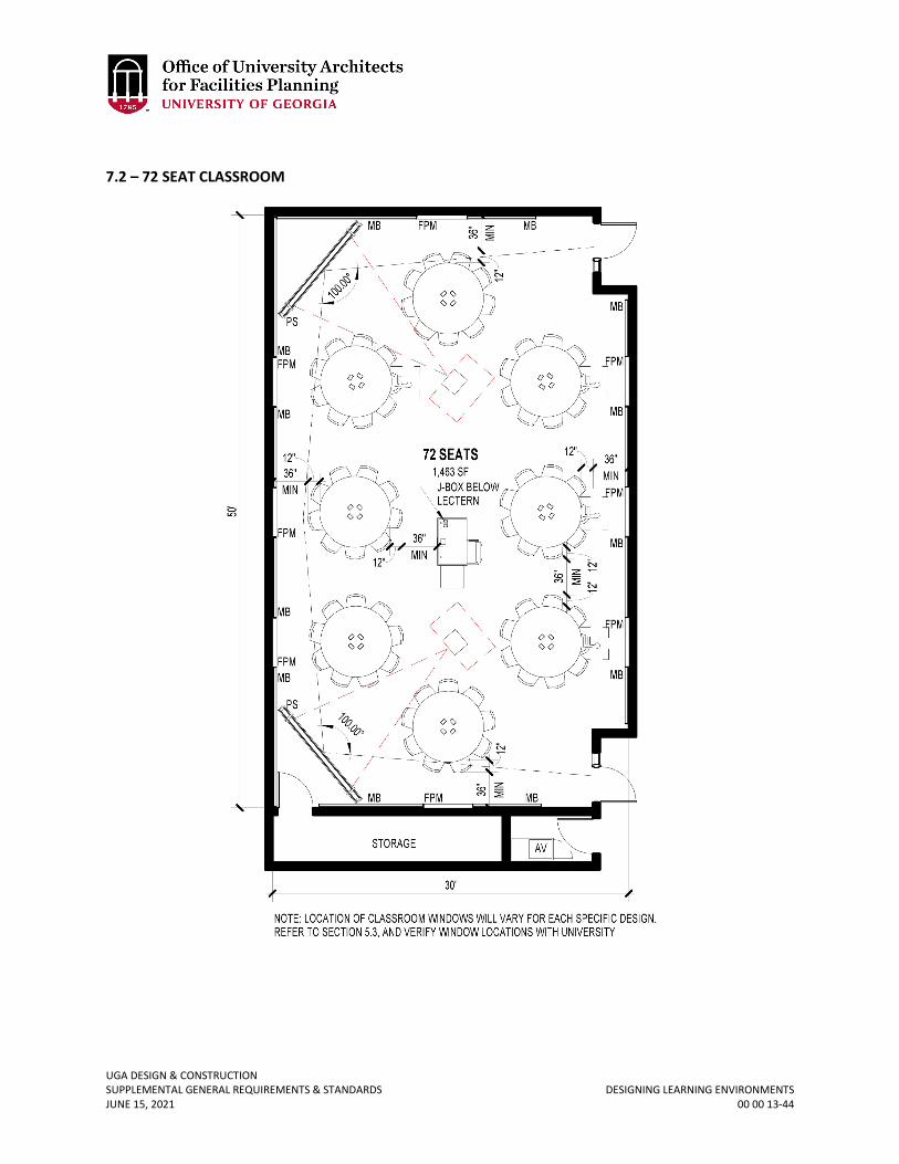
UGA DESIGN & CONSTRUCTION SUPPLEMENTAL GENERAL REQUIREMENTS & STANDARDS DESIGNING LEARNING ENVIRONMENTS JUNE 15, 2021 00 00 13-44
7.2 – 72 SEAT CLASSROOM
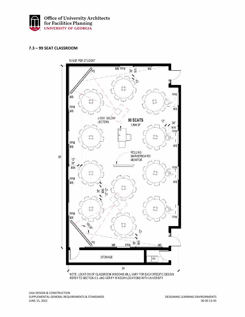
UGA DESIGN & CONSTRUCTION SUPPLEMENTAL GENERAL REQUIREMENTS & STANDARDS DESIGNING LEARNING ENVIRONMENTS JUNE 15, 2021 00 00 13-45
7.3 – 99 SEAT CLASSROOM
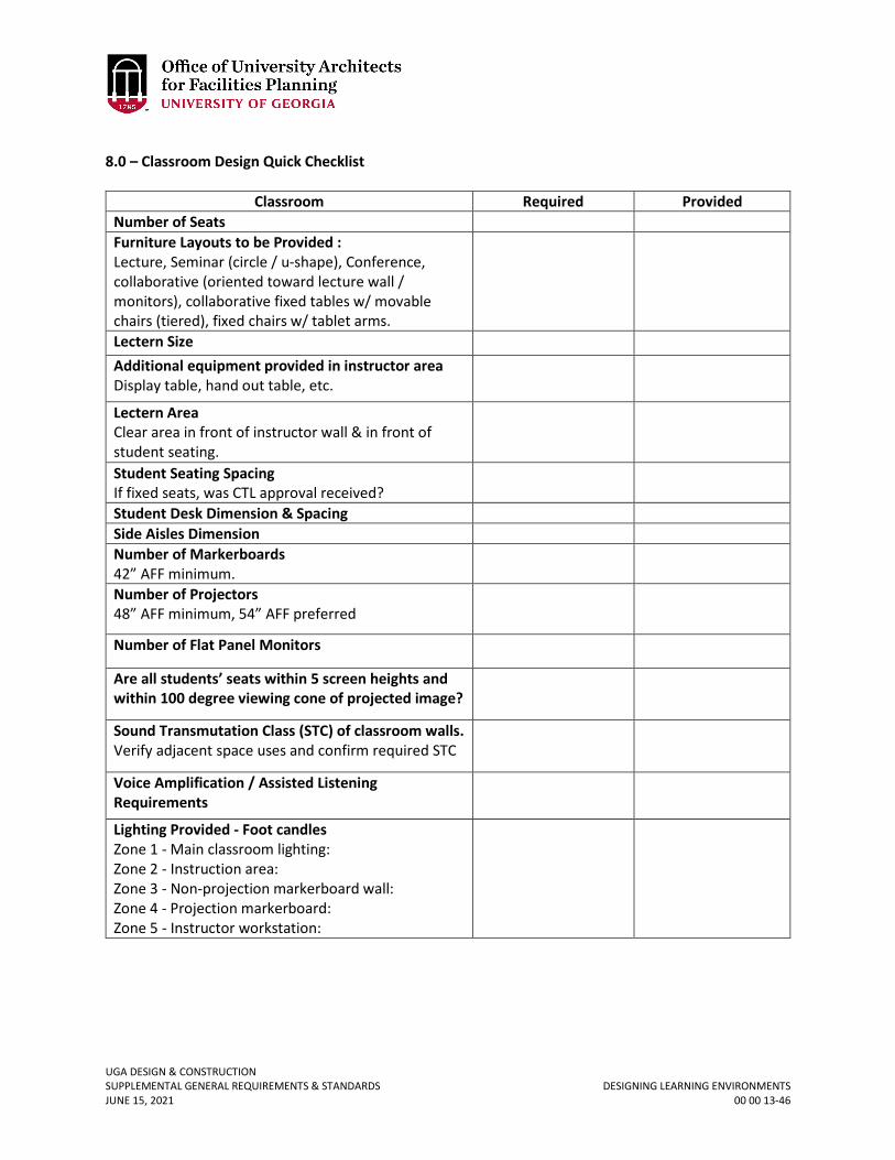
UGA DESIGN & CONSTRUCTION SUPPLEMENTAL GENERAL REQUIREMENTS & STANDARDS DESIGNING LEARNING ENVIRONMENTS JUNE 15, 2021 00 00 13-46
8.0 – Classroom Design Quick Checklist
Classroom Required Provided Number of Seats Furniture Layouts to be Provided : Lecture, Seminar (circle / u-shape), Conference, collaborative (oriented toward lecture wall / monitors), collaborative fixed tables w/ movable chairs (tiered), fixed chairs w/ tablet arms.
Lectern Size Additional equipment provided in instructor area Display table, hand out table, etc.
Lectern Area Clear area in front of instructor wall & in front of student seating.
Student Seating Spacing If fixed seats, was CTL approval received?
Student Desk Dimension & Spacing Side Aisles Dimension Number of Markerboards 42” AFF minimum.
Number of Projectors 48” AFF minimum, 54” AFF preferred
Number of Flat Panel Monitors
Are all students’ seats within 5 screen heights and within 100 degree viewing cone of projected image?
Sound Transmutation Class (STC) of classroom walls. Verify adjacent space uses and confirm required STC
Voice Amplification / Assisted Listening Requirements
Lighting Provided - Foot candles Zone 1 - Main classroom lighting: Zone 2 - Instruction area: Zone 3 - Non-projection markerboard wall: Zone 4 - Projection markerboard: Zone 5 - Instructor workstation:
UGA DESIGN & CONSTRUCTION SUPPLEMENTAL GENERAL REQUIREMENTS & STANDARDS CONTRACTOR INSURANCE SPECIAL CONDITIONS JUNE 15, 2021 00 00 14-1
00 00 14 CONTRACTOR INSURANCE SPECIAL CONDITIONS
1. GENERAL
A. Contractor Controlled Insurance Policies: Contractor Controlled Insurance Policies are prohibited on UGA projects unless the subject project’s stated cost limitation (SCL) exceeds $50,000,000.00 and express written permission is granted by UGA.
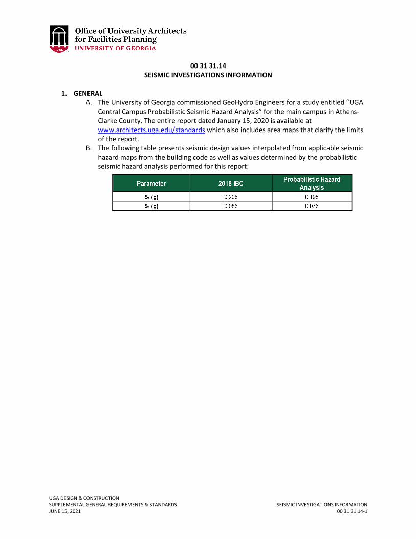
UGA DESIGN & CONSTRUCTION SUPPLEMENTAL GENERAL REQUIREMENTS & STANDARDS SEISMIC INVESTIGATIONS INFORMATION JUNE 15, 2021 00 31 31.14-1
00 31 31.14 SEISMIC INVESTIGATIONS INFORMATION
1. GENERAL
A. The University of Georgia commissioned GeoHydro Engineers for a study entitled “UGA Central Campus Probabilistic Seismic Hazard Analysis” for the main campus in Athens-Clarke County. The entire report dated January 15, 2020 is available at www.architects.uga.edu/standards which also includes area maps that clarify the limits of the report.
B. The following table presents seismic design values interpolated from applicable seismic hazard maps from the building code as well as values determined by the probabilistic seismic hazard analysis performed for this report:
UGA DESIGN & CONSTRUCTION SUPPLEMENTAL GENERAL REQUIREMENTS & STANDARDS SOLE SOURCE/ SOLE BRAND JUNE 15, 2021 00 73 01-1
00 73 01 SOLE SOURCE / SOLE BRAND
1. GENERAL
A. Related sections: i. 07 21 19 – Closed-Cell Polyurethane Foam Insulation
ii. 08 71 00 – Door Hardware iii. 12 93 13 – Bicycle Racks iv. 12 93 43.13 – Site Seating v. 23 09 23 – Building Automation and Temperature Control System (BAS)
vi. 26 56 13 – Lighting Poles and Standards vii. 27 00 00 – General Communications Requirements
viii. 27 41 00.01 – Audio-Visual Control System ix. 28 13 00 – Access Control x. 28 31 00 – Fire Detection & Alarm
xi. 32 14 16.13 – Brick Unit and Porous Paving – Ungrouted xii. 32 39 13 – Manufactured Metal Bollards
xiii. 32 84 00 – Planting Irrigation 2. PRODUCTS – These products have received sole brand or source approval and are on file with
UGA Procurement: A. Closed-Cell Polyurethane Spray Foam Insulation (see Section 07 21 19)
i. Spray foam insulation: Gaco “GacoWallFoam 183M” ii. Gaco: 1-800-331-0196
B. Door Hardware Cylinder (see Section 08 71 00) i. Cylinders for locksets, latchsets, and deadbolts.
ii. Best Access Systems: 1-855-365-2407. C. Door Hardware Exit Device (see Section 08 71 00)
i. Von Duprin, 98, 35A Series ii. Ingersoll Rand Security Technologies: 1-877-671-7011.
D. Door Hardware Power Operator (see Section 08 71 00) i. LCN 4642
ii. Ingersoll Rand Security Technologies: 1-877-671-7011. E. Exterior Bench (see Section 12 93 43.13)
i. Renaissance Bench with Armrests and Back, Model Number: 2806-6, length: 6’ ii. Renaissance “Backless” Bench with Armrests, Model Number: 2802-6, length: 6’
iii. TimberForm by Columbia Cascade, Palmetto Recreation Equipment, LLC: 1-888-214-5253.
F. Building Automation and Temperature Control System (see Section 23 09 23) i. This is a sole source of equipment by Automated Logic Corporation: 770-429-
3000 and procured through Automated Logic – Georgia: 770-421-3280. For renovation projects that utilize a different brand, the decision to change to Automated Logic Corporation or modify the existing system will be made on a case by case basis.
G. Exterior Lighting Pole (see section 26 56 13) i. Global Lighting Perspectives “University of Georgia Decorative Pole”, part #
GP33R-12/BT, overall height: 12’-0”, Traditional style tapered and fluted cast
UGA DESIGN & CONSTRUCTION SUPPLEMENTAL GENERAL REQUIREMENTS & STANDARDS SOLE SOURCE/ SOLE BRAND JUNE 15, 2021 00 73 01-2
aluminum base with exterior mounting plate, 14” round base cover, black textured powdercoat finish.
ii. Global Lighting Perspectives: 1-281-412-2944. H. Exterior Lighting Fixtures (see Section 26 56 13)
i. LUMEC L80 series street lighting fixture, custom without ball finial on top; black texture power coated paint finish. Metal Halide with RACE refractor optics; metal halide with SE optics; and LED with LES3 optics.
ii. Philips Lighting Products and Services. 1-855-486-2216 I. Irrigation Water Management Controller (see Section 32 84 00)
i. ET2000E Enhanced Water Management Controller. ii. Calsense: 1-800-572-8608.
J. Inside Cabling Solution (see Section 27 00 00) i. Includes all parts and components (and those by Siemon’s Cable Partners).
Including, but not limited to, patch cables, patch panels, cabling, telecommunication jacks, and face plates.
ii. Siemon Network Cabling Solutions: 1-860-945-4200. K. Outside Cabling Solution (see Section 27 00 00)
i. Includes all parts and components including but not limited to fiber optic patch cables, fiber optic cables, connectors, splice enclosures, rack mount cabinets, adaptor pants, and cable organizers.
ii. Corning Cable Systems: 1-828-901-5000. L. Audio-Visual Control System (see Section 27 41 00.01)
i. AMX by Harman ii. AMX by Harman: 1-800-222-0193
M. Fire Detection & Alarm (see Section 28 31 00) i. Honeywell: 1-877-841-2840, Farenhyt, for new construction projects that are
not facilities operated by UGA Housing. For renovation projects that utilize a different brand, the decision to change to Farenhyt or extend the existing system will be made on a case by case basis.
ii. Honeywell: 1-877-841-2840, Notifier for new construction projects that are facilities operated by UGA Housing. For renovation projects that utilize a different brand, the decision to change to Notifier or extend the existing system will be made on a case by case basis.
N. Security and Access Control – Legacy System (see Section 28 13 00.01) i. Andover Continuum System
ii. Andover Controls: 1-978-470-0555. O. Brick Pavers (see Section 32 14 16.13)
i. Pine Hall Brick Light Traffic Paving Brick; Pine Hall Brick Heavy Vehicular Traffic Paving Brick; Pine Hall Brick StormPave for Light Traffic; Pine Hall Brick StormPave for Heavy Vehicular Traffic; Pine Hall Brick Paving Brick with Truncated Domes. All brick pavers in color: Courtyard Red – Georgia Plant.
ii. Pine Hall Brick Company: 1-800-334-8689. P. Manufactured Metal Bollards (see Section 32 39 13)
i. Model #: VI-BO-14/30 – RB ii. Visco, Inc: 1-800-341-1444.
Q. Security and Access Control (see Section 28 13 00)
UGA DESIGN & CONSTRUCTION SUPPLEMENTAL GENERAL REQUIREMENTS & STANDARDS SOLE SOURCE/ SOLE BRAND JUNE 15, 2021 00 73 01-3
i. Genetec, Inc. ii. Reference contract # AC-CB-0418 for a list of approved contractors
UGA DESIGN & CONSTRUCTION SUPPLEMENTAL GENERAL REQUIREMENTS & STANDARDS MINORITY BUSINESS ENTERPRISE JUNE 15, 2021 00 73 39-1
00 73 39 MINORITY BUSINESS ENTERPRISE
1. GENERAL
A. It is the policy of the State of Georgia that minority business enterprises shall have the maximum opportunity to participate in the State purchasing process. Therefore, the State of Georgia encourages all minority business enterprises to compete for, win, and receive contracts for goods, services, and construction. Also, the State encourages all companies to sub-contract portions of any State contract to minority business enterprises.
i. The Small and Minority Business Contact person for the University of Georgia is: Ms. Annette M. Evans Procurement Officer
University of Georgia, Procurement Office 301 Business Services Building
Athens, Georgia 30602 706-542-2361 FAX: 706-542-7035
ii. Contractor may contact the Procurement Office or any buyer for assistance with the preparation of Contractor bid or proposal, or to answer questions about the bid and award process. Specific questions about the bid specifications should be directed to the buyer that issued the bid request rather than to Procurement Officer.
iii. The State of Georgia has a law which provides for an income tax credit on the State Tax Return to any company which subcontracts with a minority owned firm to furnish goods, property or services to the State of Georgia. Vendors should direct specific questions about this law to the Small and Minority Business Coordinators, 200 Piedmont Avenue, S.E., Atlanta, Georgia 30334, telephone 404-656-6315.
UGA DESIGN & CONSTRUCTION SUPPLEMENTAL GENERAL REQUIREMENTS & STANDARDS WORK RESTRICTIONS JUNE 15, 2021 01 14 00-1
01 14 00 WORK RESTRICTIONS
1. GENERAL
A. Contractor shall schedule and control all work persons employed on the Project. Contractor shall instruct all workers to prevent tracking dirt and debris into existing buildings. Profanity, inappropriate dress, or inappropriate conduct shall not be permitted on any Project. Owner reserves the right to have the Contractor remove from the Project anyone who, in the sole opinion of the Owner, exhibits such behavior.
B. UGA Football Games: For projects in Athens-Clarke County, the Contractor shall stop all work commencing at 3:00 pm Friday before UGA home football games and shall not work the Saturday of home football games. The construction site shall be secured to prevent unauthorized persons from entering the site. See the UGA Athletic Association webpage, www.georgiadogs.com to obtain information concerning the current schedule.
UGA DESIGN & CONSTRUCTION SUPPLEMENTAL GENERAL REQUIREMENTS & STANDARDS ACCESS TO SITE – RIGHT OF ENTRY JUNE 15, 2021 01 14 13-1
01 14 13 ACCESS TO SITE – RIGHT OF ENTRY
1. GENERAL
A. The Owner retains the right to enter the construction limits to inspect and / or repair existing utilities, structures, and property whenever necessary. Owner shall coordinate non-emergency access 24 hours in advance.
B. For projects in Athens-Clarke County, Contractors shall fill out the temporary ID card request form below to receive security access to existing UGA buildings that require a UGA ID access card.
C. The Contractor shall make the construction site available and accessible to UGA FMD and any other Owner-retained Contractors to complete work within the site to include repairs and renovation of existing buildings, utilities, hardscape, and landscape. Contractor shall coordinate his schedule with other Contractors as approved by Owner to ensure a complete and usable facility.
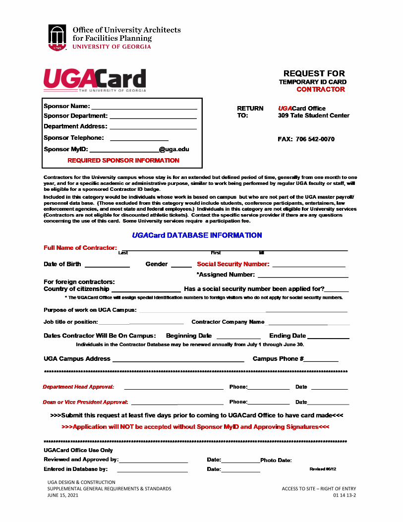
UGA DESIGN & CONSTRUCTION SUPPLEMENTAL GENERAL REQUIREMENTS & STANDARDS ACCESS TO SITE – RIGHT OF ENTRY JUNE 15, 2021 01 14 13-2
UGA DESIGN & CONSTRUCTION SUPPLEMENTAL GENERAL REQUIREMENTS & STANDARDS PAYMENT PROCEDURES JUNE 15, 2021 01 29 00-1
01 29 00 PAYMENT PROCEDURES
1. GENERAL
A. Related sections: i. 01 29 73 – Schedule of Values
ii. 01 74 19 – Construction Waste Management & Disposal iii. 01 81 00 – Facility Performance Requirements
B. Prior to being able to receive compensation for services, Design Professionals and Contractors, who have not previously contracted with UGA, must complete the UGA new vendor electronic registration and be current in the UGA system. The new vendor electronic registration is available at https://onesource.uga.edu/news/vendor_registration_information/ .
C. Prior to the Design Professional receiving full compensation for Schematic Design and Design Development/Preliminary Design, the requirements of Section 01 81 00 Facility Performance Requirements shall be met and the Section 01 81 00 Facility Performance Requirements’ checklist submitted.
D. Application for Payment Procedure for Contractor, Design-Build, and Design-Bid-Build project delivery methods:
i. Contractor shall email a .pdf copy of the Exhibit K Application for Payment, and all associated back-up documentation as required by the Contract to the Design Professional and to the Project Manager for review / approval. In addition to Exhibit K Application for Payment form in the Contract, the Contractor shall provide an Application and Certificate of Payment in the America Institute of Architects (AIA) format with corresponding schedule of values breakdown. Exhibit K Application for Payment must be executed as per the Contract; however, the additional Application and Certificate for Payment in an AIA format is not required to be signed and notarized as it is provided as reference information to assist the Design Professional and Project Manager in reviewing Application for Payment back-up documentation.
ii. Within three days of receipt of the Application for Payment, the Design Professional will either approve the Application for Payment and forward to [email protected] as well as the Project Manager, or will provide comments to be addressed by the Contractor.
iii. Once all comments are addressed to the satisfaction of the Design Professional and Project Manager, the Design Professional will sign and forward a .pdf copy of the pay application and supporting information to [email protected] and the Project Manager, also copying in the Contractor. The OUA office will then upload the electronic pay application to DocuSign for approval and signature by the Project Manager.
iv. Complete Section 01 74 19 Construction Waste Management & Disposal Report and include with monthly Application for Payment.
E. Application for Payment Documentation for Contractor and Design-Builder projects: i. For the draft version of the Application for Payment, the Contractor shall
include with it copies of all invoices, labor billings, Subcontractor applications for payment and executed Subcontractor’s interim lien releases.
UGA DESIGN & CONSTRUCTION SUPPLEMENTAL GENERAL REQUIREMENTS & STANDARDS PAYMENT PROCEDURES JUNE 15, 2021 01 29 00-2
ii. The Contractor shall maintain a Contingency Log that is updated and submitted with each Application for Payment that shows any costs that have been transferred from the contingency line item into all other line items with an explanation of each transfer.
iii. Upon approval of a Component Change Order or Change Order, the Contractor shall distribute all Component Change Order or Change Order costs among the respective line items against which the actual costs will be charged. Although Component Change Orders and Change Orders are frequently approved on a lump sum basis so as to be incorporated into the GMP, billing for the associated work is on a cost-plus basis with a maximum price and if the total value of the change order funds is not spent, the remaining value of the Component Change Order and / or Change Order will be returned to contingency funds.
F. Application for Payment Procedure for contracts held by GSFIC: i. Submit per GSFIC requirements
G. Application for Payment Procedure for Design Professional, Consultant, and Purchase Order work:
i. Submit .pdf format invoices to [email protected] and Project Manager
UGA DESIGN & CONSTRUCTION SUPPLEMENTAL GENERAL REQUIREMENTS & STANDARDS SCHEDULE OF VALUES JUNE 15, 2021 01 29 73-1
01 29 73 SCHEDULE OF VALUES
1. GENERAL
A. Related sections: i. 01 29 00 – Payment Procedures
B. The Contractor shall submit a draft of the Schedule of Values (SOV) to the Project Manager and Design Professional for approval prior to the first pay request being submitted.
C. The SOV shall include the following column headings at a minimum: original scheduled value, change orders, revised schedule of values, previous billings, current billings, stored materials, total completed and stored to date, and retainage.
D. Contractor Construction Overhead Costs (General Conditions) shall be listed as a separate line item within the SOV.
E. Insurance shall be listed as a separate line item within the SOV. F. Performance and payment bonds shall be listed as a separate line item within the SOV. G. For projects implementing Building Information Modeling (BIM), there shall be a
separate line item within the SOV for BIM related costs. H. The following items, specific to Contractor and Design-Builder project delivery methods,
shall be listed as separate line items within the SOV: i. Pre-construction Overhead Costs and Expenses (General Conditions)
ii. Pre-construction Fee iii. Construction Fee iv. Contractor Contingency
I. For Contractor and Design-Builder projects, each line of the SOV shall correspond to the Subcontract amount for only one Subcontractor so that the required back-up Subcontractor payment applications matches a specific SOV line item. In the event that there is more than one Subcontract representing a scope of work (for example steel could possibly be subdivided into steel erection, steel fabrication and miscellaneous metals), the SOV should be subdivided accordingly.
J. For Contractor or Design-Build projects, the change order amounts shall be distributed among each of the separate line items as appropriate to allow for the billings to be tracked against each corresponding subcontractor’s pay request.
K. For projects awarded on a lump sum basis, the change orders can be added as lump sums on a new line added below the total line for the original base contract amount.
L. For projects awarded on a lump sum basis, the Fee shall be allocated on a percentage basis among each of the line items.
M. For projects awarded on a lump sum basis, the SOV should be detailed enough to allow for proper review and analysis of percentages of work complete. For example, electrical should be subdivided into such categories as exterior power, exterior lighting, interior lighting, switchgear and panels, devices, conduit and wiring, telecommunications, fire alarm system, etc.
UGA DESIGN & CONSTRUCTION SUPPLEMENTAL GENERAL REQUIREMENTS & STANDARDS PRE-CONSTRUCTION MEETINGS JUNE 15, 2021 01 31 19.13-1
01 31 19.13 PRE-CONSTRUCTION MEETINGS
1. GENERAL
A. The Contractor shall schedule, at the convenience of the Owner, a Pre-Construction Meeting at least fourteen calendar days prior to beginning any construction. The meeting shall include as a minimum the Contractor’s authorized representative, the Design Professional, and the Owner’s Representatives. The Contractor shall invite the End-User, University utilities and infrastructure representatives as suggested by the Owner, Contractor, Subcontractors, and the Owner’s Testing Agency representatives. For projects with a Land Disturbance Activities permit and / or a NPDES permit, the University of Georgia Environmental Safety Division shall be invited to the pre-construction meeting. The conference shall be held at a time convenient to the Owner and held at the construction site. The conference agenda shall include introduction of key personnel and responsibilities, review of project schedule, job site logistics, contract specifications, contract administration, and University policies and procedures.
UGA DESIGN & CONSTRUCTION SUPPLEMENTAL GENERAL REQUIREMENTS & STANDARDS PROGRESS MEETINGS JUNE 15, 2021 01 31 19.23-1
01 31 19.23 PROGRESS MEETINGS
1. GENERAL
A. After every design meeting, the Design Professional shall issue a meeting summary within seven calendar days after the meeting date. The meeting summary shall include a list of attendees, the meeting date, topic, and all action items and decisions. The meeting summary shall be sent to the Project Manager as well as to others requested by the Project Manager. The Design Professional shall provide electronic tools (laptops or thumb-drives) necessary to project plans and specifications onto a UGA provided projector screen. The Design Professional shall coordinate with the Project Manager as necessary.
B. After every construction meeting, the Contractor shall issue a meeting summary within seven calendar days after the meeting date. The meeting summary shall include a list of attendees, the meeting date, topic, and all action items and decisions. The meeting summary shall be sent to the Project Manager as well as to others requested by the Project Manager. The Contractor shall provide electronic tools (laptops or thumb-drives) necessary to project plans, specifications, change orders, RFIs, photographs, schedules, etc., onto a UGA provided projector screen. The Contractor shall coordinate with the Project Manager as necessary.
UGA DESIGN & CONSTRUCTION SUPPLEMENTAL GENERAL REQUIREMENTS & STANDARDS PROJECT WEBSITE JUNE 15, 2021 01 31 23-1
01 31 23 PROJECT WEBSITE
1. GENERAL
A. For Contractor and Design-Build project delivery methods: i. The Contractor shall provide a secure website or File Transfer Protocol (FTP)
system to allow transfer of electronic files between the Design Professional, Contractor, and UGA.
ii. The Contractor shall provide login and password information to UGA personnel as requested by the Project Manager.
B. For Design-Bid-Build project delivery methods: i. The Design Professional shall provide a secure website or File Transfer Protocol
(FTP) system to allow transfer of electronic files between the Design Professional, Contractor, and UGA.
ii. The Design Professional shall provide login and password information to UGA personnel as requested by the Project Manager.
C. The secure website or FTP system shall be maintained from project inception through Final Completion.
D. As a minimum the Design Professional shall make available for download drawings and specifications at each review milestone and as requested by the Project Manager.
E. After construction documents are issued for construction, the Design Professional shall make available for download any revisions including supplementary sketches and documents.
i. The drawings shall be both in a CAD file format “.dwg” and a portable document format “.pdf”. CAD files must have x-refs bound into the file.
ii. The specifications shall be able to be read with Microsoft Word and allow for a global search.
UGA DESIGN & CONSTRUCTION SUPPLEMENTAL GENERAL REQUIREMENTS & STANDARDS CONSTRUCTION PROGRESS SCHEDULE JUNE 15, 2021 01 32 16-1
01 32 16 CONSTRUCTION PROGRESS SCHEDULE
1. GENERAL
A. Related sections: i. 01 35 46 – Indoor Air Quality – During Construction
B. Schedules shall include timeframes required to insure that off-gassing is substantially complete prior to occupancy. Refer to Section 01 35 46 Indoor Air Quality – During Construction.
C. Schedule shall include delivery and installation of furniture (regardless of whether it is Owner provided or Contractor provided) per direction of the Project Manager.
D. Schedule shall include final in-place mockups of interior paint samples with final light fixture and lamps in place.
E. Schedule shall include date of required activation of data connections for the digital controls system.
F. Schedule shall include adequate time for the completion of testing, adjusting, and balancing for HVAC prior to Material Completion. The Contractor shall take the time for resolution of these issues by the responsible party into account in the schedule. A ‘contingency’ of an additional week or two should be incorporated into the balancing plan schedule to accommodate additional time required for the responsible party to correct any minor issues preventing design performance of the building.
G. The schedule shall include 80% and 100% fire marshal inspections. H. The schedule shall include training which shall be completed prior to Material
Completion. I. The schedule shall include preparation and review of closeout submittals. Closeout
submittals shall be submitted at or prior to Material Completion.
UGA DESIGN & CONSTRUCTION SUPPLEMENTAL GENERAL REQUIREMENTS & STANDARDS SUBMITTAL PROCEDURES JUNE 15, 2021 01 33 00-1
01 33 00 SUBMITTAL PROCEDURES
1. GENERAL
A. Related sections: i. 00 00 03 – Modifications to General Requirements for BOR Contracts
ii. 01 77 00 – Project Closeout B. Any costs associated with submittals shall be included in the Contractor Overhead Cost
or Base Bid.
UGA DESIGN & CONSTRUCTION SUPPLEMENTAL GENERAL REQUIREMENTS & STANDARDS SPECIAL PROJECT PROCEDURES – UTILITY & SYSTEMS OUTAGES JUNE 15, 2021 01 35 13.01-1
01 35 13.01 SPECIAL PROJECT PROCEDURES – UTILITY & SYSTEMS OUTAGES
1. GENERAL
A. Connections to Existing Utilities: All utility work involving connections to existing utility systems (including but not limited to: electrical, communications, water, gas, steam, chill water, storm water & sanitary systems) shall be coordinated with the Owner. Contractor shall inform the Owner prior to any proposed shutdown, outage or work of any nature which will interrupt or disturb any building utility system or equipment served by that system. A minimum of 72-hours’ notice is required for the Owner to make all necessary arrangements for this work, and such shutdowns shall be scheduled at the convenience of the Owner.
B. Fire Alarm And Fire Sprinkler Deactivation (Less Than 4 Hours At One Time): If the Project has an existing fire alarm system and or fire sprinkler system that will be encountered during the work that will from time to time require temporary deactivation (for less than 4 hours), the Contractor shall contact the Owner’s Representative a minimum of 72 hours in advance to coordinate deactivation request. The Contractor shall also make the following notifications for projects in Athens-Clarke County:
i. University of Georgia Environmental Safety Division, Fire Safety (706) 369-5706 ii. University of Georgia Police Department (706) 542-5813
iii. University of Georgia Fire Alarm Monitoring Company, Fire Protection Associates (706) 548-8659
iv. University of Georgia specific facility affected C. Fire Alarm and Fire Sprinkler Deactivation (More Than 4 Hours At One Time): If a
sprinkler or fire alarm system on the campus of the University of Georgia is out of service for more than four hours, a fire watch must be implemented according to the following procedures.
i. Notifications for projects in Athens-Clarke County a. University of Georgia Environmental Safety Division, Fire Safety (706)
369-5706 b. University of Georgia Police Department (706) 542-5813 c. University of Georgia Fire Alarm Monitoring Company, Fire Protection
Associates (706) 548-8659 d. University of Georgia specific facility affected
ii. Fire Watch Duties a. Person(s) on fire watch duty should not have any other responsibility
during the time the fire watch is in effect and must keep a cell phone in his/her possession at all times during the fire watch.
b. Patrol the entire area affected by the service outage every 30 minutes and look for any signs of fire, smoke and any activities that could create a fire.
c. Keep a log of all fire watch patrols. d. Maintain fire watch for one hour beyond the last time that welding
operations occurred. e. If a fire is discovered:
1) Activate the building alarm system if in service.
UGA DESIGN & CONSTRUCTION SUPPLEMENTAL GENERAL REQUIREMENTS & STANDARDS SPECIAL PROJECT PROCEDURES – UTILITY & SYSTEMS OUTAGES JUNE 15, 2021 01 35 13.01-2
2) Call 911 to report the fire 3) If the building fire alarm system is out of service, ask the
campus police to assist in the evacuation of the building. 4) Notify others on the floor of the fire. 5) Do not attempt to fight the fire unless you have been trained on
the use of portable fire extinguishers. f. Once the need for a temporary fire watch has passed and the fire
protection system has been fully restored, the person on fire watch duty will cancel the fire watch by contacting the UGA Environmental Safety Department, the UGA Police Department, the UGA Fire Alarm monitoring company, and the UGA specific facility that is affected by the fire watch.
iii. All costs associated with the fire watch shall be included in the Cost of the Work or Base Bid.
UGA DESIGN & CONSTRUCTION SUPPLEMENTAL GENERAL REQUIREMENTS & STANDARDS SPECIAL PROJECT PROCEDURES – ROOFING & HOT WORK JUNE 15, 2021 01 35 13.02-1
01 35 13.02 SPECIAL PROJECT PROCEDURES – ROOFING & HOT WORK
1. GENERAL
A. Related sections: i. 00 00 03 – Modifications to General Requirement of BOR Contracts
B. Hot work permits are not required for new construction or full building renovations (i.e. renovations during which the building is completely vacated and turned over to the Contractor).
C. Roofing & Hot Work for Additions & Renovations: To complement the requirements of previously cited NFPA-241, regarding Contractor’s duties during the execution of work under this contract, the Owner requires that the Contractor comply with the following guidelines for all roofing projects, additions and renovations, and all other projects which require hot work. Hot work includes any construction activity that presents a source of ignition, such as welding, burning / cutting, heating, brazing and soldering. Contractor shall, prior to the start of work at the site, develop a documented fire safety plan for all areas included under the Contract. Such plan shall be the result of a complete assessment by the Contractor to minimize the potential for damage as a result of an uncontrolled fire and must be submitted to the Owner’s designated fire safety representative for review and approval. The fire safety plan must include, but need not be limited to, the description and documentation of each of the following elements:
i. Control of Combustibles a. Contractor shall visually inspect entire project location to identify
combustible and non-combustible construction. Contractor shall identify sealed, inaccessible combustible spaces.
b. Contractor shall identify and relocate all movable combustibles at least 35 feet horizontally from the work site. Where not possible, Contractor shall protect such combustibles with flame-proof covers or otherwise shield them with metal fire resistant guards or curtains.
ii. Control of Combustibles a. Contractor shall comply with the Owner’s documented hot work permit
system, including the following minimum requirements: 1) Contractor shall identify names and locations of fire watches for
all hot work operations. 2) Contractor shall identify timing and duration of all proposed hot
work. Permits shall be valid for time specified on permit, as appropriate for the project needs.
3) Contractor shall employ dedicated fire watches, which shall be located in direct visual contact of all areas of hot work operations including the underside of combustible attic spaces. If area of proposed work is not accessible from beneath, Contractor shall not under any circumstances use torches or direct flame.
4) Contractor shall maintain a daily log of activities, including accurate project records of all fire watch activities.
UGA DESIGN & CONSTRUCTION SUPPLEMENTAL GENERAL REQUIREMENTS & STANDARDS SPECIAL PROJECT PROCEDURES – ROOFING & HOT WORK JUNE 15, 2021 01 35 13.02-2
5) Contractor shall assign responsibility for overseeing fire watches to specific individual(s) whose only duty is to watch for and to prevent fires occurring due to hot work. This individual(s) shall be listed on permit as responsible.
6) Each Contractor’s fire watcher shall employ an operable cellular phone for immediate notification of fire department in the event of a fire.
7) Contractor shall be responsible for immediate fire department notification in case of fire.
8) Contractor shall continue fire watches for at least one hour after any hot work operations are completed.
9) Notify building occupants of fire or expected fire. b. Contractor shall comply with the following minimum suppression
requirements: 1) Contractor shall provide 10 lb. multi-purpose dry chemical fire
extinguishers within 20 feet of the operation. 2) Where hot work, if approved by the Owner’s designated fire
safety representative, is necessary near combustible attic spaces, Contractor shall provide a charged hose line from building standpipe or hydrant. This requirement shall be coordinated with the Owner’s fire safety coordinator to ensure standpipe or hydrant are available and that person(s) operating the charged hose line is properly trained and qualified to operate the hose.
3) Contractor’s fire watchers shall have fire extinguishing equipment readily available, and shall be trained in the proper use of all such equipment; proof of such training shall be included in fire safety plan.
iii. Fire Watch: If fire watches are required to be employed, the Contractor shall retain an independent consultant to provide a system of documented audits of compliance with fire watch provisions and NFPA 241. Contractor shall select the consultant from a list of approved firms furnished by the Owner at the pre-construction meeting. The cost for fire watch provisions, if applicable, shall be included in the Contractor Overhead Cost or Base Bid. Contractor shall note that the approval of the Contractor’s fire safety plan by the Owner’s fire safety representative does not relieve the Contractor from any duty to protect the Owner’s property during the execution of work under this Contract. The Owner shall make available to the Contractor, upon written request, all documented information in the Owner’s possession concerning the construction of the building or buildings included under this contract. The Contractor is ultimately responsible for minimizing the potential for fire damage while performing all work under this contract. If fire watch is approved, Contractor shall provide the fire watch contact information to University of Georgia Police Department 24 hours in advance of the fire watch.
UGA DESIGN & CONSTRUCTION SUPPLEMENTAL GENERAL REQUIREMENTS & STANDARDS OWNER SAFETY REQUIREMENTS – SAFETY BARRIERS JUNE 15, 2021 01 35 23-1
01 35 23 OWNER SAFETY REQUIREMENTS – SAFETY BARRIERS
1. GENERAL
A. Contractor shall provide barriers and warning signs to delineate the construction area and to designate the “Danger” area. This danger area shall be the area immediately surrounding the location where the Project is being completed. The exact location of the barriers shall be determined by the Contractor and coordinated with the Owner prior to beginning construction. The barriers shall be placed by the Contractor to warn and protect persons from any hazards, which may occur during the course of construction. The Contractor may elect to erect a fence to protect the limits of construction and to secure materials kept on site. All windscreens utilized shall be black in color and devoid of any company logos or other markers, and must be discussed with the Project Manager prior to installation. Associated costs shall be included in the Contractor Overhead Cost or Base Bid.
UGA DESIGN & CONSTRUCTION SUPPLEMENTAL GENERAL REQUIREMENTS & STANDARDS INDOOR AIR QUALITY PROCEDURES – DURING CONSTRUCTION JUNE 15, 2021 01 35 46-1
01 35 46 INDOOR AIR QUALITY PROCEDURES – DURING CONSTRUCTION
1. GENERAL
A. Related sections: i. 01 32 16 – Construction Progress Schedule:
ii. 06 00 00 – General Wood, Plastics, and Composites Requirements iii. 09 00 00 – General Finishes Requirements iv. 09 20 00 – Plaster and Gypsum Board v. 09 60 00 – Flooring
vi. 09 68 00 – Carpeting vii. 09 91 23 – Interior Painting
viii. 12 00 00 – General Furnishings Requirements B. Tobacco Free
i. In accordance with the Tobacco and Smoke-Free Campus Policy of the Board of Regents of the University System of Georgia, the use of all forms of tobacco products is prohibited on property owned, leased, rented, in the possession of, or in any way used by the University. “Tobacco Products” is defined as cigarettes, cigars, pipes, all forms of smokeless tobacco, clove cigarettes and any other smoking devices that use tobacco such as hookahs or simulate the use of tobacco such as electronic cigarettes. Further, this policy prohibits any advertising, sale, or free sampling of tobacco products on University property unless specifically stated for research purposes. This prohibition includes but is not limited to all areas indoors and outdoors, buildings and parking lots owned, leased, rented or otherwise by the University. The use of tobacco products is prohibited in all vehicles – private or public – located on University property. Additionally, all events hosted by the University or by outside groups on behalf of the University shall be tobacco-free. Failure to comply with this policy by Contractor or Subcontractor shall constitute a material breach of these terms.
2. PRODUCTS A. Low volatile organic compound (VOC) materials shall be used within the interior
weatherproofing of the facility; zero when available. Provide documentation to the Project Manager as requested. If there is a conflict between the VOC identified listed in the documents listed below, the one that allows the least VOCs shall apply.
i. Architectural coatings shall not exceed VOC limits established by the South Coast Air Quality Management (SCAQMD) Rule 1113, in effect January 1, 2004.
ii. Adhesives, adhesive bonding primers, adhesive primers, sealants, sealant primers, and any other primers shall not exceed VOC limits established by the South Coast Air Quality Management (SCAQMD) Rule 1168, in effect January 1, 2004.
iii. Paints and coatings shall not exceed VOC limits established in the Green Seal Standard GS-11 Paints and Coatings, Third Edition, August 17, 2011.
iv. Anti-corrosive paints and coatings shall not exceed VOC limits established in the Green Seal Standard GC-3 Environmental Criteria for Anti-Corrosive Paints, Second Edition, January 7, 1997.insure
UGA DESIGN & CONSTRUCTION SUPPLEMENTAL GENERAL REQUIREMENTS & STANDARDS INDOOR AIR QUALITY PROCEDURES – DURING CONSTRUCTION JUNE 15, 2021 01 35 46-2
v. Hard surface flooring products shall be FloorScore certified (current as of the date of this Standard).
vi. Carpeting, including pad or backing, shall meet or exceed the requirements of Green Label Plus, set by the Carpet and Rug Institute.
vii. Composite wood and agrifiber products that are part of the base building elements (not furniture or seating) shall not contain any added urea-formaldehyde resins.
viii. New furniture and seating shall be certified by GREENGUARD Environment Institute.
3. EXECUTION A. Maintain minimum MERV 8 air filters during construction. B. Fumes
i. During the performance of work under this Contract, the Contractor may elect to engage in activities, or to use methods and materials, that result in fumes being generated and dispersed in occupied areas. In addition to complying with all codes and ordinances having jurisdiction, Contractor shall perform his work in a manner that shall minimize or completely eliminate the probability of such an occurrence. However, if fumes of any nature are generated or released by the Contractor to occupied portions of the building, such fumes shall be contained and exhausted from the spaces in accordance with previously cited codes and ordinances. If any Contractor-generated or Contractor-released fumes spread to occupied spaces, Contractor shall:
a. Stop work causing fume generation or release. b. Contact the Owner’s Representative (for information only). c. Determine the nature and extent of fume release. d. Purge all areas of these fumes; clean up areas if fumes deposited dirt or
particulate matter. e. Change work methods to eliminate fumes. f. Continue working after steps 1 to 5 have been accomplished.
C. For facilities that will have portions remain occupied during construction, the Contractor shall develop an indoor air quality management plan in compliance with Sheet Metal and Air Conditioning Contractor’s National Association (SMACNA) Indoor Air Quality Guidelines for Occupied Buildings Under Construction, 2007.
D. For projects over 10,000 square feet, per the requirements of this section, either building flush-out or demonstration of compliance with indoor air quality air testing requirements is required prior to occupancy. All interior finishes shall be installed. It is preferable for moveable furnishings and partitions, desk systems and workstations to be in place, however, this is not required.
i. Building flush out: a. Building flush out is required prior to occupancy. If End-Users will begin
inhabiting the renovated areas or new facility at Material Completion than building-flush out shall be complete prior to Material Completion. If End-Users will not begin inhabiting the renovated areas or new facility prior to Final Completion, then building flush out shall be complete prior to Final Completion.
UGA DESIGN & CONSTRUCTION SUPPLEMENTAL GENERAL REQUIREMENTS & STANDARDS INDOOR AIR QUALITY PROCEDURES – DURING CONSTRUCTION JUNE 15, 2021 01 35 46-3
b. Building flush out shall be performed after all interior finishes are installed.
c. Following the U.S. Green Building Council guidelines, perform a building flush out that provides 14,000 cubic feet of outdoor air per square foot while maintaining a minimum interior temperature of 60 degrees with a relative humidity of less than 60%.
d. The Design Professional shall calculate how much outside air will be required for flush out and include in the specifications the number of days required for the project mechanical system to flush out the facility and the Contractor shall include the required days in the construction progress schedule.
e. Prior to building flush install all new filtration media. ii. Air testing:
a. Use protocols consistent with the EPA Compendium of Methods for the Determination of Air Pollutants in Indoor Air.
b. Documented compliance with the following indoor air quality requirement is required prior to occupancy. If End-Users will begin inhabiting the renovated areas or new facility at Material Completion than air testing compliance shall be complete prior to Material Completion. If End-Users will not begin inhabiting the renovated areas or new facility prior to Final Completion, then air testing compliance shall be complete prior to Final Completion.
c. Air testing shall demonstrate that the following maximum concentrations are not exceeded:
1) Formaldehyde 27 parts per billion 2) Particulates (PM 10) 50 micrograms per cubic meter 3) Total VOCs 500 micrograms per cubic meter 4) 4-Phenylcyclohexine 6.5 micrograms per cubic meter 5) Carbon monoxide 9 parts per million
UGA DESIGN & CONSTRUCTION SUPPLEMENTAL GENERAL REQUIREMENTS & STANDARDS REGULATORY REQUIREMENTS JUNE 15, 2021 01 41 00-1
01 41 00 REGULATORY REQUIREMENTS
1. GENERAL
A. Contractor shall comply with all applicable provisions of National Fire Protection Association (NFPA) Section 241, Standard for Safeguarding Construction, Alteration and Demolition Operations, latest edition.
UGA DESIGN & CONSTRUCTION SUPPLEMENTAL GENERAL REQUIREMENTS & STANDARDS RIGHT OF WAY ENROACHMENT / ROADWAY OWNERSHIP JUNE 15, 2021 01 41 26.01-1
01 41 26.01 RIGHT OF WAY ENCROACHMENT / ROADWAY OWNERSHIP
1. GENERAL
A. Right of way (ROW) Encroachment / Driveway Permit i. The Design Professional is responsible for verifying the sidewalk, driveway, and
roadway ownership in the location of the Project. Work in or adjacent to a road that is not owned by the BOR may require a ROW Encroachment permit and / or a driveway permit. The Design Professional is cautioned that many BOR campuses and other groups of areas that appear to be large masses of land owned by BOR, often have roadways with associated right of ways through those land masses that are not owned by the BOR.
B. Roadway Ownership – UGA Athens Only i. The Design Professional can review the map of which roads at the UGA main
campus in Athens, Georgia are owned by Athens-Clarke County. The map is located at the end of this section.
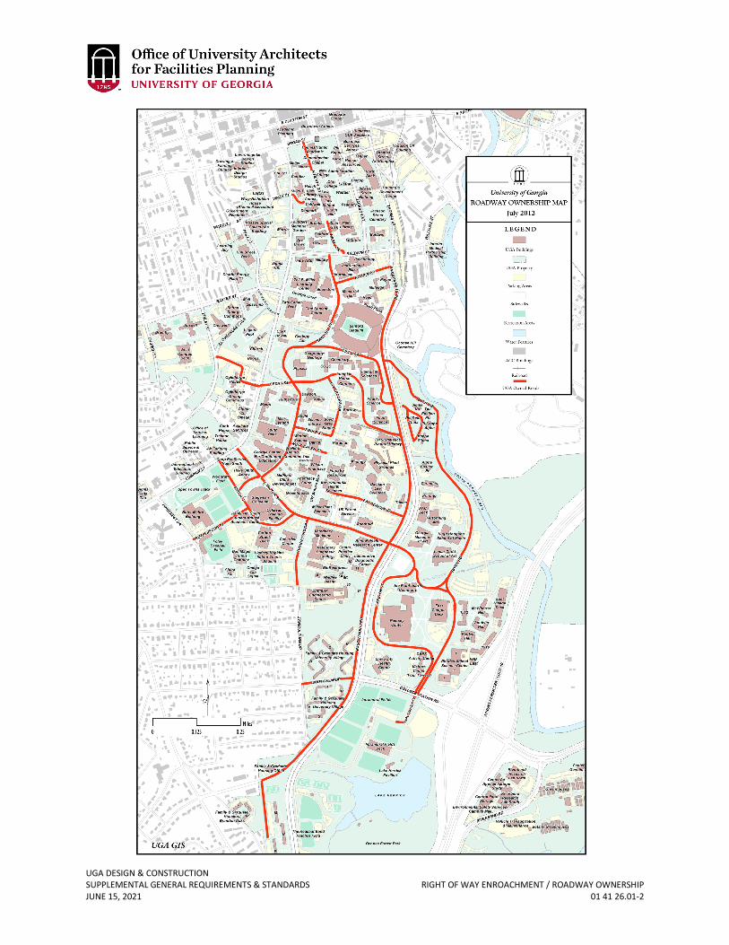
UGA DESIGN & CONSTRUCTION SUPPLEMENTAL GENERAL REQUIREMENTS & STANDARDS RIGHT OF WAY ENROACHMENT / ROADWAY OWNERSHIP JUNE 15, 2021 01 41 26.01-2
UGA DESIGN & CONSTRUCTION SUPPLEMENTAL GENERAL REQUIREMENTS & STANDARDS LOCAL UTILITY INFORMATION & LOCATE JUNE 15, 2021 01 41 26.02-1
01 41 26.02 LOCAL UTILITY INFORMATION & LOCATE
1. GENERAL
A. Related sections: i. 33 00 00 – General Utilities Requirements
ii. 33 10 00 – Water Supply Backflow Preventer Assemblies iii. 33 30 00 – Sanitary Sewerage Utilities – Sanitary Sewer Collection Systems
B. The Design Professional is responsible for identifying which various reviews and permits related to utility permits are required and meeting the design requirements of the entity having jurisdiction for the location of the Project. The Design Professional shall apply for and submit documents for all applicable permits and make design revisions as required until the permits can be obtained.
C. The Design Professional shall include the most up-to-date 811 logo on all drawings that call for excavation activity of any kind.
D. Utility Owner’s at The UGA, Athens, Georgia Campus i. Chilled Water – University of Georgia
ii. Data Communications – University of Georgia Enterprise Information Technology Services (EITS)
iii. Electric Power – Georgia Power Company or University of Georgia iv. Fire Alarm Systems – University of Georgia (maintenance contract with Fire
Protection Associates) v. Irrigation – University of Georgia Facilities Management Division Grounds
Department vi. Natural Gas – Atlanta Gas Light Company or University of Georgia
vii. Sanitary Sewer – ACC Public Utilities or University of Georgia viii. Septic Sanitary System – University of Georgia
ix. Security & Access Systems – University of Georgia Public Safety Division x. Steam – University of Georgia
xi. Storm Sewer – University of Georgia xii. Television Cable – Charter Communications or EITS
xiii. Voice Communications – AT&T or EITS xiv. Water – ACC Public Utilities or University of Georgia
E. Locator Notification i. The Contractor shall use caution as there may be active utilities in the work
area. Utilities are owned by the University of Georgia and other public utility companies. 72 hours in advance of digging, the Contractor shall contact:
1. Public Underground Utility Locator Service at 1-800-282-7411 or 811 as required by Georgia State Law.
2. For projects on the University of Georgia on the Athens, Georgia campus, University of Georgia Facilities Management Division Grounds Department at (706) 542-7450 to locate irrigation lines.
ii. The Contractor shall be liable for all repair costs if he fails to properly notify utility locators as described above. Any utility line damaged by the Contractor which was marked or identified by the Owner of the utility shall be repaired by the Contractor at his own expense. In the event the Owner of the utility elects
UGA DESIGN & CONSTRUCTION SUPPLEMENTAL GENERAL REQUIREMENTS & STANDARDS LOCAL UTILITY INFORMATION & LOCATE JUNE 15, 2021 01 41 26.02-2
to make the repairs with his own work force, the Contractor shall reimburse the Owner of the utility for the cost of repairs.
F. Utilities Furnished i. Certain utilities, if owned and operated by the University of Georgia, required
for work to be performed under this Contract shall be furnished by the Owner at the Contractor’s expense. However, these utilities shall be furnished at the point and in the capacity that they are available adjacent to the construction site. Any utility of different pressure, capacity, type, etc. required by the Contractor that is not available within the area shall be arranged for by the Contractor at his own expense. Any expense involved to the Contractor in extending the utilities from the present location to the point required shall be at the Contractor’s expense and included in the Cost of the Work or the Base Bid.
G. Water Utilities – Public Water Distribution System i. Any work on the public water distribution system must be approved and
inspected by applicable local government offices and must be performed in accordance with the local governmental regulations. In Athens-Clarke County, most water mains, fire hydrants and water meters are under the jurisdiction of The Unified Government of Athens-Clarke County (ACC). All connections to the ACC water distribution system shall be approved and inspected by ACC Public Utilities. The current version of the construction specifications published by ACC Public Utilities (available at www.athensclarkecounty.com) regarding water main construction are incorporated into this Contract. The Contractor or Subcontractor constructing the water distribution system improvements described in this Contract shall be on the ACC list of approved contractors. Final approval, acceptance and payment for work completed on the water distribution system will be contingent on acceptance of the improvements by the ACC Public Utilities. All costs associated with compliance of the water main construction requirements shall be included in the Cost of the Work or Base Bid.
H. Water Supply Backflow Preventer Assemblies i. Any work on backflow preventers must be approved and inspected by
applicable local government offices and must be performed in accordance with the local governmental regulations. In Athens-Clarke County, the Double-Check Backflow Preventer for the fire main connection and Reduced Pressure Zone (RPZ) Backflow Preventers for the domestic water connections are under the jurisdiction of ACC. The current version of the construction specifications published by ACC (available at www.athensclarkecounty.com) regarding cross-connection / back flow are incorporated into the standards. All costs associated with compliance of the cross-connection / back flow construction requirements shall be included in the Cost of the Work or Base Bid.
I. Sanitary Sewerage Utilities – Sanitary Sewer Collection System i. Any work on the public sanitary sewer collection system must be approved and
inspected by applicable local government offices and must be performed in accordance with the local governmental regulations. In Athens-Clarke County, most sanitary sewer mains and man-holes are under the jurisdiction of the ACC. All connections to the ACC wastewater system shall be approved and inspected by ACC Public Utilities. The current version of the construction specifications
UGA DESIGN & CONSTRUCTION SUPPLEMENTAL GENERAL REQUIREMENTS & STANDARDS LOCAL UTILITY INFORMATION & LOCATE JUNE 15, 2021 01 41 26.02-3
published by ACC Public Utilities (available at www.athensclarkecounty.com) regarding wastewater system construction are incorporated into the standards. For work within ACC, the Contractor or Subcontractor constructing the wastewater system improvements described in the standards shall be on the ACC list of approved contractors. Final approval, acceptance and payment for work completed on the water distribution system will be contingent on acceptance of the improvements by the ACC Public Utilities. All costs associated with compliance of the water main construction requirements shall be included in the Cost of the Work or Base Bid.
UGA DESIGN & CONSTRUCTION SUPPLEMENTAL GENERAL REQUIREMENTS & STANDARDS PERMIT REQUIREMENTS – CONSTRUCTION PERMITS JUNE 15, 2021 01 41 26.03-1
01 41 26.03 PERMIT REQUIREMENTS – CONSTRUCTION PERMITS
1. GENERAL
A. Related sections: i. 00 00 08 – Design Professional Documentation Requirements & Deliverables
ii. 01 41 26.04 – Fire Marshal Construction Inspection Requirements B. The State of Georgia Office of the Insurance and Safety Fire Commissioner (Georgia
State Fire Marshal) has jurisdiction on Board of Regents Property located in the State of Georgia, unless noted otherwise. Design Professionals should not contact the local building authority, unless guided otherwise. For state-owned property, the State Fire Marshal has jurisdiction related to construction permits, 80% and 100% inspections, certificate of occupancy, etc. Note: Local site development and utility work may require permits through the local city / county authority.
C. Leased property: When the BOR leases property outside state owned property the construction permit will be obtained from the local city / county authority having jurisdiction.
D. Variance: In the instance that modifications need to be made, which, therefore, deviates from the approved permit by the Georgia State Fire Marshal, the Design Professional can only request for a Georgia State Fire Marshal variance with the written approval by the Associate Vice President of OUA and Office of Fire Safety.
E. UGA Office of Fire Safety: For renovation projects where the cost of the renovation is up to 50% of the assessed value of the structure as determined by the insured value by the records of the State Department of Administrative Services, the University of Georgia shall provide the following services on all University owned and operated or occupied buildings and structures on behalf of the Office of the Insurance and Safety Fire Commissioner and the Safety Fire Division:
i. Conduct plan reviews, provide comments and approvals, and issue building permits for renovation project.
a. One copy of the “UGA Fire Safety Form 354” and two sets of drawings and specifications shall be submitted to the Project Manager to forward to the UGA Office of Fire Safety. The form is included at the end of this section for reference and posted for download on the Standards website at: www.architects.uga.edu/standards.
b. The transmittal form and drawings and specifications shall be submitted at minimum of four weeks prior to the date of commencement of the scheduled date of construction.
ii. Plan reviews and inspections are of small renovations that involve life safety code features including (but not limited to) egress and exiting, fire alarm systems, incidental changes to sprinkler systems, occupancy changes for incidental use areas, egress lighting, emergency lighting and other relevant life safety and building code features. This also includes adding or eliminating doors and walls, egress corridors or exit discharge.
iii. Conduct field inspections when a project has reached 80% completion and 100% completion and conduct site consultative inspections.
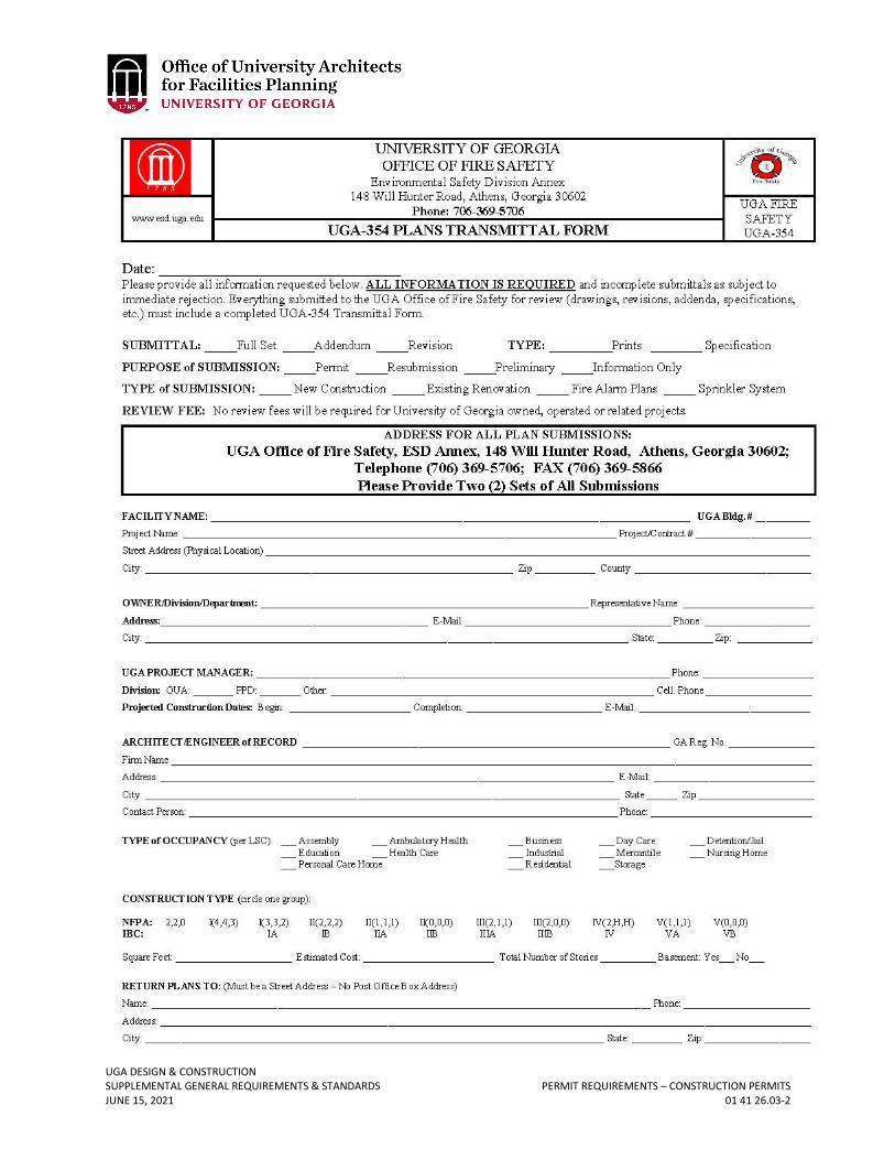
UGA DESIGN & CONSTRUCTION SUPPLEMENTAL GENERAL REQUIREMENTS & STANDARDS PERMIT REQUIREMENTS – CONSTRUCTION PERMITS JUNE 15, 2021 01 41 26.03-2

UGA DESIGN & CONSTRUCTION SUPPLEMENTAL GENERAL REQUIREMENTS & STANDARDS PERMIT REQUIREMENTS – CONSTRUCTION PERMITS JUNE 15, 2021 01 41 26.03
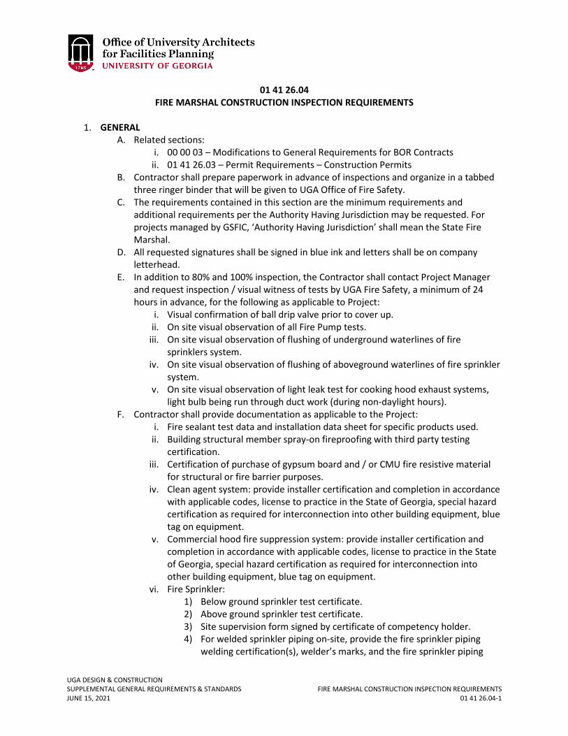
UGA DESIGN & CONSTRUCTION SUPPLEMENTAL GENERAL REQUIREMENTS & STANDARDS FIRE MARSHAL CONSTRUCTION INSPECTION REQUIREMENTS JUNE 15, 2021 01 41 26.04-1
01 41 26.04 FIRE MARSHAL CONSTRUCTION INSPECTION REQUIREMENTS
1. GENERAL
A. Related sections: i. 00 00 03 – Modifications to General Requirements for BOR Contracts
ii. 01 41 26.03 – Permit Requirements – Construction Permits B. Contractor shall prepare paperwork in advance of inspections and organize in a tabbed
three ringer binder that will be given to UGA Office of Fire Safety. C. The requirements contained in this section are the minimum requirements and
additional requirements per the Authority Having Jurisdiction may be requested. For projects managed by GSFIC, ‘Authority Having Jurisdiction’ shall mean the State Fire Marshal.
D. All requested signatures shall be signed in blue ink and letters shall be on company letterhead.
E. In addition to 80% and 100% inspection, the Contractor shall contact Project Manager and request inspection / visual witness of tests by UGA Fire Safety, a minimum of 24 hours in advance, for the following as applicable to Project:
i. Visual confirmation of ball drip valve prior to cover up. ii. On site visual observation of all Fire Pump tests.
iii. On site visual observation of flushing of underground waterlines of fire sprinklers system.
iv. On site visual observation of flushing of aboveground waterlines of fire sprinkler system.
v. On site visual observation of light leak test for cooking hood exhaust systems, light bulb being run through duct work (during non-daylight hours).
F. Contractor shall provide documentation as applicable to the Project: i. Fire sealant test data and installation data sheet for specific products used.
ii. Building structural member spray-on fireproofing with third party testing certification.
iii. Certification of purchase of gypsum board and / or CMU fire resistive material for structural or fire barrier purposes.
iv. Clean agent system: provide installer certification and completion in accordance with applicable codes, license to practice in the State of Georgia, special hazard certification as required for interconnection into other building equipment, blue tag on equipment.
v. Commercial hood fire suppression system: provide installer certification and completion in accordance with applicable codes, license to practice in the State of Georgia, special hazard certification as required for interconnection into other building equipment, blue tag on equipment.
vi. Fire Sprinkler: 1) Below ground sprinkler test certificate. 2) Above ground sprinkler test certificate. 3) Site supervision form signed by certificate of competency holder. 4) For welded sprinkler piping on-site, provide the fire sprinkler piping
welding certification(s), welder’s marks, and the fire sprinkler piping
UGA DESIGN & CONSTRUCTION SUPPLEMENTAL GENERAL REQUIREMENTS & STANDARDS FIRE MARSHAL CONSTRUCTION INSPECTION REQUIREMENTS JUNE 15, 2021 01 41 26.04-2
welder letter of certification for disc or coupon retrieval (these are the plugs that are burned/cut out when a branch line is welded to a main line).
5) For fire pump, installation acceptance testing data and flow graph. 6) Fire sprinkler certification for any specialized interconnection to pre-
action systems or deluge systems. 7) Copy of sprinkler contractor’s license to practice work in the State of
Georgia. 8) Certificate of completion of work in accordance with NFPA 13 (or other
applicable codes). vii. Plumbing / Site Utility (from each Contractor if there are separate plumbing and
site utility contractors): 1) Certificate of completion of work in accordance with the International
Plumbing Code edition applicable to the Project (or other applicable codes).
2) Copy of Plumbing Contractor’s license to practice work in the State of Georgia.
3) Installation data for boiler equipment. 4) Backflow preventer test certificates.
viii. HVAC/Mechanical Items: 1) Certificate of completion of work in accordance with the International
Mechanical Code edition applicable to the Project (or other applicable codes).
2) Copy of HVAC/Mechanical Contractor’s license to practice work in the State of Georgia.
3) If there is a smoke shutdown system, provide a letter of certification indicting the proper operation of this system.
ix. Electrical 1) Certificate of completion of work in accordance with the current
edition of National Electrical Code and NFPA 72 (or other applicable codes).
2) Copy of Electrical Contractor’s license to practice work in the State of Georgia.
3) Fire alarm system battery calculations indicating the minimum amps per hour required to run the system in accordance with NFPA 72.
4) Fire alarm system record of completion and certification. 5) Copy of Fire Alarm Contractor’s license to practice work in the State of
Georgia (required if fire alarm contractor is not the same as the electrical contractor).
6) Fire alarm certification for interconnection to auxiliary systems such as kitchen hood suppression system, air handling duct detectors, smoke removal systems, exhaust fume hoods, chemical fume hoods, elevator recall systems, fire exit door releases.
7) If there is a generator, provide electrical generator acceptance test.
Revised June 15, 2021
UGA DESIGN & CONSTRUCTION SUPPLEMENTAL GENERAL REQUIREMENTS & STANDARDS ROCK REMOVAL – ROCK BLASTING JUNE 15, 2021 01 41 26.05-1
01 41 26.05 ROCK REMOVAL – ROCK BLASTING
1. GENERAL
A. If the concept to use explosives to remove rock is approved by the Project Manager, then the Contractor, a minimum of seven calendar days prior to commencing blasting activities, shall provide the Project Manager with:
i. The proposed blasting schedule. ii. A complete and executed ‘UGA Blasting Checklist’ which is located at the end of
this section. B. The Project Manager will forward the blasting schedule and ‘UGA Blasting Checklist’ to
UGA Office of Fire Safety who will in turn coordinate with the State Fire Marshal. The Project Manager and Contractor must receive written authorization of approval from UGA Office of Fire Safety prior to authorizing the commencement of blasting.

UGA DESIGN & CONSTRUCTION SUPPLEMENTAL GENERAL REQUIREMENTS & STANDARDS ROCK REMOVAL – ROCK BLASTING JUNE 15, 2021 01 41 26.05-2
UGA Blasting Checklist
** This form is to be submitted and approved prior to all blasting activities **
Project Name: ________________________________________________________________________
Contractor Responsible: _________________________________________________________________
Trade Contractor Responsible: ___________________________________________________________
Blasting Company Responsible: ___________________________________________________________
Scheduled Date / Time of Blasting: ________________________________________________________
Notifications (one week in advance): 1. UGA Office of Fire Safety (call 706-369-5706)
Date/Time Notified_______________________ Contact Person______________________________
2. UGA Police (call
Date/Time Notified_______________________ Contact Person______________________________
3. Local Police/Fire Department (For Athens-Clarke County call 706-542-2200)
Date/Time Notified_______________________ Contact Person ______________________________
Day of Blast: _______________________________________________________________________
2. Local Utilities Department (For Athens-Clarke County call 706-613-3470 Admin)
Date/Time Notified _______________________ Contact Person _____________________________
3. Department Notifications (Coordinate list and Contact with Owner’s Representative) Department Name: _______________________ Date/Time Notified__________________________
Checklist
1. Blaster certification card on file / Georgia license #:
_______________________________________________________________________________
2. Pre-blast seismic survey completed prior to blast__________________________________________
Surveying Company_______________________________ Survey Date ________________________
3. 6’ of earth cover confirmed on site ____________________________________________________
4. Blast mats in place __________________________________________________________________
5. Crushed stone used to fill boring holes __________________________________________________
6. Perimeter verified & staffed by blaster and WT with radio communication – 200’ from blast
zone______________________________________________________________________________
7. Verify no charges are within 10’ of existing utilities ________________________________________
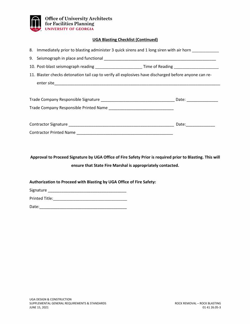
UGA DESIGN & CONSTRUCTION SUPPLEMENTAL GENERAL REQUIREMENTS & STANDARDS ROCK REMOVAL – ROCK BLASTING JUNE 15, 2021 01 41 26.05-3
UGA Blasting Checklist (Continued)
8. Immediately prior to blasting administer 3 quick sirens and 1 long siren with air horn ____________
9. Seismograph in place and functional __________________________________________________
10. Post-blast seismograph reading _____________________ Time of Reading ____________________
11. Blaster checks detonation tail cap to verify all explosives have discharged before anyone can re-
enter site__________________________________________________________________________
Trade Company Responsible Signature _________________________________ Date: ______________
Trade Company Responsible Printed Name _____________________________
Contractor Signature _______________________________________________ Date:_____________
Contractor Printed Name ___________________________________________
Approval to Proceed Signature by UGA Office of Fire Safety Prior is required prior to Blasting. This will
ensure that State Fire Marshal is appropriately contacted.
Authorization to Proceed with Blasting by UGA Office of Fire Safety:
Signature ___________________________________
Printed Title:_________________________________
Date:_______________________________________
UGA DESIGN & CONSTRUCTION SUPPLEMENTAL GENERAL REQUIREMENTS & STANDARDS DINING SERVICES JUNE 15, 2021 01 41 26.06-1
01 41 26.06 DINING SERVICES
1. GENERAL
A. Related sections: i. 00 00 08 – Design Professional Documentation Requirements & Deliverables
B. Dining Services projects being undertaken as a component of another active project are funded separately, however decisions regarding Design Professional and Contractor selection must be made concurrently with the selections for the main Project’s Contract.
C. The UGA Environmental Safety Division (ESD) shall be involved in the design development and reviews, permitting, and inspections for all new or renovated food service areas where food is being prepared in UGA owned or leased facilities. The Design Professional shall work through the Project Manager to coordinate meetings as required.
i. Catering kitchens are exempt from this requirement. D. Programming: As soon as a food service operations is identified within a project
program, a meeting should be coordinated with the Design Professional(s), Project Manager, ESD, and UGA Dining Services to further discuss the scope, refine the program, and to identify and coordinate contractual requirements involving third party franchisors.
E. Design Professional(s) shall coordinate a meeting between Dining Services, Project Manager, and Construction Manager regarding the sourcing and installation responsibilities regarding equipment on a per project basis.
F. For renovations and other work in existing facilities, a Pre-TAB report shall be provided by UGA prior to any design work occurring to verify existing operational parameters.
G. An air balance diagram shall be provided as a component of the mechanical design documents.
H. Coordinate grease trap placement with outside air intake locations. I. Equipment schedules delineating sourcing and installation responsibilities must be
reviewed, signed off on, and accepted by both Dining Services and the Project Manager for each project.
J. Prior to Schematic Design, signage requirements shall be reviewed with Dining Services, OUA, and the Design Professional(s).
K. Schematic Design and Design Development: As part of these milestone design reviews, the Project Manager will coordinate meetings with the Design Professional(s), ESD, and UGA Dining Services to review the documents to date and provide input and guidance.
i. ESD will review the drawings and ESD will forward preliminary concept drawings to the authority having jurisdiction for food safety permitting and share any review comments with the Project Manager.
L. Construction Documents: The Project Manager will coordinate meetings with the Design Professional(s), ESD, and UGA Dining Services to review the documents to date and provide input and guidance.
M. Submission to Health Department for Construction Permit i. The Project Manager shall coordinate submission of design information
(drawings, specifications, equipment lists, etc.) to the Athens-Clarke County Health Department for review at the Design Development and 80% design
UGA DESIGN & CONSTRUCTION SUPPLEMENTAL GENERAL REQUIREMENTS & STANDARDS DINING SERVICES JUNE 15, 2021 01 41 26.06-2
milestones in order to obtain a construction permit from ACC Health Department.
N. Submission to Health Department for Operational Permit i. The Design Professional shall not submit any documents directly to the Athens-
Clarke County Health Department. ii. ESD will coordinate with the appropriate entity (UGA Dining Services, Stadium
Concessionaire, etc.) to complete the application and the entity responsible for preparing the food will submit the application.
iii. The Design Professional shall supply all necessary information to complete the forms as part of the Contract Basic Services.
iv. Reference resource: http://dph.georgia.gov/food-rules-and-regulations and http://dph.georgia.gov/food-service-design-installation-and-construction-manual.
v. The documents that will be submitted as part of the food service application shall include as a minimum (may vary per jurisdiction having authority):
1. Physical address of the building 2. Location of building onsite showing access roads, alleys, and streets. 3. Location of outside equipment as applicable:
a. Dumpsters and compactors b. Well c. Septic System
4. Plan drawn to scale showing location of kitchen equipment. 5. Detail drawings of any walk-in refrigerators / freezers, if applicable. 6. Square footage for eatery including dimensions. 7. Cubic footage of dry storage, if applicable. 8. Manufacturer specification sheet for each piece of equipment shown on
the plan. 9. Manufacturer specification sheet for water heater. 10. Manufacturer specification sheet for grease trap. 11. Plan drawing(s) for plumbing. 12. Plan drawings(s) for electrical. 13. Plan(s) for mechanical ventilation including:
a. Mechanical hood ventilation detail drawing if applicable with: i. Design Intent
ii. Filters and / or extraction devices iii. Square footage iv. Fire protection v. Air capacity in cubic feet per minute (current capacity
and anticipated needed) vi. Air makeup in cubic feet per minute (current capacity
and anticipated needed) 14. Finish schedule. Refer to the already approved finishes listed in Section
L of the Rules and Regulations Food Service – Chapter 290-5-14 Manual for Design, Installation and Construction: http://dph.georgia.gov/food-service-design-installation-and-construction-manual.
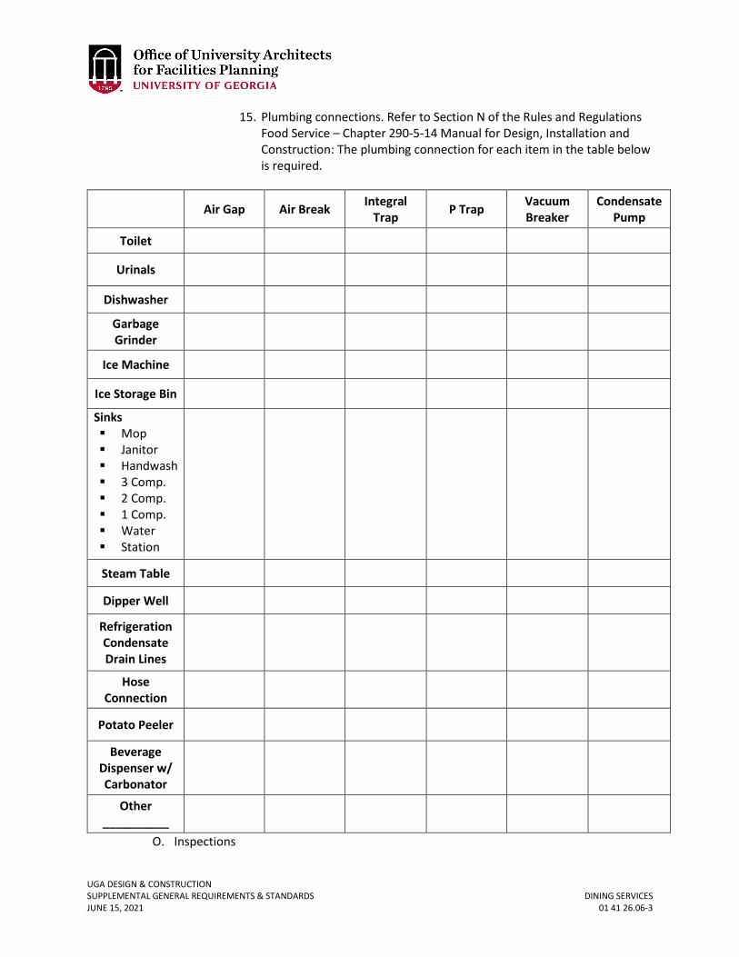
UGA DESIGN & CONSTRUCTION SUPPLEMENTAL GENERAL REQUIREMENTS & STANDARDS DINING SERVICES JUNE 15, 2021 01 41 26.06-3
15. Plumbing connections. Refer to Section N of the Rules and Regulations Food Service – Chapter 290-5-14 Manual for Design, Installation and Construction: The plumbing connection for each item in the table below is required.
Air Gap Air Break Integral Trap P Trap Vacuum
Breaker Condensate
Pump
Toilet
Urinals
Dishwasher
Garbage Grinder
Ice Machine
Ice Storage Bin
Sinks Mop Janitor Handwash 3 Comp. 2 Comp. 1 Comp. Water Station
Steam Table
Dipper Well
Refrigeration Condensate Drain Lines
Hose Connection
Potato Peeler
Beverage Dispenser w/ Carbonator
Other __________
O. Inspections
UGA DESIGN & CONSTRUCTION SUPPLEMENTAL GENERAL REQUIREMENTS & STANDARDS DINING SERVICES JUNE 15, 2021 01 41 26.06-4
i. The Contractor shall not submit requests for inspections directly to the authority having jurisdiction for the project.
ii. ESD or Dining Services will notify the Project Manager of proposed food service area inspection dates, will coordinate the inspection and will typically have personnel on site during all inspections.
2. PRODUCTS A. Plumbing
i. All above-floor grease interceptors shall be constructed of polyethylene. Alternate materials are not acceptable.
ii. Acceptable options for above-floor grease interceptors shall be Zurn GT2702-07 or equal.
iii. Outdoor subgrade grease interceptors shall be constructed of precast concrete, and shall be located with sufficient separation from outside air intakes in order to prevent odors from the interceptor from entering the building.
iv. Acceptable options for three-compartment sinks at smaller café facilities shall be Advance Tabco K7-CS-21 or equal. For full-size kitchen facilities, the Design Professional shall coordinate specific requirements.
v. Lever waste drains are required and shall be by T&S (or equal). vi. Indirect drains shall be installed at all sinks.
vii. The domestic water supply serving the Dining Services area shall be sub-metered. The Design Professional shall contact the Project Manager in order to coordinate project-specific metering and sub-metering requirements.
viii. An EcoLab water filtration shall be provided by Dining Services and coordinated by the Design Professional and Contractor.
ix. The water filtration system shall be centralized whenever possible and shall serve equipment such as ice machines, coffee makers, tea brewers, etc. Coordinate point of connection and space requirements with Dining Services and Project Manager.
x. Hand sink faucets shall be by T&S Brass (or equal) and shall be equipped with integrated hands-free sensors and hydrogenerators.
xi. It is preferred that each Dining Services location is served by its own water heater.
B. Mechanical i. No horizontal runs are allowed for grease ducts. Grease ducts are to be light
tested, pressure tested, and smoke tested prior to space turnover. ii. Kitchen hoods shall be energy efficient and comply with the Standards.
iii. Make-up air to hoods shall be conditioned. iv. All exhausts and other system components shall be accessible. v. All HVAC controls shall be compatible with the existing building systems and all
equipment provided shall have native BACnet interface. vi. Refrigeration condensing units are to be remotely located where the rejected
heat will not add load to the HVAC system; coordinate with Project Manager and Dining Services. If remote location of compressors is not possible, provide equipment with bottom-mounted compressors and provide water cooled condensers in buildings with conveniently located recirculating chilled or process chilled water; coordinate with Project Manager.
UGA DESIGN & CONSTRUCTION SUPPLEMENTAL GENERAL REQUIREMENTS & STANDARDS DINING SERVICES JUNE 15, 2021 01 41 26.06-5
C. Electrical i. The electrical service feeding the food service area shall be metered at the panel
or sub-panel feeding the food service area. The Design Professional shall contact the Project Manager in order to coordinate project-specific metering and sub-metering requirements.
ii. Each piece of hard wired equipment must have a point of disconnect to facilitate maintenance activities.
iii. Each piece of equipment requiring nonstandard outlets must be coordinated with equipment requirements and indicated on both the equipment schedule and electrical design documents.
iv. GFI breakers shall be provided in lieu of GFI outlets when possible. v. Lighting fixtures shall be LED and comply with the Standards. Refer to Section 26
51 00 Interior Lighting. vi. In general, lights are to be switched; no dimmers or lighting control systems are
required. Coordinate project-specific lighting requirements and switch locations with Project Manager and Dining Services.
D. Finishes i. The wall surface material of back-of-house rooms associated with the food
service area shall be fiber-reinforced plastic (FRP) panels, which shall extend from floor to ceiling.
ii. Flooring at all non-guest areas (food preparation, storage, coolers, freezers, etc.) shall be Titan non-skid, slip-resistant flooring by BMI (or equal). Guest use areas shall receive easily cleanable slip-resistant flooring consistent with the overall design and finish selections. Base in these areas shall also be of Titan material.
iii. Base shall be cove base where the top leading edge of the cove shall be flush with the finish surface of the floor material.
iv. Grout at all food service areas shall be dark color epoxy grout. v. Ceiling tiles shall be NSF-approved washable tiles at all food preparation and
storage areas. E. Caulking / Sealants
i. All joints between dissimilar materials shall be caulked with clear silicone caulk in a manner commensurate with manufacturer instructions.
F. Furnishings i. Food service work tables, cabinets, and casework shall be constructed entirely
of stainless steel. Legs and frame shall be square (304-SS) and sheet stainless steel shall be 200- or 300-series. 400-series stainless steel is not acceptable in any case. Decorative cladding is acceptable at aesthetically sensitive areas subject to approval by the Project Manager and Dining Services. When decorative cladding is used, all plywood substrates must be marine grade. Cabinet base may be required to be elevated on a concrete or stainless steel curb; Design Professional to coordinate with Project Manager and Dining Services.
ii. Countertops and backsplashes shall be stainless steel or solid surface material as approved by Project Manager and Dining Services.
iii. Cabinet backsplashes shall be integral with countertops. G. Communications
UGA DESIGN & CONSTRUCTION SUPPLEMENTAL GENERAL REQUIREMENTS & STANDARDS DINING SERVICES JUNE 15, 2021 01 41 26.06-6
i. DSL lines for credit / debit card services are not tied to the campus network and specific needs (entrance location and distribution devices) must be coordinated with the End-User during design.
ii. Phone and campus network data ports are required at each point-of-sale station. These ports should be run back to the network / communications wall cabinet for the Dining Services area.
H. Security i. Coordinate service entrance access requirements with End-User.
ii. Security cameras and any recording device shall be provided by Dining Services, however conduit, backboxes, cabling, and other supporting appurtenances required to accommodate the security system shall be provided and installed by the Contractor. Locations shall be coordinated with Dining Services through the assigned Project Manager. Typical locations to be monitored include (but are not limited to) storage areas and point-of-sale locations.
iii. The video recording device should be established within the Dining Service area, such as, for example, in the network / communications wall cabinet typically installed for such areas.
UGA DESIGN & CONSTRUCTION SUPPLEMENTAL GENERAL REQUIREMENTS & STANDARDS CHEMICAL STORAGE ROOMS JUNE 15, 2021 01 41 26.07-1
01 41 26.07 CHEMICAL STORAGE ROOMS
1. GENERAL
A. Related Sections: i. 00 00 07 - Design Professional Documentation Requirements and Deliverables
ii. 01 58 13 – Temporary Project Signage iii. 01 77 00 – Project Closeout
B. This section applies to projects with any of the following: i. Instructional laboratory prep rooms
ii. Research laboratory support rooms iii. Research laboratory chemical storage rooms
C. During Design i. Anticipated chemical types and quantities to be identified by end users and
provided in excel spreadsheet to Office of the University Architect (OUA) or Facilities Maintenance Division (FMD) Project Manager that will be shared with design professional of record, Environmental Safety Division (ESD), and Office of Research Safety (ORS).
ii. For all prep, support, and chemical storage rooms, the end users should consider if there are anticipated bulk purchases related to how funding is allocated to determine if greater storage needs are required for portions of the year; during design, discussions should occur about what room size makes sense related to annual purchase funding for chemicals and the project construction funding available for the room. Final room size decisions will be documented by the FMD or OUA Project Manager or the Design Professional and shared with the end users, ESD, and OR.
iii. For instructional prep rooms, the end users should also provide to the FMD or OUA Project Manager and / or Design Professional the anticipated quantities of UGA prepared solutions (mixed from purchased chemicals) that will be stored in the prep room so potential outgassing can also be accounted for in the design of the room exhaust and amount of air changes.
iv. Design professional of record, in compliance with the provisions of the State of Georgia Minimum Fire Safety Standard 120-3-3 and the most current adopted edition of NFPA 45 – Standard on Fire Protection for Laboratories Using Chemicals will determine, using the provisions of NFPA 45 – Chapter 4: Laboratory Unit Hazard Classification and Chapter 5: Laboratory Unit and Construction, the maximum quantities of flammable liquids for each laboratory and laboratory support room, the Classification (A, B, C, or D) of each room.
v. After design development, the OUA or FMD Project Manager will develop letter about end user awareness and adherence to maximum chemical quantity storage requirements. OUA PM to follow procedure in the OUA Policy and Procedure Manual.
D. During Construction
UGA DESIGN & CONSTRUCTION SUPPLEMENTAL GENERAL REQUIREMENTS & STANDARDS CHEMICAL STORAGE ROOMS JUNE 15, 2021 01 41 26.07-2
i. For rooms specifically used for chemical storage, based on construction and occupancy type, the code classification utilized for construction permitting and quantity amount limitations shall be posted inside the room.
E. During Closeout i. Include in the Operations and Maintenance Manual, copies of the letters and
chemical quantity lists prepared during design. ii. During owner training, a session shall be held with end users about chemical
quantity storage amounts (led by ORS and/or ESD). This should include educating end-users about purchasing of chemicals in bulk and insuring that allowable chemical quantities are not exceeded.
a. This should also include training of building manager(s) and also pointing out that personnel who frequently occupy a space may not notice chemical smells as they become use to it.
b. End users and building managers shall also be trained to immediately report any signs of corrosion as that could be an indicator of chemical quantities higher than what the system was designed to handle
F. Post-Occupancy i. During first year of occupancy and afterwards, ESD and/or ORS shall inspect
chemical storage rooms and laboratories for compliance with allowable quantities at least once per year with reports to Principle Investigators, Department Heads, and Deans and Vice Presidents as applicable.
UGA DESIGN & CONSTRUCTION SUPPLEMENTAL GENERAL REQUIREMENTS & STANDARDS SPECIAL INSPECTIONS JUNE 15, 2021 01 45 33-1
01 45 33 SPECIAL INSPECTIONS
1. GENERAL
A. The Owner will contract directly with the Owner’s Testing Agency. B. Design Professional to prepare schedule of special inspections for the Project. C. Testing
i. The Owner reserves the right to employ the services of a testing agency (“Owner’s Testing Agency”). Owner’s Testing Agency shall perform tests as mandated by the Owner and the Contract Documents. For testing identified in the Contract Documents, the Contractor is responsible for notifying Owner’s Testing Agency 24 hours in advance of time and date testing is required. If the Contractor requests the Owner’s Testing Agency on site and is not ready for the Owner’s Testing Agency’s services, the Contractor shall reimburse the Owner for the Owner’s Testing Agency’s complete cost for the site trip including mileage, travel time, and time spent on-site waiting for the Contractor to be ready for the Owner’s Testing Agency’s services. The Contractor shall reimburse the Owner for any re-test due to failure of initial testing.
UGA DESIGN & CONSTRUCTION SUPPLEMENTAL GENERAL REQUIREMENTS & STANDARDS SANITARY FACILITIES – TOILET FACILITIES JUNE 15, 2021 01 52 19-1
01 52 19 SANITARY FACILITIES – TOILET FACILITIES
1. GENERAL
A. The Contractor shall provide from the beginning of work, washing and temporary enclosed toilet facilities for use of workers on the job. Such facilities shall be maintained in a clean and sanitary condition meeting all local and state health standards throughout their use. The Contractor shall not permit any sanitary nuisance in or about the work. Toilet facilities for the Contractor’s workers shall be provided by the Contractor as part of the Contractor Overhead Cost or Base Bid. University toilet facilities shall NOT be made available to the Contractor's workforce.
UGA DESIGN & CONSTRUCTION SUPPLEMENTAL GENERAL REQUIREMENTS & STANDARDS ROADWAY, SIDEWALK, AND PARKING LOT CLOSURES JUNE 15, 2021 01 55 00.01-1
01 55 00.01 ROADWAY, SIDWALK, AND PARKING LOT CLOSURES
1. GENERAL
A. Roadway, sidewalk, and parking lot use, blocking and closing shall be subject to approval by the Owner. The Contractor shall coordinate through the Project Manager. A minimum of 72-hour notice is required for the Owner to make all necessary arrangements for this work, and such work shall be scheduled at the convenience of the Owner. Roadways, sidewalks, and parking lots shall not be blocked for extended periods of time.
UGA DESIGN & CONSTRUCTION SUPPLEMENTAL GENERAL REQUIREMENTS & STANDARDS TEMPORARY PARKING AREAS JUNE 15, 2021 01 55 19-1
01 55 19 TEMPORARY PARKING AREAS
1. GENERAL
A. This work is being performed on the Owner’s property and parking is restricted and regulated. Contractor and workers shall park only in areas designated by the Owner.
B. For projects in Athens-Clarke County only: The Contractor is required to purchase “Contractor Parking Permits” from University of Georgia Parking Services (706-542-PARK). Contractor shall include the cost of parking permits in the Contractor Overhead Cost or Base Bid. Any costs associated with parking permits shall be included in the Cost of the Work by each Subcontractor as applicable. Designated ‘laydown’ area taken from an existing permitted parking area shall not be used as a ‘free parking’ area. However, the Contractor may park some (around 10) vehicles within the designated construction site that do not require permits. Abuse of this free parking allowance may result in the UGA Parking Services requiring the purchase of permits or immediate reduction of parked vehicles. Parking spaces directly adjacent to the project site are not guaranteed. It is the responsibility of the Contractor to coordinate parking availability outside of the Project fence with University of Georgia Parking Services. The Contractor is responsible for paying for all fines related to parking violations at Contractor sole cost and the Contractor shall not be allowed to pay for fines from the Contractor Contingency or as part of the Cost of the Work or as a Change Order.
C. A permit is not required for parking construction related vehicles and / or personal vehicles driven by those working on the construction site within the staging area. It is ultimately up to the Contractor to decide how to utilize available space within their staging area.
UGA DESIGN & CONSTRUCTION SUPPLEMENTAL GENERAL REQUIREMENTS & STANDARDS TRAFFIC CONTROL JUNE 15, 2021 01 55 26-1
01 55 26 TRAFFIC CONTROL
1. GENERAL
A. Contractor shall provide adequate traffic warning methods and devices in accordance with Georgia Department of Transportation standards to warn motorist and pedestrians of any obstructions within the right of way of the roadway. Contractor shall coordinate with the Project Manager and obtain land and road closure permits as required by the Owner and the local Public Works Department. The cost of all traffic control and associated permits shall be included in the Base Bid or Overhead Cost.
UGA DESIGN & CONSTRUCTION SUPPLEMENTAL GENERAL REQUIREMENTS & STANDARDS STAGING AREAS – STORAGE JUNE 15, 2021 01 55 29-1
01 55 29 STAGING AREAS – STORAGE
1. GENERAL
A. The Contractor shall coordinate and use only the area(s) designated by the Owner for job site office, storage of materials and equipment, parking and staging operations. These areas and grounds shall be left clean and shall be restored to the same condition as when accepted by the Contractor. Construction and staging are limited to the designated areas.
UGA DESIGN & CONSTRUCTION SUPPLEMENTAL GENERAL REQUIREMENTS & STANDARDS TEMPORARY TREE & PLANT PROTECTION JUNE 15, 2021 01 56 39-1
01 56 39 TEMPORARY TREE & PLANT PROTECTION
1. GENERAL
A. Related sections: i. 32 01 90.23 – Pruning
ii. 32 90 00 – Planting iii. 32 91 00 – Planting Preparation iv. 32 91 13.16 – Mulching v. 32 92 00 – Turf and Grasses
vi. 32 93 00 – Plants vii. 32 94 13 – Landscape Edging
B. Scope i. All existing trees and shrubs in or near an area to be planted shall be protected
from soil compaction, equipment damage and stockpiling of materials such as sand, gravel and topsoil. This includes any adjoining areas in which planting materials or equipment (including vehicles) will be stored. In order to prevent damage to trees and tree root systems, protective barriers shall be installed before bed preparation.
ii. The tree canopy / tree root zones of trees designated to be preserved shall be protected during the entire construction process.
iii. Tree trunks and branches shall not be damaged by equipment or workers. Tree roots shall be protected from soil compaction, damage by trenching or excessive grade changes, and hazardous materials or waste products.
iv. Any anticipated or required pruning shall be performed by the UGA Grounds Department.
v. A Tree and Plant Protection Map shall be prepared by the design professional, which identifies all areas affected by the Project. The Tree and Plant Protection Map must show the location, species and size of all existing trees and landscape that may be negatively impacted by the Project. The map must indicate which trees and shrubs are to be removed, and which ones are to remain. The plan shall include protection measures for all tree and landscape impacts, including all utility connections for the Project. Plants scheduled to be removed shall be evaluated for relocation as approved by the UGA Grounds Department.
C. Tree Canopy / Tree Root Protection Zones i. Prior to the start of any site work the Contractor will erect fencing around trees
which are to be preserved and sensitive root zones which are to be protected within the construction site.
ii. The Contractor shall meet with the UGA Grounds Department representative and Project Manager prior to beginning any site work to review and verify all work procedures, trailer location, stockpiling and staging areas, access and haul routes, and equipment operation methods with respect to the required tree canopy / tree root protection measures.
iii. Trees indicated on the plan to remain shall be protected from injury to their branches, trunks, and root zones during the entire construction period.
UGA DESIGN & CONSTRUCTION SUPPLEMENTAL GENERAL REQUIREMENTS & STANDARDS TEMPORARY TREE & PLANT PROTECTION JUNE 15, 2021 01 56 39-2
Protection of tree canopy / tree root zones shall be by the placement of temporary fencing as outlined.
iv. No removal or encroachment into tree protection enclosures shall be permitted unless coordinated with the Project Manager.
v. The Contractor shall be responsible for installation and maintenance of all tree protection fencing. Protective fencing shall remain undisturbed until all site work has been completed. The Contractor shall remove fencing at completion of the Project.
vi. If protective fencing is damaged, the Contractor shall immediately execute the necessary repairs to re-establish the protective fencing to the original configurations.
vii. The Contractor shall be held liable for any damages to protected trees and root zones caused by unauthorized intrusions into the protected areas during construction activity.
viii. Any pruning of protected trees that may be required during the course of construction shall be performed by the UGA Grounds Department. Coordinate pruning requests with the Project Manager.
ix. Erosion control devices shall be installed as per contract drawings with particular emphasis on preventing siltation and / or erosion from occurring within the tree root protection zone.
D. Tree Canopy and Tree Root Zones Allowed Disturbance i. In situations where the Design Professional has received written approval from
the Project Manager to allow work that will compromise tree root zones, the Contractor will be responsible for the follow up and shall be included in the Cost of the Work or Bid:
a. Watering affected tree as prescribed by the Design Professional or UGA Grounds Department.
b. Air spading by certified arborist. 2. PRODUCTS
A. Protective Fencing i. Protective fencing shall be 6 feet high chain link fencing. Support posts for
chain link fencing shall be metal posts with a minimum of 2-inch diameter and full height of fencing. Use 9 gauge top and bottom wires between posts to support chain link fencing. Attach fencing to posts and top and bottom wires with 9 gauge wire ties.
B. Geotextile Fabric i. Filter fabric shall meet the requirements for GADOT Type 3 engineering fabric,
Class A. C. Mulch
i. Coarse chipped or ground wood mulch shall be approved prior to application by the Project Manager.
3. EXECUTION A. General
i. The Contractor shall locate utilities prior to installing chain link fence support posts into the ground.
UGA DESIGN & CONSTRUCTION SUPPLEMENTAL GENERAL REQUIREMENTS & STANDARDS TEMPORARY TREE & PLANT PROTECTION JUNE 15, 2021 01 56 39-3
ii. Trees to be removed that have branches extending into the canopy of trees to be preserved shall be removed by a certified arborist and not by the Contractor or a demolition Subcontractor. The certified arborist shall remove the tree in a manner that causes no damage to the protected trees and landscape to remain after construction is completed.
iii. Trees to be removed shall be felled so as to fall away from protective zones and to avoid pulling and breaking of tree roots indicated on the plan to remain.
iv. Any brush clearing required within or around the tree canopy protection zone shall be accomplished with hand operated equipment.
v. The Contractor shall be held liable for damages incurred to any tree branches that extend over protective fencing and to any trees or other plant material located on the site and indicated on the plan to remain. The Contractor shall notify the Project Manager when any overhanging branches or other plant material is interfering with or risks damage due to construction activity.
vi. If work causes an existing tree to be removed that is not shown on plans as planned demolition, the UGA Grounds Department shall be consulted with to evaluate and determine future viability of the existing tree(s) located within the area(s) of proposed construction excavation.
vii. Final evaluations shall be coordinated with the Project Manager to determine if tree should remain, be relocated, or be removed if unable to survive encroachment of new revised design and construction.
B. Scope of work Within or Around Tree Root Protection Zone i. Any grading, construction, demolition, remedial measures or other work that
is expected to encounter tree roots shall be made in consultation with the Project Manager.
ii. No machine digging shall take place within a radius of one and one-half foot for each 1 inch diameter at breast height (DBH) of the tree. DBH is defined as the diameter of the trunk measured at 54 inches above grade.
iii. Any roots 2 inches in diameter or less that sustain damage during construction shall be exposed to sound tissue and cleanly pruned close to the tree side of the trench. Clean cuts shall be made at all times.
iv. For construction Projects requiring access or haul roads that must pass over the root area of trees to be retained, a roadbed shall be installed using 4 inches (minimum) of mulch or wood chips covered with approved logging mats. Approval shall be given by the Project Manager. The roadbed shall be replenished and maintained as necessary to provide desired root zone protection. For projects requiring materials storage within the root area of trees to be retained or protected, this area shall be constructed using an approved geotextile base covered with 4 inches (minimum) of coarse wood mulch or chips. The area shall be replenished as necessary to maintain a 4 inch (minimum) depth.
v. No material shall be stored or piled within a radius of 2 feet for each 1 inch DBH (minimum) of the designated tree root zone or as directed by the Project Manager. No gasoline, fuel oil, harmful chemicals, etc., or other deleterious materials shall be stored, spilled or deposited on the ground with in this limit.
UGA DESIGN & CONSTRUCTION SUPPLEMENTAL GENERAL REQUIREMENTS & STANDARDS TEMPORARY TREE & PLANT PROTECTION JUNE 15, 2021 01 56 39-4
vi. There shall be no vehicular traffic or parking permitted under the drip line / canopy of any tree to be retained or protected within the construction site unless approved tree root protection measures have been installed.
vii. Foot traffic shall be kept to a minimum under the drip line / canopy. If temporary foot traffic must be directed over the root zone of trees to be retained or protected, a pathway shall be installed using an approved geotextile base covered with 3 inches (minimum) or mulch or wood chips. The pathway material shall be replenished as necessary to maintain a 3 inch (minimum) depth.
viii. Installation of curbs and sidewalks shall be completed in a manner least damaging to trees and tree root systems. An approved geotextile fabric shall be considered a viable alternative to the specified sub-base in sensitive root zones. When unique site conditions not addressed in the contract drawings result in the opportunity for an alternative solution or a potential modification to the plan, the Contractor may present a proposal to the Project Manager.
ix. For an existing landscape with an irrigation system that requires protection, the Contractor shall either maintain operation of the irrigation system at all times or hand water at rate and schedule approved by the Project Manager.
C. Liability i. The Contractor shall be held liable for any damage to protected trees. A dollar
value shall be determined by following criteria contained in A Guide for Plant Appraisal (Council of Tree and Landscape Appraisal, Latest Edition).
ii. The Contractor shall be held liable for all remedial measures required to treat broken limbs, or damaged trees and roots, or for unauthorized removal of existing trees or plant material, etc. All tree surgery and remedial treatments will be accomplished by a certified arborist.
iii. Contractor will protect all trees, shrubs and grass in the Project site that will not be removed as part of the scope of work. Any damages to these live plants will be repaired or replaced by the Contractor at the Contractor’s sole cost before final payment will be issued by the Owner.
iv. The actual damages are difficult to ascertain. Therefore, in addition to the above, the Contractor shall pay the Owner as liquidated damages and not as a penalty, $500 per day for each day that the Owner and / or Design Professional documents violation(s) of the requirements within this section. Such liquidated damages shall be paid to the Owner through a unilateral deductive change order to the Contractor’s Contract.
UGA DESIGN & CONSTRUCTION SUPPLEMENTAL GENERAL REQUIREMENTS & STANDARDS CAMPUS SIGNAGE STANDARDS JUNE 15, 2021 01 58 00-1
01 58 00 UGA CAMPUS SIGNAGE STANDARDS
1. GENERAL
A. Related sections: i. 00 00 09 – Room & Space Numbering
ii. 10 14 00 – Signage iii. 26 56 00 – Exterior Lighting (for requirements regarding exterior signage.)
B. The University of Georgia campus consists of a mosaic of buildings and open space within an intricate fabric of natural landscape. Its layout generally provides close and distant views that are free of unnecessary architectural obstacles such as signage that blight other campuses. The purpose of these guidelines is to provide a framework by which exterior signage is properly employed to provide clear information without cluttering the campus and detracting from its enjoyment. Protecting the campus from visual clutter protects the University’s brand identity and renowned aesthetic character. Further, the framework contributes to a coherent and consistent wayfinding system across campus. Ultimately, the purpose of a sign is to provide information when needed and to fade into the background when not.
C. Exterior signage shall be limited to campus gateway identification, building identification, and signage required by code and regulation. The UGA Uniform Sign Program, developed in 1967 by Professor Ron Arhholm of the Department of Art, provided the original specifications for campus exterior signs. LDSOA faculty and FMD have updated this document over the years, and the current specifications are incorporated into the Standards.
D. All requests for exterior signage not conforming to the Standards or those exceptions listed below shall be brought to the Campus Environs Review Committee ([email protected]) for consideration.
E. Donor or memorial related signage is addressed as an exception category with specific guidelines governing design and placement in a subsection below.
F. Design and placement of campus educational signage, historical markers, etc. shall be reviewed on a case by case basis by the Campus Environs Review Committee.
G. Consistent with Section I-C-iii of the campus solicitation policy, there shall be no exterior facing commercial signage. Though allowed inside certain buildings associated with a service provision, commercial signage shall not be visible from the exterior of the building. This includes commercial signage associated with vending, except in those locations reviewed and approved by the Campus Environs Committee. At athletic fields, approved signage may be allowed on the interior facing field walls or fences. However, no commercial signage shall be fastened to any exterior facing wall or the exterior of any stadium, court, or athletic facility.
H. Exterior electronic message centers are not permitted as they detract from the campus aesthetic.
I. New signage not in conformance with UGA sign regulations shall be removed at the cost of the party responsible for erecting the sign. This includes temporary signage that has not been removed on schedule and where temporary signage has caused damage to landscape or wall surfaces.
UGA DESIGN & CONSTRUCTION SUPPLEMENTAL GENERAL REQUIREMENTS & STANDARDS CAMPUS SIGNAGE STANDARDS JUNE 15, 2021 01 58 00-2
J. Existing exterior signage types not identified in this document should be reviewed by the Campus Environs Review Committee. A decision should be made for either immediate removal, removal coinciding with scheduled maintenance or future improvements, or for an exception to be granted.
K. Campus Environs Review Committee may also approve and set standards for additional signage types in the future.
2. TYPICAL EXTERIOR SIGNAGE A. Campus Gateway Signage and University of Georgia Identification: In general, the
landscape and architecture of UGA adequately identify campus edges; however, signs identifying the campus may be placed at prominent campus entryways and / or prominent corners created by intersections.
i. Campus identification signage (whether on Main Campus, Whitehall, Riverbend Research, or the Health Sciences Campus, or outlying properties) should consist of the free standing painted metal signs identified in section 2 below. Consistency with the graphic standards specified in the section regarding color, typography, and content is required.
ii. At various key entries or prominent corners, granite rubble walls with pin-mounted metal letters have been used. However, requests for these must be approved by the Campus Environs Review Committee.
iii. Requests for additional or alternate identification sign types must be presented to the Campus Environs Review Committee for review and determination.
iv. “University of Georgia” identification is to be employed only on signs for buildings or sites located on the periphery of or away from the main campuses.
B. Building / Property Name Identification: Campus buildings are identified by either free-standing or attached signage.
i. Free-Standing Metal Sign: Buildings, building complexes, and campus properties shall be identified as specified below:
a. Short form of the building or property name (generally the vernacular). This is a normally two to three word name (five word maximum).
b. Name may occupy no more than two (2) lines of text. c. The building number as assigned and noted on campus maps d. Subtext Listings
1) Subtext listings may appear on a building I.D. sign only if the main / administrative office of that entity is located within the building. For example, the name of a college may only be placed on signage for the building in which the dean’s office is located.
2) Subtext listings may not occupy more than two lines of text. Length of text lines is limited to approximately 40 letters and spaces.
3) The order of hierarchy is as follows: i) Name of a presidential or vice presidential office,
college, school (headed by a dean), or division. ii) Name of an academic or administrative department,
or a school existing as a unit within a college.
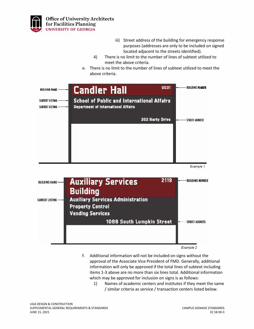
UGA DESIGN & CONSTRUCTION SUPPLEMENTAL GENERAL REQUIREMENTS & STANDARDS CAMPUS SIGNAGE STANDARDS JUNE 15, 2021 01 58 00-3
iii) Street address of the building for emergency response purposes (addresses are only to be included on signed located adjacent to the streets identified).
4) There is no limit to the number of lines of subtext utilized to meet the above criteria.
e. There is no limit to the number of lines of subtext utilized to meet the above criteria.
f. Additional information will not be included on signs without the approval of the Associate Vice President of FMD. Generally, additional information will only be approved if the total lines of subtext including items 1-3 above are no more than six lines total. Additional information which may be approved for inclusion on signs is as follows:
1) Names of academic centers and institutes if they meet the same / similar criteria as service / transaction centers listed below.
UGA DESIGN & CONSTRUCTION SUPPLEMENTAL GENERAL REQUIREMENTS & STANDARDS CAMPUS SIGNAGE STANDARDS JUNE 15, 2021 01 58 00-4
2) Names of auditoriums if the facility is regularly used for public presentations, lectures, etc.
3) Service / transaction points open and available to the public (library, clinic, gallery, computing center, etc.).
4) Name of an academic program office if the program generates a significant number of site visits by students or the public, and if the program offices and operations are centralized within the facility. (Note - An academic program office may be removed from a sign if another entity that ranks higher on the scale takes up occupancy in the facility.)
g. The following information may not be included on exterior building I.D. signs:
1) Non-academic program offices 2) Academic offices that do not meet the criteria of f.4 3) Section Offices 4) Centers and institutes that do not have a public interface
component 5) Personal names of building occupants
h. FMD’s Sign Shop applies detailed font type, size, and spacing guidelines in these production of uniform identification signs.
ii. Attached to Buildings: Buildings shall be identified by lettering in all capitals using either carved-in-stone or projected, pin-mounted letters. In general, signs should be located above major building entrances. However, depending on sight-lines and building configuration, sign location may be located at the discretion of the OUA.
a. Letters carved in stone (or sand blasted into precast or stone) shall be Legacy Font. Size of font and use of serif or sans-serif shall be determined by the OUA.
b. Projected, pin mounted letters shall be ½-inch thick cast bronze, black non-ferrous metal, or brushed aluminum and shall be Helvetica Medium font. Typically, sizes shall range from 4 inches to 8 inches at the discretion of the OUA.
c. In rare instances, the metal identification sign described above as a free-standing sign may be mounted on a building, where site limitations preclude a free-standing sign, as on downtown streets.
C. Informational Signs and Parking Signs i. Blue and black signs shall be used for signs which are more informational in
nature, such as directional or parking information. These sign types shall be limited in use and provide for basic identification and wayfinding needs that are outside the context of building and complex identification. The UGA Grounds Department sign shop shall determine the placement and appearance of all informational and parking signs.
D. Regulation / Code Required Signs i. Road signs, ADA signs, fire and life safety signs, and all other signs required by
code or regulation shall be governed by the Reference Manual of Uniform Traffic Control Devices and any other applicable regulatory parameters.
UGA DESIGN & CONSTRUCTION SUPPLEMENTAL GENERAL REQUIREMENTS & STANDARDS CAMPUS SIGNAGE STANDARDS JUNE 15, 2021 01 58 00-5
E. Campus Directories / Location Maps i. Directories should be placed at logical locations throughout campus.
a. Campus maps with “You Are Here” identification: Campus maps shall be placed at logical locations throughout campus. They should not be placed where they obstruct entryway views, historic views, or prominent views of campus. These signs should be constructed to fade into the campus landscape. Preferably these should be constructed so that they can be updated regularly and cost effectively.
3. TYPICAL INTERIOR SIGNAGE A. Interior wayfinding signage (room identification and directional signage) is
provided and maintained by the FMD. B. Room Identification Signage and Code-Required Signage
i. In order to assure cost effective building maintenance and replacement, materials should be limited to the Rowmark ADA signage available for fabrication through UGA FMD in a variety of contrasting background / lettering options.
a. Within Resident Instruction (RI) buildings, the Provost must approve any requested room identification signage that requires third party fabrication as a result of the design or material preferences of the user group.
b. Within non-RI buildings, deviations that require third party fabrication are discouraged and will be the responsibility of the user to fund maintenance and replacement.
4. DONOR AND / OR MEMORIAL SIGNAGE A. Donor and memorial signage opportunities shall be identified in accordance with
relevant naming / memorial policies and designed, ordered, and installed only after approval procedures have been completed. Development officers should work with OUA when determining appropriate size and design of recognition signage.
B. Use of Logos i. Use of the official UGA logo in donor recognition graphics should conform
to the style guide available through the UGA Division of Marking and Communication Office at http://styleguide.uga.edu/index.php?/entries/logo_guide_and_downloads
ii. No commercial or corporate logos or other branding imagery is permitted in association with campus donor recognition graphics. In special circumstances, use of logos on interior recognition plaques may be approved by the Office of the President.
C. Building Naming i. Exterior (attached) building sign
a. Location – Generally the exterior building naming signage should be located above the most prominent formal entry and limited to this singular location.
b. Content – Use only BOR-approved naming language for exterior building signage.
Revised June 15, 2021
UGA DESIGN & CONSTRUCTION SUPPLEMENTAL GENERAL REQUIREMENTS & STANDARDS CAMPUS SIGNAGE STANDARDS JUNE 15, 2021 01 58 00-6
c. Material – Engraved or cast lettering as well as pin-mounted dimensional letters are both appropriate materials and methods for providing building naming signage. Dimensional naming letters across campus are commonly black non-ferrous metal, anodized bronze, or brushed aluminum. Brushed aluminum should be limited to pin-mounted dimensional letters set against a field of brick, where legibility of darker letters can be obscured.
d. Typeface should adhere to precinct precedents when nearby. e. Depending on the size of the overall facility, the letter heights may vary.
Lettering is typically 6 inches tall with ½-inch (to be consistent with above notes) extrusion. Requests for taller letter heights shall be submitted to the OUA for approval.
f. Letters on a field of brick shall be carefully placed to work in concert with the horizontal mortar joints to make the letters as legible as possible.
ii. Exterior (free-standing) grounds sign a. No deviation from Section III-2-A above is permitted to ensure a
consistent and coherent campus wayfinding system. iii. Dedication plaque
a. Coordinated through the President’s Office, up to two dedication plaques may be associated with a building project, depending upon funding source.
1) Typically there is one dedication plaque and the content and layout shall be determined in conformance with BOR standards. Refer to BOR Policy Manual 9.7.5 Plaques: http: / / www.usg.edu / policymanual / section9 / C528
2) When there is a rededication of a building due to the reuse of a name, there may be a second plaque.
3) Material – Cast bronze is the generally accepted material for building dedication plaques, but at the discretion of the OUA, material choices may be altered to fit building character.
4) Location – Dedication plaques should be located in the primary interior entry or lobby.
iv. Other a. Any other donor recognition graphics associated with the building
namesake should conform to the standards outlined elsewhere within this document and reviewed on a case-by-case basis. Placement within entries or central circulation spaces should be prioritized.
1) Size - The overall size of such graphics should not be larger than the BOR dedication plaques (typically 17 inches by 30 inches).
2) Material – Acrylic, glass, bronze, and aluminum are all common materials employed in donor plaque design. Consistency in material and layout should be a priority throughout a campus building.
3) Content – Content should be limited to donor(s) and / or honoree(s) names, degrees from UGA, and association with the
UGA DESIGN & CONSTRUCTION SUPPLEMENTAL GENERAL REQUIREMENTS & STANDARDS CAMPUS SIGNAGE STANDARDS JUNE 15, 2021 01 58 00-7
unit or university community leading to gift. Personalized imagery is discouraged but will reviewed on a case-by-case basis.
4) Location – Should be located in primary interior entry or lobby and coordinated with other building dedication plaques.
D. Interior Space Naming Recognition i. Room Identification – Functional room identification signage is an appropriate
location to co-locate recognition of interior space naming, though the character limitations of these signs may require abridged naming language.
a. Typeface – Because of the primary wayfinding function of these signs, typefaces for space type and room numbers should be limited to sans-serif, ADA compliant options (typically Helvetica) with 5/8-inch lettering. Legacy san-serif is an acceptable alternative. Alternative typefaces should be approved by the OUA.
b. Materials – In order to assure cost effective building maintenance and replacement, materials should be limited to the Rowmark ADA signage available for fabrication through UGA FMD in a variety of contrasting background / lettering options. Within Resident Instruction (RI) buildings, the Provost must approve any requested room identification signage that requires third party fabrication as a result of the design or material preferences of the user group. Within non-RI buildings, deviations that require third party fabrication are discouraged and will be the responsibility of the user to fund maintenance and replacement.
c. Examples from across campus are included below:
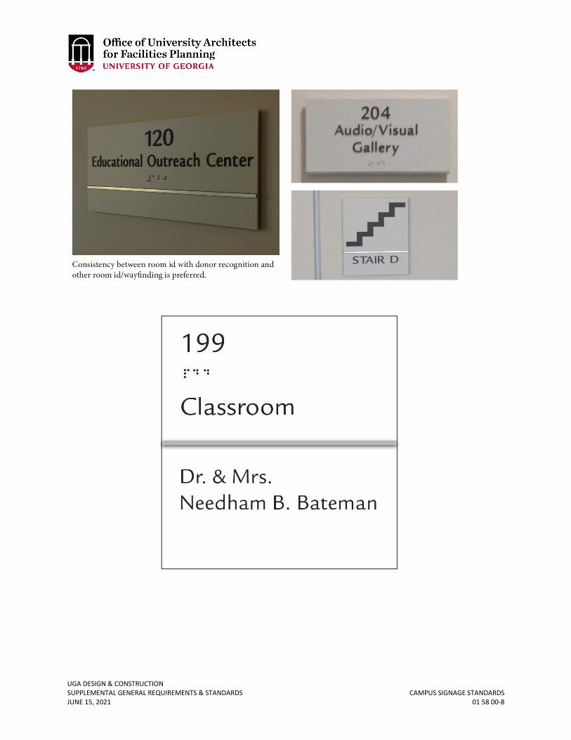
UGA DESIGN & CONSTRUCTION SUPPLEMENTAL GENERAL REQUIREMENTS & STANDARDS CAMPUS SIGNAGE STANDARDS JUNE 15, 2021 01 58 00-8
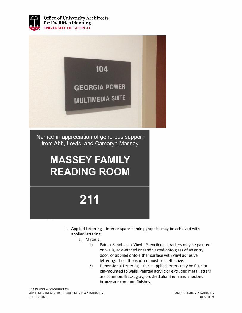
UGA DESIGN & CONSTRUCTION SUPPLEMENTAL GENERAL REQUIREMENTS & STANDARDS CAMPUS SIGNAGE STANDARDS JUNE 15, 2021 01 58 00-9
ii. Applied Lettering – Interior space naming graphics may be achieved with applied lettering.
a. Material 1) Paint / Sandblast / Vinyl – Stenciled characters may be painted
on walls, acid-etched or sandblasted onto glass of an entry door, or applied onto either surface with vinyl adhesive lettering. The latter is often most cost effective.
2) Dimensional Lettering – these applied letters may be flush or pin-mounted to walls. Painted acrylic or extruded metal letters are common. Black, gray, brushed aluminum and anodized bronze are common finishes.
UGA DESIGN & CONSTRUCTION SUPPLEMENTAL GENERAL REQUIREMENTS & STANDARDS CAMPUS SIGNAGE STANDARDS JUNE 15, 2021 01 58 00-10
b. Size – Size varies depending upon location but should typically be limited between 1-inch to 3-inch lettering. Vast interior spaces such as auditoriums may merit larger lettering up to 4 inches.
c. Location – Generally, applied lettering should be provided in one location, interior to the named space, with the exception of lettering applied within an entry door lite. In certain circumstances, applied lettering outside the named space may be acceptable, but every effort should be made to reduce the visual clutter of multiple signs types and locations along public corridors and other circulation areas.
d. Content - This method should limit content to the approved naming only.
iii. Typefaces a. For new construction a consistent use of typeface among donor-
recognition graphics shall be utilized throughout a campus building. For renovations and additions, the existing typefaces shall be considered and an appropriate typeface selected that best blends the new and renovated areas.
b. There are four approved typefaces and any deviations shall be submitted to the OUA for approval prior to fabrication:
1) Galliard roman, italic and bold are commonly employed font variants. Application of this typeface in donor recognition graphics is encouraged.
2) Designed in 1992 by Lamar Dodd School of Art professor Ron Arnholm, ITC Legacy (32 variants in serif and sans-serif fonts) is encouraged.
3) Times New Roman is also commonly employed across campus and is acceptable if more appropriate than Galliard or ITC Legacy.
4) Helvetica or ITC Legacy Sans-Serif, ADA-compliant typefaces, should be used when donor naming is combined with room identification signage.
iv. Logos a. Use of the official UGA logo in donor recognition graphics should
conform to the styleguide available through the UGA Division of Marketing and Communications Office at http: / / styleguide.uga.edu / index.php? / entries / logo_guide_and_downloads
b. No commercial or corporate logos or other branding imagery is permitted in association with campus donor recognition graphics. Requests for variances from this rule in building interior spaces shall be made to the Office of the President of the University through coordination with the Project Manager. Requests for variances from this rule in exterior settings should be made first to the President of the University and, if approved, to the Board of Regents.
UGA DESIGN & CONSTRUCTION SUPPLEMENTAL GENERAL REQUIREMENTS & STANDARDS CAMPUS SIGNAGE STANDARDS JUNE 15, 2021 01 58 00-11
v. Donor Information Plaques a. Material – Acrylic, glass, bronze, and aluminum are all common
materials employed in donor plaque design. Consistency in material and layout should be a priority throughout a campus building.
b. Content – Content should be limited to donor(s) and / or honoree(s) names, degrees from UGA, and association with the unit or university community leading to gift. No personalized imagery should be included.
c. Location – Interior to named space only. With the exception of the building namesake, donor information plaques should not be placed in public corridors or other circulation areas.
d. Size – Recommended maximum size is 12 inches x 18 inches, to be deferential to building naming plaques which are typically 17 inches x 30 inches.
vi. Collective Donor Recognition a. Panels – recognition of group philanthropic efforts should maintain
consistency to greatest extent feasible with the broader recognition graphics program. Digital displays can provide a flexible medium for adding or changing content over time. These collective recognition displays may be located along central corridors and common spaces.
E. Exterior Space Naming Recognition i. Named exterior spaces – engraved cast stone or granite set flush within the
hardscape of a named plaza or other exterior space is the preferred campus method for donor recognition graphics within the campus landscape.
ii. Collective Donor Recognition a. Pavers – “brick campaigns” are discouraged as a result of the typically
low quality and inconsistent paver material associated with these installations. Preferred alternatives may include engraved flagstone, bluestone, or granite pavers.
b. Consider using these engraved pavers within discrete, un-mortared fields within a plaza or as plaza or walkway borders. Ongoing campaigns that require additions after the initial installation require careful planning and coordination to maintain a seamless appearance over time.
iii. Other Memorial / Donor Signage within the Campus Environs shall conform to either the Arboretum or Memorial Bench policies. All other request types shall be reviewed on a case-by-case basis by the Campus Environs Review Committee.
a. Arboretum – For gifts of a minimum value identified in the Arboretum Policy, an engraved granite paver will be added to the DW Brooks Arboretum Memorial.
b. Benches – For gifts of a minimum value identified in the Memorial or Honorary Bench policy, an engraved granite paver will be set flush within the standard brick paver pad or a bronze plaque (3 inches x 5 inches) will be set flush within concrete pads / sidewalks.
UGA DESIGN & CONSTRUCTION SUPPLEMENTAL GENERAL REQUIREMENTS & STANDARDS CAMPUS SIGNAGE STANDARDS JUNE 15, 2021 01 58 00-12
5. SPECIAL EVENTS A. Temporary Signs
i. Temporary signage is defined as signage that is erected for a period of no more than 30 days and must conform to temporary sign design standards with review and approval for design and placement by UGA Marketing and Communications in accordance with the Outdoor Temporary Signage policy. Requests for temporary signage should be directed to UGA Marketing and Communications at [email protected] or otherwise adhere to the Temporary Banner signage policy below.
ii. Banners - The UGA Division of Marketing and Communications worked with OUA, FMD and others to develop a policies and procedures guide for temporary campus banners, accessible via the following links: Pole Banners, http: / / publicaffairs.uga.edu / index.php / site / policy / banners-on-light-poles-guidelines.
iii. No other temporary signage shall be attached to a building or posted within the campus landscape. Only temporary signs (as managed by the Office of Special Events, Facilities Management Department, and / or the Division of Marketing and Communications) are permitted.
B. Pin-up Student Message Boards i. Student message boards are a part of college / community life that persists
despite the emergence of newer forms of social media. However, considering that these sign types present certain maintenance requirements, message boards should be limited to current locations, and in certain locations, reviewed for phasing out.
ii. It is recommended that most buildings have an interior message board located in common location (not in direct line of sight when entering building), or by the restrooms, water fountains, or elevators. Size of pin-up area should increase with public / social function of building (i.e. dining hall to have larger pin-up board than instructional facility).
a. Exterior pin-up boards should be limited to current locations.
UGA DESIGN & CONSTRUCTION SUPPLEMENTAL GENERAL REQUIREMENTS & STANDARDS TEMPORARY PROJECT SIGNAGE JUNE 15, 2021 01 58 13-1
01 58 13 TEMPORARY PROJECT SIGNAGE
1. GENERAL
A. The Contractor shall install an official Project Construction Sign at a location agreed upon with the Owner. The sign shall be installed prior to beginning construction on site. The cost shall be included in the Contractor Overhead Cost or Base Bid. The sign shall be a 4’x8’ sheet of plywood with black lettering and white background and adhere to the template provided at the link below. The Contractor shall provide a proof to the Owner for review and approval prior to fabrication.
B. The Contractor shall obtain the templates from the following location under the Section 01 58 13 Temporary Project Signage sub-heading: https://www.architects.uga.edu/standards The Contractor shall contact the Project Manager if difficulty is encountered while accessing the files.
i. Note: in the case of projects administered by FMD, the bottom line of the Project Construction Sign shall state: “Administered by the Facilities Management Division” as directed by Project Manager.
ii. For Georgia State Financing and Investment Commission (GSFIC) funded projects, include among the listed parties.
C. The Contractor may provide and install signage as required to direct deliveries. No additional Contractor, Subcontractor, or Supplier signs may be installed on site without prior authorization. It is the intent of the Owner to not allow signs that advertise for the Contractor, Design Professional, Subcontractor, or Supplier.
UGA DESIGN & CONSTRUCTION SUPPLEMENTAL GENERAL REQUIREMENTS & STANDARDS PRODUCT REQUIREMENTS JUNE 15, 2021 01 60 00-1
01 60 00 PRODUCT REQUIREMENTS
1. GENERAL
A. Under no circumstances shall any asbestos, formaldehyde, or lead containing material be installed under this Contract. New materials shall not contain asbestos, formaldehyde, or lead in any form or quantity (i.e. zero asbestos, formaldehyde, or lead). Manufacturers shall submit certification to the Owner of zero-asbestos, formaldehyde, or lead for all materials used on this Project prior to request for final payment.
UGA DESIGN & CONSTRUCTION SUPPLEMENTAL GENERAL REQUIREMENTS & STANDARDS PRODUCT DELIVERY REQUIREMENTS JUNE 15, 2021 01 65 00-1
01 65 00 PRODUCT DELIVERY REQUIREMENTS
1. GENERAL
A. The Owner can NOT accept delivery of any materials. Contractor shall unload his/her equipment and materials and move them to the site of the work.
UGA DESIGN & CONSTRUCTION SUPPLEMENTAL GENERAL REQUIREMENTS & STANDARDS CONSTRUCTION WASTE MANAGEMENT & DISPOSAL JUNE 15, 2021 01 74 19-1
01 74 19 CONSTRUCTION WASTE MANAGEMENT & DISPOSAL
1. GENERAL
A. Related sections: i. 01 29 00 – Payment Procedures
ii. 01 77 00 – Project Closeout iii. 01 81 00 – Facility Performance Requirements
B. The University of Georgia has implemented recycling and waste management policies for all waste materials removed from its campus as a result of construction and demolition activity. The materials that should be recycled include:
i. Asphalt ii. Concrete, concrete block, concrete masonry units (CMU), slump stone
(decorative concrete block), and rocks iii. Brick iv. Paper, including bond, newsprint, cardboard, mixed paper, packing materials,
and packaging v. Glass
vi. Plastics vii. Fluorescent Light Tubes, per EPA regulations
viii. Green materials (i.e. tree trimmings and land clearing debris) ix. Metals (ferrous and non-ferrous) including, but not limited to, stud trim,
ductwork, piping, reinforcing steel (rebar), roofing, other trim, steel, iron, galvanized sheet steel, stainless steel, aluminum, copper, zinc, lead, brass, and bronze.
x. Wood (non-pressure/chemically treated wood) including, clean dimensional wood, pallet wood, plywood, oriented strand board (OSB), and particle board.
C. The Contractor should make an attempt to recycle or provide for re-use the following additional materials to the extent practical:
i. Cement Fiber Products including shingles, panels, and siding ii. Paint
iii. Carpet iv. Gypsum Wallboard v. Ceiling Tiles
vi. Porcelain Plumbing Fixtures vii. Vinyl Composition Tile
D. The Contractor is required to account for all waste materials removed from the project, and to recycle, salvage, or reuse, to the maximum extent practical, all of the materials listed above if this can be done within 20 miles of the construction site. If there is a cost premium associated with recycling (i.e., if a comingled dumpster must be used due to insufficient space on site for separate dumpsters), the Contractor should identify this cost premium to allow the Project Manager to assist making a decision regarding the best course of action to take for each project. Upon request, the Project Manager will provide assistance to the Contractor in identifying markets for recyclable materials. The Contractor shall make provision as practical for the Project Manager to utilize any recycled materials and processed waste materials on campus. If the Contractor believes
UGA DESIGN & CONSTRUCTION SUPPLEMENTAL GENERAL REQUIREMENTS & STANDARDS CONSTRUCTION WASTE MANAGEMENT & DISPOSAL JUNE 15, 2021 01 74 19-2
that recycling, salvage, or reuse of any of these materials is impractical, the Contractor should inform the Project Manager before commencement of construction.
E. The Contractor will be required to supply to the Project Manager during the Pre-Construction Meeting a Waste Management Plan which documents procedures to recycle, salvage, or reuse the materials listed above, including 1) separation, hauling and recycling procedures, 2) material recovery facilities and their distance from job site; and 3) markets for each material recovered. This plan must also address training and communications, recordkeeping, and reporting requirements to assure that all waste materials are accounted for properly. At Material Completion, the Plan shall be updated and submitted to the Project Manager with the total quantities of each waste material that was reused, salvaged, recycled, or disposed of, and the markets to which these materials were directed, so that it provides documentation in a single source of waste management performance on the Project.
F. During construction, the Contractor shall maintain records of a) each type of material removed from the job site (including materials that are not recycled), b) the name(s) of specific end destinations for all materials removed (whether recycled or disposed of), and c) weights or measures of all types of materials removed. Every load of waste material that leaves the site must be documented (including receipts, pictures or tickets from material hauler or recovery facility) and reported to the Project Manager on a monthly basis by including with monthly invoice. Refer to Section 01 29 00 Payment Procedures.
G. UGA retains the right to inspect, and subsequently approve or disapprove any and all recycling end markets, reuse or salvage outlets, and / or waste disposal facilities that are involved in the receipt of recyclables and / or waste materials generated from the project. Disapproval of such a market or outlet may be based on past or current violations of federal or state environmental, health, or safety laws, improper disposal activities, risk or liability exposure, excessive distance from the job site, or any other reason deemed sufficient by UGA.
H. The Contractor shall include administrative and recordkeeping costs associated with Construction and Waste Management in the Contractor Overhead Cost and Base Bid. All other associated costs shall be included in the appropriate line item cost of the General Conditions for the Guaranteed Maximum Price.
2. PRODUCTS – Not used 3. EXECUTION
A. The Contract shall complete and submit the Waste and Recycling Report located at the end of this section. This report is intended to assist UGA with tracking completion of sustainable design and facility performance requirements. Each project is required to address all aspects of the Standards whether included in this report or not.
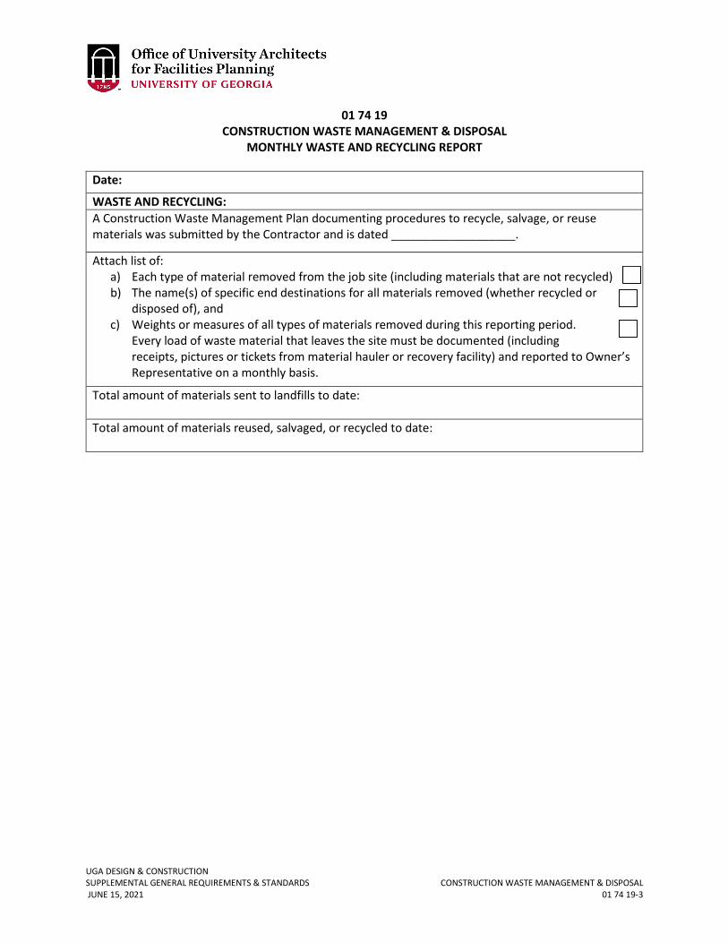
UGA DESIGN & CONSTRUCTION SUPPLEMENTAL GENERAL REQUIREMENTS & STANDARDS CONSTRUCTION WASTE MANAGEMENT & DISPOSAL JUNE 15, 2021 01 74 19-3
01 74 19 CONSTRUCTION WASTE MANAGEMENT & DISPOSAL
MONTHLY WASTE AND RECYCLING REPORT
Date:
WASTE AND RECYCLING: A Construction Waste Management Plan documenting procedures to recycle, salvage, or reuse materials was submitted by the Contractor and is dated ___________________.
Attach list of: a) Each type of material removed from the job site (including materials that are not recycled) b) The name(s) of specific end destinations for all materials removed (whether recycled or
disposed of), and c) Weights or measures of all types of materials removed during this reporting period.
Every load of waste material that leaves the site must be documented (including receipts, pictures or tickets from material hauler or recovery facility) and reported to Owner’s Representative on a monthly basis.
Total amount of materials sent to landfills to date: Total amount of materials reused, salvaged, or recycled to date:
UGA DESIGN & CONSTRUCTION SUPPLEMENTAL GENERAL REQUIREMENTS & STANDARDS STARTING & ADJUSTING JUNE 15, 2021 01 75 00-1
01 75 00 STARTING & ADJUSTING
1. GENERAL
A. Related sections: i. 01 77 00 – Project Closeout
ii. 11 53 13 – Laboratory Fume Hoods iii. 11 82 26 – Facility Waste Compactors iv. 14 20 00 – Elevators v. 21 00 00 – General Fire Suppression Requirements
vi. 23 05 14 – Variable Frequency Drive vii. 23 09 23 – Building Automation & Temperature Control Systems (BAS)
viii. 23 20 00 – HVAC Piping & Pumps ix. 23 21 23 – Hydronic Pumps x. 23 22 16 – Steam & Condensate Heating Piping Specialties
xi. 23 25 00 – HVAC Water Treatment xii. 23 64 16.13 – Air-Cooled Chillers
xiii. 23 64.16.16 – Water-Cooled Chillers xiv. 23 65 00 – Cooling Towers xv. 23 73 00 – Indoor Central –Station Air-Handling Units
xvi. 23 81 29 – Variable Refrigerant Flow (VRF) HVAC Systems xvii. 26 09 43.19 – Addressable Fixture Lighting Control
xviii. 26 24 19 – Motor – Control Centers xix. 26 32 00 – Packaged Generator Assemblies xx. 28 13 00 – Access Control
xxi. 28 31 00 – Fire Detection & Alarm B. All documentation required in this section shall also be provided in the closeout
submittal. C. The closeout manual shall include factory or authorized agent completed and signed
start-up certification documentation. D. Chillers, condensing units, cooling towers, boilers, pumps, VSDs, Variable-Frequency
Motor Controllers, AHUs, humidifiers, heat exchangers and water heaters, PRVs, controllers and controlled elements, meters, pre- insulated underground piping, etc., shall be field inspected and tested by the manufacturer or a factory trained authorized representative for installation in compliance with the manufacturer’s installation instructions and recommendations prior to start-up. The manufacturer or a factory trained authorized representative shall perform, or be present at, the start-up. Start-up documentation certifying proper installation and start-up shall be promptly forwarded to the Design Professional and Project Manager after successful start-up.
E. Condenser, chilled water, and heating hot water systems shall not be started until cleaning, flushing, and pre-treatment has been done to the satisfaction of the water treatment contractor.
F. Heating hot water systems shall be cycled through heat up and cool down and checked for leaks prior to handover. Inspection for leaks shall be performed by the TAB agency at the seasonal TAB.
UGA DESIGN & CONSTRUCTION SUPPLEMENTAL GENERAL REQUIREMENTS & STANDARDS STARTING & ADJUSTING JUNE 15, 2021 01 75 00-2
G. Base mounted pumps shall be properly grouted and aligned by, or to the written approval, of a factory certified representative. Contractor shall submit written certification to this effect.
UGA DESIGN & CONSTRUCTION SUPPLEMENTAL GENERAL REQUIREMENTS & STANDARDS PROJECT CLOSEOUT JUNE 15, 2021 01 77 00-1
01 77 00 PROJECT CLOSEOUT
1. GENERAL
A. Related sections: i. 00 00 08 – Design Professional Documentation Requirements & Deliverables
ii. 01 33 00 – Submittal Procedures iii. 01 74 19 – Construction Waste Management & Disposal iv. 01 75 00 – Starting and Adjusting v. 09 00 00 – General Finishes Requirements
B. At the end of this section is the sample Contractor & Project Manager Project Close-Out Checklist to be used as a reference for closing out the Project.
C. Closeout Meeting: The Contractor shall coordinate a Project Closeout Meeting with the Project Manager.
D. Operations and Maintenance Training: i. The Contractor shall coordinate with the Project Manager to schedule training
of facility system. ii. The Contractor shall submit O&M manuals for review simultaneously to the PM
and to the Design Professional at least two weeks prior to O&M training dates. See below for more information regarding items in O&M manuals.
iii. There shall be at least a two week notice prior to the established training date(s).
iv. The Contractor shall prepare an agenda with times allocated for each training session.
v. All training sessions shall be videotaped by a third-party company, unless directed otherwise by the Project Manager.
E. Closeout-Submittals Format Requirements: i. Both the hardcopies and electronic copies shall be organized using the
Construction Specifications Institute (CSI) numbering system utilized in the Project Manual. The documentation shall be organized with labeled tabs, and consolidated into one three ring binder to the extent possible. If there are multiple binders, the volumes shall be labeled.
ii. Electronic Deliverables: a. Electronic file names shall be no longer than 15 characters using only
Microsoft acceptable file names and shall be delivered by CD-Rom(s), flash drive, file download, or other acceptable deliverable.
b. For projects that do not require BIM, AutoCAD files shall be version 2007 or later and be whole and complete with NO Xrefs to symbols or other drawings.
c. All drawings and specifications shall be submitted in AutoCAD (.dwg), Revit (.rvt) (depending on if BIM is utilized), Microsoft Word (.doc), and Adobe PDF (.pdf) formats. All PDF files shall be searchable.
d. Drawings and specifications shall each be submitted as one PDF binder set and as separate files for each drawing sheet/specification section.
e. Multivista shall be engaged to incorporate the simplified floor plans for each project into the campus maps under a 'client-use Revised June 15, 2021
UGA DESIGN & CONSTRUCTION SUPPLEMENTAL GENERAL REQUIREMENTS & STANDARDS PROJECT CLOSEOUT JUNE 15, 2021 01 77 00-2
o&m manual' location. The contractor will be responsible for adding color-coded electronic push-pins onto these maps and linking all product data and o&m data to these pins that correspond to the equipment and shut-off valve locations. the o&m training videos will also be linked to these maps to be located in the general 'video' file. The color coding of the push-pins is as follows:
1) Dark Blue - Chilled Water/Hot Water piping associated with HVAC system
2) Light Blue - Domestic, potable water systems associated with the plumbing system
3) Red - Electrical 4) Yellow - Gas, Oil, Steam 5) Green - Sewer 6) Brown - Storm 7) Telecom/Data - Orange 8) Pink (South Arrow) - Fire Extinguishers 9) Pink - Access Control/Security 10) Purple - Irrigation and Fire Protection 11) Grey - HVAC/Mechanical Systems (except Chilled
water/hot water) 12) Black - Elevator
F. Prior to submitting the final closeout documents, the Contractor shall forward one set of closeout submittals to the Design Professional and one to the Project Manager for simultaneous review. The comments generated by the Design Professional and Project Manager shall be collected by the Design Professional and consolidated prior to returning to the Contractor for any required revisions. Once all comments have been received, the Contractor shall pickup both copies, address comments, and distribute final sets per information below.
G. The Contractor shall provide to the Project Manager the final closeout submittals including the following (see chart below for quantities and UGA distribution):
i. Contractor Marked-up Construction Documents and Project Manual: For a Project not utilizing BIM, the Contractor shall provide the Project Manager and the Design Professional marked-up documents (per quantities and formats in the tables later in this section) for both the drawings and specifications that incorporate all change orders, requests for information, and other as-built information per the Contract. For a Project that utilized BIM, the Design Professional and Contractor shall provide to the Project Manager marked-up documents (per quantities and formats in the tables later in this section) for both the drawings and specifications that incorporate all change orders, requests for information, and other as-built information as agreed upon in the BIM Execution Plan.
ii. Shop Drawings and Submittals iii. Operations and Maintenance Manual which includes as a minimum the
following items. In addition, include all other items that are Project specific that may be necessary for the facility to be properly maintained.
Revised June 15, 2021
UGA DESIGN & CONSTRUCTION SUPPLEMENTAL GENERAL REQUIREMENTS & STANDARDS PROJECT CLOSEOUT JUNE 15, 2021 01 77 00-3
a. All close out items b. Contact List c. Simplified Site and Building Plan indicating Emergency Utility Shut off
devices d. Finish Schedule including color samples and codes for each coating and
color used on the project. e. Light Fixture Schedule f. Schedule of all mesh sizes for all strainers used. g. Test & Balance Report h. Warranties and Affidavits i. Contractor Training Videos
iv. Data / Telecommunications: In addition to above, break out separate sets of drawings, specifications, submittals, equipment list, specifically related to data / telecommunications as required in Section 27 00 00 General Communications Requirements.
v. Audio-Visual: In addition to above, break out separate sets of drawings, specifications, submittals, equipment list, specifically related to audio / visual as required in Section 27 41 00.01 Audio-Visual Control System.
vi. Site and Utility Plan: Within 30 days of Material Completion, the Contractor shall provide a layered site plan drawing per the OUA Standards to indicate site and utility conditions as constructed. Updates to the Record Drawings to document any field modifications or an as-built survey of site utilities and other features is required to fulfill this closeout documentation. A Simplified Site Plan CAD template including the relevant site features as layers can be downloaded here: https://www.architects.uga.edu/standards .
a. The submitted site plans shall be an AutoCAD (.dwg) file 2007 release or later. All survey information shall be included in the drawing as an External Reference and should be submitted as a separate (.dwg) file. All submitted drawings drawing shall be referenced to NAD 83 State plane coordinates system or to a suitable state plane coordinate system depending on its location. The electronic AutoCAD (.dwg) drawing file shall be submitted via e-mail to the Project Manager.
b. As-built site information shall also provide the size and layout of stormwater management appurtenances including, but not limited to, storm and footer drain laterals.
H. Final Quantities and Distribution: Contractor shall deliver all copies of the closeout submittals to the Project Manager. Refer to charts below for ‘Contractor Closeout Deliverables for OUA Project’ and ‘Contractor Closeout Deliverables for FMD Project’ for quantities and types.
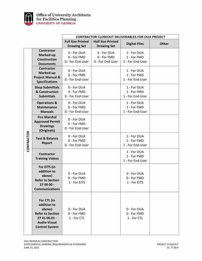
UGA DESIGN & CONSTRUCTION SUPPLEMENTAL GENERAL REQUIREMENTS & STANDARDS PROJECT CLOSEOUT JUNE 15, 2021 01 77 00-4
CONTRACTOR CLOSEOUT DELIVERABLES FOR OUA PROJECT
Full Size Printed
Drawing Set Half Size Printed
Drawing Set Digital Files Other
CON
TRAC
TOR
Contractor Marked-up
Construction Documents
0 - For OUA 0 - For FMD
0 - For End-User
0 - For OUA 0 - For FMD
0 - For End-User
1 - For OUA 1 - For FMD
1 - For End-User Contractor Marked-up
Project Manual & Specifications
0 - For OUA 0 - For FMD
0 - For End-User
1 - For OUA 1 - For FMD
1 - For End-User Shop Submittals & Construction
Submittals
0 - For OUA 0 - For FMD
0 - For End-User
1 - For OUA 1 - For FMD
1 - For End-User Operations & Maintenance
Manuals
0 - For OUA 0 - For FMD
0 - For End-User
1 - For OUA 1 - For FMD
1 - For End-User Fire Marshal
Approved Permit Drawings (Originals)
0 - For OUA 0 - For FMD
0 - For End-User
Test & Balance Report
0 - For OUA 0 - For FMD
0 - For End-User
1 - For OUA 1 - For FMD
1 - For End-User
Contractor Training Videos
1 - For OUA 1 - For FMD
1 - For End-User
For EITS (in addition to
above) Refer to Section
27 00 00 - Communications
0 - For OUA 0 - For FMD 1 - For EITS
0 - For OUA 0 - For FMD 1 - For EITS
For CTL (in addition to
above) Refer to Section
27 41 00.01 - Audio-Visual
Control System
0 - For OUA 0 - For FMD 1 - For CTL
0 - For OUA 0 - For FMD 1 - For CTL
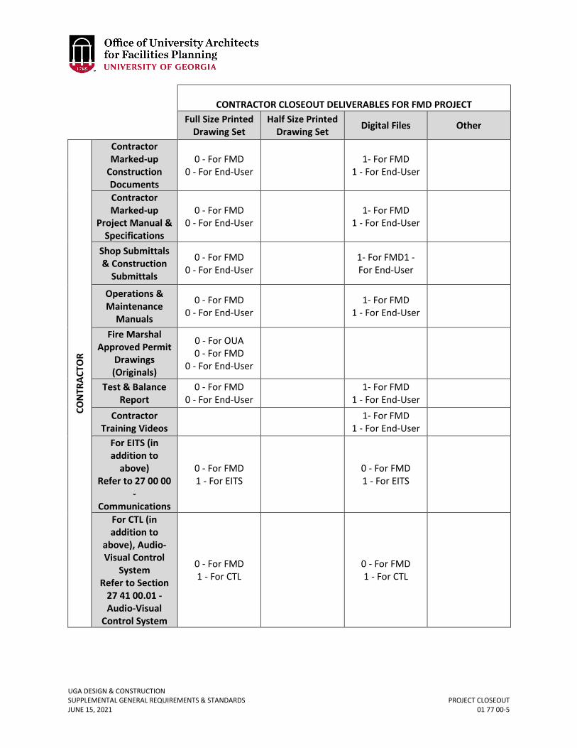
UGA DESIGN & CONSTRUCTION SUPPLEMENTAL GENERAL REQUIREMENTS & STANDARDS PROJECT CLOSEOUT JUNE 15, 2021 01 77 00-5
CONTRACTOR CLOSEOUT DELIVERABLES FOR FMD PROJECT
Full Size Printed Drawing Set
Half Size Printed Drawing Set Digital Files Other
CON
TRAC
TOR
Contractor Marked-up
Construction Documents
0 - For FMD 0 - For End-User 1- For FMD
1 - For End-User
Contractor Marked-up
Project Manual & Specifications
0 - For FMD 0 - For End-User 1- For FMD
1 - For End-User
Shop Submittals & Construction
Submittals
0 - For FMD 0 - For End-User 1- For FMD1 -
For End-User
Operations & Maintenance
Manuals
0 - For FMD 0 - For End-User 1- For FMD
1 - For End-User
Fire Marshal Approved Permit
Drawings (Originals)
0 - For OUA 0 - For FMD
0 - For End-User
Test & Balance
Report 0 - For FMD
0 - For End-User 1- For FMD 1 - For End-User
Contractor Training Videos 1- For FMD
1 - For End-User
For EITS (in addition to
above) Refer to 27 00 00
- Communications
0 - For FMD 1 - For EITS 0 - For FMD
1 - For EITS
For CTL (in addition to
above), Audio-Visual Control
System Refer to Section
27 41 00.01 - Audio-Visual
Control System
0 - For FMD 1 - For CTL 0 - For FMD
1 - For CTL
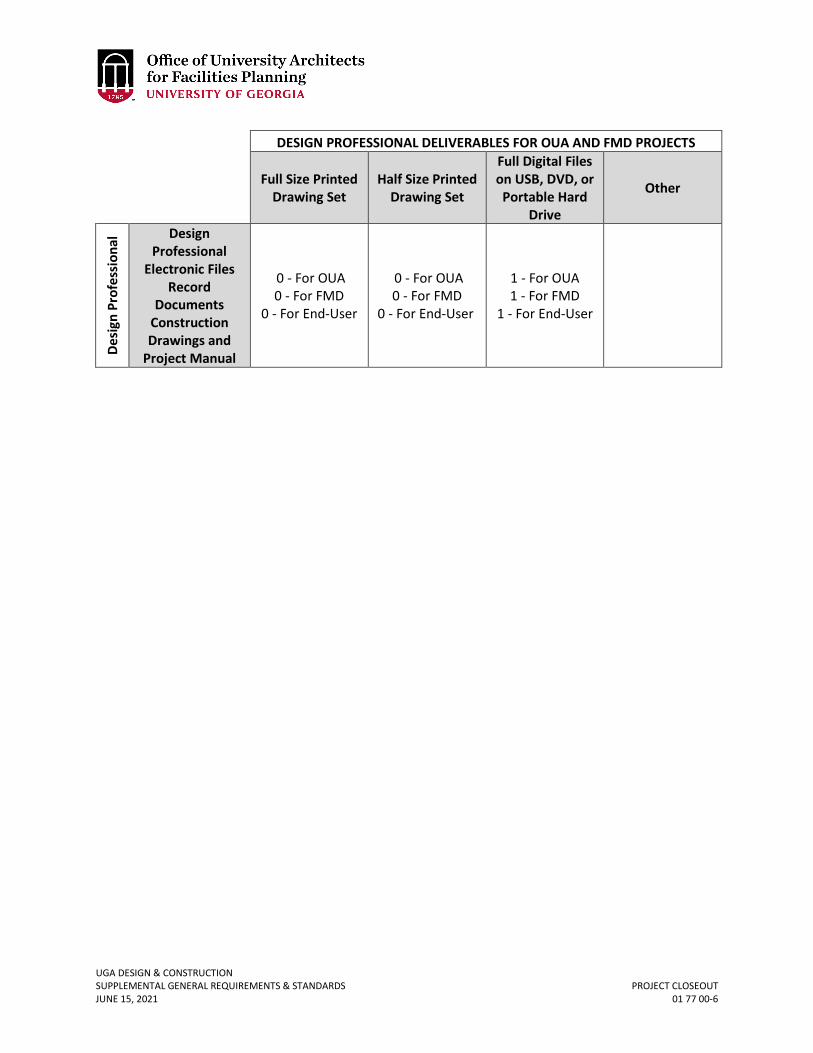
UGA DESIGN & CONSTRUCTION SUPPLEMENTAL GENERAL REQUIREMENTS & STANDARDS PROJECT CLOSEOUT JUNE 15, 2021 01 77 00-6
DESIGN PROFESSIONAL DELIVERABLES FOR OUA AND FMD PROJECTS
Full Size Printed Drawing Set
Half Size Printed Drawing Set
Full Digital Files on USB, DVD, or Portable Hard
Drive
Other
Desi
gn P
rofe
ssio
nal Design
Professional Electronic Files
Record Documents
Construction Drawings and
Project Manual
0 - For OUA 0 - For FMD
0 - For End-User
0 - For OUA 0 - For FMD
0 - For End-User
1 - For OUA 1 - For FMD
1 - For End-User
UGA DESIGN & CONSTRUCTION SUPPLEMENTAL GENERAL REQUIREMENTS & STANDARDS EXTRA STOCK MATERIALS JUNE 15, 2021 01 78 46-1
01 78 46 EXTRA STOCK MATERIALS
1. GENERAL
A. Related sections: i. 09 00 00 – General Finishes Requirements
B. UGA does not require extra stock materials (attic stock) unless space is designated in the completed building.
C. Design Professional shall coordinate any attic stock proposed by the Design Professional with the Project Manager and only provide the items required by the Project Manager.
D. For new and large facilities, Contractor to assist with locating attic stock material in room designated by the Project Manager.
E. Contractor shall label all attic stock with same nomenclature as in Contract documents. F. All surplus materials stored by the Contractor (other than the Project Manager specified
attic stock) shall be removed from UGA properties prior to the Project close-out.
UGA DESIGN & CONSTRUCTION SUPPLEMENTAL GENERAL REQUIREMENTS & STANDARDS FACILITY PERFORMANCE REQUIREMENTS JUNE 15, 2021 01 81 00-1
01 81 00 FACILITY PERFORMANCE REQUIREMENTS
1. GENERAL
A. Related sections: i. 00 00 07 – Design Professional Design Process Requirements
ii. 00 00 08 – Design Professional Documentation Requirements & Deliverables iii. 01 29 00 – Payment Procedures iv. 01 74 19 – Construction Waste Management & Disposal v. 12 46 33 – Interior Waste Receptacles
vi. 12 93 23 – Trash, Litter, and Recycling Receptacles vii. 23 05 19 – Meters & Gages
B. Introduction: The UGA requires and has been implementing efficient and sustainable designs for new construction and renovations for many years. Regardless of whether a project will utilize a third party green building certification system, the Design Professional shall present multiple scenarios with various levels of energy and water conservation options for the Project Manager’s review.
i. Not all Projects will have sufficient budgets to meet all of the requirements of this section 01 81 00 Facility Performance Requirements. It is the responsibility of the Design Professional and the Contractor (except for Design-Bid-Build delivery method) to provide cost estimates and detailed return on investment options during the Schematic Design and Design Development design phases for the Owner’s evaluation. If at the end of the Design Development phase, as directed by the Project Manager, all of the requirements of this section will not be met, the Design Professional shall submit a variance for approval to document which aspects will not be met.
ii. These Facility Performance Requirement evaluation and option services through Design Development shall be included in the Design Professional’s Basic Services and the Contractor’s Pre-Construction Overhead Costs and Pre-Construction Fee. The Owner may elect to fully follow this section or to only select portions of this section (due to budget constraints) for incorporation into Construction Documents, and the Owner will not incur any additional design services or Pre-Construction Overhead costs as long as the Facility Performance Requirements and associated systems selections are made and documented prior to the beginning of Construction Documents.
C. Green Building Rating Systems: No specific green building rating system certification is required by UGA; certification is pursued on a per project basis.
D. The design and construction of a new building shall be for at least a fifty year life with emphasis on minimum life cycle costs rather than low first costs.
E. Energy Performance: i. The mechanical, electrical, and plumbing energy related design for all
buildings shall comply with International Energy Conservation Code (IECC) – 2015 with Georgia Supplement and Amendments (most up to date adopted amendments).
ii. Computerized energy budget analysis, forecasting consumption in BTU/GSF/Year is mandatory for all new construction projects over 10,000 square feet that have heating and cooling. Design Professional shall submit a
Revised June 15, 2021
UGA DESIGN & CONSTRUCTION SUPPLEMENTAL GENERAL REQUIREMENTS & STANDARDS FACILITY PERFORMANCE REQUIREMENTS JUNE 15, 2021 01 81 00-2
model output summary and live model to UGA for review with each major design submission and as required to obtain energy savings rebates.
iii. Computerized energy budget analysis, forecasting consumption in BTU/GSF/Year is mandatory for all renovation projects that renovate an entire building (not a portion of a building). Design Professional shall submit a model output summary and live model to UGA with each major design submission and as required to obtain energy savings rebates.
iv. For partial renovation projects, the Design Professional shall submit a passed output summary and associated files from a ComCheck analysis (lighting only).
v. Life cycle cost comparisons with return on investment calculations of different proposed mechanical systems shall be presented at the end of schematic design.
a. Design Professional shall develop narrative of each system with diagrams of major equipment locations and review with Project Manager prior to coordinating costing information.
vi. Metering of utilities shall be reviewed with the Project Manager at the Design Phase Kickoff meeting. For new construction and full building renovation projects, metering of all utilities (electricity, natural gas, steam, and chilled water) shall be provided at the building level and sub-metering of building systems as needed to isolate, manage and optimize building energy use at the system level. See section 23 05 19 Meters & Gauges. In addition, new utility meters shall be connected to the building automated system. Metering requirements for partial renovation projects shall be reviewed on a project-by-project basis.
F. Renewable Energy i. For new construction and major renovations, the Design Professional shall
identify and evaluate opportunities for on-site renewable energy generation including life-cycle cost analysis and return on investment calculations with a target of meeting up to 5% of the project's predicted annual electrical and/or thermal energy consumption.
G. Water Conservation i. For new construction and major renovations over $5M, provide design and cost
options for the project to conserve 10% and 20% more water, not including irrigation, than the code requirement for the state of Georgia.
H. Storm Water and Condensate i. Options for collection and reuse of storm water and condensate are required for
all new construction projects with special attention given to uses other than irrigation. Storm water best management practices shall be incorporated to exceed the Project jurisdiction storm water quality standards, with a preference for visible and vegetative storm water controls.
ii. Design Professional shall evaluate feasibility of rain water and condensate water collection, distribution and reuse to serve non-consumptive uses including but not limited to cooling tower make-up, toilet flushing and landscape irrigation.
I. Waste & Recycling i. The University of Georgia is committed to drastically reducing waste and
diverting 65% or more of the campus waste stream from landfills. For new construction and major renovations, the project shall provide convenient
UGA DESIGN & CONSTRUCTION SUPPLEMENTAL GENERAL REQUIREMENTS & STANDARDS FACILITY PERFORMANCE REQUIREMENTS JUNE 15, 2021 01 81 00-3
facilities for recycling for building occupants and facilities management staff to reduce waste and increase collection of recyclables. See section 01 74 19 Construction Waste Management & Disposal.
J. For UGA Athens Campus only: Use the following outdoor design conditions: i. Winter, design dry bulb 10 ˚F
ii. Summer, design - cooling 95 ˚F DB / 76 ˚F MCWB iii. Summer, design - evaporation 78 ˚F WB / 89 ˚F MCDB iv. Summer, design - dehumidification 75 ˚F DP / 135.3 HR / 82.3 MCDB v. Degree days heating 2,900 (base 65 ˚F)
vi. Degree days cooling 1,700 (base 65 ˚F) vii. Climate zone Zone 3A
K. Comfort Conditions: i. Indoor design conditions shall suit the process and user requirements.
ii. For comfort conditions use 75 ˚F DB in summer and 70 ˚F DB in winter. iii. Cooling equipment shall be selected to achieve 50% RH at design cooling
conditions and maximum space humidity shall not exceed 60% RH. Positive dehumidification control may be required for high outdoor air supply applications and/or specific process needs. The Design Professional shall determine and confirm in writing all indoor design conditions during Schematic Design.
L. Georgia Power Rebates: i. The Design Professional and Contractor shall meet with the Project Manager
and Georgia Power and / or Georgia Power’s delegated representatives to determine which, if any, Georgia Power rebates may apply to the Project. The Design Professional and Contractor shall supply all required documentation in a timely manner to assist the Owner with obtaining the rebates and any costs associated with the documentation shall be included in the Design Professional’s Basic Services Fee and the Contractor’s Base Bid or Overhead Costs.
2. PRODUCTS – Not used. 3. EXECUTION
A. The Design Professional shall complete the Facility Performance Requirement Checklist located at the end of this section. This checklist is intended to assist UGA with tracking completion of sustainable design and facility performance requirements. Each project is required to address all aspects of the Standards whether included in this checklist or not. The Design Professional completes as much as possible as for the Schematic Design deliverable and shall fully complete for the Design Development deliverable. See 01 29 00.
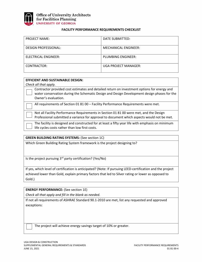
UGA DESIGN & CONSTRUCTION SUPPLEMENTAL GENERAL REQUIREMENTS & STANDARDS FACILITY PERFORMANCE REQUIREMENTS JUNE 15, 2021 01 81 00-4
FACILITY PERFORMANCE REQUIREMENTS CHECKLIST
PROJECT NAME:
DATE SUBMITTED:
DESIGN PROFESSIONAL: MECHANICAL ENGINEER:
ELECTRICAL ENGINEER: PLUMBING ENGINEER:
CONTRACTOR: UGA PROJECT MANAGER:
GREEN BUILDING RATING SYSTEMS: (See section 1C) Which Green Building Rating System framework is the project designing to? Is the project pursuing 3rd party certification? (Yes/No) If yes, which level of certification is anticipated? (Note: If pursuing LEED-certification and the project achieved lower than Gold, explain primary factors that led to Silver rating or lower as opposed to Gold.)
ENERGY PERFORMANCE: (See section 1E) Check all that apply and fill in the blank as needed. If not all requirements of ASHRAE Standard 90.1-2010 are met, list any requested and approved exceptions:
The project will achieve energy savings target of 10% or greater.
EFFICIENT AND SUSTAINABLE DESIGN: Check all that apply.
Contractor provided cost estimates and detailed return on investment options for energy and water conservation during the Schematic Design and Design Development design phases for the Owner’s evaluation.
All requirements of Section 01 81 00 – Facility Performance Requirements were met.
Not all Facility Performance Requirements in Section 01 81 00 were met, and the Design Professional submitted a variance for approval to document which aspects would not be met.
The facility is designed and constructed for at least a fifty year life with emphasis on minimum life cycles costs rather than low first costs.
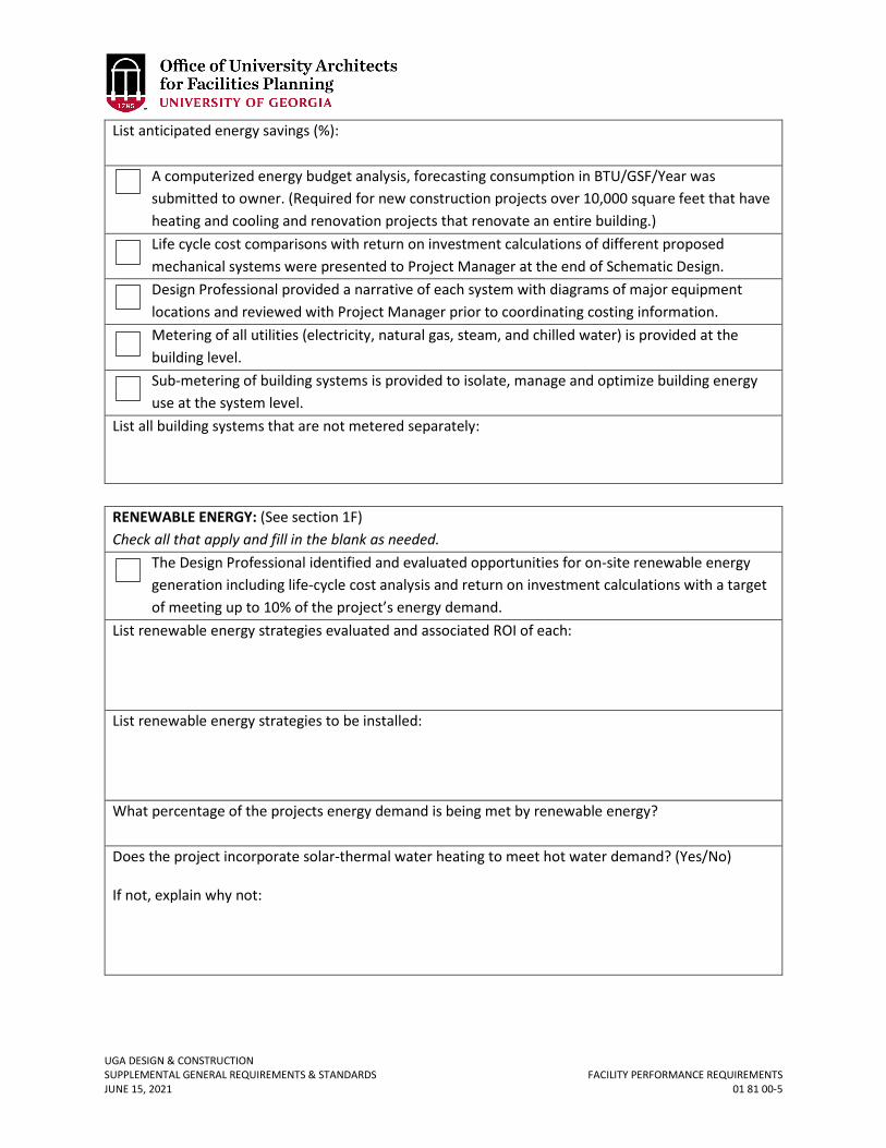
UGA DESIGN & CONSTRUCTION SUPPLEMENTAL GENERAL REQUIREMENTS & STANDARDS FACILITY PERFORMANCE REQUIREMENTS JUNE 15, 2021 01 81 00-5
List anticipated energy savings (%):
A computerized energy budget analysis, forecasting consumption in BTU/GSF/Year was submitted to owner. (Required for new construction projects over 10,000 square feet that have heating and cooling and renovation projects that renovate an entire building.) Life cycle cost comparisons with return on investment calculations of different proposed mechanical systems were presented to Project Manager at the end of Schematic Design. Design Professional provided a narrative of each system with diagrams of major equipment locations and reviewed with Project Manager prior to coordinating costing information. Metering of all utilities (electricity, natural gas, steam, and chilled water) is provided at the building level. Sub-metering of building systems is provided to isolate, manage and optimize building energy use at the system level.
List all building systems that are not metered separately:
RENEWABLE ENERGY: (See section 1F) Check all that apply and fill in the blank as needed.
The Design Professional identified and evaluated opportunities for on-site renewable energy generation including life-cycle cost analysis and return on investment calculations with a target of meeting up to 10% of the project’s energy demand.
List renewable energy strategies evaluated and associated ROI of each: List renewable energy strategies to be installed: What percentage of the projects energy demand is being met by renewable energy? Does the project incorporate solar-thermal water heating to meet hot water demand? (Yes/No)
If not, explain why not:
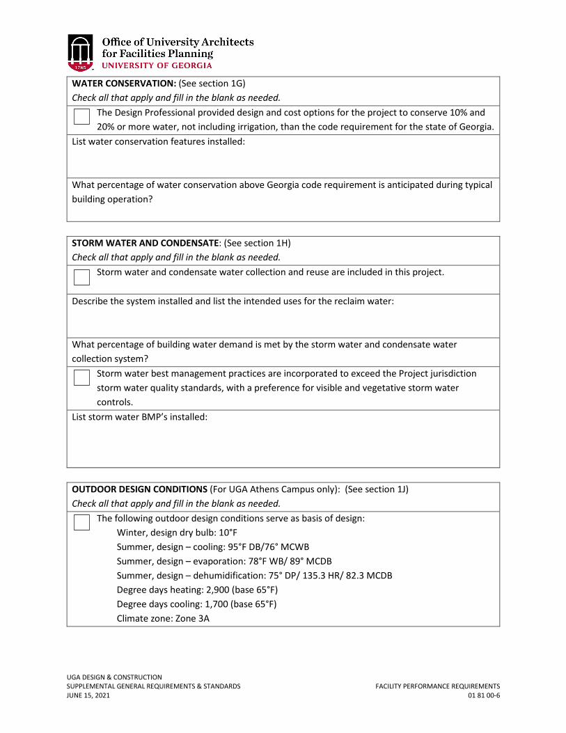
UGA DESIGN & CONSTRUCTION SUPPLEMENTAL GENERAL REQUIREMENTS & STANDARDS FACILITY PERFORMANCE REQUIREMENTS JUNE 15, 2021 01 81 00-6
WATER CONSERVATION: (See section 1G) Check all that apply and fill in the blank as needed.
The Design Professional provided design and cost options for the project to conserve 10% and 20% or more water, not including irrigation, than the code requirement for the state of Georgia.
List water conservation features installed: What percentage of water conservation above Georgia code requirement is anticipated during typical building operation?
STORM WATER AND CONDENSATE: (See section 1H) Check all that apply and fill in the blank as needed.
Storm water and condensate water collection and reuse are included in this project.
Describe the system installed and list the intended uses for the reclaim water: What percentage of building water demand is met by the storm water and condensate water collection system?
Storm water best management practices are incorporated to exceed the Project jurisdiction storm water quality standards, with a preference for visible and vegetative storm water controls.
List storm water BMP’s installed:
OUTDOOR DESIGN CONDITIONS (For UGA Athens Campus only): (See section 1J) Check all that apply and fill in the blank as needed.
The following outdoor design conditions serve as basis of design: Winter, design dry bulb: 10°F Summer, design – cooling: 95°F DB/76° MCWB Summer, design – evaporation: 78°F WB/ 89° MCDB Summer, design – dehumidification: 75° DP/ 135.3 HR/ 82.3 MCDB Degree days heating: 2,900 (base 65°F) Degree days cooling: 1,700 (base 65°F) Climate zone: Zone 3A
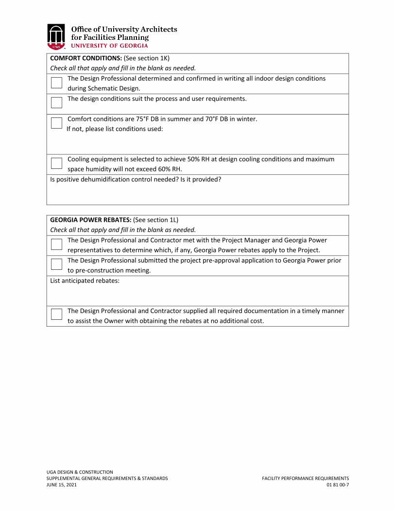
UGA DESIGN & CONSTRUCTION SUPPLEMENTAL GENERAL REQUIREMENTS & STANDARDS FACILITY PERFORMANCE REQUIREMENTS JUNE 15, 2021 01 81 00-7
COMFORT CONDITIONS: (See section 1K) Check all that apply and fill in the blank as needed.
The Design Professional determined and confirmed in writing all indoor design conditions during Schematic Design. The design conditions suit the process and user requirements. Comfort conditions are 75°F DB in summer and 70°F DB in winter.
If not, please list conditions used: Cooling equipment is selected to achieve 50% RH at design cooling conditions and maximum space humidity will not exceed 60% RH.
Is positive dehumidification control needed? Is it provided?
GEORGIA POWER REBATES: (See section 1L) Check all that apply and fill in the blank as needed.
The Design Professional and Contractor met with the Project Manager and Georgia Power representatives to determine which, if any, Georgia Power rebates apply to the Project. The Design Professional submitted the project pre-approval application to Georgia Power prior to pre-construction meeting.
List anticipated rebates:
The Design Professional and Contractor supplied all required documentation in a timely manner to assist the Owner with obtaining the rebates at no additional cost.
UGA DESIGN & CONSTRUCTION SUPPLEMENTAL GENERAL REQUIREMENTS & STANDARDS GENERAL COMMISSIONING REQUIREMENTS APRIL 30, 2020 01 91 13-1
01 91 13 GENERAL COMMISSIONING REQUIREMENTS
1. GENERAL
A. Related sections: i. 00 00 07 – Design Professional Design Process Requirements
ii. 00 00 08 – Design Professional Documentation Requirements & Deliverables iii. 01 75 00 – Starting and Adjusting iv. 01 77 00 – Project Closeout v. 01 81 00 – Facility Performance Requirements
vi. 02 22 00 – Existing Conditions Assessment vii. 22 00 00 – General Plumbing Requirements
viii. 23 00 00 – General Mechanical Requirements (HVAC) ix. 23 09 23 – Building Automation and Temperature Control System x. 26 00 00 – General Electrical Requirements
xi. 28 31 00 – Fire Detection & Alarm B. Description of Commissioning: Commissioning is the systematic process of ensuring that
building systems operate and perform according to the Owner’s Project requirements and operational needs. The Commissioning process oversees, verifies and documents that the facility and its system and assemblies are planned, designed, installed, tested, operated and maintained as required to meet the Owner’s functional intent and the Project Contract Documents. The Commissioning process does not take away from or reduce the responsibility of the Design Professional or Contractor to provide a finished and fully functioning product.
C. Timeline of Commissioning: For most projects at UGA, the Commissioning process will begin at the beginning of the Design Development stage of the design phase and continue through and conclude at the end of the first year warranty period.
D. Coordination: i. Commissioning Team: The members of the Commissioning Team consist of the
Commissioning Provider (CxP), Project Manager, Contractor, Design Professional and Consultants (particularly the Mechanical Engineer), the Mechanical Subcontractor, the Electrical Subcontractor, the TAB representative, the Controls Subcontractor, and any other installing subcontractors or suppliers of equipment. The Owner’s building or plant operator / engineer shall be included in the commissioning process.
ii. Management: The CxP is hired by the Owner directly. The CxP directs and coordinates the commissioning activities and the reports to the Project Manager. All members of the Commissioning Team work together to fulfill their contracted responsibilities and meet the objectives of the Contract Documents. The CxP shall include in its Commissioning Plans a project specific lists of roles and responsibilities to be discussed and agreed to during the commissioning kickoff meeting. The CxP’s responsibilities are the same regardless of who hired contracted the CxP.
iii. Scheduling: The CxP will work with the Contractor according to established protocols to schedule the commissioning activities. The CxP will provide sufficient notice to the Contractor for scheduling commissioning activities. The
UGA DESIGN & CONSTRUCTION SUPPLEMENTAL GENERAL REQUIREMENTS & STANDARDS GENERAL COMMISSIONING REQUIREMENTS JUNE 15, 2021 01 91 13-2
Contractor will integrate all commissioning activities into the master schedule. All parties will address scheduling problems and make necessary notifications in a timely manner in order to expedite the commissioning process. The CxP will provide the initial schedule of primary commissioning events at the commissioning kickoff meeting. The Commissioning Plan provides a format for this schedule. As construction progresses more detailed schedules are developed by the CxP. The Commissioning Plan also provides a format for detailed schedules.
E. Commissioning scope of work may include the following phases as defined in ASHRAE 1.1:
i. Pre-Design Phase: Develop design phase commissioning plan, outline the scope of design requirements and design intent, describe systems to be installed, outline the documentation requirements for each party involved in the commissioning process, define subsequent commissioning procedures and document the process. Interface with the Design Team to refine the construction phases and ensure that the phasing of MEP systems is logical and appropriate. Develop commissioning specifications and functional testing requirements to be included in the bid documents.
ii. Design Phase: a. Continuation of Pre-Design and interface with the Design Team to refine
the construction phases and ensure that the phasing of MEP systems is logical and appropriate.
b. Develop commissioning specifications and functional testing requirements to be included in the bid documents.
c. Review design documentation for compliance with the Standards and shall clearly identify all deviations from the Standards.
d. Designs shall be reviewed critically for inclusion of design intent, with metrics; included in documents from the schematic design submittal. The design intent with metrics shall be included on the first construction drawing sheet of the associated service.
e. Metrics shall include system data in the form of sq. ft. / ton; cfm / sq. ft.; steam lb. / hr. gas cfh, lighting watts / sq. ft., design temperature & humidity goals, etc. and various individual spaces metrics such as lighting watts / sq. ft., number of people and cfm / person, cfm / sq. ft. for zones, air change rates for lab and other specialized spaces, noise level goals, design temperature & humidity goals if different from overall building. Informative Annex K, ASHRAE Guideline 1 1.1-2007 provides example of metrics required. This shall be tailored to the specific project.
f. The CxP shall verify that the HVAC design documents cover sheet contains at minimum the information listed in Section 00 00 07 Design Professional Design Process Requirements.
g. The CxP shall verify that, at minimum, the HVAC design narratives is project specific, with metrics, shows major equipment locations, main duct and pipe routing, access paths for major equipment, HVAC system zoning and what provision is to be made for 24 / 7 spaces.
UGA DESIGN & CONSTRUCTION SUPPLEMENTAL GENERAL REQUIREMENTS & STANDARDS GENERAL COMMISSIONING REQUIREMENTS APRIL 30, 2020 01 91 13-3
iii. Construction Phase: a. Early Construction: Complete commissioning plan at the beginning of
the construction phase. Obtain project schedules, work with contractor to incorporate Cx activities into construction schedule. Gather and review subcontractor submittals and operation and maintenance manuals. Work with subcontractors to develop detailed pre-functional check lists and performance test plans for each system and piece of equipment involved in the commissioning process. CxP shall provide pre-functional checklists and functional test procedures to Contractor, Design Professional, and Project Manager for comment a minimum of 6 weeks prior to their execution.
b. Construction: Conduct site visits to observe construction, noting details that might affect equipment and system performance or operation.
c. Pre-functional Start-up: Coordinate with various subcontractors start-up performance tests. Oversee all start-up tests and ensure that pre-functional performance and checklists are completed, and all deficiencies resolved. CxP shall review Controls Contractor self-created Pre-functional checklist and include items in the CxP checklist that are not duplications.
d. The CxP shall be responsible for coordinating with the drive manufacturer / vendor controls contractor and the TAB agency to ensure that VSDs are adjusted so that harmonic frequencies are skipped.
e. Field Verification/Inspection of Systems: Develop equipment and system functional performance test procedures. Observe and verify proper operation of equipment, systems, and controls based upon functional performance test plans. Verify that corrective measures are taken as needed.
f. Operations and Maintenance Staff Training and Documentation: Reviews the O&M documentation and ensures the presence of complete operation and maintenance manuals. Determine the training needs of the building operation and maintenance staff. Reviews, pre- approve, and coordinate the training provided by subcontractors and verify that training was completed in accordance with training needs and project requirements. Refer to Section 01 77 00 Project Closeout.
iv. Occupancy and Operations Phase: a. Warranty Review and Seasonal Testing: Coordinate and supervise
seasonal or deferred testing and deficiency corrections and provide the final testing documentation for the commissioning record and O&M manuals.
b. The CxP shall meet on campus with the appropriate facilities and maintenance personnel (FMD for Athens campus; designated facility managers for other campuses) to review building systems and the Systems Manual.
F. Systems commissioned by the CxP may include the following:
UGA DESIGN & CONSTRUCTION SUPPLEMENTAL GENERAL REQUIREMENTS & STANDARDS GENERAL COMMISSIONING REQUIREMENTS JUNE 15, 2021 01 91 13-4
i. Building Envelope Systems (refer to Section 01 81 00 Facility Performance Requirements)
ii. Building Automation Systems (BAS), including links to remote monitoring and control sites and integration to other systems (refer to Section 23 09 23 Building Automation and Temperature Control Systems.)
iii. Plumbing Systems iv. Lighting Controls v. HVAC Systems
vi. Laboratory Control Systems, including integration to the building automation system HVAC Equipment and Systems
vii. Energy Recovery Equipment and Systems viii. Smoke Evacuation Systems
ix. Water Reclaim Systems x. Utility Metering Systems
xi. Emergency Power Systems xii. Other systems as required on a project-by-project basis.
UGA DESIGN & CONSTRUCTION SUPPLEMENTAL GENERAL REQUIREMENTS & STANDARDS MAINTENANCE OF EXISTING CONDITIONS JUNE 15, 2021 02 01 00-1
02 01 00 MAINTENANCE OF EXISTING CONDITIONS
1. GENERAL
A. Protection i. All existing hardscape and landscape to include, but not limited to, buildings,
curb and gutter, stairs, sidewalks, retaining walls, bus shelter, roadway, parking lot, trees, and shrubbery not noted for demolition or improvements shall be protected during the work to prevent damage and staining.
B. Repair i. All damaged and / or stained work, as described above, shall be repaired by the
Contractor at his / her own expense. In the event the Owner of said structure or utility elects to make necessary repairs with his / her own workforce, the Contractor shall reimburse the Owner for the cost of repairs. Contractor shall repair or replace damage as required to return it to its original state before final payment shall be issued by the Owner.

UGA DESIGN & CONSTRUCTION SUPPLEMENTAL GENERAL REQUIREMENTS & STANDARDS EXISTING CONDITIONS ASSESSMENT JUNE 15, 2021 02 22 00-1
02 22 00 EXISTING CONDITIONS ASSESSMENT
1. GENERAL
A. The Contractor shall document with photographs and / or video all existing conditions of the jobsite and submit a copy to the Owner’s Representative prior to commencing work. This documentation will form the basis of the existing conditions and the Contractor will be responsible, at Contractor’s cost, for repair of any and / or all new damages discovered within the jobsite. Any costs associated with this documentation shall be included in the Contractor Overhead Cost or Base Bid.
B. The Contractor shall, prior to the start of the work, identify and check the condition and operation of all existing valves, circuit breakers, and disconnects serving the new work that are to be reused for proper shut-off and isolation of the service. Any problems found shall be brought to Project Manager’s attention for remedy.
C. The Design Professional shall, as part of the design process, engage an entity to perform a video documentation of existing sanitary sewer lines beneath the building footprint extending to the nearest manhole to ascertain condition and identify any deficiencies requiring correction. Any recommendations for repair or correction shall be discussed with the UGA PM and incorporated into the Construction Documents as agreed upon.
UGA DESIGN & CONSTRUCTION SUPPLEMENTAL GENERAL REQUIREMENTS & STANDARDS DEMOLITION JUNE 15, 2021 02 40 00-1
02 40 00 DEMOLITION
1. GENERAL
A. Related sections: i. 01 74 19 – Construction Waste Management & Disposal
ii. 10 44 00 – Fire Protection Specialties B. All existing services and equipment that were active at the beginning of the Project and
that will no longer be in service at the end of the Project shall be removed from the Project and not be abandoned in place.
C. Design Professional shall prioritize deconstruction and / or reuse of materials and equipment over demolition and landfilling, specifically noting in the design documents materials to be salvaged and reused on-site and / or off-site.
D. Equipment and materials slated for demolition that are not deemed appropriate for reuse should be recycled per Section 01 74 19 Construction Waste Management & Disposal.
E. Fire extinguishers in buildings that are being demolished or in areas that are being renovated shall be removed and picked-up by the UGA Office of Fire Safety prior to the Contractor beginning work. It is the Contractor’s responsibility to contact UGA Office of Fire Safety to request removal and pick-up of fire extinguishers. The existing fire extinguishers are inventoried and the Contactor shall not throw away any existing extinguishers in the work area. The Contractor will be held responsible for replacing any UGA-owned fire extinguishers that are lost or damaged.
UGA DESIGN & CONSTRUCTION SUPPLEMENTAL GENERAL REQUIREMENTS & STANDARDS ARCHITECTURAL CAMPUS PLANNING PRINCIPLES JUNE 15, 2021 PAGE 1 OF 32
ARCHITECTURAL CAMPUS PLANNING PRINCIPLES
INTRODUCTION The purpose of this section of the master plan document is to form a basis for the architectural character, composition, and typology of future buildings, groups of buildings and exterior spaces on the University of Georgia campus. This portion of the document aspires to be both a "mirror" and a "lamp." The buildings already existent on the Athens campus were observed, documented, and analyzed in the course of preparation of this study. Thus the suggestions for future architectural interventions made herein attempt to reflect the best architectural traditions evident on campus. While many aspects of the University of Georgia's campus make it one of the most memorable compositions of buildings and open spaces to be found in the nation, it is not the purpose of this document to replicate the historic core in order to create a new architecture of empty nostalgia. The University of Georgia campus forms a collection of buildings from many different time periods and of various styles. There is not a unique "University of Georgia style" per se, rather the notable buildings built over the course of time, reflect both the needs of the moment and the traditions of architecture compatible with the context of the Athens campus. It is hoped that the insights gleaned from a reading of this section will enable the campus community to better recognize and understand the architectural traditions of the campus, while simultaneously forming a touchstone for architects, landscape architects, planners, and other design working on future projects. Since innovation is always understood relative to some context, the traditions suggested by this portion of the document are intended to "light the way" for future projects.
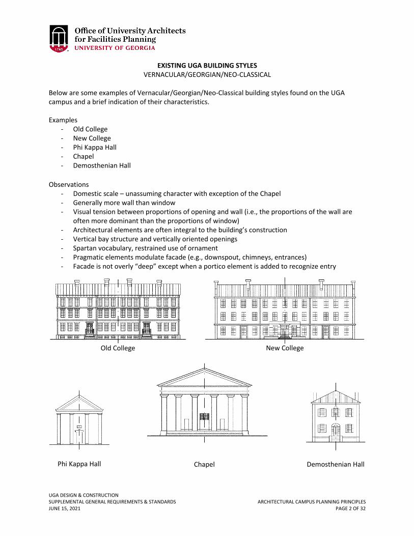
UGA DESIGN & CONSTRUCTION SUPPLEMENTAL GENERAL REQUIREMENTS & STANDARDS ARCHITECTURAL CAMPUS PLANNING PRINCIPLES JUNE 15, 2021 PAGE 2 OF 32
EXISTING UGA BUILDING STYLES VERNACULAR/GEORGIAN/NEO-CLASSICAL
Below are some examples of Vernacular/Georgian/Neo-Classical building styles found on the UGA campus and a brief indication of their characteristics. Examples
- Old College - New College - Phi Kappa Hall - Chapel - Demosthenian Hall
Observations
- Domestic scale – unassuming character with exception of the Chapel - Generally more wall than window - Visual tension between proportions of opening and wall (i.e., the proportions of the wall are
often more dominant than the proportions of window) - Architectural elements are often integral to the building’s construction - Vertical bay structure and vertically oriented openings - Spartan vocabulary, restrained use of ornament - Pragmatic elements modulate facade (e.g., downspout, chimneys, entrances) - Facade is not overly “deep” except when a portico element is added to recognize entry
Old College New College
Phi Kappa Hall Chapel Demosthenian Hall
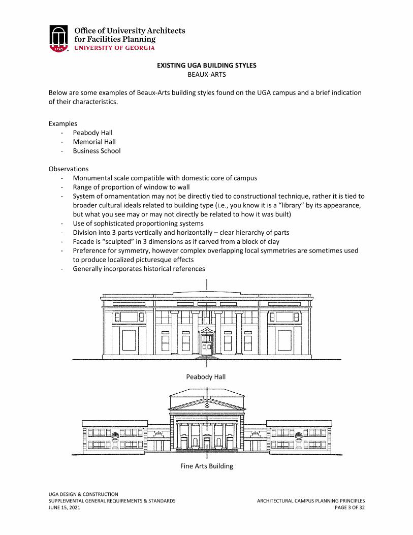
UGA DESIGN & CONSTRUCTION SUPPLEMENTAL GENERAL REQUIREMENTS & STANDARDS ARCHITECTURAL CAMPUS PLANNING PRINCIPLES JUNE 15, 2021 PAGE 3 OF 32
EXISTING UGA BUILDING STYLES BEAUX-ARTS
Below are some examples of Beaux-Arts building styles found on the UGA campus and a brief indication of their characteristics. Examples
- Peabody Hall - Memorial Hall - Business School
Observations
- Monumental scale compatible with domestic core of campus - Range of proportion of window to wall - System of ornamentation may not be directly tied to constructional technique, rather it is tied to
broader cultural ideals related to building type (i.e., you know it is a “library” by its appearance, but what you see may or may not directly be related to how it was built)
- Use of sophisticated proportioning systems - Division into 3 parts vertically and horizontally – clear hierarchy of parts - Facade is “sculpted” in 3 dimensions as if carved from a block of clay - Preference for symmetry, however complex overlapping local symmetries are sometimes used
to produce localized picturesque effects - Generally incorporates historical references
Peabody Hall
Fine Arts Building
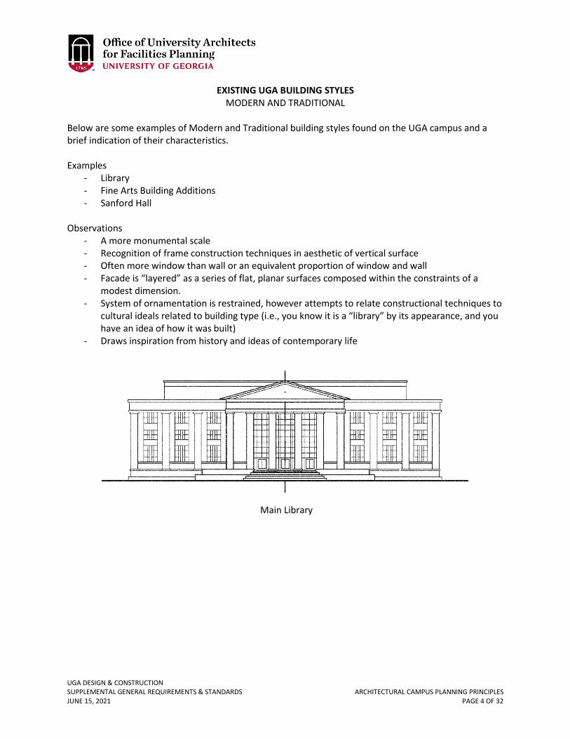
UGA DESIGN & CONSTRUCTION SUPPLEMENTAL GENERAL REQUIREMENTS & STANDARDS ARCHITECTURAL CAMPUS PLANNING PRINCIPLES JUNE 15, 2021 PAGE 4 OF 32
EXISTING UGA BUILDING STYLES MODERN AND TRADITIONAL
Below are some examples of Modern and Traditional building styles found on the UGA campus and a brief indication of their characteristics.
Examples
- Library - Fine Arts Building Additions - Sanford Hall
Observations
- A more monumental scale - Recognition of frame construction techniques in aesthetic of vertical surface - Often more window than wall or an equivalent proportion of window and wall - Facade is “layered” as a series of flat, planar surfaces composed within the constraints of a
modest dimension. - System of ornamentation is restrained, however attempts to relate constructional techniques to
cultural ideals related to building type (i.e., you know it is a “library” by its appearance, and you have an idea of how it was built)
- Draws inspiration from history and ideas of contemporary life
Main Library
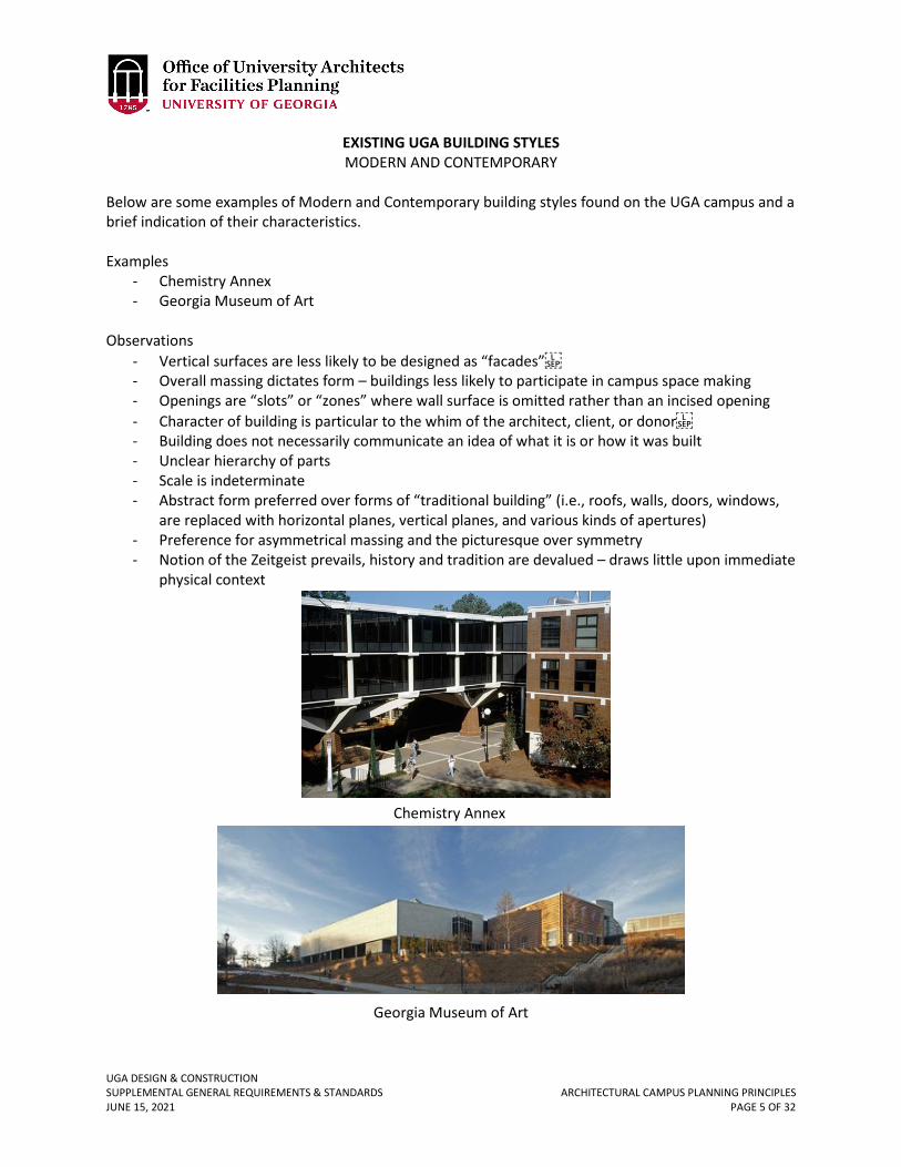
UGA DESIGN & CONSTRUCTION SUPPLEMENTAL GENERAL REQUIREMENTS & STANDARDS ARCHITECTURAL CAMPUS PLANNING PRINCIPLES JUNE 15, 2021 PAGE 5 OF 32
EXISTING UGA BUILDING STYLES MODERN AND CONTEMPORARY
Below are some examples of Modern and Contemporary building styles found on the UGA campus and a brief indication of their characteristics.
Examples
- Chemistry Annex - Georgia Museum of Art
Observations
- Vertical surfaces are less likely to be designed as “facades” - Overall massing dictates form – buildings less likely to participate in campus space making - Openings are “slots” or “zones” where wall surface is omitted rather than an incised opening - Character of building is particular to the whim of the architect, client, or donor - Building does not necessarily communicate an idea of what it is or how it was built - Unclear hierarchy of parts - Scale is indeterminate - Abstract form preferred over forms of “traditional building” (i.e., roofs, walls, doors, windows,
are replaced with horizontal planes, vertical planes, and various kinds of apertures) - Preference for asymmetrical massing and the picturesque over symmetry - Notion of the Zeitgeist prevails, history and tradition are devalued – draws little upon immediate
physical context
Chemistry Annex
Georgia Museum of Art
UGA DESIGN & CONSTRUCTION SUPPLEMENTAL GENERAL REQUIREMENTS & STANDARDS ARCHITECTURAL CAMPUS PLANNING PRINCIPLES JUNE 15, 2021 PAGE 6 OF 32
THE APPLICATION OF AMERICAN CAMPUS PLANNING PRINCIPLES TO THE UNIVERSITY OF GEORGIA
The planning principles exhibited on American campuses are truly a unique art form. While the traditions of campus planning in the United States are closely related to attitudes concerning building and the landscape developed between the 16th and 19th centuries in England, France, and Italy, the application of these principles to the built form of the university is an art form, which evolved principally in this country. The close relationship between built form and the landscape is a characteristic of campus planning that is the taproot of this art form. From Thomas Jefferson’s University of Virginia, to Saarenin’s Cranbrook Academy, this tradition remained unbroken until the Second World War. One of the most readily identifiable characteristics of this tradition was the creation of exterior spaces, which could be likened to interior rooms. In the diagram illustrated in Figure 1, a prototypical room is drawn alongside a university quadrangle of similar proportions. Nearly everyone is familiar with the sense of enclosure and protection afforded by a room’s bounding surfaces – walls enclose space; windows admit light and air while permitting views to the exterior world; doors permit access; and typically there is some element of focus within the room, perhaps a hearth. It is readily evident that every element performs a role supporting the larger notion of “room.” That is, walls alone do not the room make. The interdependency of elements and the specialized tasks they play relegate elements of the room to hierarchical roles in the overall composition. That is a door to the room will serve to frame a view of the room’s principal feature – the hearth, and all along the corners of the room will be subservient to both the former and later elements. Likewise, the exterior room of a campus quadrangle has features, which might be seen as analogous to that of a traditional interior room. The library may dominate the composition in much the same manner as the hearth, while a pair of buildings axially disposed across the quadrangle from this principal feature might serve the same threshold purposes as that of a door. One might readily see that a successful composition of a college quadrangle requires that the buildings operate in concert with one another. Sometimes buildings are called upon to play more assertive roles that of a “hero,” like the library, or the matching buildings forming the campus threshold. The heroic buildings, however, require substantial amounts of good “soldier” buildings to form the backdrop against which these more assertive buildings might be seen. In planning and building a new campus or on a portion of an existing campus it is very important to understand the role that individual buildings are required to play. Too many heroic structures would be like a room full of guests all talking at the same time. Too few heroic buildings would be like a party where none of the guests ever arrived — a bit of a bore. In planning a successful campus composition, one seeks to strike a balance between the “heroes” and the “soldiers.” Experience has shown that every trustee, donor, president, dean, every department chair, or faculty member, usually like to view their “new building” as aspiring to be a “hero.” And, while much might be said of the heroic nature of the common foot soldier, it is recommended that the creation of heroic buildings on college campuses be limited to those building types which embody and relate the most universal and lofty aspirations of the entire institution — churches, libraries, places of assembly, etc.
UGA DESIGN & CONSTRUCTION SUPPLEMENTAL GENERAL REQUIREMENTS & STANDARDS ARCHITECTURAL CAMPUS PLANNING PRINCIPLES JUNE 15, 2021 PAGE 7 OF 32
Figure 1
Main Library
Main Library
UGA DESIGN & CONSTRUCTION SUPPLEMENTAL GENERAL REQUIREMENTS & STANDARDS ARCHITECTURAL CAMPUS PLANNING PRINCIPLES JUNE 15, 2021 PAGE 8 OF 32
CAMPUS BUILDING TYPOLOGY THE EDGE-DEFINING TYPE
This building type often performs the role of the common foot soldier, but it may also take on heroic assignments. The generic configuration of the type is that of an elongated rectilinear volume. Most often entry is achieved on the center of one of the long faces, however edge entries, or entry from one of the narrow elevations is also possible (see facade guidelines). This building type commonly aligns its eaves and ridgelines, not the gable end, to the quadrangle thus reinforcing the geometry of this exterior room. A central corridor gives access to the rooms. Typically the corridor is double loaded, however in some instances a single loaded corridor may serve the needs of the program. The length of this building type may vary from 120 feet to 300 feet, while the width of the type is generally in the neighborhood of 45-90 feet. When this type exceeds the 90 foot width dimension natural lighting and ventilation of the interior spaces becomes impossible. Thus, depending upon the actual intended use of buildings of this type, care should be given to the width of the block. There are a variety of methods for distributing this type in a campus plan (Figure 2).
- Illustrates this building type located as a central element on the long side of a campus quadrangle – the building performs both the role of edge definer and central focus.
- Much the same might be said about the positioning of the type in this configuration, however because the building alone forms the edge of the narrow side of a long quadrangle, it tends to take on a more heroic dimension.
- In this instance the type is paired to form both the wall to the quadrangle as well as a threshold to the campus.
- The final illustration of this type in context is interesting because it presents its end elevation to the major quadrangle of the campus while forming the edge of a new quadrangle behind the first building discussed in this drawing.
Examples of this building type on the UGA campus are Old College and New College, at other institutions, Nassau Hall, Princeton and Old East and Old West at UNC Chapel Hill. The type might accommodate housing, classrooms, laboratories, administrative activities, and a wide variety of other functions. It is typically the most prevalent variety of building to be found on college campuses. This type along with the Centralized Type form the two essential building blocks of campus architecture from which all other types might be derived.
UGA DESIGN & CONSTRUCTION SUPPLEMENTAL GENERAL REQUIREMENTS & STANDARDS ARCHITECTURAL CAMPUS PLANNING PRINCIPLES JUNE 15, 2021 PAGE 9 OF 32
Figure 2
Façade
End Elevation
Variation
120’ – 300’
48’ –
70’
Plan in Context
Typical Plan
UGA DESIGN & CONSTRUCTION SUPPLEMENTAL GENERAL REQUIREMENTS & STANDARDS ARCHITECTURAL CAMPUS PLANNING PRINCIPLES JUNE 15, 2021 PAGE 10 OF 32
CAMPUS BUILDING TYPOLOGY THE CENTRALIZED TYPE
This building type is often associated with a heroic posture within a campus plan, however, the type might defer to other buildings depending upon its specific context. The general configuration of the type is that of a compact rectilinear volume, however other platonic forms are also associated with this type circular, octagonal, or other centralized form. Entry is most often achieved on the center of one of the narrow facades and the type most often presents its gabled end to the quadrangle thereby gaining a certain amount of visual attention. Generally the type houses one large open space internally — often conceived of as a space of assembly. The dimensions of the type vary dramatically and should be determined based upon a mitigation of the concerns of the context against those of the building’s function. There are a variety of methods for distributing this type in a campus plan, refer to Figure 3.
- Illustrates this building in a central position on the long edge of a campus quadrangle (a position analogous to that of a hearth in a room)
- The positioning of a pair of buildings around a principal campus axis forms both edge and threshold to the quadrangle.
- The placement of the type in this position affords four separate exposures – the building is seen in the round (from all sides). This later placement can present problems in servicing the building if the concerns of use are not properly mitigated against those of the campus context. A chapel or assembly hall might be well served by this location, while a dining hall might not work well with the context given an intensive service component of the program.
Examples of this building type on the UGA campus are the Chapel and the Phi Kappa building, at other institutions, the Rotunda at the University of Virginia and Whig and Clio Halls at Princeton. The type might accommodate various assembly activities: chapel, lecture hall, gymnasium, dining hall, etc. When used in conjunction with the Edge Defining Type in a single unified composition an unlimited variety of building forms might be created.
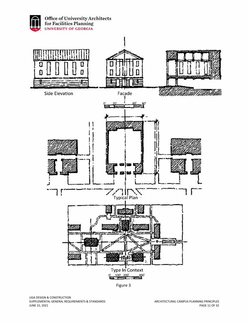
UGA DESIGN & CONSTRUCTION SUPPLEMENTAL GENERAL REQUIREMENTS & STANDARDS ARCHITECTURAL CAMPUS PLANNING PRINCIPLES JUNE 15, 2021 PAGE 11 OF 32
Figure 3
Façade
Typical Plan
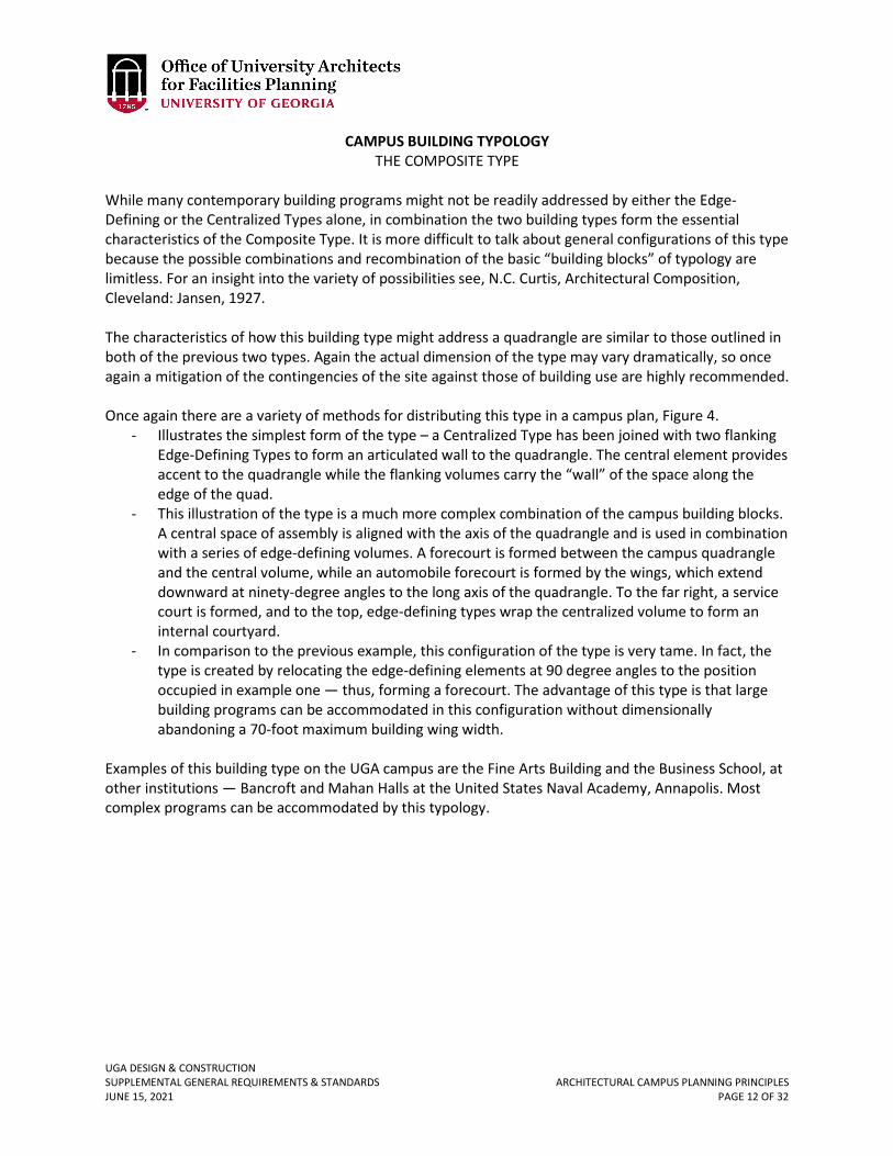
UGA DESIGN & CONSTRUCTION SUPPLEMENTAL GENERAL REQUIREMENTS & STANDARDS ARCHITECTURAL CAMPUS PLANNING PRINCIPLES JUNE 15, 2021 PAGE 12 OF 32
CAMPUS BUILDING TYPOLOGY THE COMPOSITE TYPE
While many contemporary building programs might not be readily addressed by either the Edge-Defining or the Centralized Types alone, in combination the two building types form the essential characteristics of the Composite Type. It is more difficult to talk about general configurations of this type because the possible combinations and recombination of the basic “building blocks” of typology are limitless. For an insight into the variety of possibilities see, N.C. Curtis, Architectural Composition, Cleveland: Jansen, 1927. The characteristics of how this building type might address a quadrangle are similar to those outlined in both of the previous two types. Again the actual dimension of the type may vary dramatically, so once again a mitigation of the contingencies of the site against those of building use are highly recommended. Once again there are a variety of methods for distributing this type in a campus plan, Figure 4.
- Illustrates the simplest form of the type – a Centralized Type has been joined with two flanking Edge-Defining Types to form an articulated wall to the quadrangle. The central element provides accent to the quadrangle while the flanking volumes carry the “wall” of the space along the edge of the quad.
- This illustration of the type is a much more complex combination of the campus building blocks. A central space of assembly is aligned with the axis of the quadrangle and is used in combination with a series of edge-defining volumes. A forecourt is formed between the campus quadrangle and the central volume, while an automobile forecourt is formed by the wings, which extend downward at ninety-degree angles to the long axis of the quadrangle. To the far right, a service court is formed, and to the top, edge-defining types wrap the centralized volume to form an internal courtyard.
- In comparison to the previous example, this configuration of the type is very tame. In fact, the type is created by relocating the edge-defining elements at 90 degree angles to the position occupied in example one — thus, forming a forecourt. The advantage of this type is that large building programs can be accommodated in this configuration without dimensionally abandoning a 70-foot maximum building wing width.
Examples of this building type on the UGA campus are the Fine Arts Building and the Business School, at other institutions — Bancroft and Mahan Halls at the United States Naval Academy, Annapolis. Most complex programs can be accommodated by this typology.
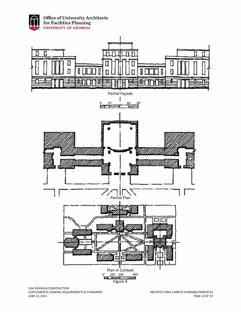
UGA DESIGN & CONSTRUCTION SUPPLEMENTAL GENERAL REQUIREMENTS & STANDARDS ARCHITECTURAL CAMPUS PLANNING PRINCIPLES JUNE 15, 2021 PAGE 13 OF 32
Partial Façade
Partial Plan
Plan in Context Figure 4
UGA DESIGN & CONSTRUCTION SUPPLEMENTAL GENERAL REQUIREMENTS & STANDARDS ARCHITECTURAL CAMPUS PLANNING PRINCIPLES JUNE 15, 2021 PAGE 14 OF 32
CAMPUS BUILDING TYPOLOGY THE COMPOUND TYPE
In many cases contemporary programs call for very large footprints to accommodate specialized activities. While the advantage of these large footprints is that many activities can be located in an efficient proximity to one another, the liability is that these types of buildings often become hermetically sealed and connections between interior spaces and the exterior world become severed. Faculty, staff, and students can find themselves living out their entire academic life in these “mega structures” without ever stepping foot outside of their own domain. In short the danger of these “academic malls” are that they often do not contribute in an effective manner to the overall well-being of the university. However, when properly designed these big buildings can indeed contribute well to the life of a campus. Of primary interest is care given to issues of scale and proportion. Wherever possible, the massiveness of the building should be mitigated by elements in concert with the human scale of the campus environment. The Typical Plan in Figure 5 illustrates an Edge-Defining Type used as a frontispiece, or head house, for a much larger building mass. The site section diagrams located above the typical plan drawing also illustrate two techniques for masking the massiveness of the “large footprint” building. The uphill site illustrates a laboratory building nestled into the grade to minimize the impact of its height and girth, while the downhill site illustrates a parking structure carved into the hillside behind an academic building. The upper deck of this later building is then landscaped and treated as a garden terrace. Again, there are a variety of methods for distributing this type in a campus plan, Figure 5.
- Illustrates a very large laboratory building, which is flanked by two classroom buildings and headed up by an administrative/office wing, which mediates a connection to the quadrangle.
- Is a center for continuing education, which presents a face both to the outside world (bottom edge) and to the campus quadrangle (right edge). These wings, joined by a rotund element mask the large parking structure located behind. Access to the parking structure is from the extreme right edge of the footprint. It should be noted that care would be given to the surface of the parking structure to create a “handsome” facade in concert with the vocabulary of the campus.
- Illustrates a large student center with large dining halls, meeting rooms, ballrooms, and recreational spaces. The configuration presents a forecourt to the campus quadrangle using two Edge-Defining and one Centralized Type in order to mask the large footprints of the big assembly halls. To the far right a service court provides access for deliveries and waste removal.
Successful examples of this building type are Cabel Hall at the University of Virginia, the Physics and Astronomy Building at Johns Hopkins University, the Student Center at Carnegie Mellon, Barton Hall at Cornell University, and the original buildings on the campus of Duke University.
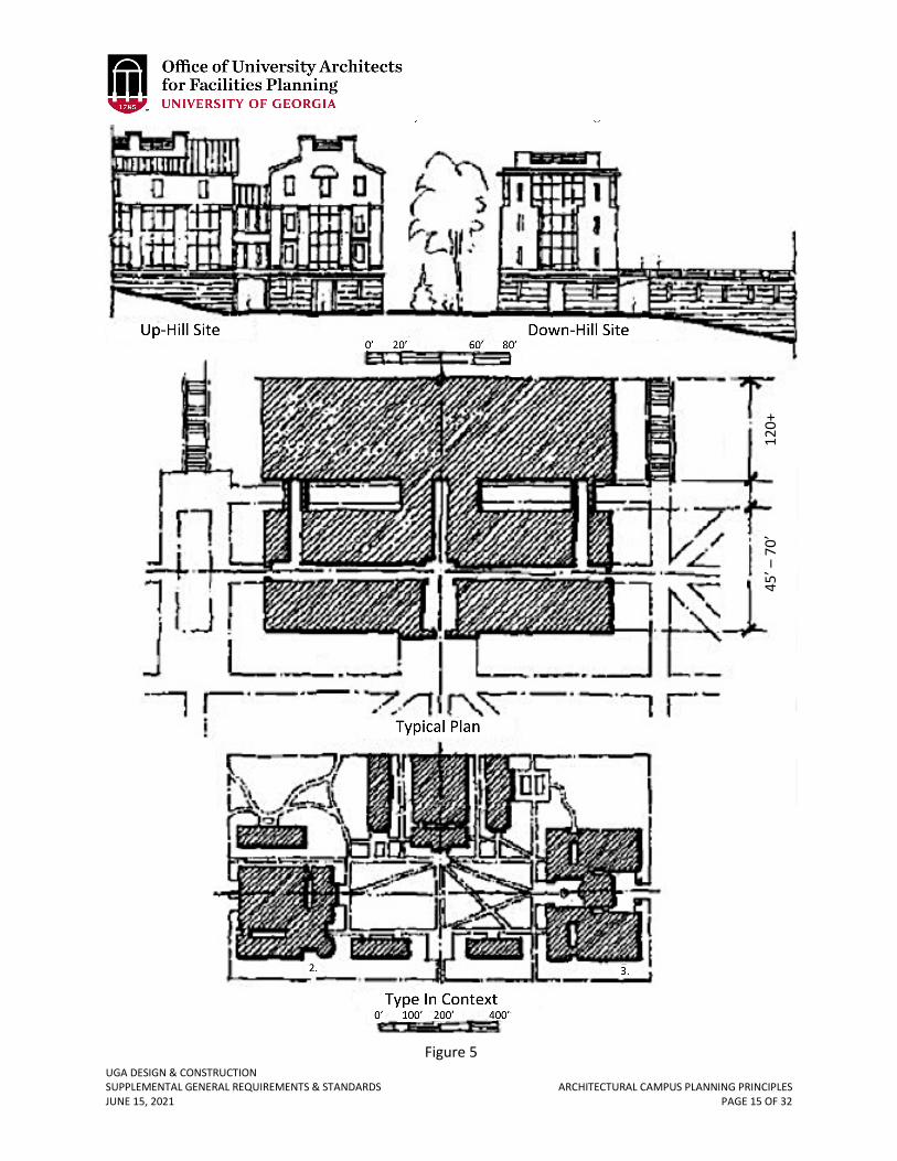
UGA DESIGN & CONSTRUCTION SUPPLEMENTAL GENERAL REQUIREMENTS & STANDARDS ARCHITECTURAL CAMPUS PLANNING PRINCIPLES JUNE 15, 2021 PAGE 15 OF 32
Figure 5
Down-Hill Site Up-Hill Site
120’
+ 45
’ – 7
0’
45’ –
70’
120+
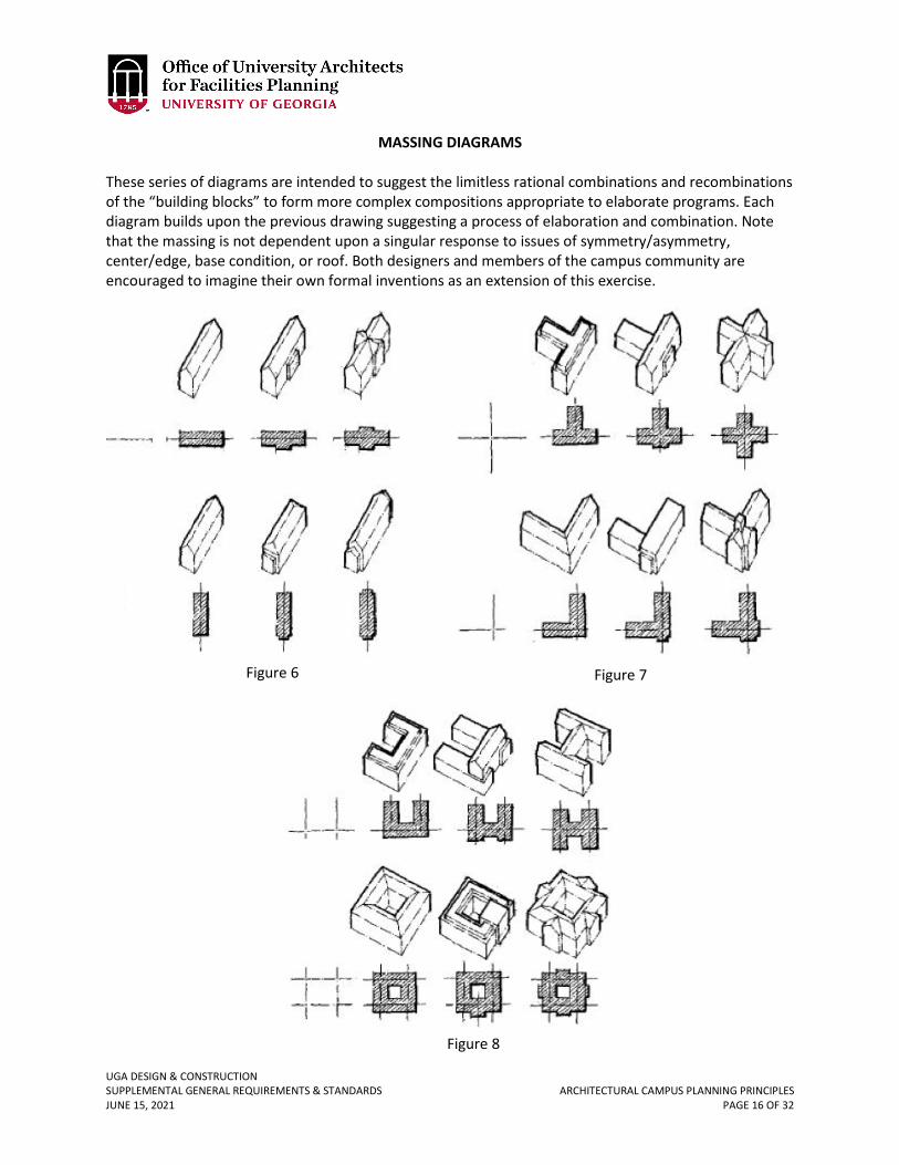
UGA DESIGN & CONSTRUCTION SUPPLEMENTAL GENERAL REQUIREMENTS & STANDARDS ARCHITECTURAL CAMPUS PLANNING PRINCIPLES JUNE 15, 2021 PAGE 16 OF 32
MASSING DIAGRAMS
These series of diagrams are intended to suggest the limitless rational combinations and recombinations of the “building blocks” to form more complex compositions appropriate to elaborate programs. Each diagram builds upon the previous drawing suggesting a process of elaboration and combination. Note that the massing is not dependent upon a singular response to issues of symmetry/asymmetry, center/edge, base condition, or roof. Both designers and members of the campus community are encouraged to imagine their own formal inventions as an extension of this exercise.
Figure 6 Figure 7
Figure 8
UGA DESIGN & CONSTRUCTION SUPPLEMENTAL GENERAL REQUIREMENTS & STANDARDS ARCHITECTURAL CAMPUS PLANNING PRINCIPLES JUNE 15, 2021 PAGE 17 OF 32
CAMPUS FAÇADE TYPOLOGY INTRODUCTION
Each of the facade variations illustrated herein derives from the previously mentioned observation, documentation, and analysis of the UGA campus. The proportions of openings and wall surfaces are derived from UGA traditions and may not be directly applicable to other campuses, however, many of the techniques for creating hierarchical “readings” of the facades are generic in nature. Typically this study recognizes two generic architectural conditions — that of the wall and that of the frame. Both types are to be found alone and in combination on the UGA campus. Once again, the observations made herein are not an attempt to advocate specific styles, however, it is explicitly the intention of this portion of the document to encourage the development of rationale for the vertical surfaces. Thomas L. Schumacher’s, “Scull and the Mask,” as well as, “The Palladio Variations,” (Cornell Journal of Architecture, New York: Rizolli) are excellent starting points for discussion of facade making themes. Since a building on a college campus is likely to be kept in service for in excess of 100 years, it is important to give the design of facades considerable attention.
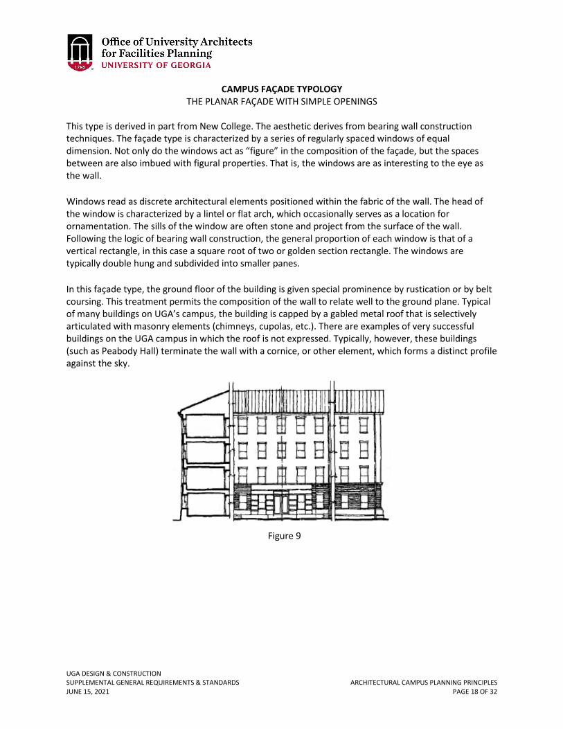
UGA DESIGN & CONSTRUCTION SUPPLEMENTAL GENERAL REQUIREMENTS & STANDARDS ARCHITECTURAL CAMPUS PLANNING PRINCIPLES JUNE 15, 2021 PAGE 18 OF 32
CAMPUS FAÇADE TYPOLOGY THE PLANAR FAÇADE WITH SIMPLE OPENINGS
This type is derived in part from New College. The aesthetic derives from bearing wall construction techniques. The façade type is characterized by a series of regularly spaced windows of equal dimension. Not only do the windows act as “figure” in the composition of the façade, but the spaces between are also imbued with figural properties. That is, the windows are as interesting to the eye as the wall. Windows read as discrete architectural elements positioned within the fabric of the wall. The head of the window is characterized by a lintel or flat arch, which occasionally serves as a location for ornamentation. The sills of the window are often stone and project from the surface of the wall. Following the logic of bearing wall construction, the general proportion of each window is that of a vertical rectangle, in this case a square root of two or golden section rectangle. The windows are typically double hung and subdivided into smaller panes. In this façade type, the ground floor of the building is given special prominence by rustication or by belt coursing. This treatment permits the composition of the wall to relate well to the ground plane. Typical of many buildings on UGA’s campus, the building is capped by a gabled metal roof that is selectively articulated with masonry elements (chimneys, cupolas, etc.). There are examples of very successful buildings on the UGA campus in which the roof is not expressed. Typically, however, these buildings (such as Peabody Hall) terminate the wall with a cornice, or other element, which forms a distinct profile against the sky.
Figure 9
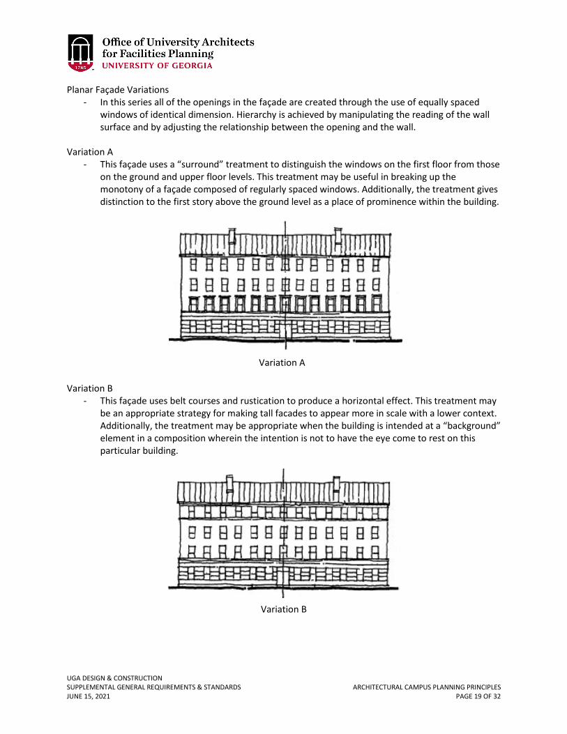
UGA DESIGN & CONSTRUCTION SUPPLEMENTAL GENERAL REQUIREMENTS & STANDARDS ARCHITECTURAL CAMPUS PLANNING PRINCIPLES JUNE 15, 2021 PAGE 19 OF 32
Planar Façade Variations - In this series all of the openings in the façade are created through the use of equally spaced
windows of identical dimension. Hierarchy is achieved by manipulating the reading of the wall surface and by adjusting the relationship between the opening and the wall.
Variation A
- This façade uses a “surround” treatment to distinguish the windows on the first floor from those on the ground and upper floor levels. This treatment may be useful in breaking up the monotony of a façade composed of regularly spaced windows. Additionally, the treatment gives distinction to the first story above the ground level as a place of prominence within the building.
Variation B
- This façade uses belt courses and rustication to produce a horizontal effect. This treatment may be an appropriate strategy for making tall facades to appear more in scale with a lower context. Additionally, the treatment may be appropriate when the building is intended at a “background” element in a composition wherein the intention is not to have the eye come to rest on this particular building.
Variation B
Variation A
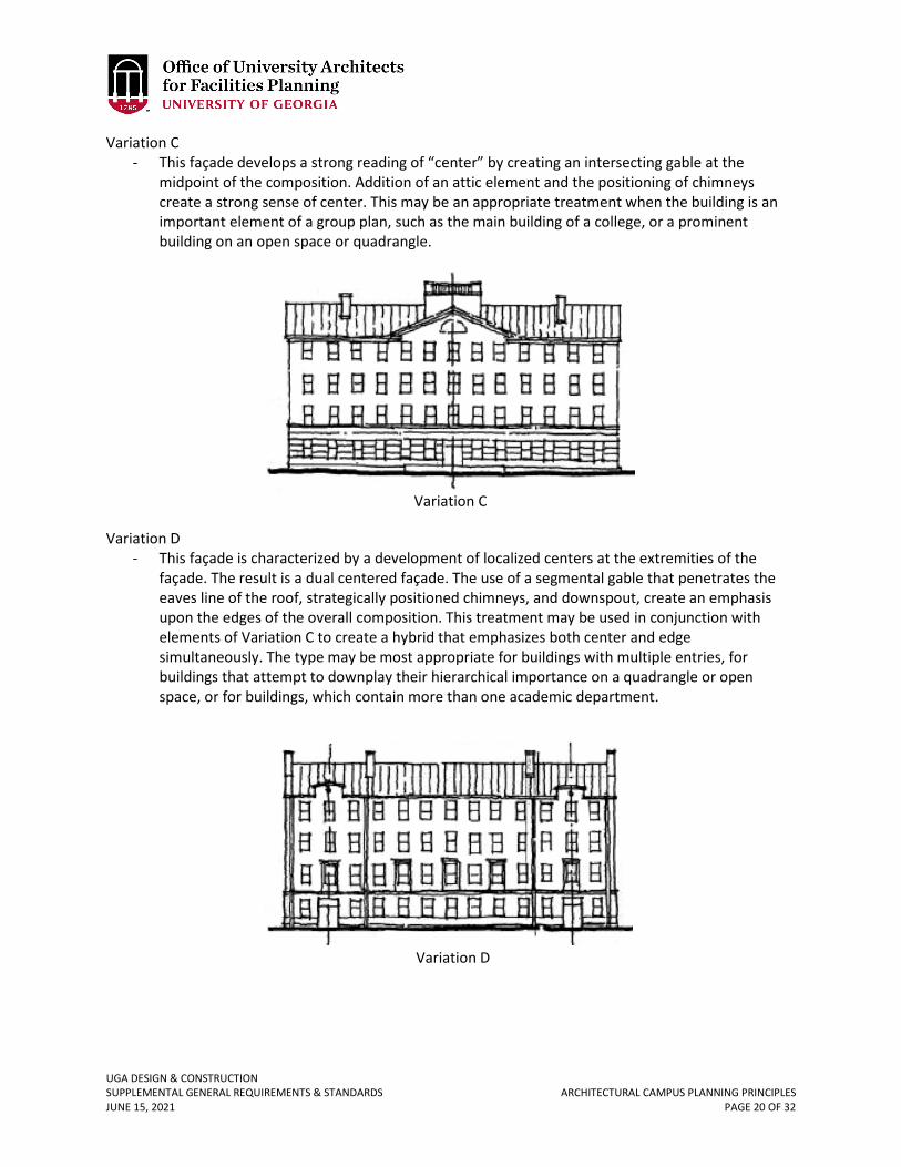
UGA DESIGN & CONSTRUCTION SUPPLEMENTAL GENERAL REQUIREMENTS & STANDARDS ARCHITECTURAL CAMPUS PLANNING PRINCIPLES JUNE 15, 2021 PAGE 20 OF 32
Variation C - This façade develops a strong reading of “center” by creating an intersecting gable at the
midpoint of the composition. Addition of an attic element and the positioning of chimneys create a strong sense of center. This may be an appropriate treatment when the building is an important element of a group plan, such as the main building of a college, or a prominent building on an open space or quadrangle.
Variation D
- This façade is characterized by a development of localized centers at the extremities of the façade. The result is a dual centered façade. The use of a segmental gable that penetrates the eaves line of the roof, strategically positioned chimneys, and downspout, create an emphasis upon the edges of the overall composition. This treatment may be used in conjunction with elements of Variation C to create a hybrid that emphasizes both center and edge simultaneously. The type may be most appropriate for buildings with multiple entries, for buildings that attempt to downplay their hierarchical importance on a quadrangle or open space, or for buildings, which contain more than one academic department.
Variation D
Variation C
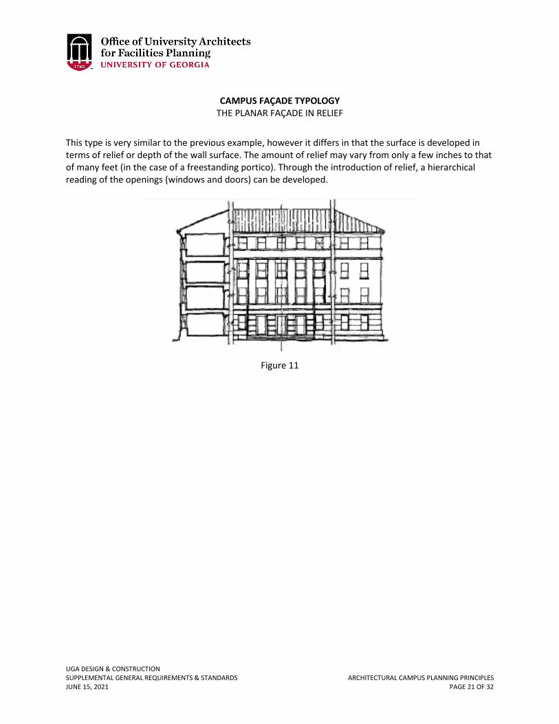
UGA DESIGN & CONSTRUCTION SUPPLEMENTAL GENERAL REQUIREMENTS & STANDARDS ARCHITECTURAL CAMPUS PLANNING PRINCIPLES JUNE 15, 2021 PAGE 21 OF 32
CAMPUS FAÇADE TYPOLOGY
THE PLANAR FAÇADE IN RELIEF This type is very similar to the previous example, however it differs in that the surface is developed in terms of relief or depth of the wall surface. The amount of relief may vary from only a few inches to that of many feet (in the case of a freestanding portico). Through the introduction of relief, a hierarchical reading of the openings (windows and doors) can be developed.
Figure 11
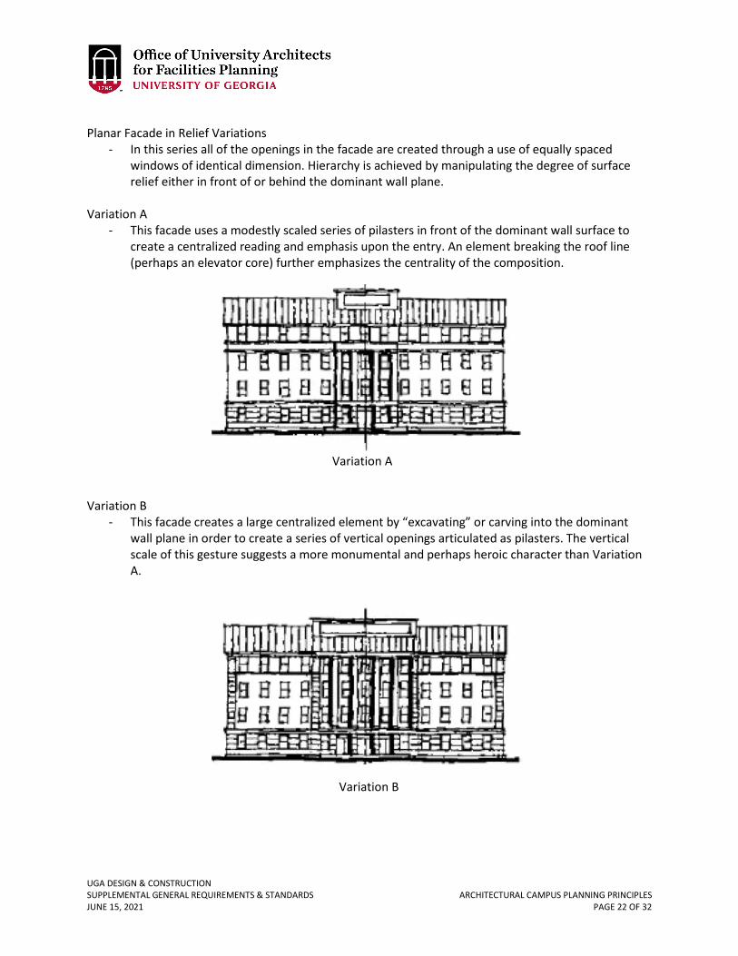
UGA DESIGN & CONSTRUCTION SUPPLEMENTAL GENERAL REQUIREMENTS & STANDARDS ARCHITECTURAL CAMPUS PLANNING PRINCIPLES JUNE 15, 2021 PAGE 22 OF 32
Planar Facade in Relief Variations
- In this series all of the openings in the facade are created through a use of equally spaced windows of identical dimension. Hierarchy is achieved by manipulating the degree of surface relief either in front of or behind the dominant wall plane.
Variation A - This facade uses a modestly scaled series of pilasters in front of the dominant wall surface to
create a centralized reading and emphasis upon the entry. An element breaking the roof line (perhaps an elevator core) further emphasizes the centrality of the composition.
Variation B
- This facade creates a large centralized element by “excavating” or carving into the dominant wall plane in order to create a series of vertical openings articulated as pilasters. The vertical scale of this gesture suggests a more monumental and perhaps heroic character than Variation A.
Variation A
Variation B
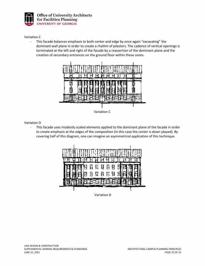
UGA DESIGN & CONSTRUCTION SUPPLEMENTAL GENERAL REQUIREMENTS & STANDARDS ARCHITECTURAL CAMPUS PLANNING PRINCIPLES JUNE 15, 2021 PAGE 23 OF 32
Variation C
- This facade balances emphasis to both center and edge by once again “excavating” the dominant wall plane in order to create a rhythm of pilasters. The cadence of vertical openings is terminated at the left and right of the facade by a reassertion of the dominant plane and the creation of secondary entrances on the ground floor within these zones.
Variation D
- This facade uses modestly scaled elements applied to the dominant plane of the facade in order to create emphasis at the edges of the composition (in this case the center is down played). By covering half of this diagram, one can imagine an asymmetrical application of this technique.
Variation C
Variation D
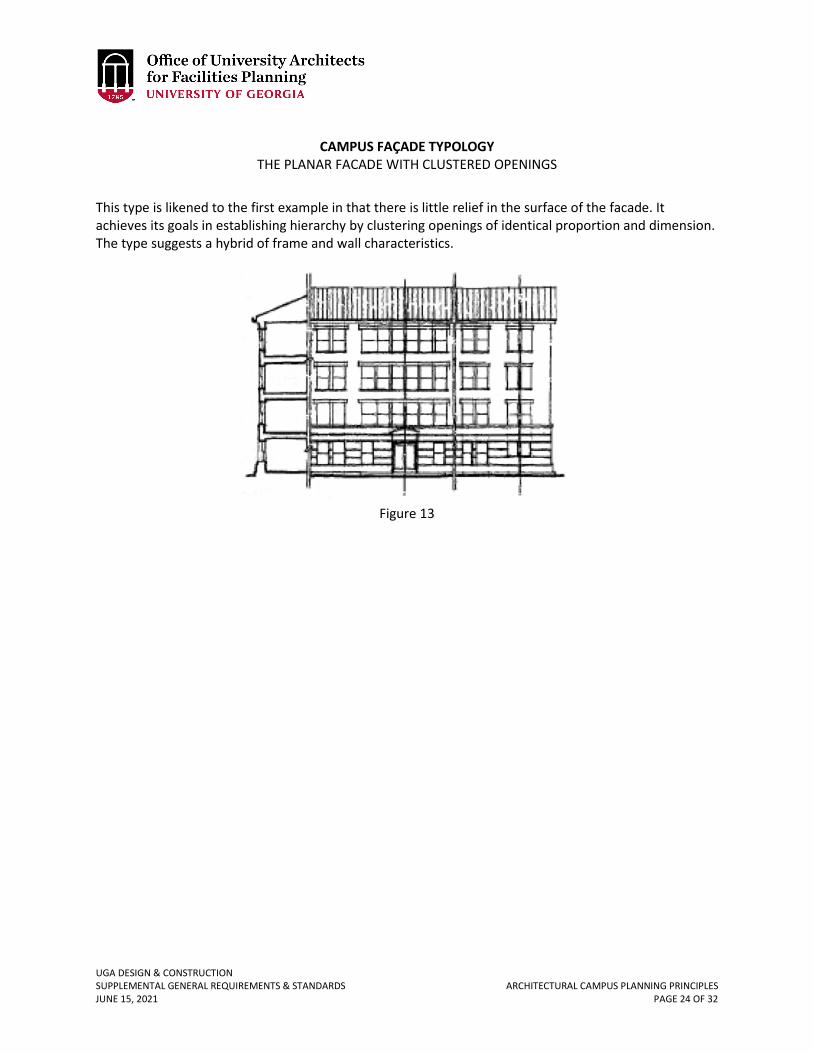
UGA DESIGN & CONSTRUCTION SUPPLEMENTAL GENERAL REQUIREMENTS & STANDARDS ARCHITECTURAL CAMPUS PLANNING PRINCIPLES JUNE 15, 2021 PAGE 24 OF 32
CAMPUS FAÇADE TYPOLOGY
THE PLANAR FACADE WITH CLUSTERED OPENINGS This type is likened to the first example in that there is little relief in the surface of the facade. It achieves its goals in establishing hierarchy by clustering openings of identical proportion and dimension. The type suggests a hybrid of frame and wall characteristics.
Figure 13
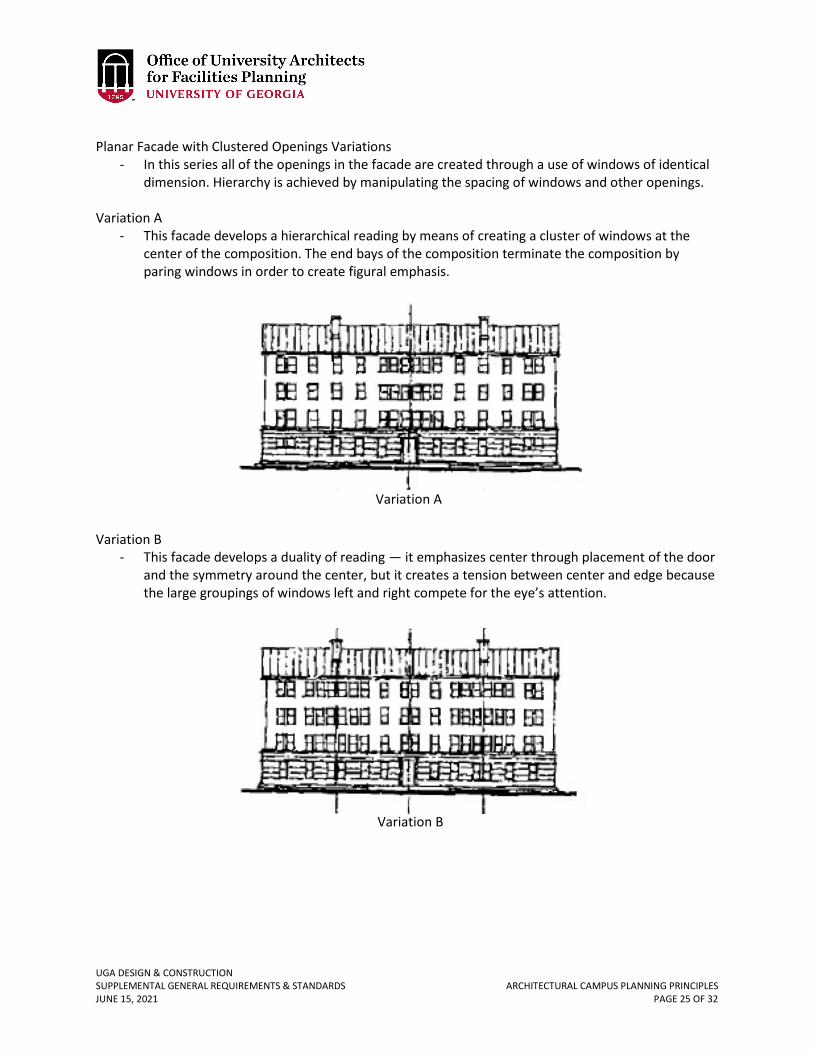
UGA DESIGN & CONSTRUCTION SUPPLEMENTAL GENERAL REQUIREMENTS & STANDARDS ARCHITECTURAL CAMPUS PLANNING PRINCIPLES JUNE 15, 2021 PAGE 25 OF 32
Planar Facade with Clustered Openings Variations
- In this series all of the openings in the facade are created through a use of windows of identical dimension. Hierarchy is achieved by manipulating the spacing of windows and other openings.
Variation A - This facade develops a hierarchical reading by means of creating a cluster of windows at the
center of the composition. The end bays of the composition terminate the composition by paring windows in order to create figural emphasis.
Variation B
- This facade develops a duality of reading — it emphasizes center through placement of the door and the symmetry around the center, but it creates a tension between center and edge because the large groupings of windows left and right compete for the eye’s attention.
Variation A
Variation B
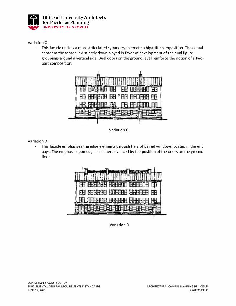
UGA DESIGN & CONSTRUCTION SUPPLEMENTAL GENERAL REQUIREMENTS & STANDARDS ARCHITECTURAL CAMPUS PLANNING PRINCIPLES JUNE 15, 2021 PAGE 26 OF 32
Variation C
- This facade utilizes a more articulated symmetry to create a bipartite composition. The actual center of the facade is distinctly down played in favor of development of the dual figure groupings around a vertical axis. Dual doors on the ground level reinforce the notion of a two-part composition.
Variation D
- This facade emphasizes the edge elements through tiers of paired windows located in the end bays. The emphasis upon edge is further advanced by the position of the doors on the ground floor.
Variation C
Variation D
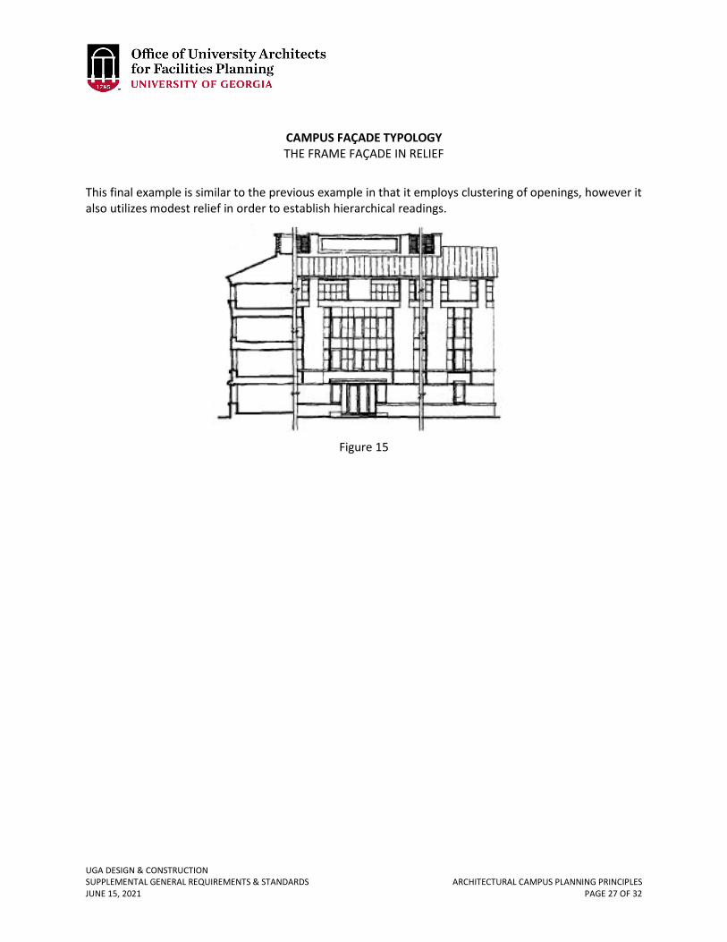
UGA DESIGN & CONSTRUCTION SUPPLEMENTAL GENERAL REQUIREMENTS & STANDARDS ARCHITECTURAL CAMPUS PLANNING PRINCIPLES JUNE 15, 2021 PAGE 27 OF 32
CAMPUS FAÇADE TYPOLOGY THE FRAME FAÇADE IN RELIEF
This final example is similar to the previous example in that it employs clustering of openings, however it also utilizes modest relief in order to establish hierarchical readings.
Figure 15
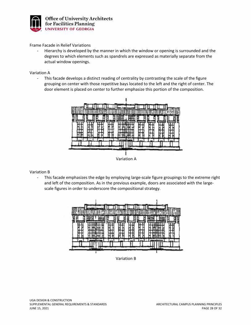
UGA DESIGN & CONSTRUCTION SUPPLEMENTAL GENERAL REQUIREMENTS & STANDARDS ARCHITECTURAL CAMPUS PLANNING PRINCIPLES JUNE 15, 2021 PAGE 28 OF 32
Frame Facade in Relief Variations
- Hierarchy is developed by the manner in which the window or opening is surrounded and the degrees to which elements such as spandrels are expressed as materially separate from the actual window openings.
Variation A
- This facade develops a distinct reading of centrality by contrasting the scale of the figure grouping on center with those repetitive bays located to the left and the right of center. The door element is placed on center to further emphasize this portion of the composition.
Variation B
- This facade emphasizes the edge by employing large-scale figure groupings to the extreme right and left of the composition. As in the previous example, doors are associated with the large-scale figures in order to underscore the compositional strategy.
Variation A
Variation B
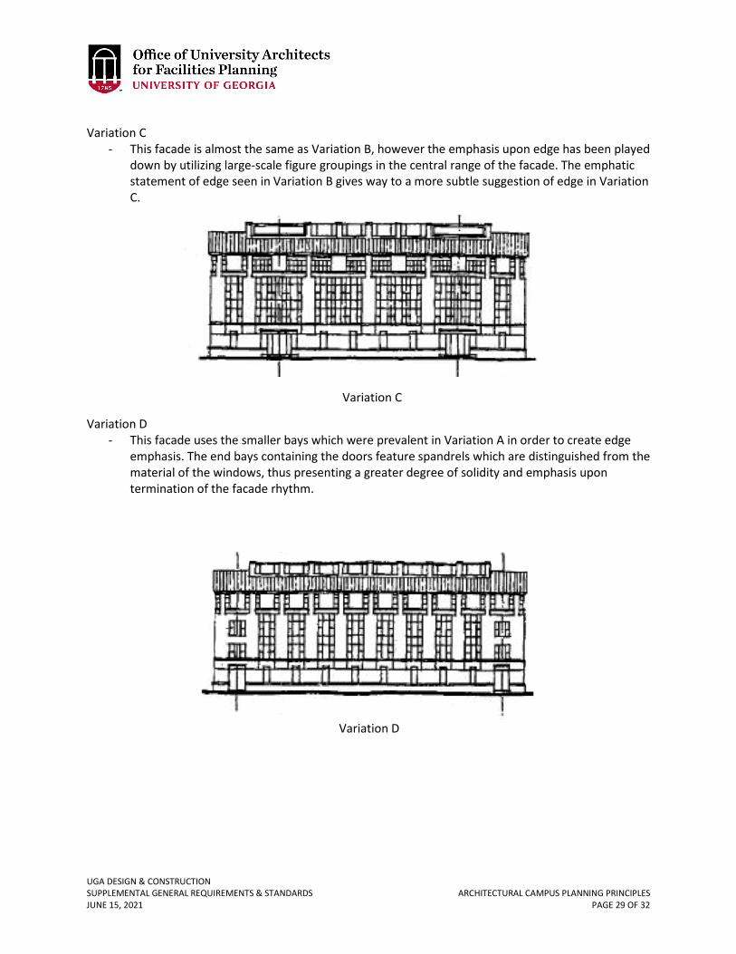
UGA DESIGN & CONSTRUCTION SUPPLEMENTAL GENERAL REQUIREMENTS & STANDARDS ARCHITECTURAL CAMPUS PLANNING PRINCIPLES JUNE 15, 2021 PAGE 29 OF 32
Variation C
- This facade is almost the same as Variation B, however the emphasis upon edge has been played down by utilizing large-scale figure groupings in the central range of the facade. The emphatic statement of edge seen in Variation B gives way to a more subtle suggestion of edge in Variation C.
Variation D
- This facade uses the smaller bays which were prevalent in Variation A in order to create edge emphasis. The end bays containing the doors feature spandrels which are distinguished from the material of the windows, thus presenting a greater degree of solidity and emphasis upon termination of the facade rhythm.
Variation C
Variation D
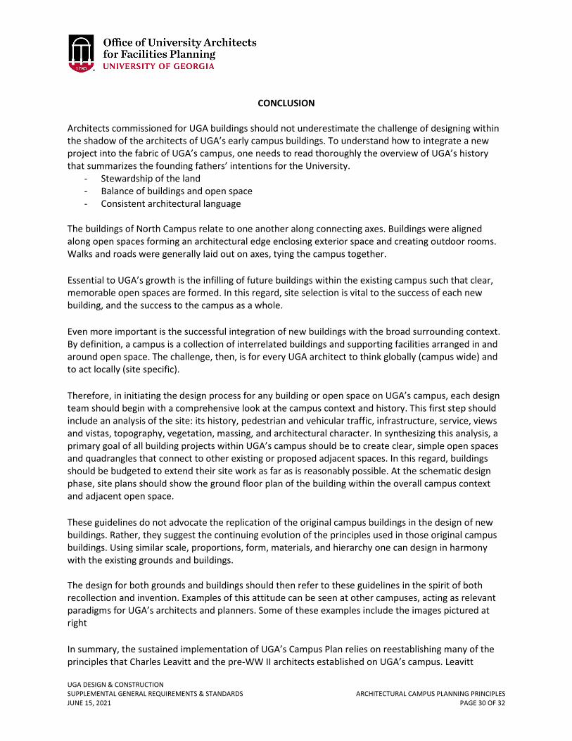
UGA DESIGN & CONSTRUCTION SUPPLEMENTAL GENERAL REQUIREMENTS & STANDARDS ARCHITECTURAL CAMPUS PLANNING PRINCIPLES JUNE 15, 2021 PAGE 30 OF 32
CONCLUSION
Architects commissioned for UGA buildings should not underestimate the challenge of designing within the shadow of the architects of UGA’s early campus buildings. To understand how to integrate a new project into the fabric of UGA’s campus, one needs to read thoroughly the overview of UGA’s history that summarizes the founding fathers’ intentions for the University.
- Stewardship of the land - Balance of buildings and open space - Consistent architectural language
The buildings of North Campus relate to one another along connecting axes. Buildings were aligned along open spaces forming an architectural edge enclosing exterior space and creating outdoor rooms. Walks and roads were generally laid out on axes, tying the campus together. Essential to UGA’s growth is the infilling of future buildings within the existing campus such that clear, memorable open spaces are formed. In this regard, site selection is vital to the success of each new building, and the success to the campus as a whole. Even more important is the successful integration of new buildings with the broad surrounding context. By definition, a campus is a collection of interrelated buildings and supporting facilities arranged in and around open space. The challenge, then, is for every UGA architect to think globally (campus wide) and to act locally (site specific). Therefore, in initiating the design process for any building or open space on UGA’s campus, each design team should begin with a comprehensive look at the campus context and history. This first step should include an analysis of the site: its history, pedestrian and vehicular traffic, infrastructure, service, views and vistas, topography, vegetation, massing, and architectural character. In synthesizing this analysis, a primary goal of all building projects within UGA’s campus should be to create clear, simple open spaces and quadrangles that connect to other existing or proposed adjacent spaces. In this regard, buildings should be budgeted to extend their site work as far as is reasonably possible. At the schematic design phase, site plans should show the ground floor plan of the building within the overall campus context and adjacent open space. These guidelines do not advocate the replication of the original campus buildings in the design of new buildings. Rather, they suggest the continuing evolution of the principles used in those original campus buildings. Using similar scale, proportions, form, materials, and hierarchy one can design in harmony with the existing grounds and buildings. The design for both grounds and buildings should then refer to these guidelines in the spirit of both recollection and invention. Examples of this attitude can be seen at other campuses, acting as relevant paradigms for UGA’s architects and planners. Some of these examples include the images pictured at right In summary, the sustained implementation of UGA’s Campus Plan relies on reestablishing many of the principles that Charles Leavitt and the pre-WW II architects established on UGA’s campus. Leavitt
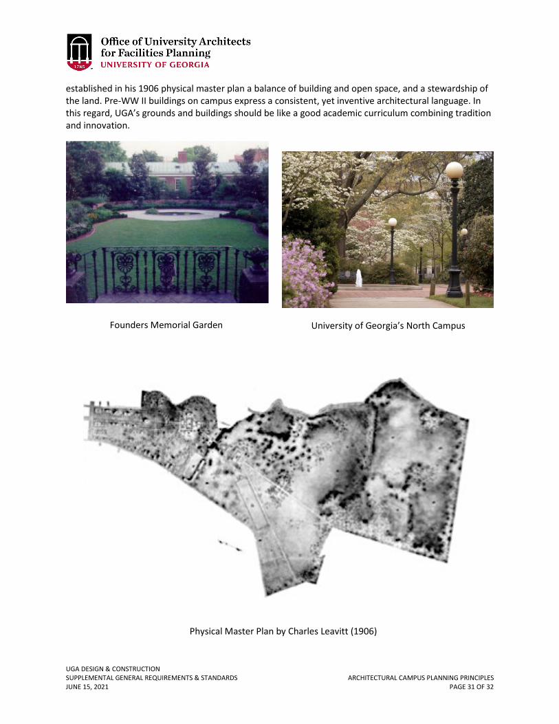
UGA DESIGN & CONSTRUCTION SUPPLEMENTAL GENERAL REQUIREMENTS & STANDARDS ARCHITECTURAL CAMPUS PLANNING PRINCIPLES JUNE 15, 2021 PAGE 31 OF 32
established in his 1906 physical master plan a balance of building and open space, and a stewardship of the land. Pre-WW II buildings on campus express a consistent, yet inventive architectural language. In this regard, UGA’s grounds and buildings should be like a good academic curriculum combining tradition and innovation.
Founders Memorial Garden
University of Georgia’s North Campus
Physical Master Plan by Charles Leavitt (1906)
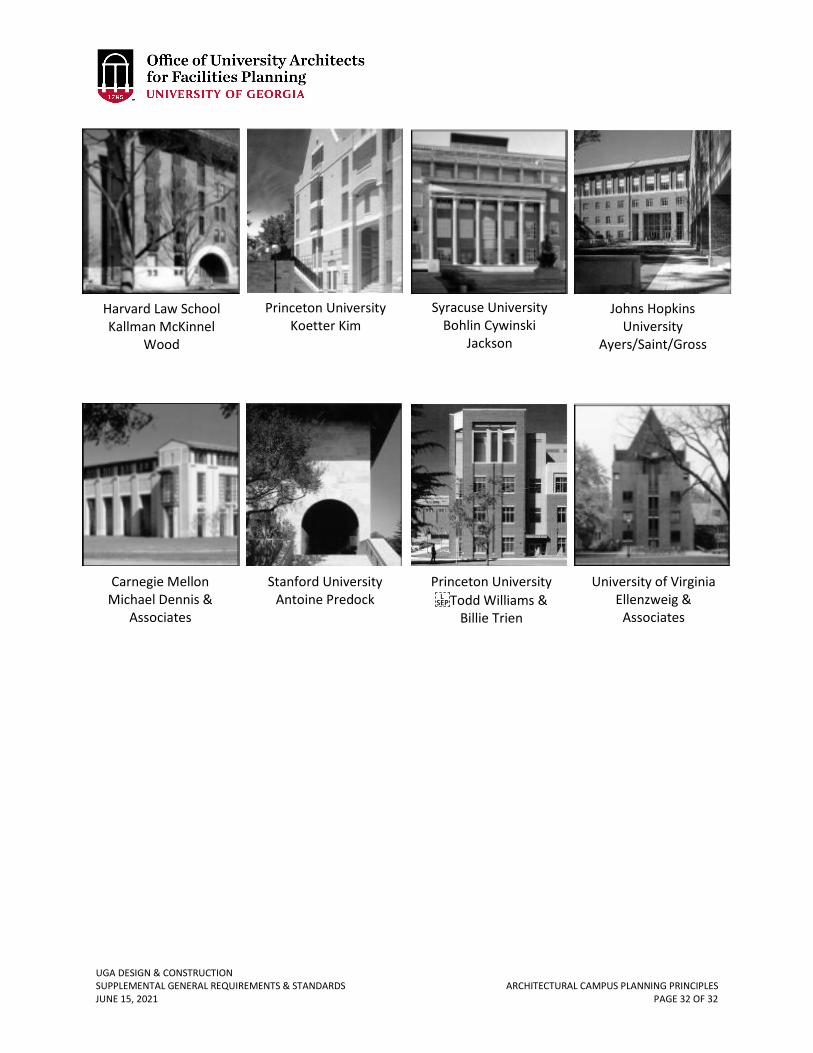
UGA DESIGN & CONSTRUCTION SUPPLEMENTAL GENERAL REQUIREMENTS & STANDARDS ARCHITECTURAL CAMPUS PLANNING PRINCIPLES JUNE 15, 2021 PAGE 32 OF 32
Harvard Law School Kallman McKinnel
Wood
Princeton University Koetter Kim
Syracuse University Bohlin Cywinski
Jackson
Johns Hopkins University
Ayers/Saint/Gross
Carnegie Mellon Michael Dennis &
Associates
Stanford University Antoine Predock
Princeton University Todd Williams &
Billie Trien
University of Virginia Ellenzweig &
Associates
UGA DESIGN & CONSTRUCTION SUPPLEMENTAL GENERAL REQUIREMENTS & STANDARDS SITE CAMPUS PLANNING PRINCIPLES JUNE 15,2021 PAGE 1 OF 24
SITE CAMPUS PLANNING PRINCIPLES
INTRODUCTION The UGA Site Campus Planning Principles defines essential features unique to the UGA campus. These design standards contribute to pedestrian safety, way finding, campus iconography, and sense of place. They are important identifying characteristics of the 605-acre UGA campus. The standards are made available here to design professionals engaged on the UGA campus as a way to maximize efficiency and streamline parts of the design process. The UGA Site Campus Planning Principles defines essential features that not only instruct architects, landscape architects, engineers, and other design professionals of the aesthetic make-up of the University of Georgia campus, but also formulates the design criteria for future development, which essentially brings forth continuity and respect for elements that are deemed appropriate. This section is intended as a guideline of pertinent design principles. Specific construction detail requirements may be found in Standards.
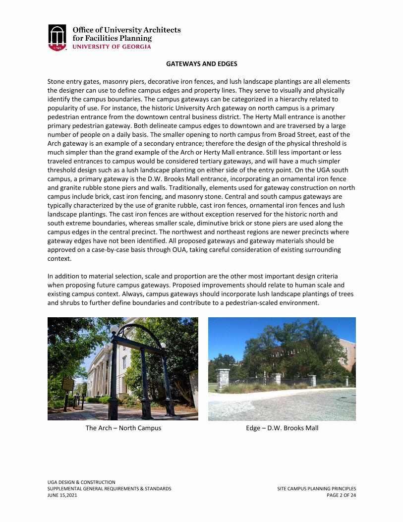
UGA DESIGN & CONSTRUCTION SUPPLEMENTAL GENERAL REQUIREMENTS & STANDARDS SITE CAMPUS PLANNING PRINCIPLES JUNE 15,2021 PAGE 2 OF 24
GATEWAYS AND EDGES Stone entry gates, masonry piers, decorative iron fences, and lush landscape plantings are all elements the designer can use to define campus edges and property lines. They serve to visually and physically identify the campus boundaries. The campus gateways can be categorized in a hierarchy related to popularity of use. For instance, the historic University Arch gateway on north campus is a primary pedestrian entrance from the downtown central business district. The Herty Mall entrance is another primary pedestrian gateway. Both delineate campus edges to downtown and are traversed by a large number of people on a daily basis. The smaller opening to north campus from Broad Street, east of the Arch gateway is an example of a secondary entrance; therefore the design of the physical threshold is much simpler than the grand example of the Arch or Herty Mall entrance. Still less important or less traveled entrances to campus would be considered tertiary gateways, and will have a much simpler threshold design such as a lush landscape planting on either side of the entry point. On the UGA south campus, a primary gateway is the D.W. Brooks Mall entrance, incorporating an ornamental iron fence and granite rubble stone piers and walls. Traditionally, elements used for gateway construction on north campus include brick, cast iron fencing, and masonry stone. Central and south campus gateways are typically characterized by the use of granite rubble, cast iron fences, ornamental iron fences and lush landscape plantings. The cast iron fences are without exception reserved for the historic north and south extreme boundaries, whereas smaller scale, diminutive brick or stone piers are used along the campus edges in the central precinct. The northwest and northeast regions are newer precincts where gateway edges have not been identified. All proposed gateways and gateway materials should be approved on a case-by-case basis through OUA, taking careful consideration of existing surrounding context. In addition to material selection, scale and proportion are the other most important design criteria when proposing future campus gateways. Proposed improvements should relate to human scale and existing campus context. Always, campus gateways should incorporate lush landscape plantings of trees and shrubs to further define boundaries and contribute to a pedestrian-scaled environment.
The Arch – North Campus Edge – D.W. Brooks Mall
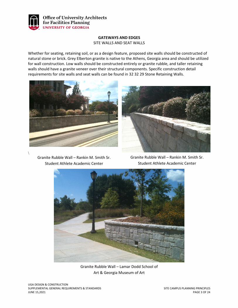
UGA DESIGN & CONSTRUCTION SUPPLEMENTAL GENERAL REQUIREMENTS & STANDARDS SITE CAMPUS PLANNING PRINCIPLES JUNE 15,2021 PAGE 3 OF 24
GATEWAYS AND EDGES SITE WALLS AND SEAT WALLS
Whether for seating, retaining soil, or as a design feature, proposed site walls should be constructed of natural stone or brick. Grey Elberton granite is native to the Athens, Georgia area and should be utilized for wall construction. Low walls should be constructed entirely or granite rubble, and taller retaining walls should have a granite veneer over their structural components. Specific construction detail requirements for site walls and seat walls can be found in 32 32 29 Stone Retaining Walls.
\
Granite Rubble Wall – Lamar Dodd School of Art & Georgia Museum of Art
Granite Rubble Wall – Rankin M. Smith Sr. Student Athlete Academic Center
Granite Rubble Wall – Rankin M. Smith Sr. Student Athlete Academic Center
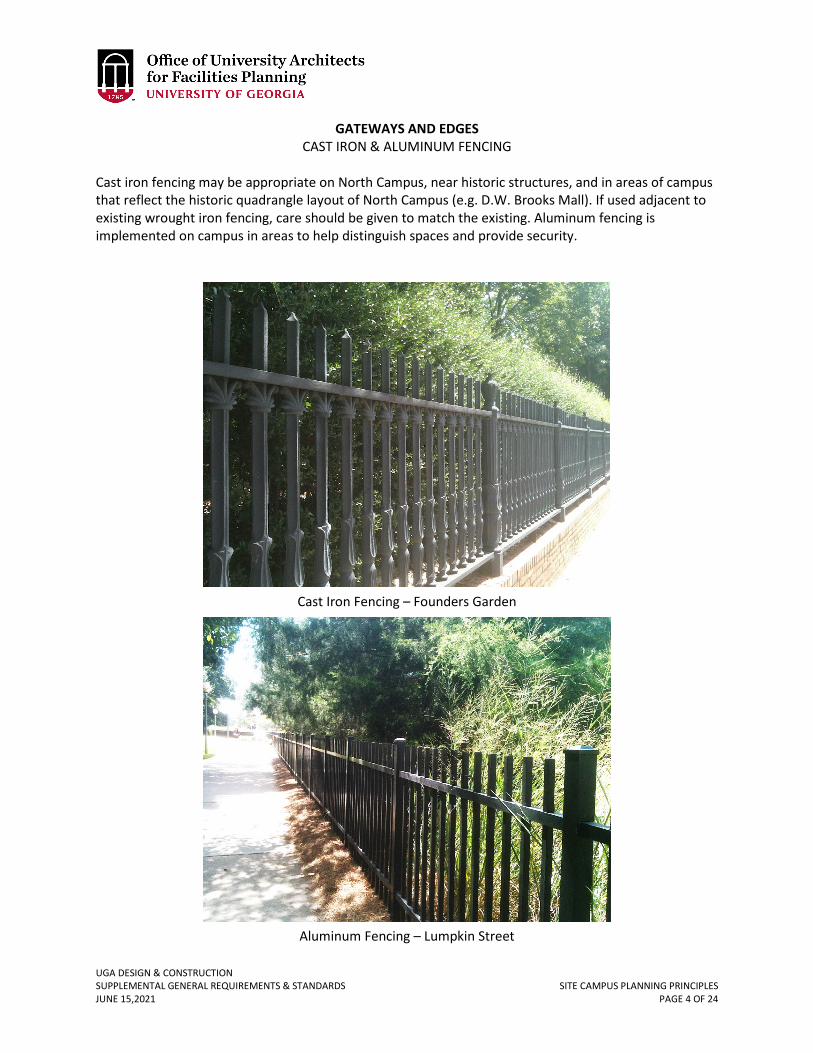
UGA DESIGN & CONSTRUCTION SUPPLEMENTAL GENERAL REQUIREMENTS & STANDARDS SITE CAMPUS PLANNING PRINCIPLES JUNE 15,2021 PAGE 4 OF 24
GATEWAYS AND EDGES CAST IRON & ALUMINUM FENCING
Cast iron fencing may be appropriate on North Campus, near historic structures, and in areas of campus that reflect the historic quadrangle layout of North Campus (e.g. D.W. Brooks Mall). If used adjacent to existing wrought iron fencing, care should be given to match the existing. Aluminum fencing is implemented on campus in areas to help distinguish spaces and provide security.
Cast Iron Fencing – Founders Garden
Aluminum Fencing – Lumpkin Street
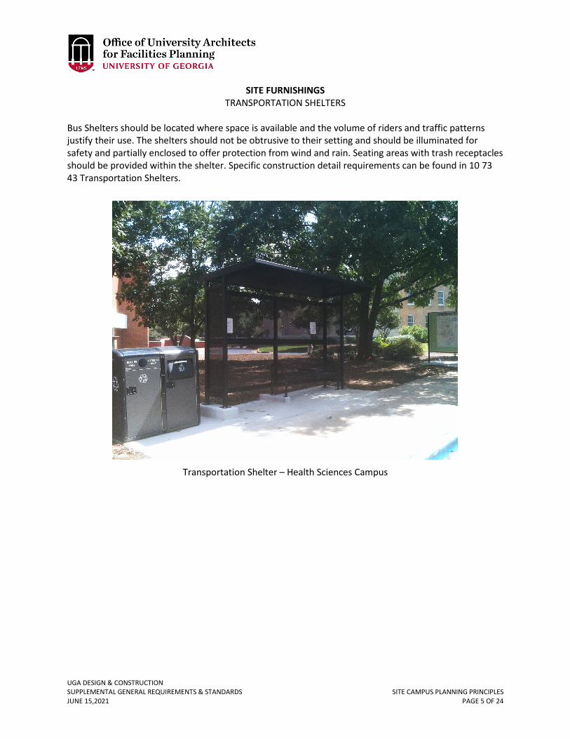
UGA DESIGN & CONSTRUCTION SUPPLEMENTAL GENERAL REQUIREMENTS & STANDARDS SITE CAMPUS PLANNING PRINCIPLES JUNE 15,2021 PAGE 5 OF 24
SITE FURNISHINGS TRANSPORTATION SHELTERS
Bus Shelters should be located where space is available and the volume of riders and traffic patterns justify their use. The shelters should not be obtrusive to their setting and should be illuminated for safety and partially enclosed to offer protection from wind and rain. Seating areas with trash receptacles should be provided within the shelter. Specific construction detail requirements can be found in 10 73 43 Transportation Shelters.
Transportation Shelter – Health Sciences Campus
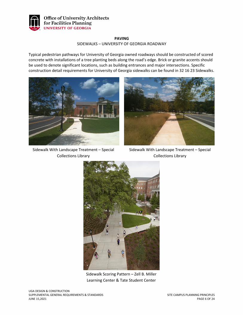
UGA DESIGN & CONSTRUCTION SUPPLEMENTAL GENERAL REQUIREMENTS & STANDARDS SITE CAMPUS PLANNING PRINCIPLES JUNE 15,2021 PAGE 6 OF 24
PAVING SIDEWALKS – UNIVERSITY OF GEORGIA ROADWAY
Typical pedestrian pathways for University of Georgia owned roadways should be constructed of scored concrete with installations of a tree planting beds along the road’s edge. Brick or granite accents should be used to denote significant locations, such as building entrances and major intersections. Specific construction detail requirements for University of Georgia sidewalks can be found in 32 16 23 Sidewalks.
Sidewalk With Landscape Treatment – Special Collections Library
Sidewalk With Landscape Treatment – Special Collections Library
Sidewalk Scoring Pattern – Zell B. Miller Learning Center & Tate Student Center
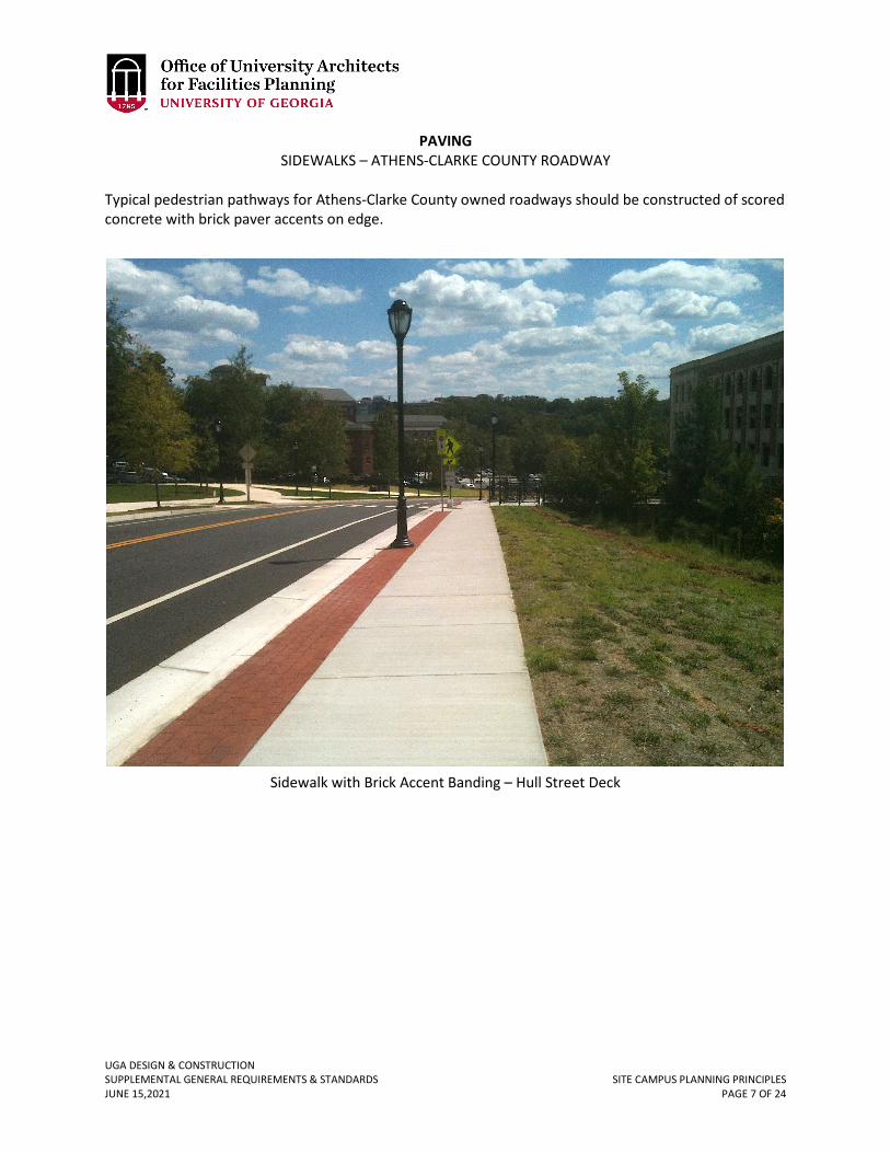
UGA DESIGN & CONSTRUCTION SUPPLEMENTAL GENERAL REQUIREMENTS & STANDARDS SITE CAMPUS PLANNING PRINCIPLES JUNE 15,2021 PAGE 7 OF 24
PAVING SIDEWALKS – ATHENS-CLARKE COUNTY ROADWAY
Typical pedestrian pathways for Athens-Clarke County owned roadways should be constructed of scored concrete with brick paver accents on edge.
Sidewalk with Brick Accent Banding – Hull Street Deck
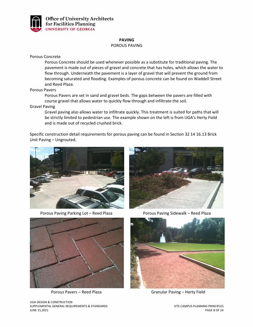
UGA DESIGN & CONSTRUCTION SUPPLEMENTAL GENERAL REQUIREMENTS & STANDARDS SITE CAMPUS PLANNING PRINCIPLES JUNE 15,2021 PAGE 8 OF 24
PAVING POROUS PAVING
Porous Concrete
Porous Concrete should be used whenever possible as a substitute for traditional paving. The pavement is made out of pieces of gravel and concrete that has holes, which allows the water to flow through. Underneath the pavement is a layer of gravel that will prevent the ground from becoming saturated and flooding. Examples of porous concrete can be found on Waddell Street and Reed Plaza.
Porous Pavers Porous Pavers are set in sand and gravel beds. The gaps between the pavers are filled with course gravel that allows water to quickly flow through and infiltrate the soil.
Gravel Paving Gravel paving also allows water to infiltrate quickly. This treatment is suited for paths that will be strictly limited to pedestrian use. The example shown on the left is from UGA’s Herty Field and is made out of recycled crushed brick.
Specific construction detail requirements for porous paving can be found in Section 32 14 16.13 Brick Unit Paving – Ungrouted.
Porous Paving Parking Lot – Reed Plaza Porous Paving Sidewalk – Reed Plaza
Granular Paving – Herty Field Porous Pavers – Reed Plaza
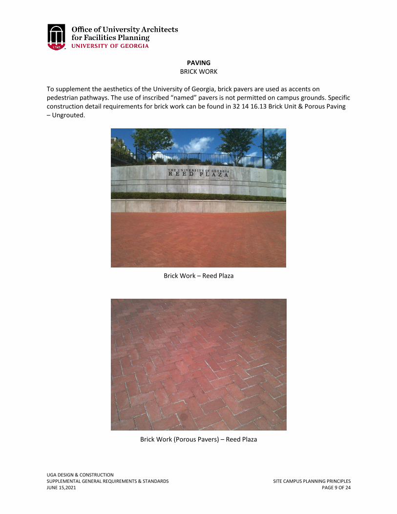
UGA DESIGN & CONSTRUCTION SUPPLEMENTAL GENERAL REQUIREMENTS & STANDARDS SITE CAMPUS PLANNING PRINCIPLES JUNE 15,2021 PAGE 9 OF 24
PAVING BRICK WORK
To supplement the aesthetics of the University of Georgia, brick pavers are used as accents on pedestrian pathways. The use of inscribed “named” pavers is not permitted on campus grounds. Specific construction detail requirements for brick work can be found in 32 14 16.13 Brick Unit & Porous Paving – Ungrouted.
Brick Work – Reed Plaza
Brick Work (Porous Pavers) – Reed Plaza
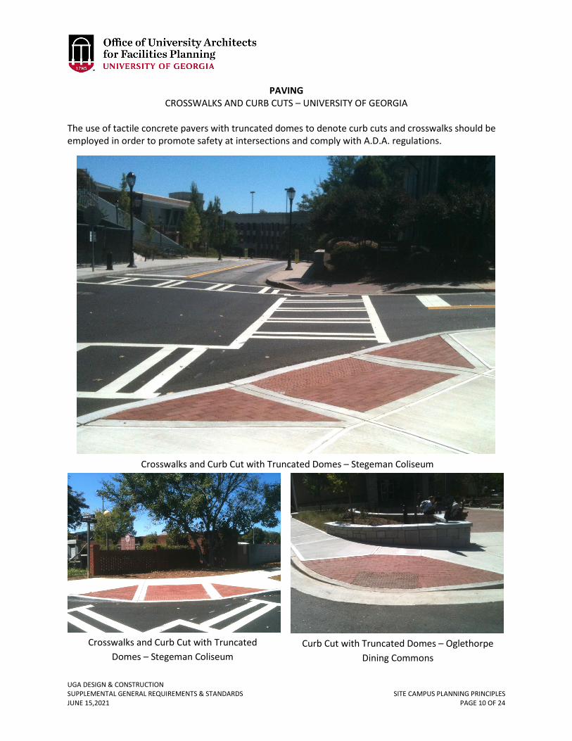
UGA DESIGN & CONSTRUCTION SUPPLEMENTAL GENERAL REQUIREMENTS & STANDARDS SITE CAMPUS PLANNING PRINCIPLES JUNE 15,2021 PAGE 10 OF 24
PAVING CROSSWALKS AND CURB CUTS – UNIVERSITY OF GEORGIA
The use of tactile concrete pavers with truncated domes to denote curb cuts and crosswalks should be employed in order to promote safety at intersections and comply with A.D.A. regulations.
Crosswalks and Curb Cut with Truncated Domes – Stegeman Coliseum
Crosswalks and Curb Cut with Truncated Domes – Stegeman Coliseum
Curb Cut with Truncated Domes – Oglethorpe Dining Commons
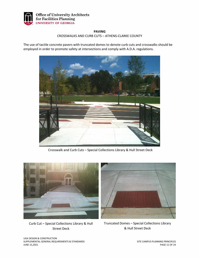
UGA DESIGN & CONSTRUCTION SUPPLEMENTAL GENERAL REQUIREMENTS & STANDARDS SITE CAMPUS PLANNING PRINCIPLES JUNE 15,2021 PAGE 11 OF 24
PAVING CROSSWALKS AND CURB CUTS – ATHENS-CLARKE COUNTY
The use of tactile concrete pavers with truncated domes to denote curb cuts and crosswalks should be employed in order to promote safety at intersections and comply with A.D.A. regulations.
Crosswalk and Curb Cuts – Special Collections Library & Hull Street Deck
Curb Cut – Special Collections Library & Hull Street Deck
Truncated Domes – Special Collections Library & Hull Street Deck
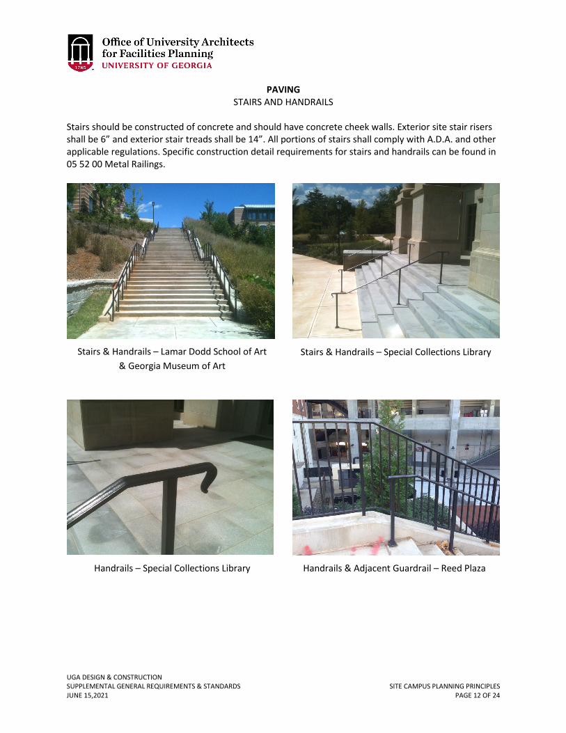
UGA DESIGN & CONSTRUCTION SUPPLEMENTAL GENERAL REQUIREMENTS & STANDARDS SITE CAMPUS PLANNING PRINCIPLES JUNE 15,2021 PAGE 12 OF 24
PAVING STAIRS AND HANDRAILS
Stairs should be constructed of concrete and should have concrete cheek walls. Exterior site stair risers shall be 6” and exterior stair treads shall be 14”. All portions of stairs shall comply with A.D.A. and other applicable regulations. Specific construction detail requirements for stairs and handrails can be found in 05 52 00 Metal Railings.
Stairs & Handrails – Lamar Dodd School of Art & Georgia Museum of Art
Stairs & Handrails – Special Collections Library
Handrails – Special Collections Library Handrails & Adjacent Guardrail – Reed Plaza
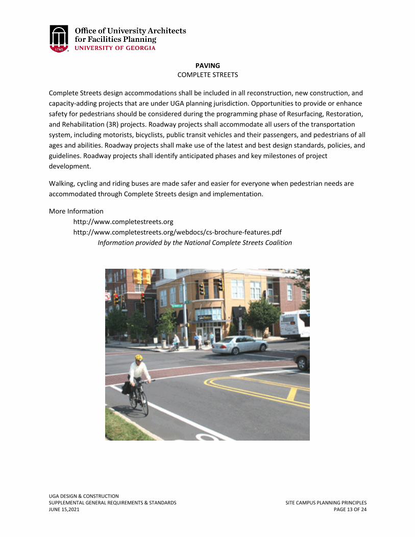
UGA DESIGN & CONSTRUCTION SUPPLEMENTAL GENERAL REQUIREMENTS & STANDARDS SITE CAMPUS PLANNING PRINCIPLES JUNE 15,2021 PAGE 13 OF 24
PAVING COMPLETE STREETS
Complete Streets design accommodations shall be included in all reconstruction, new construction, and capacity-adding projects that are under UGA planning jurisdiction. Opportunities to provide or enhance safety for pedestrians should be considered during the programming phase of Resurfacing, Restoration, and Rehabilitation (3R) projects. Roadway projects shall accommodate all users of the transportation system, including motorists, bicyclists, public transit vehicles and their passengers, and pedestrians of all ages and abilities. Roadway projects shall make use of the latest and best design standards, policies, and guidelines. Roadway projects shall identify anticipated phases and key milestones of project development.
Walking, cycling and riding buses are made safer and easier for everyone when pedestrian needs are accommodated through Complete Streets design and implementation.
More Information http://www.completestreets.org http://www.completestreets.org/webdocs/cs-brochure-features.pdf
Information provided by the National Complete Streets Coalition
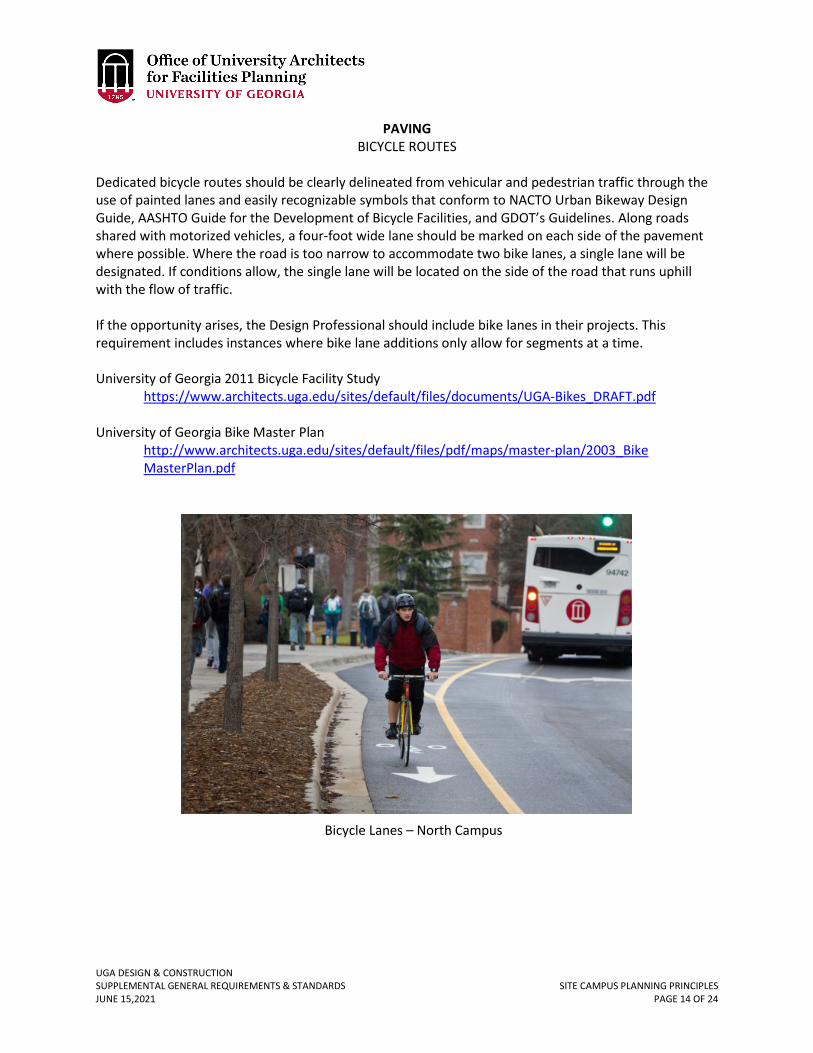
UGA DESIGN & CONSTRUCTION SUPPLEMENTAL GENERAL REQUIREMENTS & STANDARDS SITE CAMPUS PLANNING PRINCIPLES JUNE 15,2021 PAGE 14 OF 24
PAVING BICYCLE ROUTES
Dedicated bicycle routes should be clearly delineated from vehicular and pedestrian traffic through the use of painted lanes and easily recognizable symbols that conform to NACTO Urban Bikeway Design Guide, AASHTO Guide for the Development of Bicycle Facilities, and GDOT’s Guidelines. Along roads shared with motorized vehicles, a four-foot wide lane should be marked on each side of the pavement where possible. Where the road is too narrow to accommodate two bike lanes, a single lane will be designated. If conditions allow, the single lane will be located on the side of the road that runs uphill with the flow of traffic. If the opportunity arises, the Design Professional should include bike lanes in their projects. This requirement includes instances where bike lane additions only allow for segments at a time. University of Georgia 2011 Bicycle Facility Study
https://www.architects.uga.edu/sites/default/files/documents/UGA-Bikes_DRAFT.pdf University of Georgia Bike Master Plan
http://www.architects.uga.edu/sites/default/files/pdf/maps/master-plan/2003_Bike MasterPlan.pdf
Bicycle Lanes – North Campus
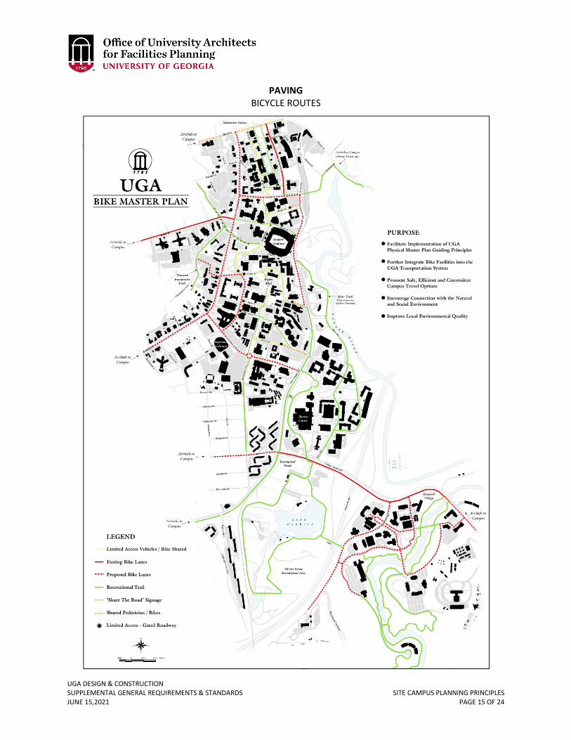
UGA DESIGN & CONSTRUCTION SUPPLEMENTAL GENERAL REQUIREMENTS & STANDARDS SITE CAMPUS PLANNING PRINCIPLES JUNE 15,2021 PAGE 15 OF 24
PAVING BICYCLE ROUTES
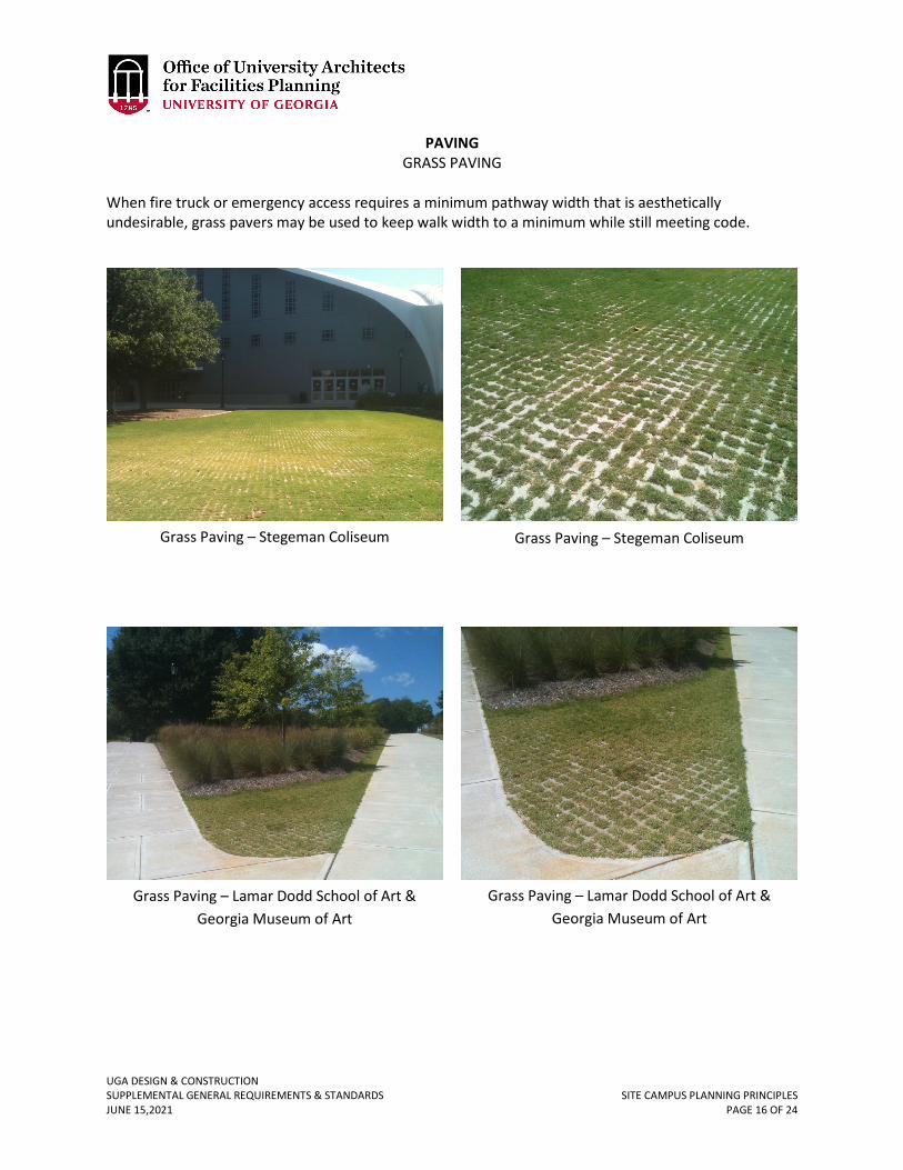
UGA DESIGN & CONSTRUCTION SUPPLEMENTAL GENERAL REQUIREMENTS & STANDARDS SITE CAMPUS PLANNING PRINCIPLES JUNE 15,2021 PAGE 16 OF 24
PAVING GRASS PAVING
When fire truck or emergency access requires a minimum pathway width that is aesthetically undesirable, grass pavers may be used to keep walk width to a minimum while still meeting code.
Grass Paving – Stegeman Coliseum Grass Paving – Stegeman Coliseum
Grass Paving – Lamar Dodd School of Art & Georgia Museum of Art
Grass Paving – Lamar Dodd School of Art & Georgia Museum of Art
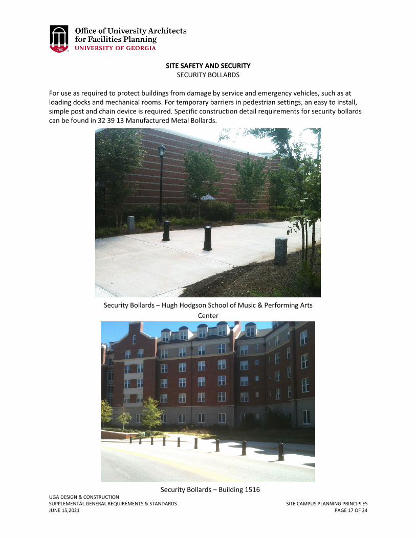
UGA DESIGN & CONSTRUCTION SUPPLEMENTAL GENERAL REQUIREMENTS & STANDARDS SITE CAMPUS PLANNING PRINCIPLES JUNE 15,2021 PAGE 17 OF 24
SITE SAFETY AND SECURITY SECURITY BOLLARDS
For use as required to protect buildings from damage by service and emergency vehicles, such as at loading docks and mechanical rooms. For temporary barriers in pedestrian settings, an easy to install, simple post and chain device is required. Specific construction detail requirements for security bollards can be found in 32 39 13 Manufactured Metal Bollards.
Security Bollards – Hugh Hodgson School of Music & Performing Arts Center
Security Bollards – Building 1516
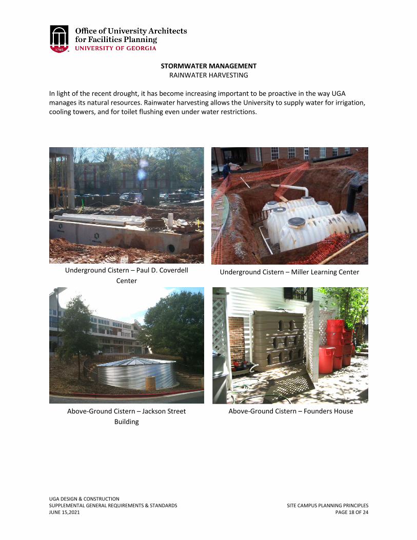
UGA DESIGN & CONSTRUCTION SUPPLEMENTAL GENERAL REQUIREMENTS & STANDARDS SITE CAMPUS PLANNING PRINCIPLES JUNE 15,2021 PAGE 18 OF 24
STORMWATER MANAGEMENT RAINWATER HARVESTING
In light of the recent drought, it has become increasing important to be proactive in the way UGA manages its natural resources. Rainwater harvesting allows the University to supply water for irrigation, cooling towers, and for toilet flushing even under water restrictions.
Underground Cistern – Paul D. Coverdell Center
Underground Cistern – Miller Learning Center
Above-Ground Cistern – Jackson Street Building
Above-Ground Cistern – Founders House
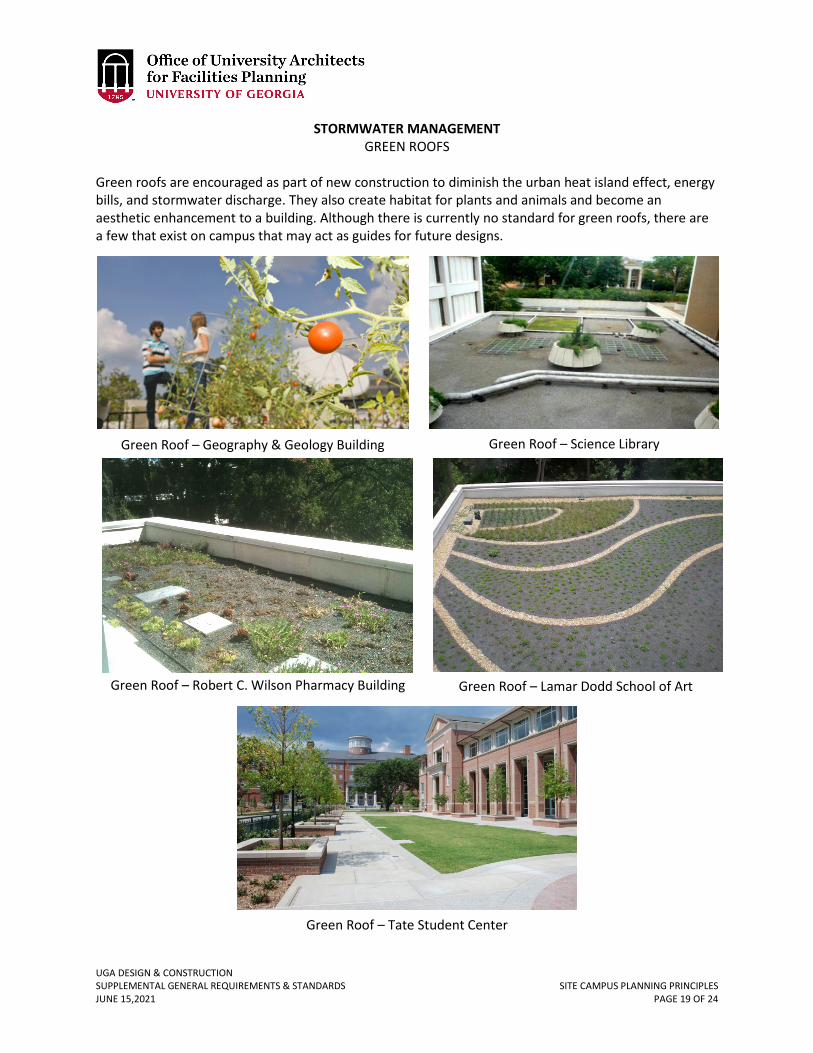
UGA DESIGN & CONSTRUCTION SUPPLEMENTAL GENERAL REQUIREMENTS & STANDARDS SITE CAMPUS PLANNING PRINCIPLES JUNE 15,2021 PAGE 19 OF 24
STORMWATER MANAGEMENT GREEN ROOFS
Green roofs are encouraged as part of new construction to diminish the urban heat island effect, energy bills, and stormwater discharge. They also create habitat for plants and animals and become an aesthetic enhancement to a building. Although there is currently no standard for green roofs, there are a few that exist on campus that may act as guides for future designs.
Green Roof – Geography & Geology Building Green Roof – Science Library
Green Roof – Lamar Dodd School of Art Green Roof – Robert C. Wilson Pharmacy Building
Green Roof – Tate Student Center
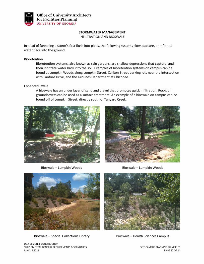
UGA DESIGN & CONSTRUCTION SUPPLEMENTAL GENERAL REQUIREMENTS & STANDARDS SITE CAMPUS PLANNING PRINCIPLES JUNE 15,2021 PAGE 20 OF 24
STORMWATER MANAGEMENT INFILTRATION AND BIOSWALE
Instead of funneling a storm’s first flush into pipes, the following systems slow, capture, or infiltrate water back into the ground. Bioretention
Bioretention systems, also known as rain gardens, are shallow depressions that capture, and then infiltrate water back into the soil. Examples of bioretention systems on campus can be found at Lumpkin Woods along Lumpkin Street, Carlton Street parking lots near the intersection with Sanford Drive, and the Grounds Department at Chicopee.
Enhanced Swale
A bioswale has an under layer of sand and gravel that promotes quick infiltration. Rocks or groundcovers can be used as a surface treatment. An example of a bioswale on campus can be found off of Lumpkin Street, directly south of Tanyard Creek.
Bioswale – Lumpkin Woods Bioswale – Lumpkin Woods
Bioswale – Special Collections Library Bioswale – Health Sciences Campus
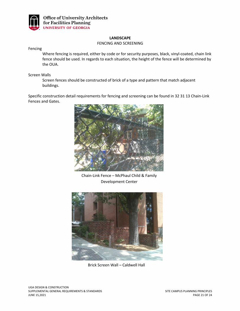
UGA DESIGN & CONSTRUCTION SUPPLEMENTAL GENERAL REQUIREMENTS & STANDARDS SITE CAMPUS PLANNING PRINCIPLES JUNE 15,2021 PAGE 21 OF 24
LANDSCAPE FENCING AND SCREENING
Fencing Where fencing is required, either by code or for security purposes, black, vinyl-coated, chain link fence should be used. In regards to each situation, the height of the fence will be determined by the OUA.
Screen Walls
Screen fences should be constructed of brick of a type and pattern that match adjacent buildings.
Specific construction detail requirements for fencing and screening can be found in 32 31 13 Chain-Link Fences and Gates.
Chain-Link Fence – McPhaul Child & Family Development Center
Brick Screen Wall – Caldwell Hall
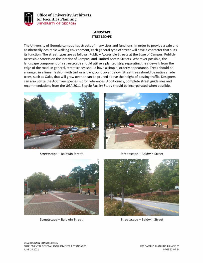
UGA DESIGN & CONSTRUCTION SUPPLEMENTAL GENERAL REQUIREMENTS & STANDARDS SITE CAMPUS PLANNING PRINCIPLES JUNE 15,2021 PAGE 22 OF 24
LANDSCAPE STREETSCAPE
The University of Georgia campus has streets of many sizes and functions. In order to provide a safe and aesthetically desirable walking environment, each general type of street will have a character that suits its function. The street types are as follows: Publicly Accessible Streets at the Edge of Campus, Publicly Accessible Streets on the Interior of Campus, and Limited Access Streets. Wherever possible, the landscape component of a streetscape should utilize a planted strip separating the sidewalk from the edge of the road. In general, streetscapes should have a simple, orderly appearance. Trees should be arranged in a linear fashion with turf or a low groundcover below. Street trees should be native shade trees, such as Oaks, that will grow over or can be pruned above the height of passing traffic. Designers can also utilize the ACC Tree Species list for references. Additionally, complete street guidelines and recommendations from the UGA 2011 Bicycle Facility Study should be incorporated when possible.
Streetscape – Baldwin Street Streetscape – Baldwin Street
Streetscape – Baldwin Street Streetscape – Baldwin Street
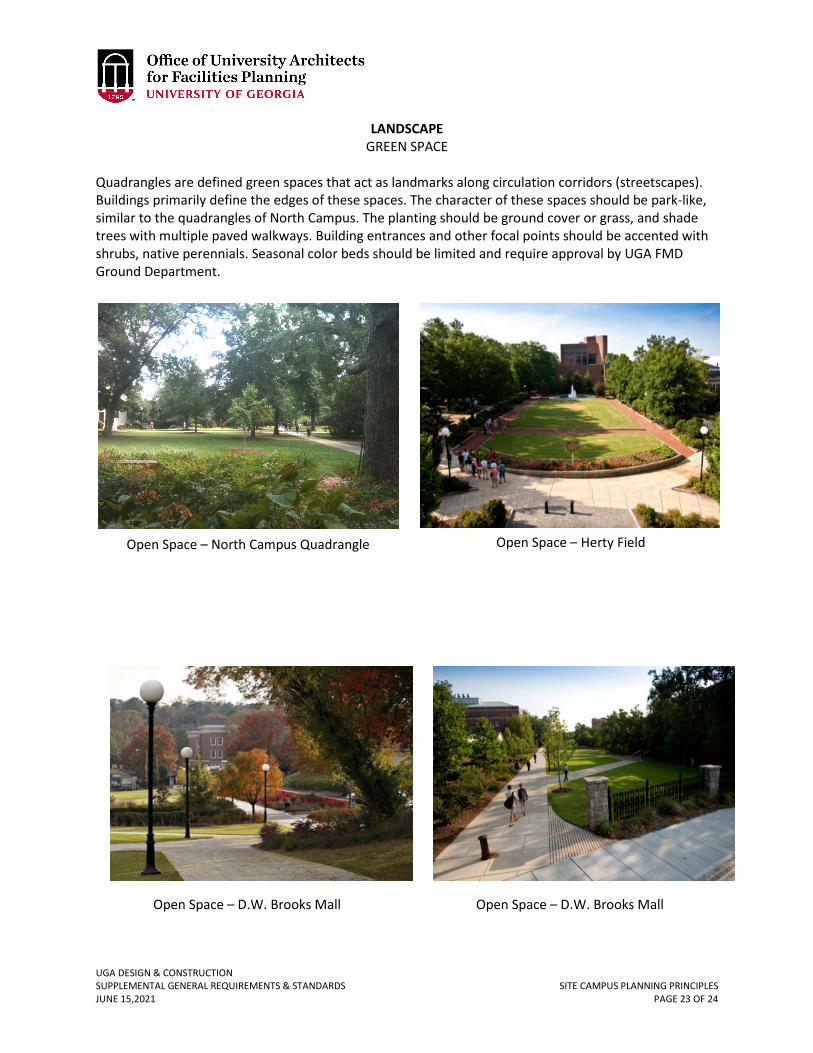
UGA DESIGN & CONSTRUCTION SUPPLEMENTAL GENERAL REQUIREMENTS & STANDARDS SITE CAMPUS PLANNING PRINCIPLES JUNE 15,2021 PAGE 23 OF 24
LANDSCAPE GREEN SPACE
Quadrangles are defined green spaces that act as landmarks along circulation corridors (streetscapes). Buildings primarily define the edges of these spaces. The character of these spaces should be park-like, similar to the quadrangles of North Campus. The planting should be ground cover or grass, and shade trees with multiple paved walkways. Building entrances and other focal points should be accented with shrubs, native perennials. Seasonal color beds should be limited and require approval by UGA FMD Ground Department.
Open Space – North Campus Quadrangle
Open Space – D.W. Brooks Mall Open Space – D.W. Brooks Mall
Open Space – Herty Field
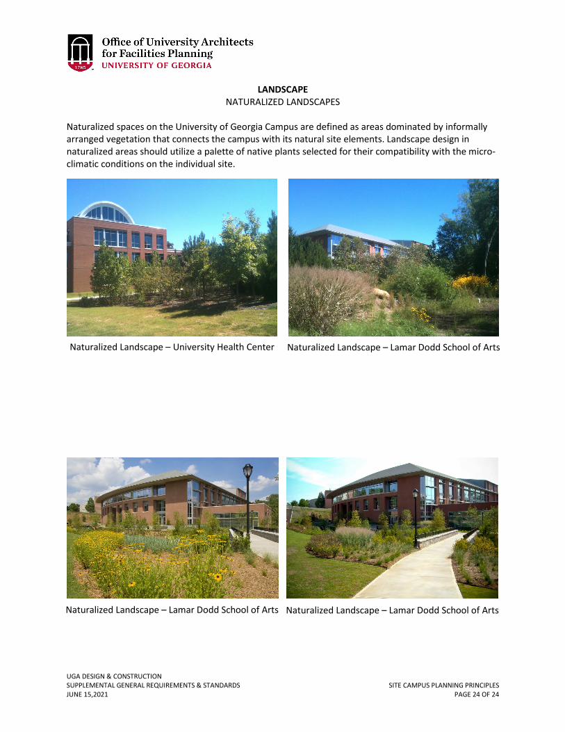
UGA DESIGN & CONSTRUCTION SUPPLEMENTAL GENERAL REQUIREMENTS & STANDARDS SITE CAMPUS PLANNING PRINCIPLES JUNE 15,2021 PAGE 24 OF 24
LANDSCAPE NATURALIZED LANDSCAPES
Naturalized spaces on the University of Georgia Campus are defined as areas dominated by informally arranged vegetation that connects the campus with its natural site elements. Landscape design in naturalized areas should utilize a palette of native plants selected for their compatibility with the micro-climatic conditions on the individual site.
Naturalized Landscape – University Health Center Naturalized Landscape – Lamar Dodd School of Arts
Naturalized Landscape – Lamar Dodd School of Arts Naturalized Landscape – Lamar Dodd School of Arts
UGA DESIGN & CONSTRUCTION SUPPLEMENTAL GENERAL REQUIREMENTS & STANDARDS GENERAL CONCRETE REQUIREMENTS JUNE 15, 2021 03 00 00-1
03 00 00 GENERAL CONCRETE REQUIREMENTS
1. GENERAL
A. Related sections: i. University of Georgia Planning Principles – Site Campus Planning Principles –
Paving – Porous Paving, Page 8 ii. 32 16 23 – Sidewalks
B. Vandalism: The Contractor is responsible for assuring that all exposed concrete surfaces are not vandalized prior to the concrete initial setting. If refinishing or replacement is required due to vandalism during the initial setting the Contractor shall replace the concrete at no cost to the Owner.
C. Rinsing out of transit mix trucks, washing or wetting of concrete, site cleanup, or other activity related to water at the site shall be carried out in strict conformance with the Clean Water Act, Georgia Water Quality Control Act, and Georgia Soil Erosion and Sedimentation Act.
D. Rinsing of transit mix trucks or other concrete mixing devices shall either be off of the Project site or onsite in a contained area, which does not allow run-off. If rinsed in a contained area onsite, run-off must be prevented until concrete dries, at which time it must be removed as solid debris.
E. Fly ash shall not be used in architecturally exposed concrete. 2. PRODUCTS
A. Where appropriate, the Design Professional shall specify porous concrete paving for pedestrian and light vehicle use per approval by the Project Manager.
UGA DESIGN & CONSTRUCTION SUPPLEMENTAL GENERAL REQUIREMENTS & STANDARDS GENERAL MASONRY REQUIREMENTS JUNE 15, 2021 04 00 00-1
04 00 00 GENERAL MASONRY REQUIREMENTS
1. GENERAL
A. Related sections: i. 32 32 53 – Stone Retaining Walls
ii. 32 14 16.13 – Brick Unit and Porous Paving B. Any type of exterior masonry sealer, water repellant, or waterproofing coating is not
allowed. 2. PRODUCTS
A. Regional Materials: Provide granite that is quarried within 200 miles of the Project site. Make available documentation as requested by Project Manager.
i. Basis of design: Grey Elberton Granite, Elberton, Georgia by: Keystone Memorials, Inc. 1595 Washington Hwy, Elberton, GA
B. Regional Materials: Provide brick that is quarried within 500 miles of the Project site. Make available documentation as requested by Project Manager.
C. For reference, the following are brick palettes have been utilized on projects at the UGA Main Campus in Athens:
i. Pharmacy School Addition: Jenkins Brick Company Salisbury, Modular Montgomery Plant HBS Grade SW FBS Grade SW Facing brick ASTM
ii. Paul D. Coverdell Center and Coliseum Training Facility: Pine Hall Brick Wirecut F/R Modular Type FBS Grade SW ASTM Specification C216
iii. Miller Learning Center and Science Learning Center: Cherokee Brick & Tile Company Velour Flash #4, Modular Item 53-05-1094 ASTM Specification C216-01A
iv. Tate Student Center: Boral Brick - Woodward Blend Shelby Tan grout by Holcim
v. Reed Hall: Cherokee Brick & Tile Company – Old Birmingham Shelby Tan grout by Holcim
vi. Interdisciplinary STEM Research Buildings 1 and 2 (Bldg. #s 1131 and 1132): Cherokee Brick Velour Flash
Revised June 15, 2021
UGA DESIGN & CONSTRUCTION SUPPLEMENTAL GENERAL REQUIREMENTS & STANDARDS GENERAL MASONRY REQUIREMENTS JUNE 15, 2021 04 00 00-2
Holcim 200 Ivory Buff grout vii. Reed Plaza:
Cherokee Brick Old Birmingham viii. Sanford Stadium West End:
Boral Bricks Mt. Vernon ix. New First Year Residence Hall (Bldg. # 2264)
Cherokee Brick Old Birmingham Holcim Antique Buff
3. EXECUTION A. Granite inscriptions shall use Legacy font.
Revised June 15, 2021
UGA DESIGN & CONSTRUCTION SUPPLEMENTAL GENERAL REQUIREMENTS & STANDARDS METAL RAILINGS JUNE 15, 2021 05 52 00-1
05 52 00 METAL RAILINGS
1. GENERAL
A. Related sections: i. University of Georgia Planning Principles – Site Campus Planning Principles –
Paving – Stairs and Handrails, Page 12 B. Exterior free-standing handrails at concrete steps shall be mounted on stair treads
inside the concrete cheek walls. C. Final engineering and design of hand rails and guard rails shall be included in the
scope of the Design Professional. 2. PRODUCTS
A. Refer to diagram at end of this section. B. All handrails should be constructed of steel. C. Galvanizing: In order to prevent rust at the bottom of the newel posts and newel post
collars, all newel posts and newel post collars shall be galvanized inside and out. During the galvanizing, the quenching process shall be omitted. The steel to be galvanized should be properly prepared by the steel fabricator to receive a primer coat of paint. It is the Contractor’s option to galvanize just the components in their entirety that will come into contact with the ground or concrete or to galvanize the entire handrail / guardrail assembly.
D. Exterior free-standing handrail i. Steel handrail and channel shall be equal to Julius Blum “Steel Handrail and
Steel Channel” – Part Number: 4441. ii. Steel handrail “Lamb’s Tongue” terminal shall be equal to Julius Blum “Lamb’s
Tongue” – Part Number: 4441-S. Locate end posts top and bottom to allow lamb’s tongue to return to post.
iii. Steel newel posts shall be 1 ½-inch square. iv. Steel newel post collar shall be 1 ½-inchx 1 ½-inch inside dimension. v. Steel vertical pickets, if required by code, shall be ¾-inch x ¾-inch and equally
spaced with maximum clear dimension between vertical pickets per code. Bottom steel channel shall be minimum ½-inch thick x 1 ½-inch wide.
E. Exterior guardrail i. Exterior guardrail with pickets shall be comprised of the same products and
sizes listed for ‘Exterior free-standing handrail.’ F. Exterior wall mounted handrail
i. Steel handrail and channel shall be equal to Julius Blum “Steel Handrail and Steel Channel” – Part Number: 4441.
3. EXECUTION A. Weld all joints and connections, channels, terminals, and posts (continuous), grind
welds smooth prior to priming and painting. B. All handrail material to be primed after all field modifications prior to applying paint. All
material to receive two (2) coats black exterior enamel after installation. Protect all surfaces not receiving paint or primer.
C. Maintain positive drainage away from the bottom of the newel post.
Revised June 15, 2021
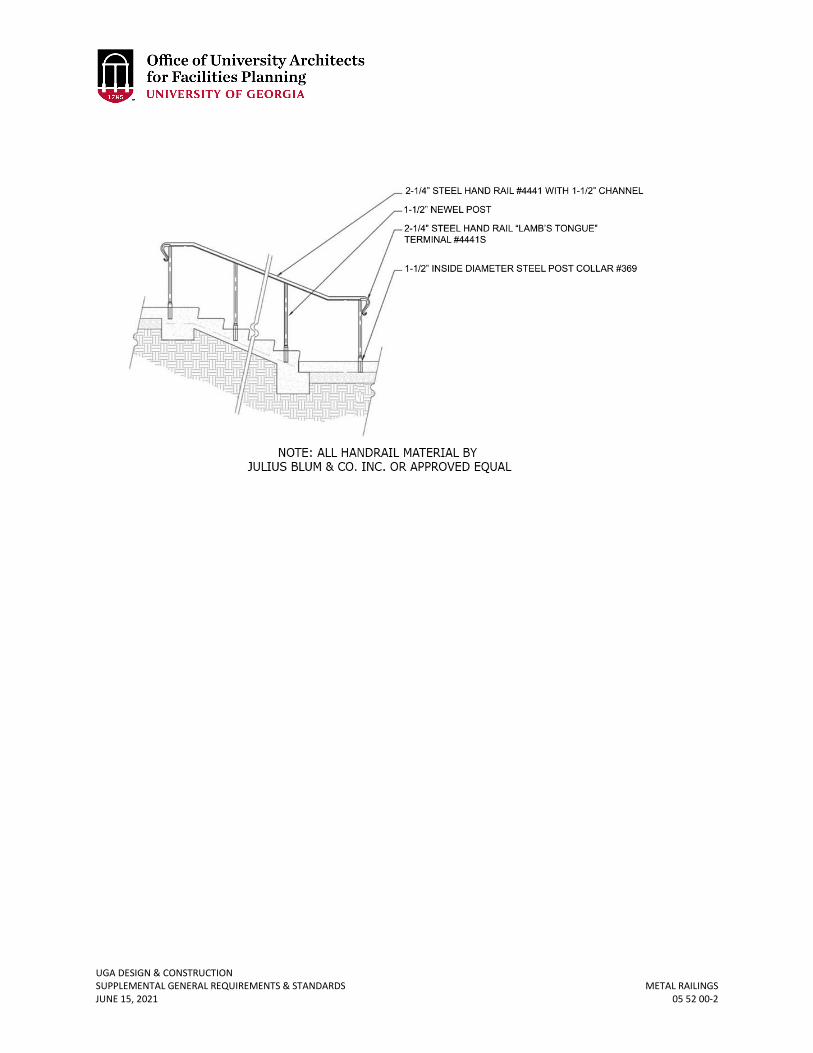
UGA DESIGN & CONSTRUCTION SUPPLEMENTAL GENERAL REQUIREMENTS & STANDARDS METAL RAILINGS JUNE 15, 2021 05 52 00-2
UGA DESIGN & CONSTRUCTION SUPPLEMENTAL GENERAL REQUIREMENTS & STANDARDS GENERAL WOOD, PLASTICS, & COMPOSITES REQUIREMENTS JUNE 15, 2021 06 00 00-1
06 00 00 GENERAL WOOD, PLASTICS, & COMPOSITES REQUIREMENTS
1. GENERAL
A. Related sections: i. 01 35 46 – Indoor Air Quality Procedures – During Construction
ii. 06 61 16 – Solid Surfacing Fabrications iii. 12 00 00 – General Furnishings Requirements iv. 12 36 00 – Countertops
B. Composite and wood agrifiber products include, but are not limited to, particleboard, medium density fiber board (MDF), plywood, wheatboard, door cores, panel substrates, and strawboard.
2. PRODUCTS A. Low volatile organic compound (VOC) materials shall be used within the interior
weatherproofing of the facility; zero when available. Refer to Section 01 35 46 Indoor Air Quality – During Construction.
UGA DESIGN & CONSTRUCTION SUPPLEMENTAL GENERAL REQUIREMENTS & STANDARDS SOLID SURFACING FABRICATIONS JUNE 15, 2021 06 61 00-1
06 61 00 SOLID SURFACE FABRICATIONS
1. GENERAL
A. Related sections: i. 01 35 46 – Indoor Air Quality Procedures – During Construction
ii. 12 00 00 – General Furnishings Requirements iii. 12 36 00 – Countertops
2. PRODUCTS A. Low volatile organic compound (VOC) materials shall be used within the interior
weatherproofing of the facility; zero when available. Refer to Section 01 35 46 Indoor Air Quality – During Construction.
B. For UGA Housing only (New Construction): i. Synthetic solid surfacing for:
a. Open toiletry shelving b. Window sills c. Shower corner caddy d. Shower wall panels e. Shower pans
ii. Synthetic solid surfacing material shall be solid acrylic or polyester and acrylic resin based solid, structural surfacing material:
a. Material shall be through-patterned and homogeneous. No coated materials or non-homogeneous materials allowed.
b. Materials shall be 100% repairable. iii. Synthetic solid surfacing material shall be matte finish iv. Thickness
a. Window sills: ¾-inch b. Shower wall panels: ¼-inch c. Shower caddies: ½-inch d. Shower pans: 1-inch e. Shower corner trim: 3/8-inch
v. Shower pans: a. Shower pan shall be made from solid cast polyester / acrylic blend resin
or 100% acrylic and have adjustable drain locations, coved side walls, with a minimum 1-inch panel platform with a degree slope and 1-foot minimum water dam. It shall have a non-skid floor with water channels directing water to the drain at a 2-degree slope (1/4-inch per foot).
b. Pans shall carry a 10-year materials and workmanship warranty against cracks, breakage, and leaks.
c. Shower pans shall meet the minimum ANSI Z124.2 certification. d. Shower pans shall have a non-slip coefficient of friction rating of 0.20 or
greater as registered by the ASTM F462 slip resistance test method. vi. Shower walls:
a. Adhered, over waterproofing system over cementitious backer board
UGA DESIGN & CONSTRUCTION SUPPLEMENTAL GENERAL REQUIREMENTS & STANDARDS SOLID SURFACING FABRICATIONS JUNE 15, 2021 06 61 00-2
b. Install shower wall panels with adhesive as recommended by manufacturer. Seal joints using manufacturer’s recommended mildew-resistant silicone sealant.
UGA DESIGN & CONSTRUCTION GENERAL THERMAL & MOISTURE PROTECTION SUPPLEMENTAL GENERAL REQUIREMENTS & STANDARDS REQUIREMENTS – ROOF DRAINS & ROOFS JUNE 15, 2021 07 00 00-1
07 00 00 GENERAL THERMAL AND MOISTURE PROTECTION REQUIREMENTS – ROOF DRAINS & ROOFS
1. GENERAL
A. Related sections: i. 07 00 00 – General Thermal Moisture Protection Requirements – Roof Drains
and Roofs ii. 07 31 13 – Asphalt Shingles
iii. 07 41 10 – Copper & Zinc Sheet Metal Roofing iv. 07 41 20 – Steel Standing Seam Metal Roofing v. 07 52 13.11 – Cold Adhesive Applied Atactic-Polypropylene (APP) Modified
Bituminous Membrane Roofing vi. 07 54 23 – Thermoplastic Polyolefin Roofing
vii. 07 62 00 – Sheet Metal Flashing viii. 07 71 23.13 – Gutter Debris Guards
ix. 07 84 00 – Fire Stopping B. Roofing
i. Design Approach a. For new construction, flat and low slope roofs are not allowed to be the
primary roof form for both aesthetic and performance reasons. b. For new construction the roof slope is 9 in 12 slope for buildings with
the Georgian aesthetic. c. For new construction, the design shall minimize the placement of
equipment on the roof. d. A variance may be requested to allow some low slope roof areas to
accommodate mechanical systems. It is not unusual to notch some areas of the sloped roof to provide visual recesses for equipment.
e. An addition to a building with an existing flat or low slope roof may dictate a design solution with a low slope roof. A variance should be requested for such situations.
f. For a low slope roof approved through the variance process, a ¼-inch per foot is the minimum allowed. In some cases, intensive or extensive green roof may be allowed per separate approval by the Project Manager and UGA Grounds Department.
g. The preferred roof material for most new construction is slate or synthetic slate (non-rusticated thin profile). Due to budget constraints asphalt shingles or metal roofs with at least 12-inch panel width may be considered. In some cases, intensive or extensive green roof may be appropriate per approval by the Project Manager and UGA Grounds Department.
h. For some historic buildings a standing seam roof may be appropriate. Often these roofs are zinc coated copper or zinc.
i. Interior drainage is prohibited. In instances where existing conditions necessitate such construction, the Design Professional shall submit a variance request to the Project Manager.
UGA DESIGN & CONSTRUCTION GENERAL THERMAL & MOISTURE PROTECTION SUPPLEMENTAL GENERAL REQUIREMENTS & STANDARDS REQUIREMENTS – ROOF DRAINS & ROOFS JUNE 15, 2021 07 00 00-2
ii. General a. Many existing roofs on campus contain asbestos and the Design
Professional and Contractor shall be responsible for removal and disposal per applicable codes and regulations.
b. Contractor shall protect all roof drainage systems during all roof repairs and all roof work. If these roof drainage systems are not protected, maintained or remain open, the Contractor shall be held liable for all damages in the building and on the roof resulting from this failure to protect. Interior drainage is discouraged, unless existing conditions necessitate such construction. Access panels shall be provided to all interior drain pipes and cleanouts to allow for inspection and maintenance of interior chases.
c. Roof-mounted equipment such as fume hoods fans, motor starters, etc. shall be installed on fully flashed curbs. When set on stands, allow 24 inches minimum clearance to facilitate repairs to equipment and allow for roof repair and reroofing. Equipment is not allowed to be mounted on pressure-treated wood, plastic pads or panels set directly on roof surface. Curb caps shall not be penetrated by attachment of motors or equipment. Install raised brackets that attach thru the side of curbs and allow equipment attachment without penetrating curb cap.
d. For steep roofs, greater than 5 in 12 slope, include OSHA compliant fall arrest and roof anchor systems.
e. Roofs with parapet walls less than 42 inches in height may require fall arrest anchors. For low slope roofs greater than 3 stories in height, fall restraint anchors shall be installed.
f. Stone precast concrete or metal coping systems require a complete thru wall flashing system. Flash the roof side of parapet walls the full height.
iii. Reroofing a. Scaled roof plans should indicate, as accurately as possible the locations
of existing drains, equipment, vents, hatches, parapets, gutters, scuppers, and other items in fixed locations.
b. The Design Professional shall determine when new emergency drainage is required and shall add overflow scuppers to the design as required.
c. Determine the extent of materials to be removed. If the scope cannot be predetermined, the Design Professional should include provision in contract that will allow on-site evaluation for the extent of work.
d. Complete removal of the existing roofing system to the surface of the roof deck is required by the Contractor. The Contractor shall take all necessary steps to insure that while removing the existing roof system, that the Contractor does not damage the existing roof deck. The Design Professional shall inspect the roof deck for damage and document the repairs / replacement that will be required for the Contractor to perform.
e. Only when project conditions warrant, identify components (e.g. mechanical equipment) that are required to be removed to facilitate roof repairs and upgrading.
UGA DESIGN & CONSTRUCTION GENERAL THERMAL & MOISTURE PROTECTION SUPPLEMENTAL GENERAL REQUIREMENTS & STANDARDS REQUIREMENTS – ROOF DRAINS & ROOFS JUNE 15, 2021 07 00 00-3
f. Provide a schedule when differing locations require definition as to extent of removal work and identify the subsequent roofing system to be installed.
g. Ascertain that roof repairs and especially those involving new roof penetrations do not void existing roof warranties. The Project Manager will assist the Design Professional in determining who holds the current warranties.
h. Provide the Project Manager with details of boots, sleeves, flashing, counter-flashing, curbs, crickets, etc. compatible with the roofing systems.
i. The preferred method of flashing penetrations through flat roofs involves the construction of a curb around the opening. Small penetrations do not require curbs.
C. Flashing i. Thru-Wall Flashing: Contractor shall inspect and certify proper installation of all
thru-wall flashing. Prior to installation of first piece of thru-wall flashing related to the wall system and prior to the first piece of thru-wall flashing related to the roof system, the Contractor shall coordinate an on-site meeting so that the Project Manager (or another person requested by the Project Manager, for example, the Design Professional) can be on site and witness the installation prior to it being covered up. It is the responsibility of the Contractor to allow time in the schedule for each of these initial inspections. The Contractor shall create and maintain a Thru-Wall Flashing Log listing the date, time, and area inspected and provide copies of the log at each job site meeting. The Contractor shall photo document inspections and each photo shall have a date and time stamp. The Contractor shall provide digital copies of the photos within 24 hours upon the Project Manager’s request. The log and photos shall be part of the close-out documentation.
ii. The reuse of existing counter flashing materials is discouraged. The Design Professional shall specify the installation of new counter flashing in materials matching the existing materials.
2. PRODUCTS A. All thru-wall flashing shall be stainless steel backplate with 40 mil rubberized asphalt
peel and stick over the top for a seamless system.
UGA DESIGN & CONSTRUCTION SUPPLEMENTAL GENERAL REQUIREMENTS & STANDARDS Closed-Cell Spray Foam Insulation JUNE 15, 2021 07 21 19-1
07 21 19 CLOSED-CELL SPRAY POLYURETHANE FOAM INSULATION
1. GENERAL
A. Related sections: i. 00 73 01 – Sole Source / Sole Brand
2. PRODUCTS A. This product has sole source approval and the manufacture is:
i. GacoWallFoam 183M by Gaco Western a. Gaco Western, LLC. b. Address: 200 Wests Mercer Street, Suite #202, Seattle, WA, 98119 c. Office Phone: 800-331-0196 d. Website: www.gaco.com
UGA DESIGN & CONSTRUCTION SUPPLEMENTAL GENERAL REQUIREMENTS & STANDARDS EXTERIOR INSULATION & FINISH SYSTEM (EIFS) JUNE 15, 2021 07 24 00-1
07 24 00 EXTERIOR INSULATION AND FINISH SYSTEM (EIFS)
1. GENERAL
A. The BOR and the UGA prohibits the use of Exterior Insulation Finish Systems (EIFS).
UGA DESIGN & CONSTRUCTION SUPPLEMENTAL GENERAL REQUIREMENTS & STANDARDS ASPHALT SHINGLES JUNE 15, 2021 07 31 13-1
07 31 13 ASPHALT SHINGLES
1. GENERAL
A. Related sections: i. 01 35 13.02 – Special Project Procedures – Roofing & Hot Work
ii. 07 00 00 – General Thermal Moisture Protection Requirement – Roof Drains and Roofs
iii. 07 62 00 – Sheet Metal Flashing iv. 07 71 23.13 – Gutter Debris Guards
B. Asphalt shingles shall be “dimensional” or “architectural” type. C. Project Manager shall approve color selection.
2. PRODUCTS A. Acceptable manufacturers are:
i. Strip Shingle with laminated tabs: Three-tab type with random laminated tabs and random shadow line.
a. GAF Timberline HD b. Owens Corning Oakridge c. Tamko Heritage 30
B. Roofing Felt Underlayment i. Underlayment shall be synthetic mat manufactured from UV stabilized
polypropylene rolls 54 inches wide by 222 feet long. Equal to “Deck Armor” as manufactured by GAF Corp.
C. Penetration Flashing i. Vent pipe flashing shall be equal to “Water-Tite Boots” as manufactured by IPS
Roofing Products. Base manufactured from plastic, copper or aluminum multi-sized unit for 1-1/2-inch, 2-inch, 3-inch, and 4-inch pipe.
ii. Spilt pipe flashing shall be equal to “ASI Retrokit” as supplied by Copperstate Roofing Supply. It shall include galvanized steel base, collar assembly, and clamp.
D. Mod Bit Underlayment i. Self-adhesive membrane manufactured from elastomeric blend of asphalt with
polyethylene film intended for use as shingle underlayment at transitions, roof-wall intersections, eaves, rakes and similar roof perimeters and around penetrations. Membrane shall be installed at all walls adjacent to roofing and at all penetrations. Minimum thickness 40 mils, minimum 36-inch wide rolls. High temperature formulation.
3. EXECUTION A. Warranty
i. Manufacturer’s 30-year system warranty is required.
UGA DESIGN & CONSTRUCTION SUPPLEMENTAL GENERAL REQUIREMENTS & STANDARDS COPPER & ZINC SHEET METAL ROOFING JUNE 15, 2021 07 41 10-1
07 41 10 COPPER & ZINC SHEET METAL ROOFING
1. GENERAL
A. Related sections: i. 01 35 13.02 – Special Project Procedures – Roofing & Hot Work
ii. 07 00 00 – General Thermal and Moisture Protection Requirements iii. 07 62 00 – Sheet Metal Flashing iv. 07 71 23.13 – Gutter Debris Guards
B. References i. Copper Development Association (CDA) – Contemporary Copper, A Handbook of
Sheet Copper Fundamentals, Design, Details and Specifications. ii. Sheet Metal and Air Conditioning Contractors National Association (SMACNA) –
Architectural Sheet Metal Manual, latest edition. C. At the UGA Athens, Georgia campus, sheet metal roofs are most often used on historic
buildings. D. Qualifications: Fabricators and subcontractors shall be pre-approved and deemed
acceptable by virtue of having completed at least three comparable projects in the past three years. Examples of comparables shall be documented and an opportunity for site inspection may be required. Personnel responsible for the work shall be identified and should be associated with the comparable projects documented.
E. Submittals i. Product date including metal manufacturers and fabricator’s specifications,
installation instructions, and general recommendations for roofing applications. Include certification or other data substantiating that materials comply with requirements.
ii. Samples: a. 6-inch square sample of specified sheet metal roofing materials in
thickness indicated. b. Waterproofing sheet membrane underlayment.
iii. Shop drawings showing manner of forming, joining, and securing copper roofing, and pattern of seams. Show expansion joint details and waterproofing connections to adjoining work and at obstructions and penetrations. Indicate types of thicknesses of metal and dimensions. Provide layouts at ¼-inch scale and details at 3-inch scale.
iv. Mock-up: Before proceeding with final purchase of materials and fabrication of copper roofing components, prepare a mock-up of work. Incorporate materials and methods of fabrication and installation identical with project requirements. Install mock-up at roof area location directed by Design Professional. Retain accepted mock-up as quality standard for acceptance of completed copper roofing. If accepted, mock-up may be incorporated as part of copper roofing work.
a. Provide mock-up of sufficient size and scope to show typical pattern of seams, fastening details, edge construction, and finish texture and color.
2. PRODUCTS A. Copper or Zinc Coated Copper Roofing Sheets
UGA DESIGN & CONSTRUCTION SUPPLEMENTAL GENERAL REQUIREMENTS & STANDARDS COPPER & ZINC SHEET METAL ROOFING JUNE 15, 2021 07 41 10-2
i. Z-T Alloy Coated Copper Sheets: Zinc / Tin coated copper sheet, ASTM B 370; temper H00 (cold-rolled) except where temper 060 is required for forming; thickness as indicated. Provide zinc / tin coating of 0.5 mils thick; both sides of copper sheet. Composition of the alloy shall be approximately 50-percent zinc and 50-percent tin with trace elements controlled for durability, corrosion resistance and color.
a. Roofing Sheets: Weight: 20 oz. per sq. ft. unless otherwise indicated. ii. Product: Freedom Gray, Z-T Alloy Coated Copper, as manufactured by Revere
Copper Products, Inc., or approved equal. B. Zinc Roof Panels
i. Equal to Rheinzink 24 gauge and the manufacturer’s approved underlayment to control condensation.
C. Shop-Fabricated Units i. General Metal Fabrication: Shop-fabricate work to greatest extent possible.
Comply with details shown and with applicable requirements of CDA “Copper in Architecture Handbook” and SMACNA “Architectural Sheet Metal Manual” and other recognized industry practices. Fabricate for waterproof and weather-resistant performance with expansion provisions for running work, sufficient to permanently prevent leakage, damage, or deterioration of the work. Form work to fit substrate. Comply with material manufacturer’s instructions and recommendations for forming materials. For exposed copper work without excessive oil-canning, buckling, and too marks, true to line and levels indicate, with exposed edges folded back to form hems.
D. Underlayment i. System shall include high temperature self-adhesive modified bitumen
underlayment. 3. EXECUTION
A. Preparation i. Coordinate metal roofing with rain drainage work, flashing, trim, roof decking
replacement (if applicable), and other adjoining work to provide a permanently leak proof, secure, and noncorrosive installation.
B. Installation of Metal Roofing i. Except as otherwise indicated, comply with manufacturer’s installation
instructions and recommendations and with CDA “Copper in Architecture Handbook” and SMACNA “Architectural Sheet Metal Manual.” Anchor units of work securely in place by methods indicated, providing for thermal expansion of metal units; conceal fasteners where possible, and set units true to line and level as indicated. Install work with laps, joints, and seams that will be permanently watertight and weatherproof.
ii. All seams shall be crimped. iii. Construct the hip and ridge cap flashing by hand rolling panels to form
watertight joints. Ridge and hip caps are not acceptable. C. Warranty
i. The Manufacturer shall provide a 30-year system warranty.
UGA DESIGN & CONSTRUCTION SUPPLEMENTAL GENERAL REQUIREMENTS & STANDARDS STEEL STANDING SEAM SHEET METAL ROOFING JUNE 15, 2021 07 41 20-1
07 41 20 STEEL STANDING SEAM SHEET METAL ROOFING
1. GENERAL
A. Related sections: i. 01 35 13.02 – Special Project Procedures – Roofing & Hot Work
ii. 07 00 00 – General Thermal and Moisture Protection Requirements iii. 07 62 00 – Sheet Metal Flashing iv. 07 71 23.13 – Gutter Debris Guards
B. Qualifications: Fabricators and Subcontractors shall be pre-approved and deemed acceptable by virtue of having completed at least three comparable projects in the past three years. Examples of comparables shall be documented and an opportunity for site inspection may be required. Personnel responsible for the work shall be identified and should be associated with the comparable projects documented.
C. Submittals i. Product date including metal manufacturers and fabricator’s specifications,
installation instructions, and general recommendations for roofing applications. Include certification or other data substantiating that materials comply with requirements.
ii. Samples: a. Square sample of specified metal roofing materials in thickness
indicated. b. Waterproofing sheet membrane underlayment.
iii. Shop drawings showing manner of joining and securing roofing, and pattern of seams. Show expansion joint details and waterproofing connections to adjoining work and at obstructions and penetrations. Indicate types of thicknesses of metal and dimensions. Provide layouts at ¼-inch scale and details at 3-inch scale.
iv. Mock-up: Before proceeding with final purchase of materials and fabrication of roofing components, prepare a mock-up of work. Incorporate materials and methods of fabrication and installation identical with project requirements. Install mock-up at roof area location directed by Design Professional. Retain accepted mock-up as quality standard for acceptance of completed roofing. If accepted, mock-up may be incorporated as part of roofing work.
a. Provide mock-up of sufficient size and scope to show typical pattern of seams, fastening details, edge construction, and finish texture and color.
2. PRODUCTS A. Roof Panels shall be:
i. Roll formed, 24 gauge galvanized steel (42,000 PSI yield), sheet coated on both sides with 1.25 ounce zinc coating, G-90 conforming to ASTM A525. Mechanically seamed cap strip with factory applied weather stripping.
ii. Finish: Manufacturer’s standard color Kynar 500 fluoropolymer. iii. Style: Thin Seam
a. Width: (see note on standing seam spacing) b. Panel depth: 1 ¾-inch c. 2 stiffening flues centered in the flat plan
UGA DESIGN & CONSTRUCTION SUPPLEMENTAL GENERAL REQUIREMENTS & STANDARDS STEEL STANDING SEAM SHEET METAL ROOFING JUNE 15, 2021 07 41 20-2
iv. Standing Seam Spacing: a. Standing seam spacing shall be coordinated with the Project Manager to
ensure proper aesthetic spacing for the building. Standing seams spaced 12 inches on center or 16 inches on center are typical spacing dimensions. 18 inches on center may be considered. 24 inches on center standing seam spacing is not acceptable.
v. Mounting Clip: Fabricated from 22-guage stainless steel with two fasteners through the 3-inch length.
vi. Panel Length: As field measured to assure no panel end seams. 3. EXECUTION
A. Preparation i. Coordinate metal roofing with rain drainage work, flashing, trim, roof decking
replacement (if applicable), and other adjoining work to provide a permanently leak proof, secure, and noncorrosive installation.
B. Installation of Metal Roofing i. Anchor units of work securely in place by methods indicated, providing for
thermal expansion of metal units; conceal fasteners where possible, and set units true to line and level as indicated. Install work with laps, joints, and seams that will be permanently watertight and weatherproof.
C. Warranty i. The Manufacturer shall provide a 30-year system warranty.
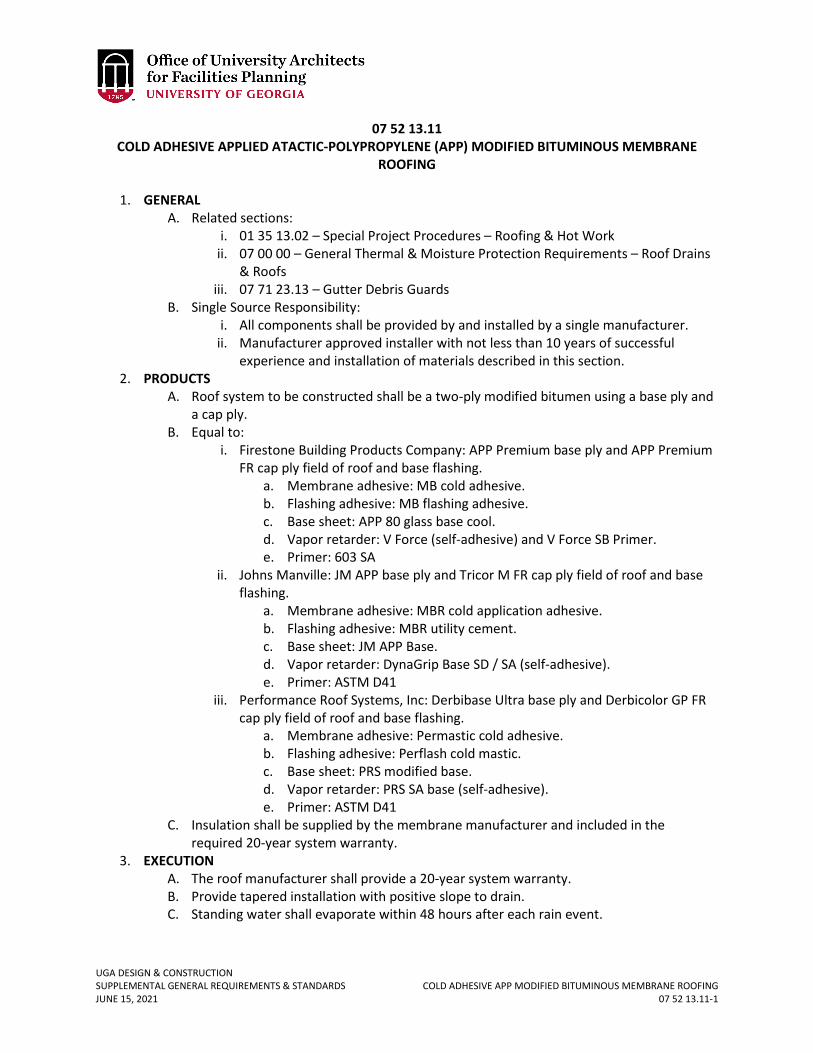
UGA DESIGN & CONSTRUCTION SUPPLEMENTAL GENERAL REQUIREMENTS & STANDARDS COLD ADHESIVE APP MODIFIED BITUMINOUS MEMBRANE ROOFING JUNE 15, 2021 07 52 13.11-1
07 52 13.11 COLD ADHESIVE APPLIED ATACTIC-POLYPROPYLENE (APP) MODIFIED BITUMINOUS MEMBRANE
ROOFING
1. GENERAL A. Related sections:
i. 01 35 13.02 – Special Project Procedures – Roofing & Hot Work ii. 07 00 00 – General Thermal & Moisture Protection Requirements – Roof Drains
& Roofs iii. 07 71 23.13 – Gutter Debris Guards
B. Single Source Responsibility: i. All components shall be provided by and installed by a single manufacturer.
ii. Manufacturer approved installer with not less than 10 years of successful experience and installation of materials described in this section.
2. PRODUCTS A. Roof system to be constructed shall be a two-ply modified bitumen using a base ply and
a cap ply. B. Equal to:
i. Firestone Building Products Company: APP Premium base ply and APP Premium FR cap ply field of roof and base flashing.
a. Membrane adhesive: MB cold adhesive. b. Flashing adhesive: MB flashing adhesive. c. Base sheet: APP 80 glass base cool. d. Vapor retarder: V Force (self-adhesive) and V Force SB Primer. e. Primer: 603 SA
ii. Johns Manville: JM APP base ply and Tricor M FR cap ply field of roof and base flashing.
a. Membrane adhesive: MBR cold application adhesive. b. Flashing adhesive: MBR utility cement. c. Base sheet: JM APP Base. d. Vapor retarder: DynaGrip Base SD / SA (self-adhesive). e. Primer: ASTM D41
iii. Performance Roof Systems, Inc: Derbibase Ultra base ply and Derbicolor GP FR cap ply field of roof and base flashing.
a. Membrane adhesive: Permastic cold adhesive. b. Flashing adhesive: Perflash cold mastic. c. Base sheet: PRS modified base. d. Vapor retarder: PRS SA base (self-adhesive). e. Primer: ASTM D41
C. Insulation shall be supplied by the membrane manufacturer and included in the required 20-year system warranty.
3. EXECUTION A. The roof manufacturer shall provide a 20-year system warranty. B. Provide tapered installation with positive slope to drain. C. Standing water shall evaporate within 48 hours after each rain event.
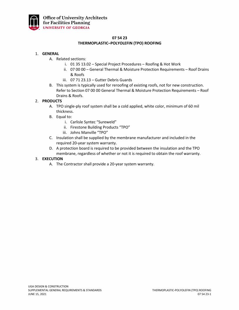
UGA DESIGN & CONSTRUCTION SUPPLEMENTAL GENERAL REQUIREMENTS & STANDARDS THERMOPLASTIC-POLYOLEFIN (TPO) ROOFING JUNE 15, 2021 07 54 23-1
07 54 23 THERMOPLASTIC–POLYOLEFIN (TPO) ROOFING
1. GENERAL
A. Related sections: i. 01 35 13.02 – Special Project Procedures – Roofing & Hot Work
ii. 07 00 00 – General Thermal & Moisture Protection Requirements – Roof Drains & Roofs
iii. 07 71 23.13 – Gutter Debris Guards B. This system is typically used for reroofing of existing roofs, not for new construction.
Refer to Section 07 00 00 General Thermal & Moisture Protection Requirements – Roof Drains & Roofs.
2. PRODUCTS A. TPO single-ply roof system shall be a cold applied, white color, minimum of 60 mil
thickness. B. Equal to:
i. Carlisle Syntec “Sureweld” ii. Firestone Building Products “TPO”
iii. Johns Manville “TPO” C. Insulation shall be supplied by the membrane manufacturer and included in the
required 20-year system warranty. D. A protection board is required to be provided between the insulation and the TPO
membrane, regardless of whether or not it is required to obtain the roof warranty. 3. EXECUTION
A. The Contractor shall provide a 20-year system warranty.
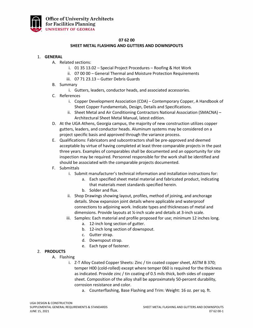
UGA DESIGN & CONSTRUCTION SUPPLEMENTAL GENERAL REQUIREMENTS & STANDARDS SHEET METAL FLASHING AND GUTTERS AND DOWNSPOUTS JUNE 15, 2021 07 62 00-1
07 62 00 SHEET METAL FLASHING AND GUTTERS AND DOWNSPOUTS
1. GENERAL
A. Related sections: i. 01 35 13.02 – Special Project Procedures – Roofing & Hot Work
ii. 07 00 00 – General Thermal and Moisture Protection Requirements iii. 07 71 23.13 – Gutter Debris Guards
B. Summary i. Gutters, leaders, conductor heads, and associated accessories.
C. References i. Copper Development Association (CDA) – Contemporary Copper, A Handbook of
Sheet Copper Fundamentals, Design, Details and Specifications. ii. Sheet Metal and Air Conditioning Contractors National Association (SMACNA) –
Architectural Sheet Metal Manual, latest edition. D. At the UGA Athens, Georgia campus, the majority of new construction utilizes copper
gutters, leaders, and conductor heads. Aluminum systems may be considered on a project specific basis and approved through the variance process.
E. Qualifications: Fabricators and subcontractors shall be pre-approved and deemed acceptable by virtue of having completed at least three comparable projects in the past three years. Examples of comparables shall be documented and an opportunity for site inspection may be required. Personnel responsible for the work shall be identified and should be associated with the comparable projects documented.
F. Submittals i. Submit manufacturer’s technical information and installation instructions for:
a. Each specified sheet metal material and fabricated product, indicating that materials meet standards specified herein.
b. Solder and flux. ii. Shop Drawings showing layout, profiles, method of joining, and anchorage
details. Show expansion joint details where applicable and waterproof connections to adjoining work. Indicate types and thicknesses of metal and dimensions. Provide layouts at ¼-inch scale and details at 3-inch scale.
iii. Samples: Each material and profile proposed for use; minimum 12 inches long. a. 12-inch long section of gutter. b. 12-inch long section of downspout. c. Gutter strap. d. Downspout strap. e. Each type of fastener.
2. PRODUCTS A. Flashing
i. Z-T Alloy Coated Copper Sheets: Zinc / tin coated copper sheet, ASTM B 370; temper H00 (cold-rolled) except where temper 060 is required for the thickness as indicated. Provide zinc / tin coating of 0.5 mils thick, both sides of copper sheet. Composition of the alloy shall be approximately 50-percent durability, corrosion resistance and color.
a. Counterflashing, Base Flashing and Trim: Weight: 16 oz. per sq. ft.
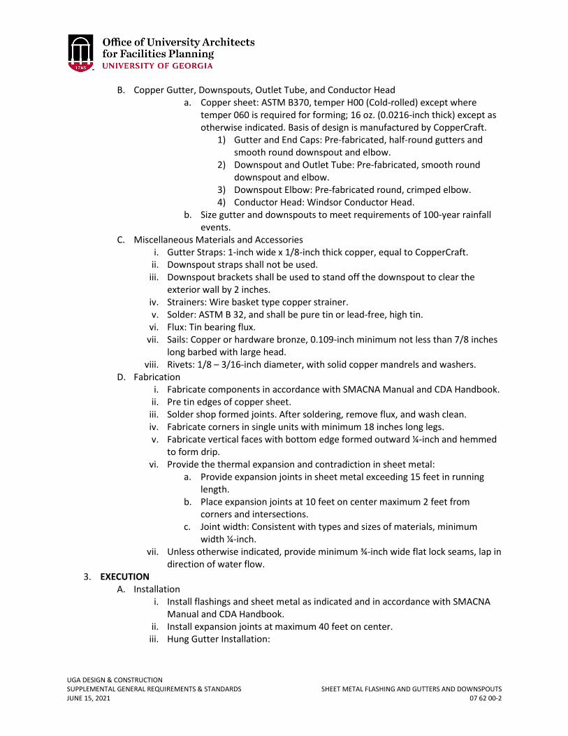
UGA DESIGN & CONSTRUCTION SUPPLEMENTAL GENERAL REQUIREMENTS & STANDARDS SHEET METAL FLASHING AND GUTTERS AND DOWNSPOUTS JUNE 15, 2021 07 62 00-2
B. Copper Gutter, Downspouts, Outlet Tube, and Conductor Head a. Copper sheet: ASTM B370, temper H00 (Cold-rolled) except where
temper 060 is required for forming; 16 oz. (0.0216-inch thick) except as otherwise indicated. Basis of design is manufactured by CopperCraft.
1) Gutter and End Caps: Pre-fabricated, half-round gutters and smooth round downspout and elbow.
2) Downspout and Outlet Tube: Pre-fabricated, smooth round downspout and elbow.
3) Downspout Elbow: Pre-fabricated round, crimped elbow. 4) Conductor Head: Windsor Conductor Head.
b. Size gutter and downspouts to meet requirements of 100-year rainfall events.
C. Miscellaneous Materials and Accessories i. Gutter Straps: 1-inch wide x 1/8-inch thick copper, equal to CopperCraft.
ii. Downspout straps shall not be used. iii. Downspout brackets shall be used to stand off the downspout to clear the
exterior wall by 2 inches. iv. Strainers: Wire basket type copper strainer. v. Solder: ASTM B 32, and shall be pure tin or lead-free, high tin.
vi. Flux: Tin bearing flux. vii. Sails: Copper or hardware bronze, 0.109-inch minimum not less than 7/8 inches
long barbed with large head. viii. Rivets: 1/8 – 3/16-inch diameter, with solid copper mandrels and washers.
D. Fabrication i. Fabricate components in accordance with SMACNA Manual and CDA Handbook.
ii. Pre tin edges of copper sheet. iii. Solder shop formed joints. After soldering, remove flux, and wash clean. iv. Fabricate corners in single units with minimum 18 inches long legs. v. Fabricate vertical faces with bottom edge formed outward ¼-inch and hemmed
to form drip. vi. Provide the thermal expansion and contradiction in sheet metal:
a. Provide expansion joints in sheet metal exceeding 15 feet in running length.
b. Place expansion joints at 10 feet on center maximum 2 feet from corners and intersections.
c. Joint width: Consistent with types and sizes of materials, minimum width ¼-inch.
vii. Unless otherwise indicated, provide minimum ¾-inch wide flat lock seams, lap in direction of water flow.
3. EXECUTION A. Installation
i. Install flashings and sheet metal as indicated and in accordance with SMACNA Manual and CDA Handbook.
ii. Install expansion joints at maximum 40 feet on center. iii. Hung Gutter Installation:
UGA DESIGN & CONSTRUCTION SUPPLEMENTAL GENERAL REQUIREMENTS & STANDARDS SHEET METAL FLASHING AND GUTTERS AND DOWNSPOUTS JUNE 15, 2021 07 62 00-3
a. Hangers shall be of adjustable shank and circle type, secured by brass screws. Hangers shall be spaced not more than 32 inches apart.
b. Outlet Tubes: Connect to outside leader or downspout with locked and soldered longitudinal seam. Upper end of tube shall be flanged ½-inch to gutter lining. Tube shall extend into leader at least 3 inches.
UGA DESIGN & CONSTRUCTION SUPPLEMENTAL GENERAL REQUIREMENTS & STANDARDS GUTTER AND DEBRIS GUARDS JUNE 15, 2021 07 71 23.13-1
07 71 23.13 GUTTER AND DEBRIS GUARDS
1. GENERAL
A. Related sections: i. 07 00 00 – General Thermal & Moisture Protection Requirements – Roof Drains
& Roofs ii. 07 31 13 – Asphalt Shingles
iii. 07 41 10 – Copper & Zinc Sheet Metal Roofing iv. 07 41 20 – Steel Standing Seam Sheet Metal Roofing v. 07 52 13.11 – Cold Adhesive Applied Atactic – Polypropylene (APP) Modified
Bituminous Membrane Roofing vi. 07 54 23 – Thermoplastic-Polyolefin (TPO) Roofing
vii. 07 62 00 – Sheet Metal Flashing viii. 07 84 00 – Fire Stopping
B. Gutter Debris Guards shall be included on all gutters for sloped roofs that are located under a canopy of trees or will be susceptible to leaf collection. Coordinate with the Project Manager.
C. If conductor drains are utilized, they shall have guards to prevent pigeons from nesting. 2. PRODUCTS
A. Acceptable Debris Guard manufacturers are equal to: i. Hallett Gutter Cover
ii. Gutter Helmet by Southeastern Metals Manufacturing Company, Inc. B. Screws shall be stainless steel or aluminum to attach to the clip. C. Colors shall be coordinated with Project Manager. D. Debris guard material shall be compatible with gutter material to avoid galvanic
corrosion.
UGA DESIGN & CONSTRUCTION SUPPLEMENTAL GENERAL REQUIREMENTS & STANDARDS FIRE STOPPING JUNE 15, 2021 07 84 00-1
07 84 00 FIRE STOPPING
1. GENERAL
A. Related sections: i. 27 00 00 – General Communications Requirements
B. Contractor shall be required to provide verification of purchase to UGA of product provided for fire stopping penetrations through rated partitions.
C. UGA reserves the right to verify that the correct thickness of material has been provided at fire-stopped penetrations by cutting out sections at random at no extra cost to the contract.
D. Fire stop installer shall post labels at all fire stopped penetrations to identify “hour rating”, UL System, etc. Submit samples with shop drawing submittals.
E. The installing Contractor shall be trained and authorized by the manufacturer of the fire stop product used to do the work; authorization shall be included in product submittals.
F. The manufacturer’s local representative shall be required to periodically visit the site to review the work done and make recommendations to UGA on the work performed. A site visit report shall be submitted to the Project Manager.
G. Floor penetrations in all mechanical spaces shall be sealed and water-proofed. On new construction sleeves shall be cast-in-place schedule 40 steel pipe and shall project 3 inches above the floor in all above grade rooms housing mechanical equipment.
H. All fire rated penetrations related to communications rooms, telecommunication conduit (MDF and IDF) shall be per Section 27 00 00 General Communications Requirements, 2B.
2. PRODUCTS A. Acceptable manufactures are:
i. Fire Protection Products ii. Flame Stop, Inc.
iii. Hilti Corporation iv. Specified Technologies, Inc.
UGA DESIGN & CONSTRUCTION SUPPLEMENTAL GENERAL REQUIREMENTS & STANDARDS DOOR AND FRAMES JUNE 15, 2021 08 10 00-1
08 10 00 DOORS AND FRAMES
1. GENERAL 2. PRODUCTS
A. All hollow metal door frames shall have welded joints. B. Knock down door frames (factory pre-finished steel door frames which are delivered to
the site in pieces for field assembly) are allowed in certain cases with UGA Project Manager approval.
C. All doors shall be commercial / institutional thickness of 1 ¾-inch. D. For new construction, interior wood doors shall be stain grade structural composite
lumber / laminated strand lumber with birch veneer that either receives a clear coat finish or stain.
E. For new construction, interior paint grade, painted wood doors shall not be specified (see exception below for UGA Housing).
F. For UGA Housing Only (New Construction) i. Design Professional to coordinate with Project Manager.
ii. Steel Doors (Per ANSI / Steel Door Institute definitions): a. Interior hollow metal doors shall be Level III, 16 ga., Extra Heavy Duty,
Model Two seamless, 1 ¾-inch thickness. b. Exterior metal doors shall be insulated composite metal doors, Level III,
16 ga., Extra Heavy Duty, Model Two seamless, 1 ¾-inch thickness with polyurethane core.
c. Label fire resistive metal doors shall be fire resistive composite metal doors, Level III, 16 ga., Extra Heavy Duty, Model Two seamless, 1 ¾-inch thickness, with mineral fiberboard core for ratings over 20 minutes.
iii. Wood Doors (generally used at student rooms): a. Glued particleboard or structural composite lumber (SCL) core wood
doors meeting AWI Standards, five-ply veneer face construction, AWI PC5, 1-3/4 inches thickness, Type II or better.
1) Adhesives shall not contain urea formaldehyde. 2) For doors indicated to receive closers, provide 15 inches high
top rail and top rail shall accommodate specified hardware without through-bolting hardware.
3) Core: Single-piece particle board meeting ANSI A208.1, Grade LD-1 or LD-2, DPC-1, or SCL made with binder containing no added urea formaldehyde resin.
4) Construction: solid hardware, engineered laminated strand lumber or SCL tiles and rails glued to core; core assembly sanded for uniform thickness.
5) Fire resistance rating: comply with specified requirements for tested, labeled door construction for Project.
6) Lite/lock conflicts: follow door manufacturer’s guidelines to avoid lite/lock conflicts in order to maintain fire-rating and warranty.
UGA DESIGN & CONSTRUCTION SUPPLEMENTAL GENERAL REQUIREMENTS & STANDARDS DOOR AND FRAMES JUNE 15, 2021 08 10 00-2
b. Facing for opaque finish: medium density fiberboard overly (MDO/MDF). Plastic Laminate is also acceptable.
UGA DESIGN & CONSTRUCTION SUPPLEMENTAL GENERAL REQUIREMENTS & STANDARDS ALUMINUM WINDOWS JUNE 15, 2021 08 51 13-1
08 51 13 ALUMINUM WINDOWS
1. GENERAL 2. PRODUCTS - For UGA Housing Only (New Construction)
A. Single Hung Windows i. Finish: Warrant fluoropolymer coating to remain free of checking, crazing,
peeling, chalking, or fading for a period of 15 years, beginning at date of Material Completion.
ii. Sill locks: Aluminum automatic sill locks, two per window. iii. Sash shall be set to open not more than 6 inches by unauthorized
personnel. iv. Security screens shall be security level 5 rating at operable windows with grade-
level access. v. Internal muntin grids: Insulated glass units shall be fabricated with internal
muntin grids in air space between interior and exterior glass, for simulated divided lites.
UGA DESIGN & CONSTRUCTION SUPPLEMENTAL GENERAL REQUIREMENTS & STANDARDS DOOR HARDWARE JUNE 15, 2021 08 71 00-1
08 71 00 DOOR HARDWARE
1. GENERAL
A. Related sections: i. 00 73 01 – Approved Sole Source / Sole Brand
ii. 08 80 00 – Glazing iii. 28 13 00 – Access Control
B. For UGA Athens Campus projects (excluding Housing projects): The UGA has sole source approval for Best Access Systems cylinders and cores. The Contractor includes the cylinders as part of the Cost of the Work or the Bid and makes payment directly to Best Access Systems. Best Access Systems ships the cylinders directly to the UGA FMD Key Shop. The FMD Key Shop finalizes keying and the permanent cores are installed by UGA. The Contractor furnishes and installs keyed temporary cores as required for the Project. For UGA Housing projects, keying is handled directly by the UGA Housing Department. Coordinate specific requirements on a project-by-project basis with the Project Manager.
C. Keying Schedule: The Contractor shall coordinate and document a meeting with the Best Access Systems representative, the Project Manager, and the FMD Key Shop to coordinate a final keying schedule. For Housing projects, the contractor and hardware vendor shall coordinate with the Project Manager and the Housing key shop. The Contractor shall prepare the final keying schedule based on this meeting that clearly indicates how the UGA’s final instructions on keying of locks has been fulfilled and submit it as part of the hardware submittal process.
D. Single Source Responsibility: Obtain each type of hardware latch and locksets, hinges, closers, etc. from a single manufacturer.
E. No swing type door hardware shall be used such that it would allow for the chaining of the doors from the interior of the building.
2. PRODUCTS A. Cylinders and Cores:
i. This product has sole source approval and shall be Best Access Systems. ii. Material for keys shall be nickel silver.
iii. Warranty: Three (3) year manufacturer warranty. iv. Construction cores are furnished and installed by the Contractor as part of the
Cost of the Work or Bid. v. Furnish twenty (20) operating keys and two (2) control keys for use with
the construction cores. Furnish three (3) keys per lockset, (4) for Housing only, or as directed by UGA PM.
vi. The contract between the Contractor and the supplier of the Best Access Systems cylinders (consisting of cylinder housing and construction cores) shall include provisions (a) imposing upon Best Access Systems the obligation to obtain and deliver to the Contractor the "certificate and receipt" set forth below and (b) relieving the Contractor, Subcontractors, and the Owner from an obligation to deliver construction cores to Best Access Systems.
vii. Application for Payment: Prior to including the cost of the Best Access System cylinders (consisting of cylinder housing and construction core), the operating
Revised June 15, 2021
UGA DESIGN & CONSTRUCTION SUPPLEMENTAL GENERAL REQUIREMENTS & STANDARDS DOOR HARDWARE JUNE 15, 2021 08 71 00-2
keys, and the control keys on any periodical application for payment and in any event prior to making demand for final payment, the Contractor shall deliver to the Project Manager a “Certificate and Receipt” in the following exact language:
CERTIFICATE AND RECEIPT This will certify (a) that the permanent cores for the doors designated in the contract documents for Project No. _____ on the campus of _____________________were delivered to the comptroller of the said Institution on_____________,20__; that (b) all keys for permanent cores call for in the aforesaid contract documents were delivered to the aforesaid comptroller on the same date; and that (c) by reason of the fact that the cost of the aforesaid permanent cores and the aforesaid keys for the aforesaid permanent cores were included in the cost of the Best mortise cylinders (consisting of cylinder housing and construction core), no additional charge has been made or will be made by Best Access Systems against the Contractor, the Subcontractor, the Owner, or the institution for the aforesaid permanent cores or the aforesaid keys for the aforesaid permanent cores. This certificate is furnished in consideration of $1.00 and other good and valuable consideration the receipt of which is hereby acknowledged. This ________day of__________________, 20__.
Best Access Systems BY: _______________________
Factory Representative This receipt, made on behalf of the ____________________ will acknowledge receipt of the permanent cores and the keys to the said permanent cores as referred to in the above certificate of BEST ACCESS SYSTEMS.
___________________________ Comptroller,_______________
B. Locksets, Latchsets, Deadbolts
i. Acceptable manufacturer for cylindrical lockset: a. Best – 93K Series (Basis of Design) b. Sargent – 10 Line Series c. Schlage – ND Series
ii. Acceptable manufacturer for mortise lockset: a. Best – 45H Series b. Sargent – 8200 Series c. Schlage – L9000 Series shall be used as the Basis of Design for
Housing projects
Revised June 15, 2021
UGA DESIGN & CONSTRUCTION SUPPLEMENTAL GENERAL REQUIREMENTS & STANDARDS DOOR HARDWARE JUNE 15, 2021 08 71 00-3
iii. Specified locksets, latchsets, and deadbolts must accept Best Access Systems cylinders.
iv. Mortise locksets and latchsets: a. Chassis: cold-rolled steel, handing field-changeable without
disassembly. b. Latchbolts: 3/4-inch throw stainless steel antifriction type. c. Lever Trim: through-bolted, accessible design, cast or solid rod lever as
scheduled. d. Spindles: independent break-away. All electrical, mechanical and
hazardous spaces are to have tactile warning on the inside of the outside lever.
e. Deadbolts: stainless steel 1-inch throw. f. Electric operation: Manufacturer-installed continuous duty solenoid. g. Strikes: 16-gage curved stainless steel, bronze, or brass with 1-inch deep
box construction, lips of sufficient length to clear trim and protect clothing.
h. Lock cylinders must accept Best Access System cores. i. Plastic thumb turns are prohibited.
C. Exit Devices i. This product has sole brand approval and shall be Von Duprin – 98/98 Series.
ii. Warranty: Three (3) year manufacturer warranty. iii. Characteristics:
a. All exit devices shall be one manufacturer. b. All trim shall be thru-bolted to the lock stile case. c. Provide glass bead conversion kits to shim exit devices on doors with
raised glass heads. d. All exit devices shall incorporate a fluid damper, which decelerates the
touchpad on its return stroke and eliminate noise associated with exit device operation. All exit devices shall be non-handed. Touch pad shall extend a minimum of half of the door width and shall extend to the height of the cross rail housing for a “no pinch” operation. Plastic touchpads are not acceptable. All latchbolts to be the deadlocking type. Latchbolts shall have a self-lubricating coating to reduce wear. Plated or plastic coated latchbolts are not acceptable. Plastic and “dogging” components are not acceptable.
e. Lever trim shall be solid case material with a break-away feature to limit damage to the unit from vandalism.
f. Exit device to include impact resistant, flush mounted end cap design to avoid damage due to carts and other heavy objects passing through an opening. End cap shall be of heavy-duty metal alloy construction and provide horizontal adjustment to provide flush alignment with device cover plate. When exit device end cap is installed, no raised edges will protrude.
iv. Due to historical buildings and aesthetics, the Design Professional shall communicate with the Project Manager on different solutions for exit devices as well as apply for a variance on these new solutions.
UGA DESIGN & CONSTRUCTION SUPPLEMENTAL GENERAL REQUIREMENTS & STANDARDS DOOR HARDWARE JUNE 15, 2021 08 71 00-4
D. Closers and Door Control Devices i. Acceptable manufacturer:
a. LCN – 4040XP Series b. Sargent 280 Series c. Corbin Russwin DC8000 Series
ii. Characteristics: Door closers shall have fully hydraulic, full rack, and pinion action with a high strength cast iron cylinder.
iii. All closers shall utilize a stable fluid withstanding temperature range of 120 °F to -30 °F without seasonal adjustment of closer speed to properly close the door. Closers for fire-rated doors shall be provided with temperature stabilizing fluid that complies with standards UBC 7-2 (1997) and UL 10C.
iv. Spring power shall be continuously adjustable over the full range of closer sizes, and allow for reduced opening force for the physically handicapped. Hydraulic regulation shall be by tamper-proof, non-critical valves. Closers shall have separate adjustment for latch speed, general speed and back check.
v. All closers shall have solid forged steel main arms (and “EDA” forearms for parallel arm closers) and where specified shall have a cast-in solid stop on the closer shoe (“CNS”). Where door travel on out-swing doors must be limited, use “CNS” or “S-CNS” type closers. Auxiliary stops are not required when cush type closers are used.
vi. All surface closers shall be certified to exceed ten million (10,000,000) full load cycles by a recognized independent testing laboratory. All closers (overhead, surface and concealed) shall be of one manufacturer and carry manufacturer's ten year warranty (electric closers to have two (2) year warranty).
vii. Where possible, mount closers inside rooms. viii. Powder coating finish to be certified to exceed 100 hours salt spray testing by
ETL, an independent testing laboratory used by BHMA for ANSI certification. ix. Magnetic Door Holders to be heavy duty wall or floor mounted with metal
housing and complete mounting hardware. Provide 24V holding coils unless otherwise scheduled.
E. Power Operators: i. This product has sole brand approval and shall be LCN 4642; however, for
housing this product shall be LCN9542SR or equal. ii. All electrically powered operators shall include the following features or
functions: a. When an obstruction or resistance to the opening swing is encountered,
the operator will pause at that point, then attempt to continue opening the door. If the obstruction or resistance remains, the operator will again pause the door.
b. Easily accessible main power and maintain hold open switches will be provided on the operator.
c. An electronically controlled clutch to provide adjustable opening force. d. A microprocessor to control all motor and clutch functions. e. An on-board power supply capable of delivering both 12V and 24V
outputs up to a maximum of 1.0 ampere combined load.
UGA DESIGN & CONSTRUCTION SUPPLEMENTAL GENERAL REQUIREMENTS & STANDARDS DOOR HARDWARE JUNE 15, 2021 08 71 00-5
f. All input and output power wiring shall be protected by slow blow fuses. These fuses shall be easily replaceable without special tools or component replacement.
iii. Actuators shall have stainless steel touch plates that are in conformance with the ADA requirements.
F. Overhead Door Holders: i. Acceptable Manufacturers:
a. Glynn Johnson b. Rixson Firemark c. Sargent
ii. Characteristics: a. Provide heavy duty door holders of stainless steel. b. Concealed holders to be installed with the jamb bracket mortised flush
with the bottom of the jamb. The arm and channel to be mortised into the door.
c. Surface holders to be installed with the jamb bracket mounted on the stop.
G. Floor Stops and Wall Bumpers: i. Acceptable Manufacturers:
a. Glynn Johnson b. Ives c. Rockwood Manufacturing
H. Door Bolts / Coordinators: i. Acceptable Manufacturers:
a. Glynn Johnson b. Ives c. Rockwood Manufacturing
ii. Characteristics: a. Flush bolts to be forged brass 6-3/4 x 1 inches, with ½-inch diameter
bolts. Plunger to be supplied with milled surface one side that fits into a matching guide.
b. Bolt construction to be of rugged steel and brass components. c. Automatic flush bolts and self-latching flushbolts shall be UL listed for
fire door application without bottom bolts (LBB). d. Coordinator to be soffit mounted non-handed fully automatic UL listed
coordinating device for sequential closing of paired doors with or without astragals.
e. Provide filler pieced to close the header. Provide brackets as required for mounting of soffit applied hardware.
I. Push Plates: i. Acceptable Manufacturers:
a. Glynn Johnson b. Ives c. Rockwood Manufacturing
J. Door Pulls and Pull Plates: i. Acceptable Manufacturers:
UGA DESIGN & CONSTRUCTION SUPPLEMENTAL GENERAL REQUIREMENTS & STANDARDS DOOR HARDWARE JUNE 15, 2021 08 71 00-6
a. Glynn Johnson b. Ives c. Rockwood Manufacturing
ii. Characteristics: a. Provide concealed thru-bolted trim on back to back mounted pulls, but
not for single units. b. Material to be extruded forged, stainless steel.
K. Protective Plates: i. Acceptable Manufacturers:
a. Glynn Johnson b. Ives c. Rockwood Manufacturing
ii. Characteristics: a. Provide manufacturers standard exposed fasteners for door trim units
consisting of either machine screws or self-tapping screws. b. Metal Plates: Stainless Steel, .05 inch, U.S. 18-gage. c. Fabricate protection plates not more than 2 inches less than door width
on hinge side and not more than 1-inch less than door width on pull side.
d. Heights: Kick plates to be 8 inches in height. Mop plates to be 8 inches in height. Armor plates to be 30 inches in height.
e. Armor plates on fire doors to comply with NFPA 80. L. Thresholds:
i. Acceptable Manufacturers: a. National Guard Products, Inc. b. Reese Industries c. Zero Weatherstripping Co., Inc.
M. Door Seals / Gasketing: i. Acceptable Manufacturers:
a. National Guard Products, Inc. b. Reese Industries c. Zero Weatherstripping Co., Inc.
N. Silencers: i. Acceptable Manufacturers:
a. Glynn Johnson b. Ives c. Rockwood Manufacturing
ii. Three for each single door; four for pairs of doors. O. Security Equipment:
i. Acceptable Manufacturers: a. Equal to Schlage Electronics, C0100 stand-alone. b. Equal to Schlage AD-200 (for housing).
ii. Coordinate security equipment with electrical.
UGA DESIGN & CONSTRUCTION SUPPLEMENTAL GENERAL REQUIREMENTS & STANDARDS DOOR HARDWARE JUNE 15, 2021 08 71 00-7
P. Hardware Finishes: i. Provide protective lacquer coating on all exposed hardware finishes of brass,
bronze, and aluminum, except as otherwise indicated. The suffix "-NL" is used with standard finish designations to indicate "no lacquer.”
ii. The designations used to indicate hardware finishes are those listed in ANSI/BHMA A156.18, "Materials and Finishes," including coordination with the traditional U.S. finishes shown by certain manufacturers for their products.
a. Continuous Hinges: 628 (US28) Clear Anodized Aluminum b. Door Closers: 689 Powder Coat Aluminum c. Door Stops: 626 (US26D) Satin Chrome Plated Brass / Bronze d. Exit Devices: 626 (US26D) Satin Chrome Plated e. Flush Bolts: 626 (US26D) Satin Chrome Plated Brass / Bronze f. Hinges (Exterior): 630 (US32D) Satin Stainless Steel g. Hinges (Interior): 626 (US26D) Satin Chrome Plated Steel h. Locks: 630 (US32D) Satin Stainless Steel i. Overhead Holders: 630 Satin Stainless Steel j. Protective Plates: 630 (US32D) Satin Stainless Steel k. Pull Plates: 630 (US32D) Satin Stainless Steel l. Push Plates: 630 (US32D) Satin Stainless Steel m. Thresholds / Weather-stripping: 627/628 (US27/US28) Aluminum
3. EXECUTION A. Set thresholds for exterior doors in full bed of butyl-rubber or polyisobutylene mastic
sealant complying with requirements specified in Division 7. B. Adjust and check each operating item of hardware and each door to ensure proper
operation or function of every unit. Replace units that cannot be adjusted to operate freely and smoothly or as intended for the application made.
i. Where door hardware is installed more than one month prior to acceptance or occupancy of a space or area, return to the installation during the week prior to acceptance or occupancy and make final check and adjustment of all hardware items in such space or area. Clean operating items as necessary to restore proper function and finish of hardware and doors. Adjust door control devices to function properly with final operation of heating and ventilating equipment.
C. Prior to project completion, representatives of the lock, exit device and overhead closer manufacturers shall inspect and adjust all units and certify that all units are installed in accordance with the manufacturer’s instructions, and are regulated properly and functioning correctly. A written report shall be provided to the Design Professional as to the inspection and shall include appropriate certificates.
UGA DESIGN & CONSTRUCTION SUPPLEMENTAL GENERAL REQUIREMENTS & STANDARDS GLAZING JUNE 15, 2021 08 80 00-1
08 80 00 GLAZING
1. GENERAL
A. Related sections: i. 01 81 00 – Facility Performance Requirements
B. All sloped glass, regardless of the slope of the angle, shall be a laminated glass assembly so that that the outer most layer of glass on each side of the assembly will remain in place if the glass breaks.
C. Window glazing with a low Solar Heat Gain Coefficient (SHGC) is preferred, particularly on south and west facing facades.
D. Lite panels in doors and / or glazing that is part of a door assembly (sidelights, transom window, etc.) that require a fire rating shall be fire rated glass.
UGA DESIGN & CONSTRUCTION SUPPLEMENTAL GENERAL REQUIREMENTS & STANDARDS MIRRORS JUNE 15, 2021 08 83 00-1
08 83 00 MIRRORS
1. GENERAL
A. Related sections: i. 10 28 13 – Toilet, Bath, and Laundry Accessories
B. Warrant all mirrors for five years against silver spoilage. C. UGA Housing Only (New Construction):
i. Typical framed mirror units equal to Bobrick #B-165 Series, 36-inch by 36-inch.
UGA DESIGN & CONSTRUCTION SUPPLEMENTAL GENERAL REQUIREMENTS & STANDARDS GENERAL FINISHES REQUIREMENTS JUNE 15, 2021 09 00 00-1
09 00 00 GENERAL FINISHES REQUIREMENTS
1. GENERAL
A. Related sections: i. 00 00 13 – Designing Learning Environments
ii. 01 35 46 – Indoor Air Quality Procedures – During Construction iii. 01 41 26.06 – Dining Services iv. 09 30 00 – Tiling v. 09 60 00 – Flooring
vi. 09 68 00 – Carpeting vii. 09 70 00 – Wall Finishes
viii. 09 72 00 – Wall Coverings ix. 09 80 00 – Acoustical Treatment x. 09 91 23 – Interior Painting
B. Designing Learning Environments i. Low-maintenance finishes are preferred in classroom spaces. Hard surface,
resilient flooring, and / or carpeting may be used in classroom spaces, but should be determined on a case-by-case basis. Where a live acoustical environment is acceptable and / or desired, consider hard surface flooring with a lower noise reduction coefficient (NRC). Where a more controlled, sound absorptive space is desired, such as a distance learning classroom, consider carpet or flooring with a higher NRC. Ensure that floor finishes are durable, and properly protected to withstand the amount of traffic and abuse that will occur in each specific classroom. An example of proper floor finish protection would include providing durable stair nosing at steps in tiered classrooms.
ii. Gypsum wallboard with either epoxy coatings or other durable materials is adequate for wall areas within arm’s reach of end users. Wall finishes that have sound-absorbing qualities are acceptable in locations outside of arm’s reach. Where acoustical wall panels must be provided within arm’s reach, consider using “hard-side” panels that have a high-impact underlayment and chemically hardened edges. In either case, ensure that fabrics covering acoustical wall panels are acoustically transparent (Guilford of Maine Fabric FR701 or equal). Consider providing chair rails in areas with movable furnishings, and corner guards in high-traffic areas to protect walls from damage.
iii. Typical drop ceiling panel materials, as well as gypsum wall board are acceptable finishes for classroom ceilings. Ceiling design should take into account ceiling mounted equipment locations and acoustical requirements.
iv. Color and selection of all finishes are to be coordinated and approved by UGA. Design Professionals should keep the following considerations in mind when selecting finish colors:
a. A person's eyes move toward the brightest object in its field of vision. Thus, lighting should highlight what is most important to see. Desk surfaces should contrast from the paper, book, or computer screen. Also, the instructor wall, where markerboards and
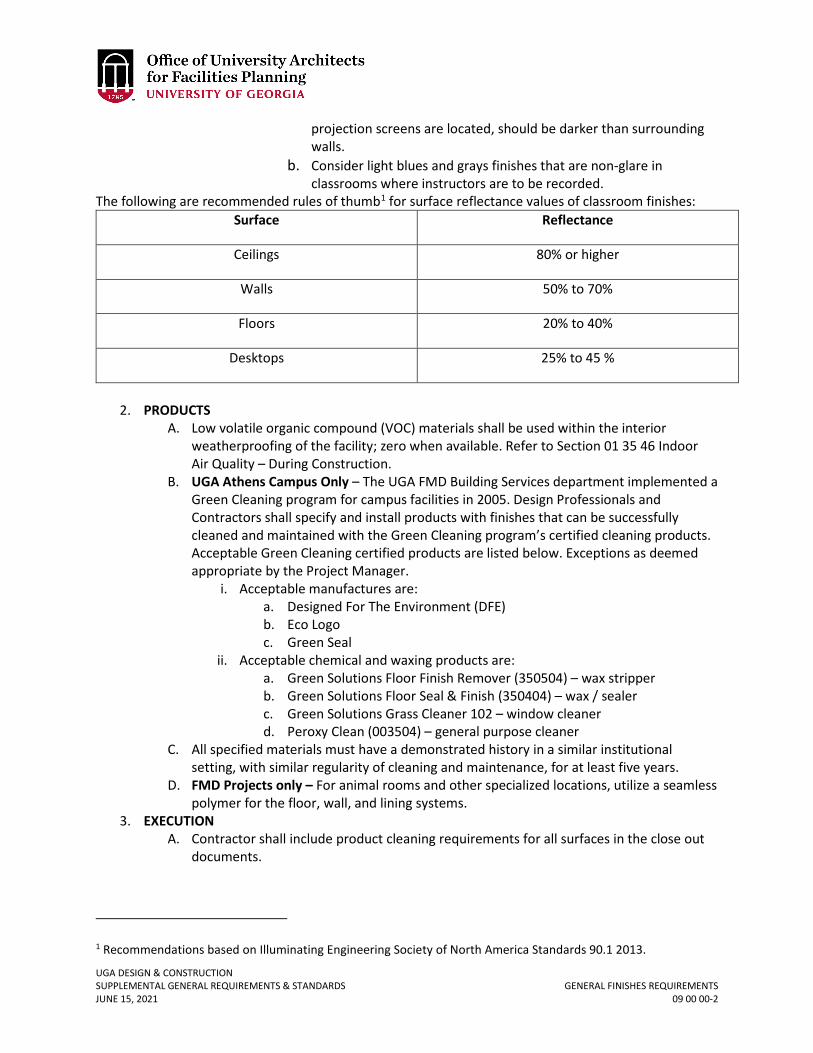
UGA DESIGN & CONSTRUCTION SUPPLEMENTAL GENERAL REQUIREMENTS & STANDARDS GENERAL FINISHES REQUIREMENTS JUNE 15, 2021 09 00 00-2
projection screens are located, should be darker than surrounding walls.
b. Consider light blues and grays finishes that are non-glare in classrooms where instructors are to be recorded.
The following are recommended rules of thumb1 for surface reflectance values of classroom finishes: Surface Reflectance
Ceilings 80% or higher
Walls 50% to 70%
Floors 20% to 40%
Desktops 25% to 45 %
2. PRODUCTS
A. Low volatile organic compound (VOC) materials shall be used within the interior weatherproofing of the facility; zero when available. Refer to Section 01 35 46 Indoor Air Quality – During Construction.
B. UGA Athens Campus Only – The UGA FMD Building Services department implemented a Green Cleaning program for campus facilities in 2005. Design Professionals and Contractors shall specify and install products with finishes that can be successfully cleaned and maintained with the Green Cleaning program’s certified cleaning products. Acceptable Green Cleaning certified products are listed below. Exceptions as deemed appropriate by the Project Manager.
i. Acceptable manufactures are: a. Designed For The Environment (DFE) b. Eco Logo c. Green Seal
ii. Acceptable chemical and waxing products are: a. Green Solutions Floor Finish Remover (350504) – wax stripper b. Green Solutions Floor Seal & Finish (350404) – wax / sealer c. Green Solutions Grass Cleaner 102 – window cleaner d. Peroxy Clean (003504) – general purpose cleaner
C. All specified materials must have a demonstrated history in a similar institutional setting, with similar regularity of cleaning and maintenance, for at least five years.
D. FMD Projects only – For animal rooms and other specialized locations, utilize a seamless polymer for the floor, wall, and lining systems.
3. EXECUTION A. Contractor shall include product cleaning requirements for all surfaces in the close out
documents.
1 Recommendations based on Illuminating Engineering Society of North America Standards 90.1 2013.
UGA DESIGN & CONSTRUCTION SUPPLEMENTAL GENERAL REQUIREMENTS & STANDARDS GENERAL FINISHES REQUIREMENTS JUNE 15, 2021 09 00 00-3
B. Contractor shall completely remove all paint, epoxies, and other excess finish materials prior to completion of the Project. Additional unused supplies to be turned over to UGA shall be coordinated through the Project Manager at substantial completion.
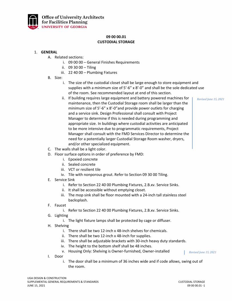
UGA DESIGN & CONSTRUCTION SUPPLEMENTAL GENERAL REQUIREMENTS & STANDARDS CUSTODIAL STORAGE JUNE 15, 2021 09 00 00.01 -1
09 00 00.01 CUSTODIAL STORAGE
1. GENERAL
A. Related sections: i. 09 00 00 – General Finishes Requirements
ii. 09 30 00 – Tiling iii. 22 40 00 – Plumbing Fixtures
B. Size: i. The size of the custodial closet shall be large enough to store equipment and
supplies with a minimum size of 5’-6” x 8’-0” and shall be the sole dedicated use of the room. See recommended layout at end of this section.
ii. If building requires large equipment and battery powered machines for maintenance, then the Custodial Storage room shall be larger than the minimum size of 5’-6” x 8’-0”and provide power outlets for charging and a service sink. Design Professional shall consult with Project Manager to determine if this is needed during programming and appropriate size. In buildings where custodial activities are anticipated to be more intensive due to programmatic requirements, Project Manager shall consult with the FMD Services Director to determine the need for a potentially larger Custodial Storage Room washer, dryers, and/or other specialized equipment.
C. The walls shall be a light color. D. Floor surface options in order of preference by FMD:
i. Epoxied concrete ii. Sealed concrete
iii. VCT or resilient tile iv. Tile with nonporous grout. Refer to Section 09 30 00 Tiling.
E. Service Sink i. Refer to Section 22 40 00 Plumbing Fixtures, 2.B.xv. Service Sinks.
ii. It shall be accessible without emptying closet. iii. The mop sink shall be floor mounted with a 24-inch tall stainless steel
backsplash. F. Faucet
i. Refer to Section 22 40 00 Plumbing Fixtures, 2.B.xv. Service Sinks. G. Lighting
i. The light fixture lamps shall be protected by cage or diffuser. H. Shelving
i. There shall be two 12-inch x 48-inch shelves for chemicals. ii. There shall be two 12-inch x 48-inch for supplies.
iii. There shall be adjustable brackets with 30-inch heavy duty standards. iv. The height to the bottom shelf shall be 48 inches. v. Housing Only: Shelving is Owner-furnished, Owner-installed
I. Door i. The door shall be a minimum of 36 inches wide and if code allows, swing out of
the room.
Revised June 15, 2021
Revised June 15, 2021
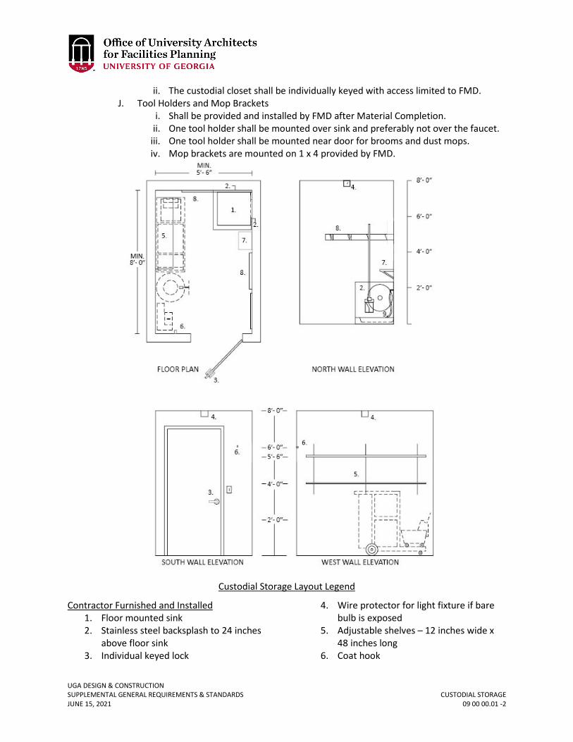
UGA DESIGN & CONSTRUCTION SUPPLEMENTAL GENERAL REQUIREMENTS & STANDARDS CUSTODIAL STORAGE JUNE 15, 2021 09 00 00.01 -2
ii. The custodial closet shall be individually keyed with access limited to FMD. J. Tool Holders and Mop Brackets
i. Shall be provided and installed by FMD after Material Completion. ii. One tool holder shall be mounted over sink and preferably not over the faucet.
iii. One tool holder shall be mounted near door for brooms and dust mops. iv. Mop brackets are mounted on 1 x 4 provided by FMD.
Custodial Storage Layout Legend
Contractor Furnished and Installed 1. Floor mounted sink 2. Stainless steel backsplash to 24 inches
above floor sink 3. Individual keyed lock
4. Wire protector for light fixture if bare bulb is exposed
5. Adjustable shelves – 12 inches wide x 48 inches long
6. Coat hook
UGA DESIGN & CONSTRUCTION SUPPLEMENTAL GENERAL REQUIREMENTS & STANDARDS CUSTODIAL STORAGE JUNE 15, 2021 09 00 00.01 -3
Owner Furnished and Owner Installed 7. Chemical Lock & Dial
8. “Gripit” tool holder 9. Hose – 36’
UGA DESIGN & CONSTRUCTION SUPPLEMENTAL GENERAL REQUIREMENTS & STANDARDS PLASTER & GYPSUM BOARD JUNE 15, 2021 09 20 00-1
09 20 00 PLASTER & GYPSUM BOARD
1. GENERAL
A. Related sections: i. 01 35 46 – Indoor Air Quality Procedures – During Construction
2. PRODUCTS A. Low volatile organic compound (VOC) materials shall be used within the interior
weatherproofing of the facility; zero when available. Refer to Section 01 35 46 Indoor Air Quality – During Construction.
B. Regional Materials: Gypsum board shall have been manufactured within 500 miles of the project site. Provide documentation as requested by the Project Manager.
C. Standard gypsum wall board product thickness is 5/8 inches. For typical wall assemblies, ½-inch gypsum board is prohibited.
D. Wet areas and / or tile backer board: i. Use cement backer board for tile.
ii. Paper-faced moisture resistant gypsum board panels (“green board”) are not allowed.
E. Abuse resistant gypsum board and / or impact resistant gypsum board shall be considered for public areas, corridors, and student rooms. Design Professional shall coordinate with Project Manager.
3. EXECUTION A. Install gypsum board only after building is enclosed. B. If plaster or gypsum board repairs that cause air borne dust are made as part of the
punchlist corrections prior to Final Completion, the Contractor is responsible for full cleaning of areas that are affected by the plaster or gypsum board dust at no additional cost to the Owner. This includes cleaning of all affected surfaces like windows, furniture, carpets, etc. If final air filters were installed prior to any plaster or gypsum board punchlist corrections, Contractor is responsible for replacing air filters that serve affected areas again at no additional cost to the Owner.
UGA DESIGN & CONSTRUCTION SUPPLEMENTAL GENERAL REQUIREMENTS & STANDARDS TILING JUNE 15, 2021 09 30 00-1
09 30 00 TILING
1. GENERAL
A. Related sections: i. 01 35 46 – Indoor Air Quality Procedures – During Construction
ii. 09 00 00 – General Finishes Requirements iii. 09 00 00.01 – Custodial Storage
B. For public areas with high levels of pedestrian traffic, especially main entry lobbies and corridors, it is preferable to use a durable, low maintenance, long lasting floor material like granite.
2. PRODUCTS A. Low volatile organic compound (VOC) materials shall be used within the interior
weatherproofing of the facility; zero when available. Refer to Section 01 35 46 Indoor Air Quality – During Construction.
B. Regional Materials: See below for granite tile requirements. All other tile products shall have been extracted, harvested or recovered, as well as manufactured, within 500 miles of the project site for a minimum of 20%, based on cost, of the total materials value of flooring excluding granite tiling. Provide documentation as requested by the Project Manager.
C. Silver Cloud Granite: i. When the Project budget can afford granite flooring, the main field granite color
shall be Silver Cloud (a granite with a marbling of grays and whites). ii. Silver Cloud granite shall be quarried, cut, and finished within 500 miles of the
project site. iii. The basis of design is Silver Cloud granite quarried in Lithonia, Georgia by Broad
River Quarries which is located in Elberton, Georgia, 706-213-1255 or North Carolina Granite, Mt. Airy, North Carolina, 336-786-5141.
iv. Depending on the tile module selected for the space, the tile may be thin-set tiling or mortar-bed tiling.
v. The interior granite surface finish shall be honed with a clear penetrating sealer. D. Grout at restrooms and food service areas shall:
i. Use epoxy type grout meeting ANSI 118.3. ii. Dark grout colors are preferred for floors.
3. EXECUTION A. For granite tile installation, the Contractor shall coordinate a pre-installation meeting
with the Design Professional, Project Manager, and tile Subcontractor. It is understood that granite is a natural material and that color variation will occur; however, the Contractor and tile Subcontractor are responsible for the complimentary color and granite patterning distribution. Attention shall be given to the placement of matched tiles as directed by the Design Professional and Project Manager. The Contractor and tile Subcontractor shall avoid placing noticeably lighter Silver Cloud pieces in a field of darker Silver Cloud pieces and vice-versa. If this situation occurs without prior approval from the Project Manager, the Contractor shall remove and reinstall pieces as directed by the Project Manager at no additional cost to the Owner.
UGA DESIGN & CONSTRUCTION SUPPLEMENTAL GENERAL REQUIREMENTS & STANDARDS CEILINGS JUNE 15, 2021 09 50 00-1
09 50 00 CEILINGS
1. GENERAL
A. Related sections: i. 09 00 00 – General Finishes Requirements
ii. 26 51 00 – Interior Lighting B. Ceilings and mechanical / electrical equipment coordination:
i. Mechanical and electrical access to equipment above a hard-lid ceiling requires a minimum of 24 inches x 24 inches access panel with clear path to the equipment.
ii. Coordination with mechanical, electrical, and plumbing equipment is required when laying out ceiling grids and supports; no mechanical, electrical, or plumbing access should be blocked
iii. A ‘Maintenance Access’ zone (vertically & horizontally) is to be defined and called out on drawings and maintained through final construction.
iv. Lighting shall not be located in the ‘Maintenance Access’ zones or access points. v. Removal of ceiling tiles may not be blocked by equipment locations.
a. 6 inches from the suspended ceiling to the bottom of equipment & ductwork is required for ceiling tile removal.
2. PRODUCTS A. Concealed spline ceiling support systems are not allowed. B. 2’ x 4’ ceiling grid and tile not allowed.
3. EXECUTION A. Fiberglass batt insulation is not allowed to be placed directly on top of acoustical ceiling
tiles.
UGA DESIGN & CONSTRUCTION SUPPLEMENTAL GENERAL REQUIREMENTS & STANDARDS FLOORING JUNE 15, 2021 09 60 00-1
09 60 00 FLOORING
1. GENERAL
A. Related sections: i. 01 35 46 – Indoor Air Quality Procedures – During Construction
ii. 01 41 26.06 – Dining Services iii. 09 00 00 – General Finishes Requirements iv. 09 30 00 – Tiling v. 09 68 00 – Carpeting
2. PRODUCTS A. Low volatile organic compound (VOC) materials shall be used within the interior
weatherproofing of the facility; zero when available. Refer to Section 01 35 46 Indoor Air Quality – During Construction.
B. Regional Materials: For carpeting, refer to Section 09 68 00 Carpeting. All other flooring products shall have been extracted, harvested or recovered, as well as manufactured, within 500 miles of the project site for a minimum of 20%, based on cost, of the total materials value of flooring excluding carpeting. Provide documentation as requested by the Project Manager.
C. Vinyl Composition Tile (VCT) shall contain a minimum 10% post-consumer recycled content or a minimum 5% post-consumer recycled content combined with a minimum 10% pre-consumer recycled content.
D. Resilient flooring shall have the following characteristics: i. Luxury Vinyl Tile (LVT) shall have a minimum wear layer thickness of 30 mil
ii. LVT in dark colors or possessing a heavily directional pattern is discouraged. E. For resilient wall base, prefabricated corners shall not be used. F. FMD Projects Only
i. Epoxy flooring: For renovations with existing exposed concrete flooring in the auditorium, apply a two-component, high performance, polyamide-epoxy coating. Primer and finish coat shall be compatible and by the same manufacturer. Clean and prepare substrate according to manufacturer’s specifications to ensure proper bonding.
UGA DESIGN & CONSTRUCTION SUPPLEMENTAL GENERAL REQUIREMENTS & STANDARDS CARPETING JUNE 15, 2021 09 68 00-1
09 68 00 CARPETING
1. GENERAL
A. Related sections: i. 01 35 46 – Indoor Air Quality Procedures – During Construction
ii. 01 74 19 – Construction Waste Management and Disposal iii. 09 00 00 – General Finishes Requirements iv. 12 48 26 – Entrance Carpet Tile
B. Any existing carpeting that is removed must be recycled per Section 01 74 19 Construction Waste Management and Disposal.
C. As part of the submittals, provide flame spread documentation demonstrating compliance of carpets with code requirements. State the minimum requirements per the applicable codes and the flame spread of the products.
D. Carpeting is prohibited in telecommunications MDF / IDF rooms. 2. PRODUCTS
A. Low volatile organic compound (VOC) materials shall be used within the interior weatherproofing of the facility; zero when available. Refer to Section 01 35 46 Indoor Air Quality – During Construction.
B. Regional Materials: Provide carpets that have been manufactured within the state of Georgia. Provide documentation as requested by Project Manager.
C. Use only carpet and carpet cushion that meets or exceeds requirements of Green Label Plus, set by the Carpet and Rug Institute.
D. Any carpet cushion shall be an attached backing system to the carpet and not a separate underlayment system.
E. The Design Professional shall forward manufacturer’s suggested carpet maintenance cleaning methods to the Project Manager for review and approval.
F. Minimum 10-year manufacturer’s warranty covering: wear, edge ravel, tuft bind, delamination, and static control.
G. Requirements for carpeting attic stock shall be coordinated with the Project Manager.
UGA DESIGN & CONSTRUCTION SUPPLEMENTAL GENERAL REQUIREMENTS & STANDARDS WALL COVERINGS JUNE 15, 2021 09 72 00-1
09 72 00 WALL COVERINGS
1. GENERAL
A. Wall coverings are a long-term maintenance issue. 2. PRODUCTS
A. Vinyl coated fabric wall coverings, flexible vinyl wall coverings, rigid sheet vinyl wall coverings, and wallpaper are not allowed. Wall coverings are occasionally allowed as specialty accents, but must be approved through the variance process.
B. Textile wall coverings are not allowed unless they are part of an acoustical wall treatment system approved by the Project Manager.
UGA DESIGN & CONSTRUCTION SUPPLEMENTAL GENERAL REQUIREMENTS & STANDARDS ACOUSTICAL TREATMENT JUNE 15, 2021 09 80 00-1
09 80 00 ACOUSTICAL TREATMENT
1. GENERAL
A. Related sections: i. 00 00 13 – Designing Learning Environments
ii. 09 00 00 – General Finishes Requirements iii. 12 05 13 – Fabrics
2. PRODUCTS A. Low volatile organic compound (VOC) materials shall be used within the interior
weatherproofing of the facility; zero when available. Refer to Section 01 35 46 Indoor Air Quality – During Construction.
B. As part of the submittals, provide flame spread documentation demonstrating compliance of the acoustical treatment assembly with code requirements. State the minimum requirements per the applicable codes and the flame spread of the products and assembly.
UGA DESIGN & CONSTRUCTION SUPPLEMENTAL GENERAL REQUIREMENTS & STANDARDS INTERIOR PAINTING JUNE 15, 2021 09 91 23-1
09 91 23 INTERIOR PAINTING
1. GENERAL
A. Related sections: i. 01 32 16 – Construction Progress Schedule
ii. 01 35 46 – Indoor Air Quality Procedures – During Construction B. In addition to card stock brush-outs, Contractor shall provide 6’x6’ in place samples for
each paint color, with final light fixtures and lamps in place, as requested by the Design Professional and / or Project Manager as part of the Cost of the Work or Bid.
2. PRODUCTS A. Low volatile organic compound (VOC) materials shall be used within the interior
weatherproofing of the facility; zero when available. Refer to Section 01 35 46 Indoor Air Quality – During Construction.
B. All coatings shall be commercial grade. C. Acceptable Manufacturers:
i. Benjamin Moore Company ii. PPG Paints
iii. Sherwin-Williams Company D. Paint Sheens
i. Painted walls shall have eggshell paint sheen. ii. Painted wood trim shall have semi-gloss sheen.
iii. Flat paint sheen is prohibited on walls and trim. iv. Variations may be requested for Housing-specific projects. (For example,
student rooms and corridors will always be semi-gloss)
Revised June 15, 2021
UGA DESIGN & CONSTRUCTION SUPPLEMENTAL GENERAL REQUIREMENTS & STANDARDS SIGNAGE JUNE 15, 2021 10 14 00-1
10 14 00 SIGNAGE
1. GENERAL
A. Related sections: i. 00 00 09 – Room & Space Numbering
ii. 01 58 00 – Campus Signage Standards iii. 26 56 00 – Exterior Lighting (for requirements regarding exterior signage)
B. For projects at the University of Georgia, Athens, Georgia campus, the FMD will fabricate the interior environmental way finding signage for the Project. The Owner will provide the signs and the Contractor shall install them. The quantity and location of signs shall be agreed upon during the construction document design phase and the installation costs shall be included in the Contractor’s Cost of the Work in the Guaranteed Maximum Price.
C. For new single use occupancy toilet rooms, unless required by code to be labeled and have signage as a ‘Family Restroom’, shall be labeled in construction documents as ‘Restroom’.
2. PRODUCTS A. The Design Professional shall develop a spreadsheet that lists room numbers in one
column and room names in another column. The listing shall be organized by floor. The file shall be given to the Project Manager for use in developing final building signage.

UGA DESIGN & CONSTRUCTION SUPPLEMENTAL GENERAL REQUIREMENTS & STANDARDS TOILET COMPARTMENTS JUNE 15, 2021 10 21 13-1
10 21 13 TOILET COMPARTMENTS
1. GENERAL
A. Related sections: i. 10 28 13 – Toilet, Bath, and Laundry Accessories
B. Use wall-mounted vanity panels at urinals. C. Coat hooks shall be mounted on permanent non-moving toilet partitions and shall not
be mounted on the toilet compartment doors. 2. PRODUCTS
A. Toilet partitions shall be solid surface plastic HDPE (High Density Polyethylene) or solid phenolic panels that are floor-mounted and head-braced.
i. Toilet partition hardware shall be stainless steel.
UGA DESIGN & CONSTRUCTION SUPPLEMENTAL GENERAL REQUIREMENTS & STANDARDS CORNER GUARDS JUNE 15, 2021 10 26 13-1
10 26 13 CORNER GUARDS
1. GENERAL
A. Provide corner guards in all public spaces, service areas and at specialty finishes. B. Protect outside corners of gypsum board partitions in public corridors to minimum 36-
inch height as deemed appropriate by Project Manager. C. Prefer wall protection at chair rail height for public areas with moveable seating.
2. PRODUCTS A. Material as appropriate for specific conditions, coordinate with Project Manager.
UGA DESIGN & CONSTRUCTION SUPPLEMENTAL GENERAL REQUIREMENTS & STANDARDS TOILET, BATH, AND LAUNDRY ACCESSORIES JUNE 15, 2021 10 28 00-1
10 28 00 TOILET, BATH, AND LAUNDRY ACCESSORIES
1. GENERAL – For UGA Athens Campus Only
A. The UGA has sole source approval for soap, paper towels, and toilet paper products. The UGA will provide the dispensers for soap, toilet paper, and paper towels for the Project. The basic dispensers are provided by FMD Services at no additional cost to the Project. Some of the products are available in stainless steel material and some are available in plastic in a stainless steel color. The Contractor shall install the Owner provided toilet accessories listed above and shall include the installation costs as part of the Cost of the Work or Bid. The Contractor is responsible for coordinating in wall blocking.
i. UGA Housing project only (new construction) does not use the UGA standard toilet accessories and its requirements are listed separately below.
B. Sanitary napkin dispensers shall not be included in the Project. C. Toilet seat cover dispensers are typically not included in UGA Projects. However, if a
certain department wishes to include them, it shall be coordinated between the Design Professional and the Project Manager.
2. PRODUCTS A. Soap Dispenser (Information is provided for planning and coordination only, not for
specification for purchase): i. Manufacturer:
a. GOJO Industries b. One GOJO Plaza, Suite 500, Akron, Ohio 44311 c. P.O. Box 991, Akron, Ohio 44309-0991 USA d. 1-800-321-9647, 1-330-255-6000
ii. Model: a. GOJO FMX-12 Dispenser b. Product SKU Number: 5150-06 c. Website: http://www.gojo.com/united-
states/productsearch.aspx?SearchStr=5150-06&ProdID={BB36B071-6C22-4676-BCF8-E64245BA5B8C}
d. See additional pages in this section for manufacturer data sheet. iii. Capacity: 1250 mL Capacity iv. Color and Material:
a. Standard is plastic in Dove Gray with glossy finish. b. Stainless steel is an option; similar style but may be a different model
number. v. Special Features:
a. ADA compliant one hand push operation b. Includes optional key lock
B. Toilet Tissue Dispenser (Information is provided for planning and coordination only, not for specification for purchase):
i. 2-Roll a. Manufacturer / Vendor:
1) Wausau Paper: www.wausaupaper.com b. Model:
UGA DESIGN & CONSTRUCTION SUPPLEMENTAL GENERAL REQUIREMENTS & STANDARDS TOILET, BATH, AND LAUNDRY ACCESSORIES JUNE 15, 2021 10 28 00-2
1) Wausau (Bay West Green Seal Certified EcoSoft) Silhouette Dubl-Serv 2-Roll OptiCore Capacity
2) Product Number: 80200 3) Website:
http://www.wausaupaper.com/Towel_and_Tissue/Products/1839/1033.aspx
4) See additional pages in section for manufacturer data sheet. c. Size: 11-1/16 inches x 8-13/16 inches x 7-3/16 inches d. Weight: 2.1 lbs. e. Color and Material:
1) Standard is plastic in Black Translucent. 2) Stainless steel is an option; similar style but may be a different
model number. f. Special Features: ADA Title III Compliant and Locking Cover
ii. 3 Roll a. Manufacturer:
1) Wausau Paper: www.wausaupaper.com b. Model:
1) Wausau (Bay West Green Seal Certified EcoSoft) Silhouette Revolution 3-Roll OptiCore
2) Product Number: 80300 3) Website:
http://www.wausaupaper.com/Towel_and_Tissue/Products/1840/1033.aspx
4) See additional pages in this section for manufacturer data sheet.
c. Size: 14-1/8 inches x 14-9/16 inches x 6-5/16 inches d. Weight: 3.4 lbs. e. Color and Material:
1) Standard is plastic in Black Translucent. 2) Stainless steel is an optional upgrade; similar style but may be a
different model number. f. Special Features:
1) ADA Title III Compliant 2) Locking Cover
C. Paper Towel Dispenser (Information is provided for planning and coordination only, not for specification for purchase). The OptiServ 76700 is typically utilized and the Optiserv Accent 76600 is for areas that require a more compact dispenser.
i. OptiServ 86500 a. Manufacturer:
1) Wausau Paper: www.wausaupaper.com b. Model:
1) Wausau Bay West Silhouette OptiServ Hands-Free 2) Product Number: 76700 3) Website: http://www.wausaupaper.com/product/optiserv-
76700/
UGA DESIGN & CONSTRUCTION SUPPLEMENTAL GENERAL REQUIREMENTS & STANDARDS TOILET, BATH, AND LAUNDRY ACCESSORIES JUNE 15, 2021 10 28 00-3
c. Size: 12-1/8 inches x 16-13/16 inches x 9-13/16 inches d. Weight: 6.85 lbs. e. Color and Material: Standard is plastic in Black Translucent . f. Special Features: ADA Title III Compliant g. Notes:
1) Design Professional is to coordinate final selection with Project Manager.
2) See additional pages in section for manufacturer data sheet. ii. OptiServ Accent 76600
a. Manufacturer: 1) Wausau Paper: www.wausaupaper.com
b. Model: 1) Wausau Bay West Silhouette OptiServ Hands-Free 2) Product Number: 76600 3) Website:
http://www.wausaupaper.com/product_type/optiserv-accent-roll-towel-dispensers/
c. Size: 12-3/16 inches x 12-5/8 inches x 7-1/2 inches d. Weight: 5.65 lbs. e. Color and Material: Standard is plastic in Black Translucent. f. Special Features: ADA Title III Compliant g. Notes:
1) Design Professional is to coordinate final selection with Project Manager.
2) See additional pages in section for manufacturer data sheet. D. Toilet and Bath Accessories – For UGA Housing Only (New Construction)
i. All products furnished and installed by Contractor unless noted otherwise. ii. Public Restroom:
a. Toilet tissue dispenser equal to Bobrick B-2740 (Owner-furnished/ Owner-installed).
b. Grab bars equal to Bobrick #B-6806 with lengths as required by code. c. Partition-mounted feminine napkin disposal cabinet for two toilet
compartments equal to Bobrick #B-354 (Owner-furnished/ Owner-installed).
d. Surface-mounted feminine napkin disposal cabinet equal to Bobrick #B-254 (Owner-furnished/ Owner-installed).
e. Soap dispensers provided and installed by Owner. iii. Private Bath in Residential Unit:
a. Toilet Tissue Dispenser – single-roll, recessed units at non-rated walls, residential units equal to Bobrick #B-667 (Owner-furnished/ Owner-installed).
b. Toilet Tissue Dispenser – single-roll, surface-mounted units at fire-rated walls, residential units equal to Bobrick #B-2730 (Owner-furnished/ Owner-installed).
c. Grab bars, equal to Bobrick #B-6861.99 with lengths as required by code.
UGA DESIGN & CONSTRUCTION SUPPLEMENTAL GENERAL REQUIREMENTS & STANDARDS TOILET, BATH, AND LAUNDRY ACCESSORIES JUNE 15, 2021 10 28 00-4
d. Towel bars, 1-inch diameter, 18 inches long, equal to Bobrick #B-530. e. Robe/towel hook equal to Bradley SA37. f. Shower rods equal to Bobrick #B-6047. g. Shower seats equal to Bobrick #B-5181.
iv. Custodial Closet: a. Mop and broom holder (3-foot length) equal to Bobrick #B-223 X 36.
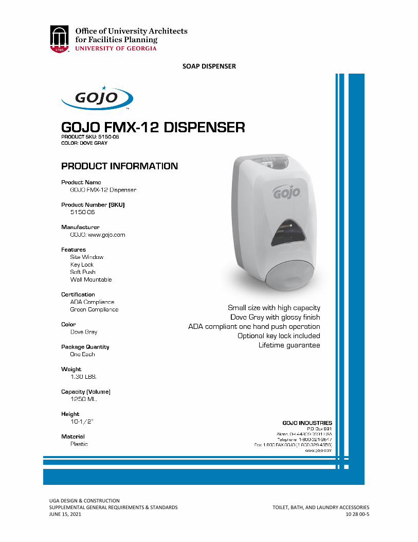
UGA DESIGN & CONSTRUCTION SUPPLEMENTAL GENERAL REQUIREMENTS & STANDARDS TOILET, BATH, AND LAUNDRY ACCESSORIES JUNE 15, 2021 10 28 00-5
SOAP DISPENSER
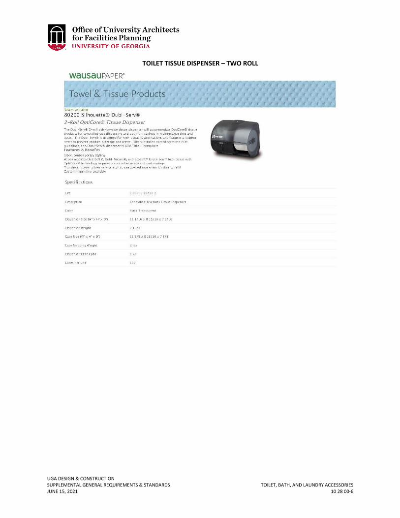
UGA DESIGN & CONSTRUCTION SUPPLEMENTAL GENERAL REQUIREMENTS & STANDARDS TOILET, BATH, AND LAUNDRY ACCESSORIES JUNE 15, 2021 10 28 00-6
TOILET TISSUE DISPENSER – TWO ROLL
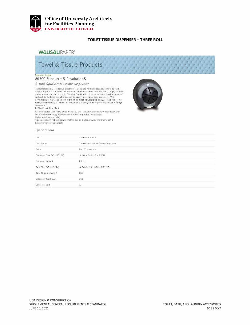
UGA DESIGN & CONSTRUCTION SUPPLEMENTAL GENERAL REQUIREMENTS & STANDARDS TOILET, BATH, AND LAUNDRY ACCESSORIES JUNE 15, 2021 10 28 00-7
TOILET TISSUE DISPENSER – THREE ROLL

UGA DESIGN & CONSTRUCTION SUPPLEMENTAL GENERAL REQUIREMENTS & STANDARDS TOILET, BATH, AND LAUNDRY ACCESSORIES JUNE 15, 2021 10 28 00-8
PAPER TOWEL DISPENSER – OPTISERV 86500
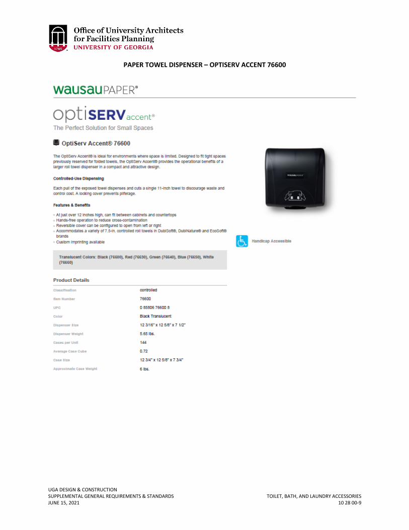
UGA DESIGN & CONSTRUCTION SUPPLEMENTAL GENERAL REQUIREMENTS & STANDARDS TOILET, BATH, AND LAUNDRY ACCESSORIES JUNE 15, 2021 10 28 00-9
PAPER TOWEL DISPENSER – OPTISERV ACCENT 76600
UGA DESIGN & CONSTRUCTION SUPPLEMENTAL GENERAL REQUIREMENTS & STANDARDS FIRE PROTECTION SPECIALITIES JUNE 15, 2021 10 44 00-1
10 44 00 FIRE PROTECTION SPECIALITIES
1. GENERAL
A. Related sections: i. 02 40 00 – Demolition
B. The Design Professional shall specify all required new fire extinguishers and related accessories, and they shall be provided and installed by the Contractor as part of the Project.
2. PRODUCTS A. Fire Extinguisher Cabinets
i. Semi-recessed fire extinguisher cabinets are preferred verses flush cabinets. ii. For semi-recessed cabinets, provide “FIRE EXTINGUISHER” decal on both sides
of cabinet that are perpendicular to wall. iii. For flush cabinets, provide “FIRE EXTINGUISHER” three-dimensional sign above
the cabinet to allow identification of cabinet from a distance.
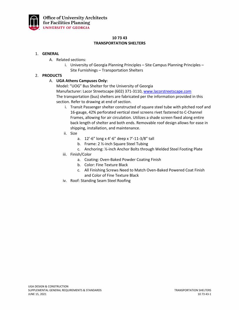
UGA DESIGN & CONSTRUCTION SUPPLEMENTAL GENERAL REQUIREMENTS & STANDARDS TRANSPORTATION SHELTERS JUNE 15, 2021 10 73 43-1
10 73 43 TRANSPORTATION SHELTERS
1. GENERAL
A. Related sections: i. University of Georgia Planning Principles – Site Campus Planning Principles –
Site Furnishings – Transportation Shelters 2. PRODUCTS
A. UGA Athens Campuses Only: Model: “UOG” Bus Shelter for the University of Georgia Manufacturer: Lacor Streetscape (602) 371-3110, www.lacorstreetscape.com The transportation (bus) shelters are fabricated per the information provided in this section. Refer to drawing at end of section.
i. Transit Passenger shelter constructed of square steel tube with pitched roof and 16-gauge, 42% perforated vertical steel screens rivet fastened to C-Channel Frames, allowing for air circulation. Utilizes a shade screen fixed along entire back length of shelter and both ends. Removable roof design allows for ease in shipping, installation, and maintenance.
ii. Size a. 12’-6” long x 4’-6” deep x 7’-11-3/8” tall b. Frame: 2 ½-inch Square Steel Tubing c. Anchoring: ½-inch Anchor Bolts through Welded Steel Footing Plate
iii. Finish/Color a. Coating: Oven-Baked Powder Coating Finish b. Color: Fine Texture Black c. All Finishing Screws Need to Match Oven-Baked Powered Coat Finish
and Color of Fine Texture Black iv. Roof: Standing Seam Steel Roofing
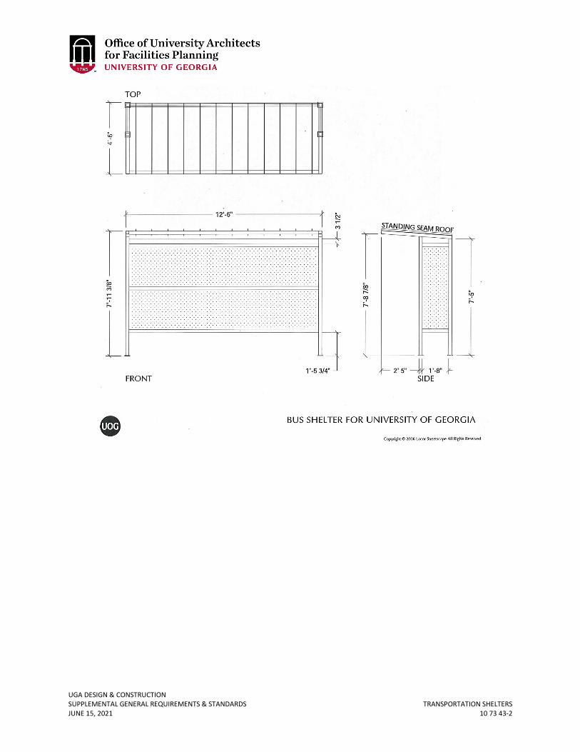
UGA DESIGN & CONSTRUCTION SUPPLEMENTAL GENERAL REQUIREMENTS & STANDARDS TRANSPORTATION SHELTERS JUNE 15, 2021 10 73 43-2
UGA DESIGN & CONSTRUCTION SUPPLEMENTAL GENERAL REQUIREMENTS & STANDARDS AUDIO-VISUAL EQUIPMENT JUNE 15, 2021 11 52 00-1
11 52 00 AUDIO-VISUAL EQUIPMENT
1. GENERAL
A. Related sections: i. 00 00 13 – Designing Learning Environments
ii. 11 52 13 – Projection Screens iii. 12 56 52 – Audio-Visual Equipment iv. 72 41 00 – General Audio-Visual Systems Requirements
B. Bidding of Audio-Visual Equipment and Systems i. When soliciting multiple bids for audio-visual equipment and systems, the
request for proposals and bid documents shall include written communication to vendors that the project is considered a ‘Statewide contract release’ and shall ensure the State administrative fee associated with use of the statewide contract is included in the bids.
2. PRODUCTS A. Flat Panel Monitors
i. Flat-panel monitors shall be provided in small classrooms of 10-20 seats, in lieu of ceiling mounted projectors, as well as in SCALE-UP classrooms (one for each group of 9).
ii. Consider providing recessed wall boxes behind the monitors for housing any small electronics and accommodating power, AV and data connections. Size all displays (both flat-panel monitors and projection systems) such that the farthest viewer is within five screen heights from the image.
B. Projectors i. Projectors are typically ceiling mounted but may be shelf mounted at the rear of
the room with a long-throw lens if the ceiling is not conducive to mounting the projector. Long pole mounts should be avoided due to potential for vibration concerns.
ii. Projectors with a low noise level (<42 dBA) are recommended. For the largest lecture halls, a conditioned sound enclosure may be required to mitigate sound in the room while properly removing heat from the enclosure. Projectors in high-ceiling spaces and / or in hard to service areas may require a retractable projector lift to lower the projector for routine maintenance (e.g. lamp and filter replacement).
iii. Projectors should be sufficiently bright to provide at least a 10:1 contrast ratio (and preferably 15:1) during typical teaching conditions. The contrast ratio would be determined by ANSI/INFOCOMM 3M-2011 - Projected Image System Contrast Ratio. Those situations that require high resolution or have detailed visual information (e.g. medical imaging or fine art) may require a 50:1 to 80:1 contrast ratio depending on the physical makeup of the room. The largest negative contributor to achieving the preferable contrast ratio is ambient light from the room’s lighting system and / or sunlight (direct or reflected) on the projection surface. Generally, ambient light will need to be less than five foot-candles on the projection surface during normal AV presentation mode while maintaining light on the students and instructor. Indirect lighting near the front
UGA DESIGN & CONSTRUCTION SUPPLEMENTAL GENERAL REQUIREMENTS & STANDARDS AUDIO-VISUAL EQUIPMENT JUNE 15, 2021 11 52 00-2
of a classroom should be avoided to manage both the ambient light level on the screen and to maintain a clear light path from projector to screen.
iv. Display technology is constantly evolving; therefore, the Design Professional should consult with The Center for Teaching and Learning as to the preferred make and model of projector for each classroom in a given project.
v. Projector lifts are required if any of the following conditions exist: a. A projector’s “show” position is to be higher than 14 feet. b. A projector is positioned over fixed flat seating. c. A projector is positioned over tiered fixed seating. d. A projector is positioned over an aisle with rails. e. A projector’s access is limited by mechanical or physical infrastructure.
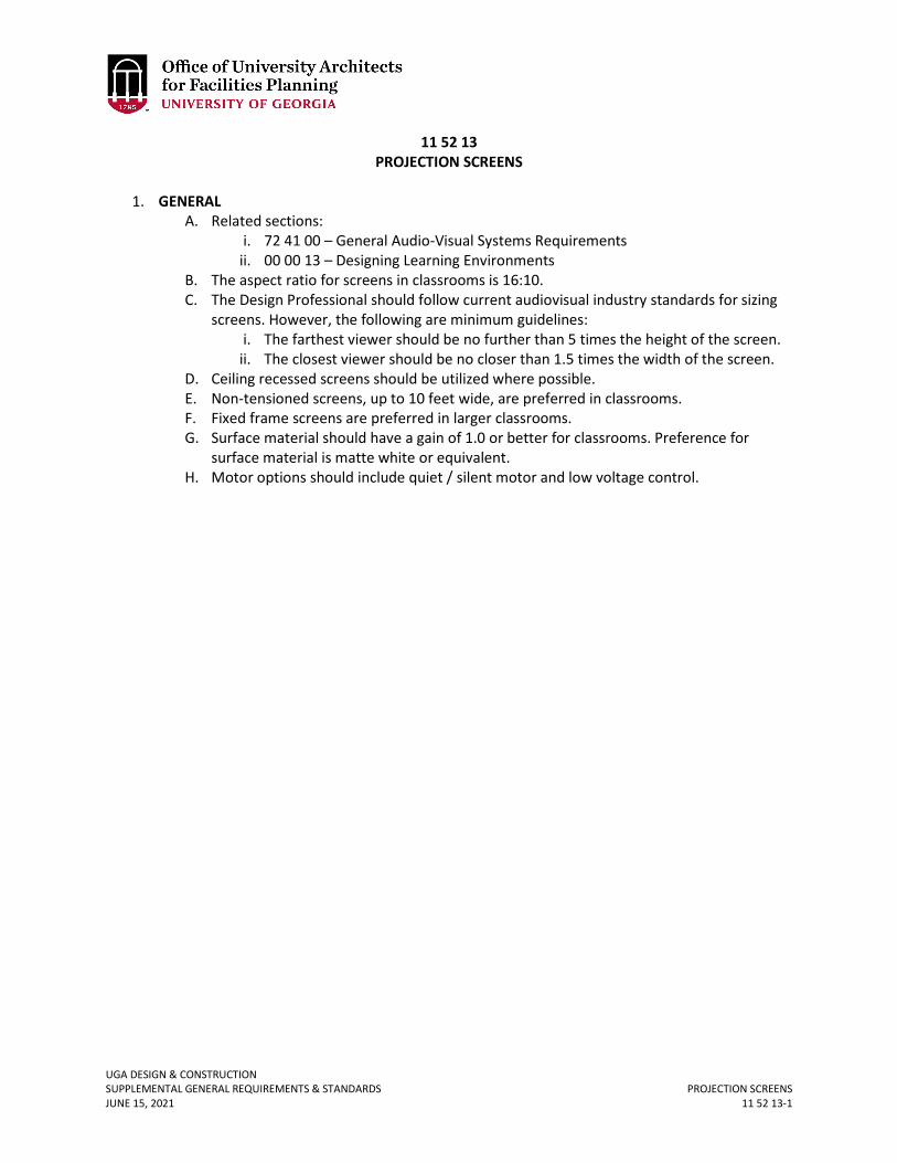
UGA DESIGN & CONSTRUCTION SUPPLEMENTAL GENERAL REQUIREMENTS & STANDARDS PROJECTION SCREENS JUNE 15, 2021 11 52 13-1
11 52 13 PROJECTION SCREENS
1. GENERAL
A. Related sections: i. 72 41 00 – General Audio-Visual Systems Requirements
ii. 00 00 13 – Designing Learning Environments B. The aspect ratio for screens in classrooms is 16:10. C. The Design Professional should follow current audiovisual industry standards for sizing
screens. However, the following are minimum guidelines: i. The farthest viewer should be no further than 5 times the height of the screen.
ii. The closest viewer should be no closer than 1.5 times the width of the screen. D. Ceiling recessed screens should be utilized where possible. E. Non-tensioned screens, up to 10 feet wide, are preferred in classrooms. F. Fixed frame screens are preferred in larger classrooms. G. Surface material should have a gain of 1.0 or better for classrooms. Preference for
surface material is matte white or equivalent. H. Motor options should include quiet / silent motor and low voltage control.
UGA DESIGN & CONSTRUCTION SUPPLEMENTAL GENERAL REQUIREMENTS & STANDARDS LABORATORY FUME HOODS JUNE 15, 2021 11 53 13-1
11 53 13 LABORATORY FUME HOODS
1. GENERAL
A. Related sections: i. 23 00 00 – General Mechanical Requirements (HVAC)
B. As a minimum, conform to the current Board of Regents of the University System of Georgia Design Criteria for Laboratories. This document is located at http://www.usg.edu/facilities/resources/design_criteria_for_laboratories.
C. This section is for general purpose, hoods only; it is not appropriate for radiation, perchloric acid, or special purpose type hoods which should be discussed with the Project Manager.
D. Cup sinks shall be located at the rear of the cabinet. For ADA hoods, locate one sink to the front of the cabinet (rotate sink sideways).
E. Determination of whether the hood should be variable volume or constant volume should be discussed with the Project Manager.
F. Specific requirements of the hood shall be coordinated with laboratory staff and the final specification shall be submitted to the Project Manager for review.
G. Fume hood performance shall be scheduled on the mechanical drawings (total hood cfm, including bypass, required to achieve design face velocity).
2. PRODUCTS A. The hood shall be “High Performance” type:
i. Basis of Design shall be Labconco Protector Xstream. ii. Airfoil at face of fume hood shall be curved. However, in cases where ADA
compliance is required, then the flat airfoil is necessary. iii. For constant volume hoods, with a dedicated exhaust fan, the exhaust fan shall
be selected to for stable operation at 60 feet per minute and 80 feet per minute with the vertical sash at 18” above the work surface and the horizontal sashes closed. The Design Professional shall submit fan curves to the Project Manager for review indicating the fan operating duty point(s) at the cfm associated with 60 fpm and 80 fpm.
iv. The hood shall not incorporate moving baffles, but shall be able to maintain fume capture by means of the hood design alone. Although, the use of air curtains are acceptable.
v. After Testing, Adjusting, Balancing (TAB) of HVAC systems is complete, the hood shall be ASHRAE 110 tested on site (AI) as follows:
1. Constant Volume Hood a. Set the vertical sash height at 18”, fully close the horizontal
sashes (if combination sashes utilized), and manually modulate the fan speed to achieve an average face velocity of 60 and 80 feet per minute (confirm intended face velocity with design). If seeking to utilize combination sash type fume hood, DP and/or Construction firm must first obtain UGA PM approval.
b. Use of combination sash fume hoods in the project shall require advance approval by UGA PM.
Revised June 15, 2021
UGA DESIGN & CONSTRUCTION SUPPLEMENTAL GENERAL REQUIREMENTS & STANDARDS LABORATORY FUME HOODS JUNE 15, 2021 11 53 13-2
c. The hood shall be tested with the vertical sash fully closed and the horizontal sashes fully open (in the working position). The fan speed shall be maintained from step one.
d. The test shall include all three components of ASHRAE testing to include, visual (smoke), tracer gas, and face measurement.
e. Hood shall be tested to failure in order to identify lowest face velocity at which the hood passes visual smoke testing. Face velocity shall be reduced from design face velocity in increments of 10 fpm until failure. Hood failure testing procedure shall include placing boxes inside the hood and assigning an individual to walk past the hood during testing to simulate an “as used” test condition.
2. Variable Volume Hood a. The hood shall be tested at 6” increments from fully closed to
the 18” fully open at both 60 and 80 feet per minute. b. Use of combination sash fume hoods in the project shall require
advance approval by UGA PM. c. The hood shall be tested with the vertical sash fully closed and
the horizontal sashes fully open (in the working position). d. The test shall include all three components of ASHRAE testing to
include, visual (smoke), tracer gas, and face measurement. e. Hood shall be tested to failure in order to identify lowest face
velocity at which the hood passes visual local challenge testing. 3. The contractor shall complete UGA’s standard test report, including the
following: a. Testing shall identify lowest face velocity at which the hood is capable of passing airflow visualization (local challenge) testing within +/- 2 feet per min. Each face velocity at which the test was performed shall be documented along with the corresponding VFD speed (%) and pass/fail record.
B. The fume hood shall be provided with a vertical rising sash. Combination sashes shall be provided when specified by the Project Manager.
i. A sash stop shall be provided to permit a vertical opening of 18” from the counter top to top of the slotted opening located near the base of the sash
ii. Sash shall be 3/16’ thick laminated safety glass with an epoxy-coated aluminum sash handle
iii. Sash counterbalanced system by a single weight: Chain and sprocket type C. The cabinet shall be double-walled. The exterior shall be 18 gauge and powder epoxy
painted. The interior shall have a polyresin liner. D. The work surface shall be cast 1.25” thick chemical resistant epoxy resin. E. All hoods shall be provided with the following services as a minimum:
i. Cold Water ii. Air
iii. Vacuum iv. Natural Gas.
UGA DESIGN & CONSTRUCTION SUPPLEMENTAL GENERAL REQUIREMENTS & STANDARDS LABORATORY FUME HOODS JUNE 15, 2021 11 53 13-3
F. All utility service piping serving fume hoods shall be provided with shut off valves located external to the fume hood in an accessible location. Service shut off valves shall not be located in hood casework utility chases.
G. Services (Water, air, vacuum and natural gas) shall be provided through front loaded control valves (serviceable from the front of hood).
H. Provide an alarm monitor with the following features: i. LED readout
ii. Measure face velocity iii. Local visual and audible alarm iv. Relay output
I. Plumbing service fixtures shall be located maximum 12 inch from the inside of the sash and shall be on a common vertical centerline.
J. Provide vacuum breaker on CW piping supply at gooseneck CW fixture inside fume hood. K. Provide transition duct flanged at both ends for mounting atop the hood and connection
to exhaust system. Transition duct shall be bolted and gasketed to top of hood with Teflon gasket. Gasket shall be 1/16” thick neoprene with UV inhibitor.
L. Provide a minimum of two 120 volt GFCI duplex electrical services per side of the fume hood (208 volt may also be required).
M. Lights: i. Type: Two-tube, rapid-start fluorescent light fixture of longest practicable length
or equivalent LED fixture. ii. Ballast: Electronic ballast and be suitable for T-8 lamps.
iii. Shield: 1/4 inch thick safety glass or 1/8 inch thick tempered glass panel, sealed air tight into hood body with chemical resistant rubber channels.
iv. Lamps: T-8 LED lamps. v. Include light switch, controls interface, and all internal wiring to circuit junction
boxes located on top of hood. vi. Switch: Location shall be on sash post.
vii. Set units so that lamps are replaceable from outside hood. viii. Provide only fixtures that carry UL label.
ix. Average interior illumination levels of the work area: 80-foot candles minimum. N. Acid Storage Cabinets shall have the following::
i. Corrosion resistant interior liner, including the backside of doors and shelf surfaces.
ii. One-piece corrosion resistant insert tray with 2 inch lip for containment of spills at bottom of cabinet.
iii. One shelf with 1 inch lip, adjustable on 1 inch increments. iv. Vented with a minimum 1-1/2 inch I.D. corrosion resistant vent pipe at rear of
cabinet terminating inside of fume hood 2 inch above the working surface. v. Vent pipe shall be close to rear of hood as possible. Seal opening between
working surface and pipe with chemical resistant material. vi. Non-metal door catch or strike plate.
vii. Front of cabinet labeled with minimum 1 inch high, 1/4 inch stroke red letters: "ACID".
O. Flammable Liquids Storage Cabinets shall have the following: i. Identified for flammable and combustible liquids shall be constructed in
compliance with UL, OSHA, NFPA Standard No. 30, and UFC Article 79.

UGA DESIGN & CONSTRUCTION SUPPLEMENTAL GENERAL REQUIREMENTS & STANDARDS LABORATORY FUME HOODS JUNE 15, 2021 11 53 13-4
ii. Self-closing and self-latching doors synchronized so that both doors will always fully close.
iii. Bottom of the cabinet liquid tight to a height of 2 inches. iv. Front of cabinet labeled with minimum 1 inch high, 1/4 inch stroke red letters:
"FLAMMABLE - KEEP FIRE AWAY". P. Vacuum Pump Cabinets (WHEN REQUIRED):
i. Designed to provide a means to store and vent vacuum pumps and their emissions and heat load.
ii. Hinged doors with integral toe space without a bottom and designed to allow a 20” by 16” mobile cart to roll in and out of cabinet. Door to swing open 165 degrees.
iii. Cabinet shall incorporate acoustical insulation on the interior door panels, sides, back and underside of top panel. Insulation shall be an open cell foam of clonal design. Top insulation/panel design shall prevent heat from pump from heating up the hood work surface.
iv. Cabinet shall incorporate an integral electrical switch with pilot light, located on the top front of the cabinet, just below hood, to indicate operational mode of pump.
v. Cabinet shall have an electrical duplex outlet (adequately sized), located in the rear (mid-height) for the vacuum pump plug. Outlet to be accessible from the inside of the cabinet. Outlet to be hard wired to the lighted electrical switch.
vi. Provide minimum 2 inch I.D. vent pipe at top rear of cabinet terminating inside of fume hood vacuum pump exhaust.
vii. Vent pipe shall be as close to rear of hood as possible. Seal opening between working surface and pipe with chemical resistant material.
viii. Provide 2 inch I.D. hole in hood work surface for vacuum piping/tubing. Provide rigid pass through bench top sleeve as manufactured by Scientific Plastics, Inc. Seal sleeve to bench top.
ix. Provide mobile platform, 20” by 16” min, capable of supporting 300 lbs. Front two casters shall be locking/swivel models. Lipped construction shall contain any accidental spills.
x. Vented with a minimum 1-1/2 inch I.D. corrosion resistant vent pipe at rear of cabinet terminating inside of fume hood 2 inch above the working surface.
xi. Front of cabinet labeled with minimum 1 inch high, 1/4 inch stroke red letters: "NO CHEMICAL STORAGE".
Q. Fume Hood Identification Label: Provide label attached to the fume hood exterior with condensed information covering fume hood identification and initial performance label completed by the performance testing (ASHRAE 110) contractor.
i. Each fume hood that passes the performance tests shall be labeled with the following baseline information inscribed into the label:
1. -Date tested 2. -Name of Inspector 3. -Company Inspecting 4. -Testing protocol used (such as ASHRAE 110 smoke visualization) 5. -Average face velocity at the specified maximum operating sash height
(measured from bench top to bottom of sash; for combination sashes, horizontal sashes are close -during testing).
UGA DESIGN & CONSTRUCTION SUPPLEMENTAL GENERAL REQUIREMENTS & STANDARDS LABORATORY FUME HOODS JUNE 15, 2021 11 53 13-5
R. “Signage: i. A sign shall be secured to the center of the hood lintel, immediately above the
sash opening. The sign shall be of white lettering, ¼ inch high, with red facing; (FUME HOOD “TYPE” lettering shall be ½ inch high) reading as follows:
ii. GENERAL PURPOSE FUME HOOD”, “Reactions with radioactive material exceeding NRC guidelines, perchloric acid, highly toxic or unstable explosive materials are not permitted in this fume hood. Check with the Radiation Safety Officer for limits on isotope use.”
3. EXECUTION: A. Set up hoods as follows:
i. Constant volume: 1. The vertical sash shall be placed at 18” above the work surface. 2. The horizontal sashes shall be fully closed. 3. The Face velocity shall be set up for between 60 and 80 feet per minute
by manually modulating the exhaust fan VFD speed dial for dedicated fan hoods or adjusting exhaust valve. The face velocity shall be determined by UGA and the design team.
ii. Variable Volume: 1. The horizontal sashes shall be fully closed. 2. For all vertical sash positions up to 18” above the work surface, the Face
velocity shall be maintained at 60 feet per minute by automatically modulating the laboratory controls.
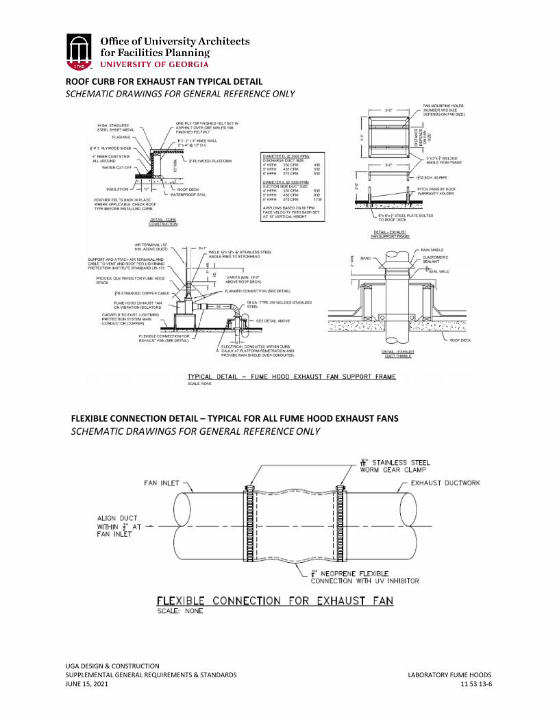
UGA DESIGN & CONSTRUCTION SUPPLEMENTAL GENERAL REQUIREMENTS & STANDARDS LABORATORY FUME HOODS JUNE 15, 2021 11 53 13-6
ROOF CURB FOR EXHAUST FAN TYPICAL DETAIL SCHEMATIC DRAWINGS FOR GENERAL REFERENCE ONLY
FLEXIBLE CONNECTION DETAIL – TYPICAL FOR ALL FUME HOOD EXHAUST FANS SCHEMATIC DRAWINGS FOR GENERAL REFERENCE ONLY
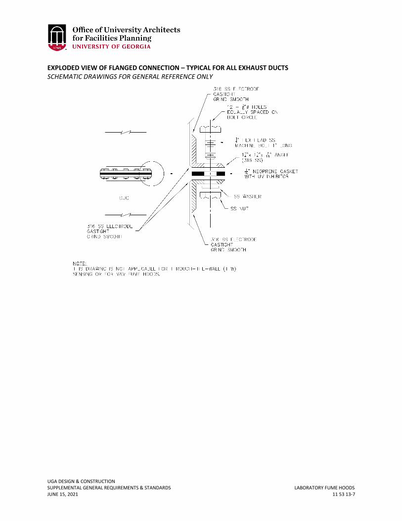
UGA DESIGN & CONSTRUCTION SUPPLEMENTAL GENERAL REQUIREMENTS & STANDARDS LABORATORY FUME HOODS JUNE 15, 2021 11 53 13-7
EXPLODED VIEW OF FLANGED CONNECTION – TYPICAL FOR ALL EXHAUST DUCTS SCHEMATIC DRAWINGS FOR GENERAL REFERENCE ONLY

UGA DESIGN & CONSTRUCTION SUPPLEMENTAL GENERAL REQUIREMENTS & STANDARDS FACILITY WASTE COMPACTORS JUNE 15, 2021 11 82 26-1
11 82 26 FACILITY WASTE COMPACTORS
1. GENERAL
A. Design Professional shall coordinate with Project Manager and FMD Services Department on whether a waste compactor shall be part of a project and the type of compactor used. Suitable types include: stationary compactors, self-contained compactors, and auger compactors.
2. PRODUCTS A. Acceptable manufacturers are:
i. Bakers Waste Equipment ii. Sani-Tech Systems
iii. Wastequip
UGA DESIGN & CONSTRUCTION SUPPLEMENTAL GENERAL REQUIREMENTS & STANDARDS GENERAL FURNISHINGS REQUIREMENTS JUNE 15, 2021 12 00 00-1
12 00 00 GENERAL FURNISHINGS REQUIREMENTS
1. GENERAL
A. Related sections: i. 00 00 13 – Designing Learning Environments
ii. 01 35 46 – Indoor Air Quality Procedures – During Construction iii. 01 41 26.06 – Dining Services iv. 09 00 00 – General Finishes Requirements v. 12 05 13 – Fabrics
vi. 26 00 00 – General Electrical Requirements B. For OUA Projects, the Design Professional shall include the Project Manager and the
OUA Director of Interiors in all decisions related to furnishings, fixtures, and equipment (FF&E).
C. For FMD Projects, the Design Professional shall include the Project Manager and the Interior Designer in the FMD Engineering Department in all decisions related to FF&E.
D. Early in the programming and planning phase of a major renovation or new construction project, the method to be used for delivery of interior design services should be established. The Design Professional should come to an agreement with the Project Manager and the OUA Director for Interiors or the FMD Interior Designer to determine responsibility for FFE: whether design is to be done under the Design Professional’s contract, whether a separate interior Design Professional will be contracted directly with the Owner, or whether OUA or FMD, will assume responsibility for the design and purchasing of furnishings under another arrangement.
i. For most major construction and renovation projects, the Design Professional scope includes interior design, but does not include final selection and specification of the loose furnishings. The Design Professional may propose certain systems or styles that complement the architectural design, but typically the Design Professional will not prepare the full furnishings specifications.
E. The scope and budget for furnishings must be established early in the design process so the furniture systems will fall into its proper sequence in the project schedule. A first step in the process may be conducting an inventory of the End-User’s existing FF&E, with an evaluation recommending re-use or replacement. Design Professional shall coordinate with the Project Manager to finalize scope of work (if any) regarding inventorying of existing FF&E.
F. Prior to the end of schematic design, the Design Professional shall schedule a meeting to initiate the design and proposal process for related interior FF&E.
G. For schematic design and design development the Design Professional shall indicate preliminary furniture layout on the floor plans. These preliminary furniture layouts are to assist with confirmation of function and size of space and are place holders for the final furnishing selections. The Design Professional is required to use furniture templates that are realistic and do not make the spaces appear larger than they are by using furniture templates that are too small to be functional. The Design Professional, if not using actual manufacturer furniture templates, shall ensure that the following minimum overall footprint sizes are used. If the Design Professional utilizes furniture floor plan
UGA DESIGN & CONSTRUCTION SUPPLEMENTAL GENERAL REQUIREMENTS & STANDARDS GENERAL FURNISHINGS REQUIREMENTS JUNE 15, 2021 12 00 00-2
templates that are smaller than the sizes listed below, the Design Professional is responsible for re-design as required without additional compensation.
i. Guest Chair: minimum 24 inches deep x 24 inches wide ii. Task Chair: minimum 30 inches deep x 30 inches wide
iii. Typical Desk: minimum 36 inches deep x 72 inches wide iv. Conference Table: 2’ of length per each chair width; length of table should seat
equal number of occupants; i.e. 20’ table seats 20 occupants. v. Typical Credenza: 24 inches deep x 72 inches wide
vi. Fixed Auditorium Seat: minimum of 4 seat spacing 20 inches, 22 inches, 23 inches & 24 inches to accommodate range of shapes and sizes.
H. After the proposed products are reviewed and approved, the OUA Director for Interiors or the FMD Interior Designer will review all related space plans, concept layouts and assist the Design Professional with coordination of the location of power / voice / data and any required utilities. The Design Professional shall provide an electronic background floor plans that shows power, voice, and data on one floor plan and shall relocate power / voice / data locations as requested by the Project Manager as part of the Design Professional’s Basic Design Services Fee.
I. The OUA Director for Interiors or the FMD Interior Designer will typically coordinate receipt of FF&E samples, approval by End-Users, verification of FF&E space plans, procurement, delivery, installation, punch list generation and warranty supervision for the project furnishings.
J. Contract documents and submittals must clearly identify and note specialty items, including their locations and installation requirements.
K. Designing Learning Environments i. Refer to Section 00 00 13 Designing Learning Environments, 4.4 for information
about seat spacing. 2. PRODUCTS
A. Low volatile organic compound (VOC) materials shall be used within the interior weatherproofing of the facility; zero when available. Refer to Section 01 35 46 Indoor Air Quality – During Construction.
B. All FF&E items selected shall meet the Business and Institutional Furniture Manufacturers Association (BIFMA) Business and Institutional Furniture Sustainability Standard, E3-2008. Provide documentation to the Project Manager as requested.
C. The State of Georgia, Department of Administrative Services (DOAS) State Purchasing Division, has established a statewide contract for a variety of products, services, and equipment which leverages the state's purchasing power. These contracts cover commonly specified, moveable and fixed furnishings commodities such as those required for office, conference, classrooms and public spaces. This contract is available for use by all state, city and county public entities within the State of Georgia. Currently, approximately seventy-five (75) approved furniture vendors / manufacturers are accessed via the Team Georgia Marketplace website: http://doas.ga.gov/StateLocal/SPD/Pages/StatewideContractIndex.aspx
i. The key benefits to specifying product from this contract include: a. Multiple authorized dealers for the varied manufacturers b. Pre-negotiated manufacturers' discounts c. Additional discounts with increased purchase volume
UGA DESIGN & CONSTRUCTION SUPPLEMENTAL GENERAL REQUIREMENTS & STANDARDS GENERAL FURNISHINGS REQUIREMENTS JUNE 15, 2021 12 00 00-3
d. Guaranteed pricing discounts for additional post occupancy purchases e. 24-hour access online catalog f. Guaranteed on-time delivery and installation g. Workplace setting consultation via network of authorized dealers h. Minimum 10-year product warranty i. Tax-exempt purchase
D. All FF&E items selected, by virtue of meeting the DOAS State Contract requirements, shall be tested and rated by the Business and Institutional Furniture Manufacturers Association (BIFMA) for structural integrity and static weight capacity.
E. For all furniture, including but not limited to seating, desk systems, moveable, fixed and/or powered wall panel systems, etc., the Design Professional shall only specify products that are available on Statewide Contract.
F. For laboratory, audio visual, and other specialty equipment, the Design Professional shall coordinate with the Project Manager to determine which items should be procured through statewide contract and which items should be included in the Contractor’s scope of work. All FF&E items will be reviewed to determine which items are to be dock delivered, and which require more detailed installations involving mechanical, electrical, or plumbing hard connections.
G. All specified FF&E should have a demonstrated history in a similar higher education institutional setting, with similar regularity of cleaning and maintenance.
H. Custom materials or materials that require significant specialized maintenance should be avoided.
3. EXECUTION A. Requirements for FF&E Attic Stock should be coordinated with the Project Manager.
UGA DESIGN & CONSTRUCTION SUPPLEMENTAL GENERAL REQUIREMENTS & STANDARDS FABRICS JUNE 15, 2021 12 05 13-1
12 05 13 FABRICS
1. GENERAL
A. Related sections: i. 09 80 00 – Acoustical Treatment
ii. 12 00 00 – General Furnishings Requirements 2. PRODUCTS
A. All fabrics shall be evaluated and approved by the OUA Director for Interiors or the FMD Interior Designer based on intended use and location, fiber content, Wyzenbeek Wire screen, and / or Cotton Duck abrasion rating, protective finish / coating, pattern, and required maintenance.
B. Finishes of all FF&E items shall reflect the nature of the building’s architectural aesthetic and documentation, if requested, shall be provided to demonstrate minimum compliance with BIFMA Class A, UFAC Class #1 and CAL #117, compliance, California Technical Bulletin, Fabric Open Flame Burn Test.
C. As part of the submittals, provide flame spread documentation demonstrating compliance of fabrics with code requirements. State the minimum requirements per the applicable codes and the flame spreads of the products.
UGA DESIGN & CONSTRUCTION SUPPLEMENTAL GENERAL REQUIREMENTS & STANDARDS WINDOW TREATMENTS JUNE 15, 2021 12 20 00-1
12 20 00 WINDOW TREATMENTS
1. GENERAL
A. Consider the exterior façade of the building and coordinate window treatments to provide a uniform look. Do not mix vertical blinds and horizontal blinds in the same facility.
2. PRODUCTS A. Plastics blinds are prohibited. B. Metal mini blinds, with 1-inch or 2-inch slats, are generally preferred and are
acceptable. Metal micro blinds are prohibited. C. Wood blinds may be utilized in specialty areas or as appropriate to a specific building.
UGA DESIGN & CONSTRUCTION SUPPLEMENTAL GENERAL REQUIREMENTS & STANDARDS COUNTERTOPS JUNE 15, 2021 12 36 00-1
12 36 00 COUNTERTOPS
1. GENERAL
A. Related sections: i. 01 35 46 – Indoor Air Quality – During Construction
ii. 06 61 16 – Solid Surface Fabrications 2. PRODUCTS
A. Low volatile organic compound (VOC) materials shall be used within the interior weatherproofing of the facility; zero when available. Refer to Section 01 35 46 Indoor Air Quality – During Construction.
B. For UGA Housing Only (New Construction) i. Synthetic solid surfacing for:
a. Countertops and lavatory tops ii. Synthetic solid surfacing material shall be solid acrylic or polyester and acrylic
resin based solid, structural surfacing material. a. Material shall be through-patterned and homogeneous. No coated
materials or non-homogeneous materials allowed. b. Materials shall be 100% repairable.
iii. Synthetic solid surfacing material shall be matte finish. iv. Thickness:
a. ½-inch lavatory tops and counter tops. v. Tops:
a. Tops shall be provided as full-length units. b. Bowls for bedroom lavatory tops shall be integral type with and same
material and appearance as surrounding tops. C. FMD Projects Only
i. For restroom countertops and backsplashes, utilize high density polyethylene (HDPE) panels.
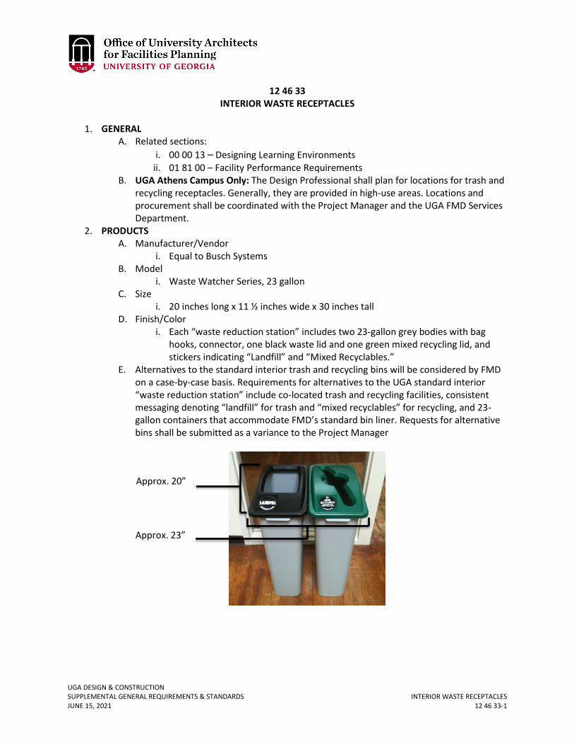
UGA DESIGN & CONSTRUCTION SUPPLEMENTAL GENERAL REQUIREMENTS & STANDARDS INTERIOR WASTE RECEPTACLES JUNE 15, 2021 12 46 33-1
12 46 33 INTERIOR WASTE RECEPTACLES
1. GENERAL
A. Related sections: i. 00 00 13 – Designing Learning Environments
ii. 01 81 00 – Facility Performance Requirements B. UGA Athens Campus Only: The Design Professional shall plan for locations for trash and
recycling receptacles. Generally, they are provided in high-use areas. Locations and procurement shall be coordinated with the Project Manager and the UGA FMD Services Department.
2. PRODUCTS A. Manufacturer/Vendor
i. Equal to Busch Systems B. Model
i. Waste Watcher Series, 23 gallon C. Size
i. 20 inches long x 11 ½ inches wide x 30 inches tall D. Finish/Color
i. Each “waste reduction station” includes two 23-gallon grey bodies with bag hooks, connector, one black waste lid and one green mixed recycling lid, and stickers indicating “Landfill” and “Mixed Recyclables.”
E. Alternatives to the standard interior trash and recycling bins will be considered by FMD on a case-by-case basis. Requirements for alternatives to the UGA standard interior “waste reduction station” include co-located trash and recycling facilities, consistent messaging denoting “landfill” for trash and “mixed recyclables” for recycling, and 23-gallon containers that accommodate FMD’s standard bin liner. Requests for alternative bins shall be submitted as a variance to the Project Manager
Approx. 23”
Approx. 20”
UGA DESIGN & CONSTRUCTION SUPPLEMENTAL GENERAL REQUIREMENTS & STANDARDS ENTRANCE CARPET TILE JUNE 15, 2021 12 48 26-1
12 48 26 ENTRANCE CARPET TILE
1. GENERAL
A. Related sections: i. 09 68 00 – Carpeting
B. FMD Building Services prefers entrance carpet tile or over grate or grill mating due to maintenance issues.
2. PRODUCTS A. Entrance Floor Mats
i. Ideally allow for 10-foot depth of floor matting inside entrance ways. ii. Replaceable carpet tile squares are preferred.
iii. If using grate / grill mating at entrances, they should be lightweight for one person to lift. Do not use heavy grating or grating that requires fastening to the floor.
UGA DESIGN & CONSTRUCTION SUPPLEMENTAL GENERAL REQUIREMENTS & STANDARDS AUDIO-VISUAL FURNITURE JUNE 15, 2021 12 56 52-1
12 56 52 AUDIO-VISUAL FURNITURE
1. GENERAL
A. Related sections: i. 00 00 13 – Designing Learning Environments
ii. 72 41 00 – General Audio-Visual Systems Requirements 2. PRODUCTS
A. Equal to Computer Comforts or equal to Malone Institutional Lecterns pending the room type as per the chart below. Any variation from the lectern schedule below shall be approved in writing by the Center for Teaching and Learning. Contact Project Manager for additional information:
B. Equal to Computer Comforts, IT-3030-SS i. This standard product has been modified for UGA.
ii. Instructional Lectern with general dimensions of 30 inches wide x 30 inches deep x 38 inches tall, space saver model.
iii. 20 inches wide x 27.5 inches deep flip up surface. iv. Equipment racks must be approved by the Center for Teaching and Learning. v. Locks by UGA.
vi. Coordinate finish selection with Project Manager. C. Equal to Computer Comforts, ULS-2
i. This standard product has been modified for UGA. ii. Universal lectern with general dimensions of 48 inches wide x 30 inches deep x
38 inches tall. iii. 20 inches wide x 27.5 inches deep flip up surface. iv. Equipment racks must be approved by the Center for Teaching and Learning. v. Locks by UGA.
vi. Coordinate finish selection with Project Manager. D. Equal to Malone design / fabricators, Arches AAA
Room Type Lectern Type 10 to 20 Seat Flat Classroom Equal to Computer Comforts: IT-3030-SS
(Modified for UGA) 20 to 49 Seat Flat Classroom Equal to Computer Comforts: IT-3030-SS
(Modified for UGA) 50 to 60 Seat Flat Classroom Equal to Computer Comforts: ULS-2 (Modified
for UGA) 60 to 100 Seat Flat Classroom Equal to Computer Comforts: ULS-2 (Modified
for UGA) 100 to 120 Seat Tiered Classroom Equal to Computer Comforts: ULS-2 (Modified
for UGA) 200 to 280 Seat Tiered Classroom Equal to Malone design / fabricators, Arches
AAA or Arches MB (Custom for UGA)
45, 72, and 99 Seat SCALE-UP Classroom Equal to Computer Comforts ULS-2 (Modified for UGA), or modified IT-3030-SS
UGA DESIGN & CONSTRUCTION SUPPLEMENTAL GENERAL REQUIREMENTS & STANDARDS AUDIO-VISUAL FURNITURE JUNE 15, 2021 12 56 52-2
i. Custom design for UGA. ii. General dimensions of 58 inches wide x 28 inches deep x 39 ¾ inches tall.
iii. 2 locking casters, 2 non-locking casters. iv. Equipment racks must be approved by the Center for Teaching and Learning. v. Locks by UGA.
vi. Coordinate finish selection with Project Manager. E. Equal to Malone design / fabricators, Arches MB
i. Custom design for UGA. ii. General dimensions of 72 inches wide, 29 inches deep, 40 ½ inches tall.
iii. 2 locking casters, 2 non-locking casters. iv. Equipment racks must be approved by the Center for Teaching and Learning. v. Locks by UGA.
vi. Coordinate finish selection with Project Manager.
UGA DESIGN & CONSTRUCTION SUPPLEMENTAL GENERAL REQUIREMENTS & STANDARDS BICYCLE RACKS JUNE 15, 2021 12 93 13-1
12 93 13 BICYCLE RACKS
1. GENERAL 2. PRODUCTS
A. Manufacturer i. Timberform or approved equal
B. Model i. Cycloops Model 2170-3 Single Inverted ‘U’ or approved equal
C. Size i. Height: 3 feet (nominal)
ii. Length: 1’-3” (nominal) iii. Width: 3 inches (nominal)
D. Finish / Color i. Black suede powdercoat
E. Special Features i. In-ground anchor mount
F. Technical Specifications i. One-piece ASTM A53 Schedule 40 Steel Pipe (2-inch I.D. x 0.156 Wall), with
smooth 6-inch radius mandrel bend, hot dipped galvanized per ASTM 123 after complete fabrication.
G. Installation Options i. Embedment Mount (Preferred): Legs shall extend ten (10) inches below finish
grade and shall be drilled to accept No. 4 re-bar. ii. Pedestal Mount: Shall include separate pedestal mount bases comprised of ¼-
inch thick mild steel plate permanently welded to two 1 ½-inch I.D. Sch. 40 pipe sleeves. Decorative metal base covers shall conceal pedestal bases and the anchor hardware shall be tamper resistant.
3. EXECUTION A. Placement
i. Bicycle racks shall be placed per the Placement section of Association of Pedestrian and Bicycle Professionals Essentials of Bike Parking (2015). See diagram on following page.
B. Installation i. Install per manufacturer instructions.
ii. Installation shall be plumb and level. iii. Take measures to prevent damage to rack during delivery, storage, and
mounting. iv. Wherever possible, locate bicycle racks on level ground.

UGA DESIGN & CONSTRUCTION SUPPLEMENTAL GENERAL REQUIREMENTS & STANDARDS BICYCLE RACKS JUNE 15, 2021 12 93 13-2
UGA DESIGN & CONSTRUCTION SUPPLEMENTAL GENERAL REQUIREMENTS & STANDARDS TRASH & LITTER RECEPTACLES JUNE 15, 2021APRIL 30, 2020 12 93 23-1
12 93 23 TRASH, LITTER, AND RECYCLING RECEPTACLES
1. GENERAL
A. Related sections: i. 01 81 00 – Facility Performance Requirements
B. UGA Athens Campus Only: Proposed new trash and recycling receptacles in this section are to be provided in high-use areas on the UGA Athens Campuses shall be coordinated with the Project Manager and the UGA FMD Services Department.
C. The trash and recycling receptacles are to be placed on a poured concrete base (approx. 30 inches x 60 inches) or other paved surface as approved by the Project Manager.
2. PRODUCTS A. Manufacturer/Vendor
i. Big Belly Solar or approved equal. B. Model
i. Big Belly Duo-station (for trash and recycling) WS-BB-DBL-1YR. C. Finish/Color
i. Polyester TGIC powder-coat finish for outdoor durability. D. Design Professional shall coordinate with manufacturer requirements to insure selected
location receives adequate daylight for solar power component. E. Special Features
i. Solar-powered compactor (30 watts or greater) with fully interlocked access doors.
ii. Bi-directional communication with remote diagnostic and reprogramming capability to be integrated into University of Georgia’s Big Belly bin monitoring / CLEAN Software system account.
iii. DuoStation Right Component: Black Hopper with “Trashman” Icon (HP-T). Left Component: Green Hopper with “Recycle” Icon (HP-R-GREEN).
Deleted Apr 30, 2020
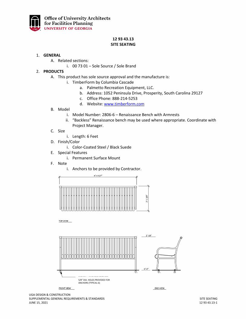
UGA DESIGN & CONSTRUCTION SUPPLEMENTAL GENERAL REQUIREMENTS & STANDARDS SITE SEATING JUNE 15, 2021 12 93 43.13-1
12 93 43.13 SITE SEATING
1. GENERAL
A. Related sections: i. 00 73 01 – Sole Source / Sole Brand
2. PRODUCTS A. This product has sole source approval and the manufacture is:
i. TimberForm by Columbia Cascade a. Palmetto Recreation Equipment, LLC. b. Address: 1052 Peninsula Drive, Prosperity, South Carolina 29127 c. Office Phone: 888-214-5253 d. Website: www.timberform.com
B. Model i. Model Number: 2806-6 – Renaissance Bench with Armrests
ii. “Backless” Renaissance bench may be used where appropriate. Coordinate with Project Manager.
C. Size i. Length: 6 Feet
D. Finish/Color i. Color-Coated Steel / Black Suede
E. Special Features i. Permanent Surface Mount
F. Note i. Anchors to be provided by Contractor.
5/8” DIA. HOLES PROVIDED FOR ANCHORS (TYPICAL-6)
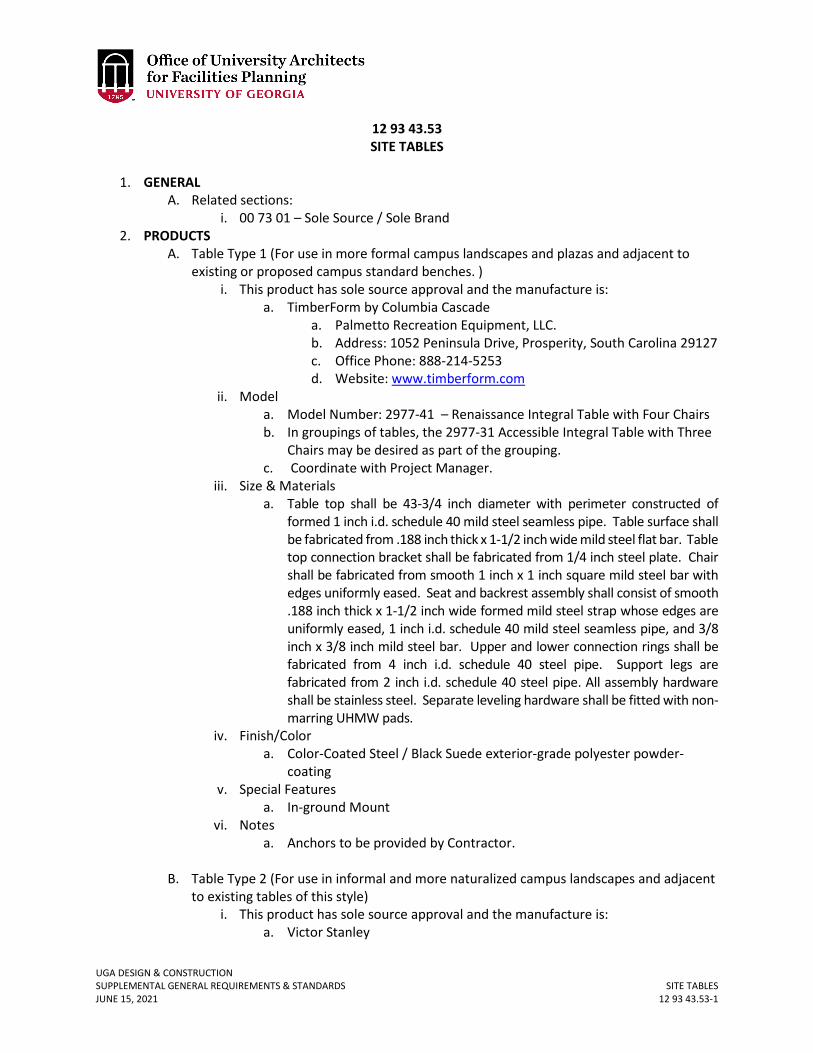
UGA DESIGN & CONSTRUCTION SUPPLEMENTAL GENERAL REQUIREMENTS & STANDARDS SITE TABLES JUNE 15, 2021 12 93 43.53-1
12 93 43.53 SITE TABLES
1. GENERAL
A. Related sections: i. 00 73 01 – Sole Source / Sole Brand
2. PRODUCTS A. Table Type 1 (For use in more formal campus landscapes and plazas and adjacent to
existing or proposed campus standard benches. ) i. This product has sole source approval and the manufacture is:
a. TimberForm by Columbia Cascade a. Palmetto Recreation Equipment, LLC. b. Address: 1052 Peninsula Drive, Prosperity, South Carolina 29127 c. Office Phone: 888-214-5253 d. Website: www.timberform.com
ii. Model a. Model Number: 2977-41 – Renaissance Integral Table with Four Chairs b. In groupings of tables, the 2977-31 Accessible Integral Table with Three
Chairs may be desired as part of the grouping. c. Coordinate with Project Manager.
iii. Size & Materials a. Table top shall be 43-3/4 inch diameter with perimeter constructed of
formed 1 inch i.d. schedule 40 mild steel seamless pipe. Table surface shall be fabricated from .188 inch thick x 1-1/2 inch wide mild steel flat bar. Table top connection bracket shall be fabricated from 1/4 inch steel plate. Chair shall be fabricated from smooth 1 inch x 1 inch square mild steel bar with edges uniformly eased. Seat and backrest assembly shall consist of smooth .188 inch thick x 1-1/2 inch wide formed mild steel strap whose edges are uniformly eased, 1 inch i.d. schedule 40 mild steel seamless pipe, and 3/8 inch x 3/8 inch mild steel bar. Upper and lower connection rings shall be fabricated from 4 inch i.d. schedule 40 steel pipe. Support legs are fabricated from 2 inch i.d. schedule 40 steel pipe. All assembly hardware shall be stainless steel. Separate leveling hardware shall be fitted with non-marring UHMW pads.
iv. Finish/Color a. Color-Coated Steel / Black Suede exterior-grade polyester powder-
coating v. Special Features
a. In-ground Mount vi. Notes
a. Anchors to be provided by Contractor.
B. Table Type 2 (For use in informal and more naturalized campus landscapes and adjacent to existing tables of this style)
i. This product has sole source approval and the manufacture is: a. Victor Stanley
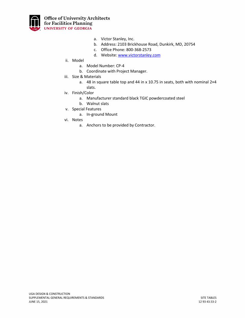
UGA DESIGN & CONSTRUCTION SUPPLEMENTAL GENERAL REQUIREMENTS & STANDARDS SITE TABLES JUNE 15, 2021 12 93 43.53-2
a. Victor Stanley, Inc. b. Address: 2103 Brickhouse Road, Dunkirk, MD, 20754 c. Office Phone: 800-368-2573 d. Website: www.victorstanley.com
ii. Model a. Model Number: CP-4 b. Coordinate with Project Manager.
iii. Size & Materials a. 48 in square table top and 44 in x 10.75 in seats, both with nominal 2×4
slats. iv. Finish/Color
a. Manufacturer standard black TGIC powdercoated steel b. Walnut slats
v. Special Features a. In-ground Mount
vi. Notes a. Anchors to be provided by Contractor.
UGA DESIGN & CONSTRUCTION SUPPLEMENTAL GENERAL REQUIREMENTS & STANDARDS FOUNTAINS JUNE 15, 2021 13 12 00-1
13 12 00 FOUNTAINS
1. GENERAL
A. Due to water conservation efforts and the high maintenance requirements of fountains, new interior and / or exterior fountains are not allowed.
B. If a variance is granted for a fountain, it shall be connected to the sanitary sewer system and shall not connect to the storm sewer system.
C. If a variance for a fountain is granted, funding source for the related infrastructure and fountain shall be private funds.

UGA DESIGN & CONSTRUCTION SUPPLEMENTAL GENERAL REQUIREMENTS & STANDARDS PRE-FABRICATED ENVIRONMENTAL ROOMS JUNE 15, 2021 13 21 00-1
13 21 00 PRE-FABRICATED ENVIRONMENTAL ROOMS
1. GENERAL
A. Related sections: i. 23 00 00 – General Mechanical Requirements (HVAC)
ii. 26 00 00 – General Electrical Requirements B. Intent:
i. The guide is for the purpose of assisting the design engineer with specifying environmental rooms, walk-in coolers and / or freezers used in research or for educational purposes. This guide specification is not intended for food storage walk-in coolers.
ii. The unit shall be provided by a single-source manufacturer and the manufacturer shall be ISO 9001 registered.
2. PRODUCTS A. Acceptable manufacturers are:
i. Nor-Lake, Inc. ii. Harris Environmental
iii. Thermmax Scientific Products B. Insulated Panels / Walls / Roof
i. The environmental room shall be pre-fabricated and field assembled and shall consist of modular, interlocking, pre-insulated panels. The panel insulation shall be polyurethane rigid foam and the thickness shall be sized to prevent condensation on the exterior and shall be no less than 4 inches thick. Sufficient gasketing shall be provided to stop moisture migration.
ii. Floor panels shall be designed to withstand 600 pounds per square foot pressure minimum.
iii. Adjoining environmental rooms operating at different conditions shall not share panels, but shall be independent of one another. (No shared roof, floor or wall panels).
C. Doors i. The door shall have an anti-sweating heater wire around the perimeter to
prevent sweating, an observation window and a kick-plate. D. Ramps
i. Discuss with UGA project manager whether a ramp is needed and if so should it be internal or external to the unit.
E. Interior floors shall be provided with tread plate covering to reducing slipping. F. Condensing units shall not be mounted atop the cooler unless it is water-cooled. If
mounted atop unit, a minimum of 36 inches clear from the top of the unit to structure is required. In addition, adequate clearances for access and maintenance shall be provided. Air-cooled units shall be installed remotely outdoors unless specifically approved by Project Manager.
G. Electrical: i. The environmental room shall have a single point of power connection in a
NEMA 1 cabinet containing circuit breakers for lights, outlets and cooler located directly above the controls.
UGA DESIGN & CONSTRUCTION SUPPLEMENTAL GENERAL REQUIREMENTS & STANDARDS PRE-FABRICATED ENVIRONMENTAL ROOMS JUNE 15, 2021 13 21 00-2
ii. Lighting shall be designed to maintain to provide 70 foot candles. Lights shall be gasketed and all associated hardware designed to operate in a damp location without rusting. All wiring shall be concealed in conduit inside the panels.
iii. Provide 2 duplex receptacles per wall minimum unless otherwise instructed. Discuss locations with Project Manager.
H. Controls: i. Discuss with Project Manager to ensure what design conditions are needed.
Many environmental rooms are designed for 4 degrees Celsius, but others may vary depending upon the department. Others may require humidification and / or dehumidification. DP shall confirm any tolerance/dead band requirements for both temperature and humidity with UGA PM at the start of the project.
ii. Programmable microprocessor controls for temperature and humidity control shall be encased in a lockable panel with an acrylic cover. Temperature and humidity shall be displayed via a liquid crystal alphanumeric display.
iii. The controllers shall have sufficient outputs and inputs to interface with alarms or other devices as required.
iv. The controller shall be provided with the capability of generating e-mail or text messages to identified individuals via the internet in the case of the cold room operating outside set parameters.
a. Coordination with the FMD IT Department will be required for installation of associated software and for programming of individual text and e-mail addresses.
b. Coordination with campus EITS to provide data cable drop for transmission of alarm text or e-mail.
v. Provide low and high limit safeties to prevent over cooling or over-heating and shall generate audible and visual alarms. High and low safeties shall be provided with automatic resets rather than manual resets.
vi. Paper chart recorders are generally not desired. Requirements for reviewing temperature and humidity historical trend data shall be confirm with the UGA PM at the start of the project.
vii. Product sample temperature sensors shall be provided with protective cover. I. Alarms:
i. Provide audible and visual alarms. J. Water-Cooled Condensing Units:
i. The condensing unit shall be indoor type. ii. The compressors shall be hermetic.
iii. Indoor water-cooled condensing unit accessories include: iv. Water regulating valve for head pressure control v. Coaxial or shell and tube condenser shall be selected for the proper EWT and
condensing temperature. K. Outdoor Condensing Units:
i. The condensing units shall include pre-painted galvanized cabinet, compressor, condenser, fan motors, liquid receiver with fusible plug, compressor service valves and waterproof electrical control panel. The assembly shall be designed for outdoor use.
ii. The compressors shall be serviceable semi-hermetic or scroll type
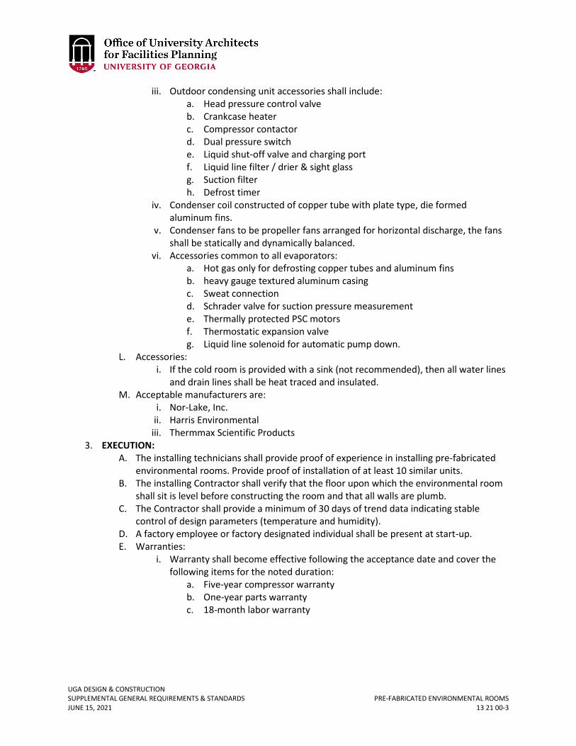
UGA DESIGN & CONSTRUCTION SUPPLEMENTAL GENERAL REQUIREMENTS & STANDARDS PRE-FABRICATED ENVIRONMENTAL ROOMS JUNE 15, 2021 13 21 00-3
iii. Outdoor condensing unit accessories shall include: a. Head pressure control valve b. Crankcase heater c. Compressor contactor d. Dual pressure switch e. Liquid shut-off valve and charging port f. Liquid line filter / drier & sight glass g. Suction filter h. Defrost timer
iv. Condenser coil constructed of copper tube with plate type, die formed aluminum fins.
v. Condenser fans to be propeller fans arranged for horizontal discharge, the fans shall be statically and dynamically balanced.
vi. Accessories common to all evaporators: a. Hot gas only for defrosting copper tubes and aluminum fins b. heavy gauge textured aluminum casing c. Sweat connection d. Schrader valve for suction pressure measurement e. Thermally protected PSC motors f. Thermostatic expansion valve g. Liquid line solenoid for automatic pump down.
L. Accessories: i. If the cold room is provided with a sink (not recommended), then all water lines
and drain lines shall be heat traced and insulated. M. Acceptable manufacturers are:
i. Nor-Lake, Inc. ii. Harris Environmental
iii. Thermmax Scientific Products 3. EXECUTION:
A. The installing technicians shall provide proof of experience in installing pre-fabricated environmental rooms. Provide proof of installation of at least 10 similar units.
B. The installing Contractor shall verify that the floor upon which the environmental room shall sit is level before constructing the room and that all walls are plumb.
C. The Contractor shall provide a minimum of 30 days of trend data indicating stable control of design parameters (temperature and humidity).
D. A factory employee or factory designated individual shall be present at start-up. E. Warranties:
i. Warranty shall become effective following the acceptance date and cover the following items for the noted duration:
a. Five-year compressor warranty b. One-year parts warranty c. 18-month labor warranty
UGA DESIGN & CONSTRUCTION SUPPLEMENTAL GENERAL REQUIREMENTS & STANDARDS METAL BUILDING SYSTEMS JUNE 15, 2021 13 34 19-1
13 34 19 METAL BUILDING SYSTEMS
1. GENERAL
A. Introduction: Metal Building Systems are generally used in rural or agricultural settings, and the design intent is for the metal building form to emulate the shape of a barn.
B. The roof shall be a gable form with a minimum 6 in 12 slope. C. Overhangs of at least 12 inches are required on all sides of the building. D. Vinyl soffits are not allowed. E. The roof color and material shall be equal to Galvalume (55 percent aluminum-zinc alloy
coated sheet steel). F. The siding color shall be a medium gray and color samples shall be submitted to the
Project Manager for approval. G. All roof penetrations shall utilize a pre-manufactured boot and / or sleeve that is
specifically designed for a metal building roof system.
UGA DESIGN & CONSTRUCTION SUPPLEMENTAL GENERAL REQUIREMENTS & STANDARDS ELEVATORS JUNE 15, 2021 14 20 00-1
14 20 00 ELEVATORS
1. GENERAL
A. Related sections: i. 01 77 00 – Project Closeout
B. Elevator control systems of proprietary design or that use a separate device for troubleshooting are not acceptable. Contractor shall submit complete information to the Design Professional and Project Manager demonstrating the universal servicing capability of the proposed system.
C. All elevators are to be traditional traction or hydraulic elevators as necessitated by the individual project requirements, with a traditional machine room. Machine Room Less elevators are not allowable without an express, approved variance signed by OUA or FMD Associate Vice President.
2. PRODUCTS A. Acceptable manufactures and / or installers:
i. Otis Elevator Company ii. Premier Elevator Co., Inc.
iii. Thyssenkrupp B. Microprocessor and Control Systems
i. The system shall be of a non-proprietary design. The equipment shall be maintainable by any elevator maintenance company employing certified elevator mechanics without the requirement to purchase, lease, rent, or borrow additional diagnostic devices, special tools, instructions, etc. from the original equipment manufacturer.
a. Microprocessor and control systems basis of design is GAL Manufacturing Corp., Bronx, New York.
ii. The equipment shall be provided with on-site capability to diagnose faults of all components, parts, circuit boards, etc. of the solid state controls. If the equipment requires a separate, detachable device / tool for fault diagnostics or adjustments, that device / tool shall be incorporated as a permanent part of the equipment and provided to Owner as a part of the installation.
iii. The device / tool shall become the property of the Owner and shall be provided with complete troubleshooting guides and all technical information including passwords, addresses, etc. to completely adjust the elevator. The device / tool shall be of the perpetual type (never need recharging or reprogramming).
iv. The equipment manufacturer must agree to sell any and all parts, printed circuit boards, programmed chips, transducers, controller power supplies, etc. to any elevator maintenance contractor providing services to the Owner for this location.
v. Equipment installed not meeting these requirements shall be removed and replaced with equipment as specified at no cost to the Owner.
C. Signals and Fixtures i. All signals, fixtures and fasteners shall be vandal-resistant. Communications
device shall be self-dialing, vandal resistant, push to talk. For all devices
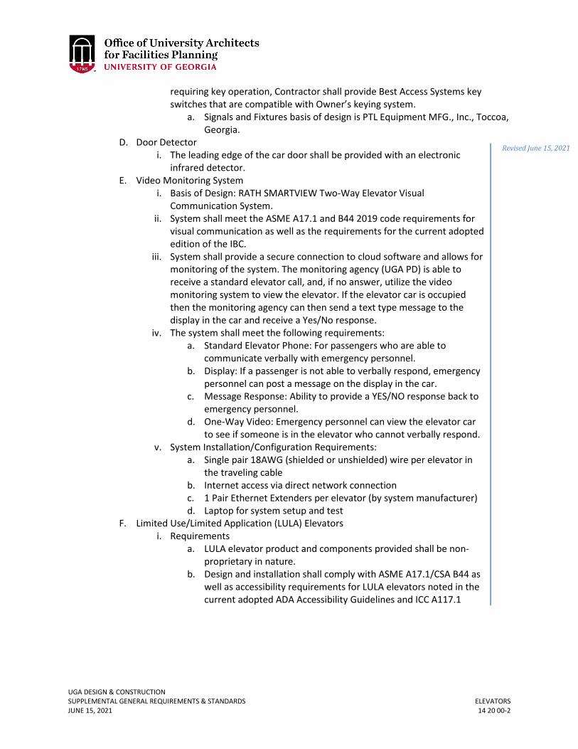
UGA DESIGN & CONSTRUCTION SUPPLEMENTAL GENERAL REQUIREMENTS & STANDARDS ELEVATORS JUNE 15, 2021 14 20 00-2
requiring key operation, Contractor shall provide Best Access Systems key switches that are compatible with Owner’s keying system.
a. Signals and Fixtures basis of design is PTL Equipment MFG., Inc., Toccoa, Georgia.
D. Door Detector i. The leading edge of the car door shall be provided with an electronic
infrared detector. E. Video Monitoring System
i. Basis of Design: RATH SMARTVIEW Two-Way Elevator Visual Communication System.
ii. System shall meet the ASME A17.1 and B44 2019 code requirements for visual communication as well as the requirements for the current adopted edition of the IBC.
iii. System shall provide a secure connection to cloud software and allows for monitoring of the system. The monitoring agency (UGA PD) is able to receive a standard elevator call, and, if no answer, utilize the video monitoring system to view the elevator. If the elevator car is occupied then the monitoring agency can then send a text type message to the display in the car and receive a Yes/No response.
iv. The system shall meet the following requirements: a. Standard Elevator Phone: For passengers who are able to
communicate verbally with emergency personnel. b. Display: If a passenger is not able to verbally respond, emergency
personnel can post a message on the display in the car. c. Message Response: Ability to provide a YES/NO response back to
emergency personnel. d. One-Way Video: Emergency personnel can view the elevator car
to see if someone is in the elevator who cannot verbally respond. v. System Installation/Configuration Requirements:
a. Single pair 18AWG (shielded or unshielded) wire per elevator in the traveling cable
b. Internet access via direct network connection c. 1 Pair Ethernet Extenders per elevator (by system manufacturer) d. Laptop for system setup and test
F. Limited Use/Limited Application (LULA) Elevators i. Requirements
a. LULA elevator product and components provided shall be non-proprietary in nature.
b. Design and installation shall comply with ASME A17.1/CSA B44 as well as accessibility requirements for LULA elevators noted in the current adopted ADA Accessibility Guidelines and ICC A117.1
Revised June 15, 2021
UGA DESIGN & CONSTRUCTION SUPPLEMENTAL GENERAL REQUIREMENTS & STANDARDS ELEVATORS JUNE 15, 2021 14 20 00-3
ii. Basis-of-Design (subject to compliance with requirements): a. Symmetry Elevating Solutions LULA Elevator, or comparable
product by one of the following: b. American Crescent Elevator Mfg. Corp. c. Cambridge Elevating d. Cemcolift, Inc. e. Garaventa Lift. f. Savaria
3. EXECUTION
A. Elevator Contractor Qualifications i. The Elevator Contractor shall be competent and experienced in the field of
elevator installation, maintenance, and modernization with a minimum of five years prior experience on comparable or more complex elevator equipment and currently have service contracts on similar specified equipment. The Elevator Contractor must demonstrate the ability to answer a service call within one (1) hour of notification by telephone.
B. Wiring Diagrams i. Contractor shall furnish three complete sets of full sized As-Built wiring
diagrams at closeout. Contractor shall laminate and securely mount one complete set of the wiring diagrams on the wall of the elevator machine room.
ii. All block diagrams including input and output signals and all diagnostic and troubleshooting guides of a technical level shall be included to completely adjust the entire elevator system.
iii. Contractor shall provide two sets of “As-Built” wiring diagrams on compact disk with read-write access by AutoCAD 2007 or later.
C. Parts Manuals i. Contractor shall furnish three sets of replacement parts manuals covering all of
the equipment and components installed for this location. D. Maintenance Service
i. Elevator maintenance will be performed by the UGA elevator maintenance contractor under an already established contract held directly by UGA FMD. No maintenance responsibilities are required to be included otherwise.
E. Warranty i. Contractor shall correct any defects not due to ordinary wear which may
develop within twelve (12) months from the date of Material Completion. Contractor and Elevator Contractor response time shall be one (1) hour maximum from the time notification is made to Contractor.
Revised June 15, 2021
UGA DESIGN & CONSTRUCTION SUPPLEMENTAL GENERAL REQUIREMENTS & STANDARDS GENERAL FIRE SUPPRESSION REQUIREMENTS JUNE 15, 2021 21 00 00-1
21 00 00 GENERAL FIRE SUPPRESSION REQUIREMENTS
1. GENERAL
A. Related sections: i. 00 00 07 – Design Professional Design Process Requirements
ii. 01 41 26.04 – Fire Marshal Construction Inspection Requirements B. Fire Department Connections (FDC) are preferred to be placed at same location as Post
Indicator Valve (PIV) and to not be placed on the building. C. For UGA Athens Campuses Only:
i. Athens-Clarke County requires a fire suppression system in all parking decks. This is an interpretation by the Authority Having Jurisdiction and is non-negotiable.
D. Dry pipe systems shall be Nitrogen Generation Corrosion Inhibiting System. This system shall be designed to service call Dry and/or Pre-action fire protection systems.
i. The Nitrogen Generation System shall be provided with air compressor and a Nitrogen Generation System controls cabinet.
ii. The integral controls shall include the following as a minimum: 1. Shall have local human machine interface (HMI). 2. Shall monitor leak rate, hours of operation of the nitrogen generator,
time in air bypass mode, generator pressure, current status of nitrogen generator, maintenance schedules, provide service reminders, and alarms.
3. The control system shall be BACNET compatible. iii. The system shall be started by an authorized factory representative. iv. Basis of design shall be South-Tek or an approved equal.
E. Flexible sprinkler piping/heads are not allowed above hard ceilings. New June 15, 2021
UGA DESIGN & CONSTRUCTION SUPPLEMENTAL GENERAL REQUIREMENTS & STANDARDS GENERAL PLUMBING REQUIREMENTS JUNE 15, 2021 22 00 00-1
22 00 00 GENERAL PLUMBING REQUIRMENTS
1. GENERAL
A. Related sections: i. 00 00 07 – Design Professional Design Process Requirements
ii. 00 00 08 – Design Professional Documentation Requirements and Deliverables iii. 00 00 13 – Designing Learning Environments iv. 01 41 26.06 – Dining Services v. 01 81 00 – Facility Performance Requirements
vi. 22 07 00 – Plumbing Insulation vii. 22 10 00 – Plumbing Piping
viii. 22 40 00 – Plumbing Fixtures ix. 22 45 00 – Emergency Plumbing Fixtures x. 23 05 53 – Identification for HVAC Piping and Equipment
xi. 23 09 23 – Building Automation and Temperature Control System (BAS) B. The Design Professional is recommended to refer to Section 00 00 07 Design
Professional Design Process Requirements, Section 00 00 08 Design Professional Documentation Requirements and Deliverables, and Section 01 81 00 Facility Performance Requirements before beginning design.
C. Design Professional shall provide riser diagrams for all plumbing systems. D. Design Professional shall refer to Section 23 05 53 Identification for HVAC Piping and
Equipment for information regarding plumbing identification. E. Domestic Water:
i. Provide a valve at each floor in branch line serving that floor (provide 2 valves if system is looped).
ii. Provide a valve in hot and cold water at entry to each bathroom and at each fixture.
iii. Provide a valve in each service (water, gas, comp air, etc.) at entry to each laboratory and at each lab bench, fume hood, and at terminations for equipment. Valves shall be readily accessible, grouped together and located in lockable valve cabinet(s) at entry to the lab.
iv. Design Professional shall determine need for any application specific additional valves that may be required and show these on the plans.
v. Hot water: provide re-circulating systems on all systems with dead-leg runs greater than 30 feet.
vi. Isolation valves shall be provided in readily accessible locations and coordinated with other disciplines as required.
vii. Provide balancing valves and thermometers in hot water circulation lines to assist in balancing.
viii. Propress fitting (or other similar mechanical joints) shall not be allowed in new facilities, but may be considered in renovations of existing facilities.
ix. For any domestic water sub-metering applications, controls contractor to provide meter and plumbing contractor to install. Refer to Section 23 09 23 Building Automation and Temperature Control System (BAS) for specification
UGA DESIGN & CONSTRUCTION SUPPLEMENTAL GENERAL REQUIREMENTS & STANDARDS GENERAL PLUMBING REQUIREMENTS JUNE 15, 2021 22 00 00-2
details. Plumbing designer to show meter and associated notes on plumbing drawings.
x. All thermometer gauges located on domestic plumbing shall be dail type gauges.
F. Provide floor drains in all toilet rooms. G. Provide trap primers for all floor drains and floor sinks except for UGA Housing
projects where trap guards shall be used as the basis of design. Plumbing design shall review with UGA PM which types of primer to use for each project and clearly designate which type is used for each location on the drawings.
H. Ball valves shall be used for plumbing services isolation (no gate valves). For larger pipe sizes other valves other valve types can be submitted to UGA PM for approval (still no gate valves).
I. Pressure reducing valves (PRVs) i. Shall be suitable for the application. Verify the prevailing mains water pressure
and consult the manufacturer’s engineering department to verify the correct selection of the PRV provided irrespective of any model specified on the drawings.
ii. Provide pressure gauge downstream and P/T ports up and downstream of every PRV.
iii. Provide an upstream strainer if installed ahead of the PRV. J. Design for Learning Environments
i. Avoid locating high traffic plumbing pipe within the classroom space. When plumbing is provided within a classroom wall, ensure that the wall’s sound transmission class (STC) rating is adequate. Avoid plumbing layouts which may cause excessive pipe noise through the effects of water hammer.
ii. Whenever a project includes work that will penetrate existing concrete slab (elevated and / or on grade), the Design Professional and / or Construction Professional shall review conditions during design with Project Manager to verify if additional investigative work is needed (x-ray, GPR, ferroscan, etc.).
K. Strategy for supplying deionized water shall be reviewed with UGA PM to determine if a building, regional, or point of use system is to be used. Also need to confirm required water purity levels (1 MΩ, 18 MΩ, etc.).
L. If a point of use DI system is utilized, review with UGA PM to determine if a floor drain is needed.
M. For projects incorporating DI loops design professional shall incorporate the below detail:
N. Installation of residential-type dishwashers is prohibited. In cases where there is adequate reasoning, a variance must be submitted and approved prior to incorporation into the design.
New June 15, 2021
New June 15, 2021
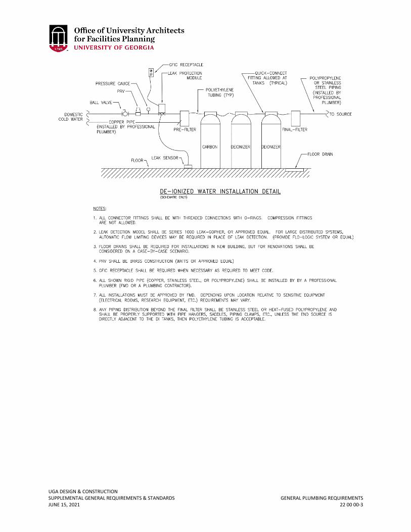
UGA DESIGN & CONSTRUCTION SUPPLEMENTAL GENERAL REQUIREMENTS & STANDARDS GENERAL PLUMBING REQUIREMENTS JUNE 15, 2021 22 00 00-3
UGA DESIGN & CONSTRUCTION SUPPLEMENTAL GENERAL REQUIREMENTS & STANDARDS PLUMBING INSULATION JUNE 15, 2021 22 07 00-1
22 07 00 PLUMBING INSULATION
1. GENERAL
A. Related sections: i. 22 00 00 – General Plumbing Requirements
ii. 22 10 00 – Plumbing Piping B. All hot and tempered water piping shall be insulated. Cold water piping insulation is not
mandatory but should be provided if required by project conditions. 2. PRODUCTS
A. Insulation shall be performed fiberglass pipe insulation with vapor barrier and an all service jacket.

UGA DESIGN & CONSTRUCTION SUPPLEMENTAL GENERAL REQUIREMENTS & STANDARDS PLUMBING PIPING JUNE 15, 2021 22 10 00-1
22 10 00 PLUMBING PIPING
1. GENERAL
A. Related sections: i. 22 00 00 – General Plumbing Requirements
ii. 22 07 00 – Plumbing Insulation iii. 22 40 00 – Plumbing Fixtures iv. 22 45 00 – Emergency Plumbing Fixtures
2. PRODUCTS A. Under slab sanitary sewer piping shall be PVC. Buried sanitary sewer piping from 5 feet
outside the building shall be ductile iron piping. Above-grade sanitary sewer piping shall be cast iron pipe with cast iron fittings.
B. All sanitary mains leaving the building and under the slab (4" and larger) shall be camera-ed at the end of the warranty period.
C. Water piping, buried within 5 feet of building, and below slab shall be ductile iron pipe with ductile iron or gray iron fittings.
D. Domestic water piping above grade shall be type “L” copper pipe. E. Acid resistant waste and vent piping shall be polypropylene or polyvinyllidene fluoride
(PVDF). F. Fuel gas piping above grade shall be type “K” copper pipe or steel pipe, schedule
40. G. Strategy for supplying deionized water shall be reviewed with UGA PM to determine if a
building, regional, or point of use system is to be used. H. In addition, the required water purity levels shall be confirmed (1 MΩ, 18 MΩ, etc.). I. If a point of use DI system is utilized, review with UGA PM to determine if a floor drain is
needed.
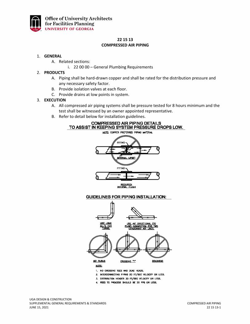
UGA DESIGN & CONSTRUCTION SUPPLEMENTAL GENERAL REQUIREMENTS & STANDARDS COMPRESSED AIR PIPING JUNE 15, 2021 22 15 13-1
22 15 13 COMPRESSED AIR PIPING
1. GENERAL
A. Related sections: i. 22 00 00 – General Plumbing Requirements
2. PRODUCTS A. Piping shall be hard-drawn copper and shall be rated for the distribution pressure and
any necessary safety factor. B. Provide isolation valves at each floor. C. Provide drains at low points in system.
3. EXECUTION A. All compressed air piping systems shall be pressure tested for 8 hours minimum and the
test shall be witnessed by an owner appointed representative. B. Refer to detail below for installation guidelines.
UGA DESIGN & CONSTRUCTION SUPPLEMENTAL GENERAL REQUIREMENTS & STANDARDS PLUMBING FIXTURES JUNE 15, 2021 22 40 00-1
22 40 00 PLUMBING FIXTURES
1. GENERAL
A. Related sections: i. 22 00 00 – General Plumbing Requirements
ii. 22 10 00 – Plumbing Piping iii. 06 61 00 – Solid Surface Fabrications iv. 09 00 00.01 – Custodial Storage
B. Flow rates for fixtures and fitting shall comply with or be less than GA State Amendments to International Plumbing Code, Table 604.4.
2. PRODUCTS A. Sensor actuated flush valves and faucets are not allowed. If the Design Professional feels
that circumstances for a particular project warrant sensor actuated flush valves, the Design Professional shall discuss with Project Manager and determine if a variance request should be submitted.
B. Acceptable manufactures and/or products are: i. Lavatories – Sensor Type Faucets (if allowed)
a. Equal to Sloan: ETF 600 (Hardwire) b. Equal to Sloan: SF2350 (Battery) c. Equal to Speakman Sensorflo: S-8701 (Battery)
ii. Lavatories – Meeting faucets require pre-approval by the Project Manager a. American Standard b. Delta c. Encore d. Kohler e. Moen f. T&S Brass
iii. Teaching Labs – Two Handle Faucets with Vacuum Breaker in Spout a. Chicago b. T&S Brass c. Water Saver
iv. Urinals 0.5 GPF Max a. Equal to American Standard: Washbrook 6590.001 (0.5 GPF) b. Equal to Crane: 7399 (0.5 GPF) c. Equal to Zurn: Z5738 (0.125 GPF) d. Equal to Zurn: Z5798 (0.125 GPF)
v. Urinals – Sensor Flushometers (if allowed) a. Equal to Sloan: Optima 186 ES-S Series b. Equal to Zurn: ZEG6003EV (for pint urinal)
vi. Urinals – Manual Flushometers a. Equal to Sloan: 186 HEU Series (0.125 GPF and 0.5 GPF) b. Equal to Zurn: Z6003AV-ULF (for 0.125 GPF urinal) Z6003AV-EWS (0.5
GPF) vii. Water Closets
a. Equal to American Standard: AFWALL 3351.001/3461.001 (1.28 GPF)
UGA DESIGN & CONSTRUCTION SUPPLEMENTAL GENERAL REQUIREMENTS & STANDARDS PLUMBING FIXTURES JUNE 15, 2021 22 40 00-2
b. Equal to American Standard: Madera 3451.001 c. Equal to Crane: 3346NS (Wall) d. Equal to Crane: 3H701 (ADA Floor) e. Equal to Kohler: K04325 (Wall)
viii. Water Closets – Manual Flushmeters a. Equal to Sloan: 111-1.28 (1.28 GPF) b. Equal to Zurn: Z-6000AV-HET (1.28 GPF)
ix. Water Coolers / Bottle Filling Station: Wall mounted electric drinking fountain shall be complete filtered bi-level dual fountain cooler and bottle filling station, ADA compliant, no touch sensor activation on bottle filler, cooler shall have push bar activation, water filter, flexible bubblers, refrigerated unit, 8 GPH of 50F water at 90F ambient and 80F inlet water, lead free design; equal to Elkay LZSTL8WSLK. (Single Unit: Elkay EZH2O model # LZS8WSLK) Provide 17 gauge, chrome plated cast brass P-trap with cleanout and flexible ½-inch supply with wheel handle angle valve.
x. Kitchen Sinks – 18 Gauge a. Double Bowl – Equal to Elkay LR 3322 b. Single Bowl – Equal to Elkay LR 2522 c. Bar Sink – Equal to Elkay BCR 15
xi. Kitchen Faucets a. Equal to Wolverine Brass b. Equal to Moen
xii. Service Sink – 24 inches x 24 inches x 17 inches a. Equal to Stern Williams SBC-1700BP
xiii. Service Sink Faucet a. Equal to Wolverine b. Equal to T&S c. Equal to Kohler
xiv. Laundry Sink – 23 inches x 21 ½ inches x 33 ½ inches a. Equal to Fiat FL1 b. Equal to Mustee
xv. Laundry Sink Faucet a. Equal to Wolverine b. Equal to T&S c. Equal to Moen
xvi. Wall Hung Lavatory – China a. Equal to Kohler K2005-0
xvii. Drop –In Vanity Sink / China a. Equal to Kohler K2196-4-0
C. For UGA Housing Only (New Construction) – Acceptable products i. Water Closet – Dorm Rooms: Floor mounted, tank type, two piece vitreous
china toilet with bottom outlet, elongated bowl, universal height, chrome trip lever, 1.28 gallons per flush (GPF), cotton color; equal to Toto CST744ELG(#01). Seat (Dorm Rooms): Commercial plastic elongated seat with closed front and cover. Seat and cover shall include soft close hinge system, cotton color; equal to Toto SS154 (#01).
UGA DESIGN & CONSTRUCTION SUPPLEMENTAL GENERAL REQUIREMENTS & STANDARDS PLUMBING FIXTURES JUNE 15, 2021 22 40 00-3
ii. ADA Water Closet: ADA Toilets with roll up area on right side of fixture shall be provided with right hand chrome trip level; equal to Toto CST744ELRG.
iii. Water Closet – Public Areas: Wall mounted, flush valve type with bottom outlet, 1.28 GPF, elongated bowl; equal to American Standard A2257101020. Seat (Public Area): Elongated open front seat less cover; equal to Toto SC534. Flush Value shall be chrome plated brass, exposed, diaphragm type with vacuum breaker; Sloan Royal 111-1.28 or equal by Toto or Zurn.
iv. ADA Water Closet – Public Areas: Same as Water Closet – Public Areas except ADA toilets in public areas shall be ADA height: American Standard A2257101020. Flush handle shall be installed on wide roll up side of fixture.
v. Urinal: ADA compliant, wall hung, vitreous china, 0.125 GPF (pint), washout type flush action, ¾-inch inlet top spud, 2-inch outlet, cotton color; equal to Toto UT105UG(#01). Flush Valve: manual operated, exposed, 0.125 GPF flush (pint), chrome plated brass valve with vacuum breaker and adjustable tailpiece; Sloan 186-0.13 or equal by Toto or Zurn.
vi. Dorm Room Vanity Sink: Sink basin shall be integral counter mounted type. Faucet: ADA compliant, chrome plated brass, 4-inch center set single handle faucet with metal pop-up waste assembly, adjustable temperature limit stop and 1.5 GPM laminar flow aerator; Basis of Design is Delta Commercial with Delta aerator.
vii. ADA Dorm Room Vanity Sink: Same as Dorm Room Vanity Sink except with offset tailpiece and insulation kit on piping below fixture.
viii. Counter Lavatories – Public Areas: Fixture: 17 inches x 13 inches (overall) 18 gauge, type 304 under mount stainless steel lavatory with undercoating and overflow assembly; equal to Elkay ELU1511 or equal by Just Manufacturer. Faucet: ADA compliant, chrome plated brass, 4-inch center set single handle faucet with grid drain waste assembly, adjustable temperature limit stop and 0.5 GPM aerator; Basis of Design is Delta Commercial with Delta aerator.
ix. Wall Hung Lavatory: ADA compliant, 21 inches x 18 inches wall hung, vitreous china lavatory, 4-inch faucet centers, front overflow; equal to Toto LT307.4. Faucet: ADA compliant, chrome plated brass, 4-inch center set single handle faucet with grid drain waste assembly, adjustable temperature limit stop and 0.5 GPM aerator; Basis of Design is Delta Commercial with Delta aerator.
x. Dorm Showers: Enclosures shall include solid surface panels and shower pans. Provide 2-inch shower drain with stainless steel strainer and securing nut in each shower compartment; equal to Zurn FD-2270. Valve and trim shall be manual pressure balancing mixing valve with check stops, lever handle and low flow showerhead (1.5 GPM). Equal to Delta valve with Delta head. Provide with chrome plated arm and flange; Basis of Design is Delta Commercial. Provide Rinse Ace diverter between shower arm and head at each fixed showerhead; Rinse Ace WCRA-4050.
New June 15, 2021
UGA DESIGN & CONSTRUCTION SUPPLEMENTAL GENERAL REQUIREMENTS & STANDARDS PLUMBING FIXTURES JUNE 15, 2021 22 40 00-4
xi. ADA Dorm Shower: Enclosures shall include solid surface panels and shower pans as specified by the Architect. Provide 2-inch shower drain with stainless steel strainer and securing nut in each shower compartment; equal to Zurn FD-2270. Valve and trim shall be manual pressure balancing mixing valve with check stops, level handle and low flow showerhead (1.5 GPM). Basis of Design is Delta valve with Delta head. Provide with chrome plated arm and flange. Provide with ADA hand held showerhead (1.5 GPM) on slide bar; Basis of Design is Delta. Diverter to control showers heads shall be provided; Basis of Design is Delta. Provide Rinse Ace diverter between shower arm and head at each fixed showerhead; Rinse Ace WCRA-4050.
xii. Kitchen Sink – Apartment: 30 inches x 18 inches x 5 ½ inches deep, two compartment, 18 gauge, under mount, type 304 stainless steel sink with drain opening in center rear of each compartment; equal to Elkay ELUHAD3118 or equal by Just Manufacturer. Provide basket strainers with tailpiece. Sink faucets shall be 8-inch center set with 8-inch spout with single handle faucet, ceramic disc cartridge with 1.5 GPM aerators, side spray; Basis of Design is Delta Commercial. Provide 17-gauge chrome plated offset tailpiece and 17-gauge chrome plated cast brass p-trap with cleanout. Provide supplies to wall with wheel handle angle stops.
xiii. Kitchen Sink – Student Kitchen: 30 inches x 18 inches x 5 ½ inches deep, two compartment, 18 gauge, under mount, type 304 stainless steel sink with drain opening in center rear of each compartment; equal to Elkay ELUHAD3118 or equal by Just Manufacturer. Provide basket strainers with tailpiece. Sink faucets shall be 8-inch center set with 8-inch spout with single handle faucet, ceramic disc cartridge with 1.5 GPM aerators, and no side spray. Basis of Design is Delta Commercial faucet with Delta Commercial aerator. Provide 17-gauge chrome plated offset tailpiece and 17 gauge chrome plated cast brass p-trap with cleanout. Provide supplies to wall with wheel handle angle stops.
xiv. Kitchen Sink – Catering Kitchen: 30 inches x 18 inches x 5 ½ inches deep, two compartment, 18 gauge, under mount, type 304 stainless steel sink with drain opening in center rear of each compartment; equal to Elkay ELUHAD3118 or equal by Just Manufacturer. Provide basket strainers with tailpiece. Sink faucets shall be 8-inch center set with 8-inch spout with single handle faucet, ceramic disc cartridge with 1.5 GPM aerators, and no side spray. Basis of Design is Delta Commercial faucet with Delta Commercial aerator. Provide 17-gauge chrome plated offset tailpiece and 17 gauge chrome plated cast brass p-trap with cleanout. Provide supplies to wall with wheel handle angle stops.
xv. Service Sinks: 24 inches x 24 inches x 12 inches deep, floor type, terrazzo mop sink with stainless steel caps and wall guards; equal to Stern Williams SBC-1700-BP or comparable product by Fiat. Faucet shall be chrome plated brass and include vacuum breaker spout with hose thread outlet, pail hook, wall support, integral check stops, service stops, lever
New June 15, 2021
New June 15, 2021
UGA DESIGN & CONSTRUCTION SUPPLEMENTAL GENERAL REQUIREMENTS & STANDARDS PLUMBING FIXTURES JUNE 15, 2021 22 40 00-5
handles with color indicators, 1/4 turn ceramic disc cartridge; equal to Delta. xvi. Laundry Sinks: 23 inches x 21 ½ inches x 33 ½ inches tall, molded stone floor
mounted sink on metal legs. Legs shall be white baked enamel angle legs that slip into molded sockets with leveling devices. Equal to Fiat FL1 or equal by Mustee. Faucet shall be deck mounted, chrome plated metal construction, 4-inch center set, 5 ½-inch spout, small lever style handles; Basis of Design is Delta Commercial.
xvii. Water Coolers: Wall mounted electric drinking fountain shall be complete filtered bi-level dual fountain cooler and bottle filling station, ADA compliant, no touch sensor activation on bottle filler, cooler shall have push bar activation, water filter, flexible bubblers, refrigerated unit, 8 GPH of 50 °F water at 90 °F ambient and 80 °F inlet water, lead free design; Equal to Elkay LZSTL8WSLK. Provide 17 gauge, chrome plated cast brass P-trap with cleanout and flexible ½-inch supply with wheel handle angle valve.
xviii. Bath Tub at Apartment: Tub fixture to be 60 inches x 30 inches x 14 inches high enameled cast iron tub with structural composite backing, slip resistant surface, integral apron; Kohler K-715 or equal by American Standard or Toto. Valve and trim shall be manual pressure balancing mixing valve with check stops, lever handle and low flow showerhead (1.5 GPM). Basis of Design is Delta Commercial valve with Delta Commercial head. Provide with chrome plated arm and flange; equal to Delta Commercial. Provide with ADA hand held showerhead (1.5 GPM) on slide bar; equal to Delta Commercial. Diverter to control shower heads shall be provided; equal to Delta Commercial. Provide chrome plated brass tub spout equal to Delta Commercial. Provide Rinse Ace diverter between shower arm and head at each fixed shower head; Rinse Ace WCRA-4050.
UGA DESIGN & CONSTRUCTION SUPPLEMENTAL GENERAL REQUIREMENTS & STANDARDS EMERGENCY PLUMBING FIXTURES JUNE 15, 2021 22 45 00-1
22 45 00 EMERGENCY PLUMBING FIXTURES
1. GENERAL
A. Related sections: i. 22 00 00 – General Plumbing Requirements
2. PRODUCTS A. Emergency showers shall be equal to the Speakman Company – SE238 Life Saver or
Guardian GBF1670 Emergency Shower. i. Emergency showers are third-party certified to meet or exceed the provisions of
current edition of ANSI Z358.1. B. Eye / face washes shall be equal to Guardian G1750P or Speakman SE-580.
UGA DESIGN & CONSTRUCTION SUPPLEMENTAL GENERAL REQUIREMENTS & STANDARDS DOMESTIC WATER HEATERS JUNE 15, 2021 22 52 00-1
22 52 00 DOMESTIC WATER HEATERS
1. GENERAL
A. Related sections: i. 23 00 00 – General Mechanical Requirements (HVAC)
B. This specification is applicable for 199,000 BTU / Hr input and greater, and greater than 119 gallons storage.
2. PRODUCTS A. Boiler Types:
i. Gas source shall be specified as follows: a. High efficiency condensing water heaters shall be specified. b. Water heaters shall be fully modulating with a minimum of 4-to-1 turn-
down. ii. Electric shall be specified as follows:
a. Water heater trim shall be equipped with electronic low water cutoff, immersion operating thermostat, immersion temperature limiting device, drain valve, and ASME rated temperature and pressure relief valve.
B. Controls: i. Water heater shall employ an electronic operating control with digital
temperature readout. Operator shall be capable of connecting to a building automation system through serial connection using BACnet protocol.
ii. Water heaters provide BAS connectivity for remote visibility of the following minimum points:
a. Modulation rate (%) b. Outlet Temp c. Runtime (hours) d. Enable / disable e. Manual override f. Alarm
C. Certification and Standards: i. Water heater shall bear the ASME HLW stamp and be National Board listed.
ii. Gas-fired units, when tested to the ANSI Z21.10.3 efficiency standard, result shall be no less than 94% thermal efficiency at full firing rate.
iii. Manufacturer must be ISO 9001 QMS Certified. D. Basis of Design:
Gas: PVI Industries or equal Electric: PVI Industries or equal
3. EXECUTION A. Condensing water heaters shall be provided with acid neutralization kits. B. The water heaters shall be started by a factory authorized representative. C. The BAS shall not control the water heater(s), but shall only monitor. D. Drain valves and pressure relief valves shall be piped to a drain in a code-approved
manner. E. Warranty:
UGA DESIGN & CONSTRUCTION SUPPLEMENTAL GENERAL REQUIREMENTS & STANDARDS DOMESTIC WATER HEATERS JUNE 15, 2021 22 52 00-2
i. Covering manufacturing or material defects, waterside / fire side corrosion, leaks, and / or production of rusty water and / or chloride stress corrosion cracking – 15 years (8 years non-prorated), on-site labor, freight, and parts.
UGA DESIGN & CONSTRUCTION SUPPLEMENTAL GENERAL REQUIREMENTS & STANDARDS DOMESTIC WATER HEATERS – STEAM-FIRED JUNE 15, 2021 22 52 00.01-1
22 52 00.1 DOMESTIC WATER HEATERS – STEAM-FIRED
1. GENERAL
A. Related sections: i. 23 00 00 – General Mechanical Requirements (HVAC)
2. PRODUCTS A. Water Heater Type
i. For high or low pressure steam semi-instantaneous domestic water heater that doesn’t require storage.
ii. Heater shall provide 90-99 percent efficiency with 2-pass helical coil heat exchanger that self descales.
iii. Manufacturer shall provide 10-year warranty. B. Controls
i. The water heater shall have a feed forward monitoring system with fully modulating steam control valve for +/- 4 degree Fahrenheit water outlet.
ii. Control panel shall be provided with BACnet card. C. Basis of Design
i. Aerco Water Wizard 3. EXECUTION
A. The water heater shall be started up by factory trained representative. B. Startup paperwork to be provided to Owner.
UGA DESIGN & CONSTRUCTION SUPPLEMENTAL GENERAL REQUIREMENTS & STANDARDS GENERAL MECHANICAL REQUIREMENTS (HVAC) JUNE 15, 2021 23 00 00-1
23 00 00 GENERAL MECHANICAL REQUIREMENTS (HVAC)
1. GENERAL
A. Related sections: i. 00 00 07 – Design Professional Design Process Requirements
ii. 00 00 08 – Design Professional Documentation Requirements & Deliverables iii. 00 00 13 – Designing Learning Environments iv. 01 41 26.06 – Dining Services v. 01 75 00 – Starting and Adjusting
vi. 01 77 00 – Project Closeout vii. 01 81 00 – Facility Performance Requirements
viii. 01 91 13 – General Commissioning Requirements ix. 02 22 00 – Existing Conditions Assessment x. 07 00 00 – General Thermal and Moisture Protection Requirements
xi. 11 53 13 – Laboratory Fume Hoods xii. 22 00 00 – General Plumbing Requirements
xiii. 23 05 14 – Variable Frequency Drives xiv. 23 05 19 – Meters and Gages xv. 23 05 23 – General-Duty Valves for HVAC Piping
xvi. 23 05 29 – Hangers and Supports for HVAC Piping and Equipment xvii. 23 05 53 – Identification for HVAC Piping and Equipment
xviii. 23 05 93 – Testing, Adjusting and Balancing for HVAC xix. 23 07 13 – Duct Insulation xx. 23 07 19 – HVAC Piping Insulation
xxi. 23 09 23 – Building Automation and Temperature Control System xxii. 23 20 00 – HVAC Piping and Pumps
xxiii. 23 21 13 – Hydronic Piping xxiv. 23 21 23 – Hydronic Pumps xxv. 23 22 13 – Steam and Condensate Heating Piping
xxvi. 23 22 16 – Steam and Condensate Heating Piping Specialties xxvii. 23 25 00 – HVAC Water Treatment
xxviii. 23 31 13 – Metal Ducts xxix. 23 33 13 – Dampers xxx. 23 41 33 – High Efficiency Particulate Air (HEPA) Filtration
xxxi. 23 64 46.13 – Air-Cooled Water Chillers xxxii. 23 64 16.16 – Water-Cooled Water Chillers
xxxiii. 23 65 00 – Cooling Towers xxxiv. 23 73 00 – Indoor Central-Station Air Handling Units xxxv. 26 00 00 – General Electrical Requirements
B. The Design Professional is recommended to refer to Section 00 00 07 Design Professional Design Process Requirements, Section 00 00 08 Design Professional Documentation Requirements and Deliverables, and Section 01 81 00 Facility Performance Requirement before beginning design.
C. HVAC Design
UGA DESIGN & CONSTRUCTION SUPPLEMENTAL GENERAL REQUIREMENTS & STANDARDS GENERAL MECHANICAL REQUIREMENTS (HVAC) JUNE 15, 2021 23 00 00-2
i. On schedules specify basis of design by make and model including all options. Design Professional shall verify all model numbers and determine if products are still currently in production.
ii. All equipment on design documents shall have unique ID including VAV terminals. This ID shall be maintained for all pipe and duct layout shop drawings and controls diagrams and graphics. Design Professional to discuss with Project Manager the equipment ID requirements.
iii. Design documents shall include a project specific owner approved Training Plan. The CxP, if employed on the Project, shall assist in the preparation of the training plan.
iv. Design Professionals shall determine and specify R-values for AHUs, duct and pipe insulation thicknesses to prevent condensation on all cold surfaces inside the building run in spaces such as un-air-conditioned mechanical rooms attic and, crawl spaces under all operating conditions. R-Value of equipment and piping outside the building shall operate without condensation and shall be selected to prevent freezing under all operating conditions.
v. All equipment specified shall be suitable for the anticipated ambient conditions; electronic equipment such as temperature controls, VSDs, etc., in particular, shall be rated (or de-rated) to suit.
vi. All outdoor air intakes shall have separate minimum outdoor air damper sections (except in the case of Energy Recovery or Dedicated Outdoor air Systems).
vii. Check fan selection to ensure fan can unload properly and maintain stability under the anticipated operating range. Fan system curves on VAV systems shall have the zero-flow point at the set-point of the duct static controller, typically about 1 ¼ inches to 1 ½ inches.
viii. Specify direct drive fans with VSD for all applications. Applications where use of a direct drive fan with VSD is not feasible shall be discussed with UGA and an approved variance obtained in writing. Belt drives using ‘cogged’ belts may be permitted through the variance process.
ix. The curb on all roof mounted exhaust fans shall be sealed to eliminate induction of air.
x. The use of air side or water-side economizers shall be discussed with the Project Manager early in the design process.
xi. Once-through water cooled condensing units, heat pumps, etc., and including research / scientific equipment, growth chambers, cold rooms, x-ray machines and similar shall not be cooled with domestic water.
xii. Flow measuring stations, dampers (including damper authority), sound attenuators (where required) shall be scheduled on the drawings.
xiii. Fan static pressure calculations shall be based on filter 50% loaded conditions, and take into account, system effect, internal cabinet losses, external duct losses, and all internal losses due to coils, dampers, humidifiers, etc. Confirm all losses with basis of design manufacturer to ensure motors / fans are properly sized. All fan motors shall be selected so the BHP at design does not exceed 85% of the motor nameplate Hp.
Revised June 15, 2021
UGA DESIGN & CONSTRUCTION SUPPLEMENTAL GENERAL REQUIREMENTS & STANDARDS GENERAL MECHANICAL REQUIREMENTS (HVAC) JUNE 15, 2021 23 00 00-3
xiv. See Section 07 00 00 General Thermal and Moisture Protection Requirements – Roof Drains & Roofs for design requirements related to equipment on roofs.
xv. Duct smoke detectors to be specified in Division 23 Sections and shall be compatible with the new or existing fire alarm system.
xvi. Electrical equipment, disconnects, conduits, etc., shall be independently supported and not secured to mechanical equipment and ductwork.
xvii. In general, electrical equipment shall not be attached using a screw / bolt attachment through the equipment casing. When conditions do require attachment, attachment shall be made utilizing a stud type bonding fastener with perforated base adhered to the equipment casing with a compatible high strength structural adhesive.
xviii. Fan coil unit drain pans shall be 16 gauge stainless steel. xix. Sequences shall be provided and shown on the drawings for all packaged
equipment, even if the controls are integral (not provided by BAS vendor). The documents shall clearly indicate what devices are provided by equipment vendor and what is provided by BAS vendor.
xx. Packaged equipment provided with integral controls shall be provided with factory installed ALC controls when possible. If ALC controls are not provided at the factory, then a BACnet interface shall be provided. The equipment manufacturer shall provide as a minimum the following, as a part of the shop drawing submittal process:
a. Specified project specific BACnet I/O point list for the unit with point names and addresses as shown on the drawings.
b. Specified project specific sequence of operation for each unit. c. Specified project specific control wiring diagram for unit.
xxi. The Design Professional shall review all equipment. For equipment that requires interfacing with BAS, the Design Professional shall review equipment submittals with UGA BAS Contractor.
xxii. For new projects and projects involving a renovation valued at 50% or more of the building value, all mechanical rooms shall be drawn in 3-D utilizing AutoCAD, Revit or compatible software. Included shall be all piping 2 inches in diameter and over, all valves, fittings, rotating equipment, air-handlers, ductwork, and other mechanical equipment. AutoCAD or Revit compatible files shall be provided to Project Manager as part of final close-out documents.
xxiii. Mechanical designer shall indicate the total chilled water and hot water system volumes in the design intent.
xxiv. Provide start-up reports for all new major equipment to UGA PM from factory authorized technician at start-up, but no later than two weeks after equipment start-up. Types of equipment include but are not limited to air handling equipment (AHUs, ERUs, DOAS), pumps, chiller, boilers, cooling towers, and VRF systems.
Revised June 15, 2021
UGA DESIGN & CONSTRUCTION SUPPLEMENTAL GENERAL REQUIREMENTS & STANDARDS GENERAL MECHANICAL REQUIREMENTS (HVAC) JUNE 15, 2021 23 00 00-4
xxv. FCU (CHW or mini-split) condensate may be drained to the outside but must not create a nuisance on the building enclosure, the site, or hardscape.
xxvi. All mechanical rooms containing “cold equipment (equipment utilizing chilled water), or electrical rooms shall be mechanically cooled rather than ventilated.
xxvii. Mechanical rooms shall be provided with a hose bibb(s) for maintenance purposes.
xxviii. When AHUs are installed in penthouses, the penthouse shall be designed with multiple floor drains, sloped floors, and/or coated with epoxy coating as necessary to mitigate the possibility of water leaks damaging occupied spaces below.
D. Design for Access i. AHUs and FCUs are not allowed to be placed above a ceiling.
ii. Mechanical rooms at grade shall have exterior doors to grade level; mechanical drawings shall indicate path of travel for removal and replacement of the largest piece of equipment located in mechanical rooms, attic spaces, etc.
iii. Area required for coil pulls shall be shown to scale on drawings. iv. Access doors / panels shall be hinged, cam-locked (not fixed by screws / bolts),
airtight on ducts and AHUs; provide access to all devices with duct probes such as duct static sensors, humidifier manifolds, smoke detector probes, AFMS, etc.
v. VAV terminals, controllers and water valves shall be easily accessible. Locate in hallways or at entry to space where furniture or equipment will not be placed; access door / panel shall be provided upstream and downstream of re-heat coils to allow easy cleaning of coil. In case of duct mounted hydronic re-heat coils (i.e. no VAV terminal), access panels shall be installed in duct upstream and downstream coils.
vi. Access ladders shall be safe, shall not be vertical fixed to wall and shall allow maintenance personnel to scale with ease while carrying toolbox, filter, box or similar.
vii. All mechanical equipment shown to be located in an attic / penthouse mechanical area shall be coordinated with existing structure. Mechanical area accessibility shall be coordinated to provide the capability to remove and replace mechanical equipment. Accessibility shall be indicated on drawings and shall be sufficient to allow removal of largest component of the mechanical equipment installed in the space. Coordination with other trades shall ensure that clear and safe paths to equipment are provided.
viii. Grease ducts shall be designed to minimize horizontal runs. Horizontal runs shall not exceed 10 feet, and shall be sloped in accordance with the governing codes. Each kitchen exhaust hood shall be provided with a single dedicated exhaust fan. Kitchens shall be provided with dedicated, mechanically cooled make-up air systems.
ix. When heat trace is specified, an indicator light shall be provided. The heat trace shall be indicated on the BAS graphics.
x. Frost-free spigots shall be installed at cooling towers and at air-cooled chillers / condensing units to allow for field cleaning.
Revised June 15, 2021
Revised June 15, 2021
UGA DESIGN & CONSTRUCTION SUPPLEMENTAL GENERAL REQUIREMENTS & STANDARDS GENERAL MECHANICAL REQUIREMENTS (HVAC) JUNE 15, 2021 23 00 00-5
E. Design for Classrooms i. General layout of fans, ductwork, and diffusers should take into account the
layout of the classroom. To avoid excessive noise at the instructor station and movement of projector screens, do not locate ductwork and/or air diffusers near these areas.
ii. Locate mechanical equipment in the plenum requiring routine maintenance outside of the classroom space. This will allow the equipment to be serviced during classroom use, without causing disturbance. When above-ceiling equipment must be located within the classroom, locate it where it may easily be accessed by latter, preferably in an area where seating is not provided. Ensure that adequate space is provided to service equipment, to that issue will not arise later which impact the overall life cycle of the equipment.
iii. Building, mechanical, and machinery noise and vibration must be isolated from classrooms. Keep in mind the noise or vibrations from elevator, HVAC equipment and ducts, and light fixtures. Refer to ANSI/ASA S12.60- 2002 for maximum sound and vibration levels allowable at classrooms.
iv. It is important that HVAC equipment with the proper noise criterion (NC) ratings is provided in classroom spaces to reduce background noise levels. Proper installation of equipment is essential to ensuring that mechanical equipment does not transfer unwanted noise. Avoid locating main ductwork runs within classrooms spaces, and provide ductwork stiffening as needed. General classrooms should have HVAC equipment with NC 35 or less. Large classrooms with over 100 seats should have equipment with NC rating of 25 or less. In classrooms where video conferencing and / or distance learning take place, equipment should have a NC rating of 25 or less.
v. Consider providing tamper-proof thermostat covers. Ensure that thermostats are not located away from markerboards, cabinets, and away from heat producing equipment located within the room.
vi. Whenever Project includes work that will penetrate existing concrete slab (elevated and / or on grade), the Design Professional and / or Construction Manager shall review conditions during design with Project Manager to verify if additional investigative work is needed (x-ray, GPR, ferroscan, etc.).
vii. Existing internally-lined supply air duct systems shall be removed and replaced with externally-insulated supply ductwork whenever the existing system is modified for any renovation. The Design Professional shall review, in conjunction with the Project Manager, the extent of the removal and replacement of supply air duct system.
UGA DESIGN & CONSTRUCTION SUPPLEMENTAL GENERAL REQUIREMENTS & STANDARDS VARIABLE FREQUENCY DRIVE JUNE 15, 2021 23 05 14-1
23 05 14 VARIABLE FREQUENCY DRIVE
1. GENERAL
A. Related sections: i. 01 19 13 – General Commissioning Requirements
ii. 01 75 00 – Starting & Adjusting iii. 01 77 00 – Project Closeout iv. 23 00 00 – Heating Ventilation and Air Conditioning v. 26 00 00 – General Electrical Requirements
2. PRODUCTS A. Acceptable manufactures are:
i. ABB ACH 500 with by-pass mounted on the side of the VSD (Basis of Design for motor HP > 1)
ii. ABB ACS 150 (basis of design for motor HP < 1) iii. Danfoss-Approved equivalent to above iv. Yaskawa-Approved equivalent to above
B. Variable Speed Drive (VSD) and Variable-Frequency Drive (VFD) terms are interchangeable.
C. Fan replacement shall be "plug-in" replaceable with the drive running and shall not require removal of components and / or opening of the drive enclosure.
D. Variable Speed Drive (VSD) shall have integral reactive filters. E. Conduits shall be metal, separate for power input, power to the motor and controls. F. VSD shall have a built-in 5% impedance reactor / filter, I/O's for communication shall be
integral with the drive enclosure. G. VSD shall be capable of withstanding a 10,000 volt spike, 50 joules of power, and input
voltage variations from 408v up to 528v without tripping. H. VSD shall be rated (de-rated) for the anticipated operating conditions. I. Enclosure shall be NEMA 12. Note NEMA 12 enclosure is larger than NEMA 1. If space is
a premium coordinate with Project Manager to confirm, through variance process, if NEMA 1 will be accepted.
J. For VSDs serving fume hood exhaust fans (fan motor HP < 1), VSD shall be located in lab space on wall near fume hood in vented NEMA 1 enclosure with hinged, clear access door.
K. Warranty, including parts and on-site labor, shall be 36 months from Material Completion.
L. VSDs shall have a manual by-pass switch. M. VSDs shall be native BacNet compatible and firmware shall allow the device MAC
address to be manually configured. The VSD shall be capable of interfacing without the need for gateways. The controls contractor shall program the VSD to report, at minimum, fan power (Kw), air supply (cfm) to the Building Automation and Control System and trended.
N. All motors driven by VSDs with shaft grounding rings shall be grounded to their source ground with no more than 25 ohms in resistance measurement.
O. Drive of other approved manufacturer shall be provided with all optional extras required to meet the specification implied by the basis of design drive.
UGA DESIGN & CONSTRUCTION SUPPLEMENTAL GENERAL REQUIREMENTS & STANDARDS VARIABLE FREQUENCY DRIVE JUNE 15, 2021 23 05 14-2
P. Motors for equipment served by variable speed drives shall be Inverter-rated motors conforming to NEMA MG-1, Part 3, 1.15 service factor and class “F” insulation.
Q. Motors served by VSDs shall incorporate means to protect motor bearings from VSD-induced currents. To eliminate fluting, motor bearings shall have grounding ring to safely redirect shaft currents along a low-impedance path to ground. On new motors ring shall be factory installed. Existing inverter rated motors shall be field retrofitted by adding a shaft grounding ring. The shaft grounding brushes shall be virtually frictionless, cause no wear and be unaffected by dirt, grease, or other contaminants. The grounding rings shall be AEGIS™ SGR split ring or approved equal installed in accordance with the manufacturer’s instructions and recommendations.
R. The VFD manufacturer shall provide CFM or GPM output to BAS vendor. 3. EXECUTION
A. The manufacturer or a factory trained authorized representative shall do, or be present at, the start-up. Start-up documentation certifying proper installation and start-up shall be included in the O&M manuals. Refer to Sections 01 75 00 Starting & Adjusting and 01 77 00 Project Closeout.
B. The CxP shall be responsible for coordinating with the drive manufacturer / vendor controls contractor and the TAB agency to ensure that VFDs are adjusted so that harmonic frequencies are skipped.
UGA DESIGN & CONSTRUCTION SUPPLEMENTAL GENERAL REQUIREMENTS & STANDARDS METERS & GAUGES JUNE 15, 2021 23 05 19-1
23 05 19 METERS AND GAUGES
1. GENERAL
A. Related sections: i. 23 00 00 – General Mechanical Requirements (HVAC)
ii. 23 09 00 – Instrumentation and Control for HVAC iii. 23 09 23 – Building Automation & Temperature Control systems (BAS) iv. 23 65 00 – Cooling Towers v. 33 00 00 – Utilities
B. Utilities: All utilities serving the building / system shall be metered. Design Professional shall discuss metering requirements with UGA.
i. Steam - 100psi ii. Steam Condensate
iii. Domestic Water iv. Natural Gas v. Chilled Water
vi. Cooling tower make up water vii. Cooling tower blow down
C. The intent of the metering is to allow accurate measurement of the building systems energy consumption for the purpose of:
i. Monitoring and managing efficient energy use. ii. Billing of utilities supplied to buildings (or part thereof) managed by other units
on campus that directly pay their utility invoices. 2. PRODUCTS
A. Chilled water flow and btu meter shall be have matched 1000-ohm resistance temperature detectors and be equal to ultrasonic flowmeter Flexim FLUXUS 5000 series or GE Panametrics.
B. Steam flowmeter shall have a 100:1 turn down; basis of design shall be Gilflo ILVA. A properly sized steam separator shall be provided upstream of a steam flow meter.
C. Meters shall have electronic BACnet compatible outputs capable of being interfaced with the BAS.
D. Condenser water make-up meter: An appropriately sized make-up water meter shall be provided and installed in the cooling tower make-up water line. Meter shall have a 100 gal/contact pulse contactor that will send a dry-contact pulse signal to the DC-4500 which will actuate the inhibitor feed and will allow for feed proportionate to load. Provide meter equal to Seametrics MJ Series.
E. Gauges i. Gauges shall be 4 ½-inch diameter. ii. Pressure gauges across all chiller heat exchangers shall be equal to Orange
Research Delta-P gauges. Install with dirt legs and means of draining. F. Digital temperature indicators across all chiller heat exchangers shall be equal to Weiss
Instruments or equal approved. Provide models that can send analog signal to front end. Solar or light powered devices shall not be provided. ACC Water Meters: For projects located in Athens-Clarke County that incorporate a cooling tower, separate water
UGA DESIGN & CONSTRUCTION SUPPLEMENTAL GENERAL REQUIREMENTS & STANDARDS METERS & GAUGES JUNE 15, 2021 23 05 19-2
meters shall be provided as required to interface with Athens Clarke County for the purpose of obtaining evaporation credits for sewer credits. The meters shall be Neptune model number T-10 with R450 MIU registers. The meters must be purchased from Athens Clarke County Utilities (Contractor shall be required to coordinate meter purchase and installation with ACC PUD Meter Management Division and FMD Energy Services). These meters are for billing purposes and do not replace makeup and/or blowdown meters necessary for tower chemical treatment systems.
3. EXECUTION A. Meters shall be installed strictly in accordance with the manufacturer’s installation
instructions and recommendations. A factory trained and authorized representative shall inspect and verify that meters are installed correctly and that the read-outs are accurate. They shall also be verified by the TAB subcontractor and CxP.
B. Coordinate with the controls subcontractor during preparation of shop drawings to ensure that tappings for sensors are provided and are located to ensure accurate sensing and control.
C. Refer to Section 23 09 23, Part 3 – Execution, for items to be provided and installed by the mechanical sub-contractor in coordination with the controls sub-contractor.
D. Thermometers and pressure gauges shall be mounted to be easily readable by observer standing on the floor and adjusting the device concerned.
UGA DESIGN & CONSTRUCTION SUPPLEMENTAL GENERAL REQUIREMENTS & STANDARDS GENERAL-DUTY VALVES FOR HVAC PIPING JUNE 15, 2021 23 05 23-1
23 05 23 GENERAL-DUTY VALVES FOR HVAC PIPING
1. GENERAL
A. Related sections: i. 27 00 00 – General Mechanical Requirements (HVAC)
ii. 23 09 23 – Building Automation and Temperature Control Systems iii. 23 22 16 – Steam and Condensate Heating Piping Specialties
B. Isolation Valves i. Provide isolation valves for each
a. Independent item of equipment and fixture. b. Floor and mechanical room.
1) Provide a valve at each floor in branch line serving that floor (provide 2 valves if system is looped).
2) Provide a valve in at entry to mechanical room on each service. 3) Provide a valve on each branch line to a heating coil or group of
heating coils. If the branch to a single heating coil is less than 25 feet then the isolating valve at the coil valve cluster will suffice. If longer than 25 feet then provide valve at coil and at branch.
4) Design Professional shall determine need for any application specific additional valves that may be required and show these on the plans.
ii. Locate isolation valves outside the coil pull line to allow coil removal without disruption of hydronic service to other equipment and to keep piping disassembly to a minimum.
C. Coil Control Valves i. Locate coil control valve clusters to allow easy visual (operator position) and
maintenance access to components and allow free opening of access doors, filter removal, etc.
ii. Design Professional shall show control valve locations on the drawings (plan view and at least one section / elevation).
D. All components on PRVs, control valve assemblies, etc., excluding the control valve itself, shall be full line size.
2. PRODUCTS A. Hydronic systems control valves
i. Shall be 2-way modulating. ii. 3-way valves are not allowed without UGA variance approval.
B. Valves, 6 inches and greater in size, located 6 feet or greater above the floor shall be chain operated.
C. Valves on plumbing, heating hot water, chilled water and condenser water systems shall be quarter turn ball or butterfly valves; gate valves are not allowed on plumbing, heating hot water, chilled water, or condenser water services.
D. Motor operated butterfly valves shall have a lug style body, shall have the double-offset design, have field-replaceable seats and shall be equal to Keystone K-LOK® Series 36.
UGA DESIGN & CONSTRUCTION SUPPLEMENTAL GENERAL REQUIREMENTS & STANDARDS GENERAL-DUTY VALVES FOR HVAC PIPING JUNE 15, 2021 23 05 23-2
E. Butterfly valves utilized for manual isolation shall have lug style body, shall have stainless steel stem and disc, shall provide bubble-tight shut-off up to 250 psi, and shall be equal to Keystone Figure 222.
F. Vibration isolators for piping shall be braided stainless steel type rated for no less than 150 psi. Victaulic flexible grooved couplings (no less than three in series) may be provided in the place of the braided stainless-steel isolator.
G. Manual balancing valves shall be calibrated, multi-turn type with hand-wheel and numeric indicator displaying number of turns in increments of tenths and shall be Tour & Anderson STAD or equal.
UGA DESIGN & CONSTRUCTION SUPPLEMENTAL GENERAL REQUIREMENTS & STANDARDS HANGERS AND SUPPORTS FOR HVAC PIPING AND EQUIPMENT JUNE 15, 2021 23 05 29-1
23 05 29 HANGERS AND SUPPORTS FOR HVAC PIPING AND EQUIPMENT
1. GENERAL
A. Related sections: i. 23 07 13 – Duct Insulation
ii. 27 00 00 – General Mechanical Requirements B. Provide 4-inch high minimum concrete pads for all floor mounted equipment. C. Equipment housing cooling coils shall be provided with additional base frames as
necessary to allow installation of condensate drain traps of adequate depth. D. Refer to Section 23 07 13 Duct Insulation “Trapeze Hanger Insulation Detail” for specific
requirement regarding the trapeze hanger insulation details and requirements. E. When providing roof-mounted equipment mounted atop structural steel, ensure that 24
inches is provided between all mechanical components and roof deck to allow for re-roofing of the deck.
F. Structural steel columns (mounted on roof decks) shall be round rather than angle to allow for ease of flashing during future reroofing projects.
UGA DESIGN & CONSTRUCTION SUPPLEMENTAL GENERAL REQUIREMENTS & STANDARDS IDENTIFICATION FOR HVAC PIPING & EQUIPMENT JUNE 15, 2021 23 05 53-1
23 05 53 IDENTIFICATION FOR HVAC PIPING & EQUIPMENT
1. GENERAL
A. Related sections: i. 23 00 00 – General Mechanical Requirements
B. Pipeline and valve identification on all new work, as well as unidentified existing valves and pipes that are within the a renovation area that are being reused, shall comply with latest ANSI standards. The Contractor shall submit ANSI color-coding and identification for all services with equipment submittals.
C. The Contractor shall provide identification labels per this section for all new construction as well as unidentified existing valves and pipes that are within the renovation area that are being reused.
D. Summary i. Extent of mechanical identification work required by this section is indicated on
Contract drawings and / or specified in other Division 23 Sections. ii. Types of identification devices specified in this section include the following:
a. Brass Valve Identification Tags b. Equipment Identification Plates c. Pipe Contents and Identification Markers
iii. This section specifies the color schemes for identifying piping. iv. Mechanical identification furnished as part of factory-fabricated equipment, is
specified as part of equipment assembly in other Division 23 Sections. v. Refer to Division 26 Sections for identification requirements of electrical work;
not work of this section. E. Submittals
i. Product Data: Provide manufacturers’ technical product data and installation instructions for each type of identification device specified.
ii. Samples: Provide samples of each color, lettering style, and other graphic representation required for:
a. Brass Valve Identification Tags b. Plastic Equipment Identification Plates c. Pipe Contents and Identification Markers
iii. Valve Identification Schedule: For each piping system provide a proposed valve numbering scheme and schedule. Reproduce on standard-size bond paper. Tabulate valve number, piping system, system abbreviation as shown on tag, room or space location of valve, normal-operating position (open, closed, or modulating), and variations for identification. Mark valves intended for emergency shut-off and similar special uses. Besides mounted copies, furnish copies from maintenance manuals specified in special conditions.
iv. Equipment Label Identification Schedule: Include a listing of all equipment to be labeled with the proposed content for each label.
v. Pipe System Label Identification Schedule: Include a list of all piping systems indicating a proposed nomenclature. Where a manufacturer's standard pre-printed nomenclature does not match up exactly with what is specified, proposed nomenclature will be evaluated for acceptance.
UGA DESIGN & CONSTRUCTION SUPPLEMENTAL GENERAL REQUIREMENTS & STANDARDS IDENTIFICATION FOR HVAC PIPING & EQUIPMENT JUNE 15, 2021 23 05 53-2
F. Quality Assurance i. Codes and Standards:
a. ANSI Standards: Comply with ANSI A13.1 for lettering size, length of color field, colors, and viewing angles of identification devices.
G. Coordination i. Coordinate installation of identifying devices with completion of covering and
painting of surfaces where devices are to be applied. ii. Coordinate installation of identifying devices with locations of access panels and
doors. iii. Install identifying devices before installing acoustical ceilings and similar
concealment. 2. PRODUCTS
A. Mechanical Identification Materials i. General: Provide manufacturer's standard products of categories and types
required for each application as referenced in other Division 22 and 23 Sections. For each identification type, provide all tags from same manufacturer with same text, style, color, shape, and other identification features.
B. Brass Valve Identification Tags i. Description: For the purpose of identifying manual valves, control valves,
meters, pressure regulating valves, and steam traps, the Contractor shall provide on each item an engraved brass identification tag. This identification tag shall be in addition to any valve identification plates designated for the valve. All valves shall be identified, even those provided as part of a package for a piece of equipment.
ii. Lettering: Symbol letters and numerals shall be not less than 3/16-inch high and shall be engraved into the metal tag. Letter and numeral engraving shall be filled black.
iii. Size and Shape: Round, minimum 1 ½-inch diameter with a minimum 0.032-inch thickness.
iv. Fastening: Attach through punched hole on side of tag to valve body or yoke, not the valve handwheel.
v. Valve Tag Fasteners: Brass, wire-link or beaded chain; or brass S-hooks vi. Terminology: Include the following:
a. System Identification, i.e. “HPS” b. Equipment Designation, i.e. “-001”
C. Pipe Contents and Identification Markers i. Description: The Contractor shall provide pre-coiled, semi-rigid, pre-printed
snap-on type pipe markers for each piping system for all new piping that is provided under this Contract. Pipe markers shall indicate line contents, and direction of flow.
ii. Material: Fade-resistant, vinyl material. All markers shall have a service temperature of -40 °F to 175 °F and be rated for outdoor service. Material shall be compatible with carbon steel pipe, stainless steel pipe, plastic pipe, all service jackets, Canvas jacketing, and aluminum jacketing.
iii. Arrangement: For external diameters (including insulation) equal to or greater than 1 ½-inch, rectangular pipe contents indication marker shall contain only
UGA DESIGN & CONSTRUCTION SUPPLEMENTAL GENERAL REQUIREMENTS & STANDARDS IDENTIFICATION FOR HVAC PIPING & EQUIPMENT JUNE 15, 2021 23 05 53-3
one line of text and appear on both sides of the pipe with a flow direction arrow roll wrapping 360 degrees around at both ends of the pipe contents indication marker. For external diameters less than 1 ½-inch, provide full-band marker extending 360 degrees around pipe. The wording of each marker shall be spelled out in the direction of the travel of the pipe.
iv. Color, Size and Shape: Depending on service, yellow markers with black lettering or green markers with white letters. Content markers minimum text height shall be as follows:
Overall OD Including Insulation Min. Letter Size 3/4" to 1-1/4" 1/2" 1-1/2" to 2" 3/4" 2-1/2" to 6" 1-1/4" 8" to 10" 2-1/2" Over 10" 3-1/2" v. Basis of Design: Seton Products
3. EXECUTION A. General Installation Requirements
i. Coordination: Where identification is to be applied to surfaces which require insulation, painting, acoustical ceiling concealment or other covering or finish, install identification after completion of covering and painting. In addition, provide pipe markers only after each line has been completed, erected, purged, tested, and / or painted.
B. Valve System Identification i. Valve Schedule: Contractor shall provide aluminum framed, glass encased, valve
and equipment schedules for placement each in the control room (all equipment and valves), chiller room (chiller room equipment and valves only), and boiler room (boiler room equipment and valves only), etc. Tabulate valve number, piping system, system abbreviation as shown on tag, room or space location of valve, normal-operating position (open, closed, or modulating), and variations for identification. Mark valves intended for emergency shut-off and similar special uses. Besides mounted copies, furnish copies from maintenance manuals specified in special conditions.
ii. Items Tagged: Install valve identification tags on manual valves, control valves, meters, pressure regulating valves, and steam traps. This identification tag shall be in addition to any valve identification plates designated for the valve.
a. Provide a brass identification tag for every manual valve, no matter what size, including gate, globe, ball, check, plug, diaphragm, angle, butterfly, and stock which indicates the valve type identification.
b. Location: Attach tag to valve body or yoke, not the valve handwheel. C. Equipment Signs And Markers
i. Install engraved plastic-laminate signs or equipment markers on or near each major item of mechanical equipment. Include signs for the following general categories of equipment:
a. Boilers, deaerators, water softeners, brine tanks, condensate polishers, condensate return units, etc.
UGA DESIGN & CONSTRUCTION SUPPLEMENTAL GENERAL REQUIREMENTS & STANDARDS IDENTIFICATION FOR HVAC PIPING & EQUIPMENT JUNE 15, 2021 23 05 53-4
b. Main control and operating valves, including safety devices and hazardous units such as gas outlets.
c. Fire department hose valves and hose stations. d. Control System equipment panels. e. Meters, gauges, thermometers, transmitters, and similar units. f. Boilers, steam generators, and similar equipment. g. Pumps, compressors, chillers, condensers, and similar motor-driven
units. h. Heat exchangers, coils, evaporators, cooling towers, heat recovery units,
and similar equipment. i. Fans, blowers, primary balancing dampers, and mixing boxes. j. Packaged HVAC central-station and zone-type units, air handlers and
condensing units. k. Tanks and pressure vessels. l. Strainers, filters, humidifiers, water-treatment systems, air separators
and similar equipment. ii. Mark location of equipment above ceilings with identifying “buttons” to help in
identification for maintenance. iii. Special Instructions:
a. Split System Condensing Units shall be provided with the following additional information on the equipment marker: ID Unit - Rm #-###. (This information will help locate the associated indoor unit).
b. Exhaust fans shall be provided with the following additional information on the equipment marker: Serves Rm #-###. If the fan serves multiple rooms, than state the following: Serves: Multiple Rms.
D. Pipe System Identification i. General: Provide pipe markers on every system including pipe contents service
(such as supply and return) and flow direction. Locations of all markers shall be subject to final approval by the Owner.
ii. Location: a. Locate pipe markers in a conspicuous manner at a minimum distance of
every 40 feet as follows: 1) Upstream of each control valve and pressure regulating valve
station. 2) Downstream of every pressure regulating valve station. 3) Near each branch. 4) On both sides of a wall, floor, ceiling, or roof within 4 feet of the
barrier. 5) Near all origination and termination points of all equipment
(tanks, pumps, etc.). 6) Near the inside and outside of concealed points. 7) Outdoors at each major elevation. 8) Where pipes run parallel to each other, identify each pipe in the
same general location. E. Pipe Identification Color Scheme
i. Use color scheme as follows for identifying piping:
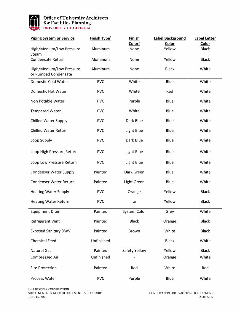
UGA DESIGN & CONSTRUCTION SUPPLEMENTAL GENERAL REQUIREMENTS & STANDARDS IDENTIFICATION FOR HVAC PIPING & EQUIPMENT JUNE 15, 2021 23 05 53-5
Piping System or Service Finish Type1 Finish Color2
Label Background Color
Label Letter Color
High/Medium/Low Pressure Steam
Aluminum None Yellow Black
Condensate Return Aluminum None Yellow Black
High/Medium/Low Pressure or Pumped Condensate
Aluminum None Black White
Domestic Cold Water PVC White Blue White
Domestic Hot Water PVC White Red White
Non Potable Water PVC Purple Blue White
Tempered Water PVC White Blue White
Chilled Water Supply PVC Dark Blue Blue White
Chilled Water Return PVC Light Blue Blue White
Loop Supply Loop High Pressure Return
PVC
PVC
Dark Blue
Light Blue
Blue
Blue
White
White
Loop Low Pressure Return PVC Light Blue Blue White
Condenser Water Supply Painted Dark Green Blue White
Condenser Water Return Painted Light Green Blue White
Heating Water Supply PVC Orange Yellow Black
Heating Water Return PVC Tan Yellow Black
Equipment Drain Painted System Color Grey White
Refrigerant Vent Painted Black Orange Black
Exposed Sanitary DWV Painted Brown White Black
Chemical Feed Unfinished - Black White
Natural Gas Painted Safety Yellow Yellow Black Compressed Air Unfinished - Orange White
Fire Protection Process Water
Painted
PVC
Red
Purple
White
Blue
Red
White
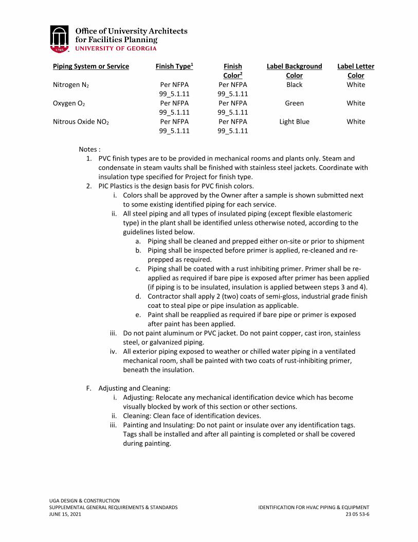
UGA DESIGN & CONSTRUCTION SUPPLEMENTAL GENERAL REQUIREMENTS & STANDARDS IDENTIFICATION FOR HVAC PIPING & EQUIPMENT JUNE 15, 2021 23 05 53-6
Piping System or Service Finish Type1 Finish Color2
Label Background Color
Label Letter Color
Nitrogen N2
Per NFPA 99_5.1.11
Per NFPA 99_5.1.11
Black White
Oxygen O2
Per NFPA 99_5.1.11
Per NFPA 99_5.1.11
Green White
Nitrous Oxide NO2
Per NFPA 99_5.1.11
Per NFPA 99_5.1.11
Light Blue White
Notes :
1. PVC finish types are to be provided in mechanical rooms and plants only. Steam and condensate in steam vaults shall be finished with stainless steel jackets. Coordinate with insulation type specified for Project for finish type.
2. PIC Plastics is the design basis for PVC finish colors. i. Colors shall be approved by the Owner after a sample is shown submitted next
to some existing identified piping for each service. ii. All steel piping and all types of insulated piping (except flexible elastomeric
type) in the plant shall be identified unless otherwise noted, according to the guidelines listed below.
a. Piping shall be cleaned and prepped either on-site or prior to shipment b. Piping shall be inspected before primer is applied, re-cleaned and re-
prepped as required. c. Piping shall be coated with a rust inhibiting primer. Primer shall be re-
applied as required if bare pipe is exposed after primer has been applied (if piping is to be insulated, insulation is applied between steps 3 and 4).
d. Contractor shall apply 2 (two) coats of semi-gloss, industrial grade finish coat to steal pipe or pipe insulation as applicable.
e. Paint shall be reapplied as required if bare pipe or primer is exposed after paint has been applied.
iii. Do not paint aluminum or PVC jacket. Do not paint copper, cast iron, stainless steel, or galvanized piping.
iv. All exterior piping exposed to weather or chilled water piping in a ventilated mechanical room, shall be painted with two coats of rust-inhibiting primer, beneath the insulation.
F. Adjusting and Cleaning: i. Adjusting: Relocate any mechanical identification device which has become
visually blocked by work of this section or other sections. ii. Cleaning: Clean face of identification devices.
iii. Painting and Insulating: Do not paint or insulate over any identification tags. Tags shall be installed and after all painting is completed or shall be covered during painting.
UGA DESIGN & CONSTRUCTION SUPPLEMENTAL GENERAL REQUIREMENTS & STANDARDS TESTING, ADJUSTING, & BALANCING (TAB) FOR HVAC JUNE 15, 2021 23 05 93-1
23 05 93 TESTING, ADJUSTING, & BALANCING (TAB) FOR HVAC
1. GENERAL
A. Related sections: i. 01 32 16 – Construction Progress Schedule
ii. 01 75 00 – Starting and Adjusting iii. 01 77 00 – Project Closeout iv. 01 91 13 – General Commissioning Requirements v. 23 00 00 – HVAC
vi. 23 31 13 – Metal Ducts vii. 25 09 23 – Building Automation and Temperature Control System
B. The Design Professional shall include in the TAB specification any special control sequences that will require the assistance of the TAB Subcontractor. For example this may include fan tracking, economizers, demand control ventilation systems, life safety systems, etc.
C. A balancing plan prepared by the TAB Subcontractor shall cover balancing techniques and testing procedures for all individual systems and equipment as well as for the overall system. The selected TAB Subcontractor shall submit the balancing plan to the Contractor who will then submit it to the Design Professional and Project Manager. The balancing plan shall be submitted at the same time as mechanical submittal data. The TAB Subcontractor shall follow up with the Contractor to ensure that the balancing plan has been properly reviewed and incorporated within the construction schedule. The balancing plan shall include:
i. A list of the test instruments that are planned to be used in the testing and balancing process.
ii. A description of the testing procedure for each HVAC system to be tested. List all of the equipment to be tested for each system and the techniques to be used for the testing procedure. Standard forms used by the TAB Subcontractor shall be completed to reflect all equipment and systems identified by system and/or model number specific to the project. Blank, “sample” forms are unacceptable.
iii. A list of the all subcontractors that are required to assist with the testing and balancing process along with the expectations of each of the contractors to successfully complete a total system balance. Most importantly, the expectations of the temperature controls contractor shall be listed. This shall include provision of automation software for balancing, timely automation system access, and the development of global overrides for system maximum performance testing.
iv. An outline of the required construction completeness prior to starting the testing and balancing process
v. A realistic estimate of the time required to complete the testing and balancing process; the plan shall describe in detail the required time to complete balance of sub-systems and total system balance. The Contractor shall recognize that the balancing process is sequential and not a process that can be shortened by simply putting more technicians on the project to complete the process faster. Buildings with direct digital control systems require a great deal of the testing
UGA DESIGN & CONSTRUCTION SUPPLEMENTAL GENERAL REQUIREMENTS & STANDARDS TESTING, ADJUSTING, & BALANCING (TAB) FOR HVAC JUNE 15, 2021 23 05 93-2
and balancing process to be performed through adjustments to the HVAC systems via the automation / control system. Network access limitations and / or control software may prevent more than one operator from communicating with the automation / control system at a time. This makes it inefficient to have too many balancing technicians on a single project if the majority of the adjustments can only be made through one computer terminal.
vi. A listing of the necessary uninterrupted accessibility to the building to completely test HVAC equipment and sub systems.
vii. The Contractor shall allow time in the balancing plan schedule to allow the TAB Subcontractor to address any issues in the design or installation, which prevents a system from operating at design performance. The Contractor shall take the time for resolution of these issues by the responsible party into account in the balancing schedule. A ‘contingency’ of an additional week or two should be incorporated into the balancing plan schedule to accommodate additional time required for the responsible party to correct any minor issues preventing design performance of the building. The TAB final report shall be scheduled to be completed three weeks prior to Material Completion.
viii. With the balancing plan the TAB Subcontractor shall submit a sample reporting form that includes project specific information with the specified AHU, pumps, etc. by item number identified on the drawings. It shall show intended location of duct traverses, all units that will have static pressure profiles, AFMS, etc. The final completed version shall also include manufacturer and model numbers.
D. Building accessibility during balancing: The Contractor shall provide the TAB Subcontractor with uninterrupted access to all areas of the building. Large HVAC systems may require the access to the same area several times throughout the balancing process. Finishing processes of the building construction such as laying carpet and tile flooring, waxing floors, construction cleaning, and fire alarm testing that require the HVAC systems to be shut down shall be identified in the balancing plan to inform the Contractor of possible conflicts who shall attempt to schedule the testing and balancing process around them. Some building accessibility issues to address in the balancing plan include the following:
i. Flooring work, such as carpet laying and tiling, must be performed either before or after the testing and balancing process for a particular system serving the area in which the flooring work is to be done. If the completed flooring will restrict the use of boom lifts, the testing and balancing of the system serving that area shall be completed before the floor work if the HVAC system components are inaccessible by ladder.
ii. Final building cleaning that would prevent further access of contractors shall be delayed until the testing and balancing is completed.
iii. If fire alarm testing will affect the HVAC system, the balancing contractor should be notified in advance when fire alarm testing is scheduled. For example, closing fire dampers or shutting down air handling units can disrupt total system balancing.
2. PRODUCTS A. Provide all instruments, charts, materials, and equipment required to develop a
complete TAB report.
UGA DESIGN & CONSTRUCTION SUPPLEMENTAL GENERAL REQUIREMENTS & STANDARDS TESTING, ADJUSTING, & BALANCING (TAB) FOR HVAC JUNE 15, 2021 23 05 93-3
3. EXECUTION A. The TAB Subcontractor shall be required to be contracted directly by the Construction
Manager; the TAB Subcontractor shall not be contracted to the mechanical Subcontractor. Additionally, unless approved otherwise by UGA, be an Associated Air Balance Council (AABC) or National Environmental Balancing Bureau (NEBB) certified member and the TAB work shall be performed by an AABC or NEBB certified test and balance technician.
B. As a minimum, the TAB Subcontractor shall test, adjust and balance: i. Each supply air, return, exhaust and outdoor air distribution system, including
operation and adjustment of all manual and automatic air volume control dampers, particularly outdoor air dampers, including static pressure profile across AHUs and duct pitot traverses. Final measurements shall be made after balancing at outlets / inlets and main duct traverses to determine and record the amount of leakage.
ii. Each hydronic system. iii. Each control system including calibration of all control elements and check
operation including all interlocks. iv. Overall air balance in building and individual spaces. v. Adjust systems to optimize energy use; adjust air distribution systems for fan
pressure optimization to control system static to lowest level while maintaining flow requirements in all zones; adjust hydronic systems to optimize pump pressure to force at least one valve to full flow. Document all index runs.
B. Test and balance shall include all equipment and distribution systems and shall be reported, as a minimum, as outlined in Para 1.5 of the AABC National Standards, sixth edition, 2002, on forms as published in the standards manual, appendix 1, or NEBB equivalent, at least equal in scope. Standard forms submitted for approval (as shop drawings) shall be filled out and be project specific with specified AHU, fans, pumps, etc. by item number identified on the drawings; shall show intended location of duct traverses, all units that will have static pressure profile, AFMS, etc. The approved forms shall then be completed after approval of shop drawings to identify manufacturer, model numbers, etc.
C. Measure and record the dry bulb and wet bulb temperatures, humidities, and pressures in all spaces served when the outside temperature is above 85 °F (summer TAB) and below 50 °F of (winter TAB) record outside dry bulb and wet bulb.
D. Reports shall include manufacturer’s performance curves, tables and graphs with specified design and actual, measured/”as-balanced” duty points marked up on these. System effect on AHUs shall be measured, recorded and plotted on the fan duty curve. The curves shall clearly show efficiency, brake horsepower, speeds, etc. for design and actual.
E. The TAB Subcontractor shall check the controls system operation for proper calibration and operation and a report on the operation and adjustment shall be submitted to the owner. The TAB Subcontractor shall verify by check measurements in the field to ensure that the controls indication is accurate; every safety and alarm interlock shall be checked. The interface with the building fire alarm system shall be checked. Check and provide statement that all smoke detectors are operating properly and are installed in accordance with the manufacturer’s installation instructions and recommendations.
UGA DESIGN & CONSTRUCTION SUPPLEMENTAL GENERAL REQUIREMENTS & STANDARDS TESTING, ADJUSTING, & BALANCING (TAB) FOR HVAC JUNE 15, 2021 23 05 93-4
Sensor shall be checked for proper location, space temperature sensors shall be free from drafts, heat sources and other factors that can affect the accuracy of the control system.
F. The Contractor and the TAB Subcontractor shall check all the systems operating together, in all modes of operation, to ensure that the air-conditioned spaces are under an overall positive pressure; shall check and report that the building envelope is properly sealed and uncontrolled air leakage into the building does not occur; shall check that return and exhaust ducts located outside the air-conditioned space are sealed; shall check supply air ducts for leaks to ensure that cold air leakage does not cause condensation on duct, equipment and building surfaces above the ceiling (during summer TAB); shall check return and exhaust grilles for proper seal at duct connections to ensure that air does not enter these ducts through un-air-conditioned walls, chases, etc.
G. The Contractor and the TAB Subcontractor shall, immediately following award of the Contract, review the proposed systems installations drawings and determine all measuring and balancing devices required for proper test and balance of the systems are specified and sized correctly. These shall include, but shall not be limited to, manual air volume balancing dampers, etc. The Contractor shall be responsible for providing these in the locations recommended by the TAB Subcontractor, in addition to any shown on the drawings. These devices shall be provided under the Contract. Check that duct layouts allows TAB Subcontractor to do duct pitot traverses to determine overall air flows. Any factors that prevent the proper TAB of the systems shall be brought to Project Manager’s attention for a decision prior to proceeding with the work.
H. The TAB Subcontractor shall check refrigeration lines for compliance with the equipment manufacturer’s installation instructions and recommendations shall check superheat settings on all systems with lines longer than 50 feet.
I. The TAB Subcontractor shall test condensate drains and drain pans for proper drainage under operating conditions and that all condensate drains from pans.
J. Instruments used for testing and balancing shall have been calibrated within a period of six months of the time of the testing and balancing and such instruments shall be checked for accuracy prior to start of work. Submit verification of certification to the owner; submit purchase invoices for all instruments identified as “new”.
K. Three copies of the complete test report shall be submitted to the Design Professional and the Project Manager prior to Material Completion of the project plus at least one complete copy in searchable electronic format.
L. Balancing and Adjustment after Final Completion: After the building is accepted and occupied, and after testing and preliminary balancing are completed, send qualified personnel, at no additional cost, to the building for not less than one period during summer and one period during winter, observer temperatures throughout conditioned spaces, consult with Project Manager as to need for additional balancing or adjustment, then perform such work as indicated. Schedule these visits at a time agreeable to the Project Manager during December through February for heating, and July through August for cooling.
M. The TAB report shall include a list of all deficiencies found during the preliminary testing and a contractor response indicating remedial action taken for each item. The TAB work shall not be deemed complete without this report.
UGA DESIGN & CONSTRUCTION SUPPLEMENTAL GENERAL REQUIREMENTS & STANDARDS TESTING, ADJUSTING, & BALANCING (TAB) FOR HVAC JUNE 15, 2021 23 05 93-5
N. The TAB final report shall be submitted to the Design Professional and the Project Manager at least three weeks prior to Material Completion.
UGA DESIGN & CONSTRUCTION SUPPLEMENTAL GENERAL REQUIREMENTS & STANDARDS DUCT INSULATION JUNE 15, 2021 23 07 13-1
23 07 13 DUCT INSULATION
1. GENERAL
A. Related sections: i. 27 00 00 – General Mechanical Requirements
ii. 27 05 29 – Hangers and Supports for HVAC Piping and Equipment B. UGA does not allow the metal duct to be penetrated by either the duct insulation
fasteners or the fasteners associated with hanging the ductwork. Refer to the Trapeze Hanger Insulation Detail included in this section.
C. If sound attenuation is a project requirement, the method to be utilized shall be approved by the Project Manager in writing.
2. PRODUCT A. Ductwork inside mechanical rooms shall be insulated with 2-inch thick 3 lbs./cu. ft.
aluminum foil faced board. B. Duct insulation for exterior location:
i. All ductwork exposed to ambient conditions, including, but not limited to, in crawlspaces and attics and ductwork located in mechanical rooms shall be insulated with minimum 3-inch thick aluminum foil faced board type insulation (R12, installed) having a minimum density of 6 lbs./cu. ft.
ii. Insulation on round, oval or curved ducting located outside the building shall be minimum 6 lbs./cu. ft. board with fibers arranged perpendicular to the board surface to allow insulation to closely fit the curved surfaces. Pre-score rigid insulation board where necessary to conform to curved surfaces. The insulation shall be faced with an all-purpose Kraft paper bonded to aluminum foil. Insulation basis of design is Johns Manville 817 Series Spin Glass or approved equal.
C. Outer covering (in mechanical rooms and where subject to ambient conditions): i. The flexible membrane basis of design shall be multilayer, aluminum polyester
laminate; self-adhering 5mil membrane, Foster Vapor-Fas 62-05 (embossed), VentureClad or approved equal.
ii. The color shall be aluminum or white as required by UGA (verify color with Project Manager).
D. Internal duct liner anywhere downstream of filter banks, including inside equipment such as AHU’s, FCU’s, VAV terminals, etc. is prohibited (unless otherwise approved in writing by Project Manager).
3. EXECUTION A. General
i. Apply the insulation on clean, dry surfaces. Observe manufacturer’s recommended temperature limits during application. The ducts must be sealed, and leak tested before application of the insulation. The Contractor and the insulator shall inspect ducts to verify that the ducts are properly sealed prior to insulating and shall review duct leakage test reports provided by the TAB Subcontractor where duct leakage testing is specified.
UGA DESIGN & CONSTRUCTION SUPPLEMENTAL GENERAL REQUIREMENTS & STANDARDS DUCT INSULATION JUNE 15, 2021 23 07 13-2
ii. All insulation joints shall be firmly butted and sealed. Adhere insulation to ducts with 100% coverage of fire retardant manufacturer approved adhesive Foster 85-15.
iii. For ducts over 24 inches wide, impale insulation on the bottom of the ducts on metal pins, on maximum 12-inch centers, welded to the duct and secure with speed washers. Minimum compression is to be used to assure firm fit and still maintain thermal performance.
iv. Vapor retarders should overlap a minimum of 2 inches (51 mm) at all seams and be sealed with appropriate pressure-sensitive tape and mastic Foster 30-65. When applying pressure-sensitive tapes, the tape must be firmly rubbed with a proper sealing tool to make sure the closure is secure. Follow tape manufacturer's instructions and recommendations.
v. Fasteners shall be located a maximum of 3 inches (76 mm) from each edge and spaced no greater than 12 inches (305 mm) on center.
vi. Prior to application of the outer weather proofing layer all penetrations and facing damage shall be repaired with tapes or mastic Foster 30-65 with a minimum of 2-inch (51 mm) overlap. Tapes should be applied using a sealing tool and moving pressure.
vii. The insulation on the top surface of the ductwork shall be tapered for positive drainage. Maintain specified minimum thickness as at the low side.
viii. Insulation shall be installed, sealed and vapor-proofed, continuous through penetrations. Seal penetrations to outside of insulation as required.
B. Exterior weatherproof covering: i. Apply a commercially available flexible, self-adhering, aluminum waterproofing
system/product specifically made for the application, installed in accordance with the manufacturer’s installation instructions and recommendations to the insulated duct and pipe to provide a vapor barrier, water and weather seal.
ii. The insulation shall be secured prior to applying the waterproofing layer which shall not be used as a means of securing the underlying materials.
iii. Observe manufacturer’s recommended temperature limits during application. iv. Apply the material to shed water over the laps. Sheets shall be continuous on
underside of ducts. v. The insulation sub-contractor shall inspect the outer coverings after the TAB
work is complete and shall plug and seal all tappings holes found with sealant, insulation and outer covering.
vi. After completion of final inspection, adhere sheets of the outer covering over access doors and around other duct penetrations / openings.
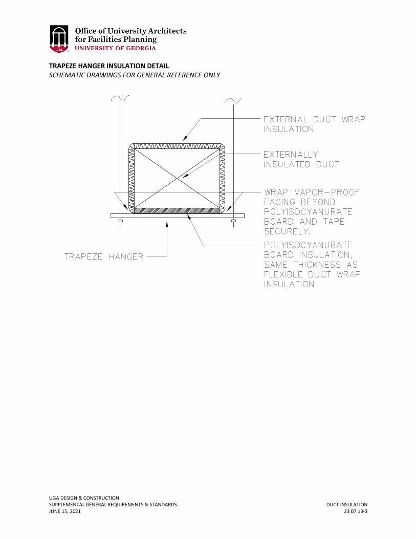
UGA DESIGN & CONSTRUCTION SUPPLEMENTAL GENERAL REQUIREMENTS & STANDARDS DUCT INSULATION JUNE 15, 2021 23 07 13-3
TRAPEZE HANGER INSULATION DETAIL SCHEMATIC DRAWINGS FOR GENERAL REFERENCE ONLY
UGA DESIGN & CONSTRUCTION SUPPLEMENTAL GENERAL REQUIREMENTS & STANDARDS HVAC PIPING INSULATION JUNE 15, 2021 23 07 19-1
23 07 19 HVAC PIPING INSULATION
1. GENERAL
A. Related sections: i. 23 00 00 – General Mechanical Requirements (HVAC)
ii. 23 21 13 – Hydronic Piping 2. PRODUCTS
A. Heating hot water piping insulation inside buildings shall be fiberglass with vapor barrier all service jacket.
B. Chilled water pipe insulation inside buildings shall be equal to closed cell John Manville Trymer Green phenolic 2.5 lb./cu ft. (0.15 Btu·in./hr·ft2·°F @ 75°F mean) with Saran 560 or Pittsburgh Corning foam glass with approved wrap. For renovations, when an existing cold line to be modified has fiberglass insulation, patching with fiberglass insulation may be allowed with owner’s approval.
C. On fittings/elbows, apply vapor retarder coating equal to Foster 30-80 AF with reinforcing mesh Foster 42-24 Mast a Fab; with 9 x 8 opening / sq. inch.
D. All seams, butted joints, and terminations shall be sealed with a product equal to Foster 95-50 and vapor proofed with a product equal to Foster 30- 80 AF meeting ASTM D5590 before the piping ‘goes cold’ in such a manner to prevent any moisture laden air getting in the insulation system.
E. Exterior above grade insulation may be equal to Trymer PIR, 2.5 lb./cu ft., (25/450 flame spread/smoke developed) wrapped and coated as above.
F. Limited use of flexible closed cell insulation similar to “Armaflex” may be permitted with owner approval at piping at valve clusters, etc., provided no condensation occurs on cold surfaces.
3. EXECUTION A. Chilled water pipe insulation shall be sealed (“tied down”) to pipe every 40 feet, 3 feet
from equipment, up and downstream of valve clusters, etc. and vapor proofed. B. Pipe insulation and vapor proofing shall be continuous through all building penetrations. C. Non-compressible insulation inserts, extending beyond hanger, wrapped and vapor
proofed before hangers is ‘closed’, shall be installed at hangers in such a way that the insulation and vapor proofing is continuous through the hanger.
Revised June 15, 2021
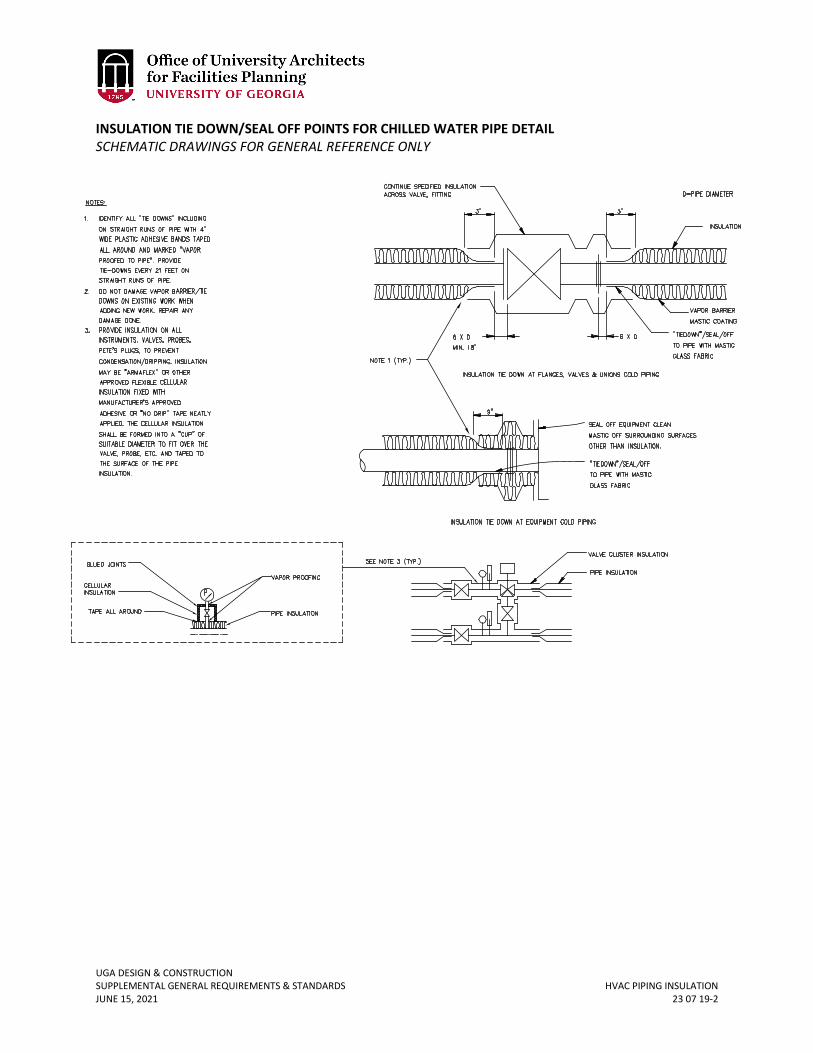
UGA DESIGN & CONSTRUCTION SUPPLEMENTAL GENERAL REQUIREMENTS & STANDARDS HVAC PIPING INSULATION JUNE 15, 2021 23 07 19-2
INSULATION TIE DOWN/SEAL OFF POINTS FOR CHILLED WATER PIPE DETAIL SCHEMATIC DRAWINGS FOR GENERAL REFERENCE ONLY
UGA DESIGN & CONSTRUCTION SUPPLEMENTAL GENERAL REQUIREMENTS & STANDARDS BUILDING AUTOMATION AND TEMPERATURE CONTROL SYSTEM (BAS) JUNE 15, 2021 23 09 23-1
23 09 23 BUILDING AUTOMATION AND TEMPERATURE CONTROL SYSTEM (BAS)
1. GENERAL
A. Related sections: i. 00 73 01 – Sole Source / Sole Brand
ii. 01 91 13 – Commissioning Requirements iii. 23 00 00 – General Mechanical Requirements (HVAC) iv. 23 05 93 – Testing, Adjusting, and Balancing for HVAC v. 27 00 00 – Communications
vi. 27 15 00 – Communications Horizontal Cabling vii. 23 05 19 – Meters and Gages for HVAC Piping
B. The BAS shall utilize direct digital control (DDC) technology to maintain the space conditions and provide automatic control of the associated mechanical equipment.
C. For the UGA Athens campus, the building automation controls system main software and hardware reside at server racks located at the Boyd Graduate Research Center. The Design Professional shall coordinate with the Project Manager and FMD to determine if any front-end computing hardware upgrade / replacements are required as part of the Project. The Contractor and controls Subcontractor are additionally responsible for including any required software or hardware upgrades specific to the selected controls system in the Cost of the Work or Bid.
D. The University of Georgia Standard Controls shall be reviewed by the design team and incorporated into designs for both renovations and new construction. The document is available at the following location: https://www.architects.uga.edu/standards.
E. The Design Professional is responsible for coordinating the connection locations of the direct digital controls system to the UGA network.
i. Refer to Section 27 15 00 Communications Horizontal Cabling for data cabling requirements.
ii. The Design Professional shall locate all required ethernet points / drops to the Project Manager and the Project Manager shall request IP address assignments from EITS. The Contractor shall provide the Project Manager with the date that the data connection points utilized by the DDC are required to be active. The DDC system shall be actively connected to the UGA network prior to the start of TAB to allow TAB Subcontractor, CxP and Design Professional to check the Work before completion and handover.
iii. All information technology related issues shall be communicated promptly to Project Manager.
iv. BAS contractor is to provide a temporary network and server setup to allow BAS startup and Commissioning activities to occur if the permanent IT connection provided by EITS is not in place in sufficient time to use during construction. The setup will allow multiple users.
F. The Contractor shall coordinate with the controls Subcontractor during preparation of shop drawings to ensure that tappings for sensors are provided and are located to ensure accurate sensing and control.
G. Provide instrumentation across all heat exchangers plus P/T plugs. P/T plugs and wells for pressure gauges and thermometers shall be provided across all heating and cooling
UGA DESIGN & CONSTRUCTION SUPPLEMENTAL GENERAL REQUIREMENTS & STANDARDS BUILDING AUTOMATION AND TEMPERATURE CONTROL SYSTEM (BAS) JUNE 15, 2021 23 09 23-2
coils, control valves and strainers. Provide differential pressure sensors across all filter banks on AHUs and elsewhere, where indicated. These shall have an analog output connected to the BAS. Filter status shall be displayed on AHU graphic. Display shall indicate ‘as tabbed’ filter ‘clean’ DP and filter clean-out, as specified – shown as ‘dirty’ DP and actual DP in inches WG. Display shall change to “CLEAN FILTER” when ‘filter dirty’ set=point is reached. Transmitter shall be equal to Dwyer Photohelic gauge if there is no BAS and, with Owner’s prior approval, equal to Magnahelic if no power is available.
H. Utilities to building shall be independently metered and trended via the BAS. Rolling, Daily, Monthly, and Annual Consumption and peak demand data shall be stored in historical trend database for a period of 2 years for all main utility meters and sub-meters.
I. Control drawings shall show schematic control diagrams for all systems; show, as minimum, symbols for sensors, controllers, and actuator; sequences referencing these sensors, controllers, actuator symbols; I/O summaries; system architecture / riser. Input and output numbering shall be descriptive to indicate the function (use SAT1, OAD1, etc., in lieu of AI1, DI1, etc.); every actuator shall, unless specified otherwise, have a dedicated output and independently adjustable control range. Designers shall refer to campus standard control sequences of operation and schematics. Campus standard sequences, modified as required for project-specific considerations, shall be incorporated into each project, all variations from the standard sequences shall be discussed with the UGA project manager.
J. Controls graphics shall be submitted as a standalone submittal unless a live/online graphics review is conducted with necessary personnel (UGA, Cx, and DP).
K. Status of sump and steam condensate pumps shall be monitored by ALC. L. Control system devices and panels shall have suppressors to protect against lightning
damage; power supply surges; induced voltage from other equipment such as transformers or electric motor operations; and electronic transmission / relay such as may be caused by radio / TV broadcasting towers, radars and high-voltage transmission lines.
M. Provide leaving air temp sensor on all AHUs, FCUs, and VAV terminals. N. Humidity sensors for HVAC applications shall be equal to Vaisala, model HMD60/70 (or
HMD50 with INTERCAP replaceable sensors), HMW82/83 or HMT120/130 to suit the application, and output required. Sensor to be interchangeable in the field and calibration-free. Accuracy is +/- 3% RH from 0 and 90% RH. Sensor to have a stability of a +/- 2% RH over a two-year period. Transmitter shall operate over a humidity range of 0 – 100%. Sensors shall be warranted for 2 years from date of installation and shall be NIST-certified / traceable calibration. Wall-mounted devices shall have replaceable sensor kits. Where dewpoint sensing is called for, the transmitters shall be equal to Vaisala HMW110B1VA1NN for wall-mounted and HMD 102B1VA1NN for duct-mounted; 2% accuracy, 3-point NIST-certified / traceable calibration; on-site calibration using HM70 hand-held meter or PC connection. Output parameters to be selectable with a PC connection. Sensors shall be warranted for two (2) years from date of installation and shall be NIST-certified / traceable calibration.
Revised June 15, 2021
UGA DESIGN & CONSTRUCTION SUPPLEMENTAL GENERAL REQUIREMENTS & STANDARDS BUILDING AUTOMATION AND TEMPERATURE CONTROL SYSTEM (BAS) JUNE 15, 2021 23 09 23-3
O. The controls Contractor shall verify the specified sizes of control devices, (valves, dampers, etc.) to ensure the devices have the correct system authority for proper, stable, control.
P. HVAC systems shall be zoned for a maximum of 3 thermally similar spaces per zone. All non-common areas shall have separate adjustable sensors.
Q. The controls Contractor shall provide the applicable version of the Building Automated Systems (BAS) software required by the TAB Subcontractor to do the Test and Balance work specified at no extra cost to the Contract or the TAB Subcontractor.
R. Upon completion of the Project, the controls Contractor shall provide, to the Owner, all software and design tools required for system design, programming, graphics, etc.
S. For critical applications, in lieu of a "power trunk", provide a minimum 40va, 24vac control transformer from the factory for each terminal unit, to be wired by Division 26 subcontractor in the field with a toggle switch disconnect.
T. Control devices shall be provided with disconnects and shall be wired such that any device can be removed from the circuit without causing other devices on the same circuit to be de-energized.
U. Graphic User Interface: (shall be available through the web browser). i. If an MDF/IDF room is served by a mini-split AC unit, a sensor shall be
added to the space that connects to the BAS for temperature monitoring only. If an MDF/IDF room is served by a mini-split AC unit, a sensor shall be added to the space that connects to the BAS for temperature monitoring only.”
ii. Building Graphics a. General b. GRAPHICS specific to this Project as follows:
LEVEL ONE: Shall identify location of building on the site. LEVEL TWO: Shall show each floor plan such as basement, first, second, and roof showing terminal devices with link to its schematic diagram. LEVEL THREE: Shall show mechanical rooms linked to level four devices. LEVEL FOUR: Shall show each individual system, chiller, air-handling units, terminal units, fans, etc.
c. On all screens, the entire graphics screen should be visible in full screen mode, i.e. no scroll bar required to view entire screen and should be printable with a white back ground.
d. A legend should be provided on all screens where graphical colors are used. Provide an active link to a comprehensive project specific legend that explains all abbreviations used.
e. Floor plan graphics should be uniform design for all projects: simple, easy to read, intuitive, uncluttered and organized. Floor plans should be 2 dimensional only. (No 3D floor plans).
f. Graphic displays shall show all I/O points including set points, dynamic, real time values of temperature, pressure, status, etc., alarm settings and any current alarm / alert conditions; shall show air flows in CFM and temperature, actual and set-point, for outdoor air, return air and supply on AHUs and primary air on VAV terminals. Fan amp and Kw shall be shown at each device. Graphics for VAV terminals shall so maximum,
Revised June 15, 2021
UGA DESIGN & CONSTRUCTION SUPPLEMENTAL GENERAL REQUIREMENTS & STANDARDS BUILDING AUTOMATION AND TEMPERATURE CONTROL SYSTEM (BAS) JUNE 15, 2021 23 09 23-4
minimum, dual minimum, etc., as applicable and the actual real-time CFM.
g. Graphic screens shall include a complete system schematic layout showing real-time values and set-points for all points. For VAV systems, the airside shall show AHU serving the system, air terminals, duct static-pressure sensor location(s) with an active link to floor plan(s) showing actual installed locations, etc. For water side, the graphic shall show control valves and pump status. The graphic screen shall show design goal for monitored points and set-point and the real-time current temperature, humidity, static pressure, flow rate, etc., as well as status of all fans associated with the system; to include, real-time air flow rate, with maximum and minimum cfm sert-points (as specified). All air flows shall be shown in an air balance schedule on the graphic screen, as well as the space static pressure for the system or, depending on the amount of information on the graphic screen, accessible via an active link. The air balance schedule shall show the actual net positive or negative air flow in the summary. The graphic shall show all control air flow damper positions and re-heat, hot water valves, or electric heat control, as a percentage open or closed.
h. All outputs should be able to be overridden from the graphical interface. Clear intuitive means of indicating when any point is overridden to a manual position shall be provided on the graphic. This could be done by text changing color from a normal state or a hand icon appearing next to the over-ridden point. Piping schematics shall be two dimensional to clearly identify service (CHW Supply, CHW Return, CW Supply, CW Return, MP Steam, Pumped Condensate, Make-up, etc.). Display shall use bold colors (rather than shades).
i. Piping schematics shall be two-dimensional to clearly identify service (CHW Supply, CHW Return, CW Supply, CW Return, MP Stream, Pumped Condensate, Make-up, etc.). Display shall use bold colors (rather than shades).
j. Graphics shall show water flow in real-time and set-point for GPM, temperature and pressure drop and pump amps draw and Kw.
k. All points shall be trended and provided historical trending with enough memory for up to 1 year of data.
l. Point names shall be process specific, unique and intuitive on control drawings with the same on graphic screen and in the program (do not use AI1, DO1, T1, P1, but LAT1, SDSP1, etc.). Special attention shall be given to pump point naming; names shall consistent across graphics, control drawings and in programming.
m. A point naming legend shall be provided on the control drawings and graphic screens. Link the legend to pump graphic icons.
n. Graphics shall clearly differentiate between normal operating mode, manual over-ride, alarm, etc.
o. Economizer control shall be dry-bulb unless the application requires control of space humidity levels in which case enthalpy control shall be
UGA DESIGN & CONSTRUCTION SUPPLEMENTAL GENERAL REQUIREMENTS & STANDARDS BUILDING AUTOMATION AND TEMPERATURE CONTROL SYSTEM (BAS) JUNE 15, 2021 23 09 23-5
used. p. Graphic screens showing floor plans and zones shall be color coded
based on temperature setpoints (not actual temperature). Zone, area, and building information shall be displayed using colors to indicate conditions. Relative temperature conditions, based on setpoint, are displayed in a series of colors indicating the zone performance to represent comfort within a given zone.
q. Graphics shall be viewable, over the web, on mobile devices such as phones and tablets without need for installing “Apps.”
r. Control drawings shall be linked to the graphics, allowing the user to verify intended sequence of operations for all controlled equipment.
s. As-built mechanical drawings shall be linked to the graphics. iii. Building Level Graphics
a. This level should include an overall building plan, illustrating all floors (if possible). The overall floor plans will indicate comfort status displayed via color codes. The intent is to allow the building engineer to quickly see problem areas within the facility.
b. Main building screen should indicate major building systems that are in alarm and those elements that have lost connectivity with the server.
c. Main building screen should provide active links to as-built control drawings, basis of design documentation, and sequence of operations.
d. Outside air temperature and relative humidity should be displayed. e. “Global” Building heating and cooling set-points shall be indicated at
this level and shall be able to be modified for all associated building systems.
iv. Floor Plan Level a. Floor plan level graphics should display the comfort status of all rooms
on that floor via color codes incorporated into the actual floor layout. Comfort status should include actual status of all controlled variables: temperature, humidity, indoor air quality (CO2 level), etc. Active links to change the set points of these variables should be incorporated.
b. Zone boundaries should be able to be determined by means of color- coded floor plans at this level.
c. Web page should identify the building, i.e. “Pharmacy 2nd Floor”, clear
at the top of the page, centered, just above the floor plan(s). d. Active links to other floors in the building should be provided. e. Layout and location of system components: duct, boxes, etc. should be
provided with color code according to use (supply, return). f. Identify AHU(s) and central exhaust fan(s) with name and location
serving the floor with active link to its graphic. v. Zone Level
a. All “%” indicators of valves or dampers should indicate “open” or “closed.”
b. Should indicate air handler supplying the zone on the page and provide a dynamic link to that page.
c. Occupancy status and temperature should be graphically represented
UGA DESIGN & CONSTRUCTION SUPPLEMENTAL GENERAL REQUIREMENTS & STANDARDS BUILDING AUTOMATION AND TEMPERATURE CONTROL SYSTEM (BAS) JUNE 15, 2021 23 09 23-6
via a color bar chart. d. Entering and Exiting temperatures should be shown at the device. e. Indication of air flow through box should be shown graphically. f. Actual components of box should be shown graphically. g. All points should have process specific, intuitive, names on every
graphic screen (not T1, P1, but LAT1, SDSP1, etc. (see ‘project specific legend’) – to be used consistently across all graphics and for all projects, (ex. don’t use ‘discharge air temp’ and ‘leaving air temp’).
h. Provide zone level environmental index and building performance dashboard.
i. The system shall provide equipment fault diagnostics, with analysis, and detection alarms.
vi. System Schematics a. Graphics should include a system schematics page showing all major
components of any given monitored system (chilled water system, hot water system, AHU and all associated terminal units, etc.) and all measured variables as required to give the building engineer an overall perspective of any given system.
V. Trending / Reporting i. General
a. System should allow user to create new trends / reports from the browser mode without the need for any programming.
b. All points, software, hardware, calculated / virtual, shall be trended continuously. System shall be delivered to owner in this way without need for any additional programming.
c. Trends and reports should be pre-formatted, requiring minimal user effort to establish a quick trend or report for system troubleshooting.
d. System should allow user to copy, using simple operating system menu commands, trend / report data to a spreadsheet that management can use for trouble shooting, energy reporting, etc.
ii. Programmed Trends / Reports a. System should provide a drop-down menu, by page, of all equipment
where programmed trends / reports are available and link directly to these for viewing.
iii. Configured Trends / Reports a. Within browser mode, user should be able to select any controlled point
for trending and reporting. b. New graphical trends should be able to show up to 5 user selectable
points concurrently. c. User should have the ability to save new trends and reports and view at
later time showing all data since trend / report was created. iv. Standard and Custom Reports
a. Standard reports shall include, but not be limited to, locked points report, commissioning reports, network points, hardware points.
b. Commissioning reports shall at a minimum identify date, technician name and action.
UGA DESIGN & CONSTRUCTION SUPPLEMENTAL GENERAL REQUIREMENTS & STANDARDS BUILDING AUTOMATION AND TEMPERATURE CONTROL SYSTEM (BAS) JUNE 15, 2021 23 09 23-7
c. Custom reports shall be configurable by the use / operator. d. An audit log report identifying system changes by action, date,
password, etc. shall be included in the BAS. W. Programming
i. General a. Programming pages for the whole campus shall be accessible through
the web browser from the graphics display window, without requiring additional logon or opening new windows.
b. Active links to programming should be available from all levels of graphics screens, i.e. floor plan, zone, etc. Link should access pertinent areas of programming for that screen.
c. Programming function should accept multiple concurrent users, without ‘bumping’ a current user offline when an additional user logs on. Further, only one user can have access to a specific system at a time for programming purposes.
d. Graphical programming shall be with live graphic function blocks in a continuous program without opening multiple screens.
ii. Editing a. Edit capabilities should be available on programming pages. b. Programming pages should be graphical representations of live
programming, i.e. pages should show actual data values as they change. c. Over-ride capabilities should be directly accessible from programming
pages. d. Troubleshooting capabilities for each component should be confined to
a single page. iii. Scheduling
a. Scheduling should be available for each individual device. b. Group scheduling should be provided whereby multiple device
schedules can be modified concurrently without having to modify each schedule individually. Individual devices shall be assignable to multiple groups.
c. Scheduling shall be hierarchical allowing all devices below a given device to follow the same schedule. All devices shall have override capability to allow deviation from the hierarchical schedule.
iv. Energy Saving Strategies a. The BAS software shall include energy saving strategies such as, but not
limited to the following: 1) Demand Limit Control
i) Demand control settings should be provided whereby individual and group set points are relaxed in response to energy pricing signals.
ii) Three demand levels should be provided by device. iii) Source temperature optimization. Zone conditions and
actual load demand will reset and optimize air side and water side equipment.
v. User Help Files
UGA DESIGN & CONSTRUCTION SUPPLEMENTAL GENERAL REQUIREMENTS & STANDARDS BUILDING AUTOMATION AND TEMPERATURE CONTROL SYSTEM (BAS) JUNE 15, 2021 23 09 23-8
a. Video training modules and context sensitive help shall be provided with the BAS system software through a ‘help’ function.
X. Information Technology i. General
a. Server control software shall be platform independent and shall reside on UGA’s Linux (open source) operating system.
b. Web client should be accessible via multiple browser systems other than Internet Explorer. System shall support unlimited simultaneous users at no additional cost to the Owner.
c. All future versions of the control system software should be compliant with older versions.
d. Server software will be virtualized using enterprise platforms such as VMware ESX or Microsoft HyperV.
e. All trend data, including historical trend data shall utilize an Oracle database. Trend data whether current or historical shall be readily available to user through the web browser.
ii. Architecture a. System should be able to operate as an intranet without connectivity to
campus backbone for setup and testing. b. System should operate via a single Internet Protocol (IP) address for
each building, not multiple IPs. c. Any data within the system must be available either through database
or flat-file exports. iii. Alarms
a. System should be configured with a single alarm screen where alarms from multiple buildings are displayed.
b. Active links should be provided from the alarm screen to the device in alarm for troubleshooting purposes.
c. Remote alarm notification via e-mail, mobile devices, text messaging shall be included in the software and setup as required by users at no extra cost. Users shall also be able to set up alarms and alarm notifications without additional programming.
iv. Configurable User Access a. The Owner shall have the ability to assign access privileges (such as
programming, view only, specific buildings, etc.) to various operators and users.
2. PRODUCTS A. This is a sole source of equipment by Automated Logic Corporation: 770-429-3000 and
procured through Automated Logic – Georgia: 770-421-3280. For renovation projects that utilize a different brand, the decision to change to Automated Logic Corporation or modify the existing system will be made on a case by case basis.
i. The Construction Manager shall contract with Automated Logic Georgia as a direct Subcontractor.
ii. Automated Logic Georgia shall not, for example, be in a sub-subcontract relationship with the mechanical Subcontractor.
B. DDC Control Modules
UGA DESIGN & CONSTRUCTION SUPPLEMENTAL GENERAL REQUIREMENTS & STANDARDS BUILDING AUTOMATION AND TEMPERATURE CONTROL SYSTEM (BAS) JUNE 15, 2021 23 09 23-9
i. All modules shall be native BACnet, fully programmable, including zone modules (down to lowest control level).
ii. Non-customizable routines are not acceptable. iii. Air handling unit and plant control modules require manual override switches
on all outputs. iv. All modules shall have stand-alone capability including trending. v. All outputs shall be isolated. TRIAC outputs are not acceptable.
C. All equipment interfacing with the BAS shall have BACnet communication interfaces. D. Control valves on AHU cooling and heating water coils and steam coils shall have 300:1
rangeability / turn-down. Valves on terminal reheat coils may be 100:1 minimum turndown. All valves and associated actuation shall be selected to operate and close tight at a valve differential pressure of 1.5 times the pump design head or the pump shut-off head. Basis of design control valves for AHUs shall be Valve Solutions – Vee Ball. Valve actuators shall be direct coupled.
E. High occupancy spaces shall have demand control ventilation (DCV). Basis of design CO2 sensors shall be Telaire model 8002.
F. CTs shall be adjustable equal to Veris H608. Wet media differential pressure transducers shall be equal to Veris PW Series (or PW2 Series depending power supply availability). The Design Professional shall identify the correct locations of differential pressure sensors based on pipe calculation and shall, if necessary, require the Contractor to re-locate the sensors to a better location based on TAB results.
G. Measuring station shall be capable of continuously monitoring the airflow volume of the duct served and electronically transmitting a signal linear to the airflow volume. Airflow measuring devices shall be of the insertion type, or built into ductwork to suit the system configuration and shall be capable of measuring velocity over the range 375 to 7000 FPM with +/- 2% accuracy. Devices shall be selected by the manufacturer or authorized representative, and installed in accordance with the manufacturer’s installation instructions and recommendations. Standard materials shall be aluminum bars with aluminum and ABS or aluminum sensors. Support bars over one foot in length shall be supported on both ends; in corrosive air streams, sensors and support bars, shall be of corrosion resistant materials. Velocity sensors shall not be affected by dust, lint, temperature, pressure, or humidity. The sensors shall be passive in nature, with no active parts within the air stream. The output from individual sensors shall be linear with respect to airflow velocity and shall be capable of sensing airflow in one direction only. The velocity sensors shall not require calibration. The transmitter shall provide a scale-able output over the full range of control of the unit, via on-board adjustments. The output signal of the transmitter shall be industry standard electronic signals, selectable on-board via jumpers or switches, for 4-20ma, 1-5vdc or 2-10vdc. Power requirement for the transmitter shall be 24VAC or DC. The device and associated controls shall be native Bacnet-compatible. Measurement system accuracy shall be +/- 2% of volumetric airflow rate. Turndown capability shall be at least 15:1.
H. Wet Differential Pressure: Water system differential pressure use the Veris PW2 series or approved equal. Select the appropriate PW2 range for the given application Select operational range according to maximum gauge pressure, NOT differential pressure. Differential Pressure tubing shall be constructed of ¼” hard copper. Blowdown piping shall be run to the closest floor drain.
UGA DESIGN & CONSTRUCTION SUPPLEMENTAL GENERAL REQUIREMENTS & STANDARDS BUILDING AUTOMATION AND TEMPERATURE CONTROL SYSTEM (BAS) JUNE 15, 2021 23 09 23-10
I. Air Differential Pressure / Dry Media Measurement: For dry media differential pressure monitoring (static, building pressure, etc.), use the Veris Industries series PXULX05S or approved equal. For static pressure use the included static tip. For room pressure use the KELE RPS along with the SD-030 Surge Dampener or approved equal. When you need to reference OA pressure, use the KELE A-306 OA static pressure sensor kit or approved equal.
J. The airflow measuring device shall be Vortek VT series (IAQ 2000 for outdoor sensor) manufactured by Tek-Air Systems or approved equal.
K. Basis of design for actuators shall be Belimo. L. All water-cooled chillers shall be provided with a dedicated DDC control panel. The
control panel shall have a hand / off / auto (HOA) switch and an alarm light indicator. In the manual position, the chiller and all associated auxiliary equipment will be commanded “on” and will modulate normally to maintain chilled water set-point temperature. The rest of the loop chillers will modulate normally.
M. Domestic water flow meter used in sub-metering applications shall be shown on the plumbing drawings to be installed under that division. The meter shall be furnished under Section 23 09 23 Building Automation and Temperature Control System BAS, and shall be Badger Recordall Meter, or approved equal, for meters 2 inches or less and Recordall Turbo Meter, or approved equal, for meters greater than 2 inches. Meters to be furnished with a pulsed output for interface to BAS.
N. Building main electric meter shall be shown on the electrical drawings but shall be furnished under Section 23 09 23 Building Automation and Temperature Control System BAS and shall be Veris E50H or approved equal. Meter to be installed by electrical contractor. Refer to Section 26 24 13 Switchboards.
3. EXECUTION A. For all equipment with which the controls Contractor will be interfacing, the controls
Contractor shall be responsible for reviewing the equipment submittals to ensure that the equipment is being supplied with appropriate accommodations to interface with the BAS as specified.
B. Work required under paragraphs 1.E, 1. F, 1.J, and 2.C shall be provided by the mechanical Contractor in coordination with the controls Contractor.
C. Locate instrumentation, sensor wells, to allow removal and replacement without having to cause damage to or having to remove insulation, etc. show, to scale, on piping shop drawings. Well and sensor shall be matched to ensure accurate measurement of the medium.
D. Label all control elements to clearly indicate function; labels to match control wiring diagrams, schematics and BAS and graphics. Provide legend for each symbol used on both control drawings and graphics.
E. Control sequences shall be written clearly and stated in a logical progression of events and / or actions for all modes of. Sequences shall be provided for both DDC controlled equipment and “packaged equipment”. The graphic screen for each item of equipment and system shall have a link to the associated ‘as-built’ sequence of operation. Package equipment suppliers shall provide sequences of operation specific for the equipment provided. (Although the packaged equipment may not be internally controlled by the BAS, UGA needs to understand the internal operation of the equipment and how it relates to the external system).
UGA DESIGN & CONSTRUCTION SUPPLEMENTAL GENERAL REQUIREMENTS & STANDARDS BUILDING AUTOMATION AND TEMPERATURE CONTROL SYSTEM (BAS) JUNE 15, 2021 23 09 23-11
F. Electrical supply serving controls shall be permanently energized; one circuit will be provided per floor, all wiring and electrical work, including surge protection, from electrical termination point will be by the controls provider. Control panels associated with the HVAC BAS, the wiring in the panels, and the connections to the panels and all control elements shall be executed by the controls Subcontractor. Subcontracted electrical work associated with the HVAC BAS shall be confined to conduits and wiring between panels and controls devices. Control wiring shall be run in conduit. For exceptions permitted in the specification, wiring shall be independently supported, run continuously tight to and fixed to structure, J-hooks at approved spacing will be accepted. New wireways shall be installed in walls or chases. Surface mounted conduit and wire molding shall not be used without written approval.
G. The controls Contractor shall submit an as-built electronic copy of all programming done, including point-to-point wiring, VAV terminal coefficients as set and calibrated by the TAB Subcontractor. This shall be updated to as-built at the end of the warranty period. An electronic zip file after all TAB and Cx with all final programming loaded shall be provided to UGA to allow reloading of the complete program in the event of a ‘crash’.
H. Controls drawings shall be laminated and bound and placed within a pocket inside each control panel.
I. Service: i. Two year warranty on parts and labor required.
ii. Maximum of 5 working days response time to warranty items required. J. Smoke Damper and Fire Smoke Damper Power / Control: All smoke dampers shall be
powered and wired by Division 26 00 00 Electrical. Smoke damper power circuits shall be designated on the electrical panels on the electrical drawings. Control of these dampers shall be by the fire alarm contractor and designated as such on the electrical drawings.
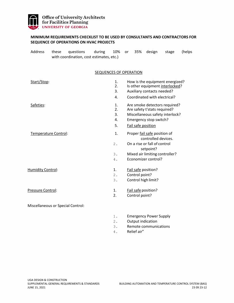
UGA DESIGN & CONSTRUCTION SUPPLEMENTAL GENERAL REQUIREMENTS & STANDARDS BUILDING AUTOMATION AND TEMPERATURE CONTROL SYSTEM (BAS) JUNE 15, 2021 23 09 23-12
MINIMUM REQUIREMENTS CHECKLIST TO BE USED BY CONSULTANTS AND CONTRACTORS FOR SEQUENCE OF OPERATIONS ON HVAC PROJECTS
Address these questions during 10% or 35% design stage (helps with coordination, cost estimates, etc.)
SEQUENCES OF OPERATION
Start/Stop: 1. How is the equipment energized? 2. Is other equipment interlocked? 3. Auxiliary contacts needed? 4. Coordinated with electrical?
Safeties: 1. Are smoke detectors required? 2. Are safety t'stats required? 3. Miscellaneous safety interlock? 4. Emergency stop switch? 5. Fail safe position
Temperature Control: 1. Proper fail safe position of controlled devices.
2. On a rise or fall of control setpoint?
3. Mixed air limiting controller? 4. Economizer control?
Humidity Control: 1. Fail safe position?
2. Control point? 3. Control high limit?
Pressure Control: 1. Fail safe position?
2. Control point? Miscellaneous or Special Control:
1. Emergency Power Supply 2. Output indication 3. Remote communications 4. Relief air”

UGA DESIGN & CONSTRUCTION SUPPLEMENTAL GENERAL REQUIREMENTS & STANDARDS HVAC PIPING SCHEMATICS JUNE 15, 2021 23 20 00-1
23 20 00 HVAC PIPING SCHEMATICS
1. GENERAL
A. Related sections: i. 23 00 00 – General Mechanical Requirements (HVAC)
ii. 23 21 13 – Hydronic Piping B. A.H.U. Coil Piping Detail – Single Coil
SCHEMATIC DRAWINGS FOR GENERAL REFERENCE ONLY
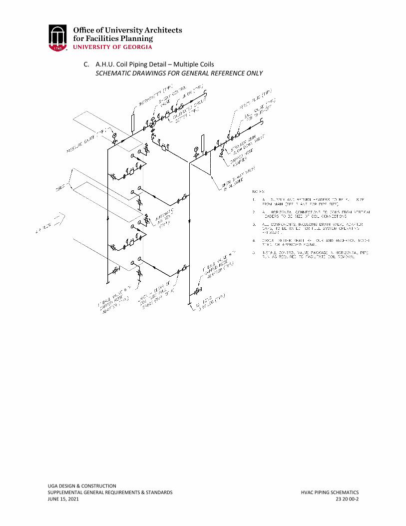
UGA DESIGN & CONSTRUCTION SUPPLEMENTAL GENERAL REQUIREMENTS & STANDARDS HVAC PIPING SCHEMATICS JUNE 15, 2021 23 20 00-2
C. A.H.U. Coil Piping Detail – Multiple Coils SCHEMATIC DRAWINGS FOR GENERAL REFERENCE ONLY
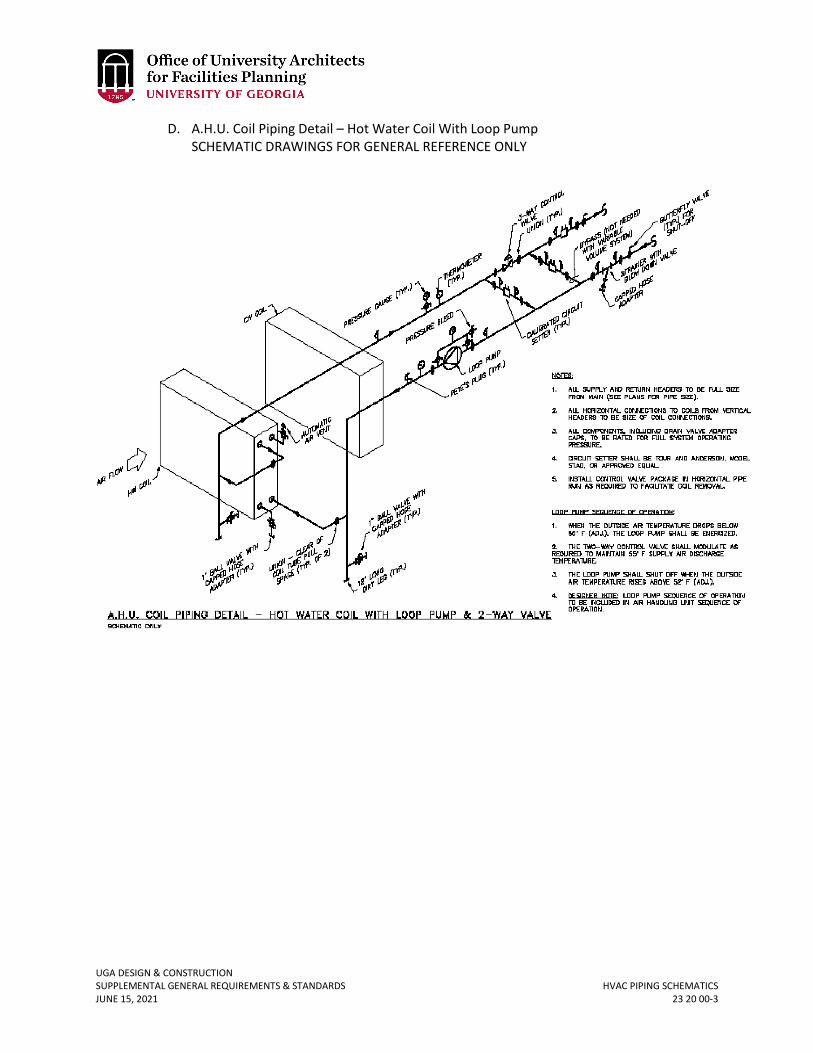
UGA DESIGN & CONSTRUCTION SUPPLEMENTAL GENERAL REQUIREMENTS & STANDARDS HVAC PIPING SCHEMATICS JUNE 15, 2021 23 20 00-3
D. A.H.U. Coil Piping Detail – Hot Water Coil With Loop Pump SCHEMATIC DRAWINGS FOR GENERAL REFERENCE ONLY
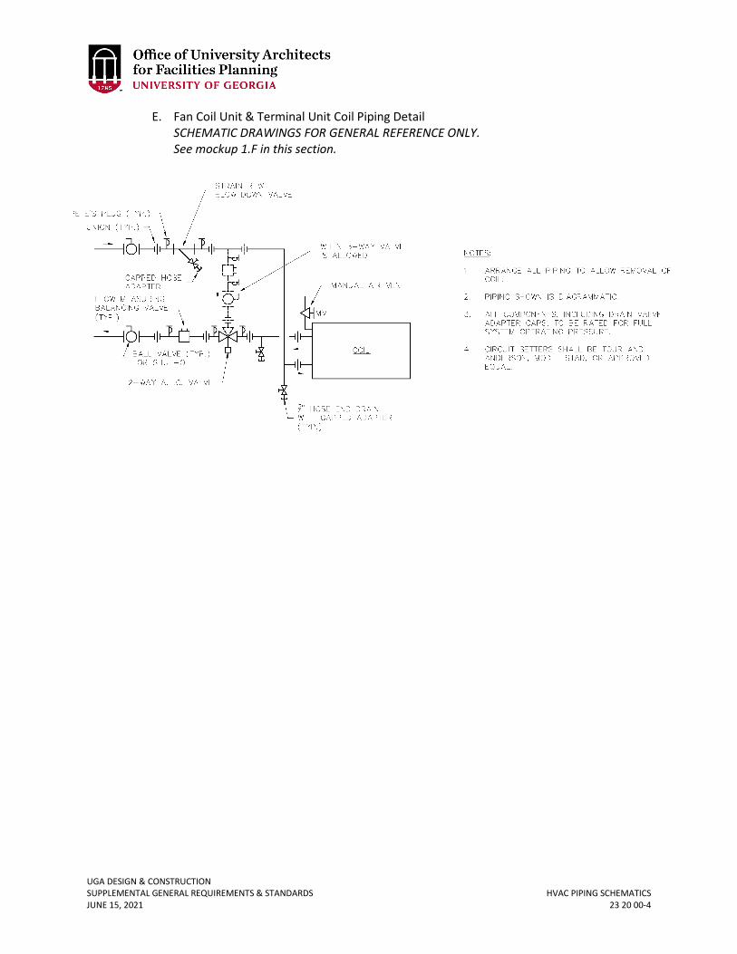
UGA DESIGN & CONSTRUCTION SUPPLEMENTAL GENERAL REQUIREMENTS & STANDARDS HVAC PIPING SCHEMATICS JUNE 15, 2021 23 20 00-4
E. Fan Coil Unit & Terminal Unit Coil Piping Detail SCHEMATIC DRAWINGS FOR GENERAL REFERENCE ONLY. See mockup 1.F in this section.
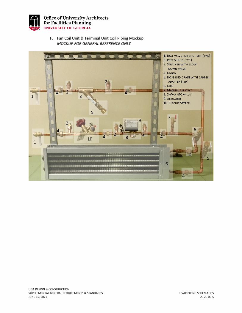
UGA DESIGN & CONSTRUCTION SUPPLEMENTAL GENERAL REQUIREMENTS & STANDARDS HVAC PIPING SCHEMATICS JUNE 15, 2021 23 20 00-5
F. Fan Coil Unit & Terminal Unit Coil Piping Mockup MOCKUP FOR GENERAL REFERENCE ONLY
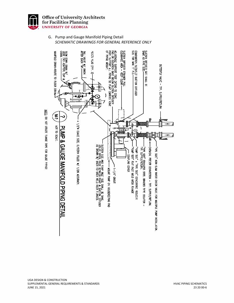
UGA DESIGN & CONSTRUCTION SUPPLEMENTAL GENERAL REQUIREMENTS & STANDARDS HVAC PIPING SCHEMATICS JUNE 15, 2021 23 20 00-6
G. Pump and Gauge Manifold Piping Detail SCHEMATIC DRAWINGS FOR GENERAL REFERENCE ONLY
UGA DESIGN & CONSTRUCTION SUPPLEMENTAL GENERAL REQUIREMENTS & STANDARDS HYDRONIC PIPING JUNE 15, 2021 23 21 13-1
23 21 13 HYDRONIC PIPING
1. GENERAL
A. Related sections: i. 23 00 00 – General Mechanical Requirements (HVAC)
ii. 23 07 19 – HVAC Piping Insulation iii. 23 20 00 – HVAC Piping & Pumps iv. 23 21 23 – Hydronic Pumps
B. Design Professional drawings shall show piping in mechanical rooms particularly at connections to coils and shall not leave piping installation to be left up to the Contractor. Provide at least one elevation view.
C. The Contractor shall submit shop drawings for all gasket materials on jointing which shall include installation instructions and recommendations.
D. Reference drawings are provided at the end of this section for Automatic Air Vent Detail and Manual Air Vent Detail.
2. PRODUCTS A. Underground chilled water supply and return piping shall be equal to Thermacor FERRO-
THERM SC steel piping system with HDPE jacket ASTM D-1248, 0.1-inch thickness (minimum) for up to 12-inch diameter pipe, polyurethane foam insulation and a carrier pipe of the schedule indicated above. Fittings shall be factory insulated with pressure testable joint closure, leak detection wiring, connectors and monitoring panel.
B. Red rubber gaskets are acceptable on chilled water lines but only with flat-faced flanges on both mating flanges. (Note: mis-matched flat and raised face flanges, on pipe and/or valve flanges, shall not be used).
C. Pipe system air and dirt removal basis of design shall be Spirovent; devices shall be selected for 100% free, 100% entrained and 99% dissolved air removal; shop drawings shall clearly indicate this performance.
D. Grooved piping systems shall not be used on chilled water or heating hot water without variance approval. Grooved piping systems shall not be used on open system, cooling tower condenser water piping.
E. Dielectric unions shall not be used. Dielectric flanges and insulating kits may be used and shall be rated for 300 °F at 150 psig minimum.
F. Condensate piping shall be hard-drawn copper and shall be insulated. Condensate piping shall be sloped at ¼ inches per foot and shall never be run more than 20 feet horizontally before dropping vertically to a drain.
G. Heating hot water pumps shall have a drain pan with drain pipe to floor drain. Route drain piping safely to avoid trip hazards.
H. Pipe sizing ranges shall not exceed 4 fps maximum for pipe sizes 2" and less and pressure losses shall be sized for no greater than 4 ft/100 ft for pipe sizes larger than 2".
3. EXECUTION A. Welding
i. All welding for above ground piping shall be done in accordance with ASME B31.9 (latest edition), Code for Building Services Piping. All welding done below ground shall be done in accordance with ASME 31.1 (latest addition), code for Power Piping.
UGA DESIGN & CONSTRUCTION SUPPLEMENTAL GENERAL REQUIREMENTS & STANDARDS HYDRONIC PIPING JUNE 15, 2021 23 21 13-2
ii. All welding procedures, welder qualification, quality, and testing shall conform to the requirements of ANSI B31.1, Code for Pressure Piping; and to the ASME Boiler and Pressure Vessel Code, Section IX, Welding and Brazing Qualifications. The Contractor shall be responsible for the procedures, quality and visual testing of all welding performed by him and his employees.
iii. The WPQs shall be performed under the witness of an independent agency. The witness shall be a representative of an independent testing agency, Authorized Inspector, or consultant, any of which must be approved by the National Certified Pipe Welding Bureau. The qualifying test segment must be a 2-inch nominal pipe size with wall thickness within range of the WPS. Tests position shall be “6G” per ASME Section IX.
iv. Welding procedures, and all welder qualifications (WPQs and Evidence of Continuity) shall be maintained on the jobsite.
v. A third party testing firm shall perform Ultrasonic testing of 100% of the full penetration welds for all underground piping and any above ground welds that the owner chooses. Fillet welds shall be tested using a dye penetrant. Contractor shall be responsible for all labor, material and travel expenses involved in the re-inspection and retesting of any welds found to be unacceptable.
B. Buried pre-insulated pipe shall be installed in accordance with the manufacturer’s installation instructions and recommendations and shall be laid on a minimum 6-inch deep sand bed and a minimum 12-inch backfill of sand on top of pipe.
C. Provide detectable aluminum foil plastic backed tape or detectable magnetic plastic tape manufactured specifically for warning and identification of buried utility. Locate 6 inches above sand bed. Provide a second tape 6 inches below grade for pipes buried at 6 feet, or greater depth.
D. Thrust blocks, if required, shall be poured in place and inspected by UGA utility personnel prior to covering up.
E. The manufacturer of the pre-insulated pipe shall prepare field verified installation shop drawings prior to fabrication and installation; the manufacturer’s authorized representative shall field inspect installation and testing; the contractor shall provide exact as-installed record “as-built” including GIS location of pipe and depth of bury. The manufacturer’s representative shall check the leak detection wiring, for continuity, prior to back filling.
F. Flange bolts shall be torqued as recommended by the gasket manufacturer. G. Design Professional shall provide means to allow for specified flushing procedure.
Necessary ports, valves, etc. shall be shown on the plans and labeled for their intended purpose. Design Professional shall coordinate with the campus water treatment vendor.
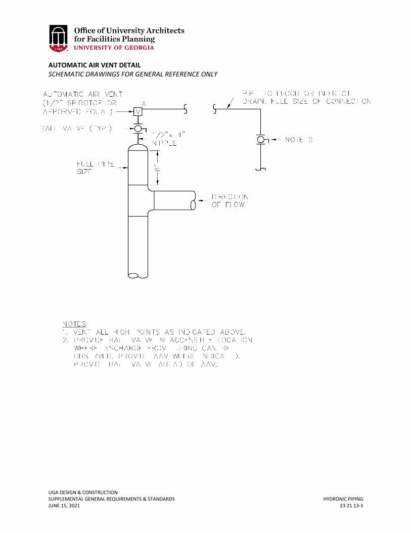
UGA DESIGN & CONSTRUCTION SUPPLEMENTAL GENERAL REQUIREMENTS & STANDARDS HYDRONIC PIPING JUNE 15, 2021 23 21 13-3
AUTOMATIC AIR VENT DETAIL SCHEMATIC DRAWINGS FOR GENERAL REFERENCE ONLY
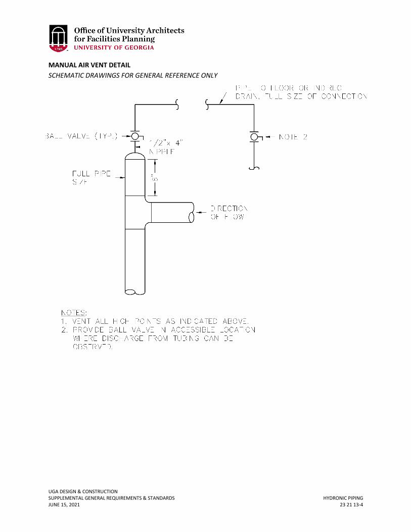
UGA DESIGN & CONSTRUCTION SUPPLEMENTAL GENERAL REQUIREMENTS & STANDARDS HYDRONIC PIPING JUNE 15, 2021 23 21 13-4
MANUAL AIR VENT DETAIL SCHEMATIC DRAWINGS FOR GENERAL REFERENCE ONLY
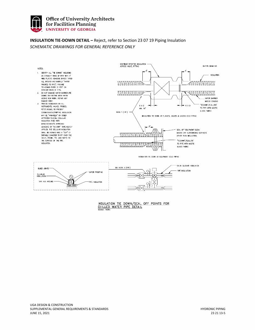
UGA DESIGN & CONSTRUCTION SUPPLEMENTAL GENERAL REQUIREMENTS & STANDARDS HYDRONIC PIPING JUNE 15, 2021 23 21 13-5
INSULATION TIE-DOWN DETAIL – Reject, refer to Section 23 07 19 Piping Insulation SCHEMATIC DRAWINGS FOR GENERAL REFERENCE ONLY
UGA DESIGN & CONSTRUCTION SUPPLEMENTAL GENERAL REQUIREMENTS & STANDARDS HYDRONIC PUMPS JUNE 15, 2021 23 21 23-1
23 21 23 HYDRONIC PUMPS
(For chilled and condenser water) 1. GENERAL
A. Related sections: i. 23 00 00 – General Mechanical Requirements (HVAC)
ii. 23 21 13 – Hydronic Piping iii. 26 00 00 – General Electrical Requirements
2. PRODUCTS A. Basis of design shall be Patterson Pump Company. B. Shall have bronze wear rings, external seal flush line, silicon carbide seals and tungsten
carbide seals on chilled and condenser water systems respectively. 3. EXECUTION
A. Pipe connections shall be installed in such a manner as not to put stress on the seal. B. Provide all pumps with start-up strainer to be removed before handover. C. Pump base shall be properly grouted, and pump and motor aligned per the
manufacturer’s instructions and recommendations. D. Pump impellers, on oversized pumps, shall be skimmed for peak flow of no more than
5% of maximum design flow the current project. E. The manufacturer or factory authorized representative shall inspect the installation and
submit certification that the pumps installations are in accordance with installation instructions and good engineering practice.
F. Install shaft grounding rings equal to Aegis SCR to all pumps requiring the use of VSDs.
UGA DESIGN & CONSTRUCTION SUPPLEMENTAL GENERAL REQUIREMENTS & STANDARDS STEAM & CONDENSATE HEATING PIPING JUNE 15, 2021 23 22 13-1
23 22 13 STEAM AND CONDENSATE HEATING PIPING
1. GENERAL
A. Related sections: i. 23 00 00 – General Mechanical Requirements (HVAC)
ii. 23 22 16 – Steam and Condensate Heating Piping Specialties iii. 33 66 00 – Hydronic and Steam Energy Utilities
B. Heating shall be steam; supply pressure to the building is 100 psig; reduce inside building at pipe entry; provide drip set immediately upstream of PRV station. PRV installation shall comply with manufacturer’s installation instructions and recommendations. Provide pressure gauge downstream and P/T ports up and downstream of every PRV.
C. UGA requires the use of expansion loops; expansion joints require variance approval. D. For underground steam piping the manufacturer of the pre-insulated pipe shall provide
field verified installation shop drawings to the Contractor, Design Professional, and the Project Manager prior to fabrication and installation.
2. PRODUCTS A. Above Ground Steam Piping
i. Steam piping shall be steel, ASTM A53, Schedule 40 seamless steel with welded joints for all piping larger than 2 inches. Threaded steel pipe shall be allowed for 2 inches and smaller.
ii. Steam condensate piping and pumped condensate shall be Schedule 80. B. Underground Steam Piping
i. High / Medium Pressure Steam Piping (greater than 50 psig) a. The steam pipe shall be a class A, conduit system. b. Carrier piping shall be steel, Schedule 40 seamless steel. c. The carrier pipe shall be insulated with aerogel insulation. d. The conduit pipe shall be insulated with polyurethane foam. The
insulation shall be blown or injected. If injected, provide third party verification that there are no voids in the foam.
e. Provide HDPE outer jacket. f. End seals, gland seals and anchors shall be designed, and factory
prefabricated to prevent the ingress of moisture into the system. All subassemblies shall be designed to allow for complete draining and drying of the conduit system.
g. Basis of design is Thermacor Duo-Therm 505. ii. Steam Condensate
a. Steam condensate piping and pumped condensate shall be Schedule 80. b. The foam insulation shall be rated for no less than 250 degrees. c. Foam shall be blown on or injected. If injected, the manufacturer shall
provide third party verification that there are no voids in the foam. d. Provide HDPE outer jacket. e. Basis of design is Thermacor HT-406.
UGA DESIGN & CONSTRUCTION SUPPLEMENTAL GENERAL REQUIREMENTS & STANDARDS STEAM & CONDENSATE HEATING PIPING JUNE 15, 2021 23 22 13-2
3. EXECUTION A. Steam Piping
i. Above ground steam piping and condensate piping shall be installed to slope in the direction of flow.
ii. All welding procedures, welder qualification, quality, and testing shall conform to the requirements of ANSI B31.1, Code for Pressure Piping; and to the ASME Boiler and Pressure Vessel Code, Section IX, Welding and Brazing Qualifications. The Contractor shall be responsible for the procedures, quality and visual testing of all welding performed by him and his employees.
iii. The WPQs shall be performed under the witness of an independent agency. The witness shall be a representative of an independent testing agency, Authorized Inspector, or consultant, any of which must be approved by the National Certified Pipe Welding Bureau. The qualifying test segment must be a 2-inch nominal pipe size with wall thickness within range of the WPS. Tests position shall be “6G” per ASME Section IX.
iv. All welding shall be done in accordance with ASME B31.1, Code for Power Piping.
v. Welding procedures, and all welder qualifications (WPQs and Evidence of Continuity) shall be maintained on the jobsite.
vi. The Contractor shall pressure test the steam and condensate piping. A third party testing firm shall be hired by the owner to perform ultrasonic testing of 100% of the underground full penetration welds and any above ground welds that the owner chooses. Fillet welds shall be tested using a dye penetrant. Contractor shall be responsible for all labor, material, and travel expenses involved in the re-inspection and retesting of any welds found to be unacceptable.
B. Underground Steam and Condensate Piping i. The manufacturer’s authorized representative shall field inspect installation and
shall witness and report on all testing. ii. Fittings shall be factory insulated with pressure testable joint closure; leak
detection wiring, connectors and monitoring panel. iii. The Contractor shall provide exact as-installed record “as-built” including GIS
location of pipe and depth of bury. The Contractor shall employ a licensed surveyor to measure the elevation of the installed piping and include information in close out documents.
iv. Underground piping shall contain leak detection wire wired to a monitoring panel. The manufacturer’s representative shall check the leak detection wiring, for continuity, prior to back filling.
v. Steam pipe in vaults shall be insulated with aerogel and covered with stainless steel jacketing.
vi. The Contractor shall provide an air pressure test of the outer conduit for all Class A piping.
vii. Provide detectable aluminum foil plastic backed tape or detectable magnetic plastic tape manufactured specifically for warning and identification of buried utility at two levels above the buried pipe, at 12 inches below grade and at the top of the fill (approximately 12 inches above pipe).
UGA DESIGN & CONSTRUCTION SUPPLEMENTAL GENERAL REQUIREMENTS & STANDARDS STEAM & CONDENSATE HEATING PIPING SPECIALTIES JUNE 15, 2021 23 22 16-1
23 22 16 STEAM & CONDENSATE HEATING PIPING SPECIALTIES
1. GENERAL
A. Related sections: i. 23 00 00 – General Mechanical Requirements (HVAC)
ii. 23 05 23 – General-Duty Valves for HVAC Piping iii. 23 22 13 – Steam and Condensate Heating and Piping
B. The Contractor shall submit shop drawings for gasket materials on jointing which shall include manufacturer’s installation instructions and recommendations.
C. Provide steam powered sump pumps in all steam manholes as required to keep the manhole dry.
D. In steam manholes, provide redundant steam traps at drip legs. E. Status of sump and steam condensate pumps shall be monitored by ALC.
2. PRODUCTS A. Steam system components requiring access (PRVs, unions, valves, etc.) shall be
insulated with removable customized jackets. Features shall include: i. High temperature insulation blanket capable of withstanding 1000 °F. If installed
in below ground vaults, then the insulation blanket shall be aerogel. ii. PTFE jacketing
iii. Kevlar threads iv. Double-row stitching with minimum 4-6 stiches per inch. v. The surface temperature shall not exceed 120 °F, for 100 psi steam.
vi. Mating seams shall include 2-inch flap secured with hook and loop fastening material, and straps with buckles.
B. Basis of Design shall be Thermaxx. C. Valves manufactured in China are prohibited. D. Ball Valves are not allowed for any steam, steam condensate, or pumped condensate
systems. E. Ball Joints
i. Equal to Hyspan Type N Style I ii. Equal to Advanced Thermal Systems (ATS) S Series Ball Joint
F. Control Valves i. Equal to Armstrong International Inc. or Jordan Valve
G. Expansion Joints i. Equal to Hyspan – Packed Type
ii. Equal to ATS Thermal Pak TP2 Expansion Joint H. Gaskets
i. For steam piping joints shall be equal to spiral-wound metallic - Flexitallic, Flexite Super metallic spiral wound type, 304 SS (minimum) with non-asbestos mineral filler ring-type gaskets in conformance with ANSI B16.20.
I. Pilot Valves i. Equal to Spence Engineering Company, Inc. Type D Pressure Pilot
J. Pressure Reducing Stations i. Equal to Spence Engineering Company, Inc. Type E Main
K. Relief Valves
Revised June 15, 2021
UGA DESIGN & CONSTRUCTION SUPPLEMENTAL GENERAL REQUIREMENTS & STANDARDS STEAM & CONDENSATE HEATING PIPING SPECIALTIES JUNE 15, 2021 23 22 16-2
i. Equal to Kunkle or Spence Engineering Company, Inc. L. Steam Traps
i. Equal to Armstrong 800PC Series Bucket Traps (for use in steam manholes and campus distribution).
ii. Provide dual traps in steam vaults. All steam trap assemblies located in steam vaults shall be threaded (not welded) and shall consist of the following components: two bucket steam traps in parallel with individual strainers and check valves. A total of 6 isolation valves shall be provided.
M. Steam Powered Sump Pumps (for use in steam manholes) i. Equal to Spirex Sarco (required 36 inches x 36 inches x 36 inches sump)
ii. Equal to Penberty (requires 18 inches x 18 inches x 18 inches sump) N. Valves for steam and steam condensate:
i. 1/8-inch to 2-inch threaded gate valves equal to Nibco Inc. or Milwaukee Valve ii. 2-inch to 20-inch
a. In steam manholes and campus steam distribution system, triple offset butterfly type, 150 lb. class, with face-to-face dimensions allowing interchangeability with gate valve. Valve shall be double-flanged, bi-directional, zero leakage, with single-piece valve and stem, and field replaceable seats. Valve shall be provided with manual operated hand wheel and gear operated shaft to allow for slow opening of valve. Acceptable manufacturers are:
1) Vanessa 2) Nibco 3) Adams Valves 4) Bray 5) ABZ
b. Within buildings, flanged gate valves shall be allowed. 3. EXECUTION
A. Steam and condensate and heating hot water lines shall be cycled through heat-up and cool-down and joints inspected for leaks and tightened as needed (at least twice, after 2 months and after 9 months during the warranty period).
B. Flange bolts shall be torqued strictly in accordance with the gasket manufacturer’s installation instructions and recommendations.
UGA DESIGN & CONSTRUCTION SUPPLEMENTAL GENERAL REQUIREMENTS & STANDARDS HVAC WATER TREATMENT JUNE 15, 2021 23 25 00-1
23 25 00 HVAC WATER TREATMENT
1. GENERAL
A. Related sections: i. 23 00 00 – General Mechanical Requirements (HVAC)
ii. 23 64 16.16 – Water-Cooled Water Chillers iii. 23 65 00 – Cooling Towers
B. For UGA Athens Campus Only - HVAC water treatment company responsible for all water treatment on campus is:
i. Chem Aqua ii. Contact persons are:
John Mayfield, (404) 558-9695, [email protected]. iii. Mark Vandiver, (404) 394-5841, [email protected] Chem Aqua
shall be employed by the Contractor on all new and renovated condenser water, chilled and heating hot water plant to review design, preparation, cleaning, flushing and start-up.
C. Design Professionals are encouraged to explore design solutions that do not require and / or minimize any chemical water treatment requirements.
2. PRODUCTS A. Cooling Towers Treatment:
i. Controllers: Chemical feed and conductivity controller shall be equal to Chem Aqua aquaDART The aquaDART Water Treatment Control employ Direct Analysis and Response Technology (DART) to continuously monitor and adjust the water treatment program based on changing system demands. Real-time sensors are used to directly measure the cycles, inhibitor and oxidizing biocide concentrations, and other key parameters that determine scale, corrosion, and microbiological control. Custom control software continuously regulates blowdown and chemical feed, based on changes in system demand, and immediately communicates upset conditions. This system (including the pumps) shall be mounted and pre-piped to a hard synthetic backboard. Flow assembly should include a 4 station corrosion coupon rack (3 for steel and 1 for copper) and shall be piped in 1-inch schedule 80 PVC pipe. Ball valve cut off at inlet and outlet of board. The controllers shall be provided with a BACNET card and shall interface with the DDC.
ii. Pumps: All chemical feed pumps shall be Pulsafeeder Model C+ or approved equal and shall include both speed and stroke adjustability and shall be a 12 GPD capacity. Pumps shall also be pre-mounted on hard synthetic backboard and plumbed to a 1-inch injection assembly. Injection assembly will be piped in 1-inch schedule 80 PVC pipe. Oxidizing chemical pumps shall be equipped with de-gassing heads.
iii. Flow Indicator: A Flow indicator shall be installed upstream of the chemical injection assembly. Flow indicator shall be of brass and or stainless steel construction and will have graduated markings. At a minimum flow indicator will read from 0-15 gpm.
iv. Biocide:
UGA DESIGN & CONSTRUCTION SUPPLEMENTAL GENERAL REQUIREMENTS & STANDARDS HVAC WATER TREATMENT JUNE 15, 2021 23 25 00-2
a. Primary Biocide shall be a non-oxidizing biocide controlled via a biocide timer built into the aquaDART controller. Controller will send 120 volts to the biocide pump at a pre-determined time and duration. Dosages will vary depending on system size, load, etc.
b. Secondary Biocide shall be an oxidizing biocide controlled via a biocide timer and ORP built into the aquaDART controller. Controller will send 120 volts to the biocide pump at a pre-determined time and duration. Dosages will vary depending on system size, load, etc.
v. Blow-Down Solenoid Valve: Provide a solenoid valve appropriately sized for the system blow-down and installed separately of the chemical feed system piping. 120 volt coil assembly shall be wired from solenoid to coil. The solenoid Valve shall be appropriately sized by the Design Professional. Model will depend on size of system and blow-down requirements.
vi. Shut off Valves: All shut off valves shall be ball valves. vii. Water Meters: An appropriately sized make-up water meter shall be provided
and installed in the cooling tower make-up water line and the blowdown water line. Meter shall have a 100 gal/contact pulse contactor that will send a dry-contact pulse signal to the aquaDart Controller which can actuate the inhibitor feed and can allow for feed proportionate to load. Provide Meters equal to Pulsa MTR series.
viii. ACC Water Meters: See section 23 05 19. ix. Chemical Feed Tanks: Chemical Feed tanks shall be Peabody double wall
containment tanks or equal and be minimum 10 gallons and maximum 120 gallons in capacity and should be sized according to the system size and requirements. Provide transmitting electronic sensors for each tank, shall be capable of being configured for gallons or % level.
B. Closed Loop Water Treatment: i. Bypass Feeders should be a flat bottom style 5 gallon capacity. Shall have a ¼-
inch turn locking lid with minimum 3 ½-inch opening at the top for chemical addition. Install a ball valve on inlets and outlets of bypass feeder tank. Drain line shall be provided from feeder tanks to floor drains.
C. Provide corrosion coupon test rack upstream to include three test stations for steel and one for copper for both closed loop and open loop systems.
3. EXECUTION A. The aquaDART controller shall calculate cycles of concentration, system conductivity
and make-up water conductivity, totalize make-up water and tower blowdown, and report all via BACNEt to the BMS.
B. Provide flushing and cleaning of all new systems as approved by the water treatment vendor.
C. Provide corrosion coupon test rack upstream of water treatment controller and blow-down solenoid. Test steel coupons after exposure for 30, 60, and 90 days and submit evaluation to Project Manager. Test steel and copper coupons prior to expiration of first year warranty and submit evaluation to Project Manager.
D. Mount bypass feeder on house-keeping pad or steel stand. E. Provide the following for new and renovated condenser water system installations:
UGA DESIGN & CONSTRUCTION SUPPLEMENTAL GENERAL REQUIREMENTS & STANDARDS HVAC WATER TREATMENT JUNE 15, 2021 23 25 00-3
i. The site shall be visited quarterly during the warranty period by the water treatment company and evaluation report submitted to include:
ii. Microbiological testing for aerobic and anaerobic bacteria. iii. Provide minimum of 2 legionella tests per visit.
UGA DESIGN & CONSTRUCTION SUPPLEMENTAL GENERAL REQUIREMENTS & STANDARDS METAL DUCTS JUNE 15, 2021 23 31 13-1
23 31 13 METAL DUCTS
1. GENERAL
A. Related sections: i. 23 00 00 – General Mechanical Requirements (HVAC)
ii. 23 07 13 – Duct Insulation B. Duct distribution layout shall allow the total air flows on all air moving devices to be
accurately measured air flow measuring devices and by pitot traverses (by TAB agency). C. All supply air, and exhaust systems after the fan, ductwork shall be sealed using UL 181
B listed duct sealant similar or equal to Foster 32-19 non-fibrated to SMACNA seal class “A”. At the Contractor’s option longitudinal joints on supply air ductwork downstream of VAV terminals and return air do not need to be sealed however the leakage class specified shall be achieved. Connections at all duct branches, spin-ins, fire / smoke dampers, in-duct equipment, etc., shall be sealed.
D. SMACNA Leakage Class shall be 6/3 upstream of VAV terminals; 12/6 downstream of VAV terminals; all supply air ducts upstream of VAV terminals shall be leak tested as well as all the return air ductwork located outside the building insulated vapor / water barrier envelope. The tests shall be witnessed by FMD personnel. Duct leakage tests shall be performed by the TAB agency and the TAB report shall clearly indicate the amount of leakage measured (difference between that measured at outlets and at duct traverse(s). Ductwork downstream of VAV terminals and return air ductwork located outside the building insulated vapor/water barrier envelope shall be tested at the discretion of the CxP and / or the Project Manager. All HVAC ductwork located in high humidity areas, where condensation could occur, shall be leak tested.
i. FMD Projects Only – Additional duct section(s) to be tested, if required, shall be selected by the Engineering Job Captain.
E. Duct leakage tests shall be done with fire dampers, duct access doors, flexible duct connector run-outs, etc., installed.
F. For renovation projects where the existing ductwork to be utilized in the new design, the ductwork shall be pressure tested to verify air leakage. If leakage is excessive, than remedial action shall be taken.
G. Strap hangers or any other duct installation method utilizing screws or rivets through the ductwork shall not be used.
H. Flexible ductwork shall be factory-fabricated Class-1 type rated for a minimum 10-inch positive and 2-inch negative operating pressure and 5000 fpm velocity. Flexible ductwork shall be insulated type, R = 6 minimum and shall be listed under UL181. Vapor barrier shall be metalized film with reinforcement, 0.05 perm per ASTM E96 Procedure A. Inner film shall be CPE or PE with corrosion-resistant helix. Flexible ductwork shall be equal to Flexmaster 1m, Thermaflex MKE (4-12 inches ID); MKC (14 inches and above). Flexible ducts downstream of terminal units shall be max 5 ft. long, installed free of kinks, and connected at terminations equal to Flexmaster “Quick Release – LS Series” stainless steel clamps.
I. Internal duct liner anywhere downstream of filter banks, including inside equipment such as AHU’s, FCU’s, VAV terminals, etc. is prohibited.
UGA DESIGN & CONSTRUCTION SUPPLEMENTAL GENERAL REQUIREMENTS & STANDARDS METAL DUCTS JUNE 15, 2021 23 31 13-2
J. Hangers shall be installed completely outside the duct vapor barrier. Rigid, non- compressible (under the load), inserts shall be provided between duct and hanger in such a manner that the insert is sealed to the butting insulation on either side and vapor proofed continuously through the hanger.
K. Each duct branch shall have a MVD; splitter dampers shall not be used; dampers at air registers shall not be used for primary balance.
L. In addition to spot-pins, adhere insulation to ducts with 100% coverage of fire retardant adhesive Foster 85-65. The use of staples on insulation will not be permitted.
M. Low-pressure spin-in fittings with dampers shall be furnished at round duct run-outs in diffusers, grilles, and registers where shown on the drawings. Fittings shall be spin-in type (stick-on type is not acceptable), complete with damper, 3/8-inch square one-piece damper shaft, nylon shaft bushings at exterior duct wall penetrations, 2-inch stand-off bracket, locking quadrant, and factory-sealed longitudinal seams. Barrel leakage to be less than 1 cfm at 4-inch sp. Basis of design is Flexmaster FLD-B03 with sealed seams, or equal.
N. Turning vanes in elbows shall be welded in place, rather than riveted or screwed.
UGA DESIGN & CONSTRUCTION SUPPLEMENTAL GENERAL REQUIREMENTS & STANDARDS DAMPERS JUNE 15, 2021 23 33 13-1
23 33 13 DAMPERS
1. GENERAL
A. Related sections: i. 23 00 00 – General Mechanical Requirements (HVAC)
ii. 23 09 00 – Building Automation and Temperature Control System (BAS) iii. 23 31 13 – Metal Ducts
2. PRODUCTS A. Basis of design shall be TAMCO 1000 for typical indoor, non-corrosive applications. B. Dampers shall have aluminum frame with airfoil aluminum blades; shall be flanged with
full face area matching the duct internal dimension where used for balancing, to reduce pressure loss.
C. Linkage shall be concealed in frame outside air stream and accessible for inspection. D. Blade seals shall be silicon, EPDM or vinyl. E. Axle material shall be plated steel or aluminum. F. Jamb seals shall be silicon or flex stainless steel; shall be AMCA labeled AMCA leakage
rated AMCA Class 1 (4 cfm / sq. ft. maximum with 1-inch pressure). G. Shall be ‘no maintenance construction’ and have a 5 year manufacturer warranty. H. Flow control dampers size shall be determined by the Design Professional and verified
by the controls Subcontractor and the damper manufacturer to ensure proper control damper authority.
I. Manual dampers shall be sized and installed such that the frame does not reduce the free area of the duct in which it is installed.
UGA DESIGN & CONSTRUCTION SUPPLEMENTAL GENERAL REQUIREMENTS & STANDARDS VAV TERMINAL UNITS June 15, 2021 23 36 01-1
23 36 01 VAV TERMINAL UNITS
1. GENERAL
A. Related sections: i. 23 00 00 – General Mechanical Requirements (HVAC)
ii. 23 20 00 – HVAC Piping & Pumps 2. PRODUCTS
A. Terminal units shall comply with ASHRAE Standards 130 and AHRI Standard 880. B. The Design Professional shall specify:
i. The static or total pressure drop through terminal at design maximum primary fluid air flow with damper / valve full open under steady state control;
ii. Design primary air-flow; external static pressure loss through the ductwork and other elements; including, coils, maximum allowable pressure on system, and operating system pressure system reference point when in operation.
iii. Allowable pressure drop by specifying and scheduling the primary inlet pressure and the external static pressure associated with each air terminal unit. Air flow sensor shall provide accuracy within 5%, with a 90-degree elbow connected directly to the unit inlet.
C. Air terminals shall be tested in accordance with current / latest ASHRAE Standard 130 methods of testing Air Terminal Units. NC levels shall be estimated, as outlined in AHRI Standard 880, latest edition at time of design. The manufacturer’s air terminal unit data shall be certified as per ANSI / AHRI Standard 880 ‘Performance Rating of Air Terminals,’ as governed by the Air Control and Distribution Devices (ACDD) section of AHRI. Design Professionals shall ensure to check the notes pertaining to NC calculations in printed catalog used for the Project. Cataloged NC values shall be based for attenuation for both radiated and discharge sound. Design Professionals shall specify sound power level with end reflection added into the discharge cataloged and certified data for sound power levels. Use of sound attenuators to achieve design sound goals shall be avoided.
D. Control of air terminal units shall be pressure independent over the intended design flow range. The VAV Controller shall have an operating range of velocity pressure from. In w.g. to 1.0 in w.g. Design Professional shall consider the range of flow required to ensure that the air terminal units can be controlled to the lowest minimum flow (high amplification).
E. Terminal unit air dampers shall be the butterfly-type, and shall not be opposed blade damper type.
F. Insulation, where needed to prevent condensation or achieve design noise levels, shall be 1”-thick, closed-cell foam insulation with a minimum of R=4. Insulation shall meet state and local code requirements applicable to air terminal unit insulation and shall meet the current edition of the following standards – ASTM C1071, UL 181, NFPA 90A, ASTM E81 (or UL 723 or NFPA 255). Raw edges shall be coated with an approved sealant. Alternatively, terminal units may be double wall with fiberglass insulation. Discuss with Project Manager.
G. Leakage rate from terminal unit casing not to exceed 1 cfm with 1-inch inlet static pressure for terminals up to, and including, 12 inches and 2 cfm from terminals above 12 inches.
New June 15, 2021
UGA DESIGN & CONSTRUCTION SUPPLEMENTAL GENERAL REQUIREMENTS & STANDARDS VAV TERMINAL UNITS June 15, 2021 23 36 01-2
H. Motors shall be ECM suitable for variable speed control of an analog output signal from a BACnet compatible controller.
I. Design Professional shall include an airflow temperature sequence diagram for the air flow terminals showing; set-points, dead band, and max and min flows in cooling and heating modes. Graphic shall indicate fan speed 0 to 100%.
3. EXECUTION A. Install in accordance with manufacturer’s recommendations. B. Design Professional to include allowable noise levels, air pressure drop, air flows for
cooling max, heating max and minimum in VAV schedules as a minimum.
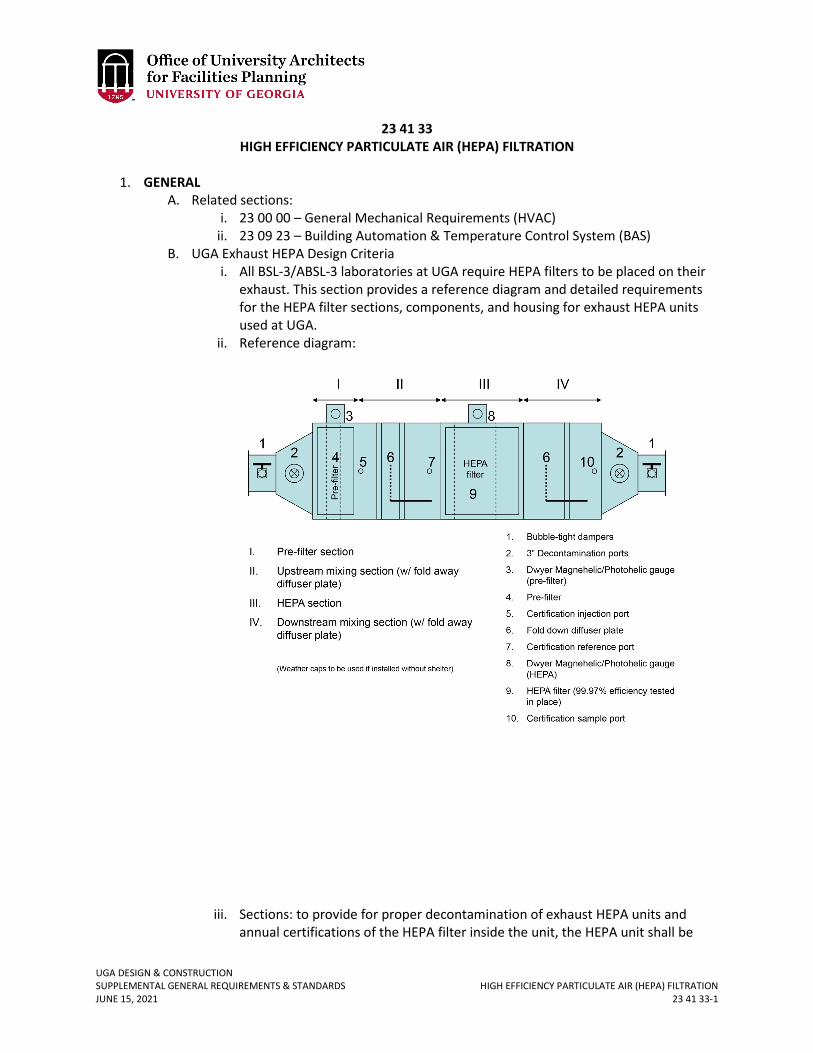
UGA DESIGN & CONSTRUCTION SUPPLEMENTAL GENERAL REQUIREMENTS & STANDARDS HIGH EFFICIENCY PARTICULATE AIR (HEPA) FILTRATION JUNE 15, 2021 23 41 33-1
23 41 33 HIGH EFFICIENCY PARTICULATE AIR (HEPA) FILTRATION
1. GENERAL
A. Related sections: i. 23 00 00 – General Mechanical Requirements (HVAC)
ii. 23 09 23 – Building Automation & Temperature Control System (BAS) B. UGA Exhaust HEPA Design Criteria
i. All BSL-3/ABSL-3 laboratories at UGA require HEPA filters to be placed on their exhaust. This section provides a reference diagram and detailed requirements for the HEPA filter sections, components, and housing for exhaust HEPA units used at UGA.
ii. Reference diagram:
iii. Sections: to provide for proper decontamination of exhaust HEPA units and annual certifications of the HEPA filter inside the unit, the HEPA unit shall be
UGA DESIGN & CONSTRUCTION SUPPLEMENTAL GENERAL REQUIREMENTS & STANDARDS HIGH EFFICIENCY PARTICULATE AIR (HEPA) FILTRATION JUNE 15, 2021 23 41 33-2
comprised of the following sections: pre-filter section, upstream test section (with fold away diffuser plate), HEPA section, downstream test section (with fold away diffuser plate).
a. The pre-filter section will have frames that accommodate filters that are standard to campus use. There shall be no gaps in the housing filter frame and around the filter panel that allows air to by-pass the filter media. The placement of the pre-filter is application specific and the Design Professional shall ask the Project Manager to coordinate a meeting with Office of Biosaftey to discuss during the design phases. If deemed appropriate (because of the frequency of changing the pre-filter), the pre-filter can, be located in the BSL3 lab itself; however, this requires variance approval as the Project Manager will need to coordinate with Office of Biosafety to determine acceptability.
b. An upstream swing-away, fold away, or pivot test section (that achieves the effect of mixing certification challenge aerosol equivalent to injecting the challenge aerosol in a straight run of duct 10 duct diameters upstream of the dirty face of the HEPA) shall be provided between the upstream bubble-tight and the dirty face of the HEPA filter.
c. A HEPA section that secures a gasket-seal 99.97% tested-in-place efficient HEPA filter. The mechanism that secures the HEPA filter should be replaceable without having to replace the housing.
d. A downstream swing-away, fold away, or pivot test section (that achieves the effect of mixing certification challenge aerosol equivalent to the mixing of the challenge aerosol in a straight run of duct 10 duct diameters downstream of the clean face of the HEPA) shall be provided between the clean face of the HEPA and the downstream bubble tight damper. Alternatively, a sample port located 10 duct diameters downstream of the clean face of the HEPA can be provided downstream of the downstream bubble tight.
2. PRODUCT A. Components
i. Bubble tight dampers on the dirty and clean side of the HEPA housing to facilitate room isolation and gas decontamination shall be provided. The dampers shall:
a. Be a positive seal, isolation type damper. b. Cylindrical and constructed of 11 gauge T-304 stainless steel. c. Have a blade that shall consist of two 3/16-inch thick stainless steel
plates with a replaceable silicone gasket between them. d. Be sealed when the gasket is in against the housing wall of the damper. e. Be constructed under a quality assurance program that addresses the
requirements of ANSI/ASME NQA-1, “Quality Assurance Program Requirements for Nuclear Facilities.”
f. Be an all weld design. Welded joins and seams shall be continuous if they are pressure retaining.
g. Be buffed or brushed to remove heat discoloration, burrs, and sharp edges.
UGA DESIGN & CONSTRUCTION SUPPLEMENTAL GENERAL REQUIREMENTS & STANDARDS HIGH EFFICIENCY PARTICULATE AIR (HEPA) FILTRATION JUNE 15, 2021 23 41 33-3
h. Have damper parts (if part of a gasket setting surface) that are ground smooth and flush.
i. Be built buy welders, procedures and operators that are qualified in compliance with ACME Boiler and Pressure Code, Section IX.
j. Have a blade that is tested in the closed position at 10-inch water gage and be bubble tight per ANSI/ASME N509-1989, Paragraph 5.9.7.3.
k. Have a damper housing that is tested by the pressure decay method in accordance with ANSI/ASME N510-1989: “Testing of Nuclear Air Cleaning Systems,” Paragraph 6 and 7 and have a maximum leak rate of 0/0005 CFM per cubic foot of housing volume at 10-inch water gage. Test duration shall be 5 minutes with readings taken at 1 minute intervals.
l. Have a ¼ turn worm-geared actuator with hand wheel. The actuator shall have an aluminum base and cover and be fully lubricated and self-locking.
m. The basis of design for the bubble type damper is the Flanders model DBTM-FB-304-12.
ii. 3-inch decontamination ports will be provided between the bubble tight dampers and the HEPA filter housing on the transitions between the bubble tight dampers and the HEPA filter housing. The 3-inch decontamination port will be made of stainless steel, have a lockable butterfly valve, dust cap and be designed and constructed under the same standards as the HEPA housing.
iii. A Dwyer Photohelic gauge, or approved equal, with an appropriate range based on fan selection calculations, to accurately detect pressure differences across the pre-filter will be provided. The Photohelic gauge will be protected from contamination by inline HEPA filters suitable for the environment the HEPA unit is installed in. The inline HEPA filters will be located between (2) 2-way ball valves and have a decontamination port with a ball valve to allow decontamination of the inline filters. There will be one line with this set up on the upstream side of the pre-filter and one on the downstream side of the pre-filter. An analog signal from the Photohelic shall be input to the Building Automation System (BAS) to indicate filter condition and to alert remote operators and lab occupants when filter panel needs to be replaced.
iv. Pre-filters (if required by conditions of the facility environment) will be provided for HEPA filters and be located in the exhaust HEPA housing unit upstream of the upstream mixing section. Pre-filter sections will provide and continuous seal on all 4 sides of filter as to prevent contaminants from going around the pre-filter and getting into the HEPA. Pleats of pre-filters shall be in the vertical position when installed.
v. A certification injection port made of a 1-inch stainless steel half coupling with a stainless steel plug will be provided for injection of certification challenge aerosols between the pre-filter and the upstream fold down diffuser plate.
vi. A fold down diffuser plate (that creates mixing of certification challenge material as noted above) will be provided. The fold down diffuser plate will lock out of the way during normal HEPA unit use and will lock in the diffusion position during certification.
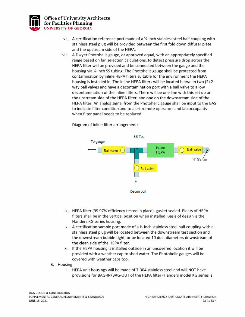
UGA DESIGN & CONSTRUCTION SUPPLEMENTAL GENERAL REQUIREMENTS & STANDARDS HIGH EFFICIENCY PARTICULATE AIR (HEPA) FILTRATION JUNE 15, 2021 23 41 33-4
vii. A certification reference port made of a ½-inch stainless steel half coupling with stainless steel plug will be provided between the first fold down diffuser plate and the upstream side of the HEPA.
viii. A Dwyer Photohelic gauge, or approved equal, with an appropriately specified range based on fan selection calculations, to detect pressure drop across the HEPA filter will be provided and be connected between the gauge and the housing via ¼-inch SS tubing. The Photohelic gauge shall be protected from contamination by inline HEPA filters suitable for the environment the HEPA housing is installed in. The inline HEPA filters will be located between two (2) 2-way ball valves and have a decontamination port with a ball valve to allow decontamination of the inline filters. There will be one line with this set up on the upstream side of the HEPA filter, and one on the downstream side of the HEPA filter. An analog signal from the Photohelic gauge shall be input to the BAS to indicate filter condition and to alert remote operators and lab occupants when filter panel needs to be replaced. Diagram of inline filter arrangement:
ix. HEPA filter (99.97% efficiency tested in place), gasket sealed. Pleats of HEPA
filters shall be in the vertical position when installed. Basis of design is the Flanders KG series housing.
x. A certification sample port made of a ½-inch stainless steel half coupling with a stainless steel plug will be located between the downstream test section and the downstream bubble tight, or be located 10 duct diameters downstream of the clean side of the HEPA filter.
xi. If the HEPA housing is installed outside in an uncovered location it will be provided with a weather cap to shed water. The Photohelic gauges will be covered with weather caps too.
B. Housing i. HEPA unit housings will be made of T-304 stainless steel and will NOT have
provisions for BAG-IN/BAG-OUT of the HEPA filter (Flanders model KG series is
UGA DESIGN & CONSTRUCTION SUPPLEMENTAL GENERAL REQUIREMENTS & STANDARDS HIGH EFFICIENCY PARTICULATE AIR (HEPA) FILTRATION JUNE 15, 2021 23 41 33-5
an example of an acceptable housing style). The following information is taken from a Flanders/CSC® spec sheet.
ii. The filter housing shall be a side access housing and shall be manufactured from 14 Ga. & 11 Ga. T-304 stainless steel (unpainted). The housing shall be adequately reinforced to withstand a negative or positive pressure of 10-inch water gage. The housing shall be side access for filter installation and change-out. Housing design and filter arrangement shall allow air to enter and exit housing without changing direction. The housing shall accommodate gasket seal filters. Prior to leaving the factory, each filter sealing mechanism will be checked with an alignment gage to ensure proper alignment of the sealing edge.
iii. All “pressure retaining” weld joints and seams shall be continuously welded; weld joints and seams requiring only intermittent welds by design shall not be continuously welded. As a minimum, all weld joints and seams shall be wire brushed and/or buffed to remove heat discoloration, all burrs, and sharp edges. All weld joints and seams that are a portion of any gasket setting surface (i.e., duct connecting flanges) shall be ground smooth and flush with adjacent base metals. All welding procedures, welders, and welder operators shall be qualified in accordance with ASME Boiler and Pressure Vessel Code, section IX. All production welds shall be subjected to a visual inspection which incorporates the workmanship acceptance criteria described in sections 5 & 6 of ANSI/AWS D9.1-1990, “Specification for Welding of Sheet Metal.”
iv. All hardware on the housing and mechanical components of the filter sealing mechanism shall be 300 series stainless steel except for the access door knobs which are cast aluminum.
v. The filter sealing mechanism shall be replaceable and shall be operated by a locking handle. The sealing mechanism shall be designed to exert an equal force to the top and bottom edge of each filter when engaging and disengaging the filter on the sealing edge of the housing.
vi. The housing shall have a filter access port that is sealed by a removable, gasket sealed access door. The door gasket shall be silicone and shall be manually replaceable after the door has been removed from the housing.
vii. The filter housing shall be manufactured under a quality assurance program that addresses the requirements of ANSI/ASME NQA-1, “Quality Assurance Program Requirements for Nuclear Facilities”. The housing shall be tested for filter fit, operation of the filter clamping mechanism, sealing edge alignment, and leak tightness before leaving the factory. Both the filter sealing surface and the complete assembly pressure boundary shall be leak tested by the “pressure decay method”, in accordance with ANSI/ASME N510-1989 (reaffirmed in 1995), “Testing of Nuclear Air-Cleaning Systems”, paragraphs 6 & 7 and have a maximum leak rate of 0.0005 CFM per cubic foot of housing volume at 10-inch water gage. Test duration shall be 5 minutes with pressure readings recorded at 1 minute intervals.
viii. Fold Away, Pivot, or Swing Aside Test Sections: The test sections shall be constructed the same as the filter housings. The test sections shall provide the ability to test the system per the intent of ANSI/ASME N510-1989 (reaffirmed in 1995), “Testing of Nuclear Air Cleaning Systems” (ANSI/ASME N510 was written

UGA DESIGN & CONSTRUCTION SUPPLEMENTAL GENERAL REQUIREMENTS & STANDARDS HIGH EFFICIENCY PARTICULATE AIR (HEPA) FILTRATION JUNE 15, 2021 23 41 33-6
for walk-in style filter plenums and contains some tests that cannot be performed on side-load style filter housings). All components of the test sections shall be constructed of 300 series stainless steel. The test sections shall have a maximum pressure drop in accordance with the air flow of the housing unit when the diffuser wall is in the open position. All test section ports shall be labeled with stainless steel (SS) labels. Injection ports shall be 1-inch SS half coupling with SS plugs and sample parts shall be ½-inch SS half couplings with SS plugs.
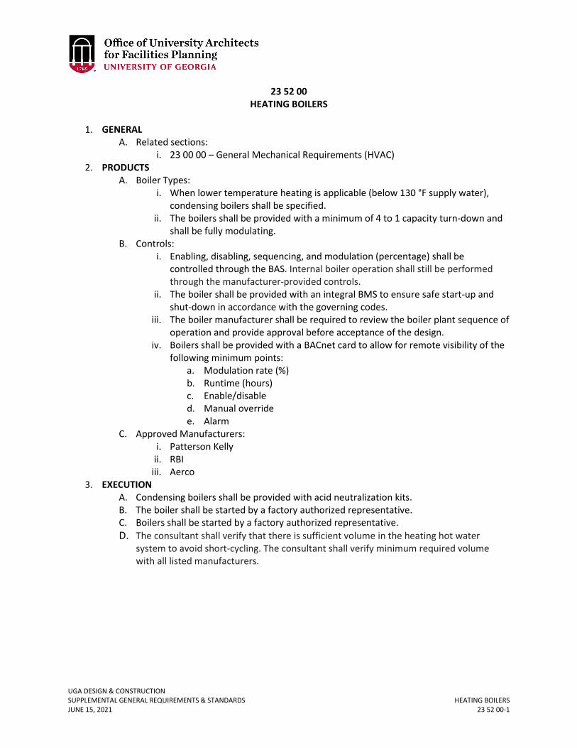
UGA DESIGN & CONSTRUCTION SUPPLEMENTAL GENERAL REQUIREMENTS & STANDARDS HEATING BOILERS JUNE 15, 2021 23 52 00-1
23 52 00 HEATING BOILERS
1. GENERAL
A. Related sections: i. 23 00 00 – General Mechanical Requirements (HVAC)
2. PRODUCTS A. Boiler Types:
i. When lower temperature heating is applicable (below 130 °F supply water), condensing boilers shall be specified.
ii. The boilers shall be provided with a minimum of 4 to 1 capacity turn-down and shall be fully modulating.
B. Controls: i. Enabling, disabling, sequencing, and modulation (percentage) shall be
controlled through the BAS. Internal boiler operation shall still be performed through the manufacturer-provided controls.
ii. The boiler shall be provided with an integral BMS to ensure safe start-up and shut-down in accordance with the governing codes.
iii. The boiler manufacturer shall be required to review the boiler plant sequence of operation and provide approval before acceptance of the design.
iv. Boilers shall be provided with a BACnet card to allow for remote visibility of the following minimum points:
a. Modulation rate (%) b. Runtime (hours) c. Enable/disable d. Manual override e. Alarm
C. Approved Manufacturers: i. Patterson Kelly
ii. RBI iii. Aerco
3. EXECUTION A. Condensing boilers shall be provided with acid neutralization kits. B. The boiler shall be started by a factory authorized representative. C. Boilers shall be started by a factory authorized representative. D. The consultant shall verify that there is sufficient volume in the heating hot water
system to avoid short-cycling. The consultant shall verify minimum required volume with all listed manufacturers.
UGA DESIGN & CONSTRUCTION SUPPLEMENTAL GENERAL REQUIREMENTS & STANDARDS AIR-COOLED WATER CHILLERS JUNE 15, 2021 23 64 16.13-1
23 64 16.13 AIR-COOLED WATER CHILLERS
1. GENERAL
A. Related sections: i. 23 00 00 – General Mechanical Requirements (HVAC)
ii. 23 25 00 – HVAC Water Treatment B. Chillers shall be provided with Bacnet communication and shall utilize R134a. C. Chillers shall generally be selected for 10 °F chilled water temperature drop. D. Design Professional shall specify noise levels and, if required to meet owners
performance requirements, options for sound dampening. E. Chiller shall have capacity control down to 10%. F. Chiller available output data shall include operating and peak tonnage and amps, chilled
water temperature difference, pressure drop across chiller, and accessible trend data for all associated points without need for additional software and programming.
G. Shall have multiple independent refrigerant circuits. H. Air-cooled chillers with micro-channel condensers shall be provided with
10 years parts and labor warranty for the condenser. 2. PRODUCT
A. Acceptable Manufacturers: i. Carrier
ii. Trane iii. York iv. Daikin
3. EXECUTION A. The Design Professional shall verify that there is sufficient system volume to avoid short-
cycling. An additional chilled water storage tank shall be provided if necessary. Ensure a minimum water change rate of 12 minutes shall be provided for new and existing systems.
Revised June 15, 2021
UGA DESIGN & CONSTRUCTION SUPPLEMENTAL GENERAL REQUIREMENTS & STANDARDS WATER-COOLED WATER CHILLERS JUNE 15, 2021 23 64 16.16-1
23 64 16.16 WATER-COOLED WATER CHILLERS
1. GENERAL
A. Related sections: i. 01 81 00 – Facility Performance Requirements
ii. 23 00 00 – General Mechanical Requirements (HVAC) iii. 23 25 00 – HVAC Water Treatment
B. Design Professionals must discuss chiller selection with Project Manager at project concept design stage to determine Owner’s performance requirements. Chillers shall be selected at the concept design stage based on energy efficiency and maintainability in addition to first cost. For any water-cooled chiller above 300 tons, selection must be based upon life-cycle costs analysis for at least 10 entering separate conditions accounting for varying entering condenser water temperatures and anticipated capacity operating points. The life-cycle analysis shall account for anticipated maintenance costs, first cost, and energy costs over the life of the machine.
i. Design Professional shall discuss sound level requirements for the specific project with the Project Manager and establish decibel limits and agreed noise levels shall be listed on chiller schedule.
ii. Design Professional shall discuss with manufacturers and Contractors cost options to increase warranty length from 12 months after Material Completion (not start up) to 24 months and for 60 months.
C. Chillers shall be provided with Bacnet communication. D. Chillers shall generally be selected for 10 °F chilled water temperature drop. Discuss
with Project Manager during concept design stage. E. Design Professional shall discuss piping design (preliminary, secondary, etc.) with Project
Manager during concept design stage. Factory test as required to verify chiller performance may be required. Discuss with Project Manager early in the design.
F. Chillers shall operate, in the installed location, free of any condensation under all operating conditions. Insulate accordingly.
G. Chiller piping configuration shall match existing in renovated buildings. H. Factory-mounted refrigerant pump-down machine may be desired. Discuss with Project
Manager early in the design. 2. PRODUCT
A. Acceptable manufacturers: i. Carrier
ii. Daiken iii. York iv. Trane
B. All water-cooled Centrifugal chillers above 300 tons shall have VSD. C. Water cooled chillers shall include marine water-boxes with hinged covers. D. The chiller shall be provided with refrigerant leak detection system and associated
exhaust as required to meet the International Mechanical Code. E. Provide hand-off-auto switch (HOA located on the BAS control panel itself and labeled
“chiller command” for the purpose of isolating the chiller from the BAS).
Revised June 15, 2021
UGA DESIGN & CONSTRUCTION SUPPLEMENTAL GENERAL REQUIREMENTS & STANDARDS WATER-COOLED WATER CHILLERS JUNE 15, 2021 23 64 16.16-2
F. Condenser water cooled VFDs shall be provided with dual strainers installed in the cooling medium piping as required to ensure that the VFD heat exchanger does not clog up.
G. Chillers with VFDs shall provide shaft grounding rings and ceramic back bearings for open drive configurations. Semi-hermetic drives shall provide approved means to protect against and shaft current induced bearing fluting.
H. Chiller Plant Sequence Requirements: i. Whenever a chiller is idle for 24 hours or more and the temperature is above 60
degrees, then the water treatment controls shall be activated, and the condenser water pump shall run for 30 minutes.
ii. Condenser water pumps shall always be provided with VFDs, and shall start at low speed.
3. EXECUTION A. The chiller shall be installed to allow adequate clearance for compressor removal.
Installation of hoists and rails should be considered where possible to accommodate compressor removal.
B. The chiller shall be installed to allow for adequate clearance for rodding out both the condenser water and evaporator barrels.
C. The chiller shall be started by an authorized factory representative. D. Provide Y-strainers before the chilled water pump and the condenser water pump, as
required to protect the chiller and associated pumps. E. Chillers will be monitored by a third-party remote monitoring system through data
obtained from the BAS system.
UGA DESIGN & CONSTRUCTION SUPPLEMENTAL GENERAL REQUIREMENTS & STANDARDS COOLING TOWERS JUNE 15, 2021 23 65 00-1
23 65 00 COOLING TOWERS
1. GENERAL
A. Related sections: i. 23 00 00 – General Mechanical Requirements (HVAC)
ii. 23 05 19 – Meters and Gauges iii. 23 25 00 – HVAC Water Treatment iv. 26 29 23 – Variable-Frequency Motor Controllers
B. Design Professional shall discuss suitability of a cooling tower system that does not require chemical water treatment with the Project Manager.
2. PRODUCTS A. Cooling towers shall have fully welded stainless steel cold water / lower basins (no
bolted sumps) and stainless steel hot / upper sumps B. Motors in air stream shall be Totally Enclosed, Air Over (TEAO). C. Vertical shaft bearings shall have rain seals. D. For new cooling towers, provide mechanical float valve(s) on make-up(s) at the tower.
Float valve shall be brass. On retrofits to existing cooling towers, using electronic probes provide Magnetrol model T52-1E3a-BKP mechanical valve or approved equal mounted to the exterior of the tower and re-use existing wiring and solenoid valve(s).
E. Concrete basins shall be sand blasted and pressure cleaned prior to applying bonding agent and coating under required temperature and humidity conditions. All coating processes must be observed by UGA or CxP.
F. Fans drives shall be VSD and it is preferred for the VSD to be located inside the building. G. Condenser water filtration shall be accomplished using centrifugal separators and basin
sweepers. Cooling tower shall be provided with a 2” drain, minimum, located in the center of the basin well to allow for ease of basin cleaning.
H. Cooling Tower Access: i. Cooling towers shall be provided with access platforms that allow for cleaning
and maintaining of cooling tower. ii. Provide hand-rails on the top of the tower for safety and davits for removal of
fan motors. iii. Access platform design shall be submitted to Project Manager for approval early
in the design phase. I. Design Professional shall consider site location of cooling tower including dust, sound,
and accessibility issues. If placed too close to a road there may be a maintenance issue due to dust.
J. Below grade sumps shall not be allowed. K. Fiberglass cooling towers or fiberglass cooling tower fans are not allowed. L. Cooling Tower supply water outlet shall be sized as required to ensure that water
velocities are low enough to prevent vortexing. M. Cooling Tower Make-up and Blowdown water shall be metered with meters purchased
from ACC Public Utilities. Refer to section 23 05 19 for details.
UGA DESIGN & CONSTRUCTION SUPPLEMENTAL GENERAL REQUIREMENTS & STANDARDS COOLING TOWERS JUNE 15, 2021 23 65 00-2
3. EXECUTION A. All drains shall be routed to sanitary sewer. B. Provide a factory-authorized service representative to perform start-up services. C. Provide adequate clearance (30-inch minimum) under the cooling tower to
accommodate drain(s) and allow inspection and cleaning. D. Verify that existing devices to be re-used are working (see above). E. Remove all redundant existing devices and repair surrounding as required. F. Contractor shall ensure that construction debris and dust does not enter condenser
water system. G. Provide heat tracing for the make-up water piping.
UGA DESIGN & CONSTRUCTION SUPPLEMENTAL GENERAL REQUIREMENTS & STANDARDS INDOOR CENTRAL-STATION AIR-HANDLING UNITS JUNE 15, 2021 23 73 00-1
23 73 00 INDOOR CENTRAL-STATION AIR-HANDLING UNITS
1. GENERAL
A. Related sections: i. 23 00 00 – General Mechanical Requirements (HVAC)
ii. 26 92 23 – Variable-Frequency Motor Controllers B. Design Professional shall discuss selection, location, and model number of AHU(s) with
UGA in the early stages of design. C. Select most efficient fan for the application by comparing life cycle costs of alternatives
considered; submit details with shop drawings submittals; specify highest efficiency motor available (NEMA Premium); consider fan performance over full range of anticipated operation and submit curves at the design development stage.
D. Unit information shall be provided on a permanent label secured to the unit to include but is not limited to: Unit ID, model number, serial number, job/project identifier, date of manufacture, design CFM at the design total static pressure, and filter details (size(s) and number of each).
2. PRODUCTS A. AHUs over 3000 cfm
i. Select cooling coils for 400 fpm max face velocity and entering water 1 °F above the design chilled water supply temperature.
ii. AHUs shall be modular, double walled; operate without condensation forming on exterior surfaces under any and all anticipated operating conditions. Outer wall shall be min. 16 gauge G-90 galvanized steel and inner wall shall be min. 20 gauge G-90 Galvanized steel. Coil and humidifier sections shall have 20 gauge 304 stainless steel inner walls. Unit double wall internal insulation shall have a flame spread rating not over 25 and smoke developed rating no higher than 50 complying with NFPA 90A.
iii. Air handling units shall be factory assembled and shipped to the site in as few sections as reasonably possible. Shipping sections to be clearly shown on all submittals for approval. Contractors to coordinate with jobsite requirements.
iv. The floor shall be insulated with foam and shall be equal to the R-value of the wall panels. Floor shall be constructed of 0.125” thick aluminum treadplate.
v. Structure shall be fully welded. Deflection shall be no more than L/240 of panel length +/- 10” static pressure. Manufacturer shall perform a factory deflection test on at least one unit.
vi. AHU shall have a leakage rate of 1% or less at 10-inch pressure. vii. Heating and Cooling coils:
a. Coil tube diameter shall be 5/8-inch minimum, tube thickness of .02 inches, and minimum aluminum fin thickness of .008 inches.
b. Tube bends shall be constructed of return bend fittings that are the same thickness or greater than the coil tube.
c. Cooling coils shall have a minimum of 6 row cooling coils and maximum of 8 row cooling coils.
d. Fin spacing shall not exceed 10 fpi. Fin height on cooling coils shall be limited to 39 inches for all units.
Revised June 15, 2021

UGA DESIGN & CONSTRUCTION SUPPLEMENTAL GENERAL REQUIREMENTS & STANDARDS INDOOR CENTRAL-STATION AIR-HANDLING UNITS JUNE 15, 2021 23 73 00-2
e. Provide multiple sections with drain pan where 39 inches has to be exceeded.
f. Cooling coil casings, supports, and tie off walls to be stainless steel construction.
viii. Drain pans: a. 16 gauge stainless steel b. Multiple section cooling coils shall have intermediate drain pans. c. Drain pans to be sloped, IAQ type, to prevent standing water from
accumulating in pans.
ix. Filters: a. Filter efficiency shall suit the application and be MERV 11 minimum
where application does not dictate higher efficiency. b. Specified sizes shall be limited to 24x24xD; 12x24xD; 20x20xD; 16x20xD;
16x25xD; 20x25xD. The depth ‘D’ will depend on the application (Design Professional to discuss with Project Manager). Face velocity shall be the same or less than 450 fpm.
c. On units 72 inches and less in height, use side access filter sections. d. On units greater than 72 inches high, use upstream access filter
sections. e. Filters: Rating systems for air filters shall be ASHRAE Standard 52.2-2007
Method of Testing General Ventilation Air-Cleaning Devices for Removal Efficiency by Particle Size.
f. The lifecycle cost of filters shall be carefully considered during the design and selection of the filters. Filters shall be scheduled on the drawings. Dust holding capacity shall be included in selection criteria.
g. Layout shall ensure adequate ease of access to space is provided. h. Filter and holding frame combination shall ensure that air does not by-
pass the filter media. i. Provide permanent label on filter access door listing filter size(s),
quantity of filter types, and specified MERV rating. x. AHUs with chilled water coils shall have pre-heat coils.
xi. Heating coils shall be heating hot water. Steam heating coils shall not be used without variance approval.
xii. Air blenders shall be provided on AHUs units that contain mixing boxes that are designed and configured to ensure proper mixing of outdoor and return air and to prevent “nuisance” freeze stat trips. If space does not allow for the use of air blenders, mix air in ductwork prior to entering the mixing plenum, or utilize baffles inside the mixing plenum to ensure proper air mixing.
xiii. Units shall have, minimum 24 inches wide, access doors on filter, coil (up-stream, down-stream and between coils), and fan. If a filter is directly upstream of a coil, access may be provided through the filter rack and not a separate section, if mechanical room space requirements are not adequate for a separate access section.
xiv. UV disinfection system:
UGA DESIGN & CONSTRUCTION SUPPLEMENTAL GENERAL REQUIREMENTS & STANDARDS INDOOR CENTRAL-STATION AIR-HANDLING UNITS JUNE 15, 2021 23 73 00-3
a. The device shall be classified by UL (Underwriters Laboratories) as an Air Duct Mounted Accessory and meet all applicable UL standards. Manufactures UL file number shall be permanently marked on the exterior of the product.
b. Shall be of stainless steel and aluminum construction. Any exposed screws or fasteners shall be stainless steel.
c. Approved UV lights shall be provided at all cooling coils. d. On units 72 inches and less in height, UV light racks shall be side
accessible slide out type, to slide out of units for changing bulbs. e. On units greater than 72 inches high, utilize stationary UV racks. f. AHU shall incorporate automatic shut-off for UV when access doors to
UV section are opened. However, shut-off device shall not be screw type.
g. The UV dosage shall be calculated for probable rating of URV-13, 99% air disinfection (S. marcescens) at air velocity and temperature and shall be adequate to deactivate microbial growth on all exposed surfaces.
h. Lamps: 1) Lamps shall be positioned for a 360-degree disinfection zone.
Lamp supports shall be stainless steel. Exposed screws and fasteners shall be stainless steel.
2) The lamp shall be generic, available on the open market and not product specific. Lamps shall be Philips, GE, Sylvania, Ushio or UGA preapproved equal.
3) UV lights dosage shall be increased to account for air-bourne pathogens such as COVID-19 in recirculating air systems. Discuss with Project Manager.
i. UV disinfection system shall be warranted to be free of defects in workmanship and material for a period of 5 years from date of Material Completion.
xv. Face-and-by-pass damper control shall not be used without FMD approval. If IFB coils are permitted to be utilized, dampers shall shut off tight to prevent air leakage through damper assembly to coil.
xvi. All air handling units shall have a base rail for unit support and coil trapping. Base rail height shall be sized such that the cooling coil may be trapped without chipping or penetrating the floor. Base rails shall be 5 inches minimum and higher if 4 inches housekeeping pad cannot be provided. Base rails shall be a welded structural steel assembly to form a rigid, unitized support structure. Base rail s shall be constructed of structural tubular steel, structural C Channel members, or structural I beam members and shall be coated with rust-inhibiting paint. Formed galvanized steel is not acceptable for the base rails.
xvii. Energy Recovery Wheels: The wheel(s) shall be provided with a 10 year parts and on-site labor warranty. The hub and bearings shall be provided with a manufacturer publicized minimum L-10 life of 1,000,000 hours. The desiccant media shall be provided with a maximum 3 angstrom molecular sieve. The drive shall consist of twin v-belts that ride on a grooved rim. The drive shall be rated for a minimum of 90,000 hours. Each section/module shall have an interior light.
Revised June 15, 2021
UGA DESIGN & CONSTRUCTION SUPPLEMENTAL GENERAL REQUIREMENTS & STANDARDS INDOOR CENTRAL-STATION AIR-HANDLING UNITS JUNE 15, 2021 23 73 00-4
Lights shall be factory wired to a single light switch with GFI outlet located adjacent to the fan access door. Access doors shall have a view window.
xviii. Fan array system: This shall consist of multiple, direct driven, arrangement 4 plenum fans with fan wheels that are rated and certified with tests and procedures in accordance with AMCA publication 211 and comply with the requirements of the AMCA Certified Ratings Program and constructed per the AMCA requirements for the duty specified. Fan wheels shall be constructed of aluminum and double thickness airfoil blades. The fan array shall be selected to operate at a system Total Static Pressure (TSP) that does not exceed 90% of the specified fan’s peak static pressure producing capability at the specified fan/motor speed. Fan static efficiency shall be selected for 70% or higher.
a. Each fan cube shall be furnished with sound attenuation (internal to the air handling unit) and internal vibration isolation.
b. Each fan / motor assembly shall be dynamically balanced to meet AMCA standard 204-96, category BV-5, to meet or exceed an equivalent Grade G.55, indicating a maximum of 0.03 inches per second peak, filter in (0.55mm per second peak, filter in) residual unbalance.
c. Each fan / motor “cube” will be provided with an individual backdraft damper. Manufacturer shall incorporate damper System Effect Pressure Loss when selecting fans. Damper system effect pressure loss shall be generated from test data of the dampers as installed on the inlet of the fan. Dampers shall be low leakage, maximum 2 CFM / sq. ft. at 1-inch differential static pressure. If the manufacturer cannot provide this data, they shall allow 0.5” loss in total static pressure calculation for the fan selection.
d. All motors shall be standard foot mounted type, TEAO or TEFC motors, premium efficiency. Motors shall meet the requirements of NEMA MG-1 Part 30 and 31, section 4.4.2. Motors for use in multiple fan arrays that operate at varying synchronous speeds shall be rated for use with Variable Frequency Drive(s) (VFDs). All motors shall include permanently sealed bearings and shaft grounding system (or ceramic bearings), to protect the motor bearings from electrical discharge machining due to stray shaft currents. Motors sizes shall be limited to 7.5 Hp or smaller. All motors to be factory wired to an electrical panel or VFD mounted on the exterior of the air unit. Wiring of motors in the field by the contractor is not acceptable.
e. If necessary, the front bearing on a direct drive fan should have a grease zerk at a 45 degree angle toward the rear of the motor for ease of maintenance access. Remote plastic lines are not preferred.
f. It is preferred that each fan shall be driven by an individual VFD, for maximum redundancy and individual motor protection. If a single VFD is used to serve more than one fan, each fan motor shall be furnished with a means of manual disconnect and overload protection (circuit breaker).
Revised June 15, 2021
UGA DESIGN & CONSTRUCTION SUPPLEMENTAL GENERAL REQUIREMENTS & STANDARDS INDOOR CENTRAL-STATION AIR-HANDLING UNITS JUNE 15, 2021 23 73 00-5
g. Both local (indicator lights or panel) and interface for remote indication of fan operation (on-off) at BMS shall be provided.
h. Ductwork and ERU/ERV layout shall coordinate to allow for proper air distribution across energy recovery medium for maximum benefit.
Revised June 15, 2021
UGA DESIGN & CONSTRUCTION SUPPLEMENTAL GENERAL REQUIREMENTS & STANDARDS PACKAGED OUTDOOR HVAC EQUIPMENT JUNE 15, 2021 23 74 00-1
23 74 00 PACKAGED OUTDOOR HVAC EQUIPMENT
1. GENERAL
A. Related sections: i. 23 09 23 – Building Automation and Temperature Control System (BAS)
B. All packaged equipment shall be provided with native BACnet interfaces to allow seamless interface with BAS.
C. Provide permanent label on filter access door listing filter size(s), quantity of filter types, and specified MERV rating.
D. Direct Expansion systems above 5 tons that do not have inverter compressors shall be supplied complete with APR Control valve by Rawal Industries to allow system to operate without short cycling under low load conditions and allow modulation to reduce fan speed. The device shall be capable of maintaining constant discharge temperature without cycling. Installation of the device shall not void warranty/guarantee on equipment. Only manufacturers who comply with this shall be listed in the specifications. DP is responsible for confirming this in writing with the manufacturer. Factory start-up shall be specified. TAB agency shall check and verify correct piping installation, that all manual valves are in the correct position, that the systems operates without short cycling and shall document the TEV and HGBV start-up settings (note factory settings may not necessarily prevent short cycling).
E. Packaged units that provide both ventilation air and control space temperature shall be provided with the means to automatically maintain space humidity below 60% RH, either with hot gas reheat, or other approved means.
F. Packaged AC equipment shall be provided with integral disconnects.
New June 15, 2021
UGA DESIGN & CONSTRUCTION SUPPLEMENTAL GENERAL REQUIREMENTS & STANDARDS VARIABLE REFRIGERANT FLOW (VRF) HVAC SYSTEMS JUNE 15, 2021 23 81 29-1
23 81 29 VARIABLE REFRIGERANT FLOW (VRF) HVAC SYSTEMS
1. GENERAL
A. Related sections: i. 01 75 00 – Starting & Adjusting
ii. 23 00 00 – General Mechanical Requirements (HVAC) 2. PRODUCTS
A. VRF System Type: i. VRF systems may be water-cooled or air-cooled. Discuss with Project Manager.
ii. The Design Professional shall consider the requirements of ASHRAE Standard 15 to ensure that potential refrigerant release does not endanger occupants.
iii. Ducted systems shall be provided with manufacturer supplied filter rack. iv. All refrigeration piping shall be brazed. Selector boxes, fan coils, and condensing
units shall be connected to system piping with brazed connections. Mechanical joints shall not be allowed.
v. Unless specifically approved by the UGA PM, systems must have full VRF capabilities (heat recovery, controls, remotely accessible trending capabilities.
B. Quality Control: i. The Contractor shall provide proof that at least two of the installing technicians
have received and completed training from the manufacturer. Provide proof of training with submittals. VRF Trained technicians / installers must be on site overseeing the duration of project.
ii. The bidding Mechanical Subcontractor must give proof of adequate manufacturer VRF training. Three VRF successful installs of similar capacity and referrals with contacts shall be provided to the Project Manager.
C. System Flexibility: i. Variable Refrigerant Flow Systems shall be designed to allow for maximum
flexibility in the case of future renovations. All VRF projects shall be reviewed to accommodate future expansion or modifications. Discuss requirements with Project Manager.
ii. The number of selector boxes and the number of associated zones shall be discussed with Project Manager.
iii. Isolation valves shall be provided upstream of each branch selector box, allowing for zone isolation.
D. Controls: i. DP shall review controls requirements with UGA PM early in the design
process. ii. The system shall be provided with a BACnet interface allowing for
monitoring of all points through the BAS. In addition, the controls shall allow for remote set-point adjust of the VRF system.
Revised June 15, 2021
Revised June 15, 2021
UGA DESIGN & CONSTRUCTION SUPPLEMENTAL GENERAL REQUIREMENTS & STANDARDS VARIABLE REFRIGERANT FLOW (VRF) HVAC SYSTEMS JUNE 15, 2021 23 81 29-2
3. EXECUTION: A. A factory employee or factory designated individual shall be present at start-up. B. Technicians working on VRF shall be certified and shall maintain current VRF installation
certifications on site at all times. All refrigeration piping shall be hard drawn, and shall be selected to handle the operation pressure.
C. The refrigeration piping shall be purged with nitrogen, vacuum tested and pressure tested in accordance with the manufacturer’s recommendations. The system shall be pressured tested for a period no less than 24 hours.
D. A qualified owner’s appointed representative shall witness purging, vacuum testing, and pressure testing. It is the contractor’s responsibility to schedule and coordinate this activity with the UGA PM in advance.
E. The VRF system shall not be used to cool the building during construction. The Contractor shall provide temporary cooling if necessary.
F. Brazing Qualifications: i. All brazing procedures, brazer qualification, quality, and testing shall conform to
the requirements of ANSI B31.1; and to the ASME Boiler and Pressure Vessel Code, Section IX, Welding and Brazing Qualifications. The Contractor shall be responsible for the procedures, quality, and visual testing of all brazing performed by him / her and his / her employees.
ii. The BPQs shall be performed under the witness of an independent agency. The witness shall be a representative of an independent testing agency, Authorized Inspector, or consultant, any of which must be a Certified Welding Inspector (CWI) and / or approved by the National Certified Pipe Welding Bureau. The qualifying test segment must be a minimum 3-inch diameter pipe with the range of wall thicknesses and material types qualified as applicable for each project and within range of the BPS. Tests position shall be all positions defined in QB-120 to QB-124 of ASME Section IX.
iii. All brazing shall be done in accordance with ASME B31.1. iv. Brazing procedures, and all brazer qualifications (BPQs and Evidence of
Continuity) shall be maintained on the jobsite. v. All technicians who will be performing brazing operations shall be certified in
accordance with American Welding Society standards. All welding certifications and procedures shall be maintained on site.
Revised June 15, 2021
UGA DESIGN & CONSTRUCTION SUPPLEMENTAL GENERAL REQUIREMENTS & STANDARDS GENERAL ELECTRICAL REQUIREMENTS JUNE 15, 2021 26 00 00-1
26 00 00 GENERAL ELECTRICAL REQUIREMENTS
1. GENERAL
A. Related sections: i. 00 00 07 – Design Professional Design Process Requirements
ii. 00 00 08 – Design Professional Documentation Requirements & Deliverables iii. 00 00 13 – Designing Learning Environments iv. 01 41 26.06 – Dining Services v. 01 81 00 – Facility Performance Requirements
vi. 01 91 13 – General Commissioning Requirements vii. 23 05 14 – Variable Frequency Drives
viii. 23 09 23 – BAS ix. 26 05 19 – Low-Voltage Electrical Power Conductors and Cables x. 26 05 26 – Grounding & Bonding for Electrical Systems
xi. 26 05 33.13 – Conduit for Electrical Systems xii. 26 05 43 – Underground Ducts and Raceways for Electrical Systems
xiii. 26 09 23 – Lighting Control Devices xiv. 26 09 36 – Modular Dimming Controls xv. 26 09 43.16 – Addressable Fixture Lighting Control
xvi. 26 22 00 – Low-Voltage Transformers xvii. 26 24 13 – Low-Voltage Switchgears/Switchboards
xviii. 26 24 16 – Low-Voltage Panelboards xix. 26 24 19 – Motor-Control Centers xx. 26 32 00 – Packaged Generator Assemblies
xxi. 26 41 00 – Facility Lightning Protection xxii. 26 51 00 – Interior Lighting
xxiii. 26 56 00 – Exterior Lighting xxiv. 26 56 13 – Lighting Poles and Standards xxv. 26 56 16 – Parking Lighting
xxvi. 26 56 19 – Roadway Lighting xxvii. 26 56 29 – Site and Building Entry Lighting
xxviii. 26 56 33 – Walkway Lighting xxix. 26 56 36 – Flood Lighting xxx. 27 00 00 – General Communications Requirements
xxxi. 33 71 18 – Electrical Underground Ducts & Manholes B. The Design Professional is recommended to refer to Sections 00 00 07 Design
Professional Design Process Requirements, 00 00 08 Design Professional Documentation Requirements and Deliverables, and 01 81 00 Facility Performance Requirements before beginning design.
C. Electrical Design Consultant shall locate the IT drops for BAS and Mechanical Equipment on the electrical drawings.
D. Electrical Design consultant shall coordinate with the Mechanical Design consultant to ensure that hydronic, domestic, condensate, waste, etc. piping is to routed above electrical equipment (transformers, panels, switchgear, etc.).
E. Designing for Learning Environments
Revised June 15, 2021
UGA DESIGN & CONSTRUCTION SUPPLEMENTAL GENERAL REQUIREMENTS & STANDARDS GENERAL ELECTRICAL REQUIREMENTS JUNE 15, 2021 26 00 00-2
i. In flat classrooms with movable furniture, regularly spaced wall-mounted electrical outlets should be provided at 18 inches above finished floor (AFF) spaced maximum 12 feet horizontally. In classrooms with fixed tables, duplex electrical receptacles will be provided every other seat on the work surface. Ensure that adequate convenience receptacles are provided on or near the instructor station.
ii. Avoid power poles or other features that block views of instructors, markerboards, and screens. Additionally, floor receptacle covers shall be rated for pedestrian traffic and shall be mounted flush with the floor surface.
F. Power Distribution Design i. For UGA Athens Main Campus Only: The power for campus originates at the
main campus sub-station on UGA’s east campus. All medium voltage work on campus is performed by FMD. The Project Manager will provide guidance as to whether the cost of any required medium voltage work will be included in the Cost of the Work, the Bid, or if it will be a direct project cost. The Design Professional will coordinate with the Project Manager and FMD to verify which scope of Work that will be provided by FMD and which Work will be provided by the Contractor. Typically building service transformers and loop feed switches will be provided by FMD and installed by FMD. In some cases, FMD will supply and install 15 kV cables and associated splice kits and termination kits, and 2-hole compression lugs for transformer primary spaces (coordinate with Project Manager and FMD based upon project requirements and conditions). On new building projects, the Design Professional will include concrete duct banks for medium voltage primary to the utility transformer or loop feed switch and the associated pads for the utility equipment in their design documents.
ii. The power for UGA Athens Health Sciences Campus and Board of Regents properties along South Milledge, Athens, Georgia is provided by Georgia Power.
iii. Empty concrete duct banks, concrete pads, etc., related to the medium voltage Work will be by the Contractor, and FMD will set the building service transformers and install the associated medium voltage cabling for the primary. The Contractor shall provide and install all secondary service cable in concrete duct banks (to be included in Design Professionals’ design documents), using double-compression lugs, and make the final secondary connections to the utility transformer.
iv. One line diagram(s) showing incoming service(s), emergency generator(s), automatic transfer switches, switchgear / switchboard ratings, breaker sizes and feeder sizes shall be furnished for each facility. All downstream equipment ratings such as motor control centers (MCC’s) and panelboards, etc., shall be indicated. Existing one line diagram(s) shall be updated for all renovation projects. Partial one line diagrams are not acceptable. When existing one-line diagrams are not available, an as-built one-line diagram shall be created based on the Design Professional’s field survey. All one-line diagrams shall include short-circuit ratings at all nodes in the system, as well as arc-fault ratings. Electrical services (including utility transformer) shall be
Revised June 15, 2021
UGA DESIGN & CONSTRUCTION SUPPLEMENTAL GENERAL REQUIREMENTS & STANDARDS GENERAL ELECTRICAL REQUIREMENTS JUNE 15, 2021 26 00 00-3
sized according to the demand load. The Design Professional shall apply industry standard demand factors in conjunction with NEC requirements in their calculations for the sizing of all electrical services including all electrical distribution equipment (distribution transformers, panelboards, etc.).
v. Power riser diagrams for multistory facilities shall be furnished in addition to one-line diagrams.
vi. Circuit breaker long-time and short-time trip settings shall be furnished as part of the engineering design. Settings shall be based on the circuit breaker coordination study which is an integral part of the engineering scope.
vii. Power and lighting plans shall indicate all electrical apparatus including switchgears, switchboards, wall receptacles, panelboards, emergency generators, uninterruptable power supplies (UPS’s), MCC’s and HVAC equipment, light fixtures, etc., and all the associated wiring and conduits. The Design Professional shall calculate voltage drop on all circuits per the NEC and size each individual circuit’s conductors accordingly. Notes instructing the Contractor to up-size circuit wiring over a certain distance will not be accepted.
viii. Detailed schedules showing connected loads for each circuit shall be furnished for each panelboard. The schedules shall contain connected and demand kVA, type of load, location of load including room number and electrical characteristics such as number of poles and ampere rating for each circuit. Total connected load for each phase shall be furnished for each panel, as well as demand load. Panelboard schedules shall also contain mains ratings (225A/14 kAIC, 800A/42 kAIC, etc.) whether the panel is main breaker or main-lug only, operating voltage(s) (208V, 480Y/277V, etc.), number of phases (1 or 3 Phase), number of wires (3W or 4W), and general notes related to service entrance rating (if applicable), NEMA enclosure rating (1, 3R, 4X, etc.), top or bottom feed, and mounting type (flush, surface, etc.)
ix. Electrical load tabulation and calculations shall be provided to the UGA Project Manager. The Project Manager will coordinate with FMD to confirm acceptance of the Design Professional’s design for the building service transformer capacity, associated pad, opening, and manhole sizes and locations, underground vault locations and size, and routing of all medium voltage concrete duct banks. Load tabulation shall include types of load such as lighting, heating, chillers, air handlers, pumps, elevators, general purpose outlets, dedicated outlets for dedicated equipment, etc. A diversity factor for each type of load shall also be included. This task also serves as the basis to determine switchgear capacity.
x. All existing equipment (switchboards, panelboards, motors, circuit breakers, transformers, disconnect switches, conduit/wiring, etc.) that are associated with the project shall be verified and assessments shall be made if modifications and / or upgrades are required. All existing panelboards associated with the project shall be surveyed and recorded by the Design Professional.
Revised June 15, 2021
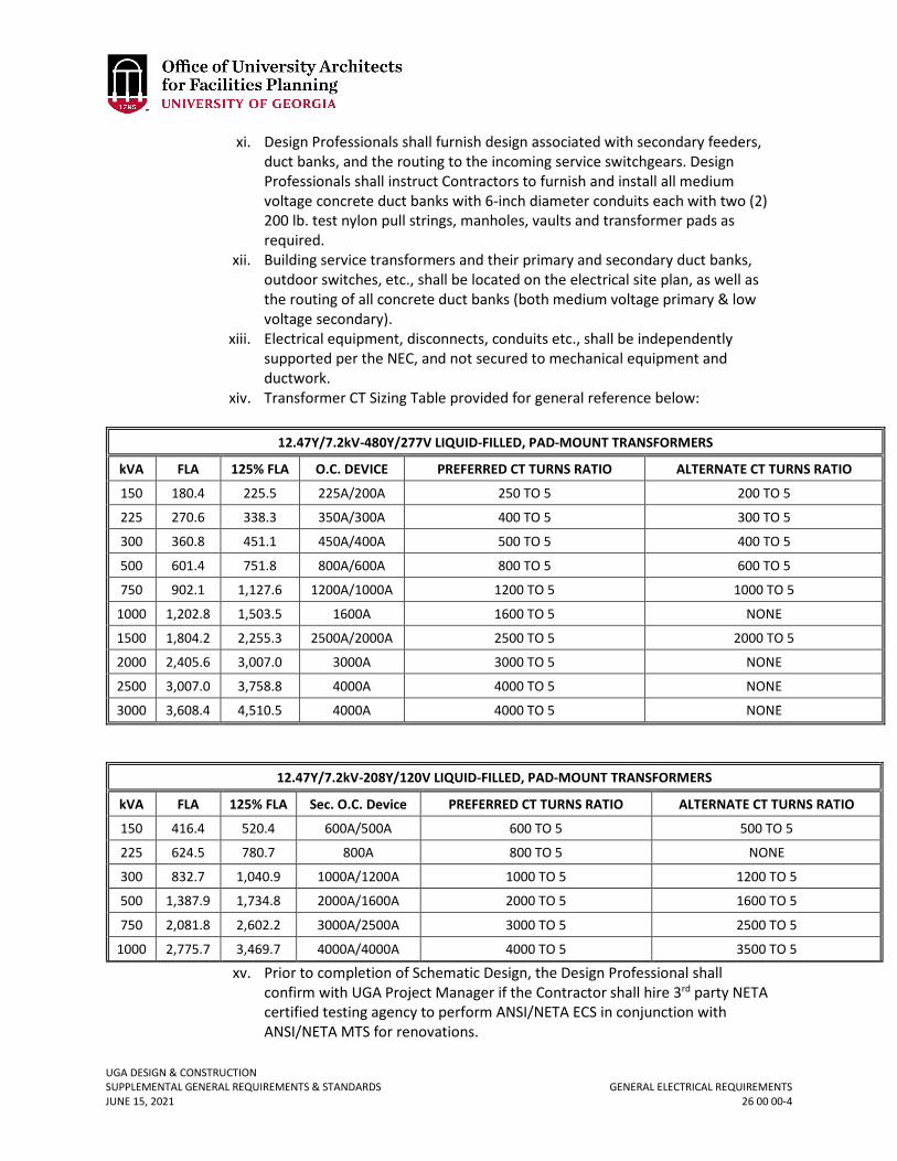
UGA DESIGN & CONSTRUCTION SUPPLEMENTAL GENERAL REQUIREMENTS & STANDARDS GENERAL ELECTRICAL REQUIREMENTS JUNE 15, 2021 26 00 00-4
xi. Design Professionals shall furnish design associated with secondary feeders, duct banks, and the routing to the incoming service switchgears. Design Professionals shall instruct Contractors to furnish and install all medium voltage concrete duct banks with 6-inch diameter conduits each with two (2) 200 lb. test nylon pull strings, manholes, vaults and transformer pads as required.
xii. Building service transformers and their primary and secondary duct banks, outdoor switches, etc., shall be located on the electrical site plan, as well as the routing of all concrete duct banks (both medium voltage primary & low voltage secondary).
xiii. Electrical equipment, disconnects, conduits etc., shall be independently supported per the NEC, and not secured to mechanical equipment and ductwork.
xiv. Transformer CT Sizing Table provided for general reference below:
12.47Y/7.2kV-480Y/277V LIQUID-FILLED, PAD-MOUNT TRANSFORMERS
kVA FLA 125% FLA O.C. DEVICE PREFERRED CT TURNS RATIO ALTERNATE CT TURNS RATIO
150 180.4 225.5 225A/200A 250 TO 5 200 TO 5
225 270.6 338.3 350A/300A 400 TO 5 300 TO 5
300 360.8 451.1 450A/400A 500 TO 5 400 TO 5
500 601.4 751.8 800A/600A 800 TO 5 600 TO 5
750 902.1 1,127.6 1200A/1000A 1200 TO 5 1000 TO 5
1000 1,202.8 1,503.5 1600A 1600 TO 5 NONE
1500 1,804.2 2,255.3 2500A/2000A 2500 TO 5 2000 TO 5
2000 2,405.6 3,007.0 3000A 3000 TO 5 NONE
2500 3,007.0 3,758.8 4000A 4000 TO 5 NONE
3000 3,608.4 4,510.5 4000A 4000 TO 5 NONE
12.47Y/7.2kV-208Y/120V LIQUID-FILLED, PAD-MOUNT TRANSFORMERS
kVA FLA 125% FLA Sec. O.C. Device PREFERRED CT TURNS RATIO ALTERNATE CT TURNS RATIO
150 416.4 520.4 600A/500A 600 TO 5 500 TO 5
225 624.5 780.7 800A 800 TO 5 NONE
300 832.7 1,040.9 1000A/1200A 1000 TO 5 1200 TO 5
500 1,387.9 1,734.8 2000A/1600A 2000 TO 5 1600 TO 5
750 2,081.8 2,602.2 3000A/2500A 3000 TO 5 2500 TO 5
1000 2,775.7 3,469.7 4000A/4000A 4000 TO 5 3500 TO 5
xv. Prior to completion of Schematic Design, the Design Professional shall confirm with UGA Project Manager if the Contractor shall hire 3rd party NETA certified testing agency to perform ANSI/NETA ECS in conjunction with ANSI/NETA MTS for renovations.
UGA DESIGN & CONSTRUCTION SUPPLEMENTAL GENERAL REQUIREMENTS & STANDARDS GENERAL ELECTRICAL REQUIREMENTS JUNE 15, 2021 26 00 00-5
G. Lighting plans shall be furnished to show all lighting fixture layouts including emergency lights with circuits, switches, wire and conduit sizes indicated. Lighting plans showing only lighting fixture layout are not acceptable. Lighting panelboard schedules and lighting fixture schedules shall be furnished. The Lighting Fixture Schedule shall include for each fixture: fixture designation (A, B, A1, B1, X1, X2, OA, OB, etc.); fixture description; manufacturer(s); complete manufacturer(s’) part number(s); lamp type; / number of lamps (if not LED); lumen output for LED lighting fixtures; operating voltage; operating wattage or volt-amps; mounting type; mounting height; specific remarks or notes for individual fixtures (if required). If all lighting fixtures associated with a project are 4000K LED, a general note within the Lighting Fixture Schedule will suffice for the lamp type and color temperature columns.
H. Prior to installation of electrical appurtenances, contractor shall coordinate a meeting at the project site involving the electrical subcontractor, Design Professional, UGA Project Manager, and OUA Interiors to review the furniture layout plan(s) and coordinate electrical appurtenance locations with the plan prior to installation of outlets, switches, etc. that may conflict with the furniture layout.
UGA DESIGN & CONSTRUCTION SUPPLEMENTAL GENERAL REQUIREMENTS & STANDARDS MEDIUM VOLTAGE CABLE JUNE 15, 2021 26 05 13-1
26 05 13 MEDIUM VOLTAGE CABLE
1. GENERAL
A. Related sections: i. 26 00 00 – General Electrical Requirements
ii. 33 00 00 – General Utilities Requirements B. Design Professional shall specify Okonite “Okoguard URO-J” jacketed 15 kV medium
voltage cable with aluminum conductor with copper concentric neutral in #4/0 AWG with full neutral or 500 MCM (kCMIL) with 1/3 neutral sizes or approved equal.
2. PRODUCTS A. UGA only uses Okonite “Okoguard URO-J” 15 kV jacketed medium voltage cable with
aluminum conductor and copper concentric neutral. i. Central conductor – Aluminum per ASTM B-609, Class B stranded per B-231.
ii. Filled strand – Water swellable powder compliant with ICEA T-31-610 water penetration resistance and ANSI/NEMA Class A connectorability requirements.
iii. Conductor and insulation screens – Extruded semi-conducting ethylene-propylene rubber meeting or exceeding ICEA S-94-649.
iv. Insulation – Meets or exceeds ICEA S-94-649 with 133% insulation level. v. Concentric conductor (neutral) – Bare, uncoated, soft drawn copper.
See section 33 71 19 for Primary Concrete-Encased Ducts Detail and other details.
UGA DESIGN & CONSTRUCTION SUPPLEMENTAL GENERAL REQUIREMENTS & STANDARDS MEDIUM VOLTAGE CABLE INSTALLATION – OUTSIDE CONTRACTOR JUNE 15, 2021 26 05 14-1
26 05 14 MEDIUM VOLTAGE CABLE INSTALLATION – OUTSIDE CONTRACTOR
1. GENERAL
A. References i. The publications listed below form a part of this section to the extent
referenced: a. American Society for Testing and Materials (ASTM) b. ASTM B8-11 (2011) Standard Specification for Concentric-Lay-Stranded
Copper Conductors, Hard, Medium-Hard, or Soft c. Institute of Electrical and Electronics (IEEE) d. IEEE 386 (2016) Separable Insulated Connector Systems for Power
Distribution Systems Above 600V e. IEEE 48 (2009) Test Procedures and Requirements For Alternating
Current Cable Terminations 2.5 kV Through 765 kV f. IEEE 404 (2012) Cable Joints for use with Extruded Dielectric Cable
Rated 5000- 138,000V and Cable Joints for use with Laminated Dielectric Cable Rated 2500-500,000V
g. International Electrical Testing Association, Inc. (NETA) h. NETA ATS (2013) Acceptance Testing Specifications for Electrical Power
Distribution Equipment and Systems i. National Fire Protection Association (NFPA) j. NFPA 70 (Latest version adopted) National Electrical Code k. Occupational Safety and Health Administration (OSHA)
B. Definitions i. Medium voltage power cables shall mean all cables rated 1001 to 35,000 volts.
C. General Requirements i. Refer to Section 26 00 00 Electrical General Provisions as it applies to work
specified in this section. D. Submittals
i. The following shall be submitted in accordance with the Standards. Reference Section 01 33 00 Submittal Procedures in sufficient detail to show full compliance with the specifications.
ii. Test Reports: Submit test reports in accordance with the paragraph entitled, “Field Testing”, of this section including insulation resistance test and direct-current high-potential test.
E. Qualifications of cable splicers shall be provided. i. Personnel performing splicing shall have a minimum of 5 years of experience in
medium-voltage cable splicing and terminations of the type used in this project. Once a termination or splice has been started by a worker, the same person shall complete that particular splice. Each termination and splice shall be started and completed in one continuous work period.
2. PRODUCTS A. Splices
i. Splice kits shall be furnished by Owner and installed by Contractor.
UGA DESIGN & CONSTRUCTION SUPPLEMENTAL GENERAL REQUIREMENTS & STANDARDS MEDIUM VOLTAGE CABLE INSTALLATION – OUTSIDE CONTRACTOR JUNE 15, 2021 26 05 14-2
B. Terminations i. All terminations shall be furnished by the Owner and installed by the
Contractor. C. Cable Pulling Lubricant
i. Polywater “Dyna-Blue” heavy duty cable pulling lubricant shall be provided by Owner for Contractor’s use.
D. Cable Cleaner i. Shall be provided by Owner and installed by Contractor.
E. Cable Tags in Manholes and at Terminations i. Polyethylene Cable Tags
a. Provide tags of polyethylene that have an average tensile strength of 4500 pounds per square inch; and that are 0.035-inch thick, non-corrosive non-conductive; resistive to acids, alkalis, organic solvents, and salt water; and distortion resistant to 300 °F. Provide a one-piece nylon, self-locking tie at each end of the cable tag. Ties shall have a minimum loop tensile strength of 175 pounds. The cable tags shall have block letters, numbers, and symbols 1-inch high on a yellow background. Letters, numbers, and symbols shall not fall off or change positions regardless of the cable tags orientation.
3. EXECUTION A. Installation
i. Medium-voltage cables shall be installed in accordance with NFPA 70 (2014) National Electrical Code.
ii. Verify existing phasing and phase rotation at each interface with existing equipment. Provide qualified personnel and the appropriate medium and low voltage test equipment as required to safely perform this phasing. Match and maintain existing system phasing and phase rotation at each splice and termination.
iii. Cable shall be installed in underground duct banks and through manholes. iv. Protection During Splicing Operations:
a. Waterproof protective coverings shall be available on the work site to provide protection against moisture while a splice is being made. Under no conditions shall a splice or termination be made with the interior of a cable exposed to moisture.
v. Duct Cleaning: a. Ducts shall be thoroughly cleaned before installation of power cables. b. A standard flexible mandrel shall be pulled through each duct to loosen
particles of earth, sand, or foreign material in the conduit. vi. Pulling Cables in Ducts and Manholes:
a. All cable pulling equipment and tools shall be provided by Contractor. Pulling equipment shall utilize steel cable, not ropes.
b. A pulling plan shall be submitted. c. De-watering of manholes may be required. This shall be performed by
the Contractor as needed.
UGA DESIGN & CONSTRUCTION SUPPLEMENTAL GENERAL REQUIREMENTS & STANDARDS MEDIUM VOLTAGE CABLE INSTALLATION – OUTSIDE CONTRACTOR JUNE 15, 2021 26 05 14-3
d. A sufficient number of trained personnel and equipment with two-way radio communication capability shall be employed to ensure the careful and proper installation of the cable.
e. Cable reel shall be set up at the side of the manhole and above the duct, allowing the cable to enter through the opening, without reverse bending. Flexible tube guide shall be installed through the opening in a manner that will prevent the cable from rubbing on the edges of any structural member (manhole frame, duct, etc.).
f. Two long-radius (30 inches minimum) quadrant block cable pulling sheaves and necessary jamb skid support shall be used at the pulling end to ensure that sidewall pressures during pulling will not be excessive. A dynamometer shall be used in the pulling line to ensure that the pulling force is not exceeded. The pulling force shall not exceed the smaller of allowable tension on pulling device, allowable tension of cable, or the tension which produces the allowable sidewall pressure.
g. The allowable tension on the pulling device is 6500 pounds for pulling eyes and 1000 pounds for pulling grip (where allowed). The allowable tension on cable shall not exceed the value computed from the following equation: TM = 0.008 x N x CM
Where:
TM = maximum allowable pulling tension in pounds N = number of conductors in the cable CM = cross-sectional area of each conductor in circular mils
h. The allowable sidewall pressure is the smaller of 500 pounds per foot of
bend radius or the cable manufacturer’s recommended maximum value. The pulling plan submittal shall show the calculations for allowable tension and sidewall pressure as well as the anticipated tension and sidewall pressure for each pull in the project.
i. Cable shall be unreeled from the top of the reel. Payout shall be carefully controlled. Cable to be pulled shall be attached through a swivel to the main pulling wire by means of a pulling eye.
j. Pulling eyes shall be attached to the cable conductors of the 3-1/C circuit to prevent damage to the cable structure. The entire 3-1/C circuit must be pulled simultaneously.
k. Minimum bending radius during cable pulling operations shall be 3 inches. For permanent cable, bending / racking the minimum bending radius shall be 12 times cable diameter.
l. Cables shall be liberally coated with a suitable cable-pulling lubricant provided by Owner as it enters the tube guide or duct. Grease and oil lubricants shall not be used. Nonmetallic sheathed cables shall be covered with wire-pulling compounds when required which have no deleterious effects on the cable. Rollers, sheaves, or tube guides around
UGA DESIGN & CONSTRUCTION SUPPLEMENTAL GENERAL REQUIREMENTS & STANDARDS MEDIUM VOLTAGE CABLE INSTALLATION – OUTSIDE CONTRACTOR JUNE 15, 2021 26 05 14-4
which the cable is pulled shall conform to the 30 inches minimum bending radius of the cable during the pulling operations.
m. Cables shall be pulled into ducts at a speed not to exceed 50 feet per minute and not in excess of maximum permissible pulling tension specified by the cable manufacturer. Cable pulling using a vehicle shall not be permitted. Pulling operations shall be stopped immediately with any indication of binding or obstruction and shall not be resumed until such difficulty is corrected. Sufficient slack shall be provided for free movement of cable due to expansion and contraction.
n. Cable splices made up in manholes shall be firmly supported on cable racks. No cable splices shall be pulled in ducts. Cable ends shall overlap at the ends of a section to provide sufficient undamaged cable for splicing. Cables to be spliced in manholes shall overlap the centerline of the proposed joint by not less than 2 feet.
o. Cables cut in the field shall have the cut ends immediately sealed to prevent entrance of moisture with heat-shrinkable molded cable end caps.
vii. Splices and Terminations: All splices and terminations will be performed by the Contractor.
a. Splices shall be made in manholes. Splicing of cables shall be expedited to minimize exposure and cable deterioration.
b. The cable concentric neutral wires shall be connected across each side of the splice. Bare connections of concentric neutral wires shall be shall be sealed via an additional outer covering. This outer covering shall consist of a heavy wall, heat shrinkable tubing containing adhesive material (mastic) that melts as heat is applied and the outer tubing shrinks to form a moisture-proof environmental seal. The splice shall meet the requirements of IEEE 404 for a 15kV rating and must be rated by the manufacturer for use on 15kV class feeder cable systems. The splice shall be of a cold shrink design that does not require any additional heat source installation. The cold shrink splice body must be of a molded design made of silicone rubber. The splice jacketing shall be of a cold shrink tubing made of EPDM rubber. Extra precautions shall be taken to seal around the exit area of the bare copper jumpers with an additional mastic per the splice manufacturer’s recommendations.
c. Cable splices shall be field fabricated from splicing kits supplied by the Owner and in accordance with the cable manufacturer’s recommendations for the type, size, and electrical characteristics of the cable specified. Cable splices in manholes shall be located midway between cable racks on walls of manholes and supported with cable arms at approximately the same elevation as the enclosing duct.
d. Cable splices shall be installed on cable racks, which will minimize physical stress on the splice connections. Splices shall be supported at approximately the same elevation as the installed cable except where space limitations or existing cable length limitations make this method impractical or impossible.
UGA DESIGN & CONSTRUCTION SUPPLEMENTAL GENERAL REQUIREMENTS & STANDARDS MEDIUM VOLTAGE CABLE INSTALLATION – OUTSIDE CONTRACTOR JUNE 15, 2021 26 05 14-5
viii. Cable Tag Installation: a. Install cable tags in each manhole and at each termination. Install cable
tags over the fireproofing and position the tags so that they are clearly visible without disturbing any cabling or wiring in the manholes and equipment.
B. Field Testing i. After the installation of power cables has been completed, including splices,
joints, and terminations, and before the cable is energized, each medium voltage cable shall be subjected to field testing in accordance with NETA ATS and the following requirements.
ii. Test equipment, labor, and trained technical personnel shall be Contractor provided as necessary to perform the electrical acceptance tests.
iii. All tests shall be recorded on pre-approved forms. iv. Arrangements shall be made to have tests approved by the Engineer. v. Each power-cable installation shall be completely isolated from extraneous
electrical connections at cable terminations and joints. Safety precautions shall be observed.
vi. Each power cable shall first be given an insulation resistance test using a meg- ohmmeter with a voltage output of at least 2,500-volts. Test shall be applied for a long enough time to fully charge the cable (no less than one minute). Readings shall be recorded as indicated on forms provided. Minimum reading shall be 5000 meg-ohms at an ambient temperature of 68 °F. Readings taken at other than 68 °F ambient temperatures shall be corrected accordingly.
vii. Upon successful completion of the insulation resistance test, the cable shall be subjected to a direct-current high-potential test. Maximum DC test voltage for new 15 kV cable shall be 40 kilovolts.
viii. The installed cable shall be tested in no less than four (4) separate sections in addition to an overall test for the entire length of cable after all splices and terminations are complete. Submit for approval by the Engineer a testing plan, indicating the proposed testing points at the pre-commencement meeting.
ix. All power sources for test equipment, including but not limited to generator power, shall be regulated so as to prevent voltage fluctuations.
x. Leakage current readings and voltage decay readings shall be recorded as indicated in NETA ATS (2013) Acceptance Testing Specifications for Electrical Power Distribution Equipment and Systems and the test report. Final acceptance shall depend upon the satisfactory performance of the cable under test. No cable shall be energized until recorded test data have been approved by the Engineer.
xi. Terminations shall be clean and dry and shall be tested per IEEE 48. Radiographic tests shall be performed on all terminations at the discretion of the Engineer to determine if voids exist in the termination. Unacceptable cable, splices, or terminations shall be reworked at no additional expense to the Owner.
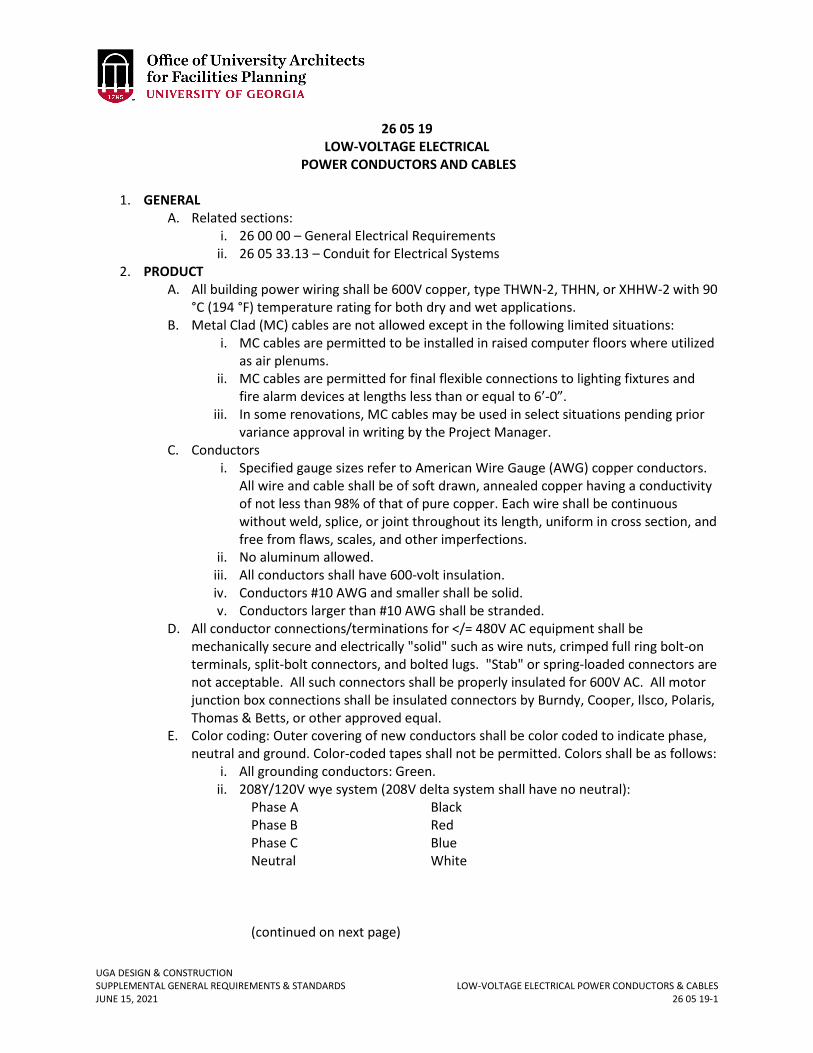
UGA DESIGN & CONSTRUCTION SUPPLEMENTAL GENERAL REQUIREMENTS & STANDARDS LOW-VOLTAGE ELECTRICAL POWER CONDUCTORS & CABLES JUNE 15, 2021 26 05 19-1
26 05 19 LOW-VOLTAGE ELECTRICAL
POWER CONDUCTORS AND CABLES
1. GENERAL A. Related sections:
i. 26 00 00 – General Electrical Requirements ii. 26 05 33.13 – Conduit for Electrical Systems
2. PRODUCT A. All building power wiring shall be 600V copper, type THWN-2, THHN, or XHHW-2 with 90
°C (194 °F) temperature rating for both dry and wet applications. B. Metal Clad (MC) cables are not allowed except in the following limited situations:
i. MC cables are permitted to be installed in raised computer floors where utilized as air plenums.
ii. MC cables are permitted for final flexible connections to lighting fixtures and fire alarm devices at lengths less than or equal to 6’-0”.
iii. In some renovations, MC cables may be used in select situations pending prior variance approval in writing by the Project Manager.
C. Conductors i. Specified gauge sizes refer to American Wire Gauge (AWG) copper conductors.
All wire and cable shall be of soft drawn, annealed copper having a conductivity of not less than 98% of that of pure copper. Each wire shall be continuous without weld, splice, or joint throughout its length, uniform in cross section, and free from flaws, scales, and other imperfections.
ii. No aluminum allowed. iii. All conductors shall have 600-volt insulation. iv. Conductors #10 AWG and smaller shall be solid. v. Conductors larger than #10 AWG shall be stranded.
D. All conductor connections/terminations for </= 480V AC equipment shall be mechanically secure and electrically "solid" such as wire nuts, crimped full ring bolt-on terminals, split-bolt connectors, and bolted lugs. "Stab" or spring-loaded connectors are not acceptable. All such connectors shall be properly insulated for 600V AC. All motor junction box connections shall be insulated connectors by Burndy, Cooper, Ilsco, Polaris, Thomas & Betts, or other approved equal.
E. Color coding: Outer covering of new conductors shall be color coded to indicate phase, neutral and ground. Color-coded tapes shall not be permitted. Colors shall be as follows:
i. All grounding conductors: Green. ii. 208Y/120V wye system (208V delta system shall have no neutral):
Phase A Black Phase B Red Phase C Blue Neutral White (continued on next page)
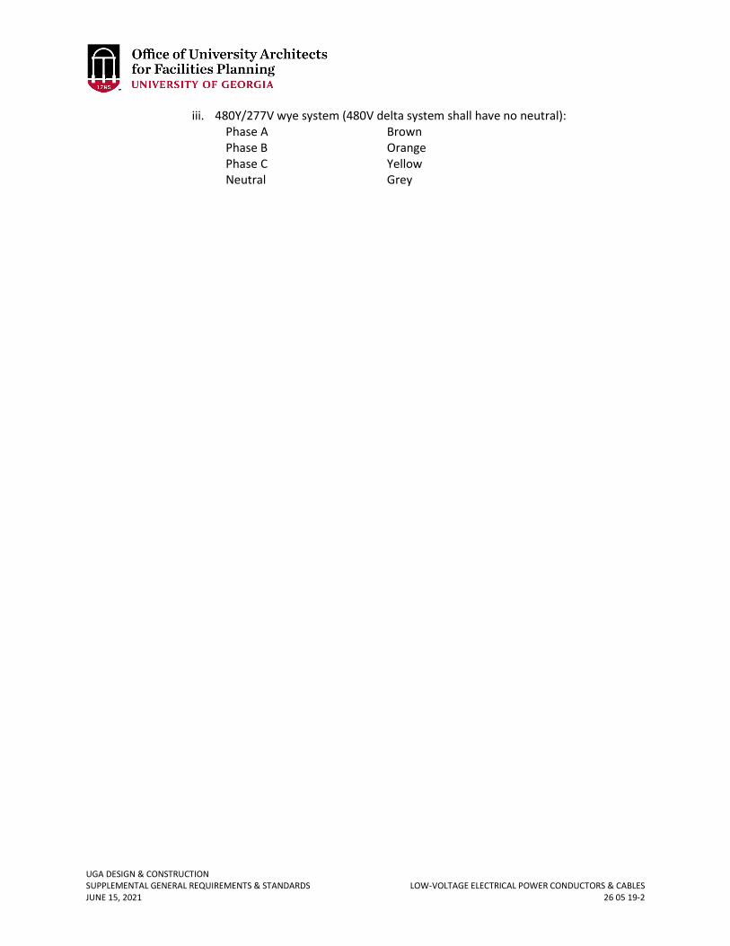
UGA DESIGN & CONSTRUCTION SUPPLEMENTAL GENERAL REQUIREMENTS & STANDARDS LOW-VOLTAGE ELECTRICAL POWER CONDUCTORS & CABLES JUNE 15, 2021 26 05 19-2
iii. 480Y/277V wye system (480V delta system shall have no neutral): Phase A Brown Phase B Orange Phase C Yellow Neutral Grey
UGA DESIGN & CONSTRUCTION SUPPLEMENTAL GENERAL REQUIREMENTS & STANDARDS GROUNDING & BONDING FOR ELECTRICAL SYSTEMS JUNE 15, 2021 26 05 26-1
26 05 26 GROUNDING & BONDING FOR ELECTRICAL SYSTEMS
1. GENERAL
A. Related sections: i. 26 00 00 – General Electrical Requirements
B. Incoming building service shall be grounded per NEC. In most buildings, the power system is either 208Y/120V wye or 480Y/277V wye solidly grounded. 240/120V single phase services with grounded center tap neutrals are common in student apartments and fraternity housing.
C. All buildings’ electrical services shall be provided with a grounding grid. The building main water service pipe shall not be used solely as the main grounding electrode. Dependent upon project requirements, “grid” may be as simple as a three ground rod triad with each ground rod buried a minimum 2’-0” below finished grade and spaced 10’-0” apart horizontally forming an equilateral triangle, or a ground ring consisting of a buried bare, tinned copper grounding conductor connected to ground rods spaced 20’-0” on center around the perimeter of the building, and all vertical structural steel columns, re-bars of the foundation, incoming water service pipe within 5’-0” of its building entrance, etc. A separate grounding triad (as described above) shall be installed for the medium voltage side of a new building service (utility) transformer. It shall be separate from the building service grounding grid. It may be a single ground rod depending on the available space to install underground electrodes. This will be decided by the Design Professional in conjunction with the Project Manager. Typically, a minimum of two separate grounding electrode triads shall be installed. If for any reason the Design Professional needs to specify less than the two separate grounding triads, contact Project Manager.
D. All grounding connections between grounding electrodes and grounding electrode conductors shall have exothermic welds.
E. For new facilities, at least one grounding test well shall be provided for each grounding triad.
F. It is undesirable to have grounding electrode systems buried under concrete, but if the grounding electrode system must be buried under concrete, a test well for each ground rod buried under concrete shall be provided. In this case only, the top of ground rods shall be a minimum 18 inches below finished grade, but the grounding electrode conductors shall still be routed down and away from the ground rods at a minimum of 24 inches below finished grade. The test well shall have a minimum 12 inches inside diameter for unobstructed access to ground rods buried 18 inches below finished grade and a screw down cap. It shall have a length of 24 inches and slotted up to at least 12 inches below finished grade on at least two sides for grounding electrode conductor entry / exit. Leave a minimum of 3 inches of the top of each ground rod exposed (but still 18 inches below finished grade to top of ground rod) for ease of testing / maintenance access. The test well(s) shall be traffic rated in traffic areas.
G. One of the perimeter steel columns in new buildings shall be bonded to its own ground rod with a #4/0 AWG bare, stranded, tinned, copper grounding electrode conductor down lead with the ground rod buried a minimum of 2 feet below finished grade, and a
UGA DESIGN & CONSTRUCTION SUPPLEMENTAL GENERAL REQUIREMENTS & STANDARDS GROUNDING & BONDING FOR ELECTRICAL SYSTEMS JUNE 15, 2021 26 05 26-2
minimum 3 feet off the face of the building foundation. If buried under concrete, these ground rods shall have a test well as previously described.
H. All grounding electrode system underground (buried) bare copper wire shall be tinned. I. Any grounding resistance test with less than 25 ohms (per NEC) shall not be acceptable. J. For “isolated grounded” receptacles, the ground conductors shall be connected to the
dedicated grounding electrode and not connected to the building grounding system.
K. All motors driven by VSD’s (VFD’s) shall have shaft grounding rings, and shall be grounded to their source ground with no more than 25 ohms in resistance measurement.
L. Do not provide emergency generator with a separate ground. UGA does not switch the neutral at the automatic transfer switches (3 pole ATS vs. 4 pole ATS). Refer to National Electrical Code section 250.30.
M. All grounding electrode connections to equipment shall be with a 2-hole lug.
UGA DESIGN & CONSTRUCTION SUPPLEMENTAL GENERAL REQUIREMENTS & STANDARDS CONDUIT FOR ELECTRICAL SYSTEMS JUNE 15, 2021 26 05 33.13-1
26 05 33.13 CONDUIT FOR ELECTRICAL SYSTEMS
1. GENERAL
A. Related sections: i. 26 00 00 – General Electrical Requirements
ii. 26 05 19 – Low-voltage Electrical Power Conductors and Cables iii. 28 31 00 – Fire Detection & Alarm
2. PRODUCTS A. Minimum conduit size shall be ¾-inch diameter.
i. Exception: ½-inch flexible metal conduit or Type AC or MC is permitted for flexible connections to lighting fixtures and fire alarm devices in maximum 6’-0” length.
ii. ½-inch conduit may be allowed in tight conditions in existing walls or ceilings; however, an approved variance is required from the Project Manager.
B. Conduit for all fire alarm systems shall be red or painted red. C. All exposed conduit in back of house, work room areas, mechanical rooms, etc. shall be
galvanized rigid steel. D. All underground low voltage (0V up to 1000V) service secondary and other conduits
shall be schedule 40 PVC transitioning to galvanized rigid steel at all elbows to include vertical members penetrating grade, unless otherwise specified. It shall also be encased in minimum 2 inches of 3000 p.s.i. concrete cover around entire circumference of outer conduit(s) with minimum 2 inches concrete separation between the outer circumferences of each conduit.
E. All underground primary (medium voltage) conduit shall be 6-inch diameter Schedule 40- Type EB PVC transitioning to galvanized rigid steel at turn-up or turn-down elbows to include vertical members penetrating grade encased in minimum 3 inches of 3000 p.s.i. concrete cover around the entire exterior of the outer conduits’ circumferences with minimum 3” (three inches) concrete separation between the outer circumferences of each conduit. Steel reinforcing bars for concrete duct bank shall be required in certain circumstances depending on the path of the duct bank itself (beneath roads, railroad tracks, etc.).
F. All underground conduits either turning upward or downward shall transition to galvanized rigid steel (galvanized rigid steel elbows) if not in concrete duct bank.
UGA DESIGN & CONSTRUCTION SUPPLEMENTAL GENERAL REQUIREMENTS & STANDARDS UNDERGROUND DUCTS & RACEWAYS FOR ELECTRICAL SYSTEMS JUNE 15, 2021 26 05 43-1
26 05 43 UNDERGROUND DUCTS AND RACEWAYS FOR ELECTRICAL SYSTEMS
1. GENERAL
A. Related sections: i. 26 00 00 – General Electrical Requirements
ii. 26 20 00 – Low Voltage Transformers iii. 26 56 00 – Exterior Lighting iv. 33 71 19 – Electrical Underground Ducts & Manholes v. 33 72 00 – Pad-Mount Utility Transformers
2. PRODUCTS A. All medium voltage duct banks for main feeders shall be 6-inch diameter (minimum
conduit size may be minimum 5 inch diameter for other cases) schedule 40-Type EB PVC transitioning to galvanized rigid steel at turn-up or turn-down elbows to include vertical members penetrating grade, with minimum 3 inches of 3000 p.s.i. or greater concrete encased around the exterior of the duct bank, and 3 inches of concrete between the outer circumference of each conduit. Design for duct bank spacers every five (5) linear feet. No exceptions are allowed.
B. Duct banks crossing under roadways, driveways, and railroad tracks shall be reinforced with steel reinforcing bars (re-bar) as required by Georgia Department of Transportation Standards.
C. Provide and install 1250 lb. test polyester pull tape in each empty conduit leaving a minimum of 4 feet excess for each pull-string at each end.
D. The largest practicable radii for commercially available conduit elbows shall be used, and in all cases shall exceed the minimum radii to which the conduit can be bent without mechanically degrading the performance of the conduit per manufacturer recommendations.
E. Concrete duct banks shall be natural (unpainted and untinted) concrete color. 3. EXECUTION
A. Slope duct away from building entrances.
UGA DESIGN & CONSTRUCTION SUPPLEMENTAL GENERAL REQUIREMENTS & STANDARDS LIGHTING CONTROL DEVICES JUNE 15, 2021 26 09 23-1
26 09 23 LIGHTING CONTROL DEVICES
1. GENERAL
A. Related sections: i. 26 00 00 – General Electrical Requirements
ii. 26 09 36 – Modular Dimming Controls iii. 26 09 43.16 – Addressable Fixture Lighting Control iv. 26 51 00 – Interior Lighting
2. PRODUCTS 3. EXECUTION
A. Occupancy based lighting controls system commissioning. i. Upon completion of the installation, the system shall be completely
commissioned by the manufacturer’s factory authorized technician who will verify all adjustments and sensor placement to ensure a trouble-free occupancy-based lighting control system.
ii. The manufacturer’s factory authorized technician, shall upon completion of the commissioning, provide a written report to the Contractor, Design Professional, and Project Manager indicating satisfactory completion of the Work. This report shall also indicate any corrective actions required on the part of the Contractor.
UGA DESIGN & CONSTRUCTION SUPPLEMENTAL GENERAL REQUIREMENTS & STANDARDS MODULAR DIMMING CONTROLS JUNE 15, 2021 26 09 36-1
26 09 36 MODULAR DIMMING CONTROLS
1. GENERAL
A. Related sections: i. 26 00 00 – General Electrical Requirements
ii. 26 09 23 – Lighting Control Devices iii. 26 09 43.16 – Addressable Fixture Lighting Control iv. 27 41 00 – General Audio-Visual Systems Requirements v. 27 41 00.01 – Audio-Visual Control Systems
vi. 26 51 00 – Interior Lighting B. Classroom Automated Lighting Presets Minimum: All classrooms shall have the
following minimum presets as listed below. Refer to Section 27 41 00.01 Audio-Visual Control Systems for detailed information on audio-visual touch panel interface requirements with lighting. All classrooms shall have dimmable fluorescents or dimmable LEDs with low voltage or wireless addressable controls. For classroom lighting presets, refer to Section 26 09 36 Modular Dimming Controls and Section 27 41 00.01 Audio-Visual Control Systems. Strategic zone switching (especially in smaller classrooms) may be approved through the variance process. Lighting systems shall operate independently from audio-video presentation systems, even when integrated together. The information is general guidance as to the recommended lighting configuration for each preset, but does not include and is not intended to specify every aspect of the required setting. Through the Project Manager, coordinate with the UGA Center for Teaching and Learning as needed.
i. Preset / Scene 1 – Full On a. All light fixtures ON b. All dimmable fixtures set at full brightness
ii. Preset / Scene 2 – Normal Projection Mode a. Fixtures in front third of room OFF. b. Any other fixtures in the room which produce noticeable wash on the
projection screens should be OFF. c. Any spot lights or down lights which illuminate the instructors podium
should be full on, unless they produce a noticeable wash on the projection screen in which case they should be dimmed or turned off.
d. The lighting in rear two-thirds of room should be set to be comfortable for reading and writing but not overpowering the image of the video projection system. Options are as follows:
1) If none of the fixtures in the room are dimmable then turn on half of the fixtures in the rear two-thirds of the room.
2) If all of the fixtures in the room are dimmable then set them at a reasonable level (eg. 60%).
3) If there are a combination of dimmable and non-dimmable circuits then choose a combination which is comfortable for reading and writing but not overpowering the projector image.
iii. Last Preset / Scene – All Off a. ALL Fixtures in room OFF
UGA DESIGN & CONSTRUCTION SUPPLEMENTAL GENERAL REQUIREMENTS & STANDARDS MODULAR DIMMING CONTROLS JUNE 15, 2021 26 09 36-2
b. There should be a delay from when this button is hit to when the lights are fully off. The delay should be long enough to allow the user to exit the room before the lights are fully off.
C. Presenter Mode – For classrooms with whiteboard or blackboard behind projector screen.
i. Preset / Scene 3 – Presenter Mode a. Fixtures in front third of room FULL ON. b. Any spot lights or down lights which illuminate the instructors podium
should be FULL ON. c. Any spot lights illuminating the Whiteboard or Blackboard should be
FULL ON. d. The light fixtures in rear two-thirds of room should be set as described
for Preset 2 above. D. Movie Projector Mode
i. Preset / Scene 4 – Movie Projection Mode a. Fixtures in front third of room OFF b. ANY other fixtures in the room which produce noticeable wash on the
projection screens should be OFF c. The lighting in rear two-thirds of room should be set to be dim but with
enough brightness to make it safe for audience members to walk in the aisles and stairways. Options are as follows:
1) If none of the fixtures in the room are dimmable then turn on only the minimum number of fixtures in the rear two-thirds of the room.
2) If all of the fixtures in the room are dimmable florescent lights then set them at the minimum dimming level allowed by the fixtures without flickering. Alternating fixture may also be turned completely off to provide a minimum safe level.
2. PRODUCTS 3. EXECUTION
A. Test classroom settings with blackout shades and blinds closed to simulate nighttime usage.
UGA DESIGN & CONSTRUCTION SUPPLEMENTAL GENERAL REQUIREMENTS & STANDARDS ADDRESSABLE FIXTURE LIGHTING CONTROL JUNE 15, 2021 26 09 43.16-1
26 09 43.16 ADDRESSABLE FIXTURE LIGHTING CONTROL
1. GENERAL
A. Related sections: i. 26 00 00 – General Electrical Requirements
ii. 26 09 23 – Lighting Control Devices iii. 26 09 36 – Modular Dimming Controls iv. 26 51 00 – Interior Lighting v. 26 56 00 – Exterior Lighting
B. Relay output shall be clearly posted for future reference. 2. PRODUCTS
A. Acceptable manufactures are: i. Douglas Lighting Controls
ii. Lithonia Lighting iii. Lutron
3. EXECUTION A. Training
i. The Contractor shall include in the Cost of the Work or Bid sixteen (16) hours of on-site training and sixteen (16) hours of off-site technical support during the one-year warranty period. On-site training and off-site technical support requests will be initiated by and scheduled at the request of the Project Manager. End-User must be present at site during on-site training and off-site technical support sessions.
UGA DESIGN & CONSTRUCTION SUPPLEMENTAL GENERAL REQUIREMENTS & STANDARDS LOW-VOLTAGE DRY TAPE TRANSFORMERS JUNE 15, 2021 26 22 00-1
26 22 00 LOW-VOLTAGE DRY TYPE TRANSFORMERS
1. GENERAL
A. Related sections: i. 26 00 00 – General Electrical Requirements
B. Transformers 30 kVA and smaller are allowed to be wall or ceiling mounted. C. Transformers larger than 30 kVA shall be floor mounted. If there are space restrictions,
larger transformers can be ceiling hung from a “trapeze” type mounting arrangement or wall mounted only after providing signed and sealed documentation of evaluation by a Georgia registered structural engineer.
2. PRODUCTS A. Building transformers for outlets and lighting shall be dry type with copper windings and
voltage adjustment taps: (Minimum two pluses and two minuses) +5%; +2.5%; center tap (0%); -2.5%; & -5%.
B. Transformer efficiency shall meet the latest Department of Energy requirements. Low voltage dry-type transformers shall be high efficiency with copper windings and an 80 °C rise. If approved by Project Manager, a product up to a maximum of 115 °C rise can be selected. Aluminum windings may be specified on a case-by-case basis where weight is a concern with prior written variance approval from FMD engineering via the Project Manager.
C. “K” rated transformers shall be specified where required (such as data centers, labs with highly sensitive electronic equipment, etc.). Their “K” rating shall be determined by the Design Professional on the basis of their application.
UGA DESIGN & CONSTRUCTION SUPPLEMENTAL GENERAL REQUIREMENTS & STANDARDS SWITCHBOARDS JUNE 15, 2021 26 24 13-1
26 24 13 SWITCHGEARS AND SWITCHBOARDS
1. GENERAL
A. Related sections: i. 26 00 00 – General Electrical Requirements
B. Switchgears or switchboards shall be provided for each incoming electrical service of 800 amperes or higher.
2. PRODUCTS A. Bus materials shall be copper or plated copper. B. All switchgears / switchboards shall contain a fully-rated neutral bus bar. C. Main overcurrent device shall be circuit breaker type. Fused disconnects are NOT
acceptable. D. Breakers rated 800 amperes or higher shall be insulated case type with electronic
tripping devices. Design Professional shall coordinate with FMD Engineering via the Project Manager for case-specific needs.
E. Surge protection devices (transient voltage surge suppressors) and digital metering package shall be standard for all switchgears and switchboards. Automated Logic Controls (ALC) will provide a Veris “E50H5A” or equal power and energy meter with “U018” rope CT’s to be installed by the contractor in or adjacent to (in separate enclosure) the service switchgear / switchboard. It shall be programmed into the BAS by ALC.
F. Design Professional shall coordinate with FMD Engineering via the Project Manager for case-specific needs for draw-out breakers.
G. All switchgear / switchboard breakers shall be 100% rated, and each breaker shall have ground-fault protection.
H. All switchgear / switchgear breakers rated for 400A (four hundred amps) or greater shall have electronic tripping devices.
I. All switchgears / switchboards shall have short-circuit ratings greater than it’s short-circuit rating as determined by the Design Professional’s short-circuit analysis of the respective electrical system it is employed in.
J. Acceptable manufacturers are Schneider / Square D, Eaton / Cutler‐Hammer, and ABB/General Electric (ABB/GE). No exceptions.
K. A breaker coordination study shall be performed on all new switchgear / switchboard installations to include all breakers downstream of the switchgear / switchboard as well. The instantaneous, long, short, and ground-fault time trip settings of each breaker shall be performed by the contractor and confirmed by the design and/or commissioning engineer prior to owner acceptance.
UGA DESIGN & CONSTRUCTION SUPPLEMENTAL GENERAL REQUIREMENTS & STANDARDS PANELBOARDS JUNE 15, 2021 26 24 16-1
26 24 16 PANELBOARDS
1. GENERAL
A. Related sections: i. 26 00 00 – General Electrical Requirements
B. All panelboard circuit breakers shall be bolt on type. C. All interior panelboard enclosures shall be equipped with “door-in-door” feature. D. All service entrance current limiting devices shall be circuit breakers. No fused switches
are allowed. E. All electrical panelboard enclosures shall be NEMA rated for the environment they are
specified to be installed. The Contractor is responsible for ensuring that this requirement is met and shall include related costs in the Base Bid or Cost of the Work.
F. All panelboards shall have copper bus bars. G. Acceptable manufacturers are Schneider / Square D, Eaton / Cutler-Hammer, and
ABB/General Electric (ABB/GE). H. All panelboards shall have a short-circuit rating greater than it’s short-circuit rating as
determined by the Design Professional’s short-circuit analysis of the respective electrical system it is employed in.
UGA DESIGN & CONSTRUCTION SUPPLEMENTAL GENERAL REQUIREMENTS & STANDARDS MOTOR-CONTROL CENTERS JUNE 15, 2021 26 24 19-1
26 24 19 MOTOR-CONTROL CENTERS
1. GENERAL
A. Related sections: i. 23 05 14 – Variable Frequency Drives
ii. 26 00 00 – General Electrical Requirements B. Low voltage (600V and below) motor control centers (MCC) shall be provided for motor
starters, feeder breakers for variable speed drives (VSDs) and other electrical equipment where practical.
2. PRODUCTS A. The use of wall mounted starters shall be discouraged. B. All motor starters shall be across-the-line combination type with motor circuit
protectors and hand-off-automatic (H-O-A) door switches with transformer type ‘red’ run indicating lights. Each motor starter shall also have a transformer type ‘white’ indicating light for overload condition (overload relay tripped).
C. Control voltage shall be 120V or 277V. D. MCC bus materials shall be copper, tin-coated copper, or silver-plated copper. E. Minimum rating for vertical buses shall be 300 amperes unless otherwise specified on
MCC one-line diagram. Horizontal main bus shall be fully rated for MCC and non-tapered.
F. All bus rating shall be braced for greater than or equal to RMS short-circuit amperage as specified on MCC one-line diagram by the Design Professional’s short-circuit analysis.
G. Enclosure shall be NEMA 1 gasketed unless otherwise specified. H. Provide a continuous copper ground bus bar across the bottom of the MCC.
UGA DESIGN & CONSTRUCTION SUPPLEMENTAL GENERAL REQUIREMENTS & STANDARDS PACKAGED GENERATOR ASSEMBLIES JUNE 15, 2021 26 32 00-1
26 32 00 PACKAGED GENERATOR ASSEMBLIES
1. GENERAL
A. Related sections: i. 26 00 00 – General Electrical Requirements
ii. 26 05 26 – Grounding and Bonding for Electrical Systems B. Design Professional shall discuss with Project Manager to determine if the End-User
requires a closed transition option. C. All new packaged generator installations require coordination of variances and EPA
certifications. This coordination shall be initiated by the UGA Project Manager during the design phase with UGA Environmental Safety Division’s Environmental Affairs Program (706) 542-5801 and shall involve the Design Professional.
2. PRODUCTS A. The fuel source shall be natural gas. Diesel fuel is not allowed without UGA and Board of
Regents approval. B. The emergency power shall be fed through dedicated panelboards via automatic
transfer switches equipped with by-pass switches. C. Transfer switches installed in conjunction with new generator installations shall be 4-
pole (switching neutral). D. Gas line capacity, line size, and pressure shall be confirmed by the natural gas provider
for a given generator set. E. Provide either radiator mounted resistive load bank or separate pad mounted load bank
as recommended by the generator manufacturer. F. Packaged generator assemblies shall be by Caterpillar, Cummins, Kohler, or Onan. G. New generators shall not be specified with attached load banks, however an
extra spare 100% circuit shall be provided on all new generators. Revised June 15, 2021
UGA DESIGN & CONSTRUCTION SUPPLEMENTAL GENERAL REQUIREMENTS & STANDARDS FACILITY LIGHTNING PROTECTION JUNE 15, 2021 26 41 00-1
26 41 00 FACILITY LIGHTNING PROTECTION
1. GENERAL
A. Related sections: i. 26 00 00 – General Electrical Requirements
B. Design Professional shall provide code documentation of whether or not facility lightning protection is required.
C. For situations where it is not required, coordinate with Project Manager to confirm if lightning protection shall be included in the Project.
D. If system is required, as a minimum the system shall be installed in a manner that allows UL Certification to be obtained.
UGA DESIGN & CONSTRUCTION SUPPLEMENTAL GENERAL REQUIREMENTS & STANDARDS INTERIOR LIGHTING JUNE 15, 2021 26 51 00-1
26 51 00 INTERIOR LIGHTING
1. GENERAL
A. Related sections: i. 00 00 13 – Designing Learning Environments
ii. 09 50 00 – Ceilings iii. 26 00 00 – General Electrical Requirements iv. 26 09 23 – Lighting Control Devices v. 26 09 36 – Modular Dimming Controls
vi. 26 09 43.16 – Addressable Fixture Lighting Control vii. 27 41 00 – General Audio-Visual Systems Requirements
viii. 27 41 00.01 – Audio-Visual Control System B. Lighting level shall conform to minimum IES Standards, UGA Standards, and
applicable codes. C. During the design phases provide manufacturers’ cut-sheets for basis of design of
each proposed fixture to Project Manager for review and approval. D. Provide photometric analysis in footcandles for each space or area. E. Provide watts per square foot calculations for each space. F. Provide list to Project Manager of types of lamps selected for Project. For maintenance
purposes minimize the number of types of lamps if other than LED. The Lighting Fixture Schedule will suffice for this requirement.
G. Locate fixtures so that maintenance of fixtures is not difficult and does not require a ladder over 20’ tall or lift.
i. Light fixtures for stairwells shall not be placed so that access to the fixture must be from the stairs.
ii. Design Professional is required to submit documentation to the Project Manager and receive location approval of any light fixtures that will require a ladder over 20’ tall or a lift to access fixtures.
iii. Light fixtures shall be installed so that all maintainable parts of the fixture are totally accessible.
H. For occupancy based light sensors, the Design Professional shall review length of time setting requirements for deactivation of lights with the Project Manager.
I. Light fixtures adjacent to exterior windows shall be circuited and controlled separately from light fixtures in the same room that are remote to the exterior windows. This is to allow light fixtures adjacent to windows to be turned down or off during times of sufficient interior natural light.
J. Classroom Lighting i. Proper lighting is an essential element of instructional spaces. Natural
daylighting is encouraged, but must be easily controlled to allow for projected media to effectively be viewed by classroom occupants. Lighting needs are dependent upon classroom size, shape, whiteboard size, AV configuration, ceiling height, and window locations. It is important to ensure that the color temperature of light fixtures provided within each classroom is the same. 2’ x 2’ fixtures are preferable to 2’ x 4’ fixtures, because they provide more even light
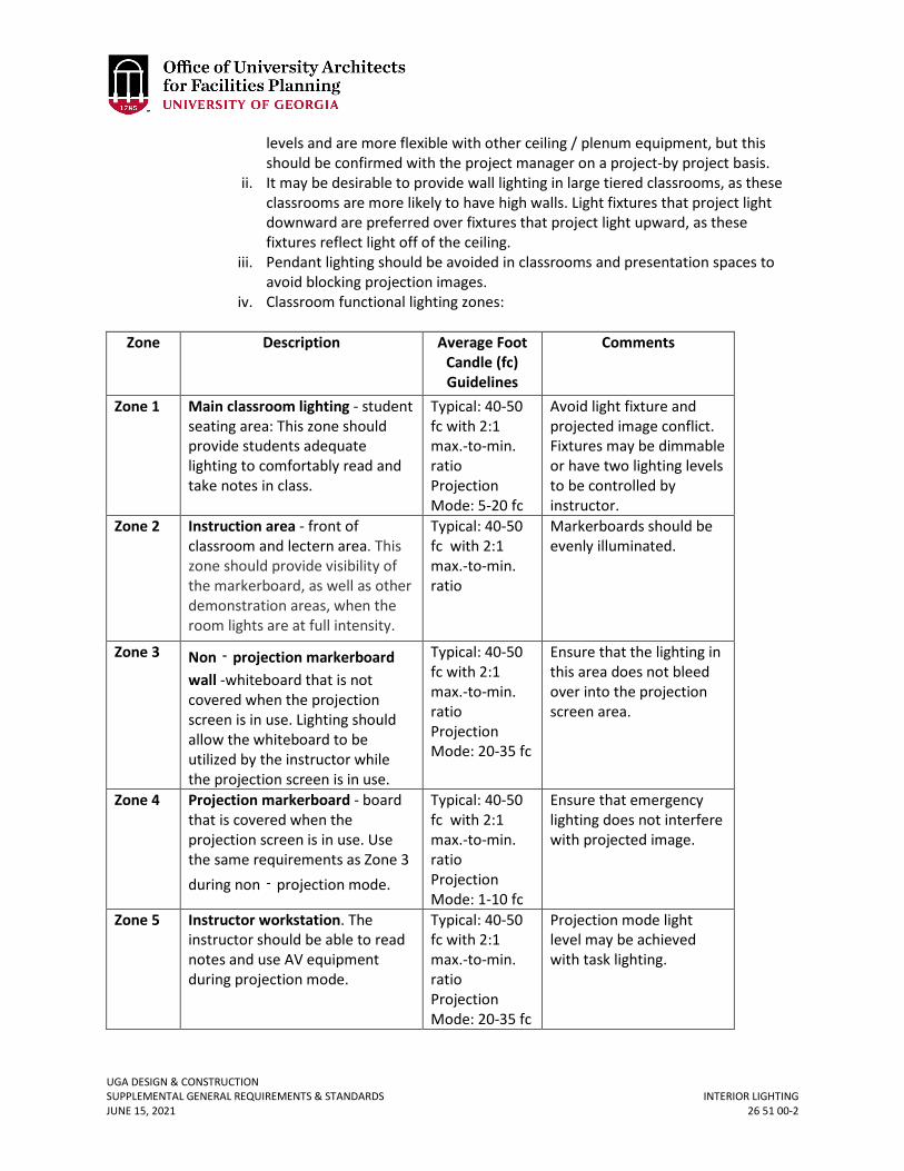
UGA DESIGN & CONSTRUCTION SUPPLEMENTAL GENERAL REQUIREMENTS & STANDARDS INTERIOR LIGHTING JUNE 15, 2021 26 51 00-2
levels and are more flexible with other ceiling / plenum equipment, but this should be confirmed with the project manager on a project-by project basis.
ii. It may be desirable to provide wall lighting in large tiered classrooms, as these classrooms are more likely to have high walls. Light fixtures that project light downward are preferred over fixtures that project light upward, as these fixtures reflect light off of the ceiling.
iii. Pendant lighting should be avoided in classrooms and presentation spaces to avoid blocking projection images.
iv. Classroom functional lighting zones:
Zone Description Average Foot Candle (fc) Guidelines
Comments
Zone 1 Main classroom lighting - student seating area: This zone should provide students adequate lighting to comfortably read and take notes in class.
Typical: 40-50 fc with 2:1 max.-to-min. ratio Projection Mode: 5-20 fc
Avoid light fixture and projected image conflict. Fixtures may be dimmable or have two lighting levels to be controlled by instructor.
Zone 2 Instruction area - front of classroom and lectern area. This zone should provide visibility of the markerboard, as well as other demonstration areas, when the room lights are at full intensity.
Typical: 40-50 fc with 2:1 max.-to-min. ratio
Markerboards should be evenly illuminated.
Zone 3 Non‐projection markerboard wall -whiteboard that is not covered when the projection screen is in use. Lighting should allow the whiteboard to be utilized by the instructor while the projection screen is in use.
Typical: 40-50 fc with 2:1 max.-to-min. ratio Projection Mode: 20-35 fc
Ensure that the lighting in this area does not bleed over into the projection screen area.
Zone 4 Projection markerboard - board that is covered when the projection screen is in use. Use the same requirements as Zone 3 during non‐projection mode.
Typical: 40-50 fc with 2:1 max.-to-min. ratio Projection Mode: 1-10 fc
Ensure that emergency lighting does not interfere with projected image.
Zone 5 Instructor workstation. The instructor should be able to read notes and use AV equipment during projection mode.
Typical: 40-50 fc with 2:1 max.-to-min. ratio Projection Mode: 20-35 fc
Projection mode light level may be achieved with task lighting.
UGA DESIGN & CONSTRUCTION SUPPLEMENTAL GENERAL REQUIREMENTS & STANDARDS INTERIOR LIGHTING JUNE 15, 2021 26 51 00-3
v. Lighting controls should be located near each entrance to the classroom, as well as on or near the instructor station. Switching to control lighting zones should be provided on or near the instructor station. When cost concerns prohibit the use of dimmable fixtures in classrooms, consider providing inboard / outboard switching to achieve the desired variable lighting scenarios.
K. Design Professional is responsible for ensuring coordination of any pendant lighting with the projector screen to ensure there are no conflicts.
L. Design Professional is responsible for ensuring control compatibility of lighting fixtures and accessories with the selected lighting control system.
M. Downlighting shall be spaced at least 24” from textured (i.e. tiled) walls in order to mitigate the highlighting of tile lippage and other dimensional inconsistencies.
2. PRODUCTS A. Linear fluorescent tubes, when required by other than LED applications, shall be
either T5 or T8; however, mixture of these types of lamps in one facility is not allowed.
B. Offices, laboratories, and classrooms are typically furnished with 2’ x 2’ and/or 2’ x 4’ recessed fixtures (troffers). These fixtures shall be LED. Recessed fixtures shall be Philips “EvoGrid”, “EvoKit”, or approved equals. All new 2’ x 2’ troffers shall have an efficacy of greater than or equal to 110 lumens/Watt, and 2’ x 4’ troffers shall have an efficacy of greater than or equal to 130 lumens/Watt. See manufacturer’s cut-sheets at end of this section for the `EvoGrid’ complete fixtures and the `EvoKit’ retro-fit kits for existing fluorescent troffers.
C. All offices and laboratories shall have dimming systems and / or zoning switching, and / or inboard and outboard switching.
D. All classrooms shall have dimmable LEDs with low voltage or addressable controls. For classroom lighting presets, refer to Sections 26 09 36 Modular Dimming Controls and 27 41 00.01 Audio-Visual Control Systems. Strategic zone switching (especially in smaller classrooms) may be approved through the variance process. Lighting systems shall operate independently from audio-video presentation systems, even when integrated together.
E. All interior lighting shall have a color temperature of approximately 4000K. If the Design Professional has design reasons for other than 4000K it should be discussed with the Project Manager and a variance submitted in writing for approval. Refer to Section 26 56 16 Parking Lighting for color temperature requirements in parking garages.
F. MR16 halogen lamps and are not allowed. G. Incandescent lighting is not allowed. H. High-intensity discharge lighting is not allowed except in research applications where
it is required, and will be requested by the Project Manager. I. LED fixtures: Refer to Section 26 56 00 Exterior Lighting. The section entitled ‘LED
Fixtures’ applies to interior LED fixtures. 3. EXECUTION
A. Warranty of LED Fixtures: UGA will seek written assurances from the manufacturer that the product will perform as claimed in terms of life.
i. Provide a written five-year on-site replacement of material, fixture finish, and workmanship. On-site replacement includes transportation, removal,
UGA DESIGN & CONSTRUCTION SUPPLEMENTAL GENERAL REQUIREMENTS & STANDARDS INTERIOR LIGHTING JUNE 15, 2021 26 51 00-4
and installation of new products. Finish warranty must include warranty against failure or substantial deterioration such as blistering, cracking, peeling, chalking, or fading.
ii. Provide a written five year replacement material warranty for defective or non-starting LED source assemblies.
iii. Provide a written five-year replacement material warranty on all power supply units (PSUs), which are the LED drivers.
iv. Provide a written five-year replacement warranty for luminaires producing inadequately-maintained illuminance levels at end of warranty period, as prorated from levels expected at end of useful life. For example, a luminaire expected to produce 70% of initial lumens at 100,000 hours would be expected to last over 11 years (continuous operation), so levels would be expected to be at 87% of initial at end of five-year warranty period. Warranty must cover all light sources (LED package, LED array, or LED module) including, but not limited to the LED die, encapsulate, and phosphor. If the expected useful life of the luminaire system is not maintained, the manufacturer must replace the light source(s) or luminaire(s) as needed at no cost to the Owner.
v. Owner may request an optional ten year replacement warranty for inadequately-maintained illuminance levels, finish of luminaire, power-supply unit (PSU), or defective LED source assemblies. The terms of the extended warranty will be negotiated by the Owner and the luminaire manufacturer for an additional cost.
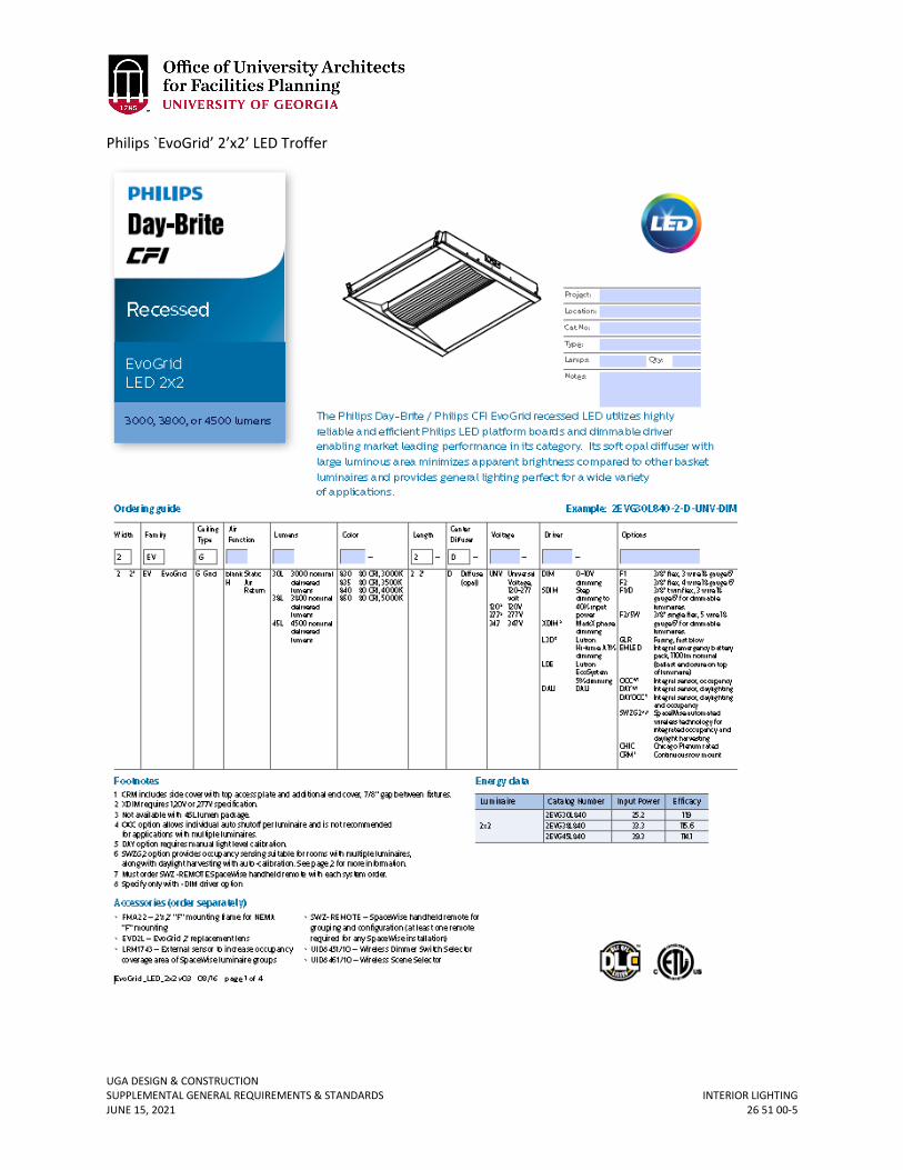
UGA DESIGN & CONSTRUCTION SUPPLEMENTAL GENERAL REQUIREMENTS & STANDARDS INTERIOR LIGHTING JUNE 15, 2021 26 51 00-5
Philips `EvoGrid’ 2’x2’ LED Troffer
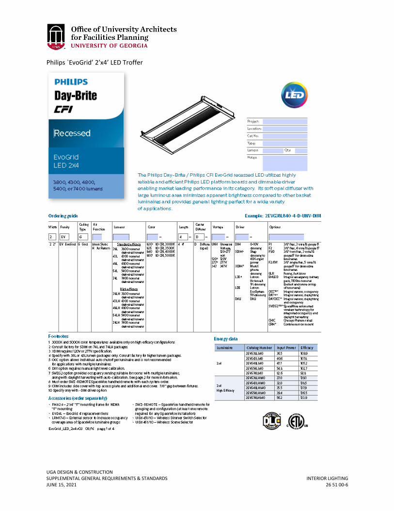
UGA DESIGN & CONSTRUCTION SUPPLEMENTAL GENERAL REQUIREMENTS & STANDARDS INTERIOR LIGHTING JUNE 15, 2021 26 51 00-6
Philips `EvoGrid’ 2’x4’ LED Troffer
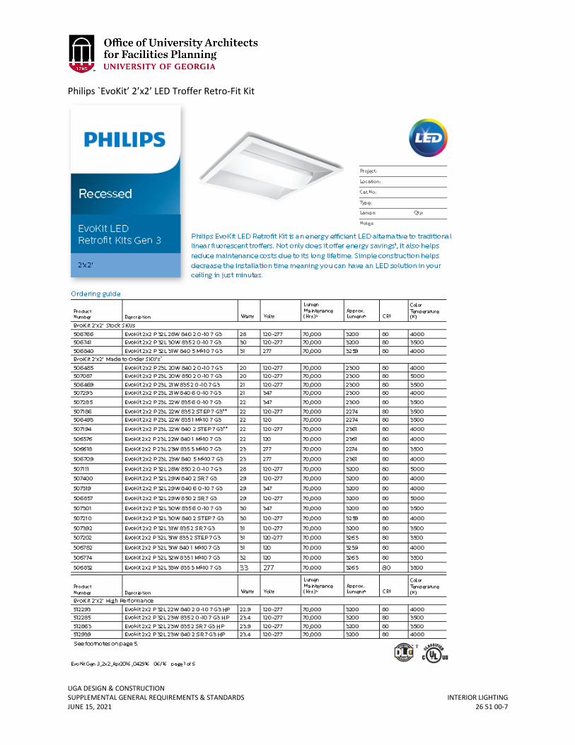
UGA DESIGN & CONSTRUCTION SUPPLEMENTAL GENERAL REQUIREMENTS & STANDARDS INTERIOR LIGHTING JUNE 15, 2021 26 51 00-7
Philips `EvoKit’ 2’x2’ LED Troffer Retro-Fit Kit

UGA DESIGN & CONSTRUCTION SUPPLEMENTAL GENERAL REQUIREMENTS & STANDARDS INTERIOR LIGHTING JUNE 15, 2021 26 51 00-8
Philips `EvoKit’ 2’x4’ LED Troffer Retro-Fit Kit
UGA DESIGN & CONSTRUCTION SUPPLEMENTAL GENERAL REQUIREMENTS & STANDARDS EXTERIOR LIGHTING JUNE 15, 2021 26 56 00-1
26 56 00 EXTERIOR LIGHTING
1. GENERAL
A. Related sections: i. 26 56 13 – Lighting Poles and Standards
ii. 26 56 16 – Parking Lighting iii. 26 56 19 – Roadway Lighting iv. 26 56 29 – Site & Building Entry Lighting v. 26 56 33 – Walkway Lighting
vi. 26 56 36 – Flood Lighting B. Purpose
i. The exterior lighting goal is to provide strategies which will ensure a consistently well-lit, safe and attractive campus. In addition, implementing these standardized specifications and practices will reduce light pollution and energy consumption campus-wide.
ii. This lighting standard minimizes the problems created by improperly designed and installed outdoor lighting. It reduces problems with glare, sky glow, light trespass, and capitalizes on the reduction of energy and financial costs of outdoor architectural and landscape lighting.
iii. Excessive glare can be troublesome and may cause safety problems. Light trespass reduces privacy, and higher energy use results in increased costs besides impacting the environment directly and indirectly. There is a need for a lighting Standard that recognizes the benefits of outdoor lighting and provides clear performance-based guidelines for its installation on UGA campuses. Appropriately regulated and installed outdoor lighting will contribute to the safety and welfare of the UGA community and greater Athens area.
C. General Campus Requirements i. Quality exterior lighting is achieved by providing light where it is most needed
without creating glare. In this fashion, smaller lamp wattages can be used to achieve a desirable effect. Energy consumption, maintenance and capital equipment costs can be reduced without sacrificing visibility or aesthetics.
ii. Technical design criteria includes basic requirements such as lighting levels (illuminance), uniformity of light and balance of brightness (luminance) in addition to comments on trespass, night sky pollution and glare control. The technical design criteria, including but not limited to luminance levels, shall not be exceeded without an approved written variance issued by the Project Manager. If the Design Professional’s design does not meet the criteria in this document, the Design Professional shall incur charges (as a design error) to modify the installation to meet the requirements.
iii. Design Professionals shall provide support documentation including photometric calculations, manufacturer's data sheets, and lighting fixture schedule(s). Refer to Section 26 51 00, under 1.C Lighting Fixture Schedules.
iv. The OUA recommends that Design Professionals be Lighting Certified by the National Council for Qualification of Lighting Professionals (NCQLP). The NCQLP has established the LC certification process, by which practitioners in lighting
UGA DESIGN & CONSTRUCTION SUPPLEMENTAL GENERAL REQUIREMENTS & STANDARDS EXTERIOR LIGHTING JUNE 15, 2021 26 56 00-2
and related fields, through testing, demonstrate their knowledge and experience across the lighting profession.
v. Fixture Selection: All outdoor light fixtures installed on UGA campuses shall be either selected from the product group specified in the Standards, or submitted as alternates with all supporting data to be approved by the Project Manager. Alternates proposed will however have to exhibit construction, optical characteristics, and lamping of comparable quality as a prerequisite for consideration.
vi. All exterior lighting fixtures shall be shown wired and circuited on either exterior lighting plans or as a part of electrical site plans. Lighting calculations shall be furnished to FMD for future references.
vii. Direct burial cables are not allowed. All underground wiring shall be in minimum 1-inch diameter Schedule 40 PVC conduits.
viii. All exterior lighting fixtures shall be controlled by individual photocells. Time clock and / or group photo controls (with or without lighting contactors) are permitted under special situations.
ix. All exterior lighting circuits shall be fed from lighting panels of the associated building. Tapping power from the building service transformer secondaries is not permitted.
x. Exceptions a. Exceptions to this Standard include sports lighting, temporary lighting,
lighting integral to historic structures, and emergency lighting. b. Any exceptions to this standard shall be reviewed by the OUA on a case-
by-case basis. xi. Prohibitions
a. Laser Source Light: The use of laser source light or any similar high intensity light projected above the horizontal shall not be permitted.
b. Searchlights: The operation of searchlights shall not be permitted. c. Lamps: Low Pressure Sodium and High-Pressure Mercury Vapor Lamps
in new installations shall not be permitted. d. Uplighting of new building facades and new landscaping is not
permitted. D. Design Guidelines
i. Minimize light trespass and glare. a. Light fixtures should be designed so that the light goes exactly where it
is intended. Special care should be taken to include louvers, glare shields, or barn doors to the front of floodlight fixtures to prevent light pollution and direct glare. Extra light bouncing into the atmosphere interferes with the work of astronomers and can disrupt the neighboring buildings. Wherever possible, use cut-off or full-cutoff fixtures, as defined by the Illuminating Engineering Society of North America (IESNA).
ii. Avoid overly bright lighting. a. The intent of lighting building entries and circulation areas is to enhance
the best qualities of that building, not to become a "beacon" on campus. The brightest is not necessarily the best. Maintain a maximum
UGA DESIGN & CONSTRUCTION SUPPLEMENTAL GENERAL REQUIREMENTS & STANDARDS EXTERIOR LIGHTING JUNE 15, 2021 26 56 00-3
average illuminance level of 1-3 footcandles on all horizontal surfaces, in accordance with the Ninth Edition of the IES Handbook, depending on application.
iii. Use “white” LED light sources. a. White LED light sources with a color temperature of 4000K are
recommended for campus exterior lighting. b. In the white light category, LED lighting is swiftly growing as a viable
technology. Use of LED fixtures on the campuses must comply with minimum performance and warranty criteria in this document.
iv. Avoid “yellow” light sources. a. Do not use LED fixtures with less than 4000K color temperature.
v. Design with maintenance in mind. a. Light fixtures shall be mounted in accessible locations so that the
lighting can be maintained regularly. Specify fixtures that have simple mechanisms for lamp changing and captive hardware.
vi. Connect lighting to a control system. a. Due to the difference between summer and winter daylight hours,
lighting shall be connected to a photocell to turn fixtures on and a time clock to turn them off. The use of a dimming system or building automation is allowed in special applications with the approval of the Project Manager.
vii. Design with efficiency in mind. a. Use the smallest wattage lamp source available in any given application
to meet the desired light levels specified in section D5 to minimize energy consumption. Do not, however, compromise desired light levels as outlined in D5 to achieve higher efficiency.
viii. Design with lamp color in mind. a. Specify lamps with a high color rendering index (>/= 70 CRI for exterior
fixtures and >/= 80 CRI for interior fixtures) and a uniform color temperature. The UGA campus standard correlated color temperature (CCT) is 4000K.
ix. Design with safety in mind. a. Safety and security are paramount in an exterior environment. Factors
other than horizontal illuminance should be taken into consideration when considering lighting design for safety. Vertical illuminance, glare, color of light, uniformity, contrast, and heat are equally important in lighting design. The ratios of average-to-minimum and maximum-to-minimum illuminance and luminance values shall be as per current edition of the IESNA Handbook’s recommended standards.
b. Fixtures should be placed such that they cannot easily or readily be touched by individuals, but are easily accessible to maintenance personnel. No design will be accepted where light fixtures are located so as to not be easily accessible by maintenance personnel.
c. At locations with CCTV cameras, special attention must be paid to the illumination levels and distribution because a camera perceives its surrounding very differently from the human visual system. The CCTV
UGA DESIGN & CONSTRUCTION SUPPLEMENTAL GENERAL REQUIREMENTS & STANDARDS EXTERIOR LIGHTING JUNE 15, 2021 26 56 00-4
manufacturer and security consultant must be consulted for vertical and horizontal illuminance requirements as well as uniformity requirements for the system. There might also be a requirement of using fixtures with specific optical characteristics. The lighting should be specified and designed to adhere to these requirements.
d. Compliance with the IES guidelines and the light levels prescribed in this document is required.
E. Required Light Levels i. Pedestrian Walkways
a. Refer to Sections 26 56 33 Walkway Lighting and 26 56 13 Lighting Poles and Standards.
ii. Bikeways and Roadways a. Refer to Sections 26 56 19 Roadway Lighting and 26 56 13 Lighting Poles
and Standards. iii. Surface Parking and Parking Garages
a. Refer to Section 26 56 16 Parking Lighting. iv. Site and Building Entry Lighting
a. Refer to Section 26 56 29 Site and Building Entry Lighting. v. Signage
a. Signage lighting, when used, should comply with the following requirements:
1) Fixtures illuminating signage shall have precision optics so as not to throw light beyond the sign. Specify appropriate shielding accessories for the fixtures
2) Whenever possible, signage should be illuminated from above using shielded fixtures to restrict and avoid night sky light pollution.
3) Lamping shall be LED light sources of 4000K CCT, and >/= 70 CRI (>/= 80 CRI for interior fixtures).
4) Illuminance values measured vertically on the signage surface should not exceed 20 footcandle average maintained, with a maximum-to-minimum ratio of 4:1. For special applications that might require higher illuminance levels, the OUA shall be informed.
5) Fixtures used for signage applications should have lockable aiming, easy maintainability and wherever possible, integral transformers instead of remote (except in case of LEDs).
vi. Demonstration Of Compliance a. Point-by-point photometric plans (in footcandles) of these applications,
using software such as AGI32 or Visual, shall be provided for Owner review upon request. Point-by-point spacing shall be determined by FMD Engineering via the Project Manager on the basis of the size of the area to be lit, and boundary restrictions such as light pollution, etc. The calculations shall consider all light loss factors – lamp lumen depreciation, luminaire dirt depreciation and ballast factors. In case of
UGA DESIGN & CONSTRUCTION SUPPLEMENTAL GENERAL REQUIREMENTS & STANDARDS EXTERIOR LIGHTING JUNE 15, 2021 26 56 00-5
fluorescent lamping, light losses expected due to cold weather shall be accounted for in the design / specification of the system. Justification for deviating from the Standards shall be submitted to the Project Manager during the design development phase.
F. LED Fixtures i. Introduction
a. Projected life of LED sources and luminaires is a key component to payback scenarios in the University’s purchase evaluations; therefore, life claims provided by suppliers, typically 70% lumen maintenance at 50,000 hours or greater, needs to be verified.
b. Along with this issue, LED luminaires and retrofit lamps are being produced by many companies with varied experience in the lighting industry. In order to ensure that any product reviewed for application on the UGA campuses meet a standard performance benchmark, the following requirements will have to be met by the manufacturer.
c. Unless there is a very good reason for not adhering to these benchmarks, the product will not be considered suitable for the University.
ii. Materials and Fabrication a. Manufacturer of LED lighting systems shall utilize an advanced
production LED binning process to maintain color consistency. All LED individual fixture types must be shipped at the same time and stored on-site to ensure that products have been produced from the same bin. Tolerances greater than 200K will not be acceptable.
b. For exterior application, all white LED’s shall have a color temperature of 4000K, and a color rendering index (CRI) of 70 or greater (>/= 80 CRI for interior fixtures).
c. The LED fixtures shall be operated at constant and carefully regulated current levels. LEDs shall not be overdriven beyond their specified nominal voltage and current.
d. High power LED fixtures shall be thermally protected using one or more of the following thermal management techniques: metal core board, gap pad, heat sinks and / or internal monitoring firmware. Junction temperature of LED shall not exceed LED chip manufacturer’s recommendation.
e. LED fixture housings shall be designed to transfer heat from the LED board to the outside environment.
f. Where applicable, for wet location use, LED-based fixture itself shall be sealed, rated, and tested for appropriate environmental conditions, not accomplished by using an additional housing or enclosure.
g. Fixtures used on the exterior building facades shall have a minimum IP65 rating. All LED fixtures and power / data supplies shall be provided by a single manufacturer to ensure compatibility.
h. All LED fixtures (100% of each lot) shall undergo a minimum eight-hour burn-in test during manufacturing.
UGA DESIGN & CONSTRUCTION SUPPLEMENTAL GENERAL REQUIREMENTS & STANDARDS EXTERIOR LIGHTING JUNE 15, 2021 26 56 00-6
i. All LEDs used in the LED fixture shall be high brightness and proven quality from established and reputable LED manufacturers in business for greater than 5 years.
j. LED fixtures shall be UL / ETL Listed. k. Manufacturer shall be able to provide supporting documentation of the
product meeting third party regulatory compliance. At the minimum, LM79 and LM80 test results shall be made available.
l. Manufacturer shall provide optical performance, polar diagrams, and relevant luminance and illuminance photometric data based on test results from an independent testing lab.
m. White LED sources must meet the following requirements: 1) Luminaires must be rated for -40 °C to +50 °C operation 2) Duv tolerance of 0.001 ± 0.006 3) Color Rendering Index (CRI): ≥ 80 4) Luminaire manufacturer must submit reliability reports
indicating that the manufacturer of the LED (chip, diode, or package) has performed JEDEC (Joint Electron Devices Engineering Council) reliability tests on the LEDs as follows:
i) High Temperature Operating Life (HTOL) ii) Room Temperature Operating Life (RTOL)
iii) Low Temperature Operating Life (LTOL) iv) Powered Temperature Cycle (PTMCL) v) Non-Operating Thermal Shock (TMSK)
vi) Mechanical shock vii) Variable vibration frequency
viii) Solder Heat Resistance (SHR) iii. Warranty of Led Fixtures: UGA will seek written assurances from the
manufacturer that the product will perform as claimed in terms of life. a. Provide a written five-year on-site replacement of material, fixture
finish, and workmanship. On-site replacement includes transportation, removal, and installation of new products. Finish warranty must include warranty against failure or substantial deterioration such as blistering, cracking, peeling, chalking, or fading.
b. Provide a written five-year replacement material warranty for defective or non-starting LED source assemblies.
c. Provide a written five-year replacement material warranty on all power supply units (PSUs), which are the LED drivers.
d. Provide a written five-year replacement warranty for luminaires producing inadequately-maintained illuminance levels at end of warranty period, as prorated from levels expected at end of useful life. For example, a luminaire expected to produce 70% of initial lumens at 100,000 hours would be expected to last over 11 years (continuous operation), so levels would be expected to be at 87% of initial at end of five-year warranty period. Warranty must cover all light sources (LED package, LED array, or LED module) including, but not limited to the LED die, encapsulate, and phosphor. If the expected useful life of the
UGA DESIGN & CONSTRUCTION SUPPLEMENTAL GENERAL REQUIREMENTS & STANDARDS EXTERIOR LIGHTING JUNE 15, 2021 26 56 00-7
luminaire system is not maintained, the manufacturer must replace the light source(s) or luminaire as needed at no cost to the Owner.
e. Owner may request an optional ten year replacement warranty for inadequately-maintained illuminance levels, finish of luminaire, power-supply unit (PSU), or defective LED source assemblies. The terms of the extended warranty will be negotiated by the Owner and the luminaire manufacturer for an additional cost.
iv. The following is a list of requirements for all LED light fixtures: a. UL / ETL listed as a whole assembly. b. Only accept fixtures with LED chips manufactured by Philips, Osram, GE,
Nichia, Cree, Hitachi and Xicato. c. Provide LM80 test results from the LED chip manufacturer showing
minimum 6000 hours of test time, conducted by the chip manufacturer using bare LED chips.
d. Provide LM79 test results for the fixture for total lumen output, electrical characteristics, efficacy and color characteristics, conducted by the manufacturer of the fixture with LEDs installed in it.
e. Provide L70 test results guaranteeing a minimum 70% of initial lumens at 50,000 hours, at full current and ambient temperature of the room / application that the fixture is designed for.
f. Provide binning size of the LED chips. This indicates the amount of consistency and variation in color of the white LEDs. Recommended bin sizes are ±25K for premium interior spaces, ±75K for standard interior spaces and outdoor signage lighting, and ±150K for outdoor area lighting.
g. Correlated Color Temperature (CCT) for the fixtures – UGA standard color temperature for interior & exterior lighting is 4000K, except for special applications.
h. Color Rendering Index (CRI) of minimum 70 for exterior and 80 for interior lighting fixtures.
i. Minimum 5-years warranty, see LED warranty section. G. Definitions
Cutoff A luminaire light distribution where the candela per 1000 lamp lumens does not numerically exceed 25cd (2.5 percent) at an angle of 90 degrees above nadir, and 100cd (10 percent) at a vertical angle of 80 degrees above nadir.
Fixture The assembly that houses the lamp or lamps and can include all or some of the following parts: a housing, a mounting bracket or pole socket, a lamp holder, a ballast, a reflector or mirror, and / or a refractor or lens, and a light trespass shield if required.
Flood Light / Spot Light Any light fixture or lamp that incorporates a reflector or a refractor to concentrate the light output into a directed beam in a particular direction.
Full Cutoff
UGA DESIGN & CONSTRUCTION SUPPLEMENTAL GENERAL REQUIREMENTS & STANDARDS EXTERIOR LIGHTING JUNE 15, 2021 26 56 00-8
A luminaire light distribution where zero candela intensity occurs at an angle of 90 degrees above nadir, and at all greater angles from nadir. Additionally, the candela per 1000 lamp lumens does not numerically exceed 100cd (10 percent) at a vertical angle of 80 degrees above nadir.
Fully Shielded Fixture A lighting fixture constructed in such a manner that all light emitted by the fixture, either directly from the lamp or a diffusing element, or indirectly by reflection or refraction from any part of the luminaire, is projected below the horizontal as determined by photometric test or certified by the manufacturer. Any structural part of the light fixture providing this shielding must be permanently affixed.
Glare Light emitting from a luminaire with an intensity great enough to reduce a viewer’s ability to see, and in extreme cases causing momentary blindness.
High Pressure Sodium A common lamp used to produce high intensity narrow spectrum light, typically described as “amber” or “yellow”. One of the most efficient light producers.
IES Illuminating and Engineering Society. The lighting industry’s recognized technical authority on illumination.
Lamp The component of a luminaire that produces the light (the bulb or LED board).
LED Light Emitting Diode
Light Trespass The shining of light produced by a luminaire beyond the boundaries of the property on which it is located.
Lumen A unit of luminous flux. One footcandle is one lumen per square foot. For the purposes of this standard, the lumen-output values shall be the INITIAL lumen output ratings of a lamp.
Luminaire A complete lighting system, and includes a lamp or lamps and a fixture.
Metal Halide A common lamp used to produce high intensity broad spectrum light, typically described as “white”.
Refractor The clear or translucent “lens” containing the lamp. It can be made of glass or other polycarbonate compounds, and have a range of textures. Prismatic refractors are the most common, as they direct light in a more uniform, controlled manner.
Semi Cutoff A luminaire light distribution where the candela per 1000 lamp lumens does not numerically exceed 50cd (5 percent) at an angle of 90 degrees above nadir, and 200cd (20 percent) at a vertical angle of 80 degrees above nadir.
UGA DESIGN & CONSTRUCTION SUPPLEMENTAL GENERAL REQUIREMENTS & STANDARDS EXTERIOR LIGHTING JUNE 15, 2021 26 56 00-9
2. PRODUCTS A. For Pedestrian Walkways, Bikeways, and Roadways – E1
See Section 26 56 13 Lighting Poles and Standards for Specifications. E1.a. Fixture for Replacement of Existing Campus Fixtures on Poles (Metal Halide and
Semi-Cutoff Classification with RACE optics) E1.b. Fixture for New Construction Campus Fixtures on Poles (Metal Halide and Cutoff
classification with SE optics) E1.c. Fixture for New Construction Campus Fixtures on Poles (LED and Cutoff
Classification) E1.d. Pole for E1.a., E1.b., and E1.c.
B. For Building Entries – E2
See Section 26 56 29 Site and Building Entry for Specifications. E2.a. RAB Lighting LED Wallpacks – LED
C. For Parking Surfaces – E3
See Section 26 56 16 Parking Lighting for Specifications. E3.a. Parking Surface Fixture – LED E3.b. Pole for E3.ab.
D. For Parking Garages – E4
See Section 26 56 16 Parking Lighting for Specifications. E4.a. Linear Fixture – CFL E4.b. LED Retrofit For Fixture E4.a. E4.c. Various Shapes Integral LED E4.d. Linear Integral LED
E. For Interior Grid Ceiling Recessed Fixtures – E4
See Section 26 56 16 Interior Lighting. E4.a. Recessed Grid Lay Fixture (Troffer) – LED E4.b. LED Retrofit For Fixture E4.a.
UGA DESIGN & CONSTRUCTION SUPPLEMENTAL GENERAL REQUIREMENTS & STANDARDS LIGHTING POLES & STANDARDS JUNE 15, 2021 26 56 13-1
26 56 13 LIGHTING POLES & STANDARDS
1. GENERAL A. Related sections:
i. 00 73 01 – Sole Source / Sole Brand ii. 26 56 00 – Exterior Lighting
iii. 26 56 16 – Parking Lighting iv. 26 56 19 – Roadway Lighting v. 26 56 29 – Site and Building Entry Lighting
vi. 26 56 33 – Walkway Lighting B. Concrete pole bases shall extend minimum 6 inches above finished grade.
2. PRODUCTS A. For Pedestrian Walkways, Bikeways, and Roadways – Series E1 B. See following product cutsheets for additional specification information on Series E1:
E1.a. LED Fixture for Post Top Fixtures, New Construction, & Replacement of Existing. E1.b. Pole for E1.a. E1.c. LED Globe Fixture Replacement.
C. Concrete pole bases shall extend minimum 6 inches above finished grade.
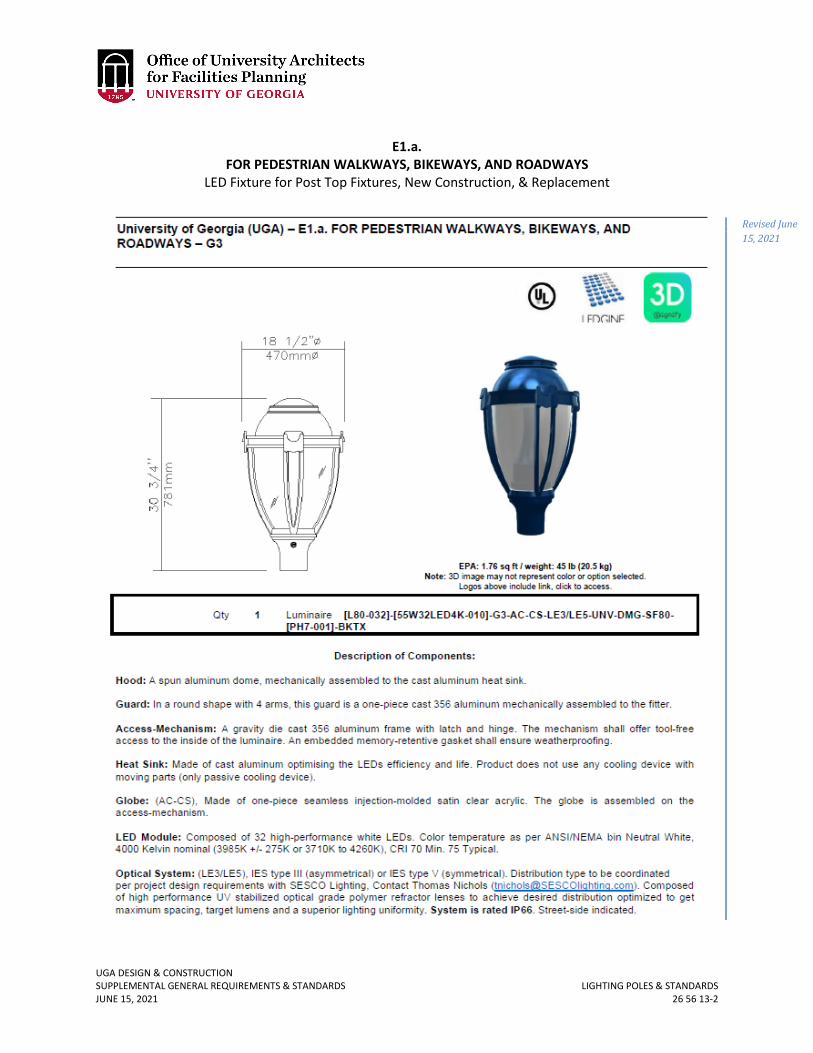
UGA DESIGN & CONSTRUCTION SUPPLEMENTAL GENERAL REQUIREMENTS & STANDARDS LIGHTING POLES & STANDARDS JUNE 15, 2021 26 56 13-2
E1.a.
FOR PEDESTRIAN WALKWAYS, BIKEWAYS, AND ROADWAYS LED Fixture for Post Top Fixtures, New Construction, & Replacement
Revised June 15, 2021
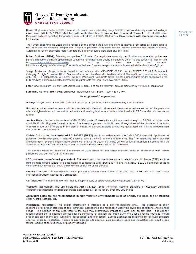
UGA DESIGN & CONSTRUCTION SUPPLEMENTAL GENERAL REQUIREMENTS & STANDARDS LIGHTING POLES & STANDARDS JUNE 15, 2021 26 56 13-3
Revised June 15, 2021
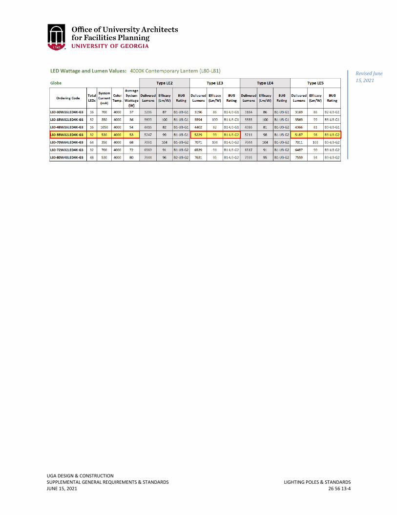
UGA DESIGN & CONSTRUCTION SUPPLEMENTAL GENERAL REQUIREMENTS & STANDARDS LIGHTING POLES & STANDARDS JUNE 15, 2021 26 56 13-4
Revised June 15, 2021
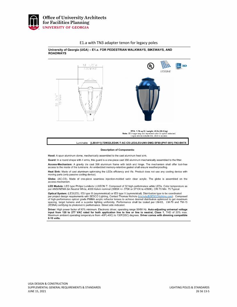
UGA DESIGN & CONSTRUCTION SUPPLEMENTAL GENERAL REQUIREMENTS & STANDARDS LIGHTING POLES & STANDARDS JUNE 15, 2021 26 56 13-5
E1.a with TN3 adapter tenon for legacy poles
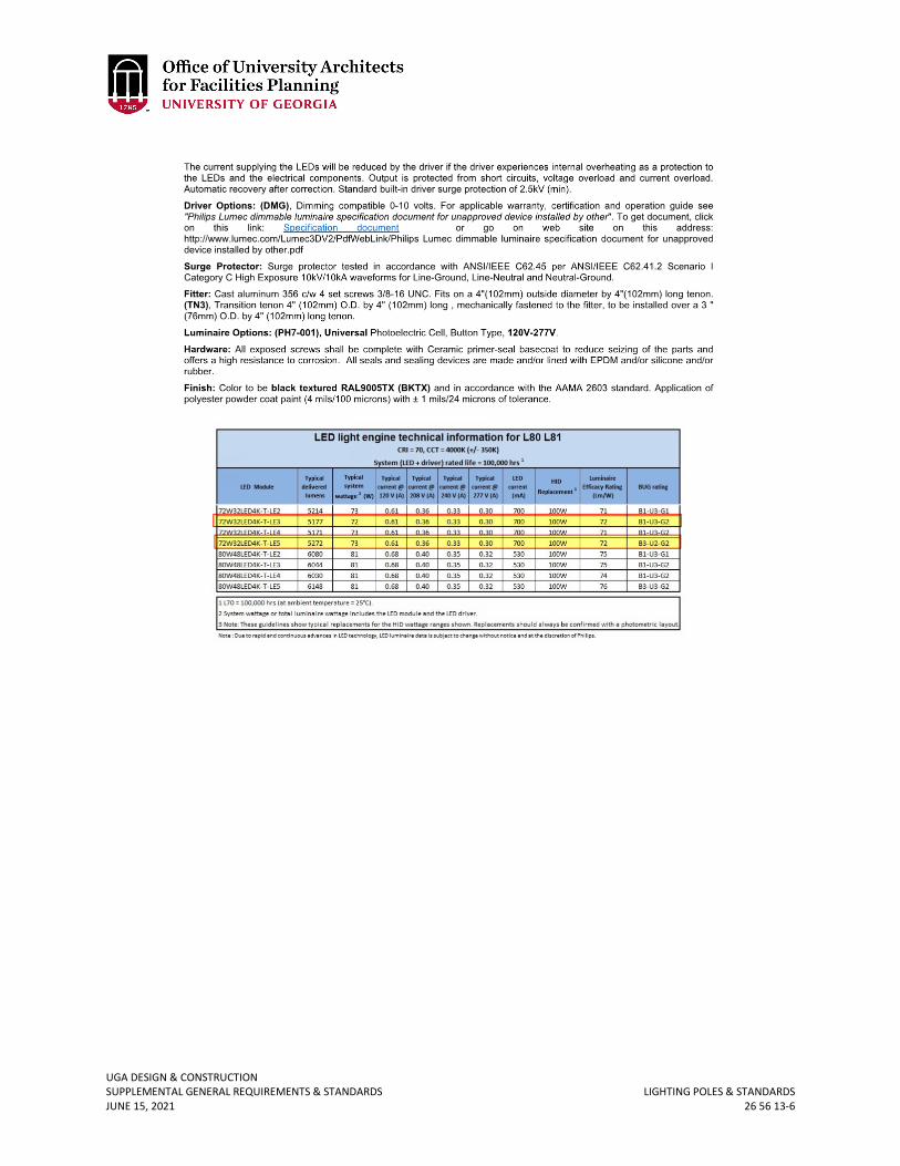
UGA DESIGN & CONSTRUCTION SUPPLEMENTAL GENERAL REQUIREMENTS & STANDARDS LIGHTING POLES & STANDARDS JUNE 15, 2021 26 56 13-6
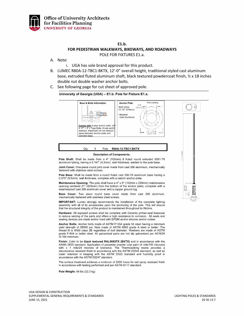
UGA DESIGN & CONSTRUCTION SUPPLEMENTAL GENERAL REQUIREMENTS & STANDARDS LIGHTING POLES & STANDARDS JUNE 15, 2021 26 56 13-7
E1.b.
FOR PEDESTRIAN WALKWAYS, BIKEWAYS, AND ROADWAYS POLE FOR FIXTURES E1.a.
A. Note: i. UGA has sole brand approval for this product.
B. LUMEC R80A-12-TBC1-BKTX, 12’-0” overall height, traditional styled cast aluminum base, extruded fluted aluminum shaft, black textured powdercoat finish, ½ x 18 inches double nut double washer anchor bolts.
C. See following page for cut sheet of approved pole.
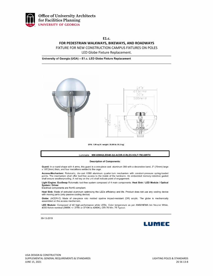
UGA DESIGN & CONSTRUCTION SUPPLEMENTAL GENERAL REQUIREMENTS & STANDARDS LIGHTING POLES & STANDARDS JUNE 15, 2021 26 56 13-8
E1.c.
FOR PEDESTRIAN WALKWAYS, BIKEWAYS, AND ROADWAYS FIXTURE FOR NEW CONSTRUCTION CAMPUS FIXTURES ON POLES
LED Globe Fixture Replacement.
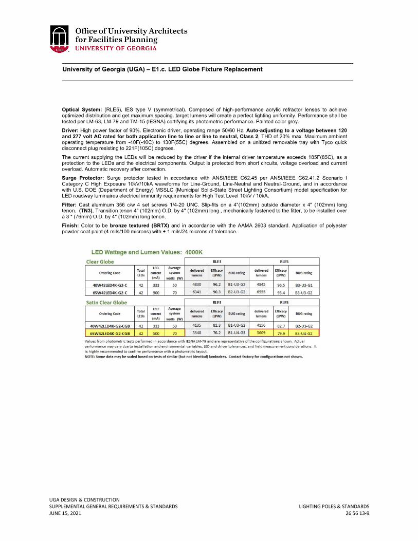
UGA DESIGN & CONSTRUCTION SUPPLEMENTAL GENERAL REQUIREMENTS & STANDARDS LIGHTING POLES & STANDARDS JUNE 15, 2021 26 56 13-9
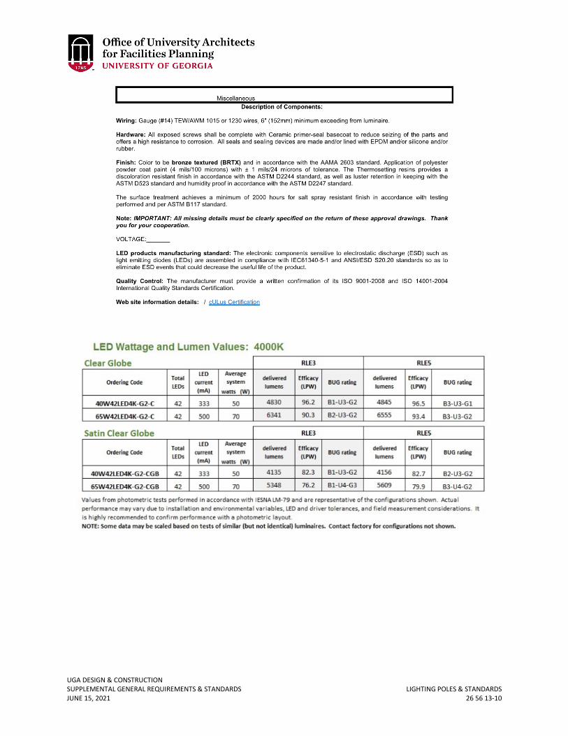
UGA DESIGN & CONSTRUCTION SUPPLEMENTAL GENERAL REQUIREMENTS & STANDARDS LIGHTING POLES & STANDARDS JUNE 15, 2021 26 56 13-10
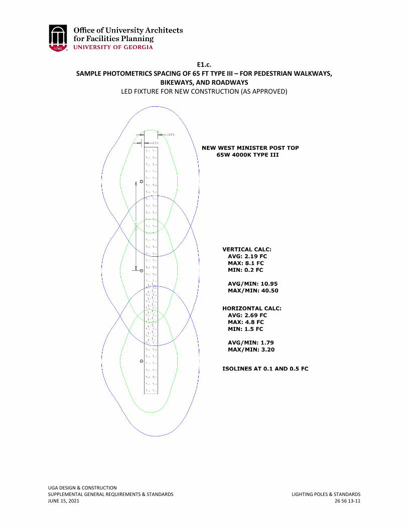
UGA DESIGN & CONSTRUCTION SUPPLEMENTAL GENERAL REQUIREMENTS & STANDARDS LIGHTING POLES & STANDARDS JUNE 15, 2021 26 56 13-11
E1.c. SAMPLE PHOTOMETRICS SPACING OF 65 FT TYPE III – FOR PEDESTRIAN WALKWAYS,
BIKEWAYS, AND ROADWAYS LED FIXTURE FOR NEW CONSTRUCTION (AS APPROVED)
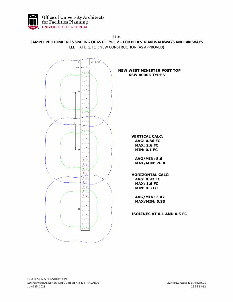
UGA DESIGN & CONSTRUCTION SUPPLEMENTAL GENERAL REQUIREMENTS & STANDARDS LIGHTING POLES & STANDARDS JUNE 15, 2021 26 56 13-12
E1.c. SAMPLE PHOTOMETRICS SPACING OF 65 FT TYPE V – FOR PEDESTRIAN WALKWAYS AND BIKEWAYS
LED FIXTURE FOR NEW CONSTRUCTION (AS APPROVED)
UGA DESIGN & CONSTRUCTION SUPPLEMENTAL GENERAL REQUIREMENTS & STANDARDS PARKING LIGHTING JUNE 15, 2021 26 56 16-1
26 56 16 PARKING LIGHTING
1. GENERAL
A. Related sections: i. 26 56 00 – Exterior Lighting
B. Surface Parking Areas i. Illuminance levels for most campus parking lots are based on low-use criteria,
while a few parking areas fall into the medium-use category. Uniformity and glare control are the most important factors in parking area lighting design because they contribute the most to nighttime visibility. These factors should take precedence over measured light levels. Vertical illumination is also important for motorists to be able to see pedestrians or obstructions such as curbs or poles; it is also critical for facial recognition and threat detection. Finally, care should be taken to avoid shadows and minimize light pollution and trespass.
a. Pole mounted IESNA full-cutoff fixtures or cutoff fixtures with max 2% upward lumens will be used for parking lot lighting. Off-street parking and small parking lots may be lit using the standard decorative pole provided illuminance requirements listed below are met.
b. All parking lots on campus shall be illuminated in the same way. Provide a maintained average illuminance of 2 footcandle over the parking surfaces, with a minimum level of 0.2 footcandle at the ground plane, a minimum vertical illuminance of 0.1 footcandle measured 5’-0” above the ground plane, and a maximum / minimum uniformity ratio of 20:1 (this means that if the minimum is 0.2 footcandle, the maximum footcandle level shall not be higher than 4.0 footcandles).
c. These values are based on the Ninth Edition of the IES Handbook. Justification for exceeding the minimum standards shall be submitted to the OUA during the design phase.
C. Parking Garages i. Parking deck lighting shall be designed with two key principles in mind. First, idle
modes shall be implemented during off-peak hours to reduce light pollution and energy consumption. Second, light trespass from the parking aisles and entrances shall be strictly contained.
ii. All parking garages on campus shall be illuminated in the same way. Refer to the following table for minimum illuminance values and uniformity ratios to be achieved:
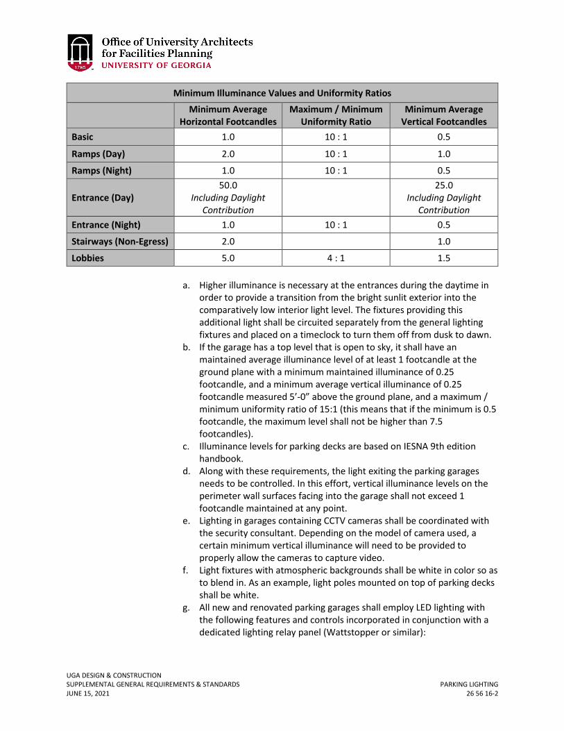
UGA DESIGN & CONSTRUCTION SUPPLEMENTAL GENERAL REQUIREMENTS & STANDARDS PARKING LIGHTING JUNE 15, 2021 26 56 16-2
Minimum Illuminance Values and Uniformity Ratios
Minimum Average Horizontal Footcandles
Maximum / Minimum Uniformity Ratio
Minimum Average Vertical Footcandles
Basic 1.0 10 : 1 0.5
Ramps (Day) 2.0 10 : 1 1.0
Ramps (Night) 1.0 10 : 1 0.5
Entrance (Day) 50.0
Including Daylight Contribution
25.0
Including Daylight Contribution
Entrance (Night) 1.0 10 : 1 0.5
Stairways (Non-Egress) 2.0 1.0
Lobbies 5.0 4 : 1 1.5
a. Higher illuminance is necessary at the entrances during the daytime in order to provide a transition from the bright sunlit exterior into the comparatively low interior light level. The fixtures providing this additional light shall be circuited separately from the general lighting fixtures and placed on a timeclock to turn them off from dusk to dawn.
b. If the garage has a top level that is open to sky, it shall have an maintained average illuminance level of at least 1 footcandle at the ground plane with a minimum maintained illuminance of 0.25 footcandle, and a minimum average vertical illuminance of 0.25 footcandle measured 5’-0” above the ground plane, and a maximum / minimum uniformity ratio of 15:1 (this means that if the minimum is 0.5 footcandle, the maximum level shall not be higher than 7.5 footcandles).
c. Illuminance levels for parking decks are based on IESNA 9th edition handbook.
d. Along with these requirements, the light exiting the parking garages needs to be controlled. In this effort, vertical illuminance levels on the perimeter wall surfaces facing into the garage shall not exceed 1 footcandle maintained at any point.
e. Lighting in garages containing CCTV cameras shall be coordinated with the security consultant. Depending on the model of camera used, a certain minimum vertical illuminance will need to be provided to properly allow the cameras to capture video.
f. Light fixtures with atmospheric backgrounds shall be white in color so as to blend in. As an example, light poles mounted on top of parking decks shall be white.
g. All new and renovated parking garages shall employ LED lighting with the following features and controls incorporated in conjunction with a dedicated lighting relay panel (Wattstopper or similar):
UGA DESIGN & CONSTRUCTION SUPPLEMENTAL GENERAL REQUIREMENTS & STANDARDS PARKING LIGHTING JUNE 15, 2021 26 56 16-3
1) Daylight sensors and daylight responsive switching / dimming along perimeter of the garage, as determined by the lighting designer.
2) The parking garage will be divided into zones based on circulation and occupancy patterns, and lighting at each zone will be controlled by astronomical timeclock and ceiling mounted occupancy / vacancy sensors strategically located to cover the zone. Timeclock will control the zones during the peak hours of the buildings, and the sensors will take over during off-peak hours. The sensors will be set to an adequate delay to prevent frequent switching cycles.
3) Sensors mounted to each fixture are not recommended, and will be reviewed on a case by case basis.
4) Commissioning and programming of the systems shall be included in base bids of the projects.
2. PRODUCTS A. For Parking Lighting – Series E1 B. See following product cut sheets for additional specification information on Series E1:
E3.a. Parking Surface Fixture – LED E3.b. Pole for E3.a
E3.c. Bracket options for E3.a.
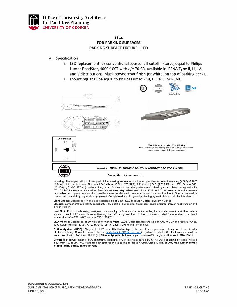
UGA DESIGN & CONSTRUCTION SUPPLEMENTAL GENERAL REQUIREMENTS & STANDARDS PARKING LIGHTING JUNE 15, 2021 26 56 16-4
E3.a. FOR PARKING SURFACES
PARKING SURFACE FIXTURE – LED
A. Specification i. LED replacement for conventional source full-cutoff fixtures, equal to Philips
Lumec RoadStar, 4000K CCT with >/= 70 CR, available in IESNA Type II, III, IV, and V distributions, black powdercoat finish (or white, on top of parking deck).
ii. Mountings shall be equal to Philips Lumec PC4, 6, OR 8, or PSA4.
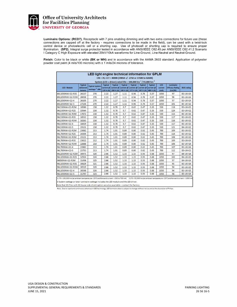
UGA DESIGN & CONSTRUCTION SUPPLEMENTAL GENERAL REQUIREMENTS & STANDARDS PARKING LIGHTING JUNE 15, 2021 26 56 16-5
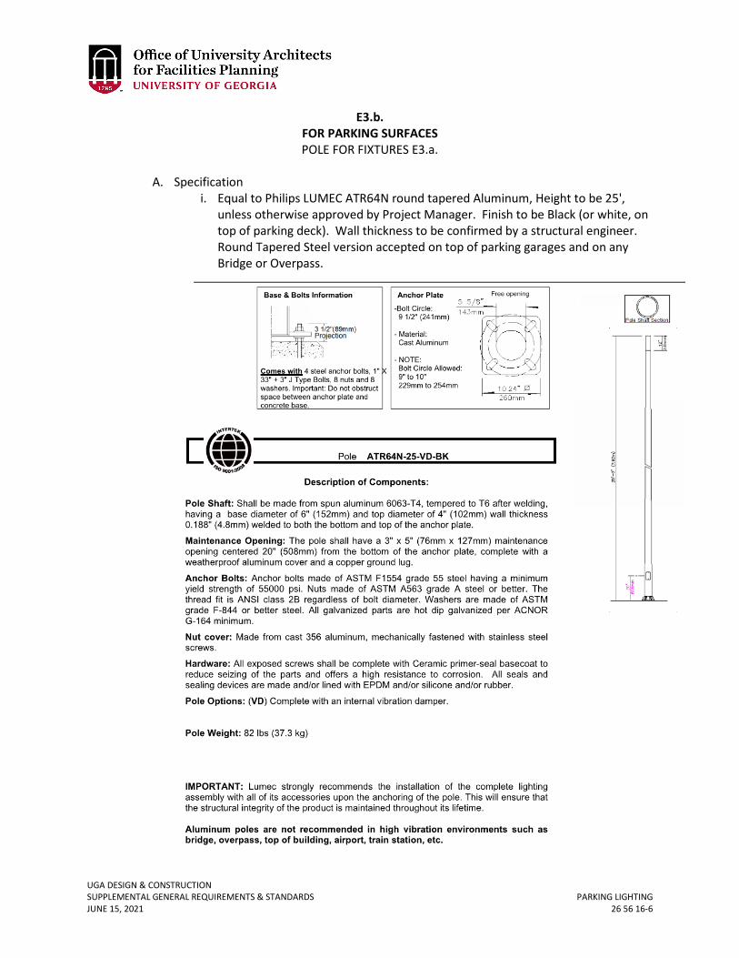
UGA DESIGN & CONSTRUCTION SUPPLEMENTAL GENERAL REQUIREMENTS & STANDARDS PARKING LIGHTING JUNE 15, 2021 26 56 16-6
E3.b. FOR PARKING SURFACES POLE FOR FIXTURES E3.a.
A. Specification
i. Equal to Philips LUMEC ATR64N round tapered Aluminum, Height to be 25', unless otherwise approved by Project Manager. Finish to be Black (or white, on top of parking deck). Wall thickness to be confirmed by a structural engineer. Round Tapered Steel version accepted on top of parking garages and on any Bridge or Overpass.
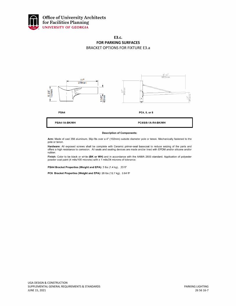
UGA DESIGN & CONSTRUCTION SUPPLEMENTAL GENERAL REQUIREMENTS & STANDARDS PARKING LIGHTING JUNE 15, 2021 26 56 16-7
E3.c. FOR PARKING SURFACES
BRACKET OPTIONS FOR FIXTURE E3.a
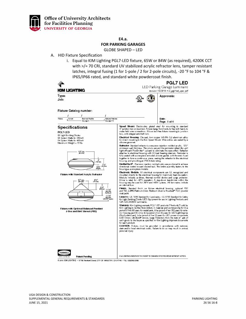
UGA DESIGN & CONSTRUCTION SUPPLEMENTAL GENERAL REQUIREMENTS & STANDARDS PARKING LIGHTING JUNE 15, 2021 26 56 16-8
E4.a. FOR PARKING GARAGES
GLOBE SHAPED – LED A. HID Fixture Specification
i. Equal to KIM Lighting PGL7-LED fixture, 65W or 84W (as required), 4200K CCT with >/= 70 CRI, standard UV stabilized acrylic refractor lens, tamper resistant latches, integral fusing (1 for 1-pole / 2 for 2-pole circuits), -20 °F to 104 °F & IP65/IP66 rated, and standard white powdercoat finish.
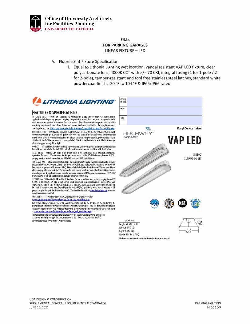
UGA DESIGN & CONSTRUCTION SUPPLEMENTAL GENERAL REQUIREMENTS & STANDARDS PARKING LIGHTING JUNE 15, 2021 26 56 16-9
E4.b. FOR PARKING GARAGES
LINEAR FIXTURE – LED
A. Fluorescent Fixture Specification i. Equal to Lithonia Lighting wet location, vandal resistant VAP LED fixture, clear
polycarbonate lens, 4000K CCT with >/= 70 CRI, integral fusing (1 for 1-pole / 2 for 2-pole), tamper-resistant and tool free stainless steel latches, standard white powdercoat finish, -20 °F to 104 °F & IP65/IP66 rated.

UGA DESIGN & CONSTRUCTION SUPPLEMENTAL GENERAL REQUIREMENTS & STANDARDS PARKING LIGHTING JUNE 15, 2021 26 56 16-10
E4.c. FOR PARKING GARAGES
LED RETROFIT FOR FIXTURE E4.b.
A. LED Lamp Specification i. Equal to Bartco LED tube made of extruded aluminum / heat sink, extruded
linear ribbed lens to hide direct view of emitters, 350mA driving current, installs in fluorescent sockets after bypass of fluorescent ballast, 4000K CCT with >/= 80CRI. Mock-up strongly recommended before permanent installations.
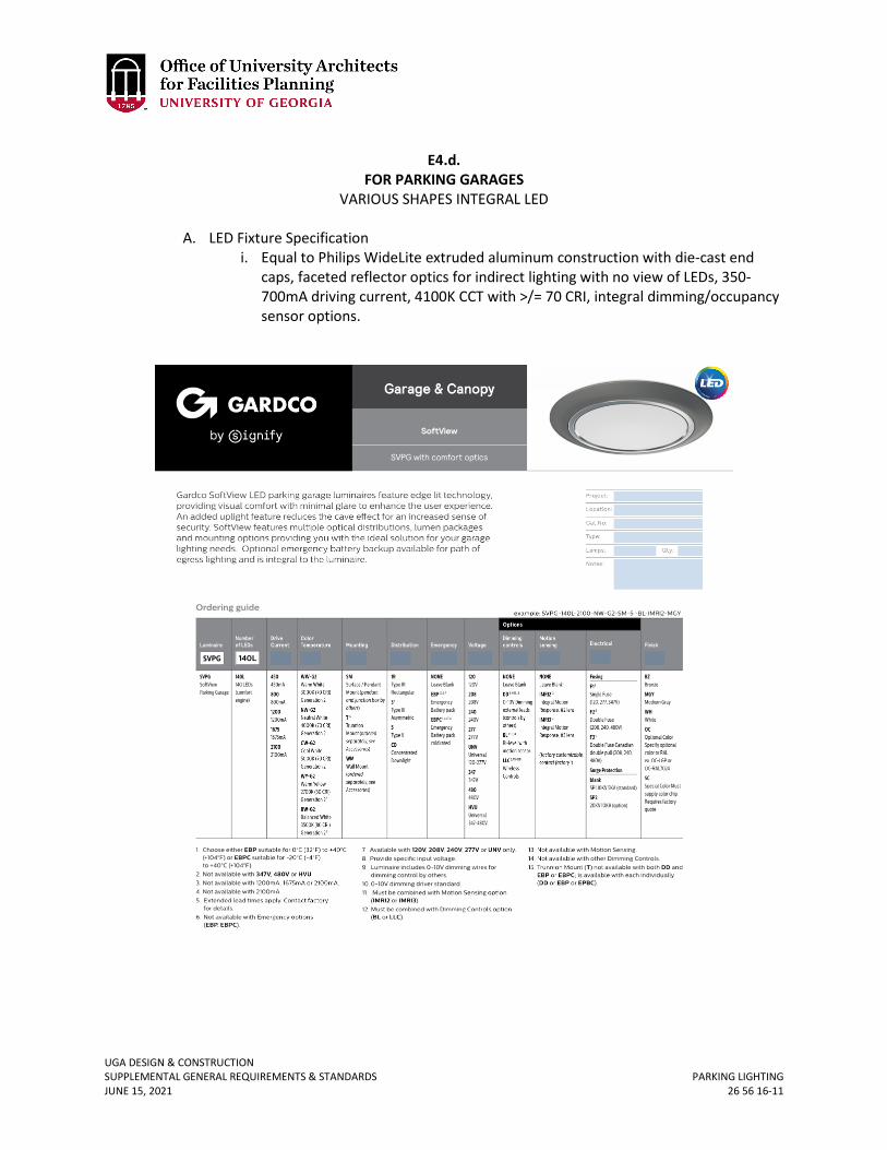
UGA DESIGN & CONSTRUCTION SUPPLEMENTAL GENERAL REQUIREMENTS & STANDARDS PARKING LIGHTING JUNE 15, 2021 26 56 16-11
E4.d.
FOR PARKING GARAGES VARIOUS SHAPES INTEGRAL LED
A. LED Fixture Specification
i. Equal to Philips WideLite extruded aluminum construction with die-cast end caps, faceted reflector optics for indirect lighting with no view of LEDs, 350-700mA driving current, 4100K CCT with >/= 70 CRI, integral dimming/occupancy sensor options.
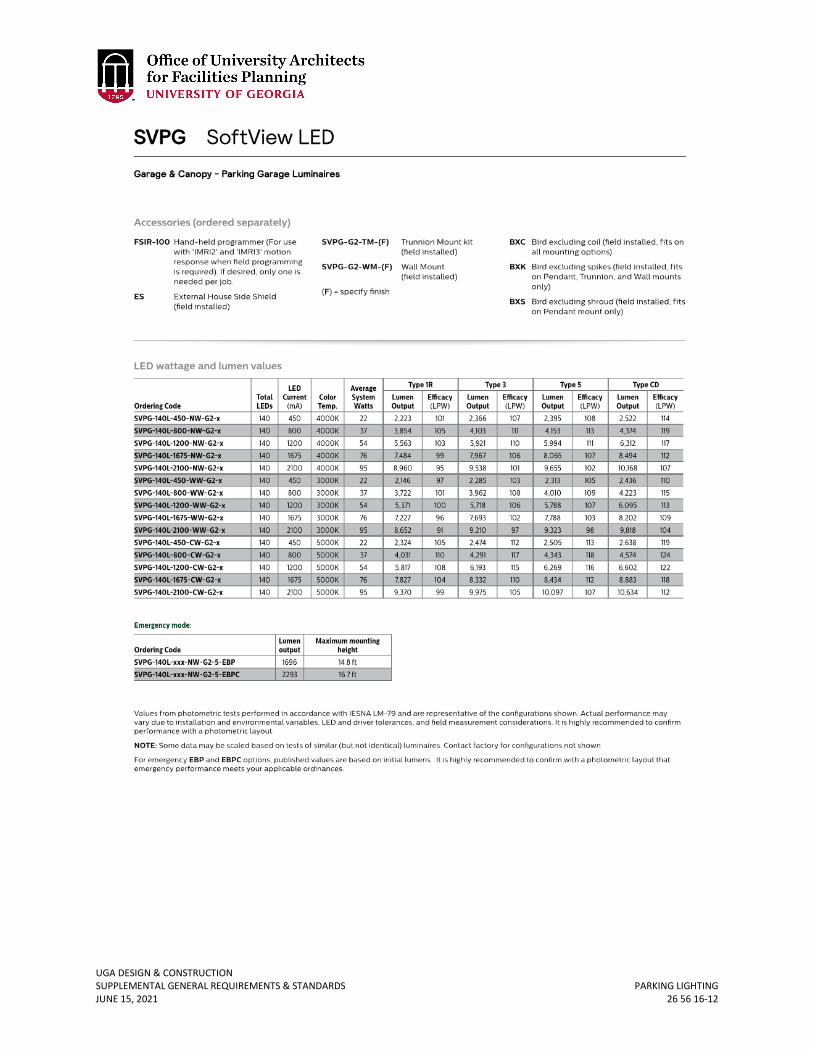
UGA DESIGN & CONSTRUCTION SUPPLEMENTAL GENERAL REQUIREMENTS & STANDARDS PARKING LIGHTING JUNE 15, 2021 26 56 16-12

UGA DESIGN & CONSTRUCTION SUPPLEMENTAL GENERAL REQUIREMENTS & STANDARDS PARKING LIGHTING JUNE 15, 2021 26 56 16-13
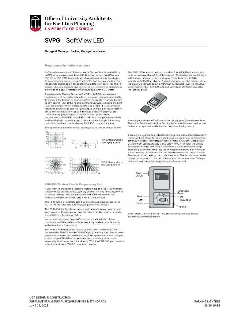
UGA DESIGN & CONSTRUCTION SUPPLEMENTAL GENERAL REQUIREMENTS & STANDARDS PARKING LIGHTING JUNE 15, 2021 26 56 16-14
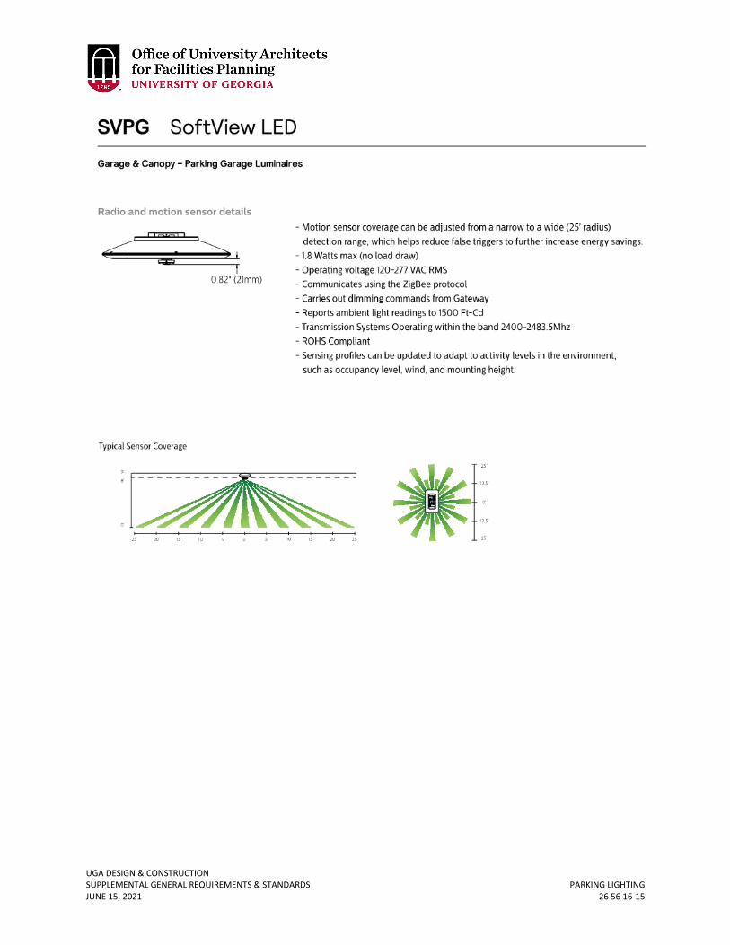
UGA DESIGN & CONSTRUCTION SUPPLEMENTAL GENERAL REQUIREMENTS & STANDARDS PARKING LIGHTING JUNE 15, 2021 26 56 16-15
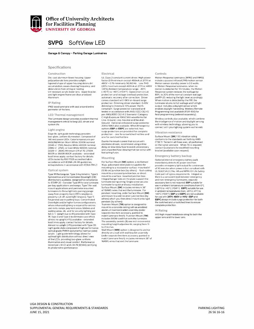
UGA DESIGN & CONSTRUCTION SUPPLEMENTAL GENERAL REQUIREMENTS & STANDARDS PARKING LIGHTING JUNE 15, 2021 26 56 16-16
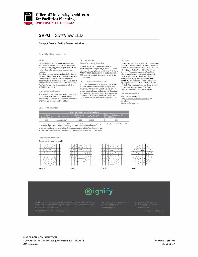
UGA DESIGN & CONSTRUCTION SUPPLEMENTAL GENERAL REQUIREMENTS & STANDARDS PARKING LIGHTING JUNE 15, 2021 26 56 16-17
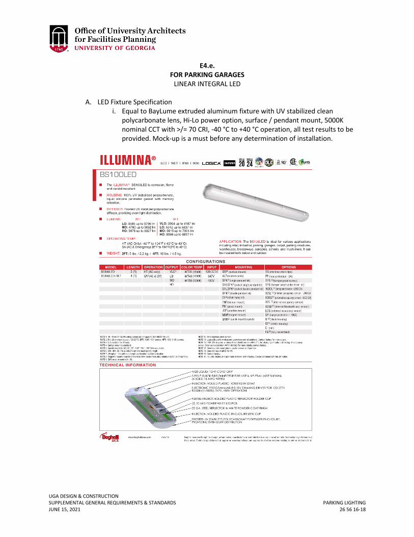
UGA DESIGN & CONSTRUCTION SUPPLEMENTAL GENERAL REQUIREMENTS & STANDARDS PARKING LIGHTING JUNE 15, 2021 26 56 16-18
E4.e. FOR PARKING GARAGES
LINEAR INTEGRAL LED
A. LED Fixture Specification i. Equal to BayLume extruded aluminum fixture with UV stabilized clean
polycarbonate lens, Hi-Lo power option, surface / pendant mount, 5000K nominal CCT with >/= 70 CRI, -40 °C to +40 °C operation, all test results to be provided. Mock-up is a must before any determination of installation.
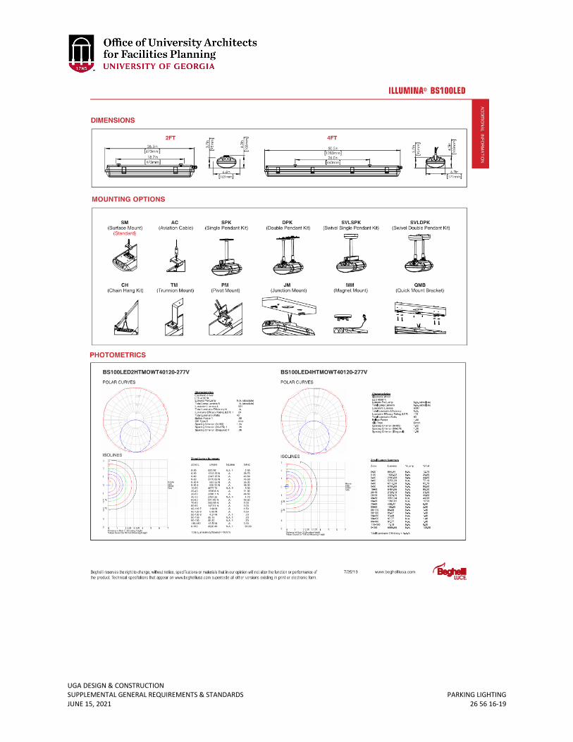
UGA DESIGN & CONSTRUCTION SUPPLEMENTAL GENERAL REQUIREMENTS & STANDARDS PARKING LIGHTING JUNE 15, 2021 26 56 16-19
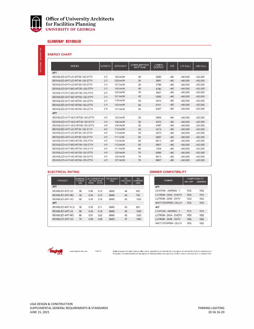
UGA DESIGN & CONSTRUCTION SUPPLEMENTAL GENERAL REQUIREMENTS & STANDARDS PARKING LIGHTING JUNE 15, 2021 26 56 16-20
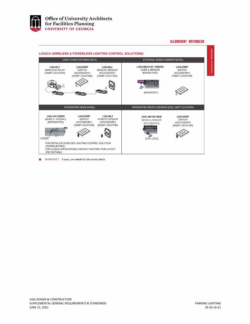
UGA DESIGN & CONSTRUCTION SUPPLEMENTAL GENERAL REQUIREMENTS & STANDARDS PARKING LIGHTING JUNE 15, 2021 26 56 16-21
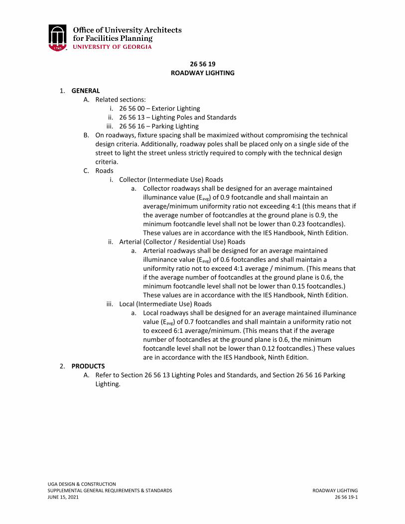
UGA DESIGN & CONSTRUCTION SUPPLEMENTAL GENERAL REQUIREMENTS & STANDARDS ROADWAY LIGHTING JUNE 15, 2021 26 56 19-1
26 56 19 ROADWAY LIGHTING
1. GENERAL
A. Related sections: i. 26 56 00 – Exterior Lighting
ii. 26 56 13 – Lighting Poles and Standards iii. 26 56 16 – Parking Lighting
B. On roadways, fixture spacing shall be maximized without compromising the technical design criteria. Additionally, roadway poles shall be placed only on a single side of the street to light the street unless strictly required to comply with the technical design criteria.
C. Roads i. Collector (Intermediate Use) Roads
a. Collector roadways shall be designed for an average maintained illuminance value (Eavg) of 0.9 footcandle and shall maintain an average/minimum uniformity ratio not exceeding 4:1 (this means that if the average number of footcandles at the ground plane is 0.9, the minimum footcandle level shall not be lower than 0.23 footcandles). These values are in accordance with the IES Handbook, Ninth Edition.
ii. Arterial (Collector / Residential Use) Roads a. Arterial roadways shall be designed for an average maintained
illuminance value (Eavg) of 0.6 footcandles and shall maintain a uniformity ratio not to exceed 4:1 average / minimum. (This means that if the average number of footcandles at the ground plane is 0.6, the minimum footcandle level shall not be lower than 0.15 footcandles.) These values are in accordance with the IES Handbook, Ninth Edition.
iii. Local (Intermediate Use) Roads a. Local roadways shall be designed for an average maintained illuminance
value (Eavg) of 0.7 footcandles and shall maintain a uniformity ratio not to exceed 6:1 average/minimum. (This means that if the average number of footcandles at the ground plane is 0.6, the minimum footcandle level shall not be lower than 0.12 footcandles.) These values are in accordance with the IES Handbook, Ninth Edition.
2. PRODUCTS A. Refer to Section 26 56 13 Lighting Poles and Standards, and Section 26 56 16 Parking
Lighting.
UGA DESIGN & CONSTRUCTION SUPPLEMENTAL GENERAL REQUIREMENTS & STANDARDS SITE & BUILDING ENTRY LIGHTING JUNE 15, 2021 26 56 29-1
26 56 29 SITE & BUILDING ENTRY LIGHTING
1. GENERAL
A. Related sections: i. 26 56 00 – Exterior Lighting
ii. 26 56 13 – Lighting Poles and Standards iii. 26 56 33 – Walkway Lighting iv. 26 56 36 – Flood Lighting
B. Building Entries: Lighting of building entrances provides a transition from a low exterior light level to much higher light levels inside while entering, and vice versa while exiting a building. As a rule, this lighting should follow criteria of exterior lighting discussed earlier, but with some alterations as described.
i. Primary Building Entry Lighting a. This shall be provided by using wall surface mount or wall recessed
fixtures, and ceiling surface or recessed fixtures where they can be easily accessed and relamped. No fixture shall be mounted above the height of 20’-0” A.F.G. without prior approval from the OUA.
b. Decorative fixtures shall be used in these locations only if approved by the OUA.
c. An average maintained illuminance value (Eavg) of 3.0 footcandles and an average/minimum illuminance uniformity ratio of 3:1 measured at the ground plane will be provided within the footprint of the entrance area. If these fixtures also function as emergency egress lighting, ensure that the egress criteria given below and as per NFPA are met.
ii. Exterior Emergency Egress Lighting a. Emergency egress sources shall be mounted above the doors to
minimize glare wherever possible. At secondary building entrances, a single compact fluorescent fixture shall be centered directly above the door(s).
b. LED fixtures may be used for these applications, but must be approved by the OUA.
c. Provide an average maintained illuminance value (Eavg) of 1.0 footcandles and an average/minimum illuminance uniformity ratio of 10:1 measured at the ground plane. Lighting shall be designed to provide a minimum of 0.1 footcandle measured at the ground plane at a distance not less than 2 times the fixture mounting height and shall have IESNA full cutoff classification.
iii. Service Area Lighting a. These shall be designed to provide the necessary average illuminance
levels required based on the specific task in accordance with the IES Handbook, Tenth Edition. The luminaires used should be provided with shielding accessories such as glare shield, louvers or barn doors to avoid glare. As far as possible, fixed wall/column mounted full cutoff type luminaires shall be used for area lighting and adjustable floodlights shall be avoided due to light pollution concerns.
UGA DESIGN & CONSTRUCTION SUPPLEMENTAL GENERAL REQUIREMENTS & STANDARDS SITE & BUILDING ENTRY LIGHTING JUNE 15, 2021 26 56 29-2
2. PRODUCTS A. For Site and Building Entry – Series E1. B. Refer to Section 26 56 13 Lighting Poles and Standards; site lighting may be a mixture of
light poles and building entry fixtures. C. See following product cutsheet for additional specification information on Series E1:
E2.a RAB Lighting LED Wallpacks – LED.
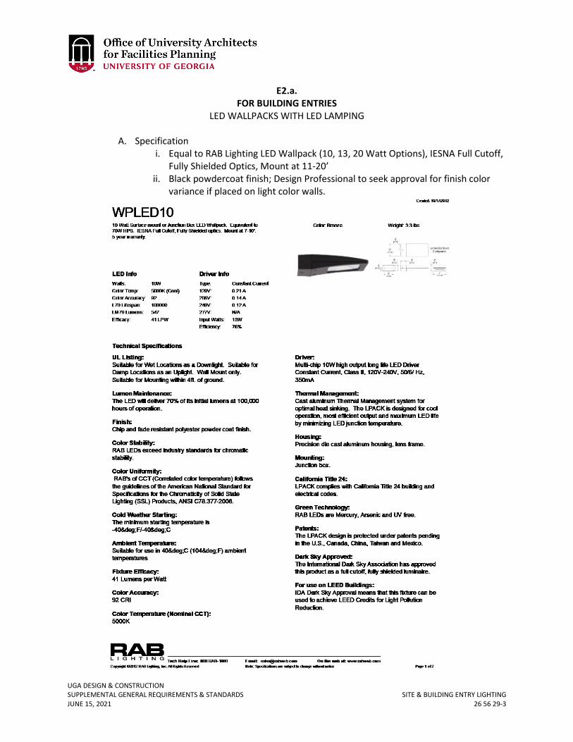
UGA DESIGN & CONSTRUCTION SUPPLEMENTAL GENERAL REQUIREMENTS & STANDARDS SITE & BUILDING ENTRY LIGHTING JUNE 15, 2021 26 56 29-3
E2.a. FOR BUILDING ENTRIES
LED WALLPACKS WITH LED LAMPING
A. Specification i. Equal to RAB Lighting LED Wallpack (10, 13, 20 Watt Options), IESNA Full Cutoff,
Fully Shielded Optics, Mount at 11-20’ ii. Black powdercoat finish; Design Professional to seek approval for finish color
variance if placed on light color walls.
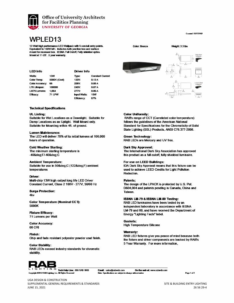
UGA DESIGN & CONSTRUCTION SUPPLEMENTAL GENERAL REQUIREMENTS & STANDARDS SITE & BUILDING ENTRY LIGHTING JUNE 15, 2021 26 56 29-4
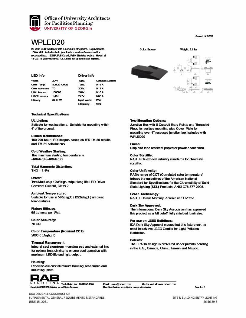
UGA DESIGN & CONSTRUCTION SUPPLEMENTAL GENERAL REQUIREMENTS & STANDARDS SITE & BUILDING ENTRY LIGHTING JUNE 15, 2021 26 56 29-5
UGA DESIGN & CONSTRUCTION SUPPLEMENTAL GENERAL REQUIREMENTS & STANDARDS WALKWAY LIGHTING JUNE 15, 2021 26 56 33-1
26 56 33 WALKWAY LIGHTING
1. GENERAL
A. Related sections: i. 26 56 00 – Exterior Lighting
ii. 26 56 13 – Lighting Poles and Standards iii. 26 56 29 – Site & Building Entry Lighting
B. Pedestrian Walkways / Bikeways (Adjacent To Roadways) i. Pedestrian walkways and bikeways adjacent to roads shall be designed for an
average maintained illuminance value (Eavg) of 0.6 footcandle horizontal, and 1.1 footcandle vertical, as measured 6’- 0" above ground, and shall maintain an avg/min illuminance uniformity ratio not to exceed 4:1. (This means that if the average illuminance at the ground plane is 0.6 footcandles, the minimum illuminance shall not be lower than 0.15 footcandles.) These values are in accordance with the IES Handbook, Ninth Edition.
C. Pedestrian Walkways / Bikeways (Distant From Roadways) i. Pedestrian walkways distant from roads and bikeways adjacent to roads, a
minimum average maintained horizontal illuminance value (Eavg) of 0.5 footcandles to identify obstacles on the pavement, and vertical illuminance of 0.5 footcandle measured 6’- 0" above ground, and shall maintain an average/min illuminance uniformity ratio not to exceed 5:1. (This means that if the average illuminance at the ground plane is 0.5 footcandles, the minimum illuminance level shall not be lower than 0.1 footcandles). Also important to security is a luminous environment, which extends out from the pavement and for a reasonable distance into the adjacent area. This extension should range at least six feet on either side of the pavement and have at least 1/3 of the value of the average illuminance level on the pavement. These values are in accordance with the IES Handbook, Ninth Edition.
D. UGA does not allow the use of lighted bollards. 2. PRODUCTS
A. Refer to Section 26 56 13 Lighting Poles and Standards.
UGA DESIGN & CONSTRUCTION SUPPLEMENTAL GENERAL REQUIREMENTS & STANDARDS FLOOD LIGHTING JUNE 15, 2021 26 56 36-1
26 56 36 FLOOD LIGHTING
1. GENERAL
A. Related sections: i. 26 56 00 – Exterior Lighting
B. Existing ground-based flood lighting of building facades shall be phased out and are not allowed on new construction projects. For renovations, these types of lights are to be replaced with wall-mounted, dark-sky friendly (full cutoff or fully shielded) fixtures (as approved) or fixtures placed at the base of the structure rather than in the landscape.
UGA DESIGN & CONSTRUCTION SUPPLEMENTAL GENERAL REQUIREMENTS & STANDARDS GENERAL COMMUNICATIONS REQUIREMENTS JUNE 15, 2021 27 00 00-1
27 00 00 GENERAL COMMUNICATIONS REQUIREMENTS
1. GENERAL
A. Related sections: i. 00 00 08 – Design Professional Documentation Requirements & Deliverables
ii. 00 00 13 – Designing Learning Environments iii. 00 73 01 – Sole Source / Sole Brand iv. 01 41 26.06 – Dining Services v. 27 05 26 – Grounding and Bonding for Communication Systems
vi. 27 05 29 – Hangers and Supports for Communications Systems vii. 27 05 36 – Cable Trays for Communications Systems
viii. 27 05 43 – Underground Ducts and Raceways for Communications Systems ix. 27 05 46 – Utility Poles for Communications Systems x. 27 05 53 – Identification for Communications Systems
xi. 27 08 00 – Commissioning of Communications xii. 27 11 16 – Communications Cabinets, Racks, Frames, and Enclosures
xiii. 27 11 19 – Communications Termination Blocks and Patch Panels xiv. 27 11 23 – Communications Cable Management and Ladder Rack xv. 27 13 13 – Communications Copper Backbone Cabling
xvi. 27 13 13.13 – Communications Copper Cable Splicing and Terminations xvii. 27 13 23 – Communications Optical Fiber Backbone Cabling
xviii. 27 13 23.13 – Communications Optical Fiber Splicing and Terminations xix. 27 13 33 – Communications Coaxial Backbone Cabling xx. 27 13 43.43 – Cable Services Cabling
xxi. 27 15 00 – Communications Horizontal Cabling xxii. 27 20 00.01 – Data Communications – Wireless
xxiii. 27 41 00 – General Audio-Visual Systems Requirements xxiv. 27 41 00.01- Audio-Visual Control System
B. Abbreviations i. ANSI – American National Standards Institute
ii. APC – Angled Physical Contact (fiber connector) iii. CATV – Cable Television iv. CTL – Center for Teaching and Learning (UGA) v. EIA – Electronic Industries Alliance
vi. EITS – Enterprise Information Technology Services (UGA) vii. FMD IT – Facilities Management Division Information Technology (UGA)
viii. FCC – Federal Communications Commission ix. I.D. – Inside Diameter x. ICEA – Insulated Cable Engineers Association
xi. IDF – Intermediate Distribution Frame xii. IEEE – Institute of Electrical and Electronics Engineers
xiii. MDF – Main Distribution Frame xiv. MHz – Megahertz xv. MM – Multi Mode Optical Fiber xvi. NEC – National Electrical Code
UGA DESIGN & CONSTRUCTION SUPPLEMENTAL GENERAL REQUIREMENTS & STANDARDS GENERAL COMMUNICATIONS REQUIREMENTS JUNE 15, 2021 27 00 00-2
xvii. OFNP – Optical Fiber Non-Metallic Plenum xviii. OTDR – Optical Time Domain Reflectometer
xix. PAWS – Personal Access Wireless System xx. RF – Radio Frequency
xxi. SC – Subscriber Connector (fiber connector) xxii. SCS – Standard Cabling System
xxiii. SM – Single Mode Optical Fiber xxiv. TDR – Time Domain Reflectometer xxv. TR – Telecommunications Room
xxvi. TIA – Telecommunications Industry Association xxvii. UPC – Ultra Physical Contact (fiber connector)
xxviii. UTP – Unshielded Twisted Pair C. EITS is the primary unit responsible for the majority of the low-voltage systems installed
at UGA. This responsibility includes but is not limited to any and all UGA property and structures including hand holes, maintenance holes, pull boxes, pedestals and enclosures as well as inside and outside plant installations. FMD IT is the primary unit responsible for the following low-voltage systems: building automation and temperature control systems, access control systems, and lighting control systems. CTL is the primary unit responsible for low-voltage audio-video system. The Design Professional and Contractor shall coordinate with the Project Manager to coordinate with EITS, FMD IT, and CTL as required within the Standards.
D. The Telecommunications Contractor shall mean either: i. A telecommunications Subcontractor retained by the Contractor.
ii. A telecommunications Contractor contracted directly with UGA. E. Wiring and cross connect locations within a building are referred to as
Telecommunications Rooms (TR’s). These rooms have traditionally been referred to as Main Distribution Frame (MDF) which serves the building, and Intermediate Distribution Frame (IDF) which is floor serving.
F. UGA’s communications systems follow the codes and standards set forth by standard-making bodies, including but not limited to current editions of the National Electric Safety Codes, National Fire Protection Association, NEC, ANSI/TIA/EIA Telecommunications Infrastructure Standards, FCC, IEEE, and Building Industry Consulting Services International Telecommunications Distribution Methods Manual and Customer Owned Outside Plant Manual.
i. When a discrepancy arises between the above mentioned standards and the standards contained in this document, it shall be brought to the attention of EITS immediately for resolution. Typically the more stringent of the two guidelines will be implemented.
G. The Telecommunications Contractor will obtain and supply copies of all required permits to Design Professional and Project Manager.
H. Periodic inspections to the telecommunications installation will be conducted by the Design Professional, Project Manager, and EITS ensure that supplied materials and workmanship conform to the project requirements.
I. All telecommunication and information technology related hardware devices and system configurations shall comply with the latest edition of the UGA EITS Office of
UGA DESIGN & CONSTRUCTION SUPPLEMENTAL GENERAL REQUIREMENTS & STANDARDS GENERAL COMMUNICATIONS REQUIREMENTS JUNE 15, 2021 27 00 00-3
Information Security Policies and Regulations which can be located at: http://eits.uga.edu/access_and_security/infosec/pols_regs.
J. Design Review Requirements i. EITS shall be involved in all phases of design.
ii. As the project moves toward the construction documentation and code review phases, it is required that the project construction documents be submitted to EITS for an internal review process for compliance with the Standards. Plans are to be submitted for review at:
a. Completion of Schematic Design; b. Completion of Design Development; c. At 50% completion of construction documents; d. At 85% completion of construction documents; e. At 100% completion of construction documents.
iii. EITS will document any comments on these documents and provide these comments to the Project Manager. The Project Manager will forward comments to the Design Professional and the Design Professional shall provide timely and coordinated responses to all review comments.
iv. All drawings shall indicate the following information for copper feeder cable: cable type, size, gauge, year installed, cable no., pair counts, distance(s), and any and all splice location(s).
v. All drawings shall indicate the following information for fiber feeder cable: type cable, size, cable number, fiber count, distance(s), splice locations and cable length.
vi. All drawings shall indicate the following terminal information: terminal identity, quantity and type of protectors, quantity and type termination blocks, cable and pairs entering and/or leaving.
vii. All drawings shall indicate the following information for riser cable: cable type, size, gauge, year installed, length, splice points, cable number and pair count(s).
viii. Network Drop Spreadsheet: At the end of this section see sample template for Network Drop Counts. Design Professional shall submit this as an Excel spreadsheet at each milestone design phase review. Refer to Section 00 00 08 Design Professional Documentation Requirements & Deliverables.
K. Design Coordination i. During preliminary design, the Project Manager and Design Professional are to
consult with EITS to ascertain the requirements for telecommunications use and installation. The Design Professional is to coordinate his/her work with other disciplines so that a cohesive set of documents is produced for the telecommunications work.
ii. During preliminary design the demarcations of which Work may be performed by EITS and which Work will be designed by the Design Professional and installed by the Contractor shall be determined.
iii. Typically for all Projects, empty racks are provided by the Contractor in the TR rooms and EITS is responsible for the design, procurement, and installation of electronic equipment in the racks and activation of the building system with the UGA network.
UGA DESIGN & CONSTRUCTION SUPPLEMENTAL GENERAL REQUIREMENTS & STANDARDS GENERAL COMMUNICATIONS REQUIREMENTS JUNE 15, 2021 27 00 00-4
iv. Active telecommunications network equipment (electronics) will typically be supplied and installed by EITS but may be specified for installation by a telecommunications Contractor in accordance with specifications from EITS. Project Manager shall verify requirements for each specific project with EITS during the design phase.
v. For smaller projects EITS may provide the installation of the entire system including exterior infrastructure cabling, interior cabling, and terminations.
vi. Conduit and cable trays are typically provided by the Contractor’s electrical Subcontractor.
vii. For larger projects, EITS typically provides administrative review and does not perform any of the cabling and termination installation.
viii. During preliminary design and design development the Project Manager and Design Professional are to consult with EITS to define system distribution strategies and to discuss any obstacles that might be preexisting in a building, or problems inherent in a particular design or structural system. For major renovations and new construction, the Design Professional shall consult with the Project Manager and EITS to determine if VOIP is appropriate for the particular project. VOIP requires the End-User to commit to the EITS Gold Network Support Partnership level which is an on-going cost once the facility is complete. Additionally, VOIP handsets shall be accommodated within the Project Budget or provided by the End-User.
ix. The planning process shall include all Telephone, Data, and CATV services. x. EITS will provide information on design requirements for point of entry and TR.
This information will be based on the number of outlets anticipated for the project, the length of wiring runs in the project, the distance of terminations from point of entry and TR, and any other pertinent information.
xi. The Design Professional shall coordinate installation of the necessary connections to the appropriate maintenance hole / vault serving the campus infrastructure, with guidance and input from EITS.
xii. The Design Professional shall coordinate the type and position of the connection of the conduit into the maintenance hole / vault with guidance and input from EITS.
xiii. The Design Professional shall be responsible for coordination and installation of any needed infrastructure that might be necessary “behind” the first serving maintenance hole / vault back to the service entrance / TR serving this building.
L. Telecommunication Rooms i. Wiring and cross connect locations within a building are referred to as
Telecommunications Rooms (TR’s). There should be a minimum of one TR per floor. It is recommended that multiple TR be provided on the same floor if usable floor space exceeds 10,000 sq. ft. or the cable pathway length between the horizontal cross-connect in the TR and any telecommunication outlets being served exceeds 250 feet. The maximum allowable cable length of horizontal cable installed to outlets must not exceed 295 feet. When used for 10/100/1000BASE-T, the maximum allowed length of a Cat 6 cable Channel is 100 meters or 328 feet. This consists of 90 meters (295 ft) of solid "horizontal" cabling between the patch panel and the wall jack, plus 10 meters (33 ft) of
UGA DESIGN & CONSTRUCTION SUPPLEMENTAL GENERAL REQUIREMENTS & STANDARDS GENERAL COMMUNICATIONS REQUIREMENTS JUNE 15, 2021 27 00 00-5
stranded patch cable between each jack and the attached device. Since stranded cable has higher attenuation than solid cable, exceeding 10 meters of patch cabling will reduce the permissible length of horizontal cable. Pathway lengths should be kept to a maximum of 250 feet to accommodate the cable length.
a. The number of TR shall be approved by EITS to ensure horizontal category cable runs do not exceed a distance of 295 feet (plus an additional 33 feet for equipment jumpers).
ii. All buildings shall have a minimum of one dedicated TR. This room may be used to terminate both backbone and horizontal cabling. In addition to cable terminations and cross connects, these rooms may serve to house equipment for data, video, other telecommunications equipment, and other low voltage systems like access control and building automation and temperature controls systems..
iii. These rooms are only for low-voltage systems and shall not to be shared facilities for other services such as, electrical, plumbing, or storage. Utilities such as HVAC duct work, sprinkler pipes, electrical conduits, drain pipes, or other water pipes or systems not providing direct service to the space shall not pass through the interior of the room.
iv. The TR shall be accessible from a hallway or other common space in the building. The room should have only one door to eliminate the possibility of the space being used as a passage.
v. NEC Section 110-16 provides requirements for working space and clearances around exposed electrical equipment. Per this requirement allow a minimum of 1 meter (3.3 ft.) of clear working space from equipment and equipment racks and any wall where wall mounted cross-connect fields are mounted when determining the size of the room. Design Professional shall indicate clearance areas on the plans.
vi. As a general rule, new construction will require a minimum of 8 square feet of telecommunications room space per 1000 square feet of building space, and one duplex communication outlet (2-Cat6 connections) for every 75 square feet of space for gross estimating purposes
vii. Individual telecommunication rooms shall be sized to appropriately accommodate equipment to serve maximum drops required for programmed space type. A typical TR would be 8’ x 10’. For larger communications or extraordinary drop quantities, the telecommunications TR may require slightly more space.
viii. In existing, retrofit, or other building types, minimum Telecommunications Room sizes may not be possible. If the use of a shallow closet is approved by EITS, the minimum dimensions shall be 6’ deep by 8’ wide by 8’-6” high. The door to the room shall be a minimum of 36 inches wide. If a double door is used, the center post shall be eliminated. Due to space limitations and safety concerns, no other equipment other than telecommunication related equipment and termination blocks shall be housed in the space. Refer to National Fire Protection Association 80.
UGA DESIGN & CONSTRUCTION SUPPLEMENTAL GENERAL REQUIREMENTS & STANDARDS GENERAL COMMUNICATIONS REQUIREMENTS JUNE 15, 2021 27 00 00-6
ix. Renovations and small new structures and spaces may require less space for providing telecommunications services. In those cases, a single TR with less total square footage is adequate to serve the space. Project Manager and Design Professional shall consult EITS to determine the actual size required for those TR.
x. In new buildings, TR shall be ideally designed to be vertically aligned directly above each other.
xi. All walls in TR will be furnished with full size panels of 4' x 8' x 3/4" fire-rated plywood backboards painted on all sides with two coats of latex grey paint suitable for adherence to a wood substrate. Paint should be applied such that a block-out is left identifying the fire-rated stamp on each individual piece of plywood.
xii. All access doors in the TR shall open outward unless prohibited by local codes. Inward swinging doors eliminate three (3) feet of useable wall space, therefore; room size shall be increased to compensate for the lost area.
xiii. The Design Professional is responsible for confirming that floor loading meets all applicable codes and shall confirm that the loads of the actual equipment to be housed are within the requirements.
xiv. To minimize dust and static electricity, floors shall be sealed concrete. Carpet is prohibited.
xv. TR shall not have ceilings other than exposed structure. xvi. These rooms must not house, or be near equipment (minimum of 10 foot
radius) that emits high RF / Electronic Magnetic Interference radiation, or be exposed to any other adverse environmental conditions.
xvii. For security reasons TR shall solely be used for network infrastructure and network electronics. Use of TR for storage, office space, etc. is prohibited.
xviii. It is highly recommended that these rooms be equipped with a pre-active (dry pipe) sprinkler system in lieu of the traditional fire control sprinkler approach.
xix. Each TR must be provided with a means of wiring egress. It is recommended that this be accomplished by providing four (4) 3-inch or 4-inch diameter (deemed as appropriate by EITS) “home run” conduits with pull string in each conduit with pull boxes if needed, running from MDF to IDF #1 to IDF #2, etc., or by providing four 4-inch conduit sleeves in each TR room. However if this latter sleeve approach is used, the sleeves must extend to the cable tray in the hall.
xx. Under no circumstances shall any conduit contain more than two (2) 90 degree bends nor exceed 180 degrees of total bend without the installation of pull box(s) to accomplish the above.
xxi. Cabling in walls is required to be in conduit; however, conduit home runs for telecommunications cabling are prohibited. At times, typically for security reasons, home run conduit may be necessary, but shall be approved through the variance process. Refer to Section 27 05 29 Hangers and Supports for Communications Systems.
xxii. Fire Wall Penetrations a. Assume that an existing TR wall that goes all the way to the decking of
the floor above it, or to the roof, is a firewall. All such walls are assumed to be firewalls unless the Contractor has specific and documented
Revised June 15, 2021
UGA DESIGN & CONSTRUCTION SUPPLEMENTAL GENERAL REQUIREMENTS & STANDARDS GENERAL COMMUNICATIONS REQUIREMENTS JUNE 15, 2021 27 00 00-7
evidence to the contrary. If the Work utilizes an existing penetration through a fire rated wall, the Contractor is responsible for properly resealing the penetration per applicable codes.
b. All new fire wall penetrations in either existing or new TR room perimeter walls, floors, or ceilings shall utilize an engineered fire wall penetration system that does not require reapplication of fire caulking each time new cabling is pulled through the sleeve.
c. PVC conduit or metal conduit sleeves that are not part of a fire wall penetration system are prohibited.
xxiii. Air Conditioning a. For spaces housing active equipment, the temperature range should be
64 °F to 75 °F, and the humidity range should be 30% to 55% relative humidity measured at 5 feet above the floor.
b. For spaces without active equipment, the temperature range should be 50 °F 95 °F. It is preferable that the temperature range is maintained to within +/- 9 °F of the adjoining office space and that humidity be kept below 85% relative humidity measured at 5 feet above the floor.
xxiv. Electrical a. Ensure that lighting fixtures are located a minimum of 8.5 feet above
the finished floor and that light switches are located near the entrance. Light levels shall be at least 500 lux (50 footcandles) measured at the points of cable termination.
b. Minimum requirement of four dedicated 20 amp, 120 volt circuits for electronic equipment power, each with double duplex receptacles placed at expected equipment locations, unless stated otherwise by EITS.
c. Convenience power outlets should be provided every 6 feet along walls at a height of 6 inches, and connected to different branch circuits than the electronic equipment.
d. If emergency (generator) power is provided for the building, it is strongly recommended that the network equipment in the TR be placed on these circuits.
M. Submittals i. Prior to starting the Work, the telecommunications Contractor shall furnish the
required information in a single consolidated submittal (including samples and manufacturer’s product literature) to the Design Professional. The Design Professional will forward submittals to the Project Manager and EITS for additional review.
ii. The telecommunications Contractor shall provide a list of any and all deviations in materials, construction, and workmanship from those specified in the Standards or in the Contract documents. The Design Professional, Project Manager, EITS will review the list and declare each item as either an approved exception, or as one the telecommunications Contractor must correct.
N. Closeout i. The UGA has records and drawings on paper of their telecommunications plant.
As modifications or changes are made to the system, it is necessary to update
UGA DESIGN & CONSTRUCTION SUPPLEMENTAL GENERAL REQUIREMENTS & STANDARDS GENERAL COMMUNICATIONS REQUIREMENTS JUNE 15, 2021 27 00 00-8
the University drawings and records. Therefore, drawings and records must be provided on each project. Telecommunication Contractors will be given paper prints and they are required to prepare and provide scaled drawings illustrating the new distribution system(s). The Telecommunications Contractor will prepare and submit two copies of drawings (to scale) on white paper with black print. Approximate size should be 24 inches x 36 inches. An electronic copy of all drawings produced in AutoCAD will also be required. The Telecommunications Contractor must deliver all drawings and test records to the Project Manager, Design Professional, and EITS.
ii. It is the Telecommunication Contractor’s responsibility to ensure that all building, outside plant, station, and all other records and drawings that would relate to the project are updated and provided to the Project Manager, Design Professional, and EITS. This will include additions that are performed by other parties such as the Contractor or other subcontractors.
iii. The telecommunications Contractor will furnish operating instructions, service and maintenance instructions, one-line diagrams, data sheets for the exact equipment installed, manufacturers parts lists and parts numbers or other identification established by the original manufacturer, schematic diagrams of the frames, and other diagrams included as part of the manufacturers data sheets. “As built and installed” drawings shall be included in the service manuals and shall show all cable and terminal markings corresponding with the equipment. Upon completion of all work, test results will be provided via actual records. One preliminary copy of the information shall be delivered to EITS for approval prior to the completion of the manuals. If additions or revisions are required, the telecommunications Contractor shall make them and resubmit a preliminary manual. After approval, deliver two completed copies to EITS, and / or the Project Manager.
iv. Refer to Section 27 08 00 Commissioning of Communications for testing requirements.
2. PRODUCTS A. All materials used in a plenum (wires, conduit, wire ties, etc.) must be plenum-rated. B. TR acceptable engineered fire wall penetration systems are equal to:
i. EZ Path – 2” – #EZDP22-FWS, 3” – #EZDP33-FWS, 4” – #EZDP44-FWS ii. Hilti Speed Sleeve – 2” – #CP653-2”-BA, 4” – #CP653-4” – BA
iii. Unique Fire-Stop, Split Sleeve for retrofit, 1” – #SSS-1, 2” – #SSS-2, 4” – #SSS-4 3. EXECUTION
A. EITS reserves the right to exercise its discretion to require the Telecommunication Contractor to remove from the project any such employee that EITS finds to be incompetent, careless, or insubordinate.
B. Telecommunications Contractor Qualification Requirements: In order to assure the quality and reliability of the telecommunications Contractor hired to perform Work, the UGA requires that telecommunications Contractors meet the following criteria:
i. Shall be a firm normally employed in the low voltage cabling industry with a reference list of five (5) projects and contact names to confirm successful category-rated UTP and fiber-optic cable projects.
ii. Must be licensed and bonded in the State of Georgia.
UGA DESIGN & CONSTRUCTION SUPPLEMENTAL GENERAL REQUIREMENTS & STANDARDS GENERAL COMMUNICATIONS REQUIREMENTS JUNE 15, 2021 27 00 00-9
iii. Be in business a minimum of five (5) years. iv. Shall demonstrate satisfaction of sound financial condition and can be bonded
and insured if the Project deems necessary. v. Shall be able to obtain permits required to perform telecommunications
installations in the specified jurisdiction. vi. Shall have personnel knowledgeable in local, state and national codes and
regulations. All Work shall comply with the latest revision of the codes or regulations. When conflict exists between local or national codes or regulations, the most stringent codes or regulations shall be followed.
vii. Shall possess current liability insurance certificates. viii. Shall be registered with Building Industry Consulting Services International and
have at least one RCDD on staff. ix. Shall have personnel fluent in the use of Computer Aided Design and possess
and operate CAD software using .dwg or .dxf format. x. Required Telecommunications Contractor Training:
a. The telecommunications Contractor shall have personnel trained and certified in fiber optic cabling, splicing, termination and testing techniques. Personnel must have experience using an optical light source and power meter plus OTDR.
b. The telecommunications Contractor shall have personnel trained in the installation of pathways and support for housing horizontal and backbone cabling.
c. All telecommunications Contractors doing telecommunications work at UGA shall hold and show proof of current certifications on the following manufactures equipment regardless of the connectivity being installed:
1) Corning 2) Panduit 3) Siemon 4) Uniprise
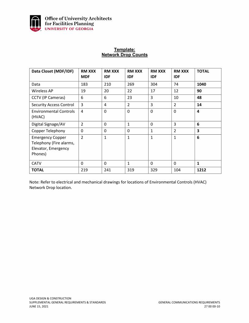
UGA DESIGN & CONSTRUCTION SUPPLEMENTAL GENERAL REQUIREMENTS & STANDARDS GENERAL COMMUNICATIONS REQUIREMENTS JUNE 15, 2021 27 00 00-10
Template: Network Drop Counts
Data Closet (MDF/IDF) RM XXX MDF
RM XXX IDF
RM XXX IDF
RM XXX IDF
RM XXX IDF
TOTAL
Data 183 210 269 304 74 1040 Wireless AP 19 20 22 17 12 90 CCTV (IP Cameras) 6 6 23 3 10 48
Security Access Control 3 4 2 3 2 14 Environmental Controls (HVAC)
4 0 0 0 0 4
Digital Signage/AV 2 0 1 0 3 6 Copper Telephony 0 0 0 1 2 3 Emergency Copper Telephony (Fire alarms, Elevator, Emergency Phones)
2 1 1 1 1 6
CATV 0 0 1 0 0 1 TOTAL 219 241 319 329 104 1212
Note: Refer to electrical and mechanical drawings for locations of Environmental Controls (HVAC) Network Drop location.
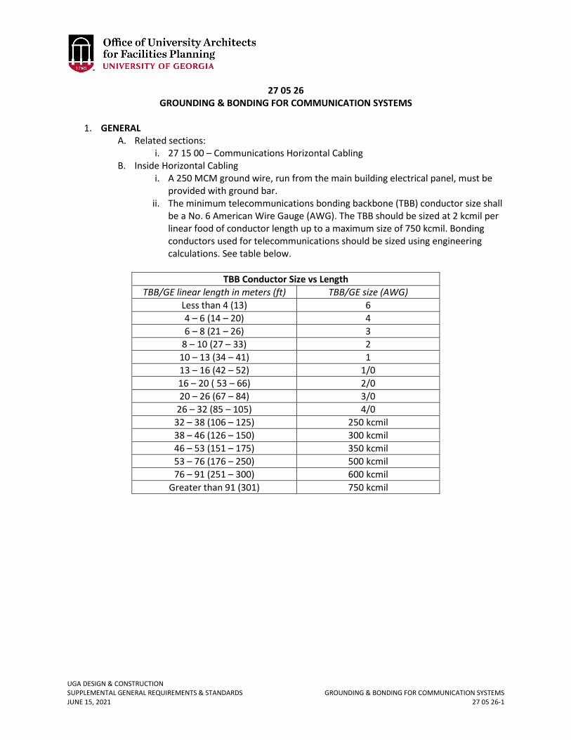
UGA DESIGN & CONSTRUCTION SUPPLEMENTAL GENERAL REQUIREMENTS & STANDARDS GROUNDING & BONDING FOR COMMUNICATION SYSTEMS JUNE 15, 2021 27 05 26-1
27 05 26 GROUNDING & BONDING FOR COMMUNICATION SYSTEMS
1. GENERAL
A. Related sections: i. 27 15 00 – Communications Horizontal Cabling
B. Inside Horizontal Cabling i. A 250 MCM ground wire, run from the main building electrical panel, must be
provided with ground bar. ii. The minimum telecommunications bonding backbone (TBB) conductor size shall
be a No. 6 American Wire Gauge (AWG). The TBB should be sized at 2 kcmil per linear food of conductor length up to a maximum size of 750 kcmil. Bonding conductors used for telecommunications should be sized using engineering calculations. See table below.
TBB Conductor Size vs Length
TBB/GE linear length in meters (ft) TBB/GE size (AWG) Less than 4 (13) 6 4 – 6 (14 – 20) 4 6 – 8 (21 – 26) 3
8 – 10 (27 – 33) 2 10 – 13 (34 – 41) 1 13 – 16 (42 – 52) 1/0 16 – 20 ( 53 – 66) 2/0 20 – 26 (67 – 84) 3/0
26 – 32 (85 – 105) 4/0 32 – 38 (106 – 125) 250 kcmil 38 – 46 (126 – 150) 300 kcmil 46 – 53 (151 – 175) 350 kcmil 53 – 76 (176 – 250) 500 kcmil 76 – 91 (251 – 300) 600 kcmil
Greater than 91 (301) 750 kcmil
UGA DESIGN & CONSTRUCTION SUPPLEMENTAL GENERAL REQUIREMENTS & STANDARDS HANGERS & SUPPORTS FOR COMMUNICATIONS SYSTEMS JUNE 15, 2021 27 05 29-1
27 05 29 HANGERS & SUPPORTS FOR COMMUNICATIONS SYSTEMS
1. GENERAL
A. Related sections: i. 27 00 00 – Communications
ii. 27 05 36 – Cable Trays for Communications Systems iii. 27 11 16 – Communications Cabinets, Racks, Frames, and Enclosures iv. 27 11 19 – Communications Termination Blocks and Patch Panels
2. PRODUCTS A. ERICO CADDY, J-Hook, or equivalent
i. p/n CAT32 (2”) ii. p/n CAT64 (4”)
3. EXECUTION A. Under no circumstances shall the walls, ceiling, floor, etc. of a stairwell be penetrated. B. Under no circumstances shall cable be installed below ceiling in an exposed fashion, i.e.,
all surface mounted cable shall be enclosed in conduit except when specified for architectural purposes.
C. Cables shall not be tie wrapped or routed along electrical or gas conduit. D. Horizontal cable run in hallways above a suspended ceiling shall be in a cable tray or
supported by J-hooks with a spacing of about 4 foot or 5 foot on center to minimize cable sag. Refer to Section 27 00 00 Communications for limitations of conduit use.
UGA DESIGN & CONSTRUCTION SUPPLEMENTAL GENERAL REQUIREMENTS & STANDARDS CABLE TRAYS FOR COMMUNICATIONS SYSTEMS JUNE 15, 2021 27 05 36-1
27 05 36 CABLE TRAYS FOR COMMUNICATIONS SYSTEMS
1. GENERAL
A. Related sections: i. 27 00 00 – Communications
ii. 27 05 29 – Hangers and Supports for Communications Systems iii. 27 11 16 – Communications Cabinets, Racks, Frames, and Enclosures iv. 27 11 19 – Communications Termination Blocks and Patch Panels
B. In general, J-hook hanger installation method is preferred over cable trays due to ease of installation. Refer to Section 27 05 29 Hangers and Supports for Communications Systems.
C. Under no circumstances shall the walls, ceiling, floor, etc. of a stairwell be penetrated. 2. PRODUCTS
A. Cable Tray i. Hoffman Quick Tray Pro in 2”, 4”, or 6” depth, or equivalent.
3. EXECUTION A. The conduit for the telecommunications outlet shall run from a receptacle box (as
marked on the building plans) to a cable tray in the hallway or as a minimum above the ceiling. Sleeves will need to be placed to the hallway cable tray if conduits do not run unbroken to cable tray from the outlet. From the hallway cable tray, cable will be routed to appropriate TR.
B. Under no circumstances shall the walls, ceiling, floor, etc. of a stairwell be penetrated. C. Under no circumstances shall cable be installed below ceiling in an exposed fashion, i.e.,
all surface mounted cable shall be enclosed in conduit except when specified for architectural purposes.
D. Cables shall not be tie wrapped or routed along electrical or gas conduit. E. Horizontal cable run in hallways above a suspended ceiling shall be in a cable tray or
supported by J-hooks with a spacing of about 4 foot or 5 foot on center to minimize cable sag.
UGA DESIGN & CONSTRUCTION SUPPLEMENTAL GENERAL REQUIREMENTS & STANDARDS UNDERGROUND DUCTS & RACEWAYS FOR COMMUNICATION SYSTEMS JUNE 15, 2021 27 05 43-1
27 05 43 UNDERGROUND DUCTS & RACEWAYS FOR COMMUNICATIONS SYSTEMS
1. GENERAL
A. Related sections: i. 27 00 00 – Communications
ii. 27 05 26 – Grounding and Bonding for Communication Systems iii. 27 05 46 – Utility Poles for Communications Systems iv. 27 13 13 – Communications Copper Backbone Cabling v. 27 13 13.13 – Communications Copper Cable Splicing and Terminations
vi. 27 13 23 – Communications Optical Fiber Backbone Cabling vii. 27 13 23.13 – Communications Optical Fiber Splicing and Terminations
viii. 27 13 33 – Communications Coaxial Backbone Cabling B. This section is for outside infrastructure for telephone, data, and cable TV services for
new buildings and renovation of existing buildings where expanded services to the building will be required. This section also applies to the installation of additional network services in existing buildings not undergoing renovation.
C. Service Entrance Requirements: The service entrance is the route by which telecommunication services and cables enter a building. Following are the guidelines to install service entrances to buildings and information for the termination of those cables. There are two types of service entrances:
i. Underground Entrance – Buried Conduit. Conduit sizing and quantities between buildings, and/or maintenance holes and vaults shall be determined by the quantities and requirements for the cabling needed to serve the building.
a. The recommended conduit size for use in an underground entrance is 4 inches in diameter. A minimum of one 4-inch conduit (with pull wire) for telephone, one 4-inch PVC conduit (with pull wire) for data / CATV, and two spare (empty) 4-inch PVC conduits (with pull wire) will be installed for most new buildings. Minimally, there needs to be one 4-inch conduit installed for each desired service (voice, data / CATV, and / or leased common carrier) along with one spare 4-inch conduit. Therefore, the minimum conduit run to any building would be two 4-inch conduits.
ii. Buried Entrance – may be used for temporary service only. Permanent buried entrance method is prohibited.
D. Telecommunications Vaults - UGA has an extensive network of telecommunications conduit and maintenance holes throughout the campus. Design Professional should assure that all projects connect to this system as needed. All new maintenance holes or telecommunication vaults shall be coordinated with EITS.
i. Telecommunication vaults shall be placed in outside plant conduit runs at an interval no greater than every 400 feet if a direct path between structures is attainable (i.e. no 90 degree bends). The maximum distance between maintenance holes shall be reduced by 50 feet for every 90 degree bend installed in the pathway up to a maximum of two bends.
ii. Conduit routing between two telecommunications vaults, or between a vault and a building, shall contain no more than two 90-degree bends or a total of 180
UGA DESIGN & CONSTRUCTION SUPPLEMENTAL GENERAL REQUIREMENTS & STANDARDS UNDERGROUND DUCTS & RACEWAYS FOR COMMUNICATION SYSTEMS JUNE 15, 2021 27 05 43-2
degrees of bend. If additional conduit bends are required, additional vaults shall be placed as needed.
iii. Telecommunications vaults are typically constructed of pre-fabricated cast concrete, and contain a floor section, wall section, and top section. Vaults shall be a minimum of 6’ wide by 12’ long by 7’ headroom standard inside dimension. Smaller vaults may be used as a pulling point between the main conduit vaults and a building but only as a pass through with no splicing in them and shall be approved in advance by EITS.
2. PRODUCTS A. Underground Burial Conduit
i. All buried conduit will be corrosive resistant, plastic polyvinyl chloride (PVC). Conduits shall be installed concrete encased; PVC conduit with concrete encasement is unacceptable.
ii. Conduits shall have a woven polyester pull tape with minimum test rating of 1500 lbs pulling strength in each conduit or compartment within the conduit.
B. Telecommunications Vault: i. Acceptable vault manufacturers and part numbers are equal to:
a. Manhole – Old Castle Precast b. Handhole – Quazite or NewBasis
3. EXECUTION A. Underground Burial Conduit
i. Conduit must be buried at a minimum depth of 24 inches to the top of the concrete and encased in concrete rated at 3,000 psi. Conduit that will be placed under load should be encased in concrete rated to 3,500 psi. To minimize accidental digging or damage, a detectable, warning tape shall be placed in the trench a minimum of 12 inches below the surface and directly over the conduit. Install a #6 ground wire at the bottom of the conduit path, terminate and ground in all pull boxes and terminate before entrance of any building with an 8 foot long ground-rod. This is used to bleed off static charges and to provide a signal path to locate non-metallic systems.
ii. Telecommunications conduit is not to be placed in the same trench or duct banks with other utilities. Design of underground conduit should be fully coordinated with EITS.
iii. Entrance conduit must not have more than two 90 degree bends without a pull box, handhole, or maintenance hole. Bends must be sweeping with a radius not less than 10 times the inside diameter of the 4 inch conduit.
iv. All 4-inch conduits conveying fiber optic cable shall be compartmentalized into multiple channels via multi-cell duct liner.
v. Conduits entering a building from below grade shall extend 4 inches above the finished floor.
vi. Conduits entering the building through the ceiling shall extend to 8 ½ feet above the finished floor.
vii. Conduits entering the building through walls shall have sweeps installed in a manor that allows the conduit to extend to 8 ½ ft. above the finished floor.
Revised June 15, 2021
UGA DESIGN & CONSTRUCTION SUPPLEMENTAL GENERAL REQUIREMENTS & STANDARDS UNDERGROUND DUCTS & RACEWAYS FOR COMMUNICATION SYSTEMS JUNE 15, 2021 27 05 43-3
viii. All conduits entering buildings will be sealed to prevent water, noxious gases and rodents from entering the building.
ix. All conduits shall be securely fastened to the structure to withstand typical cabling installation.
x. Telecommunications conduits are for the exclusive use of telecommunications cables. They shall not be shared with any other utility.
xi. Multiple service entrance conduits (two diverse routes) should be considered for buildings which provide crucial services, including research, health care, and emergency services.
UGA DESIGN & CONSTRUCTION SUPPLEMENTAL GENERAL REQUIREMENTS & STANDARDS UTILITY POLES FOR COMMUNICATIONS SYSTEMS JUNE 15, 2021 27 05 46-1
27 05 46 UTILITY POLES FOR COMMUNICATIONS SYSTEMS
1. GENERAL
A. Related sections: i. 27 00 00 – Communications
ii. 27 05 43 – Underground Ducts and Raceways for Communications Systems B. Service Entrance Requirements
i. Except for temporary service, aerial entrance method is prohibited.
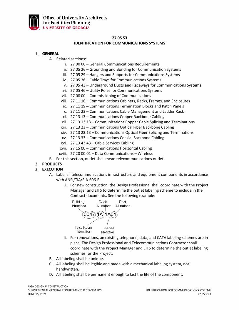
UGA DESIGN & CONSTRUCTION SUPPLEMENTAL GENERAL REQUIREMENTS & STANDARDS IDENTIFICATION FOR COMMUNICATIONS SYSTEMS JUNE 15, 2021 27 05 53-1
27 05 53 IDENTIFICATION FOR COMMUNICATIONS SYSTEMS
1. GENERAL
A. Related sections: i. 27 00 00 – General Communications Requirements
ii. 27 05 26 – Grounding and Bonding for Communication Systems iii. 27 05 29 – Hangers and Supports for Communications Systems iv. 27 05 36 – Cable Trays for Communications Systems v. 27 05 43 – Underground Ducts and Raceways for Communications Systems
vi. 27 05 46 – Utility Poles for Communications Systems vii. 27 08 00 – Commissioning of Communications
viii. 27 11 16 – Communications Cabinets, Racks, Frames, and Enclosures ix. 27 11 19 – Communications Termination Blocks and Patch Panels x. 27 11 23 – Communications Cable Management and Ladder Rack
xi. 27 13 13 – Communications Copper Backbone Cabling xii. 27 13 13.13 – Communications Copper Cable Splicing and Terminations
xiii. 27 13 23 – Communications Optical Fiber Backbone Cabling xiv. 27 13 23.13 – Communications Optical Fiber Splicing and Terminations xv. 27 13 33 – Communications Coaxial Backbone Cabling
xvi. 27 13 43.43 – Cable Services Cabling xvii. 27 15 00 – Communications Horizontal Cabling
xviii. 27 20 00.01 – Data Communications – Wireless B. For this section, outlet shall mean telecommunications outlet.
2. PRODUCTS 3. EXECUTION
A. Label all telecommunications infrastructure and equipment components in accordance with ANSI/TIA/EIA-606-B.
i. For new construction, the Design Professional shall coordinate with the Project Manager and EITS to determine the outlet labeling scheme to include in the Contract documents. See the following example:
ii. For renovations, an existing telephone, data, and CATV labeling schemes are in place. The Design Professional and Telecommunications Contractor shall coordinate with the Project Manager and EITS to determine the outlet labeling schemes for the Project.
B. All labeling shall be unique. C. All labeling shall be legible and made with a mechanical labeling system, not
handwritten. D. All labeling shall be permanent enough to last the life of the component.
UGA DESIGN & CONSTRUCTION SUPPLEMENTAL GENERAL REQUIREMENTS & STANDARDS IDENTIFICATION FOR COMMUNICATIONS SYSTEMS JUNE 15, 2021 27 05 53-2
E. Labels at one end of cables, conduits, etc. shall exactly correspond with the label at the other end of the cable, conduit, etc.
F. The Telecommunications Contractor shall present all labeling schemes for approval to the Design Professional, Project Manager, and EITS before any components are labeled at the Project.
G. The identification assigned to the jack shall be the same as the corresponding label on the patch panel.
UGA DESIGN & CONSTRUCTION SUPPLEMENTAL GENERAL REQUIREMENTS & STANDARDS COMMISSIONING OF COMMUNICATIONS JUNE 15, 2021 27 08 00-1
27 08 00 COMMISSIONING OF COMMUNICATIONS
1. GENERAL
A. Related sections: i. 27 00 00 – General Communications Requirements
ii. 27 05 26 – Grounding and Bonding for Communication Systems iii. 27 05 29 – Hangers and Supports for Communications Systems iv. 27 05 36 – Cable Trays for Communications Systems v. 27 05 43 – Underground Ducts and Raceways for Communications Systems
vi. 27 05 46 – Utility Poles for Communications Systems vii. 27 05 53 – Identification for Communications Systems
viii. 27 11 16 – Communications Cabinets, Racks, Frames, and Enclosures ix. 27 11 19 – Communications Termination Blocks and Patch Panels x. 27 11 23 – Communications Cable Management and Ladder Rack
xi. 27 13 13 – Communications Copper Backbone Cabling xii. 27 13 13.13 – Communications Copper Cable Splicing and Terminations
xiii. 27 13 23 – Communications Optical Fiber Backbone Cabling xiv. 27 13 23.13 – Communications Optical Fiber Splicing and Terminations xv. 27 13 33 – Communications Coaxial Backbone Cabling
xvi. 27 13 43.43 – Cable Services Cabling xvii. 27 15 00 – Communications Horizontal Cabling
xviii. 27 20 00.01 – Data Communications – Wireless B. The Telecommunications Contractor shall test every pair in every cable, on an end-to-
end basis after splicing and termination for conformity to the design standards and specifications. The test procedures and results will be documented with certification that the system meets all applicable standards and specifications. The Contract shall state the beginning date and duration of system acceptance checkout. Performance detail sheets will be submitted for final review and system acceptance by the University. Test record forms are to be completed and turned over to the Design Professional, Project Manager, and EITS.
2. PRODUCTS 3. EXECUTION
A. Testing Parameters i. Optical Fiber Testing: Singlemode and Multimode Fiber
a. Fiber horizontal cables shall be 100% tested for insertion loss and length.
b. Insertion loss shall be tested at 850 nm and 1300 nm for 50/125um and 62.5/125um multimode cabling in at least one direction using the Method B (1-jumper) test procedure as specified in ANSI/TIA/EIA-526-14A.
c. Insertion loss shall be tested at 1310 and 1550 for singlemode cabling in at least one direction using the Method A.1 (1-jumper) test procedure as specified in ANSI/TIA/EIA-526-7.
d. Length shall be tested using an OTDR, optical length test measurement device or sequential cable measurement markings.
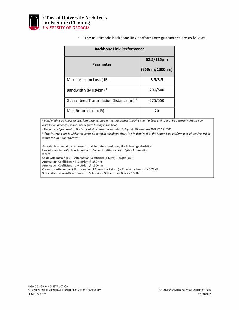
UGA DESIGN & CONSTRUCTION SUPPLEMENTAL GENERAL REQUIREMENTS & STANDARDS COMMISSIONING OF COMMUNICATIONS JUNE 15, 2021 27 08 00-2
e. The multimode backbone link performance guarantees are as follows:
Backbone Link Performance
Parameter 62.5/125µm
(850nm/1300nm)
Max. Insertion Loss (dB) 8.5/3.5
Bandwidth (MHz•km) 1 200/500
Guaranteed Transmission Distance (m) 2 275/550
Min. Return Loss (dB) 3 20
1 Bandwidth is an important performance parameter, but because it is intrinsic to the fiber and cannot be adversely affected by installation practices, it does not require testing in the field. 2 The protocol pertinent to the transmission distances as noted is Gigabit Ethernet per IEEE 802.3:2000. 3 If the insertion loss is within the limits as noted in the above chart, it is indicative that the Return Loss performance of the link will be within the limits as indicated.
Acceptable attenuation test results shall be determined using the following calculation: Link Attenuation = Cable Attenuation + Connector Attenuation + Splice Attenuation where: Cable Attenuation (dB) = Attenuation Coefficient (dB/km) x length (km) Attenuation Coefficient = 3.5 dB/km @ 850 nm Attenuation Coefficient = 1.0 dB/km @ 1300 nm Connector Attenuation (dB) = Number of Connector Pairs (n) x Connector Loss = n x 0.75 dB Splice Attenuation (dB) = Number of Splices (s) x Splice Loss (dB) = s x 0.3 dB
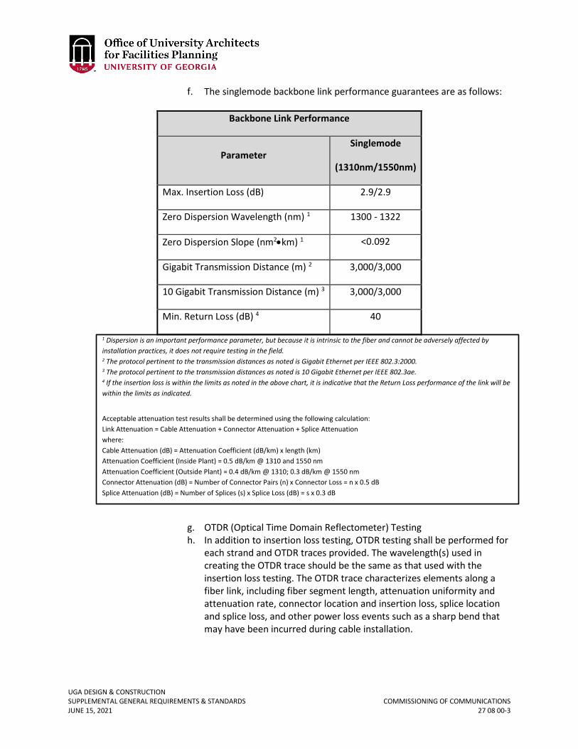
UGA DESIGN & CONSTRUCTION SUPPLEMENTAL GENERAL REQUIREMENTS & STANDARDS COMMISSIONING OF COMMUNICATIONS JUNE 15, 2021 27 08 00-3
f. The singlemode backbone link performance guarantees are as follows:
Backbone Link Performance
Parameter Singlemode
(1310nm/1550nm)
Max. Insertion Loss (dB) 2.9/2.9
Zero Dispersion Wavelength (nm) 1 1300 - 1322
Zero Dispersion Slope (nm2•km) 1 <0.092
Gigabit Transmission Distance (m) 2 3,000/3,000
10 Gigabit Transmission Distance (m) 3 3,000/3,000
Min. Return Loss (dB) 4 40
1 Dispersion is an important performance parameter, but because it is intrinsic to the fiber and cannot be adversely affected by installation practices, it does not require testing in the field. 2 The protocol pertinent to the transmission distances as noted is Gigabit Ethernet per IEEE 802.3:2000. 3 The protocol pertinent to the transmission distances as noted is 10 Gigabit Ethernet per IEEE 802.3ae. 4 If the insertion loss is within the limits as noted in the above chart, it is indicative that the Return Loss performance of the link will be within the limits as indicated. Acceptable attenuation test results shall be determined using the following calculation: Link Attenuation = Cable Attenuation + Connector Attenuation + Splice Attenuation where: Cable Attenuation (dB) = Attenuation Coefficient (dB/km) x length (km) Attenuation Coefficient (Inside Plant) = 0.5 dB/km @ 1310 and 1550 nm Attenuation Coefficient (Outside Plant) = 0.4 dB/km @ 1310; 0.3 dB/km @ 1550 nm Connector Attenuation (dB) = Number of Connector Pairs (n) x Connector Loss = n x 0.5 dB Splice Attenuation (dB) = Number of Splices (s) x Splice Loss (dB) = s x 0.3 dB
g. OTDR (Optical Time Domain Reflectometer) Testing h. In addition to insertion loss testing, OTDR testing shall be performed for
each strand and OTDR traces provided. The wavelength(s) used in creating the OTDR trace should be the same as that used with the insertion loss testing. The OTDR trace characterizes elements along a fiber link, including fiber segment length, attenuation uniformity and attenuation rate, connector location and insertion loss, splice location and splice loss, and other power loss events such as a sharp bend that may have been incurred during cable installation.
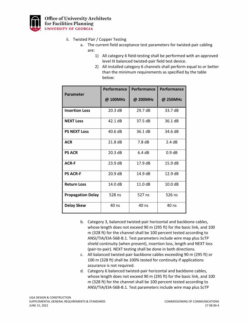
UGA DESIGN & CONSTRUCTION SUPPLEMENTAL GENERAL REQUIREMENTS & STANDARDS COMMISSIONING OF COMMUNICATIONS JUNE 15, 2021 27 08 00-4
ii. Twisted Pair / Copper Testing a. The current field acceptance test parameters for twisted-pair cabling
are: 1) All category 6 field-testing shall be performed with an approved
level III balanced twisted-pair field test device. 2) All installed category 6 channels shall perform equal to or better
than the minimum requirements as specified by the table below:
Parameter Performance
@ 100MHz
Performance
@ 200MHz
Performance
@ 250MHz
Insertion Loss 20.3 dB 29.7 dB 33.7 dB
NEXT Loss 42.1 dB 37.5 dB 36.1 dB
PS NEXT Loss 40.6 dB 36.1 dB 34.6 dB
ACR 21.8 dB 7.8 dB 2.4 dB
PS ACR 20.3 dB 6.4 dB 0.9 dB
ACR-F 23.9 dB 17.9 dB 15.9 dB
PS ACR-F 20.9 dB 14.9 dB 12.9 dB
Return Loss 14.0 dB 11.0 dB 10.0 dB
Propagation Delay 528 ns 527 ns 526 ns
Delay Skew 40 ns 40 ns 40 ns
b. Category 3, balanced twisted-pair horizontal and backbone cables,
whose length does not exceed 90 m (295 ft) for the basic link, and 100 m (328 ft) for the channel shall be 100 percent tested according to ANSI/TIA/EIA-568-B.1. Test parameters include wire map plus ScTP shield continuity (when present), insertion loss, length and NEXT loss (pair-to-pair). NEXT testing shall be done in both directions.
c. All balanced twisted-pair backbone cables exceeding 90 m (295 ft) or 100 m (328 ft) shall be 100% tested for continuity if applications assurance is not required.
d. Category 6 balanced twisted-pair horizontal and backbone cables, whose length does not exceed 90 m (295 ft) for the basic link, and 100 m (328 ft) for the channel shall be 100 percent tested according to ANSI/TIA/EIA-568-B.1. Test parameters include wire map plus ScTP
UGA DESIGN & CONSTRUCTION SUPPLEMENTAL GENERAL REQUIREMENTS & STANDARDS COMMISSIONING OF COMMUNICATIONS JUNE 15, 2021 27 08 00-5
shield continuity (when present), length, NEXT loss (pair-to-pair), NEXT loss (power sum), ELFEXT loss (pair-to-pair), ELFEXT loss (power sum), return loss, insertion loss, propagation delay, and delay skew.
e. Test Equipment Criteria 1) All balanced twisted-pair field testers shall be factory calibrated
each calendar year by the field test equipment manufacturer as stipulated by the manuals provided with the field test unit. The calibration certificate shall be provided for review prior to the start of testing.
2) Autotest settings provided in the field tester for testing the installed cabling shall be set to the default parameters.
3) Test settings selected from options provided in the field testers shall be compatible with the installed cable under test.
iii. CATV Coaxial Cable Testing a. CATV coaxial cabling at 75 Ohms will be tested for bi-directional use b. DC loop resistance c. Impedance d. Length e. TDR f. Frequency Attenuation variation g. Structural loss- physical damage to cable h. These are tested with Digital Multi-Meters, TDR’s, Sweep Generation
Testing, and other testing equipment. iv. Telephone Cable Testing
a. All telephony cables shall be 100% tested for continuity. v. Optical Cabling
a. Multimode – The fiber cable shall be a graded index fiber with a nominal 50/125µm core / cladding. The fiber shall conform to the following standards or international equivalents:
ANSI/TIA/EIA-568-B (overall requirements) ANSI/TIA/EIA-492AAAC (Laser bandwidth DMD specification) ANSI/ICEA-83-596 (indoor optical cables) ANSI/ICEA-87-640 (indoor optical cables)
b. Single-mode – The fiber shall be at least Class IVa Dispersion unshifted single-mode optical fiber. It shall conform to the following standards or international equivalents:
ANSI/TIA/EIA-568-B (overall requirements) ANSI/TIA/EIA-492CAAA (fiber specifications) ANSI/ICEA S-83-596 (indoor optical cable) ANSI/ICEA S-87-640 (outdoor optical cable)
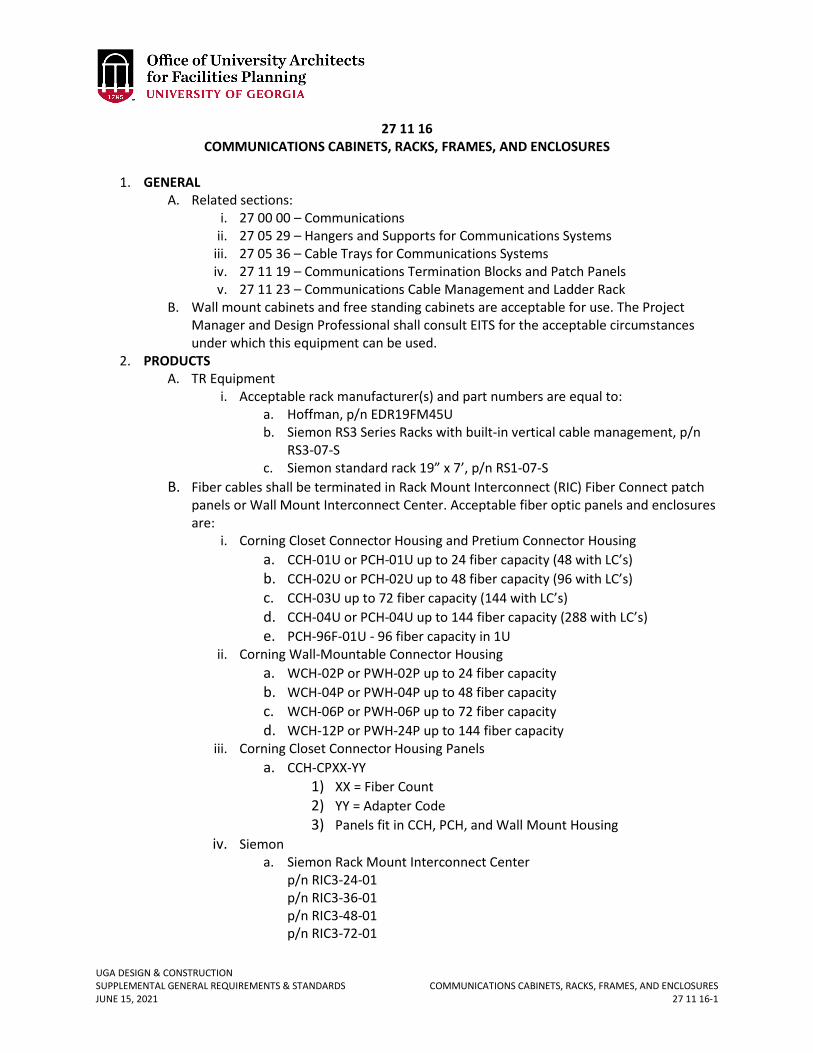
UGA DESIGN & CONSTRUCTION SUPPLEMENTAL GENERAL REQUIREMENTS & STANDARDS COMMUNICATIONS CABINETS, RACKS, FRAMES, AND ENCLOSURES JUNE 15, 2021 27 11 16-1
27 11 16 COMMUNICATIONS CABINETS, RACKS, FRAMES, AND ENCLOSURES
1. GENERAL
A. Related sections: i. 27 00 00 – Communications
ii. 27 05 29 – Hangers and Supports for Communications Systems iii. 27 05 36 – Cable Trays for Communications Systems iv. 27 11 19 – Communications Termination Blocks and Patch Panels v. 27 11 23 – Communications Cable Management and Ladder Rack
B. Wall mount cabinets and free standing cabinets are acceptable for use. The Project Manager and Design Professional shall consult EITS for the acceptable circumstances under which this equipment can be used.
2. PRODUCTS A. TR Equipment
i. Acceptable rack manufacturer(s) and part numbers are equal to: a. Hoffman, p/n EDR19FM45U b. Siemon RS3 Series Racks with built-in vertical cable management, p/n
RS3-07-S c. Siemon standard rack 19” x 7’, p/n RS1-07-S
B. Fiber cables shall be terminated in Rack Mount Interconnect (RIC) Fiber Connect patch panels or Wall Mount Interconnect Center. Acceptable fiber optic panels and enclosures are:
i. Corning Closet Connector Housing and Pretium Connector Housing a. CCH-01U or PCH-01U up to 24 fiber capacity (48 with LC’s) b. CCH-02U or PCH-02U up to 48 fiber capacity (96 with LC’s) c. CCH-03U up to 72 fiber capacity (144 with LC’s) d. CCH-04U or PCH-04U up to 144 fiber capacity (288 with LC’s) e. PCH-96F-01U - 96 fiber capacity in 1U
ii. Corning Wall-Mountable Connector Housing a. WCH-02P or PWH-02P up to 24 fiber capacity b. WCH-04P or PWH-04P up to 48 fiber capacity c. WCH-06P or PWH-06P up to 72 fiber capacity d. WCH-12P or PWH-24P up to 144 fiber capacity
iii. Corning Closet Connector Housing Panels a. CCH-CPXX-YY
1) XX = Fiber Count 2) YY = Adapter Code 3) Panels fit in CCH, PCH, and Wall Mount Housing
iv. Siemon a. Siemon Rack Mount Interconnect Center
p/n RIC3-24-01 p/n RIC3-36-01 p/n RIC3-48-01 p/n RIC3-72-01
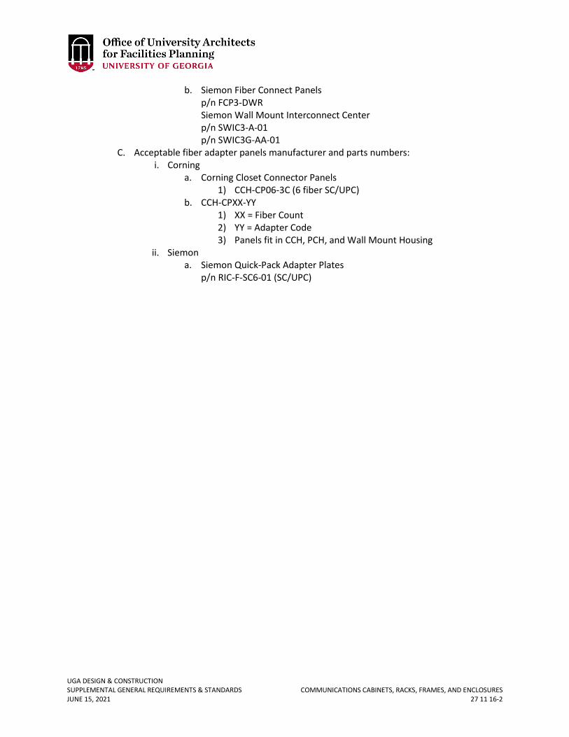
UGA DESIGN & CONSTRUCTION SUPPLEMENTAL GENERAL REQUIREMENTS & STANDARDS COMMUNICATIONS CABINETS, RACKS, FRAMES, AND ENCLOSURES JUNE 15, 2021 27 11 16-2
b. Siemon Fiber Connect Panels p/n FCP3-DWR Siemon Wall Mount Interconnect Center p/n SWIC3-A-01 p/n SWIC3G-AA-01
C. Acceptable fiber adapter panels manufacturer and parts numbers: i. Corning
a. Corning Closet Connector Panels 1) CCH-CP06-3C (6 fiber SC/UPC)
b. CCH-CPXX-YY 1) XX = Fiber Count 2) YY = Adapter Code 3) Panels fit in CCH, PCH, and Wall Mount Housing
ii. Siemon a. Siemon Quick-Pack Adapter Plates
p/n RIC-F-SC6-01 (SC/UPC)
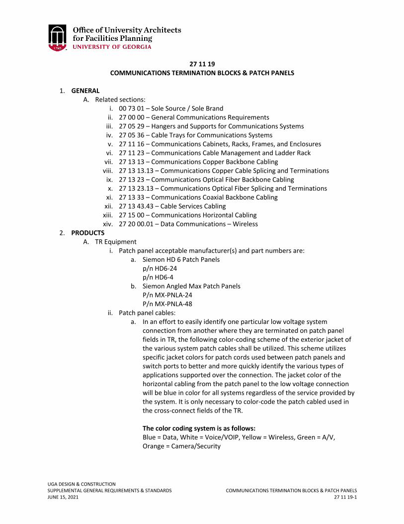
UGA DESIGN & CONSTRUCTION SUPPLEMENTAL GENERAL REQUIREMENTS & STANDARDS COMMUNICATIONS TERMINATION BLOCKS & PATCH PANELS JUNE 15, 2021 27 11 19-1
27 11 19 COMMUNICATIONS TERMINATION BLOCKS & PATCH PANELS
1. GENERAL
A. Related sections: i. 00 73 01 – Sole Source / Sole Brand
ii. 27 00 00 – General Communications Requirements iii. 27 05 29 – Hangers and Supports for Communications Systems iv. 27 05 36 – Cable Trays for Communications Systems v. 27 11 16 – Communications Cabinets, Racks, Frames, and Enclosures
vi. 27 11 23 – Communications Cable Management and Ladder Rack vii. 27 13 13 – Communications Copper Backbone Cabling
viii. 27 13 13.13 – Communications Copper Cable Splicing and Terminations ix. 27 13 23 – Communications Optical Fiber Backbone Cabling x. 27 13 23.13 – Communications Optical Fiber Splicing and Terminations
xi. 27 13 33 – Communications Coaxial Backbone Cabling xii. 27 13 43.43 – Cable Services Cabling
xiii. 27 15 00 – Communications Horizontal Cabling xiv. 27 20 00.01 – Data Communications – Wireless
2. PRODUCTS A. TR Equipment
i. Patch panel acceptable manufacturer(s) and part numbers are: a. Siemon HD 6 Patch Panels
p/n HD6-24 p/n HD6-4
b. Siemon Angled Max Patch Panels P/n MX-PNLA-24 P/n MX-PNLA-48
ii. Patch panel cables: a. In an effort to easily identify one particular low voltage system
connection from another where they are terminated on patch panel fields in TR, the following color-coding scheme of the exterior jacket of the various system patch cables shall be utilized. This scheme utilizes specific jacket colors for patch cords used between patch panels and switch ports to better and more quickly identify the various types of applications supported over the connection. The jacket color of the horizontal cabling from the patch panel to the low voltage connection will be blue in color for all systems regardless of the service provided by the system. It is only necessary to color-code the patch cabled used in the cross-connect fields of the TR. The color coding system is as follows: Blue = Data, White = Voice/VOIP, Yellow = Wireless, Green = A/V, Orange = Camera/Security
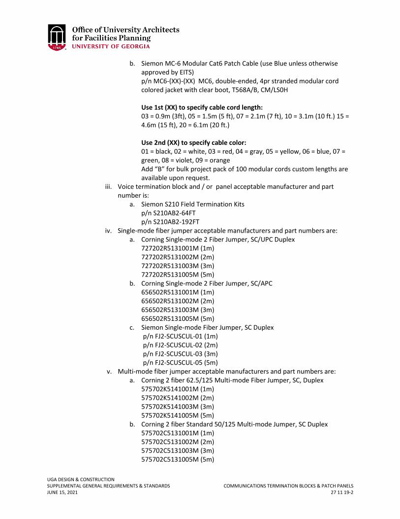
UGA DESIGN & CONSTRUCTION SUPPLEMENTAL GENERAL REQUIREMENTS & STANDARDS COMMUNICATIONS TERMINATION BLOCKS & PATCH PANELS JUNE 15, 2021 27 11 19-2
b. Siemon MC-6 Modular Cat6 Patch Cable (use Blue unless otherwise approved by EITS) p/n MC6-(XX)-(XX) MC6, double-ended, 4pr stranded modular cord colored jacket with clear boot, T568A/B, CM/LS0H Use 1st (XX) to specify cable cord length: 03 = 0.9m (3ft), 05 = 1.5m (5 ft), 07 = 2.1m (7 ft), 10 = 3.1m (10 ft.) 15 = 4.6m (15 ft), 20 = 6.1m (20 ft.) Use 2nd (XX) to specify cable color: 01 = black, 02 = white, 03 = red, 04 = gray, 05 = yellow, 06 = blue, 07 = green, 08 = violet, 09 = orange Add “B” for bulk project pack of 100 modular cords custom lengths are available upon request.
iii. Voice termination block and / or panel acceptable manufacturer and part number is:
a. Siemon S210 Field Termination Kits p/n S210AB2-64FT p/n S210AB2-192FT
iv. Single-mode fiber jumper acceptable manufacturers and part numbers are: a. Corning Single-mode 2 Fiber Jumper, SC/UPC Duplex
727202R5131001M (1m) 727202R5131002M (2m) 727202R5131003M (3m) 727202R5131005M (5m)
b. Corning Single-mode 2 Fiber Jumper, SC/APC 656502R5131001M (1m)
656502R5131002M (2m) 656502R5131003M (3m) 656502R5131005M (5m)
c. Siemon Single-mode Fiber Jumper, SC Duplex p/n FJ2-SCUSCUL-01 (1m) p/n FJ2-SCUSCUL-02 (2m) p/n FJ2-SCUSCUL-03 (3m) p/n FJ2-SCUSCUL-05 (5m)
v. Multi-mode fiber jumper acceptable manufacturers and part numbers are: a. Corning 2 fiber 62.5/125 Multi-mode Fiber Jumper, SC, Duplex
575702K5141001M (1m) 575702K5141002M (2m) 575702K5141003M (3m) 575702K5141005M (5m)
b. Corning 2 fiber Standard 50/125 Multi-mode Jumper, SC Duplex 575702C5131001M (1m) 575702C5131002M (2m) 575702C5131003M (3m) 575702C5131005M (5m)
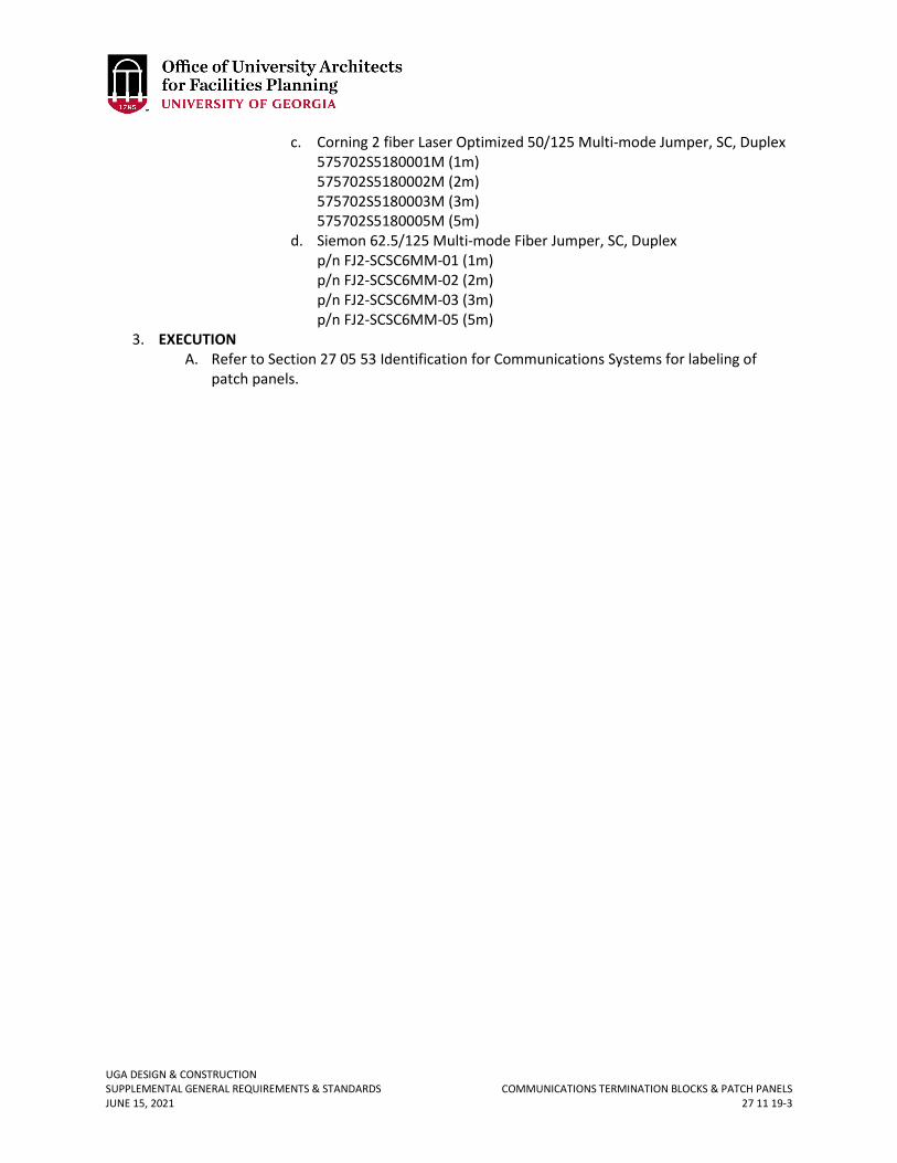
UGA DESIGN & CONSTRUCTION SUPPLEMENTAL GENERAL REQUIREMENTS & STANDARDS COMMUNICATIONS TERMINATION BLOCKS & PATCH PANELS JUNE 15, 2021 27 11 19-3
c. Corning 2 fiber Laser Optimized 50/125 Multi-mode Jumper, SC, Duplex 575702S5180001M (1m) 575702S5180002M (2m) 575702S5180003M (3m) 575702S5180005M (5m)
d. Siemon 62.5/125 Multi-mode Fiber Jumper, SC, Duplex p/n FJ2-SCSC6MM-01 (1m) p/n FJ2-SCSC6MM-02 (2m) p/n FJ2-SCSC6MM-03 (3m) p/n FJ2-SCSC6MM-05 (5m)
3. EXECUTION A. Refer to Section 27 05 53 Identification for Communications Systems for labeling of
patch panels.
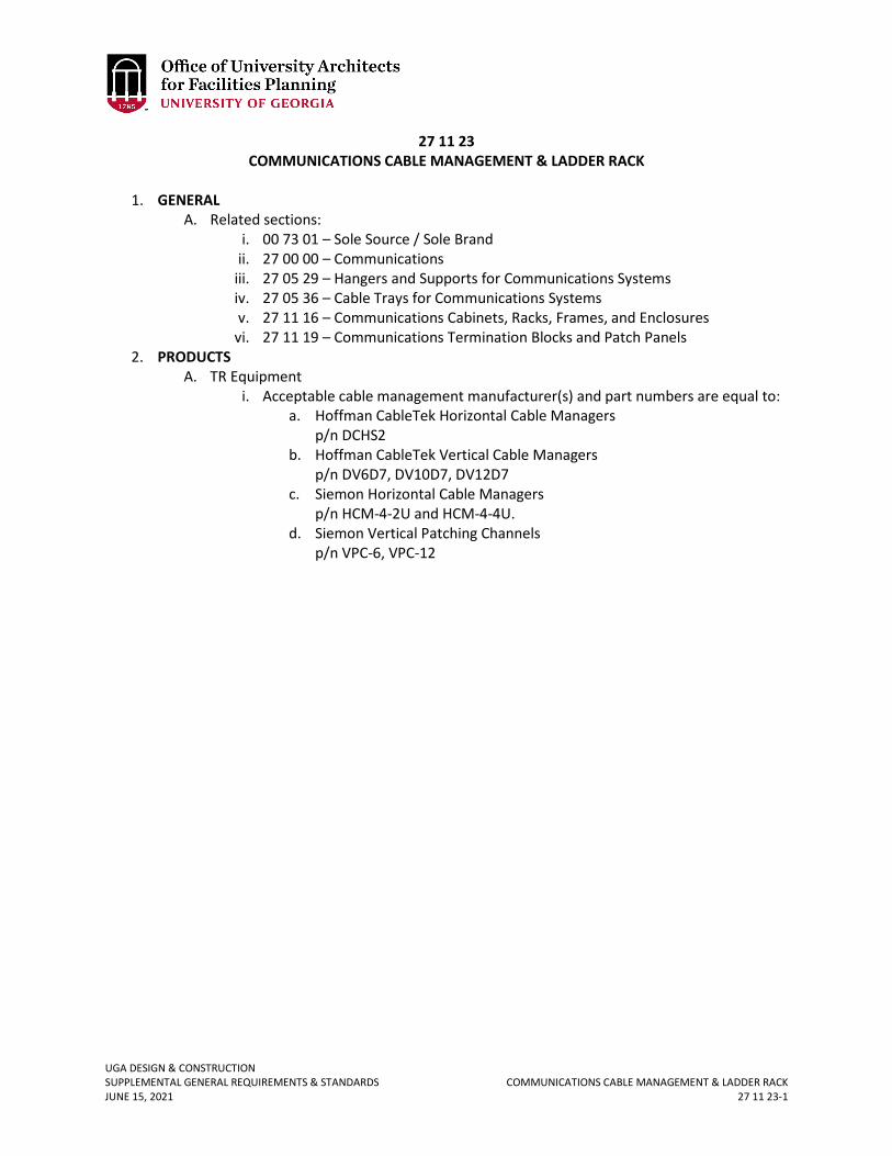
UGA DESIGN & CONSTRUCTION SUPPLEMENTAL GENERAL REQUIREMENTS & STANDARDS COMMUNICATIONS CABLE MANAGEMENT & LADDER RACK JUNE 15, 2021 27 11 23-1
27 11 23 COMMUNICATIONS CABLE MANAGEMENT & LADDER RACK
1. GENERAL
A. Related sections: i. 00 73 01 – Sole Source / Sole Brand
ii. 27 00 00 – Communications iii. 27 05 29 – Hangers and Supports for Communications Systems iv. 27 05 36 – Cable Trays for Communications Systems v. 27 11 16 – Communications Cabinets, Racks, Frames, and Enclosures
vi. 27 11 19 – Communications Termination Blocks and Patch Panels 2. PRODUCTS
A. TR Equipment i. Acceptable cable management manufacturer(s) and part numbers are equal to:
a. Hoffman CableTek Horizontal Cable Managers p/n DCHS2
b. Hoffman CableTek Vertical Cable Managers p/n DV6D7, DV10D7, DV12D7
c. Siemon Horizontal Cable Managers p/n HCM-4-2U and HCM-4-4U.
d. Siemon Vertical Patching Channels p/n VPC-6, VPC-12
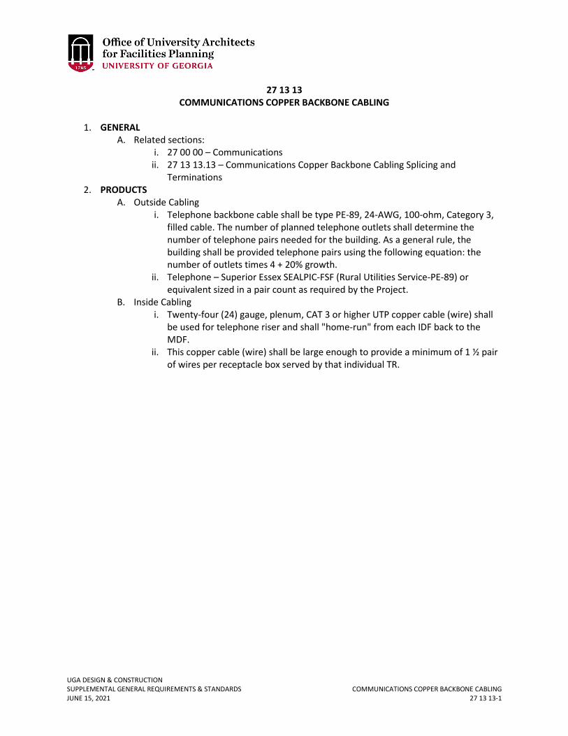
UGA DESIGN & CONSTRUCTION SUPPLEMENTAL GENERAL REQUIREMENTS & STANDARDS COMMUNICATIONS COPPER BACKBONE CABLING JUNE 15, 2021 27 13 13-1
27 13 13 COMMUNICATIONS COPPER BACKBONE CABLING
1. GENERAL
A. Related sections: i. 27 00 00 – Communications
ii. 27 13 13.13 – Communications Copper Backbone Cabling Splicing and Terminations
2. PRODUCTS A. Outside Cabling
i. Telephone backbone cable shall be type PE-89, 24-AWG, 100-ohm, Category 3, filled cable. The number of planned telephone outlets shall determine the number of telephone pairs needed for the building. As a general rule, the building shall be provided telephone pairs using the following equation: the number of outlets times 4 + 20% growth.
ii. Telephone – Superior Essex SEALPIC-FSF (Rural Utilities Service-PE-89) or equivalent sized in a pair count as required by the Project.
B. Inside Cabling i. Twenty-four (24) gauge, plenum, CAT 3 or higher UTP copper cable (wire) shall
be used for telephone riser and shall "home-run" from each IDF back to the MDF.
ii. This copper cable (wire) shall be large enough to provide a minimum of 1 ½ pair of wires per receptacle box served by that individual TR.
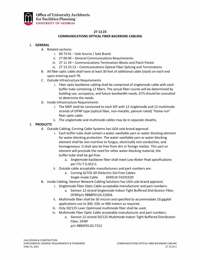
UGA DESIGN & CONSTRUCTION SUPPLEMENTAL GENERAL REQUIREMENTS & STANDARDS COMMUNICATIONS OPTICAL FIBER BACKBONE CABLING JUNE 15, 2021 27 13 23-1
27 13 23 COMMUNICATIONS OPTICAL FIBER BACKBONE CABLING
1. GENERAL
A. Related sections: i. 00 73 01 – Sole Source / Sole Brand
ii. 27 00 00 – General Communications Requirements iii. 27 11 19 – Communications Termination Blocks and Patch Panels iv. 27 13 23.13 – Communications Optical Fiber Splicing and Terminations
B. All fiber optic cable shall have at least 30 feet of additional cable (slack) on each end upon entering each TR.
C. Outside Infrastructure Requirements i. Fiber optic backbone cabling shall be comprised of singlemode cable with each
buffer tube containing 12 fibers. The actual fiber counts will be determined by building use, occupancy, and future bandwidth needs. EITS should be consulted to determine the needs.
D. Inside Infrastructure Requirements i. The MDF shall be connected to each IDF with 12 singlemode and 12 multimode
strands of OFNP type (optical fiber, non-metallic, plenum rated) "home-run" fiber optic cable.
ii. The singlemode and multimode cables may be in separate sheaths. 2. PRODUCTS
A. Outside Cabling; Corning Cable Systems has UGA sole brand approval. i. Each buffer tube shall contain a water-swellable yarn or water blocking element
for water-blocking protection. The water-swellable yarn or water blocking element shall be non-nutritive to fungus, electrically non-conductive, and homogeneous. It shall also be free from dirt or foreign matter. This yarn or element will preclude the need for other water-blocking material; the buffer-tube shall be gel-free.
a. Singlemode backbone fiber shall meet Low Water Peak specifications per ITU-T G.652.C.
ii. Outside cable acceptable manufacturers and part numbers are: a. Corning ALTOS All-Dielectric Gel-Free Cables
Single-mode Cable XXXEU4-T4101D20 B. Inside Cabling; Siemon Network Cabling Solutions has UGA sole brand approval.
i. Singlemode Fiber Optic Cable acceptable manufacturer and part numbers: a. Siemon 12-strand Singlemode Indoor Tight Buffered Distribution Fiber,
OFNPp/n 9BB8P012G-E205A ii. Multimode fiber shall be 50 micron and specified to accommodate 10 gigabit
applications out to 300, 550, or 600 meters as required. iii. Only 50/125 Laser Optimized multimode fiber shall be used. iv. Multimode Fiber Optic Cable acceptable manufacturer and part numbers:
a. Siemon 12-strand 50/125 Multimode Indoor Tight Buffered Distribution Fiber, OFNP p/n 9BB5P012G-T312
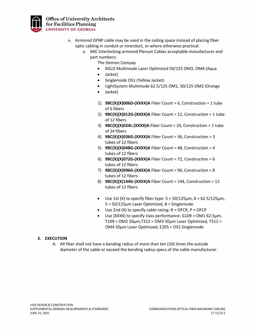
UGA DESIGN & CONSTRUCTION SUPPLEMENTAL GENERAL REQUIREMENTS & STANDARDS COMMUNICATIONS OPTICAL FIBER BACKBONE CABLING JUNE 15, 2021 27 13 23-2
v. Armored OFNP cable may be used in the ceiling space instead of placing fiber optic cabling in conduit or innerduct, or where otherwise practical.
a. MIC Interlocking armored Plenum Cables acceptable manufacturer and part numbers:
The Siemon Compay • XGLO Multimode Laser Optimized 50/125 OM3, OM4 (Aqua • Jacket) • Singlemode OS1 (Yellow Jacket) • LightSystem Multimode 62.5/125 OM1, 50/125 OM2 (Orange • Jacket)
1) 9BC(X)(X)006D-(XXXX)A Fiber Count = 6, Construction = 1 tube
of 6 fibers 2) 9BC(X)(X)012G-(XXXX)A Fiber Count = 12, Construction = 1 tube
of 12 fibers 3) 9BC(X)(X)024L-(XXXX)A Fiber Count = 24, Construction = 1 tube
of 24 fibers 4) 9BC(X)(X)036G-(XXXX)A Fiber Count = 36, Construction = 3
tubes of 12 fibers 5) 9BC(X)(X)048G-(XXXX)A Fiber Count = 48, Construction = 4
tubes of 12 fibers 6) 9BC(X)(X)072G-(XXXX)A Fiber Count = 72, Construction = 6
tubes of 12 fibers 7) 9BC(X)(X)096G-(XXXX)A Fiber Count = 96, Construction = 8
tubes of 12 fibers 8) 9BC(X)(X)144G-(XXXX)A Fiber Count = 144, Construction = 12
tubes of 12 fibers • Use 1st (X) to specify fiber type: 5 = 50/125µm, 6 = 62.5/125µm,
5 = 50/125µm Laser Optimized, 8 = Singlemode • Use 2nd (X) to specify cable rating: R = OFCR, P = OFCP • Use (XXXX) to specify class performance: G109 = OM1 62.5µm,
T109 = OM2 50µm,T312 = OM3 50µm Laser Optimized, T512 = OM4 50µm Laser Optimized, E205 = OS1 Singlemode
3. EXECUTION A. All fiber shall not have a bending radius of more than ten (10) times the outside
diameter of the cable or exceed the bending radius specs of the cable manufacturer.
UGA DESIGN & CONSTRUCTION SUPPLEMENTAL GENERAL REQUIREMENTS & STANDARDS COMMUNICATIONS OPTICAL FIBER SPLICING & TERMINATIONS JUNE 15, 2021 27 13 23.13-1
27 13 23.13 COMMUNICATIONS OPTICAL FIBER SPLICING & TERMINATIONS
1. GENERAL
A. Related sections: i. 00 73 01 – Sole Source / Sole Brand
ii. 27 00 00 – General Communications Requirements iii. 27 13 23 – Communications Optical Fiber Backbone Cabling
B. General communication services shall be terminated with duplex SC/UPC. 2. PRODUCTS
A. Outside Infrastructure; Corning Cable Systems has UGA sole brand approval. i. Outside fiber closures acceptable manufacturers are:
a. Corning Advanced Splice Closures (SCF) 1) SCF-6C22-01 72 Fiber Splices 2) SCF-6C28-01 144 Fiber Splices 3) SCF-8C28-01 240 Fiber Splices 4) SCF-8C28-02 480 Fiber Splices
ii. The splice closure housing shall be non-metallic. It shall be resistant to solvents, stress cracking, and creep. The housing materials shall also be compatible with chemicals and other materials to which they might be exposed in normal applications. The splice closure shall be re–enterable. The closure end cap shall be capable of accepting additional cables without removal of the sheath retention or strength member clamping hardware on previously installed cables or disturbing existing splices. The optical fiber splice closure shall provide a clamping mechanism to prevent pistoning of the central member or strength members and to prevent cable sheath slip or pullout.
B. Inside Infrastructure; Siemon Network Cabling Solutions has UGA sole brand approval. i. Fusion splice trays acceptable manufacturer(s) and part numbers are:
a. Siemon Fusion Splice Tray p/n TRAY-3
ii. Singlemode pigtail acceptable manufacturer(s) and part numbers are: a. Seimon
1) Siemon Singlemode Simplex Pigtail, SC/UPC, 1m p/n FP1B-SCUL-01
2) Siemon Singlemode Simplex Pigtail, SC/APC, 1m p/n FP1B-SCA-01
iii. Multimode pigtail acceptable manufacturer(s) and part numbers are: a. Siemon 50/125 Multimode Simplex Pigtail, SC, 1m
p/n P1B-SC5MM-01 3. EXECUTION
A. All fibers shall be terminated with SC style connectors. Fusion spliced pigtails, epoxy minimal polish connectors and UNICAM style connectors are all acceptable methods of fiber termination for backbone cables.
B. Singlemode fiber should be terminated with a minimum of 1 pair of Angle Polish Connectors at each end of the cable to support video/CATV service.
UGA DESIGN & CONSTRUCTION SUPPLEMENTAL GENERAL REQUIREMENTS & STANDARDS COMMUNICATIONS COAXIAL BACKBONE CABLING JUNE 15, 2021 27 13 33-1
27 13 33 COMMUNICATIONS COAXIAL BACKBONE CABLING
1. GENERAL
A. Related sections: i. 00 73 01 – Sole Source / Sole Brand
ii. 27 00 00 – General Communications Requirements iii. 27 13 43.43 – Cable Services Cabling
B. Any individual cable length over 250 feet will need to be approved by EITS in writing prior to installation.
C. For CATV services, fiber optic backbone cabling shall be terminated with a minimum 1 pair, green in color, single-mode SC/APC connector at both ends of cable.
2. PRODUCTS A. Inside CATV Cabling
i. CATV coaxial cable shall be plenum rated, quad-shielded, RG-6, from each outlet back to the appropriate TR with no more than 250 feet of cable. Acceptable products are:
a. Commscope 2227V b. General Cable C3525 c. Belden 1189AP.
ii. CATV Connectors a. Compression style CATV connectors with rubber o-rings shall be used.
Siemon RG6C Compression Connectors p/n RG6C Belden Snap n Seal RG6 p/n FSNS6PLQ or equal
iii. CATV Patch Panels/Connectors a. Siemon MAX Patch Panel and F-Type MAX Modules
p/n MX-PNL-24 p/n MX-PNL-48 p/n MX-F-FA-01
3. EXECUTION A. Cable shall be terminated on wall mounted patch panels / taps.
UGA DESIGN & CONSTRUCTION SUPPLEMENTAL GENERAL REQUIREMENTS & STANDARDS CABLE SERVICES CABLING JUNE 15, 2021 27 13 43.43-1
27 13 43.43 CABLE SERVICES CABLING
1. GENERAL
A. Related sections: i. 00 73 01 – Sole Source / Sole Brand
ii. 27 00 00 – Communications iii. 27 05 53 – Identification for Communications Systems iv. 27 08 00 – Commissioning of Communications v. 27 13 33 – Communications Coaxial Backbone Cabling
vi. 27 15 00 – Communications Horizontal Cabling B. EITS shall provide consultation and preliminary planning guidance to assist the Design
Professional and Project Manager in determining the cabling requirements on a case-by-case basis for each building.
C. The following general specifications will be required for buildings which are connected to the UGA Cablevision network.
i. The network must be two-way capable with 862 MHz actives and 1 Gig passives. The downstream frequency will be from 54 MHz-862 MHz for digital / analog video and data transmissions. The upstream frequency will be from 5 MHz - 42 MHz for digital / analog video and data transmissions.
ii. The network must deliver a signal at the following levels: a. The signal level at each outlet / drop should have minimum of 6 dBmV
and a maximum of 15 dBmV on all channels. b. The signal to noise ratio must be 43 dB or better. c. The signal to composite triple beat must be 51dB or better. d. Network hum must be less than 1%. e. System response must be +/- 1 ½ dBmV within any channel. f. Signal to beat interference must be 57 dB or better. g. For digital signals, a 32 MER reading or better is required. h. Radiation must be within FCC Specifications, i.e., less than 20 uv/m
within 10 feet with a tuned dipole antenna. iii. All rooms will be “home run” to TR equipment room(s). It is permissible for one
loop-through within one room. iv. Cabling for CATV shall be placed in a 1-inch I.D. minimum conduit for up 6
cables. 2. PRODUCTS
A. All outlets will be the standard CATV termination known as an F-81 barrel splice type connector (no solder or screw systems will be allowed).
B. CATV: Coaxial Cable Preparation and Connection i. Hardline .500, .750, and .100 jacketed and unjacketed cables must be used.
ii. The standard RG-6 connectors to be used are as follows: Siemon RG6C Compression Connector’s p/n RG6C Belden Snap n Seal RG6 p/n FSNS6PLQ or equal
UGA DESIGN & CONSTRUCTION SUPPLEMENTAL GENERAL REQUIREMENTS & STANDARDS CABLE SERVICES CABLING JUNE 15, 2021 27 13 43.43-2
C. RG-11 and RG-6 CATV cable i. Active and Passive RF Components:
a. Fiber Node – Olsen Technology OTPN-400C, SC/APC or equal. b. Amplifier – Toner TIBA-37-1000 or equal. c. Taps – RMS brand Digitap’s or equal.
ii. Coaxial cable acceptable manufacturer: a. RG-6:
1) Commscope 2227V 2) general cable C3525 3) Belden 1189AP only.
b. RG-11: 1) Commscope 2287K 2) general cable C3529 3) Belden 1153A.
iii. Coaxial cable shall be plenum rated RG-6. 3. EXECUTION
A. CATV: Coaxial Cable Preparation and Connection i. For flooded cable, clean flooding compound off the aluminum sheath to keep
the ground loop complete. ii. Clean, sharp, serviced, coring tools must be used.
iii. Metallic knives may NOT be used when cleaning dielectric from center conductor. This will cause a problem with the ‘skin effect’ for higher frequencies to ride on the cable center conductor. Use plastic removal tools.
B. CATV: Activation and Testing i. Refer to Section 27 08 00 Commissioning of Communications.
ii. Passives verification - use sweeping methods for verification. iii. All cables must be labeled with room number (where outlet is) both on the
outlet and in the TR wiring closet. Refer to Section 27 05 53 Identification for Communications Systems.
C. RG-11 and RG-6 CATV Wire i. Use proper preparation tools for specific connectors for correct installation.
Change blades when necessary.
UGA DESIGN & CONSTRUCTION SUPPLEMENTAL GENERAL REQUIREMENTS & STANDARDS COMMUNICATIONS HORIZONTAL CABLING JUNE 15, 2021 27 15 00-1
27 15 00 COMMUNICATIONS HORIZONTAL CABLING
1. GENERAL
A. Related sections: i. 00 73 01 – Sole Source / Sole Brand
ii. 27 00 00 – General Communications Requirements iii. 27 05 26 – Grounding and Bonding for Communication Systems iv. 27 05 29 – Hangers and Supports for Communications Systems v. 27 05 36 – Cable Trays for Communications Systems
vi. 27 41 00 – General Audio-Visual System Requirements vii. 27 05 43 – Underground Ducts and Raceways for Communications Systems
viii. 27 05 46 – Utility Poles for Communications Systems ix. 27 05 53 – Identification for Communications Systems x. 27 08 00 – Commissioning of Communications
xi. 27 11 16 – Communications Cabinets, Racks, Frames, and Enclosures xii. 27 11 19 – Communications Termination Blocks and Patch Panels
xiii. 27 11 23 – Communications Cable Management and Ladder Rack xiv. 27 13 13 – Communications Copper Backbone Cabling xv. 27 13 13.13 – Communications Copper Cable Splicing and Terminations
xvi. 27 13 23 – Communications Optical Fiber Backbone Cabling xvii. 27 13 23.13 – Communications Optical Fiber Splicing and Terminations
xviii. 27 13 33 – Communications Coaxial Backbone Cabling xix. 27 13 43.43 – Cable Services Cabling xx. 27 20 00.01 – Data Communications - Wireless
B. UGA’s high-speed data network is designed to accommodate Ethernet applications up to 1 Gigabit with a manufactures guaranteed electrical performance up to 550 MHz for, 4 pair, 24 AWG, 100 ohm, UTP Category 6 cable. The applications for use would include; high-speed internet access, Voice Over IP (VoIP), and other current and emerging applications.
C. For this section, outlet shall mean telecommunications outlet. D. Refer to Section 27 00 00 Communications for Contractor qualification requirements. E. Refer to Sections 27 05 09 Hangers and Supports for Communications and 27 05 33
Cable Trays for Communication Systems. F. Only one telecommunications color scheme, white, (faceplate, wiremold, etc.) shall be
used throughout the Project. For areas that may require stainless steel or a different color, the Design Professional shall coordinate with the Project Manager and EITS to discuss options and approval must be obtained through the variance process.
G. A minimum of two (2) blue jacketed plenum rated, Category 6 (Cat 6) UTP cables shall be run from the receptacle box (outlet) to the appropriate TR. Two (2) ports served by the Cat6 communication cables capable of delivering either data or voice services are typical per office space receptacle box.
H. Wiring shall be placed in 1-inch I.D. minimum conduit for up to 11 cables. There can be up to 44 cables in a 2-inch conduit, 98 cables in a 3-inch conduit, and 122 cables in a 4-inch conduit.
UGA DESIGN & CONSTRUCTION SUPPLEMENTAL GENERAL REQUIREMENTS & STANDARDS COMMUNICATIONS HORIZONTAL CABLING JUNE 15, 2021 27 15 00-2
I. Under no circumstances shall any conduit contain more than two 90 degree bends nor exceed 180 degrees of total bend without the installation of pull box(s) to accomplish the above.
J. The outlet shall be a minimum of 1.75 inches deep, single gang box. K. The outlet must be within 250 cable feet of the TR. L. If divided raceway is used to serve both electrical and telecommunications, the raceway
must be metal with dividers between. M. At the outlet end, enough additional cable (slack) must be left to reach the farthest
corner of the wall, plus five feet. N. At the TR end, at least 15 feet of additional cable (slack) must be provided past the
center point of the appropriate telephone or data racks. O. For renovation projects when it is necessary to have exposed interior wiring runs, the
wire shall be enclosed using wire molding or conduit. Under no circumstances should cable be installed below ceiling in an exposed fashion, i.e., all surface mounted cable should be enclosed in conduit.
P. For small projects, the extent of cabling replacement to current standards contained herein shall be determined on a case-by-case basis with the input of EITS, the Project Manager, and the departmental point of contact. Factors to be considered shall include a speed test of existing cabling (by EITS), the anticipated speed demands required by End-Users, funding availability, and project schedule.
2. PRODUCTS A. Cabling / Cabling System
i. The cabling system shall be the Siemon System 6 UTP Cabling System. ii. All cabling shall be blue jacketed and plenum rated.
iii. All cable shall be Siemon cable or approved Siemon cable partners. Acceptable CAT6 cables are:
a. Berktek LanMark 1000 10032093 (reel) b. Berktek LanMark 1000 10032094 (box) c. Berktek LanMark 1000 10065423 (reel in a box) d. Berktek LanMark 2000 10032251 e. General Cable GenSpeed 6500 7131431 f. General Cable GenSpeed 6600 7131721 g. Mohawk AdvanceNet 6E M57193 h. Mohawk GigaLan 6E+ M57414 i. Siemon System 6 9C6P4-E3-06-RXA j. Siemon Premium 6 9C6P4-E4-06-RBA k. Superior Essex DataGain 450 66-272-2B (reel) l. Superior Essex DataGain 450 66-246-2B (brake box) m. Superior Essex DataGain 450 66-240-2B (POP box) n. Superior Essex Nextgain 54-272-2B (reel) o. Superior Essex Nextgain 54-246-2B (reel in a box)
iv. All telephone, data, and CATV installations shall include, but may not be limited to, the following Siemon System 6 UTP Cabling System products:
a. Category 6 Cross-Connect Wire b. HD6 Patch Panels c. MAX 6 Modules
UGA DESIGN & CONSTRUCTION SUPPLEMENTAL GENERAL REQUIREMENTS & STANDARDS COMMUNICATIONS HORIZONTAL CABLING JUNE 15, 2021 27 15 00-3
d. MAX Modular Faceplates e. MAX Patch Panels f. MC 6 Modular Cords g. S210 Connecting Block h. S210 Field Termination Kits
B. Outlets i. All surface mounted outlets shall be 4 port, white, Siemon MX-SM Surface
Mount Box, part number MX-SM4-02 or MX-SM6-02 for 6 port box. All surface mount boxes will use Siemon Flat modules.
ii. All flush mount, in wall outlets shall use white Siemon MAX Modular single gang or double gang style faceplates in whatever port configuration is necessary.
iii. The following are suitable flush mount faceplate part numbers: a. MX-FP-S-01-02 single gang 1-port b. MX-FP-S-02-02 single gang 2-port c. MX-FP-S-03-02 single gang 3-port d. MX-FP-S-04-02 single gang 4-port e. MX-FP-S-06-02 single gang 6-port f. MX-FP-D-06-02 double gang 6-port g. MX-FP-D-08-02 double gang 8-port h. MX-FP-D-12-02 double gang 12-port
C. Jacks (Telephone, Data, and CATV, and modules) i. All voice and data jacks shall be Siemon white MAX 6 Modules, part number
MX6-02 for angled jack or, part number MX6-F02 for flat jack with red icon to indicate data, and white slide-in icons to indicate voice connection. The cable must be installed so that mechanical strain does not reach the jack. Note: flat jack to be used for surface mounted boxes ONLY.
ii. Flush mount faceplates, shall be Siemon, white, MAX 6 angled modules, part number MX6-02.
iii. Surface mount boxes shall be Siemon, white, MAX 6 flat modules, part number MX6-F02.
iv. CATV connections in flush mount faceplates shall use, Siemon, white, F-type coax MAX, flat module, part number MX-FA-02 mounted in a Siemon CT2-FP-02 faceplate in conjunction with bezel p/n CTE-MXA-01-01.
v. CATV connections in surface mount boxes shall use part number MX-F-FA-02. 3. EXECUTION
A. For labeling of data, telephone, and CATV outlets, refer to Section 27 05 53 Identification for Communications Systems.
B. Cable installation i. Cable ties must be trimmed off cleanly at a locking hole.
ii. Cables shall be secured at every corner. iii. Cables shall be run in a uniform fashion and shall not be woven among other
utilities. iv. Under no circumstances should cable be installed below ceiling in an exposed
fashion, i.e., all surface mounted cable shall be enclosed in conduit. v. Cables shall not be tie wrapped or routed along electrical or gas conduit.
UGA DESIGN & CONSTRUCTION SUPPLEMENTAL GENERAL REQUIREMENTS & STANDARDS COMMUNICATIONS HORIZONTAL CABLING JUNE 15, 2021 27 15 00-4
vi. No cabling runs will exceed the specification of the cable used (receptacle box to serving TR wiring frame).
C. Jack installation shall conform to ANSI/TIA/EIA-568-B (Commercial Building Telecommunications Cabling Standards).
i. Before wiring the actual jacks, EITS must be contacted for purposes of approving the proposed wiring method. Failure to do so will result in non-compliance with the Standards.
D. Jack Installation - Surface Mount i. Surface mount jacks shall be installed in accordance with NEC specifications.
ii. Surface mount station jacks shall be mounted on wall at 1.5 feet from the floor (unless specified otherwise).
iii. The modular jack opening shall face out, down, or to either side, but not up. Where the opening faces out, the notch for the locking tab shall be on the bottom.
iv. Surface mount station jacks shall be secured to the wall with two or more screws.
E. Jack Installation - Flush Mount i. Flush mount station jacks shall be installed in metal or plastic outlet boxes in the
wall at 1.5 feet above floor. ii. The boxes must be secured in the wall so that no movement occurs during
installation use or during normal use. iii. The jack and wall plate must each be secured to the box by metal screws. iv. The jack shall be oriented so the locking tab is facing downward. v. All in-wall faceplates will use angled modules.
UGA DESIGN & CONSTRUCTION SUPPLEMENTAL GENERAL REQUIREMENTS & STANDARDS DATA COMMUNICATIONS – WIRELESS JUNE 15, 2021 27 20 00.01-1
27 20 00.01 DATA COMMUNICATIONS – WIRELESS
1. GENERAL
A. Related sections: i. 27 00 00 – General Communications Requirements
B. Introduction i. This section specifies the wireless local area network (WLAN) standards for the
University of Georgia for IEEE 802.11 Personal Access Wireless System (PAWS) wireless systems. These standards apply to the design and installation of all WLAN systems connected to the PAWS network which are installed on the UGA campuses or any remote locations directly connected to the campus network.
ii. Only hardware and software consistent with these standards shall be used in conjunction with the PAWS wireless network.
iii. New plans for buildings and gathering areas shall consider the need for and use of wireless networking, similar to the planning done currently for wired networking. Refer to Section 27 00 00 Communications.
C. Purpose i. A coordinated, centralized delivery of wireless networking services is essential
to provide a successful wireless service. The goal is to provide a common user experience across campus, efficiently support users, protect network resources, and provide a quality service. This coordinated effort is led by UGA’s Enterprise Information Technology Services (EITS). To this end, EITS shall be solely responsible for the management of IEEE 802.11 and related access points at UGA.
ii. Since EITS is responsible for management of the system, the Design Professional shall coordinate design reviews and approvals with EITS through the Project Manager. EITS will assist with oversight of the installation and will provide final configurations.
iii. Wireless networks shall be installed only as extensions or additions to hard-wired networks and not as a replacement for cabled telephone, data, or CATV networks.
D. Frequency Use i. The 2.4 GHz radio frequency used by 802.11b and 802.11g is an unlicensed
shared spectrum band. The 5 GHz radio frequency is another unlicensed shared spectrum which is used by 802.11a access points. 802.11n radios may use either one of these frequency ranges. In addition, there are only three non-overlapping channels within the 802.11b and 802.11g specifications.
ii. Consequently, access points can interfere with each other and other communications devices or appliances if not administered or deployed properly. Microwave ovens and cordless phones are prominent examples.
iii. EITS will manage the shared use of unlicensed radio frequencies for the campus community and has campus authority to resolve interference issues.
E. Responsibility And Enforcement i. All users connecting to the campus network will gain access through their UGA
MyID which determines the identity of and authenticates the user.
UGA DESIGN & CONSTRUCTION SUPPLEMENTAL GENERAL REQUIREMENTS & STANDARDS DATA COMMUNICATIONS – WIRELESS JUNE 15, 2021 27 20 00.01-2
ii. EITS is responsible for implementation of wireless technology, enforcing campus network standards, and has the authority to resolve frequency interference issues.
F. Departmental Wireless Service i. Prior to purchase or deployment, EITS shall be consulted and will be responsible
for approving and overseeing the design, planning, installation, and configuration.
G. Guidelines for Best Practice i. Wireless access points installed in public spaces, classrooms, etc. shall be
securely mounted (and locked) or in places not easily accessible by the public. ii. Access points installed in private places shall be secured like other computing
equipment. iii. Only connect access points to an Ethernet switch. Hubs shall not be used in
wireless networking. iv. Use of 100 Mbps Ethernet is sufficient when connecting 802.11g and 802.11a
access points to the campus network. Use of 1000 Mbps Ethernet when connecting 802.11n access points to the campus network is recommended.
H. Allowed Access Points i. Any Cisco LWAPP access points are compatible with the centralized PAWS
system and shall be the only access points deployed on campus.
UGA DESIGN & CONSTRUCTION SUPPLEMENTAL GENERAL REQUIREMENTS & STANDARDS GENERAL AUDIO-VISUAL SYSTEMS REQUIREMENTS JUNE 15, 2021 27 41 00-1
27 41 00 GENERAL AUDIO-VIDEO SYSTEMS REQUIREMENTS
1. GENERAL
A. Related sections: i. 00 00 13 – Designing Learning Environments
ii. 11 52 00 – Audio-Visual Equipment iii. 11 52 13 – Projection Screens iv. 12 56 52 – Audio-Visual Furniture v. 27 00 00 – General Communications Requirements
vi. 27 41 00.01 – Audio-Visual Control System B. The information in this section establishes a baseline for audio-visual system design that
conforms to current campus audio-video standards maintained by the UGA Center for Teaching and Learning (CTL). The CTL continually evaluates products, services and systems design in order to provide cost effective, dependable and supportable technology for the UGA campus. The CTL maintains standard equipment list and diagrams for audio, video and control systems currently installed in the CTL supported classrooms, conference rooms and other instructional spaces. It is the responsibility of the Design Professional and Contractor to request documentation for reference. Refer to Section 27 41 00.01 Audio-Visual Systems Requirements for additional control system specifications.
C. Video conference and lighting systems shall operate independently from audio-video presentation systems, even when integrated together. Room lighting will be managed by a dedicated lighting controller. The primary controls for operating and configuring lighting scenes shall be part of the lighting control system. For convenience some lighting control may be accessible through the AV control interface. Refer to Sections 26 09 36 Modular Dimming Controls and 26 51 00 Interior Lighting for additional details regarding lighting and lighting presets.
2. PRODUCTS A. Audio-Visual Cabling Specifications
i. All audio-visual twisted pair cabling shall use only Siemon Category 6A Shielded Twisted Pair cables and associated Siemon products installed to manufacturer’s standards.
ii. All horizontal cables should be green jacketed. iii. All patch cables should be green jacketed and pre-terminated.
B. Assisted Listening Devices i. Radio Frequency (RF) is the preferred ALS technology. All associated hardware
must be in the 72 MHz frequency band. ii. All classrooms shall have either an installed assistive listening system (for large
lecture halls) or the ability to easily connect a portable assistive listening system (ALS) in smaller classrooms. For large lecture halls that have speech reinforcement systems, a full mix of speech and program audio should be mixed and sent to ALS transmitters. For rooms that are small enough to not require speech reinforcement, an easily accessible output of the room’s program audio system should be provided at the instructor station so that this audio feed can
UGA DESIGN & CONSTRUCTION SUPPLEMENTAL GENERAL REQUIREMENTS & STANDARDS GENERAL AUDIO-VISUAL SYSTEMS REQUIREMENTS JUNE 15, 2021 27 41 00-2
be inserted into a portable ALS transmitter and mixed with a speech feed from the portable system.
C. Designing Learning Environments i. Comparable to the role room acoustics plays to the transmission of the spoken
work, audiovisual (AV) systems similarly support the transmission of digital audio and video content within today’s learning environments. As such, classrooms should be designed such that all students can easily hear and see instructional content.
ii. A typical classroom AV system is comprised of several subsystems as noted below:
a. An instructor workstation with connections for mobile presentation sources (e.g. laptop computers, tablets, etc.), as well as an array of installed source devices (e.g. room PC, document camera, DVD player, etc.) The exact complement of sources is dependent on the needs of each particular project / discipline / department.
b. Video display(s) including front projection systems (projector and motorized screen) for larger spaces and flat-panel monitors (LCD, LED, etc.) for smaller spaces and / or for group tables
c. Program playback speakers and associated amplifier(s), which include either a distributed speaker system with a left and right channel mix for small to medium sized rooms or separate left and right channel low impedance speakers for larger spaces.
d. Audio and video routing / distribution / processing equipment which can be either installed within the instructor workstation or in a nearby AV rack closet. Increasingly, the trend in higher education is to specify multi-function AV processors which can replace several single purpose devices with one box.
e. Control processors and associated instructor control interface, typically a touch panel at the instructor console, but potentially also control via instructor tablet.
f. Speech reinforcement systems including wired and wireless microphones, digital signal processors (DSPs) and distributed ceiling speakers.
g. Either portable or installed ALS systems to meet the ADA as noted in the previous section on Accessibility.
iii. Please note that the UGA does not intend to equip each classroom on campus with lecture capture technology (i.e. cameras, digital recording / streaming capture stations, etc.) or distance learning systems (i.e. cameras, codecs, etc.). The Design Professional should assess on a case-by-case basis the extent to which lecture capture and distance learning is required on a project and respond accordingly understanding that lighting requirements, room acoustics, light control from windows are much more sensitive when recording and videoconferencing are added to a classroom environment. Likewise, AV costs per room are increased when these capabilities are included.
iv. Voice amplification is required in 200-280 seat lecture halls and potentially in 100-120 seat rooms depending on the room geometry, background noise levels
UGA DESIGN & CONSTRUCTION SUPPLEMENTAL GENERAL REQUIREMENTS & STANDARDS GENERAL AUDIO-VISUAL SYSTEMS REQUIREMENTS JUNE 15, 2021 27 41 00-3
and acoustical treatments. Voice amplification needs for all other room types should be determined on a case-by-case basis. In many instances, sound absorbing materials should utilized in classrooms to minimize the need for voice amplification systems. Students with hearing difficulties will receive individual assistive devices for classroom listening.
UGA DESIGN & CONSTRUCTION SUPPLEMENTAL GENERAL REQUIREMENTS & STANDARDS AUDIO-VISUAL CONTROL SYSTEM JUNE 15, 2021 27 41 00.01-1
27 41 00.01 AUDIO-VISUAL CONTROL SYSTEM
1. GENERAL
A. Related sections: i. 00 00 13 – Designing Learning Environments
ii. 00 73 01 – Sole Source / Sole Brand iii. 01 77 00 – Project Closeout iv. 11 52 00 – Audio-Visual Equipment v. 11 52 13 – Projection Screens
vi. 12 56 52 – Audio-Visual Furniture vii. 26 09 36 – Modular Dimming Controls
viii. 26 09 43.16 – Addressable Fixture Lighting Control ix. 27 00 00 – General Communications Requirements x. 27 41 00 – General Audio-Visual System Requirements
B. This section is intended as a minimum requirement for single projector classrooms with standard source devices and room infrastructure. More complicated installations (multiple projectors, video conference, etc.) will require additional design coordination with the Project Manager, Design Professional, and the CTL. UGA will provide existing example touch panel files for these more complicated systems. Regardless of system complexity the basic operation will still be as described here.
2. PRODUCTS A. The UGA prefers Extron hardware and software touch panel interfaces for
classrooms, conference rooms, and other spaces with sophisticated audio-visual technology.
3. EXECUTION A. This section describes the minimum functionality required to ensure uniformity of UGA
systems, and this, along with an accompanying Extron touch panel layout file, provide a general overview of how the final controls system shall function. This example Extron touchpanel file “CR7_TLP1025v1.gdl” is available for download at www.architects.uga.edu/standards.
B. Final versions of all source code and touch panel files will be provided by the Contractor as part of the closeout submittal. All support files, code modules, IR files, etc. required to compile and reload a room shall be provided (to be included in the complete closeout submittal package that is given to FMD).
C. Most recent source code should also be stored on each control processor. D. Software will be written in such a way that equipment changes can be made without
major rewrite. Use prebuilt Extron modules wherever they are available for a specific projector or hardware device.
Revised June 15, 2021
UGA DESIGN & CONSTRUCTION SUPPLEMENTAL GENERAL REQUIREMENTS & STANDARDS AUDIO-VISUAL CONTROL SYSTEM JUNE 15, 2021 27 41 00.01-2
E. The control system software must interface with UGA’s campus-wide “Extron Global Viewer Enterprise” (GVE) asset management system.
i. Report device status to GVE: System power state, Projector power state, bulb life, online status of system devices, etc.
ii. Report alarms with GVE: projector bulb error, projector filter error, projector offline (or stolen?), system offline, system rebooting, etc.
iii. Record usage statistic for each source device with GVE. iv. Synchronize controller date and time with UGA time server
(128.192.1.19). v. Support GVE server automation to control classroom equipment: System
on/off, projector on/off, etc.. vi. For Extron controller hardware integration with GVE is “Plug and Play”.
vii. For AMX controller hardware see Extron’s “GVE Third Party Protocol Manual” PDF. To assist Netlinx programmers there is an example module “GVENetlinxAdapter_ugaXXX.axs” provided by UGA to simplify programming.
a. Confirm that NX controller host name is the normal default format “AMXMxxxxxx” (last 6 characters = last 6 hex digits of MAC address).
b. Load text file to NX controller flash disk containing IP address of GVE server (see example “GVESERVERIPADDR.txt” file provided by UGA).
c. Your mainline program should have the following hooks added 1) In DEFINE_DEVICE section
dvGveIPServer_rx = 0:7:0 // data handler receives from GVE dvGveIPClient_tx = 0:8:0 // data handler transmits to GVE
2) In DEFINE_VARIABLE a device array of 1 or more displays DEV vdvVProjGve[] = {vdvVProj1, vdvVProj2}
3) In DEFINE_MODULE compile the provided module DEFINE_MODULE 'GVENetlinxAdapter_uga2020MMDD' mGVEAdapter(dvGveIPServer_rx, dvGveIPClient_tx, dvTP, vdvTP, dvSwitcher, vdvVProjGve)
d. The “GVENetlinxAdapter_uga2020MMDD.axs” module has the following features which must be customized to monitor your system.
1) Edit the system on/off button channel numbers to match your touchpanel (for system power control by GVE).
2) Edit the source button channel numbers to match your touchpanel (for source usage tracking by GVE).
3) The "dvIPServer_rx" listens for requests from GVE. 4) The "dvIPClient_tx" send data to GVE
Revised June 15, 2021
UGA DESIGN & CONSTRUCTION SUPPLEMENTAL GENERAL REQUIREMENTS & STANDARDS AUDIO-VISUAL CONTROL SYSTEM JUNE 15, 2021 27 41 00.01-3
5) The "dvTP" monitors status of touchpanel device. 6) The "vdvTP" monitors button presses for usage tracking. 7) The "dvSwitcher" monitors status of switcher device. 8) The "vdvVProjArray[]" is a device array of 1 or more
virtual devices linked to Duet modules for monitor and control.
F. All bi-directional controlled devices (Ethernet, RS232, AXLINK, ICSNET, etc.) should provide true feedback on touchpanel buttons:
i. Projector ON, OFF and BLANK buttons feedback state will be based upon serial responses from projector (e.g. Projector ON button will be unlit when projector is off. Button will flash when in transition warming up. Button will light when projector is fully on). Periodic polling of projector status will regularly update this feedback.
ii. System ON button feedback state will be combination of projector state AND system power state (e.g. System ON button will light and stay on only if sequencer has been turned on AND projector is fully on. Button will flash while projector is in transition AND sequencer is on. Button will be off if projector is on but sequencer is off.) Periodic polling of projector status will regularly update this feedback.
iii. System OFF button feedback state will be combination of projector state AND system power state (e.g. Button will light and stay on only if sequencer has been turned off AND projector is fully off. Button will be off if projector is off but sequencer is still on). Periodic polling of projector status will regularly update this feedback.
iv. Document camera power ON, OFF, and LIGHT buttons will be based upon serial responses from document camera.
v. Volume mute buttons will follow state of audio volume control hardware. vi. Volume bar graph will smoothly track actual audio level.
G. Unidirectional controlled devices (DVD, and etc.) should not simulate feedback on touch panel, e.g. the DVD transport buttons should have momentary feedback lighting only when the user presses the button.
H. Program source select buttons (e.g. Desktop Computer, Laptop VGA, Laptop HDMI, Document, DVD, etc.) shall be located along left side of touchpanel layout:
i. Button press will route all the signals necessary to send that multimedia source to the projector and to the audio system.
ii. Feedback to source select buttons will remain lit indicating the most recently selected source (radio button style).
iii. Most recently selected source button will remain lit even when the system is turned off. This simplifies the user experience since the most commonly used input is already preselected.
iv. When hardware is turned on (projector, switcher, etc.) they will be re-initialized to route the most recently selected source.
I. If there is not sufficient space for all the source buttons to fit along the left side of the touchpanel, additional sub-select buttons may be added on transport pages:
Revised June 15, 2021
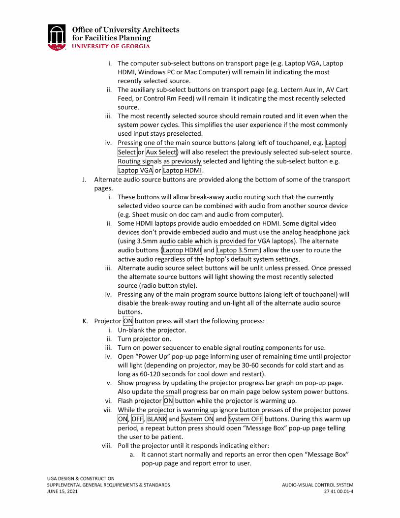
UGA DESIGN & CONSTRUCTION SUPPLEMENTAL GENERAL REQUIREMENTS & STANDARDS AUDIO-VISUAL CONTROL SYSTEM JUNE 15, 2021 27 41 00.01-4
i. The computer sub-select buttons on transport page (e.g. Laptop VGA, Laptop HDMI, Windows PC or Mac Computer) will remain lit indicating the most recently selected source.
ii. The auxiliary sub-select buttons on transport page (e.g. Lectern Aux In, AV Cart Feed, or Control Rm Feed) will remain lit indicating the most recently selected source.
iii. The most recently selected source should remain routed and lit even when the system power cycles. This simplifies the user experience if the most commonly used input stays preselected.
iv. Pressing one of the main source buttons (along left of touchpanel, e.g. Laptop Select or Aux Select) will also reselect the previously selected sub-select source. Routing signals as previously selected and lighting the sub-select button e.g. Laptop VGA or Laptop HDMI.
J. Alternate audio source buttons are provided along the bottom of some of the transport pages.
i. These buttons will allow break-away audio routing such that the currently selected video source can be combined with audio from another source device (e.g. Sheet music on doc cam and audio from computer).
ii. Some HDMI laptops provide audio embedded on HDMI. Some digital video devices don’t provide embeded audio and must use the analog headphone jack (using 3.5mm audio cable which is provided for VGA laptops). The alternate audio buttons (Laptop HDMI and Laptop 3.5mm) allow the user to route the active audio regardless of the laptop’s default system settings.
iii. Alternate audio source select buttons will be unlit unless pressed. Once pressed the alternate source buttons will light showing the most recently selected source (radio button style).
iv. Pressing any of the main program source buttons (along left of touchpanel) will disable the break-away routing and un-light all of the alternate audio source buttons.
K. Projector ON button press will start the following process: i. Un-blank the projector.
ii. Turn projector on. iii. Turn on power sequencer to enable signal routing components for use. iv. Open “Power Up” pop-up page informing user of remaining time until projector
will light (depending on projector, may be 30-60 seconds for cold start and as long as 60-120 seconds for cool down and restart).
v. Show progress by updating the projector progress bar graph on pop-up page. Also update the small progress bar on main page below system power buttons.
vi. Flash projector ON button while the projector is warming up. vii. While the projector is warming up ignore button presses of the projector power
ON, OFF, BLANK and System ON and System OFF buttons. During this warm up period, a repeat button press should open “Message Box” pop-up page telling the user to be patient.
viii. Poll the projector until it responds indicating either: a. It cannot start normally and reports an error then open “Message Box”
pop-up page and report error to user.
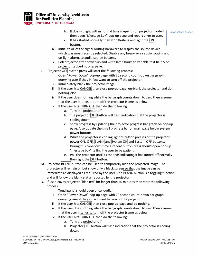
UGA DESIGN & CONSTRUCTION SUPPLEMENTAL GENERAL REQUIREMENTS & STANDARDS AUDIO-VISUAL CONTROL SYSTEM JUNE 15, 2021 27 41 00.01-5
b. It doesn’t light within normal time (depends on projector model) then open “Message Box” pop-up page and report error to user.
c. It has started normally then stop flashing and light the ON button.
ix. Initialize all of the signal routing hardware to display the source device which was most recently selected. Disable any break-away audio routing and un-light alternate audio source buttons.
x. Poll projector after power-up and write lamp hours to variable text field 5 on projector tabbed pop-up page.
L. Projector OFF button press will start the following process: i. Open “Power Down” pop-up page with 20 second count-down bar graph,
querying user if they in fact want to turn off the projector. ii. Immediately blank the projector image.
iii. If the user hits CANCEL then close pop-up page, un-blank the projector and do nothing else.
iv. If the user does nothing while the bar graph counts down to zero then assume that the user intends to turn off the projector (same as below).
v. If the user hits TURN OFF then do the following: a. Turn the projector off. b. The projector OFF button will flash indication that the projector is
cooling down. c. Show progress by updating the projector progress bar graph on pop-up
page. Also update the small progress bar on main page below system power buttons.
d. While the projector is cooling, ignore button presses of the projector power ON, OFF, BLANK and System ON and System OFF buttons. During this cool down time a repeat button press should open pop-up “message box” telling the user to be patient.
e. Poll the projector until it responds indicating it has turned off normally then light the OFF button.
M. Projector BLANK button can be used to temporarily hide the projected image. The projector will remain on but show only a black screen so that the image can be immediate re-displayed as required by the user. The BLANK button is a toggling function and will follow the blank status reported by the projector.
N. If user leaves projector “blanked” for longer than 60 minutes then start the following process:
i. Touchpanel should beep once loudly. ii. Open “Power Down” pop-up page with 20 second count-down bar graph,
querying user if they in fact want to turn off the projector. iii. If the user hits CANCEL then close pup-up page and do nothing. iv. If the user does nothing while the bar graph counts down to zero then assume
that the user intends to turn off the projector (same as below). v. If the user hits TURN OFF then do the following:
a. Turn the projector off. b. Projector OFF button will flash indication that the projector is cooling
down.
Revised June 15, 2021
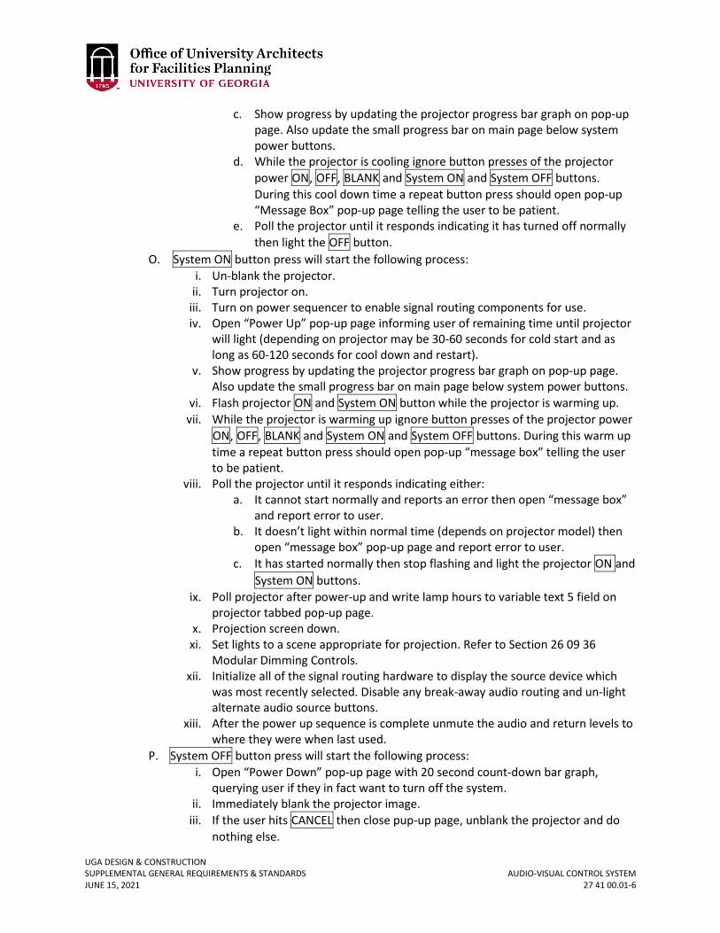
UGA DESIGN & CONSTRUCTION SUPPLEMENTAL GENERAL REQUIREMENTS & STANDARDS AUDIO-VISUAL CONTROL SYSTEM JUNE 15, 2021 27 41 00.01-6
c. Show progress by updating the projector progress bar graph on pop-up page. Also update the small progress bar on main page below system power buttons.
d. While the projector is cooling ignore button presses of the projector power ON, OFF, BLANK and System ON and System OFF buttons. During this cool down time a repeat button press should open pop-up “Message Box” pop-up page telling the user to be patient.
e. Poll the projector until it responds indicating it has turned off normally then light the OFF button.
O. System ON button press will start the following process: i. Un-blank the projector.
ii. Turn projector on. iii. Turn on power sequencer to enable signal routing components for use. iv. Open “Power Up” pop-up page informing user of remaining time until projector
will light (depending on projector may be 30-60 seconds for cold start and as long as 60-120 seconds for cool down and restart).
v. Show progress by updating the projector progress bar graph on pop-up page. Also update the small progress bar on main page below system power buttons.
vi. Flash projector ON and System ON button while the projector is warming up. vii. While the projector is warming up ignore button presses of the projector power
ON, OFF, BLANK and System ON and System OFF buttons. During this warm up time a repeat button press should open pop-up “message box” telling the user to be patient.
viii. Poll the projector until it responds indicating either: a. It cannot start normally and reports an error then open “message box”
and report error to user. b. It doesn’t light within normal time (depends on projector model) then
open “message box” pop-up page and report error to user. c. It has started normally then stop flashing and light the projector ON and
System ON buttons. ix. Poll projector after power-up and write lamp hours to variable text 5 field on
projector tabbed pop-up page. x. Projection screen down.
xi. Set lights to a scene appropriate for projection. Refer to Section 26 09 36 Modular Dimming Controls.
xii. Initialize all of the signal routing hardware to display the source device which was most recently selected. Disable any break-away audio routing and un-light alternate audio source buttons.
xiii. After the power up sequence is complete unmute the audio and return levels to where they were when last used.
P. System OFF button press will start the following process: i. Open “Power Down” pop-up page with 20 second count-down bar graph,
querying user if they in fact want to turn off the system. ii. Immediately blank the projector image.
iii. If the user hits CANCEL then close pup-up page, unblank the projector and do nothing else.
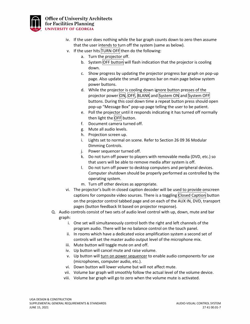
UGA DESIGN & CONSTRUCTION SUPPLEMENTAL GENERAL REQUIREMENTS & STANDARDS AUDIO-VISUAL CONTROL SYSTEM JUNE 15, 2021 27 41 00.01-7
iv. If the user does nothing while the bar graph counts down to zero then assume that the user intends to turn off the system (same as below).
v. If the user hits TURN OFF then do the following: a. Turn the projector off. b. System OFF button will flash indication that the projector is cooling
down. c. Show progress by updating the projector progress bar graph on pop-up
page. Also update the small progress bar on main page below system power buttons.
d. While the projector is cooling down ignore button presses of the projector power ON, OFF, BLANK and System ON and System OFF buttons. During this cool down time a repeat button press should open pop-up “Message Box” pop-up page telling the user to be patient.
e. Poll the projector until it responds indicating it has turned off normally then light the OFF button.
f. Document camera turned off. g. Mute all audio levels. h. Projection screen up. i. Lights set to normal on scene. Refer to Section 26 09 36 Modular
Dimming Controls. j. Power sequencer turned off. k. Do not turn off power to players with removable media (DVD, etc.) so
that users will be able to remove media after system is off. l. Do not turn off power to desktop computers and peripheral devices.
Computer shutdown should be properly performed as controlled by the operating system.
m. Turn off other devices as appropriate. vi. The projector’s built-in closed caption decoder will be used to provide onscreen
captions for composite video sources. There is a toggling Closed Caption button on the projector control tabbed page and on each of the AUX IN, DVD, transport pages (button feedback lit based on projector response).
Q. Audio controls consist of two sets of audio level control with up, down, mute and bar graph:
i. One set will simultaneously control both the right and left channels of the program audio. There will be no balance control on the touch panel.
ii. In rooms which have a dedicated voice amplification system a second set of controls will set the master audio output level of the microphone mix.
iii. Mute button will toggle mute on and off. iv. Up button will cancel mute and raise volume. v. Up button will turn on power sequencer to enable audio components for use
(microphones, computer audio, etc.). vi. Down button will lower volume but will not affect mute.
vii. Volume bar graph will smoothly follow the actual level of the volume device. viii. Volume bar graph will go to zero when the volume mute is activated.
UGA DESIGN & CONSTRUCTION SUPPLEMENTAL GENERAL REQUIREMENTS & STANDARDS AUDIO-VISUAL CONTROL SYSTEM JUNE 15, 2021 27 41 00.01-8
R. Lighting control will be provided by bi-directional communication interface (either RS232 or Ethernet) to an external dedicated lighting controller. The command language of this external lighting controller should include:
i. Command for recalling preset lighting scenes. ii. Command for turning on a specific circuit (relay or dimmer).
iii. Command for turning off a specific circuit (relay or dimmer). S. Lighting scene buttons on the touchpanel will simply recall preset lighting scenes from
the external lighting controller. These preset lighting scenes are setup independently using the keypad on the external lighting control system. The preset lighting scenes stored on the external controller will depend on the rooms use and size but might include:
i. Lights On – all normal room lights on. ii. Projection Mode – lights near screen turned off, rest of room on.
iii. Cinema Mode – lights near screen turned off, rest of room dim. iv. Whiteboard Mode – lights near white board all on, rest of room 50%. v. Stage Mode – directional lights ON, front lighting on, rest of room 50%.
vi. Video Conference Mode – directional spotlights on, lights near screen off, rest of room on.
vii. Lights Off – all lights off. T. A “more controls” lighting pop-up page will provide discrete control of each of the
electrical lighting circuits. This will allow the user to fine tune the lighting beyond those choices provided in the presets above.
U. If electric window shades are controlled from the touchpanel then include up and down controls on the tabbed lighting controls pop-up page.
V. The document camera control page will function as follows: i. Power ON button will turn on document camera.
ii. Top Light button will toggle upper lamp on and off. iii. Bottom Light button will toggle lower lamp on and off. iv. Power OFF button will turn off document camera. v. Zoom, iris and focus buttons will send start command on press and stop
command on release. W. When the control processor is reset perform the following initialization:
i. Trigger an GVE event recording the fact that the control processor has been reset.
ii. On each of the pages for desktop and laptop computers write the native resolution of the projectors. This provides a guide for the user if they need to manually set their computer to the correct resolution to match the projector. Touchpanel variable text field 7.
iii. Write AV help desk telephone number (as requested by End-User) to touchpanel variable text field 3.
iv. Write current lamp hours as reported by projector to touchpanel variable text field address port 5 code 14.
v. Write maximum lamp hours to the projector pop-up page as a guide to user (maximum as defined in projector manual). This will be printed beside the current lamp hours, in variable text field 4, as a guide to the user.
UGA DESIGN & CONSTRUCTION SUPPLEMENTAL GENERAL REQUIREMENTS & STANDARDS AUDIO-VISUAL CONTROL SYSTEM JUNE 15, 2021 27 41 00.01-9
X. When the touch panel wakes from sleep mode the “help_page” pop-up page should be displayed for 15 seconds and then closed to expose whatever pages had last been visible.
Y. GVE provides interface allow user to entire time of day for daily shutdown of the projector default (23:59 midnight). At the designated shutdown time do the following:
i. Touchpanel should beep once loudly. ii. Open “Power Down” pop-up page with 20 second count-down bar graph.
Querying user if they in fact want to turn off the projector. iii. Immediately blank the projector image. iv. If the user hits CANCEL then close pup-up page, unblank the projector and do
nothing else. v. If the user hits Turn Off then turn off projector (same as below).
vi. If the user does not intervene to cancel the process then: a. Turn the projector off. b. Projector OFF and System OFF buttons will flash indication that the
projector is cooling down. c. Show progress by updating the projector progress bar graph on pop-up
page. Also update the small progress bar on main page below system power buttons.
d. Poll the projector until it responds indicating it has turned off normally then light the OFF button.
Z. Ethernet connected Audio-Video control devices should use DHCP in private 172.19.xx.xx range which are part of the campus-wide VLAN1024. (Do not manually configure NIC or use public 128.192.153.xx ranges or shared VLAN with PC. This avoids interference due to other traffic, IP conflicts due to typos and does not allow off-campus connectivity. )
i. EITS will designate new 172.19.xx.xx range with adequate space for AV equipment in building on VLAN1024.
ii. Provide MAC addresses to CTL for all AV devices for registration using the Proteus management system for DHCP.
iii. EITS extends VLAN1024 to building edge device. This VLAN1024 has open TCP ports to GVE server and other maintenance requirements and doesn’t allow any off campus connectivity.
iv. Multiple dedicated Ethernet jack must be activated. Lectern tether has dedicated cables to connect AV devices (Computer and other non-AV devices must have separate Ethernet cabling).
v. Label jack to indicate that it is for AV devices on VLAN1024 (also label other jacks for PC, etc. to avoid confusion).
vi. EITS will extend VLAN1024 only to specific jack with AV devices connected. vii. Jacks configured for VLAN1024 must not connect Non-AV devices such as
Computers, VC CODECs, and other devices with off-campus access or which might interfere.
viii. AV devices receive DHCP service to setup IP address, mask, gateway and DNS settings for network interface card.
UGA DESIGN & CONSTRUCTION SUPPLEMENTAL GENERAL REQUIREMENTS & STANDARDS AUDIO-VISUAL CONTROL SYSTEM JUNE 15, 2021 27 41 00.01-10
aa. Additional Standards for network configuration. i. Configuration of Extron four digit system number should use room
number: xxRR, xRRR or RRRR. ii. Configuration of AMX five digit system number should use the
convention: RRRBB where RRR = first three digits are room number and BB = last two digits are building number defined in “SystemNumberKey.XLS” document available for download at www.architects.uga.edu/standards.
iii. Peripheral AMX devices should connect to Master device using AMX “Auto-connect” mode pointing at the master system number.
iv. Where practical, the touchpanel should connect directly to the processors AVLAN bus RJ45. This isolates the touchpanel from the building LAN for reliability. The touchpanel will receive DHCP service directly from the control processor (in this case there is no need to register touchpanel MAC address with CTL).
v. Code for non-System devices must use URL names and should be hardcoded with numeric IP addresses. Alternatively a text file loaded on flash disk can contain numeric IP address which can be modified by FTP.
vi. During installation and testing, the device security settings can use default passwords. But after commissioning, the systems will be configured for UGA standard password scheme.
vii. Connectivity to GVE server varies depending on hardware as discussed earlier (for Extron hardware is plug and play)(for AMX will require the inclusion of “GVENetlinxAdapter_ugaYYYYMMDD.axs”). When the control processor see the GVE server it will attempt to connect and await approval by GVE server administrator.
Revised June 15, 2021
UGA DESIGN & CONSTRUCTION SUPPLEMENTAL GENERAL REQUIREMENTS & STANDARDS SECURITY AND ACCESS CONTROL JUNE 15, 2021 28 13 00-1
28 13 00 SECURITY AND ACCESS CONTROL
1. GENERAL – For UGA Athens Campus Only
A. Related sections: i. 00 73 01 – Approved Sole Source / Sole Brand
ii. 01 41 26.06 – Dining Services iii. 01 77 00 – Project Closeout iv. 08 71 00 – Door Hardware v. 27 00 00 – General Communications Requirements
B. The UGA Campus in Athens, Georgia has standardized the Genetec Access Control System as the required access control product for the campus. All installed access control systems (ACS) shall be based on the Genetec Access Control system.
C. The Security Contractor shall provide and coordinate all conduit, raceways, and box system requirements for the Security & Access Control System.
D. The security contractor must be a certified Genetec Synergis installer and have completed formal, documented training through UGA Access Control Group prior to being awarded a contract to perform work on UGA’s campus. All programming must be completed by the contractor at the direction of UGA Access Control group. The security contractor must provide a valid Genetec training certificate prior to installation. Sub-contracting of Genetec equipment installation is not permitted.
E. The contractor shall be required to customize the ACS per the requirements of the job. The contractor shall be responsible for coordinating with the user group in programming all ACS features and functions.
F. Students, faculty, and staff can obtain UGA identification cards that shall serve as an ACS credential from the UGA Card Office. These cards can have electronic information embedded and can interface with the ACS. Credentials shall match industry standard ABA and Wiegand formats to communicate with the ACS.
G. For any work on Biosafety locations, the Contractor, through the Project Manager, shall coordinate with FMD and the UGA Office of the Vice President for Research Office of Biosafety.
H. The Contractor that performs work on projects including Biosafety level spaces must be authorized by and complete credentials as required by the UGA Office of Vice President for Research Office of Biosafety.
I. The Design Professional and / or Contractor shall request IP addresses related to the ACS installation through the Project Manager who will request them from FMD Information Technology.
J. All hardware must be home run to the ACS panel. No hardware shall be physically connected to perform a task outside of the ACS panel but should rather be programmatically connected after being home run to the ACS panel unless otherwise approved.
K. The contractor shall provide all documentation and shall perform all duties involved in obtaining work permits as required to complete the Project. All permitting shall be within the associated city or jurisdiction.
L. The access control installer shall not subcontract the access control installation. M. Quality Assurance

UGA DESIGN & CONSTRUCTION SUPPLEMENTAL GENERAL REQUIREMENTS & STANDARDS SECURITY AND ACCESS CONTROL JUNE 15, 2021 28 13 00-2
i. Industry Referenced Standards. The following specifications and standards are incorporated into and become a part of this Specification by reference.
a. FCC compliance b. UL compliance c. NEC compliance
2. PRODUCTS A. Acceptable Products
i. Approved access Control equipment and systems conforming to this section of the specifications manufactured by Genetec, Mercury, and HID will be acceptable.
ii. Acceptable door hardware can be found under Section 08 71 00 Door Hardware. iii. Magnetic locking systems are not allowed. In some instances they may be
required due to facility requirements in which case an approved variance signed both the Project Manager and FMD is required.
iv. All exterior, not located inside the building, hardware must be exterior rated and installed as per the manufacturer’s specifications and instructions regarding exterior installation.
B. Card Readers i. The ACS System shall support a variety of card readers that shall encompass a
wide functional range. ii. Supported Readers as required for each job are as follows:
a. HID Dorado WP644B model or equal b. HID RP40 series or equal
iii. Readers shall be black in color and shall be weather-proof. C. Cards
i. All access control cards are existing. D. Doors
i. All security door hardware shall be fail secure unless otherwise required to meet building, fire, or other code.
ii. All doors shall require the use of at least request to exit and door position switch devices.
iii. Doors that require power shall use electric hinges or power transfer devices. Door loops shall not be used unless specified for the job.
iv. Acceptable door hardware can be found under Section 08 71 00 Door Hardware. E. Door Strikes
i. Rutherford, HES Assa Abloy or Von Duprin door strikes shall be used. The following are acceptable models:
ii. Rutherford F2164 (failed locked) / 2364 (failed unlocked) series iii. Von Duprin 6100, 6200, 6300 series iv. HES Assa Abloy 9600 series v. Electric strikes can be surface or flush mounted.
F. System Intelligent Controller i. The System Intelligent Controller shall operate and control access to multiple
doors as a total standalone unit with full distributed database and with no dependency on the Central System. All valid card numbers, time zones, relay pulse times, and alarm point shunt times shall be loaded into the controller’s
UGA DESIGN & CONSTRUCTION SUPPLEMENTAL GENERAL REQUIREMENTS & STANDARDS SECURITY AND ACCESS CONTROL JUNE 15, 2021 28 13 00-3
memory. The multiple reader access control panel shall support Wiegand, magnetic stripe, proximity, keypads, barcode, vehicle ID, barium ferrite and biometric devices. The panel shall provide programmable communications ports, Power supply with backup, TVSS, etc. The System Intelligent Controller shall be connected to the LAN and receive and transmit data to / from the Network File Server and Client Workstations.
ii. The Synergis Cloud Link module shall contain 2 GB of DDR3 DRAM, 16 GB on-board SSD, two Gigabit Ethernet ports and four RS-485 communication ports. Cloud Link module to be provided with battery back-up, and surge suppression.
iii. Battery back-up shall be required inside each panel. Battery should be sized for one hour of constant operation
G. Mercury-based Intelligent Controller i. The Mercury Intelligent Controller shall communicate between the System
Intelligent Controller and the 2 Reader Interface Module. The device shall support Wiegand, magnetic stripe, proximity, keypads, barcode, vehicle ID, barium ferrite and biometric devices. The panel shall provide programmable communications ports, Power supply with backup, TVSS, etc. The Mercury Intelligent Controller shall be connected to the LAN and receive and transmit data to / from the Network File Server and Client Workstations.
ii. Mercury EP1502 module shall contain 16 MB RAM, two reader ports, eight supervised inputs and four Form C output relays. The module shall provide capacity for up to 240,000 cardholders and 50,000 transactions. The module shall communicate to downstream READER INTERFACE MODULES via RS-485 communication bus.
iii. Battery back-up required inside each panel. Battery should be sized for one hour of constant operation.
H. Mercury-based 2 Reader Interface Module i. The 2 Reader Interface Module shall be the microprocessor based interface
device between the card readers and the ACS Central System. The module shall be compatible with the readers and Central System equipment specified herein. The module shall be mounted in metal enclosure with ample space to accommodate equipment necessary for amount of readers specified and for 20% future growth. Metal enclosure may also house power supply for door hardware, where specified.
ii. Mercury MR52 module shall contain two reader ports, eight general purpose inputs and six Form C output relays. The module shall communicate to the Mercury Intelligent Controller via RS-485 communication bus.
iii. Battery back-up shall be required inside each panel. Battery should be sized for one hour of constant operation.
I. DC Power Supply i. Provide low voltage power supply units associated with Local Interface Units
and Door Control Panels, and as required to provide 12 and 24 volt regulated, filtered D.C. power for locking controls, D.C. locks, signal devices, and readers. Output power shall be 24 volt D.C. with ampere rating not less than 150% of load imposed on power supply under most severe conditions of load. D.C.
UGA DESIGN & CONSTRUCTION SUPPLEMENTAL GENERAL REQUIREMENTS & STANDARDS SECURITY AND ACCESS CONTROL JUNE 15, 2021 28 13 00-4
output shall be fused. Output voltage shall be regulated within plus or minus 5% from no load to full load. Power supply shall be UL listed.
ii. Provide low voltage power supply units as required to provide iii. 5 volt regulated, filtered D.C. power for magnetic stripe card readers. Output
power shall be 5 volt D.C. with ampere rating not less than 150% of load imposed on power supply under most severe conditions of load. D.C. output shall be fused. Output voltage shall be regulated within plus or minus 5% from no load to full load. Power supply shall be UL listed.
iv. Battery back-up shall be required inside each power supply panel. v. Battery should be sized for one hour of constant operation.
J. Field Hardware Power Supplies i. Auxiliary power supplies for doors or other field devices that require power
outside of that provided by the access control system shall be located as close to the door or field device they are providing power for as possible. Power supplies shall be installed no more than 20 feet from the device they are providing power for.
K. Door Position Switch Contacts i. Overhead Doors - Overhead door contacts shall be provided with armored cable
and be surface mounted. The floor mount units shall be constructed with a low-profile heavy cast aluminum housing. The reed switch assembly shall be fully encased in polyurethane potting material to prevent damage due to moisture or humidity. A wide operation gap distance of up to three inches shall be required to prevent false alarms caused by door movement or damaged and loose fitting doors.
a. Door contacts shall be GE / Sentrol 2200 series or approved equal. ii. Surface Mount - Door contacts shall be provided with supervised loop and shall
have a flexible armored cable with total encapsulation to protect against moisture.
a. Door contact for surface mount swing door locations shall be GE / Sentrol 2700 series or approved equal.
b. Door contacts for recessed mounted swing or sliding door locations shall be GE / Sentrol 1078 or approved equal.
iii. Door contact shall have anodized aluminum finish, with stainless steel flexible cable.
iv. Door contacts shall be UL Listed and be warrantied for two years. L. Request-to-Exit Devices
i. Door hardware shall provide free egress. ii. Request-to-exit (REX) devices shall be used to shunt DPS alarm only, and shall
not unlock door hardware. iii. REX devices shall be internal to door where the door and location allows iv. Motion REX (PIR) devices shall have wide angle, long range lenses (adjustable) to
detect motion of personnel desiring to exit through the door. Coordinate exact field mounting location to provide best operation of (PIR) type (REX) device. (PIR) device shall operate at 9.0 to 16.0 VDC and have form-C output contacts rated at minimum 24 VDC / 0.5 amps. Bosch DS series or approved equal.
UGA DESIGN & CONSTRUCTION SUPPLEMENTAL GENERAL REQUIREMENTS & STANDARDS SECURITY AND ACCESS CONTROL JUNE 15, 2021 28 13 00-5
v. Motion Request to exit devices shall be Bosch DS150i, DS160, or approved equal.
vi. When REX is provided in door hardware, REX signal must be sent prior to door physically unlocking. REX signal should be sent on initial operation of level handle on panic bar.
M. Motion Detector Devices i. Shall be equal to Tri-tech motion detectors.
ii. Shall use at least the three following technologies: a. Passive Infrared b. Microwave c. Digital Signal Processing
N. Panels and Enclosures i. Tamper switches must be installed on all panels and enclosures
ii. Physical panel box type shall be equal to the following Life Safety FlexPower MCLASS™ Integrated Mercury power systems.
iii. A standardized key must be used for all panels and enclosures. Project Manager shall coordinate with FMD IT to obtain specification.
O. Copper System Wiring i. Card reader connection cable shall be of a type specified by the manufacturer of
the ACS System. Cable must meet minimum NEC requirements for Class 2 wiring.
ii. Power wiring for electrified door hardware shall not be smaller than No. 22 THWN or XHHW.
iii. All wiring systems shall use stranded copper conductors. Terminations can be made to crimp type screw lug.
iv. All wiring systems shall be color-coded so that each conductor for individual lock set is of a distinctive color.
v. All wiring shall be in accordance with the manufacturers written recommendations.
vi. All cabling / wiring shall be submitted in a detailed spreadsheet including cut sheets and samples to the Owner prior to any installation.
vii. All conductors within junction boxes, pull boxes, and equipment cabinets shall be grouped and laced with nylon tie straps with identification tab, for individual lock sets.
viii. All signal and low voltage wire to be plenum rated. ix. All security wiring shall be supervised. This includes monitoring of all inputs.
P. Transient Voltage Surge Suppression i. Protect all equipment against surges induced on all control, video, and power
cables. All copper cables and conductors which serve as 120V power, control, or video conductors shall have surge protection circuits installed at each end and locations where conductors enter or exit a building.
ii. Fuses shall not be used for surge protection. iii. Surge suppression devices shall meet the following standards / publications:
a. UL 497B b. UL 1449 (must meet 330 Volt suppression rating) c. IEEE Category B impulse and ring wave tests
UGA DESIGN & CONSTRUCTION SUPPLEMENTAL GENERAL REQUIREMENTS & STANDARDS SECURITY AND ACCESS CONTROL JUNE 15, 2021 28 13 00-6
iv. Acceptable Manufacturers: Northern Technologies, Inc., EDCO, or equal. Product shall be warranted against defect for a period of not less than five (5) years.
v. All power connections, including 24 VDC and 24 VAC power supplies and direct wired or plug-in 120 VAC power connections, for all systems and components specified herein, shall be equipped with surge suppression devices. Devices shall be bonded to building grounding system in accordance with Article 250 of the National Electric Code.
vi. Grounding: a. Provide a dedicated, separate No. 6 AWG copper conductor from
building grounding system to all security equipment rooms, security equipment cabinets, and control rooms.
b. Connect all lightning protection devices and security equipment non-current carrying metal parts to grounding conductor in accordance with Article 250 of the National Electric Code.
c. Provide ground bus bar in each equipment room and control room with dedicated ground conductor to each cabinet, enclosure, pull / junction box and all equipment.
vii. Ground Resistance Measurement: viii. Each signal ground system
a. D.C. resistance shall be measured between any point on the signal ground bus and the earth ground. An instrument designed specifically to measure the resistance of a point to each earth ground shall be used. The systems subcontractor shall measure ground resistance in accordance with the procedure as outlined by the test equipment manufacturer. Instrument shall be Biddle earth resistance test instrument, or approved equal.
3. EXECUTION A. Submittals
i. Product Data: Submit manufacturer’s technical product data, including specifications and installation instructions, for each type of system equipment. Include drawings, which contain complete wiring and schematic diagrams and other details required to demonstrate that the system has been coordinated, and will function properly as a system. Drawings shall include floor plan layouts of devices, components, vertical riser diagrams, equipment rack details, elevation drawings of equipment racks, sizes and types of all cables and conduits. For each IP Networked device cable label names, patch down room numbers, patch down cable names, patch down port numbers, and switch port numbers must be provided.
ii. Test Plan: Contractor shall submit a test plan that defines the tests required to ensure that the system meets technical, operational, and performance specifications, 15 days prior to the proposed test date. Owner / User must approve the test plan before the start of any testing. The test plan shall identify the capabilities and functions to be tested, and include detailed instructions for the setup and execution of each test and procedure for evaluation and documentation of the results.
UGA DESIGN & CONSTRUCTION SUPPLEMENTAL GENERAL REQUIREMENTS & STANDARDS SECURITY AND ACCESS CONTROL JUNE 15, 2021 28 13 00-7
iii. Manufacturer Certification: Submit a letter from the manufacturer’s representative stating the proposed system being submitted for review are in accordance with the recommendations of the manufacturer.
B. It is the responsibility of the contractor to meet with the appropriate UGA Facilities representative to compare the placement and installation of proper devices with the drawings and specifications. A 100% device by device test will be conducted by the vendor under the supervision of the owner’s representative. Punch lists will be developed at that time and furnished to the contractor. All punch list items must be corrected and verified prior to acceptance of the system.
C. Closeout Submittals i. At the time of final inspection, provide four (4) sets of complete data on ACS
equipment used in this Project. This data shall be in bound form and shall include all shop drawings required for this Project.
ii. All record drawings shall include "as built" system interconnection diagrams with major components identified and number and type of interconnecting conductors.
iii. Submit maintenance and operating instructions on all systems. iv. Submit certification from system manufacturers that systems are installed in
accordance with manufacturer's recommendations and are functioning correctly at the time of final inspection.
v. Submit as-built drawings to show conduit layout and wiring for all systems. Contractor to submit four (4) sets of hard copy As-Built drawings and submit electronic files in .dwg and .pdf formats electronically with the owner.
vi. Submit corrected point-to-point drawings for all systems with color code to show the actual as-built conditions.
vii. Contractor to submit all finalized programming settings, including schedules, user database, etc.
viii. Note IP switch port numbers and locations (room number) assigned to the security system. This is a requirement for every IP device.
ix. For additional close out submittals, refer to Section 01 78 00 Closeout Submittals
x. Contact the UGA Access Control Team at [email protected] or 706-542-7551 to obtain Record Drawing Requirements.
D. System Requirements i. The University of Georgia security and access control systems shall be
connected to the dedicated General Building Genetec server but shall operate autonomously from other campus buildings. Tasks such as defining access groups, time zones, generating reports, creating maps, etc. shall be programmed specific to each space.
ii. All access control panels must be installed in a building network closet. iii. As per Genetec standard all systems must be installed with one master Cloud
Link module which controls Mercury EP1502 modules over the network. The Mercury EP1502 modules then control Mercury MR modules over a RS-485 bus. All field panels must be connected back to the Cloud Link over the network using an EP1502 module. No RS-485 busses should leave the panel enclosures.
UGA DESIGN & CONSTRUCTION SUPPLEMENTAL GENERAL REQUIREMENTS & STANDARDS SECURITY AND ACCESS CONTROL JUNE 15, 2021 28 13 00-8
iv. All field equipment including but not limited to card readers and input buttons must be mounted in compliance with all codes and regulations.
v. The Contractor shall only use the existing web interface provided by FMD IT as a system interface for End-Users.
E. Wiring Systems i. All wiring must be installed in conduit unless otherwise agreed upon with the
UGA Project Manager. ii. Protect all communication and data equipment against surge induced on all
control, sensor and data cables. iii. All cables and conductors which serve as control, sensor, or data conductors
shall have surge protection circuits installed at each end that meet the IEEE 472 surge withstand capability test and the electrical transient tests established in UL365.
iv. Fuses shall not be used for surge protection. v. The work under this section of the specifications includes the installation of all
wiring for the electric door hardware. The installation of the door hardware and the actual connections to the electric hardware and the access control system shall be done under this section of the specifications. It is the responsibility of the Security Contractor to coordinate all electrical requirements and connections of the electrified hardware and to coordinate with & communicate to UGA all work to be done by UGA. Provide necessary instruction in writing.
vi. All security wiring shall be labeled at the head end, any separating junction, and at the field device.
vii. All security wiring shall be supervised. This includes monitoring of all inputs. Specifications for wire supervision can be requested from the Project Manager.
viii. The contractor is responsible for running networking cable between each networked device and to each networking closet as required for device communication. Before plugging into a switch networking cable must be punched into a patch panel. All access control related patch cables must be red. Campus networking requirements can be found under Section 27 00 00 General Communications Requirements.
F. Testing i. Testing requirements apply to all construction.
ii. All door hardware shall be tested prior to inspections. Where door hardware installations are impacted by existing doors or hollow metal frames, contractor shall immediately notify UGA representative and provide, in writing, information on existing deficiency and corrective measure required to allow the completion of the Project.
iii. Materials and documentation to be furnished under this specification are subject to inspections and tests. All components shall be terminated prior to testing.
iv. Equipment and systems will not be accepted until the required inspections and tests have been made, demonstrating that the access control system conforms to the specified requirements, and that the required equipment, systems, and documentation have been provided.
UGA DESIGN & CONSTRUCTION SUPPLEMENTAL GENERAL REQUIREMENTS & STANDARDS SECURITY AND ACCESS CONTROL JUNE 15, 2021 28 13 00-9
v. Issues log must be turned over at 10 month and 1 year mark. Include all service events conducted to date.
G. Training i. The Contractor shall include in the base Contract all costs required to train
operation and maintenance personnel in the use and maintenance of systems provided under this section of the specifications. Training sessions shall be conducted by instructors certified in writing by the manufacturer of the specific system.
ii. University of Georgia Facilities shall be staffed by unique UGA personnel, which shall be cross reference to the UGA master database. The contractor shall be responsible for configuring personnel in the Genetec system to use the Project’s location.
iii. Sessions shall be conducted for not less than two hour periods during normal working hours, i.e., Monday through Friday, 8:00 AM to 5:00 PM. Training session schedules shall conform to the requirements of UGA Facilities; therefore such schedules shall be submitted to UGA for approval not less than two weeks prior to the training session. At UGA’s discretion, provisions shall be made to allow owner personnel to participate in final system check out of all systems.
iv. Time to be included in base Contracts for specific systems shall be as follows: a. ACS System entirely - 4 hour
H. Genetec Software Design Requirements i. General
a. The contractor responsible for programming the Genetec system is herein referred to as ‘integrator’
b. The integrator will under no circumstances change any entities or configurations from another integrator without direct permission from the UGA Access Control Project Manager.
c. The integrator does not have delete or remove permission for any entities in the system. The removal of any entity in the system must be coordinated with the UGA Access Control Project Manager.
d. The integrator shall make no changes to any entities listed as ‘Templates’.
e. All change requests must be given to the UGA Access Control Project Manager in writing.
ii. Partitions a. The integrator is not able or responsible for entering new partitions into
the Genetec system. b. If additional partitions are needed the integrator must coordinate this
with the UGA Access Control Project Manager. c. The integrator is required to put all entities created by the integrator
into the correct partition(s). Partitions will be provided for each location the integrator is responsible for. An additional unique partition is included for each integrator that can be used for testing purposes by that integrator.
d. The integrator will not put any entity in the ‘Root’ partition. iii. Access Control Units
UGA DESIGN & CONSTRUCTION SUPPLEMENTAL GENERAL REQUIREMENTS & STANDARDS SECURITY AND ACCESS CONTROL JUNE 15, 2021 28 13 00-10
a. Set the name of the access control unit to the name of the building or location it is providing security for. Campus maps and UGA building names can be found here, http://www.architects.uga.edu/maps/current.
b. Set the building number in the custom field tab. Building numbers can also be found here, http://www.architects.uga.edu/maps/current.
c. Set the integrator custom field with the name of the installing integrator. Use the full company name and the same name for all similar fields.
d. Update the Cloud Link and all downstream hardware to the latest supported firmware revision unless otherwise coordinate with the UGA Access Control Project Manager.
e. Initialize and configure the Cloud Link and all downstream hardware. f. IP information will be provided by the UGA Access Control Project
Manager. g. Once all downstream devices are configured, rename all objects under
the ‘Peripherals’ tab with the following format: h. Building name - Corresponding Entity name - Peripheral Type (REX, DPS,
Lock, etc.) - Interface Board Details - Peripheral name 1) Ex: Building A - Door 1 - REX - EP1502 1 - MR52 2 - Input 1 2) Ex: Building A - EP1052 1 3) Ex: Building A - Unused - EP1502 1 - Input 1
i. Set the correct Time Zone and location information under Location. j. All access control units must have their passwords changed from the
manufacturer defaults. This must be coordinated with the UGA Access Control Project Manager.
iv. Cardholders a. The integrator is not able or responsible for entering new cardholders
into the Genetec system. b. If adding new cardholders is required for the installation they must be
coordinated through the UGA Access Control Project Manager. c. The installation may require the integrator to add access rules or modify
other fields for existing cardholders. v. Cardholder Groups
a. The integrator is responsible for creating any cardholder groups that are required for the installation.
b. The integrator is responsible for adding any cardholders to cardholder groups that are required for the installation.
c. The installation may require the integrator to add access rules or modify other fields for existing cardholder groups.
d. Cardholder groups shall be used for granting access for cardholders to areas / doors
e. Cardholder group names must follow this format: f. UGA Building Name / Department Name Relevant Group Information
1) Ex: UGA Building A Custodial Supervisors 2) Ex: UGA Department B Staff
UGA DESIGN & CONSTRUCTION SUPPLEMENTAL GENERAL REQUIREMENTS & STANDARDS SECURITY AND ACCESS CONTROL JUNE 15, 2021 28 13 00-11
vi. Credentials a. The integrator is neither able nor responsible for entering new
credentials into the Genetec system. b. If adding new credentials is required for the installation they must be
coordinated through the UGA Access Control Project Manager. vii. Access Rules
a. The integrator is responsible for creating any access rules as required for the installation.
b. The integrator is responsible for attaching and configuring access rules to the relevant entities as necessary such as schedules, cardholder groups, doors, elevator, and areas.
c. Access Rules shall not be attached directly to cardholders. Access Rules shall only be attached to cardholder groups and then those groups attached to specific cardholders.
d. Access rule names must follow this format: 1) UGA Building Name / Department Name Relevant Access Rule
Information i) Ex: UGA Building A
ii) Ex: UGA Building A Shop viii. General Settings
a. The integrator shall make no changes to any options under the System Task->General Settings Tab with the exception of Actions.
b. Any needed changes here such as custom fields, custom events, etc. must be coordinated through the UGA Access Control Project Manager.
ix. Actions a. The integrator is responsible for creating and configuring any Event to
Actions that are required for the installation, such as alarms. x. Roles
a. The integrator shall make no changes to any roles under the System Task->Roles Tab.
b. Any needed changes here must be coordinated through the UGA Access Control Project Manager
xi. Schedules a. The integrator is responsible for creating any schedules that are
required for the installation. b. The integrator is responsible for attaching and configuring schedules to
the relevant entities as necessary such as access rules, doors, and areas. c. For each schedule intended the integrator must create two schedules. d. One schedule must be a ‘Weekly’ schedule following the name format:
1) UGA Building Name / Department Name Relevant Schedule Information
i) Ex: UGA Building A Unlock Weekly Schedule ii) Ex: UGA Building A Shop Alarm Weekly Schedule
e. One schedule must be a ‘Specific’ schedule following the name format: 1) UGA Building Name / Department Name Relevant Schedule
Information
UGA DESIGN & CONSTRUCTION SUPPLEMENTAL GENERAL REQUIREMENTS & STANDARDS SECURITY AND ACCESS CONTROL JUNE 15, 2021 28 13 00-12
i) Ex: UGA Building A Unlock Exception Schedule ii) Ex: UGA Building A Shop Alarm Exception Schedule
xii. Scheduled Tasks a. The integrator is responsible for creating any scheduled tasks that are
required for the installation. b. The integrator is responsible for configuring any scheduled tasks that
are required for the installation xiii. Macros
a. The integrator is not able to create new macros into the Genetec system.
b. If macros are required for an installation, the integrator will be responsible for testing those macros outside of the UGA Production Genetec system. Once testing is complete, the macros must be delivered to the UGA Access Control Project Manager for testing by UGA before being created and configured in the system by UGA.
c. All changes for macros must follow the process mentioned in Macros Subsection B.
xiv. Output Behaviors a. The integrator is responsible for creating any output behaviors that are
required for the installation. b. The integrator is responsible for configuring any output behaviors that
are required for the installation. c. The default output behaviors, such as Normal, Active, Periodic, and
Pulse, may be used by the integrator but not modified. xv. Reports
a. The integrator is responsible for creating any reports that are required for the installation.
b. The integrator is responsible for configuring any reports that are required for the installation. This may include automation such as running the reports with a scheduled task or e-mailing the reports to a user or user group.
xvi. Users a. The integrator is neither able nor responsible for entering new users
into the Genetec system. b. If adding new users is required for the installation this must be
coordinated through the UGA Access Control Project Manager. xvii. User Groups
a. The integrator is neither able nor responsible for entering new user groups into the Genetec system.
b. If adding new user groups is required for the installation this must be coordinated through the UGA Access Control Project Manager.
xviii. Alarms a. The integrator is responsible for creating all alarms that are required for
the installation. b. The integrator is responsible for configuring all alarms that are required
for the installation.
UGA DESIGN & CONSTRUCTION SUPPLEMENTAL GENERAL REQUIREMENTS & STANDARDS SECURITY AND ACCESS CONTROL JUNE 15, 2021 28 13 00-13
c. The integrator shall use the copy configuration tool to create new alarms. New alarms must be created by copying all of the configurations from the ‘Empty Alarm Template’ alarm.
d. Any configuration changes from the default ‘Empty Alarm Template’ alarm must be coordinated with the UGA Access Control Project Manager.
e. For all installations the following alarms must be created for relevant entities:
1) Door Forced Alarms 2) Door Held Open Alarms 3) Input / Zone Alarms
i) Ex: Glass Break, Motion Sensor, etc. 4) Each alarm must have its corresponding entities attached in
‘Attached Entities’ section. i) Ex: Door 1 at Building A must have a door forced alarm
and a door held open alarm created and Door 1 must be added under the ‘Attached Entities’ Section.
5) Alarm names must following the name format: i) UGA Building Name Entity Name Alarm Type
a) Ex: UGA Building A Door 1 Door Forced Alarm b) Ex: UGA Building B Room 238 Door Held Open
Alarm c) Ex: UGA Building C Hallway 1 North Glass Break
Alarm xix. Maps
a. The integrator is responsible for creating maps for all areas included in their installation. The integrator shall use basic floorplan maps, use an appropriate map size for the area, and crop / remove any extraneous information from the map as necessary.
b. The integrator is responsible for configuring maps for all areas included in their installation.
c. All maps must be readable. At all zoom levels maps must displays solid and clearly defined lines and walls along with legible text from the imported map source.
d. Configuration must include: 1) A readable text field noting the name of the building and area
i) Ex: Building A - Floor 1 ii) Ex: Building B - North
2) The additional of all doors and inputs to the map. 3) A compass rose must be included and correctly positioned on
the map. e. For multi-area, multi-floor, multi-building, or any combination therein
the map must contain links to all corresponding areas. This must be accomplished through the usage of text boxes placed on the map in such a way as to not impede the viewing of any points on the maps.
f. Zone inputs must be represented on the maps as input entities.
UGA DESIGN & CONSTRUCTION SUPPLEMENTAL GENERAL REQUIREMENTS & STANDARDS SECURITY AND ACCESS CONTROL JUNE 15, 2021 28 13 00-14
g. If a single map can encompass multiple areas it can be set on the parent area of the multiple areas.
1) Ex: A small building with a single floor is split into two areas on either side of the building. A single map can be used on the building area to represent both child areas.
xx. Areas a. The integrator is responsible for creating new areas that are required
for the installation. b. The integrator is responsible for configuring areas that are required for
the installation. c. If the integrator needs a new partition for a new area this must be
coordinated through the UGA Access Control Project Manager d. The integrator shall set all relevant access rules for the area e. Area naming formats must follow a tree structure with the building or
location as the root. 1) Ex: Building A
| | | Floor 1 Floor 2
| | | Labs Offices
xxi. Doors a. The integrator is responsible for creating new doors that are required
for the installation. b. The integrator is responsible for configuring doors that are required for
the installation. c. The integrator shall use the copy configuration tool to create new
doors. New doors must be created by copying all of the configurations from the ‘Door Template’ door under the Root->Templates area.
d. Any configuration changes on the door properties tab from the default ‘Door Template’ alarm must be coordinated with the UGA Access Control Project Manager.
e. The integrator shall set all relevant hardware points under the hardware tab.
f. The integrator shall set all relevant access rules for the door. The preferred use of access rules would be to inherit them from a parent area.
g. The integrator shall set all relevant schedules for the door. This must include both a ‘Weekly’ and ‘Specific’ schedule as mentioned in the schedules section.
h. The integrator must set the integrator custom field with the name of the installing integrator. Use the full company name and the same name for all similar fields.
i. Door names must follow the name format: 1) Building Name EXT / INT Door Name
UGA DESIGN & CONSTRUCTION SUPPLEMENTAL GENERAL REQUIREMENTS & STANDARDS SECURITY AND ACCESS CONTROL JUNE 15, 2021 28 13 00-15
i) Ex: Building A EXT Door 1 ii) Ex: Building B INT Door 238
j. Door descriptions must include information relevant to the purpose of the room or provide additional information helpful for locating the door.
1) Ex: Exterior Stairwell Northwest Corner 2) Interior Lab Near Northwest Stairwell
xxii. Elevators a. The integrator is responsible for creating new elevators that are
required for the installation. b. The integrator is responsible for configuring elevators that are required
for the installation. This includes floor information, access rules, schedules, and advanced data
c. The integrator must set the integrator custom field with the name of the installing integrator. Use the full company name and the same name for all similar fields.
d. Elevator names must follow the name format: 1) Building Name Elevator Name
i) Ex: Building A Main Elevator ii) Ex: Building B Service Elevator
xxiii. Zones a. The integrator is responsible for creating new zones that are required
for the installation. b. The integrator is responsible for configuring zones that are required for
the installation. This includes properties, arming, and cameras. c. The integrator must set the integrator custom field with the name of
the installing integrator. Use the full company name and the same name for all similar fields.
d. The integrator shall use only hardware zones. If a virtual zone is required for the installation its creation and configuration must be coordinated through the UGA Access Control Project Manager.
xxiv. Video Units a. The integrator is responsible for creating new video units that are
required for the installation. b. The integrator is responsible for configuring video units that are
required for the installation. c. The integrator must set the integrator custom field with the name of
the installing integrator. Use the full company name and the same name for all similar fields.
d. All video units must use SSL or other secure communication protocols. Any exceptions must be coordinated with the UGA Access Control Project Manager.
e. All video units must have their passwords changed from the manufacturer defaults. This must be coordinated with the UGA Access Control Project Manager.
UGA DESIGN & CONSTRUCTION SUPPLEMENTAL GENERAL REQUIREMENTS & STANDARDS SECURITY AND ACCESS CONTROL JUNE 15, 2021 28 13 00-16
f. All video units must have their firmware updated to the latest version. Any exceptions must be coordinated with the UGA Access Control Project Manager.
g. IP information will be provided by the UGA Access Control Project Manager.
h. Video unit names must follow the name format: 1) Building Name Camera Function Description
i) Ex: Building A North Parking Lot ii) Ex: Building B Main Stairwell First Floor
xxv. Cameras a. The integrator is responsible for creating new cameras that are required
for the installation. b. The integrator is responsible for configuring cameras that are required
for the installation. c. The integrator must set the integrator custom field with the name of
the installing integrator. Use the full company name and the same name for all similar fields.
d. Camera names must follow the name format: 1) UGA Building Name Camera Function Description
i) Ex: Building A North Parking Lot ii) Ex: Building B Main Stairwell First Floor
e. If multiple cameras come from the same video unit the names must include information to denote which camera they are and how they relate to the video unit. The description must also include information on how locate each camera
1) Ex: i) Name: Building A North Parking Lot Camera 1
ii) Description: Camera on pole next Main Street xxvi. Monitor Groups
a. The integrator is responsible for creating new monitor that are required for the installation.
b. The integrator is responsible for configuring monitor groups that are required for the installation.
xxvii. Plugins a. The integrator is not responsible for creating or configuring and shall
neither create nor configure plugins unless explicitly stated in the installation requirements. The creation or configuration of any plugins must be coordinate with the UGA Access Control Project Manager.
I. Warranty i. The contractor shall warrant the ACS for one year from date of receiving
substantial completion from the Owner / User against defects in equipment or workmanship. Failed equipment shall be replaced by the contractor at no cost to the owner. Owner's personnel may perform initial trouble investigation but replacement of failed equipment and escalated problem support will be handled by the contractor.
UGA DESIGN & CONSTRUCTION SUPPLEMENTAL GENERAL REQUIREMENTS & STANDARDS SECURITY AND ACCESS CONTROL JUNE 15, 2021 28 13 00-17
ii. A 10 month warranty inspection must be scheduled and performed by the contractor. This inspection shall include a full site walkthrough and testing of each access controlled point.
iii. Issues log must be turned over at 10 month and 1 year mark. Include all service events conducted to date.
UGA DESIGN & CONSTRUCTION SUPPLEMENTAL GENERAL REQUIREMENTS & STANDARDS SECURITY AND ACCESS CONTROL – LEGACY SYSTEM JUNE 15, 2021 28 13 00.01-1
28 13 00.01 SECURITY AND ACCESS CONTROL – LEGACY SYSTEM
1. GENERAL – For UGA Athens Campus Only
A. Related sections: i. 00 73 01 – Approved Sole Source / Sole Brand
ii. 01 41 26.06 – Dining Services iii. 01 77 00 – Project Closeout iv. 08 71 00 – Door Hardware v. 27 00 00 – General Communications Requirements
vi. 28 13 00 – Security and Access Control B. All new Access Control Systems (ACS) are required to use the approved sole brand
system identified in Section 28 13 00 Electronic Access Control and Intrusion Detection. C. This section shall only apply to work on existing installations of the legacy Andover
Controls ‘Andover Continuum’ access control system in cases approved by the UGA Access Control Team ([email protected] or 706-542-7551). The sole source provider of the Andover Continuum access control system is Convergint Technologies, LLC (770-840-7007).
D. For this section “Contractor” shall also mean “ACS subcontractor” unless specifically noted otherwise.
E. The ACS consists of card readers, biometric readers, keypad readers, intrusion detection sensors, and electric door hardware that are connected to an ACS field panel. The field panel is typically located in a building telecom room (TR) or designated building network location such as an MDF or IDF. The ACS panel is connected to an existing server over the UGA network. This typically requires a direction connection between the ACS field panel and a campus network switch.
F. Students, faculty, and staff can obtain UGA identification cards that shall serve as an ACS credential. These cards can have electronic information embedded and include magnetic swipe cards or proximity field cards that can interface with the ACS. All magnetic swipe cards, proximity cards, and biometrics shall use industry standard ABA and Wiegand formats to communicate with the ACS.
G. Server / Database Programming: To maintain security and accuracy, the UGA contracts with Convergint Technologies, LLC to program and provide support for the ACS. Only this vendor is allowed access to the ACS server / database for programming and support information related to ACS installations covered under this section.
i. The FMD manages the agreement between the UGA and Convergint. ii. Any ACS programming required as part of work covered under this section are
required to be performed by Convergint. iii. For project delivery methods in which the Contractor is a Construction Manager,
Design-Builder, or General Contractor: a. The Contractor must contract directly with Convergint. The Contractor is
not allowed to have an ACS installation subcontractor contract with Convergint.
b. The Contractor shall include in their Bid or Cost of the Work the cost for the Contractor to retain the services of Convergint to perform all
UGA DESIGN & CONSTRUCTION SUPPLEMENTAL GENERAL REQUIREMENTS & STANDARDS SECURITY AND ACCESS CONTROL – LEGACY SYSTEM JUNE 15, 2021 28 13 00.01-2
required ACS programming to make the new facility or renovation ACS fully operational.
H. Any variance request approvals related to Access Control shall be signed by both the Project Manager and FMD IT.
I. Any work on a new or renovated ACS must be completed by a Contractor certified by the ACS manufacturer and the Contractor shall have been in business for at least three years.
J. For any work on Biosafety locations, the Contractor, through the Project Manager, shall coordinate with FMD and the UGA Office of the Vice President for Research Office of Biosafety.
K. The Contractor that performs work on Projects including biosafety level spaces must be authorized by and complete credentials as required by the UGA Office of Vice President for Research Office of Biosafety.
L. During the design phase, if any of the following are being considered, the Design Professional and / or Contractor, through the Project Manager, shall coordinate with FMD and the UGA programming and maintenance vendor to ensure functionality with the ACS:
i. Biometric technology ii. Glass Breaks
iii. Elevator iv. Automatic ADA Door Openers v. Motion Sensors
vi. Duress / Panic Buttons M. The Design Professional and Contractor shall refer to Division 27 00 00 General
Communications Requirements of the Standards for all network cabling required to interface with the ACS.
N. The Design Professional and / or Contractor shall request IP addresses related to the ACS installation through the Project Manager who will request them from FMD Information Technology.
O. The Contractor shall only use the existing web interface provided by FMD IT as a system interface for End-Users.
P. All hardware must be home run to the ACS panel. No hardware shall be physically connected to perform a task outside of the ACS panel but should be programmatically connected after being home run to the ACS panel.
i) Example – A push button for a door with a door operator should not connect directly to the door operator to open the door. Both the push button and operator connections must be home run to the ACS panel. Once at the panel the software must be configured to allow the door operator to open when the button is pressed based on the lock state of the door.
Q. Refer to 27 00 00 General Communications Requirements. i. Cables shall not be spliced and must be continuous from the field hardware
device to the respective ACS panel. ii. All cables must be labeled on each end specifying the device type and a specific
device identifier. iii. All manufacturers’ specifications must be followed when joining wiring with all
connecting hardware such as wire nuts.
UGA DESIGN & CONSTRUCTION SUPPLEMENTAL GENERAL REQUIREMENTS & STANDARDS SECURITY AND ACCESS CONTROL – LEGACY SYSTEM JUNE 15, 2021 28 13 00.01-3
2. PRODUCTS A. All new access control systems are required to be part of the Andover Controls, Andover
Continuum system (Andover). The UGA has sole brand approval for this access control system and no substitutions are allowed.
B. Magnetic locking systems are not allowed. In some instances they may be aesthetically appropriate for some historic facilities in which case an approved variance signed both the Project Manager and FMD is required.
C. Magnetic locking systems that require a “Push to Exit” button are not allowed. D. All exterior, not located inside the building, hardware must be exterior rated and
installed as per the manufacturer’s specifications and instructions regarding exterior installation.
E. Door Hardware i. General Door Hardware
a. The following devices must be installed with supervised wiring: 1) Request to Exit 2) Door Position Switch 3) Motion Sensor 4) Panic / Duress Button 5) Glass Break Sensor
b. All door installation shall require the use of no less than a request to exit device and a door position switch device.
c. All door hardware shall be fail secure. d. Doors that require power shall use electric hinges or power transfer
devices and door loops shall not be used. e. Auxiliary power supplies for doors or other field devices that require
power excluding the ACS panel shall be located as close to the door or field device they are providing power for as possible. The location of the power supply shall not exceed 20 feet from the door or device.
ii. Door Strike a. Equal to HES Assa Abloy or Von Duprin b. Electric strikes can be surface or flush mounted.
iii. Locks: a. All doors must mechanically relock after removing a key used to unlock
or open the door. iv. Door Position Switch
a. Internal door position switches should be used where the door and location allows.
b. Door position switches shall be equal to GE Sentrol magnetic contact or sensor.
v. Request to Exit a. Request to exit devices shall be internal to the door where the door and
location allows. b. Mechanical crash bar or turn handle request to exit devices must be
used where the door and location allows. vi. Motion Detector
a. Shall be equal to Tri-tech motion detectors.
UGA DESIGN & CONSTRUCTION SUPPLEMENTAL GENERAL REQUIREMENTS & STANDARDS SECURITY AND ACCESS CONTROL – LEGACY SYSTEM JUNE 15, 2021 28 13 00.01-4
b. Shall use at least the three following technologies: 1) Passive Infrared 2) Microwave 3) Digital Signal Processing
vii. Readers: All magnetic swipe and proximity card readers shall be equal to HID. viii. Keypads: Shall be equal to HID keypads.
ix. Sliding Doors shall use internal locking mechanisms and internal door position switch.
F. Panels and Enclosures i. Tamper switches must be installed on all panels and enclosures
ii. Physical panel box type a. Shall be equal to the following Hoffman enclosures:
1) A42N3009 2) A36N24ALP 3) A36N30ALP 4) A30N24ALP 5) A24N24ALP
iii. A standardized key must be used for all panels and enclosures. Through Project Manager coordinate with FMD IT to obtain specification.
iv. Battery Backups a. Batteries must include labeling that specifies the device that is powered
or backed up by the battery and the installation date of the battery. b. Must provide battery backups that will last at least 1.5 hours at time of
installation with an average lifetime of no less than 3 years. 3. EXECUTION
A. Installation Performance Test i. After an ACS installation is deemed complete by Convergint an installation
performance test must be coordinated and conducted. ii. The Contractor shall coordinate with the Project Manager for the following
attendees to be present at the performance test: a. Contractor b. Design Professional c. Project Manager d. FMD ACS Project Manager e. FMD Hardware Technician f. FMD Software Technician g. UGA Public Safety Division Police Department
iii. The installation performance test must include but is not limited to the following tests for all related devices:
a. General Door Tests 1) Doors have been rekeyed. 2) Doors open and close without mechanical problems. 3) Doors lock and unlock mechanically for ingress and egress.
b. Card Reader Door Tests 1) Door locks, unlocks, and secures from the ACS manually and
with a schedule.
UGA DESIGN & CONSTRUCTION SUPPLEMENTAL GENERAL REQUIREMENTS & STANDARDS SECURITY AND ACCESS CONTROL – LEGACY SYSTEM JUNE 15, 2021 28 13 00.01-5
2) Door locks, unlocks, and secures when using a card that is granted access.
3) Door does not lock or unlock when using a card that is not granted access.
4) After a valid card swipe that unlocks the door, if the door is not opened it must automatically lock back after a predetermined amount of time.
5) After a valid card swipe that unlocks the door, if the door is opened it must lock immediately following being opened.
6) Door alarms when forced open and resets when the door is closed.
7) Door alarms when held open longer than the door ajar time and resets when the door is closed.
c. Door Position Switch / 1) Value is ‘off’ when the door is closed or contact is closed. 2) Value is ‘on’ when the door is open or contact is opened. 3) Door position switch alarms when its respective door is opened
in a manner that should cause an alarm and resets when the door is closed.
d. Request To Exit Tests 1) Value is ‘off’ when the request to exit is not triggered 2) Value is ‘on’ when the request to exit is triggered.
e. Contact Tests 1) Value is ‘off’ when the contact is closed. 2) Value is ‘on’ when the contact is opened. 3) Contact alarms when the contact is broken and resets when the
contact is made. f. Motion Sensor Tests
1) Value is ‘off’ when the motion sensor is not triggered 2) Value is ‘on’ when the sensor is triggered. 3) Motion sensor alarms when its respective space is configured in
a manner that should cause an alarm and resets when the motion sensor resets.
g. Tamper Switch Tests 1) Value is ‘off’ when the tamper switch is not triggered 2) Value is ‘on’ when the tamper switch is triggered. 3) Tamper switch alarms when the enclosure or object is opened
or removed and resets when the enclosure is closed or object is returned
h. Duress / Panic Button Tests 1) Value is ‘off’ when the duress / panic button is not triggered 2) Value is ‘on’ when the duress / panic button is triggered. 3) Duress / panic button alarms when the button is pressed and
resets when the button is reset. i. Glass Break Tests
1) Value is ‘off’ when the glass break is not triggered
UGA DESIGN & CONSTRUCTION SUPPLEMENTAL GENERAL REQUIREMENTS & STANDARDS SECURITY AND ACCESS CONTROL – LEGACY SYSTEM JUNE 15, 2021 28 13 00.01-6
2) Sensitivity is set so that the value does not turn ‘on’ under normal building operation.
j. Door Operator Tests 1) When triggered, if the door is unlocked, the door operator
successfully opens the door and closes the door back within expected time-frame.
k. Push Button Tests 1) Value is ‘off’ when the push button is not triggered 2) Value is ‘on’ when the push button is triggered.
l. ADA Door Tests 1) When the exterior push button is triggered while the door is
locked the door remains locked and the door operator is not triggered.
2) When the exterior push button is triggered after a valid card swipe that unlocks the door the door operator opens the door and closes the door back within the expected time-frame.
3) When the interior push button is triggered while the door is locked the door is unlocked, the door operator opens the door, and closes the door within the expected time-frame.
4) When the interior push button is triggered while the door is unlocked the door operator opens the door and closes the door back within the expected time-frame.
m. Battery Tests 1) Devices on battery backups should continue to function for the
expected amount of time after external power is removed and the devices are operating solely on battery power.
n. ACS Controller Tests 1) All internal batteries are connected. 2) Upon total power loss and restoration of a time period no
shorter than five minutes the ACS Controller should automatically initialize itself from internal memory.
3) After the self-initialization the controller is fully functional with no external interaction.
o. All above and non-listed devices must be tested to ensure complete functionality as specified in the installation contract.
p. All above and non-listed devices must be tested to ensure that there is no found case in which the device shows a ‘trouble’ state.
B. Warranty Inspection i. The original installing Contractor is required to perform a warranty inspection
on all installations no later than two months before the end of installation warranty.
ii. This inspection shall be coordinated with the Project Manager and FMD. iii. The warranty inspection must follow the test criteria specified in the
“Installation Performance Test” above. C. Closeout Submittals
i. Drawings
UGA DESIGN & CONSTRUCTION SUPPLEMENTAL GENERAL REQUIREMENTS & STANDARDS SECURITY AND ACCESS CONTROL – LEGACY SYSTEM JUNE 15, 2021 28 13 00.01-7
a. A copy of all installation drawings shall be delivered to Project Manager for distribution at the completion of the job. Refer to Section 01 78 00 Closeout Submittals.
b. The drawings shall include but not be limited to: 1) Wiring diagrams shall be included with locations of wire runs
between all devices. The drawing must contain the ACS aliases of the devices the wiring connects. This shall also include network cable installations.
2) For network cable installations punch-down and port number information must be clearly shown at the location on the drawing that the network cable from the ACS plugs into the campus network equipment.
3) Riser diagrams for the ACS panel shall be included and labeled with the ACS aliases for all of devices contained within.
4) Drawings shall include floor plans with the mentioned wiring diagrams and must also include locations of all field and panel devices and any supporting devices such as auxiliary power supplies.
ii. Documentation a. A copy of all installation documents shall be delivered to the Project
Manager to distribute at the completion of the job. These documents will be provided in pdf formats.
b. The documentation shall include but no be limited to: 1) IP address, IP Gateway, IP Netmask, and device MAC
information of the ACS panel installed. 2) Punch-down and network hardware port numbers that the ACS
devices connect to. 3) Manufacturer’s documentation for all installed devices. 4) All procedural documents for custom development done for the
installation. These shall include but not be limited to: i) Summary of the development done
ii) Instruction documentation on how to use the development
iii) High level overview of all features of the development. This shall be detailed enough that it could be used to support the development.
UGA DESIGN & CONSTRUCTION SUPPLEMENTAL GENERAL REQUIREMENTS & STANDARDS FIRE DETECTION & ALARM JUNE 15, 2021 28 31 00-1
28 31 00 FIRE DETECTION & ALARM
1. GENERAL
A. Related sections: i. 00 73 01 – Sole Source / Sole Brand
ii. 01 91 13 – General Commissioning Requirements iii. 23 00 00 – General Mechanical Requirements (HAVC) iv. 26 00 00 – General Electrical Requirements v. 26 05 33.13 – Conduit for Electrical Systems
B. In general, a fire alarm riser diagram is a minimum requirement showing the type of smoke detectors in each floor and each room, locations of smoke detectors in the HVAC system, pull stations, horns, strobe lights and control panel(s). A performance specification shall accompany the riser diagram, describing the control panel make- up, features and construction, the zoning requirements, HVAC and elevator (if any) and door holders (if any) interlock descriptions.
C. The fire alarm shall be programmed so that the silencing of the alarm allows for the visual notifications to remain on and in ‘alarm’ mode while muting audible alarms.
D. All fire alarm cable shall be placed within fire alarm conduit which shall be red in color. Any variance regarding this shall be reviewed and specifically approved by the UGA AVP at FMD or OUA.
E. No fire alarm devices shall be mounted on the exterior of the building; if Design Professional believes that exterior-mounted fire alarm devices are required by code, the Design Professional shall bring this to the attention of the Project Manager for further discussion.
F. It is UGA’s preference that ceiling mounted horns and/or strobes and smoke detectors be utilized wherever possible in lieu of wall-mounted devices.
2. PRODUCTS A. Honeywell: 1-877-841-2840, Farenhyt, for new construction projects that are not
facilities operated by UGA Housing. For renovation projects that utilize a different brand, the decision to change to Farenhyt or extend the existing system will be made on a case by case basis. This is a sole brand (refer to Section 00 73 01 Sole Source / Sole Brand).
B. Honeywell: 1-877-841-2840, Notifier for new construction projects that are facilities operated by UGA Housing. For renovation projects that utilize a different brand, the decision to change to Notifier or extend the existing system will be made on a case by case basis. This is a sole brand (refer to Section 00 73 01 Sole Source / Sole Brand).
UGA DESIGN & CONSTRUCTION SUPPLEMENTAL GENERAL REQUIREMENTS & STANDARDS GENERAL EARTHWORK REQUIREMENTS JUNE 15, 2021 31 00 00-1
31 00 00 GENERAL EARTHWORK REQUIREMENTS
1. GENERAL
A. Related sections: i. 00 00 08 – Design Professional Documentation Requirements and
Deliverables ii. 01 33 00 – Submittal Procedures
iii. 02 40 00 – Demolition B. In order to assist archaeologist for projects in the North Campus district in
Athens, design professional shall provide a separate drawing that shows the extents of excavated areas – in particular showing all utility trenches, footings, other anticipated areas of excavation, and other anticipated subsurface disturbance.
C. For projects in the North Campus district in Athens, Contractor shall provide, as part of the submittal package, a comprehensive excavation plan showing all layback areas and extents of ground disturbance.
Revised June 15, 2021
UGA DESIGN & CONSTRUCTION SUPPLEMENTAL GENERAL REQUIREMENTS & STANDARDS ROCK REMOVAL – ROCK BLASTING JUNE 15, 2021 31 23 16.26-1
31 23 16.26 ROCK REMOVAL – ROCK BLASTING
1. GENERAL
A. Related sections: i. 01 41 26.05 – Rock Removal – Rock Blasting
UGA DESIGN & CONSTRUCTION SUPPLEMENTAL GENERAL REQUIREMENTS & STANDARDS PRUNING JUNE 15, 2021 32 01 90.23-1
32 01 90.23 PRUNING
1. GENERAL
A. Related sections: i. 01 56 39 – Temporary Tree and Plant Protection
ii. 32 90 00 – Planting iii. 32 91 00 – Planting Preparation iv. 32 91 13.16 – Mulching v. 32 92 00 – Turf and Grasses
vi. 32 93 00 – Plants vii. 32 94 13 – Landscape Edging
2. PRODUCTS 3. EXECUTION
A. For UGA Athens Campus Only – Content applies to new plant installations only. i. If pruning of roots is required of existing plants or trees, Contractor must
contact Project Manager and arrange for FMD Grounds to review the conditions and advise.
B. If pruning of roots is required for new plants, Contractor must seek approval from Design Professional prior to proceeding.
C. Contractor shall remove only dead, dying, or broken branches as approved by FMD Grounds. Do not prune for shape.
D. Contractor shall prune and thin trees, shrubs, and vines according to standard professional horticultural and arboricultural practices. Unless otherwise indicated by Design Professional, do not cut tree leaders; remove only injured, dying, or dead branches from trees and shrubs; and prune to retain natural character.
E. Pruning of plant material shall be limited to fine pruning. F. Fine pruning is the removal of dead, diseased, injured, broken, rubbing, or crowded
branches or twigs. Minor branches and branches that connect to the trunk may be fine pruned. Fine pruning should not result in large voids in the general outline or structure of the plant.
G. Protruding branch stubs, left on the tree after pruning, is not acceptable. It will increase the possibility of decay and may result in the growth of undesirable shoots from the stub.
H. The normal shape of the plant shall be left intact unless otherwise directed by the Design Professional. Additional pruning may be required on trees of special use or character.
i. All pruning cuts on woody plants shall be made in accordance with standards set forth in the National Arborist Association's Pruning Standards for Shade Trees, Class I Fine Pruning. Improperly pruned shrubs and trees may result in rejection of plants by the Design Professional.
ii. Location of Pruning Cut a. All pruning cuts by the Contractor shall be made sufficiently close to the
parent limb so as not to have a protruding stub but shall be beyond the branch bark collar of the branch.
UGA DESIGN & CONSTRUCTION SUPPLEMENTAL GENERAL REQUIREMENTS & STANDARDS PRUNING JUNE 15, 2021 32 01 90.23-2
b. Branch bark ridges and collars are areas or lines of bulging bark that usually are rougher and darker in color than surrounding bark. Branch bark ridges occur above the lateral on the parent limb, while the collar occurs below the lateral. Studies show that the branch bark ridges and the collar form a strong barrier between the branch and the trunk against decay. This barrier shall not be violated by a pruning cut.
iii. Pruning Large Branches a. If a cut is required on a limb greater than 1 inch diameter, the
Contractor shall consult the Design Professional for prior approval and instructions.
iv. Treatment of Pruning Cuts a. Treatment of pruning cuts with wound dressings and / or paints is not
necessary for proper wound repair and shall not be applied to any pruning cuts or wounds.
UGA DESIGN & CONSTRUCTION SUPPLEMENTAL GENERAL REQUIREMENTS & STANDARDS ASPHALT PAVING JUNE 15, 2021 32 12 16-1
32 12 16 ASPHALT PAVING
1. GENERAL
A. Asphalt paving shall be used in all roadways and parking lots throughout campus unless otherwise stated on plans
B. Heavy Duty paving shall be used in all major collectors and light duty paving shall be used in local streets and parking lots that do not receive bus traffic.
C. All roadways with unusual or poor subgrade conditions shall require design by registered professional engineer.
D. At no point shall concrete be within 6” of paved surface to minimize conflicts with pavement milling. See Utility Cut Patch Detail for preferred patching method.
2. PRODUCTS A. GAB shall be used as base material for all paving operations and be compacted to a
minimum of 98% standard proctor. Project manager shall employ testing agency to verify compaction.
B. Asphaltic base course shall use 25mm aggregate and be a minimum of 4” thickness. C. Binder / Intermediate course shall use 19mm aggregate and be 2 -2 1/2” thick. D. Asphalt surface course shall use 12.5mm aggregate and be 1.5” thick. E. All surfaces shall receive a tack coating between courses.
3. EXECUTION 3.1 GENERAL
The Asphalt Concrete Paving equipment, weather limitations, job-mix formula, mixing, construction methods, compaction, finishing, tolerance, and protection shall conform to the requirements of the appropriate sections of the GDOT Specifications for the type of material specified. Requirements may vary from GDOT Specifications by project based upon specific site and design considerations; individual project requirements shall be reviewed by Design Professional and UGA Project Manager during the design process.
3.2 MIXING ASPHALTIC CONCRETE MATERIALS A. Provide hot plant-mixed asphaltic concrete paving materials.
i. Temperature leaving the plant: 143 degrees C (290 degrees F) minimum, 160 degrees C(320 degrees F) maximum.
ii. Temperature at time of placing: 138 degrees C(280 degrees F) minimum. 3.3 SUBGRADE
A. Shape to line and grade. Compact as required. B. All depressions that develop while compacting shall be filled with acceptable material
and the area re-compacted. C. Soft areas shall be removed and filled with acceptable materials and the area re-
compacted. D. Should the subgrade become rutted or displaced prior to the placing of the GAB base, it
shall be reworked to bring to line and grade. E. Proof-roll the subgrade to achieve required results as specified by the Engineer of
Record.
UGA DESIGN & CONSTRUCTION SUPPLEMENTAL GENERAL REQUIREMENTS & STANDARDS ASPHALT PAVING JUNE 15, 2021 32 12 16-2
3.4 BASE COURSE A. Spread and compact to the thickness shown on the drawings. B. Rolling shall begin at the sides and continue toward the center and shall continue until
there is no movement ahead of the roller. C. After completion of the base rolling there shall be no hauling over the base other than
the delivery of material for the top course. 3.5 PLACEMENT OF ASPHALTIC CONCRETE PAVING
A. Remove all loose materials from the compacted base. B. Apply the specified prime coat, and tack coat where required, and allow to dry in
accordance with the manufacturer’s recommendations as approved by the Architect or Engineer.
C. Receipt of asphaltic concrete materials: i. Do not accept material unless it is covered with a tarpaulin until unloaded, and
unless the material has a temperature of not less than 130 degrees C(280 degrees F).
ii. Do not commence placement of asphaltic concrete materials when the atmospheric temperature is below 10 degrees C (50 degrees F), not during fog, rain, or other unsuitable conditions.
D. Spreading: i. Spread material in a manner that requires the least handling.
ii. Where thickness of finished paving will be 76mm (3") or less, spread in one layer.
E. Rolling: i. After the material has been spread to the proper depth, roll until the surface is
hard, smooth, unyielding, and true to the thickness and elevations shown own the drawings.
ii. Roll in at least two directions until no roller marks are visible. iii. Finished paving smoothness tolerance:
1. No depressions which will retain standing water 2. No deviation greater than 3mm in 1.8m (1/8" in six feet).
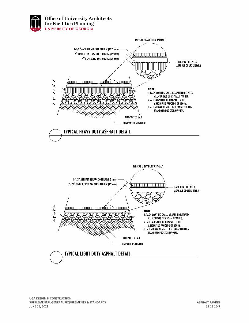
UGA DESIGN & CONSTRUCTION SUPPLEMENTAL GENERAL REQUIREMENTS & STANDARDS ASPHALT PAVING JUNE 15, 2021 32 12 16-3
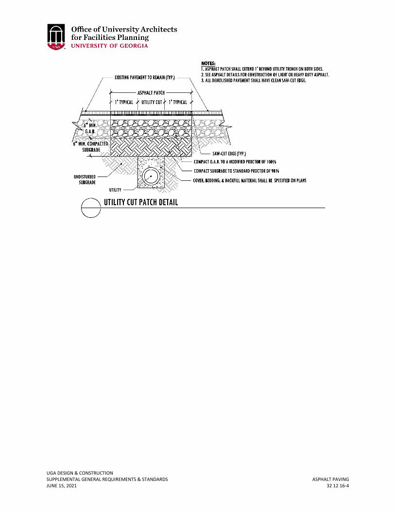
UGA DESIGN & CONSTRUCTION SUPPLEMENTAL GENERAL REQUIREMENTS & STANDARDS ASPHALT PAVING JUNE 15, 2021 32 12 16-4
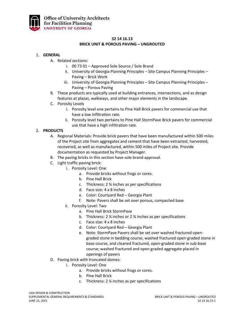
UGA DESIGN & CONSTRUCTION SUPPLEMENTAL GENERAL REQUIREMENTS & STANDARDS BRICK UNIT & POROUS PAVING – UNGROUTED JUNE 15, 2021 32 14 16.13-1
32 14 16.13 BRICK UNIT & POROUS PAVING – UNGROUTED
1. GENERAL
A. Related sections: i. 00 73 01 – Approved Sole Source / Sole Brand
ii. University of Georgia Planning Principles – Site Campus Planning Principles – Paving – Brick Work
iii. University of Georgia Planning Principles – Site Campus Planning Principles – Paving – Porous Paving
B. These products are typically used at building entrances, intersections, and as design features at plazas, walkways, and other major elements in the landscape.
C. Porosity Levels i. Porosity level one pertains to Pine Hall Brick pavers for commercial use that
have a low infiltration rate. ii. Porosity level two pertains to Pine Hall StormPave Brick pavers for commercial
use that have a high infiltration rate. 2. PRODUCTS
A. Regional Materials: Provide brick pavers that have been manufactured within 500 miles of the Project site from aggregates and cement that have been extracted, harvested, recovered, as well as manufactured, within 500 miles of Project site. Provide documentation as requested by Project Manager.
B. The paving bricks in this section have sole brand approval. C. Light traffic paving brick:
i. Porosity Level: One a. Provide bricks without frogs or cores. b. Pine Hall Brick c. Thickness: 2 ¾ inches as per specifications d. Face size: 4 x 8 inches e. Color: Courtyard Red – Georgia Plant f. Note: Pavers shall be set over porous, compacted base
ii. Porosity Level: Two a. Pine Hall Brick StormPave b. Thickness: 2 ¼ inches or 2 ¾ inches as per specifications c. Face size: 4 x 8 inches d. Color: Courtyard Red – Georgia Plant e. Note: StormPave Pavers shall be set over washed fractured open-
graded stone in bedding course, washed fractured open-graded stone in base course, and cleaned fractured, open-graded stone in sub-base course; washed fractured and open graded aggregate placed in openings of pavers
D. Paving brick with truncated domes: i. Porosity Level: One
a. Provide bricks without frogs or cores. b. Pine Hall Brick c. Thickness: 2 ¼ inches as per specifications
UGA DESIGN & CONSTRUCTION SUPPLEMENTAL GENERAL REQUIREMENTS & STANDARDS BRICK UNIT & POROUS PAVING – UNGROUTED JUNE 15, 2021 32 14 16.13-2
d. Face size: 4 x 8 inches e. Color: Courtyard Red – Georgia Plant f. Note: In some instances, pavers shall be set over concrete sub-base.
Coordinate with Project Manager. E. Heavy vehicular paving brick:
i. Porosity Level: One a. Provide bricks without frogs or cores in surfaces exposed to view in the
completed Work. b. Pine Hall Brick c. Thickness: 2 ¾ inches as per specifications d. Face size: 4 x 8 inches e. Color: Courtyard Red – Georgia Plant f. Note: Pavers shall be set over concrete sub-base
ii. Porosity Level: Two a. Pine Hall Brick StormPave b. Thickness: 2 ¼ inches or 2 ¾ inches as per specifications c. Face size: 4 x 8 inches d. Color: Courtyard Red – Georgia Plant e. Note: StormPave Pavers shall be set over washed fractured open-
graded stone in bedding course, washed fractured open-graded stone in base course, and cleaned fractured, open-graded stone in sub-base course; washed fractured and open graded aggregate placed in openings of pavers
F. Brick shall be rated “not effloresced.” 3. EXECUTION
A. Contractor shall mix pavers from several pallets or cubes, as they are placed, to produce uniform blend of color and textures.
B. Contractor shall set pavers per manufacture’s recommendation for paver type, or minimally at a joint width of 1/16 inches and a maximum of 1/8 inches.
C. Tolerances: Do not exceed 1/16 inches in 10 feet from level, or indicated slope, for finished surface of paving.
D. Contractor shall repeat sand joint-filling process 30 days later ton ensure uniformity of joint infill.
UGA DESIGN & CONSTRUCTION SUPPLEMENTAL GENERAL REQUIREMENTS & STANDARDS SIDEWALKS JUNE 15, 2021 32 16 23-1
32 16 23 SIDEWALKS
1. GENERAL
A. Related sections: i. University of Georgia Planning Principles – Site Campus Planning Principles –
Paving – Sidewalks – University of Georgia Roadway ii. 03 00 00 – General Concrete Requirements
B. Sidewalks shall be repaired in complete panels as originally scored. Cutting and replacement shall be at existing construction joints as agreed to with Project Manager.
2. PRODUCTS A. All sidewalks greater than 5 feet wide will have vehicles drive on them and shall be a
minimum of 6 inches thick unreinforced concrete, 3000 psi, with a minimum 6 inches graded aggregate base.
B. Porous paving may be specified in appropriate locations per approval by the Project Manager.
3. EXECUTION A. The Design Professional shall verify all scoring patterns with the Project Manager. B. Sidewalks shall have the following scoring pattern (except for porous paving which shall
be coordinated with Project Manager): i. Joint Pattern ‘A’ Example: Typical scoring pattern for sidewalk widths less than 8
feet. ii. Joint Pattern ‘B’ Example: Typical scoring pattern for sidewalk widths greater
than 8 feet and in prominent focal areas that generate heavy pedestrian traffic.
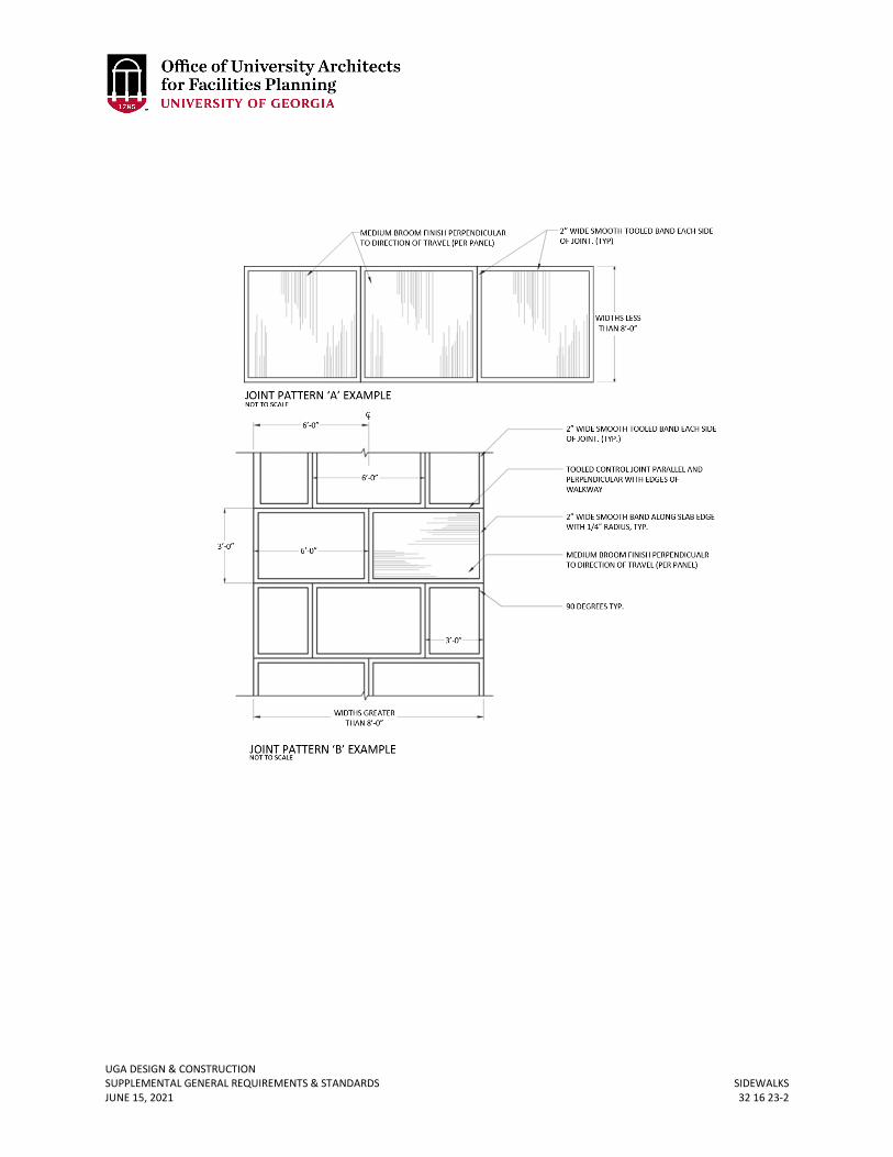
UGA DESIGN & CONSTRUCTION SUPPLEMENTAL GENERAL REQUIREMENTS & STANDARDS SIDEWALKS JUNE 15, 2021 32 16 23-2
UGA DESIGN & CONSTRUCTION SUPPLEMENTAL GENERAL REQUIREMENTS & STANDARDS PAVEMENT MARKINGS JUNE 15, 2021 32 17 23-1
32 17 23 PAVEMENT MARKINGS
1. GENERAL
A. The Owner requires a double stripe line configuration between 90 degree and angled parking spaces. All parking space lines shall be 4 inches in width. Ninety degree parking spaces shall be 9 feet wide center to center of the double line configuration and 18 feet deep. The double stripe line between spaces shall be 24 inches in overall width. Refer to diagram below.
B. Design Professional shall coordinate with Project Manager to include UGA Parking Services for review of parking layouts during the design phase.
2. PRODUCTS A. All arrows, hashes, stop bars, and roadway centerline markings shall be made using
thermoplastic paint. All roadway edge lines, bicycle lane markings, and other parking space pavement marking paint for asphalt or porous concrete shall be water-borne traffic paint (without glass beads) that meets applicable sections of the Georgia Department of Transportation (GDOT) specification 870.2.02.
i. Basis of design manufacturers are Tran Safe (Transportation Safety Products) and Pride Enterprises Baker Traffic Paint.
B. For parking space pavement marking paint for new concrete, the Design Professional shall coordinate with the Project Manager.
C. Parking space related pavement marking colors: Only standard pre-tinted paint colors shall be used for white, yellow, blue, red, green, and black traffic paint markings. White and blue are the most commonly used colors on campus and the Design Professional shall coordinate with the Project Manager for locations of any of the other standard colors.
i. The Design Professional shall coordinate with the Project Manager to include UGA Fire Safety for review of any markings for fire lanes or fire hydrants.
3. EXECUTION A. For asphalt surfaces, apply two coats, each wet application shall be a minimum 15 mils.
For concrete surfaces apply 1 coat, and the wet application shall be a minimum of 15 mils.
B. Contractor shall ensure that the manufacturer-required asphalt cure time is achieved prior to application of pavement markings (typical cure time is +/- 30 days).
C. Sample Pavement Markings diagram for reference on next page:
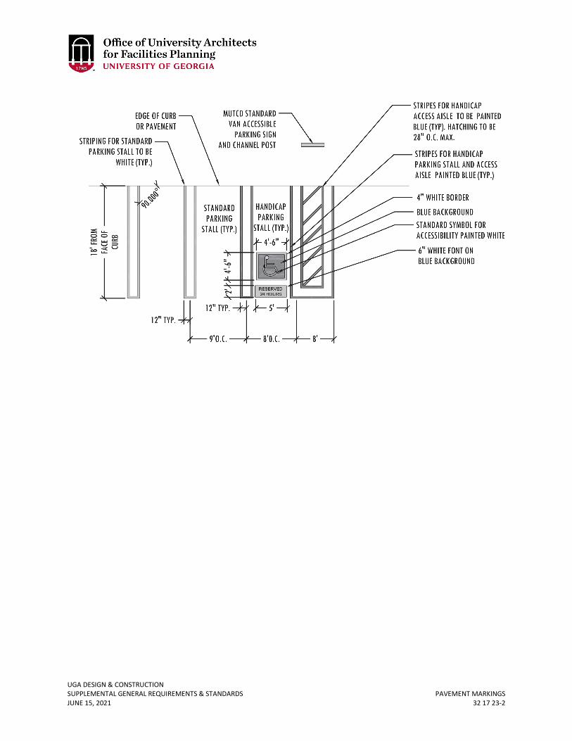
UGA DESIGN & CONSTRUCTION SUPPLEMENTAL GENERAL REQUIREMENTS & STANDARDS PAVEMENT MARKINGS JUNE 15, 2021 32 17 23-2
UGA DESIGN & CONSTRUCTION SUPPLEMENTAL GENERAL REQUIREMENTS & STANDARDS CHAIN-LINK FENCES & GATES JUNE 15, 2021 32 31 13-1
32 31 13 CHAIN-LINK FENCES & GATES
1. GENERAL
A. Related sections: i. University of Georgia Planning Principles – Site Campus Planning Principles –
Landscape – Fencing and Screening B. Where chain link fencing is required, either by code or for security purposes, black,
vinyl-coated, chain link fence should be used. In regards to each situation, the height of the fence will be determined by the OUA.
UGA DESIGN & CONSTRUCTION SUPPLEMENTAL GENERAL REQUIREMENTS & STANDARDS TIMBER RETAINING WALLS JUNE 15, 2021 32 32 29-1
32 32 29 TIMBER RETAINING WALLS
1. GENERAL
A. Timber retaining walls are not allowed.
UGA DESIGN & CONSTRUCTION SUPPLEMENTAL GENERAL REQUIREMENTS & STANDARDS STONE RETAINING WALLS JUNE 15, 2021 32 32 53-1
32 32 53 STONE RETAINING WALLS
1. GENERAL
A. Related sections: i. University of Georgia Planning Principles – Site Campus Planning Principles –
Gateways and Edges – Site Walls and Seat Walls ii. 04 00 00 – General Masonry Requirements
B. Site retaining walls, depending on the height, are preferably constructed of granite rubble or granite faced granite rubble on a concrete wall. Coordinate with Project Manager to determine if retaining wall exposed surfaces shall be granite rubble or concrete.
2. PRODUCTS A. Regional Materials: Provide granite rubble that is quarried within 200 miles of the
Project site. Make available documentation as requested by Project Manager. B. Basis of design: Grey Elberton Granite, Elberton, Georgia. C. Type: Cubic-shaped granite stones to provide random pattern of stone sizes, but with all
stone edges oriented orthogonally. Stone shall be weathered and broken face. D. Size: On the wall elevation, the minimum allowable individual piece of stone shall be 4
inches x 5 inches. 3. EXECUTION
A. Contractor shall provide a mockup of at least 5 feet wide by the height of the wall. An in place mock up is allowable as long as Contractor makes any required corrections.
B. There shall only be vertical and horizontal mortar joints. Any stones that are oriented in the wall so that the edges are diagonal (not oriented horizontally and vertically) will be rejected.
C. The mortar joint size shall be a minimum ½ inches. Mortar color to match stone. D. A granite coping cap shall be used on all seat walls. The width of the cap should have a
minimum 1-inch overhang on all sides and a minimum thickness of 4 inches. All cap pieces shall span the entire width of the top of the wall and contain cubic-shaped granite stones to ensure random pattern of stone sizes.
E. Any polished faces that are installed will be rejected. F. Weep holes that are formed with PVC shall be gray PVC (white PVC is not allowed). PVC
shall be recessed 1-inch from face of wall. G. Granite inscriptions shall use Legacy font.
UGA DESIGN & CONSTRUCTION SUPPLEMENTAL GENERAL REQUIREMENTS & STANDARDS MANUFACTURED METAL BOLLARDS JUNE 15, 2021 32 39 13-1
32 39 13 MANUFACTURED METAL BOLLARDS
1. GENERAL
A. Related sections: i. 00 73 01 – Approved Sole Source / Sole Brand
ii. University of Georgia Planning Principles – Site Campus Planning Principles – Site Safety and Security – Security Bollards
B. Removable Bollards are generally used to restrict vehicular access on large driveways and sidewalks located on campus.
C. Fixed Utilitarian Bollards are undecorated, simple, steel bollards that are used in utilitarian locations.
2. PRODUCTS A. Removable Bollards:
i. This product has sole brand approval. a. VISCO, Inc.
Address: 29579 Awbrey Lane, Eugene, OR 97402 Office Phone: (800) 341-1444 Website: www.visco-light.com
ii. Model a. #VI-BO-14/30 - RB
iii. Finish/Color a. Factory finish painted black
iv. Special Features a. Removable mounting
v. Notes a. Pipe to be galvanized prior to paint finish
vi. Drawing provided for reference:
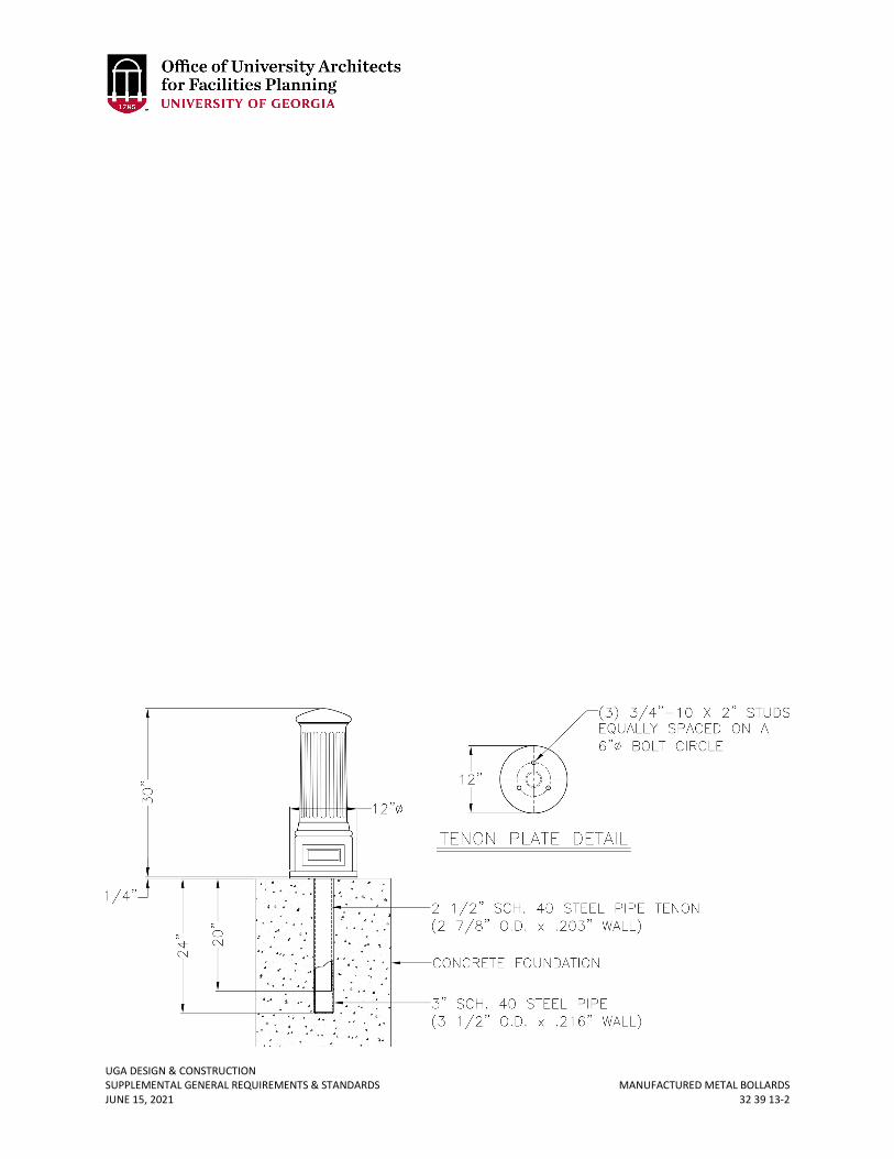
UGA DESIGN & CONSTRUCTION SUPPLEMENTAL GENERAL REQUIREMENTS & STANDARDS MANUFACTURED METAL BOLLARDS JUNE 15, 2021 32 39 13-2
UGA DESIGN & CONSTRUCTION SUPPLEMENTAL GENERAL REQUIREMENTS & STANDARDS PLANTING IRRIGATION JUNE 15, 2021 32 84 00-1
32 84 00 PLANTING IRRIGATION
1. GENERAL
A. Related sections: i. 00 73 01 – Approved Sole Source / Sole Brand
ii. 01 56 39 – Temporary Tree and Plant Protection iii. 01 77 00 – Project Closeout iv. 02 01 00 – Maintenance of Existing Conditions v. 32 01 90.23 – Pruning
vi. 32 90 00 – Planting vii. 32 91 00 – Planting Preparation
viii. 32 91 13.16 – Mulching ix. 32 92 00 – Turf and Grasses x. 32 93 00 – Plants
xi. 32 94 13 – Landscape Edging B. For this section “Contractor” may also mean “Irrigation Subcontractor.” C. The Design Professional shall determine if backflow preventer is required. D. Pre-Construction Conference: Before Work is started, the Contractor and Irrigation
Subcontractor shall coordinate a meeting with the Project Manager. E. The Contractor shall maintain continuously a competent superintendent, satisfactory to
the Owner, on the Work during progress with authority to act in all matter pertaining to the Work.
F. It is the Contractor’s responsibility to coordinate and cooperate with any other Contractors retained directly by the Owner to enable Work to proceed rapidly and efficiently.
G. The Contractor shall confine his operations to the area to be improved and to the areas allotted him by the Design Professional for material and equipment.
H. Contractor shall take all necessary precautions to protect the existing site conditions and vegetation.
I. Contractor shall review drawings and data to supply actual precipitation rates and times for each zone and include in closeout documents.
J. Prior to trenching, Contractor shall submit proposed trenching equipment to Design Professional and Project Manager for approval.
K. It shall be the Contractor’s responsibility to report in writing to the Design Professional any deviations between drawings, specification, and actual site conditions. Cost incurred due to failure to do so prior to installing equipment shall be the responsibility of the Contractor.
L. Contractor to refer to landscape plan to keep sprinkler equipment and accessory material from interfering with proper planting, i.e. verify root ball size for planting.
M. Contractor shall install manufacturers’ recommendation on fault ground and lightening protection.
2. PRODUCTS A. Pipe and Fittings
i. Pipe sizes shall conform to those shown on the drawings. No substitutions of smaller pipe sizes will be permitted, but substitutions of larger size may be
UGA DESIGN & CONSTRUCTION SUPPLEMENTAL GENERAL REQUIREMENTS & STANDARDS PLANTING IRRIGATION JUNE 15, 2021 32 84 00-2
approved. All pipe damaged or rejected because of defects shall be removed from the site at the time of said rejection.
ii. All mainline piping 2 ½ inches and larger will be equipped with gaskets. iii. All fittings for mainline pipes 2 ½ inches or larger will be equipped with gaskets. iv. All piping downstream of electric valves, sizes 3 inches and smaller shall be rigid
unplasticized PVC 200 PSI working pressure extruded from virgin parent material of the type specified on the drawings. The pipe shall be homogeneous throughout and free from visible cracks, holes, foreign materials, blisters, wrinkles and permanently marked with the manufacture's name, material, size, and schedule type. Pipe must bear the NFS seal.
v. All mainline piping and underground piping under continuous pressure shall be rigid unplasticized PVC-Schedule 40 working pressure extruded from virgin parent material of the type specified on the drawings. The pipe shall be homogeneous throughout and free from visible cracks, holes, and foreign materials, blisters, wrinkles, and dents.
vi. All plastic fittings to be installed shall be molded fittings manufactured of the same material as the pipe and shall be suitable for solvent weld, slip joint ring tight seal, or screwed connections. No fitting made of other material shall be used except as hereinafter specified.
vii. Slip fitting socket tapers shall be so sized that a dry unsoftened pipe end conforming to these special provisions can be inserted no more than halfway into the socket. Plastic saddle and flange fittings will not be permitted. Only Schedule 80 pipe may be threaded.
viii. Fittings for all mainline piping 4 inches and larger shall be equal to Harco Ductile Iron Gasketed Fittings. All mainline piping 4 inches and larger shall utilize approved thrust blocking and or restraints. Thrust Blocking and restraints to be installed as per manufacturer's recommendations for pipe type, pipe size and local environmental conditions.
B. Sleeves i. All sleeves should be a minimum Schedule 40 PVC or stronger. All sleeves are
required at every crossing indicated on drawings. ii. All sleeves shall be installed under proposed pavement areas prior to subgrade
and base construction. iii. Sleeves shall have a minimum horizontal separation of 18 inches and a
maximum of 24 inches clearance below bottom of curb. iv. All sleeves shall have a minimum horizontal separation of 18 inches and a
maximum of 36 inches from center to center. v. All sleeves shall be marked with 3 ½-inch mag nail. Nail shall be placed 4 inches
from edge of pavement on both sides as per the following detail.
UGA DESIGN & CONSTRUCTION SUPPLEMENTAL GENERAL REQUIREMENTS & STANDARDS PLANTING IRRIGATION JUNE 15, 2021 32 84 00-3
Sleeving Detail
vi. All sleeves shall be taped shut prior to final installation. vii. The location of all sleeves shown on the plans is schematic. The Contractor shall
make any adjustments necessary to accommodate existing vegetation, utilities, or other existing conditions.
viii. If the road crossings are designated as being bore locations the bore must be ample size to accommodate the size sleeve specified.
C. Control System i. All landscape installations shall utilize the Calsense ET2000E Enhanced Water
Management Controller in the SSE Heavy – Duty Stainless Steel Cabinet. The Calsense Water Management Controller has sole brand approval. Refer to Section 00 73 01 Approved Sole Source/Sole Brand. If appropriate request a variance from project manager for small existing system extensions.
a. The ET2000E allows irrigation based on time, Evapo-transpiration rate (ET), and on soil moisture with the ability to integrate moisture sensing and ET-based operations. Cycle & soak watering, twelve month programming and interactive monthly volume budgets.
b. The Calsense 2000E controller shall be able to communicate directly with the software program on the computer at the FMD Grounds Maintenance Facility.
ii. Depending on location of the product, specify either the SSE-R model capable of communicating with central control software hub via local radio or the SSE-EN model that is capable of communicating with the central control software hub via Ethernet connection.
iii. Controllers and valves shall be equal to Rain Bird. Rain Bird DVF or Rain Bird PEB valves shall be used for all zone control valves.
iv. All regular turf rotary heads shall be Hunter I-20 rotors. v. Smaller turf areas may utilize Hunter MP Rotator heads.
D. Control Wire i. Control wire shall be type UF, UL approved, for direct burial and shall be gauge
14 or larger for the control wire and gauge 12 or larger for common wire.

UGA DESIGN & CONSTRUCTION SUPPLEMENTAL GENERAL REQUIREMENTS & STANDARDS PLANTING IRRIGATION JUNE 15, 2021 32 84 00-4
ii. All 24 volt wire shall be #12 UF/UL for common wire and #14 UF/UL for control wires, direct burial, and solid copper.
iii. 24 volt wire shall be color coded; common-white, control-red. iv. Joining of underground wires shall be made with watertight connectors in valve
boxes. No splicing between boxes is acceptable. v. All wire connections in valve boxes. The first installation shall stay open until
the Design Professional approves. E. Zone Control Valves
i. Control zone kits shall be preassembled with a Pressure Regulating (PR) Filter. ii. The Pressure Regulating Filter combines filtration and pressure regulation in
one unit for protection of downstream components of a drip irrigation system. The pressure regulator is integrated into the filter body. The unit contains both a 200 mesh (75 micron) filter and a pressure regulator. The PR Filter shall have a body and cap that are made of glass-filled, UV-resistant polypropylene, with 120 psi (8,3 bars) pressure rating. The pressure regulating device is a normally open device that allows full flow with little pressure loss unless the inlet pressure is greater than the preset level. As the inlet pressure increases above the preset level it compresses a spring and begins to reduce the downstream pressure. The pressure regulator built into the PR Filter body shall have a preset outlet pressure of approximately 30 psi (2, 1 bars). The filter screen shall be constructed of durable polyester fabric attached to propylene frame. The standard 200-mesh screen (75 micron) shall be serviceable for cleaning purposes by unscrewing the cap from the body and removing the filter element. The design shall be of a compact "Y" body and cap configuration. The 3/4" filter body shall have a 3/4" male threaded inlet and outlet. The dimension of PR filter shall not exceed the following: 4 ½ inches (11,4 em) in height, 5 ½ inches (14 em) in length, 2 inches (5,1 em) in width.
iii. Contractor shall utilize valve I.D. tags, 1-inch, 1.5-inch, or 2-inch, round brass, attached with beaded brass chain on all remote control valves.
iv. Contractor to utilize appropriate automatic drain device where low head drainage may occur.
F. Valve Boxes i. All valves shall be installed in thermoplastic valve access boxes of the size
required to permit access to the valve. Valve boxes shall include black thermoplastic locking covers. Manufacturer: Ametek or approved equal.
ii. All valve boxes shall be installed on at least a two (2) cubic foot gravel base to provide foundation and drainage.
iii. All valve box elevations shall be at grade. iv. No electrical connections shall be made in the field except at a valve control box
or another valve box specifically for connections. v. Contractor shall provide expansion coils at each wire connection in valve box
(wrap around ¾-inch pipe 12 times). 3. EXECUTION
A. Excavation and Back Fill i. Trenches for pipe sprinkler lines shall be excavated of sufficient depth and
width to permit proper handling and installation by any other method the
UGA DESIGN & CONSTRUCTION SUPPLEMENTAL GENERAL REQUIREMENTS & STANDARDS PLANTING IRRIGATION JUNE 15, 2021 32 84 00-5
Contractor may desire if approved by the Project Manager, pipe manufacturer, and Design Professional. The backfill shall be thoroughly compacted and evened off with the adjacent soil level. Selected fill dirt or sand shall be used if soil conditions are rocky. In rocky areas the trenching depth shall be 2 inches below normal trenching depth to allow for this bedding. The fill dirt or sand shall be used in filling 4 inches above the pipe. The remainder of the backfill shall contain no lumps or rocks larger than 3 inches. The top 12 inches of backfill shall be topsoil, free of rocks, subsoil, or trash. Any open trenches or partially backfilled trenches left overnight or left unsupervised shall be barricaded to prevent undue hazard to the public.
ii. The Contractor shall backfill in 6-inch compacted lifts as needed to bring the soil to its original density.
iii. In the spring following the year of installation, the Contractor shall repair any settlement of the trenches by bringing them to grade with topsoil, and seeding with the existing lawn type(s). Watering and maintenance of the repaired areas shall be the Owner's responsibility.
iv. All mainlines to have a minimum of 18 inches of cover. (Schedule 40 PVC Pipe). v. All lateral and sub-main pipes to have a minimum of 12 inches of cover.
(Schedule 40 PVC Pipe). B. Installation of Plastic Pipe
i. Plastic pipe shall be installed in a manner that permits expansion and contraction as recommended by the manufacturer.
ii. Plastic pipe shall be cut with a handsaw or hacksaw with the assistance of a square in sawing vice or in a manner so as to ensure a square cut. Burrs at cut ends shall be removed prior to installation so that a smooth unobstructed flow will be obtained.
iii. All plastic-to-plastic joints shall be solvent weld joints or slip seal joints. Only the solvent recommended for the pipe and fittings shall be installed as outlined and instructed by the pipe manufacturer. The Contractor shall assume full responsibility for the correct installation.
iv. All threaded joints to be coated with Teflon tape or liquid Teflon. v. The joints shall be allowed to set at least 24 hours before pressure is applied to
the system on PVC pipe. vi. Contractor shall install sprinkler equipment 12 inches from foundations and 4
inches from curb or walks. C. Controller and Electrical Connections
i. Control wires installed beneath walks, drives, or other permanent surfaces shall be placed in sleeves.
ii. Wires shall be spliced only at valve boxes. iii. Leave 24-inch loop of wire at each valve for expansion / contraction and
servicing. iv. 120 VAC electrical power supply to the controller location shall be supplied by
the contractor. D. Flushing and Testing
i. After all new sprinkler piping and risers are in place and connected for a given section and all necessary division work has been completed and prior to the
UGA DESIGN & CONSTRUCTION SUPPLEMENTAL GENERAL REQUIREMENTS & STANDARDS PLANTING IRRIGATION JUNE 15, 2021 32 84 00-6
installation of sprinkler heads all control valves shall be opened and a full head of water used to flush out the system.
ii. Sprinkler main shall be tested under normal water pressure for a period of 12 hours. If leaks occur, repair, and repeat the test. Give Design Professional 24 hours’ notice prior to testing.
iii. Testing of the system shall be performed after completion of the entire installation and any necessary repairs shall be made at the Contractor's expense to put the system in good working order before final payment by the Owner.
iv. All quick couplers shall be mounted on swing joints. v. All sprinkler heads shall be installed with funny pipe connections.
vi. One quick coupler shall be required for every five (5) irrigation valves. vii. Adjustment of the sprinkler heads, and automatic equipment, will be done by
the Contractor upon completion of installation to provide optimum performance. Minor adjustments during the guarantee period will be made by the Owner
viii. After completion, testing, and acceptance of the system, the Contractor will instruct the Owner's personnel in the operation and maintenance of the system.
ix. Contractor to add extension riser to pop-up heads when needed for proper coverage.
E. Clean Up and Protection i. During irrigation Work, Contractor shall keep Project site clean and orderly.
ii. Upon completion of Work, clear grounds of debris, superfluous materials and all equipment. Remove from site to satisfaction of the Owner's Representative.
F. Closeout i. Record Drawings and Instructions
a. Upon completion of installation, Contractor shall produce as-built drawings showing all sprinkler heads, valves, drains, and pipelines to scale with dimensions. These drawings shall have dimensions from easily located stationary points (cross measured) as they relate to all valves, mainlines, and wire. Clearly note all approved substitutions of size, material, etc. Complete, concise instruction sheets and parts lists covering all operating equipment and weathering techniques shall be bound into folders and furnished to the Project Manager. Submission of this information is a requirement for final acceptance. Refer to Section 01 78 00 Closeout Submittals.
ii. All material to be supplied by Contractor to Owner: a. Two wrenches for disassembling and adjusting each type of sprinkler
heads and valve supplied. b. Two keys for each of the automatic controllers. c. Two quick coupler keys with matching hose swivels.
iii. After completion, testing, and acceptance of the system, the Contractor shall coordinate with the Project Manager for a training session and the Irrigation Sub-contractor shall verbally instruct the Owner’s personnel in the operation and maintenance of the system.
UGA DESIGN & CONSTRUCTION SUPPLEMENTAL GENERAL REQUIREMENTS & STANDARDS PLANTING IRRIGATION JUNE 15, 2021 32 84 00-7
G. Inspection i. It will be the responsibility of the irrigation Contractor to provide a reliable
communication system (i.e. two way radios or remote radio control activation system) for substantial completion and all periodic inspections.
H. Permits and Fees i. The Contractor shall obtain, at his/her expense, all required permits and shall
pay all required fees and include such costs in to Cost of the Work or the Base Bid. Any penalties imposed due to failure to obtain any permit or pay any fee shall be the responsibility of the Contractor.
I. Warranty and Guarantee i. The Contractor shall furnish a certificate of warranty registration and a written
guarantee of work and materials for a one-year period from the date of Material Completion of the irrigation system by the Owner and the Design Professional.
UGA DESIGN & CONSTRUCTION SUPPLEMENTAL GENERAL REQUIREMENTS & STANDARDS PLANTING JUNE 15, 2021 32 90 00-1
32 90 00 PLANTING
1. GENERAL
A. Related sections: i. 32 01 90.23 – Pruning
ii. 32 84 00 – Planting Irrigation iii. 32 91 00 – Planting Preparation iv. 32 91 13.16 – Mulching v. 32 92 00 – Turf and Grasses
vi. 32 93 00 – Plants vii. 32 94 13 – Landscape Edging
2. PRODUCTS 3. EXECUTION
A. Water i. Design Professional shall coordinate a water source with the Project Manager so
that suitable water for the implementation and maintenance of the landscape plan shall be available on or near the Project sites. If a new water source or extension of water source is included in the Contract documents, the Contractor shall plan that the water source is functional prior to planting. The Contractor shall provide water trucks, hoses and other conveyances.
ii. The root system of all plants shall be watered by the Contractor at such intervals as to keep the surrounding soil in the best condition for promotion of root and plant growth.
B. Pesticides i. All pesticides used shall be labeled for specific use and for use in public areas.
ii. Contractor applying pesticides must have a Commercial Contractor's Pesticide Applicator's License.
iii. Contractor shall apply treatments as required to keep plant materials, planted areas, and soils free of pests and pathogens or disease. Use practices to minimize the use of pesticides and reduce hazards.
iv. Contractor shall apply pesticides and other chemical products and biological control agents in accordance with authorities having jurisdiction and manufacturer's written recommendations. Coordinate applications with Project Manager's operations and others in proximity to the Work. Notify Project Manager before each application is performed.
C. Maintenance i. The Contractor shall begin maintenance immediately after each plant is installed
and shall continue until final acceptance of the Work in total by the Design Professional. Maintenance shall include watering, cultivating, weeding, mulching, maintaining guy wires and stakes, pest control, and general site cleanup.
ii. Contractor shall provide maintenance by skilled employees of landscape Installer.
iii. Maintenance Period for Trees and Shrubs: Maintain trees and shrubs from time of initial installation until Material Completion.
UGA DESIGN & CONSTRUCTION SUPPLEMENTAL GENERAL REQUIREMENTS & STANDARDS PLANTING JUNE 15, 2021 32 90 00-2
iv. Maintenance Period for Ground Cover and Other Plants: Maintain trees and shrubs from time of initial installation Material Completion.
v. Maintain plantings by pruning, cultivating, watering, weeding, fertilizing, mulching, restoring planting saucers, resetting to proper grades or vertical position, and performing other operations as required to establish healthy, viable plantings. Spray or treat as required to keep trees and shrubs free of insects and disease.
D. Plant Damage: i. Planting areas and plants shall be protected by the Contractor at all times
against trespassing and damages of any kind for the duration of the maintenance period. If any plants become damaged or injured, they shall be treated or replaced by the Contractor as directed by the Design Professional at no additional cost to the Owner. No work shall be done by the Contractor within, adjacent to, or over any plant or planting area without proper safeguards and protection of the plant material.
ii. Contractor shall protect plants from damage due to landscape operations and operations of other contractors and trades. Maintain protection during installation and maintenance periods. Treat, repair, or replace damaged plantings.
E. Guarantee i. The Contractor shall guarantee, in writing, all materials assigned to
workmanship for a period of one year from the date of Material Completion by the Design Professional.
ii. Plant Replacement: a. During the installation, prior to material completion, any dead or dying
plants shall be replaced as part of the Contract. Any delay in replacement must be approved by the Design Professional. During and at the end of standard one (1) year guarantee period, the Contractor shall replace, without cost to the Owner, and within 30 days of notification by the Project Manager all Contractor furnished plant materials which are dead or are not in a vigorous, thriving condition. Replacements shall closely match adjacent specimens of the same species and cultivar, and shall be subject selection in the field by the Design Professional prior to digging. Replacements shall be subject to all requirements previously stated in these specifications.
iii. The Contractor shall make all necessary repairs to grades, lawns, plantings, and paving as required because of plant replacements. Such repairs shall be done at no extra cost to the Owner.
iv. The acceptance of all replacement plants by the Design Professional at the end of the guarantee period terminates the Contractor's responsibility for such. In the event that a replacement plant dies, the Project Manager may elect a subsequent substitution.
v. Replacement plants shall be guaranteed for a one (1) year period from the date of replacement, NOT from the date of original planting.
vi. Soil Preparation/Excavation Repairs:
UGA DESIGN & CONSTRUCTION SUPPLEMENTAL GENERAL REQUIREMENTS & STANDARDS PLANTING JUNE 15, 2021 32 90 00-3
a. During the 1-year guarantee period, the Contractor shall be responsible to correct any excessive settling or poor drainage areas directly attributable to Contractor's Work.
UGA DESIGN & CONSTRUCTION SUPPLEMENTAL GENERAL REQUIREMENTS & STANDARDS PLANTING PREPARATION JUNE 15, 2021 32 91 00-1
32 91 00 PLANTING PREPARATION
1. GENERAL
A. Related sections: i. 32 01 90.23 – Pruning
ii. 32 84 00 – Planting Irrigation iii. 32 91 00 – Planting Preparation iv. 32 91 13.16 – Mulching v. 32 92 00 – Turf and Grasses
vi. 32 93 00 – Plants vii. 32 94 13 – Landscape Edging
B. Prior to landscaping, the Contractor shall obtain soil samples from 3 separate and representative locations on site and send samples to:
i. Trace Level Analysis Laboratory (TLA) 2300 College Station Road Athens, GA 30602 Phone: 706-542-9023
Fax: 706-542-1474
UGA Cooperative Extension Office [email protected]
ii. A copy of the soil testing results shall be sent to the Design Professional two weeks prior to any application of fertilizer or lime.
C. Drainage i. No plant shall be planted in soil that is obviously or predictably poorly drained.
Any poorly-drained areas on the site shall be brought to the attention of the Design Professional before planting. Alterations shall be made by the Contractor to provide adequate drainage or changes will be made in the planting plan. Adjustment in final billing charges, if necessary, will be made to compensate Contractor for any additional work beyond fine grading to alleviate a drainage problem.
D. Underground Obstructions i. When an obstruction exists in any proposed plant pit or bed, the Design
Professional shall be notified immediately. If necessary, an alternate location shall be selected by the Contractor, with the approval of the Design Professional. If the location cannot be changed, the obstruction shall, if possible, be sufficiently removed to allow adequate root growth after the plant is properly planted.
2. PRODUCTS A. Compost – For UGA Athens Campus Only
i. The UGA FMD Grounds Department develops its own compost for use on projects. Coordinate with the Project Manager to determine if appropriate for specific project. If available for use, there is not a project cost for the materials; however, the Contractor will be required to obtain the material at the compost
UGA DESIGN & CONSTRUCTION SUPPLEMENTAL GENERAL REQUIREMENTS & STANDARDS PLANTING PREPARATION JUNE 15, 2021 32 91 00-2
site, which is located on Whitehall Road and transport the material to the Project site.
ii. The loading, hauling, and unloading of compost material shall be included in the Cost of the Work or Bid.
B. Topsoil i. Topsoil shall be friable and similar in physical characteristics to locally occurring
topsoil. It shall be taken from a well-drained, arable site and shall not be delivered or moved in a muddy or frozen condition. It shall be reasonable free of subsoil. It shall contain no stones, clods, sticks, roots, or other extraneous matter greater than 1-inch in size and shall contain no materials toxic to plants.
ii. Upon request of the Design Professional, the Contractor shall send representative samples of the topsoil to a recognized commercial or government agency to be tested for pH, fertility, and bulk density. Copies of the results and recommendations shall be furnished to the Design Professional by the Contractor.
C. Fertilizer i. Phosphate is the only fertilizer material to be used in the preparation and
planting of plant materials (other than turf). Phosphate is to be incorporated in all planting beds and individual planting holes as per soil test result.
D. Lime i. Lime shall meet the specifications of the Georgia Department of Agriculture and
shall be of an agricultural grade. Lime shall be dolomitic in composition. Any hardened or caked lime shall be pulverized to its original condition before it is used.
E. Landscape Fabric i. All landscape fabric and erosion control netting must be biodegradable in
nature. 3. EXECUTION
A. Soil Preparation – Current Vegetated / Undisturbed Areas i. Contractor shall loosen subgrade of planting areas to a minimum depth of 12
inches. Remove stones larger than 1-inch in any dimension and sticks, roots, rubbish, and other extraneous matter and legally dispose of them off Owner's property.
a. Contractor shall apply fertilizer directly to subgrade before loosening. b. Contractor shall thoroughly blend planting soil off-site before spreading
or spread topsoil, apply soil amendments and fertilizer on surface, and thoroughly blend planting soil.
c. Contractor shall spread planting soil to a depth of 4 inches but not less than required to meet finish grades after natural settlement. Do not spread if planting soil or subgrade is frozen, muddy, or excessively wet.
B. Soil Preparation – Previously Compacted, Paved, or Heavily Impervious Surfaces i. Areas outside the drip line of existing trees are to be excavated to a depth of 18
inches. Where equipment use is not possible, the area is to be dug by hand. Use of specific implements must be approved by the Design Professional. After disturbing the entire planting area (outside the drip line), the soil shall be removed and sent through a screening machine to separate out large-sized
UGA DESIGN & CONSTRUCTION SUPPLEMENTAL GENERAL REQUIREMENTS & STANDARDS PLANTING PREPARATION JUNE 15, 2021 32 91 00-3
materials (greater than 1-inch in diameter) from usable soil. The Contractor shall be responsible for removing the sorted screened deleterious material from the UGA campus. After initial screening, additional topsoil (equal to the amount of screened deleterious material) shall be incorporated into the usable soil and re-screened. Screened soil should be replaced in a manner that will prevent compaction to the site. Light weight equipment on rubber tracks should be used over large, heavy equipment. If the site has constrained access, back fill shall be done by hand.
a. Amendments 1) Compost shall be incorporated into all perennial beds areas.
Additional need for compost shall be determined by Design Professional prior to soil preparation. After screening and soil replacement, 2 inches of compost (if required), plus recommended lime and phosphorus, shall be applied and roto-tilled. Areas where slope is 3:1 or less shall be cross tilled to the previous till. In case of extreme slope, or other situations where tillage is not possible, Design Professional shall consider alternatives recommended by the Contractor.
C. Soil Preparation – When Inside Tree Drip Line i. Because of the need to protect existing tree roots, areas within the existing tree
drip line shall not be disturbed and / or roto-tilled. Inside the tree drip line, individual holes shall be dug for each plant or small mass of plants.
a. Amendments 1) Prior to planting and backfilling, recommended amounts of
phosphate and lime shall be added to the soil excavated from the plant holes. After planting, an application of 2 inches of compost, if needed, shall be spread over the entire planting area, before mulching.
2) The only exception to this method of planting and amending shall be in the case of ground covers planted from small (less than 1 pint) containers. In areas where groundcovers are planted in mass, the lime, phosphate, and compost shall be applied over the entire ground cover area prior to digging the planting holes.
D. Bed preparation for Meadow and Seeded Grass Areas i. All existing vegetation shall be fully killed and removed from proposed meadow
areas prior to the sowing of any meadow grass or wildflower seeds. All existing vegetation shall be sprayed with glycosophate (Round-Up) non-selective herbicide a minimum of 6 weeks prior to seed planting.
ii. After dieback of the existing vegetation is evident, it shall be removed from the site. No mixing of existing vegetation into the soil will be permitted. The planting area shall be loosened to a depth of at least six inches. Compost and other amendments as specified shall be applied and mixed thoroughly into the top 4 inches of soil. Soil shall be tilled to a homogenous mixture of fine texture and raked free of debris (rocks, sticks, trash, etc.) larger than 1-inch in any dimension.
UGA DESIGN & CONSTRUCTION SUPPLEMENTAL GENERAL REQUIREMENTS & STANDARDS PLANTING PREPARATION JUNE 15, 2021 32 91 00-4
iii. Any additional vegetation germinating in the six weeks between the initial herbicide application and the meadow planting date shall be removed by hand and disposed of off Owner property prior to sowing of meadow areas.
E. Finish Grading i. Contractor shall grade planting areas to a smooth, uniform surface plane with
loose, uniformly fine texture. Roll and rake, remove ridges, and fill depressions to meet finish grades.
F. Dust i. Contractor is responsible for controlling wind bourn dust and shall take
preventative measures as required. If adjacent structures are covered in dust from the Project, the Contractor will be held responsible for complete cleaning of all surfaces at no additional cost to the Owner. This includes, but not limited to, roofs, walls, windows, etc.
G. Drip Line Definition i. For purposes of defining type of soil preparation and planting methods, the
term 'drip line' shall be used. The drip line shall be determined by measuring the distance of the furthest limb tip from the tree. This distance shall be the radius of drip line circle. Any variation of this circle must be approved by the Design Professional.
H. Landscape Topography i. After soil preparation, but prior to planting, Design Professional shall approve
topography. This includes any previous or newly specified mounds, drainage areas, slopes, swales, edging treatments, or any other similar topographic features. Any adjustment to topography shall be made by the Contractor prior to planting.
I. Grooming and Shaping i. Soil Surface
a. All rocks, clods, sticks, and other debris larger than 1-inch shall be removed from the soil surface. Soil surface shall be raked and groomed to a smooth, even appearance. Unless specified on the landscape plan, the general slope and texture of the planted area should be returned to the approved condition before plant installation began.
UGA DESIGN & CONSTRUCTION SUPPLEMENTAL GENERAL REQUIREMENTS & STANDARDS MULCHING JUNE 15, 2021 32 91 13.16-1
32 91 13.16 MULCHING
1. GENERAL
A. Related sections: i. 32 01 90.23 – Pruning
ii. 32 90 00 – Planting iii. 32 91 00 – Planting Preparation iv. 32 92 00 – Turf and Grasses v. 32 93 00 – Plants
vi. 32 94 13 – Landscape Edging 2. PRODUCTS
A. All planting areas shall receive appropriate mulch material as directed by Design Professional or Project Manager.
B. For pine straw mulched areas: i. All pine straw shall be clean, fresh, and free of branches and foreign matter.
ii. The mulching material shall be pine straw, applied 4 inches to 6 inches thick to achieve a minimum settling depth of 3 inches.
C. For shredded hardwood bark mulched areas: i. All shredded hardwood bark mulch shall be 100% shredded hardwood bark
mulch. Each delivery must contain only double-ground shredded hardwood bark that is clean, double-ground, uniform particle size (no piece shall be any longer than 3 inches and not wider than ½ inches), free of foreign matter, and aged for a minimum of six months.
ii. The mulching material shall be 100% shredded hardwood bark mulch, applied 3 inches to 5 inches thick to achieve a minimum settling depth of 3 inches.
iii. Note: Only shredded hardwood bark mulch will be accepted; ground wood (not bark) will be rejected.
D. Placement of Crushed Slate, Gravel Paving Materials i. Gravel, crushed slate, or any other loose paving material shall not be permitted
immediately adjacent to turf grass areas or within 20 feet of building entrances. This presents both maintenance and safety issues.
3. EXECUTION A. Contractor shall mulch all trees and shrubs immediately after planting, not at the end of
the entire planting project. B. The contractor shall mulch the planting holes and staked areas of individual trees shall
be mulched, while the entire planting areas of shrub and ground cover beds shall be uniformly mulched. No soil, rocks, clods, or drip irrigation lines shall be visible through the mulch.
C. Trees planted in turf areas shall have a circular mulch ring with a four-foot radius from the trunk of the tree. All areas that are not turf or hardscape shall be mulched, unless otherwise specified.
UGA DESIGN & CONSTRUCTION SUPPLEMENTAL GENERAL REQUIREMENTS & STANDARDS TURF & GRASSES JUNE 15, 2021 32 92 00-1
32 92 00 TURF & GRASSES
1. GENERAL
A. Related sections: i. 32 01 90.23 – Pruning
ii. 32 84 00 – Planting Irrigation iii. 32 90 00 – Planting iv. 32 91 00 – Planting Preparation v. 32 91 13.16 – Mulching
vi. 32 93 00 – Plants vii. 32 94 13 – Landscape Edging
2. PRODUCTS A. All sod shall be TIF 419.
3. EXECUTION A. Grading
i. Newly Graded Subgrades: Contractor shall loosen subgrade to a minimum depth of 6 inches. Remove stones larger than 1 inch in any dimension and sticks, roots, rubbish, and other extraneous matter and legally dispose of them off Owner's property.
a. Contractor shall apply fertilizer directly to subgrade before loosening. b. Contractor shall thoroughly blend planting soil off-site before spreading
or spread topsoil, apply soil amendments and fertilizer on surface, and thoroughly blend planting soil.
c. Contractor shall spread planting soil to a depth of 4 inches but not less than required to meet finish grades after light rolling and natural settlement. Do not spread if planting soil or subgrade is frozen, muddy, or excessively wet.
1) Reduce elevation of planting soil to allow for soil thickness of sod.
ii. Unchanged Subgrades: If turf is to be planted in areas unaltered or undisturbed by excavating, grading, or surface-soil stripping operations, prepare surface soil as follows:
a. Contractor shall remove existing grass, vegetation, and turf. Do not mix into surface soil.
b. Contractor shall loosen surface soil to a depth of at least 6 inches. Apply soil amendments and fertilizers according to planting soil mix proportions and mix thoroughly into top 4 inches of soil. Till the soil to a homogeneous mixture of fine texture.
1) Contractor shall apply fertilizer directly to surface soil before loosening.
c. Contractor shall remove stones larger than 1 inch in any dimension and sticks, roots, trash, and other extraneous matter.
d. Contractor shall legally dispose of waste material, including grass, vegetation, and turf, off Owner's property.
UGA DESIGN & CONSTRUCTION SUPPLEMENTAL GENERAL REQUIREMENTS & STANDARDS TURF & GRASSES JUNE 15, 2021 32 92 00-2
iii. Finish Grading: Contractor shall grade planting areas to a smooth, uniform surface plane with loose, uniformly fine texture. Grade to within plus or minus ½ inches of finish elevation. Roll and rake, remove ridges, and fill depressions to meet finish grades. Limit finish grading to areas that can be planted in the immediate future.
iv. Moisten prepared area before planting if soil is dry. Water thoroughly and allow surface to dry before planting. Do not create muddy soil.
v. Before planting, Contractor shall obtain Design Professional and / or Project Manager acceptance of finish grading; restore planting areas if eroded or otherwise disturbed after finish grading.
B. Sodding i. Contractor shall lay sod within 24 hours of harvesting. Do not lay sod if dormant
or if ground is frozen or muddy. ii. Lay sod to form a solid mass with tightly fitted joints. Butt ends and sides of sod;
do not stretch or overlap. Stagger sod strips or pads to offset joints in adjacent courses. Avoid damage to subgrade or sod during installation. Tamp and roll lightly to ensure contact with subgrade, eliminate air pockets, and form a smooth surface. Work sifted soil or fine sand into minor cracks between pieces of sod; remove excess to avoid smothering sod and adjacent grass.
iii. Lay sod across angle of slopes exceeding 1:3. iv. Contractor shall anchor sod on slopes exceeding 1:6 with wood pegs spaced as
recommended by sod manufacturer but not less than 2 anchors per sod strip to prevent slippage.
v. Contractor shall saturate sod with fine water spray within two hours of planting. During first week after planting, water daily or more frequently as necessary to maintain moist soil to a minimum depth of 1 ½ inches below sod.
vi. For parking lot islands, sod shall not be installed in any parking lot island in such a way that the sod width is narrower than 10 feet.
C. Turf Maintenance i. Contractor shall maintain and establish turf by watering, fertilizing, weeding,
mowing, trimming, replanting, and performing other operations as required to establish healthy, viable turf. Roll, regrade, and replant bare or eroded areas and remulch to produce a uniformly smooth turf. Provide materials and installation the same as those used in the original installation.
ii. Contractor shall mow turf as soon as top growth is tall enough to cut. Repeat mowing to maintain height appropriate for species without cutting more than a third of grass height. Remove no more than a third of grass-leaf growth in initial or subsequent mowings.
iii. Contractor shall apply pesticides and other chemical products and biological control agents in accordance with authorities having jurisdiction and manufacturer's written recommendations. Coordinate applications with Owner's operations and others in proximity to the work. Notify Project Manager before each application is performed.
UGA DESIGN & CONSTRUCTION SUPPLEMENTAL GENERAL REQUIREMENTS & STANDARDS TURF & GRASSES JUNE 15, 2021 32 92 00-3
D. Satisfactory Turf installations shall meet the following criteria as determined by Design Professional:
i. Satisfactory Seeded Turf: At end of maintenance period, a healthy, uniform, close stand of grass has been established, free of weeds and surface irregularities, with coverage exceeding 90 percent over any 10 sq. ft. and bare spots not exceeding 5 by 5 inches.
ii. Satisfactory Sodded Turf: At end of maintenance period, a healthy, well-rooted, even-colored, viable turf has been established, free of weeds, open joints, bare areas, and surface irregularities.
iii. Use specified materials to reestablish turf that does not comply with requirements and continue maintenance until turf is satisfactory.
UGA DESIGN & CONSTRUCTION SUPPLEMENTAL GENERAL REQUIREMENTS & STANDARDS PLANTS JUNE 15, 2021 32 93 00-1
32 93 00 PLANTS
(GROUND COVERS, PLANTS, SHRUBS, TREES, ETC.)
1. GENERAL A. Related sections:
i. 32 01 90.23 – Pruning ii. 32 84 00 – Planting Irrigation
iii. 32 91 00 – Planting Preparation iv. 32 91 13.16 – Mulching v. 32 92 00 – Turf and Grasses
vi. 32 93 00 – Plants vii. 32 94 13 – Landscape Edging
B. Specific plants that require seasonal planting will be indicated on the planting plan. Actual plant installation shall occur only during periods when weather and soil conditions are favorable. The Design Professional shall be notified at least 48 hours before planting begins.
C. Planting Locations i. The Contractor shall stake the location of planting sites and the Design
Professional will approve the location prior to beginning any planting. The time required between staking and planting will be determined at the pre-construction conference.
D. Plant Placement i. Each plant shall be placed in a straight, upright, and centered position in its
planting hole or as specified. Balled and burlapped and container-grown plants shall be handled only by their roots, balls, and containers.
ii. No plant shall be specified with a spacing less than two-thirds the average diameter for the given plant’s mature spread.
iii. In general, shrubs, perennials, and groundcovers should be placed a minimum of 2 to 3 feet away from building walls, depending on the species. Plants shall be located far enough away from building walls to allow maintenance personnel to easily access the plants for pruning and to access the building wall itself.
iv. Plants may settle after transplanting and water will collect around the trunks. In all but very well-drained soils, plants will not establish and thrive if the tops of their root balls are below the level of the surrounding soil.
v. Some plants should be planted slightly higher than they were originally growing to allow for this settling of the backfill or soil conditions. Consult with Design Professional for recommendations. In no case, should the top portion of the root ball be exposed above surrounding soil line. Any special directions for planting in poorly drained soils or other specific plant needs will be indicated on the planting plan.
vi. Balled-and-burlapped plants shall have all synthetic materials removed from the root ball, trunk or crown as they will not decompose and will cause damage to the plant.
vii. All synthetic straps, bands and twine shall be removed from one-half to one-third of the top of the root ball and all ropes or wires shall be removed from the
UGA DESIGN & CONSTRUCTION SUPPLEMENTAL GENERAL REQUIREMENTS & STANDARDS PLANTS JUNE 15, 2021 32 93 00-2
plant's trunk or crown. Burlap shall be left intact around the edge of the root ball, but shall not be left on the upper portion of the ball or left exposed above the soil surface.
E. Due to the difficulty and time required to maintain extensive planting beds in accordance with UGA Standards, random plant mixtures consisting of assorted perennials, grasses, and flowering bulbs will not be permitted except in meadow type areas. Plantings in typical plant beds shall occur as distinct masses of individual species so that they are easily recognizable for appropriate maintenance by campus personnel. Atypical or special installations shall be reviewed on a case by case basis for design and plant selection (eg: rooftop gardens).
F. Site Triangles in Parking Lots: Plantings shall be designed so as not to obstruct site triangles for vehicles at campus street and driveway intersections. For parking lot islands, no proposed shrub shall exceed 30 inches in height at maturity. Additionally, sod shall not be installed in any parking lot island in such a way that the sod width is narrower than 10 feet.
2. PRODUCTS A. Plant Selection: The Contractor shall use only plants that are nursery grown, unless
otherwise specified and approved by the Design Professional. All plants shall be in accordance with American Association of Nurserymen's (AAN) of American Standard for Nursery Stock, latest edition. All plants shall be typical of their species or cultivar and have a normal growth habit. They shall be healthy, vigorous, well-branched, and densely foliated when in leaf. Plants shall be free of disease, nematode, and insect pests, including insect eggs and larvae. They shall have a healthy, well-developed root system.
B. Double Leaders in Trees: Unless specified as multi-stem trees, shade trees shall not be supplied with co-dominant stems. Only shade trees with single dominant leaders will be deemed acceptable for planting. Co-dominant stems occurring within the lower half of the crown do not meet minimum quality requirements for acceptable tree specimens.
C. Regional Materials: The Design Professional shall specify plant material that is grown within 100 miles of the Project site. Make available documentation as requested by the Project Manager. If the Contractor believes that specified plant material cannot be
UGA DESIGN & CONSTRUCTION SUPPLEMENTAL GENERAL REQUIREMENTS & STANDARDS PLANTS JUNE 15, 2021 32 93 00-3
sourced within 100 miles, the Contractor must inform the Design Professional and Project Manager in writing and wait for direction on how to proceed.
D. Substitutions: All substitutions in genus, species, cultivar, or size must be made by the Contractor and approved by the Design Professional. Plants larger than specified may be substituted on approval of the Design Professional, but such plants shall not increase the contract price. If the use of larger plants is approved, the spread of roots or ball of earth shall be increased in proportion to the size of the plant. If larger sizes are used, any future replacements shall match the size installed.
3. EXECUTION A. Mulch backfilled surfaces of planting areas and other areas indicated.
i. Trees and Tree-like Shrubs in Turf Areas: Apply organic mulch ring of 4 inch average thickness, with 36-inch radius around trunks or stems. Do not place mulch within 3 inches of trunks or stems.
ii. Organic Mulch in Planting Areas: Apply 3-inch (75-mm) average thickness of mulch over whole surface of planting area, and finish level with adjacent finish grades. Do not place mulch within 3 inches (75 mm) of trunks or stems.
B. Contractor shall set out and space ground cover and plants other than trees, shrubs, and vines 18 inches apart or as indicated in even rows with triangular spacing.
C. Use planting soil for backfill. D. Contractor shall dig holes large enough to allow spreading of roots. E. Contractor shall water thoroughly after planting, taking care not to cover plant crowns
with wet soil. F. Protect plants from hot sun and wind; remove protection if plants show evidence of
recovery from transplanting shock. G. Deliver plants after preparations for planting have been completed, and install
immediately. If planting is delayed more than six hours after delivery, set plants and trees in their appropriate aspect (sun, filtered sun, or shade), protect from weather and mechanical damage, and keep roots moist.
H. Fill in as necessary soil subsidence that may occur because of settling or other processes. Replace mulch materials damaged or lost in areas of subsidence.
I. Plant Digging i. Balled and Burlapped
a. Balled and burlapped plants shall be dug with a firm, natural ball of earth around the roots, conforming to AAN's most current American Standards for Nursery Stock. Root balls shall be covered with natural burlap (treated or untreated) and secured with pinning nails, twine, wire, and wire baskets, or a combination of these materials. Synthetic wrapping materials shall not be used around the root ball.
b. Container-Grown Plants: Container-grown plants shall be healthy, vigorous and well-rooted in their containers. They shall have fibrous root systems sufficiently developed so that the root mass will retain its shape when removed from the container. No plant shall be loose in its container, nor shall it be severely root bound. Plants shall be watered prior to shipment and if transported in open vehicles shall be covered with shade cloth or tarp to prevent wind burn.
UGA DESIGN & CONSTRUCTION SUPPLEMENTAL GENERAL REQUIREMENTS & STANDARDS PLANTS JUNE 15, 2021 32 93 00-4
J. Storage i. Balled and burlapped plants which cannot be planted immediately upon
delivery to the site shall be placed on the ground (not on a paved surface) with the roots balls well protected from drying by covering them with a moisture holding material, such as sawdust, bark, or topsoil. These plants shall be provided adequate moisture and protection from temperature extremes and strong winds. All trunks shall be covered with adequate shade cloth or trunk wrapping to prevent exposure to sun if not planted within 24 hours.
ii. Container grown plants shall be brought to the planting site as close to the installation date as possible. They shall be provided adequate protection from injury, strong winds and exposure to desiccation and temperature extremes. All plants shall be watered thoroughly in their containers prior to installation. It is the responsibility of the contractor to ensure the plants are adequately watered during this period.
K. Stakes i. Stakes shall be uniform pieces of 2 inches by 2 inches treated pine of a length to
adequately support the tree and be securely anchored into the ground a minimum of 2 feet.
L. Guying Material and Straps i. Guy wire shall be annealed galvanized, sixteen (16) gauge double strand. Tree
ties or straps shall be made of reinforced webbing with grommets for attaching guy wire or hose for trees or shrubs larger than 3-inch caliper. Hose material shall be a minimum of ½-inch diameter, heavy duty, and reinforced. Materials such as eye bolts, lag screws, and textile fabrics shall not be used as tree ties.
M. Planting Holes – Outside Tree Drip Line i. In beds outside the drip line, where the soil has been thoroughly tilled, screened
and prepared, both balled and burlapped and container-grown plants shall only require a planting hole with vertical sides and a diameter slightly greater than the root ball of the transplant.
N. Plant Holes – Inside Tree Drip Line i. The planting hole shall only be dug deep enough to allow the installation of the
plant at the same depth as it was originally growing in the field or in its container or as otherwise detailed on the planting plan. The width of the hole shall be determined by the type and size of plant being installed.
a. Bare Root: 1) Bare root plants shall have holes excavated with vertical side
walls greater in diameter than the root spread of the transplant and to a depth of 12 inches.
b. Balled and Burlapped & Container Grown: 1) Balled and burlapped and container grown plants shall have
holes excavated to a depth equal to the root ball and a width twice the width of the root ball. For larger rootballs, the hole does not have to be excavated the entire depth at twice the width. A modified hole shall be a minimum twice the rootball width, to a depth of 12 inches, with vertical side walls. For the
UGA DESIGN & CONSTRUCTION SUPPLEMENTAL GENERAL REQUIREMENTS & STANDARDS PLANTS JUNE 15, 2021 32 93 00-5
remainder depth, the hole shall be at least 4 inches greater in diameter than the rootball.
c. Mechanically transplanted trees: 1) Trees dug and transplanted with a mechanical tree spade (on
site) shall be placed in a planting hole dug by a mechanical tree spade of the same size.
d. Ground covers: 1) Individual holes shall be made by hand, or with an auger. 2) If holes are dug using an auger, each planting hole shall be
made by auguring 3 adjoining holes to form a larger hole. Groundcovers shall be planted into these holes and backfilled with the soil and compost.
O. Backfill i. Unless otherwise specified on the landscape plan, all plants shall be backfilled
with soil excavated from the planting hole. Plants installed in raised beds shall be backfilled with soil taken from those amended beds.
ii. The backfill shall be placed in the planting hole in 6 to 8-inch layers, and firmed to remove air pockets, until the hole is filled. No more than ½-inch of backfill or soil shall be applied to the top surface of the root ball.
iii. All plants must be thoroughly watered in individually, to ensure proper settlement of the backfill. This shall be accomplished by applying water at the BASE of the plant for a period of time long enough to saturate the soil to a depth of the root ball.
P. Grooming and Shaping i. Plant Saucers
a. The level of soil around the plant shall be even with the slope and the top of the root ball, unless otherwise specified. Shallow saucers shall be formed around all large shrubs and trees NOT within areas to receive watering from an irrigation system. In irrigated areas, saucers shall be formed around shrubs taller than 6 feet and all trees. When used, saucers shall be formed by mounding soil two to four inches high around the perimeter of the planting hole. Saucers should be capable of holding water around each plant. On slopes, a saucer shall be formed on the lower side of the slope.
Q. Staking and Guying i. Staking or guying plants shall be dependent upon the plant's type, size, root
system, and location. Stakes and guy wires shall be used only when necessary to protect, support, or anchor the transplant. Any device that would wound the trunk of the plant shall not be used. Staking and guying shall be completed immediately after planting. Plants shall stand plumb after staking in accordance with the landscape plan.
ii. Tree ties shall be used to support and protect tree trunks or limbs which are guyed with wire. Tree ties should contact the trunk or limb with a broad, smooth surface and be elastic enough to minimize abrasion.
a. Support Staking and Guying:
Revised Apr 30, 2020
UGA DESIGN & CONSTRUCTION SUPPLEMENTAL GENERAL REQUIREMENTS & STANDARDS PLANTS JUNE 15, 2021 32 93 00-6
1) This method of staking shall be used for all small trees greater than 5 feet in height and / or under 3 inch caliper and large shrubs greater than 6 feet in height. Two 2 inches by 2 inches treated wooden stakes shall be driven into the soil, within the mulched area but outside the planting hole, to a depth to adequately secure the stakes. The plant's trunk shall be attached to the support stakes using wire and straps in such a manner that the trunk will not be damaged or girdled and yet allow natural movement of the plant. The exact height of the stakes and support wire will vary with each plant, but should attach to the tree between one-third to one-half of the tree’s height.
b. Anchor Staking and Guying: 1) This method of staking shall be used for all trees (and shrubs)
greater than 3-inch caliper or trees planted in bare root condition. Anchor stakes are used to hold the roots or the root ball of the tree or shrub in the soil until the roots can grow and adequately support the plant.
2) Three treated, wooden stakes 2 inches by 2 inches by 36 inches (or longer), shall be driven at least 2 feet into the soil leaving 6 inches exposed. The stakes shall be placed within the mulched area but outside the planting hole.
3) The trunk shall be attached to the stake with specified wire in such a manner that the trunk will not be damaged or girdled and so limited natural movement of the plant can occur. The point of attachment shall be located at the lowest set of main scaffold limbs, unless otherwise indicated on landscape plans or by Design Professional. Wire shall be secured to the tree using either webbing straps or garden hose. Safety flags shall be used to mark the guy wires.
c. Protective Staking 1) Protective staking shall be used as required. Protective stakes
may be required to prevent or reduce damage caused by mowing, pedestrian traffic, or vandals. Examples include: individual plants installed in a small isolated bed by themselves or when shrubs or trees are planted on corners near high pedestrian traffic.
2) Three (3) treated wood stakes that are 2 inches x 2 inches x 4 feet (or taller) shall be driven into the soil outside the planting hole of the plant, but inside the mulch ring, to a depth adequately securing the stakes. The placement of stakes shall form a triangle around the plant. Stakes and webbing may be required to guide traffic around tight corners, etc.
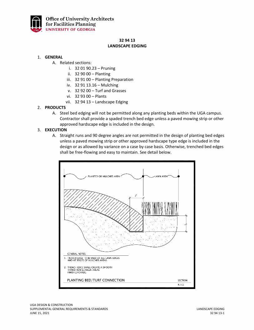
UGA DESIGN & CONSTRUCTION SUPPLEMENTAL GENERAL REQUIREMENTS & STANDARDS LANDSCAPE EDGING JUNE 15, 2021 32 94 13-1
32 94 13 LANDSCAPE EDGING
1. GENERAL
A. Related sections: i. 32 01 90.23 – Pruning
ii. 32 90 00 – Planting iii. 32 91 00 – Planting Preparation iv. 32 91 13.16 – Mulching v. 32 92 00 – Turf and Grasses
vi. 32 93 00 – Plants vii. 32 94 13 – Landscape Edging
2. PRODUCTS A. Steel bed edging will not be permitted along any planting beds within the UGA campus.
Contractor shall provide a spaded trench bed edge unless a paved mowing strip or other approved hardscape edge is included in the design.
3. EXECUTION A. Straight runs and 90 degree angles are not permitted in the design of planting bed edges
unless a paved mowing strip or other approved hardscape type edge is included in the design or as allowed by variance on a case by case basis. Otherwise, trenched bed edges shall be free-flowing and easy to maintain. See detail below.
UGA DESIGN & CONSTRUCTION SUPPLEMENTAL GENERAL REQUIREMENTS & STANDARDS GENERAL UTILITIES REQUIREMENTS JUNE 15, 2021 33 00 00-1
33 00 00 GENERAL UTILITIES REQUIREMENTS
1. GENERAL
A. Related sections: i. 01 41 26.02 – Local Utility Information & Locate
ii. 23 05 19 – Meters and Gauges iii. 33 10 00 – Water Utilities – Public Water Distribution System33 12 13.13 –
Water Supply Backflow Preventer Assemblies iv. 33 30 00 – Sanitary Sewerage Utilities – Sanitary Sewer Collection Systems v. 33 60 00 – Hydronic and Steam Energy Utilities
vi. 33 71 19 – Electrical Underground Ducts & Manholes vii. 33 80 00 – Communications Utilities
B. Contractor shall install and make operational the applicable utility revenue meter and notify FMD Utility and Energy Management prior to using any utility where UGA is the utility provider. Any un-metered utility use will be estimated by UGA based on the peak design usage rate applied over the period in which un-metered usage begins until the utility revenue meter is fully functional and FMD-energy services is notified.
C. Accessible isolation valves, identified as to function, shall be provided at new taps from existing utilities.
D. Provide detectable aluminum foil plastic backed tape or detectable magnetic plastic tape manufactured specifically for warning and identification of buried utility.
E. Existing services and equipment shall be specified to be removed from site and not be abandoned in place except with the written approval of FMD.
F. The Contractor shall adjust all existing and new utility structures (manholes, valve boxes, etc.) to meet new grades as required to complete this project at part of the Cost of the Work or Base Bid.
G. The Engineer shall provide underground profile drawings of all utilities to be installed on campus (steam, chilled water electrical duct bank, sewer, storm, etc.) clearly indicating depths of existing underground utilities.
H. Where utility excavation will be required, the Engineer shall specify “maximum limits of excavation” and shall calculate anticipated rock and unsuitable soil allowances. In addition, the engineer shall specify that the contractor provide “unit prices” for rock, and unsuitable soils.
I. Design Professional shall provide spot elevations for hardscape and landscape elements as required to clearly illustrate storm water flow direction.
J. Design Professional shall route all utilities to avoid the critical root zone of mature trees and landscapes. When absolutely necessary to enter the critical root zone of mature trees a licensed arborist must be consulted to determine the best course of action for attempting to preserve the tree.
K. Design Professional shall include pedestrian re-routing plans and traffic control drawings where applicable.
L. Underground utilities, to include electrical duct-bank, communications conduit, or any other conduit that can be damaged by high temperatures shall be protected at steam pipe crossings (in the case of stream piping failure or insulation failure) in the immediate
Revised June 15, 2021
UGA DESIGN & CONSTRUCTION SUPPLEMENTAL GENERAL REQUIREMENTS & STANDARDS GENERAL UTILITIES REQUIREMENTS JUNE 15, 2021 33 00 00-2
vicinity (within 36 inches). The protection shall consist of both thermal and physical barriers utilizing a minimum of 12-inch thick Gilsulate (or equal) and a physical barrier (3/8-inch thick, 316 grade stainless steel plate). The protection shall extend a minimum 12 inches in every direction beyond the crossing of the steam line.
M. All modified or new sanitary and storm mains shall be camera-ed at the end of the project and the video submitted as part of the close-out documents.
UGA DESIGN & CONSTRUCTION SUPPLEMENTAL GENERAL REQUIREMENTS & STANDARDS WATER UTILITIES – PUBLIC WATER DISTRIBUTION SYSTEM JUNE 15, 2021 33 10 00-1
33 10 00 WATER UTILITIES – PUBLIC WATER DISTRIBUTION SYSTEM
1. GENERAL
A. Related sections: i. 01 41 26.02 – Local Utility Information & Locate
UGA DESIGN & CONSTRUCTION SUPPLEMENTAL GENERAL REQUIREMENTS & STANDARDS WATER SUPPLY BACKFLOW PREVENTER ASSEMBLIES JUNE 15, 2021 33 12 13.13-1
33 12 13.13 WATER SUPPLY BACKFLOW PREVENTER ASSEMBLIES
1. GENERAL
A. Related sections: i. 01 41 26.02 – Local Utility Information & Locate
B. Building backflow preventers shall be designed and installed so that two backflow preventers are in parallel. This will allow for annual maintenance to occur without disruption of service.
UGA DESIGN & CONSTRUCTION SUPPLEMENTAL GENERAL REQUIREMENTS & STANDARDS SANITARY SEWERAGE UTILITIES – SANITARY SEWER COLLECTION SYSTEM JUNE 15, 2021 33 30 00-1
33 30 00 SANITARY SEWERAGE UTILITIES – SANITARY SEWER COLLECTION SYSTEM
1. GENERAL
A. Related sections: i. 01 41 26.02 – Local Utility Information & Locate
B. Prior to Material Completion, the Contractor shall camera all new sanitary sewer pipe installed exterior to the building perimeter, and 10 feet beyond the connection point with existing pipe. The Contractor shall provide the Design Professional and Project Manager with an electronic copy of the video footage for review. Cost of videoing the system shall be included in the Cost of the Work or Base Bid.
C. Sanitary sewer piping shall be installed in a 6-inch minimum sand bed. Gravel is not acceptable.
D. Schedule 40 PVC is acceptable for use under concrete slabs.
UGA DESIGN & CONSTRUCTION SUPPLEMENTAL GENERAL REQUIREMENTS & STANDARDS SANITARY SEWERAGE UTILITIES – SANITARY SEWER COLLECTION SYSTEM JUNE 15, 2021 33 42 00-1
33 42 00 DOWNSPOUT CONVEYANCE PIPES
1. GENERAL
A. Related sections: i. 33 00 00 – General Utilities Requirements
B. This section describes the requirements for storm drainage systems, including piping and all necessary accessories as designated in this section.
2. PRODUCTS A. See accompanying typical details at the end of this section. B. PVC storm sewer pipe and fittings shall be 6” minimum schedule 40 solid core piping
conforming to ASTM D1785 and ASTM D2665, Sewer and Drain Series, with ends for solvent cemented joints.
C. PVC joints shall be solvent welded socket type using solvent cement conforming to ASTM D2564 and adhesive primer conforming to ASTM F656. Bio-based materials shall be utilized when possible.
D. Cleanouts i. Downspout cleanouts shall be required on all downspouts. Cleanouts shall be
easily accessible and shall be watertight. ii. Each downspout shall be converted to round pipe, with proper adapter,
upstream of clean out. iii. Clean out shall be a wye fitting to match size of downspout; not less than 6
inches in diameter. iv. A minimum clearance of 24 inches shall be provided for clearing a clogged
storm sewer line. v. Clean out shall be between 24” and 6” above finished grade.
3. EXECUTION A. The pipe installation shall comply with the requirements of these specifications and
the current edition of the International Plumbing Code adopted in Georgia at the time of design.
B. All pipe runs shall be laid out to avoid interference with other work/trades. C. Pipe shall be round and straight. Cutting shall be done with proper tools. Pipe, except
for glass, shall be reamed to remove burrs and a clean smooth finish restored to full pipe inside diameter.
D. The piping shall be installed free of sags. E. Unless otherwise stated on the documents, minimum horizontal slope shall be two
inches for every 8 feet: 2 percent slope. F. Buried storm drainage piping shall be laid beginning at the low point of each system.
Piping shall be installed true to grades and alignment indicated with unbroken continuity of invert. Hub ends shall be placed upstream. Required gaskets shall be installed according to manufacturer’s written instruction for use of lubricants, cements, and other installation requirements. Bio-based materials shall be utilized when possible.
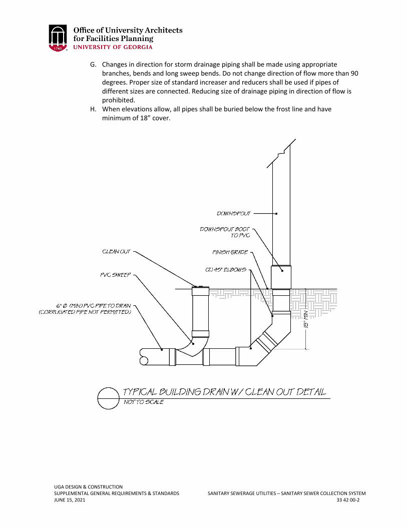
UGA DESIGN & CONSTRUCTION SUPPLEMENTAL GENERAL REQUIREMENTS & STANDARDS SANITARY SEWERAGE UTILITIES – SANITARY SEWER COLLECTION SYSTEM JUNE 15, 2021 33 42 00-2
G. Changes in direction for storm drainage piping shall be made using appropriate branches, bends and long sweep bends. Do not change direction of flow more than 90 degrees. Proper size of standard increaser and reducers shall be used if pipes of different sizes are connected. Reducing size of drainage piping in direction of flow is prohibited.
H. When elevations allow, all pipes shall be buried below the frost line and have minimum of 18” cover.
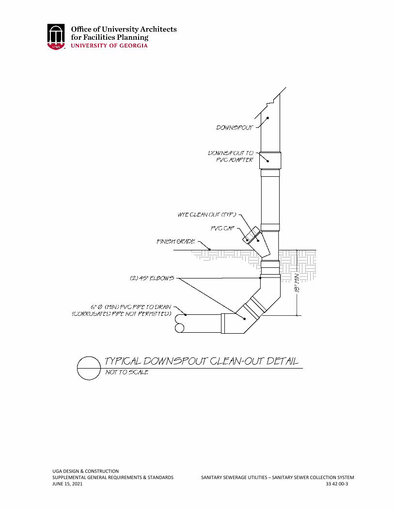
UGA DESIGN & CONSTRUCTION SUPPLEMENTAL GENERAL REQUIREMENTS & STANDARDS SANITARY SEWERAGE UTILITIES – SANITARY SEWER COLLECTION SYSTEM JUNE 15, 2021 33 42 00-3
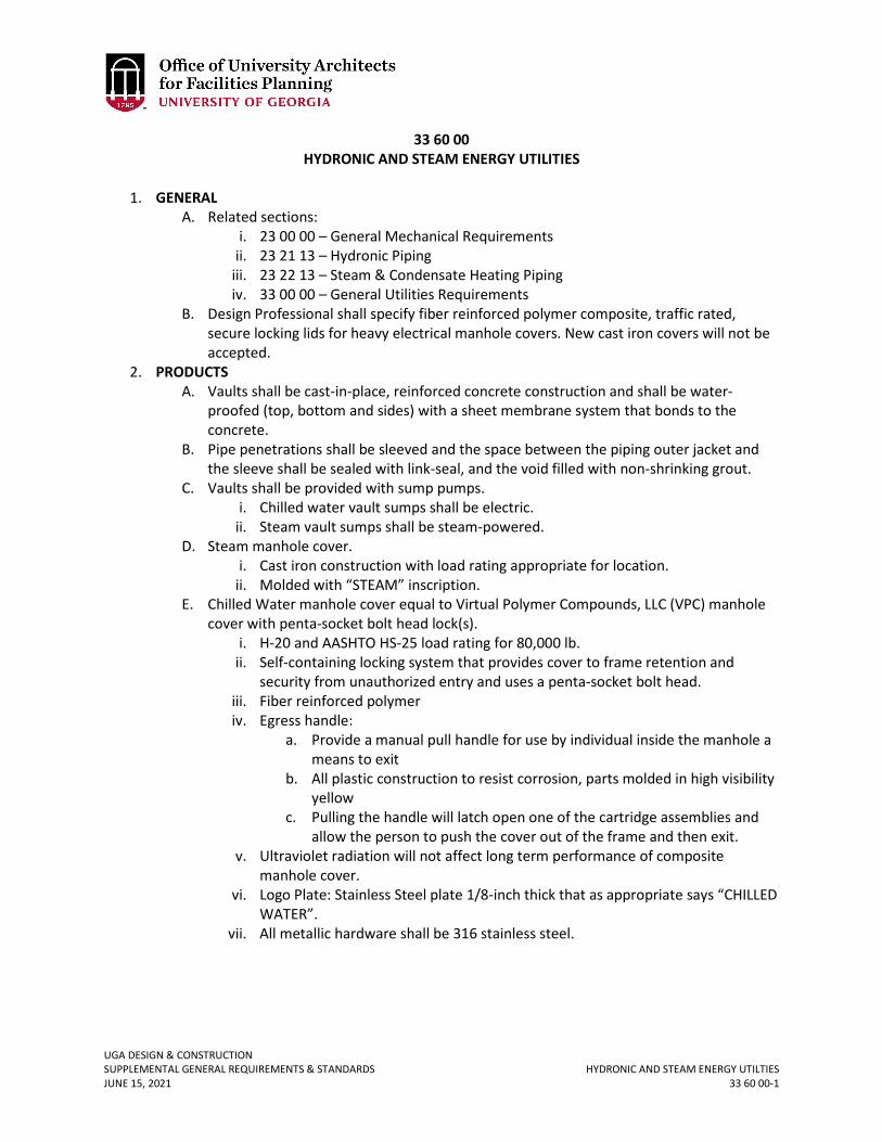
UGA DESIGN & CONSTRUCTION SUPPLEMENTAL GENERAL REQUIREMENTS & STANDARDS HYDRONIC AND STEAM ENERGY UTILTIES JUNE 15, 2021 33 60 00-1
33 60 00 HYDRONIC AND STEAM ENERGY UTILITIES
1. GENERAL
A. Related sections: i. 23 00 00 – General Mechanical Requirements
ii. 23 21 13 – Hydronic Piping iii. 23 22 13 – Steam & Condensate Heating Piping iv. 33 00 00 – General Utilities Requirements
B. Design Professional shall specify fiber reinforced polymer composite, traffic rated, secure locking lids for heavy electrical manhole covers. New cast iron covers will not be accepted.
2. PRODUCTS A. Vaults shall be cast-in-place, reinforced concrete construction and shall be water-
proofed (top, bottom and sides) with a sheet membrane system that bonds to the concrete.
B. Pipe penetrations shall be sleeved and the space between the piping outer jacket and the sleeve shall be sealed with link-seal, and the void filled with non-shrinking grout.
C. Vaults shall be provided with sump pumps. i. Chilled water vault sumps shall be electric.
ii. Steam vault sumps shall be steam-powered. D. Steam manhole cover.
i. Cast iron construction with load rating appropriate for location. ii. Molded with “STEAM” inscription.
E. Chilled Water manhole cover equal to Virtual Polymer Compounds, LLC (VPC) manhole cover with penta-socket bolt head lock(s).
i. H-20 and AASHTO HS-25 load rating for 80,000 lb. ii. Self-containing locking system that provides cover to frame retention and
security from unauthorized entry and uses a penta-socket bolt head. iii. Fiber reinforced polymer iv. Egress handle:
a. Provide a manual pull handle for use by individual inside the manhole a means to exit
b. All plastic construction to resist corrosion, parts molded in high visibility yellow
c. Pulling the handle will latch open one of the cartridge assemblies and allow the person to push the cover out of the frame and then exit.
v. Ultraviolet radiation will not affect long term performance of composite manhole cover.
vi. Logo Plate: Stainless Steel plate 1/8-inch thick that as appropriate says “CHILLED WATER”.
vii. All metallic hardware shall be 316 stainless steel.
UGA DESIGN & CONSTRUCTION SUPPLEMENTAL GENERAL REQUIREMENTS & STANDARDS HYDRONIC AND STEAM ENERGY UTILTIES JUNE 15, 2021 33 60 00-2
3. EXECUTION A. Contractors shall coordinate with FMD Welding Shop (706-542-7593) before entering
steam pits. B. Vaults sump pumps shall be piped to the nearest storm manhole.
UGA DESIGN & CONSTRUCTION SUPPLEMENTAL GENERAL REQUIREMENTS & STANDARDS ELECTRICAL UNDERGROUND DUCTS & MANHOLES JUNE 15, 2021 33 71 19-1
33 71 19 ELECTRICAL UNDERGROUND DUCTS & MANHOLES
1. GENERAL
A. Related sections: i. 26 00 00 – General Electrical Requirements
ii. 33 00 00 – General Utilities Requirements B. Design Professional shall specify fiber reinforced polymer composite, traffic rated,
secure locking lids for heavy electrical manhole covers. New cast iron covers will not be accepted.
2. PRODUCTS A. Electrical manhole / handhole cover equal to Virtual Polymer Compounds, LLC (VPC)
manhole cover with penta-socket bolt head lock(s). i. H-20 and AASHTO HS-25 load rating for 80,000 lb.
ii. Self-containing locking system that provides cover to frame retention and security from unauthorized entry and uses a penta-socket bolt head.
iii. Fiber reinforced polymer. iv. Egress handle:
a. Provide a manual pull handle for use by individual inside the manhole a means to exit.
b. All plastic construction to resist corrosion, parts molded in high visibility yellow.
c. Pulling the handle will latch open one of the cartridge assemblies and allow the person to push the cover out of the frame and then exit.
v. Ultraviolet radiation will not affect long term performance of composite manhole cover.
vi. Logo Plate: Stainless Steel plate 1/8-inch thick that as appropriate says “ELECTRIC” or “HIGH VOLTAGE”.
vii. All metallic hardware shall be 316 grade stainless steel. B. Manhole / Handhole Cable Racking
i. Underground Devices Incorporated “BNT Non-Metallic Cable Support” system with 316 grade stainless steel stanchion hardware, or approved equal.
C. Refer to schematic drawings at end of this section. 3. EXECUTION/INSTALLATION
A. All conduits entering/leaving manholes shall be straight for a minimum of 5’-0” (no bends) off of the exterior walls of the manhole / handhole, and there shall be no conduit elbows into or out of manholes / handholes.
B. Leave a minimum of 1’-0” of conduit extending into manhole when using cored holes.
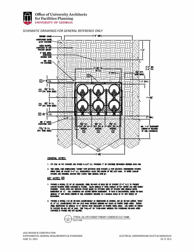
UGA DESIGN & CONSTRUCTION SUPPLEMENTAL GENERAL REQUIREMENTS & STANDARDS ELECTRICAL UNDERGROUND DUCTS & MANHOLES JUNE 15, 2021 33 71 19-2
SCHEMATIC DRAWINGS FOR GENERAL REFERENCE ONLY
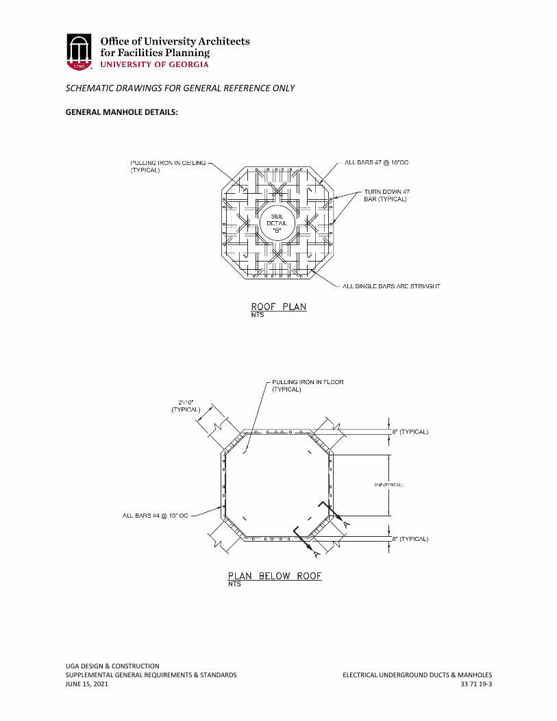
UGA DESIGN & CONSTRUCTION SUPPLEMENTAL GENERAL REQUIREMENTS & STANDARDS ELECTRICAL UNDERGROUND DUCTS & MANHOLES JUNE 15, 2021 33 71 19-3
SCHEMATIC DRAWINGS FOR GENERAL REFERENCE ONLY GENERAL MANHOLE DETAILS:
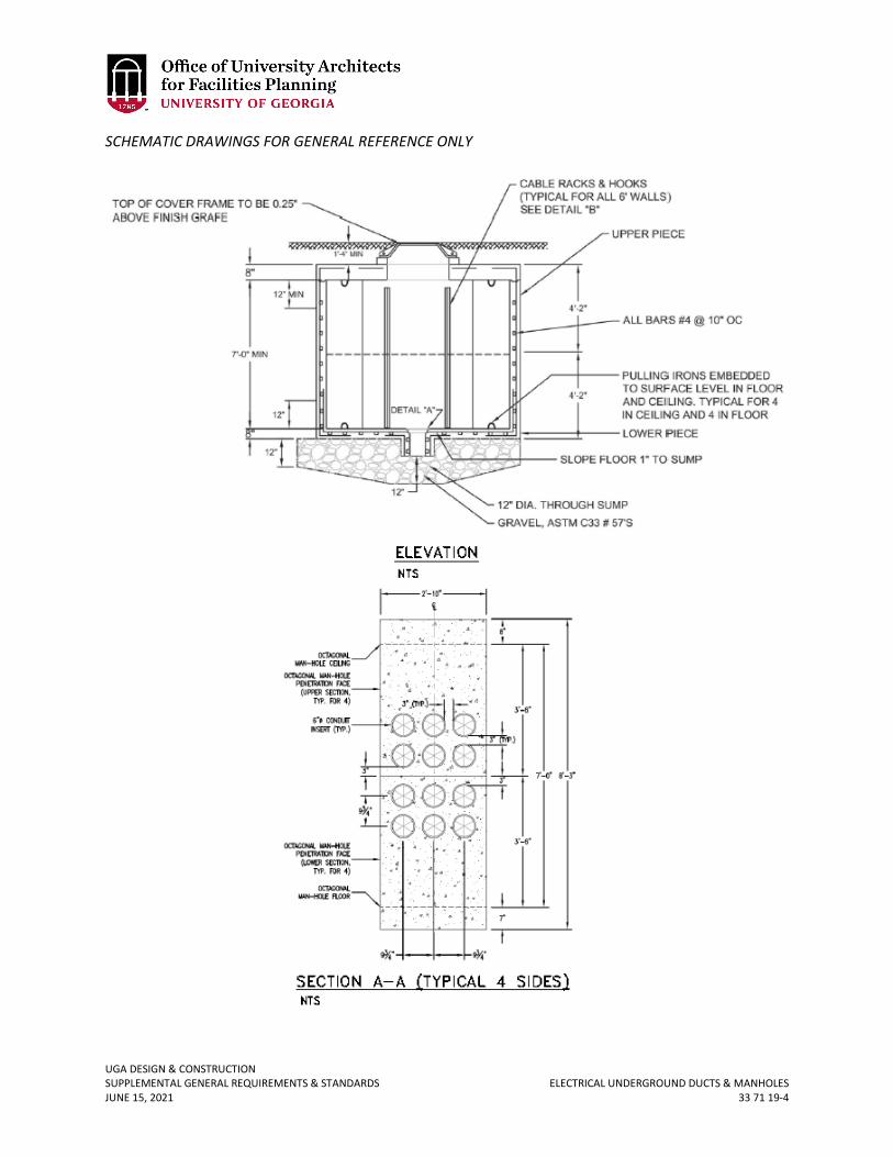
UGA DESIGN & CONSTRUCTION SUPPLEMENTAL GENERAL REQUIREMENTS & STANDARDS ELECTRICAL UNDERGROUND DUCTS & MANHOLES JUNE 15, 2021 33 71 19-4
SCHEMATIC DRAWINGS FOR GENERAL REFERENCE ONLY
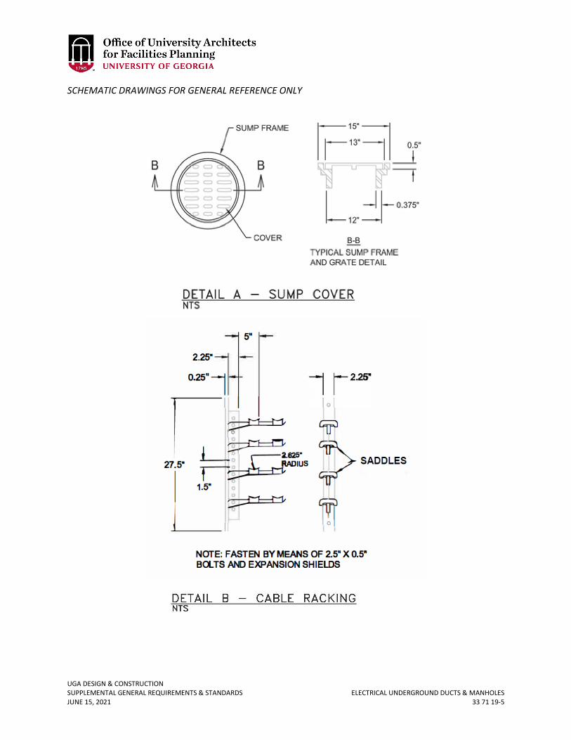
UGA DESIGN & CONSTRUCTION SUPPLEMENTAL GENERAL REQUIREMENTS & STANDARDS ELECTRICAL UNDERGROUND DUCTS & MANHOLES JUNE 15, 2021 33 71 19-5
SCHEMATIC DRAWINGS FOR GENERAL REFERENCE ONLY
UGA DESIGN & CONSTRUCTION SUPPLEMENTAL GENERAL REQUIREMENTS & STANDARDS COMMUNICATIONS UTILITIES JUNE 15, 2021 33 80 00-1
33 80 00 COMMUNICATIONS UTILITIES
1. GENERAL
A. Related sections: i. 27 00 00 – General Communications Requirements
ii. 27 05 43 – Underground Ducts & Raceways for Communications