design and construction of shear walls
TRANSCRIPT
DESIGN AND CONSTRUCTION OF SHEAR WALLS
GRIET Page 1
PROJECT REPORT
DESIGN AND CONSTRUCTION OF SHEAR WALLS
A PROJECT REPORT SUBMITTED TO JNTU, HYD
BACHELOR OF TECHNOLOGY
IN
CIVIL ENGINEERING
BY
K.BHASKER RAO 09241A0163
A.KAMAL TEJ 09241A0169
MD.BASEERUDDIN 09241A0176
B.RAVI TEJA 09241A0191
B.SANTHOSH REDDY 09241A01A1
DEPARTMENT OF CIVIL ENGINEERING
GokarajuRangaraju Institute of Engineering & Technology
Bachupally HYDERABAD-500 090
DESIGN AND CONSTRUCTION OF SHEAR WALLS
GRIET Page 2
CERTIFICATE
This is to certify that project entitled “DESIGN AND CONSTRUCTION OF SHEAR WALLS”
that is being submitted by K.BhaskerRao (09241A0163), A. Kamal Tej (09241A0169), Md.
Baseeruddin (09241A0176), B. Ravi Teja (09241A0191), B.Santhosh Kumar Reddy
(09241A01A1) in partial fulfillment of the requirement for the award of Degree of Bachelor of
Technology in Civil Engineering and Technology ( Affiliated to Jawaharlal Nehru Technological
University, Hyderabad) is a record of bonafide work carried out by them under my guidance and
supervision. The results embodied in this thesis have not been submitted to any other University
or Institute for the award of any degree.
Dr.G.VENKATA RAMANAMr. G.V.V Satyanarayana
Head of the Department Associate Professor
Civil Engineering Department Civil Engineering Department
G.R.I.E.T, ` G.R.I.E.T
Hyderabad Hyderabad
DESIGN AND CONSTRUCTION OF SHEAR WALLS
GRIET Page 3
ACKNOWLEDGEMENT
Success is epitome of hard work, congency for fulfilling the mission, indefatigable perseverance
and most of all encouraging guidance and steering.
We express our sincere thanks to, Dr. Jandhyala Murthy principal, GRIET for the support and
motivation provided to us.
It gives us immense pleasure to express our gratitude to Prof. Dr. G.VenkataRamana , Head of
the department of Civil Engineering and all the faculty of civil engineering department ,for their
esteemed guidance and able supervision during the course of project. Their constant
encouragement and Co-operation made this project a success.
It also gives us immense pleasure to express our gratitude to Associate Prof.Mr.G.V.V.
Satyanarayana who has been always helping out in design of shear wall, his supervision during
the course of our project has been proved as an greatest asset to our project.
We would like to express our sincere thanks to Cybercity and Ashoka builders,
for providing us an opportunity to complete our main project successfully, which is part of our
course curriculum. The training would not have successfully completed without the guidance of
Mr. Kiran (Structural Engineer) and Mr. Sudheer (Assistant Project Manager)
DESIGN AND CONSTRUCTION OF SHEAR WALLS
GRIET Page 4
DECLARATION
We hereby declare that the work presented in this project titled “Design and Construction of
Shear walls submitted towards completion of main-project in Seventh Semester of B.Tech
(CIVIL ENGINEERING) at the GokarajuRangaraju Institute of Engineering and Technology
affiliated to Jawaharlal Nehru Technological University, Hyderabad is authenticate work and had
not been submitted to any University or Institute for any award.
K.BHASKER RAO (09241A0163)
A.KAMAL TEJ (09241A0169)
MD.BASEERUDDIN (09241A0176)
B.RAVI TEJA (09241A0191)
B.SANTHOSH REDDY (09241A01A1)
DESIGN AND CONSTRUCTION OF SHEAR WALLS
GRIET Page 5
Abstract
Besides, food and clothing, shelter is a basic human need. India has been successful in
meeting the food and clothing requirements of its vast population; however the problem of
providing shelter of all is defying solutions. “While there has been an impressive growth in the
total housing stock from 65 million in 1947 to 187.05 million in 2001, a large gap still exists
between the demand and supply of housing units. The Working Group on Housing for the 9th
five-year plan estimated the housing shortage in 2001 at 19.4 million units- 12.76 million in rural
area and 6.64 million in urban area. The shortage of housing is acutely felt in urban areas –more
so in the 35 Indian cities, which according to the 2001 census have a population of more than a
million”.
Hence in order to overcome this problem construction process should be quick, tall and
effective to accommodate huge population in a given area. So we have chosen this topic of
“DESIGN AND CONSTRUCTION OF SHEAR WALLS”. This type of shear wall construction
helps to build tall structure of about 20 floors within no time. Hence the construction process will
become much quicker and efficient.
Constructions made of shear walls are high in strength ,they majorly resist the seismic
force, wind forces and even can be build on soils of weak bases by adopting various ground
improvement techniques. Not only the quickness in construction process but the strength
parameters and effectiveness to bare horizontal loads is very high. Shear walls generally used in
high earth quake prone areas, as they are highly efficient in taking the loads. Not only the earth
quake loads but also winds loads which are quite high in some zones can be taken by these shear
walls efficiently and effectively.
Though these types of constructions have their origin in western nations in early 90’s,
this ideology has changed rapidly and spread all over the world with in no time. The form work
used in this type of construction is of a new kind in Indian construction scenario.
Certain patented systems based on imported technologies such as “Mascon System”
(Canada), “Mivan System” (Malaysia) have come on the Indian scene in recent years. In these
systems traditional column and beam construction is eliminated and instead walls and slabs are
cast in one operation at site by use of specially designed, easy to handle (with minimum labor
and without use of any equipment) light weight pre-engineered aluminum forms. Rapid
construction of multiple units of a repetitive type can be achieved with a sort of assembly line
production by deployment of a few semi-skilled labors.
DESIGN AND CONSTRUCTION OF SHEAR WALLS
GRIET Page 6
The entire operation essentially comprises fitting and erecting the portion of shuttering as
already determined (the optimization in use is determined by appropriate planning) and then
carrying out concreting of the walls and slabs. Props are so designed that they stay in position
while de-shuttering of slabs and/or takes place. The dimensional accuracy of the formwork is of
high order. Therefore any possibility of errors does not rise. Though this type of constructions
are cost effective, still in order to build a better society and for satisfying present need of shelter ,
shear wall construction are going to be a solution to this problem of shelter in our nation.
The main idea of we taking this topic of “Design and construction of shear walls” is the
challenging task in designing of shear walls. Shear walls have a peculiar behaviour towards
various types of loads. Calculation of rigidity factor, reactions, shear center, shear force and
bending moment is a topic of interest. Hence by adopting the technologies used in Cyber City,
Rainbow Vista, Near IDPL road, Moosapet, to the college building of GRIET fourth block, we
are going to check the building behaviour. We are also verifying and designing this same
structure using extended three dimensional analysis of buildings (ETABS) software.
As said by Benjamin Franklin “An investment in knowledge pays the best interest“. We would
like to invest our knowledge to whatever extent we can and design the building most efficiently
CONTENTS
TITLE PAGE NO:
CHAPTER 1: Introduction
1.1 Definition
1.2 Scope of the work
1.3 Objective
1.4 Organization
DESIGN AND CONSTRUCTION OF SHEAR WALLS
GRIET Page 7
CHAPTER 2: Literature Review
2.1 Review of Literature
CHAPTER 3: Shear Walls
3.1 Purpose of constructing shear wall
3.2 Comparison of shear wall with conventional
Load bearing wall
3.3 Forces acting on shear wall
3.4 Classification of shear wall
3.5 Types of shear walls
CHAPTER 4: Manual design of shear wall
4.1 Introduction
4.2 Calculation of rigidity values
4.3 Calculation of shear centre
4.4 Calculation of seismic and shear forces at
Different floors in collegebuilding
4.5 Design the ductile shear wall for college building
CHAPTER 5: Design of college building using E-Tabs
5.1 Marking of columns, beams
5.2 Drawing floor area
5.3 Assigning of loads
5.4 Analysis
5.5 Results
CHAPTER 6: Construction of shear walls
DESIGN AND CONSTRUCTION OF SHEAR WALLS
GRIET Page 8
6.1 Excavation
6.2 Foundation and Footings
6.3 Bottom three floors and Waffle slab
6.4 Shear wall construction
6.5 Mivan formwork
6.6 Wall ties, Pins and Wedges
6.7 Electrical boards and Plumbing lines
6.8 Concreting
6.9 Curing
6.10 Holes in the slab
6.11 Electrical and Plumbing lines after Concreting
6.12 Painting and Finishing
CHAPTER 7: Scope for future work
CHAPTER 8: Conclusion
CHAPTER 9: References
Chapter 1
DESIGN AND CONSTRUCTION OF SHEAR WALLS
GRIET Page 9
INTRODUCTION
1.1 Definition
Shear walls are vertical elements of the horizontal force resisting system. Shear walls are
constructed to counter the effects of lateral load acting on a structure. In residential construction,
shear walls are straight external walls that typically form a box which provides all of the lateral
support for the building. When shear walls are designed and constructed properly, and they will
have the strength and stiffness to resist the horizontal forces.
In building construction, a rigid vertical diaphragm capable of transferring lateral forces
from exterior walls, floors, and roofs to the ground foundation in a direction parallel to their
planes. Examples are the reinforced-concrete wall or vertical truss. Lateral forces caused by
wind, earthquake, and uneven settlement loads, in addition to the weight of structure and
occupants; create powerful twisting (torsion) forces. These forces can literally tear (shear) a
building apart. Reinforcing a frame by attaching or placing a rigid wall inside it maintains the
shape of the frame and prevents rotation at the joints. Shear walls are especially important in
high-rise buildings subjected to lateral wind and seismic forces.
In the last two decades, shear walls became an important part of mid and high-rise residential
buildings. As part of an earthquake resistant building design, these walls are placed in building
plans reducing lateral displacements under earthquake loads. So shear-wall frame structures are
obtained.
Shear wall buildings are usually regular in plan and in elevation. However, in some buildings,
lower floors are used for commercial purposes and the buildings are characterized with larger
plan dimensions at those floors. In other cases, there are setbacks at higher floor levels. Shear
wall buildings are commonly used for residential purposes and can house from 100 to 500
inhabitants per building
1.2 Scope of the work
The aim of the shear wall is to investigate the different ways in which the tall structures can be
stabilized against the effects of strong horizontal wind loading and seismic loading.
Some other reasons why we use shear walls are tall structures can be constructed which reduces
the area used and we can accommodate a large population in that particular area.
Other objective is to construct a cost effective structure in less period of time.
This study helps in the investigation of strength and ductility of walls.
DESIGN AND CONSTRUCTION OF SHEAR WALLS
GRIET Page 10
The scope is to analyze the constructed shear wall that is to be constructed. Firstly the model is
implemented into known computer software and then it is analyzed based on the investigation of
strength and ductility.
The strength of shear walls tested are compared with the calculated strengths based on design
codes.
1.3 Objective
Shear walls are not only designed to resist gravity / vertical loads (due to its self-weight and
other living / moving loads), but they are also designed for lateral loads of earthquakes / wind.
The walls are structurally integrated with roofs / floors (diaphragms) and other lateral walls
running across at right angles, thereby giving the three dimensional stability for the building
structures.
Shear wall structural systems are more stable. Because, their supporting area (total cross-
sectional area of all shear walls) with reference to total plans area of building, is comparatively
more, unlike in the case of RCC framed structures.Walls have to resist the uplift forces caused by
the pull of the wind. Walls have to resist the shear forces that try to push the walls over. Walls
have to resist the lateral force of the wind that tries to push the walls in and pull them away from
the building.
Shear walls are quick in construction, and in a country like India where shelter is very important
in a short lapse of time shear walls can be built very quickly.The precision to which they are
built is also very high compared to normally built brick structures. Hence the key objective of
shear wall is to build a safe, tall, aesthetic building.
1.4 Organisation
The colors of the rainbow light up your life at Rainbow Vistas. For the discerning individual and
for those to whom quality of life is something they care about – Rainbow Vistas is a 4.3 acres
450 luxury apartments the best option and only solution. This dream housing project is
strategically located near HI-TECH City, MMTS and the city’s IT hub on one side and prime
residential area on the other. A prestige project jointly promoted by Ashoka Developers and
Builders Ltd and Cybercity Builders and Developers Pvt. Ltd, Rainbow Vistas adds value to your
dream. Rainbow Vistas is approved by GHMC and all leading banks and institutions offer loans
for the property. The project has the first Hill-top club house and construction work is at full
swing.
We are most obliged to have our main project being done in Rainbow Vistas, as a part of our
fulfillment of bachelors degree. They have been very patient, co operativethrough out our main
project. The information given by them is immense and very useful in completion of our project
DESIGN AND CONSTRUCTION OF SHEAR WALLS
GRIET Page 11
Chapter 2
Literature Review
Review of literature:
Development of shear wall system for construction has advanced dramatically over the past few
years. Shear wall systems were initially developed to reduce damage due to earth quakes labour
requirements, increase strength of the building, shorten construction time reduce cost increase
quality of life.
U.H. Varyani described about shear walled buildings under horizontal loads. Considering in his
design “Reinforced concrete framed buildings are adequate for resisting both the vertical and the
horizontal loads acting on shear walls of a building”.In his 2nd
edition 2002 of “Design of
structures”. He gave rigidity of shear wall, torsional rigidity and shear center of a building in a
detailed description.
S.K. Duggal on his profound interest on structures gave a detailed description about reinforced
concrete buildings in his book “ Earth quake resistant design of structures “describing a wall in a
building which resist lateral loads originating from wind or earthquakes are known as shear
walls”. He considered flexural strength in the wall to be dominant force based on which design
of structure to be carried out in tall shear walls. He described in detail about various types of
shear walls with their load bearing capacities as per code requirements.
Mr A.P. Jadhav Associate Professor Rajarambapu Institute of technology rajaramnagar, Islampur
has given a detailed report on the form work used for the construction of shear walls.
Mr.A.P.Jadhav highlighted the importance of quickness in construction and the need for
earthquake resistant building for better sustainability of life.
A report on effects of openings in shear walls on seismic response of structure by
sharminrizachowdhary, department of civil engineering dhake-1208, Bangladesh mostly focused
DESIGN AND CONSTRUCTION OF SHEAR WALLS
GRIET Page 12
on the design of shear walls with openings on seismic response using E-Tabs,i.e extended three
dimensional analysis of buildings. This report gives a detailed explanation of how ETABS can
be effectively used to design shear walls.
INDIAN STANDARD CODES:
I.S 456:2000
As per clause 32, design for wall describes, design of horizontal shear in clause 32.4 given
details of how shear wall have to be constructed.
I.S:1893 Criteria of Earth Quake resistant Buildings Part (3) page 23, clause 4.2 gives the
estimation of earth quake loads.
In IS: 13920:1993 it gives the ductile detailing of shear wall as per clause 9, where 9.1 gives
general requirements.
9.2 shear strength
9.3 give flexural strength
9.6 give openings in shear walls.
Ductile detailing, as per the code IS: 13920:1993 is considered very important as the ductile
detailing gives the amount of reinforcement required and the alignment of bars.
DESIGN AND CONSTRUCTION OF SHEAR WALLS
GRIET Page 13
Chapter 3
Shear Walls
Shear walls are vertical elements of the horizontal force resisting system. Shear walls are
constructed to counter the effects of lateral load acting on a structure. In residential construction,
shear walls are straight external walls that typically form a box which provides all of the lateral
support for the building. When shear walls are designed and constructed properly, and they will
have the strength and stiffness to resist the horizontal forces.
In building construction, a rigid vertical diaphragm capable of transferring lateral forces
from exterior walls, floors, and roofs to the ground foundation in a direction parallel to their
planes. Examples are the reinforced-concrete wall or vertical truss. Lateral forces caused by
wind, earthquake, and uneven settlement loads, in addition to the weight of structure and
occupants; create powerful twisting (torsion) forces. These forces can literally tear (shear) a
building apart. Reinforcing a frame by attaching or placing a rigid wall inside it maintains the
shape of the frame and prevents rotation at the joints. Shear walls are especially important in
high-rise buildings subjected to lateral wind and seismic forces.
In the last two decades, shear walls became an important part of mid and high-rise residential
buildings. As part of an earthquake resistant building design, these walls are placed in building
plans reducing lateral displacements under earthquake loads. So shear-wall frame structures are
obtained.
Shear wall buildings are usually regular in plan and in elevation. However, in some buildings,
lower floors are used for commercial purposes and the buildings are characterized with larger
plan dimensions at those floors. In other cases, there are setbacks at higher floor levels. Shear
wall buildings are commonly used for residential purposes and can house from 100 to 500
inhabitants per building
3.1 PURPOSE OF CONSTRUCTING SHEAR WALLS
Shear walls are not only designed to resist gravity / vertical loads (due to its self-weight and
other living / moving loads), but they are also designed for lateral loads of earthquakes / wind.
The walls are structurally integrated with roofs / floors (diaphragms) and other lateral walls
running across at right angles, thereby giving the three dimensional stability for the building
DESIGN AND CONSTRUCTION OF SHEAR WALLS
GRIET Page 14
structures.
Shear wall structural systems are more stable. Because, their supporting area (total cross-
sectional area of all shear walls) with reference to total plans area of building, is comparatively
more, unlike in the case of RCC framed structures.
Walls have to resist the uplift forces caused by the pull of the wind. Walls have to resist the shear
forces that try to push the walls over. Walls have to resist the lateral force of the wind that tries
to push the walls in and pull them away from the building.
Shear walls are quick in construction, as the method adopted to construct is concreting the
members using formwork.
Shear walls doesn’t need any extra plastering or finishing as the wall itself gives such a high
level of precision, that it doesn’t require plastering.
3.2 COMPARISONS OF SHEAR WALL WITH CONSTRUCTION OF
CONVENTIONAL LOAD BEARING WALLS
Load bearing masonry is very brittle material. Due to different kinds of stresses such as shear,
tension, torsion, etc., caused by the earthquakes, the conventional unreinforced brick masonry
collapses instantly during the unpredictable and sudden earthquakes.
The RCC framed structures are slender, when compared to shear wall concept of box like three-
dimensional structures. Though it is possible to design the earthquake resistant RCC frame, it
requires extraordinary skills at design, detailing and construction levels, which cannot be
anticipated in all types of construction projects.
On the other hand even moderately designed shear wall structures not only more stable, but also
comparatively quite ductile. In safety terms it means that, during very severe earthquakes they
will not suddenly collapse causing death of people. They give enough indicative warnings such
as widening structural cracks, yielding rods, etc., offering most precious moments for people to
run out off structures, before they totally collapse.
For structural purposes we consider the exterior walls as the shear-resisting walls. Forces from
the ceiling and roof diaphragms make their way to the outside along assumed paths, enter the
walls, and exit at the foundation.
DESIGN AND CONSTRUCTION OF SHEAR WALLS
GRIET Page 15
3.3 FORCES ON SHEAR WALL
Shear walls resist two types of forces: shear forces and uplift forces. Shear forces are generated
in stationary buildings by accelerations resulting from ground movement and by external forces
like wind and waves. This action creates shear forces throughout the height of the wall between
the top and bottom shear wall connections.
Uplift forces exist on shear walls because the horizontal forces are applied to the top of the wall.
These uplift forces try to lift up one end of the wall and push the other end down. In some cases,
the uplift force is large enough to tip the wall over. Uplift forces are greater on tall short walls
and less on low long walls. Bearing walls have less uplift than non-bearing walls because gravity
loads on shear walls help them resist uplift. Shear walls need hold down devices at each end
when the gravity loads cannot resist all of the uplift. The hold down device then provides the
necessary uplift resistance.
Shear walls should be located on each level of the structure including the crawl space. To form
an effective box structure, equal length shear walls should be placed symmetrically on all
four exterior walls of the building. Shear walls should be added to the building interior when
the exterior walls cannot provide sufficient strength and stiffness.
Shear walls are most efficient when they are aligned vertically and are supported on foundation
walls or footings. When exterior shear walls do not provide sufficient strength, other parts of the
building will need additional strengthening. Consider the common case of an interior wall
supported by a sub floor over a crawl space and there is no continuous footing beneath the wall.
For this wall to be used as shear wall, the sub floor and its connections will have to be
strengthened near the wall. For Retrofit work, existing floor construction is not easily changed.
That’s the reason why most retrofit work uses walls with continuous footings underneath them as
shear walls.
3.4 CLASSIFICATION OF SHEAR WALLS
¬ Simple rectangular types and flanged walls (bar bell type)
¬ Coupled shear walls
¬ Rigid frame shear walls
¬ Framed walls with in filled frames
¬ Column supported shear walls
¬ Core type shear walls
DESIGN AND CONSTRUCTION OF SHEAR WALLS
GRIET Page 16
3.5 TYPES OF SHEAR WALLS
¬ RC Shear Wall
¬ Plywood Shear Wall
¬ Mid ply Shear Wall
¬ RC Hollow Concrete Block Masonry Wall
¬ Steel Plate Shear Wall
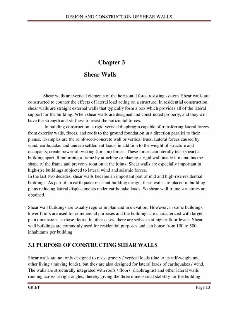
RC SHEAR WALL:
It consists of reinforced concrete walls and reinforced concrete slabs. Wall thickness varies from
140 mm to 500 mm, depending on the number of stories, building age, and thermal
insulation requirements. In general, these walls are continuous throughout the building height;
however, some walls are discontinued at the street front or basement level to allow for
commercial or parking spaces. Usually the wall layout is symmetrical with respect to at least one
axis of symmetry in the plan.
FIGURE:3.5.1 R.C. Shear wall
Floor slabs are either cast-in-situ flat slabs or less often, precast hollow-core slabs. Buildings are
supported by concrete strip or mat foundations; the latter type is common for buildings with
basements. Structural modifications are not very common in this type of construction.
DESIGN AND CONSTRUCTION OF SHEAR WALLS
GRIET Page 17
Reinforcement requirements are based on building code requirements specific for each country.
In general, the wall reinforcement consists of two layers of distributed reinforcement (horizontal
and vertical) throughout the wall length. In addition, vertical reinforcement bars are provided
close to the door and window openings, as well as at the wall end zones (also known as boundary
elements or barbells).
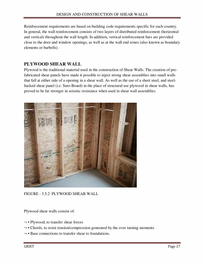
PLYWOOD SHEAR WALL
Plywood is the traditional material used in the construction of Shear Walls. The creation of pre-
fabricated shear panels have made it possible to inject strong shear assemblies into small walls
that fall at either side of a opening in a shear wall. As well as the use of a sheet steel, and steel-
backed shear panel (i.e. Sure-Board) in the place of structural use plywood in shear walls, has
proved to be far stronger in seismic resistance when used in shear wall assemblies.
FIGURE : 3.5.2 PLYWOOD SHEAR WALL
Plywood shear walls consist of:
¬ • Plywood, to transfer shear forces
¬ • Chords, to resist tension/compression generated by the over turning moments
¬ • Base connections to transfer shear to foundations.
DESIGN AND CONSTRUCTION OF SHEAR WALLS
GRIET Page 18
MIDPLY SHEAR WALL:
The MIDPLY shear wall is an improved timber shear wall that was developed by redesigning the
joints between sheathing and framing members, so that the failure modes observed in standard
wall testing are virtually eliminated at lateral load levels high enough to cause failures in
standard walls.
In MIDPLY shear wall design, one ply of sheathing material is placed at the center of the wall
between a series of pairs of studs oriented in a 90° rotated position relative to those in standard
shear walls
RC HOLLOW CONCRETE BLOCK MASONRY WALLS:
RHCBM walls are constructed by reinforcing the hollow concrete block masonry, by taking
advantage of hollow spaces and shapes of the hollow blocks. It requires continuous steel rods
(reinforcement) both in the vertical and horizontal directions at structurally critical locations of
the wall panels, packed with the fresh grout concrete in the hollow spaces of masonry blocks.
Reinforced Hollow Concrete Block Masonry (RHCBM) elements are designed both as load
bearing walls for gravity loads and also as shear walls for lateral seismic loads, to safely with
stand earthquakes. This structural system of construction is known as shear wall – diaphragm
concept, which gives three-dimensional structural integrity for the buildings.
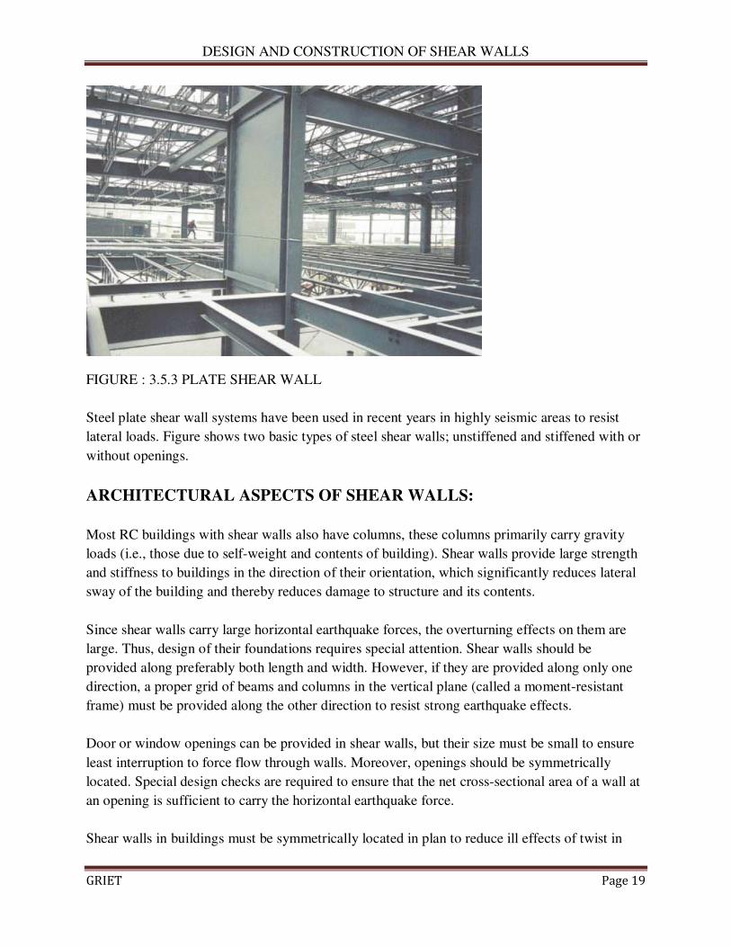
STEEL PLATE SHEAR WALL:
In general, steel plate shear wall system consists of a steel plate wall, boundary columns and
horizontal floor beams. Together, the steel plate wall and boundary columns act as a vertical
plate girder. The columns act as flanges of the vertical plate girder and the steel plate wall acts as
its web. The horizontal floor beams act, more-or-less, as transverse stiffeners in a plate girder.
DESIGN AND CONSTRUCTION OF SHEAR WALLS
GRIET Page 19
FIGURE : 3.5.3 PLATE SHEAR WALL
Steel plate shear wall systems have been used in recent years in highly seismic areas to resist
lateral loads. Figure shows two basic types of steel shear walls; unstiffened and stiffened with or
without openings.
ARCHITECTURAL ASPECTS OF SHEAR WALLS:
Most RC buildings with shear walls also have columns, these columns primarily carry gravity
loads (i.e., those due to self-weight and contents of building). Shear walls provide large strength
and stiffness to buildings in the direction of their orientation, which significantly reduces lateral
sway of the building and thereby reduces damage to structure and its contents.
Since shear walls carry large horizontal earthquake forces, the overturning effects on them are
large. Thus, design of their foundations requires special attention. Shear walls should be
provided along preferably both length and width. However, if they are provided along only one
direction, a proper grid of beams and columns in the vertical plane (called a moment-resistant
frame) must be provided along the other direction to resist strong earthquake effects.
Door or window openings can be provided in shear walls, but their size must be small to ensure
least interruption to force flow through walls. Moreover, openings should be symmetrically
located. Special design checks are required to ensure that the net cross-sectional area of a wall at
an opening is sufficient to carry the horizontal earthquake force.
Shear walls in buildings must be symmetrically located in plan to reduce ill effects of twist in
DESIGN AND CONSTRUCTION OF SHEAR WALLS
GRIET Page 20
buildings. They could be placed symmetrically along one or both directions in plan. Shear walls
are more effective when located along exterior perimeter of the building – such a layout
increases resistance of the building to twisting.
Advantages of Steel Plate Shear Wall to Resist Lateral Loads:
1. The system, designed and detailed properly is very ductile and has relatively large energy
dissipation capability. As a result, steel shear walls can be very efficient and economical lateral
load resisting systems.
2. The steel shear wall system has relatively high initial stiffness, thus very effective in limiting
the drift.
3. Compared to reinforced concrete shear walls, the steel shear wall is much lighter which can
result in less weight to be carried by the columns and foundations as well as less seismic load
due to reduced mass of the structure.
4. By using shop-welded, field-bolted steel shear walls, one can speed-up the erection process
and reduce the cost of construction, field inspection and quality control resulting in making these
systems even more efficient.
5. Due to relatively small thickness of steel plate shear walls compared to reinforced concrete
shear walls, from architectural point of view, steel plate shear walls occupy much less space than
the equivalent reinforced concrete shear walls. In high-rises, if reinforced concrete shear walls
are used, the walls in lower floors become very thick and occupy large area of the floor plan.
6. Compared to reinforced concrete shear walls, steel plate shear walls can be much easier and
faster to construct when they are used in seismic retrofit of existing building.
7. Steel plate shear wall systems that can be constructed with shop welded-field bolted elements
can make the steel plate shear walls more efficient than the traditional systems. These systems
can also be very practical and efficient for cold regions where concrete construction may not be
economical under very low temperatures.
DESIGN AND CONSTRUCTION OF SHEAR WALLS
GRIET Page 21
Chapter 4
Manual design of Shear Walls
4.1 INTRODUCTION
The walls, in a building, which resist lateral loads originating from wind or earthquakes, are
known as shear walls. A large portion of the lateral load on a building, if not the whole amount,
as well as the horizontal shear force resulting from the load, are often assigned to such structural
elements made of RCC. These shear walls, may be may be added solely to resist horizontal
force, or concrete walls enclosing stairways, elevated shafts, and utility cores may serve as shear
walls. Shear walls not only have very large in-plane stiffness and therefore resist lateral load and
control deflection very efficiently, but may also help to ensure development of all available
plastic hinge locations throughout the structure prior to failure. The other way to resist such loads
may be to have the rigid frame augmented by the combination of masonry walls.
The use of shear walls or their equivalent becomes imperative in certain high-rise buildings, if
inter- storey deflections caused by lateral loadings are to be controlled. Well-designed shear
walls not only provide adequate safety, but also give a great measure of protection against costly
non-structural damage during moderate seismic disturbances.
The term shear wall is actually a misnomer as far as high-rise buildings are concerned, since a
slender shear wall when subjected to lateral force has predominantly moment deflections and
only very insignificant shear distortions. High-rise structures have become taller and more
slender, and with this trend the analysis of shear walls may emerge as a critical design element.
More often than not, shear walls are pierced by numerous openings. Such shear walls are called
coupled shear walls. The walls on both sides of the openings are interconnected by short, open
deep, beams forming part of the wall, or floor slab, or both of these. The structural engineer is
fortunate if these walls are arranged in a systematic pattern. The scope of the book limits the
discussion to shear walls without any openings.
This shows a building with the lateral force represented by arrows acting on the edge of each
floor or roof. The horizontal surfaces act as deep beams to transmit loads to vertical-resisting
elements-the shear walls A and B. These walls, in turn, act as cantilever beams fixed at their base
and transfer loads to the foundation. For the building plan additional shear walls C and D are
provided to resist the lateral loads that may act in the orthogonal direction. The shear walls are
subjected to the following loads: (a) A variable shear which reaches a maximum at the base.
(b) A bending moment which tends to cause vertical tension near the loaded edge and
compression at the far edge.
(c) A vertical compression due to ordinary gravity loading from the structure.
DESIGN AND CONSTRUCTION OF SHEAR WALLS
GRIET Page 22
Rigidity of a Wall Element Normal to the Direction of Horizontal Shear to Ensure Simple
Bending (���,���):
���is defined as the horizontal force necessary to prevent y-distortion of a wall element when Rx
is applied in the x-direction producing a unit deflection. ���is also similarly defined. This gives
the directions of ��� and ��� for various positions of the angle section. When the principal axes
of the shape of a shear wall are parallel to the X and Y axes, ���and ���vanish. Table 8.1 gives
the values of ��� and ��� calculated as explained by Benjamin.
4.1 Calculation of rigidity of a Shear Wall:
Torsional rigidity of a shear wall is defined as the torque required to produce a unit rotation. If a
torque T acting on a shear wall produces a rotation of � radians, then the torsional rigidity of the
wall is,
J=��
The torsional rigidity of any given shape of a shear wall consists of the summation of its
torsional rigidities calculated on the basis of uniform and non-uniform torsional theories, the
uniform-torsion theory component for open sections only, being given by,
��= �� ��.��
Where ‘0’ equals the perimeter of the section of shear wall of height h and thickness ‘t’. It,
however, works out to be negligibly small in the case of open sections such as channels, angles,
tees, etc. Being a function of the cube of thickness of shear wall, which is assumed to be very
small in comparison to its other dimensions. However, for box sections, it is not a small quantity,
as it is proportional to its thickness. The non-uniform torsion theory applied to flanged walls of
open cross-sections and gives approximate torsion rigidity based on the rigidities of separated
flanges opposite to each other, neglecting the web. Referring to for an I-section, rotation � in
radians due to a unit displacement of either flange on account of force �� is given by
�=�� ,
which is produced by a torque
DESIGN AND CONSTRUCTION OF SHEAR WALLS
GRIET Page 23
T= �� x a
Where ��= rigidity of the flange, i.e. a wall element of length b and thickness t.
The torsional rigidity is, by definition, given on th basis of non-uniform torsion theory as,
��= �� = ��x
���
For box sections, the torsion due to non-uniform theory can be neglected. The torsional rigidity
of a shear wall is then given by,
J= ��+ ��
This gives the values of torsional rigidities of various shapes of shear walls.
Shear Centre of a Shear wall:
The shear center may be defined as the point through which the plane of loading must pass to
eliminate torsion. The shear center’s of various shapes of shear walls. The rigidities��,R�, ���,
���of a shear wall are all assumed to act through its shear center.
This gives a summary of the rigidity characteristics of the various shapes of shear walls
frequently met with in practice, which have been evaluated on the principles discussed by
Benjamin and Timoshenko.
Shear Centre of a Shear Wall structure:
Shear centre of a shear wall structure in a story is the centre of rigidities of all the shear walls
which partake of the applied horizontal shear due to the infinite rigidity of the floor diaphragm.
The coordinates of the shear centre of a structure are fixed by taking moments of rigidities ��and
��� and separately of rigidities ��and ���of all the shear walls about any convenient point O1
and equating them to the corresponding moments of the summation of the above quantities
taking them to be concentrated at the shear centre of the structure. This gives assuming positive
sign for all forces
Where (x, y) give the location of the shear centre of the structure and the point chosen O1 is the
origin of axes x1and y1 and the summation extends to all the shear walls joined monolithically
with the floor diaphragm. The equations are solved for x and y to locate the shear centre of the
structure, taking proper signs of all the forces involved.
DESIGN AND CONSTRUCTION OF SHEAR WALLS
GRIET Page 24
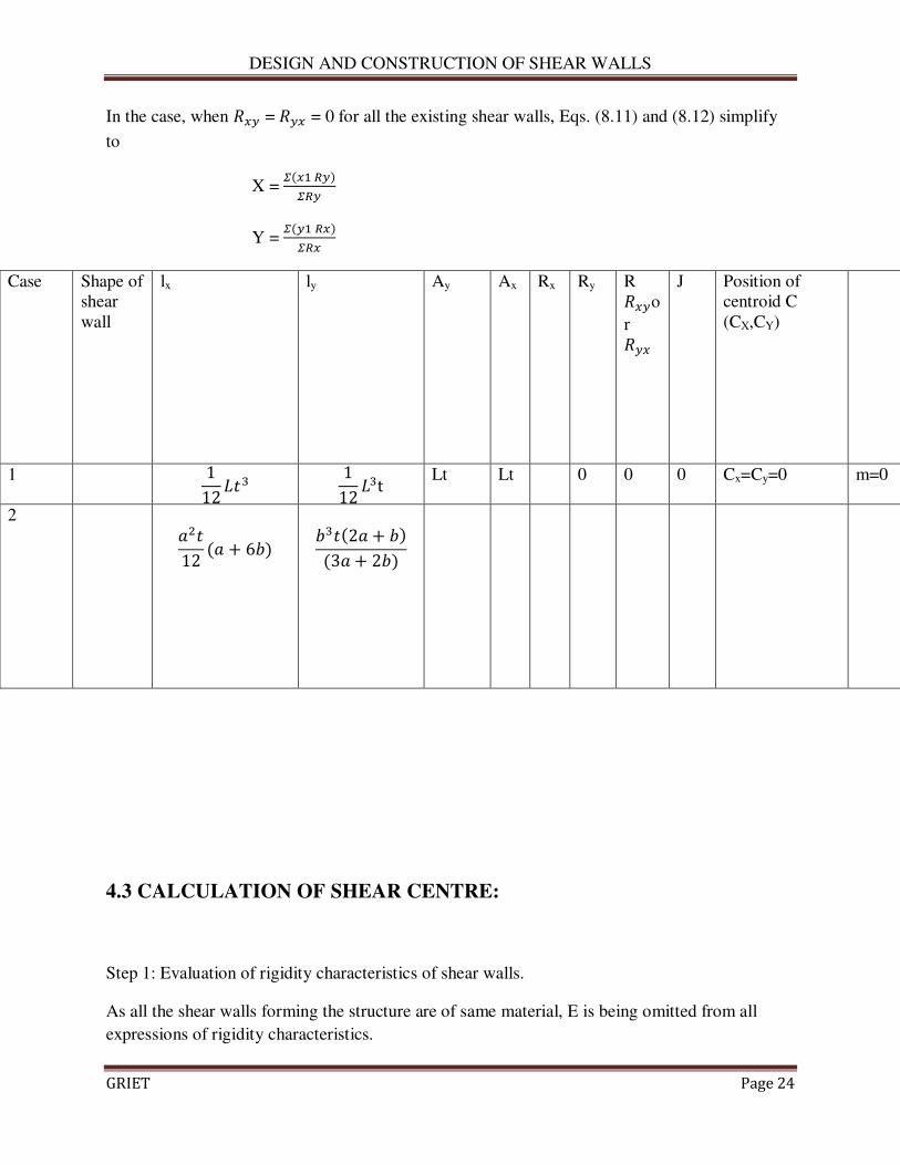
In the case, when ��� = ��� = 0 for all the existing shear walls, Eqs. (8.11) and (8.12) simplify
to
X = �������
���
Y = �������
���
Case Shape of
shear
wall
lx ly Ay Ax Rx Ry R���o
r ���
J Position of
centroid C
(CX,CY)
1 112� !
112 �!t Lt Lt 0 0 0 Cx=Cy=0 m=0
2 #� 12 �# + 6&�
&! �2# + &��3# + 2&�
4.3 CALCULATION OF SHEAR CENTRE:
Step 1: Evaluation of rigidity characteristics of shear walls.
As all the shear walls forming the structure are of same material, E is being omitted from all
expressions of rigidity characteristics.
DESIGN AND CONSTRUCTION OF SHEAR WALLS
GRIET Page 25
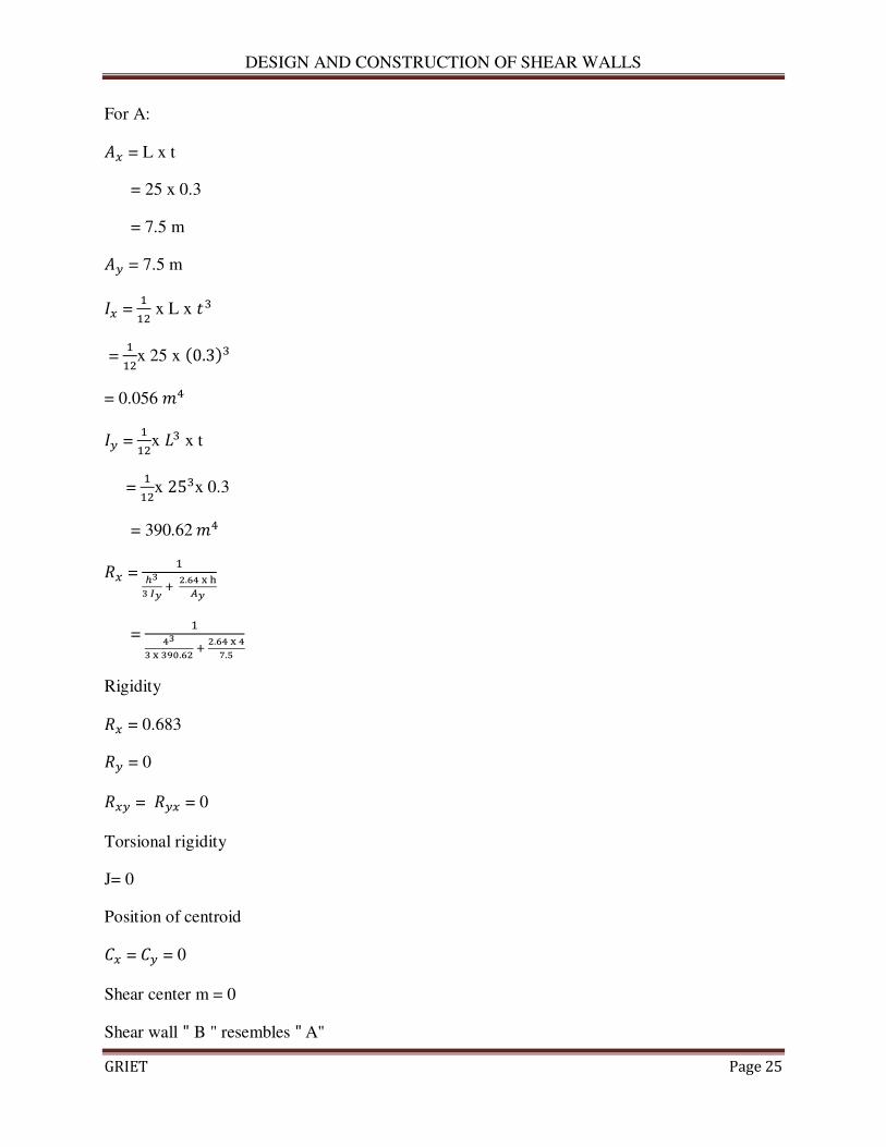
For A:
(� = L x t
= 25 x 0.3
= 7.5 m
(� = 7.5 m
)� = ��� x L x !
= ���x 25 x �0.3�!
= 0.056 +,
)� = ���x �! x t
= ���x 25!x 0.3
= 390.62+,
�� = �
.��/01�.2345
60
= �
3��4�78.2�1�.23439.:
Rigidity
�� = 0.683
�� = 0
��� = ��� = 0
Torsional rigidity
J= 0
Position of centroid
;� = ;� = 0
Shear center m = 0
Shear wall " B " resembles " A"
DESIGN AND CONSTRUCTION OF SHEAR WALLS
GRIET Page 26
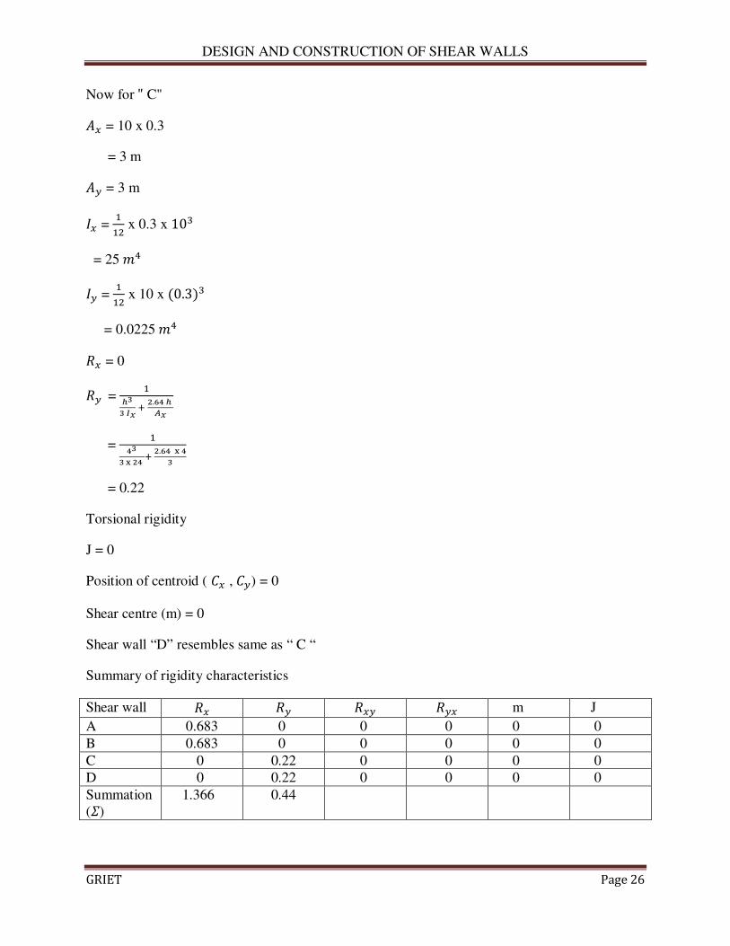
Now for " C"
(� = 10 x 0.3
= 3 m
(� = 3 m
)� = ��� x 0.3 x 10!
= 25 +,
)� = ��� x 10 x �0.3�!
= 0.0225 +,
�� = 0
�� = �
.��/=1�.23.
6=
= �
3��4�31�.2343
�
= 0.22
Torsional rigidity
J = 0
Position of centroid ( ;� , ;�) = 0
Shear centre (m) = 0
Shear wall “D” resembles same as “ C “
Summary of rigidity characteristics
Shear wall �� �� ��� ��� m J
A 0.683 0 0 0 0 0
B 0.683 0 0 0 0 0
C 0 0.22 0 0 0 0
D 0 0.22 0 0 0 0
Summation
(>)
1.366 0.44
DESIGN AND CONSTRUCTION OF SHEAR WALLS
GRIET Page 27
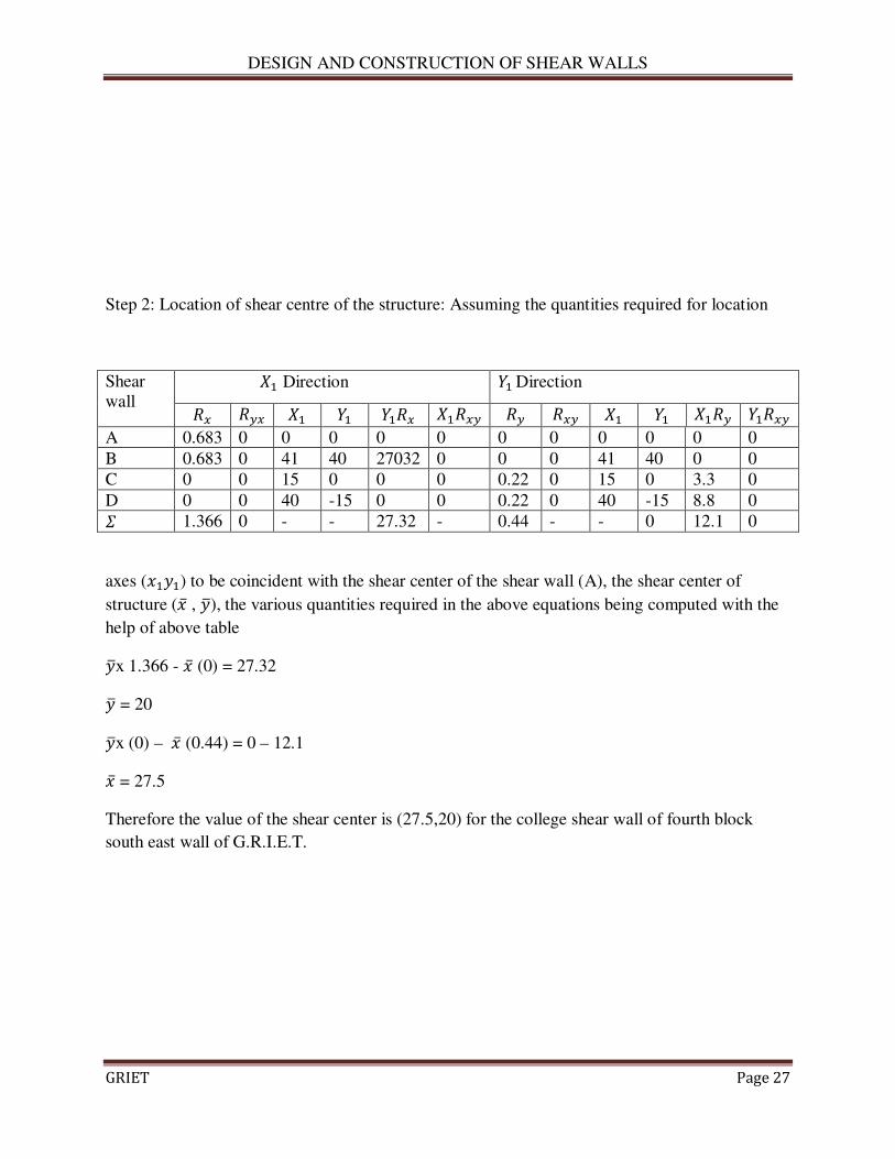
Step 2: Location of shear centre of the structure: Assuming the quantities required for location
Shear
wall ?� Direction @�Direction
�� ��� ?� @� @��� ?���� �� ��� ?� @� ?��� @����
A 0.683 0 0 0 0 0 0 0 0 0 0 0
B 0.683 0 41 40 27032 0 0 0 41 40 0 0
C 0 0 15 0 0 0 0.22 0 15 0 3.3 0
D 0 0 40 -15 0 0 0.22 0 40 -15 8.8 0 > 1.366 0 - - 27.32 - 0.44 - - 0 12.1 0
axes (A�B�) to be coincident with the shear center of the shear wall (A), the shear center of
structure (A̅ , BD), the various quantities required in the above equations being computed with the
help of above table
BDx 1.366 - A̅ (0) = 27.32
BD = 20
BDx (0) – A̅ (0.44) = 0 – 12.1
A̅ = 27.5
Therefore the value of the shear center is (27.5,20) for the college shear wall of fourth block
south east wall of G.R.I.E.T.
DESIGN AND CONSTRUCTION OF SHEAR WALLS
GRIET Page 28
4.4 Calculation of seismic and shear forces
BEHAVIOUR OF SHEAR WALLS:
The behavior of shear walls, with particular reference to their typical mode of failure is, as in the
case of beams, influenced by their proportions as well as their support conditions. Low shear
walls also known as squat walls, characterized by relatively small height-to length ratios, may be
expected to fail in shear just like deep beams. Shear walls occurring in high-rise buildings, on the
other hand, generally behave as vertical cantilever beams with their strength controlled by
flexure rather than by shear. Such walls are subjected to bending moments and shear originating
from lateral loads, and to axial compression caused by gravity. These may, therefore, be
designed in the same manner as regular flexural elements. When acting as a vertical cantilever
beam, the behavior of a shear wall which is properly reinforced for shear will be governed by the
yielding of the tension reinforcement located near the vertical edge of the wall and, to some
degree, by the vertical reinforcement disturbed along the central portion of wall.
It is thus evident that shear is critical for walls with relatively low height-to-length ratios and tall
shear walls are controlled mainly by flexural requirements particularly if only uniformly
distributed reinforcement is used. This is a typical shear wall of height�ℎF�, length�GF�, and
thickness� F�. It is assumed to be fixed at its base and loaded horizontally along its left edge.
Vertical flexural reinforcement of area �(H� is provided at the left edge, with its centroid at a
distance IF from the extreme compression face. To allow for reversal of load, identical
reinforcement is provided along the right edge. Horizontal reinforcement of area �(J� at spacing
S2, as well as vertical reinforcement of area (Av) at spacing S1 is provided as shear
reinforcement. Distribution of minimum reinforcement vertically and horizontally helps to
control the width of inclined cracks. Such distributed steel normally is placed in two layers,
parallel to both faces of the wall.
Since the ductility of a flexural member such as a tall shear wall can be significantly affected by
the maximum usable strain in the compression zone concrete, confinement at the ends of the
shear wall section would improve the performance of such shear walls. Such confinement can
take the form of enlarged boundary element with adequate confining reinforcement. In the
flanged wall sections, the adjacent parts of the wall will provide lateral support to each other.
Confinement may also be obtained from the presence of other walls running at right angles to the
shear wall at its ends. In both cases, the additional compression flanges contribute to the increase
in ductility. Shear wall sections are often thin and therefore, under reversed cyclic yielding there
is a danger of section instability. The wall-return may usually be necessary between the ground
and first floors of a building to increase stability.
It is also required that the vertical forces resulting from seismic loads are resisted entirely by the
boundary elements. It is similar to the design approach used in steel I-beams where flanges resist
DESIGN AND CONSTRUCTION OF SHEAR WALLS
GRIET Page 29
the flexural stresses and the web carries the entire shear. In shear walls of high-rise structures,
enough shear capacity is provided so that a shear failure does not precede a flexural failure.
However, a portion of a shear wall, which interacts with the frames, may behave as a low shear
wall, depending upon the proportions of the walls and the location of the point of contra flexure
along the height of the wall. The latter is dependent primarily on the relative stiffness of the
frame and the shear wall elements in a structure.
TALL SHEAR WALLS:
In multi-storey buildings, the shear walls are slender enough and are idealized as cantilevers
fixed at base. Their seismic response is dominated by flexure. Because of local reversals, shear
wall sections necessarily contain substantial quantities of compression reinforcement. IS 1893:
2002 has laid down the procedure to assess the flexural and shear strengths of tall shear walls
and is described in the following subsections.
FLEXURAL STRENGTH:
In shear walls, particularly in areas not affected by earth quakes, the strength requirement for
flexural steel is not great. Traditionally, the practice is to provide about 0.25 per cent
reinforcement uniformly in both directions over the entire depth. Naturally, such an arrangement
does not efficiently utilize the steel at the ultimate moment because many bars operate on a
relatively small lever arm. Moreover, the ultimate curvature, hence the curvature ductility, is
considerably reduced and this arrangement is also uneconomical.
In an efficient shear wall section subjected to considerable moments, the bulk of the flexural
reinforcement is placed close to the tensile edge. Because of moment reversals originating from
lateral loads, equal amounts of reinforcement are normally required at both extremities. Thus, a
considerable part of bending moment can be resisted by the internal steel couple, and this will
result in improved ductility properties. The practice is to provide minimum reinforcement over
the inner 80 percent depth and allocate the remainder of the steel to outer zones of the section.
As shown by the theoretical moment-curvature relationship, this distribution of steel results in an
increase in the available strength and ductility.
To increase the ductility of cantilever shear walls at the base, where the overturning moments
and axial compression are the largest, the concrete in the compression zone must be confined.
The confining steel is provided in the same way as in tied columns and can be extended over the
part of the depthGF, where concrete strains in excess of 0.0035 are required. This is particularly
important over the region of a possible plastic hinge, which may extend over a full storey height
or more. The flexural strength of a slender rectangular shear wall section with uniformly
distributed vertical reinforcement and subjected to uniaxial bending and axial load may be
estimated as follows:
DESIGN AND CONSTRUCTION OF SHEAR WALLS
GRIET Page 30
Case 1:
For ��KF = ��
KF
M���NO�FK�F = P QR1 + S
TU R�� − 0.416 �X
KFU − R��KFU� R0.168 + Z�
! U[
Where
�XK\ =
T1]�T1^.!_
�X∗K\ =
^.^^!a^.^^!a18.b9c0
de
P = ^.fg�0h
�ij , k = lX
�ij�\K\
Ρ = men
�\K\ , β = ^.fg�0
^.^^!ae
Where A� is the depth of the neutral axis from extreme compression flange,is the balanced depth
of neutral axis,
α is the inclination of the diagonal reinforcement in the coupling beam,
β is the soil-foundation factor (IS 1893: 2002),
ρ is the vertical reinforcement ratio,
(H�is the area of uniformly distributed vertical reinforcement,
oHis the elastic modulus of steel, and
p�is the axial compression on the wall.
Case 2
For �X∗K\ <
�XK\< 1.0
MXq�ijn\r�\
= s� R�XK\U - s� R�X
K\U�- s! -
]�
DESIGN AND CONSTRUCTION OF SHEAR WALLS
GRIET Page 31
Where s� = t0.36 + P R1 −Z� − ��ZUu
s� = t0.15 + T� R1 − v −Z�
� − �!ZUu and
s! = T_Z wx �=Xr\
y − 3z
The values of R�XK\U to be used in this equation, can be calculated from the following quadratic
equation
s� R�XK\U�
+ s, R�XK\U + sa = 0
s, = RTZ − kU and sa = R T
�ZU
From the above equations we have derived assuming a rectangular wall section of depth GF and
thickness Fthat is subjected to combined uniaxial bending and axial compression. The vertical
reinforcement is represented by an equivalent steel plate along the length of the section. The
stress-strain curve assumed for concrete is as per IS 456:2000, whereas that for steel is assumed
to be bilinear. Above equations are given for calculating the flexural strength of the section.
Their use depends on whether the section fails in flexural tension or in flexural compression.
SHEAR STRENGTH
The shear strength of tall shear walls can be assessed in the same way as for beams, with due
allowance made for the contribution of axial compression in boosting the share of the concrete
shear-resisting mechanism. In doing so, the adverse effect of vertical acceleration induced by
earthquakes should also be considered. At the base of the wall, where yielding of the flexural
steel is possible in both faces, the contribution of the concrete towards the shear strength should
be neglected and shear reinforcement in the form of horizontal stirrups should be provided at
least over the possible length of the plastic hinge, to carry all the shear force. The minimum
reinforcement of 0.25 per cent in the horizontal direction, when appropriately anchored, is found
to be sufficient. The effective depth of the rectangular shear wall can be taken as greater than
0.8GF. It must be noted that flanges of the shear wall are not taken into account while calculating
the shear strength.
DESIGN AND CONSTRUCTION OF SHEAR WALLS
GRIET Page 32
In the potential plastic hinge zone, wide flexural cracks combine with diagonal tension cracks,
due to shear. The effect of diagonal cracking on the distribution of flexural shear stresses should
be considered in the same way as in beams.
CONSTRUCTION JOINTS
There are two potential locations in cantilever shear walls where failure by sliding shear can
occur. One is a horizontal construction joint and the other is the plastic hinge zone, usually
immediately above the foundation level. The inelastic response of mechanisms associated with
sliding shear indicates drastic loss of stiffness and strength with reversed cyclic loading.
Therefore, sliding shear should be considered as being an unsuitable energy dissipating
mechanism in earthquake resistant structures.
Earthquake damage in shear walls is more common at construction joints along which sliding
movement may occur necessitating efficient vertical reinforcement to check sliding. The shear
force that can be safely transferred across a well prepared rough horizontal joint is given by
{|}~�p� + 0.87��(�)
Where p�is the factored axial force on the section,
(�is the vertical steel to be utilized,
and µ is the coefficient of the friction at the joint (µ = 1.0).
For shear walls, the gravity loads with 20 percent reduction to account for negative vertical
acceleration are considered
{|= 0.8Pu +0.87 ��(�
The strength of the construction joint is
��� = ��m�
And this must be equal to but preferably greater than the diagonal tension shear strength of the
wall.
The steel content across the construction joint is given by
DESIGN AND CONSTRUCTION OF SHEAR WALLS
GRIET Page 33
��� = mqm�
The vertical reinforcement ratio, �� across a horizontal construction joint should not be less than
��� − lXm�� ^.��
�0 ≥ 0.0025
Where �� is the factored shear stress at the joint, p� is the factored axial force, and (� is the
gross cross-sectional area of the joint.
DESIGN OF SHEAR WALLS
Shear walls construction is an economical method of bracing buildings to limit damage. For
good performance of well designed shear walls, the shear wall structures should be designed for
greater strength against lateral loads than ductile reinforced concrete frames with similar
characteristics; shear walls are inherently less ductile and perhaps the dominant mode of failure
is shear. With low design stress limits in shear walls, deflection due to shear walls is small.
However, exceptions to the excellent performances of shear walls occur when the height-to-
length ratio becomes great enough to make overturning a problem and when there are excessive
openings in shear walls. Also, if the soil beneath its footing is relatively soft, the entire shear wall
may rotate, causing localized damage around the wall. Following are the design steps of
cantilever shear walls.
GENERAL REQUIREMENTS
(a) The thickness of the shear wall should not be less than 150mm to avoid unusually thin
sections. Very thin sections are susceptible to lateral instability in zones where inelastic cyclic
loading may have to be sustained.
(b) The effective flange width for the flanged wall section from the face of web should be taken
as least of
® Half the distance to an adjacent shear wall web, and
® One-tenth of total wall height.
(c) The minimum reinforcement in the longitudinal and transverse directions in the plan of the
wall should be taken as 0.0025 times the gross area in each direction and distributed uniformly
across the cross-section of wall. This helps in controlling the width of inclined cracks that are
caused due to shear.
DESIGN AND CONSTRUCTION OF SHEAR WALLS
GRIET Page 34
(d) If the factored shear stress in the wall exceeds 0.25√fck or if the wall thickness exceeds 200
mm, the reinforcement should be provide in two curtains, each having bars running in both the
longitudinal and transverse directions in the plane of the wall. The use of reinforcement in two
curtains reduces fragmentation and premature deterioration of the concrete under cyclic loading.
(e) The maximum spacing of reinforcement in either direction should be lesser thanK\a , 3 F, and
450mm, where GFis the horizontal length and Fis the thickness of the wall web.
(f) The diameter of the bars should not exceed one-tenth of the thickness of that part. This puts a
check on the use of very large diameter bars in thin wall sections.
SHEAR STRENGTH
The provisions for shear strength are almost same as those of RCC beams. The increase in shear
strength may also be considered. However, for this, only 80 percent of the factored axial force is
considered as effective. This reduction of 20 per cent is made to account for possible effect of
vertical acceleration.
(a) The nominal shear stress is
�� = {� F IF
Where {� is the factored shear force, F is the thickness of web, and IFis the effective depth
of the wall section.
(b) The design shear strength of concrete (�N) should be as per IS 456: 2000.
(c) The nominal shear stress, ��, should not be greater than �N��� . The value of �N��� can be
found from IS 456: 2000. If �� < �N, minimum shear reinforcement of 0.25 percent should be
provided in the horizontal direction. If �� > �N, the area of horizontal shear reinforcement, (J, at
a vertical spacing, ��, can be determined from the expression
{�H = ^.fg�0m.�\
�q
Where {�H is the shear force to be resisted by the horizontal reinforcement and is given by
{�H ={� −�N FIF
(d) Uniformly distributed vertical reinforcement not less than the horizontal reinforcement
should be provided. This is particularly important for squat walls. When the height-to-width ratio
DESIGN AND CONSTRUCTION OF SHEAR WALLS
GRIET Page 35
is about 1.0, both the vertical and horizontal reinforcement are equally effective in resisting the
shear force.
FLEXURAL STRENGTH
The moment of resistance of short shear walls is calculated as for columns subjected to
combined bending and axial load. The procedure for the calculation of moment of resistance,
��� of tall rectangular shear walls is as described
For walls without boundary elements, the vertical reinforcement is concentrated at the ends of
the walls. A minimum of four bars, 12mm P, arranged in two layers, are provided at each end.
BOUNDARY CONDITIONS
There are the portions along the wall edges and may have the same or greater thickness than the
wall web. These are provided throughout the height with special confining reinforcement. Wall
sections having stiff and well confined boundary elements develop substantial flexural strength,
are less susceptible to lateral buckling and have better shear strength and ductility in comparison
to plane rectangular walls not having stiff and well-confined boundary elements.
(a) During a severe earthquake, the ends of a wall are subjected to high compressive and tensile
stresses. Hence, the concrete needs to be well confined so as to sustain the load reversals without
a large deterioration in strength. Thus, the boundary elements are provided along the vertical
boundaries of walls, when the extreme fibre compressive stress in the wall due to factored
gravity load plus factor earthquake force exceeds 0.2fck. The boundary element may be
discontinued where the calculated compressive stress becomes less than 0.15fck.
(b) The boundary element is assumed to be effective in resisting the design moment due to
earthquake induced forces, along with the web of the wall. The boundary element should have an
adequate axial load carrying capacity so as to carry an axial compression equal to the sum of the
factored gravity load plus compressive load due to seismic load. The latter may be calculated as
pN = MX�MXq
�\
Where Mu is the factored design moment on the entire wall section, ��� is the moment of
resistance provided by the distributed reinforcement across the wall section, and ;F is the c/c
distance between the boundary elements along the two vertical edges of the wall.
(c) Moderate axial compression results in higher moment capacity of the wall. Hence, the
beneficial effect of axial compression by gravity loads should not be fully relied upon in a
DESIGN AND CONSTRUCTION OF SHEAR WALLS
GRIET Page 36
design, due to the possible reduction in its magnitude by vertical acceleration. When gravity
loads add to the strength of the wall, a load factor of 0.8 may be taken
(d) The percentage of vertical reinforcement in boundary elements should range between 0.8 and
6 percent.
(e) During a severe earthquake, boundary elements may be subjected to stress reversals. Hence,
they have to be confined adequately to sustain the cyclic loading without a large degradation in
strength. Therefore, these should be provided throughout their height.
(f) Boundary elements need not be provided if the entire wall section is provided with special
confining reinforcement.
4.5 Design the ductile shear wall for college building
A five storey building with plan dimensions as shown.
The height between floors is 4.0m
The dead load per unit area of the floor which consists of floor slab finishes is 4 KN/+�.
Weight of partitions on floors is 2 KN/m
The intensity of live load acting is 3 KN/+� on floor and on terrace 1.5 KN/+�.
Loads are considered as per IS: 875, part1and part 2.
Grade of concrete being used M-30.
Grade of steel used is Fe 415.
Unit weight of reinforced concrete is 25 KN/+!.
And Beams and Columns o cross section is 450x300mm and 600x300mm.
To calculate:
The seismic forces and shears at different floor levels.
Design the ductile shear wall to resist seismic forces.
Solution:
DESIGN AND CONSTRUCTION OF SHEAR WALLS
GRIET Page 37
Seismic weight of the building:
As per IS code 1893:2002 the percentage of design live load to be considered for the calculation
of earthquake. Force is 25% for the floors and no live load needs to be considered for roof.
Hence the effective weight of each floor = 4.0 + 2.0 + 0.25 x 4 = 7 KN/+�.
And that of roof = 4 KN/+�. Self weight of 80 columns = 0.3 x 0.6 x 4 x 25 x 80 = 1440 KN
Weight of columns at roof = �� A1440 = 720��
Weight of 140 beams = 0.45 x 0.300 x 5 x 140 x 25 = 2362.5
Plan area of building = (40 x 40.5) + (10 x 20) = 1820 +�
Equivalent load at roof level = 4 x 1820 + 2362.5 + 720 = 10363.5 KN
Equivalent load at each floor = 6.75 x 1820 + 2362.5 + 1440 = 16087.5 KN
Seismic weight of building = 10363.5 + (16087.5 x 4) = 74713.5 KN
Base shear:
The fundamental natural period of vibration (T) for the buildings having shear walls is
T = ^.^�J√� =
^.^���^√,^ = 0.28
Building is situated in Hyderabad zone II.
As per zone factor (Z) = 0.10
Importance factor (I) = 1.5
Response reduction
Ductile shear wall with shear moment resistant frame (R) = 5
For 5% damping and type I soil
��� = 1.81
Design horizontal seismic coefficient
DESIGN AND CONSTRUCTION OF SHEAR WALLS
GRIET Page 38
(J = ������� =
^.�^��.a��.f���a = 0.02715
Base shear {� = (J x W = 0.02715 x 74713.5 = 2028.47
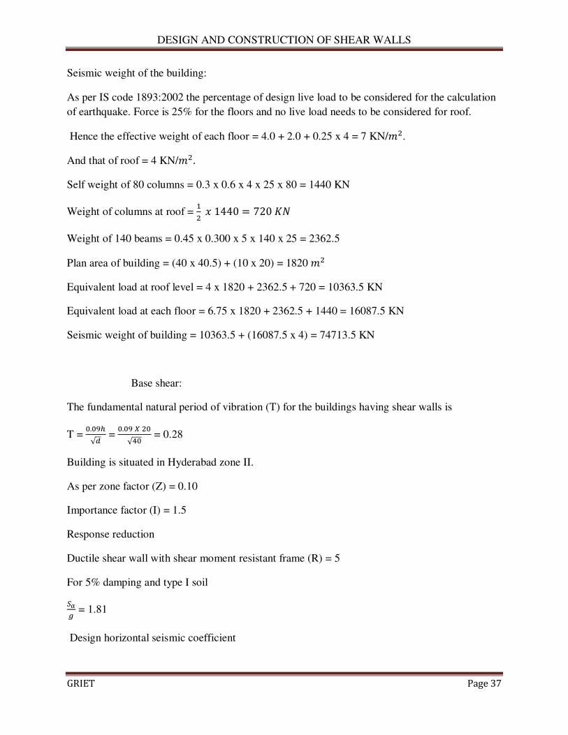
Design lateral force at various floor levels. Design lateral force at floor i:
¡= {¢ £¤J¤�∑ £�J��¦§¨©
Mass no.
1 10363.5 20 4145400 0.3493 708.54 708.54
2 16087.5 16 4118400 0.3470 703.9 1412.44
3 16087.5 12 2316600 0.195 395.5 1807.94
4 16087.5 8 1029600 0.0867 175.9 1983.84
5 16087.5 4 257400 0.0216 43.8 2027.64 > = 11867400
Bending moment and shear force:
Two shear walls are provided as given in the problem to resist the seismic forces in each
direction
The shear wall is assumed to be cantilever in calculations.
Maximum shear force at base (V) = 1013.82 KN
Maximum bending moment at base
M = (21.4 x 4) + (87.95 x 8) (197.75 x 12) + (3510.95 x 16) (354.27 x 20) = 15878.8 KN. m
Taking partial safety factor = 1.5
Factored shear force ({ª) = 1.5 X 1013.82 = 1520.73
Factored bending moment (��) = 15878.8 x 1.5 = 23818.2
Considering axial load acting = 16000 KN
Factored axial load = 1.5 x 16000 = 24000 KN
Flexural strength of shear wall:
�NO = 30 N / m+�
�� = 415 N / m+�
oH = 2.0 x 10a N/ m+�
DESIGN AND CONSTRUCTION OF SHEAR WALLS
GRIET Page 39
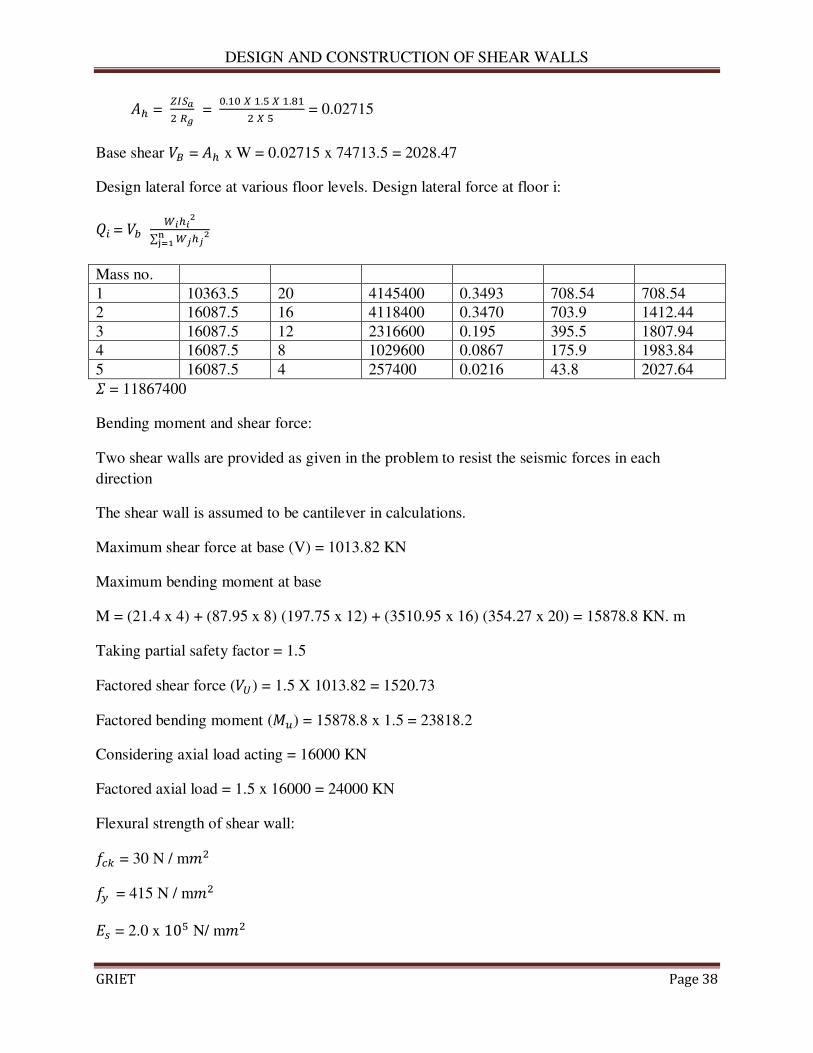
Length of wall (GF) = 24.4 m
Thickness of wall ( F) = 0.3 m
Providing uniformly distributed vertical reinforcement ratio
« = 0.25%
P = ^.fg�0¬
�ij
= ^.fg�,�a�^.^^�a
!^ = 0.030
k = lX
�ijr\n\ =
�,^^^��^^^!^�!^^��,,^^ = 0.0728 = 0.109
Β = ^.fg�0
^.^^!ae = ^.fg�,�a
^.^^!a����^: = 0.5158
�XK\ =
T1]�T1^.!_ =
�^.^!^1^.�^�����^.^!�1^.!_ = 0.3309
�X∗K\ =
^.^^!a^.^^!a18.b9c0
de =
^.^^!a^.^^!a18.b93©:
�©8: = 0.6597
�XK\<
�X∗K\
Moment of resistance:
�� = �NO FGF�Pwt1 + ]Tu t�� − 0.416 �XK\u − t�X∗
K\ u� t0.168 + Z�! uz
= 30 x 300 x �24400�� x 0.03 wt1 + ^.�^�^.^! u t�� − 0.416A0.1078u − �0.3309�� t0.168 +^.a�a�
! uz = 1.607 x10��¯�0.53� −�0.111�° = 2.638694 x10��
= 67513.8 KN m
�� = 263869.4
Factored bending moment = 23818.2
�� > ����#± ²³´I� 67513.8 > 23818.2
DESIGN AND CONSTRUCTION OF SHEAR WALLS
GRIET Page 40
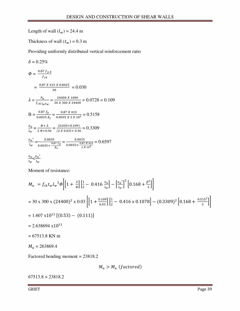
Balance moment to be resisted by the edge reinforcement in each shear wall
= �−23818.2 + 67513.8� = 43695.6
Effective depth of wall IF = 0.9 GF = 0.9 x 24400 = 21960
Area of steel = MX
^.fg�0µ\ =
,!_�a._��^2^.fg�,�a����_^ = 5511.09
Equal amount of reinforcement is provided on the vertical edges of the wall which will act like
the flanges of a steel beam.
Provide 20 numbers. 20 P bars in two layers in the wall at each end.
(H�Provided at ends = 314.15 x 20 = 6283 m+�
Minimum reinforcement is provided in the vertical direction for a length of wall
0.8 GF = 19520 mm.
Minimum area of steel required in the shear wall
= 0.0025 x 24400 x 300 = 18300 m+�
Area of minimum reinforcement per meter length of wall
= 0.0025 x 1000 x 300 = 750 m+�
Maximum permissible spacing = K\a or 3 F or 450.
K\a =
!�,^^a = 7880
3 F = 3 x 300 = 900
Therefore spacing between reinforcement = 450 mm c/c.
Provide 10mm Pbars at 300 mm c/c in the vertical direction in two layers.
Check for shear:
Factored shear force ({�) = 1520.73 KN
Nominal shear stress = �X
�\�\ = �a�^.g!
!^^����_^ = 0.23 N/m+�
Permissible shear stress for M30 grade concrete and steel ratio,
DESIGN AND CONSTRUCTION OF SHEAR WALLS
GRIET Page 41
P = 0.25%
(As per clause 9.24 of IS: 13920 : 1993 )
If
Then
As per clause 9.15:
If the factored shear stress in the wall exceeds 0.25¶�NO or if the wall thickness exceeds 200 mm
then the reinforcement is provided in two directions. each having running in horizontal and
transverse directions.
The maximum spacing shall not be smaller thanK\a , 3 F and 450 mm = 450 mm
Thus the reinforcement provided in horizontal direction = ��·©8�
3 ��^^^,a^
= gf.a����^^^
,a^ = 349.06 m+�
But area of minimum reinforcement is 750 m+�. Hence provide minimum reinforcement of 0.25% of the gross area of the wall, in the horizontal
direction.
Provide 10 P bars at 450 mm c/c
The detailing of shear wall
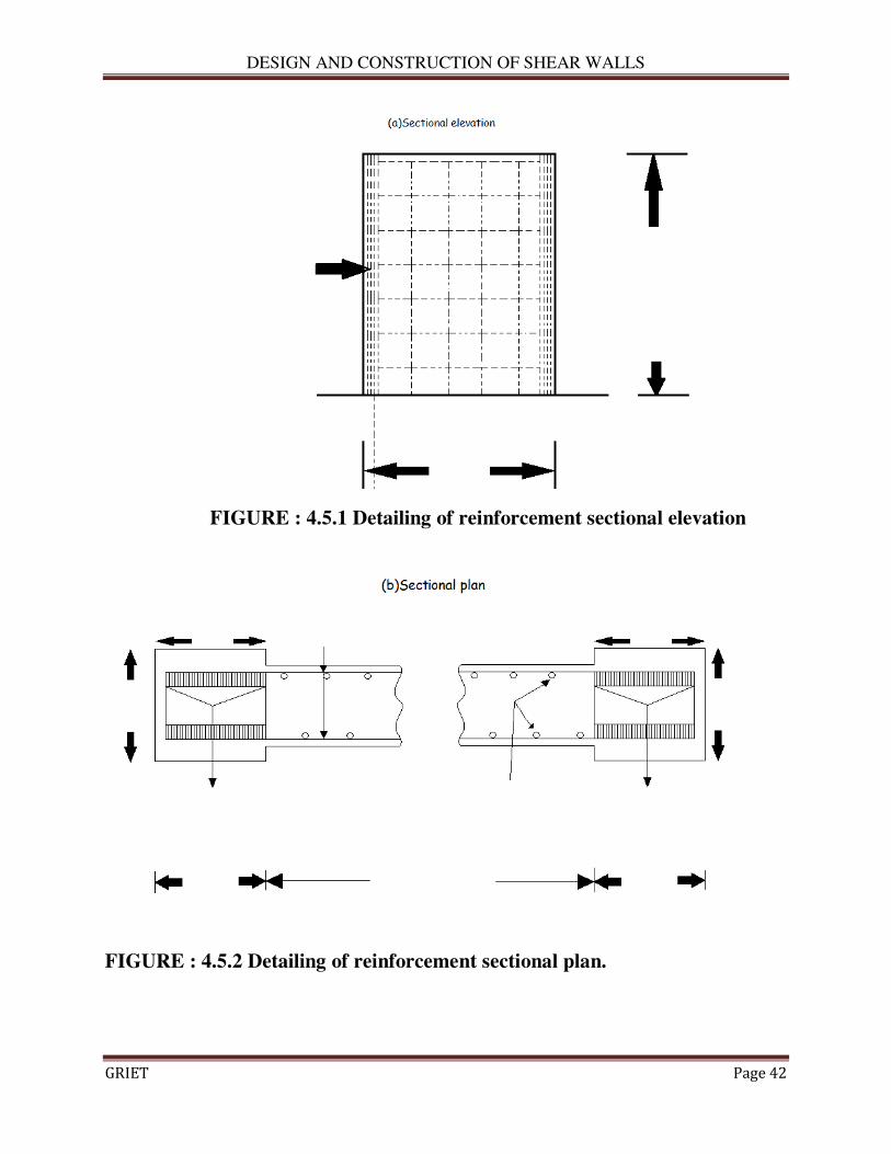
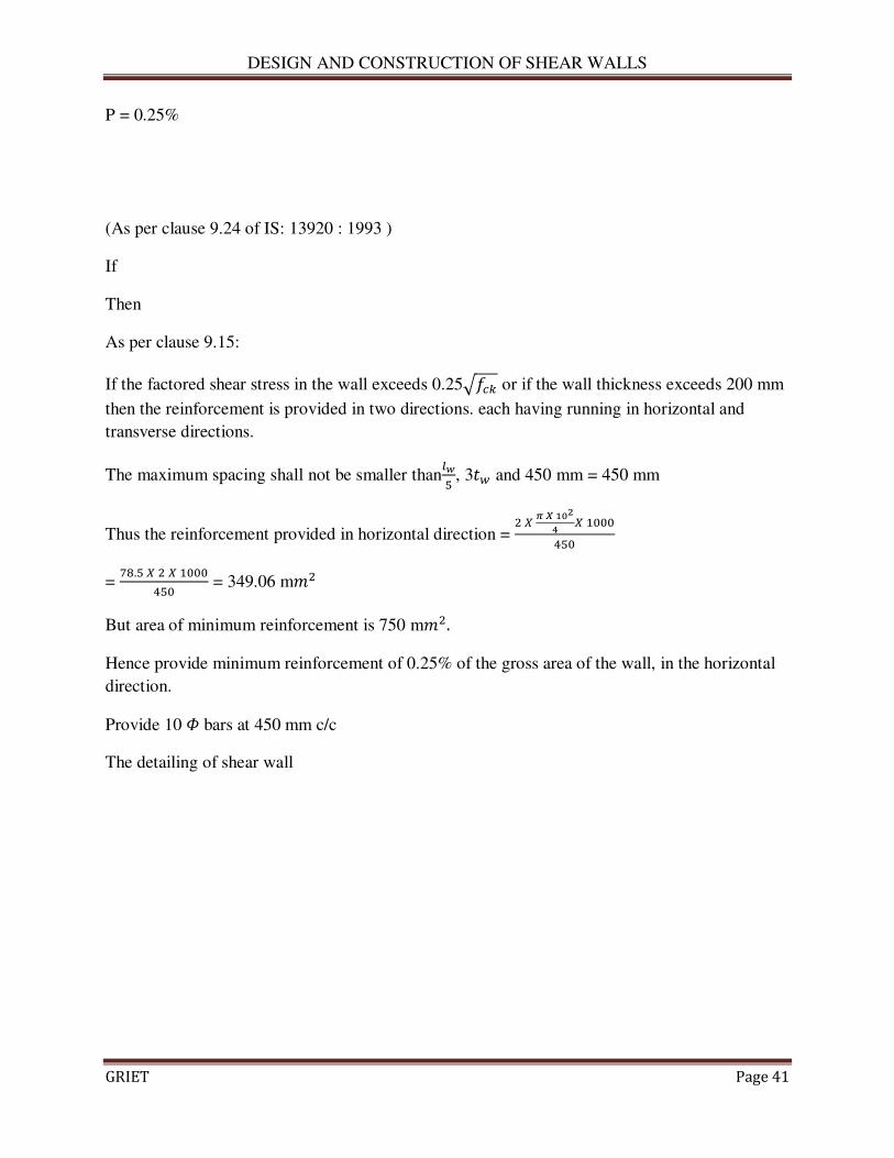
DESIGN AND CONSTRUCTION OF SHEAR WALLS
GRIET Page 42
FIGURE : 4.5.1 Detailing of reinforcement sectional elevation
FIGURE : 4.5.2 Detailing of reinforcement sectional plan.
DESIGN AND CONSTRUCTION OF SHEAR WALLS
GRIET Page 43
DESIGN AND CONSTRUCTION OF SHEAR WALLS
GRIET Page 44
CHAPTER 5
DESIGN OF COLLEGE BUILDING USING E-TABS
Firstly click on the ETABS icon .A window appears which shows a different tip every time you
open the software.
This window provides us 3 options. You can click on previous or next tip to checkout some
more tips or else click ok to move further.
Change the units at the right bottom to KN-m or any other as per your convenience.
Click on file option to create a new file or to open an already existing file
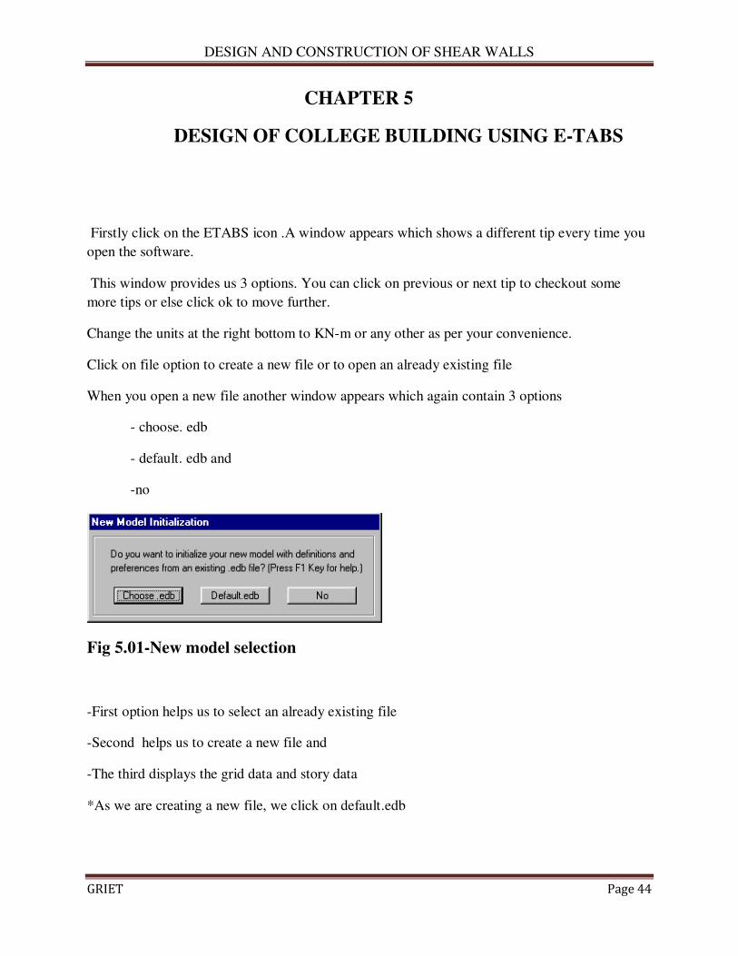
When you open a new file another window appears which again contain 3 options
- choose. edb
- default. edb and
-no
Fig 5.01-New model selection
-First option helps us to select an already existing file
-Second helps us to create a new file and
-The third displays the grid data and story data
*As we are creating a new file, we click on default.edb
DESIGN AND CONSTRUCTION OF SHEAR WALLS
GRIET Page 45
*A new window appears which has Building plan grid system and Story data. In grid dimensions
we can either use uniform spacing or we can customize the grid spacing. We have to provide no
of lines in x and y directions as per the columns and beams used in the plan.
Fig 5.02-Provision of storey and grid data
*In the story dimensions, we have simple story data and custom story data. In simple story data,
use the defaults or specify values for the number of stories, typical story height, and bottom story
height. The value specified for the typical story height will be used for all stories in the model,
except the bottom story whereas in custom story data we can manually define story names, story
levels of non-uniform height, and story similarity.
*After providing the entire data click on grid only in structural objects and then click on ok.
DESIGN AND CONSTRUCTION OF SHEAR WALLS
GRIET Page 46
Fig 5.03-ETABS main window
*Now the screen is divided into two equal halves in which one is plan view and the other is 3-D
view of the provided data.
*We can change the view options to plan,3D or elevation views. We can select any of the stories
as per the work to be done on that particular story. At the right corner we change the story
options to either similar or all stories. This makes us to save time i.e. if we are working on a
particular story, then that is transferred to remaining stories or similar stories as per the option
selected. The top story is selected as default story.
*After the entire grid data and story data is provided, then we have to define the properties of the
material that is used.
*To define a material property, select define=>material properties. This makes us to either add
new material, modify or delete an existing material. Click on add new material to create a new
material with required properties.
*Firstly provide a name(say M20,M30 etc) and then provide the other properties of the material
such as mass per unit volume, weight per unit volume, elastic modulus, Poisson’s ratio. The
other design properties that are to be provided are characteristic compressive strength and yield
strength values. You have other options such as change in display colour, type of material which
is always isotropic. After the entire data is provided click on ok.
DESIGN AND CONSTRUCTION OF SHEAR WALLS
GRIET Page 47
*The next step is to create beams and columns. To create a beam or column, first we click on
define=>frame sections command to create a beam or column. In this window we have import
and add options further provided with modify or delete options of already existing properties.
Fig 5.04-Addition of frame sections
*There are many options in add such as add circle, steel joints and further more but we provide
rectangular columns or beams in common and hence we add a rectangular section and then click
on ok. Another window appears which gives details about section. Here we can provide section
name i.e., either a beam or column and change the material to the one that is defined above.
Provide the dimensions of the section as required and change the data according to the section
provided. If a beam is to be provided then select the design type to beam and provide the
required dimensions to the cover and if a column is provided select design type to column and
then nominal cover is provided.
5.1:Marking of columns, beams:
*To create a column, the above process is repeated again and the only difference is the
reinforcement data which is stated earlier both for beams and columns.
DESIGN AND CONSTRUCTION OF SHEAR WALLS
GRIET Page 48
Fig 5.1.1-Columns of the Civil block
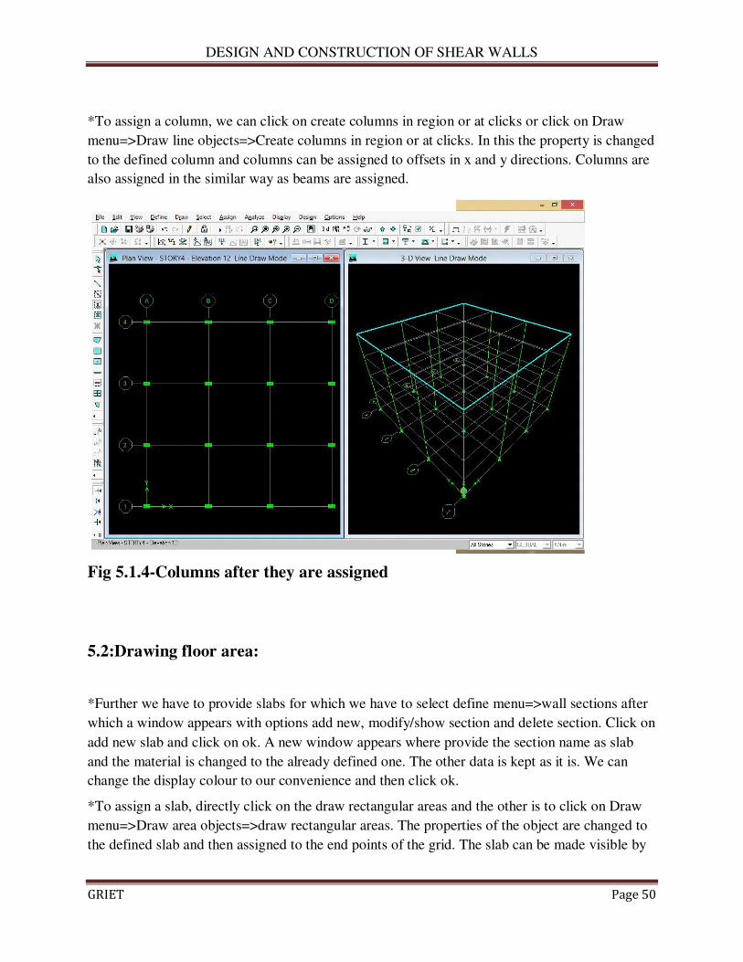
*To assign a beam, we can directly click on the icon create lines or region at click. The other
way to do it is to click on Draw menu=>Draw line objects=>Create lines or regions at click
command. A window appears which provides properties of the object in which the property is
changed to the beam that we defined earlier. We can click on each grid point or directly select all
at once and the beams are assigned to the grid.
DESIGN AND CONSTRUCTION OF SHEAR WALLS
GRIET Page 49
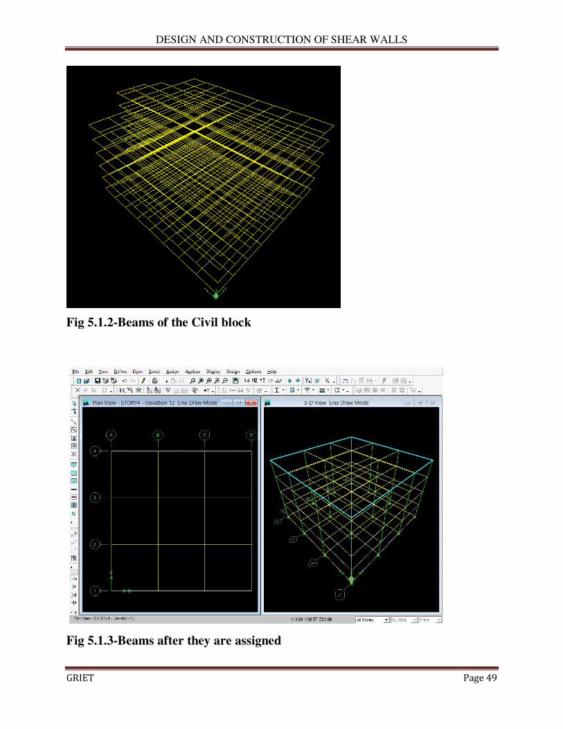
Fig 5.1.2-Beams of the Civil block
Fig 5.1.3-Beams after they are assigned
DESIGN AND CONSTRUCTION OF SHEAR WALLS
GRIET Page 50
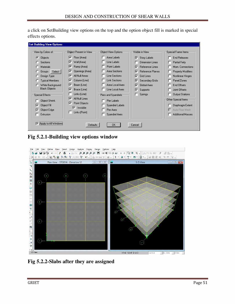
*To assign a column, we can click on create columns in region or at clicks or click on Draw
menu=>Draw line objects=>Create columns in region or at clicks. In this the property is changed
to the defined column and columns can be assigned to offsets in x and y directions. Columns are
also assigned in the similar way as beams are assigned.
Fig 5.1.4-Columns after they are assigned
5.2:Drawing floor area:
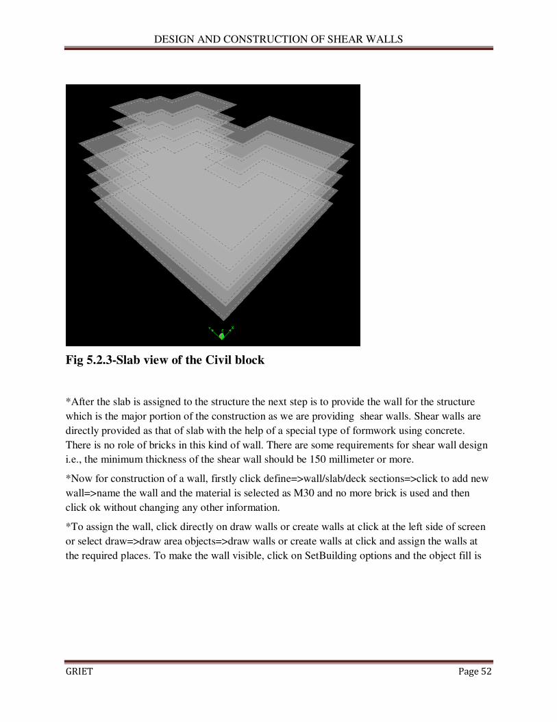
*Further we have to provide slabs for which we have to select define menu=>wall sections after
which a window appears with options add new, modify/show section and delete section. Click on
add new slab and click on ok. A new window appears where provide the section name as slab
and the material is changed to the already defined one. The other data is kept as it is. We can
change the display colour to our convenience and then click ok.
*To assign a slab, directly click on the draw rectangular areas and the other is to click on Draw
menu=>Draw area objects=>draw rectangular areas. The properties of the object are changed to
the defined slab and then assigned to the end points of the grid. The slab can be made visible by
DESIGN AND CONSTRUCTION OF SHEAR WALLS
GRIET Page 51
a click on SetBuilding view options on the top and the option object fill is marked in special
effects options.
Fig 5.2.1-Building view options window
Fig 5.2.2-Slabs after they are assigned
DESIGN AND CONSTRUCTION OF SHEAR WALLS
GRIET Page 52
Fig 5.2.3-Slab view of the Civil block
*After the slab is assigned to the structure the next step is to provide the wall for the structure
which is the major portion of the construction as we are providing shear walls. Shear walls are
directly provided as that of slab with the help of a special type of formwork using concrete.
There is no role of bricks in this kind of wall. There are some requirements for shear wall design
i.e., the minimum thickness of the shear wall should be 150 millimeter or more.
*Now for construction of a wall, firstly click define=>wall/slab/deck sections=>click to add new
wall=>name the wall and the material is selected as M30 and no more brick is used and then
click ok without changing any other information.
*To assign the wall, click directly on draw walls or create walls at click at the left side of screen
or select draw=>draw area objects=>draw walls or create walls at click and assign the walls at
the required places. To make the wall visible, click on SetBuilding options and the object fill is
DESIGN AND CONSTRUCTION OF SHEAR WALLS
GRIET Page 53
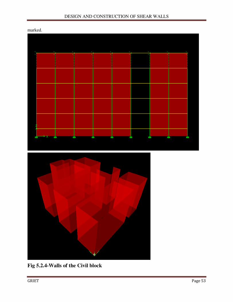
marked.
Fig 5.2.4-Walls of the Civil block
DESIGN AND CONSTRUCTION OF SHEAR WALLS
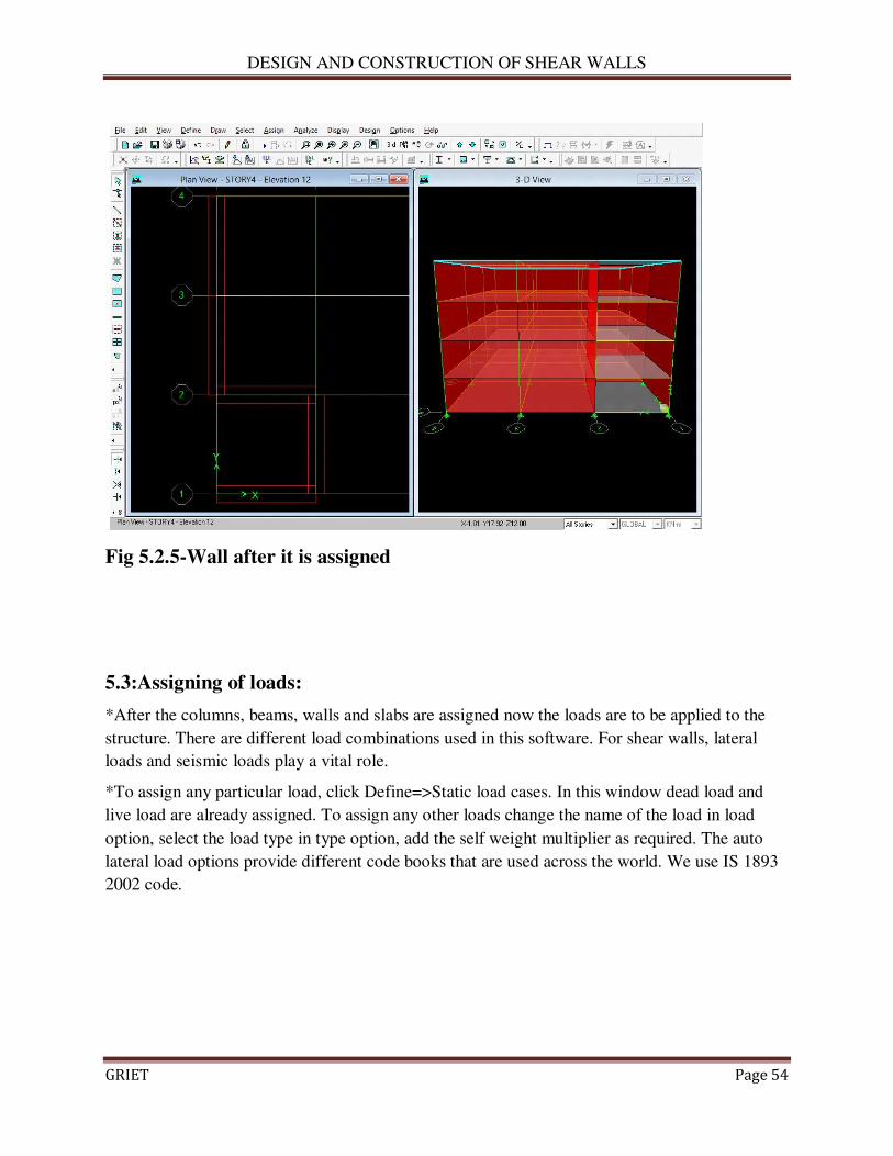
GRIET Page 54
Fig 5.2.5-Wall after it is assigned
5.3:Assigning of loads:
*After the columns, beams, walls and slabs are assigned now the loads are to be applied to the
structure. There are different load combinations used in this software. For shear walls, lateral
loads and seismic loads play a vital role.
*To assign any particular load, click Define=>Static load cases. In this window dead load and
live load are already assigned. To assign any other loads change the name of the load in load
option, select the load type in type option, add the self weight multiplier as required. The auto
lateral load options provide different code books that are used across the world. We use IS 1893
2002 code.
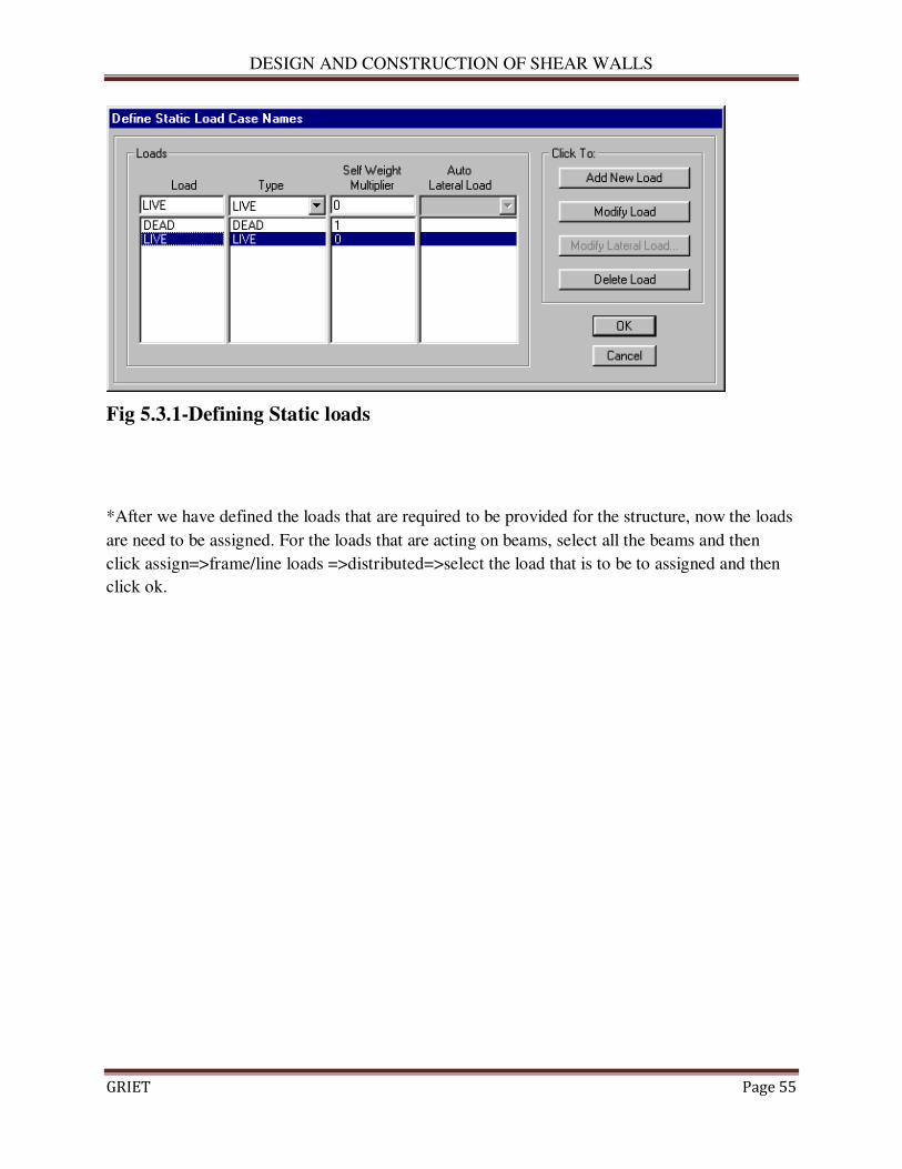
DESIGN AND CONSTRUCTION OF SHEAR WALLS
GRIET Page 55
Fig 5.3.1-Defining Static loads
*After we have defined the loads that are required to be provided for the structure, now the loads
are need to be assigned. For the loads that are acting on beams, select all the beams and then
click assign=>frame/line loads =>distributed=>select the load that is to be to assigned and then
click ok.
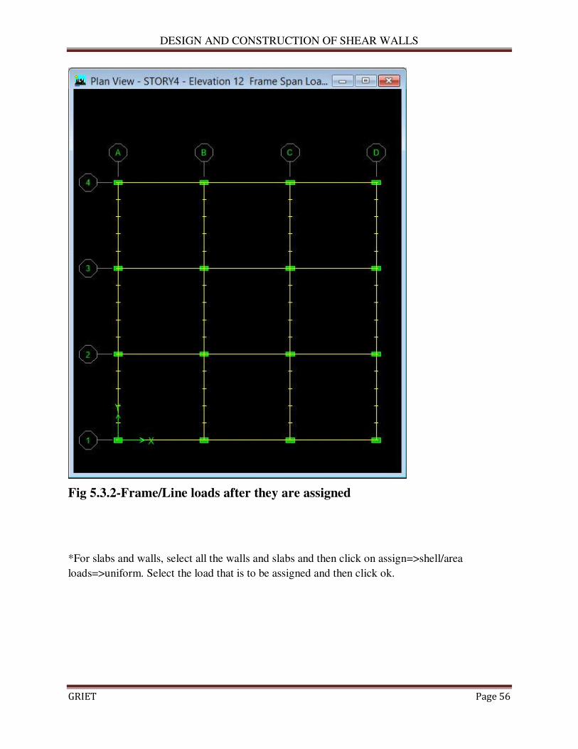
DESIGN AND CONSTRUCTION OF SHEAR WALLS
GRIET Page 56
Fig 5.3.2-Frame/Line loads after they are assigned
*For slabs and walls, select all the walls and slabs and then click on assign=>shell/area
loads=>uniform. Select the load that is to be assigned and then click ok.
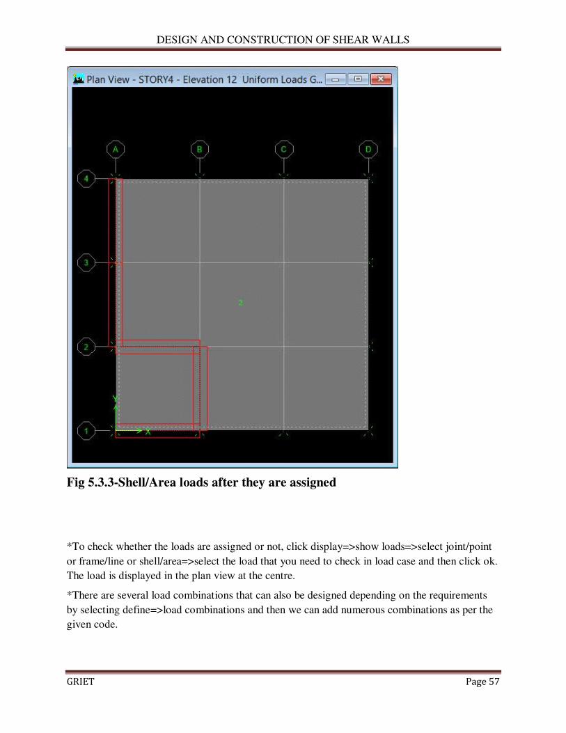
DESIGN AND CONSTRUCTION OF SHEAR WALLS
GRIET Page 57
Fig 5.3.3-Shell/Area loads after they are assigned
*To check whether the loads are assigned or not, click display=>show loads=>select joint/point
or frame/line or shell/area=>select the load that you need to check in load case and then click ok.
The load is displayed in the plan view at the centre.
*There are several load combinations that can also be designed depending on the requirements
by selecting define=>load combinations and then we can add numerous combinations as per the
given code.
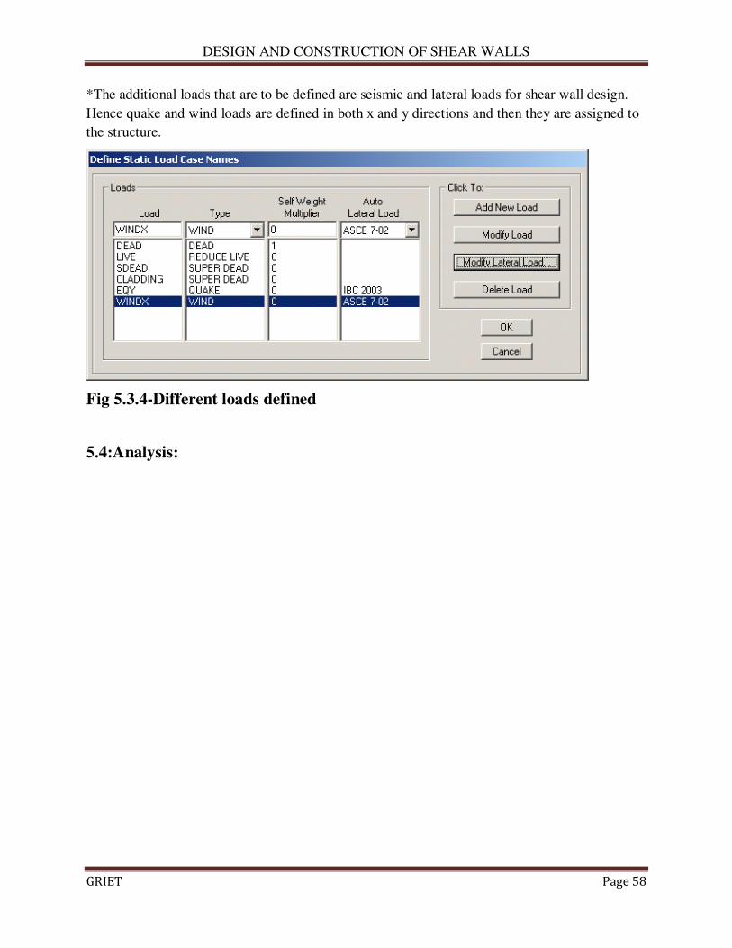
DESIGN AND CONSTRUCTION OF SHEAR WALLS
GRIET Page 58
*The additional loads that are to be defined are seismic and lateral loads for shear wall design.
Hence quake and wind loads are defined in both x and y directions and then they are assigned to
the structure.
Fig 5.3.4-Different loads defined
5.4:Analysis:
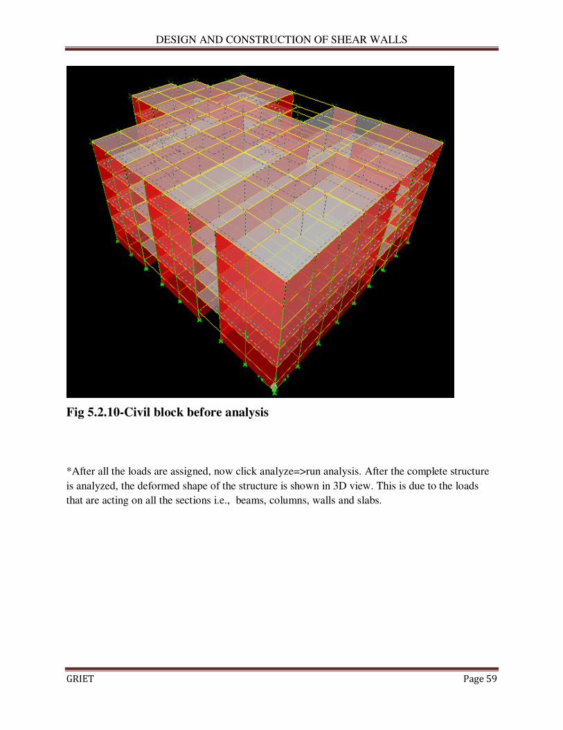
DESIGN AND CONSTRUCTION OF SHEAR WALLS
GRIET Page 59
Fig 5.2.10-Civil block before analysis
*After all the loads are assigned, now click analyze=>run analysis. After the complete structure
is analyzed, the deformed shape of the structure is shown in 3D view. This is due to the loads
that are acting on all the sections i.e., beams, columns, walls and slabs.
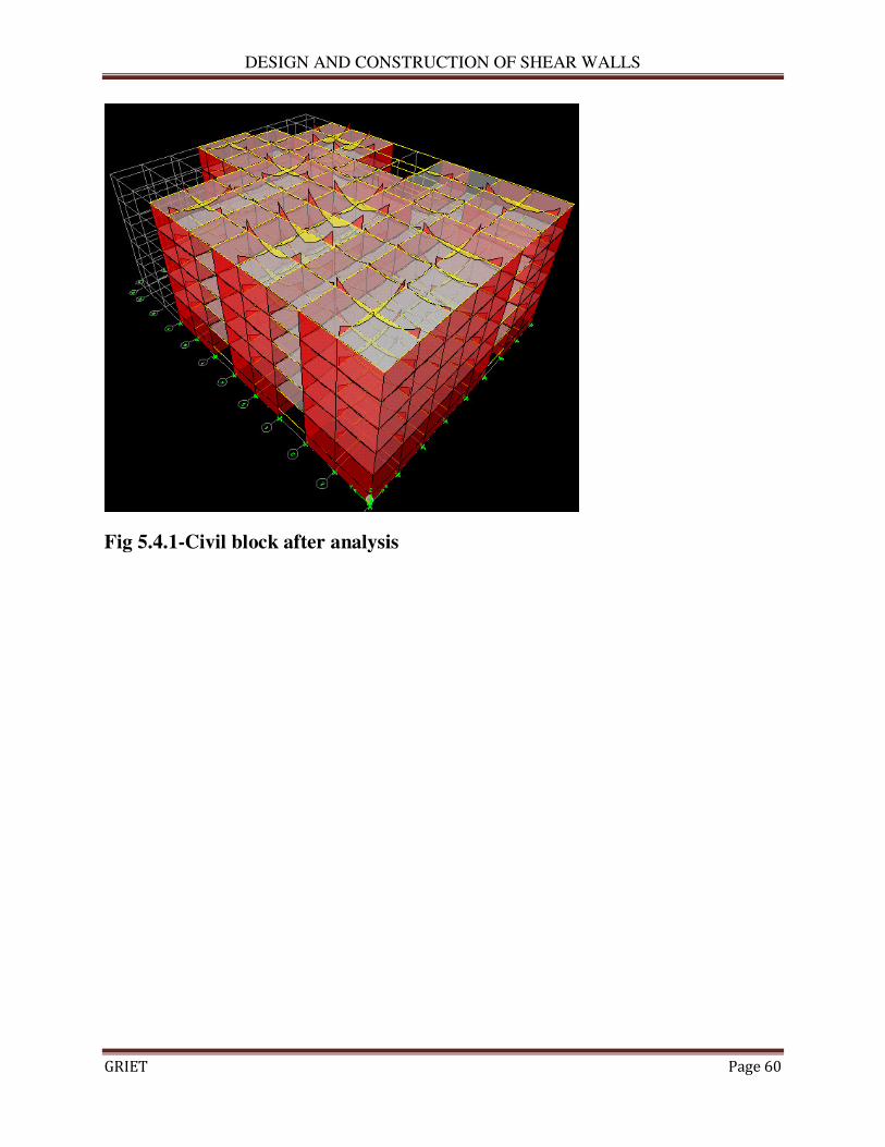
DESIGN AND CONSTRUCTION OF SHEAR WALLS
GRIET Page 60
Fig 5.4.1-Civil block after analysis
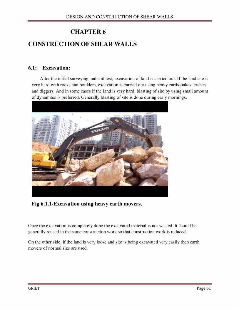
DESIGN AND CONSTRUCTION OF SHEAR WALLS
GRIET Page 61
CHAPTER 6
CONSTRUCTION OF SHEAR WALLS
6.1: Excavation:
After the initial surveying and soil test, excavation of land is carried out. If the land site is
very hard with rocks and boulders, excavation is carried out using heavy earthquakes, cranes
and diggers. And in some cases if the land is very hard, blasting of site by using small amount
of dynamites is preferred. Generally blasting of site is done during early mornings.
Fig 6.1.1-Excavation using heavy earth movers.
Once the excavation is completely done the excavated material is not wasted. It should be
generally reused in the same construction work so that construction work is reduced.
On the other side, if the land is very loose and site is being excavated very easily then earth
movers of normal size are used.
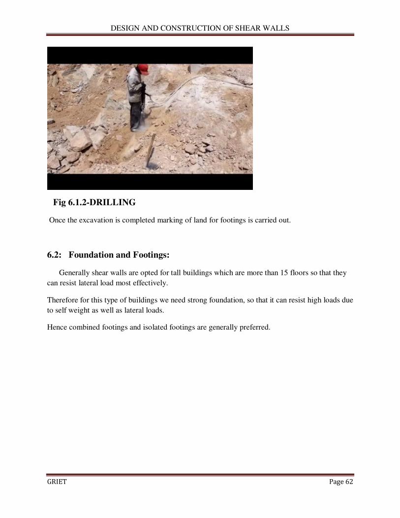
DESIGN AND CONSTRUCTION OF SHEAR WALLS
GRIET Page 62
Fig 6.1.2-DRILLING
Once the excavation is completed marking of land for footings is carried out.
6.2: Foundation and Footings:
Generally shear walls are opted for tall buildings which are more than 15 floors so that they
can resist lateral load most effectively.
Therefore for this type of buildings we need strong foundation, so that it can resist high loads due
to self weight as well as lateral loads.
Hence combined footings and isolated footings are generally preferred.
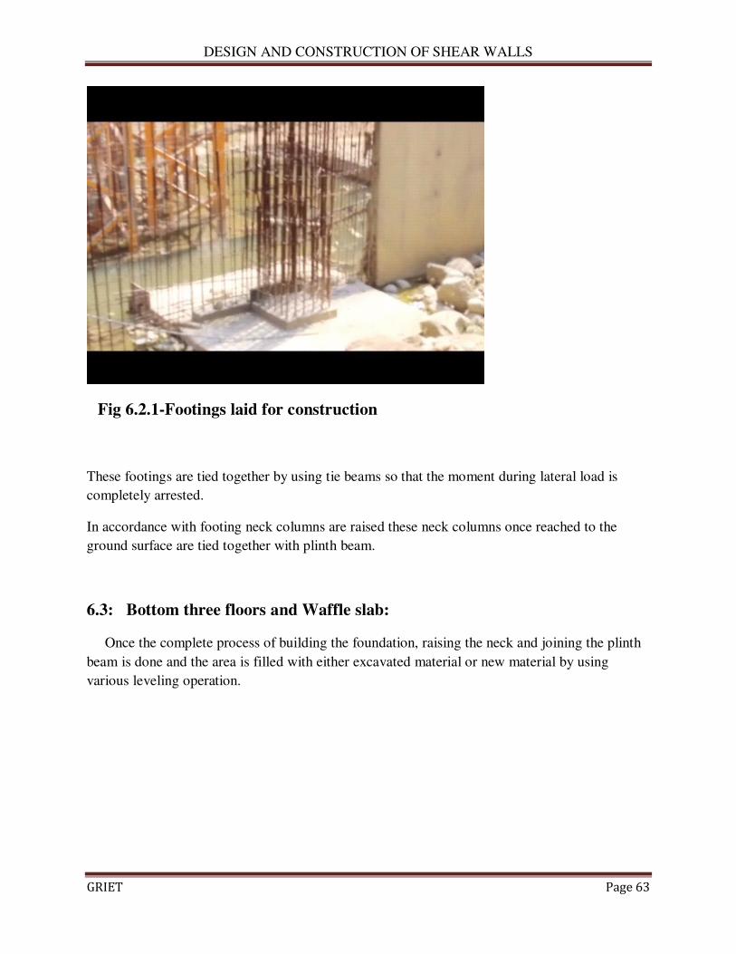
DESIGN AND CONSTRUCTION OF SHEAR WALLS
GRIET Page 63
Fig 6.2.1-Footings laid for construction
These footings are tied together by using tie beams so that the moment during lateral load is
completely arrested.
In accordance with footing neck columns are raised these neck columns once reached to the
ground surface are tied together with plinth beam.
6.3: Bottom three floors and Waffle slab:
Once the complete process of building the foundation, raising the neck and joining the plinth
beam is done and the area is filled with either excavated material or new material by using
various leveling operation.
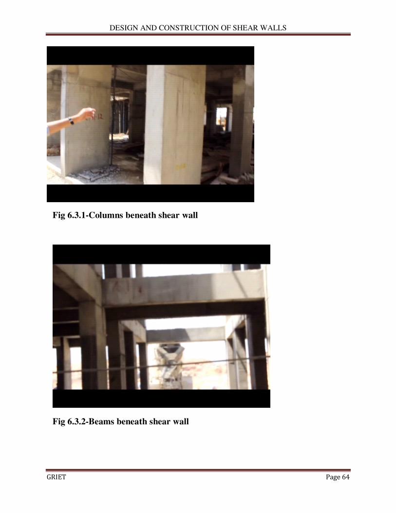
DESIGN AND CONSTRUCTION OF SHEAR WALLS
GRIET Page 64
Fig 6.3.1-Columns beneath shear wall
Fig 6.3.2-Beams beneath shear wall
DESIGN AND CONSTRUCTION OF SHEAR WALLS
GRIET Page 65
Now if the building requires parking, the bottom two to three floors are built with heavy beams
and columns of dimensions (0.9 x 0.3) m and (0.45 x 0.3) m.
Waffle slab:
The slab here should be of high load bearing as it needs to bare the vehicles load as well as the
top floor loads.
Hence for this situation waffle slab is most preferred.
Fig 6.3.3-Waffle slab layout
Waffle slab is a kind of slab which is of thickness 40 – 45 cm. But mostly empty with spacing as
of waffles.
The placing of the waffles is quite peculiar.
A form is placed and on above the waffles are arranged, once the arrangement is done,
reinforcement is arranged in such a way that it forms a chess board and the squares are hollow
and the area with lines act as beams.
DESIGN AND CONSTRUCTION OF SHEAR WALLS
GRIET Page 66
Fig 6.3.4-Formwork for waffle slab
The waffle slab after curing looks like a normal slab from top but from the lower or bottom side
it chess board with hollow spacings.
Fig 6.3.5- Cured upper portion of waffle slab
DESIGN AND CONSTRUCTION OF SHEAR WALLS
GRIET Page 67
Fig 6.3.6-Lower view of waffle slab
Once the parking and waffle slab is completely laid then it comes the part of shear walls.
6.4: Shear Wall Construction:
Shear Walls:
Shear walls are generally casted monolithically, in this type of construction the beams and
columns are placed inside the walls so that you can never find beams inside any floor in this type
of construction.
Schedule of reinforcements:
DESIGN AND CONSTRUCTION OF SHEAR WALLS
GRIET Page 68
After the horizontal reinforcement is placed in accordance with the design, vertical
reinforcement is placed.
Fig 6.4.1-Horizontal reinforcement of shear wall
As per the design details the reinforcement of size 10mm spacing 30mm is placed in the middle
of the wall of length 0.8 = 0.8 x 25 = 200 m and the edge reinforcement of 20 mm P 20 bars are
placed in the remaining 0.2 space.
The horizontal bars on the vertical reinforcement are placed of diameter 10 mm spacing 300 mm
distance.
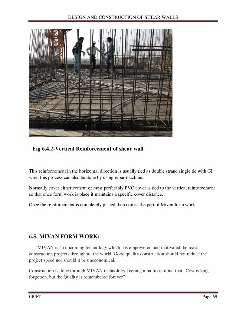
DESIGN AND CONSTRUCTION OF SHEAR WALLS
GRIET Page 69
Fig 6.4.2-Vertical Reinforcement of shear wall
This reinforcement in the horizontal direction is usually tied as double strand single tie with GI
wire, this process can also be done by using rebar machine.
Normally cover either cement or most preferably PVC cover is tied to the vertical reinforcement
so that once form work is place it maintains a specific cover distance.
Once the reinforcement is completely placed then comes the part of Mivan form work.
6.5: MIVAN FORM WORK:
MIVAN is an upcoming technology which has empowered and motivated the mass
construction projects throughout the world. Good quality construction should not reduce the
project speed nor should it be uneconomical.
Construction is done through MIVAN technology keeping a motto in mind that “Cost is long
forgotten, but the Quality is remembered forever”
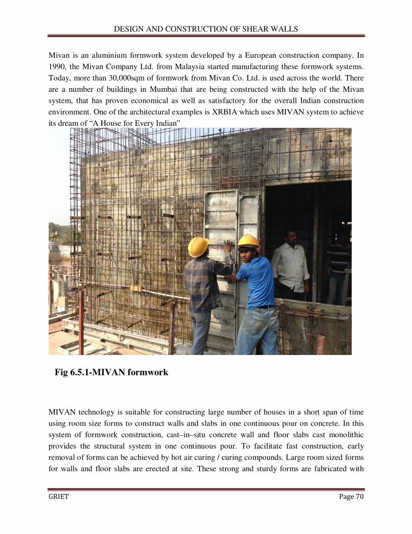
DESIGN AND CONSTRUCTION OF SHEAR WALLS
GRIET Page 70
Mivan is an aluminium formwork system developed by a European construction company. In
1990, the Mivan Company Ltd. from Malaysia started manufacturing these formwork systems.
Today, more than 30,000sqm of formwork from Mivan Co. Ltd. is used across the world. There
are a number of buildings in Mumbai that are being constructed with the help of the Mivan
system, that has proven economical as well as satisfactory for the overall Indian construction
environment. One of the architectural examples is XRBIA which uses MIVAN system to achieve
its dream of “A House for Every Indian”
Fig 6.5.1-MIVAN formwork
MIVAN technology is suitable for constructing large number of houses in a short span of time
using room size forms to construct walls and slabs in one continuous pour on concrete. In this
system of formwork construction, cast–in–situ concrete wall and floor slabs cast monolithic
provides the structural system in one continuous pour. To facilitate fast construction, early
removal of forms can be achieved by hot air curing / curing compounds. Large room sized forms
for walls and floor slabs are erected at site. These strong and sturdy forms are fabricated with
DESIGN AND CONSTRUCTION OF SHEAR WALLS
GRIET Page 71
accuracy and are easy to handle. The concrete is produced in RMC batching plants under strict
quality control and convey it to site with transit mixers.
The frames for windows, doors and ducts for services are placed in the form before concreting.
Staircase flights, panels, chajjas and jails etc. and other pre-fabricated items are also integrated
into the structure. This proves to be a major advantage as compared to other modern construction
techniques. High quality Mivan Formwork panels ensure consistency of dimensions. On the
removal of the formwork mould a high quality concrete finish is produced to accurate tolerances
and verticality. The high tolerance of the finish means that, no further plastering is required.
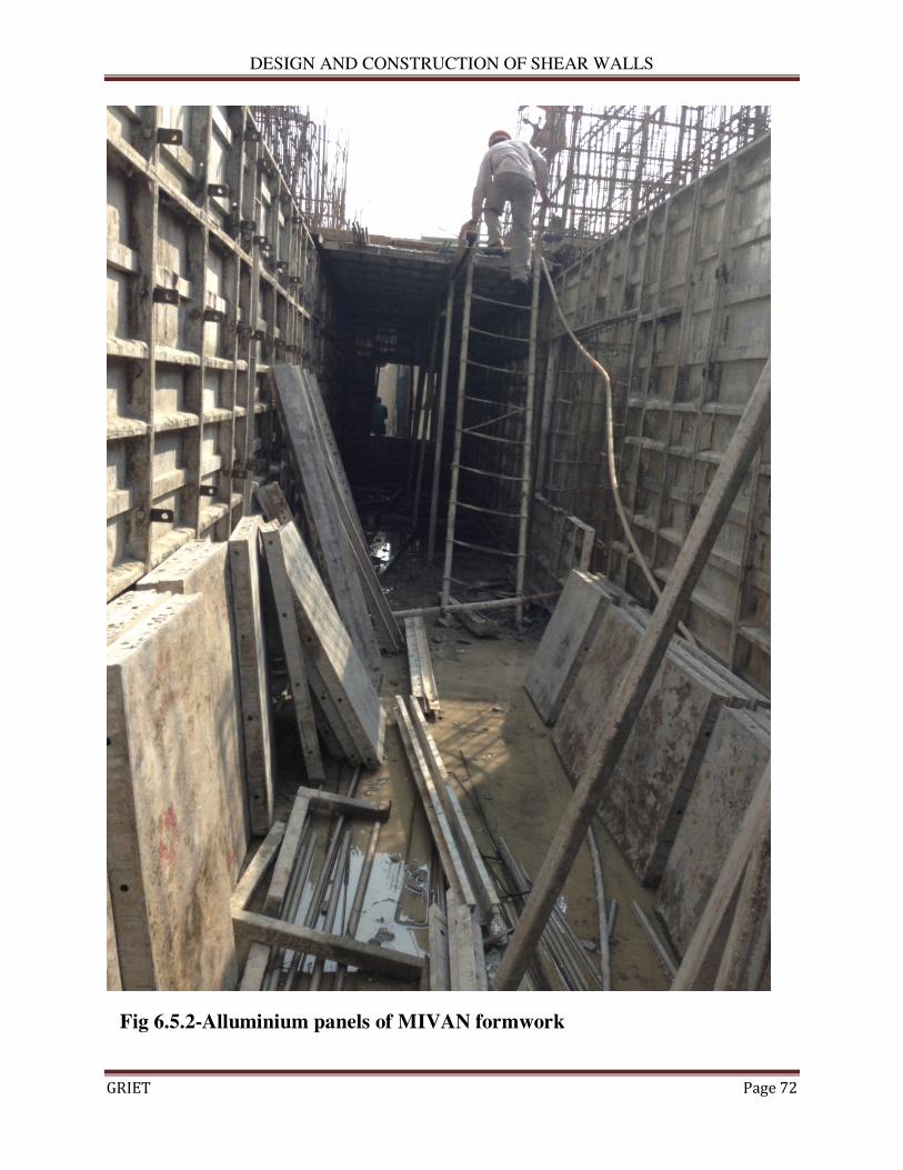
DESIGN AND CONSTRUCTION OF SHEAR WALLS
GRIET Page 72
Fig 6.5.2-Alluminium panels of MIVAN formwork
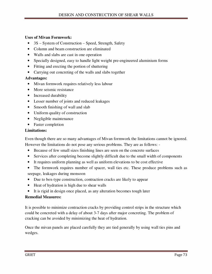
DESIGN AND CONSTRUCTION OF SHEAR WALLS
GRIET Page 73
Uses of Mivan Formwork:
• 3S – System of Construction – Speed, Strength, Safety
• Column and beam construction are eliminated
• Walls and slabs are cast in one operation
• Specially designed, easy to handle light weight pre-engineered aluminium forms
• Fitting and erecting the portion of shuttering
• Carrying out concreting of the walls and slabs together
Advantages:
• Mivan formwork requires relatively less labour
• More seismic resistance
• Increased durability
• Lesser number of joints and reduced leakages
• Smooth finishing of wall and slab
• Uniform quality of construction
• Negligible maintenance
• Faster completion
Limitations:
Even though there are so many advantages of Mivan formwork the limitations cannot be ignored.
However the limitations do not pose any serious problems. They are as follows: -
• Because of few small sizes finishing lines are seen on the concrete surfaces
• Services after completing become slightly difficult due to the small width of components
• It requires uniform planning as well as uniform elevations to be cost effective
• The formwork requires number of spacer, wall ties etc. These produce problems such as
seepage, leakages during monsoon
• Due to box-type construction, contraction cracks are likely to appear
• Heat of hydration is high due to shear walls
• It is rigid in design once placed, as any alteration becomes tough later
Remedial Measures:
It is possible to minimize contraction cracks by providing control strips in the structure which
could be concreted with a delay of about 3-7 days after major concreting. The problem of
cracking can be avoided by minimizing the heat of hydration.
Once the mivan panels are placed carefully they are tied generally by using wall ties pins and
wedges.
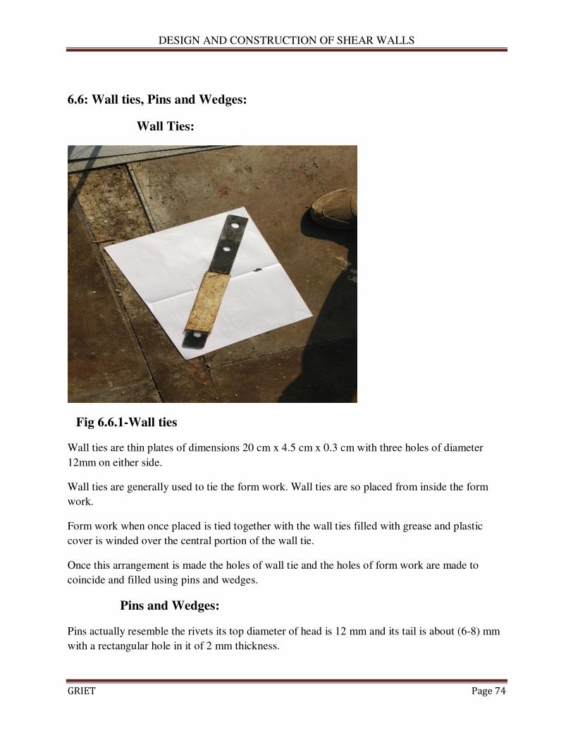
DESIGN AND CONSTRUCTION OF SHEAR WALLS
GRIET Page 74
6.6: Wall ties, Pins and Wedges:
Wall Ties:
Fig 6.6.1-Wall ties
Wall ties are thin plates of dimensions 20 cm x 4.5 cm x 0.3 cm with three holes of diameter
12mm on either side.
Wall ties are generally used to tie the form work. Wall ties are so placed from inside the form
work.
Form work when once placed is tied together with the wall ties filled with grease and plastic
cover is winded over the central portion of the wall tie.
Once this arrangement is made the holes of wall tie and the holes of form work are made to
coincide and filled using pins and wedges.
Pins and Wedges:
Pins actually resemble the rivets its top diameter of head is 12 mm and its tail is about (6-8) mm
with a rectangular hole in it of 2 mm thickness.
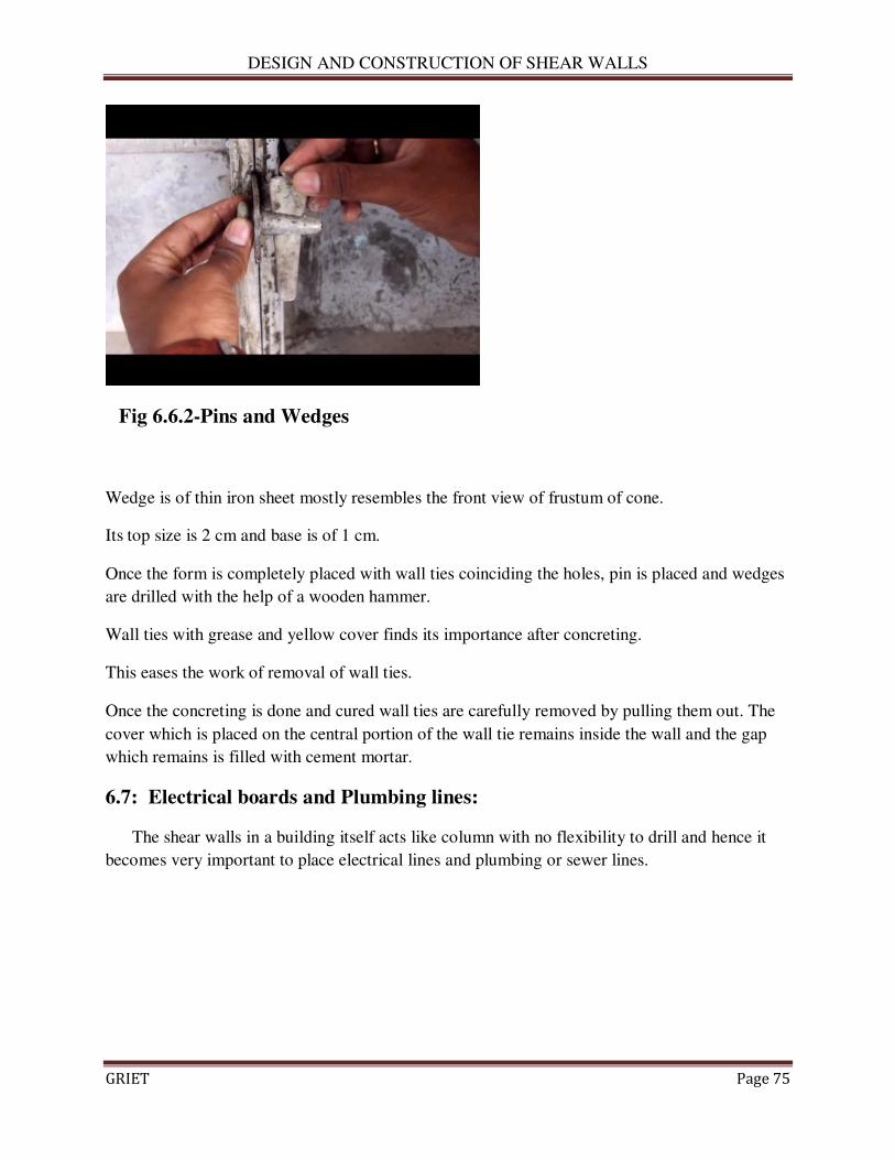
DESIGN AND CONSTRUCTION OF SHEAR WALLS
GRIET Page 75
Fig 6.6.2-Pins and Wedges
Wedge is of thin iron sheet mostly resembles the front view of frustum of cone.
Its top size is 2 cm and base is of 1 cm.
Once the form is completely placed with wall ties coinciding the holes, pin is placed and wedges
are drilled with the help of a wooden hammer.
Wall ties with grease and yellow cover finds its importance after concreting.
This eases the work of removal of wall ties.
Once the concreting is done and cured wall ties are carefully removed by pulling them out. The
cover which is placed on the central portion of the wall tie remains inside the wall and the gap
which remains is filled with cement mortar.
6.7: Electrical boards and Plumbing lines:
The shear walls in a building itself acts like column with no flexibility to drill and hence it
becomes very important to place electrical lines and plumbing or sewer lines.
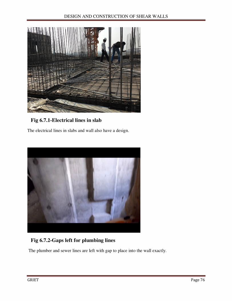
DESIGN AND CONSTRUCTION OF SHEAR WALLS
GRIET Page 76
Fig 6.7.1-Electrical lines in slab
The electrical lines in slabs and wall also have a design.
Fig 6.7.2-Gaps left for plumbing lines
The plumber and sewer lines are left with gap to place into the wall exactly.
DESIGN AND CONSTRUCTION OF SHEAR WALLS
GRIET Page 77
6.8: Concreting:
Once the complete arrangement of the form work i.e., wall ties, pins and wedges with
electrical lines are placed completely up to an accuracy of 1 mm, precision is done so that no
concrete will leak out of the form work.
The cement generally used in this is of grade of concrete is.
The size of aggregate should be 10mm or 12mm. So that it moves easily inside the wall.
Sand here used may be either robust sand or sea sand.
Admixtures generally used are of self compacting nature.
Reobuild and Gilinium are two admixtures which are used most effectively in the shear walls
construction.
These admixtures are generally mixed using a design mix in a transit mixer. Once the mixing is
done accurately for specified time, this mixture of concrete is pumped using pipes.
Once the form is arranged accurately concrete pouring is done using the hydraulic pumps.
As the concrete used in this type is of self compacting nature, there is no need for additional
compaction, but still pin vibrators are generally used to place in the wall and vibrate the concrete.
After the wall form is completely filled with concrete with proper compaction it is left for one
complete day to set in its position.
6.9: Curing:
After one day of curing of the wall, removal of form is done.
Removal of form is done very carefully.
DESIGN AND CONSTRUCTION OF SHEAR WALLS
GRIET Page 78
Fig 6.9.1-Shear wall after removal of formwork
Firstly the wedge is taken out by using a hammer and then pin is also removed.
Now started from top and one side form is carefully removed.
The form removed is cleaned immediately, to remove the concrete on it, so that it can be reused
effectively.
Once the form is completely removed a smooth finish of wall is obtained which does not require
any plastering.
The wall which is now finished with the removal of form is cured with regular water i.e water
which we use for drinking purpose.
Curing of walls is done for 3 – 7 days continuously and for better curing and to reduce heat of
hydration a white coating with lime powder is also preferred.
Curing can also be done by covering walls with plastic covers and watering them so that it
reduces the heat of hydration.
6.10: Holes in the slab:
There are rectangular holes in the slab left out to carry form work from bottom storey to top.
DESIGN AND CONSTRUCTION OF SHEAR WALLS
GRIET Page 79
As it becomes difficult to take form work through staircase for constructing the next floor, these
holes are drilled in the slab of size a little more than the standard form work.
Fig 6.10.1-Holes drilled in the slab
Hence these holes play a key hole in transfer of mivan form work.
6.11: Electrical and Plumbing lines after concreting:
After the walls are completely built they are checked for electrical and plumbing
connections.
As electrical lines are pre-established with design pattern in the slab as well in the wall only
thing needed is to arrange them with proper connection.
DESIGN AND CONSTRUCTION OF SHEAR WALLS
GRIET Page 80
Fig 6.11.1-Electrical spaces left in wall
When it comes to the server lines holes or empty gaps are left over. And in these empty spaces
the sewer pipes are placed exactly to match the empty spaces.
Fig 6.11.2-Gaps left for sewer pipes
In this way electrical and plumbing lines are placed.

DESIGN AND CONSTRUCTION OF SHEAR WALLS
GRIET Page 81
6.12: Painting and Finishing Works:
As the wall which is obtained is perfectly plain with exact finishes there is no need for and
plastering work.
Fig 6.12.1-Painting and finishing works
It is said that finishing on shear wall is so perfect that plumb line drawn from the top storey
meets the bottom storey exactly without any deflection or deviation.
Generally for shear wall two coats of white wash and paint colour of your choice on it is enough.
Special architectural features on the shear wall building like fall ceiling can also be done.
Hence the construction of shear wall is completed which are resistant to lateral loads, quick in
construction, aesthetic in view, these walls are generally built for tall structures hence they give
lots of solace from pollution and noise as well.
DESIGN AND CONSTRUCTION OF SHEAR WALLS
GRIET Page 82
Chapter 7
Scope for future work
Shear walls are considered to be a gift to the future construction industry. Scope of shear
walls in construction field is immense. It’s since their arrival in market there topic was always a
topic of interest. Shear walls are the structures usually build to balance lateral loads acting on the
structure. Where the lateral loads are most predominantly wind and earth quake loads. And
predominantly earthquake loads are more intense in their effect on the building structures.
Earthquakes are becoming more intense due to the key reason that is ground water
depleashement . Hence in order to overcome the diverse effects of earthquake its always best to
save ourselves from future disasters.
Shear walls are quick in construction, as the walls doesn’t need any special brick
arrangement or plastering they are very quick in their construction. It just requires an effective
form work and very few skilled labour. It was estimated that a 20 floors building can be built
within six months which is most astonishing.
Not only for the quickness in its work and resistance to earthquakes, shear walls are also
build for defense purpose. Presently The Hindustan Prefab Limited (HPL) is executing various
relocatable prefab structures for paramilitary forces especially for the CRPF in Karnataka, Uttar
Pradesh, Chhattisgarh and Bihar among others. We are using “Shear Wall” technology with
thermal curing –a fast track technology– for KMDA for construction of houses in Kolkata,
chairman and managing director HPL JaiveerSrivastava said.
“In structural engineering, a shear wall is a wall composed of braced panels to counter the effects
of lateral load like wind and seismic acting on a structure. Under several building codes
including the International Building Code and Uniform Building Code all exterior wall lines in
wood or steel frame construction are braced. Plywood is the conventional material used in the
construction of shear walls, but with advances in technology and modern building methods, there
are other prefabricated options which have made it possible to inject shear assemblies into
narrow walls that fall at either side of an opening in a shear wall. Sheet steel and steel-backed
shear panels in the place of structural plywood in shear walls have proved to be far stronger in
seismic resistance.”
DESIGN AND CONSTRUCTION OF SHEAR WALLS
GRIET Page 83
Chapter 8
Conclusion about shear walls
As per our design by hand in chapter 4 the corner reinforcement of the shear wall of 25 meters is
to be provided with 20 mm bars of 20 in numbers, and the middle area is provided with 10 mm
bars with 300mm spacing in vertical direction and 450 mm spacing in horizontal direction for
300 mm wall. The values in the computer design also matched the theoretical design. It is
estimated that whenever an opening is expected the bar diameter is increased and lateral ties are
provided inside the wall to replicate lintel beam in the wall for extra stability.
Advantages of Steel Plate Shear Wall to Resist Lateral Loads:
1. The system, designed and detailed properly is very ductile and has relatively large energy
dissipation capability. As a result, steel shear walls can be very efficient and economical lateral
load resisting systems.
2. The steel shear wall system has relatively high initial stiffness, thus very effective in limiting
the drift.
3. Compared to reinforced concrete shear walls, the steel shear wall is much lighter which can
result in less weight to be carried by the columns and foundations as well as less seismic load
due to reduced mass of the structure.
4. By using shop-welded, field-bolted steel shear walls, one can speed-up the erection process
and reduce the cost of construction, field inspection and quality control resulting in making these
systems even more efficient.
5. Due to relatively small thickness of steel plate shear walls compared to reinforced concrete
shear walls, from architectural point of view, steel plate shear walls occupy much less space than
the equivalent reinforced concrete shear walls. In high-rises, if reinforced concrete shear walls
are used, the walls in lower floors become very thick and occupy large area of the floor plan.
6. Compared to reinforced concrete shear walls, steel plate shear walls can be much easier and
faster to construct when they are used in seismic retrofit of existing building.
DESIGN AND CONSTRUCTION OF SHEAR WALLS
GRIET Page 84
7. Steel plate shear wall systems that can be constructed with shop welded-field bolted elements
can make the steel plate shear walls more efficient than the traditional systems. These systems
can also be very practical and efficient for cold regions where concrete construction may not be
economical under very low temperatures.
ARCHITECTURAL ASPECTS OF SHEAR WALLS
Most RC buildings with shear walls also have columns; these columns primarily carry gravity
loads (i.e., those due to self-weight and contents of building). Shear walls provide large strength
and stiffness to buildings in the direction of their orientation, which significantly reduces lateral
sway of the building and thereby reduces damage to structure and its contents.
Since shear walls carry large horizontal earthquake forces, the overturning effects on them are
large. Thus, design of their foundations requires special attention. Shear walls should be
provided along preferably both length and width. However, if they are provided along only one
direction, a proper grid of beams and columns in the vertical plane (called a moment-resistant
frame) must be provided along the other direction to resist strong earthquake effects.
Door or window openings can be provided in shear walls, but their size must be small to ensure
least interruption to force flow through walls. Moreover, openings should be symmetrically
located. Special design checks are required to ensure that the net cross-sectional area of a wall at
an opening is sufficient to carry the horizontal earthquake force.
Shear walls in buildings must be symmetrically located in plan to reduce ill effects of twist in
buildings. They could be placed symmetrically along one or both directions in plan. Shear walls
are more effective when located along exterior perimeter of the building – such a layout
increases resistance of the building to twisting.
ADVANTAGES OF SHEAR WALLS IN BUILDINGS
Properly designed and detailed buildings with shear walls have shown very good performance in
past earthquakes. Shear walls in high seismic regions require special detailing. However, in past
earthquakes, even buildings with sufficient amount of walls that were not specially detailed for
seismic performance (but had enough well-distributed reinforcement) were saved from collapse.
Shear wall buildings are a popular choice in many earthquake prone countries, like Chile, New
Zealand and USA.
Shear walls are easy to construct, because reinforcement detailing of walls is relatively straight
DESIGN AND CONSTRUCTION OF SHEAR WALLS
GRIET Page 85
forward and therefore easily implemented at site.
Shear walls are efficient, both interims of construction cost and effectiveness in minimizing
earthquake damage in structural and nonstructural elements like glass windows and building
contents.
CONCLUSION
Thus shear walls are one of the most effective building elements in resisting lateral forces during
earthquake. By constructing shear walls damages due to effect of lateral forces due to earthquake
and high winds can be minimized. Shear walls construction will provide larger stiffness to the
buildings there by reducing the damage to structure and its contents.
Not only its strength , in order to accommodate huge number of population in a small area tall
structures with shear walls are considered to be most useful.
Hence for a developing nation like India shear wall construction is considered to be a back bone
for construction industry.
DESIGN AND CONSTRUCTION OF SHEAR WALLS
GRIET Page 86
References
U.H. Varnayi in his second edition of “Design of structures”
S.K. Duggal in his “ Earth quake resistant design of structures” Page no:301 ,8.12 about Shear
walls.
S.K. Duggal in his “ Earth quake resistant design of structures “ pg.no:305 on flexural strength
8.14.1 case:1, case:2.
S.K. Duggal in his “ Earth quake resistant design of structures” 8.16 Design of Shear walls
which is also given in Is code 13920:1993
Mr A.P. Jadhav Associate Professor Rajarambapu Institute of technology rajaramnagar, Islampur
has given a detailed report on the form work used for the construction of shear walls.
A report on effects of openings in shear walls on seismic response of structure by
sharminrizachowdhary, department of civil engineering dhake-1208, Bangladesh mostly focused
on the design of shear walls with openings on seismic response using E- Tabs
I.S 456:2000
As per clause 32, design for wall describes, design of horizontal shear in clause 32.4 given
details of how shear wall have to be constructed.
I.S:1893 Criteria of Earth Quake resistant Buildings Part (3) page 23, clause 4.2 gives the
estimation of earth quake loads.
In IS: 13920:1993 it gives the ductile detailing of shear wall as per clause 9, where 9.1 gives
general requirements.
9.2 shear strength
9.3 gives flexural strength
9.6 gives openings in shear walls.
Ductile detailing, as per the code IS: 13920:1993 is considered very important as the ductile
detailing gives the amount of reinforcement required and the alignment of bars