multnomah county design and construction manual
TRANSCRIPT

TABLE OF CONTENTS DESIGN AND CONSTRUCTION MANUAL
Introduction Part I - Design Manual Section 1 - Traffic Planning 1.1 Operational Standards
1.1.1 Roadway Functional Classification 1.1.2 Roadway Design Treatments 1.1.3 Traffic Study Requirements 1.1.4 Design Year Traffic Projections 1.1.5 Design Level of Service
1.2 Access Management Standards 1.2.1 Minimum Traffic Signal Spacing
1.2.2 Non-Traversable Median Openings 1.2.3 Public Intersection Spacing 1.2.4 Private Access Driveway Requirements
1.2.5 Pedestrian Crosswalk Spacing
Section 2 - Geometric Design 2.1 Design Requirements
2.1.1 Standards to be used as a basis for design of improvement 2.1.2 Drawing Standards 2.1.3 Design Standard Exception Process
2.2 Roadway Cross Sections 2.2.1 Typical Sections for Functional/Design Classification
2.2.2 Widths for Roadway Cross Section Elements 2.2.3 Variance from Preferred Standards
2.2.4 Criteria for Placement of Non-Traversable Median vs. Center Left Turn Lane 2.3 Intersection Design Standards
2.3.1 Curb Returns 2.3.2 Sidewalk Ramps
2.3.3 Left-Turn Lane Channelization 2.3.4 Right-Turn Lane Channelization
2.3.5 Through Lane Tapers 2.3.6 Minimum Intersection Angle 2.3.7 Corner Intersection Sight Distance 2.3.8 U-Turn Design Elements 2.3.9 Curb Extensions/Pedestrian Refuge Islands
2.4 Engineering Design Standards

2.4.1 Stopping Sight Distance 2.4.2 Horizontal Alignment 2.4.3 Vertical Alignment 2.4.4 Cross-Slope 2.4.5 Curbs and Sidewalks
Section 3 - Traffic Engineering Design 3.1 Traffic Signal Design
3.1.1 Signal Warrants/Phasing 3.1.2 Design Format
3.2 Traffic Signing 3.2.1 Design Format 3.2.2 Street Name Signs 3.2.3 Sign Materials
3.3 Pavement Marking 3.3.1 Design Format 3.3.2 Crosswalk Markings 3.3.3 Pavement Marking Materials
3.4 Construction Traffic Control 3.4.1 Design Format 3.4.2 Traffic Control Plans Minimum Requirements
3.5 Speed Bumps 3.5.1 Introduction 3.5.2 Standardization of Application 3.5.3 Types of Speed Bumps 3.5.4 Generalized Standards and Guidelines 3.5.5 Construction and Maintenance of Speed Bumps 3.5.6 4.25 Meter Speed Bump 3.5.7 6.70 Meter Speed Bump
Section 4 - Pavement Design 4.1 Standard Sections 4.2 Flexible Pavement Design
4.2.1 AASHTO Design Method Parameters 4.2.2 Design Coefficient Values 4.2.3 AASHTO Design Method
4.3 Rigid Pavement Design

Section 5 - Drainage 5.1 Introduction 5.1.1 Impacts 5.1.2 Water Quantity Design Standards
5.1.3 Water Quality Design Standards 5.1.4 Drainage Easements
5.2 Hydrology Calculations 5.2.1 Rational Method 5.2.2 SCS Method 5.2.3 Santa Barbara Unit Hydrograph Method
5.3 Drainage Facility Components 5.4 Drainage Appendix
5.4.1 Worksheet 1 Time of Concentration Rational Method 5.4.2 Worksheet 2 Time of Concentration SCS TR55 Method 5.4.3 Worksheet 3 Time of Concentration SBUH Method 5.4.4 Worksheet 4 Circular Culvert Analysis Worksheet 5.4.5 Worksheet 5 Box Culvert Analysis Worksheet
Section 6 - Street Lighting
6.1 Placement Criteria 6.2 Design Format Section 7 - Transit 7.1 Bus Stop Spacing and Placement
7.1.1 Bus Stop Spacing 7.1.2 Bus Stop Placement
7.2 Bus Stop Facilities 7.2.1 On-Street Facilities 7.2.2 Off-Street Facilities
7.3 Transit Provisions for Proposed Developments Section 8 - Landscape Treatments 8.0 Landscape Treatments 8.1 Median Landscaping 8.2 Pedestrian Space Landscaping 8.3 Swale 8.4 Maintenance

Section 9 - Survey 9.1 Monumentation – Road Repair and Maintenance 9.2 Monumentation – Road Construction Part II - Construction Manual Section 1 - Materials Standards 1.1 Embankment & Subgrade 1.2 Aggregate Base 1.3 Asphalt Pavement 1.4 Concrete 1.5 Pipe Bedding & Backfill APPENDICES: Appendix A - Description of Level of Service Concept

Multnomah County Design Standards Part 1 – Design Manual
1
INTRODUCTION "This Manual is authorized and developed pursuant to Multnomah County Code Chapter 29, Section 29.571, and Multnomah County Rules For Street Standards, Rule 30. 100." OVERALL ORGANIZATION OF MANUAL This manual includes the engineering standards and specifications to be followed in the design and construction of new and improved roadways in Multnomah County. The document supplements the Multnomah County Street Standards - Rules document, which includes all administrative procedures to be followed with respect to roadway design and construction, including plan preparation format, permitting, and variances. This Design and Construction Manual is a comprehensive reference to all relevant roadway design standards in Multnomah County. The standards and specifications are to be applied on all roadways either currently under County jurisdiction, or for which the County will assume maintenance responsibility upon the completion of construction. This manual is divided into two other parts: Part I: Design Manual, includes all roadway design-related standards, with sections covering traffic planning, geometric design, drainage, landscaping/urban design, and traffic engineering design. Part II: Construction Manual, includes all procedures and specifications related to roadway construction. Sections covering traffic, roadway, drainage, and landscaping/urban design construction are presented. Appendix A: Level of Service, describes the concept of level of service criteria and how it used to evaluate the performance of transportation facilities including unsignalized and signalized intersections, rural and suburban highways, urban and suburban arterials, etc.

Multnomah County Design Standards Part 1 – Design Manual
2
DESIGN PROVISIONS The design components of the manual are presented in different sections covering traffic, geometric design, drainage, landscaping/urban design and traffic engineering design elements. The following highlights the content of each chapter within the different sections. Section 1 - Traffic Planning Chapter 1: Traffic operations specifies standards for the functional classification and design treatments for the Multnomah County roadway system, and identifies traffic level of service thresholds to which new or improved roadways should be designed, as well as the appropriate analysis procedures to identify the required sizing and operations of roadways. Also, guidelines for performing site-impact traffic studies and public sector traffic studies are given. Chapter 2: Access Management provides standards for the location and design of public and private access along a roadway. This includes standards for median provision, raised median vs. two-way left turn lane development, public intersection spacing, private driveway spacing, signal spacing, pedestrian crosswalk spacing, and bus stop placement Section 2 - Geometric Design Chapter 1: Roadway Cross Sections, includes a set of typical cross sections for roadways of different functional classification, based on right-of-way availability, the degree of integration of pedestrian, bicycle, and transit modes, and relative placement of different facilities within the right-of-way. Minimum widths for travel lanes, turn lanes, bike lanes, and sidewalks are also presented. Chapter 2: Intersection Design, includes all standards related to intersection design, including curb returns, curb ramps, island channelization, minimum angle, and bus stop amenities. Chapter 3: Engineering Design, specifies the standards for roadway geometric design. Included are design standards for stopping sight distance, horizontal and vertical alignment, cross slope, and curbs and sidewalks. Section 3 - Traffic Engineering Design Chapter 1: Traffic Signal Design, identifies the standards for signal warrants and signal phasing options, and the standards related to the layout of traffic signal installations, including mast arm vs. span wire installations, the format and content of signal plans. Chapter 2: Traffic Signing, specifies the standards for the format and content of signing plans, the different types of street name signs, and the different types of sign materials. Chapter 3: Pavement Marking, specifies the standards for the format and application of pavement marking designs, and the different types and uses of pavement marking materials.

Multnomah County Design Standards Part 1 – Design Manual
3
Chapter 4: Construction Traffic Control, describes the standards for preparing construction traffic control plans during roadway improvement or construction projects. Chapter 5: Speed Bump, describes standards and guidelines for application of speed bumps in the public ROW. Section 4 - Pavement Design Chapter 1: Standard Sections, describes standard sections to be used when full design calculations are not necessary. Chapter 2: Flexable Pavement Design, gives standards for determining thickness and type of roadway pavement. Chapter 3: Rigid Pavement Design: specifies AASHTO Guide to be used for rigid pavement design. Section 5 - Drainage Chapter 1: Introduction, specifies the standard minimum requirements and methodology used to determine various criteria necessary for design and construction of roadway drainage systsems. Chapter 2: Hydrology Calculations, identifies the standards to be applied in estimating stormwater runoff for use in designing roadway drainage facilities. Chapter 3: Drainage Facility Components, identifies design standards for several different types of drainage facilities, including storm sewers, inlets, and detention ponds. Section 6 - Street Lighting Chapter 1: Placement Criteria, gives standards for street light spacing and average maintained lighting levels. Chapter 2: Design Format, includes standards for conduit, cable and wire, poles, lighting fixtures, and lighting controls design. Section 7 - Transit Chapter 1: Bus Stop Spacing and Placement, includes standards for the optimum spacing of bus stops along a transit route. Also, an overview of the Tri-Met guidelines is given for optimum bus stop location, in terms of the near-side of an intersection, far-side of an intersection, or mid-block. Chapter 2: Bus Stop Facilities, presents standards for typical on-street and off-street bus stop facilities. On-street facilities included are bus pullouts and curb extensions. Off-street facilities included are landing pads, bus stop benches, and bus stop shelters. Chapter 3: Transit Provisions for Proposed Developments, includes standards in determining whether a proposed development is required to provide transit facilities.

Multnomah County Design Standards Part 1 – Design Manual
4
Section 8 - Landscape/Urban Design This section identifies placement standards associated with integration of landscaping and urban design elements into new and improved roadway projects. This includes criteria for placement of street trees, irrigation systems, and street furniture. The section also identifies standards to be applied for integration of low-level landscaping, street trees, irrigation systems, and street furniture, into roadway projects. Section 9 – Survey Section 10 – Erosion Control (Future Chapter) The erosion control measures shall be designed to perform as effectively as those prescribed in the “Erosion Control Plans Technical Guidance Handbook” and the “Surface Water Quality Facilities Technical Guidance Handbook.” Section 12 – Structures (Future Chapter) PART II – CONSTRUCTION The Standard Specifications are the Oregon Department of Transportation 1996 edition of the Standard Specification for Highway Construction,” and the 1998 Supplemental Standard Specifications.

PART I - DESIGN MANUAL

Multnomah County Design Standards Part I – Design Manual
1 - 1
SECTION 1 - TRAFFIC PLANNING
1.1 TRAFFIC OPERATIONS 1.1.1 Roadway Functional Classification The Multnomah County Comprehensive Framework Plan’s Policy 34: Trafficways and the Functional Classification of Trafficways Map, includes nine roadway functional classifications, four within the broad arterial classification (principal, major, minor, and rural), three within the collector classification (major, neighborhood, and rural), and two within the local street classification (urban and rural). A brief description of each classification is presented in this section. In addition, a range of design treatments that can be accommodated within each functional classification will be described in subsection 1.1.2 of this manual. For a more detailed description of each functional classification, see Policy 34: Trafficways and the Functional Classification of Trafficways Map. Arterials Arterial streets comprise the regional roadway network, and provide for travel between communities in the County, and between counties. Arterial streets accommodate the full array of travel modes including the regional bikeway system, fixed-route transit network, goods delivery and higher volume automobile traffic than collector streets. Principal Arterial Streets connect to freeways and highways that serve travelers without an origin or destination in the County. This interstate and interregional traffic, including trucks, is in addition to regional traffic traveling between cities and counties, and traffic generated by intensive and higher density land uses along the arterial corridor. The ability to move auto, truck, and regional bicycle traffic is preserved. Major Arterial Streets carry high volumes of traffic between cities in the County as part of the regional trafficway system. Priority may be given to transit- and pedestrian-oriented land uses by way of regional boulevard design treatments. Design and management of major arterial streets emphasizes preservation of the ability to move auto and transit traffic by limiting accesses while also accommodating regional bikeways and pedestrian movements. Minor Arterial Streets are the lowest order arterial facility in the urban regional street network. They typically carry less traffic volume than principal and major arterial streets, but have a high degree of connectivity between communities. Minor arterial streets provide major links in the regional road and bikeway networks; provide for truck mobility and transit corridors; and may serve as significant links in the local pedestrian system, especially where they are designed as community boulevards. Rural Arterial Roads are the primary means of access into the County’s large rural districts, and often connect between counties to accommodate through movements. Rural arterial roads connect to freeways or highways, and link rural collector and local roads to the urban area and other regions. Rural arterial roads carry greater traffic volumes than rural collector roads, including commuters and other home-based trips, natural resources involving trucks, and recreational trips involving autos, bicycles, and equestrians.

Multnomah County Design Standards Part I – Design Manual
1 - 2
Collectors Collector streets distribute traffic between local streets and the arterial street network. They are not intended to serve trips without an origin or destination inside the County. Collector streets provide for automobile, bicycle and pedestrian circulation, and basic transit service. Major Collector Streets serve several purposes including linking neighborhoods to the regional system of bicycle and automobile streets, and basic transit service. They typically provide direct access between residential and commercial developments, schools, and parks. Neighborhood Collector Streets provide access primarily to residential land uses and link neighborhoods to higher order roads. They generally have higher traffic volumes than local streets but through or non-local traffic is discouraged. Rural Collector Roads distribute automobile traffic over large areas and generally connect to urban streets or rural arterial roads. They may also provide for recreational trips by auto, bicycle, and equestrian. Local Streets Local streets provide access to abutting land uses and do not serve through traffic. Local streets may be further classified by adjacent land use, such as residential, commercial, and industrial. Their primary purpose is to serve local pedestrian, bicycle, and automobile trips in urban areas. In rural areas, local roads serve automobile and farm circulation, as well as local pedestrian, bicycle, and equestrian uses. 1.1.2 Roadway Design Treatments Metro’s Regional Transportation Policy’s “Regional Street Design Goals and Objectives,” provides design guidelines for streets in the region. The County’s roadway design treatments have incorporated Metro’s Street Design Guidelines. (For detailed description of each treatment, see Metro’s “Street Design Guidelines for 2040” and the Regional Street Design map in the current Regional Transportation Plan.) Boulevards
Boulevards serve the multi-modal travel needs of the region’s most intensely developed activity centers, including regional centers, station communities, town centers and some main streets. Boulevards are the continuation of the regional street network within more intensively developed activity centers. Boulevards are designed with special amenities that promote pedestrian, bicycle, and public transportation travel in the districts they serve. Boulevards are classified as regional and community scale designs. Regional boulevards are designated on specific major arterial roadways while community boulevards are designated on specific minor arterial roadways. Regional and community boulevards are located within the most intensely developed activity centers with development oriented to the street. These are primarily regional centers, town centers, station

Multnomah County Design Standards Part I – Design Manual
1 - 3
communities and some main streets. Regional boulevards consist of four or more vehicle lanes, balanced multi-modal function, and a broad right of way. Features highly desirable on regional boulevards include on-street parking, bicycle lanes, narrower travel lanes than throughways, more intensive land use oriented to the street, wide sidewalks, and landscaped medians. Community boulevards consist of four or fewer vehicle travel lanes, balanced multi-modal function, narrower right of way than a regional boulevard, landscaped medians, no on-street parking, narrower travel lanes than throughways, more intensive land use oriented to the street, and wide sidewalks. Streets Streets serve the multi-modal travel needs of corridors, inner and outer residential neighborhoods and some main streets. Streets typically are more vehicle-oriented and less pedestrian-oriented than boulevards, providing a multi-modal function with an emphasis on vehicle mobility. Streets are classified as regional and community designs. Regional streets are designated on specific major arterial roadways, while the community streets are designated on specific minor arterial roadways. Regional streets consist of four or more vehicle travel lanes, balanced multi-modal function, broad right of way, limited on-street parking, wider travel lanes than boulevards, land use set back from the street, sidewalks with pedestrian buffering from street, and a raised landscaped median or, usually a continuous two way left turn lane. Community streets consist of two to four travel lanes, balanced multi-modal function, narrower right of way than regional streets, on-street parking, narrower or fewer travel lanes than regional streets and residential neighborhood and corridor land use set back from the street. Community streets provide a higher level of local access and street connectivity than regional streets. Community streets have the greatest flexibility in cross sectional elements. Depending on the intensity of adjacent land use and site access needs, community streets can have three different median conditions; center two way left turn lane, narrow landscaped median, or no median.

Multnomah County Design Standards Part I – Design Manual
1 - 4
The relation of the design treatments to the functional classifications is shown in Table 1.1.1.
Table 1.1.1 Application of the Design Treatments to the Functional Classifications
Functional Classification Design
Treatment Major Arterial Minor Arterial
Street Type
Regional Street Community Street
Boulevard Type
Regional Boulevard
Community Boulevard
1.1.3 Traffic Study Requirements Site-Development Traffic Impact Study - A site-development traffic impact study may be required by the County with the proposed development’s land use application, depending on the type of proposed development, location of the site, and its perceived impact on the surrounding transportation system. A traffic impact study will generally be required for a proposed development under the following circumstances: The proposed development is expected to forecast more than 1,000 vehicle trips per weekday, or the proposed development’s location, proposed site plan, or trip generation characteristics could affect traffic safety, access management, street capacity, or other known traffic deficiencies in the vicinity of the site. A Professional Engineer competent in traffic engineering or a registered Traffic Engineer in the State of Oregon shall prepare the traffic impact study. The County may exercise the prerogative to require a pre-study memorandum of understanding to be agreed upon between the County and the developer to specify the scope of the study. Traffic impact studies involving street network planning shall follow design standards for street connectivity as described in section 1.2.3. The following elements of the traffic impact study should be included as a minimum: Purpose and Objectives of Study - Discussion of the purpose of the study, key traffic issues to be addressed, the characteristics of the surrounding transportation system, and development objectives related to the proposed site. Project Description - Discussion of existing land uses and proposed land uses, including a map showing the site plan. Description of whether the proposed land use is in compliance with the existing zoning of the site property. If not, the study is labeled as a “zone change.” Include discussion of proposed location of access driveways and estimated time line for ultimate build-out of site.

Multnomah County Design Standards Part I – Design Manual
1 - 5
Existing Conditions - Description of surrounding roadway facilities, including functional classification of roadways, nature and intensity of nearby pedestrian and bicycle facilities and activity, and current or planned transit routes. Level of service analysis of key study intersections and/or arterial corridors, with diagrams of intersection/ arterial lane configurations, and traffic control. The County Transportation Division will provide direction in determining the study area and intersections to be evaluated. In general, all study intersections which will be impacted by 10 or more site-generated trips during the weekday a.m. or p.m. peak hour should be analyzed. The standard level of service analysis methodology and criteria is documented in 1.1.5 & Appendix B of this manual. Background Conditions - Level of service analysis for background traffic conditions. “Background” traffic conditions constitute the future non-project-related traffic volumes and committed roadway configurations (diagrammed) during the future year the proposed development is expected to be fully constructed and operational. Background conditions would also include approved, but not yet completed off-site developments within the study area. If the proposed development is a “zone change” (see description under Project Description section), then an additional level of service analysis for a 20-year forecast background year may be required. See 1.1.4 for a description of the methodology to be used in formulating 20-year volume forecasts. Development Site-Generated Trip Characteristics - Evaluation of expected trip generation, trip distribution, trip assignment, and modal split. Trip generation analysis should follow trip generation rates given in the latest edition of the Trip Generation Manual, published by the Institute of Transportation Engineers (ITE), unless more appropriate local data is available. Trip distribution analysis shall be clearly documented. A roadnet diagram with percentage distributions and the resulting volumes should be provided. The trip distribution methodology can be based on trip patterns of similar nearby developments, existing intersection or corridor volumes, modeling results from a regional transportation planning model (from Metro or other local jurisdiction), and/or the anticipated market area of the proposed development. For a 20-year forecast condition, a sub-area comparison of trips from the proposed zoning change versus the modeled zone designation shall be performed. Total (Background plus Site-generated) Conditions - Level of service analysis of total traffic conditions with full build-out of the proposed development. Analysis should include proposed site-access driveways. Zone change studies may also be required to evaluate total traffic conditions for a 20-year forecast year. On-site Circulation - Evaluation of safety and efficiency of on-site circulation for all modes (vehicle, bicycle, pedestrian, etc.). Anticipated truck movements should be safely accommodated. Summary of Findings and Recommendations - Summarize key findings of study and recommendations necessary to mitigate traffic operations deficiencies under background or total traffic conditions. Include lane configuration and traffic control diagrams noting recommended modifications.

Multnomah County Design Standards Part I – Design Manual
1 - 6
Public Project Traffic Study - Prior to the design of a new roadway or reconstruction of an existing roadway financed using public funds, a traffic study shall be conducted to identify the functional layout of the roadway improvement. The traffic analysis may be incorporated into a project environmental study process or preliminary design study, or may be a stand-alone analysis. A public project traffic study typically would utilize traffic projections developed for the roadway to be designed from Metro’s regional “emme/2” transportation model or approved traffic impact studies. The model traffic projections would be desegregated into turning movements at major intersections, with the information used to identify the number of travel lanes and appropriate access control along the roadway, as well as intersection channelization and signalization requirements. 1.1.4 Design Year Traffic Projections New or improved arterial and collector roadways in Multnomah County shall be designed to provide added capacity to accommodate 20-year traffic projections, unless a shorter time frame is identified for design by the County Engineer. Traffic projections will be developed based on Metro’s regional “emme/2” model projections, adjusted as necessary to reflect the specific analysis year and the roadway or intersection being designed. The 20-year traffic projections will be translated into design hour volumes, by direction of travel. The design hour volume is typically the 30th highest hourly volume during the year, and in some cases can be accommodated by a weekday p.m. peak hour volume pattern (which is included in Metro's regional “emme/2” model). Under certain circumstances, the design hour volume might be reflective of weekend peak hour conditions. The development of roadway segment traffic projections shall include estimated truck and bus traffic, and preferably bike traffic. Where specific truck traffic projections have not been developed, estimates based on existing truck percentages on certain road segments can be used and adjusted as necessary. At intersections, model approach link volumes can be translated into future turning movement projections through application of an algorithm approved by the County Engineer, that adjusts approach volumes to reflect realistic turning movement patterns at the intersection. Traffic model turning movements at intersections typically require such adjustments. In cases where the design year is less than 20-years, factoring of the traffic based on an existing intersection turning movement count would be appropriate. The development of intersection traffic projections shall include estimated truck and bus, and preferably bike and pedestrian traffic. 1.1.5 Design Level of Service The roadway level of service (LOS) concept is applied in the U.S. as a qualitative assessment of the road user's perception of the quality of flow. LOS is represented by one of the letters "A" through "F," with "A" representing free flow operation and "F" stop and go operation. LOS reflects the quality of flow as measured by some scale of driver satisfaction. Measures of effectiveness such as average travel speed, volume to capacity ratio, average seconds of delay, and others. have been developed to approximate these qualitative representations quantitatively. Different measures of effectiveness are used for different types of roadways because the user's perception of quality of flow varies by road type.

Multnomah County Design Standards Part I – Design Manual
1 - 7
Appendix B discusses the level of service concept in greater detail related to rural/suburban highways, urban/suburban arterials, and signalized/unsignalized intersections. All new and improved arterial and major collector roadways in urban areas shall be designed to accommodate a level of service "D" or better during the design hour. In rural areas, such facilities shall be designed to accommodate level of service "C" or better during the design hour. On neighborhood collectors in urban areas, the design level of service shall also be "C" or better. In special circumstances, such as downtown central business districts or designated regional centers, level of service "E" might be acceptable for roadway design purposes, if approved by the County Engineer. Local streets intersecting arterials or collectors may be level of service ”F” during the peak hour if approved by the County Engineer. The required capacity (number of through lanes, intersection approach configuration) associated with a new or improved roadway project in Multnomah County will be identified using the procedures introduced in the latest edition of the Highway Capacity Manual, prepared by the Transportation Research Board. This document includes traffic operations analysis procedures for urban and suburban arterials, two-lane highways, multi-lane highways, and signalized and unsignalized intersections. At intersections, for sizing the number and configuration of lanes, the operations methodology will be applied, unless the planning methodology is approved by the County Engineer. At existing or new signal locations, the assumed signal cycle length and phasing shall be reviewed and approved by the County Transportation Division before any analysis proceeds. Where there is a series of existing or prospective traffic signals in a roadway corridor to be upgraded, a corridor level operations analysis will be applied to verify the number of travel lanes and signalized intersection approach configurations. The TRANSYT-7F model is the preferred model of choice, with alternate models (PASSERII-90, TRAF-NETSIM, etc.) being applied only with the approval of the County Engineer. Analysis periods shall be at a minimum the weekday p.m. peak hour, and could also include the weekday a.m. peak hour and/or weekend peak hour if directed by the County Engineer.

Multnomah County Design Standards Part I – Design Manual
1 - 8
1.2 ACCESS MANAGEMENT Access management is needed to ensure both the safety and efficiency of traffic flow for vehicles traveling on the roadway system. Managing the access of roadways benefits the overall roadway system by increasing safety, increasing capacity, and reducing travel times. Controlling access must not become too restrictive, however, as to prohibit local businesses and home owners reasonable access to the roadway system. Overall, access management must balance the needs of through traffic, local traffic, pedestrians and bicyclists on a particular roadway. By the nature of the roadway functional classification system, arterial streets require the highest access management standards, while collector streets and local streets require less restrictive access management standards. 1.2.1 Minimum Traffic Signal Spacing The minimum signal spacing standards on Multnomah County roadways is shown in Table 1.2.1.
Table 1.2.1 Minimum Traffic Signal Spacing Standards
Functional Classification
Minimum Traffic Signal Spacing
Major/Principal Arterial
800 m
Minor Arterial
800 m
Major Collector
400 m
Neighborhood Collector
400 m
Local Residential Street
N/A
Local Commercial/Industrial Street
N/A
Note: N/A = Not Applicable. Typically, local street intersections should not be controlled by a traffic signal; thus, the signal spacing standard is not applicable for these streets. Traffic signals closer than the minimums can be considered if the signal will not cause vehicle queues to back-up into the adjacent signal, and if vehicle progression will not be impacted. Also, signals closer than the minimums can be considered for the purpose of optimizing vehicle capacity and safety, as well as for providing pedestrian crossing opportunities where appropriate. Signals at private driveways, or access points, may be allowed with a variance but must adhere to the above signal spacing standards. One or more of the major signal warrants (No. 1 to No. 8) described in the Manual of Uniform Traffic Control Devices (MUTCD) should be met, or shown to be met upon full build-out of a development, before considering a traffic signal at a private access point. Private access points which are expected to become signalized shall be designed with full radius returns, and roadway type profiles/cross slopes per the geometric design section of this manual. Alternatives to signals should be investigated, including restricting turning movements. Final decisions shall be made on a case-by-case basis by the County Engineer.

Multnomah County Design Standards Part I – Design Manual
1 - 9
1.2.2 Non-Traversable Median Openings The minimum non-traversable median opening spacing standards on Multnomah County roadways are shown in Table 1.2.2. Refer to section 2.2.4 for a discussion of the criteria used in determining the type of median to be provided on a roadway: non-traversable (raised median) or traversable (center two way left turn lane). Table 1.2.2 also specifies the conditions where non-traversable medians are not recommended unless warranted under the criteria of section 2.2.4. These situations are noted with a “N/A.” According to Table 1.2.2, there are three different area types, which affect the median opening standards; rural, urban, andCBD/Regional & Town Centers. “Rural” refers to the area outside the urban growth boundary, “urban” refers to the area within the urban growth boundary, and “CBD/Regional & Town Centers” refers to urban locations within a central business district or regional and town centers.
Table 1.2.2 Minimum Non-traversable Median Opening Spacing Standards
Functional Classification
Area (1)
Minimum Median Opening Spacing
Rural
240 m
Urban
180 m
Major/Principal Arterial
CBD/Regional & Town
Centers
120 m
Rural
150 m
Urban
90 m
Minor Arterial
CBD/Regional & Town
Centers
60 m
Major Collector
All
N/A
Neighborhood Collector
All
N/A
Local Residential Street
All
N/A
Local Commercial/Industrial Street
All
N/A
Notes:(1)-“Rural” refers to locations outside the urban growth boundary. “Urban” refers to locations inside the urban growth boundary. ”CBD/Regional & Town Centers” refers to urban locations within a central business district or regional & town centers as defined by regional planning authorities.
“All“ refers to all areas within Multnomah County. N/A = Not Applicable, since non-traversable medians are not recommended under these conditions.
1.2.3 Public Intersection Spacing The aggregate effect of local street design impacts the effectiveness of the regional system when local travel is restricted by a lack of connecting routes, and local trips are forced onto the regional network. Therefore, streets should be designed to keep through trips on arterial streets and provide local trips with alternative routes. The following design criteria is intended to improve local circulation in a manner that protects the integrity of the regional system.

Multnomah County Design Standards Part I – Design Manual
1 - 10
1) For new residential and mixed-use development, all contiguous areas of vacant and primarily
undeveloped land of five acres or more shall be identified and a map that identifies possible local street connections to adjacent developing areas will be prepared, consistent with region wide street design policies. The map shall include:
a) Full street connections at intervals of no more than 160 m, except where prevented by
topography, barriers such as railroads or freeways, or environmental constraints such as major streams and rivers. Street connections at intervals of no more than 100m are recommended in areas planned for the highest density mixed-use development.
b) accessways for pedestrians, bicycles or emergency vehicles on public easements or right-of-way where full street connections are not possible, with spacing between full street or accessway connections of no more than 100 m, except where prevented by topography, barriers such as railroads or freeways, or environmental constraints such as major streams and rivers.
2) New residential and mixed-use developments shall include local street plans that:
a) encourage pedestrian and bicycle travel by providing short, direct public right-of-way routes to connect residential uses with nearby existing and planned commercial services, schools, parks and other neighborhood facilities; and
b) include no cul-de-sac streets longer than 60 m, and no more than 25 dwelling units on a closed-end street system except where topography, barriers such as railroads or freeways, or environmental constraints such as major streams and rivers, prevent street extension; and
c) provide bike and pedestrian connections on public easements or right-of-way when full street connections are not possible, with spacing between connections of no more than 100 m except where prevented by topography, barriers such as railroads or freeways, or environmental constraints such as major streams and rivers; and
d) consider opportunities to incrementally extend and connect local streets in primarily developed areas; and
e) serve a mix of land uses on contiguous local streets; and f) support posted speed limits; and g) consider narrow street design alternatives that feature total right-of-way of no more than
15 m, including pavement widths of no more than 8.5 m, curb-face to curb-face, sidewalk widths of at least 1.5 m and landscaped pedestrian buffer strips that include street trees; and
h) limit the use of cul-de-sac designs and closed street systems to situations where topography, pre-existing development or environmental constraints prevent full street extensions.
3) For redevelopment of existing land uses, the minimum public intersection spacing standards on
Multnomah County roadways are shown in Table 1.2.3.

Multnomah County Design Standards Part I – Design Manual
1 - 11
Table 1.2.3
Minimum Public Intersection Spacing Standards Functional Classification
Major/Princ.
Arterial
Minor
Arterial
Major
Collector
Neighborhood
Collector
Local
Residential Street
Local Com-mercial/Ind-ustrial Street
Major/Princ. Arterial
1.6 km
1.6 km
400 m
300 m
150 m
150 m
Minor Arterial
1.6 km
1/2 mile
300 m
240 m
120 m
120 m
Major Collector
400 m 300 m
240 m
180 m
90 m
100 m
Neighborhood Collector
300 m
240 m
180 m
150 m
60 m
60 m
Local Resid-ential Street
150 m
120 m
90 m
60 m
45 m
45 m
Local Comm-ercial/Indust-rial Street
150 m 120 m 90 m 60 m 45 m 45 m
As shown in Table 1.2.3, the minimum spacing between a major arterial and neighborhood collector shall be 300 m. The minimum spacing between a major collector and minor arterial shall also be 300 m. Intersection spacings closer than these standards may be granted through the variance process described in the “Street Standards Codes & Rules,” and will be decided on a case-by-case basis by the County Engineer. 1.2.4 Private Access Driveway Requirements Reducing the number of existing and proposed access points on arterials and major collectors and improving traffic flow and safety in accordance with Multnomah Comprehensive Framework Plan Policy 34: Trafficways will be the primary consideration when reviewing access proposals for approval. Variance to the access requirements of these rules for number, width, or location must be approved under the variance procedures in the “Street Standards Codes and Rules.” Restrictions may be imposed when approving a variance request. The restrictions could include limiting the turning movements, requiring a shared access, and/or closing one or more existing driveways. Existing lots of record, too small to meet the requirements, and minor modifications to existing active uses, may be given some flexibility when evaluating a variance request. Single Family Residential Uses - Direct access onto arterials or major collectors will not be allowed if an approved alternate access is available. If no alternate is available, then direct access will only be allowed through the variance procedure of the “Street Standards Codes and Rules.” For access onto neighborhood collectors or local streets, the standard will be one driveway per lot.

Multnomah County Design Standards Part I – Design Manual
1 - 12
Multi-Family Residential, Commercial, Office, and Industrial Uses - All requests for access must include a site plan and a traffic report as required by the County Engineer. The scope of the development will determine the information required, and could include, but not limited to, any or all of the information listed in the variance requirements of the “Street Standards Codes and Rules.” The evaluation of the access request will consider the impacts that traffic generated by the proposed development will have on through traffic, traffic patterns, traffic queuing, and safety in the area. Approval will be based on the access requirements of section 1.2 of this manual. Shared driveways will be encouraged, or required where possible. Easements to accomplish shared access, either current or future, may be required as a condition of site design review or permit approval. Access may be denied if minimum requirements cannot be met and there is an approved alternate such as a shared access or access to an equal or lower classification street. One driveway access per frontage, or reasonable shared access, will be the standard for approval. Double frontage lots will be limited to access from a single street, usually the lower classification street. Approval of more than one driveway access, must be requested through the variance procedure. Private Access Driveway Width - Private access driveways shall conform to the following width dimensions shown in Table 1.2.4.
Table 1.2.4
Private Access Driveway Width Standards
Land Use
Minimum
Maximum
Single Family Residential
3.6 m
7.5 m
Multi-Family Residential
6 m
10.5m
Commercial
6 m
10.5 m
Industrial
6 m
12 m
Agricultural
6 m
10.5 m In general, the minimum widths listed in Table 1.2.4 should be used in designing the appropriate driveway width. However, larger widths may be used, up to the maximum widths listed in Table 1.2.4, if there are high turning movements which require an additional traffic lane entering and/or exiting the driveway. These larger widths shall be secured through the variance process to accommodate a safe turning movement for buses or large trucks.

Multnomah County Design Standards Part I – Design Manual
1 - 13
Private Access Driveway Spacing - Table 1.2.5 shows the private access driveway, or access point, spacing standards on Multnomah County roadways.
Table 1.2.5 Minimum Private Access Driveway Spacing Standards
As Shown in Figure 1.2.1
Functional Classification
Minimum Access Driveway
Spacing (ΑD)
Minimum Setback from Intersecting Street (ΑS)
Major/Principal Arterial
120 m
60 m
Minor Arterial
90 m
45 m
Major Collector
45 m
30 m
Neighborhood Collector
30 m
30 m
Local Residential Street
15 m (1)
15 m
Local Commercial/Industrial Street
15 m (1)
15 m
Note: (1) - 15 m spacing applies to all land uses except single family residential. There is no minimum spacing standard for single family residential driveways on local streets.
Figure 1.2.1 illustrates the definition of “access driveway spacing” and “setback from intersecting street.” As shown in Figure 1.2.1, the access driveway spacing is defined as the distance between driveway centerlines. The minimums apply both to driveways on the same side of the street as well as driveways on opposite sides of the street. Access driveways on opposite sides of the street should be located directly opposite each other, whenever possible. If not possible, the minimum access driveway spacing shall conform to Table 1.2.5. If these access driveway spacing standards preclude a frontage development from having an access driveway within their property, a driveway closer than the spacing standards with restricted turning movements can be considered through the variance process. With the exception of shared driveways, no driveway may encroach on any neighboring frontage, and the top of the driveway ramp must start at least 0.6 m from the property line. The intersection setback distance is defined as the distance between the intersection end of curb radius and the top of the driveway ramp. Access driveways near an intersection with a major collector or arterial shall be located beyond the maximum standing queue length at the intersection approach and no less than 15 m from the end of the radius return. If these intersection setback requirements prohibit access to the site, a driveway with restricted turning movements can be considered through the variance process.

Multnomah County Design Standards Part I – Design Manual
1 - 14
Figure 1.2.1 Access Spacing

Multnomah County Design Standards Part I – Design Manual
1 - 15
1.2.5 Pedestrian Crosswalk Spacing Crosswalks shall be marked at all signalized intersections. Mid-block crosswalks may be considered in urbanized or rural areas on major collector or arterial streets in the vicinity of a major pedestrian generator. For a mid-block crosswalk to be considered, the pedestrian generator must be located at a point where it is inconvenient for pedestrians to walk to the nearest crosswalk to cross the street. The minimum distance between a mid-block crosswalk and an intersection crosswalk in fully developed urban areas (CBD, regional centers, town centers and LRT station area) shall be such that pedestrians do not need to walk more than 45 m to reach either a crosswalk or an intersection. This distance shall be 90m in other urban areas. All designated mid-block pedestrian crosswalks shall have advance crossing warning signs per the MUTCD. Signalization of pedestrian crosswalks at locations where vehicular signal warrants are not met is appropriate where MUTCD pedestrian volume or accident experience warrants are met.

Multnomah County Design Standards Part I – Design Manual
2 - 1
SECTION 2 - GEOMETRIC DESIGN
2.1 DESIGN REQUIREMENTS 2.1.1 Design Standards 1) Current AASHTO Standards 2) Manual of Uniform Traffic Control Devices(MUTCD) 3) Multnomah County Street Standards 4) ODOT Metric Standard Drawings (Current Revisions) 5) Multnomah County Metric Standard Drawings (Current Revisions) 6) Miscellaneous Details (1 of 2) #MC 100 (2 of 2) #MC 105 7) Manholes (AP and BP) #MC 110 – (Large Manhole) #MC 115 8) Sedimentation Manhole with Sump #MC 120 9) A design review narrative will be required with submitted plans. The narrative will include
all criteria used to complete the design of the improvements. 2.1.2 Drawing Standards 1) Cover Sheet (Multnomah County Standard) Drawing #MC COV 2) Legend Sheet (Multnomah County Standard) Drawing #MC LGND 3) Plan Profile Sheet (Multnomah County Standard) Drawing #MC P&P 4) Plan and Profile to be in Metric units 5) Plan and Profile to be 1:250 2.1.3 Design Standard Variance Process Requests for variance from design standards with justification and mitigation shall be submitted to the County Engineer as required in Rule 4.100 and approved in writing prior to incorporation of design features into project plans and/or other documents. Requests for design variances must be accompanied by justification documentation and should include mitigation. The request for variances shall consist of a completed application form and supporting documentation submitted to the County Engineer. The supporting documentation should include: 1) Summary of the proposed exception 2) Project description/purpose 3) Affect on other standards 4) Cost to build to standard 5) Reasons (low benefit/cost, relocations, environment impacts, etc.) for not attaining standard 6) Compatibility with adjacent sections (route continuity) 7) Accident history and potential (specifically as it applies to the requested exception.) 8) Probably time before reconstruction of the section due to traffic increases or changed conditions 9) Mitigation measures to be used

Multnomah County Design Standards Part I – Design Manual
2 - 2
2.2 ROADWAY CROSS SECTIONS 2.2.1 Typical Sections for Functional/Design Classification Tables 2.2.1 through 2.2.4 present the cross section standards for new or reconstructed Multnomah County arterials, collectors, boulevards, and local streets within the urban growth boundary of the County. Table 2.2.5 presents cross section standards for arterials, collectors, and local streets standards for the rural portion of the County, outside the urban growth boundary. A minimum, preferred, and maximum cross section is shown for each street functional classification. Variations from the preferred cross section may be considered when right-of-way is restricted, on-street parking is necessary due to the lack of off-street parking, bicycle lanes are required on all streets classified as collector or above. Design elements less than the minimums or greater than the maximums shall only be approved by the County Engineer. Urban Arterials - Principal arterials can be as wide as seven lanes, while major and minor arterials can have a five lane cross section. Detached sidewalks and planter strips, which can improve the visual aesthetics of the street and improve pedestrian safety are preferred. Bicycle lanes are also required on all urban arterials. On-street parking may be allowed on urban arterials in fully developed areas (CBD, regional center, LRT station area). Either a raised median or center two-way left turn lane are to be provided on all arterials. Where a raised median is provided, periodic median openings will be provided to maintain adequate local access to adjacent properties (see access management spacing criteria, section 1.2 of the Design part of this manual). Urban Collectors - Major collectors are designated as three lane facilities, with a center left turn lane treatment. Major collectors have striped bicycle lanes, on-street parking lanes will be allowed in certain cases. Neighborhood collectors, the preferred cross-section includes two travel lanes, bike lanes and with on-street parking lanes on both sides. Detached sidewalks and planting strips should also be incorporated into the roadway cross-section. Urban Local Streets - On local residential streets, a 9.7 m pavement width characteristic of traditional subdivision streets is preferred, with on-street parking lanes. Bikes share pavement with motor vehicles. Narrower cross sections may be allowed through: 1) reduction in travel way to 3.6 m ("queuing" street), or 2) provision of parking on only one side of the street or both. Rural Arterials, Collectors, and Local Streets - The rural street typical cross sections reflect the provision of shoulders as opposed to curbing as an edge of road treatment. Paved shoulders are needed to accommodate bikes and pedestrians for arterial and collector roads. (See table 2.2.5) A portion of the shoulder will need to be gravel in areas of anticipated equestrian use. See Transportation Planning. Private Accessways - The private accessway typical section will differ according to the number of residents it serves. See Table 1.2.4. Its intersection with the through street will have a 6 meter landing of no more than 3%. The landing will be measured from the curb line of the through street. Horizontal and vertical alignments will meet Current AASHTO Standards, design speed shall be 30 km/h minimum.

Multnomah County Design Standards Part I – Design Manual
2 - 3
Table 2.2.1 Urban Arterial Cross Sections

Multnomah County Design Standards Part I – Design Manual
2 - 4
Table 2.2.2 Urban Collector Cross Sections

Multnomah County Design Standards Part I – Design Manual
2 - 5
Table 2.2.3 Boulevard Cross Sections

Multnomah County Design Standards Part I – Design Manual
2 - 6
Table 2.2.4 Urban Local Cross Sections

Multnomah County Design Standards Part I – Design Manual
2 - 7
Table 2.2.5 Rural Cross Sections

Multnomah County Design Standards Part I – Design Manual
2 - 8
2.2.2 Widths for Roadway Cross Section Elements Except in overlay zones or approved by County Engineer. Travel Lanes - Travel lane widths vary from 3.6 m to 4.2 m on principal/major arterials, and 3.0 m to 4.2 m on minor arterials and collectors. There are no striped lanes on local streets, with the designated travel way varying from 3.6 m to 6 m for residential, and 6 m to 7.3 m for commercial. Medians - Center Two Way Left Turn Lane (TWLTL) widths vary from 4.3 m on principal/major arterials, to 3.6 m on minor arterials and major collectors. Non Traversable Median (raised) width is 3.6 m with an allowance of 0.6 m of clear area for striping each side of the median, giving a total of 4.8 m of median width. See figure 2.2.1 Parking Lanes - Where on-street parking is provided, a 2.7 m wide parking lane should be provided (2.4 m can be provided in certain circumstances where only compact vehicles are parked along a roadway, and a bike lane provides a buffer from the travel lane). Bicycle Lanes - The preferred on-street bike lanes is 1.8 m., 1.5 m is acceptable if physical constraints or limited ROW prohibit the full width. The width of the bike lane is measured from the center of the 200 mm strip to the face of curb or edge of pavement. Planting Strips - The planting strip separating the street from the sidewalk on arterial, collector and local streets varies in width from 2.4 m on principal/major arterials, to 1.8 m to 2.4 m on minor arterials, 1.5 m on minor arterials and major collectors, and 1.2 m on neighborhood collectors and local streets. See section 8.0, Landscape/Urban Design, for criteria related to placement of landscaping in the planting strip area. Sidewalks - As a basic treatment, sidewalks should be detached from the curb on all urban street cross-sections. In fully developed areas (CBD, regional center, LRT station areas), the sidewalk may be extended into the planting strip with tree wells within the sidewalk. The layout of trees, etc. should take into consideration the traffic sign installation and maintenance requirements. Detached sidewalks shall be designed to allow the sidewalk transitions at driveway locations to meet ADA maximum grade requirements. Minimum sidewalk width varies from 1.8 m on principal/major arterials, to 1.5 m on minor arterials, collectors, and local streets. If sidewalk abuts curb and its width exceeds 1.5 m, traffic signs will be placed in sidewalk. See local jurisdictions for requirements.

Multnomah County Design Standards Part I – Design Manual
2 - 9
2.2.3 Variance from Preferred Standards The typical street cross-sections developed for Multnomah County’s different street classifications include a preferred cross-section, with a range of minimum to maximum values given for each cross-section element. The range is given to provide flexibility to the standards in the realization that not every situation can be accommodated by the preferred cross-sections due to monetary, right-of-way, environmental, or some other constraint. The purpose of this section is to develop a framework which will help give guidance to the roadway designers when a given roadway can use the minimum or maximum standards. The following evaluation criteria are to be used in determining if the roadway cross-section dimensions should be less or greater than the preferred standards: Accessibility - Means access to the transportation system for all modes of travel, including trucks, buses, bicycles, and pedestrians. A multi-modal transportation system is therefore a vital component of effective street design. The role of a road’s needed accessibility varies depending on the functional classification of the roadway. Accessibility also refers to the roadway system’s impact on access to adjacent land uses, which is addressed in the access management section of this manual. Travel Operations - Means the quality of mobility the roadway provides for vehicles, bicycles, and pedestrians. The two most commonly used subcriteria to evaluate the travel operations of motor vehicles are level of service and vehicle operating speed. The average vehicle operating speed refers to the efficiency which a roadway allows motorists to travel along a roadway. Level of service is the most widely used criteria for travel operations. Level of service refers to the amount of delay experienced by motorists at an intersection or along a roadway, and is developed by noting the difference in desired travel speed and actual operating speed. Traffic Safety - Means to the safety of all travel modes on a roadway. Traffic safety can be compromised by vehicle-vehicle, pedestrian-vehicle, bicycle-vehicle, bicycle-bicycle, and bicycle-pedestrian conflicts. Enhancement of traffic safety indirectly decreases the cost of roadway maintenance, as vehicle accidents can often damage a part of the roadway such as the median or utility posts. Environmental Impact - Is the assessment made of the effects a roadway will have on the surrounding environment. For example, a well-designed planter strip with trees can improve the aesthetic look of the roadway, as well as block noise and air pollution from entering the nearby residential neighborhoods. A multi-modal transportation system provides an alternative to single-occupied vehicle travel and help reduce the overall air and noise pollution in the environment. Land Use - Refers to how the type and density of development along a roadway impacts the roadway cross-section and potential added provisions for alternate modes of travel. Higher density areas generally support greater provisions for pedestrians and transit.

Multnomah County Design Standards Part I – Design Manual
2 - 10
Cost - Refers to the monetary cost of building and maintaining roadways. The cost of building a new roadway involves the cost of construction, which is effected by the width of the pavement, channelization, and number of traffic signals installed, as well as the cost of buying adjacent right-of-way. A street with a larger right-of-way requirement will be more expensive than a street with a smaller right-of-way requirement. Once a roadway is built, money is needed to maintain the roadway. In evaluating these standards, a qualitative evaluation can be made for each of the listed criteria. For the evaluation criteria, the following qualitative comments can be made in evaluating the standards: 1) Pedestrian accessibility is directly affected by the presence of sidewalks and street crossing. For
trucks and buses, a wider travel lane welcomes these larger vehicles to safely drive on the given roadway. Also, the access management standards affect the accessibility of vehicles in getting to adjacent businesses. More restrictive access management standards translates to less convenient access to local businesses but increases efficient movement of traffic and increases safety for bicyclists and pedestrians.
2) Traffic operations are improved as the width of the travel lanes, bike lanes, and sidewalks are increased to stated maximum widths. Also, a center two-way left-turn lane or median can improve traffic operations on arterials or major collectors (medians are not allowed on neighborhood collector or local streets). The number of travel lanes also directly affects the traffic operations of vehicles, with more lanes translating to more capacity and better traffic operations. The access management standards can also affect traffic operations by decreasing the number of turning movements, which slow the through traffic.
3) Traffic safety is generally increased as the width of travel lanes, bike lanes, and sidewalks are increased to stated maximum widths. Detached sidewalks improve safety for both pedestrians and motor vehicles. More restrictive access management standards (driveway spacing, intersection spacing), and the presence of a raised median, tend to create safer traffic operations by prohibiting unsafe movements and eliminating (or reducing) vehicle turning conflicts. Raised medians also provide pedestrian refuges.
4) Environmental Impacts which a roadway can have on the surrounding environment include impacts to storm drainage and air and noise pollution. Air and noise pollution, in general, is increased with the number of motor vehicles traveling on the roadway. In this sense, encouraging pedestrian, bicycle, and bus travel may help reduce the number of vehicles on the roadway. Thus, providing 1.8 m wide bicycle lanes and sidewalks helps reduce the air and noise environmental impacts.
5) In fully developed urban areas (CBD, regional centers, town centers, LRT station areas), pedestrian and bicycle travel is particularly encouraged, with sidewalks and bicycle lanes. Added transit amenities such as bus shelters and benches are also appropriate. Due to the lower speed of traffic on arterials and collectors in these developed areas, reduced travel lane width could be applicable. Also, on-street parking on arterials and major collectors could be appropriate if there are limited off-street parking truck loading provisions.
6) Cost is increased with more travel lanes, the presence of on-street parking lanes, bicycle lanes, planting strips, and sidewalks. Also, in general the width all elements proportionally impact the cost of the roadway.

Multnomah County Design Standards Part I – Design Manual
2 - 11
2.2.4 Criteria for Placement of Non-Traversable Median vs. Center Left Turn Lane For new multi-lane arterial roadways, a median treatment should be incorporated into the roadway design. Where the design speed is 70 km/h or higher, a non-traversable median shall be used. Continuous two-way left turn lanes may be considered on roadway segments which have the following characteristics: 1) The design speed, or 85th percentile speed is 65 km/h or less. 2) In fully developed urban areas which have a driveway density of more than 37 driveways per
kilometer (total both sides) and it is impractical to provide U-turn’s. Existing undivided multi-lane roadways and those multi-lane roadways with continuous two-way left turn lanes should be considered for reconstruction with a non-traversable median when the average daily traffic exceeds 28,000 vehicles per day. A non-traversable median should be considered on existing two-lane roadways only when there is a high accident rate which may be corrected by a non-traversable median. Specific details on median design can be found in the ODOT Metric Standard Drawings. Turn lane width will need to be widened to accommodate the use of non-traversable medians. See Figure 2.2.1 Figure 2.2.1

Multnomah County Design Standards Part I – Design Manual
2 - 12
2.3 INTERSECTION DESIGN STANDARDS 2.3.1 Curb Returns The minimum allowed curb return radii between intersecting streets is shown in Table 2.3.1. The minimum radii is based on the lowest classification of the two intersecting streets. For example, if a minor arterial intersects a neighborhood collector, the minimum turning radius for the four intersection corners should be 7.6 m, as displayed on the neighborhood collector row of Table 2.3.1. If the intersection corner has on-street parking or bicycle lanes, the minimum radii can be reduced by 1.5 m. See Figure 2.3.1 for drawing and staking details.
Table 2.3.1 Minimum Curb Return Radii (meter)
Edge of Pavement/Curb Lowest Street Classification of Two Intersecting
Streets Minimum Curb Return Radius
Principal/Major Arterial 9 m Minor Arterial 9 m Major Collector 7.6 m Neighborhood Collector 7.6 m Local Residential Street 4.5 m Local Commercial/Industrial Street 9 m
Note: If bicycle lane or on-street parking exists, above turning radii may be reduced by 1.5 m. Streets with heavy truck movements may be required to install larger curb radii than shown in Table 2.3.1. The County Engineer will provide direction in deciding if an area needs larger-than-minimum turning radii at specific intersections. When designing turning radii higher than the minimums, the County Engineer will identify the design vehicle to be applied. Streets with daily transit routes shall not have curb return radii less than 7.6 m to accommodate safe bus turning movements. 2.3.2 Sidewalk Ramps Sidewalk ramps shall be provided at all corners of all Multnomah County intersections which have sidewalks within the urban growth boundary, regardless of the curb type. Sidewalk ramps shall be designed to meet current ADA standards and as shown in Standard Drawing RD725 of the ODOT Standard Drawings Manual or Multnomah County Standard Drawing #MC-100. Double sidewalk ramps (two ramps on each street corner) shall be used on all street intersections. If the largest radii of the curb return is less than 6.5 m, double ramps will require widening behind the normal sidewalk width.

Multnomah County Design Standards Part I – Design Manual
2 - 13
Figure 2.3.1 Curb Return Detail
CURB RETURN
PLAN
TABLE

Multnomah County Design Standards Part I – Design Manual
2 - 14
2.3.3 Left-Turn Lane Channelization The need for an exclusive left-turn lane at an intersection shall be based on the turning volumes, through volumes, opposing traffic volumes, roadway speed, accident experience, and available capacity. A traffic engineering analysis shall determine if an exclusive left-turn lane is warranted. The procedure for left-turn lane warrants shall follow those shown in Appendix C. Figure 2.3.2 shows the design elements of a channelized left-turn lane. The following formulas should be used to determine the design taper lengths: Desirable Minimum Absolute Minimum Approach Taper: L = 0.6(W x S)
For S = 70 km/h or more
In urban areas where space is restricted, “S” may be reduced to 30 km/h.
L = (W x S2) 150
For S = less than 70 km/h
Bay Taper: L = ( W x S) 4.7
In urban areas where space is restricted, 27 m minimum may be considered.
Where: L = minimum length of taper (meters)
S = roadway design speed (km/h) W = width of left-turn lane (meters)
Bay tapers can either be straight line, partial tangent, symmetrical reverse, or asymmetrical reverse tapers. Taper lengths less than the desirable minimum should only be considered in urban areas where space is restricted. Proposed design lengths less than the desirable minimum will be considered on a case-by-case basis, and the final decision will be made by the Multnomah County Traffic Engineering Section. 2.3.4 Right-Turn Lane Channelization The need for an exclusive right-turn lane at an intersection or driveway shall be based on the turning volumes, through volumes, roadway speed, and accident experience. A traffic engineering analysis shall determine if an exclusive right-turn lane is warranted. The length of the right-turn storage length and bay taper shall follow the formulas given for left-turn lane channelization. Traffic islands are often used in channelizing a right-turn lane from the through lanes at an intersection approach. Right-turn traffic islands should be used on arterial or major collector streets where the curb return radius is at least 13 m. Islands shall be designed as shown in Standard Drawings RD710 of the ODOT Standard Drawings Manual. Right-turn islands in urban areas shall have three sidewalk ramps. The minimum island area shall be 13 square meters, with 20 square meters desirable. Type ’C‘ curbs are considered inappropriate for the use of right-turn islands. Provides bicycle lanes both directions past islands.

Multnomah County Design Standards Part I – Design Manual
2 - 15
2.3.5 Through Lane Tapers Street width transitions shall follow the guidelines set forth by Current AASHTO Standards and Current MUTCD Manual. For streets with through traffic lanes being added or dropped, the length of the transition taper shall be determined as follows:
L = 0.6(W x S) for S = 70 km/h or more L = ( W x S2) for S = less than 60 km/h
155
Where: L = minimum length of taper (meters) S = design speed (km/h) W = width of lane being added or dropped (meters)
2.3.6 Minimum Intersection Angle The interior angle at intersecting streets shall be kept as near to ninety (90) degrees as possible, and in no case shall it be less than seventy five (75) degrees. Regardless of the intersection angle, a tangent section shall be carried a minimum of 15 meters each side of intersecting right-of-way lines. 2.3.7 Corner Intersection Sight Distance Corner intersection sight distance shall be in accordance with the procedures stated in current AASHTO Standards. Sight distance should be measured from a driver’s eye 1.07 m high and 4.5m from the near edge of the nearest lane to an object height of 1.3 m above the street pavement. Table 2.3.2 below summarizes the minimum required intersection sight distance for minor streets of a two-way stop-controlled intersection.
Table 2.3.2 Minimum Corner Intersection Sight Distance
Design Speed of Major Street (km/h)
Minimum Corner Intersection Sight Distance
(meters.)
30 25 40 35 50 40 60 50 70 60 80 65 90 75
Where the minimum corner intersection sight distance shown in Table 2.3.2 can not be met, the minimum sight distance should be no less than the stopping sight distance on the major street. Stopping sight distance requirements are shown in Section 2.4.1 of the Design portion of this manual.

Multnomah County Design Standards Part I – Design Manual
2 - 16
2.3.8 U-Turn Design Elements At intersections where U-turns are allowed, the minimum width between the right edge of the left-turn lane and the curb-line of the opposing traffic lanes shall be at least 19 m where all vehicles are allowed to make a U-turn. Where all vehicles are allowed except trucks, a minimum width of 15.8 m must be provided. 2.3.9 Curb Extensions/Pedestrian Refuge Islands Curb extensions at intersections can be applied where on-street parking is provided and where such treatments are needed to reduce pedestrian crossing distance of the major street, and/or are desirable to increase pedestrian circulation space in the sidewalk area. Curb extensions may also facilitate transit operations at near side stops on lower volume collector streets, by allowing buses to stop in the travel lane. Curb extensions shall only be developed where adequate turning radius for identified design vehicles to and from the side street can be provided. In certain situations at intersections, in lieu of or in addition to curb extensions, medians may be required to provide pedestrian refuge islands, due to the wide pavement to cross at unsignalized intersections, or the inability to provide sufficient pedestrian crossing time at signalized intersections (thus requiring pedestrians to cross half of the street at a time). In these cases, the width of the median should be at least 2.4 m, with appropriate ramp provisions. The storage length should be determined through a traffic engineering analysis. In the analysis, the minimum storage length shall be based on the 95th percentile vehicle queue length during the peak hour periods. In other words, the storage length should be designed so that the vehicle queue will remain within the available storage at least 95 percent of the time during the critical peak hour period. The desirable minimum allowed storage length is 27 m, even if the 95th percentile queue length is less than 27 m. In constrained urban conditions, a storage length of 15 m may be considered as the absolute minimum. Desirable minimum bay opening is 50 m for arterials and 25 m for collectors. To calculate 95th percentile queue lengths, refer to Highway Capacity Manual procedures for the queue length methodology for both unsignalized and signalized intersections. For roadways with design speeds equal to or less than 70 km/h, all deceleration can safely be accommodated within the bay taper length. For design speeds over 70 km/h, the braking distance (on wet pavement) becomes greater than the bay taper length. Thus, some deceleration must take place in the storage length area. Taking this into account, the following formulas summarize the minimum storage length for a channelized left-turn lane:
L = (95% Vehicle Queue) for S = or less than 70 km/h (95% Vehicle Queue) + 6 m for S = 80 km/h (95% Vehicle Queue) + 18 m for S = 90 km/h
Where: L = Storage Length, meters
S = Roadway Design Speed, km/h

Multnomah County Design Standards Part I – Design Manual
2 - 17
Figure 2.3.2 Left Turn Channelization Elements

Multnomah County Design Standards Part I – Design Manual
2 - 18
The ”stop bar offset“ refers to the distance between the stop bar at a signalized intersection approach and the near edge of the crosswalk. If the intersection geometry is such that buses or trucks cannot make a left-turn from the cross street to the major street without crossing over into the opposing major street travel lanes, then the stop bar should be offset from the crosswalk to facilitate a safe movement for buses and trucks. Stop bars shall only be placed in left-turn lanes, not in the through lanes. The Multnomah County Traffic Engineering Section should be contacted to determine the appropriate design vehicle. Refer to Current AASHTO Standards for minimum turning radii templates for different design vehicles. Two separate types of left-turn channelization can be used: a full shadowed left-turn bay, or a partial shadowed left-turn bay. Figure 2.3.1 shows an example of a full shadowed and partial shadowed left turn bay. Full shadowed bays require the through vehicles to shift the entire width of the left-turn bay, while partial shadowed bays allow left-turning vehicles to move directly into the turn lane without first deflecting into the through lane. Partial shadowed bays shall only be used on collector or local streets. Full shadowed bays may be used on all street classifications. The length of the combined bay and approach taper for partial shadowed bays shall follow the formula given for the approach taper above. Taper lengths may be adjusted if the roadway goes through a horizontal curve while tapering into a left- or right-turn lane. A left-turn taper should be longer if the horizontal curve direction is to the driver’s left. Conversely, a left-turn taper should be shorter if the horizontal curve direction is to the driver’s right. The adjustment for right-turns is opposite of that for left-turns. The severity of the taper adjustment is dependent on the deflection angle and can be figured graphically. 2.4 ENGINEERING DESIGN STANDARDS 2.4.1 Stopping Sight Distance The sight distance requirements shall conform to the requirements as determined by the procedures specified by Current AASHTO Standards. Stopping site distance shall consider slope and use wet pavement in the design. Sight distance is the length of roadway ahead visible to the driver. The minimum sight distance available on a roadway should be sufficient to enable a vehicle traveling at or near the design speed to stop before reaching a stationary object in its path. This is called the stopping distance and is measured from the driver’s eye, 1.07 m above the pavement, to the object, 0.15 m above the pavement. Stopping sight distance is the sum of the brake reaction distance and the braking distance. The brake reaction distance is the distance the vehicle travels at design speed during a reaction time of 2.5 seconds. The brake reaction distance is determined by the following formula:
d = 2.5 sec ( 1000 x V ) d = 0.695V 3600 sec
Where: d = braking reaction distance (meters) V = design speed (km/h)

Multnomah County Design Standards Part I – Design Manual
2 - 19
The braking distance of a vehicle on a level roadway is determined by the following formula:
d = V2 254f
Where: d = braking distance (meters)
V = initial speed (km/h) f = coefficient of friction between tires and roadways
SOURCE: Current AASHTO Standards The minimum stopping sight distance on level roadways is given in Table 2.4.1. Where the grade is not level, the braking distance of a vehicle on a roadway is determined by the following formula:
d = V2 254(f + g)
Where: d = braking distance (meters)
V = initial speed (km/h) f = coefficient of friction between tires and roadways g = grade in percent divided by 100 (+ for upgrade; - for downgrade)
Current AASHTO Standards Hence the minimum stopping sight distance (SSD) can be computed from the following formula:
SSDmin = 0.695V + V2 254(f+g)
Table 2.4.1
Stopping Sight Distance
Design Speed(km/h) Coefficient of Friction (f) 1
Minimum Stopping Sight Distance 2
30 0.40 29.7 40 0.38 44.4 50 0.35 62.9 60 0.33 84.6 70 0.31 110.9 80 0.30 139.6 90 0.30 168.8
Notes: 1. Based on wet pavement 2. For level grades. Where grades are not level, minimum stopping sight distance shall be computed in accordance with
Section 2.3.1.

Multnomah County Design Standards Part I – Design Manual
2 - 20
2.4.2 Horizontal Alignment Alignments shall meet the following requirements: 1) Centerline alignment of improvements should be parallel to the centerline of the right-of-way. 2) Centerline of a proposed street extension shall be aligned with the existing street centerline. 3) Horizontal curves in alignments shall meet the minimum radius requirements as shown in Table 2.4.2.
Table 2.4.2 - Design Speed and Centerline Radius Minimums
Major Collectors/Arterials Streets/All Rural Roads(high speed)
Slope/Rad. In meters (min.)
Design Speed (km/h)
Friction Factor
(F)
(e) -4%
(e ) -2%
(e) 0%
(e) 2%
(e) 4%
(e) 6%
30
.165 55 49 42 38 34 31
40
.160 101
90 76 70 61 56
50
.155 164 146 123 112 98 89
60
.150 258 218 189 167 149 135
70
.145 367 309 266 234 209 188
80
.140 504 420 360 315 280 252
90
.130 709 580 491 425 375 336
100
.120 984 787 656 562 492 437
Table 2.4.2 (cont.) - Design Speed and Centerline Radius Minimums
Minor Collectors/Local Street(Low Speed Urban)
Slope/Rad. In meters (min.)
Design Speed (km/h)
Friction Factor
(F)
(e) -4%
(e ) -2%
(e) 0%
(e) 2%
(e) 4%
(e) 6%
30 .312
26 24
23
21
20
19 40 .252 59 54
50 46
43
40
50 .214 113 101
92 84
78
72 Notes: Off right-of-way run-off shall be controlled to prevent concentrated cross flow in superelevated sections. Where superelevation is used, street curves should be designed for a maximum superelevation rate of 0.04. If terrain dictates sharp curvature, a maximum, superelevation of 0.06 is justified if the curve is long enough to provide an adequate superelevation transition. On local streets, requests for design speeds less than 30 km/h shall be based on topography, R.O.W., or geographic conditions which impose an economic hardship on the applicant. Requests must show that a reduction in centerline radius will not compromise safety. There will be posting requirements associated with designs below 30 km/h.

Multnomah County Design Standards Part I – Design Manual
2 - 21
2.4.3 Vertical Alignment Alignments shall meet the following requirements: 1) Minimum tangent street gradients shall be one-half (0.5) percent along the crown and curb.
Maximum street gradients shall be twelve (12) percent for minor collectors, and local streets, and ten (10) percent for all other streets. Grades in excess of twelve (12) percent must be approved by the County Engineer on an individual basis.
2) A minimum street gradient of 0.5% is allowed. Any flatter gradients require a variance approval.
3) Local streets intersecting with a minor collector or greater functional classification street or streets intended to be posted with a stop sign shall provide a landing averaging three(3) percent or less. Landings are that portion of the street within 6 m of the edge of the intersecting street at full improvement.
4) Grade changes of more than one (1) percent shall be accomplished with vertical curves. Minimum vertical curve length is 0.6 times speed (V) unless approved by County Engineer
5) Street grades, intersections and superelevation transitions shall be designed to not allow concentrations of storm water to flow over the pavement.
6) Streets intersected by streets not constructed to full urban standards shall be designed to match both present and future vertical alignments of the intersecting street. The requirements of this manual shall be met for both present and anticipated future conditions.
7) Vertical curves shall conform to the values set forth by Current AASHTO Standards.
Design Controls For Crest Vertical Curves Based On Stopping Sight Distance
When S (Stopping Sight Distance) is less than L
L = AS2 404
When S (stopping sight distance) is greater than L
L = 2S- (404) A
A = Algebraic Difference in grades, percent. L = Length of vertical curve, (meters) S = Light Beam Distance (meters)

Multnomah County Design Standards Part I – Design Manual
2 - 22
Design Controls For Sag Vertical Curves Based On Stopping Sight Distance
When S is less than L
L = AS2 (120+3.5S)
When S is greater than L
L = 2S- (120+3.5S) A
A = Algebraic Difference in grades, percent. L = Length of vertical curve, meters S = Stopping Sight Distance in meters
Drainage along curb lines must also be studied for vertical curves that exceed minimum calculated lengths. * Values may be reduced if street lighting is present for sag vertical curves. AASHTO publication, An Informational Guide for Roadway Lighting shall serve as a guide.
SOURCE: Current AASHTO 2.4.4 Cross-Slope The standard street section for Multnomah County streets is a center crowned street with two percent (2%) slope to each side of the centerline. When preparing drawings for one half street improvements cross slope may vary from one percent (1.0%) to no greater than five percent (5%). These slopes shall be designed to ensure height of curb line is consistent with future development. See pavement design section. These slopes shall be limited to edge of street as defined by Multnomah County for the specific improvement. All paved shoulders along Multnomah County rural sections shall have the same slope as the pavement. All non-paved shoulders shall have a 6:1 cross slope. 2.4.5 Curbs and Sidewalks The following specifies the requirements for curbs for streets: 1) Urban arterial and major collector roads shall include curbs on both sides except in the situations
of interim width improvements. Interim designs shall have shoulders and ditches.

Multnomah County Design Standards Part I – Design Manual
2 - 23
The following specifies the requirements for sidewalks: 1) Sidewalks shall be constructed according to Multnomah Standard Drawings. The location and
width of the sidewalks shall be as required by the land development review. Check with Local Jurisdiction. Where clustered mailboxes or other objects larger than single mailboxes are within a sidewalk, the walk shall be widened to provide clearance equal to the ADA required sidewalk width.
2) In the instances where a permanent sidewalk cannot be constructed or standards met, a temporary walkway may be constructed. The temporary sidewalk may consist of a asphaltic concrete or Portland cement concrete to a width, location and structure approved by the County Engineer.
3) All sidewalk and driveway construction must meet ADA requirements.

Multnomah County Design Standards Part I – Design Manual
3 - 1
SECTION 3 - TRAFFIC ENGINEERING DESIGN
3.1 TRAFFIC SIGNAL DESIGN 3.1.1 Signal Warrants/Phasing
New traffic signals on Multnomah County roadways should meet one of the signal warrants in the Manual of Uniform Traffic Control Devices, within three years after construction, and shall be approved for installation by the County Traffic Engineer. Peak hour volume warrants shall only be approved if the intersection serves a special generator with unique peak traffic characteristics. A traffic signal that is installed prior to meeting signal warrants shall be turned off until such time as field conditions demonstrate the meeting of a warrant. The signal cycle length and phasing for a new or modified traffic signal during different times of day shall be based on an approved signalized intersection operations analysis. Guidelines for selection of signal phasing are included in ODOT's Traffic Signal Guidelines. This includes warrants for left turn protected, protected/permissive, and permissive/protected signal phasing, and protected right turn signal phasing. Emergency vehicle signal preemption (Opticom) shall be incorporated into the signal operation of all approaches to the intersection. Railroad signal preemption shall be required when tracks are 60 meters or less from a signalized intersection. A green track clearance by vehicles and pedestrians shall be incorporated into the signal preemption design. Separate bicycle detectors should be placed in all striped bicycle lanes. Pedestrian crossings shall be provided at all approaches of a signalized intersection, unless traffic studies show that crosswalks should not be allowed due to a dangerous situation that can not be resolved otherwise. Pedestrian crossing on any leg of the intersection can only be prohibited by official action of Multnomah County. In these cases pedestrian signal heads shall not be installedand signs shall be posted closing the crosswalk, and directing pedestrians to open crosswalks. Pedestrian signal push buttons shall be placed with direct access from sidewalk ramps or pedestrian landings. 3.1.2 Design Format All new or modified traffic signal installations on Multnomah County roadways shall be designed based on the most current versions of the following: 1) ODOT Consultant Package for Traffic Signal Design a) ODOT Traffic Signal Guidelines 2) Manual of Uniform Traffic Control Devices (MUTCD) 3) Oregon Supplement to the MUTCD 4) ODOT Metric Standard Drawings 5) ODOT Metric Standard Specifications for Roadway and Bridge Construction. 6) County Signal and Loop Installation Guideline Drawings.

Multnomah County Design Standards Part I – Design Manual
3 - 2
Signal plan format should be as identified in the ODOT Traffic Signal Guidelines, with typical installations including a Signal Layout Plan and Detector Plan. As background information, these plans should provide Survey baseline, right-of-way boundaries, existing/proposed roadway and sidewalk geometrics, all existing/proposed utilities (underground and overhead), drainage systems, and other relevant topographical features. A Signal Interconnect Plan shall be required if the new or modified signal needs to be coordinated with adjacent signals. A Signal Removal Plan shall be required if significant signal removal items are a part of the project. Typical plan scales are as follows:
Signal Layout Plan - 1:125 or 1:250 Detector Plan - 1:250 Signal Interconnect Plan - 1:600 Signal Removal Plan - 1:250
All signal plans on Multnomah County roadways shall be prepared in metric units, as displayed in the traffic signal standard drawings in Appendix XXX. The checklist as provided in Appendix XXX shall be used for review of traffic signal plans. Particular signal design features to Multnomah County signal design include the following: Signal Poles/Heads 1) Use mast arm poles where possible. 2) Use louvered traffic signal backboards. 3) Use elevated plumbizers for signals on mast arms whenever possible. 4) Use red LED signal heads, and glass lenses for incandescent signal heads. 5) Use 5 section Protected/Permitted signal heads, when warranted for left turns. 6) Use alternating dual color (green/yellow) fiber-optic arrow for right turn overlap phasing. Detection 1) Use 1.8 meter diamond or circular loops. 2) Use ODOT standard for loop placement in through lanes. 3) Use County design of four consecutive loops in left turn lanes. 4) Use County standard wiring diagram drawing as applicable to the project. 5) Use 100mm PVC for loop feeder entrance under curbs instead of cast iron junction boxes. Wiring 1) Signal wires shall be of XHHW type wires. 2) Use County color code for signal wires. 3) IMSA cable in conduit, poles, and arms. 4) Single conductors for power service and street lighting. 5) Install electrical meter bases without the meter for power service.

Multnomah County Design Standards Part I – Design Manual
3 - 3
3.2 TRAFFIC SIGNING 3.2.1 Design Format Traffic signs on Multnomah County roadways shall be designed and erected in conformance with the most current versions of the following: 1) Manual of Uniform Traffic Control Devices (MUTCD) 2) Oregon Supplement to the MUTCD 3) ODOT Metric Standard Drawings 4) ODOT Metric Standard Specifications for Roadway and Bridge Construction. 5) ODOT Traffic Line Manual Traffic signing plans will be prepared at a minimum 1:600 scale, and may be combined with pavement marking plans if applicable. The signing plan shall identify the location of each sign to be installed, relocated or removed, as well as the type of mounting and sign panel. On simple roadway design projects, the sign legend (with identified dimensions) may be placed on the signing plan to identify each sign. On larger design projects involving several signs, a separate detail sheet should be prepared identifying the legend and dimensions of each sign. All signing plans on Multnomah County roadways shall be prepared in metric units. 3.2.2 Street Name Signs At all public street intersections, street name signs should be installed. In business districts and on major arterials, street name signs should be placed on all corners so that they will be on both sides of the intersection for traffic on all streets. At signalized intersections, larger size street name signs shall be mounted overhead on the far side signal support. In residential areas, at least two sets of street name signs will be mounted at each intersection. On T-intersections, the street name signs will be designated at three locations. One set of street name signs shall be placed at the end of a T-intersection, and the other two sets shall be placed on the two corners of the intersecting street. 3.2.3 Sign Materials Sign Panels - All traffic and street name signs shall be medium density plywood with the exception of mast arm/strain pole mounted street name signs which shall be aluminum not less than 2.5mm thick. No internally illuminated signs shall be installed except when approved by the County Traffic Engineer. Sheeting - 3M Scotchlite brand reflective sheeting shall be used as a background, except for "STOP" and overhead street name signs where 3M Diamond Grade V.I.P. reflective sheeting is required. Manufacturer's splicing of sheeting will be permitted. Only one manufacturer's splice will be permitted per sign.

Multnomah County Design Standards Part I – Design Manual
3 - 4
Letter Spacing - Spacing between letters, words, numbers, and/or symbols shall be in conformance with the Standard Alphabets for Highway Signs manual. For street name signs, all letters shall be white on a green background, and the location of the intersection shall determine the letter and panel sizes as follows: 1) Overhead-Mounted Signal Signage: Lettering shall be 300mm mixed case. Signs shall be
450mm (except dual line messages) x 1800 mm to 2400mm size with white reflective border. 2) Pole-Mounted Signal Signage: Lettering shall be 150mm upper case. Signs shall be 200mm
x 900mm to 1150mm. 3) Local Side Street Signage: Lettering shall consist of two sizes, 50mm series "C" and 100mm
series "B". Any block numbers shall be provided in 50mm series "C". All letters shall be upper case. Signs shall be 150mm x 600mm to 900mm.
Posts - Treated fir wood posts of 89mm x 89mm/ 89mm x 140mm/ 140mm x 140mm by 4.3m minimum length shall be used for signposts. Posts shall be pointed and embedding shall be at least 1.2m or more as provided in ODOT standard drawing TM205. The posts must be configured and drilled for breakaway per ODOT specifications. Round metal posts will not be permitted. Square metal posts may be used for special purposes with prior approval of the County Traffic Engineer, and must be configured and drilled for breakaway per ODOT specifications. Square tubing of 50mm x 50mm by 3.0m minimum length, 12-gauge perforated posts, or approved equivalent shall be used for metal signposts. Heavy duty anchors or County standard pedestal bases are required with perforated posts. Bases - The breakaway post base for metal posts shall consist of a 56mm x 56mm (I.D.) x 900mm galvanized base. All bases and any sleeves shall be heavy duty style. Fastening - Nuts and bolts shall be used to fasten signs onto wood posts. Drive rivets or stainless steel bolts with esna nuts shall be used to fasten signs onto metal signposts. Stainless steel washers shall be used behind all fasteners to attach signs to posts. 3.3 PAVEMENT MARKING 3.3.1 Design Format Multnomah County crews typically install pavement markings on County roadway projects. On significant projects for new roadways, the County Engineer may designate that contractors shall install pavement markings in accordance with County specifications. In either case, the format of pavement marking plans is similar, in conformance with the most current versions of the following: 1) Manual of Uniform Traffic Control Devices (MUTCD) 2) Oregon Supplement to the MUTCD 3) ODOT Metric Standard Drawings 4) ODOT Metric Standard Specifications for Roadway and Bridge Construction. 5) ODOT Traffic Line Manual

Multnomah County Design Standards Part I – Design Manual
3 - 5
Pavement marking plans will be prepared at a minimum 1:600 scale, and may be combined with traffic signing plans if applicable. Included on a pavement marking plan is the location (by station) of each pavement marking. Either on the pavement marking plan or on a separate detail sheet, details showing the different pavement marking dimensions shall be provided. All pavement marking plans on Multnomah County roadways shall be prepared in metric units. 3.3.2 Crosswalk Markings Parallel pavement markings shall be used for crosswalks at signalized or stop-controlled crosswalks. Ladder pavement markings shall be used for crosswalks at school crossings, mid-block crosswalks, pedestrian flasher crossings, and other crosswalks as determined by the county engineer. 3.3.3 Pavement Marking Materials Different materials are used for different pavement marking treatments. The following standards should be followed on pavement marking installations not involving County forces. See Part III - Construction section of this manual for detailed application specifications. 1) Preformed thermoplastic shall be used for all permanent marking installed on all concrete
streets. A concrete sealer recommended by the manufacturer shall be used prior to installing the markings.
2) Preformed thermoplastic shall be used on new asphalt streets, including overlays. 3) Painting or foil back tape may be used for temporary marking. 4) An approved pavement marking material and layout shall be submitted to and approved by
the County Traffic Engineer prior to installation. 3.4 CONSTRUCTION TRAFFIC CONTROL 3.4.1 Design Format Upon the direction of the County Traffic Engineer, construction traffic control plans shall be prepared on certain roadway improvement projects, during the design of such projects. Such plans are usually needed on more complex roadway projects involving construction staging and traffic detours, and are developed at the design stage of the project as an aid in identifying appropriate construction staging and project cost estimates. The plans would serve as a guide to contractors in bidding on a roadway project and in providing construction traffic control, with refined construction traffic control plans potentially being developed by the contractor at the outset of construction. For both design and construction, the format of pavement marking plans is similar and shall be in conformance with the most current versions of the following: 1) Manual of Uniform Traffic Control Devices (MUTCD) 2) Oregon Supplement to the MUTCD 3) ODOT Metric Standard Drawings 4) ODOT Metric Standard Specifications for Roadway and Bridge Construction.

Multnomah County Design Standards Part I – Design Manual
3 - 6
3.4.2 Traffic Control Plans Minimum Requirements Construction traffic control plans will be prepared at a minimum 1:250 scale, and may be supplemented with larger scale drawings showing particular traffic control treatments at intersections or other areas. Included on a construction traffic control plan are both temporary signing and pavement marking during construction. The ODOT Metric Standard Drawings and the MUTCD show typical design treatments for alternate construction traffic control conditions. All construction traffic control plans shall be prepared in metric units. Specifications for construction traffic control are included in the Part III - Construction portion of this manual. The following checklist sets forth the minimum presentation requirements for TCP submittals. Any set of TCPs that does not display at least these elements will be returned for proper re-submittal before review of the contents. 1) The pre-work situation, including all roadside features should be shown and dimensioned
appropriately. The base map shall be an engineering drawing to scale whenever possible. 2) The area of the project activity shall be shown and dimensioned.
a) The limits of the construction work shall be shown, both along and across the road. b) The area of the traffic rerouting/detour shall be shown.
3) Where traffic is maintained on the road with the construction, all side streets, driveways and curb cuts within the anticipated area of traffic control shall be shown in their proper location and clearly labeled.
4) The layout of temporary traffic lanes with the proposed control devices (including signing) shall be shown and dimensioned together with the pre-work pavement markings.
5) Any adjustments in signal operations shall be clearly identified and noted on the plans. 6) Where traffic will be completely removed from the road with the construction, detour routes
with signing shall be identified. (Requests for street closure shall be submitted to the Right-of-Way Section, 248-3582, at least ten [10] working days in advance.)
7) Include North arrow. 8) Working hours and construction schedule are to be included. 9) Traffic Control Devices are to be shown per the Manual on Uniform Traffic Control Devices
(MUTCD) and the County/ODOT manual for traffic control. 3.5 SPEED BUMP 3.5.1 Introduction Speed bumps are traffic management devices used for lowering the speed of motor vehicles along specific street sections. Speed bumps should be used only when justified by field studies. The following provides standards and guidelines for the application of speed bumps in the public right-of-way on streets classified as either “local streets” or “neighborhood collectors” as defined in the Multnomah County Street Standards. The use of speed bumps on streets of other classification is currently not allowed. Standards for 4.25m and 6.70m speed bumps are described in further detail on the following pages.

Multnomah County Design Standards Part I – Design Manual
3 - 7
3.5.2 Standardization of Application Through the strict adherence to standards and guidelines outlines in this manual, any given speed bump installation will be equally recognizable and require the same action on the part of the motorists regardless where it is encountered. Unique, “non-standard” situations may warrant unique treatment but shall be based on a comprehensive engineering evaluation and approval by the County Engineer. Speed bumps should be installed only for the specific purpose prescribed for in this manual and shall be placed only by the authority of the County Engineer. The installation of an unauthorized speed bump by a private organization or individual is unlawful. The application of speed bumps on County roads shall ordinarily be made in accordance with the criteria set forth in this manual. However, as with other traffic control devices, engineering judgment is essential to the proper use of speed bumps. Traffic engineering studies may indicate that speed bumps would be unnecessary or unsafe at certain locations. Data obtained from traffic engineering studies of physical and traffic related factors should be used in determining where speed bumps are appropriate. 3.5.3 Types of Speed Bumps There are two types of speed bumps that have been adopted for use by Multnomah County: Local 4.25 Meter Speed Bump - For use only on local streets that do not serve to move through traffic, as defined in Multnomah County Street Standards, Code & Rules. Collector 6.70 Meter Speed Bump - For use on both local streets and neighborhood collectors, with volumes typically less than 4000 vehicles per day, and as defined in the Multnomah County Street Standards, Code & Rules. 3.5.4 Generalized Standards and Guidelines The following are general standards and guidelines that apply to all speed bump applications. There may be situations which do not meet all criteria. Grade - Speed bumps may be installed on street sections with a grade equal to or less than 5 percent. The installation of speed bumps on street sections with a grade greater than 5 percent must be based on an engineering evaluation to assure that the installation will not create inappropriate risks to traffic safety. Speed bumps shall not be installed on streets with grades greater than 8 percent.1 Proximity To Curve - Speed bumps will only be placed on tangent sections. Speed bumps and/or speed bump warning signs should be placed where minimum stopping sight distance is provided per AASHTO standards.
1 Based on ITE Draft Speed Bump Guidelines.

Multnomah County Design Standards Part I – Design Manual
3 - 8
Street Condition - The County Maintenance Supervisor should inspect all streets prior to any proposed bump construction. The County Maintenance Supervisor will determine if the existing street pavement conditions are adequate to support the impact loads caused by the bumps and if any pavement maintenance is required. If it is determined that improvements or maintenance is required, that work should be completed before bumps are constructed. Curbs - Speed bumps may be installed on streets without curbs. However, in order to avoid navigation around the bumps at locations without curbs, roadside delineators or similar devices may need to be installed. Driveways - Speed bumps should be constructed at least 1.5 meters from the edge of driveways to reduce potential vehicle conflict. PARKING - Parking removal on or near speed bumps is not required. Street Lighting - Speed bumps should be located near existing street lights or lighting should be considered. Diversion Potential - Adjacent streets identified as having potential for becoming alternate routes to the street with speed bumps should be monitored. Transit & Truck Routes - Where possible, speed bumps should not be installed on transit or truck routes. If necessary, consider diverting transit to an alternate route. Emergency Response Routes - Speed bumps not installed on primary emergency response routes or on streets with emergency facilities. Spacing - Speed bumps installed in series should be spaced according to an engineering evaluation of the physical street section as well as traffic operations data. Speed bumps are most effective when spaced between 60 and 180 meters apart. Utilities - Speed bumps should not be located over manholes or near fire hydrants. Avoid conflict with underground utility access to boxes and vaults and provide for adequate drainage. 3.5.5 Construction and Maintenance of Speed Bumps Construction - Speed bumps may be constructed by the County Road Maintenance Section or by a private contractor per the appropriate Standard Plan as approved by the County Engineer. Speed bumps should be constructed of asphalt and installed within 0.3-0.6 meter of the curb or edge of road to provide drainage but prevent motorists from avoiding bumps. Construction Tolerances - Speed bumps must be constructed per the appropriate Standard Plan within a tolerance of +/- 12mm in height. Road/Utility Work - Any speed bump, including any associated pavement markings or signing, that is damaged by road or utility work shall be repaired to the original condition by the utility agency responsible for the damage.

Multnomah County Design Standards Part I – Design Manual
3 - 9
Maintenance - Speed bumps shall be maintained by the County Road Maintenance Section. Monitoring - The County Transportation Division will monitor speed bump locations for speed reductions and neighborhood satisfaction. If the speed bumps are not having the desired effect on traffic, they may be removed by the County. 3.5.6 4.25 Meter Speed Bump Application 1) Limited for use on two lane local service streets, as defined in the Multnomah County Street
Standards. 2) For use on streets posted 25 MPH (40 KPH) or in residence districts as defined by statutory
law. 3) To be used on street sections with 85th percentile speeds between 25 and 35 MPH (40 and 55
KPH).2 4) Shall not be used on streets with an 85th percentile speed greater than 40 MPH (65 KPH). Design 1) The vertical cross-section, measured in the direction of traffic flow, shall be a parabolic curve
with a maximum height of 75mm at the mid-point, and shall be 4.25m in length as detailed in the standard plans for 4.25m speed bumps.
2) Shall be accompanied by appropriate signing and pavement markings as detailed in the standard plans for 4.25m speed bumps.
Placement
Where possible, 4.25m speed bumps should be located at least 18m from the closest perpendicular extension of an intersecting street curb or pavement edge line.3
2 The application of a speed reduction device which lowers the 85th percentile speed at device locations more than 15 miles per hour (25 kilometers per hour) will tend to create a pronounced “sinewave” type velocity profile. Such a velocity profile is inappropriate with regards to traffic safety and the noise of acceleration and deceleration. Since research has indicated that 4.25 meter speed bumps reduce 85th percentile speeds to approximately 20 mph (30 kph), their use on streets with 85th percentile speeds in excess of 35 mph (55 kph) is inappropriate. 3 The placement of 4.25 meter speed bumps at a minimum of 20 meters from the closest intersecting curb or pavement line will assure that all bump related pavement markings remain outside the intersection and ensure that vehicles turning from the side street will engage the bump in a perpendicular fashion.

Multnomah County Design Standards Part I – Design Manual
3 - 10
3.5.7 6.70 Meter Speed Bump Application 1) Limited for use on two lane local streets and neighborhood collector streets, as defined in the
Multnomah County Street Standards. 2) For use on streets posted 35 MPH (55 KPH) or less. 3) To be used on streets with 85th percentile speeds between 30 MPH (50 KPH)4 and 45 MPH
(70 KPH)5. 4) Shall not be used on streets with 85th percentile speeds greater than 45 MPH (70 KPH)6. Design 1) The vertical cross-section, measured in the direction of traffic flow, shall consist of a 3.0m
horizontal platform, 75mm in height which transitions at both ends to existing pavement level by way of 1.83m parabolic curves, as detailed in the standard plan for collector speed bumps.
2) Shall be accompanied by appropriate signing and pavement markings as detailed in the standard plans for collector speed bumps.
Placement
Where possible, 6.70m bumps should be located at least 30m from the closest intersecting curb or pavement edge line.7
4 Research has indicated that the 6.70 meter speed bump is effective in reducing 85th percentile speeds to approximately 30 mph (50 kph). The use of 6.70 meter speed bumps on street sections with 85th percentile speeds less than 30 mph (50 kph) would be ineffective. 5 6.70 meter speed bumps are yet to be tested on street segments with 85th percentile speeds between 40 and 45 mph (60 and 75 kph). 6 The application of a speed reduction device which lowers the 85th percentile speed at device locations more than 15 miles per hour (25 kilometers per hour) will tend to create a pronounced “sinewave” type velocity profile. Such a velocity profile is inappropriate with regards to traffic safety and the noise of acceleration and deceleration. Since research has indicated that 6.70 meter speed bumps reduce 85th percentile speeds to approximately 30 mph (50 kph), their use on streets with 85th percentile speeds in excess of 45 mph (70 kph) is inappropriate. 7 The placement of 6.70 meter speed bumps at a minimum of 30 meters from the closest intersecting curb or pavement line will assure that all bump related pavement markings remain outside the intersection and ensure that vehicles turning from the side street will engage the bump in a perpendicular fashion.

Multnomah County Design Standards Part I – Design Manual
4 - 1
SECTION 4 - PAVEMENT DESIGN
Pavement sections shall be designed using the AASHTO design method as described in the latest AASHTO Guide For Design of Pavement Structures. The County Engineer may allow a project to install the standard section as an alternative to full testing and design analysis. The County Engineer may require full testing and analysis, if there are concerns such as traffic loading or soil conditions. 4.1 STANDARD SECTIONS When the standard sections are used for the design during construction, the new installations shall match the existing section if the existing section is greater. Unless the County Engineer determines otherwise, the asphalt base courses shall be standard duty type B and the asphalt wearing surface shall be standard duty type C, all placed in lifts no thicker than 65 mm. Street Pavement Standard Section Standard Section Design Basis Classification SN ESALs Soil Mr Arterial 175 mm Asphalt with 425 mm Base Rock 4.98 2,100,000 3800 Collector 125 mm Asphalt with 325 mm Base Rock 3.66 300,000 3800 Major Collector 150 mm Asphalt with 375 mm Base Rock 4.31 800,000 3800 Local 100 mm Asphalt with 325 mm Base Rock 3.24 150,000 3800 4.2 FLEXIBLE PAVEMENT DESIGN 4.2.1 AASHTO Design Method Parameters Reliability (R%) - This is a measure of safety. A typical value recommended by ODOT is 90%. Standard Deviation (S.) - This is a statistical number used in conjunction with the Reliability (R%) to determine the predicted error of the data. The recommended value from ODOT is 0.45. 20 Year 18 KIP ESAL - This is a measure of load repetition expressed as equivalent 18KIP single axle loads. A traffic classification count is required to provide a one-day count of the various vehicle types. ODOT has supplied us with damage factors, shown in the next section, to apply to axle groups based on state averages. The structural damage from four tire trucks, autos and motorcycles is assumed to be negligible. The bus counts are considered equal to 6 and 7 axle trucks. The summation of vehicle count by class multiplied by the damage factor is calculated for each lane. The summation result is then multiplied by the traffic expansion coefficient supplied by the Multnomah County Traffic Section to generate the annual average ESAL count. Multiply this by 20 to get the 20 year ESAL count. Resilient Modulus (Mr) - This is a measure of a materials ability to resist deformation to an applied load. The modulus is moisture sensitive. ODOT recommends a soil study the to determine the moisture density curve and the average moisture content for the soil found by testing several times spread over a year’s time. An alternate approach ODOT uses when the soil moisture information is not available is to test the materials modulus at a moisture content of 98% maximum density on the wet side of the curve.

Multnomah County Design Standards Part I – Design Manual
4 - 2
Soil testing to obtain the strength of the soil (Resilient Modulus) is required to analyze and design the road structural section. Soil tests are needed on undisturbed samples of the subgrade materials that are expected to be within one Meter of the planned subgrade elevation. Samples are needed for each one thousand 300 meters of roadway and for each visually observed soil type. Soil tests are required from a minimum of two (2) locations. The soil test shall be run at confinement pressure of 0, 1 and 3 psi. The resultant soil resilient modulus is dependent on the loading or confinement pressure supplied by the material placed on top of the subgrade. A soils program such as ELSYM 5 will interpret the test data and supply the resilient modulus based on an assumed loading. An iterative approach is required between the soils program and the AASHTO Design method. A suggested process is to input the loading of the standard pavement section along with a slightly higher and slightly lower loading. These calculated resilient modulus numbers can then be used in the AASHTO design method. The process will need to be repeated until the confinement pressure and resilient modulus matches between the two programs or methodologies. Design Serviceability Loss (∆ Psi) - This is a measure of loss of serviceability of a facility from what was constructed to the terminal serviceability index Pt values range from 0 (impossible roads) to 5 (perfect roads). ODOT recommends using 4.2 as an upper limit and 2.5 for a terminal limit. This results in a ∆ psi of 4.2 - 2.5 = 1.7. A value for local streets may use Pt at 2.0. Drainage Factor – This allows adjustment for poor draining areas. Use one unless there is a drainage problem. 4.2.2 Design Coefficient Values Reliability 90% Standard Deviation 0.45 Design Serviceability Loss 1.7 Drainage Coefficient 1.00 Layer Coefficient Value
Asphalt 0.42 Bit Base 0.32 C.T.B. 0.22 Crushed Base 0.12
Typical Resilient Modulus Values
Asphalt 400,000 A.T.B. 400,000 Crushed Base 21,500 Crushed Base with Geotextile 22,000 C.T.B. 820,000

Multnomah County Design Standards Part I – Design Manual
4 - 3
Vehicle Damage Factors 100 for 2 Axle 6 tire trucks 220 for 3 axle trucks 320 for 4 axle trucks 650 for >5 axle trucks and busses 4.2.3 AASHTO Design Method The calculations for the AASHTO Design Method can be done using the nomograph provided in the AASHTO manual. It is best to use a software program due to the graphical induced inaccuracies of a nomograph. The AASHTO Design Method designs the structural section from the top layer down. The required structural number or SN is calculated for the top layer by inputting the ESAL and the resilient modulus of the layer directly below it. The thickness of asphalt in inches is then calculated using the equation:
D1 = SN Asphalt 0.42
Next using the modulus of subbase material, the SN is calculated for the entire structural section. The thickness of base material is calculated using the equation:
D2 = SN total - SN asphalt where a2 = 0.10 for 1"-0 Aggregate Base a2 m2 .22 for C.T.B.
0.32 for Bit. Base m2 = Drainage Coefficient
The process is repeated for multiple layer structural systems. The value of SN is the summation of layer coefficients times the layer thickness and adjusted for drainage conditions. SN = a1 D1+a2 D2 m2+a3 D3 m3 where a1,a2,a3 = layer coefficients
D1,D2,D3 = layer thickness m2,m3 = drainage coefficients
Swelling and frost heave also affect SN. Special consideration must be given to soils susceptible to these conditions. 4.3 RIGID PAVEMENT DESIGN The latest AASHTO Guide For Design of Pavement Structures shall be used for Rigid Pavement Design.

Multnomah County Design Standards Part I – Design Manual
5 - 1
SECTION 5 - DRAINAGE 5.1 Introduction This section provides technical standards for projects and drainage systems within the ROW. This includes standards for water allowed entering or leaving the ROW. In addition to these standards any project must comply with all Federal, State, County and City environmental and land use regulations. Proof of required permits shall be submitted prior to any construction. This Manual shall not be interpreted to authorize any water control or drainage management system contrary to the requirements of any Federal, State or Local law or regulation, including the Endangered Species Act (ESA). With respect to the pending ESA regulations relating to water quality and fish habitat protection, any party pursuing a development project subject to this Manual shall establish project compliance with such regulations through the appropriate Federal, State or Local agency. To the extent any provision of this Manual is found to be in conflict with any Federal or State law or regulation relating to water quality or fish habitat protection, such Federal or State provision shall prevail and control. The County shall periodically review this Manual to address any issues relating to compliance with all applicable Federal and State laws and regulations and shall revise this Manual as necessary to ensure compliance. Stormwater shall be managed on site or as close as is practicable to the improvement project site. Stormwater management shall avoid impacts on other property and the environment. Stormwater management shall avoid a net negative impact on nearby streams, wetlands, groundwater and other water bodies. Improvement projects shall address more than just the on-site drainage concerns. The off-site concerns, both upstream and downstream of a project are critical to the development of proper improvements 5.1.1 Impact Evaluation Impacts on Upstream Off-site Property - Modifications to the existing onsite storm drainage facilities shall not restrict flows creating backwater onto off-site property to levels greater than the existing conditions. Impacts on Downstream Off-site Property - Proposed storm drainage facility modifications shall not move the location of the runoff’s outflow without executing properly recorded agreements with all affected downstream property owners. Proposed undue concentration of outflows shall not be allowed without executing properly recorded agreements with all affected property owners between the release point and an existing defined receiving conveyance facility such as a pipe, culvert, ditch, creek, river, etc. Agreements described above shall include, but not be limited to, execution of the proper easements in favor of the public and construction of conveyance facilities satisfactory to all property owners and the County. Environmental Impacts – Pollution control facilities permanent or temporary may be required to eliminate or reduce environmental impacts. Siltation of receiving streams due to construction of streets, drainage facilities and other utilities shall be prevented through the use of temporary and permanent on-site siltation detention systems. Such systems shall be subject to County approval. Erosion control plans and details may be required by the County as part of regular plan submittal. 5.1.2 Water Quantity Design Standards

Multnomah County Design Standards Part I – Design Manual
5 - 2
The County uses the following guidelines to quantify the storm water issues so that the proper storm water mitigation can be designed. Flow control and volume storage shall be analyzed for the 2, 5, 10, and 25 year storm events for the pre-development discharges, and the post development discharges. The post-developed discharge flow rate shall be controlled to the pre-development levels. In addition, initial discharge flow rate shall be controlled to one half the 2 year flow rate before any development. Public storm water infrastructure shall be designed to the 25-year storm, unless the structure is within a 100-year flood plain. Infrastructure within a 100-year flood plain shall be designed to the 100-year storm. All conveyance components shall be designed to provide a level of protection from all damage due to flooding for the specified storm event. Hydraulically, “a level of protection from all damage due to flooding” means that all surface runoff waters must pass through a conveyance system without flooding streets, rights-of-way, public and private property and other items of value not normally publicly acceptable to be flooded. Surcharge in below-ground facilities shall be allowed provided that it will not cause surface flooding. Surcharge in below-ground facilities shall not be allowed if it will cause subsurface seepage flooding in any portion of a habitable structure, including the below-floor crawl spaces. Beyond the level of protection stated above, additional measures must be designed to minimize the potential damage incurred for more intense rainfall. Hydraulically, “additional measures must be designed to minimize the potential damage incurred” means that the surface runoff may surcharge the flood and cause damage, but this damage must be minimized as far as practicable. This level of minimization shall include making all attempts, as far as practicable, to reduce potential damage due to flooding in regards to loss of life, public safety, public and private property, structures and other items of value. Methods to minimize potential damage may include, but not be limited to, site grading, overflow structures (such as ditches), etc. In developments where downstream storm systems are available, drains may be piped to the street gutter or directly to the storm drain system if proper on-site detention can be provided for. The connection to the street gutter shall be through a fifty (50) mm plastic pipe, set in the curb during construction or cut through an existing curb. These requirements shall apply to all storm drainage facilities in existing and proposed County Road rights-of-way, public rights-of-way, public drainage easements and tracts of common ownership in unincorporated areas. Storm drainage systems include, but are not limited to; inlets, pipes, ditches, creeks, rivers, and runoff detention facilities. 5.1.3 Water Quality Design Standards The quality of stormwater entering or leaving the ROW after a project shall be equal to or better than the quality of stormwater entering or leaving the ROW before the project, as much as practicable, based on the following criteria: Water quality control facilities required for projects shall be designed, installed and maintained in accordance with the City of Portland’s Stormwater Management Manual, which is based on achieving at least 70% removal of the Total Suspended Solids (TSS) from the flow entering the facility for the design storm. Projects in a watershed that drain to streams with established Total Maximum Daily Load limitations, as provided under the Federal Clean Water Act, Oregon Law, Administrative Rules and other legal mechanisms shall assure that water quality control facilities shall be consistent with requirements for specific pollutants of concern.

Multnomah County Design Standards Part I – Design Manual
5 - 3
5.1.4 Drainage Easements All portions of the storm drainage system shall preferably be located within the right-of-way, but if necessary, may be located in easements or common tracts. All common tracts for open drainage facilities such as ditches and creeks shall be three (3) meters wider then the width to carry the flows of a twenty-five (25) year storm. This additional width shall be on one side only, be usable for maintenance equipment and have adequate access to a right-of-way. Easements and Common Tracts that are not straight shall provide space at the corners adequate to allow maintenance vehicles to negotiate the required turns. 5.2 HYDROLOGY The County accepts the Rational Method, the SCS Method from TR 55, and the SBUH Method. 5.2.1. Rational Method The Rational Method (Q=CIA) can be used for drainage areas of one acre or less. References for the Rational Method come from ODOT Hydraulics Manual 1990 edition. For the equation Q = C*I*A Q = Runoff rate (cfs) C = Runoff Coefficient (From Table 2.1) I = Rainfall Intensity (in/hr) (From IDF curve) A = Drainage Basin Area (Acres) Runoff Coefficient ( C ) Use Table 2.1. In some instances, the use of individual characteristic runoff coefficients is more appropriate than composite coefficients. Project-specific composite coefficients can be calculated from an area-weighted-average basis using characteristic coefficients. Rainfall Intensity (I (in/hr)) The rainfall intensity used in the design and analysis of storm drainage facilities shall vary depending on the time of concentration (Tc) for the drainage basin that is tributary to the location under consideration. Time of concentration (Tc) (min) The Tc for the drainage basin is equal to the sum of the travel times (Tt) of the various legs that make up the overall route that the water follows to get from the farthest point in the basin to the point of interest. These individual legs usually consist of one or more of the following:
Overland Sheet flow, up to the first 300 feet Shallow concentrated flow Channel flow

Multnomah County Design Standards Part I – Design Manual
5 - 4
Overland Sheet flow Up to the first 300 feet can be considered to be overland sheet flow. To calculate the overland sheet flow the following equation needs to be solved:
Tt = (.93*((n*L)^0.6)/((I^0.4)*(S^0.3)) Tt = Travel time (min) L = Length (ft) n = Manning roughness coefficient from Table 2.2 S = Average slope
I = Rainfall intensity (in/hr) Use the appropriate recurrence year, and, IDF curve from Zones 5,7 or 8 to determine rainfall intensity. Use map on page A4 to determine which Zone to use. The correct Tt has been achieved when the calculated Tt for the selected I equals the same T from the IDF curve for that same I on the curve. Example Tt calculated equals 25 minutes for a given I. Looking at the IDF curve and finding the given I you have the same 25 minutes for T. Figure 2.2 on Page 12 can be used to solve this equation by trial and error. See Worksheet 1, lines 5,6, and 7. Shallow concentrated flow Use Figure 2.3 to determine the average velocity of flow. Then solve the equation Tt = L/(60*V) Tt = Travel time. (min) L = Length (ft) V = Velocity of shallow flow from Figure 2.3 (ft/sec) To determine the velocity from Fig 2.3 you will need the average slope (s) and the ground cover type. Channelized Flow Channel flow can consist of several different geometrical shapes and different lengths. Use Manning's equation to solve for the average velocity, then solve for the equation above for Tt. Manning's Equation V = (1.49*(r^.667)*(s^.5))/n V = Velocity (ft/sec) r = Hydraulic radius (ft) R = A/P A = Cross sectional area of flow (ft^2) P = wetted perimeter (ft) (Length of water contact surface) n = Manning’s friction factor (Table 3-1) s = Average slope of channel

Multnomah County Design Standards Part I – Design Manual
5 - 5
The Tt in a conveyance system shall be based on the full-flow velocity of the conveyance facility. The benefits of upstream detention systems shall not be accounted for in determining the Tc for any storm drain system. Total Tc is equal to the sum of all Tt’s previously calculated. The minimum Tc allowable by calculation is 10 min. The minimum Tc without analysis is 25 min. unless justified by some other evidence. Longer minimum Tc can be required based upon available evidence that would support a longer Tc. Once the Tc has been calculated, then using the appropriate IDF curve, and recurrence storm, the rainfall intensity (I) can be determined. Use Worksheet 1 in the Appendix to calculate the Tc. Drainage Basin Areas (A (Acres)) The drainage area used in the design or analysis of storm drainage facilities shall be limited to only the area undergoing alteration unless other drainage issues either impact the site or are impacted by the site. Runoff (Q (cfs)) The runoff calculated from the formula Q = C*I*A is the allowable runoff (Qall) when calculated in the before any development conditions for the 2, 5, 10, and 25 year events. These runoff values shall limit the post developed runoff rates, requiring some kind of flow rate control device to be constructed and some temporary storage of water to be accommodated within the altered land area. Detention/Retention Calculation The calculation for the Detention/Retention facility follows the form of calculating the inflow volume versus the outflow volume over the same time period. In tabular form the analysis looks like the following: Column 1 Time (min) Column 2 Rainfall Intensity from IDF Curve (in/hr) Column 3 C*A (Acres) Column 4 Qin = Col 2 * Col 3 (cfs) Column 5 Vin = Col 1 * Col 4 * 60 (ft^3) Column 6 If Col 4 < Qall; Use Col 4; otherwise use Qall (cfs) Column 7 Vout = Col 1 * Col 6 * 60 (ft^3) Column 8 Storage = Col 5 – Col 7 (ft^3)
1 T
(min)
2 I
(in/hr)
3 C*A
(Acres)
4 Qin (cfs)
5 Vin
(ft^3)
6 Qo
(cfs)
7 Vout (ft^3)
8 Storage (ft^3)
5 6 7

Multnomah County Design Standards Part I – Design Manual
5 - 6
8 etc Discussion of Calculation Assumptions The primary assumption inherent in this analysis is that the rainfall intensity is constant during the corresponding time interval. Thus the rainfall intensity (I) that corresponds to the time interval of 7 minutes is constant during that 7 minute interval. That assumption produces a constant runoff (Q) for that same time period that can be used to calculate the volume of water flowing into the detention/retention facility. Results The volume of the detention/retention facility has been determined when the Storage volume has reached its peak value. At some time (T) the Storage value will reach a peak value, with succeeding values decreasing as the allowable flow out is beginning to catch up with the flow coming in. Infiltration Trench Calculation (in development) References 1992 Stormwater Management Manual for the Puget Sound Basin III.-3.4 City of Portland 1999 Stormwater Management Manual 5.5.1 Flow Control Device Calculation Orifice References 1992 Stormwater Management Manual for the Puget Sound Basin III.-2.4.1 Weir References 1992 Stormwater Management Manual for the Puget Sound Basin III.-2.4.1 5.2.2 SCS TR55 Method The SCS Method can be used for any drainage areas. References for the SCS Method come from Soil Conservation Service (SCS) TR-55 and SCS Soil Survey of Multnomah County 1983 Edition. Storm Type SCS has developed several different storm types. This is an attempt to model the typical storm pattern across the country. The storm type that applies to Multnomah County is Type 1A. Drainage Basin Areas (A) The drainage area used in the design or analysis of storm drainage facilities shall be limited to only the area undergoing alteration unless other drainage issues either impact the site or are impacted by the site.

Multnomah County Design Standards Part I – Design Manual
5 - 7
Curve Numbers ( CN ) To determine the appropriate CN the hydrologic group and soil cover needs to be known. To determine the hydrologic group, determine the soil name using the SCS Soil Survey. After locating the soil name from the aerial photos look up the hydrologic group in Table 24 of the Survey. With the hydrologic group and ground cover, use Table 2.2, or Figure 2.3, or Figure 2.4 from TR55 to determine the CN for each ground condition within the site. Time of concentration (Tc) The Tc for the drainage basin is equal to the sum of the travel times (Tt) of the various legs that make up the overall route that the water follows to get from the farthest point in the basin to the point of interest. These individual legs usually consist of one or more of the following:
Overland Sheet flow, up to the first 300 feet Shallow concentrated flow Channel flow.
Channel flow can consist of several different geometrical shapes of different lengths and slopes. Overland Sheet flow - Up to the first 300 feet can be considered overland sheet flow. To calculate the overland sheet flow the following equation needs to be solved:
Tt = (.42*(n*L)^0.8)*)/((P2^0.5)*(S^0.4)) Tt = Overland sheet flow time (min) L = Overland flow length (ft) n = Manning roughness coefficient from Table 3-1 S = Average slope of overland area
P2 = 2 Year 24 hour rainfall total (in) Use the 2 year 24 hour isopluvial map to determine P2.
Shallow concentrated flow - Use Figure 3-1 to determine the average velocity of flow. Then solve the equation Tt = L/(60*V) Tt = shallow concentrated flow time. (min) L = shallow flow length (ft) V = velocity of shallow flow from Figure 3-1 (ft/sec) Channelized Flow - Use Manning’s equations to solve for the various channel types and solve for average velocity. Then solve for the equation above for Tt. Manning’s Equation V = (1.49*(r^.667)*(s^.5))/n

Multnomah County Design Standards Part I – Design Manual
5 - 8
V = Velocity (ft/sec) r = Hydraulic radius (ft) R = A/P A = Cross sectional area of flow (ft^2) P = wetted perimeter (ft) (Length of water contact surface) n = Manning’s friction factor (from appropriate Table) s = Average slope of channel The Tt in a conveyance system shall be based on the full-flow velocity of the conveyance facility. The benefits of upstream detention systems shall not be accounted for in determining the Tc for any storm drain system. Total Tc is equal to the sum of all Tt’s previously calculated. Use Worksheet 2 from the Appendix. Runoff (Q (cfs)) The runoff calculated from the formula
Q = ((P - .2*((1000/CN)-10)))^2)/(P + (.8*((1000/CN) – 10))) Q = runoff (in) P = 24 hr rainfall (in) CN = Curve Number is the allowable runoff when calculated in the before any development conditions for the 2, 5, 10, and 25 year events. These runoff values shall limit the post developed runoff rates, requiring some kind of flow rate control device to be constructed and some temporary storage of water to be accommodated within the altered land area. Detention Storage (in development from Chapter 6 TR55) 5.2.3 Santa Barbara Unit Hydrograph (SBUH) Method The SBUH Method can be used for any drainage areas. References for the SBUH Method come from the SCS TR-55 and SCS Soil Survey of Multnomah County 1983 Edition and the February 1992 Stormwater Management Manual for the Puget Sound Basin Volume III. Drainage Basin Areas (A) The drainage area used in the design or analysis of storm drainage facilities shall be limited to only the area undergoing alteration unless other drainage issues either impact the site or are impacted by the site. Curve Numbers ( CN ) To determine the appropriate CN the hydrologic group and soil cover needs to be known. To determine the hydrologic group, determine the soil name using the SCS Soil Survey. After locating the soil name from the aerial photos look up the hydrologic group in Table 24 of the Survey. With the hydrologic group and ground cover, use Table 2.2, or Figure 2.3, or Figure 2.4 from TR55 to determine the CN for each ground condition within the site.

Multnomah County Design Standards Part I – Design Manual
5 - 9
Time of concentration (Tc) The Tc for the drainage basin is equal to the sum of the travel times (Tt) of the various legs that make up the overall route that the water follows to get from the farthest point in the basin to the point of interest. These individual legs usually consist of one or more of the following:
Overland Sheet flow, up to the first 300 feet Shallow concentrated flow Channel flow.
Channel flow can consist of several different geometrical shapes of different lengths and slopes. Overland Sheet flow Up to the first 300 feet can be considered overland sheet flow. To calculate the overland sheet flow the following equation needs to be solved:
Tt = (.42*(n*L)^0.8)*)/((P2^0.527)*(S^0.4)) Tt = Overland sheet flow time (min) L = Overland flow length (ft) n = Manning roughness coefficient from Table III-1.4 S = Average slope of overland area
P2 = 2 Year 24 hour rainfall total (in) Use the 2 year 24 hour isopluvial map to determine P2.
Shallow concentrated flow and Channelized flow Solve the equation V = k*(S^.5) V = velocity (ft/sec) k = time of concentration velocity factor (ft/s) Table III-1.4 S = Average slope of overland area Then solve the following equation Tt = L/(60*V) Tt = shallow concentrated flow time. (min) L = shallow flow length (ft)
V = velocity (ft/sec)
The Tt in a conveyance system shall be based on the full-flow velocity of the conveyance facility. The benefits of upstream detention systems shall not be accounted for in determining the Tc for any

Multnomah County Design Standards Part I – Design Manual
5 - 10
storm drain system. Total Tc is equal to the sum of all Tt’s previously calculated. Use Worksheet 3 from the Appendix. Hydrograph Calculation Section III 1.4.3 and III 1.4.4 (in development) Detention Calculation (in development) 5.3 DRAINAGE FACILITY DESIGN Water Quality Facilities References City of Portland 1999 Stormwater Management Manual Chapter 5. Multnomah County NDPES Permit. Use current City of Portland Stormwater Management Manual. Meet the requirements of Multnomah County NDPES Permit Catch Basins, Inlets and Grates References AASHTO 1991 Model Drainage Model 13.11 FHWA 1979 Design of Urban Highway Drainage 5.5 ODOT 1990 Hydraulics Manual 5.5 Multnomah County Standard Detail Sheet MC 105 Types: Precast or Cast-in-Place, G, CG, G-1, CG-1, G-2, CG-2, P-45, and D Locations The spacing between catch basins and curb or gutter inlets shall be as required hydraulically by the street gutter and the basin for the local roads. Flow shall not run deeper than ten (10) centimeters against a curb. For all other road classifications, water width shall not exceed a one and a third (1.35) meters or deeper than ten (10) centimeters against a curb. Where bike lanes exists, the water width shall not exceed two-thirds (0.65) meters. Catch basins and gutter inlets shall be of sufficient size to accept the inflows without backing up water on the street. 1) Catch basins with curb inlets or gutter inlets shall be provided just prior to curb returns on
streets with a centerline gradient of three (3) percent or more and a street gutter drainage run of one hundred (100) feet or more.
2) Catch basins shall have a maximum depth of one (1) meter from surface to flowline.
Minimum depth shall be top of outside surface of pipe is ten (10) centimeters below the subgrade surface.
3) Catch basins shall normally connect to a receiving conveyance pipe with a manhole or
another catch basin, or gutter inlet. Where the conveyance pipe is nine hundred (900) mm or larger, tee connections are allowed. Wye connections are not allowed.

Multnomah County Design Standards Part I – Design Manual
5 - 11
4) At 115 meters intervals maximum. 5) At intersection returns. 6) At low points of vertical curves, additional inlets to be installed to each side of the low point
inlet. Gutters References AASHTO 1991 Model Drainage Model 13.10 FHWA 1979 Design of Urban Highway Drainage 5.4 Manholes AP, BP, and Large References AASHTO 1991 Model Drainage Model 13.13 FHWA 1979 Design of Urban Highway Drainage 5.9.2 ODOT 1990 Hydraulics Manual 5.6 Standard Drawing 110 Standard Drawing 115 Manholes, shall be required at, but not limited to, the following locations: 1) Abrupt changes in vertical grade or horizontal alignment of storm drain pipes 2) Change in size or abrupt change in elevation of storm drain pipes. 3) Uppermost extent of storm pipe not open (day lighted) to receive ditch or other open
conveyance flows. Cleanouts are not allowed in this situation. 4) Maximum spacing of one hundred and fifteen (115) meters Manholes with pipe horizontal alignment changes of more than thirty (30) degrees in angle shall have the outlet pipe invert at least six (6) centimeter in elevation lower than all inflow pipe inverts, in addition to the normal grade crossing the manhole. Catch basins and curb inlets may be used instead of manholes if the catch basin and curb inlet criteria are also satisfied. Manhole lids and frames shall conform to Multnomah County Standard Detail Sheet MC 110. Some locations may require the use of tamper proof lids. Standard Frames and Lids shall be used in travel lanes. Suburban Frames and Lids may be used in bike lanes and sidewalks Manholes may be constructed with a concrete collar meeting the requirements of Standard Detail Sheet MC 105 in newly constructed pavement surfaces. Manholes for pipes larger than thirty (30) inches shall conform to Multnomah County Standard Detail Sheet MC 115.

Multnomah County Design Standards Part I – Design Manual
5 - 12
Pipes and Culverts References ODOT 1996 Standard Specifications for Highway Construction Pipes and culverts may be constructed of the following materials: Concrete, shall meet the requirements of Section 02410.10 and 02410.20 Corrugated Aluminum, shall meet the requirements of Section 02420.40 Polyethylene, smooth or corrugated shall meet the requirements of Section 02410.60 The material used shall be adequate to carry anticipated dead and live loads within deflection limits specified by the manufacturer. All pipe and culverts shall have a minimum design service life of seventy-five (75) years based on manufacturer recommendations and be per the applicable ASTM (American Society of Testing Materials) or AASHTO test standards. All pipes and culverts shall be strong enough to withstand the stresses created by cleaning equipment. Installation techniques shall be documented and follow manufacturers recommendations. Pipes of different materials shall be connected together properly to avoid damaging chemical interaction between the different materials. Minimum sizes for pipes and culverts shall be 1) Pipe lateral between Inlet and Manhole two hundred (200) mm. 2) Pipe lateral between Sedimentation Manhole and Sump two hundred and fifty (250) mm. 3) All other pipes and culverts, three hundred (300) mm. For pipes and culverts not of circular cross-section the minimum clear dimension that crosses the centroid shall be three hundred (300) mm. All pipes and culverts shall have minimum slope of one-half per cent (.5%). Tongue and groove joints are preferred and shall be used when commercially available in the size required. Joints used shall meet the manufacturer recommendations. All pipe and culvert type shall be as required by size, loading, bedding, and trench conditions. No curved storm drain pipes shall be allowed by joint displacement or deflection if it results in a joint that allows the adjacent soil material to enter the pipe. Joints with rubber gaskets shall be used for all curved storm drains. Minimum radii shall not exceed manufacturers recommendations. All pipe and culvert outlets with exit velocities in excess of one and a quarter (1.25) meter per second shall be examined with respect to soil type to guarantee adequate erosion control. Where grades require, all end pipes shall be supported by tie downs, end walls or aprons, etc. to prevent the separation and dislodging of pipe sections.

Multnomah County Design Standards Part I – Design Manual
5 - 13
Pipes References AASHTO 1991 Model Drainage Model 13.15 Pipe design Capacity All pipes shall be designed to the 25 year storm, full build out of the right-of-way, and all natural runoff that drains into the right-of-way. If area of concern has been studied for stormwater planning, the pipe shall be designed so as to accommodate the stormwater plan flows. Load Bearing Concrete Use Table 6.9 ODOT 1990 Hydraulics Manual Polyethylene Corrugated aluminum Use Table 6.4 ODOT 1990 Hydraulics Manual Culverts References AASHTO 1991 Model Drainage Model Chapter 9.0 AASHTO 1992 Highway Drainage Guidelines Volume IV FHWA 1985 Hydraulic Design of Highway Culverts ODOT 1990 Hydraulics Manual Chapter 4 Culvert Design See Appendix for Worksheets 5 and 6 for design data input for Culvert Design calculations Fish Passage Design References FHWA 1985 Hydraulic Design of Highway Culverts Section VI.B.6 AASHTO 1992 Highway Drainage Guidelines Volume IV Section 7.4 ODOT 1999 Culvert Fish Passage Improvement ODOT 1990 Hydraulics Manual 4.4.9 Fish Passage Design shall meet the requirements of the Endangered Species Act (in development). Outfalls Rip Rap Design References AASHTO 1991 Model Drainage Model 11.8 City of Portland 1999 Stormwater Management Manual 5.4.4

Multnomah County Design Standards Part I – Design Manual
5 - 14
Energy Dissipaters References AASHTO 1991 Model Drainage Model 11.9 Ditches and Open Channel Flow References ODOT 1990 Hydraulics Manual Chapter 3 AASHTO 1991 Model Drainage Chapter 8 Proposed roadside ditches shall be properly sized to pass all required flows, have a maximum depth of no more than two thirds (.65) meter as measured from the shoulder of the road, side slopes no steeper than two (2) to one (1). All other ditches shall be properly sized to pass all required flows but are not limited to the geometric restrictions of roadside ditches. Any proposed roadside ditch improvement that does not meet this requirement above shall be piped. All proposed or modified channels shall have adequate erosion control provisions to prevent damage to the shoulder of the adjacent road or the water course channel. Side slopes no steeper than two (2) to one (1) will be allowed unless soil/rock conditions substantiated by a geotechnical report demonstrates that erosion control is adequate, four (4) to one (1) is the desired channel side slope. No protruding pipes, culverts or other structures which reduce or hinder the flow characteristics of the ditch channel or creek will be allowed. Pollution Control Manhole References: Standard Drawing MC 125 Sedimentation Manhole with Sump References: Standard Drawing MC 120 All new sumps within the right-of-way shall have a sediment manhole just upstream.

Worksheet 1: Time of Concentration (Tc) or travel time (Tt) Rational Method Calculation
All references from ODOT 1990 Hydraulics Manual 5 - 18 Appendix
Project ____________________________________________ By _________ Date ________
Location ___________________________________________ Checked _____ Date ________
Circle one: Present Developed ________________________________
Circle one: Tc Tt through subarea ________________________________
Notes: Space for as many as two segments per flow type can be used for each worksheet. Include a map, schematic, or description of flow segments. Sheet flow (Applicable to Tc only) Segment ID
1. Surface description (table 2.2) ………………………
2. Manning’s roughness coeff., n (table 2.2) …………..
3. Flow length, L (total L ≤ 300 ft) ……………………. ft
4. Land slope, s ………………………………………… ft/ft
5. Trial I from IDF Curve ……………………………… in/hr
6. Trial T from IDF Curve for I from line 5 …………… min
7. Compute Tt ………… min + =
(Check computed Tt with I from IDF curve. If line 7 equals line 6, Done. If line 7 does not equal line 6 pick new I in line 5. Repeat until line 7 equals line 6) Shallow concentrated flow Segment ID
8. Surface description (paved or unpaved) ……………..
9. Flow length, L ………………………………………. ft
10. Watercourse slope, s ………………………………… ft/ft
11. Average velocity, V (figure 2.3) ……………………. ft/s
12. Compute Tt ………... min + =
Channel flow Segment ID
13. Cross sectional flow area, a ………………………….. ft2
14. Wetted perimeter, Pw ………………………………… ft
15. Hydraulic radius, Compute r .…………. ft
16. Channel slope, s ……………………………………… ft/ft
17. Manning’s roughness coeff., n (Appendix 3.1) ……..
18. Compute V …………. ft/s
19. Flow length, L ……………………………………….. ft
20. Compute Tt ………… min + =
Watershed or subarea Tc or Tt (add Tc in steps 6, 11, and 19) …………………………min
3.04.0
6.0)(93.0sInLTt =
VLTt 60
=
VLTt 60
=
nsrV
2/13/249.1=
wpar =

Worksheet 2: Time of Concentration (Tc) or travel time (Tt) SCS TR55 Method Calculation
(210-VI-TR55, Second Ed., June 1986) All References from SCS TR55 5 - 19 Appendix
Project ____________________________________________ By _________ Date ________
Location ___________________________________________ Checked _____ Date ________
Circle one: Present Developed ________________________________
Circle one: Tc Tt through subarea ________________________________
Notes: Space for as many as two segments per flow type can be used for each worksheet. Include a map, schematic, or description of flow segments. Sheet flow (Applicable to Tc only) Segment ID
1. Surface description (table 3.1) ………………………
2. Manning’s roughness coeff., n (table 3.1) …………..
3. Flow length, L (total L ≤ 300 ft) ……………………. ft
4. Two-yr. 24-hr rainfall, P2 ……………………………. in
5. Land slope, s ………………………………………… ft/ft
6. Compute Tt ………… hr + =
7. Shallow concentrated flow Segment ID
8. Surface description (paved or unpaved) ……………..
9. Flow length, L ………………………………………. ft
10. Watercourse slope, s ………………………………… ft/ft
11. Average velocity, V (figure 3.1) ……………………. ft/s
12. Compute Tt ………... hr + =
Channel flow Segment ID 13. Cross sectional flow area, a ………………………….. ft2
14. Wetted perimeter, Pw ………………………………… ft
15. Hydraulic radius, Compute r .…………. ft
16. Channel slope, s ……………………………………… ft/ft
17. Manning’s roughness coeff., n ………………………..
18. Compute V …………. ft/s
19. Flow length, L ……………………………………….. ft
20. Compute Tt ………… hr + =
21. Watershed or subarea Tc or Tt (add Tc in steps 6, 11, and 19) ………………………… hr
4.05.02
8.0)(007.0sPnLTt =
VLTt 3600
=
VLTt 3600
=
nsrV
2/13/249.1=
wpar =
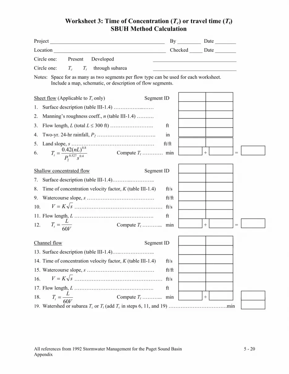
Worksheet 3: Time of Concentration (Tc) or travel time (Tt) SBUH Method Calculation
All references from 1992 Stormwater Management for the Puget Sound Basin 5 - 20 Appendix
Project ____________________________________________ By _________ Date ________
Location ___________________________________________ Checked _____ Date ________
Circle one: Present Developed ________________________________
Circle one: Tc Tt through subarea ________________________________
Notes: Space for as many as two segments per flow type can be used for each worksheet. Include a map, schematic, or description of flow segments.
Sheet flow (Applicable to Tc only) Segment ID
1. Surface description (table III-1.4) ……………...……
2. Manning’s roughness coeff., n (table III-1.4) ……….
3. Flow length, L (total L ≤ 300 ft) ……………………. ft
4. Two-yr. 24-hr rainfall, P2 ……………………………. in
5. Land slope, s ………………………………………… ft/ft
6. Compute Tt ………… min + =
Shallow concentrated flow Segment ID
7. Surface description (table III-1.4)………..…………..
8. Time of concentration velocity factor, K (table III-1.4) ft/s
9. Watercourse slope, s ………………………………… ft/ft
10. …………………………………………… ft/s
11. Flow length, L ………………………………………. ft
12. Compute Tt ………... min + =
Channel flow Segment ID
13. Surface description (table III-1.4)…..………………..
14. Time of concentration velocity factor, K (table III-1.4) ft/s
15. Watercourse slope, s ………………………………… ft/ft
16. …………………………………………… ft/s
17. Flow length, L ………………………………………. ft
18. Compute Tt ………... min +
19. Watershed or subarea Tc or Tt (add Tc in steps 6, 11, and 19) …………………………….min
4.0527.02
8.0)(42.0sP
nLTt =
VLTt 60
=
sKV =
sKV =
VLTt 60
=

5 - 21
DESIGN FLOW OF WATER IN CUBIC FEET PER SECOND
MAXIMUM HEIGHT BEFORE WATER OVERTOPS EMBANKMENT
CULVERT ELEVATION AT UPSTREAM END
CULVERT ELEVATION AT DOWNSTREAM END
SLOPE OF CULVERT (INLET ELEV. − OUTLET ELEV.)/LENGTH
MANNINGS ‘‘N" FOR PIPE SMOOTHNESS
HEADWATER DEPTH/PIPE DIAMETER
ENTRANCE LOSS COEFFICIENT (SEE ATTACHED TABLE)
LENGTH
CIRCULAR CULVERT ANALYSIS WORKSHEET
CULVERT PROFILE
N
C
D
Ke
HW/D
S
HW
TW
LENGTH
PIPE DIAMETER
CORRUGATION
LENGTH OF CULVERT
HEADWATER DEPTH
TAILWATER DEPTH
Q
OUTLET ELEV.
# OF BARRELS
INLET ELEV.
MAX. ELEV.
HW
BARRELS
BANK
UPSTREAM CROSS SECTION
MAXHW
INLET ELEV.
HW
UPSTREAM
OUTLET ELEV.
MAXIMUM HEIGHT BEFORE WATER JUMPS NATURAL BANK
BANKTW
DOWNSTREAM CROSS SECTION
TWMAX
D
TW
DOWNSTREAM

5 - 22
ENTRANCE LOSS COEFFICIENT (SEE ATTACHED TABLE)
BOX CULVERT ANALYSIS WORKSHEET
MANNINGS ‘‘N" ______ FOR BOTTOM, ______ FOR SIDES
SLOPE OF CULVERT (INLET ELEV. − OUTLET ELEV.)/LENGTH
MAXIMUM HEIGHT BEFORE WATER OVERTOPS EMBANKMENT
DESIGN FLOW OF WATER IN CUBIC FEET PER SECOND
HEADWATER DEPTH/PIPE DIAMETER
CULVERT ELEVATION AT DOWNSTREAM END
CULVERT ELEVATION AT UPSTREAM END
CULVERT PROFILE
LENGTH
N
Ke
HW/D
SPAN
RISE
HW
TW
LENGTH
S
WIDTH IN FEET
HEIGHT IN FEET
TAILWATER DEPTH
HEADWATER DEPTH
LENGTH OF CULVERT
SPAN
Q
# OF BARRELS
OUTLET ELEV.
INLET ELEV.
MAX. ELEV.
HW RISE
BARRELS
BANK
UPSTREAM CROSS SECTION
MAXHW
INLET ELEV.
HW
UPSTREAM
OUTLET ELEV.
MAXIMUM HEIGHT BEFORE WATER JUMPS NATURAL BANK
SPAN
BANK RISE TW
DOWNSTREAM CROSS SECTION
TWMAX
RISE
TW
DOWNSTREAM

Multnomah County Design Standards Part I – Design Manual
6 - 1
SECTION 6 - STREET LIGHTING 6.1 PLACEMENT CRITERIA In the past, Multnomah County did not have a formal standard for incorporating lighting into road improvement projects. Typically, lighting was mounted onto existing utility poles where possible, with minimal use of separate street light poles and circuitry. All new urban street construction or reconstruction should incorporate street lighting. A lighting analysis software program should be applied to identify requirements along a corridor, given the particular pavement and right-of-way section proposed. Table 6.1.2 identifies lighting level standards which should be achieved in the location and design of new street lighting installations for asphalt surfaces. The average to minimum ratio should be less than 6 for a local street, less than 4 for a minor collector and less than 3 for all other streets.
Table 6.1.1
Average Maintained Lighting Levels for Asphalt Surfaces
Street Classification
Minimum Average Maintained in Lux
Commercial
Intermediate
Residential
Major/Minor Arterial
20
14
10
Major Collector
12
9
6
Minor Collector
9
6
5
Local
9
6
5
Table 6.1.2 Average Maintained Lighting Levels
Other Pedestrian and
Bicycle Ways
Average Lux
Sidewalk and Bikeway Distant From Roadway
5
Pedestrian Tunnels
40
Pedestrian Overpasses
5
Pedestrian Stairways
6

Multnomah County Design Standards Part I – Design Manual
6 - 2
The spillover of light onto adjacent property needs to be checked on all designs. The maximum point lighting level on adjacent property more than 8 meters from the ROW should be less than half of the street’s averaged maintained lighting level. The lighting of adjacent property within 8 meters of the ROW will be limited as much as possible. When locating standard lighting along a corridor, preference should be given to mount luminaries on existing utility poles. If this is not possible, separate light poles should be installed. Cobra Head fixtures mounting height shall not be less than 7.5 m for 100watt, not less than 9 m for 150 watt, and not less than 10.5 m for 200 watt and over. Typical spacing of Cobra Head fixtures is 45 m to 54 m feet apart on one side of the street for Minor Collectors and Local Streets. Arterials and Major Collectors typically require street lights on both sides. All streets with median planter strips shall require street lights on both sides of the street. Any separate street light poles installed, as part of a roadway project should be located near property lines. Lights should be at least 7.5 m from any trees or be located on mast arms long enough to extend past the tree canopy over the street. Boulevards should be lighted with pedestrian friendly, globe style fixtures installed on 4.2 m poles. 4.8 m poles are required for 200 watt and over globe fixtures. 6.2 DESIGN FORMAT General Design - All street lighting shall be designed using the Illuminating Engineering Society of North America guidelines as modified in this manual. All electrical components shall be UL approved or approved equal. All fixtures, poles, mast arms and other major components must be on PGE’s approved products list. All street lighting plans shall include: pole locations, conduit locations, junction box locations, transformer/service cabinet locations, photometrics from the lighting level analysis, along with any other pertinent information. The contractor shall be responsible for making arrangements with PGE for connecting the street lighting system to the local distribution system. Conduit - All new installations and cable replacements shall be in schedule 40 PVC conduit, which shall conform to the requirements in the National Electrical code. Junction boxes within sidewalks shall be concrete with cast metal covers, and stamped “Street Lighting.” Any PGE approved box may be used outside of sidewalk areas. Connections between a junction box and a light pole are to be made using direct buried cable as opposed to conduit if direct bury poles are used. Splices shall never be done within the conduit. All conduit shall have a burial depth of 0.9 m to 1.1 m below finished grade. Cable and Wire - Most cable and wire for street lighting will be installed and owned by PGE in conduit provided by the project. Wires shall be sized to limit voltage drops to a maximum of 5 percent. All wire shall be stranded copper, single conductor, with a 600 volt installation. The minimum size shall be #10 AWG stranded copper type THWN or THHN. The maximum wire size shall be #1 AWG stranded copper.

Multnomah County Design Standards Part I – Design Manual
6 - 3
Poles - For separate light poles to be installed on roadway projects, anchor base poles shall be used, unless otherwise approved by the County Transportation Division. These poles are to be aluminum, unless the County approves another material. All poles shall have a 63.5 mm by 127 mm hand hole placed at 1.2 m above the ground line. Lighting Fixtures - Cobra head fixtures shall be the GE Powr/Dor fixtures (unless otherwise pre–approved by Mid- County Lighting District), with a sharp cutoff optical system. High-pressure sodium lamps shall be used in all fixtures, per the lighting levels required of different street classifications as identified in Table 6.1.2. A twist-lock photocell receptacle shall be incorporated into the fixtures. All lighting fixtures shall have a factory house side shield. Lighting Controls - The location and type of street light service cabinet(s), if required, shall be shown on all street lighting plans. Whenever possible, the service cabinets should be installed away from intersections. Each service cabinet shall be placed on a concrete pad. The cabinet shall have a service panel with a UL label (or approved label) attached to the panel.

Multnomah County Design Standards Part I – Design Manual
7 - 1
SECTION 7 - TRANSIT In general, the standards for transit facilities on Multnomah County roadways shall follow those set forth by Tri-Met. This section summarizes the key design guidelines featured in the Tri-Met manuals which are used by roadway designers. This section should be used in conjunction with the referenced Tri-Met manuals. 7.1 BUS STOP SPACING AND PLACEMENT 7.1.1 Bus Stop Spacing As specified by Tri-Met, the following spacing guidelines should be followed: 1) Group 1 Stops - Provide access to commercial districts, shopping centers, office developments,
medium- or high-density housing (22 or more units per 0.4 hectare), or other areas of medium-density development. Spacing should be about 234 m.
2) Group 2 Stops - Provide access to low-density or scattered residential developments (4 to 22 units per 0.4 hectare) or transfer points in low-density areas. Spacing should be about 300 m.
3) Group 3 Stops - Provide access to rural or isolated areas (fewer than four residences per 0.4 hectare). Stops should be placed as needed, but no closer than 300 m.
Contact Tri-Met for which group should be used for a particular area. A Right of Way permit is required for new or modified stops. 7.1.2 Bus Stop Placement The placement of a bus stop relative to an intersection is an important decision since it affects the traffic operations of both buses and passenger vehicles, and it affects the safety of vehicles and pedestrians near the intersection. The placement of a bus stop depends on a number of criteria, highlighted below. Far-Side Stops - In general, far-side stops are preferred. They result in fewer traffic delays, provide better auto and pedestrian sight distances, provide more bus maneuvering area, and cause fewer conflicts between buses and pedestrians. At signalized intersections, far-side stops should generally only be provided when the bus can avoid stopping in the travel lane (i.e., bus pullout). Near-Side Stops - Near-side stops are preferred where the bus must stop in a travel lane on a street with curbside parking so that the front door of the bus is at the intersection crosswalk. Coordination of Far-side and Near-side Stops - Coordination of near-side and far-side stops should be occur where major transit routes cross and form important transfer points. In these areas, the stop locations should be designed to allow for transfers along commute routes without crossing the street.

Multnomah County Design Standards Part I – Design Manual
7 - 2
Mid-block Stops - Mid-block stops should generally be avoided as it is typically undesirable to develop mid-block pedestrian crossings of streets to access such a stop. Locations where mid-block stops may be desirable are where the distance between intersections is unusually long or major transit generators that are located at mid-block cannot be adequately served by nearby intersection stops. Design Constraints - When designing a bus stop at a particular location, the following design constraints should be considered: 1) Adequate distance between bus stops and driveways should be maintained to prevent buses from
blocking driveway traffic or sight lines. In constrained situations, buses may block driveways if other access is provided to the property and adequate sight distances are maintained.
2) Bus stops should not be located where a bus wheel will stop on a catch basin (storm drain). This event could cause the bus to lurch or change direction and could cause excessive settlement of the basin structure.
3) Where possible, bus stops should not be located on an upgrade in a residential area, as the bus engine noise will bother area residents. Slippery winter conditions dictate not placing bus stops on steep grades.
7.2 BUS STOP FACILITIES 7.2.1 On-Street Facilities Bus Pullouts - Bus pullouts are intended to provide safe passenger loading and unloading while minimizing delays to passenger vehicles. Pullouts should be placed where buses can easily re-enter the traffic flow and allow for adequate vehicle acceleration and deceleration. Pullouts should be avoided at mid-block locations unless a development generating significant transit ridership is linked to a mid-block pedestrian crossing. Bus pullouts must allow adequate tapers and lane widths to accommodate safe bus movement. Figure 7.1 displays bus pullout design options. Tri-Met suggests the following pullout design guidelines: 1) Along arterials with posted speeds over 50 km/h, provide a 3.6 m wide pullout lane to reduce the
potential for accidents. Adjacent to bike lanes, the pullout lane width may be reduced to 3 m unless buses will be stopped for extended periods of time (e.g., layovers).
2) Bus pullouts may be required by the County Engineer on arterial or collector streets if traffic conflicts create congestion levels impacting air quality, levels of service or other safety considerations. Buses are required to use pullouts where they exist.
3) At far-side pullouts, provide a minimum 5:1 exit taper. An entrance taper may be necessary if the intersection can not accommodate a 18 m long deceleration movement into the pullout.

Multnomah County Design Standards Part I – Design Manual
7 - 3
4) At far-side pullouts with curb extensions and at mid-block pullouts, allow for a 10:1 entrance and a 5:1 exit taper if traffic speeds range from 50 to 65 km/h. Where roadway design speeds are less than 50 km/h or exceed 65 km/h, design entrance and exit tapers according to the following formula:
L = (0.6) x W x S Where: L = Length of Taper, meters
3 W = Pullout Width, meters S = Roadway Design Speed, km/h
5) Allow a 18 m stopping length for a standard bus and 24 m feet for an articulated bus. Coordinate
with Tri-Met on what type of vehicle serves a particular site. Curb Extensions - Curb extensions create a bulb at an intersection, usually the width of the parking lane. Curb extensions are typically considered appropriate along streets with lower traffic speeds (i.e., boulevards) and/or reduced traffic congestion where it is acceptable to stop buses in the travel lane. Collector streets in neighborhoods and designated pedestrian districts are also good candidates for such treatment. Curb extensions should be designed to facilitate an adequate turning radius for right turn vehicles, as well as an adequate width for the adjacent travel lane. Bus stops in the vicinity should be located at the near side of an intersection. Figure 7.2 identifies a typical curb extension treatment. 7.2.2 Off-Street Facilities Lighting - All bus stops should have adequate lighting to increase transit customer safety. Lighting levels must be sufficient to provide customers with a sense of security while they wait for buses as well as provide adequate visibility for bus operators to safely approach and depart from a bus stop. Between 10 and 15 lux of illumination should be provided at each bus stop.

Multnomah County Design Standards Part I – Design Manual
7 - 4
Figure 7.1 Bus Pullout Design Option

Multnomah County Design Standards Part I – Design Manual
7 - 5
Figure 7.2 Bus Pad Concrete Pavement Section

Multnomah County Design Standards Part I – Design Manual
7 - 6
Bus Stop Shelters - The following criteria should be used to determine if a shelter is warranted at an existing or new bus stop: 1) Number of passenger boardings per day - A stop warrants a shelter if it has at least 20 passenger
boardings per day. To evaluate potential ridership of a new development, contact Tri-Met’s Transit Development Department.
2) Type of population served - Locations that serve higher concentrations of elderly customers or people with disabilities are given priority for shelter placement. This frequently includes stops at medical facilities and public service agencies.
3) Preparation required - Level sites that provide adequate placement area with minimal impact to surrounding properties are preferred.
4) Availability of nearby shelter - To achieve the best level of service for each customer, shelters are distributed to obtain maximum coverage and access.
5) Weather Conditions – Winds , rain and sun impacts should be considered and shelters installed on a trial basis if potential ridership exists.
The design of bus stop shelters must meet ADA standards which, in part, state that the inside of a shelter must provide a minimum clear floor area of 0.75 m by 1.2 m. Also, the interior of the structure should not be constructed to be any part of the separate 2.4 m by 3 m passenger landing area. Benches - Providing bus benches without shelters at a particular bus stop should be considered under the following conditions: 1) The number of regular riders is just short of the normal ridership threshold to warrant a shelter. 2) The existence of adjacent site features that attract riders onto adjacent property (i.e., retaining
walls, stairs, low fences). 3) In high-use areas unsuitable for shelters due to high pedestrian movement over a small area. 4) In high ridership locations with local weather protection but without seating. 5) At transfer locations with buses on long headways. 6) At locations used by elderly and disabled persons. Bus benches should be located upstream of where the bus will stop and outside the 2.4 m by 3 m ADA landing pad. 7.3 TRANSIT PROVISIONS FOR PROPOSED DEVELOPMENTS All proposed developments with frontage on an existing, or planned future, transit street shall adhere to the provisions set forth in this chapter. All affected developments should be reviewed by Tri-Met which may recommend transit-related facilities to be constructed at the time of development. Any transit facilities recommended by Tri-Met and required by Multnomah County shall be identified on the site plan to be submitted with the application.

Multnomah County Design Standards Part I – Design Manual
7 - 7
The extent of the required transit facilities depends on the street classification, length of block, proximity of major pedestrian destinations, level of existing transit service in site vicinity, and projected transit needs of the proposed development. When transit facilities are required, the minimum requirement shall include a landing pad (see Chapter 7.2.2 of this section) and transit signage conforming to current Tri-Met standards. Additional requirements may include bus pullouts, curb extensions, median refuges for pedestrian crossings, bus shelters, public telephones, benches, or pedestrian lights. The following guidelines shall be considered in determining whether a proposed development is required to provide transit facilities: 1) If the proposed development is located within 150 m of an existing transit stop, a new transit
stop shall only be provided if recommended by Tri-Met and required by Multnomah County. 2) Proposed developments which are estimated to generate over 1,000 average daily vehicle trips
may be required to provide a transit improvement dedication along the frontage of the transit street for the installation of a bus pullout and/or other facilities.

Multnomah County Design Standards Part I – Design Manual
8 - 1
SECTION 8 - LANDSCAPE TREATMENTS 8.0 LANDSCAPE TREATMENTS Landscape treatments in the right-of-way shall be based on the classification of the street and the base land use zone in which the street is located. Landscaping should exist within the framework of the Metro design guidelines which: 1) Provide a safe environment 2) Support regional multi-modal travel 3) Support economic vitality 4) Create pedestrian and bicycle accessibility 5) Support social contact 6) Provide orientation and identity to the region 7) Provide for physical comfort and spatial orientation The following sections are intended as a guideline of practices which should be followed in order to achieve regional goals. 8.1 MEDIAN LANDSCAPING All medians with a minimum width of 1.2 m - 1.8 m should be considered for landscaping. All landscape treatments should consider a combination of trees, shrubs and groundcovers. Planting themes should be designated for transportation corridors linking individual districts with a unifying plant characteristic, i.e., bloom color, habit, or fall color. When specifying thematic planting material, monocultures should be avoided, particularly those species susceptible to disease and weather conditions. Medians used for pedestrian refuge should be designed for short-term use only with plant material for cooling and dust control and pedestrian-scale lighting. The design of these spaces should facilitate safe pedestrian crossing with lighting and accent paving to delineate a safe crossing zone visually clear to motorists and pedestrians alike. Street Trees - Medians wider than 1.8 m should have street tree plantings. Trees should be planted according to the minimum on center distances appropriate to the tree and the size of tree should correlate with the width of the median (refer to Figure 8.1.1 Plant Material matrix). The habit, scale and placement of street trees should relate to the character of an area or district and categorized as either high density urban (Figure 8.1.2) or low density suburban (Figure 8.1.3). These terms should be used to loosely define an area, requiring final interpretation by the County Engineer. Street tree placement should also respond to the more repetitious and ordered urban environment with formal plantings of regularly-spaced trees depending on densities and the type of vehicle traffic. For medians narrower than 3.6 m wide, trees may be arranged in a triangular pattern to create the illusion of a wider median and to spread the tree canopies increasing cooling and dust control. Plantings in medians wider than 3.6 m may have a double row of street trees arranged in a linear pattern to create a strong, formal visual effect as well as to maximize tree canopy for cooling and dust control.

Multnomah County Design Standards Part I – Design Manual
8 - 2
Lower density suburban areas (low use mix and low end of allowed density range) should have round-headed to broad tree canopies to provide shade and dust control while responding to lower densities and shorter structures of the built environment and remnants of countryside often remaining within this development type. Street tree placement should also respond to the lower density suburban environment with naturally occurring patterns of irregularly-spaced trees arranged in a roughly triangular pattern for maximization of tree canopy cooling and dust control. Shrubs and Groundcovers - All medians used for pedestrian refuge shall have low plant masses within 1.5 m of pedestrian crossings to enhance visibility for safety and criminal deterrence (Figure 8.1.4). Medians used only as buffers should have medium (1.1 m – 1.7 m) plant masses to block lights of oncoming traffic, decrease dust and heat, and enhance the aesthetics of the roadway. Plantings may comprise of evergreen year-round or provide seasonal interest with fall color, blooms or fruits, and at maturity maintain growth within planting area (refer to Figure 8.1.1 Plant Material matrix). Plant placement shall also adhere to clear sight line requirements as well as any other relevant County safety measures.

Multnomah County Design Standards Part I – Design Manual
8 - 3
Table 8.1.1a Recommendation List STREET TREES
COMMON NAME SCIENTIFIC NAME HEIGHT SPREAD TEMPERAMENT COLORING Green Ash
Fraxinus Pennsylvanica Lanceolata
Early Cultivator, bottom of slope near water
Glossy green leaves, yellow fall color
Marshall Ash
Fraxinus Pennsylvania Marshall
15 m
13.5 m
Adaptable, irregular and asymmetrical in shape, seedless
Dark glossy green leaves
Summit Ash
Fraxinus Pennsylvanica Summit
13.5 m
7.5 m
Uniform branching to narrow oval, open, light , dry foliage, seedless
Fast growing
Patmore Ash
Fraxinus Pennsylvanica Palmore
15 m
12 m
Symmetrical upright branches forming an oval head, extremely hardy, seedless
Dark green glossy leaves
Emerald Ash
Fraxinus Pennsylvanica Emerald
13.5 m
12 m
Roundheaded, heavily furrowed bark and hardy in hot, dry weather
Medium green leaves, yellow fall color
Dr. Pirone Ash
Fraxinus Agustifolia Doctor Pirone
10.5 m
Excellent, strong up-sweeping branches, good crotches. Can be used in 1.2 m beds or over tree lawn
Beautiful bright glossy green leaves
Autumn Applause Ash
Fraxinus Americana Autumn Applause
13.5 m
7.5 m
Small, dense, oval form
Purple fall color
Rosehill Ash
Fraxinus Americana Rosehill
15 m
10.5 m
Fast growing, upright form with open branching, seedless
Purple fall color
Flowering Ash
Fraxinus
7.5 m to 9 m
7.5 m
Exceptional, fragrant flowers, roundheaded
Dark green leaves
Golden Desert Ash
Fraxinus Oxycarpa Aureafolia
7.5 m
5.5 m to 6 m
Handsome, distinctively different and of great ornamental value. Excellent where site factors limit the use of large growing trees.
Rich golden bark, green leaves turning gold in July
Rancho Roundhead Ash
Fraxinus Excelsior Rancho
7.5 m to 9 m
6 m to 7.5 m
Suitable for low overhead wire conditions and can be used in parking strips (narrow as 1.2 m), adaptable to most soil conditions.
Amur Chokecherry
Prunus Maacki
7.5 m to 9 m
Good foliage, the white
flowers are typical of chokecherry that hang in
White flowers, golden flaky

Multnomah County Design Standards Part I – Design Manual
8 - 4
COMMON NAME SCIENTIFIC NAME HEIGHT SPREAD TEMPERAMENT COLORING
graceful raceme, extremely hardy
bark
Kwanzan Flowering Cherry
Prunus Serrulata Kwanzan
10.5 m to 12 m
9 m
Grafted on a 6 1/2 mazzard, understock provides immediate clearance on streets greatly reducing maintenance
Rosy/pink flowers, leaves are red when young
Alberti Cherry
Prunus Padus Alberti
6 m
9 m
Upright, oval and very floriferous. Has spikes of flowers 50 mm to 100 mm in length and hearty in this region
White flowers
Rancho Columnar Sargent Cherry
Prunus Sargenti Rancho
7.5 m to 9 m
3.6 m
Strong and handsome, can be used in a 0.9 m tree lawn, incredibly it survives storm damage. Ascending branches with strong crotches
Rose/pink flowers, spectacular red fall color
Redbark Cherry
Prunus Serrula
9 m
The bark is magnificent, bright and shinny
Red
September Goldenrain
Koelreuteria Paniculata September Goldenrain
10.5 m
6 m to 7.5 m
Intense flower blooms in late August, early September, the panicle is large and densely branched and is roundheaded
Sulphur yellow flower
Lavalle Hawthorn
Crataegus Lavelle
9 m
7.5 m
Prized ornamental street tree, oval headed and best used for low overhead wire situations
Rich shining green leaves, white flowers coral color berries
Globe-Headed European Hornbeam
Carpinus Betulus Pyramidalis
7.5 m to 9 m
5.4 m
Tight, compact and roundheaded.
Japanese Tree Lilac
Syringa Amurensis Japonica
7.5 m
3.6 m to 4.5 m
Ideal for narrow parkways, a slow grower with tough, hardy and beautiful large flowers that bloom in June, roundheaded
White flowers
Bicentennial Linden
Tilia Cordata Bicentennial
10.5 m
5.4 m to 6 m
A tight pyramidal form, small leaves
Rich color
Rancho Littleleaf Linden
Tilia Cordata Rancho
9 m
4.8 m Early branching habits and
different from other Littleleaf Lindens, branch pattern is flat, fan-like and departs from the trunk in whorls that gracefully curl upward to build a nice,
Dark green leaves

Multnomah County Design Standards Part I – Design Manual
8 - 5
COMMON NAME SCIENTIFIC NAME HEIGHT SPREAD TEMPERAMENT COLORING
compact crown of small and finely serrated leaves
Redmond Linden
Tilia Americana Redmond
10.5 m
7.5 m
Rapidly growing, densely pyramidal and symmetrical with large leaves
Greenspire Linden
Tilia Cordata Greenspire
12 m
10.5 m
Pyramidal and symmetrical with uniform branching
Amur Maple
Acer Ginnala
6 m
A fine, sturdy roundheaded tree, flower spikes give the tree an exotic look and bloom to 150 mm in August, a small slow growing tree
White flowers
Almira Norway Maple
Acer Platanoides Almira
4.8 m in 30 years
3.6 m to 4.5 m
Excellent for use under low wire situations, an informal dwarf globe selection
Armstrong II Red Maple
Acer Rubrum Armstrong II
9 m max height
2.4 m
An improved variety and superior to other Armstrong Red Maples, it has a tighter form, narrower crotches and tight ascending branches, the strong branches and narrow silhouette make it resistant to ice and storm damage and requires practically no maintenance, a good selection for vary narrow streets with a 0.9 m parkway and 1.5 m to 2.1 m setback from the sidewalk, ideal for business streets with shallow setbacks and business signs, the root system is greatly restricted to eliminate future sidewalk and curb problems
Cavalier Norway Maple
Acer Platanoides Cavalier
12 m
13.5 m
Compact, roundheaded, a fine selection of the Norway Maple it should be spaced at a minimum of 12 m
Yellow fall color
Cleveland II Norway Maple
Acer Platanoides Cleveland II
9 m to 10.5 m
6 m An improved maple with
superior branching habits, the branches are closely spaced along the trunk giving the effect of a

Multnomah County Design Standards Part I – Design Manual
8 - 6
COMMON NAME SCIENTIFIC NAME HEIGHT SPREAD TEMPERAMENT COLORING
dense, compact head with oval form
Crimson Sentry Maple
Acer Platanoides Crimson Sentry
7.5 m
4.5 m
Compact, dense and pyramidal to oval shape
Deep purple leaves changing to maroon in fall
Crimson Kind Maple
Acer Platanoides Crimson King
12 m
10.5 m
Oval when young becoming roundheaded in maturity
Deep purple leaves
Deborah Maple
Acer Platanoides Deborah
13.5 m
12 m
Broad oval shape
Reddish purple leaves in spring, bronze green in summer and bronze in the fall
Emerald Queen Maple
Acer Platanoides Emerald Queen
15 m
12 m
Dense oval with upright spreading branches
Deep green summer leave color, bright yellow in the fall
Olmsted Norway Maple
Acer Platanoides Olmsted
Extremely narrow, columnar shape. Excellent for heavy traffic street
Deep green leaves
Royal Red Maple
Acer Platanoides Royal Red
Schlesinger Red Maple
Acer Rubrum Schlesinger
Schedleri Maple
Acer Platanoides Schedleri
Superform Maple
Acer Platanoides Superform
13.5 m
12 m
Broad oval to rounded shape, well behaved, uniformed branching and symmetrical
Columnar Norway Maple
Acer Platanoides Columnare
10.5 m
4.5 m
Compact narrow form of the Norway maple and is ideal for streets with narrow parkways and close building situations
English Hedge Maple
Acer Campestre
7.5 m
5.4 m to 6 m
Sturdy and compact-headed, the branches come off the trunk and proceed about 200 mm to 250 mm and then sharply curve upward, it is an ideal shade tree

Multnomah County Design Standards Part I – Design Manual
8 - 7
COMMON NAME SCIENTIFIC NAME HEIGHT SPREAD TEMPERAMENT COLORING Faassen Black Norway Maple
Acer Platanoides Faassen's
10.5 m
Roundheaded
Deep Red
Autumn Flame Maple
Acer Rubrum Autum Flame
10.5 m
10.5 m
Dense, rounded, small front and hardy, a slow grower with small leaves, best in small leaves, best in small yards or cul-de-sacs
Bowhall Red Maple
Acer Rubrum Bowhall
12 m
4.5 m
Upright, very narrow column, tightly formed
Good fall color
October Glory Red Maple
Acer Rubrum October Glory
12 m
10.5 m
Broad oval to rounded, midwinter and hot summer prep is the best application
Glossy medium green leavers turning to deep red and purple in fall
Scarlet Sentinel Red Maple
Acer Rubrum Scarlet Sentinel
12 m
6 m
Upright and narrow branching pattern giving bold appearance
Gerling Red Maple
Acer Rubrun Schlesinger
10.5 m
6 m to 6.6 m
Broad-leaf pyramidal
Globe-head Norway Maple
Acer Platanoides Globosum
4.5 m
5.4 m
Grafted on a 2.1 m standard, this is ideal under low overhead wires in a 4.5 m parkway to provide vehicular and pedestrian branch clearance, a very formal looking tree, appropriate for small cul-de-sac front yards
Pyramidal Sycamore Maple
Acer Psuedoplatanus Pyramidalis
9 m to 10.5 m
5.4 m
Rich leaves, strong up-sweeping branches and good crotches
Red Sunset Red Maple
Acer Rubrum Red Sunset
13.5 m
10.5 m to 12 m
Up right and oval
Bright orange-red fall coloring holding for several weeks
Scanlon Red Maple
Acer Rubrum Scanlon
10.5 m
7.5 m
Extensively used on narrow setbacks, since the branches are compact, it is conical shaped
Dark green leaves that turns to brilliant orange, amber and red in fall
Tilford Red Maple
Acer Rubrum Tilford
10.5 m
7.5 m
Roundheaded, excellent fine textured branches and small foliage
Acer Pseudoplatanus
Deep rich

Multnomah County Design Standards Part I – Design Manual
8 - 8
COMMON NAME SCIENTIFIC NAME HEIGHT SPREAD TEMPERAMENT COLORING
Spaethii Maple Altopurpureum 12m 9 m Roundheaded green leaves with burgundy colored under parts of the leaf
Columnar Sugar Maple
Acer Sccharum
Green Mt. Sugar Maple
Acer Saccharum
13.5 m
10.5 m
Broadly, oval, very hardy
Dark green leaves turns orange in fall
Legacy Sugar Maple
Acer Accharum
15 m
10.5 m
Oval, very symmetrical and tough leaves resistant to wind tatter
Glossy, dark green leaves, turn orange/red in fall
Parkway Maple
Acer Platanoides Parkway
12 m
7.5 m
Oval with good central leader. Faster growing than other Norway Maples
Queen Elizabeth Maple
Acer Campestre Queen Elizabeth
Small, upright, oval and varying habit, small leaves with wavy margins, good selection for front yard on cul-de-sacs
Dark glossy green
Green Column Maple
Acer Nigrum Green Column
15 m
6 m
Upright, narrow oval with good resistance to heat and dry conditions, leaf shape is unique
Excellent fall color
Commorating Sugar Maple
Acer Succharum
Columbia Queen Mt. Ash
Sorbus Aucuparia Columbia Queen
10.5 m
4.5 m to 5.4 m
Vigorous grower with a cone shaped head
Dark green leaves with red heavy fruit clusters
Hybrid Mt. Ash
Pyramidal Oakleaf Mt. Ash, Sorbus Hybrida Pyramidalis
10.5 m
2.4 m to 3 m
A tight compact branching structure
Northern Red Oak
Quercus Borealis
30 m
25.5 m to 27 m'
Roundheaded and large broad leaf
Red fall color
Chanticleer Flowering Pear
Pyrus Calleryanda Chanticleer, Arisotcrat Pear
10.5 m
4.8 m to 5.4 m
Glossy green leaves in summer, white flowers, fall plum color
Rancho Pear
Pyrus Calleryana Rancho
The apex crown is blunt,
compact and handsome. An important trait is it colors-up at least 10 days

Multnomah County Design Standards Part I – Design Manual
8 - 9
COMMON NAME SCIENTIFIC NAME HEIGHT SPREAD TEMPERAMENT COLORING
earlier than the chanticleer Trinity Pear
Pyrus Calleryana Trinity
9 m
6 m
Roundheaded, profusion of delicate flowers blooming in early May, small sparse fruit
Green waxy leaves
Skyrocket Oak
Quercus Skyrocket
9 m
3 m
Extremely Columnar
Leaves persist through winter
Fruitless Mulberry
Morus Alba Kingpin
9 m
6 m
Roundheaded
Bright green leaves, fall lemon color
Zelkova Greenvase
Zelkova Serratta Greenvase
15 m
15 m
Developed as a replacement for the Elm, it's disease resistant, yet has structural characteristics similar to the Elm. It has small leaflets and requires a 15 m space in a neighborhood with homes of appropriate scale and proportion
Updated: 2/4/99

Multnomah County Design Standards Part I – Design Manual
8 - 10
Figure 8.1.2

Multnomah County Design Standards Part I – Design Manual
8 - 11
Figure 8.1.3

Multnomah County Design Standards Part I – Design Manual
8 - 12
Figure 8.1.4

Multnomah County Design Standards Part I – Design Manual
8 - 13
8.2 PEDESTRIAN SPACE LANDSCAPING Pedestrian spaces include sidewalks and planting strips. Planting strips provide a physical and psychological buffer for pedestrians from traffic with plant material that reduces heat and dust creating a more comfortable pedestrian environment. Planting strips also provide areas for street furniture for pedestrian comfort and safety, i.e., benches, waste receptacles and pedestrian-scale lighting. These spaces should be designed for short as well as long-term use. Elements of pedestrian spaces shall not obstruct sight lines and shall adhere to any other required County safety measures. Planting strips should have different arrangements and combinations of plant material when adjacent to on-street parking. Planting strips which do not have adjacent parking should have a combination of groundcovers, low shrubs and trees (Figure 8.2.1). Planting strips adjacent to on-street parking should have trees protected with tree grates. (Figure 8.2.2). District themes or corridor themes linking individual districts should be followed utilizing a unifying plant characteristic, i.e. bloom color, habit, or fall color. When specifying thematic plant material, monocultures should be avoided, particularly those species susceptible to disease. Street Trees - All planting strips should have street trees. Planting strips which do not have adjacent parking should have a combination of groundcovers, low shrubs and trees. (Figure 8.2.1). Planting strips adjacent to on-street parking should have trees protected with tree grates. (Figure 8.2.2). Trees must be planted according to the minimum on center distances appropriate to the tree and the size of tree should correlate with the width of the street (refer to Figure 8.1.1 Plant Material matrix). The habit, scale and placement of street trees should correlate with the character of an area or district and categorized as either higher density urban or lower density suburban (refer to Figure 8.1.1 Plant Material matrix). Street tree placement should also respond to the more repetitious and ordered urban environment with formal plantings of regularly-spaced trees depending on densities and the type of vehicle traffic. Lower density suburban areas (low use mix and low end of allowed density range) should have round-headed to broad tree canopies to provide shade and dust control while responding to lower densities and shorter structures as well as remnants of countryside often remaining between this development type. Street tree placement should also respond to the lower density suburban environment with naturally occurring patterns of irregularly-spaced trees arranged in a roughly triangular pattern for maximization of tree canopy cooling and dust control (Figure 8.1.2). Shrubs and Groundcovers - Planting strips without adjacent parking should have low planting masses to enhance visibility, discourage criminal activity, and provide a physical as well as psychological buffer from passing traffic (Figure 8.1.4). Plantings may comprise of evergreen year-round or provide seasonal interest with fall color or blooms, and at maturity maintain growth within planting area. All plant placement shall adhere to clear sight line requirements as well as any other relevant County safety measures.

Multnomah County Design Standards Part I – Design Manual
8 - 14
Figure 8.2.1

Multnomah County Design Standards Part I – Design Manual
8 - 15
Figure 8.2.2

Multnomah County Design Standards Part I – Design Manual
8 - 16
Lighting - Pedestrian-scale lighting should be installed along sidewalks and in medians used for pedestrian refuge. Pole lights as well as bollard lighting may be specified, however the amount and type of pedestrian activity during evening hours, i.e. transit stops, nighttime service districts, should ultimately determine the type of fixture chosen. Luminaire styles should match the area/district theme or existing luminaires and should not conflict with existing building or roadway lights causing glare. Lighting heights and styles should be chosen to prevent glare and to designate a clear and safe path and discourage vandalism (Figure 8.2.1). Lighting should be placed near the curb to provide maximum illumination for spaces furthest from building illumination. Spacing should correspond to that of the street trees to prevent tree foliage from blocking light. Street Furniture - Street furniture such as benches and waste receptacles should be provided for spaces near sidewalks. Furniture should be sited in areas with the heaviest pedestrian activity, i.e. transit stops, shopping districts/centers. Benches should be arranged to facilitate conversation between individuals with L-shaped arrangements and should face the area focal point, i.e. shops, fountain, plaza, and divert attention away from nearby traffic. Other street furniture such as bus shelters should be sited and provided by the responsible transportation agency. Paved Surface Details - Paving and curb cuts shall facilitate safe pedestrian crossing and meet all ADA requirements for accessibility. Accent paving may be used at key intersections to clearly define the pedestrian crosswalk and not impede wheelchair accessibility or conflict with surfacing for sight-impaired individuals. Accent paving should include scored or colored asphalt or concrete surfaces in contrast from the predominant paving type as well as any modular paving units. County Transportation staff shall define which locations are considered key intersections according to traffic flow, amount and type of pedestrian activity, and width of crossing. Curb cuts shall be provided for accessibility at sidewalk corners per ADA guidelines. 8.3 SWALE All swales shall be landscaped. Plant material shall filter storm water runoff and improve the aesthetics of the roadway. Plantings shall be easily maintained, non-toxic, non-invasive plants designed to cover all surfaces of the swale to prevent erosion (refer to Figure 8.1.1 Plant Material matrix). Street trees shall be prohibited within the depression of the swale. All plant placement shall adhere to clear sight line requirements as well as any other relevant County safety measures. Installation - Earthwork of all swales shall meet the minimum slope and water retention requirements as defined by County engineering standards. Grading shall be prohibited during wet periods particularly during the months of November through February unless an exception is granted by the County Engineer. Soil erosion shall be controlled by County approved methods immediately following grading. Slopes shall be protected from erosion with a layer of filter fabric and seeded with Carex grass seed, or other equal substitute, for long-term storm water runoff filtration purposes. Grass seed substitutions may be considered by the County Engineer if the proposed material is non-invasive, low maintenance, and equal to Carex in terms of filtration capability. Density and method of seeding shall be in accordance with grower recommendations to achieve complete and uniform coverage.

Multnomah County Design Standards Part I – Design Manual
8 - 17
8.4 MAINTENANCE All landscapes shall be maintained for the duration of the planting to encourage health of plant material as well as public health and safety. A maintenance schedule detailing fertilizing, weeding and watering requirements shall be provided on all landscape plans as individual water requirements of plants and planting density affects frequency and duration of maintenance activities. All street trees and shrubs shall be pruned to maintain health and structure of the plant material for public safety purposes. Irrigation - All plant material shall be maintained with an automatic irrigation system or hand-watered during long periods of hot weather as recommended. Two different types of irrigation systems may be installed subject to final approval by the County Engineer. Conventional pop-up spray heads are the most typical irrigation application in this area. They are most beneficial for delivering large amounts of water over large areas for a short duration. Drip irrigation systems are installed below grade and provide water to roots via an underground conduit which slowly emits water into the soil. These systems are particularly useful because of their low water-usage, deep-watering, which encourages deep rooting protecting curbs and paved surfaces, and low potential for over watering, which often causes erosion and slick paved surfaces. Because of this, drip irrigation is the preferred system for small and/or narrow planting areas. However, soils must be analyzed prior to installation because emitters are subject to clogging in some soils and may be difficult to reach for replacement and/or maintenance. Pruning - All street trees shall be pruned according to the National Arborist Association (N.A.A.) standards. These standards describe methods of hazard pruning, crown reduction and two different intensities of general pruning practices. Maturing trees shall be routinely maintained to provide clearance underneath the canopy and to develop a central leader and strong limbs. Lowest limbs shall be removed to provide a minimum clearance of 2.4 m between sidewalk and lowest limb and a minimum clearance of 3 m between roadway surface and lowest limb. This shall eliminate limbs blocking pedestrian and vehicular traffic and views. Trees shall also be pruned if the crown conflicts with utility lines or other structures while preserving its overall shape and structural integrity. All shrubs shall be pruned if foliage or limbs extend into the path of pedestrian or vehicular traffic. Natural shrub habit shall be maintained, prohibiting "poodling" or "bonsai" pruning styles. Fertilizing - All landscapes shall be fertilized to maintain health of plant material. At a minimum, landscapes shall be fertilized at installation. Organic fertilizers shall be required for all applications to prevent contaminant increase in storm water runoff. In planted areas which are intended to filter storm water runoff or areas adjacent to natural water bodies, fertilizers shall be "environmentally safe" as determined by the Environmental Protection Agency and amount shall be regulated to prevent nutrient increase in water bodies which may lead to algae blooms and habitat degradation. Weeding - All landscapes shall be weeded to eliminate competition during establishment of plant material as well as for aesthetic purposes. At a minimum, landscapes shall be weeded until established and weeded two times per year thereafter.

Multnomah County Design Standards Part I – Design Manual
9 - 1
SECTION 9 - SURVEY 9.1 MONUMENTATION - ROAD REPAIR AND MAINTENANCE Any road repair project needs to take care to preserve survey monuments. This includes maintenance work as well as road repairs. ORS 209.140 requires any person or public agency that finds it necessary to interfere with or pave over any established public land survey corner (includes section corners, quarter corner and Donation Land Claim corners) or accessories shall notify the county surveyor, who shall take steps to preserve the monument. The county surveyor may charge a fee for this work. ORS 209.150 requires that any person or public agency removing, disturbing or destroying any survey monument of record in the office of the county surveyor or county clerk shall cause a registered professional land surveyor to reference and replace the monument within 90 days. 9.2 MONUMENTATION - ROAD CONSTRUCTION Any road construction or reconstruction project is required to preserve monumentation and establish new monumentation in some cases. See ORS 209.155 for complete requirements and options. Oregon Revised Statutes 209.140 Necessary interference with corners; prior notice to county surveyor required; exception for emergency; fees. 1) Any person or public agency that finds it necessary to interfere with or pave over any
established public land survey corner or accessories for any reason, shall notify the county surveyor prior to the interference, who shall lower and witness the monument, or place another monument and witness over the existing monument or reference and replace or set a witness monument, as the case may demand, and record the proceedings in the record of permanent surveys. The county surveyor may charge a fee in an amount that will reimburse the county for the work performed.
2) When an emergency exists and the county surveyor is unavailable, the person or public
agency causing the interference shall cause a registered professional land surveyor to preserve the monument as required in subsection (1) of this section. The registered professional land surveyor referencing the monument shall notify the county surveyor of the references within two business days after the references or interference, whichever occurs first. [Amended by 1979 c.653 s.9; 1985 c.582 s.8; 1989 c.394 s.11]

Multnomah County Design Standards Part I – Design Manual
9 - 2
209.150 Removal or destruction of monument; notice to county surveyor; replacement of monument; exception. 1) Any person or public agency removing, disturbing or destroying any survey monument of
record in the office of the county surveyor or county clerk shall cause a registered professional land surveyor to reference and replace the monument within 90 days of the removal, disturbance or destruction. The registered professional land surveyor referencing and replacing the monument shall do so in the same manner that is provided for public land survey corners according to ORS 209.140 and shall notify the county surveyor of that action within two business days. The costs of referencing and replacing the survey monument shall be paid by the person or public agency causing the removal, disturbance or destruction.
2) Notwithstanding subsection (1) of this section, a county surveyor may, upon written request
and written notice to an affected property owner, provide written authorization to a registered professional land surveyor to remove a survey monument other than a public land survey corner as defined in ORS 209.005. A county surveyor may require that the position of the removed monument be referenced to another survey monument and noted on a survey map filed in accordance with ORS 209.250. [Amended by 1979 c.653 s.10; 1989 c. 394 s.12; 1991 c.339 s.2; 1997 c.336 s.3; 1997 c.489 s.10]
209.155 Removal or destruction of monument during road construction; survey map in lieu of replacement; delineation of newly defined right of way. 1) Notwithstanding ORS 209.150, when a recorded survey monument, other than a public land
survey corner, is removed, destroyed or disturbed as a result of construction or reconstruction of a public road, the survey monument does not have to be replaced if:
a) The original location of the recorded survey monument is within the new right of
way; and b) The person or public agency responsible for the construction or reconstruction causes
a registered professional land surveyor to locate any survey monuments that are subject to removal, destruction or disturbance and to file a map, prior to the beginning of construction, with the county surveyor that identifies all existing recorded monuments, the existing right of way and controlling centerline and the survey control used to comply with this section.
2) The newly defined right of way may be delineated by either of the following methods:
a) All control points that define the right of way centerline are monumented or referenced with monuments. The right of way boundary is monumented at all angle points, points of curve, points of tangency and at least every 1,000 feet on long curves and tangents. A survey that identifies the survey control and the new right of way and controlling centerline shall be filed with the county surveyor within 180 days after completion of construction.
b) A permanent survey control point network is established referencing the new right of way and controlling centerline. The network shall consist of at least three control monuments and must span the length of the project. Each control monument shall be intervisible with at least two other control monuments. At least two monuments on the network must be part of the original control used to locate the monuments

Multnomah County Design Standards Part I – Design Manual
9 - 3
described in subsection (1)(b) of this section. A map identifying the control network and the new right of way and controlling centerline shall be filed with the county surveyor within 180 days after completion of construction.
3) The types of monuments shall be as described in ORS 92.060. 4) The survey maps required by this section shall comply with ORS 209.250 and any other
requirement of law. 5) For the purpose of complying with subsection (1)(b) of this section, locating a survey
monument may consist of establishing coordinates on the monument. These coordinates may be Oregon State Plane coordinates, Local Datum Plane coordinates or other coordinates compatible with those coordinates shown on the survey.
6) For the purpose of complying with this section, the date of completion of construction shall
be considered to be the date when all substantial road improvements are completed. [1997 c.336 s.2]
MULTNOMAH COUNTY TRANSPORTATION DIVISION FIELD AND OFFICE/MAP PROCEDURES AS PART OF OUR ROAD CONSTRUCTION PROJECTS Field Procedures 1) Establish a control traverse or network. Control points shall be permanent monuments, i.e.
5/8” X 15” rebar with red plastic caps marked “MULT. CO. CONTROL” set below grade, preferably in places that will be preserved during construction. Make sure that at least two control points are established at each end of the project and are a safe distance outside the scope of the project. These control points should be observable by GPS.
2) Traverses through control points shall be accomplished using an electronic data collector. Two sets of angles (set = BS, FS, RFS, RBS) shall be turned at each control point and distances will be measured both to FS and to BS, and recorded. NOTE: The data collector must be properly set up for this! Traverses will be run using the “leap frog method” (tripod to tripod).
3) Make a thorough search for all property corners of record (County Surveyor’s Office or County Recorder’s Office), benchmarks, Geodetic Control Points, Government corners, existing centerline and right of way monuments that may be disturbed by the construction project. ALSO, look in obvious places (i.e. occupation lines) for unrecorded survey monuments. Contact property owner/occupant before going on private property.
4) All ties are to be made from precisely set control points. 5) Double the angles to each monument (one complete set) (or single angle and distance from
two control points) and as a check, measure and record a second distance. 6) Record a complete description of each found monument. A complete description should
include the following: type, size (I.D. for pipe, length if pulled), above/below ground, condition (bent, rusty, etc.), color and identification of cap. If monument is “bent”, spin, pull, straighten, measure length, and reset before tying to it.

Multnomah County Design Standards Part I – Design Manual
9 - 4
7) Make a written record of any conversations with property owners/occupants concerning the replacement of monuments that may be destroyed or anything else that you think might develop into a problem later.
8) If any benchmarks or geodetic control points are found, tie to them as outlined above and notify the office surveyor, who will notify the appropriate agency/surveyor that their survey mark might be disturbed.
9) Record sketches and field notes to help the office surveyor to reduce the data collected. Field notes shall contain the following: date, party chief and crew, instruments used, weather conditions, etc.
10) Upon completion of the construction project, all established and reestablished corner/control points shall be replaced by a set of angles and rechecked from other control points.
Office Procedures 1) Research survey office records for recorded property and right of way surveys (Road maps,
field notes and Road Records Book), Plat Records, Benchmarks, Geodetic Control Monuments, and government corners along the entire length of the project.
2) Prior to the commencement of the field work (ties to property corners, etc.), notify the land owner/occupant by letter outlining our objectives.
3) Field notes shall be computed and a preliminary right of way map prepared. Along with the usual centerline and right of way data, all found monuments shall be shown by centerline stationing and right angle offset distance.
4) The preliminary right of way map complying with ORS 209.250 must be completed and filed in the County Surveyor’s Office prior to the commencement of actual construction.
5) Upon completion of the construction project:
a) Notify “Underground Utilities” (246-6699) for a locate 10 days prior to the setting of any monumentation.
b) Monument the road centerline and right of way per ORS 209.150(2b). c) Government corners shall be reestablished. d) Reset destroyed/disturbed property corners that were on or outside of the final right of
way. e) Prepare a final right of way map identifying corners/control points, etc. that were:
(1) Destroyed and not replaced (only property corners that are within the new right of way and not requested to be reset by property owner).
(2) Destroyed and replaced. (3) New set centerline, right of way, etc., control points. (4) All other monumentation that was tied into. (5) Centerline stationing shall show all monumentation and right angle offset
distance using a table.
6) The final right of way map shall be completed within 180 days of completion of the construction project per ORS 209.150(2b). The 180 days start with the “Second Notice of Completion”. The final right of way map must comply with the requirements of ORS 209.250.

PART II - CONSTRUCTION MANUAL

Multnomah County Design Standards Part II - Construction Manual
SECTION 1 - QUALITY ASSURANCE
1.1 EMBANKMENT & SUBGRADE Overview Soil curves are developed for the material used. Nuclear density tests are taken at specified frequencies. Area under nuclear test is excavated to verify or modify the curve used. Test reports are generated. Specifications Section 00165 QA - Quality of Materials Section 00330 QA - Earthwork
Both sections apply to Multnomah County projects. Quality control is the responsibility of the contractor with verification by ODOT or Multnomah County. QC testing is provided by the contractor at specified, or engineer requested frequencies according to the Special Provisions of the contract. The contractor shall provide certified technicians in all quality control and testing responsibilities. Acceptance based on test results.
Test Methods Proctor Curve - ODOT TM 104 Speedy Moisture - AASHTO T 217 Family of Curves - AASHTO T 272 Nuclear Compaction - NAQTC TM 7 Curve Correction - AASHTO T 224 Small Quantity
2000 M3 or 2000 M2 with submittal and acceptance of contractor proposal outlining equipment and procedure to assure quality.
Multnomah County Design Standards Part II - Construction Manual 1.2 AGGREGATE BASE Overview Aggregate is submitted for qualification tests. Process control testing is done during aggregate production. Aggregate curves are developed using AASHTO T-99 specification.
Aggregate is placed in 6"- 8" lifts at the appropriate moisture content and compacted. Nuclear compaction tests are taken at specified frequencies. Aggregate is sampled on grade to verify quality. Test reports are generated. Specifications Section 00165 QA - Quality of Materials Contractor responsible for quality control & testing Section 00640 - Aggregate Base and Shoulders Aggregate to be 25 mm-0 or 19 mm-0 size. Aggregate from qualified source. Process control documentation is required. Compact until no yielding or deflection is observed. Acceptance is visual by the engineer. Section 00641 QA - Aggregate Subbase, Base, and Shoulders
Quality control is the responsibility of the contractor with verification by ODOT or Multnomah County. QC testing is provided by the contractor at specified frequencies according to the Special Provisions. Contractor shall provide certified technicians in all quality control and testing responsibilities. Acceptance based on test results.
Test Methods Sampling Aggregates - AASHTO T 2 Sieve Analysis - AASHTO T 27 [dry] & AASHTO T 11 [wet] Sand Equivalent - AASHTO T 176 Aggregate Curve - AASHTO T 99 Nuclear Compaction - NAQTC TM 7 Small Quantity
2000 mg with quality compliance, process control documentation and accepted contractor proposal for quality assurance.

Multnomah County Design Standards Part II - Construction Manual 1.3 ASPHALT PAVEMENT Overview
Aggregate to be used is from qualified source. Mix design is submitted and approved. Maximum specific gravity [rice] is developed for the mix. Asphalt mix is sampled to verify tolerance to mix design. Asphalt is placed in specified lifts and compacted. Test reports are generated.
Specifications Section 00165 QA - Quality of Materials Contractor responsible for quality control & testing. Section 00743 - Asphalt Concrete Pavement [commercial mix] Aggregate from qualified source. PBA-5 asphalt for all Multnomah County projects. Job mix formula approved by engineer. Mix accepted visually by engineer. Rollers as directed by engineer. Compaction by minimum 4 roller passes. Pavement smoothness testing as specified. Section 00744 - Asphalt Concrete Pavement Qualified aggregate source. Approved mix design. PBA-5 asphalt for Multnomah County projects. Visual acceptance. Section 00745 QA - Hot Mixed Asphalt Concrete
Quality control is the responsibility of the contractor with verification testing by ODOT or Multnomah County. QC testing is provided by the contractor at specified frequencies according to the Special Provisions. Contractor shall provide certified technicians in all quality control and testing responsibilities. Acceptance based on test results.

Multnomah County Design Standards Part II - Construction Manual Test Methods Sampling Bituminous Mixtures - AASHTO T 40 Sampling Bituminous Paving Mixtures - AASHTO T 168 Maximum Specific Gravity [Rice] - AASHTO T 209 Moisture Content - OSHD TM 311 OR NAQTC TM 6 Asphalt Content by Ignition - AASHTO TP 53 Sieve Analysis of Extracted Aggregates - ASSHTO TM 30 Nuclear Compaction Tests - NAQTC TM 8 Small Quantity
2500 MG with approved mix design, prior acceptance within 2 years of the same product, and contractor proposal to assure quality.

Multnomah County Design Standards Part II - Construction Manual 1.4 CONCRETE Overview
Aggregate used from qualified source. Mix design developed using trial batches to achieve strength requirements. Concrete is batched and placed according to specification. Sample is taken for verification testing in air entrainment, slump, temperature & strength.
Specifications Section 00165 QA - Quality of Materials Section 00440 QA - Minor Structure Concrete Section 00540 QA - Concrete Bridges
The above sections apply to Multnomah County projects. Quality control and assurance is the responsibility of the contractor with verification by ODOT or Multnomah County. QC testing is provided by the contractor at specified frequencies according to the Special Provisions of the contract. The contractor shall provide certified technicians in all quality control and testing responsibilities. Frequency and type of test vary according to section. Acceptance is based on test results.
Test Methods Sampling Concrete - NAQTC TM 2 Temperature of Concrete - NAQTC TM 10 Slump of Concrete - AASHTO T 119 Air Content of Concrete - AASHTO T 152 Making & Curing Concrete Cylinders & Beams - AASHTO T 23 Small Quantity
Section 00440 - 50 M3 with approved mix design and prior acceptance of the same product within 2 years. Section 00540 - No small quantity

Multnomah County Design Standards Part II - Construction Manual 1.5 PIPE BEDDING & BACKFILL Overview Trench is excavated according to plans. Bedding is placed on firm bottom of trench. Pipe is placed on bedding at elevations designated. Trench is backfilled and compacted.
Test reports are generated. Specifications
Section 00165.00 - Quality of Materials Section 00405 QA - Ditch Excavation, Trench Excavation, Bedding & Backfill
Both sections apply to Multnomah County projects. Multnomah County specifies Granular Bedding & Backfill or controlled low strength material of 1.0 to 1.7 MPa. Quality control is the responsibility of the contractor with verification by ODOT or Multnomah County. QC testing is provided by the contractor at specified, or engineer requested frequencies according to the Special Provisions of the contract. The contractor shall provide certified technicians in all quality control and testing responsibilities. Acceptance based on test results. All pipe requires quality certification.
Test Methods
Granular Material - same as aggregate base Controlled Low Strength Material - acceptance based on certification and trial batch cylinder reports.
Small Quantity
50 M3 with quality compliance, prior acceptance of the same products within 2 years, and contractor proposal to assure quality control.

Multnomah County Design Standards Appendix A
1
Appendix A Levels of Service - The concept of levels of service uses qualitative measures that characterize operational conditions within a traffic stream and their perception by motorists and passengers. The descriptions of individual levels of service characterize these conditions in terms of such factors as speed and travel time, freedom to maneuver, traffic interruptions, and comfort and convenience. Six levels of service are defined for each type of facility for which analysis procedures are available. They are given letter designations, from A to F, with LOS A representing the best operating conditions and LOS F the worst. Each level of service represents a range of operating conditions. The volume of traffic that can be served under the stop-and-go conditions of LOS F is generally accepted as being lower than that possible at LOS E; consequently, service flow rate E is the value that corresponds to the maximum flow rate, or capacity, on the facility. For most design or planning purposes, however, service flow rates D or C are usually used because they ensure a more acceptable quality of service to facility users. Levels of service for uninterrupted and interrupted flow facilities vary widely in terms of both the user's perception of service quality and the operational variables used to describe them. Measures of Effectiveness - For each type of facility, levels of service are defined on the basis of one or more operational parameters that best describe the operating quality for the facility type. Although the concept of level of service attempts to address a wide range of operating conditions, limitations on data collection and availability make it impractical to treat the full range of operational parameters for every type of facility. The parameters selected to define levels of service for each facility type are called measures of effectiveness and represent available measures that best describe the quality of operation on the subject facility type. Table B1 presents the primary measures of effectiveness used to define levels of service for each facility type. Each level of service represents a range of conditions, as defined by a range in the parameter(s) presented in the table.
TABLE B1 Primary Measures of Effectiveness for LOS Definition Type of Facility Measure of Effectiveness Freeways Basic freeway segments Density (pc/mi/ln) Weaving areas Density (pc/mi/ln) Ramp junctions Flow rates (pcph) Multilane highways Density (pc/mi/ln) Free-flow speed (mph) Two-lane highways Time delay (percent) Signalized intersections Average control delay (sec/veh) Unsignalized intersections Average control delay (sec/veh) Arterials Average travel speed (mph) Transit Load factor (pers/seat, veh/hr,
people/hr) Pedestrians Space (sq ft/ped)
Level of Service for Signalized Intersections - Level of service for signalized intersections is defined in terms of delay, which is a measure of driver discomfort, frustration, fuel consumption,

Multnomah County Design Standards Appendix A
2
and lost travel time. The delay experienced by a motorist is made up of a number of factors that relate to control, geometrics, traffic, and incidentals. Total delay is the difference between the travel time actually experienced and the reference travel time that would result during ideal conditions: in the absence of traffic control, in the absence of geometric delay, in the absence of any incidents, and when there are no other vehicles on the road. This delay is called control delay. Control delay includes initial deceleration delay, queue move-up time, stopped delay, and final acceleration delay. In contrast, in previous versions of the HCM (1994 and earlier), delay included only stopped delay.
TABLE B2 Level-of-Service Criteria for Signalized Intersections Level of Service Control Delay Per Vehicle (Sec)
A ≤10 B >10 and ≤20 C >20 and ≤35 D >35 and ≤55 E >55 and ≤80 F >80
Specifically, LOS criteria for traffic signals are stated in terms of the average control delay per vehicle, typically for a 15-min analysis period. The criteria are given in Table B2. Delay may be measured in the field or estimated using procedures presented in the HCM. Delay is a complex measure and is dependent on a number of variables, including the quality of progression, the cycle length, the green ratio, and the v/c ratio for the lane group in question. LOS A describes operations with very low control delay, up to 10 sec per vehicle. This level of service occurs when progression is extremely favorable and most vehicles arrive during the green phase. Most vehicles do not stop at all. Short cycle lengths may also contribute to low delay. LOS B describes operations with control delay greater than 10 and up to 20 sec per vehicle. This level generally occurs with good progression, short cycle lengths, or both. More vehicles stop than with Los A, causing higher levels of average delay. LOS C describes operations with control delay greater than 20 and up to 35 sec per vehicle. These higher delays may result from fair progression, longer cycle lengths, or both. Individual cycle failures may begin to appear at this level. The number of vehicles stopping is significant at this level, though many still pass through the intersection without stopping. LOS D describes operations with control greater than 35 and up to 55 sec per vehicle. At level D, the influence of congestion becomes more noticeable. Longer delays may result from some combination of unfavorable progression, long cycle lengths, or high v/c ratios. Many vehicles stop, and the proportion of vehicles not stopping declines. Individual cycle failures are noticeable. LOS E describes operations with control delay greater than 55 and up to 80 sec per vehicle. This level is considered by many agencies to be the limit of acceptable delay. These high delay values generally indicate poor progression, long cycle lengths, and high v/c ratios. Individual cycle failures are frequent occurrences. LOS F describes operations with control delay in excess of 80 sec per vehicle. This level, considered to be unacceptable to most drivers, often occurs with oversaturation, that is, when arrival flow rates exceed the capacity of the intersection. It may also occur at high v/c ratios below 1.0 with

Multnomah County Design Standards Appendix A
3
many individual cycle failures. Poor progression and long cycle lengths may also be major contributing factors to such delay levels. Relating Capacity and Level of Service - Because delay is a complex measure, its relationship to capacity is also complex. The levels of service in Table B2 were established on the basis of the acceptability of various amounts of delay to drivers. Although local standards may vary, LOS C may be regarded as a desirable design objective. It is important to note that this concept is not related to capacity in a simple one-to-one fashion. Previously the lower bound of LOS E was defined to be capacity; that is, the v/c ratio is by definition 1.0. However, it is possible, for example, to have delays in the range of LOS F (unacceptable) while the v/c ratio is below 1.0, perhaps as low as 0.75 to 0.85. Very long delays can occur at such v/c ratios when some combination of the following conditions exists: (a) the cycle length is long, (b) the lane group in question is disadvantaged by the signal timing (has a long red time), and (c) the signal progression for the subject movements is poor. The reverse is also possible: a saturated lane group (i.e., v/c ratio greater than 1.0) may have short delays if (a) the cycle length is short or (b) the signal progression is favorable for the subject lane group, or both. Thus, the designation LOS F does not automatically imply that the intersection, approach, or lane group is over capacity, nor does a level of service better than E automatically imply that unused capacity is available. The procedures and methods in this chapter require the analysis of both capacity and LOS conditions to fully evaluate the operation of a signalized intersection. It is imperative that the analyst recognize the unique relationship of these two concepts as they apply to signalized intersections. Level-of-Service Criteria for Unsignalized Intersections - The level of service for a TWSC intersection is determined by the computed or measured control delay and is defined for each minor movement. Level of service is not defined for the intersection as a whole. LOS criteria are given in Table B3. Average control delay less than 10 sec/veh is defined as LOS A. Follow-up times of less than 5 sec/veh have been measured when there is no conflicting traffic for a minor-street movement, so control delays of less than 10 sec/veh are appropriate for low flow conditions. The proposed LOS criteria for TWSC intersections are somewhat different than the criteria used for signalized intersections. The primary reason for this difference is that drivers expect different levels of performance from different kinds of transportation facilities. The expectation is that a signalized intersection would be designed to carry higher traffic volumes than an unsignalized intersection. In addition, a number of driver behavior considerations combine to make delays at signalized intersections less onerous than delays at unsignalized intersections. For example, drivers at signalized intersections are able to relax during the red interval, whereas drivers on the minor approaches to unsignalized intersections must remain attentive to the task of identifying acceptable gaps and vehicle conflicts. Also, there is often much more variability in the amount of delay experienced by individual drivers at an unsignalized intersection versus that at signalized intersections. For these reasons, it is considered that the control delay threshold for any given level

Multnomah County Design Standards Appendix A
4
of service would be less for an unsignalized intersection than it would be for a signalized intersection.
TABLE B3 Level-of-Service Criteria Level of Service Delay Range
A ≤10 B >10 and ≤15 C >15 and ≤25 D >25 and ≤35 E >35 and ≤50 F >50
Arterial Level of Service - Arterial level of service is based on average through-vehicle travel speed for the segment, section, or entire arterial under consideration. This parameter is the basic measure of effectiveness arterial LOS. The average travel speed is computed from the running time on the arterial segment or segments and the control delay for through movements at all intersections. To ensure that the arterial is of sufficient length so that average travel speed is a reasonable measure of effectiveness, the arterial's length generally should be at least 1 mi in downtown areas and at least 2 mi in other areas. Arterial level of service is defined in terms of average travel speed of all through vehicles on the arterial. It is strongly influenced by the number of signals per mile and the average intersection control delay. On a given facility, such factors as inappropriate signal timing, poor progression, and increasing traffic flow can substantially degrade arterial level of service. Arterials with medium to high signal densities (more than two signalized intersections per mile) are even more susceptible to these factors, and poor arterial level of service will probably be observed even before substantial intersection problems occur. The following general statements may be made regarding arterial level of service: 1. LOS A describes primarily free-flow operations at average travel speeds, usually about 90
percent of the free-flow speed for the arterial classification. Vehicles are seldom impeded in their ability to maneuver in the traffic stream. Delay at signalized intersections in minimal.
2. LOS B represents reasonably unimpeded operations at average travel speeds, usually about 70 percent of the free-flow speed for the arterial classification. The ability to maneuver in the traffic stream is only slightly restricted and delays are not bothersome.
3. LOS C represents stable operations; however, ability to maneuver and change lanes in midblock locations may be more restricted than in LOS B, and longer queues, adverse signal coordination, or both may contribute to lower average travel speeds of about 50 percent of the average free-flow speed for the arterial classification.
4. LOS D borders on a range in which small increases in flow may cause substantial increases in approach delay and hence decreases in arterial speed. LOS D may be due to adverse signal progression, inappropriate signal timing, high volumes, or some combination of these. Average travel speeds are about 40 percent of free-flow speed.
5. LOS E is characterized by significant delays and average travel speeds of one-third the free flow speed or less. Such operations are caused by some combination of adverse progression, high signal density, high volumes, extensive delays at critical intersections, and inappropriate signal timing.

Multnomah County Design Standards Appendix A
5
6. LOS F characterizes arterial flow at extremely low speeds, from less than one-third to one-quarter of the free-flow speed. Intersection congestion is likely at critical signalized locations, with long delays and extensive queuing.
Table B4 contains the arterial LOS definitions, which are based on average travel speed over the arterial segment being considered (up to and including the entire facility). It should be noted that if demand volume exceeds capacity at any point on the facility, average travel speed may not be a good measure of the arterial level of service. Thus, intersection demand-to-capacity ratios greater than 1.0 will probably result in an unacceptable level of service on the arterial.
TABLE B4 Arterial Levels of Service Arterial Classification I II III IV Range of free-flow speeds 45 to 55 35 to 45 30 to 35 25 to 35 Typical free-flow speeds 50 40 33 30 Level of Service Average Travel Speed
A ≥42 ≥35 ≥30 ≥25 B ≥34 ≥28 ≥24 ≥19 C ≥27 ≥22 ≥18 ≥13 D ≥21 ≥17 ≥14 ≥9 E ≥16 ≥13 ≥10 ≥7 F <16 <13 <10 <7
Note: Units are miles per hour. Methodology and LOS Analysis for other type of Facilities - Methodology for LOS analysis for all types of facilities are described in detail in the latest edition of Highway Capacity Manual and shall be used.