construction methodology
TRANSCRIPT

Chapter - 10Construction Program, Manpower
and Plant Planning
10.0 General
This chapter describes the construction methodology and equipmentplanning for construction of the main components of the project. Theconstruction methodology for each type of structure has been describedunder the relevant sub sections of this chapter. The type and sizes of theequipment to be used have also been indicated while describing theconstruction methodology. The number of machines required forconstruction of each component of the project has been worked out andtotal requirement for each type and size of the major equipment has beenarrived at after preparing the construction/ deployment schedule for maincomponents of the project. In case, the work is executed through award ofcontract, the contractors in all probability may suggest their ownconstruction techniques and equipment for execution of the job based onequipment actually available with them. The tentative requirement ofmachines as worked out herein will help in analysis of rates of works, costestimation and in evaluating the reasonableness of the participatingbidders’ construction techniques and equipment, within overallconstruction schedule and cost estimate.
10.1 Objective of the Project
Par-Tapi-Narmada Link Project has been planned to transfer surpluswaters of West flowing Par, Auranga, Ambica and Purna river basins ofSouth Gujarat and neighbouring Maharashtra to provide irrigation facilitiesto: the areas on its enroute: tribal areas enroute right side of the link canal;tribal dominant districts of Dang and Valsad of Gujarat and Nasik district ofMaharashtra; command area of five projects proposed by Government ofGujarat in its initial reaches to caters the water demands for irrigation anddrinking purposes in its enroute; and take over the part command area ofexisting Miyagam Branch Canal of Narmada Canal System. The Narmadawaters so saved in Sardar Sarovar Project would be utilized to provideirrigation facilities: in tribal areas of Naswadi, Kavant, Sankheda, JetpurPavi, Chhota Udepur talukas of Chhota Udepur district and Halol,
718

Ghogamba and Kalol talukas of Panchmahal district by lift directly fromNarmada Main Canal on substitution basis; and in drought affectedSaurashtra region of Gujarat on substitution basis through Narmada CanalSystem to meet irrigation, domestic and other requirements. In addition tothis, all possible Panchayat / village tanks coming in the vicinity of theproject will be filled up. The project will also provide drinking water totribal population in the vicinity.
10.2 Main Project Components
Par-Tapi-Narmada Link Project involves construction of followingcomponents:
i) A 808.32 m long composite embankment (concrete face rock fill)cum concrete dam across river Par near village Jheri with FRL 246.00m and corresponding gross storage capacity 206.03 MCM. Thelength of concrete face rock fill portion of the dam is 663.32 m andthe length of concrete non-overflow section and spill way is 145.00m. The dam axis is located at Latitude 20°22'25" N and Longitude73°25'51" E.
ii) A 1431.85 m long composite embankment (concrete face rock fill)cum concrete dam across river Nar (a tributary of Par river) nearvillage Paikhed with FRL 248.00 m and corresponding gross storagecapacity of 229.53 MCM. The length of concrete face rock fillportion of the dam is 1310.85 m and the length of concrete non-overflow section and spill way is 121.00 m. The dam axis is locatedat Latitude 20°27'42" N and Longitude 73°23'37" E;
iii) A power house of 9 MW installed capacity at the toe of Paikhed damwith 3 units each of 3 MW.
iv) A 2781.00 m long composite embankment (concrete face rock fill)cum concrete dam across river Tan (a tributary of Auranga river) nearvillage Chasmandva with FRL 214.00 m and corresponding grossstorage capacity of 83.63 MCM. The length of concrete face rock fillportion of the dam is 2703.00 m and the length of concrete nonoverflow section and spill way is 78.00 m. The dam axis is located atLatitude 20°37'02" N and Longitude 73°22'36" E.
719

v) A power house of 2 MW installed capacity at the toe of Chasmandvadam with 2 units each of 1 MW.
vi) A 1887.00 m long composite embankment (concrete face rock fill)cum concrete dam across river Ambica near village Chikkar with FRL210.00 m and corresponding gross storage capacity of 141.99 MCM.The length of concrete face rock fill portion of the dam is 1736.00 mand the length of concrete non overflow section and spill way is151.00 m. The dam axis is located at Latitude 20°42'00" N andLongitude 73°30'50" E.
vii) A power house of 2 MW installed capacity at the toe of Chikkar damwith 2 units each of 1 MW.
viii) A 1170.00 m long composite embankment (concrete face rock fill)cum concrete dam across river Khapri (a tributary of Ambica river)near village Dabdar with FRL 169.00 m and corresponding grossstorage capacity 222.38 MCM. The length of concrete face rock fillportion of the dam is 1035.00 m and the length of concrete nonoverflow section and spill way is 135.00 m. The dam axis is located atLatitude 20°48'58" N and Longitude 73°32'05" E.
ix) A power house of 3.2 MW installed capacity at the toe of Dabdar damwith 2 units each of 1.60 MW.
x) A 1330.00 m long composite embankment (concrete face rock fill)cum concrete dam across river Purna near village Kelwan with FRL164.00 m and corresponding gross storage capacity of 282.16 MCM.The length of concrete face rock fill portion of the dam is 1141.00 mand the length of concrete non overflow section and spill way is189.00 m. The main dam is located at Latitude 20°55'30" N andLongitude 73°32'00" E.
xi) A power house of 2.5 MW installed capacity at the toe of Kelwandam with 2 units each of 1.25 MW.
xii) A power house of 2 MW installed capacity at the fall of feeder Pipeline connecting Kelwan dam with main link canal with 2 units each of1 MW.
720

xiii) A tunnel of about 12.70 km long with 3.00 m diameter (D shape) andbed slope of 1:875 connecting Jheri reservoir with Paikhed reservoir.
xiv) A 147.50 m long barrage in the downstream of Paikhed dam withcrest level of 136.00 m.
xv) A 128.00 m long barrage in the downstream of Chasmandva dam withcrest level of 123.00 m.
xvi) A 369.043 km long link canal off-taking from Paikhed barrage at FSL142.800 m.
xvii) A 100 m long tunnel No.1 at RD 14.650 to 14.750 km; A 350 m longtunnel No.2 at RD 24.000 to 24.350 km; A 200 m long tunnel No.3 atRD 32.350 to 32.550 km; A 50 m long tunnel No.4 at RD 37.750 to37.800 km; and A 450 m long tunnel No.5 at RD 51.500 to 51.950km;
xviii) A 2.859 km feeder Pipe line connecting main canal with Chasmandvabarrage.
xix) A 14.342 km open Pipe line inter connecting Chikkar and Dabdarreservoirs.
xx) A 12.258 km feeder Pipe line connecting main canal with Dabdardam.
xxi) A 7.616 km feeder Pipe line connecting main canal with Kelwan dam.
xxii) Cross Drainage / Cross Masonry works including Regulators, Escapes, Road/ Railway bridges (469 No).
10.3 Basis for Study10.3.1 General
Methodology adopted for construction of Par-Tapi Narmada LinkProject takes into consideration the construction schedule, thecompatibility of the construction equipment to site conditions and thequantities as well as the utilization factor of the equipment within thescheduled construction period. Number of machines required for
721

construction of each component of the project has been worked out and thetotal requirement for each type and size of machine for the project as awhole has been arrived at after drawing up the construction/deploymentschedule for the main components of the project.
Mechanized construction has been planned for almost all types ofconstruction jobs so as to achieve consistent quality at a faster rate andalso to minimize the requirement of skilled manpower. Moreover, veryhigh degree of quality standards are required to be maintained asunderground works are normally not available for regular maintenanceafter the completion.
Sequencing of construction activities, wherever possible, has beenattempted in such a way that equipment from one activity, on itscompletion can be shifted to the other. This way, the total requirement ofequipment at a time would be reduced and also, sufficient utilization ofequipment on the project would be ensured.
10.3.2 Construction Material Sources
Locations of different borrow areas and quarries for constructionmaterial with respect to the dam location have been described in theChapter - 4 on “Surveys and Investigations”.
Suitable fill material for the concrete face rock fill dam has beenfound in at different site for each Dam. Borrow areas with minimum leadshould be utilized during dam construction.
Location of all Quarry site/Borrow site corresponding to different Damsalong with respective Lead Distance has been shown in following table:
Sl.No.
Name of theProject
Location of Quarry/borrow site
Distance ofQuarry/Borrow site
DAM 1 Jheri Sand- Confluence of Par
& Keng river. Rock- Left bank of Keng river on U/S of dam axis.
500 m. 900 m.
722

2 Paikhed Sand- on D/S of dam axis. Rock- on D/S of dam axis..
1 km. 1 km.
3 Chasmandva Sand- At Mola amba bridge on D/S of dam axis. Rock- At choravani villageon U/S of dam axis.
4 km.
1 km.
4 Chikkar Sand- on D/S of dam axis near Rambhas village. Rock- on D/S of dam axis near Rambhas village .
2 km. 1.5 km.
5 Dabdar Sand- D/S of Mheskatri-Waghai road bridge. Rock-Near Gira Village.
2.75 km. 2.5 km.
6 Kelwan Sand- Near Wankan village. Rock- Near Wankan village .
500 m. 1.25 km.
However, during construction, appropriate decision may be taken toselect the borrow areas which meet the requisite specifications.Construction material for concrete, viz. sand/fine aggregate, rock/coarseaggregate, for both non-wearing and wearing surfaces are also located inthe vicinity of dam site. The area for disposal of excavated material hasbeen considered at an average distance of 1.0 km from the dam site forequipment planning purpose.
10.3.3 Basic Considerations
Based on past experience, about 8 working months in a year areavailable in the area where the project is situated. Other projects in theregion have also been planned with this consideration. However, allunderground works like tunnels can be constructed throughout the year.
723

All the surface works are proposed to be executed in two shifts. Allthe underground works are proposed to be executed in three-shiftoperation throughout the year
10.3.3.1 Scheduled Working Hours
Equipment planning for calculating requirement of equipment iscarried out based on the number of working days available, which furtherdepends upon climatic conditions of the project area. In the presentscenario, the monsoon sets in during June and continues till October in theproject area. For equipment planning purpose the monsoon season hasbeen considered from 15th June to 15th October. Thus, for over groundworks i.e. dam and appurtenant works a working season of eight monthswould be available. The underground works are generally not affected bythe vagaries of weather and work has, thus, been planned to continuethroughout the year. However, since the production capability would beaffected during monsoon months especially for the supplies/ services andmuck disposal, etc., suitable reduction in the progress has been taken intoaccount for the year as a whole. The scheduled working hours considering25 working days per month, accordingly works out as under:
Type of Work
Type of Shift
Over groundworks(hour)
Undergroundworks(hour)
Single shift work/day 8x25x6 = 1200 12x25x20=6000Two shift work/day 8x25x11=2200 Three shift work/day 8x25x15 = 3000
Two shifts working of equipment is normally considered mosteconomical in view of the high cost of three shift working on account oflow availability of equipment and higher stand-by equipment requirement.Thus planning for all over ground works has been carried out based on twoshifts per day working. Underground works in any case, are planned for 20hours working as these involve cyclic operations, which do not follownormal shift operation.
Provision of standby equipment has been considered as follows:
724

1. Single shift working 10%2. Two shift working 20%3. Three shift working 30%
10.3.3.2 Construction Period
A total period of seven years has been considered for completion ofthe project. The infra-structural development, pre-construction surveys andinvestigations, preparation of design/ specifications and tender documentsare proposed to be taken up during the first two years. In case the worksare to be executed through award of contract, it is planned to awardcontracts for all major works by the 3rd quarter of year 2. However, someof the works like stripping, River diversion and portal formation& slopestabilization for link tunnels may have to be undertaken from the 1st
quarter of the 2nd year itself and therefore award of work for these worksmay be planned accordingly. The work on infrastructure facilities likeproject colonies, approach roads, workshop, haul roads, stores, officebuildings etc. will also start in the second year itself. Some of theseactivities will continue for some time during the third year also. Theconstruction of all civil structures is proposed to be completed within 3rd
quarter of year 7. The erection, commissioning and testing of units wouldbe required to be planned so that full benefits could be accrued at the endof the proposed construction period.
The detailed construction schedule for the project in the form of abar chart is attached as Annexure-10.1.
10.4 Construction Methodology and Equipment Planning
The construction methodology and equipment planning along withconstruction programme for different components of the project have beendescribed in the succeeding sub-sections.
10.4.1 River Diversion Works
725

No formal diversion arrangement has been provided for theconstruction of all the six dams. The diversion arrangement during projectconstruction will be evolved depending upon the requirement. As sufficientwidth is available, the flow only needs to be channelized through diversionchannels which can be decided at construction stage. Also the sluicesproposed can be used for diversion during construction stage.
The following construction methods have been considered for riverdiversion works:
Excavation and loading of the material by 2.0 cum hydraulic excavator. Transport to the disposal area by means of 25 t rear dumpers. The rock excavation to be undertaken by drilling & blasting. Jack hammers and wagon/crawler drill with hole patterns of 1m and
2.75 m c/c respectively to be deployed for drilling of charge holes.
Separate provision of the equipment for this activity has not beenkept as some of the equipment to be deployed for CFR dam can be utilizedon this activity.
10.4.2 Jheri Dam
10.4.2.1 Concrete Face Rock-Fill Dam (Jheri Dam)The construction of the dam involves surface excavation, placement
of fill material, spreading & wetting and compaction of the fill material.Total quantity of Jheri dam excavation excluding OF and NOF section isabout 951200 cum. The excavation of 411800 cum quantity which does notinvolve blasting operation is considered as common excavation andremaining 539400 cum which requires blasting is considered as rockexcavation. Following table describes quantities of different activities forthe construction of dam:
Description of Work
Type / Material Quantity, Unitin-situ
Stripping - 69,600 cum Excavation Common 342200 cum
Rock 539400 cum
726

Fill placement Impervious material (1B) 63224 cumProcessed fine filter (2A) 3949 cumfine grained with particlesize upto 150 mm (1A)
24049 cum
sand and gravel particles ingrade of 0.074 to 76.2 mm(2B)
126969 cum
300mm or less graded stone(3A)
169,086 cum
800mm or less graded stone(3B)
2,192,914 cum
1000mm or less gradedstone (3C)
1,244,732 cum
1000mm or more gradedstone (3D)
57,808 cum
rock-toe 6081 cumBelow and Behind rock-toe 3041 cum
10.4.2.1 (a) Surface Excavation
The surface excavation for main dam involves both common and rockexcavations. The volume of required excavation is given below.
Volume of Surface Excavation
TypeDescription
Commonexcavation
(cum)
Rockexcavation
(cum)Stripping 69,600 NilRiver Bed Excavation 342200 539400
Total 411,800 539400
Duration of 2 months has been earmarked for undertaking strippingand a period of 6 months has been provided to undertake surface excavationpertaining to main dam. Although work in the river bed can be undertakenonly after completion of river diversion work, the work of stripping can betaken up earlier. The requirement for which provision of equipment for thesurface excavation is to be made is estimated below:
727

Estimation of hourly quantity of excavation for Stripping
Type Description Common Excavation(stripping)
Total volume (cum) 69,600Time period (months) 2Shift proposed 2Total operational hours (hour) 550Volume to be handled in-situ (cum/hr) 127Volume to be handled loose (cum/hr) 158
Total quantity= 158cum/hr
Estimation of hourly quantity of excavation (for River bed )Type
Description Common Excavation (River bed excavation only)
Rock Excavation
Total volume (cum) 342,200 539400Time period (months) 6 6Shift proposed 2 2Total operational hours(hour)
1650 1650
Volume to be handled in-situ (cum/hr)
208 326
Volume to be handled loose (cum/hr)
260 523
Total quantity= 260+523Peak quantity = 783 cum/hour
Following construction methods are proposed for surface excavations:
Stripping and excavation for trenching & preparation of base of dam
and loading of the soft material (earth and alluvium) by 2.0 cumhydraulic excavators assisted by 180 HP crawler dozer.
Transportation to the disposal area by 25 t capacity rear dumper.
A 180 HP bulldozer is also considered to stay in the disposal area for
spreading of the unloaded materials. The rock excavation to be undertaken by drilling & blasting. Jack
hammers and wagon/crawler drill with hole patterns of 1m c/c and 2.75m c/c respectively to be deployed for drilling of charge holes.
728

10.4.2.1 (b) Fill Placement
The construction of earth fill dam involves placement of3891853 cum of fill materials. As per construction schedule the fillplacement is to be undertaken in period of 24 months. The break-up of totalquantity into different types of fill material to be placed in different zonesand their expected source of supply is given below:
Quantities and source of fill material
Sr. No. Fill Material Quantity(compacted) (cum)
1 Impervious material (1B) 632242 Processed fine filter (2A) 3949
3fine grained with particle size upto 150 mm(1A)
24049
4sand and gravel particles in grade of 0.074to 76.2 mm (2B)
126969
5 300mm or less graded stone (3A) 169,0866 800mm or less graded stone (3B) 2,192,9147 1000mm or less graded stone (3C) 1,244,7328 1000mm or more graded stone (3D) 57,8089 rock-toe 608110 Below and Behind rock-toe 3041
TOTAL = 3891853
The fill placement will require excavation and loading of material atthe borrow areas/quarries, transportation of the material to the placementsite and unloading. It is necessary that various alternative methods andequipment are evaluated and appropriate construction methods and suitableconstruction equipment are selected.
Hydraulic excavator-rear dumper combination is the most commonlyused method of material transportation in a river valley project. Theselection of hydraulic excavators depends on the quantities to be handled,limitations of space at the site and the availability of standard equipment.Matching rear dumpers are estimated taking into account the distance to be
729

traveled, the load ratings of haul roads and traffic intensity. This method isconsidered quite flexible as this allows introduction of additional equipmentto supplement the capacity, if required. These equipments are available asstandard items and most of the sizes which may be required on river valleyprojects are manufactured indigenously. Belt conveyor system is considered a good alternative fortransportation of material over long distances. In this method the capitalcost of equipment is high, but the disadvantage is offset by the low runningand maintenance costs. However, some limitations are posed by themaximum lump size, which can be transported through these beltconveyors.
In the present case, since fill material is available within a distance of1 kilometer and borrow areas are scattered over different locations, theconventional method of material transportation, i.e., hydraulic excavator-dumper combination has been considered for material transportation.
As mentioned above, the fill quantities are to be placed in oneworking seasons. The hourly placement quantities for hearting material havebeen worked out and indicated below:(i) Impervious Material (Zone 1A,1B and 2A)
Estimation of hourly quantity of hearting material placement
The
following construction methods have been considered for hearting fill:
Excavation and loading by means of 2.0 cum hydraulic excavator.
Transport to the embankment by means of 25 t capacity Rear end
dumpers. Spreading in layers up to 30 cm thick by 180 HP bulldoze.
Moisture adjustment by 8000 L water sprinklers.
730
SN Description Quantity Unit1. Total volume 91,222 cum2. Time period 8 month3. Shift proposed 2 -4. Operational hours/month 275 hour
5. Total operational hours 2200 hour6. Volume to be handled (in-situ) 41 cum/hour7. Volume to be handled (loose) 66 cum/hour8. Peak quantity 83 cum/hour

Compaction by 8 passes of 10t pad foot vibrating roller.
An average distance of 0.5 km from dam site has been considered forthe borrow areas for impervious material.
(ii) Fine Filter material Placement (zone 2B, 3A)
The fine filter will have a total volume of 296,055 cum. The sand andgravel material is used to fill 2B, 3A zone of CFRD Dam. This quantity willbe brought from quarries located at an average distance of 2 km from damsite. The material will be processed in a processing plant located suitablynear the quarry itself. The sand and gravel material will be processed andbrought to the dam site for placement.
As the quantity of filter material is comparatively less, so single shiftwork/day has been proposed for filter placement. The hourly rate at whichplacement of filter is to be carried out has been estimated below.
Estimation of hourly quantity of fine filter material placement
SN Description Quantity Unit1. Total volume 296,055 cum2. Time period 32 month3. Shift proposed 1 -4. Operational hours/month 150 hour5. Total operational hours 4800 hour6. Volume to be handled (in-situ) 62 cum/hour7. Volume to be handled (loose) 78 cum/hour8. Peak quantity 97 cum/hour
The following construction methods have been considered for theplacement of fine filter:
Loading at the quarry by 2.0 cum hydraulic excavator and
transportation up to filter processing plant by 25t capacity reardumper.
Processing at the filter processing plant of capacity, 200 TPH
installed near the quarry.
731

Loading by 2.5 cum loader and transport to the dam site by 25t
capacity rear dumper. Spreading on the embankment in layers up to 30 cm thick by
bulldozer with flywheel power of 180 HP. Compaction with 6 passes of 10t smooth drum vibratory roller.
(iii) Coarse Filter (Zone 3B)
The requirements of coarse filter which is going to be used in zone3B filling is approximately 2,192,914 cum. The same will be met from rockquarries. The rock will be transported to the placement site. The tablesbelow shows the estimation of hourly quantities involved.
Estimation of hourly quantity of coarse filter material placement
SN Description Quantity Unit1. Total volume 2,192,914 cum2. Time period 32 month3. Shift proposed 2 -4. Operational
hours/month 275 hour
5. Total operationalhours
8800 hour
6. Volume to be handled(in-situ)
249 cum/hour
7. Volume to be handled(loose)
400 cum/hour
8. Peak quantity 500 cum/hour
The following construction methods and equipment are consideredsuitable for rockfill placement: Drilling of charge holes at the quarry by means of jack hammers and
crawler drills with hole patterns of 1-2.75 m c/c. Blasting by means of electric detonators connected to proper wire
circuits. Loading at the quarry by 2.0 cum hydraulic excavator and
transportation up to filter processing plant by 25t capacity rear dumper.
732

Processing at the filter processing plant of 2 no. of 500 TPH installed at
about 1 km to Dam Site. Loading at the filter processing plant by 2.5 cum loader and transport to
the dam site by 25t capacity rear dumper. Spreading of the unloaded material on the embankment to about 50 cm
to 70cm layer thickness, by means of 180 HP flywheel power bulldozer. Compaction by 6 pass of 10t smooth drum vibrating rollers.
(iv) Rock material for Zone 3C,3D, Rock toe
The requirements of coarse filter which is going to be used in Rocktoe and below Rock toe is approximately 1,311,662cum. The same will bemet from rock quarries. The tables below shows the estimation of hourlyquantities involved.
Estimation of hourly quantity of coarse filter and rock-toe materialplacement
SN Description Quantity Unit1. Total volume 1,311,662 cum2. Time period 32 month3. Shift proposed 2 -4. Operational hours/month 275 hour5. Total operational hours 8,800 hour6. Volume to be handled (in-
situ)149 cum/hour
7. Volume to be handled(loose)
238 cum/hour
8. Peak quantity 298 cum/hour
The following construction methods and equipment are consideredsuitable for rockfill placement:
Drilling of charge holes at the quarry by means of jack hammers and
crawler drills with hole patterns of 1-2.75 m c/c. Blasting by means of electric detonators connected to proper wire
circuits.
733

Loading at the quarry by 2.0 cum hydraulic excavator and
transportation up to filter processing plant by 25t capacity reardumper.
Processing at the filter processing plant of capacity, 500 TPH installed
at about 1 km to Dam Site. Loading at the filter processing plant by 2.5 cum loader and transport
to the dam site by 25t capacity rear dumper. Spreading of the unloaded material on the embankment to about 100
cm to 150cm layer thickness, by means of 324 HP flywheel powerbulldozer.
Compaction by 6 passes of 10t smooth drum vibrating rollers.
Concreting work on CFRD Dam like concreting of face slab, plinth etccan be done with the help of concrete pump of capacity 15 cum/hr withboom length of 25m. One moving type batch and mixing plant ofcapacity 18cum/hr may be deployed to meet the requirement of concrete.
10.4.2.1(c) List of Major Construction Plant and Equipment for CFRD Dam
Based on above methodology and equipment planning the list ofequipment required for construction of Concrete Face Rock Fill Dam (JheriDam) is given in the following table.
S. No. Description Size/capacity
Quantity
1. Hyd. Excavator 2.0 cum 92. Hyd. Excavator 1.0 cum 23. Loader, frnt end 2.5 cum 94. Loader, frnt end 1.5 cum 25. Dumper 25 T 536. wagon drill 550 cfm 57. Jack hammer 120 cfm 218. Air requirement cfm 42009. Filter Processing
plant 200 TPH 110. Filter Processing
plant 500 TPH 3
734

S. No. Description Size/capacity
Quantity
11. Dozer 180 HP 1412. Dozer 324 Hp 113. Vibratory roller
(Padfoot) 10 T 114. Vibratory roller
(smoothpad) 10 T 315. Water Sprinkler 8000 liters 1016. Transit mixer 4.5 cum 217. Concrete vibrator 318. B&M plant(moving) 18 Cum/hr 119. Concrete Pump 15 Cum/hr 120. Grout Pump 20 Kg/cm2 421. Mobile crane 16 Ton 422. Truck 8/10 Ton 8
10.4.2.1 (d) Construction Programme
The excavations for the dam will start from the abutments above riverbed level in the 2nd quarter of year 2 and will be completed within tenmonths working period. Excavations in the river bed will start as soon as thework area in the river bed becomes dry. The dam foundation treatment,which includes consolidation grouting and curtain grouting, will start locallyas the excavation is completed in that area.
Embankment construction will start by 3rd quarter of year 3, once theexcavation and foundation preparation works in the river bed aresufficiently advanced. The period before the beginning of the embankmentconstruction shall be devoted to the preparation of the haul roads anddevelopment of the borrow area.
A total period of 32 months (4 season), excluding the monsoon periodhas been allowed for the completion of the dam embankment with the aimto reach crest elevation by the end of 2nd quarter of year 7.
735

10.4.2.2 Concrete Dam (Jheri Dam)
Main activities to be undertaken for construction of concrete dam(over flow & non-over flow sections) are surface excavations andconcreting. Surface excavations will comprise of common excavation inoverburden and rock excavation. The total quantity of concrete damexcavation is about 263601 cum, and total quantity of concreting is about300190 cum.
Quantities involved in construction of concrete dam(over flow & non-over flow)
Description of Work
Type / Material Quantity, Unitin-situ
Stripping - - cumExcavation Common 69200 cum
Rock 194401 cum Total excavation 263601 cum
Concreting 300190 cum
10.4.2.2 (a) Surface Excavations
The surface excavations have been planned to be completed within 1working seasons (8 months). The surface excavation for main dam involvesboth common and rock excavations. The excavated material will betransported to the disposal area using conventional excavator and reardumper combination. The provision of equipment for the surfaceexcavation is to be made is estimated below:
Estimation of hourly quantity of excavation
TypeDescription
CommonExcavation
RockExcavation
Total volume (cum) 69200 194401Time period (months) 5 5Shift proposed 2 2Total operational hours (hour) 1,375 1,375Volume to be handled in-situ (cum/hour)
50 141
Volume to be handled loose 63 224
736

(cum/hour)
Total quantity = 63 + 224 ~ 287 cum/hour
The construction equipment for surface excavations is as under: Excavation and loading of the soft material (common excavation) by 2.0
cum hydraulic excavators assisted by 180 hp bulldozers. For rock excavations requiring drilling & blasting, drilling the very
steep areas by hand-held rigs (jack hammer) of 38 mm diameter withhole patterns of about 2.75 m2 and drilling the accessible areas bycrawler drill.
Loading of blasted rock by 2.0cum hydraulic excavator, shovel
attachment and assisted by 180 hp dozers. Transportation to the disposal areas/main dam by 25t rear dumpers.
Crawler dozer, 180 HP to be deployed at the disposal area to spread the
material.
10.4.2.2 (b) Concreting
For concreting of main dam and appurtenant structures, totalquantity of the order of 300190 cum, will have to be placed. A period of 27months has been planned for the placement. The peak rate of placementworks out to 32 cum/hour approximately. The concrete required for maindam is proposed to be produced in a centralized Batching and Mixing Plantof capacity 60 cum/hour. The plant shall be located in the vicinity of thedam. In addition, one numbers mobile batching & mixing plant of capacity,18 cum/hour will be provided. The concrete from the plant will betransported with the help of transit mixers, 4.5 cum capacity.
Following construction equipments have been considered forconcreting of main dam and appurtenant structures:
Placing of concrete with the help of 2 Nos. tower cranes, 6
ton @ 40 metre radius are proposed to be deployed at suitablelocations. In addition, 2 Nos. 25 cum/hr concrete pumps with 25 mboom will be used for concrete placement.
737

Concrete transportation by transit mixers of 4.5 cum capacity.
Batching and mixing plant of capacity 40 cum/hr to be
located preferably within a radius of 1 km from the concrete dam. The aggregate crushing and screening plant of 150 TPH for
preparation of coarse and fine aggregates.
10.4.2.2(c ) List of Major Construction Plant and Equipment for Concrete Dam
Based on above construction methodology, major construction plantand equipment required for construction of concrete dam are listed below.
S. N0.
Equipments Size/capacity Quantity
1. Hyd. Excavator 2 cum 22. Hyd. Excavator 1 cum 03. Loader, side dump 1.5 cum 14. Dumper 25 T 85. wagon drill 550 cfm 2 6. Jack hammer 120 cfm 87. Air requirement cfm 18008. Tower Crane 6T@40m 29. Dozer 180 HP 210. B&M Plant 60 cum/hr 111. mobile B&M Plant 18 cum/hr 112. APP 180 TPH 113. Transit Mixer 4.5 cum 314. Concrete pump 25 cum/hr 215. Grout Pump 20 Kg/cm2 216. Mobile crane 16 Ton 217. Truck 8/10 Ton 3
10.4.2.2 (d) Construction Programme
The sequence of construction of concrete dam takes into account thefollowing aspects:
738

Surface excavation of concrete dam to start during the 3rd
quarter of Year 2.
The total quantity of excavation to be completed in a period
of 5 months. The activity to be completed by the end of 4 th quarter ofyear 2.
Concreting to start in the 1st quarter of Year 3 and will
continue for 3 working seasons and to be completed by the end of the2nd quarter of year 6.
Since a part of over-flow section (two blocks) is to be used
for diversion of river during construction of earth dam, the phasing ofconcerting is to be planned in such a way that the work of these twoblocks is completed during lean season.
Gate installation work to start in the beginning of 1st quarter
of year 6 and will be completed by the end of 3rd quarter of Year 7.
10.4.3 Paikhed Dam10.4.3.1 Concrete Face Rock-Fill Dam (Paikhed Dam)
The construction of the dam involves surface excavation, placementof fill material, spreading & wetting and compaction of the fill material.Total quantity of Paikhed dam excavation excluding OF and NOF section isabout 1121451 cum. The excavation of 616798 cum quantity which does notinvolve blasting operation is considered as common excavation andremaining 504653cum which requires blasting is considered as rockexcavation. Following tables describes the quantities of different activitiesfor the construction of dam:
Description of Work
Type / Material Quantity, Unitin-situ
Stripping - 134,574 cum Excavation Common 482224 cum
Rock 504653 cumFill placement Impervious material (1B) 111389 cum
Processed fine filter (2A) 4267 cumfine grained with particlesize upto 150 mm (1A)
47848 cum
739

sand and gravel particles ingrade of 0.074 to 76.2 mm(2B)
240057 cum
300mm or less graded stone(3A)
291,064 cum
800mm or less graded stone(3B)
4,351,098
cum
1000mm or less gradedstone (3C)
2,561,827
cum
1000mm or more gradedstone (3D)
96,960 cum
rock-toe 12,762 cumBelow and Behind rock-toe 6,381 cum
10.4.3.1 (a) Surface Excavation
The surface excavation for main dam involves both common and rockexcavations. The volume of required excavation is given below
Volume of Surface Excavation
TypeDescription
Commonexcavation
(cum)
Rockexcavation
(cum)Stripping 134,574 NilRiver Bed Excavation 482224 504653
Total 616,798 504653
Duration of 2 months has been earmarked for undertaking strippingand a period of 4 months has been provided to undertake surface excavationpertaining to main dam. The requirement for which provision of equipmentfor the surface excavation is to be made is estimated below:
Estimation of hourly quantity of excavation for Stripping
Type Description Common Excavation ( stripping)
Total volume (cum) 134,574
740

Time period (months) 2Shift proposed 2Total operational hours (hour) 550Volume to be handled in-situ (cum/hr) 245Volume to be handled loose (cum/hr) 306
Estimation of hourly quantity of excavation (for River bed)Type
Description CommonExcavation(River bedexcavation only)
RockExcavation
Total volume (cum) 482,224 504653Time period (months) 4 4Shift proposed 2 2Total operational hours (hour) 1100 1100Volume to be handled in-situ (cum/hr)
438 458
Volume to be handled loose (cum/hr)
548 734
Total quantity= 548+734Peak quantity = 1282 cum/hour
Following construction methods are proposed for surface excavations:
Stripping and excavation for trenching & preparation of base of dam and
loading of the soft material (earth and alluvium) by 2.0 cum hydraulicexcavators assisted by 180 HP crawler dozer.
Transportation to the disposal area by 25 t capacity rear dumper.
A 180 HP bulldozer is also considered to stay in the disposal area for
spreading of the unloaded materials. The rock excavation to be undertaken by drilling & blasting. Jack
hammers and wagon/crawler drill with hole patterns of 1m c/c and 2.75 mc/c respectively to be deployed for drilling of charge holes.
10.4.3.1 (b) Fill Placement
741

The construction of earth fill dam involves placement of 7723653cum of fill materials. As per construction schedule the fill placement is to beundertaken in period of 24 months. The break-up of total quantity intodifferent types of fill material to be placed in different zones and theirexpected source of supply is given below:
Quantities and source of fill material
Sr.No.
Fill Material Quantity(compacted)
1 Impervious material (1B) 1113892 Processed fine filter (2A) 4267
3fine grained with particle size upto150 mm (1A)
47848
4sand and gravel particles in grade of0.074 to 76.2 mm (2B)
240057
5 300mm or less graded stone (3A) 291,0646 800mm or less graded stone (3B) 4,351,0987 1000mm or less graded stone (3C) 2,561,8278 1000mm or more graded stone (3D) 96,9609 rock-toe 12,76210 Below and Behind rock-toe 6,381
TOTAL= 7723653cum
In the present case, since fill material is available within a distance of
1 kilometer and borrow areas are scattered over different locations, theconventional method of material transportation, i.e., hydraulic excavator-dumper combination has been considered for material transportation.
As mentioned above, the fill quantities are to be placed in oneworking seasons. The hourly placement quantities for hearting material havebeen worked out and indicated below:(i) Impervious Material(Zone 1A,1B and 2A)
SN Description Quantity Unit1. Total volume 163,504 Cum2. Time period 8 Month3. Shift proposed 2 -4. Operational hours/month 275 Hour5. Total operational hours 2200 Hour
742

6. Volume to be handled (in-situ) 74 cum/hour7. Volume to be handled (loose) 118 cum/hour8. Peak quantity 150 cum/hour
Estimation of hourly quantity of hearting material placement
The following construction methods have been considered for hearting fill:
Excavation and loading by means of 2.0 cum hydraulic excavator.
Transport to the embankment by means of 25 t capacity Rear end
dumpers. Spreading in layers up to 30 cm thick by 180 HP bulldoze.
Moisture adjustment by 8000 L water sprinklers.
Compaction by 8 passes of 10t pad foot vibrating roller.
An average distance of 0.5 km from dam site has been considered forthe borrow areas for impervious material.
(ii) Fine Filter material Placement(zone 2B, 3A)
The fine filter will have a total volume of 531,121 cum. The sand andgravel material is used to fill 2B, 3A zone of CFRD Dam. This quantitywill be brought from quarries located at an average distance of 2 km fromdam site. The material will be processed in a processing plant locatedsuitably near the quarry itself. The sand and gravel material will beprocessed and brought to the dam site for placement.
Estimation of hourly quantity of fine filter material placement.
SN Description Quantity Unit1. Total volume 531,121 Cum2. Time period 36 Month3. Shift proposed 2 -4. Operational hours/month 275 Hour
5. Total operational hours 9900 Hour6. Volume to be handled (in-situ) 54 cum/hour7. Volume to be handled (loose) 67 cum/hour8. Peak quantity 84 cum/hour
The following construction methods have been considered for theplacement of fine filter:
743

Loading at the quarry by 2.0 cum hydraulic excavator and transportation
up to filter processing plant by 25t capacity rear dumper. Processing at the filter processing plant of capacity, 200 TPH installed
near the quarry. Loading by 2.5 cum loader and transport to the dam site by 25t capacity
rear dumper. Spreading on the embankment in layers up to 30 cm thick by bulldozer
with flywheel power of 180 HP. Compaction with 6 passes of 10t smooth drum vibratory roller.
(iii) Coarse Filter (Zone 3B)
The requirements of coarse filter which is going to be used in zone3B filling is approximately 4,351,098 cum. The same will be met from rockquarries. The rock will be transported to the placement site. The tablesbelow shows the estimation of hourly quantities involved.
Estimation of hourly quantity of coarse filter material placementSN Description Quantity Unit1. Total volume 4,351,098 Cum2. Time period 36 month3. Shift proposed 2 -4. Operational hours/month 275 hour
5. Total operational hours 9900 hour
6. Volume to be handled (in-situ) 440 cum/hour
7. Volume to be handled (loose) 703 cum/hour
8. Peak quantity 880 cum/hour
The following construction methods and equipment are consideredsuitable for rockfill placement:
Drilling of charge holes at the quarry by means of jack
hammers and crawler drills with hole patterns of 1-2.75 m c/c. Blasting by means of electric detonators connected to proper
wire circuits.
744

Loading at the quarry by 2.0 cum hydraulic excavator and
transportation up to filter processing plant by 25t capacity rear dumper. Processing at the filter processing plant of 2 no. of 750TPH
and 1 no. of 250TPH capacity installed at about 1 km to Dam Site. Loading at the filter processing plant by 2.5 cum loader and
transport to the dam site by 25t capacity rear dumper. Spreading of the unloaded material on the embankment to
about 50 cm to 70cm layer thickness, by means of 180 HP flywheelpower bulldozer.
Compaction by 6 pass of 10t smooth drum vibrating rollers.
(iv) Rock material for Zone 3C,3D, Rock toe
The requirements of coarse filter which is going to be used in Rocktoe and below Rock toe is approximately 2,677,930cum. The same will bemet from rock quarries. The tables below shows the estimation of hourlyquantities involved.
Estimation of hourly quantity of coarse filter and rock-toe materialplacement
SN Description Quantity Unit1. Total volume 2,677,930 cum2. Time period 36 month3. Shift proposed 2 -4. Operational hours/month 275 hour5. Total operational hours 9900 hour6. Volume to be handled (in-situ) 270 cum/hour
7. Volume to be handled (loose) 432 cum/hour8.. Peak quantity 541 cum/hour
The following construction methods and equipment are consideredsuitable for rockfill placement:
Drilling of charge holes at the quarry by means of jack
hammers and crawler drills with hole patterns of 1-2.75 m c/c. Blasting by means of electric detonators connected to proper
wire circuits.
745

Loading at the quarry by 2.0 cum hydraulic excavator and
transportation up to filter processing plant by 25t capacity rear dumper. Processing at the filter processing plant of capacity, 1 no.
750TPH and 1 no 250TPH installed at about 1 km to Dam Site. Loading at the filter processing plant by 2.5 cum loader and
transport to the dam site by 25t capacity rear dumper. Spreading of the unloaded material on the embankment to
about 100 cm to 150cm layer thickness, by means of 324 HP flywheelpower bulldozers.
Compaction by 6 passes of 10t smooth drum vibrating rollers.
Concreting work on CFRD Dam like concreting of face slab, plinth etccan be done with the help of concrete pump of capacity 15 cum/hr withboom length of 25m. One moving type batch and mixing plant of capacity18cum/hr may be deployed to meet the requirement of concrete. 10.4.3.1(c) List of Major Construction Plant and Equipment for CFRD Dam
Based on above methodology and equipment planning the list ofequipment required for construction of CFR Dam is given in the followingtable.
S. No. Description Size/capacity
Quantity
1. Hyd. Excavator 2.0 cum 132. Hyd. Excavator 1.0 cum 23. Loader, frnt end 2.5 cum 154. Loader, frnt end 1.5 cum 25. Dumper 25 T 896. wagon drill 550 cfm 77. Jack hammer 120 cfm 298. Air requirement cfm 60009. Filter Processing plant 200 TPH 110. Filter Processing plant 250 TPH 211. Filter Processing plant 750 TPH 312. Dozer 180 HP 2113. Dozer 324 Hp 214. Vibratory roller (Padfoot) 10 T 115. Vibratory roller 10 T 6
746

S. No. Description Size/capacity
Quantity
(smoothpad)16. Water Sprinkler 8000 liters 1617. Transit mixer 4.5 cum 218. Concrete vibrator 319. B&M plant(moving) 18 Cum/hr 120. Concrete Pump 15 Cum/hr 123. Grout Pump 20 Kg/cm2 424. Mobile crane 16 Ton 425. Truck 8/10 Ton 8
10.4.3.1 (d) Construction Programme
The excavations for the dam will start from the abutments above riverbed level in the 2nd quarter of year 2 and will be completed within twomonths working period. Excavations in the river bed will start as soon as thework area in the river bed becomes dry. The dam foundation treatment,which includes consolidation grouting and curtain grouting, will start locallyas the excavation is completed in that area.
Embankment construction will start by 1st quarter of year 3, once theexcavation and foundation preparation works in the river bed aresufficiently advanced. The period before the beginning of the embankmentconstruction shall be devoted to the preparation of the haul roads anddevelopment of the borrow area.
A total period of 36 months, excluding the monsoon period has beenallowed for the completion of the dam embankment with the aim to reachcrest elevation by the end of 2nd quarter of year 7.
10.4.3.2 Concrete Dam (Paikhed Dam)
Main activities to be undertaken for construction of concrete dam(over flow & non-over flow sections) are surface excavations andconcreting. Surface excavations will comprise of common excavation in
747

overburden and rock excavation. The total quantity of concrete damexcavation is about 233199 cum, and total quantity of concreting is about331967 cum.
Quantities involved in construction of concrete dam(over flow & non-over flow)
Description of Work
Type / Material Quantity,in-situ
Unit
Stripping - - cumExcavation Common 65138 cum
Rock 168061 cum Total excavation 233199 cumConcreting 331967 cum
10.4.3.2 (a) Surface Excavations The surface excavations have been planned to be completed within 1
working seasons (3 months). The surface excavation for main dam involvesboth common and rock excavations. The excavated material will betransported to the disposal area using conventional excavator and reardumper combination. The provision of equipment for the surfaceexcavation is to be made is estimated below:
Estimation of hourly quantity of excavation
TypeDescription
CommonExcavation
RockExcavation
Total volume (cum) 65138 168061Time period (months) 4 4Shift proposed 2 2Total operational hours (hour) 1100 1100Volume to be handled in-situ (cum/hour) 59 153Volume to be handled loose (cum/hour) 75 245
Total quantity = 74+245~ 320 cum/hour
The construction equipment for surface excavations is as under: Excavation and loading of the soft material (common excavation) by
2.0 cum hydraulic excavators assisted by 180 hp bulldozers. For rock excavations requiring drilling & blasting, drilling the very
steep areas by hand-held rigs (jack hammer) of 38 mm diameter with
748

hole patterns of about 2.75 m2 and drilling the accessible areas bycrawler drill.
Loading of blasted rock by 2.0 cum hydraulic excavator, shovel
attachment and assisted by 180 hp dozers. Transportation to the disposal areas/main dam by 25t rear dumpers.
Crawler dozer, 180 HP to be deployed at the disposal area to spread the
material.
10.4.3.2 (b) Concreting
For concreting of main dam and appurtenant structures, totalquantity of the order of 331967 cum, will have to be placed. A period of 27months excluding monsoon period has been planned for the placement. Thepeak rate of placement works out to 35 cum/hour approximately. Theconcrete required for main dam is proposed to be produced in a centralizedBatching and Mixing Plant of capacity 60 cum/hour. The plant shall belocated in the vicinity of the dam. In addition, one numbers mobile batching& mixing plant each of capacity, 18 cum/hour will be provided. Theconcrete from the plant will be transported with the help of transit mixers,4.5 cum capacity.
Following construction equipments have been considered forconcreting of main dam and appurtenant structures:
Placing of concrete with the help of 2 Nos. tower cranes, 6 ton @ 40
metre radius are proposed to be deployed at suitable locations. Inaddition, 2 Nos. 25 cum/hr concrete pumps with 25 m boom will beused for concrete placement.
Concrete transportation by transit mixers of 4.5 cum capacity.
Batching and mixing plant of capacity 60 cum/hr to be located
preferably within a radius of 1 km from the concrete dam. The aggregate crushing and screening plant of 180 tph for preparation
of coarse and fine aggregates.
10.4.3.2(c ) List of Major Construction Plant and Equipment for Concrete Dam
749

Based on above construction methodology, major construction plantand equipment required for construction of concrete dam are listed below.
S. N0.
Equipments Size/capacity Quantity
1. Hyd. Excavator 2 cum 32. Hyd. Excavator 1 cum 03. Loader, side dump 1.5 cum 14. Dumper 25 T 115. wagon drill 550 cfm 2 6. Jack hammer 120 cfm 87. Air requirment cfm 18008. Tower Crane 6T@40m 29. Dozer 180 HP 310. B&M Plant 60 cum/hr 111. mobile B&M Plant 18 cum/hr 112. APP 180 TPH 113. Transit Mixer 4.5 cum 314. Concrete pump 25 cum/hr 215. Grout Pump 20 Kg/cm2 216. Mobile crane 16 Ton 217. Truck 8/10 Ton 3
10.4.3.2 (d) Construction Programme
The sequence of construction of concrete dam takes into account thefollowing aspects:
Surface excavation of concrete dam to start during the 3rd
quarter of Year 2. The total quantity of excavation to be completed in a period of 4 months.
The activity to be completed by the mid of 4th quarter of year 2. Concreting to start in the 1st quarter of Year 3 and will continue for 3
working seasons and to be completed by the the 3rd quarter of year 6. Since a part of over-flow section (two blocks) is to be used
for diversion of river during construction of earth dam, the phasing of
750

concerting is to be planned in such a way that the work of these twoblocks is completed during lean season.
Gate installation work to start in the beginning of 1st quarter
of year 6 and will be completed by the end of 3rd quarter of Year 7.
10.4.3.3 Paikhed Dam Power House10.4.3.3(a) Excavation and Concreting
Main activities to be undertaken for construction of power house aresurface excavations and concreting along with erection of electro-mechanical equipment. The quantities involved in the dam power housecomplex are indicated below:
S. No. Description
Quantity (cum)
1 Surface excavations a) Common Excavation 10,320b) Rock excavation 433,037
2 Concreting 31,582
The sequence of operations for power house complex is based on thefollowing construction methods and equipment:
Excavation and loading of the soft material by 2.0 cum hydraulic
excavators assisted by 180 HP dozer. For rock excavations requiring drilling and blasting, drilling the very
steep areas by hand-held rigs with 38 mm diameter with hole patternsof about 1-2.5 m2 and drilling the accessible areas by crawler rigs with76 mm bits and hole patterns ranging from 7.5 to 9.0 m2.
Loading of the blasted rock by 2.0 cum hydraulic excavator bucket
shovel attachment and assisted by 180 HP dozers. Transportation to the disposal areas by 25t rear end dumpers.
Placing of concrete with 20 cum/hr concrete pumps with 25 m boom.
Concrete transportation by 4.5 cum transit mixers.
Concrete production in a moving Batching and mixing plant of
capacity 18 cum/hr.
751

The aggregate crushing and screening plant of 180 tph for preparation
of coarse and fine aggregates. Mobile crane of 16t is to be utilized for handling of construction
material, shutter forms etc.
10.4.3.3(b) List of Major Construction Plant and Equipment for Power House
No separate equipment for construction of powerhouse complex hasbeen provided as equipment deployed for concrete dam shall be utilized forconstruction of power house.
10.4.3.3 (c ) Construction Programme
As the excavation quantities are not much, a period of 6 months hasbeen planned beginning in the 3rd quarter of year 6. The construction of theconcrete structures will begin by mid of 4th quarter of Year 6 starting fromthe structures of the erection area. Almost 15 months have been considerednecessary to complete the powerhouse.
All works including electro-mechanical works will be essentiallycompleted by 3rd quarter of year 7.
10.4.4 Chasmandva Dam 10.4.4.1 Concrete Face Rock-Fill Dam (Chasmandva)
The construction of the dam involves surface excavation, placementof fill material, spreading & wetting and compaction of the fill material.Total quantity of Chasmandva excavation excluding OF and NOF section isabout 1416844 cum. The excavation of 720418 cum quantity which doesnot involve blasting operation is considered as common excavation andremaining 696426 cum which requires blasting is considered as rockexcavation. Following table describes quantities of different activities forthe construction of dam:
Description of Work
Type / Material Quantity, Unitin-situ
Stripping - 179,078 cum
752

Excavation Common 541340 cumRock 696426 cum
Fillplacement
Impervious material (1B) 282915 cumProcessed fine filter (2A) 4267 cumfine grained with particle sizeupto 150 mm (1A)
103144 cum
sand and gravel particles ingrade of 0.074 to 76.2 mm (2B)
306011 cum
300mm or less graded stone(3A)
499,141 cum
800mm or less graded stone (3B) 3,461,531
cum
1000mm or less graded stone(3C)
1,813,197
cum
1000mm or more graded stone(3D)
143,722 cum
rock-toe 22,941 cumBelow and Behind rock-toe 11,470 cum
10.4.4.1 (a) Surface Excavation
The surface excavation for main dam involves both common and rockexcavations. The volume of required excavation is given below
Volume of Surface Excavation
TypeDescription
Commonexcavation
(cum)
Rockexcavation
(cum)Stripping 179,078 NilRiver Bed Excavation 541340 696426
Total 720,418 696426
Duration of 2 months has been earmarked for undertaking strippingand a period of 6 months has been provided to undertake surface excavationpertaining to main dam. Although work in the river bed can be undertakenonly after completion of river diversion work, the work of stripping can betaken up earlier. The requirement for which provision of equipment for thesurface excavation is to be made is estimated below:
753

Estimation of hourly quantity of excavation for Stripping
Type Description Common Excavation( stripping)
Total volume (cum) 179,078Time period (months) 2Shift proposed 2Total operational hours (hour) 550Volume to be handled in-situ (cum/hr) 326Volume to be handled loose (cum/hr) 407
Estimation of hourly quantity of excavation (for River bed )
Type Description CommonExcavation(River bedexcavationonly)
RockExcavation
Total volume (cum) 541,340 696426
Time period (months) 6 6Shift proposed 2 2Total operational hours (hour) 1650 1650Volume to be handled in-situ (cum/hr) 348 422
Volume to be handled loose (cum/hr) 410 675
Total quantity= 410+675Peak quantity = 1085 cum/hour
Following construction methods are proposed for surface excavations:
Stripping and excavation for trenching & preparation of base of dam
and loading of the soft material (earth and alluvium) by 2.0 cumhydraulic excavators assisted by 180 HP crawler dozer.
Transportation to the disposal area by 25 t capacity rear dumper.
A 180 HP bulldozer is also considered to stay in the disposal area for
spreading of the unloaded materials. The rock excavation to be undertaken by drilling & blasting. Jack
hammers and wagon/crawler drill with hole patterns of 1m c/c and 2.75m c/c respectively to be deployed for drilling of charge holes.
754

10.4.4.1 (b) Fill Placement
The construction of earth fill dam involves placement of 6648339cum of fill materials. As per construction schedule the fill placement is to beundertaken in period of 24 months. The break-up of total quantity intodifferent types of fill material to be placed in different zones and theirexpected source of supply is given below:
Quantities and source of fill material
Sr.No.
Fill Material Quantity(compacted)
1 Impervious material (1B) 2829152 Processed fine filter (2A) 4267
3fine grained with particle size upto 150 mm(1A)
103144
4sand and gravel particles in grade of 0.074 to76.2 mm (2B)
306011
5 300mm or less graded stone (3A) 499,1416 800mm or less graded stone (3B) 3,461,5317 1000mm or less graded stone (3C) 1,813,1978 1000mm or more graded stone (3D) 143,7229 rock-toe 22,94110 Below and Behind rock-toe 11,470
TOTAL= 6648339
In the present case, since fill material is available within a distance of1 kilometer and borrow areas are scattered over different locations, theconventional method of material transportation, i.e., hydraulic excavator-dumper combination has been considered for material transportation.
As mentioned above, the fill quantities are to be placed in oneworking seasons. The hourly placement quantities for hearting material havebeen worked out and indicated below:
(i) Impervious Material(Zone 1A,1B and 2A)
SN Description Quantity Unit1. Total volume 390,326 cum2. Time period 8 month3. Shift proposed 2 -
755

4. Operational hours/month 275 hour5. Total operational hours 2200 hour6. Volume to be handled (in-situ) 177 cum/hour7. Volume to be handled (loose) 284 cum/hour8. Peak quantity 354 cum/hour
Estimation of hourly quantity of hearting material placement
The following construction methods have been considered for hearting fill:
Excavation and loading by means of 2.0 cum hydraulic
excavator. Transport to the embankment by means of 25 t capacity Rear end
dumpers. Spreading in layers up to 30 cm thick by 180 HP
bulldoze. Moisture adjustment by 8000 L water sprinklers.
Compaction by 8 passes of 10t pad foot vibrating roller.
An average distance of 0.5 km from dam site has been considered forthe borrow areas for impervious material.
(ii) Fine Filter material Placement (zone 2B, 3A)
The fine filter will have a total volume of 805,152cum. The sand andgravel material is used to fill 2B, 3A zone of CFRD Dam. This quantity willbe brought from quarries located at an average distance of 2 km from damsite. The material will be processed in a processing plant located suitablynear the quarry itself. The sand and gravel material will be processed andbrought to the dam site for placement.
Estimation of hourly quantity of fine filter material placement.
SN Description Quantity Unit1. Total volume 805,152 cum2. Time period 32 month
756

3. Shift proposed 2 -4. Operational hours/month 275 hour5. Total operational hours 8,800 hour6. Volume to be handled (in-situ) 92 cum/hour
7. Volume to be handled (loose) 114 cum/hour
8. Peak quantity 143 cum/hour
The following construction methods have been considered for theplacement of fine filter:
Loading at the quarry by 2.0 cum hydraulic excavator and
transportation up to filter processing plant by 25t capacity rear dumper. Processing at the filter processing plant of capacity, 250 TPH
installed near the quarry. Loading by 2.5 cum loader and transport to the dam site by 25t
capacity rear dumper. Spreading on the embankment in layers up to 30 cm thick by
bulldozer with flywheel power of 180 HP. Compaction with 6 passes of 10t smooth drum vibratory roller.
(iii) Coarse Filter (Zone 3B)
The requirement of coarse filter which is going to be used in zone 3Bfilling is approximately 3,461,531cum. The same will be met from rockquarries. The rock will be transported to the placement site. The tablesbelow shows the estimation of hourly quantities involved.
Estimation of hourly quantity of coarse filter material placement
SN Description Quantity Unit1. Total volume 3,461,531 cum2. Time period 32 month3. Shift proposed 2 -4. Operational hours/month 275 hour
5. Total operational hours 8,800 hour
6. Volume to be handled (in-situ)
394 cum/hour
757

7. Volume to be handled(loose)
630 cum/hour
8. Peak quantity 787 cum/hour
The following construction methods and equipment are consideredsuitable for rockfill placement:
Drilling of charge holes at the quarry by means of jack hammers and
crawler drills with hole patterns of 1-2.75 m c/c. Blasting by means of electric detonators connected to proper wire
circuits. Loading at the quarry by 2.0 cum hydraulic excavator and
transportation up to filter processing plant by 25t capacity rear dumper. Processing at the filter processing plant of 2 no. of 750 TPH capacity
installed at about 1 km to Dam Site. Loading at the filter processing plant by 2.5 cum loader and transport
to the dam site by 25t capacity rear dumper. Spreading of the unloaded material on the embankment to about 50 cm
to 70cm layer thickness, by means of 180 HP flywheel powerbulldozer.
Compaction by 6 pass of 10t smooth drum vibrating rollers.
(iv) Rock material for Zone 3C,3D, Rock toe
The requirements of coarse filter which is going to be used in Rocktoe and below Rock toe is approximately 1,991,330cum. The same will bemet from rock quarries. The tables below shows the estimation of hourlyquantities involved.
Estimation of hourly quantity of coarse filter and rock-toe materialplacement
SN Description Quantity Unit1. Total volume 1,991,330 cum2. Time period 32 month3. Shift proposed 2 -4. Operational hours/month 275 hour5. Total operational hours 8,800 hour
758

6. Volume to be handled (in-situ)
226 cum/hour
7. Volume to be handled(loose)
362 cum/hour
8. Peak quantity 453 cum/hour
The following construction methods and equipment are consideredsuitable for rockfill placement:
Drilling of charge holes at the quarry by means of jack hammers and
crawler drills with hole patterns of 1-2.75 m c/c. Blasting by means of electric detonators connected to proper wire
circuits. Loading at the quarry by 2.0cum hydraulic excavator and
transportation up to filter processing plant by 25t capacity reardumper.
Processing at the filter processing plant of capacity, 2 500 TPH
installed at about 1 km to Dam Site. Loading at the filter processing plant by 2.5 cum loader and transport
to the dam site by 25t capacity rear dumper. Spreading of the unloaded material on the embankment to about 100
cm to 150cm layer thickness, by means of 324 HP flywheel powerbulldozer.
Compaction by 6 passes of 10t smooth drum vibrating rollers.
Concreting work on CFRD Dam like concreting of face slab, plinthetc can be done with the help of concrete pump of capacity 15 cum/hr withboom length of 25m. One moving type batch and mixing plant of capacity18cum/hr may be deployed to meet the requirement of concrete.
10.4.4.1(c) List of Major Construction Plant and Equipment for CFRD Dam
Based on above methodology and equipment planning the list of equipment required for construction of Concrete Face Rock Fill Dam is given in the following table.
759

S. No. Description Size/capacity Quantity1. Hyd. Excavator 2.0 cum 122. Hyd. Excavator 1.0 cum 23. Loader, frnt end 2.5 cum 144. Loader, frnt end 1.5 cum 25. Dumper 25 T 786. wagon drill 550 cfm 67. Jack hammer 120 cfm 258. Air requirement cfm 52009. Filter Processing plant 200 TPH 110. Filter Processing plant 250 TPH 111. Filter Processing plant 750 TPH 312. Dozer 180 HP 2013. Dozer 324 Hp 214. Vibratory roller (Padfoot) 10 T 115. Vibratory roller
(smoothpad) 10 T 616. Water Sprinkler 8000 liters 1617. Transit mixer 4.5 cum 218. Concrete vibrator 319. B&M plant(moving) 18 Cum/hr 120. Concrete Pump 15 Cum/hr 126. Grout Pump 20 Kg/cm2 427. Mobile crane 16 Ton 428. Truck 8/10 Ton 8
10.4.4.1 (d) Construction Programme
The excavations for the dam will start from the abutments above riverbed level in the 2th quarter of year 2 and will be completed within twomonths working period. Excavations in the river bed will start as soon as thework area in the river bed becomes dry. The dam foundation treatment,which includes consolidation grouting and curtain grouting, will start locallyas the excavation is completed in that area.
Embankment construction will start by 3rd quarter of year 3, once theexcavation and foundation preparation works in the river bed aresufficiently advanced. The period before the beginning of the embankment
760

construction shall be devoted to the preparation of the haul roads anddevelopment of the borrow area.
A total period of 32 months, excluding the monsoon period has beenallowed for the completion of the dam embankment with the aim to reachcrest elevation by the end of 2nd quarter of year 7.
10.4.4.2 Concrete Dam (Chasmandva)
Main activities to be undertaken for construction of concrete dam(over flow & non-over flow sections) are surface excavations andconcreting. Surface excavations will comprise of common excavation inoverburden and rock excavation. The total quantity of concrete damexcavation is about 403659 cum, and total quantity of concreting is about249153 cum.
Quantities involved in construction of concrete dam(over flow & non-over flow)
Description of Work
Type / Material Quantity, Unitin-situ
Stripping - - cumExcavation Common 104476 cum
Rock 299183 cum Total excavation 403659 cum
Concreting 249153 cum
10.4.4.2 (a) Surface Excavations
The surface excavations have been planned to be completed within 1working seasons (5 months). The surface excavation for main dam involvesboth common and rock excavations. The excavated material will betransported to the disposal area using conventional excavator and reardumper combination. The provision of equipment for the surfaceexcavation is to be made is estimated below:
Estimation of hourly quantity of excavation
TypeDescription
CommonExcavation
RockExcavation
761

Total volume (cum) 104476 299183Time period (months) 5 5Shift proposed 2 2Total operational hours (hour) 1,375 1,375Volume to be handled in-situ (cum/hour)
76 218
Volume to be handled loose(cum/hour)
95 345
Total quantity = 95+ 345 ~ 440 cum/hour
The construction equipment for surface excavations is as under: Excavation and loading of the soft material (common
excavation) by 2.0 cum hydraulic excavators assisted by 180 hpbulldozers.
For rock excavations requiring drilling & blasting, drilling the
very steep areas by hand-held rigs (jack hammer) of 38 mm diameter withhole patterns of about 2.75 m2 and drilling the accessible areas by crawlerdrill.
Loading of blasted rock by 2.5 cum hydraulic excavator,
shovel attachment and assisted by 180 hp dozers. Transportation to the disposal areas/main dam by 25t rear
dumpers. Crawler dozer, 180 HP to be deployed at the disposal area to
spread the material.
10.4.4.2 (b) Concreting
For concreting of main dam and appurtenant structures, totalquantity of the order of 249153 cum, will have to be placed. A period of 27months excluding of monsoon period been planned for the placement. Thepeak rate of placement works out to 32 cum/hour approximately. Theconcrete required for main dam is proposed to be produced in a centralizedBatching and Mixing Plant of capacity 60 cum/hour. The plant shall belocated in the vicinity of the dam. In addition, one mobile batching &mixing plant of capacity, 18 cum/hour will be provided. The concrete from
762

the plant will be transported with the help of transit mixers, 4.5 cumcapacity.
Following construction equipments have been considered forconcreting of main dam and appurtenant structures:
Placing of concrete with the help of 2 Nos. tower cranes, 6 ton @ 40
metre radius are proposed to be deployed at suitable locations. Inaddition, 2 Nos. 25 cum/hr concrete pumps with 25 m boom will be usedfor concrete placement.
Concrete transportation by transit mixers of 4.5 cum capacity.
Batching and mixing plant of capacity 60 cum/hr to be located preferably
within a radius of 1 km from the concrete dam. The aggregate crushing and screening plant of 180 TPH for preparation of
coarse and fine aggregates.
10.4.4.2(c) List of Major Construction Plant and Equipment for Concrete Dam
Based on above construction methodology, major construction plantand equipment required for construction of concrete dam are listed below.
S. N0.
Equipments Size/capacity Quantity
1. Hyd. Excavator 2 cum 42. Hyd. Excavator 1 cum 03. Loader, side dump 1.5 cum 14. Dumper 25 T 135. wagon drill 550 cfm 36. Jack hammer 120 cfm 147. Air requirment cfm 25008. Tower Crane 6T@40m 29. Dozer 180 HP 310. B&M Plant 60 cum/hr 111. mobile B&M Plant 18 cum/hr 112. APP 180 TPH 113. Transit Mixer 4.5 cum 314. Concrete pump 25 cum/hr 215. Grout Pump 20 Kg/cm2 216. Mobile crane 16 Ton 2
763
17. Truck 8/10 Ton 3
10.4.4.2 (d) Construction Programme
The sequence of construction of concrete dam takes into account thefollowing aspects:
Surface excavation of concrete dam to start during the 3rd quarter of
Year 2. The total quantity of excavation to be completed in a period of 6
months. The activity to be completed by the end of 4th quarter of year2.
Concreting to start in the 1st quarter of Year 3 and will continue for 3
working seasons and to be completed by the 3rd quarter of year 6. Since a part of over-flow section (two blocks) is to be used for
diversion of river during construction of earth dam, the phasing ofconcerting is to be planned in such a way that the work of these twoblocks is completed during lean season.
Gate installation work to start in the beginning of 1st quarter of year 6
and will be completed by the end of 3rd quarter of Year 7.
10.4.4.3 Chasmandva Dam Power House10.4.4.3(a) Excavation and Concreting
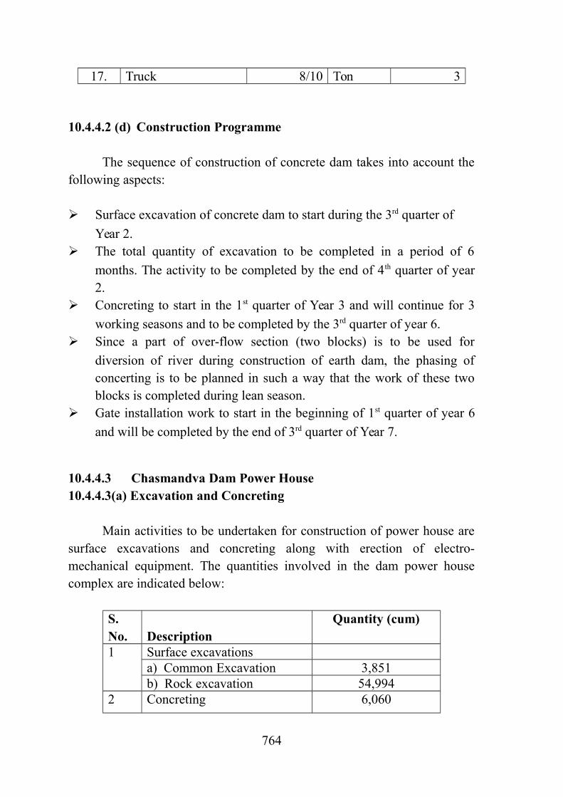
Main activities to be undertaken for construction of power house aresurface excavations and concreting along with erection of electro-mechanical equipment. The quantities involved in the dam power housecomplex are indicated below:
S. No. Description
Quantity (cum)
1 Surface excavations a) Common Excavation 3,851b) Rock excavation 54,994
2 Concreting 6,060
764

The sequence of operations for power house complex is based on thefollowing construction methods and equipment:
Excavation and loading of the soft material by 2.0 cum hydraulic
excavators assisted by 180 HP dozer. For rock excavations requiring drilling and blasting, drilling the very
steep areas by hand-held rigs with 38 mm diameter with hole patterns ofabout 1-2.5 m2 and drilling the accessible areas by crawler rigs with 76mm bits and hole patterns ranging from 7.5 to 9.0 m2.
Loading of the blasted rock by 2.0 cum hydraulic excavator bucket shovel
attachment and assisted by 180 HP dozers. Transportation to the disposal areas by 25t rear end dumpers.
Placing of concrete with 20 cum/hr concrete pumps with 25 m boom.
Concrete transportation by 4.5 cum transit mixers.
Concrete production in a moving Batching and mixing plant of capacity
18 cum/hr. The aggregate crushing and screening plant of 180 tph for preparation of
coarse and fine aggregates. Mobile crane of 16t is to be utilized for handling of construction material,
shutter forms etc.
10.4.4.3 (b) List of Major Construction Plant and Equipment for Power House
No separate equipment for construction of powerhouse complex hasbeen provided as equipment deployed for concrete dam shall be utilized forconstruction of power house.
10.4.4.3 (c) Construction Programme
As the excavation quantities are not much, a period of 3 months hasbeen planned beginning in the 3rd quarter of year 6. The construction of theconcrete structures will begin by the 4th quarter of Year 6 starting from thestructures of the erection area. Almost 15 months have been considerednecessary to complete the powerhouse.
All works including electro-mechanical works will be essentiallycompleted by 3rd quarter of year 7.
765

10.4.5 Chikkar Dam10.4.5.1 Concrete Face Rock-Fill Dam (Chikkar)
The construction of the dam involves surface excavation, placementof fill material, spreading & wetting and compaction of the fill material.Total quantity of Chikkar excavation excluding OF and NOF section isabout 1397914 cum. The excavation of 582464 cum quantity which doesnot involve blasting operation is considered as common excavation andremaining 815450 cum which requires blasting is considered as rockexcavation. Following table describes the quantities of different activitiesfor the construction of dam.
Description of Work
Type / Material Quantity, Unitin-situ
Stripping - 109,212 cum Excavation Common 473252 cum
Rock 815450 cumFill
placementImpervious material (1B) 176925 cumProcessed fine filter (2A) 9785 cumfine grained with particle sizeupto 150 mm (1A)
74393 cum
sand and gravel particles ingrade of 0.074 to 76.2 mm (2B)
215816 cum
300mm or less graded stone(3A)
331,434 cum
800mm or less graded stone(3B)
2,868,597
cum
1000mm or less graded stone(3C)
1,566,138
cum
1000mm or more graded stone(3D)
98,396 cum
rock-toe 22,941 cumBelow and Behind rock-toe 11,470 cum
10.4.5.1 (a) Surface ExcavationThe surface excavation for main dam involves both common and rock
excavations. The volume of required excavation is given below:
766

Volume of Surface Excavation
TypeDescription
Commonexcavation (cum)
Rock excavation(cum)
Stripping 109,212 NilRiver Bed Excavation 473252 815450
Total 582,464 815450
Duration of 2 months has been earmarked for undertaking strippingand a period of 7 months has been provided to undertake surface excavationpertaining to main dam. Although work in the river bed can be undertakenonly after completion of river diversion work, the work of stripping can betaken up earlier. The requirement for which provision of equipment for thesurface excavation is to be made is estimated below: Estimation of hourly quantity of excavation for Stripping
Type Description Common Excavation( stripping)
Total volume (cum) 109,212Time period (months) 2Shift proposed 2Total operational hours (hour) 550Volume to be handled in-situ (cum/hr) 198Volume to be handled loose (cum/hr) 250
Estimation of hourly quantity of excavation (for River bed )
TypeDescription
CommonExcavation(River bedexcavationonly)
RockExcavation
767

Total volume (cum) 473,252 815450Time period (months) 7 7Shift proposed 2 2Total operational hours (hour) 1925 1925Volume to be handled in-situ (cum/hr)
246 424
Volume to be handled loose (cum/hr)
307.3 677.8
Total quantity= 307.3+677.8Peak quantity = 985.1 cum/hour
Following construction methods are proposed for surface excavations:
Stripping and excavation for trenching & preparation of base of dam
and loading of the soft material (earth and alluvium) by 2.0 cumhydraulic excavators assisted by 180 HP crawler dozer.
Transportation to the disposal area by 25 t capacity rear dumper.
A 180 HP bulldozer is also considered to stay in the disposal area for
spreading of the unloaded materials. The rock excavation to be undertaken by drilling & blasting. Jack
hammers and wagon/crawler drill with hole patterns of 1m c/c and 2.75m c/c respectively to be deployed for drilling of charge holes.
10.4.5.1 (b) Fill Placement
The construction of earth fill dam involves placement of 5375895cum of fill materials. As per construction schedule the fill placement is to beundertaken in period of 24 months. The break-up of total quantity intodifferent types of fill material to be placed in different zones and theirexpected source of supply is given below:
Quantities and source of fill material
Sr.No.
Fill Material Quantity(compacte
d)
Averagedistance of
borrowarea/quarr
y (km)
768

1 Impervious material (1B) 176925 22 Processed fine filter (2A) 9785 2
3fine grained with particle size upto150 mm (1A)
74393 2
4sand and gravel particles in grade of0.074 to 76.2 mm (2B)
215816 1
5 300mm or less graded stone (3A) 331,434 2
6800mm or less graded stone (3B) 2,868,5
972
71000mm or less graded stone (3C) 1,566,1
382
8 1000mm or more graded stone (3D) 98,396 29 rock-toe 22,941 110 Below and Behind rock-toe 11,470 1
TOTAL= 5375895 cum
In the present case, since fill material is available within a distance of1 kilometer and borrow areas are scattered over different locations, theconventional method of material transportation, i.e., hydraulic excavator-dumper combination has been considered for material transportation.
As mentioned above, the fill quantities are to be placed in oneworking seasons. The hourly placement quantities for hearting material havebeen worked out and indicated below:
(i) Impervious Material(Zone 1A,1B and 2A)
SN Description Quantity Unit1. Total volume 261,103 cum2. Time period 8 month3. Shift proposed 2 -4. Operational hours/month 275 hour
5. Total operational hours 2200 hour6. Volume to be handled
(in-situ)118 cum/hour
7. Volume to be handled(loose)
188 cum/hour
8. Peak quantity 236 cum/hour
769

Estimation of hourly quantity of hearting material placement
The following construction methods have been considered for hearting fill:
Excavation and loading by means of 2.0 cum hydraulic excavator.
Transport to the embankment by means of 25 t capacity Rear end
dumpers. Spreading in layers up to 30 cm thick by 180 HP bulldoze.
Moisture adjustment by 8000 L water sprinklers.
Compaction by 8 passes of 10t pad foot vibrating roller.
An average distance of 0.5 km from dam site has been considered forthe borrow areas for impervious material.
(ii) Fine Filter material Placement (zone 2B, 3A)
The fine filter will have a total volume of 547,250 cum. The sand and gravelmaterial is used to fill 2A zone of CFRD Dam. This quantity will be broughtfrom quarries located at an average distance of 2 km from dam site. Thematerial will be processed in a processing plant located suitably near thequarry itself. The sand and gravel material will be processed and broughtto the dam site for placement.
The hourly rate at which placement of filter is to be carried out has
been estimated below.
Estimation of hourly quantity of fine filter material placement.
SN Description Quantity Unit1. Total volume 547,250 cum2. Time period 32 month3. Shift proposed 2 -4. Operational hours/month 275 hour5. Total operational hours 8800 hour6. Volume to be handled (in-
situ)63 cum/hour
770

7. Volume to be handled (loose) 78 cum/hour
8. Peak quantity 99 cum/hour
The following construction methods have been considered for theplacement of fine filter:
Loading at the quarry by 2.0 cum hydraulic excavator and
transportation up to filter processing plant by 25t capacity rear dumper. Processing at the filter processing plant of capacity, 250 tph installed
near the quarry. Loading by 2.5 cum loader and transport to the dam site by 25t
capacity rear dumper. Spreading on the embankment in layers up to 30 cm thick by bulldozer
with flywheel power of 180 HP. Compaction with 6 passes of 10t smooth drum vibratory roller.
(iii) Coarse Filter (Zone 3B)
The requirement of coarse filter which is going to be used in zone 3Bfilling is approximately 2,868,597cum. The same will be met from rockquarries. The rock will be transported to the placement site. The tablesbelow shows the estimation of hourly quantities involved.
Estimation of hourly quantity of coarse filter material placement
SN Description Quantity Unit1. Total volume 2,868,597 cum2. Time period 32 month3. Shift proposed 2 -4. Operational hours/month 275 hour
5. Total operational hours 8800 hour
6. Volume to be handled (in-situ) 326 cum/hour
7. Volume to be handled (loose) 522 cum/hour
8. Peak quantity 652 cum/hour
The following construction methods and equipment are consideredsuitable for rockfill placement:
771

Drilling of charge holes at the quarry by means of jack hammers and
crawler drills with hole patterns of 1-2.75 m c/c. Blasting by means of electric detonators connected to proper wire
circuits. Loading at the quarry by 2.0 cum hydraulic excavator and
transportation up to filter processing plant by 25t capacity rear dumper. Processing at the filter processing plant of 1 no. of 750 TPH and 1 no.
of 500TPH capacity installed at about 1 km to Dam Site. Loading at the filter processing plant by 2.5 cum loader and transport
to the dam site by 25t capacity rear dumper. Spreading of the unloaded material on the embankment to about 50 cm
to 70cm layer thickness, by means of 180 HP flywheel powerbulldozer.
Compaction by 6 pass of 10t smooth drum vibrating rollers.
(iv) Rock material for Zone 3C, 3D, Rock toe
The requirements of coarse filter which is going to be used in Rocktoe and below Rock toe is approximately 1,698,945 cum. The same will bemet from rock quarries. The tables below shows the estimation of hourlyquantities involved.
Estimation of hourly quantity of coarse filter and rock-toe materialplacement
SN Description Quantity Unit1. Total volume 1,698,945 cum2. Time period 32 month3. Shift proposed 2 -4. Operational hours/month 275 hour
5. Total operational hours 8,800 hour6. Volume to be handled (in-situ) 193 cum/hour
7. Volume to be handled (loose) 308 cum/hour8. Peak quantity 395 cum/hour
The following construction methods and equipment are consideredsuitable for rockfill placement:
772

Drilling of charge holes at the quarry by means of jack hammers and
crawler drills with hole patterns of 1-2.75 m c/c. Blasting by means of electric detonators connected to proper wire
circuits. Loading at the quarry by 2.5 cum hydraulic excavator and
transportation up to filter processing plant by 25t capacity rear dumper.
Processing at the filter processing plant of capacity, 1 no. 750 TPH
installed at about 1 km to Dam Site. Loading at the filter processing plant by 2.5 cum loader and transport
to the dam site by 25t capacity rear dumper. Spreading of the unloaded material on the embankment to about 100
cm to 150cm layer thickness, by means of 324 HP flywheel powerbulldozer.
Compaction by 6 passes of 10t smooth drum vibrating rollers.
Concreting work on CFRD Dam like concreting of face slab, plinthetc can be done with the help of concrete pump of capacity 15 cum/hr withboom length of 25m. One moving type batch and mixing plant of capacity18cum/hr may be deployed to meet the requirement of concrete. 10.4.5.1(c) List of Major Construction Plant and Equipment for CFRD Dam
Based on above methodology and equipment planning the list ofequipment required for construction of Concrete Face Rock Fill Dam(Chasmandva) is given in the following table.
S. No. Description Size/capacity
Quantity
1. Hyd. Excavator 2.0 cum 112. Hyd. Excavator 1.0 cum 23. Loader, frnt end 2.5 cum 134. Loader, frnt end 1.5 cum 25. Dumper 25 T 746. wagon drill 550 cfm 57. Jack hammer 120 cfm 21
773

S. No. Description Size/capacity
Quantity
8. Air requirement cfm 46009. Filter Processing plant 200 TPH 110. Filter Processing plant 500 TPH 111. Filter Processing plant 750 TPH 212. Dozer 180 HP 1813. Dozer 324 Hp 214. Vibratory roller (Padfoot) 10 T 115. Vibratory roller
(smoothpad) 10 T 416. Water Sprinkler 8000 liters 1417. Transit mixer 4.5 cum 218. Concrete vibrator 319. B&M plant(moving) 18 Cum/hr 120. Concrete Pump 15 Cum/hr 121. Grout Pump 20 Kg/cm2 422. Mobile crane 16 Ton 423. Truck 8/10 Ton 8
10.4.5.1 (d) Construction Programme
The excavations for the dam will start from the abutments above riverbed level in the 2nd quarter of year 2 and will be completed within threemonths working period. Excavations in the river bed will start as soon as thework area in the river bed becomes dry. The dam foundation treatment,which includes consolidation grouting and curtain grouting, will start locallyas the excavation is completed in that area.
Embankment construction will start by 3rd quarter of year 3, once theexcavation and foundation preparation works in the river bed aresufficiently advanced. The period before the beginning of the embankmentconstruction shall be devoted to the preparation of the haul roads anddevelopment of the borrow area.
A total period of 32 months, excluding the monsoon period has beenallowed for the completion of the dam embankment with the aim to reachcrest elevation by the end of 2nd quarter of year 7.
10.4.5.2 Concrete Dam (Chikkar)
774

Main activities to be undertaken for construction of concrete dam(over flow & non-over flow sections) are surface excavations andconcreting. Surface excavations will comprise of common excavation inoverburden and rock excavation. The total quantity of concrete damexcavation is about 553819 cum, and total quantity of concreting is about311774 cum.
Quantities involved in construction of concrete dam (over flow & non-over flow)
Description of Work
Type / Material Quantity, Unitin-situ
Stripping - - cumExcavation Common 143855 cum
Rock 409964 cum Total excavation 553819 cum
Concreting 311774 cum
10.4.5.2 (a) Surface Excavations
The surface excavations have been planned to be completed within 1working seasons (6 months). The surface excavation for main dam involvesboth common and rock excavations. The excavated material will betransported to the disposal area using conventional excavator and reardumper combination. The provision of equipment for the surfaceexcavation is to be made is estimated below:
Estimation of hourly quantity of excavation
TypeDescription
CommonExcavation
RockExcavation
Total volume (cum) 143855 409964Time period (months) 6 6Shift proposed 2 2Total operational hours (hour) 1650 1650Volume to be handled in-situ (cum/hour)
87 248
Volume to be handled loose(cum/hour)
109 397
775

Total quantity = 109 + 397 ~ 506 cum/hour
The construction equipment for surface excavations is as under: Excavation and loading of the soft material (common excavation) by
2.0 cum hydraulic excavators assisted by 180 hp bulldozers. For rock excavations requiring drilling & blasting, drilling the very
steep areas by hand-held rigs (jack hammer) of 38 mm diameter withhole patterns of about 2.75 m2 and drilling the accessible areas bycrawler drill.
Loading of blasted rock by 2.5 cum hydraulic excavator, shovel
attachment and assisted by 180 hp dozers. Transportation to the disposal areas/main dam by 25t rear dumpers.
Crawler dozer, 180 HP to be deployed at the disposal area to spread the
material.
10.4.5.2 (b) Concreting
For concreting of main dam and appurtenant structures, totalquantity of the order of 311774 cum, will have to be placed. A period of 27months excluding monsoon period been planned for the placement. The rateof placement works out to 33 cum/hour approximately. The concreterequired for main dam is proposed to be produced in a centralized Batchingand Mixing Plant of capacity 60 cum/hour. The plant shall be located in thevicinity of the dam. In addition, one numbers mobile batching & mixingplant of capacity, 18 cum/hour will be provided. The concrete from the plantwill be transported with the help of transit mixers, 4.5 cum capacity.
Following construction equipments have been considered forconcreting of main dam and appurtenant structures:
Placing of concrete with the help of 2 Nos. tower cranes, 6 ton @ 40
metre radius are proposed to be deployed at suitable locations. Inaddition, 2 Nos. 25 cum/hr concrete pumps with 25 m boom will beused for concrete placement.
Concrete transportation by transit mixers of 4.5 cum capacity.
776

Batching and mixing plant of capacity 60 cum/hr to be located
preferably within a radius of 2 km from the concrete dam. The aggregate crushing and screening plant of 180 tph for preparation of
coarse and fine aggregates.
10.4.5.2 ( c ) List of Major Construction Plant and Equipment for Concrete Dam
Based on above construction methodology, major construction plantand equipment required for construction of concrete dam are listed below.
S. No.
Equipments Size/capacity Quantity
1. Hyd. Excavator 2 cum 42. Hyd. Excavator 1 cum 03. Loader, side dump 1.5 cum 14. Dumper 25 T 175. wagon drill 550 cfm 36. Jack hammer 120 cfm 167. Air requirment cfm 30008. Tower Crane 6T@40m 29. Dozer 180 HP 310. B&M Plant 60 cum/hr 111. mobile B&M Plant 18 cum/hr 112. APP 180 TPH 113. Transit Mixer 4.5 cum 414. Concrete pump 25 cum/hr 215. Grout Pump 20 Kg/cm2 216. Mobile crane 16 Ton 217. Truck 8/10 Ton 3
10.4.5.2 (d) Construction Programme
The sequence of construction of concrete dam takes into account thefollowing aspects:
Surface excavation of concrete dam to start during the 4th quarter of
Year 2.
777

The total quantity of excavation to be completed in a period of 6
months. The activity to be completed by the end of 1st quarter of year 3. Concreting to start in the 1st quarter of Year 3 and will continue for 3
working seasons and to be completed by the 3rd quarter of year 6. Since a part of over-flow section (two blocks) is to be used for
diversion of river during construction of earth dam, the phasing ofconcerting is to be planned in such a way that the work of these twoblocks is completed during lean season.
Gate installation work to start in the beginning of 1st quarter of year 6
and will be completed by the end of 3rd quarter of Year 7.
10.4.5.3 Chikkar Dam Power House10.4.5.3 (a) Excavation and Concreting
Main activities to be undertaken for construction of power house aresurface excavations and concreting along with erection of electro-mechanical equipment. The quantities involved in the dam power housecomplex are indicated below:
S. No. Description
Quantity (cum)
1 Surface excavations a) Common Excavation 5,287b) Rock excavation 201,763
2 Concreting 7,540
The sequence of operations for power house complex is based on thefollowing construction methods and equipment:
Excavation and loading of the soft material by 2.0 cum hydraulic
excavators assisted by 180 HP dozer. For rock excavations requiring drilling and blasting, drilling the very
steep areas by hand-held rigs with 38 mm diameter with hole patterns ofabout 1-2.5 m2 and drilling the accessible areas by crawler rigs with 76mm bits and hole patterns ranging from 7.5 to 9.0 m2.
Loading of the blasted rock by 2.0 cum hydraulic excavator bucket
shovel attachment and assisted by 180 HP dozers.
778

Transportation to the disposal areas by 25t rear end dumpers.
Placing of concrete with 20 cum/hr concrete pumps with 25 m boom.
Concrete transportation by 4.5 cum transit mixers.
Concrete production in a moving Batching and mixing plant of capacity
18 cum/hr. The aggregate crushing and screening plant of 180 tph for preparation of
coarse and fine aggregates. Mobile crane of 16t is to be utilized for handling of construction
material, shutter forms etc.
10.4.5.3 (b) List of Major Construction Plant and Equipment for Power House
No separate equipment for construction of powerhouse complex hasbeen provided as equipment deployed for concrete dam shall be utilized forconstruction of power house.
10.4.5.3(c ) Construction Programme
As the excavation quantities are not much, a period of 3 months hasbeen planned beginning in the 3rd quarter of year 6. The construction of theconcrete structures will begin by the 4th quarter of Year 6 starting from thestructures of the erection area. Almost 15 months have been considerednecessary to complete the powerhouse.
All works including electro-mechanical works will be essentiallycompleted by 3rd quarter of year 7.
10.4.6 Dabdar Dam10.4.6.1 Concrete Face Rock-Fill Dam (Dabdar)
The construction of the dam involves surface excavation, placementof fill material, spreading & wetting and compaction of the fill material.Total quantity of Dabdar excavation excluding OF and NOF section is about2376516 cum. The excavation of 789459 cum quantity which does notinvolve blasting operation is considered as common excavation and
779

remaining 1587057 cum which requires blasting is considered as rockexcavation. Following Table describes the quantities of different activitiesfor the construction of dam.
Description of Work
Type / Material Quantity,in-situ
Unit
Stripping - 97,665 cum Excavation Common 691794 cum
Rock 1587057 cumFill
placementImpervious material (1B) 104811 cumProcessed fine filter (2A) 5938 cumfine grained with particle sizeupto 150 mm (1A)
39976 cum
sand and gravel particles ingrade of 0.074 to 76.2 mm (2B)
217022 cum
300mm or less graded stone (3A) 280,812 cum
800mm or less graded stone (3B) 3,455,102 cum1000mm or less graded stone(3C)
1,942,842 cum
1000mm or more graded stone(3D)
98,029 cum
rock-toe 22,941 cumBelow and Behind rock-toe 11,470 cum
10.4.6.1(a) Surface Excavation
The surface excavation for main dam involves both common and rockexcavations. The volume of required excavation is given below:
Volume of Surface Excavation
TypeDescription
Commonexcavation
(cum)
Rockexcavation
(cum)Stripping 97,665 NilRiver Bed Excavation 691794 1587057
Total 789,459 1587057
780

Duration of 2 months has been earmarked for undertaking strippingand a period of 12 months has been provided to undertake surfaceexcavation pertaining to main dam. The requirement for which provision ofequipment for the surface excavation is to be made is estimated below:
Estimation of hourly quantity of excavation for Stripping
TypeDescription
CommonExcavation(stripping)
Total volume (cum) 97,665Time period (months) 2Shift proposed 2Total operational hours (hour) 5500Volume to be handled in-situ (cum/hr) 178Volume to be handled loose (cum/hr) 222
Estimation of hourly quantity of excavation (for River bed )
TypeDescription
CommonExcavation(River bedexcavation
only)
RockExcavation
Total volume (cum) 691,794 1587057Time period (months) 12 12Shift proposed 2 2Total operational hours (hour) 3300 3300Volume to be handled in-situ (cum/hr) 209 481Volume to be handled loose (cum/hr) 262 770
Peak 315 925
Total quantity= 315+925Peak quantity = 1240 cum/hour
Following construction methods are proposed for surface excavations:
Stripping and excavation for trenching & preparation of base of dam
and loading of the soft material (earth and alluvium) by 2.0 cumhydraulic excavators assisted by 180 HP crawler dozer.
Transportation to the disposal area by 25 t capacity rear dumper.
781

A 180 HP bulldozer is also considered to stay in the disposal area for
spreading of the unloaded materials. The rock excavation to be undertaken by drilling & blasting. Jack
hammers and wagon/crawler drill with hole patterns of 1m c/c and 2.75m c/c respectively to be deployed for drilling of charge holes.
10.4.6.1 (b) Fill Placement
The construction of earth fill dam involves placement of6178943 cum of fill materials. As per construction schedule the fillplacement is to be undertaken in period of 24 months. The break-up of totalquantity into different types of fill material to be placed in different zonesand their expected source of supply is given below:
Quantities and source of fill material
Sr.No.
Fill Material Quantity(compacted)
Averagedistance of
borrowarea/quarry
(km)1 Impervious material (1B) 104811 22 Processed fine filter (2A) 5938 2
3fine grained with particle size upto150 mm (1A)
39976 2
4sand and gravel particles in grade of0.074 to 76.2 mm (2B)
217022 1
5 300mm or less graded stone (3A) 280,812 26 800mm or less graded stone (3B) 3,455,102 27 1000mm or less graded stone (3C) 1,942,842 28 1000mm or more graded stone (3D) 98,029 29 rock-toe 22,941 110 Below and Behind rock-toe 11,470 1
TOTAL= 6178943 cum
In the present case, since fill material is available within a distance of1 kilometer and borrow areas are scattered over different locations, theconventional method of material transportation, i.e., hydraulic excavator-dumper combination has been considered for material transportation.
782
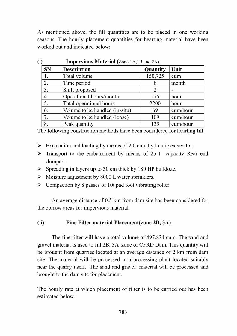
As mentioned above, the fill quantities are to be placed in one workingseasons. The hourly placement quantities for hearting material have beenworked out and indicated below:
(i) Impervious Material (Zone 1A,1B and 2A)
SN Description Quantity Unit1. Total volume 150,725 cum2. Time period 8 month3. Shift proposed 2 -4. Operational hours/month 275 hour5. Total operational hours 2200 hour6. Volume to be handled (in-situ) 69 cum/hour7. Volume to be handled (loose) 109 cum/hour8. Peak quantity 135 cum/hour
The following construction methods have been considered for hearting fill:
Excavation and loading by means of 2.0 cum hydraulic excavator.
Transport to the embankment by means of 25 t capacity Rear end
dumpers. Spreading in layers up to 30 cm thick by 180 HP bulldoze.
Moisture adjustment by 8000 L water sprinklers.
Compaction by 8 passes of 10t pad foot vibrating roller.
An average distance of 0.5 km from dam site has been considered forthe borrow areas for impervious material.
(ii) Fine Filter material Placement(zone 2B, 3A)
The fine filter will have a total volume of 497,834 cum. The sand andgravel material is used to fill 2B, 3A zone of CFRD Dam. This quantity willbe brought from quarries located at an average distance of 2 km from damsite. The material will be processed in a processing plant located suitablynear the quarry itself. The sand and gravel material will be processed andbrought to the dam site for placement.
The hourly rate at which placement of filter is to be carried out has beenestimated below.
783

Estimation of hourly quantity of fine filter material placement.
SN Description Quantity Unit1. Total volume 497,834 cum2. Time period 28 month3. Shift proposed 2 -4. Operational hours/month 275 hour
5. Total operational hours 7700 hour6. Volume to be handled (in-situ) 64 cum/hour7. Volume to be handled (in-situ) 80 cum/hour
8. Peak quantity 101 cum/hour
The following construction methods have been considered for theplacement of fine filter:
Loading at the quarry by 2.0 cum hydraulic excavator and
transportation up to filter processing plant by 25t capacity rear dumper. Processing at the filter processing plant of capacity, 200 TPH installed
near the quarry. Loading by 2.5 cum loader and transport to the dam site by 25t
capacity rear dumper. Spreading on the embankment in layers up to 30 cm thick by bulldozer
with flywheel power of 180 HP. Compaction with 6 passes of 10t smooth drum vibratory roller.
(iii) Coarse Filter (Zone 3B)
The requirement of coarse filter which is going to be used in zone 3Bfilling is approximately 3,455,102cum. The same will be met from rockquarries. The rock will be transported to the placement site. The tablesbelow shows the estimation of hourly quantities involved.
Estimation of hourly quantity of coarse filter material placement
SN Description Quantity Unit1. Total volume 3,455,102 cum2. Time period 28 month3. Shift proposed 2 -4. Operational hours/month 275 hour
784

5. Total operational hours 7700 hour6. Volume to be handled (in-situ) 448 cum/hour
7. Volume to be handled (in-situ) 718 cum/hour
8. Peak quantity 897 cum/hour
The following construction methods and equipment are consideredsuitable for rockfill placement: Drilling of charge holes at the quarry by means of jack hammers and
crawler drills with hole patterns of 1-2.75 m c/c. Blasting by means of electric detonators connected to proper wire
circuits. Loading at the quarry by 2.0 cum hydraulic excavator and
transportation up to filter processing plant by 25t capacity rear dumper. Processing at the filter processing plant of 2 no. of 750 tph and 1 no. of
250 Tph capacity installed at about 1 km to Dam Site. Loading at the filter processing plant by 2.5 cum loader and transport
to the dam site by 25t capacity rear dumper. Spreading of the unloaded material on the embankment to about 50 cm
to 70cm layer thickness, by means of 180 HP flywheel powerbulldozer.
Compaction by 6 pass of 10t smooth drum vibrating rollers.
(v) Rock material for Zone 3C,3D, Rock toe
The requirements of coarse filter which is going to be used in Rocktoe and below Rock toe is approximately 2,075,282. The same will be metfrom rock quarries. The tables below shows the estimation of hourlyquantities involved.
Estimation of hourly quantity of coarse filter and rock-toe materialplacement
SN Description Quantity Unit1. Total volume 2,075,282 cum2. Time period 29 month3. Shift proposed 2 -4. Operational hours/month 275 hour
785

5. Total operational hours 7,700 hour6. Volume to be handled (in-
situ)269 cum/hour
7. Volume to be handled (in-situ)
432 cum/hour
8. Peak quantity 540 cum/hour
The following construction methods and equipment are consideredsuitable for rockfill placement:
Drilling of charge holes at the quarry by means of jack hammers and
crawler drills with hole patterns of 1-2.75 m c/c. Blasting by means of electric detonators connected to proper
wire circuits. Loading at the quarry by 2.0 cum hydraulic excavator and
transportation up to filter processing plant by 25t capacity rear dumper. Processing at the filter processing plant of capacity, 2 nos 500 PH
installed at about 1 km to Dam Site. Loading at the filter processing plant by 2.5 cum loader and
transport to the dam site by 25t capacity rear dumper. Spreading of the unloaded material on the embankment to
about 100 cm to 150cm layer thickness, by means of 324 HP flywheelpower bulldozer.
Compaction by 6 passes of 10t smooth drum vibrating rollers.
Concreting work on CFRD Dam like concreting of face slab, plinth etccan be done with the help of concrete pump of capacity 15 cum/hr withboom length of 25m. One moving type batch and mixing plant of capacity18cum/hr may be deployed to meet the requirement of concrete. 10.4.6.1(c) List of Major Construction Plant and Equipment for CFRD Dam
Based on above methodology and equipment planning the list of equipment required for construction of Concrete Face Rock Fill Dam is given in the following table.
786

S. No. Description Size/capacity
Quantity
1. Hyd. Excavator 2.0 cum 132. Hyd. Excavator 1.0 cum 23. Loader, frnt end 2.5 cum 164. Loader, frnt end 1.5 cum 25. Dumper 25 T 966. wagon drill 550 cfm 77. Jack hammer 120 cfm 298. Air requirement cfm 60009. Filter Processing plant 200 TPH 210. Filter Processing plant 500 TPH 211. Filter Processing plant 750 TPH 212. Dozer 180 HP 2213. Dozer 324 Hp 214. Vibratory roller (Padfoot) 10 T 115. Vibratory roller
(smoothpad) 10 T 616. Water Sprinkler 8000 liters 1617. Transit mixer 4.5 cum 318. Concrete vibrator 319. B&M plant(moving) 18 Cum/hr 120. Concrete Pump 15 Cum/hr 121. Grout Pump 20 Kg/cm2 422. Mobile crane 16 Ton 423. Truck 8/10 Ton 8
10.4.6.1 (d) Construction Programme
The excavations for the dam will start from the abutments above riverbed level in the 2th quarter of year 2 and will be completed within twomonths working period. Excavations in the river bed will start as soon as thework area in the river bed becomes dry. The dam foundation treatment,which includes consolidation grouting and curtain grouting, will start locallyas the excavation is completed in that area.
Embankment construction will start by 4th quarter of year 3, once theexcavation and foundation preparation works in the river bed aresufficiently advanced. The period before the beginning of the embankment
787

construction shall be devoted to the preparation of the haul roads anddevelopment of the borrow area.
A total period of 28 months, excluding the monsoon period has beenallowed for the completion of the dam embankment with the aim to reachcrest elevation by the end of 2nd quarter of year 7.
10.4.6.2 Concrete Dam (Dabdar)
Main activities to be undertaken for construction of concrete dam(over flow & non-over flow sections) are surface excavations andconcreting. Surface excavations will comprise of common excavation inoverburden and rock excavation. The total quantity of concrete damexcavation is about 311336 cum, and total quantity of concreting is about400926 cum.
Quantities involved in construction of concrete dam(over flow & non-over flow)
Description of Work
Type / Material Quantity, Unitin-situ
Stripping - - cumExcavation Common 83719 cum
Rock 227617 cum Total excavation 311336 cum
Concreting 400926 cum
10.4.6.2 (a) Surface Excavations
The surface excavations have been planned to be completed within 1working seasons (3 months). The surface excavation for main dam involvesboth common and rock excavations. The excavated material will betransported to the disposal area using conventional excavator and reardumper combination. The provision of equipment for the surfaceexcavation is to be made is estimated below:
788

Estimation of hourly quantity of excavation
TypeDescription
CommonExcavation
RockExcavation
Total volume (cum) 83719 227617Time period (months) 5 5Shift proposed 2 2Total operational hours (hour) 1375 1375Volume to be handled in-situ (cum/hour)
61 166
Volume to be handled loose(cum/hour)
76 265
Total quantity = 76 + 265 ~ 341 cum/hour
The construction equipment for surface excavations is as under: Excavation and loading of the soft material (common excavation) by
2.0 cum hydraulic excavators assisted by 180 hp bulldozers. For rock excavations requiring drilling & blasting, drilling the very
steep areas by hand-held rigs (jack hammer) of 38 mm diameter withhole patterns of about 2.75 m2 and drilling the accessible areas bycrawler drill.
Loading of blasted rock by 2.5 cum hydraulic excavator, shovel
attachment and assisted by 180 hp dozers. Transportation to the disposal areas/main dam by 25t rear dumpers.
Crawler dozer, 180 HP to be deployed at the disposal area to spread the
material.
10.4.6.2 (b ) Concreting
For concreting of main dam and appurtenant structures, total quantityof the order of 400926 cum, will have to be placed. A period of 27 monthsexcluding monsoon period has been planned for the placement. The peakrate of placement works out to 48 cum/hour approximately. The concrete
789

required for main dam is proposed to be produced in a centralized Batchingand Mixing Plant of capacity 60 cum/hour. The plant shall be located in thevicinity of the dam. In addition, two numbers mobile batching & mixingplant each of capacity, 18 cum/hour will be provided. The concrete from theplant will be transported with the help of transit mixers, 4.5 cum capacity.
Following construction equipments have been considered forconcreting of main dam and appurtenant structures:
Placing of concrete with the help of 2 Nos. tower cranes, 6 ton @ 40
metre radius are proposed to be deployed at suitable locations. Inaddition, 2 Nos. 25 cum/hr concrete pumps with 25 m boom will beused for concrete placement.
Concrete transportation by transit mixers of 4.5 cum capacity.
Batching and mixing plant of capacity 60 cum/hr to be located
preferably within a radius of 2 km from the concrete dam. The aggregate crushing and screening plant of 250 tph for preparation
of coarse and fine aggregates.
10.4.6.2( c ) List of Major Construction Plant and Equipment for Concrete Dam
Based on above construction methodology, major construction plantand equipment required for construction of concrete dam are listed below.
S. N0.
Equipments Size/capacity Quantity
1. Hyd. Excavator 2 cum 32. Hyd. Excavator 1 cum 03. Loader, side dump 1.5 cum 14. Dumper 25 T 135. wagon drill 550 cfm 26. Jack hammer 120 cfm 97. Air requirment cfm 18008. Tower Crane 6T@40m 29. Dozer 180 HP 310. B&M Plant 60 cum/hr 111. mobile B&M Plant 18 cum/hr 212. APP 250 TPH 1
790

13. Transit Mixer 4.5 cum 514. Concrete pump 25 cum/hr 215. Grout Pump 20 Kg/cm2 216. Mobile crane 16 Ton 217. Truck 8/10 Ton 3
10.4.6.2 (d ) Construction Programme
The sequence of construction of concrete dam takes into account thefollowing aspects:
Surface excavation of concrete dam to start during the 4th quarter of Year
2. The total quantity of excavation to be completed in a period of 5 months.
The activity to be completed by the end of 4th quarter of year 2. Concreting to start in the 1st quarter of Year 3 and will continue for 3
working seasons and to be completed by the 3rd quarter of year 6. Since a part of over-flow section (two blocks) is to be used for diversion
of river during construction of earth dam, the phasing of concerting is tobe planned in such a way that the work of these two blocks is completedduring lean season.
Gate installation work to start in the beginning of 1st quarter of year 6 and
will be completed by the end of 3rd quarter of Year 7.
10.4.6.3 Dabdar Dam Power House10.4.6.3(a) Excavation and Concreting
Main activities to be undertaken for construction of power house aresurface excavations and concreting along with erection of electro-mechanical equipment. The quantities involved in the dam power housecomplex are indicated below:
S. No. Description
Quantity(cum)
1 Surface excavations a) Common Excavation 1,308b) Rock excavation 10,724
791

2 Concreting 9,491
The sequence of operations for power house complex is based on thefollowing construction methods and equipment:
Excavation and loading of the soft material by 2.0 cum hydraulic
excavators assisted by 180 HP dozer. For rock excavations requiring drilling and blasting, drilling the very
steep areas by hand-held rigs with 38 mm diameter with hole patternsof about 1-2.5 m2 and drilling the accessible areas by crawler rigs with76 mm bits and hole patterns ranging from 7.5 to 9.0 m2.
Loading of the blasted rock by 2.0 cum hydraulic excavator bucket
shovel attachment and assisted by 180 HP dozers. Transportation to the disposal areas by 25t rear end dumpers.
Placing of concrete with 20 cum/hr concrete pumps with 25 m boom.
Concrete transportation by 4.5 cum transit mixers.
Concrete production in a moving Batching and mixing plant of
capacity 18 cum/hr. The aggregate crushing and screening plant of 250 tph for preparation
of coarse and fine aggregates. Mobile crane of 16t is to be utilized for handling of construction
material, shutter forms etc.
10.4.6.3(b )List of Major Construction Plant and Equipment for Power House
No separate equipment for construction of powerhouse complex hasbeen provided as equipment deployed for concrete dam shall be utilized forconstruction of power house.
10.4.6.3(c ) Construction Programme
As the excavation quantities are not much, a period of 3 months hasbeen planned beginning in the 3rd quarter of year 6. The construction of theconcrete structures will begin by the 4th quarter of Year 6 starting from thestructures of the erection area. Almost 15 months have been considered
792

necessary to complete the powerhouse.
All works including electro-mechanical works will be essentiallycompleted by 3rd quarter of year 7..10.4.7 Kelwan Dam10.4.7.1 Concrete Face Rock-Fill Dam (Kelwan Dam)
The construction of the dam involves surface excavation, placementof fill material, spreading & wetting and compaction of the fill material.Total quantity of Jheri dam excavation excluding OF and NOF section isabout 1827000 cum. The excavation of 675990 cum quantity which doesnot involve blasting operation is considered as common excavation andremaining 1151010 cum which requires blasting is considered as rockexcavation. Following assumptions have been made while working out thequantities of different activities for the construction of dam
Description of Work
Type / Material Quantity,in-situ
Unit
Stripping - 109,620 cum Excavation Common 566370 cum
Rock 1151010 cum
Fill placement Impervious material (1B) 112890 cumProcessed fine filter (2A) 6757 cumfine grained with particlesize upto 150 mm (1A)
42185 cum
sand and gravel particles ingrade of 0.074 to 76.2 mm(2B)
210780 cum
300mm or less graded stone(3A)
289,590 cum
800mm or less graded stone(3B)
3,159,590 cum
1000mm or less graded stone(3C)
1,757,670 cum
1000mm or more gradedstone (3D)
99,134 cum
793

rock-toe 22,941 cumBelow and Behind rock-toe 11,470 cum
10.4.7.1 (a) Surface Excavation
The surface excavation for main dam involves both common and rockexcavations. The volume of required excavation is given below:
Volume of Surface Excavation
TypeDescription
Commonexcavation
(cum)
Rockexcavation
(cum)Stripping 109,620 NilRiver Bed Excavation 566370 1151010
Total 675,990 1151010
Duration of 2 months has been earmarked for undertaking strippingand a period of 12 months has been provided to undertake surfaceexcavation pertaining to main dam. Although work in the river bed can beundertaken only after completion of river diversion work, the work ofstripping can be taken up earlier. The requirement for which provision ofequipment for the surface excavation is to be made is estimated below:
Estimation of hourly quantity of excavation for Stripping
Type Description Common Excavation( stripping)
Total volume (cum) 109,620Time period (months) 2Shift proposed 2Total operational hours (hour) 550Volume to be handled in-situ (cum/hr) 199Volume to be handled loose (cum/hr) 249
Estimation of hourly quantity of excavation (for River bed )
794

TypeDescription
CommonExcavation (Riverbed excavationonly)
RockExcavation
Total volume (cum) 566,370 1151010Time period (months) 12 12Shift proposed 2 2Total operational hours (hour) 3300 3300Volume to be handled in-situ (cum/hr)
171 348
Volume to be handled loose (cum/hr)
215 558
Peak quantities 258 698Total quantity= 268+669Peak quantity = 926 cum/hour
Following construction methods are proposed for surfaceexcavations:
Stripping and excavation for trenching & preparation of base of dam
and loading of the soft material (earth and alluvium) by 2.0 cumhydraulic excavators assisted by 180 HP crawler dozer.
Transportation to the disposal area by 25 t capacity rear dumper.
A 180 HP bulldozer is also considered to stay in the disposal area for
spreading of the unloaded materials. The rock excavation to be undertaken by drilling & blasting. Jack
hammers and wagon/crawler drill with hole patterns of 1m c/c and 2.75m c/c respectively to be deployed for drilling of charge holes.
10.4.7.1 (b) Fill Placement
The construction of earth fill dam involves placement of 5713007cum of fill materials. As per construction schedule the fill placement is to beundertaken in period of 24 months. The break-up of total quantity intodifferent types of fill material to be placed in different zones and theirexpected source of supply is given below:
795

Quantities and source of fill material
Sr.No.
Fill Material Quantity(compacted)
1 Impervious material (1B) 1128902 Processed fine filter (2A) 6757
3fine grained with particle size upto 150 mm(1A)
42185
4sand and gravel particles in grade of 0.074 to76.2 mm (2B)
210780
5 300mm or less graded stone (3A) 289,5906 800mm or less graded stone (3B) 3,159,5907 1000mm or less graded stone (3C) 1,757,6708 1000mm or more graded stone (3D) 99,1349 rock-toe 22,94110 Below and Behind rock-toe 11,470
TOTAL= 5713007 In the present case, since fill material is available within a distance of
1 kilometer and borrow areas are scattered over different locations, theconventional method of material transportation, i.e., hydraulic excavator-dumper combination has been considered for material transportation.
As mentioned above, the fill quantities are to be placed in oneworking seasons. The hourly placement quantities for hearting material havebeen worked out and indicated below:
(i) Impervious Material(Zone 1A,1B and 2A)
Estimation of hourly quantity of hearting material placementSl.No Description Quantity Unit1. Total volume 161,832 cum2. Time period 8 month3. Shift proposed 2 -4. Operational hours/month 275 hour5. Total operational hours 2200 hour6. Volume to be handled (in-situ) 74 cum/hour
7. Volume to be handled (loose) 117 cum/hour8. Peak quantity 147 cum/hour
796

The following construction methods have been considered forhearting fill:
Excavation and loading by means of 2.0 cum hydraulic excavator.
Transport to the embankment by means of 25 t capacity Rear end
dumpers. Spreading in layers up to 30 cm thick by 180 HP bulldoze.
Moisture adjustment by 8000 L water sprinklers.
Compaction by 8 passes of 10t pad foot vibrating roller.
An average distance of 0.5 km from dam site has been considered forthe borrow areas for impervious material.
(ii) Fine Filter material Placement (zone 2B, 3A)
The fine filter will have a total volume of 500,370cum. The sand andgravel material is used to fill 2B, 3A zone of CFRD Dam. This quantity willbe brought from quarries located at an average distance of 2 km from damsite. The material will be processed in a processing plant located suitablynear the quarry itself. The sand and gravel material will be processed andbrought to the dam site for placement.
The hourly rate at which placement of filter is to be carried out hasbeen estimated below
Estimation of hourly quantity of fine filter material placement.
SN Description Quantity Unit1. Total volume 500,370 cum2. Time period 28 month3. Shift proposed 2 -4. Operational hours/month 275 hour
5. Total operational hours 7,700 hour6. Volume to be handled (in-situ) 65 cum/hour7. Volume to be handled (loose) 81 cum/hour8 Peak quantity 101 cum/hour
797
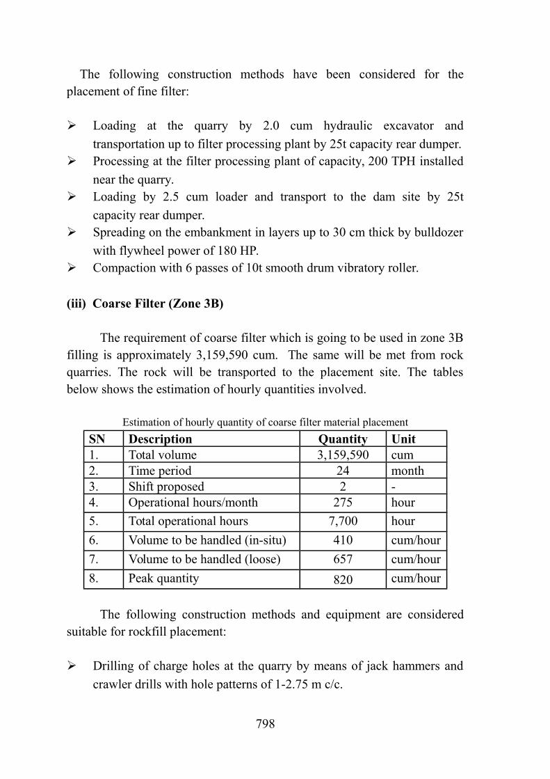
The following construction methods have been considered for theplacement of fine filter:
Loading at the quarry by 2.0 cum hydraulic excavator and
transportation up to filter processing plant by 25t capacity rear dumper. Processing at the filter processing plant of capacity, 200 TPH installed
near the quarry. Loading by 2.5 cum loader and transport to the dam site by 25t
capacity rear dumper. Spreading on the embankment in layers up to 30 cm thick by bulldozer
with flywheel power of 180 HP. Compaction with 6 passes of 10t smooth drum vibratory roller.
(iii) Coarse Filter (Zone 3B)
The requirement of coarse filter which is going to be used in zone 3Bfilling is approximately 3,159,590 cum. The same will be met from rockquarries. The rock will be transported to the placement site. The tablesbelow shows the estimation of hourly quantities involved.
Estimation of hourly quantity of coarse filter material placement
SN Description Quantity Unit1. Total volume 3,159,590 cum2. Time period 24 month3. Shift proposed 2 -4. Operational hours/month 275 hour
5. Total operational hours 7,700 hour
6. Volume to be handled (in-situ) 410 cum/hour
7. Volume to be handled (loose) 657 cum/hour
8. Peak quantity 820 cum/hour
The following construction methods and equipment are consideredsuitable for rockfill placement:
Drilling of charge holes at the quarry by means of jack hammers and
crawler drills with hole patterns of 1-2.75 m c/c.
798

Blasting by means of electric detonators connected to proper wire
circuits. Loading at the quarry by 2.0 cum hydraulic excavator and
transportation up to filter processing plant by 25t capacity rear dumper. Processing at the filter processing plant of 2 no. of 750 TPH capacities
installed at about 1 km to Dam Site. Loading at the filter processing plant by 2.5 cum loader and transport
to the dam site by 25t capacity rear dumper. Spreading of the unloaded material on the embankment to about 50 cm
to 70cm layer thickness, by means of 180 HP flywheel powerbulldozer.
Compaction by 6 pass of 10t smooth drum vibrating rollers.
(iv) Rock material for Zone 3C,3D, Rock toe
The requirements of coarse filter which is going to be used in Rocktoe and below Rock toe is approximately 1,891,215cum. The same will bemet from rock quarries. The tables below shows the estimation of hourlyquantities involved.
Estimation of hourly quantity of coarse filter and rock-toe materialplacement
SN Description Quantity Unit1. Total volume 1,891,215 cum2. Time period 28 month3. Shift proposed 2 -4. Operational hours/month 275 hour
5. Total operational hours 7,700 hour6. Volume to be handled (in-situ) 246 cum/hour7. Volume to be handled (loose) 393 cum/hour8. Peak quantity 492 cum/hour
The following construction methods and equipment are consideredsuitable for rockfill placement:
Drilling of charge holes at the quarry by means of jack
hammers and crawler drills with hole patterns of 1-2.75 m c/c.
799

Blasting by means of electric detonators connected to proper
wire circuits. Loading at the quarry by 2.5 cum hydraulic excavator and
transportation up to filter processing plant by 25t capacity rear dumper. Processing at the filter processing plant of capacity, 750 tph
installed at about 1 km to Dam Site. Loading at the filter processing plant by 2.5 cum loader and
transport to the dam site by 25t capacity rear dumper. Spreading of the unloaded material on the embankment to
about 100 cm to 150cm layer thickness, by means of 324 HP flywheelpower bulldozer.
Compaction by 6 passes of 10t smooth drum vibrating rollers.
Concreting work on CFRD Dam like concreting of face slab, plinth etccan be done with the help of concrete pump of capacity 15 cum/hr withboom length of 25m. One moving type batch and mixing plant of capacity18cum/hr may be deployed to meet the requirement of concrete. 10.4.7.1(c) List of Major Construction Plant and Equipment for CFRD Dam
Based on above methodology and equipment planning the list ofequipment required for construction of Concrete Face Rock Fill Dam isgiven in the following table.
S. No. Description Size/capacity
Quantity
1. Hyd. Excavator 2.0 cum 132. Hyd. Excavator 1.0 cum 23. Loader, frnt end 2.5 cum 144. Loader, frnt end 1.5 cum 25. Dumper 25 T 816. wagon drill 550 cfm 67. Jack hammer 120 cfm 268. Air requirement cfm 65009. Filter Processing plant 200 TPH 110. Filter Processing plant 500 TPH 211. Filter Processing plant 750 TPH 2
800
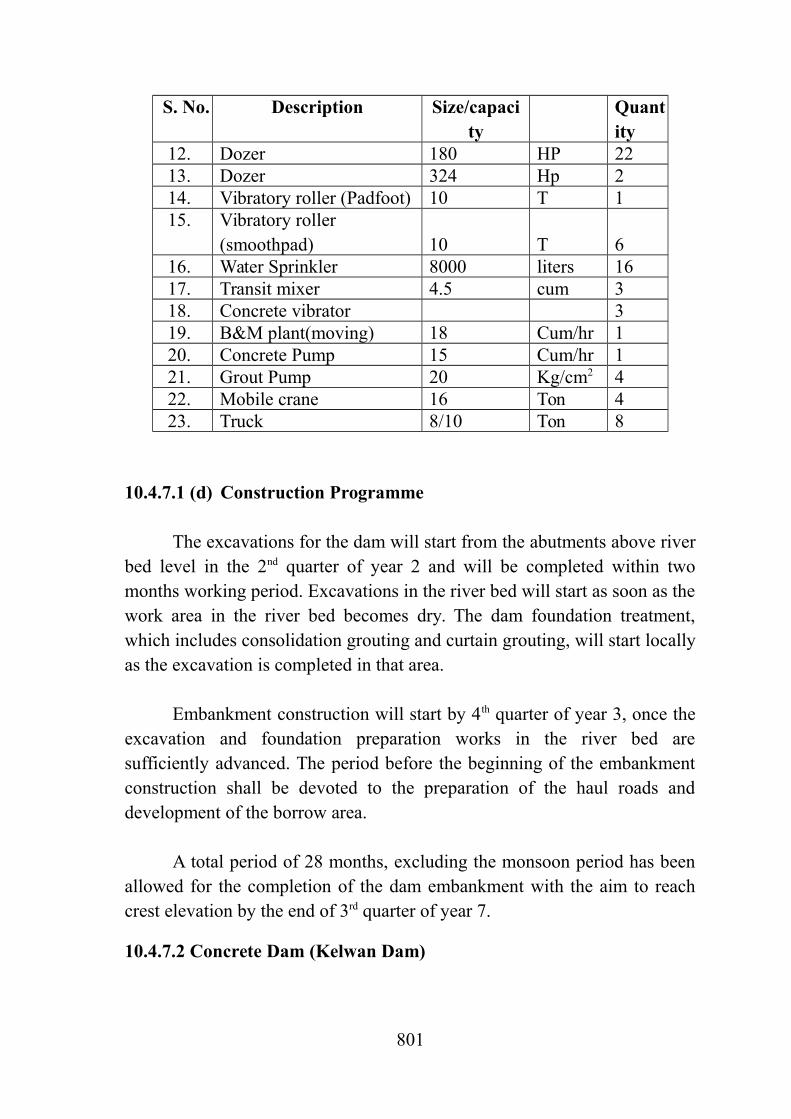
S. No. Description Size/capacity
Quantity
12. Dozer 180 HP 2213. Dozer 324 Hp 214. Vibratory roller (Padfoot) 10 T 115. Vibratory roller
(smoothpad) 10 T 616. Water Sprinkler 8000 liters 1617. Transit mixer 4.5 cum 318. Concrete vibrator 319. B&M plant(moving) 18 Cum/hr 120. Concrete Pump 15 Cum/hr 121. Grout Pump 20 Kg/cm2 422. Mobile crane 16 Ton 423. Truck 8/10 Ton 8
10.4.7.1 (d) Construction Programme
The excavations for the dam will start from the abutments above riverbed level in the 2nd quarter of year 2 and will be completed within twomonths working period. Excavations in the river bed will start as soon as thework area in the river bed becomes dry. The dam foundation treatment,which includes consolidation grouting and curtain grouting, will start locallyas the excavation is completed in that area.
Embankment construction will start by 4th quarter of year 3, once theexcavation and foundation preparation works in the river bed aresufficiently advanced. The period before the beginning of the embankmentconstruction shall be devoted to the preparation of the haul roads anddevelopment of the borrow area.
A total period of 28 months, excluding the monsoon period has beenallowed for the completion of the dam embankment with the aim to reachcrest elevation by the end of 3rd quarter of year 7.
10.4.7.2 Concrete Dam (Kelwan Dam)
801

Main activities to be undertaken for construction of concrete dam(over flow & non-over flow sections) are surface excavations andconcreting. Surface excavations will comprise of common excavation inoverburden and rock excavation. The total quantity of concrete damexcavation is about 264617 cum, and total quantity of concreting is about317156 cum.
Quantities involved in construction of concrete dam(over flow & non-over flow)
Description of Work
Type / Material Quantity, Unitin-situ
Stripping - - cumExcavation Common 77657 cum
Rock 186960 cum Total excavation 264617 cum
Concreting 317156 cum
10.4.7.2 (a) Surface Excavations
The surface excavations have been planned to be completed within 1working seasons (5 months). The surface excavation for main dam involvesboth common and rock excavations. The excavated material will betransported to the disposal area using conventional excavator and reardumper combination. The provision of equipment for the surfaceexcavation is to be made is estimated below:
Estimation of hourly quantity of excavation
TypeDescription
CommonExcavation
RockExcavation
Total volume (cum) 77657 186960Time period (months) 5 5Shift proposed 2 2Total operational hours (hour) 1,100 1,100Volume to be handled in-situ (cum/hour)
56 135
Volume to be handled loose(cum/hour)
71 218
802

Total quantity = 71 + 218 ~ 289 cum/hour
The construction equipment for surface excavations is as under: Excavation and loading of the soft material (common excavation) by
2.0 cum hydraulic excavators assisted by 180 hp bulldozers. For rock excavations requiring drilling & blasting, drilling the very
steep areas by hand-held rigs (jack hammer) of 38 mm diameter withhole patterns of about 2.75 m2 and drilling the accessible areas bycrawler drill.
Loading of blasted rock by 2.5 cum hydraulic excavator, shovel
attachment and assisted by 180 hp dozers. Transportation to the disposal areas/main dam by 25t rear dumpers.
Crawler dozer, 180 HP to be deployed at the disposal area to spread the
material.
10.4.7.2 (b) Concreting
For concreting of main dam and appurtenant structures, total quantityof the order of 317156 cum, will have to be placed. A period of 27 monthsexcluding monsoon period has been planned for the placement. The peakrate of placement works out to 33 cum/hour approximately. The concreterequired for main dam is proposed to be produced in a centralized Batchingand Mixing Plant of capacity 60 cum/hour. The plant shall be located in thevicinity of the dam. In addition, one number mobile batching & mixingplant of capacity, 18 cum/hour will be provided. The concrete from the plantwill be transported with the help of transit mixers, 4.5 cum capacity.
Following construction equipments have been considered forconcreting of main dam and appurtenant structures:
Placing of concrete with the help of 2 Nos. tower cranes, 6 ton @ 40
metre radius are proposed to be deployed at suitable locations. Inaddition, 2 Nos. 25 cum/hr concrete pumps with 25 m boom will beused for concrete placement.
Concrete transportation by transit mixers of 4.5 cum capacity.
803

Batching and mixing plant of capacity 60 cum/hr to be located
preferably within a radius of 2 km from the concrete dam. The aggregate crushing and screening plant of 180 tph for preparation
of coarse and fine aggregates.10.4.7.2 (c ) List of Major Construction Plant and Equipment for Concrete Dam
Based on above construction methodology, major construction plantand equipment required for construction of concrete dam are listed below.
S. N0.
Equipments Size/capacity Quantity
1. Hyd. Excavator 2 cum 32. Hyd. Excavator 1 cum 03. Loader, side dump 1.5 cum 14. Dumper 25 T 115. wagon drill 550 cfm 26. Jack hammer 120 cfm 97. Air requirment cfm 18008. Tower Crane 6T@40m 29. Dozer 180 HP 310. B&M Plant 60 cum/hr 111. mobile B&M Plant 18 cum/hr 112. APP 180 TPH 113. Transit Mixer 4.5 cum 414. Concrete pump 25 cum/hr 215. Grout Pump 20 Kg/cm2 216. Mobile crane 16 Ton 217. Truck 8/10 Ton 3
10.4.7.2 (d) Construction Programme
The sequence of construction of concrete dam takes into account thefollowing aspects:
Surface excavation of concrete dam to start during the 4th quarter of
Year 2.
804

The total quantity of excavation to be completed in a period of 1
working seasons(5 months). The activity to be completed by the end of1st quarter of year 3.
Concreting to start in the 1st quarter of Year 3 and will continue for 3
working seasons and to be completed by the 3rd quarter of year 6. Since a part of over-flow section (two blocks) is to be used for
diversion of river during construction of earth dam, the phasing ofconcerting is to be planned in such a way that the work of these twoblocks is completed during lean season.
Gate installation work to start in the beginning of 1st quarter of year 6
and will be completed by the end of 3rd quarter of Year 7.
10.4.7.3 Kelwan Dam Power House10.4.7.3(a) Excavation and Concreting
Main activities to be undertaken for construction of power house aresurface excavations and concreting along with erection of electro-mechanical equipment. The quantities involved in the dam power housecomplex are indicated below:
S. No.
Description Quantity (cum)
1 Surface excavations a) Common Excavation 492b) Rock excavation 1,292
2 Concreting 6,629
The sequence of operations for power house complex is based on thefollowing construction methods and equipment:
Excavation and loading of the soft material by 2.0 cum hydraulic
excavators assisted by 180 HP dozer. For rock excavations requiring drilling and blasting, drilling the very
steep areas by hand-held rigs with 38 mm diameter with hole patternsof about 1-2.5 m2 and drilling the accessible areas by crawler rigs with76 mm bits and hole patterns ranging from 7.5 to 9.0 m2.
Loading of the blasted rock by 2.0 cum hydraulic excavator bucket
805

shovel attachment and assisted by 180 HP dozers. Transportation to the disposal areas by 25t rear end dumpers.
Placing of concrete with 20 cum/hr concrete pumps with 25 m boom.
Concrete transportation by 4.5 cum transit mixers.
Concrete production in a moving Batching and mixing plant of
capacity 18 cum/hr. The aggregate crushing and screening plant of 180 tph for preparation
of coarse and fine aggregates. Mobile crane of 16t is to be utilized for handling of construction
material, shutter forms etc.
10.4.7.3(b) List of Major Construction Plant and Equipment for Power House
No separate equipment for construction of powerhouse complex hasbeen provided as equipment deployed for concrete dam shall be utilized forconstruction of power house.
10.4.7.3 (c ) Construction Programme
As the excavation quantities are not much, a period of 3 months hasbeen planned beginning in the 3rd quarter of year 6. The construction of theconcrete structures will begin by the 4th quarter of Year 6 starting from thestructures of the erection area. Almost 15 months have been considerednecessary to complete the powerhouse.
All works including electro-mechanical works will be essentiallycompleted by 3rd quarter of year 7.
10.4.8 Barrages
This project envisages the construction of following barrages:
a) Paikhed Barrage
b) Chasmandva Barrage
806

The construction of the above said barrages involves surface excavationand concreting. The quantities involved in construction of the barrages areshown in the table below.
Quantities involved in construction of barrages
S.No.
Description Excavation(cum)
Filling(Cum)
Concreting(cum)
1. Paikhed barrage 1,041,093 11386.4 105,1362. Chasmandva
barrage325,095 11386.4 96,807
Total 1,366,188 22772.7 201,943
10.4.8 (a) Paikhed Barrage & Head Regulator10.4.8.(a). 1. Surface Excavation
Main activities to be undertaken for construction of Paikhed barrageare surface excavations and concreting. Surface excavations will compriseof common excavation in overburden. The quantities involved andrequirement for which provision of equipment for the surface excavation isto be made is given in table below.
Estimation of hourly quantity of excavation
TypeDescription
Excavation(cum)
Filling(cum)
Total volume (cum) 1,041,093 11386.35Time period (months) 11 11Shift proposed 2 2Total operational hours (hour) 3025 3025Volume to be handled in-situ (cum/hour)
344 4
Volume to be handled loose(cum/hour)
4816
Peak Volume to be handled(cum/hour)
57810
Total quantity = 578+10=578 cum/hour
The construction equipment for surface excavations is as under:
807

Excavation and loading of the soft material (common excavation) by
2.0cum hydraulic excavators assisted by 180 HP bulldozers. For rock excavations requiring drilling & blasting, drilling the very
steep areas by hand-held rigs (jack hammer) of 38 mm diameter withhole patterns of about 2.75 sq.m and drilling the accessible areas bycrawler drill.
Loading of blasted rock by 2.5 cum hydraulic excavator, shovel
attachment and assisted by 180 HP dozers. Transportation to the disposal areas/main dam by 18/20T rear
dumpers. Crawler dozer, 180 HP to be deployed at the disposal area to spread
the material.
10.4.8.(a). 2 Concreting
For concreting of Paikhed barrage, total quantity of the order of105,136 cum, will have to be placed. A period of 12 months has beenplanned for the placement. The average rate of placement works out to 20cum/hour approximately. The concrete required for the barrages is proposedto be produced in 2 nos of Batching and Mixing Plant of capacity 18cum/hour. The plants shall be located in the vicinity of the barrages. Theconcrete from the plant will be transported with the help of transit mixers,4.5 cum capacity. The Placement of the concrete will be done with the helpof 20cum/hr capacity concrete pump.
10.4.8.(a).3. List of Major Construction Plant and Equipment for Paikhed Barrage
Based on above construction methodology, major construction plantand equipment required for construction of Paikhed Barrage are given intable.
S.N0.
Equipments Size/capacity
Quantity
1. Hydraulic excavator 2.0 cum 52. Crawler dozer 180 hp 43. Crawler dozer 90 hp 4
808

4. Front End Loader 1.5 cum 45. Crawler/wagon drill 600 cfm 26. Jack hammer 120 cfm 97. Rear dumper 18/20T 208. Tippers 4.5 cum 109. Aggregate processing plant 50 tph 210. Mobile Batching & mixing plant 18 cum/hour 212. Transit mixers 4.5 cum 613. Concrete pump with 25m boom 20cum/hour 414. Concrete Vibrator
(electrical/pneumatic)8
15. Compressed air cfm 200016. Grout pump 20 kg/m2 417. Trucks 8/10 ton 618. Vibratory compactor (pad foot) 10t 219. Vibratory compactor (smooth
drum)10t 2
20. Water sprinklers 8000 6
10.4.8.(b). Chasmandva Barrage & Head Regulator10.4.8.(b).1. Surface Excavation
Main activities to be undertaken for construction of Chasmandvabarrage are surface excavations and concreting. Surface excavations willcomprise of common excavation in overburden. The quantities involvedand requirement for which provision of equipment for the surfaceexcavation is to be made is given in table below.
Estimation of hourly quantity of excavation
TypeDescription
Excavation(cum)
Filling(cum)
Total volume (cum) 325,095 11386Time period (months) 3 3Shift proposed 2 2Total operational hours (hour) 825 825Volume to be handled in-situ (cum/hour)
394 14
Volume to be handled loose(cum/hour)
552 20
Peak Volume to be handled 550 20
809

(cum/hour)
Total quantity = 550+20=570 cum/hour
The construction equipment for surface excavations is as under:
Excavation and loading of the soft material (common excavation) by
2.0 cum hydraulic excavators assisted by 180 HP bulldozers. For rock excavations requiring drilling & blasting, drilling the very
steep areas by hand-held rigs (jack hammer) of 38 mm diameter withhole patterns of about 2.75 sq.m and drilling the accessible areas bycrawler drill.
Loading of blasted rock by 2.5 cum hydraulic excavator, shovel
attachment and assisted by 180 HP dozers. Transportation to the disposal areas/main dam by 25t rear dumpers.
Crawler dozer, 180 HP to be deployed at the disposal area to spread
the material.
10.4.8.(b).2 Concreting
For concreting of Chasmandva barrage, total quantity of the order of96807.296 cum, will have to be placed. A period of 12 months has beenplanned for the placement. The average rate of placement works out to 18cum/hour approximately. The concrete required for the barrages is proposedto be produced in two no. of Batching and Mixing Plant of capacity 18cum/hour. The plants shall be located in the vicinity of the barrages. Theconcrete from the plant will be transported with the help of transit mixers,4.5 cum capacity. The Placement of the concrete will be done with the helpof 20cum/hr capacity concrete pump.
10.4.8.(b).3 List of Major Construction Plant and Equipment for Chasmandva Barrage
No separate equipment for construction of powerhouse complex hasbeen provided as equipment deployed Paikhed Barrage shall be utilized forconstruction of power house.
810

Construction Programme
The sequence of construction of Barrage takes into account the followingaspects:
Surface excavation of Paikhed barrages to start during the 2nd quarter of
Year 3 to complete within 10 months. First two months will be used forstripping.
Concreting of Paikhed barrages to start in the 3rd quarter of year 4.
Concreting of will be completed in months and will be completed bythe end of 2nd quarter of year 5.
Surface excavation of Chasmandva barrages to start after the
completion of surface excavation of Paikhed barrages. It start duringthe 4th quarter of Year 4. First two months will be used for stripping.Surface excavation of balance quantity will be completed in another 3months and will be completed by the end of 1st quarter of year 5.
Concreting of Chasmandva barrages to start in the 3rd quarter of year 5.
Concreting will be completed in 12 months and will be completed bythe end of 2nd quarter of year 6.
Gate installation work of Paikhed barrages to start in the beginning of
1st quarter of year 5 and will be completed within 6 months. Gate installation work of Chasmandva barrages to start in the
beginning of 1st quarter of year 5 and will be completed within 6months.
It is proposed to carry out work in non-monsoon period for at least tillthe floor for full length of Barrage. A coffer dam of suitable height (say 4 m)may be required to enclose the work area in non-monsoon season.
10.4.9.1 (a) Chasmandva Pipe line
Main activities to be undertaken for execution work of Feeder Pipelines are excavation of trenches according to the levels to accommodatefeeder pipe lines, followed by lowering and laying of pipe lines along withconstruction of Pipe line bridges and other structures as necessary. Earthwork comprises of both the common excavation in overburden and rockexcavation. For fill reaches, spreading & wetting and compaction of the fill
811

material will have to be undertaken. The quantities involved inconstruction of the Chasmandva Pipe line are shown in the table below.
Quantities involved in construction of the Chasmandva Feeder Pipeline
Description of Work Quantity, in-situ UnitExcavation 160666 cumFill placement 194346 cumPipe line 2859 m
Estimation of hourly quantity excavation
TypeDescription
ExcavationFill
PlacementTotal volume (cum) 160666 194346Time period (months) 8 8Shift proposed 2 2Total operational hours (hour) 2200 2200Volume to be handled in-situ (cum/hour)
73 89
Volume to be handled loose(cum/hour)
102 124
Peak Volume to be handled(cum/hour)
102 124
Total quantity =102+124=226 cum/hour
The sequence of operations for Chasmandva Feeder Pipe lines isbased on the following construction methods and equipment:
Excavation and loading of the soft material by 2.0 cum hydraulic
excavators assisted by 180 HP dozer. For rock excavations requiring drilling and blasting, drilling the very
steep areas by hand-held rigs with 38 mm diameter with hole patternsof about 1-2.5 sq.m and drilling the accessible areas by crawler rigswith 76 mm bits and hole patterns ranging from 7.5 to 9.0 sq.m.
Loading of the blasted rock by 2.0 cum hydraulic excavator bucket
shovel attachment and assisted by 180 HP dozers. Transportation to the disposal areas by 18/20t rear end dumpers.
812

For fill reaches spreading by 180 HP bulldozers. Moisture adjustment
by 8000 L water sprinklers and compaction by 8 passes of 10t padfoot vibrating roller.
For concreting works, placing of concrete by 15 cum/hr concrete
pumps with 20 m boom. Concrete transportation by 4.5 cum transit mixers.
Concrete production in a mobile Batching and mixing plant of
capacity 18 cum/hr. The aggregate crushing and screening plant of 50 tph for preparation
of coarse and fine aggregates.10.4.9.1 (b) List of Major Construction Plant and Equipment for Chasmandva Feeder Pipe line
No separate equipment for construction of powerhouse complex aswell as Feeder pipe lines has been provided as equipment deployedChasmandva Barrage shall be utilized for construction of power house.
10.4.9.1 (c ) Construction Programme
A construction period of 2 working seasons has been planned startingfrom beginning of 3rd quarter of year 5. A period of 20 months excluding themonsoon period have been considered necessary to complete the laying ofPipe lines along with the all Pipe line bridges.
10.4.9.2 (a) Chikkar-Dabdar Feeder Pipe line
Main activities to be undertaken for execution work of Pipe lines areexcavation of trenches according to the levels to accommodate feeder pipelines, followed by lowering and laying of pipe lines along with constructionof pipe line Bridges, and other structures as necessary. Earth workcomprises of both the common excavation in overburden and rockexcavation. For fill reaches, spreading & wetting and compaction of the fillmaterial will have to be undertaken. The quantities involved in constructionof the Chikkar Feeder Pipe lines are shown in the table below.
813

Quantities involved in construction of the Chikkar Feeder Pipe line
Description of Work Quantity, in-situ UnitExcavation 1097689 cumFill placement 1823188 cumPipe line 14342 m
Estimation of hourly quantity excavation
TypeDescription
ExcavationFill
PlacementTotal volume (cum) 1097689 1823188Time period (months) 40 40Shift proposed 2 2Total operational hours (hour) 11000 11000Volume to be handled in-situ (cum/hour)
99 166
Volume to be handled loose(cum/hour)
140 232
Peak Volume to be handled(cum/hour)
174 290
Total quantity =174+290=464 cum/hour
The sequence of operations for Chikkar Feeder Pipe lines is based onthe following construction methods and equipment:
Excavation and loading of the soft material by 2.0 cum hydraulic
excavators assisted by 180 HP dozer. For rock excavations requiring drilling and blasting, drilling the very
steep areas by hand-held rigs with 38 mm diameter with hole patternsof about 1-2.5 sq.m and drilling the accessible areas by crawler rigswith 76 mm bits and hole patterns ranging from 7.5 to 9.0 sq.m.
Loading of the blasted rock by 2.0 cum hydraulic excavator bucket
shovel attachment and assisted by 180 HP dozers. Transportation to the disposal areas by 18/20t rear end dumpers.
For fill reaches spreading by 180 HP bulldozer. Moisture adjustment
by 8000 L water sprinklers and compaction by 8 passes of 10t padfoot vibrating roller.
For concreting works, placing of concrete by 15 cum/hr concrete
814

pumps with 20 m boom. Concrete transportation by 4.5 cum transit mixers.
Concrete production in a Batching and mixing plant of capacity 18
cum/hr(mobile). The aggregate crushing and screening plant of 50 tph for preparation
of coarse and fine aggregates.
10.4.9.2 (b ) List of Major Construction Plant and Equipment for Chikkar- Dabdar Feeder Pipe line
Based on the above methodology, major construction plant andequipment required for execution work of Feeder Pipe lines have beenworked out and given in table.
S. No. Equipments Size/capacity Quantity1. Hydraulic excavator 2.0 cum 42. Front End Loader 2.5 cum 23. Front End Loader 1.5 cum 14. Crawler/ wagon drill 600 cfm 15. Jack hammer 120 cfm 66. Rear dumper 18/20t 127. Tipper 4.5 cum 48. Crawler dozer 180 HP 29. Crawler dozer 90 HP 310. Aggregate processing plant 50 tph 111. Mobile concrete mixers 18 cum/hr 112. Transit mixers 4.5 cum 413. Concrete Vibrator
(electrical/pneumatic)4
14. Grout pump 20 kg/m2 215. Mobile crane 16t 216. Compressed air Cfm 4000 17. Trucks 8/10 ton 418. Vibratory compactor (pad
foot)10 t 1
19. Vibratory compactor (smooth drum)
10 t 3
20. Water sprinklers 8000 L 10
815

10.4.9.2 (c) Construction Programme
As the main canal stretches over a significant distance, sufficienttime is required to carry out detail surveys for main canal, branch canals,distributaries, minors and to finalize portions of canals for irrigation alongwith specific emphasis on time required for land acquisition. The contractsfor all major works are to be awarded by the second year itself so that theentire basic infrastructure required for the canal construction can becompleted by the end of 3rd quarter of second year itself.
A construction period of 5 working seasons has been planned startingfrom beginning of 3rd quarter of year 2. A period of 40 months excluding themonsoon period have been considered necessary to complete the all Pipeline structures. An additional 3 months have been provided for grouting andcleaning activity.
10.4.9.3 (a) Dabdar Feeder Pipe lineMain activities to be undertaken for execution work of Pipe lines are
excavation of trenches according to the levels to accommodate Feeded pipelines, followerd by lowering and laying of pipe lines and pipe line Bridgesas well as other structures as necessary..Earth work comprises of both thecommon excavation in overburden and rock excavation. For fill reaches,spreading & wetting and compaction of the fill material will have to beundertaken. The quantities involved in construction of the Dabdar FeederPipe line are shown in the table below.
Quantities involved in construction of the Dabdar Feeder Pipe line
Description of Work Quantity, in-situ UnitExcavation 443597 cumFill placement 4348862 cumPipe line 12258 m
Estimation of hourly quantity excavation
TypeDescription
ExcavationFill
PlacementTotal volume (cum) 443597 4348862Time period (months) 40 40
816

Shift proposed 2 2Total operational hours (hour) 11000 11000Volume to be handled in-situ (cum/hour)
40 395
Volume to be handled loose(cum/hour)
56 553
Peak Volume to be handled(cum/hour)
70 692
Total quantity =70+692=762 cum/hour
The sequence of operations for Dabdar Pipe lines is based on thefollowing construction methods and equipment:
Excavation and loading of the soft material by 2.0 cum hydraulic
excavators assisted by 180 HP dozer. For rock excavations requiring drilling and blasting, drilling the very
steep areas by hand-held rigs with 38 mm diameter with hole patternsof about 1-2.5 sq.m and drilling the accessible areas by crawler rigswith 76 mm bits and hole patterns ranging from 7.5 to 9.0 sq.m.
Loading of the blasted rock by 2.0 cum hydraulic excavator bucket
shovel attachment and assisted by 180 HP dozers. Transportation to the disposal areas by 25t rear end dumpers.
For fill reaches spreading by 180 HP bulldozer. Moisture adjustment
by 8000 L water sprinklers and compaction by 8 passes of 10t padfoot vibrating roller.
For concreting works, placing of concrete by 15 cum/hr concrete
pumps with 20 m boom. Concrete transportation by 4.5 cum transit mixers.
Concrete production in a Batching and mixing plant of capacity 18
cum/hr (mobile). The aggregate crushing and screening plant of 50 tph for preparation
of coarse and fine aggregates.
10.4.9.3(b) List of Major Construction Plant and Equipment for Dabdar Feeder Pipe line
817

Based on the above methodology, major construction plant andequipment required for execution work of pipe lines have been worked outand given in table below.
Major construction plant and equipment required for construction ofDabdar Feeder Pipe line
S. No. Equipments Size/capacity Quantity1. Hydraulic excavator 2.0 cum 62. Front End Loader 2.5 cum 43. Front End Loader 1.5 cum 24. Crawler/ wagon drill 600 cfm 25. Jack hammer 120 cfm 106. Rear dumper 18/20t 307. Tipper 4.5 cum 108. Crawler dozer 180 HP 49. Crawler dozer 90 HP 510. Aggregate processing plant 50 tph 111. Mobile concrete mixers 18 cum/hr 112. Transit mixers 4.0 cum 313. Concrete Vibrator
(electrical/pneumatic)4
14. Grout pump 20 kg/m2 215. Mobile crane 16t 216. Compressed air Cfm 200017. Trucks 8/10 ton 418. Vibratory compactor (pad
foot)10 t 1
19. Vibratory compactor (smooth drum)
10 t 4
20. Water sprinklers 8000 L 12
10.4.9.3 (c) Construction Programme
As the main canal stretches over a significant distance, sufficienttime is required to carry out detail surveys for main canal, branch canals,distributaries, minors and to finalize portions of canals for irrigation along
818

with specific emphasis on time required for land acquisition. The contractsfor all major works are to be awarded by the second year itself so that theentire basic infrastructure required for the canal construction can becompleted by the end of 3rd quarter of second year itself.
A construction period of 5 working seasons has been planned startingfrom beginning of 3rd quarter of year 2. A period of 40 months excluding themonsoon period have been considered necessary to complete all pipe linestructures. An additional 3 months have been provided for grouting andcleaning activity.
10.4.9.4(a) Kelwan Feeder Pipe line
Main activities to be undertaken for execution work of Pipe lines areexcavation of trenches according to the levels, followed by lowering andlaying of pipe lines and pipe line Bridges and other structures as necessary.Earth work comprises of both the common excavation in overburden androck excavation. For fill reaches, spreading & wetting and compaction ofthe fill material will have to be undertaken. The quantities involved inconstruction of the Kelwan Feeder Pipe lines are shown in the table below.
Quantities involved in construction of the Kelwan Feeder Pipe line
Description of Work Quantity, in-situ UnitExcavation 356021 cumFill placement 142118 cumPipe line 7616 m
Estimation of hourly quantity excavation
TypeDescription
ExcavationFill
PlacementTotal volume (cum) 356021 142118Time period (months) 8 8Shift proposed 2 2Total operational hours (hour) 2200 2200Volume to be handled in-situ (cum/hour)
162 65
Volume to be handled loose(cum/hour)
202 81
Peak Volume to be handled 253 101
819

(cum/hour)
Total quantity =253+101=304 cum/hourThe sequence of operations for Kelwan Feeder Link Pipe lines is based
on the following construction methods and equipment:
Excavation and loading of the soft material by 2.0 cum hydraulic
excavators assisted by 180 HP dozer. For rock excavations requiring drilling and blasting, drilling the very
steep areas by hand-held rigs with 38 mm diameter with hole patternsof about 1-2.5 sq.m and drilling the accessible areas by crawler rigswith 76 mm bits and hole patterns ranging from 7.5 to 9.0 sq.m.
Loading of the blasted rock by 2.5 cum hydraulic excavator bucket
shovel attachment and assisted by 180 HP dozers. Transportation to the disposal areas by 18/20t rear end dumpers.
For fill reaches spreading by 180 HP bulldozer. Moisture adjustment
by 8000 L water sprinklers and compaction by 8 passes of 10t padfoot vibrating roller.
For concrete lining and concreting works, placing of concrete by 20
cum/hr concrete pumps with 20 m boom. Concrete transportation by 4.5 cum transit mixers.
Concrete production in a Batching and mixing plant of capacity 18
cum/hr. The aggregate crushing and screening plant of 50 tph for preparation
of coarse and fine aggregates.
10.4.9.4(b) List of Major Construction Plant and Equipment for Kelwan Feeder Pipe line
No separate equipment for construction of powerhouse complex aswell as Feeder pipe lines has been provided as equipment deployedChasmandva Barrage shall be utilized for construction of power house.
10.4.9.4 (c) Construction Programme
A construction period of 2 working seasons has been planned startingfrom beginning of 3rd quarter of year 5. A period of 20 months excluding themonsoon period have been considered necessary to complete the all Pipeline structures.
820

10.4.10 Kelwan Dam Power House at the drop of Feeder Pipe line From Kelwan Reservoir
10.4.10(a) Excavation and Concreting
Main activities to be undertaken for construction of power house aresurface excavations and concreting along with erection of electro-mechanical equipment. The quantities involved in the dam power housecomplex are indicated below:
S. No. Description
Quantity(cum)
1 Surface excavations a) Common Excavation 3,525b) Rock excavation 6,093
2 Concreting 8,878
The sequence of operations for power house complex is based on thefollowing construction methods and equipment:
Excavation and loading of the soft material by 2.0 cum hydraulic
excavators assisted by 180 HP dozer. For rock excavations requiring drilling and blasting, drilling the very
steep areas by hand-held rigs with 38 mm diameter with hole patterns ofabout 1-2.5 m2 and drilling the accessible areas by crawler rigs with 76mm bits and hole patterns ranging from 7.5 to 9.0 m2.
Loading of the blasted rock by 2.0 cum hydraulic excavator bucket
shovel attachment and assisted by 180 HP dozers. Transportation to the disposal areas by 20t rear end dumpers.
Placing of concrete with 20 cum/hr concrete pumps with 25 m boom.
Concrete transportation by 4.5 cum transit mixers.
Concrete production in a moving Batching and mixing plant of capacity
18 cum/hr. The aggregate crushing and screening plant of 50 tph for preparation of
coarse and fine aggregates. Mobile crane of 16t is to be utilized for handling of construction
821

material, shutter forms etc.
10.4.10(b) List of Major Construction Plant and Equipment for Power House
No separate equipment for construction of powerhouse complex hasbeen provided as equipment deployed for Kelwan feeder Pipe lines shall beutilized for construction of power house.
10.4.10 (c ) Construction Programme
As the excavation quantities are not much, a period of 3 months hasbeen planned beginning in the 2nd quarter of year 7. The construction of theconcrete structures will begin by the 3rd quarter of Year 7 starting from thestructures of the erection area. Almost 9 months have been considerednecessary to complete the powerhouse.
All works including electro-mechanical works will be essentiallycompleted by 4th quarter of year 7.
10.4.11 (a) Par-Tapi Link Canal
Main activities to be undertaken for construction of canal are maincanal, branch canals, distributaries and other canal structures like siphons,bridges, railway crossings, super passages along with concrete lining of themain canal. Earth work comprises of both the common excavation inoverburden and rock excavation. For fill reaches, spreading & wetting andcompaction of the fill material will have to be undertaken. The quantitiesinvolved in construction of the Par-Tapi Canal (except CDs) are shown inthe table below:
Quantities involved in construction of the Par Tapi Link Canal
Description of Work Quantity, in-situ UnitExcavation 24853903 cumFill placement 19599774 cumLining 512455 cum
822

It is proposed to divide the entire length of canal into eight segmentsand take up the work in all the segments simultaneously so the work can becompleted within the stipulated time period. The estimation of hourlyquantity is given in table below.
Estimation of hourly quantity excavation
TypeDescription
ExcavationFill
PlacementTotal volume (cum) 24853903 19599774Av. Volume in each of 8 segments 3106737 2449971Time period (months) 40 40Shift proposed 2 2Total operational hours (hour) 11000 11000Volume to be handled in-situ (cum/hour)
282 222
Volume to be handled loose(cum/hour)
395 312
Peak Volume to be handled(cum/hour)
495 390
Total quantity =495+390=1180 cum/hour
The sequence of operations for Par-Tapi Canal is based on the followingconstruction methods and equipment:
Excavation and loading of the soft material by 2.0 cum hydraulic
excavators assisted by 180 HP dozer. For rock excavations requiring drilling and blasting, drilling the very
steep areas by hand-held rigs with 38 mm diameter with hole patternsof about 1-2.5 sq.m and drilling the accessible areas by crawler rigswith 76 mm bits and hole patterns ranging from 7.5 to 9.0 sq.m.
Loading of the blasted rock by 2.0 cum hydraulic excavator bucket
shovel attachment and assisted by 180 HP dozers. Transportation to the disposal areas by 18/20t rear end dumpers.
For fill reaches spreading by 180 HP bulldozer. Moisture adjustment
by 8000 L water sprinklers and compaction by 8 passes of 10t padfoot vibrating roller.
For concrete lining and concreting works, placing of concrete by 20
cum/hr concrete pumps with 20 m boom.
823

Concrete transportation by 4.5 cum transit mixers.
Concrete production in a Batching and mixing plant of capacity 18
cum/hr. The aggregate crushing and screening plant of 50 tph for preparation
of coarse and fine aggregates.
10.4.11(b) List of Major Construction Plant and Equipment for Par-Tapi Link Canal
Based on the above methodology, major construction plant andequipment required for construction of link canal including upper leveltunnel have been worked out and given in table.
Major construction plant and equipment required for construction of Par-Tapi Link canal
S. No. Equipments Size/capacity Quantity1 Hydraulic excavator 2.0 cum 562 Front End Loader 2.5 cum 243 Front End Loader 1.5 cum 84 Crawler/ wagon drill 600 cfm 165 Jack hammer 120 cfm 726 Rear dumper 18/20t 2487 Tipper 4.5 cum 328 Crawler dozer 180 HP 329 Crawler dozer 90 HP 24
10 Aggregate processing plant 50 tph 811 Filter Processing Plant 400TPH 1612 Concrete pump 15 cum/hr 813 Mobile concrete mixers 18 cum/hr 814 Transit mixers 4.5 cum 40
15Concrete Vibrator (electrical/pneumatic)
32
16 Grout pump 20 kg/m2 1617 Mobile crane 16t 1618 Compressed air Cfm 1120019 Trucks 8/10 ton 2420 Vibratory compactor (pad
foot)10 t 8
21 Vibratory compactor 10 t 24
824

(smooth drum)22 Water sprinklers 8000 L 64
10.4.11 (c ) Construction Programme
As the main canal stretches over a significant distance, sufficienttime is required to carry out detail surveys for main canal, branch canals,distributaries, minors and to finalize portions of canals for irrigation alongwith specific emphasis on time required for land acquisition. The contractsfor all major works are to be awarded by the first year itself so that theentire basic infrastructure required for the canal construction can becompleted by the end of 2nd quarter of second year itself.
A construction period of 5 working seasons has been planned startingfrom beginning of 3rd quarter of year 2. A period of 40 months excluding themonsoon period have been considered necessary to complete the lining oflink canal along with the all canal structures. An additional 3 months havebeen provided for grouting and cleaning activity. All other componentsplanned in the DPR of Par-Tapi-Narmada link project, as suggested byGovernment of Gujarat, like providing net work of pipe line as distributionsystem in the command areas under the proposed five projects includingcommand areas in all Tribal areas will be taken care by Government ofGujarat at the pre-construction stage of the project.
10.4.12 (a) Tapi- Narmada Link Canal
Main activities to be undertaken for construction of canal are maincanal, branch canals, distributaries and other canal structures like siphons,bridges, railway crossings, super passages along with concrete lining of themain canal. Earth work comprises of both the common excavation inoverburden and rock excavation. For fill reaches, spreading & wetting andcompaction of the fill material will have to be undertaken. The quantitiesinvolved in construction of the Tapi Narmada Canal (except CDs) areshown in the table below.
825

Quantities involved in construction of the Tapi Narmada Main Canal
Description of Work Quantity, in-situ UnitExcavation 23729633 cumFill placement 15159482 cumLining 624754 cum
It is proposed to divide the entire length of canal into eight segmentsand take up the work in all the segments simultaneously so the work can becompleted within the stipulated time period. The estimation of hourlyquantity is given in table below.
Estimation of hourly quantity excavation
TypeDescription
ExcavationFill
PlacementTotal volume (cum) 23729633 15159482Av. Volume in each of 6 segments 2966204 1894935Time period (months) 40 40Shift proposed 2 2Total operational hours (hour) 11000 11000Volume to be handled in-situ (cum/hour) 270 172Volume to be handled loose(cum/hour) 378 241Peak Volume to be handled(cum/hour) 472 302
Total quantity =472+302=774 cum/hourThe sequence of operations for Tapi-Narmada Link Canal is based on
the following construction methods and equipment:
Excavation and loading of the soft material by 2.0 cum hydraulic
excavators assisted by 180 HP dozer. For rock excavations requiring drilling and blasting, drilling the very
steep areas by hand-held rigs with 38 mm diameter with hole patternsof about 1-2.5 sq.m and drilling the accessible areas by crawler rigswith 76 mm bits and hole patterns ranging from 7.5 to 9.0 sq.m.
Loading of the blasted rock by 2.0 cum hydraulic excavator bucket
shovel attachment and assisted by 180 HP dozers. Transportation to the disposal areas by 18/20t rear end dumpers.
826

For fill reaches spreading by 180 HP bulldozer. Moisture adjustment
by 8000 L water sprinklers and compaction by 8 passes of 10t padfoot vibrating roller.
For concrete lining and concreting works, placing of concrete by 20
cum/hr concrete pumps with 20 m boom. Concrete transportation by 4.5 cum transit mixers.
Concrete production in a Batching and mixing plant of capacity 18
cum/hr(mobile).. The aggregate crushing and screening plant of 50 tph for preparation
of coarse and fine aggregates.
10.4.12 (b) List of Major Construction Plant and Equipment for Tapi-Narmada Canal
Based on the above methodology, major construction plant andequipment required for construction of link canal including upper leveltunnel have been worked out and given in table.
Major construction plant and equipment required for construction of Tapi-Narmadacanal
S. No. Equipments Size/capacity Quantity1 Hydraulic excavator 2.0 cum 482 Front End Loader 2.5 cum 243 Front End Loader 1.5 cum 84 Crawler/ wagon drill 600 cfm 165 Jack hammer 120 cfm 486 Rear dumper 18/20t 2087 Tipper 4.5 cum 248 Crawler dozer 180 HP 329 Crawler dozer 90 HP 1610 Aggregate processing plant 50 tph 911 Filter Processing Plant 300TPH 1612 Concrete pump 20 cum/hr 813 Mobile concrete mixers 18 cum/hr 814 Transit mixers 4.5 cum 40
15Concrete Vibrator (electrical/pneumatic)
32
16 Grout pump 20 kg/m2 1617 Mobile crane 16t 16
827

18 Compressed air Cfm 1040019 Trucks 8/10 ton 1220 Vibratory compactor (pad
foot)10 t 8
21 Vibratory compactor (smooth drum)
10 t 16
22 Water sprinklers 8000 L 48
10.4.12 (c ) Construction Programme
As the main canal stretches over a significant distance, sufficienttime is required to carry out detail surveys for main canal, branch canals,distributaries, minors and to finalize portions of canals for irrigation alongwith specific emphasis on time required for land acquisition. The contractsfor all major works are to be awarded by the first year itself so that theentire basic infrastructure required for the canal construction can becompleted by the end of 2nd quarter of second year itself.
A construction period of 5 working seasons has been planned startingfrom beginning of 3rd quarter of year 2. A period of 40 months excluding themonsoon period have been considered necessary to complete the lining oflink canal along with the all canal structures. An additional 3 months havebeen provided for grouting and cleaning activity. All other componentsplanned in the DPR of Par-Tapi-Narmada link project, as suggested byGovernment of Gujarat, like providing net work of pipe line as distributionsystem in the command areas in all Tribal areas will be taken care byGovernment of Gujarat at the pre-construction stage of the project.
10.4.13(a) Jheri to Paikhed Link Tunnel
The Jheri to Paikhed Link Tunnel having 3.0m diameter (finish) is of12700m length. 1 No. of construction adit has been proposed forconstruction of J-P link tunnel. The provision of 1 no. of adit providesopportunity to excavate tunnel from 4 faces simultaneously; provideddeployment of equipment sets is feasible at all the faces at a time. The RDof each adits and distance between them is given as under:
RD of each adits and distance between them
828

Adit LengthofAdit(m)
RD fromIntelPortal(m)
Length of Tunnel Distance B/waditsFace
NumberLength served through Face
Inlet Portal - 0.0 F1 3150 6300Adit 408.60 6300 F2
F331503200
OutletPortal
- 12700 F4 3200 6400
Total 12700 12700 Max length to be excavated = 0.5*(408.60+6400) ~ 3410 m
Excavation of Tunnel
Before taking up actual tunnel excavation, portal construction andslope stabilization would be required for which following constructionsequence is suggested
Excavation and loading of the soft material by 2.0 cum hydraulic
excavators assisted by 180 HP dozer. For rock excavations requiring drilling and blasting, drilling the very
steep areas by hand-held rigs with 38 mm diameter with hole patternsof about 1-2.5 m2 and drilling the accessible areas by crawler rigs with76 mm bits and hole patterns ranging from 7.5 to 9.0 m2.
Loading of the blasted rock by 2.0 cum hydraulic excavator bucket
shovel attachment and assisted by 180 HP dozers. Transportation to the disposal areas by 18/20t rear end dumpers. Slope stabilization using shotcrete machine and anchoring by jack
hammer/hydraulic drilling rig Portal concreting by using potable concrete mixer with weigh batches.
The portal excavation and slop stabilization will be completed withinthree month from start of work. Once this work is completed, theexcavation of adits and tunnel (from inlet and outlet faces) will be start. Inview of its size, both adits and tunnel are proposed to be excavated by fullface drill and blast method. For a finish diameter of 3.0m, the minimumexcavated diameter of the tunnel shall be 4.0m to account for 500mm thickconcrete lining and shotcrete.
829

Following construction method for the excavation of tunnel and aditsmay be adopted.
Drilling of charge holes by means of Jack hammers. Driving of each round variable according to the Class of rock (approx.
3.5 m for the Class I & II, 3.0 m for the Class III and 2.5 m for therock Class IV and V).
Number of holes per round (including those necessary for carrying out
the smooth blasting along the peripheral surface) approximately 25 -35.
Charging operations of explosive to be executed by means of man
basket and firing of the rounds using nonel detonators. Loading of the muck resulting from blasting, by Railway Hydraulic
mucker/rock loader (50 cum/hr output capacity). Transport of the muck to the spoil area by Granby-type Side dump cars
(6 to 9 cum capacity) mounted on rail system. Shotcrete with the help of 4-6cum/hr capacity wet shotcreting machine. Rock bolting using mechanized rock bolting rig
With the above construction methods and equipment, it is possible tocomplete a cycle of operation within a period of 9.7 hours. Although thetime of each activity within a cycle may vary according to class of rockencountered, the total cycle time for the pull [planned as indicated above fordifferent classes of rock will be the same order.
A typical cycle for Class III (pull of 3.00m)is given below:i) Preparation of job 0.5hrii) Drilling of Charge Holes 5.2hr iii) Charging 1.0hriv) Removal of Jumbo to safe position 0.5hrv) Blasting and defuming 1.0hrvi) Mucking 1.8hrvii) Scaling 0.5hrviii) Shotcreting and rock bolting 2.0hr Total 12.5hr
830

As per the rock condition of tunnel and with above cycle time, anaverage sustainable progress of 102m/month/face can be achieved.Considering 4 face excavation, all the construction activities of J-P linktunnel would be planned and staged for optimum utilization of equipmentsfor planned time period. Accordingly the time required for excavation 34months
10.4.13 (b) Concrete Lining
Concrete lining is to be undertaken after the completion ofexcavation. Following sequence of operation will be followed for concretelining of the head race tunnel
Concrete to be placed in three stages viz., kerb, overt, invert.
Kerb concreting to be placed with the help of 20m form work.
Installation of Rails on kerb for movement of 10m travelling
collapsible formwork for overt concreting. Pouring of concrete for Overt by 20cum/hr capacity concrete pump.
Transportation of concrete by 4.5cum capacity transit mixers.
Invert concreting with the help of screed board.
Pouring of concrete for invert with similar equipment as deployed for
overt. Preparation of Concrete in a Batching & Mixing Plant of 30cum./hr
capacity installed near Portal of each adit and outlet. An Aggregate Crushing & Screen Plant of 70tph to be installed near
each adit location for preparation of coarse aggregate. A tertiarycrusher for preparation of crushed fine aggregate is also to be providedas river sand is to be blended with crushed
Excavated material form tunnel excavation to be utilized as aggregate
after crushing & screening. In case material from quarries is to beobtained, tipper, 10 T payload capacity to be utilized for transportationand wheel loader, 1.0 cum for loading .
A typical cycle time for overt concreting is as under:
Estimated Cycle Time in Overt Concreting (10m)
i.) Erection time 16.00 hr
831

ii.) Pouring time
iii.) Setting time
iv.) Dismantling of formwork
8.00 hr
20.00 hr
4.00 hrTotal 48.00 Hrs
With 48 hr cycle time and two set of shutter form, a progress of10 m per day or an average progress of about 200m/month/face at each facecan be achieved. Invert concrete to be undertaken simultaneously withovert concreting with a time lag. Total time required for concreting 18months.
Based on the above methodology, major Construction Plant &Equipment required for construction of Jheri-Paikhed Link Tunnel havebeen listed out in following table:
10.4.13 (c ) List of Major Construction Plant & Equipment for Construction of Jheri- Paikhed Link Tunnel
S.No.
Item Qty./No.
1. Heavy Duty Rock Drill, 120 cfm (jack Hammers) 122. Railway Hydraulic mucker/rock loader 33. Wagon Drill 34. Muck cars 4.50 cum capacity 205. Crawler Dozer, 180 hp 46. Loader-cum-Excavator, 1.0 cum./ 0.24 cum. 47. Shotcrete m/c, 4-6 cum 38. Shotcrete m/c with Robot Arm, 10 cum 39. Air Compressor, 500 cfm, Electric 310. Aggregate Crushing & Screening Plant, 70 tph 311. Concrete Batching & Mixing Plant, 30 m3/hr 312. Collapsible Shutter Form with Traveller 413. Transit Mixer, 4.5 m3 1614. Concrete Pump, 25 m3/hr 415. Concrete Mixer, 14/10 cft 416. Tipper, 16 t 3217. Wheel Loader 1.0 Cum 418. Grout pump 4
832

An average distance of 5.0 km from quarry site has been consideredfor calculating the no of tipper required.
10.4.13 (d) Construction Program The sequence of Construction of J-P Link Tunnel takes into account
the following aspects:
Open excavation for face and portal construction is to be started in the
3rd quarter of year 2 and will completed within three months. Adits/Tunnel excavation to start in 4th quarter of year 2 and are to be
completed by the end of 3rd quarter of year 4. Concrete lining of whole of tunnel to be taken up from all the face
simultaneously. Lining to start in the 4th quarter of year 3 and to becompleted by the end of 1st quarter of year 6.
Contact/consolidation grouting of the tunnel to start simultaneously
with the concreting and will finish in three month after concreting.
Final cleaning of tunnel and other miscellaneous work will be completed in two months after consolidation grouting.
10.4.14 Tunnels in Main Canal
5 No. of tunnels of diameter 5.5 m has been proposed in the mainCanal. The Details of each tunnel is given as under:
10.4.14 (a) Excavation of Tunnel
833
Tunnel No. 1 between RD 14.650-14.750 km) Length (m) 100Tunnel No. 2 between RD 24.000-24.350 km) Length (m) 350Tunnel No. 3 between RD 32.350-32.550 km) Length (m) 200Tunnel No. 4 between RD 37.750-37.800 km) Length (m) 50Tunnel No. 5 between RD 51.500-51.950 km) Length (m) 450

Before taking up actual tunnel excavation, portal construction andslope stabilization would be required for which following constructionsequence is suggested
Excavation and loading of the soft material by 2.0 cum hydraulic
excavators assisted by 180 HP dozer. For rock excavations requiring drilling and blasting, drilling the very
steep areas by hand-held rigs with 38 mm diameter with hole patternsof about 1-2.5 m2 and drilling the accessible areas by crawler rigs with76 mm bits and hole patterns ranging from 7.5 to 9.0 m2.
Loading of the blasted rock by 2.0 cum hydraulic excavator bucket
shovel attachment and assisted by 180 HP dozers. Transportation to the disposal areas by 18/20t rear end dumpers. Slope stabilization using shotcrete machine and anchoring by jack
hammer/hydraulic drilling rig Portal concreting by using potable concrete mixer with weigh batches.
The portal excavation and slop stabilization will be completed withinthree month from start of work. Once this work is completed, theexcavation of tunnel (from inlet and outlet faces) will be start. In view of itssize, tunnels are proposed to be excavated by full face drill and blastmethod. For a finish diameter of 5.5m, the minimum excavated diameter ofthe tunnel shall be 6.4 m to account for 300mm thick concrete lining andshotcrete.
Following construction method for the excavation of tunnel and aditsmay be adopted.
Drilling of charge holes by means of single boom hydraulic drill
jumbo. Driving of each round variable according to the Class of rock (approx.
3.5 m for the Class I & II, 3.0 m for the Class III and 2.5 m for therock Class IV and V).
Number of holes per round (including those necessary for carrying out
the smooth blasting along the peripheral surface) approximately 60 -70.
834

Charging operations of explosive to be executed by means of man
basket and firing of the rounds using nonel detonators. Loading of the muck resulting from blasting, by 2.5 cum side dump
loader. Transport of the muck to the spoil area by 10T dumper Shotcrete with the help of 4-6cum/hr capacity wet shotcreting machine. Rock bolting using mechanized rock bolting rig
With the above construction methods and equipment, it is possible tocomplete a cycle of operation within a period of 9.7 hours. Although thetime of each activity within a cycle may vary according to class of rockencountered, the total cycle time for the pull [planned as indicated above fordifferent classes of rock will be the same order.
A typical cycle for Class III (pull of 3.00 m)is given below:
ix) Preparation of job 0.5hrx) Drilling of Charge Holes 4.2hr xi) Charging 1.0hrxii) Removal of Jumbo to safe position 0.5hrxiii) Blasting and defuming 1.0hrxiv) Mucking 1.8hrxv) Scaling 0.5hrxvi) Shotcreting and rock bolting 3.0hr Total 11.5hr
In whole tunnel, 99% tunneling is in rock class of 1, II & III (no –rock support system required) and 1% tunneling is in rock class IV & V(require rock support system). As per the rock condition of tunnel and withabove cycle time, an average sustainable progress of 110m/month/face can be achieved.
Considering 5 tunnels of different length, all the construction activities oftunnel in Main Canal would be planned and staged for optimum utilizationof equipments for planned time period.
10.4.14 (b) Concrete Lining
Concrete lining is to be undertaken after the completion of
835

excavation. Following sequence of operation will be followed for concretelining of the head race tunnel.
Concrete to be placed in three stages viz., kerb, overt, invert.
Kerb concreting to be placed with the help of 20m form work.
Installation of Rails on kerb for movement of 10m travelling
collapsible formwork for overt concreting. Pouring of concrete for Overt by 25cum/hr capacity concrete pump.
Transportation of concrete by 4.5cum capacity transit mixers.
Invert concreting with the help of screed board.
Pouring of concrete for invert with similar equipment as deployed for
overt. Preparation of Concrete in a Batching & Mixing Plant of 30cum./hr
capacity installed near Portal of each adit and outlet. An Aggregate Crushing & Screen Plant of 70tph to be installed near
each adit location for preparation of coarse aggregate. A tertiarycrusher for preparation of crushed fine aggregate is also to be providedas river sand is to be blended with crushed.
Excavated material form tunnel excavation to be utilized as aggregate
after crushing & screening. In case material from quarries is to beobtained, tipper, 10 T payload capacity to be utilized for transportationand wheel loader, 1.0 cum for loading .
A typical cycle time for overt concreting is as under:
Estimated Cycle Time in Overt Concreting (10m)
v.) Erection time
vi.) Pouring time
vii.) Setting time
viii.) Dismantling of formwork
16.00 hr
8.00 hr
20.00 hr
4.00 hrTotal 48.00 Hrs
With 48 hr cycle time and two set of shutter form, a progress of10 m per day or an average progress of about 200m/month/face at each facecan be achieved. Invert concrete to be undertaken simultaneously with
836

overt concreting with a time lag.
Based on the above methodology, major Construction Plant &Equipment required for construction of Link Tunnels have been listed out infollowing table:
10.4.14(c) List of Major Construction Plant & Equipment for Construction of tunnel in Main Canal
S.No.
Item Qty./No.
1. Single Boom hydraulic Drill Jumbo with workingplatform
1
2. Rock Bolting Jumbo 13. Side dump loader, 2.5 cum 14. Wagon Drill 15. Heavy Duty Rock Drill, 120 cfm 36. 10T dumper 67. Crawler Dozer, 180 hp 18. Loader-cum-Excavator, 1.0 cum./ 0.24 cum. 1
9. Shotcrete m/c, 4-6 cum 110. Shotcrete m/c with Robot Arm, 10 cum 1
11. Air Compressor, 500 cfm, diesel 112. Aggregate Crushing & Screening Plant, 100 tph 113. Concrete Batching & Mixing Plant, 30 m3/hr 114. Collapsible Shutter Form with Traveller 115. Transit Mixer, 4.5 m3 416. Concrete Pump, 25 m3/hr 117. Concrete Mixer, 14/10 cft 118. Tipper, 10 t 819. Wheel Loader 1.0 Cum 120. Grout pump 1
An average distance of 5.0 km from quarry site has been consideredfor calculating the no of tipper required.
10.4.14 (d ) Construction Program
837
The sequence of Construction of Tunnel in Main Canal is given in construction schedule attached at Annexure-10.1.
10.5 Construction Programme & Deployment Schedule
Based on equipment planning and construction programme describedin preceding Sections, a construction schedule for whole of the project hasbeen prepared in the form of a Bar Chart and is placed at Annexure:10.1.Keeping this construction schedule as one of the major criteria, adeployment schedule of major construction equipment required for theproject is placed at Annexure:10.2. The number of equipment shown in thelist has been arrived at after scheduling the equipment in such a way thatminimum number of equipment, in general, would be needed. The basis forplanning, indicating the type of equipment to be used, has already beendealt with in the respective sections and sub-sections corresponding todifferent items of the structures. As the deployment schedule may differdepending upon the number of executing agencies, the total number ofequipment required will have to be reviewed at the time of projectexecution.
10.6 Manpower Planning10.6.1 Organisation Setup
The project will be implemented under an organisation set-up headedby an officer of the rank of General Manager. The works will be executedunder the overall supervision of six Officers of the rank of Chief Engineerswho will report to General Manager. In addition, there will be six officersof the rank of Superintending Engineer to assist General Manager: Director(Administration), Director (Finance), Director (Technical Coordination) andDirector (EMP and R&R) and Public Relation Officer and Labour WelfareOfficer. Each will be assisted by appropriate subordinate officers and staff.The organisation chart for the project is appended as Annexure - 10.3.1 to10.3.7 in Volume - II.
There will be six Chief Engineers for the Project to look after theworks, viz., Engineer (Designs), Chief Engineer (Head works-I), ChiefEngineer (Head works-II), Chief Engineer (E&M), Chief Engineer (Canal-I)and Chief Engineer (Canal-II). Chief Engineer (Designs) will be supportedby 5 officers of the rank of Superintending Engineer; Chief Engineer (Headworks-I) and (Head works-II) will be supported by 4 officers of the rank of
838

Superintending Engineer; Chief Engineer (Canal-I and II) and ChiefEngineer (E&M) will be supported by 3 officers of the rank ofSuperintending Engineer who will be heading the field formations of circles.Each circle will have two to three division offices which will be headed bythe officers of the rank of Executive Engineers. Executive Engineers in turnwill have Assistant Executive Engineers as their subordinate officers whowill manage Sub-Divisional offices.
The Chief Engineer (Designs) will be supported by five officers of therank of Superintending Engineer: three for design units, one for Qualitycontrol, and one Superintending Engineer for EMP and R&R. These SEswill be further supported Executive Engineers/ Assistant ExecutiveEngineers and other supporting staff.
Chief Engineer (Head Works-I) will be responsible for execution ofworks related to construction of Jheri, Paikhed and Chasmandva dams,Power Houses and Barrages. One of the Superintending Engineers underhim will be responsible for construction of Jheri dam and Jheri to Paikhedtunnel; one Superintending Engineer will be responsible for construction ofPaikhed dam, Power House and Barrage; one Superintending Engineer willbe responsible for construction of Chasmandva dam, Power House andBarrage; and one Rehabilitation Officer for EMP and R&R. They will besupported by appropriate subordinate officers as elaborated under theorganisation chart.
Similarly, Chief Engineer (Head Works-II) will be responsible forexecution of works related to construction of Chikkar, Dabdar and Kelwandams and Power Houses. One of the Superintending Engineers under himwill be responsible for construction of Chikkar dam and Power house; oneSuperintending Engineer will be responsible for construction of Dabdar damand Power House; one Superintending Engineer will be responsible forconstruction of Kelwan dam and Power House and Kelwan Feeder Pipe linePower house; and one Rehabilitation Officer for EMP and R&R. They willbe supported by appropriate subordinate officers as elaborated under theorganisation chart.
Chief Engineer (Canal-I) will be responsible for execution of worksrelated to construction of Canal-I i.e Par-Tapi reach of Par-Tapi-Narmadalink canal. He will be supported by three Superintending Engineers. OneSuperintending Engineer will be responsible for Earth work andconstruction of canal; Second Superintending Engineer will look after theconstruction of CD structures; and another Superintending Engineer willlook after the distribution works and Colony and stores.
839

Similarly Chief Engineer (Canal-II) will be responsible for executionof works related to construction of Canal-II i.e. Tapi-Narmada reach of Par-Tapi-Narmada link canal. He will be supported by three SuperintendingEngineers. One Superintending Engineer will be responsible for Earth workand construction of canal; Second Superintending Engineer will look afterthe construction of CD structures; and another Superintending Engineer willlook after the distribution works and Colony and stores.
The civil designs of all the components of the project will be carriedout by the Chief Engineer (Designs). The Chief Engineer (Electrical &Mechanical) will look after the electro-mechanical works of the 6 dams, 6power houses, and 2 barrages both design and field executions. Hisformation will also provide assistance in respect of electrical andmechanical works for whole of the project.
Detailed manpower requirement has been indicated in Annexures -10.4 to 10.5 in Volume - II.
10.7 Year Wise Allocation of Cost
The year wise allocation of cost for the project is given below andthe details are at Annexure - 10.6 in Volume – II.
Yearly phasing of Expenditure
Year Allocation of cost (lakh Rs.)1st Year 878162nd Year 867953rd Year 1531684th Year 1531685th Year 1940136th Year 1940137th Year 152148
Total 1021121
840