design and construction guidelines - uottawa
TRANSCRIPT
Last revision: 2022-04-01
DESIGN and CONSTRUCTION
GUIDELINES
University of Ottawa · Facilities
INDEX DESIGN and CONSTRUCTION GUIDELINES
Last revision: 2022-04-01 Page 1 of 5
TABLE OF CONTENTS Index 2022-04-01
VOLUME I – SPACE & DESIGN STANDARDS General:
1a Definition & Contact information 2022-04-01 2a Introduction, General & Codes information 2022-04-01 3a Documents & Procedure 2021-12-01 4a Drafting 2021-12-01 5a Site Management 2021-01-31
Design Standard per Type of Space: A. Student Spaces 2020-08-01 B. Administrative Spaces 2021-04-01 C. Classrooms 2021-12-01 D. Laboratories & Support 2021-01-31 E. Public spaces 2021-08-01 F. Residences 2020-08-01 G. Service Rooms 2022-03-01 H. Sports Facilities 2021-12-01 I. Washrooms 2021-01-31 J. Reserved
Circulation Standards:
K. Barrier-Free Design 2020-08-01 L. Reserved
Assemblies & Schedules Standards: M. Building Envelope 2021-12-01 N. Interior Work, Partitions & Acoustical 2021-01-31 O. Door Schedule 2022-03-01 P. Finish Schedule 2022-03-01 Q. Furniture & Millwork Schedule 2021-01-31 R. Allocated areas 2020-08-01
System Standards: S. Energy and Sustainability 2019-10-01 T. HVAC 2019-10-01 U. Refrigeration 2019-10-01 V. Controls and Instrumentation 2020-03-01
University of Ottawa · Facilities
INDEX DESIGN and CONSTRUCTION GUIDELINES
Last revision: 2022-04-01 Page 2 of 5
W. Plumbing 2019-10-01 X. Fire Protection 2019-10-01 Y. Commissioning 2019-10-01 Z. Utilities To come Z1 Electrical 2019-10-01 Z2 Power Distribution 2019-10-01 Z3 Lighting 2019-10-01 Z4 Fire Alarm 2019-10-01 Z5 Emergency Power 2020-03-01 Z6 Telecom To come
Z7 Security Systems 2019-10-01 Z8 Voice and Data To come Z9 Multimedia To come Z10 Environment 2020-03-01
Related Standards: Signage system (Normes de système de signalisation):
Furniture (Normes d’ameublement): Curent document (Normes de design et de construction): Other IPD - Refer to: http://www.uottawa.ca/immeubles/secteurs/livraison-projets-integree
Other Sectors - Refer to: http://www.uottawa.ca/facilities/sectors
VOLUME II – PROCUREMENT DIVISION 00 & 01 – CONTRACT REQUIREMENTS 01 75 00 Inspection & Testing 2021-12-01 01 95 00 Procedures, Products & Quality Requirements 2021-12-01
VOLUME III – CONSTRUCTION STANDARD – Architecture & Structure DIVISION 02 – EXISITING CONDITIONS 02 41 00 Demolition 2020-08-01
DIVISION 03 – CONCRETE & STRUCTURE 03 30 00 Cast-in-place Concrete & Steel deck 2021-08-01 03 45 00 Architectural Precast Concrete 2021-08-01
DIVISION 04 - MASONRY 04 80 00 Masonry & Stone Work 2022-03-01
University of Ottawa · Facilities
INDEX DESIGN and CONSTRUCTION GUIDELINES
Last revision: 2022-04-01 Page 3 of 5
DIVISION 05 - METALS 05 40 00 Exterior Metal Framing Walls, Parapets and Soffits 2022-03-01 05 50 00 Metal Work 2022-03-01
DIVISION 06 - WOOD, PLASTICS AND COMPOSITES 06 10 00 Wood & Plastic Work 2019-10-01
DIVISION 07 - THERMAL AND MOISTURE PROTECTION 07 10 00 Air / Moisture / Water protection 2022-03-01 07 20 00 Thermal Insulation 2022-03-01 07 30 00 Shingles, Roof Tiles and Covering 2022-03-01 07 40 00 Manufactured Siding and Cladding panels 2022-03-01 07 50 00 Membrane Roofing & Parapets 2022-03-01 07 80 00 Fire and Smoke Protection 2022-03-01 07 90 00 Sealants 2022-03-01
DIVISION 08 - OPENINGS 08 11 00 Doors and Frames 2021-12-01 08 40 00 Curtain Wall and Glazed Metal Work 2021-12-01 08 70 00 Finish Hardware 2021-12-01 08 80 00 Glazing 2021-12-01
DIVISION 09 - FINISHES 09 20 00 Drywall Work 2022-03-01 09 30 00 Tile Work 2022-03-01 09 50 00 Acoustical Ceilings 2022-03-01 09 61 00 Surface preparation 2022-03-01 09 65 00 Resilient & Synthetic Flooring 2022-03-01 09 67 00 Special Flooring 2022-03-01 09 91 00 Painting 2022-03-01 09 96 00 Special Coating 2022-03-01
DIVISION 10 - SPECIALTIES 10 11 00 Visual Display Boards 2021-12-01 10 21 00 Toilet Compartments 2021-12-01 10 22 00 Demountable Partitions 2021-12-01 10 26 00 Wall & Corner Protection 2021-12-01 10 28 10 Washroom and other Accessories 2021-12-01 10 51 00 Lockers 2021-12-01
University of Ottawa · Facilities
INDEX DESIGN and CONSTRUCTION GUIDELINES
Last revision: 2022-04-01 Page 4 of 5
DIVISION 11 - EQUIPMENT 11 13 00 Loading Dock Equipment 2022-03-01 11 14 00 Hospitality equipment 2022-03-01
DIVISION 12 - FURNISHINGS 12 20 00 Window Treatment 2021-12-01 12 35 00 Laboratory Furniture 2021-12-01 12 48 00 Foot Grilles 2021-12-01 12 50 00 Furniture and Accessories systems 2021-12-01
DIVISION 13 - SPECIAL CONSTRUCTION 13 00 00 General works To come
DIVISION 14 - CONVEYING SYSTEMS 14 20 00 Elevators 2021-12-01
VOLUME IV – CONSTRUCTION STANDARD – Mechanical & Electrical DIVISION 22 – PLUMBING 22 00 00 General Works 2021-12-01 22 42 01 Plumbing Fixtures 2021-12-01 22 42 02 Piping 2021-12-01
DIVISION 23 – HEATING, VENTILATION AND AIR-CONDITIONING (HVAC) 23 00 00 General Works 2020-08-01
DIVISION 25 – INTEGRATED AUTOMATION 25 00 00 General works To come
DIVISION 26 – ELECTRICAL 26 00 00 General works 2021-12-01 26 50 00 Lighting 2021-12-01
DIVISION 27 – COMMUNICATIONS 27 00 00 General works To come
DIVISION 28 – ELECTRONIC, SAFETY AND SECURITY 28 00 00 General works To come
University of Ottawa · Facilities
INDEX DESIGN and CONSTRUCTION GUIDELINES
Last revision: 2022-04-01 Page 5 of 5
VOLUME V - CONSTRUCTION STANDARD - Site and Amenities DIVISION 31 – EARTHWORK 31 10 00 Site preparation & hard landscaping 2020-08-01
DIVISION 32 – EXTERIOR IMPROVEMENTS 32 30 00 Site improvements and amenities 2022-03-01 32 80 00 Irrigation system 2022-03-01 32 90 00 Planting and soft landscaping 2022-03-01
VOLUME VI - APPENDIX Notes
AG. General Notes 2021-12-01
AB. Lab Furniture Legend 2021-12-01 AL. Miscellaneous Steel Legend 2021-12-01
AM. Millwork Legend 2021-12-01 AN. Washroom Accessories Legend 2021-12-01 AP. Partition Legend 2021-12-01 AR. Doors & Hardware Legend 2021-12-01 AV. Envelope Legend 2021-12-01 AY. M&E Legend 2021-12-01
Typical Details DB. Lab Furniture Details 2021-04-01 DL. Miscellaneous Steel Details 2021-12-01
DM. Millwork Details 2019-04-01 DP. Partition Details 2021-08-01 DR. Doors & Hardware Details 2021-08-01 DV. Envelope Details 2021-12-01
University of Ottawa · Facilities VOLUME I
1a. DEFINITION & CONTACT INORMATION DESIGN and CONSTRUCTION GUIDELINES
Last revision: 2022-04-01 Page 1 of 3
1.0 GENERAL 1.1 Overview
.1 The following are main information implicated in the current Guidelines. For full contact information, visit UofO web site.
1.2 Definition, References and Contact info: .1 General:
AODA: Accessibility for Ontarians with Disabilities Act CFI: Canadian Foundation for Innovation DCG: UofO Design and Construction Guidelines ECA: Environmental Compliance Approval OEPA: Ontario Environmental and Protection Act Facilities: Physical Resources Services of the UofO, located at:
141 Louis Pasteur, Ottawa, Ontario, K1N 6N5
GC: General Contractor (including all sub-contractors), and all individual Contractors MECP: Ministry of the Environment and Climate Change (Ontario) OBC: Ontario Building Code OFC: Ontario Fire Code OWRA: Ontario Water Resource Act TSSA: Technical Standard & Safety authority UofO: University of Ottawa, duly constituted and having a place of business at:
550 Cumberland, Ottawa, Ontario, K1N 6N5.
.2 Facilities and UofO Service departments:
ACVS: Animal Care & Veterinary Services Contact: Holly Orlando – Ext.: 8409
ARCH: Architecture, Building Code & Technical Expertise Services
Contact: Charles Albert Azar – Cell: 613-797-7469 BAS: Building Automation Systems
Contact: Raymond Carrey – Ext.: 6938 CSS: Cleaning and Sanitary Services
Contact: Suzanne Vincent – Ext.: 6613 Brigitte Morin – Ext. : 8116
DES: Interior Design & Furniture Services Contact: Nathalie Charron – Cell :613-286-6514
University of Ottawa · Facilities VOLUME I
1a. DEFINITION & CONTACT INORMATION DESIGN and CONSTRUCTION GUIDELINES
Last revision: 2022-04-01 Page 2 of 3
FPS: Fire Protection Services Contact: Richard Sincennes – Ext.: 6091 – Cell: 343-998-8975
DHS: Designated and Hazardous Substances Contact: Martine Bergeron – Ext.: 6992
HS: Housing Services Contact: Jérémie Génier – Ext.: 6333
ITS: IT Services Contact: Eric Rivard – Ext.: 2269
KCS: Keying and Cylinder systems
Contact: Vernon McLeod – Ext.: 1468 LGS: Landscaping, Grounds, Snow removal & Ancillary Services
Contact: Pierre-Yves Leroux – Cell: 613-697-0100
M&E: Mechanical and Electrical services Contact: Shahrokh Farzam – Cell: 613-769-5908
OPST: Office of Parking and Sustainable Transportation (Also responsible for the approval of the fire prevention department) Contact: Francine Faubert – Ext .3050
Charles Martel - Ext .4409 ORM: Office of Risk Management:
Environmental Management Contact: Pascal Simard – Ext.: 2487 Health & Safety Contact: Celine Clement – Ext.: 3052
Graham Nelson - Ext.: 2486 Insurances Contact: John Lamney – Ext.: 2093 Rad Laser Biosafety Contact: Lois Sowden-Plunkett – Ext.: 3058
University of Ottawa · Facilities VOLUME I
1a. DEFINITION & CONTACT INORMATION DESIGN and CONSTRUCTION GUIDELINES
Last revision: 2022-04-01 Page 3 of 3
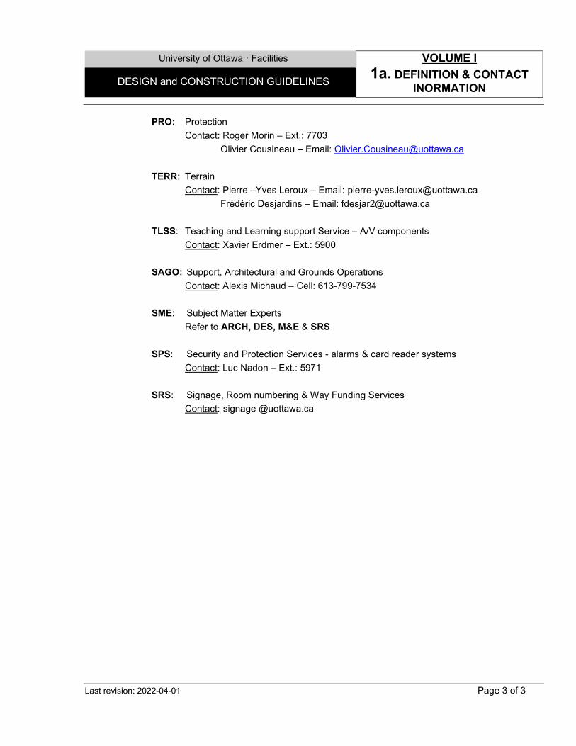
PRO: Protection Contact: Roger Morin – Ext.: 7703 Olivier Cousineau – Email: [email protected]
TERR: Terrain
Contact: Pierre –Yves Leroux – Email: [email protected] Frédéric Desjardins – Email: [email protected]
TLSS: Teaching and Learning support Service – A/V components
Contact: Xavier Erdmer – Ext.: 5900 SAGO: Support, Architectural and Grounds Operations
Contact: Alexis Michaud – Cell: 613-799-7534 SME: Subject Matter Experts
Refer to ARCH, DES, M&E & SRS
SPS: Security and Protection Services - alarms & card reader systems Contact: Luc Nadon – Ext.: 5971
SRS: Signage, Room numbering & Way Funding Services Contact: signage @uottawa.ca
University of Ottawa · Facilities VOLUME I
2a. INTRODUCTION, GENERAL & CODES INFORMATION DESIGN and CONSTRUCTION GUIDELINES
Last revision: 2022-04-01 Page 1 of 2
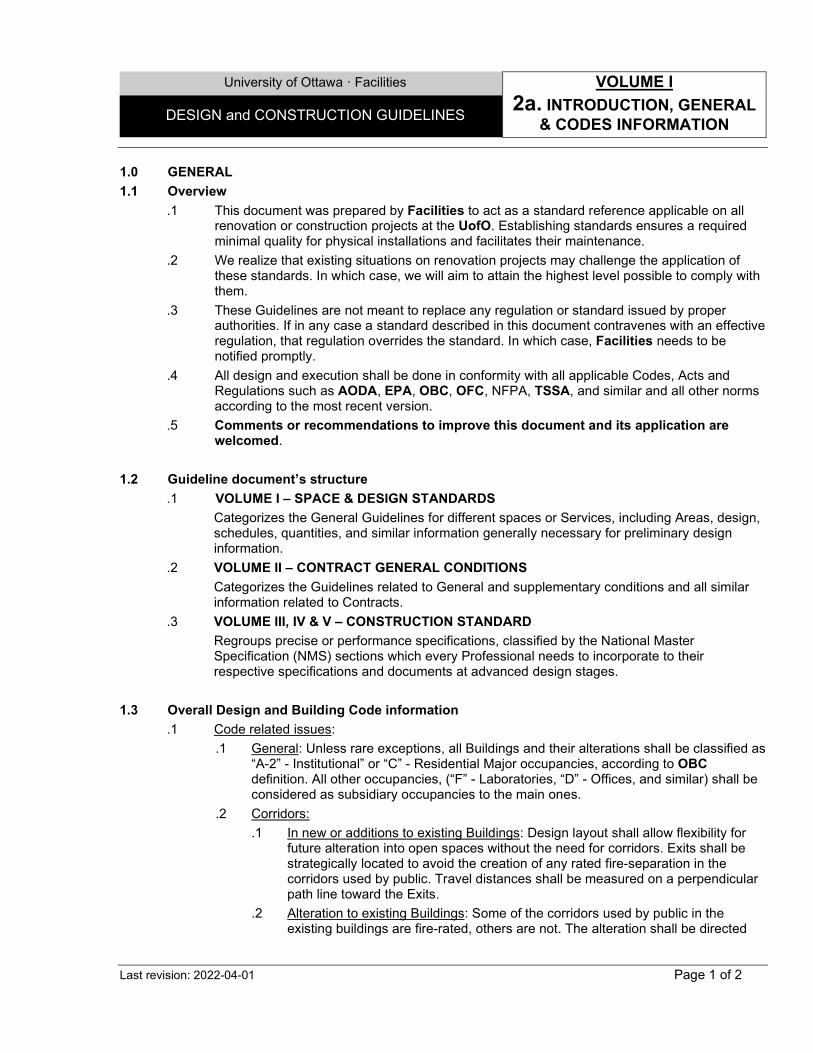
1.0 GENERAL 1.1 Overview
.1 This document was prepared by Facilities to act as a standard reference applicable on all renovation or construction projects at the UofO. Establishing standards ensures a required minimal quality for physical installations and facilitates their maintenance.
.2 We realize that existing situations on renovation projects may challenge the application of these standards. In which case, we will aim to attain the highest level possible to comply with them.
.3 These Guidelines are not meant to replace any regulation or standard issued by proper authorities. If in any case a standard described in this document contravenes with an effective regulation, that regulation overrides the standard. In which case, Facilities needs to be notified promptly.
.4 All design and execution shall be done in conformity with all applicable Codes, Acts and Regulations such as AODA, EPA, OBC, OFC, NFPA, TSSA, and similar and all other norms according to the most recent version.
.5 Comments or recommendations to improve this document and its application are welcomed.
1.2 Guideline document’s structure
.1 VOLUME I – SPACE & DESIGN STANDARDS Categorizes the General Guidelines for different spaces or Services, including Areas, design, schedules, quantities, and similar information generally necessary for preliminary design information.
.2 VOLUME II – CONTRACT GENERAL CONDITIONS Categorizes the Guidelines related to General and supplementary conditions and all similar information related to Contracts.
.3 VOLUME III, IV & V – CONSTRUCTION STANDARD Regroups precise or performance specifications, classified by the National Master Specification (NMS) sections which every Professional needs to incorporate to their respective specifications and documents at advanced design stages.
1.3 Overall Design and Building Code information
.1 Code related issues: .1 General: Unless rare exceptions, all Buildings and their alterations shall be classified as
“A-2” - Institutional” or “C” - Residential Major occupancies, according to OBC definition. All other occupancies, (“F” - Laboratories, “D” - Offices, and similar) shall be considered as subsidiary occupancies to the main ones.
.2 Corridors: .1 In new or additions to existing Buildings: Design layout shall allow flexibility for
future alteration into open spaces without the need for corridors. Exits shall be strategically located to avoid the creation of any rated fire-separation in the corridors used by public. Travel distances shall be measured on a perpendicular path line toward the Exits.
.2 Alteration to existing Buildings: Some of the corridors used by public in the existing buildings are fire-rated, others are not. The alteration shall be directed
University of Ottawa · Facilities VOLUME I
2a. INTRODUCTION, GENERAL & CODES INFORMATION DESIGN and CONSTRUCTION GUIDELINES
Last revision: 2022-04-01 Page 2 of 2
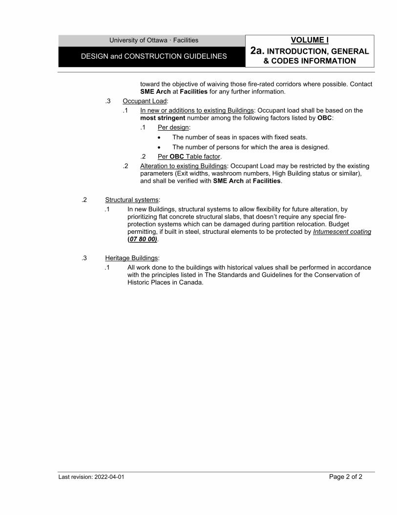
toward the objective of waiving those fire-rated corridors where possible. Contact SME Arch at Facilities for any further information.
.3 Occupant Load: .1 In new or additions to existing Buildings: Occupant load shall be based on the
most stringent number among the following factors listed by OBC: .1 Per design:
• The number of seas in spaces with fixed seats. • The number of persons for which the area is designed.
.2 Per OBC Table factor. .2 Alteration to existing Buildings: Occupant Load may be restricted by the existing
parameters (Exit widths, washroom numbers, High Building status or similar), and shall be verified with SME Arch at Facilities.
.2 Structural systems:
.1 In new Buildings, structural systems to allow flexibility for future alteration, by prioritizing flat concrete structural slabs, that doesn’t require any special fire-protection systems which can be damaged during partition relocation. Budget permitting, if built in steel, structural elements to be protected by Intumescent coating (07 80 00).
.3 Heritage Buildings:
.1 All work done to the buildings with historical values shall be performed in accordance with the principles listed in The Standards and Guidelines for the Conservation of Historic Places in Canada.
University of Ottawa · Facilities VOLUME I
3a. DOCUMENTS & PROCEDURES DESIGN and CONSTRUCTION GUIDELINES
Last revision: 2021-12-01 Page 1 of 8
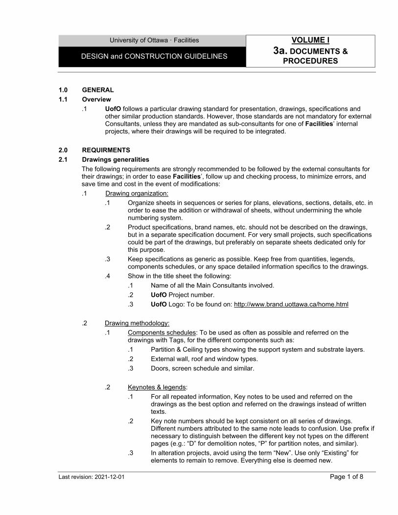
1.0 GENERAL 1.1 Overview
.1 UofO follows a particular drawing standard for presentation, drawings, specifications and other similar production standards. However, those standards are not mandatory for external Consultants, unless they are mandated as sub-consultants for one of Facilities’ internal projects, where their drawings will be required to be integrated.
2.0 REQUIRMENTS 2.1 Drawings generalities
The following requirements are strongly recommended to be followed by the external consultants for their drawings; in order to ease Facilities’, follow up and checking process, to minimize errors, and save time and cost in the event of modifications: .1 Drawing organization:
.1 Organize sheets in sequences or series for plans, elevations, sections, details, etc. in order to ease the addition or withdrawal of sheets, without undermining the whole numbering system.
.2 Product specifications, brand names, etc. should not be described on the drawings, but in a separate specification document. For very small projects, such specifications could be part of the drawings, but preferably on separate sheets dedicated only for this purpose.
.3 Keep specifications as generic as possible. Keep free from quantities, legends, components schedules, or any space detailed information specifics to the drawings.
.4 Show in the title sheet the following: .1 Name of all the Main Consultants involved. .2 UofO Project number. .3 UofO Logo: To be found on: http://www.brand.uottawa.ca/home.html
.2 Drawing methodology:
.1 Components schedules: To be used as often as possible and referred on the drawings with Tags, for the different components such as: .1 Partition & Ceiling types showing the support system and substrate layers. .2 External wall, roof and window types. .3 Doors, screen schedule and similar.
.2 Keynotes & legends:
.1 For all repeated information, Key notes to be used and referred on the drawings as the best option and referred on the drawings instead of written texts.
.2 Key note numbers should be kept consistent on all series of drawings. Different numbers attributed to the same note leads to confusion. Use prefix if necessary to distinguish between the different key not types on the different pages (e.g.: “D” for demolition notes, “P” for partition notes, and similar).
.3 In alteration projects, avoid using the term “New”. Use only “Existing” for elements to remain to remove. Everything else is deemed new.
University of Ottawa · Facilities VOLUME I
3a. DOCUMENTS & PROCEDURES DESIGN and CONSTRUCTION GUIDELINES
Last revision: 2021-12-01 Page 2 of 8
.3 Duplication of information: To be avoided as possible, especially: .1 Between similar detail types. Use multi-references instead. .2 Between the source drawing and the blow-up portion. If the info is in the blow-
up portion or detail, remove it from the source. .3 Between Components schedules and the drawings: If the info is shown in the
schedule, do not repeat it on the drawings. The reference Tag should be enough.
.4 Clarity: Insure clarity of information, especially for the following:
.1 Elevations: Show hierarchy in the lines: Use dark lines for close object, and light lines as objects fades back.
.2 Nomenclature: Shall be with the appropriate sizes suitable for each scale. Avoid oversize or very small illegible sizes.
.5 Redundancies: Avoid unnecessary drawings, such as:
.1 Several internal Elevations, Plans or Details showing the same information for different - but similar- types of spaces or conditions. Use multi-reference instead.
2.2 Documents deliverables
The following may be superseded by particular requests or detailed checklist, depending on project’s complexities and contract specifcs: .1 Architectural drawings should show at minimum – As applicable:
.1 Preliminary & Schematic Concept Design: .1 Schematic design documents to illustrate the scale and character of the Project
and how the parts of the Project functionally relate to each other including as appropriate.
.2 Applicable codes summary.
.3 Site Plan.
.4 Spatial Relationship diagrams.
.5 Schematic Floor Plans.
.6 Schematic Elevations & Sections.
.7 Outline Specifications .2 Design Brief (to be included with every submittal):
.1 Executive Summary & Introduction.
.2 Applicable codes and standards.
.3 Brief analysis of Project’s requirements.
.4 Sketches and/or Schematics of proposed concept, reflecting current site conditions.
.5 Appendices as required.
University of Ottawa · Facilities VOLUME I
3a. DOCUMENTS & PROCEDURES DESIGN and CONSTRUCTION GUIDELINES
Last revision: 2021-12-01 Page 3 of 8
.3 At 33% stage: .1 Code Matrix analysis. .2 Building main envelope system descriptions (exterior walls, roofs, parapets,
soffits, internal partitions, and similar). .3 Site plans, Floor plans showing main layouts. .4 Elevations and sections.
.4 At 66% stage. At minimum:
.1 Fire safety drawings. .2 Site, Roof & Floor plans showing the different wall and partition types. .3 Reflected Ceiling plans showing the different compositions. .4 Wall sections identifying main components. .5 External elevations with identified materials. .6 Typical main envelope details. .7 Preliminary detailed spec sections. .8 Preliminary door and finish schedules.
.5 At 99% stage:
.1 All the previous stage items fully developed, identified and dimensioned.
.2 Interior elevations as applicable.
.3 Finished colored pattern (at least % of accent items).
.4 Location of internal partition control joints and patterns.
.5 Location of external masonry control joints and patterns. .6 Fire-Safety drawings submitted to the City:
.1 A summary description of the scope.
.2 For new construction or Extensive Renovation (OBC) projects: .1 A matrix summarizing the basic building information: Area, year of
construction, type, number of stories, applicable Codes, major fire-rated components for floors, and similar.
.2 Fire-separations on all partitions on the entire floor area.
.3 Show Fire-spatial separations (floors, shafts, etc.), if the layout include Mezzanines or other complex spatial components.
.4 Critical travel distances to the exits covering the entire floor area. .3 For Basic Renovation (OBC) projects: Where information may not be available
for the rest of the space: .1 The matrix provided by Facilities which summarize the basic building
information and a justification for the assessment of the fire-resistance ratings of spaces.
.2 Fire-separations on partitions only in the affected area.
.3 Travel distances only from the affected area to the exits.
University of Ottawa · Facilities VOLUME I
3a. DOCUMENTS & PROCEDURES DESIGN and CONSTRUCTION GUIDELINES
Last revision: 2021-12-01 Page 4 of 8
.4 ULC, cUL or OBC SB-3 reference test number (or any approved equivalent) on all proposed fire-resistance or sound rated assemblies.
.2 Mechanical, Electrical, Plumbing drawings should show at minimum - As applicable:
.1 I&R & Schematic Design: .1 Detailed report that thoroughly describes and characterizes the options. This is
to include: .2 An overview of the project; .3 Narratives to describe the existing mechanical, electrical, controls, life and
safety systems, and related elements including their condition, deficiencies and life expectancy;
.4 Report on existing mechanical, electrical, controls and life and safety systems and related elements;
.5 Narratives to determine all applicable codes, regulation, standards and authorities having jurisdiction and outlined requirements related to the project;
.6 Graphical floor plans and schematics for all mechanical and electrical system to clearly demonstrate proposed options proposed in the report being recommended along with description how the new equipment/systems will impact existing installations;
.7 Provide sequencing of project deliverables and phasing based on priority and/or constructability. Identify short/medium/long term requirements;
.8 Identify the project impact on existing spaces which may need to remain operational during construction; identify project impact on spaces that fall outside of the project boundary taking into account all project phases.
.9 Regardless of whether existing infrastructure is being utilized or not, investigate how other areas of the building may be negatively affected due to shutdowns, etc. Also provide recommendations to alleviate any building system capacity issues that may arise due to the project;
.10 Identify long delivery items which have impact on project schedule and/or phasing of construction. Equipment with long delivery time will require to be purchased in advance;
.11 Prepare and submit Life Cycle Cost Analysis (LCCA) of mechanical and electrical systems for preferred option and/or recommendation(s). LCCA shall consider the total life cycle cost of the project. LCCA shall include the initial or first cost plus the overall operating cost and equipment replacement costs when applicable over the life of the project;
.12 Report shall include an executive summary;
.13 Breakdown Class D cost estimate for recommended options and other options pertain to all mechanical and electrical systems related to the project;
.14 As a minimum the I&R report shall include sections to cover the following topics: • Executive summary. • Introduction. • Project background. • Applicable codes and standards.
University of Ottawa · Facilities VOLUME I
3a. DOCUMENTS & PROCEDURES DESIGN and CONSTRUCTION GUIDELINES
Last revision: 2021-12-01 Page 5 of 8
• Existing conditions. • Analysis of project’s requirements. • Validation and/or deviation along with recommendation(s). • Energy consumption and O&M cost impact. • Appendices as necessary.
.2 Design Brief (to be included with every submittal):
.1 Executive Summary & Introduction.
.2 Applicable codes and standards.
.3 Brief analysis of Project’s requirements.
.4 Narratives to describe all of the proposed mechanical systems. For controls system provide narrative to describe the integration with other building systems including lighting controls, fire alarm, security, energy monitoring and verification.
.5 Narratives to describe all of the proposed electrical systems. Narratives to include total connected normal load, maximum demand and diversity factors for normal load, total connected emergency load and capacity of base building emergency generator (where applicable), short-circuit requirements and calculations showing the ratings of equipment used.
.6 Approximate size of the required equipment/systems along with cut-sheet of preliminary selections.
.7 Analysis of selected equipment and calculations sufficient to justify the economy of the selected equipment.
.8 Sketches and/or Schematics of proposed concept, reflecting current site conditions.
.9 Appendices as necessary. .3 At 33% stage:
.1 Single line diagrams of all mechanical system including but not limited to HVAC, plumbing, fire protection and process systems indicating the equipment tags, preliminary system sizing, flow rates and directions, equipment capacities and all control valves, isolating valves, strainers, gauges, dampers, louvers, etc. Single line to demonstrate all the spaces affected by the project and modification(s) to existing systems.
.2 Mechanical controls schematics complete with sequences of operations and comprehensive list of control points.
.3 Floor plans showing the preliminary sizing, physical dimensions and require service areas of all major equipment complete with their locations and layouts (Equipment on floor plans must reflect the proper location within the system on both this drawing and the single line diagrams).
.4 Floor plans showing the zoning of thermal, ventilation and lighting systems.
.5 Equipment schedule including preliminary selection of all major mechanical and electrical equipment.
University of Ottawa · Facilities VOLUME I
3a. DOCUMENTS & PROCEDURES DESIGN and CONSTRUCTION GUIDELINES
Last revision: 2021-12-01 Page 6 of 8
.6 Floor plans showing the applicable occupancy classification for fire protection systems.
.7 Site Plan showing service entrances for mechanical and electrical systems and connections to utility services including all key elevations.
.8 Single line diagram of the electrical power distribution circuits with their metering and protection, including rating of equipment, ratios and connections of current transformer and power transformer, description of relays (when used, maximum short circuit levels on which design is based. identification and size of services, connected load and estimated maximum demand on each load center.
.9 Riser diagrams for lighting, power and telecommunication cable systems, fire alarm and other systems.
.10 Preliminary control diagrams for each system.
.11 Schedule for motors and controls.
.12 Panel boards schedule with loadings for each panel.
.4 At 66% stage: .1 Revised design brief as required. .2 Revised single line diagrams of systems as required. .3 Schedule for motor and controls. .4 Floor plans of mechanical systems showing routing and sizing of major lines
and location of all equipment. .5 Floor plans of power distribution indicating all conduit and wire sizes except for
minimum sizes (minimum sizes should be given in the specification).
.5 At 99% stage: .1 Revised design brief as required. .2 Revised single line diagrams of systems as required. .3 Complete working drawings. .4 Specifications in National Master Specification format. .5 Class A cost estimate (Highlight changes from previous cost estimate). .6 Preliminary Coordination, Short Circuit, Device Evaluation, and Arc Flash
study. .7 ESA Plans Approval Response. .8 Electrical drawings as a minimum must show the following: .9 Single line diagram of the electrical power distribution circuits with their
metering and protection, including: Complete rating of equipment, Ratios and connections of Current Transformer (CT's) and Power Transformer (PT's), Description of relays when used, Maximum short circuit levels on which design is based, Identification and size of services and Connected load and estimated maximum demand on each load center.
.10 Electrical plans with: Circuit numbers at outlets and control switching identified. All conduit and wire sizes except for minimum sizes which should be given in
University of Ottawa · Facilities VOLUME I
3a. DOCUMENTS & PROCEDURES DESIGN and CONSTRUCTION GUIDELINES
Last revision: 2021-12-01 Page 7 of 8
the specification and IT, AV and Security conduits system layout for ceiling/floor distribution.
.11 For electrical layout and schedule provide the following data:
.12 Total connected normal load.
.13 Maximum demand and diversity factors for normal load.
.14 Total connected emergency load.
.15 Maximum demand and diversity factors for emergency load.
.16 Capacity of base building emergency generator.
.17 Sizing of standby load.
.18 Short-circuit requirements and calculations showing the ratings of equipment used.
.3 Specifications:
.1 Specifications produced by the external consultants, shall follow the National Master Specification (NMS) format in a separate document. For very small projects, the specifications could be incorporated to the drawings on separate sheets dedicated for this purpose, following the same NMS format.
.4 Cost Estimates:
• Preliminary Concept, schematic, I&R, and similar: Class D. • 33% Stage: Class C. • 66% Stage: Class B. • 99% Stage: Class A.
.5 Closeouts: • Updated & Record Drawings. • Updated & Record Specifications. • Contractor's Documentation at Completion, including Warranties, Test reports, Owner
Manuals, Shop Drawings Samples, and similar. • Updated Code reports, if done by external Consultants. • Final Commissioning Reports and related data. • Drawing ecteronic format. Refer to “4a. DRAFTING” of this DCG Document. • Any other as listed in the project specific requirements.
3.1 Procedures .1 Reviews:
.1 Coordination: At early design stages, coordination between the different Consultants, the users and Facilities is imperative toward the realization of the design objectives. Special attention should be given to the equipment and clearances for maintenance and easy access. Design developments, Construction drawings, Reports, and all other similar documents shall be reviewed by SME’s during the different project phases as established and agreed with the Project Manager.
University of Ottawa · Facilities VOLUME I
3a. DOCUMENTS & PROCEDURES DESIGN and CONSTRUCTION GUIDELINES
Last revision: 2021-12-01 Page 8 of 8
.2 SME’s will overview the documents to ensure they are conforming to the established UofO DCG and will highlight any issues to Consultants a.s.a.p. (typically, allow 5 working days). Consultant shall incorporate review comments into the next submission stage and provide written responses as necessary.
.3 Unless otherwise noted, Consultants to provide written responses to all comments received from the UofO, Comments shall be incorporated in the next submission as required.
.4 During the review process by SME’s, the Consultant shall keep working in parallel to develop their documents for the next phase, unless specifically requested to stop by UofO. Depending on the project’s complexities, Consultants may be requested to obtain authorization before proceeding to the following stage.
.5 UofO review does not relieve the Consultants from their responsibilities and/or liabilities. The Consultants are solely responsible for integrity of design and shall ensure project requirements and DCG have been included in design.
.2 Room Numbering:
.1 It is imperative to consult UofO, SFS department to establish the proper Room numbering prior to the beginning of every project. Room numbering done without such consultation will not be accepted. Refer to contact information at the beginning of this document.
.3 Color & Samples:
.1 Color & Finish Sample patterns, shall be ready - ideally by 99% phase and submitted to UofO for review.
.4 Shop Drawings (SD):
.1 SD’s shall be submitted to Consultant and UofO in parallel.
.2 If specific input is required, Consultant to highlight to UofO, and vice versa.
.3 UofO will not necessarily review all SD’s, but in some case may do so. UofO will inform Consultants about any new pressing issues – if applicable.
.4 Once reviewed by Consultant, SD’s electronic copy to be sent to contractor and UofO.
.4 Construction Documents:
.1 Consultants to issue fully stamped/sealed construction sets by all consultants.
.2 If exceptions present themselves, UofO must formally agree to release without stamps.
University of Ottawa · Facilities VOLUME I
4a. DRAFTING DESIGN and CONSTRUCTION GUIDELINES
Last revision: 2021-12-01 Page 1 of 2
1.0 GENERAL 1.1 Overview
.1 This document comprises the Facilities Computer Aided Drafting and Design (CADD) & other related drafting Standard.
.2 This document forms a legal part of project deliverables. It is to be applied both internally and by any Consultant providing external Drafting, or on Project delivery services for UofO.
2.0 REQUIRMENTS 2.1 Production
.1 Consultants working Medium: .1 BIM (Revit or similar 3D) modeling Software: Shall be used in:
.1 New Buildings.
.2 New addition to existing buildings.
.3 Alteration / renovation to newly constructed buildings after 2015 (ARC, CRX & STEM).
.4 Major Renovation projects inside older buildings (generally where project area exceeds 50% of floor).
.2 CADD Software: .1 Can be used in all other conditions not listed above, which include generally
minor renovations, roof renewal, landscape projects, etc. .2 Refer Refer to the Related document and Sample drawing / Blocks / Layering &
Attributes on UofO Web Site.
2.2 Deliverable .1 Format & timeline:
.1 At all project phases; drawings, or other requested files as per agreements, shall be delivered to Facilities in electronic tabled (indexed) format (pdfs), and Aided Drafting and Design format (CADD and/or BIM). Paper format is optional, depending on the project size.
.2 In addition, As Built Record drawings to be delivered as follow: .1 Architecture: 30 days at most after the project close-out. .2 M&E, Structure and other disciplines: 60 days at most after the project close-
out.
.2 By CADD software: .1 Refer to the Related document on UofO Web Site. .2 Layer structure, Blocks, Symbols, and other similar components shall conform to
UofO’s standards, published on the Web Site. .3 By BIM (Revit or similar 3D) modeling Software: Elements shall be transferred to the CADD
format before being delivered to Facilities, following similar UofO CADD Standards listed above. .1 Provide a copy of all available BIM (Revit) models.
University of Ottawa · Facilities VOLUME I
4a. DRAFTING DESIGN and CONSTRUCTION GUIDELINES
Last revision: 2021-12-01 Page 2 of 2
.2 Provide CADD drawings, conversion of the BIM model, based on the same CADD parameters highlighted above.
.3 Not accepted: Overlapping partition lines (resulting from 3D flattening process).
University of Ottawa ꞏ Facilities VOLUME I
5a. SITE MANAGEMENT DESIGN and CONSTRUCTION GUIDELINES
Last revision: 2021-01-31 Page 1 of 1
1.0 GENERAL
1.1 Overview
.1 Unless otherwise noted, the measures indicated below shall to be applied by the GC, depending on project complexities, scope, and duration.
2.0 REQUIRMENTS
.1 Access:
.1 Provide access to building and Employees' Parking Area at all times. Arrange access points with Owner.
.2 Provide and maintain road access and egress from / to property fronting, except where other means of road access exist that meet approval by Facilities.
.2 Traffic Control:
.1 Provide traffic control mechanisms for all areas surrounding the buildings for extended or prolonged Construction periods. PRO may take very limited and short periods in charge. To be confirmed with every scope.
.2 Traffic control Measures shall be based on “Ontario Traffic Manual, Book 7 - Temporary Conditions”, mainly:
.1 Through competent and trained flag personnel.
.2 By continually maintain traffic control devices in use.
.3 By maintaining and providing signs, flashing warning lights and other devices required to indicate construction activities or other temporary and unusual conditions resulting from Project.
.3 Waste containers:
.1 All applications for projects waste containers on campuses shall be approved by the OPST and by the Facilities TERR department.
.2 Once the application is approved, the GC must respect the demands laid upon approval. E.g.: Install boards under the waste container to protect asphalt or terrain, observe the established distances around trees, and similar.
.3 All waste containers must be enclosed (fenced in) in order to minimize the chances of people getting injured trying to get inside, or that other people use the container without project approval. E.g.: To throw dangerous products or material that cannot usually be thrown in the waste.
.4 A poster with the name and contact of the UofOttawa Project Manager and the GC shall be installed on the fences surrounding the waste container.
.5 The GC must comply with the dates initially established, as there could be other projects requesting this specific space. If there are no other requests, a new date could be established.
.6 The GC is responsible to establish the space to its originally state before the waste container installation. E.g.: re-installation of grass or damaged plants.
.7 The GC shall pay for parking that was blocked by the waste container to the tariff established in the initial meeting (as applicable.
.8 For all additional info, contact PRO, or TERR.
University of Ottawa ꞏ Facilities VOLUME I
A. STUDENT SPACES DESIGN and CONSTRUCTION GUIDELINES
Last revision: 2020-08-01 Page 1 of 1
1.0 GENERAL
1.1 Overview
.1 Student spaces vary based on project and design specifics.
1.2 Design
.1 Definitions:
.1 Master or PHD student spaces:
.1 Enclosed study spaces to accommodate several students applying for their Master Studies.
.2 Design permitted, shall have direct access to natural lighting or indirectly through vision panels.
.2 Student Association offices:
.1 Enclosed office to hold common activity by several Student associations.
.2 Design permitted, shall have direct access to natural lighting or indirectly through vision panels.
.3 Student Lounge / Focus room: Refer to Public spaces section.
.4 Quiet Study Space / Workstation:
.1 Open or closed spaces to accommodate several students, in a quit individual environment for studying.
1.3 Accessories
.1 Coat Hook Strip (10 28 10): To be installed in every closed office, behind door.
2.0 SERVICES
2.1 Mechanical
.1 Xxxxxx
2.2 Electrical
.1 Xxxxxx
2.3 Power and Data outlets
.1 In Student lounge / focus room spaces, trailing wires connected to wall-mount outlets constitutes a Health safety hazard. Special consideration shall be taking while designing the outlets through integrating them into furniture or by other means.

University of Ottawa · Facilities VOLUME I
B. ADMINISTRATIVE SPACES DESIGN and CONSTRUCTION GUIDELINES
Last revision: 2021-04-01 Page 1 of 2
1.0 GENERAL 1.1 Overview
.1 Administrative spaces vary considerably based upon major users such as the Registrar or a Faculty, and project specific.
1.2 Design
.1 Definitions: .1 Closed (Private) Offices:
.1 Sizes vary based on the users and their hierarchy. To include but not limited to: Dean, Chair, Professor, Directors Assistant directors, Admin CAO, and similar.
.2 Design permitted, shall have direct access to natural lighting, or indirectly through vision panels.
.2 Open Office spaces:
.1 Open spaces for admin personnel, to be organized in a way to preserve a semi-privacy factor, with enough circulating and gathering spaces.
.2 Shall have direct access to natural lighting, or indirectly through skylights.
.3 Meeting Rooms: .1 Design shall accommodate reasonable number of people based on design
requirements, with a versatile design. .2 Shall be located at strategic places, ideally at intersection of main corridors,
to facilitate its sharing between different groups.
.4 Reception Areas: .1 Space to accommodate several persons depending on design parameters
with enough support space for electronic equipment. .2 Consider in the design additional space for lineups or waiting seated area,
which do not impede on the main corridors or circulation. .5 Staff & Professor Lounge:
.1 Closed spaces for common social, gaming and reading activities.
.2 Could be used as lunchroom with a small kitchenette space with sink, which can accommodate basic appliances such as microwave and fridge.
.6 Support Spaces:
.1 Include all related support administrative spaces include but not limited to: .1 Reprographics. .2 Storage for students’ Records.
.2 General:
.1 For privacy and acoustical issues, avoid locating office and meeting room doors face to face in double loaded corridors.
1.3 Accessories
.1 Coat Hook Strip (10 28 10): To be installed in the following locations: .1 In every closed office, behind door. .2 In every Meeting room behind door, and common office space, closed to every
workstation.

University of Ottawa · Facilities VOLUME I
B. ADMINISTRATIVE SPACES DESIGN and CONSTRUCTION GUIDELINES
Last revision: 2021-04-01 Page 2 of 2
2.0 SERVICES 2.1 Mechanical
.1 Xxxxxxx 2.2 Electrical
.1 In Meeting rooms, consider dimmable pot light combined with on/off fluorescent fixtures. 2.3 Power and Data outlets
.1 Depending on size and design imperatives, Power and Data outlets shall be located in a monument type on the floor, with possibilities of extension to the meeting table.
University of Ottawa · Facilities VOLUME I
C. CLASSROOMS DESIGN and CONSTRUCTION GUIDELINES
Last revision: 2021-08-01 Page 1 of 6
1.0 GENERAL 1.1 Overview
.1 Classrooms and their specific requirements vary considerably based upon major users such as the Registrar or a Faculty.
1.2 Design .1 Definitions:
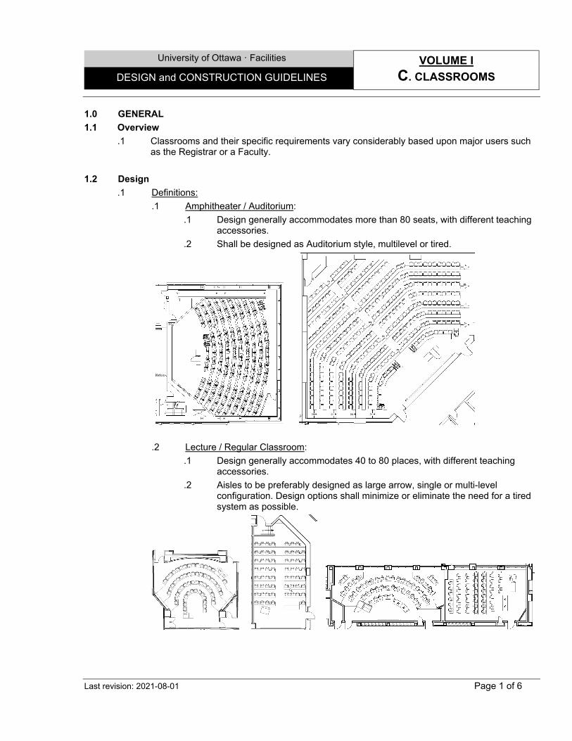
.1 Amphitheater / Auditorium: .1 Design generally accommodates more than 80 seats, with different teaching
accessories. .2 Shall be designed as Auditorium style, multilevel or tired.
.2 Lecture / Regular Classroom:
.1 Design generally accommodates 40 to 80 places, with different teaching accessories.
.2 Aisles to be preferably designed as large arrow, single or multi-level configuration. Design options shall minimize or eliminate the need for a tired system as possible.

University of Ottawa · Facilities VOLUME I
C. CLASSROOMS DESIGN and CONSTRUCTION GUIDELINES
Last revision: 2021-08-01 Page 2 of 6
.3 Seminar Room: .1 Design accommodates generally 20 to 50 places, with different teaching
accessories. .2 Shall be designed for an interactive teaching environment, single tire, with
aisles generally set-up in rectangular fashion.
.4 Computer Classroom: .1 Depending on the parameters, design shall accommodate variable number of
students, and other teaching accessories. .2 Design shall be versatile, to accommodate different student’s or TLSS
groups.
.5 Music (acoustic) Room: .1 Closed room or space designated for students to play different musical
instruments. Sizes vary based on the number of instrument enclosed. .2 Design options could include insulated prefabricated booth.
University of Ottawa · Facilities VOLUME I
C. CLASSROOMS DESIGN and CONSTRUCTION GUIDELINES
Last revision: 2021-08-01 Page 3 of 6
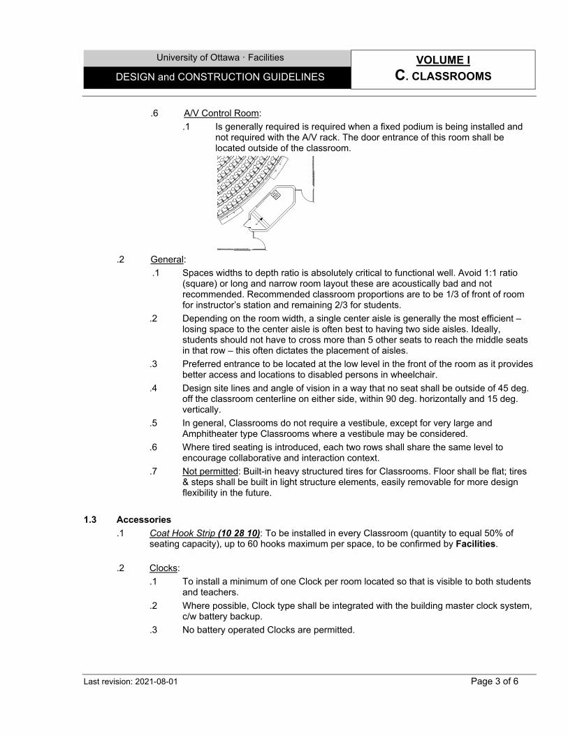
.6 A/V Control Room: .1 Is generally required is required when a fixed podium is being installed and
not required with the A/V rack. The door entrance of this room shall be located outside of the classroom.
.2 General:
.1 Spaces widths to depth ratio is absolutely critical to functional well. Avoid 1:1 ratio (square) or long and narrow room layout these are acoustically bad and not recommended. Recommended classroom proportions are to be 1/3 of front of room for instructor’s station and remaining 2/3 for students.
.2 Depending on the room width, a single center aisle is generally the most efficient – losing space to the center aisle is often best to having two side aisles. Ideally, students should not have to cross more than 5 other seats to reach the middle seats in that row – this often dictates the placement of aisles.
.3 Preferred entrance to be located at the low level in the front of the room as it provides better access and locations to disabled persons in wheelchair.
.4 Design site lines and angle of vision in a way that no seat shall be outside of 45 deg. off the classroom centerline on either side, within 90 deg. horizontally and 15 deg. vertically.
.5 In general, Classrooms do not require a vestibule, except for very large and Amphitheater type Classrooms where a vestibule may be considered.
.6 Where tired seating is introduced, each two rows shall share the same level to encourage collaborative and interaction context.
.7 Not permitted: Built-in heavy structured tires for Classrooms. Floor shall be flat; tires & steps shall be built in light structure elements, easily removable for more design flexibility in the future.
1.3 Accessories
.1 Coat Hook Strip (10 28 10): To be installed in every Classroom (quantity to equal 50% of seating capacity), up to 60 hooks maximum per space, to be confirmed by Facilities.
.2 Clocks:
.1 To install a minimum of one Clock per room located so that is visible to both students and teachers.
.2 Where possible, Clock type shall be integrated with the building master clock system, c/w battery backup.
.3 No battery operated Clocks are permitted.
University of Ottawa · Facilities VOLUME I
C. CLASSROOMS DESIGN and CONSTRUCTION GUIDELINES
Last revision: 2021-08-01 Page 4 of 6
.3 Seats: Free standing or fixed models, depends on space configuration. Other than amphitheatres, all seat options shall have the ability for 360degress rotation for shared learning experience.
2.0 MULTIMEDIA TECHNOLOGIES PRESENTATION TOOLS 2.1 Overview
.1 This is a very specialized and essential component of classroom design. Requirements and technologies are in constant evolution. Coordination with TLSS Multimedia Section is mandatory.
2.2 Typical Multimedia video conference technologies
.1 Podium desk (12 50 00): .1 General:
.1 Designed to house all the electronics and computer teaching equipment and is linked to the classroom light controls, ceiling projectors and screens and other stuff.
.2 This is a prefabricated unit with a fixed non-adjustable component and an electrically adjustable component designed to meet barrier free requirements.
.3 To be provided and installed by GC.
.4 Refer to furniture standard for more details on UofO Web site. .2 Podium desk control (26 50 00):
.1 One dedicated telephone line to be located on the Podium desk or at the front of the room adjacent to professors teaching station. This is required in the event of an emergency or a technology malfunction.
.2 Control design shall be similar to the following sketch. Refer to Xxxxxxx. .2 Multi-media Rack: A fixed unit containing A/V equipment and is used in smaller type
classrooms where fixed podiums will not fit and are not used. This unit is supplied and installed by TLSS.
.3 Computers: Supplied and installed by TLSS. .4 Projectors, (overhead, ceiling mounted) and sound systems: Supplied and installed by TLSS.
.5 Projection Screens, (manual and/or motorized):
.1 Are supplied by TLSS and installed by the Contractor.
.2 A/V screens to be concealed within the ceiling space or using gypsum board bulkheads.
.6 Visual Display Boards – Writing Surfaces (10 11 00), Bulletin Boards and Tack Strips: .1 Shall be included in the GC responsibilities to supply and install. As a general rule
mounting heights for chalkboards and whiteboards to be 36” above finished floor.
University of Ottawa · Facilities VOLUME I
C. CLASSROOMS DESIGN and CONSTRUCTION GUIDELINES
Last revision: 2021-08-01 Page 5 of 6
.2 Chalk boxes are always required. These are specially designed units by UofO and installed by GC. Request installation with Facilities, Custodial section.
.3 White boards are not allowed in Registrar classrooms, chalkboards to be installed.
.7 Flat screen Monitor: Supplied and installed by TLSS.
3.0 SERVICES 3.1 Mechanical
.1 Consider the cooling load required for equipment heat rejection, especially in A/V control rooms, with the appropriate solution.
3.2 Electrical
.1 Electrical Panel (26 00 00): .1 Each new Classroom shall have a new Electrical Panel, to be located outside the
Technical Support room and the Classroom to permit electricians’ access. .2 All audio/video equipment circuits shall be connected to the same phase and same
ground at the Electrical Panel.
.2 Light Fixtures: .1 Classroom Light (26 50 00): Use preferably 2’x2’ indirect light fixture to allow for
better zone distribution application. .2 Classroom Fluorescent Lamps (26 50 00): Shall be of dimmable type.
.3 Lighting Controls:
.1 General: .1 All lighting controls shall be located in the A/V room and be accessible. .2 A plasticized lighting zones plan shall be affixed inside A/V Control room and
on the wall, including zone numbers and electrical circuit numbers.
.2 Wiring (26 50 00): Run separate neutral for dimmable lighting load circuits. No common neutral.
.3 Terminal Strip Box (26 00 00): All lighting zones power circuit shall be run to a
terminal strip box.
.4 Lighting & Emergency Light Controller (26 50 00): .1 Shall not exceed maximum recommended load per zone and per controller. .2 If emergency lighting to the multimedia classroom is not required, use normal
power circuits for lighting control.
.5 Occupancy Sensor (26 50 00): .1 Classroom lighting shall be controlled by occupancy sensors.
University of Ottawa · Facilities VOLUME I
C. CLASSROOMS DESIGN and CONSTRUCTION GUIDELINES
Last revision: 2021-08-01 Page 6 of 6
.2 All lighting zones need to be turned off when room is unoccupied.
.6 Lighting Panic Mode: Consider the requirement for lighting panic mode option in case of a fire alarm, and if the lights are OFF due to a video presentation.
.7 Motorized Projection Screen control (26 00 00):
.1 Must be installed inside the A/V Control room.
.1 Are supplied by TLSS and installed by the Contractor.
.8 Multimedia Conduits (26 00 00): Provide an additional EMT conduit for lighting control wiring between the main lighting controller, switches, interfaces and scene selectors at the podium.
3.3 Power and Data outlets
.1 Data: .1 Data port required at podium or media rack. .2 Fixed seats; Data outlets or wireless system requirement to be confirmed on an
individual project basis. .2 Power outlets: A minimum of one receptacle per wall shall be installed.
.3 A/V Electric Outlet (26 00 00): All electric receptacles for audio/video systems (excluding
student table power pack) shall be new surge suppression duplex receptacles. .4 Accessible Table outlets (26 00 00): Install one power outlet (2 plugs) per table on centerline
of long side.
.5 Seats with retractable tablet outlets (26 00 00) and similar fixed: .1 Design shall allow for a maximum of eight laptops per 15 amp, 1110 volt circuit or 1.5
amp draw per electrical outlet. .2 Electric raceway systems and top table power pack shall be approved by the UofO
and authority having jurisdiction. .3 To install one power outlet (2 plugs) at:
.1 Every seat with retractable tablet.
.2 Every Fixed table for each 2 Swivel Seats.
University of Ottawa · Facilities VOLUME I
D. LABORATORIES & SUPPORT DESIGN and CONSTRUCTION GUIDELINES
Last revision: 2021-08-01 Page 1 of 7
1.0 GENERAL 1.1 Overview
.1 Laboratories vary from very large to smaller, more precise specific areas. Each of these Labs types have their own specific requirements and the functional programs associated with these spaces must be clearly defined early in the design process since size and weight of materials being handled will affect both the structural aspects as well as location and proximity to major loading areas, some specific equipment may generate excessive noise or heat or require large amount of chilled water or domestic water. It is very important to work with the users to define their needs and confirm with Facilities & ORM, for elements such as: .1 Natures of operations they are conducting, including hazardous materials, chemicals
and similar. .2 Type of Labs they operate. .3 Furniture configuration, material, accessories and hardware. .4 Equipment & Fume hoods types, sizes, weights, locations, and similar info. .5 All requested or necessary services.
1.2 Design
.1 Definitions: .1 Laboratories: Spaces designated in general for testing, or experimental issues which
request specialized equipment and furniture and related teaching activities Generally dedicated for Teaching staff & Undergraduate. They include: .1 Types:
.1 Wet (Chemical): Generally, where drugs, chemicals, and other types of biological matter can be analyzed and tested by using various liquids or flammable products, with plumbing services. They often require special architectural and HVAC environment.
.2 Dry (Analytical & Support): Generally, focuses more on applied or computational or electronic mathematical analyses via the creation of computer-generated models or simulations, without plumbing services. They may require humidity and temperature control, or dust control.
.3 Animal Care / Vivarium Facilities: Labs where experiments are performed on animals, fishes and similar that requires special architectural and HVAC confined environment. May also request to be confined, if dealing with hazardous experiments as defined by Health Agency of Canada’s.
.4 Engineering: Labs dealing with machinery, industrial experiment, or similar. They may require proper HVAC or dedicated power systems.
Note: Computer Classrooms, with large number of computers generally dedicated for students use, are not considered Labs as described in this section. They may require proper HVAC or dedicated power systems.
.2 Categories: .1 Classified (Clean rooms, Bio containment level CL2(Basic), CL2-Ag,
CL2-P, CL3): Labs mainly dealing with hazardous pathogens that require special architectural and HVAC confined environment as defined by Health Agency of Canada’s.
University of Ottawa · Facilities VOLUME I
D. LABORATORIES & SUPPORT DESIGN and CONSTRUCTION GUIDELINES
Last revision: 2021-08-01 Page 2 of 7
.2 Non-classified: Labs mainly dealing with chemicals requiring special power, humidity and cooling control systems, or particular safety and health requirements, in a non-confined environment.
Note: Unless otherwise noted, UofO Wet (Chemical) Labs shall be designed based on the CL2(Basic) principles.
.2 Lab offices: Spaces that are generally daily used by the same personnel who will be operating the laboratory. While they could be integrated to the same confined Lab area, it is strongly recommended by ORM to keep them separate.
.3 Cloakrooms: Design permitted, consider an open separated space located adjacent to a Lab zone, for personal’s students belongings such as coats, bags, water & coffee bottles, and similar belongings not allowed inside the Labs.
.4 High Hazard Spaces: .1 Hazardous Service Space: To be implemented in every building containing
Labs, for the use of ORM, dedicated to hazardous, chemical, flammable or combustible waste.
.2 Hazardous Storage Space: To be implemented in every building containing Labs, dedicated for the flammable or compressed gas and combustible liquid storage.
.3 Hazardous Dispensing Space: To be implemented in every building containing Labs, dedicated for the flammable or combustible liquid dispensing for cylinders or containers exceeding the permitted sizes in a typical Lab.
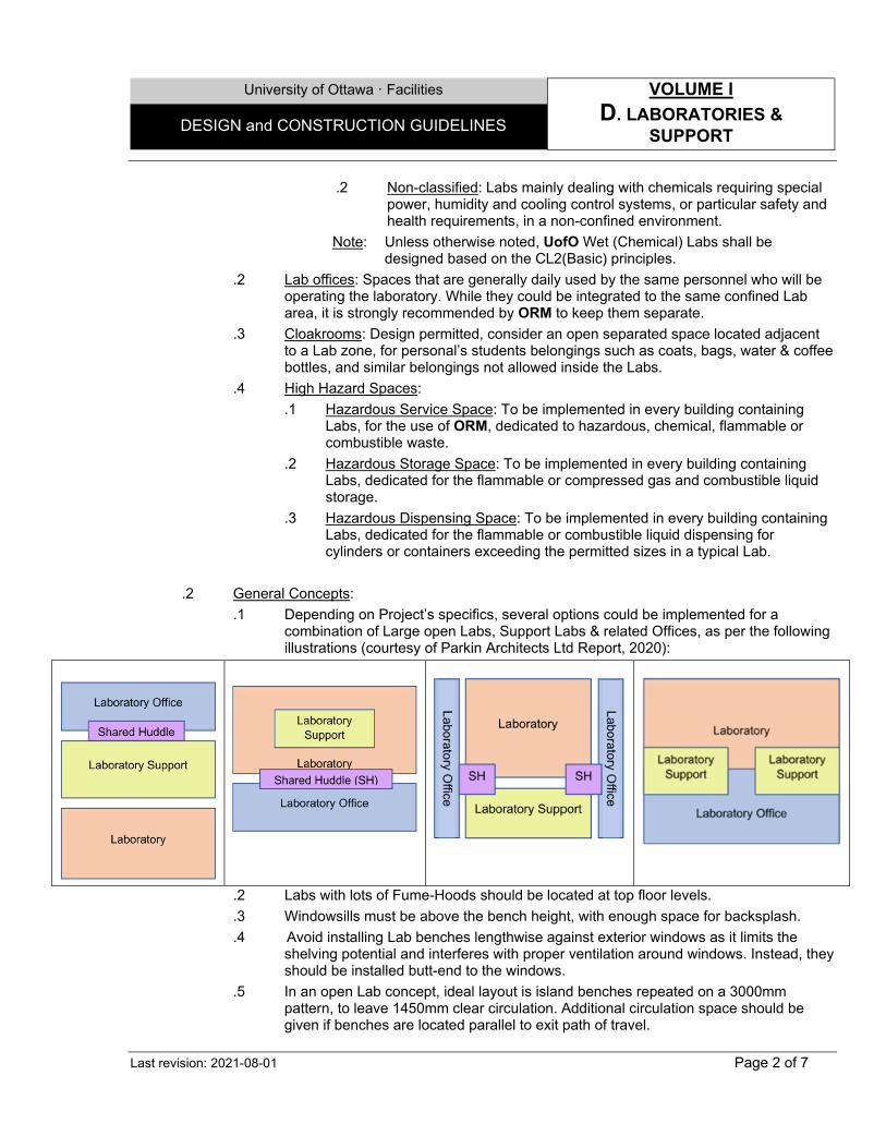
.2 General Concepts:
.1 Depending on Project’s specifics, several options could be implemented for a combination of Large open Labs, Support Labs & related Offices, as per the following illustrations (courtesy of Parkin Architects Ltd Report, 2020):
.2 Labs with lots of Fume-Hoods should be located at top floor levels.
.3 Windowsills must be above the bench height, with enough space for backsplash.
.4 Avoid installing Lab benches lengthwise against exterior windows as it limits the shelving potential and interferes with proper ventilation around windows. Instead, they should be installed butt-end to the windows.
.5 In an open Lab concept, ideal layout is island benches repeated on a 3000mm pattern, to leave 1450mm clear circulation. Additional circulation space should be given if benches are located parallel to exit path of travel.
University of Ottawa · Facilities VOLUME I
D. LABORATORIES & SUPPORT DESIGN and CONSTRUCTION GUIDELINES
Last revision: 2021-08-01 Page 3 of 7
.6 Unless few exceptions in existing buildings, Labs with Class I liquids which requires handling shall not be installed in the basement levels or any building, according to OFC.
.3 Safety Measures:
.1 Laboratories Handling Pathogen agents or Animal Care facilities: To follow: .1 Public Health Agency of Canada’s Laboratory Biosafety Guidelines.
http://www.phac-aspc.gc.ca/lab-bio/index-eng.php .2 Canadian Food Inspection Agency’s Containment Standards for Veterinary
Facilities. .3 Canadian Council on Animal Care in science. .4 Animals for Research Act.
http://www.ontario.ca/laws/regulation/900024 .5 Occupation Health & Safety Act & Regulations.
.2 Laboratories handling chemicals, flammable or combustible material: Shall follow NFPA 45 - Standard on Fire Protection for Laboratories Using Chemicals, and ORM Hazardous material & waste directives. Depending on the sizes, Fire-Rated boundaries or compartments can include a single or serval contiguous Labs.
.3 Specific Measures: .1 Eye/Face Wash - Deck-mount (22 42 01): Should be installed in each Lab
which deal with chemical or hazardous materials, or as necessary, adjacent to a Sink (22 42 01), along the closest exit pathway.
.2 Emergency Showers & eye wash (22 42 01): Design permitted, not to be installed within the Laboratories, but in nearby corridors.
.3 First-aids and other safety equipment: Shall be located next to entrance within the Lab.
.4 Spill kits: Supplied by ORM, shall be installed in every Lab dealing with chemical or hazardous materials, shall be highly visible, and hooked on walls.
.5 Fume Hoods: To take in consideration minimal clearances (i.e., safety, proper airflow), as per described standards below.
.6 In Contained spaces: .1 All Mechanical / Electrical fixtures and similar penetrations on ceiling
and walls, must be air-tight and sealed around their entire perimeter, with compressible gaskets and appropriate sealants.
1.3 Accessories & Furniture
.1 Lab furniture (12 35 00): Unless there is any special condition or design specific: .1 Existing Lab extensions or modifications: Shall follow the existing configuration and
materials, unless otherwise indicated by Facilities. .2 New Labs:
.1 System: Units shall be Fixed Countertop Units for Labs requiring multiple services, and Mobile Countertop Units, serviced from ceiling for Labs requiring few services. depending on design imperatives.
.2 Dimensions: Countertop unit width: 762mm. Shelves and wall units: 305mm.
University of Ottawa · Facilities VOLUME I
D. LABORATORIES & SUPPORT DESIGN and CONSTRUCTION GUIDELINES
Last revision: 2021-08-01 Page 4 of 7
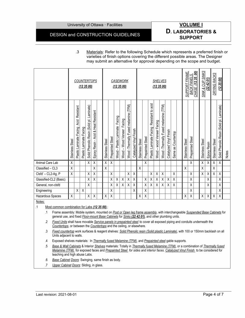
.3 Materials: Refer to the following Schedule which represents a preferred finish or varieties of finish options covering the different possible areas. The Designer may submit an alternative for approval depending on the scope and budget.
COUNTERTOPS
(12 35 00) CASEWORK
(12 35 00) SHELVES (12 35 00)
SUPP
ORT
FRAM
E,
BACK
PAN
ELS,
CH
ASE
(12 3
5 00
)
SINK
& C
UP S
INKS
(2
2 42 0
1)
DRYI
NG R
ACKS
(1
2 35 0
0)
Stain
less S
teel
Plas
tic La
mina
te Fa
cing
Acid
Res
istan
t Pl
astic
Lami
nate
Facin
g So
lid P
heno
lic R
esin
(Soli
d pl. L
amina
te)
Epox
y Res
in - A
cid &
Hea
t Res
istan
t St
ainles
s Stee
l Pr
epain
ted S
teel
Woo
d - P
lastic
Lami
nate
Fac
ing
Woo
d – W
ood V
enee
r Fa
cing
Woo
d -Th
erma
lly F
used
mela
mine
(TFM
) Ca
talyz
ed V
inyl F
inish
St
ainles
s Stee
l Pr
epain
ted S
teel
Plas
tic La
mina
te Fa
cing
Resis
tant to
acid
Woo
d – w
ood V
enee
r Fac
ing
Woo
d -Th
erma
lly F
used
mela
mine
(TFM
) Ca
talyz
ed V
inyl F
inish
Sa
me as
Cou
nterto
p St
ainles
s Stee
l Pr
epain
ted S
teel
Stain
less S
teel
Epox
y Res
in St
ainles
s Stee
l So
lid P
heno
lic R
esin
(Soli
d pl. L
amina
te)
Notes
Animal Care Lab X X X X X X X X X X X Classified – CL3 X X X X X X X Clsfd’ – CL2-Ag, P X X X X X X X X X X X X X X X Glassified-CL2 (Basic) X X X X X X X X X X X X X X X X General, non-clsfd X X X X X X X X X X X X X X X Engineering X X X X X X X Hazardous Spaces X X X X X X X X X X X X X Notes: .1 Most common combination for Labs (12 35 00),:
.1 Frame assembly: Mobile system, mounted on Post or Open leg frame assembly, with interchangeable Suspended Base Cabinets for general use, and fixed Floor-mount Base Cabinets for Sinks (22 42 01), and other plumbing units.
.2 Fixed Units shall have movable Service panels in prepainted steel to cover all exposed piping and conduits underneath the Countertops, or between the Countertops and the ceiling, or elsewhere.
.3 Fixed countertop work surfaces & reagent shelves: Solid Phenolic resin (Solid plastic Laminate), with 100 or 150mm backlash on all Units adjacent to walls.
.4 Exposed shelves materials: In Thermally fused Melamine (TFM), and Prepainted steel gable supports.
.5 Base & Wall Cabinets & Interior Shelves materials: Totally in Thermally fused Melamine (TFM), or a combination of Thermally fused Melamine (TFM) for exposed faces and Prepainted Steel for sides and interior faces. Catalyzed Vinyl Finish to be considered for teaching and high abuse Labs.
.6 Base Cabinet Doors: Swinging, same finish as body.
.7 Upper Cabinet Doors: Sliding, in glass.
University of Ottawa · Facilities VOLUME I
D. LABORATORIES & SUPPORT DESIGN and CONSTRUCTION GUIDELINES
Last revision: 2021-08-01 Page 5 of 7
.2 Accessories: .1 For a typical Lab:
o Drying Rack (12 35 00) o Paper towel dispenser, surface mounted (12 28 10) o Soap dispenser (12 28 10) o Hand Sanitizer (12 28 10) o Integrated waste bins: Only in classified Labs, where no exposure is allowed. o All other M&E accessories as per design imperative
.2 For a Cloakroom, or a Lab: o Coat Hook Strip: (10 28 10): Quantity to equal 50% of space capacity, to be
confirmed by Facilities. 2.0 CANOPIES, BIOLOGICAL SAFETY CABINETS & FUME HOODS 2.1 Standard References
.1 Fume Hoods (12 35 00): To follow CSA Standard Z316.5, latest edition - Fume Hoods and Associated Exhaust Systems.
.2 Class I and Class II biological safety cabinet: .1 NSF/ANSI 49-2004a - Class II (Laminar Flow) Biosafety Cabinetry standard. Should
be certified by the supplier at the time of installation. .2 NSF/ANSI 49 - Installation and field testing of biological containment cabinets.
.3 Flammable Liquid Storages: UL/NFPA standards.
2.2 Design .1 When selecting a Fume Hood (12 35 00), user needs, type of use and type of sash must be
considered. In all cases consideration shall be given to the use of low volume Hoods. .2 Base Cabinets, for Storage of Chemical Products (12 35 00) products shall be properly
ventilated. .3 Canopy Hoods i.e., overhead Hoods are only intended to vent heat or local processes (e.g.
autoclaves) and not designed for a personal work station. Where work involves manual manipulation or release of volatile materials, a chemical fume Hood shall be used.
.4 Ductless Fume Hoods are generally not permitted; portable Hood may however be used for limited applications e.g. used for odor control.
.5 In general, consideration must be given to using high efficiency-low air volume Fume-Hood. Where the required velocity can be obtained by partly closing the sash, the sash and/or jamb shall be marked to show the maximum opening at which the Hood face velocity will meet the requirements.
.6 Automatic fire dampers shall not be used in Hood exhaust systems. 3.0 SERVICES (as applicable) 3.1 Ventilation
.1 Unless otherwise noted, minimal ventilation rates within Wet (Chemical) Labs, all the time shall be as per OFC part 4, as minimal 6 Air Change per Hour (ACH).
University of Ottawa · Facilities VOLUME I
D. LABORATORIES & SUPPORT DESIGN and CONSTRUCTION GUIDELINES
Last revision: 2021-08-01 Page 6 of 7
.2 Outdoor exchange rates must be established in consultation with Facilities.
.3 Air flow to the rooms should be such that a good purge of all spaces within the room is maintained while avoiding drafts.
.4 Air flow in front of fume Hoods should not cause a turbulence that will affect the operation of the Hood. Supply diffusers shall be selected such that air flow in vicinity of Bio Safety Hoods is laminar.
.5 Variable air volume system shall be used in densely spaced Hood installations where design room air changes significantly exceed 5 air changes per hour.
.6 Certain Labs applications will permit air to be turned down/off when the lab is not in use.
.7 The Lab exhaust system shall preferably incorporate a heat recovery loop system.
.8 Discharge from exhaust stacks must have a velocity of 3000 fpm. This velocity should not be achieved by the installation of a cone type reducer. Exhaust duct may be reduced but the duct beyond the reduction must be of sufficient length to allow the air movement to return to a linear pattern (Ref ANSI Z. 95-2003, 5.3.5). Strobic type exhaust fans may be used to address exhaust velocity needs.
.9 Lab ventilation exhaust fans shall be spark-proof and constructed of materials or coated with corrosion resistant materials for the chemicals being transported. V-belt drives shall be conductive.
.10 Labs venting must be dedicated, separated from all other Building systems. 3.2 Heating/Cooling/Humidity Control
.1 Hydronic heating should be designed to heat the space in order to allow the outdoor air ventilation system to be turned off/down in these Labs during unoccupied hours, but never –in any case- below the minimal ACH value indicated above.
.2 Ceiling mounted hydronic radiant panels could be considered in order to allow the butting of the Lab benches to the exterior windows.
.4 Where applicable main outdoor air supply unit shall be equipped with additional heating coils to allow for use of chill water return to preheat air during colder seasonal weather.
.5 Humidity control shall be provided where 100% outdoor air is supplied. Minimum 18% RH shall be provided during the dry winter periods, maximum 55% shall be maintained during the wetter summer periods. More stringent humidity control ranges mat be required for certain applications (animal care areas).
3.3 Provincial requirements
.1 Fume Hood exhaust system design and installation must meet all requirements under section 9 of EPA and related regulations. Liaison and application for ECA is made through ORM.
3.4 Plumbing
.1 Each Lab should have accessible shut off valves at all time. They should be located in the wall c/w a 24”x24” access door located between 3-5 feet above finished floor.
.2 All piping servicing Labs shall be in horizontal pipe chases, integrated within cabinets’ benches and easily accessible through removable panels.
.3 A separate dedicated drainage system shall be provided for drains, Sinks, Cup sinks, Emergency Showers & eye wash (22 42 01) floor drains, and similar; then combined with building sanitary system immediately after exiting the Building.
University of Ottawa · Facilities VOLUME I
D. LABORATORIES & SUPPORT DESIGN and CONSTRUCTION GUIDELINES
Last revision: 2021-08-01 Page 7 of 7
.4 Ensure piping system and jointing methods will resist spills and illicit discharges of corrosive chemicals.
.5 Drying Racks (12 35 00) must not drain into the sewer system.
3.5 Power and Data outlets .1 Depending on hazardous material type, quantities and applicable Codes, in Hazardous
Spaces, electrical equipment may be required to be explosion proof.
University of Ottawa · Facilities VOLUME I
E. PUBLIC SPACES DESIGN and CONSTRUCTION GUIDELINES
Last revision: 2021-08-01 Page 1 of 2
1.0 GENERAL 1.1 Overview
.1 Public spaces vary considerably based upon design parameters and project or building specifics.
.2 Spaces are very valuable to UofO. General circulation and open Public spaces shall have reasonable proportions, but not to be overdesigned.
1.2 Design
.1 Definitions: .1 Cafeterias:
.1 Design shall include: .1 Seating area, which could eating as well versatile common activities. .2 Check-in counter space, and all related accessories. .3 Kitchen area, accommodating service and all related catering equipment
and services. .2 Shall have direct access to exterior light, through windows or skylight.
.2 Corridors, Atrium Hall and Vestibule spaces:
.1 Shall be designed with reasonable proportions between widths and heights, in order to minimize the “tunnel effect”.
.2 Design permitted, Vestibules to be designed with enough dimensions, to accommodate Foot Grill (12 48 00): with no less than 1600mm deep.
.3 Elevators (14 20 00):
.1 Sizes to accommodate a stretcher.
.2 At least one freight elevator shall be included in every new building. .4 Libraries:
.1 Design shall include: .1 Reading areas. To be organized to insure a quite environment as
possible. .2 Book storing aisles. .3 Reception area, with related security gates and service spaces.
.2 Aisles to be designed in order to ease the circulation and increase the security. Avoid exposing bookshelves to direct sun contact.
.5 Locker spaces:
.1 Depending on project specifies, spaces could be left open with no entrance doors, located adjacent to corridors.
.2 Shall take in consideration enough circulation space around Lockers (10 51 00) with no dead end corridors.
.3 Avoid placing Lockers (10 51 00) within corridors or main circulation areas.
University of Ottawa · Facilities VOLUME I
E. PUBLIC SPACES DESIGN and CONSTRUCTION GUIDELINES
Last revision: 2021-08-01 Page 2 of 2
.6 Lounge spaces:
.1 Open spaces designated for general public. Shall have appealing and versatile design, which could be converted to accommodate different activities.
.2 Design permitted, shall be located adjacent to public corridors, in a manner to ease people flow, and not to impede on main traffic areas.
.7 Stairs:
.1 Exit stairs: Design and finishes shall be limited to the minimum Code requirements.
.2 Internal communication and exterior stairs: Not to overdesign, in order to save costs. Step sizes shall be: .1 Risers: 152mm minimum, up to 177mm maximum. .2 Treads: 305mm minimum.
.2 General:
.1 Avoid placing Cafeterias, Lounge and other noisy spaces close to classrooms laboratory or similar study spaces.
.2 Avoid installing showers accessible for public in new buildings – unless specifically requested for operational or health and safety purposes. Confirm with Facilities before proceeding.
2.0 SERVICES 2.1 Mechanical
.1 Water Fountains (22 42 03): To install minimum 1 per floor in visible locations. Not inside Washrooms or any similar closed spaces.
.2 Vestibules located on top of occupied basements shall be equipped with corrosive resistant drains & appropriate PVC Rated (22 42 02) piping.
2.2 Electrical
.1 In Stairwell, light fixture should be installed on walls or in the ceiling of the landing area, avoid installing fixtures above the stairs.
2.3 Power and Data outlets
.1 Electrical outlets in stand up counters, trailing wires connected to wall-mount outlets constitutes a Health safety hazard. Special consideration shall be taking while designing the outlets through integrating them into furniture or by other means.
.2 In general, consideration should be given to the use wireless internet and data connections.
University of Ottawa · Facilities VOLUME I
F. RESIDENCES DESIGN and CONSTRUCTION GUIDELINES
Last revision: 2020-08-01 Page 1 of 2
1.0 GENERAL
1.1 Overview
.1 Residences and their specific requirements vary considerably based upon number of users and design specifics. Layout, amenities services, furnishings and similar shall be coordinated with HS. They are generally split into 2 categories: .1 Suite style Residences: Described in this section. .2 Dormitory style Residences: With common or public services and amenities. Shall
follow similar Guidelines described in other sections. .2 Users are mainly Students who rent the places during learning season. In summer time,
some units are also rented to the public (hotel style). .3 These spaces are subject to high abuse; construction and finished materials should be easy
to maintain and resistant to high-abuse.
1.2 Design .1 Definitions:
.1 Common Spaces: .1 Corridors, Halls, Vestibules and service areas: Refer to Public spaces section. .2 Laundry facilities:
.1 Not to be located inside of Suites, but as Common closed space which accommodate sufficient Laundry equipment.
.2 Design permitted, to be located on each floor. .3 Lounge spaces:
.1 Closed Shared spaces for common social, gaming and reading activities.
.2 Design permitted, shall be located on every floor, with direct access to natural lights and terraces, if applicable.
.2 Suite spaces:
.1 In-suite Bathrooms: .1 Design to accommodate practical functioning. Not oversized or too
squeezed. .2 In-suite Bedroom:
.1 Sizes shall accommodate a sleeping area and a study area.
.2 Built-in closets are highly not recommended, for maintenance issues.
.3 Shall have direct access to natural light and ventilation, as per Codes. .3 In-suite Kitchens:
.1 Shall be designed as an open concept, without doors.
.2 Shall accommodate the typical appliances, such as stove, microwave, fridge and similar, except dishwashers.
University of Ottawa · Facilities VOLUME I
F. RESIDENCES DESIGN and CONSTRUCTION GUIDELINES
Last revision: 2020-08-01 Page 2 of 2
.4 In-suite Living room: .1 Shall have appropriate proportions to allow common activity, without the
narrow-corridor feeling proportions. .2 Sizes shall accommodate a sleeping area and a study area.
.2 General:
.1 Design shall include common Garbage chute.
.2 Design or project specific permitted, common Terraces to be included in the general layout.
1.3 Accessories
.1 Mirror, framed (08 80 00): Shall be installed on top of all Sink counter surface, at 150mm height at least, except for handicapped mirror in accessible area.
.2 In-suite W.C. Accessories (10 28 10): Types and quantities to be:
o Stainless sheet plate 610mm wide on each side of the Stove (Kitchen countertops) o 1 Tissue dispenser. o 1 Towel racks. o All necessary Toilet accessories, for Accessible W.C. (Refer to the related section).
.3 Coat Hook Strip (10 28 10): To be installed in the following locations:
.1 In every Bathroom.
.2 In every Bedroom (behind doors).
.4 Stainless steel plates: Shall be installed on the kitchen countertop, extended 300mm at each side of the stove.
2.0 SERVICES
2.1 General
.1 Unless approved by Facilities, all Mechanical electrical services on the ceilings including sprinkler heads to be recessed. Exit signs to be mounted on the walls.
2.2 Mechanical
.1 No ceiling hung pipes or conduits shall be left exposed inside Suites.
.2 In the In-Suite bathrooms, Shower & bathtub shall be prefabricated units.
2.3 Electrical
.1 Public Electrical panels should be in locked vandal proof enclosures.
2.4 Power and Data outlets
.1 Considerations should be given for installation of power outlets for hair dryers.
.2 Every room should have a minimum of two outlets.
University of Ottawa · Facilities VOLUME I
G. SERVICE ROOMS DESIGN and CONSTRUCTION REQUIREMENTS
Last revision: 2022-03-01 Page 1 of 4
1.0 GENERAL 1.1 Overview
.1 Service rooms vary considerably based upon design parameters and project or building specifics.
.2 Size, number and location of Service spaces, especially M&E rooms as well as lay-out of mechanical equipment inside the mechanical rooms shall be considered at the early stage of design process. Adequate space shall be considered to provide safe distance and sufficient work space around and in front of electrical components and equipment to satisfy code requirements and for maintenance work.
.3 Lay-out of M&E rooms shall show the equipment service area(s) to demonstrate component and equipment clearances for code, maintenance and service purposes have been respected.
1.2 Design
.1 Definitions: .1 Janitor rooms:
.1 Shall have appropriate sizes to accommodate cleaning carts, ladders and all other specified cleaning accessories.
.2 Shall be located as close as possible to washrooms - but not inside, to ease maintenance personnel access.
.2 Loading Docks:
.1 Design permitting, Loading Platform shall be located indoor at the building perimeter - not outdoor, using integrated Loading Dock Levellers, Hydraulic (11 13 00).
.2 Not Acceptable: Scissor lifts or any other similar lifting mechanism. .3 Mechanical & Electrical rooms:
.1 Unless otherwise noted, M&E rooms shall be enclosed spaces, accessible from the inside of the building. Wherever impossible or in existing buildings, a special attention shall be given for adequate maintenance access, generally through marine ladders or similar.
.2 Location of transformer rooms shall be close to service entrance of building. Main transformer rooms / Vaults shall be accessible from outside of buildings and free of other systems not associated with electrical distribution systems.
.3 Design to take in consideration easy access for maintenance and personnel evacuation. Lay-out of M&E rooms shall show the equipment to demonstrate sufficient work space around equipment for work, safety, and routine maintenance. Following clearances shall be provided as a minimum: .1 For fans bearing/belts/motors repair/replacement: 75 cm (3 ft.). .2 Around pumps and compressors: 75 cm (3 ft.). .3 For coil removal, filter replacement, tube bundle replacement and VAV
boxes: As per manufacturer’s recommendation. .4 Installation of equipment from ceiling are not preferred and shall be approved
by Facilities. .5 Air handling unit shall be installed high enough to ensure adequate trapping
and condensate pitch.
University of Ottawa · Facilities VOLUME I
G. SERVICE ROOMS DESIGN and CONSTRUCTION REQUIREMENTS
Last revision: 2022-03-01 Page 2 of 4
.6 All penthouse mechanical rooms shall have elevator rooftop access for removal/replacement of equipment.
.7 Penthouse elevators shall have rooftop access for removal/replacement of equipment.
.8 Basements are considered as preferred location for heating equipment.
.9 All equipment or part of equipment which imped on minimum clearances of travel of exits shall be highlighted with distinguished colors.
.10 Where project budget permits it is preferred to provide separate room for switch gear and main distribution panels.
.11 Electrical rooms for power distribution shall be enclosed and dedicated spaces and accessible from the inside of the building.
.12 Minimum one electrical room shall be provided per floor.
.13 All floor mounted transformers, switch gears, large power distribution panels, MCCs and mechanical equipment shall be installed on concrete housekeeping pad minimum 100mm (4 in.) high with rounded or steel angle protected edges.
.14 Critical M&E components and equipment shall be protected from water and fire damage.
.15 Whenever replacing or adding any equipment in existing spaces, consideration shall be given to refurbish the surrounding walls / floors / ceilings - budget permitted. To be discussed with Facilities.
.5 Workshop:
.1 Design to accommodate different repair or maintenance activities.
.2 To take in consideration all regulation and safety requirements related to the nature of work, including welding, grinding, and similar.
.6 Storage rooms:
.1 Design shall have sufficient space to store extra replacement materials for each finish product, as indicated in the related sections.
.2 Design shall optimize the space, while easing the circulation flow with enough manoeuvring space for transportation equipment such as pump lifts and similar.
.2 Ideally to have a single entrance point for security reasons.
.2 General: .1 Design permitted, avoid locating the Service spaces close to areas with high
sensitivity to vibration or noise, such as Classrooms and Laboratories. 1.3 Accessories
.1 Mop suspensions: To be installed in Janitor rooms, to fit 6 mops.
.2 Shelves: To be considered for Janitor spaces, Workshops & Storage rooms.
.2 Loading Dock Equipment (11 13 00): Budget permitted, design to include: .1 Loading Dock Levelers, Hydraulic. .2 Dock bumpers.
University of Ottawa · Facilities VOLUME I
G. SERVICE ROOMS DESIGN and CONSTRUCTION REQUIREMENTS
Last revision: 2022-03-01 Page 3 of 4
.3 Dock door seals.
.4 Any other as necessary or requested.
2.0 SERVICES 2.1 Mechanical
.1 General: Special consideration shall be given to the heating system in mechanical rooms, loading dock spaces, Workshops or similar spaces, when delivery overhead doors are kept open for prolonged periods of time.
.2 Janitor rooms: .1 Where Janitor rooms serving floor cleaning machines floor drains or Slop Sink (22 42
01) shall be equipped with sediment interceptors. .2 Ventilation shall be capable of ventilation the Janitor rooms at a minimum of 10 L/S/M2
(0.2 CFM/ Ft2) or as per OBC requirements whichever is greater. .3 Slop Sink (22 42 01) shall be installed in all Janitor rooms. .4 Eye/Face Wash (22 42 01) shall be installed in every Janitor room with dispensing
and/or chemical diluting activities. .3 Loading Docks:
.1 Where loading dock is subject to excessive soiling, hot and cold water shall be included in design.
.2 Design shall include dedicated floor drain in loading docks.
.3 Where there is risk of freezing, fire protection shall be dry type sprinkler system.
.4 Requirements of refrigerated waste room on the loading dock shall be reviewed with Faculties when loading dock serves food services.
.4 Mechanical & Electrical rooms:
.1 All equipment shall be seismically retrained as per OBC.
.2 In each mechanical room one hose bib shall be provided.
.3 In Electrical rooms, heating and ventilation systems shall be capable of maintaining the space set point of minimum 13°C (55°F) in winter and maximum of 40°C (104°F) in summer. Mechanical cooling is not preferred. Where mechanical cooling is required review the design with Facilities.
.4 All mechanical rooms shall be provided with fire extinguishers distributed as per applicable codes.
.5 All penetration sleeves shall extend to a minimum of 25mm (1 in.) above slab. .6 Workshop:
.1 Ventilation system shall be capable of accommodating the nature of work, including welding, grinding, and similar.
.2 A separate dedicated drainage system shall be provided for drains, Sinks (22 42 01), and other similar fixtures, and merged with the Sanitary Lab system, if applicable.
.7 Storage rooms:
University of Ottawa · Facilities VOLUME I
G. SERVICE ROOMS DESIGN and CONSTRUCTION REQUIREMENTS
Last revision: 2022-03-01 Page 4 of 4
.1 Ventilation system design shall be capable of providing tempered outdoor air to storage rooms as a minimum.
.2 Mechanical systems such as piping, ductwork shall be installed in such maintaining maximum headroom outlined in project requirement.
.3 Sprinklers shall be upright pendant with wire cage. 2.2 Electrical
.1 Janitor rooms: .1 A minimum of one 20A/102V duplex normal power receptacle shall be provided in each
janitor room.
.2 Loading Docks: .1 To be developed.
.3 Mechanical & Electrical rooms:
.1 Motor Control Centers (MCC) shall be located in Mechanical rooms. Consultants shall demonstrate the coordination of the supply of MMC/Starters between trades in construction documents.
.2 One campus phone line for emergency shall be provided in main switch gear and/or electrical room.
.3 Normal power receptacle(s) (20A) not more than 7.5 m (25 Ft.) apart shall be provided in M&E rooms.
.4 Minimum one emergency power receptacle shall be provided in main mechanical rooms.
.5 Minimum one 50A, 3 phase receptacle for welding purposes shall be provided in main mechanical rooms.
.6 At least one emergency light shall be provided in M&E rooms.
.7 Adequate conduits shall be provided for spare circuits. Spare conduits shall be extended to above ceiling and shall be boxed or troughed at the end.
.8 Lighting fixtures shall be shall include T8 LED bulbs.
.9 Power distribution panels in M&E rooms shall be surface mount (recessed in finished areas).
.10 All penetration sleeves shall extend to a minimum of 25mm (1 in.) above slab. .11 Workshop:
.1 To be developed. .12 Storage rooms:
.1 Lighting fixtures shall be guarded against damage due to moving objects in the storage rooms.
University of Ottawa · Facilities VOLUME I
H. SPORTS Facilities DESIGN and CONSTRUCTION GUIDELINES
Last revision: 2020-08-01 Page 1 of 2
1.0 GENERAL 1.1 Overview
.1 Sports rooms vary considerably based upon design parameters and project or building specifics.
1.2 Design
.1 Definitions: .1 Change room:
.1 Design to accommodate Locker (10 51 00) spaces with Benches (10 51 00).
.2 Avoid dead end corridors within the space.
.2 Entrance and exit doors shall be located separately, or separated by rails, in order to ease people flow, especially in rush hours.
.2 Exercise room:
.1 Design to accommodate: .1 Check point entrance space; which could accommodate several
persons, with related service spaces, including Turnstiles or similar security gates.
.3 Exercise space; which should take in consideration training machine sizes and secure circulation spaces around.
.2 Shall have direct access to natural lighting, or indirectly through skylights.
.3 Gymnasium: .1 Design shall accommodate different sport activities as well as major gathering
events. .2 Shall be built in durable materials to withstand high abuse from.
.4 Shower spaces: .1 Shall include Toilet compartments (10 21 00) between showers. Doors ore
curtain are optional. Design imperative and ceiling height permitted, shall be Ceiling hung.
.2 Shower space design shall prevent water spread to adjacent spaces, by curbs or other means installed at every booth, or at the entrance level of the area.
.3 Spaces to include Washrooms (refer to related section). .2 General:
.1 Design permitted, Gymnasiums and Exercise rooms, to have direct connection with change rooms, without the need to travel through main corridors.
1.3 Accessories
.1 Mirrors, framed (08 80 00): Shall be installed on Exercise room perimeter, up to 7000mm, installed directly above floor base.
University of Ottawa · Facilities VOLUME I
H. SPORTS Facilities DESIGN and CONSTRUCTION GUIDELINES
Last revision: 2020-08-01 Page 2 of 2
2.0 SERVICES 2.1 Mechanical
.1 Xxxxxxxxxxx 2.2 Electrical
.1 Xxxxxxxxxxxx
2.3 Power and Data outlets .1 Xxxxxxxxxxxxxxxxx
University of Ottawa · Facilities VOLUME I
I. WASHROOMS DESIGN and CONSTRUCTION GUIDELINES
Last revision: 2021-12-01 Page 1 of 3
1.0 GENERAL 1.1 Overview
.1 Washrooms to be strategically located – generally on high traffic paths, in order to minimize user’s displacements and unnecessary lineups.
1.2 Design
.1 Definitions: .1 Barrier-Free Compartment: Located within Common Washrooms, to be sized and
adapted as per OBC requirements. .2 Common Washroom:
.1 Includes several Toilets to be segregated by standard height Toilet compartments (10 21 00). Unless otherwise requested, no Compartment to be installed between Urinals.
.2 Where space permits, Common washrooms should be barrier free labyrinth type entrance, with no entrance doors.
.3 Universal Washroom: For the use of one person at a time, as defined by OBC. To be
located on every floor, in addition to the Barrier-Free Compartments located within the Common Washrooms
.2 Showers: Spaces permitted, to be placed in Common Washrooms, adjacent to
Laboratories: One for males, and one for females.
.2 General: .1 In new buildings, or extensive renovation projects, all Washrooms to be regrouped in
the same vicinity with a common entrance. Additional Individual or independent Washrooms may be added elsewhere, as necessary.
.2 Washroom flooring to have a positive 1% slope toward the drains. In the existing installations, where a slope is difficult, a barrier-free threshold to be installed at the entrance.
University of Ottawa · Facilities VOLUME I
I. WASHROOMS DESIGN and CONSTRUCTION GUIDELINES
Last revision: 2021-12-01 Page 2 of 3
1.3 Accessories .1 Mirrors:
.1 Mirror, framed (08 80 00): Continuous, in one pieces, to be installed at 150mm over the to top of Washroom.
.2 Mirror for disabled (10 28 10): To be installed in every Washroom, to accommodate Barrier-Free dedicated Lavatory Sinks (22 42 01).
.2 Washroom. Accessories (10 28 10): Quantities and types to be: .1 In all Washrooms, as applicable:
o One Tissue dispenser - standard for each Toilet. o One Heavy duty shelf in each Toilet, to be mounted at 200 mm on top of Tissue
dispenser. o One Soap dispenser per 2 Lavatory Sinks (22 42 01). o One Waste bin per 4 Lavatory Sinks (22 42 01). o One Sanitary napkins receptacle for each female Toilet. o One Individual Hook for each cubicle.
.2 Additional, for Barrier-Free Toilets: o One P.T. hinged offset rail (10 28 10), to be installed on the opposite wall space of
the grab bars. o One Adult change table (10 28 10), to be installed at least in one Universal
Washroom of every new Building. o Any other as per related Codes (Grab bars and similar).
.3 Not acceptable:
o Recessed Accessories. o Paper towel dispenser (10 28 10), in any Washroom accessible by public.
2.0 SERVICES 2.1 Mechanical
.1 Washroom Fixtures (22 42 01): Installation criteria to be confirmed by Facilities. In general: o Water Closet:
o Manual lever operated for small renovated Washrooms with one Toilet. o Sensor activated for Common Washrooms with several Toilets.
o Urinals: o Manual lever operated for small renovated Washrooms with one Urinal. o Sensor activated for Common Washrooms with several Urinals.
o Water Closet Seat for every Toilet. o Lavatory Sinks:
o Manual lever operated for small renovated Washrooms with one Lavatory Sink. o Sensor activated faucet for Common washrooms with several Lavatory Sinks.
University of Ottawa · Facilities VOLUME I
I. WASHROOMS DESIGN and CONSTRUCTION GUIDELINES
Last revision: 2021-12-01 Page 3 of 3
2.2 Electrical .1 Washroom Fixtures (26 00 00): Installation criteria to be:
.1 One Electric jet towel hand dryer per 2 Lavatory Sinks (22 42 01), to be installed in every Washroom.
.2 Not acceptable: Light sensors in Common Washrooms.
.3 Universal Washrooms door & security operating mechanism: .1 Not acceptable: Sensor occupancy mechanism. .2 Occupancy censors to be installed for lights and ventilation. Refer to Security
Systems section. .3 Emergency call system and outside sign to be installed as per OBC, and to also be
linked to the central security dispatch on Campus. .4 Interior Actuator Switch (08 70 00) must always unlock the door at any time. .5 “Push to lock” lit button to be installed beside the interior Actuator to deactivate the
exterior Actuator while occupied and lock / unlock the door. .6 Interior door Lever (08 70 00) to be always operational (never locked). Door can be
manually unlocked and should reactivate the exterior Actuator through a door contact. .7 Outside door Lever (08 70 00) to be always locked with a cylinder key. Outside Door
Operator Electrical strike (08 70 00) to not function unless the Washroom is not occupied.
.8 Outside Actuator Switch (08 70 00) to be equipped with perimeter lit – or additional lit sign, to indicate when Washroom is occupied.
2.3 Power and Data outlets
.1 Xxxxxxxx
University of Ottawa · Facilities VOLUME I
K. BARRIER-FREE DESIGN DESIGN and CONSTRUCTION GUIDELINES
Last revision: 2020-08-01 Page 1 of 2
1.0 GENERAL
1.1 Overview
.1 Barrier free design should follow OBC requirements, Canadian Standards Barrie-free design, Accessibility Standards (CAN/CSA-B651) for the Built Environment, all other regulations and special owner or users request specifics to the project. AODA part IV.1 & IV.2 is currently applicable for all exterior pathways, routes, ramps, and similar; and public customer services spaces (e.g.: service counters). In case of contradiction, the most stringent shall prevail.
.2 Always verify with users and Facilities, the extent and applicability of such Codes into the specifics of each project.
1.2 Design
.1 Spaces: Design to take in consideration the following: .1 Rooms dedicated to general public, such as Public spaces, Classrooms,
Laboratories, Administration spaces, and similar, to accommodate disabled persons in wheelchair (number to vary based on OBC requirements). Refer to related sections for special requirements.
.2 Free manoeuvering spaces in front of accessible cubicles in W.C., in order not to interfere with other occupants’ activities.
.3 Exceptions: .1 Spaces which contain hazardous materials that require highly trained
persons, or special procedures, such as classified Labs, Animal care and similar facilities may be exempted from accommodating persons on wheelchairs. However, this issue should be approved by UofO’s users and accepted by the City.
.2 Maintenance spaces that require qualified personnel, such M&E spaces, Janitor, and similar, need not to accommodate persons on wheelchairs.
.2 Pathways:
.1 Avoid Wall or furniture projections or special design features in accessible pathways, which may disturb disabled persons.
.2 Exterior ramps to be concrete heated and have a canopy.
1.3 Furniture & Accessories
.1 General Accessories’ height shall accommodate disabled persons on wheelchairs in the designated areas.
.2 Coat hooks (10 28 10): Shall be installed at accessible heights (three minimum), where
several units are required in the space.
.3 Portable Ceiling lift Device (11 14 00): Shall be installed in a total enclosed and acoustically insulated environment in special accessible W.C. designated by Facilities.
.4 Reception Counter desks: Shall accommodate at least one disabled receptionist and a visitor
in wheelchair. .5 Accessible Table, Adjustable & Motorized (12 50 00): Shall be provided in all Classroom and
University of Ottawa · Facilities VOLUME I
K. BARRIER-FREE DESIGN DESIGN and CONSTRUCTION GUIDELINES
Last revision: 2020-08-01 Page 2 of 2
similar spaces with fixed tables. Quantity as prescribed by Codes, size as necessary, but not less than 750mm x 480mm clear space underneath, with 1100mm preferred space on the back.
.6 Millwork (06 10 00) Stand-up Counters: Shall be lowered in some portions to accommodate
disabled persons.
.7 Lab areas: .1 Unless deemed hazardous or highly specialized, each Lab space shall include
accommodations for people with disabilities, including Lab furniture countertop units (12 35 00), Emergency showers and eye wash, Laboratory Sinks (22 42 01), and other related accessories and features.
.2 Accessible Fume hoods (12 35 00), shall be provided in each Lab space, if deemed important to the operations for every user. To be discussed with Facilities.
.8 Motorized doors or open pathways: Building Codes & Regulations permitted, Doors in the
following location are to be kept open or motorized, to ease the flow of disabled persons: .1 Within main corridors, leading to general public spaces .2 Between Floor Entrances, Elevators and at Washrooms.
.9 Universal Barrier-Free Washroom or Accessible stall accessories:
.1 Refer to related Washroom section in this Manual.
.10 Door sizes: .1 Refer to related Door Schedule section in this Manual.
2.0 SERVICES
2.1 General
.1 Height of Electrical and data, controls outlets, Mechanical services (water fountains, and similar) shall accommodate disabled persons in the designated areas.
University of Ottawa · Facilities VOLUME I
M. BUILDING ENVELOPE DESIGN and CONSTRUCTION GUIDELINES
Last revision: 2021-12-01 Page 1 of 3
1.0 GENERAL 1.1 Overview
.1 UofO advocates matching the built surrounding environment, best practices, City bylaws or any other particular or specific parameters based on the existing conditions or project specifics.
2.0 DESIGN 2.1 Aspect
.1 Cladding materials for walls and high sloped roofs shall be durable, easy to maintain and to clean. At grade levels and all similar accessible areas, it shall resist high abuse.
.2 Special consideration shall be taken on designing entrances, to include canopies or other means of protection from weather imperatives.
.3 Special consideration shall be taken for traffic protection - especially at loading docks, by the means of bollards, corner guards and similar.
2.2 Systems criteria .1 All building envelope systems shall be approved by Facilities. Refer to the “VOLUME VI”
Section for proposed Assemblies. Preferred ones: .1 Walls: Precast Concrete (03 45 00), Masonry & Stone (04 80 00), Composite Reinforced
panels (07 40 00), Aluminum (08 40 00) or similar cladding systems.
.2 Roofs: .1 New buildings:
.1 Conventional roofing System: For high rise or difficult to access roofs busy with equipment.
.2 Green: Extensive (light) - tray over conventional roofing system, or Intensive (heavy) - vegetation over inverted roofing system: General application, especially for all low-level roofs which could be seen from higher floors, or large exposed surfaces.
.3 Inverted roofing system, for walking Terraces. .2 Existing buildings:
.1 Conventional roofing system: Where existing structure capacity cannot afford the additional load, or roofs that are busy with equipment.
.2 Green: Extensive (light) - tray over conventional roofing system: Generally, where existing structural capacity is adequate.
.3 Asphalt Shingle (07 30 00) Roofing systems for replacement of similar. .3 Note: All green roofs shall be provided with non-freezing Hose Bibs.
.3 Soffits: To be vented to the exterior or heated to the interior.
.2 Not acceptable:
.1 EIFS (Exterior Insulation Finish System) wall systems.
.2 PVC cladding system.
.3 Ceramic cladding system.
.4 Thin brick “light” cladding systems.
University of Ottawa · Facilities VOLUME I
M. BUILDING ENVELOPE DESIGN and CONSTRUCTION GUIDELINES
Last revision: 2021-12-01 Page 2 of 3
.5 Window wall systems.
.6 Curtain wall systems on blind walls (e.g. concrete sheer walls). However, Curtain wall components may be used for particular applications (e.g.: Multi-floor vertical Atriums, Entrance Halls, continuous opening strips, or similar) upon approval by Facilities.
.7 Shadow boxes (deep spandrel panels) in curtain wall assemblies.
.8 Single unit Glazing (08 80 00) units, or non-sealed double unit glass in new buildings.
.9 PVC window frames.
.3 To use only in specific cases: .1 Polymer & Acrylic Plaster systems (07 20 00): Foundation walls, and less exposed
areas. .2 Corrugated Metal siding panels (07 40 00): Where hidden from public view, or for
Mechanical penthouses. .3 Wood claddings and frames: In historical buildings.
3.0 TECHNICAL NOTES 3.1 Thermal and Moisture protection
.1 Achieve total thermal insulation of the building envelope by ensuring continuity of insulating products from the foundation walls up to the roof, minimizing thermal bridging. Exterior wall assemblies to be designed as complete cavity insulated assemblies with all required thermal values installed on exterior face of air and vapour barriers. Thermally broken anchors, supports and clips shall be used to secure cladding to structure. Thermal break shall be located within the continuous insulating layer.
.2 Achieve complete, uninterrupted moisture and Air/Vapour tightness of the building envelope, ensuring continuity from foundation walls up to and including the roof, covering all surfaces, also ensuring continuity with existing surfaces. Building enclosure elements shall prevent condensation on exposed/concealed interior surfaces caused by water vapour diffusion or air leakage, by maintaining temperatures above the dew point, using Air/Vapour membrane seal on the warm side of the insulation.
.3 Not acceptable: .1 Use of stud cavity insulated assemblies with Flexible Insulation (07 20 00) or hybrid
systems using Sprayed Polyurethane Insulation (07 20 00) in substitution of a Vapor-Retarder membrane – except in very specific and concealed conditions. To be approved by Facilities.
.2 Design details that require the sealant on the exterior wall cladding to be the sole and permanent principal weather shield.
3.2 Drainage
.1 The exterior wall systems shall follow the Rain Screen principles, with design pressure-equalization airspace, vented and drained to the exterior, within the wall construction. All cladding elements to be designed to evacuate water from back cavities with an adequate pressure-equalized continuous drainage cavity outside of exterior wall structural.
.2 Bottom drainage line at cladding shall be installed at150mm in height minimum over the grade level.
.3 Provide Insect screens (07 40 00) in exterior cladding systems, whenever gaps exceed 6mm.
University of Ottawa · Facilities VOLUME I
M. BUILDING ENVELOPE DESIGN and CONSTRUCTION GUIDELINES
Last revision: 2021-12-01 Page 3 of 3
3.3 Compatibility .1 Non-compatible materials EDM, PVC, TPO, asphalt or bituminous materials shall be
separated using felt membranes, prefinished metal sheets or other similar features. .2 The junctions or interfaces of dissimilar metals shall have an electrolytic separation device or
appropriate membrane, to prevent electrolytic corrosion and metal degradation. 3.4 Compartmentalization
.1 Provide Wind compartmentalization in cladding cavity wall systems, applied vertically @ 9000mm o/c average (±1000mm from building corners).
.2 If exterior cavity exceed 25mm, and a combustible or foam plastic insulation is used in the cavity with a flame spread exceeding 25, provide fire compartmentalization (metal sheets or similar) distanced 20m horizontally / 3m vertically in walls, and 20m in soffits, as per OBC2012, 3.1.11.2; and 2012, 3.1.11.5(2).
3.5 Structural criteria’s
.1 Refer to section “N. Interior Work” of this DCG Document. 3.6 Protection
.1 Apply Anti-graffiti shield (09 96 00) on all exterior rough surfaces susceptible to be vandalized on new buildings. Protected surfaces –up to 3000m higher than any accessible level, to include walls and high sloped roofs at the following locations: .1 Perimeter at grade level. .2 Perimeter at roof levels accessible to public, patios, terraces, and similar. .3 Any similar, as per project specifics.
3.7 Bird Friendly Design
.1 Bird friendly Design parameters shall be considered – generally on the first 12m of a building (tree canopy height): .1 Design well-articulated buildings where structures are easily distinguishable from the
natural environment. .2 Avoid parallel glass. .3 Avoid at grade glass rails. .4 Ensure ground level ventilation grates have a porosity of less than 20mm X 20mm (or
40 mm x 10 mm). .5 Ensure lighting is ‘Dark Sky’ compliant. Lower lighting angles. .6 Plant lush landscape immediately adjacent to windows. .7 Incorporate features that reduce or break-up reflections or transparency of glass:
overhangs, louvers, window treatments, awnings, external screens, lattice or grill-work.
.8 Use bird friendly glass with fritting, etching, film or frosting on the outside of the glass, visible in all light conditions. Pattern elements should be at least 6mm wide.
University of Ottawa ꞏ Facilities VOLUME I
N. INTERIOR WORK, PARTITIONS & ACOUSTICAL
DESIGN and CONSTRUCTION GUIDELINES
Last revision: 2021-01-31 Page 1 of 5
1.0 INTERNAL PARTITIONS
1.1 Overview
.1 Non withstand the cases where Building Code allows combustible constructions, only non-combustible partition construction should be used, unless applied to repair or match existing combustible conditions.
1.2 Design
.1 Assemblies criteria:
.1 Refer to the “Appendix” Section for proposed details. General application:
.1 Gypsum board, regular or fire-resistant (09 20 00): General use for walls and ceilings.
.2 Mould and moisture resistant gypsum board, regular or fire-resistant (09 20 00): High moisture spaces and similar.
.3 Glass mat water resistant gypsum board, regular or fire-resistant (09 20 00): or Llightweight concrete board (05 40 00): High humid exposed spaces, showers , and all surfaces under ceramic, porcelain, thin brick cladding, Porcelain tiles and similar.
.4 Abuse resistant gypsum board, regular or fire-resistant (09 20 00): Corridors, high traffic and all similar spaces.
.5 High impact resistant gypsum board, regular and fire-resistant (09 20 00): Corridors, Halls, and all common spaces in Residencies and all similar high abuse spaces.
.6 Acoustical gypsum board (09 20 00): Spaces with particular requests for sound attenuation.
.7 Concrete Masonry Units (04 80 00): Stairwells, Elevator shafts, Garbage chutes, Mechanical, Machine shops, and all similar and high abuse spaces.
.8 Demountable Partitions (10 22 00), with Glass fibre flexible acoustical buffer (07 20 00): Generally in office spaces, Classrooms, temporary spaces or at any location requiring flexibility in design.
.2 Height:
.1 In general, partitions to be full-height in the following locations:
.1 Corridors, Halls, and similar common spaces.
.2 Classrooms, teaching labs, Meeting room other similar spaces.
.3 Wherever there is a special acoustical necessity.
.2 In spaces places where sound attenuation is not an issue, or whenever sound tests allows it, partitions may stop at 150mm above ceiling height.
.3 Avoid terminating partitions under ceiling height, unless working in an existing –difficult to reach area, or in flexible design spaces.
.3 Thicknesses:
.1 As necessary by design specifics, but not less than:
.1 16mm for Board material (09 20 00)
.2 92mm for Steel Stud System (09 20 00)
University of Ottawa ꞏ Facilities VOLUME I
N. INTERIOR WORK, PARTITIONS & ACOUSTICAL
DESIGN and CONSTRUCTION GUIDELINES
Last revision: 2021-01-31 Page 2 of 5
.3 150mm for Concrete Masonry Units (04 80 00)
.4 Sound attenuation:
.1 Mineral Fibre Acoustical Bat Insulation (07 20 00): Should be applied to fill cavity in wall partitions. In addition, to be applied in the following or similar conditions:
.1 On top of folding panel partitions.
.2 In door / vision panel / window frame cavities or similar if partition containing these elements is filled with acoustic insulation.
.3 In all concealed voids between partitions and exterior window mullions and other similar adjacent spaces.
.4 In the flute metal decks, on top of the partition, if sound insulated.
.2 To ensure that the required STC ratings are achieved, strict adherence to the construction details during installation is critical, including sealing all penetrations and partition perimeters. Leaks or gaps in the walls, or vibrating equipment improperly mounted to the main structure will become sources of unwanted noise and defeat any sound insulation being provided by the walls and doors.
.5 Notes:
.1 Unless any particular necessity, in Non-Fire-rated full-height Gypsum board partitions, substitute all Gypsum board types above ceiling level, with Regular gypsum board (09 20 00), same thickness.
1.3 Structural criteria’s
.1 Provide slot connection and gaps as necessary to accommodate structural deflection, which includes, but is not limited to:
.1 Exterior cladding support ("z" sub-girts, hat channels, or other).
.2 Curtain wall mullions, window support.
.3 Masonry, Glazing or Drywall’s partition systems, using double tracks, moldings or similar approved.
.2 Maximum deflections: L/360th of span (ceilings), L/240th of span (partitions).
.2 All Walls, Partitions and Glazed partitions to comply with OBC, section 4, (Loads on walls acting as guards), for all walls where the floor elevation on one side (including around a shaft) is more than 600mm higher than the elevation of the floor or ground on the other side.
2.0 ACOUSTICAL PERFORMANCE
2.1 Design
.1 Parameters:
.1 Reverberation time of 0.8 to 1.0 seconds to be considered (by adding surface Architectural treatment absorptive materials):
.1 In large spaces, such as Classrooms and similar spaces.
.2 In open ceiling spaces.
.2 Consideration to be given to exterior outside noise intrusion (ex: vehicle traffic).
University of Ottawa ꞏ Facilities VOLUME I
N. INTERIOR WORK, PARTITIONS & ACOUSTICAL
DESIGN and CONSTRUCTION GUIDELINES
Last revision: 2021-01-31 Page 3 of 5
.3 In Amphitheaters, Classrooms, and other similar spaces, the following should be considered:
.1 In general, the walls, floor, and ceiling can be finished with acoustically reflective materials, such as wood sheathing, paneling or gypsum board. Concave walls should be avoided to eliminate sound focusing and walls that might produce echoes should be "broken up" with a series of splays or undulations of sufficient scale to scatter the sound.
.2 Side walls should provide some lateral reflections to the audience over a broad frequency range. The rear walls should provide reflections to the rear and centre of the rooms. Ceiling reflectors can be used to provide proper sound dispersion around the room.
.3 Acoustical sound absorbing panels installed at human height shall be in abuse resistive materials.
.2 Sound Transmission Class (STC) ratings:
.1 Specific requirements are relative to the type of each space, existing locations, conditions and particular specifics of every space, including those of the OBC.
.2 STC rated components shall be based on OBC SB-3 or any approved equivalent tested assemblies.
.3 New spaces:
The following STC performance is to be reached:
Space: STC Level
A. Student spaces:
Closed Office 45
Student Lounge 50
Quiet Study spaces 50
B. Admin Spaces:
Open office space 35
Closed office 45*
Meeting, Conference Room 50
Lounge 50
Support (Repro, etc.) 45
* When confidentiality is required
C. Classrooms: Amphitheatre 58
A/V Control Room 50
Computer Classroom 52
Lecture Room 52 to 55
Music (Acoustic) Rooms 55
Seminar Room 52
D. Laboratories: Animal Care Lab 55
Classified – CL2, CL3 50
Engineering 50
General, non-classified 50
Cloakroom 45
E. Public Spaces:
Atrium Halls, stores 45
Cafeteria 55
Corridor (main) 45
Space: STC Level
Corridor (secondary) 40
Elevators & shaft walls 60
Vestibules --
Library 55
Locker Space 45
Lounge 45
Parking (Indoor) 55
Stairwell (Exit) 55
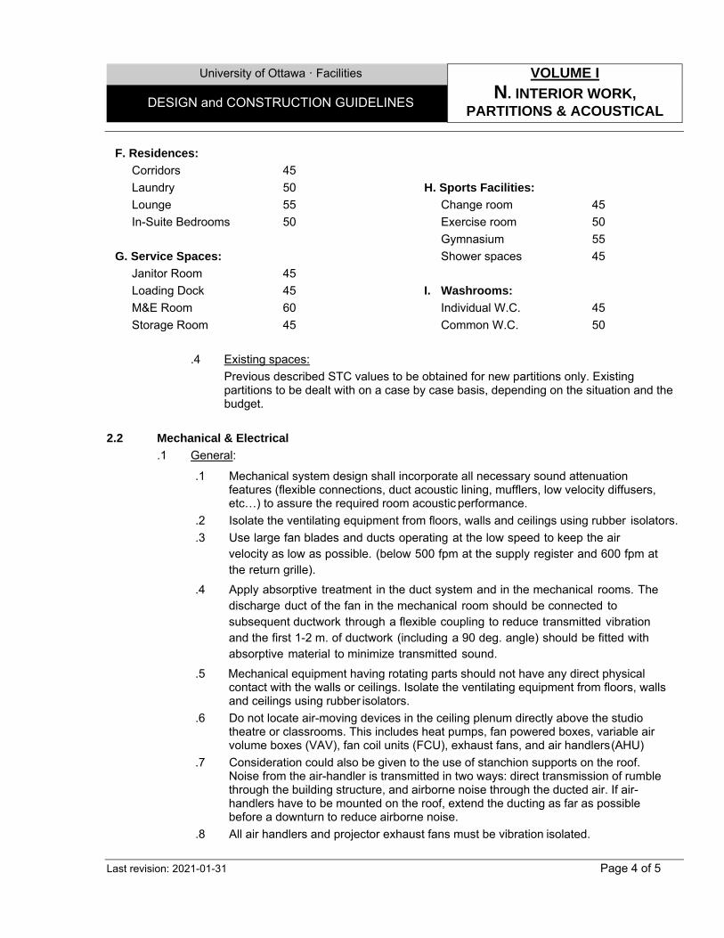
University of Ottawa ꞏ Facilities VOLUME I
N. INTERIOR WORK, PARTITIONS & ACOUSTICAL
DESIGN and CONSTRUCTION GUIDELINES
Last revision: 2021-01-31 Page 4 of 5
F. Residences:
Corridors 45
Laundry 50
Lounge 55
In-Suite Bedrooms 50
G. Service Spaces:
Janitor Room 45
Loading Dock 45
M&E Room 60
Storage Room 45
H. Sports Facilities:
Change room 45
Exercise room 50
Gymnasium 55
Shower spaces 45
I. Washrooms:
Individual W.C. 45
Common W.C. 50
.4 Existing spaces:
Previous described STC values to be obtained for new partitions only. Existing partitions to be dealt with on a case by case basis, depending on the situation and the budget.
2.2 Mechanical & Electrical
.1 General:
.1 Mechanical system design shall incorporate all necessary sound attenuation features (flexible connections, duct acoustic lining, mufflers, low velocity diffusers, etc…) to assure the required room acoustic performance.
.2 Isolate the ventilating equipment from floors, walls and ceilings using rubber isolators.
.3 Use large fan blades and ducts operating at the low speed to keep the air velocity as low as possible. (below 500 fpm at the supply register and 600 fpm at the return grille).
.4 Apply absorptive treatment in the duct system and in the mechanical rooms. The discharge duct of the fan in the mechanical room should be connected to subsequent ductwork through a flexible coupling to reduce transmitted vibration and the first 1-2 m. of ductwork (including a 90 deg. angle) should be fitted with absorptive material to minimize transmitted sound.
.5 Mechanical equipment having rotating parts should not have any direct physical contact with the walls or ceilings. Isolate the ventilating equipment from floors, walls and ceilings using rubber isolators.
.6 Do not locate air-moving devices in the ceiling plenum directly above the studio theatre or classrooms. This includes heat pumps, fan powered boxes, variable air volume boxes (VAV), fan coil units (FCU), exhaust fans, and air handlers (AHU)
.7 Consideration could also be given to the use of stanchion supports on the roof. Noise from the air-handler is transmitted in two ways: direct transmission of rumble through the building structure, and airborne noise through the ducted air. If air-handlers have to be mounted on the roof, extend the ducting as far as possible before a downturn to reduce airborne noise.
.8 All air handlers and projector exhaust fans must be vibration isolated.
University of Ottawa ꞏ Facilities VOLUME I
N. INTERIOR WORK, PARTITIONS & ACOUSTICAL
DESIGN and CONSTRUCTION GUIDELINES
Last revision: 2021-01-31 Page 5 of 5
.9 Review supply air diffuser selections and specify an NC rating five points less than required.
.10 Layout supply air ductwork and registers to have equivalent duct lengths between diffusers and the fan.
.11 Dampers should never be located directly behind the face of the air distribution device.
.12 Provide a clearance between pipes and gypsum board or other finish surfaces. Do not allow pipes to make rigid metal-to-metal contact between ceiling hanger wires, supports, framing, or other structure to which finishes are attached.
.13 Ducts penetrating the sound rated wall or floor/ceiling construction should be in an insulated sleeve packed with one inch thick mineral wool fire safing and sealed on both sides using backer rod and acoustical sealant. Piping penetrations less than three inches in diameter should be sealed using acoustic sealant filling a 1/4-inch clearance. Larger pipes should be treated similar to ducts.
.14 Avoid any back-to-back penetrations, such as electrical panel boards, junction boxes or fire extinguisher cabinets. Offset penetrations two stud cavities.
.2 Amphitheaters, Classrooms and similar teaching spaces:
.1 Avoid locating plumbing and rainwater leaders in the walls or ceiling spaces.
.2 Avoid locating Air Handling Units devices on the roof directly on top.
.3 Isolate the ventilation ducts from noise pickup in adjacent rooms en route to the Auditoriums and Classrooms. These ducts should be enclosed in a sealed wall (STC 4045).
.4 Any piping located in the walls or ceiling should be attached with resilient mountings.
.3 Audiovisual Control rooms:
.1 Special consideration shall be given to eliminate sound transmission from A/V Control rooms located within spaces, particularly concerning ventilation systems.
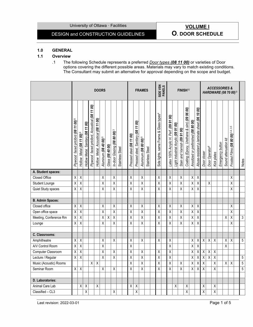
University of Ottawa ꞏ Facilities VOLUME I
O. DOOR SCHEDULE DESIGN and CONSTRUCTION GUIDELINES
Last revision: 2022-03-01 Page 1 of 5
1.0 GENERAL
1.1 Overview
.1 The following Schedule represents a preferred Door types (08 11 00) or varieties of Door options covering the different possible areas. Materials may vary to match existing conditions. The Consultant may submit an alternative for approval depending on the scope and budget.
DOORS FRAMES
SID
E VS
N
PAN
ELS
FINISH10 ACCESSORIES &
HARDWARE (08 70 00) 9
Plyw
ood
face
d pr
tclb
rd (0
8 11
00)
8
Hol
low
Met
al (0
8 11
00)
8
Hol
low
Met
al, S
anita
ry (0
8 11
00)
Plyw
ood
face
d pr
tclb
rd, A
cous
tical
(08
11 0
0)
Hol
low
Met
al, A
cous
tical
(08
11 0
0)
Alum
inum
(08
40 0
0) 8
Gla
ss (0
8 40
00)
In-d
oor G
lazi
ng (0
8 80
00)
3
Stai
nles
s St
eel
Pres
sed
stee
l (08
11
00)
Pres
sed
stee
l, Sa
nita
ry (0
8 11
00)
Alum
inum
(08
80 0
0) 8
Stai
nles
s St
eel
Side
ligh
ts, s
ame
Fram
e &
Gla
ss ty
pes4
Late
x 10
0% A
cryl
ic H
. Per
f. (0
9 91
00)
Ligh
t ind
ustri
al A
cryl
ic (0
9 91
00)
Stai
n an
d Va
rnis
h (0
9 91
00)
Coa
ting
(Epo
xy, U
reth
ane
& si
m) (
09 9
6 00
)
Anod
ized
or p
refin
ishe
d (0
8 80
00)
Abus
e -re
sist
ant p
.lam
inat
e sh
eet (
06 1
0 00
)
Doo
r clo
ser
Doo
r Ope
rato
r6
Kick
pla
tes
Emer
genc
y bu
tton
Soun
d at
tenu
atio
n ki
t
Fros
ted
Film
s (0
8 80
00)
3.4
, 3.5
Not
es
A. Student spaces:
Closed Office X X X X X X X X X X X X
Student Lounge X X X X X X X X X X X X X
Quiet Study spaces X X X X X X X X X X X X
B. Admin Spaces:
Closed office X X X X X X X X X X X X
Open office space X X X X X X X X X X X X
Meeting, Conference Rm X X X X X X X X X X X X X X 3
Lounge X X X X X X X X X X X X
C. Classrooms:
Amphitheatre X X X X X X X X X X X X X X X 5
A/V Control Room X X X X X X X X
Computer Classroom X X X X X X X X X X X X X
Lecture / Regular X X X X X X X X X X X X X 5
Music (Acoustic) Rooms X X X X X X X X X X X X X 5
Seminar Room X X X X X X X X X X X X X 5
D. Laboratories:
Animal Care Lab X X X X X X X X X
Classified – CL3 X X X X X X
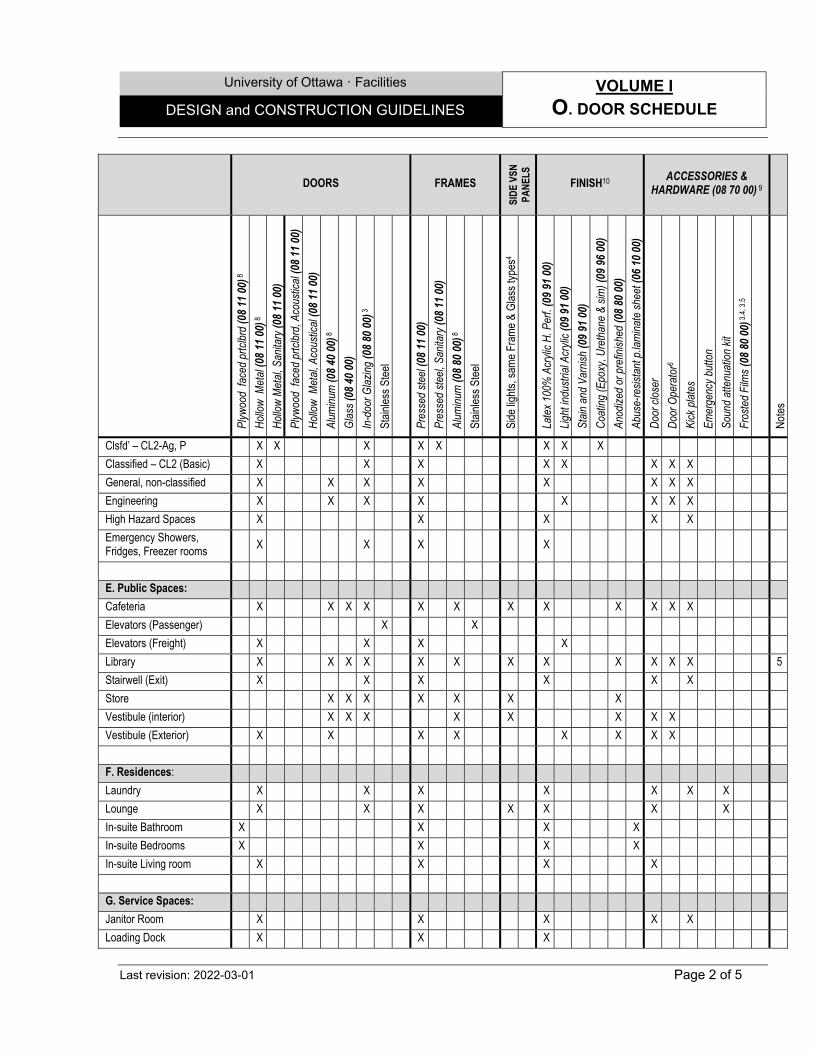
University of Ottawa ꞏ Facilities VOLUME I
O. DOOR SCHEDULE DESIGN and CONSTRUCTION GUIDELINES
Last revision: 2022-03-01 Page 2 of 5
DOORS FRAMES
SID
E VS
N
PAN
ELS
FINISH10 ACCESSORIES &
HARDWARE (08 70 00) 9
Plyw
ood
face
d pr
tclb
rd (0
8 11
00)
8
Hol
low
Met
al (0
8 11
00)
8
Hol
low
Met
al, S
anita
ry (0
8 11
00)
Plyw
ood
face
d pr
tclb
rd, A
cous
tical
(08
11 0
0)
Hol
low
Met
al, A
cous
tical
(08
11 0
0)
Alum
inum
(08
40 0
0) 8
Gla
ss (0
8 40
00)
In-d
oor G
lazi
ng (0
8 80
00)
3
Stai
nles
s St
eel
Pres
sed
stee
l (08
11
00)
Pres
sed
stee
l, Sa
nita
ry (0
8 11
00)
Alum
inum
(08
80 0
0) 8
Stai
nles
s St
eel
Side
ligh
ts, s
ame
Fram
e &
Gla
ss ty
pes4
Late
x 10
0% A
cryl
ic H
. Per
f. (0
9 91
00)
Ligh
t ind
ustri
al A
cryl
ic (0
9 91
00)
Stai
n an
d Va
rnis
h (0
9 91
00)
Coa
ting
(Epo
xy, U
reth
ane
& si
m) (
09 9
6 00
)
Anod
ized
or p
refin
ishe
d (0
8 80
00)
Abus
e -re
sist
ant p
.lam
inat
e sh
eet (
06 1
0 00
)
Doo
r clo
ser
Doo
r Ope
rato
r6
Kick
pla
tes
Emer
genc
y bu
tton
Soun
d at
tenu
atio
n ki
t
Fros
ted
Film
s (0
8 80
00)
3.4
, 3.5
Not
es
Clsfd’ – CL2-Ag, P X X X X X X X X
Classified – CL2 (Basic) X X X X X X X X
General, non-classified X X X X X X X X
Engineering X X X X X X X X
High Hazard Spaces X X X X X
Emergency Showers, Fridges, Freezer rooms
X X X X
E. Public Spaces:
Cafeteria X X X X X X X X X X X X
Elevators (Passenger) X X
Elevators (Freight) X X X X
Library X X X X X X X X X X X X 5
Stairwell (Exit) X X X X X X
Store X X X X X X X
Vestibule (interior) X X X X X X X X
Vestibule (Exterior) X X X X X X X X
F. Residences:
Laundry X X X X X X X
Lounge X X X X X X X
In-suite Bathroom X X X X
In-suite Bedrooms X X X X
In-suite Living room X X X X
G. Service Spaces:
Janitor Room X X X X X
Loading Dock X X X
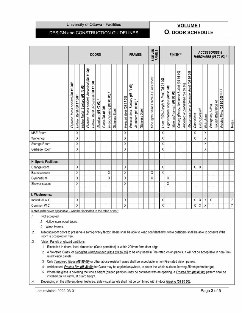
University of Ottawa ꞏ Facilities VOLUME I
O. DOOR SCHEDULE DESIGN and CONSTRUCTION GUIDELINES
Last revision: 2022-03-01 Page 3 of 5
DOORS FRAMES
SID
E VS
N
PAN
ELS
FINISH10 ACCESSORIES &
HARDWARE (08 70 00) 9
Plyw
ood
face
d pr
tclb
rd (0
8 11
00)
8
Hol
low
Met
al (0
8 11
00)
8
Hol
low
Met
al, S
anita
ry (0
8 11
00)
Plyw
ood
face
d pr
tclb
rd, A
cous
tical
(08
11 0
0)
Hol
low
Met
al, A
cous
tical
(08
11 0
0)
Alum
inum
(08
40 0
0) 8
Gla
ss (0
8 40
00)
In-d
oor G
lazi
ng (0
8 80
00)
3
Stai
nles
s St
eel
Pres
sed
stee
l (08
11
00)
Pres
sed
stee
l, Sa
nita
ry (0
8 11
00)
Alum
inum
(08
80 0
0) 8
Stai
nles
s St
eel
Side
ligh
ts, s
ame
Fram
e &
Gla
ss ty
pes4
Late
x 10
0% A
cryl
ic H
. Per
f. (0
9 91
00)
Ligh
t ind
ustri
al A
cryl
ic (0
9 91
00)
Stai
n an
d Va
rnis
h (0
9 91
00)
Coa
ting
(Epo
xy, U
reth
ane
& si
m) (
09 9
6 00
)
Anod
ized
or p
refin
ishe
d (0
8 80
00)
Abus
e -re
sist
ant p
.lam
inat
e sh
eet (
06 1
0 00
)
Doo
r clo
ser
Doo
r Ope
rato
r6
Kick
pla
tes
Emer
genc
y bu
tton
Soun
d at
tenu
atio
n ki
t
Fros
ted
Film
s (0
8 80
00)
3.4
, 3.5
Not
es
M&E Room X X X X X
Workshop X X X X X
Storage Room X X X X
Garbage Room X X X X
H. Sports Facilities:
Change room X X X X X
Exercise room X X X X X
Gymnasium X X X X X
Shower spaces X X X
I. Washrooms:
Individual W.C. X X X X X X X 7
Common W.C. X X X X X X 7
Notes (whenever applicable – whether indicated in the table or not):
.1 Not accepted:
.1 Hollow core wood doors.
.2 Wood frames.
.2 Meeting room doors to preserve a semi-privacy factor: Users shall be able to keep confidentiality, while outsiders shall be able to observe if the room is occupied or free.
.3 Vision Panels or glazed partitions:
.1 If installed in doors, ideal dimension (Code permitted) is within 200mm from door edge.
.2 A fire-rated Glass, or Georgian wired polished glass (08 80 00) to be only used in Fire-rated vision panels. It will not be acceptable in non-Fire-rated vision panels.
.3 Only Tempered Glass (08 80 00) or other abuse-resistant glass shall be acceptable in non-Fire-rated vision panels.
.4 Architectural Frosted film (08 80 00) for Glass may be applied anywhere, to cover the whole surface, leaving 25mm perimeter gap.
.5 Where the glass is covering the whole height (glazed partition) may be confused with an opening, a Frosted film (08 80 00) pattern shall be installed on full width, at guard height.
.4 Depending on the different deign features, Side visual panels shall not be combined with in-door Glazing (08 80 00).
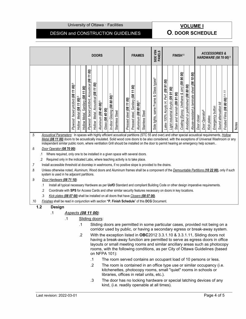
University of Ottawa ꞏ Facilities VOLUME I
O. DOOR SCHEDULE DESIGN and CONSTRUCTION GUIDELINES
Last revision: 2022-03-01 Page 4 of 5
DOORS FRAMES
SID
E VS
N
PAN
ELS
FINISH10 ACCESSORIES &
HARDWARE (08 70 00) 9
Plyw
ood
face
d pr
tclb
rd (0
8 11
00)
8
Hol
low
Met
al (0
8 11
00)
8
Hol
low
Met
al, S
anita
ry (0
8 11
00)
Plyw
ood
face
d pr
tclb
rd, A
cous
tical
(08
11 0
0)
Hol
low
Met
al, A
cous
tical
(08
11 0
0)
Alum
inum
(08
40 0
0) 8
Gla
ss (0
8 40
00)
In-d
oor G
lazi
ng (0
8 80
00)
3
Stai
nles
s St
eel
Pres
sed
stee
l (08
11
00)
Pres
sed
stee
l, Sa
nita
ry (0
8 11
00)
Alum
inum
(08
80 0
0) 8
Stai
nles
s St
eel
Side
ligh
ts, s
ame
Fram
e &
Gla
ss ty
pes4
Late
x 10
0% A
cryl
ic H
. Per
f. (0
9 91
00)
Ligh
t ind
ustri
al A
cryl
ic (0
9 91
00)
Stai
n an
d Va
rnis
h (0
9 91
00)
Coa
ting
(Epo
xy, U
reth
ane
& si
m) (
09 9
6 00
)
Anod
ized
or p
refin
ishe
d (0
8 80
00)
Abus
e -re
sist
ant p
.lam
inat
e sh
eet (
06 1
0 00
)
Doo
r clo
ser
Doo
r Ope
rato
r6
Kick
pla
tes
Emer
genc
y bu
tton
Soun
d at
tenu
atio
n ki
t
Fros
ted
Film
s (0
8 80
00)
3.4
, 3.5
Not
es
.5 Acoustical Parameters: In spaces with highly efficient acoustical partitions (STC 55 and over) and other special acoustical requirements, Hollow Metal (08 11 00) doors to be acoustically insulated. Solid wood core doors to be also considered. with the exceptions of Universal Washroom or any independent similar public room, where ventilation Grill should be installed on the door to permit hearing an emergency help scream..
.6 Door Operator (08 70 00):
.1 Where required, only one to be installed in a given space with several doors.
.2 Required only in the indicated Labs, where teaching activity is to take place.
.7 Install accessible threshold at doorstep in washrooms, if no positive slope is provided to the drains.
.8 Unless otherwise noted, Aluminum, Wood doors and Aluminum frames shall be a component of the Demountable Partitions (10 22 00), only if such system is used in he adjacent partitions.
.9 Door Hardware (08 71 10):
.1 Install all typical necessary Hardware as per UofO Standard and compliant Building Code or other design imperative requirements.
.2 Coordinate with SPS for Access Cards and other similar security features necessary on doors in key locations.
.3 Kick plates (08 07 00) shall be installed on all doors that have Closers (08 07 00).
.10 Finishes shall be read in conjunction with section “P. Finish Schedule” of this DCG Document.
1.2 Design
.1 Aspects (08 11 00):
.1 Sliding doors:
.1 Sliding doors are permitted in some particular cases, provided not being on a corridor used by public, or having a secondary egress or break-away system.
.2 With the exception listed in OBC2012 3.3.1.10 & 3.3.1.11, Sliding doors not having a break-away function are permitted to serve as egress doors in office layouts or small meeting rooms and similar ancillary areas such as photocopy rooms, with the following conditions, as per City of Ottawa Guidelines (based on NFPA 101):
.1 The room served contains an occupant load of 10 persons or less.
.2 The room is contained in an office type use or similar occupancy (i.e. kitchenettes, photocopy rooms, small "quiet" rooms in schools or libraries, offices in retail units, etc.).
.3 The door has no locking hardware or special latching devices of any kind, (i.e. readily openable at all times).
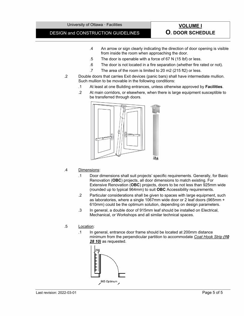
University of Ottawa ꞏ Facilities VOLUME I
O. DOOR SCHEDULE DESIGN and CONSTRUCTION GUIDELINES
Last revision: 2022-03-01 Page 5 of 5
.4 An arrow or sign clearly indicating the direction of door opening is visible from inside the room when approaching the door.
.5 The door is openable with a force of 67 N (15 lbf) or less.
.6 The door is not located in a fire separation (whether fire rated or not).
.7 The area of the room is limited to 20 m2 (215 ft2) or less.
.2 Double doors that carries Exit devices (panic bars) shall have intermediate mullion. Such mullion to be movable in the following conditions:
.1 At least at one Building entrances, unless otherwise approved by Facilities.
.2 At main corridors, or elsewhere, when there is large equipment susceptible to be transferred through doors.
.4 Dimensions:
.1 Door dimensions shall suit projects’ specific requirements. Generally, for Basic Renovation (OBC) projects, all door dimensions to match existing. For Extensive Renovation (OBC) projects, doors to be not less than 925mm wide (rounded up to typical 964mm) to suit OBC Accessibility requirements.
.2 Particular considerations shall be given to spaces with large equipment, such as laboratories, where a single 1067mm wide door or 2 leaf doors (965mm + 610mm) could be the optimum solution, depending on design parameters.
.3 In general, a double door of 915mm leaf should be installed on Electrical, Mechanical, or Workshops and all similar technical spaces.
.5 Location:
.1 In general, entrance door frame should be located at 200mm distance minimum from the perpendicular partition to accommodate Coat Hook Strip (10 28 10) as requested.
University of Ottawa ꞏ Facilities VOLUME I
P. FINISH SCHEDULE DESIGN and CONSTRUCTION GUIDELINES
Last revision: 2022-03-01 Page 1 of 6
1.0 GENERAL
1.1 Overview
.1 The following Schedule represents a preferred finish or varieties of finish options covering the different possible areas. Materials may vary to match existing conditions. The Consultant may submit an alternative for approval depending on the scope and budget. To be coordinated with users and DES.
FLOORS BASES WALLS CEILINGS1
Coa
ting
(Epo
xy, U
reth
ane
& si
m) (
09 6
7 00
)
Cle
ar S
eale
r (09
67
00)
VCT,
LVT
, or R
ubbe
r Tile
s (0
9 20
00)
18
Hom
ogen
ous
Viny
l or
Rub
ber S
heet
(09
65
00)
Lino
leum
She
et (0
9 65
00)
12
Porc
elai
n Ti
le (0
9 30
00)
12
Synt
hetic
Car
pet T
iles
(09
65 0
0)
Woo
d
Oth
er17
Rub
ber /
Vin
yl (0
9 65
00)
Sam
e as
Flo
orin
g
Inte
gral
with
floo
ring
(cov
e)
Oth
er17
Pain
t
(09
91 0
0)
Coa
ting
(Epo
xy, U
reth
ane
& si
m) (
09 9
6 00
)
Cer
amic
/ Po
rcel
ain
Tile
s (0
9 30
00)
Orn
amen
tal f
inis
hes21
Expo
sed
Oth
er17
Pain
t and
\or
on G
ypsu
m
Coa
ting
(Epo
xy, U
reth
ane
& si
m) (
09 9
6 00
) Ac
oust
ical
tile
s, R
egul
ar (0
9 50
00)
2
Acou
stic
al ti
les,
Orn
amen
tal (
09 5
0 00
)2
Acou
stic
al ti
les,
soi
l Res
ist.
Film
(09
50 0
0)2
Expo
sed
Oth
er
Not
es
Late
x 10
0% A
cryl
ic H
. Per
f.
Late
x 10
0% A
cryl
ic
Ligh
t ind
ustri
al A
cryl
ic
Late
x 10
0% A
cryl
ic
Ligh
t ind
ustri
al A
cryl
ic
A. Student spaces:
Closed Office X X X X X X
Student Lounge X X X X X X X
Study spaces X X X X X X
B. Admin Spaces:
Closed office X X X X X
Open office space X X X X X
Meeting, Conference Room
X X
X X
X
X
X X
Reception Areas X X X X X X X X
Lounge X X X X X X X
Support (Reprographics, etc.)
X X
X X
X
X X
C. Classrooms:
Amphitheatre X X X X X X X X X X X
A/V Control Room X X X X X
Computer Classroom X X X X X X
Lecture / Regular X X X X X X
Music (Acoustic) Room X X X X X
Seminar Room X X X X X

University of Ottawa ꞏ Facilities VOLUME I
P. FINISH SCHEDULE DESIGN and CONSTRUCTION GUIDELINES
Last revision: 2022-03-01 Page 2 of 6
FLOORS BASES WALLS CEILINGS1
Coa
ting
(Epo
xy, U
reth
ane
& si
m) (
09 6
7 00
)
Cle
ar S
eale
r (09
67
00)
VCT,
LVT
, or R
ubbe
r Tile
s (0
9 20
00)
18
Hom
ogen
ous
Viny
l or
Rub
ber S
heet
(09
65
00)
Lino
leum
She
et (0
9 65
00)
12
Porc
elai
n Ti
le (0
9 30
00)
12
Synt
hetic
Car
pet T
iles
(09
65 0
0)
Woo
d
Oth
er17
Rub
ber /
Vin
yl (0
9 65
00)
Sam
e as
Flo
orin
g
Inte
gral
with
floo
ring
(cov
e)
Oth
er17
Pain
t
(09
91 0
0)
Coa
ting
(Epo
xy, U
reth
ane
& si
m) (
09 9
6 00
)
Cer
amic
/ Po
rcel
ain
Tile
s (0
9 30
00)
Orn
amen
tal f
inis
hes21
Expo
sed
Oth
er17
Pain
t and
\or
on G
ypsu
m
Coa
ting
(Epo
xy, U
reth
ane
& si
m) (
09 9
6 00
) Ac
oust
ical
tile
s, R
egul
ar (0
9 50
00)
2
Acou
stic
al ti
les,
Orn
amen
tal (
09 5
0 00
)2
Acou
stic
al ti
les,
soi
l Res
ist.
Film
(09
50 0
0)2
Expo
sed
Oth
er
Not
es
Late
x 10
0% A
cryl
ic H
. Per
f.
Late
x 10
0% A
cryl
ic
Ligh
t ind
ustri
al A
cryl
ic
Late
x 10
0% A
cryl
ic
Ligh
t ind
ustri
al A
cryl
ic
D. Laboratories:
Animal Care Lab X X X X X X X X 4
Classified – CL3 X X X X 4
Clsfd’ – CL2-Ag, P15 X X X X X X X X X X 4
Classified – CL2(Basic) X X X X X X X X X 4
General, non-classified X X X X X X X X X 4
Engineering X X X X X X X X X X X X 4
Cloakrooms X X X X X X
Lab Offices X X X X X X X X X X X X X X X X X X X 22
High Hazard Spaces X X X X X X X X
Emergency Showers, Fridges, Freezer rooms
X X
X
X
X 11
E. Public Spaces:
Atrium Halls X X X X X X X X X X
Cafeteria X X X X X X X X X X X
Corridor (main) X X X X X X X X X X X X
Corridor (secondary) X X X X X X X X X
Elevators (Passenger) X X X X X X X X 19
Elevators (Freight) X X X X 19
Library X X X X X X X
Locker Space X X X X X X X X
Lounge (Public) X X X X X X X X X X
Parking (Indoor) X X X
Stairwell (Exit) X X X X X X 9
Stair (Communication) X X X X X X X 20
Store for public X X X X X X X X X X X X
Vestibule X X X X X X X
F. Residences:
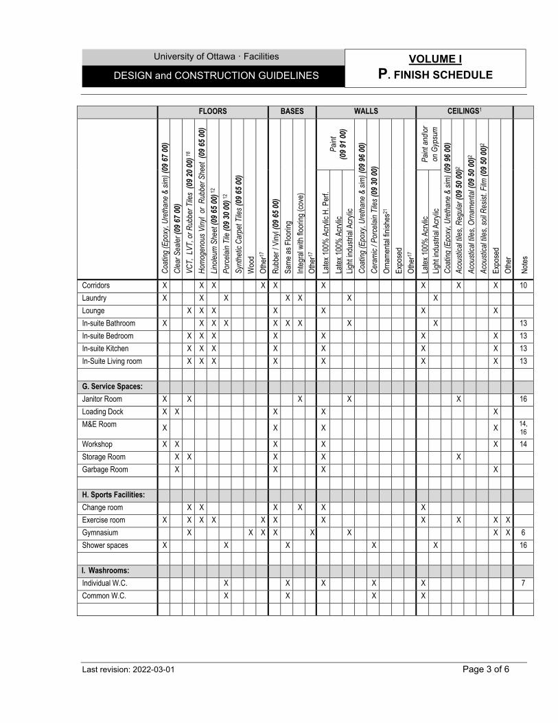
University of Ottawa ꞏ Facilities VOLUME I
P. FINISH SCHEDULE DESIGN and CONSTRUCTION GUIDELINES
Last revision: 2022-03-01 Page 3 of 6
FLOORS BASES WALLS CEILINGS1
Coa
ting
(Epo
xy, U
reth
ane
& si
m) (
09 6
7 00
)
Cle
ar S
eale
r (09
67
00)
VCT,
LVT
, or R
ubbe
r Tile
s (0
9 20
00)
18
Hom
ogen
ous
Viny
l or
Rub
ber S
heet
(09
65
00)
Lino
leum
She
et (0
9 65
00)
12
Porc
elai
n Ti
le (0
9 30
00)
12
Synt
hetic
Car
pet T
iles
(09
65 0
0)
Woo
d
Oth
er17
Rub
ber /
Vin
yl (0
9 65
00)
Sam
e as
Flo
orin
g
Inte
gral
with
floo
ring
(cov
e)
Oth
er17
Pain
t
(09
91 0
0)
Coa
ting
(Epo
xy, U
reth
ane
& si
m) (
09 9
6 00
)
Cer
amic
/ Po
rcel
ain
Tile
s (0
9 30
00)
Orn
amen
tal f
inis
hes21
Expo
sed
Oth
er17
Pain
t and
\or
on G
ypsu
m
Coa
ting
(Epo
xy, U
reth
ane
& si
m) (
09 9
6 00
) Ac
oust
ical
tile
s, R
egul
ar (0
9 50
00)
2
Acou
stic
al ti
les,
Orn
amen
tal (
09 5
0 00
)2
Acou
stic
al ti
les,
soi
l Res
ist.
Film
(09
50 0
0)2
Expo
sed
Oth
er
Not
es
Late
x 10
0% A
cryl
ic H
. Per
f.
Late
x 10
0% A
cryl
ic
Ligh
t ind
ustri
al A
cryl
ic
Late
x 10
0% A
cryl
ic
Ligh
t ind
ustri
al A
cryl
ic
Corridors X X X X X X X X X 10
Laundry X X X X X X X
Lounge X X X X X X X
In-suite Bathroom X X X X X X X X X 13
In-suite Bedroom X X X X X X X 13
In-suite Kitchen X X X X X X X 13
In-Suite Living room X X X X X X X 13
G. Service Spaces:
Janitor Room X X X X X 16
Loading Dock X X X X X
M&E Room X X X X 14, 16
Workshop X X X X X 14
Storage Room X X X X X
Garbage Room X X X X
H. Sports Facilities:
Change room X X X X X X
Exercise room X X X X X X X X X X X
Gymnasium X X X X X X X X 6
Shower spaces X X X X X 16
I. Washrooms:
Individual W.C. X X X X X 7
Common W.C. X X X X
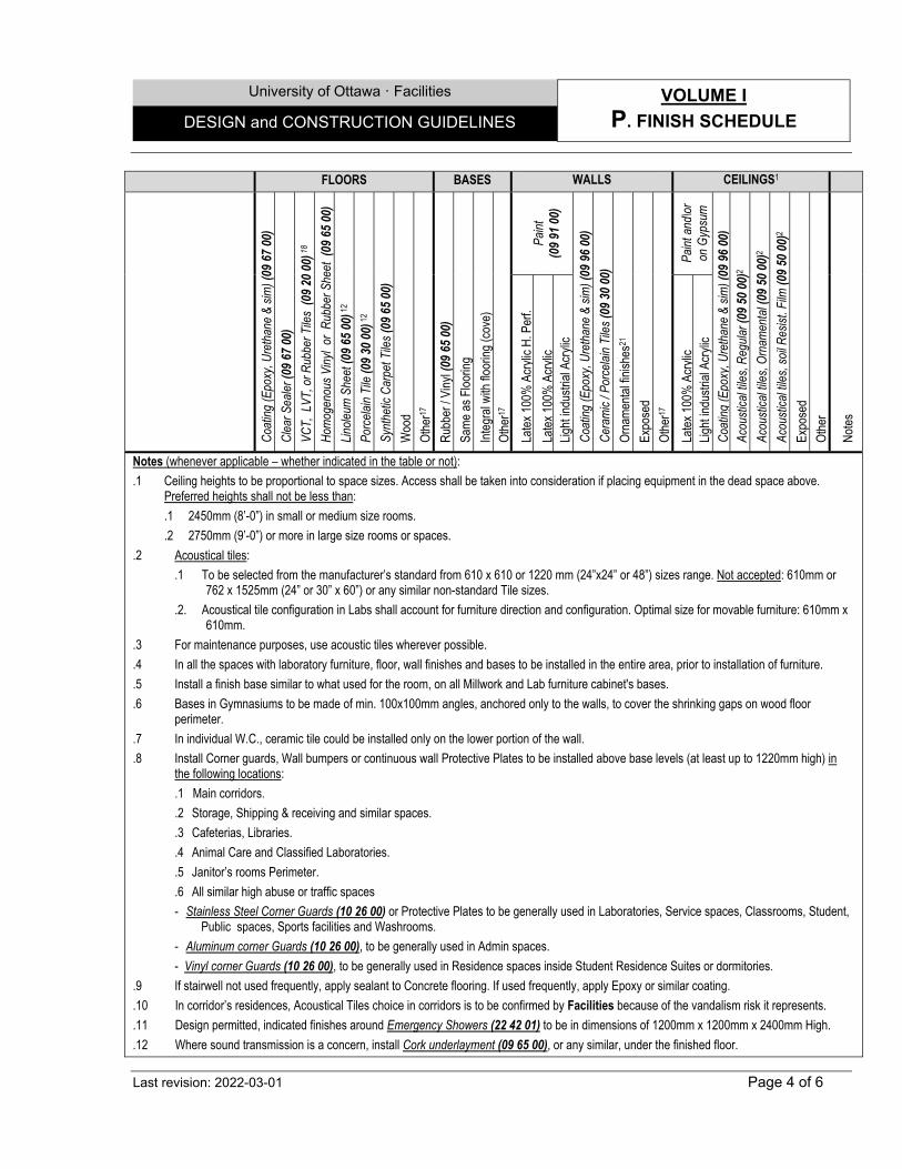
University of Ottawa ꞏ Facilities VOLUME I
P. FINISH SCHEDULE DESIGN and CONSTRUCTION GUIDELINES
Last revision: 2022-03-01 Page 4 of 6
FLOORS BASES WALLS CEILINGS1
Coa
ting
(Epo
xy, U
reth
ane
& si
m) (
09 6
7 00
)
Cle
ar S
eale
r (09
67
00)
VCT,
LVT
, or R
ubbe
r Tile
s (0
9 20
00)
18
Hom
ogen
ous
Viny
l or
Rub
ber S
heet
(09
65
00)
Lino
leum
She
et (0
9 65
00)
12
Porc
elai
n Ti
le (0
9 30
00)
12
Synt
hetic
Car
pet T
iles
(09
65 0
0)
Woo
d
Oth
er17
Rub
ber /
Vin
yl (0
9 65
00)
Sam
e as
Flo
orin
g
Inte
gral
with
floo
ring
(cov
e)
Oth
er17
Pain
t
(09
91 0
0)
Coa
ting
(Epo
xy, U
reth
ane
& si
m) (
09 9
6 00
)
Cer
amic
/ Po
rcel
ain
Tile
s (0
9 30
00)
Orn
amen
tal f
inis
hes21
Expo
sed
Oth
er17
Pain
t and
\or
on G
ypsu
m
Coa
ting
(Epo
xy, U
reth
ane
& si
m) (
09 9
6 00
) Ac
oust
ical
tile
s, R
egul
ar (0
9 50
00)
2
Acou
stic
al ti
les,
Orn
amen
tal (
09 5
0 00
)2
Acou
stic
al ti
les,
soi
l Res
ist.
Film
(09
50 0
0)2
Expo
sed
Oth
er
Not
es
Late
x 10
0% A
cryl
ic H
. Per
f.
Late
x 10
0% A
cryl
ic
Ligh
t ind
ustri
al A
cryl
ic
Late
x 10
0% A
cryl
ic
Ligh
t ind
ustri
al A
cryl
ic
Notes (whenever applicable – whether indicated in the table or not):
.1 Ceiling heights to be proportional to space sizes. Access shall be taken into consideration if placing equipment in the dead space above. Preferred heights shall not be less than:
.1 2450mm (8’-0”) in small or medium size rooms.
.2 2750mm (9’-0”) or more in large size rooms or spaces.
.2 Acoustical tiles:
.1 To be selected from the manufacturer’s standard from 610 x 610 or 1220 mm (24”x24” or 48”) sizes range. Not accepted: 610mm or 762 x 1525mm (24” or 30” x 60”) or any similar non-standard Tile sizes.
.2. Acoustical tile configuration in Labs shall account for furniture direction and configuration. Optimal size for movable furniture: 610mm x 610mm.
.3 For maintenance purposes, use acoustic tiles wherever possible.
.4 In all the spaces with laboratory furniture, floor, wall finishes and bases to be installed in the entire area, prior to installation of furniture.
.5 Install a finish base similar to what used for the room, on all Millwork and Lab furniture cabinet's bases.
.6 Bases in Gymnasiums to be made of min. 100x100mm angles, anchored only to the walls, to cover the shrinking gaps on wood floor perimeter.
.7 In individual W.C., ceramic tile could be installed only on the lower portion of the wall.
.8 Install Corner guards, Wall bumpers or continuous wall Protective Plates to be installed above base levels (at least up to 1220mm high) in the following locations:
.1 Main corridors.
.2 Storage, Shipping & receiving and similar spaces.
.3 Cafeterias, Libraries.
.4 Animal Care and Classified Laboratories.
.5 Janitor’s rooms Perimeter.
.6 All similar high abuse or traffic spaces
- Stainless Steel Corner Guards (10 26 00) or Protective Plates to be generally used in Laboratories, Service spaces, Classrooms, Student, Public spaces, Sports facilities and Washrooms.
- Aluminum corner Guards (10 26 00), to be generally used in Admin spaces.
- Vinyl corner Guards (10 26 00), to be generally used in Residence spaces inside Student Residence Suites or dormitories.
.9 If stairwell not used frequently, apply sealant to Concrete flooring. If used frequently, apply Epoxy or similar coating.
.10 In corridor’s residences, Acoustical Tiles choice in corridors is to be confirmed by Facilities because of the vandalism risk it represents.
.11 Design permitted, indicated finishes around Emergency Showers (22 42 01) to be in dimensions of 1200mm x 1200mm x 2400mm High.
.12 Where sound transmission is a concern, install Cork underlayment (09 65 00), or any similar, under the finished floor.
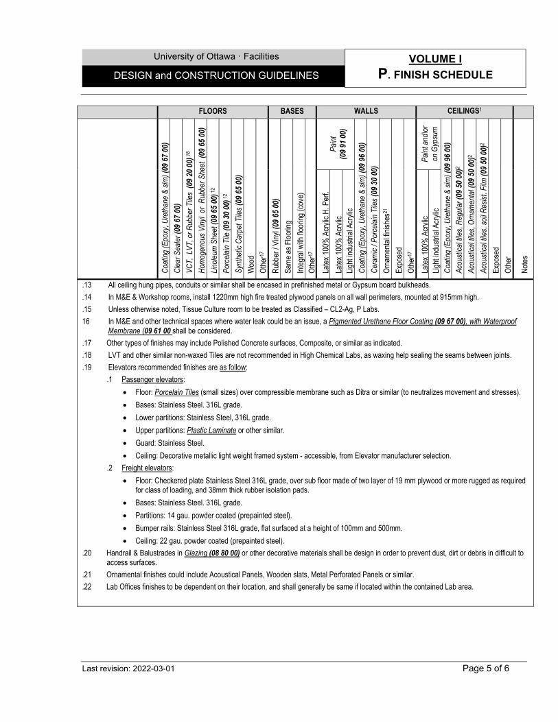
University of Ottawa ꞏ Facilities VOLUME I
P. FINISH SCHEDULE DESIGN and CONSTRUCTION GUIDELINES
Last revision: 2022-03-01 Page 5 of 6
FLOORS BASES WALLS CEILINGS1
Coa
ting
(Epo
xy, U
reth
ane
& si
m) (
09 6
7 00
)
Cle
ar S
eale
r (09
67
00)
VCT,
LVT
, or R
ubbe
r Tile
s (0
9 20
00)
18
Hom
ogen
ous
Viny
l or
Rub
ber S
heet
(09
65
00)
Lino
leum
She
et (0
9 65
00)
12
Porc
elai
n Ti
le (0
9 30
00)
12
Synt
hetic
Car
pet T
iles
(09
65 0
0)
Woo
d
Oth
er17
Rub
ber /
Vin
yl (0
9 65
00)
Sam
e as
Flo
orin
g
Inte
gral
with
floo
ring
(cov
e)
Oth
er17
Pain
t
(09
91 0
0)
Coa
ting
(Epo
xy, U
reth
ane
& si
m) (
09 9
6 00
)
Cer
amic
/ Po
rcel
ain
Tile
s (0
9 30
00)
Orn
amen
tal f
inis
hes21
Expo
sed
Oth
er17
Pain
t and
\or
on G
ypsu
m
Coa
ting
(Epo
xy, U
reth
ane
& si
m) (
09 9
6 00
) Ac
oust
ical
tile
s, R
egul
ar (0
9 50
00)
2
Acou
stic
al ti
les,
Orn
amen
tal (
09 5
0 00
)2
Acou
stic
al ti
les,
soi
l Res
ist.
Film
(09
50 0
0)2
Expo
sed
Oth
er
Not
es
Late
x 10
0% A
cryl
ic H
. Per
f.
Late
x 10
0% A
cryl
ic
Ligh
t ind
ustri
al A
cryl
ic
Late
x 10
0% A
cryl
ic
Ligh
t ind
ustri
al A
cryl
ic
.13 All ceiling hung pipes, conduits or similar shall be encased in prefinished metal or Gypsum board bulkheads.
.14 In M&E & Workshop rooms, install 1220mm high fire treated plywood panels on all wall perimeters, mounted at 915mm high.
.15 Unless otherwise noted, Tissue Culture room to be treated as Classified – CL2-Ag, P Labs.
16 In M&E and other technical spaces where water leak could be an issue, a Pigmented Urethane Floor Coating (09 67 00), with Waterproof Membrane (09 61 00 shall be considered.
.17 Other types of finishes may include Polished Concrete surfaces, Composite, or similar as indicated.
.18 LVT and other similar non-waxed Tiles are not recommended in High Chemical Labs, as waxing help sealing the seams between joints.
.19 Elevators recommended finishes are as follow:
.1 Passenger elevators:
Floor: Porcelain Tiles (small sizes) over compressible membrane such as Ditra or similar (to neutralizes movement and stresses).
Bases: Stainless Steel. 316L grade.
Lower partitions: Stainless Steel, 316L grade.
Upper partitions: Plastic Laminate or other similar.
Guard: Stainless Steel.
Ceiling: Decorative metallic light weight framed system - accessible, from Elevator manufacturer selection.
.2 Freight elevators:
Floor: Checkered plate Stainless Steel 316L grade, over sub floor made of two layer of 19 mm plywood or more rugged as required for class of loading, and 38mm thick rubber isolation pads.
Bases: Stainless Steel. 316L grade.
Partitions: 14 gau. powder coated (prepainted steel).
Bumper rails: Stainless Steel 316L grade, flat surfaced at a height of 100mm and 500mm.
Ceiling: 22 gau. powder coated (prepainted steel).
.20 Handrail & Balustrades in Glazing (08 80 00) or other decorative materials shall be design in order to prevent dust, dirt or debris in difficult to access surfaces.
.21 Ornamental finishes could include Acoustical Panels, Wooden slats, Metal Perforated Panels or similar.
.22 Lab Offices finishes to be dependent on their location, and shall generally be same if located within the contained Lab area.
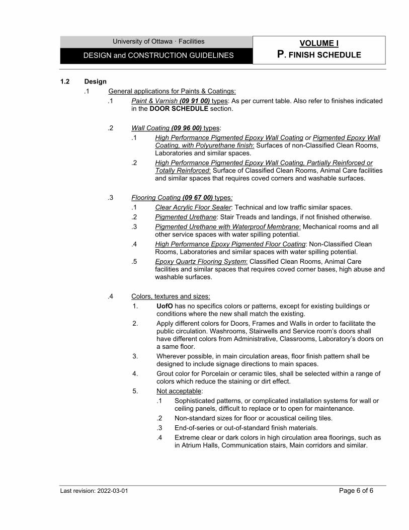
University of Ottawa ꞏ Facilities VOLUME I
P. FINISH SCHEDULE DESIGN and CONSTRUCTION GUIDELINES
Last revision: 2022-03-01 Page 6 of 6
1.2 Design
.1 General applications for Paints & Coatings:
.1 Paint & Varnish (09 91 00) types: As per current table. Also refer to finishes indicated in the DOOR SCHEDULE section.
.2 Wall Coating (09 96 00) types:
.1 High Performance Pigmented Epoxy Wall Coating or Pigmented Epoxy Wall Coating, with Polyurethane finish: Surfaces of non-Classified Clean Rooms, Laboratories and similar spaces.
.2 High Performance Pigmented Epoxy Wall Coating, Partially Reinforced or Totally Reinforced: Surface of Classified Clean Rooms, Animal Care facilities and similar spaces that requires coved corners and washable surfaces.
.3 Flooring Coating (09 67 00) types:
.1 Clear Acrylic Floor Sealer: Technical and low traffic similar spaces.
.2 Pigmented Urethane: Stair Treads and landings, if not finished otherwise.
.3 Pigmented Urethane with Waterproof Membrane: Mechanical rooms and all other service spaces with water spilling potential.
.4 High Performance Epoxy Pigmented Floor Coating: Non-Classified Clean Rooms, Laboratories and similar spaces with water spilling potential.
.5 Epoxy Quartz Flooring System: Classified Clean Rooms, Animal Care facilities and similar spaces that requires coved corner bases, high abuse and washable surfaces.
.4 Colors, textures and sizes:
1. UofO has no specifics colors or patterns, except for existing buildings or conditions where the new shall match the existing.
2. Apply different colors for Doors, Frames and Walls in order to facilitate the public circulation. Washrooms, Stairwells and Service room’s doors shall have different colors from Administrative, Classrooms, Laboratory’s doors on a same floor.
3. Wherever possible, in main circulation areas, floor finish pattern shall be designed to include signage directions to main spaces.
4. Grout color for Porcelain or ceramic tiles, shall be selected within a range of colors which reduce the staining or dirt effect.
5. Not acceptable:
.1 Sophisticated patterns, or complicated installation systems for wall or ceiling panels, difficult to replace or to open for maintenance.
.2 Non-standard sizes for floor or acoustical ceiling tiles.
.3 End-of-series or out-of-standard finish materials.
.4 Extreme clear or dark colors in high circulation area floorings, such as in Atrium Halls, Communication stairs, Main corridors and similar.
University of Ottawa ꞏ Facilities VOLUME I
Q. FURNITURE & MILLWORK SCHEDULE
DESIGN and CONSTRUCTION GUIDELINES
Last revision: 2021-01-31 Page 1 of 5
1.0 GENERAL 1.1 Overview
.1 The following Schedule represents preferred furniture or varieties of furniture options covering the different possible areas. Materials may vary to match existing conditions. Scope of work and responsibilities of external Consultants may vary depending project specifics. Whether included or not, all furniture to be taken in consideration and coordinated throughout the design. To be coordinated with users and DES.
Standing Offer furniture lab M. Media Millwork (06 10 00) Misc. furn Specialized furniture
Users furniture
Wor
ksta
tion
Filin
g &
Stor
age
cabi
net
Mee
ting
tabl
ePa
nels
Stor
age
cabi
net /
She
lves
Vario
us c
hairs
Trai
ning
tabl
eW
ardr
obe
Lab
furn
iture
(12
35
00)
Gen
eral
(Ref
er to
rela
ted
sect
ions
)Po
dium
des
k (1
2 50
00)
A/
V R
ack
Com
pute
r cab
inet
Sink
Cou
nter
top
Cou
nter
/ C
abin
et /
shel
ves
Stan
d-up
cou
nter
2
Was
te re
cycl
ing
stat
ion3
Sofa
sM
odul
ar c
ount
er
Mod
ular
cou
nter
Se
ats
with
retra
ctab
le ta
blet
(12
50 0
0)
Fixe
d ta
bles
sys
tem
s (1
2 50
00)
1 Ac
cess
ible
Tab
le (1
2 50
00)
Pr
efab
ricat
ed R
acks
/ Sh
elve
s Bo
oksh
elve
s Pr
efab
ricat
ed b
ench
es (1
0 51
00)
Lo
cker
s (1
0 51
00)
Be
d +
side
tabl
es +
dre
sser
+ w
ardr
obe5
Stud
y de
sk
Cha
irs
Cou
ches
Equi
pmen
t Rac
ks
Not
es
A. Student Spaces:
Closed Office X X X
Association office X X X
Student Lounge X X X X X X
Study spaces X X
B. Admin Spcs:
Closed office X X X X
Open office space
X X X X X
X
Meeting Rm X X X X
Reception Areas X X X X X
Lounge X X X X X X
Support (Repro) X
C. Classrooms:
Amphitheatre X X X X X
A/V Control Rm X
Computer Clsrm X X X X X
Lecture Rm X X X X
Music Rm X X
Seminar Rm X X X X
University of Ottawa ꞏ Facilities VOLUME I
Q. FURNITURE & MILLWORK SCHEDULE
DESIGN and CONSTRUCTION GUIDELINES
Last revision: 2021-01-31 Page 2 of 5
Standing Offer furniture lab M. Media Millwork (06 10 00) Misc. furn Specialized furniture
Users furniture
Wor
ksta
tion
Filin
g &
Stor
age
cabi
net
Mee
ting
tabl
ePa
nels
Stor
age
cabi
net /
She
lves
Vario
us c
hairs
Trai
ning
tabl
eW
ardr
obe
Lab
furn
iture
(12
35
00)
Gen
eral
(Ref
er to
rela
ted
sect
ions
)Po
dium
des
k (1
2 50
00)
A/
V R
ack
Com
pute
r cab
inet
Sink
Cou
nter
top
Cou
nter
/ C
abin
et /
shel
ves
Stan
d-up
cou
nter
2
Was
te re
cycl
ing
stat
ion3
Sofa
sM
odul
ar c
ount
er
Mod
ular
cou
nter
Se
ats
with
retra
ctab
le ta
blet
(12
50 0
0)
Fixe
d ta
bles
sys
tem
s (1
2 50
00)
1 Ac
cess
ible
Tab
le (1
2 50
00)
Pr
efab
ricat
ed R
acks
/ Sh
elve
s Bo
oksh
elve
s Pr
efab
ricat
ed b
ench
es (1
0 51
00)
Lo
cker
s (1
0 51
00)
Be
d +
side
tabl
es +
dre
sser
+ w
ardr
obe5
Stud
y de
sk
Cha
irs
Cou
ches
Equi
pmen
t Rac
ks
Not
es
D. Laboratories:
Animal Care Lab X X X X
Classified – CL3 X X X X
Classified – CL2-Ag, P
X
X
X X
Classified – CL2 X X X X
General, non-classified
X
X
X X
Engineering X X X X X X
Cloakrooms X
Hazardous Spaces
X
X
X X
E. Public Spcs:
Atrium Halls X X
Cafeteria X X X X X X
Corridor (main) X
Corridor (scd) X
Library X X X X X X
Locker Spce X
Lounge (Public) X X X X X X
Store for public X X
F. Residences:
Laundry X X
Lounge X X X
In-Suite Bathroom
X X
4
In-Suite Bedroom X X X
In-Suite Kitchen X 4
In-Suite Living Rm
X X
University of Ottawa ꞏ Facilities VOLUME I
Q. FURNITURE & MILLWORK SCHEDULE
DESIGN and CONSTRUCTION GUIDELINES
Last revision: 2021-01-31 Page 3 of 5
Standing Offer furniture lab M. Media Millwork (06 10 00) Misc. furn Specialized furniture
Users furniture
Wor
ksta
tion
Filin
g &
Stor
age
cabi
net
Mee
ting
tabl
ePa
nels
Stor
age
cabi
net /
She
lves
Vario
us c
hairs
Trai
ning
tabl
eW
ardr
obe
Lab
furn
iture
(12
35
00)
Gen
eral
(Ref
er to
rela
ted
sect
ions
)Po
dium
des
k (1
2 50
00)
A/
V R
ack
Com
pute
r cab
inet
Sink
Cou
nter
top
Cou
nter
/ C
abin
et /
shel
ves
Stan
d-up
cou
nter
2
Was
te re
cycl
ing
stat
ion3
Sofa
sM
odul
ar c
ount
er
Mod
ular
cou
nter
Se
ats
with
retra
ctab
le ta
blet
(12
50 0
0)
Fixe
d ta
bles
sys
tem
s (1
2 50
00)
1 Ac
cess
ible
Tab
le (1
2 50
00)
Pr
efab
ricat
ed R
acks
/ Sh
elve
s Bo
oksh
elve
s Pr
efab
ricat
ed b
ench
es (1
0 51
00)
Lo
cker
s (1
0 51
00)
Be
d +
side
tabl
es +
dre
sser
+ w
ardr
obe5
Stud
y de
sk
Cha
irs
Cou
ches
Equi
pmen
t Rac
ks
Not
es
G. Service Spcs:
Janitor Rm
Loading Dock X
Workshop X X X
Storage Rm X X
H. Sports:
Change Rm X X
Exercise Rm X X X X X
Gymnasium
I. Washrooms:
Individual W.C. X 6
Common W.C. X 6
Notes (whenever applicable – whether indicated in the table or not):
.1 Fixed tables systems (12 50 00):
.1 Tables: Shall be minimum 510 mm (20”) deep with modesty panels, with 610mm minimum clear (face to back). Spacing shall increase proportionally with the number of the seats.
.2 Millwork (06 10 00) Stand-up counter: To be designed with modesty panel if installed against glazed partitions.
.3 Millwork (06 10 00) Waste recycling station:
.1 At least one recycling station shall be installed per floor. Location to be coordinated with Facilities Custodial Services, but generally located on the outside of classrooms, and to be considered with large and amphitheater classroom.
.2 Refer to Millwork Details, under VOLUME VI – Appendix, of this DCG for more info.
.4 Private (In-suites) Residence Kitchen and W.C. Millwork (06 10 00) Sink Countertop:
.1 To be made of Regular or Abuse-resistant plastic laminate on Plywood Wood Panel c/w backlash of 100mm of height. MDF Fiberboard Medium Density core will not be accepted.
.2 No gap between the back counter and wall will be acceptable.
.5 Residences beds: To be double size.
University of Ottawa ꞏ Facilities VOLUME I
Q. FURNITURE & MILLWORK SCHEDULE
DESIGN and CONSTRUCTION GUIDELINES
Last revision: 2021-01-31 Page 4 of 5
Standing Offer furniture lab M. Media Millwork (06 10 00) Misc. furn Specialized furniture
Users furniture
Wor
ksta
tion
Filin
g &
Stor
age
cabi
net
Mee
ting
tabl
ePa
nels
Stor
age
cabi
net /
She
lves
Vario
us c
hairs
Trai
ning
tabl
eW
ardr
obe
Lab
furn
iture
(12
35
00)
Gen
eral
(Ref
er to
rela
ted
sect
ions
)Po
dium
des
k (1
2 50
00)
A/
V R
ack
Com
pute
r cab
inet
Sink
Cou
nter
top
Cou
nter
/ C
abin
et /
shel
ves
Stan
d-up
cou
nter
2
Was
te re
cycl
ing
stat
ion3
Sofa
sM
odul
ar c
ount
er
Mod
ular
cou
nter
Se
ats
with
retra
ctab
le ta
blet
(12
50 0
0)
Fixe
d ta
bles
sys
tem
s (1
2 50
00)
1 Ac
cess
ible
Tab
le (1
2 50
00)
Pr
efab
ricat
ed R
acks
/ Sh
elve
s Bo
oksh
elve
s Pr
efab
ricat
ed b
ench
es (1
0 51
00)
Lo
cker
s (1
0 51
00)
Be
d +
side
tabl
es +
dre
sser
+ w
ardr
obe5
Stud
y de
sk
Cha
irs
Cou
ches
Equi
pmen
t Rac
ks
Not
es
.6 Public Kitchen and W.C. Millwork (06 10 00) Sink Countertop:
.1 Shall be made of Solid Homogeneous Panel, with 100mm min. solid backsplash.
.2 No gap between the back counter and wall will be acceptable.
.3 Not acceptable: Trough design lavatory sinks. Individual Lavatories (22 42 01) are mandatories.
.4 Design to incorporate Built-in Lavatory (22 42 01) or Wall-mount Lavatory (22 42 01), in an approved concept by Facilities.
.7 Minimum distance between furniture: Shall take into consideration all related accessibility and access to egress parameters as requested by Codes. However, distances are recommended to be 900 mm free between non-fixed furniture.
1.2 Design
.1 Main furniture categories (also refer to other related sections):
.1 Standing Offer furniture: Designate furniture used generally in Administrative and similar spaces. To be provided and installed by specialized firm, as per Standing Offer agreement with UofO.
.2 Lab furniture (12 35 00): Designate special furniture generally installed in Laboratory and similar spaces. To be provided and installed by GC. Refer to related section.
.3 Multi-Media furniture: Designate furniture dedicated for A/V equipment, generally installed in Classrooms and similar spaces. Refer to related sections.
.4 Miscellaneous furniture: Designate all types of fixed and non-fixed furniture, to be provided and installed by specialized firms.
.5 Specialized furniture: Designate pre-manufactured furniture described in different locations. Shall be provided and installed by GC.
.6 Users supplied furniture: Designate furniture to be provided and installed by different users, faculty or services. Shall be coordinated and approved by Faculty managers to ensure there is no risk to injury others. Location must be approved by Facilities to ensure they do not impede into path of travel or Exit minimums, in conformity with Code and Security parameters.
University of Ottawa ꞏ Facilities VOLUME I
Q. FURNITURE & MILLWORK SCHEDULE
DESIGN and CONSTRUCTION GUIDELINES
Last revision: 2021-01-31 Page 5 of 5
.2 Keying: Furniture master key shall not be handled to users, but only to Faculty managers or Facilities.
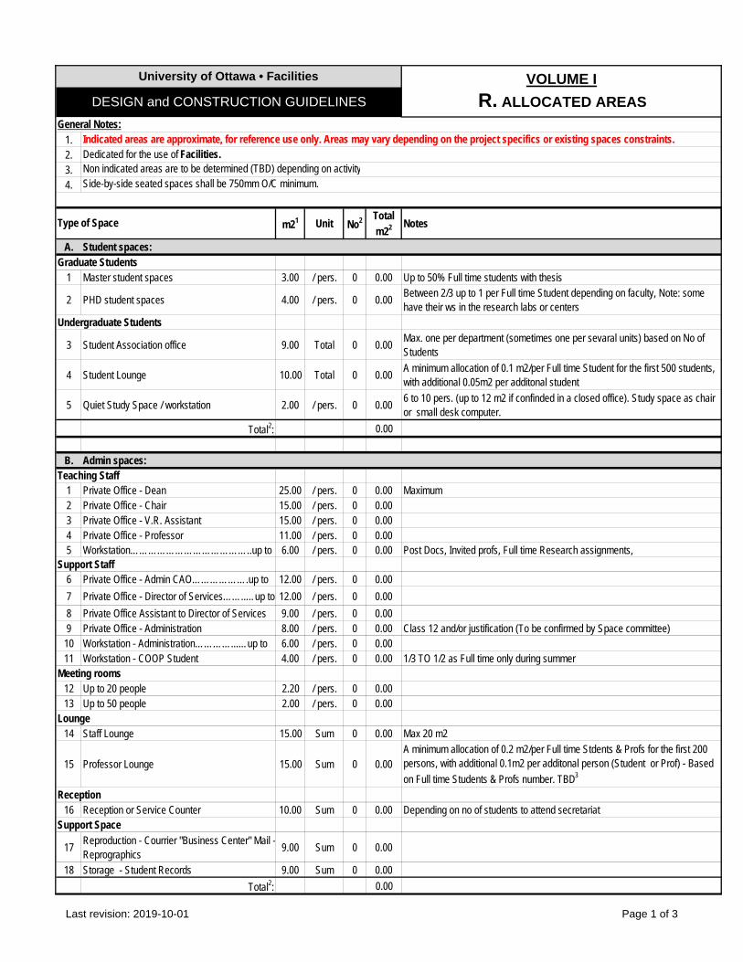
1.2.3.4.
m21 Unit No2 Total
m22 Notes
A. Student spaces:Graduate Students
1 Master student spaces 3.00 / pers. 0 0.00 Up to 50% Full time students with thesis
2 PHD student spaces 4.00 / pers. 0 0.00Between 2/3 up to 1 per Full time Student depending on faculty, Note: some have their ws in the research labs or centers
Undergraduate Students
3 Student Association office 9.00 Total 0 0.00Max. one per department (sometimes one per sevaral units) based on No of Students
4 Student Lounge 10.00 Total 0 0.00A minimum allocation of 0.1 m2/per Full time Student for the first 500 students, with additional 0.05m2 per additonal student
5 Quiet Study Space / workstation 2.00 / pers. 0 0.006 to 10 pers. (up to 12 m2 if confinded in a closed office). Study space as chair or small desk computer.
Total2: 0.00
B. Admin spaces:Teaching Staff
1 Private Office - Dean 25.00 / pers. 0 0.00 Maximum2 Private Office - Chair 15.00 / pers. 0 0.003 Private Office - V.R. Assistant 15.00 / pers. 0 0.004 Private Office - Professor 11.00 / pers. 0 0.005 Workstation…………………………………..up to 6.00 / pers. 0 0.00 Post Docs, Invited profs, Full time Research assignments,
Support Staff6 Private Office - Admin CAO……………….up to 12.00 / pers. 0 0.00
7 Private Office - Director of Services……..…up to 12.00 / pers. 0 0.00
8 Private Office Assistant to Director of Services 9.00 / pers. 0 0.009 Private Office - Administration 8.00 / pers. 0 0.00 Class 12 and/or justification (To be confirmed by Space committee)10 Workstation - Administration…………...…up to 6.00 / pers. 0 0.0011 Workstation - COOP Student 4.00 / pers. 0 0.00 1/3 TO 1/2 as Full time only during summer
Meeting rooms12 Up to 20 people 2.20 / pers. 0 0.0013 Up to 50 people 2.00 / pers. 0 0.00
Lounge14 Staff Lounge 15.00 Sum 0 0.00 Max 20 m2
15 Professor Lounge 15.00 Sum 0 0.00A minimum allocation of 0.2 m2/per Full time Stdents & Profs for the first 200 persons, with additional 0.1m2 per additonal person (Student or Prof) - Based
on Full time Students & Profs number. TBD3
Reception16 Reception or Service Counter 10.00 Sum 0 0.00 Depending on no of students to attend secretariat
Support Space
17Reproduction - Courrier "Business Center" Mail -Reprographics
9.00 Sum 0 0.00
18 Storage - Student Records 9.00 Sum 0 0.00
Total2: 0.00
DESIGN and CONSTRUCTION GUIDELINES
University of Ottawa • Facilities VOLUME I
R. ALLOCATED AREAS
Type of Space
General Notes:Indicated areas are approximate, for reference use only. Areas may vary depending on the project specifics or existing spaces constraints.Dedicated for the use of Facilities.Non indicated areas are to be determined (TBD) depending on activitySide-by-side seated spaces shall be 750mm O/C minimum.
Last revision: 2019-10-01 Page 1 of 3
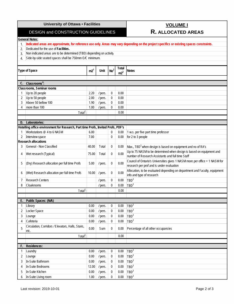
1.2.3.4.
m21 Unit No2 Total
m22 Notes
DESIGN and CONSTRUCTION GUIDELINES
University of Ottawa • Facilities VOLUME I
R. ALLOCATED AREAS
Type of Space
General Notes:Indicated areas are approximate, for reference use only. Areas may vary depending on the project specifics or existing spaces constraints.Dedicated for the use of Facilities.Non indicated areas are to be determined (TBD) depending on activitySide-by-side seated spaces shall be 750mm O/C minimum.
C. Classrooms4:Classrooms, Seminar rooms
1 Up to 20 people 2.20 / pers. 0 0.002 Up to 50 people 2.00 / pers. 0 0.003 Above 50 bellow 100 1.90 / pers. 0 0.004 more than 100 1.00 / pers. 0 0.00
Total2: 0.00
D. Laboratories:Hotelling office environment for Research, Part time Profs, Invited Profs, PDF's
1 Workstations @ 4 to 6 NASM 6.00 0 0.00 1 w.s. per five part time professor2 Interview space 7.00 0 0.00 for 2 to 3 people
Research allocations
3 General - Non Classified 40.00 Total 0 0.00 Max., TBD3 when design is based on equipment and no of RA's
4 Wet research (Typical) 75.00 Total 0 0.00Up to 75 NASM to be determined when design is based on equipment and number of Research Assistants and full time Staff
5 (Dry) Research allocation per full time Profs 5.00 / pers. 0 0.00Council of Ontario's Universities gives 1 NASM more per office + 1 NASM for research per prof and is under evaluation
6 (Wet) Research allocation per full time Profs 10.00 / pers. 0 0.00Allocation, to be evaluated depending on department and Faculty, equipment info and type of research
7 Research Centers / pers. 0 0.00 TBD3
8 Cloakrooms / pers. 0 0.00 TBD3
Total2: 0.00
E. Public Spaces: (N/A)
1 Library 0.00 / pers. 0 0.00 TBD3
2 Locker Space 0.00 / pers. 0 0.00 TBD3
3 Lounge 0.00 / pers. 0 0.00 TBD3
4 Cafeteria 0.00 / pers. 0 0.00 TBD3
5Circulation, Corridors / Elevators, Halls, Stairs, etc.
0.00 Sum 0 0.00 Percentage of all other occupancies
Total2: 0.00
F. Residences:
1 Laundry 0.00 / pers. 0 0.00 TBD3
2 Lounge 0.00 / pers. 0 0.00 TBD3
3 In-Suite Bathroom 0.00 / pers. 0 0.00 TBD3
4 In-Suite Bedrooms 12.00 / pers. 0 0.00 TBD3
5 In-Suite Kitchen 0.00 / pers. 0 0.00 TBD3
6 In-Suite Living room 1.00 / pers. 0 0.00 TBD3
Last revision: 2019-10-01 Page 2 of 3
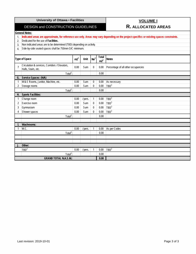
1.2.3.4.
m21 Unit No2 Total
m22 Notes
DESIGN and CONSTRUCTION GUIDELINES
University of Ottawa • Facilities VOLUME I
R. ALLOCATED AREAS
Type of Space
General Notes:Indicated areas are approximate, for reference use only. Areas may vary depending on the project specifics or existing spaces constraints.Dedicated for the use of Facilities.Non indicated areas are to be determined (TBD) depending on activitySide-by-side seated spaces shall be 750mm O/C minimum.
7Circulation & services, Corridors / Elevators, Halls, Stairs, etc.
0.00 Sum 0 0.00 Percentage of all other occupancies
Total2: 0.00
G. Service Spaces: (N/A)1 M & E Rooms, Janitor, Machine, etc. 0.00 Sum 0 0.00 As necessary2 Storage rooms 0.00 Sum 0 0.00 TBD3
Total2: 0.00
H. Sports Facilities:
1 Change room 0.00 / pers. 1 0.00 TBD3
2 Exercise room 0.00 Sum 0 0.00 TBD3
3 Gymnasium 0.00 Sum 0 0.00 TBD3
4 Shower spaces 0.00 Sum 0 0.00 TBD3
Total2: 0.00
I. Washrooms:1 W.C. 0.00 / pers. 1 0.00 As per Codes
Total2: 0.00
J. Other:
TBD3 0.00 / pers. 1 0.00 TBD3
Total2: 0.00
GRAND TOTAL N.A.S.M.: 0.00
Last revision: 2019-10-01 Page 3 of 3
UofO of Ottawa · Facilities VOLUME I
S. ENERGY & SUSTAINABILITY DESIGN and CONSTRUCTION REQUIREMENTS
Last revision: 2019-10-01 Page 1 of 6
1.0 GENERAL
1.1 Overview .1 This section has been prepared to provide direction and resources for the energy efficient and
sustainable design for new construction and Extensive Renovations (OBC) projects. It is not the intent of this section to limit innovation but to encourage information exchange of different ideas with the UofO in order to achieve better energy performance.
.2 The UofO is committed to sustainable campus development. One of the objectives is to reduce carbon emissions, therefore improving buildings energy efficiency is a major objective.
.3 The Energy Section applies to new construction and Extensive Renovations (OBC) and where application and when feasible and practical, also to small projects.
.4 In addition to the requirements outlined in this section the UofO aggressively implements energy retrofit (ECO Prosperity Projects) projects for UofO infrastructure and existing buildings.
.5 Energy performance, analysis and reporting requirements including identification of energy efficiency measures (EEMs), building simulation, building envelope, daylighting design and measurement and verification (M&V) for all new construction and Extensive Renovations (OBC) projects are also outlined in this section.
2.0 DESIGN
2.1 Parameters
.1 General: .1 Budget permitting, all new construction or addition projects which exceeds 10,000m2 shall
be certified LEED Silver. To be confirmed by Facilities, to determine whether formal certification will be sought.
.2 Architecture:
.1 Building envelope components shall conform or surpass the effective (R-values) requirements in OBC SB-10, prescriptive method with an energy modeling simulation analysis. Use of nominal thermal performance (R-Value) of the wall in the energy models and load calculations are not permitted.
.2 For new buildings, openings to wall ratio (OWR) shall be minimized. It is strongly recommended to maintain this ration between 25% - 35% maximum. Minimization of OWR shall be combined with daylighting control strategy. Concepts such as utilization of windows with high visible transmittance (VT) and positioned high to simulate a clerestory should be considered. Building orientation as discussed earlier plays a strategic role in effective daylighting.
.3 Not acceptable: Curtain wall systems on blind walls; unless their components are part of the OWR upon approval by Facilities. Refer to other related notes in the “Envelope Assemblies” Section.
.4 In new construction projects and Extensive Renovations (OBC) where replacement of windows is under review solar heat gain coefficient (SHGC) of glass shall be minimized. Use of glass with high SHGC will provide additional savings in building energy use during winter via an increase in the winter solar heat gain offsetting the space heating energy use, but at the expense of an increase the cooling load and the size of cooling system.
.5 For new construction explore the effect of external shading elements such as utilization of recess openings. External shading elements can reduce the solar heat gain and cooling load. The recess effect in summer should be compared with the reduction of solar heat gain
UofO of Ottawa · Facilities VOLUME I
S. ENERGY & SUSTAINABILITY DESIGN and CONSTRUCTION REQUIREMENTS
Last revision: 2019-10-01 Page 2 of 6
during winter in order to evaluate the effect of shading element for the overall building energy use. Below are suggestions as the means to reduce solar heat gain: .1 Vertical fins for west and east façades. .2 Overhangs for south façade. .3 North façade does not require any shading element, however consider to including
clerestory windows to contribute to daylighting.
.3 M&E: .1 Integrated Building Design (IBD) methodology shall apply in all projects. .2 The following steps shall be considered in the IBD process:
.1 Building Load Optimization.
.2 High Efficiency Equipment Utilization.
.3 Operation Optimization.
.4 Commissioning. .3 New construction projects are required to achieve minimum 50% reduction in total energy
consumption as compared to the AHSRAE 90.1-2010 as listed on OBC SB-10. Where feasible total energy reduction of major renovations must also target a 50% reduction in total energy use as compared to ASHRAE 90.1-2010.
.4 Design of mechanical and electrical systems for all new construction and Extensive Renovations (OBC) shall comply with the requirements outlined in OBC sections 6.5, 7.5, 9.5 or 9.6 of ASHARE 90.1 – 2010 and OBC SB-10 whichever is more stringent.
.5 It is strongly recommended that the Design Team follow the guidance provided in ASHARE 50% Advanced Energy Design Guides (AEDG50) where applicable to the project type.
.6 Where requirements outlined in this section are not feasible and/or in contradiction with applicable codes, deviation shall be reviewed with Facilities.
2.2 Building Load Optimization
.1 Following features shall be considered for building load optimization:
.2 For new buildings explore the best building shape and orientation with highest contribution to energy reduction. A building with a shape close to a cube (lowest surface to floor area ratio) and its long axis running in an east-west direction is strongly suggested as they generally display a lower building energy use (lower electrical demand and reduced space peak).
.3 For new construction and Extensive Renovations (OBC) consideration shall be given to efficient lighting design that will exhibit low lighting power densities (LPD). Utilization of high illuminance level with T8 lamp-ballast combinations should allow the design to attain LPD of 0.75 W/m2 (0.7 W/Ft2) as a minimum where 4.5 - 6.5 m2 / Fixtures (50 – 70 Ft2 / Fixtures) fixture density is used. Four foot LED type T8 lamps to be the dominant light source.
.4 For new construction and Extensive Renovations (OBC) where daylighting via continuous dimming control strategy is deemed feasible care shall be given to selection of dimming lamp-ballast system to ensure same input power and efficacy is achieved compare to non dimming lamp-ballast systems.
2.3 High Efficiency Equipment Utilization
.1 For all projects regardless of the size and type:

UofO of Ottawa · Facilities VOLUME I
S. ENERGY & SUSTAINABILITY DESIGN and CONSTRUCTION REQUIREMENTS
Last revision: 2019-10-01 Page 3 of 6
.1 Fan system power shall meet or exceeds the requirements outlined in article 6.5.3.1 of ASHRAE 90.1-2010 (Refer to table 6.5.3.1.1.A and B).
.2 Energy efficiency of HVAC equipment shall meet or exceed the requirements outlined in subsection 6.8 of ASHRAE 90.1-2010 (Refer to tables 6.8.1.A to K).
2.4 Operation Optimization
.1 For all projects regardless of the size and type: .1 Optimum control strategies such as reset control loops for chilled water, condenser
water, hot water, supply air temperatures and ductwork pressurization shall comply with the requirements outlined in articles 6.5.3.2, 6.5.3.3, 6.5.3.4, 6.5.3.4 of ASHRAE 90.1-2010.
.2 Optimal start-stop strategies and operating schedules shall be included in the control systems sequences of operation to ensure that equipment only operates when needed.
.3 For cooling and heating seasons, occupied and unoccupied periods space temperature set points shall be included in design.
2.5 Commissioning
.1 For all projects regardless of the size and type building commissioning shall be an integral part of project and shall be included in all projects from design to warranty period based on following strategies .1 For new construction and Extensive Renovation (OBC) projects Third Party
Independent Commissioning Authority will be retained by the UofO. Commissioning Authority will report to UofO throughout the project.
.2 For small size projects consultants will act as Commissioning Authority. .2 For commissioning requirements refer to related section of UofO DCG requirements.
3.0 SUSTAINABILITY
3.1 General
.1 To ensure sustainable approach is undertaken for the project under review IBD methodology shall apply in all projects. Followings shall be included in the process: .1 Kick-off meeting shall be held to introduce the project team. Project team comprises of
UofO Project Manager (PM); SME, UofO’s operational representatives and sustainability team; Design Team and stakeholders (end-user representatives). At this meeting and throughout the design process Design Team must collaborate to ensure that an environmentally sustainable project is delivered.
.2 At the beginning of design concept stage a charrette meeting shall be held. At this meeting the Project Team will establish goals and objectives with respect to sustainable metrics including energy target outlined earlier in this section.
.3 At trade’s bidding debriefing meeting UofO’s PM and Design Team will present sustainability objective to the bidders. Objectives shall be reviewed with the construction team again at the construction kick-off meeting.
.2 Life Cycle Cost Analysis (LCCA) and Energy Modeling are main tools of sustainable approach. LCCA assist UofO to make informed decisions.
3.2 Life Cycle Cost Analysis
.1 LCCCA shall be applied to projects as an effective decision-making tool that will consider the total life cycle cost of the project. This LCCA will include the initial or first cost plus the overall
UofO of Ottawa · Facilities VOLUME I
S. ENERGY & SUSTAINABILITY DESIGN and CONSTRUCTION REQUIREMENTS
Last revision: 2019-10-01 Page 4 of 6
operating cost over the life of the project. This is in contrast to more traditional financial performance evaluations that are based on only the first cost. Thus, an option with a higher first cost, but significantly lower operating cost, over the life of the facility may display an overall lower LCC compared to the option with the lowest first cost, but much higher operating cost.
.2 LCCA is applicable to all projects regardless of their size. UofO’s Project Manger may waive the requirements of LCCA for small size projects.
.3 LCCA shall be prepared to compare two or more options.
.4 For LCCA as a minimum building envelope, mechanical and electrical, water and energy systems shall be included.
.5 Interior materials can be included in the LCCA. Design Team shall review the inclusion of Interior material with Facilities.
.6 LCCA will require the initial or first cost plus the operating costs of the facility or system including energy costs, O&M and equipment replacement costs when applicable.
.7 LCCA shall be prepared in accordance with Standard Practice for Life-Cycle Costs of Buildings and Building Systems, ASTM E917-05 (2010). LCCA shall be completed over 35 years.
.8 In order to ensure consistency of LCCA across all the UofO’s projects data required to render LCCA shall be included as follow: .1 Project area (Gross square feet) based on the design by the design team. .2 Invested cost (First cost) based on cost estimate at each stage by the design team. .3 Energy usage from energy model at each stage by design team. .4 Utility cost by Facilities Operation department. .5 Operation & Maintenance (O&M) by Facilities Operation department. .6 Building component useful life as a minimum based on Table 4, Chapter 37, ASHARE
Handbook – Application, 2011. .7 Replacement/Renewal cost based on building component useful life by the design team. .8 Financing cost by Facilities. .9 Discount and Escalation rate by Facilities finance or Operation department. .10 Inflation by Facilities finance department. .11 Service date based on forecast of substantial completion date from project schedule. .12 Base date based on start of the project.
.9 Energy model for energy consumption shall be based on acceptable industry standard modeling software (eQuest or EE4). All data input and configuration files shall be delivered to allow the UofO to execute the model using identical modeling software to support internal and external third party QA/QC review.
3.3 Energy Modeling
.1 Energy model is an essential tool to demonstrate the energy consumption of the proposed design options but also an essential tool to perform LCCA.
.2 A preliminary energy model shall be prepared in pre-design stage. The preliminary energy model will identify the largest energy end uses.
.3 Energy model shall refine and be revised at each stage of the design process. Final energy model shall be performed prior to issuance of construction documents.
UofO of Ottawa · Facilities VOLUME I
S. ENERGY & SUSTAINABILITY DESIGN and CONSTRUCTION REQUIREMENTS
Last revision: 2019-10-01 Page 5 of 6
.4 Cost of electric power due to CO2 emissions reduction legislation (cap and trade system) shall be included in the energy model to account for anticipated costs.
.5 Energy modeling shall be carried out for all Extensive Renovations (OBC) and new construction projects. For small size projects the UofO may request the design team to prepare and submit the energy model.
.6 Energy model shall be established in accordance with procedures and guidance outlined in section 11 and Appendix G of the ASHRAE 90.1-2010.
.7 One of the UofO goals is to meet realistic energy performance targets. Energy model therefore need to be developed and calibrated so that the reported energy use is realistic. Therefore, the UofO’s desire is to see savings that are close to actual energy savings as opposed to speculative results that are not consistent or in line with typical energy benchmark data(Academic Buildings: less than 450 MJ/m2 and research buildings less than 1000 MJ/m2). Design methodology, equipment selection and how to apply their efficiency in energy models shall be reviewed and discussed with the UofO.
.8 Acceptable energy models are eQuest and EE4.
4.0 MANDATES AND DELIVERABLES
.1 Scope of work and deliverables at each stage of project are identified as per the following:
Milestone Scope of Service Deliverables
Concept Design (CD)
For Each Option: .1 Identify Project’s Energy Target .2 Identify Energy Efficiency Measures and Review
with UofO .3 Identify Design Concept of Building Envelope
Design Concept and Review with UofO .4 Demonstrate the Perspective Compliance of
Building Envelope Concept .5 Perform Glazing (Daylighting) and Thermal
Performance Calculation of Building Envelope .6 Perform Life Cycle Cost Analysis (LCCA)
Submit Report to Include: .1 Summarizing Energy Target, Energy Efficiency
Measures and Building Envelope Concept for Each Option
.2 Preliminary energy Model for Each Option
.3 Input / Output Spreadsheet and Zoning Diagram for Each Option
.4 Summarizing the Result of Glazing (Daylighting) and Thermal Performance Calculations for Each Option
.5 Preliminary Life Cycle Cost Analysis for Each Option
Des
ign
Con
cept
(DD
) 30% DD
For selected option: .1 Develop Energy Efficiency Measures and Building
Envelope Concept .2 Perform preliminary selection of major equipment .3 Develop the first Energy Model .4 Revise Input / Output Spreadsheet and Zoning
Diagrams .5 Revise result of Glazing (Daylighting) and Thermal
Performance calculations .6 Revise Life Cycle Cost Analysis (LCCA)
Based on selected option from Concept Design stage, submit design brief to Include:
.1 Narratives for Energy Target, Energy Efficiency Measures and Building Envelope Concept
.2 Cut sheet of the preliminary selection of major equipment
.3 Revised Energy Model
.4 Revised Input / Output Spreadsheet and Zoning Diagrams
.5 Revised result of Glazing (Daylighting) and Thermal Performance calculations
.6 Revised Life Cycle Cost Analysis (LCCA)
60% DD
.1 Revise Energy Efficiency Measures and Building Envelope Concept as required
.2 Perform final selection of major equipment
.3 Revise the first Energy Model to reflect development from 30% DD
.4 Revise Input / Output Spreadsheet and Zoning Diagrams to reflect development from 30% DD
.5 Revise result of Glazing (Daylighting) and Thermal
Submit revised design brief to reflect the development from 33% DD to Include: .1 Narratives for Energy Efficiency Measures and
Building Envelope Concept .2 Cut sheet of the final selection of major equipment .3 Revised Energy Model .4 Revised Input / Output Spreadsheet and Zoning
Diagrams
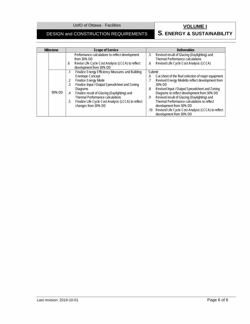
UofO of Ottawa · Facilities VOLUME I
S. ENERGY & SUSTAINABILITY DESIGN and CONSTRUCTION REQUIREMENTS
Last revision: 2019-10-01 Page 6 of 6
Milestone Scope of Service Deliverables Performance calculations to reflect development from 30% DD
.6 Revise Life Cycle Cost Analysis (LCCA) to reflect development from 30% DD
.5 Revised result of Glazing (Daylighting) and Thermal Performance calculations
.6 Revised Life Cycle Cost Analysis (LCCA)
90% DD
.1 Finalize Energy Efficiency Measures and Building Envelope Concept
.2 Finalize Energy Mode
.3 Finalize Input / Output Spreadsheet and Zoning Diagrams
.4 Finalize result of Glazing (Daylighting) and Thermal Performance calculations
.5 Finalize Life Cycle Cost Analysis (LCCA) to reflect changes from 30% DD
Submit: .6 Cut sheet of the final selection of major equipment .7 Revised Energy Modelto reflect development from
30% DD .8 Revised Input / Output Spreadsheet and Zoning
Diagrams to reflect development from 30% DD .9 Revised result of Glazing (Daylighting) and
Thermal Performance calculations to reflect development from 30% DD
.10 Revised Life Cycle Cost Analysis (LCCA) to reflect development from 30% DD
University of Ottawa · Facilities VOLUME I
T. HVAC DESIGN and CONSTRUCTION REQUIREMENTS
Last revision: 2019-10-01 Page 1 of 7
1.0 GENERAL
1.1 Overview .1 This section has been prepared to provide consultants with a general overview of HVAC
systems design requirements for new buildings and renovations in existing building. It is not the intent of this section to limit consultants’ innovation but to encourage them to exchange information and to discuss different design approaches with UofO.
.2 In many instances UofO undertakes short term planning and long term master planning to address economic and practical inefficacies associated with renovations in existing building, therefore consultants shall always review project requirements. In all cases consultation with Facilities will be required to determine the specific scope of work and requirements suitable to the project under review. All systems shall be reviewed by Facilities.
.3 Design and installation of HVAC systems must be implemented in compliance with section 9 of EPA, where applicable. To be coordinated with ORM.
2.0 DESIGN
2.1 Parameters
.1 General: .1 Outdoor design conditions:
.1 Summer: To Ontario Building Code, Supplementary Standard SB-1 for Ottawa, Ontario, 30°C (86°F) dry bulb and 23°C (73.4°F) wet bulb temperature (2.5% July design day);
.2 Winter: To Ontario Building Code, Supplementary Standard SB-1 for Ottawa, Ontario, -27°C (-16.6 °F) dry bulb temperature (1% design temperature).
.2 Indoor design conditions: System capacity shall be capable of maintaining 23.5 °C (74.3 °F) in summer and 22 °C (71.6 °F) in winter. Indoor relative humidity shall be maintained within ASHRAE recommend thermal comfort zone roughly between 20% in winter and 60% in summer time. For laboratories review the research program requirements or consult Facilities.
.3 Design of HVAC systems shall provide an acceptable level of indoor air quality and comfort while it minimized the energy use within a safe environment.
.4 In design of HVAC systems and selection of respective equipment operating life of 30 years shall be considered.
.5 Unless otherwise instructed all buildings shall be metered for all utilities including electricity, gas, water, domestic hot water, steam, steam condensate, chilled and heating hot water.
.6 When large amount of air is exhausted the feasibility of heat/energy recovery unit shall be examined. Use of heat/energy recovery unit shall be based on life cycle cost analysis. Type and selection of heat/energy recovery unit shall be reviewed with Facilities.
.7 As permitted consideration shall be given to the use of heat recovery chiller. Use of heat recovery chiller shall be based on life cycle cost analysis. Type and selection of heat recovery chiller shall be reviewed with Facilities.
.8 Generally, humidification is not preferred. Where special applications require humidification HVAC system design shall be reviewed with Facilities.
.9 HVAC systems design shall reflect the differing thermal zones and exposure of building. Followings shall be considered where HVAC systems serve multiple thermal zones:
University of Ottawa · Facilities VOLUME I
T. HVAC DESIGN and CONSTRUCTION REQUIREMENTS
Last revision: 2019-10-01 Page 2 of 7
.1 Each board/meeting room and classroom shall be treated as an individual thermal zone. They shall be provided with separate space thermostat and/or sensor.
.2 As a value engineering measure, offices with similar load profile (maximum of three), i.e. on the same exposure and/or floor may be considered as common thermal zone as they shall be served with one active space thermostat and/or sensor. Each room shall be equipped with a space sensing device to permit trouble shooting and tuning. Corner offices shall be treated as a separate thermal zone. In the case that perimeter heating is used, provide a control valve for each individual room.
.3 In residences each suite shall be thermally controlled as a separate zone. .10 Space thermostats or temperature sensing shall not be located on: exterior walls, in
direct sunlight, in the way of any obstructions and in the path of supply air. .11 There are some existing areas where active ventilation does not exist. In this cases
consider to either use of mechanical or natural ventilation. Spaces with operable windows may meet the code requirements. Areas with low occupancy load may be adequately by windows leakage.
.12 Operable windows shall not be used in spaces such as laboratories where differential pressure and air flow is critical to the design. Where existing areas have operable windows, they shall be locked closed.
.13 Where HVAC systems are designed for new buildings, include 20% extra capacity in the main air duct and piping distribution systems.
.14 Include redundancy in HVAC systems for major equipment such as boilers, chillers, and pumps.
.15 Hydronic control valves shall be selected in such they can provide control with system design pressure differentials at maximum and minimum flows.
.16 To prevent quick, sudden system pressure fluctuation automatic relief valves shall not be oversized.
.17 For modifications to existing systems verify systems parameters with Facilities prior to commencement of design.
.18 Where applicable, a screening level numerical exhaust dispersion and environmental and odor assessment of the preliminary HVAC design shall be completed as per ASHRAE / NPC, to include: .1 The applicability of the proposed exhaust system locations in the context of the
surrounding buildings and environment. .2 If necessary – recommendations to address any concerns related to air and noise
emissions & odors.
.2 Ventilation and Air Distribution Systems
.1 Ventilation rate shall be minimized. Except in Laboratories (refer to related section), minimum fresh air shall not be less than required by ASHRAE Standard 62.1.
.2 Ventilation system fans and distribution systems shall be capable of providing 100% outside air intake and relief for air economizer operation (air-side free cooling) when conditions permit.
.3 Room carbon dioxide levels shall be limited to 700 PPM above outside condition under normal circumstances in accordance with ASHARE 62.1.
.4 Design of medium and high pressure air distribution system for new buildings is not permitted. Air distribution system shall be deigned to low pressure as per AHSRAE and
University of Ottawa · Facilities VOLUME I
T. HVAC DESIGN and CONSTRUCTION REQUIREMENTS
Last revision: 2019-10-01 Page 3 of 7
SMACNA standards and guidelines. For existing buildings where Extensive Renovation (OBC) is under review consideration shall be given to conversion of the medium/high pressure air distributing system to low pressure when they exist.
.5 Supply and return ductwork shall be sized with a static pressure drop less than 20 Pa per 30 linear metres (0.08 in. per 100 linear feet) of the duct run.
.6 Diffusers and registers shall be selected with a static pressure drop on less than 20 Pa (0.08 in).
.7 Locate fresh air intakes to prevent contamination by external sources such as road traffic, smoke stacks or exhaust outlets.
.8 Where variable volume systems are used provide VFD for fan control. Selection of fan motor shall match the VFD.
.9 Fan selection shall be based on fan efficiency rather than design operating pressure.
.10 Generally, duct design shall maintain maximum NC 35 except as specified in project requirements.
.11 Intake louvers shall be sized to maximum 2.5 m/s (500 FPM) through free area.
.12 Exhaust louvers shall be sized to maximum 3.6 m/s (700 FPM) through free area.
.13 Face velocity of hydronic and refrigerant cooling coils shall be maintained between 1.8 – 1.9 m/s (350 - 375 FPM).
.14 Face velocity of pre-heating and heating coils shall be maintained between 2.3 – 2.5 m/s (450 – 500 FPM).
.15 Cascade air from dry spaces to wet spaces in Laboratory buildings and from offices to corridors in all buildings where applicable cods allow.
.16 Include heat recovery on ventilation air and recover heat from cooling systems as useful heat when loads permit. Consider exporting excess heat to central heating loops in shoulder seasons (Outdoor air temperatures from 8 - 15 °C). Consider exporting cooling to central chilled water distribution system when waste heat from heat recovery chiller can be used.
.3 Cooling Systems:
.1 Campus chilled water distribution system consist of a chiller plant with three centrifugal electric driven chillers and associated pumps and chemical treatment equipment. Use of campus chilled water is the preferred method for cooling and dehumidification throughout the campus.
.2 Available differential pressure of the campus chilled water system varies from XX psi to xx psi at remote side of the campus (Tabaret Hall). Consult Facilities for the pressure differentials across the campus.
.3 Chilled water is supplied between 4 – 10 °C (39 – 50 °F) depending on campus loads. Chilled water supply varies throughout the year.
.4 Use of campus chilled water system shall be based on 10°C (18°F) temperature difference (delta T).
.5 Use of all electrically-driven chillers and/or refrigeration units shall be reviewed with Facilities.
.6 Water-type cooling towers are preferred, to conserve energy, and shall generally be considered on systems 80 tons and larger. On units below 80 tons, an economic evaluation, including cost of maintenance should be made to determine if the condensing unit will be air cooled or water cooled. Cooling tower fan motor loads shall not exceed
University of Ottawa · Facilities VOLUME I
T. HVAC DESIGN and CONSTRUCTION REQUIREMENTS
Last revision: 2019-10-01 Page 4 of 7
0.06 H.P./ton of chiller capacity. Reduced condenser water temperatures should be utilized when possible to reduce the chiller electrical consumption.
.7 Systems with control valves either modulating or two position shall be designed for variable flow using VFD capable of reducing of reducing flow to 30% or more based on part load requirement. Consult chiller manufacturer or Facilities for minimum flow requirement.
.8 Piping system deign shall be sized between friction rate of 1.5 - 4 Ft./100 Ft. of pipe (average friction rate of 1.5 Ft./100 Ft. of pipe is proffered). Velocity shall be limited to 1.8 m/s (6 FPS) in occupied areas and 2.7 m/s (8 FPS) in unoccupied areas such as mechanical rooms. Under part load condition velocity shall not be less than 0.4 m/s (1.5 FPS).
.9 Many laboratories in the campus have requirements for chilled water for water cooling the research equipment. Type of system, i.e. open vs. close, local vs. central shall be reviewed with Facilities, and end researcher. Characteristic of the require chilled water such as but not limited to tight chilled water temperature, high or low operating pressure, special chilled water filtration, use of specific piping material, user’s controllability/adjustability, and chemical treatment shall be reviewed with Facilities, the facility manager and researcher.
.4 Heating Systems:
.1 Steam produced in the Central Heating Plant (CHP) is supplied 15 - 40 PSIG at the plant wall based on outside air temperature. For most of the buildings located at the South end of the main campus the steam is used at the building to produce hot water for heating purposes. North end campus buildings are directly supplied building heating water produced via large exchanger located in the Lamoureux basement. The hot water supply temperature varies between 35 – 80°C (95 – 176 °F). Below is the hot water supply schedule.
.2 In new buildings ceiling mounted hydronic radiant panels are not acceptable.
.3 For new buildings, design heating system for low hot water system such as 46°C (115°F) supply and 35°C (95°F) return water temperature.
.4 Systems with control valves either modulating or two position shall be designed for variable flow using VFD capable of reducing of reducing flow to 30% or more based on part load requirement. Consult boiler manufacturer or Facilities for minimum flow requirement.
.5 Piping system deign shall be sized between friction rate of 1.5 - 4 Ft./100 Ft. of pipe (average friction rate of 1.5 Ft./100 Ft. of pipe is preferred). Velocity shall be limited to 1.8 m/s (6 FPS) in occupied areas and 2.7 m/s (8 FPS) in unoccupied areas such as mechanical rooms. Under part load condition velocity shall not be less than 0.4 m/s (1.5 FPS).
.6 When heat loss is less than 200 Btu/hr. per lineal feet of wall, heat should be provided from under the window or from base of the wall or it can be provided from overhead diffusers located adjacent to or slightly away from the exterior wall. If heat loss is between 250-450 Btu/hr. per lineal feet of wall heat loss should be provided from under the window or from the base of the wall or it can be provided from overhead diffusers located adjacent to the perimeter wall discharging air directly downward covering the exterior wall and windows. If heat loss exceeds 450 Btu/hr. per lineal feet of the wall in order to prevent downdraft heat shall be provided from under the window or from the base of the wall.
University of Ottawa · Facilities VOLUME I
T. HVAC DESIGN and CONSTRUCTION REQUIREMENTS
Last revision: 2019-10-01 Page 5 of 7
.7 In lobbies and vestibules, heating systems shall be designed to suit the foot traffic into the building.
2.2 Installation and Maintenance
.1 General: .1 All major air handling equipment shall be installed in a mechanical room accessible from
the inside of the building. Roof-top air-handling units are not desirable. .2 Special attention shall be given early in the design process to provide for sufficient and
safe access space for maintenance of mechanical systems. Sufficient space implies the capability to replace major components with minor impact to the Building.
.3 Mechanical room locations shall take into account how large equipment can be moved in and out to/from the building to accommodate the initial installation and future installation due to maintenance, repair and replacement.
.4 Equipment shall be designed to be accessible and maintainable from floor level whenever possible. When not possible, permanent structures shall be designed to minimize the necessity of such tools as ladders, hoists and portable lighting (i.e.: platforms and permanent ladders for overhead work, rail systems for removal of pumps in pits, adequate permanent lighting, etc.).
.5 Provide minimum 90 cm (36”) clearance around heat exchangers. Where shell and tube heat exchangers are used provide minimum clearance for tube pull-out (generally equal to the length of the heat exchanger) for servicing and cleaning as per manufacture’s recommendation.
.6 Use of heat pump terminal units on a closed hydronic loops are not permitted.
.7 Pressure gages are required across all filter banks (filter and pre-filter separate). Filter status shall be monitored by BAS.
.8 In open ceiling spaces with high visibility (entrances, offices, and similar), exposed Mechanical ductwork to be finished from their inside faces, to form clean and smooth visible joints.
.9 Ensure to install Floor drain wherever there is a need for maintenance of coil cleaning.
.10 In hydronic systems differential pressure control valves shall not be installed in pump discharge bypasses.
.11 When differential pressure control strategy is utilized desirable differential pressure shall not be accomplished at the pump. Pressure bypass shall be provided at the end of the system or at the end of subsystem regardless of whether system utilizes bypass flow system or VFD. Where bypass flow is utilized flow should not exceed 20% of the pump design flow.
.12 Use of pipe less than ¾” shall be avoided.
.13 Air vents and drains shall be installed at high and low points in the hydronic systems respectively. Air vents and drains shall be piped to a safe location within 15 cm (6”) of the floor preferably over a funnel drain.
.14 Provide manual air vent on chemical feed tank.
.15 Thermometer shall be installed at both supply and return piping for all coils, chillers, boilers, heat exchangers.
.16 Where major return streams are mixed provide thermometer downstream and upstream of mixing points.
.17 Water make-up and blowdown water lines shall be monitored by BAS.
University of Ottawa · Facilities VOLUME I
T. HVAC DESIGN and CONSTRUCTION REQUIREMENTS
Last revision: 2019-10-01 Page 6 of 7
.18 Sound and vibration isolation systems shall be provided to minimize structural, system and airborne noise to acceptable level as outlined in this section or as per project requirements.
.19 In mechanical rooms where valves are installed above 2.1 m (7’) chain wheel operator shall be provided.
.20 Where balancing valves are installed they shall be provided with position indicator and maximum adjustable stops.
.21 All pipe services shall be identified with wrap-mark flow arrows and wording. Stencil ducting with flow arrows and wording.
.22 For all valves, valve tag shall be provided.
.23 Affix plastic point identification tags on all control items.
.24 Fasten lamacoid nameplates on all equipment, starters and panels.
.2 Ventilation and Air Distribution Systems: .1 Provide minimum clearance for air handling units’ coil pull-out (generally equal to the
width of the air handling unit) per manufacturer’s recommendation. Where it is not feasible provide minimum 60 cm (24”) on non-service side and 90 cm (36”) on service side clearance around air handling units and similar equipment.
.2 In order to make the fabrication easy and reduce the cost of duct work consider to change only one duct dimension at a time size.
.3 Duct taps shall be at least 2” smaller than main duct.
.4 Duct size shall be 2” wider than diffusers, register and grilles.
.5 90° square elbows shall be provided with double radius turning vanes.
.6 Where rectangular duct taps are used they shall be shoe fittings (45° fittings). Splitter dampers and extractors are not acceptable.
.7 Where fire dampers, smoke detectors, humidifiers, coils, in general items which require service and inspection are installed, access doors shall be provided.
.8 In dishwasher, kitchen and laundry exhaust systems where elbows are required, elbows shall be smooth radius construction. Use of vane in these applications are not permitted. It is recommended to construct the elbows with the radius equal to 1-1/2 times width of duct.
.9 Flexible ducts shall be 1.5 m (5 ft.) maximum in length.
.10 Operable intake and exhaust louvers are not permitted.
.11 Where flow measuring stations are installed they shall be accessible in a distance recommended by the manufacturer.
.12 In laboratory’s exhaust system, ductwork material shall be selected to accommodate the chemicals being exhausted. Examples of ductwork materials are vinyl coated carbon steel, 304/316 stainless steel, Teflon or coated stainless steel, fiberglass reinforced plastic (FRP), Polyvinyl Chloride (PVC). In FRP and PVC ductwork sprinklers may be required. Refer to applicable codes.
.13 Horizontal laboratory exhaust ductwork shall be slopped s minimum of 1/8” per foot with a drain provided at the low point. Drain shall be piped to the appropriate waste system.
.3 Cooling Systems:
.1 Use of satellite chillers and refrigeration units shall be reviewed by Facilities.
University of Ottawa · Facilities VOLUME I
T. HVAC DESIGN and CONSTRUCTION REQUIREMENTS
Last revision: 2019-10-01 Page 7 of 7
.2 When remote refrigeration is required use of chilled water cooling with city water back-up is the preferred option monitored and controlled by BAS.
.3 Victaulic piping system for cooling system is not permitted.
.4 Heating Systems: .1 In new buildings ceiling mounted heating radiant panels require high temperature hot
water shall not be used. .2 Victaulic piping system for heating system is not permitted.
University of Ottawa · Facilities VOLUME I
U. REFRIGERATION DESIGN and CONSTRUCTION GUIDELINES
Last revision: 2019-10-01 Page 1 of 2
1.0 GENERAL
1.1 Overview .1 This section has been prepared to provide consultants with a general overview of Refrigeration
systems requirements for new buildings and renovations in existing building. .2 In many instances UofO undertakes short term and long term master planning to address
renovations in existing building; therefore consultants shall always review project requirements. In all cases consultation with Facilities will be required to determine the specific scope of work and requirements suitable to the project under review.
2.0 DESIGN
2.1 Parameters .1 Environmentally friendly refrigerant shall be used. .2 CFC and HCFC refrigerant shall not be used. .3 Chillers with cooling capacity of 80 Tons and over shall be water cooled. .4 Use of cooling tower are preferred however utilization of evaporative cooler and dry coolers
shall be evaluated based on Life Cycle Cost Analysis, manufacturer’s recommendations and project site requirements.
.5 Cooling equipment shall be ARI rated.
.6 Cooling towers shall be CTI certified.
.7 Minimum performance of the water cooled and direct expansion systems and equipment shall meet or exceed performances outlined in ASHARE 90.1 – 2010.
.8 For small process chillers municipal water may be used for back-up when pressure differential of chilled water loop across the process chiller is below the required set point.
.9 Acceptable type of compressors is as follow: 1. Up to 80 Tons: Screw and Scroll. 2. 80 to 200 Tons: Screw and Centrifugal. 3. 200 Tons and above: Centrifugal. 4. All sizes: Oil free centrifugal with magnetic bearing.
.10 Ventilation and Refrigeration monitoring requirement shall meet requirements of CAN/CSA-B52.
.11 IT room and specialty loads shall be rated for full capacity of the cooling load. Design and selection of systems and equipment shall include 30% extra capacity as a minimum
.12 Water and air cooled Direct Expansion (DX) systems shall not be permitted.
.13 Where use of water cooled Direct Expansion (DX) is required for kitchen and laboratory equipment, heat must be rejected to campus chilled water loop. Due to fluctuation of campus chilled water loop as the result of high demand in the campus there is a possibility of tripping the compressor(s) in DX systems on high head pressure therefore, design shall include a measure to overcome this scenario.
.14 Kitchen refrigeration equipment shall not be provided with redundancy. Design of kitchen refrigeration system shall not send temperature alarm to BAS.
2.2 Installation and Maintenance
.1 Ladders, railings and roof anchors for fall arrest systems shall meet requirements outlined by Ministry of Labour.
University of Ottawa · Facilities VOLUME I
U. REFRIGERATION DESIGN and CONSTRUCTION GUIDELINES
Last revision: 2019-10-01 Page 2 of 2
.2 Cooling Towers and Evaporative Coolers shall not be equipped with water heater for water sump.
.3 Cooling Towers and Evaporative Coolers shall not be equipped for winter operation.
.4 IT room and specialty loads shall be satisfied by chilled water. Chilled water cooling of DX systems is not permitted.
.5 Removal, discharge, handling and disposal process of refrigerants that contain Ozone substances and other hydro carbon such as CFC’s, HCFC’s, HFC’s shall be coordinated with ORM.
University of Ottawa · Facilities VOLUME I
V. CONTROLS & INSTRUMENTATIONS
DESIGN and CONSTRUCTION REQUIREMENTS
Last revision: 2020-03-01 Page 1 of 12
1.0 GENERAL
1.1 Overview
.1 This section has been prepared to provide consultants with a general overview of Controls systems design requirements for new buildings and renovations in existing building.
.2 UofO undertakes short term planning and long term planning to address requirements of controls systems in existing building, therefore consultants shall always review project requirements and consult with Facilities to determine the specific scope of work and requirements suitable to the project under review. All systems shall be reviewed by Facilities.
.3 Facilities maintains a control center at 141 Louis Pasteur for the monitoring and control of most campus buildings mechanical systems. The level of control within systems varies with age and type of installed systems and equipment.
.4 The campus control network allows the University to manage buildings environmental conditions and energy consumption through web access.
.5 It is the goal of UofO to employ sever based Direct Digital Controls (DDC) systems for all systems and equipment through the campus network.
.6 UofO has a variety of automatic control devices. Over the years through renovations and upgrades hybrid combinations of pneumatic and DDC systems have come into existence. Renovation projects shall convert existing pneumatic systems over to DDC and new construction shall implement DDC.
.7 In certain applications where high pressure is required for durability and compressed air is readily available, the application shall be reviewed with Facilities’ Instrumentation group.
.8 New HVAC systems and equipment have electronic application and zone controllers. The zone controllers in occupied spaces are typically electronically actuated DDC with adjustable zone sensors for the occupants.
.9 DDC product from Delta is the standard for all future projects. No proprietary controllers shall be permitted on HVAC systems or equipment. In cases of specialized systems or equipment where proprietary controllers are required, full access, licensing, and training shall be provided to Facilities. For these cases, the options shall be reviewed with Facilities.
.10 The current Building Automation Systems (BAS) consists of DDC panels that communicate back to the central control systems utilizing campus Ethernet / Bacnet. All new DDC panels shall be connected to University’s network infrastructure.
1.2 DESIGN
2.1 Parameters
.1 Control systems design shall be based of Delta Controls.
.2 Hardware and software design of control system shall include point database, graphical system and network interface to main control system front end located at Facilities.
.3 As a minimum hardware and software design shall include 20% spare capacity for future expansion.
.4 Control systems use different control modes to accomplish their purposes. Each control mode is applicable to a process with certain characteristic. Following table lists control modes and applications which shall be used in the campus.
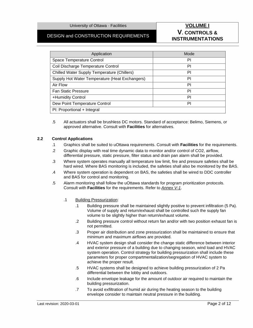
University of Ottawa · Facilities VOLUME I
V. CONTROLS & INSTRUMENTATIONS
DESIGN and CONSTRUCTION REQUIREMENTS
Last revision: 2020-03-01 Page 2 of 12
Application Mode Space Temperature Control PI Coil Discharge Temperature Control PI Chilled Water Supply Temperature (Chillers) PI Supply Hot Water Temperature (Heat Exchangers) PI Air Flow PI Fan Static Pressure PI +Humidity Control PI Dew Point Temperature Control PI PI: Proportional + Integral
.5 All actuators shall be brushless DC motors. Standard of acceptance: Belimo, Siemens, or
approved alternative. Consult with Facilities for alternatives.
2.2 Control Applications
.1 Graphics shall be suited to uOttawa requirements. Consult with Facilities for the requirements.
.2 Graphic display with real time dynamic data to monitor and/or control of CO2, airflow, differential pressure, static pressure, filter status and drain pan alarm shall be provided.
.3 Where system operates manually all temperature low limit, fire and pressure safeties shall be hard wired. Where BAS monitoring is included, the safeties shall also be monitored by the BAS.
.4 Where system operation is dependent on BAS, the safeties shall be wired to DDC controller and BAS for control and monitoring.
.5 Alarm monitoring shall follow the uOttawa standards for program prioritization protocols. Consult with Facilities for the requirements. Refer to Annex V-1.
.1 Building Pressurization:
.1 Building pressure shall be maintained slightly positive to prevent infiltration (5 Pa). Volume of supply and return/exhaust shall be controlled such the supply fan volume to be slightly higher than return/exhaust volume.
.2 Building pressure control without return fan and/or with two position exhaust fan is not permitted.
.3 Proper air distribution and zone pressurization shall be maintained to ensure that minimum and maximum airflows are provided.
.4 HVAC system design shall consider the change static difference between interior and exterior pressure of a building due to changing season, wind load and HVAC system operation. Control strategy for building pressurization shall include these parameters for proper compartmentalization/segregation of HVAC system to achieve the proper result.
.5 HVAC systems shall be designed to achieve building pressurization of 2 Pa differential between the lobby and outdoors.
.6 Include envelope leakage for the amount of outdoor air required to maintain the building pressurization.
.7 To avoid exfiltration of humid air during the heating season to the building envelope consider to maintain neutral pressure in the building.
University of Ottawa · Facilities VOLUME I
V. CONTROLS & INSTRUMENTATIONS
DESIGN and CONSTRUCTION REQUIREMENTS
Last revision: 2020-03-01 Page 3 of 12
.2 Air Handling Units: .1 For precise control of fresh air, outdoor air volume shall be controlled utilizing
enthalpy of outdoor air. The quantity of fresh air will be overridden to satisfy CO2 conditions.
.2 Control of outdoor air described above shall be combined with maintaining a constant negative static pressure in the mixing air via referencing the pressure across the outdoor air damper to maintain the variable minimum position until the airside free cooling (economizer mode) is triggered.
.3 The supply fan static pressure set-point shall be reset by the air terminal units’ requirements.
.4 Filter pressure-drop sensing is required in the unit for maintenance purposes.
.5 Fan flow measurements by fan-inlet Pitot tube is preferred. Other means shall be consulted by the Facilities for approval.
.6 Drain pans shall be positively sloped to drain.
.7 Control valves for coils shall be two-way modulating. When Dual Purpose coils are used, twined valves (six–way valves) sharing an actuator assembly shall be used to eliminate the risk of cross-over. Consult with Facilities for more details.
.3 Hot and Chilled Water Systems:
.1 Chillers’ control strategy shall include supply water temperature reset based on return water or outdoor air temperature. For systems with cooling capacity of 50 Tons control strategy of condenser water reset shall also be included.
.2 Cooling Towers and Evaporative Coolers controls strategy shall include capacity control and provision for free cooling.
.4 Air Terminal Units:
.1 In variable air volume systems all air terminal units shall be pressure independent. Pressure independent air terminal units deliver the required airflow to the space regardless of the supply static pressure.
.2 Single Duct Variable Air Volume Air Terminal Units: .1 Pressure independent air terminal units shall be programmed to change the
airflow delivered to the space based on the operating mode. .2 Where single duct variable air volume air terminal unit is used the amount of
air delivered to the space shall be controlled by the space temperature via PI loop. Flow sensor at the air terminal unit modulates the damper actuator of the air terminal unit. A space temperature sensor / thermostat resets the airflow setpoint as the space load changes. The airflow control loop shall be set to maintain the minimum airflow at part load conditions. Maximum airflow shall be set to limit flow to meet design conditions.
.3 Where single duct variable air volume air terminal unit is equipped with heating coil The amount of air delivered to the space shall be controlled by the space temperature via PID loop. The amount of air delivered to the space varies from maximum to minimum as the cooling load drops to maintain setpoint. If the cooling load drops more the space temperature drops through dead band until is controlled to maintain the heating setpoint. Heating capacity is controlled either by modulating the two-way control valve or by

University of Ottawa · Facilities VOLUME I
V. CONTROLS & INSTRUMENTATIONS
DESIGN and CONSTRUCTION REQUIREMENTS
Last revision: 2020-03-01 Page 4 of 12
staging the SCR heating coil where hydronic heating coil or electric heating coil are used respectively.
.3 Dual Duct Air Terminal Units: .1 Pressure independent air terminal units shall be programmed to change the
airflow delivered to the space based on the operating mode. .2 Hot duct damper modulates up to a total flow not to exceed the maximum
airflow setpoint to maintain the room temperature. Constant total airflow is maintained by modulating the cold duct damper. With this configuration there is no dead band and comfort is maintained by mixing hot and cold air at a constant total airflow.
.3 Consideration shall be made to temperature load reset in duct systems to minimize energy use.
.4 Sequences of operation of dual duct air terminal unit shall be consulted with the Facilities.
.5 Each office shall be equipped with a temperature sensing device.
.5 Radiant Panels: .1 Control of radiant panel are difficult and may not be appropriate for space heating.
Because the radiant panels do not heat the air space temperature sensor / thermostat must see the radiant hear or sense the space temperature change caused by the radiation warming the furniture and occupants there will a time lag in heating the space and no accurate control. Therefore, radiant panels are not desirable.
.2 Where use of radiant panels is not avoidable, the space temperature sensor / thermostat shall reset the control valve(s) based on outdoor temperature. As hot water circulates the radiant panel and space temperature rises controller to reposition the control valve to response the changes.
.3 Where in slab radiant heating is used surface temperature of floor shall not exceed 30°C (86 °F). Ceiling panel’s surface temperature shall not exceed 46°C (115 °F). Where hot water temperature exceeds these settings a high limit sensor shall reset the circulating water temperature.
.6 Unit Heaters:
.1 Unit heaters shall be used only for loading docks and mechanical rooms.
.2 Only hot water unit heaters are accepted. Use of electric or gas unit heaters shall be reviewed with Facilities.
.3 Control of hydronic unit heaters shall be modulating. Modulating control modulate the heating hot water in proportion to changes in space temperature. Fan operates continuously to prevent air stagnation. As the space temperature falls the space temperature sensor / thermostat sends a signal to reposition the control valve. When the control valve is closed and coil cools down the low-limit controls turns off the fan.
.4 Low-limit control for night or summer shut down when the heating system is off via sensing the water temperature shall be provided. This control strategy also shall prevent fan from blowing cold air when the heating system fails.
.5 Where down blow unit heaters are used two space temperature sensors / thermostats shall be utilized. One shall be installed in occupied area and the other

University of Ottawa · Facilities VOLUME I
V. CONTROLS & INSTRUMENTATIONS
DESIGN and CONSTRUCTION REQUIREMENTS
Last revision: 2020-03-01 Page 5 of 12
close to the ceiling. The space temperature sensor / thermostat controls the control valve and cycles the fan. As the ceiling temperature rises above ceiling temperature setpoint it overrides the control and starts the fan. Fan runs until the ceiling setpoint is met.
.7 Unit Ventilators:
.1 In new construction projects, unit ventilators shall not be used.
.8 Fan Coil Units (FCU): .1 Use of two pipe heating/cooling FCUs are not permitted. .2 Use of two pipe heating (for heating only), two pipe cooling (for cooling only) and
four pipe heating/cooling FCUs are acceptable. .3 All FUCs shall be equipped with ECM. .4 Control valves for FCUs shall be two-way modulating. When Dual Purpose coils
are used, twined valves sharing an actuator assembly shall be used to eliminate the risk of cross-over. Consult with Facilities for more details.
.5 The room temperature sensor / thermostat regulates the control valve(s) while the fan moves air across the coil(s). Fan run continuously, cycled on/off as scheduled by the room temperature sensor / thermostat. Use of multi speed fans are not preferred. FCUs fans shall be equipped with ECM. ECM motors shall be controlled by duct static pressure and supply air temperature.
.9 Fume Hoods (FH):
.1 Control of FHs shall be based on face velocity. Sash position control is not permitted.
.2 For all FHs, Triatek and TSI controllers are acceptable. These controllers are standalone and they monitor and control the FH operation. Each controller shall control up to maximum two FHs.
.3 BAS shall not control the FHs. Exhaust flow shall be monitored through BAS. All Fume hood shall be equipped with local alarm.
.4 Consideration should be made to use of Optinet to reduce the air change of the labs where contaminations is below the set point.
.5 Where constant volume system is used, average face velocities at FH sashes shall not be less than 80 FPM at all sash positions.
.6 Where variable volume system is used, consult manufacturer for minimum FH face velocity.
.7 Variable volume FH minimum air flow rate shall be not less than 50 CFM per linear foot of FH.
.8 BAS shall control room differential pressure and make-up air.
.9 Laboratory pressurization shall achieve 2 to 5 Pa differential between the laboratory and the corridors.
.10 All fume hoods shall be ULC listed and shall be certified to North American standards.
University of Ottawa · Facilities VOLUME I
V. CONTROLS & INSTRUMENTATIONS
DESIGN and CONSTRUCTION REQUIREMENTS
Last revision: 2020-03-01 Page 6 of 12
.10 Control Valves:
.1 Control valves shall not be oversized.
.2 Control valves shall be positioned properly upon HVAC system shutdown and/or upon loss of power. Below outlines desirable actuator positioning on system shutdown and/or loss of power.
Valves System Shutdown Loss of Power
AHU Chilled Water Closes Stays Same AHU Steam Heating Closes Closes AHU Hot Water Closes Stays Same Steam Humidifier Closes Closes Terminal Reheat Closes Stays Same OA Preheat Below 2°C (36°F) Opens Opens OA Preheat Above 2°C (36°F) Closes Opens
.3 Where hot water pump is provided for freeze protection, hot water valve should be
positioned 25% open when low temperature loop senses freezing condition. .4 For chilled water coils it is preferable to close the valve shutdown to prevent
excessive condensation around duct and coil and to save pumping energy. This may be accomplished with normally closed valves.
.5 Heat exchanger control valve shall be normally closed and outdoor air preheat valves shall be normally open.
.6 For tight shut-off consider using single seated valves and for pressure by-pass lines double seated valves.
.7 When the control valve is fully open, pressure drop across the valve shall be adequate to allow the valve to have precise controllability.
.8 When the control valve is closed, pressure drop across the valve shall not exceed valve and actuator close-0ff rating.
.9 For Extensive Renovations (OBC)/addition and new construction projects use of Two-way modulating valves with pressure independent characteristic (PICCV) shall be reviewed with Facilities University of Ottawa. Type of Two-way valves in small projects shall match the existing.
.10 Combined performance of two-way control valve and coil shall be linear.
.11 Use of three-way valves are not desirable. Where use of three-way valves is not avoidable consider the use of mixing type as oppose to diverting type.
.12 Frost pumps complete with two-way valves and check valves shall be used to prevent coils from freezing. Frost pumps shall be monitored by the BAS for status and start-stop.
.11 Dampers:
.1 Where size of damper is over 1.5 m2 (16.1 Ft2), use of single damper is not permitted and it shall be divided in multiple sections. In this case multiple sections shall be all linked together in vertical and horizontal stacks. All sections shall be
University of Ottawa · Facilities VOLUME I
V. CONTROLS & INSTRUMENTATIONS
DESIGN and CONSTRUCTION REQUIREMENTS
Last revision: 2020-03-01 Page 7 of 12
linked together with multiple actuators with the same operating range, torque and stroke.
.2 Safety Factor of 2 on damper actuator torque spec shall be applied.
.3 Outdoor air dampers shall include .1 Thermally insulated damper with severe cold silicone option .2 Upgraded damper linkages suitable for saltwater vapour exposure .3 No double stacking of damper actuators shall be accepted. Actuators must
be easily serviceable and outside of the ductwork. .4 Damper bearings shall have no metal-to-metal or metal-to-plastic contact.
No “oillite” type bearings are acceptable. .4 Below outlines desirable actuator positioning on system shutdown and/or loss of
power. Self-closing feature shall be spring return or capacitor return.
Dampers System Shutdown Loss of Power Outdoor Air (OA) Closes Closes Relief Air Closes Closes Return Air (RA) Opens Opens VAV Box Based on Space
Req’s Based on Space
Req’s Multi Zone Hot Deck (Cold Spaces) Opens Opens Multi Zone Cold Deck (Hot Spaces) Closes Closes
.5 When fan is delayed upon start-up to confirm OA damper position, RA damper
should not be spring return to ensure the fan does not work with both OA and RA dampers closed.
2.3 Metering
.1 UofO has strategized metering in addition to service metering of utility providers (City, hydro and gas). The intention is to achieve the following goals: .1 Provide energy/emissions reports for the local, provincial, and national jurisdictions
required by law. .2 Measuring Building Energy Performance Index (BEPI). .3 Benchmark energy-related baselines and determine potential case studies for energy
retrofits and audits. .4 Discontinue manual readings and engage Operations Staff to monitor energy use in real-
time. .5 Support revenue grade billing. .6 Energy tracking for ESCo performance bonus and government/utility provider incentives .7 Provide data to MECP for Cap & Trade Program.
.2 The metering strategy is divided into two groups:
University of Ottawa · Facilities VOLUME I
V. CONTROLS & INSTRUMENTATIONS
DESIGN and CONSTRUCTION REQUIREMENTS
Last revision: 2020-03-01 Page 8 of 12
.1 Building Metering: University metering shall be installed at main building services, downstream to utility service metering. This applies to new construction, additions and Extensive Renovations (OBC).
.2 Sub-Metering: Applies to service branches serving revenue based University services and/or 3rd party tenants including but not limited to Food Services, Residences, Housing Services, Sports Services, and Student Federation Offices.
.3 Electrical meters shall be equal to Triacta Power Hawk Series and must have the following met criterion: .1 Revenue-Grade meters. .2 Measurement Canada certified. .3 Shall be ULC approved. .4 Shall have a pulse output capable of communicating with an Ethernet connection c/w
device MAC address. .5 Associated current transformers (CTs) shall be solid core. Split core CTs are not
acceptable as a permanent metering solution. .6 Real-time capability with maximum 5-minute delay on data transmission. .7 Phase Transformers (PTs), CTs, electrical meter, and associated metering devices shall
be mounted on a fire-rated plywood panel. .8 Meter tag and proper identification (lamacoid or P-Touch is acceptable for labelling).
.4 Mechanical meters (Magnetic Flow, Vortex, and Turbine) equal to Endress + Hauser and shall
have the following criterion: .1 4-20mA signal output. .2 Industrial-Grade meters for power plant and preferred for all campus (commercial-grade
is acceptable for all other facilities). .3 Flanged connections complete with full-port isolation ball valves. .4 Digital head display, or digital remote head for inaccessible areas. .5 Intelligent meter with diagnostic mode. .6 Meter body and flanges to be thermally insulated. .7 Meter Tag and proper identification (lamacoid or P-Touch is acceptable for labelling).
.5 Energy shall meet the following criterion:
.1 Installed in a NEMA 4 enclosure.
.2 Data loggers shall be installed in a NEMA 4 enclosure c/w Duplex receptacle.
.6 Varity of Building Meters are as follow: .1 Electricity: Consumption (kWh), Power (kW), demand (KVa), reactive power (kVar),
voltage (V), amps (A), frequency and power factor. To be installed on the 600V or 208V side.
.2 Heating water: Demand (GJ/h), consumption (GJ), peak demand (date/time). To be a full port magnetic flowmeter to be installed on supply c/w with thermal well and RTD’s thermometer (on both system supply and return lines), + Energy calculator; Ultrasonic meters are an acceptable alternative where system shut-down is impossible or where
University of Ottawa · Facilities VOLUME I
V. CONTROLS & INSTRUMENTATIONS
DESIGN and CONSTRUCTION REQUIREMENTS
Last revision: 2020-03-01 Page 9 of 12
magflow meter installation is not feasible without significant piping modifications. Remote head display is required for meters installed in elevated or hard-to-reach areas. Meters shall have a 4-20mA pulse out-put and report to a data logger capable of communicating with an Ethernet connection c/w MAC address.
.3 Chilled water: Demand (GJ/h), consumption (GJ), peak demand (date/time). To be a full port magnetic flowmeter to be installed on return c/w with thermal well and RTD’s thermometer (On both system supply and return lines), + Energy calculator; Ultrasonic meters are an acceptable alternative where system shut-down is impossible or where magflow meter installation is not feasible without significant piping modifications. Remote head display is required for meters installed in elevated or hard-to-reach areas. Meters shall have a 4-20mA pulse out-put and report to a data logger capable of communicating with an Ethernet connection c/w MAC address.
.4 Cold domestic water (if permitted by the city): demand (GMP, m3/h). To be a magnetic flowmeter to be installed on supply; Ultrasonic meters are an acceptable alternative where system shut-down is impossible or where magflow meter installation is not feasible without significant piping modifications. Remote head display is required for meters installed in elevated or hard-to-reach areas. Meters shall have a 4-20mA pulse out-put and report to a data logger capable of communicating with an Ethernet connection c/w MAC address.
.5 Domestic Hot water: Demand (GJ/h), consumption (GJ), peak demand (date/time. To be a magnetic flowmeter to be installed on supply c/w with themal well and RTD’s thermometer (On both supply and return lines if applicable), + Energy calculator; Ultrasonic meters are an acceptable alternative where system shut-down is impossible or where magflow meter installation is not feasible without significant piping modifications. Remote head display is required for meters installed in elevated or hard-to-reach areas. Meters shall have a 4-20mA pulse out-put and report to a data logger capable of communicating with an Ethernet connection c/w MAC address.
.6 Natural Gas: Consumption (m3), demand (m3/h); Tie in to existing Enbridge meter complete with Zener Barrier and data logger capable of communicating with Ethernet connection and c/w MAC address.
.7 Steam: Consumption (lb), energy (GJ). To be a vortex flowmeter to be installed on supply c/w pressure sensor rated for associated line pressure, and a jet turbine meter to be installed on condensate, c/w with RTD’s thermometer, + Energy calculator. Remote head display is required for meters installed in elevated or hard-to-reach areas. Meters shall have a 4-20mA pulse out-put and report to a data logger capable of communicating with an Ethernet connection c/w MAC address.
.8 Building usage to be monitored and tracked through TRIACTA and all metering devices shall be compatible with this system.
.7 For design and installation purposes of proposed sub-metering, following shall be considered: .1 Electrical panel, piping and conduit layout, shall be organized in a matter that the sub-
metering strategies can be implemented. This include but not limited to: .1 Provide adequate space for the meters to be installed and service. The inside of
electrical panel shall be organized in a matter that enough space is allocated for CT’s to be installed on power supply and on branch circuits. Wall-mount electrical metering devices shall be installed on fire rated plywood.
.2 Provide data outlet per metering devices or data logging device
University of Ottawa · Facilities VOLUME I
V. CONTROLS & INSTRUMENTATIONS
DESIGN and CONSTRUCTION REQUIREMENTS
Last revision: 2020-03-01 Page 10 of 12
.3 Group similar load per panel such as lighting panel, plug load panel, HVAC equipment panel and shall be reviewed by the campus utilities department for approval.
.4 Revenue base services and tenant’s utility services to be a single point of entry before being distributed throughout their space
2.4 Testing, Commissioning and Training
.1 Following procedures shall be incorporated and conducted in commissioning process of all projects .1 Selective verification of installation and functionality of supervisory equipment, pathway,
wiring and individual component (by Controls Contractors). .2 Verification of signal and device response by conducting comprehensive control point
functionality (by Controls Contractors). .3 Validation of the sequences of operation of control systems after review and acceptance
of TAB report (by CxA). .4 Review and validation of the functionality of control systems in different modes such as
but limited to heating, cooling, fire, smoke, occupancy/un-occupancy, start-up, warm-up and cool-down .
.2 Test all FHs at a maximum room supply air volume at 13°C (55°C) and minimum exhaust air volume at 13°C (55°C) and maximum exhaust air volume.
.3 Commissioning of FHs shall be done by a third party CxA. FHs shall be certified by an independent qualified/certified third party. Commissioning and certification as per CSA Z316.2 and ASHRAE 110 under the certification procedure. The commissioning and certification process shall be reviewed by the University of Ottawa.
.4 For variable air volume FHs sash movement effect test must be conducted. Once face velocity and smoke test has been passed, the five-minute average test result for the tracer gas testing shall be less than or equal to 0.1 PPM for all operating conditions tested.
2.5 Installation and Maintenance
.1 Pressure gauges shall be stainless steel and shall be suitable for vibration and working temperature and pressure. The dial reading shall be in the two-thirds range.
.2 For differential pressure control strategy of heating hot water and chilled water loops consult Facilities’ Instrumentation group.
University of Ottawa · Facilities VOLUME I
V. CONTROLS & INSTRUMENTATIONS
DESIGN and CONSTRUCTION REQUIREMENTS
Last revision: 2020-03-01 Page 11 of 12
ANNEX V-1
Séquence des opérations des alarmes sur le campus • Séquence campus alarme OK
Si la température d’eau refroidie intégré est plus grande ou égale à 12 °C et que la pression différentiel a Tabaret est – 5 Psi du point de consigne (10 Psi). (Campus Cooling flag en alarme)
Si la pression de steam intégré est plus petite 120 Psi. (Campus heating flag en alarme) Si la génératrice est en marche… (Campus Power flag en alarme) Si la pression d’air compriméest plus petite que 70 PSI.(Campus Comp air flag en alarme) Si Campus Cooling en alarme, Campus heating en alarme, Campus Power ou Campus comp Air
flag est en alarme… (Campus flag en alarme) • Séquence building alarme OK
Vérifier si la pression de vapeur intégré est <8 Psi au secondaire de la PRV ou si la température est < 20 °C de la courbe à Lamoureux. (Building heating flag en alarme)
Vérifier si le différentiel de pression intégré de l’eau refroidi est < 5 Psi de son point de consigne et que la température eau a l’entré du bâtiment est + 5 °C de la central… (Building Cooling flag en alarme)
Si la génératrice fonctionne dans le bâtiment… (Building Power flag en alarme) • Séquence alarme pour boucle de chauffage (échangeur) OK
Vérifier s’il n’y pas d’alarme a la central (Campus flag) et s’il a de l’électricité dans le bâtiment (Building Power flag)
Vérifier s’il y a une source d’eau chaude dans le bâtiment (Building Heating flag) Vérifier si la pompe n’est pas en alarme … (Pompe alarme) Vérifier si la pompe fonctionne bien … (status de la pompe) Vérifier que la température de l’eau intégré ne dépasse pas + ou - 20 °C du point de consigne…
(Température alarme) • Séquence alarme pour eau refroidit (échangeur) OK
Vérifier s’il n’y pas d’alarme a la central (Campus flag) et s’il a de l’électricité dans le bâtiment (Building Power flag)
Vérifier s’il y a une source d’eau froide dans le bâtiment (Building Cooling flag) Vérifier que la température de l’eau froide intégré ne dépasse pas + ou - 5 °C du point de
consigne… (Température alarme) • Séquence alarme pour ventilation
Vérifier s’il n’y pas d’alarme a la central (Campus flag) et s’il a de l’électricité dans le bâtiment (Building Power flag)
Vérifier si la fan n’est pas en alarme (comparaison du statu avec la comment de la fan) Vérifier si la ventilation fonctionne déjà depuis un Demi-heure. (status de la fan ON)
University of Ottawa · Facilities VOLUME I
V. CONTROLS & INSTRUMENTATIONS
DESIGN and CONSTRUCTION REQUIREMENTS
Last revision: 2020-03-01 Page 12 of 12
Vérifier s’il y a une source d’eau refroidie et d’eau chaude disponible pour cette ventilation… (Building Cooling flag, Building Heating flag ou échangeur approprier)
Vérifier la température d’alimentation intégré pour quel ne dépasse pas + ou - 5 °C du point de consigne… (Température d’alimentation en alarme)
Vérifier pression statique intégré pour quel ne dépasse pas + ou – 50% du point de consigne… (Pression statique en alarme)
• Séquence alarme pièce
Vérifier s’il n’y a pas d’alarme approprier a la ventilation (Vent flag)
University of Ottawa · Facilities VOLUME I
W. PLUMBING DESIGN and CONSTRUCTION REQUIREMENTS
Last revision: 2019-10-01 Page 1 of 4
1.0 GENERAL
1.1 Overview
.1 This following has been prepared to provide Design Team with a general overview of plumbing system requirements in existing and new building installations. For all projects consultation with Facilities will be required to determine the specific scope of requirements suitable to the project under review. All designs shall be reviewed by Facilities.
.2 Design and installation of storm sewer systems must be implemented in compliance with section 53 of OWRA, where applicable. To be coordinated with ORM.
2.0 DESIGN
2.1 Parameters
.1 Domestic Hot and Cold Water Systems: .1 Design of water entry at building entrance shall comply with City of Ottawa by-laws. .2 Domestic hot water is generated centrally on campus from waste heat. Wherever is
feasible use this system for generation of domestic hot water. .3 For energy and water usage design of domestic hot and cold water systems shall meet
or exceed the requirements outlined in OBC and section 7 of ASHRAE 90.1-2010. .4 Back flow prevention devices shall be included in accordance with OBC and City of
Ottawa by-laws. .5 For new construction design of domestic hot and cold water shall include allowance for
future expansions. Branches shall be sized to accommodate 20% additional flow in addition to design flow for future renovation projects.
.6 Design of domestic hot and cold water systems shall be in accordance with the minimum pressure available at the municipal main.
.7 Water pressure at any outlets shall be maintained at 150 KPa residual and between 300 and 500 KPa static as a minimum at any conditions.
.8 Maximum water velocity shall be maintained at 1.2 m/s (4 fps)
.9 Hot and cold water thermal insulation shall meet design temperature and to prevent condensation.
.10 For the purpose of maintenance hose bibs and compressed air outlet shall be included in design for all mechanical rooms.
.11 Where for domestic cold water system booster pump is required down-feed system is proffered. Booster pump shall be equipped with VSD and control panel capable of displaying inlet and outlet pressure, flow, totalized flow, pump status and to communicate with BAS.
.12 Following equipment shall be connected to the emergency power: .1 Sewage ejectors. .2 Storm sump pumps. .3 Elevator sump pumps. .4 Domestic booster pumps.
For redundancy all of above systems shall be duplex. Duplex configuration shall be packaged pre-wired pump alternator controller with liquid level controls, control panel (to cut in second pump when liquid level rises or first pump fails), level control for high alarm and contacts to BAS for remote alarm on pump failure and high level. Local control panel shall be completed with audio and visual alarm.
University of Ottawa · Facilities VOLUME I
W. PLUMBING DESIGN and CONSTRUCTION REQUIREMENTS
Last revision: 2019-10-01 Page 2 of 4
.13 Where required tenant and food services domestic hot water and base-building shall be sub-metered. Sub-metering system shall be capable of providing access to BAS and logged for monitoring and billing purposes.
.14 Local domestic heaters are discouraged. Any justifications for local domestic heaters shall be reviewed by Facilities.
.15 Design of domestic hot water services shall include recirculation system to provide 49°C (120°F) in 10 seconds or less at any domestic hot water outlet. In applications such as food services where domestic hot water in excess of 9°C (120°F) is required, local booster heater shall be provided.
.2 Sanitary Sewage and Storm Drainage Systems:
.1 For sewage ejectors and sump pumps, dry contacts to communicate with BAS on level controls shall be included.
.2 Variations of plumbing fixtures and associated accessories shall be reviewed with Facilities.
.3 All public washrooms shall be completed with floor drains.
.4 Except in Laboratories, Hazardous spaces, Workshops, provide floor drains in Mechanical rooms, Garbage rooms, Loading ducks and Washrooms.
.5 Design shall include trap primer to floor drains as per requirements outlined in OBC.
.6 Where floor drains and/or Slop Sink (22 42 01) serve the floor cleaning machine, sediment interceptors shall be provided.
.7 Grease traps shall be provided in all commercial food services, and shall be accessible for maintenance.
2.2 Installation and Maintenance
.1 General: .1 Piping shall be installed straight and parallel with building structure/guidelines. .2 Di-electric couplings for joining pipes of dissimilar metals shall be used. .3 Where noise in an application is a concern drainage and water systems shall be
avoided if feasible. Where passage of these systems is not avoidable design shall include acoustic treatment.
.4 At the completion of all piping work, all piping shall be tested in accordance with the following schedule and Ontario Building Code whichever is stringent:
Service Duration Testing Pressure Domestic Hot and Cold Water Four (4) hours 690 Kpa (100 Psig) Sanitary Sewage One (1) hour 30 Kpa (10 ft. wc)
.5 Pressure testing shall be witness and approved by either Third Party CxA or Design
Team as per requirements outlined in commissioning section of UofO Design and Construction Requirements.
.6 Testing procedure shall be in accordance with Pre-Functional and Functional testing as outlined in project commissioning specification.
.2 Domestic Hot and Cold Water Systems:
University of Ottawa · Facilities VOLUME I
W. PLUMBING DESIGN and CONSTRUCTION REQUIREMENTS
Last revision: 2019-10-01 Page 3 of 4
.1 Use of press fittings are not permitted. In limited application such as process water in laboratories use of press fittings might be acceptable. Utilization of press fittings shall be reviewed with Facilities.
.2 Use of PEX tubing are not permitted in the campus.
.3 All new water piping shall be flushed to remove foreign material.
.4 All exterior hose bibs shall be keyed, frost proof and equipped with vacuum breaker.
.5 Water piping systems including potable water, hydronic, sanitary and storm drainage shall no be permitted within the IT rooms/closets and electrical rooms including within the partitions.
.6 Backflow preventer devices with body materials dissimilar to the connected piping shall be installed with a dielectric kit as per manufacturer’s recommendation.
.7 For domestic cold water continuous vapor barrier shall be applied to prevent condensation.
.8 For new construction projects all main branches shall be terminated with valve and capped connections.
.9 Isolation valves shall be ball valve and be located: .1 At supply piping to fixtures or group of fixtures and equipment. .2 At branch take-offs and vertical risers. .3 In accessible locations to facilitate maintenance.
.10 Connections to equipment and main branches shall be made with unions or flanges. Where flanges are used gaskets shall be provided.
.11 Piping shall be in parallel to walls.
.12 Efforts shall be made to group piping at common elevations.
.13 Where feasible avoid joints in piping below grade.
.14 Drain valves shall be located: .1 Near the main shut-off valves. .2 At base of vertical raisers. .3 At the equipment and; .4 At low points of piping systems.
.15 Victaulic piping system for plumbing is not permitted.
.16 Design shall consider power pipe type heat recovery to preheat domestic hot water make-up in residences.
.17 Pipes and fittings must conform to North American standards.
.18 All Water Fountains (22 42 01) shall be: .1 Refrigerated. .2 Have accessible bottle filler.
.3 Sanitary Sewage and Storm Drainage Systems:
.1 Clean-outs shall be extended to finished floor or wall surface.
.2 Provide enough clearance at clean-outs for rodding of drainage systems.
.3 Clean-outs in wet areas shall be completed with membrane clamp.
.4 Where electric trap seal primer is used, controls and flow activated bronze body shall be located in an accessible location within a service area. Where flow activated bronze body is located in a public area, it shall be concealed with access door.
University of Ottawa · Facilities VOLUME I
W. PLUMBING DESIGN and CONSTRUCTION REQUIREMENTS
Last revision: 2019-10-01 Page 4 of 4
.5 All drain pans of fancoil units shall be piped to drain. Pipe sizes shall be 19 mm as a minimum.
University of Ottawa · Facilities VOLUME I
X. FIRE PROTECTION DESIGN and CONSTRUCTION REQUIREMENTS
Last revision: 2019-10-01 Page 1 of 1
1.0 GENERAL
1.1 Overview
.1 This following has been prepared to provide Design Team with a general overview of Fire Protection system requirements in existing and new building. For all projects consultation with Facilities will be required to determine the specific scope of requirements suitable to the project under review. All designs shall be reviewed by Facilities.
2.0 DESIGN
2.1 Parameters
.1 Sprinkler System: .1 Design of sprinkler system design shall have based on volume and pressure of incoming
water data derived from latest closest hydrant test result. .2 Where available flow and pressure is not sufficient, fire pump shall be provided. Design if
fire pump system shall meet the requirements outlined in NFPA 20 based on the edition referenced in OBC.
.3 Sprinkler system shall be interlocked with fire alarm system.
.4 Design and lay-out of sprinkler system shall conform with OBC and referenced edition of NFPA 13 in OBC.
.5 Design of standpipe system shall conform with OBC and referenced edition of NFPA 14 in OBC.
.6 In areas such as loading docks, freezers and public vestibules where there is a risk of freezing design of sprinkler system shall include dry pipe system. Use of listed dry pipe sprinkler heads from a wet pipe system where the coverage area is small is permitted.
.7 Sprinkler system design shall be based on hydraulic calculation method and not the schedule method, unless otherwise is permitted by applicable codes.
.8 Unless is required by the applicable code or approved by the authority having jurisdiction, standpipe and sprinkler systems shall be separated.
.9 Where fire pump is installed to ensure the required pressure at the fire hose cabinet, pressure reducing valve and/or orifices shall be installed.
2.2 Installation and Maintenance
.1 Sprinkler System: .1 All sprinkler risers shall be protected with adequate posts and guards to prevent physical
damage. .2 Horizontal piping shall be sloped to allow for drainage. .3 For system repair, alteration sprinkler system shall be design so that the system can be
drain entirely. Piping to drain point shall be provided. .4 Piping shall be parallel to building structure/gridlines. .5 Piping shall be hung from structural elements. Piping shall nit be hung from ductwork or
bottom chord of open web steel joists. .6 Where fire pump is required, it shall be listed packaged factory assembled equipped with
controller and accessories as required.
University of Ottawa · Facilities VOLUME I
Y. COMMISSIONING DESIGN and CONSTRUCTION GUIDELINES
Last revision: 2019-10-01 Page 1 of 13
1.0 GENERAL 1.1 Definition
.1 For the purpose of this section (see also other Definitions in the beginning of this document): Cx: Commissioning. CxA: Commissioning Authority. DT: Design Team, including its internal (in-house) and/or external resources
(Consultants). ITP: Independent Third Party. OPR: Owner Project Requirement.
1.2 Overview .1 UofO is committed to Cx of all projects to ensure the systems meet the project requirements
and are operated and calibrated as required to deliver functional and efficient performance in accordance with the project objectives. The objective of Cx described in this section is to provide documented confirmation for such a purpose, and that training is provided to UofO’s operation personnel.
.2 To achieve the objectives of Cx, it is necessary to verify and document the UofO OPR for systems function, performance, and maintainability. as well as, to verify and document compliance with these criteria throughout he different design and construction phases.
.3 Cx of a building ensure that when the building is handed over to operational personnel it meets all requirements as described in OPR. It shall be followed and requires coordinated efforts from all Project Team members, including Planning, Design and Construction Teams.
.4 The Cx topics elaborated in this section deals mainly with M&E issues, with few Architectural.
.5 Refer to Volume II, “Inspection & testing” for additional information which may be required.
.6 The Cx Process is encompassed of three stages as follows: .1 During Design Phase. .1 During Construction Phase. .3 During Occupancy and Operation Phase.
2.0 DESIGN 2.1 Models types
.1 Depending on the size and type of the projects, Cx services will be implemented in the following different models: .1 CxA: The DT with its internal (in-house) and/or external resources (Consultants) will be
responsible of Cx of the project on behalf of the UofO. This model generally applies to the project with construction budget of the mechanical and electrical services less than or equals $250,000. To be confirmed by Facilities.
.2 ITP CxA: UofO will retain Independent Cx services of an ITP CxA, which will be responsible for the project Cx in collaboration with Design and Construction Teams and will report to UofO. This model generally applies to the project with construction budget of the mechanical and electrical services more than $250,000. To be confirmed by Facilities.
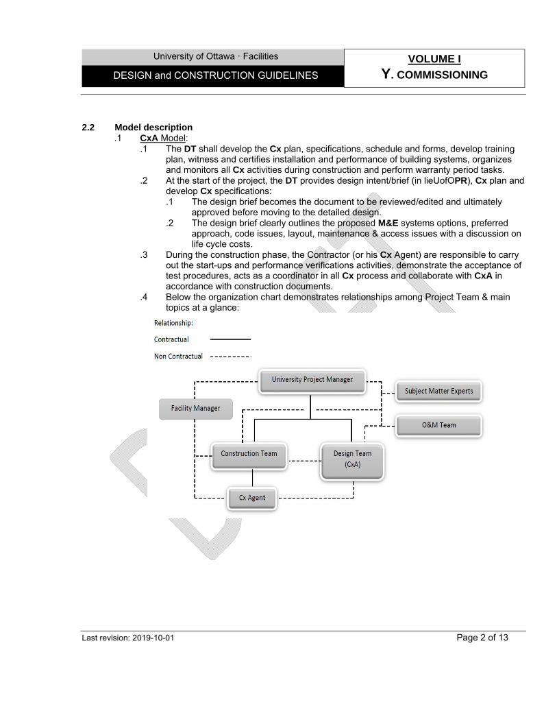
University of Ottawa · Facilities VOLUME I
Y. COMMISSIONING DESIGN and CONSTRUCTION GUIDELINES
Last revision: 2019-10-01 Page 2 of 13
2.2 Model description .1 CxA Model:
.1 The DT shall develop the Cx plan, specifications, schedule and forms, develop training plan, witness and certifies installation and performance of building systems, organizes and monitors all Cx activities during construction and perform warranty period tasks.
.2 At the start of the project, the DT provides design intent/brief (in lieUofOPR), Cx plan and develop Cx specifications: .1 The design brief becomes the document to be reviewed/edited and ultimately
approved before moving to the detailed design. .2 The design brief clearly outlines the proposed M&E systems options, preferred
approach, code issues, layout, maintenance & access issues with a discussion on life cycle costs.
.3 During the construction phase, the Contractor (or his Cx Agent) are responsible to carry out the start-ups and performance verifications activities, demonstrate the acceptance of test procedures, acts as a coordinator in all Cx process and collaborate with CxA in accordance with construction documents.
.4 Below the organization chart demonstrates relationships among Project Team & main topics at a glance:
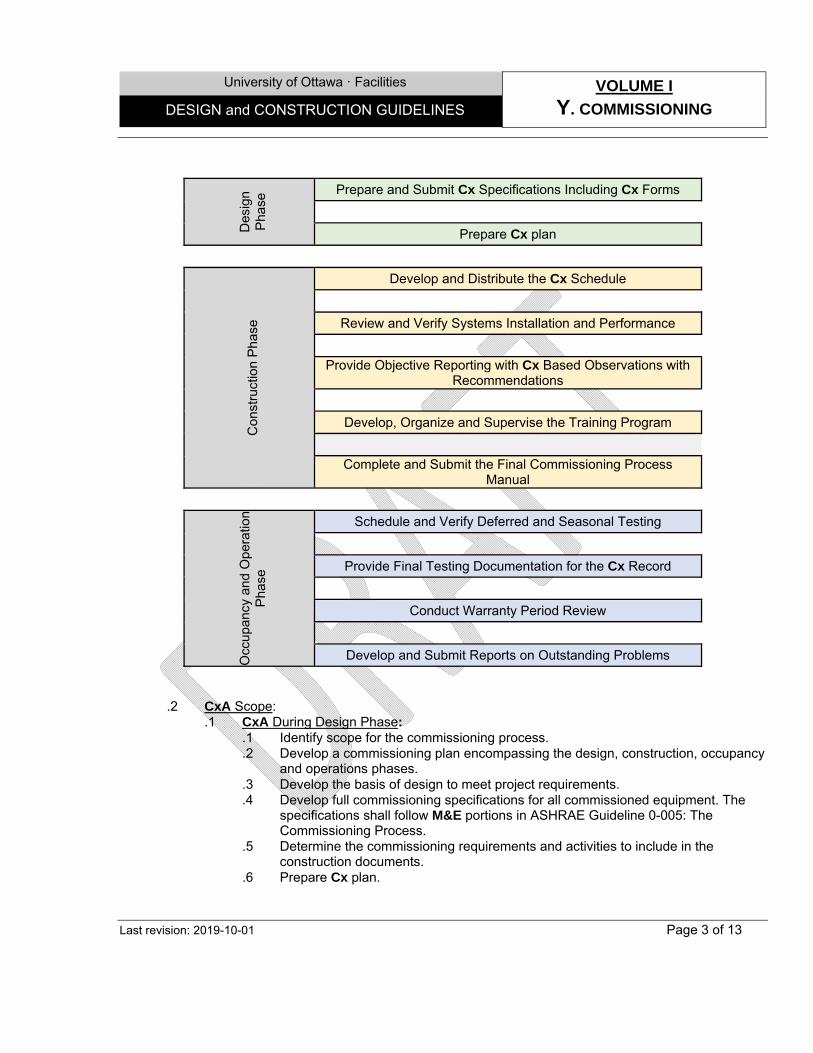
University of Ottawa · Facilities VOLUME I
Y. COMMISSIONING DESIGN and CONSTRUCTION GUIDELINES
Last revision: 2019-10-01 Page 3 of 13
Des
ign
Pha
se Prepare and Submit Cx Specifications Including Cx Forms
Prepare Cx plan C
onst
ruct
ion
Pha
se
Develop and Distribute the Cx Schedule
Review and Verify Systems Installation and Performance
Provide Objective Reporting with Cx Based Observations with Recommendations
Develop, Organize and Supervise the Training Program
Complete and Submit the Final Commissioning Process Manual
Occ
upan
cy a
nd O
pera
tion
Pha
se
Schedule and Verify Deferred and Seasonal Testing
Provide Final Testing Documentation for the Cx Record
Conduct Warranty Period Review
Develop and Submit Reports on Outstanding Problems
.2 CxA Scope: .1 CxA During Design Phase:
.1 Identify scope for the commissioning process.
.2 Develop a commissioning plan encompassing the design, construction, occupancy and operations phases.
.3 Develop the basis of design to meet project requirements.
.4 Develop full commissioning specifications for all commissioned equipment. The specifications shall follow M&E portions in ASHRAE Guideline 0-005: The Commissioning Process.
.5 Determine the commissioning requirements and activities to include in the construction documents.
.6 Prepare Cx plan.
University of Ottawa · Facilities VOLUME I
Y. COMMISSIONING DESIGN and CONSTRUCTION GUIDELINES
Last revision: 2019-10-01 Page 4 of 13
.2 CxA During Construction Phase: .1 Organize and conduct periodic commissioning team meetings. .2 Develop and distribute the Cx schedule. .3 Develop the Operations/Systems Manual for use in assessing performance and
desired operational parameters. .4 Coordinate and direct commissioning activities in a logical, sequential and efficient
manner. .5 Witness systems pressure testing, cleaning and flushing to ensure that proper
procedures are followed. .6 Develop and distribute pre�functional checklists and detailed functional
performance test procedures and checklist for all commissioned systems and equipment.
.7 Coordinate and document functional performance testing performed by installing contractors.
.8 Review mechanical and electrical controls systems with performance testing and verification.
.9 Work with contractors in completing construction checklists and tracking of checklist completion.
.10 Review and approve systems start-up by reviewing the reports and by selected site observation.
.11 With necessary assistance and review from installing contractors, write the test procedures.
.12 Coordinate witness and recommend approval of test procedure performed by installing contractors.
.13 Maintain a master issues log and a separate testing record and submit written progress reports and test results with recommended actions.
.14 Document the correction and retesting of non�compliance items by the contractors.
.15 Develop, organize and supervise the training program conducted by construction team and DT.
.16 Complete and submit the final Commissioning Process Manual. As the minimum following shall be included in the Cx Process Manual: Basis of Design. Cx Plan. Schematic Design Review. Construction Documents Review. Cx Specifications. Equipment Installation and Performance Verification. Completed Equipment Installation and Performance Verification Forms. Submissions and Changes during Construction. CX Schedule. Cx Tracking Logs and Status of Completeness. Operations/Systems Manual. Training Program. Warranty Period Activities. Occupancy Issues.
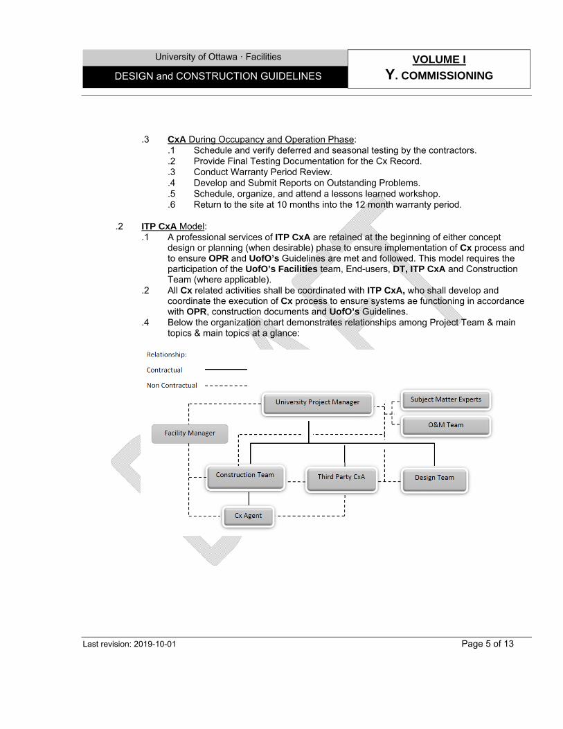
University of Ottawa · Facilities VOLUME I
Y. COMMISSIONING DESIGN and CONSTRUCTION GUIDELINES
Last revision: 2019-10-01 Page 5 of 13
.3 CxA During Occupancy and Operation Phase:
.1 Schedule and verify deferred and seasonal testing by the contractors.
.2 Provide Final Testing Documentation for the Cx Record.
.3 Conduct Warranty Period Review.
.4 Develop and Submit Reports on Outstanding Problems.
.5 Schedule, organize, and attend a lessons learned workshop.
.6 Return to the site at 10 months into the 12 month warranty period.
.2 ITP CxA Model: .1 A professional services of ITP CxA are retained at the beginning of either concept
design or planning (when desirable) phase to ensure implementation of Cx process and to ensure OPR and UofO’s Guidelines are met and followed. This model requires the participation of the UofO’s Facilities team, End-users, DT, ITP CxA and Construction Team (where applicable).
.2 All Cx related activities shall be coordinated with ITP CxA, who shall develop and coordinate the execution of Cx process to ensure systems ae functioning in accordance with OPR, construction documents and UofO’s Guidelines.
.4 Below the organization chart demonstrates relationships among Project Team & main topics & main topics at a glance:
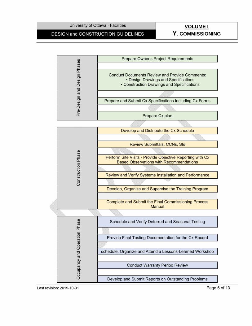
University of Ottawa · Facilities VOLUME I
Y. COMMISSIONING DESIGN and CONSTRUCTION GUIDELINES
Last revision: 2019-10-01 Page 6 of 13
Pre
-Des
ign
and
Des
ign
Pha
ses Prepare Owner’s Project Requirements
Conduct Documents Review and Provide Comments: • Design Drawings and Specifications
• Construction Drawings and Specifications
Prepare and Submit Cx Specifications Including Cx Forms
Prepare Cx plan
Con
stru
ctio
n P
hase
Develop and Distribute the Cx Schedule
Review Submittals, CCNs, SIs
Perform Site Visits - Provide Objective Reporting with Cx Based Observations with Recommendations
Review and Verify Systems Installation and Performance
Develop, Organize and Supervise the Training Program
Complete and Submit the Final Commissioning Process Manual
Occ
upan
cy a
nd O
pera
tion
Pha
se
Schedule and Verify Deferred and Seasonal Testing
Provide Final Testing Documentation for the Cx Record
schedule, Organize and Attend a Lessons‐Learned Workshop
Conduct Warranty Period Review
Develop and Submit Reports on Outstanding Problems
University of Ottawa · Facilities VOLUME I
Y. COMMISSIONING DESIGN and CONSTRUCTION GUIDELINES
Last revision: 2019-10-01 Page 7 of 13
.2 ITP CxA Scope: .1 ITP CxA During Design Phase:
.1 Develop the OPR.
.2 Identify scope for the commissioning process.
.3 Develop the initial commissioning plan.
.4 Collaborate with the DT in documenting the basis of design.
.5 Verify the basis of design in regard to the OPR.
.6 Attend design reviews and value engineering meetings and/or discussions.
.7 Participate in discussions to evaluate technologies and design methods to meet OPR.
.8 Perform review of the design documents at the end of each design phase and submit review comments.
.9 Develop full commissioning specifications for all commissioned equipment. The specifications shall follow ASHRAE Guideline 0-2005: The Commissioning Process.
.10 Develop and finalize the commissioning plan encompassing the design, construction, occupancy and operations phases.
.11 Determine the commissioning requirements and activities to include in the construction documents.
.12 Prepare Cx plan.
.2 ITP CxA During Construction Phase: .1 Organize and conduct the commissioning pre-construction meeting. .2 Develop and distribute the Cx schedule. .3 Develop the Operations/Systems Manual for use in assessing performance and
desired operational parameters .4 Coordinate and direct commissioning activities in a logical, sequential and efficient
manner. .5 Perform site visits, as necessary, to observe component and system installations
followed by reports with suggested direction. .6 Attend selected planning and job�site meetings to obtain information on
construction progress. .7 Conduct periodic on-Site observations during construction and submit observation
report. .8 Witness systems pressure testing, cleaning and flushing to ensure that proper
procedures are followed. .9 Develop and distribute pre-functional checklists and detailed functional
performance test procedures and checklist for all commissioned systems and equipment.
.10 Coordinate and document functional performance testing performed by installing contractors.
.11 Review mechanical and electrical controls systems with performance testing and verification.
.12 Organize and conduct periodic commissioning team meetings.
.13 Review submittals concurrent with the DT’s review, including shop drawings, Site instructions, and similar.
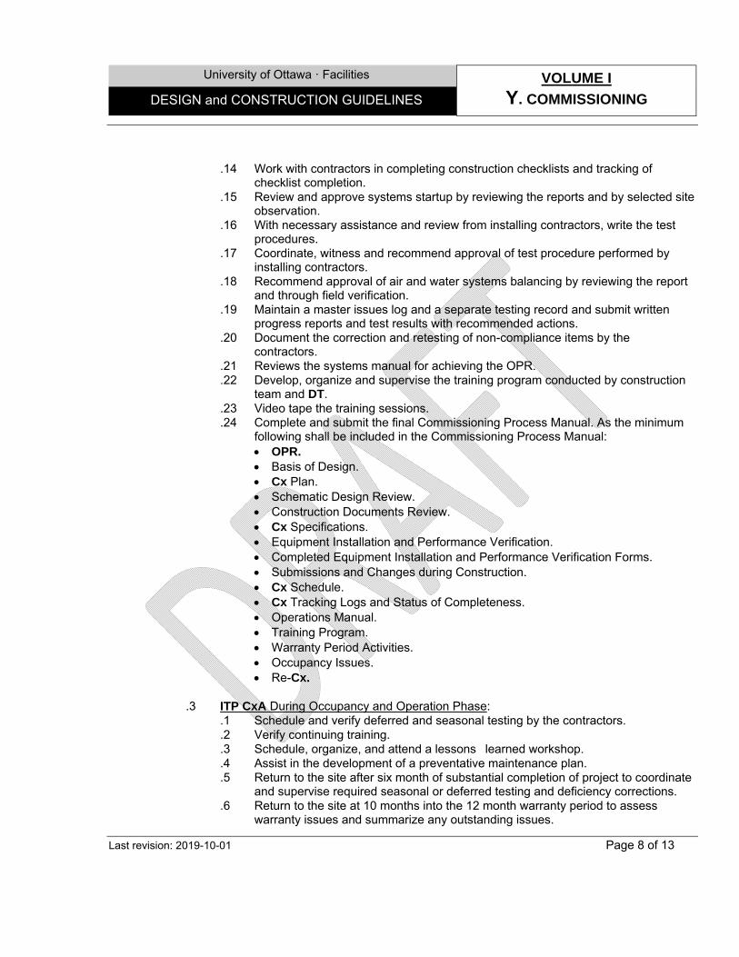
University of Ottawa · Facilities VOLUME I
Y. COMMISSIONING DESIGN and CONSTRUCTION GUIDELINES
Last revision: 2019-10-01 Page 8 of 13
.14 Work with contractors in completing construction checklists and tracking of checklist completion.
.15 Review and approve systems startup by reviewing the reports and by selected site observation.
.16 With necessary assistance and review from installing contractors, write the test procedures.
.17 Coordinate, witness and recommend approval of test procedure performed by installing contractors.
.18 Recommend approval of air and water systems balancing by reviewing the report and through field verification.
.19 Maintain a master issues log and a separate testing record and submit written progress reports and test results with recommended actions.
.20 Document the correction and retesting of non-compliance items by the contractors.
.21 Reviews the systems manual for achieving the OPR.
.22 Develop, organize and supervise the training program conducted by construction team and DT.
.23 Video tape the training sessions.
.24 Complete and submit the final Commissioning Process Manual. As the minimum following shall be included in the Commissioning Process Manual: OPR. Basis of Design. Cx Plan. Schematic Design Review. Construction Documents Review. Cx Specifications. Equipment Installation and Performance Verification. Completed Equipment Installation and Performance Verification Forms. Submissions and Changes during Construction. Cx Schedule. Cx Tracking Logs and Status of Completeness. Operations Manual. Training Program. Warranty Period Activities. Occupancy Issues. Re-Cx.
.3 ITP CxA During Occupancy and Operation Phase:
.1 Schedule and verify deferred and seasonal testing by the contractors.
.2 Verify continuing training.
.3 Schedule, organize, and attend a lessons�learned workshop.
.4 Assist in the development of a preventative maintenance plan.
.5 Return to the site after six month of substantial completion of project to coordinate and supervise required seasonal or deferred testing and deficiency corrections.
.6 Return to the site at 10 months into the 12 month warranty period to assess warranty issues and summarize any outstanding issues.
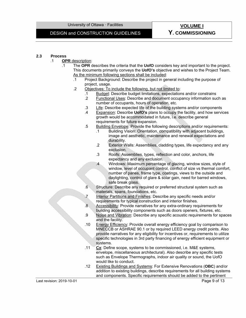
University of Ottawa · Facilities VOLUME I
Y. COMMISSIONING DESIGN and CONSTRUCTION GUIDELINES
Last revision: 2019-10-01 Page 9 of 13
2.3 Process .1 OPR description:
.1 The OPR describes the criteria that the UofO considers key and important to the project. This documents primarily conveys the UofO’s objective and wishes to the Project Team. As the minimum following sections shall be included: .1 Project Background: Describe the project in general including the purpose of
project, usage. .2 Objectives: To include the following, but not limited to:
.1 Budget: Describe budget limitations, expectations and/or constrains
.2 Functional Uses: Describe and document occupancy information such as number of occupants, hours of operation, etc.
.3 Life: Describe expected life of the building systems and/or components
.4 Expansion: Describe UofO’s plans to occupy the facility, and how services growth would be accommodated in future, i.e. describe general requirements for future expansion.
.5 Building Envelope: Provide the following descriptions and/or requirements: .1 Building Vision: Orientation, compatibility with adjacent buildings,
image and aesthetic, maintenance and renewal expectations and durability.
.2 Exterior Walls: Assemblies, cladding types, life expectancy and any exclusion.
.3 Roofs: Assemblies, types, reflection and color, anchors, life expectancy and any exclusion.
.4 Windows: Maximum percentage of glazing, window sizes, style of window, level of occupant control, conflict of size vs thermal comfort, number of panes, frame type, coatings, views to the outside and daylighting, control of glare & solar gain, need for barred windows, safe break glass.
.6 Structure: Describe any required or preferred structural system such as materials, spans, foundations, etc.
.7 Interior Partitions and Finishes: Describe any specific needs and/or requirements for typical construction and interior finishes.
.8 Accessibility: Provide narratives for any extra-ordinary requirements for building accessibility components such as doors openers, fixtures, etc.
.9 Noise and Vibration: Describe any specific acoustic requirements for spaces and the facility.
.10 Energy Efficiency: Provide overall energy efficiency goal by comparison to MNECCB or ASHRAE 90.1 or by required LEED energy credit points. Also provide narratives for any eligibility for incentives or, requirements to utilize specific technologies in 3rd party financing of energy efficient equipment or systems.
.11 Cx: Define scope, systems to be commissioned, i.e. M&E systems, envelope, miscellaneous architectural). Also describe any specific tests such as Envelope Thermographs, indoor air quality or sound, the UofO would like to conduct.
.12 Existing Buildings and Systems: For Extensive Renovations (OBC) and/or addition to existing buildings, describe requirements for all building systems and components. Specific requirements should be added to the pertinent
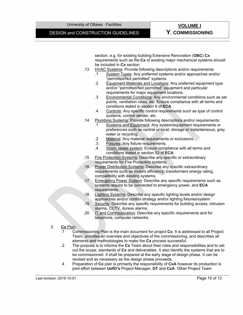
University of Ottawa · Facilities VOLUME I
Y. COMMISSIONING DESIGN and CONSTRUCTION GUIDELINES
Last revision: 2019-10-01 Page 10 of 13
section, e.g. for existing building Extensive Renovation (OBC) Cx requirements such as Re-Cx of existing major mechanical systems should be included in Cx section.
.13 HVAC Systems: Provide following descriptions and/or requirements: .1 System Types: Any preferred systems and/or approaches and/or
“permitted/Not permitted” systems. .2 Equipment Materials and Locations: Any preferred equipment type
and/or “permitted/Not permitted” equipment and particular requirements for major equipment locations.
.3 Environmental Conditions: Any environmental conditions such as set points, ventilation rates, etc. Ensure compliance with all terms and conditions stated in section 9 of ECA.
.4 Controls: Any specific control requirements such as type of control systems, control vender, etc.
.14 Plumbing Systems: Provide following descriptions and/or requirements: .1 Systems and Equipment: Any system/equipment requirements or
preferences such as central or local, storage or instantaneous, grey water or recycling.
.2 Material: Any material requirements or exclusions.
.3 Fixtures: Any fixture requirements.
.4 Storm sewer system: Ensure compliance with all terms and conditions stated in section 53 of ECA.
.15 Fire Protection Systems: Describe any specific or extraordinary requirements for Fire Protection systems
.16 Power Distribution Systems: Describe any specific extraordinary requirements such as motors efficiency, transformers energy rating, compatibility with existing systems.
.17 Emergency Power System: Describe any specific requirements such as systems require to be connected to emergency power, and ECA requirements.
.18 Lighting Systems: Describe any specific lighting levels and/or design approaches and/or control strategy and/or lighting fixtures/system
.19 Security: Describe any specific requirements for building access, intrusion alarms, CCTV, duress alarms.
.20 IT and Communication: Describe any specific requirements and for telephone, computer networks.
.2 Cx Plan:
.1 Commissioning Plan is the main document for project Cx. It is addressed to all Project Team, provides an overview and objectives of the commissioning, and describes all elements and methodologies to make the Cx process successful.
.2 The purpose is to informs the Cx Team about their roles and responsibilities and to set out the scope, standards of Cx and deliverables. It also identify the systems that are to be commissioned. It shall be prepared at the early stage of design phase. It can be revised and as necessary as the design phase proceeds.
.4 Preparation of Cx plan is primarily the responsibility of CxA however its production is joint effort between UofO’s Project Manager, DT and CxA. Other Project Team
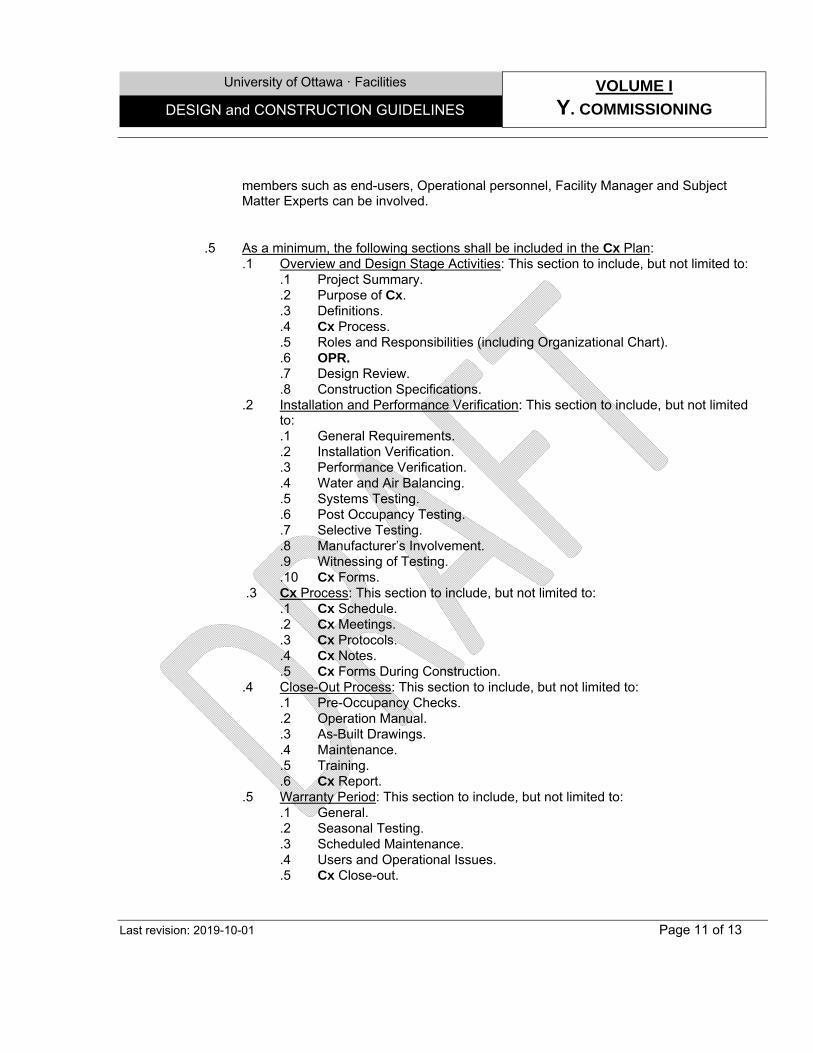
University of Ottawa · Facilities VOLUME I
Y. COMMISSIONING DESIGN and CONSTRUCTION GUIDELINES
Last revision: 2019-10-01 Page 11 of 13
members such as end-users, Operational personnel, Facility Manager and Subject Matter Experts can be involved.
.5 As a minimum, the following sections shall be included in the Cx Plan:
.1 Overview and Design Stage Activities: This section to include, but not limited to: .1 Project Summary. .2 Purpose of Cx. .3 Definitions. .4 Cx Process. .5 Roles and Responsibilities (including Organizational Chart). .6 OPR. .7 Design Review. .8 Construction Specifications.
.2 Installation and Performance Verification: This section to include, but not limited to: .1 General Requirements. .2 Installation Verification. .3 Performance Verification. .4 Water and Air Balancing. .5 Systems Testing. .6 Post Occupancy Testing. .7 Selective Testing. .8 Manufacturer’s Involvement. .9 Witnessing of Testing. .10 Cx Forms.
.3 Cx Process: This section to include, but not limited to: .1 Cx Schedule. .2 Cx Meetings. .3 Cx Protocols. .4 Cx Notes. .5 Cx Forms During Construction.
.4 Close-Out Process: This section to include, but not limited to: .1 Pre-Occupancy Checks. .2 Operation Manual. .3 As-Built Drawings. .4 Maintenance. .5 Training. .6 Cx Report.
.5 Warranty Period: This section to include, but not limited to: .1 General. .2 Seasonal Testing. .3 Scheduled Maintenance. .4 Users and Operational Issues. .5 Cx Close-out.
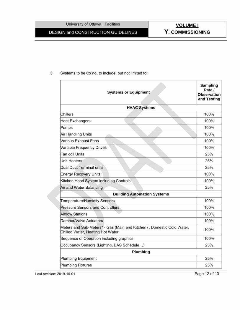
University of Ottawa · Facilities VOLUME I
Y. COMMISSIONING DESIGN and CONSTRUCTION GUIDELINES
Last revision: 2019-10-01 Page 12 of 13
.3 Systems to be Cx’nd, to include, but not limited to:
Systems or Equipment
Sampling Rate /
Observation and Testing
HVAC Systems
Chillers 100%
Heat Exchangers 100%
Pumps 100%
Air Handling Units 100%
Various Exhaust Fans 100%
Variable Frequency Drives 100%
Fan coil Units 25%
Unit Heaters 25%
Dual Duct Terminal units 25%
Energy Recovery Units 100%
Kitchen Hood System including Controls 100%
Air and Water Balancing 25%
Building Automation Systems
Temperature/Humidity Sensors 100%
Pressure Sensors and Controllers 100%
Airflow Stations 100%
Damper/Valve Actuators 100%
Meters and Sub‐Meters* ‐ Gas (Main and Kitchen) , Domestic Cold Water, Chilled Water, Heating Hot Water
100%
Sequence of Operation including graphics 100%
Occupancy Sensors (Lighting, BAS Schedule…) 25%
Plumbing
Plumbing Equipment 25%
Plumbing Fixtures 25%
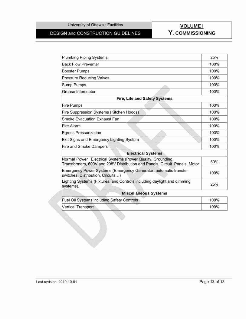
University of Ottawa · Facilities VOLUME I
Y. COMMISSIONING DESIGN and CONSTRUCTION GUIDELINES
Last revision: 2019-10-01 Page 13 of 13
Plumbing Piping Systems 25%
Back Flow Preventer 100%
Booster Pumps 100%
Pressure Reducing Valves 100%
Sump Pumps 100%
Grease Interceptor 100%
Fire, Life and Safety Systems
Fire Pumps 100%
Fire Suppression Systems (Kitchen Hoods) 100%
Smoke Evacuation Exhaust Fan 100%
Fire Alarm 100%
Egress Pressurization 100%
Exit Signs and Emergency Lighting System 100%
Fire and Smoke Dampers 100%
Electrical Systems
Normal Power Electrical Systems (Power Quality, Grounding, Transformers, 600V and 208V Distribution and Panels, Circuit Panels, Motor 50%
Emergency Power Systems (Emergency Generator, automatic transfer switches, Distribution, Circuits…)
100%
Lighting Systems (Fixtures, and Controls including daylight and dimming systems). 25%
Miscellaneous Systems
Fuel Oil Systems including Safety Controls 100%
Vertical Transport 100%
University of Ottawa · Facilities VOLUME I
Z1. ELECTRICAL DESIGN and CONSTRUCTION REQUIREMENTS
Last revision: 2019-10-01 Page 1 of 4
1.0 GENERAL
1.1 Overview
.1 This section has been prepared to provide consultants with a general overview of Electrical Systems design requirements for new buildings and renovations in existing building.
.2 Different team at the UofO including UofO’s IT, Security and AV teams share responsibility of programming and performance review of the various electrical disciplines along with Facilities Integrated Project Delivery (IPD), Facilities Operations (Ops), therefore consultants shall always review project requirements with respective teams to determine required information. All systems will be reviewed by Facilities.
2.0 DESIGN
2.1 Parameters .1 Design of electrical systems shall be flexible and expandable without significant modifications
to the system infrastructure. .2 Design of electrical systems shall be done in such that the equipment and the systems to be
able to operate in their maximum operation limit without causing any damage to the equipment and/or failure of the service.
.3 Electrical equipment and/or components shall meet or exceed the energy efficiency requirements outline in ASHERAE 90.1-2010.
.4 Design of Electrical Systems shall include the lowest life cycle maintenance cost and long service life.
.5 UofO’s preference is to reduce harmonics therefore followings shall be considered in design: .1 Where high rated transforms are required consider to size high the neutral. .2 For loads with significant third harmonic content neutral shall be doubled. .3 For all circuit provide separate neutral conductor. Avoid sharing neutral in design.
.6 In application such as laboratories, computer centers, substations where continuity of power is required, service shall be double ended.
.7 Design shall include housekeeping pad for switch gears and MCCs.
.8 Type, efficiency and temperature rise of transformers shall be consulted with Facilities.
.9 Low voltage transformers shall be dry type with 115°C rise.
.10 Generally electrical rooms shall be ventilated without mechanical cooling. Review the design requirements with Facilities when mechanical cooling is required.
.11 For future expansion requirements, design of subpanel distribution system shall minimize the distance between.
.12 Locations of normal and emergency panels/subpanels shall be reviewed with Facilities.
.13 Design of main electrical distribution panels shall include 30% spare circuits. The spare circuits for other distribution panels shall be 20%.
.14 Aluminum cables are not permitted.
.15 Aluminum bus bar is not permitted.
.16 For renovation and new construction projects loads shall be balanced. Amperage shall be listed at the panel boards.
.17 Motors of 1 hp and above shall be 3-phase. Use of single phase motor for fraction hp motors such as Fan Coil units are acceptable.
University of Ottawa · Facilities VOLUME I
Z1. ELECTRICAL DESIGN and CONSTRUCTION REQUIREMENTS
Last revision: 2019-10-01 Page 2 of 4
.18 3 Phase motors shall be premium efficiency to meet or exceed requirements outlined in ASHRAE 90.1-2010.
.19 All magnetic starters shall be equipped with Hand-Off-Auto controls, light test switches, running lights, reset buttons, auxiliary contacts and controls transformers. For protection motor circuit protectors shall be used, fuses are not permitted.
.20 Where VFDs are to be installed very close electrically to the incoming facility power source or in other locations within the electrical system where they will be otherwise highly susceptible to incoming spikes and other transients, the installation shall include additional measures for the protection of the front end/diode section of the drives such as a 3-5% line reactor. Line reactor(s) shall be appropriately sized and specified to suit the characteristics of the drive(s) and the electrical distribution system to minimize negative side effects.
.21 Where VFDs are to be installed in locations subject to harmonic distortion caused by nearby nonlinear loads, the installation shall include additional harmonic mitigation measures such as a DC link choke or 3-5% line reactor. Line reactor(s) shall be appropriately sized and specified to suit the characteristics of the drive(s) and the electrical distribution system to minimize negative side effects.
.22 VFDs shall be equipped with built in harmonic mitigation technology to minimize harmonic distortion and maintain system power quality.
.23 Where outdoor mechanical equipment equip with VFD(s) are used, CFD s shall not be installed inside the equipment. VFDs shall be installed in the closest mechanical or electrical room to the equipment.
.24 Where six or more starters are needed, MCC shall be provided.
.25 Where a main distribution panel is not used or available, MCC shall be used for distribution centers.
.26 Where elevators are fed from MCC, it shall have only breakers and not starters.
.27 Arc Flash, Short Circuit study and Coordination study shall be completed during design phase.
.28 Where an existing Arc Flash study is available consultants shall modify the study for the final design. Where there is no existing study consultants shall perform their own study.
.29 All equipment requiring Arc Flash study shall receive a permanent, durable Arc Flash Protection label as per code.
2.2 Installation and Maintenance
.1 Provide adequate space for servicing, replacement and addition (for future projects) where equipment are installed in service rooms.
.2 Electrical and communication equipment and/or components shall not be installed in mechanical service rooms unless required to service mechanical equipment.
.3 Where electrical panels are installed in electrical rooms, closets and/or load centers, design and installation shall allow space for two additional panel boards for future projects/expansion.
.4 Main ceiling mounted equipment, devices, sensors and components requiring readily service access and/or periodic maintenance and/or inspection shall be located, where possible in service rooms or and not over corridors.
.5 Ceiling mounted equipment, devices, sensors and components requiring periodic maintenance and/or inspection shall be installed in such the installation provides ease of servicing access. The required maintenance and/or inspection work shall not jeopardize the health and safety of UofO’s operational staff and/or service contractors. They shall be accessible from the floor or a permanent service or access platform or walkway, standard step ladder or extension ladder.
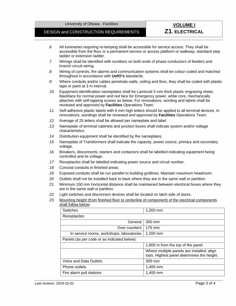
University of Ottawa · Facilities VOLUME I
Z1. ELECTRICAL DESIGN and CONSTRUCTION REQUIREMENTS
Last revision: 2019-10-01 Page 3 of 4
.6 All luminaries requiring re-lamping shall be accessible for service access. They shall be accessible from the floor or a permanent service or access platform or walkway, standard step ladder or extension ladder.
.7 Wirings shall be identified with numbers on both ends of phase conductors of feeders and branch circuit wiring.
.8 Wiring of controls, fire alarms and communication systems shall be colour coded and matched throughout in accordance with UofO’s standards.
.9 Where conduits and/or cables penetrate walls, ceiling and floor, they shall be coded with plastic tape or paint at 3 m interval.
.10 Equipment identification nameplates shall be Lamicoid 3 mm thick plastic engraving sheet, blackface for normal power and red face for Emergency power, white core, mechanically attaches with self-tapping screws as below. For renovations, wording and labels shall be reviewed and approved by Facilities Operations Team.
.11 Self-adhesive plastic labels with 6 mm high letters should be applied to all terminal devices. In renovations, wordings shall be reviewed and approved by Facilities Operations Team.
.12 Average of 25 letters shall be allowed per nameplate and label.
.13 Nameplate of terminal cabinets and junction boxes shall indicate system and/or voltage characteristics.
.14 Distribution equipment shall be identified by the nameplates.
.15 Nameplate of Transformers shall indicate the capacity, power source, primary and secondary voltage.
.16 Breakers, disconnects, starters and contactors shall be labelled indicating equipment being controlled and its voltage.
.17 Receptacles shall be labelled indicating power source and circuit number.
.18 Conceal conduits in finished areas.
.19 Exposed conduits shall be run parallel to building gridlines. Maintain maximum headroom.
.20 Outlets shall not be installed back to back where they are in the same wall or partition.
.21 Minimum 150 mm horizontal distance shall be maintained between electrical boxes where they are in the same wall or partition.
.22 Light switches and disconnect devices shall be located on latch side of doors.
.23 Mounting height (from finished floor to centerline of component) of the electrical components shall follow below:
Switches 1,200 mm Receptacles:
General 300 mm Over counters 175 mm
In service rooms, workshops, laboratories 1,200 mm Panels (as per code or as indicated below): 1,800 m from the top of the panel Where multiple panels are installed; align
tops. Highest panel determines the height. Voice and Data Outlets 300 mm Phone outlets 1,400 mm Fire alarm pull stations 1,400 mm
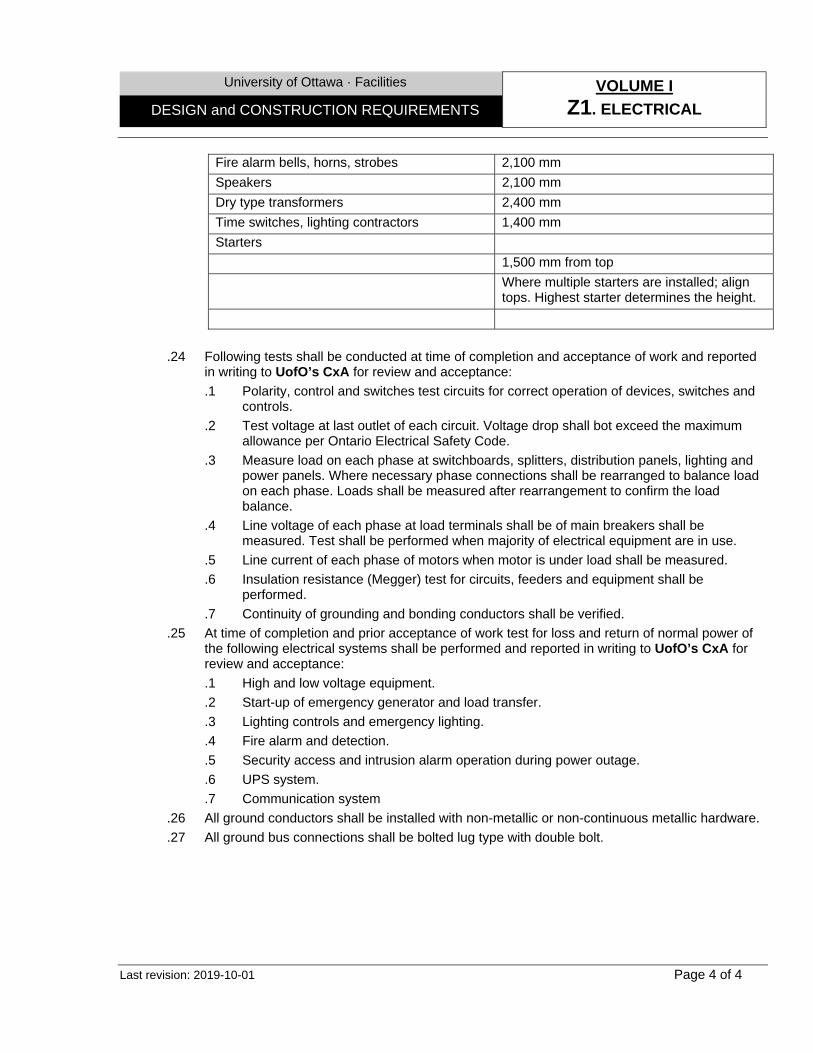
University of Ottawa · Facilities VOLUME I
Z1. ELECTRICAL DESIGN and CONSTRUCTION REQUIREMENTS
Last revision: 2019-10-01 Page 4 of 4
Fire alarm bells, horns, strobes 2,100 mm Speakers 2,100 mm Dry type transformers 2,400 mm Time switches, lighting contractors 1,400 mm Starters 1,500 mm from top Where multiple starters are installed; align
tops. Highest starter determines the height.
.24 Following tests shall be conducted at time of completion and acceptance of work and reported in writing to UofO’s CxA for review and acceptance: .1 Polarity, control and switches test circuits for correct operation of devices, switches and
controls. .2 Test voltage at last outlet of each circuit. Voltage drop shall bot exceed the maximum
allowance per Ontario Electrical Safety Code. .3 Measure load on each phase at switchboards, splitters, distribution panels, lighting and
power panels. Where necessary phase connections shall be rearranged to balance load on each phase. Loads shall be measured after rearrangement to confirm the load balance.
.4 Line voltage of each phase at load terminals shall be of main breakers shall be measured. Test shall be performed when majority of electrical equipment are in use.
.5 Line current of each phase of motors when motor is under load shall be measured.
.6 Insulation resistance (Megger) test for circuits, feeders and equipment shall be performed.
.7 Continuity of grounding and bonding conductors shall be verified. .25 At time of completion and prior acceptance of work test for loss and return of normal power of
the following electrical systems shall be performed and reported in writing to UofO’s CxA for review and acceptance: .1 High and low voltage equipment. .2 Start-up of emergency generator and load transfer. .3 Lighting controls and emergency lighting. .4 Fire alarm and detection. .5 Security access and intrusion alarm operation during power outage. .6 UPS system. .7 Communication system
.26 All ground conductors shall be installed with non-metallic or non-continuous metallic hardware.
.27 All ground bus connections shall be bolted lug type with double bolt.
University of Ottawa · Facilities VOLUME I
Z2. POWER DISTRIBUTION DESIGN and CONSTRUCTION REQUIREMENTS
Last revision: 2019-10-01 Page 1 of 3
1.0 GENERAL
1.1 Overview
.1 This section has been prepared to provide consultants with a general overview of Electrical Systems design requirements for new buildings and renovations in existing building.
.2 In many instances University undertakes short term planning and long term master planning to address economic and practical inefficacies associated with renovations in existing building, therefore consultants shall always review project requirements. In all cases consultation with Facilities will be required to determine the specific scope of work and requirements suitable to the project under review. All systems shall be reviewed by Facilities.
2.0 DESIGN
2.1 Parameters .1 Electrical rooms shall be located in such to maximize the flexibility of power distribution system
and ease of access to floor area served. .2 Power distribution system shall be designed to provide flexibility and adaptability when change
of spaces are required. Also ease of access to electrical panels shall be considered in the design to facilitate the addition of new feeds are required.
.3 Central distribution panels shall be located close to load centers, such as mechanical rooms.
.4 All panel boards shall be suitable for bolt-on breakers and be completed with copper bussing with full size neutrals for all distributions and branch panels with ground bus bonded to the panel board for bonding conductors.
.5 Distribution system shall be deigned with sufficient spare capacity to accommodate significant change of use.
.6 Power distribution system shall be design to accommodate 30% spare capacity as a minimum at all nodes of the system for future growth.
.7 Distribution panel, switch boards and panel boards shall be supplied by the same manufacturer.
.8 Feeders to panels distribution panels, MCCs, etc. shall be TECK or RWZ(Z) XLPE copper conductors in rigid steel conduits and EMT. All feeders shall have the same ratings or larger than it’s over load protection.
.9 Indoor transformers shall be dry type, class 200 insulation and copper windings.
.10 Computer server transformers shall be harmonic mitigation type.
.11 Transformers shall be energy efficient meeting or exceed the requirements outlined in CSA C802.
.12 Routing of distribution feeders shall be through common areas. Routing of distribution feeders between adjacent spaces which are subject to change is not acceptable.
.13 Design of power distribution system shall minimize the arc flash hazard.
.14 Design of power distribution system shall separate the lighting load from mechanical load for the purpose of metering and facilitate the measurement and verification.
.15 Design of power distribution shall include the subdivision of the following categories: .1 Normal lighting. .2 Emergency lighting. .3 Exterior lighting. .4 Mechanical equipment.
University of Ottawa · Facilities VOLUME I
Z2. POWER DISTRIBUTION DESIGN and CONSTRUCTION REQUIREMENTS
Last revision: 2019-10-01 Page 2 of 3
.5 Electronic equipment and non-linear loads.
.6 Power feeds to rental spaces.
.7 UPS or emergency. .16 Consideration shall be given to control noise of electromagnetic fields in design of power
system for noise sensitive areas. Electrical transformers shall not be located inside and/or adjacent to these areas.
.17 All outdoor electrical cables shall be properly rated copper cables in underground duct bank complete with fully sized neutral.
.18 All electrical conductors shall be copper.
.19 Main switch boards shall be free standing with capacity and short circuit ratings to suit the specific characteristic of scheduled loads complete with 100% rated main circuit breaker and metering devices.
.20 Design of 208/120V lighting panels shall include six, 15A/120V spare breakers as minimum.
.21 Design of 600/347V power panels shall include two, 3 pole spare breakers as a minimum.
.22 Design of all electrical panels (lighting and power) shall include 20% as a minimum additional space in addition to spare breakers.
.23 Electrical equipment located in areas with sprinkler system shall be provided with water proof enclose/protection against water from sprinklers acceptable to authorities having jurisdiction.
.24 Where UPS system is used: .1 UPS panel shall be completed with an isolated ground bus. .2 UPS panel shall be located in UPS room.
.25 For motors with 10 hp and larger (208V) and 30 hp and larger (600V) except for motors operating through VFD, reduced voltage or soft start starter shall be used.
.26 All magnetic starters shall be equipped with Hand-Off-Auto controls, light test switches, running lights, reset buttons, auxiliary contacts and controls transformers.
.27 For the purpose of protecting motors from loss/reversal or over/under current situations all three phase motors shall be equipped with phase protection devices.
.28 Where motors are grouped (more than three) in an area, motor starters shall be grouped in MCC.
.29 Motor starters shall be operated by the building automation system.
.30 For motors 1 hp and larger single phase protection shall be provided.
.31 Design main electrical room shall provide ground bus around the perimeter.
.32 Grounding system shall be star configuration. Loop configuration is not acceptable.
.33 Rooftop receptacles and receptacles in hallways and corridors shall be on their own branch circuits and not be powered from room branch circuits.
2.2 Installation and Maintenance
.1 Conduits shall be grouped on channels.
.2 Cables shall be run in conduits, ducts or wire ways.
.3 Dry mount transformers shall be mounted on concrete pad with adequate clearance for ventilation.
.4 At least one general purpose duplex receptacle shall be provided in electrical closets. In electrical rooms two duplex receptacles shall be provided as a minimum.
.5 Motors with ½ hp and larger shall be three phase.
University of Ottawa · Facilities VOLUME I
Z2. POWER DISTRIBUTION DESIGN and CONSTRUCTION REQUIREMENTS
Last revision: 2019-10-01 Page 3 of 3
.6 Lighting panels shall have minimum 60 circuit capacity.
.7 In order to obtain better lagging power factor (better than 0.95) automatic power factor correction equipment shall be provided.
.8 Single pole breakers with handle ties shall not be used in lieu of multiple breakers.
.9 Recessed panels shall have two spare conduits from the panel to the ceiling for future use.
University of Ottawa · Facilities VOLUME I
Z3. LIGHTING DESIGN and CONSTRUCTION REQUIREMENTS
Last revision: 2019-10-01 Page 1 of 4
1.0 GENERAL
1.1 Overview
.1 This section has been prepared to provide consultants with a general overview of Lighting system design requirements for new buildings and renovations in existing building.
.2 Consultants shall always review project requirements with Facilities teams to determine other related required information. All systems will be reviewed by Facilities.
2.0 DESIGN 2.1 Models types
.1 Lighting system shall be design to meet functional requirement of each specific space.
.2 Design of lighting systems shall provide ease of maintenance and replacement of lamps. Design of lighting systems for ceiling heights over 4.5 m (15 Ft.) shall be reviewed by the Facility Operational team for lamp and ballast access.
.3 Lighting controls shall be minimizing the building lighting system energy use.
.4 Design of lighting system shall be done in such that illumination is directed to desired location with minimal direct glare and reflection.
.5 Generally, design of lighting system shall provide one third of luminance required for specific task or area for surrounding.
.6 Lighting fixture lay-out within drop ceilings shall allow relocation of lighting fixture by one ceiling tile in either direction.
.7 Interior and exterior lighting design shall consider use of LED lighting lamps. As a minimum design of interior and exterior lighting system design shall include T8 and HID luminaries respectively. T5 lighting lamps are not permitted.
.8 Color temperature of for LED fixtures are generally 3500K, however acceptable colour temperature shall be reviewed for each application with Facility.
.9 Illuminance of lighting system shall comply with UofO standard. Refer to Annex Z3-1.
.10 Lighting Power Density (LPD) of lighting system shall either exceed 35% better than ASHRAE 90.1 – 2010 or meet or exceed the requirements outlined in section S - Energy and Sustainability.
.11 All luminaries shall operate at 120 VAC.
.12 For multi-zone spaces lighting system design shall consider controlled dimming system.
.13 Lighting system design of multi-purpose spaces shall be flexible for change of space configuration.
.14 Site lighting system shall: .1 Meet the safety and security objectives. .2 Enhance the character of building. .3 Minimize the light pollution to meet or exceed the requirements of LEED design guideline
where feasible. .15 Design of lighting systems in spaces where visual display terminals (VDT) is required shall be
able to control reflected and direct glare and to limit luminance in both the dynamic field and task surrounding area.
.16 In order to design lighting systems for spaces where visual display terminals (VDT) is required confirm/determine: .1 How the VDT screen is utilized. .2 Type of visual image is displayed.
University of Ottawa · Facilities VOLUME I
Z3. LIGHTING DESIGN and CONSTRUCTION REQUIREMENTS
Last revision: 2019-10-01 Page 2 of 4
.3 The angular relationship between screen and end-user. .17 For enclosed area lighting controls system shall include one control point for each task location
or each group of task locations within an area of 45 sq. m. or less. .18 In design of lighting system of large open space where must be used as a whole, lighting
control for shall be controlled by a lesser number of controls but not less than one control point per 1500 W (120 VAC) and 4150 W (347 VAC) of connected lighting power or a total of three control points whichever is greater.
.19 For the purpose of energy conservation lighting system design shall include occupancy sensors as a control point, manual toggle switches for multi-level lighting, daylight harvesting sensors.
.20 Occupancy sensors shall be used in the following spaces: .1 Private and open offices. .2 Meeting rooms. .3 Functional rooms. .4 Study rooms. .5 Washrooms and locker rooms. .6 Service rooms. .7 Laundries in residences.
.21 Dimming controls shall be considered for the following spaces: .1 Classrooms. .2 AV spaces. .3 Large gathering spaces such as dining halls. .4 Large open multi-user laboratories.
.22 Where daylight harvesting sensors are provided, lights shall dim, turn off when daylight is available.
.23 Security night lights shall be provided in areas to left ON at all times for safety or video cameras.
.24 Exterior lighting shall be controlled by lighting contactors or relay system and photo sensors with HOA override capability via BAS.
.25 Design of lighting controls system shall include low voltage lighting control system capable of communicating with the BAS for either manual or automatic lighting controls.
.26 Lighting controls system shall include programmable ballast. Lighting system shall include electronic ballast.
.27 With the exception of main electrical and generator rooms, battery pack type emergency lighting fixtures are not permitted.
.28 In small laboratories where emergency light are not required by the code, at least one emergency light shall be provided.
2.2 Installation and Maintenance
.1 Special consideration shall be given to the access and maintenance where design and location of fixtures shall be such as to eliminate the usage of scaffolding when changing lamps. In particular:
.2 In high ceiling or Auditorium applications, consideration shall be given to provide cat walk above the light fixture;
.3 In Stairwell, lighting fixture should be installed on walls or in the ceiling of the landing area. Avoid installing fixtures above the stairs.
University of Ottawa · Facilities VOLUME I
Z3. LIGHTING DESIGN and CONSTRUCTION REQUIREMENTS
Last revision: 2019-10-01 Page 3 of 4
.4 For ease of maintenance for high volume and high ceilings consider utilization of remote ballasts.
.5 Lighting controls shall be readily accessible to occupants.
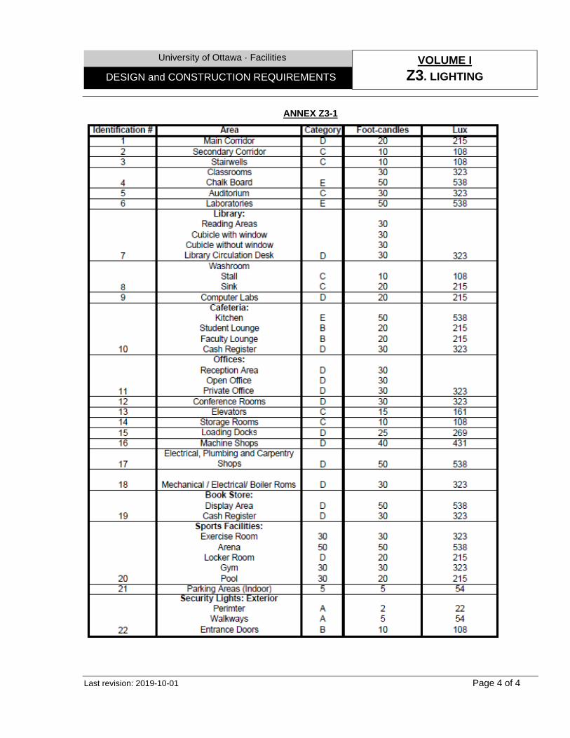
University of Ottawa · Facilities VOLUME I
Z3. LIGHTING DESIGN and CONSTRUCTION REQUIREMENTS
Last revision: 2019-10-01 Page 4 of 4
ANNEX Z3-1
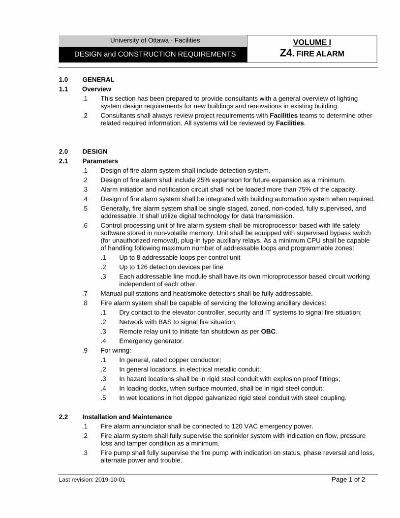
University of Ottawa · Facilities VOLUME I
Z4. FIRE ALARM DESIGN and CONSTRUCTION REQUIREMENTS
Last revision: 2019-10-01 Page 1 of 2
1.0 GENERAL
1.1 Overview
.1 This section has been prepared to provide consultants with a general overview of lighting system design requirements for new buildings and renovations in existing building.
.2 Consultants shall always review project requirements with Facilities teams to determine other related required information. All systems will be reviewed by Facilities.
2.0 DESIGN
2.1 Parameters .1 Design of fire alarm system shall include detection system. .2 Design of fire alarm shall include 25% expansion for future expansion as a minimum. .3 Alarm initiation and notification circuit shall not be loaded more than 75% of the capacity. .4 Design of fire alarm system shall be integrated with building automation system when required. .5 Generally, fire alarm system shall be single staged, zoned, non-coded, fully supervised, and
addressable. It shall utilize digital technology for data transmission. .6 Control processing unit of fire alarm system shall be microprocessor based with life safety
software stored in non-volatile memory. Unit shall be equipped with supervised bypass switch (for unauthorized removal), plug-in type auxiliary relays. As a minimum CPU shall be capable of handling following maximum number of addressable loops and programmable zones: .1 Up to 8 addressable loops per control unit .2 Up to 126 detection devices per line .3 Each addressable line module shall have its own microprocessor based circuit working
independent of each other. .7 Manual pull stations and heat/smoke detectors shall be fully addressable. .8 Fire alarm system shall be capable of servicing the following ancillary devices:
.1 Dry contact to the elevator controller, security and IT systems to signal fire situation;
.2 Network with BAS to signal fire situation;
.3 Remote relay unit to initiate fan shutdown as per OBC.
.4 Emergency generator. .9 For wiring:
.1 In general, rated copper conductor;
.2 In general locations, in electrical metallic conduit;
.3 In hazard locations shall be in rigid steel conduit with explosion proof fittings;
.4 In loading docks, when surface mounted, shall be in rigid steel conduit;
.5 In wet locations in hot dipped galvanized rigid steel conduit with steel coupling.
2.2 Installation and Maintenance
.1 Fire alarm annunciator shall be connected to 120 VAC emergency power.
.2 Fire alarm system shall fully supervise the sprinkler system with indication on flow, pressure loss and tamper condition as a minimum.
.3 Fire pump shall fully supervise the fire pump with indication on status, phase reversal and loss, alternate power and trouble.
University of Ottawa · Facilities VOLUME I
Z4. FIRE ALARM DESIGN and CONSTRUCTION REQUIREMENTS
Last revision: 2019-10-01 Page 2 of 2
.4 Fire alarm system shall alarm by operating sounding horns and strobe lights.
.5 Provide wire circuits for alarm, trouble and signals from addressable components.
.6 Fire alarm annunciator shall be located at main entrance to building.
.7 Fire alarm annunciator and fire department connection shall be located in same general area of building.
.8 Building design shall consider device locations to facilitate replacement and testing.
.9 Building Fire Alarm panel to be connected to central monitoring panel at 720 King Edward Ave.
.10 Update addressable messages to reflect modified room numbers and spaces
.11 Updated list shall be provided to Facilities Operations Team.
.12 Self-adhesive plastic labels with 6 mm high letters shall be applied to all devices with their respective address.
University of Ottawa · Facilities VOLUME I
Z5. EMERGENCY POWER DESIGN and CONSTRUCTION REQUIREMENTS
Last revision: 2020-03-01 Page 1 of 3
1.0 GENERAL
1.1 Overview
.1 This section has been prepared to provide consultants with a general overview of Emergency Power Systems (EPS) design requirements for new buildings and renovations in existing building.
.2 In many instances UofO undertakes short term planning and long term master planning to address economic and practical inefficacies associated with renovations in existing building, therefore consultants shall always review project requirements. In all cases consultation with Facilities will be required to determine the specific scope of work and requirements suitable to the project under review. All systems shall be reviewed by Facilities.
.3 Design and installation of EPS systems must be implemented in compliance with MECP regulations, where applicable. To be coordinated with ORM.
2.0 DESIGN 2.1 Parameters
.1 Emergency generator sizing shall be based on demand calculation rather than on the entire load operating simultaneously.
.2 Design of EPS shall include connection to a 100% rated resistive load bank.
.3 Design of EPS shall operate at 600V, 3 phase, 60 Hz and capable of handling 20% total harmonic distortion as a minimum.
.4 Emergency generator shall be sized capable of handling the following loads plus 20% additional load: .1 Life Safety Systems including:
.1 Emergency egress lighting.
.2 Egress signage.
.3 Communications systems.
.4 Fire alarm systems.
.5 Self-contained, battery-powered lighting at generator set location.
.6 Medical gas alarm systems.
.7 Fire suppression systems (fire pumps, compressors, valves, etc.).
.8 Security, intrusion detection and access control systems.
.9 Automatic doors used for egress.
.10 Elevator cab lighting, control, communication and signal systems.
.11 Generator day tank pump. .2 Base Building Systems:
.1 Pumps, components and all devices associated with fuel stored in large storage tanks serving the emergency generator.
.2 Sewage ejector systems.
.3 Sump pumps.
.4 Sump dewatering pumps.
.5 Lighting provided at the generator.
.6 Critical supply and exhaust fans. (As determined through Containment Regulations and Animal Care Regulations).
.7 Operating/Procedure rooms.

University of Ottawa · Facilities VOLUME I
Z5. EMERGENCY POWER DESIGN and CONSTRUCTION REQUIREMENTS
Last revision: 2020-03-01 Page 2 of 3
.8 One elevator per bank of elevators. All elevators shall be on emergency power with only one elevator per each bank of elevators to run at a given time. The lock-out of the elevators shall be provided by the elevator controller.
.9 Air handling systems associated with active smoke surge/evacuation systems.
.10 Medical Gas system.
.11 Fume hood exhaust fans.
.12 One light fixture per module per laboratory (minimum).
.13 Biosafety cabinets, bio bubbles, containment devices, etc.
.14 Supply and exhaust fans for animal areas (In accordance with Regulations).
.15 Laboratory equipment alarm monitoring system.
.16 IT Infrastructure / Backup system Computer room. .3 Medical / Scientific Equipment/Systems:
.1 High-value specimen refrigerators (4°C Refrigerators), freezers (-80°C and -20°C), cold rooms, warm rooms and Controlled Temperature Environmental (CTE) Rooms equipment.
.2 Refrigerated and CO2 Incubators (4 per researcher - minimum 2 per FHS and MED labs and one for Animal Care).
.3 Lighting system of Animal Care facility.
.4 Equipment in Animal Behaviour Rooms (2 equipment per room).
.5 CL3 Laboratories systems. .5 Ventilation and heating system of Emergency Generator room shall be designed in such to
operate as follow: .1 Air intake and outlet dampers closed when engine is not in operation; .2 On engine start air intake damper opens (minimum positon of air intake damper shall be
set by manual potentiometer); .3 Generator room thermostat modulates the air intake and outlet dampers to maintain
room setpoint; .4 Ventilation fan starts when air intake damper is 90% open; .5 Heating system maintains the room temperature at above 10°C (50°F)
2.2 Installation and Maintenance
.1 Emergency powered receptacles shall have distinctive color or mark (be coloured red).
.2 The emergency generator shall be capable of starting and attaining settled voltage and frequency limits and to accept full rated load to steady state bands within 10 seconds of the loss of normal power within the specified operating temperatures.
.3 Exhaust stack shall be completed with rain shield cap.
.4 Any hot surface including exhaust pipe and silencer exceeding 60°C (140°F) shall be insulated.
.5 Generator shall be installed on heavy duty fabricated steel base plate or concrete house keeping pad. Base shall be supported on spring type high efficiency isolators complete with leveling bolts, adjustable oil proof snubbers and minimum 6 mm sound pads. Isolators shall be located to carry equal proportion of weight.
.6 Fuel system shall be sized capable to run the emergency generator at full load for at least 24 hours.
University of Ottawa · Facilities VOLUME I
Z5. EMERGENCY POWER DESIGN and CONSTRUCTION REQUIREMENTS
Last revision: 2020-03-01 Page 3 of 3
.7 Non-metallic fuel hoses shall be steel reinforced rubber type with crimped and swaged end fittings.
.8 Vent and fill pipes shall be extended to the outside of generator room/enclosure.
.9 Vent pipe shall be equipped with fill cap and whistle.
.10 Vent discharge shall be located away from air intake louvers and above the room or generator enclosure.
.11 As a minimum following shall be provided with the generator: .1 Five fuel filter elements for each type of fuel filter and water separator. .2 Five lubrication oil filter elements. .3 Three air cleaner elements.
.12 For panels: .1 One spare control circuit breaker per rating .2 One spare control relays and socket per rating and contact arrangement;
.13 One spare contactor operating coil.

University of Ottawa · Facilities VOLUME I
Z7. SECURITY SYSTEMS DESIGN and CONSTRUCTION GUIDELINES
Last revision: 2019-10-01 Page 1 of 3
1.0 GENERAL
1.1 Overview
.1 This following has been prepared to provide Designers with a general overview of SPS requirements in new building installations. In all cases further consultation with UofO SPS will be required to determine the specific scope of requirements suitable to the project under review. A full security Audit is to be executed with the client representatives of the space to fully understand the needs.
1.2 Design
.1 General: In general the building security systems may provide for some or all of the following features: .1 Segregates the administrative areas and public / teaching areas, so that the
Administrative areas can easily be secured after certain hours. .2 May include electronic access control to the exterior doors of the building which will
limit access after certain hours and holidays. Main access points may have CCTV coverage which will be digitally recorded and viewable live at Protection Services dispatch center.
.3 Access control at strategic locations, requirements to be identified by the clients/tenants during security audit.
.4 Registrars controlled classrooms are typically secured with access control as per the Multimedia standard system, now in place across campus.
.5 Emergency Code Blue type Emergency telephones may be required at strategic locations within the public locations. These will all have a Pan Tilt Zoom camera associated to them.
.6 ATM banking machines are to have a PTZ camera associated.
.7 All 24 Hr computer labs will have fixed cameras installed covering the labs activity as a safety feature.
.8 Where applicable elevators will be equipped with access control readers to restrict access to floors as required, All cabs will be equipped with a CCTV cameras and emergency call boxes.
.9 Where applicable, exterior Pan Tilt Zoom (PTZ) camera will be installed on the exterior wall(s).
.10 Panic alarms to Protection Services that handle cash require a dedicated CCTV camera.
.11 Emergency buttons shall be installed in every Individual / Universal Washroom, or totally enclosed stall within a Common washroom. Signal to interface with UofO Security Network.
.2 Conduits / cable trays:
.1 Security system cabling is generally installed using a combination of conduit, cable tray and free air.
.2 Multimedia Classrooms design should generally provide conduits for related security cabling requirements.
.3 To minimize costs free air cabling can be used in concealed ceiling space or cable trays where available.
University of Ottawa · Facilities VOLUME I
Z7. SECURITY SYSTEMS DESIGN and CONSTRUCTION GUIDELINES
Last revision: 2019-10-01 Page 2 of 3
.4 No more than two 3/16" cables are typically required to any classroom or card reader location.
.5 When running conduits up to 8 card readers can be daisy chained form one reader location to the next.
.3 Electronically secured doors & electrified hardware: .1 All proposed electrified hardware must be submitted to both the Manager of UofO
security, as well as the lead UofO locksmith for approval. .2 A ¾“ conduit is required at each door card reader location, door strike location, and
door contact location. The strike and reader conduit may be combined if done as per the configuration below.
.3 In concrete frames a standard electrical 1100 should be placed on top of the frame to create a space to mount the conduit to and install the Door contact to. A 1” hole should be punched in the door frame for the door contact at 4” from the door frame corner (from the strike side).
.4 For door opener systems, GC to provide back boxes, conduits c/w pull wires and power supply (115V @ headers). Conduits to connect door operator system with access control system to be provided.
.5 In general all secured doors driven by security controllers will operate with 24 V electrical devices at the doors. Certain doors may nevertheless require 110V /24 V power supply.
University of Ottawa · Facilities VOLUME I
Z7. SECURITY SYSTEMS DESIGN and CONSTRUCTION GUIDELINES
Last revision: 2019-10-01 Page 3 of 3
.4 Elevators: .1 A 1” conduit for CCTV interface and access control with the elevators must be provided
into elevator machine rooms from the cable tray system or from the main riser. .2 Elevator specifications shall be written so as to indicate that the elevator supplier and
subcontractors are to coordinate works with SPS to interface all CCTV equipment and access control equipment related to elevator security (Floor and camera control).
.3 Each cab travelling cable must have 3 twisted pairs for camera operation, and 4 twisted pair for the card reader system (Gauge 2/18).
.4 Elevator control system shall be designed such that Protection Services will be automatically advised when either of cab emergency phones (we generally interface to telephone line and monitor for line loop activation at machine room; we need an individual line activation per cab. Protection has no other requirement as to fire alarm with respect to the elevator).
.5 University communication closets:
.1 UofO communication closets shall be designed with approximately 1m2 floor space to install security system controllers. One dedicated four inch conduit risers shall also be provided between vertical closets for security system requirements. This requirement may vary as per number of security devices required.
.2 UofO communication closets shall be provided with one 110 V emergency powered duplex circuit dedicated to security system. In general all secured doors driven by security controllers will operate with 24 V electrical devices at the doors. Certain doors may nevertheless require 110V /24 V power supply. Controllers are hard wired to 110 V emergency circuits.
.3 Design team shall co-ordinate with ITS for the allocation to Security Services of dedicated fiber optic cable links back to 141 Louis Pasteur and Network ports as required by project.
.6 Protection services requirements:
.1 ITS may require CCTV front end equipment additions and Basic Renovations (OBC) to accommodate additional CCTV Cameras and digital video recorders. The costs to provide this infrastructure shall be included in the construction project.
UofO of Ottawa · Facilities VOLUME I
Z10. ENVIRONMENT DESIGN and CONSTRUCTION REQUIREMENTS
Last revision: 2020-03-01 Page 1 of 6
1.0 GENERAL
1.1 Overview .1 This section has been prepared to provide Consultants with a general overview of
Environmental requirements for new buildings and renovations in existing buildings. .2 Environmental considerations are part of all activities and operations within the UofO. All
Contractors & Consultants must understand their Environmental responsibilities conforming to all related laws and regulations, including, but not limited to, UofO related policies, directives, procedures and Guidelines, especially Environmental and Sustainability Policy (Policy 72) on UofO Web Site, which contains the following key commitments: .1 Continual Environmental Performance Improvement. .2 Pollution Prevention. .3 Regulatory Compliance.
.3 All obligation, procedures and policies described in this section shall be depending on the project size and design context. Consultants shall review project requirements with Facilities - including ORM to determine other related required services when the project or any part of the work involves the following, but not limited to: .1 Excavations greater than 5m2 and 15cm deep. .2 Demolition. .3 Laboratory and workshop renovations, upgrades, relocation or decommissioning. .4 Hazardous waste management. .5 Installation, modification, replacement and decommissioning (or any other work outside
regular maintenance), in parts or in whole, for: • HVAC systems, Boilers & Chillers. • Fume hoods, canopy hoods and paint booths. • Exhaust fans, rooftop and wall mounted. • Stacks. • Emergency generators and associated fuel systems. • Storm, sanitary and combined sewer systems.
2.0 ENVIRONMENTAL MANAGEMENT
2.1 Construction Environmental Management Plan (CEMP)
.1 CEMP specific requirements are defined as follow: .1 Complies with all applicable requirements in the Environmental scope. .2 Identifies the roles and provides detailed descriptions of the responsibilities and
communication protocols of the members of the GC’s Environmental team and the UofO. .3 Identifies and provides detailed descriptions of monitoring and reporting requirements. .4 Sets out the initial list of the sensitive Environmental issues and compliance requirements,
in connection with which the GC shall prepare Environmental Work Plans described below.
.5 Includes the Component Plans listed below.
.6 Complies with all of the GC’s and the UofO’s Environmental obligations and policies, listed in this document.
UofO of Ottawa · Facilities VOLUME I
Z10. ENVIRONMENT DESIGN and CONSTRUCTION REQUIREMENTS
Last revision: 2020-03-01 Page 2 of 6
.2 CEMP Component Plans: As applicable and to address the various phases of the work, shall consist, of the following components (as minimum): .1 Communications Plan: Describing the approach for communicating and collaborating on
the project, including all internal and external members of the project team and relevant management stakeholders, the information to be communicated and the methods used. Shall be regularly updated on different phases.
.2 Construction Schedule: Including the schedule for obtaining Environmental studies, permits, authorizations and/or approvals, Environmental tasks towards mitigation and/or compliance measures and, if required, work restrictions planned during the overall project Schedule.
.3 Contaminated Sites Management Plan (CSMP): Identifying additional Environmental studies requirements, areas of soil and/or groundwater contamination and extent of remediation requirements, mitigation options, excess soil management options, and procedures for which the GC is responsible and describes the contingency plan for remediation and/or disposal procedures in the event that new or additional contamination is encountered in the course of the project or an accidental release results in soil and/or groundwater contamination. Must also include requirements for long-term monitoring, if applicable.
.4 Air Quality and Dust Control Management Plan (AQDCMP): Describing the measures to be used to control dust during construction and the program that will be implemented to monitor nuisance dust concentrations, ambient particulate matter (PM10 and PM2.5), and ambient air quality.
.5 Surface Erosion Prevention and Sediment Control Plan (SEPCP): Identifying areas and
activities that are prone to generate elevated amount of sediments, describe general and Site-specific measures that will be applied to mitigate soil erosion and shallow slope movement, to control sediment-laden flows, and to prevent sediment from entering sanitary and storm sewer systems and adjacent water courses. Shall include a description of the monitoring program that will be implemented on the proposed Site specific measures.
.6 Construction Site Dewatering Plan (CSDP): Identifying measures necessary to plan and manage dewatering operations in compliance with federal, provincial and municipal regulations both prior to and during construction activities. It must describe the general steps and roles and responsibilities with respect to assessment requirements, permits, authorizations and approvals, construction dewatering and disposal procedures, management of construction Site run-off, melt water run-off and sediment control. It shall also include the measures that will be implemented to manage and remove snow from the Site in a timely and efficient manner with considerations for contaminated sediments.
.7 Noise and Vibration Management Plan (NVMP): Describing Site-specific schedule
pertaining to noise and vibration-generating activities, procedures and Best Management Practices to control Construction noise emissions including target noise emission levels of equipment, equipment maintenance, management and education, UofO community communication, and noise monitoring. The goal is to minimize impacts and allowing the UofO Community and GC enough time for implementing appropriate identified measures
UofO of Ottawa · Facilities VOLUME I
Z10. ENVIRONMENT DESIGN and CONSTRUCTION REQUIREMENTS
Last revision: 2020-03-01 Page 3 of 6
towards achieving acceptance of unavoidable noise and/or vibration.
.8 Fuels, Chemicals and Materials Storage and Handling Management Plan (FCMSHMP): Describing procedures and Best Management Practices for the transport, inventory and storage of Hazardous Substances, servicing of equipment and equipment operations in Environmentally sensitive areas, including but not limited to, near sewer manholes.
.9 Spill Prevention and Emergency Response Plan (SPERP): Identifying potential spills, list the spill abatement materials and equipment to be stored on the Site, responsible work personnel and external contacts, training procedures, recovery procedures including communications, containment, clean-up, debriefing and follow-up reporting.
.10 Solid and Liquid Waste Management Plan (SLWMP): Describing measures that will be
implemented to reduce, reuse and recycle solid waste, as well as the disposal plan for solid, non-hazardous waste.
.11 Water Taking Plan and Discharge Plan - produced by a Qualified Person (QP): As per Ontario regulation 153/04 which estimates the dewatering efforts required, analyze potential impacts and, if required, identify where the water can be discharged. The QP will also need to develop a Discharge Plan if there is any discharge of water to occur.
2.2 Environmental Work Plans (EWP)
.1 General: .1 EWP demonstrate the measures which the GC will implement and follow to protect the
Environment and to ensure regulatory compliance. Such compliance requirements to include areas that are defined or referenced in permits, authorizations or approvals which relate to or are required under Environmental laws in connection with the work.
.2 The information shall be clear and concise as to enable the GC, any Subcontractor of any tier or any other person engaged or involved in the performance of the work, and their respective representatives, agents, employees and Contractors, to effectively use and understand the EWP in connection with the performance of the work.
.2 EWP specific requirements shall include the following: .1 A description of the Site, or portion thereof applicable to the work described in the
EWP, the part of the work that is to be carried out at such part of the Site, the schedule and duration of such part of the work.
.2 A description (including maps and drawings, as appropriate) of the Environmental issues or requirements at the Site or portion thereof, and adjacent lands, applicable to the work described in the EWP, including regular maintenance activities.
.3 A specification of the applicable sections, terms, conditions and commitments of the CEMP, permits, authorizations and approvals relevant to the specified portion of the Site, the described part of the work, and the described mitigation measures, as applicable.
.4 A description of the expected and scheduled timing of internal Environmental inspections, including full time, daily, and as required inspections, as applicable, and the specific reporting procedures that will apply.
.5 A description of the emergency procedures and relevant 24/7 GC complete contact

UofO of Ottawa · Facilities VOLUME I
Z10. ENVIRONMENT DESIGN and CONSTRUCTION REQUIREMENTS
Last revision: 2020-03-01 Page 4 of 6
information, specific to the applicable portion of the Site.
3.0 ENVIRONMENTAL OBLIGATIONS
3.1 Procedure
.1 All Environmental procedures shall be done through the Assistant Director (AD), who is UofO’s representative for all Environmental matters at the ORM, and is the signing authority for all Environmental approvals, authorizations and permits. He is ensuring: .1 The Final approval and defined authority on the GC’s Environmental strategies. .2 The applicable UofO’s policies, directives, procedures and guidelines are respected or
alternative approaches are proposed and approved. .3 The Environmental issues are mitigated and that all applicable legislative requirements are
fulfilled.
3.2 GC’s obligations
.1 Depending on the scope, the GC Shall: .1 Perform its duties and obligations in accordance with Best Management Practices with
regards to Environmental compliance and sustainability laws and regulations. .2 Manage, identify, plan and coordinate all Environmental obligations and their potential
impacts on the project with the UofO’s Environmental Management department at the ORM.
.3 Observe, comply with, and perform all of its duties and obligations, and cause all persons for whom the GC is in law responsible to observe, comply with and perform such duties and obligations.
.4 Notify of any circumstance that may require the UofO to provide notice to Federal, Provincial or Municipal authorities, including regional conservation authorities, in accordance with regulatory requirements.
.5 Obtain on behalf of the UofO all approvals, authorizations and permits, including amendments to existing approvals (except in relation to existing Environmental compliance approvals), authorizations and permits, which relate to or are required under Federal, Provincial and Municipal legislation in connection with the project or any part of the work in his contractual obligations.
.6 Maintain copies of all documents, reports, plans, figures, analytical data sets, inspections, emission results, procedures and any other relevant records in connection with the project and the performance of the work relating to Environmental matters.
.7 Obtain the authorization of the UofO’s AD prior to provide any type of documents or information to any Environmental authority or other stakeholder in connection with the project and the performance of the work relating to Environmental matters.
.8 Submit to the AD for acceptance the preliminary CEMP prior to implementing it and/or submitting to any appropriate Environmental authority or other stakeholder,
.9 Reports: .1 Promptly forward to the UofO’s AD - upon request - a copy of any report, submission,
application or other document that is produced or otherwise obtained relating to Environmental matters affecting the work, the Site or any aspect of the project.
.2 Develop, implement, maintain and update CEMP plans and reports (include updates and supplements to reflect all changes) described above.
UofO of Ottawa · Facilities VOLUME I
Z10. ENVIRONMENT DESIGN and CONSTRUCTION REQUIREMENTS
Last revision: 2020-03-01 Page 5 of 6
.3 Prepare monthly Environmental management reports that outline the design and construction activities undertaken and projected, key Environmental issues, summaries of weekly inspection activities, mitigation measures (successes and failures), resolutions to Environmental impacts and compliance with all applicable permits, authorizations and approvals. Shall include all Environmental sub-Consultant reports, Environmental incident reports, specific mitigation plans and sediment and drainage plans.
3.3 Specialists
.1 Depending on the scope: .1 The GC will have available, at all times until the Substantial Completion date, a multi-
disciplinary team of qualified Environmental specialists and thereafter shall have available such a team to the extent relevant to the GC’s obligations that continue after the Substantial Completion date until the expiry of the Warranty Period.
.2 The multi-disciplinary team of qualified Environmental specialists shall ensure the day-to-day implementation of the GC’s CEMP.
.3 The job specification and responsibilities of such a team shall include the following: .1 Identification, planning and management of all Environmental issues and compliance
requirements associated with all aspects of the Work on a day-to-day basis. .2 Complete internal audits on the performance of the CEMP. .3 Prepare and submit to the UofO’s Assistant Director all reports required under the
CEMP and all other documentation and information required.
3.4 Contaminated Sites
.1 Contaminants include, but not limited to: .1 Any groundwater, surface water, soil, building material or other material on the Site which
contains any hazardous substance which exceeds the MECP background standards or the standards permitted for use at the Site under applicable Environmental Laws and Regulations, including the Records of Site Condition regulation 153/04 under the Environmental Protection Act (Ontario).
.2 If the GC is in law responsible excavates, disturbs, moves, manipulates, treats, pumps, transports or otherwise handles or deals with, or is required to do any of the foregoing for the purposes of the work for any Contaminant on the Site (whether such contamination is existing, foreseeable, non-foreseeable or subsequent), the GC shall: .1 Obtain from an independent and qualified Environmental Consultant, accepted by the
UofO’s AD, the required Environmental Site assessment studies for the Site. .2 Initiate and complete any assessment, remedial, by removal and disposal, such
Contaminant as the case may be (unless an alternative method of contamination management is accepted).
.3 Ensure that neither the GC nor any person for whom the GC is in law responsible contributes to or exacerbates, or causes the leaching or migration of, any contamination on the Site or onto any adjacent properties, including the sewer systems, land, water or air.
UofO of Ottawa · Facilities VOLUME I
Z10. ENVIRONMENT DESIGN and CONSTRUCTION REQUIREMENTS
Last revision: 2020-03-01 Page 6 of 6
.3 Notifications: .1 The GC shall promptly notify the ORM of:
.1 Any release of a hazardous substance or any other occurrence or condition involving hazardous substances at or affecting the UofO property.
.2 Any release that may subject the GC, sub-contractors or the UofO of any fines, penalties, orders, investigations or other proceedings under any Environmental Laws.
.3 The identification of any contamination uncovered in the course of a project which was not disclosed previously.
.4 All charges, orders, investigations or notices of violation or non-compliance issued against the GC or relating to the performance of work completed at a UofO property under any Environmental law.
.5 Any notice, claim, action or other proceeding by any person against the GC or relating to the performance of work completed at a UofO property concerning the release or alleged release of any Contaminant.
.2 The GC shall immediately notify the relevant Environmental authorities of any release of any hazardous substance at or from a UofO property as required pursuant to and in accordance with Environmental laws. In the event of a failure from the GC to provide such a notice, the UofO may notify the relevant Environmental authorities of such occurrence.
University of Ottawa · Facilities VOLUME II – Division 01
CONTRACT REQUIREMENTS DESIGN and CONSTRUCTION GUIDELINES
Last revision: 2021-12-01 Page 1 of 4
SECTION 01 75 00 – INSPECTION & TESTING
1.0 GENERAL 1.1 Responsibilities
.1 Inspections and Testing done by independent agencies do not, in any way, limit the GC's responsibility for ensuring that products and execution of the work meet contract requirements.
.2 Upon receipt of reports of inspections and tests, UofO, in consultation with the Consultants, will decide upon any action that may be required.
1.2 Third party required inspections
.1 General: .1 Inspections and Testing may be required by jurisdictional authorities, or by the
Contract. Companies engaged for Inspections and Testing may be hired by the UofO, the GC, its Sub-Contractor, or the Consultant, depending on the scope and budget, and shall be determined at the beginning of every project.
.2 Building Envelope components: Depending on the scale of the Project, scope mayl include -
but not limited to: .1 Field Testing of Vertical Envelope Components:
.1 Opening’s connections (to include sealed chambers as applicable): .1 Smoke/fog Air Leakage testing as per ASTM E1186 standard entitled
“Standard practices for Air Leakage Site Detection in Building Envelopes and Air Barrier Systems”.
.2 Air Leakage testing as per ASTM E783 standard entitled “Standard Test Method for Field Measurement of Air Leakage through Installed Exterior Windows, Curtain walls or similar”.
.3 Resistance to water penetration test as per ASTM E1105 standard entitled “Standard Test Method for Field Determination of Water Penetration of Installed Exterior Windows, Curtain Walls or similar, by Uniform or Cyclic Static Air Pressure Difference”.
.4 Opening’s connections test to be performed as follow: .1 One test per different opening type unit (e.g.: curtain wall, window,
and similar). .2 One test per different envelope component intersection with opening
unit.
.2 Building Elevations (to be undertaken after the completion of air barrier assemblies, or wall assemblies – as suitable): .1 Infrared Thermographic surveys as per ASTM C1060 standard entitled
“Standard Practice for Thermographic Inspection of Insulation Installations in Envelope Cavities of Frame Buildings” and CAN/CGSB 149-GP-2MP: .1 Conducted from outside on all exterior elevations from ground level.
All accessible areas will be scanned and recorded on tape. .2 Conducted from inside on all suspect areas that were identified
during the exterior survey.
University of Ottawa · Facilities VOLUME II – Division 01
CONTRACT REQUIREMENTS DESIGN and CONSTRUCTION GUIDELINES
Last revision: 2021-12-01 Page 2 of 4
.2 Overall Smoke/fog Air Leakage testing as per ASTM E1186-17: Exterior &
Interior, using smoke or tracer gasses to qualitatively detect or quantify sources of air leakage through building envelope or air barrier assemblies, projected by calibrated fans or permanent building mechanical systems to create negative and positive air pressure differentials in accordance with ASTM E779-19.
.3 Overall thermal performance: Exterior thermographic inspection to locate possible water penetration from exterior sources and of moisture accumulation from interior sources using portable calibrated fans or permanent building mechanical systems to create negative and positive air pressure differentials in accordance with ASTM E799-19.
.4 Standard cut tests of applied self-adhesive membranes at random locations, which involve making a small “V” cut and making a subjective determination of the quality of the adhesion between the membrane and the substrate. As necessary, alongside with the On-Site inspection.
.3 Other:
.1 Concrete Relative humidity as per ASTM F2170 standard entitled “Standard Test Method for Determining Relative Humidity in Concrete Floor Slabs”.
.2 Moisture Vapor Emission as per ASTM F1869 standard entitled “Standard Test Method for Measuring Moisture Vapor Emission Rate of Concrete Subfloor Using Anhydrous Calcium Chloride”.
.3 Ground Penetrating Radar as per ASTM D6432 standard entitled “Surface Ground Penetrating Radar Method for Subsurface Investigation”.
.3 Roofs: To be performed over the completed roof membrane. One test per Roof level
or area. To pick from one of the followings methods: .1 24 hour flooded test and review the water tightness of the membrane at the
conclusion. .2 Electrical Capacitance (Impedance) Testing. .3 Nuclear Moisture Testing. .4 Electric Field Vector Mapping Testing (EFVM). .5 Electronic Leak Detection Testing (ELD). .6 Infrared imaging (ASTM C1153) and CAN/CGSB 149 GP 2MP.
.3 Fire and Smoke protection assemblies: Depending on City’s requirements, scope shall
include - but not limited to: .1 Sampling and checking the thickness of fireproofing, confirming the integrity
of each firestopping assembly and its installation in conformity with specification design parameters, and as per City’s requests. One Test for each different component.
.4 Acoustical performances: Acoustical performance testing shall confirm the integrity of the
different components in accordance with specification design parameters. Generally, an Acoustical performance Testing is required in the following conditions:
University of Ottawa · Facilities VOLUME II – Division 01
CONTRACT REQUIREMENTS DESIGN and CONSTRUCTION GUIDELINES
Last revision: 2021-12-01 Page 3 of 4
.1 Existing renovated Amphitheaters before and after the work.
.2 When an acoustical consultant is requested for particular projects such as musical rooms, Spectacle rooms, Amphitheaters and similar).
.3 In projects including Folding Panels. One Test for each different component.
End of Section
University of Ottawa · Facilities VOLUME II – Division 01
CONTRACT REQUIREMENTS DESIGN and CONSTRUCTION GUIDELINES
Last revision: 2021-12-01 Page 4 of 4
SECTION 01 95 00 –PRODUCTS & QUALITY REQUIREMENTS
1.0 GENERAL 1.1 Design Criteria and Notes
.1 The execution and installed materials shall be conforming with all applicable codes and regulations including ULC, UL or cUL listed tests, and all other norms according to the most recent version.
1.2 Notes
.1 Abandoned equipment: When equipment, wiring, piping, telecommunications cable, etc. is disconnected or "abandoned", it must be physically removed back to source of origin, made safe and disposed of as part of the project.
.2 Structural verification: All issues of shop drawing of elements which deals with structural
loads and other supporting systems shall be signed and stamped by a professional Engineer registered in the province. Particularly but not limited to the following: .1 Stairs, Ladders, Balustrades and handrails. .2 Catwalks, Platforms. .3 Support for operable partitions, Demountable Partitions (10 22 00), Portable Ceiling
lift Devices (11 14 00), ceiling hung projectors and other hung elements. .4 Bent plate frames for specialty doors, or wide openings. .5 Wall bumpers, Bollards. .6 Wall-hung Counter supports. .7 Loose lintels, shelf angles and similar masonry supports .8 Partitions or Glazing acting like guards, structural steel studs, load-bearing partitions,
free standing partitions, framed (self-supported) ceilings. .9 Ceilings with resistances to seismic forces. .10 All-Glass partitions. .11 Exterior wall framing or cladding supporting components, Curtain wall and similar
systems.
2.0 PRODUCTS .1 Definition:
.1 Materials specified as "Suggested (or equivalent) product", bearing manufacturer’s name, are given as reference only, as an indication for the minimum acceptable quality of physical and chemical properties, visual characteristics, texture, performance, etc. The Consultant can submit products as per his choice with similar or higher quality, for Facilities approval.
.2 Materials specified as "UofO Standard Product", bearing manufacturer’s name, are the minimum required. No alternative submittal will be acceptable.
.2 Provision: Unless otherwise noted, all materials and product listed in the DCG are to be
supplied and installed by the qualified contractors. End of Section
University of Ottawa ꞏ Facilities VOLUME III – Division 02 DEMOLITION DESIGN and CONSTRUCTION GUIDELINES
Last revision: 2020-08-01 Page 1 of 2
SECTION 02 41 00 – DEMOLITION
1.0 GENERAL
1.1 Design Criteria and Notes
.1 General:
.1 Notify the users and Facilities at least five (5) working days in advance before proceeding with demolition work.
.2 Protection:
.1 Locate and protect utilities. Preserve active utilities traversing site in operating condition.
.2 Notify and obtain approval of utility companies before starting demolition.
.3 Immediately notify UofO, and the utility company concerned in case of damage to any utility or service, designated to remain in place and await instruction regarding remedial action.
.4 Confirm by a structural engineer before demolishing any structural elements.
.5 Take all necessary steps to prevent movement, settlement or damage of adjacent areas and services. Provide bracing, shoring and underpinning as required.
.6 Provide protection for new and existing work, for material, equipment, fixtures and accessories which must remain undamaged for whatever reason.
.3 Demolition work:
.1 Plan and execute each operation in a secure way and with the objective of minimum disturbance, noise and vibration to the users of the existing services.
.2 Demolish in a manner to minimize or eliminate dust. All cutting through Concrete, Stone, Masonry elements or similar shall be done through wet cutting methods.
.4 Openings in existing Building Envelope:
.1 Ensure that demolition work involving exterior walls is performed adequately to provide continuous protection against water infiltration at all times. Repair and finish with same materials as existing, or as indicated. Provide continuous air/vapour/ waterproofing membranes as well as of thermal insulation at the end of each working day to prevent inside condensation and excessive heat loss.
.2 Make necessary cuttings, holes and penetrations in the existing walls and roof to provide passageways for mechanical/electrical services or special equipment, or for other reasons.
.3 Cut existing membrane, insulation and vapour barriers properly and execute with precision the holes or penetrations through the roof deck or the wall materials.
.4 After installation of services or other elements, build required curbs on roof and make necessary repairs to the vapour barrier, insulation and membrane, including flashings, flexible flashings, and caulking to seal perfectly around these elements and ensure their continuity.
.5 Ensure continuity of air/vapour barriers and insulation of walls affected.
.6 Do not perforate steel deck or interior metal liner panels.
.7 Repair and make good any parts of the roofing or walls that have been affected by the work of this Section or any other Section.

University of Ottawa ꞏ Facilities VOLUME III – Division 02 DEMOLITION DESIGN and CONSTRUCTION GUIDELINES
Last revision: 2020-08-01 Page 2 of 2
.8 Provide weathertight safety enclosures if openings in the building envelope shall remain open for construction work.
.5 Waste Management and Disposal:
.1 Separate waste materials for reuse and recycling or dispose in accordance with “Environmental Protection and Waste Reduction” section included in the Bid documents – if applicable. Refer to the related “Environment” Section in this DCG.
End of Section
University of Ottawa · Facilities VOLUME III – Division 03
CONCRETE & STRUCUTRE DESIGN and CONSTRUCTION GUIDELINES
Last revision: 2020-08-01 Page 1 of 3
SECTION 03 30 00 – CAST-IN-PLACE CONCRETE & STEEL DECK 1.0 GENERAL 1.1 Design Criteria and Notes
.1 General: .1 Unless project or design specifics, limit Roof assembly deflection due to specified live
load to L/360 of span. Limit Floor assembly deflection as follow: .1 Live Load Deflection = L/360 .2 Long-Term Deflection = L/480 .3 Specified Total Load = L/240
.2 Design to mitigate vibration caused by mechanical equipment. .2 Concrete:
.1 Concrete floors to be designed in accordance with CAN/CSA-A23.1 – 27.3.
.2 Exposed concrete: .1 Architectural concrete finishing to be approved by UofO. .2 Ensure that exposed concrete surfaces are dense, even, uniform in color,
texture and distribution of exposed aggregates, free from defects such as honeycombing, voids, loss of fines, visible flow lines, cold joints, excessive bug holes, inadequate cover to reinforcement and incorrect tie holes, spacers, reglets, formwork joints or construction joints.
.3 Ensure that exposed concrete members have sharp accurate definitions of corners, reglets, etc. and are free from chips and spalls.
.4 Failure to meet all the above requirements shall be cause for rejection at the discretion of UofO.
.3 Only use corrosion coated Materials on reinforcement.
.4 For exposed prefabricated concrete units, on site patching for Concrete is not permitted without approval of UofO.
.5 Slab-on-grade: .1 Provide construction joints in both directions. Maximum spacing of 30m with
sawcut in between spaced at 30 times slab thickness max., but not more than 5m max. Locate joints in column center lines whenever possible and on intermediate lines, and as best recommended practices.
.2 Extensive cracking or cracks in excess of 3mm in width shall shall be cause for rejection at the discretion of UofO.
.3 Steel:
.1 Structural steel floors to be designed in accordance with CAN/CSA-S136.
.2 Provide flashing at columns and points of discontinuity to prevent leakage of mortar when concrete is placed over deck.
.3 Provide edge forming for concrete slabs over deck.
.4 Exercise particular care in erection of exposed deck. Sections which are dented, damaged or perforated by welding will not be accepted.

University of Ottawa · Facilities VOLUME III – Division 03
CONCRETE & STRUCUTRE DESIGN and CONSTRUCTION GUIDELINES
Last revision: 2020-08-01 Page 2 of 3
.5 Where deck slopes steeply, fasteners may be substituted for welding of deck to support.
End of Section
University of Ottawa · Facilities VOLUME III – Division 03
CONCRETE & STRUCUTRE DESIGN and CONSTRUCTION GUIDELINES
Last revision: 2020-08-01 Page 3 of 3
SECTION 03 45 00 – ARCHITECTURAL PRECAST CONCRETE 1.0 GENERAL 1.1 Extended Warranty
.1 Precast architectural elements shall be guaranteed from sapling or show visible evidence of cracking or any deterioration, and shall meet the design criteria and protect the building against air and water infiltration for a period of 5 years.
1.2 Design Criteria and Notes
.1 Panels to be sealed by double caulking lines with vented cavity, drained to the exterior with tubular vents.
.2 Anchors for Precast elements to be generally in hot dipped Galvanized steel. Use Stainless steel polished Finish #2B (Grade 316) for below grade use.
2.0 PRODUCTS 2.1 Precast Panels
.1 Precast Concrete Insulated Sandwich Panels: .1 Composed of an outer skin of 125 mm (5") thickness and inner skin of 76 mm or 102
mm (3" or 4") thickness, and 76 mm (3") thick or more rigid Polyisocyanurate Board Wall Insulation (07 20 00) in between, with interior joints and exposed ends of insulation board sealed.
.2 The two concrete skins to be held together by means of stainless steel ties.
.3 On the perimeter of sandwich panels, provide 200 mm (8") extension of vapour barrier on rear of insulation using Modified bitumen, air/vapour barrier sheet (07 10 00), turn and glue it to the insulation and concrete surfaces. - Suggested (or equivalent) Product:
.1 Permacon Group Inc.
2.2 Accessories .1 Tube Vent: Tube in UV stabilized polypropylene, used in the mortar joints of block or brick
wall for allowing water to flow from behind the substrate. - Suggested (or equivalent) Product, as manufactured by:
.1 Hohmann & Barnard (Dur-o-wal) Limited.
.2 Muphco Ltmited.
End of Section
University of Ottawa · Facilities VOLUME III – Division 04
MASONRY DESIGN and CONSTRUCTION GUIDELINES
Last revision: 2022-03-01 Page 1 of 2
SECTION 04 80 00 – MASONRY & STONE WORK 1.0 GENERAL 1.1 Design Criteria and Notes
.1 Do not select a masonry or stone of unit face design, colour, size or shape that will be difficult or impractical to duplicate at a later date, for renovations or future additions.
.2 Do not sandblast exterior masonry as a restoration process.
.3 Install movement joints of 16mm as by best recommended practices, and at: .1 At all junctions with structural columns. .2 At connection between existing and new partitions. .3 At intersection between main & intersecting partitions. .4 At intervals @ ±7620 mm o/c, and as recommended.
.4 Top course of Concrete Masonry partitions or walls, to be 100% solid or filled with mortar.
.5 Exposed Concrete Masonry units used as internal partitions shall have rounded corners at intersections.
.6 Allow tolerances for structural deflection on top of non-load-bearing partitions, to prevent transmission of structural loads to studs. Coordinate with Structure.
.7 Fasteners, ties and support for masonry, stone cladding or similar to be generally in hot dipped Galvanized steel. Use Stainless steel polished Finish #2B (Grade 316) for popping-out supports below or at grade levels.
.8 Jointing of exterior cladding masonry units to be Concave, Flush, Vee or Weathered. No Beaded, Extruded, Racked, or Struck joints will be acceptable.
2.0 PRODUCTS 2.1 Masonry & Stone Units
.1 Manufactured Stone Masonry Units: As per CSA A165, of modular metric. - Suggested (or equivalent) Product: As manufactured by by Permacon.
.2 Natural Stone Masonry: As per ASTM C615, Granite, 32 mm (1¼") thick slabs, square edges.
- Suggested (or equivalent) Product: As manufactured by Milestone Marble & Granite
.3 Clay Brick: As per CAN/CSA-A82.1, of modular metric. - Suggested (or equivalent) Products, as manufactured by:
.1 Belden Brick .2 Canada Brick
.4 Concrete Masonry Units: Regular or reinforced conforming to CSA A165, or ASTM C90 Type 1, grade N-1, heavy or lightweight, cured with low pressure steam curing, with the following characteristics: .1 Hollow concrete block: Type H/15/A/M. .2 Solid concrete block: Type S/25/A/M. - Suggested (or equivalent) Products, as manufactured by (in Ontario):
.1 Permacon .2 Boehmers
.3 Atlas Block .4 Niagara Block Inc.
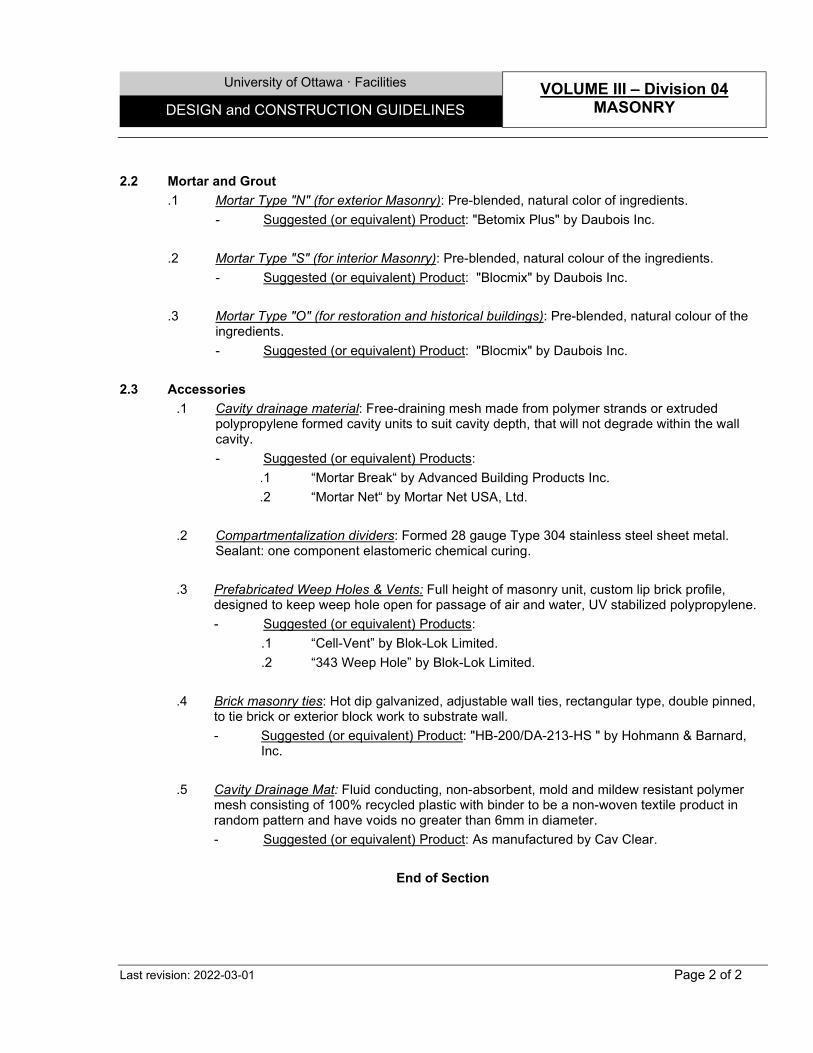
University of Ottawa · Facilities VOLUME III – Division 04
MASONRY DESIGN and CONSTRUCTION GUIDELINES
Last revision: 2022-03-01 Page 2 of 2
2.2 Mortar and Grout
.1 Mortar Type "N" (for exterior Masonry): Pre-blended, natural color of ingredients. - Suggested (or equivalent) Product: "Betomix Plus" by Daubois Inc.
.2 Mortar Type "S" (for interior Masonry): Pre-blended, natural colour of the ingredients.
- Suggested (or equivalent) Product: "Blocmix" by Daubois Inc.
.3 Mortar Type "O" (for restoration and historical buildings): Pre-blended, natural colour of the ingredients. - Suggested (or equivalent) Product: "Blocmix" by Daubois Inc.
2.3 Accessories
.1 Cavity drainage material: Free-draining mesh made from polymer strands or extruded polypropylene formed cavity units to suit cavity depth, that will not degrade within the wall cavity. - Suggested (or equivalent) Products:
.1 “Mortar Break“ by Advanced Building Products Inc.
.2 “Mortar Net“ by Mortar Net USA, Ltd.
.2 Compartmentalization dividers: Formed 28 gauge Type 304 stainless steel sheet metal. Sealant: one component elastomeric chemical curing.
.3 Prefabricated Weep Holes & Vents: Full height of masonry unit, custom lip brick profile,
designed to keep weep hole open for passage of air and water, UV stabilized polypropylene. - Suggested (or equivalent) Products:
.1 “Cell-Vent” by Blok-Lok Limited.
.2 “343 Weep Hole” by Blok-Lok Limited.
.4 Brick masonry ties: Hot dip galvanized, adjustable wall ties, rectangular type, double pinned, to tie brick or exterior block work to substrate wall. - Suggested (or equivalent) Product: "HB-200/DA-213-HS " by Hohmann & Barnard,
Inc.
.5 Cavity Drainage Mat: Fluid conducting, non-absorbent, mold and mildew resistant polymer mesh consisting of 100% recycled plastic with binder to be a non-woven textile product in random pattern and have voids no greater than 6mm in diameter. - Suggested (or equivalent) Product: As manufactured by Cav Clear.
End of Section
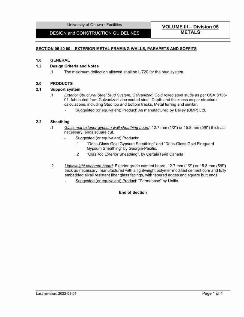
University of Ottawa · Facilities VOLUME III – Division 05
METALS DESIGN and CONSTRUCTION GUIDELINES
Last revision: 2022-03-01 Page 1 of 4
SECTION 05 40 00 – EXTERIOR METAL FRAMING WALLS, PARAPETS AND SOFFITS 1.0 GENERAL 1.2 Design Criteria and Notes
.1 The maximum deflection allowed shall be L/720 for the stud system. 2.0 PRODUCTS 2.1 Support system
.1 Exterior Structural Steel Stud System, Galvanized: Cold rolled steel studs as per CSA S136-01, fabricated from Galvanized zinc coated steel. Depth and thickness as per structural calculations, including Stud top and bottom tracks, Metal furring and similar. - Suggested (or equivalent) Product: As manufactured by Bailey (BMP) Ltd.
2.2 Sheathing .1 Glass mat exterior gypsum wall sheathing board: 12.7 mm (1/2") or 15.8 mm (5/8") thick as
necessary, ends square cut. - Suggested (or equivalent) Products:
.1 "Dens-Glass Gold Gypsum Sheathing" and "Dens-Glass Gold Fireguard Gypsum Sheathing" by Georgia-Pacific.
.2 “GlasRoc Exterior Sheathing”, by CertainTeed Canada. .2 Lightweight concrete board: Exterior grade cement board, 12.7 mm (1/2") or 15.8 mm (5/8")
thick as necessary, manufactured with a lightweight polymer modified cement core and fully embedded alkali resistant fiber glass facings, with tapered edges and square butt ends. - Suggested (or equivalent) Product: "Permabase" by Unifix.
End of Section

University of Ottawa · Facilities VOLUME III – Division 05
METALS DESIGN and CONSTRUCTION GUIDELINES
Last revision: 2022-03-01 Page 2 of 4
SECTION 05 50 00 - METAL WORK 1.0 GENERAL 1.2 Design Criteria and Notes
.1 Detail and fabricate balustrades / handrails as per National Association of Architectural Metal Manufacturers (NAAMM) Metal Stairs Manual. Design Load criteria shall be as per OBC part 4.
.2 Work shall be true to detail, clean, straight, with sharp profile and smooth finish surfaces. No material containing plugged or filled holes permitted.
.3 Use hot dipped galvanized fasteners and anchors for galvanized items, and Stainless Steel fasteners and anchors for stainless steel and aluminum items.
.4 Use self-tapping shake-proof flat headed screws on items requiring assembly by screws and Countersunk exposed fastenings, cut off bolts flush with nuts for exposed item.
.5 Install support at hang-on Countertops perimeter with miscellaneous steel ‘C’ or ‘L’ channel, minimum 76mm (H) X 51mm (W) structurally anchored to the walls.
.6 Grind welds smooth and flat, and fill flush with filler compatible with finish coating system, where exposed to view.
.7 Allow for differential movements with assemblies and at junctions of assemblies with surrounding of work.
.8 Insulate between dissimilar metals or between metal and masonry and concrete with bituminous paint to prevent electrolytic action.
.9 Finishes:
Elements: Handrails, guardrails, decorative columns, wall panels, treads, stairs and similar, or as indicated.
S.S.
, G
rade
316L
S.S.
, Gra
de 3
04
Prepainted
Hot
dip
ped
Gal
vani
zed
Prim
ed s
teel
FRP
Alum
inum
Zinc
Pow
der c
oatin
g &
Poly
este
r Pow
der c
oate
d
Hot
dip
ped
Gal
vani
zed
& Po
lyes
ter P
owde
r coa
ted
Polis
hed
Fini
sh
#2B
Fine
Sat
in F
inis
h #4
• High corrosive areas. • CL3 classified Laboratories.
X X
• Countertops and Sinks (22 42 01). X • Exterior or interior elements in
contact with exterior grade or on ground floor level close to entrance Lobbies.
X X X X
• Mechanical spaces. X X • Elsewhere exterior, roofs and
similar. X X
• Elsewhere interior. X X X X

University of Ottawa · Facilities VOLUME III – Division 05
METALS DESIGN and CONSTRUCTION GUIDELINES
Last revision: 2022-03-01 Page 3 of 4
2.0 PRODUCTS 2.1 Grating, stairs & Ladders .1 Steel grating, treads & landings, antiskid: Composed of bars 38 mm x 5 mm (1½" x 3/16")
and rods, smooth or serrated (antiskid) surface, regular mesh. - Suggested (or equivalent) Product: "Type 19-W-4" by Russel Metals Inc.
.2 Fiber Reinforced Polymer (FRP) Grating, treads, landings, anti-skid: In moulded gratings,
38mm thick mesh pattern, c/w anti-skid nosing. - Suggested (or equivalent) Product: "Duragrate Stair tread" by Fiberman Inc.
.3 Steel safety ladder rungs: In cold formed steel, 2.28 mm (0.09" / 13 ga) thick, 40 mm (15/8")
wide and 28 mm (11/8") high, with 3 holes. - Suggested (or equivalent) Product: as manufactured by Fisher and Ludlow (Harris
Steel Group Inc.).
.4 Steel Checker Plates, anti-skid: In cold formed steel, 3 mm (.13" / 11 ga) thick, sizes as indicated, with diamond shape anti-ski surface, folded to suit. - Suggested (or equivalent) Product: as manufactured by Mascot Steel + Tools.
2.2 Accessories
.1 Access panels, primed steel, regular or fire resistant: Cold rolled steel access doors and panels with continuous piano hinges, with manual locks, primed, with galvanized steel corners, regular or fire rated and insulated. - Suggested (or equivalent) Products: as manufactured by Cendrex:
.1 "AHD" model (regular), for masonry walls.
.2 "AHD GYP" model (flush), for gypsum walls and ceilings (metal faced).
.3 "AHA GYP" model (recessed), for gypsum walls and ceilings (gypsum or tile faced).
.4 "PFI" model (fire rated and insulated).
.5 "PFN" model (fire rated non-insulated).
.2 Tactile Walking Surface Indicators, in Iron: In Iron - with asphalt dip. Cast-in place, or inserted. - Suggested (or equivalent) Product: As manufactured by Duralast.
.3 Tactile Walking Surface Indicators, in Polymer: In engineered polymer composites -
reinforced with fiberglass, and integral colour. Cast-in place, or inserted. - Suggested (or equivalent) Product: As manufactured by Kinesik Engineered Products.
.4 Carborundum anti-skid strips: Manufactured from a choice of 1.6mm galvanised metal,
Stainless Steel or Aluminium, coated with a mix of two-part acrylic polyurethane and an aluminium oxide granule.
University of Ottawa · Facilities VOLUME III – Division 05
METALS DESIGN and CONSTRUCTION GUIDELINES
Last revision: 2022-03-01 Page 4 of 4
- Suggested (or equivalent) Product: As manufactured by Floorsafe Inc. End of Section
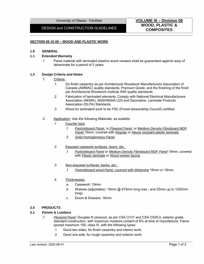
University of Ottawa ꞏ Facilities VOLUME III – Division 06 WOOD, PLASTIC &
COMPOSITES DESIGN and CONSTRUCTION GUIDELINES
Last revision: 2020-08-01 Page 1 of 2
SECTION 06 10 00 – WOOD AND PLASTIC WORK
1.0 GENERAL
1.1 Extended Warranty
.1 Panel material with laminated plastics wood veneers shall be guaranteed against warp of delaminate for a period of 2 years.
1.2 Design Criteria and Notes
.1 Criteria:
.1 Do finish carpentry as per Architectural Woodwork Manufacturers Association of Canada (AWMAC) quality standards, Premium Grade; and the finishing of the finish per Architectural Woodwork Institute AWI quality standards.
.2 Fabrication of laminated elements: Comply with National Electrical Manufacturers Association (NEMA): ANSI/NEMA LD3 and Decorative. Laminate Products Association (DLPA) Standards.
.3 Wood for laminated work to be FSC (Forest stewardship Council) certified.
.2 Application: Use the following Materials, as suitable:
.1 Counter tops:
.1 Particleboard Panel, or Plywood Panel, or Medium Density Fibreboard MDF Panel 19mm, covered with Regular or Abuse resistant plastic laminate.
.2 Solid Homogeneous Panel.
.2 Exposed casework surfaces, doors, etc.:
.1 Particleboard Panel or Medium Density Fibreboard MDF Panel 19mm, covered with Plastic laminate or Wood veneer facing.
.3 Non-exposed surfaces, backs, etc.:
.1 Particleboard wood Panel, covered with Melamine 16mm or 19mm.
.4 Thicknesses:
.a Casework: 19mm.
.b Shelves (adjustable): 19mm @ 915mm long max., and 25mm up to 1220mm long).
.c Doors & Drawers: 16mm.
2.0 PRODUCTS
2.1 Panels & Lumbers
.1 Plywood Panel: Douglas fir plywood, as per CSA O121 and CSA O325.0, exterior grade, standard construction, with maximum moisture content of 8% at time of manufacture. Flame spread maximum 150, class III, with the following types:
.1 Good two sides, for finish carpentry and interior work.
.2 Good one side, for rough carpentry and exterior work.
University of Ottawa ꞏ Facilities VOLUME III – Division 06 WOOD, PLASTIC &
COMPOSITES DESIGN and CONSTRUCTION GUIDELINES
Last revision: 2020-08-01 Page 2 of 2
.2 Particleboard wood Panel: Interior mat-formed particleboard, minimum density of 720 kg/m3 (45 lb/ft 3), sanded faces (grit 120), Type 1, Grade "M2" (industrial).
- Suggested (or equivalent) Products, as manufactured by:
.1 Tafisa. .2 Uniboard Canada Inc.
.3 Medium Density Fibreboard MDF Panel: Density of 770 kg/m, formaldehyde free, smooth faces.
- Suggested (or equivalent) Products:
.1 "Norbord MDF" by Norbord Industries Inc.
.2 "Medite II" by Medite Co.
.3 "Panfibre Excel MDF" by Uniboard Canada Inc.
.10 Particleboard wood Panel, covered with Melamine: Similar to Particleboard Wood panel, covered with Melamine resin impregnated decorative sheet thermally fused to both faces of particleboard core, grade M3.
- Suggested (or equivalent) Products, as manufactured by:
.1 Tafisa. .2 Uniboard Canada Inc.
.11 Wood veneer facing: 0.508 mm (0.02") or 0.75 mm (1/32") thick rift cut, with edges in solid hardwood, same species as face veneer, or veneer, without hardwood.
2.2 Plastic Laminate
.1 Regular plastic laminate sheet: Grade GP (general purpose), and grade PF (post forming). Regular 1.15 mm (0.045") thick, or light duty 0.75 mm (0.030") thick, depending on the use.
.2 Abuse-resistant plastic laminate sheet: A homogeneous non-porous high density composed of paper impregnated with thermosetting resin, with Nanotechnology anti-scratch characteristic.
- Suggested (or equivalent) Products: “Fenix NTM”, by Arpa.
2.3 Solid Composite
.1 Solid Homogeneous Panel: Non-porous, homogeneous filled acrylic composite, smooth finished, resistant to marking.
- Suggested (or equivalent) Products: as manufactured by:
.1 Corian. .2 Hanex
2.4 Accessories
.1 Wall mount shelve adjustable brackets and racks: In steel, ultra-robust, double slot Wall Standards 16-gauge, with double flange brackets 16-gauge (8", 10", and 12" brackets) or 14-gauge (14"-24" brackets), adjustable in 1” (25mm) increments, sizes and configuration as indicated, colour in prepainted white or zinc plated.
- Suggested (or equivalent) Products: “85 & 185 Series”, as manufactured by Knape & Vogt.
End of Section
University of Ottawa · Facilities VOLUME III – Division 07
THERMAL & MOISTURE PROTECTION DESIGN and CONSTRUCTION GUIDELINES
Last revision: 2022-03-01 Page 1 of 24
SECTION 07 10 00 – AIR / MOISTURE / WATER PROTECTION 1.0 GENERAL 1.1 Extended Warranty
.1 The work of the whole moisture, air/vapour protection system shall be guaranteed against failure of performance, by the manufacturers and by the Subcontractor, for a period of 5 years for labour and 10 years for Materials.
.2 Manufacturer representative shall be present at all construction phases to ensure adequate quality control on the installation.
1.2 Design Criteria and Notes
.1 All Air barrier/Vapour retarder membranes at connections with curtain wall mullions, door or window frames and at deflection joints or similar, shall be supported by Metal flashing and coping, galvanized or pre-painted (07 40 00) 26 ga. min. (bent and folded to suit), or similar, where the unsupported gap exceeds 13mm. Otherwise, apply Silicone sealant transitional Membrane, or similar at those locations.
2.0 PRODUCTS 2.1 Water proofing Membranes
.1 Hot Applied Asphalt Waterproofing Membrane: Hot applied, rubberized asphalt membrane composed of specially selected blend of refined asphalts, synthetic rubber and mineral stabilizers, solids content: 100%; thickness: 5 mm (3/16") average (dry film), with fabric reinforcement; water vapour permeance: 0.6 ng/Pa.m2.s (0.01 perm) for 3 mm (1/8") wet film. - Suggested (or equivalent) Products:
.1 "Elasto-Seal 790-11" by Henry. .2 "6125" by Hydrotech.
.3 "PQ 6100" by Permaquik.
-With Fabric reinforcing system: spun polyester fabric, min. 0.2 mm (8 mils) thick. - Suggested (or equivalent) Products:
.1 "Polyester fabric" by Henry. .2 "Reemay 2016" by Hydrotech.
.3 "PQ 2016" by Parmaquik. .2 Bituminous Damp proofing Membrane: Premium quality, medium consistency, solvent type
damp proofing compound of selected asphalts and fibres, with a water vapour permeance at 3 mm (1/8") wet film of 2.9 ng/Pa.m².s (0.05 perms). - Suggested (or equivalent) Product: "710-11" by Henry.
.3 Cementitious Waterproofing: A special formulation powder containing organic and inorganic
cementitious material, used as a slurry coating, with dry film thickness 1.5 mm (1/16") for Base coat and 1.5 mm (1/16") for Wear coat. - Suggested (or equivalent) Product: "Krystol T1" (base coat) + "Krystol T2" (wear coat)
by Poly-Tech MP Inc.
University of Ottawa · Facilities VOLUME III – Division 07
THERMAL & MOISTURE PROTECTION DESIGN and CONSTRUCTION GUIDELINES
Last revision: 2022-03-01 Page 2 of 24
.4 Elastomeric Waterproofing Membrane: A modified asphalt emulsion seamless monolithic membrane using formulated polymers providing elastomeric performance. - Suggested (or equivalent) Products:
.1 "Roller/Brush Rubber " by Cantex, distributed by Krytex Poly-Tech MP Inc.
.2 “MasterSeal® HLM 5000” by BASF.
.5 Self-Adhering Waterproofing Membrane: A high-performance waterproofing barrier, SBS rubberized asphalt compound, 60 mils (1.5 mm) thick, with hydrostatic head pressures of 231 feet. - Suggested (or equivalent) Product: "Blueskin WP 200" by Henry.
2.2 Air barrier Membranes .1 Modified bitumen, air barrier sheet: A self-adhered vapour permeable, water resistive air
barrier membrane consisting of an engineered film and a patented, permeable adhesive technology with split-back poly-release film, with 1914 ng/Pa.s.m² (33 Perms) water Vapour permeance. - Suggested (or equivalent) Product: "Blueskin VP160" by Henry.
2.3 Air barrier/Vapour retarder Products .1 Polyolefin Vapour Barrier Membrane (for use under concrete slab on grade): A highly durable
polyolefin sheet and a non-tacky adhesive coating, with maximum 1.7 ng/Pa.s.m2 (0.03 perms) water vapour permeance. - Suggested (or equivalent) Product: "FlorprufeTM 120" by Grace.
.2 Polyethylene Vapour Barrier Membrane, Fire Retardant: A highly durable polyethylene sheet 10 mills, with 1.7 ng/Pa.s.m2 (0.03 perms) water vapour permeance. - Suggested (or equivalent) Product: As manufactured by Uline Inc.
.3 Modified bitumen, air/vapour barrier sheet and thru-wall flashing Membranes, self-adhesive
(for general use and transition points with adjacent surfaces membrane and through-wall flashing at bottom of masonry walls or at shelf angles, and at bottom of manufactured siding walls): Self-adhered, SBS modified bitumen membrane reinforced with proprietary glass scrim, or integrally laminated to a cross-laminated polyethylene film (thru-wall), minimum 1.0 mm (40 mil) thick, with maximum 5 ng/Pa.s.m2 (0.08 perms – Method B) water vapour permeance. - Suggested (or equivalent) Products for general membrane:
.1 "Blueskin SA" and "Lo-Temp Blueskin SA" by Henry. .2 "Sopraseal Stick 1100T" by Soprema.
- Suggested (or equivalent) Products for thru-wall membrane: .1 "Blueskin TWF" by Henry.
.4 Liquid Emulsion Air and Vapour Barrier Membrane: One component, liquid applied, elastomeric membrane, cold applied by trowel or spray, with maximum 5 ng/Pa.s.m2 (0.08 perms) water vapour permeance. - Suggested (or equivalent) Product: "Air-Bloc 32" by Henry.
University of Ottawa · Facilities VOLUME III – Division 07
THERMAL & MOISTURE PROTECTION DESIGN and CONSTRUCTION GUIDELINES
Last revision: 2022-03-01 Page 3 of 24
.5 Modified Bitumen Air/Vapour Barrier Sheet Membrane, Thermofusible Grade: Thermofusible,
SBS modified bitumen membrane reinforced with proprietary glass scrim, 2.5 mm (100 mils) thick, with maximum 0.2 ng/Pa.m2.s (0.003 perms) water vapour permeance. - Suggested (or equivalent) Products:
.1 "Blueskin TG" by Henry. .2 "Aquabarrier TG" by IKO.
.3 "Sopraseal 60" by Soprema.
.6 Latex Moisture Vapor retarder Paint: Interior Latex combining a primer and finish in a single, fast drying coat, can be topcoated, with any compatible interior latex or alkyd product, 2.4 mils total thickness, with maximum 60.0 ng/Pa.m2.s (1.0 perms) water vapour permeance. - Suggested (or equivalent) Product: "Moisture Vapor Barrier" by Sherwin-Williams.
2.4 Accessories
.1 Geo-drain: Geo-drain with a dimple core of high-density polyethylene with a non-woven needle-punched filler fabric. - Suggested (or equivalent) Product:
.1 "Hydro-drain 400" by Hydro-tech (vertical surfaces).
.2 "Hydro-drain 700" by Hydro-tech (horizontal surfaces)
.2 Drainage board: A polypropylene Three-dimensional polymeric core drain board with a non-woven geotextile fabric fully bonded to the top dimples of the core. - Suggested (or equivalent) Product: “Henry DB” Series by Henry.
.3 Silicone sealant transitional Membrane: Self-supportive transitional membrane in preformed silicone elastomer extrusion set in silicone bed. - Suggested (or equivalent) Product:
.1 “123 Silicone Seal Series” and “795 Silicone Building Sealant” by Dow Corning.
.2 “Proglaze ETA System” by Tremco.
.4 Expansion joint – Pre-compressible: Exposed or hidden Preformed, self-expanding foam, sealant system with Silicone pre- coated surface. - Suggested (or equivalent) Product: As manufactured by EMSEAL Inc.
End of Section
University of Ottawa · Facilities VOLUME III – Division 07
THERMAL & MOISTURE PROTECTION DESIGN and CONSTRUCTION GUIDELINES
Last revision: 2022-03-01 Page 4 of 24
SECTION 07 20 00 – THERMAL INSULATION 1.0 GENERAL 1.2 Design Criteria and Notes .1 Butt joints tightly and offset vertical joints to form an unbroken thermal barrier. Use largest
possible dimensions to reduce number of joints.
2.0 PRODUCTS 2.1 Rigid Insulation
.1 Extruded expanded polystyrene board roof insulation: Type 4, with shiplapped edges, and joints staggered, RSI = 0.88 / 25 mm (R = 5.00 / 1"), of 240 kPa (35 psi) compressive strength. - Suggested (or equivalent) Products:
.1 "Celfort 350" by Owens Corning. .2 "Roofmate" by Dow Chemical.
.2 Extruded Expanded Polystyrene Board Wall Insulation: Type 4, ship lapped edges, RSI = 0.88 / 25 mm (R = 5 / 1"), minimum compressive strength of 210 kPa (30 psi). Provide appropriate grooves where Metal furring for application with rigid insulation are used. - Suggested (or equivalent) Products:
.1 "Celfort 300" by Owens Corning.
.2 "Styrofoam SM" by Dow Chemical.
.3 "Styrofoam XPS" by Dupont. .3 Extruded Expanded Polystyrene Board Wall Insulation with Modified Concrete Facing: Type
4, thickness as indicated, ship lapped edges, RSI = 0.88 / 25 mm (R = 5 / 1"), minimum compressive strength of 210 KPA (30 psi); with 6 mm (1/4") modified concrete facing. - Suggested (or equivalent) Product: "Tech-Crete" by CFI.
.4 Polyisocyanurate Board Wall Insulation with Foil facer: Type 1, rigid, closed cell insulation,
integrally laminated to tri-laminate foil/kraft/foil facers, outside face non-reflective, inside face non perforated, without CFC, with thermal resistance: RSI value of 1.27 / 25 mm (R = 7.2 / 1"); density: 32 kg/m3 (2 lb/ft3); compressive strength: 140 KPA (20 lb/in2). - Suggested (or equivalent) Product: "AP Foil-Faced” by Johns Manville.
2.2 Sprayed Insulation
.1 Sprayed Polyurethane Insulation: foam Class 1, RSI = 1.05 / 25 mm (R = 6.00 / 1"). - Suggested (or equivalent) Products:
.1 "Airmetic 0223-A100" ("Heatlok 0240") by Demilec.
.2 "Airmetic 0223F/A100" by Demilec (for cold weather applications).
.2 Sprayed or Injected Polyurethane Insulation, Portable System (in structural members’ cavities or similar): Two components, without CFCs, having a density of 28 kg/m3 (1.75 lbs/ft3), in a portable dispensing system (not in cans). - Suggested (or equivalent) Product: "Froth-Pak" by Dow Chemical.
University of Ottawa · Facilities VOLUME III – Division 07
THERMAL & MOISTURE PROTECTION DESIGN and CONSTRUCTION GUIDELINES
Last revision: 2022-03-01 Page 5 of 24
.3 Polyurethane foam adhesive sealant (to to fill spaces between frames and adjacent walls): Polymeric insulating sealant, without CFC’s single component, low density. - Suggested (or equivalent) Product: "CF 812" by Hilti
2.3 Semi-Rigid Insulation
.1 Mineral Fibre Semi-Rigid Board Siding Wall Insulation, Medium Density (for metal siding panels): Stone wool, Type 1, Class 1, RSI = 0.71 / 25 mm (R = 4.0 / 1"), 32 kg/m3 (2 lb/ft3) minimum density. - Suggested (or equivalent) Product: "Roxul Plus MB" by Roxul.
.2 Mineral Fibre Semi-Rigid Board cavity Wall Insulation: Made of stone wool, Type 2, Class 4,
RSI = 0.76 / 25 mm (R = 4.3 / 1"), 72 kg/m3 (4.5 lb/ft3) minimum density. - Suggested (or equivalent) Product: "CavityRock DD" by Roxul.
.3 Mineral Fibre Semi-Rigid Board Insulation for Curtain Wall: Made of stone wool, Type 2,
Class 4, RSI = 0.75 / 25 mm (R = 4.2 / 1"), 56 kg/m3 (3.5 lb/ft3) minimum density. - Suggested (or equivalent) Product: "CurtainRock" by Roxul.
.4 Glass Fibre Semi-Rigid Board Insulation with Foil Facer: Semi-rigid insulation laminated to FSK Vapor-retarder facer. Type 2, Class 4, RSI = 0.76 / 25 mm (R = 4.3 / 1"), 48 kg/m3 minimum density. - Suggested (or equivalent) Product: "I/S 300 – FSK Faced" by Johns Manville.
2.4 Batt & Flexible Insulation .1 Mineral Fiber Flexible Insulation (for deflection joints): Made of stone wool, RSI = 0.68 / 25
mm (R = 3.86 / 1"), 32 kg/m3 (2 lb/ft3) minimum density. - Suggested (or equivalent) Products:
.1 For wood studs: "ComfortBatt" by Roxul.
.2 For steel studs: "Roxul Plus" by Roxul. .2 Glass Fibre Flexible Insulation (within metal studs): RSI = 0.70 / 25 mm (R = 4.00 / 1"), of
12.58 kg/m³ (0.79 lb/ft³) density. - Suggested (or equivalent) Product: "Fiberglas Pink Insulation" by Owens-Corning.
.3 Mineral Fibre Acoustical Batt Insulation: Friction fit type insulation, 40 kg/m3 (2.5 lb/ft3)
minimum density. - Suggested (or equivalent) Product: "Acoustical Fire Batts (AFB)" by Roxul.
.4 High Thermal Resistance Blanket (for thermal bridging points): Thin-profile (starting at 10mm), flexible semi-rigid insulation. RSI = 1.72 / 25mm (R = 9.8) compressive strength 10 psi. - Suggested (or equivalent) Product:
.1 “Spaceloft" by Aspen/Aerogels. .2 "HPI-1000" by Dow Corning.
University of Ottawa · Facilities VOLUME III – Division 07
THERMAL & MOISTURE PROTECTION DESIGN and CONSTRUCTION GUIDELINES
Last revision: 2022-03-01 Page 6 of 24
2.5 Plenum Insulation .1 Glass fibre flexible acoustical liner (over bulkheads & ceiling tiles): Made of fibreglass bonded
with thermosetting resin. - Suggested (or equivalent) Product: “Permacote Linacoustic Standard" by Johns
Manville. .2 Flexible acoustical buffer (suspended in plenums): Made of fiberglass, faced with fiberglass
cloth and backed with a flame-proof foil (50mm thick), secured with metal track. - Suggested (or equivalent) Products: “Plenum Barrier Quilt”, by Insul-Quilts.
.3 Semi-rigid acoustical buffer (suspended in plenums): Made of mineral wool, faced with a flame-proof foil (50mm thick), secured with metal track. - Suggested (or equivalent) Products: “Rockfon Plenum Barrier Board”, by Rockfon.
2.6 Polymer & Acrylic Systems
.1 Plaster System for Foundation Walls: High performance, polymer-modified, two-component, fast-setting, non-sag cementitious mortar. Thickness from 5 mm (3/16") to 25mm (1"). - Suggested (or equivalent) Product: “SikaTop-123 Plus” by Sika.
.2 Plaster System, on Insulation or Lightweight Concrete Boards:
.1 Base coat: of 5 mm (3/16") thickness (on Insulation), or 1.6 mm (1/16") thickness (on Lightweight concrete board (05 40 00), composed of 2 parts by mass of 100% acrylic product and 1 part of Type 10 Portland cement, having after 28 days an impact resistance greater than 3.5 MPa, a compression resistance of 37.6 MPa, a tension resistance of 3.6 MPa and a bending strength of 9.3 Mpa, with joint tape at the transition points (starter mesh), and Glass Fibre reinforcing on the total surface.
.2 Finish coat: alkali, humidity and mildew resistant, ready mixes, 100% acrylic polymer based coating, standard light sand texture, natural grey. - Suggested (or equivalent) Products:
.1 For Insulation system:"Adex-HC" by Adex Systems Inc. (Groupe BAO)
.2 For concrete board system: “Unifix System" by Unifix Inc. 2.6 Accessories
.1 Sound Barrier Sheet (In the Studs or though Drywall Layers): A mass loaded vinyl (MLV), to increase STC ratings of walls, floors & ceilings. Can be used in new construction and also to correct noise problems in existing spaces, 3mm or 6mm thick. - Suggested (or equivalent) Product: “Audioseal Sound Barrier” by Acoustical Solutions.
.2 Metal furrings, for application with rigid insulation: "U" or "L" shaped, min. 0.38 mm (28 ga)
thick, galvanized, for drywall installation. Use custom fabricated 0.91mm (20 ga) thick furrings of bent plate, and of similar shape for the soffit application. - Suggested (or equivalent) Products: As manufactured by:
.1 Owens Corning. .2 Dow Chemical.

University of Ottawa · Facilities VOLUME III – Division 07
THERMAL & MOISTURE PROTECTION DESIGN and CONSTRUCTION GUIDELINES
Last revision: 2022-03-01 Page 7 of 24
.2 Insulation fasteners: Soft washer and pin type, direct fasten type: polyethylene washer, corrosion resistant fastener. - Suggested (or equivalent) Product: “X-SW 60 Pins” by Hilti.
End of Section
University of Ottawa · Facilities VOLUME III – Division 07
THERMAL & MOISTURE PROTECTION DESIGN and CONSTRUCTION GUIDELINES
Last revision: 2022-03-01 Page 8 of 24
SECTION 07 30 00 – SHINGLES, ROOF TILES AND COVERING 1.0 GENERAL 1.1 Extended Warranty .1 The work of the whole shingle roofing system shall be guaranteed against failure of
performance, by the manufacturer and by the Contractor, for a period of 20 years for labor and qualified life period for the shingles.
2.0 PRODUCTS 2.1 Shingles
.1 Asphalt shingles: Architectural shingles, with rectangular pattern, and auto adhesive back strips. Weight / square: 350 lbs approximate. - Suggested (or equivalent) Products:
.1 As manufactured by GAF Inc.
.2 As manufactured by CertainTeed Inc. 2.2 Underlayment: .1 Roofing felt underlayment: Asphalt saturated 15, non-perforated.
- Suggested (or equivalent) Product: as manufactured by BP Shingle.
.2 Glass fiber reinforced modified bitumen waterproofing membrane for roofing: 1.5 mm (60 mils) thick, with mineral granules surface; self-adhesive. - Suggested (or equivalent) Product: "Gripgard" by BP Shingle.
End of Section
University of Ottawa · Facilities VOLUME III – Division 07
THERMAL & MOISTURE PROTECTION DESIGN and CONSTRUCTION GUIDELINES
Last revision: 2022-03-01 Page 9 of 24
SECTION 07 40 00 – MANUFACTURED SIDING AND CLADDING PANELS 1.0 GENERAL 1.1 Extended Warranty
.1 Metal siding products furnished and installed shall be guaranteed against all defects of fabrication, installation and shall be air and water tight for a period of 5 years.
1.2 Design Criteria and Notes .1 Metal-to-metal fastenings and accessories shall be fabricated of the same metal, or of a
metal which will not set up electrolytic action causing damage to fastenings or components, or both, under most conditions.
.2 All fasteners for aluminum or Composite Panels work shall be stainless steel, as per manufacturer’s recommendations and as per ASME B18.6.4-1999.
.3 All exposed screws to have a neoprene washer and be painted same colour as siding. .4 Fasteners to be self-tapping. .6 In siding aluminum panels or similar, provide weep-holes to control condensation, including
proper inclusion of seals, and provision for breathing, venting and drainage. Do all drilling (for weep-holes, etc.) in shop, not on site. (6mm min. @ 600mm o/c)
2.0 PRODUCTS 2.1 Metallic Exterior Panels
.1 Exterior metal siding panels, prepainted: as per CAN/CGSB-93.4, in galvanized prepainted steel, installed vertically, with smooth surface and interlocking edges, in metal sandwich walls or on other substrates, 0.76 mm (0.03" / 22 ga) thick or as necessary. - Suggested (or equivalent) Product: As manufactured by VicWest.
.2 Exterior metal siding panels, galvanized: as per CAN/CGSB-93.4, in hot dipped galvanized
steel, with overlapping edges, in metal sandwich walls or on other substrates, 0.76 mm (0.03" / 22 ga) min. or as necessary, with Zinc coating in Glavalum Plus. - Suggested (or equivalent) Product: "22/3" x 7/8" Corrugated", by VicWest.
2.2 Composite Panels
.1 Glass fiber reinforced concrete cladding panels: composed of inorganic fibre with natural stone and cement, with glass fibre reinforcements. - Suggested (or equivalent) Product: As manufactured by Synstone.
2.3 Sub-Girts
.1 Galvanized Steel sub-girt System for Walls: Double or triple system, in galvanized steel "Z", "L" or "U" elements, of thickness as necessary, min. 1.2 mm (cal. 18), to comply to design load specified. Interior and exterior surfaces insulated by means of polyethylene Insulating strip for metal work, self-adhesive.
2.4 Interior Air barrier/Vapour retarder Panels
.1 Interior metal liner panels, galvanized or prepainted: in galvanized or prepainted steel,
University of Ottawa · Facilities VOLUME III – Division 07
THERMAL & MOISTURE PROTECTION DESIGN and CONSTRUCTION GUIDELINES
Last revision: 2022-03-01 Page 10 of 24
installed vertically in metal sandwich walls, with interlocking edges, 0.60 mm (0.02" / 24 ga) min. or as necessary. - Suggested (or equivalent) Product: "L-800R" or "L-800SR" by VicWest.
2.5 Finishes for Prepainted Aluminum work
.1 Prepainted fluoropolymer coating finish for aluminum surfaces: a fluoropolymer resin thermosetting coating, treated with and applied in plant, in three coats, of a total dry film thickness of 50.8 microns (2.0 mils), including primer, base coat and transparent finish coat. - Suggested (or equivalent) Product: "Duranar XL" by PPG.
2.6 Accessories
.1 Aluminium flashing and coping, anodized: including all accessories such as alignment bars, brackets, clips, inserts, shims, trims, fillers, sills, gutters as required, AA-5005-H14 alloy and temper, "stretcher level" quality, flat or profiled, minimum 0.81 mm (0.032" /20 ga) min., or as necessary.
.2 Aluminum flashing and coping, prepainted: Alloy AA-5005-H14, "stretcher level" quality,
minimum 0.81 mm (0.032"/20 ga) min., or as necessary, prepainted. .3 Metal flashing and coping, galvanized or pre-painted: Hot dipped galvanized or powder
coated, including all accessories such as alignment bars, brackets, clips, inserts, shims, trims, flashings, fillers, sills, gutters, as required, base metal minimum 0.61 mm (24 ga) min., or as necessary, same material, galvanization.
.4 Insect screens, galvanized steel (for all gaps bigger than 4mm): Hot dipped galvanized, 0.3
mm (0.012") diameter wire 18 x 14 mesh with 60% free area, secured to the bird-screen frame.
.5 Insect screens, aluminium (for all gaps bigger than 4mm): 0.3 mm (0.012") diameter
aluminum wire, with a stitch of 7.1 x 6.3 / cm2 (18 x 16 / in2) and 44% free area, secured to aluminum frame.
.6 Thermal breaks: (Thermal or electrolytic break and/or water-tightness), Insulating strip for metal work, self-adhesive, in cross-linked waterproof polyethylene EVA strip with adhesive on one or both faces, depending on location and required use, 3 mm (1/8") thick. - Suggested (or equivalent) Product: "Polyethylene #2720" by Jacobs and Thomson
(RCR International Inc.). .7 Thermally broken sub-spacers: In ceramic, Aluminum composite, or similar, engineered to
meet structural requirements. - Suggested (or equivalent) Products:
.1 “TCLIP” by Engineering Assemblies.
.2 “TAC Thermal Spacer” by ETG.
.3 “Cascadia Clip” by Cascadia Windows & doors.
.4 “Iso Clip”, by Northern Facades.
University of Ottawa · Facilities VOLUME III – Division 07
THERMAL & MOISTURE PROTECTION DESIGN and CONSTRUCTION GUIDELINES
Last revision: 2022-03-01 Page 11 of 24
.8 Cross-linked butyl preformed sealant (at joints between metal liners and sub girts): Of 100% solids, cross-linked butyl rubber. - Suggested (or equivalent) Product: "440 II Tape" by Tremco.
.9 Polyethylene foam EVA closure blocking (for compartmentalization): matching the siding
profile, in cross-linked waterproof polyethylene (EVA). - Suggested (or equivalent) Product: As manufactured by Jacobs and Thompson (RCR
International Inc.) .10 Synthetic rubber based industrial sealant (concealed between overlapping panels): non-
skinning. - Suggested (or equivalent) Product: "JS-773" by Tremco.
End of Section
University of Ottawa · Facilities VOLUME III – Division 07
THERMAL & MOISTURE PROTECTION DESIGN and CONSTRUCTION GUIDELINES
Last revision: 2022-03-01 Page 12 of 24
SECTION 07 50 00 – MEMBRANE ROOFING & PARAPETS 1.0 GENERAL 1.1 Extended Warranty
.1 The work of the full roofing system (including, sheathing, membranes and other) shall be guaranteed against failure of performance by the Contractor for a period of 2 years, and by the Manufacturer for a period of 10 years – non-prorated - for labor and Materials.
1.2 Design Criteria and Notes
.1 For conventional systems, roofing components shall be fully adhered, with the deck sheathing board fastened to the steel supporting structure underneath. Fully mechanically through fastened roofing membrane systems are not acceptable.
.2 Unless cases with particular energy saving concerns, or building specifics, the use of reflective white surfaces should not be considered in the roofing system choice.
.3 In new Buildings, structural decks shall be design to slope toward the drains in order to minimize the amount of sloped insulation.
.4 Only non-combustible supporting systems (steel studs, masonry or similar) are allowed in non-combustible buildings for parapets. Plywood is allowed as nailer substrate, provided it doesn’t exceed 600mm height, and the Parapet Flashing Membrane is covered by a metal flashing (OBC 2012, 3.1.5.3.3 & 4).
.5 For new constructions, Roofs to be designed to have positive slopes of 2% to the drains. Parapets to be designed with tops offering 10% slopes to the roof sides.
.6 On steel deck, fasteners for Support boards shall be anchored against upper flute ribs. The apparent portion shall not exceed the rib depths.
.7 Work shall be carried out in accordance with good Roofing practice and Canadian Roofing Contractors’ Association (CRCA).
.8 Install Lightweight concrete board (05 40 00) 300mm deep cement board, same thickness as adjacent described deck sheathing board on the roof perimeter of steel deck, around openings and under all curbs or accessories, for structural consolidation.
.9 Where parapet height exceeds 900mm approximate, or wherever handrails are supported on parapets, provide a structural reinforcement within the load bearing stud system.
.10 Roof vapor barrier membrane, shall be upturned against parapet framing.
.11 Access: .1 All Roof Hatches need to be installed at least 2 meters away from perimeter; otherwise,
a guard rail should be installed. .2 Always provide access to the different roof levels with appropriate means, taking in
consideration the size and type of the maintenance elements for equipment. .3 Protect roofing system from foot traffic damage at roof access doors, access hatches,
around roof mounted mechanical and electrical equipment, and other facilities requiring maintenance access using appropriate Traffic Elements.
.4 Roof anchors shall be considered in the following conditions (to be confirmed by Facilities): .1 High roofs or where facades are not easily accessible from grade level. .2 If an equipment or other similar maintenance access is required on a roof with no
guard protection.
University of Ottawa · Facilities VOLUME III – Division 07
THERMAL & MOISTURE PROTECTION DESIGN and CONSTRUCTION GUIDELINES
Last revision: 2022-03-01 Page 13 of 24
.12 Green Roofs: Design permitted; avoid plant material in the following locations: .1 Underneath roof lines unless there is built in irrigation. .2 Within 2 feet of south or west facing walls, unless irrigated weekly (during growing
season), as reflected light will cause excessive loss of soil moisture. .3 Underneath downspouts and drip lines. .4 In corners where snow tends to drift during winter. .5 In shady areas, those that get less than 3 hours of direct sunlight per day—too shady
for sedums. .6 Locations with constricted air movement. .7 Areas where there is reflected light from white membrane, glass and skylights, unless
there is a built-in irrigation system and access to water at least once per week. .8 Areas where there is excessive heat below roof deck, such as from steam or hot water
pipes. Use pavers or stone ballast in such areas. .9 Any area where water pools on the roof. .10 Within 10 feet of the leeward side of wind screens unless they extend to the ground. If
there is a gap, the wind will blow under it, accelerate, and dry out the plants. .11 Under landscape lighting that is close enough to plant material to throw heat onto the
plant material. 2.0 PRODUCTS 2.1 Roof Membranes
.1 Modified bitumen two-ply exposed roofing membrane, granule surfaced: .1 Base sheet: SBS polymer modified bitumen roofing membrane, minimum 2.2 mm
(90 mils) thick, with a 180 g/m2 non-woven polyester reinforcement, sanded lower surface for application with mopped asphalt or adhesive, and thermofusible polyethylene covered upper surface for torch application. - Suggested (or equivalent) Products: mopping asphalt or adhesive applied:
.1 "Modified Plus NP180 p/s" by Henry. .2 "Modiflex MP-180-FS-Base" by IKO. .3 "Elastophene 180 PS" by Soprema Inc.
.2 Top sheet: SBS minimum 4 mm (160 mils) thick, with a non-woven polyester reinforcement, thermofusible polyethylene covered back face for torch application and granular finish front face. - Suggested (or equivalent) Products, torch applied:
.1 "Modified Plus NP 250gT4" by Henry. .2 "Torchflex TP-250-Cap" by IKO. .3 "Sopralene Flam 250gr" by Soprema Inc.
.2 Modified bitumen two-ply protected roofing membrane:
.1 Base sheet: SBS polymer modified bitumen roofing membrane, minimum 2.2 mm or 3 mm (90 mils or 120 mils) thick, with a non-woven 180 g/m2 polyester reinforcement, both faces thermofusible polyethylene covered for torch application, or bottom face sanded for mopped asphalt application, and top face with thermofusible polyethylene.
University of Ottawa · Facilities VOLUME III – Division 07
THERMAL & MOISTURE PROTECTION DESIGN and CONSTRUCTION GUIDELINES
Last revision: 2022-03-01 Page 14 of 24
- Suggested (or equivalent) Products: Torch applied: .1 "Modified Plus NP180 p/p" by Henry. .2 "Torchflex TP-180-FF-Base" by IKO. .3 "Sopralene Flam 180" by Soprema Inc.
Mopping asphalt or adhesive applied:
.1 "Modified Plus NP180 p/s" by Henry. .2 "Modiflex MP-180-FS-Base" by IKO. .3 "Elastophene 180 PS" by Soprema Inc.
.2 Top sheet: similar to base sheet, both faces thermofusible polyethylene covered.
- Suggested (or equivalent) Products, torch applied: .1 "Modified Plus NP180 p/p" by Henry. .2 "Torchflex TP-180-FF-Base" by IKO. .3 "Sopralene Flam 180" by Soprema Inc.
.3 Hot applied modified asphalt roofing membrane: A specially selected blend of refined
asphalts, synthetic rubber and mineral stabilizers, with additives for better adhesion and low temperature flexibility, with Polyester Reinforcing sheet fabric, 0.2 mm to 0.25 mm (8-10 mils) thick. - Suggested (or equivalent) Products:
.1 Membrane "Elasto-Seal 790-11" with "Polyester Fabric" by Monsey Henry. .2 Membrane “6125" with "Reemay 2016" by Hydrotech
2.2 Parapet flashing Membrane:
.1 Modified bitumen two-ply sheet flashing membrane, granule surfaced: (on parapets, curbs, other vertical exposed surfaces): .1 Base sheet: SBS polymer modified bitumen roofing membrane, minimum 2.5 or 3
mm (100 mils or 120 mils) thick, with a non-woven polyester (or polyester and glass) reinforcement, self-adhesive, with a thermofusible polyethylene covered upper face for torch application. - Suggested (or equivalent) Products: self-adhesive:
.1 "Modified Plus NP180 Tack sheet" by Henry. .2 "Armourbond 180" by IKO. .3 "Sopralene Flam Stick" by Soprema Inc.
.2 Top sheet: SBS minimum 4 mm (160 mils) thick, with a non-woven polyester
reinforcement, thermofusible polyethylene covered back face for torch application and granular finish front face. - Suggested (or equivalent) Products: Torch applied:
.1 "Modified Plus NP 250gT4" or “NP250TUW (white)” by Henry. .2 "Torchflex TP-250-Cap" by IKO.
University of Ottawa · Facilities VOLUME III – Division 07
THERMAL & MOISTURE PROTECTION DESIGN and CONSTRUCTION GUIDELINES
Last revision: 2022-03-01 Page 15 of 24
.3 "Sopralene Flam 250gr" by Soprema Inc.
.2 Liquid flashing membrane: For difficult to adhere situations. One-component polyurethane / bitumen resin membrane. - Suggested (or equivalent) Product: "Alsan Flashing" (imbibed in granule, for UV
protection), by Soprema Inc.,
2.3 Support Boards .1 Fibreboard panels, regular: With square edges, asphalt coated on both faces and all edges,
12.7 mm (1/2") min. thick or as necessary. - Suggested (or equivalent) Products:
.1 "Esgard High Strength" by BP Shingles (EMCO). .2 "Cascades II haute performance HP" by Matériaux Cascades Inc. .3 "Xpress Board HD" by Soprema
.2 Fibreboard panels, sloped: high performance, with square/shiplapped edges, tapered,
thickness as necessary. - Suggested (or equivalent) Products:
.1 "Esgard" by BP Shingles (EMCO).
.2 As manufactured by Matériaux Cascades Inc.
.3 Perlite panels, regular and sloped, Homogeneous, expanded perlite, blended with selected binders and fibers, with waterproof top face, 25 mm (1") thick or as necessary. - Suggested (or equivalent) Product: "Fesco" by Johns Manville.
2.4 Insulations and Related Products
.1 Expanded polystyrene board roof insulation, with laminated fibreboard: Incorporating a fire retardant agent, Type II, RSI = 0.70 / 25 mm (R = 4.0 / 1"), with shiplapped edges, factory laminated by asphalt to 12.7 mm (½") fibreboard panels, Type I, RSI = 0.5/25 mm (R = 2.8/1"). - Suggested (or equivalent) Product: "Izofibre" by Fransyl.
.2 Expanded polystyrene board roof insulation, sloped: Incorporating a fire retardant agent,
Type II, RSI = 0.70 / 25 mm (R = 4.0 / 1"), having a compressive strength of 125.2 kPa (18.21 lbs/in2), with square edges. - Suggested (or equivalent) Product: "Bizolon" by Fransyl.
.3 Expanded polystyrene board roof insulation, with sloped laminated fibreboard: Incorporating
a fire-retardant agent, Type II, RSI = 0.70 / 25 mm (R = 4.0 / 1"), with square edges, factory laminated by asphalt to 12.7 mm (½") fibreboard panels, RSI = 0.5 / 25 mm (R = 2.8 / 1"). - Suggested (or equivalent) Product: "Bizofibre" by Fransyl.
.4 Polyisocyanurate board roof insulation regular and sloped: Type III class 2, rigid, closed cell,
inorganic/organic felt facing, with ecological expansion agent; RSI = 1.01 / 25 mm (R = 5.7 /
University of Ottawa · Facilities VOLUME III – Division 07
THERMAL & MOISTURE PROTECTION DESIGN and CONSTRUCTION GUIDELINES
Last revision: 2022-03-01 Page 16 of 24
1"). density: 32 kg/m3 (2 lb/ft3) ; compressive strength: 158 kPa (23 lb/in2); edges: square; flame spread/smoke developed values: less than 25. Use two layers where more than 51 mm or 63.7 mm (2" or 2½") is required. - Suggested (or equivalent) Product: "E’NRG’Y 3" by NRG Polyiso (Johns Manville).
.5 Extruded expanded polystyrene board roof insulation: Type 4, thickness as shown, with
shiplapped edges, and joints staggered, RSI = 0.88 / 25 mm (R = 5.00 / 1"), of 240 kPa (35 psi) compressive strength; with drainage grooves on the underside where required. - Suggested (or equivalent) Products:
.1 "Celfort 350" by Celfortec. .2 "Roofmate" by Dow Chemical.
2.5 Air barrier/Vapour retarder Membrane
.1 Asphalt laminated kraft paper vapour barrier: Asphalt laminated double kraft paper vapour retarder, with glass fibre yarn reinforced edges, Type 2. - Suggested (or equivalent) Products:
.1 "Vapour Bloc" by Henry. .2 "Roof Retarder" by Tremco. .3 "Armourgard" by Iko.
.2 Organic felt reinforced two-ply asphalt roofing membrane: Organic roofing felts, asphalt
saturated, perforated, No. 15 organic felts, in 5 layers (3 and 2), with Regular mopping or Modified elastomeric mopping asphalt. - Suggested (or equivalent) Product: "No.15 Asphalt Felt Perforated" by IKO Industries
Ltd.
.3 Interconnecting Vapour barrier membrane, asphalt or adhesive applied: Minimum 2.2 mm (90 mils) thick, with a non-woven 180 g/m2 polyester reinforcement, with sanded faces. - Suggested (or equivalent) Products:
.1 "Modified Plus NP180 s/s" by Henry. .2 "Modiflex MP-180-SS-Base" by IKO. .3 "Elastophene 180 SS" by Soprema Inc.
.4 Modified bitumen one-ply vapour barrier membrane, self-adhesive, torch or adhesive applied:
(for connection between roof and wall Air/vapour-barriers membranes under parapets): to serve also as of minimum 3 mm (120 mils) thick, with a non-woven 180 g/m2 polyester or 160 g/m2 non-woven polyester and glass scrim reinforcement, self-adhesive, or with thermofusible polyethylene covered faces. - Suggested (or equivalent) Products: self-adhesive:
.1 "Modified Plus NP180 Tack Sheet" (3 mm/120 mils) by Henry.
.2 "Armourbond 180" (3 mm/120 mils) by IKO.
.3 "Sopralene Flam Stick" (2.5 mm/100 mils) by Soprema Inc.
- Suggested (or equivalent) Products: Torch applied: .1 "Modified Plus NP180 p/p" by Henry.
University of Ottawa · Facilities VOLUME III – Division 07
THERMAL & MOISTURE PROTECTION DESIGN and CONSTRUCTION GUIDELINES
Last revision: 2022-03-01 Page 17 of 24
.2 "Modiflex MP-180-FF-Base" by IKO. .3 "Sopralene Flam 180" by Soprema Inc.
2.6 Deck Sheathing
.1 Glass fibre mat faced, silicone core gypsum roof sheathing board: A core of silicone treated gypsum, with inorganic glass mat surfaces, and non-asphaltic surface treatment of the face (primed type), 12.7 mm (1/2") min. thick or as necessary, square edges.
- Suggested (or equivalent) Product: "Dens-Deck" and "Dens-Deck Prime Roof Guard" by Georgia-Pacific.
.2 Gypsum-Fiber Roof Board: A high-performance, versatile board with advanced fiber-reinforced technology 9.5 mm (3/8”) min. thickness or as necessary, square edges.
- Suggested (or equivalent) Product: " Securock" by CGC.
2.7 Traffic Elements: .1 Concrete paving slabs: Plain face, 610 mm x 610 mm (24" x 24") paver size, 50 mm (2")
thick, natural colour, with prefabricated high density polyethylene grid-type pedestals, integral with spacer ribs, or on a layer of laminated insulation. - Suggested (or equivalent) Product: "Izodalle" by Fransyl Ltée.
.2 Modified bitumen protection and traffic pads: Precut pieces of the top layer of Modified
bitumen SBS roofing membrane, 915 mm (36") wide by 457 mm (18"), in contrasting colour. 2.8 Accessories
.1 Chemical curb system: 50 mm (2") pourable urethane rubber seal, with precast curb components of fireproof polymer cement or black structural urethane, as necessary. - Suggested (or equivalent) Product:
.1 "ChemCurb" by Chem Link.
.2 “Interclip system” by Duomastic.
.2 Gravel ballast: Nonporous material, washed, free from fines, ice, snow or long splinters: well graded, well rounded, Standard Size No.3, as per ASTM D 448, 25 mm to 51 mm (1" to 2"), well graded, having a density of approximately 2643 kg/m3 (165 lb/ft3), moisture content not exceeding 0.5%, as per ASTM D 1863, or as per FM Global requirements.
.3 Polyethylene film separation membrane: Min. 100 micron (4 mil) thick, Type 2.
- Suggested (or equivalent) Product: as manufactured by W. Ralston.
.4 Woven fabric membrane: Woven polyolefin or polyethylene fabric, UV stabilized, water permeable. - Suggested (or equivalent) Products:
.1 "Fabrene V.I.E." by Dow Chemical. .2 "Fabroc 400" by Hydrotech.

University of Ottawa · Facilities VOLUME III – Division 07
THERMAL & MOISTURE PROTECTION DESIGN and CONSTRUCTION GUIDELINES
Last revision: 2022-03-01 Page 18 of 24
.5 Expansion joint trim for roofing (at exposed joints): A combination of flexible rubber membranes supported by a closed cell foam to form flexible bellows, with two metal flanges. - Suggested (or equivalent) Product: "Expand-O-Flash" by Johns Manville.
.6 Expansion joint waterproof membrane (with high exposure to water): Exposed or hidden
elastomeric expansion waterproofing joint membrane, with asphaltic based medium, glued or torched.
.7 Butyl flexible membrane, reinforced (for connection between roof and wall Air/vapour-barriers membranes where structural or expansion movement is expected): Flexible flashing membrane composed of a combination of butyl and EPDM polymers, and reinforced with polyester fabric, 1.2 mm (47 mils) thick. - Suggested (or equivalent) Product: "990-26" by Henry.
.8 Plywood panel, Pressure Treated, Water Resistant: as per CSA O121 and CSA O325.0,
exterior grade, standard construction, with maximum moisture content of 8% at time of manufacture, pressure treated with copper alkaline quaternary, in a closed cylinder, in vacuum, to obtain a retention of 6.4 kg/cm3 of wood. - Suggested (or equivalent) Product: "NW100" by Timber Specialties (Goodfellow Inc.).
.9 Roof accessories & Post supports: In aluminium or as indicated, complete with the
corresponding 2 mm (0.08") thick flashing assemblies and seals. - Suggested (or equivalent) Products: As manufactured by Thaler.
.10 Roof Edge Safety Railing Systems: Modular system, with no penetration to roofing, for flat or
up to 3 degrees slope roofs. - Suggested (or equivalent) Products:
.1 “KeeGuard” by KeeSafety.
.2 As manufactured by Skyline Group.
.11 Growing Medium: Mix of organic and inorganic materials, to retain water, and support and maintain long term life and healthy growth of plant material. - Suggested (or equivalent) Products: “Rooftop Biomix” by Landsource Organix Ltd.
.12 Roof drainage board: A polypropylene Three-dimensional polyethylene core drain board with a factory laminated geotextile fabric fully bonded to the top dimples of the core. - Suggested (or equivalent) Product: “Sopradrain” by Soprema.
.13 Anti-Root barrier: A woven and micro-perforated polyethylene fabric. - Suggested (or equivalent) Product: “Microfab” by Soprema.
.14 Tray vegetated system: Modular tray system c/w planters and growing medium, variable depths from 75mm to 200mm. - Suggested (or equivalent) Product: “Hybrid modular system” by Liveroof.
University of Ottawa · Facilities VOLUME III – Division 07
THERMAL & MOISTURE PROTECTION DESIGN and CONSTRUCTION GUIDELINES
Last revision: 2022-03-01 Page 19 of 24
.15 Roof Hatches: with thermally broken cover and curb, polyisocyanurate insulation (R-20+), and special EPDM gasketing. - Suggested (or equivalent) Product: “S-50TB” by Bilco.
End of Section
University of Ottawa · Facilities VOLUME III – Division 07
THERMAL & MOISTURE PROTECTION DESIGN and CONSTRUCTION GUIDELINES
Last revision: 2022-03-01 Page 20 of 24
SECTION 07 80 00 - FIRE AND SMOKE PROTECTION 1.0 GENERAL 1.1 Extended Warranty
.1 Caulking work shall be guaranteed against failure for a period of 3 years. .2 Include coverage of repair or replacement of Firestopping materials, which fail to achieve a
smoke tight or watertight seal, exhibits loss of adhesion or cohesion, or do not cure. Sealants that crack, crumble, melt, shrink, run, or stain adjacent surfaces will be considered failed.
1.2 Design Criteria and Notes
.1 All applications of fire and smoke protection assemblies shall be as per tested assemblies UL, ULC, cUL or OBC SB-3. For assemblies not tested and rated, submit proposals based on related designs using accepted design criteria.
.2 A particular attention shall be given to the structural deflection on top of partitions, taking in consideration the compressibility of the fire-rated stopping materials. On head of partitions, compress FRR components (Insulation and / or sealant) with maximum 30% compression to allow structural deflection above.
.3 Pipe & ducts penetrations should be done in accordance with the Engineers specifications. - Suggested (or equivalent) Systems including but not limited to:
cUL HW-D-0002, cUL HW-D-0060, HW-D-0061, cUL HW-D-0091, cUL HW-D-0092, cUL HW-D-0330, cUL HW-D-0291, cUL HW-D-0264, cUL HW-D-0538, cUL HW-D-1049, , ULC O504. Hilti Top Track Seal CFS-TTS http://www.tremcosealants.com/technical-resources/fire-systems/fire-systems-canada/fire-systems-search-results-canada.aspx#p0000-bo-cw
.4 A certificate, confirming the integrity of each firestopping assembly and its installation in conformity with drawings and specification standards shall be submitted.
.5 Wherever Fire Resistant Rated (FRR) partition meets an Exterior wall or any other non-FRR Partitions, this partition shall penetrate through the core of the other Wall or Partition.
.6 Patch damage to fireproofing caused by testing or by other trades before fireproofing is concealed, or if exposed, before final inspection.
.7 FRR sealants and caulking products shall be in contrasting colors (preferably red) comparing to other sealants in order to facilitate the identification and inspection between rated and non-rated components (partitions, slabs, etc.).
2.0 PRODUCTS 2.1 Insulation
.1 Mineral fibre fire resistant batt Insulation: Stone wool, Type 2, of 72 kg/m3 (4.5 lbs/ft3) density and 6.9 kPa (144 lbs/ft2) compressive strength, compressed at least 25%, of required thickness; flame spread: 0; smoke developed: 5.
- Suggested (or equivalent) Products: .1 "Roxul-Safe" by Roxul Inc. .2 "Safing Insulation" by Fibrex. .3 "Firebarrier" by A/D.
.2 Mineral fibre fire resistant pre-cut insulation for steel deck ribs: For top of wall with metal deck
use mineral wool cut to flute configuration to perfectly fit without gaps or voids.
University of Ottawa · Facilities VOLUME III – Division 07
THERMAL & MOISTURE PROTECTION DESIGN and CONSTRUCTION GUIDELINES
Last revision: 2022-03-01 Page 21 of 24
- Suggested (or equivalent) Product: "Speed plugs CP 777" by Hilti. .3 Intumescent coating: Fireproofing system, interior grade application, with topcoat as
necessary for colour coding. - Suggested (or equivalent) Products:
.1 For steel work: .1 “A/D Firefilm” by A/D Fire Protection Systems Inc. .2 “SprayFilm WB3” by Cafco. .3 “Carboline Nullifier S607” by StonCor.
.2 For polyurethane or plastic insulation and similar: .1 “Flame Seal TB-C” by FSP.
.4 Cementitious Fireproofing Coating: Spray-applied material, without asbestos or mineral wool,
providing high fire resistance with fast reliable application. single component. It shall have a bond strength of 16.2 kPa (339 psf) minimum, a compressive strength at 10% deformation of 68.9 kPa (1440 psf) minimum, a dry density of 240 kg/m3 (15 pcf) minimum, a flame spread of 0 and smoke development of 0, for 25 mm (1") thickness. - Suggested (or equivalent) Products:
.1 "Monokote Type MK-6 or Type MK-6/HY" by Grace. .2 "Cafco 400" by Cafco.
2.2 Sealants & Seals .1 Silicone sealant, fire resistant, or Modified acrylic latex elastomer sealant, fire resistant (for
sealing openings around metal conduits, pipes, and ductwork, and at wall/ceiling junctions, and similar): High performance silicone or modified latex elastomer. - Suggested (or equivalent) Products: As manufactured by:
.1 Tremco. .2 3M Canada. .3 Hilti
.2 Intumescent acrylic sealant (for sealing openings around non-metal conduits, pipes and similar): Single-component, water-based firestop sealant that will expand to fill the voids left when combustible materials burn and deteriorate in a fire. - Suggested (or equivalent) Products: “TREMstop IA+” by Tremco.
.3 Prefabricated collar (for sealing openings around non-metal odd pipe sizes and similar): With a hose clamp sealing system for securing the device around the penetrating items. - Suggested (or equivalent) Products: “TREMstop D+” by Tremco.
.4 Firestop top track seal: A pre-formed firestop device in wrapped polyurethane foam.
- Suggested (or equivalent) Products: “CFS-TTS” by Hilti.
University of Ottawa · Facilities VOLUME III – Division 07
THERMAL & MOISTURE PROTECTION DESIGN and CONSTRUCTION GUIDELINES
Last revision: 2022-03-01 Page 22 of 24
.5 Penetrable cable sleeve: A Re-penetrable sleeve penetrations for single and bundled cables, with resealing capacity. - Suggested (or equivalent) Products: “CP 653 BA” by Hilti.
2.3 Mortars
.1 Fire-rated Mortar (as a complete Firestop system or to close down annular spaces making penetrations easier to treat with other products): one-part, fast setting, fire resistive micro silica compound, with thermal insulation and high impact resistance. - Suggested (or equivalent) Products: “Fire Mortar” by Tremco
2.4 Wraps .1 Duct wrap (for wrapping ducts where shaft walls or Fire-dampers are difficult to install): A
flexible fire-resistant wrap, inorganic fiber blanket encapsulated with a scrim-reinforced foil. 1-1/2" thick, 6 pcf density. - Suggested (or equivalent) Products: “Duct Wrap 614+” by 3M.
End of Section
University of Ottawa · Facilities VOLUME III – Division 07
THERMAL & MOISTURE PROTECTION DESIGN and CONSTRUCTION GUIDELINES
Last revision: 2022-03-01 Page 23 of 24
SECTION 07 90 00 - SEALANTS 1.0 GENERAL 1.1 Extended Warranty
.1 All caulking and sealant shall be guaranteed against leak, crack, crumble, melt, shrink, run, lose adhesion or stain adjacent surfaces, for a period of 3 years for labour and Material.
1.2 Design Criteria and Notes
.1 Examine joint sizes and conditions to establish correct depth to width relationship for installation of back-up materials and sealants: i.e. depth of joint = 2 times the width of joint (min. 3 mm (1/8"), max. 25 mm (1") width). Install backing rod to achieve correct joint depth and shape, with approximately 30% compression, where the joint width exceed 3mm.
.2 Apply Sealant after painting and coating work is completed. Do not paint over sealants not manufactured to be painted.
.3 Apply Sealant on the perimeter of the new door or vision panel frames where they come to contact with adjacent surfaces; and on existing frames, if the adjacent surfaces’ finishes (walls, floors) have been modified or replaced.
.4 Install Backing rods to support sealants where joint gaps exceed 3mm. 2.0 PRODUCTS 2.1 Exterior Sealants
.1 Epoxidized polyurethane terpolymer sealant: Non-sag, for general application for joints on Building Envelope components. - Suggested (or equivalent) Products:
.1 "Dymeric 240" by Tremco
.2 "Sikaflex-2c NS/SL” by Sika
.2 Multi Cable sleeves & sealant: Combined thermoplastic sleeve and rubberised sealant system. - Suggested (or equivalent) Product: “Riswat” by BEELE Eng.
2.2 Interior Sealants .1 Siliconized acrylic latex sealant: Paintable, around interior work in general.
- Suggested (or equivalent) Products: "Tremflex 834" by Tremco.
.2 Silicone building and glazing sealant: Not paintable, for Classified Labs, Clean rooms and similar spaces. - Suggested (or equivalent) Products:
.1 "999-A" by Dow Corning
.2 "Contractors SCS1800" by GE Silicones
.3 "Tremsil 200" by Tremco
University of Ottawa · Facilities VOLUME III – Division 07
THERMAL & MOISTURE PROTECTION DESIGN and CONSTRUCTION GUIDELINES
Last revision: 2022-03-01 Page 24 of 24
.3 Silicone sealant, mildew resistant: Not paintable, around W.C. accessories and similar items. - Suggested (or equivalent) Products:
.1 "786" by Dow Corning
.2 "Sanitary SCS1700" by GE Silicones
.4 Cellular Foam & silicone sealant: Foam component + Silicone Sealant for expansion, dynamic joints or wide joints exceeding 25mm wide. - Suggested (or equivalent) Products: “Colorseal” by Emseal
.5 Smoke & acoustic top track seal: A pre-formed device in wrapped polyurethane foam.
- Suggested (or equivalent) Products: “CS-TTS SA” by Hilti. 2.3 Accessories
.1 Polyethylene closed cell foam Backing rod: compressible and resilient, oversized 30 to 50%. - Suggested (or equivalent) Products:
.1 "Ethafoam 220 Round" by Dow Chemical Co. .2 "HBR" by Tremco.
End of Section
University of Ottawa ꞏ Facilities VOLUME III – Division 08 OPENINGS DESIGN and CONSTRUCTION GUIDELINES
Last revision: 2021-12-01 Page 1 of 22
SECTION 08 11 00 - DOORS AND FRAMES
1.0 GENERAL
1.1 Extended Warranty
.1 Steel doors and frames, shall be guaranteed for a period of 3 years.
.2 Wood doors shall be guaranteed against warp, twist, show core lines, split, delaminate or sag, for a period of 3 years.
1.2 Design Criteria and Notes
.1 General:
.1 Fabricate steel doors and frames in accordance with Canadian Steel Door and Frame Manufacturers Association (CSDMA), for hollow steel and honeycomb core construction, except where specified otherwise.
.2 Fabricate wood doors and frames doors in accordance with AWI/AWAAC Section 1300, Window and Door Manufacturers Association (WDMA) Series I.S.1-A-97 and CAN/CSA-O132.2 Series 90.
.3 Fabricate fire resisting doors and frames as per CAN4-S104 and CAN-S105 and label and list by an organization accredited by Standards Council of Canada; provide certification for oversized doors and frames.
.4 Install labelled fire-rated frames and doors according to NFPA 80 requirements.
.5 Reinforce head of frames wider than 1220 mm (4' - 0").
.6 Make allowance for deflection to ensure structural loads are not transmitted to frames. Provide flexible connections on head of frames, if the head of the partition at underside of structural are not equipped with deflection joints.
.7 Paint all faces, edges, tops and bottoms of doors.
.8 Fill frames with acoustic insulation, if partition is filled with insulation.
.9 Cut mitres and joints accurately and weld continuously on inside of frame profile.
.10 On site modifications will be accepted on fire rated doors and frames.
.11 Frame sizes, profiles and installation to match adjacent existing. For new frames, width to be 50mm min. for for adequate installation of electrified hardware.
.12 Unless in FRR separation or similar special conditions, steel frames shall not be filled with mortar in masonry partitions.
2.0 PRODUCTS
2.1 Steel Frames
.1 Pressed steel frames for interior doors and vision panel, Standard or Fire-Rated: In Cold formed galvanized steel sheets, shall be labelled if Fire-Rated, with the following thicknesses:
.1 1.6 mm (0.060" / 16 ga) min. base thickness for vision panel frames and for openings up to 2440 mm (8'- 0") wide and up to 2440 mm (8'- 0") high, or not larger than 1930mm (6'- 4") and up to 3050 mm (10'- 0") high.
.2 1.9 mm (0.075" / 14 ga) min. base thickness for openings wider than the values previously mentioned.
- Suggested (or equivalent) Products: as manufactured by:
.1 Doormasters of Ottawa Inc. .2 Fleming Steel Doors and Frames.
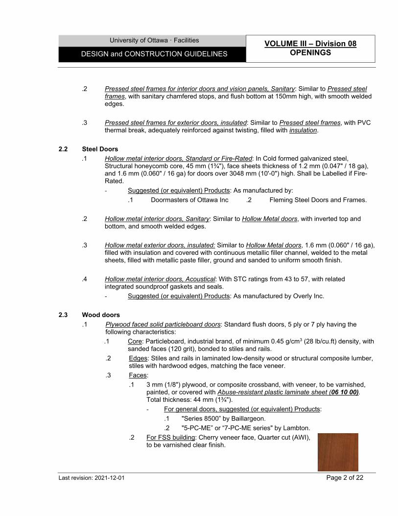
University of Ottawa ꞏ Facilities VOLUME III – Division 08 OPENINGS DESIGN and CONSTRUCTION GUIDELINES
Last revision: 2021-12-01 Page 2 of 22
.2 Pressed steel frames for interior doors and vision panels, Sanitary: Similar to Pressed steel frames, with sanitary chamfered stops, and flush bottom at 150mm high, with smooth welded edges.
.3 Pressed steel frames for exterior doors, insulated: Similar to Pressed steel frames, with PVC thermal break, adequately reinforced against twisting, filled with insulation.
2.2 Steel Doors
.1 Hollow metal interior doors, Standard or Fire-Rated: In Cold formed galvanized steel, Structural honeycomb core, 45 mm (1¾"), face sheets thickness of 1.2 mm (0.047" / 18 ga), and 1.6 mm (0.060" / 16 ga) for doors over 3048 mm (10'-0") high. Shall be Labelled if Fire-Rated.
- Suggested (or equivalent) Products: As manufactured by:
.1 Doormasters of Ottawa Inc .2 Fleming Steel Doors and Frames.
.2 Hollow metal interior doors, Sanitary: Similar to Hollow Metal doors, with inverted top and bottom, and smooth welded edges.
.3 Hollow metal exterior doors, insulated: Similar to Hollow Metal doors, 1.6 mm (0.060" / 16 ga), filled with insulation and covered with continuous metallic filler channel, welded to the metal sheets, filled with metallic paste filler, ground and sanded to uniform smooth finish.
.4 Hollow metal interior doors, Acoustical: With STC ratings from 43 to 57, with related integrated soundproof gaskets and seals.
- Suggested (or equivalent) Products: As manufactured by Overly Inc.
2.3 Wood doors
.1 Plywood faced solid particleboard doors: Standard flush doors, 5 ply or 7 ply having the following characteristics:
.1 Core: Particleboard, industrial brand, of minimum 0.45 g/cm3 (28 lb/cu.ft) density, with sanded faces (120 grit), bonded to stiles and rails.
.2 Edges: Stiles and rails in laminated low-density wood or structural composite lumber, stiles with hardwood edges, matching the face veneer.
.3 Faces:
.1 3 mm (1/8") plywood, or composite crossband, with veneer, to be varnished, painted, or covered with Abuse-resistant plastic laminate sheet (06 10 00). Total thickness: 44 mm (1¾").
- For general doors, suggested (or equivalent) Products:
.1 "Series 8500” by Baillargeon.
.2 "5-PC-ME” or “7-PC-ME series" by Lambton.
.2 For FSS building: Cherry veneer face, Quarter cut (AWI), to be varnished clear finish.
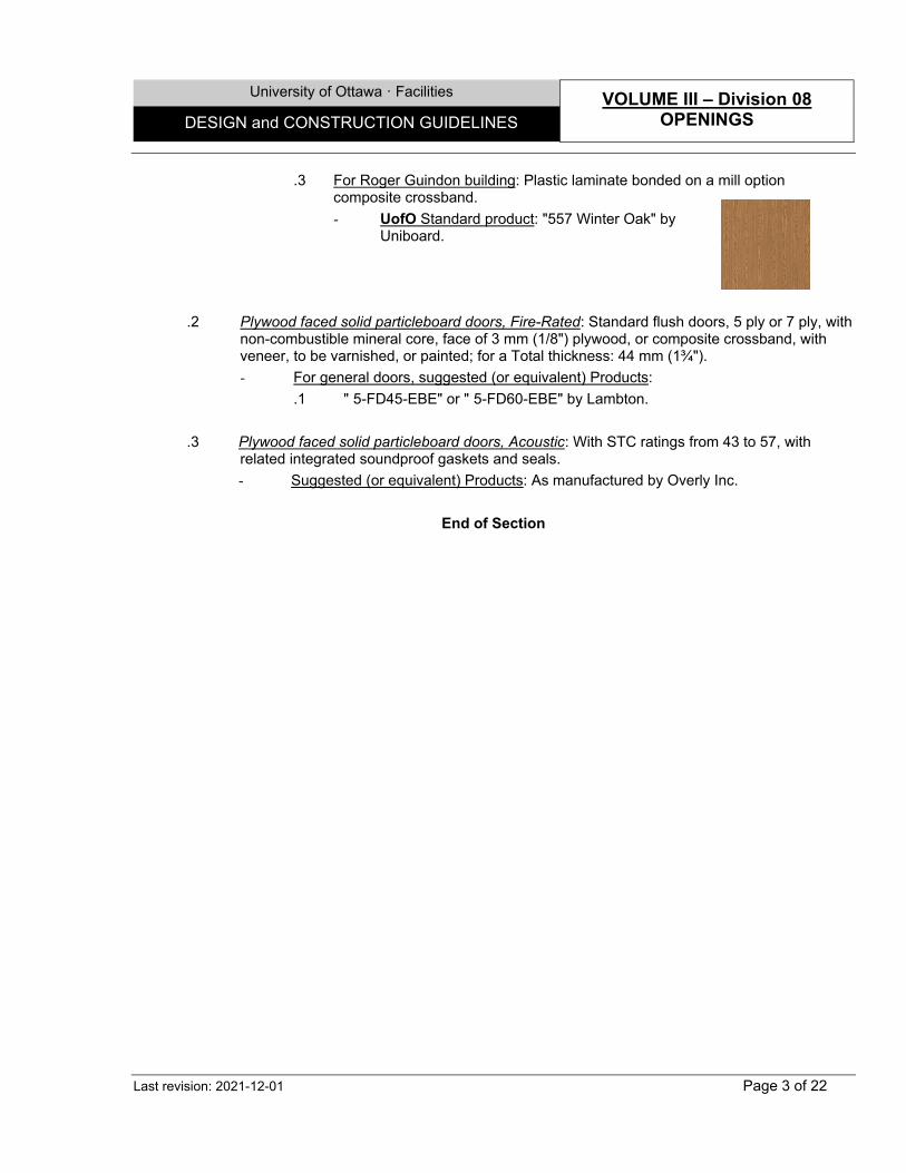
University of Ottawa ꞏ Facilities VOLUME III – Division 08 OPENINGS DESIGN and CONSTRUCTION GUIDELINES
Last revision: 2021-12-01 Page 3 of 22
.3 For Roger Guindon building: Plastic laminate bonded on a mill option composite crossband.
- UofO Standard product: "557 Winter Oak" by Uniboard.
.2 Plywood faced solid particleboard doors, Fire-Rated: Standard flush doors, 5 ply or 7 ply, with non-combustible mineral core, face of 3 mm (1/8") plywood, or composite crossband, with veneer, to be varnished, or painted; for a Total thickness: 44 mm (1¾").
- For general doors, suggested (or equivalent) Products:
.1 " 5-FD45-EBE" or " 5-FD60-EBE" by Lambton.
.3 Plywood faced solid particleboard doors, Acoustic: With STC ratings from 43 to 57, with related integrated soundproof gaskets and seals.
- Suggested (or equivalent) Products: As manufactured by Overly Inc.
End of Section

University of Ottawa ꞏ Facilities VOLUME III – Division 08 OPENINGS DESIGN and CONSTRUCTION GUIDELINES
Last revision: 2021-12-01 Page 4 of 22
SECTION 08 40 00 – CURTAIN WALL AND GLAZED METAL WORK
1.0 GENERAL
1.1 Extended Warranty
.1 The work included in this Section shall be guaranteed against all defects, including glazing sealed units, deterioration, texture and colour modification, for a period of 10 years for labour and Material.
1.2 Design Criteria and Notes
.1 Curtain wall and glazed metal to comply with or surpass requirements of OBC, AAMA and CAN/CSA-A440-00/A440.1 standards.
.2 The design of the curtain wall and skylight shall be based on the "Rain Screen" principle. Behind the curtain wall or windows or at other points where rain may penetrate to the building interior, the rain water must be drained quickly to the exterior of the screen by means of flashings or waterproof membranes to drip openings provided for this eventuality.
.3 No condensation shall form on any interior surfaces of the aluminum members or glazing before any of the exposed area of sealed units reaches the dew point temperature.
.4 The structural performance shall be based on CAN3-S157 and ASTM E330 and deflection of mullions shall be limited to L/175 of clear span, or a maximum of 19 mm (3/4"), perpendicular to the panel, and to L/360 or a maximum of 3 mm (1/8") parallel to the panel plane, with full recovery of glazing materials.
.5 Mitre all joints between aluminum elements meeting at angles, unless otherwise designed.
.6 The cavities between curtain wall mullions and adjacent walls, shall not be obstructed or filled with insulation. Similarly, at parapet levels, roof decks should be retracted 50mm to 75mm away from Spandrel Panels to allow warm air to heat the back of the mullions.
.7 Fabricate the Air/vapour barrier metal pans in such a manner as to leave 6 mm (1/4") space between their lateral faces and the adjacent mullions, to allow these to be conditioned to the ambient temperature.
.8 As necessary, install Mineral Fibre Semi-Rigid Board Insulation for Curtain Wall (07 20 00) (100mm long min.) on perimeter of spandrel panel cavities, with drip holes 25mm that matches the pressure plates.
.9 Spandrel panels shall be able to be replaced with other panels in a simple operation by mechanical means only from the exterior of the building.
.10 Adhere, seal and mechanically fasten connection membrane to mullions' throat, with adjacent walls.
.11 Glazing details shall permit glass replacement after initial construction, the reuse of original gaskets, and replacement glass of the same nominal size as original glass. Silicone supported vision glass shall be replaceable from the exterior and/or interior.
.12 Closures to be installed at top or bottom edges of vertical mullions and caps, if exposed, or serve to support membranes.
.13 Screws, lag screws, and other attachments shall be non-corrosive and of types and sizes required. They shall be concealed as much as possible and those impossible to conceal shall be finished to match adjacent surfaces.
.14 Manufacturer's name plates on aluminum work are not permitted.
University of Ottawa ꞏ Facilities VOLUME III – Division 08 OPENINGS DESIGN and CONSTRUCTION GUIDELINES
Last revision: 2021-12-01 Page 5 of 22
2.0 PRODUCTS
2.1 Curtain wall and curtain wall type window frames
.1 Frames in aluminum, tubular extrusions for curtain wall, windows and exterior doors, regular or with S.S.G., anodized or prepainted: Application with double sealed Glass units. For horizontal and vertical members, 65 mm (21/2") wide. High Performance Series highly recommended.
- Suggested (or equivalent) Products:
.1 "1600UT System 1/System 2” by Kawneer.
.2 "Series 3400HP" (High Performance) by A. & D. Prévost Inc.
.2 Frames in aluminum, tubular extrusions for curtain wall, windows and exterior doors, regular and for S.S.G. anodized or prepainted, with high thermal resistance: Application with triple sealed Glass units. For vertical and horizontal framing members, 65 mm (21/2") wide.
- Suggested (or equivalent) Products:
.1 "G450GEE/S" by Gamma.
.2 "7525" by Kawneer.
.3 "Series 3400 HPT" by A. & D. Prevost Inc.
.3 Frames in aluminium, tubular extrusions for light curtain wall, windows and exterior doors. anodized or prepainted: For horizontal and vertical members, 51 mm (2") wide.
- Suggested (or equivalent) Products:
.1 “1620” by Kawneer.
.4 Aluminum curtain wall frame covers, anodized or prepainted: Extruded aluminum, of the compatible alloy and temper.
- Suggested (or equivalent) Products: as manufactured by:
.1 Gamma.
.2 Kawneer.
.3 A. & D. Prevost.
.5 Sun control screens, aluminium, anodized or prepainted: Aluminum extrusions, aerofoil fin type fixed blades.
- Suggested (or equivalent) Products, as manufactured by:
.1 Nysan Shading System Ltd.
.2 Arc Structures Inc.
.3 Kawneer
2.2 Storefront entries
.1 Frames in aluminum, tubular extrusions for exterior doors and vision panels anodized or prepainted, storefront: With thermal break, 51 mm (2") wide.
- Suggested (or equivalent) Product: "Trifab 451UT" Series by Kawneer.
University of Ottawa ꞏ Facilities VOLUME III – Division 08 OPENINGS DESIGN and CONSTRUCTION GUIDELINES
Last revision: 2021-12-01 Page 6 of 22
2.3 Windows
.1 Windows in aluminum, anodized or prepainted extruded sections, with high thermal resistance: Depth as necessary, with inserted insulation.
- Suggested (or equivalent) Products:
.1 "Series 1300/1300 HPT" by A. & D. Prévost.
.2 “562”, “5525” by Kawneer.
2.4 Skylights
.1 Frames in aluminum, tubular extrusions for skylight, regular or with S.S.G., anodized or prepainted: 65 mm (21/2") wide, with drainage gutters incorporated.
- Suggested (or equivalent) products:
.1 "500" by Gamma.
.2 "2000" by Kawneer.
.3 "Series 3700" by A. & D. Prevost.
.2 Aluminum skylight frame covers, anodized or prepainted: Extruded aluminum, of the compatible alloy and temper.
- Suggested (or equivalent) Products: "216-103" & “822-031 (snap-on cover)” by Kawneer.
2.5 Interior vision panel & vestibule frames
.1 Frames in aluminum, tubular extrusions for interior doors and vision panels anodized or prepainted: 44.5 mm (1¾") or 51 mm (2") wide.
- Suggested (or equivalent) Products:
.1 "Trifab VG450" Series by Kawneer.
.2 "Series 65", by A. & D. Prévost.
2.6 Panels
.1 Panels in aluminum, anodized or prepainted: In AA-6063-T5 alloy and temper aluminum, 3 mm (1/8") minimum thickness.
.2 Insulated sandwich panels in aluminum, anodized or prepainted: Composed of an exterior panel in AA-6063-T5 alloy and temper aluminum , 1.2 mm (18 ga) thick, with Polyisocyanurate insulation, all laminated and prefinished in plant, with sealed edges.
.3 Cold formed galvanized steel air/vapour barrier pans: Min. 0.9 mm (0.036") thick, or more as per the structural requirements, in galvanized steel, to be fabricated in one piece, with tapered sides and sealed corners, used in conjunction with aluminum or glazed spandrel panels.
2.7 Cladding panel system
.1 Cladding panel system in aluminum, anodized or prepainted: Exterior aluminum cladding system in sheets or bent plates, complete with supporting system, 3 mm (1/8") minimum for plates, and 2 mm (3/32") minimum for extrusions.
University of Ottawa ꞏ Facilities VOLUME III – Division 08 OPENINGS DESIGN and CONSTRUCTION GUIDELINES
Last revision: 2021-12-01 Page 7 of 22
- Suggested (or equivalent) Products:
.1 "Series 4400" by A. & D. Prevost.
.2 "Almura, Series G-2100" by Gamma.
.3 "Ultima Type 5" by VicWest.
.4 As manufactured by Alucobond
2.8 Doors & Architectural railing systems
.1 Aluminum interior swinging glazed doors, anodized or prepainted: Strongly built, glazed swinging doors with wide stiles, min. 44.5 mm (1¾") thick, aluminum extrusions, with minimum wall thickness of 3.2 mm (0.126") and mechanically-joined, reinforced corners.
- Suggested (or equivalent) Products:
.1 "350" or "500" by Kawneer.
.2 "2200" or "2700" by A. & D. Prevost.
.2 Aluminum exterior swinging glazed doors, insulated anodized or prepainted: Heavy duty insulated glazed swing doors, min. 51 mm (2") thick, aluminum extrusions with minimum wall thickness of 3.2 mm (0.126"), with thermal break and mechanically-joined, reinforced corners.
- Suggested (or equivalent) Products:
.1 "360" or "560" "Insulclad" Series, by Kawneer.
.2 "2250" or "2750" by A. & D. Prévost.
.3 Glass doors, swinging: All glass, single, swinging, or double, Including all gaskets, shoes, mouldings, supports, and other related accessories.
- Acceptable (or equivalent) products: "Prel-Gard Entrances" by Prelco Inc.
.4 Railing & Handrail systems in Anodized, prepainted Alluvium, or Stainless steel: Including all gaskets, shoes, mouldings, supports, and other related accessories.
- Suggested (or equivalent) Product: As manufactured by C.R. Laurence of Canada.
2.9 Accessories
.1 Strip and pad for metals work, self-adhesive: For thermal or electrolytic isolation between steel surfaces and aluminum: 3 mm (1/8") closed cell polyethylene (EVA) tape and pad, with adhesive on one or two faces, as necessary.
- Suggested (or equivalent) Product: As manufactured by Jacobs and Thompson.
2.10 Finishes
.1 Anodized finish: Clear or colored anodic oxide treatment, 18 microns (0.7 mil) thick, on surfaces treated with a caustic etch. Execute preparation and anodization after assembling and welding aluminum elements.
- Suggested (or equivalent) Product: "Permanodic" by Kawneer.
.2 Prepainted coating finish for aluminum surfaces: A caustic etch, a fluoropolymer resin thermosetting coating, treated with and applied in plant, in three coats, of a total dry film thickness of 50.8 microns (2.0 mils).
University of Ottawa ꞏ Facilities VOLUME III – Division 08 OPENINGS DESIGN and CONSTRUCTION GUIDELINES
Last revision: 2021-12-01 Page 8 of 22
- Suggested (or equivalent) Product: "Duranar XL" by PPG.
- Not Acceptable Product: Prepainted acrylic coating "Duracron" by PPG.
.3 Stainless Steel: As per section 05 50 00.
End of Section

University of Ottawa ꞏ Facilities VOLUME III – Division 08 OPENINGS DESIGN and CONSTRUCTION GUIDELINES
Last revision: 2021-12-01 Page 9 of 22
SECTION 08 70 00 – FINISH HARDWARE
1.0 GENERAL
1.1 Extended Warranty
.1 The following items shall be guaranteed:
.1 Door closers for a period of 10 years.
.2 Locksets for a period of 5 years.
.3 Exit devices for a period of 3 years.
.4 Automatic door operators, compressors & control boxes for a period of 3 years.
.5 Electric strikes for a period of 3 years.
.6 Electrical Power Transfers and Loops for a period of 3 years.
1.2 Design Criteria and Notes
.1 General:
.1 Provide a hardware schedule indicating the type of lockset or exit device recommended and the type cylinder required. UofO - ATS will consult the potential occupying faculties or departments in order to establish their individual needs and develop a basic master-keying plan to meet these needs. The building shall be assigned to a zone which has Great Grand Master Key (GGMK) space to include it. The master key plan shall then be submitted to “Medeco Canada” keying records management for comments and approval.
.2 A “take-off” sheet, as part of the keying list, shall be prepared by UofO - ATS and submitted to “Medeco” indicating the amount of different cylinders, and to whom the MK’s must be sent. When received, the cylinder order should be checked by UofO - ATS to ensure the appropriate number is received. Upon approval, the keying list shall be submitted to the Associate Director, Project Management, Facilities or his representative for process of purchase orders and a letter of authorization for the contractor to purchase the required cylinders from “Medeco” on the University’s behalf.
.3 The following products shall be avoided as much as possible:
.1 Maglock installations.
.2 Electrical Automatic Door Operator installation. Use the pneumatic types instead.
.4 All hardware items to be provided and installed by the GC, with the exception of the following; which will be provided by UofO and installed by the GC:
.1 Non-Electronic Door Hardware - less than 5.
.2 Door Cylinders and keys – less than 50.
.2 Application:
.1 Only hardware items satisfying standards CAN/CGSB-69 series and ANSI/BHMA A156 series are acceptable for use, except otherwise indicated. Use hardware recognized by ULC for fire-rated-doors.
.2 All hardware to match make of existing unless requested otherwise.
.3 Keying & Cylinders:
.1 If provided by GC (see above):
University of Ottawa ꞏ Facilities VOLUME III – Division 08 OPENINGS DESIGN and CONSTRUCTION GUIDELINES
Last revision: 2021-12-01 Page 10 of 22
.1 All cylinders to be master-keyed on existing master key system as per Owner’s requirements, using keying Facilities schedule standards.
.2 Supply the following:
.1 One key cabinet with the required capacity plus 10%, such as made by Lund.
.2 Number of keys per lock: 3.
.3 Number of master keys per system: 10.
.4 Construction keys as required.
.5 Extractor keys as required.
.3 Supply keys directly to Owner, in properly identified envelopes.
.2 If provided by UofO (see above):
.1 Two (2) keys shall be supplied with each cylinder. Individual additional keys must be requested from the Coordinator, Facilities (2222). These requests must be made in advance of their perceived need in order for the locksmith to complete the additional work load. When received, the cylinder order should be checked by UofO ATS to ensure the appropriate number is received.
.2 When installing the Medeco cylinders, the contractor shall use the accompanying change key to verify the cylinders are functional. Contractor shall then return the key to its original container which is returned to the university locksmith staff when the installation is complete.
.3 Combination locks:
.1 “Ilco Unican” push button locks L1021-M have been used at strategic areas on campus where it was not feasible to issue keys to numerous authorized persons. “Medeco” grand master keys must be allowed to by-pass the combination key code. The preferred combination lock is “King Cobra” which has proven to be less expensive, more flexible and almost maintenance free.
.4 Key functions:
.1 Circuit Entry: Can be unlocked for periods of time but can also be locked on a personal basis.
.2 Classroom: Can be unlocked to give access to groups of people.
.3 Storage: Always remains on the lock position – key use is essential.
.4 Passage: No cylinder.
.5 Privacy: No cylinder
.4 Fastenings:
.1 Use fasteners compatible with the materials they penetrate. Exposed fastening devices to match finish of hardware. Stainless steel hardware to be fastened with stainless steel fasteners.
.2 Where pull is scheduled on one side of door and push plate on other side, supply fastening devices, and install so pull can be secured through door from reverse side. Install push plate to cover fasteners.
University of Ottawa ꞏ Facilities VOLUME III – Division 08 OPENINGS DESIGN and CONSTRUCTION GUIDELINES
Last revision: 2021-12-01 Page 11 of 22
.3 Use cross recessed countersunk flat mushroom head screws for attachment of kickplates, pushplates, and similar devices.
.5 Electrified hardware:
.1 General:
.1 Classroom function is required on locksets at all electronically secured doors.
.2 Wiring schematics detailing all electrical components for each door opening to be prepared by the hardware manufacture at the request and with the support of the hardware supplier.
.2 Installation and wiring:
.1 Shall be done by Electrical trades up to the Control boxes. All necessary pneumatic, conduit and wiring connections to the electrical hardware elements shall be done by this division.
.2 All access controlled doors to have door closers supplied and adjusted at time of installation.
.3 All access control hardware to installed by qualified tradesman competent in the installation of finishing hardware with minimum of (5) years experience shall be used. The installer shall adjust, clean and make good all installation of Finishing hardware to the satisfaction of the Universities Security manager or hardware consultant.
.4 Final inspection to be carried out by the Hardware Supplier consultant whose name is written on the cover sheet and Product representative. Representative to provide written certification that hardware has been installed and adjusted as intended. Once written documentation is provided that the access controlled opening is functioning 100% will Protection Services dedicate the necessary resources to complete and commission the system at that door Above and beyond manufactures specifications, the door needs to be tested that:
.1 It closes form any position in its swing including from a position resting on the latch.
.2 That all door pins fit securely in receptacles.
.3 No excessive play of latch in strike.
.4 No preload exerted on electrified hardware.
.5 Door does not rub on floor or any part of frame.
.6 Door closer is adjusted properly, ( not over tightened to make up for other door deficiencies.)
.7 No excessive gaps under, above or between twin doors.
.3 Low Voltage Wiring for Electrified Hardware: All wiring to be stranded, FT6 rated (exposed) or FT4 rated (totally enclosed in a non-combustible raceway): EMT conduit or as indicated on drawings. Use as specified, 18ga 2 conductor wires, stranded; 22ga foil shielded 4 conductor wires, stranded; and 22ga foil shielded 6 conductor wires, stranded.
UofO Standard Products: For Protection Wiring:
- White & Green Conductors are reserved for:
- Latch Bolt Monitor (Electric Strike)
University of Ottawa ꞏ Facilities VOLUME III – Division 08 OPENINGS DESIGN and CONSTRUCTION GUIDELINES
Last revision: 2021-12-01 Page 12 of 22
- Exit to Request (Electrified Mortise)
- Door Contact
- Red & Black Conductors, 22ga, are reserved to provide power to:
- Electric Strike
- Electrified Mortise
.4 Pneumatic tubing: To be rated plenum.
.5 Automatic Door Closer Delay Timing:
Delay: Unless otherwise requested, operation required delays to be:
.1 5 seconds after actuator is pushed before the door closer is activated.
.2 12 seconds when door is full opened before closing.
.6 Actuators:
Actuators, whether wired or wireless, to be connected individually to the door closers control box.
Run an additional 6 Conductor Wires to actuator for eventual card reader installation, on corridor side.
.7 Electric Strikes:
.1 Door frames to adapt to sizes of specified electric strikes.
.2 To install a Classroom function lock to permit locking the door if electric strike is out of order.
.3 Fail safe position during power outage shall be in unlock position. Fail secure position during power outage shall be in locked position.
.4 Doors controlled by these means shall have a “Medeco” cylinder keyed to the “E” GGMK only.
.5 Power to be connected to the Red or White and Black Conductor wires, 22ga.
.6 Latch Bolt Monitor to be connected to Green & White Conductor wires.
.8 Connection:
.1 If a scheduled card-reader or similar security system is to be connected to Fire-rated door, electrified mortises or similar electrified hardware should be installed and not electrical strikes, in order to maintain a positive latch all the time.
.2 In Fire-rated doors, door operators to be connected to electrical strike, and card readers to be connected to electrified mortises.
.9 Control Boxes: Generally, to be installed wall mounted or in ceiling spaces with vibration isolators in corridors, A/V rooms or storage rooms. Never install in Classroom ceiling space. Final location to be coordinated with UofO.
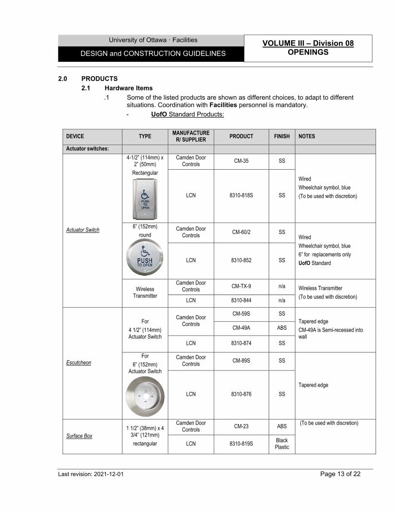
University of Ottawa ꞏ Facilities VOLUME III – Division 08 OPENINGS DESIGN and CONSTRUCTION GUIDELINES
Last revision: 2021-12-01 Page 13 of 22
2.0 PRODUCTS
2.1 Hardware Items
.1 Some of the listed products are shown as different choices, to adapt to different situations. Coordination with Facilities personnel is mandatory.
- UofO Standard Products:
DEVICE TYPE MANUFACTURE
R/ SUPPLIER PRODUCT FINISH NOTES
Actuator switches:
Actuator Switch
4-1/2” (114mm) x 2” (50mm)
Rectangular
Camden Door Controls
CM-35 SS
Wired
Wheelchair symbol, blue
(To be used with discretion) LCN 8310-818S SS
6” (152mm)
round
Camden Door Controls
CM-60/2 SS Wired
Wheelchair symbol, blue
6” for replacements only
UofO Standard LCN 8310-852 SS
Wireless Transmitter
Camden Door Controls
CM-TX-9 n/a Wireless Transmitter
(To be used with discretion) LCN 8310-844 n/a
Escutcheon
For
4 1/2” (114mm) Actuator Switch
Camden Door Controls
CM-59S SS Tapered edge
CM-49A is Semi-recessed into wall
CM-49A ABS
LCN 8310-874 SS
For
6” (152mm) Actuator Switch
Camden Door Controls
CM-89S SS
Tapered edge
LCN 8310-876 SS
Surface Box 1 1/2” (38mm) x 4
3/4” (121mm)
rectangular
Camden Door Controls
CM-23 ABS (To be used with discretion)
LCN 8310-819S
Black Plastic
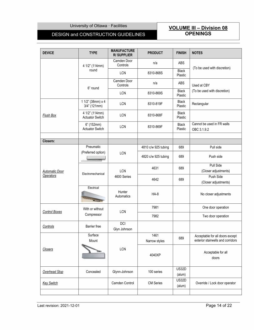
University of Ottawa ꞏ Facilities VOLUME III – Division 08 OPENINGS DESIGN and CONSTRUCTION GUIDELINES
Last revision: 2021-12-01 Page 14 of 22
DEVICE TYPE MANUFACTURE
R/ SUPPLIER PRODUCT FINISH NOTES
4 1/2” (114mm) round
Camden Door Controls
n/a ABS (To be used with discretion)
LCN 8310-868S Black Plastic
6” round
Camden Door Controls
n/a ABS Used at CBY
(To be used with discretion) LCN 8310-869S
Black Plastic
Flush Box
1 1/2” (38mm) x 4 3/4” (121mm)
LCN 8310-819F Black Plastic
Rectangular
4 1/2” (114mm) Actuator Switch
LCN 8310-868F Black Plastic
6” (152mm) Actuator Switch
LCN 8310-869F Black Plastic
Cannot be used in FR walls
OBC 3.1.9.2
Closers:
Automatic Door Operators
Pneumatic
(Preferred option)
LCN
4810 c/w 925 tubing 689 Pull side
4820 c/w 925 tubing 689 Push side
Electromechanical LCN
4600 Series
4631 689 Pull Side
(Closer adjustments)
4642 689 Push Side
(Closer adjustments) Electrical
Hunter Automatics
HA-8 No closer adjustments
Control Boxes With or without
Compressor LCN
7981 One door operation
7982 Two door operation
Controls Barrier free DCI
Glyn Johnson
Closers
Surface
Mount
LCN
1461
Narrow styles 689
Acceptable for all doors except exterior stairwells and corridors
4040XP Acceptable for all
doors
Overhead Stop Concealed Glynn-Johnson 100 series US32D
(alum)
Key Switch Camden Control CM Series US32D
(alum) Override / Lock door operator
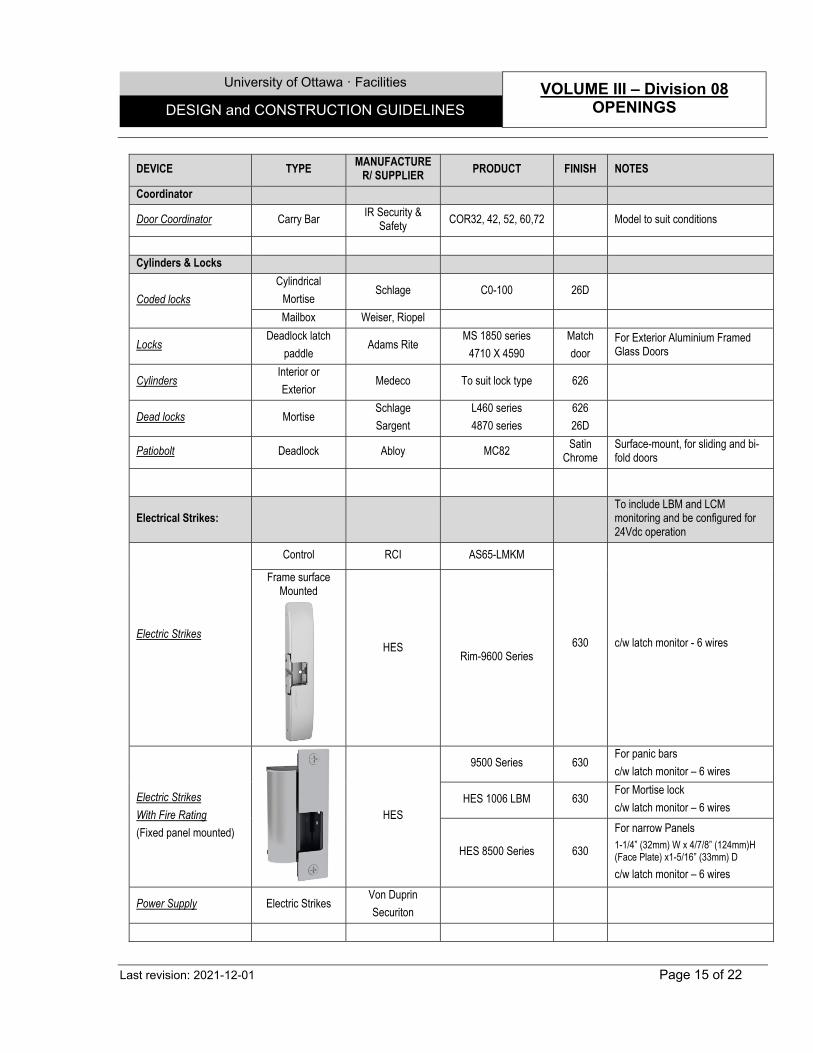
University of Ottawa ꞏ Facilities VOLUME III – Division 08 OPENINGS DESIGN and CONSTRUCTION GUIDELINES
Last revision: 2021-12-01 Page 15 of 22
DEVICE TYPE MANUFACTURE
R/ SUPPLIER PRODUCT FINISH NOTES
Coordinator
Door Coordinator Carry Bar IR Security &
Safety COR32, 42, 52, 60,72 Model to suit conditions
Cylinders & Locks
Coded locks
Cylindrical
Mortise Schlage C0-100 26D
Mailbox Weiser, Riopel
Locks Deadlock latch
paddle Adams Rite
MS 1850 series
4710 X 4590
Match
door For Exterior Aluminium Framed Glass Doors
Cylinders Interior or
Exterior Medeco To suit lock type 626
Dead locks Mortise Schlage
Sargent
L460 series
4870 series
626
26D
Patiobolt Deadlock Abloy MC82 Satin
Chrome Surface-mount, for sliding and bi-fold doors
Electrical Strikes: To include LBM and LCM monitoring and be configured for 24Vdc operation
Electric Strikes
Control RCI AS65-LMKM
630 c/w latch monitor - 6 wires
Frame surface Mounted
HES
Rim-9600 Series
Electric Strikes
With Fire Rating
(Fixed panel mounted)
HES
9500 Series 630 For panic bars
c/w latch monitor – 6 wires
HES 1006 LBM 630 For Mortise lock
c/w latch monitor – 6 wires
HES 8500 Series 630
For narrow Panels 1-1/4” (32mm) W x 4/7/8” (124mm)H (Face Plate) x1-5/16” (33mm) D
c/w latch monitor – 6 wires
Power Supply Electric Strikes Von Duprin
Securiton

University of Ottawa ꞏ Facilities VOLUME III – Division 08 OPENINGS DESIGN and CONSTRUCTION GUIDELINES
Last revision: 2021-12-01 Page 16 of 22
DEVICE TYPE MANUFACTURE
R/ SUPPLIER PRODUCT FINISH NOTES
Exit Devices:
Exit device (Panic Bar) Rim
Von Duprin 996L with 98EO or
99EO 626
Sargent 88 series 32D
Exit Lever Trim Von Duprin 996L with 98EO or
99EO 626
Electrified Breakaway Lever Trim
Von Duprin E996L with 98EO or
99EO 626
Hinges:
Hinges
Butt*
Hager BB1168 26D
McKinney TA2714, T4A3786 26D
Stanley FBB179, FBB168 26D
Continuous
McKinney MCK-12HD / MCK-
25D CLA
Roton 780 112 HD(alum)
780 224 HD (HMD) CLA
Select SL11HD (alum)
SL24HD (HMD) CLA
*Note: Consider using offset hinges in order to accommodate the latest OBC recommended minimum Accessibility door clearances.
Latch Guard:
Latch Guard Outswing MAG Security Mag 8849-AL 11-3/4” AL
Power Transfer
Electric Power Transfer
(Connections for Electric Strikes / Electrified Mortise or Other)
Electric Power Transfer (EPT)
Von Duprin
EPT10
Al Fire Rated
(Preferred option for new)
Concealed Door Loop (CDL)
Command Access
CDL-AL-FX
SS Flexible
Power Transfer Loop (PTL)
RCI
Rutherford Controls
9509-18S Flex Loops
SS Surface Mounted Heavy Duty, 18 Gau. versions
(Preferred option in renovations)
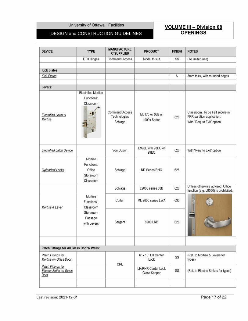
University of Ottawa ꞏ Facilities VOLUME III – Division 08 OPENINGS DESIGN and CONSTRUCTION GUIDELINES
Last revision: 2021-12-01 Page 17 of 22
DEVICE TYPE MANUFACTURE
R/ SUPPLIER PRODUCT FINISH NOTES
ETH Hinges Command Access Model to suit SS (To limited use)
Kick plates:
Kick Plates Al 3mm thick, with rounded edges
Levers:
Electrified Lever & Mortise
Electrified Mortise
Functions:
Classroom
Command Access Technologies
Schlage
ML170 w/ 03B or
L909x Series 626
Classroom. To be Fail secure in FRR partition application,
With “Req. to Exit” option.
Electrified Latch Device Von Duprin E996L with 98EO or
99EO 626 With “Req. to Exit” option
Cylindrical Locks
Mortise
Functions:
Office
Storeroom
Classroom
Schlage ND Series RHO 626
Mortise & Lever
Mortise
Functions :
Classroom
Storeroom
Passage
with Levers
Schlage L9000 series 03B 626 Unless otherwise advised, Office function (e.g. L9050) is prohibited.
Corbin ML 2000 series LWA 630
Sargent 8200 LNB 626
Patch Fittings for All Glass Doors/ Walls:
Patch Fittings for Mortise on Glass Door
CRL
6” x 10” LH Center Lock
SS (Ref. to Mortise & Levers for types)
Patch Fittings for Electric Strike on Glass Door
LH/RHR Center Lock
Glass Keeper SS (Ref. to Electric Strikes for types)

University of Ottawa ꞏ Facilities VOLUME III – Division 08 OPENINGS DESIGN and CONSTRUCTION GUIDELINES
Last revision: 2021-12-01 Page 18 of 22
DEVICE TYPE MANUFACTURE
R/ SUPPLIER PRODUCT FINISH NOTES
Pull / Pushes / Stops:
Flatware – Pulls-
Bolts, and similar
Kick plate
Push plate
Flush bolts
Gallery Specialty
GSH80A (Screwed)
GSH81AA (Screwed)
GSH401
32D
Hager Alternate
32D Standard Metal Alternate
CBH Alternate
Door Stops Floor mount Gallery
specialities GSH 218 SS
Magnetic catch Triple Magnetic
catch Hardware Hut AME-BP9798AW AL
Weather stripping:
Sound-dampening &
Weather-stripping
Weather stripping
K N Crowder
W-20N
W20P
AL Neoprene
Pile
Heavy Duty
Door sweep
W24S AL
Threshold
CT 11 / 12 / 32 AL
Threshold stop CT40P AL
Automatic Door Bottoms
CT-52F AL Surface mount preferred for simpler maintenance
Sound Trap & stripping
Zero International
#870 (Head & Jamb)
#365 (Aut. Door bottom)
#566A (Threshold)
AL Based on 49 STC Sealing system
Weather Stripping Pemko Series 306
End of Section
University of Ottawa ꞏ Facilities VOLUME III – Division 08 OPENINGS DESIGN and CONSTRUCTION GUIDELINES
Last revision: 2021-12-01 Page 19 of 22
SECTION 08 80 00 – GLAZING
1.0 GENERAL
1.1 Extended Warranty
.1 Mirrors shall be guaranteed against silvering defects, for a period of 10 years.
.2 Double-glazed sealed units shall be guaranteed for a period of 10 years.
.3 Fire-rated glazing shall be guaranteed for a period of 5 years.
1.2 Design Criteria and Notes
.1 Notwithstanding OBC Supplementary Standard SB-13, all interior Glazing located at floor openings, stairs or similar where difference in level is exceeding 600mm shall be laminated.
.2 All sealed glazed units to be manufactured as per CAN/CGSB-12.8, and by a manufacturer who has certified these units in accordance with the Insulating Glass Certification Council (IGCC) Certification Program.
.3 All tempered glass must be produced by the horizontal roller hearth method, and bear a discrete mark of being so treated.
.4 All interior glazing for openings, visual panels, doors and similar, shall be made of Tempered Glass units or stronger / equivalent.
.5 Not acceptable: Georgian wired polished Glass in non-Fire-rated installations.
.6 All Glazing for skylight shall be Sealed, Laminated, Tempered Glass and Tinted units, with all additional necessary films or colors.
.7 Georgian wired polished glass or Fire-Rated glass sizes in doors or windows shall be as per the maximum allowed per OBC, ULC or any other accredited tests for single pans, with or without intermediate mullions.
.8 All Glazing for exterior openings shall be Sealed, Laminated or Tempered Glass units, with all additional necessary films or colors.
.9 All exterior sealed Glazing units to be at least argon filled with Low Emissivity soft coating, with the following minimal performances (triple glazed units may also be accepted as per the Consultant’s suggestions and design imperatives):
.1 Clear double glazed sealed units, with Low-E soft coating, on position #2, argon filled:
.1 Thermal resistance (in winter), at centre of vision panel: RSI = 0.73 (R = 4.17); or more.
.2 Solar heat gain coefficient: 0.39 or less.
.3 Light transmission: 70 % or more.
.4 Shading coefficient: 0.45 or less.
.2 Tinted double glazed sealed units, with Low-E soft coating in position #3, argon filled:
.1 Thermal resistance (in winter), at centre of vision panel: RSI = 0.73 (R = 4.17), or more.
.2 Solar heat coefficient gain: 0.32 or less.
.3 Light transmission: 42% or more.
.4 Shading coefficient: 0.37 or less.
- Suggested (or equivalent) manufacturers:
.1 AFGD. .2 Industries April Inc. .3 Prelco (Thermalite).
University of Ottawa ꞏ Facilities VOLUME III – Division 08 OPENINGS DESIGN and CONSTRUCTION GUIDELINES
Last revision: 2021-12-01 Page 20 of 22
2.0 PRODUCTS
2.1 Single Glass Units
.1 Tempered Glass: Clear safety glass, as per CAN/CGSB-12.1, 6 mm (1/4") min., or as necessary.
.2 Laminated glass: Safety glass, as per CAN/CGSB-12.1, 2 x 3 mm (1/8") (regular) and 2 x 6 mm or 5 or as necessary, with clear PVB glass lamination film interlayer 1.5 mm (0.060") thick.
.3 Georgian wired polished glass (for fire-rated openings): As per CAN/CGSB-12.11, with 12.7 mm x 12.7 mm (1/2" x 1/2") wire mesh square design, 6 mm (1/4") thick min.
.4 Polycarbonate glazing: Clear, 6 mm (1/4") thick min., as per CAN/CGSB-12.12, abrasion resistant.
- Suggested (or equivalent) Products:
.1 As manufactured by Plastique Alto Inc.
.2 As manufactured by GE Plastics (General Electric).
5 Opaque glass for spandrel panels: as per CAN/CGSB-12.9, 6 mm (1/4") thick min., heat strengthened glass, with ceramic frit opacifier on the back, or with silicone based paint on the back.
- Suggested (or equivalent) Products:
.1 With "Ceramic Frit" by Ferro.
.2 With "Opaci-Coat 300" paint by Industrial Control Development Inc.
.6 Heat soaked Thermally Toughened glass: as per DIN EN 14179-1 (Heat soaked thermally toughened soda lime silicate safety glass).
.7 Fire-Rated glass Ceramic: 8 mm thick, Premium Grade-Ground and polished on both sides, with Glazing Tape: Closed cell polyvinyl chloride foam, coiled on release paper over adhesive on two sides, maximum water absorption by volume of 2 percent. Glass panels that exceed 1,393 sq. inches for 90-minute ratings shall be glazed with fire-rated glazing tape supplied by manufacturer.
- Suggested (or equivalent) Product: “FireLite Plus”, manufactured by Nippon Electric Glass Company, Ltd., and distributed by Technical Glass Products Canada.
.8 Mirror, silvered, framed: as per CAN/CGSB-12.5, tempered, 6 mm (1/4") thick, dimensions as shown, in stainless steel frame, with shelf, or without shelf, as indicated, square corner type, and vandal proof concealed mounting.
.9 Acrylic glazing (Plexiglas): As per CAN/CGSB.12.12, extruded grade, clear, or matt, 6 mm (1/4") thick min..
- Suggested (or equivalent) product:
.1 As manufactured by Plastique Alto Inc.
.2 As manufactured by 3 Form Inc.
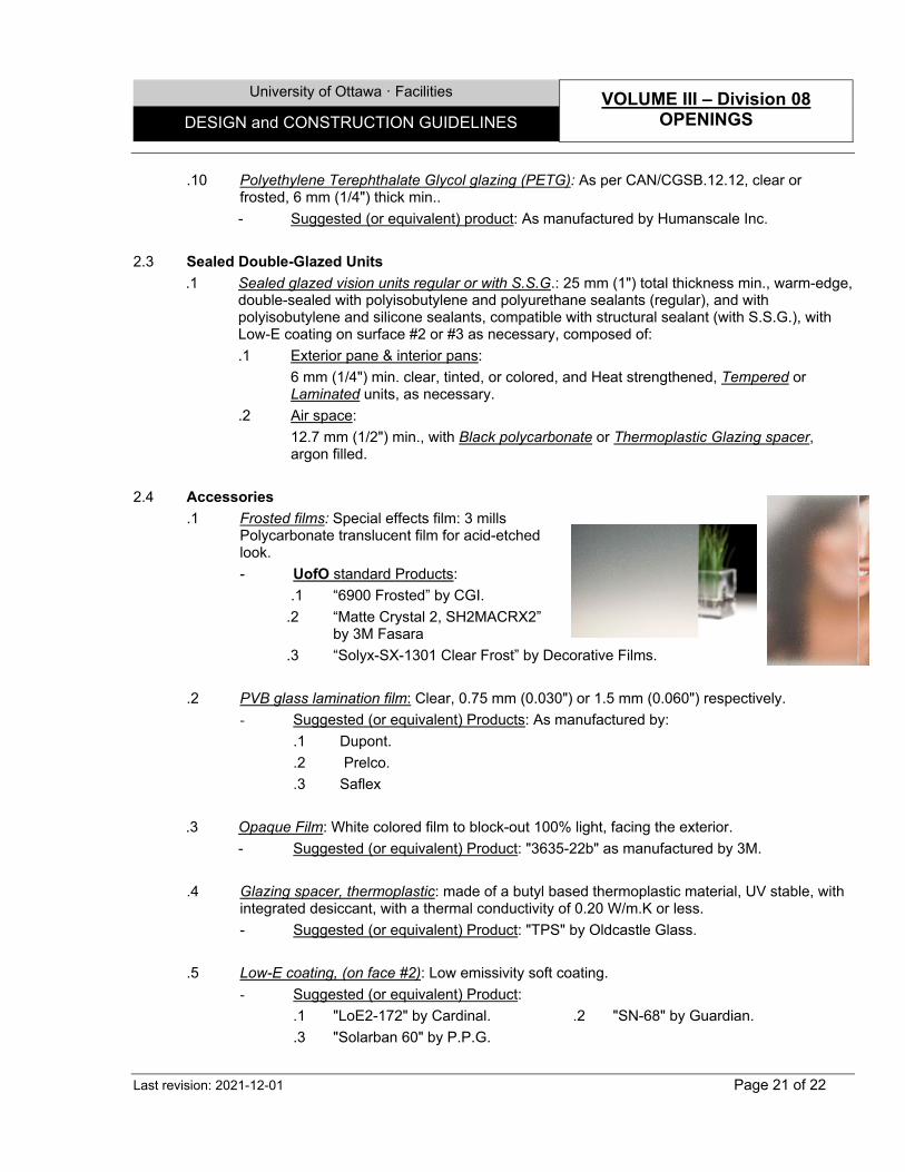
University of Ottawa ꞏ Facilities VOLUME III – Division 08 OPENINGS DESIGN and CONSTRUCTION GUIDELINES
Last revision: 2021-12-01 Page 21 of 22
.10 Polyethylene Terephthalate Glycol glazing (PETG): As per CAN/CGSB.12.12, clear or frosted, 6 mm (1/4") thick min..
- Suggested (or equivalent) product: As manufactured by Humanscale Inc.
2.3 Sealed Double-Glazed Units
.1 Sealed glazed vision units regular or with S.S.G.: 25 mm (1") total thickness min., warm-edge, double-sealed with polyisobutylene and polyurethane sealants (regular), and with polyisobutylene and silicone sealants, compatible with structural sealant (with S.S.G.), with Low-E coating on surface #2 or #3 as necessary, composed of:
.1 Exterior pane & interior pans:
6 mm (1/4") min. clear, tinted, or colored, and Heat strengthened, Tempered or Laminated units, as necessary.
.2 Air space:
12.7 mm (1/2") min., with Black polycarbonate or Thermoplastic Glazing spacer, argon filled.
2.4 Accessories
.1 Frosted films: Special effects film: 3 mills Polycarbonate translucent film for acid-etched look.
- UofO standard Products:
.1 “6900 Frosted” by CGI.
.2 “Matte Crystal 2, SH2MACRX2” by 3M Fasara
.3 “Solyx-SX-1301 Clear Frost” by Decorative Films.
.2 PVB glass lamination film: Clear, 0.75 mm (0.030") or 1.5 mm (0.060") respectively.
- Suggested (or equivalent) Products: As manufactured by:
.1 Dupont.
.2 Prelco.
.3 Saflex
.3 Opaque Film: White colored film to block-out 100% light, facing the exterior.
- Suggested (or equivalent) Product: "3635-22b" as manufactured by 3M.
.4 Glazing spacer, thermoplastic: made of a butyl based thermoplastic material, UV stable, with integrated desiccant, with a thermal conductivity of 0.20 W/m.K or less.
- Suggested (or equivalent) Product: "TPS" by Oldcastle Glass.
.5 Low-E coating, (on face #2): Low emissivity soft coating.
- Suggested (or equivalent) Product:
.1 "LoE2-172" by Cardinal. .2 "SN-68" by Guardian.
.3 "Solarban 60" by P.P.G.
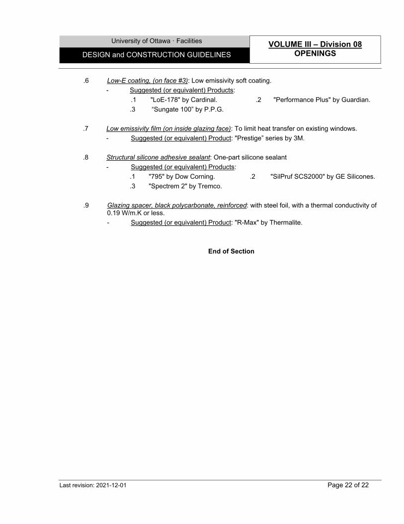
University of Ottawa ꞏ Facilities VOLUME III – Division 08 OPENINGS DESIGN and CONSTRUCTION GUIDELINES
Last revision: 2021-12-01 Page 22 of 22
.6 Low-E coating, (on face #3): Low emissivity soft coating.
- Suggested (or equivalent) Products:
.1 "LoE-178" by Cardinal. .2 "Performance Plus" by Guardian.
.3 “Sungate 100” by P.P.G.
.7 Low emissivity film (on inside glazing face): To limit heat transfer on existing windows.
- Suggested (or equivalent) Product: "Prestige” series by 3M.
.8 Structural silicone adhesive sealant: One-part silicone sealant
- Suggested (or equivalent) Products:
.1 "795" by Dow Corning. .2 "SilPruf SCS2000" by GE Silicones.
.3 "Spectrem 2" by Tremco.
.9 Glazing spacer, black polycarbonate, reinforced: with steel foil, with a thermal conductivity of 0.19 W/m.K or less.
- Suggested (or equivalent) Product: "R-Max" by Thermalite.
End of Section
University of Ottawa · Facilities VOLUME III – Division 09
FINISHES DESIGN and CONSTRUCTION GUIDELINES
Last revision: 2022-03-01 Page 1 of 17
SECTION 09 20 00 - DRYWALL WORK 1.0 GENERAL 1.1 Extended Warranty
.1 Drywall board shall be guaranteed from defect, including fissures, cracking, surface deterioration or other defects of appearance or for a period of 3 years for labour and Material.
1.2 Design Criteria and Notes
.1 Structural criteria’s: .1 Partitions in Laboratory areas should be designed to carry a load of 195kg/m2 (40
lb/ft2) - or as prescribed loads, uniformly distributed, for wall mounted cabinets and shelves.
.2 Cavity shaft wall systems to withstand a min. positive and negative pressure of 10psf.
.3 Partitions in office or similar areas shall be designed to support shelves or any other wall mount indicated loads.
.4 Provide adequate stiffeners, furring channels and/or plates, and sheet reinforcing secured between studs for installation of: .1 A/V and similar feature .2 M&E and A/V features or fixtures .3 Handrails .4 Shelving and cabinets .5 Any other similar.
.5 No wood blocking is permitted within the following locations: .1 Classified Laboratory spaces .2 Animal care facilities .3 High moisture spaces
.6 Carry out additional Regular Steel Stud, Structural Steel Stud or miscellaneous steel reinforcement for vertical posts and lintels, as necessary in the following: .1 For all openings wider than 1800mm. .2 All free standing partitions.
.7 Use a min. 20 ga thick for Steel Stud supporting the following: .1 Board material finished with ceramic, porcelain or thin brick cladding. .2 Fibre reinforced or High impact gypsum board or similar.
.8 Double the studs at each side of door openings and all openings 915 mm (3'- 0") or wider.
.9 On the perimeter of all board ceilings, install continuous galvanized "L" shape frame 50mm x necessary height x ±16 Gauge.
.10 Resistance to seismic forces shall be as required by codes in retrofit or new installation projects.
.2 Notes: .1 Install 250 mm (10") long joint tape at 45 degrees, perpendicular to the diagonals, at
all corners of openings (doors, windows, inserted items of more than 100 mm x 100 mm (4"x 4") and at all changes of width or depth and take all other measures necessary to avoid cracking.
University of Ottawa · Facilities VOLUME III – Division 09
FINISHES DESIGN and CONSTRUCTION GUIDELINES
Last revision: 2022-03-01 Page 2 of 17
.2 Install control joint as by best recommended practices, and at: .1 Maximum 9 m (30'-0") apart on walls horizontally and vertically, and 5 m (16'-
0") apart on walls to receive ceramic, porcelain or thin brick cladding. .2 Maximum 9 m (30'-0") apart on ceilings without perimeter relief, in both
directions. .3 Maximum 1.5 m (50'-0") apart in ceilings with perimeter relief, in both
directions. .4 Maximum 5 m (16'-0") apart on walls to receive ceramic, porcelain or thin brick
cladding. .3 Install Insulating strip for drywall, self-adhesive under floor track and above top track.
2.0 PRODUCTS 2.1 Board Material
.1 Gypsum board, regular or fire-resistant: Ends square cut, edges tapered. - Suggested (or equivalent) products:
.1 "Sheetrock" and "Sheetrock Firecode”, regular, type X or type C, by CGC Inc.
.2 "ToughRock" and "ToughRock Fireguard”, regular, type X or type C, by Georgia-Pacific Canada.
.3 “Easy-Lite”, regular, type X or type C, by CertainTeed Canada.
.2 Mould and moisture resistant gypsum board, regular or fire-resistant: Composed of a blend of gypsum and cellulose fibre, ends square cut, edges tapered. - Suggested (or equivalent) products:
.1 "Fiberock AquaTough”, regular, type X or type C, Interior panels by CGC Inc.
.2 “M2Tech”, regular, type X or type C, by CertainTeed.
.3 “Dens Armor Plus”, regular, type X or type C, by Georgia Pacific.
.3 Glass mat water resistant gypsum board, regular or fire-resistant: Composed of a blend of gypsum inorganic fiberglass mat surfacing on both sides, ends and edges square cut. - Suggested (or equivalent) products:
.1 "Dens-Shield" and "Dens-Shield Fire-Guard”, regular, type X or type C, by Georgia-Pacific.
.2 “DiamondBack Glasroc”, regular, type X or type C, by CertainTeed. .4 Abuse resistant gypsum board, regular or fire-resistant: Composed of a core and faces of a
blend of gypsum and cellulose fibre, ends square cut, edges tapered. - Suggested (or equivalent) product:
.1 "Fiberock Abuse Resistant" by CGC Inc.
.2 “Extreme Abuse” by CertainTeed Canada.
.5 High impact resistant gypsum board, regular and fire-resistant: Composed of a core of a blend of gypsum and cellulose fibre, with embedded glass fibre mesh scrim at the back, ends square cut, edges tapered.
University of Ottawa · Facilities VOLUME III – Division 09
FINISHES DESIGN and CONSTRUCTION GUIDELINES
Last revision: 2022-03-01 Page 3 of 17
- Suggested (or equivalent) product: .1 "Fiberock VHI" by CGC Inc. .2 “Extreme Impact” by CertainTeed Canada.
.6 Acoustical gypsum board, regular and fire-resistant: Sound damping gypsum panel without
paper or metal in the core, with tapered edges, cuts and installs similar to regular gypsum panel products. - Suggested (or equivalent) products:
.1 "QuietRock ES" by QuietRock Inc.
.2 “SilentFX QuickCut” by CertainTeed Canada. 2.2 Steel stud systems
.1 Steel Stud System, Regular, Galvanized: Channel stud framing in "U","ST": Roll formed from cold-formed galvanized steel sheets, of min. 0.455 mm (0.0179") (26 ga.) base metal thickness or more, as necessary; hot-dipped galvanized, for screw attachment of gypsum boards, with Top and bottom channel tracks in widths to suit stud sizes. - Suggested (or equivalent) product: As manufactured by by CGC Inc.
.2 Interior Structural Steel Stud and Open-Web Heavy Duty Joist System, Galvanized: Channel
stud framing and joists: as per ASTM A653/A653M, studs of 152 mm (6") or 92 mm (3⅝") depth. - Suggested (or equivalent) product: As manufactured by Baily Inc.
2.3 Accessories
.1 Insulating strip for drywall, self-adhesive: Rubberized, moisture resistant 3 mm (1/8") thick closed cell neoprene composition strip, 19 mm (3/4") wide or full width, with self-sticking permanent adhesive on one face. - Suggested (or equivalent) products: "Permastik 1220" by Jacobs and Thompson Inc.
(RCR International Inc.).
.2 Deflection joint trim for walls: Pre-assembled joint trim composed of two 76 mm (3") wide, 0.66 mm (24 ga) thick galvanized metal strips joined by a 150 mm (6") wide, 1320 g/m2 (39 oz/yd2) glass fibre fabric coated with neoprene. - Suggested (or equivalent) products: "Super Metal-Fab", by Duro Dyne Canada Inc.
.3 Steel deck flute closures in galvanized steel: In cold formed galvanized steel, at least 0.76
mm (22 ga) thick, with galvanized finish. - Suggested (or equivalent) products: As manufactured by Canam Inc.
.4 Control joint trim for gypsum board: made of zinc sheet, 44 mm x 13 mm (13/4" x 1/2"). - Suggested (or equivalent) products: "Zinc # 093" by CGC Inc.
End of Section
University of Ottawa · Facilities VOLUME III – Division 09
FINISHES DESIGN and CONSTRUCTION GUIDELINES
Last revision: 2022-03-01 Page 4 of 17
SECTION 09 30 00 - TILE WORK 1.0 GENERAL 1.1 Extended Warranty
.1 All special flooring shall be guaranteed against all defects including cracking, crazing, surface deterioration or any other defects detrimental to the appearance or strength of the finishes, for a period of 3 years for labour and Materials.
.2 Manufacturer representative shall be present at all construction phases to ensure adequate quality control on the installation.
1.2 Design Criteria and Notes
.1 Maintain air temperature and structural base temperature at installation area above 12oC for 72 hours before, during and 72 hours after installation.
.2 Install tile in accordance with recommendations of Terrazzo Tile & Marble Association of Canada (TTMAC) and manufacturers' instructions.
.3 Do not bridge saw-cuts or control-joints. Install backer rod and apply sealant or mouldings.
.4 Terminate tiles at adjacent dissimilar finishes with transition or finishing trims at unprotected edges.
1.2 Extra Material
.1 Deliver 3% of each type and colour of different finish Products to Owner, for maintenance use.
2.0 PRODUCTS 2.1 Tiles
.1 Porcelain Tiles: Tiles for floors and walls, single-fired, 8mm (0.32") thick, square edges, slip resistant surface (matte) or polished, through body, colored base, colored body or double pressed tile. Thin set application.
.2 Unglazed Ceramic (Quarry) Tile: Tiles mainly for floors, unglazed, single fired, usual
thickness from 8mm to 12mm, square edges, slip resistant matte finish, uniform texture and colored all the way through. Thin set application.
.3 Glazed Ceramic Tile: Wall application only, vitreous natural clay or semi-vitrified glazed, 7 to
10mm thick, square edges, glossy surface and uniform texture. Multipurpose adhesive. Tiles larger than 4x16 require thin set method.
2.2 Mortars, Grouts and Membranes
.1 Grout for floor tiles: Pre-mixed urethane based sanded that is stain resistant, single-part product, pigment free, color uniformity, low shrinkage and high crack resistance; colors to be selected by Consultants.. - Suggested (or equivalent) product: "Colour Max Plus" by Flextile Ltd.

University of Ottawa · Facilities VOLUME III – Division 09
FINISHES DESIGN and CONSTRUCTION GUIDELINES
Last revision: 2022-03-01 Page 5 of 17
.2 Grout for wall tiles: Portland cement base, polymer additives with high adherence and resistance, mildew resistant, for mixing with water; colours to be selected by Consultants. - Suggested (or equivalent) product: "Flextile 500 Series" by Flextile Ltd
End of Section
University of Ottawa · Facilities VOLUME III – Division 09
FINISHES DESIGN and CONSTRUCTION GUIDELINES
Last revision: 2022-03-01 Page 6 of 17
SECTION 09 50 00 - ACOUSTICAL CEILINGS 1.0 GENERAL 1.1 Design Criteria and Notes
.1 Design criteria’s: .1 All services must be supported independently from the ceiling system, except of grid,
panel or tile, light fixtures, and air terminals. .2 Resistances to seismic forces shall be as required by codes in retrofit or new
installation projects. .2 Notes:
.1 Not accepted: ULC assembly rated systems, unless specifically approved by Facilities, for very special conditions.
1.2 Extra Material
.1 Deliver 3% of each type and colour of different finish Products to Owner, for maintenance use.
2.0 PRODUCTS 2.1 Acoustical Tiles
.1 Mineral Fibre Acoustical Tiles, Regular: made of acoustically efficient non-combustible wet-formed mineral fibre, with Square edge, latex paint face, white colour. - Suggested (or equivalent) product: "Radar Clima Plus" by USC/CGC Inc.
.2 Mineral Fibre Acoustical Tiles, Fire-Rated: made of acoustically efficient non-combustible wet-
formed mineral fibre, with Square edge, UL approved. - Suggested (or equivalent) product:
.1 "Radar Clima Plus Firecode" by USG/CGC Inc
.2 “Performa Baroque”, by CertainTeed. .3 Mineral Fibre Acoustical Tiles, Ornamental: made of acoustically efficient non-combustible wet-
formed mineral fibre, with Tegular edge, latex paint face, white colour. - Suggested (or equivalent) products:
.1 "Cortega Second Look II" by Armstrong.
.2 "Radar Illusion Two/24" by CGC Inc.
.3 “Performa Baroque”, by CertainTeed. .4 Mineral Fibre Acoustical Tiles, with Vinyl Soil-Resistant Film: made of acoustically efficient non-
combustible wet-formed mineral fibre, with soil-resistant finish, with square, sealed, coated edge when cut, vinyl film face, adhered to entire surface, white colour. - Suggested (or equivalent) products:
.1 "Clean Room VL & VL", by Armstrong.
.2 "Clean Room Class 100", by CGC Inc.
.3 “Vinylshield A,C”, by CertainTeed.
University of Ottawa · Facilities VOLUME III – Division 09
FINISHES DESIGN and CONSTRUCTION GUIDELINES
Last revision: 2022-03-01 Page 7 of 17
2.2 Suspension System .1 Suspension System, Standard, for Acoustical Ceilings, Regular: Intermediate duty system, non-
fire-rated, commercial quality, corrosion resistant. Components die cut. Tee with double web, rectangular bulb and 24 mm (15/16") rolled cap on exposed face. - Suggested (or equivalent) products:
.1 "Prelude XL", by Armstrong.
.2 "DX", by CGC Inc.
.3 “15/16 Classic Stab System”, by CertainTeed. .2 Suspension System, Narrow Faced, for Acoustical Ceilings, Regular: Similar to Standard
Suspension system, but with 14.3 mm (9/16") face. - Suggested (or equivalent) products:
.1 "Suprafine XL", by Armstrong.
.2 "Centricitee DXT", by CGC Inc.
.3 “9/16 Elite Narrow Stab System”, by CertainTeed. .3 Suspension System, Standard, for Acoustical Ceilings, Fire-Rated: Intermediate duty system,
commercial quality, corrosion resistant. Components die cut. Tee with double web, rectangular bulb and 24 mm (15/16") rolled cap on exposed face, UL approved. - Suggested (or equivalent) products:
.1 "DX/DXL", by CGC Inc.
.2 “15/16 FireSecure Stab System”, by CertainTeed.
End of Section
University of Ottawa · Facilities VOLUME III – Division 09
FINISHES DESIGN and CONSTRUCTION GUIDELINES
Last revision: 2022-03-01 Page 8 of 17
SECTION 09 61 00 – SURFACE PREPARATION 1.0 GENERAL 1.1 Design Criteria and Notes
.1 Prepare floor using grinding, Blastrac system, acid etching (as a last resort), or by other means, to remove all surface gloss and laitance and produce a level surface, as recom-mended by the manufacturer. Do not use sand shot blasting without Facilities approval.
.2 Scarify narrow cracks to 12.7 mm (1/2), then fill depressions and cracks, as well as holes, and other defects and crevices in the substrate with appropriate types of mortar.
.3 Do not fill saw-cuts, expansion and construction joints with mortar or grout.
.4 Remove all surface contamination by washing with an appropriate cleaner such as ''TSP'' (Trisodium Phosphate). Rinse thoroughly and allow drying. Do not use hydrocarbon solvents for cleaning. Existing peeled or checked paint should be scraped and sanded to a sound surface. Glossy surfaces should be sanded dull. Stains from water, smoke, ink, pencil, grease, etc. should be sealed with the appropriate primer/sealer.
.5 For extreme conditions, prepare existing painted metal surfaces as per The Society for Protective Coatings (SSPC-SP1 & SSPC-SP6) solvent & commercial blast cleaning specifications, to remove existing or cracked paint, rust or other contaminants and render surface rough.
2.0 PRODUCTS 2.1 Flooring fillings
.1 Crack filler and repair mortar: Two-component multi-purpose, non-shrink, solvent-free and moisture- insensitive epoxy and binder. - Suggested (or equivalent) product: "Planibond EBA" by Mapei.
.2 Patching compound, over existing finishes (up to 3mm): A fast-setting mix of Portland cement
blended with inner fillers and synthetic dry polymer resins for conditioning concrete and patching and filling of minor cracks cracks and depressions over properly prepared wood underlayments, vinyl or cermaic tiles. - Suggested (or equivalent) product: "Plani/Patch" with "Plani/Patch Plus" by Mapei.
.3 Modified cementitious mortar for concrete repairs and slopes (for toppings of 1.5mm to
40mm): A self-levelling & tapered blend of Portland cement and other hydraulic cements; for interior use only. - Suggested (or equivalent) product: "Ardex K13" by Ardex.
.4 Modified cementitious mortar for concrete fill (for toppings of 10mm to 100mm): One-
component, shrinkage crack free, fast-setting and drying polymer-modified cementitious mortar consisting of special hydraulic binders, selected aggregates, special additives and polymeric resin, for interior or exterior use. - Suggested (or equivalent) product: "Mapecem 100" by Mapei.
University of Ottawa · Facilities VOLUME III – Division 09
FINISHES DESIGN and CONSTRUCTION GUIDELINES
Last revision: 2022-03-01 Page 9 of 17
.5 Epoxy based grout for concrete repairs and slopes fast drying: A three-component, fast-setting, trowelable, epoxy based grout designed for permanent horizontal repairs to concrete foundations, decks, floors and structural surfaces, with high strength and excellent chemical resistance, for interior use. - Suggested (or equivalent) product: "Stonset TG5" by Stonhard.
.6 Levelling and repairing compound, high compressive: A high compressive strength
cementitious, rapid hardening premixed self-levelling underlayment compound for levelling and repairing substrate up to 12 mm (½”) in depth, with compressive strength attaining more than 29.5 MPa and linear shrinkage not more than 0.05% after 28 days cure. - Suggested (or equivalent) product: "Ultra/Plan" by Mapei.
.7 Modified cementitious mortar for concrete repair, high resistance, low permeable (for toppings
of 6mm to 50mm): A preblended two-component, shrinkage crack free, fast-setting polymer-modified cementitious mortar consisting of high strength hydraulic binders, selected aggregates, and special additives; high wear resistant, for interior and exterior use. - Suggested (or equivalent) product: "Mapecem 202" by Mapei.
.8 Portland Cement Terrazzo: Underbed and topping, to comply with NTMA's (Terrazzo
Specifications and Design Guide) for terrazzo system indicated for component proportions and mixing, with the following characteristics: .1 Portland Cement: As per ASTM C 150, Type 1. .2 Water: Potable. .3 Sand: As per ASTM C 33/C 33M. .4 Aggregates: Contain no deleterious or foreign matter. a. Abrasion and Impact Resistance: Less than 40 percent loss per ASTM C 131. b. 24-Hour Absorption Rate: Less than 0.75 percent. c. Dust Content: Less than 1.0 percent by weight. .5 Matrix Pigments: Pure mineral or synthetic pigments, alkali resistant, durable under
exposure to sunlight, and compatible with terrazzo matrix. .6 Bonding Agent: Neat Portland Cement, or epoxy or acrylic bonding agents formulated
for use with topping indicated. .7 Underbed Reinforcement: Galvanized welded-wire reinforcement, wire 2 by 2 inches
(51 by 51 mm) by 0.062 inch (1.57 mm) in diameter, complying with ASTM A 185/A 185M and ASTM A 82/A 82M, except for minimum wire size.
.8 Isolation Membrane (if necessary): Polyethylene sheeting, ASTM D 2103, Type 13300, 4 mils (0.1 mm) thick; or unperforated asphalt felt, ASTM D 226, Type I (No. 15).
.9 Mix Color and Pattern: To match existing.
2.2 Accessories .1 Underlayer Waterproof Membrane: For interior use, a Waterproof & Crack Isolation
Membrane, for use below bond coat, under all ceramic tile and stone installation where a waterproof surface is required. Exceeds ANSI A118.10 and ANSI A118.12 standards. - Suggested (or equivalent) product: “WP-900”, with “WP980 fabric”, by Flextile Ltd.
End of Section
University of Ottawa · Facilities VOLUME III – Division 09
FINISHES DESIGN and CONSTRUCTION GUIDELINES
Last revision: 2022-03-01 Page 10 of 17
SECTION 09 65 00 - RESILIENT & SYNTHETIC FLOORING 1.0 GENERAL 1.1 Extended Warranty
.1 Resilient sheet flooring with heat welded seams shall be guaranteed to be free of defects and not to wear through the colour/pattern for a period of 5 years for labour and Materials.
.2 Manufacturer representative shall be present at all construction phases to ensure adequate quality control on the installation.
1.2 Design Criteria and Notes
.1 Maintain minimum 20oC air temperature at flooring installation area for 3 days before, during and for 48 hours after installation.
.2 Install transition or finishing trims, or reduction strips where necessary at termination of flooring.
.3 Hard nosing to be installed on the steps or tiers, with contrasting colours.
.4 Seal and Waxing: .1 No wax or other floor finish shall be applied on pre-protected Linoleum surfaces and
other non-waxed resilient products. .2 Waxing procedures:
.1 Decap / clean existing surface Resilient finishes.
.2 Application of Sealer coat product, recommended by Resilient finish manufacturer, followed by three coats of wax.
.3 The following Sealing and waxing’s UofO approved sub-contractor must be mandated by GC:
GDI Integrated Facility Services 580 Industrial Ave, Unit 1 Ottawa, K1G 0Y9 Contact : 613-247-0065
1.3 Extra Material .1 Deliver 3% of each type and colour of different finish Products to Owner, for maintenance
use.
2.0 PRODUCTS 2.1 Resilient finishes
.1 Vinyl Composition Tiles (VCT) or Luxury Vinyl Tiles (LVT): Through pattern, asbestos-free, 3 mm (1/8") thick, precision cut, with colour and pattern extending through the full thickness of the tile, and chemical and abrasive resistance to suit.
.2 Homogeneous Vinyl Sheet Flooring: Wax-free, homogeneous sheet vinyl flooring having
nominal thickness of 2 mm (0.08"). Colour and pattern shall be dispersed uniformly throughout the thickness of the product, with a polyurethane coating, and chemical and abrasive resistance to suit.
University of Ottawa · Facilities VOLUME III – Division 09
FINISHES DESIGN and CONSTRUCTION GUIDELINES
Last revision: 2022-03-01 Page 11 of 17
.3 Linoleum Sheet Flooring or Tile: Made of natural ingredients, consisting of oxidized linseed oil combined with resins, wood flour, inorganic filler material, chalk, natural pigments and cork, mixed and calendared to a jute backing.
2.2 Synthetic finishes
.1 Synthetic Carpet Tiles: Flocked high performance broadloom carpet with a 100% nylon type 6.6 wear layer with an intermediate fiberglass layer and a recycled closed cell vinyl cushioned backing. - Suggested (or equivalent) product: “Flotex modular Seagrass” series, as manufactured
by Forbo. 2.3 Accessories
.1 Cork underlayment: In rolls or sheets, made of natural Cork, 6mm or 12mm as necessary. - Suggested (or equivalent) product: As manufactured by QEP.
.2 Sound Reducing Underlayment Sheet: Dual Sheet, 10mm Thick free floating, dry leveling,
sound reducing. - Suggested (Or Equivalent) Products:
.1 "Jumpax Waterprrof", By Impacta.
.2 “Forbo NR 99”, by Forbo.
.3 Floating floor underlayment sheet: 1.8mm thick. - Suggested (or equivalent) product: "floexpro", by xtrafloor.
.4 Stair Tread with Integrated Riser, in Rubber: Ant-skid, in homogeneous composition of 100%
synthetic rubber, integral with constrasting nosing patterns. - Suggested (or equivalent) Product: “Angle Fit” by Tarket.
.5 Tactile Walking Surface Indicators, in Rubber: In homogeneous composition of 100%
synthetic rubber, high quality additives – for interior applications only. - Suggested (or equivalent) Product: “Tactile Walking Surface” by Tarket.
End of Section

University of Ottawa · Facilities VOLUME III – Division 09
FINISHES DESIGN and CONSTRUCTION GUIDELINES
Last revision: 2022-03-01 Page 12 of 17
SECTION 09 67 00 - SPECIAL FLOORING 1.0 GENERAL 1.1 Extended Warranty
.1 All special flooring shall be guaranteed against all defects including cracking, crazing, surface deterioration or any other defects detrimental to the appearance or strength of the finishes, for a period of 3 years for labour and Materials.
.2 Manufacturer representative shall be present at all construction phases to ensure adequate quality control on the installation.
1.2 Design Criteria and Notes
.1 Maintain surfaces and ambient air temperature between 13oC and 28oC for a minimum of 72 hours before, during and after application, and ambient relative humidity below 80% during application. Ensure moisture content in the substrate is within the limits prescribed by the manufacturer.
.2 Do adherence test before beginning the work to ensure compatibility between new and existing floorings and coatings. Also, do a test of the cleaning process to ensure sufficient adhesion of new coating.
.3 Separate with a clean cut existing and new surfaces.
.4 Do not cover expansion joints. For flooring with considerable thickness, at saw cuts and construction joints, install a 150 mm (6") Glass fiber Reinforcing fabric tape (09 96 00), attaching with epoxy adhesive on both sides to the concrete slab surfaces, but leaving unadhered over the caulking. Only at construction joints install also "L" shaped divider strips, back to back, without attaching them together and ensuring that each one has at least 6 mm (1/4") adherence to the slab.
.5 Obtain from UofO’s users the approval of degree of slip resistance. 2.0 PRODUCTS 2.1 Flooring systems
.1 Clear Acrylic Floor Sealer: Acrylic resin based polymer sealer-curing film. Minimum two coats, 50-75 microns (2-3 mils) of dry film per coat. - Suggested (or equivalent) product: "Sikafloor CureHard-24" by Sika (Duochem).
.2 Pigmented Urethane Floor Coating: Two component glossy polyester resin and aliphatic
polyurethane hardener coating, with an antiskid agent. Minimum two coats, 87.5 microns (3.5 mils) of dry film per coat. - Suggested (or equivalent) product: “942” system by Sika (Duochem).
.3 Pigmented Urethane Floor Coating, with Waterproof Membrane: Two components Glossy
polyester resin and aliphatic polyurethane hardener coating, with an antiskid agent and with polyurethane based elastomeric membrane. Minimum 1 mm (40 mils) of dry film, and 850 microns (34 mils) of membrane and 125 microns (5 mils) of finish coating. - Suggested (or equivalent) products: “SikaFloor 304W, by Sika (Duochem).
.4 Epoxy Floor Coating, Glossy: Two-component heavy duty, catalyzed, water borne, polyamide
epoxy floor coating, chemical resistant Primer: 150 microns (6 mils) dry film same resin.
University of Ottawa · Facilities VOLUME III – Division 09
FINISHES DESIGN and CONSTRUCTION GUIDELINES
Last revision: 2022-03-01 Page 13 of 17
Finish coats: two coats of 50 &10 microns (2 & 0.5 mils) per coat. - Suggested (or equivalent) products:
.1 "Armorseal floor-plex 7100 WB", with anti-slip additives, by Sherwin Williams.
.2 "Atonkote GS4", with anti-slip additives, by Stonehard.
.5 Epoxy Quartz Flooring System, trowelled: Seamless, trowel applied epoxy quartz mortar flooring, with a multi-colored ceramic granular aggregate, with antiskid finish and a clear urethane protective coat. Minimum 3 mm (1/8") – up to 5mm (3/8”), including primer coat, grout coat, and two epoxy finish coats of 125 microns (5 mils) dry film each. In addition, a protective urethane coat of 87.5 microns (3.5 mils) of dry film. - Suggested (or equivalent) products:
.1 "9200/902" system by Sika (Duochem).
.2 “Stonblend GSI-G” by Stonehard.
End of Section
University of Ottawa · Facilities VOLUME III – Division 09
FINISHES DESIGN and CONSTRUCTION GUIDELINES
Last revision: 2022-03-01 Page 14 of 17
SECTION 09 91 00 - PAINTING 1.0 GENERAL 1.1 Design Criteria and Notes
.1 Notes: .1 The temperature of the room, the substrate and the paint should be at a minimum of
7oC. Relative humidity should be less than 85%. If the temperature falls below the minimum prescribed limits during the 24 hours preceding paint application, install heating equipment to obtain the minimum specified temperature.
.2 Paint walls and ceilings before new mechanical and electrical equipment is installed; do the necessary repairs to the painted surfaces after the installation of the latter.
.3 Apply paint of similar properties and matching the existing in at least two finishing coats on existing painted surfaces.
.4 All paint should be lead free.
.2 Systems: .1 System paintings to be one primer coat, minimum one undercoat, and two finished
coats, as per industry standards, to suit all surfaces and conditions. 2.0 PRODUCTS .1 Paint surfaces in accordance with the following MPI (Master Painter Institute) Manual
requirements: - Suggested (or equivalent) products: As manufactured by:
.1 Benjamin-Moore .2 Dulux
.3 Sherwin-Williams .4 SICO
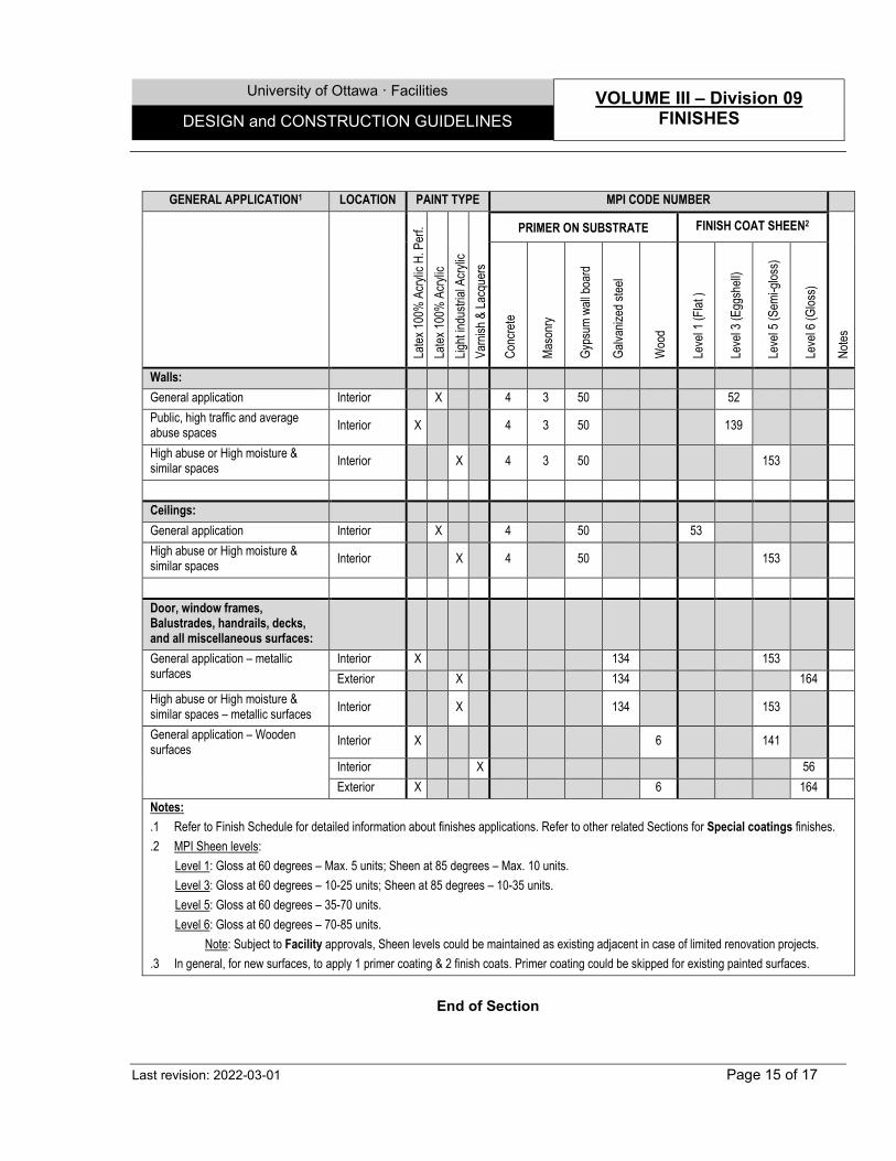
University of Ottawa · Facilities VOLUME III – Division 09
FINISHES DESIGN and CONSTRUCTION GUIDELINES
Last revision: 2022-03-01 Page 15 of 17
End of Section
GENERAL APPLICATION1 LOCATION PAINT TYPE MPI CODE NUMBER
Latex
100%
Acry
lic H
. Per
f. La
tex 10
0% A
crylic
Lig
ht ind
ustria
l Acry
lic
Varn
ish &
Lacq
uers
PRIMER ON SUBSTRATE FINISH COAT SHEEN2
Notes
Conc
rete
Maso
nry
Gyps
um w
all bo
ard
Galva
nized
stee
l
Woo
d
Leve
l 1 (F
lat )
Leve
l 3 (E
ggsh
ell)
Leve
l 5 (S
emi-g
loss)
Leve
l 6 (G
loss)
Walls: General application Interior X 4 3 50 52 Public, high traffic and average abuse spaces Interior X 4 3 50 139
High abuse or High moisture & similar spaces Interior X 4 3 50 153
Ceilings: General application Interior X 4 50 53 High abuse or High moisture & similar spaces Interior X 4 50 153
Door, window frames, Balustrades, handrails, decks, and all miscellaneous surfaces:
General application – metallic surfaces
Interior X 134 153 Exterior X 134 164
High abuse or High moisture & similar spaces – metallic surfaces Interior X 134 153
General application – Wooden surfaces Interior X 6 141
Interior X 56 Exterior X 6 164
Notes: .1 Refer to Finish Schedule for detailed information about finishes applications. Refer to other related Sections for Special coatings finishes. .2 MPI Sheen levels:
Level 1: Gloss at 60 degrees – Max. 5 units; Sheen at 85 degrees – Max. 10 units. Level 3: Gloss at 60 degrees – 10-25 units; Sheen at 85 degrees – 10-35 units. Level 5: Gloss at 60 degrees – 35-70 units. Level 6: Gloss at 60 degrees – 70-85 units. Note: Subject to Facility approvals, Sheen levels could be maintained as existing adjacent in case of limited renovation projects.
.3 In general, for new surfaces, to apply 1 primer coating & 2 finish coats. Primer coating could be skipped for existing painted surfaces.
University of Ottawa · Facilities VOLUME III – Division 09
FINISHES DESIGN and CONSTRUCTION GUIDELINES
Last revision: 2022-03-01 Page 16 of 17
SECTION 09 96 00 - SPECIAL COATING 1.0 GENERAL 1.1 Extended Warranty
.1 All special coating shall be guaranteed against all defects including cracking, crazing, surface deterioration or any other defects detrimental to the appearance or strength of the finishes, for a period of 3 years for labour and Materials.
.2 Manufacturer representative shall be present at all construction phases to ensure adequate quality control on the installation.
1.2 Design Criteria and Notes
.1 Maintain surfaces and ambient air temperature between 13oC and 28oC for a minimum of 72 hours before, during and after application, and ambient relative humidity below 80% during application. Ensure moisture content in the substrate is within the limits prescribed by the manufacturer.
.2 Do not apply coatings on sealants, unless they are compatible.
.3 Protect adequately or remove all prefinished adjacent elements, such as apparatus, equipment or accessories, using canvases, masking tape or other appropriate means.
2.0 PRODUCTS 2.1 Coating systems
.1 High Performance Pigmented Epoxy Wall Coating, High Gloss: Two-component high performance epoxy coating, high gloss finish, with a water borne epoxy finish coat. System includes recommended Primers with minimum Two coats of 200 microns (8 mils) dry film thickness per coat and One coat of water borne epoxy of 50-75 microns (2-3 mils) dry film thickness. - Suggested (or equivalent) products: As manufactured by Sika (Duochem):
.1 "Cor-Pro 470" (primer for metal surface).
.2 "Sika (Duochem) 265" (primer for gypsum surfaces).
.3 "Sika (Duochem) VA" (filler for concrete block surfaces).
.4 "Duroplast 100" (coating).
.5 "Duroplast 150" (finish coat).
.2 Pigmented Epoxy Wall Coating, with Polyurethane finish, High-Gloss: Two-component, high performance, high solids, epoxy base layer, with a high performance, UV resistant, Polyurethane finish. System includes recommended Primers with minimum One coat applied at 5 to 7 mil/125 to 180 microns, and Two coats of 2 to 4 mils/50 to 100 microns dry film thickness. - Suggested (or equivalent) product: “Stonglaze VSR” system by Stonehard.
.1 As recommended (Primer).
.2 “Stonglaze Topcoat EPX” (Base coat).
.3 “Stonglaze URE” (Topcoat).
.3 High Performance Pigmented Epoxy Wall Coating, High Gloss, Partially Reinforced: Two-component high performance epoxy coating, high gloss finish, with a water borne epoxy finish
University of Ottawa · Facilities VOLUME III – Division 09
FINISHES DESIGN and CONSTRUCTION GUIDELINES
Last revision: 2022-03-01 Page 17 of 17
coat, partially reinforced at junctions of dissimilar materials and at rounded corners with Glass fiber Reinforcing fabric tape. System includes recommended Primers with minimum Two coats of 200 microns (8 mils) dry film thickness per coat and One coat of water borne epoxy of 50-75 microns (2-3 mils) dry film thickness. - Suggested (or equivalent) products: As manufactured by Sika (Duochem):
.1 "Cor-Pro 470", primer for metal surfaces.
.2 "Sika (Duochem) 265", primer for gypsum surfaces.
.3 "Sika (Duochem) VA" filler for concrete block surfaces.
.4 "Duroplast 100" coating.
.5 "Duroplast 150" finish coat.
.4 High Performance Pigmented Epoxy Wall Coating, High Gloss, Totally Reinforced: Two-component high performance epoxy coating, high gloss finish, with a water borne epoxy finish coat, reinforced on entire surface with Glass fiber Reinforcing fabric tape. System includes recommended Primers with minimum Two coats of 200 microns (8 mils) dry film thickness per coat and One coat of water borne epoxy of 50-75 microns (2-3 mils) dry film thickness. - Suggested (or equivalent) products: As manufactured by Sika (Duochem):
.1 "Cor-Pro 470", primer for metal surfaces.
.2 "Sika (Duochem) 265", primer for gypsum surfaces.
.3 "Sika (Duochem) VA" filler for concrete block surfaces.
.4 "Duroplast 100" coating.
.5 "Duroplast 150" finish coat.
2.3 Accessories .1 Glass fiber Reinforcing fabric tape: Min. 100 mm (4") wide tape, simple weave, 194 g/m2 (5.7
oz/yd2), 0.20 mm (0.008") thick. - Suggested (or equivalent) product: "Style 7521" by Bay Mills.
.2 Anti-graffiti shield: VOC compliant, clear, water-based sacrificial coating for control of graffiti
on most building surfaces, preventing spray paints, crayons and ink from penetrating and staining the underlying surface. To be reapplied after every graffiti removal. - Suggested (or equivalent) Product: “Defacer Eraser Sacrificial Coating SC-1” by
Prosco.
End of Section
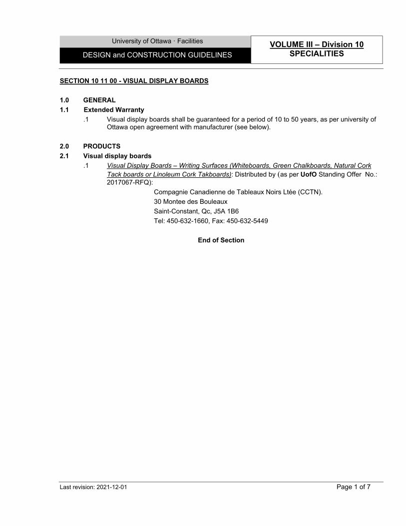
University of Ottawa · Facilities VOLUME III – Division 10
SPECIALITIES DESIGN and CONSTRUCTION GUIDELINES
Last revision: 2021-12-01 Page 1 of 7
SECTION 10 11 00 - VISUAL DISPLAY BOARDS 1.0 GENERAL 1.1 Extended Warranty
.1 Visual display boards shall be guaranteed for a period of 10 to 50 years, as per university of Ottawa open agreement with manufacturer (see below).
2.0 PRODUCTS 2.1 Visual display boards
.1 Visual Display Boards – Writing Surfaces (Whiteboards, Green Chalkboards, Natural Cork Tack boards or Linoleum Cork Takboards): Distributed by (as per UofO Standing Offer No.: 2017067-RFQ):
Compagnie Canadienne de Tableaux Noirs Ltée (CCTN). 30 Montee des Bouleaux Saint-Constant, Qc, J5A 1B6 Tel: 450-632-1660, Fax: 450-632-5449
End of Section
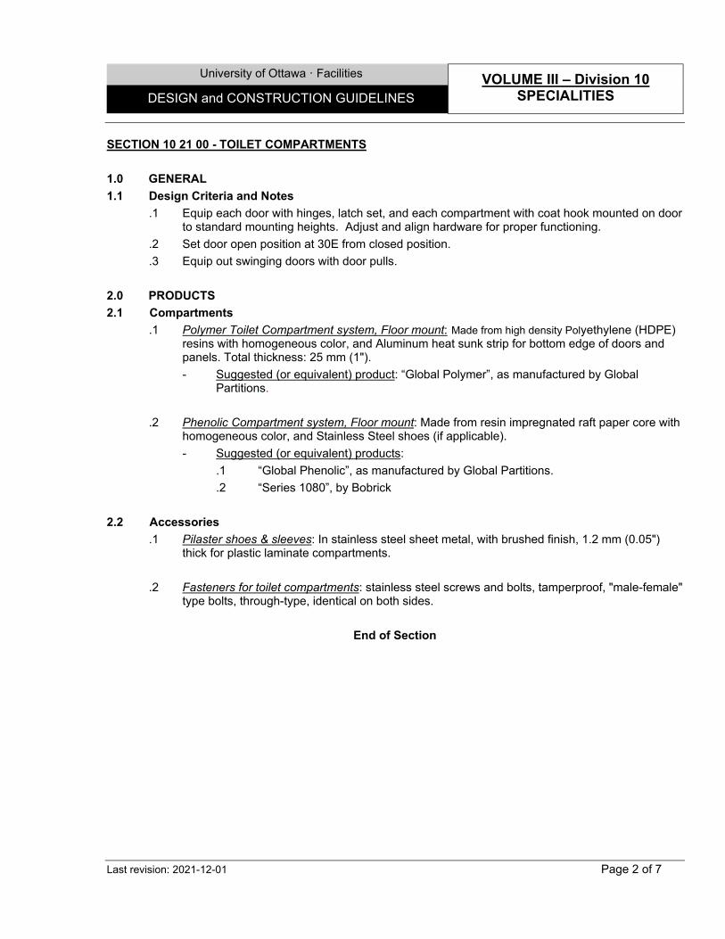
University of Ottawa · Facilities VOLUME III – Division 10
SPECIALITIES DESIGN and CONSTRUCTION GUIDELINES
Last revision: 2021-12-01 Page 2 of 7
SECTION 10 21 00 - TOILET COMPARTMENTS 1.0 GENERAL 1.1 Design Criteria and Notes
.1 Equip each door with hinges, latch set, and each compartment with coat hook mounted on door to standard mounting heights. Adjust and align hardware for proper functioning.
.2 Set door open position at 30E from closed position.
.3 Equip out swinging doors with door pulls. 2.0 PRODUCTS 2.1 Compartments
.1 Polymer Toilet Compartment system, Floor mount: Made from high density Polyethylene (HDPE) resins with homogeneous color, and Aluminum heat sunk strip for bottom edge of doors and panels. Total thickness: 25 mm (1"). - Suggested (or equivalent) product: “Global Polymer”, as manufactured by Global
Partitions.
.2 Phenolic Compartment system, Floor mount: Made from resin impregnated raft paper core with homogeneous color, and Stainless Steel shoes (if applicable). - Suggested (or equivalent) products:
.1 “Global Phenolic”, as manufactured by Global Partitions.
.2 “Series 1080”, by Bobrick
2.2 Accessories .1 Pilaster shoes & sleeves: In stainless steel sheet metal, with brushed finish, 1.2 mm (0.05")
thick for plastic laminate compartments.
.2 Fasteners for toilet compartments: stainless steel screws and bolts, tamperproof, "male-female" type bolts, through-type, identical on both sides.
End of Section
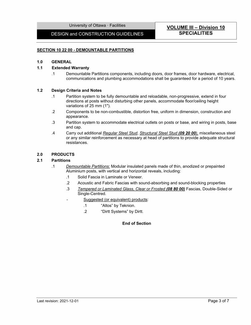
University of Ottawa · Facilities VOLUME III – Division 10
SPECIALITIES DESIGN and CONSTRUCTION GUIDELINES
Last revision: 2021-12-01 Page 3 of 7
SECTION 10 22 00 - DEMOUNTABLE PARTITIONS 1.0 GENERAL 1.1 Extended Warranty
.1 Demountable Partitions components, including doors, door frames, door hardware, electrical, communications and plumbing accommodations shall be guaranteed for a period of 10 years.
1.2 Design Criteria and Notes
.1 Partition system to be fully demountable and reloadable, non-progressive, extend in four directions at posts without disturbing other panels, accommodate floor/ceiling height variations of 25 mm (1").
.2 Components to be non-combustible, distortion free, uniform in dimension, construction and appearance.
.3 Partition system to accommodate electrical outlets on posts or base, and wiring in posts, base and cap.
.4 Carry out additional Regular Steel Stud, Structural Steel Stud (09 20 00), miscellaneous steel or any similar reinforcement as necessary at head of partitions to provide adequate structural resistances.
2.0 PRODUCTS 2.1 Partitions
.1 Demountable Partitions: Modular insulated panels made of thin, anodized or prepainted Aluminium posts, with vertical and horizontal reveals, including: .1 Solid Fascia in Laminate or Veneer. .2 Acoustic and Fabric Fascias with sound-absorbing and sound-blocking properties .3 Tempered or Laminated Glass, Clear or Frosted (08 80 00) Fascias, Double-Sided or
Single-Centred. - Suggested (or equivalent) products:
.1 “Altos” by Teknion.
.2 “Dirtt Systems” by Dirtt.
End of Section
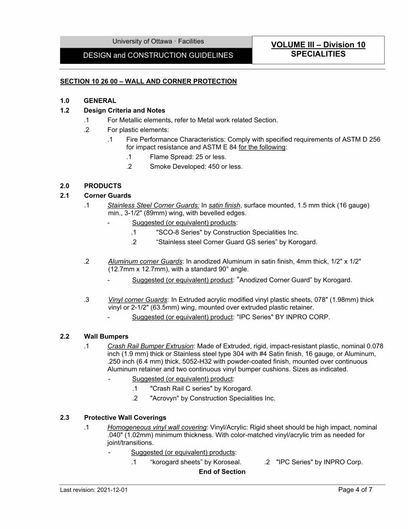
University of Ottawa · Facilities VOLUME III – Division 10
SPECIALITIES DESIGN and CONSTRUCTION GUIDELINES
Last revision: 2021-12-01 Page 4 of 7
SECTION 10 26 00 – WALL AND CORNER PROTECTION 1.0 GENERAL 1.2 Design Criteria and Notes
.1 For Metallic elements, refer to Metal work related Section.
.2 For plastic elements: .1 Fire Performance Characteristics: Comply with specified requirements of ASTM D 256
for impact resistance and ASTM E 84 for the following: .1 Flame Spread: 25 or less. .2 Smoke Developed: 450 or less.
2.0 PRODUCTS 2.1 Corner Guards
.1 Stainless Steel Corner Guards: In satin finish, surface mounted, 1.5 mm thick (16 gauge) min., 3-1/2" (89mm) wing, with bevelled edges. - Suggested (or equivalent) products:
.1 "SCO-8 Series" by Construction Specialities Inc.
.2 “Stainless steel Corner Guard GS series” by Korogard. .2 Aluminum corner Guards: In anodized Aluminum in satin finish, 4mm thick, 1/2" x 1/2"
(12.7mm x 12.7mm), with a standard 90° angle. - Suggested (or equivalent) product: “Anodized Corner Guard” by Korogard.
.3 Vinyl corner Guards: In Extruded acrylic modified vinyl plastic sheets, 078" (1.98mm) thick
vinyl or 2-1/2" (63.5mm) wing, mounted over extruded plastic retainer. - Suggested (or equivalent) product: "IPC Series" BY INPRO CORP.
2.2 Wall Bumpers .1 Crash Rail Bumper Extrusion: Made of Extruded, rigid, impact-resistant plastic, nominal 0.078
inch (1.9 mm) thick or Stainless steel type 304 with #4 Satin finish, 16 gauge, or Aluminum, .250 inch (6.4 mm) thick, 5052-H32 with powder-coated finish, mounted over continuous Aluminum retainer and two continuous vinyl bumper cushions. Sizes as indicated. - Suggested (or equivalent) product:
.1 "Crash Rail C series" by Korogard.
.2 "Acrovyn" by Construction Specialities Inc.
2.3 Protective Wall Coverings .1 Homogeneous vinyl wall covering: Vinyl/Acrylic: Rigid sheet should be high impact, nominal
.040" (1.02mm) minimum thickness. With color-matched vinyl/acrylic trim as needed for joint/transitions. - Suggested (or equivalent) products:
.1 “korogard sheets” by Koroseal. .2 "IPC Series" by INPRO Corp. End of Section
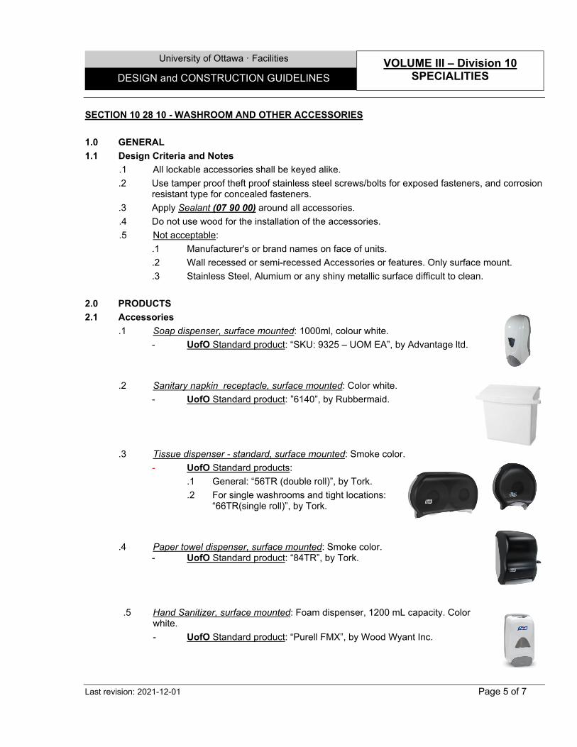
University of Ottawa · Facilities VOLUME III – Division 10
SPECIALITIES DESIGN and CONSTRUCTION GUIDELINES
Last revision: 2021-12-01 Page 5 of 7
SECTION 10 28 10 - WASHROOM AND OTHER ACCESSORIES 1.0 GENERAL 1.1 Design Criteria and Notes
.1 All lockable accessories shall be keyed alike.
.2 Use tamper proof theft proof stainless steel screws/bolts for exposed fasteners, and corrosion resistant type for concealed fasteners.
.3 Apply Sealant (07 90 00) around all accessories. .4 Do not use wood for the installation of the accessories. .5 Not acceptable:
.1 Manufacturer's or brand names on face of units.
.2 Wall recessed or semi-recessed Accessories or features. Only surface mount.
.3 Stainless Steel, Alumium or any shiny metallic surface difficult to clean.
2.0 PRODUCTS 2.1 Accessories
.1 Soap dispenser, surface mounted: 1000ml, colour white. - UofO Standard product: “SKU: 9325 – UOM EA”, by Advantage ltd.
.2 Sanitary napkin receptacle, surface mounted: Color white.
- UofO Standard product: ”6140”, by Rubbermaid.
.3 Tissue dispenser - standard, surface mounted: Smoke color.
- UofO Standard products: .1 General: “56TR (double roll)”, by Tork. .2 For single washrooms and tight locations:
“66TR(single roll)”, by Tork.
.4 Paper towel dispenser, surface mounted: Smoke color.
- UofO Standard product: “84TR”, by Tork.
.5 Hand Sanitizer, surface mounted: Foam dispenser, 1200 mL capacity. Color
white. - UofO Standard product: “Purell FMX”, by Wood Wyant Inc.
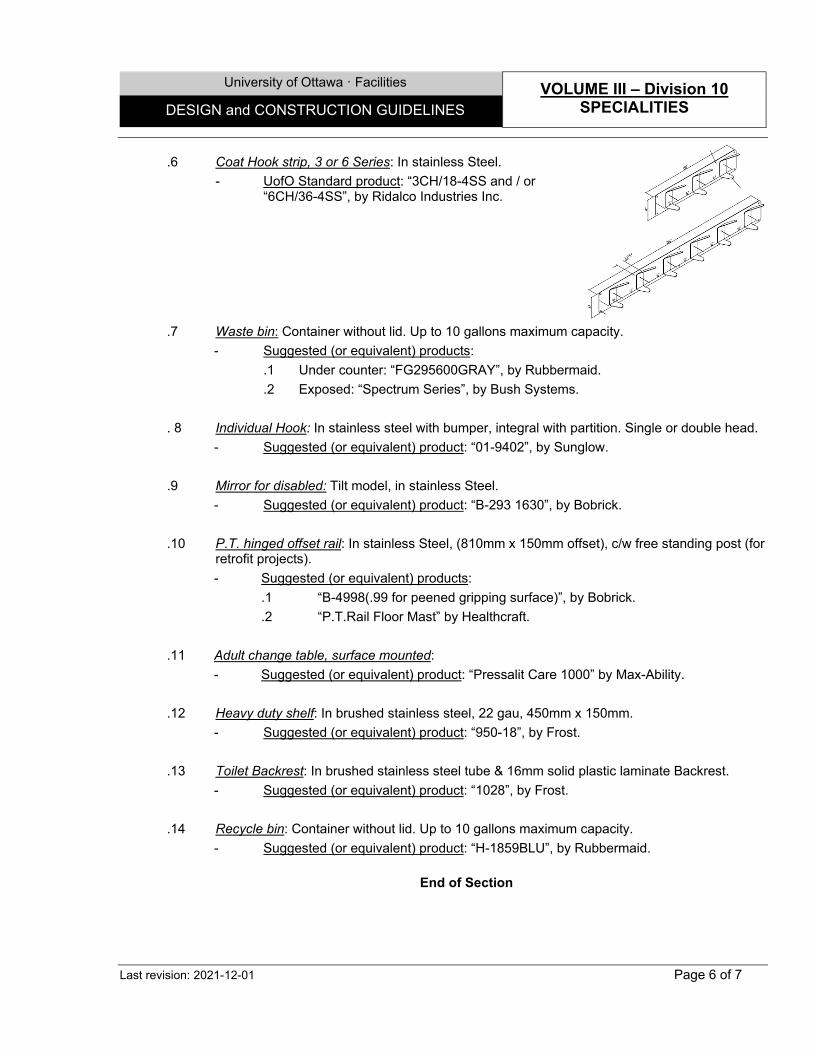
University of Ottawa · Facilities VOLUME III – Division 10
SPECIALITIES DESIGN and CONSTRUCTION GUIDELINES
Last revision: 2021-12-01 Page 6 of 7
.6 Coat Hook strip, 3 or 6 Series: In stainless Steel. - UofO Standard product: “3CH/18-4SS and / or
“6CH/36-4SS”, by Ridalco Industries Inc.
.7 Waste bin: Container without lid. Up to 10 gallons maximum capacity.
- Suggested (or equivalent) products: .1 Under counter: “FG295600GRAY”, by Rubbermaid. .2 Exposed: “Spectrum Series”, by Bush Systems.
. 8 Individual Hook: In stainless steel with bumper, integral with partition. Single or double head.
- Suggested (or equivalent) product: “01-9402”, by Sunglow.
.9 Mirror for disabled: Tilt model, in stainless Steel. - Suggested (or equivalent) product: “B-293 1630”, by Bobrick.
.10 P.T. hinged offset rail: In stainless Steel, (810mm x 150mm offset), c/w free standing post (for retrofit projects). - Suggested (or equivalent) products:
.1 “B-4998(.99 for peened gripping surface)”, by Bobrick.
.2 “P.T.Rail Floor Mast” by Healthcraft.
.11 Adult change table, surface mounted: - Suggested (or equivalent) product: “Pressalit Care 1000” by Max-Ability.
.12 Heavy duty shelf: In brushed stainless steel, 22 gau, 450mm x 150mm.
- Suggested (or equivalent) product: “950-18”, by Frost.
.13 Toilet Backrest: In brushed stainless steel tube & 16mm solid plastic laminate Backrest. - Suggested (or equivalent) product: “1028”, by Frost.
.14 Recycle bin: Container without lid. Up to 10 gallons maximum capacity. - Suggested (or equivalent) product: “H-1859BLU”, by Rubbermaid.
End of Section
University of Ottawa · Facilities VOLUME III – Division 10
SPECIALITIES DESIGN and CONSTRUCTION GUIDELINES
Last revision: 2021-12-01 Page 7 of 7
SECTION 10 51 00 - LOCKERS 1.0 GENERAL .1 Design Criteria and Notes
.1 Install filler panels above or beside lockers & finished end panels to exposed surfaces of locker banks.
.2 Shall be sitting on concrete base or steel base if concrete not possible.
.3 Apply Sealant (07 90 00) at joints between lockers and adjoining surfaces.
2.0 PRODUCTS 2.1 Lockers
.1 Institutional type lockers: Sizes as necessary, 305 mm (12") wide maximum, in High Density Polyethylene. Single or double tier, space permitted. - Suggested (or equivalent) products:
.1 As manufactured by Royal Plastic Lockers.
.2 As manufactured by Tufftec HDPE Lockers.
.2 Clean Room type lockers: Similar to Institutional type lockers in Brush Satin vertical grain Finish #4 (Grade 304).
- Suggested (or equivalent) product: As manufactured by Famous Lockers. 2.2 Prefabricated Benches
.1 Prefabricated benches, wood top (for general use): Solid maple tops, corners rounded and sanded; with a clear urethane finish, 460mm wide minimum, mounted on prepainted steel pedestals consisting of single diameter tubing.
- Suggested (or equivalent) product: “20B72-12” by Prefix. .2 Prefabricated benches, stainless steel (for clean rooms): Brush Satin vertical grain Finish #4
(Grade 304), solid top; 460mm wide minimum. - Suggested (or equivalent) product: "Pedestal Gowning Bench" by Pearce Stainless.
End of Section
University of Ottawa · Facilities VOLUME III – Division 11
EQUIPMENT DESIGN and CONSTRUCTION GUIDELINES
Last revision: 2022-03-01 Page 1 of 2
SECTION 11 13 00 – LOADING DOCK EQUIPMENT 1.0 GENERAL 1.1 Extended Warranty
.1 The following elements shall be guaranteed as follow: .1 Loading Dock levellers: 10 year general warranty (all components). .2 Dock bumpers: 2 year performance warranty. 1 year for labour and Materials. .3 Dock door seals: 1 year performance warranty. 1 year for labour and Materials. 1.2 Design Criteria and Notes
.1 Coordinate with transport companies for the exact dimensions and locations of the bumpers and seals.
2.0 PRODUCTS
.1 Loading Dock levellers, Hydraulic: .1 Unless otherwise requested, Dock levellers minimum capacity of moving or rollover
live load shall be of 11340 kg (25,000 lb) and static load of 22,680 kg (50,000 lb), to be installed in a dry pit.
.2 Pit will be built with full length structural steel "C" channels and "I" beams. Formed-steel moulds are not accepted.
.3 Sides of platform will be equipped with protective full range steel sheet plates to provide toe guards for platform in raised position.
.4 Deck to be thoroughly thermally insulated, with Weatherseals on all 3, with an easily replaceable flexible part fitted into a steel section welded to the leveller or curb angle. - Suggested (or equivalent) product: "RHH 5000", by Rite-Hite.
.2 Dock Bumpers, High Impact Resistant: Completely enclosed box construction with 12.7 mm
(1/2") high-carbon steel face cap, 6 mm (1/4") steel body and rubber slats, 610 mm x 267 mm x 102 mm (24" x 10½" x 4"). - Suggested (or equivalent) product: "Docksaver" by Rite-Hite.
.3 Dock door Seals: Construct dock shelter seal of 100 mm (4") tapered projection pads, 305 mm to 405 mm x 305 mm (12" - 16" x 12") high density polyurethane foam, continuously bonded to 50 mm (2") thick kiln-dried pressurized wood frames and a galvanized steel base, with a non-flammable elastic adhesive, and covered with waterproof high performance "Durathon" fabric, and one full width touch and hold velcro adjustable split curtain, complete with "wiper" pad.
- Acceptable product: "S-600" with "S-900 DD Dry Dock" by the Serco Corporation.
End of Section
University of Ottawa · Facilities VOLUME III – Division 11
EQUIPMENT DESIGN and CONSTRUCTION GUIDELINES
Last revision: 2022-03-01 Page 2 of 2
SECTION 11 14 00 – HOSPITALITY EQUIPMENT 1.0 GENERAL 1.1 Design Criteria and Notes
.1 Mounting method shall be ceiling hung (from structure above) application.
3.0 PRODUCTS .1 Portable Ceiling lift Device: Lift device composed of aluminium rail, suspension system, rods,
straps, and all similar installation features with following characteristics: .1 Operation system: Battery operation. Capacity as recommended by manufacturer. .2 Capacity: 440 lb (200 kg) .3 Noise level: 60.5 dB. .4 Accessories: Trolley Track, Extension strap, Reacher,
Portable lift carry bag, Pivoting adaptor, Swivel Trolley, Non-slip feet that provide stability and protection when put on the table.
.5 Power Supply: At disconnect switches. - U ofO Standard product: "V3 (MAXISKY 440)" by BHM
Medical.
End of Section
University of Ottawa · Facilities VOLUME III – Division 12
FURNISHING DESIGN and CONSTRUCTION GUIDELINES
Last revision: 2021-12-01 Page 1 of 15
SECTION 12 20 00 - WINDOW TREATMENT 1.0 GENERAL 1.1 Design Criteria and Notes
.1 Secure aluminium components with non-corrosive metal fasteners for installation, concealed in final assembly.
.2 When installed on multi-mullion windows, any joint between two fabric pieces shall occur only at center line of an intermediate mullion.
.3 Design brake to stop and hold blinds in any position.
.4 In general: .1 Motorized Shading Systems to be used in areas that are hard to reach or in rooms where
there is a large span of windows where the shades would always have to be drawn up or down at the same time (Classrooms, Laboratories, and similar).
.2 Manual Shading Systems to be used in public spaces, with a mechanism that can be controlled by chain but also pulled down manually, as it does not jam if a student pull on the shade.
2.0 PRODUCTS
.1 Shading Systems, Manual or Motorized: Chain operated and sprocket roller shading system with infinite positioning, or with motor. Fabric in Shade cloths woven of .018 opaque, vinyl coated polyester yarn consisting of approximately 79% vinyl and 21% 500 denier polyester core yarn. Percentage of openness: 3%, 1% and 0%. - Suggested (or equivalent) products:
.1 "Sheerweave 2410” (3%), "Sheerweave 2500” (1%), "Sheerweave 7500” (0%), as manufactured by SOL-R:
.2 Spring Assistant models (for large, high or big units), as manufactured by Sun Project.
End of Section
University of Ottawa · Facilities VOLUME III – Division 12
FURNISHING DESIGN and CONSTRUCTION GUIDELINES
Last revision: 2021-12-01 Page 2 of 15
SECTION 12 35 00 - LABORATORY FURNITURE 1.0 GENERAL 1.1 Extended Warranty
.1 All lab furniture and related accessories shall be guaranteed against all defects in design, Material fabrication and installation for a period of 3 years.
1.2 Design Criteria and Notes
.1 Criteria: Comply with all standards is this specification, unless more stringent requirements are given herein. Work shall conform also to the following: .1 Safety Guide for Laboratory Operations, Chapter 5.1, Treasury Board Manual,
Occupational Safety and Health. .2 Health Canada, Office of Laboratory Security, The Laboratory Bio-Safety Guidelines.
.3 ANSI/AIHA Z9.5 - American National Standard, Laboratory Ventilation
.4 ANSI/NFPA 30 - Flammable and Combustible Liquids Code. .5 NFPA 45 – Fire Protection for Laboratories Using Chemicals.
.6 SEFA-2.3 – Installation of Scientific Laboratory Furniture and Equipment, Recommended Practices
.7 SEFA-3 – Work surfaces
.8 SEFA-5.1 – Scope of Work
.9 SEFA-7 – Laboratory and Hospital Fixtures
.10 SEFA-8 – Laboratory Furniture Casework, Shelving and Tables, Recommended Practices
.11 OSHA applicable standards.
.12 EEMAC standards. .13 Ontario Electrical Safety Code.
.14 CSA C22.1-02 - Canadian Electrical Code.
.15 "Quality Standards for Architecural WoodWork", for wood casework.
.16 AWI and CSA quality standards for finish carpentry and Plywood identification to be by grade mark.
.2 Notes:
.1 An operational HVAC system that maintains temperature and humidity at occupancy levels must be in place. Relative humidity must be between 25% and 55% before product is brought on site.
.2 Permissible variation is 1.5 mm in 3 meters (1/16" in 10'-0"). Bolt together casework, in such a way that joints between them shall not be wider than 1 mm (0.04").
.3 Integrate existing cabinets into the new furniture (if applicable) and make necessary repairs.
.4 Use non-corrosive screws and bolts for concealed fastenings. .5 No oils or waxes are to be used on finished installation.
University of Ottawa · Facilities VOLUME III – Division 12
FURNISHING DESIGN and CONSTRUCTION GUIDELINES
Last revision: 2021-12-01 Page 3 of 15
2.0 PRODUCTS 1.0 General
.1 The Contractor / Manufacturer shall be a member of SEFA & AWI/AWMAC. - UofO standard products: As manufactured by:
.1 Bedcolab Inc .2 CIF Lab Solutions
.3 Mottlab Inc .4 Duralab Equipment Corp.
.5 Fisher-Hamilton .6 ICI 2.2 Countertops, Table top (work surfaces) & Shelves
.1 General: .1 Tops shall be fabricated in as long a length as possible to minimize the number of
joints. All joints shall be butt type and factory fitted to provide proper alignment on site.
.2 Exposed edges and Laboratory Sink (22 42 01) openings surfaces shall be finished in same manner as specified for working surface of countertop material and faces shall have a drip groove on the underside.
.2 Countertops - Plastic Laminate Facing with Resistance to Acid:
.1 To be fabricated from wood panel particleboard 28.6 mm (1-1/8") thick overall, with chamfered edges, covered with plastic laminate with Acid resistance or with High resistance to acids, 1.2 mm (0.047") thick material on the exposed / open / underneath faces.
.2 Splash backs of the same material shall be part of the counter, with a 3 mm (1/8") pencil radius at the intersection of counter. Lateral splashbacks shall be fixed mechanically to the counter and joints sealed.
.3 Solid PVC finishing edge strip 3mm shall be applied by electro-pressure to the exposed edges of the countertop. - Suggested (or equivalent) products:
.1 "Arborite flex 4", finish "CA" or "Diamond", by Arborite.
.2 "Chemtop", finish "58" or "42", by Formica.
.3 "Panelab" by Panelyte - Suggested (or equivalent) products for High Acid resistant plastic Laminate:
.1 "Arbo chem", finish "MT" or "qm", by arborite.
.2 "Laboratory grade 840/LGP", black colour, finish "58" or "42", by Formica.
.3 Countertops - Solid Phenolic Resin (Solid plastic Laminate) – Acid resistant:
.1 Shall be 25 mm (1") overall thickness or more, with chamfered edges.
.2 Splashbacks of the same material shall be mechanically fastened to the counter and the resultant joints shall be sealed. - Suggested (or equivalent) products:
.1 "Arborite laboratory grade solid phenolic core", finish "CA" or "Diamond", by Arborite.
.2 "Laboratory grade 840/LGP Thick stock", black colour, finish "58" or "42",
University of Ottawa · Facilities VOLUME III – Division 12
FURNISHING DESIGN and CONSTRUCTION GUIDELINES
Last revision: 2021-12-01 Page 4 of 15
by Formica. .3 “Trespa TopLab Plus” by Total Lab solutions. .4 “Chemical resistant SPC” by Durcon.
.4 Countertops – Epoxy Resin - Acid and Heat Resistant:
.1 Moulded, homogeneous, 100% modified epoxy resin boards, completely cured in processing, with at least 1.25 mm (0.05") thick (dry film) coating, very smooth finish, non-glazing, non-reflecting, without surface defects.
.2 Of 25 mm (1") overall thickness or more, with bevelled edges, and with 32 mm (1¼") marine edges in fume hoods, extremities rounded 6.4 mm.
.3 Joints shall be welded with identical material. - Suggested (or equivalent) product: As manufactured by Chemtops.
.5 Countertops - Stainless Steel:
.1 Shall be of 1.5 mm (16 ga) with closed edges and reinforced with 1.5 mm (16 ga) thick hat-shaped channels spaced 400 mm (16") o.c. maximum, and welded to the underside to avoid twisting or buckling with sound deadening. With integral splashbacks, and milled to match the Stainless Steel counter tops, with a cove, at the junction with the countertop and shall have a total thickness of 19 mm (¾").
.2 The front edges and all other exposed or open ends of such tops shall have a raised rim or marine edge 25 mm (1") wide. From the extreme inward edge of the rim, a slope downwards of 30o shall be provided with a vertical drop of 6 mm (1/4"). Exposed edge shall be of 25 mm (1") total height.
2.3 Casework 2.3.1 General
.1 Units: Shall be interchangeable, rigid and self-supporting. .2 Suspended Cabinets or on Casters:
.1 To be provided with steel hanging rails to match correspondent Framing system.
.2 To be provided with finished backs and bottoms made of similar materials.
.3 Suspended cabinets shall have dust cover to enclose the top, made of similar materials, and units on Casters shall have a finished countertop surface, with similar construction as the fixed countertops.
.4 Depending on the number, shall be provided with 2 cabinet transfer carts that will allow for installation, removal and relocation of suspended cabinets without tools or removal of contents of cabinets.
.3 Additional notes for Stainless Steel units
.1 Shall be of similar construction to that of Prepainted Steel furniture.
.2 All base cabinets and other furniture, including those with drawers and with sinks, shall be sealed units.
.3 Joints in exposed Stainless Steel cabinet surfaces shall be ground and polished to the same finish as the rest of the surfaces. All Stainless Steel nuts, screws, bolts, rivets, etc., shall be of the same type stainless as in the sheet material.
University of Ottawa · Facilities VOLUME III – Division 12
FURNISHING DESIGN and CONSTRUCTION GUIDELINES
Last revision: 2021-12-01 Page 5 of 15
.4 All Stainless Steel welding material shall be of type similar to the sheet material, by the argon arc process. To be continuous, crevice-free, ground and polished to the original finish of the surface. Fillers, solders or spot welding will not be permitted.
2.3.2 Base cabinets, wall cabinets or floor cabinets
.1 Units in Prepainted Steel or Stainless Steel: .1 Casework:
.1 Each unit shall be a completely welded structure. Under hood base cabinets must be capable of supporting the weight of the fume hoods and their contents.
.2 All metal surfaces shall be isolated from direct contact with dissimilar metals, concrete and masonry.
.3 No exposed horizontal structural cabinet members between doors and drawers shall be accepted.
.2 Internal shelves:
.1 Shelves shall be mild Steel of similar finish to the cabinets, with edges turned down on all four (4) sides 19 mm and shall return under on the front and back 16 mm (5/8"). Shelves shall be adjustable on 16 mm (5/8") increments and shall be full depth and width of interior. A minimum of four (4) zinc plated shelf clips per shelf shall be provided.
.3 Doors:
.1 Hinged doors shall be double-wall telescoping construction 19 mm (3/4") thick, with front panel and inner liner formed on four sides. All interior surfaces shall be painted before assembly. Doors shall be sound-deadened on interior.
.2 Sliding doors:
.1 To be easily removable, without having to remove shelving, and bumpered.
.2 Frameless sliding Glass doors shall be with "H" shaped extruded aluminum shoes fixed to and running the full width of door bottom.
.3 Sliding doors, with or without glazing, shall have a hollow metal frame 19 mm x 32 mm. same finish as adjacent.
.4 Drawers:
.1 Drawer bodies shall be reinforced and spot-welded to the inner drawer front and back panel. Fronts shall be 19 mm (3/4") double pan construction sound deadened, consisting of two telescoping metal panels (painted inside and out). All interior surfaces shall be painted before assembly.
.5 Basic thicknesses: In general, metal used in the construction of cases shall be of
the following minimum gauges: .1 Front support rail: 3 mm. .2 Case ends, bottoms, tops, vertical posts, uprights, filler panels, shelves, door
University of Ottawa · Facilities VOLUME III – Division 12
FURNISHING DESIGN and CONSTRUCTION GUIDELINES
Last revision: 2021-12-01 Page 6 of 15
panels, glazed door frames and top rear corner gussets, back rails, intermediate horizontal rails: 1.2 mm (18 gauge / 0.048").
.3 Exposed case tops, drawer suspensions, door and case hinge and front corner reinforcement, and levelling device brackets: 1.5 mm (16 gauge / 0.059").
.4 Drawer bodies and cabinet backs: 0.91 mm (20 gauge / 0.036").
.2 Units in wood: .1 Casework:
.1 Wood Core Material shall be in Medium density fibreboard (MDF) of 700-745 kg/m3 density, minimum grade 130, FSC certified, minimum 75% recycled material content, free of added formaldehyde. Finish to be one (or a combination) of the following: .1 Catalysed Vinyl Finish: Color to be selected from the manufacturer
standard. - Suggested (or equivalent) products: As manufactured by CIF
.2 Wood Veneer Facing with Catalysed Vinyl Finish: 0.508 mm (0.02")
thick rift cut, Book match pattern, clear Vinyl finish or stained, in Grade AA (with modifications to grade), White Maple (Plain Sliced ), Grade A Birch (Rotary cut), European Steamed Beech (Plain Sliced) or Cherry (Plain sliced).
.3 Thermally Fused Melamine (TFM): High wear resistant Resin
Impregnated decorative sheet thermally fused to both faces of wood core. Colour to be selected by Consultants. - Suggested (or equivalent) products: Flakeboard Thermally
Fused Melamine .4 Plastic Laminate Facing with Resistance to Acid: Similar to material
used for Countertops. .5 Plastic Laminate Facing: Plastic laminate sheet: regular grade (GPR),
1.15 mm (0.045") thick, colour as per Consultant's choice. - Suggested (or equivalent) products: As manufactured by:
.1 Arborite .2 Abet Laminati
.3 Wilsonart .4 Formica .2 Edging shall be in 3mm solid PVC for Plastic Laminate Facing, Catalysed
Vinyl, TFM units, or Solid wood, same type for Wood veneer Facing units. .3 All Cabinet work shall be Full Flush overlay Modular Construction, factory
assembled, using dowel construction. Overall thickness shall be as follow: .1 Sides: 19mm with 1mm solid edging on 4 edges .2 Back: 19mm
University of Ottawa · Facilities VOLUME III – Division 12
FURNISHING DESIGN and CONSTRUCTION GUIDELINES
Last revision: 2021-12-01 Page 7 of 15
.3 Bottom: 19mm with 1mm solid edging .4 Floor mounted cabinets to have an integral fir waterproof veneer core base.
.2 Internal shelves: .1 Refer to Exposed Shelving articles.
.3 Doors:
.1 Swinging: .1 In Wood Veneer Facing, Catalysed Vinyl, TFM or Plastic Laminate
Facing, with a MDF core, or as indicated of same construction, thickness and finishes as Casework, and 3mm similar solid edging on perimeter.
.2 Sliding: .1 Shall be easily removable, without having to remove shelving. .2 Sliding doors, with or without glazing, shall have a wood frame, same
composition as casework frame 19 mm x 32 mm. Or, Frameless sliding Glass doors shall be with ground, polished edges and door pull.
.4 Drawers:
.1 Faces: In Wood Veneer Facing, Catalysed Vinyl, TFM or Plastic Laminate Facing, with a MDF core, thickness and finishes as Casework, and 3mm similar solid edging on perimeter.
.2 System: Shall be in Plastic Laminate Facing with MDF core, Fully dovetailed drawer box, with 12mm TFM bottoms, or in Prepainted Steel.
2.3.3 System & Frame assemblies
.1 Fixed Countertop Units: .1 Post or Open Leg frame assembly, in Prepainted Steel or Stainless Steel: Consisting
of special tubular frame system (50mm x 50 mm approx.) with prolonged posts (uprights) for shelf support, with hangers to accommodate Suspended Cabinets, with the following minimum gauges: .1 Leg frames, uprights and ddifferent supports and connections: 2 mm (14 ga). .2 Front and rear cabinet hangar rails: 2.7mm (12ga). .3 Toe kick Plate: 1.5mm (16ga). .4 Modesty panels (if applicable): 1.2 mm (18 ga). .5 Wall and Isle Pilasters: 1.5mm (16ga), double slotted.
.2 Service panels in Prepainted Steel or Stainless Steel: To be flanged on all four sides
and reinforced, 1.2 mm (18 ga) thick. Completely or partially removable, without the use of tools and shall be bumpered to prevent rattling. To be part of the removable or on caster base cabinets. To be also provided for base cabinets in peninsular or split island benches, with or without electrical outlets.
University of Ottawa · Facilities VOLUME III – Division 12
FURNISHING DESIGN and CONSTRUCTION GUIDELINES
Last revision: 2021-12-01 Page 8 of 15
.3 Aprons for knee space, in Prepainted Steel or Stainless Steel: Unless otherwise noted, aprons, with or without drawers, to be 64 mm high maximum, to match adjacent units in material, design and finish.
.4 Gable legs: Unless otherwise noted, shall be with same composition as the
Casework. To be provided for exposed end Aprons.
.5 Suspended Base Cabinets: Modular and interchangeable.
.6 Floor-mount Base Cabinets: Modular, with continuous base. - Suggested (or equivalent) products:
.1 “Chorus” by Bedcolab In.
.2 “Sigma Flex” by MottLab Inc.
.2 Mobile Countertop Units: .1 Similar to Fixed Countertop Units, with adjustable legs or pads, and upper Sleeves for
shelves and Suspended cabinets, serviced by the ceiling, with integrates services. - Suggested (or equivalent) products:
.1 “Symphony” by Bedcolab In.
.2 “Sigma Carts” by MottLab Inc.
.3 “Ascent Series Tables” by CIF Lab Solutions
.3 Upper Units: .1 Wall-mount Brackets in Prepainted Steel or Stainless Steel: Consisting of special
adjustable tubular frame system (13mm x 50mm approx.) for shelf support, wall-mount cabinets, with hangers to accommodate wall-mount Cabinets, 2 mm (14 ga).
.2 Wall-Mount Cabinets: Adjustable heights, mount on Wall-mount Brackets, or on Post
or Open Leg frame, with Sliding doors.
2.3.4 Exposed shelving .1 Reagent shelving:
.1 Reagent shelves shall be of Plastic Laminate, provided with a 3mm solid PVC edges, or in Epoxy Resin, thickness and finishes as Countertops. Underside to be finished to match top, provided with Stainless Steel edges and trims.
.2 Vertical Supports shall be of the same material, 32 mm (1¼") thick.
.2 Adjustable wood shelving: .1 In Wood Veneer Facing, Catalysed Vinyl, TFM or Plastic Laminate Facing, with a
MDF core. Shall be of same construction, thickness and finishes as Casework (19mm min.), and 3mm similar solid edging on perimeter. Shelves exceeding 914mm shall have 25mm thickness min.
.2 In Epoxy Resin, or Solid Phenolic Resin: Underside to be finished to match top,
University of Ottawa · Facilities VOLUME III – Division 12
FURNISHING DESIGN and CONSTRUCTION GUIDELINES
Last revision: 2021-12-01 Page 9 of 15
provided with Stainless Steel edges and trims. Thickness, finishes and compositions as described for Countertops. - Suggested (or equivalent) product: “Vario system” by CIF.
.3 Adjustable Prepainted Steel or Stainless shelving: Shall be of similar construction and
finishes as the cabinets, reinforced, to avoid deflection, supported on the slotted tubular Steel uprights.
2.3.5 Fume hoods
.1 General: .1 Fume hoods shall be provided with an airflow sensing, monitoring and alarm device.
Airflow sensor shall be of the direct measurement type i.e. velocity or pressure sensing. Where applicable system shall be integrated into room air supply/exhaust control system.
.2 Heated perchloric acid shall only be used in a laboratory specifically designed for its use and identified as “For Perchloric Acid Operations”. Ref. NFPA 45- 6.11.1
.3 Exhaust Fume-Hood ductwork should typically be made of 316L stainless steel or corrosion coated galvanized steel.
.2 Control strategies: Must be compatible with the rest of the building automation system.
- UofO Standard product: As provided by Delta system. 2.3.6 Cabinets for Storage of Chemical Products
.1 Cabinets for Corrosive (Acids and Bases) Storage: Shall be enamelled Prepainted Steel or wood finish, except the whole of the interior shall be lined with 6 mm (¼") thick chemical-resistant panel liners, with Stainless Steel drainage basins, on the shelf and on the cabinet floor, with a 2" rim all around.
.2 Base Cabinets, for Flammable (Solvent) Storage: Cabinets shall be of the same construction and appearance as the corrosive storage cabinets. Cabinets shall also comply with NFPA's flammable and combustible liquids Code 30, and have ULC or Factory Mutual approvals and/or certification, lockable.
.3 Also, refer to ORM’s related Guidelines for any additional requirments.
2.4 Cabinet Hardware
.1 Nuts, bolts and washers: Shall be Stainless Steel. .2 Drawer and door pulls: Shall be recess mounted and shall be 100 mm (4") extruded anodized
aluminum for baked enamel furniture, Stainless Steel for Stainless Steel furniture, and Nickel plated for wood furniture.
.3 Door hinges:
.1 For Metal furniture: 5 knuckle, removable, institutional type, semi-concealed, with unequal wings, Stainless Steel. Hinges shall be attached to doors and case with
University of Ottawa · Facilities VOLUME III – Division 12
FURNISHING DESIGN and CONSTRUCTION GUIDELINES
Last revision: 2021-12-01 Page 10 of 15
cadmium plated flathead machine screws. .2 For wood furniture: 3 knuckle, self-Closing type, Nickel-plated finish, casework hinges
with mounting plates to provide overlay and height adjustment. minimum 170 deg. .3 Quantity: Provide 3 hinges for doors 800 mm to 1300 mm high. 4 hinges for doors
1300 mm to 1800 mm high, and 5 hinges for doors 1800 mm to 2400 mm high. .4 Adjustable shelf supports:
.1 For Internal Steel Shelves: Seismic type, shall be cadmium or chrome plated Steel for cabinets with baked enamel finish, and Stainless Steel for cabinets in Stainless Steel, or shall be gloss nickel finish, as recommended by Lab Manufacturer.
.2 For Internal Wood Shelves: Seismic type, Double Pin Polycarbonate locking shelf
clip. .3 For External shelves assemblies: Seismic type, Gables shall be 16ga with mounting
pins, with finish to match supporting system leg frames or brackets.
2.5 General Accessories .1 Drying Racks:
.1 Drying Racks in Solid Phenolic Resin (Solid plastic Laminate): To be with a wall hanger bracket, and Pegs of 10 mm x 125 mm (3/8" x 5"). Pegs shall not be bonded into board, but shall be held securely by mechanical design, with horizontal trough at bottom of rack to catch drips, pitched to drain directly into sinks, in Stainless Steel, c/w drain basket accessories. - Suggested (or equivalent) product: As manufactured by InterDyne Systems.
.2 Drying Racks in Stainless Steel: To be with a wall hanger bracket and integral drip
through. Pegs shall be 12 mm x 150 mm (1/2" x 6"), with interchangeable bases with horizontal trough at bottom of rack to catch drips, pitched to drain directly into sinks, c/w drain basket accessories. - Suggested (or equivalent) product: As manufactured by InterDyne Systems.
2.6 Service Chases and Air Returns .1 Service Chases and Air Returns in Prepainted Steel or Stainless Steel:
.1 To have at least 1.5 mm (0.059") thick with reinforcing and accessories as necessary, with Stainless Steel bases (sleeves) and access panels and be easily demountable to allow access to the services.
2.7 Support frames for mechanical services
.1 Mechanical support frame in Steel: .1 To be of adequate thickness, of cold rolled Galvanized or Prepainted Steel box
channel Construction, spaced a maximum of 1220 mm (48") o.c. at all standard wall benches, for service piping. - Suggested (or equivalent) product: As manufactured by Unistrut.
University of Ottawa · Facilities VOLUME III – Division 12
FURNISHING DESIGN and CONSTRUCTION GUIDELINES
Last revision: 2021-12-01 Page 11 of 15
2.8 Plumbing Service & Fixtures .1 General:
.1 Plumbing Fixtures shall meets ADA standards, and be vandal Resistant.
.2 Standard Identification of Fixtures to be as per color schedule CGCB 1-GP-12c. Classifying colors and markers to be easily seen from floor.
.2 Types: .1 Refer to Mechanical section for more details.
2.09 Electrical Accessories .1 General:
.1 All electrical accessories shall conform to AMEEC, ULC and CSA standards. .2 Types:
.1 Refer to Electrical section for more details. 2.10 Finishes
.1 Wood Veneer Facing Catalysed Vinyl, TFM or Plastic Laminate Facing: (As indicated). .2 Stainless Steel elements: Unless otherwise indicated:
.1 To be in Polished Finish #2B (Grade 316L) for the Countertops, Sinks, Cup sinks and Electrical Monument boxes.
.2 To be in Brush Satin vertical grain finish #4 (Grade 304) for all other elements. .3 Prepainted Steel elements: Finish shall be a high-grade laboratory furniture quality,
chemically resistant polyester baked enamel, baked in a controlled high heat. Surfaces exposed to view (interior or exterior) shall receive one coat pigmented primer applied over carefully sanded surfaces followed by two coats of enamel. Surfaces not exposed to view shall have one coat of primer and one of enamel. Completed finish shall be highly resistant to acids, alkalis, salts and solvents.
End of Section
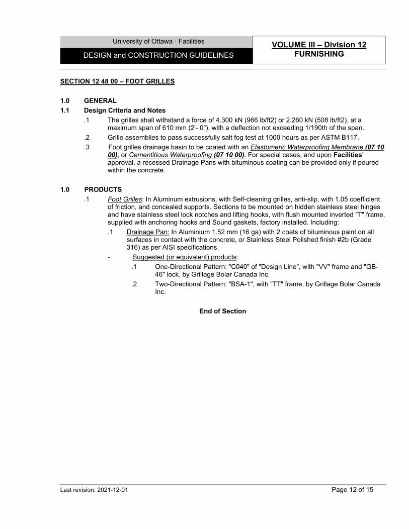
University of Ottawa · Facilities VOLUME III – Division 12
FURNISHING DESIGN and CONSTRUCTION GUIDELINES
Last revision: 2021-12-01 Page 12 of 15
SECTION 12 48 00 – FOOT GRILLES 1.0 GENERAL 1.1 Design Criteria and Notes
.1 The grilles shall withstand a force of 4.300 kN (966 lb/ft2) or 2.260 kN (508 lb/ft2), at a maximum span of 610 mm (2'- 0"), with a deflection not exceeding 1/190th of the span.
.2 Grille assemblies to pass successfully salt fog test at 1000 hours as per ASTM B117.
.3 Foot grilles drainage basin to be coated with an Elastomeric Waterproofing Membrane (07 10 00), or Cementitious Waterproofing (07 10 00). For special cases, and upon Facilities’ approval, a recessed Drainage Pans with bituminous coating can be provided only if poured within the concrete.
1.0 PRODUCTS
.1 Foot Grilles: In Aluminum extrusions, with Self-cleaning grilles, anti-slip, with 1.05 coefficient of friction, and concealed supports. Sections to be mounted on hidden stainless steel hinges and have stainless steel lock notches and lifting hooks, with flush mounted inverted "T" frame, supplied with anchoring hooks and Sound gaskets, factory installed. Including: .1 Drainage Pan: In Aluminium 1.52 mm (16 ga) with 2 coats of bituminous paint on all
surfaces in contact with the concrete, or Stainless Steel Polished finish #2b (Grade 316) as per AISI specifications.
- Suggested (or equivalent) products: .1 One-Directional Pattern: "C040" of "Design Line", with "VV" frame and "GB-
46" lock, by Grillage Bolar Canada Inc. .2 Two-Directional Pattern: "BSA-1", with "TT" frame, by Grillage Bolar Canada
Inc.
End of Section
University of Ottawa · Facilities VOLUME III – Division 12
FURNISHING DESIGN and CONSTRUCTION GUIDELINES
Last revision: 2021-12-01 Page 13 of 15
SECTION 12 50 00 - FURNITURE AND ACCESSORIES SYSTEMS 1.0 GENERAL 1.1 Extended Warranty
.1 Furniture shall be guaranteed to perform without defect for a period of 10 years. 1.2 Design Criteria and Notes
.1 For full information, refer to Furniture Standards document on UofO web site.
2.0 PRODUCTS 2.1 Seats
.1 Seats with retractable tablet: With the following characteristics: .1 Load Criteria: Seats shall be designed at minimum to withstand the following loads in
addition to their own weight: .1 Seat: Shall wisthand an evenly distributed static load of 275lb. .2 Seat back: Shall withstand an evenly distributed front or rear static load
275lb. .3 Retractable tablet: Shall wisthand an evenly distributed static load of 150lb.
.2 Seats:
.1 Backrest: Shall be fabricated to accommodate a range of seat spacing from 19” – 24” on center. Shall fit a riser of 37 inches in depth.
.2 Armrest: To be located on each seat side and shared between seats.
.3 End Panels: Plastic or metal end panels shall be included at the end of each row to conceal seat structure.
.4 Seat numbers: Seat numbers shall be recessed on the front of the seat shroud and be numbered in a clear and visible manner.
.5 Fabric: Shall be polyester and meet or exceed performance guidelines outlined by the Association for Contract Textiles for Heavy Duty Upholstery.
.3 Retractable tablet: .1 Shall be self-storing underneath or between seats without interfering with the
seat, in one single motion and have anti-panic release movement. .2 Writing surface shall be minimum 18mm thick Birch plywood core c/w high-
pressure laminate on face and High pressure laminate backer sheet or phenolic polyurethane board. Dimensions shall be minimum 13 ¼” wide by 10 ½” deep (159 sq. in) and capable of supporting a laptop computer.
.4 Power:
.1 Lights shall be installed on every seat edge adjacent to circulation isles.
.2 Refer to Elect. For other information.
.5 Finish: As per Consultant’s choice. - Suggested (or equivalent) products:
.1 “Concerto” Auditorium Seating” by KI.
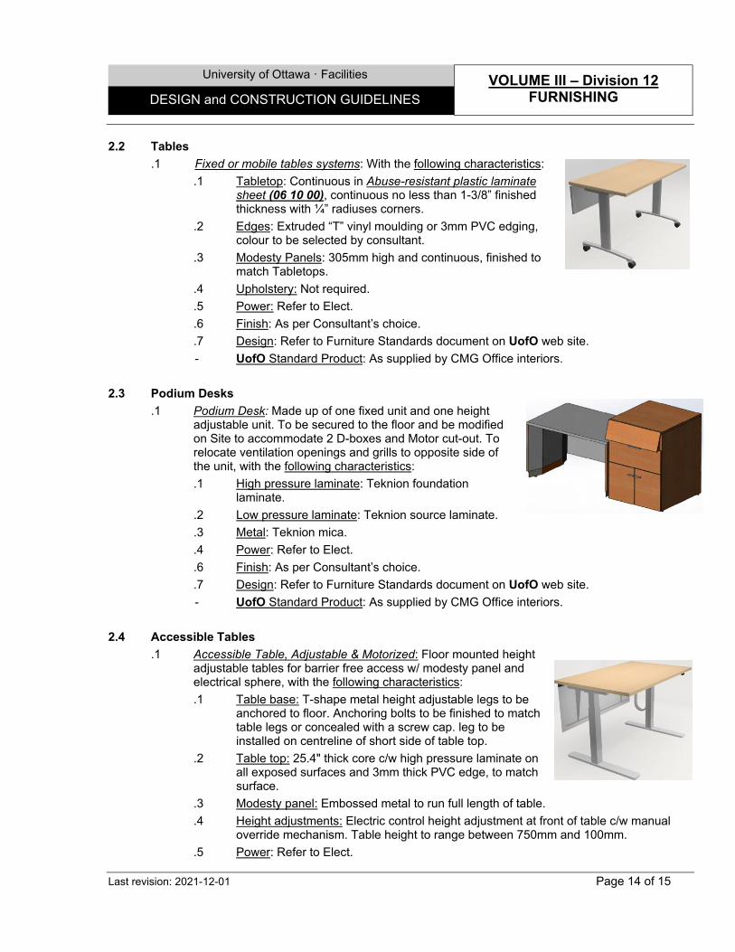
University of Ottawa · Facilities VOLUME III – Division 12
FURNISHING DESIGN and CONSTRUCTION GUIDELINES
Last revision: 2021-12-01 Page 14 of 15
2.2 Tables .1 Fixed or mobile tables systems: With the following characteristics:
.1 Tabletop: Continuous in Abuse-resistant plastic laminate sheet (06 10 00), continuous no less than 1-3/8” finished thickness with ¼” radiuses corners.
.2 Edges: Extruded “T” vinyl moulding or 3mm PVC edging, colour to be selected by consultant.
.3 Modesty Panels: 305mm high and continuous, finished to match Tabletops.
.4 Upholstery: Not required.
.5 Power: Refer to Elect.
.6 Finish: As per Consultant’s choice.
.7 Design: Refer to Furniture Standards document on UofO web site. - UofO Standard Product: As supplied by CMG Office interiors.
2.3 Podium Desks
.1 Podium Desk: Made up of one fixed unit and one height adjustable unit. To be secured to the floor and be modified on Site to accommodate 2 D-boxes and Motor cut-out. To relocate ventilation openings and grills to opposite side of the unit, with the following characteristics: .1 High pressure laminate: Teknion foundation
laminate. .2 Low pressure laminate: Teknion source laminate. .3 Metal: Teknion mica. .4 Power: Refer to Elect. .6 Finish: As per Consultant’s choice. .7 Design: Refer to Furniture Standards document on UofO web site. - UofO Standard Product: As supplied by CMG Office interiors.
2.4 Accessible Tables
.1 Accessible Table, Adjustable & Motorized: Floor mounted height adjustable tables for barrier free access w/ modesty panel and electrical sphere, with the following characteristics: .1 Table base: T-shape metal height adjustable legs to be
anchored to floor. Anchoring bolts to be finished to match table legs or concealed with a screw cap. leg to be installed on centreline of short side of table top.
.2 Table top: 25.4" thick core c/w high pressure laminate on all exposed surfaces and 3mm thick PVC edge, to match surface.
.3 Modesty panel: Embossed metal to run full length of table.
.4 Height adjustments: Electric control height adjustment at front of table c/w manual override mechanism. Table height to range between 750mm and 100mm.
.5 Power: Refer to Elect.
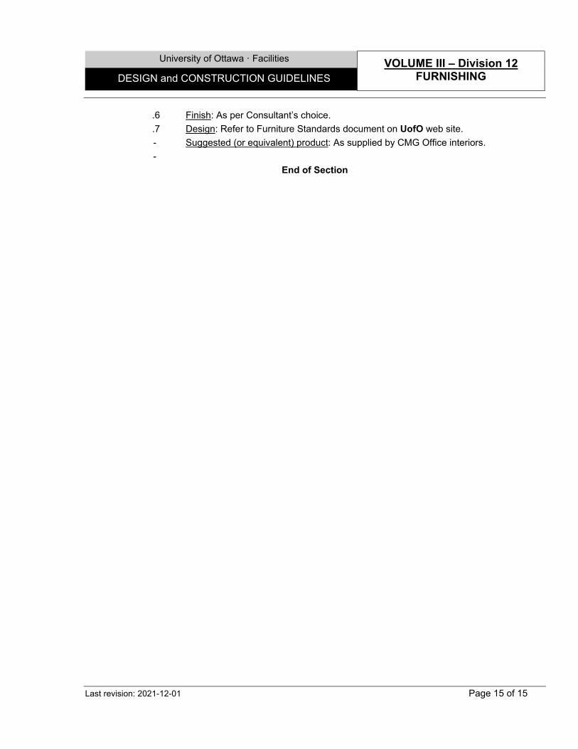
University of Ottawa · Facilities VOLUME III – Division 12
FURNISHING DESIGN and CONSTRUCTION GUIDELINES
Last revision: 2021-12-01 Page 15 of 15
.6 Finish: As per Consultant’s choice.
.7 Design: Refer to Furniture Standards document on UofO web site. - Suggested (or equivalent) product: As supplied by CMG Office interiors. -
End of Section
University of Ottawa · Facilities VOLUME III – Division 14
CONVEYING SYSTEMS DESIGN and CONSTRUCTION GUIDELINES
Last revision: 2021-12-01 Page 1 of 2
SECTION 14 20 00 - ELEVATORS 1.0 GENERAL 1.1 Extended Warranty
.1 All proper functioning of the elevators, including the doors, the accessory equipment and all hardware shall be guaranteed against all defects, Material fabrication and installation for a period of 2 years.
1.2 Design Criteria and Notes
.1 Performance: .1 Operate Elevators with smooth acceleration and provide a comfortable and agreeable
ride to the passengers. .2 Adjust typical acceleration rate to 0.92 g. Provide car speed to within 10% of 0.15m/s in
both directions. .3 Provide adjustable dwell times and independent dwell settings for car and hall calls. .4 Set door detector interrupt and nudging time to 20 seconds. .5 Adjust door opening and closing times to suit handicapped users. .6 Door noise level increase above ambient shall not exceed 6 dBa, as measured inside
the elevator cab during a full door cycle; .7 Car running noise level increase above ambient shall not exceed 4 dBa, as measured
inside the elevator cab when travelling bottom to top of the hoistway; .8 Machine room noise level will not exceed 75 dBa, as measured when the elevator is
running in either direction. .2 Systems:
.1 Provide machine within minimum 85% efficiency. .2 Install machine on high performance insulating pads.
.3 Drive System:
.1 The compatibility of the drive and motor shall have been tested successfully on five other comparable installations.
.2 The unit response shall be instantaneous and noiseless. .3 Provide filters to limit electrical noises to 5 percent of nominal signal. .4 Mount all drive components on insulating pads so that any vibration is not transmitted
to the building structure. .4 Position Transducer:
.1 Provide a device to transmit position of the car to the controller. .2 Install automatic levelling device for smooth deceleration at floor in both directions. .3 Provide on top of the car, a position reader to count number of tape perforations. .4 Ensure position readings every floor as a minimum. .5 Stroboscopic and dual tachometers devices are permitted. .6 Do not use stepper switches.
University of Ottawa · Facilities VOLUME III – Division 14
CONVEYING SYSTEMS DESIGN and CONSTRUCTION GUIDELINES
Last revision: 2021-12-01 Page 2 of 2
.5 Notes:
.1 Elevator design must meet ASME A17.1/CSA-B44, OBC, OFC and TSSA codes.
.2 All buttons and signage are to meet the needs of visually impaired and mobile impaired users, and to be vandal proof.
.3 Elevators are to come with moving blankets.
.4 Provide a clear cab interior height of 2743 mm (9'-0") to the underside of the fixed ceiling.
.5 Paint all non-machined metal surfaces.
.6 Finishes: Refer to section “P. Finish Schedule” of this DCG Document. .7 Control Panel:
.1 To be bilingual, French first.
.2 To include braille.
.3 Level numbering to reflect the way it is on plans: Using numbers to indicate levels (no use of “lobby” or “ground”, etc).
End of Section
University of Ottawa · Facilities VOLUME IV – Division 22
PLUMBING DESIGN and CONSTRUCTION GUIDELINES
Last revision: 2021-12-01 Page 1 of 10
SECTION 22 00 00 – GENERAL WORKS 1.0 GENERAL 1.1 Design Criteria and Notes
.1 Pumps: .1 Avoid the use of flexible rubber connectors. .2 Pumps should be direct drive where possible. .3 Provide gauges/gauge ports across pumps. .4 Provide a strainer strainers upstream of the pumps, complete with isolating and drain
valves. .5 Pumps with motors greater than 1Hp to be considered for Variable Speed Drives.
.2 Valves:
.1 Ball valves in sizes 1½ through 6" (40 mm through 150 mm) to be designed for minimum 125 psig (WOG) bubble-tight working pressures. Valve seals shall be designed for 450°F (232°C) maximum temperature.
.2 All butterfly valves 6" through 12" (150 mm through 300 mm) to have manual gear operators. Valve bodies shall be of one-piece design, zinc electroplated in accordance with ASTM A-164, and cast of ductile iron conforming to ASTM A-536 or malleable iron conforming to ASTM A-47. Valve discs to be of ductile iron conforming to ASTM A-536, 65-45-12 and plated with nickel chromium. Valve operator hubs to be cast of malleable iron conforming to ASTM A-47. Infinitely variable, extending lever handles shall be electroplated carbon steel.
End of Section
University of Ottawa · Facilities VOLUME IV – Division 22
PLUMBING DESIGN and CONSTRUCTION GUIDELINES
Last revision: 2021-12-01 Page 2 of 10
SECTION 22 42 01 – PLUMBING FIXTURES 1.0 GENERAL 1.2 Design Criteria and Notes
.1 Low voltage transformers shall be located in an accessible space, hardwired to electrical circuit, plug-in transformer is not recommended for public space.
2.0 PRODUCTS 2.1 Water Closets
.1 Water Closet: With the following characteristics: .1 High efficiency, Low consumption. .2 Operating in a range of 4.2Lpf to 6.0 Lpf (1.1 gpf to 1.6 gpf). .3 Wall hung. .4 Vitreous china. .5 Elongated bowl. .6 Antimicrobial surface. .7 Direct-fed siphon jet action. .8 Top inlet spud (1-1/2’’ diam.) (Back spud - conceal application- is not acceptable). .9 Color: White. - Suggested (or equivalent) Product: “3351.101” by American Standard.
.2 Manual lever operated Water Closet Flush Valve: With the following characteristics:
.1 Exposed flush valve with manual lever.
.2 High efficiency (1.28gpf/4.8Lpf).
.3 Chloramine resistant diaphragm.
.4 Brass construction with Polished chrome plated finish.
.5 1’’ IPS Screwdriver Back-check angle stop.
.6 Vandal resistant stop cap.
.7 Chrome plated vacuum breaker tube.
.8 Spud coupling and flange for 1-1/2’’ top spud.
.9 Trap primer connection to flush valve shall be considered where new floor drain is required.
.10 ADA & ASSE1037 compliant. - Suggested (or equivalent) Products:
.1 “111-1.28” by SLOAN (Manual Lever).
.2 “81T201-48”, by DELTA (Manual Lever). .2 Sensor activated Water Closet Flush valve: With the following characteristics:
.1 Exposed hardwired flush valve with integral solenoid (concealed flush valve is not allowed).
.2 High efficiency (1.28gpf/4.8Lpf).
.3 Brass construction with polished chrome plated finish.
University of Ottawa · Facilities VOLUME IV – Division 22
PLUMBING DESIGN and CONSTRUCTION GUIDELINES
Last revision: 2021-12-01 Page 3 of 10
.4 Chloramine resistant diaphragm.
.5 1’’ IPS Screwdriver Back-check angle stop.
.6 Vandal resistant stop cap.
.7 Chrome plated vacuum breaker tube (concealed vacuum breaker is not allowed).
.8 Spud coupling and flange for 1-1/2’’ top spud.
.9 Chrome plated wire covering tube.
.10 Hardwired infrared sensor, to be recessed in wall.
.11 Valve top mounted infrared sensor also acceptable.
.12 Sensor range shall be field adjustable.
.13 Electronic manual override button or true mechanical override.
.14 Vandal resistant chrome plated or stainless steel cover plates with vandal resistant screws (cover plates using hidden/invisible fastener such as set crews are not acceptable).
.15 Trap primer connection to flush valve shall be considered where new floor drain is required.
.16 ADA & ASSE1037 compliant. - Suggested (or equivalent) Products:
.1 “111-1.28 ES-S Optima” by SLOAN or (Wall Mounted Sensor with Override Button).
.2 “81T201-48-WMSHWA” by DELTA (Wall Mounted Sensor with Override Button).
.3 “81T201-48-HWA” by DELTA (Valve Top Mounted Sensor with Override Button). .4 Water Closet Seat: With the following characteristics:
.1 Commercial high strength impact resistant thermoplastic.
.2 Heavy duty.
.3 Corrosion free hardware.
.4 Open front elongated bowl seat, without cover.
.5 Stainless steel check hinges, nuts and lock washers.
.6 Withstanding strong chemicals.
.7 Color: Black. - Suggested (or equivalent) Product: “500STSCC” by Centoco.
2.2 Urinals
.1 Urinals: With the following characteristics: .1 Washout wall hung urinal with integral extended shields. .2 Ultra-High efficiency, Low consumption. .3 Operating in a range of 0.5 Lpf to 3.8 Lpf (0.125 gpf to 1.0 gpf). .4 Vitreous china. .5 Top inlet spud (3/4’’ diam.) (Back spud - conceal application - is not acceptable). .6 Color: White. .7 ADA Compliant. - Suggested (or equivalent) Products:
University of Ottawa · Facilities VOLUME IV – Division 22
PLUMBING DESIGN and CONSTRUCTION GUIDELINES
Last revision: 2021-12-01 Page 4 of 10
.1 “6590.001” by American Standard.
.2 “Z5758”, by ZURN. .2 Manual lever operated Urinal flush valve: With the following characteristics:
.1 Exposed flush valve with manual lever.
.2 High efficiency (0.125 gpf/0.5 Lpf).
.3 Chloramine resistant diaphragm.
.4 Brass construction with Polished chrome plated finish.
.5 3/4’’ IPS Screwdriver Back-check angle stop.
.6 Vandal resistant stop cap.
.7 Chrome plated vacuum breaker tube.
.8 Spud coupling and flange for ¾’’ top spud.
.9 Trap primer connection to flush valve shall be considered where new floor drain is required.
- Suggested (or equivalent) Products: .1 “186-0.125 DBP” by SLOAN (Manual Lever) .2 “81T231-05”, by DELTA (Manual Lever)
.3 Sensor activated Urinal flush valve: With the following characteristics:
.1 Exposed hardwired flush valve with integral solenoid (concealed flush valve is not allowed).
.2 High efficiency (0.125 gpf/0.5 Lpf).
.3 Brass construction with Polished chrome plated finish.
.4 Chloramine resistant diaphragm.
.5 3/4’’ IPS Screwdriver Back-check angle stop.
.6 Vandal resistant stop cap.
.7 Chrome plated Vacuum breaker tube (concealed vacuum breaker is not allowed).
.8 Spud coupling and flange for 3/4’’ top spud.
.9 Chrome plated wire covering tube.
.10 Hardwired infrared sensor, to be recessed in wall.
.11 Valve top mounted infrared sensor is also acceptable.
.12 Sensor range shall be field adjustable.
.13 No manual override button for urinals.
.14 Vandal resistant chrome plated or stainless steel cover plates with vandal resistant screws (cover plates using hidden/invisible fastener such as set crews are not acceptable).
.15 Trap primer connection to flush valve shall be considered where new floor drain is required.
.16 ADA & ASSE1037 compliant. - Suggested (or equivalent) Products:
.1 “186-0.125 DBP ESS Optima” by SLOAN or (Wall Mounted Sensor).
.2 “81T231-05-WMSHWA” by DELTA (Wall Mounted Sensor).
University of Ottawa · Facilities VOLUME IV – Division 22
PLUMBING DESIGN and CONSTRUCTION GUIDELINES
Last revision: 2021-12-01 Page 5 of 10
.3 “81T231HWA-05” by DELTA (Valve Top Mounted Sensor).
2.3 General Lavatories & Sinks .1 Wall-mount Lavatory: Commercial sink, vitreous China, with recessed self-draining deck, and
rear overflow. - Suggested (or equivalent) Products: “Murro 0955.000”, by American Standard.
.2 Manual lever Lavatory faucet: 4” trim plate, 0.5 usgpm vandal resistant aerator, brass body,
Faucet height 5 ¾” max, ADA compliant.
.3 Sensor activated Lavatory faucet: With the following characteristics: .1 Waterproof sensor and control module. .2 Hardwire, 4” trim plate, .3 0.5 usgpm vandal resistant aerator. .4 Brass body, adjustable sensing distance and auto-shutoff. .5 Faucet height 5 ¾” max. .6 Mixing valve shall compensate for inlet water temperature fluctuations (Mechanical
mixing valves - with thermostatic limit stop are not acceptable). .7 ADA compliant. - Suggested (or equivalent) products: “ETF-600 Optima” by SLOAN, c/w “04-021-
120v/24v” transformer and thermostatic mixing valve and ¼ turn mini ball valves by Dahl. .4 Slop Sink: Terrazzo 6” drop front slop sink, 36”x36”x12”, c/w Stainless Steel caps and drain.
Trim to be service-sink faucet. - Suggested (or equivalent) Product: “TSB 3002” by Crane & “830-AA” by Fiat. -
.5 Kitchen Sink: Size as per design parameters, with the following characteristics: .1 In Stainless steel, type 304 (18/10), No. 4 satin finished. .2 Single compartment, self-rimming drop sink with faucet ledge. .3 Material thickness: 18 gauge (1.2 mm). .4 No overflow. .5 One Faucet hole. .6 Undercoated to reduce condensation and resonance. .7 3 ½’’ cup strainer. .8 1 ½’’ brass tailpiece. - Suggested (or equivalent) product: “LBS6808P-1” by Franke.
.6 Faucet Kitchen Sink: With the following characteristics:
.1 Single hole, single lever.
.2 Chrome plated.
.3 9 ½’’ center to center integral cast brass spout.
.4 1.5 GPM (5.7 L/s) max., non-aerating outlet.
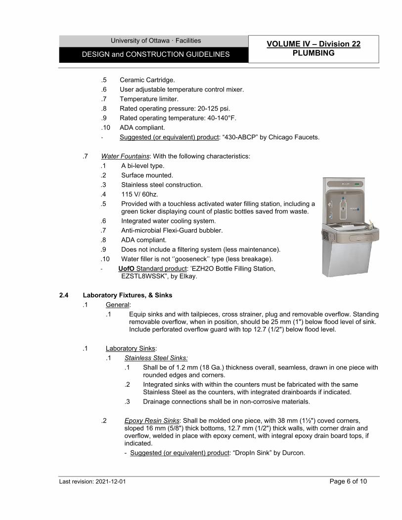
University of Ottawa · Facilities VOLUME IV – Division 22
PLUMBING DESIGN and CONSTRUCTION GUIDELINES
Last revision: 2021-12-01 Page 6 of 10
.5 Ceramic Cartridge.
.6 User adjustable temperature control mixer.
.7 Temperature limiter.
.8 Rated operating pressure: 20-125 psi.
.9 Rated operating temperature: 40-140°F.
.10 ADA compliant. - Suggested (or equivalent) product: “430-ABCP” by Chicago Faucets.
.7 Water Fountains: With the following characteristics:
.1 A bi-level type.
.2 Surface mounted.
.3 Stainless steel construction.
.4 115 V/ 60hz.
.5 Provided with a touchless activated water filling station, including a green ticker displaying count of plastic bottles saved from waste.
.6 Integrated water cooling system.
.7 Anti-microbial Flexi-Guard bubbler.
.8 ADA compliant.
.9 Does not include a filtering system (less maintenance).
.10 Water filler is not ‘’gooseneck’’ type (less breakage). - UofO Standard product: ’EZH2O Bottle Filling Station,
EZSTL8WSSK”, by Elkay. 2.4 Laboratory Fixtures, & Sinks
.1 General: .1 Equip sinks and with tailpieces, cross strainer, plug and removable overflow. Standing
removable overflow, when in position, should be 25 mm (1") below flood level of sink. Include perforated overflow guard with top 12.7 (1/2") below flood level.
.1 Laboratory Sinks:
.1 Stainless Steel Sinks: .1 Shall be of 1.2 mm (18 Ga.) thickness overall, seamless, drawn in one piece with
rounded edges and corners. .2 Integrated sinks with within the counters must be fabricated with the same
Stainless Steel as the counters, with integrated drainboards if indicated. .3 Drainage connections shall be in non-corrosive materials.
.2 Epoxy Resin Sinks: Shall be molded one piece, with 38 mm (1½") coved corners,
sloped 16 mm (5/8") thick bottoms, 12.7 mm (1/2") thick walls, with corner drain and overflow, welded in place with epoxy cement, with integral epoxy drain board tops, if indicated. - Suggested (or equivalent) product: “DropIn Sink” by Durcon.
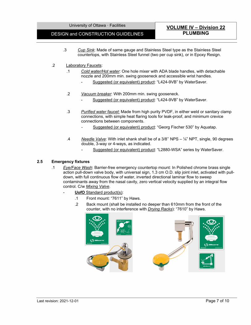
University of Ottawa · Facilities VOLUME IV – Division 22
PLUMBING DESIGN and CONSTRUCTION GUIDELINES
Last revision: 2021-12-01 Page 7 of 10
.3 Cup Sink: Made of same gauge and Stainless Steel type as the Stainless Steel countertops, with Stainless Steel funnel (two per cup sink), or in Epoxy Resign.
.2 Laboratory Faucets:
.1 Cold water/Hot water: One hole mixer with ADA blade handles, with detachable nozzle and 200mm min. swing gooseneck and accessible wrist handles. - Suggested (or equivalent) product: “L424-9VB” by WaterSaver.
.2 Vacuum breaker: With 200mm min. swing gooseneck. - Suggested (or equivalent) product: “L424-9VB” by WaterSaver.
.3 Purified water faucet: Made from high purity PVDF, in either weld or sanitary clamp
connections, with simple heat flaring tools for leak-proof, and minimum crevice connections between components. - Suggested (or equivalent) product: “Georg Fischer 530” by Aquatap.
.4 Needle Valve: With inlet shank shall be of a 3/8’’ NPS – ¼” NPT, single, 90 degrees
double, 3-way or 4-ways, as indicated. - Suggested (or equivalent) product: “L2880-WSA” series by WaterSaver.
2.5 Emergency fixtures
.1 Eye/Face Wash: Barrier-free emergency countertop mount: In Polished chrome brass single action pull-down valve body, with universal sign, 1.3 cm O.D. slip joint inlet, activated with pull-down, with full continuous flow of water, inverted directional laminar flow to sweep contaminants away from the nasal cavity, zero vertical velocity supplied by an integral flow control. C/w Mixing Valve. - UofO Standard product(s):
.1 Front mount: “7611” by Haws.
.2 Back mount (shall be installed no deeper than 610mm from the front of the counter, with no interference with Drying Racks): “7610” by Haws.
University of Ottawa · Facilities VOLUME IV – Division 22
PLUMBING DESIGN and CONSTRUCTION GUIDELINES
Last revision: 2021-12-01 Page 8 of 10
.2 Emergency Shower & eye wash: Combination shower and eye/face wash shall include: .1 11" (27.9 cm) Stainless steel round bowl. .2 Axion MSR™ eye wash head that supplies an inverted directional laminar flow which achieves zero vertical velocity supplied by an integral flow control. .3 Dust cover, 50 x 50 mesh water strainer. .4 Stay-open shower and eyewash ball valves. .5 Cast 9" (22.9 cm) diameter floor flange. .6 High visibility safety colors. .7 1-1/4" ips supply. .8 ADA & ANSI 2358.1 compliant. - Suggested (or equivalent) Products:
.1 Surface mount: - “8309WC” by Haws. - “GBF1909” by Hadrian.
.2 Recessed: “8355WCC” by Haws.
2.6 Mixing valves .1 Mixing Valve: Thermostatic mixing valve to provide tepid water to eyewash station, 26.5 L/min.,
15mm inlets & discharge, c/w cold water bypass in case of thermostatic failure, automatic spring check stops, rough brass, +/- 1.7 degree c, valve precision, temperature gauge, maximum discharge set point 29 degree c, factory set at 26 degree c, mounted in ceiling space in flush mounted box cabinet, accessible for maintenance.
- Suggested (or equivalent) product: “SE-370” & “SE-376” (mounting - as applicable) by Speakman.
End of Section
University of Ottawa · Facilities VOLUME IV – Division 22
PLUMBING DESIGN and CONSTRUCTION GUIDELINES
Last revision: 2021-12-01 Page 9 of 10
SECTION 22 42 02 – PIPING 1.0 GENERAL 1.1 Design Criteria and Notes
.1 Piping Systems: .1 Hydronic piping to be steel pipe to ASTM A53 Grade B:-1 to 6" (150 mm), Schedule 40,
8" to 10" (200 mm to 250mm), Schedule 30, 12" (300 mm) and over, 3/8" (10 mm) wall thickness or copper tube piping, hard drawn, type L to ASTM B88M-99.
.2 Drainage piping to be: .1 For Urinals, laboratories or any other dealing with high corrosive materials: Shall
have high chemical corrosive resistance, such as Polypropylene - with either fused sockets or proprietary mechanical joints, or Polyvinylidene Fluoride (PVDF) - with polyfusion joint or solvent bonding.
.2 For vestibules entrances dealing with salty conditions, or where the pipes are penetrating fire separation: Uncoated PVC Rated with, appropriate fire-sealing around the penetrations.
.2 Layout- Vertical piping chase: .1 On each floor, access to vertical piping chase shall be made easy by means of
access doors. .2 Piping should be layout in a manner that future connections will be easy to make. .3 Shut off valve should be located on each floor.
.3 Pure water piping: .1 Pure water piping system shall be design and installed with a recirculation loop. .2 Pure water piping shall be new, unpigmented Polypropylene to schedule 80, IPS
dimensions. Joints shall be shock welded or Rionite mechanical joints.
.4 Clean-out: .1 For sanitary equipment, sewer clean-out to be installed above rim level, in order to
prevent the rejection of waste during cleaning process.
2.0 PRODUCTS .1 Floor Drain: Floor drain with round bronze strainer, cast iron, 4” throat, and reversible
membrane clamp. - Suggested (or equivalent) Product: “FD-100-C-A” by Watts.
.2 Area Drain: Epoxy coated cast iron, 8”x8”, adjustable top, standard outlet c/w body collar with
weep holes and anchor flanges. - Suggested (or equivalent) Product: “FD-330” by Watts.
.3 Trap Seal Primer (for Washroom/kitchen Area Drains): To be provided with Flush Valve Trap
Seal Primer. In location where it is impossible or too costly to connect the drain with a Flush Valve Trap Seal Primer, a Trap Guard seal may be used instead.
University of Ottawa · Facilities VOLUME IV – Division 22
PLUMBING DESIGN and CONSTRUCTION GUIDELINES
Last revision: 2021-12-01 Page 10 of 10
- Suggested (or equivalent) Product: .1 “MI-702” by MiFab. .2 “VBF-72-A1” by Sloan.
.4 Polypropylene piping: Schedule 40, certified to CAN/CSA B1800-02. - Suggested (or equivalent) Product:
.1 “Blueline” by Orion.
.5 Polyvinylidene Fluoride (PVDF) piping: - Suggested (or equivalent) Product: “Pegas Superblue” by Corix.
.6 PVC Rated: Made of tough, impact resistant PVC, high moisture, salts, soils and acid
resistant. With fire-retardant properties that eliminate flame spread and reduce the volume of smoke generated. To apply with related fire stopping products. - Suggested (or equivalent) Product: “System 15 XFR” by IPEX.
End of Section
University of Ottawa ꞏ Facilities VOLUME IV – Division 23 HVAC DESIGN and CONSTRUCTION GUIDELINES
Last revision: 2020-08-01 Page 1 of 2
SECTION 23 00 00 – GENERAL WORKS 1.0 GENERAL 1.1 Design Criteria and Notes
.1 Vibration and seismic controls for HVAC piping and equipment:
.1 Use ASHRAE guide for determining the recommended limits and NC curves. Select mechanical equipment that will not produce noise and vibration beyond the recommended noise criteria for the space under consideration.
2. All equipment subject to vibration shall be adequately supported on isolation devices to limit transmission of vibration to an acceptable level.
.2 Mechanical identification
.1 All piping and equipment in exposed locations such as equipment rooms, pipe service chases, ceiling spaces, etc., shall be clearly labelled and identified with flow directions indicated. For pipes over 3” in diameter and all ducts, the lettering shall be 2” high.
.2 Marking system shall be standardized with black lettering on a background colour the same as the pipe, duct, etc. for the yellow, blue and green backgrounds and white lettering on the red background. Use factory printed self-sticking labels.
.3 Identification shall be applied where view is not obstructed. Apply at each valve and where pipes leave or enter a room. Also apply no more than 25 feet apart on long runs. Where label will not stick to a surface, the pipe shall be wrapped continuously with the pipe tape to provide a suitable surface.
.4 For identification of ductwork use 2” high black stencilled letters easily seen from floor. Provide markers on underside of ceiling to locate boxes.
.5 For identification of valves and controllers use laminated plastic tags with ¾” engraved lettering.
.3 Thermal insulation for ducting
.1 All air intake and exhaust ducts shall be insulated to protect building interiors from frost and moisture damage.
.4 Hydronic specialties
.1 Mechanical provisions to facilitate cleaning, and to ensure adequate flushing of piping systems shall be provided.
.2 Adequate clearances shall be provided for the removal of Tube bundles of all heat exchanges.
.5 Metal ducts:
.1 Use quality hardware for balancing dampers to facilitate the balancing operation and to ensure positive locking of the damper.
.2 Provide pitot tube openings, complete with spring-loaded caps, on all supply, return and exhaust systems around major equipment. Make adequate provision where insulation is encountered.
.3 Flexible duct connections need to be made of a anti-bacterial material.
.6 Fan coil units:
.1 Cooling coils shall be cleanable and drainable. The tubes should be readily accessible without having the need to disconnect piping.
.2 Cooling coils shall be counter flow type and installed according to manufacturer’s
University of Ottawa ꞏ Facilities VOLUME IV – Division 23 HVAC DESIGN and CONSTRUCTION GUIDELINES
Last revision: 2020-08-01 Page 2 of 2
specifications. .3 Preheat coils shall make use of glycol for protection against freezing.
.7 Chillers:
.1 Chill water coils shall be sized for a 9°C chill water delta-T on design day (6 C degree supply, 15 C return water temperatures).
.2 Pressure gages are required across all AHU coils and filter banks (filter and pre-filter combined).
.3 Air-cooled condensers shall be capable of operating at 95°F ambient temperature with 30°F temperature difference between air entering and leaving the condenser. Air-cooled condensers on roofs shall be capable of operating at 105°F ambient temperature.
.4 Pressure gages are required across all AHU coils and filter banks (filter and pre-filter combined).
.8 Exhaust fan: Shall have speed control switch.
2.0 PRODUCTS .1 Filters: Shall be for two-stage air filtration at AHUs. Pre-Filter to be 2 inches pleated, High
Capacity, MERV 7, initial resistance 0.17” WC at 400 FPM. Final Filter shall be 12 inches pleated, V style, High Capacity MERV 14, initial resistance 0.275” wc at 400 fpm.
.2 Intake and Exhaust Louvers: In prepainted or anodized Aluminum extrusions. To be equipped
with bird screen and insect screen, easily removed from the interior of the duct shaft. - Suggested (or equivalent) Product: As manufactured by E.H.Price.
End of Section
University of Ottawa · Facilities VOLUME IV – Division 26
ELECTRICAL DESIGN and CONSTRUCTION GUIDELINES
Last revision: 2021-12-01 Page 1 of 5
26 00 00 – GENERAL WORKS 1.0 GENERAL 1.1 Design Criteria and Notes
.1 Receptacle circuit identification: .1 All receptacle covers shall be provided with a PTouch panel and circuit # identification
label. .2 Receptacles whose panel is supplied by an emergency power source shall be identified
by a red color cover plate.
.2 High voltage substations: .1 Generally all Campus buildings are supplied from a 13.2 KV loop feeder with step-
down transformers located within each of the Buildings.
.3 Generators: .1 Diesel fuel is normally utilized for emergency power sources. .2 Where liquid cooled engines are required, a closed circuit glycol system is required. .3 An automatic battery charger shall be provided to maintain the batteries at full charge,
complete with adequate accessories. Charger shall have high/low charge rate and be capable of “floating” on the batteries at all times.
.4 Alarm indication resulting in shut down shall identify initial fault.
.5 The engine control panel shall incorporate a hand/off/auto selector.
.4 Junction boxes: All existing junction boxes that are opened in the ceiling space shall have cover plates.
2.0 PRODUCTS 2.1 General fixtures
.1 Hallway service receptacles: Shall be of the industrial grade “T” slot type suitable for 120 volt, 20 amp circuits (housekeeping services).
.2 GFI receptacles: CSA approved, ULC listed, Class A, c/w Test/Reset feature and Green/Red
pilot lights, c/w stainless steel cover plate, white finish. - Suggested (or equivalent) Product: “GFST15W” (15 amp circuit), & “GFST20W” (20
amp circuit).
.3 Electrical Panel: With the following characteristics: .1 To keep a total of 20% available circuits (spare breakers and blank spaces) for future
use. .2 Provide around 10% of 15 amps spare breakers for future use. - Suggested (or equivalent) Product: “EZ box, PRL-1a”, including Bolt-on breakers, by
Cuttler Hammer, with identification label “Lamicoid.” White letters on black label.
.4 Motorized Projection Screen control: Projection screen motor shall have a new 2 Poles, 1HP, 230V, ON/OFF manual motor starter switch installed at proximities and capable of cutting both power up and power down.
University of Ottawa · Facilities VOLUME IV – Division 26
ELECTRICAL DESIGN and CONSTRUCTION GUIDELINES
Last revision: 2021-12-01 Page 2 of 5
.5 Podium desk control: With the following characteristics: .1 Podium-mounted momentary contact switch for projection screen shall be 20A –
120V, spring load three-position, single pole, double throw, center OFF, including stainless steel cover plate.
.2 All podium Electric Outlet shall be equivalent to the surge suppression duplex receptacles indicated.
.3 Lighting scenes shall be identified on the scene selector located on the podium lip - Suggested (or equivalent) Product:
.1 Scene selector: As manufactured by Lutron.
.2 Key switch controlling electrical outlet by-pass relay: “1221-2KL”, single pole by LEVITON.
.3 Electrical outlet by-pass relay: “BZ-100EP”, 120VAC, Featuring hold-on inputs, by WattStopper.
.4 Podium door operated contact switch: “1865”, momentary, metal push button, normally ON contact, by LEVITON.
.6 A/V Electric Outlet: 120 Volt, surge suppression duplex receptacles, 15A-125V, “Commercial
Specification” grade minimum, with stainless steel cover plates. - Suggested (or equivalent) Product: “HBL5260S” blue colour with stainless steel cover
plate by Hubble.
.7 Accessible Table outlets: Two simplex outlets per sphere, with the following notes: .1 All blanks to be permanently capped. .2 All electrical wires to be contained within a tamper proof raceway mounted on
underside of table. .3 All wires to be concealed in a suitable black liquid tight flexible conduit. - Suggested (or equivalent) Product: “Sphere” by Byrne Electrical.
.8 Seats with retractable tablet outlets: The electrical distribution system shall be integrated in the design of the seating, to accommodate the requirements of laptop computers. The receptacle shall not interfere with the seat and tablet return. All wires and components shall be concealed with covers. The receptacle module shall be constructed of a vandal proof material and be both visible and accessible from a seated position.
.9 Fixed table and Swivel Seat outlet: To have concealed wiring systems from power stub-ups at floor level to power monument on tabletop. Pedestal/base plate structure/seat to provide for the installation of power devices. - UofO standard Products:
.1 For new tables: “Sphere” by Byrne Electrical.
.2 For existing tables: “VIRCO” could be used upon Facilities approval.
.10 Terminal Strip Box: With the following characteristics: .1 All zones and electrical circuit shall be identified to all devices and terminal strip box. .2 Provide wiring diagram on or inside terminal strip box cover.
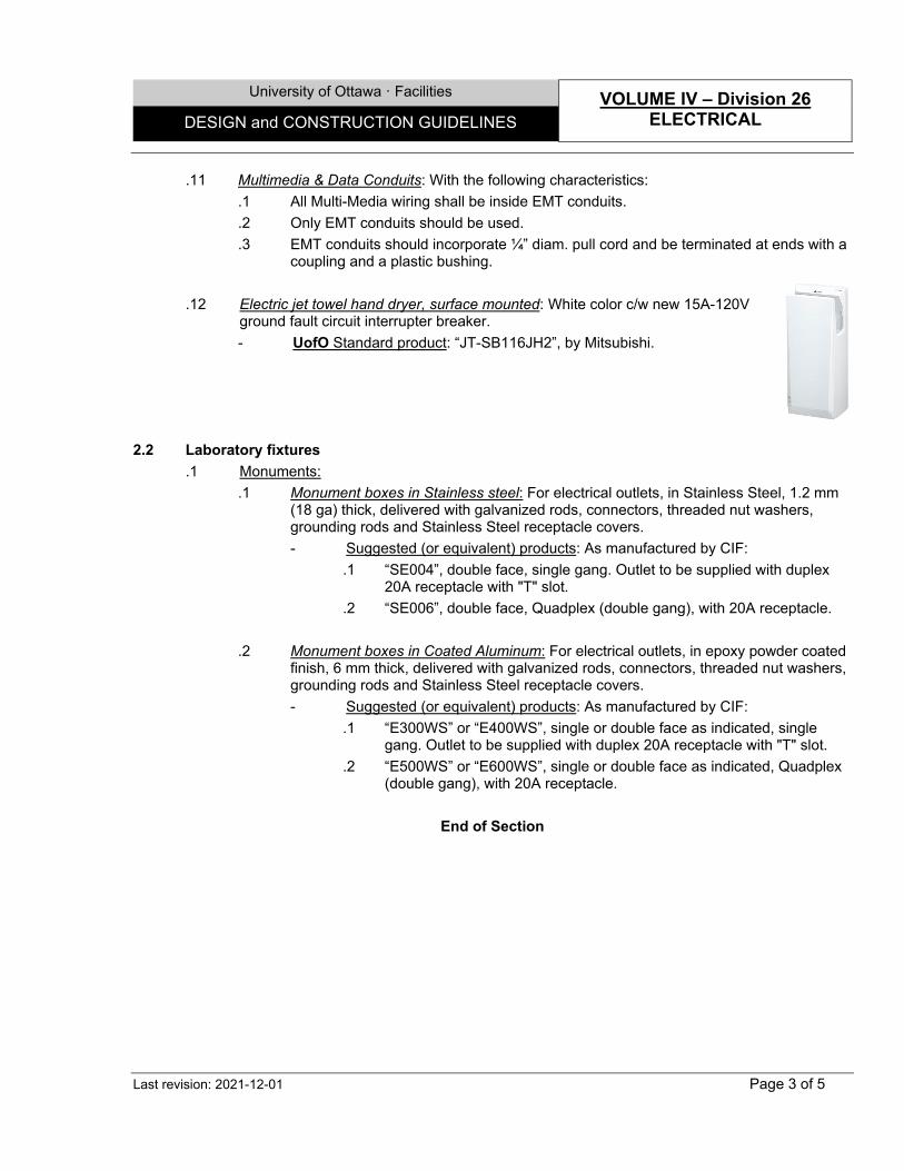
University of Ottawa · Facilities VOLUME IV – Division 26
ELECTRICAL DESIGN and CONSTRUCTION GUIDELINES
Last revision: 2021-12-01 Page 3 of 5
.11 Multimedia & Data Conduits: With the following characteristics: .1 All Multi-Media wiring shall be inside EMT conduits. .2 Only EMT conduits should be used. .3 EMT conduits should incorporate ¼” diam. pull cord and be terminated at ends with a
coupling and a plastic bushing.
.12 Electric jet towel hand dryer, surface mounted: White color c/w new 15A-120V ground fault circuit interrupter breaker. - UofO Standard product: “JT-SB116JH2”, by Mitsubishi.
2.2 Laboratory fixtures .1 Monuments:
.1 Monument boxes in Stainless steel: For electrical outlets, in Stainless Steel, 1.2 mm (18 ga) thick, delivered with galvanized rods, connectors, threaded nut washers, grounding rods and Stainless Steel receptacle covers. - Suggested (or equivalent) products: As manufactured by CIF:
.1 “SE004”, double face, single gang. Outlet to be supplied with duplex 20A receptacle with "T" slot.
.2 “SE006”, double face, Quadplex (double gang), with 20A receptacle. .2 Monument boxes in Coated Aluminum: For electrical outlets, in epoxy powder coated
finish, 6 mm thick, delivered with galvanized rods, connectors, threaded nut washers, grounding rods and Stainless Steel receptacle covers. - Suggested (or equivalent) products: As manufactured by CIF:
.1 “E300WS” or “E400WS”, single or double face as indicated, single gang. Outlet to be supplied with duplex 20A receptacle with "T" slot.
.2 “E500WS” or “E600WS”, single or double face as indicated, Quadplex (double gang), with 20A receptacle.
End of Section
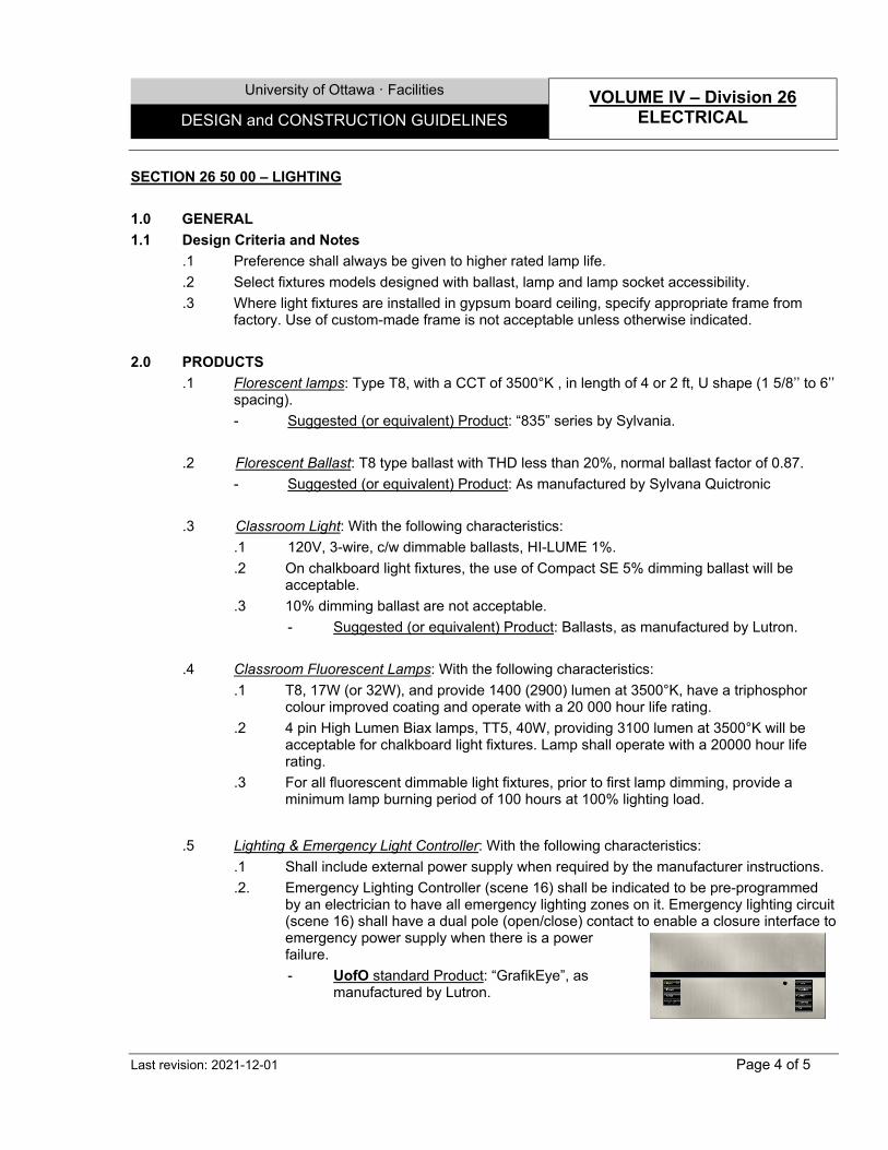
University of Ottawa · Facilities VOLUME IV – Division 26
ELECTRICAL DESIGN and CONSTRUCTION GUIDELINES
Last revision: 2021-12-01 Page 4 of 5
SECTION 26 50 00 – LIGHTING 1.0 GENERAL 1.1 Design Criteria and Notes
.1 Preference shall always be given to higher rated lamp life.
.2 Select fixtures models designed with ballast, lamp and lamp socket accessibility.
.3 Where light fixtures are installed in gypsum board ceiling, specify appropriate frame from factory. Use of custom-made frame is not acceptable unless otherwise indicated.
2.0 PRODUCTS
.1 Florescent lamps: Type T8, with a CCT of 3500°K , in length of 4 or 2 ft, U shape (1 5/8’’ to 6’’ spacing). - Suggested (or equivalent) Product: “835” series by Sylvania.
.2 Florescent Ballast: T8 type ballast with THD less than 20%, normal ballast factor of 0.87.
- Suggested (or equivalent) Product: As manufactured by Sylvana Quictronic
.3 Classroom Light: With the following characteristics: .1 120V, 3-wire, c/w dimmable ballasts, HI-LUME 1%. .2 On chalkboard light fixtures, the use of Compact SE 5% dimming ballast will be
acceptable. .3 10% dimming ballast are not acceptable.
- Suggested (or equivalent) Product: Ballasts, as manufactured by Lutron. .4 Classroom Fluorescent Lamps: With the following characteristics:
.1 T8, 17W (or 32W), and provide 1400 (2900) lumen at 3500°K, have a triphosphor colour improved coating and operate with a 20 000 hour life rating.
.2 4 pin High Lumen Biax lamps, TT5, 40W, providing 3100 lumen at 3500°K will be acceptable for chalkboard light fixtures. Lamp shall operate with a 20000 hour life rating.
.3 For all fluorescent dimmable light fixtures, prior to first lamp dimming, provide a minimum lamp burning period of 100 hours at 100% lighting load.
.5 Lighting & Emergency Light Controller: With the following characteristics: .1 Shall include external power supply when required by the manufacturer instructions. .2. Emergency Lighting Controller (scene 16) shall be indicated to be pre-programmed
by an electrician to have all emergency lighting zones on it. Emergency lighting circuit (scene 16) shall have a dual pole (open/close) contact to enable a closure interface to emergency power supply when there is a power failure. - UofO standard Product: “GrafikEye”, as
manufactured by Lutron.
University of Ottawa · Facilities VOLUME IV – Division 26
ELECTRICAL DESIGN and CONSTRUCTION GUIDELINES
Last revision: 2021-12-01 Page 5 of 5
.6 Occupancy Sensor: Shall be connected to a contact closure interface controlling the Lighting controller, dual technology ceiling mount occupancy sensor. - Suggested (or equivalent) Product: As manufactured by WattStopper.
.7 Exit signs: Depending on electrical parameters and minimal lighting Codes requirements: Pictogram sign, Photoluminescent system, Zero energy consumption, surface ceiling or flag mount. - Suggested (or equivalent) Product: “Ecolo Exit Signs” Series by Kinesik.
.8 Wiring: System cable data line connected to Controller shall be separate from line voltage wiring by at least ¼” (7mm), to avoid functioning problems.
.9 Task light: Mid-powered LEDs spaced uniformly for even distribution on the task plane: Even
glow diffuser, minimize shadow effects, easy to clean, 3500K colour temperature, with individual dimming to off on each luminaire, 565mm, 62.2 lumens per watt efficacy, 380 lumens light output, 6.1w power consumption, 60w power supplies to provide power up to 4 luminaires , 87 color rendering index, rated for 100 000 hours at 90% initial lumens, power cable from power supply to first luminaire, patch cables for daisy chaining luminaires (length according to furniture layout without excessive lengths), splitter cable for two rows of lights at the island, and extension cables as necessary. Can be used as stand also unit or daisy chained. - Suggested (or equivalent) products: “UC-E-22-S-PS-60W” by Finelite.
End of Section
University of Ottawa ꞏ Facilities VOLUME V – Division 31 EARTHWORK DESIGN and CONSTRUCTION GUIDELINES
Last revision: 2020-08-01 Page 1 of 2
SECTION 31 10 00 – SITE PREPARATION & HARD LANDSCAPING
1.0 GENERAL
1.1 Design Criteria and Notes
.1 Protection:
.1 Prevent damage and protect existing fencing, landscaping, existing structures, bench marks, buildings, pavement, surface or underground utility lines which are to remain.
.2 Reduce environmental impacts during construction by limiting topsoil removal, stockpiling existing topsoil on site and exposing smallest area of soil at any one time during development.
.3 Maintain access roads to prevent accumulation of mud.
.4 Integrate finish grading to waste management plan.
.5 Cut off unsound branches and cut down trees that could endanger the area to be cleared.
.6 All earth work has to be planned and coordinated with SAGO and ORM.
.2 Grading:
.1 Slope rough grade away from building 1:100 minimum, and towards catch basins and drainage points, or as necessary to adapt to site conditions.
.3 Backfilling:
.1 Areas to be backfilled to be free from debris, snow, ice, water or frozen ground.
.2 Do not use backfill material which is frozen or contains ice, snow or debris.
.3 Do not backfill around or over cast-in-place concrete within 3 days after placing the concrete.
.4 Asphalt:
.1 Do not apply primer or tack coat, nor commence laying of asphalt base or binder courses until base surfaces are dry and at least at 2oC, and the ambient temperature is above 5oC.
.2 Commence laying of asphalt surface courses only when base or binder course surfaces are completely dry, when atmospheric temperature in shade is at least 10oC and rising, or above 15oC if falling, and the weather is not foggy or rainy.
.3 Suspend paving operations two hours before it rains, if temperature drops below specified minimums, and if the surfaces become wet or humid.
.4 Provide access to building and Employees' Parking Area at all times. Arrange access points with Owner.
.5 Do paving operations only when other dust producing operations are completed or stopped and truck movements are not scheduled adjacent to area of installation.
.6 Finished surfaces should not have a variation of more than 5 mm (3/16") under a 3 m (10'-0") long straightedge in any direction.

University of Ottawa ꞏ Facilities VOLUME V – Division 31 EARTHWORK DESIGN and CONSTRUCTION GUIDELINES
Last revision: 2020-08-01 Page 2 of 2
2.0 PRODUCTS
.1 Granular fill material: Clean, angular, crusher run natural stone, free from shale, clay, friable materials, roots and vegetable matter.
.2 French drains: High density polyethylene resine ringed tubes of 100 mm (4") diameter, or larger, as per ASTM D1248, Type III, category 4 or 5, grade P33 or P34, Class C.
- Suggested (or equivalent) product: "Big-O" by Big-O Inc.
.3 Geotextile: Non-woven rootproof polyester fabric non-biodegradable, with a mass of 300 g/m2.
- Suggested (or equivalent) product: "7609" by Texel (Solmax).
End of Section
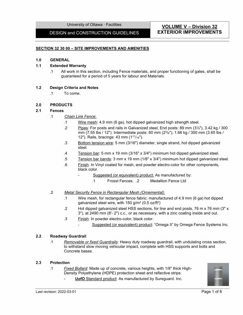
University of Ottawa · Facilities VOLUME V – Division 32
EXTERIOR IMPROVEMENTS DESIGN and CONSTRUCTION GUIDELINES
Last revision: 2022-03-01 Page 1 of 8
SECTION 32 30 00 – SITE IMPROVEMENTS AND AMENITIES 1.0 GENERAL 1.1 Extended Warranty
.1 All work in this section, including Fence materials, and proper functioning of gates, shall be guaranteed for a period of 5 years for labour and Materials.
1.2 Design Criteria and Notes
.1 To come. 2.0 PRODUCTS 2.1 Fences
.1 Chain Link Fence: .1 Wire mesh: 4.9 mm (6 ga), hot dipped galvanized high strength steel. .2 Pipes: For posts and rails in Galvanized steel, End posts: 89 mm (3½"), 3.42 kg / 300
mm (7.55 lbs / 12"). Intermediate posts: 60 mm (23/8"), 1.66 kg / 300 mm (3.65 lbs / 12"). Rails, bracings: 43 mm (111/16").
.3 Bottom tension wire: 5 mm (3/16") diameter, single strand, hot dipped galvanized steel.
.4 Tension bar: 5 mm x 19 mm (3/16" x 3/4") minimum hot dipped galvanized steel.
.5 Tension bar bands: 3 mm x 19 mm (1/8" x 3/4") minimum hot dipped galvanized steel.
.6 Finish: In Vinyl coated for mesh, and powder electro-color for other components, black color. - Suggested (or equivalent) product: As manufactured by:
.1 Frosst Fences. .2 Medallion Fence Ltd
.2 Metal Security Fence in Rectangular Mesh (Ornemental): .1 Wire mesh, for rectangular fence fabric: manufactured of 4.9 mm (6 ga) hot dipped
galvanized steel wire, with 150 g/m2 (0.5 oz/ft2) .2 Hot dipped galvanized steel HSS sections, for line and end posts, 76 m x 76 mm (3" x
3"), at 2490 mm (8'- 2") c.c., or as necessary, with a zinc coating inside and out. .3 Finish: In powder electro-color, black color.
- Suggested (or equivalent) product: “Omega II” by Omega Fence Systems Inc. 2.2 Roadway Guardrail
.1 Removable or fixed Guardrails: Heavy duty roadway guardrail, with undulating cross section, to withstand slow moving vehicular impact, complete with HSS supports and bolts and Concrete bases.
2.3 Protection
.1 Fixed Bollard: Made up of concrete, various heights, with 1/8" thick High-Density Polyethylene (HDPE) protection sheet and reflective strips.
- UofO Standard product: As manufactured by Sureguard. Inc.

University of Ottawa · Facilities VOLUME V – Division 32
EXTERIOR IMPROVEMENTS DESIGN and CONSTRUCTION GUIDELINES
Last revision: 2022-03-01 Page 2 of 8
.2 Removable Bollard: Made up of concrete, 960mm or 1220mm high. - UofO Standard product: "6432" or “6433”, with “6439” base (optional) by Central
Precast Inc.
.3 Conical Bollard: Made up of concrete, 1425mm high. - UofO Standard product: "6431" by Central Precast Inc.
.4 Parking Lot Divider: Made up of concrete. - UofO Standard product: "6437" by Central Precast Inc.
.5 Parking Post: Made up of galv. Steel post on concrete base, 1370mm or 1830mm high.
- UofO Standard product: "6436" or “6435” by Central Precast Inc. 2.4 Site Furnishing and amenities
.1 Recycle bins: 1702mm x 610mm x 1143mm, triple stream front load waste, in PVC, Color Black Grey. With (3) engraved identifiers: "WASTE", "GLASS", "PLASTIC", or "CANS". Includes liners and hinged doors. Capacity 45 + 45 + 45 Gal (67"w x 24"d x 45"h), SKU # 030 470 045 - UofO Standard product: “Halston”, by Max-R.
.2 Park benches: 1778mm x 762mm, with two end arms, legs painted black, gloss collection, wood grain texture High Density Polyethylene or IPE Wood. To be bolted. - UofO Standard product: “100 Series Backed Benches”, by
Maglin. .3 Bicycle rack: Capacity 6 to 8. 1473mm x 864mm x 864mm. In Stainless
Steel. To be blotted. - UofO Standard product: “Expo series W5808”, by Bicycle Cora.
.4 Picnic tables with seating: 1473mm x 1372mm x 762mm, with hole for parasol, woodgrain domestic modified sourced, Thermally Modified Ash Matte, black low sheen designer palette, wheelchair accessible at end of table can add length for better accessibility. To be bolted. - UofO Standard product: “Gretchen Picnic Table”, by
Landscapeforms.
.5 Table, Cluster seating: 2388mm x 838mm, 3 seat backed backrest, prepainted steel, various colors. To be bolted. Allowing space for wheelchair accessibility - UofO Standard product: “Carousel”, by Arno Yurk.
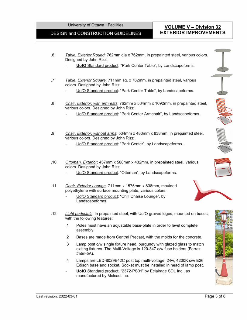
University of Ottawa · Facilities VOLUME V – Division 32
EXTERIOR IMPROVEMENTS DESIGN and CONSTRUCTION GUIDELINES
Last revision: 2022-03-01 Page 3 of 8
.6 Table, Exterior Round: 762mm dia x 762mm, in prepainted steel, various colors.
Designed by John Rizzi. - UofO Standard product: “Park Center Table”, by Landscapeforms.
.7 Table, Exterior Square: 711mm sq. x 762mm, in prepainted steel, various
colors. Designed by John Rizzi. - UofO Standard product: “Park Center Table”, by Landscapeforms.
.8 Chair, Exterior, with armrests: 762mm x 584mm x 1092mm, in prepainted steel, various colors. Designed by John Rizzi. - UofO Standard product: “Park Center Armchair”, by Landscapeforms.
.9 Chair, Exterior, without arms: 534mm x 483mm x 838mm, in prepainted steel,
various colors. Designed by John Rizzi. - UofO Standard product: “Park Center”, by Landscapeforms.
.10 Ottoman, Exterior: 457mm x 508mm x 432mm, in prepainted steel, various colors. Designed by John Rizzi. - UofO Standard product: “Ottoman”, by Landscapeforms.
.11 Chair, Exterior Lounge: 711mm x 1575mm x 838mm, moulded
polyethylene with surface mounting plate, various colors. - UofO Standard product: “Chill Chaise Lounge”, by
Landscapeforms.
.12 Light pedestals: In prepainted steel, with UofO graved logos, mounted on bases, with the following features:
.1 Poles must have an adjustable base-plate in order to level complete assembly.
.2 Bases are made from Central Precast, with the molds for the concrete.
.3 Lamp post c/w single fixture head, burgundy with glazed glass to match exiting fixtures. The Multi-Voltage is 120-347 c/w fuse holders (Ferraz #atm-5A).
.4 Lamps are LED-8029E42C post top multi-voltage, 24w, 4200K c/w E26 Edison base and socket. Socket must be installed in head of lamp post.
- UofO Standard product: “2372-PS01” by Eclairage SDL Inc., as manufactured by Molcast inc.
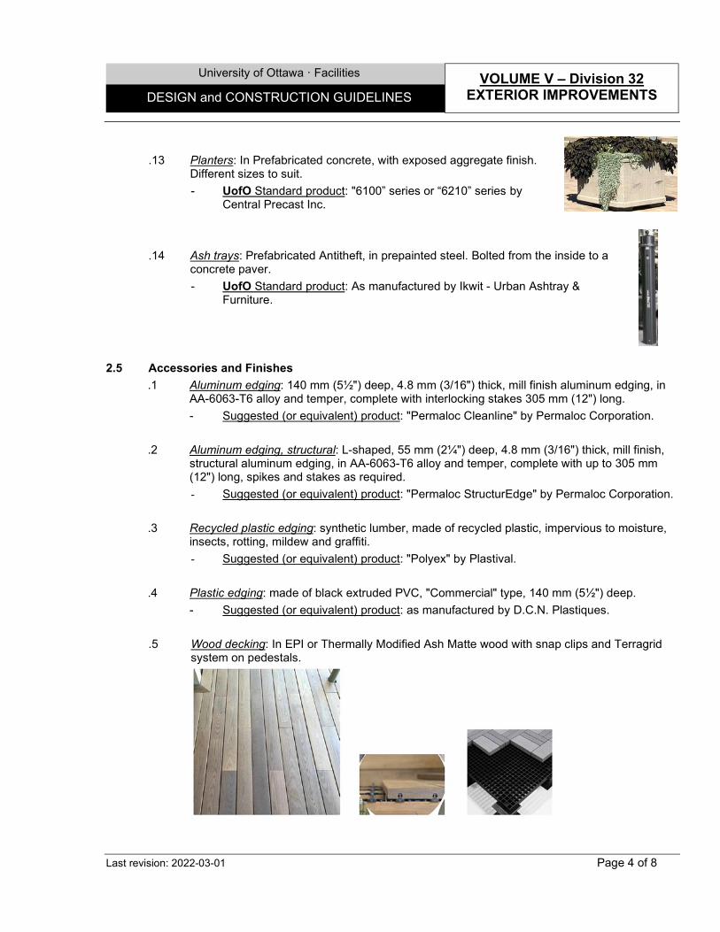
University of Ottawa · Facilities VOLUME V – Division 32
EXTERIOR IMPROVEMENTS DESIGN and CONSTRUCTION GUIDELINES
Last revision: 2022-03-01 Page 4 of 8
.13 Planters: In Prefabricated concrete, with exposed aggregate finish.
Different sizes to suit. - UofO Standard product: "6100” series or “6210” series by
Central Precast Inc.
.14 Ash trays: Prefabricated Antitheft, in prepainted steel. Bolted from the inside to a concrete paver. - UofO Standard product: As manufactured by Ikwit - Urban Ashtray &
Furniture.
2.5 Accessories and Finishes .1 Aluminum edging: 140 mm (5½") deep, 4.8 mm (3/16") thick, mill finish aluminum edging, in
AA-6063-T6 alloy and temper, complete with interlocking stakes 305 mm (12") long. - Suggested (or equivalent) product: "Permaloc Cleanline" by Permaloc Corporation.
.2 Aluminum edging, structural: L-shaped, 55 mm (2¼") deep, 4.8 mm (3/16") thick, mill finish,
structural aluminum edging, in AA-6063-T6 alloy and temper, complete with up to 305 mm (12") long, spikes and stakes as required. - Suggested (or equivalent) product: "Permaloc StructurEdge" by Permaloc Corporation.
.3 Recycled plastic edging: synthetic lumber, made of recycled plastic, impervious to moisture, insects, rotting, mildew and graffiti. - Suggested (or equivalent) product: "Polyex" by Plastival.
.4 Plastic edging: made of black extruded PVC, "Commercial" type, 140 mm (5½") deep.
- Suggested (or equivalent) product: as manufactured by D.C.N. Plastiques. .5 Wood decking: In EPI or Thermally Modified Ash Matte wood with snap clips and Terragrid
system on pedestals.

University of Ottawa · Facilities VOLUME V – Division 32
EXTERIOR IMPROVEMENTS DESIGN and CONSTRUCTION GUIDELINES
Last revision: 2022-03-01 Page 5 of 8
.6 Wood edging: In IPE wood inserts. .7 Tactile Walking Surface Indicators, in Concrete: In pressed concrete pavers, engineered, with
integral colour. Cast-in place. - Suggested (or equivalent) Product: “H or V series, as manufactured by Wausau Tile.
End of Section
University of Ottawa · Facilities VOLUME V – Division 32
EXTERIOR IMPROVEMENTS DESIGN and CONSTRUCTION GUIDELINES
Last revision: 2022-03-01 Page 6 of 8
SECTION 32 80 00 – IRRIGATION SYSTEM 1.0 GENERAL 1.1 Extended Warranty
.1 The specified system shall carry a 3 year warranty. This is to include 1 year winterization in the fall and 1 year reactivation in the following spring.
1.2 Design Criteria and Notes
.1 Excavation and Trenching: .1 Minimum depth of trenches shall be 450 mm (18") below finished grade with sufficient
slope to allow drainage of the system or as detailed or indicated on drawing(s). Width of trench at bottom shall be minimum 100 mm (4") greater than the outside diameter of pipe it contains and keep free from rocks and all other material that may damage pipe.
.2 Piping, and zone valves:
.1 Snake pipe from side to side of trench bottom to allow for expansion and contraction.
.2 Where possible, main supply lines may occupy the same trench as sprinkler lines provided a minimum horizontal clearance of 150 mm (6") is maintained.
.3 Thoroughly flush out all water lines before installing heads, valves and other hydrants.
.4 Control wires under walks or paving to be sleeved with PVC Class 160 pipe or galvanized heavy wall steel conduit. Wires to the controller(s) in pump house to be sleeved in conduit.
.5 All splices to be made watertight using appropriate connectors.
.6 Group valves together where practical. Place valves no closer than 300 mm (12") to walk edges, buildings and/or walls. All valves shall be located in approved heavy duty high impact plastic valve boxes.
.7 Valve boxes shall have adequate space for proper operation of each component within. Install minimum 150 mm (6") depth of pea gravel below valve boxes for drainage.
.8 Quick coupling valves to be installed perpendicular to and flush with finished grade. .3 Testing After Completion:
.1 Test the entire system for leaks, blockages, operation of sprinklers, valves and controller(s) in the presence of SAS. Continue to make adjustments and repairs and re-test, as required, until the entire system has been approved.
.3 Carry out pressure testing of the entire mainline system at full line pressure plus one hundred percent (100%) for a three (3) hour duration. During this time, the pressure shall not drop more than ten percent (10%) of the total initial pressure.
End of Section
University of Ottawa · Facilities VOLUME V – Division 32
EXTERIOR IMPROVEMENTS DESIGN and CONSTRUCTION GUIDELINES
Last revision: 2022-03-01 Page 7 of 8
SECTION 32 90 00 – PLANTING AND SOFT LANDSCAPING 1.0 GENERAL 1.1 Extended Warranty
.1 All work in this section shall be guaranteed against defects for a period of 2 growing seasons years.
.2 During warranty period, remove from site any plant material that has died or failed to grow satisfactorily. Replace plant material in the next planting season. Extend warranty on replacement plant material for a period equal to the original warranty period. Continue such replacement and warranty until plant material is acceptable
1.2 Design Criteria and Notes
.1 Planter supply source, should be member of the Canadian Nursey Association.
.2 Plants approved at the supply source may be rejected before or after planting. Imported plants must be submitted with all required permits.
.3 Contractor is responsible for soil analysis and shall determine the need for soil amendments, so that soil meets prescribed formulation.
.4 Plant material obtained from areas with milder climatic conditions from those of site acceptable only when moved to site prior to the breaking of buds in their original location and heeled-in, in a protected area until conditions suitable for planting.
. 5 Use trees and shrubs with strong fibrous root system free of disease, insects, defects or injuries and structurally sound. Use trees with straight trunks, well and characteristically branched for species. Plants must have been root pruned regularly, but not later than one growing season prior to arrival on site.
.6 Large trees must have been half root pruned during each of two successive growing seasons, the latter at least one growing season prior to arrival on site.
.7 Plant material that has come out of dormant stage and is too far advanced will not be accepted unless prior approval obtained.
2.0 PRODUCTS 2.1 Trees and Shrubs
.1 Source of plant material: grown in compatible zone in accordance with Agriculture Canada Plant Hardiness Zone Map. Use trees and shrubs of No.1 grade.
.2 Plant material: free of disease, insects, defects or injuries and structurally sound with strong
fibrous root system; root pruned regularly, but not later than one growing season prior to arrival on site.
.3 Trees: with straight trunks, well and characteristically branched for species except where
specified otherwise. .4 Bare root stock: nursery grown, in dormant stage, not balled and burlapped or container
grown.
University of Ottawa · Facilities VOLUME V – Division 32
EXTERIOR IMPROVEMENTS DESIGN and CONSTRUCTION GUIDELINES
Last revision: 2022-03-01 Page 8 of 8
.5 Collected stock: maximum 40 mm (1½") in caliper, with well-developed crowns and characteristically branched; no more than 40% of overall height may be free of branches.
End of Section
GENERAL NOTES:
LEGENDS, NOTES & SYMBOLS:
WHETHER INDICATED OR NOT, NOTES AND LEGENDS ARE INTERCHANGEABLE, AND SHALL APPLY
INTEGRALLY TO ALL DETAILS, WHEREVER APPLICABLE.
SUFFIX
"G"
A01
A03
DESCRIBED ASSEMBLIES ARE FOR GENERAL INFORMATION ONLY. CONSULTANTS MAY USE
EQUIVALENT DIFFERENT MATERIALS OR MIXED ASSEMBLIES DEPENDING ON THE PROJECT NATURES
AND SPECIFICS - SUBJECT TO FACILITY'S APPROVAL. MATERIALS' THICKNESS SHALL BE AS
NECESSARY TO SUIT THE DIFFERENT CONDITIONS. ALSO REFER TO "BUILDING ENVELOPE" &
"PARTITIONS & ACOUSTICAL ASSEMBLIES" SECTION IN THE DESIGN STANDARD GUIDELINES MANUAL.
A02
THE DETAILS, SKETCHES OR DIAGRAMS SHOWN DEPICT STANDARD GUIDELINES FOR DESIGNING HIGH
PERFORMANCE ASSEMBLIES, AND ARE INTENDED TO REFLECT "BEST PRACTICE" OPTIONS APPLIED IN
PREVIOUS PROJECTS. LICENSED PROFESSIONALS & CONSULTANTS MAY ADAPT AND DESIGN ANY
EQUIVALENT VARIATIONS TO SUIT THE SPECIFICS OF EACH PROJECT - SUBJECT TO THE FACILITIES'S
APPROVAL. THE CONCEPT IS BASED ON MANY OTHER INDUSTRY STANDARDS, WHICH SHOULD ALSO
BE CONSULTED, AND INCLUDES, BUT NOT LIMITED TO:
· SEVERAL ULC, UL & cUL TESTS.
· ARCHITECTURAL DETAILS FOR INSULATED BUILDING, BY RONALD BRAND.
· NATIONAL INSTITUTE OF BUILDING SCIENCE (WBDG)
· SEVERAL MANUFACTURAR`S INFORMATION.
· VARIOUS PUBLICATIONS OF:
·· BUILDING ENVELOPE COUNCIL OTTAWA REGION (CEBQ)
·· ONTARIO ASSOCIATION OF ARCHITECTS (OAA)
·· CANADA MORTGAGE & HOUSING CORPORATION (CMHC)
·· "LE CONSEIL DE L'ENVELOPPE DE BATIMENT DU QUEBEC" (CEBQ)
·· "L'ASSOCIATION DES MAITRES COUVREURS DU QUEBEC" (AMCQ)
·· "L'ASSOCIATION DE REVETEMENT METALLIQUE DU QUEBEC" (ARMQ)
·· "L'ASSOCIATION DES MANUFACTURIERS DE MACONNERIE DE BETON" (AmmB)
University of Ottawa · Facilities
DESIGN and CONSTRUCTION GUIDELINES
Last revision: Page: AA-001
AA. General Notes
VOLUME VI - Appendix
2021-12-01
ACT ACOUSTICAL TILE
AFF ABOVE FINISHED FLOOR
APPROX.
APPROXIMATE(LY)
C/L CENTER LINE
C/W COMPLETE WITH
C/C CENTER TO CENTER
CLR CLEAR
CMU CONCRETE MASONRY UNIT
DDEEP, DEPTH
DCG
UofO DESIGN
CONSTRUCTION
GUIDELINES
DIM. DIMENSION
EQ. EQUAL
EX. EXISTING
EXT. EXTERIOR
FRR FIRE-RESISTANT RATED
FHC FIRE HOSE CABINET
GA GAUGE
GMP GOOD MANUFACTURING
PRACTICE
GWB GYPSUM WALL BOARD
INT. INTERIOR
LIN. LINEAR
MAX. MAXIMUM
MIN. MINIMUM
MISC. MISCELLANEOUS
MSN MASONRY
NBC NATIONAL BUILDING CODE,
OR APPLICABLE
PROVINCIAL CODES
NFC NATIONAL FIRE CODE OR
APPLICABLE PROVINCIAL
CODES
NFPA NATIONAL FIRE
PROTECTION ASSOCIATION
NIC NOT IN CONTRACT
NTS NOT TO SCALE
O/C ON CENTER
OBC ONTARIO BUILDING CODE
PP PERPENDICULAR
SIM. SIMILAR
TBD TO BE DETERMINED
TVS TO BE VERIFIED ON SITE
OR CHECKED W/
SUPPLIER OR SUB-TRADE
TYP. TYPICAL
UL UNDERWRITERS'
LABORATORIES
ULC/cUL UNDERWRITERS'
LABORATORIES OF
CANADA OR ANY
APPROVED/CERTIFIED
LISTINGS FOR CANADA
UON UNLESS OTHERWISE
NOTED
U/S UNDERSIDE OF
VAR. VARIABLE
GENERAL ABBREVIATIONS LIST:
University of Ottawa · Facilities
DESIGN and CONSTRUCTION GUIDELINES
Last revision: Page: AA-002
AA. General Notes
VOLUME VI - Appendix
2021-12-01
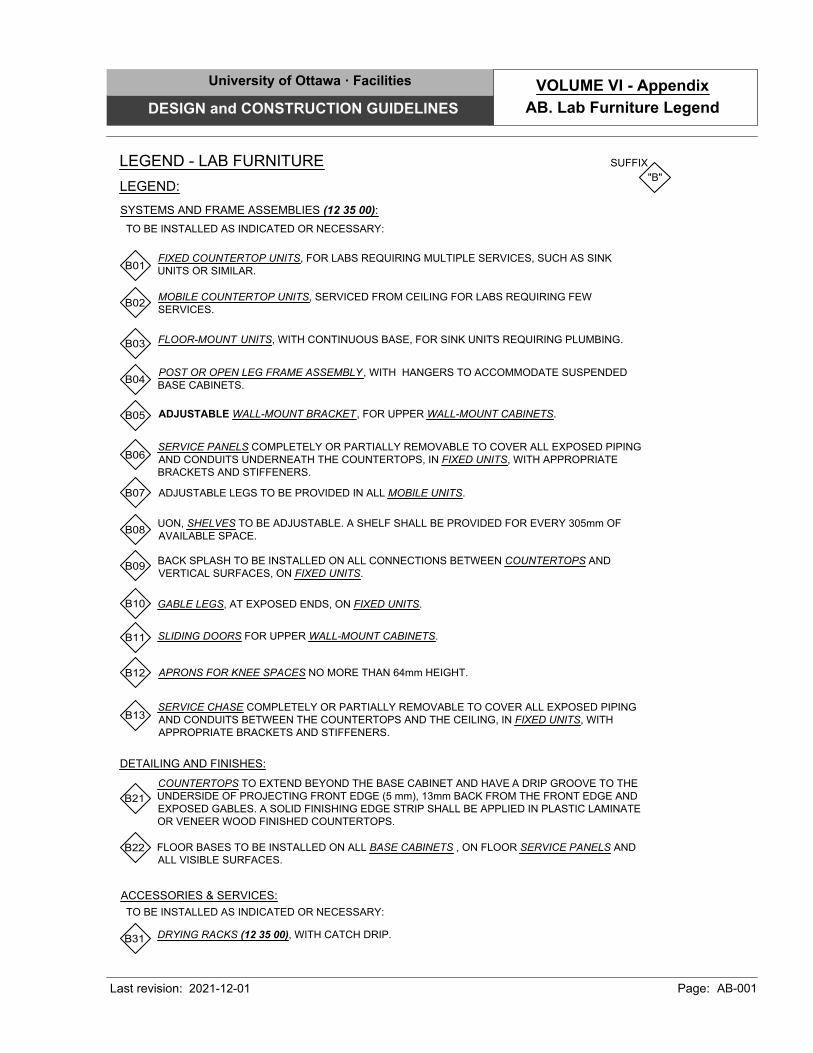
LEGEND - LAB FURNITURE SUFFIX
"B"
LEGEND:
SYSTEMS AND FRAME ASSEMBLIES (12 35 00):
POST OR OPEN LEG FRAME ASSEMBLY , WITH HANGERS TO ACCOMMODATE SUSPENDED
BASE CABINETS.
FIXED COUNTERTOP UNITS, FOR LABS REQUIRING MULTIPLE SERVICES, SUCH AS SINK
UNITS OR SIMILAR.
MOBILE COUNTERTOP UNITS, SERVICED FROM CEILING FOR LABS REQUIRING FEW
SERVICES.
B01
B02
B04
BACK SPLASH TO BE INSTALLED ON ALL CONNECTIONS BETWEEN COUNTERTOPS AND
VERTICAL SURFACES, ON FIXED UNITS.
UON, SHELVES TO BE ADJUSTABLE. A SHELF SHALL BE PROVIDED FOR EVERY 305mm OF
AVAILABLE SPACE.
SERVICE PANELS COMPLETELY OR PARTIALLY REMOVABLE TO COVER ALL EXPOSED PIPING
AND CONDUITS UNDERNEATH THE COUNTERTOPS, IN FIXED UNITS, WITH APPROPRIATE
BRACKETS AND STIFFENERS.
B06
TO BE INSTALLED AS INDICATED OR NECESSARY:
FLOOR-MOUNT UNITS, WITH CONTINUOUS BASE, FOR SINK UNITS REQUIRING PLUMBING.
B03
ADJUSTABLE LEGS TO BE PROVIDED IN ALL MOBILE UNITS.
GABLE LEGS, AT EXPOSED ENDS, ON FIXED UNITS.
ADJUSTABLE WALL-MOUNT BRACKET , FOR UPPER WALL-MOUNT CABINETS.
SLIDING DOORS FOR UPPER WALL-MOUNT CABINETS.
B05
APRONS FOR KNEE SPACES NO MORE THAN 64mm HEIGHT.
B07
B08
B09
B10
B11
B12
FLOOR BASES TO BE INSTALLED ON ALL BASE CABINETS , ON FLOOR SERVICE PANELS AND
ALL VISIBLE SURFACES.
B21
DETAILING AND FINISHES:
DRYING RACKS (12 35 00), WITH CATCH DRIP.
B31
ACCESSORIES & SERVICES:
B22
COUNTERTOPS TO EXTEND BEYOND THE BASE CABINET AND HAVE A DRIP GROOVE TO THE
UNDERSIDE OF PROJECTING FRONT EDGE (5 mm), 13mm BACK FROM THE FRONT EDGE AND
EXPOSED GABLES. A SOLID FINISHING EDGE STRIP SHALL BE APPLIED IN PLASTIC LAMINATE
OR VENEER WOOD FINISHED COUNTERTOPS.
TO BE INSTALLED AS INDICATED OR NECESSARY:
SERVICE CHASE COMPLETELY OR PARTIALLY REMOVABLE TO COVER ALL EXPOSED PIPING
AND CONDUITS BETWEEN THE COUNTERTOPS AND THE CEILING, IN FIXED UNITS, WITH
APPROPRIATE BRACKETS AND STIFFENERS.
B13
University of Ottawa · Facilities
DESIGN and CONSTRUCTION GUIDELINES
Last revision: Page: AB-001
AB. Lab Furniture Legend
VOLUME VI - Appendix
2021-12-01
STEEL PLATES.
STEEL OR FIBER REINFORCED POLYMER (FRP) GRATING, TREADS & LANDINGS, ANTI-SKID (05 50 00).
STEEL OR FIBER REINFORCED POLYMER (FRP) STRINGER.
STEEL CHECKERED PLATES, ANTISKID (05 50 00)
CONCRETE FILL-IN TOPPING
CARBORUNDUM ANTI-SKID STRIPS (05 50 00).
STEEL PIPES, TUBES OR RODS.
STEEL CHAIN (MOVABLE, WITH APPROPRIATE HOOKS).
STEEL CAST-IN SLEEVE, SIZE TO ADAPT TO BALUSTRADE / POST.
STEEL BARS.
INSTALL ALL STIFFENERS, SUPPORTS AND REINFORCEMENTS AS NECESSARY TO ENSURE STRUCTURAL
STABILITY OF UNITS.
UON, STEEL ELEMENTS TO BE WELDED TOGETHER AND GRINDED SMOOTHLY.
INSTALLATION:
L21
L22
UON, STEEL ELEMENTS TO BE ANCHORED TO OTHER ELEMENTS USING COUNTERSUNK FASTENER BOLTS
(IF EXPOSED), OR ANY OTHER APPROPRIATE BOLTS AS RECOMMENDED.
L23
LEGEND:
LEGEND - MISCELLANEOUS STEEL:
STEEL SHAPES ("L", "C", OR SIMILAR).
L01
L02
L03
L04
L05
L06
L07
L08
L09
L10
L11
ALL HANDRAILS ADJACENT TO WALLS SHALL BE TERMINATED (TURNED) AGAINST THE WALLS, IN ORDER
NOT TO CONSTITUTE A HAZARD TO THE USERS.
L24
COMPONENTS:
TO BE INSTALLED AS INDICATED (SIZES AS INDICATED OR NECESSARY):
SUFFIX
"L"
TACTILE WALKING SURFACE INDICATORS, IN IRON OR POLYMER (05 50 00), SURFACE MOUNT (IN EXISTING
CONSTRUCTION) OR CAST-IN (IN NEW CONSTRUCTION).
L12
IN NON-INUSTRIAL STAIRS: BALUSTRADES SHALL PREVENT THE PASSAGE OF A 100mm DIAMETER
SPHERE.
L25
University of Ottawa · Facilities
DESIGN and CONSTRUCTION GUIDELINES
Last revision: Page: AL-001
AL. Miscellaneous Steel Legend
VOLUME VI - Appendix
2021-12-01
INSERTS:
IN SAME MATERIAL AS THE PANEL. TO BE SECURED AT ALL SIDES (2 PER SIDE) WITH METAL FITTING PLATE OR
BRACKETS.
M11
COMPONENTS:
COUNTER TOP:
A) PLYWOOD PANELS (06 10 00) OR PREMOLDED PARTICLE BOARD (06 10 00) 19mm, COVERED WITH PLASTIC
LAMINATE (06 10 00)
B) NATURAL STONE 19mm
C) SOLID HOMOGENEOUS PANEL (06 10 00) 19mm
M01
M02
BACKSPLASHES:
PLYWOOD PANELS (06 10 00) 19mm, COVERED WITH PLASTIC LAMINATE (06 10 00) OR VENEER WOOD (06 10 00) .
FOR RECYCLING COUNTER: TO BE DOUBLE (2 X 19mm), SECURED ONLY TO THE COUNTER WITH ADEQUATE
METAL FITTING PLATE OR BRACKET.
STIFFENERS:
PLYWOOD PANELS (06 10 00) 19mm, @ 1220mm O/C, COVERED WITH PLASTIC LAMINATE (06 10 00) OR VENEER
WOOD (06 10 00).
BODY / SIDES:
PARTICLE BOARD WOOD (06 10 00) 19mm, COVERED WITH PLASTIC LAMINATE (06 10 00) OR VENEER WOOD
(06 10 00).
SHELVES (ADJUSTABLE):
PARTICLE BOARD WOOD (06 10 00) (19mm @ 915mm LONG MAX., AND 25mm @ 1220mm LONG), COVERED WITH
PLASTIC LAMINATE (06 10 00) OR VENEER WOOD (06 10 00).
DOORS:
PARTICLE BOARD WOOD (06 10 00) 16mm, COVERED WITH PLASTIC LAMINATE (06 10 00) OR VENEER WOOD
(06 10 00).
DRAWERS:
-FACES: PARTICLE BOARD WOOD (06 10 00) 16mm, COVERED WITH PLASTIC LAMINATE (06 10 00) OR VENEER
WOOD( 06 10 00).
-BACKS AND SIDES: PARTICLE BOARD WOOD (06 10 00) 13mm, COVERED WITH PLASTIC LAMINATE (06 10 00).
BACK PANEL:
PARTICLE BOARD WOOD 13mm, COVERED WITH PLASTIC LAMINATE (06 10 00) OR VENEER WOOD 06 10 00).
CABINET BASES:
PLYWOOD PANELS (06 10 00) 19mm, COVERED WITH PLASTIC LAMINATE (06 10 00) OR VENEER WOOD (06 10 00)
OR WALL BASE FINISH (06 10 00).
DECORATIVE PANELS / FASCIAS:
PARTICLE BOARD WOOD (06 10 00) 19mm, COVERED WITH PLASTIC LAMINATE (06 10 00) OR VENEER WOOD
(06 10 00) .
M03
M04
M05
M06
M07
M08
M09
M10
LEGEND - MILLWORK SUFFIX
"M"
LEGEND:
TO BE INSTALLED AS INDICATED OR NECESSARY:
University of Ottawa · Facilities
DESIGN and CONSTRUCTION GUIDELINES
Last revision: Page: AM-001
AM. Millwork Legend
VOLUME VI - Appendix
2021-12-01
WASTE DEFLECTORS: STAINLESS STEEL, SECURELY FIXED TO INSIDE OF DOOR AT ALL 4 RECTANGULAR
OPENINGS.
WASTE AND RECYCLE CONTAINERS (N.I.C.): PROVIDED BY OWNER
M30
LIQUID DRAIN CONTAINERS (N.I.C.): PROVIDED BY OWNER.
M31
M32
TRIMS: STAINLESS STEEL RING Ø 152mm.
M28
LIQUID DRAIN TROUGH: STAINLESS STEEL DRAIN TROUGH COMPLETE WITH 13mm STAINLESS STEEL EDGE AND
HINGED GRATE. RECESSED 13mm. TO BE CONNECTED AND SECURED TO APPROPRIATE FLEX TUBING IDENTICAL
TO SIMILAR INSTALLATIONS ON EXISTING UOFO RECYCLING COUNTERS. ANY ALTERNATIVE TO BE APPROVED.
M29
INSTALL ALL WOOD BLOCKING OR OTHER STIFFENERS OR SUPPORTS NECESSARY TO ENSURE STRUCTURAL
STABILITY OF UNITS.
ALL NECESSARY CUTS FOR ELECTRICAL RECEPTACLES OR OTHER SIMILAR FEATURES, TO BE CARRIED OUT
AS PER ELECTRICAL FEATURES.
NOTES:
HANDLES: CHROMED STEEL, SS, PR PVC.
FOR RECYCLING COUNTER: CONTINUOUS: "RICHELIEU #3182".
SLIDES: CHROMES, WITH EXTRA EXTENSION
HINGES: CONCEALED, CHROMES, WITH SLOW RETURN TYPE 'BLUM".
GROMMETS: PRE FABRICATED IN PVC
ACCESSORIES:
M21
M22
M41
M42
MOULDINGS: ANODIZED ALUMINUM TRIMS "L" SHAPE ON PERIMETER & "T" SHAPE INSIDE(3/4")
ALL EXPOSED EDGES TO BE COVERED WITH PLASTIC LAMINATE EDGING TO MATCH ADJACENT.
WALL MOUNT SHELVE ADJUSTABLE BRACKETS AND RACKS (06 10 00): IN PRE-PAINTED STEEL, ULTRA-ROBUST
(DOUBLE SLOT WITH DOUBLE FLANGE BRACKETS), TO ADAPT TO SHELVE SIZES.
M27
M23
M24
M25
M43
COAT RACKS: S.S. TUBE Ø 41mm.
M26
LEGEND - MILLWORK SUFFIX
"M"
LEGEND:
TO BE INSTALLED AS INDICATED OR NECESSARY:
PL1
FOR BACK SIGNAGE PANEL:
FORMICA, 909-58, BLACK, MATTE FINISH.
ALL EXPOSED EXTERIOR FINISHES (EXCEPT BACK SIGNAGE PANEL).
FORMICA, 7012-58, AMBER MAPLE, MATTE FINISH.
ALL EXPOSED INTERIOR SURFACES:
WHITE MELAMINE, MATTE FINISH.
PLASTIC LAMINATE FINISHES:
UON, THE FOLLOWING ARE THE FINISHES TO BE USED:
PL2
PL3
University of Ottawa · Facilities
DESIGN and CONSTRUCTION GUIDELINES
Last revision: Page: AM-001
AM. Millwork Legend
VOLUME VI - Appendix
2021-12-01
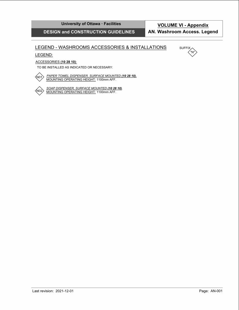
PAPER TOWEL DISPENSER, SURFACE MOUNTED (10 28 10).
MOUNTING OPERATING HEIGHT: 1100mm AFF.
SOAP DISPENSER, SURFACE MOUNTED (10 28 10).
MOUNTING OPERATING HEIGHT: 1100mm AFF.
LEGEND - WASHROOMS ACCESSORIES & INSTALLATIONS SUFFIX
"N"
LEGEND:
TO BE INSTALLED AS INDICATED OR NECESSARY:
ACCESSORIES (10 28 10):
N01
N02
University of Ottawa · Facilities
DESIGN and CONSTRUCTION GUIDELINES
Last revision: Page: AN-001
AN. Washroom Access. Legend
VOLUME VI - Appendix
2021-12-01
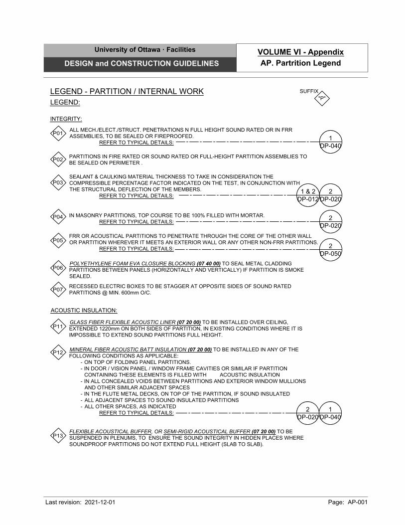
LEGEND - PARTITION / INTERNAL WORK
SUFFIX
"P"
LEGEND:
P11
P12
P01
GLASS FIBER FLEXIBLE ACOUSTIC LINER (07 20 00) TO BE INSTALLED OVER CEILING,
EXTENDED 1220mm ON BOTH SIDES OF PARTITION, IN EXISTING CONDITIONS WHERE IT IS
IMPOSSIBLE TO EXTEND SOUND PARTITIONS FULL HEIGHT.
IN MASONRY PARTITIONS, TOP COURSE TO BE 100% FILLED WITH MORTAR.
REFER TO TYPICAL DETAILS:
MINERAL FIBER ACOUSTIC BATT INSULATION (07 20 00) TO BE INSTALLED IN ANY OF THE
FOLLOWING CONDITIONS AS APPLICABLE:
- ON TOP OF FOLDING PANEL PARTITIONS.
- IN DOOR / VISION PANEL / WINDOW FRAME CAVITIES OR SIMILAR IF PARTITION
CONTAINING THESE ELEMENTS IS FILLED WITH ACOUSTIC INSULATION
- IN ALL CONCEALED VOIDS BETWEEN PARTITIONS AND EXTERIOR WINDOW MULLIONS
AND OTHER SIMILAR ADJACENT SPACES
- IN THE FLUTE METAL DECKS, ON TOP OF THE PARTITION, IF SOUND INSULATED
- ALL ADJACENT SPACES TO SOUND INSULATED PARTITIONS
- ALL OTHER SPACES, AS INDICATED
REFER TO TYPICAL DETAILS:
POLYETHYLENE FOAM EVA CLOSURE BLOCKING (07 40 00) TO SEAL METAL CLADDING
PARTITIONS BETWEEN PANELS (HORIZONTALLY AND VERTICALLY) IF PARTITION IS SMOKE
SEALED.
FRR OR ACOUSTICAL PARTITIONS TO PENETRATE THROUGH THE CORE OF THE OTHER WALL
OR PARTITION WHEREVER IT MEETS AN EXTERIOR WALL OR ANY OTHER NON-FRR PARTITIONS.
REFER TO TYPICAL DETAILS:
ALL MECH./ELECT./STRUCT. PENETRATIONS N FULL HEIGHT SOUND RATED OR IN FRR
ASSEMBLIES, TO BE SEALED OR FIREPROOFED.
REFER TO TYPICAL DETAILS:
PARTITIONS IN FIRE RATED OR SOUND RATED OR FULL-HEIGHT PARTITION ASSEMBLIES TO
BE SEALED ON PERIMETER .
RECESSED ELECTRIC BOXES TO BE STAGGER AT OPPOSITE SIDES OF SOUND RATED
PARTITIONS @ MIN. 600mm O/C.
INTEGRITY:
ACOUSTIC INSULATION:
P02
P03
P04
P05
P06
SEALANT & CAULKING MATERIAL THICKNESS TO TAKE IN CONSIDERATION THE
COMPRESSIBLE PERCENTAGE FACTOR INDICATED ON THE TEST, IN CONJUNCTION WITH
THE STRUCTURAL DEFLECTION OF THE MEMBERS.
REFER TO TYPICAL DETAILS:
P07
DP-020
2
DP-012
1 & 2
DP-020
2
DP-050
2
DP-040
1
DP-020
2
DP-040
1
P13
FLEXIBLE ACOUSTICAL BUFFER, OR SEMI-RIGID ACOUSTICAL BUFFER (07 20 00) TO BE
SUSPENDED IN PLENUMS, TO ENSURE THE SOUND INTEGRITY IN HIDDEN PLACES WHERE
SOUNDPROOF PARTITIONS DO NOT EXTEND FULL HEIGHT (SLAB TO SLAB).
University of Ottawa · Facilities
DESIGN and CONSTRUCTION GUIDELINES
Last revision: Page: AP-001
AP. Partrition Legend
VOLUME VI - Appendix
2021-12-01

P21
P22
P23
P25
UON, ADDITIONAL CROSS BRACING @ 1500mm O/C MAX TO ATTACH DOUBLE STUD
PARTITIONS.
STUDS TO BE DOUBLED AT ALL OPENINGS, DOOR OR WINDOW FRAMES IN DRY WALL
PARTITIONS.
CONTINUOUS GALVANIZED "L" SHAPE FRAME 50mm x NECESSARY HEIGHT x ±16 GA., TO BE
INSTALLED ON THE PERIMETER OF ALL BOARD CEILINGS.
REFER TO TYPICAL DETAILS:
ADDITIONAL FRAMING TO BE INSTALLED IN CEILINGS AS NECESSARY TO ACCOmmODATE
ALL ELECTRICAL / MECHANICAL FEATURES SUCH AS FUME HOOD COVER PANELS, LIGHTING,
DUCTS, PIPES, OR SIMILAR.
REFER TO TYPICAL DETAILS:
ADDITIONAL STUD, ALUMINUM EXTRUSIONS OR MISCELLANEOUS STEEL REINFORCEMENT
TO BE ADDED FOR VERTICAL POSTS AND LINTELS, AS NECESSARY IN THE FOLLOWING:
- DRY WALL PARTITIONS, FOR ALL OPENINGS WIDER THAN 1800mm.
- ALL FREE STANDING PARTITIONS, WHERE NECESSARY TO SUPPORT THE DESCRIBED
DIMENSIONS.
REFER TO TYPICAL DETAILS:
DEFLECTION GAP TO BE CARRIED AT THE HEAD OF ALL PARTITIONS (MASONRY AND /
OR STUDS) USING DOUBLE TRACK OR SIMILAR APPROVED SYSTEM TO ALLOW FOR
FLEXIBLE STRUCTURAL DEFLECTION ABOVE.
F: STRUCTURAL DEFLECTION AS RECOmmENDED BY STRUCTURAL ENGINEER. =
20mm MIN. RECOmmENDED
REFER TO TYPICAL DETAILS:
CONCRETE OR STEEL LINTELS TO BE INSTALLED OVER OPENINGS, DOORS, MECHANICAL /
ELECTRICAL SERVICE OR EQUIPMENT PENETRATIONS IN MASONRY PARTITIONS. REFER TO
STRUCTURAL AS NECESSARY.
CONTINUOUS STEEL PLATE ±16 GAUGE X APPROPRIATE WIDTH OR SIMILAR TO BE
INSTALLED AS NECESSARY FOR THE SUPPORT AND/OR REINFORCEMENT OF PARTITION
STUDS UNDER WASHROOM ACCESSORIES, ELECTRO/ MECHANICAL ITEMS, SUSPENDED
FURNITURE, OR SIMILAR.
STEEL STUD SYSTEM (09 20 00) (SAME GAUGE AND STUD SPACING AS ADJACENT) TO BE
INSTALLED AS NECESSARY FOR BRACING & REINFORCEMENTS OF BULKHEAD FACES,
PARTITION HEADS, SUSPENSIONS OR SIMILAR.
REFER TO TYPICAL DETAILS:
STRUCTURAL STABILITY:
P26
P27
P28
P29
P30
P31
P24
"L" SHAPE, CHANNEL, OR SIMILAR MISCELLANEOUS STEEL REINFORCEMENT TO BE
INSTALLED AS NECESSARY AS REINFORCEMENT FOR THE FOLLOWING:
- VANITY SUPPORT
- CEILING HUNG PARTITIONS
REFER TO TYPICAL DETAILS:
UON, UNDER STEEL DECK COMPONENTS, ALL CEILING HUNG ELEMENTS TO BE ANCHORED
TO THE STRUCTURAL SUPPORTING ELEMENTS OR LOWER PORTIONS OF THE FLUTES, AND
NOT TO THE UPPER PORTIONS.
REFER TO TYPICAL DETAILS:
LEGEND - PARTITION / INTERNAL WORK
SUFFIX
"P"
DP-050
1
DP-031
2
DP-021
1
DP-020
Series
DP-010
Series
DP-022
1
DP-031
1
DP-012
1
DP-030
1
University of Ottawa · Facilities
DESIGN and CONSTRUCTION GUIDELINES
Last revision: Page: AP-002
AP. Partrition Legend
VOLUME VI - Appendix
2021-12-01
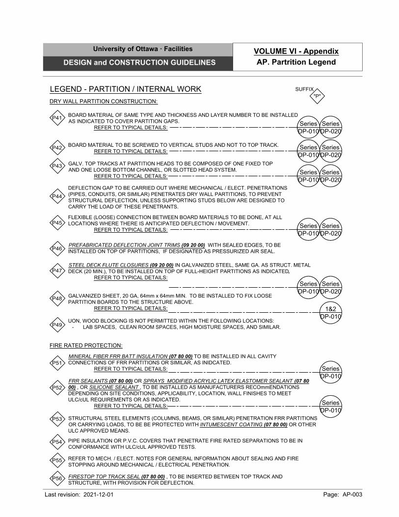
GALVANIZED SHEET, 20 GA, 64mm x 64mm MIN. TO BE INSTALLED TO FIX LOOSE
PARTITION BOARDS TO THE STRUCTURE ABOVE.
REFER TO TYPICAL DETAILS:
P41
P42
P43
P44
P45
P46
P47
P51
P52
P53
PIPE INSULATION OR P.V.C. COVERS THAT PENETRATE FIRE RATED SEPARATIONS TO BE IN
CONFORMANCE WITH ULC/cUL APPROVED TESTS.
MINERAL FIBER FRR BATT INSULATION (07 80 00) TO BE INSTALLED IN ALL CAVITY
CONNECTIONS OF FRR PARTITIONS OR SIMILAR, AS INIDCATED.
REFER TO TYPICAL DETAILS:
FRR SEALANTS (07 80 00) OR SPRAYS MODIFIED ACRYLIC LATEX ELASTOMER SEALANT (07 80
00) , OR SILICONE SEALANT , TO BE INSTALLED AS MANUFACTURERS RECOmmENDATIONS
DEPENDING ON SITE CONDITIONS, APPLICABILITY, LOCATION, WALL FINISHES TO MEET
ULC/cUL REQUIREMENTS OR AS INDICATED.
REFER TO TYPICAL DETAILS:
STRUCTURAL STEEL ELEMENTS (COLUMNS, BEAMS, OR SIMILAR) PENETRATION FRR PARTITIONS
OR CARRYING LOADS, TO BE BE PROTECTED WITH INTUMESCENT COATING (07 80 00) OR OTHER
ULC APPROVED MEANS.
DEFLECTION GAP TO BE CARRIED OUT WHERE MECHANICAL / ELECT. PENETRATIONS
(PIPES, CONDUITS, OR SIMILAR) PENETRATES DRY WALL PARTITIONS, TO PREVENT
STRUCTURAL DEFLECTION, UNLESS SUPPORTING STUDS BELOW ARE DESIGNED TO
CARRY THE LOAD OF THESE PENETRANTS.
DRY WALL PARTITION CONSTRUCTION:
FIRE RATED PROTECTION:
STEEL DECK FLUTE CLOSURES (09 20 00) IN GALVANIZED STEEL, SAME GA. AS STRUCT. METAL
DECK (20 MIN.), TO BE INSTALLED ON TOP OF FULL-HEIGHT PARTITIONS AS INDICATED
REFER TO TYPICAL DETAILS:
GALV. TOP TRACKS AT PARTITION HEADS TO BE COMPOSED OF ONE FIXED TOP
AND ONE LOOSE BOTTOM CHANNEL, OR SLOTTED HEAD SYSTEM.
REFER TO TYPICAL DETAILS:
BOARD MATERIAL TO BE SCREWED TO VERTICAL STUDS AND NOT TO TOP TRACK.
REFER TO TYPICAL DETAILS:
BOARD MATERIAL OF SAME TYPE AND THICKNESS AND LAYER NUMBER TO BE INSTALLED
AS INDICATED TO COVER PARTITION GAPS.
REFER TO TYPICAL DETAILS:
PREFABRICATED DEFLECTION JOINT TRIMS (09 20 00) WITH SEALED EDGES, TO BE
INSTALLED ON TOP OF PARTITIONS, IF DESIGNATED AS PRESSURIZED AIR SEAL.
FLEXIBLE (LOOSE) CONNECTION BETWEEN BOARD MATERIALS TO BE DONE, AT ALL
LOCATIONS WHERE THERE IS ANTICIPATED DEFLECTION / MOVEMENT.
REFER TO TYPICAL DETAILS:
P48
UON, WOOD BLOCKING IS NOT PERMITTED WITHIN THE FOLLOWING LOCATIONS:
- LAB SPACES, CLEAN ROOM SPACES, HIGH MOISTURE SPACES, AND SIMILAR.
P49
REFER TO MECH. / ELECT. NOTES FOR GENERAL INFORMATION ABOUT SEALING AND FIRE
STOPPING AROUND MECHANICAL / ELECTRICAL PENETRATION.
P54
P55
LEGEND - PARTITION / INTERNAL WORK
SUFFIX
"P"
DP-020
Series
DP-010
Series
DP-020
Series
DP-010
Series
DP-020
Series
DP-010
Series
DP-020
Series
DP-010
Series
DP-020
Series
DP-010
Series
DP-010
1&2
DP-010
Series
DP-010
Series
FIRESTOP TOP TRACK SEAL (07 80 00) , TO BE INSERTED BETWEEN TOP TRACK AND
STRUCTURE, WITH PROVISION FOR DEFLECTION.
P56
University of Ottawa · Facilities
DESIGN and CONSTRUCTION GUIDELINES
Last revision: Page: AP-003
AP. Partrition Legend
VOLUME VI - Appendix
2021-12-01
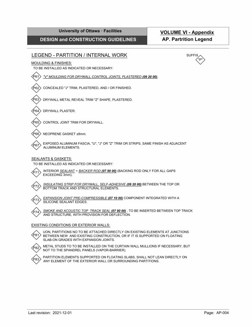
P62
P71
DRYWALL METAL REVEAL TRIM "Z" SHAPE, PLASTERED.
DRYWALL PLASTER.
INTERIOR SEALANT + BACKER ROD (07 90 00) (BACKING ROD ONLY FOR ALL GAPS
EXCEEDING 3mm).
NEOPRENE GASKET ±8mm.
CONCEALED "J" TRIM, PLASTERED, AND / OR FINISHED.
EXPOSED ALUMINUM FASCIA, "U", "J" OR "Z" TRIM OR STRIPS, SAME FINISH AS ADJACENT
ALUMINUM ELEMENTS.
CONTROL JOINT TRIM FOR DRYWALL.
MOULDING & FINISHES:
"V" MOULDING FOR DRYWALL CONTROL JOINTS, PLASTERED (09 20 00).P61
SEALANTS & GASKETS:
P81
P82
P83
UON, PARTITIONS NO TO BE ATTACHED DIRECTLY ON EXISTING ELEMENTS AT JUNCTIONS
BETWEEN NEW AND EXISTING CONSTRUCTION, OR IF IT IS SUPPORTED ON FLOATING
SLAB-ON GRADES WITH EXPANSION JOINTS.
METAL STUDS TO TO BE INSTALLED ON THE CURTAIN WALL MULLIONS IF NECESSARY, BUT
NOT TO THE SPANDREL PANELS (VAPOR-BARRIER).
PARTITION ELEMENTS SUPPORTED ON FLOATING SLABS, SHALL NOT LEAN DIRECTLY ON
ANY ELEMENT OF THE EXTERIOR WALL OR SURROUNDING PARTITIONS.
EXISTING CONDITIONS OR EXTERIOR WALLS:
P72
INSULATING STRIP FOR DRYWALL, SELF-ADHESIVE (09 20 00) BETWEEN THE TOP OR
BOTTOM TRACK AND STRUCTURAL ELEMENTS.
P63
P64
P65
P66
P67
P73
EXPANSION JOINT PRE-COMPRESSIBLE (07 10 00) COMPONENT INTEGRATED WITH A
SILICONE SEALANT EDGES.
LEGEND - PARTITION / INTERNAL WORK
SUFFIX
"P"
TO BE INSTALLED AS INDICATED OR NECESSARY:
TO BE INSTALLED AS INDICATED OR NECESSARY:
SMOKE AND ACOUSTIC TOP TRACK SEAL (07 90 00) , TO BE INSERTED BETWEEN TOP TRACK
AND STRUCTURE, WITH PROVISION FOR DEFLECTION.
P74
University of Ottawa · Facilities
DESIGN and CONSTRUCTION GUIDELINES
Last revision: Page: AP-004
AP. Partrition Legend
VOLUME VI - Appendix
2021-12-01
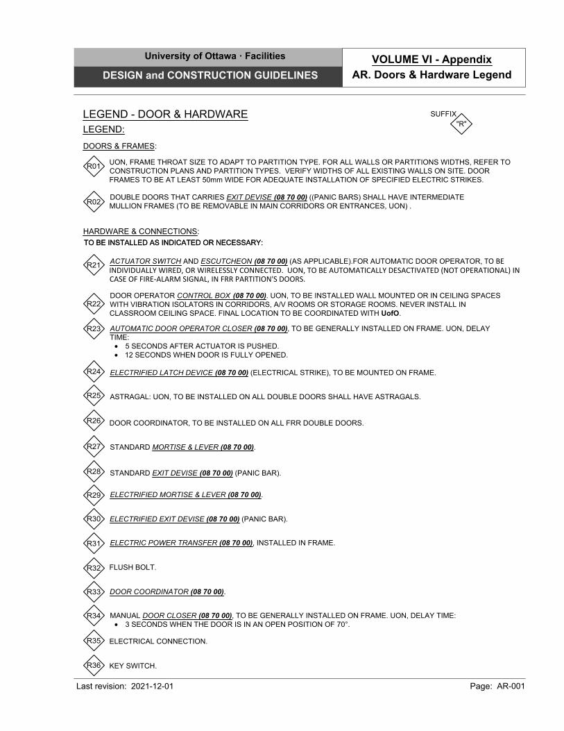
LEGEND - DOOR & HARDWARE
SUFFIX
"R"
LEGEND:
DOORS & FRAMES:
ASTRAGAL: UON, TO BE INSTALLED ON ALL DOUBLE DOORS SHALL HAVE ASTRAGALS.
HARDWARE & CONNECTIONS:
R01
R24
TO BE INSTALLED AS INDICATED OR NECESSARY:TO BE INSTALLED AS INDICATED OR NECESSARY:
UON, FRAME THROAT SIZE TO ADAPT TO PARTITION TYPE. FOR ALL WALLS OR PARTITIONS WIDTHS, REFER TO
CONSTRUCTION PLANS AND PARTITION TYPES. VERIFY WIDTHS OF ALL EXISTING WALLS ON SITE. DOOR
FRAMES TO BE AT LEAST 50mm WIDE FOR ADEQUATE INSTALLATION OF SPECIFIED ELECTRIC STRIKES.
R02
DOUBLE DOORS THAT CARRIES EXIT DEVISE (08 70 00) ((PANIC BARS) SHALL HAVE INTERMEDIATE
MULLION FRAMES (TO BE REMOVABLE IN MAIN CORRIDORS OR ENTRANCES, UON) .
DOOR COORDINATOR, TO BE INSTALLED ON ALL FRR DOUBLE DOORS.
R25
DOOR OPERATOR CONTROL BOX (08 70 00). UON, TO BE INSTALLED WALL MOUNTED OR IN CEILING SPACES
WITH VIBRATION ISOLATORS IN CORRIDORS, A/V ROOMS OR STORAGE ROOMS. NEVER INSTALL IN
CLASSROOM CEILING SPACE. FINAL LOCATION TO BE COORDINATED WITH UofO.
R21
ACTUATOR SWITCH AND ESCUTCHEON (08 70 00) (AS APPLICABLE).FOR AUTOMATIC DOOR OPERATOR, TO BEINDIVIDUALLY WIRED, OR WIRELESSLY CONNECTED. UON, TO BE AUTOMATICALLY DESACTIVATED (NOT OPERATIONAL) INCASE OF FIRE-ALARM SIGNAL, IN FRR PARTITION'S DOORS.
R22
AUTOMATIC DOOR OPERATOR CLOSER (08 70 00), TO BE GENERALLY INSTALLED ON FRAME. UON, DELAY
TIME:
· 5 SECONDS AFTER ACTUATOR IS PUSHED.
· 12 SECONDS WHEN DOOR IS FULLY OPENED.
R23
ELECTRIFIED LATCH DEVICE (08 70 00) (ELECTRICAL STRIKE), TO BE MOUNTED ON FRAME.
R26
ELECTRIC POWER TRANSFER (08 70 00), INSTALLED IN FRAME.
R27STANDARD MORTISE & LEVER (08 70 00).
STANDARD EXIT DEVISE (08 70 00) (PANIC BAR).
R28
ELECTRIFIED MORTISE & LEVER (08 70 00).R29
R30 ELECTRIFIED EXIT DEVISE (08 70 00) (PANIC BAR).
R31
FLUSH BOLT.
R32
R33
MANUAL DOOR CLOSER (08 70 00), TO BE GENERALLY INSTALLED ON FRAME. UON, DELAY TIME:
· 3 SECONDS WHEN THE DOOR IS IN AN OPEN POSITION OF 70°.
R34
DOOR COORDINATOR (08 70 00).
R35ELECTRICAL CONNECTION.
R36KEY SWITCH.
University of Ottawa · Facilities
DESIGN and CONSTRUCTION GUIDELINES
Last revision: Page: AR-001
AR. Doors & Hardware Legend
VOLUME VI - Appendix
2021-12-01
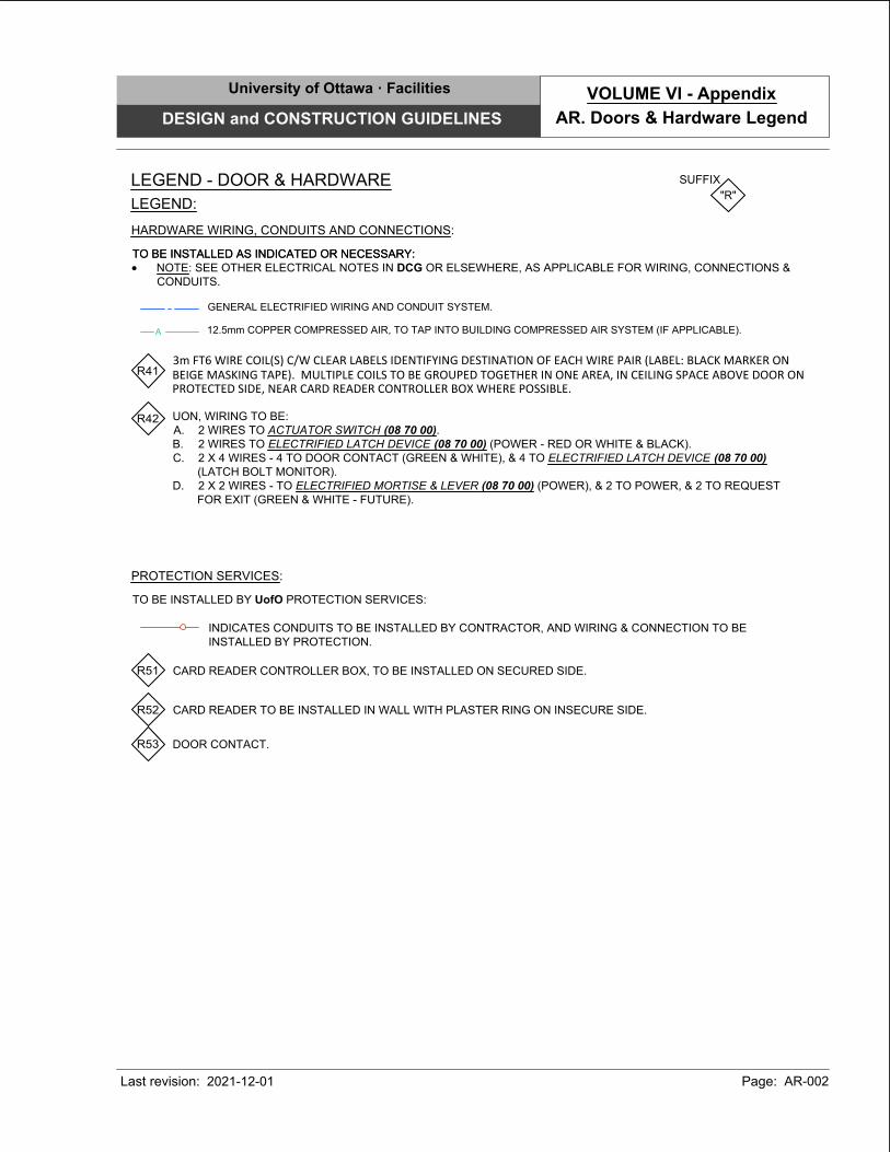
GENERAL ELECTRIFIED WIRING AND CONDUIT SYSTEM.
3m FT6 WIRE COIL(S) C/W CLEAR LABELS IDENTIFYING DESTINATION OF EACH WIRE PAIR (LABEL: BLACK MARKER ONBEIGE MASKING TAPE). MULTIPLE COILS TO BE GROUPED TOGETHER IN ONE AREA, IN CEILING SPACE ABOVE DOOR ONPROTECTED SIDE, NEAR CARD READER CONTROLLER BOX WHERE POSSIBLE.
INDICATES CONDUITS TO BE INSTALLED BY CONTRACTOR, AND WIRING & CONNECTION TO BE
INSTALLED BY PROTECTION.
PROTECTION SERVICES:
TO BE INSTALLED BY UofO PROTECTION SERVICES:
R51 CARD READER CONTROLLER BOX, TO BE INSTALLED ON SECURED SIDE.
R52 CARD READER TO BE INSTALLED IN WALL WITH PLASTER RING ON INSECURE SIDE.
R53 DOOR CONTACT.
R41
R42
LEGEND - DOOR & HARDWARE
SUFFIX
"R"
LEGEND:
UON, WIRING TO BE:
A. 2 WIRES TO ACTUATOR SWITCH (08 70 00).
B. 2 WIRES TO ELECTRIFIED LATCH DEVICE (08 70 00) (POWER - RED OR WHITE & BLACK).
C. 2 X 4 WIRES - 4 TO DOOR CONTACT (GREEN & WHITE), & 4 TO ELECTRIFIED LATCH DEVICE (08 70 00)
(LATCH BOLT MONITOR).
D. 2 X 2 WIRES - TO ELECTRIFIED MORTISE & LEVER (08 70 00) (POWER), & 2 TO POWER, & 2 TO REQUEST
FOR EXIT (GREEN & WHITE - FUTURE).
HARDWARE WIRING, CONDUITS AND CONNECTIONS:
TO BE INSTALLED AS INDICATED OR NECESSARY:TO BE INSTALLED AS INDICATED OR NECESSARY:
· NOTE: SEE OTHER ELECTRICAL NOTES IN DCG OR ELSEWHERE, AS APPLICABLE FOR WIRING, CONNECTIONS &
CONDUITS.
A
12.5mm COPPER COMPRESSED AIR, TO TAP INTO BUILDING COMPRESSED AIR SYSTEM (IF APPLICABLE).
University of Ottawa · Facilities
DESIGN and CONSTRUCTION GUIDELINES
Last revision: Page: AR-002
AR. Doors & Hardware Legend
VOLUME VI - Appendix
2021-12-01
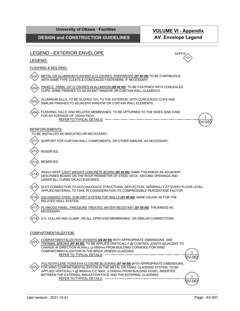
LEGEND - EXTERIOR ENVELOPE SUFFIX
"V"
LEGEND:
REINFORCEMENTS:
METAL OR ALUMINUM FLASHING & CLOSURES, PREPAINTED (07 40 00) TO BE CONTINUOUS
WITH SAME TYPE CLEATS & CONCEALED FASTENERS, IF NECESSARY.
PANELS, TRIMS, OR CLOSURES IN ALUMINUM (08 40 00), TO BE FASTENED WITH CONCEALED
CLIPS, SAME FINISHES TO ADJACENT WINDOW OR CURTAIN WALL ELEMENTS.
FLASHING, SILLS, AND RELATED MEMBRANES, TO BE UPTURNED TO THE SIDES (END DAM)
FOR AN AVERAGE OF 100mm HIGH.
REFER TO TYPICAL DETAILS:
ALUMINUM SILLS, TO BE SLOPED 10% TO THE EXTERIOR, WITH CONCEALED CLIPS AND
SIMILAR FINISHES TO ADJACENT WINDOW OR CURTAIN WALL ELEMENTS.
SUPPORT FOR CURTAIN WALL COMPONENTS, OR OTHER SIMILAR, AS NECESSARY.
300mm DEEP LIGHT WEIGHT CONCRETE BOARD (05 45 00), SAME THICKNESS AS ADJACENT
DESCRIBED BOARD ON THE ROOF PERIMETER OF STEEL DECK, AROUND OPENINGS AND
UNDER ALL CURBS OR ACCESSORIES.
SLOT CONNECTION TO ACCOmmODATE STRUCTURAL DEFLECTION, GENERALLY AT EVERY FLOOR LEVEL.
APPLIED MATERIAL TO TAKE IN CONSIDERATION ITS COMPRESSIBLE PERCENTAGE FACTOR .
GALVANIZED STEEL SUB-GIRT SYSTEM FOR WALLS (07 40 00), SAME GAUGE AS FOR THE
RELATED WALL SYSTEM.
RESERVED.
POLYETHYLENE FOAM EVA CLOSURE BLOCKING (07 40 00) WITH APPROPRIATE DIMENSIONS,
FOR WIND COMPARTMENTALIZATION IN THE METAL OR PANEL CLADDING SYSTEM, TO BE
APPLIED VERTICALLY @ 9000mm C/C MAX. (±1000mm FROM BUILDING EDGE), INSERTED
BETWEEN THE EXTERNAL INSULATION FACE AND THE EXTERNAL CLADDING.
REFER TO TYPICAL DETAILS:
COMPARTMENTALIZATION DIVIDERS (04 80 00) WITH APPROPRIATE DIMENSIONS AND
THERMAL BREAKS (07 40 00), TO BE APPLIED VERTICALLY @ CONTROL JOINTS ADJACENT TO
CHANGE IN DIRECTION IN WALL (±1000mm FROM BUILDING CORNERS) FOR WIND
COMPARTMENTALIZATION IN THE BRICK VENEER CLADDING.
REFER TO TYPICAL DETAILS:
COMPARTMENTALIZATION:
V01
V02
V03
V04
V11
V12
V13
V14
V15
V16
V21
V22
DV-020
1
FLASHING & MOLDING:
PLYWOOD PANEL, PRESSURE TREATED, WATER-RESISTANT (07 50 00), THICKNESS AS
NECESSARY.
V17
TO BE INSTALLED AS INDICATED OR NECESSARY:
DV-063
1
DV-063
1
S.S. COLLAR AND CLAMP, ON ALL OPEN END MEMBRANES, OR SIMILAR CONNECTIONS.V18
RESERVED.
University of Ottawa · Facilities
DESIGN and CONSTRUCTION GUIDELINES
Last revision: Page: AV-001
AV. Envelope Legend
VOLUME VI - Appendix
2021-12-01
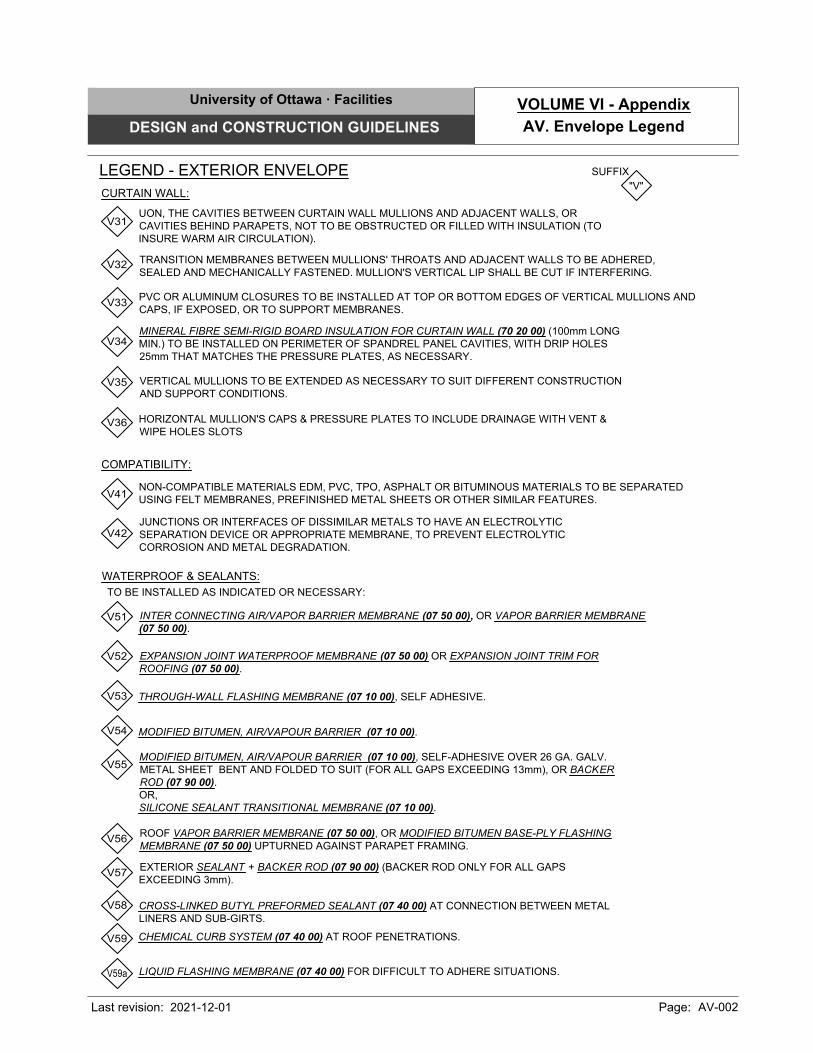
LEGEND - EXTERIOR ENVELOPE
CURTAIN WALL:
COMPATIBILITY:
WATERPROOF & SEALANTS:
SUFFIX
"V"
UON, THE CAVITIES BETWEEN CURTAIN WALL MULLIONS AND ADJACENT WALLS, OR
CAVITIES BEHIND PARAPETS, NOT TO BE OBSTRUCTED OR FILLED WITH INSULATION (TO
INSURE WARM AIR CIRCULATION).
TRANSITION MEMBRANES BETWEEN MULLIONS' THROATS AND ADJACENT WALLS TO BE ADHERED,
SEALED AND MECHANICALLY FASTENED. MULLION'S VERTICAL LIP SHALL BE CUT IF INTERFERING.
PVC OR ALUMINUM CLOSURES TO BE INSTALLED AT TOP OR BOTTOM EDGES OF VERTICAL MULLIONS AND
CAPS, IF EXPOSED, OR TO SUPPORT MEMBRANES.
VERTICAL MULLIONS TO BE EXTENDED AS NECESSARY TO SUIT DIFFERENT CONSTRUCTION
AND SUPPORT CONDITIONS.
MINERAL FIBRE SEMI-RIGID BOARD INSULATION FOR CURTAIN WALL (70 20 00) (100mm LONG
MIN.) TO BE INSTALLED ON PERIMETER OF SPANDREL PANEL CAVITIES, WITH DRIP HOLES
25mm THAT MATCHES THE PRESSURE PLATES, AS NECESSARY.
NON-COMPATIBLE MATERIALS EDM, PVC, TPO, ASPHALT OR BITUMINOUS MATERIALS TO BE SEPARATED
USING FELT MEMBRANES, PREFINISHED METAL SHEETS OR OTHER SIMILAR FEATURES.
JUNCTIONS OR INTERFACES OF DISSIMILAR METALS TO HAVE AN ELECTROLYTIC
SEPARATION DEVICE OR APPROPRIATE MEMBRANE, TO PREVENT ELECTROLYTIC
CORROSION AND METAL DEGRADATION.
THROUGH-WALL FLASHING MEMBRANE (07 10 00), SELF ADHESIVE.
EXPANSION JOINT WATERPROOF MEMBRANE (07 50 00) OR EXPANSION JOINT TRIM FOR
ROOFING (07 50 00).
MODIFIED BITUMEN, AIR/VAPOUR BARRIER (07 10 00).
MODIFIED BITUMEN, AIR/VAPOUR BARRIER (07 10 00), SELF-ADHESIVE OVER 26 GA. GALV.
METAL SHEET BENT AND FOLDED TO SUIT (FOR ALL GAPS EXCEEDING 13mm), OR BACKER
ROD (07 90 00).
OR,
SILICONE SEALANT TRANSITIONAL MEMBRANE (07 10 00).
INTER CONNECTING AIR/VAPOR BARRIER MEMBRANE (07 50 00), OR VAPOR BARRIER MEMBRANE
(07 50 00).
EXTERIOR SEALANT + BACKER ROD (07 90 00) (BACKER ROD ONLY FOR ALL GAPS
EXCEEDING 3mm).
ROOF VAPOR BARRIER MEMBRANE (07 50 00), OR MODIFIED BITUMEN BASE-PLY FLASHING
MEMBRANE (07 50 00) UPTURNED AGAINST PARAPET FRAMING.
V31
V32
V33
V34
V35
V41
V42
V51
V52
V53
V54
V55
V56
V57
HORIZONTAL MULLION'S CAPS & PRESSURE PLATES TO INCLUDE DRAINAGE WITH VENT &
WIPE HOLES SLOTS
V36
TO BE INSTALLED AS INDICATED OR NECESSARY:
CROSS-LINKED BUTYL PREFORMED SEALANT (07 40 00) AT CONNECTION BETWEEN METAL
LINERS AND SUB-GIRTS.
V58
CHEMICAL CURB SYSTEM (07 40 00) AT ROOF PENETRATIONS.
V59
LIQUID FLASHING MEMBRANE (07 40 00) FOR DIFFICULT TO ADHERE SITUATIONS.
V59a
University of Ottawa · Facilities
DESIGN and CONSTRUCTION GUIDELINES
Last revision: Page: AV-002
AV. Envelope Legend
VOLUME VI - Appendix
2021-12-01
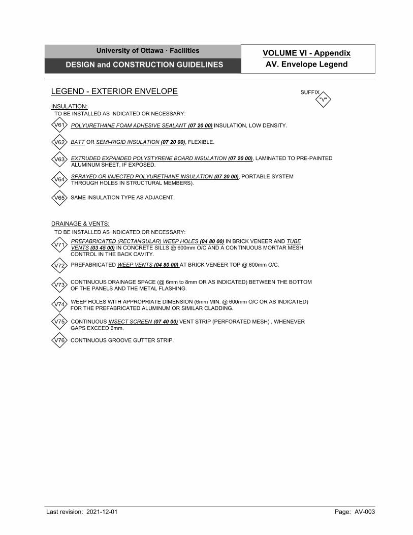
INSULATION:
DRAINAGE & VENTS:
LEGEND - EXTERIOR ENVELOPE SUFFIX
"V"
BATT OR SEMI-RIGID INSULATION (07 20 00), FLEXIBLE.
POLYURETHANE FOAM ADHESIVE SEALANT (07 20 00) INSULATION, LOW DENSITY.
EXTRUDED EXPANDED POLYSTYRENE BOARD INSULATION (07 20 00), LAMINATED TO PRE-PAINTED
ALUMINUM SHEET, IF EXPOSED.
SPRAYED OR INJECTED POLYURETHANE INSULATION (07 20 00), PORTABLE SYSTEM
THROUGH HOLES IN STRUCTURAL MEMBERS).
SAME INSULATION TYPE AS ADJACENT.
PREFABRICATED (RECTANGULAR) WEEP HOLES (04 80 00) IN BRICK VENEER AND TUBE
VENTS (03 45 00) IN CONCRETE SILLS @ 600mm O/C AND A CONTINUOUS MORTAR MESH
CONTROL IN THE BACK CAVITY.
CONTINUOUS DRAINAGE SPACE (@ 6mm to 8mm OR AS INDICATED) BETWEEN THE BOTTOM
OF THE PANELS AND THE METAL FLASHING.
PREFABRICATED WEEP VENTS (04 80 00) AT BRICK VENEER TOP @ 600mm O/C.
WEEP HOLES WITH APPROPRIATE DIMENSION (6mm MIN. @ 600mm O/C OR AS INDICATED)
FOR THE PREFABRICATED ALUMINUM OR SIMILAR CLADDING.
CONTINUOUS INSECT SCREEN (07 40 00) VENT STRIP (PERFORATED MESH) , WHENEVER
GAPS EXCEED 6mm.
V71
V61
V62
V63
V64
V65
V72
V73
V74
V75
CONTINUOUS GROOVE GUTTER STRIP.V76
TO BE INSTALLED AS INDICATED OR NECESSARY:
TO BE INSTALLED AS INDICATED OR NECESSARY:
University of Ottawa · Facilities
DESIGN and CONSTRUCTION GUIDELINES
Last revision: Page: AV-003
AV. Envelope Legend
VOLUME VI - Appendix
2021-12-01
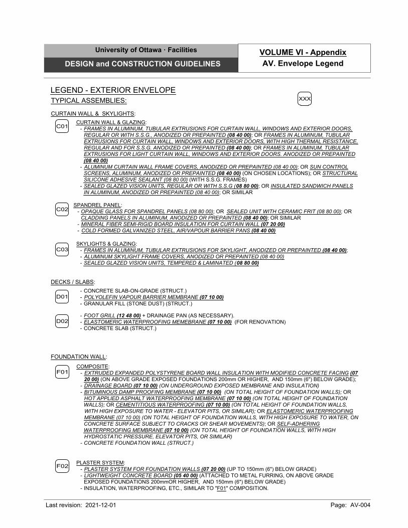
LEGEND - EXTERIOR ENVELOPE
FOUNDATION WALL:
DECKS / SLABS:
CURTAIN WALL & SKYLIGHTS:
- CONCRETE SLAB-ON-GRADE (STRUCT.)
- POLYOLEFIN VAPOUR BARRIER MEMBRANE (07 10 00)
- GRANULAR FILL (STONE DUST) (STRUCT.)
CURTAIN WALL & GLAZING:
- FRAMES IN ALUMINUM, TUBULAR EXTRUSIONS FOR CURTAIN WALL, WINDOWS AND EXTERIOR DOORS,
REGULAR OR WITH S.S.G., ANODIZED OR PREPAINTED (08 40 00); OR FRAMES IN ALUMINUM, TUBULAR
EXTRUSIONS FOR CURTAIN WALL, WINDOWS AND EXTERIOR DOORS, WITH HIGH THERMAL RESISTANCE,
REGULAR AND FOR S.S.G. ANODIZED OR PREPAINTED (08 40 00); OR FRAMES IN ALUMINUM, TUBULAR
EXTRUSIONS FOR LIGHT CURTAIN WALL, WINDOWS AND EXTERIOR DOORS. ANODIZED OR PREPAINTED
(08 40 00)
- ALUMINUM CURTAIN WALL FRAME COVERS, ANODIZED OR PREPAINTED (08 40 00); OR SUN CONTROL
SCREENS, ALUMINUM, ANODIZED OR PREPAINTED (08 40 00) (ON CHOSEN LOCATIONS); OR STRUCTURAL
SILICONE ADHESIVE SEALANT (08 80 00) (WITH S.S.G. FRAMES)
- SEALED GLAZED VISION UNITS, REGULAR OR WITH S.S.G (08 80 00); OR INSULATED SANDWICH PANELS
IN ALUMINUM, ANODIZED OR PREPAINTED (08 40 00); OR SIMILAR
D01
C01
SPANDREL PANEL:
- OPAQUE GLASS FOR SPANDREL PANELS (08 80 00); OR SEALED UNIT WITH CERAMIC FRIT (08 80 00); OR
CLADDING PANELS IN ALUMINUM, ANODIZED OR PREPAINTED (08 40 00); OR SIMILAR
- MINERAL FIBER SEMI-RIGID BOARD INSULATION FOR CURTAIN WALL (07 20 00)
- COLD FORMED GALVANIZED STEEL, AIR/VAPOUR BARRIER PANS (08 40 00)
C02
TYPICAL ASSEMBLIES:
- FOOT GRILL (12 48 00) + DRAINAGE PAN (AS NECESSARY).
- ELASTOMERIC WATERPROOFING MEMEBRANE (07 10 00) (FOR RENOVATION)
- CONCRETE SLAB (STRUCT.)
D02
XXX
C03
SKYLIGHTS & GLAZING:
- FRAMES IN ALUMINUM, TUBULAR EXTRUSIONS FOR SKYLIGHT, ANODIZED OR PREPAINTED (08 40 00);
- ALUMINUM SKYLIGHT FRAME COVERS, ANODIZED OR PREPAINTED (08 40 00)
- SEALED GLAZED VISION UNITS, TEMPERED & LAMINATED (08 80 00)
COMPOSITE:
- EXTRUDED EXPANDED POLYSTYRENE BOARD WALL INSULATION WITH MODIFIED CONCRETE FACING (07
20 00) (ON ABOVE GRADE EXPOSED FOUNDATIONS 200mm OR HIGHER, AND 150mm (6") BELOW GRADE);
- DRAINAGE BOARD (07 10 00) (ON UNDERGROUND EXPOSED MEMBRANE AND INSULATION)
- BITUMINOUS DAMP PROOFING MEMBRANE (07 10 00) (ON TOTAL HEIGHT OF FOUNDATION WALLS); OR
HOT APPLIED ASPHALT WATERPROOFING MEMBRANE (07 10 00) (ON TOTAL HEIGHT OF FOUNDATION
WALLS); OR CEMENTITIOUS WATERPROOFING (07 10 00) (ON TOTAL HEIGHT OF FOUNDATION WALLS,
WITH HIGH EXPOSURE TO WATER - ELEVATOR PITS, OR SIMILAR); OR ELASTOMERIC WATERPROOFING
MEMBRANE (07 10 00) (ON TOTAL HEIGHT OF FOUNDATION WALLS, WITH HIGH EXPOSURE TO WATER, ON
CONCRETE SURFACE SUBJECT TO CRACKS OR SHEAR MOVEMENTS); OR SELF-ADHERING
WATERPROOFING MEMBRANE (07 10 00) (ON TOTAL HEIGHT OF FOUNDATION WALLS, WITH HIGH
HYDROSTATIC PRESSURE, ELEVATOR PITS, OR SIMILAR)
- CONCRETE FOUNDATION WALL (STRUCT.)
PLASTER SYSTEM:
- PLASTER SYSTEM FOR FOUNDATION WALLS (07 20 00) (UP TO 150mm (6") BELOW GRADE)
- LIGHTWEIGHT CONCRETE BOARD (05 40 00) (ATTACHED TO METAL FURRING, ON ABOVE GRADE
EXPOSED FOUNDATIONS 200mmOR HIGHER, AND 150mm (6") BELOW GRADE)
- INSULATION, WATERPROOFING, ETC., SIMILAR TO "F01" COMPOSITION.
F01
F02
University of Ottawa · Facilities
DESIGN and CONSTRUCTION GUIDELINES
Last revision: Page: AV-004
AV. Envelope Legend
VOLUME VI - Appendix
2021-12-01
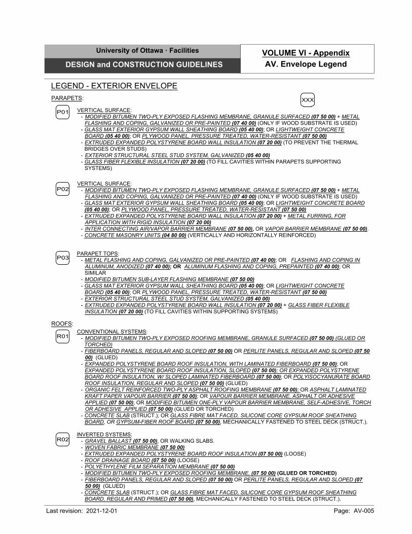
ROOFS:
PARAPETS:
CONVENTIONAL SYSTEMS:
- MODIFIED BITUMEN TWO-PLY EXPOSED ROOFING MEMBRANE, GRANULE SURFACED (07 50 00) (GLUED OR
TORCHED)
- FIBERBOARD PANELS, REGULAR AND SLOPED (07 50 00) OR PERLITE PANELS, REGULAR AND SLOPED (07 50
00) (GLUED)
- EXPANDED POLYSTYRENE BOARD ROOF INSULATION, WITH LAMINATED FIBERBOARD (07 50 00); OR
EXPANDED POLYSTYRENE BOARD ROOF INSULATION, SLOPED (07 50 00); OR EXPANDED POLYSTYRENE
BOARD ROOF INSULATION, W/ SLOPED LAMINATED FIBERBOARD (07 50 00); OR POLYISOCYANURATE BOARD
ROOF INSULATION, REGULAR AND SLOPED (07 50 00) (GLUED)
- ORGANIC FELT REINFORCED TWO-PLY ASPHALT ROOFING MEMBRANE (07 50 00); OR ASPHALT LAMINATED
KRAFT PAPER VAPOUR BARRIER (07 50 00); OR VAPOUR BARRIER MEMBRANE, ASPHALT OR ADHESIVE
APPLIED (07 50 00); OR MODIFIED BITUMEN ONE-PLY VAPOUR BARRIER MEMBRANE, SELF-ADHESIVE, TORCH
OR ADHESIVE APPLIED (07 50 00) (GLUED OR TORCHED)
- CONCRETE SLAB (STRUCT.); OR GLASS FIBRE MAT FACED, SILICONE CORE GYPSUM ROOF SHEATHING
BOARD, OR GYPSUM-FIBER ROOF BOARD (07 50 00), MECHANICALLY FASTENED TO STEEL DECK (STRUCT.).
VERTICAL SURFACE:
- MODIFIED BITUMEN TWO-PLY EXPOSED FLASHING MEMBRANE, GRANULE SURFACED (07 50 00) + METAL
FLASHING AND COPING, GALVANIZED OR PRE-PAINTED (07 40 00) (ONLY IF WOOD SUBSTRATE IS USED)
- GLASS MAT EXTERIOR GYPSUM WALL SHEATHING BOARD (05 40 00); OR LIGHTWEIGHT CONCRETE
BOARD (05 40 00); OR PLYWOOD PANEL, PRESSURE TREATED, WATER-RESISTANT (07 50 00)
- EXTRUDED EXPANDED POLYSTYRENE BOARD WALL INSULATION (07 20 00) (TO PREVENT THE THERMAL
BRIDGES OVER STUDS)
- EXTERIOR STRUCTURAL STEEL STUD SYSTEM, GALVANIZED (05 40 00)
- GLASS FIBER FLEXIBLE INSULATION (07 20 00) (TO FILL CAVITIES WITHIN PARAPETS SUPPORTING
SYSTEMS)
R01
R02
INVERTED SYSTEMS:
- GRAVEL BALLAST (07 50 00), OR WALKING SLABS.
- WOVEN FABRIC MEMBRANE (07 50 00)
- EXTRUDED EXPANDED POLYSTYRENE BOARD ROOF INSULATION (07 50 00) (LOOSE)
- ROOF DRAINAGE BOARD (07 50 00) (LOOSE)
- POLYETHYLENE FILM SEPARATION MEMBRANE (07 50 00)
- MODIFIED BITUMEN TWO-PLY EXPOSED ROOFING MEMBRANE, (07 50 00) (GLUED OR TORCHED)
- FIBERBOARD PANELS, REGULAR AND SLOPED (07 50 00) OR PERLITE PANELS, REGULAR AND SLOPED (07
50 00) (GLUED)
- CONCRETE SLAB (STRUCT.); OR GLASS FIBRE MAT FACED, SILICONE CORE GYPSUM ROOF SHEATHING
BOARD, REGULAR AND PRIMED (07 50 00), MECHANICALLY FASTENED TO STEEL DECK (STRUCT.).
P01
VERTICAL SURFACE:
- MODIFIED BITUMEN TWO-PLY EXPOSED FLASHING MEMBRANE, GRANULE SURFACED (07 50 00) + METAL
FLASHING AND COPING, GALVANIZED OR PRE-PAINTED (07 40 00) (ONLY IF WOOD SUBSTRATE IS USED)
- GLASS MAT EXTERIOR GYPSUM WALL SHEATHING BOARD (05 40 00); OR LIGHTWEIGHT CONCRETE BOARD
(05 40 00); OR PLYWOOD PANEL, PRESSURE TREATED, WATER-RESISTANT (07 50 00)
- EXTRUDED EXPANDED POLYSTYRENE BOARD WALL INSULATION (07 20 00) + METAL FURRING, FOR
APPLICATION WITH RIGID INSULATION (07 20 00)
- INTER CONNECTING AIR/VAPOR BARRIER MEMBRANE (07 50 00), OR VAPOR BARRIER MEMBRANE (07 50 00).
- CONCRETE MASONRY UNITS (04 80 00) (VERTICALLY AND HORIZONTALLY REINFORCED)
P02
PARAPET TOPS:
- METAL FLASHING AND COPING, GALVANIZED OR PRE-PAINTED (07 40 00); OR FLASHING AND COPING IN
ALUMINUM, ANODIZED (07 40 00); OR ALUMINUM FLASHING AND COPING, PREPAINTED (07 40 00); OR
SIMILAR
- MODIFIED BITUMEN SUB-LAYER FLASHING MEMBRANE (07 50 00)
- GLASS MAT EXTERIOR GYPSUM WALL SHEATHING BOARD (05 40 00); OR LIGHTWEIGHT CONCRETE
BOARD (05 40 00); OR PLYWOOD PANEL, PRESSURE TREATED, WATER-RESISTANT (07 50 00)
- EXTERIOR STRUCTURAL STEEL STUD SYSTEM, GALVANIZED (05 40 00)
- EXTRUDED EXPANDED POLYSTYRENE BOARD WALL INSULATION (07 20 00) + GLASS FIBER FLEXIBLE
INSULATION (07 20 00) (TO FILL CAVITIES WITHIN SUPPORTING SYSTEMS)
P03
LEGEND - EXTERIOR ENVELOPE
XXX
University of Ottawa · Facilities
DESIGN and CONSTRUCTION GUIDELINES
Last revision: Page: AV-005
AV. Envelope Legend
VOLUME VI - Appendix
2021-12-01
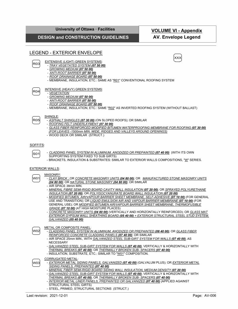
EXTERIOR WALLS:
SOFFITS:
METAL OR COMPOSITE PANEL:
- CLADDING PANEL SYSTEM IN ALUMINUM, ANODIZED OR PREPAINTED (08 40 00); OR GLASS FIBER
REINFORCED CONCRETE CLADDING PANELS (07 40 00); OR SIMILAR
- AIR SPACE 25mm MIN., WITH GALVANIZED STEEL SUB-GIRT SYSTEM FOR WALLS (07 40 00), AS
NECESSARY
- GALVANIZED STEEL SUB-GIRT SYSTEM FOR WALLS (07 40 00), VERTICALLY & HORIZONTALLY WITH
THERMAL BREAKS (07 40 00); OR THERMALLY BROKEN SUB- SPACERS (07 40 00)
- INSULATION, SUBSTRATE, ETC.: SIMILAR TO "W01" COMPOSITION.
- CLADDING PANEL SYSTEM IN ALUMINUM, ANODIZED OR PREPAINTED (07 40 00) (WITH ITS OWN
SUPPORTING SYSTEM FIXED TO SUB GIRTS)
- BRACKETS, INSULATION & SUBSTRATES: SIMILAR TO EXTERIOR WALLS COMPOSITIONS, "W" SERIES.
MASONRY:
- CLAY BRICK ; OR CONCRETE MASONRY UNITS (04 80 00); OR MANUFACTURED STONE MASONRY UNITS
(04 80 00); OR NATURAL STONE MASONRY (04 80 00); OR SIMILAR
- AIR SPACE 38mm MIN.
- MINERAL FIBRE SEMI-RIGID BOARD CAVITY WALL INSULATION (07 20 00); OR SPRAYED POLYURETHANE
INSULATION (07 20 00); OR POLYISOCYANURATE BOARD WALL INSULATION (07 20 00)
- MODIFIED BITUMEN, AIR/VAPOUR BARRIER SHEET MEMBRANE, SELF-ADHESIVE (07 10 00) (FOR GENERAL
USE AND TRANSITION); OR LIQUID EMULSION AIR AND VAPOUR BARRIER MEMBRANE (07 10 00) (FOR
GENERAL USE); OR MODIFIED BITUMEN AIR/VAPOUR BARRIER SHEET MEMBRANE, THERMOFUSIBLE
GRADE (07 10 00) (AT HIGH MOISTURE PLACES)
- CONCRETE MASONRY UNITS (04 80 00) (VERTICALLY AND HORIZONTALLY REINFORCED); OR GLASS MAT
EXTERIOR GYPSUM WALL SHEATHING BOARD (05 40 00) + EXTERIOR STRUCTURAL STEEL STUD SYSTEM,
GALVANIZED (05 40 00)
W01
W02
CORRUGATED METAL:
- EXTERIOR METAL SIDING PANELS, GALVANIZED (07 40 00) (GALVALUM PLUS); OR EXTERIOR METAL
SIDING PANELS, PREPAINTED (07 40 00)
- MINERAL FIBER SEMI-RIGID BOARD SIDING WALL INSULATION, MEDIUM DENSITY (07 20 00)
- GALVANIZED STEEL SUB-GIRT SYSTEM FOR WALLS (07 40 00), VERTICALLY & HORIZONTALLY WITH
THERMAL BREAKS (07 40 00), OR THERMALLY BROKEN SUB- SPACERS (07 40 00)
- INTERIOR METAL LINER PANELS, PREPAINTED OR GALVANIZED (07 40 00) (APPLIED AGAINST
STRUCTURAL STEEL GIRTS)
- STEEL, PRIMED, STRUCTURAL SECTIONS (STRUCT.)
W03
S01
R03
EXTENSIVE (LIGHT) GREEN SYSTEMS:
- TRAY VEGETATED SYSTEM (07 50 00)
- GROWING MEDIUM (07 50 00)
- ANTI-ROOT BARRIER (07 50 00)
- ROOF DRAINAGE BOARD (07 50 00)
- MEMBRANE, INSULATION, ETC.: SAME AS "R01" CONVENTIONAL ROOFING SYSTEM
R05
SHINGLE:
- ASPHALT SHINGLES (07 30 00) (ON SLOPED ROOFS); OR SIMILAR
- ROOFING FELT UNDERLAYMENT (07 30 00)
- GLASS FIBER REINFORCED MODIFIED BITUMEN WATERPROOFING MEMBRANE FOR ROOFING (07 30 00)
(FOR LEAVES -1500mm MIN. WIDE, RIDGES AND VALLEYS AROUND OPENINGS)
- WOOD DECK OR SIMILAR (STRUCT.)
LEGEND - EXTERIOR ENVELOPE
XXX
R04
INTENSIVE (HEAVY) GREEN SYSTEMS:
- VEGETATION
- GROWING MEDIUM (07 50 00)
- ANTI-ROOT BARRIER (07 50 00)
- ROOF DRAINAGE BOARD (07 50 00)
- MEMBRANE, INSULATION, ETC.: SAME "R02" AS INVERTED ROOFING SYSTEM (WITHOUT BALLAST)
University of Ottawa · Facilities
DESIGN and CONSTRUCTION GUIDELINES
Last revision: Page: AV-006
AV. Envelope Legend
VOLUME VI - Appendix
2021-12-01
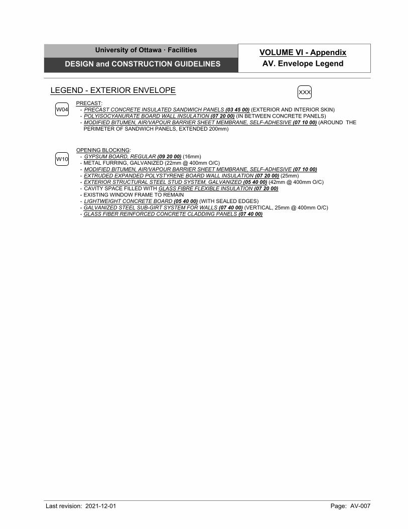
PRECAST:
- PRECAST CONCRETE INSULATED SANDWICH PANELS (03 45 00) (EXTERIOR AND INTERIOR SKIN)
- POLYISOCYANURATE BOARD WALL INSULATION (07 20 00) (IN BETWEEN CONCRETE PANELS)
- MODIFIED BITUMEN, AIR/VAPOUR BARRIER SHEET MEMBRANE, SELF-ADHESIVE (07 10 00) (AROUND THE
PERIMETER OF SANDWICH PANELS, EXTENDED 200mm)
W04
OPENING BLOCKING:
- GYPSUM BOARD, REGULAR (09 20 00) (16mm)
- METAL FURRING, GALVANIZED (22mm @ 400mm O/C)
- MODIFIED BITUMEN, AIR/VAPOUR BARRIER SHEET MEMBRANE, SELF-ADHESIVE (07 10 00)
- EXTRUDED EXPANDED POLYSTYRENE BOARD WALL INSULATION (07 20 00) (25mm)
- EXTERIOR STRUCTURAL STEEL STUD SYSTEM, GALVANIZED (05 40 00) (42mm @ 400mm O/C)
- CAVITY SPACE FILLED WITH GLASS FIBRE FLEXIBLE INSULATION (07 20 00)
- EXISTING WINDOW FRAME TO REMAIN
- LIGHTWEIGHT CONCRETE BOARD (05 40 00) (WITH SEALED EDGES)
- GALVANIZED STEEL SUB-GIRT SYSTEM FOR WALLS (07 40 00) (VERTICAL, 25mm @ 400mm O/C)
- GLASS FIBER REINFORCED CONCRETE CLADDING PANELS (07 40 00)
LEGEND - EXTERIOR ENVELOPE
XXX
W10
University of Ottawa · Facilities
DESIGN and CONSTRUCTION GUIDELINES
Last revision: Page: AV-007
AV. Envelope Legend
VOLUME VI - Appendix
2021-12-01
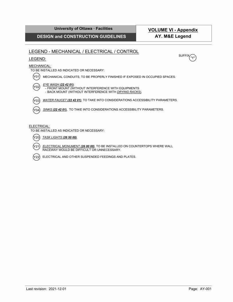
EYE WASH (22 42 01):
- FRONT MOUNT (WITHOUT INTERFERENCE WITH EQUIPMENTS.
- BACK MOUNT (WITHOUT INTERFERENCE WITH DRYING RACKS).
TASK LIGHTS (26 50 00).
WATER FAUCET (22 42 01), TO TAKE INTO CONSIDERATIONS ACCESSIBILITY PARAMETERS.
ELECTRICAL MONUMENT (26 00 00), TO BE INSTALLED ON COUNTERTOPS WHERE WALL
RACEWAY WOULD BE DIFFICULT OR UNNECESSARY.
Y02
LEGEND - MECHANICAL / ELECTRICAL / CONTROL
LEGEND:
MECHANICAL:
SUFFIX
"Y"
Y20
ELECTRICAL:
SINKS (22 42 01), TO TAKE INTO CONSIDERATIONS ACCESSIBILITY PARAMETERS.
MECHANICAL CONDUITS, TO BE PROPERLY FINISHED IF EXPOSED IN OCCUPIED SPACES.
Y21
Y01
Y03
Y04
TO BE INSTALLED AS INDICATED OR NECESSARY:
TO BE INSTALLED AS INDICATED OR NECESSARY:
ELECTRICAL AND OTHER SUSPENDED FEEDINGS AND PLATES.
Y22
University of Ottawa · Facilities
DESIGN and CONSTRUCTION GUIDELINES
Last revision: Page: AY-001
AY. M&E Legend
VOLUME VI - Appendix
2021-12-01
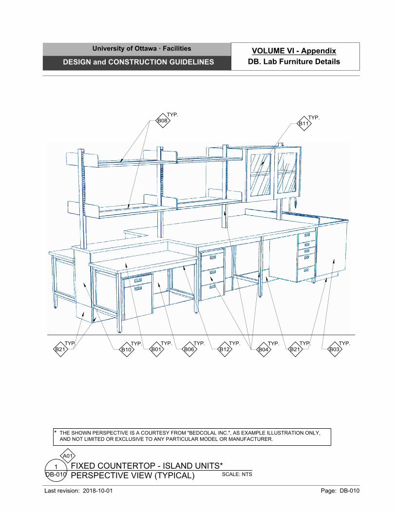
SCALE: NTS
PERSPECTIVE VIEW (TYPICAL)
FIXED COUNTERTOP - ISLAND UNITS*
DB-010
1
A01
TYP.
B01
TYP.
B03
TYP.
B06
TYP.
B08
TYP.
B10
TYP.
B11
TYP.
B12
TYP.
B21
TYP.
B21
TYP.
B04
THE SHOWN PERSPECTIVE IS A COURTESY FROM "BEDCOLAL INC.", AS EXAMPLE ILLUSTRATION ONLY,
AND NOT LIMITED OR EXCLUSIVE TO ANY PARTICULAR MODEL OR MANUFACTURER.
*
University of Ottawa · Facilities
DESIGN and CONSTRUCTION GUIDELINES
Last revision: Page: DB-010
DB. Lab Furniture Details
VOLUME VI - Appendix
2018-10-01
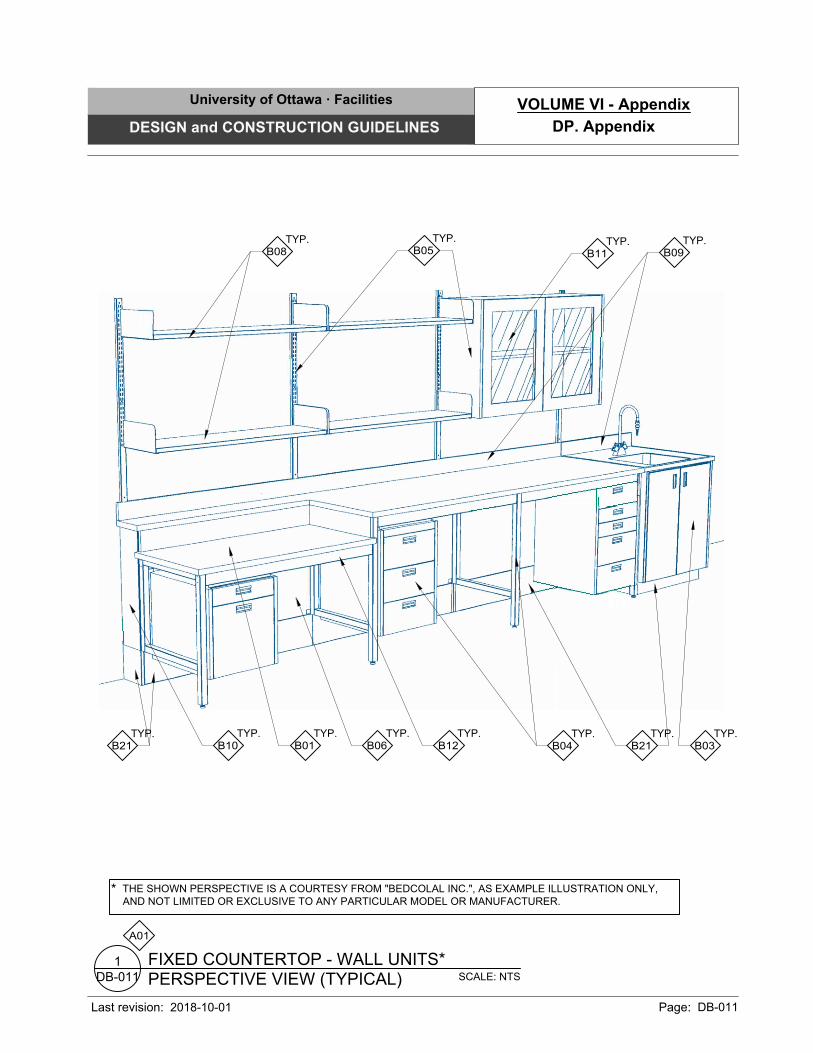
SCALE: NTS
PERSPECTIVE VIEW (TYPICAL)
FIXED COUNTERTOP - WALL UNITS*
DB-011
1
TYP.
B05
TYP.
B09
TYP.
B10
TYP.
B01
TYP.
B06
TYP.
B12
TYP.
B04
TYP.
B03
TYP.
B21
TYP.
B21
A01
THE SHOWN PERSPECTIVE IS A COURTESY FROM "BEDCOLAL INC.", AS EXAMPLE ILLUSTRATION ONLY,
AND NOT LIMITED OR EXCLUSIVE TO ANY PARTICULAR MODEL OR MANUFACTURER.
*
TYP.
B08
TYP.
B11
University of Ottawa · Facilities
DESIGN and CONSTRUCTION GUIDELINES
Last revision: Page: DB-011
DP. Appendix
VOLUME VI - Appendix
2018-10-01

SCALE: NTS
PICTURES (ARC Building)
FIXED COUNTERTOP
DB-012
1
A01
University of Ottawa · Facilities
DESIGN and CONSTRUCTION GUIDELINES
Last revision: Page: DB-012
DB. Lab Furniture Details
VOLUME VI - Appendix
2018-10-01
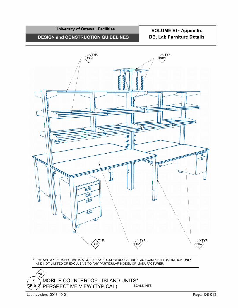
TYP.
B02
SCALE: NTS
PERSPECTIVE VIEW (TYPICAL)
MOBILE COUNTERTOP - ISLAND UNITS*
DB-013
1
TYP.
B02
TYP.
B04
TYP.
B07
TYP.
B08
A01
*
THE SHOWN PERSPECTIVE IS A COURTESY FROM "BEDCOLAL INC.", AS EXAMPLE ILLUSTRATION ONLY,
AND NOT LIMITED OR EXCLUSIVE TO ANY PARTICULAR MODEL OR MANUFACTURER.
University of Ottawa · Facilities
DESIGN and CONSTRUCTION GUIDELINES
Last revision: Page: DB-013
DB. Lab Furniture Details
VOLUME VI - Appendix
2018-10-01
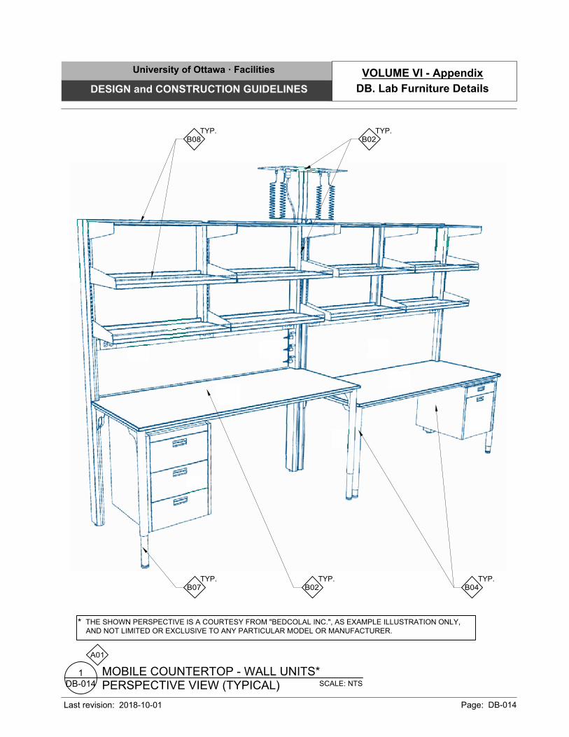
SCALE: NTS
PERSPECTIVE VIEW (TYPICAL)
MOBILE COUNTERTOP - WALL UNITS*
DB-014
1
A01
*
THE SHOWN PERSPECTIVE IS A COURTESY FROM "BEDCOLAL INC.", AS EXAMPLE ILLUSTRATION ONLY,
AND NOT LIMITED OR EXCLUSIVE TO ANY PARTICULAR MODEL OR MANUFACTURER.
TYP.
B02
TYP.
B08
TYP.
B07
TYP.
B02
TYP.
B04
University of Ottawa · Facilities
DESIGN and CONSTRUCTION GUIDELINES
Last revision: Page: DB-014
DB. Lab Furniture Details
VOLUME VI - Appendix
2018-10-01
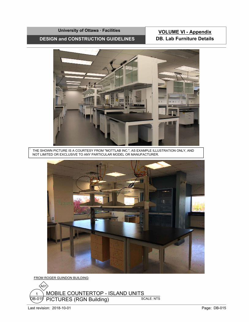
SCALE: NTS
PICTURES (RGN Building)
MOBILE COUNTERTOP - ISLAND UNITS
DB-015
1
THE SHOWN PICTURE IS A COURTESY FROM "MOTTLAB INC.", AS EXAMPLE ILLUSTRATION ONLY, AND
NOT LIMITED OR EXCLUSIVE TO ANY PARTICULAR MODEL OR MANUFACTURER.
*
FROM ROGER GUINDON BUILDING:
A01
University of Ottawa · Facilities
DESIGN and CONSTRUCTION GUIDELINES
Last revision: Page: DB-015
DB. Lab Furniture Details
VOLUME VI - Appendix
2018-10-01
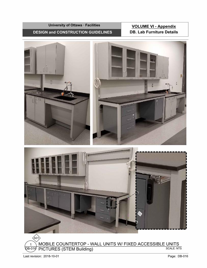
SCALE: NTS
PICTURES (STEM Building)
MOBILE COUNTERTOP - WALL UNITS W/ FIXED ACCESSIBLE UNITS
DB-016
1
FROM STEM BUILDING:
A01
University of Ottawa · Facilities
DESIGN and CONSTRUCTION GUIDELINES
Last revision: Page: DB-016
DB. Lab Furniture Details
VOLUME VI - Appendix
2018-10-01
A01
SCALE: 1:20
SECTION (TYPICAL)
FIXED COUNTERTOP - WALL UNITS
DB-020
1
TYP.
B01
TYP.
B04
SUSPENDED
CABINET
KNEE SPACE
TYP.
B04
TYP.
B01
TYP.
B21
TYP.
P25
TYP.
B11
TYP.
B08
762
VARIES
305
VARIES
914
ST
AN
D-U
P C
OU
NT
ER
914
ST
AN
D-U
P C
OU
NT
ER
TYP.
B22
TYP.
B22
TYP.
B06
TYP.
B06
TYP.
B08
TYP.
B08
VA
RIE
S914
GE
NE
RA
L
TYP.
B04
TYP.
B09
Y20
Y21
TYP.
B05
TYP.
P25
University of Ottawa · Facilities
DESIGN and CONSTRUCTION GUIDELINES
Last revision: Page: DB-020
DB. Lab Furniture Details
VOLUME VI - Appendix
2018-10-01
SCALE: 1:20
SECTION DETAIL (TYPICAL)
COUNTER SINK UNIT
DB-021
1
A01
CONVENTIONAL
UNIT
ACCESSIBLE
UNIT
840
105
685
350
485
75 150
735
205
860
140
230
720
CSA
REQUIREMENTS
OBC
REQUIREMENTS
ACCESSIBLE DESIGN
PARAMETERS
PLUMBING UTILITY
LOCATION
TYP.
P25485
TYP.
B31
ACCESSIBLE
PROFILE TO
SUIT DESIGN
PARAMETERSVA
RIE
S
914
ST
AN
D-U
P C
OU
NT
ER
100
TYP.
B03
762
VARIES
TYP.
B08
TYP.
B22
TYP.
B06
TYP.
B06
762
VARIES
TYP.
B01
Y04
N01
N01
Y02
Y02
Y04
TYP.
B09
Y03
Y03
TYP.
B22
University of Ottawa · Facilities
DESIGN and CONSTRUCTION GUIDELINES
Last revision: Page: DB-021
DB. Lab Furniture Details
VOLUME VI - Appendix
2018-10-01
SCALE: 1:10
SECTION DETAIL (TYPICAL)
NON-IDUSTRIAL CONCRETE RISERS & HANDRAIL / BALUSTRADE
DL-010
1
A01
25
VA
RIE
S
SE
E S
EC
TIO
N
VARIES
SEE PLAN
38
38
25
VA
RIE
S
VARIES
R
1
0
R
1
0
TYP.
L02
CONCRETE TRADES
AND LANDINGS (REFER
TO STRUCT. - IF
APPLICABLE)
CONCRETE TRADES
AND LANDINGS (REFER
TO STRUCT. - IF
APPLICABLE)
TYP.
L09
L12
300 300 TO 600
TYP.
L25
University of Ottawa · Facilities
DESIGN and CONSTRUCTION GUIDELINES
Last revision: Page: DL-010
DL. Miscellaneous Steel Details
VOLUME VI - Appendix
2021-12-01
A01
VARIES
25
38
VA
RIE
S
VA
RIE
S
R
1
0
EL.
VARIES
SCALE: 1:10
SECTION DETAIL (TYP.)
NON-INDUSTRIAL CLOSED RISER & HANDRAIL / BALUSTRADE
DL-011
1
TYP.
L02
TYP.
L05
TYP.
L06
TYP.
L05
TYP.
L02
TYP.
L06
TYP.
L01
Ø 41mm
TYP.
L08
TYP.
@ 100mm O/C
@ 13mm
L07
TYP.
@ 1200mm O/C
@ 41mm
L08
L22
L22
L22
B
TYP.
"A" SECTION "B" SECTION
TYP.
L25
TYP.
L25
920m
m M
AX
. A
T S
TE
PS
1070m
m A
T LA
ND
IN
GS
VA
RIE
S
University of Ottawa · Facilities
DESIGN and CONSTRUCTION GUIDELINES
Last revision: Page: DL-011
DL. Miscellaneous Steel Details
VOLUME VI - Appendix
2021-12-01
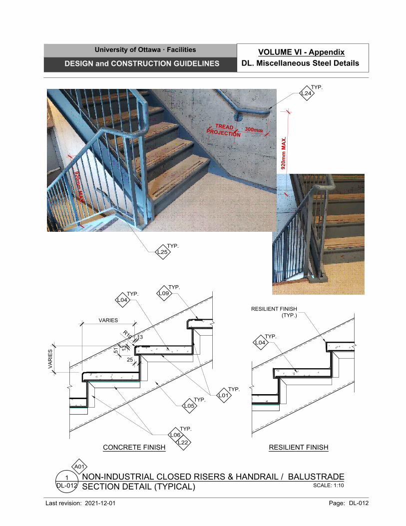
51
13
13
VARIES
25
VA
RIE
S
TYP.
L04
TYP.
L06
TYP.
L01
TYP.
L05
TYP.
L04
TYP.
L09
L22
SCALE: 1:10
SECTION DETAIL (TYPICAL)
NON-INDUSTRIAL CLOSED RISERS & HANDRAIL / BALUSTRADE
DL-012
1
A01
R
1
0
RESILIENT FINISH
(TYP.)
CONCRETE FINISH RESILIENT FINISH
TYP.
L25
TYP.
L24
300m
m
920m
m M
AX
.
TR
EA
D
PR
O
JE
C
TIO
N
9
2
0
m
m
M
A
X
.
University of Ottawa · Facilities
DESIGN and CONSTRUCTION GUIDELINES
Last revision: Page: DL-012
DL. Miscellaneous Steel Details
VOLUME VI - Appendix
2021-12-01
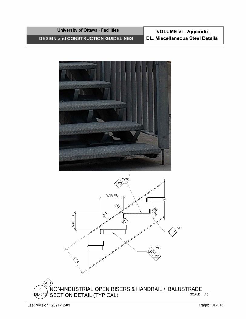
25
38
VA
RIE
S
VARIES
R
1
0
±
2
5
4
TYP.
L02
TYP.
L05
TYP.
L06
38
L22
SCALE: 1:10
SECTION DETAIL (TYPICAL)
NON-INDUSTRIAL OPEN RISERS & HANDRAIL / BALUSTRADE
DL-013
1
A01
University of Ottawa · Facilities
DESIGN and CONSTRUCTION GUIDELINES
Last revision: Page: DL-013
DL. Miscellaneous Steel Details
VOLUME VI - Appendix
2021-12-01
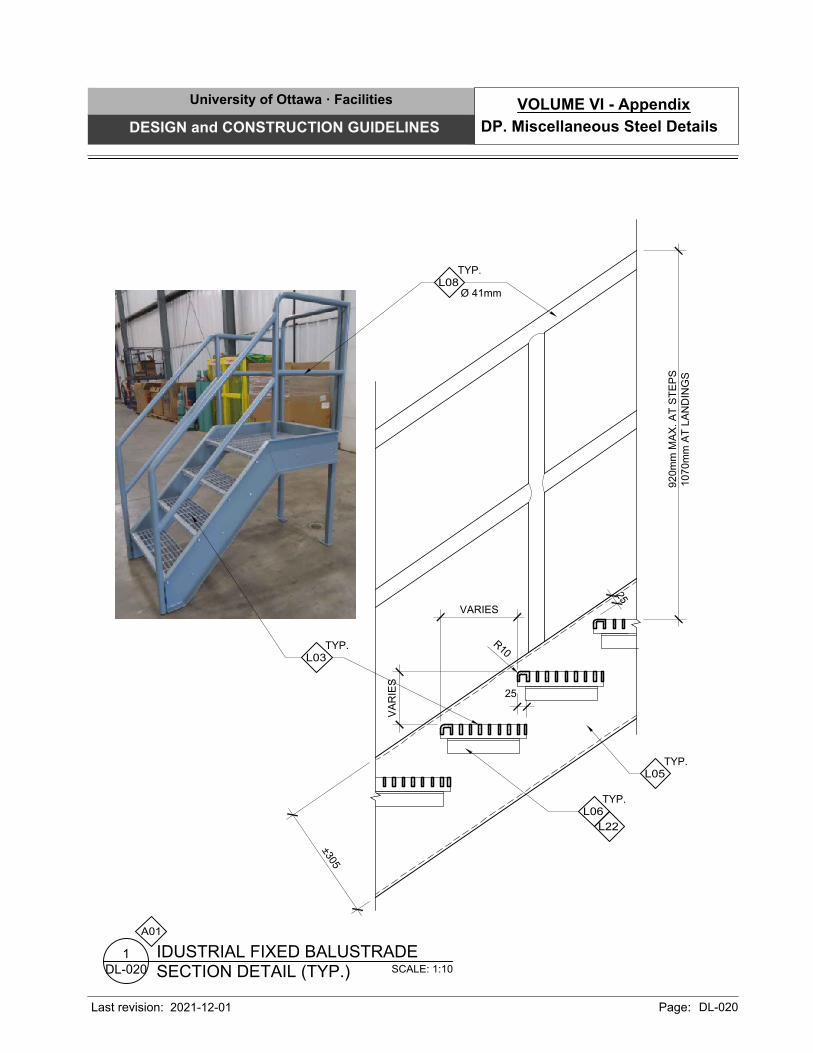
25
VA
RIE
S
VARIES
2
5
R
1
0
±
3
0
5
TYP.
L06
TYP.
L05
TYP.
L03
L22
A01
SCALE: 1:10
SECTION DETAIL (TYP.)
IDUSTRIAL FIXED BALUSTRADE
DL-020
1
920m
m M
AX
. A
T S
TE
PS
1070m
m A
T LA
ND
IN
GS
Ø 41mm
TYP.
L08
University of Ottawa · Facilities
DESIGN and CONSTRUCTION GUIDELINES
Last revision: Page: DL-020
DP. Miscellaneous Steel Details
VOLUME VI - Appendix
2021-12-01
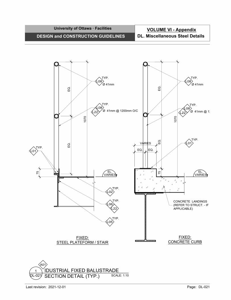
1070
EQ
.E
Q.
FIXED:
CONCRETE CURB
FIXED:
STEEL PLATEFORM / STAIR
1070
EQ
.E
Q.
EQ. EQ.
75
75
VARIES
EL.
VARIES
EL.
VARIES
TYP.
L05
TYP.
L02
TYP.
L06
CONCRETE LANDINGS
(REFER TO STRUCT. - IF
APPLICABLE)
TYP.
L01
TYP.
L01
Ø 41mm @ 1200mm O/C
TYP.
L08
Ø 41mm @ 1200mm O/C
TYP.
L08
Ø 41mm
TYP.
L08
Ø 41mm
TYP.
L08
L22
L22
L22
A01
SCALE: 1:10
SECTION DETAIL (TYP.)
IDUSTRIAL FIXED BALUSTRADE
DL-021
1
University of Ottawa · Facilities
DESIGN and CONSTRUCTION GUIDELINES
Last revision: Page: DL-021
DL. Miscellaneous Steel Details
VOLUME VI - Appendix
2021-12-01
1070
EQ
.E
Q.
102
VA
RIE
S
MOVABLE POST AND CHAIN:
CONCRETE CURB PLATFORM
EL.
VARIES
TYP.
L10
CONCRETE PLATFORM.
(REFER TO STRUCT. - IF
APPLICABLE)
TYP.
L01
CAST-IN CONCRETE
STRUCTURAL SUPPORT
ANGLE (REFER TO
STRUCT.) (TYP.)
L22
A01
SCALE: 1:10
SECTION DETAIL (TYP.)
INDUSTRIAL BALUSTRADE
DL-022
1
L11
Ø 41mm
TYP.
L08
University of Ottawa · Facilities
DESIGN and CONSTRUCTION GUIDELINES
Last revision: Page: DL-022
DL. Miscellaneous Steel Details
VOLUME VI - Appendix
2021-12-01
51
89
13
SECTION "A"ELEVATION "B"
1
5
2
SE
E E
LE
VA
TIO
NS
PART. TYPE
REFER
Ø 127mm
TYP.
L01
A
-
TYP.
Ø 41mm
TYP.
L08
Ø 13mm @1200mm O/C
TYP.
L08
TYP.
P25
TYP.
L23
L22
A01
SCALE: 1:10
SECTION DETAIL (TYP.)
HANDRAILS
DL-023
1
TYP.
L24
University of Ottawa · Facilities
DESIGN and CONSTRUCTION GUIDELINES
Last revision: Page: DL-023
DL. Miscellaneous Steel Details
VOLUME VI - Appendix
2021-12-01
A01
SCALE: 1:10
ISOMETRIC DETAIL (TYP.)
PROJECTOR SUPPORT BRACKET
DL-030
1
ADJUSTMENT HOLES
FOR BOLT 150mm O/C
±
2
5
VA
RIE
S: A
DJU
ST
AB
LE
FR
OM
3050m
m T
O 3660m
m(V
.I.S
.)
±
7
6
±
3
0
5
±
3
0
5
BOLTED TO STRUCTURE
6mm
L01
WIRING SLOT
36mm X 64mm @ 915mm
FROM THE TOP
(TYP.)
WELDED
64mm x 64mm
L08
WELDED
76mm x 76mm
L08
WIRING SLOT 36mm X
64mm @ 50mm FROM
THE BOTTOM
6mm
L01
4
8
0
4
8
0
PROJECTOR
CARRIER (N.I.C.)
6.4mm HOLES TAPPED
IN PLATES (TREADED
IN) (TYP.)
±
5
0
University of Ottawa · Facilities
DESIGN and CONSTRUCTION GUIDELINES
Last revision: Page: DL-030
DL. Miscellaneous Steel Details
VOLUME VI - Appendix
2021-12-01
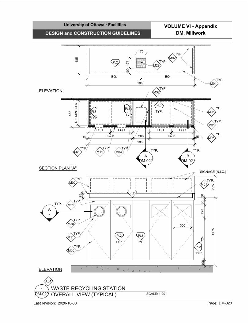
A01
SCALE: 1:20
OVERALL VIEW (TYPICAL)
WASTE RECYCLING STATION
DM-020
1
TYP.
M11
485
TYP.
M06
TYP.
M11
TYP.
M28
TYP.
M04
TYP.
M05
TYP.
M31
TYP.
M32
1860
286EQ.2
15
15
EQ.1 EQ.1
EQ.2
EQ.1EQ.1
485
1860
TYP.
M02
TYP.
M01
100
175
175
EQ. EQ.
375
1175
TYP.
M06
TYP.
M28
100
85
228
38
300
SIGNAGE (N.I.C.)
TYP.
M02
TYP.
M01
TYP.
M21
ELEVATION
SECTION PLAN "A"
ELEVATION
75
A
-
TYP.
A
DM-021
TYP.
B
DM-021
TYP.
TYP.
PL2
PL2
TYP.
PL3
TYP.
PL3
PL2
TYP.
M29
TYP.
PL3
TYP.
PL2
TYP.
PL2
724
432 M
IN
. C
LR
University of Ottawa · Facilities
DESIGN and CONSTRUCTION GUIDELINES
Last revision: Page: DM-020
DM. Millwork
VOLUME VI - Appendix
2020-10-30
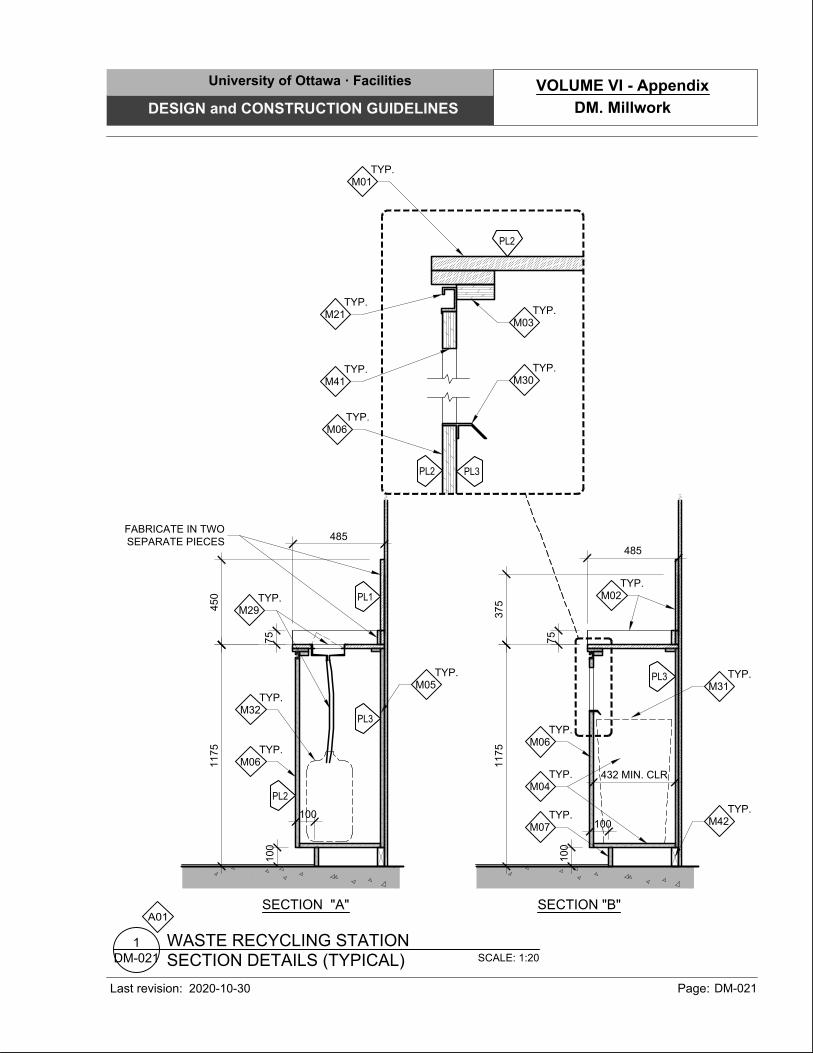
A01
SCALE: 1:20
SECTION DETAILS (TYPICAL)
WASTE RECYCLING STATION
DM-021
1
TYP.
M02
1175
75
375
485
100
75
450
485
100
TYP.
M32
TYP.
M31
100
TYP.
M05
TYP.
M06
TYP.
M06
TYP.
M01
TYP.
M07
TYP.
M04
1175
TYP.
M29
TYP.
M30
SECTION "A" SECTION "B"
TYP.
M21
TYP.
M06
TYP.
M41
TYP.
M03
TYP.
M42
PL3
PL3
PL3
100
PL2
PL2
PL2
FABRICATE IN TWO
SEPARATE PIECES
432 MIN. CLR
PL1
University of Ottawa · Facilities
DESIGN and CONSTRUCTION GUIDELINES
Last revision: Page: DM-021
DM. Millwork
VOLUME VI - Appendix
2020-10-30
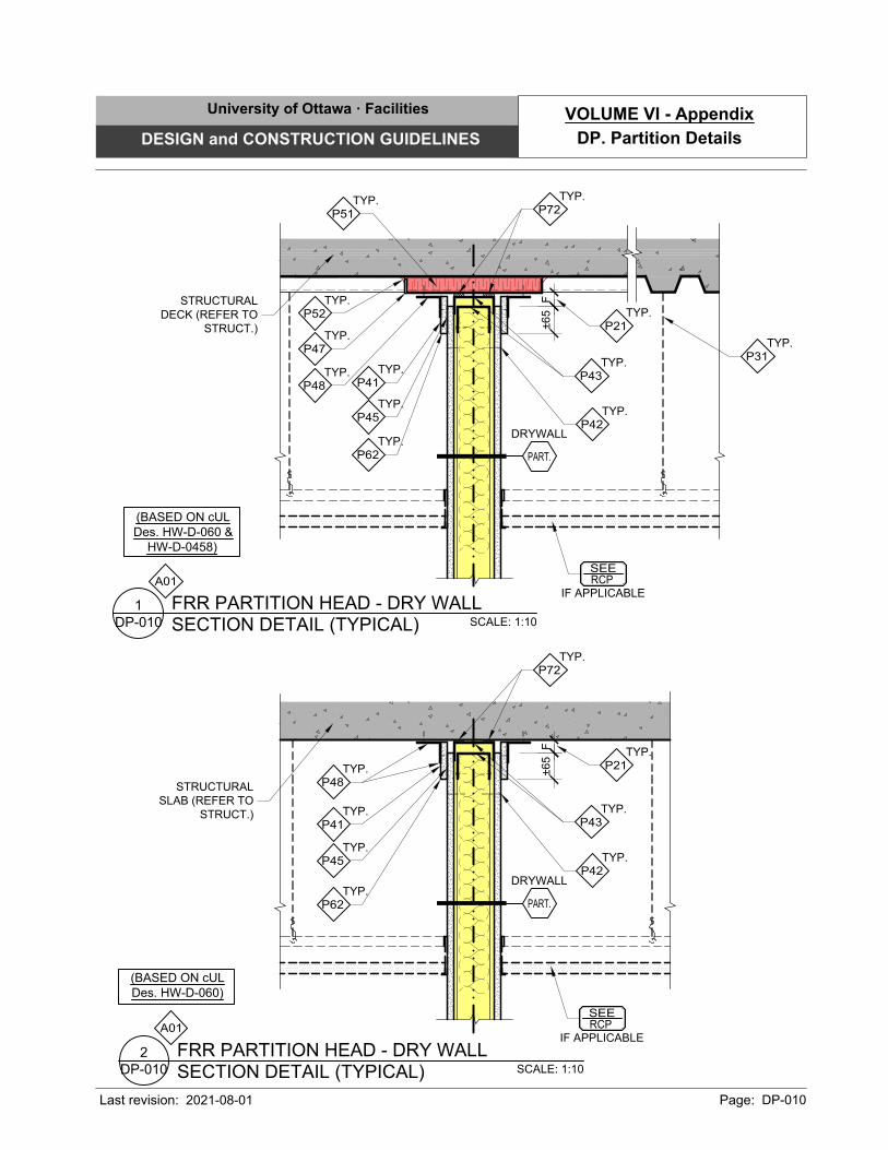
F±65
(BASED ON cUL
Des. HW-D-060 &
HW-D-0458)
F
(BASED ON cUL
Des. HW-D-060)
SCALE: 1:10
SECTION DETAIL (TYPICAL)
FRR PARTITION HEAD - DRY WALL
DP-010
1
SCALE: 1:10
SECTION DETAIL (TYPICAL)
FRR PARTITION HEAD - DRY WALL
DP-010
2
SEE
RCP
IF APPLICABLE
SEE
RCP
IF APPLICABLE
STRUCTURAL
SLAB (REFER TO
STRUCT.)
STRUCTURAL
DECK (REFER TO
STRUCT.)
TYP.
P72
TYP.
P21
TYP.
P42
TYP.
P43
TYP.
P48
TYP.
P41
TYP.
P62
TYP.
P45
TYP.
P52
TYP.
P47
TYP.
P48
TYP.
P41
TYP.
P62
TYP.
P45
TYP.
P21
TYP.
P42
TYP.
P43
TYP.
P72
TYP.
P51
TYP.
P31
DRYWALL
PART.
DRYWALL
PART.
A01
A01
±65
University of Ottawa · Facilities
DESIGN and CONSTRUCTION GUIDELINES
Last revision: Page: DP-010
DP. Partition Details
VOLUME VI - Appendix
2021-08-01

F±65
SCALE: 1:10
SECTION DETAIL (TYPICAL)
FRR PARTITION HEAD - DRY WALL
DP-011
1
SCALE: 1:10
SECTION DETAIL (TYPICAL)
FRR PARTITION HEAD - DRY WALL
DP-011
2
SEE
RCP
IF APPLICABLE
SEE
RCP
IF APPLICABLE
STRUCTURAL
SLAB (REFER TO
STRUCT.)
STRUCTURAL
DECK (REFER TO
STRUCT.)
TYP.
P52
TYP.
P47
TYP.
P21
TYP.
P42
TYP.
P43
TYP.
P51
TYP.
P31
DRYWALL
PART.
DRYWALL
PART.
A01
A01
(BASED ON cUL
Des. HW-D-0264 &
UL 2079)
F±65 TYP.
P21
TYP.
P42
TYP.
P43
(BASED ON
UL 2079)
P56
P56
University of Ottawa · Facilities
DESIGN and CONSTRUCTION GUIDELINES
Last revision: Page: DP-011
DP. Appendix
VOLUME VI - Appendix
2021-08-01
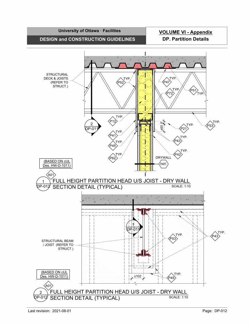
TYP.
P21
TYP.
P42
TYP.
P43
TYP.
P72
TYP.
P41
TYP.
P62
TYP.
P45
TYP.
P12
±102
SCALE: 1:10
SECTION DETAIL (TYPICAL)
FULL HEIGHT PARTITION HEAD U/S JOIST - DRY WALL
DP-012
2
(BASED ON cUL
Des. HW-D-1011)
1
DP-011
STRUCTURAL BEAM
/ JOIST (REFER TO
STRUCT.)
TYP.
P43
TYP.
P45
F
SCALE: 1:10
SECTION DETAIL (TYPICAL)
FULL HEIGHT PARTITION HEAD U/S JOIST - DRY WALL
DP-012
1
±65
(BASED ON cUL
Des. HW-D-1011)
2
DP-011
STRUCTURAL
DECK & JOISTS
(REFER TO
STRUCT.)
TYP.
P52
TYP.
P47
TYP.
P51
DRYWALL
PART.
A01
A01
TYP.
P53
TYP.
P53
University of Ottawa · Facilities
DESIGN and CONSTRUCTION GUIDELINES
Last revision: Page: DP-012
DP. Partition Details
VOLUME VI - Appendix
2021-08-01
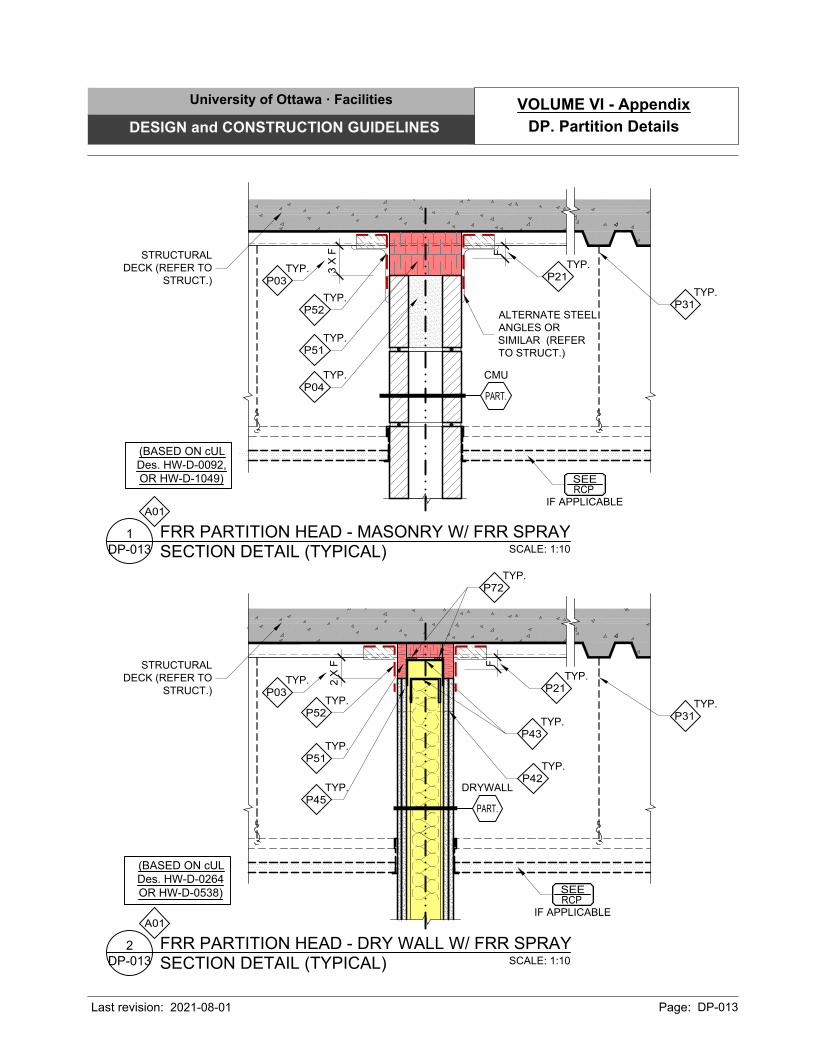
(BASED ON cUL
Des. HW-D-0264
OR HW-D-0538)
SCALE: 1:10
SECTION DETAIL (TYPICAL)
FRR PARTITION HEAD - DRY WALL W/ FRR SPRAY
DP-013
2
SEE
RCP
IF APPLICABLE
TYP.
P03
TYP.
P21
TYP.
P42
TYP.
P43
TYP.
P72
TYP.
P51
TYP.
P31
2 X
F
TYP.
P52
F
(BASED ON cUL
Des. HW-D-0092,
OR HW-D-1049)
SCALE: 1:10
SECTION DETAIL (TYPICAL)
FRR PARTITION HEAD - MASONRY W/ FRR SPRAY
DP-013
1
SEE
RCP
IF APPLICABLE
TYP.
P03
TYP.
P21
TYP.
P31
3 X
F
TYP.
P52
F
STRUCTURAL
DECK (REFER TO
STRUCT.)
STRUCTURAL
DECK (REFER TO
STRUCT.)
ALTERNATE STEEL
ANGLES OR
SIMILAR (REFER
TO STRUCT.)
TYP.
P51
TYP.
P04
TYP.
P45
CMU
PART.
DRYWALL
PART.
A01
A01
University of Ottawa · Facilities
DESIGN and CONSTRUCTION GUIDELINES
Last revision: Page: DP-013
DP. Partition Details
VOLUME VI - Appendix
2021-08-01
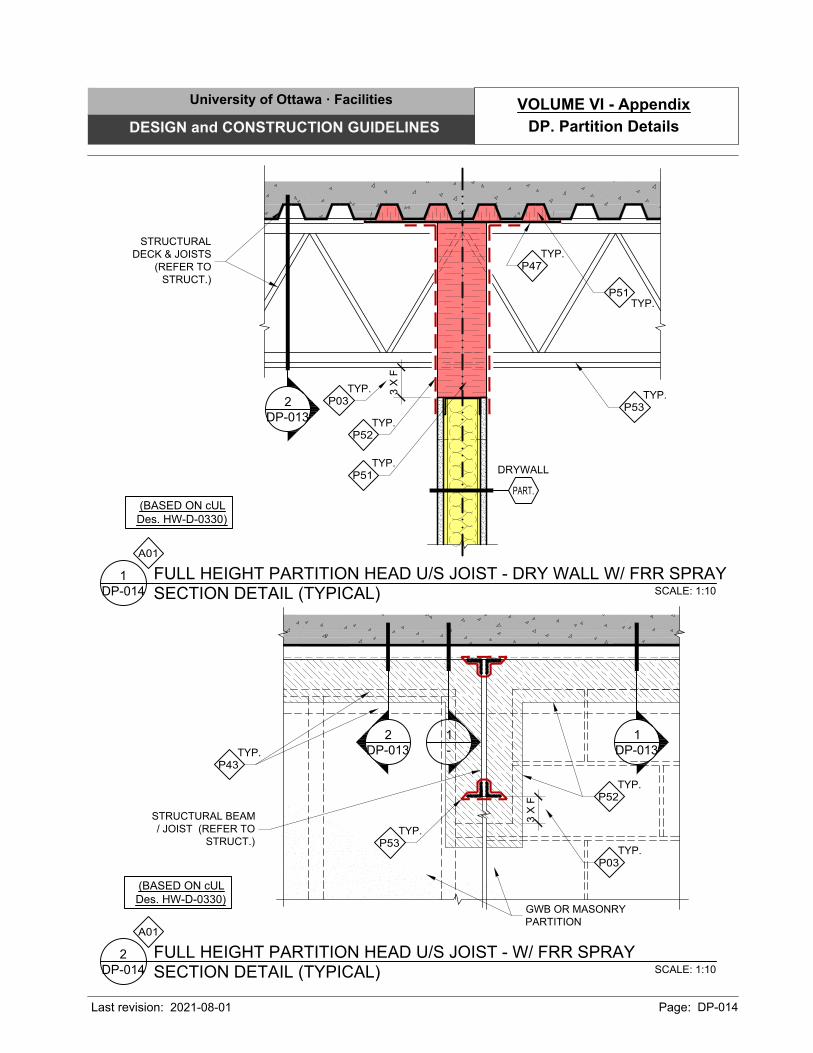
(BASED ON cUL
Des. HW-D-0330)
SCALE: 1:10
SECTION DETAIL (TYPICAL)
FULL HEIGHT PARTITION HEAD U/S JOIST - W/ FRR SPRAY
DP-014
2
STRUCTURAL BEAM
/ JOIST (REFER TO
STRUCT.)
TYP.
P43
STRUCTURAL
DECK & JOISTS
(REFER TO
STRUCT.)
TYP.
P47
TYP.
P51
SCALE: 1:10
SECTION DETAIL (TYPICAL)
FULL HEIGHT PARTITION HEAD U/S JOIST - DRY WALL W/ FRR SPRAY
DP-014
1
3 X
F
(BASED ON cUL
Des. HW-D-0330)
TYP.
P52
TYP.
P51
2
DP-013
1
-
TYP.
P52
GWB OR MASONRY
PARTITION
3 X
F
DRYWALL
PART.
A01
A01
TYP.
P03
TYP.
P03
TYP.
P53
1
DP-013
2
DP-013
TYP.
P53
University of Ottawa · Facilities
DESIGN and CONSTRUCTION GUIDELINES
Last revision: Page: DP-014
DP. Partition Details
VOLUME VI - Appendix
2021-08-01
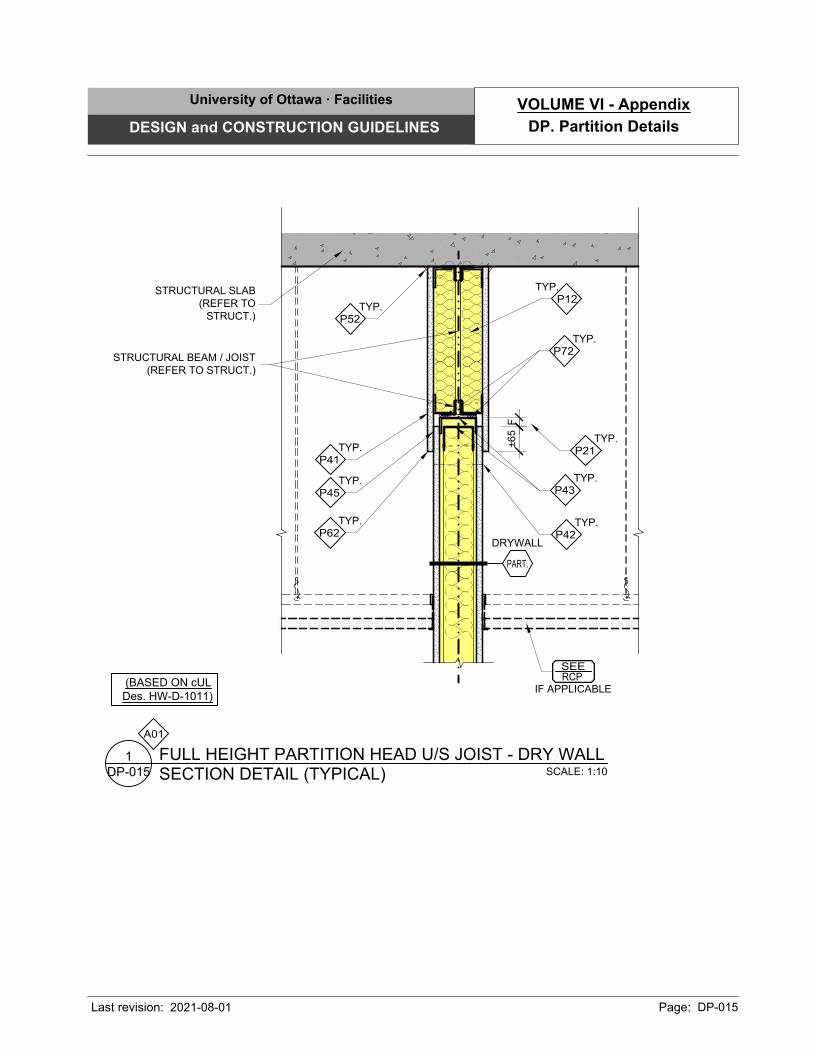
F
SCALE: 1:10
SECTION DETAIL (TYPICAL)
FULL HEIGHT PARTITION HEAD U/S JOIST - DRY WALL
DP-015
1
SEE
RCP
IF APPLICABLE
STRUCTURAL SLAB
(REFER TO
STRUCT.)
TYP.
P21
TYP.
P42
TYP.
P43
TYP.
P72
TYP.
P41
TYP.
P62
TYP.
P45
±65
TYP.
P52
TYP.
P12
STRUCTURAL BEAM / JOIST
(REFER TO STRUCT.)
(BASED ON cUL
Des. HW-D-1011)
DRYWALL
PART.
A01
University of Ottawa · Facilities
DESIGN and CONSTRUCTION GUIDELINES
Last revision: Page: DP-015
DP. Partition Details
VOLUME VI - Appendix
2021-08-01
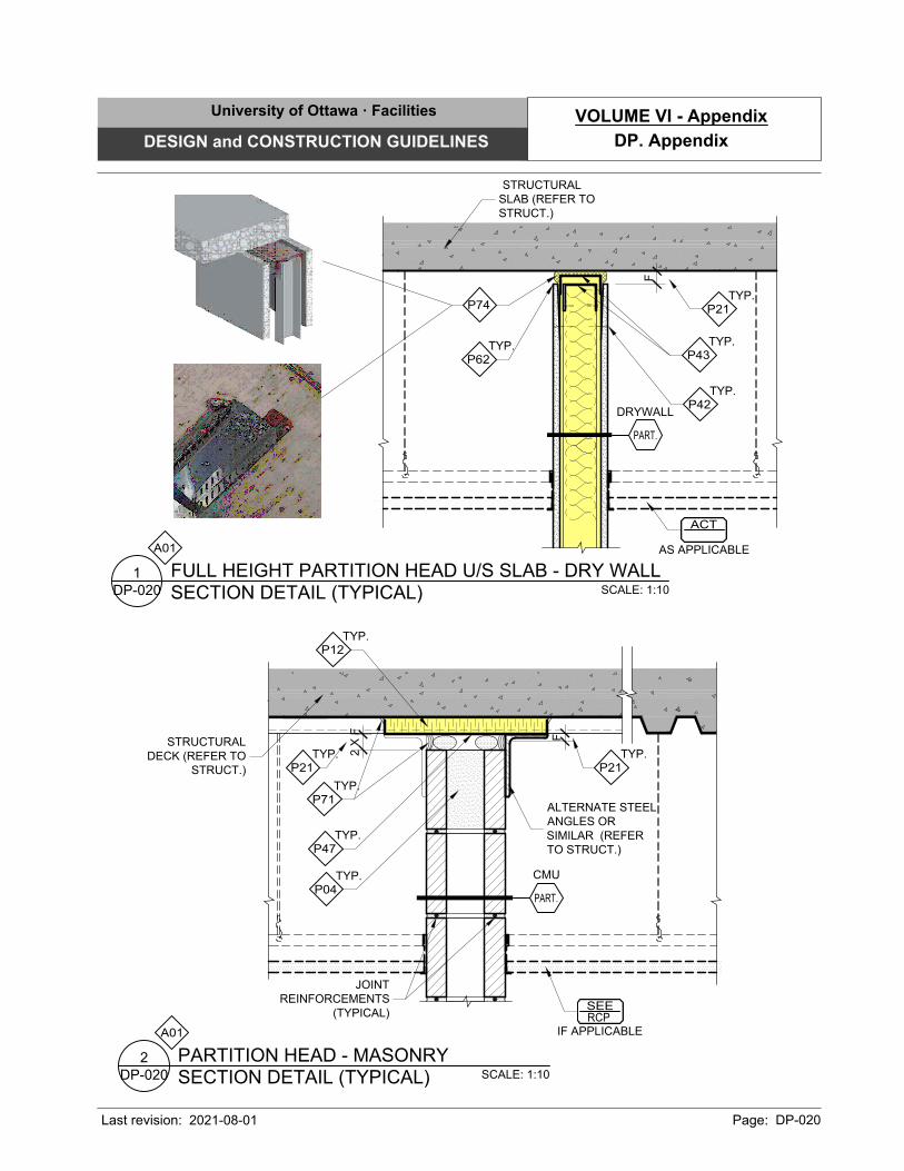
F
SCALE: 1:10
SECTION DETAIL (TYPICAL)
FULL HEIGHT PARTITION HEAD U/S SLAB - DRY WALL
DP-020
1
STRUCTURAL
SLAB (REFER TO
STRUCT.)
TYP.
P42
TYP.
P43
TYP.
P21
TYP.
P62
F
SEE
RCP
IF APPLICABLE
STRUCTURAL
DECK (REFER TO
STRUCT.)
TYP.
P71
TYP.
P47
TYP.
P21
TYP.
P12
SCALE: 1:10
SECTION DETAIL (TYPICAL)
PARTITION HEAD - MASONRY
DP-020
2
2 X
F
TYP.
P21
ALTERNATE STEEL
ANGLES OR
SIMILAR (REFER
TO STRUCT.)
JOINT
REINFORCEMENTS
(TYPICAL)
TYP.
P04
DRYWALL
PART.
CMU
PART.
ACT
AS APPLICABLE
A01
A01
P74
University of Ottawa · Facilities
DESIGN and CONSTRUCTION GUIDELINES
Last revision: Page: DP-020
DP. Appendix
VOLUME VI - Appendix
2021-08-01
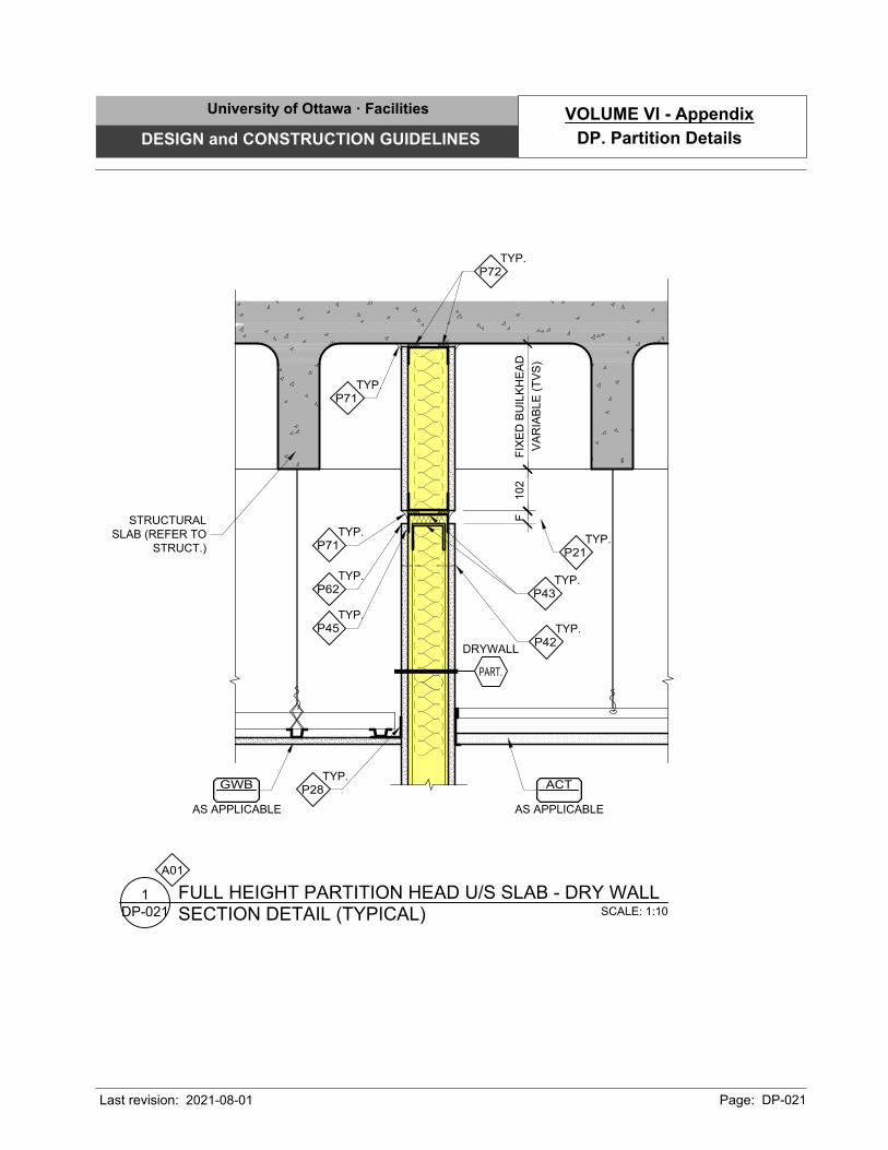
FF
IX
ED
B
UILK
HE
AD
VA
RIA
BLE
(T
VS
)
102
SCALE: 1:10
SECTION DETAIL (TYPICAL)
FULL HEIGHT PARTITION HEAD U/S SLAB - DRY WALL
DP-021
1
ACT
AS APPLICABLE
STRUCTURAL
SLAB (REFER TO
STRUCT.)
TYP.
P72
TYP.
P71
TYP.
P71
TYP.
P62
TYP.
P42
TYP.
P43
TYP.
P21
TYP.
P28
GWB
AS APPLICABLE
TYP.
P45
DRYWALL
PART.
A01
University of Ottawa · Facilities
DESIGN and CONSTRUCTION GUIDELINES
Last revision: Page: DP-021
DP. Partition Details
VOLUME VI - Appendix
2021-08-01
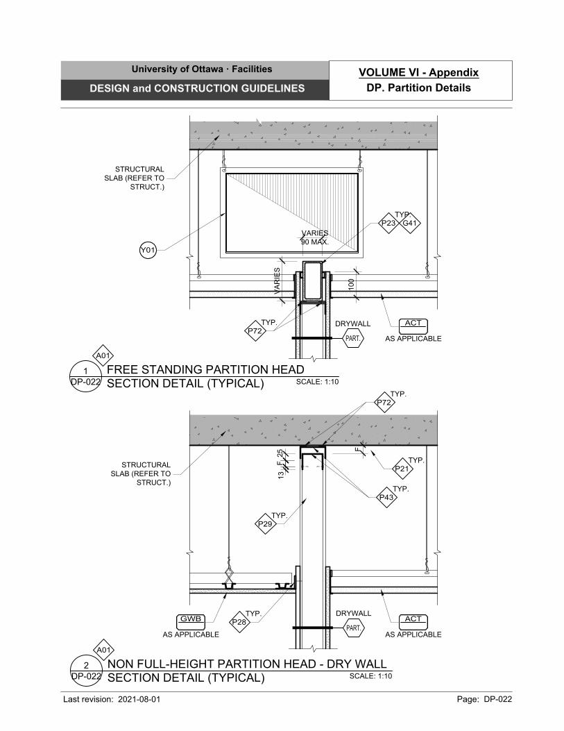
F
25
F
13
VARIES
90 MAX.
100
VA
RIE
S
SCALE: 1:10
SECTION DETAIL (TYPICAL)
NON FULL-HEIGHT PARTITION HEAD - DRY WALL
DP-022
2
SCALE: 1:10
SECTION DETAIL (TYPICAL)
FREE STANDING PARTITION HEAD
DP-022
1
TYP.
P43
TYP.
P21
TYP.
P72
TYP.
P29
TYP.
P23
TYP.
P72
G41
STRUCTURAL
SLAB (REFER TO
STRUCT.)
STRUCTURAL
SLAB (REFER TO
STRUCT.)
TYP.
P28
ACT
AS APPLICABLE
GWB
AS APPLICABLE
ACT
AS APPLICABLE
DRYWALL
PART.
DRYWALL
PART.
A01
A01
Y01
University of Ottawa · Facilities
DESIGN and CONSTRUCTION GUIDELINES
Last revision: Page: DP-022
DP. Partition Details
VOLUME VI - Appendix
2021-08-01
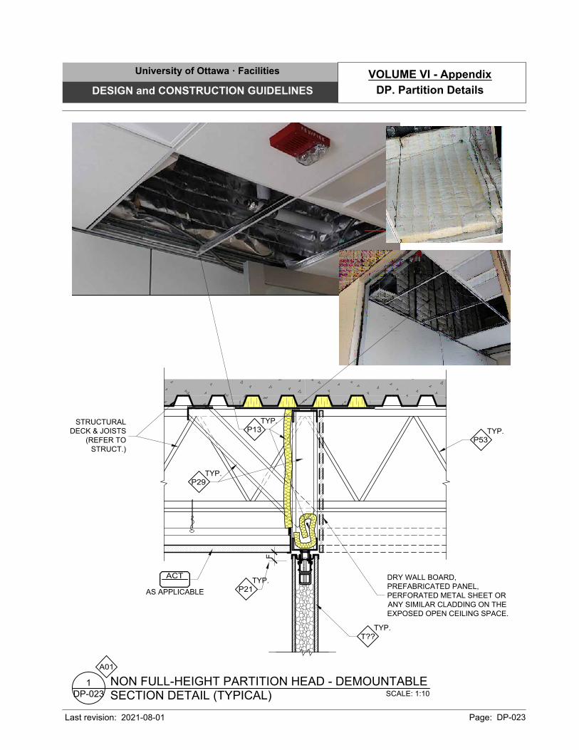
SCALE: 1:10
SECTION DETAIL (TYPICAL)
NON FULL-HEIGHT PARTITION HEAD - DEMOUNTABLE
DP-023
1
A01
TYP.
T??
ACT
AS APPLICABLE
STRUCTURAL
DECK & JOISTS
(REFER TO
STRUCT.)
TYP.
P29
F
TYP.
P21
TYP.
P13
DRY WALL BOARD,
PREFABRICATED PANEL,
PERFORATED METAL SHEET OR
ANY SIMILAR CLADDING ON THE
EXPOSED OPEN CEILING SPACE.
TYP.
P53
University of Ottawa · Facilities
DESIGN and CONSTRUCTION GUIDELINES
Last revision: Page: DP-023
DP. Partition Details
VOLUME VI - Appendix
2021-08-01

50
123
100
SCALE: 1:10
SECTION DETAIL (TYPICAL)
EDGE BULKHEAD
DP-030
2
TYP.
P29
TYP.
P41
T??
RE
FE
R
T
O R
CP
100
TYP.
P41
REFER
TO RCP
TYP.
G11
TYP.
P29
TYP.
D??
STRUCTURAL
SLAB (REFER TO
STRUCT.)
SCALE: 1:10
SECTION DETAIL (TYPICAL)
EDGE BULKHEAD
DP-030
1
ACT
AS APPLICABLE
GWB
AS APPLICABLE
GWB
AS APPLICABLE
ACT
AS APPLICABLE
A01
A01
University of Ottawa · Facilities
DESIGN and CONSTRUCTION GUIDELINES
Last revision: Page: DP-030
DP. Partition Details
VOLUME VI - Appendix
2021-08-01
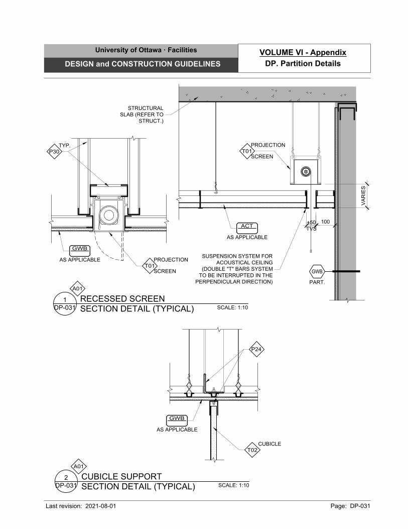
±50
TVS
100
VA
RIE
S
SUSPENSION SYSTEM FOR
ACOUSTICAL CEILING
(DOUBLE "T" BARS SYSTEM
TO BE INTERRUPTED IN THE
PERPENDICULAR DIRECTION)
SCALE: 1:10
SECTION DETAIL (TYPICAL)
RECESSED SCREEN
DP-031
1
SCREEN
PROJECTION
T01
TYP.
P30
SCALE: 1:10
SECTION DETAIL (TYPICAL)
CUBICLE SUPPORT
DP-031
2
CUBICLE
T02
P24
STRUCTURAL
SLAB (REFER TO
STRUCT.)
SCREEN
PROJECTION
T01
PART.
GWB
ACT
AS APPLICABLE
GWB
AS APPLICABLE
GWB
AS APPLICABLE
A01
A01
University of Ottawa · Facilities
DESIGN and CONSTRUCTION GUIDELINES
Last revision: Page: DP-031
DP. Partition Details
VOLUME VI - Appendix
2021-08-01
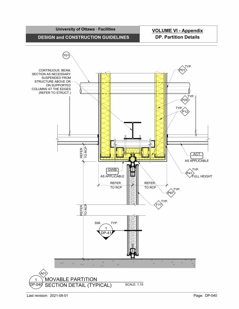
RE
FE
R
T
O R
CP
REFER
TO RCP
REFER
TO RCP
RE
FE
R
T
O R
CP
SCALE: 1:10
SECTION DETAIL (TYPICAL)
MOVABLE PARTITION
DP-040
1
TYP.
T??
1
DP-41
SIM. TYP.
CONTINUOUS BEAM,
SECTION AS NECESSARY
SUSPENDED FROM
STRUCTURE ABOVE OR
ON SUPPORTED
COLUMNS AT THE EDGES
(REFER TO STRUCT.)
TYP.
P12
FULL HEIGHT
TYP.
P41
TYP.
P29
TYP.
P67
TYP.
P01
ACT
AS APPLICABLE
GWB
AS APPLICABLE
A01
Y01
University of Ottawa · Facilities
DESIGN and CONSTRUCTION GUIDELINES
Last revision: Page: DP-040
DP. Partition Details
VOLUME VI - Appendix
2021-08-01
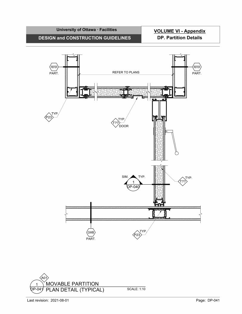
REFER TO PLANS
PART.
REFER
PART.
GWB
1
DP-040
SIM. TYP.
TYP.
T??
PART.
REFER
TYP.
P23
TYP.
P23
DOOR
TYP.
T??
SCALE: 1:10
PLAN DETAIL (TYPICAL)
MOVABLE PARTITION
DP-041
1
A01
University of Ottawa · Facilities
DESIGN and CONSTRUCTION GUIDELINES
Last revision: Page: DP-041
DP. Partition Details
VOLUME VI - Appendix
2021-08-01
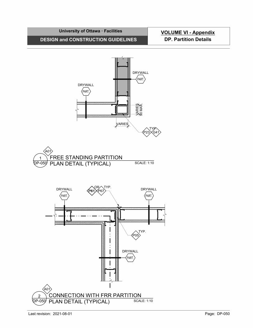
VA
RIE
S
90 M
AX
.
VARIES
SCALE: 1:10
PLAN DETAIL (TYPICAL)
FREE STANDING PARTITION
DP-050
1
TYP.
P23 G41
SCALE: 1:10
PLAN DETAIL (TYPICAL)
CONNECTION WITH FRR PARTITION
DP-050
2
TYP.
P67
TYP.
P05
P61
OR
P61
DRYWALL
PART.
DRYWALL
PART.
DRYWALL
PART.
DRYWALL
PART.
DRYWALL
PART.
A01
A01
University of Ottawa · Facilities
DESIGN and CONSTRUCTION GUIDELINES
Last revision: Page: DP-050
DP. Partition Details
VOLUME VI - Appendix
2021-08-01
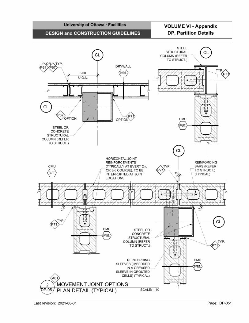
250
U.O.N.
SCALE: 1:10
PLAN DETAIL (TYPICAL)
MOVEMENT JOINT OPTIONS
DP-051
2
CL
STEEL
STRUCTURAL
COLUMN (REFER
TO STRUCT.)
TYP.
P71
CL
CL
STEEL OR
CONCRETE
STRUCTURAL
COLUMN (REFER
TO STRUCT.)
TYP.
P67
OR
P61
OPTION
P67
OPTION
P71
15
15
TYP.
P71
TYP.
P71
STEEL OR
CONCRETE
STRUCTURAL
COLUMN (REFER
TO STRUCT.)
HORIZONTAL JOINT
REINFORCEMENTS
(TYPICALLY AT EVERY 2nd
OR 3rd COURSE). TO BE
INTERRUPTED AT JOINT
LOCATIONS
TYP.
P71
REINFORCING
SLEEVES (IMBEDDED
IN A GREASED
SLEEVE IN GROUTED
CELLS) (TYPICAL)
CL
CL
REINFORCING
BARS (REFER
TO STRUCT.)
(TYPICAL)
DRYWALL
PART.
CMU
PART.
CMU
PART.
CMU
PART.
CMU
PART.
A01
15
University of Ottawa · Facilities
DESIGN and CONSTRUCTION GUIDELINES
Last revision: Page: DP-051
DP. Partition Details
VOLUME VI - Appendix
2021-08-01
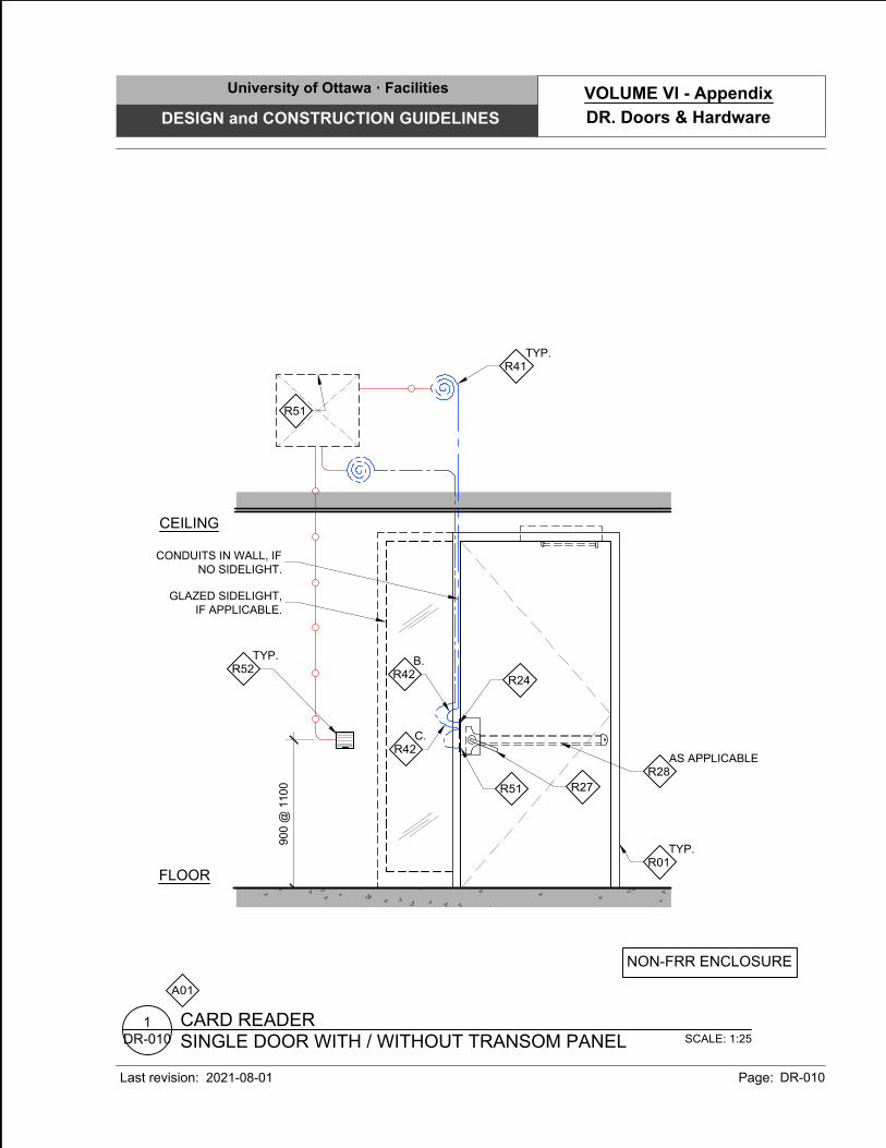
A01
SCALE: 1:25
SINGLE DOOR WITH / WITHOUT TRANSOM PANEL
CARD READER
DR-010
1
FLOOR
CEILING
900 @
1100
R51
TYP.
R41
TYP.
R52
AS APPLICABLE
R28
R27
R51
R24
TYP.
R01
C.
R42
B.
R42
NON-FRR ENCLOSURE
GLAZED SIDELIGHT,
IF APPLICABLE.
CONDUITS IN WALL, IF
NO SIDELIGHT.
University of Ottawa · Facilities
DESIGN and CONSTRUCTION GUIDELINES
Last revision: Page: DR-010
DR. Doors & Hardware
VOLUME VI - Appendix
2021-08-01
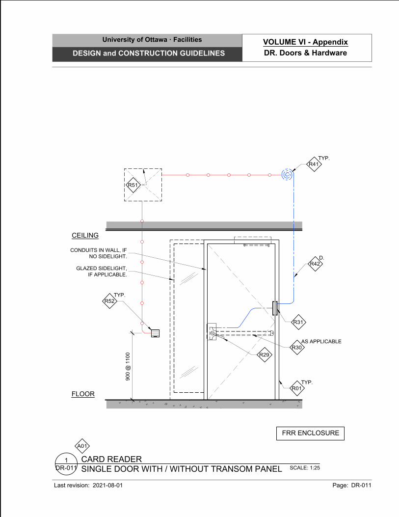
A01
SCALE: 1:25
SINGLE DOOR WITH / WITHOUT TRANSOM PANEL
CARD READER
DR-011
1
FLOOR
CEILING
900 @
1100
TYP.
R41
R31
D.
R42
AS APPLICABLE
R30
R29
TYP.
R52
TYP.
R01
R51
FRR ENCLOSURE
GLAZED SIDELIGHT,
IF APPLICABLE.
CONDUITS IN WALL, IF
NO SIDELIGHT.
University of Ottawa · Facilities
DESIGN and CONSTRUCTION GUIDELINES
Last revision: Page: DR-011
DR. Doors & Hardware
VOLUME VI - Appendix
2021-08-01
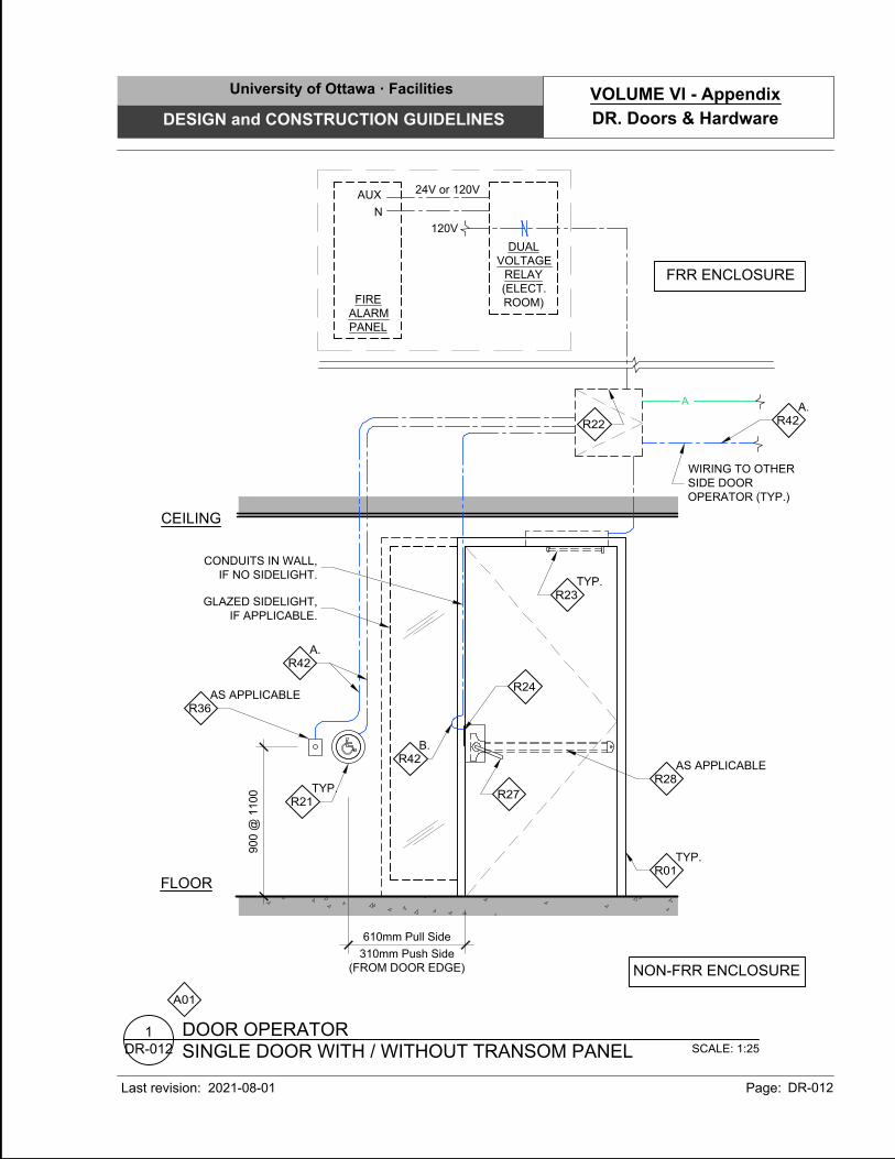
A01
SCALE: 1:25
SINGLE DOOR WITH / WITHOUT TRANSOM PANEL
DOOR OPERATOR
DR-012
1
FLOOR
CEILING
90
0 @
1
10
0
TYP.
R23
A.
R42
TYP.
R21
TYP.
R01
R22
A
WIRING TO OTHER
SIDE DOOR
OPERATOR (TYP.)
A.
R42
FIRE
ALARM
PANEL
NON-FRR ENCLOSURE
AS APPLICABLE
R28
R27
R24
B.
R42
610mm Pull Side
310mm Push Side
(FROM DOOR EDGE)
DUAL
VOLTAGE
RELAY
(ELECT.
ROOM)
FRR ENCLOSURE
AS APPLICABLE
R36
AUX
N
120V
24V or 120V
GLAZED SIDELIGHT,
IF APPLICABLE.
CONDUITS IN WALL,
IF NO SIDELIGHT.
University of Ottawa · Facilities
DESIGN and CONSTRUCTION GUIDELINES
Last revision: Page: DR-012
DR. Doors & Hardware
VOLUME VI - Appendix
2021-08-01
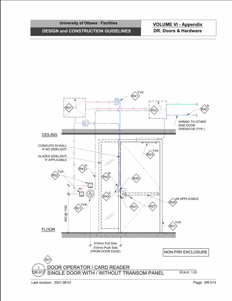
A01
SCALE: 1:25
SINGLE DOOR WITH / WITHOUT TRANSOM PANEL
DOOR OPERATOR / CARD READER
DR-013
1
FLOOR
CEILING
900 @
1100
R22
R51
TYP.
R41
TYP.
R52
TYP.
R21
TYP.
R23
AS APPLICABLE
R28
R27
R51
R24
A.
R42
TYP.
R01
or
A
WIRING TO OTHER
SIDE DOOR
OPERATOR (TYP.)
A.
R42
C.
R42
B.
R42
NON-FRR ENCLOSURE
610mm Pull Side
310mm Push Side
(FROM DOOR EDGE)
GLAZED SIDELIGHT,
IF APPLICABLE.
CONDUITS IN WALL,
IF NO SIDELIGHT.
University of Ottawa · Facilities
DESIGN and CONSTRUCTION GUIDELINES
Last revision: Page: DR-013
DR. Doors & Hardware
VOLUME VI - Appendix
2021-08-01
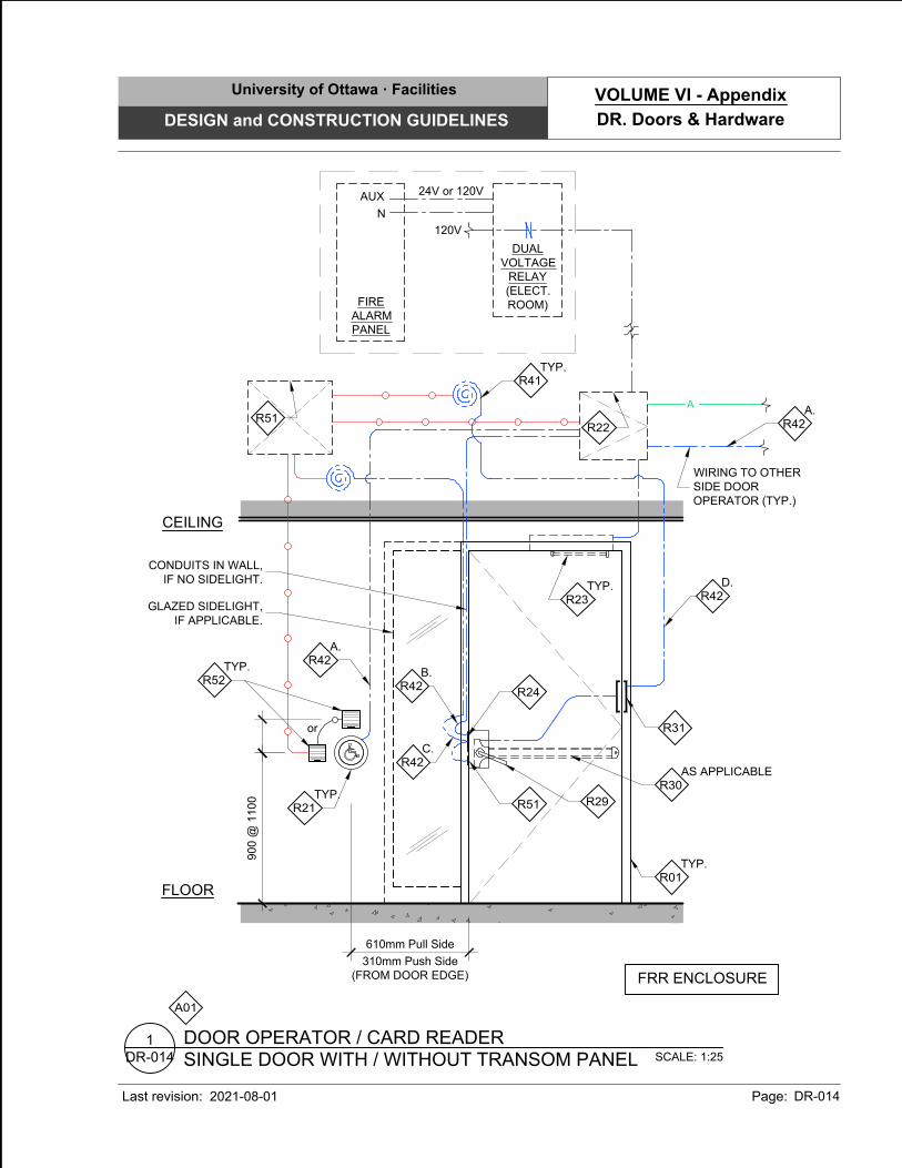
A01
SCALE: 1:25
SINGLE DOOR WITH / WITHOUT TRANSOM PANEL
DOOR OPERATOR / CARD READER
DR-014
1
FLOOR
CEILING
or
TYP.
R41
TYP.
R23
R31
A.
R42
D.
R42
AS APPLICABLE
R30
R29
R51
R24
TYP.
R52
TYP.
R21
TYP.
R01
R22
R51
A
WIRING TO OTHER
SIDE DOOR
OPERATOR (TYP.)
A.
R42
FIRE
ALARM
PANEL
C.
R42
B.
R42
FRR ENCLOSURE
610mm Pull Side
310mm Push Side
(FROM DOOR EDGE)
DUAL
VOLTAGE
RELAY
(ELECT.
ROOM)
AUX
N
120V
24V or 120V
GLAZED SIDELIGHT,
IF APPLICABLE.
CONDUITS IN WALL,
IF NO SIDELIGHT.
900 @
1100
University of Ottawa · Facilities
DESIGN and CONSTRUCTION GUIDELINES
Last revision: Page: DR-014
DR. Doors & Hardware
VOLUME VI - Appendix
2021-08-01
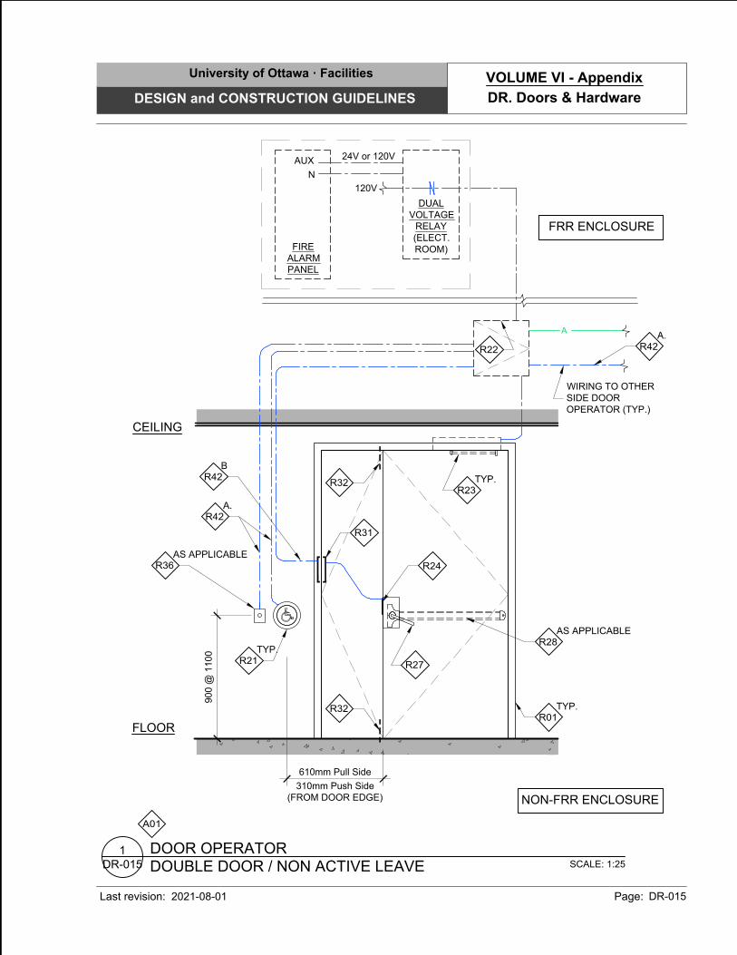
A01
SCALE: 1:25
DOUBLE DOOR / NON ACTIVE LEAVE
DOOR OPERATOR
DR-015
1
FLOOR
CEILING
900 @
1100
TYP.
R23
TYP.
R21
TYP.
R01
R22
A
WIRING TO OTHER
SIDE DOOR
OPERATOR (TYP.)
A.
R42
FIRE
ALARM
PANEL
A.
R42
R32
R32
R27
R24
B
R42
R31
AS APPLICABLE
R28
NON-FRR ENCLOSURE
610mm Pull Side
310mm Push Side
(FROM DOOR EDGE)
DUAL
VOLTAGE
RELAY
(ELECT.
ROOM)
FRR ENCLOSURE
AS APPLICABLE
R36
AUX
N
120V
24V or 120V
University of Ottawa · Facilities
DESIGN and CONSTRUCTION GUIDELINES
Last revision: Page: DR-015
DR. Doors & Hardware
VOLUME VI - Appendix
2021-08-01
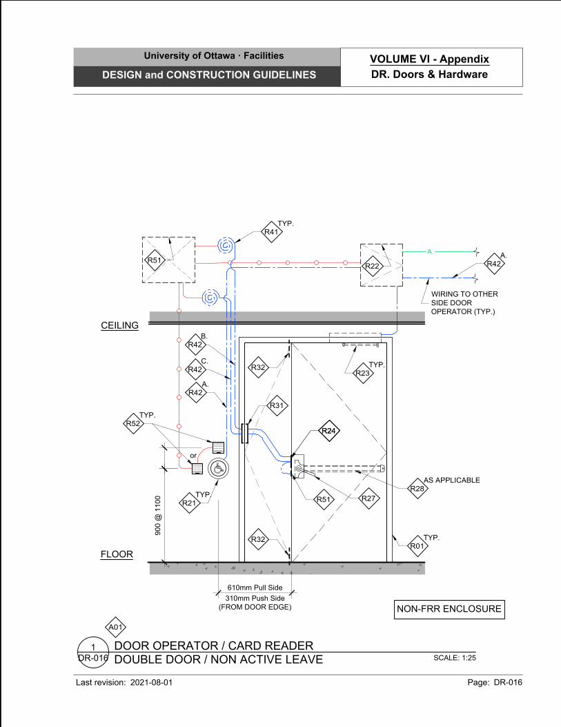
A01
SCALE: 1:25
DOUBLE DOOR / NON ACTIVE LEAVE
DOOR OPERATOR / CARD READER
DR-016
1
FLOOR
CEILING
R22
TYP.
R41
TYP.
R52
TYP.
R21
TYP.
R23
R27
R51
R24
C.
R42
B.
R42
A.
R42
TYP.
R01
or
A
WIRING TO OTHER
SIDE DOOR
OPERATOR (TYP.)
A.
R42
R32
R32
R24
R31
R51
AS APPLICABLE
R28
NON-FRR ENCLOSURE
610mm Pull Side
310mm Push Side
(FROM DOOR EDGE)
900 @
1100
University of Ottawa · Facilities
DESIGN and CONSTRUCTION GUIDELINES
Last revision: Page: DR-016
DR. Doors & Hardware
VOLUME VI - Appendix
2021-08-01
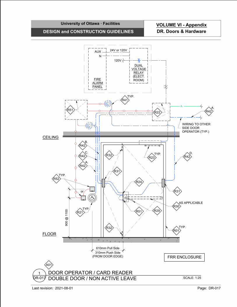
A01
SCALE: 1:25
DOUBLE DOOR / NON ACTIVE LEAVE
DOOR OPERATOR / CARD READER
DR-017
1
FLOOR
CEILING
or
TYP.
R41
TYP.
R23
R31
D.
R42
R29
R51
R24
TYP.
R52
TYP.
R21
TYP.
R01
R22
A
WIRING TO OTHER
SIDE DOOR
OPERATOR (TYP.)
A.
R42
FIRE
ALARM
PANEL
A.
R42
R32
R32
C.
R42
B.
R42
R31
R51
AS APPLICABLE
R30
FRR ENCLOSURE
610mm Pull Side
310mm Push Side
(FROM DOOR EDGE)
DUAL
VOLTAGE
RELAY
(ELECT.
ROOM)
AUX
N
120V
24V or 120V
900 @
1100
University of Ottawa · Facilities
DESIGN and CONSTRUCTION GUIDELINES
Last revision: Page: DR-017
DR. Doors & Hardware
VOLUME VI - Appendix
2021-08-01
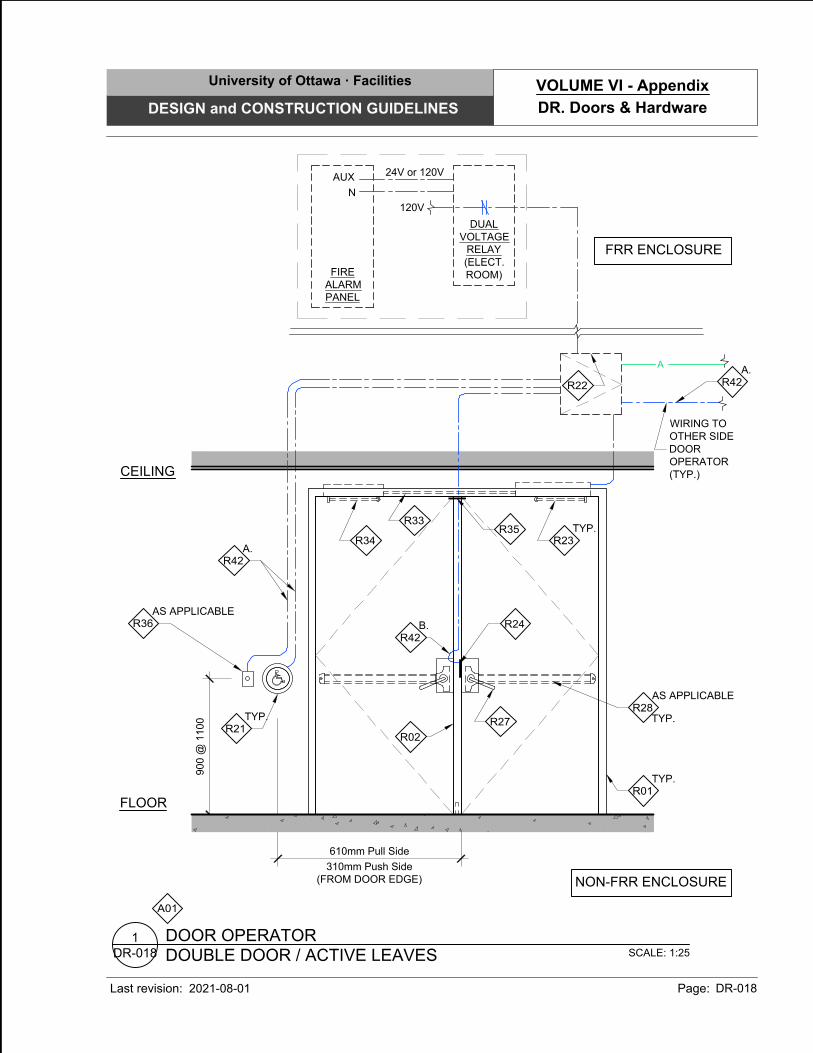
A01
SCALE: 1:25
DOUBLE DOOR / ACTIVE LEAVES
DOOR OPERATOR
DR-018
1
610mm Pull Side
310mm Push Side
(FROM DOOR EDGE)
FLOOR
CEILING
900 @
1100
TYP.
R21
TYP.
R23
TYP.
AS APPLICABLE
R28
R27
A
WIRING TO
OTHER SIDE
DOOR
OPERATOR
(TYP.)
R24
B.
R42
A.
R42
TYP.
R01
A.
R42
R22
R02
R34
R33
R35
NON-FRR ENCLOSURE
FIRE
ALARM
PANEL
DUAL
VOLTAGE
RELAY
(ELECT.
ROOM)
FRR ENCLOSURE
AS APPLICABLE
R36
AUX
N
120V
24V or 120V
University of Ottawa · Facilities
DESIGN and CONSTRUCTION GUIDELINES
Last revision: Page: DR-018
DR. Doors & Hardware
VOLUME VI - Appendix
2021-08-01
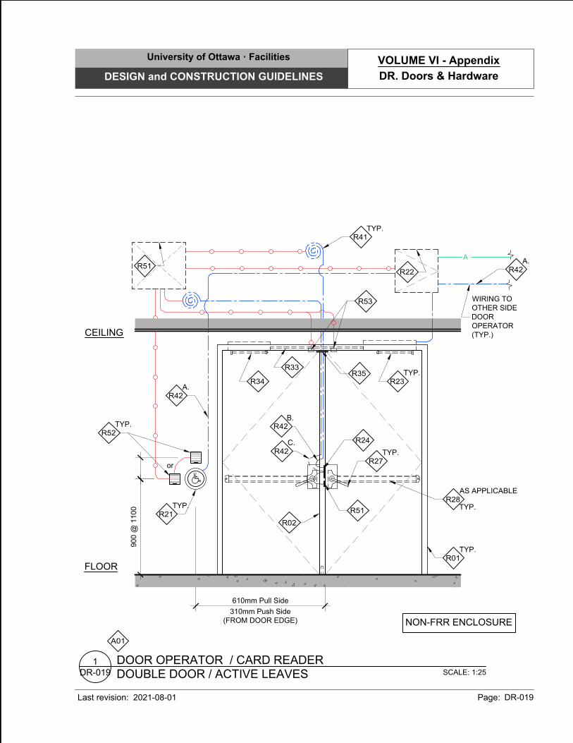
A01
SCALE: 1:25
DOUBLE DOOR / ACTIVE LEAVES
DOOR OPERATOR / CARD READER
DR-019
1
NON-FRR ENCLOSURE
R51
TYP.
R41
TYP.
R52
R51
R24
or
C.
R42
B.
R42
610mm Pull Side
310mm Push Side
(FROM DOOR EDGE)
FLOOR
CEILING
TYP.
R21
TYP.
R23
TYP.
AS APPLICABLE
R28
TYP.
R27
A
WIRING TO
OTHER SIDE
DOOR
OPERATOR
(TYP.)
A.
R42
TYP.
R01
A.
R42
R22
R02
R34
R33
R35
R53
900 @
1100
University of Ottawa · Facilities
DESIGN and CONSTRUCTION GUIDELINES
Last revision: Page: DR-019
DR. Doors & Hardware
VOLUME VI - Appendix
2021-08-01
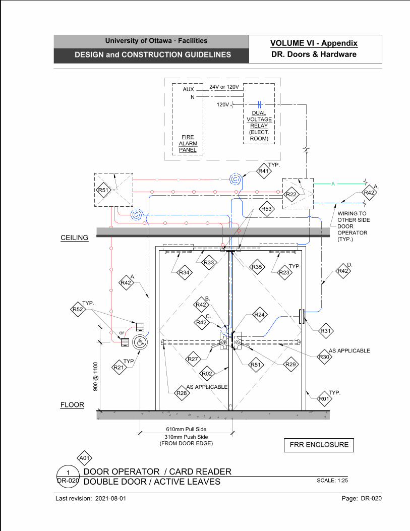
A01
SCALE: 1:25
DOUBLE DOOR / ACTIVE LEAVES
DOOR OPERATOR / CARD READER
DR-020
1
FRR ENCLOSURE
R51
TYP.
R41
TYP.
R52
R51
R24
or
C.
R42
B.
R42
610mm Pull Side
310mm Push Side
(FROM DOOR EDGE)
FLOOR
TYP.
R21
TYP.
R23
AS APPLICABLE
R28
R27
A
WIRING TO
OTHER SIDE
DOOR
OPERATOR
(TYP.)
A.
R42
TYP.
R01
A.
R42
R22
R02
R34
R33
R35
R53
FIRE
ALARM
PANEL
D.
R42
R31
AS APPLICABLE
R30
R29
AUX
N
120V
24V or 120V
DUAL
VOLTAGE
RELAY
(ELECT.
ROOM)
CEILING
900 @
1100
University of Ottawa · Facilities
DESIGN and CONSTRUCTION GUIDELINES
Last revision: Page: DR-020
DR. Doors & Hardware
VOLUME VI - Appendix
2021-08-01
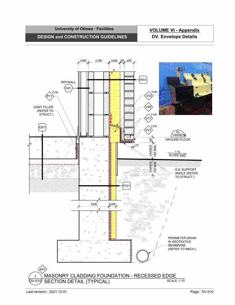
SCALE: 1:10
SECTION DETAIL (TYPICAL)
MASONRY CLADDING FOUNDATION - RECESSED EDGE
DV-010
1
±190 VAR. 38 ±90
VA
RIE
S
150 M
IN
.
15
VAR.
50
VA
RIE
S
150 M
IN
.
EL.
GROUND FLOOR
VARIES
TYP.
V71
V65
S.S. SUPPORT
ANGLE (REFER
TO STRUCT.)
TYP.
V01
TYP.
V53
DRYWALL
PART.
A01
1 %
SLO
PE
MIN
.
W01
F01
VAR.VAR.
PERIMETER DRAIN
IN GEOTEXTILE
MEMBRANE
(REFER TO MECH.)
JOINT FILLER
(REFER TO
STRUCT.)
TYP.
P71
D01
University of Ottawa · Facilities
DESIGN and CONSTRUCTION GUIDELINES
Last revision: Page: DV-010
DV. Envelope Details
VOLUME VI - Appendix
2021-12-01
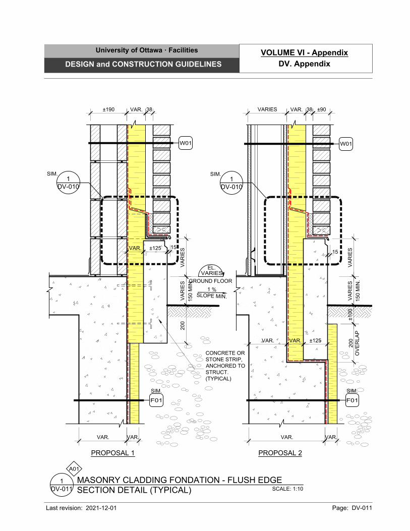
SCALE: 1:10
SECTION DETAIL (TYPICAL)
MASONRY CLADDING FONDATION - FLUSH EDGE
DV-011
1
VA
RIE
S
150 M
IN
.
VAR.VAR.
15
VA
RIE
S
200
OV
ER
LA
P
VAR. 38
VA
RIE
S
150 M
IN
.
VAR.
200
VAR.
15
VA
RIE
S
PROPOSAL 1 PROPOSAL 2
±125
±100
VAR.
±125
VAR.VAR.
EL.
GROUND FLOOR
VARIES
DV-010
1
SIM.
VAR. 38
CONCRETE OR
STONE STRIP,
ANCHORED TO
STRUCT.
(TYPICAL)
VARIES±190 ±90
A01
DV-010
1
SIM.
1 %
SLO
PE
MIN
.
SIM.
F01
W01
W01
SIM.
F01
University of Ottawa · Facilities
DESIGN and CONSTRUCTION GUIDELINES
Last revision: Page: DV-011
DV. Appendix
VOLUME VI - Appendix
2021-12-01
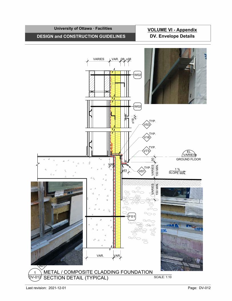
SCALE: 1:10
SECTION DETAIL (TYPICAL)
METAL / COMPOSITE CLADDING FOUNDATION
DV-012
1
VARIES 38 ±38VAR.
VAR.VAR.
±63
VAR.
VA
RIE
S
150 M
IN
.
VA
RIE
S
150 M
IN
.
50
EL.
GROUND FLOOR
VARIES
TYP.
V16
TYP.
V01
TYP.
V53
TYP.
V73
±19
A01
1 %
SLO
PE
MIN
.
F01
W02
W02
University of Ottawa · Facilities
DESIGN and CONSTRUCTION GUIDELINES
Last revision: Page: DV-012
DV. Envelope Details
VOLUME VI - Appendix
2021-12-01
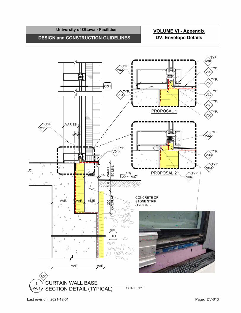
15
SCALE: 1:10
SECTION DETAIL (TYPICAL)
CURTAIN WALL BASE
DV-013
1
VA
RIE
S
150 M
IN
.
VAR.VAR.
±125
±35
VAR.VAR. ±125
200
OV
ER
LA
P
±100
CONCRETE OR
STONE STRIP
(TYPICAL)
TYP.
V04
TYP.
V11
VARIES
A01
1 %
SLO
PE
MIN
.
C01
TYP.
V55
TYP.
V32
PROPOSAL 1
PROPOSAL 2
TYP.
V36
TYP.
V31
TYP.
V02
TYP.
V03
TYP.
V55
TYP.
V32
TYP.
V63
TYP.
V53
TYP.
V33
SIM.
F01
TYP.
V63
University of Ottawa · Facilities
DESIGN and CONSTRUCTION GUIDELINES
Last revision: Page: DV-013
DV. Envelope Details
VOLUME VI - Appendix
2021-12-01
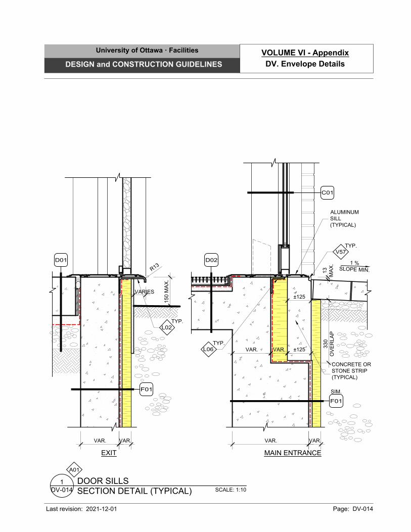
VAR.VAR.
VARIES
150 M
AX
.
SCALE: 1:10
SECTION DETAIL (TYPICAL)
DOOR SILLS
DV-014
1
VAR.VAR.
±125
VAR.VAR. ±125
330
OV
ER
LA
P
CONCRETE OR
STONE STRIP
(TYPICAL)
A01
TYP.
L06
1 %
SLO
PE
MIN
.
TYP.
V57
13
MA
X.
EXIT MAIN ENTRANCE
ALUMINUM
SILL
(TYPICAL)
TYP.
L02
R
1
3
D02D01
C01
F01
SIM.
F01
University of Ottawa · Facilities
DESIGN and CONSTRUCTION GUIDELINES
Last revision: Page: DV-014
DV. Envelope Details
VOLUME VI - Appendix
2021-12-01
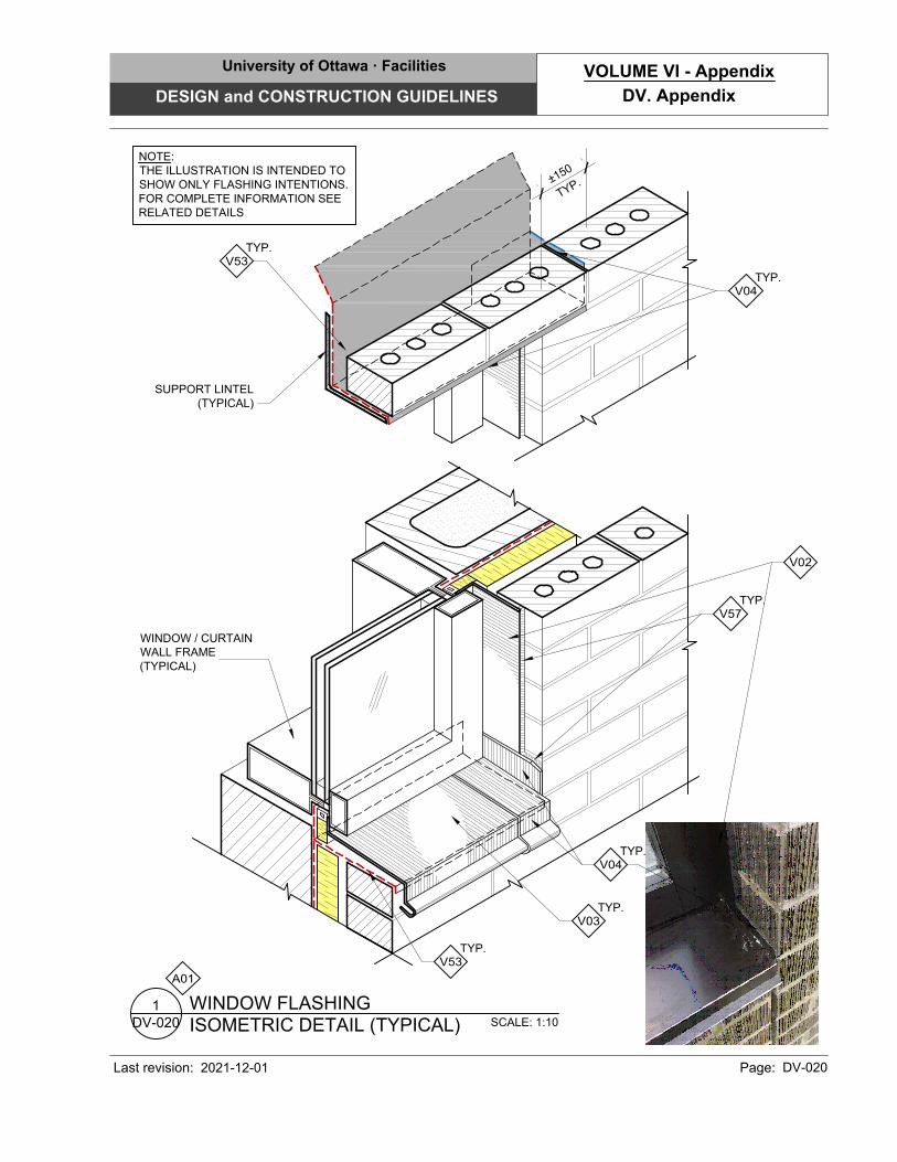
SCALE: 1:10
ISOMETRIC DETAIL (TYPICAL)
WINDOW FLASHING
DV-020
1
±
1
5
0
T
Y
P
.
NOTE:
THE ILLUSTRATION IS INTENDED TO
SHOW ONLY FLASHING INTENTIONS.
FOR COMPLETE INFORMATION SEE
RELATED DETAILS
TYP.
V03
WINDOW / CURTAIN
WALL FRAME
(TYPICAL)
TYP.
V53
TYP.
V04
TYP.
V57
V02
TYP.
V53
SUPPORT LINTEL
(TYPICAL)
TYP.
V04
A01
University of Ottawa · Facilities
DESIGN and CONSTRUCTION GUIDELINES
Last revision: Page: DV-020
DV. Appendix
VOLUME VI - Appendix
2021-12-01
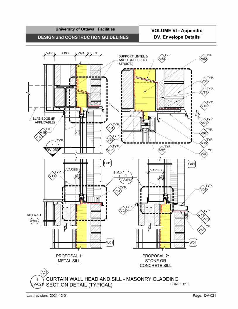
SCALE: 1:10
SECTION DETAIL (TYPICAL)
CURTAIN WALL HEAD AND SILL - MASONRY CLADDING
DV-021
1
TYP.
V04
VAR. 38±190
±35
VARIES
DRYWALL
PART.
±90VAR.
A01
SUPPORT LINTEL &
ANGLE (REFER TO
STRUCT.)
±35
VARIES
TYP.
V04
PROPOSAL 1:
METAL SILL
PROPOSAL 2:
STONE OR
CONCRETE SILL
TYP.
V53
TYP.
V7125
V76
TYP.
V11
TYP.
V36
TYP.
V55
TYP.
V32
TYP.
V63
F
TYP.
V15
TYP.
V04
TYP.
V71
TYP.
V01
TYP.
V53
TYP.
V02
TYP.
V31
SLAB EDGE (IF
APPLICABLE)
DV-013
1
SIM.
±35
TYP.
V15
V02
C01
C01
W01 W01
1
DV-060
TYP.
TYP.
V02
TYP.
V62
TYP.
V15
University of Ottawa · Facilities
DESIGN and CONSTRUCTION GUIDELINES
Last revision: Page: DV-021
DV. Envelope Details
VOLUME VI - Appendix
2021-12-01
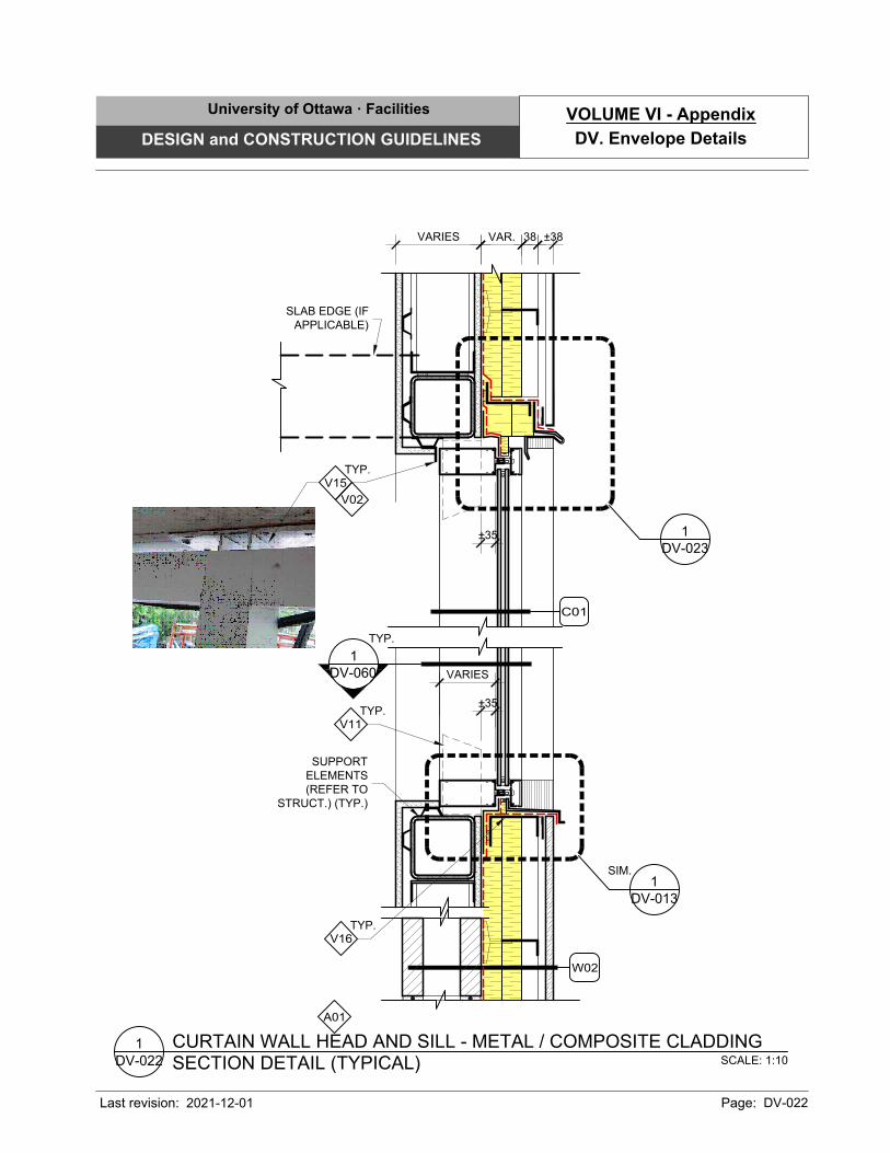
VAR.VARIES 38 ±38
A01
SCALE: 1:10
SECTION DETAIL (TYPICAL)
CURTAIN WALL HEAD AND SILL - METAL / COMPOSITE CLADDING
DV-022
1
±35
VARIES
±35
SLAB EDGE (IF
APPLICABLE)
SUPPORT
ELEMENTS
(REFER TO
STRUCT.) (TYP.)
DV-013
1
SIM.
TYP.
V16
TYP.
V15
V02
C01
W02
1
DV-060
TYP.
TYP.
V11
DV-023
1
University of Ottawa · Facilities
DESIGN and CONSTRUCTION GUIDELINES
Last revision: Page: DV-022
DV. Envelope Details
VOLUME VI - Appendix
2021-12-01
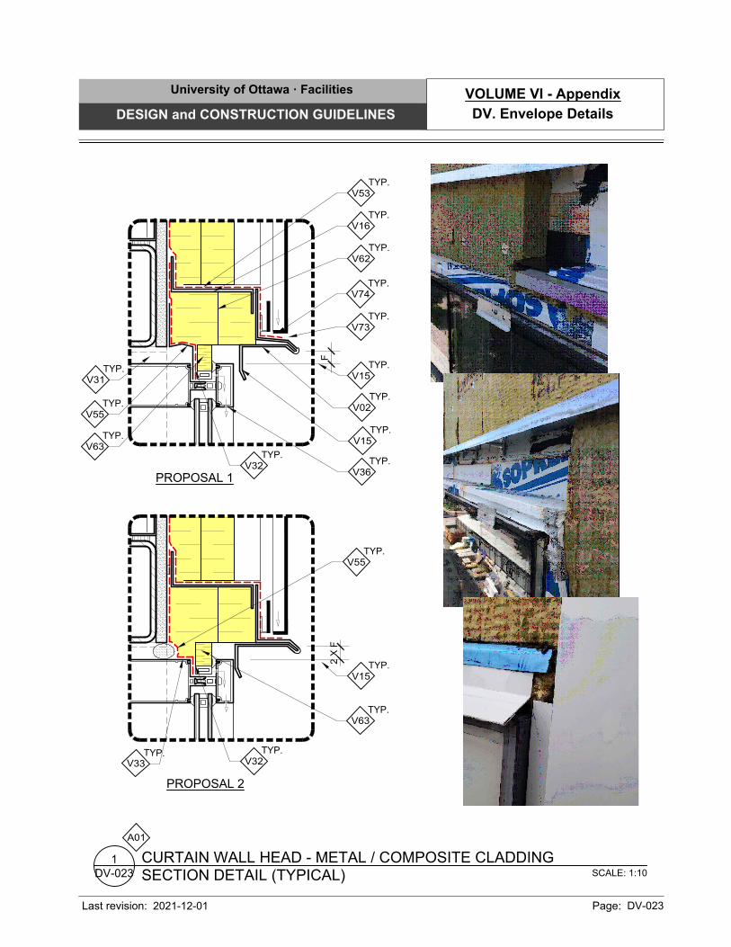
TYP.
V55
TYP.
V62
TYP.
V36
TYP.
V15
TYP.
V32
TYP.
V63
F
TYP.
V15
TYP.
V31
TYP.
V53
TYP.
V74
TYP.
V16
TYP.
V73
TYP.
V55
TYP.
V63
2 X
F
PROPOSAL 1
PROPOSAL 2
TYP.
V15
TYP.
V02
TYP.
V32
TYP.
V33
A01
SCALE: 1:10
SECTION DETAIL (TYPICAL)
CURTAIN WALL HEAD - METAL / COMPOSITE CLADDING
DV-023
1
University of Ottawa · Facilities
DESIGN and CONSTRUCTION GUIDELINES
Last revision: Page: DV-023
DV. Envelope Details
VOLUME VI - Appendix
2021-12-01

SCALE: 1:10
SECTION DETAIL (TYPICAL)
WINDOW UNIT HEAD AND SILL - MASONRY CLADDING
DV-024
1
VAR. 38±190
±25
DRYWALL
PART.
±90VAR.
A01
TYP.
V04
FREE LINTEL
& ANGLE
TYP.
V04
PROPOSAL 1:
METAL SILL
PROPOSAL 2:
STONE OR
CONCRETE SILL
TYP.
V53
TYP.
V7125
V76
TYP.
V04
TYP.
V71
TYP.
V53
TYP.
V02
TYP.
V01
TYP.
V57
TYP.
V61
TYP.
V57
TYP.
V54
TYP.
V17
TYP.
V65
±25
TYP.
V53
TYP.
V57
TYP.
V61
TYP.
V54
TYP.
P71
TYP.
V03
W01W01
1
DV-061
TYP.
ALUMIUM
WINDOW
(08 40 00)
(TYP.)
TYP.
V02
University of Ottawa · Facilities
DESIGN and CONSTRUCTION GUIDELINES
Last revision: Page: DV-024
DV. Envelope Details
VOLUME VI - Appendix
2021-12-01
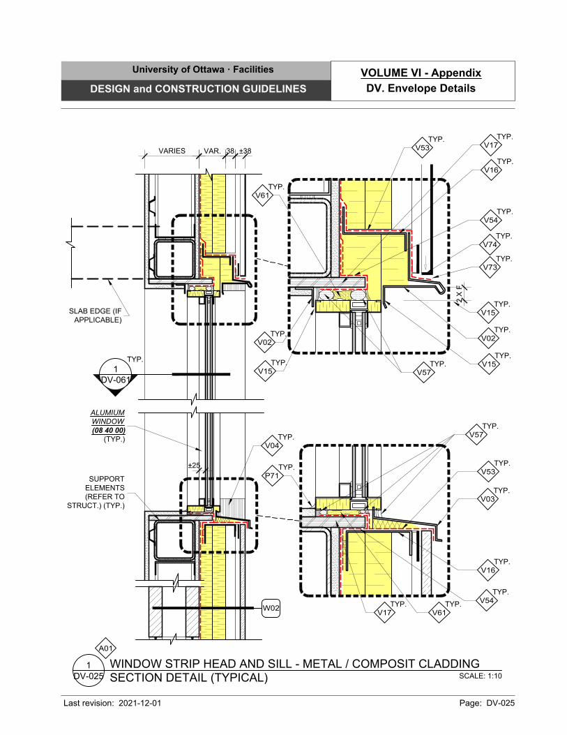
VARIES VAR. 38 ±38
SCALE: 1:10
SECTION DETAIL (TYPICAL)
WINDOW STRIP HEAD AND SILL - METAL / COMPOSIT CLADDING
DV-025
1
A01
SUPPORT
ELEMENTS
(REFER TO
STRUCT.) (TYP.)
TYP.
V15
TYP.
V53
TYP.
V74
TYP.
V16
TYP.
V16
±25
TYP.
V53
TYP.
V57
TYP.
V61
TYP.
V54
TYP.
V17
ALUMIUM
WINDOW
(08 40 00)
(TYP.)
TYP.
V03
TYP.
P71
TYP.
V04
SLAB EDGE (IF
APPLICABLE)
TYP.
V57
TYP.
V54
TYP.
V02
TYP.
V15
TYP.
V61
TYP.
V17
W02
1
DV-061
TYP.
TYP.
V73
2 X
F
TYP.
V02
TYP.
V15
University of Ottawa · Facilities
DESIGN and CONSTRUCTION GUIDELINES
Last revision: Page: DV-025
DV. Envelope Details
VOLUME VI - Appendix
2021-12-01
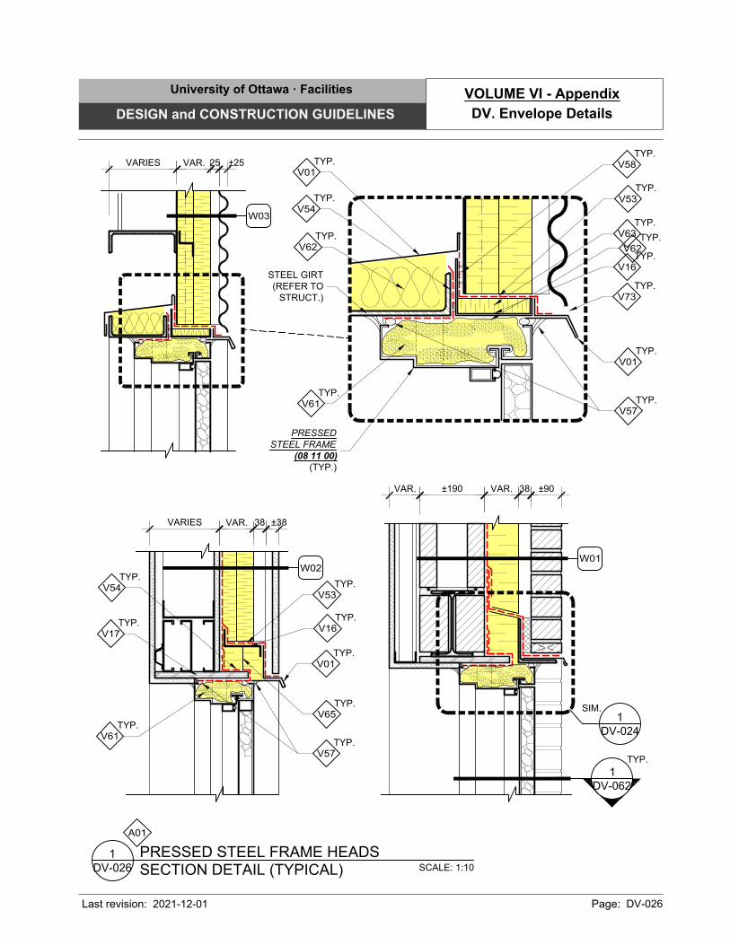
TYP.
V62
VARIES VAR. 25 ±25
W03
PRESSED
STEEL FRAME
(08 11 00)
(TYP.)
SCALE: 1:10
SECTION DETAIL (TYPICAL)
PRESSED STEEL FRAME HEADS
DV-026
1
VAR. 38±190 ±90VAR.
A01
W02
1
DV-062
TYP.
DV-024
1
SIM.
TYP.
V16
TYP.
V53
TYP.
V01
TYP.
V65
TYP.
V54
TYP.
V17
W01
TYP.
V61
TYP.
V57
VARIES VAR. 38 ±38
TYP.
V53
TYP.
V58
STEEL GIRT
(REFER TO
STRUCT.)
TYP.
V01
TYP.
V62
TYP.
V54
TYP.
V16
TYP.
V01
TYP.
V63
TYP.
V61
TYP.
V57
TYP.
V73
University of Ottawa · Facilities
DESIGN and CONSTRUCTION GUIDELINES
Last revision: Page: DV-026
DV. Envelope Details
VOLUME VI - Appendix
2021-12-01
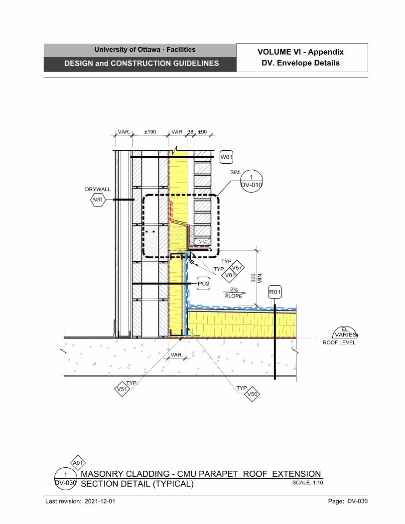
TYP.
V01
300
MIN
.
2%
SLO
PE
TYP.
V56
TYP.
V57
±190 ±90VAR. 38VAR.
DRYWALL
PART.
TYP.
V51
SCALE: 1:10
SECTION DETAIL (TYPICAL)
MASONRY CLADDING - CMU PARAPET ROOF EXTENSION
DV-030
1
EL.
ROOF LEVEL
VARIES
A01
DV-010
1
SIM.
W01
P02
R01
VAR.
University of Ottawa · Facilities
DESIGN and CONSTRUCTION GUIDELINES
Last revision: Page: DV-030
DV. Envelope Details
VOLUME VI - Appendix
2021-12-01
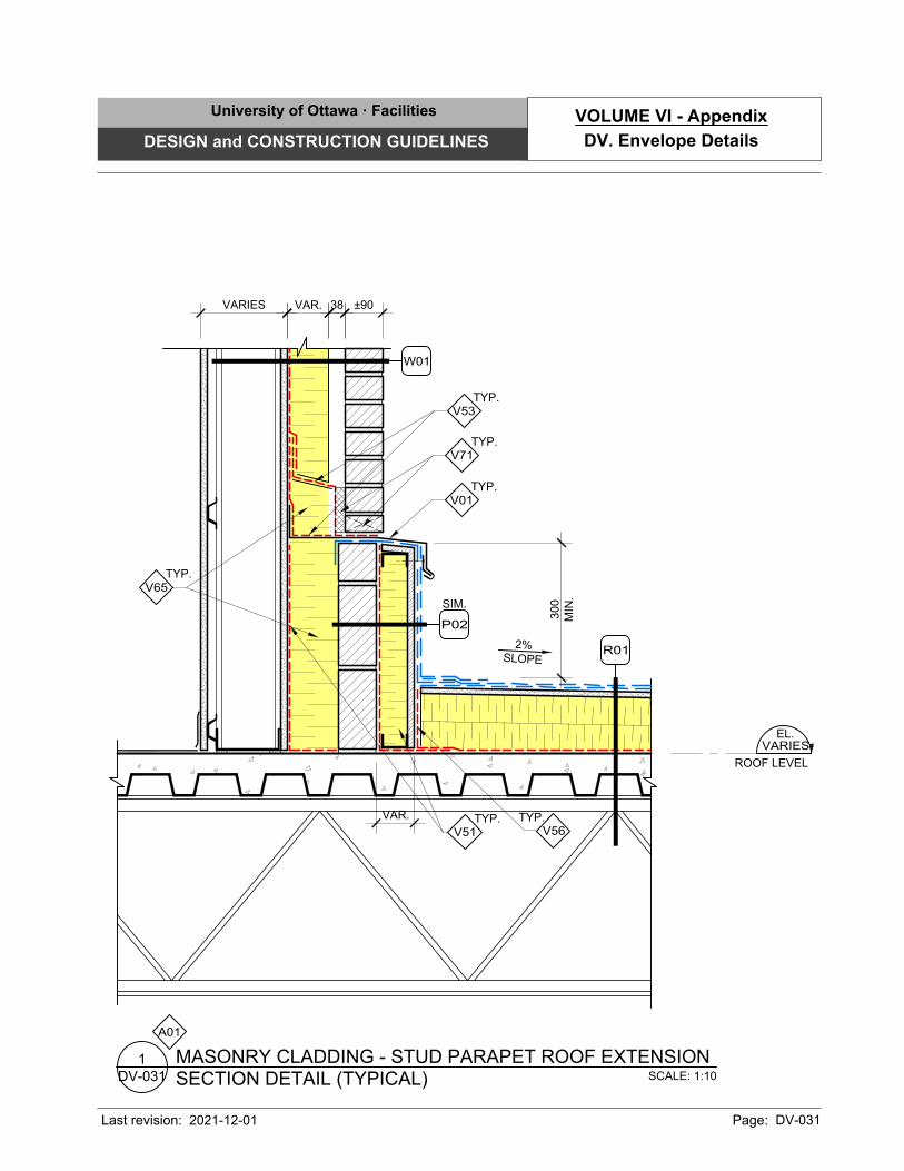
±90
300
MIN
.
2%
SLO
PE
VAR. 38
TYP.
V53
TYP.
V56
TYP.
V51
TYP.
V71
TYP.
V01
SCALE: 1:10
SECTION DETAIL (TYPICAL)
MASONRY CLADDING - STUD PARAPET ROOF EXTENSION
DV-031
1
EL.
ROOF LEVEL
VARIES
A01
VARIES
W01
SIM.
P02
TYP.
V65
R01
VAR.
University of Ottawa · Facilities
DESIGN and CONSTRUCTION GUIDELINES
Last revision: Page: DV-031
DV. Envelope Details
VOLUME VI - Appendix
2021-12-01
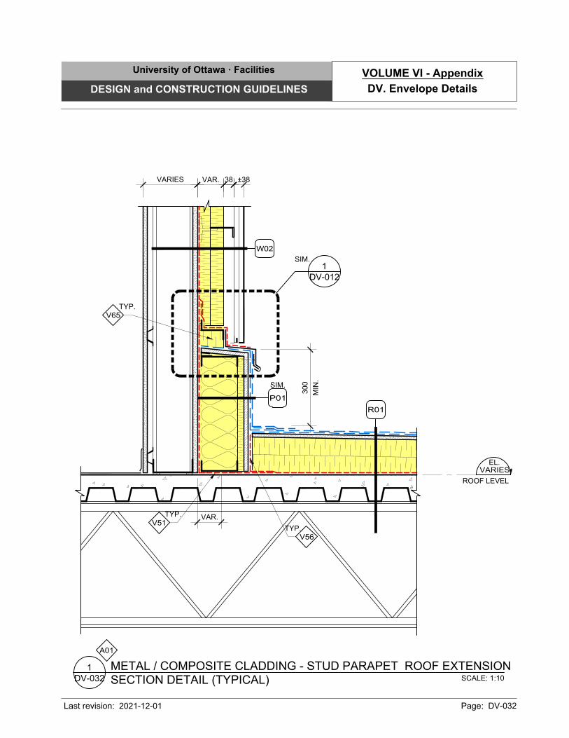
VARIES 38VAR. ±38
300
MIN
.
SCALE: 1:10
SECTION DETAIL (TYPICAL)
METAL / COMPOSITE CLADDING - STUD PARAPET ROOF EXTENSION
DV-032
1
TYP.
V65
EL.
ROOF LEVEL
VARIES
TYP.
V56
DV-012
1
SIM.
TYP.
V51
A01
W02
SIM.
P01
R01
VAR.
University of Ottawa · Facilities
DESIGN and CONSTRUCTION GUIDELINES
Last revision: Page: DV-032
DV. Envelope Details
VOLUME VI - Appendix
2021-12-01
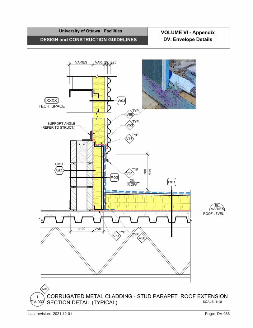
VARIES VAR. 25 ±25
SCALE: 1:10
SECTION DETAIL (TYPICAL)
CORRUGATED METAL CLADDING - STUD PARAPET ROOF EXTENSION
DV-033
1
A01
300
MIN
.
EL.
ROOF LEVEL
VARIES
TYP.
V56
2%
SLO
PE
CMU
PART.
TYP.
V53
TYP.
V16
TYP.
V01
SUPPORT ANGLE
(REFER TO STRUCT.)
TECH. SPACE
XXXX
TYP.
V58
W03
P02
R01
VAR.±190
TYP.
V51
University of Ottawa · Facilities
DESIGN and CONSTRUCTION GUIDELINES
Last revision: Page: DV-033
DV. Envelope Details
VOLUME VI - Appendix
2021-12-01
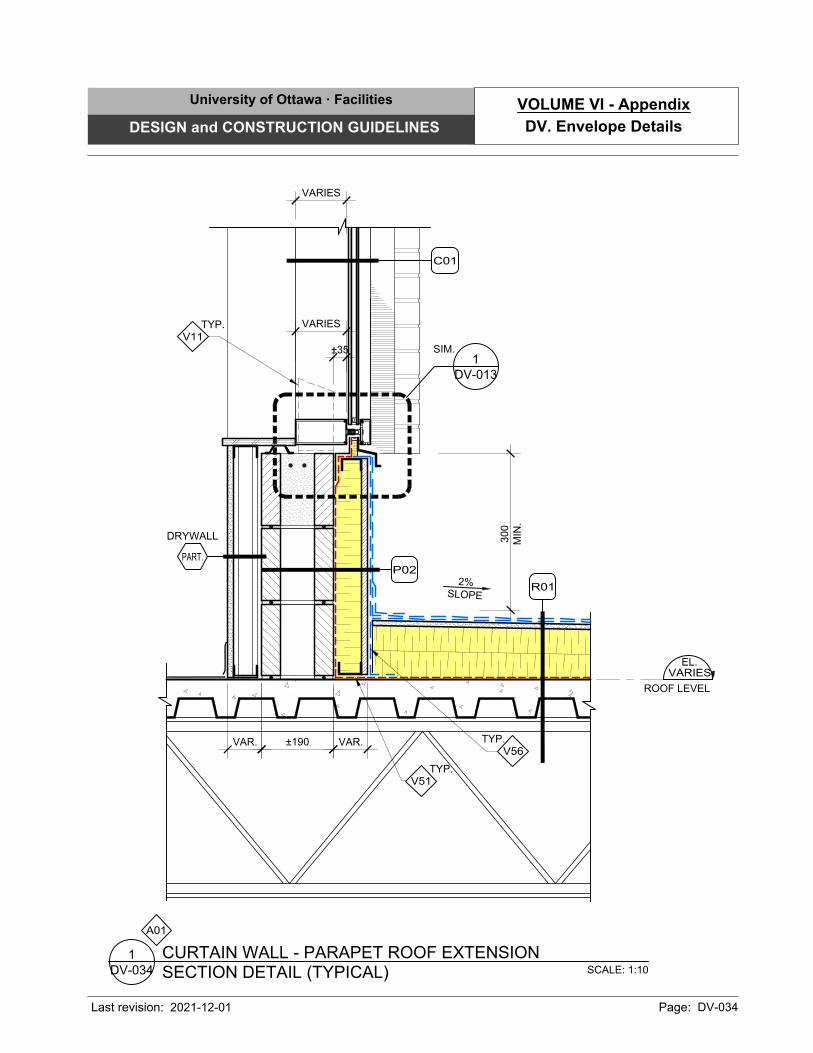
300
MIN
.
2%
SLO
PE
±190VAR.
DRYWALL
PART.
SCALE: 1:10
SECTION DETAIL (TYPICAL)
CURTAIN WALL - PARAPET ROOF EXTENSION
DV-034
1
EL.
ROOF LEVEL
VARIES
A01
P02
TYP.
V11
C01
DV-013
1
SIM. ±35
VARIES
VARIES
TYP.
V56
TYP.
V51
R01
VAR.
University of Ottawa · Facilities
DESIGN and CONSTRUCTION GUIDELINES
Last revision: Page: DV-034
DV. Envelope Details
VOLUME VI - Appendix
2021-12-01
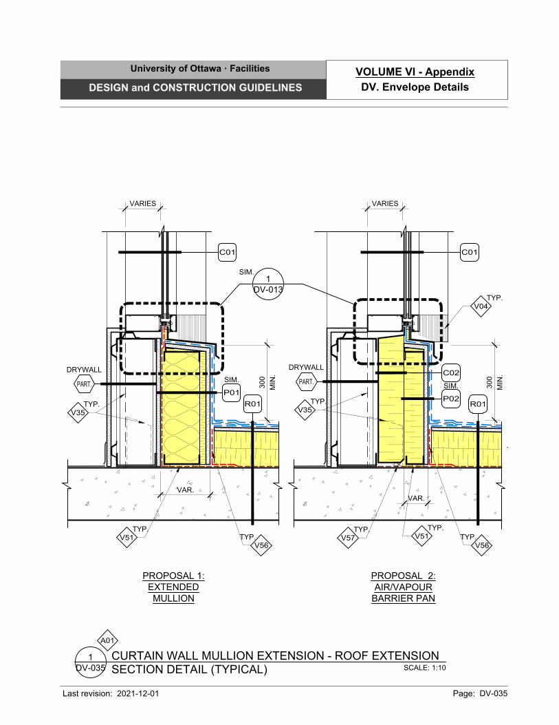
VARIES
300
MIN
.
SIM.
P01
C01
300
MIN
.
TYP.
V35
C01
DRYWALL
PART.
SCALE: 1:10
SECTION DETAIL (TYPICAL)
CURTAIN WALL MULLION EXTENSION - ROOF EXTENSION
DV-035
1
A01
SIM.
P02
TYP.
V56
TYP.
V51
R01 R01
DRYWALL
PART.
C02
TYP.
V56
TYP.
V51
PROPOSAL 1:
EXTENDED
MULLION
PROPOSAL 2:
AIR/VAPOUR
BARRIER PAN
DV-013
1
SIM.
TYP.
V35
VAR.
VAR.
VARIES
TYP.
V04
TYP.
V57
University of Ottawa · Facilities
DESIGN and CONSTRUCTION GUIDELINES
Last revision: Page: DV-035
DV. Envelope Details
VOLUME VI - Appendix
2021-12-01
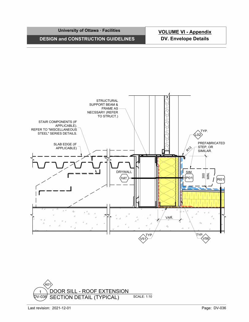
R
1
3
SLAB EDGE (IF
APPLICABLE)
SCALE: 1:10
SECTION DETAIL (TYPICAL)
DOOR SILL - ROOF EXTENSION
DV-036
1
A01
300
MIN
.
SIM.
P01
DRYWALL
PART.
TYP.
V56
TYP.
V51
R01
VAR.
STRUCTURAL
SUPPORT BEAM &
FRAME AS
NECSSARY (REFER
TO STRUCT.)
TYP.
L02
STAIR COMPONENTS (IF
APPLICABLE).
REFER TO "MISCELLANEOUS
STEEL" SERIES DETAILS.
PREFABRICATED
STEP, OR
SIMILAR.
University of Ottawa · Facilities
DESIGN and CONSTRUCTION GUIDELINES
Last revision: Page: DV-036
DV. Envelope Details
VOLUME VI - Appendix
2021-12-01
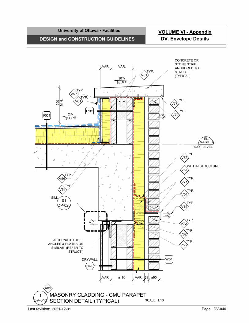
SCALE: 1:10
SECTION DETAIL (TYPICAL)
MASONRY CLADDING - CMU PARAPET
DV-040
1
VAR.
EL.
ROOF LEVEL
VARIES
200
MIN
.
ALTERNATE STEEL
ANGLES & PLATES OR
SIMILAR (REFER TO
STRUCT.)
F
TYP.
V15
F
±38
2%
SLO
PE
CONCRETE OR
STONE STRIP,
ANCHORED TO
STRUCT.
(TYPICAL)
10%
SLO
PE
DRYWALL
PART.
DP-020
01
SIM.
TYP.
V51
TYP.
V76
TYP.
V56
TYP.
V01
TYP.
V57
TYP.
V71
WITHIN STRUCTURE
V61
TYP.
V01
TYP.
V53
TYP.
V62
TYP.
V55
TYP.
V72
±190 VAR. 38 ±90VAR.
TYP.
V51
A01
VAR.
W01
R01
P02 TYP.
V72
University of Ottawa · Facilities
DESIGN and CONSTRUCTION GUIDELINES
Last revision: Page: DV-040
DV. Envelope Details
VOLUME VI - Appendix
2021-12-01
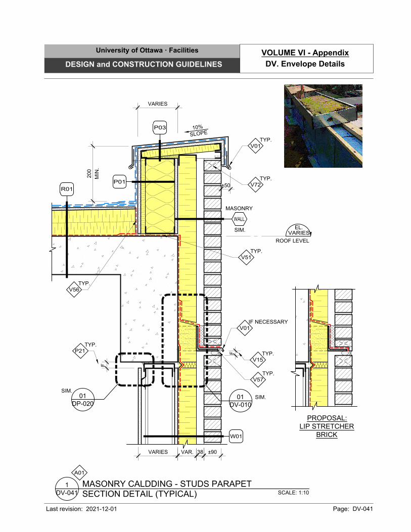
SCALE: 1:10
SECTION DETAIL (TYPICAL)
MASONRY CALDDING - STUDS PARAPET
DV-041
1
EL.
ROOF LEVEL
VARIES
200
MIN
.
F
TYP.
P21
F
±50
10%
S
LO
P
E
TYP.
V51
VARIES
TYP.
V56
TYP.
V01
TYP.
V57
DV-010
01
SIM.
IF NECESSARY
V01
VAR. 38VARIES ±90
MASONRY
SIM.
WALL
DP-020
01
SIM.
A01
TYP.
V15
W01
R01
P01
P03
PROPOSAL:
LIP STRETCHER
BRICK
TYP.
V72
University of Ottawa · Facilities
DESIGN and CONSTRUCTION GUIDELINES
Last revision: Page: DV-041
DV. Envelope Details
VOLUME VI - Appendix
2021-12-01
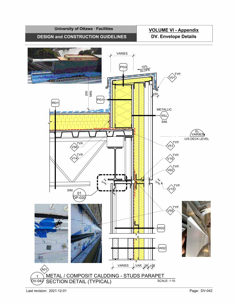
SCALE: 1:10
SECTION DETAIL (TYPICAL)
METAL / COMPOSIT CALDDING - STUDS PARAPET
DV-042
1
10%
S
LO
P
E
F
VARIES VAR. 38 ±38
±50
F
EL.
U/S DECK LEVEL
VARIES
200
MIN
.
TYP.
V14
TYP.
V56
TYP.
V55
TYP.
V62
TYP.
V01
DP-020
01
SIM.
TYP.
V51
METALLIC
SIM.
WALL
A01
VARIES
TYP.
V15
TYP.
V16
W02
W02
R01
P01
P03
University of Ottawa · Facilities
DESIGN and CONSTRUCTION GUIDELINES
Last revision: Page: DV-042
DV. Envelope Details
VOLUME VI - Appendix
2021-12-01
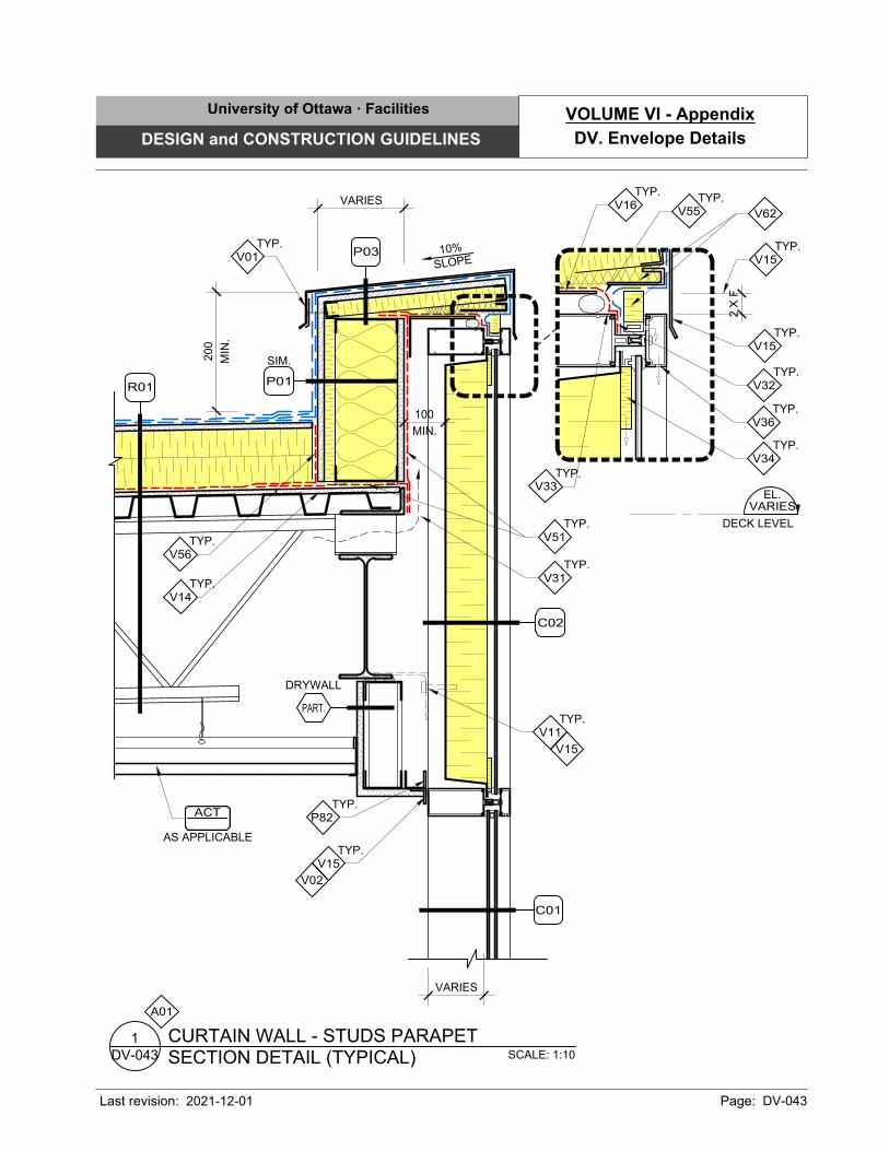
SCALE: 1:10
SECTION DETAIL (TYPICAL)
CURTAIN WALL - STUDS PARAPET
DV-043
1
A01
TYP.
V55
TYP.
V15
10%
S
LO
P
E
200
MIN
.
EL.
DECK LEVEL
VARIES
TYP.
V14
TYP.
V56
TYP.
V01
100
MIN.
ACT
AS APPLICABLE
DRYWALL
PART.
TYP.
V36
TYP.
V32
TYP.
V16
TYP.
V34
TYP.
V31
TYP.
V51
TYP.
V11
V15
VARIES
VARIES
TYP.
V15
V02
C01
C02
R01
SIM.
P01
P03
TYP.
P82
V62
2 X
F
TYP.
V15
TYP.
V33
University of Ottawa · Facilities
DESIGN and CONSTRUCTION GUIDELINES
Last revision: Page: DV-043
DV. Envelope Details
VOLUME VI - Appendix
2021-12-01
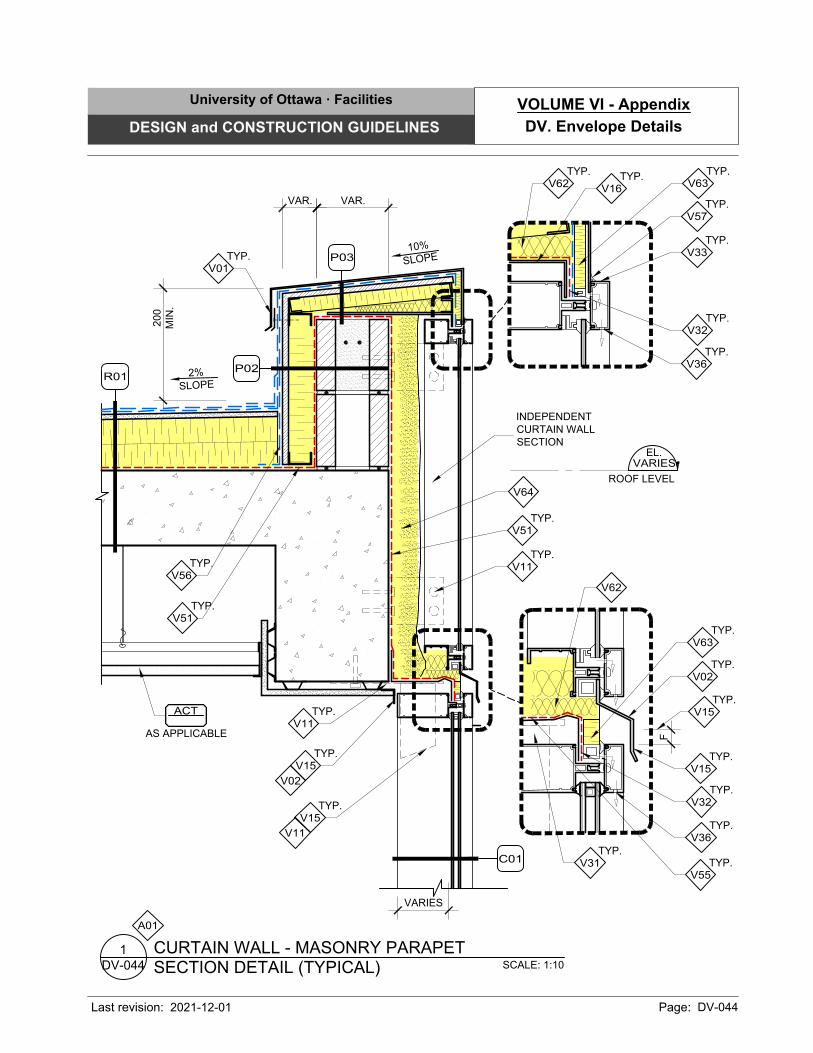
SCALE: 1:10
SECTION DETAIL (TYPICAL)
CURTAIN WALL - MASONRY PARAPET
DV-044
1
A01
TYP.
V36
TYP.
V32
TYP.
V63
TYP.
V16
TYP.
V62
TYP.
V57
TYP.
V33
VAR.
EL.
ROOF LEVEL
VARIES
200
MIN
.
2%
SLO
PE
TYP.
V56
TYP.
V51
VAR.
10%
S
LO
P
E
VARIES
ACT
AS APPLICABLE
INDEPENDENT
CURTAIN WALL
SECTION
V64
TYP.
V51
TYP.
V15
TYP.
V11
TYP.
V11
TYP.
V36
V62
TYP.
V32
TYP.
V55
TYP.
V01
TYP.
V15
V02
V11
C01
R01
P02
P03
F
TYP.
V15
TYP.
V31
TYP.
V02
TYP.
V15
TYP.
V63
University of Ottawa · Facilities
DESIGN and CONSTRUCTION GUIDELINES
Last revision: Page: DV-044
DV. Envelope Details
VOLUME VI - Appendix
2021-12-01
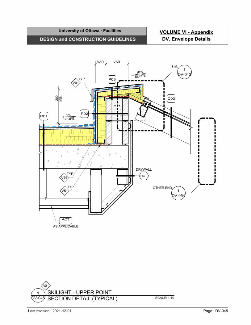
C03
VAR.
200
MIN
.
2%
SLO
PE
TYP.
V56
TYP.
V51
VAR.
10%
S
LO
P
E
ACT
AS APPLICABLE
TYP.
V01
R01
P02
P03
SCALE: 1:10
SECTION DETAIL (TYPICAL)
SKILIGHT - UPPER POINT
DV-045
1
A01
DV-054
1
OTHER END
DV-043
1
SIM.
DRYWALL
PART.
University of Ottawa · Facilities
DESIGN and CONSTRUCTION GUIDELINES
Last revision: Page: DV-045
DV. Envelope Details
VOLUME VI - Appendix
2021-12-01
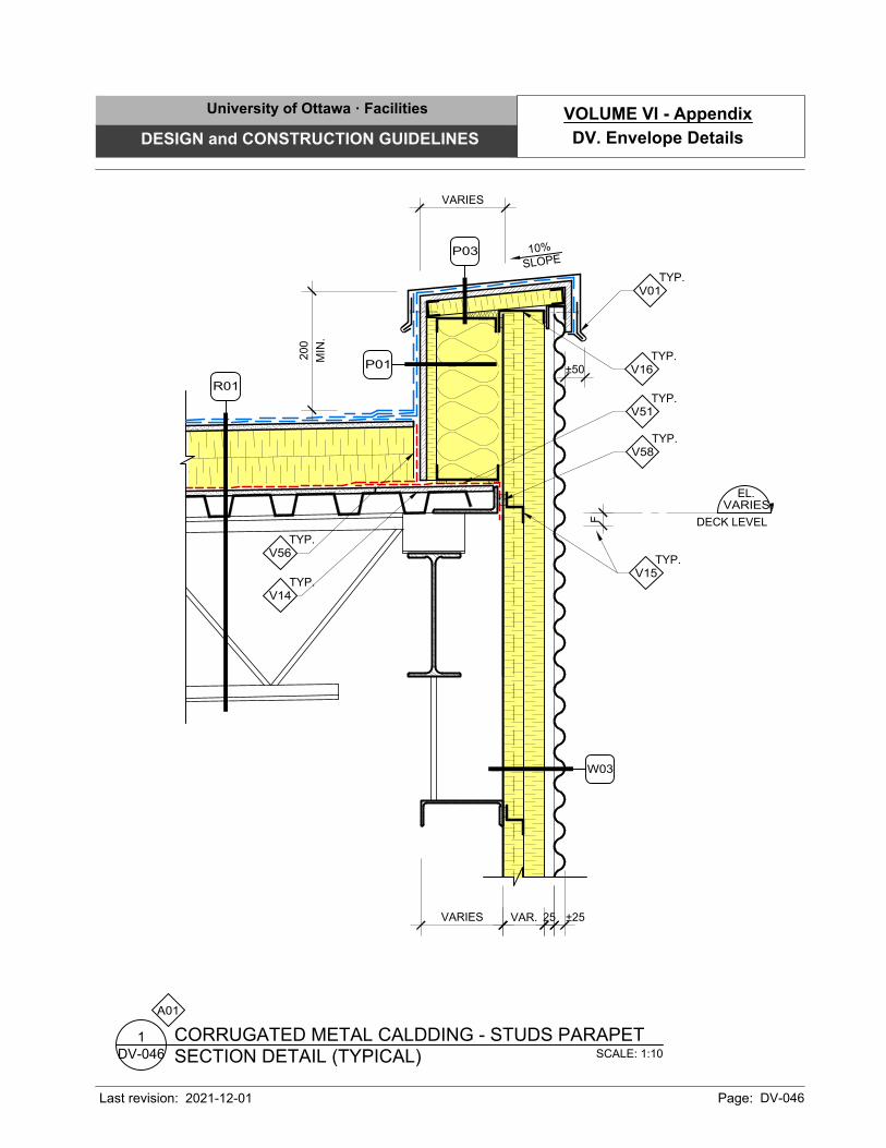
VARIES VAR. 25 ±25
±50
F
TYP.
V15
10%
S
LO
P
E
200
MIN
.
EL.
DECK LEVEL
VARIES
TYP.
V14
TYP.
V56
TYP.
V01
TYP.
V51
SCALE: 1:10
SECTION DETAIL (TYPICAL)
CORRUGATED METAL CALDDING - STUDS PARAPET
DV-046
1
TYP.
V58
A01
VARIES
TYP.
V16
W03
R01
P01
P03
University of Ottawa · Facilities
DESIGN and CONSTRUCTION GUIDELINES
Last revision: Page: DV-046
DV. Envelope Details
VOLUME VI - Appendix
2021-12-01
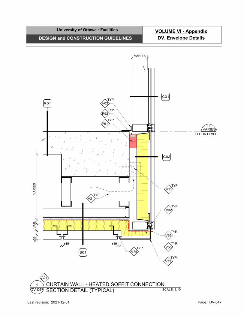
EL.
FLOOR LEVEL
VARIES
C02
VA
RIE
S
TYP.
V11
VA
R.
±38
±19
S01
TYP.
P51
TYP.
P52
TYP.
V31
TYP.
V55
TYP.
V32
TYP.
V63
TYP.
V75
±19
A01
SCALE: 1:10
SECTION DETAIL (TYPICAL)
CURTAIN WALL - HEATED SOFFIT CONNECTION
DV-047
1
C01
R01
TYP.
V02
VARIES
TYP.
V73
University of Ottawa · Facilities
DESIGN and CONSTRUCTION GUIDELINES
Last revision: Page: DV-047
DV. Envelope Details
VOLUME VI - Appendix
2021-12-01
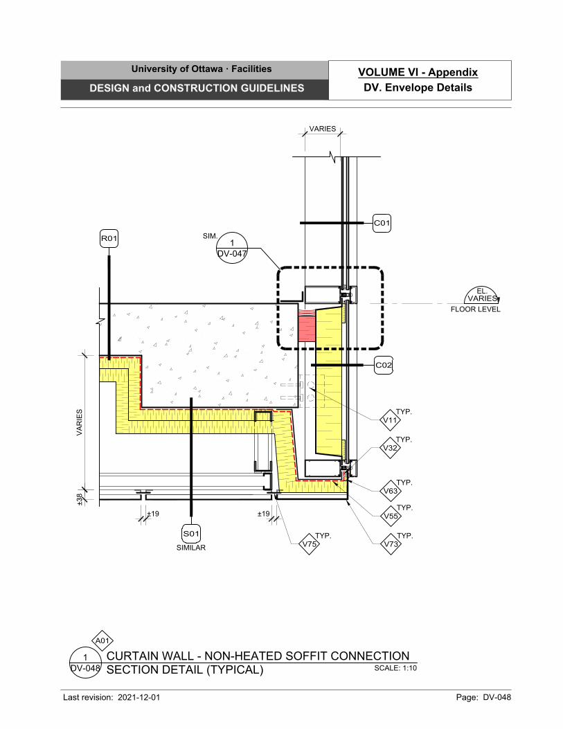
C02
TYP.
V11
VA
RIE
S±38
±19
SIMILAR
S01
TYP.
V73
TYP.
V32
TYP.
V63
TYP.
V75
±19
TYP.
V55
A01
SCALE: 1:10
SECTION DETAIL (TYPICAL)
CURTAIN WALL - NON-HEATED SOFFIT CONNECTION
DV-048
1
EL.
FLOOR LEVEL
VARIES
C01
R01
VARIES
DV-047
1
SIM.
University of Ottawa · Facilities
DESIGN and CONSTRUCTION GUIDELINES
Last revision: Page: DV-048
DV. Envelope Details
VOLUME VI - Appendix
2021-12-01
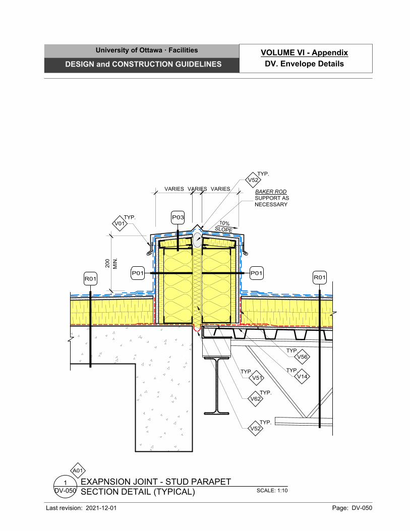
SCALE: 1:10
SECTION DETAIL (TYPICAL)
EXAPNSION JOINT - STUD PARAPET
DV-050
1
200
MIN
.
VARIES
10%
S
LO
P
E
TYP.
V14
TYP.
V56
TYP.
V51
TYP.
V62
TYP.
V52
VARIESVARIES
TYP.
V52
TYP.
V01
BAKER ROD
SUPPORT AS
NECESSARY
A01
R01
R01
P01 P01
P03
University of Ottawa · Facilities
DESIGN and CONSTRUCTION GUIDELINES
Last revision: Page: DV-050
DV. Envelope Details
VOLUME VI - Appendix
2021-12-01
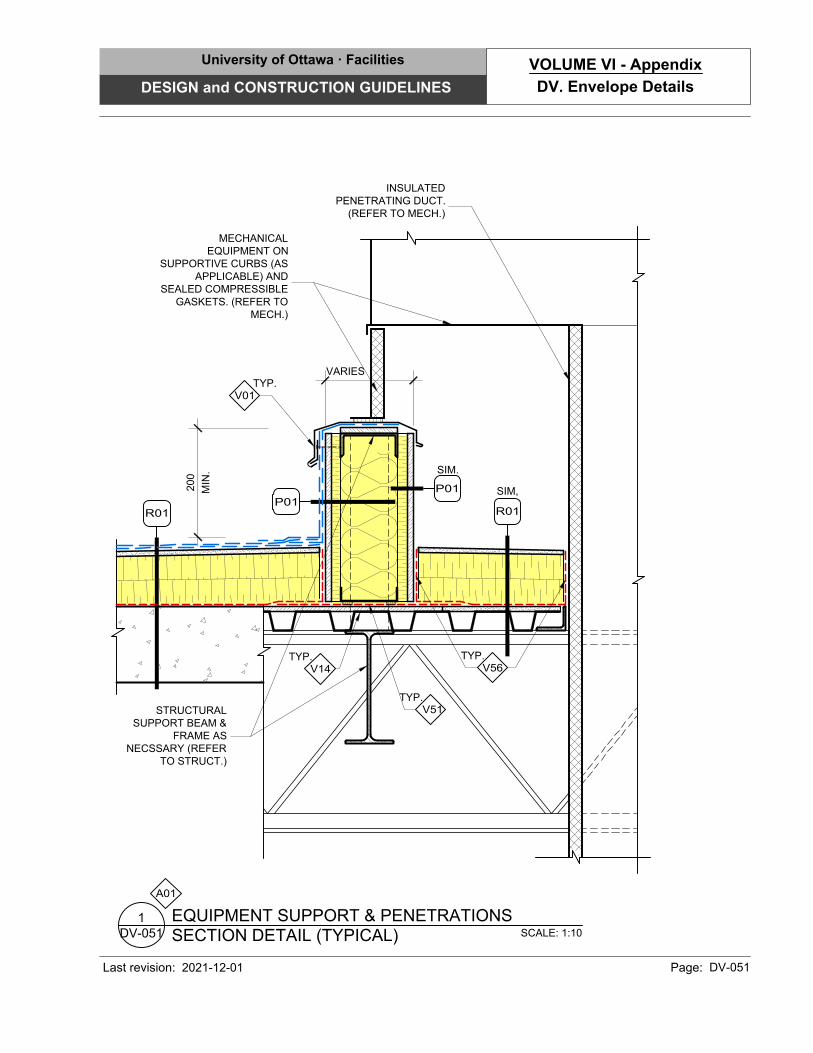
SCALE: 1:10
SECTION DETAIL (TYPICAL)
EQUIPMENT SUPPORT & PENETRATIONS
DV-051
1
20
0
MIN
.
TYP.
V14
TYP.
V56
TYP.
V51
VARIES
TYP.
V01
A01
R01
SIM,
R01
P01
MECHANICAL
EQUIPMENT ON
SUPPORTIVE CURBS (AS
APPLICABLE) AND
SEALED COMPRESSIBLE
GASKETS. (REFER TO
MECH.)
STRUCTURAL
SUPPORT BEAM &
FRAME AS
NECSSARY (REFER
TO STRUCT.)
SIM.
P01
INSULATED
PENETRATING DUCT.
(REFER TO MECH.)
University of Ottawa · Facilities
DESIGN and CONSTRUCTION GUIDELINES
Last revision: Page: DV-051
DV. Envelope Details
VOLUME VI - Appendix
2021-12-01
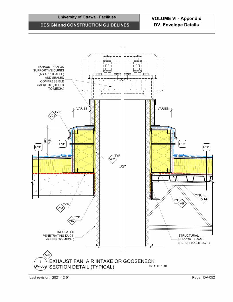
SCALE: 1:10
SECTION DETAIL (TYPICAL)
EXHAUST FAN, AIR INTAKE OR GOOSENECK
DV-052
1
A01
20
0
MIN
.
VARIES
TYP.
V14
TYP.
V51
TYP.
V51
TYP.
V01
R01
P01
EXHAUST FAN ON
SUPPORTIVE CURBS
(AS APPLICABLE)
AND SEALED
COMPRESSIBLE
GASKETS. (REFER
TO MECH.)
VARIES
R01
P01
TYP.
V62
TYP.
V57
STRUCTURAL
SUPPORT FRAME
(REFER TO STRUCT.)
INSULATED
PENETRATING DUCT.
(REFER TO MECH.)
University of Ottawa · Facilities
DESIGN and CONSTRUCTION GUIDELINES
Last revision: Page: DV-052
DV. Envelope Details
VOLUME VI - Appendix
2021-12-01
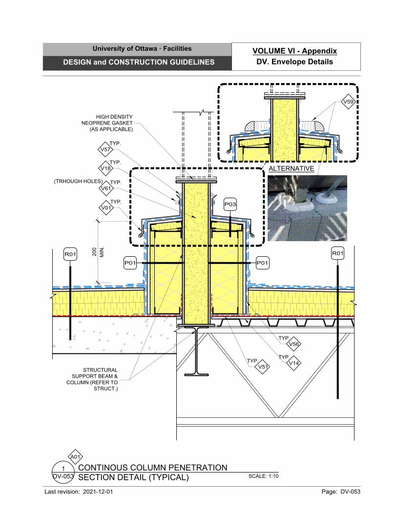
200
MIN
.
TYP.
V14
TYP.
V56
TYP.
V51
STRUCTURAL
SUPPORT BEAM &
COLUMN (REFER TO
STRUCT.)
P01
R01
R01
TYP.
V01
P03
P01
TYP.
V57
SCALE: 1:10
SECTION DETAIL (TYPICAL)
CONTINOUS COLUMN PENETRATION
DV-053
1
A01
TYP.
V18
V59
ALTERNATIVE
(TRHOUGH HOLES)
TYP.
V61
HIGH DENSITY
NEOPRENE GASKET
(AS APPLICABLE)
University of Ottawa · Facilities
DESIGN and CONSTRUCTION GUIDELINES
Last revision: Page: DV-053
DV. Envelope Details
VOLUME VI - Appendix
2021-12-01
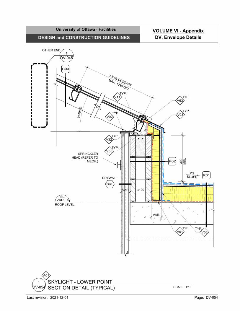
300
MIN
.
2%
SLO
PE
±190VAR.
DRYWALL
PART.
SCALE: 1:10
SECTION DETAIL (TYPICAL)
SKYLIGHT - LOWER POINT
DV-054
1
EL.
ROOF LEVEL
VARIES
A01
P02
TYP.
V11
TYP.
V56
TYP.
V51
R01
VAR.
A
S
N
E
C
E
S
S
A
R
Y
M
A
X
.
1
2
2
0
O
/
C
V
A
R
IE
S
C03
TYP.
V02
TYP.
V03
TYP.
V55
TYP.
V63
TYP.
V32
SPRINCKLER
HEAD (REFER TO
MECH.)
DV-045
1
OTHER END
University of Ottawa · Facilities
DESIGN and CONSTRUCTION GUIDELINES
Last revision: Page: DV-054
DV. Envelope Details
VOLUME VI - Appendix
2021-12-01
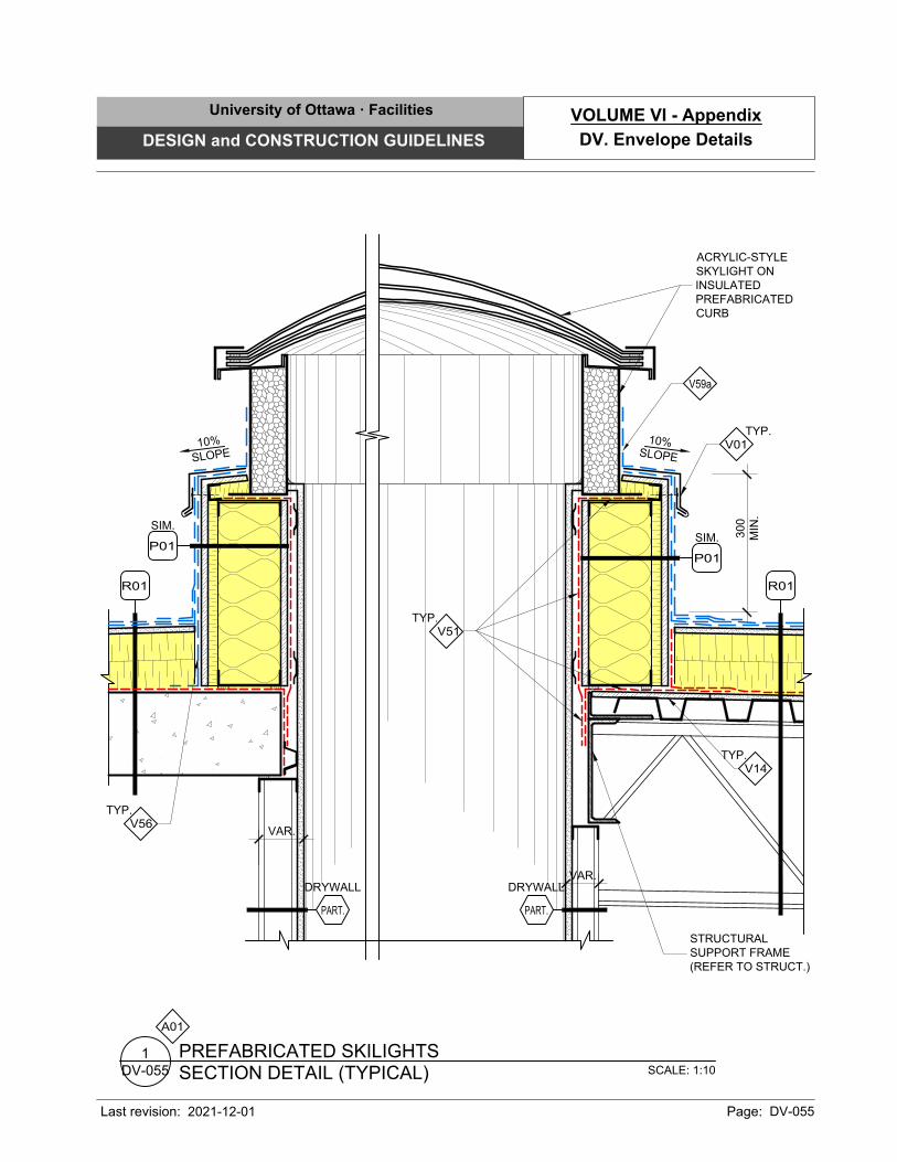
300
MIN
.
SCALE: 1:10
SECTION DETAIL (TYPICAL)
PREFABRICATED SKILIGHTS
DV-055
1
A01
10%
S
LO
P
E
TYP.
V14
TYP.
V56
TYP.
V51
R01
VAR.
DRYWALL
PART.
SIM.
P01
STRUCTURAL
SUPPORT FRAME
(REFER TO STRUCT.)
ACRYLIC-STYLE
SKYLIGHT ON
INSULATED
PREFABRICATED
CURB
V59a
TYP.
V01
10%
S
LO
P
E
R01
VAR.
DRYWALL
PART.
SIM.
P01
University of Ottawa · Facilities
DESIGN and CONSTRUCTION GUIDELINES
Last revision: Page: DV-055
DV. Envelope Details
VOLUME VI - Appendix
2021-12-01
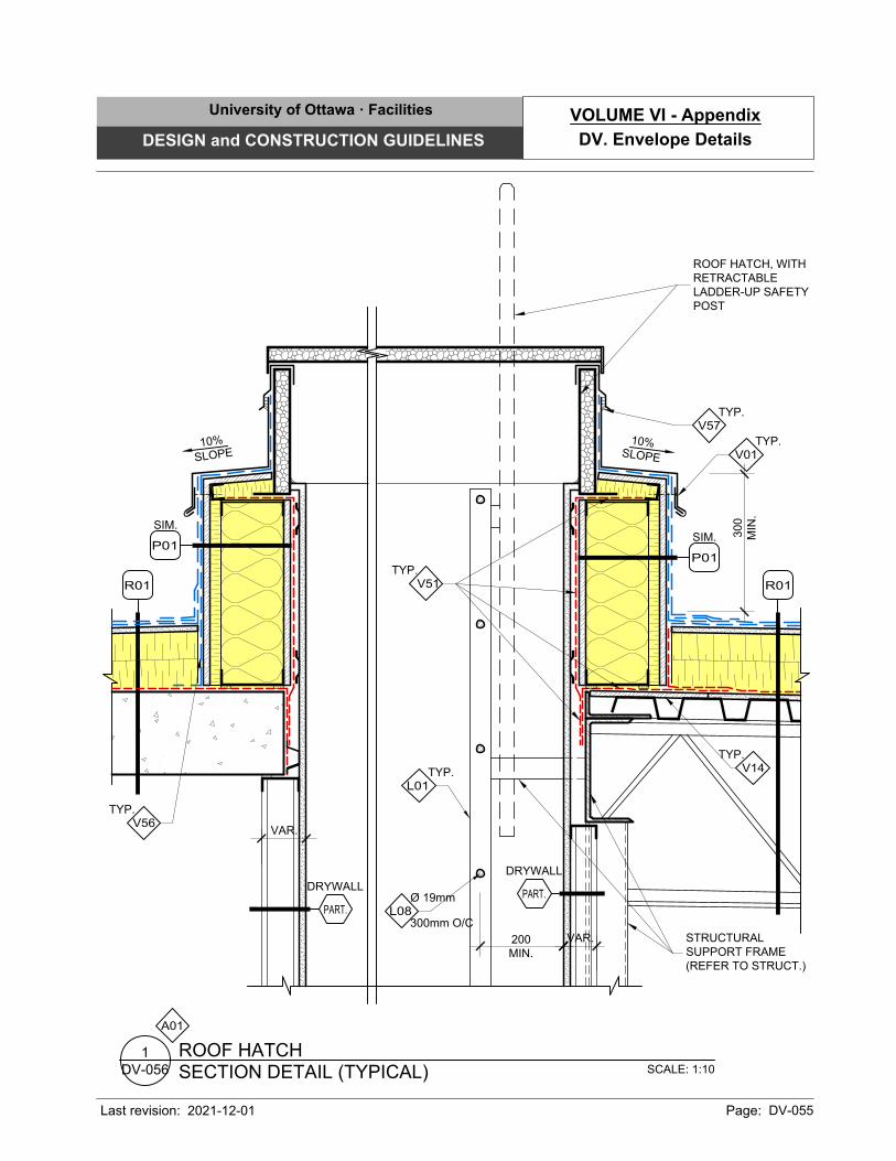
300
MIN
.
10%
S
LO
P
E
TYP.
V14
TYP.
V51
R01
VAR.
DRYWALL
PART.
SIM.
P01
STRUCTURAL
SUPPORT FRAME
(REFER TO STRUCT.)
ROOF HATCH, WITH
RETRACTABLE
LADDER-UP SAFETY
POST
TYP.
V01
SCALE: 1:10
SECTION DETAIL (TYPICAL)
ROOF HATCH
DV-056
1
A01
TYP.
V57
300mm O/C
Ø 19mm
L08
TYP.
L01
200
MIN.
TYP.
V56
10%
S
LO
P
E
R01
VAR.
DRYWALL
PART.
SIM.
P01
University of Ottawa · Facilities
DESIGN and CONSTRUCTION GUIDELINES
Last revision: Page: DV-055
DV. Envelope Details
VOLUME VI - Appendix
2021-12-01
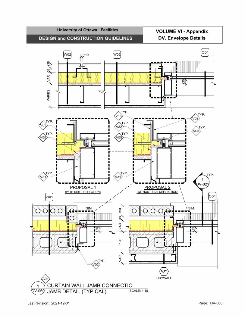
SCALE: 1:10
JAMB DETAIL (TYPICAL)
CURTAIN WALL JAMB CONNECTIO
DV-060
1
A01
VA
RIE
SV
AR
.38
±38
±19
±35
VA
R.
38
±190
±90
VA
R.
±35
TYP.
V31
TYP.
V02
TYP.
V32
TYP.
V55
SIM.
TYP.
V16
C01
C01
W01
W02W02
1
DV-021
TYP.
±35
SIM.
TYP.
V02
PROPOSAL 1
(WITH SIDE DEFLECTION)
TYP.
V55
TYP.
V63
TYP.
V31
PROPOSAL 2
(WITHOUT SIDE DEFLECTION)
TYP.
V63
DRYWALL
PART.
University of Ottawa · Facilities
DESIGN and CONSTRUCTION GUIDELINES
Last revision: Page: DV-060
DV. Envelope Details
VOLUME VI - Appendix
2021-12-01
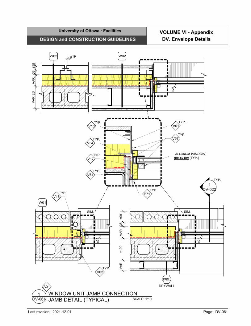
SCALE: 1:10
JAMB DETAIL (TYPICAL)
WINDOW UNIT JAMB CONNECTION
DV-061
1
A01
VA
RIE
SV
AR
.38
±38
±19
±25
±25
TYP.
V57
TYP.
V61
TYP.
V54
TYP.
V17
TYP.
P71
TYP.
V01
TYP.
V16
SIM.
W02W02
W01
ALUMIUM WINDOW
(08 40 00) (TYP.)
1
DV-022
TYP.
±25
SIM.
TYP.
V16
TYP.
V02
VA
R.
38
±190
±90
VA
R.
DRYWALL
PART.
University of Ottawa · Facilities
DESIGN and CONSTRUCTION GUIDELINES
Last revision: Page: DV-061
DV. Envelope Details
VOLUME VI - Appendix
2021-12-01
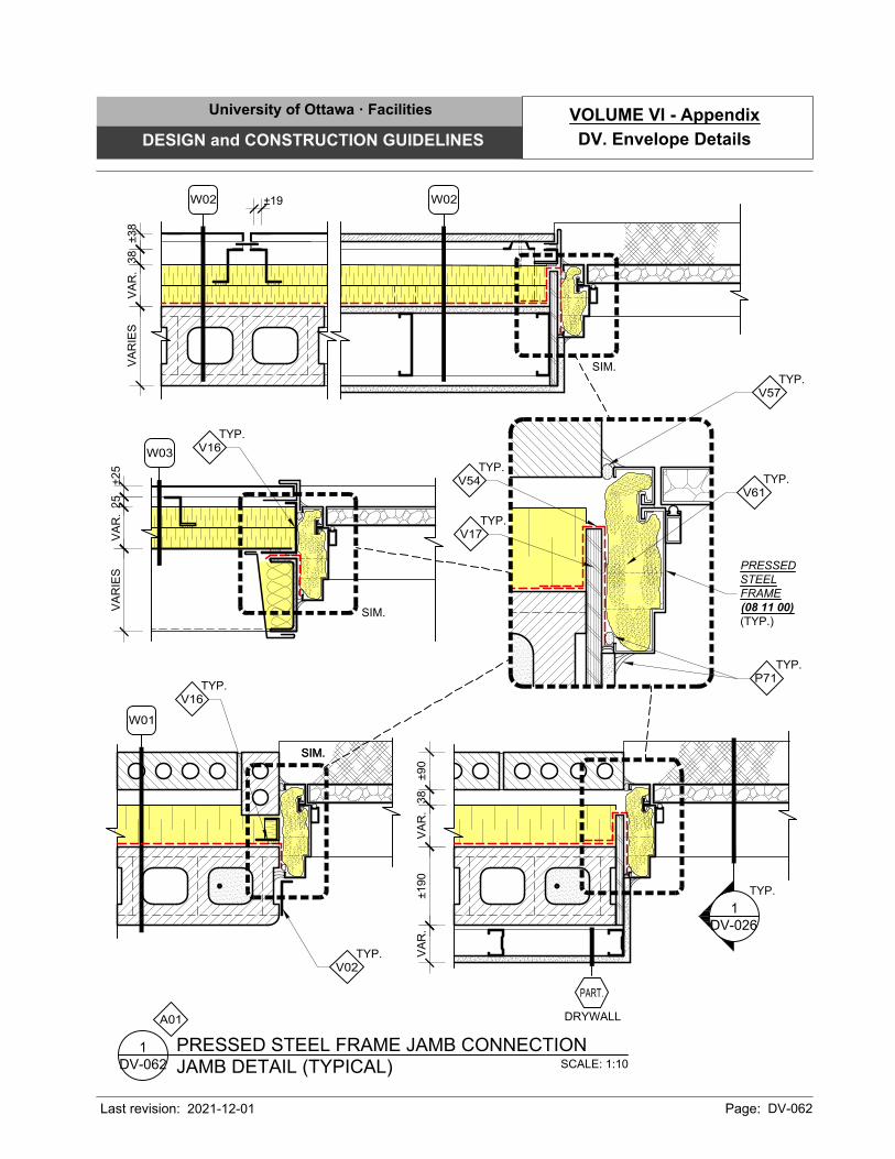
SCALE: 1:10
JAMB DETAIL (TYPICAL)
PRESSED STEEL FRAME JAMB CONNECTION
DV-062
1
A01
TYP.
V57
TYP.
V61
TYP.
V54
TYP.
V17
TYP.
P71
SIM.
W02
PRESSED
STEEL
FRAME
(08 11 00)
(TYP.)
VA
RIE
SV
AR
.25
±25
W03
DRYWALL
PART.
SIM.
TYP.
V16
VA
R.
W02
VA
RIE
S38
±38
±19
W01
SIM.
TYP.
V16
TYP.
V02
1
DV-026
TYP.
VA
R.
38
±190
±90
VA
R.
SIM.
University of Ottawa · Facilities
DESIGN and CONSTRUCTION GUIDELINES
Last revision: Page: DV-062
DV. Envelope Details
VOLUME VI - Appendix
2021-12-01
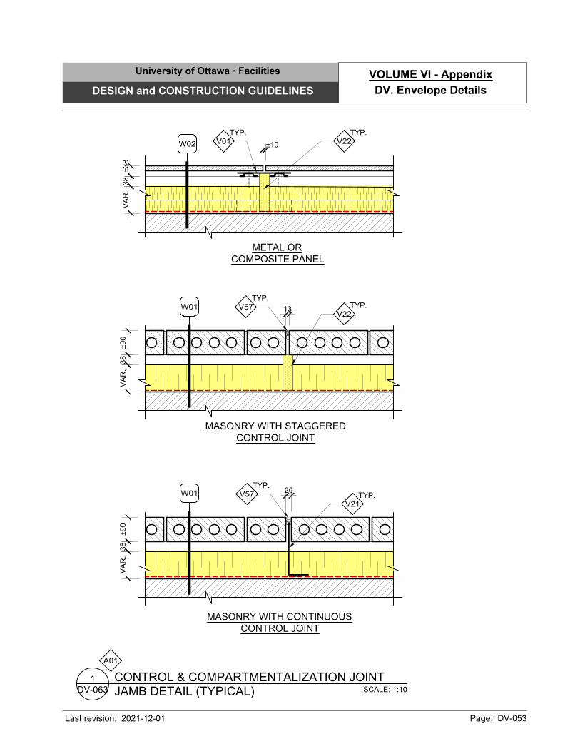
20
MASONRY WITH CONTINUOUS
CONTROL JOINT
MASONRY WITH STAGGERED
CONTROL JOINT
SCALE: 1:10
JAMB DETAIL (TYPICAL)
CONTROL & COMPARTMENTALIZATION JOINT
DV-063
1
A01
±90
TYP.
V21
TYP.
V22
W01
13
W01
TYP.
V57
VA
R.
38
±90
VA
R.
38
W02
METAL OR
COMPOSITE PANEL
±10
VA
R.
38
±38
TYP.
V22
TYP.
V01
TYP.
V57
University of Ottawa · Facilities
DESIGN and CONSTRUCTION GUIDELINES
Last revision: Page: DV-053
DV. Envelope Details
VOLUME VI - Appendix
2021-12-01
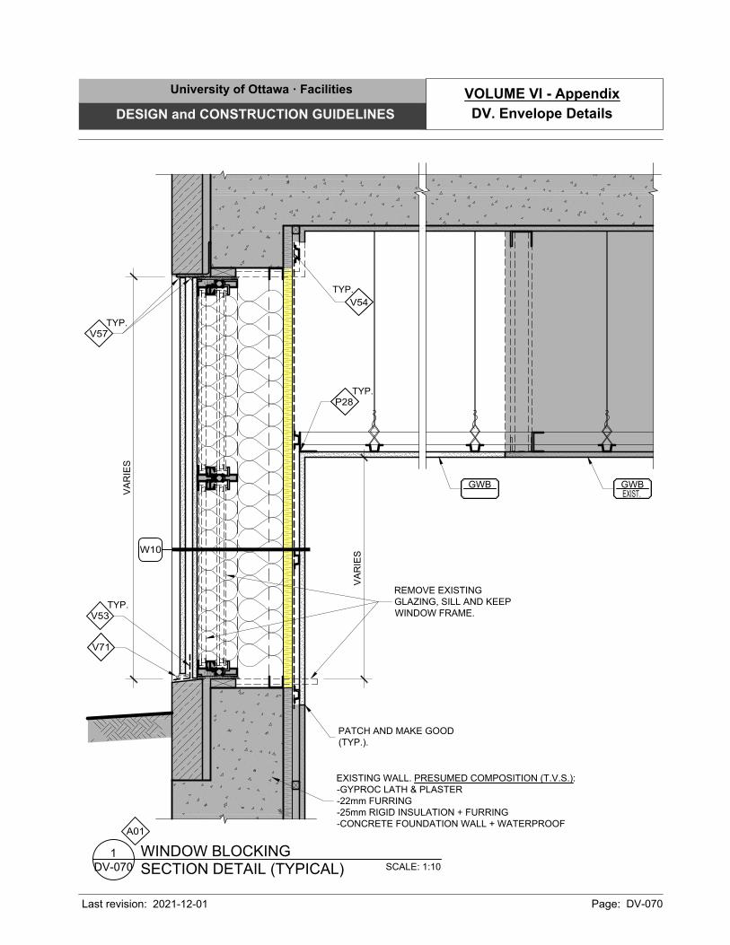
SCALE: 1:10
SECTION DETAIL (TYPICAL)
WINDOW BLOCKING
DV-070
1
A01
GWB
V71
TYP.
V54
TYP.
P28
EXISTING WALL. PRESUMED COMPOSITION (T.V.S.):
-GYPROC LATH & PLASTER
-22mm FURRING
-25mm RIGID INSULATION + FURRING
-CONCRETE FOUNDATION WALL + WATERPROOF
VA
RIE
S
VA
RIE
S
W10
TYP.
V53
TYP.
V57
GWB
EXIST.
REMOVE EXISTING
GLAZING, SILL AND KEEP
WINDOW FRAME.
PATCH AND MAKE GOOD
(TYP.).
University of Ottawa · Facilities
DESIGN and CONSTRUCTION GUIDELINES
Last revision: Page: DV-070
DV. Envelope Details
VOLUME VI - Appendix
2021-12-01
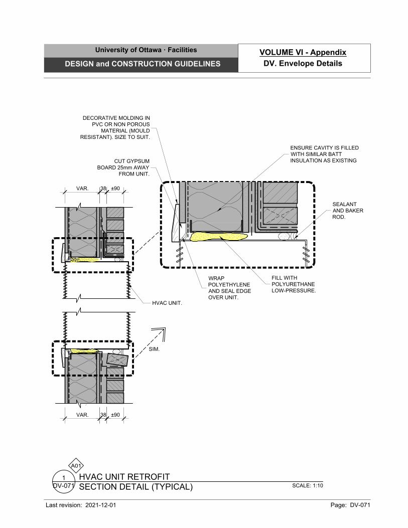
SCALE: 1:10
SECTION DETAIL (TYPICAL)
HVAC UNIT RETROFIT
DV-071
1
A01
HVAC UNIT.
SEALANT
AND BAKER
ROD.
FILL WITH
POLYURETHANE
LOW-PRESSURE.
ENSURE CAVITY IS FILLED
WITH SIMILAR BATT
INSULATION AS EXISTING
DECORATIVE MOLDING IN
PVC OR NON POROUS
MATERIAL (MOULD
RESISTANT). SIZE TO SUIT.
WRAP
POLYETHYLENE
AND SEAL EDGE
OVER UNIT.
CUT GYPSUM
BOARD 25mm AWAY
FROM UNIT.
VAR. 38 ±90
VAR. 38 ±90
SIM.
University of Ottawa · Facilities
DESIGN and CONSTRUCTION GUIDELINES
Last revision: Page: DV-071
DV. Envelope Details
VOLUME VI - Appendix
2021-12-01