design, construction and evaluation of a
TRANSCRIPT
* Corresponding author, tel: +234-817-158-0381
DESIGN, CONSTRUCTION AND EVALUATION OF A VERTICAL PLATE MAIZE
SEED PLANTER FOR GARDENS AND SMALL HOLDER FARMERS
O. A. Ani1,*, B. B. Uzoejinwa2 and N. F. Anochili3 1,2,3 DEPT. OF AGRICULTURAL AND BIORESOURCES ENG’G, UNIVERSITY OF NIGERIA, NSUKKA, ENUGU STATE. NIGERIA
E-mail addresses: [email protected], [email protected] 3 [email protected]
ABSTRACT
Metering mechanism is a key component of planters that directly affect crop development and yield based on the
performance of the particular design. Vertical plate metering device is intended to minimize seed damage during
planting while improving metering efficiency and field capacity. A vertical plate maize seed planter which is
adapted for gardens and small holder farmers cultivating less than two hectares has been designed, constructed
and tested. The major components of the planter are hopper, seed metering mechanism, seed chute, furrow opener,
furrow closer and wheels. Field test was carried out to determine the field efficiency, effective field capacity,
metering efficiency and time required to plant one hectare of farmland. Results showed that the planter has a
metering efficiency of 88.94%, effective field capacity of 0.27ha/hr and field efficiency of 71.86%.The time required
to plant one hectare of farmland was determined as 3.7 hours. The average number of seeds planted per stand was
determined as two and percentage seed damage was determined as 1.71%. This planter is considered economical,
requiring no special skill to operate and can be adopted for maize planting by small holder farmers.
Keywords: planter, design of planter, seed planter, small holder farmer
1. INTRODUCTION
Maize sometimes referred to as corn is a popular
staple food in Nigeria as well as an important raw
material for industries. It is processed in different
forms as livestock feed. Maize is an important source
of carbohydrate, protein, iron, vitamin B, and
minerals. Nigerians and other Africans consume maize
as a starchy base in a wide variety of porridges, pastes,
grits, and beer. Fresh maize is eaten parched [1]
baked, roasted or boiled. Despite previous efforts,
maize and other seed planting in Nigeria is still largely
traditional and manual, characterized by drudgery
and time wasting. In large farms, tractor drawn
planters are usually preferred, however manually
powered planters are considered more economical
and suitable for gardens and small holder farmers
cultivating less than two hectares of land.
In Nigeria, various types of planters have been
designed and developed using different approaches.
Olajide and Manuwa [2] designed, fabricated and
tested a low-cost grain planter capable of planting
three types of grains- maize, soybean and cowpea. The
planter had an average field capacity of 0.36 ha/hr
and efficiency of 71% with a percentage seed damage
of 2.58%, spacing of 50.2 cm and an average depth of
4.28 cm. Ikechukwu et al. [3] designed and fabricated
a manually operated single row maize planter for
garden use and the field test results showed that the
planter had a planting capacity of 0.0486 hectare/hr.
Oduma et al. [4] also developed and tested a manually
operated cowpea precision planter. Test results
showed minimal seed damage with good performance
for cowpea, a field efficiency of 71.71% and an
average field capacity of 0.260 ha/hr. Bashiri et al. [5]
developed and tested a prototype simple hand planter
for maize. Test results showed that the planter has a
metering efficiency and accuracy of 96% and 58%
respectively with a field capacity of 0.5ha/hr as
against 22hr per hectare if one person is to work.
Adisa and Braide [6] developed template row crop
planter with a planting rate of 0.20 ha/h. Gupta and
Herwanto [7] also designed and developed a direct
paddy seeder to match a two- wheel tractor. The
machine had a field capacity of 0.5ha/hr at a forward
Nigerian Journal of Technology (NIJOTECH)
Vol. 35, No. 3, July 2016, pp. 647 – 655
Copyright© Faculty of Engineering, University of Nigeria, Nsukka, Print ISSN: 0331-8443, Electronic ISSN: 2467-8821
www.nijotech.com
http://dx.doi.org/10.4314/njt.v35i3.25
A VERTICAL PLATE MAIZE SEED PLANTER FOR GARDENS AND SMALL HOLDER FARMERS O. A. Ani, et al
Nigerian Journal of Technology Vol. 35, No. 3, July 2016 648
speed of 0.81m/s. Kumar et al. [8] developed a
manually operated seeding attachment for an animal
drawn cultivator with a seed rate of 43.2 kg/hr and
field capacity of 0.282 ha/hr. Tests showed minimal
seed damage with good performance for wheat and
barley. Metering mechanism is a key component of
planters that directly affect crop development and
yield based on the performance of the particular
design. A wide range of seed metering devices exist,
but most can be classified as either precision or mass
flow type, depending primarily on their principle of
operation and the resulting planting pattern [9]. Mass
flow types do not meter individual seeds but rather a
consistent volume of seeds per unit of time to give the
average desired seed spacing. They are therefore used
for crops that are usually planted at higher seeding
densities (150 -1500seeds/m2); planted in relatively
narrow rows (80–350mm); and for crops (such as
cereal grains and grass pastures) that can tolerate
considerable variation in both seeding rate and
uniformity of seed spacing without a significant loss in
yield [9, 10]. Mass flow seed metering systems are
used on planters generally referred to as broadcast,
drill and air seeders and can be broadly classified as
either stationary opening, external force feed (fluted
and peg/studded rollers) and internal force feed
(double run) types [9]. Precision seed metering
systems are generally used on row crop planters and
for metering single seeds [11]. Depending on the
design and/or shape of the principal moving element
that enables selection of single seeds from the seed lot,
precision metering devices can be broadly classified as
plate, belt, disc, drum or finger types [12, 13]. Plate
planters are those that principally use a moving plate
with indents, i.e. holes, cells or cups, around its
periphery and metering performance is generally
highly dependent on matching the size (length,
breadth and thickness) of the indents to the size of the
seed. Plate meters can be sub-classified as horizontal
plate, inclined plate or vertical plate types [9].
Previous research effort suggested that plate metering
system would be suitable for maize seeds [12]. From
the foregoing, it is evident that in Nigeria, various
types of planters have been designed and developed
using different approaches; however each of them has
its own advantages and limitations as may be noticed
from the discussion. This particular design aims at
investigating the effectiveness of vertical plate
metering mechanism specifically targeted at maize
seed planting. Vertical plate metering device is
intended to minimize seed damage during planting
while improving metering efficiency and field
capacity. It is therefore another contribution to the
numerous efforts being made towards mechanizing
maize seed planting in Nigeria through indigenous
efforts. According to [14] the basic objective of
planting operation is to put the seed and fertilizer in
rows at desired depth and seed to seed spacing, cover
the seeds with soil and provide proper compaction
over the seed. Also Fenner [15] stated that for
optimum yields to be achieved, a seed planter with
high effectiveness and efficiency and also precision
has to be used to carry out the planting operation.
Research has shown that many growers could
improve their yields by just improving on the
performance of their planters [16]. This work
therefore aims at improving the metering efficiency
and field capacity of maize seed planting while
minimizing seed damage through the use of a vertical
plate push type planter. The specific objective is
therefore to design, construct and test a vertical plate
maize seed planter for gardens and small holder
farmers.
2. MATERIALS AND METHODS
2.1 Design Considerations and Mode of Operation
The planter is designed to serve as an intermediate
technology between the hand tools and the tractor
drawn multi-row planters; mainly for small holder
farmers cultivating less than two hectares of land. This
is necessary considering that more than half of the
farming population in the country cannot afford either
to buy or hire tractor drawn planting machinery, given
their level of income and size of farm. The planter is
intended to minimize drudgery by eliminating
continuous bending down and standing up, time
wasting, hand method of seed metering, furrow
opening and closing and fatigue that generally
characterize traditional seed planting by most
Nigerian farmers. The design and material selection
also ensured that the machine will be easy to
construct, affordable to the target end users, with
most of the component parts made with locally
available materials, and low technology requiring little
or no training for operation and maintenance. The
planter is a single row push type. To operate it, seeds
are poured into the hopper; the planter is then
positioned at the desired starting point, and pushed
along the row. About two seeds are picked up by the
metering plate and introduced into the chute. The
furrow opener continuously opens the soil and the
seeds metered into the chute fall into the opened
A VERTICAL PLATE MAIZE SEED PLANTER FOR GARDENS AND SMALL HOLDER FARMERS O. A. Ani, et al
Nigerian Journal of Technology Vol. 35, No. 3, July 2016 649
furrow which are simultaneously closed by the furrow
closer. As the planter is pushed along the row, it
plants continuously at 30cm intra row spacing, until
the seeds in the hopper will finish to a level requiring
refilling the hopper.
2.2 Description of Components, Design Analysis and
Material Selections
Detailed description of the component parts of the
planter, design analysis and material selections are
presented in this section.
2.2.1 Seed metering mechanism: The metering
mechanism is a major component in a planter. It picks
required number of seeds and delivers them into the
soil through the chute at required depths created by
furrow openers. Therefore the design must consider
the size of the seed, the intra and inter row spacing for
each seed, which usually differs from one crop to
another, and for different desired plant populations
and for different geographical locations. According to
[17], seed plate thickness should be between the
ranges of 3 to 6mm to enable easy picking up of seeds
and also to avoid damage of the seeds. In this design,
the metering mechanism is a mild steel plate of
100mm diameter and 5mm thickness with three
equally spaced cells near and flushing with the
circumference of the plate. The cells are designed to
pick an average of two maize seeds and drop them at
intra row spacing of 30cm. The plate is attached
vertically on a horizontal shaft driven by the front
wheel through a belt and pulley transmission. The belt
and pulley drive mechanism consists of two pulleys
and a belt used to drive the seed plate. One pulley is
attached to the front wheel of the planter which is the
driving wheel while the other is attached to the
hopper which drives the seed plate to meter the seeds.
2.2.2 Seed chute: The chute is a tube through which
the seeds metered out by the cells travel before they
are deposited into the furrow. The seed chute is
located on the outer part of the hopper by the side on
which the vertical seed plate is attached. The material
used for the design is a cylindrical funnel made of mild
steel pipe with a diameter of 32mm.
2.2.3 Furrow opener: Furrow openers open the soil
where seeds metered out and falling through the
chute will be dropped into and covered. Soil type, soil
condition, angle of attack and depth of planting should
be considered in designing furrow openers. The type
of furrow opener used for this design is the adjustable
‘shovel type’ furrow opener which gives a ‘v’ shaped
furrow opening and is suitable because it cuts and
displaces the soil sideways for easy planting [17]. The
adjustable furrow opener permits planting at each
variety’s ideal ground depth. The material used for the
furrow opener design was mild steel angle iron of
2mm thickness.
2.2.4 Furrow closer: The furrow closer was also
designed to be adjustable. It was designed to allow for
proper covering and compaction of the soil over the
seeds in the furrows. The material used for the design
was mild steel angle iron of 2mm thickness, folded
into a sort of shovel and positioned at the back of the
chute.
2.2.5 The frame : The frame is like the chasis for the
planter, it forms the platform on which other
components are fixed. The material of the main frame
was selected based on achieving a reasonable weight
and required strength and reliability and readily
available material. In this work, mild steel angle iron
of 30.2mm by 30.2mm by 3mm thickness was used.
Angle iron which is made of carbon steel has high
strength properties and is used for general
engineering purposes[18]; also it has good weld
properties and does not easily break off. The
particular angle iron selected was considered less
heavy than other dimensions while still having
required strength properties. The length of the main
frame used in this design is 900mm.
2.2.6 The front wheel: According to [19], wheels of
larger diameters are to reduce rolling resistance
especially in the case of traction wheels. In this work,
the front wheel is designed to be a traction wheel to
enhance movement on loose soils. It is made of a 6mm
thick mild steel plate cut out into 80mm width and
folded into a circle of 400mm diameter. Small pieces
of v-shaped metals are attached alternately
throughout the circumference of the wheel to provide
lugs for effective gripping of the ground surface. The
wheel has 3mm thick and 20mm wide flat bars as
spokes which are welded to a hub containing a
bearing. The front wheel provides drive for the
metering mechanism through a belt and pulley
system.
2.2.7 The rear wheel: The rear wheel is the driven
wheel. It is a rigid rubber wheel of 300mm diameter to
A VERTICAL PLATE MAIZE SEED PLANTER FOR GARDENS AND SMALL HOLDER FARMERS O. A. Ani, et al
Nigerian Journal of Technology Vol. 35, No. 3, July 2016 650
enhance stability and maneuverability. Pneumatic
tires could also be used in place of rigid tires. Rubber
tires are more suitable for withstanding vertical
deflection. Tire rolling resistance decreases with
increase in pressure on the ground surface. As the
pressure increases, the tire holds its shape more
firmly and vertical deflection decreases. The
deformation of rubber is less compared to that in a
tire with lower pressure. There are standard wheel
sizes for equipment similar to wheel barrows and they
range from 250 to 300mm in diameter [19]. These
wheels have pressure ranges of 10 to 16psi and could
be used for this design.
2.2.8 The handle: The handle is used to provide the
push force from a human operator to move the planter
from point to point during planting operation. The
handle is adjustable to take care of differences in
height of operators. Angle iron was chosen for the
handle because of its high strength and rigidity
properties to prevent bending or breaking during
operation. The 30.2mm x 30.2mm x 3mm dimension
was selected because of weight considerations to
enable ease of operation [18].
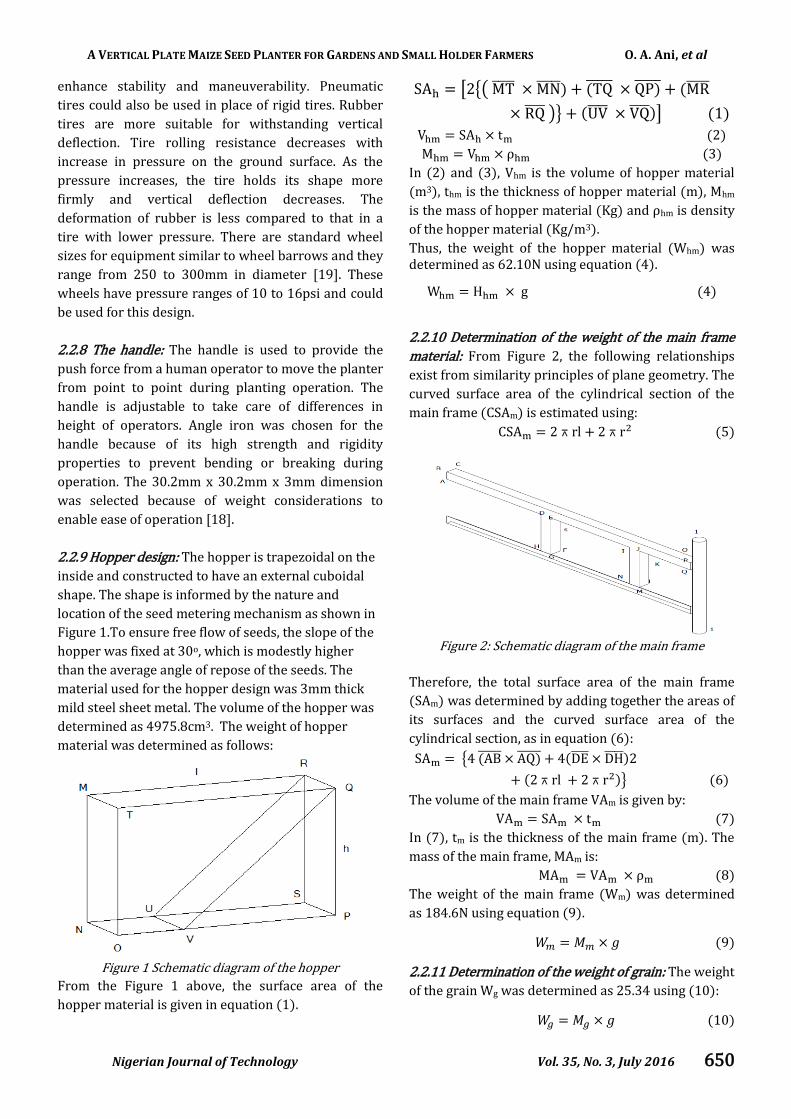
2.2.9 Hopper design: The hopper is trapezoidal on the
inside and constructed to have an external cuboidal
shape. The shape is informed by the nature and
location of the seed metering mechanism as shown in
Figure 1.To ensure free flow of seeds, the slope of the
hopper was fixed at 30o, which is modestly higher
than the average angle of repose of the seeds. The
material used for the hopper design was 3mm thick
mild steel sheet metal. The volume of the hopper was
determined as 4975.8cm3. The weight of hopper
material was determined as follows:
Figure 1 Schematic diagram of the hopper
From the Figure 1 above, the surface area of the
hopper material is given in equation (1).
[ {(
)} ]
t
In (2) and (3), Vhm is the volume of hopper material
(m3), thm is the thickness of hopper material (m), Mhm
is the mass of hopper material Kg and hm is density
of the hopper material (Kg/m3).
Thus, the weight of the hopper material (Whm) was determined as 62.10N using equation (4).
g
2.2.10 Determination of the weight of the main frame
material: From Figure 2, the following relationships
exist from similarity principles of plane geometry. The
curved surface area of the cylindrical section of the
main frame (CSAm) is estimated using:
rl r
Figure 2: Schematic diagram of the main frame
Therefore, the total surface area of the main frame
(SAm) was determined by adding together the areas of
its surfaces and the curved surface area of the
cylindrical section, as in equation (6):
{
rl r }
The volume of the main frame VAm is given by:
t
In (7), tm is the thickness of the main frame (m). The
mass of the main frame, MAm is:
The weight of the main frame (Wm) was determined
as 184.6N using equation (9).
2.2.11 Determination of the weight of grain: The weight
of the grain Wg was determined as 25.34 using (10):
A VERTICAL PLATE MAIZE SEED PLANTER FOR GARDENS AND SMALL HOLDER FARMERS O. A. Ani, et al
Nigerian Journal of Technology Vol. 35, No. 3, July 2016 651
Whence mass of grain is given by:
The actual volume of the hopper Va is determined as
the volume of the trapezoidal internal section using
the surface area of the trapezoid and its thickness ti
thus:
a h t
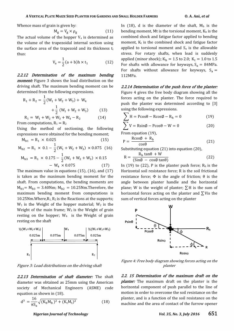
2.2.12 Determination of the maximum bending
moment: Figure 3 shows the load distribution on the
driving shaft. The maximum bending moment can be
determined from the following expressions.
From computations, R1 = R2
Using the method of sectioning, the following
expressions were obtained for the bending moment;
.
.
.
.
.
.
The maximum value in equations (15), (16), and (17)
is taken as the maximum bending moment for the
shaft. From computations, the bending moments are
= = 3.40Nm; . m.Therefore, the
maximum bending moment from computations is
10.25Nm.Where,R1, R2 is the Reactions at the supports;
W1 is the Weight of the hopper material; W2 is the
Weight of the main frame; W3 is the Weight of grain
resting on the hopper; W4 is the Weight of grain
resting on the shaft
Figure 3: Load distributions on the driving shaft
2.2.13 Determination of shaft diameter: The shaft
diameter was obtained as 25mm using the American
society of Mechanical Engineers (ASME) code
equation as shown in (18).
d
√ K K
In (18), d is the diameter of the shaft, Mb is the
bending moment, Mt is the torsional moment, Kb is the
combined shock and fatigue factor applied to bending
moment, Kt is the combined shock and fatigue factor
applied to torsional moment and Sa is the allowable
stress. For rotary shafts, when load is suddenly
applied (minor shock); K . to . K . to .
For shafts with allowance for keyways, 84MPa.
For shafts without allowance for keyways,
112MPa.
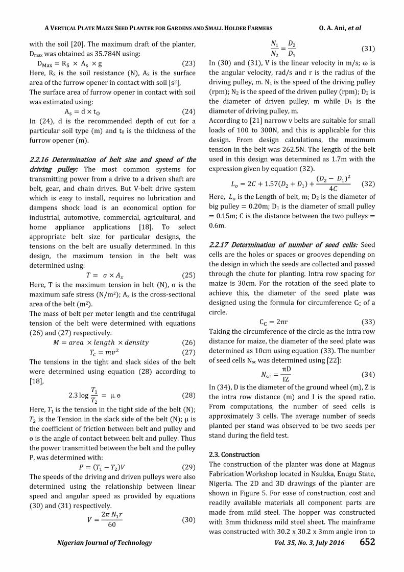
2.2.14 Determination of the push force of the planter:
Figure 4 gives the free body diagram showing all the
forces acting on the planter. The force required to
push the planter was determined according to [3]
using the following expressions.
∑ cos cos
∑ sin cos
From equation (19),
cos
cos
Substituting equation (21) into equation (20),
tan
in cos tan
In (19) to (22), P is the planter push force; Rh is the
Horizontal soil resistance force; R is the soil frictional
resistance force; Φ is the angle of friction; is the
angle between planter handle and the horizontal
plane; W is the weight of planter; ∑ is the sum of
horizontal forces acting on the planter and ∑ is the
sum of vertical forces acting on the planter
Figure 4: Free body diagram showing forces acting on the
planter
2.2. 15 Determination of the maximum draft on the
planter: The maximum draft on the planter is the
horizontal component of push parallel to the line of
motion in order to overcome the soil resistance on the
planter, and is a function of the soil resistance on the
machine and the area of contact of the furrow opener
A VERTICAL PLATE MAIZE SEED PLANTER FOR GARDENS AND SMALL HOLDER FARMERS O. A. Ani, et al
Nigerian Journal of Technology Vol. 35, No. 3, July 2016 652
with the soil [20]. The maximum draft of the planter,
Dmax was obtained as 35.784N using:
g
Here, RS is the soil resistance (N), AS is the surface
area of the furrow opener in contact with soil [s2],
The surface area of furrow opener in contact with soil
was estimated using:
d t
In (24), d is the recommended depth of cut for a
particular soil type (m) and t0 is the thickness of the
furrow opener (m).
2.2.16 Determination of belt size and speed of the
driving pulley: The most common systems for
transmitting power from a drive to a driven shaft are
belt, gear, and chain drives. But V-belt drive system
which is easy to install, requires no lubrication and
dampens shock load is an economical option for
industrial, automotive, commercial, agricultural, and
home appliance applications [18]. To select
appropriate belt size for particular designs, the
tensions on the belt are usually determined. In this
design, the maximum tension in the belt was
determined using:
Here, T is the maximum tension in belt (N), σ is the
maximum safe stress (N/m2); Ax is the cross-sectional
area of the belt (m2).
The mass of belt per meter length and the centrifugal
tension of the belt were determined with equations
(26) and (27) respectively.
The tensions in the tight and slack sides of the belt
were determined using equation (28) according to
[18],
. log .
Here, is the tension in the tight side of the belt (N);
is the Tension in the slack side of the belt (N); µ is
the coefficient of friction between belt and pulley and
is the angle of contact between belt and pulley. Thus
the power transmitted between the belt and the pulley
P, was determined with:
The speeds of the driving and driven pulleys were also
determined using the relationship between linear
speed and angular speed as provided by equations
(30) and (31) respectively.
In (30) and (31), V is the linear velocity in m/s; is
the angular velocity, rad/s and r is the radius of the
driving pulley, m. N1 is the speed of the driving pulley
(rpm); N2 is the speed of the driven pulley (rpm); D2 is
the diameter of driven pulley, m while D1 is the
diameter of driving pulley, m.
According to [21] narrow v belts are suitable for small
loads of 100 to 300N, and this is applicable for this
design. From design calculations, the maximum
tension in the belt was 262.5N. The length of the belt
used in this design was determined as 1.7m with the
expression given by equation (32).
.
Here, is the Length of belt, m; D2 is the diameter of
big pulley = 0.20m; D1 is the diameter of small pulley
= 0.15m; C is the distance between the two pulleys =
0.6m.
2.2.17 Determination of number of seed cells: Seed
cells are the holes or spaces or grooves depending on
the design in which the seeds are collected and passed
through the chute for planting. Intra row spacing for
maize is 30cm. For the rotation of the seed plate to
achieve this, the diameter of the seed plate was
designed using the formula for circumference CC of a
circle.
r
Taking the circumference of the circle as the intra row
distance for maize, the diameter of the seed plate was
determined as 10cm using equation (33). The number
of seed cells Nsc was determined using [22]:
In (34), D is the diameter of the ground wheel (m), Z is
the intra row distance (m) and I is the speed ratio.
From computations, the number of seed cells is
approximately 3 cells. The average number of seeds
planted per stand was observed to be two seeds per
stand during the field test.
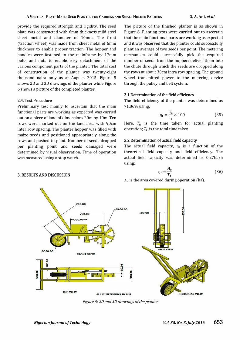
2.3. Construction
The construction of the planter was done at Magnus
Fabrication Workshop located in Nsukka, Enugu State,
Nigeria. The 2D and 3D drawings of the planter are
shown in Figure 5. For ease of construction, cost and
readily available materials all component parts are
made from mild steel. The hopper was constructed
with 3mm thickness mild steel sheet. The mainframe
was constructed with 30.2 x 30.2 x 3mm angle iron to
A VERTICAL PLATE MAIZE SEED PLANTER FOR GARDENS AND SMALL HOLDER FARMERS O. A. Ani, et al
Nigerian Journal of Technology Vol. 35, No. 3, July 2016 653
provide the required strength and rigidity. The seed
plate was constructed with 6mm thickness mild steel
sheet metal and diameter of 10mm. The front
(traction wheel) was made from sheet metal of 6mm
thickness to enable proper traction. The hopper and
handles were fastened to the mainframe by 17mm
bolts and nuts to enable easy detachment of the
various component parts of the planter. The total cost
of construction of the planter was twenty-eight
thousand naira only as at August, 2015. Figure 5
shows 2D and 3D drawings of the planter while Figure
6 shows a picture of the completed planter.
2.4. Test Procedure
Preliminary test mainly to ascertain that the main
functional parts are working as expected was carried
out on a piece of land of dimensions 20m by 10m. Ten
rows were marked out on the land area with 90cm
inter row spacing. The planter hopper was filled with
maize seeds and positioned appropriately along the
rows and pushed to plant. Number of seeds dropped
per planting point and seeds damaged were
determined by visual observation. Time of operation
was measured using a stop watch.
3. RESULTS AND DISCUSSION
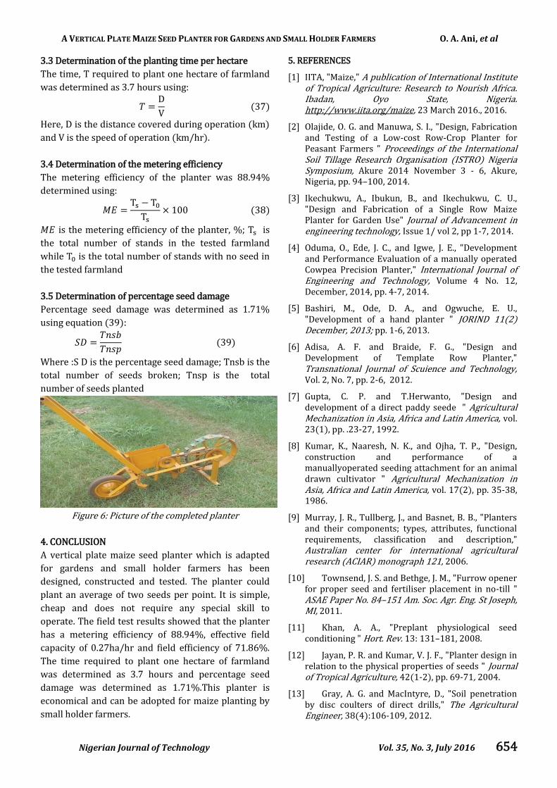
The picture of the finished planter is as shown in
Figure 6. Planting tests were carried out to ascertain
that the main functional parts are working as expected
and it was observed that the planter could successfully
plant an average of two seeds per point. The metering
mechanism could successfully pick the required
number of seeds from the hopper; deliver them into
the chute through which the seeds are dropped along
the rows at about 30cm intra row spacing. The ground
wheel transmitted power to the metering device
through the pulley and belt system.
3.1 Determination of the field efficiency
The field efficiency of the planter was determined as
71.86% using:
Here, is the time taken for actual planting
operation; is the total time taken.
3.2 Determination of actual field capacity
The actual field capacity, is a function of the
theoretical field capacity and field efficiency. The
actual field capacity was determined as 0.27ha/h
using:
is the area covered during operation (ha).
Figure 5: 2D and 3D drawings of the planter
A VERTICAL PLATE MAIZE SEED PLANTER FOR GARDENS AND SMALL HOLDER FARMERS O. A. Ani, et al
Nigerian Journal of Technology Vol. 35, No. 3, July 2016 654
3.3 Determination of the planting time per hectare
The time, T required to plant one hectare of farmland
was determined as 3.7 hours using:
Here, D is the distance covered during operation (km)
and V is the speed of operation (km/hr).
3.4 Determination of the metering efficiency
The metering efficiency of the planter was 88.94%
determined using:
is the metering efficiency of the planter, %; is
the total number of stands in the tested farmland
while is the total number of stands with no seed in
the tested farmland
3.5 Determination of percentage seed damage
Percentage seed damage was determined as 1.71%
using equation (39):
Where :S D is the percentage seed damage; Tnsb is the
total number of seeds broken; Tnsp is the total
number of seeds planted
Figure 6: Picture of the completed planter
4. CONCLUSION
A vertical plate maize seed planter which is adapted
for gardens and small holder farmers has been
designed, constructed and tested. The planter could
plant an average of two seeds per point. It is simple,
cheap and does not require any special skill to
operate. The field test results showed that the planter
has a metering efficiency of 88.94%, effective field
capacity of 0.27ha/hr and field efficiency of 71.86%.
The time required to plant one hectare of farmland
was determined as 3.7 hours and percentage seed
damage was determined as 1.71%.This planter is
economical and can be adopted for maize planting by
small holder farmers.
5. REFERENCES
[1] IITA, "Maize," A publication of International Institute of Tropical Agriculture: Research to Nourish Africa. Ibadan, Oyo State, Nigeria. http://www.iita.org/maize, 23 March 2016., 2016.
[2] Olajide, O. G. and Manuwa, S. I., "Design, Fabrication and Testing of a Low-cost Row-Crop Planter for Peasant Farmers " Proceedings of the International Soil Tillage Research Organisation (ISTRO) Nigeria Symposium, Akure 2014 November 3 - 6, Akure, Nigeria, pp. 94–100, 2014.
[3] Ikechukwu, A., Ibukun, B., and Ikechukwu, C. U., "Design and Fabrication of a Single Row Maize Planter for Garden Use" Journal of Advancement in engineering technology, Issue 1/ vol 2, pp 1-7, 2014.
[4] Oduma, O., Ede, J. C., and Igwe, J. E., "Development and Performance Evaluation of a manually operated Cowpea Precision Planter," International Journal of Engineering and Technology, Volume 4 No. 12, December, 2014, pp. 4-7, 2014.
[5] Bashiri, M., Ode, D. A., and Ogwuche, E. U., "Development of a hand planter " JORIND 11(2) December, 2013; pp. 1-6, 2013.
[6] Adisa, A. F. and Braide, F. G., "Design and Development of Template Row Planter," Transnational Journal of Scuience and Technology, Vol. 2, No. 7, pp. 2-6, 2012.
[7] Gupta, C. P. and T.Herwanto, "Design and development of a direct paddy seede " Agricultural Mechanization in Asia, Africa and Latin America, vol. 23(1), pp. .23-27, 1992.
[8] Kumar, K., Naaresh, N. K., and Ojha, T. P., "Design, construction and performance of a manuallyoperated seeding attachment for an animal drawn cultivator " Agricultural Mechanization in Asia, Africa and Latin America, vol. 17(2), pp. 35-38, 1986.
[9] Murray, J. R., Tullberg, J., and Basnet, B. B., "Planters and their components; types, attributes, functional requirements, classification and description," Australian center for international agricultural research (ACIAR) monograph 121, 2006.
[10] Townsend, J. S. and Bethge, J. M., "Furrow opener for proper seed and fertiliser placement in no-till " ASAE Paper No. 84–151 Am. Soc. Agr. Eng. St Joseph, MI, 2011.
[11] Khan, A. A., "Preplant physiological seed conditioning " Hort. Rev. 13: 131–181, 2008.
[12] Jayan, P. R. and Kumar, V. J. F., "Planter design in relation to the physical properties of seeds " Journal of Tropical Agriculture, 42(1-2), pp. 69-71, 2004.
[13] Gray, A. G. and MacIntyre, D., "Soil penetration by disc coulters of direct drills," The Agricultural Engineer, 38(4):106-109, 2012.
A VERTICAL PLATE MAIZE SEED PLANTER FOR GARDENS AND SMALL HOLDER FARMERS O. A. Ani, et al
Nigerian Journal of Technology Vol. 35, No. 3, July 2016 655
[14] Norris, C. P., "Performance of some different types of peanut/maize planters in NQ," Proc. Conf. on Agric. Eng., Armidale. I.E. Aust. Nat. Conf. Publ. No 82/8: 149–154, 1982.
[15] Fenner, M., "Environmental influences on seed size and composition," Hort. Rev. 13, 183–213, 1992.
[16] Butzen, S. and Hall, T., "Planter Maintenance and Calibration.," 2014.
[17] Murray, J. R., N.Tullberg, J., and Basnet, B. B., "Planters and their components; types, attributes, functional requirements, classification and description," Australian center for international agricultural research (ACIAR) monograph 121., 2006.
[18] Khurmi, R. S. and Gupta, J. K., "A Textbook of Machine Design " 14th revised edition. Chapters 2, 14 and 18, 2005.
[19] Bharat, M. R. and Sidharth, D., "Tire modelling for rolling resistance " aster’s hesis in automotive engineering, vehicle dynamics group, Chalmers University of technology, Sweden., p. 24, 2014 2014.
[20] Gbabo, A., "Design and construction of a two-row cowpea and maize planter " Maintenance and Repair Unit, Agricultural Engineering Section, National Cereals Research Institute, Badeggi., 1998.
[21] PIC-Design, "Interactive catalog," CAD. e-commerce, Vol. 3, Section 5, pp 1-42, 2010.
[22] Kepner, R. A., Bainer, R., and Berger, E. L., "Principle of Farm machinery," AVI Publishing Company, Inc. West Port, Connecicut, 1978.