recent experience on design, construction and performance
TRANSCRIPT

Missouri University of Science and Technology Missouri University of Science and Technology
Scholars' Mine Scholars' Mine
International Conference on Case Histories in Geotechnical Engineering
(2008) - Sixth International Conference on Case Histories in Geotechnical Engineering
15 Aug 2008, 1:30 pm - 3:00 pm
Recent Experience on Design, Construction and Performance of Recent Experience on Design, Construction and Performance of
CFRD Dams CFRD Dams
Camilo Marulanda Escobar INGETEC S.A., Bogota, Colombia
Alberto Marulanda Posada INGETEC S.A., Bogota, Colombia
Follow this and additional works at: https://scholarsmine.mst.edu/icchge
Part of the Geotechnical Engineering Commons
Recommended Citation Recommended Citation Escobar, Camilo Marulanda and Posada, Alberto Marulanda, "Recent Experience on Design, Construction and Performance of CFRD Dams" (2008). International Conference on Case Histories in Geotechnical Engineering. 9. https://scholarsmine.mst.edu/icchge/6icchge/session11b/9
This work is licensed under a Creative Commons Attribution-Noncommercial-No Derivative Works 4.0 License.
This Article - Conference proceedings is brought to you for free and open access by Scholars' Mine. It has been accepted for inclusion in International Conference on Case Histories in Geotechnical Engineering by an authorized administrator of Scholars' Mine. This work is protected by U. S. Copyright Law. Unauthorized use including reproduction for redistribution requires the permission of the copyright holder. For more information, please contact [email protected].
Paper No. 11.14b 1
RECENT EXPERIENCE ON DESIGN, CONSTRUCTION AND PERFORMANCE OF CFRD DAMS
Camilo Marulanda Escobar INGETEC S.A Bogota, Colombia
Alberto Marulanda Posada INGETEC S.A Bogota, Colombia
ABSTRACT The inherent features of concrete face rockfill dams and the trend of building higher dams have been recently questioned by three recent incidents where major dams have experienced significant cracking in the central portion of the dam after the first filling. The incidents include the dams of Mohale in South Africa, and Barra Grande and Campos Novos in Brazil, the last one being the highest dam of its type built in the world. The design and development of CFRD dams, have been based primarily on precedent and empiricism, however, these recent incidents have shown that the extrapolation of precedent with the current procedures can have serious consequences. This paper present the recent behavior of some of these high dams, as well as the development of numerical analyses (FEM) capable of reproducing observed behavior. It also discuss the design features that are being considered to avoid this unacceptable observed behavior, and the numerical simulations that have been performed to validate these design features for the Porce III hydroelectric project. INTRODUCTION The Concrete Face Rockfill Dam (CFRD) has been used in the last few decades as the dam solution for multiple projects. The inherent stability characteristics of a CFRD dam, its construction and schedule features, the foundation requirements and treatments that are less strict and more straightforward to carry out, particularly when compared to gravity or arch dams, have made this type of dam a very attractive solution. As a consequence, the CFRD is currently a very common type of dam. Fig. 1 illustrates the trend in height of CFRDs, with several projects recently finished or under construction with heights above 180 m. The design and development of concrete face rockfill dams (CFRD) has been based primarily on precedent. Most design details have developed based on past experience. The selection of the face slab thickness is typically based on previous experience, height of the dam and minimum dimensions for proper cover of reinforcement and placement of the face slab concrete. Face slab widths are typically controlled by the size of slip forming equipment and the location of the face slabs with respect to dam. Steele and Cooke reviewed the early experience of CFRD and observed that the design of these dams is empirical and it is based on experience and judgment, and that there is little that can be computed for the concrete-face rockfill dam. Also Cooke and Sherard (1987) concluded that: “The CFRD is an appropriate type in the future for the very highest dams. For a 300m high CFRD constructed of most rock types, acceptable performance can be predicted, based on reasonable extrapolation of measurements on existing dams.” Cooke ratified this previous statement in the year 2000 (Cook, 2000) where he indicated that there has been no experience to change the conclusion made in 1987 (Cooke and Sherard, 1987). He mentioned that there have
been leakage incidents, and for the CFRD “acceptable performance” can include a leakage incident. Cooke (2000) also indicated that experience with existing dams has not identified areas in design which require significant changes in design practice for the next generation of higher dams 190 m to 250 m. Based on these general trends it is important to note that the recent high dams, about 190 m, in order to pursue additional economies, have included the elimination of anti- spalling reinforcement along the compression joints, further reduction in thickness of the concrete slab have occurred, and in areas where no seismic activity is known outer slopes have been increased to 1.30 to 1 and 1.25:1.0, even for the very high dams. The last five years have shown a significant increase in the height of concrete faced rockfill dams. This was considered possible based partially on the experience of Aguamilpa dam (186 m). Nevertheless it has to be stressed that Aguamilpa is a gravel fill dam that experienced significant lower displacements due to its higher modulus than those that can occur in rockfill dams. The recent performance of high CFRDs where severe face cracking has occurred, have shown that the extrapolation of precedent with the current procedures can have serious consequences. These events have shown the need to improve the current design approaches and evolve beyond empiricism which should include the development of analytical methodologies to analyze the behavior of this type of dams. RECENT INCIDENTS Recent incidents of cracks in the concrete face have been observed in high CFRD dams including Barra Grande (186 m high,665 m crest length, concrete face area 108,000m², rockfill volume 11.8 million m³ made of highly compressible basalt),
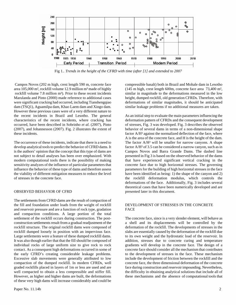
Fig 1.. Trends in the height of the CFRD with time (after [1] and extended to 2007
Campos Novos (202 m high, crest length 590 m, concrete face area 105,000 m², rockfill volume 12.9 million m³ made of highly
compressible basalt) both in Brazil and Mohale dam in Lesotho (145 m high, crest length 600m, concrete face area 73,400 m²,
rockfill volume 7.8 million m³). Prior to these recent incidents Marulanda and Pinto (2000) made reference to additional cases were significant cracking had occurred, including Tianshengqiao dam (TSQ1), Aguamilpa dam, Khao Laem dam and Xingo dam. However these previous cases were of a very different nature to the recent incidents in Brazil and Lesotho. The general characteristics of the recent incidents, where cracking has occurred, have been described in Sobrinho et al. (2007), Pinto (2007), and Johannesson (2007). Fig. 2 illustrates the extent of these incidents. The occurrence of these incidents, indicate that there is a need to develop analytical tools to predict the behavior of CFRD dams. It is the authors’ opinion that the concept that this type of dams are not subject to detail analyses has been over emphasized. With modern computational tools there is the possibility of making sensitivity analyzes of the influence of particular parameters that influence the behavior of these type of dams and therefore assess the viability of different mitigation measures to reduce the level of stresses in the concrete face. OBSERVED BEHAVIOR OF CFRD The settlements from CFRD dams are the result of compaction of the fill and foundation under loads from the weight of rockfill and reservoir pressure and are a function of rock type, gradation and compaction conditions. A large portion of the total settlement of the rockfill occurs during construction. The post-construction settlements result from a gradual readjustment of the rockfill structure. The original rockfill dams were composed of rockfill dumped loosely in position with an impervious face. Large settlements were a feature of these dumped rockfill dams. It was also though earlier that that the fill should be composed of individual rocks of large uniform size to give rock to rock contact. As a consequent high deformations occurred in some of the early CFRD’s creating considerable leakage problems. Excessive slab movements were generally attributed to low compaction of the dumped rockfill. In modern CFRDs, well graded rockfills placed in layers of 1m or less are used and are well compacted to obtain a less compressible and stiffer fill. However, as higher and higher dams are built, the deformations of these very high dams will increase considerably and could be
similar in magnitude to the deformations measured in the low height, dumped rockfill, old generation CFRDs. Therefore, with deformations of similar magnitudes, it should be anticipated similar leakage problems if no additional measures are taken. As an initial step to evaluate the main parameters influencing the deformation pattern of CFRDs and the consequent development of stresses, Fig. 3 was developed. Fig. 3 describes the observed behavior of several dams in terms of a non-dimensional shape factor A/H² against the normalized deflection of the face, where A is the area of the concrete face, and H is the height of the dam. The factor A/H² will be smaller for narrow canyons. A shape factor A/H² of 3.5 can be considered a narrow canyon, such as in Campos Novos and Barra Grande Dams. The dashed line presented in Fig 3 is based on the observed behavior of the dams that have experienced significant vertical cracking in the concrete face due to high horizontal stresses. The governing parameters for the building of high horizontal stresses in the face have been identified as being: 1) the shape of the canyon and 2) the rockfill deformation modulus, which controls the deformations of the face. Additionally, Fig. 3 includes several theoretical cases that have been numerically developed and are presented later in this document. DEVELOPMENT OF STRESSES IN THE CONCRETE FACE The concrete face, since is a very slender element, will behave as a shell and its displacements will be controlled by the deformation of the rockfill. The developments of stresses in the slabs are essentially caused by the deformation of the rockfill due to its own weight and the hydrostatic load of the reservoir. In addition, stresses due to concrete curing and temperature gradients will develop in the concrete face. The design of a concrete face should consider all the mechanism that contributes to the development of stresses in the face. These mechanism include the development of friction between the rockfill and the concrete face, the three dimensional deformation of the concrete face during construction and reservoir impounding. Nevertheless, the difficulty in obtaining analytical solutions that include all of these mechanisms and the absence of computational tools that
Paper No. 11.14b 2

Fig 2 Extent of face failure at (a) Campos Novos (b) Barra Grande and (c) Mohale
Fig 3 Normal Deflection of the face as a function of the shape factor
Paper No. 11.14b 3
allowed the calculations of the combined effect of the mechanisms acting on the slabs, contributed to the development of design procedures that were based primarily on precedent and empiricism. A sign of this tendency is the determination of the concrete slab thickness, which is essentially based on precedent. The thickness of the concrete face has been determine as a function of the hydrostatic pressure, initially with the equation e=0.30 + 0.003H; where e is the slab thickness and H is the hydrostatic head. In other cases the equation e=0.30 + 0.002H has been used and for dams with heights of less than 120 m, slabs have been designed with the equation e=0.30 + 0.001H. In addition, no procedure exists for defining the ratio of reinforcement other than empirical rules based on experience. The design of the concrete face has used a steel ratio in the order of 0.5%, however this amount of steel has been reduced with time to 0.4% and even up to 0.3%, as it was the case of Aguamilpa dam.Even, before the recent incidents of the Brazilian dams, it was considered that because of the absence of vertical fissures, the steel ratio could be reduced even below 0.3%. Actually, this type of tendencies should be based on the magnitude of stresses and strains in the face slab, which at the present cannot be predicted with a sufficient degree of accuracy. The recent tendencies also include the removal of anti-spalling reinforcement in the compressive joints, which in the authors’ opinion represents a key feature in these joints due to additional
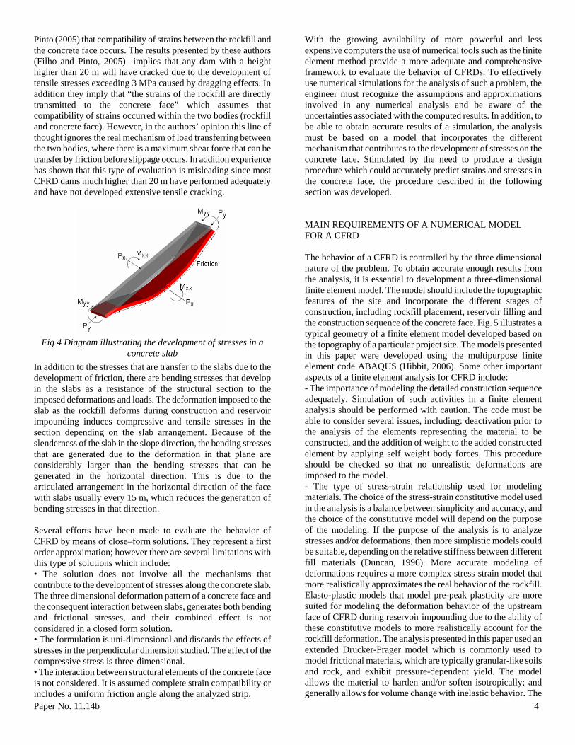
confinement provided by this reinforcement at the edge of the slabs where the maximum stresses occurs. Fig. 4 illustrates the origin of the main stresses that develop in a slab. It should be noted that in term of displacements, the concrete face, since is a very slender element its displacements will be controlled by the deformation of the rockfill. In other words, the normal displacements of the concrete face will be the same as the rockfill. However, this does not mean that compatibility of strains will occur between the two bodies. The mechanism of load transferring between the two bodies is caused by the development of friction at the interface, which depends on the characteristics of the contact between the two bodies. The maximum load that can be transferred by friction is a function of the normal force acting on the contact and the friction angle which depends on the roughness characteristics of the interface. When the relative deformation that causes the maximum shear force is exceeded, slippage between the two bodies will occur and it is not possible to transmit a higher force. In the areas where this circumstance is achieved, slippage between the two bodies will take place and the rockfill will continue to deform as the water load increases. It has been mentioned in several occasions such as in the paper by Filho and
Pinto (2005) that compatibility of strains between the rockfill and the concrete face occurs. The results presented by these authors (Filho and Pinto, 2005) implies that any dam with a height higher than 20 m will have cracked due to the development of tensile stresses exceeding 3 MPa caused by dragging effects. In addition they imply that “the strains of the rockfill are directly transmitted to the concrete face” which assumes that compatibility of strains occurred within the two bodies (rockfill and concrete face). However, in the authors’ opinion this line of thought ignores the real mechanism of load transferring between the two bodies, where there is a maximum shear force that can be transfer by friction before slippage occurs. In addition experience has shown that this type of evaluation is misleading since most CFRD dams much higher than 20 m have performed adequately and have not developed extensive tensile cracking.
Fig 4 Diagram illustrating the development of stresses in a
concrete slab In addition to the stresses that are transfer to the slabs due to the development of friction, there are bending stresses that develop in the slabs as a resistance of the structural section to the imposed deformations and loads. The deformation imposed to the slab as the rockfill deforms during construction and reservoir impounding induces compressive and tensile stresses in the section depending on the slab arrangement. Because of the slenderness of the slab in the slope direction, the bending stresses that are generated due to the deformation in that plane are considerably larger than the bending stresses that can be generated in the horizontal direction. This is due to the articulated arrangement in the horizontal direction of the face with slabs usually every 15 m, which reduces the generation of bending stresses in that direction. Several efforts have been made to evaluate the behavior of CFRD by means of close–form solutions. They represent a first order approximation; however there are several limitations with this type of solutions which include: • The solution does not involve all the mechanisms that contribute to the development of stresses along the concrete slab. The three dimensional deformation pattern of a concrete face and the consequent interaction between slabs, generates both bending and frictional stresses, and their combined effect is not considered in a closed form solution. • The formulation is uni-dimensional and discards the effects of stresses in the perpendicular dimension studied. The effect of the compressive stress is three-dimensional.
Paper No. 11.14b 4
• The interaction between structural elements of the concrete face is not considered. It is assumed complete strain compatibility or includes a uniform friction angle along the analyzed strip.
With the growing availability of more powerful and less expensive computers the use of numerical tools such as the finite element method provide a more adequate and comprehensive framework to evaluate the behavior of CFRDs. To effectively use numerical simulations for the analysis of such a problem, the engineer must recognize the assumptions and approximations involved in any numerical analysis and be aware of the uncertainties associated with the computed results. In addition, to be able to obtain accurate results of a simulation, the analysis must be based on a model that incorporates the different mechanism that contributes to the development of stresses on the concrete face. Stimulated by the need to produce a design procedure which could accurately predict strains and stresses in the concrete face, the procedure described in the following section was developed. MAIN REQUIREMENTS OF A NUMERICAL MODEL FOR A CFRD The behavior of a CFRD is controlled by the three dimensional nature of the problem. To obtain accurate enough results from the analysis, it is essential to development a three-dimensional finite element model. The model should include the topographic features of the site and incorporate the different stages of construction, including rockfill placement, reservoir filling and the construction sequence of the concrete face. Fig. 5 illustrates a typical geometry of a finite element model developed based on the topography of a particular project site. The models presented in this paper were developed using the multipurpose finite element code ABAQUS (Hibbit, 2006). Some other important aspects of a finite element analysis for CFRD include: - The importance of modeling the detailed construction sequence adequately. Simulation of such activities in a finite element analysis should be performed with caution. The code must be able to consider several issues, including: deactivation prior to the analysis of the elements representing the material to be constructed, and the addition of weight to the added constructed element by applying self weight body forces. This procedure should be checked so that no unrealistic deformations are imposed to the model. - The type of stress-strain relationship used for modeling materials. The choice of the stress-strain constitutive model used in the analysis is a balance between simplicity and accuracy, and the choice of the constitutive model will depend on the purpose of the modeling. If the purpose of the analysis is to analyze stresses and/or deformations, then more simplistic models could be suitable, depending on the relative stiffness between different fill materials (Duncan, 1996). More accurate modeling of deformations requires a more complex stress-strain model that more realistically approximates the real behavior of the rockfill. Elasto-plastic models that model pre-peak plasticity are more suited for modeling the deformation behavior of the upstream face of CFRD during reservoir impounding due to the ability of these constitutive models to more realistically account for the rockfill deformation. The analysis presented in this paper used an extended Drucker-Prager model which is commonly used to model frictional materials, which are typically granular-like soils and rock, and exhibit pressure-dependent yield. The model allows the material to harden and/or soften isotropically; and generally allows for volume change with inelastic behavior. The

flow rule, defining the inelastic straining, allows simultaneous inelastic dilation (volume increase) and inelastic shearing. The model can include creep if the material exhibits long-term inelastic deformations and a sensitivity of the rate of straining can be defined. The initial calibration of the Drucker-Prager model was carried out by simulating the laboratory tests of triaxial and oedometer tests performed by Marsal [12] on San Francisco basalt. - The importance of adequately model the concrete face. The simulation of the concrete face involves: (1) modeling of the physical concrete face; (2) modeling of the concrete face construction; and (3) modeling of the concrete face-rock fill interaction. Bending behavior of the concrete slabs in the vertical direction, as well as the transferring of compressive stresses in horizontal and vertical direction, are the most important aspects that need to be captured correctly in the model. For the analysis presented in this paper, the concrete face was modeled with hexahedron (brick) elements with variable thickness based on the design (e.g. e=0.30 + 0.003H). Each slab was modeled independently with an interface element between slabs to simulate the joint behavior. To accurately model the bending action and transferring of horizontal stresses, the real slab thickness and the concrete face weight were included in the simulations. - Incorporation of different interfaces. In a soil-structure interaction situation, relative movement of the structure with respect to the soil can occur. Interface elements, or joint elements, as sometimes referred to, can be used to model the soil-structure boundary such as the sides of the concrete face. For an analysis of a CFRD, the following interfaces have to be considered: bedrock-rockfill interface, curb-rockfill interface, concrete face- curb interface, and interface between slabs.
Paper No. 11.14b 5
Fig 5 Finite element mesh of a CFRD
VALIDATION OF THE ANALYSIS PROCEDURE BASED ON OBSERVED BEHAVIOR The analysis procedure described in the previous section was validated through the simulation of a series of existing dams for which behavior records are available. The available records are for both construction and impounding stages. The dams used for this validation procedure included (1) Cethana dam in Australia
(Fitzpatrick et al.,1973), (2) Campos Novos in Brazil (Sobrinho et al.,2007), and (3) Cajon in Mexico (Mendez and Perez, 2007). The modeling procedure has been further validated with several other dams, however due to space constraints, only three cases are presented in this paper Cethana - Australia The first case used to validate the numerical procedure was Cethana dam. This dam is located on the Forth River in Northern Tasmania; Australia. The dam has a height of 110 m and a crest length of 213 m and was extensively instrumented Fitzpatrick et al. (1973) presents the strains in both horizontal and in the slope direction measured in the concrete face and the equivalent stresses based on the strain measurements. These measurements were the basis for the comparison of the results from the numerical model. The calibrated.model predicted a maximum settlement of 47 cm which compares considerably well with the 45 cm measured in the fill. The predicted maximum normal face deflection was 16 cm compared to the 16.8 cm measured. Table 1: Cethana Dam results
Horizontal Stress (MPa) Construction Filling Total
FEA -1.1 -4.3 -5.4 Measured -1.6 -4.0 -4.6
Vertical Stress (MPa) Construction Filling Total
FEA -1.35 -2.1 -3.45 Measured -2.5 -2.26 -4.7
Fig. 6a and Fig. 6b present the calculated stress contours for both the horizontal and slope direction. Fig. 7a and Fig. 7b present the calculated strain contours. As it can be observed from the results, it was possible to obtain through the three dimensional simulation of the Cethana dam, values of stresses and strains very similar to what was measured in the field. Table 1 summarizes the obtained results. Campos Novos - Brasil Campos Novos has a height of 202 m. The measured modulus of the highly compressible basalt ranged between 40 to 60 MPa (Sobrinho et al., 2007).. The thickness of the concrete face was designed based on the equation e=0.3+0.002H up to a depth of 100 m. For subsequent depths the equation e=0.3+0.005H was used. A concrete extruded concrete curb was used as a support zone for the concrete face. The finite element model was developed based on the information presented in Sobrinho et al.(2007). Fig. 8a and Fig 8b illustrates the prediction of stresses for both horizontal and slope directions. The predicted stresses for both directions are considerably larger than the typical compressive strength of concrete (>21 MPa). Furthermore, the contours for these high stresses in the slope direction follow approximately the abutment profile which compares with the observed behavior shown in Fig. 2.
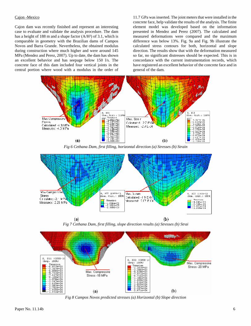
Cajon -Mexico Cajon dam was recently finished and represent an interesting case to evaluate and validate the analysis procedure. The dam has a height of 188 m and a shape factor (A/H²) of 3.1, which is comparable in geometry with the Brazilian dams of Campos Novos and Barra Grande. Nevertheless, the obtained modulus during construction where much higher and were around 145 MPa (Mendez and Perez, 2007). Up to date, the dam has shown an excellent behavior and has seepage below 150 l/s. The concrete face of this dam included four vertical joints in the central portion where wood with a modulus in the order of
11.7 GPa was inserted. The joint meters that were installed in the concrete face, help validate the results of the analysis. The finite element model was developed based on the information presented in Mendez and Perez (2007). The calculated and measured deformations were compared and the maximum difference was below 13%. Fig. 9a and Fig. 9b illustrate the calculated stress contours for both, horizontal and slope direction. The results show that with the deformation measured so far, no significant distresses should be expected. This is in concordance with the current instrumentation records, which have registered an excellent behavior of the concrete face and in general of the dam.
Fig 6 Cethana Dam, first filling, horizontal direction (a) Stresses (b) Strain
Fig 7 Cethana Dam, first filling, slope direction results (a) Stresses (b) Strai
Fig 8 Campos Novos predicted stresses (a) Horizontal (b) Slope direction
Paper No. 11.14b 6

Fig 9 Cajon predicted stresses (a) Horizontal (b) Slope direction
Theorical Cases The validation of the analysis procedure was complemented with theoretical cases to visualize tendencies in behavior based on geometrical characteristics. Fig. 3, presented in Section 4 included several cases, referred as theoretical cases. These cases were developed with a generic geometry where the shape factor and the rockfill characteristics were varied to enhance the alignment of the empirical curve that was developed originally only with observed behavior. PREDICTION OF THE BEHAVIOR OF PORCE III DAM AND THE DESIGN OPTIMIZATION The analysis procedure described previously provides capabilities in the design stages to evaluate the stress-strain behavior of a CFRD dam and assess the influence of certain parameters such as canyon geometry and rockfill modulus. The analysis procedure is also quite useful to evaluate the effectiveness of different mitigation measures to alleviate stresses in the concrete face. It should be noted that the results of such a numerical analysis cannot be taken as absolute and precise values. The analysis will point up tendencies and estimates of stress- strain behavior of the different components of the dam, so that engineers with good judgment can take further decisions. After validating the analysis procedure with several cases, the dam for the hydroelectric project of Porce III in Colombia, which is currently under construction, was analyzed. It should be emphasized that characteristics of Porce III dam, are within the precedent of dams that have behaved adequately, nevertheless a detail evaluation was considered appropriate. The prediction includes an estimate of the stress-strain behavior of the concrete face and of the deformations of the body of the dam. Fig. 10 presents a section of the dam. Further details of the design and construction issue of Porce III dam can be found in Marulanda et al. (2007). The analysis is based on the construction sequence foreseen during the design stage. An initial estimate of rockfill modulus for this dam based on the characteristics of the rockfill was in the order of 70 MPa. However, recent results obtained
from test fills (Marulanda et al., 2007) suggested that modulus in the order of 90 MPa and higher are possible. The analysis procedure permits the performance of a sensitivity analysis of the behavior of the dam to evaluate the impact in the concrete face of different rockfill modulus. Fig. 11 shows the contours of stresses in the horizontal and slope direction for the case corresponding to a field modulus of 70 MPa, however other scenarios of modulus were considered. Table 2 summarizes the predicted stresses for the different cases that were analyzed, which include variation of modulus for the different dam zones. The results suggested that having a rockfill modulus with slightly lower values in the downstream section of the dam will reduce the curvature of the face and therefore lower the stresses in the face. It should be noted that the difference between downstream and upstream modulus evaluated in this study does not promote circumstances, such as what happen in Aguamilpa dam, where a great difference of modulus within the dam produced a drastic inflection point that caused flexure and elongation of the concrete face that consequently produced horizontal cracking of the face. From the analyses, it is evident that the level of stresses in the concrete face, for the case of obtaining low rockfill modulus (< 90MPa) will be considerably high. It is considered that this condition is unlikely to occur based on the preliminary field test. Nevertheless a number of mitigation measures, in order to reduce and dissipate the compressive stresses, have been evaluated. One of the alternatives that have been evaluated is the incorporation of 3 cm of compressible materials in the joints. Fig. 12 shows some of the configuration of compressible joints that have been evaluated. Based on the results, it was determined that the development of high horizontal stresses could be adequately dissipate with the incorporation of five compressive vertical joints in the central portion of the face (Fig. 13). However, the incorporation of horizontal compressive joint to dissipate the stresses in the slope direction has shown to be a more complex solution as it creates new problems along the vertical joints and to the general behavior of the slabs, especially in narrow canyons. Different solutions to dissipate the stresses in the slope direction are currently being evaluated; including alternatives to severely reduce of the friction angle of the interface between the concrete face and the curb.
Paper No. 11.14b 7

Fig 10 Section of Porce III Dam
Table 2: Porce III - Predicted stresses with different rockfill modulus
3B 3C 3D σh σv Slab δ 70 70 70 -19.92 -19.00 0.34 90 90 90 -16.16 -17.25 0.26 120 120 120 -11.85 -12.58 0.20 90 60 60 -15.37 -16.28 0.26 90 60 50 -15.39 -17.39 0.27
Fig 11 Porce III predicted stresses, Rockfill Modulus 70 MPa (a) Horizontal (b) Slope direction
a. d.
b. e.
c. f.
Fig 12 Different configuration of compressible joints in concrete face.
Paper No. 11.14b 8
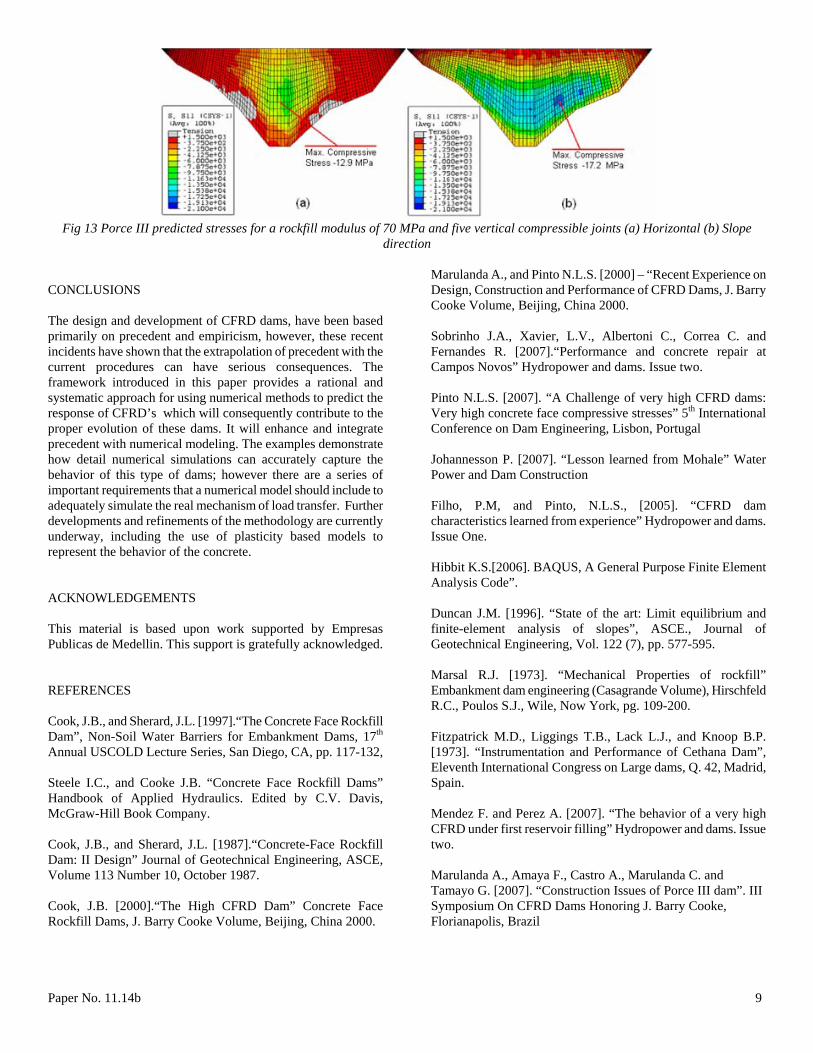
Fig 13 Porce III predicted stresses for a rockfill modulus of 70 MPa and five vertical compressible joints (a) Horizontal (b) Slope
direction CONCLUSIONS The design and development of CFRD dams, have been based primarily on precedent and empiricism, however, these recent incidents have shown that the extrapolation of precedent with the current procedures can have serious consequences. The framework introduced in this paper provides a rational and systematic approach for using numerical methods to predict the response of CFRD’s which will consequently contribute to the proper evolution of these dams. It will enhance and integrate precedent with numerical modeling. The examples demonstrate how detail numerical simulations can accurately capture the behavior of this type of dams; however there are a series of important requirements that a numerical model should include to adequately simulate the real mechanism of load transfer. Further developments and refinements of the methodology are currently underway, including the use of plasticity based models to represent the behavior of the concrete. ACKNOWLEDGEMENTS This material is based upon work supported by Empresas Publicas de Medellin. This support is gratefully acknowledged. REFERENCES Cook, J.B., and Sherard, J.L. [1997].“The Concrete Face Rockfill Dam”, Non-Soil Water Barriers for Embankment Dams, 17th Annual USCOLD Lecture Series, San Diego, CA, pp. 117-132, Steele I.C., and Cooke J.B. “Concrete Face Rockfill Dams” Handbook of Applied Hydraulics. Edited by C.V. Davis, McGraw-Hill Book Company. Cook, J.B., and Sherard, J.L. [1987].“Concrete-Face Rockfill Dam: II Design” Journal of Geotechnical Engineering, ASCE, Volume 113 Number 10, October 1987. Cook, J.B. [2000].“The High CFRD Dam” Concrete Face Rockfill Dams, J. Barry Cooke Volume, Beijing, China 2000.
Marulanda A., and Pinto N.L.S. [2000] – “Recent Experience on Design, Construction and Performance of CFRD Dams, J. Barry Cooke Volume, Beijing, China 2000. Sobrinho J.A., Xavier, L.V., Albertoni C., Correa C. and Fernandes R. [2007].“Performance and concrete repair at Campos Novos” Hydropower and dams. Issue two. Pinto N.L.S. [2007]. “A Challenge of very high CFRD dams: Very high concrete face compressive stresses” 5th International Conference on Dam Engineering, Lisbon, Portugal Johannesson P. [2007]. “Lesson learned from Mohale” Water Power and Dam Construction Filho, P.M, and Pinto, N.L.S., [2005]. “CFRD dam characteristics learned from experience” Hydropower and dams. Issue One. Hibbit K.S.[2006]. BAQUS, A General Purpose Finite Element Analysis Code”. Duncan J.M. [1996]. “State of the art: Limit equilibrium and finite-element analysis of slopes”, ASCE., Journal of Geotechnical Engineering, Vol. 122 (7), pp. 577-595. Marsal R.J. [1973]. “Mechanical Properties of rockfill” Embankment dam engineering (Casagrande Volume), Hirschfeld R.C., Poulos S.J., Wile, Now York, pg. 109-200. Fitzpatrick M.D., Liggings T.B., Lack L.J., and Knoop B.P. [1973]. “Instrumentation and Performance of Cethana Dam”, Eleventh International Congress on Large dams, Q. 42, Madrid, Spain. Mendez F. and Perez A. [2007]. “The behavior of a very high CFRD under first reservoir filling” Hydropower and dams. Issue two. Marulanda A., Amaya F., Castro A., Marulanda C. and Tamayo G. [2007]. “Construction Issues of Porce III dam”. III Symposium On CFRD Dams Honoring J. Barry Cooke, Florianapolis, Brazil
Paper No. 11.14b 9