ship construction
TRANSCRIPT

Ship Construction
Shca01.fm Page i Tuesday, March 27, 2001 12:10 PM

Shca01.fm Page ii Tuesday, March 27, 2001 12:10 PM

Ship ConstructionFifth edition
D. J. EyresM.Sc., F.R.I.N.A.Formerly Lecturer in Naval ArchitectureDepartment of Maritime StudiesPlymouth Polytechnic (now University of Plymouth)
OXFORD AUCKLAND BOSTON JOHANNESBURG MELBOURNE NEW DELHI
Shca01.fm Page iii Tuesday, March 27, 2001 12:10 PM

Butterworth-Heinemann Linacre House, Jordan Hill, Oxford OX2 8DP 225 Wildwood Avenue, Woburn, MA 01801-2041 A division of Reed Educational and Professional Publishing Ltd
A member of the Reed Elsevier plc group
First published 1972Second edition 1978Third edition 1988Fourth edition 1994Reprinted 1997, 1998, 1999, 2000Fifth edition 2001
© D. J. Eyres 1972, 1978, 1988, 1994, 2001
All rights reserved. No part of this publication may be reproduced in any material form (including photocopying or storing in any medium by electronic means and whether or not transiently or incidentally to some other use of this publication) without the written permission of the copyright holder except in accordance with the provisions of the Copyright, Designs and Patents Act 1988 or under the terms of a licence issued by the Copyright Licensing Agency Ltd, 90 Tottenham Court Road, London, England W1P 0LP. Applications for the copyright holder’s written permission to reproduce any part of this publication should be addressed to the publisher
British Library Cataloguing in Publication Data Eyres, D. J. (David John)
Ship construction – 5th ed. 1. Shipbuilding 2. Naval architecture I. Title 623.8′2
Library of Congress Cataloguing in Publication Data Eyres, David J.
Ship construction/David J. Eyres. – 5th ed. p. cm. Includes bibliographical references and index. 1. Shipbuilding. 2. Naval architecture. I. Title. VM145.E94 2001623.8′3–dc21
2001025515
ISBN 0 7506 4887 2
www.bh.com
Typeset in India at Integra Software Services Pvt Ltd, Pondicherry, India 605005, www.integra-india.comPrinted and bound in Great Britain by MPG Books Ltd, Bodmin, Cornwall
Shca01.fm Page iv Tuesday, March 27, 2001 12:10 PM

Contents vii.........................................
Preface ?............................................
Acknowledgments I.........................
Part 1 Introduction toShipbuilding 1...................................
1 Basic Design of the Ship 1............................Preparation of the Design 1.....................................Information Provided by Design 4............................Purchase of a New Vessel 6....................................Ship Contracts 7......................................................
2 Ship Dimensions and Form 2........................
3 Development of Ship Types 3.......................Dry Cargo Ships 3....................................................Bulk Carriers 19.........................................................Oil Tankers 21............................................................Passenger Ships 26...................................................
Part 2 Materials and Strength ofShips 2...............................................
4 Classification Societies 4..............................Lloyd�s Register Classification Symbols 34...............Structural Design Programs 35..................................Periodical Surveys 36................................................Damage Repairs 38...................................................
5 Steels 5.........................................................Manufacture of Steels 5...........................................Heat Treatment of Steels 41......................................Steel Sections 42.......................................................Shipbuilding Steels 42...............................................High Tensile Steels 43...............................................Steel Castings 44.......................................................Steel Forgings 44.......................................................

6 Aluminium Alloy 6..........................................Production of Aluminium 47.......................................Fire Protection 50.......................................................
7 Testing of Materials 7....................................Classification Society Tests for Hull Materials 53......
8 Stresses to which a Ship is Subject 8...........Vertical Shear and Longitudinal Bending in StillWater 8....................................................................Bending Moments in a Seaway 8............................Longitudinal Shear Forces 58....................................Bending Stresses 58..................................................Transverse Stresses 62.............................................Local Stresses 62......................................................Brittle Fracture 63......................................................Fatigue Failures 66....................................................
Part 3 Welding and Cutting 3...........9 Welding and Cutting Processes used inShipbuilding 9...................................................
Gas Welding 70.........................................................Electric Arc Welding 72..............................................Other Welding Processes 81.....................................Cutting Processes 84.................................................
10 Welding Practice and Testing Welds 10.......Welding Practice 10...................................................Welding Sequences 93..............................................Testing Welds 96.......................................................Non-destructive Testing 98........................................Classification Society Weld Tests 102.........................
Part 4 Shipyard Practice 4...............11 Shipyard Layout 11.......................................
12 Ship Drawing Offices and Loftwork 12..........Loftwork Following Drawing Office 114........................

13 Plate and Section Preparation andMachining 13......................................................
Plate and Section Preparation 13..............................Plate and Section Machining 120................................Frame Bending 126.....................................................
14 Prefabrication 14...........................................Sub-assemblies 133....................................................Unit Fabrication 133.....................................................Outfit Modules 135.......................................................Unit Erection 136.........................................................Joining Ship Sections Afloat 138.................................
15 Launching 15.................................................End Launches 15.......................................................Side Launches 151......................................................Building Docks 151......................................................Ship Lifts 152...............................................................
Part 5 Ship Structure 5.....................16 Bottom Structure 16......................................
Keels 16.....................................................................Single Bottom Structure 157........................................Double Bottom Structure 157.......................................Machinery Seats 167...................................................
17 Shell Plating and Framing 17........................Shell Plating 17..........................................................Framing 170.................................................................Tank Side Brackets 172...............................................Local Strengthening of Shell Plating 172.....................Bilge Keel 178..............................................................
18 Bulkheads and Pillars 18...............................Bulkheads 18.............................................................Watertight Doors 190...................................................Deep Tanks 192...........................................................Topside Tanks 194......................................................Shaft Tunnel 194..........................................................Pillars 195....................................................................

19 Decks, Hatches, and Superstructures 19......Decks 19....................................................................Hatches 207.................................................................Bulwarks 210...............................................................Superstructures and Deckhouses 213.........................
20 Fore End Structure 20...................................Stem 20......................................................................Bulbous Bows 219.......................................................Chain Locker 221.........................................................Hawse Pipes 222.........................................................Bow Steering Arrangements 224.................................Bow Thrust Units 224...................................................
21 Aft End Structure 21......................................Stern Construction 21................................................Stern Frame 228..........................................................Rudders 228................................................................Steering Gear 232........................................................Sterntube 234..............................................................Shaft Bossing and �A� Brackets 234............................Propellers 236..............................................................
22 Tanker Construction 22.................................Oil Tankers 22............................................................Materials for Tanker Construction 244.........................Construction in Tank Spaces 245................................Double Hull Construction 249......................................Bulkheads 249.............................................................Hatchways 250............................................................Testing Tanks 251.......................................................Fore End Structure 251................................................After End Structure 252...............................................Superstructures 253.....................................................Floating Production, Storage and OffloadingVessels 253.................................................................Chemical Tankers 254.................................................
23 Liquefied Gas Carriers 23.............................Liquefied Petroleum Gas (LPG) 23............................Liquefied Natural Gas (LNG) 23................................

The IMO International Gas Carrier Code 257..............Liquefied Petroleum Gas Ships 259............................Liquefied Natural Gas Ships 262.................................General Arrangement of Gas Carriers 264..................Lloyd�s Classification 264............................................
Part 6 Outfit 6....................................24 Derricks, Masts, and Rigging 24...................
Masts and Sampson Posts 24...................................Derrick Rigs 270..........................................................Deck Cranes 279.........................................................
25 Cargo Access, Handling and Restraint 25....Stern and Bow Doors 25............................................Ramps 282...................................................................Side Doors and Loaders 283.......................................Portable Decks 285......................................................Scissors Lift 286...........................................................Cargo Restraint 286.....................................................
26 Pumping and Piping Arrangements 26.........Bilge and Ballast Pumping and Piping 26..................General Service Pipes and Pumping 292....................Air and Sounding Pipes 293........................................Sea Inlets 293..............................................................Cargo Pumping and Piping Arrangements inTankers 294.................................................................
27 Corrosion Control and Paint Systems 27......Nature and Forms of Corrosion 27............................Corrosion Control 304..................................................Paints 307....................................................................Protection by Means of Paints 310..............................
28 Ventilation, Refrigeration, andInsulation 28.......................................................
Ventilation 28.............................................................Refrigeration 319.........................................................Insulation 319...............................................................Refrigerated Container Ships 322................................
Part 7 International Regulations 7..29 International Maritime Organization 29.........
Organization of IMO 29..............................................Work of IMO 29..........................................................Relationship with National Authorities 328...................Relationship with Classification Societies 329.............
30 Tonnage 30...................................................International Convention on TonnageMeasurement of Ships 1969 30.................................Tonnages 30..............................................................Measurement 331........................................................Compensated Tonnage 332........................................
31 Load Line Rules 31.......................................Freeboard Computation 31........................................Conditions of Assignment of Freeboard 338................
32 Structural Fire Protection 32.........................Requirements 32........................................................�A�, �B� and �C� Class Divisions 344.............................Openings in Fire Protection Divisions 346...................Protection of Special Category Spaces 347................Fire Protection Arrangements in High SpeedCraft 347......................................................................
Index 53�4...............................................

Preface
This text is primarily aimed at students of marine sciences and technology,in particular those following BTEC National and Higher National pro-grammes in preparation for careers at sea and in marine related industries.The subject matter is presented in sufficient depth to be of help to moreadvanced students on undergraduate programmes in Marine Technologyand Naval Architecture, as well as those preparing for the Extra Masterexamination. Students following professional courses in shipbuilding willalso find the book useful as background reading.
Considerable changes have occurred in shipbuilding practice with theintroduction of new technology and this book attempts to present modernshipyard techniques without neglecting basic principles. Shipbuilding coversa wide field of crafts and, with new developments occurring regularly, itwould be difficult to cover every facet fully within the scope of the averagetextbook. For this reason further reading references are given at the end ofmost chapters, these being selected from books, transactions, and period-icals which are likely to be found in the libraries of universities and othertechnical institutions.
Shca01.fm Page vii Tuesday, March 27, 2001 12:10 PM

Acknowledgments
I am grateful to the following firms and organizations who were kindenough to provide me with information and drawings from which materialfor the book was extracted:
Appledore Shipbuilders Ltd Blohm and Voss, A.G. British Maritime Technology British Oxygen Co. Ltd E.I. Du Pont De Nemours & Co. Ltd ESAB AB Irish Shipping Ltd MacGregor-Navire International A.B. Mitsubishi Heavy Industries Ltd Ocean Steamship Co. Ltd Shell Tankers (UK) Ltd Shipping Research Services A/S Hugh Smith (Glasgow) Ltd Stone Manganese Marine Ltd Wavemaster International
I would also like to thank Lloyd’s Register of Shipping for permissionto indicate various requirements of their ‘Rules and Regulations for theClassification of Ships’.
D. J. E.
Shca01.fm Page ix Tuesday, March 27, 2001 12:10 PM

Part 1
Introduction to Shipbuilding
Shcc01.fm Page 1 Monday, March 26, 2001 3:00 PM

Shcc01.fm Page 2 Monday, March 26, 2001 3:00 PM

1Basic Design of the Ship
The economic factor is of prime importance in designing a merchantship. An owner requires a ship which will give him the best possiblereturns for his initial investment and running costs. This means that thefinal design should be arrived at taking into account not only presenteconomic considerations, but also those likely to develop within the lifeof the ship.
With the aid of computers it is possible to make a study of a large numberof varying design parameters and to arrive at a ship design which is notonly technically feasible but, more importantly, is the most economicallyefficient.
Preparation of the DesignThe initial design of a ship generally proceeds through three stages: con-cept; preliminary; and contract design. The process of initial design is oftenillustrated by the design spiral (Figure 1.1) which indicates that given theobjectives of the design, the designer works towards the best solutionadjusting and balancing the interrelated parameters as he goes.
A concept design should, from the objectives, provide sufficient informa-tion for a basic techno-economic assessment of the alternatives to be made.Economic criteria that may be derived for commercial ship designs andused to measure their profitability are net present value, discounted cashflow or required freight rate. Preliminary design refines and analyses theagreed concept design, fills out the arrangements and structure and aimsat optimizing service performance. At this stage the builder should havesufficient information to tender. Contract design details the final arrange-ments and systems agreed with the owner and satisfies the buildingcontract conditions.
Total design is not complete at this stage, it has only just started, post-contract design entails in particular design for production where thestructure, outfit and systems are planned in detail to achieve a cost andtime effective building cycle. Production of the ship must also be givenconsideration in the earlier design stages, particularly where it placesconstraints on the design or can affect costs.
Shcc01.fm Page 3 Monday, March 26, 2001 3:00 PM

4 Ship Construction
Information Provided by Design When the preliminary design has been selected the following information isavailable:
Dimensions DisplacementStability Propulsive characteristics and hull form Preliminary general arrangement Principal structural details
Each item of information may be considered in more detail, together withany restraints placed on these items by the ships service or other factorsoutside the designer’s control.
1. The dimensions are primarily influenced by the cargo carrying capacityof the vessel. In the case of the passenger vessel, dimensions are influencedby the height and length of superstructure containing the accommodation.Length where not specified as a maximum should be a minimum consistentwith the required speed and hull form. Increase of length produces higher
Conceptdesign
Preliminarydesign
Contractdesign
Capacities
Weightestimate
Powering
Structure
Generalarrangements
Freeboardand subdivision
Hydrostatics
Lines
Proportions
Vesselobjectives
Costestimate
Stability
FIGURE 1.1 Design spiral
Shcc01.fm Page 4 Monday, March 26, 2001 3:00 PM

Basic Design of the Ship 5
longitudinal bending stresses requiring additional strengthening and agreater displacement for the same cargo weight. Breadth may be such as toprovide adequate transverse stability. A minimum depth is controlled bythe draft plus a statutory freeboard; but an increase in depth will result ina reduction of the longitudinal bending stresses, providing an increase instrength, or allowing a reduction in scantlings. Increased depth is thereforepreferred to increased length. Draft is often limited by area of operationbut if it can be increased to give a greater depth this can be an advantage.
Many vessels are required to make passages through various canals andthis will place a limitation on the dimensions. The Suez Canal has a draftlimit, locks in the Panama Canal and St. Lawrence Seaway limit length,beam and draft. In the Manchester Ship Canal locks place limitations onthe main dimensions and there is also a limitation on the height above thewater-line because of bridges.
2. Displacement is made up of lightweight plus deadweight. The light-weight is the weight of vessel as built, including boiler water, lubricating oil,and cooling water system. Deadweight is the difference between the light-weight and loaded displacement, i.e. it is the weight of cargo plus weights offuel, stores, water ballast, fresh water, crew and passengers, and baggage.When carrying weight cargoes (e.g. ore) it is desirable to keep the lightweightas small as possible consistent with adequate strength. Since only cargoweight of the total deadweight is earning capital, other items should be keptto a minimum as long as the vessel fulfils its commitments.
3. In determining the dimensions statical stability is kept in mind in orderto ensure that this is sufficient in all possible conditions of loading. Beam anddepth are the main influences. Statutory freeboard and sheer are importanttogether with the weight distribution in arranging the vessel’s layout.
4. Propulsive performance involves ensuring that the vessel attains therequired speeds. The hull form is such that it economically offers a minimumresistance to motion so that a minimum power with economically lightestmachinery is installed without losing the specified cargo capacity.
A service speed is the average speed at sea with normal service powerand loading under average weather conditions. A trial speed is the averagespeed obtained using the maximum power over a measured course in calmweather with a clean hull and specified load condition. This speed may be aknot or so more than the service speed.
Unless a hull form similar to that of a known performance vessel is used,tank tests of a model hull are generally specified nowadays. These providethe designer with a range of speeds and corresponding powers for the hullform, and may suggest modifications to the form. Published data fromaccumulated ship records and hull tests may be used to prepare the hullform initially.
The owner may often specify the type and make of main propulsionmachinery installation with which their operating personnel are familiar.
Shcc01.fm Page 5 Monday, March 26, 2001 3:00 PM

6 Ship Construction
5. The general arrangement is prepared in co-operation with the owner,allowing for standards of accommodation peculiar to that company, alsopeculiarities of cargo and stowage requirements. Efficient working of thevessel must be kept in mind throughout and compliance with the regulationsof the various authorities involved on trade routes must also be taken intoaccount. Some consultation with shipboard employees’ representative organ-izations may also be necessary in the final accommodation arrangements.
6. Almost all vessels will be built to the requirements of a classificationsociety such as Lloyd’s Register. The standard of classification specified willdetermine the structural scantlings and these will be taken out by the ship-builder. The calculation of hull structural scantlings can be carried out bymeans of computer programs made available to the shipyard by the classi-fication society. Owners may specify thicknesses and material requirementsin excess of those required by classification societies and special structuralfeatures peculiar to the trade or owner’s fleet may be asked for.
Purchase of a New VesselIn recent years the practice of owners commissioning ‘one off’ designs forcargo ships from consultant naval architects, shipyards or their own tech-nical staff has increasingly given way to the selection of an appropriate‘stock design’ to suit their particular needs. To determine which stockdesign, the shipowner must undertake a detailed project analysis involvingconsideration of the proposed market, route, port facilities, competition,political and labour factors, and cash flow projections. Also taken intoaccount will be the choice of shipbuilder where relevant factors such asthe provision of government subsidies/grants or supplier credit can beimportant as well as the price, date of delivery, and yards reputation. Moststock designs offer some features which can be modified, such as outfit,cargo handling equipment, or alternate manufacture of main engine, forwhich the owner will have to pay extra.
Purchase of a passenger vessel will still follow earlier procedures fora ‘one-off’ design but there are shipyards concentrating on this type ofconstruction and the owner may be drawn to them for this reason. A non-standard cargo ship of any form and a number of specialist ships will alsorequire a ‘one-off’ design. Having decided on his basic requirements, i.e.the vessel’s objectives, after an appropriate project analysis the larger ship-owners may employ their own technical staff to prepare the tender speci-fication and submit this to shipbuilders who wish to tender for the buildingof the ship. The final building specification and design is prepared by thesuccessful tendering shipbuilder in co-operation with the owners technicalstaff. The latter may oversee construction of the vessel and approve thebuilders drawings and calculations. Other shipowners may retain a firm of
Shcc01.fm Page 6 Monday, March 26, 2001 3:00 PM

Basic Design of the Ship 7
consultants or approach a firm who may assist with preliminary design stud-ies and will prepare the tender specifications and in some cases call tenderson behalf of the owner. Often the consultants will also assist the owners inevaluating the tenders and oversee the construction on their behalf.
Ship ContractsThe successful tendering shipbuilder will prepare a building specificationfor approval by the owner or his representative which will form part of thecontract between the two parties and thus have legal status. This technicalspecification will normally include the following information:
Brief description and essential qualities and characteristics of ship. Principal dimensions.Deadweight, cargo and tank capacities, etc. Speed and power requirements. Stability requirements. Quality and standard of workmanship. Survey and certificates. Accommodation details. Trial conditions. Equipment and fittings.Machinery details, including the electrical installation, will normally beproduced as a separate section of the specification.
Most shipbuilding contracts are based on one of a number of standardforms of contract which have been established to obtain some uniformity inthe contract relationships between builders and purchasers. Three of themost common standard forms of contract have been established by:
1. AWES—Association of West European Shipbuilders. 2. MARAD Maritime Administration, USA. 3. SAJ Shipowners Association of Japan.
The AWES standard form of contract includes:
1. Subject of contract (vessel details, etc.). 2. Inspection and approval. 3. Modifications. 4. Trials. 5. Guarantee (speed, capacity, fuel consumption). 6. Delivery of vessel. 7. Price.
Shcc01.fm Page 7 Monday, March 26, 2001 3:00 PM

8 Ship Construction
8. Property (rights to specification, plans, etc.). 9. Insurance.
10. Defaults by the purchaser. 11. Defaults by the contractor. 12. Guarantee (after delivery). 13. Contract expenses. 14. Patents. 15. Reference to expert and arbitration. 16. Conditions for contract to become effective. 17. Legal domicile (of purchaser). 18. Assignment (transfer of purchaser’s rights to third party).
Irrespective of the source of the owner’s funds for purchasing the shippayment to the shipbuilder is usually made as progress payments which arestipulated in the contract under item 7 above. A typical payment schedulemay have been as follows:
10 per cent on signing contract. 10 per cent on arrival of materials on site.10 per cent on keel laying. 20 per cent on launching. 50 per cent on delivery.
Given modern construction techniques, where the shipbuilder’s cashflow during the building cycle can be very different from that indicatedabove with traditional building methods, the shipbuilder will probablyprefer payments to be tied to different key events. Also of concern to theshipbuilder employing modern building procedures is item 3 in the standardform of contract where modifications called for at a late date by the ownercan have a dramatic effect on costs and delivery date given the detail nowintroduced at an early stage of the fabrication process.
Further ReadingAndrews, ‘Creative Ship Design’, The Naval Architect, November, 1981.
Buxton, ‘Engineering Economics and Ship Design’, B.S.R.A. Publication,1971.
Buxton, ‘Engineering Economics Applied to Ship Design’, The NavalArchitect, October, 1972.
Fisher, ‘The Relative Costs of Ship Design Parameters’, Trans. R.I.N.A.,1974.
Shcc01.fm Page 8 Monday, March 26, 2001 3:00 PM

Basic Design of the Ship 9
Fisher, ‘An Owner’s Management of Ship Construction Contracts’—Newbuild 2000 and the role of the Naval Architect 1995, Royal Institutionof Naval Architects Publications.
Gilfillan, ‘The Economic Design of Bulk Carriers’, Trans. R.I.N.A., 1969.
Goldrein, ‘Ship Sale and Purchase, Law and Technique’, Lloyds of LondonPress Ltd., 1985.
Goss, ‘Economic Criteria for Optimal Ship Designs’, Trans. R.I.N.A., 1965.
Hamlin Cyrus, ‘Preliminary Design of Boats and Ships’, Cornell MaritimePress, Centreville, Md., USA, 1989.
Packard, ‘Sale and Purchase’, Tramp Ship Services, Fairplay Publications,1981.
Parker, ‘Contractual and Organizational Implications of Advanced Ship-building Methods’, Proceedings of the Seminar on Advances in Designfor Production, University of Southampton, 1984.
Watson and Gilfillan, ‘Some Ship Design Methods’, The Naval Architect,July, 1977.
Shcc01.fm Page 9 Monday, March 26, 2001 3:00 PM

2Ship Dimensions and Form
The hull form of a ship may be defined by a number of dimensions andterms which are often referred to during and after building the vessel. Anexplanation of the principal terms is given below:
After Perpendicular (AP): A perpendicular drawn to the waterline at the pointwhere the aft side of the rudder post meets the summer load line. Where norudder post is fitted it is taken as the centre line of the rudder stock. Forward Perpendicular (FP): A perpendicular drawn to the waterline at thepoint where the foreside of the stem meets the summer load line. Length Between Perpendiculars (LBP): The length between the forward and aftperpendiculars measured along the summer load line. Amidships: A point midway between the after and forward perpendiculars.Length Overall (LOA): Length of vessel taken over all extremities. Lloyd’s Length: Used for obtaining scantlings if the vessel is classed withLloyd’s Register. It is the same as length between perpendiculars except thatit must not be less than 96 per cent and need not be more than 97 per cent ofthe extreme length on the summer load line. If the ship has an unusual stemor stern arrangement the length is given special consideration. Register Length is the length of ship measured from the fore-side ofthe head of the stem to the aft side of the head of the stern post or, in thecase of a ship not having a stern post, to the fore-side of the rudder stock. Ifthe ship does not have a stern post or a rudder stock, the after terminal istaken to be the aftermost part of the transom or stern of the ship. Thislength is the official length in the register of ships maintained by the flagstate and appears on official documents relating to ownership and othermatters concerning the business of the ship. Another important lengthmeasurement is what might be referred to as the IMO Length. This length isfound in various international conventions such as the Load Line, Tonnageand SOLAS conventions and determines the application of requirements ofthose conventions to a ship. It is defined as 96 per cent of the total length ona waterline at 85 per cent of the least moulded depth measured from thetop of keel, or the length from the fore-side of stem to the axis of rudderstock on that waterline, if that is greater. In ships designed with a rake of keelthe waterline on which this length is measured is taken parallel to the designwaterline.
Shcc02.fm Page 10 Monday, March 26, 2001 3:01 PM

Ship Dimensions and Form 11
Moulded dimensions are often referred to; these are taken to the insideof plating on a steel ship.
Base Line: A horizontal line drawn at the top of the keel plate. All verticalmoulded dimensions are measured relative to this line. Moulded Beam: Measured at the midship section is the maximum mouldedbreadth of the ship. Moulded Draft: Measured from the base line to the summer load line at themidship section. Moulded Depth: Measured from the base line to the heel of the upper deckbeam at the ship’s side amidships. Extreme Beam: The maximum beam taken over all extremities. Extreme Draft: Taken from the lowest point of keel to the summer load line.Draft marks represent extreme drafts. Extreme Depth: Depth of vessel at ship’s side from upper deck to lowestpoint of keel. Half Breadth: Since a ship’s hull is symmetrical about the longitudinalcentre line, often only the half beam or half breadth at any section is given. Freeboard: The vertical distance measured at the ship’s side between thesummer load line (or service draft) and the freeboard deck. The freeboarddeck is normally the uppermost complete deck exposed to weather and seawhich has permanent means of closing all openings, and below which allopenings in the ship’s side have watertight closings. Sheer: Curvature of decks in the longitudinal direction. Measured as theheight of deck at side at any point above the height of deck at side amid-ships.Camber (or Round of Beam): Curvature of decks in the transverse direction.Measured as the height of deck at centre above the height of deck at side. Rise of Floor (or Deadrise): The rise of the bottom shell plating line abovethe base line. This rise is measured at the line of moulded beam. Half Siding of Keel: The horizontal flat portion of the bottom shell measuredto port or starboard of the ship’s longitudinal centre line. This is a usefuldimension to know when dry-docking. Tumblehome: The inward curvature of the side shell above the summerload line. Flare: The outward curvature of the side shell above the waterline. It promotesdryness and is therefore associated with the fore end of ship. Stem Rake: Inclination of the stem line from the vertical. Keel Rake: Inclination of the keel line from the horizontal. Trawlers andtugs often have keels raked aft to give greater depth aft where the propellerdiameter is proportionately larger in this type of vessel. Small craft occa-sionally have forward rake of keel to bring propellers above the line of keel.Tween Deck Height: Vertical distance between adjacent decks measured fromthe tops of deck beams at ship side.
Shcc02.fm Page 11 Monday, March 26, 2001 3:01 PM

Sheer aft Sheer forward
FreeboardSummer load line
Length between perpendiculars (LBP)Length on waterline (LWL)
Length overall (LOA)
Amidships
Camber
Draft
Depth
Base line
Half siding of keel
Rise of floor
Tumblehome
Aftperpendicular
Fordperpendicular
Moulded beam
FIGURE 2.1 Principal ship dimensions
Shcc02.fm Page 12 M
onday, March 26, 2001 3:01 PM

Ship Dimensions and Form 13
Parallel Middle Body: The length over which the midship section remainsconstant in area and shape. Entrance: The immersed body of the vessel forward of the parallel middlebody.Run: The immersed body of the vessel aft of the parallel middle body. Tonnage: This is often referred to when the size of the vessel is discussed,and the gross tonnage is quoted from Lloyd’s Register. Tonnage is a measureof the enclosed internal volume of the vessel (originally computed as 100cubic feet per ton). This is dealt with in detail in Chapter 30. Deadweight: This is defined in Chapter 1. It should be noted that for tankersdeadweight is normally quoted in ‘long tons’ rather than ‘metric tonnes’.
The principal dimensions of the ship are illustrated in Figure 2.1.
Shcc02.fm Page 13 Monday, March 26, 2001 3:01 PM

3Development of Ship Types
A breakdown into broad working groups of the various craft which theshipbuilder might be concerned with are shown in Figure 3.1. This coversa wide range and reflects the adaptability of the shipbuilding industry. It isobviously not possible to cover the construction of all those types in a singlevolume. The development of the vessels with which the text is primarilyconcerned, namely dry cargo ships, bulk carriers, tankers, and passengerships follows.
Dry Cargo ShipsIf the development of the dry cargo ship from the time of introduction ofsteam propulsion is considered the pattern of change is similar to thatshown in Figure 3.2. The first steam ships followed in most respects the designof the sailing ship having a flush deck with the machinery openings pro-tected only by low coamings and glass skylights. At quite an early stage itwas decided to protect the machinery openings with an enclosed bridgestructure. Erections forming a forecastle and poop were also introduced atthe forward and after end respectively for protection. This resulted in whatis popularly known as the ‘three island type’. A number of designs at thattime also combined bridge and poop, and a few combined bridge and fore-castle, so that a single well was formed.
Another form of erection introduced was the raised quarter deck. Raisedquarter decks were often associated with smaller deadweight carryingvessels, e.g. colliers. With the machinery space aft which is proportionatelylarge in a small vessel there is a tendency for the vessel to trim by the bowwhen fully loaded. By fitting a raised quarter deck in way of the after holdsthis tendency was eliminated. A raised quarter deck does not have the fullheight of a tween deck, above the upper deck.
Further departures from the ‘three island type’ were brought about bythe carriage of cargo and cattle on deck, and the designs included a lightcovering built over the wells for the protection of these cargoes. Thisresulted in the awning or spar deck type of ship, the temporarily enclosedspaces being exempt from tonnage measurement since they were not per-manently closed spaces. These awning or spar deck structures eventually
Shcc03.fm Page 14 Monday, March 26, 2001 3:01 PM

High speedCraft Off shore
oil vesselsFishingvessels
Harbour/oceanwork craft
Drycargoships
Liquidcargo ships
Passengerships
Submersibles Warships
Multi-hullsIncludingwave piercers
Small waterplanearea, twin-hull(SWATH)
Surface effect(SES) and
Hovercraftship
Hydrofoil
Wing in groundeffect craft(WIG)
Supply ship
Pipelayers
Cranebarges
Semi-submersibledrill rigs
Drill ships
Accommodationbarges
Production platforms
Floating storageunit (FSU)
Floating productionand storage unit
(FPSO)
Trawlerspurse seiners
etc.
Factoryships
TugsCablelayers
Floatingdry docks
Dredgers
Salvage/buoy vessels
Tenders
Pilot craft
Floatingcranes
Lightships
Tramps Oil tankers
Bulkcarriers
Cargoliners
Containervessels
Barge carriers
Ro-Ro ships
Refrigerated cargoships
Timber carriers
Livestock carriers
Car carriers
Liquefied gascarriers
Chemicalcarriers
Liners
Cruiseships
Emigrantand pilgrim
ships (STP s)’
Cross-Channelferries
Coastalferries
Harbourferries
FIGURE 3.1 Ship types
Shcc03.fm Page 15 M
onday, March 26, 2001 3:01 PM

16 Ship Construction
became an integral part of the ship structure but retained a lighter structurethan the upper deck structure of other two-deck ships, later referred to as‘full scantling’ vessels. The ‘shelter deck type’ as this form of vessel becameknown, apart from having a lighter upper structure, was to have the free-board measured from the second deck, and the tween deck space wasexempt from tonnage measurement. This exemption was obtained by theprovision of openings in the shelter deck and tween deck bulkheads com-plying with certain statutory regulations.
At a later date what are known as open/closed shelter deck ships weredeveloped. These were full scantling ships having the prescribed openingsso that the tween deck was exempt from tonnage measurement when thevessel was operating at a load draft where the freeboard was measured fromthe second deck. It was possible to close permanently these temporary open-ings and re-assign the freeboard, it then being measured from the upper deckso that the vessel might load to a deeper draft, and the tween deck was nolonger exempt from tonnage measurement.
Open shelter deck vessels were popular with shipowners for a longperiod. However, during that time much consideration was given to theirsafety and the undesirable form of temporary openings in the main hullstructure. Eliminating these openings without substantially altering thetonnage values was the object of much discussion and deliberation. FinallyTonnage Regulations introduced in 1966 provided for the assignment of atonnage mark, at a stipulated distance below the second deck. A vesselhaving a ‘modified tonnage’ had tonnage measured to the second deckonly, i.e. the tween deck was exempt, but the tonnage mark was not to besubmerged. Where a vessel was assigned ‘alternative tonnages’ (the equi-valent of previous open/closed shelter deck ship), tonnage was taken as thatto the second deck when the tonnage mark was not submerged. When thetonnage mark was submerged, tonnage was taken as that to the upper deck,the freeboard being a minimum measured from the upper deck. Thetonnage mark concept effectively dispensed with the undesirable tonnageopenings. Further changes to tonnage requirements in 1969 led to theuniversal system of tonnage measurement without the need for tonnagemarks although older ships did retain their original tonnages up until 1994(see Chapter 30).
Originally the machinery position was amidships with paddle wheel propul-sion. Also with coal being burnt as the propulsive fuel, bunkers were thenfavourably placed amidships for trim purposes. With the use of oil fuel thisproblem was more or less overcome, and with screw propulsion there aredefinite advantages in having the machinery aft. Taking the machinery rightaft can produce an excessive trim by the stern in the light condition and thevessel is then provided with deep tanks forward. This may lead to a largebending moment in the ballast condition, and a compromise is oftenreached by placing the machinery three-quarters aft. That is, there are say
Shcc03.fm Page 16 Monday, March 26, 2001 3:01 PM
Development of Ship Types 17
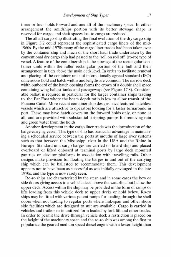
three or four holds forward and one aft of the machinery space. In eitherarrangement the amidships portion with its better stowage shape isreserved for cargo, and shaft spaces lost to cargo are reduced.
The all aft cargo ship illustrating the final evolution of the dry cargo shipin Figure 3.2 could represent the sophisticated cargo liners of the mid-1960s. By the mid-1970s many of the cargo liner trades had been taken overby the container ship and much of the short haul trade undertaken by theconventional dry cargo ship had passed to the ‘roll on roll off’ (ro-ro) type ofvessel. A feature of the container ship is the stowage of the rectangular con-tainer units within the fuller rectangular portion of the hull and theirarrangement in tiers above the main deck level. In order to facilitate removaland placing of the container units of internationally agreed standard (ISO)dimensions hold and hatch widths and lengths are common. The narrow deckwidth outboard of the hatch opening forms the crown of a double shell spacecontaining wing ballast tanks and passageways (see Figure 17.8). Consider-able ballast is required in particular for the larger container ships tradingto the Far East where the beam depth ratio is low to allow transit of thePanama Canal. More recent container ship designs have featured hatchlessvessels which are attractive to operators looking for a faster turnaround inport. These may have hatch covers on the forward holds only, or none atall, and are provided with substantial stripping pumps for removing rainand green water from the holds.
Another development in the cargo liner trade was the introduction of thebarge-carrying vessel. This type of ship has particular advantage in maintain-ing a scheduled service between the ports at mouths of large river systemssuch as that between the Mississippi river in the USA and the Rhine inEurope. Standard unit cargo barges are carried on board ship and placedoverboard or lifted onboard at terminal ports by large deck mountedgantries or elevator platforms in association with travelling rails. Otherdesigns make provision for floating the barges in and out of the carryingship which can be ballasted to accommodate them. This developmentappears not to have been as successful as was initially envisaged in the late1970s, and the type is now rarely seen.
Ro-ro ships are characterized by the stern and in some cases the bow orside doors giving access to a vehicle deck above the waterline but below theupper deck. Access within the ship may be provided in the form of ramps orlifts leading from this vehicle deck to upper decks or hold below. Ro-roships may be fitted with various patent ramps for loading through the shelldoors when not trading to regular ports where link-span and other shoreside facilities which are designed to suit are available. Cargo is carried invehicles and trailers or in unitized form loaded by fork lift and other trucks.In order to permit the drive through vehicle deck a restriction is placed onthe height of the machinery space and the ro-ro ship was among the first topopularize the geared medium speed diesel engine with a lesser height than
Shcc03.fm Page 17 Monday, March 26, 2001 3:01 PM

18 Ship Construction
its slow speed counterpart. The dramatic loss of the ro-ro passenger shipsHerald of Free Enterprise in 1987 and Estonia in 1994, respectively, sawmuch attention directed at the damage stability of this type of passengership when water entered the open un-subdivided vehicle deck space. Thishas resulted in international regulation requiring, amongst other things,
FIGURE 3.2 Development of cargo ship
FLUSH DECK SHIP
4
Shaft Tunnel
3 2 1Machinery
RAISED QUARTER DECKRaised quarter deck
Machinery 4 3 2 1Deeptank
4
Shaft Tunnel
3 2 1Machinery
AWNING OR SPAR DECKAwning deck
Machinery 4 35 2 1Deep tank
ALL AFT CARGO SHIP
4
Shaft Tunnel
3 2 1Machinery
Tonnage hatch Tonnage openingsOPEN SHELTER DECK
THREE ISLAND TYPE
4
Shaft Tunnel
3 2 1Machinery
4
Shaft Tunnel
3 2 1Machinery
COMBINED POOP AND BRIDGE
Shcc03.fm Page 18 Monday, March 26, 2001 3:01 PM

Development of Ship Types 19
strengthening and surveillance of bow doors, surveillance of internal water-tight doors used at sea, enhanced damage stability criteria (SOLAS 90) andadditional simplified stability information for the master. The Estonia lossled to further more stringent damage stability requirements adopted on aregional basis by northern European countries (Stockholm Agreement,1997). A midship section of a ro-ro passenger/vehicle/train ferry complyingwith the requirements of the latter agreement is shown in Figure 17.9.
Between the 1940s and 1970s there was a steady increase in the speedof the dry cargo ship and this was reflected in the hull form of the vessels.A much finer hull is apparent in modern vessels particularly in those shipsengaged in the longer cargo liner trades. Bulbous bow forms and open watersterns are used to advantage and considerable flare may be seen in the bowsof container ships to reduce wetness on deck where containers are stowed.In some early container ships it is thought that this was probably overdoneleading to an undesirable tendency for the main hull to whip during periodswhen the bows pitched into head seas. Larger container ships may have thehouse three-quarters aft with the full beam maintained right to the stern togive the largest possible container capacity.
Cargo handling equipment, which remained relatively unchanged for along period, has received considerable attention since the 1960s. This wasprimarily brought about by an awareness of the loss of revenue caused by thelong periods of time the vessel may spend in port discharging and loadingcargoes. Conventional cargo ships are now fitted with folding steel hatchcovers of one patent type or another or slab covers of steel, which reducemaintenance as well as speed cargo handling. Various new lifting devices,derrick forms and winches have been designed and introduced which simplifyas well as increase the rate of loading and discharge.
Bulk CarriersThe large bulk carrier originated as an ore carrier on the Great Lakes at thebeginning of the 20th century. For the period to the Second World Wardedicated bulk carriers were only built spasmodically for ocean trading,since a large amount of these cargoes could be carried by general cargotramps with the advantage of their being able to take return cargoes.
A series of turret-deck steamers were built for ore carrying purposesbetween 1904 and 1910 and a section through such a vessel is illustrated inFigure 3.4(a). Since 1945 a substantial number of ocean-going ore carriershave been built of uniform design. This form of ore carrier with a doublebottom and side ballast tanks first appeared in 1917, only at that time theside tanks did not extend to the full hold depth. To overcome the disadvant-age that the ore carrier was only usefully employed on one leg of the voyagethe oil/ore carrier also evolved at that time. The latter ship type carries oil in
Shcc03.fm Page 19 Monday, March 26, 2001 3:01 PM

20 Ship Construction
the wing tanks as shown in Figure 3.4(c), and has a passageway for crewprotection in order to obtain the deeper draft permitted tankers.
The common general bulk carrier takes the form shown in Figure 3.4(d)with double bottom, hopper sides and deck wing tanks (see also Figure 17.7).These latter tanks have been used for the carriage of light grain cargoes aswell as water ballast. Specific variations of this type have been built, Figure3.4(e) shows a ‘universal bulk carrier’ patented by the McGregor Inter-national Organization that offers a very flexible range of cargo stowagesolutions. Another type shown in Figure 3.4(f) has alternate holds of shortlength. On single voyages the vessel may carry high density bulk cargoesonly in the short holds to give an acceptable cargo distribution. Such stow-age is not uncommon on general bulk carriers with uniform hold lengthswhere alternate hold loading or block hold loading may be utilized to stowhigh density cargoes. With such loading arrangements high shear forcesoccur at the ends of the holds requiring additional strengthening of the sideshell in way of the bulkheads.
A general arrangement of a typical bulk carrier shows a clear deck withmachinery aft. Large hatches with steel covers are designed to facilitaterapid loading and discharge of the cargo. Since the bulk carrier makes many
(a) ROLL ON-ROLL OFF SHIPS
Main deck
Upper deck
Ramps
ER Hold
Lift
Tween
Angled sternramp
Sterndoor
ER
Vessel has adjustable internalramp giving access to decks
Weather deck
Main deckHold
(b) 49000 TONNE CONTAINER SHIP
ERNo. No. No. No. No. No. No. No.12345678
FIGURE 3.3
Shcc03.fm Page 20 Monday, March 26, 2001 3:01 PM

Development of Ship Types 21
voyages in ballast a large ballast capacity is provided to give adequateimmersion of the propeller. The size of this type of ship has also steadilyincreased and bulk carriers have reached 250 000 tonnes deadweight.
Ships of the general bulk carrier form have experienced a relatively highcasualty rate during the late 1980s and early 1990s giving rise to concern asto their design and construction. Throughout the 1990s bulk carrier safetyhas received considerable attention in the work of IMO, the classificationsocieties and elsewhere, and this work is ongoing. Based on experience offailures with lesser consequences it was concluded that the casualtiesoccurred through local structural failure leading to loss of watertight integ-rity of the side shell followed by progressive flooding through damagedbulkheads. The flooding resulting either in excessive hull bending stressesor excessive trim, and loss of the ship. Much of this work has concentratedon the structural hull details, stresses experienced as the result of loadingand discharging cargoes, damage to structure and protective coatingsarising from discharging cargoes, poor maintenance and subsequent inad-equate inspection of the ship structure. The outcome of this work has beenthe introduction of a new Chapter XII of SOLAS covering bulk carrier shipsafety and enhanced survey procedures for bulk carriers. Also, followingevidence from the discovery of the wreck of the bulk carrier Derbyshire,work at IMO directed at revision of the Load Line Convention 1969 is look-ing closely at adequacy of bow height and strength of hatch covers in theforward part of these ships.
The safe operation of bulk carriers is dependant on not exceeding allow-able stresses in the cycle of loading, discharging, ballasting and de-ballasting.
The size of bulk carriers may often be referred by one of the followingclasses:
‘Handysize’ the smallest bulk carriers of between 10 000 and 30 000tonnes deadweight.‘Handymax’ bulk carriers of between 35 000 and 50 000 tonnes deadweight. ‘Panamax’ bulk carriers designed to be of the maximum size that maytransit the Panama Canal and generally being just under 80 000 tonnesdeadweight.‘Capesize’ bulk carriers of 80 000 to 150 000 tonnes deadweight which aretoo large for the Panama Canal and trade from the Atlantic around theCape of Good Hope.
Oil TankersUntil 1990 the form of vessels specifically designed for the carriage of oil car-goes had not undergone a great deal of change since 1880 when the vesselillustrated in Figure 3.5(a) was constructed. The expansion tank and double
Shcc03.fm Page 21 Monday, March 26, 2001 3:01 PM

(a) TURRET TYPE ORECARRIER 1910
Waterballast
(b) ORE CARRIER
Passageway
Double bottom
Ore
Ore
Double bottom
OreOil Oil
Passageway
(c) ORE/OIL CARRIER
Waterballast Ore
(d) GENERAL BULK CARRIER
Double bottom
Cargo
Machinery
Machinery
65
5
9
44
5OreOre 7 3
33
Ore Ore 1
11
22
(e) UNIVERSAL BULK CARRIER(shown carrying ore)
(f) GENERAL CARGO SHIP WITH SHORT HOLDS FOR ORE
Ore
Water ballastor grain
FIGURE 3.4 Bulk carriers
Shcc03.fm Page 22 M
onday, March 26, 2001 3:01 PM

Development of Ship Types 23
bottom within the cargo space having been eliminated. The greatest changesin that period were the growth in ship size and nature of the structure (seeFigure 3.5(b)).
The growth in size of ocean-going vessels from 1880 to the end of theSecond World War was gradual, the average deadweight rising from 1500tons to about 12 000 tons. Since then the average deadweight increasedrapidly to about 20 000 tons in 1953 and about 30 000 tons in 1959. Todaythere are afloat tankers ranging from 100 000 tons deadweight to 500 000tons deadweight. It should be made clear that the larger size of vessel isthe crude oil carrier, and fuel oil carriers tend to remain within the smallerdeadweights.
Service speeds of oil tankers have shown an increase since the war, goingfrom 12 knots to 17 knots. The service speed is related to the optimumeconomic operation of the tanker. Also the optimum size of the tanker isvery much related to current market economics. The tanker fleet growthincreased enormously to meet the expanding demand for oil until 1973/1974 when the OPEC price increases slowed that expansion and led to aslump in the tanker market. As a result it is unlikely that such a significant risein tanker size and rise in speed will be experienced in the foreseeable future.
Structurally one of the greatest developments has been in the use ofwelding, oil tankers being amongst the first vessels to utilize the applicationof welding. Little difficulty is experienced in making and maintaining oil-tight joints: the same cannot be said of riveting. Welding has also allowedcheaper fabrication methods to be adopted. Longitudinal framing wasadopted at an early date for the larger ships and revision of the constructionrules in the late 1960s allowed the length of tank spaces to be increased,with a subsequent reduction in steel weight, and making it easier to pumpdischarge cargoes.
As far as the general arrangement is concerned there appears always tohave been a trend towards placing the machinery aft. Moving all the accom-modation and bridge aft was a later feature and is desirable from the fireprotection point of view. Location of the accommodation in one area ismore economic from a building point of view, since all services are only to beprovided at a single location.
The requirements of the International Convention for the Prevention ofPollution from Ships 1973 (see Chapter 29) and particularly its Protocol of1978 have greatly influenced the arrangement of the cargo spaces of oiltankers. A major feature of the MARPOL Convention and its Protocol hasbeen the provision in larger tankers of clean water ballast capacity. Whilstprimarily intended to reduce the pollution risk, the fitting of segregatedwater ballast tanks in the midship region aids the reduction of the still waterbending moment when the tanker is fully loaded. It also reduces corrosionproblems associated with tank spaces which are subject to alternate oil andsea water ballast cargoes.
Shcc03.fm Page 23 Monday, March 26, 2001 3:01 PM

Length 77.6mBeamDepth 5.8m
Deadweight 1680 tonnes
Speed 10 k
Expansion trunk
Wing tank Centre tank Wing tank
Double bottom
(a)
Length B.P. 330mBeam 53.3mDepth 32m
Deadweight 332000 tonnes
Speed 14½ k
Centre tanktank tank
WingWing
(b)
DOUBLE-HULL TANKER
SB
TSB
T
SB
T
SB
T
SBT SBT SBT
Centretank
tank tank
Wing Wing
MID-DECK TANKER PRINCIPLE
SBT SBTOil
Oil
Oil
Oil
Mid-deck
10.4m
FIGURE 3.5 Oil tankers
Shcc03.fm Page 24 M
onday, March 26, 2001 3:01 PM

Development of Ship Types 25
In March 1989 the tanker Exxon Valdez, which complied fully with thethen current MARPOL requirements, ran aground and discharged 11 mil-lion gallons of crude oil into the pristine waters of Prince William Soundin Alaska. The subsequent public outcry led to the United States Congresspassing the Oil Pollution Act 1990 (OPA 90). This unilateral action by theUnited States Government made it a requirement that existing single hulloil tankers operating in United States waters were to be phased out by an earlydate, after which all oil tankers were to have a double hull (see Figures 3.5and 22.7).
In November 1990 the USA suggested that the MARPOL Conventionshould be amended to make double hulls compulsory for new tankers. Anumber of other IMO member states suggested that alternative designsoffering equivalent protection against accidental oil spills should be accepted.In particular Japan proposed an alternative, the mid-deck tanker. Thisdesign has side ballast tanks providing protection against collision but nodouble bottom. The cargo tank space (see Figure 3.5) has a structural deckrunning its full length at about 0.25 to 0.5 the depth from the bottom whichensures that should the bottom be ruptured the upward pressure exerted bythe sea prevents most of the oil from escaping into the sea.
In 1992 IMO adopted amendments to MARPOL which required tankersof 5000 tons deadweight and above contracted for after July 1993, or whichcommenced construction after January 1994, to be of double-hulled or mid-deck construction, or of other design offering equivalent protection againstoil pollution.
Studies by IMO and the US National Academy of Sciences confirm theeffectiveness of the double hull in preventing oil spills caused by groundingand collision where the inner hull is not breached. The mid-deck tankerhas been shown to have more favourable outflow performance in extremeaccidents where the inner hull is breached. The United States authoritiesconsider grounding the most prevalent type of accident in their waters andbelieve only the double hull type prevents spills from tanker groundings inall but the most severe incidents. Thus, whilst MARPOL provides for theacceptance of alternative tanker designs, the United States legislation doesnot, and at the time of writing none of the alternative designs had beenbuilt.
Present MARPOL requirements are that existing single hull crude oiltankers of 20 000 tons or more deadweight and existing single hull productscarriers of 30 000 tons or more deadweight that:
• do not have segregated ballast tanks with protective location will not beable to operate after June 2007; and
• do have segregated ballast tanks with protective location will not be ableto operate after July 2021.
Shcc03.fm Page 25 Monday, March 26, 2001 3:01 PM

26 Ship Construction
As the result of the break up of the tanker Erika and subsequent pollutionof the French coastline in 1999 proposed amendments to MARPOL werebefore IMO at the time of writing aimed at having the above phase outdates brought forward. The proposed amendments would see older tankersphased out at earlier dates with all single hull tankers of 5000 tons dead-weight or more being phased out by 1 January 2017.
Oil tankers now generally have a single pump space aft, adjacent to themachinery, and specified slop tanks into which tank washings and oily res-idues are pumped. Tank cleaning may be accomplished by water drivenrotating machines on the smaller tankers but for new crude oil tankers of20 000 tons deadweight and above the tank cleaning system shall use crudeoil washing.
Passenger ShipsEarly passenger ships did not have the tiers of superstructures associatedwith modern vessels, and they also had a narrower beam in relation to thelength. The reason for the absence of superstructure decks was the MerchantShipping Act 1894 which limited the number of passengers carried on theupper deck. An amendment to this Act in 1906 removed this restriction andvessels were then built with several tiers of superstructures. This producedproblems of strength and stability, stability being improved by an increasein beam. The transmission of stresses to the superstructure from the mainhull girder created much difference of opinion as to the means of overcom-ing the problem. Both light structures of a discontinuous nature, i.e. fittedwith expansion joints, and superstructures with heavier scantlings able tocontribute to the strength of the main hull girder were introduced. Presentpractice, where the length of the superstructure is appreciable and has itssides at the ship side, does not require the fitting of expansion joints. Wherealuminium alloy superstructures are fitted in modern ships it is possible toaccept greater deformation than would be possible with steel and no similarproblem exists.
The introduction of aluminium alloy superstructures has providedincreased passenger accommodation on the same draft, and/or a loweringof the lightweight centre of gravity with improved stability. This is broughtabout by the lighter weight of the aluminium structure.
A feature of the general arrangement is the reduction in size of themachinery space in this time. It is easy to see the reason for this if theAquitania, built in 1914 and having direct drive turbines with twenty-onedouble-ended scotch boilers, is compared with the Queen Elizabeth 2.The latter as originally built had geared drive turbines with three water tubeboilers. Several modern passenger ships have had their machinery placedaft; this gives over the best part of the vessel amidships entirely to passenger
Shcc03.fm Page 26 Monday, March 26, 2001 3:01 PM

Bridge
Machinery
Accommodation
Vehicle deck
WAVE PIERCING CATAMARAN
HYDROFOIL MULTI-HULL CATAMARAN SWATH CONCEPT
FIGURE 3.6 Various types of high speed craft
Shcc03.fm Page 27 M
onday, March 26, 2001 3:01 PM

28 Ship Construction
accommodation. Against this advantage, however, allowance must be madefor an increased bending moment if a suitable trim is to be obtained.
Passenger accommodation standards have increased substantially, thevolume of space allotted per passenger rising steadily. Tween deck clear-ances are greater and public rooms extend through two or more decks,whilst enclosed promenade and atrium spaces are now common in cruisevessels. The provision of air conditioning and stabilizing devices have alsoadded to passenger comfort. Particular attention has been paid to fire safetyin the modern passenger ship, structural materials of low fire risk beingutilized in association with automatic extinguishing and detection systems.
There has been a demise of the larger passenger liner and larger passengerships are now either cruise ships, short-haul ferries or special trade passenger(STP) ships. The latter are unberthed immigrant or pilgrim passenger shipsoperating in the Middle East to South East Asian region.
The development of high speed passenger ferries of lightweight construc-tion and often of radical hull form and/or non-displacement modes ofoperation has been notable since the early 1980s. Initially relatively small,these craft may now be more than 100 metres in length and carry upwardsof 500 persons plus 100 cars/30 trucks or more. The lightweight construc-tion is usually of aluminium alloy but some have been constructed of lighterhigher tensile steels and fibre reinforced plastics may be used in the super-structure and accommodation areas. With speeds of up to 50 knots manycraft are of twin-hull form and include conventional catamarans, wave-piercers with twin hulls and a faired buoyant bridging structure forward,also small waterplane twin hulled (SWATH) ships. The latter have a highproportion of their twin-hull buoyancy below the waterline and very narrowtwin-hull beam at the waterline (see Figure 3.5). Other high speed craftinclude hydrofoils, and various surface effect ships (SESs) including hover-craft which maintain a cushion of air, fully or partially, between the hull andthe water to reduce (drag). The increasing use of these vessels led in 1994 tothe promulgation by IMO of specific international regulations concerningtheir design, safety and operation. An updated version of this Code ofSafety was due to be adopted in December 2000. Figure 3.6 illustrates thevarious types of high speed craft. Also, see Figure 17.10 which shows themidship section of a high speed wave piercing catamaran.
Further Reading‘Barge Carriers—a Revolution in Marine Transport’, The Naval Architect,
April 1973.
Bhave and Ghosh Roy, ‘Special Trade Passenger Ships’, The Naval Archi-tect, April, 1973.
Shcc03.fm Page 28 Monday, March 26, 2001 3:01 PM

Development of Ship Types 29
‘Bulk Carriers—Handle With Care’, IACS, 5 Old Queen Street, LondonSW1H 9JA.
Burrows, ‘The North Sea Platform Supply Vessel’, ImarE Trans., Part 1, 1997.
‘Code of Safety for Special Purpose Ships’, IMO publication (IMO-820E).
Coll, ‘Safety of Bulk Carriers—Are Two Skins Better Than One? Trans.R.I.N.A., 1997.
Farell, ‘Chemical Tankers—The Quiet Evolution’, The Naval Architect,July, 1975.
‘Guidelines for the Design and Construction of Offshore Supply Vessels’,IMO publication (IMO-807E).
IMO, ‘International Code of Safety for High Speed Craft (HSC Code)’, 1994.
‘Improving tanker and bulker safety’, Safety at Sea International, August,1993.
Meek, ‘Priam Class Cargo Liners—Design and Operation’, Trans. R.I.N.A.,1969.
Meek, ‘The First OCL Container Ship’, Trans. R.I.N.A., 1970.
Meek et al., ‘The Structural Design of the OCL Container Ships’, The NavalArchitect, April, 1972.
‘Modern Car Ferry Design and Development’, The Naval Architect, January,1980.
Murray, ‘Merchant Ships 1860–1960’, Trans. R.I.N.A., 1960.
Payne, ‘The Evolution of the Modern Cruise Liner’, The Naval Architect,1990.
Payne, ‘From Tropicale to Fantasy: A Decade of Cruiseship Development’,Trans. R.I.N.A., 1993.
Payne, ‘The return of the true liner’—A design critique of the modern fastcruise ship, The Naval Architect, September 1994.
‘Safety of Passenger Ro-Ro Vessels’, 1996 Conference Proceedings—RoyalInstitution of Naval Architects Publications.
Storey, ‘The design, construction and introduction of the Stena HSS 1500’,ImarE Trans., Vol 109, Part 4, 1997.
‘The Design and Operation of Container Ships’, 1999 Conference Proceed-ings—Royal Institution of Naval Architects Publications.
Shcc03.fm Page 29 Monday, March 26, 2001 3:01 PM

Shcc03.fm Page 30 Monday, March 26, 2001 3:01 PM

Part 2
Materials and Strength of Ships
Shcc04.fm Page 31 Monday, March 26, 2001 3:02 PM

Shcc04.fm Page 32 Monday, March 26, 2001 3:02 PM

4Classification Societies
A cargo shipper and the underwriter requested to insure a maritime riskrequire some assurance that any particular vessel is structurally fit to under-take a proposed voyage. To enable the shipper and underwriter to dis-tinguish the good risk from the bad a system of classification has beenformulated over a period of some two hundred years. During this periodreliable organizations have been created for the initial and continuinginspection of ships so that classification may be assessed and maintained.
The principal maritime nations have the following classification societies:
Great Britain—Lloyd’s Register of Shipping France—Bureau Veritas Germany—Germanischer Lloyd Norway—Det Norske Veritas Italy—Registro Italiano Navale United States of America—American Bureau of ShippingRussia—Russian Register of Shipping Japan—Nippon Kaiji Kyokai
These classification societies publish rules and regulations which are prin-cipally concerned with the strength of the ship, the provision of adequateequipment, and the reliability of the machinery. Ships may be built in anycountry to a particular classification society’s rules, and they are notrestricted to classification by the relevant society of the country where theyare built. Classification is not compulsory but the shipowner with anunclassed ship will be required to satisfy governmental regulating bodiesthat it has sufficient structural strength for assignment of a load line andissue of a safety construction certificate.
Only the requirements of Lloyd’s Register of Shipping which is the oldestof the classification societies are dealt with in detail. Founded in 1760 andreconstituted in 1834, Lloyd’s Register was amalgamated with the BritishCorporation, the only other British classification society in existence at thattime, in 1949. Steel ships built in accordance with Lloyd’s Register rulesor equivalent standards, are assigned a class in the Register Book, andcontinue to be classed so long as they are maintained in accordance withthe Rules.
Shcc04.fm Page 33 Monday, March 26, 2001 3:02 PM

34 Ship Construction
Lloyd’s Register Classification Symbols All ships classed by Lloyd’s Register of Shipping are assigned one or morecharacter symbols. The majority of ships are assigned the characters 100A1or � 100A1.
The character figure 100 is assigned to all ships considered suitable forsea-going service. The character letter A is assigned to all ships which arebuilt in accordance with or accepted into class as complying with the Society’sRules and Regulations. The character figure 1 is assigned to ships carryingon board anchor and/or mooring equipment complying with the Society’sRules and Regulations. Ships which the Society agree need not be fittedwith anchor and mooring equipment may be assigned the character letter Nin lieu of the character figure 1. The Maltese Cross mark is assigned to newships constructed under the Society’s Special Survey, i.e. a surveyor hasbeen in attendance during the construction period to inspect the materialsand workmanship.
There may be appended to the character symbols, when considered neces-sary by the Society or requested by the owner, a number of class notations.These class notations may consist of one or a combination of the following.Type notation, cargo notation, special duties notation, special featuresnotation, service restriction notation. Type notation indicates that the shiphas been constructed in compliance with particular rules applying to thattype of ship, e.g. 100A1 ‘Bulk Carrier’. Cargo notation indicates the ship hasbeen designed to carry one or more specific cargoes, e.g. ‘Sulphuric acid’.This does not preclude it from carrying other cargoes for which it mightbe suitable. Special duties notation indicate the ship has been designedfor special duties other than those implied by type or cargo notation, e.g.‘research’. Special features notation indicates the ship incorporates specialfeatures which significantly affect the design, e.g. ‘movable decks’. Servicerestriction notation indicates the ship has been classed on the understand-ing it is operated only in a specified area and/or under specified conditions,e.g. ‘Great Lakes and St. Lawrence’.
The class notation � LMC indicates that the machinery has beenconstructed, installed and tested under the Society’s Special Survey and inaccordance with the Society’s Rules and Regulations. Various othernotations relating to the main and auxiliary machinery may also beassigned.
Vessels with a refrigerated cargo installation constructed, installed andtested under the Society’s Special Survey and in accordance with its Rulesand Regulations may be assigned the notation � Lloyds RMC. A classedliquefied gas carrier or tanker in which the cargo reliquefaction or cargorefrigeration equipment is approved, installed and tested in accordancewith the Society’s Rules and Regulations may be assigned the notation� Lloyds RMC (LG).
Shcc04.fm Page 34 Monday, March 26, 2001 3:02 PM

Classification Societies 35
Where additional strengthening is fitted for navigation in ice conditionsan appropriate notation may be assigned. The notations fall into twogroups: those where additional strengthening is added for first-year ice, i.e.service where waters ice up in winter only; and those where additionalstrengthening is added for multi-year ice, i.e. service in Arctic and Antarc-tic. It is the responsibility of the owner to determine which notation is mostsuitable for his requirements.
Notations are:
F I R S T-Y E A R I C ESpecial features notations are:
Ice Class 1As unbroken level ice with thickness of 1 m. Ice Class 1A unbroken level ice with thickness of 0.8 m. Ice Class 1B unbroken level ice with thickness of 0.6 m. Ice Class 1C unbroken level ice with thickness of 0.4 m. Ice Class 1D same as 1C but only requirements for strengthening the for-
ward region, the rudder and steering arrangements apply.
M U L T I-Y E A R I C EThe addition of the term ‘icebreaking’ to the ship type notation, e.g. ‘ice-breaking tanker’ plus the following special features notation:
Ice Class AC1 Arctic or Antarctic ice conditions equivalent to unbrokenice with a thickness of 1 m.
Ice Class AC1.5 Arctic or Antarctic ice conditions equivalent to unbrokenice with a thickness of 1.5 m.
Ice Class AC2 Arctic or Antarctic ice conditions equivalent to unbrokenice with a thickness of 2 m.
Ice Class AC3 Arctic or Antarctic ice conditions equivalent to unbrokenice with a thickness of 3 m.
Ships specially designed for icebreaking duties are assigned the ship typenotation ‘icebreaker’ plus the appropriate special features notation for thedegree of ice strengthening provided.
Structural Design ProgramsIn recent years the principal classification societies have developed soft-ware packages for use by shipyards which incorporate dynamic-basedcriteria for the scantlings, structural arrangements and details of shipstructures. This was a response to a perception that the traditional semi-empirical published classification rules based on experience could be
Shcc04.fm Page 35 Monday, March 26, 2001 3:02 PM

36 Ship Construction
inadequate for new and larger vessel trends. The computer programs madeavailable to shipyards incorporate a realistic representation of the dynamicloads likely to be experienced by the ship and are used to determine thescantlings and investigate the structural responses of critical areas of theship’s structure. They include a program for fatigue design assessment(FDA) which is commonly used to assess the structural design detail oflarge container ships, tankers and bulk carriers. Evaluation of the structuraldesign by means of these programs can result in the ship being assignedfurther relevant notations.
Periodical Surveys To maintain the assigned class the vessel has to be examined by the Society’ssurveyors at regular periods.
The major hull items to be examined at these surveys only are indicatedbelow.
A N N U A L S U R V E Y S All steel ships are required to be surveyed at inter-vals of approximately one year. These annual surveys are where practicableheld concurrently with statutory annual or other load line surveys. At thesurvey the surveyor is to examine the condition of all closing appliancescovered by the conditions of assignment of minimum freeboard, the free-board marks, and auxiliary steering gear particularly rod and chain gear.Watertight doors and other penetrations of watertight bulkheads are alsoexamined and the structural fire protection verified. The general conditionof the vessel is assessed, and anchors and cables are inspected wherepossible at these annual surveys. Dry bulk cargo ships are subject to aninspection of a forward and after cargo hold.
I N T E R M E D I A T E S U R V E Y S Instead of the second or third annual surveyafter building or special survey an intermediate survey is undertaken. Inaddition to the requirements for annual survey particular attention is paidto cargo holds in vessels over 15 years of age and the operating systems oftankers, chemical carriers and liquefied gas carriers.
D O C K I N G S U R V E Y S Ships are to be examined in dry dock at intervalsnot exceeding 2½ years. At the drydocking survey particular attention ispaid to the shell plating, stern frame and rudder, external and through hullfittings, and all parts of the hull particularly liable to corrosion and chafing,and any unfairness of bottom.
I N-W A T E R S U R V E Y S The Society may accept in-water surveys in lieu ofany one of the two dockings required in a five-year period. The in-water
Shcc04.fm Page 36 Monday, March 26, 2001 3:02 PM

Classification Societies 37
survey is to provide the information normally obtained for the dockingsurvey. Generally consideration is only given to an in-water survey where asuitable high resistance paint has been applied to the underwater hull.
S P E C I A L S U R V E Y S All steel ships classed with Lloyd’s Register aresubject to special surveys. These surveys become due at five yearly intervals,the first five years from the date of build or date of special survey for classi-fication and thereafter five years from the date of the previous special survey.Special surveys may be carried out over an extended period commencingnot before the fourth anniversary after building or previous special survey,but must be completed by the fifth anniversary.
The hull requirements at a special survey, the details of the compart-ments to be opened up, and the material to be inspected at any specialsurvey are listed in detail in the Rules and Regulations (Part 1, Chapter 3).Special survey hull requirements are divided into four ship age groups asfollows:
1. Special survey of ships—five years old 2. Special survey of ships—ten years old 3. Special survey of ships—fifteen years old 4. Special survey of ships—twenty years old and at every special survey
thereafter.
In each case the amount of inspection required increases and morematerial is removed so that the condition of the bare steel may be assessed.It should be noted that where the surveyor is allowed to ascertain by drill-ing or other approved means the thickness of material, non-destructivemethods such as ultrasonics are available in contemporary practice for thispurpose. Additional special survey requirements are prescribed for oiltankers, dry bulk carriers, chemical carriers and liquefied gas carriers.
When classification is required for a ship not built under the supervisionof the Society’s surveyors, plans showing the main scantlings and arrange-ments of the actual ship are submitted to the Society for approval. Alsosupplied are particulars of the manufacture and testing of the materials ofconstruction, together with full details of the equipment. Where plans, etc.,are not available, the Society’s surveyors are to be allowed to lift the relev-ant information from the ship. At the special survey for classification all thehull requirements for special surveys (1), (2), and (3) are to be carried out.Ships over twenty years old are also to comply with the hull requirements ofspecial survey (4), and oil tankers must comply with the additional require-ments stipulated in the Rules and Regulations. During this survey thesurveyor assesses the standard of the workmanship, and verifies the scant-lings and arrangements submitted for approval. It should be noted thatthe special survey for classification will receive special consideration from
Shcc04.fm Page 37 Monday, March 26, 2001 3:02 PM

38 Ship Construction
Lloyd’s Register in the case of a vessel transferred from another recognizedClassification Society. Periodical surveys where the vessel is classed are sub-sequently held as in the case of ships built under survey, being dated fromthe date of special survey for classification.
Damage RepairsWhen a vessel requires repairs to damaged equipment or to the hull it isnecessary for the work to be carried out to the satisfaction of Lloyd’s Registersurveyors. In order that the ship maintains its class, approval of the repairsundertaken must be obtained from the surveyors either at the time of therepair or at the earliest opportunity.
Further ReadingLloyd’s Register of Shipping, ‘Rules and Regulations for the Classification
of Ships’, Part 1, Regulations, Chapters 2 and 3.
‘New ShipRight Design, Construction and Shipcare Procedures fromLloyds Register’, The Naval Architect, April, 1994.
Spencer, Robinson and Chen, ‘Recent Advances in Classification Rules forDesign and Evaluation of Ship Hull Structures’, Newbuild 2000, RoyalInstitution of Naval Architects Publications.
Shcc04.fm Page 38 Monday, March 26, 2001 3:02 PM

5Steels
The production of all steels used for shipbuilding purposes starts with thesmelting of iron ore and the making of pig-iron. Normally the iron ore issmelted in a blast furnace, which is a large, slightly conical structure linedwith a refractory material. To provide the heat for smelting, coke is usedand limestone is also added. This makes the slag formed by the incombust-ible impurities in the iron ore fluid, so that it can be drawn off. Air neces-sary for combustion is blown in through a ring of holes near the bottom,and the coke, ore, and limestone are charged into the top of the furnace inrotation. Molten metal may be drawn off at intervals from a hole or spout atthe bottom of the furnace and run into moulds formed in a bed of sand orinto metal moulds.
The resultant pig-iron is from 92 to 97 per cent iron, the remainder beingcarbon, silicon, manganese, sulphur, and phosphorus. In the subsequentmanufacture of steels the pig-iron is refined, in other words the impuritiesare reduced.
Manufacture of SteelsSteels may be broadly considered as alloys of iron and carbon, the carbonpercentage varying from about 0.1 per cent in mild steels to about 1.8 percent in some hardened steels. These may be produced by one of four differ-ent processes, the open hearth process, the Bessemer converter process, theelectric furnace process, or an oxygen process. Processes may be either anacid or basic process according to the chemical nature of the slag produced.Acid processes are used to refine pig-iron low in phosphorus and sulphurwhich are rich in silicon and therefore produce an acid slag. The furnacelining is constructed of an acid material so that it will prevent a reactionwith the slag. A basic process is used to refine pig-iron that is rich in phos-phorus and low in silicon. Phosphorus can be removed only by introducinga large amount of lime, which produces a basic slag. The furnace liningmust then be of a basic refractory to prevent a reaction with the slag. About85 per cent of all steel produced in Britain is of the basic type, and withmodern techniques is almost as good as the acid steels produced withsuperior ores.
Shcc05.fm Page 39 Monday, March 26, 2001 3:03 PM

40 Ship Construction
Only the open hearth, electric furnace, and oxygen processes are describedhere as the Bessemer converter process is not used for shipbuilding steels.
OPEN H E A R T H P R O C E S S The open hearth furnace is capable ofproducing large quantities of steel, handling 150 to 300 tonnes in a singlemelt. It consists of a shallow bath, roofed in, and set above two brick-linedheating chambers. At the ends are openings for heated air and fuel (gas oroil) to be introduced into the furnace. Also these permit the escape of theburned gas which is used for heating the air and fuel. Every twenty minutesor so the flow of air and fuel is reversed.
In this process a mixture of pig-iron and steel scrap is melted in thefurnace, carbon and the impurities being oxidized. Oxidization is producedby the oxygen present in the iron oxide of the pig-iron. Subsequently carbon,manganese, and other elements are added to eliminate iron oxides and givethe required chemical composition.
E L E C T R I C F U R N A C E S Electric furnaces are generally of two types, thearc furnace and the high-frequency induction furnace. The former is used forrefining a charge to give the required composition, whereas the latter mayonly be used for melting down a charge whose composition is similar to thatfinally required. For this reason only the arc furnace is considered in anydetail. In an arc furnace melting is produced by striking an arc between elec-trodes suspended from the roof of the furnace and the charge itself in thehearth of the furnace. A charge consists of pig-iron and steel scrap and theprocess enables consistent results to be obtained and the final compositionof the steel can be accurately controlled.
Electric furnace processes are often used for the production of high-gradealloy steels.
O X Y G E N P R O C E S S This is a modern steelmaking process by which amolten charge of pig-iron and steel scrap with alloying elements is con-tained in a basic lined converter. A jet of high purity gaseous oxygen is thendirected onto the surface of the liquid metal in order to refine it.
Steel from the open hearth or electric furnace is tapped into large ladlesand poured into ingot moulds. It is allowed to cool in these moulds, until itbecomes reasonably solidified permitting it to be transferred to ‘soakingpits’ where the ingot is reheated to the required temperature for rolling.
C H E M I C A L A D D I T I O N S T O S T E E L S Additions of chemical elementsto steels during the above processes serve several purposes. They may beused to deoxidize the metal, to remove impurities and bring them out intothe slag, and finally to bring about the desired composition.
Shcc05.fm Page 40 Monday, March 26, 2001 3:03 PM

Steels 41
The amount of deoxidizing elements added determines whether thesteels are ‘rimmed steels’ or ‘killed steels’. Rimmed steels are producedwhen only small additions of deoxidizing material are added to the moltenmetal. Only those steels having less than 0.2 per cent carbon and less than0.6 per cent manganese can be rimmed. Owing to the absence of deoxidiz-ing material, the oxygen in the steel combines with the carbon and othergases present and a large volume of gas is liberated. So long as the metal ismolten the gas passes upwards through the molten metal. When solidifica-tion takes place in ingot form, initially from the sides and bottom and thenacross the top, the gases can no longer leave the metal. In the centralportion of the ingot a large quantity of gas is trapped with the result that thecore of the rimmed ingot is a mass of blow holes. Normally the hot rollingof the ingot into thin sheet is sufficient to weld the surfaces of the blowholes together, but this material is unsuitable for thicker plate.
The term ‘killed’ steel indicates that the metal has solidified in the ingotmould with little or no evolution of gas. This has been prevented by theaddition of sufficient quantities of deoxidizing material, normally silicon oraluminium. Steel of this type has a high degree of chemical homogeneity,and killed steels are superior to rimmed steels. Where the process of deoxi-dation is only partially carried out by restricting the amount of deoxidizingmaterial a ‘semi-killed’ steel is produced.
In the ingot mould the steel gradually solidifies from the sides and baseas mentioned previously. The melting points of impurities like sulphidesand phosphides in the steel are lower than that of the pure metal and thesewill tend to separate out and collect towards the centre and top of the ingotwhich is the last to solidify. This forms what is known as the ‘segregate’ inway of the noticeable contraction at the top of the ingot. Owing to the highconcentration of impurities at this point this portion of the ingot is oftendiscarded prior to rolling plate and sections.
Heat Treatment of SteelsThe properties of steels may be altered greatly by the heat treatment towhich the steel is subsequently subjected. These heat treatments bring abouta change in the mechanical properties principally by modifying the steel’sstructure. Those heat treatments which concern shipbuilding materials aredescribed.
A N N E A L I N G This consists of heating the steel at a slow rate to a temperat-ure of say 850 °C to 950 °C, and then cooling it in the furnace at a very slowrate. The objects of annealing are to relieve any internal stresses, to softenthe steel, or to bring the steel to a condition suitable for a subsequent heattreatment.
Shcc05.fm Page 41 Monday, March 26, 2001 3:03 PM

42 Ship Construction
N O R M A L I Z I N G This is carried out by heating the steel slowly to atemperature similar to that for annealing and allowing it to cool in air.The resulting faster cooling rate produces a harder stronger steel thanannealing, and also refines the grain size.
Q U E N C H I N G (O R H A R D E N I N G) Steel is heated to temperatures sim-ilar to that for annealing and normalizing, and then quenched in water oroil. The fast cooling rate produces a very hard structure with a higher tens-ile strength.
T E M P E R I N G Quenched steels may be further heated to a temperaturesomewhat between atmospheric and 680 °C, and some alloy steels are thencooled fairly rapidly by quenching in oil or water. The object of this treat-ment is to relieve the severe internal stresses produced by the original hard-ening process and to make the material less brittle but retain the highertensile stress.
S T R E S S R E L I E V I N G To relieve internal stresses the temperature of thesteel may be raised so that no structural change of the material occurs andthen it may be slowly cooled.
Steel Sections A range of steel sections are rolled hot from the ingots. The more commontypes associated with shipbuilding are shown in Figure 5.1. It is preferableto limit the sections required for shipbuilding to those readily available,that is the standard types; otherwise the steel mill is required to set up rollsfor a small amount of material which is not very economic.
Shipbuilding Steels Steel for hull construction purposes is usually mild steel containing 0.15 percent to 0.23 per cent carbon, and a reasonably high manganese content. Bothsulphur and phosphorus in the mild steel are kept to a minimum (less than0.05 per cent). Higher contents of both are detrimental to the welding prop-erties of the steel, and cracks can develop during the rolling process if thesulphur content is high.
Steel for a ship classed with Lloyd’s Register is produced by an approvedmanufacturer, and inspection and prescribed tests are carried out at thesteel mill before dispatch. All certified materials are marked with theSociety’s brand and other particulars as required by the rules.
Shcc05.fm Page 42 Monday, March 26, 2001 3:03 PM

Steels 43
Ship classification societies originally had varying specifications for steel;but in 1959, the major societies agreed to standardize their requirements inorder to reduce the required grades of steel to a minimum. There are nowfive different qualities of steel employed in merchant ship construction.These are graded A, B, C, D and E, Grade A being an ordinary mild steel toLloyd’s Register requirements and generally used in shipbuilding. Grade Bis a better quality mild steel than Grade A and specified where thickerplates are required in the more critical regions. Grades C, D and E possessincreasing notch-touch characteristics, Grade C being to American Bureauof Shipping requirements. Lloyd’s Register requirements for Grades A, B,D and E steels may be found in Chapter 3 of Lloyd’s Rules for the Manu-facture, Testing and Certification of Materials.
High Tensile SteelsSteels having a higher strength than that of mild steel are employed in themore highly stressed regions of large tankers, container ships and bulkcarriers. Use of higher strength steels allows reductions in thickness ofdeck, bottom shell, and framing where fitted in the midships portion oflarger vessels; it does, however, lead to larger deflections. The weldabilityof higher tensile steels is an important consideration in their application inship structures and the question of reduced fatigue life with these steels has
FLATBAR
CHANNELBAR
TEEBAR
TEEBULB
OFFSETBULBPLATE
ANGLEBAR
FIGURE 5.1 Steel sections of shipbuilding
Shcc05.fm Page 43 Monday, March 26, 2001 3:03 PM

44 Ship Construction
been suggested. Also, the effects of corrosion with lesser thicknesses ofplate and section may require more vigilant inspection.
Higher tensile steels used for hull construction purposes are manufacturedand tested in accordance with Lloyd’s Register requirements. Full specifica-tions of the methods of manufacture, chemical composition, heat treatment,and mechanical properties required for the higher tensile steels are given inChapter 3 of Lloyd’s Rules for the Manufacture, Testing and Certification ofMaterials. The higher strength steels are available in three strength levels, 32,36, and 40 (kg/mm2) when supplied in the as rolled or normalized condition.Provision is also made for material with six higher strength levels, 42, 46, 50,55, 62 and 69 (kg/mm2) when supplied in the quenched and tempered condi-tion. Each strength level is subdivided into four grades, AH, DH, EH and FHdepending on the required level of notch-toughness.
Steel CastingsMolten steel produced by the open hearth, electric furnace, or oxygenprocess is poured into a carefully constructed mould and allowed to solidifyto the shape required. After removal from the mould a heat treatment isrequired, for example annealing, or normalizing and tempering, to reducebrittleness. Stern frames, rudder frames, spectacle frames for bossings, andother structural components may be produced as castings.
Steel ForgingsForging is simply a method of shaping a metal by heating it to a temperaturewhere it becomes more or less plastic and then hammering or squeezing itto the required form. Forgings are manufactured from killed steel madeby the open hearth, electric furnace, or oxygen process, the steel being inthe form of ingots cast in chill moulds. Adequate top and bottom discardsare made to ensure no harmful segregations in the finished forgings andthe sound ingot is gradually and uniformly hot worked. Where possiblethe working of the metal is such that metal flow is in the most favourabledirection with regard to the mode of stressing in service. Subsequent heattreatment is required, preferably annealing or normalizing and tempering,to remove effects of working and non-uniform cooling.
Further ReadingBoyd and Bushell, ‘Hull Structural Steel—The Unification of the Require-
ments of Seven Classification Societies’, Trans. R.I.N.A., 1961.
Shcc05.fm Page 44 Monday, March 26, 2001 3:03 PM

Steels 45
Buchanan, ‘The Application of Higher Tensile Steel in Merchant ShipConstruction’, Trans. R.I.N.A., 1968.
Pearson, ‘The Modern Manufacture of Steel Plate for Shipbuilding’, Trans.N.E.C. Inst., vol. 72, 1955–56.
Stevens, ‘Forging Methods’, Trans, N.E.C. Inst., vol. 67, 1950–51.
Shcc05.fm Page 45 Monday, March 26, 2001 3:03 PM

6Aluminium Alloy
There are three advantages which aluminium alloys have over mild steel inthe construction of ships. Firstly aluminium is lighter than mild steel(approximate weights being aluminium 2.723 tonnes/m3, mild steel 7.84tonnes/m3), and with an aluminium structure it has been suggested that upto 60 per cent of the weight of a steel structure may be saved. This is in factthe principal advantage as far as merchant ships are concerned, the othertwo advantages of aluminium being a high resistance to corrosion and itsnon-magnetic properties. The non-magnetic properties can have advant-ages in warships and locally in way of the magnetic compass, but they aregenerally of little importance in merchant vessels. Good corrosion propertiescan be utilized, but correct maintenance procedures and careful insulationfrom the adjoining steel structure are necessary. A major disadvantage ofthe use of aluminium alloys is their high initial cost (this has been estimatedat 8 to 10 times the price of steel on a tonnage basis). This high initial costmust be offset by an increased earning capacity of the vessel, resulting froma reduced lightship weight or increased passenger accommodation on thesame draft.
The total application of aluminium alloys to a ship’s structure as aneconomic proposition is difficult to assess and only on smaller ships hasthis been attempted. A number of vessels have been fitted with super-structures of aluminium alloy and, apart from the resulting reduction indisplacement, benefits have been obtained in improving the transversestability. Since the reduced weight of superstructure is at a position abovethe ship’s centre of gravity this ensures a lower centre of gravity than thatobtained with a comparable steel structure. If the vessel’s stability is criticalthis result may be used to give a larger metacentric height for initialstability. When the vessel already has adequate initial stability the beammay be reduced with a further saving in hull weight. With finer proportionsthe hull weight can be still further reduced because of the lower powerrequirements resulting in a saving in machinery weight. Because of theimproved stability a number of passenger ships have had the passengeraccommodation extended to increase the earning capacity rather thanreducing the beam.
Only in those vessels having a fairly high speed and hence power, alsoships where the deadweight/lightweight ratio is low, are appreciable
Shcc06.fm Page 46 Monday, March 26, 2001 3:03 PM

Aluminium Alloy 47
savings to be expected. Such ships are moderate- and high-speed passengervessels like cross-channel and passenger liners having a low deadweight. Avery small number of cargo liners have been fitted with an aluminium alloysuperstructure, principally to clear a fixed draft over a river bar with max-imum cargo. Aluminium alloy is now extensively used for the constructionof multi-hull and other high speed ferries where its higher strength toweight ratio is used to good advantage.
Production of Aluminium For aluminium production at the present time the ore, bauxite, is minedcontaining roughly 56 per cent aluminium. The actual extraction of thealuminium from the ore is a complicated and costly process involving twodistinct stages. Firstly the bauxite is purified to obtain pure aluminium oxideknown as alumina; the alumina is then reduced to a metallic aluminium.The metal is cast in pig or ingot forms and alloys are added where requiredbefore the metal is cast into billets or slabs for subsequent rolling, extrusion,or other forming operations.
Sectional material is mostly produced by the extrusion process. Thisinvolves forcing a billet of the hot material through a die of the desiredshape. More intricate shapes are produced by this method than are possiblewith steel where the sections are rolled. However, the range of thicknessof section may be limited since each thickness requires a different die.Typical sections are shown in Figure 6.1.
A L U M I N I U M A L L O Y S Pure aluminium has a low tensile strength and isof little use for structural purposes; therefore the pure metal is alloyed withsmall percentages of other materials to give greater tensile strengths. Thereare a number of aluminium alloys in use, but these may be separated intotwo distinct groups, non-heat treated alloys and heat treated alloys. Thelatter as implied are subjected to a carefully controlled heating and coolingcycle in order to improve the tensile strength.
Cold working of the non-heat treated plate has the effect of strength-ening the material and this can be employed to advantage. However, atthe same time the plate becomes less ductile, and if cold working is con-siderable the material may crack; this places a limit on the amount of coldforming possible in ship building. Cold worked alloys may be subsequentlysubjected to a slow heating and cooling annealing or stabilizing process toimprove their ductility.
With aluminium alloys a suitable heat treatment is necessary to obtain ahigh tensile strength. A heat treated aluminium alloy which is suitable forshipbuilding purposes is one having as its main alloying constituents mag-nesium and silicon. These form a compound Mg2Si and the resulting alloy
Shcc06.fm Page 47 Monday, March 26, 2001 3:03 PM
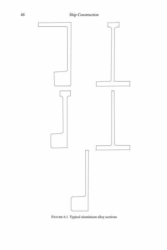
48 Ship Construction
FIGURE 6.1 Typical aluminium alloy sections
Shcc06.fm Page 48 Monday, March 26, 2001 3:03 PM

Aluminium Alloy 49
has very good resistance to corrosion and a higher ultimate tensilestrength than that of the non-heat treated alloys. Since the material isheat treated to achieve this increased strength subsequent heating, forexample welding or hot forming, may destroy the improved propertieslocally.
Aluminium alloys are generally identified by their Aluminium Associ-ation numeric designation. The 5000 alloys being non-heat treated and the6000 alloys being heat treated. The nature of any treatment is indicated byadditional lettering and numbering. Lloyd’s Register prescribe the followingcommonly used alloys in shipbuilding:
5083–0 annealed5083–F as fabricated5083–H321 strain hardened and stabilized5086–0 annealed5086–F as fabricated5086–H321 strain hardened and stabilized6061–T6 solution heat treated and artificially aged6082–T6 solution heat treated and artificially aged
R I V E T I N G Riveting may be used to attach stiffening members to lightaluminium alloy plated structures where appearance is important and dis-tortion from the heat input of welding is to be avoided.
The commonest stock for forging rivets for shipbuilding purposes is anon-heat treatable alloy NR5 (R for rivet material) which contains 3–4 percent magnesium. Non-heat treated alloy rivets may be driven cold or hot. In
TABLE 6.1
Alloying elements
Element 5083 5086 6061 6082
Copper 0.10 max 0.10 max 0.15–0.40 0.10 max Magnesium 4.0–4.9 3.5–4.5 0.8–1.2 0.6–1.2 Silicon 0.40 max 0.40 max 0.4–0.8 0.7–1.3 Iron 0.40 max 0.50 max 0.70 max 0.50 max Manganese 0.4–1.0 0.2–0.7 0.15 max 0.4–1.0 Zinc 0.25 max 0.25 max 0.25 max 0.20 max Chromium 0.05–0.25 0.05–0.25 0.04–0.35 0.25 max Titanium 0.15 max 0.15 max 0.15 max 0.10 max
Other elementseach 0.05 max 0.05 max 0.05 max 0.05 max total 0.15 max 0.15 max 0.15 max 0.15 max
Shcc06.fm Page 49 Monday, March 26, 2001 3:03 PM

50 Ship Construction
driving the rivets cold relatively few heavy blows are applied and the rivet isquickly closed to avoid too much cold work, i.e. becoming work hardenedso that it cannot be driven home. Where the rivets are driven hot thetemperature must be carefully controlled to avoid metallurgical damage.The shear strength of hot driven rivets is slightly less than that of colddriven rivets.
Fire ProtectionIt was considered necessary to mention when discussing aluminium alloysthat fire protection is more critical in ships in which this material is usedbecause of the low melting point of aluminium alloys. During a fire thetemperatures reached may be sufficient to cause a collapse of the structureunless protection is provided. The insulation on the main bulkheads inpassenger ships will have to be sufficient to make the aluminium bulkheadequivalent to a steel bulkhead for fire purposes.
For the same reason it is general practice to fit steel machinery casingsthrough an aluminium superstructure on cargo ships.
Further ReadingCorlett, ‘Aluminium as a Shipbuilding Material’, Trans. N.E.C. Inst., vol. 68,
1951–52.
Flint, ‘An Analysis of the Behaviour of Riveted Joints in Aluminium AlloyShips Plating’, Trans. N.E.C. Inst., vol. 72, 1955–56.
Muckle, The Design of Aluminium Alloy Ships Structures (Hutchinson,1963).
Muckle, ‘The Development of the Use of Aluminium in Ships’, Trans. N.E.C.Inst., vol. 80, 1963–64.
Woodward, ‘Let Aluminium Take the Strain’, Lightweight Materials inNaval Architecture, 1996, Royal Institution of Naval Architects Pub-lications.
Shcc06.fm Page 50 Monday, March 26, 2001 3:03 PM

7Testing of Materials
Metals are tested to ensure that their strength, ductility, and toughness aresuitable for the function they are required to perform.
In comparing the strengths of various metals stresses and strains areoften referred to and require to be defined. Stress is a measure of the abilityof a material to transmit a load, and the intensity of stress in the material,which is the load per unit area, is often stated. The load per unit area issimply obtained by dividing the applied load by the cross-sectional area ofthe material, e.g. if a tensile load of P kg is applied to a rod having a cross-sectional area of A mm2, then the tensile stress in the material of the rod isP/A kg/mm2 (see Figure 7.1).
Total strain is defined as the total deformation which a body undergoeswhen subjected to an applied load. The strain is the deformation per unitlength or unit volume, e.g. if the tensile load P applied to the rod of originallength l produces an elongation, or extension, of the rod of amount δl, thenthe tensile strain to which the material of the rod is subjected is given by theextension per unit length, i.e.
It can be shown that the load on the rod may be increased uniformlyand the resulting extension will also increase uniformly until a certainload is reached. This indicates that the load is proportional to extensionand hence stress and strain are proportional since the cross-sectionalarea and original length of the rod remain constant. For most metals thisdirect proportionality holds until what is known as the ‘elastic limit’ isreached. The metal behaves elastically to this point, the rod for examplereturning to its original length if the load is removed before the ‘elasticlimit’ is reached.
If a mild steel bar is placed in a testing machine and the extensions arerecorded for uniformly increasing loads, a graph of load against extension,or stress against strain may be plotted as in Figure 7.1. This shows thestraight line relationship (i.e. direct proportionality) between stress andstrain up to the elastic limit.
extensionoriginal length----------------------------------- or δl
l----
Shcc07.fm Page 51 Monday, March 26, 2001 3:04 PM

52 Ship Construction
Since stress is directly proportional to strain, the stress is equal to aconstant which is in fact the slope of the straight line part of the graph, andis given by:
A constant = stress ÷ strain
This constant is referred to as Young’s Modulus for the metal and isdenoted E (for mild steel its value is approximately 21 100 kg/mm2 or 21.1tonnes/mm2).
The yield stress for a metal corresponds to the stress at the ‘yield point’,that is the point at which the metal no longer behaves elastically. Ultimatetensile stress is the maximum load to which the metal is subjected, divided bythe original cross-sectional area. Beyond the yield point the metal behavesplastically which means that the metal deforms at a greater, unpropor-tional, rate when the yield stress is exceeded, and will not return to itsoriginal dimensions on removal of the load. It becomes deformed or isoften said to be permanently ‘set’.
Many metals do not have a clearly defined yield point; for example,aluminium having a stress/strain curve over its lower range which is astraight line becoming gradually curved without any sharp transformationon yielding as shown by mild steel (see Figure 7.1). A ‘proof stress’ is quotedfor the material and this may be obtained by setting off on the base somepercentage of the strain, say 0.2 per cent, and drawing a line parallel to the
δLδL
MILD STEEL
Ultimate tensile stress
Yield stress
Str
ess
(P/A
)
l
Ultimate tensile stress
Proof stress
Str
ess
(P/A
)
StrainStrain1% Strain
( )( )
P
lld ld l
MATERIAL WITHNO DISTINCT YIELDPOINT
A
d l
FIGURE 7.1 Stress/strain relationship of shipbuilding materials
Shcc07.fm Page 52 Monday, March 26, 2001 3:04 PM
Testing of Materials 53
straight portion of curve. The inter-section of this line with the actual stress/strain curve marks the proof stress.
It is worth noting at this stage that the ship’s structure is designed forworking stresses which are within the elastic range and much lower thanthe ultimate tensile strength of the material to allow a reasonable factorof safety.
Classification Society Tests for Hull MaterialsBoth mild steel and higher tensile steel plates and sections built into a shipare to be produced at works approved by the appropriate classification society.During production an analysis of the material is required and so are pre-scribed tests of the rolled metal. Similar analyses and tests are required bythe classification societies for steel forgings and steel castings, in order tomaintain an approved quality.
Destructive tests are made on specimens obtained from the same productas the finished material in accordance with the societies’ requirementswhich may be found in the appropriate rules. These tests usually take theform of a tensile test, and impact test.
T E N S I L E T E S T The basic principle of this test has already been described,a specimen of given dimensions being subject to an axial pull and a minimumspecified yield stress, ultimate tensile stress, and elongation must be obtained.In order to make comparisons between the elongation of tensile test piecesof the same material the test pieces must have the same proportions ofsectional area and gauge length. Therefore a standard gauge length equalto 5.65 times the square root of the cross-sectional area, which is equivalentto a gauge length of five times the diameter is adopted by the major classi-fication societies.
I M P A C T T E S T S There are several forms of impact test, but the Charpy Vnotch test or Charpy U notch test is commonly specified and thereforedescribed in this text. The object of the impact test is to determine the tough-ness of the material, that is its ability to withstand fracture under shock loading.
In Figure 7.2 the principle of the Charpy test machine is illustrated asalso is the standard test specimen for a Charpy V notch test. This specimenis placed on an anvil and the pendulum is allowed to swing so that thestriker hits the specimen opposite the notch and fractures it. Energyabsorbed in fracturing the specimen is automatically recorded by themachine. Basically, making allowances for friction, the energy absorbed infracturing the specimen is the difference between the potential energy thependulum possesses before being released, and that which it attains in swing-ing past the vertical after fracturing the specimen. A specified average impact
Shcc07.fm Page 53 Monday, March 26, 2001 3:04 PM

45°
CHARPY IMPACT TEST
Pointer
Scale
End ofswing
Hammer
Specimen
Start ofswing
Anvil
CHARPY VEENOTCH SPECIMEN
Hammerblow
10mmx
10mm
55mm
8mm
40mm
0.25mmradius
FIGURE 7.2 Charpy impact test
Shcc07.fm Page 54 M
onday, March 26, 2001 3:04 PM

Testing of Materials 55
energy for the specimens tested must be obtained at the specified testtemperature, fracture energy being dependent on temperature as will beillustrated in Chapter 8.
A L U M I N I U M A L L O Y T E S T S Aluminium alloy plate and section mater-ial is subject to specified tensile tests. Bar material for aluminium alloy rivetsis subject to a tensile test and also a dump test. The latter test requires com-pression of the bar until its diameter is increased to 1.6 times the originaldiameter without cracking occurring. Selected manufactured rivets are alsosubjected to the same dump test.
Shcc07.fm Page 55 Monday, March 26, 2001 3:04 PM

8Stresses to which a Ship is Subject
The stresses experienced by the ship floating in still water and when at seamay conveniently be considered separately.
Vertical Shear and Longitudinal Bending in Still WaterIf a homogeneous body of uniform cross-section and weight is floating instill water, at any section the weight and buoyancy forces are equal andopposite. Therefore there is no resultant force at a section and the body willnot be stressed or deformed. A ship floating in still water has an unevenlydistributed weight owing to both cargo distribution and structural distribution.The buoyancy distribution is also non-uniform since the underwater sec-tional area is not constant along the length. Total weight and total buoyancyare of course balanced, but at each section there will be a resultant force orload, either an excess of buoyancy or excess of load. Since the vessel remainsintact there are vertical upward and downward forces tending to distort thevessel (see Figure 8.1) which are referred to as vertical shearing forces, sincethey tend to shear the vertical material in the hull.
The ship shown in Figure 8.1 will be loaded in a similar manner to thebeam shown below it, and will tend to bend in a similar manner owing tothe variation in vertical loading. It can be seen that the upper fibres of thebeam would be in tension; similarly the material forming the deck of theship with this loading. Conversely the lower fibres of the beam, and likewisethe material forming the bottom of the ship, will be in compression. A vesselbending in this manner is said to be ‘hogging’ and if it takes up the reverseform with excess weight amidships is said to be ‘sagging’. When sagging thedeck will be in compression and the bottom shell in tension. Lying in stillwater the vessel is subjected to bending moments, either hogging or saggingdepending on the relative weight and buoyancy forces, and it will also besubjected to vertical shear forces.
Bending Moments in a SeawayWhen a ship is in a seaway the waves with their troughs and crests producea greater variation in the buoyant forces and therefore can increase the
Shcc08.fm Page 56 Monday, March 26, 2001 3:05 PM

12001400
14002000
2100
1700 19001800 1100
200
1700 900 200
300 Tonnes 200 Tonnes
100 Tonnes 200 Tonnes
200 Tonnes
200 Tonnes
100 Tonnes 200 Tonnes
300 Tonnes
200 Tonnes
400
400 1000
FIGURE 8.1 Vertical shear and longitudinal bending in still water
Shcc08.fm Page 57 M
onday, March 26, 2001 3:05 PM

58 Ship Construction
bending moment, vertical shear force, and stresses. Classically the extremeeffects can be illustrated with the vessel balanced on a wave of length equalto that of the ship. If the crest of the wave is amidships the buoyancy forceswill tend to ‘hog’ the vessel; if the trough is amidships the buoyancy forceswill tend to ‘sag’ the ship (Figure 8.2). In a seaway the overall effect is anincrease of bending moment from that in still water when the greater buoy-ancy variation is taken into account.
Longitudinal Shear ForcesWhen the vessel hogs and sags in still water and at sea shear forces similarto the vertical shear forces will be present in the longitudinal plane (Fig-ure 8.2). Vertical and longitudinal shear stresses are complementary andexist in conjunction with a change of bending moment between adjacentsections of the hull girder. The magnitude of the longitudinal shear forceis greatest at the neutral axis and decreases towards the top and bottom ofthe girder.
Bending StressesFrom classic bending theory the bending stress (σ) at any point in a beam isgiven by:
where M = applied bending moment. y = distance of point considered from neutral axis. I = second moment of area of cross-section of beam about the
neutral axis.
When the beam bends it is seen that the extreme fibres are, say in thecase of hogging, in tension at the top and in compression at the bottom.Somewhere between the two there is a position where the fibres are neitherin tension nor compression. This position is called the neutral axis, and atthe farthest fibres from the neutral axis the greatest stress occurs for planebending. It should be noted that the neutral axis always contains the centreof gravity of the cross-section. In the equation the second moment of area (I)of the section is a divisor; therefore the greater the value of the secondmoment of area the less the bending stress will be. This second moment ofarea of section varies as the (depth)2 and therefore a small increase indepth of the section can be very beneficial in reducing the bending stress.Occasionally reference is made to the sectional modulus (Z) of a beam; this
σ MI----- y×=
Shcc08.fm Page 58 Monday, March 26, 2001 3:05 PM

CrestCrest Crest
Crest
Trough
TroughTrough Trough
SAGGING
HOGGING
Longitudinal shear forces
FIGURE 8.2 Wave bending moments
Shcc08.fm Page 59 M
onday, March 26, 2001 3:05 PM

60 Ship Construction
is simply the ratio between the second moment of area and the distance ofthe point considered from the neutral axis, i.e. I/y = Z.
The bending stress (σ) is then given by σ = M/Z.
THE S H I P A S A B E A M It was seen earlier that the ship bends like abeam; and in fact the hull can be considered as a box-shaped girder forwhich the position of the neutral axis and second moment of area may be cal-culated. The deck and bottom shell form the flanges of the hull girder, andare far more important to longitudinal strength than the sides which formthe web of the girder and carry the shear forces. The box shaped hull girderand a conventional I girder may be compared as in Figure 8.3.
In a ship the neutral axis is generally nearer the bottom, since the bottomshell will be heavier than the deck, having to resist water pressure as well asthe bending stresses. In calculating the second moment of an area of thecross-section all longitudinal material is of greatest importance and thefurther the material from the neutral axis the greater will be its secondmoment of area about the neutral axis. However, at greater distances fromthe neutral axis the sectional modulus will be reduced and correspondinglyhigher stress may occur in extreme hull girder plates such as the deckstringer, sheerstrake, and bilge. These strakes of plating are generally heavierthan other plating.
Bending stresses are greater over the middle portion of the length and itis owing to this variation that Lloyd’s give maximum scantlings over 40 percent of the length amidships. Other scantlings may taper towards the endsof the ship, apart from locally highly stressed regions where other forms ofloading are encountered.
S T R E N G T H D E C K The deck forming the uppermost flange of the mainhull girder is often referred to as the strength deck. This is to some extenta misleading term since all continuous decks are in fact strength decks ifproperly constructed. Along the length of the ship the top flange of the hullgirder, i.e. the strength deck, may step from deck to deck where largesuperstructures are fitted or there is a natural break, for instance in wayof a raised quarter deck. Larger superstructures tend to deform with themain hull and stresses of appreciable magnitude will occur in the structure.Early vessels fitted with large superstructures of light construction demon-strated this to their cost. Attempts to avoid fracture have been made byfitting expansion joints which make the light structure discontinuous. Theseare not entirely successful and the expansion joint may itself form a stressconcentration at the strength deck which one would wish to avoid. In modernconstruction the superstructure is usually made continuous and of suchstrength that its sectional modulus is equivalent to that which the strengthdeck would have if no superstructure were fitted (see Chapter 19).
Shcc08.fm Page 60 Monday, March 26, 2001 3:05 PM

Flange
Web Web Web
I SECTION GIRDER BOX GIRDER SHIP HULL GIRDER
FlangeFlange
FlangeFlange
Flange
FIGURE 8.3 Box girder and I girder
Shcc08.fm Page 61 M
onday, March 26, 2001 3:05 PM

62 Ship Construction
Transverse StressesWhen a ship experiences transverse forces these tend to change the shapeof the vessel’s cross sections and thereby introduce transverse stresses.These forces may be produced by hydrostatic loads and impact of seas orcargo and structural weights both directly and as the result of reactions dueto change of ship motion.
R A C K I N G When a ship is rolling, the deck tends to move laterally relative tothe bottom structure, and the shell on one side to move vertically relative tothe other side. This type of deformation is referred to as ‘racking’. Trans-verse bulkheads primarily resist such transverse deformation, the side framescontribution being insignificant provided the transverse bulkheads are at theirusual regular spacings.
T O R S I O N When any body is subject to a twisting moment which iscommonly referred to as torque, that body is said to be in ‘torsion’. A shipheading obliquely (45°) to a wave will be subjected to righting moments ofopposite direction at its ends twisting the hull and putting it in ‘torsion’. Inmost ships these torsional moments and stresses are negligible but in shipswith extremely wide and long deck openings they are significant. A particularexample is the larger container ship where at the topsides a heavy torsion boxgirder structure including the upper deck is provided to accommodate thetorsional stresses (see Figures 8.4 and 17.8).
Local StressesP A N T I N G Panting refers to a tendency for the shell plating to work ‘in’and ‘out’ in a bellows-like fashion, and is caused by the fluctuating pres-sures on the hull at the ends when the ship is amongst waves. These forcesare most severe when the vessel is running into waves and is pitching heavily,the large pressures occurring over a short time cycle. Strengthening to resistpanting both forward and aft is covered in Chapter 17.
P O U N D I N G Severe local stresses occur in way of the bottom shell andframing forward when a vessel is driven into head seas. These poundingstresses, as they are known; are likely to be most severe in a lightly ballastedcondition, and occur over an area of the bottom shell aft of the collisionbulkhead. Additional stiffening is required in this region, and this is dealtwith in Chapter 16.
O T H E R L O C A L S T R E S S E S Ship structural members are often subjectedto high stresses in localized areas, and great care is required to ensure that
Shcc08.fm Page 62 Monday, March 26, 2001 3:05 PM

Stresses to which a Ship is Subject 63
these areas are correctly designed. This is particularly the case where variousload carrying members of the ship intersect, examples being where longit-udinals meet at transverse bulkheads and at intersections of longitudinal andtransverse bulkheads. Another highly stressed area occurs where there is adiscontinuity of the hull girder at ends of deck house structures, also athatch and other opening corners, and where there are sudden breaks in thebulwarks.
Brittle FractureWith the large-scale introduction of welding in ship construction muchconsideration has been given to the correct selection of materials and struc-tural design to prevent the possibility of brittle fracture occurring. During theSecond World War the incidence of this phenomenon was high amongsttonnage hastily constructed, whilst little was known about the mechanics of
Crest
Crest
Container shipsection
Torsionbox
FIGURE 8.4 Torsion
Shcc08.fm Page 63 Monday, March 26, 2001 3:05 PM

64 Ship Construction
brittle fracture. Although instances of brittle fracture were recorded inriveted ships the consequences were more disastrous in the welded vesselsbecause of the continuity of metal provided by the welded joint as opposedto the riveted lap which tended to limit the propagating crack.
Brittle fracture occurs when an otherwise elastic material fractures with-out any apparent sign or little evidence of material deformation prior tofailure. Fracture occurs instantaneously with little warning and the vessel’soverall structure need not be subject to a high stress at the time. Mild steelused extensively in ship construction is particularly prone to brittle-fracturegiven the conditions necessary to trigger it off. The subject is too complex tobe dealt with in detail and many aspects are still being investigated, but it isknown that the following factors influence the possibility of brittle fracture.
(a) A sharp notch is present in the structure from which the fractureinitiates.
(b) A tensile stress is present.(c) There is a temperature above which brittle fracture will not occur.(d) The metallurgical properties of the steel plate.(e) Thick plate is more prone.
A brittle fracture is distinguishable from a ductile failure by the lack ofdeformation at the edge of the tear, and its bright granular appearance.A ductile failure has a dull grey appearance. The brittle fracture is alsodistinguished by the apparent chevron marking, which aids location of thefracture initiation point since these tend to point in that direction.
The factors which are known to exist where a brittle fracture may occurmust be considered if this is to be avoided. Firstly the design of individualitems of ship structure must be such that sharp notches where cracks maybe initiated are avoided. With welded structures as large as a ship the com-plete elimination of crack initiation is not entirely possible owing to theexistence of small faults in the welds, a complete weld examination notbeing practicable. Steel specified for the hull construction should thereforehave good ‘notch ductility’ at the service temperatures particularly wherethick plate is used. Provision of steel having good ‘notch ductility’ prop-erties has the effect of making it difficult for a crack to propagate. Notchductility is a measure of the relative toughness of the steel, which hasalready been seen to be determined by an impact test. Steels specified forship construction have elements added (particularly manganese with a carbonlimit), and may also be subjected to a controlled heat treatment, which willenhance the notch tough properties. To illustrate the improved notch ductilityof a manganese/carbon steel against a plain carbon steel Figure 8.5 isincluded. Grade D and Grade E steels which have higher notch ductility areemployed where thick plate is used and in way of higher stressed regions, aswill be seen when the ship structural details are considered later.
Shcc08.fm Page 64 Monday, March 26, 2001 3:05 PM

DUCTILE/BRITTLE TRANSITIONBEHAVIOUR OF STEELS
Fine grain carbonmanganese steel
Medium carbon (2%)structural steel
Temperature ( C)o
–100 –50 0 50 100 150
2.75
5.5
8.25
11.0
13.25
Cha
rpy
V n
otch
impa
ct e
nerg
y (k
g M
)FATIGUE BEHAVIOUR OF PLAIN MILD STEEL
Number of cycles x 1050 1 2 3 4 5 6 7 8 9 10
16.5
Ulti
mat
e te
nsile
str
engt
h
21 kg/mm2
42 kg/mm2
FIGURE 8.5
Shcc08.fm Page 65 M
onday, March 26, 2001 3:05 PM

66 Ship Construction
In association with the problem of brittle fracture it was not uncommonat one time to hear reference to the term ‘crack arrester’. The term relatedto the now outdated practice of introducing riveted seams in cargo ships tosubdivide the vessel into welded substructures so that any possible crackpropagation was limited to the substructure. In particular such a ‘crackarrester’ was usually specified in the sheerstrake/stringer plate area oflarger ships. Today strakes of higher notch toughness steel are required tobe fitted in such areas. Lloyd’s, for example, require the mild steel sheer-strake and stringer plate at the strength deck over the midships portion ofvessels of more than 250 metres in length to be Grade D if less than15 mm thick and Grade E if of greater thickness (see Chapter 17).
Fatigue FailuresUnlike brittle fracture, fatigue fracture occurs very slowly and can in facttake years to propagate. The greatest danger with fatigue fractures is thatthey occur at low stresses which are applied to a structure repeatedly over aperiod of time (Figure 8.5). A fatigue crack once initiated may grow unno-ticed until the load bearing member is reduced to a cross-sectional areawhich is insufficient to carry the applied load. Fatigue failures are associatedwith sharp notches or discontinuities in structures, and are especially pre-valent at ‘hard spots’, i.e. regions of high rigidity in ship structures.
Further ReadingD’Archangelo, A Guide to Sound Ship Structures (Cornell Maritime Press,
1966).
Hodgson and Boyd, ‘Brittle Fracture in Welded Ships’, Trans. I.N.A., 1958.
McCallum, ‘The Strength of Fast Cargo Ships’, The Naval Architect, January,1975.
Nibbering and Scholte, ‘The Fatigue Problem in Shipbuilding in the Light ofNew Investigations’, The Naval Architect, May, 1976.
Sumpter et al., ‘Fracture Toughness of Ship Steels’, The Naval Architect,July/August, 1989.
Weck, ‘Fatigue in Ship Structures’, Trans. I.N.A., 1953.
Shcc08.fm Page 66 Monday, March 26, 2001 3:05 PM

Part 3
Welding and Cutting
Shcc09.fm Page 67 Monday, March 26, 2001 3:07 PM

Shcc09.fm Page 68 Monday, March 26, 2001 3:07 PM

9Welding and Cutting Processesused in Shipbuilding
Initially welding was used in ships as a means of repairing various metalparts. During the First World War various authorities connected with ship-building, including Lloyd’s Register, undertook research into welding andin some cases prototype welded structures were built. However, rivetingremained the predominant method employed for joining ship plates andsections until the time of the Second World War. During and after this warthe use and development of welding for shipbuilding purposes was wide-spread, and welding has now totally replaced riveting.
There are many advantages to be gained from employing welding in shipsas opposed to having a riveted construction. These may be considered asadvantages in both building and in operating the ship.
For the shipbuilder the advantages are:
(a) Welding lends itself to the adoption of prefabrication techniques. (b) It is easier to obtain watertightness and oiltightness with welded joints. (c) Joints are produced more quickly. (d) Less skilled labour is required.
For the shipowner the advantages are:
(a) Reduced hull steel weight; therefore more deadweight.(b) Less maintenance, from slack rivets, etc. (c) The smoother hull with the elimination of laps leads to a reduced
skin friction resistance which can reduce fuel costs.
Other than some blacksmith work involving solid-phase welding, thewelding processes employed in shipbuilding are of the fusion welding type.Fusion welding is achieved by means of a heat source which is intenseenough to melt the edges of the material to be joined as it is traversed alongthe joint. Gas welding, arc welding, and resistance welding all provide heatsources of sufficient intensity to achieve fusion welds.
Shcc09.fm Page 69 Monday, March 26, 2001 3:07 PM

70 Ship Construction
Gas WeldingA gas flame was probably the first form of heat source to be used for fusionwelding, and a variety of fuel gases with oxygen have been used to producea high temperature flame. The most commonly used gas in use is acetylenewhich gives an intense concentrated flame (average temperature 3000°C)when burnt in oxygen.
An oxy-acetylene flame has two distinct regions, an inner cone, in whichthe oxygen for combustion is supplied via the torch, and a surroundingenvelope in which some or all the oxygen for combustion is drawn fromthe surrounding air. By varying the ratio of oxygen to acetylene in the gasmixture supplied by the torch it is possible to vary the efficiency of the com-bustion and alter the nature of the flame (Figure 9.1). If the oxygen supplyis slightly greater than the supply of acetylene by volume, what is known asan ‘oxidizing’ flame is obtained. This type of flame may be used for weldingmaterials of high thermal conductivity, e.g. copper, but not steels as thesteel may be decarburized and the weld pool depleted of silicon. With equalamounts of acetylene and oxygen a ‘neutral’ flame is obtained, and thiswould normally be used for welding steels and most other metals. Wherethe acetylene supply exceeds the oxygen by volume a ‘carburizing’ flame isobtained, the excess acetylene decomposing and producing sub-microscopicparticles of carbon. These readily go into solution in the molten steel, and canproduce metallurgical problems in service.
The outer envelope of the oxy-acetylene flame by consuming the surround-ing oxygen to some extent protects the molten weld metal pool from the sur-rounding air. If unprotected the oxygen may diffuse into the molten metaland produce porosity when the weld metal cools. With metals containingrefractory oxides, such as stainless steels and aluminium, it is necessary touse an active flux to remove the oxides during the welding process.
Both oxygen and acetylene are supplied in cylinders, the oxygen under pres-sure and the acetylene dissolved in acetone since it cannot be compressed.Each cylinder which is distinctly coloured (red—acetylene, black—oxygen)has a regulator for controlling the working gas pressures. The welding torchconsists of a long thick copper nozzle, a gas mixer body, and valves foradjusting the oxygen and acetylene flow rates. Usually a welding rod is usedto provide filler metal for the joint, but in some cases the parts to be joinedmay be fused together without any filler metal. Gas welding techniques areshown in Figure 9.1.
Oxy-acetylene welding tends to be slower than other fusion weldingprocesses because the process temperature is low in comparison with themelting temperature of the metal, and because the heat must be transferredfrom the flame to the plate. The process is therefore only really applicableto thinner mild steel plate, thicknesses up to 7 mm being welded with thisprocess with a speed of 3 to 4 metres per hour. In shipbuilding oxy-acetylene
Shcc09.fm Page 70 Monday, March 26, 2001 3:07 PM

CARBURIZING FLAME
NEUTRAL FLAME
OXIDIZING FLAME
Weld direction
Filler material Torch
Weld metal
Weld direction
Filler material Torch
Weld metal
BACKWARD (OR LEFTWARD) WELDING
FORWARD (OR RIGHTWARD) WELDING
FIGURE 9.1 Gas welding
Shcc09.fm Page 71 M
onday, March 26, 2001 3:07 PM

72 Ship Construction
welding can be employed in the fabrication of ventilation and air con-ditioning trunking, cable trays, and light steel furniture; some plumbingand similar work may also make use of gas welding. These trades may alsoemploy the gas flame for brazing purposes, where joints are obtained withoutreaching the fusion temperature of the material being joined.
Electric Arc WeldingThe basic principle of electric arc welding is that a wire or electrode isconnected to a source of electrical supply with a return lead to the plates tobe welded. If the electrode is brought into contact with the plates an electriccurrent flows in the circuit. By removing the electrode a short distance fromthe plate, so that the electric current is able to jump the gap, a high temper-ature electrical arc is created. This will melt the plate edges and the end ofthe electrode if this is of the consumable type.
Electrical power sources vary, DC generators or rectifiers with variableor constant voltage characteristics being available as well as AC transformerswith variable voltage characteristics for single or multiple operation. Thelatter are most commonly used in shipbuilding.
Illustrated in Figure 9.2 are the range of manual, semi-automatic, andautomatic electric arc welding processes which might be employed in ship-building. Each of these electric arc welding processes is discussed belowwith its application.
S L A G S H I E L D E D P R O C E S S E S Metal arc welding started as bare wirewelding, the wire being attached to normal power lines. This gave unsatis-factory welds, and subsequently it was discovered that by dipping the wire inlime a more stable arc was obtained. As a result of further developmentsmany forms of slag are now available for coating the wire or for depositionon the joint prior to welding.
Manual Welding Electrodes The core wire normally used for mild steelelectrodes is rimming steel. This is ideal for wire drawing purposes, andelements used to ‘kill’ steel such as silicon or aluminium tend to destabilizethe arc, making ‘killed’ steels unsuitable. Coatings for the electrodes norm-ally consist of a mixture of mineral silicates, oxides, fluorides, carbonates,hydrocarbons, and powdered metal alloys plus a liquid binder. After mixing,the coating is then extruded onto the core wire and the finished electrodesare dried in batches in ovens.
Electrode coatings should provide gas shielding for the arc, easy strikingand arc stability, a protective slag, good weld shape, and most important ofall a gas shield consuming the surrounding oxygen and protecting the moltenweld metal. Various electrode types are available, the type often being
Shcc09.fm Page 72 Monday, March 26, 2001 3:07 PM

ELECTRIC ARC WELDING PROCESSES
Inert gasshielded
Consumableelectrode
Non-consumableelectrode
Plasmaarc
Carbonarc
Atomichydrogen
TIGargon
shielded
MIGargon
shielded
MIGCO
shielded2
Diptransfer
Pulsetransfer
Spraytransfer
Flux cored processes
Slagshielded
Shieldedmetal arc
Submergedarc
Studwelding
Fusarc
FIGURE 9.2 Electric arc welding processes
Shcc09.fm Page 73 M
onday, March 26, 2001 3:07 PM

74 Ship Construction
defined by the nature of the coating. The more important types are the rutileand basic (or low hydrogen) electrodes. Rutile electrodes have coatingscontaining a high percentage of titania, and are general purpose electrodeswhich are easily controlled and give a good weld finish with sound prop-erties. Basic or low hydrogen electrodes, the coating of which has a highlime content, are manufactured with the moisture content of the coatingreduced to a minimum to ensure low hydrogen properties. The mechanicalproperties of weld metal deposited with this type of electrode are superiorto those of other types, and basic electrodes are generally specified for weldingthe higher tensile strength steels. Where high restraint occurs, for exampleat the final erection seam weld between two athwartships rings of unitstructure, low hydrogen electrodes may also be employed. An experiencedwelder is required where this type of electrode is used since it is less easilycontrolled.
Welding with manual electrodes may be accomplished in the down-hand position, for example welding at the deck from above, also in thehorizontal vertical, or vertical positions, for example across or up a bulk-head, and in the overhead position, for example welding at the deck frombelow (Figure 9.3). Welding in any of these positions requires selection ofthe correct electrode (positional suitability stipulated by manufacturer),correct current, correct technique, and inevitably experience, particularlyfor the vertical and overhead positions.
Automatic Welding with Coated Wires or Cored Wires The ‘Fusarc’ weldingprocess marketed by the British Oxygen Company has been used on a largescale in British shipyards for the downhand welding of flat panels of mildsteel plating. ‘Fusarc’ machines traverse the plate at a set speed and the fluxcovered wire is fed continuously to give the correct arc length and depos-ition of weld metal. Flux covering of the continuous wire is retained bymeans of auxiliary wire spirals (Figure 9.4). The process could toleratereasonably dirty plates and was a convenient process for welding outdoorsat the berth where climatic conditions are not always ideal. Additionalshielding could be supplied in the form of carbon dioxide (Fusarc/CO2process) which, together with the flux covering of the wire, allowed higherwelding currents to be used with higher welding speeds. A twin fillet versionwas also available for use in welding sections to plates.
Cored wires rather than coated are now often used in mechanized weld-ing allowing higher welding currents with high deposition rates and improvedquality. Basic or rutile flux cored wires are commonly used for one-sidewelding with a ceramic backing.
Submerged Arc Welding This is an arc welding process in which the arc ismaintained within a blanket of granulated flux (see Figure 9.4). A consum-able filler wire is employed and the arc is maintained between this wire and
Shcc09.fm Page 74 Monday, March 26, 2001 3:07 PM

Voltage control
Generator
Currentcontrol
Electrode
Arc
Workpiece
A
Electrode
Weld
Electrode
WeldElectrode
Electrode
Weld
Weld
DOWNHAND
OVERHEADVERTICALHORIZONTALVERTICAL
FIGURE 9.3 Manual arc welding
Shcc09.fm Page 75 M
onday, March 26, 2001 3:07 PM

Flux retained byfireproof canvas
Air hose
Ceramic backing
Flux
ONE SIDED WELDING TECHNIQUES
CONSTRUCTION OF THE FUSARCPATENTED CONTINUOUS ELECTRODE
Core wire
1st auxiliarywire spiral
2nd auxiliarywire spiral
Flux covering
Flux
Wire feed
Electrode wire
Fused fluxRun on plate
Completed weld
SUBMERGED ARC WELDING
FIGURE 9.4 Automatic arc welding
Shcc09.fm Page 76 M
onday, March 26, 2001 3:07 PM

Welding and Cutting Processes used in Shipbuilding 77
the parent plate. Around the arc the granulated flux breaks down andprovides some gases, and a highly protective thermally insulating moltencontainer for the arc. This allows a high concentration of heat, making theprocess very efficient and suitable for heavy deposits at fast speeds. Afterwelding the molten metal is protected by a layer of fused flux which togetherwith the unfused flux may be recovered before cooling.
This is the most commonly used process for downhand mechanical weld-ing in the shipbuilding industry. Metal powder additions which result in a30–50 per cent increase in metal deposition rate without incurring an increasein arc energy input may be used for the welding of joint thicknesses of 25 mmor more. Submerged arc multi-wire and twin arc systems are also used togive high productivity.
With shipyards worldwide adopting one-side welding in their ship panellines for improved productivity the submerged arc process is commonly usedwith a fusible backing, using either flux or glass fibre materials to containand control the weld penetration bead.
Stud Welding Stud welding may be classed as a shielded arc process, the arcbeing drawn between the stud (electrode) and the plate to which the stud isto be attached. Each stud is inserted into a stud welding gun chuck, and aceramic ferrule is slipped over it before the stud is placed against the platesurface. On depressing the gun trigger the stud is automatically retractedfrom the plate and the arc established, melting the end of the stud and thelocal plate surface. When the arcing period is complete, the current is auto-matically shut off and the stud driven into a molten pool of weld metal soattaching stud to plate.
Apart from the stud welding gun the equipment includes a control unitfor timing the period of current flow. Granular flux is contained within theend of each stud to create a protective atmosphere during arcing. Theceramic ferrule which surrounds the weld area restricts the access of air tothe weld zone; it also concentrates the heat of the arc, and confines themolten metal to the weld area (see Figure 9.5).
Stud welding is often used in shipbuilding, generally for the fastening ofstud bolts to secure wood sheathing to decks, insulation to bulkheads, etc.Apart from various forms of stud bolts, items like stud hooks and rings arealso available.
G A S S H I E L D E D A R C W E L D I N G P R O C E S S E S The application of barewire welding with gas shielding was developed in the 1960s, and was quicklyadopted for the welding of lighter steel structures in shipyards, as well as forwelding aluminium alloys. Gas shielded processes are principally of anautomatic or semi-automatic nature.
Shcc09.fm Page 77 Monday, March 26, 2001 3:07 PM

Powersource
Controller
Control cable
Welding cable
Stud weldinggun
PlateStud
WELDING CIRCUIT
Stud
Plate
Ceramic ferrule
Flux
Straightthread
Femalethread
Bentstud
Flux
Flux
VARIOUS STUD TYPES
FIGURE 9.5 Stud welding
Shcc09.fm Page 78 M
onday, March 26, 2001 3:07 PM

Welding and Cutting Processes used in Shipbuilding 79
Tungsten Inert Gas (TIG) Welding In the TIG welding process the arc isdrawn between a watercooled non-consumable tungsten electrode and theplate (Figure 9.6). An inert gas shield is provided to protect the weld metalfrom the atmosphere, and filler metal may be added to the weld pool asrequired. Ignition of the arc is obtained by means of a high frequency dis-charge across the gap since it is not advisable to strike an arc on the platewith the tungsten electrode. Normally in Britain the inert gas shield usedfor welding aluminium and steel is argon. Only plate thicknesses of lessthan 6 mm would normally be welded by this process, and in particular alu-minium sheet, a skilled operator being required for manual work. This mayalso be referred to as TAGS welding, i.e. tungsten arc gas-shielded welding.
Metal Inert Gas (MIG) Welding This is in effect an extension of TIG weld-ing, the electrode in this process becoming a consumable metal wire.
Basically the process is as illustrated in Figure 9.6, a wire feed motorsupplying wire via guide rollers through a contact tube in the torch to thearc. An inert gas is supplied to the torch to shield the arc, and electricalconnections are made to the contact tube and workpiece. Welding isalmost always done with a DC source and electrode positive for regularmetal transfer, and when welding aluminium to remove the oxide film bythe action of the arc cathode. Although the process may be fully automatic,semi-automatic processes as illustrated with hand gun are now in greateruse, and are particularly suitable in many cases for application to shipyardwork.
Initially aluminium accounted for most of the MIG welding, with argonbeing used as the inert shielding gas. Much of the welding undertaken onaluminium deckhouses, and liquid methane gas tanks of specialized carriers,has made use of this process. Generally larger wire sizes and heaviercurrents have been employed in this work, metal transfer in the arc beingby means of a spray transfer, that is metal droplets being projected at highspeed across the arc. At low currents metal transfer in the arc is rather dif-ficult and very little fusion of the plate results, which has made the weldingof light aluminium plate rather difficult with the MIG/argon process. Theintroduction of the ‘pulsed arc’ process has to some extent overcome thisproblem and made positional welding easier. Here a low level current is usedwith high level pulses of current which detach the metal from the electrodeand accelerate it across the arc to give good penetration.
Early work on the welding of mild steel with the metal inert gas processmade use of argon as a shielding gas; but as this gas is rather expensive, andsatisfactory welding could only be accomplished in the downhand position,an alternative shielding gas was sought. Research in this direction was con-centrated on the use of CO2 as the shielding gas, and the MIG/CO2 processis now widely used for welding mild steel. Using higher current values withthicker steel plate a fine spray transfer of the metal from the electrode
Shcc09.fm Page 79 Monday, March 26, 2001 3:07 PM
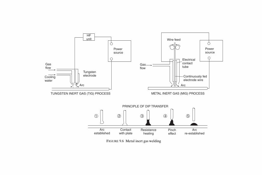
1 2 3 4 5
Pincheffect
Arcre-established
Contactwith plate
PRINCIPLE OF DIP TRANSFER
Resistanceheating
Arcestablished
Gasflow
Gasflow
Wire feed
Arc
Continuously fedelectrode wire
Electricalcontacttube
METAL INERT GAS (MIG) PROCESS
Coolingwater
TUNGSTEN INERT GAS (TIG) PROCESS
Tungstenelectrode
Arc
HFunit
Powersource
Powersource
FIGURE 9.6 Metal inert gas welding
Shcc09.fm Page 80 M
onday, March 26, 2001 3:07 PM

Welding and Cutting Processes used in Shipbuilding 81
across the arc is achieved, with a deep penetration. Wire diameters inexcess of 1.6 mm are used, and currents above about 350 amps are requiredto obtain this form of transfer. Much of the higher current work is under-taken with automatic machines, but some semi-automatic torches areavailable to operate in this range in the hands of skilled welders. Welding isdownhand only.
On thinner plating where lower currents would be employed a differentmode of transfer of metal in the arc is achieved with the MIG/CO2 process.This form of welding is referred to as the dip transfer (or short circuiting)process. The sequence of metal transfer is (see Figure 9.6):
1. Establish the arc. 2. Wire fed into arc until it makes contact with plate. 3. Resistance heating of wire in contact with plate. 4. Pinch effect, detaching heated portion of wire as droplet of molten
metal. 5. Re-establish the arc.
To prevent a rapid rise of current and ‘blast off’ of the end of the wirewhen it short circuits on the plate, variable inductance is introduced inthe electrical circuit. Smaller wire diameters, 0.8 mm and 1.2 mm, are usedwhere the dip transfer method is employed on lighter plate at low currents.The process is suitable for welding light mild steel plate in all positions.It may be used in shipbuilding as a semi-automatic process, particularly forwelding deckhouses and other light steel assemblies.
The pulsed MIG/argon process, developed for positional welding of lightaluminium plate, may be used for positional welding of light steel plate butis likely to prove more expensive.
Use of the MIG semi-automatic processes can considerably increaseweld output, and lower costs.
This form of welding may also be collectively referred to as MAGS weld-ing, i.e. metal arc gas-shielded welding.
Other Welding ProcessesThere are one or two welding processes which cannot strictly be classifiedas gas or arc welding processes and these are considered separately.
E L E C T R O-S L A G W E L D I N G The electro-slag welding process may beused for the automatic vertical welding of thicker steel plate. It is claimedthat the welding of plates of thickness down to 13 mm can be economical,but it is usual to weld somewhat heavier plates with this process. Heavy castsections up to 450 mm in thickness can in fact be welded.
Shcc09.fm Page 81 Monday, March 26, 2001 3:07 PM

82 Ship Construction
To start the weld an arc is struck, but welding is achieved by resistancepath heating through the flux, the initial arcing having been discouraged oncewelding is started. In Figure 9.7 the basic electro-slag process is illustrated;the current passes into the weld pool through the wire, and the copperwater-cooled shoes retain the molten pool of weld metal. These may bemechanized so that they move up the plate as the weld is completed, fluxbeing fed into the weld manually by the operator. A square edge prepara-tion is used on the plates, and it is found that the final weld metal has a highplate dilution. ‘Run on’ and ‘run off’ plates are required for stopping andstarting the weld, and it is desirable that the weld should be continuous. If astoppage occurs it will be impossible to avoid a major slag inclusion in theweld, and it may then be necessary to cut out the original metal and startagain. If very good weld properties are required with a fine grain structure(electro-slag welds tend to have a coarse grain structure) it is necessary tocarry out a local normalizing treatment.
E L E C T R O-G A S W E L D I N G Of greater interest to the shipbuilder is afurther development, electro-gas welding. This is in fact an arc weldingprocess which combines features of gas shielded welding with those ofelectro-slag welding. Water-cooled copper shoes similar to those for theelectro-slag welding process are used, but a flux-cored wire rather than abare wire is fed into the weld pool. Fusion is obtained by means of an arcestablished between the surface of the weld pool and the wire, and the CO2or CO2 with Argon mixture gas shield is supplied from separate nozzlesor holes located centrally near the top of the copper shoes. The system ismechanized utilizing an automatic vertical-up welding machine fed by apower source and having a closed loop cooling circuit and a level sensorwhich automatically adjusts the vertical travel speed.
The process is more suitable for welding plates in the thickness range of13 to 50 mm with square or vee edge preparations and is therefore used forshipbuilding purposes in the welding of vertical butts when erecting side shellpanels at the berth or building dock. For this purpose the use of a single ordouble vee butt with the electro-gas process is preferable since this permitscompletion of the weld manually if any breakdown occurs. A square buttwith appreciable gap would be almost impossible to bridge manually.
T H E R M I T W E L D I N G This is a very useful method of welding which maybe used to weld together large steel sections, for example parts of a sternframe. It is in fact often used to repair castings or forgings of this nature.Thermit welding is basically a fusion process, the required heat beingevolved from a mixture of powdered aluminium and iron oxide. The ends ofthe part to be welded are initially built into a sand or graphite mould, whilstthe mixture is poured into a refractory lined crucible. Ignition of thismixture is obtained with the aid of a highly inflammable powder consisting
Shcc09.fm Page 82 Monday, March 26, 2001 3:07 PM

Welding and Cutting Processes used in Shipbuilding 83
Wire fed into pool
Weld poolSlag
ELECTRO-SLAGWELDING
Moltenmetal
Coolingwater
Welddirection
IN
OUT
Coppershoe
Completedweld
Wire guide nozzle
Water-cooledcopper shoe
Weld
ELECTRO-GASWELDING
CO2
Wirefeed
Arc
Electrodewire
CO2
FIGURE 9.7 Electro-gas and Electro-slag welding
Shcc09.fm Page 83 Monday, March 26, 2001 3:07 PM

84 Ship Construction
mostly of barium peroxide. During the subsequent reaction within the cru-cible the oxygen leaves the iron oxide and combines with the aluminiumproducing aluminium oxide, or slag, and superheated thermit steel. Thissteel is run into the mould where it preheats and eventually fuses and mixeswith the ends of the parts to be joined. On cooling a continuous joint isformed and the mould is removed.
F R I C T I O N S T I R W E L D I N G* Friction stir welding is a new materialsjoining process which has been used in the shipbuilding industry and islikely to be more widely used.
Friction stir welding is a solid state process that offers advantages overfusion welding for certain applications. In producing butt joints it uses anon-consumable rotating tool the profiled pin of which is plunged into thebutted joint of two plates and then moves along the joint. The plate mater-ial is softened in both plates and forced around the rotating profiled pinresulting in a solid state bond between the two plates (see Figure 9.8, Fric-tion stir welding). To contain the softened material in the line of the joint abacking bar is used and the tool shoulder under pressure retains material atthe upper surface. Both plates and the backing bar require substantialclamping because of the forces involved. Plates of different thickness maybe butt welded by inclining the rotating tool (Figure 9.8).
The process is currently used for welding aluminium alloy plates and suchplates to aluminium alloy extrusions or castings. Dissimilar aluminiumalloys may be joined by the process. A suitable material for a rotating toolto permit friction stir welding of steel has yet to be developed.
Typical applications of friction stir welding are the construction of alu-minium alloy deck panels for high speed craft from extruded sections andaluminium alloy honeycomb panels for passenger ship cabin bulkheads.
Cutting ProcessesSteel plates and sections were mostly cut to shape in shipyards using a gascutting technique, but the introduction of competitive plasma-arc cuttingmachines has led to their widespread use in shipyards today.
G A S C U T T I N G Gas cutting is achieved by what is basically a chemical/thermal reaction occurring with iron and iron alloys only. Iron or its alloysmay be heated to a temperature at which the iron will rapidly oxidize in anatmosphere of high purity oxygen.
The principle of the process as applied to the cutting of steel plates andsections in shipbuilding is as follows. Over a small area the metal is pre-
*Friction stir welding was invented and patented by TWI Ltd., Cambridge, UK.
Shcc09.fm Page 84 Monday, March 26, 2001 3:07 PM

Welding and Cutting Processes used in Shipbuilding 85
heated to a given temperature, and a confined stream of oxygen is thenblown onto this area. The iron is then oxidized in a narrow band, and themolten oxide and metal are removed by the kinetic energy of the oxygenstream. A narrow parallel sided gap is then left between the cut edges.Throughout the cutting operation the preheat flame is left on to heat thetop of the cut since most of the heat produced by the reaction at the cuttingfront is not instantaneous, and tends to be liberated at the lower level of thecut only. Alloying elements in small amounts are dissolved in the slag andremoved when cutting steel. However, if they are present in large quantities,alloying elements, especially chromium, will retard and even prevent cut-ting. The reason for this is that they either decrease the fluidity of the slag
Downward force
Movementof tool
Rotationof tool
Shoulder
Probe
Retreating sideof weld
Shoulder
Height abovebacking bar
Probe Workpiece
Advancing sideof weld
Tool
FIGURE 9.8 Friction welding
Shcc09.fm Page 85 Monday, March 26, 2001 3:07 PM
86 Ship Construction
or produce a tenacious oxide film over the surface which prevents furtheroxidation of the iron. This may be overcome by introducing an iron richpowder into the cutting area, a process often referred to as ‘powder cut-ting’. When cutting stainless steels which have a high chromium content‘powder cutting’ would be employed.
Generally acetylene is used with oxygen to provide the preheat flame butother gases can be used: propane for example or hydrogen which is used forunderwater work because of its compressibility. Apart from the torch, theequipment is similar to that for gas welding. The torch has valves for con-trolling the volume of acetylene and oxygen provided for the preheat flame,and it has a separate valve for controlling the oxygen jet (see Figure 9.9).
The oxy-acetylene cutting process has been highly automated for use inshipyards; these developments are considered in Chapter 13. Hand burningwith an oxy-acetylene flame is used extensively for small jobbing work, andduring the fabrication and erection of units.
P L A S M A-A R C C U T T I N G Plasma in this sense is a mass of ionized gaswhich will conduct electricity. An electrode is connected to the negativeterminal of a DC supply and a gas shield is supplied for the arc from anozzle which has a bore less than the natural diameter of the arc. As a result aconstricted arc is obtained which has a temperature considerably higherthan that of an open arc. The arc is established between the electrode andworkpiece when the ionized conducting gas comes into contact with the work.This gas is ionized in the first place by a subsidiary electrical dischargebetween the electrode and the nozzle. Plates are cut by the high temperatureconcentrated arc melting the material locally (Figure 9.9).
The plasma-arc process may be used for cutting all electrically conductivematerials. Cutting units are available with cutting currents of 20 to 1000amps to cut plates with thicknesses of 0.6 to 150 mm. The plasma carrier gasmay be compressed air, nitrogen, oxygen or argon/hydrogen to cut mild orhigh alloy steels, and aluminium alloys. The more expensive argon/hydrogenmixture being required to cut the greater thickness sections. A water-injectionplasma-arc cutting system is available for cutting materials up to 75 mm thickusing nitrogen as the carrier gas. A higher cutting speed is possible andpollution minimized with the use of water and an exhaust system aroundthe torch.
Water cutting tables are often used with plasma-arc cutting. Cutting inwater absorbs the dust and particulate matter and reduces plasma noise andultraviolet radiation. Apart from improving environmental conditions it mayalso reduce distortion.
G O U G I N G Both gas and arc welding processes may be modified toproduce means of gouging out shallow depressions in plates to form edge
Shcc09.fm Page 86 Monday, March 26, 2001 3:07 PM

+
Pre
heat
ing
flam
em
ixtu
reO
xyge
n cu
tting
jet
Torc
h no
zzle
Cut
dire
ctio
n
Mild
ste
el p
late
OX
Y-A
CE
TY
LEN
E C
UT
TIN
G
Sid
e of
ker
f
Tung
sten
ele
ctro
de
Wat
er-c
oole
dno
zzle
Pla
te
Con
stric
ted
arc
Pla
sma
gas
PR
INC
IPLE
OF
PLA
SM
AC
UT
TIN
GTO
RC
H
Oxy
gen
supp
ly
Coa
ting
Ele
ctro
deD
irect
ion
ofcu
t
Sur
face
-pre
heat
edby
arc
Com
bust
ion
zone
AR
C-A
IR G
OU
GIN
G
PLA
N
ELE
VAT
ION
Pla
teBev
el c
ut
BU
RN
ING
HE
AD
WIT
HT
HR
EE
NO
ZZ
LES
FO
RP
RE
PAR
ING
PLA
TE
ED
GE
BE
VE
LS
1 1
2
2
3 3
30°
30°
VE VE
FIG
UR
E 9
.9M
etal
cut
ting
proc
esse
s
Shcc09.fm Page 87 Monday, March 26, 2001 3:07 PM

88 Ship Construction
preparations for welding purposes where precision is not important. Gougingis particularly useful in shipbuilding for cleaning out the backs of welds toexpose clean metal prior to depositing a weld back run. The alternative togouging for this task is mechanical chipping which is slow and arduous.Usually where gouging is applied for this purpose what is known as ‘arc-air’gouging is used. A tubular electrode is employed, the electrode metal con-ducting the current and maintaining an arc of sufficient intensity to heat theworkpiece to incandescence. Whilst the arc is maintained, a stream of oxygenis discharged from the bore of the electrode which ignites the incandescentelectrode metal and the combustible elements of the workpiece. At thesame time the kinetic energy of the excess oxygen removes the products ofcombustion, and produces a cut. Held at an angle to the plate the electrodewill gouge out the unwanted material (Figure 9.9).
A gas cutting torch may be provided with special nozzles which allowgouging to be accomplished when the torch is held at an acute angle to theplate.
L A S E R C U T T I N G Profile cutting and planing at high speeds can beobtained with a concentrated laser beam and the introduction to shipbuildingof this technique has been evaluated, in particular for a robot cutting head.In a laser beam the light is of one wavelength, travels in the same direction,and is coherent, i.e. all the waves are in phase. Such a beam can be focusedto give high energy densities. For welding and cutting the beam is generatedin a CO2 laser. This consists of a tube filled with a mixture of CO2, nitrogen,and helium which is caused to fluoresce by a high-voltage discharge. Thetube emits infra-red radiation with a wavelength of about 1.6 µm and iscapable of delivering outputs up to 20 kW.
Laser cutting relies on keyholing to penetrate the thickness, and the moltenmetal is blown out of the hole by a gas jet. A nozzle is fitted concentric withthe output from a CO2 laser so that a gas jet can be directed at the workcoaxial with the laser beam. The jet can be an inert gas, nitrogen or in thecase of steel, oxygen. With oxygen there is an exothermic reaction with thesteel giving additional heat as in oxy-fuel cutting. The thermal keyholinggives a narrow straight sided cut compared with the normal cut obtained byother processes relying on a chemical reaction.
W A T E R J E T C U T T I N G This cutting process may be used where thermalcutting is not possible and mechanical cutting requires extensive andexpensive subsequent working. The cutting tool employed in this process isa concentrated water jet, with or without abrasive, which is released from anozzle at 2½ times the speed of sound and at a pressure level of severalthousand bar.
Shcc09.fm Page 88 Monday, March 26, 2001 3:07 PM

Welding and Cutting Processes used in Shipbuilding 89
Further ReadingAllday, ‘Fabrication of Large Aluminium Panels by Mechanised MIG
Welding’, Lightweight Materials in Naval Architecture 1996, Royal Insti-tution of Naval Architects Publications.
‘Automatic Vertical Welding on the Berth’, The Naval Architect, April,1971.
Chadburn and Salter, ‘The Welding of Higher Tensile Shipbuilding Steels’,The Naval Architect, January, 1974.
Gilbert and Maughan, ‘Economics of Welding from One Side’, ShippingWorld and Shipbuilder, September, 1968.
Gourd, ‘Principles of Welding Technology’, Edward Arnold Ltd, 1980.
Hoare and Kattan, ‘Laser Welding and Steel Sandwich Construction forMerchant Ships’, Newbuild 2000 and the role of the Naval Architect1995, Royal Institution of Naval Architects Publications.
Howd, ‘A Review of Plasma Arc Technology’, Trans. N.E.C. Inst., vol. 84,1967–68.
‘Japanese Shipbuilding Processes (Automatic Vertical Electro-Gas ArcWelding)’, Shipbuilding and Shipping Record, 26 May, 1966.
Kallee, ‘Application of Friction Stir Welding in the Shipbuilding Industry’,Lightweight Construction—Latest Developments 2000, Royal Institutionof Naval Architects Publications.
North and McNeill, ‘The Trend to Mechanised Welding in Shipbuilding’,The Naval Architect, July, 1973.
Phillip, ‘Shipyard Welding Processes for Hull Construction’, R.I.N.A.Monographs (M7).
Przydatek, ‘Friction Stir Welding with Lloyds Register’, LightweightConstruction—Latest Developments 2000, Royal Institution of NavalArchitects Publications.
Russell, Dawes and Jones, ‘Developments in Welding Techniques forAluminium Alloys’, Lightweight Materials in Naval Architecture 1996,Royal Institution of Naval Architects Publications.
‘The Use and Welding of Aluminium in Shipbuilding’, Symposium,London, Institute of Welding, 1956.
Turner, ‘Report on Visits to Japanese Shipyards’, Metal Construction andBritish Welding Journal, June, 1970.
Shcc09.fm Page 89 Monday, March 26, 2001 3:07 PM

90 Ship Construction
Turner, ‘The Welding of High Tensile Steels Used in Shipbuilding’, Parts 1and 2, Metal Construction and British Welding Journal, October andNovember 1970.
‘Welding in Shipbuilding’, Symposium 30 October–3 November, 1961,London, Institute of Welding, 1962.
Shcc09.fm Page 90 Monday, March 26, 2001 3:07 PM

10Welding Practice and Testing Welds
The strongest welded joint which may be produced in two plates sub-sequently subjected to a tensile pull is the butt joint. A butt joint is one wherethe two joined plates are in the same plane, and in any welded structure it isdesirable that butt joints should be used wherever possible.
In mild steel the weld metal tends to have a higher yield strength thanthe plate material (see Figure 10.1). Under tension it is found that initialyielding usually occurs adjacent to a butt weld in the plate when the yieldstrength of the plate material is reached locally. Since a good butt weld intension has a strength equivalent to that of the mild steel plate it is not con-sidered as a line of structural weakness.
Lapped joints, where fillet welds are used to connect the plates, shouldbe avoided in strength members of a welded structure. As the fillet weldsare in shear when the plates are in tension the strength of the joint isvery much less than that of the plate material or butt joint. Fillet weldsare unavoidable where sections or plates are connected at an angle to anadjacent plate, but often there is not the same problem as the loading isdifferent. The fatigue strength of fillet welds is also inferior to that of abutt weld.
Welding PracticeIn making a butt weld with manual arc welding, where the plate thicknessexceeds say 5 to 6 mm it will become necessary to make more than onewelding pass to deposit sufficient weld metal to close the joint. With thehigher current automatic welding processes thicker plates may be weldedwith a single pass, but at greater thicknesses multi-pass welds becomenecessary.
In ship work unless a permanent backing bar is used, or the ‘one sided’welding technique (Chapter 9, Submerged Arc Welding) is adopted duringfabrication, a back run of weld is required to ensure complete weld penet-ration. This is made on the reverse side of the joint after cleaning out theslag, etc., by chipping or gouging. Permanent backing bars may convenientlybe introduced where it is desired to weld from one side only during erection
Shcc10.fm Page 91 Monday, March 26, 2001 3:07 PM

( )
Mild steel plate
TYPICAL MILD STEELSTRESS/STRAIN RELATIONSHIPOF PARENT AND WELD METAL
Weldyieldstress Full penetration
ReinforcementMulti-run weld madeto obtain penetration
Back run
BUTT WELDPlateyieldstress
Strain
Leglength
Str
ess
(P/A
)
1
2 3
4 5
Leglength
FILLET WELD
Throa
t Ideally 45°
l
Weld metalWidth
d l
FIGURE 10.1 Typical mild steel stress/strain relationship of parent and weld metal
Shcc10.fm Page 92 M
onday, March 26, 2001 3:07 PM
Welding Practice and Testing Welds 93
at the berth. A good example is the use of a cut-down channel bar used asa deck beam, the upper flange providing the backing bar for a deck panelbutt weld, made by machine above.
Tack welds are used throughout the construction to hold plates andsections in place after alignment and prior to completion of the full butt orfillet weld. These are short light runs of weld metal, which may be weldedover, or cut out in more critical joints during the final welding of the joint.
Fillet welds may be continuous or intermittent depending on the structuraleffectiveness of the member to be welded. Where fillets are intermittentthey may be either staggered or chain welded (see Figure 10.2), the membermay also be scalloped to give the same result when continuously welded.
On thicker plates it becomes necessary to bevel the edges of plates whichare to be butted together in order to achieve complete penetration of theweld metal (Figure 10.2). This operation may be carried out whilst profilingor trimming the plate edges which must be aligned correctly. Most edgepreparations are made by gas burning heads having three nozzles out ofphase which can be set at different angles to give the required bevels. Altern-atively the edge preparation may be obtained by mechanical machiningmethods using either a planing or milling tool. For very high quality weldsin thick plate, particularly of the higher tensile types of steel, mechanicalmachining may well be specified. It is worth noting that there is little tochoose between the two as far as metallurgical damage goes, but mechan-ical methods provide a better finish.
Plates of varying thickness may be butt welded together at different loca-tions, a good example being where heavy insert plates are fitted. Insertplates are preferred to doubling plates in welded construction, and theheavy plate is chamfered to the thickness of the adjacent thinner platebefore the butt edge preparation is made.
To ease the assembly of welded units it is common practice to make useof what is known as an ‘egg box’ construction. Within the double bottomunit the floors and side girders may be slotted at their intersections so thatthey fit neatly together prior to construction.
Welding Sequences During the welding operation heat is applied to the plate, and because ofthis the metal will expand, and on cooling contract. A weld on cooling andcontracting tends to pull the plate with it. This results in a structuraldeflection, the restraining action of the plate preventing the weld fromcontracting fully. The actual distortion of a welded structure is difficult topredict owing to the lack of knowledge of the degree of restraint. It is knownhowever that shrinkage in butt welds does occur principally along the lengthof the weld, and to a lesser extent across it. If a high restraint is provided
Shcc10.fm Page 93 Monday, March 26, 2001 3:07 PM

60°
SQUARE
VEE
Nose
DOUBLEVEE
Heavy plate
Heavy plate
Heavy plate
Heavy plate
‘U’ BUTT
Plate 6mm–18mm thick
Plate less than 6mm thick (manual)
60°
60°60°
t
t
40°
40°
20°
20°
Backing bar
TAPER 1 IN 4
Tack weld
30 4°– 0°
30O
Greater than1.125t t
FILLET VEE
FILLET J
Not greaterthan 0.25Dor 75mmwhicheveris less
LAP WELD (BAD PRACTICE) Fillet weld
TACK WELDS
Tack Tack Tack
STAGGERED INTERMITTENT FILLET WELDS
WeldWeld
Weld Weld Weld
Weld
CHAIN INTERMITTENT FILLET WELDS
SCALLOPED SECTION WITH CONTINUOUSFILLET
1/3t
1/3t
1/3t
1/3t
1/3t
1/3tRadius not less than 25mm
150mm max
D
60°
FIGURE 10.2 Plate edge preparations
Shcc10.fm Page 94 M
onday, March 26, 2001 3:07 PM

Welding Practice and Testing Welds 95
in an effort to control distortion the structure will contain high residualstresses, which are to be avoided.
In order to minimize distortion the ‘backstep’ and ‘wandering’ methodsof welding are often used, the length of each step being the amount of weldmetal laid down by an electrode to suit the required cross-section of weld(see Figure 10.3).
To reduce distortion and limit the residual stresses in the structure it isimportant that a correct welding sequence should be utilized throughout
BACKSTEP METHOD OF WELDING
Direction of weld
Direction of weld
Direction of weld
Direction of weld
6
6
5
4
4
2
3
5
2
3
1
1
1
1
2
3
3
5
4
2
5
4
6
6
Progression of welder
Progression of welder
Progression of welder
Progression of welder
WANDERING METHOD OF WELDING
WELD DISTORTION
Weld direction
Shrinkagestresses
FIGURE 10.3 Backstep and wandering methods of welding
Shcc10.fm Page 95 Monday, March 26, 2001 3:07 PM
96 Ship Construction
the construction. This applies both during the fabrication of units and aterection and joining of units on the berth.
Of the more important welds in the construction of the ship the sequencesinvolving welding of butts and seams in plating panels may be considered(see Figure 10.4). At T intersections it is necessary to weld the butt firstfully, then gouge out the ends to renew the seam edge preparation beforewelding the seam. Welding the seam first would cause high restraint acrossthe plate strake and when the butt was finished a crack might occur. Generalpractice when welding shell panels is to start by welding the central butts andthen adjacent seams, working outwards both transversely and longitudinally.Ships’ structural panels have various forms of stiffener attached to the platepanels, these generally being welded to the panel after completing the weld-ing of the panel plates. These stiffening members are left unwelded acrossthe butts and seams of the plates until these are completed, if they areattached at some intermediate stage.
Erection welding sequences generally follow the principles laid down forplating panels. In welded ships the lower side plating seams should not bewelded before the upper seams, particularly the deck and gunwale seams. Ifthis sequence of welding the side shell were adopted the upper portion ofthe hull structure would tend to be shortened causing the hull to rise from theblocks at the ends. Where in modern construction the side shell and deckplating are erected in blocks and a suitable welding sequence is employedthis problem does not arise.
In repair work correct welding sequences are also important, particularlywhere new material is fitted into the existing relatively rigid structure. Againthe procedure follows the general pattern for butts and seams in plate panels.If a new shell plate is to be welded in place the seams and butts in the sur-rounding structure are cut back 300 to 375 mm from the opening; likewisethe connection of the stiffening in way of the opening. The inserted platepanel is then welded to within 300 to 375 mm of the free edges, the butts arecompleted, and then the seams after welding any longitudinal stiffeningacross the butts. Finally the vertical framing is welded in way of the seams(Figure 10.4).
Testing WeldsFor economic reasons much of the weld testing carried out in shipbuildingis done visually by trained inspectors. Spot checks at convenient intervalsare made on the more important welds in merchant ship construction,generally using radiographic equipment. Welding materials are subjected tocomprehensive tests before they are approved by Lloyd’s Register or theother classification societies for use in ship work. Operatives are required
Shcc10.fm Page 96 Monday, March 26, 2001 3:07 PM
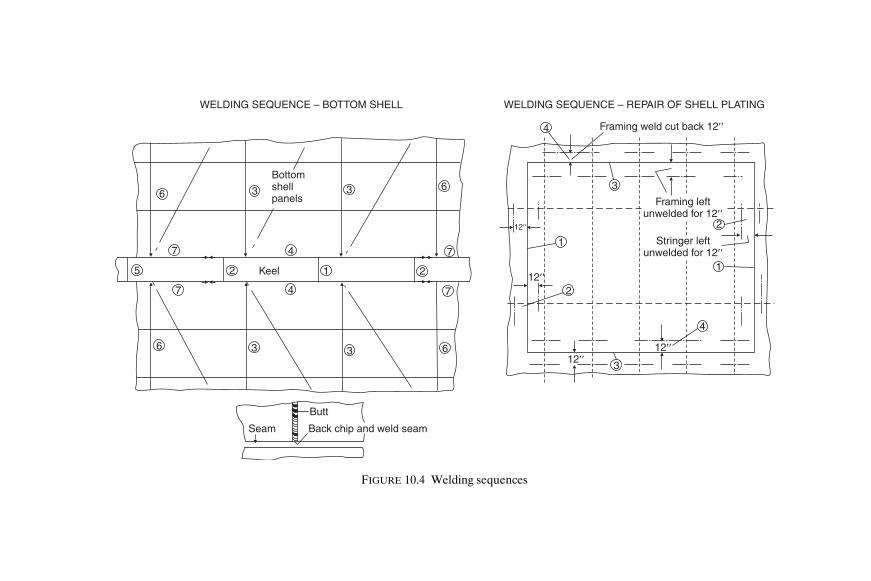
Seam
Butt
Back chip and weld seam
WELDING SEQUENCE – BOTTOM SHELL
6
7
3
4
3 6
7
2125
7
6
4
3 3 6
7
1
3
4
2
1
2
4
3
Bottomshellpanels
Keel
WELDING SEQUENCE – REPAIR OF SHELL PLATING
Framing weld cut back 12��
Framing leftunwelded for 12��
Stringer leftunwelded for 12��
12��
12��
12��
12��
FIGURE 10.4 Welding sequences
Shcc10.fm Page 97 M
onday, March 26, 2001 3:07 PM

98 Ship Construction
to undergo periodical welder approval tests to ascertain their standard ofworkmanship.
W E L D F A U L T S Various faults may be observed in butt and fillet welds.These may be due to a number of factors, bad design, incorrect weldingprocedure, use of wrong materials, and bad workmanship. Different faultsare illustrated in Figure 10.5. The judgment of the seriousness of the faultrests with the weld inspector and surveyor, and where the weld is consideredto be unacceptable it will be cut out and rewelded.
Non-destructive TestingFor obvious reasons some form of non-destructive test is required to enablethe soundness of ship welds to be assessed. The various available non-destructive testing methods may be summarized as follows:
Visual examinationDye penetrantMagnetic particleRadiographicUltrasonic
Of these five methods, the dye penetrant and magnetic particle tests havea small application in ship hull construction, being used for examining forsurface cracks in stern frames and other castings. Visual, radiographic, andultrasonic examinations are considered in more detail, as they are in com-mon use.
Magnetic particle testing is carried out by magnetizing the casting, andspreading a fluid of magnetic particles (e.g. iron fillings suspended in paraf-fin) on the surface. Any discontinuity such as a surface crack will show up asthe particles will concentrate at this point where there is an alteration in themagnetic field. A dye penetrant will also show up a surface flaw if it remainsafter the casting has been washed following the application of the dye. Toaid the detection of a surface crack the dye penetrant used is often lumin-ous and is revealed under an ultra-violet light.
Visual inspection of welds is routine procedure, and surface defects aresoon noticed by the experienced inspector and surveyor. Incorrect beadshape, high spatter, undercutting, bad stop and start points, incorrect align-ment, and surface cracks are all faults which may be observed at the surface.Sub-surface and internal defects are not observed, but the cost of visualinspection is low, and it can be very effective where examination is madebefore, during, and after welding.
Shcc10.fm Page 98 Monday, March 26, 2001 3:07 PM

OVERLAP
UNDERCUT
LACK OFREINFORCEMENT
LACK OF PENETRATION
LACK OF FUSION
EXCESSIVEREINFORCEMENT
LAMELLARTEARING
CRATER CRACKS
Resultingpull out
Lamellar tear in non-metallic stringer
INADEQUATE CROSS-SECTION
UNDERBEAD CRACKING
GAS ENTRAPMENT
Long cavities called ‘pipes’
SLAG INCLUSIONS
Inclusions between weld passesnot cleaned out
Root not properly backgouged
Small spherical cavitiescalled ‘porosity’
FIGURE 10.5 Weld faults
Shcc10.fm Page 99 M
onday, March 26, 2001 3:07 PM

100 Ship Construction
The principle of radiographic inspection is simply to subject a material toradiation from one side, and record the radiation emitted from the oppositeside. Any obstacle in the path of the radiation will affect the radiation densityemitted and may be recorded. As radiation will expose photographic plate,for all practical weld test purposes this is used to record the consistency ofthe weld metal. The photographic plate records changes in radiation densityemitted; for example a void will show up as a darker shadow on the radiograph.
Either X-ray or gamma ray devices may be used to provide the source ofradiation. X-ray equipment consists of a high voltage power source (50 to400kV) which is used to provide potential between a cathode and targetanode in a glass vacuum tube. Only a small percentage of this energy is con-verted to X-rays, so that large amounts of heat have to be conducted awayfrom the target. From the target the X-rays are projected out of the tubeonto the weld surface (see Figure 10.6).
Where gamma ray devices are used ray emission is produced by decay ofa radio-active nucleus, the rate of emission being reduced with time. Theradiation given off may be magnetically separated in three parts, α-rays, β-raysand γ-rays, the γ-rays being similar to X-rays and of most importance sincethey are very penetrating; but this also means that heavy shielding is required.Since natural radio-active sources are in short supply, great use is made ofartificial radio-active sources, namely isotopes.
To interpret the weld radiograph a large amount of experience is required,and a sound knowledge of the welding process. Radiographs usually carrythe image of an ‘image quality indicator’ which shows the minimum changeof thickness revealed by the technique. This image quality indicator may havegraded steps of metal, each step being identified on the radiograph so thatthe minimum step thickness discernible is noted, and the sensitivity of theradiograph assessed. This indicator is placed adjacent to the weld prior totaking the radiograph.
Ultrasonic energy is being used increasingly as a tool for locating defectsin welds, and has several advantages over radiography, particularly as nohealth hazard is involved. The technique is particularly useful for locatingfine cracks which are often missed by radiography, particularly where theylie perpendicular to the emission source.
The principle of ultrasonic inspection depends on the fact that pulses ofultrasonic energy are reflected from any surface which they encounter. Ultra-sonic waves travelling through a plate may be reflected from the surface ofthe metal and also from the surfaces of any flaws which exist in the metal.Virtually total reflection occurs at an air-metal interface, and therefore to getthe ultrasonic wave into the metal a liquid is placed between the source andmetal. The pattern of reflection is revealed on a cathode ray tube, whichmay be calibrated using a standard reference block. An experienced operatoris able to recognize flaws from the cathode ray tube display, and to someextent recognition of defect types is possible. Apart from weld inspection,
Shcc10.fm Page 100 Monday, March 26, 2001 3:07 PM

X 1 2 3 4 5
IMAGE QUALITY CONTROL INDICATOR(PENETRAMETER)
Powersource
50–400kV Filamentvoltage
Low filamentvoltage
Highvoltage
X-RAY APPARATUS
Filament
X-rays projectedout of tube
Penetrameter
Copper
Target
Weld
Photographicplate
Weld Traverse Probe
Reflected probe
ULTRASONIC PROBE TRAVERSE OFBUTT WELD
Probetraverse
Timer
FIGURE 10.6 Inspection of welds
Shcc10.fm Page 101 M
onday, March 26, 2001 3:07 PM

102 Ship Construction
ultrasonic techniques are valuable for assessing the thickness of structuralmembers.
Classification Society Weld Tests Classification societies specify a number of destructive tests which areintended to be used for initial electrode and weld material approval. Thesetests are carried out to ascertain whether the electrode or wire-flux combina-tion submitted is suitable for shipbuilding purposes in the category specifiedby the manufacturer.
Tests are made for conventional electrodes, deep penetration electrodes,wire-gas and wire-flux combinations, consumables for electro-slag and electro-gas welding, and consumables for one sided welding with temporary back-ing. Tensile, bend and impact tests are carried out on the deposited weldmetal and welded plate specimens. Other tests are made for the compositionof the weld metal deposited and possible cracking.
All works where electrodes, wire-flux and wire-gas combinations, con-sumables for electro-slag and electro-gas welding, and consumables for onesided welding with temporary backing are produced, and have been initiallyapproved, are subject to annual inspection.
Further ReadingAiles, ‘Notes on Industrial Radiography’, Shipping World and Shipbuilder,
Ship Repair Number, May 1968.
Control of Distortion in Welded Fabrications, 2nd Edition, The WeldingInstitute, Cambridge.
D’Archangelo, Sound Ship Structures (Cornell Maritime Press, 1964).
Harrison and Young, ‘The Acceptability of Weld Defects’, The NavalArchitect, April, 1975.
Hislop, ‘The Techniques, Applications and Scope of Non-DestructiveTesting in Industry’, Trans. N.E.C. Inst., vol. 69, 1952–53.
Lloyd’s Rules and Regulations for the Classification of Ships, Part 3, ShipStructures, Chapter 10, Welding and Structural Details.
‘Significance of Defects in Welds’, Proceedings of the First Conference,February 1967, The Welding Institute, Cambridge.
‘Ultrasonic Testing’, London, Institute of Welding, 1963.
‘Welding in Shipbuilding’, Symposium, 30 October–3 November, 1961,London, Institute of Welding, 1962.
Shcc10.fm Page 102 Monday, March 26, 2001 3:07 PM

Part 4
Shipyard Practice
Shcc11.fm Page 103 Monday, March 26, 2001 3:09 PM

Shcc11.fm Page 104 Monday, March 26, 2001 3:09 PM

11Shipyard Layout
Most shipyards are well established and were originally sited in a suitablelocation for building small ships with methods which have now been super-seded. With the growth in ship sizes and the introduction of new buildingmethods it has been recognized that a revised shipyard layout will be advant-ageous. Advantages to be gained, apart from the ability to construct largervessels, are primarily, a uniform work load, a shorter ship build cycle, andeconomies in construction practices. These are obtained by having a layoutthat lends itself to an easy flow of materials from one productive processto another with elimination of bottlenecks. Other factors of course areinvolved in achieving a smooth production flow, but it is an advantage tostart with a shop and equipment layout which is favourable.
Very rarely has it been possible for the shipbuilder to select a new siteand adopt an ideal layout. Normally the present site has to be used, andstarting from the ideal it has been necessary to make modifications to allowfor site peculiarities. At the same time shipbuilding has continued withinthe yard, and overall yard modifications have been made piecemeal inorder not to hinder this work seriously.
An ideal layout for a modern shipyard is based on a production flowbasis, with the yard extending back from the river or shore at which theberths or building dock are located. The furthest area from the berths isreserved for the material stockyard, and between the two are arranged insequence the consecutive work and shop processes. Too often existing ship-yards follow the river bank, and are restricted by their location in a built uparea or the physical river bank slope from extending back from the river, sothat modified production flow lines are required.
Planning a new shipyard, or re-planning an existing one, will involve deci-sions to be made on the following:
Size and type of ship to be built.Material production per year to be achieved.Material handling equipment to be supplied.Machining processes to be installed.Unit size and weight to be fabricated and erected.Amount of outfit and engine installation to be undertaken.
Shcc11.fm Page 105 Monday, March 26, 2001 3:09 PM

106 Ship Construction
Control services to be supplied.Administration facilities required.
With the introduction of welding followed by unit fabrication and thenthe development of sophisticated machine tool devices for plate and sectionpreparation, the shipyard layout had to be re-configured to exploit thehigher material throughput rates these processes allowed and permit theshipbuilder to remain competitive.
Before considering the actual layout of the shipyard it is as well toconsider the relationship of the work processes involved in building a shipas illustrated in Figure 11.1.
Shipyards usually have a fitting out basin or berth where the virtuallycompleted ship is tied up after launching and the finishing off work iscompleted. This is provided with adequate craneage and the outfitting and
Platestowage
Sectionstowage
Shotblast/prime Shotblast/prime
Flame planingFlame profiling
MarkingShaping
Bendingcutting
Sub-assemblies
Panelassemblies
Matrixassemblies
Curvedunit
assemblies
Blockassembly
Block and uniterection
Final outfit
Outfitpalletisation
andmodules
Outfitfabrication
and assembly
Pipe bending
Outfit materialsand bought in
items
FIGURE 11.1 Shipbuilding process
Shcc11.fm Page 106 Monday, March 26, 2001 3:09 PM

Shipyard Layout 107
machinery shops are usually adjacent to it. With the major part of the outfitand machinery now being installed in modular or other form during the hulland house fabrication cycle this feature of the yard now has less significance.
An idealized layout of a new shipyard is indicated in Figure 11.2 whichmight be appropriate for a smaller yard specializing in one or two standardtype ships with a fairly high throughput so that one covered building dockor berth was sufficient.
At this point it may be convenient to mention the advantages and dis-advantages of building docks as opposed to building berths. Building dockscan be of advantage in the building of large vessels where launching costs
Plate and section stockyard
Adminoffices
Marshalling and preparation
Platesection
andmachining
Moduleassembly
Unitassembly areas
and palletpreparation
Block fabrication Pipe andengine shop
Coveredbuildingdock
Outfitshops
Fitting outbasin
FIGURE 11.2 Shipyard layout
Shcc11.fm Page 107 Monday, March 26, 2001 3:09 PM

108 Ship Construction
are high, and there is a possibility of structural damage owing to the largestresses imposed by a conventional launch. They also give good crane clear-ance for positioning units. The greatest disadvantage of the building dock isits high initial cost.
Many yard re-constructions have incorporated undercover constructionfacilities in the form of docks or slipways within building halls. Others havebuilding halls at the head of the slipway with advanced transfer systemsinstalled so that the hull can be extruded out of the hall onto the slipway forlaunching. Such facilities permit ship construction in a factory type environ-ment providing protection from the worst effects of weather and darkness.
Further Reading‘A Covered Shipyard at Pallion gives British Shipbuilding a New Look’, The
Naval Architect, May, 1976.
Cameron and Tennant, ‘Building Dock and New Steelworking Facilities atQueen’s Island, Belfast’, Trans. N.E.C. Inst., 1971.
‘Cammell Lairds Shipyard reconstruction at Birkenhead’, The Naval Architect,November, 1978.
Grant, ‘Production Methods in Japanese Shipbuilding’, The Naval Architect,January, 1972.
Kimber and Hargroves, ‘Creating a Production Facility for Standard Ships’,The Naval Architect, January, 1977.
McNulty and McKinstry, ‘Parallel Development of Ship Production Facilitiesand Information Systems’, The Naval Architect, September, 1978.
Shcc11.fm Page 108 Monday, March 26, 2001 3:09 PM

12Ship Drawing Offices and Loftwork
The ship drawing office is traditionally responsible for producingdetailed working structural and general arrangement drawings for parts ofthe hull and outfit. Structural drawings prepared by the drawing office willbe in accordance with Lloyd’s or other classification rules and subject totheir approval; also owner’s additional requirements and standard shipyardpractices are incorporated in the drawings. General arrangements of all theaccommodation and cargo spaces and stores are prepared, which allow forstatutory requirements as well as shipowner’s requirements and standards.Other outfit plans, piping arrangements, ventilation and air conditioning(which may often be done by an outside contractor), rigging arrangements,and furniture plans, etc., are also prepared.
Since the late 1970s, developments in computer hardware based on micro-chip technology have made available to industry very powerful computersystems at moderate cost. This technology has led to a significant advancein the capability of systems for computer aided design, computer aidedengineering and computer aided manufacture (CAD/CAE/CAM) whichare commonly available to industry. Such systems have steadily replacedmanual draughting and numerically controlled parts programming in manyshipyards. Computer based shipbuilding systems developed during the late1960s and early 1970s and used for numerically controlled productionmachines and loftwork have now been enhanced to extend their scope tothe design and drawing office functions and provide interfaces with a com-prehensive range of other shipyard systems.
The CAD/CAE/CAM systems are based on a 3D Ship Product Model inwhich the geometry and the attributes of all elements of the ship derivedfrom the contract design and classification society structural requirementsare stored. This model can be visualized at all stages and can be exploited toobtain information for production of the ship.
It has been common practice for the drawing office to contain a materialordering department, which was able to lift the necessary requirementsfrom the drawings and progress them. Also, the office worked in close con-junction with the loft and planning production office. With the introductionof CAD/CAE/CAM systems to the drawing office these functions have beenincreased and improved. From the 3D ship product model the precisionof the structural drawings generated enables them to be used with greater
Shcc12.fm Page 109 Monday, March 26, 2001 3:10 PM

110 Ship Construction
confidence than was possible with manual drawings and the requisitioninginformation can be stored on the computer to be interfaced with the ship-yards commercial systems for purchasing and material control. Sub-assembly, assembly and block drawings can be created in 2-dimensionaland 3-dimensional form and a library of standard production sequencesand production facilities can be called up so that the draughtsman canensure the structural design uses the yards resources efficiently and followsestablished and cost effective practices. Weld lengths and types, steelweights and detailed parts lists can be processed from the information onthe drawing and passed to the production control systems. A 3-dimensionalsteel assembly can be rotated by a draughtsman on screen to assess the bestorientation for maximum downhand welding. The use of 3-dimensionaldrawings is particularly valuable in the area of outfit drawings where itemslike pipework and trunking can be ‘sighted’ in the 3-dimensional mode andmore accurately measured before being created in the 2-dimensional drawing.
There are several drawings or tasks undertaken in the drawing officewhich are of special interest and warrant a little more attention.
L I N E S P L A N A preliminary version of this will, in effect, be prepared atthe time of the conceptual design to give the required capacity, displace-ment and propulsive characteristics. It will subsequently be refined duringthe preliminary design stage and following any tank testing or other methodof assessing the hulls propulsive and seakeeping characteristics. The linesplan is a drawing, to a suitable scale, of the moulded lines of the vessel inplan, profile, and section. Transverse sections of the vessel at equally spacedstations between the after and forward perpendiculars are drawn to formwhat is known as the body plan. Usually ten equally spaced sections areselected with half ordinates at the ends where a greater change of shapeoccurs. A half transverse section only is drawn since the vessel is symmet-rical about the centre line, and forward half sections are drawn to the rightof the centre line with aft half sections to the left. Preliminary body plans aredrawn initially to give the correct displacement, trim, capacity, etc., and mustbe laid off in plan and elevation to ensure fairness of the hull form. Whenthe final faired body plan is available the full lines plan is completed show-ing also the profile or sheer plan of the vessel and the plan of the water-lineshapes at different heights above the base.
A lines plan is illustrated in Figure 12.1. The lines of the lateral sectionsin the sheer plan as indicated are referred to as ‘bow lines’ forward and‘buttock lines’ aft. Bilge diagonals may be drawn with ‘offsets’ taken alongthe bilge diagonal to check fairness.
When the lines plan was completed manually the draughtsmen would com-pile a ‘table of offsets’, that is a list of the half breadths, heights of decks andstringer, etc., at each of the drawn stations. These ‘offsets’ and the lines planwere then passed to loftsmen for full size or 10 to 1 scale fairing, or to a
Shcc12.fm Page 110 Monday, March 26, 2001 3:10 PM

PLAN(waterlines)
AFT
A ABC
8 8½ 9½9 10
B
CButtocklines
Bowlines
Deck
L.W.L. L.W.L.
L.W.L.
12′
8′4′
Deck Deck
0 1½1½
PROFILE AFTPROFILE FORD
AFTSECTIONS
A A BB CC
54
32
1½
9½
8½
9
87
6 5
½1
0
10 FORDSECTIONS
L.W.L.
Deck
Deck
BODY PLAN
12 L.W.L.′
8′ L.W.L.
4′ L.W.L.
Deck
FIGURE 12.1 Lines plan
Shcc12.fm Page 111 M
onday, March 26, 2001 3:10 PM

112 Ship Construction
computer centre for full scale fairing. Since the lines plan was often ofnecessity to a small scale which varied with the size of ship, the offsetstabulated from widely spaced stations and the fairing were not satisfactoryfor building purposes. The loftsmen or computer centre would prepare afull set of faired offsets for each frame space.
Given today’s common usage of integrated design systems on the ship-yards’ computers, the conceptual creation of the hull form and its subsequentfairing for production purposes is accomplished without committing theplan to paper. The hull form is generally held in the computer system as a3-dimensional ‘wire model’ which typically defines the moulded lines of allstructural items so that any structural section of the ship can be generatedautomatically from the ‘wire model’.
3 - D I M E N S I O N A L R E P R E S E N T A T I O N O F S H E L L P L A T I N G Whenpreparing the layout and arrangement of the shell plating at the drawingstage it is often difficult to judge the line of seams and plate shapes with aconventional two-dimensional drawing. Shipyards used to therefore makeuse of a ‘half block model’ which was in effect a scale model of half the ship’shull from the centre line outboard, mounted on a base board. The modelwas either made up of solid wooden sections with faired wood battens toform the exterior, or of laminated planes of wood faired as a whole. Finishedwith a white lacquer the model was used to draw on the frame lines, plateseams, and butts, lines of decks, stringers, girders, bulkheads, flats, stemand stern rabbets, openings in shell, bossings, etc.
With a CAD system the shell plating arrangement can be worked out atthe interactive (i.e. image can be worked on and added to, modified, etc.)screen on the body plan derived from the 3-dimensional ‘wire model’, tocreate a plate line body plan. This drawing can then be used to create3-dimensional representations of all the relevant lines on the curved surfacecreating in effect a visual ‘half block model’.
S H E L L E X P A N S I O N The arrangement of the shell plating taken fromthe 3-dimensional model may be represented on a 2-dimensional drawingreferred to as a shell expansion. All vertical dimensions in this drawing aretaken around the girth of the vessel rather than their being a direct verticalprojection. This technique illustrates both the side and bottom plating as acontinuous whole. In Figure 12.2 a typical shell expansion for a tanker isillustrated. This also shows the numbering of plates, and lettering of platestrakes for reference purposes and illustrates the system where strakes ‘runout’ as the girth decreases forward and aft. A word of caution is necessaryat this point for in many modern ship shell expansions there is also a number-ing system related to the erection of fabrication units rather than individualplates, and it may be difficult to use the drawing to identify individual
Shcc12.fm Page 112 Monday, March 26, 2001 3:10 PM

L
K
JSide
Bilge
Sheerstrake
plating
plating
H
GF
E
D1 D2 D3 D4 D5
C1 C9B11B10B9B8B7B6
Bottom A plating
Keel plate
FRAMING, STRINGERS, DECKS AND OPENINGS IN SIDE SHELL ARE ALSO SHOWN ON THESHELL EXPANSION BUT HAVE BEEN OMITTED FOR CLARITY
B5B4B3
C8C7C6C5C4C3C2
FIGURE 12.2 Shell expansion
Shcc12.fm Page 113 M
onday, March 26, 2001 3:10 PM

114 Ship Construction
plates. However single plates are often marked in sequence to aid orderingand production identification.
Loftwork Following Drawing Office The mould loft in a shipyard was traditionally a large covered wooden floorarea suitable for laying off ship details at full size.
When the loftsmen received the scale lines plan, and offsets from thedrawing office, using the traditional method the lines would be laid off fullsize and faired. This would mean using a great length of floor even though acontracted sheer and plan were normally drawn, and aft and forward bodylines were laid over one another. Body sections were laid out full size asthey were faired to form what is known as a ‘scrieve board’. To avoid usingup a large mould loft space for fairing the ship lines, many shipbuilderslater took advantage of main frame computer programs available at variouscentres. These provided full size fairing so that only the scrieve boardneeded to be laid down from the faired offsets.
S C R I E V E B O A R D S The scrieve board was used for preparing ‘set bars’and levels for bending frames and for making templates and mouldings forplates which required cutting and shaping. Shell plates were developed fullsize on the loft floor and wooden templates made so that these plates couldbe marked and cut to the right shape before being fitted to the framing onthe berth.
10/1 S C A L E L O F T I N G In the late 1950s the 10/1 lofting system wasintroduced and was eventually widely adopted. This reduced the mold loftto a virtual drawing office and assisted in the introduction of productionengineering methods. Lines could be faired on a 10/1 scale and a 10/1 scalescrieve board created. Many yards operated a flame profiling machine(see Chapter 13) which used 10/1 template drawings to control the cuttingoperation. In preparing these template drawings the developed or regularshape of the plates was drawn in pencil on to special white paper or plywoodsheet painted white, and then the outline was traced in ink on to a specialtransparent material. The material used was critical, having to remainconstant in size under different temperature and humidity conditions andhaving a surface which would take ink without ‘furring’. Extreme accuracywas required in ensuring uniform thickness of lines, etc., the lines beingdrawn outside, i.e. on the scrap side of the plate. Many of the outlines ofplates to be cut by the profiler could be traced directly from the scrieveboard, for example floors and transverses.
Shcc12.fm Page 114 Monday, March 26, 2001 3:10 PM

Ship Drawing Offices and Loftwork 115
CAD/C A M L O F T W O R K We have already seen that shipyard-installedcomputer systems are capable of fairing the lines full size and storing theseas a 3-dimensional model. This stored information can be accessed by the
Des
ign
Man
ufac
ture
Final linesplans
Hulldefinition
and designcalculations
Designdatabase
Conceptdesign
Generalarrangements
Ships database
3D wireship model
Material listsweights
centres ofgravity
Nestedformats
Shopdrawings
Productioncontrol
drawings
Modelintegration+ drawinggenerator
Interactiveparts
nesting
Longitudinalframe
development+ offsets
Develop-ment of
shellplates
Shellexpansion
Plate linebody plan
3Dsurface +
interrogationlines
fairing
Generationpreliminarylines to ship
database
Loadinginner
structuresurface
Loadingand fairingseams +
longitudinal
Standarddetails
Unitassemblymodels
Parts
NCtape
Nested formats
Drawingfile
Roll sets+ transverse
frameoffsets
Jigpin
heightsetc.
Interactiveparts coding
and assemblymodelbuilder
Fabricationdrawings
Structuraldrawings
Modelinterrogations
+ drawinggenerator
Software
Precodedrules –
proceduresbuilders
standards
Loadingstiffening
seams + buttscutouts
etc.
FIGURE 12.3
Shcc12.fm Page 115 Monday, March 26, 2001 3:10 PM

116 Ship Construction
loftsman in order that lofting functions such as preparing information forbending frames and longitudinals, developing shell plates, and providingshell frame sets and rolling lines or heat line bending information for platescan be done via the interactive visual display unit.
For the numerically controlled profiling machine the piece parts to becut can be ‘nested’, i.e. fitted into the most economic plate which can behandled by the machine with minimum wastage. This can be done at thedrawing stage when individual piece parts are abstracted for steel requisi-tioning and stored later being brought back to the screen for interactivenesting. The loftsman can then define the order in which parts are to bemarked and cut by drawing the tool head around the parts on the graphicsscreen. When the burning instructions are complete he is able to replay thecutting sequence and check for errors. A check of the NC tape after it hasbeen punched can be carried out with a plotter. Instructions for cuttingflame planed plates and subsequently joining them into panel assembliesand pin heights of jigs for setting up curved shell plates for welding framingand other members to them at the assembly stage can also be determinedby the loftsman.
Shell plates at the extreme ends of the hull, that is those with doublecurvature at the stern and bulbous bow, may still require manual lofting using10/1 procedures.
PARTS NESTING
DESIGN PARTS DEFINITION
PARTS LISTING
1
14
2
2
3
3
3
3
4
4
FIGURE 12.4
Shcc12.fm Page 116 Monday, March 26, 2001 3:10 PM

Ship Drawing Offices and Loftwork 117
Further Reading ‘An alternative to shell expansion drawing’, The Naval Architect, November,
1977.
Barry and Mercier, ‘Implementing CAD/CAM in Shipyards’, Newbuild2000 and the role of the Naval Architect 1995, Royal Institution of NavalArchitects Publications.
CADAP’95, Royal Institution of Naval Architects Publications.
‘Computer applications in the automation of shipyard operation and shipdesign’, The Naval Architect, November, 1979.
Dawson, ‘Computing systems for naval architects’, Ship and Boat Inter-national, April, 1987.
Forrest and Parker, ‘Steelwork Design Using Computer Graphics’, TheNaval Architect, January, 1983.
Kuo et al., ‘An Effective Approach to Structural Design for Production’,The Naval Architect, February, 1984.
Proceedings of the Seminar on Advances in Design for Production, Univer-sity of Southampton, April, 1984.
‘The role of CAD/CAE/CAM in Engineering for Production’, The NavalArchitect, November, 1994.
Torroja and Alonso, ‘Developments in Computer Aided Ship Design andProduction’, The Royal Institution of Naval Architects, 1999.
Shcc12.fm Page 117 Monday, March 26, 2001 3:10 PM

13Plate and Section Preparation and Machining
This chapter deals with the working processes which a plate or sectionundergoes from the time it is received into the shipyard until it is in its finalshape ready to be welded into a unit of the ship structure. In recent yearsmany changes have occurred in this sphere of shipyard activity, and sub-stantial economies can be achieved by obtaining an even flow of productionat this stage.
Plate and Section PreparationInitial preparation of material is essential for its efficiency in the completedship structure and its marshalling on arrival is essential to the efficiency ofthe shipbuilding process.
S T O C K Y A R D On arrival at the shipyard, plates and sections are tempor-arily stored in the stockyard. As a rule the stockyard is an uncovered spacehaving sufficient area to provide storage for enough plates and sectionsrequired for the working of the yard some months ahead. In the UnitedKingdom the amount stored might be about three months’ stock, but ship-yards in countries which are not substantial steel producers may find itnecessary to carry much larger stocks of material. In contrast a Japaneseyard closely associated with a steel manufacturer claims to carry as little asone month’s stock, and in some cases less.
When the plates and sections are ordered the steel mills are providedwith details of the identification code for each item so that they may bemarked. On arrival in the stockyard, since the coding is generally in terms ofthe unit structure for which each item is intended, it is convenient to store theplates and sections in their respective ship and ship unit areas. In other wordsthe material for each ship is allotted an area of the stockyard, this area beingsubdivided into plots for those items intended for a major structural fabrica-tion block of the ship.
Material delivery and storage is controlled in accordance with productionengineering practices to suit the ships construction programme.
As a rule the plates are now stacked horizontally in piles as required.Originally it was common practice to store the plates vertically in racks,
Shcc13.fm Page 118 Monday, March 26, 2001 3:10 PM

Plate and Section Preparation and Machining 119
which was convenient for weathering purposes, but this system is not nowemployed; sections are laid horizontally in convenient batches.
Where cranes are used for material handling it is important that there beadequate coverage for the full extent of the stockyard, and the material maybe delivered to the covered shed areas. Cranage is generally of the electricoverhead gantry type, traversing the stockyard on rails and extending intothe workshop area; alternatively the plates may be placed on a roller con-veyor for delivery to the workshops. Lifts are made with magnetic clampsfor plates and slings for the sections, the crane capacity rarely exceedingfive tonnes. To improve the handling facilities in the stockyard a deviceknown as a ‘captivator’ is now available. Plates required for the work beingprocessed may be pre-stacked at the captivator which can be remotelycontrolled so that as each plate is required it lifts, using magnetic clamps,the plate from the top of the pile and then transfers it to a roller conveyor.A stockyard employing this technique can in fact become highly automated.
M A N G L E S Mangles is the name given to a heavy set of plate straighten-ing rolls through which the plate is passed prior to its being worked. Duringtransit plates may become distorted, and for many of the modern machin-ing processes it is important that the plates should be as flat as practicable.Two sets of mangles may be provided, one for heavy plate and one for lightplate, but types are now available which permit a wide range of thickness tobe straightened.
S H O T B L A S T I N G Plates and sections are in most cases now shot blastedto remove rust and millscale. The principles of shot blasting are dealt with indetail in Chapter 27.
Shot blasting plant in shipyards is generally of the impeller wheel typewhere the abrasive is thrown at high velocity against the steel surface andmay be re-circulated. The plant can be so arranged that the plate passesthrough vertically, but more often it is installed so that the plate may passthrough in the horizontal position. In the former case equipment must beprovided to allow the plate to be raised into the vertical position from theroller conveyor before it enters the blasting plant, and to lower it on removal.There is a further problem with lighter plate which may more easily distortwhen stood on end. The only disadvantage of the horizontal plant is theremoval of spent abrasive from the top of the plate, which may be relativelyeasily overcome. A separate shot blast plant is often installed for sections.
P R I M I N G P A I N T Following the shot blasting of plates and sections, thematerial passes immediately through an airless spray painting plant. In onepass the material is automatically sprayed with a priming paint of controlledcoat thickness. A number of suitable priming paints are available; the
Shcc13.fm Page 119 Monday, March 26, 2001 3:10 PM

120 Ship Construction
requirements for these and their formulation may be found in Chapter 27.Following the priming paint stage a drying process may be provided.
P L A T E H A N D L I N G I N M A C H I N E S H O P S Throughout the machiningshops overhead electric cranes having capacities from 5 to 15 tonnes maybe provided to transport plates and sections to each machine process.Individual machines may have jig cranes mounted on the frame which canbe employed to handle the plate during the machining process.
Distribution of plates in the shop may also be by means of electric pow-ered trolleys sometimes referred to as a ‘collacator unit’ running on rails inbays between the plate working machines. Highly mechanized plant systemsare also available where conveyor systems, flame cutting tables and aligningand clamping equipment are installed as integrated units.
Plate and Section Machining A number of the methods in use for forming plates into the required shapesare time honoured. This is particularly true of the methods adopted forfitting plates to the curve of the hull, but as we have seen in the previouschapter the information for doing this can now be derived using the CAD/CAM systems available. Cutting flat plates to the required profiles has inthe past decade become highly automated, very sophisticated machine toolshaving been introduced for this purpose. In the main, cutting is achieved bythe use of an oxy-fuel flame or plasma-arcs.
P L A T E P R O F I L E R S Where a plate is to be cut into one or more, or aseries of complicated shapes, a profiling machine is employed. At presentwhere these employ gas cutting, the machines are generally referred to as‘flame profilers’. All flame, or plasma-arc profilers have some form of auto-matic control, the sophistication of which may vary considerably; thefollowing methods of control are found in shipyards:
(a) 1/1 template or drawing control (b) 1/10 drawing (c) Numerical control.
(a) A full size template or drawing may be used to control a cuttingmachine, and can be very useful where a single item is to be cut in largenumbers. The size of the item is obviously restricted, and the location fromwhich the item is cut in a large plate is selected by the operator. Wherea template is used a mechanical follower may be employed, and where adrawing is used an electronic scanning device may follow the outline.In either case simple non-automated machines are available where the
Shcc13.fm Page 120 Monday, March 26, 2001 3:10 PM

Plate and Section Preparation and Machining 121
operator guides the follower around the template, or tracing head aroundthe drawing profile. Profilers of this type have a limited application in ship-building, but might be used for cutting a batch of standard brackets, etc.
(b) Some of the earlier flame profilers found in shipyards were con-trolled by 10/1 drawings prepared by loftsmen as indicated in Chapter 12.The control mechanism for the machine was located in a darkened boothwithin the plate machining sheds. A tracing head with photo-electric celltraversed the 1/10 scale drawing located on a viewing table, following theline of the plate from the start to stop points in a sequence planned by theloftsmen. The control was linked to the machine outside, which consisted ofa carriage with extended arms carrying the burning heads. Two arms weregenerally fitted allowing the machine to cut at the same time two plates whichcould either be identical or mirror images. Each burning head was fitted withthree nozzles allowing various edge preparation bevels to be cut. The heightof the flame was automatically adjusted and speed control was maintainedduring the cut, although it was possible to speed up the burning head move-ment between the finish and start of a new cut. Later versions of thesemachines had twin tracing head controls so that both sides of a plate withdissimilar curves could be cut simultaneously.
With this type of machine it was possible to obtain an accessory for mark-ing plates. This punch marked the plate at desired locations in a mannersimilar to that employed for permanent marking by hand.
(c) Shipyards now use numerical control for the plate profiler, ratherthan optical control. The principal reasons for this are that the preparationof 1/10 scale drawings requires a high standard of draughtsmanship and thetraining of loftsmen to do this work can be very expensive. Further intro-ducing higher cutting speeds with the adoption of the plasma-arc processmakes optical control difficult.
Numerical control implies control of the machine by means of a tape onwhich is recorded the co-ordinate points of a plate profile. For a simpleplate shape having a profile consisting only of straight lines or circular arcs,the co-ordinates may be programmed manually, but for many ship plates thecontours are much more complex. Manual programming of these contourswould reduce considerably the efficiency of the process, and thereforevarious coded data systems were initially evolved for use with a digitalcomputer program. With the advent of CAD/CAM systems the integratedsoftware now developed includes, as described in Chapter 12, provision forthe draftsman to perform parts programming and nesting of plate parts andthe loftsman to add the cutting information and automatically generate theNC tape. The tape can be read into the director which produces commandsignals to the servo-mechanism of the profiling machine. The overall arrange-ment is shown in Figure 13.1.
These machines, like the 1/10 scale optically controlled machines, may beprovided with accessories for marking plates.
Shcc13.fm Page 121 Monday, March 26, 2001 3:10 PM

LoftsmanCutting data and sequenceplotter verification NC tape
Director atwork station
Numerically controlledflame profiler
Draughtsmanparts programminginteractive nesting
FIGURE 13.1 Numerical flame cutting control system
Shcc13.fm Page 122 M
onday, March 26, 2001 3:10 PM

Plate and Section Preparation and Machining 123
P L A N I N G M A C H I N E S Profiling machines are essentially for use wherea plate requires extensive shaping with intricate cuts being made. Many ofthe plates in the ship’s hull, particularly those in straightforward plate panels,decks, tank tops, bulkheads, and side shell, will only require trimming andedge preparation, and perhaps some shallow curves may need to be cut inshell plates. This work may be carried out on a planing machine, usually aflame or plasma-arc planer.
A flame planer consists basically of three beams carrying burning headsand running on two tracks, one either side of the plate working area. Onebeam carries two burning heads for trimming the plate sides during travel,whilst the other two beams have a single burning head traversing the beamin order to trim the plate ends. Each burning head may be fitted with triplenozzles and is used to give the required edge preparation. Plate, beam, andburning head positioning is manual, but cutting conditions are maintainedonce set.
Mechanical planing machines were in existence prior to the flame planer,and have an advantage where they are able to cut materials other than steels.Higher cutting speeds than that obtained with flame cutting may be obtainedfor vertical edges with a rotary shearing wheel on a carriage, where theplate is held by hydraulic clamping. For edge preparations, older machineswith a conventional planing tool require a large number of passes and aremuch slower than flame planers. There are however merits in mechanicallymachined edge preparations where the superior finish is advantageous forcritical welds. The use of plasma-arc planers which also provide a superiorand faster cut tend to make the use of mechanical planers obsolete.
D R I L L I N G M A C H I N E S Some plates or sections may need to have holesdrilled in them, for example bolted covers and portable sections. Drillingmachines generally consist of a single drilling head mounted on a radialarm which traverses the drill bed.
G U I L L O T I N E S Smaller plate shapes such as beam knees and variousbrackets may be cut in a hydraulically operated guillotine. Plate feed to theguillotine is usually assisted by the provision of plate supporting rollercastors, and positioning of the cut edge is by hand.
P R E S S E S Hydraulic presses may be extensively used in the shipyard for avariety of purposes. They are capable of bending, straightening, flanging,dishing, and swaging plates (see Figure 13.2). All of the work is done withthe plate cold, and it is possible to carry out most of the work undertaken bya set of rolls. This is done at less capital cost, but the press is slower whenused for bending and requires greater skill.
Shcc13.fm Page 123 Monday, March 26, 2001 3:10 PM

124 Ship Construction
P L A T E R O L L S Heavy duty bending rolls used for rolling shell plates,etc., to the correct curvature are hydraulically operated. Two lower rolls areprovided and are made to revolve in the same direction so that the plate isfed between them and a slightly larger diameter top roll which runs idly (seeFigure 13.3). Either or both ends of the top roll may be adjusted for height,and the two lower rolls have adjustable centres. With modern bending rolls,plates up to 45 mm thick may be handled and it is possible to roll plates to ahalf circle. These large rolls are also supplied with accessories to allow themto undertake heavy flanging work with the pressure exerted by the upperbeam, for example, ‘troughing’ corrugated bulkhead sections.
Shorter pyramid full circle rolls are also used in shipyards, these beingvery useful for rolling plates to a full circle. This may be done to obtainlarge mast and derrick post sections for example, or bow thruster tunnel.Arrangements are made for removing the rolled full circle plate by releas-ing the top roller end bearing. Vertical rolls are also available and may beused to roll plates full circle, but can be much more useful for rolling heavyflats used as facing bars on transverses of large tankers, etc.
H E A T L I N E B E N D I N G The ‘heat-line’ bending procedure is a widelyused technique to obtain curvature in steel plates for shipbuilding purposes.
PLATE SWAGING
EDGE CURVING
PLATE FLANGING ORBENDING
PLATE STRAIGHTENING
FIGURE 13.2 Gap presses
Shcc13.fm Page 124 Monday, March 26, 2001 3:10 PM

Plate and Section Preparation and Machining 125
It is, however, a process that until recently relied on highly skilled personneland did not guarantee constant accuracy of shapes formed.
Heat is applied in a line to the surface of a plate by a flame torch, andthen immediate cooling is obtained by air or water. The narrow heated lineof material is prevented from expanding in the direction of the plate surface
Apply heat Expansion
BendContraction
Single plane bending
Two planebending
1 2
43
Heat line bending principle
Beam applying load
PLATE ROLLSToproller
Drivenroll
Drivenroll
Plate
FIGURE 13.3 Forming shell plates
Shcc13.fm Page 125 Monday, March 26, 2001 3:10 PM

126 Ship Construction
by the large mass of cold plate, and therefore expands outwards perpendicularto the plate surface. On cooling contraction will take place in the directionof the plate surface, causing the plate to become concave on the side to whichheat was applied (see Figure 13.3). An experienced operator is able to makea pattern of such heat lines on a plate producing controlled distortion toobtain a required shape. Heat line bending can be more time consumingthan using rolls or presses but it has an advantage in that the plate holdsits form more accurately when stiffening and other members are addedlater in the fabrication process. This is an important consideration sinceshape inaccuracy can be critical at the erection stage in terms of lost pro-duction time.
The Japanese have in recent years developed and introduced a computer-aided fully automated heat-line bending system for shipbuilding purposes.This numerically controlled heat-line bending machine permits highly accur-ate, reproducible thermal forming of any steel plate with more than doublethe productivity of the traditional manual process.
Frame BendingThe traditional system of bending side frames may still be in use for repairwork, and is described as follows. A ‘set-bar’ which is a flat bar of soft iron isbent to the scrieve line of the frame on the scrieve board and then taken tothe frame bending slabs. On these solid cast-iron slabs pierced with holes theline of the frame is marked, and modified to agree with the line of the toeof the frame. As the heated frame on cooling will tend to bend, the set-baris sprung to allow for this change in curvature before it is fixed down on thebending slabs by means of ‘dogs’ and pins inserted in the slab holes. Whilstthe set-bar is being fixed the frame section is heated in a long oil-firedfurnace adjacent to the bending slabs. When at the right temperature it ispulled out onto the slabs and fixed with dogs and pins against the set-bar, asquickly as possible. Tools are available for forcing the frame round againstthe set-bar, including a portable hydraulic ram, and the toe of the web mayrequire constant hammering to avoid buckling under compression.
As the frames fitted have their webs perpendicular to the ship’s centreline, all except those immediately amidships will require bevelling. A bevel-ling machine is available which is placed in front of the furnace door, and asthe frame is removed it passes between its rollers which are controlled sothat the flange is bent at every point to an angle indicated by a bevel boardprepared by the mould loft.
Once bent the bar is put aside to cool, but is fastened down to prevent itswarping in the vertical direction. When cold it is checked against the frameline drawn on the slabs. Meanwhile the set-bar is turned over and used tobend the corresponding frame for the opposite side of the ship.
Shcc13.fm Page 126 Monday, March 26, 2001 3:10 PM

Plate and Section Preparation and Machining 127
Chalk line
Inverse curve bending principle
Pin
Pin
DogDog Pin
Frame
Dog
Dog
Portable hydraulic
ram
Portable hydraulicramPin
DogSlabs
Frame
Pin
TRADITIONAL HEATED FRAME BENDING
Rotating vicingjaw
Motor driven feedwheels
Fixed
vicingjaw
Rotating vicingjaw
BILGE TURN BENDINITIAL POSITIONBOW FLARE BEND
COLD FRAME BENDING MACHINE (HYDRAULIC)
FIGURE 13.4 Frame bending
Shcc13.fm Page 127 Monday, March 26, 2001 3:10 PM

128 Ship Construction
CO LD F R A M E B E N D I N G It is now almost universal practice to cold bendship frames using commercially available machines for this purpose. Theframes are progressively bent by application of a horizontal ram whilst theframe is held by gripping levers (Figure 13.4). Any type of rolled section canbe bent in some machines with a limitation on the size of section. Obtainingthe correct frame curvature can be achieved by the ‘inverse curve’ methodor numerical control. With the ‘inverse curve’ method the inverse curveinformation can be determined for each frame by the loftsman using aCAD/CAM system. The inverse curve is drawn in chalk on the straightframe and the frame bent until the chalk line becomes straight on thecurved frame (see Figure 13.4). A hydraulic cold frame bending machinecan be controlled by numerical control tapes prepared in a similar mannerto the numerically controlled flame profilers, the frame line being initiallydefined from the computer stored faired hull.
R O B O T I C S Robots have in recent years been provided with improvedcontrol features which have made them more adaptable to the workshopfloor situation. For example most robots are now available with some formof ‘adaptive control’ which provides feedback from the environment per-mitting, say, automatic adjustment of the robots path and/or its functions.Also the provision of ‘off-line’ programming and simulation packages makesit possible to develop and test programs for the robot remotely. Thus therobot carries on working whilst new programs are produced for it.
Many of the worlds shipyards and shipyard systems suppliers have beendeveloping and implementing robots in shipbuilding. A large proportion ofthese developments have been in fully automating the machine weldingprocesses described in Chapter 9 but other areas of adoption and trial haveinvolved flame and plasma-arc cutting, local shot-blasting and painting, andmarking. Robots developed to date for shipyard usage are either large gantrystructures or small portable units. The former often have the movable robotmounted on the travelling gantry with sensors providing the adaptive con-trol and are employed for cutting and welding processes. The latter can bemanually transported, or self propelled even climbing vertically, or for robotictransportation, and have been used for local welding in difficult situationsand cleaning and painting.
Many of the robot programming systems can be linked to the shipyardsCAD system so that programs developed for the robot can be run ‘off line’with the 3-dimensional graphics simulating the robots performance beforeit is put to work.
Whilst robots have advantages in their use in difficult and unpleasantwork conditions and tedious repetitive work situations, their development andadoption is increasingly seen as a means to higher productivity and reducedmanufacturing cost.
Shcc13.fm Page 128 Monday, March 26, 2001 3:10 PM

Plate and Section Preparation and Machining 129
Further ReadingAndreassen, ‘Mechanized ship and offshore module fabrication’, Shipbuilding
and Marine Engineering International, December, 1981.
Chadburn and Parker, ‘A New Approach to Numerical Control for Ship-building’, Trans. R.I.N.A., 1969.
‘Getting it right at Swan Hunter’, The Naval Architect, September, 1984.
Kalogerakis, ‘The use of robots in the shipbuilding industry’, The NavalArchitect, July/August, 1986.
Kuo and Kalogerakis, ‘The Application of a Welding Robot for SmallBatch Manufacturing in Shipbuilding’, Trans. R.I.N.A., 1988.
Shama and Miller, ‘A Design Study of a Numerically Controlled FrameBending Machine’, Trans. R.I.N.A., 1967.
‘Shipbuilding world looks on as Finns pioneer robotic gantry’, MetalConstruction and British Welding Journal, November, 1986.
Shcc13.fm Page 129 Monday, March 26, 2001 3:10 PM

14Prefabrication
During the Second World War a large number of merchant and war shipswere required to be built in a short period of time. These requirementsspeeded the adoption of welding in shipyards, and often led to the applicationof mass production techniques in shipbuilding. Prefabrication of ship units,that is the construction of individual sections of the ship’s structure prior toerection, became a highly developed science. Often the units were manu-factured at a location remote from the shipyard, and erection in the ship-yards was carried out with schedules which still look very impressive today.Many of the more spectacular achievements in this field were obtained inthe USA where much of the tonnage required during the war period wasconstructed using these new advances. Unfortunately the results of thiscrash building programme were not always entirely satisfactory; the reputa-tion of welded structures for example suffered for quite a time as a result ofwholesale application without a background of experience. Since the warprefabrication has gradually been applied to merchant ship construction asshipyards in this country have been modified to employ this technique andhave gained experience of unit fabrication. Today all vessels are to varyingdegrees prefabricated.
With riveted construction unit fabrication was rarely employed, the intro-duction of welding lent itself more favourably to this form of construction.With welding, simpler unit shapes (no staggered butts are required in theside shell for example) and less critical tolerances can be applied. Units maybe constructed under cover, which is an attractive advantage in the Britishclimate, not only because of working conditions, but because of the betterwelding conditions. It is possible to turn units over to allow downhand weld-ing which is easier to perform and likely to provide better results. There isgreat advantage in keeping vertical and overhead welding to a minimum.Also central services are more readily available at the shop, with gases forcutting, air for chipping, and electric current for welding, being placedwhere needed. Production planning techniques may be adopted with pre-fabrication sequences, the material and labour being planned in unit groupsand the whole shipbuilding sequence being controlled to fit the timeallowed on the berth, or building dock.
Until well into the 1970s prefabrication in British yards was primar-ily concerned with the construction and erection of 2-dimensional and
Shcc14.fm Page 130 Monday, March 26, 2001 3:11 PM
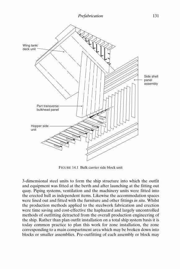
Prefabrication 131
3-dimensional steel units to form the ship structure into which the outfitand equipment was fitted at the berth and after launching at the fitting outquay. Piping systems, ventilation and the machinery units were fitted intothe erected hull as independent items. Likewise the accommodation spaceswere lined out and fitted with the furniture and other fittings in situ. Whilstthe production methods applied to the steelwork fabrication and erectionwere time saving and cost-effective the haphazard and largely uncontrolledmethods of outfitting detracted from the overall production engineering ofthe ship. Rather than plan outfit installation on a total ship system basis it istoday common practice to plan this work for zone installation, the zonecorresponding to a main compartment area which may be broken down intoblocks or smaller assemblies. Pre-outfitting of each assembly or block may
Wing tank/deck unit
Side shellpanelassembly
Hopper sideunit
Part transversebulkhead panel
FIGURE 14.1 Bulk carrier side block unit
Shcc14.fm Page 131 Monday, March 26, 2001 3:11 PM

Floor platelevel
Tank toplevel
FIGURE 14.2 Pipe module
Shcc14.fm Page 132 M
onday, March 26, 2001 3:11 PM

Prefabrication 133
be of the order of 85–90 per cent. Both steelwork and outfit are highlyplanned for each assembly and block unit, and fabrication and outfitinstallation is undertaken at a work station where the facilities and materialare supplied to the workforce.
Sub-assembliesWhen plates and sections have been machined they are ready for assemblyinto ship units. Within the fabrication shop there are often arranged a numberof bays for different assemblies, for example flat plate panels, curved shellunits, matrix or ‘egg box’ structures and some minor sub-assemblies. Allthese may be termed sub-assemblies if they are subsequently to be built intoa large unit prior to erection. Panel assembly is usually highly automatedwith prepared plates being placed and tack welded prior to automatic weld-ing of the butts, after which the plates are turned and back welded unless asingle sided weld process has been used. The panel is marked and the stiff-eners placed and welded automatically or with semi-automatic process. Minorsub-assemblies such as deep frames consisting of web and welded face flatmay also be attached at this stage. Curved shell plates are placed on jigs andwelded and the various stiffening members can be aligned and welded in asimilar manner to those on a flat panel assembly. Assembly jigs may also beused for matrix or ‘egg box’ assemblies, for example structures of solid andbracket plate floors with longitudinal side girders which are to go into doublebottom units.
Unit FabricationIn most instances the 2-dimensional sub-assemblies will be built into3-dimensional block assemblies. The size of the block assembly will havebeen decided at an early stage of the planning process ideally at the struc-tural design stage. Constraints such as lifting capacities and dimensions thatcan be handled are taken into consideration also the provision of breaks atnatural features ensuring the blocks are self supporting and easily accessed,etc. Panel assemblies used in the block may well have dimensions restrictedby the plate length that can be handled at the machining stage and this cansubsequently influence block length. In the machinery area the block sizeand arrangements can be decided by zone outfit considerations.
Each block should be designed for maximum downhand welding but mayhave to be turned for this purpose. Also blocks are turned to effect outfitinstallation particularly those containing machinery flats in the aft engine
Shcc14.fm Page 133 Monday, March 26, 2001 3:11 PM

FIGURE 14.3 Assembly unit outfitted both sides
Shcc14.fm Page 134 M
onday, March 26, 2001 3:11 PM

Prefabrication 135
room areas where pipework, etc., can be fitted on the underside of theflat with the block in the inverted position and then it is turned to installequipment above the flat (see Figure 14.3). A block’s centre of gravity iscalculated and lifting lugs so provided that these operations can be under-taken, and finally the block can be suspended for erection at the buildingdock or berth and drop into place in the correct plane.
Outfit Modules Units of machinery, pipework and other outfit systems required for a spe-cific zone can be planned and built up into modules and installed as suchinto a block fabrication. Pipework in particular lends itself to this form ofassembly and can, with careful planning from the CAD stage, be arrangedin groupings so that pipe bank modules can be arranged for a particularzone. Modules can range from a small pipe bank supported by light framingof pipe hangers, or a complete auxiliary machinery unit on its seating whichhas even been test run prior to installation, to a large modular unit whichtogether with several similar units constitutes the bulk of a complete engineroom. The latter have been developed in one European shipyard wheremacro-modules of the order of 10 m × 10 m × 4 m made up of square rolledhollow sections (which function as pillars when installed) and horizontalparts of the ship’s structure such as flats are completely outfitted. A numberof these macro-modules erected around the main engine are indistinguish-able from a conventional engine room. Sub-contractors are encouraged bythe shipyards to supply their equipment in module form.
Not all outfits can be incorporated into modules and a large number ofpiece parts have to be provided for fitting in any given zone at a particulartime within the assembly shops. To maintain production engineering stand-ards a concept of ‘palletization’ has been developed whereby the pieceparts for that zone are generated at the CAD/CAM stage, bought in and/orfabricated, etc., and made available at the work station when the particularassembly is ready to receive them.
An ‘open top’ arrangement for blocks or smaller ships being outfittedunder cover can facilitate installation of the items and modules.
Superstructure blocks are fabricated separately and pre-outfitted withaccommodation before erection as a complete unit. Modular cabin units area common feature of modern shipbuilding, some companies specializing intheir production. Figure 14.4 shows a typical self supporting cabin/toiletmodule complete with pipework, ventilation, electrical fittings, wiring, and allbuilt-in furniture. An accommodation block must be specifically designedfor such modules and the sequence of module access and placement in theblock carefully planned.
Shcc14.fm Page 135 Monday, March 26, 2001 3:11 PM

136 Ship Construction
Unit Erection When any panel and the block assemblies are complete there will be sometime buffer before their erection at the building berth or dock to allow formishaps in the production schedule. Stowage is generally adjacent to thebuilding hall and will vary in size according to the yard’s practice, someyards storing a large number of units before transferring them to the berthor dock for erection in order to cut the berth/dock time to a minimum.
Sequences of erection for any particular ship vary from shipyard to ship-yard and depend on a number of factors. Experience of previous ship erec-tion schedules and difficulties given the yard’s physical and equipmentconstraints leads to standard practices being established. These are takeninto consideration at the structural design stage as are the desirability ofminimizing positional welding and fairing. In general it is common practiceto make a start in the region of the machinery spaces aft, obviously workingfrom the bottom upwards, and also forward and aft. In earlier times thiswas done to give the engineers and other outfit workers early access tothese spaces, but with the amount of pre-outfit this might not be considered
FIGURE 14.4 Cabin/toilet module
Shcc14.fm Page 136 Monday, March 26, 2001 3:11 PM

Prefabrication 137
so important. However, this area does still require the larger amount offinishing work. In particular the boring of the stern for the tailshaft ispreferably undertaken when the after sections are fully faired and welded.
Typical erection sequences for a general cargo ship, oil tanker, and bulkcarrier are shown in Figures 14.5, 14.6 and 14.7 respectively. The blockassemblies for the bulk carrier are shown in Figure 14.8.
In erecting the ship units it is important to employ the correct weldingsequences. These are arranged to avoid excessive ‘locked in’ stresses; andoverlapping frames, longitudinals, stiffeners, etc., may be left unweldedacross unit seams and butts until these are completed in a similar manner tothat described in Chapter 10.
In erecting units tolerances are a problem, more so on 3-dimensionalunits than with 2-dimensional units and particularly at the shaped ends ofthe ship where ‘green’ material is often left. Quality control procedures inthe manufacturing shops to ensure correct dimensioning and alignment arevery necessary if time-consuming, expensive and arduous work at the berthis to be avoided. Improvements in this area have been made with the use of
9 911
7 78
5
3
10
61 2
6
4
TRANSVERSE BULKHEAD
1. Double bottom port 7. Tween deck sides2. Double bottom stbd. 8. Tween deck centre3. Transverse bulkhead 9. Main deck sides4 & 5. Side shell 10. Main deck centre6. Bilge plates 11. Main deck hatch
FIGURE 14.5 An erection sequence for a general cargo ship
Shcc14.fm Page 137 Monday, March 26, 2001 3:11 PM

138 Ship Construction
accurate jigs for curved shell units, planned weld sequences, and use of lowerheat input welding equipment, dimensional checks on piece parts, and theuse of laser alignment tools for setting up datums and checking interfaces.Tolerance allowance data is built up with experience and can become veryaccurate when building standard ships.
Joining Ship Sections Afloat Owing to the enormous increase in size of bulk carriers and tankers, ship-yards with restricted facilities, berth size particularly, have examined variousmeans of building these large ships in sections which are to be joined off theberth. In most cases the problem becomes one of joining the two hull sec-tions afloat or in a dry-dock of sufficient size where available. Where thesections are to be joined afloat extremely accurate fit up of the sections isaided by the possibilities of ballasting the two ship halves. The two sectionsmay then be pulled together by tackles; and for the finer adjustmentshydraulic cylinders may be used, extremely accurate optical instrumentsbeing employed to mark off the sections for alignment. One method adoptedis that where a cofferdam is arranged in way of the joint, a caisson is brought
10
6
8
412 1
5
13
113
7
9Transverse bulkheadin centre tank 2
6 & 7. Longitudinal bulkheadsand wing trans
8 & 9. Side shelI10 & 11. Deck wing tanks12 & 13. Bilge strakes
1. Bottom centre tank2. Bulkhead centre tank3. Deck centre tank4 & 5. Bottom plating wing tank
FIGURE 14.6 An erection sequence for a bulk oil tanker
Shcc14.fm Page 138 Monday, March 26, 2001 3:11 PM

Prefabrication 139
up against the ship’s hull, and the cofferdam and caisson are pumped dry.To balance any tendency for the vessel to hog during the pumping of thecofferdam it is necessary to shift ballast in the fore and aft sections. Oncethe spaces are dried out welding of the complete joint may be undertaken,the resulting weld being X-rayed to test the soundness of such a criticaljoint. On completion of the paint scheme in way of the joint the caisson isremoved.
A similar method makes use of a rubber ‘U’ form ring rather than a caissonwhich needs modification for each ship size.
If a dry-dock is available the sections may be aligned afloat and evenwelded above the waterline, the rest of the joint or the complete joint beingsecured by strongbacks. The welding of the rest or the whole joint is carriedout in the dock.
5
7
3 4
2
1
6
1. Double bottom unit2. Lower bulkhead unit3. Upper bulkhead panel
4 & 5. Side block incorporatingshell, tanks and part bulkhead
6. Deck between hatches7. Hatch coaming
FIGURE 14.7 An erection sequence for a dry cargo bulk carrier
Shcc14.fm Page 139 Monday, March 26, 2001 3:11 PM

R4 R3
R2 R1
A14 A11A13 A9
A6 A5
A8
A4
A3 A1 C1
K1 K2
P1
C2 C3
K3
P2
C4
K4
C5
K5 K6
C6 C7
K7
C8
P
K8 K9
C9H
K10
C10
P5 T4
T3
T2
T1
P3 P4
KE
DC
A11
A14
A8 K1 K2
Engcasing A12
A7
H1
A11A8 K1 K2
No. 5 hatch
H2
K3 K4 K5 K6
No. 4 hatch No. 3 hatch No. 2 hatch No. 1 hatch
H3
K3 K4 K5
H4
K6 K7 K8 K9 K10
K7 K8 K9 K10
H5 H6
T3
FIGURE 14.8 Typical block erection
Shcc14.fm Page 140 M
onday, March 26, 2001 3:11 PM

Prefabrication 141
Further Reading Belch, ‘Construction of Very Large Tankers in Two Parts’, The Naval
Architect, July, 1976.
Fredriksson, ‘Tolerances in the Prefabrication of Ships’, Trans. R.I.N.A.,1962.
Proceedings of the Seminar on Advances in Design for Production,University of Southampton, April, 1984.
‘Some Aspects of Building Mammoth Tankers in Two Halves’, MetalConstruction and British Welding Journal, vol. 1, No. 3, March, 1969.
‘Structural Design and Fabrication in Shipbuilding’, InternationalConference 18–20 November, 1975, London, The Welding Institute.
Shcc14.fm Page 141 Monday, March 26, 2001 3:11 PM

15Launching
Launching involves the transference of the weight of the ship from the keelblocks, shores, etc., on which it was supported during construction, to acradle on which it is allowed to slide into the water. Normally the vessel islaunched end on, stern first, but a number of shipyards located on rivers orother narrow channels are obliged to launch the vessel sideways. Vesselshave been launched bow first, but this is a rare occurrence as the buoyancyand weight moments, also the braking force, are generally more favourablewhen the vessel is launched stern first.
End Launches On release of a holding mechanism the launching cradle with the ship slidesdown the ground ways under the action of gravity. When the stern hasentered the water the vessel is partly supported by buoyancy and partly bythe ground ways. If this buoyancy is inadequate after the centre of gravity ofthe ship has passed the way ends, the ship may tip about the way ends causinglarge pressures on the bottom shell and on the ends of the ground ways. Toavoid this the greatest depth of water over the way ends should be utilized,and the ground ways extended into the water if necessary. Where this provesimpossible it becomes necessary to strengthen the way ends and provideshoring in the bottom shell region which is likely to be damaged. Theseremedies are often expensive.
As the vessel travels further into the water the buoyancy becomes suffi-cient to lift the stern. The vessel then pivots about the forward poppets, i.e.the fore end of the launching cradle. These are designed to take the loadthrown on them by the pivoting action, the load being widely distributed inorder not to squeeze out the lubricant between the sliding surfaces. Shoringmay also be found necessary forward in the ship to prevent structural damageat the time the stern lifts.
B U I L D I N G S L I P Conventional slipways or berths are relatively solid andreinforced with piles to allow them to sustain the weights of ships built uponthem. During building the keel blocks take the greater part of the weight, theremainder being carried by shores, and where used bilge blocks. Foundations
Shcc15.fm Page 142 Monday, March 26, 2001 3:11 PM

Launching 143
under the probable positions of ground ways should also be substantial sinceduring a launch the ways are subject to large pressures.
Keel blocks are arranged so that the height of keel above the ground is1.25 to 1.5m, giving reasonable access, but not too high so that a large amountof packing is required (see Figure 15.1). At the bow the height of the keelmust be sufficient to allow the ship’s forefoot to dip the required amountwithout striking the ground during pivoting when the stern lifts at launch.To suit the declivity of the launching ways determined beforehand, the keelis also inclined to the horizontal at about 1 in 20, or more where the ship-yard berths have a larger slope.
To transfer the ship from the building blocks to the launching cradle, thecommonest practice is to drive wedges into the launching cradle. This liftsthe ship and permits the removal of the keel and bilge blocks together with theshores. In large ships it becomes necessary to split the blocks to removethem, but several types of collapsible blocks have been used to overcomethis difficulty. One type is the sand box which contains sand to a depth of 80to 100 mm held in a steel frame located between two of the wooden blocks.This steel frame may be removed and the sand allowed to run out. Anothertype is a wooden block sawn diagonally, the two halves being bolted so thatthey collapse on removal of the bolts.
L A U N C H I N G W A Y S A N D C R A D L E The fixed ground ways or standingways on which the cradle and ship slide may be straight or have a fore andaft camber. Transversely the ground ways are normally laid straight but canbe canted inwards to suit the ship’s rise of floor. Usually the ground wayshave a small uniform fore and aft camber say 1 in 400, the ways being thearc of a circle of large radius. This means that the lower part of the ways hasa greater declivity (say 1 in 16) than the upper part of the ways (say 1 in 25).As a result a greater buoyancy for the same travel of the ship beyond theway ends is obtained, which will reduce the way end pressures. Additionaladvantages are increased water resistance slowing the vessel, and a bowheight which is not excessive. The slope of ground ways must be adequateto allow the vessel to start sliding; and if too steep, a large amount ofshoring will be required to support the bow; also the loads on the releasingarrangements will be high. Straight sliding ways have declivities of the orderof 1 in 25 to 1 in 16.
Generally two ground ways are fitted, the distance between the waysbeing about one-third the beam of the ship. It is often desirable that thecradle should be fitted in way of longitudinal structural members, and theground ways over slipway piling, these considerations deciding the exactspacing. Some large ships have been launched on as many as four ways, andin the Netherlands it appears to be common practice to launch vessels on asingle centre line ground way. The width of the ways should be such that the
Shcc15.fm Page 143 Monday, March 26, 2001 3:11 PM

REINFORCED BERTH
Bilgeblocks
ShoreSpace
for launchingways
Keelblocks Shore
Concrete
Spacefor launching
ways
Bilgeblocks
FIGURE 15.1 Building blocks
Shcc15.fm Page 144 M
onday, March 26, 2001 3:11 PM

Launching 145
launching weight of the ship does not produce pressures exceeding about 20tonnes per square metre.
Ground ways are laid on supporting blocks and extend down to the lowwater mark so that they are covered by at least one metre of water at hightide. To guide the sliding ways as they move over the ground ways a ribbandmay be fitted to the outer edge of the ground ways. This could be fitted tothe inner edge of the sliding ways, but when fitted to the ground ways hasthe advantage that it aids retention of the lubricating grease. Finally theground ways are shored transversely to prevent sideways movement andlongitudinally to prevent them from moving down with the ship.
The sliding ways covering about 80 per cent of the length of the vesselform the lower part of the cradle, the upper part consisting of packing,wedges, and baulks of timber with some packing fitted neatly to the line ofthe hull in way of the framing. In very fine lined vessels the forward end ofthe cradle referred to as the forward poppet will require to be relativelyhigh, and may be built up of vertical timber props tied together by stringersor ribbands. This forward poppet will experience a maximum load whichmay be as much as 20 to 25 per cent of the ship’s weight when the sternlifts. It is therefore designed to carry a load of this magnitude; but there isa danger in the fine lined vessel of the forward poppets being forced out-wards by the downward force, i.e. the bow might break through the poppets.To prevent this, cross ties or spreaders may be passed below the forefoot ofthe vessel and brackets may be temporarily fastened to the shell plating atthe heads of the poppets. In addition saddle plates taken under the forefootof the ship with packing between them and the shell may be fitted to trans-mit the load to the fore poppets and hence ground ways.
In many modern ships the bow sections are relatively full and littlesupport is required above the fore end of the sliding ways. Here short platebrackets may be temporarily welded between the shell plating and heavyplate wedge rider as illustrated in Figure 15.2. The design of the forwardpoppets is based on greater pressures than the lubricant between the slidingways and ground ways could withstand if applied for any length of time.However as the duration of pivoting is small, and the vessel has sufficientmomentum to prevent sticking at this stage, these high pressures arepermissible.
At the after end of the cradle considerable packing may also be required,and again vertical timber props or plate brackets may be fitted to form theafter poppet.
L U B R I C A N T For the ship to start sliding on release of the holdingarrangements it is necessary for the ship to overcome the coefficient offriction of the launching lubricant. To do this the slope of the ways underthe vessel’s centre of gravity must exceed the lubricant’s coefficient offriction. An estimate of the frictional resistance of the grease must be
Shcc15.fm Page 145 Monday, March 26, 2001 3:11 PM

FORE POPPET FORSHIP WITH FULLFORWARD SECTIONS
Platebracket
Plate ribband
Ramming upwedges
Make up
Ground way
Sliding way
BRACKET IN WAYOF FRAMING
Plate ribband
Packing
Sliding way
Ground way Make up
Ground way
Sliding way
Ribband
Wedge
Ribband
Ribband
Wood truss
Bracket
FORE POPPET FORSHIP WITH FINE LINESFORWARD
FIGURE 15.2 Launching ways—fore poppet
Shcc15.fm Page 146 M
onday, March 26, 2001 3:11 PM

Launching 147
made before building the ship since the declivity of the keel is dependentto a large extent on the slope of the ways.
Formerly melted tallow was applied to the ways, allowed to harden,then covered with a coat of soft soap. Present practice is to apply mineralbased greases to the ground ways, these greases being virtually unaffectedby temperature changes and insoluble in water whilst adhering firmly tothe ways. A commercially marketed petroleum-based launching grease isapplied over the mineral grease base coat. This has a coefficient of frictionwhich is low enough to allow initial starting and the maintenance of slidinguntil the initial resistance of the base coat is overcome by frictional heat. Toprevent the petroleum-based grease from soaking into the sliding ways abase coat may be applied to them. Standing ways which extend into thewater may be dried out at low tide prior to the launch and the base coat andgrease applied.
R E L E A S I N G A R R A N G E M E N T S Small ships may be released by knock-ing away a diagonal dog-shore (see Figure 15.3) fitted between the slidingand standing ways.
In most cases however triggers are used to release the ship. There areseveral types available, hydraulic, mechanical, and electrical-mechanical trig-gers having been used. Electrical-mechanical triggers are commonly used forrapid simultaneous release in modern practice; the hydraulic trigger is lesseasily installed and less safe. The electrical-mechanical trigger illustrated inFigure 15.3 is generally located near amidships and a small pit is providedin the berth to accommodate the falling levers. A number of triggers will befitted depending on the size of the vessel to be launched; in the case of the75 000-tonne bulk carrier for which a launching sequence is given below sixtriggers were fitted for the launch.
These triggers are in effect a simple system of levers which allow the largeloads acting down the ways to be balanced by a small load on the releasinggear. The principle is often compared with that of a simple mechanicalreduction gearing. Simultaneous release of the triggers is achieved by meansof catches held by solenoids wired in a common circuit. These are releasedimmediately the circuit current is reversed.
L A U N C H I N G S E Q U E N C E As a guide to the procedure leading up to thelaunch, the following example is given for the launch of a 75 000-tonne bulkcarrier. The launch ways have been built up as the ship is erected from aft;the ways have been greased and the cradle erected.
1. Four days before launch a start is made on ramming up the launchblocks, i.e. driving in the wedges (Figure 15.2) to raise ship off the build-ing blocks. This is done by a dozen or so men using a long rammingpole, a gang working either side of the ship.
Shcc15.fm Page 147 Monday, March 26, 2001 3:11 PM

BeamDog shore
Dog shore
PLAN
On sliding wayOn standing way
Groundshore
Steel shod
Beam
Sliding way
ELEVATION
Steel shod
MECHANICAL LAUNCH TRIGGER (ELEVATION)
Sliding way
Ground way
2nd lever
Solenoid release unit
Slip shackle
1stlever
3rd lever
Load
Anvil
FIGURE 15.3 Release arrangements for ship launch
Shcc15.fm Page 148 M
onday, March 26, 2001 3:11 PM

Launching 149
2. Two days before the launch a start is made on removing the shores. 3. On the morning of the launch everything is removed up to the high water
mark and tumbler shores are put in aft. These are inclined shores whichfall away as the ship starts to move.
4. Every second keel block is then removed, and the vessel is allowed tosettle.
5. An evently distributed number of keel blocks are then taken out sothat only about twenty keel blocks are left supporting the ship.
6. Half an hour before the launch the last remaining keel blocks areremoved.
7. The bilge blocks are then removed. 8. The full ship’s weight comes on the triggers at the time planned for the
launch. 9. Release of triggers on launch by sponsor.
If the vessel fails to start under the action of gravity, the initial movementmay be aided by hydraulic starting rams which are provided at the head ofthe cradle.
A R R E S T I N G A R R A N G E M E N T S In many cases the extent of the waterinto which the ship is launched is restricted. It is then necessary to providemeans of arresting the motion of the ship once it is in the water. There are anumber of methods available for doing this, one or more being employed atmost ship launches.
The commonest arrangement is to use chain drags which are generallyarranged symmetrically on either side of the ship. Each chain drag is laid inthe form of a horseshoe with its rounded portion away from the water, sothat as the ship moves down the ways the forward portion of the drag ispulled through the remainder of the pile. This prevents any excessive shockload in the chain which would occur if the pile of chain were to be suddenlyaccelerated to the speed of the ship. The wire rope drag lines are attachedto temporary pads on the side of the ship, and supported by rope tricinglines as they are led slightly forward and then aft along the ship’s sides.Each drag line is then led forward and shackled to the chain drag (seeFigure 15.4). As the ship is released and moves aft the tricing lines arebroken in turn, the work done absorbing some of the ship’s energy.
To further increase the resistance to motion of the ship wooden masksmay be fitted at the stern of the ship. The mask is made as large as possiblebut located low down to present a flat surface to the water in the directionof the motion. Masks are often constructed of horizontal pieces of woodwith spaces left between each piece to increase the resistance.
One or two shipyards are forced to provide arrangements for slewing thevessel once it has left the ways, as the river into which the ships are launchedis very narrow in relation to the ship’s length. Chain drags, weights, or
Shcc15.fm Page 149 Monday, March 26, 2001 3:11 PM

Welded padsTricing lines
Wire linesCradle
ELEVATION
MASKS SECTION AFTLOOKING FORD
Mask ofwooden slats
Way end
PLAN
Chain drags
SLEWING ARRANGEMENTS
Wire
FIGURE 15.4 Arresting arrangements at launch
Shcc15.fm Page 150 M
onday, March 26, 2001 3:11 PM

Launching 151
anchors may be placed in the water to one side of the building berth forthis purpose. These are then made fast to the stern of the ship with draglines of a predetermined length. Once the vessel is clear of the ways theslack of the lines is taken up and the stern swings so that the ship is pointingup river.
Side Launches Side launching is often used where the width of water available is consider-ably restricted. There are in fact some advantages to this method, for examplethe absence of keel declivity, and the relatively simple cradle and shortground ways which do not extend into the water. However it means that alarge area of waterfront is taken up by a single building berth, and the shipis only reasonably accessible from one side during construction.
The ground ways are arranged transversely, i.e. at right angles to the lineof keel. Sliding ways also can be placed transversely with the packing abovethem forming the cradle, but they are generally arranged longitudinally. Inthis case where they are parallel to the keel the sliding ways are in groupscovering two or three ground ways. Packing again forms the cradle with tiepieces between the groups of sliding ways.
One of the features of side launching is the drop where the ground waysare not extended into the water; consequently large angles of heel occurwhen the vessel strikes the water. As a result it is necessary to carry outcareful stability calculations and close any openings before side launchinga vessel. It is true of course that stability calculations are also required fora conventional end launch.
Building Docks Perhaps the greatest advantage of the building dock is the relative simpli-city of the task of getting the vessel waterborne (see Chapter 11). When itis convenient the dock may be flooded and the vessel floated out. Cal-culations are needed to check the stability and loads exerted by the blocksduring flooding, the whole problem being similar to that of un-docking avessel which has been dry-docked for survey or other reasons.
In some shipyards conventional berths are fitted at their river end withwhat is virtually a pair of dock gates. This can be of advantage when work-ing the aft end of the ship and installing the ways. In many instances italso permits higher tides over the way ends when the gates are opened fora launch.
Shcc15.fm Page 151 Monday, March 26, 2001 3:11 PM

152 Ship Construction
Ship Lifts Whilst large ships may be extruded out of building halls on to a slipway(Chapter 11) and large sections transferred by similar means to the head ofthe slipway and raised on to it for joining and launching, smaller completeships may be transferred to a ship lift for launching. Rail systems are incorp-orated into the building hall and lead out to the open ship lift. The bestknown of these ship lift systems is the patented ‘Syncrolift’ originally usedfor slipping ships for repairs and surveys but now also used by many ship-yards for launching new ships. Ship lifts basically consist of platforms whichcan be lowered into the water and the ship landed on or floated off the plat-form. The platform is raised and lowered mechanically or hydraulically andis usually provided with transfer arrangements so that the vessel can bemoved on or off the platform either laterally or in line with the platform.
Further Reading Doust, ‘Side Launching of Ships with Special Reference to Trawlers’, Trans.
I.N.A., 1955.
Rowell, ‘Launching Triggers’, Trans. N.E.C. Inst., vol. 61, 1945.
Smith and Vardon, ‘Way end pressure loading and ship response duringlaunching’, The Naval Architect, September, 1977.
Taylor and Williams, ‘Dynamic Loading on Launching Ways and BuildingBerths’, Trans. I.E.S.S., 1966–67.
‘The Vertical Shiplift’s Role in Modern Shipyards’, The Naval Architect,February, 1995.
Shcc15.fm Page 152 Monday, March 26, 2001 3:11 PM

Part 5
Ship Structure
Note Throughout this part of the book a number of requirements relating to thespacing and scantlings of various structural members are given. These aretaken from Lloyd’s Register Rules and are introduced to give the studentan idea of the variation in dimensions and scantlings found within the shipstructure. Other classification society requirements may differ, but basicallythe overall structure would have the same characteristics. It should be borne inmind that owner’s additional requirements can result in ships having greaterscantlings and additional strengthening to the minimum indicated in thefollowing chapters.
Shcc16.fm Page 153 Monday, March 26, 2001 3:12 PM

Shcc16.fm Page 154 Monday, March 26, 2001 3:12 PM

16Bottom Structure
Originally ships were constructed with single bottoms, liquid fuels and freshwater being contained within separately constructed tanks. The doublebottom structure which provides increased safety in the event of bottomshell damage, and also provides liquid tank space low down in the ship,only evolved during the early part of the twentieth century. Smaller vesselssuch as tugs, ferries, and cargo ships of less than 500 gross tonnage have asingle bottom construction. Larger ocean-going vessels, other than oldertankers, are fitted with some form of double bottom.
KeelsAt the centre line of the bottom structure is located the keel, which is oftensaid to form the backbone of the ship. This contributes substantially to thelongitudinal strength and effectively distributes local loading caused whendocking the ship. The commonest form of keel is that known as the ‘flatplate’ keel, and this is fitted in the majority of ocean-going and other vessels(see Figure 16.1(a)). A form of keel found on smaller vessels is the bar keel(Figure 16.1(b)). The bar keel may be fitted in trawlers, tugs, etc., and isalso found in smaller ferries.
Where grounding is possible this type of keel is suitable with its massivescantlings, but there is always a problem of the increased draft with no addi-tional cargo capacity. If a double bottom is fitted the keel is almost inevit-ably of the flat plate type, bar keels often being associated with open floors,where the plate keel may also be fitted.
Duct keels (Figure 16.1(c)) are provided in the double bottoms of somevessels. These run from the forward engine room bulkhead to the collisionbulkhead and are utilized to carry the double bottom piping. The pipingis then accessible when cargo is loaded, an entrance to the duct beingprovided at the forward end of the engine room. No duct is required aft ofthe engine room as the piping may be carried in the shaft tunnel. A width ofnot more than 2.0 m is allowed for the duct, and strengthening is providedat the tank top and keel plate to maintain continuity of strength of thetransverse floors.
Shcc16.fm Page 155 Monday, March 26, 2001 3:12 PM

Ships
Middle strake of tank top
(a) FLAT PLATE KEEL
Flat keelplate
Continuouscentre girder
(b) BAR KEEL
Garboard strakeof bottom shell
Bar keel
Drain hole
Solid floor
Flange
Ships
(c) DUCT KEEL
Solidfloor
Ships
Stiffener
Side girder Piping
Stiffener
Solidfloor
FIGURE 16.1 Keels
Shcc16.fm Page 156 M
onday, March 26, 2001 3:12 PM

Bottom Structure 157
Single Bottom Structure In smaller ships having single bottoms the vertical plate open floors arefitted at every frame space and are stiffened at their upper edge. A centreline girder is fitted and one side girder is fitted each side of the centre linewhere the beam is less than 10 m. Where the beam is between 10 and 17 mtwo side girders are fitted and if any bottom shell panel has a width tolength ratio greater than four additional continuous or intercostal stiffenersare fitted. The continuous centre and intercostal side girders are stiffenedat their upper edge and extend as far forward and aft as possible.
The single bottom structure is shown in Figure 16.2 and for clarity a3-dimensional representation of the structure is also provided to illustratethose members which are continuous or intercostal. Both single and doublebottoms have continuous and intercostal material and there is often someconfusion in the student’s mind as to what is implied by these terms.
A wood ceiling may be fitted across the top of the floors if cargoes areto be carried but this does not constitute an inner bottom offering anyprotection if the outer bottom shell is damaged.
Double Bottom StructureAn inner bottom (or tank top) may be provided at a minimum height abovethe bottom shell, and maintained watertight to the bilges. This provides aconsiderable margin of safety, since in the event of bottom shell damageonly the double bottom space may be flooded. The space is not wastedbut utilized to carry oil fuel and fresh water required for the ship, as well asproviding ballast capacity.
The minimum depth of the double bottom in a ship will depend on theclassification society’s requirement for the depth of centre girder. It maybe deeper to give the required capacities of oil fuel, fresh water, and waterballast to be carried in the bottom. Water ballast bottom tanks are com-monly provided right forward and aft for trimming purposes and if neces-sary the depth of the double bottom may be increased in these regions. Inway of the machinery spaces the double bottom depth is also increased toprovide appreciable capacities of lubricating oil and fuel oil. The increase inheight of the inner bottom is always by a gradual taper in the longitudinaldirection, no sudden discontinuities in the structure being tolerated.
Double bottoms may be framed longitudinally or transversely (see Figure16.3), but where the ship’s length exceeds 120 m it is considered desirable toadopt longitudinal framing. The explanation of this is that on longer shipstests and experience have shown that there is a tendency for the inner bottomand bottom shell to buckle if welded transverse framing is adopted. This
Shcc16.fm Page 157 Monday, March 26, 2001 3:12 PM

ELEVATION
Intercostal side girder
Flange
Floor
Flange Intercostal side girder
LOOKING FOR’D
Solid floor
Centregirder
Barkeel
Ships
Manhole
OPEN FLOORS
Flange
Fore and aftintercostalside keelsons
Centregirder
Transverseplate floors
Garboard strakeBar keel
FIGURE 16.2 Single bottom construction
Shcc16.fm Page 158 M
onday, March 26, 2001 3:12 PM

Bottom Structure 159
buckling occurs as a result of the longitudinal bending of the hull, and maybe avoided by having the plating longitudinally stiffened.
Double bottoms in the way of machinery spaces which are adjacent to theafter peak are required to be transversely framed.
I N N E R B O T T O M P L A T I N G The inner bottom plating may in a generalcargo ship be sloped at the side to form a bilge for drainage purposes. It is
(a) TRANSVERSELY FRAMEDDOUBLE BOTTOM
Margin plate
Bracket floors
Solid floor
Tank top
Intercostalside girder
Continuouscentre girder
Flat plate keel
(b) LONGITUDINALLY FRAMEDDOUBLE BOTTOM
Bracketfloors
Solid floor
Continuouscentre girder
Flat plate keel
Bottomlongitudinals
Intercostalside girder
Inner bottomlongitudinals
Tank topSolid floor
FIGURE 16.3 Double bottom construction
Shcc16.fm Page 159 Monday, March 26, 2001 3:12 PM

160 Ship Construction
not uncommon however for it to be extended to the ship’s side, and indi-vidual bilge wells are then provided for drainage purposes (see Chapter 26).In vessels requiring a passenger certificate it is a statutory requirementfor the tank top to extend to the ship’s side. This provides a greater degree ofsafety since there is a substantial area of bilge which may be damaged with-out flooding spaces above the inner bottom.
At the centre line of the ship the middle strake of the inner bottom maybe considered as the upper flange of the centre line docking girder, formedby the centre girder and keel plate. It may therefore be heavier than theother strakes of inner bottom plating. Normally a wood ceiling is providedunder a hatchway in a general cargo ship, but the inner bottom platingthickness can be increased and the ceiling omitted. If grabs are used for dis-charging from general cargo ships the plate thickness is further increased,or a double ceiling is fitted.
F L O O R S Vertical transverse plate floors are provided both where thebottom is transversely and longitudinally framed. At the ends of bottomtank spaces and under the main bulkheads, watertight or oiltight platefloors are provided. These are made watertight or oiltight by closing anyholes in the plate floor and welding collars around any members which passthrough the floors. Elsewhere ‘solid plate floors’ are fitted to strengthen thebottom transversely and support the inner bottom. These run transverselyfrom the continuous centre girder to the bilge, and manholes provided foraccess through the tanks and lightening holes are cut in each solid platefloor. Also, small air and drain holes may be drilled at the top and bottomrespectively of the solid plate floors in the tank spaces. The spacing of thesolid plate floors varies according to the loads supported and local stressesexperienced. At intermediate frame spaces between the solid plate floors,‘bracket floors’ are fitted. The bracket floor consists simply of short trans-verse plate brackets fitted in way of the centre girder and tank sides (seeFigures 16.4 and 16.5).
T R A N S V E R S E L Y F R A M E D D O U B L E B O T T O M If the double bottomis transversely framed, then transverse solid plate floors, and bracket floorswith transverse frames, provide the principal support for the inner bottomand bottom shell plating (Figure 16.4). Solid plate floors are fitted at everyframe space in the engine room and in the pounding region (see the end ofthis chapter). Also they are introduced in way of boiler seats, transversebulkheads, toes of brackets supporting stiffeners on deep tank bulkheads,and in way of any change in depth of the double bottom. Where a ship isregularly discharged by grabs, solid plate floors are also fitted at eachframe. Elsewhere the solid plate floors may be spaced up to 3.0 m apart,with bracket floors at frame spaces between the solid floors. The platebrackets of bracket floors are flanged and their breadth is at least 75 per cent
Shcc16.fm Page 160 Monday, March 26, 2001 3:12 PM

SOLID FLOORShip’s
Continuouscentre girder
Margin plate
Lighteninghole
Tank top
Flat barstiffener
Drain holes
ManholeIntercostalside girder Air holes
Margin plate
Bracket
BRACKET FLOOR
Bracket
Continuouscentre girderIntercostal
side girder
Bottom frame
Flatstiffenner
Inner bottom frame
AnglestrutFrame
Tank top (inner bottom)
FIGURE 16.4 Transversely framed double bottom construction
Shcc16.fm Page 161 M
onday, March 26, 2001 3:12 PM

Margin plate
Lighteninghole
Tank top Continuous centre girder Ship’sInner bottom longitudinals
Air holes
Drain holes
Intercostalside girder Manhole
Bottom longitudinals SOLID FLOOR
Margin plate
Bracket
Flange Flange
Bracket
BRACKET FLOOR
Flat barstiffener
Intercostalside girder
Angle strut
Tank top (inner bottom)
Bottom longitudinals
Inner bottom longitudinals
FIGURE 16.5 Longitudinally framed double bottom construction
Shcc16.fm Page 162 M
onday, March 26, 2001 3:12 PM

Bottom Structure 163
of the depth of the centre girder at the bracket floors. To reduce the spanof the frames, which should not exceed 2.5 meters, at the bracket floor,vertical angle or channel bar struts may be fitted. Vertical stiffeners usuallyin the form of welded flats will be attached to the solid plate floors, whichare further strengthened if they form a watertight or oiltight tank boundary.
One intercostal side girder is provided port and starboard where theship’s breadth exceeds 10 m but does not exceed 20 m and two are fittedport and starboard where the ship’s breadth is greater. In way of the bracketfloors a vertical welded flat stiffener is attached to the side girder. Additionalside girders are provided in the engine room, and also in the poundingregion.
L O N G I T U D I N A L L Y F R A M E D D O U B L E B O T T O M In a longitudinallyframed double bottom, solid plate floors are fitted at every frame spaceunder the main engines, and at alternate frames outboard of the engineseating. They are also fitted under boiler seats, transverse bulkheads, and thetoes of stiffener brackets on deep tank bulkheads. Elsewhere the spacing ofsolid plate floors does not exceed 3.8 m, except in the pounding region wherethey are on alternate frame spaces. At intermediate frame spaces bracketsare fitted at the tank side, and at the centre girder where they may be upto 1.25 m apart. Each bracket is flanged and will extend to the first longitud-inal (Figure 16.5).
One intercostal side girder is fitted port and starboard if the ship’sbreadth exceeds 14 m, and where the breadth exceeds 21 m two are fittedport and starboard. These side girders always extend as far forward and aftas possible. Additional side girders are provided in the engine room, andunder the main machinery, and they should run the full length of the engineroom, extending three frame spaces beyond this space. Forward the exten-sion tapers into the longitudinal framing system. In the pounding regionthere will also be additional intercostal side girders.
As the unsupported span of the bottom longitudinals should not exceed2.5 m, vertical angle or channel bar struts may be provided to support thelongitudinals between widely spaced solid floors.
ADDITIONAL STIFFENING IN THE POUNDING REGION If the mini-mum designed draft forward in any ballast or part loaded condition is lessthan 4.5 per cent of the ship’s length then the bottom structure for 30 percent of the ship’s length forward in sea-going ships exceeding 65 m in lengthis to be additionally strengthened for pounding.
Where the double bottom is transversely framed, solid plate floors arefitted at every frame space in the pounding region. Intercostal side girdersare fitted at a maximum spacing of 3 times the transverse floor spacing, and
Shcc16.fm Page 163 Monday, March 26, 2001 3:12 PM

164 Ship Construction
half height intercostal side girders are provided midway between the fullheight side girders.
If the double bottom is longitudinally framed in the pounding region,where the minimum designed draft forward may be less than 4 per cent ofthe ship’s length, solid plate floors are fitted at alternate frame spaces, andintercostal side girders fitted at a maximum spacing of 3 times the trans-verse floor spacing. Where the minimum designed draft forward may bemore than 4 per cent but less than 4.5 per cent of the ship’s length, solid platefloors may be fitted at every third frame space and intercostal side girdersmay have a maximum spacing of 4 times the transverse floor spacing. Aslongitudinals are stiffening the bottom shell longitudinally, it should benoted that less side girders need be provided than where the bottom istransversely framed to resist distortion of the bottom with the slammingforces experienced.
Where the ballast draft forward is less than 1 per cent of the ship’s lengththe additional strengthening of the pounding region is given special consid-eration.
Greater slamming forces (i.e. pounding) are experienced when the shipis in the lighter ballast condition, and is long and slender, by reason of theincreased submersion of the bow in heavy weather with impact also on thebow flare.
B O T T O M S T R U C T U R E O F B U L K C A R R I E R S Where a ship is classedfor the carriage of heavy, or ore, cargoes longitudinal framing is adoptedfor the double bottom. A closer spacing of solid plate floors is required, themaximum spacing being 2.5 m, and also additional intercostal side girdersare provided, the spacing not exceeding 3.7 m (see Figure 16.6).
The double bottom will be somewhat deeper than in a conventionalcargo ship, a considerable ballast capacity being required; and often a pipetunnel is provided through this space. Inner bottom plating, floors, andgirders all have substantial scantlings as a result of the heavier cargoweights to be supported.
T E S T I N G D O U B L E B O T T O M C O M P A R T M E N T S Each compartmentis tested on completion with a head of water representing the maximumpressure head which may be experienced in service, i.e. to the top of the airpipe. Alternatively air testing is carried out before any protective coatingsare applied. The air pressure may be raised to 0.21 kg/cm2, and then loweredto a test pressure of 0.14 kg/cm2. Any suspect joints are then subjected toa soapy liquid solution test. Water head structural tests will be carried outon tanks selected by the surveyor in conjunction with the air tests carriedout on the majority of tanks.
Shcc16.fm Page 164 Monday, March 26, 2001 3:12 PM

Hopper sidelongitudinals
Sidegirder Bottom
longitudinals
Sidegirder Flat stiffener
Inner bottomlongitudinals
Sidegirder
Tank top (inner bottom)
Sidegirder
Continuouscentre girder
Pipetunnel
ALTERNATE FRAME SPACE
Hopper side
Flat facing bar
Transverse web
Side girder
Stiffening webShip’s
Pipetunnel
Tank top
Flat stiffener Inner bottomlongitudinals
Bottomlongitudinals
Side girder Lighteninghole
Manhole
Side girder SOLID FLOOR
FIGURE 16.6 Bulk carrier double bottom construction
Shcc16.fm Page 165 M
onday, March 26, 2001 3:12 PM

Holding down bolt
Cast iron chock
Heavy plate seat
DETAIL OFHOLDING DOWNBOLTS
Welded pad
Heavy plate seat Webframe
Solid floor
Intercostalside girder
Flangedbracket
Flat bar stiffener
Continuouscentre girder
Holding down bolts
Intercostalside girder
Webframe
Continuousgirders
Ship’s Continuousgirders
Continuoushorizontal
plates
FIGURE 16.7 Engine seats
Shcc16.fm Page 166 M
onday, March 26, 2001 3:12 PM

Bottom Structure 167
Machinery Seats It has already been indicated that in the machinery spaces additionaltransverse floors and longitudinal intercostal side girders are provided tosupport the machinery effectively and to ensure rigidity of the structure.
The main engine seatings are in general integral with this double bottomstructure, and the inner bottom in way of the engine foundation has a sub-stantially increased thickness. Often the machinery is built up on seatingsforming longitudinal bearers which are supported transversely by trippingbrackets in line with the double bottom floors, the longitudinal bearersbeing in line with the double bottom side girders (see Figure 16.7).
Boiler bearers are similarly fabricated with support from transversebrackets and longitudinal members.
Shcc16.fm Page 167 Monday, March 26, 2001 3:12 PM

17Shell Plating and Framing
The shell plating forms the watertight skin of the ship and at the same time,in merchant ship construction, contributes to the longitudinal strength andresists vertical shear forces. Internal strengthening of the shell plating maybe both transverse and longitudinal and is designed to prevent collapse ofthe plating under the various loads to which it is subject.
Shell Plating The bottom and side shell plating consists of a series of flat and curved steelplates generally of greater length than breadth butt welded together. Thevertical welded joints are referred to as ‘butts’ and the horizontal weldedjoints as ‘seams’ (see Figure 17.1). Stiffening members both longitudinaland transverse are generally welded to the shell by intermittent fillet weldswith a length of continuous weld at the ends of the stiffening member. Con-tinuous welding of stiffening members to the shell is found in the after peak,the bottom shell within the forward 30 per cent of the length and wherehigher tensile steel is used. Framing is notched in way of welded plate buttsand seams.
B O T T O M S H E L L P L A T I N G Throughout the length of the ship the widthand thickness of the keel plate remain constant where a flat plate keel isfitted. Its thickness is never less than that of the adjoining bottom plating.
Strakes of bottom plating to the bilges have their greatest thickness over40 per cent of the ship’s length amidships, where the bending stresses arehighest. The bottom plating then tapers to a lesser thickness at the ends ofthe ship, apart from increased thickness requirements in way of the pound-ing region (see Chapter 16).
S I D E S H E L L P L A T I N G As with the bottom shell plating the greaterthickness of the side shell plating is maintained within 40 per cent of thevessel’s midship length and then tapers to the rule thickness at the ends.The thickness may be increased in regions where high vertical shear stressesoccur, usually in way of transverse bulkheads in a vessel permitted to carryheavy cargoes with some holds empty. There is also a thickness increase at
Shcc17.fm Page 168 Monday, March 26, 2001 3:13 PM

Shell Plating and Framing 169
the stern frame connection, at any shaft brackets, and in way of the hawsepipes where considerable chafing occurs. Further shell plate thicknessincreases may be found at the panting region, as discussed later in thischapter.
The upper strake of plating adjacent to the strength deck is referred to asthe ‘sheerstrake’. As the sheerstrake is at a large distance from the neutralaxis it has a greater thickness than the other strakes of side shell plating.Also, being in a highly stressed region it is necessary to avoid welded attach-ments to the sheerstrake, or cutouts which would introduce stress raisers.The upper edge is dressed smooth, and the welding of bulwarks to the edgeof the sheerstrake is not permitted within the amidships length of the ship.Scupper openings above the deck over the same length, and at the ends ofthe superstructure, are also prohibited in larger vessels. The connectionbetween the sheerstrake and strength deck can present a problem, and arounded gunwale may be adopted to solve this problem where the plating isheavy. This is often the case over the midship portion of large tankers andbulk carriers. Butt welds are then employed to make connections ratherthan the less satisfactory fillet weld at the perpendicular connection of thevertical sheerstrake and horizontal strength deck stringer plate. The radiusof a rounded gunwale must be adequate (not less than 15 times the thick-ness) and any welded guardrails and fairleads are kept off the radiusedplate if possible.
A smooth transition from rounded gunwale to angled sheerstrake/deckstringer connection is necessary at the ends of the ship.
All openings in the side shell have rounded corners, and openings for seainlets, etc., are kept clear of the bilge radius if possible. Where this is notpossible openings on or in the vicinity of the bilge are made elliptical.
25mmRad notchcut in framein way of seam
Welded seamOne framespace
Frame
Welded butt Welded butt
FIGURE 17.1 Shell plating
Shcc17.fm Page 169 Monday, March 26, 2001 3:13 PM

170 Ship Construction
G R A D E S O F S T E E L F O R S H E L L P L A T E S In large ships it is necessaryto arrange strakes of steel with greater notch ductility at the more highlystressed regions. Details of Lloyd’s requirements for mild steel and over40 per cent of the length amidships are given in Table 17.1 as a guide. TheRules also require thicker plating for the members referred to in Table 17.1outside the amidships region to have greater notch ductility.
FramingThe bottom shell may be transversely or longitudinally framed, longitudinalframing being preferred particularly for vessels exceeding 120 m in length.The side shell framing may also be transversely or longitudinally framed,transverse framing being adopted in many conventional cargo ships, par-ticularly where the maximum bale capacity is required. Bale capacities areoften considerably reduced where deep transverses are fitted to supportlongitudinal framing. Longitudinal framing may be adopted in larger con-tainer ships and larger bulk carriers, and it is common within the hopper andtopside wing tanks of the latter vessels. Transverse frames are then fitted atthe side shell between the hopper and topside tanks.
TABLE 17.1
Requirement Structural member
1. Grade D where thickness less than 15 mm otherwise Grade E.
Sheerstrake or rounded gunwale over40 per cent of length amidships in ships exceeding 250 m in length.
2. Grade A where thickness less than 15 mm. Grade B where thickness 15 to 20 mm. Grade D where thickness 20 to 25 mm. Grade E where thickness greater than 25 mm.
Sheerstrake and rounded gunwale over 40 per cent of length amidships in ships of 250 m or less in length. Bilge strake (other than for vessels of less than 150 m with double bottom over full breadth).
3. Grade A where thickness less than 20 mm. Grade B where thickness 20 to 25 mm. Grade D where thickness 25 to 40 mm. Grade E where thickness over 40 mm.
Bottom plating including keel. Bilge strake (ships of less than 150 m and with double bottom over full breadth).
4. Grade A where thickness less than 30 mm. Grade B where thickness 30 to 40 mm. Grade D where thickness greater than 40 mm.
Side plating.
Shcc17.fm Page 170 Monday, March 26, 2001 3:13 PM

Shell Plating and Framing 171
T R A N S V E R S E F R A M I N G In a general cargo ship the transverse framingwill consist of main and hold frames with brackets top and bottom, andlighter tween deck frames with brackets at the tops only (see Figure 17.2).
Scantlings of the main transverse frames are primarily dependent on theirposition, spacing and depth, and to some extent on the rigidity of the endconnections. In way of tanks such as oil bunkers or cargo deep tanks the sideframe size will be increased, except where supporting side stringers are fitted
Deck beam
Tween frame
Deck beam
Hold frame
Webframe
Tank side bracket
Beamknee
FIGURE 17.2 Side shell with transverse framing
Shcc17.fm Page 171 Monday, March 26, 2001 3:13 PM

172 Ship Construction
within the tank space. Frames supporting hatch end beams and those inway of deck transverses where the deck is framed longitudinally, also haveincreased scantlings.
Web frames, that is built up frames consisting of plate web and faceflat, where the web is considerably deeper than the conventional transverseframe, are often introduced along the side shell (see Figure 17.3(a)). Anumber are fitted in midship machinery spaces, generally not more than5 frame spaces apart but may be omitted if the size of normal framing isincreased. Forward of the collision bulkhead and in any deep tank adjacentto the collision bulkhead, and in tween decks above such tanks, web framesare required at not more than 5 frame spaces apart. In the tween decksabove the after peak tank, web frames are required at every fourth framespace abaft the aft peak bulkhead. In all cases the provision of web framesis intended to increase the rigidity of the transverse ship section at thatpoint.
L O N G I T U D I N A L F R A M I N G The longitudinal framing of the bottomshell is dealt with in Chapter 16. If the side shell is longitudinally framedoffset bulb sections will often be employed with the greater section scant-lings at the lower side shell. Direct continuity of strength is to be main-tained, and many of the details are similar to those illustrated for the tankerlongitudinals (see Chapter 22). Transverse webs are fitted to support theside longitudinals, these being spaced not more than 3.8 m apart, in ships of100 m length or less, with increasing spacing being permitted for longer ships.In the peaks the spacing is 2.5 m where the length of ship is less than 100 mincreasing linearly to a spacing of 3.5 m where the length exceeds 300 m.
Larger container ships are longitudinally framed at the sides with trans-verse webs arranged in line with the floors in the double bottom to ensurecontinuity of transverse strength. Many of these ships have a double skinconstruction with transverse webs and horizontal perforated flats betweenthe two longitudinally framed skins (see Figure 17.8).
Tank Side Brackets The lower end of the frame may be connected to the tank top or hopperside tank by means of a flanged or edge stiffened tank side bracket asillustrated in Figure 17.3(b).
Local Strengthening of Shell Plating The major region in which the shell plating is subjected to local forces atsea is at the forward end. Strengthening of the forward bottom shell for
Shcc17.fm Page 172 Monday, March 26, 2001 3:13 PM

Stiffener Solid floor
Solidfloor
Solidfloor
Tank sidebracket
Stiffener
Lighteninghole
Hold frame
Tank top
Hold frame
(b) TANK SIDE BRACKETS OR CONNECTIONS
Tank top
Flat stiffener
200mm flat facing bar
(a) WEB FRAME750mm
Deck transverse
Tweenframe
Tweendeck
Deck longitudinals
Webplate
Solid floor
Tank sidebracket
Marginplate
Hold frame
Flange
Flange
FIGURE 17.3 Web frame and tank side bracket
Shcc17.fm Page 173 M
onday, March 26, 2001 3:13 PM

174 Ship Construction
pounding forces is dealt with in Chapter 16. Panting which is discussed inChapter 8 will also influence the requirements for the scantlings andstrengthening of the shell forward and to a lesser extent at the aft end.Where a ship is to navigate in ice a special classification may be assigneddepending on the type and severity of ice encountered (see Chapter 4)and this will involve strengthening the shell forward and in the waterlineregion.
A D D I T I O N A L S T I F F E N I N G F O R P A N T I N G Additional stiffening isprovided in the fore peak structure, the transverse side framing beingsupported by any, or a combination of the following arrangements:
(a) Side stringers spaced vertically about 2 m apart and supported by strutsor beams fitted at alternate frames. These ‘panting beams’ are con-nected to the frames by brackets and if long may be supported at theships centre line by a partial wash bulkhead. Intermediate frames arebracketed to the stringer (see Figure 17.4).
(b) Side stringers spaced vertically about 2 m apart and supported byweb frames.
(c) Perforated flats spaced not more than 2.5m apart. The area of perfora-tions being not less than 10 per cent of the total area of the flat.
Aft of the forepeak in the lower hold or deep tank spaces panting string-ers are fitted in line with each stringer or perforated flat in the fore peakextending back over 15 per cent of the ship length from forward. Thesestringers may be omitted if the shell plating thickness is increased by 15 percent for vessels of 150m length or less decreasing linearly to 5 per cent increasefor vessels of 215 m length or more. However, where the unsupported lengthof the main frames exceeds 9 m panting stringers in line with alternatestringers or flats in the fore peak are to be fitted over 20 per cent of theships length from forward whether the shell thickness is increased or not.Stringers usually take the form of a web plate with flat facing bar.
In tween deck spaces in the forward 15 per cent of the ships length inter-mediate panting stringers are fitted where the unsupported length of tweenframe exceeds 2.6 m in lower tween decks or 3 m in upper tween decks.Alternatively the shell thickness may be increased as above.
In the aft peak space and in deep tween decks above the aft peak similarpanting arrangements are required for transverse framing except that thevertical spacing of panting stringers may be up to 2.5 m apart.
If the fore peak has longitudinal framing and the depth of tank exceeds10 m the transverse webs supporting the longitudinals are to be supportedby perforated flats or an arrangement of transverse struts or beams.
Shcc17.fm Page 174 Monday, March 26, 2001 3:13 PM
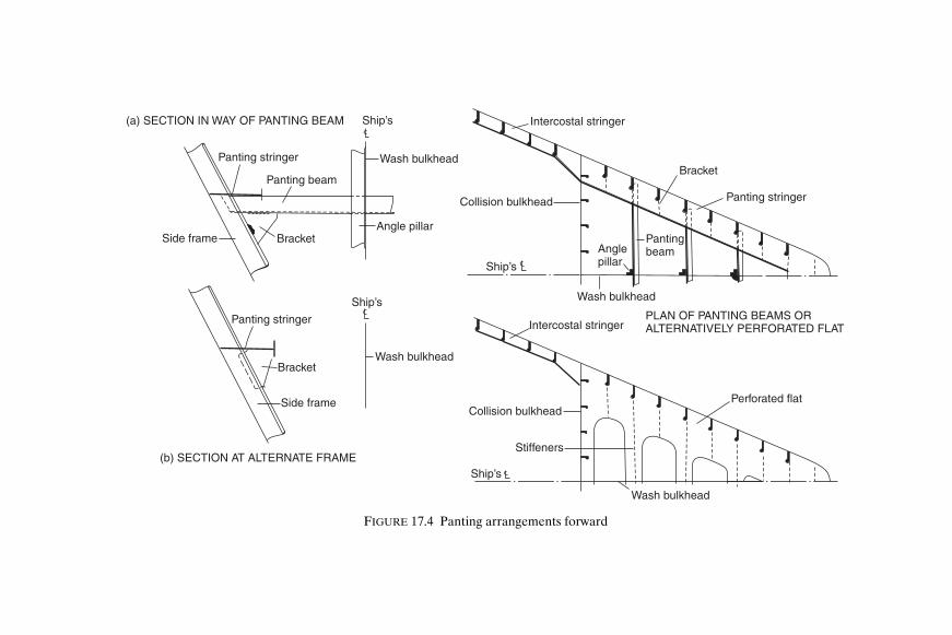
(a) SECTION IN WAY OF PANTING BEAM
Panting stringer
Panting beam
BracketSide frame
Wash bulkhead
Angle pillar
Panting stringer
Bracket
Side frame
Wash bulkhead
Ship’s
Ship’s
(b) SECTION AT ALTERNATE FRAME
Ship s’
Ship s’
Panting stringer
Bracket
PantingbeamAngle
pillar
Collision bulkhead
Wash bulkhead
Intercostal stringer
PLAN OF PANTING BEAMS ORALTERNATIVELY PERFORATED FLAT
Collision bulkhead
Intercostal stringer
Stiffeners
Wash bulkhead
Perforated flat
FIGURE 17.4 Panting arrangements forward
Shcc17.fm Page 175 M
onday, March 26, 2001 3:13 PM

176 Ship Construction
S T R E N G T H E N I N G F O R N A V I G A T I O N I N I C E IF a vessel is to beassigned a special features notation for navigation in first year ice (seeChapter 4) the additional strengthening required involves primarily anincrease in plate thickness and frame scantlings in the waterline region andthe bottom forward, and may require some modifications and strengthen-ing at the stem, stern, rudder and bossings, etc.
A main ice belt zone is defined which extends above the ice load water-line (i.e. normally the summer load waterline) and below the ice lightwaterline (i.e. lightest waterline ship navigates ice in). The extent of thiszone depends on the ice class assigned (see Table 17.2).
The shell plating thickness in this zone is greater than on a conventionalship and increases with severity of ice class and with position from aft toforward. Below the main ice belt zone forward for at least 40 per cent of the
TABLE 17.2
Main Ice Belt Zone
Class Above ice load waterline (mm) Below ice light waterline (mm)
1AS 600 7501A 500 6001B 400 5001C 400 5001D 400 500
TABLE 17.3
Note! Forward is less than 40 per cent of the length aft of the forward perpendicular
Ice class Region Minimum extent of ice framing Above ice load
waterline (mm)Below ice loadwaterline (mm)
1AS Forward (30 per cent length from forward)
1200 To double bottom or top of floors
Forward (abaft 30 per cent lengthfrom forward) and midships
1200 1600
Aft 1200 12001A Forward (30 per cent length from
forward)1000 1600
1B Forward (abaft 30 per cent length from forward) and midships
1000 1300
1C Aft 1000 10001D Forward 1000 1600
Shcc17.fm Page 176 Monday, March 26, 2001 3:13 PM

Shell Plating and Framing 177
length from forward for Ice Classes 1AS and 1A increased thickness of shellplating is required.
Transverse main and intermediate frames of the same heavier scant-lings are fitted in way of the main ice belt zone to the extent indicated inTable 17.3. If the shell is longitudinally framed longitudinals of increasedscantlings are fitted over the same vertical extent given in Table 17.3for transverse framing. Both transverse and longitudinal frame scantlingrequirements are dependent on the severity of ice class and distance offrame from forward. The main and intermediate transverse frames termin-ate at the first major longitudinal member outside the minimum extent ofice framing. Transverse ice framing is supported by ice stringers and decks,and longitudinal framing by web frames the scantlings of which are increasedwith severity of ice class and distance from forward.
Strengthening for addition of ‘Icebreaker’ notation to ship type notationand assignment of special features notation for navigation in multi-yearice concerns plating and framing but are too extensive to be coveredadequately in this text. For full details reference may be made to Chapter 9,Part 3, Ship Structures of Lloyd’s Register of Shipping ‘Rules and Regula-tions for the Classification of Ships’.
Bilge keel ending
Shellbutt
25mm diahole
Bilge keelbutt
Ground barbutt
Frame
Moulded line ofbottom shell
Bilge plate Moulded line ofside shell
FIGURE 17.5 Bilge keels
Shcc17.fm Page 177 Monday, March 26, 2001 3:13 PM

178 Ship Construction
Bilge KeelMost ships are fitted with some form of bilge keel the prime function ofwhich is to help damp the rolling motion of the vessel. Other relatively
Ceiling
Keel plate1800mm x 21mm
Side girder Bottom plating16mm
Tank top 11.25mm
Upp. Deck plating(21.25mm)
Tank side bracket
Inner bottom longitudinals 200mm x 10.5mm O.B.P.Bottom longitudinals 200mm x 13.75mm O.B.P.
Bilge ceilingMiddle line strake 12.75mm
Corrugated bulkheadSide plating (16.5mm)
Side frame340mm x 17.25mm O.B.P.
Length B.P. 132.5mBeam mid. 18.42mDepth mid. 11.75m
Deck transverse 300mm deep with 237.5mm flange
Tween deck plating (9.5mm)
Corrugated bulkheadDeck transverse 300mm deepwith 200mm flange Knee
Ship’s Upper deck longitudinals (150mm x 75mm x 15mm)
Sheerstrake(210mm x 20mm)grade ‘E’
Tripping bracketStringer plate
(20mm)
Stiffener
Knee
Cargo battens
FIGURE 17.6 General cargo ship—midship section
Shcc17.fm Page 178 Monday, March 26, 2001 3:13 PM

Shell Plating and Framing 179
minor advantages of the bilge keel are protection for the bilge on ground-ing, and increased longitudinal strength at the bilge.
The damping action provided by the bilge keel is relatively small buteffective, and virtually without cost after the construction of the ship. It iscarefully positioned on the ship so as to avoid excessive drag when the ship
Hatch coamingDeck plating(21.75mm, grade ‘D’)
Rounded sheerstrake(21.75mm, grade ‘E’)
Longitudinals (250mm x 22mm O.B.P.)
Longitudinals (200mm x 975mm O.B.P.)
Tank plating (10.5mm)
Bracket
Shell plating (150mm)
Side frame(250mm x 11mm O.B.P.)
Length B.P. 141mBeam mid. 20.5mDepth mid. 12.05m
Hopper plating (15.5mm)
Longitudinals as double bottom
Inner bottom longitudinals 225mm x 11mm O.B.P.
Tank top (15.5mm)
Pipetunnel
Stiffener Keel plate(1345mm x 22.5mm)
Bottom plating (14mm)Bottom longitudinals225mm x 11mm O.B.P.
L
FIGURE 17.7 Bulk carrier—midship section
Shcc17.fm Page 179 Monday, March 26, 2001 3:13 PM

180 Ship Construction
is under way; and to achieve a minimum drag, various positions of the bilgekeel may be tested on the ship model used to predict power requirements.This bilge keel then generally runs over the midship portion of the hull, oftenextending further aft than forward of amidships and being virtually perpen-dicular to the turn of the bilge.
LONGITUDINALS AT UPPER DECK 450 35 F.B. GRADE EH 6 9 5�
” ” 2 DECK 180 18 F.B. ” E 6 9 5” ” 3 DECK 180 18 F.B. ” A 6 9 5” ” SHEERSTRAKE 450 35 F.B. ” EH 8 5 0” ” TOP OF LONGL. BHD 450 35 F.B. ” EH 8 5 0” ” LONGL. COAMING 180 18 F.B. ” EH” ON TOP OF LONGL. COAMING 300 20 F.B. ” EH
�
�
�
�
�
�
SCANTLINGSITEM SECTION QUALITY SPACING
25.0 EH25.0 EH
30.0 EH12.5
15.0 EH
20.0 EH
20.0 E
4650
BILGE STRAKE24.0 E
UPPERDECK
5 .DECK
TH
4 .DECK
TH
SIDESHELL10.5 D
2ND. DECK
SHEERSTRAKE35.0 EH
11.5
20.0
35.0 EH
25.0 EH 26.0, EH
2785
10.0
25.0 E
PASSAGEWAY
3 DECKRD.
SIDESHELL20.0 D
15.0
15.013.0
12.5
13.0
14.0
13.0
12.5
11.5
15.0
10.0
11.0
10.0
SIDE SHELL AND MAINLONGL. BULKHEADLONGITUDINALS SPACED910 MAXIMUM
20.0
TANK TOP PLATING 16.0
ALL SCANTLINGS ARE IN MILLIMETRES
2000
12.5
15.019.0
20.0
1960
15.0
15.0
20.027.5 E BOTTOM SHELL 24.0 D.
15.0
10.0
12.5
12.5
FIGURE 17.8 Container ship—midship section
Shcc17.fm Page 180 Monday, March 26, 2001 3:13 PM

Shell Plating and Framing 181
Deck 8mm
200 × 8+ 150 × 15
200 × 8+ 150 × 20
Void(casing)
Void(casing)
Deck 12mm
Deck 12mm
Tank top 10mm
Length B.P. 137mBeam mid. 20.25mDepth mid. 12.81m
VEHICLE DECK
TRAIN DECK
Longitudinals 200×9 O.B.P.
Transverse580 × 8+200 ×15
Transverse615 × 10+200×20
Transverse600×9+150×10
Deck longitudinals100 6 O.B.P.×
7mm
Longitudinals 120×7 O.B.P.
225 × 10+200 × 15
9mmHEELINGTANK
Tank top 12mm
Bilge & Bottom plate12mm
15mmFloors 10mmStiffeners 160×9Bottom longitudinals 200 × 9
Keel
GARAGE500 ×9
+150 ×15
200 × 8+150 ×20
500 ×9+150 × 15
Longitudinals 120×7 O.B.P.
225 ×10+250 ×20
Siid
e pl
atin
g 12
mm
Sid
e pl
atin
g 9
mm
Sid
e lo
ngitu
dina
ls 1
20×
7 O
.B.P
.
D longitudinals 200×9 O.B.P.eck
Deck longitudinals 200×9 O.B.P.
10mm
BALLAST
TANK
13mm
L
FIGURE 17.9 Midship section of ro-ro ship
Shcc17.fm Page 181 Monday, March 26, 2001 3:13 PM

Bridgeingstructure
Length O.A. 44.0 MBeam O.A. 12.0 MMaterial—Aluminium Alloy
Tunnel plating
Bottomplating
Waterline
Main deck
Sideplating
Fenderextrusion
Transverse
Deck beam
Floor
FIGURE 17.10 High speed craft (catamaran)—section
Shcc17.fm Page 182 M
onday, March 26, 2001 3:13 PM

Shell Plating and Framing 183
There are many forms of bilge keel construction, and some quite elabor-ate arrangements have been adopted in an attempt to improve the dampingperformance whilst reducing any drag. Care is required in the design of thebilge keel, for although it would not be considered as a critical strengthmember of the hull structure, the region of its attachment is fairly highlystressed owing to its distance from the neutral axis. Cracks have originatedin the bilge keel and propogated into the bilge plate causing failure of themain structure. In general bilge keels are attached to a continuous groundbar with the butt welds in the shell plating, ground bar and bilge keel stag-gered (see Figure 17.5). Direct connection between the ground bar buttwelds and the bilge plate and bilge keel butt welds and the ground bar areavoided. In ships over 65 m in length, holes are drilled in the bilge keel buttwelds as shown in Figure 17.5.
The ground bar thickness is at least that of the bilge plate or 14 mm which-ever is the lesser, and the material grade is the same as that of the bilgeplate. Connection of the ground bar to the shell is by continuous fillet weldsand the bilge keel is connected to the ground bar by light continuous orstaggered intermittent weld. The latter lighter weld ensures that should thebilge keel be fouled failure occurs at this joint without the bilge plate beingdamaged.
Bilge keels are gradually tapered (at least 3 to 1) at their ends and finishin way of an internal stiffening member.
Shcc17.fm Page 183 Monday, March 26, 2001 3:13 PM

18Bulkheads and Pillars
This chapter deals with the internal vertical structure of the ship. Much ofthis structure, particularly the pillars and to some extent the transversestrength bulkheads, is responsible for carrying the vertical loading experi-enced by the ship. The principal bulkheads subdivide the ship hull into anumber of large watertight compartments, and their construction andspacing is discussed. Also considered are the boundaries of other smallercompartments such as deep tanks and the shaft tunnel.
Bulkheads Vertical partitions in a ship arranged transversely or fore and aft are referredto as ‘bulkheads’. Those bulkheads which are of greatest importance are themain hull transverse and longitudinal bulkheads dividing the ship into anumber of watertight compartments. Other lighter bulkheads, named ‘minorbulkheads’, which act as screens further subdividing compartments intosmall units of accommodation or stores, are of little structural importance.
The main hull bulkheads of sufficient strength are made watertight inorder that they may contain any flooding in the event of a compartment onone side of the bulkhead being bilged. Further they serve as a hull strengthmember not only carrying some of the ship’s vertical loading but also resist-ing any tendency for transverse deformation of the ship. As a rule thestrength of the transverse watertight bulkheads is maintained to the strengthdeck which may be above the freeboard deck. Finally each of the main hullbulkheads has often proved a very effective barrier to the spread of a holdor machinery space fire.
S P A C I N G O F W A T E R T I G H T B U L K H E A D S — C A R G O S H I P S Theminimum number of transverse watertight bulkheads which must be fittedin a dry cargo ship are stipulated. A collision bulkhead must be fittedforward, an aft peak bulkhead must be fitted, and watertight bulkheadsmust be provided at either end of the machinery space. This implies that fora vessel with machinery amidships the minimum possible number of water-tight bulkheads is four. With the machinery aft this minimum number may
Shcc18.fm Page 184 Monday, March 26, 2001 3:13 PM

Bulkheads and Pillars 185
be reduced to three, the aft peak bulkhead being at the aft end of themachinery space.
Of these bulkheads perhaps the most important is the collision bulkheadforward. It is a fact that the bow of at least one out of two ships involved ina collision will be damaged. For this reason a heavy bulkhead is specifiedand located so that it is not so far forward as to be damaged on impact.Neither should it be too far aft so that the compartment flooded forwardcauses excessive trim by the bow. Lloyd’s Register gives the location forships whose length does not exceed 200 m as not less than 5 and not greaterthan 8 per cent of the ship’s length (Lloyd’s Length) from the fore end ofthe load waterline. As a rule this bulkhead is fitted at the minimum distancein order to gain the maximum length for cargo stowage. The aft peak bulk-head is intended to enclose the stern tubes in a watertight compartmentpreventing any emergency from leakage where the propeller shafts piercethe hull. It is located well aft so that the peak when flooded would not causeexcessive trim by the stern. Machinery bulkheads provide a self-containedcompartment for engines and boilers preventing damage to these vital com-ponents of the ship by flooding in an adjacent hold. They also localize anyfire originating in these spaces.
A minimum number of watertight bulkheads will only be found in smallercargo ships. As the size increases the classification society will recommendadditional bulkheads, partly to provide greater transverse strength, and alsoto increase the amount of subdivision. Table 18.1 indicates the number ofwatertight bulkheads recommended by Lloyd’s Register for any cargo ship.These should be spaced at uniform intervals, but the shipowner may requirefor a certain trade a longer hold, which is permitted if additional approvedtransverse stiffening is provided. It is possible to dispense with one watertightbulkhead altogether, with Lloyd’s Register approval, if adequate approved
TABLE 18.1
Bulkheads for Cargo Ships
Length of ship (metres) Total number of bulkheadsAbove Not exceeding Machinery midships Machinery aft
65 4 365 85 4 485 105 5 5
105 115 6 5115 125 6 6125 145 7 6145 165 8 7165 190 9 8190 To be considered individually
Shcc18.fm Page 185 Monday, March 26, 2001 3:13 PM

186 Ship Construction
structural compensation is introduced. In container ships the spacing isarranged to suit the standard length of containers carried.
Each of the main watertight hold bulkheads may extend to the upper-most continuous deck; but in the case where the freeboard is measuredfrom the second deck they need only be taken to that deck. The collisionbulkhead extends to the uppermost continuous deck and the aft peakbulkhead may terminate at the first deck above the load waterline pro-vided this is made watertight to the stern, or to a watertight transom floor.
In the case of bulk carriers a further consideration may come into thespacing of the watertight bulkheads where a shipowner desires to obtain areduced freeboard. It is possible with bulk carriers to obtain a reduced free-board under The International Load Line Convention 1966 (see Chapter31) if it is possible to flood one or more compartments without loss of thevessel. For obvious reasons many shipowners will wish to obtain the max-imum permissible draft for this type of vessel and the bulkhead spacing willbe critical.
SPACING OF WATERTIGHT BULKHEADS—PASSENGER SHIPS Wherea vessel requires a passenger certificate (carrying more than 12 passengers),it is necessary for that vessel to comply with the requirements of the Inter-national Convention on Safety of Life at Sea, 1974 (see Chapter 29). Underthis convention the subdivision of the passenger ship is strictly specified,and controlled by the authorities of the maritime countries who are signator-ies to the convention. In the United Kingdom the controlling authority is theMarine and Coastguard Agency.
The calculations involved in passenger ship subdivision are dealt with indetail in the theoretical text-books on naval architecture. However the basicprinciple is that the watertight bulkheads should be so spaced that whenthe vessel receives reasonable damage, flooding is confined. No casualtywill then result either from loss of transverse stability or excessive sinkageand trim.
C O N S T R U C T I O N O F W A T E R T I G H T B U L K H E A D S The plating of aflat transverse bulkhead is generally welded in horizontal strakes, andconvenient two-dimensional units for prefabrication are formed. Smallerbulkheads may be erected as a single unit; larger bulkheads are in two ormore units. It has always been the practice to use horizontal strakes ofplating since the plate thickness increases with depth below the top of thebulkhead. The reason for this is that the plate thickness is directly related tothe pressure exerted by the head of water when a compartment on one sideof the bulkhead is flooded. Apart from the depth the plate thickness is alsoinfluenced by the supporting stiffener spacing.
Vertical stiffeners are fitted to the transverse watertight bulkheads ofa ship, the span being less in this direction and the stiffener therefore
Shcc18.fm Page 186 Monday, March 26, 2001 3:13 PM

Bulkheads and Pillars 187
having less tendency to deflect under load. Stiffening is usually in the formof welded inverted ordinary angle bars, or offset bulb plates, the size of thestiffener being dependent on the unsupported length, stiffener spacing,and rigidity of the end connections. Rigidity of the end connections willdepend on the form of end connection, stiffeners in holds being bracketedor simply directly welded to the tank top or underside of deck, whilst uppertween stiffeners need not have any connection at all (see Figure 18.1).Vertical stiffeners may be supported by horizontal stringers permitting areduction in the stiffener scantling as a result of the reduced span. Hori-zontal stringers are mostly found on those bulkheads forming the boundariesof a tank space, and in this context are dealt with later.
It is not uncommon to find in present day ships swedged and corrug-ated bulkheads, the swedges like the troughs of a corrugated bulkheadbeing so designed and spaced as to provide sufficient rigidity to the platebulkhead in order that conventional stiffeners may be dispensed with (seeFigure 18.2). Both swedges and corrugations are arranged in the verticaldirection like the stiffeners on transverse and short longitudinal pillar bulk-heads. Since the plating is swedged or corrugated prior to its fabrication,the bulkhead will be plated vertically with a uniform thickness equivalentto that required at the base of the bulkhead. This implies that the actualplating will be somewhat heavier than that for a conventional bulkhead, andthis will to a large extent offset any saving in weight gained by not fittingstiffeners.
The boundaries of the bulkhead are double continuously fillet weldeddirectly to the shell, decks, and tank top.
A bulkhead may be erected in the vertical position prior to the fitting ofdecks during prefabrication on the berth. At the line of the tween decks a‘shelf plate’ is fitted to the bulkhead and when erected the tween decks landon this plate which extends 300 to 400 mm from the bulkhead. The deck islap welded to the shelf plate with an overlap of about 25 mm. In the case ofa corrugated bulkhead it becomes necessary to fit filling pieces between thetroughs in way of the shelf plate.
If possible the passage of piping and ventilation trunks through water-tight bulkheads is avoided. However in a number of cases this is impossibleand to maintain the integrity of the bulkhead the pipe is flanged at thebulkhead. Where a ventilation trunk passes through, a watertight shutteris provided.
T E S T I N G W A T E R T I G H T B U L K H E A D S Both the collision bulkhead, asthe fore peak bulkhead, and the aft peak bulkhead provided they do notform the boundaries of tanks are to be tested by filling the peaks with waterto the level of the load waterline. All bulkheads, unless they form theboundaries of a tank which is regularly subject to a head of liquid, are hose
Shcc18.fm Page 187 Monday, March 26, 2001 3:13 PM

B B B B B B B
6.5 mm
B B B B B B B B B B B B
PLANDeck
longitudinal
TweenstiffenerShelfplate
Bracket
Tweendeck
HoldstiffenerW.T.
bulkhead
Upp. deck
Tank top
W.T.floor
Bracket
ELEVATION
Tank top
B B B B B B B
7.25 mm
B B B B B B B B
8.5 mm
9.5 mm
11.5 mm
B B B B B B B B B B B
LOOKING AFT
Watertight floor
Upper deck
Tween deck
Welded seam
Welded seam
Welded seam
Welded seam
FIGURE 18.1 Plain watertight bulkhead
Shcc18.fm Page 188 M
onday, March 26, 2001 3:13 PM

LOOKING AFT
Watertight floor
StiffenersCorrugations
Ship’s
Stif
fene
r
Stif
fene
r
Stif
fene
r
Pill
ar b
ulkh
ead
Stif
fene
r
Upper deck
PLAN Stiffeners
Upper deck
Tween deck
Tweenstiffener
Bracket
Holdstiffener
Tank top
W.T. floor
ELEVATION IN WAY OFSTIFFENERS
Stif
fene
r
Stif
fene
r
Stif
fene
rW
elde
d bu
tt
Wel
ded
butt
Wel
ded
butt
Wel
ded
butt
Wel
ded
butt
Wel
ded
butt
Wel
ded
butt
Wel
ded
butt
Wel
ded
butt
Stif
fene
r
Stif
fene
r
Stif
fene
r
Tank top
FIGURE 18.2 Corrugated watertight bulkhead
Shcc18.fm Page 189 M
onday, March 26, 2001 3:13 PM

190 Ship Construction
tested. Since it is not considered prudent to test ordinary watertight bulk-heads by filling a cargo hold, the hose test is considered satisfactory.
Watertight DoorsIn order to maintain the efficiency of a watertight bulkhead it is desirablethat it remains intact. However in some instances it becomes necessary toprovide access between compartments on either side of a watertight bulk-head and watertight doors are fitted for this purpose. A particular exampleof this in cargo ships is the direct means of access required betweenthe engine room and the shaft tunnel. In passenger ships watertight doorsare more frequently found where they allow passengers to pass betweenone point of the accommodation and another.
Where a doorway is cut in the lower part of a watertight bulkhead caremust be taken to maintain the strength of the bulkhead. The opening is tobe framed and reinforced, if the vertical stiffeners are cut in way of theopening. If the stiffener spacing is increased to accommodate the opening,the scantlings of the stiffeners on either side of the opening are increased togive an equivalent strength to that of an unpierced bulkhead. The actualopening is kept as small as possible, the access to the shaft tunnel beingabout 1000 to 1250 mm high and about 700 mm wide. In passenger accom-modation the openings would be somewhat larger.
Mild steel or cast steel watertight doors fitted below the water line areeither of the vertical or horizontal sliding type. A swinging hinged type ofdoor could prove impossible to close in the event of flooding and is notpermitted. The sliding door must be capable of operation when the ship islisted 15°, and be opened or closed from the vicinity of the door as well asfrom a position above the bulkhead deck. At this remote control positionan indicator must be provided to show whether the door is open or closed.Vertical sliding doors may be closed by a vertical screw thread which isturned by a shaft extending above the bulkhead and fitted with a crankhandle. This screw thread turns in a gunmetal nut attached to the top of thedoor, and a crank handle is also provided at the door to allow it to be closedfrom this position. Often horizontal sliding doors are fitted, and these mayhave a vertical shaft extending above the bulkhead deck, which may beoperated by hand from above the deck or at the door. This can also bepower driven by an electric motor and worm gear, the vertical shaft workingthrough bevel wheels, and horizontal screwed shafts turning in bronze nutson the door. The horizontal sliding door may also be opened and closed bya hydraulic ram with a hydraulic hand pump and with control at the doorand above the bulkhead deck (see Figure 18.3). With the larger number ofwatertight doors fitted in passenger ships the doors may be closed by means
Shcc18.fm Page 190 Monday, March 26, 2001 3:13 PM
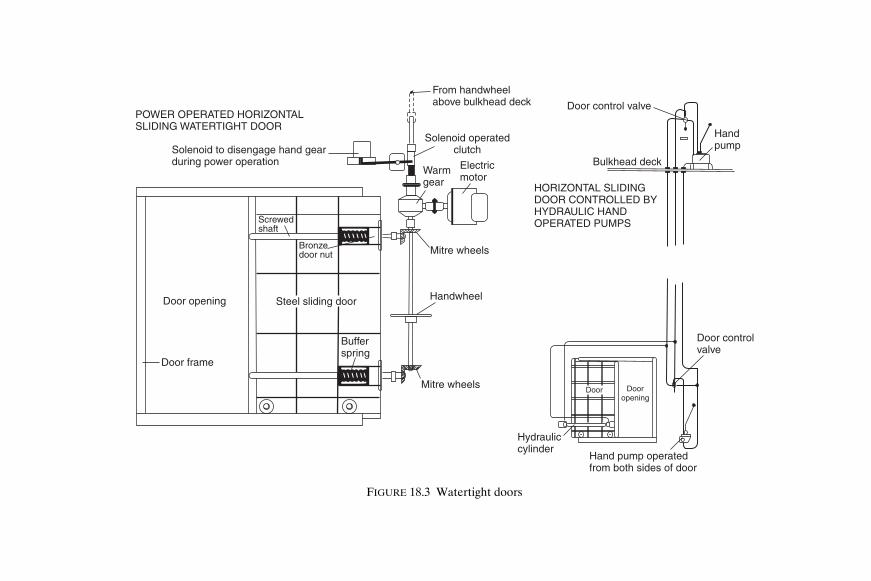
Door opening
Door frame
Steel sliding door
Screwedshaft
Bronzedoor nut
From handwheelabove bulkhead deck
Solenoid operatedclutch
Electricmotor
Warmgear
Bufferspring
Handwheel
Mitre wheels
Mitre wheels
Solenoid to disengage hand gearduring power operation
POWER OPERATED HORIZONTALSLIDING WATERTIGHT DOOR
HORIZONTAL SLIDINGDOOR CONTROLLED BYHYDRAULIC HANDOPERATED PUMPS
Door control valve
Bulkhead deck
Handpump
Door controlvalve
Dooropening
Door
Hand pump operatedfrom both sides of door
Hydrauliccylinder
FIGURE 18.3 Watertight doors
Shcc18.fm Page 191 M
onday, March 26, 2001 3:13 PM

192 Ship Construction
of hydraulic power actuated by remote control from a central positionabove the bulkhead deck.
When in place all watertight doors are given a hose test, but those in apassenger ship are required to be tested under a head of water extending tothe bulkhead deck. This may be done before the door is fitted in the ship.
In approved positions in the upper tween decks well above the waterline,hinged watertight doors are permitted. These may be similar to the weather-tight doors fitted in superstructures, but are to have gunmetal pins in thehinges.
Deep TanksDeep tanks were often fitted adjacent to the machinery spaces amidships toprovide ballast capacity, improving the draft with little trim, when the shipwas light. These tanks were frequently used for carrying general cargoes,and also utilized to carry specialist liquid cargoes. In cargo liners wherethe carriage of certain liquid cargoes is common practice it was often anadvantage to have the deep tanks adjacent to the machinery space for cargoheating purposes. However in modern cargo liners they may require to bejudiciously placed in order to avoid excessive stresses in different con-ditions of loading. Most ships now have their machinery arranged aft orthree-quarters aft, and are fitted with deep tanks forward to improve thetrim in the light conditions.
C O N S T R U C T I O N O F D E E P T AN K S Bulkheads which form the bound-aries of a deep tank differ from hold bulkheads in that they are regularlysubjected to a head of liquid. The conventional hold bulkhead may beallowed to deflect and tolerate high stresses on the rare occasions when ithas to withstand temporary flooding of a hold, but deep tank bulkheadswhich are regularly loaded in this manner are required to have greaterrigidity, and be subject to lower stresses. As a result the plate and stiffenerscantlings will be larger in way of deep tanks, and additional stiffening maybe introduced.
The greater plating thickness of the tank boundary bulkheads increaseswith tank depth, and with increasing stiffener spacing. To provide the greaterrigidity the vertical stiffeners are of heavier scantlings and more closelyspaced. They must be bracketed or welded to some other form of stiffeningmember at their ends. Vertical stiffener sizes may be reduced, however, byfitting horizontal girders which form a continuous line of support on thebulkheads and ship’s side. These horizontal girders are connected at theirends by flanged brackets and are supported by tripping brackets at the toesof the end brackets, and at every third stiffener or frame. Intermediate
Shcc18.fm Page 192 Monday, March 26, 2001 3:13 PM

Side shell
Trippingbracket
Filling in piece
Tank bulkhead
Flanged stringer
PLAN AT HORIZONTALSTRINGERS
Bracket
Tank bulkhead
Flangedstringer
Centre line bulkhead
Ship’s
Coaming
Galvanizedsteel toggle
Ship’s
Gasket
Girder
Girder
CLOSINGARRANGEMENT
Round bar weldedinside hole to formlifting eye
LIFTING EYE DETAIL
Hatchopening
DEEP TANK CROWN
Hatch
Stiffeners
Lifting eye (see detail)
ALUMINIUM HATCH COVER
Stiffener
L
L
FIGURE 18.4 Construction of deep tanks
Shcc18.fm Page 193 M
onday, March 26, 2001 3:13 PM

194 Ship Construction
frames and stiffeners are effectively connected to the horizontal girders(see Figure 18.4).
Where deep tanks are intended to carry oil fuel for the ship’s use, or oilcargoes, there will be a free surface, and it is necessary to fit a centre linebulkhead where the tanks extend from side to side of the ship. This bulkheadmay be intact or perforated, and where intact the scantlings will be the same asfor boundary bulkheads. If perforated, the area of perforations is sufficientto reduce liquid pressures, and the bulkhead stiffeners have considerablyreduced scantlings, surging being avoided by limiting the perforation area.
Both swedged and corrugated plating can be used to advantage in theconstruction of deep tanks since, without the conventional stiffening, tanksare more easily cleaned. With conventional welded stiffening it may beconvenient to arrange the stiffeners outside the tank so that the boundarybulkhead has a plain inside for ease of cleaning.
In cargo ships where various liquid cargoes are carried, arrangementsmay be made to fit cofferdams between deep tanks. As these tanks may alsobe fitted immediately forward of the machine space, a pipe tunnel is gen-erally fitted through them with access from the engine room. This tunnelcarries the bilge piping as it is undesirable to pass this through the deeptanks carrying oil cargoes.
T E S T I N G D E E P T A N K S Deep tanks are tested by subjecting them to themaximum head of water to which they might be subject in service (i.e. to thetop of the air pipe). This should not be less than 2.45 m above the crown ofthe tank.
Topside Tanks Standard general bulk carriers are fitted with topside tanks which may beused for water ballast, and in some instances are used for the carriage oflight grains. The thickness of the sloping bulkhead of this tank is determinedin a similar manner to that of the deep tank bulkheads. In present practice,as indicated in Chapter 17, the topside tank is generally stiffened internallyby longitudinal framing supported by transverses (see Figure 17.7). Trans-verses are arranged in line with the end of the main cargo hatchways; and inlarge ships, a fore and aft diaphragm may be fitted at half the width of thetank, between the deck and the sloping plating.
Shaft Tunnel When the ship’s machinery is not located fully aft it is necessary to enclosethe propeller shaft or shafts in a watertight tunnel between the aft end of
Shcc18.fm Page 194 Monday, March 26, 2001 3:13 PM

Bulkheads and Pillars 195
the machinery space and the aft peak bulkhead. This protects the shaftfrom the cargo and provides a watertight compartment which will containany flooding resulting from damage to the watertight gland at the aft peakbulkhead. The tunnel should be large enought to permit access for inspec-tion and repair of the shafting. A sliding watertight door which may beopened from either side is provided at the forward end in the machineryspace bulkhead. Two means of escape from the shaft tunnel must be pro-vided, and as a rule there is a ladder in a watertight trunk leading to anescape hatch on the deck above the waterline, at the aft end of the shafttunnel. Where the ship narrows at its after end the aftermost hold may becompletely plated over at the level of the shaft tunnel to form a tunnel flat,as the narrow stowage space either side of the conventional shaft tunnelcould not be utilized. The additional space under this tunnel flat is oftenused to stow the spare tail shaft. Shaft tunnels also provide a convenientmeans of carrying piping aft, which is then accessible and protected fromcargo damage.
C O N S T R U C T I O N O F T H E S HA F T T U N N E L The thickness of the tunnelplating is determined in the same manner as that for the watertight bulk-heads. Where the top of the tunnel is well rounded the thickness of the topplating may be reduced, but where the top is flat it is increased. Underhatchways the top plating must be increased in thickness unless it is coveredby wood of a specified thickness. Vertical stiffeners supporting the tunnelplating have similar scantlings to the watertight bulkhead stiffeners, andtheir lower end is welded to the tank top (see Figure 18.5). On completionthe shaft tunnel structure is subject to a hose test.
At intervals along the length of the shaft, stools are built which supportthe shaft bearings. A walkway is installed on one side of the shaft to permitinspection, and as a result, in a single screw ship the shaft tunnel will beoffset from the ship’s centre line. This walkway is formed by gratings laid onangle bearers supported by struts, etc., any piping is then led along under-neath the walkway.
PillarsThe prime function of the pillars is to carry the load of the decks andweights upon the decks vertically down to the ship’s bottom structure wherethese loads are supported by the upward buoyant forces. A secondary func-tion of pillars is to tie together the structure in a vertical direction. Withinthe main hull of a cargo ship two different forms of pillar may be found,those in the holds invariably fulfilling the first function, and those in themachinery spaces fulfilling the latter function. Hold pillars primarily incompression are often without bracket connections at their ends, whilst
Shcc18.fm Page 195 Monday, March 26, 2001 3:13 PM

Escape trunk
Aft peak bulkhead
No. 5 holdtunnel flat
Tunnel recess Shaft tunnel
No. 4 hold Machineryspace
shaftELEVATION IN WAYOF SHAFT TUNNEL
Heavier top plating
WeldWeld
Bracket
Ship’s
Welded stiffener
Shaft
Grating
Support
Piping
Shaft
Weld
Grating
Weld
Stool supportingshaft bearings
Welded stiffener
Heavier top plating
Double bottom
Ship’s
L
FIGURE 18.5 Shaft tunnels
Shcc18.fm Page 196 M
onday, March 26, 2001 3:13 PM

Bulkheads and Pillars 197
machinery space pillars are heavily bracketed at their ends to permit tensileloadings. This latter type of pillar may also be found in tank spaces wherethe crown of tank under pressure can put the pillar in tension.
S P A C I N G O F H O L D P I L L A R S Since pillars located in holds will interferewith the stowage arrangements, widely spaced pillars of large fabricatedsection are used rather than small, solid, closely spaced pillar systems. Thearrangement most often found in cargo ships, is a two-row pillar system,with pillars at the hatch corners or mid-length of hatch supporting deckgirders adjacent to the hatch sides. As the deck girder size is to some extentdependent on the supported span, where only a mid-hatch length pillar isfitted the girder scantlings will be greater than that where two hatch cornerpillars are fitted. In fact pillars may be eliminated altogether where it isimportant that a clear space should be provided, but the deck girder willthen be considerably larger, and may be supported at its ends by webs at thebulkhead. Substantial transverse cantilevers may also be fitted to supportthe side decks. Pillars may also be fitted in holds on the ship’s centre line atthe hatch end, to support the heavy hatch end beams securely connected toand supporting the hatch side girders. In a similar position it is not unusualto find short corrugated fore and aft pillar bulkheads. These run from theforward or aft side of the hatch opening to the adjacent transverse bulkheadon the ship’s centre line.
To maintain continuity of loading the tween pillars are arranged directlyabove the hold pillars. If this is not possible stiffening arrangements shouldbe made to carry the load from the tween pillar to the hold pillar below.
P I L L A R C O N S T R U C T I O N It has already been seen that the hold pillar isprimarily subject to a compressive loading, and if buckling is to be avoidedin service the required cross-section must be designed with both the loadcarried and length of pillar in mind. The ideal section for a compressivestrut is the tubular section and this is often adopted for hold pillars, hollowrectangular and octagonal sections also being used. For economic reasonsthe sections are fabricated in lengths from steel plate, and for the hollowrectangular section welded channels or angles may also be used (see Figure18.6). A small flat bar or cope bar may be tack welded inside these pillarsections to allow them to be welded externally.
Pillars have a bearing fit, and it is important that the loads at the headand heel of the pillar should be well distributed. At the head of the pillar acontinuous weld is made to a doubling plate supported by brackets. Detailsof the head fitting vary from ship to ship and depend very much on the formof hatch side or deck girder which they support. The heel of the hold pillarlands on a heavy doubling or insert plate at the tank top and it is commonlyarranged that the point of loading will coincide with a solid floor/side girder
Shcc18.fm Page 197 Monday, March 26, 2001 3:13 PM

Weld
Tubularpillar
PILLAR SECTIONSWeld
Hollowsquarepillar
Weld
Weldinto backing bar
Backing barWeld
Hollowsquarepillar
Octagonalpillar
Weld
Weld
Formed by flangedplates
Formed by twoangles orflanged plates
Weld
Hatchcoaming
Platebracket
Heavyriderplate
Deck
Hatchcoaming
DeckPlate
bracket
Pillar Pillar
Halfbeam
Heavyriderplate
Halfbeam
Deck
Girderat hatchside
Pillar
Deckgirder
Trippingbrackets
Deck
Heavy plateintroducedinto deckgirder flangein way ofpillar
Bracket
Pillar
Bracket
Half beamHEAD DETAILS
ENGINE ROOM PILLAR
PILLAR SECTION
Pillar
BracketInsertplate intank top
Intercostalside girder
Intercostalside girder
Tank top
PillarHEEL
DETAILS
Solidfloor
Solidfloor
FIGURE 18.6 Pillars
Shcc18.fm Page 198 M
onday, March 26, 2001 3:13 PM

Deck
Trippingbracket
Anglebeam
Weldedpalm
Anglerunner
Solid pillar
Anglebeam
Trippingbracket
Deck
Solid pillar
Solidpillar
Deck
Riderplate
HEADDETAILS
HEELDETAILS
Welded pad (or insert plate)
Stiffening under
FIGURE 18.7 Small solid pillars
Shcc18.fm Page 199 M
onday, March 26, 2001 3:13 PM

200 Ship Construction
intersection in the double bottom below. Where this is not possible partialfloors and short intercostal side girders may be fitted to distribute the load.
Machinery space pillars are fabricated from angles, channels, or rolledsteel joists, and are heavily bracketed to suitably stiffened members (Figure18.6).
S M A L L P I L L A R S Within the accommodation and in relatively smallvessels solid round steel pillars having diameters seldom exceeding 150 mmmay be fitted. These may have forged palms at their head and heel, thehead being welded to a continuous angle fore and aft runner which sup-ports the deck. Alternatively the pillar head may have a direct continuousweld connection to an inverted angle beam or deck girder, with suitabletripping brackets fitted directly above. The heel is then directly welded tothe deck which is suitably stiffened below (see Figure 18.7).
Rolled hollow steel section pillars of similar size with direct welded headand heel fittings are commonly used today in lieu of small solid pillars.
Shcc18.fm Page 200 Monday, March 26, 2001 3:13 PM

19Decks, Hatches, and Superstructures
Decks at different levels in a ship serve various functions; they may beeither watertight decks, strength decks, or simply cargo and passenger accom-modation decks. Watertight decks are fitted to maintain the integrity of themain watertight hull, and the most important is the freeboard deck which isthe uppermost deck having permanent means of closing all openings in theexposed portions of that deck. Although all decks contribute to some extentto the strength of the ship, the most important is that which forms the upperflange of the main hull girder, called the ‘strength deck’. Lighter deckswhich are not watertight may be fitted to provide platforms for passengeraccommodation and permit more flexible cargo loading arrangements. Ingeneral cargo ships these lighter decks form tweens which provide spaces inwhich goods may be stowed without their being crushed by a large amountof other cargo stowed above them.
To permit loading and discharging of cargo, openings must be cut in thedecks, and these may be closed by non-watertight or watertight hatches.Other openings are required for personal access through the decks; and inway of the machinery space casing openings are provided which allow theremoval of machinery items when necessary, and also provide light and airto this space. These openings are protected by houses or superstructures,which are extended to provide accommodation and navigating space. Forwardand aft on the uppermost continuous deck a forecastle and often a poop maybe provided to protect the ends of the ship at sea.
DecksThe weather decks of ships are cambered, the camber being parabolic orstraight. There may be advantages in fitting horizontal decks in some ships,particularly if containers are carried and regular cross-sections are desired.Short lengths of internal deck or flats are as a rule horizontal.
Decks are arranged in plate panels with transverse or longitudinalstiffening, and local stiffening in way of any openings. Longitudinal deckgirders may support the transverse framing, and deep transverses thelongitudinal framing (see Figure 19.1).
Shcc19.fm Page 201 Monday, March 26, 2001 3:14 PM

Decklongitudinal
Tripping bracket
Deck plating
Plateweb
KneeFacing flat
DECK TRANSVERSE
Deck plating
LONGITUDINAL DECK GIRDER
Plateweb
Trippingbracket
Transversedeck beam
Facing flat
Deck plating
Decklongitudinal
Trippingbracket
Plateweb
Facing flat
SECTIONSide frame
Side shell
Deck plating
Deckbeam
Plate web
Facing flat
Trippingbracket
SECTION
FIGURE 19.1 Deck supports
Shcc19.fm Page 202 M
onday, March 26, 2001 3:14 PM

Decks, Hatches, and Superstructures 203
D E C K P L A T I N G The heaviest deck plating will be found abreast thehatch openings of the strength deck. Plating which lies within the line of thehatch openings contributes little to the longitudinal strength of the deckand it is therefore appreciably lighter. As the greatest longitudinal bendingstresses will occur over the midship region, the greatest deck plate thicknessis maintained over 40 per cent of the length amidships, and it tapers to aminimum thickness permitted at the ends of the ship. Locally the plating
Bulwark stay
Bulwark
Beam knee
Side frames
Hatch end beam
Pillar
Deck longitudinalsDeck plating
Deck plating
Deckbeams
(a) TRANSVERSELYFRAMED DECK
Hatch side girderDeck plating
Hatchcoaming
Deck transverses
(b) LONGITUDINALLYFRAMED DECK
Hatchcoaming
FIGURE 19.2 Deck construction
Shcc19.fm Page 203 Monday, March 26, 2001 3:14 PM

204 Ship Construction
thickness may be increased where higher stresses occur owing to discon-tinuities in the structure or concentrated loads.
Other thickness increases may occur where large deck loads are carried,where fork lift trucks or other wheeled vehicles are to be used, and in way ofdeep tanks. Where the strength deck plating exceeds 30 mm it is to beGrade B steel and if it exceeds 40 mm Grade D over the midships region, atthe ends of the superstructure and in way of the cargo hold region in con-tainer ships. The stringer plate (i.e. the strake of deck plating adjacent tothe sheerstrake) of the strength deck, over the midship region and con-tainer ship cargo hold area, of ships less than 260 metres in length, is to be ofGrade B steel if 15 to 20 mm thick, Grade D if 20 to 25 mm thick and GradeE if more than 25 mm thick. Where the steel deck temperatures fall below0 °C in refrigerated cargo ships the steel will be of Grades B, D and Edepending on thickness.
On decks other than the strength deck the variation in plate thickness issimilar, but lighter scantlings are in use.
Weather decks may be covered with wood sheathing or an approvedcomposition, which not only improves their appearance, but also providesprotection from heat in way of any accommodation. Since this providessome additional strength, reductions in the deck plate thickness are permit-ted; and on superstructure decks the plating thickness may be furtherdecreased within deckhouses, if sheathed. Before fitting any form ofsheathing the deck is treated to prevent corrosion between the deck platingand sheathing (see Figure 19.3).
Any openings abreast the hatch openings in a deck are kept to a minimumand clear of the hatch corners. If such openings are cut, compensation isrequired to restore the sectional area of deck. All large openings in thedecks have well rounded corners, with insert plates fitted, unless thecorners are parabolic or elliptical with the major axis fore and aft, localstress concentrations being reduced if the latter type of corner is cut (seeFigure 19.4).
D E C K S T I F F E N I N G Decks may be framed transversely or longitudinallybut outside the line of openings it is preferred that longitudinal framingshould be adopted for the strength deck.
When the decks are longitudinally framed the scantlings of the longitud-inals are dependent on their spacing, the length of ship, whether they areinside or outside the line of hatch openings, their span and the deck load-ing. Deck transverses support the longitudinals, and these are built from adeep web plate with flange or welded face flat, and are bracketed to the sideframe (Figure 19.1). Within the forward 7.5 per cent of the ship’s length,the forecastle and weather deck transverses are closely spaced and thelongitudinal scantlings increased, the additional transverse and longitudinal
Shcc19.fm Page 204 Monday, March 26, 2001 3:14 PM

Stud welded bolt
Wood sheathing beddedin white lead or othercomposition
Deck plating
Wood plug
Deck plating
Tapered plank
House side
Deck plating
Side plating
300mm waterway
50mm weldedflat bar
Caulkedseam
FIGURE 19.3 Deck sheathing
Shcc19.fm Page 205 M
onday, March 26, 2001 3:14 PM

athwartshipsELLIPTICAL HATCH CORNER
2fore and aft
Hatch side girder
Deep hatch andbeam (ortransverse)
Gusset plate
Insert plate
RADIUSED HATCH CORNER
Well clear ofradius
One frame spacefore and aft
One frame spacefore and aft
1
Patent hatch cover
Hatch coaming
Deck
Longitudinal stiffener
HATCH COAMING
Offset bulb stiffener
Offset bulb plate
Deep hatchend beam (ortransverse)
Gusset plate(see detail) Hatch side girder
Deck
Hatchcoaming
Deck
Hatch
coam
ing
For’d
Aft
Radius
FIGURE 19.4 Hatch openings
Shcc19.fm Page 206 M
onday, March 26, 2001 3:14 PM

Decks, Hatches, and Superstructures 207
stiffening forward being designed to avoid buckling of the deck plating onimpact when shipping seas.
Transversely framed decks are fitted with deck beams at every frame, andthese have scantlings which are dependent on their span, spacing, and loca-tion in the ship. Those fitted right forward on weather decks, like the longit-udinal framing forward, have heavier scantlings, and the frame spacing isalso decreased in this region so they will be closer together. Beams fitted inway of deep tanks, peak tanks, and oil bunkers may also have increasedscantlings as they are required to have the same rigidity as the stiffeners ofthe tank boundary bulkheads. Deck beams are supported by longitudinaldeck girders which have similar scantlings to deck transverses fitted withany longitudinal framing. Within the forward 7.5 per cent of the ship’slength these deck girders are more closely spaced on the forecastle andweather decks. Elsewhere the spacing is arranged to suit the deck loadscarried and the pillar arrangements adopted. Each beam is connected to theframe by a ‘beam knee’ and abreast the hatches ‘half beams’ are fitted witha suitable supporting connection at the hatch side girder (see Figure 19.2).
Both longitudinals and deck beam scantlings are increased in way ofcargo decks where fork lift trucks, and other wheeled vehicles which causelarge point loads, are used.
In way of the hatches fore and aft side girders are fitted to support theinboard ends of the half beams, and transverses. At the ends of the hatchesheavy transverse beams are fitted and these may be connected at the inter-section with the hatch side girder by horizontal gusset plates (Figure 19.4).Where the deck plating extends inside the coamings of hatches amidshipsthe side coaming is extended in the form of tapered brackets.
Hatches The basic regulations covering the construction and means of closing hatchesin weathertight decks are contained within the Conditions of Assignment ofFreeboard of the Load Line Rules 1968 (see Chapter 31). Lloyd’s Registerprovides formulae for determining the minimum scantlings of steel covers,which will be within the requirements of the Load Line Rules. Only themaximum permitted stresses and deflections of covers under specified load-ings are given by the Load Line Rules. Under these regulations ships fittedwith approved steel covers having direct securing arrangements may havereduced B-100 or B-60 freeboards if they meet the subdivision requirements,but in general they are assigned standard cargo ship Type B freeboards. Ifsteel pontoon type covers which are self-supporting and have no directsecuring arrangements are fitted, then the standard Type B freeboard onlyis assigned. Where portable beams are fitted with wood or light steel coversand tarpaulins, then the ship has an increased Type B freeboard, i.e. there
Shcc19.fm Page 207 Monday, March 26, 2001 3:14 PM

208 Ship Construction
is a draft penalty. This means that most ships are fitted exclusively with thestronger stiffened self-supporting steel covers.
H A T C H C O A M I N G S Heights of coamings and cover closing arrangementsin some instances depend on the hatch position. The positions differentiatebetween regions which are more exposed than others. Position 1 indicatesthat the hatch is on the exposed freeboard deck, raised quarter deck, orsuperstructure decks within 25 per cent of the ship’s length from forward.Position 2 indicates that the hatch is located on exposed superstructuredecks abaft the forward 25 per cent of the ship’s length.
Hatches which are at Position 1 have coamings at least 600 mm high, andthose at Position 2 have coamings at least 450 mm high, the height beingmeasured above the sheathing. Provision is made for lowering these heightsor omitting the coaming altogether if directly secured steel covers are fittedand it can be shown that the safety of the ship would not be impaired in anysea condition. Where the coaming height is 600 mm or more the upper edgeis stiffened by a horizontal bulb flat and supporting stays to the deck arefitted. Coamings less than 600 mm high are stiffened by a cope or similarbar at their upper edge. The steel coamings extend down to the lower edgeof the deck beams, which are then effectively attached to the coamings(Figure 19.4).
H A T C H C O V E R S A number of patent steel covers, such as those manu-factured by MacGregor-Navire International AB, are available, which willcomply with the requirements outlined by the International Conference onLoad Lines 1966 and are in accordance with the requirements of the classi-fication societies. The means of securing the hatches and maintaining theirwatertightness is tested initially and at periodic surveys. These patentcovers vary in type the principal ones being fore and aft single pull, folding,roll-up, piggy back, pontoon and side rolling. These are illustrated in Figures19.5 and 19.6. Single pull covers may be opened or closed by built in electricmotors in the leading cover panel (first out of stowage) which drive chainwheels, one on each outboard side of the panel. Each panel wheel is perma-nently engaged on a fixed chain located along each hatch side coaming. Inoperation the leading panel pushes the others into stowage and pulls theminto the closed position. Alternatively single pull covers are opened orclosed by hydraulic or electric motors situated on the hatch end coaming atthe ships centre line driving endless chains running along the full length ofthe hatch side coaming port and starboard and connected to the leadingpanel. Vertical stowage of panels is at one end of the hatch and covers mayhave a nesting characteristic if space is at a premium, also on large hatchesopening may be to both ends with vertical stowage at each end. Folding coversmay be of direct pull type where suitable lifting gear is carried onboard orcan be opened or closed by externally mounted hydraulic cylinders actuating
Shcc19.fm Page 208 Monday, March 26, 2001 3:14 PM

45° entry to wheel rail
Hatchcover
Coaming
45°
Wheel rail
(a) FOLDING HATCH COVERS
Slotted hinges
Motor drive inleading panel
Wheel ramp
Cleat halves – cover mounted
Hydraulic cylinderexternally mounted
Closing arm
Securing hook
Closing arm pedestalStowing arm pedestal
Stowing arm
Hinged sheave
Wire pendant
Hauling eyeplateHinge
Panel 1
Panel 2
Panel 3
Wheel(b) SINGLE PULL
HATCH COVERS
(c) DIRECT PULLHATCH COVERS
FIGURE 19.5
Shcc19.fm Page 209 M
onday, March 26, 2001 3:14 PM

210 Ship Construction
the leading panels. The roll-up cover is effectively a continuous articulatedslab which is opened by rolling it onto a powered stowage drum at the hatchend. The drum rotation is reversed to close the hatch. Piggy back coverspermit horizontal stowage of panels avoiding fouling of lifting devicesparticularly in way of very large openings such as on bulk carriers and con-tainer ships where the hatch need only be partially open for working. Thecovers consist of a dumb panel which is raised by high lift cylinders and amotorised panel which is rolled underneath the dumb panel. Both panelscan then be moved ‘piggy back’ style to the fully opened hatch position portor starboard or partially opened position fore and aft. Pontoon covers arecommonly used on container ships being lifted by the ships or shore craneswith the container spreader. They are closed weathertight in a similar mannerto the other patent covers. Side rolling covers can operate on similar prin-ciples to the single pull cover except that they remain in the horizontalstowed position when the hatch is open. Various other forms of cover aremarketed, and tween deck steel covers are available to be fitted flush withthe deck, which is essential nowadays when stowing cargoes in the tweens.To obtain weathertightness the patent covers have mating boundaries fittedwith rubber gaskets; likewise at the hatch coamings, gaskets are fitted andhand or automatically operated cleats are provided to close the covers (seeFigure 19.6). The gasket and cleat arrangements will vary with the type ofcover.
Pontoon covers of steel with internal stiffening may be fitted, these beingconstructed to provide their own support without the use of portable beams.Each pontoon section may span the full hatch width, and cover perhapsone-quarter of the hatch length. They are strong enough to permit Type Bfreeboards to be assigned to the ship, but to satisfy the weathertightnessrequirements they are covered with tarpaulins and battening devices.
Where portable beams are fitted wood or stiffened steel plate covers maybe used. These and the stiffened beams have the required statutory scant-lings but an increase in the freeboard is the penalty for fitting such covers.The beams sit in sockets at the hatch coamings and the covers are protectedby at least two tarpaulins. At the coaming the tarpaulins are made fast bybattens and wedges fitted in cleats and the sections of the cover are helddown by locked bars or other securing arrangements (see Figure 19.7).
Bulwarks Bulwarks fitted on weather decks are provided as protection for personneland are not intended as a major structural feature. They are therefore oflight scantlings, and their connections to the adjacent structures are ofsome importance if high stresses in the bulkwarks are to be avoided. Free-ing ports are cut in bulwarks forming wells on decks in order that water may
Shcc19.fm Page 210 Monday, March 26, 2001 3:14 PM

Decks, Hatches, and Superstructures 211
quickly drain away. The required area of freeing ports is in accordance withthe Load Line Rules 1968 (see Chapter 31).
C O N S T R U C T I O N O F B U L W A R K S Bulwarks should be at least 1 m highon the exposed freeboard and superstructure decks, but a reduced heightmay be permitted if this interferes with the working of the ship. The bulwarkconsists of a vertical plate stiffened at its top by a strong rail section (often abulb angle or plate) and is supported by stays from the deck (Figure 19.7).On the forecastle of ships assigned B-100 and B-60 freeboards the stays aremore closely spaced. Where the bulwark is cut for any reason, the corners
Closed position
HatchcoamingSection through
cross jointbetweenpanels
Section throughsides and ends
Rubbergasket
Dumb panel raised by high-lift cylinders
Motorized panel rolled underneath
(b) ‘PIGGY-BACK’ HATCH COVER
Both panels moved ‘piggy-back’ styleto fully open position (part or starboard)
Rubber gasket
(c) WEATHER TIGHT GASKETS FORPATENT HATCH COVERS
(a) ROLLING HATCH COVERS
FIGURE 19.6
Shcc19.fm Page 211 Monday, March 26, 2001 3:14 PM

Cleat
Coaming
Round bar
Web
Flat
Hatchbeam
TarpaulinsMoulded section retainingwood covers
Batten retaining tarpaulin
Bulwark stay(cut from offsetbulb section)
Welded bulb angle section
Bulwark
Flange
Freeingport
Wedge
Cleat
Wood covers
Heavy insert platein web at socket
Vertical stiffener formingsocket in whichbeam sits
Coaming
HATCHBEAM
SECTION
Batten
PLAN AT HORIZONTAL STIFFENER
WedgeSide frameSide frame
Deck Deck
Stay
Horizontal stiffener
Half beam
BULWARK DETAIL
FIGURE 19.7 Portable hatch covers and bulwarks
Shcc19.fm Page 212 M
onday, March 26, 2001 3:14 PM

Decks, Hatches, and Superstructures 213
are well rounded and compensation is also provided. No openings arepermitted in bulwarks near the ends of the superstructures.
Superstructures and Deckhouses Superstructures might be defined as those erections above the freeboarddeck which extend to the ship’s side or almost to the side. Deckhouses arethose erections on deck which are well within the line of the ship’s side.Both structures are of importance in the assignment of the load line asthey provide protection for the openings through the freeboard deck. Ofparticular importance in this respect are the end bulkheads of the super-structures, particularly the bridge front which is to withstand the force ofany seas shipped. The bridge structure amidships or the poop aft are, inaccordance with statutory regulations, provided as protection for themachinery openings. It is possible however to dispense with these houses orsuperstructures and increase considerably the scantlings of the exposedmachinery casing; but in other than very small vessels it is unlikely that suchan arrangement would be adopted. Unless an excessive sheer is provided onthe uppermost deck it is necessary to fit a forecastle forward to give addedprotection in a seaway. Each structure is utilized to the full, the after struc-ture carrying virtually all the accommodation in modern ships. The crewmay be located all aft in the poop structure or partly housed in any bridgestructure with the navigating spaces. Passenger liners have considerableareas of superstructures covering tiers of decks and these will house themajority of passengers and some of the crew.
Of great structural importance is the strength of the vessel where super-structures and deckhouses terminate and are non-continuous. At these dis-continuities, discussed in Chapter 8, large stresses may arise and additionalstrengthening will be required locally as indicated in the following notes onthe construction. Long superstructures exceeding 15 per cent of the ship’slength and extending within 50 per cent of the vessel’s length amidshipsreceive special consideration as they contribute to the longitudinal strengthof the ship, and as such must have scantlings consistent with the main hullstrength members.
F O R E C A S T L E Sea-going ships must be fitted with a forecastle whichextends at least 7 per cent of the ship’s length aft of the stem, and a min-imum height of the bow at the forecastle deck above the summer load lineis stipulated. By increasing the upper deck sheer at the forward end toobtain the same height of bow, the forecastle might be dispensed with, butin practice this construction is seldom found. The side and end plating ofthe forecastle has a thickness which is dependent on the ship’s length andthe frame and stiffener spacing adopted, the side plating being somewhat
Shcc19.fm Page 213 Monday, March 26, 2001 3:14 PM

214 Ship Construction
heavier than the aft end plating. If a long forecastle is fitted such that itsend bulkhead comes within 50 per cent of the ship’s length amidships, addi-tional stiffening is required.
B R I D G E S T R U C T U R E S The side of bridge superstructures whose lengthexceeds 15 per cent of the ship’s length will have a greater thickness thanthe sides of other houses, the scantling being similar to that required for theship’s side shell. All bridge superstructures and midship deckhouses will havea heavily plated bridge front, and the aft end plating will be lighter than thefront and sides. Likewise the stiffening members fitted at the forward endwill have greater scantlings than those at the sides and aft end. Additionalstiffening in the form of web frames or partial bulkheads will be foundwhere there are large erections above the bridge deck. These are intendedto support the sides and ends of the houses above and are preferablyarranged over the watertight bulkheads below. Under concentrated loads onthe superstructure decks, for example under lifeboat davits, web frames arealso provided.
The longer bridge superstructure which is transmitting the main hull girderstresses requires considerable strengthening at the ends. At this major dis-continuity, the upper deck sheerstrake thickness is increased by 20 per cent,the upper deck stringer plate by 20 per cent, and the bridge side plating by 25per cent. The latter plating is tapered into the upper deck sheerstrake with agenerous radius, as shown in Figure 19.8(a), stiffened at its upper edge, andsupported by webs not more than 1.5 m apart. At the ends of short bridgesuperstructures less strengthening is required, but local stresses may still behigh and therefore the upper deck sheerstrake thickness is still increased by20 per cent and the upper deck stringer by 20 per cent.
P O O P S T R U C T U R E Where there is no midship deckhouse or bridgesuperstructure the poop front will be heavily constructed, its scantlingsbeing similar to those required for a bridge front. In other ships it is relat-ively exposed and therefore needs adequate strengthening in all cases. Ifthe poop front comes within 50 per cent of the ship’s length amidships, thediscontinuity formed in the main hull girder is to be considerably strength-ened, as for a long bridge exceeding 15 per cent of the ship’s length. Wheredeckhouses are built above the poop deck these are supported by webs orshort transverse bulkheads in the same manner as those houses fitted amid-ships. The after end of any poop house will have increased scantlings sinceit is more exposed than other aft end house bulkheads.
P A S S E N G E R S H I P S U P E R S T R U C T U R E S It is shown in Chapter 8 thatwith conventional beam theory the bending stress distribution is linear,increasing from zero at the neutral axis to a maximum at the upper deckand bottom. If a long superstructure is fitted the stress distribution remains
Shcc19.fm Page 214 Monday, March 26, 2001 3:14 PM
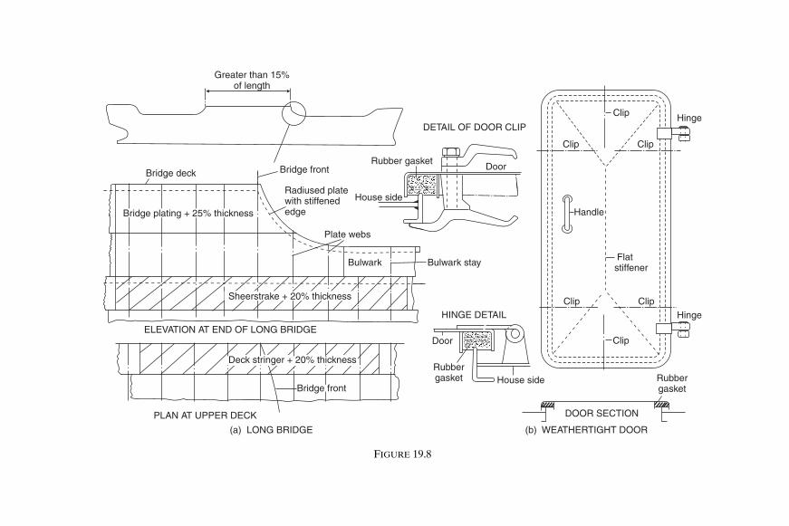
Greater than 15%of length
Clip
Clip
Clip
Clip
Clip
Clip
House side
House side
Plate webs
Bulwark Bulwark stay
Door
Bridge front
Door
Rubbergasket
DOOR SECTION
HINGE DETAIL
ELEVATION AT END OF LONG BRIDGE
PLAN AT UPPER DECK
DETAIL OF DOOR CLIP
(b) WEATHERTIGHT DOOR
Hinge
Hinge
Rubbergasket
Rubber gasketBridge deck Bridge front
Radiused platewith stiffenededge Handle
Flatstiffener
Bridge plating + 25% thickness
Deck stringer + 20% thickness
Sheerstrake + 20% thickness
(a) LONG BRIDGE
FIGURE 19.8
Shcc19.fm Page 215 M
onday, March 26, 2001 3:14 PM

216 Ship Construction
linear and the strength deck is above the upper deck in way of the super-structure deck. If a short superstructure is fitted the stress distribution willbe broken at the upper deck, which is the strength deck, the stresses in thesuperstructure deck being less than those in the upper deck. The longsuperstructure is referred to as an ‘effective superstructure’ the erectionscontributing to the overall strength of the hull girder, and therefore theyare substantially built.
In passenger ships with large superstructures the present practice is tomake the structure effective with adequate scantlings. Some older shipshave been fitted with expansion joints which are in effect transverse cutsintroduced to relieve the hull bending stresses in the houses. It has beenshown that at the end of deck erections the stresses do not conform to beamtheory and the ends are ineffective in contributing to the longitudinalstrength. The expansion joints were therefore so arranged that this ‘endeffect’ extended from joint to joint, and lighter scantlings were then permit-ted for the superstructure. Unfortunately the expansion joint often providedan ideal ‘notch’ in the structure from which cracks initiated. Aluminiumalloy superstructures offer an alternative to the use of expansion joints,since the low modulus of elasticity of the material results in lower stressesin the houses than would be the case with a steel superstructure, all otherconsiderations being equal.
W E A T H E R T I G H T D O O R S The integrity of houses on the freeboard andother decks which protect the openings in these decks must be maintained.Access openings must be provided to the houses and weathertight doors arefitted to these openings. These must comply with the requirements of theLoad Line Rules 1968 (see Chapter 31) and are steel doors which may besecured and made watertight from either side. Weathertightness is main-tained by a rubber gasket at the frame of the door (see Figure 19.8(b)).
Further Reading ‘The Design and Care of Weather Deck Hatch Covers’, The Naval Architect,
January, 1976.
Shcc19.fm Page 216 Monday, March 26, 2001 3:14 PM

20Fore End Structure
Consideration is given in this chapter to the structure forward of thecollision bulkhead. The chain locker is included as it is usually fittedforward of the collision bulkhead below the second deck or upper deck, orin the forecastle itself. An overall view of the fore end structure is shown inFigure 20.1, and it can be seen that the panting stiffening arrangements areof particular importance. These have already been dealt with in detail inChapter 17 as they are closely associated with the shell plating.
On the forecastle deck the heavy windlass seating is securely fastened,and given considerable support. The deck plating thickness is increasedlocally, and smaller pillars with heavier beams and local fore and aft inter-costals, or a centre line pillar bulkhead, may be fitted below the windlass.
StemOn many conventional ships a stem bar, which is a solid round bar, is fittedfrom the keel to the waterline region, and a radiused plate is fitted abovethe waterline to form the upper part of the stem. This forms what is referredto as a ‘soft nose’ stem, which in the event of a collision will buckle underload, keeping the impact damage to a minimum. Older ships had solid barstems which were riveted and of square section, and as the stem had norake it could cause considerable damage on impact because of its rigidity.Small ships such as tugs and trawlers may still have a solid stem bar extend-ing to the top of the bow, and some existing large passenger ships may havesteel castings or forgings forming the lower part of the stem. A speciallydesigned bow is required for ships assigned Ice Class AC notations andadditional scantlings are required for the stems of ships assigned other iceclasses (see Chapter 17).
The solid round bar is welded inside the keel plate at its lower end, andinside the radiused stem plate at its upper end, the shell being welded eachside (Figure 20.1). It is necessary to support that part of the stem which isformed by radiused plates with ‘breast hooks’, i.e. horizontal plate webs,between the decks and below the lowest deck, in order to reduce the unsup-ported span of the stem. Where the plate radius is large, further stiffeningis provided by a vertical stiffener on the centre line. The thickness of these
Shcc20.fm Page 217 Monday, March 26, 2001 3:14 PM

Stiffener
Breast hook
Solid round stem bar
STEM SECTIONS
Panting stringer
Panting beam
PLAN OF STRINGER I
Washplate
Fo’c’sle deck
Deepgirder
Upper deck
Pillar
Deep floors
Chainlocker
Pillar
Deck girder
Girder
FOREPEAK
TANK
Pillar
Stringer III
Breast hookStringer II
Stringer I
Solid round stem bar
Breast hook
PillarPantingbeam
Stiffener
ELEVATION AT SHIP’S CENTRE LINE
WASH PLATE
WASH PLATE
MUD BOX
WASH PLATE
FIGURE 20.1 Fore end construction
Shcc20.fm Page 218 M
onday, March 26, 2001 3:14 PM

Fore End Structure 219
plates will be in excess of that required for the side shell forward, but thethickness may taper to that of the side shell at the stem head.
Bulbous Bows Vessels operating at higher speeds, and those with high block coefficients,are often found to have a bulbous or protruding bow below the waterline.The arguments for and against fitting some form of bulbous bow are theprovince of text-books on naval architecture, but it may be indicated thatlike most peculiarities of the immersed hull form this feature is usuallyintended to reduce the vessel’s resistance to motion under certain conditions.
From the construction point of view the bulbous bow does not presentany great difficulty if this aspect has been considered when the bulb formis designed. In general however a greater degree of plate curvature is
Floors
Collision bulkhead
Panting stringers
Chain locker
Bulkhead stiffeners
Stem bar
Panting beams
Plate stem
Wash bulkhead
FIGURE 20.2 Fore end structure
Shcc20.fm Page 219 Monday, March 26, 2001 3:14 PM

220 Ship Construction
involved, unless a rather convenient cylindrical form is adopted and fittedinto the bow as a single unit. This has in fact been done successfully; but ingeneral the protrusion forms a continuation of the side shell. Floors arefitted at every frame space in the bulb, and a centre line wash bulkhead is
Ships
SECTION ATTRANSVERSE
Fo’c’sle deck
Breast hooks
Pillar
Upp. deck
Deck girder
Pillar
Transverse
Crown of fore peak tank
Stringer
Web
Stringer
No. 4 stringer
No. 2 stringer
No. 1 stringer
FOREPEAK
Fore peakbulkhead
Non W.T. flat
Transverse
Transverse
Breast hooksSTRINGER
No.3 stringer
STRINGER
L
FIGURE 20.3 Bulbous bow
Shcc20.fm Page 220 Monday, March 26, 2001 3:14 PM

Fore End Structure 221
introduced when the bulb is large. Transverses are fitted at about every fifthframe in long bulbs (see Figure 20.3). Smaller bulbs have a centre line webbut not a wash bulkhead; and in all bulbous bows horizontal diaphragmplates are fitted. Shell plating covering the bulb has an increased thicknesssimilar to that of a radiused plate stem below the waterline. This increasedthickness should in particular cover any area likely to be damaged by theanchors and chains; and in designing the bow fouling of the anchors shouldbe taken into consideration.
Chain Locker A chain locker is often arranged in the position forward of the collisionbulkhead shown in Figure 20.1, below either the main deck or the seconddeck. It can also be fitted in the forecastle or aft of the collision bulkhead,in which case it must be watertight and have proper means of drainage.Chain locker dimensions are determined in relation to the length and sizeof cable, the depth being such that the cable is easily stowed, and a directlead at all times is provided to the mouth of the chain pipe. Port and star-board cables are stowed separately in the locker, and the inboard ends ofeach are secured to the bottom of the centre line bulkhead or underside ofdeck (see Figure 20.4). It is desirable to have an arrangement for slippingthe cable from outside the chain locker.
C O N S T R U C T I O N O F C H A I N L O C K E R The locker does not as a rulehave the same breadth as the ship, but has conventionally stiffened forwardand side bulkheads, the stiffeners being conveniently arranged outside thelocker if possible to prevent their being damaged. A false bottom may beformed by perforated plates on bearers arranged at a height above the floorof the locker. Where fitted this provides a mudbox which can be cleaned andis drained by a centre line suction, the bottom plating sloping inboard. Toseparate the locker into port and starboard compartments a centre linebulkhead is fitted. This bulkhead does not extend to the crown of the locker,but allows working space above the two compartments. Access to thebottom of the locker is provided by means of foot holes cut in the bulkhead,and the stiffeners fitted to this bulkhead are of the vertical flush cope bartype. Any projections which would be damaged by the chains are thusavoided. The upper edge of the bulkhead is similarly stiffened and mayprovide a standing platform, with a short ladder leading from the hatch inthe deck forming the crown of the locker. Each cable is fed to the appro-priate locker compartment through port and starboard chain pipes from theforecastle deck. These chain pipes or spurling pipes are of tubular construc-tion with castings or other rounded end mouldings to prevent chafing.
Shcc20.fm Page 221 Monday, March 26, 2001 3:14 PM

222 Ship Construction
Hawse Pipes To provide an easy lead for the cable from the windlass to the anchors, thehawse pipes must be carefully fitted. It is not uncommon for a temporary
Fo’c’sle deck
Chain pipe
Hatch
Stiffening outside locker
L
Ladder
Stiffener
Foot holes
Centre line bulkheadCentre linebulkhead
Ship’s
PLANCope barstiffeners
Cableanchorage
False bottomCentre line bulkhead
False bottom
CHAINANCHORAGE
Shackle for chainWelded lugs
Welded lugs
Mud box
DoublingPinDoubling
Cope stiffenerCentre line bulkhead
FIGURE 20.4 Chain locker construction
Shcc20.fm Page 222 Monday, March 26, 2001 3:14 PM

Casting at forecastle deck
Wood sheathing
WeldWeld
Side shell
Local insertplate
CONSTRUCTION
Tubular sectionhawse pipe
Weld
Weld
Casting atshell
OVERALLARRANGEMENT
Chainlocker
Upp. dk. Hatch
Chain or spurling pipe
windloss
Hawse pipe
Foc’s’le deck
FIGURE 20.5 Hawse pipes
Shcc20.fm Page 223 M
onday, March 26, 2001 3:14 PM

224 Ship Construction
scale model of the relevant fore end structure to be constructed, and thepositions of the hawse pipes may be experimented with in order to obtainthe best lead. This model need not be elaborate but made simply of card-board and wood, and the best hawse pipe arrangement will permit theanchor to be raised and lowered smoothly, and housed properly.
Tubular hawse pipes are generally fabricated, and castings are weldedat the shell and deck to prevent chafing (see Figure 20.5). Additional stiff-ening in way of the hawse pipes is required at the side shell. On higherspeed vessels a recess is often provided in the shell for anchor stowage;this helps to reduce any drag caused by the stowed anchor and preventsserious damage in the event of a collision.
Bow Steering Arrangements Double-ended ferries are provided with a rudder at either end which islocked in position when it is at the fore end of the vessel under way.
Bow Thrust Units For manoeuvring in confined waters at low speeds, lateral bow thrust unitsare particularly useful. These are often found in research vessels, or drillingplatform vessels where very accurate positioning must be maintained. Theyare also to be found in large ships and cross-channel vessels where they areprovided as an aid to docking. The thrust unit consists as a rule of control-lable pitch or reversible impeller fitted in an athwartships watertight tunnel.Control of the unit is from the bridge, but the driving motor is in way of theimpeller. Thrust provided by the impellers are low; 16 tonnes is perhaps thelargest fitted, but the unit size does not need to be large as small thrusts arevery effective. It is true however that the greatest thrust is provided at zerospeed and as the vessel gets under way the unit becomes much less effective.
From a construction point of view the most important feature is theprovision of fairing sections at the ends of the athwartship tunnel in way ofthe shell. It has been shown that an appreciable increase in hull resistanceand hence power may result if this detail is neglected. The best way ofavoiding this is to close the tunnels at either end when they are not in use.This is possible, flush mounted, butterfly action, hydraulically operateddoors being available for this purpose.
Shcc20.fm Page 224 Monday, March 26, 2001 3:14 PM

21Aft End Structure
Considerable attention is paid to the overall design of the stern in order toimprove flow into and away from the propeller. The cruiser stern (see Figure21.1) was for many years the favoured stern type for ocean going ships, buttoday most of these vessels have a transom stern (see Figure 21.2). A cruiserstern presents a more pleasant profile and is hydrodynamically efficient, butthe transom stern offers a greater deck area aft, is a simpler construction,and can also provide improved flow around the stern.
Many forms of rudder are available and the type and form fitted isintended to give the best manoeuvring characteristics. Both the shape ofthe stern and the rudder type will dictate the form of the stern frame, andthis will be further influenced by the required propeller size. Of particularimportance at the after end are the arrangements which permit both thepropeller shaft and the rudder stock to pierce the intact watertight hull. Thesafety of the ship may depend on these arrangements. Where more thanone screw propeller is to provide the thrust required to propel the ship, boss-ings or ‘A’ brackets will be fitted to support the outboard shafts.
Stern ConstructionAs the cruiser stern overhang may be subjected to large slamming forces asubstantial construction with adequate stiffening is required. Solid floorsare fitted at every frame space, and a heavy centre line girder is fitted rightaft at the shell and decks. The stern plating is stiffened by cant frames orwebs with short cant beams supporting the decks and led to the adjacentheavy transverse deck beam. Further stiffening of the plating is provided, oradopted in lieu of cant frames, by horizontal stringers extending to the firsttransverse frame.
Cant frames are not required where the transom stern is adopted, as theflat stern plating may be stiffened with vertical stiffeners (Figure 21.2).Deep floors and a centre line girder are provided at the lower region of thetransom stern construction.
Panting arrangements at the aft end are dealt with in Chapter 17.
Shcc21.fm Page 225 Monday, March 26, 2001 3:18 PM

‘x’
Cant beam
Cant beam
Cant beam
PLAN AT UPPERDECK
Girder
Girder
Girder Ship’s
‘x’
Poop deck
SECTION ‘X’–‘X’
Cant beam
Steering flat
Upper deck
Cant frame
Stern frame
Poop deck
Bracket Deck centre line girderBulkhead stiffener
Centre line webUpper deck
Deck centre line girder
Steering flat
Centre line web Bulkhead stiffenerBracket
Centre line girder
Bulkhead
Rudder trunk
Solid floors Flat
Cant beam
FIGURE 21.1 Cruiser stern
Shcc21.fm Page 226 M
onday, March 26, 2001 3:18 PM

Aft End Structure 227
Upper deck
Rudder trunk
Steering flat
Inspectionmanhole
Verticalstiffeners
Solid floor
Wash plate
Floor
AFT PEAKTANK
Stern frame
Sideshell
Stern tube
Floor
Transom stern
Steering flat
BREAST HOOK
DETAIL
Breast hook
Ship’s
Upper deck
Aftpeakblkhd.
PLAN ATRUDDER TRUNK
FloorFloorFloorFloor
Ship’s
Inspection manhole
TRANSOM STERNLOOKING FOR’D
Centre line
bulkhead(corrugated)
FIGURE 21.2 Transom stern
Shcc21.fm Page 227 Monday, March 26, 2001 3:18 PM

228 Ship Construction
Stern FrameIt has already been indicated that the form of the stern frame is influencedby the stern profile and rudder type. To prevent serious vibration at theafter end there must be adequate clearances between the propeller andstern frame, and this will to a large extent dictate its overall size.
The stern frame of a ship may be cast, forged, or fabricated from steelplate and sections. On larger ships it is generally either cast or fabricated,the casting being undertaken by a specialist works outside the shipyard. Toease the casting problem with larger stern frames and also the transportproblem it may be cast in more than one piece and then welded togetherwhen erected in the shipyard. Fabricated stern frames are often producedby the shipyard itself, plates and bars being welded together to produce aform similar to that obtained by casting (see Figure 21.3). Forged sternframes are also produced by a specialist manufacturer and may also be madein more than one piece where the size is excessive or shape complicated.
Sternpost sections are of a streamline form, in order to prevent eddiesbeing formed behind the posts, which can lead to an increase in the hullresistance. Welded joints in cast steel sections will need careful preparationand preheat. Both the cast and fabricated sections are supported by horizontalwebs.
Two forms of stern frame are shown in Figure 21.3, one being a castingand the other fabricated, so that the similarity of the finished sections isindicated. Of particular interest is the connection of the stern frame to thehull structure for, if this is not substantial, the revolving propeller supportedby the stern frame may set up serious vibrations. The rudder post is carriedup into the main hull and connected to the transom floor which has anincreased plate thickness. Also the propeller post may be extended into thehull and connected to a deep floor, the lower sole piece being carriedforward and connected to the keel plate. Side shell plates are directlywelded to the stern frame (Figure 21.3), a ‘rabbet’, i.e. a recess, sometimesbeing provided to allow the shell plate to fit flush with the sternpost section.
RuddersMany of the rudders which are found on present-day ships are semibalanced,i.e. they have a small proportion of their lateral area forward of the turningaxis (less than 20 per cent). Balanced rudders with a larger area forward ofthe axis (25 to 30 per cent), and un-balanced rudders with the full area aftof the axis are also fitted. The object of balance is to achieve a reduction intorque since the centre of lateral pressure is brought nearer the turningaxis. However the fully balanced rudder will at low angles tend to drive the
Shcc21.fm Page 228 Monday, March 26, 2001 3:18 PM

SECTION –‘A’‘A’
Web Floor
ShellShell welded to
stern frame
Boss
SECTION –‘Y’‘Y’
SECTION –‘X’‘X’
Cast sole piece
FABRICATEDSTERN FRAME
‘X’ ‘X’
Horizontal web
Boss
Floor
Shell
Floor
Solid round bar
Plate
Horizontal web
‘Y’
‘Y’
Solid roundbar
Floor
WELDDETAIL
Side shell tostern frame weld
Floors
‘A’
‘A’CAST STEELSTERN FRAME
Weld (seedetail)
FIGURE 21.3 Stern frames
Shcc21.fm Page 229 M
onday, March 26, 2001 3:18 PM

230 Ship Construction
gear, which does not matter a great deal with power steering gears but isless satisfactory with any form of direct hand gear.
Designs of rudders are various, and patent types are available, all of whichclaim increased efficiencies of one form or another. Two common forms ofrudder are shown in Figure 21.4 each being associated with one of the sternframes shown in Figure 21.3.
R U D D E R C O N S T R U C T I O N Modern rudders are of streamlined formexcept those on small vessels, and are fabricated from steel plate, the platesides being stiffened by internal webs. Where the rudder is fully fabricated,one side plate is prepared and the vertical and horizontal stiffening websare welded to this plate. The other plate, often called the ‘closing plate’, isthen welded to the internal framing from the exterior only. This may beachieved by welding flat bars to the webs prior to fitting the closing plate,and then slot welding the plate as shown in Figure 21.4. Other rudders mayhave a cast frame and webs with welded side and closing plates which arealso shown in Figure 21.4.
Minor features of the rudders are the provision of a drain hole at thebottom with a plug, and a lifting hole which can take the form of a shortpiece of tube welded through the rudder with doubling at the side andclosing plates. To prevent internal corrosion the interior surfaces are suit-ably coated, and in some cases the rudder may be filled with an inertplastic foam. The rudder is tested when complete under a head of water2.45 m above the top of the rudder.
R U D D E R P I N T L E S Pintles on which the rudder turns in the gudgeonshave a taper on the radius, and a bearing length which exceeds the diameter.Older ships may have a brass or bronze liner shrunk on the pintles whichturn in lignum vitae (hardwood) bearings fitted in the gudgeons. Modernpractice is to use synthetic materials like ‘Tufnol’ for the bearings, and insome cases stainless steels for the liners. In either case lubrication of thebearing is provided by the water in which it is immersed. Until recently ithas not been found practicable to provide oil-lubricated metal bearings forthe pintles, but Queen Elizabeth 2 has this innovation.
R U D D E R S T O C K A rudder stock may be of cast or forged steel, and itsdiameter is determined in accordance with the torque and any bendingmoment it is to withstand. At its lower end it is connected to the rudder bya horizontal or vertical bolted coupling, the bolts having a cross-sectionalarea which is adequate to withstand the torque applied to the stock. Thiscoupling enables the rudder to be lifted from the pintles for inspection andservice.
Shcc21.fm Page 230 Monday, March 26, 2001 3:18 PM

Drain plug
Lower bearing
Side platesare slotwelded totube
Upperbearing
Boltedpalm
Rudder stock
Bolted palm
Verticalweb
Horizontal web
Side plateswelded to castframe
SECTION A–AHorizontal web Welded tube
Vertical web
Lifting hole
DETAIL OFSLOT WELD
RUDDER WITHCAST FRAME
Lifting tube weldedthrough rudder
A A
Side plate
Slot weld
Slot weld
Rudder stock
Bolted coupling
Cast frame
FIGURE 21.4 Rudders
Shcc21.fm Page 231 M
onday, March 26, 2001 3:18 PM

232 Ship Construction
R U D D E R B E A R I N G The weight of the rudder may be carried partlyby the lower pintle and partly by a rudder bearer within the hull. In somerudder types, for example, the spade type which is only supported withinthe hull, the full weight is borne by the bearer. A rudder bearer may incorp-orate the watertight gland fitted at the upper end of the rudder trunk asshown in Figure 21.5. Most of the rudder’s weight may come onto thebearer if excessive wear down of the lower pintle occurs, and the bearersillustrated have cast iron cones which limit their wear down.
R U D D E R T R U N K Rudder stocks are carried in the rudder trunk, whichas a rule is not made watertight at its lower end, but a watertight gland isfitted at the top of the trunk where the stock enters the intact hull (Figure21.5). This trunk is kept reasonably short so that the stock has a minimumunsupported length, and may be constructed of plates welded in a box formwith the transom floor forming its forward end. A small opening with water-tight cover may be provided in one side of the trunk which allows inspectionof the stock from inside the hull in an emergency.
Steering Gear Unless the main steering gear comprises two or more identical power units,every ship is to be provided with a main steering gear and an auxiliary steer-ing gear. The main steering gear is to be capable of putting the rudder overfrom 35° on one side to 35° on the other side with the ship at its deepestdraft and running ahead at maximum service speed, and under the sameconditions from 35° on either side to 30° on the other side in not more than28 seconds. It is to be power operated where necessary to meet the aboveconditions and where the stock diameter exceeds 120 mm. The auxiliarysteering gear is to be capable of putting the rudder over 15° on one side to15° on the other side in not more than 60 seconds with the ship at its deep-est draft and running ahead at half the maximum service speed or 7 knotswhichever is greater. Power operated auxiliary steering gear is requiredif necessary to meet the forgoing requirement or where the rudder stockdiameter exceeds 230 mm.
The main steering gear for oil tankers, chemical tankers or gas carriers of10 000 gross tonnage or more and every other ship of 70 000 gross tonnageor more is to consist of two or more identical power units which are capableof operating the rudder as indicated for the main steering gear above andwhilst operating with all power units. If a passenger ship, this requirementis to be met when any one of the power units is inoperable.
Steering gear control for power operated main and auxiliary steeringgears is from the bridge and steering gear compartment, the auxiliary
Shcc21.fm Page 232 Monday, March 26, 2001 3:18 PM

(b) COMBINED RUDDER CARRIERAND STUFFING BOX
(a) SEPARATE CARRIER ANDSTUFFING BOX
(A) DUNSTOS IMPROVED RUDDER CARRIER
Grease nipple
Stock
KeyGrease pipe
Gland
6 coils ofpacking
STUFFINGBOX Gland
Machinedsection ofstock
(B) COMBINED RUDDER BEARINGAND STUFFING BOX
Key
Key Tiller
Splitbearing ring
Eyebolt forlifting stock
Forged collar
FIGURE 21.5 Rudder bearings
Shcc21.fm Page 233 M
onday, March 26, 2001 3:18 PM

234 Ship Construction
steering gear control being independent of the main steering gear control(but not duplication of the wheel or steering lever).
Steering gear on ocean-going ships is generally of the electro-hydraulictype.
Where the rudder stock is greater than 230 mm an alternative powersupply is to be provided automatically from the ship’s emergency powersupply or from an independent source of power located in the steering gearcompartment.
Sterntube A sterntube forms the after bearing for the propeller shaft, and incorp-orates the watertight gland where the shaft passes through the intact hull.Two forms of sterntube are in use, that most commonly fitted having water-lubricated bearings with the after end open to the sea. The other type isclosed at both ends and has metal bearing surfaces lubricated by oil. In theformer type the bearings were traditionally lignum vitae strips and the tailshaft (aft section of propeller shaft) was fitted with a brass liner, but Tufnolstrips are now often fitted. The latter form of sterntube is preferred in manyships with machinery aft, where the short shaft is to be relatively stiff andonly small deflections are tolerated. Where this patent oil lubricated stern-tube is fitted, glands are provided at both ends to retain the oil and preventthe ingress of water, white metal (high lead content) bearing surfaces beingprovided and the oil supplied from a reservoir. Both types of sterntube areillustrated in Figure 21.6.
Shaft Bossing and ‘A’ Brackets Twin-screw or multi-screw vessels have propeller shafts which leave the lineof shell at some distance forward of the stern. To support the shaft over-hang, bossings or ‘A’ brackets may be fitted. Bossings are a common featureon the larger multiple-screw passenger ships and are in effect a moulding ofthe shell which takes in the line of shaft for some distance. Access frominside the hull is thus provided to the shaft over a great proportion of itslength, and it is afforded greater protection. Many large liners having highspeeds are shown to have benefited by a decrease in resistance when bossingshave been fitted rather than ‘A’ brackets. However large liners of morerecent design have in some instances had extended shafts solely supported by‘A’ brackets of improved design.
C O N S T R U C T I O N O F B O S S I N G A N D ‘ A ’ B R A C K E T S The shapedframes and plating forming the bossing terminate in a casting known as the
Shcc21.fm Page 234 Monday, March 26, 2001 3:18 PM

Sterntube
Shaft
Stern tube nut Stern frame
Tufnol or lignum vitae strips Tailshaft sheathed with liner
PackingOil
headertank
Gunmetal liner
Sterntube
Sterntube
Aft peak bulkheadStern frame
Oil feed holes
Oil seal
D3D 2D DD DD2
3 4Tailshaft
PumpOil outlet
Locking nut
Gunmetal liner
Oil seal
Oil ventOil supply
White metal bearing
HandpumpOil
drain
Aft peak bulkhead
W.T. gland
Sea water cock (seawater tube)
Retainingring
SECTION IN WAY OFBEARING STRIPS
FIGURE 21.6 Sterntubes
Shcc21.fm Page 235 M
onday, March 26, 2001 3:18 PM

236 Ship Construction
‘spectacle frame’ which provides the aftermost bearing for the shaft. Thismay be cast or fabricated and forms a box-like section athwartships which isrigidly connected to heavy plate floors. The arms carrying the shafts extendfrom this section which may be split in two or more parts in some instancesto aid alignment when it is erected (see Figure 21.7).
‘A’ brackets may be cast, or fabricated, particular attention being paid tothe strut section to avoid increases in resistance and cavitation. The con-nections to the main hull are of particular importance since considerablerigidity of the structure is required. Although on smaller vessels the upperpalms may simply be welded to a reinforcing pad at the shell, on largervessels the upper ends of the struts enter the main hull and are connectedto a heavy floor with additional local stiffening (Figure 21.7).
Propellers Ship propellers may have from three to six similar blades, the number beingconsistent with the design requirements. It is important that the propeller isadequately immersed at the service drafts and that there are good clear-ances between its working diameter and the surrounding hull structure. Thebore of the propeller boss is tapered to fit the tail shaft and the propellermay be keyed onto this shaft; a large locking nut is then fitted to secure thepropeller on the shaft. For securing the propeller a patent nut with a builtin hydraulic jack providing a frictional grip between the propeller and tailshaft is available. This ‘Pilgrim nut’ may also be used with keyless borepropellers. A fairing cone is provided to cover the securing nut.
C O N T R O L L A B L E P I T C H P R O P E L L E R S These are propellers in whichthe blades are separately mounted on the boss, and in which the pitch of theblades can be changed, and even reversed, by means of a mechanism in theboss, whilst the propeller is running. The pitch is mechanically or electro-mechanically adjusted to allow the engines’ full power to be absorbed underdifferent conditions of operation. It is incorrect to refer to such a propelleras a variable pitch propeller since virtually all merchant ship propellershave a fixed pitch variation from blade root to blade tip.
Propellers of this type are often found on diesel-engined tugs andtrawlers where the propeller pitch may be changed to allow the full torqueto be absorbed under towing or trawling conditions, and also when thevessel is running freely at full revolutions and a higher speed. It is possibleto reverse the pitch in order to stop the vessel rapidly and go astern, withthe propeller shaft and propeller still rotating in the one direction.
Large controllable pitch propellers have been fitted to large diesel-drivenbulk carriers in recent years.
Shcc21.fm Page 236 Monday, March 26, 2001 3:18 PM

lap
Plate
CAST SPECTACLEFRAME
SECTIONLOOKING AFT
Floor
Stringer
Strut
Floor
Ship’s
‘A’ – BRACKET
Propeller shaft
FRAME IN WAY OF BOSSING Inserted frame
Casting boltedat centre line
PLAN
Floor
Plate bossing
Horizontal web
Webframe
FIGURE 21.7 Bossings and ‘A’ brackets
Shcc21.fm Page 237 M
onday, March 26, 2001 3:18 PM

Flare plating
Leading edge bar
Trailingedge bar
Cone plating
Ring web
Fore and Aftw seb
TRANSVERSE SECTION FORE AND AFT SECTIONAT CENTRE LINE
Ring webs
Shroudplating in way ofpropeller
FIGURE 21.8 Propeller nozzle
Shcc21.fm Page 238 M
onday, March 26, 2001 3:18 PM

Aft End Structure 239
S H R O U D E D P R O P EL L E R S To increase the thrust provided by a pro-peller of given diameter at low speeds and high slips it may be enclosed in afixed nozzle. Single-screw tugs and trawlers are often fitted with the fixedpatent ‘Kort nozzle’ where under a heavy tow the propeller is working at ahigh slip. This nozzle has a reducing diameter aft and is relatively short inrelation to the diameter, to avoid increasing the directional stability thusmaking steering difficult.
When running freely the slip is much lower, and it might appear thatthere was little advantage in fitting a shrouded propeller. However seriousconsideration has been given to fitting shrouded propellers on very largesingle screw ships where there is a problem of absorbing the large powerson the limited diameter.
Some ships are fitted with a steering nozzle which not only fulfils thepurposes of a fixed nozzle but having a turning stock and fin and pivotingabout the ships longitudinal axis can be used to steer the ship.
The fabricated construction is similar for both the fixed and steeringnozzles and is shown in Figure 21.8 for a nozzle of 2.5 to 3 metres indiameter. The inner plating of the nozzle has a heavier ‘shroud’ plate in wayof the propeller tips and this is carried some distance fore and aft of thisposition. At this diameter the nozzle section has two full ring webs and ahalf-depth ring web supporting the inner and outer plating.
Further Reading‘Pilgrim Propeller Nut’, Shipbuilding and Shipping Record, 17 April, 1970.
Shcc21.fm Page 239 Monday, March 26, 2001 3:18 PM

22Tanker Construction
Ships designed specifically to carry bulk liquid cargoes are generallyreferred to as tankers. Tankers are commonly associated with the carriageof oil, but a wide variety of liquids are carried in smaller tank vessels andthere are a growing number of larger tank vessels dedicated to carryingchemicals in bulk.
Oil Tankers Small tankers, not exceeding 75 metres in length, involved principally in thecoastal trade have a single longitudinal bulkhead on the centre line provid-ing two athwartship tanks. The machinery is aft, and an expansion trunk, iffitted, is on the centre line in the way of the tank spaces (see Figure 22.1).Larger ocean-going tankers have at least two longitudinal bulkheadsproviding three athwartship tanks, and the machinery is again arranged aft(see Figures 22.2 and 22.3).
This chapter is concerned with the construction of the larger ocean-goingtype, which may be considered in two classes. There are those ships whichcarry refined oil products, and perhaps some other cargoes like molasses,which tend to be in the smaller 12 000 tons to 50 000 tons deadweight range.Then there are the crude oil carriers which extend to the 500 000 tons dead-weight range. The former vessels have a greater number of tanks, and morecomplicated pumping arrangements which permit the carriage of a numberof different products on a single voyage.
Both types of ship have traditionally been single flush deck ships withlongitudinal bulkheads and a structure within the tank spaces consisting ofa grillage of longitudinal and transverse members. The structural arrange-ment over the cargo tank length is dictated by the requirements of theMARPOL convention (see Chapter 29). Since 1980 new crude tankers of20 000 tons deadweight or more and new products carriers of 30 000 tonsdeadweight or more have been required to be provided with segregatedballast tanks (SBTs). The capacity of the SBTs being so determined that theship may operate safely on ballast voyages without recourse to the use ofcargo tanks for ballast water. These SBTs were to be located within thecargo tank length and arranged to provide a measure of protection against
Shcc22.fm Page 240 Monday, March 26, 2001 3:19 PM

Trunk plating (11mm)
Flat stiffenerStiffener175mm x 8.5mm
Frame space clear oftransverse Stringer
Deck and trunklongitudinals200mm x 12.5mm
Bracket
Stringer
Longitudinalbulkhead
Deck plating (11mm)
Sheerstrake1500mm x 12.5mm
Side shell (10.5mm)
Stringer
Frame space in way oftransverse
Bottom plating (11mm)Bottom longitudinals 250mm x 12mm Keel plate 1075mm x 16.5mm
BracketDocking bracket
Side frame175mm x 8.5mm
Transverse
FIGURE 22.1 Midship section of coastal tanker with trunk
Shcc22.fm Page 241 M
onday, March 26, 2001 3:19 PM
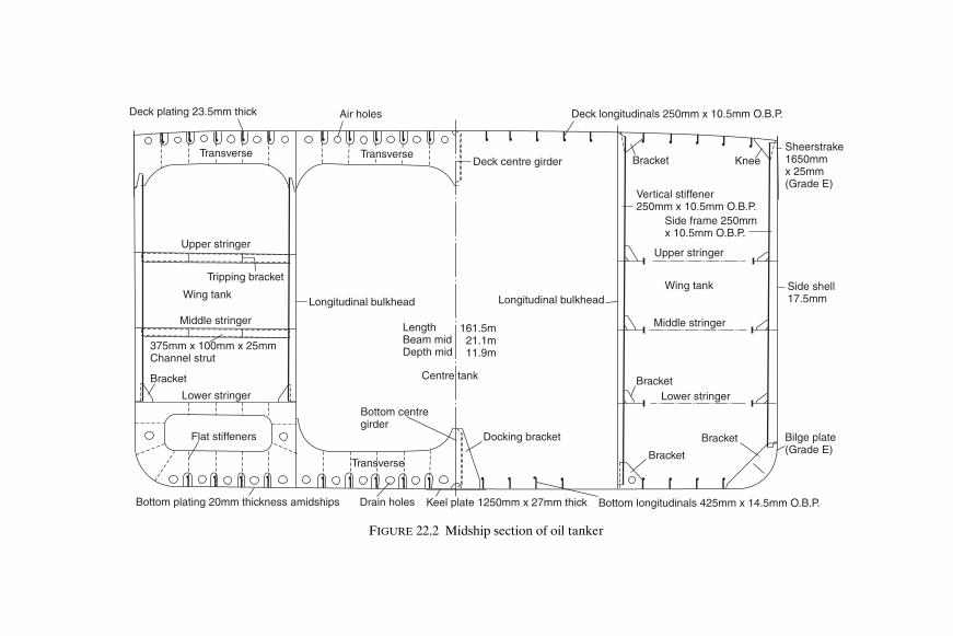
Deck plating 23.5mm thick Air holes
Upper stringer
Tripping bracket
Wing tank
Middle stringer
Longitudinal bulkhead
375mm x 100mm x 25mmChannel strut
Bracket
Lower stringer
Bottom centregirder
Flat stiffeners
Transverse
LengthBeam midDepth mid
161.5m21.1m11.9m
Centre tank
Docking bracket
Longitudinal bulkhead
Bracket
Bracket
Bracket
Bilge plate(Grade E)
Bottom plating 20mm thickness amidships Drain holes Keel plate 1250mm x 27mm thick Bottom longitudinals 425mm x 14.5mm O.B.P.
Lower stringer
Middle stringer
Wing tank Side shell17.5mm
Upper stringer
Side frame 250mmx 10.5mm O.B.P.
Vertical stiffener250mm x 10.5mm O.B.P.
Bracket KneeSheerstrake1650mmx 25mm(Grade E)
Deck longitudinals 250mm x 10.5mm O.B.P.
Deck centre girderTransverse Transverse
FIGURE 22.2 Midship section of oil tanker
Shcc22.fm Page 242 M
onday, March 26, 2001 3:19 PM

‘DH’ ‘EH’ ‘DH’
‘EH’
375mm deepside longitudinals
Decklongitudinals500mm deep
WING TANK
CENTRE
Perforated centreline bulkhead
Length B.P.Beam mid.Dept mid.
305m47.25m36.5m
Dockingbracket‘DH’
‘DH’‘DH’ ‘EH’ ‘EH’‘EH’
Keel plate3000mm x 29mm
Bottom longitudinals600mm deep,250mm face plate
730mm deepside logitudinal
Deck plating (23.5mm)
Transverse
Deck sidegirder
Longitudinalbulkhead
TANK
Web
Flat stiffeners
Bottom sidegirder
Transverse
Bottom plating (29mm)
Bilge plate
Roundedsheerstrake
Side shell(28mm)
Cross tie
Cross tie
Cross tie
Sidegirder
Bottomside
girder
L
FIGURE 22.3 Midship section of large tanker
Shcc22.fm Page 243 M
onday, March 26, 2001 3:19 PM

244 Ship Construction
oil outflow in the event of grounding or collision. The protective location ofthese tanks had the effect of providing full or partial double bottoms and/orside tanks in the way of the cargo tank space. Subsequent amendments toMARPOL require every tanker of 5000 tons deadweight or more commen-cing construction after 1993 to have the entire cargo tank length protectedby ballast tanks or spaces other than cargo and fuel oil tanks, or other provi-sions offering equivalent protection against oil pollution. See Chapter 3regarding the introduction of requirements for double hull oil tankers andthe phase out of single hull oil tankers.
Materials for Tanker ConstructionMild steel is used throughout the structure, but higher tensile steelsmay also be introduced in the more highly stressed regions of the largervessels.
M I L D S T E E L As with dry cargo ships it is a requirement that Grade B, Dand E steels be used for the heavier plating of the main hull strength mem-bers where the greatest stresses arise in tankers. These requirements arethe same as those indicated in Table 17.1. Grade E plates which we haveequated with the ‘crack arrester strake’ concept (see Chapter 8) will be seento be required over the midship region in ships exceeding 250 m in lengthand are also required as shown in Table 22.1.
H I G H E R T E N S I L E S T E E L Higher tensile steels are often used for thedeck and bottom regions of the larger tankers. As indicated in Chapter 5this leads to a reduction in the scantlings of these structural items withadvantages both for the shipbuilder and owner. The extent of this platingand section material is indicated in Figure 22.3, which shows the midshipsection of a very large tanker.
TABLE 22.1
Use of grade E steel in tankers
Location Thickness
Stringer plate, sheerstrake, rounded gunwale. Greater than 15 mmBilge strake, deck strake in way of longitudinal bulkhead. Greater than 25 mmMain deck plating, bottom plating, keel, upper strake of
longitudinal bulkhead.Greater than 40 mm
Shcc22.fm Page 244 Monday, March 26, 2001 3:19 PM

Tanker Construction 245
Construction in Tank Spaces Ocean-going tankers have a longitudinally framed bottom shell and deckthrough the tank spaces. The side shell may however be either longit-udinally framed or transversely framed, and the longitudinal bulkheadslongitudinally or vertically stiffened in other than the larger tankers. Lloyd’sRegister generally requires full longitudinal framing once the vessel’slength exceeds 150 m.
T R A N S V E R S E S I D E F R A M I N G Where transverse framing is adopted insmaller and medium size tankers the frames are supported by horizontalstringers (Figure 22.2), and the numbers of stringers depends on the depthof the ship. At the ends of the side frames bracket connections are made,the lower bracket covering the round of bilge and extending to the adjacentbottom longitudinal clear of the transverse. At the upper end the bracketconnection is to the underside of deck clear of transverses, and bracketconnections are also arranged at the stringers.
L O N G I T U D I N A L F R A M I N G Deck and bottom longitudinals have thegreatest scantlings since they are stiffening the more highly stressed flangesof the hull girder. At the side shell the upper longitudinals have the leastscantlings, and a uniform increase in size occurs down the side shell untilthe bilge is reached. The bilge longitudinal size then approaches that of thebottom shell. An important feature of the longitudinal framing is thatcontinuity of strength is maintained, particularly at the bulkheads formingthe ends of the tanks. This feature is increasingly important as the shiplength is extended, the bottom and deck longitudinals being continuousthrough the bulkhead where the ship length is excessive, unless an altern-ative arrangement is permitted by the classification society (see Figure22.4). Higher tensile steel longitudinals are to be continuous irrespective ofship length.
The longitudinals can be offset bulb plates which may be built up to givethe required scantling on large ships. It is not however uncommon to findon many tankers longitudinals having a web and symmetrical flat plateflange.
B O T T O M, S I D E, A N D D E C K T R A N S V E R S E S To support the longit-udinal framing at the deck and bottom shell, transverse webs are fitted atregular intervals. Similarly where the side shell is longitudinally frameda vertical transverse web is arranged at the shell. Between the transversebulkheads the transverse webs may be evenly spaced at intervals of say 3 mon smaller vessels to 5 m or more on larger vessels.
Transverses are as a rule built of a plate web, and heavier flat face bar thedepth being adequate to allow sufficient material abreast the slots through
Shcc22.fm Page 245 Monday, March 26, 2001 3:19 PM
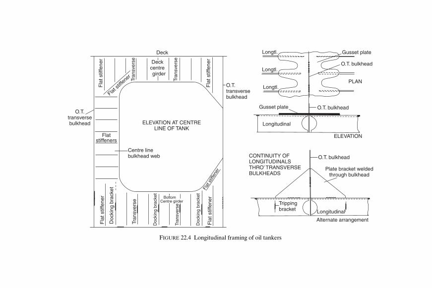
Deck
Deckcentregirder
Fla
t stif
fene
rF
lat s
tiffe
ner
Fla
t stif
fene
r
Tran
sver
se
Tran
sver
se
Doc
king
bra
cket
Doc
king
bra
cket
Doc
king
bra
cket
Flatstiffeners
Fla
t stif
fene
r
Flat st
iffene
r
Flat
stif
fene
r
Tran
sver
se
Tran
sver
se
O.T.transversebulkhead
Centre linebulkhead web
O.T.transversebulkhead ELEVATION AT CENTRE
LINE OF TANK
Longtl.
Longtl.
Longtl.
Gusset plate
Longitudinal
ELEVATION
O.T. bulkhead
O.T. bulkhead
Gusset plate
PLAN
CONTINUITY OFLONGITUDINALSTHRO’ TRANSVERSEBULKHEADS
O.T. bulkhead
Plate bracket weldedthrough bulkhead
Trippingbracket Longitudinal
Alternate arrangement
BottomCentre girder
FIGURE 22.4 Longitudinal framing of oil tankers
Shcc22.fm Page 246 M
onday, March 26, 2001 3:19 PM

Tanker Construction 247
which the longitudinals pass. In way of the longitudinals flat vertical stiffenersare fitted, and horizontal stiffeners may be provided if the transverse depthis excessive.
CRO S S T I E S Horizontal cross ties are introduced in the wing tanks toconnect the vertical webs at the ship’s side and longitudinal bulkhead,where these are longitudinally framed (Figure 22.3). The cross ties aredesigned to stiffen the tank side boundary bulkhead structure against trans-verse distortion under liquid pressure.
Two or three horizontal cross ties are provided depending on the vessel’sdepth, but diagonal cross ties may be fitted and will be found on a number
Deck longitudinals
Oil tight tr
ansverse bulkhead
Side frames
Deck transverse
Deck centre lineweb
Verticalbulkheadstiffeners
Bulkheadcentre line
web
Oil tightlongitudinal
bulkhead
Horizontalbulkheadstringer
Bottom centreline web Bottom longitudinal
Bottomtransverse
Lower stringer
Middle stringer
Upper stringer
FIGURE 22.5 Compositely framed oil tanker
Shcc22.fm Page 247 Monday, March 26, 2001 3:19 PM

248 Ship Construction
of ships. The cross tie is often simply a face plate, vertically stiffened if verydeep, and horizontally stiffened to prevent buckling and distortion in thatdirection. At its ends the cross tie is bracketed to the vertical transversewebs.
B O T T O M A N D DECK G I R D E R S Stiffening arrangements at the bottomshall require for ships with two longitudinal bulkheads either a deep centregirder between the oiltight transverse bulkheads supported by up to fivetransverses, or a smaller centre line docking girder supporting bottomtransverses spanning between longitudinal bulkheads.
Bottom centre line girders are supported by stiffened brackets midwaybetween the transverses, which are often referred to as ‘docking brackets’.These support the centre line girder which constitutes, with the heavy keelplate, the immediate structure through which docking loads are transmitted
Bottom longitudinals
Bottom transverse
Bottom intermediatgirders
Bulkheadlongitudinals
Verticaltransverseweb
Side longitudinals
Deck longitudinals
Decktransverse
Longitudinalbulkhead
Verticalbulkheadstiffeners
Deck intermediate web
Deck intermediate web
Deckcentre line
girder
Bulkheadcentre line
web
Web
Bottom centre lineWeb
FIGURE 22.6 Longitudinally framed oil tanker
Shcc22.fm Page 248 Monday, March 26, 2001 3:19 PM

Tanker Construction 249
when the vessel is placed on the keel blocks. Further stiffening for thecentre line girder, and also for other girders, is provided by vertical flatstiffeners. At the transverse oiltight bulkhead the bottom centre linegirder will be faired into a vertical centre line web.
The deck also has a continuous or intercostal centre line girder whichtogether with the bottom centre girder and vertical bulkhead web forms acontinuous ring of material on the ship’s centre line (Figure 22.4).
Double Hull Construction Double bottoms are longitudinally framed, the construction being similarto that for other ships with supporting plate and bracket transverse floors(see Chapter 16). Likewise the double hull side space and any hopper sidetank, with stiffened plate transverses in line with each double bottom floor,bulkheads, etc. (see Figure 22.7).
BulkheadsBulkhead spacing throughout the cargo tank space is determined by thepermissible length of cargo tanks. MARPOL requires that the length of eachcargo tank shall not exceed the greater of 10 metres or a length expressedas a percentage of the ship’s length which is dependent on the number oflongitudinal bulkheads fitted and the minimum distance from the ship’s sideof the outer longitudinal bulkhead. Tankers with two or more longitudinalbulkheads may have wing and centre tank lengths up to 20 per cent of theship’s length. Lloyd’s Register require the disposition of transverse bulk-heads to comply with Table 18.1, as applicable to ships with machinery aft.Cofferdams, which may be formed with two adjacent oiltight transversebulkheads at least 760 mm apart, are required at the ends of the cargo space.However in many cases a pump room is fitted at the after end of the cargospace (also forward on some products carriers), and a ballast tank is fittedat the forward end, each of these compartments being accepted in lieu of acofferdam. A cofferdam is also provided between any accommodation andoil cargo tanks.
Construction of the transverse bulkheads is similar to that in other ships,the bulkhead being oiltight. Vertical stiffeners are fitted, or corrugatedplating is provided with the corrugations running either vertically or horizont-ally. Horizontal stringers support the vertical stiffeners and corrugations, andvertical webs support any horizontal corrugations. Further support is pro-vided by the vertical centre line web which is as a rule deeper on one side ofthe bulkhead than on the other, unless the tank is very long and the webmay then be symmetrical either side of the bulkhead.
Shcc22.fm Page 249 Monday, March 26, 2001 3:19 PM

250 Ship Construction
Longitudinal bulkheads which are oiltight may be conventionally stiffenedor may be corrugated with the corrugations running horizontally. Verticalcorrugated centre line bulkheads may be fitted. Conventional stiffening isarranged vertically where the side framing is vertical, and arranged longit-udinally when the side is longitudinally framed. Vertical webs are fitted tothe longitudinal bulkhead when this is corrugated or longitudinally framed.Corrugated longitudinal bulkheads are only permitted in ships of less than200 m in length.
Hatchways Oiltight hatchways provide at the exposed deck access to the tank spaces.The openings for these are kept as small as possible, and the corners arewell rounded, circular openings being not uncommon. Coamings pro-vided for the openings should be of steel and at least 600 mm high, andsuitably fastened steel or other approved material covers are fitted. Patentoiltight hatches are available and approved with both steel and fibreglasscovers.
Access to the cofferdams and water ballast tanks may be by similarhatches in the deck, or alternatively a watertight manhole may be fitted
Stringer
Floor
Transverseweb
Deck-transverseweb
CENTRETANK
Length B.PBeam mld.Depth mld.
315m58m30.4m
Platebracket
Inner bottom
Intermediatestringer
WING TANK
Longitudinalbulkhead
Inner hull
Floor3.5m
3m
FIGURE 22.7 Double hull oil tanker
Shcc22.fm Page 250 Monday, March 26, 2001 3:19 PM
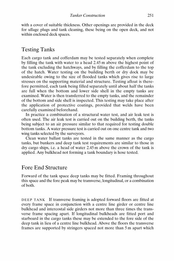
Tanker Construction 251
with a cover of suitable thickness. Other openings are provided in the deckfor ullage plugs and tank cleaning, these being on the open deck, and notwithin enclosed deck spaces.
Testing Tanks Each cargo tank and cofferdam may be tested separately when completeby filling the tank with water to a head 2.45 m above the highest point ofthe tank excluding the hatchways, and by filling the cofferdam to the topof the hatch. Water testing on the building berth or dry dock may beundesirable owing to the size of flooded tanks which gives rise to largestresses on the supporting material and structure. Testing afloat is there-fore permitted, each tank being filled separately until about half the tanksare full when the bottom and lower side shell in the empty tanks areexamined. Water is then transferred to the empty tanks, and the remainderof the bottom and side shell is inspected. This testing may take place afterthe application of protective coatings, provided that welds have beencarefully examined beforehand.
In practice a combination of a structural water test, and air leak test isoften used. The air leak test is carried out on the building berth, the tanksbeing subject to an air pressure similar to that required for testing doublebottom tanks. A water pressure test is carried out on one centre tank and twowing tanks selected by the surveyors.
Clean water ballast tanks are tested in the same manner as the cargotanks, but bunkers and deep tank test requirements are similar to those indry cargo ships, i.e. a head of water 2.45 m above the crown of the tank isapplied. Any bulkhead not forming a tank boundary is hose tested.
Fore End Structure Forward of the tank space deep tanks may be fitted. Framing throughoutthis space and the fore peak may be transverse, longitudinal, or a combinationof both.
D E E P T A N K If transverse framing is adopted forward floors are fitted atevery frame space in conjunction with a centre line girder or centre linebulkhead and intercostal side girders not more than three times the trans-verse frame spacing apart. If longitudinal bulkheads are fitted port andstarboard in the cargo tanks these may be extended to the fore side of thedeep tank in lieu of a centre line bulkhead. Above the floors the transverseframes are supported by stringers spaced not more than 5 m apart which
Shcc22.fm Page 251 Monday, March 26, 2001 3:19 PM

252 Ship Construction
are either supported by web frames connected to deep beams to form avertical ring frame, or connected to longitudinal stringers on the transversebulkheads to form horizontal ring frames. Alternatively, in narrow tanksperforated flats may be fitted at 5 m spacings.
Longitudinally framed deep tanks are supported by side transversesfive frame spaces apart. Where the depth of the tank exceeds 16 m the sidetransverses, also the web frames in a transversely framed tank, either haveone or more deep stringers fitted, cross ties, or perforated flats with deepbeams in way of the transverses or webs.
A longitudinal bulkhead generally must be provided if the tank widthexceeds 50 per cent of the ship’s beam and may solely be a wash bulkheadon the centre line. Where the breadth of tank exceeds 70 per cent of theship’s beam, at least one solid bulkhead on the centre line is recommended.
F O R E P E A K A transversely framed forepeak has a similar construction tothat of a conventional cargo ship and includes the usual panting arrange-ments (see Chapter 20). If the forepeak is longitudinally framed the sidetransverses have a maximum spacing of between 2.5 m and 3.5 m dependingon length of ship, and are connected to transverses arranged under the decksin line with the side transverses. Forecastles have web frames to support anylongitudinal side framing, and the forecastle deck may be supported bypillars at its centre line.
After End Structure The machinery is arranged aft in ocean-going tankers, and a transverselyframed double bottom structure is adopted in way of the machinery space.Constructional details of this double bottom are similar to those of theconventional dry cargo ship with floors at each frame space, additionalside girders, and the engine seating integral with the bottom stiffeningmembers.
Transverse or longitudinal side and deck framing may be adopted in wayof the engine room and aft of this space. If transversely framed, web framesare fitted not more than five frame spaces apart below the lowest deck andmay be supported by side stringers. The web frames may be extended intothe poop; and where an all-houses aft arrangement is adopted they mayalso extend into the superstructure. Similar transverse webs are introducedto support any longitudinal framing adopted in a machinery space. Trans-verse webs have the same spacing as web frames except in tween decksabove the aft peak where the maximum spacing is four frame spaces.
The aft peak and stern construction follows that of other merchant shiptypes, a centre line bulkhead being provided in the aft peak.
Shcc22.fm Page 252 Monday, March 26, 2001 3:19 PM

Tanker Construction 253
SuperstructuresTo permit the assignment of deeper freeboards for oil tankers, the condi-tions of assignment of load line (see Chapter 31) stipulate the requirementsfor protective housings enclosing openings in the freeboard and other decks.They also require provision of a forecastle covering 7 per cent of the ship’slength forward.
Structurally the houses are similar to those of other vessels, special atten-tion being paid to the discontinuities in way of breaks at the ends of thehouses. Particular attention must be paid to any endings in the midshiplength of the hull. As the machinery is aft the poop front merits specialattention, and is in fact structurally similar to the bridge front, since itsintegrity is essential.
A particular feature of the tanker with its lower freeboard is the require-ment for an access gangway at the level of the first tier of superstructurebetween accommodation spaces. This is still often found on vessels with allaccommodation aft, although the regulations would permit a rail or similarsafety arrangement at the deck level. The provision of a gangway in thelatter case is at the owner’s wish, and is an added safety factor at greaterinitial cost, requiring additional maintenance. Another feature is the absenceof bulwarks on the main decks, the regulations requiring the provision ofopen rails over at least half the length of the wells, which are often awashin heavy weather.
Floating Production, Storage and Offloading VesselsFloating production, storage and offloading vessels (FPSOs) and Floatingstorage units (FSUs) are now a common feature of offshore oil installations.
A typical FSU is of 100 000 tons deadweight with a storage capacity of112 000 cubic metres representing 10 days production. Crude oil from afloating production unit (FPU) is transferred to the FSU where it is loadedvia a submerged turret loading (STL) system. From the FSU the crude oil istransferred to shore by shuttle tankers, which are loaded by flexible hosesfrom the stern of the FSU. An FPSO combines the functions of the FPUand FSU in a single floating unit.
Many oil tankers have been converted to FPSOs and FSUs but there isan increasing trend to new design and build contracts for such vessels. Thebasic hull construction is similar to that for conventional tankers but thereare arrangements and structural features peculiar to these vessels. Thevessels are moored using a turret system forward which allows the hull toweathervane into the wind and waves to reduce dynamic loading on the hullgirder. However, because the waves will be coming mainly towards the bowfor the whole of its life the hull girder will experience greater fatigue
Shcc22.fm Page 253 Monday, March 26, 2001 3:19 PM

254 Ship Construction
problems than would be the case for a conventional tanker. The conven-tional tanker carries little in the way of loading on its main deck whereasan FPSO is fitted with a substantial oil production facility, which canweigh in excess of 20 000 tons. This loading needs to be transferred into thehull structure which means that vertical structural components are morecomplex and substantial than those of a tanker. Further, because bothFSUs and FPSOs are expected to remain on station for their lifetime andwithstand arduous conditions without drydocking, the exposed hull con-struction is generally upgraded and strengthened with increased corrosionprotection.
Chemical Tankers The structural configuration and arrangements of chemical tankers oftenare basically similar to those described for oil tankers. For existing chemicaltankers arrangements may include a double bottom in way of cargo tanks,a double skin construction, or deck cofferdams or any combination of these.Certain more hazardous cargoes may also require tanks which are separatefrom the hull structure or are to be so installed that the tank structure isnot subject to major hull stresses. In the latter cases the scantlings andarrangements may be similar to ships carrying liquefied gases described inChapter 23.
Further Reading ‘Code for the Construction and Equipment of Ships Carrying Dangerous
Chemicals in Bulk (BCH Code)’, IMO publication, (IMO-772E).
‘Double hulls—the alternative issues’, The Naval Architect, June, 1997.
‘FPSO’s’, The Naval Architect, September, 1996.
‘International Code for the Construction and Equipment of Ships CarryingDangerous Chemicals in Bulk (IBC Code)’, IMO publication (IMO-100E).
‘MARPOL 73/78, Consolidated Edition 1997’, IMO publication (IMO-520E).
‘Raising the Standard: a Quality Philosophy on BP Shipping New Tonnage’,The Naval Architect, June, 1997.
Shcc22.fm Page 254 Monday, March 26, 2001 3:19 PM

23Liquefied Gas Carriers
A large number of ships are in service which are designed to carry gasses inliquid form in bulk. Most of these ships are designed to carry liquefiedpetroleum gas (LPG) whilst a much smaller number of ships are designedto carry liquefied natural gas (LNG).
Liquefied Petroleum Gas (LPG)LPG is the name originally given by the oil industry to a mixture of petro-leum hydrocarbons principally propane and butane and mixtures of thetwo. LPG is used as a clean fuel for domestic and industrial purposes.These gases may be converted to the liquid form and transported in one ofthree conditions:
(1) Solely under pressure at ambient temperature. (2) Fully refrigerated at their boiling point (−30 °C to −48 °C). (3) Semi-refrigerated at reduced temperature and elevated pressure.
A number of other gases with similar physical properties such as ammo-nia, propylene and ethylene are commonly shipped on LPG carriers. Thesegases are liquefied and transported in the same conditions as LPG exceptethylene which boils at a much lower temperature (−104 °C) and which istherefore carried in the fully refrigerated or semi-refrigerated condition.
Liquefied Natural Gas (LNG) LNG is natural gas from which most of the impurities such as sulphur andcarbon dioxide have been removed. It is cooled to or near its boiling pointof −165 °C at or near atmospheric pressure and is transported in this formas predominantly liquid methane. Methane has a critical pressure of45.6 kg/cm2 at a critical temperature of −82.5 °C, i.e. the pressure andtemperature above which liquefication cannot occur, so that methane canonly be liquefied by pressure at very low temperatures.
Shcc23.fm Page 255 Monday, March 26, 2001 3:20 PM

256 Ship Construction
Enginecompartment
Enginecompartment
Engine compartment
4000 cu.m. FULLY PRESSURIZED LPG CARRIER
73 200 cu.m. FULLY REFRIGERATED LPG CARRIER
5200 cu.m. SEMI-PRESSURIZED/FULLY REFRIGERATED LPG/NH CARRIER3
No 4 tank No 3 tank No 2 tank No 1 tank
No 3 tank No 2 tank No 1 tank
FIGURE 23.1
Shcc23.fm Page 256 Monday, March 26, 2001 3:20 PM

Liquefied Gas Carriers 257
The IMO International Gas Carrier CodeIn 1975 the 9th Assembly of IMO adopted the Code for the Constructionand Equipment of Ships Carrying Liquefied Gases in Bulk, A.328 (IX) whichprovides international standards for ships which transport liquefied gases inbulk. It became mandatory in 1986 and is generally referred to as the IMOInternational Gas Carrier Code. The requirements of this code are incorp-orated in the rules for ships carrying liquefied gases published by Lloyd’sand other classification societies.
The code covers damage limitations to cargo tanks and ship survival inthe event of collision or grounding, ship arrangements for safety, cargo con-tainment and handling, materials of construction, environmental controls,fire protection, use of cargo as fuel, etc. Of particular interest in the contextof ship construction is the section on cargo containment which defines thebasic cargo container types and indicates if a secondary barrier is required,i.e. a lining outside the cargo containment which protects the ships hullstructure from the embrittling effect of the low temperature should cargoleak from the primary tank structure. The cargo containment types aredescribed below.
I N T E G R A L T A N K S Those tanks which form a structural part of the shipshull and are influenced in the same manner and by the same loads whichstress the adjacent hull structure. These are used for the carriage of LPG ator near atmospheric conditions, butane for example, where no provision forthermal expansion and contraction of the tank is necessary.
M E M B R A N E T A N K S These are non-self-supporting tanks consisting ofa thin layer (membrane) supported through insulation by the adjacent hullstructure. The membrane is designed in such a way that thermal and otherexpansion or contraction is compensated for without undue stressing ofthe membrane. Membrane tanks are primarily used for LNG cargoes (seeFigure 23.4).
S E M I-M E M B R A N E T A N K S These are non-self-supporting tanks in theload condition. The flat portions of the tank are supported, transferring theweight and dynamic forces through the hull, but the rounded corners andedges are not supported so that tank expansion and contraction is accom-modated. Such tanks were developed for the carriage of LNG, but havebeen used for a few LPG ships.
I N D E P E N D E N T T A N K S These are self supporting and independent ofthe hull. There are three types:
Shcc23.fm Page 257 Monday, March 26, 2001 3:20 PM

Midship section
1239 8 7 456
PLAN AT SECOND DECK
9 8 7 6 5 4 3 2 1MachineryForepeak
F.O.tanks
Nitrogentank
Cargo tanks
W.B.
PROFILE
PVC foam seal betweenbalsa panels
Aluminium cargotank
Plywood facedbalsa panels
Glass fibre
Inert space
Timberfurringstrip
Steelsection
Glass fibre
Steel innerhull
FIGURE 23.2 Liquid methane carrier
Shcc23.fm Page 258 M
onday, March 26, 2001 3:20 PM

Liquefied Gas Carriers 259
‘Type A’, which are designed primarily using standard traditional meth-ods of ship-structural analysis. LPG at or near atmospheric pressure orLNG may be carried in such tanks (see Figure 23.2).
‘Type B’, which are designed using more sophisticated analytical toolsand methods to determine stress levels, fatigue life and crack propoga-tion characteristics. The overall design concept of these tanks is based onthe so-called ‘crack detection before failure principle’ which permits theiruse with a reduced secondary barrier (see Figure 23.3). LNG is normallycarried in such tanks.
‘Type C’, which are designed as pressure vessels, the dominant designcriteria being the vapour pressure. Normally used for LPG and occasionallyethylene.
I N T E R N A L I N S U L A T I O N T A N K S Which are non-self-supporting andconsist of thermal insulation materials, the inner surface of which is exposedto the cargo supported by the adjacent inner hull or an independent tank.There are two types:
‘Type 1’, where the insulation or combination of insulation and one ormore liners act only as the primary barrier. The inner hull or independ-ent tank forms the secondary barrier.
‘Type 2’, where the insulation or combination of insulation and one ormore liners act as both the primary and secondary barrier and are clearlydistinguishable as such.
The liners on their own do not act as liquid barriers and therefore differfrom membranes. These tanks are a later addition to the Code and Type 1is known to have been used for the carriage of LPG.
S E C O N D A R Y B A R R I E R P R O T E C T I O N The requirements for secondarybarrier protection are given in Table 23.1.
Liquefied Petroleum Gas ShipsShips carrying LPG are categorized by their cargo containment system.
FUL LY P R E S S U R I Z E D T A N K S The capacity of fully pressurized shipsis usually less than 2000 m3 of propane, butane or anhydrous ammoniacarried in two to six uninsulated horizontal cylindrical pressure vesselsarranged below or partly below deck. These independent tanks of Type Care normally designed for working pressures up to 17.5 kg/cm2 which
Shcc23.fm Page 259 Monday, March 26, 2001 3:20 PM

260 Ship Construction
corresponds to the vapour pressure of propane at 45 °C, the maximumambient temperature the vessel is likely to operate in. The tanks can beconstructed from ordinary grades of steel, are mounted in cradle-shapedfoundations, and if below deck are fitted with domes protruding throughthe deck to which are fitted all connections. Wash bulkheads are fitted invery long tanks. The shape of the tanks generally prevents good utilizationof the underdeck space.
S E M I - P R E S S U R I Z E D ( O R S E M I - R E F R I G E R A T E D ) T A N K S Thecapacity of semi-pressurized ships ranges up to about 5000 m3 the cargoescarried being similar to fully-pressurized ships. The independent Type Ctanks are generally constructed of ordinary grades of steel suitable for atemperature of − 5 °C and are designed for a maximum pressure of about8 kg/cm2. The outer surface of the tank is insulated and refrigeration orreliquefication plant cools the cargo and maintains the working pressure.Cargo tanks are often horizontal cylinders mounted on two saddle supportsand many designs (see Figure 23.1) incorporate bio-lobe tanks to betterutilize the underdeck space and improve payload.
FUL LY-R E F R I G E R A T E D T A N K S The capacity of fully-refrigerated shipsranges from 10 000 m3 to 100 000 m3 the smaller ships in the range being
TABLE 23.1
Basic tank type Cargo temperatureat atmosphericpressure
− 10 °C and above
Below − 10 °CDown to − 55 °C
Below − 55 °C
No secondarybarrier required
Hull may act assecondarybarrier
Separate secondarybarrier required
Integral Tank type not normally allowedMembrane Complete secondary barrierSemi-membrane Complete secondary barrierIndependent
Type A Complete secondary barrierType B Partial secondary barrierType C No secondary barrier
Internal insulationType 1 Complete secondary barrierType 2 Complete secondary barrier
incorporated
Shcc23.fm Page 260 Monday, March 26, 2001 3:20 PM

Liquefied Gas Carriers 261
multi-product carriers whilst the larger vessels tend to be single productcarriers on a permanent route. Tanks fall almost exclusively into the pris-matic, independent Type A category with tops sloped to reduce free surfaceand bottom corners sloped to suit the bilge structure. In most cases they aresubdivided along the centreline by a liquid-tight bulkhead which extends tothe underside of the dome projecting through the deck which is used foraccess and piping connections, etc. The tanks sit on insulated bearing blocks
Weather protectivecover External
insulation
Verticaltubularsupport forpiping andaccess
Water Ballast
Drip tray for smallleak detection
Coldcondition
Method of absorbingexpansion/contraction
Warm condition
9% Nickelsteelequatorialring
FIGURE 23.3 Kvaerner-Moss spherical tank
Shcc23.fm Page 261 Monday, March 26, 2001 3:20 PM

262 Ship Construction
so that surfaces are accessible for inspection and are located by anti-rolland pitch keys in such a manner that expansion and contraction can takeplace relative to the ships structure. Anti-flotation chocks are provided toprevent the tank floating off the bearings if the hold were flooded. Tanksare constructed of a notch ductile steel for the normal minimum operatingtemperature of − 43 °C the boiling point of propane.
The ship has a double hull extending over the bottom and bilge area, thesecondary barrier being provided by low temperature (notch ductile) steelat the inner bottom, sloping bilge tank, part side shell, and sloping bottomof topside tank. Transverse bulkheads may be single or double plate(cofferdam) type between cargo holds. Insulation can be either on thetank or the secondary barrier for this type of ship.
Liquefied Natural Gas Ships There are over twenty approved patent designs of containment vessel forLNG ships, the majority of which fall into the membrane or independenttank categories. Those types which have been or are more commonly foundin service are described below. A feature of LNG ships is their double hullconstruction within which are fitted the cargo tanks and the secondarybarrier system.
‘Invar’ primary andsecondary barriers
Plywood boxesfilled withPerlite Corrugated stainless
steelPlywoodfacing
BalsaFibreglass
TECHNIGAZ
Inner hull
GAZ – TRANSPORT
FIGURE 23.4 Membrane systems
Shcc23.fm Page 262 Monday, March 26, 2001 3:20 PM

Liquefied Gas Carriers 263
I N D E P E N D E N T T Y P E A T A N K S Early LNG ships such as the ‘MethanePrincess’ and ‘Methane Progress’ were fitted with self-supporting tanks ofaluminium alloy having centreline bulkheads (see Figure 23.2). The balsawood insulation system was attached to the inner hull (secondary barrier)and each insulated hold contained three tanks. Later vessels built withtanks of this category have adopted a prismatic tank design.
I N D E P E N D E N T T Y P E B T A N K S The Kvaerner-Moss group havedesigned an independent Type B tank containment system which has beenwell accepted and is installed in a good number of LNG ships. Tanks con-sist of either an aluminium alloy or 9 per cent nickel steel sphere welded toa vertical cylindrical skirt of the same material which is its only connectionto the hull (see Figure 23.3). The sphere expands and contracts freely allmovements being compensated for in the top half of the skirt. The outersurface of the sphere and part of the skirt is covered with a polyurethanefoam insulation. The system is fitted with a partial secondary barrierconsisting of a drip tray under the tank and splash shields at the sides. Inaccordance with its Type B notation, each tank is provided with sensorswhich will detect leakage and allow timely repairs before any crack reachescritical proportions.
Spherical tanks make poor use of available cargo space, a substantial hullbeing required to house, say, 5 large spheres providing a cargo-carryingcapacity of 125 000 m3. Above deck the spheres are protected by substantialweather covers.
M E M B R A N E T A N K S Two common membrane tank designs are thosedeveloped and associated with the French companies Gaz Transport andTechnigaz. The Gaz Transport system uses a 36 per cent nickel-iron alloycalled ‘Invar’ for both the primary and secondary barriers. Invar has a verylow coefficient of thermal expansion which makes any corrugations in thetank structure unnecessary. The Invar sheet membrane used is only 0.5 to0.7 mm thick which makes for a very light structure. Insulation consists ofplywood boxes filled with perlite (see Figure 23.4).
The Technigaz system utilizes a stainless steel membrane system wheretanks are constructed of corrugated sheet in such a way that each sheet isfree to contract and expand independently of the adjacent sheet. This formsthe inner primary barrier and a balsa insulation and secondary barriersimilar to that fitted to the Independent Type A tanks described earlier isfitted (see Figure 23.4).
S E M I-M E M B R A N E T Y P E B T A N K S The Japanese ship builder IHI hasdesigned a semi-membrane, Type B tank to carry LNG cargoes which hasbeen used in a number of LPG carriers. The rectangular tank consists ofplane unstiffened walls with moderately sloped roof and rounded edges and
Shcc23.fm Page 263 Monday, March 26, 2001 3:20 PM

264 Ship Construction
corners which are not supported so that expansion and contraction isaccommodated. The tank is of 15 to 25 mm thick aluminium alloy sup-ported on a layer of PVC insulation and the partial secondary barrier ismade of plywood 25 mm thick integral with a PVC foam insulation.
General Arrangement of Gas Carriers Gas carriers have a similar overall arrangement to tankers in that theirmachinery and accommodation are aft and the cargo containment is spreadover the rest of the ship to forward where the forecastle is fitted.
Specific gravity of LPG cargoes can vary from 0.58 to 0.97 whilst LNGships are often designed for a cargo specific gravity of 0.5 so that a charac-teristic of LNG ships in particular and most LPG ships is their low draftand high freeboards. Water ballast cannot be carried in the cargo tanks soadequate provision is made for it within the double hull spaces, doublebottom, bilge tank, and upper wing tank spaces.
The double hull feature of LNG carriers and many LPG ships is arequired safety feature and the tanks of LPG ships which do not have thisfeature are required to be a minimum distance inboard of the shell.
Fore end and aft end structure is similar to that for other ships. Thecargo section is transversely or longitudinally framed depending primarilyon size in the same manner as other cargo ships, the inner hull receivingspecial consideration where it is required to support the containment system.
All gas ships have spaces around the tanks which are monitored for gasleaks and in many ships these spaces are also inerted, an inert gas systembeing fitted aboard the ship. Liquid gas cargoes are carried under positivepressure at all times so that no air can enter the tanks and create a flammablemixture.
Liquefaction equipment is provided aboard LPG ships, ‘boil off’ vapourfrom the tanks due to any heat ingress is drawn into the liquefaction plantand returned to the tank. Boil off vapour from LNG ship tanks can be utilizedas a boiler fuel in steam ships, otherwise it is vented to atmosphere, althoughthis is not permitted in many ports, and several other solutions have beendeveloped to overcome this problem.
Lloyd’s Classification For liquefied gas ships Lloyd’s Register may assign either one of two classesnamely ‘100A liquefied gas tanker’ where the vessel is designed to carryliquefied gases in bulk in integral or membrane tanks, or ‘100A1 liquefiedgas carrier’ where the vessel is designed to carry liquefied gases in bulk inindependent tanks. Class notations in respect of the type of tanks, names of
Shcc23.fm Page 264 Monday, March 26, 2001 3:20 PM

Liquefied Gas Carriers 265
gases carried, maximum vapour pressure and minimum cargo temperature,etc. may be added.
Further Reading ‘A Review of LNG Tanker Design and Containment Systems’, The Naval
Architect, October, 1972.
‘Code for the Construction and Equipment of Ships Carrying LiquifiedGases in Bulk’, IMO publication (IMO-782E).
Corlett and Leathard, ‘Methane Transportation by Sea’, Trans. R.I.N.A.,1960.
Cusdin, ‘Presidents Day Address—The Development of LiquefiedNatural Gas Carriers—Marine Engineering Success’, ImarE Trans.,Vol. 110, Part 1, 1998.
Ffooks, ‘Gas Carriers’, Fairplay Publications Ltd, 1984.
‘First LPG Carriers with Internal Polyurethane Insulation’, The NavalArchitect, May, 1977.
‘International Code for the Construction and Equipment of Ships CarryingLiquified Gases in Bulk’ (IGC Code), IMO publication (IMO-104E).
‘The Design of Tankers for the Carriage of Liquefied Petroleum Gases’,The Naval Architect, January, 1973.
Thomas, ‘Whither the LNG Ship’, The Naval Architect, July, 1975.
Shcc23.fm Page 265 Monday, March 26, 2001 3:20 PM

Shcc23.fm Page 266 Monday, March 26, 2001 3:20 PM

Part 6
Outfit
Shcc24.fm Page 267 Monday, March 26, 2001 3:32 PM

Shcc24.fm Page 268 Monday, March 26, 2001 3:32 PM
24Derricks, Masts, and Rigging
When ordering a new ship the shipowner normally specifies the number,safe working load, position, and any special features of the cargo handlingderricks to be fitted. The shipbuilder or an outside specialist consultant isthen responsible for the detailed design of each derrick rig, together withthe various fittings at the derricks and mast. Where patent derricks andmasts are fitted the patentee may supply the drawings, etc., to the shipyard,who then build and erect these rigs. Masts, except some patent types, arethe responsibility of the shipbuilders; blocks, wire, and usually derrickbooms being supplied by an outside manufacturer to the shipyard’s speci-fication.
Masts and Sampson PostsMasts on a general cargo ship may fulfil a number of functions but theirprime use in modern ships is to carry and support the derricks used forcargo handling. Single masts are often fitted, but many ships now havevarious forms of bipod mast which are often more suitable for supportingderricks, although some types can restrict the view from the bridge. Sampsonposts are also popular, particularly at the ends of houses, and are oftenfitted at the other hatches also.
The strength of masts and sampson posts is indicated by the classificationsocieties. As a result of the span loads and derrick boom thrusts, a singlemast or post may be considered similar to a built-in cantilever with axialand bending loads. Some torque may also be allowed for where the posthas a cross-tree arrangement to an adjacent post. Where shrouds and pre-venters are fitted these must be allowed for, which makes the calculationssomewhat more difficult. In modern ships there is a tendency to simplifythe rigging which can restrict cargo handling. Shrouds are often dispensedwith and preventers may only be rigged when heavy derricks are used. Eachmast or post has adequate scantlings so that they may remain unstayed.
M A S T C O N S T R U C T I O N A N D S T I F F E N I N G Tubular steel sections arecommonly used in mast and post construction, the sections being rolled in
Shcc24.fm Page 269 Monday, March 26, 2001 3:32 PM

270 Ship Construction
short lengths and welded in the shipyard. The short lengths may betapered and are of different plate thickness to allow for the greaterstresses experienced at the base of the mast. Where connections are madefor fittings such as the gooseneck and a masthead span swivel, doubling orwelded reinforcing pads may be provided. To obtain the necessary mastscantlings, excessive doubling or internal stiffeners are rarely found inmodern practice, except where a heavier derrick than that for which the mastwas originally designed is carried. Higher tensile steels are often used toadvantage in mast construction, giving less weight high up in the ship anddispensing with the need for any form of support, without excessive scant-lings.
Cross-trees, mast tables, etc., may be fabricated from welded steel platesand sections.
Derrick booms are as a rule welded lengths of seamless tubular steel. Themiddle length may have a greater diameter to allow for the bendingmoment, to which the boom is subject in addition to the axial thrust.
At the base of the mast adequate rigidity must be provided, the amountof additional structural stiffening increasing with the size of derricks carriedby the mast. Many cargo ships have mast houses into which the masts arebuilt, the house being suitably strengthened. These houses need not bedesigned to support the mast, the structure being of light scantlings, and thesupport provided by stiffening in the tweens. Where the house is strength-ened the masts or posts generally land on the upper deck, but where heavyderricks are installed the mast may then land on the upper tween deck.Since the derricks and mast are as a rule midway between holds they landover the hold transverse bulkheads which lend further support.
Heavy derrick masts will require extensive stiffening arrangements in themast house, and also in the tweens, with support for the transverse bulk-head so that the loads are transmitted through the structure to the ship’sbottom. Partial longitudinal and transverse bulkheads with deck girdersmay provide the mast house stiffening. Stiffened plate webs at the ship’scentre line in the tweens, and heavier stiffeners on the transverse bulkheadin the hold then provide the additional strengthening below decks (seeFigure 24.1). Heavy insert plates are fitted in way of the mast at the variousdecks.
Derrick Rigs Various forms of derrick rig may be used aboard the cargo ship, the com-monest use of the single derrick being as a ‘single swinging derrick’ (seeFigure 24.2(a)). Adjacent derrick booms may be used in ‘union purchase’(Figure 24.2(b)) the booms being fixed in the overboard and inboard posi-tions. Cargo is lifted from the hatch and swung outboard by the operator
Shcc24.fm Page 270 Monday, March 26, 2001 3:32 PM

Derricks, Masts, and Rigging 271
controlling the winches for the cargo runner. Variations on this rig are oftenadopted; for example the ‘butterfly’ rig (Figure 24.2(c)) which is used wherecargo is discharged from a hold to both sides of the ship.
Where a weight exceeding the safe working load of the derricks is to belifted the ‘yo-yo’ rig is sometimes adopted (Figure 24.2(d)). The heads ofthe derricks are brought together, and a travelling block may be arranged onthe cargo runner or a wire connecting the two cargo purchases as illustrated.
Heavy derrick Mast
Derrick stool
Insert plate
Winch deck
Centre linebulkhead
Centre line girder
Transversebulkhead Upper deck
Insert plate
Stiffenercentre lineplate web
Upper tween deck
Lower tween deck
Bracket
Watertight bulkhead
Heavy bulkheadstiffener oncentre line
Stiffener oncentre girder
Bracket
Tank top
FIGURE 24.1 Stiffening in way of mast and heavy derrick
Shcc24.fm Page 271 Monday, March 26, 2001 3:32 PM

Topping block
Span
Span lead Cargo purchase
Slewing guyCargolead
SINGLESWINGINGDERRICK
(a)
Heel blockStanding guy
(b) UNION PURCHASE RIG
Outboardboom
Standingguy
Cargorunner
Boomplumbinghatch
Hatch
(d) YO-YO RIGS(c) BUTTERFLYRIG
Cargo runner
Standingguy
Hatch
Standingguy
Shackle
FIGURE 24.2 Derrick rigs
Shcc24.fm Page 272 M
onday, March 26, 2001 3:32 PM
Derricks, Masts, and Rigging 273
Both the ‘butterfly’ and ‘yo-yo’ rigs give a load pattern similar to the ‘unionpurchase’ and ‘single swinging derrick’ rigs for which calculations are made,but the guy loads with each can be particularly severe.
Patent derricks are generally of the single swinging type with some formof powered slewing. The Hallen swinging derrick is shown diagrammaticallyin Figure 24.3(a). This type of derrick may be installed at the ship’s centreline to reach outboard on both sides of the ship and is controlled by a singleoperator in a manner not unlike the operation of a mechanical crane. Asa rule the safe working load of this type of derrick is between 10 and 80tonnes.
Of particular note in the very heavy lift range is the patent Stülkenderrick (Figure 24.3(b)) marketed by Blohm and Voss AG, which may havea safe working load of between 80 and 300 tonnes. One advantage that thisderrick has is its ability to serve two hatches, the boom swinging through anarc between the posts in the fore and aft direction.
F O R C E S I N D E R R I C K R I G S The geometry of the derrick rig will to alarge extent influence the loads carried by the rig components. Thosedimensions which have the greatest influence are the length of boom, thedistance between the boom heel and the masthead span connection (heightof suspension), and the angle at which the boom is topped.
When the ratio between boom length and height of suspension isincreased the boom thrust will be higher; therefore should a long boom berequired the height of suspension must be adequate. It is not unusual how-ever for shipowners to object to having posts at the bridge front and if theheight of suspension is then restricted there is some limitation on the boomlength, which can make working cargo from that position difficult. Theangle at which the derrick is topped has no effect on the axial thrust, but thelead from the cargo purchase often increases the thrust as it is led parallelto the boom on all except heavy lift derricks.
Loads carried by the span are dependent on both the ratio of boomlength to height of suspension and the angle at which the derrick is topped.The span load is greater at a lower angle to the horizontal, and increaseswith longer booms for a given suspension height.
To determine these forces simple space and force diagrams may bedrawn and the resultant forces determined to give the required wire sizes,block and connection safe working loads, and the thrust experienced by theboom. The horizontal and vertical components of the span load and boomthrust are also used to determine the mast scantlings. Force diagrams areshown for the rig components of the single swinging derrick illustrated inFigure 24.4.
For a safe working load of 15 tonnes or less the forces may be calculatedwith the derrick at angles of 30° and 70° to the horizontal unless the owner
Shcc24.fm Page 273 Monday, March 26, 2001 3:32 PM

(a) HALLEN SWINGINGDERRICK
Outrigger stays
Outrigger
Topping / slewingwinch
Derrick controljoy stick
Cargo hoist control
Cargo hoist winch
Topping/slewing winch
5 tonnederrick
Roller bearingheel fitting
Controlplatform
(b) 80 TONNESTULKENDERRICK
Cargo purchase lead
Slewing andtopping lead
Cargo purchase
Head swivels
Cargo and toppingwinches
FIGURE 24.3 Patent derricks
Shcc24.fm Page 274 M
onday, March 26, 2001 3:32 PM

Derricks, Masts, and Rigging 275
specifies that the derrick is to be used at a lower angle (not less than 15°).At safe working loads greater than 15 tonnes the forces may be calculatedat an angle of 45° to the horizontal. The loads on all the blocks except thelower block of a cargo purchase will be the resultant of the two forces to
Swivel for derrick headspan block
Eye plate welded thro’derrick
Span load
Welded lugs forslewing guys
Spa
n pu
ll Resultant load on span blockMast
Shrunk and weldedtubular sections
Cargopurchase
Der
rick
boom
Boom
thru
st
Span load
S.W.L.
Pull
in le
ad
S.W
.L.+
Car
go p
urch
ase
+ H
alf b
oom
Saf
e w
orki
ng lo
ad
Res
ulta
nt o
n ca
rgo
head
blo
ck
Resultant load on
heel blockPull
in le
ad
Pull to winch
Gooseneck seatwelded thro’ mast
FIGURE 24.4 Forces in single swinging derrick rig
Shcc24.fm Page 275 Monday, March 26, 2001 3:32 PM

276 Ship Construction
which the block is subjected. A single sheave block has a safe working loadwhich is half the resultant, and multi-sheave blocks have a safe workingload which is the same as the resultant.
In determining the span loads and boom thrusts, not only is the derricksafe working load considered to be supported by the span, but also theweight of the cargo purchase and half the boom weight. The other half ofthe boom weight is supported by the gooseneck fitting.
Allowances must be made for the frictional resistance of the blocks whendetermining the forces. This includes an allowance for the rope friction, i.e.the effort required to bend and unbend the rope around the pulley, as wellas an allowance for journal friction. Shipbuilders using British Standardsadopt the following assumed cumulative friction values.
Small and medium 8 per cent sheave with bushed plain bearingssheaves 5 per cent sheave with ball or roller bearings
Large diameter 6 per cent sheave with bushed plain bearingssheaves 4 per cent sheave with ball or roller bearings
Derrick exceeding 80 5 per cent sheave with bushed plain bearingstonnes SWL 3 per cent sheave with ball or roller bearings
Force diagrams which are more involved than those for the single swing-ing derrick are prepared for the union purchase rig. These diagrams indic-ate the safe working load of the rig, the ‘limiting height’, the boom thrustswhich are greater with this rig, and the optimum guy leads. The ‘limitingheight’ is that height below which all positions of the lifted weight will resultin an included angle between the outboard and inboard runners of lessthan 120°. At 120° if the boom heads are level the inboard and outboardrunners will experience a force equivalent to the cargo weight (see Figure24.5). Usually the runner size determines the safe working load in unionpurchase, but the thrust experienced by the derrick boom can determine thisvalue where only light derricks are fitted. The positioning of the guys can beimportant to the loads experienced by the span and the guys themselves. Ifthese are at too narrow an angle to the boom, excessive tension in the guyswill result; a good lead is therefore essential. Unfortunately in practice themagnitude of the guy loads is not always appreciated, but more attentionhas been paid to this problem of late and preventers are now often set upto reduce the load in the guy. There is available a suitable preventer forthis purpose; the use of old runners, etc., as preventers should not betolerated.
In union purchase rigs it is possible to obtain a condition where the loadcomes off the outboard span, and the boom may then close to the mastunder load. This condition is referred to as ‘jack-knifing’, and may beapparent from the force diagram prepared for the rig, since the triangle of
Shcc24.fm Page 276 Monday, March 26, 2001 3:32 PM

Limitingheight
Curve oflimiting heights(runners at 120° atany point of curve)
Loads vary in runnersat 120 included angleunless boom heads arelevel.
°
2 Tonnes
Outboard runner load
1.8 Tonnes
2.1 Tonnes
Inboard runner load
Inbo
ard
boom
Outboard boom
+
120°
120° 90°
30°
Note:
FIGURE 24.5 Forces in cargo runners of union purchase rig
Shcc24.fm Page 277 M
onday, March 26, 2001 3:32 PM

278 Ship Construction
forces does not close. At the design stage the guy positions can be adjustedto avoid this happening. In practice this condition appears to occur occa-sionally where derricks are used in union purchase at the bridge front. Herethe positioning of the guys is made difficult by the presence of the bridgestructure, but the correct placing of a suitable preventer should overcomethis problem.
I N I T I A L T E S T S A N D R E-T E S T S O F D E R R I C K R I G S To comply withthe national and class regulations ships’ derricks designed to operate as singleswinging derricks are initially tested with a proof load which exceeds thespecified safe working load of the derrick by the following amounts:
SWL Less than 20 tonnes—25 per cent in excess of SWL. SWL 20 to 50 tonnes—5 tonnes in excess of SWL. SWL over 50 tonnes—10 per cent in excess of SWL.
Heavy lift derricks are tested at an angle of not more than 45° to the hori-zontal and other derricks at an angle of not more than 30° to the horizontal.During the test the boom is swung as far as possible in both directions,and any derrick intended to be raised by power under load is raised to itsmaximum working angle at the outermost position.
Before the test for a heavy derrick it is usual to ensure that the vessel hasadequate transverse stability. Before, during, and after all tests it is necessaryto ensure that none of the components of the rig show signs of any failure;and it is good practice to have a preventer rigged during the test as a pre-caution against any of the span gear carrying away. On completion of thetest the heel of the derrick boom is clearly marked with:
(a) Its safe working load in single purchase. (b) Its safe working load in double purchase, if it is designed for that
purpose. (c) Its safe working load in union purchase, if it is designed for that
purpose, the letter ‘U’ preceding the safe working load.
e.g. SWL 3/5 tonnes SWL (U) 2 tonnes
and a certificate of test and examination is issued in an approved form. Re-tests are required if the rig is substantially modified or a major part is
damaged and repaired.The International Labour Organisation (ILO) Convention, 152 adopted,
25th June, 1979, requires thorough examination by a competent persononce in every 12 months and re-testing at least once in every 5 years.
Shcc24.fm Page 278 Monday, March 26, 2001 3:32 PM

Derricks, Masts, and Rigging 279
Deck Cranes A common feature on many modern cargo ships is deck cranes, whichreplace the derricks. Generally they are considered as an alternative to theunion purchase rig. Deck cranes have a number of advantages, the riggingtime being negligible, and the crane is able to pick up and land permittedloads anywhere within its working radius. The safe working loads of cranesis generally of the order of 10 to 15 tonnes and larger cranes are availablecapable of lifts from 30 to 40 tonnes. As with the union purchase rig thecrane is intended for rapid cargo loading and discharging duties with loadswhich only occasionally exceed, say, 3 tonnes. There is some controversyregarding the merits of cranes as opposed to the union purchase rig, but evid-ence is available to show that the crane is perhaps less efficient with verylight loads.
Cranes may often be positioned on the ship’s centre line, but this mayrequire an extremely long jib when the ship’s beam is large and a reasonableoutreach is desired. Transverse positional cranes may then be fitted which,when not under load, can be moved port or starboard and secured to workthe hatch and give the desired outreach. Alternatively fixed cranes, one ateach end of the hatch, may be placed at opposite corners. This is anarrangement which is useful in discharging to port and starboard simultan-eously. There is also a crane which is mounted on a hatch cover sectioncapable of travelling under load along the hatch coaming in the longitud-inal direction.
Deck cranes are available from specialist manufacturers and the ship-builder would be responsible for installation, any local strengthening, andseatings.
Further Reading‘Advances in Shipboard Cargo-handling Gear’, The Naval Architect, July,
1976.
British Standards Institution, BS MA 48:1976 (1987), Code of Practice forDesign and Operation of Ships’ Derrick Rigs.
British Standards Institution, BS MA 47:1977 (1987), Code of Practice forShips’ Cargo Blocks.
British Standards Institution, BS MA 81:1980, Specification for Ships’Derrick Fittings.
Code for Lifting Appliances in a Marine Environment, Lloyd’s Register ofShipping.
Shcc24.fm Page 279 Monday, March 26, 2001 3:32 PM

280 Ship Construction
Hopper et al., ‘Cargo Handling and its Effect on Dry Cargo Ship Design’,Trans. R.I.N.A., 1964.
McCaully, The Chain Tester’s Handbook, The Chain Testers Association ofGreat Britain.
Safe Working Loads of Lifting Tackle, Linder, Coubro Scrutton Ltd., andMaritime and Industrial Services Ltd.
Shcc24.fm Page 280 Monday, March 26, 2001 3:32 PM

25Cargo Access, Handling and Restraint
To speed cargo handling and storage in modern ships apart from changes inship design (Chapter 3), the introduction of mechanically handled hatchcovers (Chapter 19) and improved lifting devices (Chapter 24), variouspatented or specially manufactured items may be brought into the shipyardand fitted to the ship by the shipbuilder. Some notable items which fall intothis category are described in this chapter. These primarily relate to cargoaccess handling and restraint in ro-ro ships, container ships and vessels inwhich palletized cargo is carried.
Stern and Bow Doors Ro-ro vessels may be fitted with stern doors of the hinge down or hinge uptype which if large are articulated. Bow doors are either of the visor type orof the side hinged type (‘barn door’ type). These are situated above thefreeboard deck and where the bow doors lead to a complete or long for-ward enclosed superstructure Lloyd’s require an inner door to be fittedwhich is part of the collision bulkhead. This would also be in keeping withthe SOLAS requirements for passenger ships where the collision bulkheadis to be extended weathertight to the deck next above the bulkhead deck,but need not be fitted directly above that bulkhead. A sloping weathertightvehicle ramp may be fitted in some ships to form the collision bulkheadabove the freeboard deck and the inner door is omitted. This ramp mayextend forward of the specified limit for the collision bulkhead above aheight of more than 2.3 m above the bulkhead deck, i.e. above the heightof a conventional tween deck space. Stern and bow door strengths areequivalent to the strength of the surrounding structure and where theygive access to enclosed superstructures they are required to close weather-tight.
Stern doors and bow visors can be mechanically raised and lowered withwire rope and purchase arrangements but in general they and the sidehinged bow doors are hydraulically opened and closed (see Figure 25.1).These weathertight doors are gasketted and cleated.
Shcc25.fm Page 281 Monday, March 26, 2001 3:32 PM

282 Ship Construction
Ramps Ro-ro ships fitted with ramps usually have a stern ramp, but some vesselsfitted with bow doors may also have a bow ramp which doubles as the innerweathertight door (see above) and is lowered onto a linkspan when the bowvisor or side hinged doors have been opened. Ramps may also be fittedinternally to give access from deck to deck. These can be hydraulically ormechanically tilted to serve more than one deck and can be fixed in thehorizontal position to serve as decks themselves (see Figure 25.2). In someships they can even be raised into the hatch space and serve as weathertightcovers.
Stern ramps can be fixed axial ramps, fixed quarter ramps, slewing rampsor semi-slewing quarter ramps (see Figure 25.3). The axial stern ramp mayalso serve as the stern door and can be lowered or raised hydraulically or bywire rope arrangements. The quarter ramp was designed for ro-ro shipsusing ports which are not provided with right angled quays or link spanconnections. The large articulated quarter ramp is raised and lowered bywire rope purchase arrangements to hydraulic winches. Slewing rampsserve a similar purpose to the quarter ramp, but are more flexible. Theslewing ramp moves around the stern on a curved guide rail, the movement
Hydraulic opening/closing ram
Hydraulic securingcleats
(a) HYDRAULIC STERN DOOR
(b) STERN RAMP
Sterndoor
Sternrampup
Stern rampdown
FIGURE 25.1
Shcc25.fm Page 282 Monday, March 26, 2001 3:32 PM

Cargo Access, Handling and Restraint 283
being affected by the lifting and lowering wire purchases which are led tohydraulic winches.
Side Doors and Loaders Side door/ramps are available for ro-ro operations and are similar to sterndoor/ramp installations. Most side door installations, however, are intendedfor quayside fork lift operations with palletized cargo being loaded onto aplatform at the door by the quayside forklift and stowed in the ship byanother forklift truck. Instead of a loading platform on ships trading toports with high tidal ranges a ramp onto which the quayside forklift truckdrives may be fitted. Elevator platforms may be fitted immediately inboardof the side door to service various tween decks and the hold. A particulartype of elevator system is that developed for the transportation of paperproducts especially newsprint. The quayside forklift places the newsprintrolls on the height-adjustable loading platform which together with theelevator platform is fitted with roller conveyors. Movement of the rollerconveyors is automatic, the newsprint rolls being transferred from the load-ing platform to the elevator platform which travels to the pre-selected deckor hold level for unloading (see Figure 25.4).
Upward folding doors with hydraulic cylinders actuating the hinge areusually fitted to the side opening, the load platform being fitted inside thedoor and hinged at the bottom of the opening, automatically being lowered
Car deckStowed position
Loading position (to car deck)
Position at car deck level(cars would be on here)
PLAN VIEW OF RAMP
Vehicle ramp Down
Car deck
FIGURE 25.2
Shcc25.fm Page 283 Monday, March 26, 2001 3:32 PM

284 Ship Construction
Quarter ramp
(a) LARGE STERN RAMP TYPES
Slewing ramp Semi-slewing ramp
Plan
Ramp stowed
Ramp down
(b) LARGE QUARTER RAMP
Elevation
FIGURE 25.3
Shcc25.fm Page 284 Monday, March 26, 2001 3:32 PM

Cargo Access, Handling and Restraint 285
when the door is opened. Combined side door/hatch covers are fitted indesigns where the ship is low in the water relative to the height of quay inorder to provide sufficient head room for forklift truck operation (see Figure25.4). With the side port elevator system referred to above a combineddoor/hatch is fitted to the hatch carrying part of the tower which houses theupper part of the cargo elevator.
A side loader that dispenses with the need for a side door is the MacGregor-Navire International AB’s ‘Rotoloader’. This can be a fixed or portableinstallation. The unit load is raised from the quay to a point above the shipsside, swung inboard through 180° on a rotating frame unit and loweredthrough the hatch to the hold or tween.
Portable Decks Portable decks are fitted in a variety of ships permitting flexibility of stow-age arrangements and allowing totally different cargoes to be carried ondifferent voyages. An extreme example is a 50 000 tonne deadweight bulkcarrier fitted with hoistable car decks stowed under the hold wing tankswhen taking ore from Australia to Japan and lowered for the return voyage
(a) SIDE DOOR/HATCH COVER (b) SIDE PORT CONVEYOR SYSTEM
Loadingplatform
Sidedoor
Deckhatch
FIGURE 25.4
Shcc25.fm Page 285 Monday, March 26, 2001 3:32 PM

286 Ship Construction
when 3000 cars are carried. The car deck is the most common form of port-able deck and common in ro-ro ferries. Hoistable decks are lowered fromand stowed at the deckhead by hoist wires led through a hydraulic jiggerwinch. Folding decks stow at the sides and ends of ship spaces and aregenerally hydraulically lowered into the horizontal position. Lloyd’s Registerinclude requirements for movable decks in their Rules and if the ship isfitted with portable decks complying with these rules at the owners orbuilders request the class notation ‘movable decks’ may be assigned.
Scissors Lift Cargo can be lowered or raised between decks or to the hold by means of ascissors lift which is often fitted in ro-ro ships as an alternative to internalramps, it taking up less room. The hydraulic cylinder powered scissors lift isalso often designed to transfer heavy unit loads.
Cargo Restraint In ro-ro and container ships the lashing of cargo is an important safetyconsideration and usually calls for fittings which will permit rapid and easybut effective securing of the cargo because of short ship turn around times.The shipbuilder is responsible for the deck and perhaps hatch fittings forthe securing devices and will look to the ship operator for guidance on theirtype and positions. On the decks of ro-ro ships where the direction of lash-ing is unpredictable and vehicles must transverse the fitting a cloverleafdeck socket in conjunction with an elephants foot type of end lashing ispopular (see Figure 25.5).
Containers have very little strength in any direction other than verticallythrough the corner posts thus it is necessary to provide substantial supportto the containers when they are on the ship. Stowage of containers is withtheir longer dimension fore and aft since the ship motion transmitted tocargo is greater in rolling than pitching and it is therefore prudent to limitany possible cargo movement within the container to the shorter transversedimension. Also of course when off loading the fore and aft container ismore easily received by road or rail transport. Below decks containers arerestrained in vertical cell guides which are typically 150 × 150 × 12 anglesand they are structurally supported so that any dynamic forces other thanpurely vertical are transmitted as much as possible through the ships struc-ture and not into the containers. The cell guides are not to form an integralpart of the ships structure, they are to be so designed that they do not carrythe main hull stresses. Where four container corners are adjacent the cellguides may be built into a composite pillar (see Figure 25.5). The clearance
Shcc25.fm Page 286 Monday, March 26, 2001 3:32 PM

Cargo Access, Handling and Restraint 287
between container and cell guide is critical. If it is too small the containerwill jam, if it is too large when one container lands on the one below the cornerposts and castings which accept a maximum eccentricity may not mate. Lloyd’sstipulate a maximum clearance of 25 mm in transverse direction and 40 mmin the longitudinal direction. The tolerances are such that the cell guideshave to be fitted to an accuracy exceeding normal shipyard practice with theuse of jigs to ensure the dimensions are maintained following welding. Lloyd’srequire that the cell guide not deviate from its intended line by more than
(a) CLOVERLEAF SOCKETAND ELEPHANTS FOOTTIE DOWNS
Container
Stacker
(c) DECK FITTING
Raised decksocket
Verticalgirder 150 x 150 x 12
20mm
300 x 20
(b) CELL GUIDES
FIGURE 25.5
Shcc25.fm Page 287 Monday, March 26, 2001 3:32 PM

288 Ship Construction
4 mm in transverse direction and 5 mm in longitudinal direction. Lead indevices are fitted at the top of the guides.
Above deck cell guides may also be provided there being several patentedarrangements such as the MacGregor-Navire International AB ‘Stackcell’system. These are not widely used however and many ships carrying con-tainers above deck rely on various deck and hatch sockets with lockingand non-locking stackers mating with the standard container corners pluslashings to secure the containers. With locking stackers less lashings arerequired therefore the more expensive twistlock is often favoured. Decksockets like the container corner fitting contain the standard ISO hole intowhich the stackers fit (see Figure 25.5).
Further Reading Andersson, Alexandersson and Johansson, ‘Cargo Securing and Cargo
Shift on Passenger/Ro-Ro Vessels’—Safety of Ro-Ro Passenger Vessels1996, Royal Institution of Naval Architects Publications.
‘Code of Safe Practice for Cargo Stowage and Securing’, IMO Publication(IMO-292E).
Cole, ‘The Securing of I.S.O. Containers Theory and Practice—An ICHCASurvey’, International Cargo Handling Co-ordination Association, 1981.
Shcc25.fm Page 288 Monday, March 26, 2001 3:32 PM

26Pumping and Piping Arrangements
In the construction of a merchant ship the shipbuilder is concerned with theinstallation of the statutory bilge drainage, ballasting, general services, andwhere required the liquid cargo loading and discharging, pumping andpiping arrangements. Piping arrangements may also be fitted in oil tankersfor tank washing and for introducing inert gas into the tanks.
Bilge and Ballast Pumping and Piping All cargo ships are provided with pumping and piping arrangements so thatany watertight compartment or watertight section of a compartment can bepumped out when the vessel has a list of up to 5°, and is on an even keel. Inthe case of passenger ships, each compartment or section of a compartmentmay be pumped out following a casualty under all practical conditionswhether the ship is listed or not.
The arrangements in the machinery space are such that this space may bepumped out through two suctions under the above conditions. One suctionis from the main bilge line and the other from an independent power drivenpump. An emergency bilge suction is also provided in machinery spaces,and may be connected to the main circulating water pump (for condenser)in steam ships, or the main cooling water pump in motor ships.
B I L G E S U C T I O N S As the vessel is to be pumped out when listed it isnecessary to fit port and starboard suctions in other than very narrowspaces. Generally vessels are designed to have a moderate trim by the sternin service, and the suctions will therefore be placed in the after part of thecompartment. However, where a ship has a single hold which exceeds33.5 m in length suctions are also arranged in the forward half length of thehold. On many vessels a sloping margin plate is fitted and a natural bilge isformed with the suctions conveniently located within this recess. Adequatedrainage to the bilge is provided where a ceiling covers this space. If how-ever the tank top extends to the ship sides, bilge wells having a capacity ofat least 0.17 m3, may be arranged in the wings of the compartment. In apassenger ship these bilge wells must not extend to within 460 mm of thebottom shell so as to retain a reasonable margin of safety where the inner
Shcc26.fm Page 289 Monday, March 26, 2001 3:31 PM
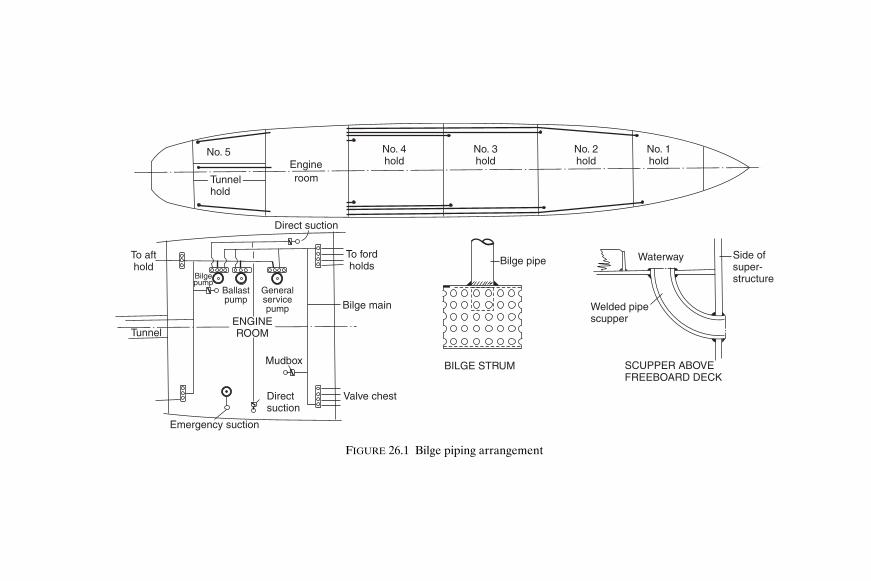
No. 5
Tunnelhold
Engineroom
No. 1hold
No. 2hold
No. 3hold
No. 4hold
BILGE STRUM
Bilge pipe Side ofsuper-structure
SCUPPER ABOVEFREEBOARD DECK
Welded pipescupper
Waterway
Direct suction
To fordholds
Bilge main
Valve chestDirectsuction
Mudbox
Emergency suction
Generalservicepump
Ballastpump
Bilgepump
To afthold
TunnelENGINEROOM
FIGURE 26.1 Bilge piping arrangement
Shcc26.fm Page 290 M
onday, March 26, 2001 3:31 PM

Pumping and Piping Arrangements 291
bottom height is effectively reduced. The shaft tunnel of the ship is drainedby means of a well located at the after end, and the bilge suction is takenfrom the main bilge line (see Figure 26.1).
At the open ends of bilge suctions in holds and other compartments,outside the machinery space and shaft tunnel, a strum box is provided. Thestrum box is a perforated plate box welded to the mouth of the bilge line(Figure 26.1) which prevents debris being taken up by the bilge pumpsuction. Perforations in the strum box do not exceed 10 mm in diameter,and their total cross-sectional area is at least twice that required for thebore of the bilge pipe. Strums are arranged at a reasonable height abovethe bottom of the bilge or drain well to allow a clear flow of water and topermit easy cleaning. In the machinery space and shaft tunnel the pipe fromthe bilges is led to the mud box which is accessible for regular cleaning. Eachmud box contains a mesh to collect sludge and foreign objects entering theend of the pipe.
B I L G E P U M P S A N D P IP E S Y S T E M S Cargo ships have at least twopower driven bilge pumping units in the machinery space connected to themain bilge line, and passenger ships have at least three.
In passenger ships the power driven bilge pumps are where practicableplaced in separate watertight compartments, so that all three are noteasily flooded by the same damage. Where the passenger ship has a lengthin excess of 91.5 m it is a requirement that at least one of these pumps willalways be serviceable in reasonable damage situations. A submersible pumpmay be supplied with its source of power above the bulkhead deck. Altern-atively the pumps are so distributed throughout the length of the ship that itis inconceivable that one might not be able to work in the event of reason-able damage.
Suction connections are led to each hold or compartment from the mainbilge line. Valves are introduced to prevent one watertight compartmentfrom being placed in direct communication with another, and to preventdry cargo spaces and machinery spaces being placed in direct communica-tion with tanks or pumps having sea inlets. These screw-down non-returnvalves are often provided in a bilge valve distribution chest, or may be fitteddirectly in the connections to the bilge main. The bilge pipes which are usedto drain cargo and machinery spaces are kept separate from the sea inletpipes and ballast pipes which are used for filling or emptying tanks wherethe water and oil are carried. Often a separate ‘dirty ballast’ system is arrangedto overcome this problem.
If possible the bilge pipes are kept out of the double bottom tanks, and inway of a deep tank are led through a pipe tunnel. If the peaks are used astanks then a power pump suction is led to each peak. Only two pipes arepermitted to pass through the collision bulkhead below the bulkhead deckand a screw-down valve operated from above the bulkhead deck is provided
Shcc26.fm Page 291 Monday, March 26, 2001 3:31 PM

292 Ship Construction
for each pipe in a chest on the forward side of the bulkhead. An indicator isprovided to show at the valve operating position whether it is open or closed.
Bilge mains in passenger ships are kept within 20 per cent of the ship’sbeam of the side shell, and any piping outside this region or in a duct keel isfitted with a non-return valve. These requirements are intended to preventany compartment from becoming flooded when the ship is grounded orotherwise damaged and a bilge pipe is severed. Many passenger ships areprovided with divided deep tanks or side tanks which permit cross flood-ing arrangements limiting the list after a casualty. This cross flooding isgenerally controlled by valves operated from above the bulkhead deck, butself-acting arrangements can also be adopted.
Bilge and ballast piping may be of cast or wrought iron, steel, copper, orother approved materials. Lead or other heat sensitive materials are notpermitted. The piping is fitted in lengths which are adequately supportedand have flanged connections, provision being made for expansion in eachrange of pipes.
S C U P P E R S Scuppers are fitted at the ship’s side to drain the decks.Below the freeboard decks and within intact houses on the freeboard deckthese scuppers are led to the bilges. They may alternatively be led over-board if they are above the waterline, and are fitted with a non-returnvalve operated from above the freeboard deck. Those scuppers at a reas-onable distance above the waterline may be fitted with two or possibly oneautomatic non-return valve which does not have positive means of closing(see Chapter 31). Scuppers draining open decks above the freeboard decksare led directly overboard (Figure 26.1).
General Service Pipes and Pumping Pumps and substantial piping systems are provided in ships to supply theessential services of hot and cold fresh water for personal use, and salt waterfor sanitary and fire fighting purposes.
Many large passenger ships are provided with a large low-pressure dis-tilling plant for producing fresh water during the voyage, as the capacitiesrequired would otherwise need considerable tank space. This space is betterutilized to carry oil fuel, improving the ship’s range. Independent tankssupplying the fresh water required for drinking and culinary purposes, andfresh washing water, etc., may be taken from the double bottom tanks, thepumps for each supply being independent also. Hot fresh water is suppliedinitially from the cold fresh water system, through a non-return valve into astorage type hot water heater fitted with heater coils, and then the heatedwater is pumped to the outlet.
Shcc26.fm Page 292 Monday, March 26, 2001 3:31 PM
Pumping and Piping Arrangements 293
The sanitary system supplies sea water for flushing water closets, etc.,and may be provided with a hydro-pneumatic pump in cargo vessels, but onlarger passenger ships where the demand is heavier, a continuously operat-ing power pump is required.
It is a statutory requirement that a fire main and deck wash system shouldbe supplied. This has hose outlets on the various decks, and is supplied bypower driven pumps in the machinery spaces. Provision may be made forwashing down the anchor chain from a connection to the fire main.
Air and Sounding Pipes Air pipes are provided for all tanks to prevent air being trapped underpressure in the tank when it is filled, or a vacuum being created when it isemptied. The air pipes may be fitted at the opposite end of the tank to thefilling pipe and/or at the highest point of the tank. Each air pipe from adouble bottom tank, deep tanks which extend to the ship’s side, or any tankwhich may be run up from the sea, is led up above the bulkhead deck. Fromoil fuel and cargo oil tanks, cofferdams, and all tanks which can be pumpedup, the air pipes are led to an open deck, in a position where no danger willresult from leaking oil or vapours. The heights above decks and closingarrangements are covered by the Load Line Conditions of Assignment (seeChapter 31).
Sounding pipes are provided to all tanks, and compartments not readilyaccessible, and are located so that soundings are taken in the vicinity of thesuctions, i.e. at the lowest point of the tank. Each sounding pipe is made asstraight as possible and is led above the bulkhead deck, except in somemachinery spaces where this might not be practicable. A minimum bore of32 mm is in general required for sounding pipes; but where they passthrough refrigeration spaces, to allow for icing, a minimum bore of 65 mmis required where the temperature is at 0 °C or less. Underneath the sound-ing pipe a striking plate is provided where the sounding rod drops in thebilge well, etc. Sometimes a slotted sounding pipe is fitted to indicate thedepth of liquid present, and the closed end must be substantial to allow forthe sounding rod striking it regularly. Various patent tank sounding devicesare available and can be fitted in lieu of sounding pipes, as long as theysatisfy the requirements of the classification society.
Sea InletsWhere the piping system requires water to be drawn from the sea, forexample fire and washdeck, ballast and machinery cooling systems, the inletvalve is fitted to a substantial box within the line of the shell plate containing
Shcc26.fm Page 293 Monday, March 26, 2001 3:31 PM

294 Ship Construction
the sea inlet opening (see Figure 26.2). This opening is to have roundedcorners and be kept clear of the bilge strake if possible. The sea inlet box isto have the same thickness as the adjacent shell but is not to be less than12.5 mm thick and need not exceed 25 mm. Sea inlets in tanker pumproomswithin 40 per cent of the ships midship length are required to have compensa-tion generally in the form of a heavier insert plate in the shell. A grill maybe fitted over the opening and a sacrificial anode will normally be fittedbecause the valve metal and steelbox set up a galvanic cell (see Chapter 27).
Cargo Pumping and Piping Arrangements in Tankers Cargo pumps are provided in tankers to load and discharge cargo, and alsoto ballast some of the tanks which becomes necessary when making voyagesin the unloaded condition. Many modern tankers have clean ballast capa-city and these tanks are served by a separate pumping system.
The particular cargo pumping system adopted depends very much on therange of cargo carried. A fairly straightforward system is available for thelarger bulk oil carrier, carrying a single product. Where smaller tankerscarry a number of oil products at one time, which must be kept separate,the pumping system is more complex.
S I N G L E P RO D U C T/C R U D E O I L C A R R I E R Where a single oil productis carried, and where larger tankers are designed solely to carry crude oil, asingle pump room is fitted aft, adjacent to the machinery spaces. The piping
Anode
Sea inlet box
Sea inlet gridspositioned so thatbars are in foreand aft direction
Closingvalve
Mudbox
Sluicevalve
FIGURE 26.2 Sea inlet
Shcc26.fm Page 294 Monday, March 26, 2001 3:31 PM

Machinery 9 8 7 6 5 4 3 2 1
Pump room
CARGO PIPING ARRANGEMENT ON SMALLER TANKER
Waterballast
Waterballast
Waterballast
Waterballast
Waterballast
Water
ballast
Waterballast
Waterballast
Waterballast
Waterballast
Pump
room
Loadingline
Cofferdam
Ballast lineStripping lineCargo line
Bulkhead valve
12345678910
FIGURE 26.3 Diagrammatic ring main cargo piping arrangement
Shcc26.fm Page 295 M
onday, March 26, 2001 3:31 PM

296 Ship Construction
system is of the ‘direct line’ type, three or four lines being provided, eachwith suctions from a group of tanks (see Figure 26.4). Each pump dischargeis led up to the deck mains which run forward to the transverse loading anddischarging connections.
A few large tankers have a discharge system which relies on hydraulicallycontrolled sluice valves in the tank bulkheads. These permit a flow of the oilto a common suction in the after tank space. Many large tankers partiallyadopt this system, sluice valves being provided in the longitudinal bulk-heads, and the oil is allowed to find its way from the wing tanks to thecentre tanks. Suctions from the main cargo lines are located in the centretanks. Such an arrangement is shown in Figure 26.4, which also indicatesthe separate stripping system, and clean ballast lines.
M U L T I-P R O D U C T S T A N K E R S Where a number of oil products arecarried, the more complex pumping arrangements require two and in somecases three pump rooms to be fitted. One may be fitted aft adjacent to themachinery space, a second amidships, and where a third pump room is pro-vided this is forward. On many older tankers the piping was often arrangedon the ‘ring main’ system to provide flexibility of pumping conditions(see Figure 26.3). To obtain the optimum number of different pumpingcombinations in modern multi-product carriers the tanks may be fittedwith individual suction lines.
C A R G O P U M P S On modern tankers the main cargo pumps are of thecentrifugal type, either geared-turbine or motor driven, and have a veryhigh pumping capacity, those on the large tankers being capable of dischar-ging say 3500 m3/hour. Because of their high capacities the centrifugal cargopumps are unsuitable for emptying tanks completely, and for this purposereciprocating stripping pumps with capacities of, say, 350 m3/hour are pro-vided with a separate stripping line. More recent developments have seenthe use of individual hydraulically driven submerged cargo pumps in thecargo tanks with a single discharge line and the conventional pump roomdispensed with. Also cargo tanks are being fitted with submerged cargopumps driven by explosion proof electric motors. Tanker cargo dischargesystems are now often fully computerized.
C A R G O T A N K W A S H I N G After discharge of cargoes oil tanker cargotanks can be cleaned by either hot or cold water, fresh or seawater, or bycrude oil washing. Water cleaning machines can be fixed in a tank or maybe portable, the portable machine being connected by hose to a deck water-main before being introduced through a tank cleaning hatch into the tank.Crude oil carriers can have fixed washing equipment in the tanks connectedto the cargo pumps via cross-connections at the ships manifold to the clean-ing main and can use crude oil instead of water as the washing medium.
Shcc26.fm Page 296 Monday, March 26, 2001 3:31 PM

12
3
9 8 7 6 5 4 3 2 1Machinery
Pumproom
CARGO PIPING WITH PARTIAL FULL FLOW IN LARGE CRUDE OIL TANKER
Pumproom
Waterballast
Waterballast
Fillinglines
Deeptank
2 1345
Stripping lineCargo line Ballast line
Bulkhead valves
FIGURE 26.4 Diagrammatic arrangement of direct line cargo piping
Shcc26.fm Page 297 M
onday, March 26, 2001 3:31 PM

298 Ship Construction
This is usually done while the tanker is discharging cargo and it enablesre-dissolving of oil fractions adhering to the tank surfaces to take place sothat these residues can be discharged with the cargo. There may then be noneed to water wash tanks for the removal of residues unless clean waterballast is to be carried in the tank.
I N E R T G A S S Y S T E M For oil tankers of 20 000 tons deadweight andupwards protection of the cargo tanks is required to be achieved by a fixedinert gas system. The inert gas system is to be so designed and operated asto render and maintain the atmosphere of the cargo tanks non-flammable,other than when the tanks are gas free. Hydrocarbon gas normally encoun-tered in oil tanks cannot burn in an atmosphere containing less than 11 percent of oxygen by volume, thus if the oxygen content in a cargo tank is keptbelow, say, 8 per cent by volume fire or explosion in the vapour space shouldnot occur. Inert gas introduced into the tank will reduce the air (oxygen)content.
On an oil tanker, inert gas may be produced by one of two processes:
(1) Ships with main or auxiliary boilers normally use the flue gas whichcontains typically only 2 to 4 per cent by volume of oxygen. This isscrubbed with sea water to cool it and to remove sulphur dioxide andparticulates, and it is then blown into the tanks through a fixed pipedistribution system.
(2) On diesel engined ships the engine exhaust gas will contain too highan oxygen level for use as an inert gas. An inert gas generating plantmay then be used to produce gas by burning diesel or light fuel oil. Thegas is scrubbed and used in the same way as boiler flue gas.
Non-return barriers in the form of a deck water seal, and non-returnvalve are maintained between the machinery space and deck distributionsystem to ensure no petroleum gas or liquid petroleum passes back throughthe system to the machinery space.
Further Reading Day et al., ‘Development of an inert gas system for oil tankers’, The Naval
Architect, January, 1972.
‘Inert Gas Systems’, IMO publication (IMO-860E).
Platt, ‘Modern Tanker Practice for Cargo Handling Equipment’, Trans.I.E.S.S., 1958–59.
Shcc26.fm Page 298 Monday, March 26, 2001 3:31 PM

27Corrosion Control and Paint Systems
Nature and Forms of CorrosionThere is a natural tendency for nearly all metals to react with their environ-ment. The result of this reaction is the creation of a corrosion productwhich is generally a substance of very similar chemical composition to theoriginal mineral from which the metal was produced.
A T M O S P H E R I C C O R R O S I O N Protection against atmospheric corrosionis important during the construction of a ship, both on the building berthand in the shops. Serious rusting may occur where the relative humidity isabove about 70 per cent; the atmosphere in British shipyards is unfortu-nately sufficiently humid to permit atmospheric corrosion throughout mostof the year. But even in humid atmospheres the rate of rusting is deter-mined mainly by the pollution of the air through smoke and/or sea salts.
C O R R O S I O N D U E T O I M M E R S I O N When a ship is in service thebottom area is completely immersed and the waterline or boot toppingregion may be intermittently immersed in sea water. Under normal operat-ing conditions a great deal of care is required to prevent excessive corrosionof these portions of the hull. A steel hull in this environment can provideideal conditions for the formation of electro-chemical corrosion cells.
E L E C T R O-C H E M I C A L N A T U R E O F C O R R O S I O N Any metal in tend-ing to revert to its original mineral state releases energy. At ordinarytemperatures in aqueous solutions the transformation of a metal atom intoa mineral molecule occurs by the metal passing into solution. During thisprocess the atom loses one or more electrons and becomes an ion, i.e. anelectrically charged atom, with the production of an electric current (thereleased energy). This reaction may only occur if an electron acceptor is pre-sent in the aqueous solution. Thus any corrosion reaction is always accom-panied by a flow of electricity from one metallic area to another through asolution in which the conduction of an electric current occurs by the passageof ions. Such a solution is referred to as an electrolyte solution; and becauseof its high salt content sea water is a good electrolyte solution.
Shcc27.fm Page 299 Monday, March 26, 2001 3:30 PM

Conventional currentOxygen
Anodeiron
Cathodecopper
Conventional current
+ve ions
–ve ions
Sodium chloride solution
GALVANIC CELL
–ve ions –ve ions
Oxygen
Sea water
CORROSION CELL SET UP BY BREAKS INMILLSCALE OR PAINT FILM ON PLATE SURFACE
Millscale or paint
Anode
CathodeCathode
FIGURE 27.1 Corrosion cell
Shcc27.fm Page 300 M
onday, March 26, 2001 3:30 PM

Corrosion Control and Paint Systems 301
A simple corrosion cell is formed by two different metals in an electrolytesolution (a galvanic cell) as illustrated in Figure 27.1. It is not essential tohave two different metals as we shall see later. As illustrated a pure ironplate and a similar pure copper plate are immersed in a sodium chloridesolution which is in contact with oxygen at the surface. Without any connec-tion the corrosion reaction on each plate would be small. Once the twoplates are connected externally to form an electrical path then the corro-sion rate of the iron will increase considerably, and the corrosion on thecopper will cease. The iron electrode by means of which the electrons leavethe cell and by way of which the conventional current enters the cell is theanode. This is the electrode at which the oxidation or corrosion normallytakes place. The copper electrode by means of which the electrons enterthe cell and by way of which the conventional current leaves the cell is thecathode, at which no corrosion occurs. A passage of current through theelectrolyte solution is by means of a flow of negative ions to the anode and aflow of positive ions to the cathode.
Electro-chemical corrosion in aqueous solutions will result from anyanodic and cathodic areas coupled in the solution whether they are metalsof different potential in the environment or they possess different poten-tials as the result of physical differences on the metal surface. The latter istypified by steel plate carrying broken millscale in sea water (Figure 27.1)or corrosion currents flowing between areas of well painted plate and areasof defective paintwork.
In atmospheric corrosion and corrosion involving immersion both oxygenand an electrolyte play an important part. Plates freely exposed to theatmosphere will receive plenty of oxygen but little moisture, and the mois-ture present therefore becomes the controlling factor. Under conditions oftotal immersion it is the presence of oxygen which becomes the controllingfactor.
B I M E T A L L I C (G A L V A N I C) C O R R O S I O N Although it is true to saythat all corrosion is basically galvanic, the term ‘galvanic corrosion’ is usuallyapplied when two different metals form a corrosion cell.
Many ship corrosion problems are associated with the coupling of metallicparts of different potential which consequently form corrosion cells underservice conditions. The corrosion rates of metals and alloys in sea waterhave been extensively investigated and as a result galvanic series of metalsand alloys in sea water have been obtained.
A typical galvanic series in sea water is shown in Table 27.1. The positions of the metals in the table apply only in a sea water environ-
ment; and where metals are grouped together they have no strong tendencyto form couples with each other. Some metals appear twice because theyare capable of having both a passive and an active state. A metal is saidto be passive when the surface is exposed to an electrolyte solution and a
Shcc27.fm Page 301 Monday, March 26, 2001 3:30 PM

302 Ship Construction
reaction is expected but the metal shows no sign of corrosion. It is generallyagreed that passivation results from the formation of a current barrier onthe metal surface, usually in the form of an oxide film. This thin protectivefilm forms, and a change in the overall potential of the metal occurs when acritical current density is exceeded at the anodes of the local corrosion cellson the metal surface.
Among the more common bimetallic corrosion cell problems in shiphulls are those formed by the mild steel hull with the bronze or nickel alloypropeller. Also above the waterline problems exist with the attachment ofbronze and aluminium alloy fittings. Where aluminium superstructures areintroduced, the attachment to the steel hull and the fitting of steel equip-ment to the superstructure require special attention. This latter problem isovercome by insulating the two metals and preventing the ingress of wateras illustrated in Figure 27.2. A further development is the use of explosion-bonded aluminium/steel transition joints also illustrated. These joints arefree of any crevices, the exposed aluminium to steel interface being readilyprotected by paint.
S T R E S S C O R R O S I O N Corrosion and subsequent failure associatedwith varying forms of applied stress is not uncommon in marine structures.
TABLE 27.1
Galvanic Series of Metals and Alloys in Sea Water
Ignoble (anodic or corroding) end
Noble (cathodic or protected) endPlatinum, gold Silver Titanium Stainless steels, passive Nickel, passive High duty bronzes Copper Nickel, active Millscale Naval brass Lead, tin Stainless steels, active Iron, steel, cast iron Aluminium alloys Aluminium Zinc Magnesium
Shcc27.fm Page 302 Monday, March 26, 2001 3:30 PM

Aluminiumhouse side
Aluminium washer
Sealing compound(Aranbee)
Galvd. steelbolt
Gasket(Neoprene tape)
Neopreneferrule
Steel angle
Steel deck
Gasket(Plascote 0306)
Aluminiumhouse side
Sealing compound(Araldite 433/328)
Hot steel rivet
Steel coaming
Steel deck
Aluminiumhouse side
Explosionbonded
AlSteel
AlSteel
Al. stiffener
Explosionbonded
Steelcoaming
Steel deck
FIGURE 27.2 Aluminium to steel connections
Shcc27.fm Page 303 M
onday, March 26, 2001 3:30 PM

304 Ship Construction
Internal stresses produced by non-uniform cold working are often moredangerous than applied stresses. For example, localized corrosion is oftenevident at cold flanged brackets. A particular case of stress corrosion inmarine structures has occurred with early wrought aluminium magnesiumalloy rivets. With a magnesium content above about 5 per cent stress corro-sion failures with cold driven rivets were not uncommon. Here the corrosiveattack is associated with a precipitate at the grain boundaries, produced byexcessive cold working, which is anodic towards the solid solution formingthe grains of the alloy. Failure occurs along an intergranular path. Speci-fications for aluminium/magnesium alloy rivets now limit the magnesiumcontent.
C O R R O S I O N/E R O S I O N Erosion is essentially a mechanical action but itis associated with electro-chemical corrosion in producing two forms ofmetal deterioration. Firstly, in what is known as ‘impingement attack’ theaction is mainly electro-chemical but it is initiated by erosion. Air bubblesentrained in the flow of water and striking a metal surface may erode awayany protective film that may be present locally. The eroded surface becomesanodic to the surrounding surface and corrosion occurs. This type of attackcan occur in most places where there is water flow, but particularly wherefeatures give rise to turbulent flow. Sea water discharges from the hull are aparticular case, the effects being worse if warm water is discharged.
Cavitation damage is also associated with a rapidly flowing liquid envir-onment. At certain regions in the flow (often associated with a velocityincrease resulting from a contraction of the flow stream) the local pressuresdrop below that of the absolute vapour pressure. Vapour cavities, that isareas of partial vacuum, are formed locally, but when the pressure increasesclear of this region the vapour cavities collapse or ‘implode’. This collapseoccurs with the release of considerable energy, and if it occurs adjacent to ametal surface damage results. The damage shows itself as pitting which isthought to be predominantly due to the effects of the mechanical damage.However it is also considered that electrochemical action may play somepart in the damage after the initial erosion.
Corrosion ControlThe prevention of corrosion may be broadly considered in two forms,cathodic protection and the application of protective coatings.
C A T H O D I C P R O T E C T I O N Only where metals are immersed in anelectrolyte can the possible onset of corrosion be prevented by cathodic
Shcc27.fm Page 304 Monday, March 26, 2001 3:30 PM

Corrosion Control and Paint Systems 305
protection. The fundamental principle of cathodic protection is that theanodic corrosion reactions are suppressed by the application of an oppos-ing current. This superimposed direct electric current enters the metal atevery point lowering the potential of the anode metal of the local corro-sion cells so that they become cathodes.
There are two main types of cathodic protection installation, sacrificialanode systems and impressed current systems.
S A C R I F I C I A L A N O D E S Y S T E M S Sacrificial anodes are metals or alloysattached to the hull which have a more anodic, i.e. less noble, potential thansteel when immersed in sea water. These anodes supply the cathodic pro-tection current, but will be consumed in doing so and therefore requirereplacement for the protection to be maintained.
This system has been used for many years, the fitting of zinc plates in wayof bronze propellers and other immersed fittings being common practice.Initially results with zinc anodes were not always very effective owing to theuse of unsuitable zinc alloys. Modern anodes are based on alloys of zinc,aluminium, or magnesium which have undergone many tests to examinetheir suitability; high purity zinc anodes are also used. The cost, with vari-ous other practical considerations, may decide which type is to be fitted.
Sacrificial anodes may be fitted within the hull, and are often fitted inballast tanks. However, magnesium anodes are not used in the cargo-ballasttanks of oil carriers owing to the ‘spark hazard’. Should any part of theanode fall and strike the tank structure when gaseous conditions exist anexplosion could result. Aluminium anode systems may be employed intankers provided they are only fitted in locations where the potentialenergy is less than 28 kg.m.
I M P R E S S E D C U R R E N T S Y S T E M S These systems are applicable to theprotection of the immersed external hull only. The principle of the systemsis that a voltage difference is maintained between the hull and fitted anodes,which will protect the hull against corrosion, but not overprotect it thuswasting current. For normal operating conditions the potential difference ismaintained by means of an externally mounted silver/silver chloride refer-ence cell detecting the voltage difference between itself and the hull. Anamplifier controller is used to amplify the micro-range reference cell current,and it compares this with the preset protective potential value which is to bemaintained. Using the amplified DC signal from the controller a saturablereactor controls a larger current from the ship’s electrical system which issupplied to the hull anodes. An AC current from the electrical systemwould be rectified before distribution to the anodes. Figure 27.3 shows sucha system.
Shcc27.fm Page 305 Monday, March 26, 2001 3:30 PM

Anodes Anodes
From ship’s power
Reactorrectifier Water lineController
Referencecell
FIGURE 27.3 Impressed current cathode protection system
Shcc27.fm Page 306 M
onday, March 26, 2001 3:30 PM

Corrosion Control and Paint Systems 307
Originally consumable anodes were employed but in recent systemsnon-consumable relatively noble metals are used; these include lead/silverand platinum/palladium alloys, and platinized titanium anodes are alsoused.
A similar impressed current system employs a consumable anode in theform of an aluminium wire up to 45 metres long which is trailed behind theship whilst at sea. No protection is provided in port.
Although the initial cost is high, these systems are claimed to be moreflexible, to have a longer life, to reduce significantly hull maintenance, andto weigh less than the sacrificial anode systems.
Care is required in their use in port alongside ships or other unprotectedsteel structures.
PaintsPaint consists of pigment dispersed in a liquid referred to as the ‘vehicle’.When spread out thinly the vehicle changes in time to an adherent dry film.The drying may take place through one of the following processes.
(a) When the vehicle consists of solid resinous material dissolved in avolatile solvent, the latter evaporates after application of the paint, leavinga dry film.
(b) A liquid like linseed oil as a constituent of the vehicle may produce adry paint film by reacting chemically with the surrounding air.
(c) A chemical reaction may occur between the constituents of thevehicle after application, to produce a dry paint film. The reactive ingredi-ents may be separated in two containers (‘two-pack paints’) and mixedbefore application. Alternatively ingredients which only react at higher tem-peratures may be selected, or the reactants may be diluted with a solvent sothat the reaction occurs only slowly in the can.
Corrosion-inhibiting paints for application to steel have the followingvehicle types:
(a) Bitumen or pitch Simple solutions of bitumen or pitch are availablein solvent naphtha or white spirit. The bitumen or pitch may also beblended by heat with other materials to form a vehicle.
(b) Oil based These consist mainly of vegetable drying oils, such as linseedoil and tung oil. To accelerate the drying by the natural reaction withoxygen, driers are added.
(c) Oleo-resinous The vehicle incorporates natural or artificial resinsinto drying oils. Some of these resins may react with the oil to give afaster drying vehicle. Other resins do not react with the oil but heat isapplied to dissolve the resin and cause the oil to body.
Shcc27.fm Page 307 Monday, March 26, 2001 3:30 PM

308 Ship Construction
(d) Alkyd resin These vehicles provide a further improvement in thedrying time and film forming properties of drying oils. The namealkyd arises from the ingredients, alcohols and acids. Alkyds neednot be made from oil, as an oil-fatty acid or an oil-free acid may beused.
(Note. Vehicle types (b) and (d) are not suitable for underwaterservice, and only certain kinds of (c) are suitable for such service.)
(e) Chemical-resistant Vehicles of this type show extremely good resist-ance to severe conditions of exposure. As any number of importantvehicle types come under this general heading these are dealt withindividually.
(i) Epoxy resins Chemicals which may be produced from petro-leum and natural gas are the source of epoxy resins. Thesepaints have very good adhesion, apart from their excellentchemical resistance. They may also have good flexibility andtoughness where co-reacting resins are introduced. Epoxyresins are expensive owing to the removal of unwanted sideproducts during their manufacture, and the gloss finish maytend to ‘chalk’ making it unsuitable for many external decorativefinishes. These paints often consist of a ‘two-pack’ formulation,a solution of epoxy resin together with a solution of cold curingagent, such as an amine or a polyamide resin, being mixedprior to application. The mixed paint has a relatively slow curingrate at temperatures below 10 °C. Epoxy resin paints should notbe confused with epoxy-ester paints which are unsuitable forunderwater use. Epoxy-ester paints can be considered as alkydequivalents, as they are usually made with epoxy resins and oil-fatty acids.
(ii) Coal tar/epoxy resin This vehicle type is similar to the epoxy resinvehicle except that, as a two-pack product, a grade of coal tar pitchis blended with the resin. A formulation of this type combines tosome extent the chemical resistance of the epoxy resin with theimpermeability of coal tar.
(iii) Chlorinated rubber and isomerized rubber The vehicle in this caseconsists of a solution of plasticized chlorinated rubber, or isomer-ized rubber. Isomerized rubber is produced chemically from naturalrubber, and it has the same chemical composition but a differentmolecular structure. Both these derivatives of natural rubberhave a wide range of solubility in organic solvents, and so allow avehicle of higher solid content. On drying, the film thickness isgreater than would be obtained if natural rubber were used. Highbuild coatings of this type are available, thickening or thixotropicagents being added to produce a paint which can be applied in
Shcc27.fm Page 308 Monday, March 26, 2001 3:30 PM

Corrosion Control and Paint Systems 309
much thicker coats. Coats of this type are particularly resistant toattack from acids and alkalis.
(iv) Polyurethane resins A reaction between isocyanates and hydroxyl-containing compounds produces ‘urethane’ and this reaction hasbeen adapted to produce polymeric compounds from which paintfilm, fibres, and adhesives may be obtained. Paint films so producedhave received considerable attention in recent years, and sincethere is a variety of isocyanate reactions, both one-pack and two-pack polyurethane paints are available. These paints have manygood properties; toughness, hardness, gloss, abrasion resistance,as well as chemical and weather resistance. Polyurethanes arenot used under water on steel ships, only on superstructures, etc.,but they are very popular on yachts where their good gloss isappreciated.
(v) Vinyl resins Vinyl resins are obtained by the polymerization oforganic compounds containing the vinyl group. The solids contentof these paints is low; therefore the dry film is thin, and morecoats are required than for most paints. As vinyl resin paints havepoor adhesion to bare steel surfaces they are generally appliedover a pretreatment primer. Vinyl paint systems are among themost effective for the underwater protection of steel.
(f) Zinc-rich paints Paints containing metallic zinc as a pigment in suffi-cient quantity to ensure electrical conductivity through the dry paintfilm to the steel are capable of protecting the steel cathodically. Thepigment content of the dry paint film should be greater than 90 percent, the vehicle being an epoxy resin, chlorinated rubber, or similarmedium.
A N T I-F O U L I N G P A I N T S Anti-fouling paints consist of a vehicle withpigments which give body and colour together with materials toxic tomarine vegetable and animal growth. Copper is the best known toxin usedin traditional anti-fouling paints.
To prolong the useful life of the paint the toxic compounds must dissolveslowly in sea water. Once the release rate falls below a level necessary toprevent settlement of marine organisms the anti-fouling composition isno longer effective. On merchant ships the effective period for traditionalcompositions was about 12 months. Demands in particular from largetanker owners wishing to reduce very high docking costs led to speciallydeveloped anti-fouling compositions with an effective life up to 24 monthsin the early 1970s. Subsequent developments of constant emission organictoxin antifoulings having a leaching rate independent of exposure time sawthe paint technologists by chance discover coatings which also tended tobecome smoother in service. These so called self-polishing antifoulings with
Shcc27.fm Page 309 Monday, March 26, 2001 3:30 PM

310 Ship Construction
a lifetime that is proportional to applied thickness and therefore theoretic-ally unlimited, smooth rather than roughen with time and result in reducedfriction drag. Though more expensive than their traditional counterparts,given the claim that each 10 micron (10−3 mm) increase in hull roughnesscan result in a 1 per cent increase in fuel consumption their self polishingcharacteristic as well as their longer effective life, up to 5 years protectionbetween drydockings, make them attractive to the shipowner.
The benefits of the first widely used SPC (self polishing copolymer) anti-fouling paints can be traced to the properties of their prime ingredient—the tributylen compounds or TBTs. TBTs are extremely active against awide range of fouling organisms, also they are able to be chemically bondedto the acrylic backbone of the paint system. When immersed in sea water aspecific chemical reaction takes place which cleaves the TBT from the paintbackbone, resulting in both controlled release of the TBT and controlleddisappearance or polishing of the paint film. Unfortunately, it was foundthat the small concentrations of TBTs released, particularly in enclosedcoastal waters, had a harmful effect on certain marine organisms. This ledto the banning of TBT anti-fouling paints for pleasure boats and smallercommercial ships in many developed countries and the introduction ofregulations limiting the release rate of TBT for anti-fouling paints on largerships. In March 2000 the IMO’s Marine Environmental Protection Com-mittee tabled a draft resolution which will see the application to ships ofTBT anti-fouling banned from 1 January 2003 and its complete prohibitionby 1 January 2008. In recent years effective TBT-free self polishing anti-fouling paints have been developed and these offer equivalent perform-ance to tin-based anti-foulings. Many of these newer paints use coppercompounds as the active anti-fouling ingredient but biocide-free productshave also been developed. The latter copper-free anti-foulings are particu-larly suited for application to aluminium alloy high speed craft hulls.
Protection by Means of Paints It is often assumed that all paint coatings prevent attack on the metalcovered simply by excluding the corrosive agency, whether air or water. Thisis often the main and sometimes the only form of protection; however thereare many paints which afford protection even though they present a poroussurface or contain various discontinuities.
For example certain pigments in paints confer protection on steel evenwhere it is exposed at a discontinuity. If the reactions at the anode and cath-ode of the corrosion cell which form positive and negative ions respectively,are inhibited, protection is afforded. Good examples of pigments of thistype are red lead and zinc chromate, red lead being an anodic inhibitor,and zinc chromate a cathodic inhibitor. A second mode of protection occurs
Shcc27.fm Page 310 Monday, March 26, 2001 3:30 PM

Corrosion Control and Paint Systems 311
at gaps where the paint is richly pigmented with a metal anodic to the basismetal. Zinc dust is a commercially available pigment which fulfils thisrequirement for coating steel in a salt water environment. The zinc dust isthe sacrificial anode with respect to the steel.
Anti-fouling paints offer protection against vegetable and animal growthwhich can lead to increased resistance requiring additional power, hencefuel, to maintain the same speed. The greater the time spent at sea the lessthe fouling; but areas of operation and seasons also decide the amount offouling, and with modern anti-fouling compounds the problem today is lessimportant.
S U R F A C E P R E P A R A T I O N Good surface preparation is essential tosuccessful painting, the primary cause of many paint failures being the inad-equacy of the initial material preparation.
It is particularly important before painting new steel that any millscaleshould be removed. Millscale is a thin layer of iron oxides which forms onthe steel surface during hot rolling of the plates and sections. Not only doesthe non-uniform millscale set up corrosion cells as illustrated previously,but it may also come away from the surface removing any paint film appliedover it.
The most common methods employed to prepare steel surfaces for paint-ing are:
Blast cleaning Pickling Flame cleaning Preparation by hand.
(a) Blast cleaning is the most efficient method for preparing the surface.Following the blast cleaning it is desirable to brush the surface, and applya coat of priming paint as soon as possible since the metal is liable to rustrapidly.
There are two main types of blasting equipment available, an impellerwheel plant where the abrasive is thrown at high velocity against the metalsurface, and a nozzle type where a jet of abrasive impinges on the metalsurface. The latter type should preferably be fitted with vacuum recoveryequipment, rather than allow the spent abrasive and dust to be dischargedto atmosphere, as is often the case in ship repair work. Impeller wheelplants which are self-contained and collect the dust and re-circulate theclean abrasive are generally fitted within the shipbuilding shops.
Cast iron and steel grit, or steel shot which is preferred, may be used forthe abrasive, but non-metallic abrasives are also available. The use of sandis prohibited in the United Kingdom because the fine dust produced maycause silicosis.
Shcc27.fm Page 311 Monday, March 26, 2001 3:30 PM

312 Ship Construction
(b) Pickling involves the immersion of the metal in an acid solution,usually hydrochloric or sulphuric acid in order to remove the millscale andrust from the surface. After immersion in these acids the metal will requirea thorough hot water rinse. It is preferable that the treatment is followed byapplication of a priming coat.
(c) Using an oxy-acetylene flame the millscale and rust may be removedfrom a steel surface. The process does not entirely remove the millscale andrust, but it can be quite useful for cleaning plates under inclement weatherconditions, the flame drying out the plate.
(d) Hand cleaning by various forms of wire brush is often not very satis-factory, and would only be used where the millscale has been loosened byweathering, i.e. exposure to atmosphere over a long period.
Blast cleaning is preferred for best results and economy in shipbuilding;pickling which also gives good results can be expensive and less applicableto production schemes; flame cleaning is much less effective; and handcleaning gives the worst results.
T E M P O R A R Y P A I N T P R O T E C T I O N D U R I N G B U I L D I N G After thesteel is blast cleaned it may be several months before it is built into the shipand finally painted. It is desirable to protect the material against rusting inthis period as the final paint will offer the best protection when appliedover perfectly clean steel.
The formulation of a prefabrication primer for immediate applicationafter blasting must meet a number of requirements. It should dry rapidly topermit handling of the plates within a few minutes, it should be non-toxic,and it should not produce harmful porosity in welds nor give off obnoxiousfumes during welding or cutting. It must also be compatible with any sub-sequent paint finishes to be applied. Satisfactory formulations are available,for example a primer consisting of zinc dust in an epoxy resin.
P A I N T S Y S T E M S O N S H I P S The paint system applied to any part of aship will be dictated by the environment to which that part of the structureis exposed. Traditionally the painting of the external ship structure wasdivided into three regions.
(a) Below the water-line where the plates are continually immersed insea water.
(b) The water-line or boot topping region where immersion is intermit-tent and a lot of abrasion occurs.
(c) The topsides and superstructure exposed to an atmosphere ladenwith salt spray, and subject to damage through cargo handling.
Shcc27.fm Page 312 Monday, March 26, 2001 3:30 PM

Corrosion Control and Paint Systems 313
However now that tougher paints are used for the ship’s bottom the dis-tinction between regions need not be so well defined, one scheme coveringthe bottom and water-line regions.
Internally by far the greatest problem is the provision of coatings for vari-ous liquid cargo and salt water ballast tanks.
(a) Below the Water-line The ship’s bottom has priming coats of corrosion-inhibiting paint applied which are followed by an anti-fouling paint. Paintsused for steels immersed in sea water are required to resist alkaline condi-tions. The reason for this is that an iron alloy immersed in a sodium chloridesolution having the necessary supply of dissolved oxygen gives rise to corro-sion cells with caustic soda produced at the cathodes. Further the paintshould have a good electrical resistance so that the flow of corrosion currentsbetween the steel and sea water is limited. These requirements make thestandard non-marine structural steel primer red lead in linseed oil unsuit-able for ship use below the water-line. Suitable corrosion-inhibiting paintsfor ships’ bottoms are pitch or bitumen types, chlorinated rubber, coal tar/epoxy resin, or vinyl resin paints. The anti-fouling paints may be appliedafter the corrosion-inhibiting coatings and should not come into directcontact with the steel hull, since the toxic compounds present may causecorrosion.(b) Water-line or Boot Topping Region Generally modern practice requiresa complete paint system for the hull above the water-line. This may bebased on vinyl and alkyd resins or on polyurethane resin paints. (c) Superstructures Red lead or zinc chromate based primers are commonlyused. White finishing paints are then used extensively for superstructures.These are usually oleo-resinous or alkyd paints which may be based on ‘non-yellowing’ oils, linseed oil-based paints which yellow on exposure beingavoided on modern ships.
Where aluminium superstructures are fitted, under no circumstanceshould lead based paints be applied; zinc chromate paints are generallysupplied for application to aluminium.
C A R G O A N D B A L L A S T T A N K S Severe corrosion may occur in a ship’scargo tanks as the combined result of carrying liquid cargoes and sea waterballast, with warm or cold sea water cleaning between voyages. This is par-ticularly true of oil tankers. Tankers carrying ‘white oil’ cargoes suffer moregeneral corrosion than those carrying crude oils which deposit a film on thetank surface providing some protection against corrosion. The latter typemay however experience severe local pitting corrosion due to the non-uniformity of the deposited film, and subsequent corrosion of any bare platewhen sea water ballast is carried. Epoxy resin paints are used extensivelywithin these tanks, and vinyl resins and zinc rich coatings may also be used.
Typical marine paint systems are shown in Table 27.2.
Shcc27.fm Page 313 Monday, March 26, 2001 3:30 PM

314 Ship Construction
TABLE 27.2
Typical Marine Paint Systems for New Ships
Type of paint Coats Dry film thickness
1. Ships bottom(a) Blast primer or holding primer 1 25 microns (b) (i) Chlorinated rubber anticorrosive system 3 75 microns/coat
or (ii) Vinyl–pitch anticorrosive system 3 75 microns/coat
or (iii) Pitch–epoxy 2 125 microns/coat
(c) (i) Economic antifouling 2 sides 50 microns/coat or 1 flat bottom
(ii) Premium antifouling 2 sides 75 microns/coat or 1 flat bottom
(iii) Advanced self-polishing antifouling 3 Depends on speed/sailing time/time between docking
2. Boottop and topsides (a) Conventional system based on:
(i) Water resistant vehicle incorporating corrosion inhibiting pigments plus
3 50 microns/coat
(ii) Oleo-resinous vehicle gloss coat with good abrasion resistance
1 40 microns
(b) High performance system based on: (i) Two pack epoxy red oxide
primer plus1 25 microns
(ii) Two pack epoxy high build coating plus
1 125 microns
(iii) Two pack epoxy based gloss finishing coat
2 50 microns/coat
3. Superstructure—external (a) Conventional system based on:
(i) Water resistant vehicle incorporatingcorrosion inhibiting pigments plus
2 50 microns/coat
(ii) Alkyd resin vehicle undercoat plus 1 40 microns (iii) Alkyd resin vehicle finishing coat with
gloss and colour retention1 40 microns
(b) High performance system based on: (i) Two pack epoxy red oxide primer plus 1 25 microns (ii) Two pack epoxy high build coating plus 1 125 microns (iii) Two pack polyurethane finishing coat
with high chalk resistance, gloss and colour retention
1 40 microns
Shcc27.fm Page 314 Monday, March 26, 2001 3:30 PM

Corrosion Control and Paint Systems 315
Further Reading ‘Any Old Paint—Not Likely’, The Naval Architect, July/August, 1985.
Daniel, ‘A Study of Abrasive Blasted Surfaces and their Effect on PaintThicknesses’, Trans. R.I.N.A., 1969.
Frederick, ‘Surface Preparation of Ship Plate for New Construction’,R.I.N.A. Publication M.T.M., no. 3.
Introduction to Paint Technology, Oil and Colour Chemists Association.
Kulkarni, ‘Ship-based Equipment to remove Marine Growth from theHull’, The Naval Architect, October, 1973.
Lee, ‘VLCC Ballast Tank Coatings: the Real Issues’, The Naval Architect,June, 1995.
‘Marine Corrosion Prevention 1994’, Conference Proceedings—RoyalInstitution of Naval Architects Publication.
‘Marine Coatings: Efficiency, Economy and Long Life Remains Key IndustryAims’, The Naval Architect, February, 1987.
Morgan, ‘Impressed Current Hull Protection’, Shipbuilding and ShippingRecord, 10 March, 1966.
‘Paints for New-Generation Ships’, The Naval Architect, June, 1998; June,1999 and June, 2000.
‘Recommended Practice for Protection of Ships Underwater and Boot-topping Plating from Corrosion and Fouling’, B.S.R.A., 1966.
Rogers, Marine Corrosion, International Monographs on Corrosion Scienceand Technology (Newnes, 1968).
Type of paint Coats Dry film thickness
4. Dry cargo holds (i) Water resistant vehicle incorporating
corrosion inhibiting pigments plus2 50 microns/coat
(ii) Oleo-resinous vehicle with aluminiumflake pigment
1 25 microns
5. Tanks—crude oil High performance two pack coal tar/epoxy 2 125 microns/coat
6. Tanks—product and chemical tankers (i) Two pack epoxy oxide primer 1 25 microns(ii) Two pack epoxy high build coating 2 125 microns/coat
Shcc27.fm Page 315 Monday, March 26, 2001 3:30 PM

316 Ship Construction
Siverwright, ‘The Case for Cathodic Protection’, Shipbuilding and ShippingRecord, International Marine Design and Equipment Number, 1967.
Telfer, ‘Some Aspects of the External Maintenance of Tankers’, The NavalArchitect, July, 1972.
Townsin et al., ‘Speed, Power and Roughness: The Economics of OuterBottom Maintenance’, The Naval Architect, September, 1980.
Turner, Introduction to Paint Chemistry (Chapman and Hall, 1967).
West, ‘Protection of Ships Hulls’, R.I.N.A. Publication M.T.M., no. 2.
Shcc27.fm Page 316 Monday, March 26, 2001 3:30 PM
28Ventilation, Refrigeration, and Insulation
Adequate ventilating and air conditioning systems are installed in ships toprovide reasonable comfort for the crew and passengers, and to maintaincargo at the correct temperature and humidity. Insulation is provided tomaintain refrigerated cargo room temperatures, and to a lesser extent tomaintain air conditioning requirements, and overcome acoustic problems inaccommodation.
Ventilation In most ships a combination of natural and mechanical ventilation isprovided in the accommodation and machinery spaces. Mechanical supplyis common, and a natural exhaust may be permitted in a number of com-partments; but where fumes, etc., are present, for example from galleys, amechanical exhaust is required. This is also the case with many publicrooms, often crowded and where smoking is permitted. The mechanicalsupply is by means of light steel sheet trunking, with louvres at each outlet.Fans may be of the quiet running centrifugal type with a separately mountedmotor.
The holds of most dry cargo ships are ventilated by a mechanical supplyand natural exhaust system. Here the object is to reduce the hold temperat-ures if necessary and prevent large amounts of condensation accumulatingon the hull and cargo. Often the cargo hold fans which are of the axial typeare located in the mast houses, although they have been positioned inderrick posts where these posts are used to ventilate the tweens and holds(see Figure 28.1). Dry cargo ships may also be fitted with de-humidificationfacilities, controls being provided so that each hold can be supplied with dryair or outside air. If dry air is desired when the weather dew-point approachesor is above the temperature in the hold, the air supply or recirculating airmay be drawn through a conditioning plant where it comes into contact witha moisture absorbing solution. A dry air fan then passes this de-humidifiedair to the cargo hold ventilation system.
Air conditioning is a common feature in the accommodation of modernships. Room temperatures are controlled by a thermostat, heated or chilledair may then be supplied as required and humidity control is also provided.
Shcc28.fm Page 317 Monday, March 26, 2001 3:30 PM

DERRICK POST AS VENTILATOR
Cowlvent
Weldedweb
Derrickpost
PLAN
Derrickpost
Upp. dk.
Weldedweb
Postthro’tween
Tween dk.
Longl.
Tween
deck Longitudinal
Opening
Masthouse
Tween
Hold
MECHANICAL HOLD VENTILATION
Tween
Hold
Fans
Tween
Hold
Tween
Hold
NATURAL HOLD VENTILATION
Cowl vents Baffle
House
Tween
Hold
FIGURE 28.1 Hold ventilation
Shcc28.fm Page 318 M
onday, March 26, 2001 3:30 PM

Ventilation, Refrigeration, and Insulation 319
Trunking and louvres are similar to those for mechanical ventilation,smaller bore trunking being possible if a high velocity system is introduced.Local air conditioning units are available and may serve an individual suiteif desired, with their own control.
RefrigerationMany perishable cargoes are carried in refrigerated compartments on drycargo ships, and there are an appreciable number of vessels specificallydesigned for carrying refrigerated cargo only. The midship section of such aship with the line of insulation is shown in Figure 28.2.
S T O W A G E O F R E F R I G E R A T E D C A R G O Chilled meat cargo is hungfrom the strengthened deck stiffening members, and the tween deck height isarranged to provide space below the hung carcasses for the circulation ofair. Frozen meat is stacked in the holds of the ship. Fruits and vegetablesare stowed in a manner which permits an adequate flow of air to be main-tained around the crates, etc.
As a rule the refrigerated rooms in general cargo ships are made rect-angular to keep down insulation costs.
R E F R I G E R A T I O N S Y S T E M S Brine made by dissolving calcium chloridein fresh water will have a freezing point well below the desired temper-atures of the refrigerated compartments. Cold brine may be pumped atcontrolled rates to give the correct working temperature, and it is led fromthe evaporator of the refrigerating machine to pipes at the top of the coldcompartment. The brine absorbs heat from the compartments and returnsto the evaporator where it is again cooled and recirculated.
Air must be continually circulated where fruit is carried to disperse anypockets of carbon dioxide gas given off by the ripening fruit. The brine isthen led into grid boxes and air drawn from the bottom of the compart-ments by fans is blown over the brine grids into the compartments viatrunking arranged along the ceiling.
InsulationAs the steel hull structure is an excellent conductor of heat, some form ofinsulation must be provided at the boundaries of the refrigerated compart-ments if the desired temperatures are to be maintained economically.
Cork, glass fibre, and various foam plastics in sheet or granulated formmay be used for insulating purposes, also air spaces which are less efficient.
Shcc28.fm Page 319 Monday, March 26, 2001 3:30 PM

320 Ship Construction
Glass fibre is often used in modern ships as it has a number of advantagesover the other materials; for example, it is extremely light, vermin-proof, andfire-resistant, and it will not absorb moisture. On the decks and particularlyat the tank top the insulation must often be load-bearing material, and corkmight be preferred, but fibreglass can be supported by tongue and groovedboard linings and wood bearers. The thickness of the insulation depends onthe type of material used and the temperature to be maintained in the com-partment. However the depth of stiffening members often determines the
Line of insulation
Square pillar
FROZEN CARGO
FROZEN CARGO
CHILLED MEAT
Square pillar
Square pillar
Ductkeel
FIGURE 28.2 Midship section of refrigerated cargo ship
Shcc28.fm Page 320 Monday, March 26, 2001 3:30 PM

Wood ground
Drain
Deck
Brine
BRINE TRAP
To bilge
Side shell
Side frame
Wood groundbolted to frame
PLAN Side shell
Galvanized mild steel or aluminium liningscrewed to wood grounds
Insulation
Fibreglass orfoam slabs
50mm air gap
150mm x 75mm pitch pine grounds at 400mm centresTank top oil tank under
25mm T&G softwood 37mm T&G Kerung hardwood
FIGURE 28.3 Insulation details
Shcc28.fm Page 321 M
onday, March 26, 2001 3:30 PM

322 Ship Construction
final depth. Insulating material is retained at the sides by galvanized sheetsteel or aluminium alloy sheet screwed to wood grounds on the frames orother stiffening members (see Figure 28.3).
Insulation on the boundaries of oil tanks, e.g. on the tank top above anoil fuel double bottom tank, has an air space of at least 50mm between theinsulation and steel. If a coating of approved oil-resisting composition witha thickness of about 5 mm is applied the air gap may be dispensed with.
Suitable insulated doors are provided to cold rooms in general cargoships, and in refrigerated cargo ships the hold and tween hatches maybe insulated. Patent steel covers or pontoon covers may be filled with asuitable insulating material to prevent heat losses.
A particular problem in insulated spaces is drainage, as ordinary scupperswould nullify the effects of the insulation. To overcome this problem brinetraps are provided in drains from the tween deck chambers and insulatedholds. The brine in the trap forms an effective seal against ingress of warmair, and it will not freeze, preventing the drain from removing water from thecompartment (Figure 28.3).
Refrigerated Container ShipsMany of the container ships operating on trade routes where refrigeratedcargoes were carried in conventional refrigerated cargo liners (‘reeferships’) have provision for carrying refrigerated containers and have in manycases replaced the latter.
The ISO containers (usually 20 foot size since with most refrigeratedcargoes 40 foot size would be too heavy) are insulated, and below decks theend of each hold may be fitted with brine coolers which serve each stack ofcontainers. Air from the brine coolers is ducted to and from each insulatedcontainer. Connection of each container to the cold air ducts is by means ofan automatic coupling which is remotely controlled and can be engagedwhen the container is correctly positioned in the cell guides.
The below decks system described with fully insulated containers meansthat heavy insulation of the hold space is unnecessary. On the ships sides,bulkheads and deckhead about 50 mm of foam insulation with a fire retard-ent coating may be fitted and the tank top covered with 75 mm of cork andbitumastic. If provision is only made for the ship to carry a part load ofunder deck refrigerated containers these are generally arranged in theafter holds adjacent to the machinery space.
On deck refrigerated containers are generally serviced by clip-on aircooled electric motor drive cooling units. The units are plugged into theships electrical system by way of suitable deck sockets. Similar water cooledunits have been used for below deck containers on short haul voyages.
Shcc28.fm Page 322 Monday, March 26, 2001 3:30 PM

Ventilation, Refrigeration, and Insulation 323
Further Reading Arnold, ‘Air Conditioning Development’, Shipbuilding and Shipping
Record, International Design and Equipment Number, 1967.
Jones and Macvicar, ‘The Development of Air Conditioning in Ships’,Trans. I.N.A., 1959.
Lindberg, ‘Present and Future Trends in Marine Air Conditioning andVentilation’, Shipbuilding and Shipping Record, Marine Design Inter-national, 1971.
Wren and Nohr Larsen, ‘Marine Air Conditioning Plant—A Review ofDesign Principles’, Shipbuilding and Shipping Record, Marine DesignInternational, 1969.
Shcc28.fm Page 323 Monday, March 26, 2001 3:30 PM

Shcc28.fm Page 324 Monday, March 26, 2001 3:30 PM

Part 7
International Regulations
Shcc29.fm Page 325 Monday, March 26, 2001 3:29 PM

Shcc29.fm Page 326 Monday, March 26, 2001 3:29 PM

29International Maritime Organization
The International Maritime Organization (IMO) is a specialized agency ofthe United Nations. It has as its most important objectives the improve-ment of maritime safety and the prevention of marine pollution. Thefunctions of IMO, only as it affects ship construction, are dealt with in thisbook.
Organization of IMO The Assembly which is the supreme governing body of IMO and consists ofrepresentatives of all member states (158 in August 2000) meets every twoyears and determines policy, the work programme, votes the budget,approves all recommendations made by IMO and elects members of theCouncil. The Council consists of an agreed number (32 in 2000) of represent-atives of member states elected for a term of two years. It normally meetstwice a year and is IMO’s governing body between Assembly sessions. TheMaritime Safety Committee deals with the technical work of IMO and inorder to facilitate this work various sub-committees are set up to deal withspecific subjects such as fire protection, ship design and equipment, etc.The Marine Environmental Protection Committee is responsible forcoordinating IMO activities in the prevention of pollution from ships. Thelatter two committees meet once, or sometimes twice, a year and all memberstates may participate in their activities.
Work of IMOThe IMO is responsible for convening and preparing international confer-ences on subjects within its sphere of action, for the purpose of concludinginternational conventions or agreements. Conventions do not come intoforce until stipulated numbers of member countries have ratified, that is,adopted them. Provided it is approved by an agreed majority of the membersparty to a convention, a technical amendment to the convention proposedby a party to the convention may be adopted at meetings of the MaritimeSafety Committee and Marine Environmental Protection Committee.
Shcc29.fm Page 327 Monday, March 26, 2001 3:29 PM

328 Ship Construction
Of particular relevance, and dealt with in the following chapters, are thefollowing conventions:
International Convention on Tonnage Measurement, 1969 International Convention on Load Lines of Ships, 1966 International Convention for the Safety of Life at Sea (SOLAS), 1974
The latter, and its subsequent amendments and protocols, includesrequirements in respect of fire protection in ships which are dealt with inChapter 32.
The International Convention for the Prevention of Pollution from Ships(MARPOL) 1973 and its Protocol of 1978 also prescribe ship constructionrequirements, particularly in respect of tankers (see Chapter 22).
Relationship with National Authorities Member countries have their own governmental agency concerned withmaritime safety which drafts and enforces the shipping legislation of thatcountry. The conventions and amendments are ratified by the membercountry when they are incorporated in that country’s national legislationrelating to ships registered in that country and which make internationalvoyages. A national authority also has responsibility for ensuring that shipswhich are not registered in that country, but visiting its ports, are complyingwith the provisions of the conventions in force and to which they are party.The conventions require ships which are trading internationally to havecurrent convention certificates issued by, or on behalf of, the governmentalagency of the country in which they are registered. In the case of SOLASthese consist of:
(a) For passenger ships a certificate called a Passenger Ship SafetyCertificate valid for not more than one year.
(b) For cargo ships of 500 gross tonnage or more the following certi-ficates: (i) A Cargo Ship Safety Construction Certificate valid for not more
than five years. (ii) A Cargo Ship Safety Equipment Certificate valid for not more
than two years. (c) For cargo ships of 300 gross tonnage or more a Cargo Ship Safety
Radio Certificate valid for not more than one year.
Under the 1988 SOLAS Protocol which came into force in February 2000, acargo ship may be issued with a single Cargo Ship Safety Certificate ratherthan separate construction, equipment and radio certificates.
Shcc29.fm Page 328 Monday, March 26, 2001 3:29 PM

International Maritime Organization 329
Oil tankers of 150 gross tonnage or more and other ships of 400 grosstonnage or more complying with MARPOL are required to have a currentInternational Oil Pollution Prevention Certificate valid for not more thanfive years.
Both passenger and cargo ships would have an International Load LineConvention Certificate valid for not more than five years. In addition eachvessel would have an International Tonnage Certificate issued by, or onbehalf of, the national authority.
Relationship with Classification SocietiesThe major classification societies (see Chapter 4) have an internationalassociation which attends the IMO meetings on a consultative basis. Manyof the member countries of IMO have authorized different classificationsocieties to issue one or more of the convention certificates on their behalf.This is particularly true in respect of assignment and issuing of Load LineCertificates where Load Line surveys are often undertaken in a foreignport. The initials of the assigning classification society, rather than thegovernmental authority, are commonly observed on a ship’s Plimsoll mark.Smaller countries with limited maritime technical expertise to service theirgovernmental authority, particularly if they have a large register of shipstrading internationally, may rely entirely on the classification societies tosurvey and issue their convention certificates.
Further Reading Katsoulis, ‘IMO Regulations for Ship Design’, R.I.N.A. monograph (M5).
MARPOL 73/78 Consolidated Edition, 1997, IMO publication (IMO-520E).
SOLAS Consolidated Edition, 2001, IMO publication (IMO-110E).
Shcc29.fm Page 329 Monday, March 26, 2001 3:29 PM
30Tonnage
Gross tonnage is a measure of the internal capacity of the ship and nettonnage is intended to give an idea of the earning or useful capacity of theship. Various port dues and other charges may be assessed on the gross andnet tonnages.
International Convention on Tonnage Measurement of Ships 1969An International Conference on Tonnage Measurement was convenedby IMO in 1969 with the intention of producing a universally acceptablesystem of tonnage measurement. The International Convention on TonnageMeasurement of Ships 1969 was prepared at this conference and thisconvention came into force on the 8th July, 1982. All ships constructed onor after that date were measured for tonnage in accordance with the 1969Convention. Ships built prior to that date were if the owner so desired per-mitted to retain their existing tonnages for a period of 12 years from thatdate, i.e. all ships are required to be measured in accordance with the 1969Convention by 18th July, 1994.
Tonnages
G R O S S T O N N A G E The gross tonnage (GT) is determined by the follow-ing formula:
where K1 = 0.2 + 0.02 log10 V V = total volume of all enclosed spaces in cubic metres.
N E T T O N N A G E The net tonnage (NT) is determined by the followingformula:
GT K1V=
Shcc30.fm Page 330 Monday, March 26, 2001 3:29 PM

Tonnage 331
(1) For passenger ships (i.e. ships carrying 13 passengers or more)
(2) For other ships:
whereVc = total volume of cargo spaces in cubic metres.d = moulded draft amidships in metres (summer load line draft or deepest
subdivision load line in case of passenger ships).D = moulded depth in metres amidships. K2 = 0. 2 + 0.02 log10 Vc
K3 = 1.25(GT+10 000)
10 000N1 = number of passengers in cabins with not more than 8 berths. N2 = number of other passengers. N1 + N 2 = total number of passengers the ship is permitted to carry.
The factor is not taken to be greater than unity. The term K2 Vc
is not to be taken as less than 0.25 GT; and NT is not to be taken as
less than 0.30 GT.It will be noted that vessels with high freeboards, i.e. low draft to depth
(d/D) ratios will have low net tonnages. Squaring this ratio can result inexcessively low net tonnages hence the limiting value of 0.30 GT.
MeasurementMeasurement for tonnage and issue of an International Tonnage Certific-ate is the responsibility of the appropriate maritime authority in the countryof registration of the ship. Most maritime authorities have authorized variousclassification societies and perhaps other bodies to act on their behalf tomeasure ships and issue the International Tonnage Certificate.
The volumes to be included in the calculation of gross and net tonnagesare measured, irrespective of the fitting of insulation or other linings to theinner side of the shell or structural boundary plating in metal, i.e. the moul-ded dimensions are used. It is possible for the surveyor to compute tonnagesdirectly from the moulded lines of the ship or computer stored offsets. This
NT K2Vc4d3D-------
2
K3 N1N2
10------+
+=
NT K2Vc4d3D-------
2
=
4d3D-------
2
4d3D-------
2
Shcc30.fm Page 331 Monday, March 26, 2001 3:29 PM

332 Ship Construction
is in contrast to the previous regulations where the surveyor was required tophysically measure spaces to the inside of frames and linings.
P A N A M A A N D S U E Z C A N A L T O N N A G E S Tolls for transiting thePanama and Suez canals are based on a net tonnage of the ship determinedin accordance with the regulations of the Panamanian and Suez authorities.
The ‘Panama Canal Universal Measurement System Net Tonnage’(PC/UMS Net Tonnage) is calculated using the 1969 Tonnage Conventionmeasurement of total volume of all the ships enclosed spaces (V) plus thevolume of the maximum capacity of any containers that may be carried onor above the upper deck.
Compensated TonnageFor a good many years the gross tonnage has been used as a measure forcomparing the output of various shipbuilding countries. Gross tonnage wasnever intended to be used for statistical purposes and, although it may haveserved this purpose, it can give very misleading impressions. For example,the building of a 65 000 gross tonnage passenger liner may involve consider-ably more man-hours and capital than the construction of a 150 000 grosstonnage oil tanker.
A system of compensated tonnage has been introduced and suggested asa means of overcoming this problem. Factors are given for each ship typeand the gross tonnage of the vessel may be multiplied by the appropriatefactor to give the compensated tonnage. Compensated tonnage factorsagreed by the Association of West European Shipbuilders in 1968 are givenin Table 30.1.
TABLE 30.1
Compensated Tonnage Coefficients
Type Coefficient
Cargo under 5000 tons dwt. 1.60 5000 tons dwt. and over 1.00 Passenger cargo 1.60 High speed cargo liner 1.60 Container ships 1.90
Tankers under 30 000 tons dwt. 0.65 30 to 50 000 tons dwt. 0.50 50 to 80 000 tons dwt. 0.45 80 to 160 000 tons dwt. 0.40 160 to 250 000 tons dwt. 0.35 Over 250 000 tons dwt. 0.30
Shcc30.fm Page 332 Monday, March 26, 2001 3:29 PM

Tonnage 333
As an example the 65 000 gross tonnage passenger ship would have acompensated tonnage of 195 000 and a 150 000 gross tonnage oil tanker(312 000 tons deadweight) a compensated tonnage of 45 000.
Further Reading Corkill, (revised by Moyes), ‘The Tonnage Measurement of Ships’ (Fair-
play Publications Ltd).
‘International Conference on Tonnage Measurement of Ships, 1969’,IMO publication (IMO-713E).
Wilson, ‘The 1969 International Conference on Tonnage Measurement ofShips’, Trans. R.I.N.A., 1970.
Type Coefficient
Multiple purpose (all sizes) 0.80 Bulk carriers under (incl. ore/oil) 30 000 tons dwt. 0.60
30 to 50 000 tons dwt. 0.50 50 to 100 000 tons dwt. 0.45 Over 100 000 tons dwt. 0.40
Refrigerated cargo 2.00 Fish factory ships 2.00 Gas carriers and chemical tankers 2.20 Passenger ships 3.00 Ferry boats 2.00 Fishing vessels and misc. vessels 1.50
Shcc30.fm Page 333 Monday, March 26, 2001 3:29 PM

31Load Line Rules
Reference to ‘rules’ in this chapter means the requirements of the Interna-tional Convention on Load Lines of Ships 1966.
Freeboard Computation Basic freeboards are given in the rules which are dependent on the lengthand type of vessel.
Ships are divided into types ‘A’ and ‘B’. Type ‘A’ ships are those whichare designed to carry only liquid cargoes in bulk, and in which the cargotanks have only small access openings closed by watertight gasketed coversof steel or equivalent material. These vessels benefit from the minimumassignable freeboard. All ships which do not come within the provisionsregarding Type ‘A’ ships are considered as Type ‘B’ ships.
As a considerable variety of ships will come within the Type ‘B’ category,a reduction or increase from the basic table Type ‘B’ freeboard is made inthe following cases:
(a) Vessels having hatchways fitted with portable beams and covers onexposed freeboard or raised quarter decks, and within 25 per cent of theship’s length from the FP on exposed superstructure decks, are to have thebasic freeboard increased. (b) Vessels having steel weathertight covers fitted with gaskets and clamp-ing devices, improved measures for the protection of the crew, better free-ing arrangements, and satisfactory sub-division characteristics may obtain areduction in the basic freeboard given for a Type ‘B’ ship. This reductionmay be increased up to the total difference between the values for Type ‘A’and Type ‘B’ basic freeboards. The Type ‘B’ ship, which is effectively adopt-ing Type ‘A’ basic freeboard, is referred to as a Type ‘B-100’ and its finalcalculated freeboard will be almost the same as that for a Type ‘A’ ship.Other Type ‘B’ vessels which comply with not such severe sub-divisionrequirements can be assigned a basic freeboard reduced by up to 60 percent of the difference between ‘B’ and ‘A’ basic values.
Obtaining the maximum possible draft can be important in many Type‘B’ vessels, and careful consideration at the initial design stage with regard
Shcc31.fm Page 334 Monday, March 26, 2001 3:28 PM

Load Line Rules 335
to sub-division requirements can result in the ship being able to load todeeper drafts. This is particularly the case with bulk carriers since thesevessels can often be designed to obtain the ‘B-60’ freeboards; and wherethis is impossible some reduction in freeboard may still be possible. TheConvention allows freeboards between that assigned to a Type ‘B’ and aType ‘B-60’ where it can be established that a one-compartment standardof sub-division can be obtained at the draft of a Type ‘B’ vessel, but not atthe draft of a Type ‘B-60’.
Ore carriers of normal layout arranged with two longitudinal bulkheadsand having the side compartments as water ballast tanks, are particularlysuited to the assignment of Type ‘B-100’ freeboards, where the bulkheadpositions are carefully arranged. In the case of Type ‘A’, Type ‘B-100’, andType ‘B-60’ vessels over 225 m the machinery space is also to be treated as afloodable compartment. The full sub-division requirements are givenbelow.
Damage is assumed as being for the full depth of the ship, with a penetra-tion of 1/5 the beam clear of main transverse bulkheads. After flooding thefinal water-line is to be below the lower edge of any opening through whichprogressive flooding may take place. The maximum angle of heel is to be15°, and the metacentric height in the flooded condition should be positive.
Type Length Sub-division requirements
A Less than 150 m None A Greater than 150 m
Less than 225 mTo withstand the flooding of any compartment
within the cargo tank length which is designed tobe empty when the ship is loaded to the summerwater-line at an assumed permeability of 0.95
A Greater than 225 m As above, but the machinery space also to be treated as a floodable compartment with an assumed permeability of 0.85
B+ — None B — None B–60 100 to 225 m To withstand the flooding of any single damaged
compartment within the cargo hold length at anassumed permeability of 0.95
B–60 Greater than 225 m As above, but the machinery space also to be treated as a floodable compartment at an assumed permeability of 0.85
B–100 100 to 225 m To withstand the flooding of any two adjacent fore and aft compartments within the cargo hold length at an assumed permeability of 0.95
B–100 Greater than 225 m As above, but the machinery space, taken alone, also to be treated as a floodable compartment atan assumed permeability of 0.85
Shcc31.fm Page 335 Monday, March 26, 2001 3:28 PM

336 Ship Construction
Having decided the type of ship, the computation of freeboard iscomparatively simple, a number of corrections being applied to the rulebasic freeboard given for Type ‘A’ and Type ‘B’ ships against length of ship.The length (L) is defined as 96 per cent of the total length on the water-lineat 85 per cent of the least moulded depth, or as the length measured fromthe fore side of the stem to the axis of the rudder stock on the water-line, ifthat is greater.
The corrections to the basic freeboard are as follows:
(a) Flush Deck Correction The basic freeboard for a Type ‘B’ ship of notmore than 100 m in length having superstructures with an effective lengthof up to 35 per cent of the freeboard length (L) is increased by:
where E = effective length of superstructure in metres.
(b) Block Coefficient Correction Where the block coefficient Cb exceeds0.68, the basic freeboard (as modified above, if applicable) is multiplied bythe ratio
Cb is defined in the rules as ∇/(L.B.d), where ∇ is the moulded displace-ment at a draft d, which is 85 per cent of the least moulded depth.
(c) Depth Correction The depth (D) for freeboard is given in the rules.Where D exceeds L/15 the freeboard is increased by (D–(L/15)) R mm, whereR is L/0.48 at lengths less than 120 m and 250 at lengths of 120 m and above.Where D is less than L/15 no reduction is made, except in the case of a shipwith an enclosed superstructure covering at least 0.6L amidships. Thisdeduction, where allowed, is at the rate described above.
(d) Superstructure Correction Where the effective length of superstruc-ture is 1.0L, the freeboard may be reduced by 350 mm at 24 m length ofship, 860 mm at 85 m length, and 1070 mm at 122 m length and above.Deductions at intermediate lengths are obtained by linear interpolation.Where the total effective length of superstructures and trunks is less than1.0L the deduction is a percentage of the above. These percentages aregiven in tabular form in the rules, and the associated notes give correctionsfor size of forecastles with Type ‘B’ ships.
7.5 100 L–( ) 0.35 EL---–
mm
Cb 0.68+1.36
-----------------------
Shcc31.fm Page 336 Monday, March 26, 2001 3:28 PM

Load Line Rules 337
(e) Sheer Correction The area under the actual sheer curve is comparedwith the area under a standard parabolic sheer curve, the aft ordinate ofwhich (SA) is given by 25(L/3 + 10) mm and the forward ordinate (SF) by2SA mm. Where a poop or fo’c’sle is of greater than standard height, anaddition to the sheer of the freeboard deck may be made.
The correction for deficiency or excess of sheer is the difference betweenthe actual sheer and the standard sheer multiplied by (0.75 – S/2L) where Sis the total mean enclosed length of superstructure. Where the sheer is lessthan standard the correction is added to the freeboard. If the sheer is inexcess of standard a deduction may be made from the freeboard if thesuperstructure covers 0.1L abaft and 0.1L forward of amidships. No deduc-tion for excess sheer may be made if no superstructure covers amidships.Where superstructure covers less than 0.1L abaft and forward of amidshipsthe deduction is obtained by linear interpolation. The maximum deductionfor excess sheer is limited to 125 mm per 100 m of length.
If the above corrections are made to the basic freeboard, the final calcu-lated freeboard will correspond to the maximum geometric summer draftfor the vessel. The final freeboard may, however, be increased if the bowheight is insufficient, or the owners request the assignment of freeboardscorresponding to a draft which is less than the maximum possible. Bowheight is defined as the vertical distance at the forward perpendicular betweenthe water-line corresponding to the assigned summer freeboard and the topof the exposed deck at the side. This height should not be less than thevalues quoted in the Convention.
M I N I M U M F R E E B O A R D S The minimum freeboard in the summer zoneis the freeboard described above; however, it may not be less than 50 mm.In the tropical and winter zones the minimum freeboard is obtained bydeducting and adding respectively 1/48th of the summer moulded draft.The tropical freeboard is, however, also limited to a minimum of 50 mm.The freeboard for a ship of not more than 100 m length in the winter NorthAtlantic zone is the winter freeboard plus 50 mm. For other ships, the winterNorth Atlantic freeboard is the winter freeboard. The minimum freeboardin fresh water is obtained by deducting from the summer or tropical free-board the quantity:
where TPC is the tonnes per cm immersion at the water-line, and displace-ment is in tonnes.
T I M B E R F R E E B O A R D S If a vessel is carrying timber on the exposeddecks it is considered that the deck cargo affords additional buoyancy and
Displacement in SW4 TPC×
------------------------------------------------- mm
Shcc31.fm Page 337 Monday, March 26, 2001 3:28 PM

338 Ship Construction
a greater degree of protection against the sea. Ships thus arranged aregranted a smaller freeboard than would be assigned to a Type ‘B’ vessel, pro-vided they comply with the additional conditions of assignment for timber-carrying vessels. No reduction of freeboard may be made in ships whichalready have Type ‘A’ or reduced Type ‘B’ freeboards. The freeboards arecomputed as described above, but have a different super-structure correc-tion, this being modified by the use of different percentage deductionsgiven in the rules for timber freeboards. Winter timber freeboard isobtained by adding to the summer timber freeboard 1/36th of the mouldedsummer timber draft. Winter North Atlantic timber freeboard is the sameas for normal freeboards, and the tropical timber freeboard is obtainedby deducting from the summer timber freeboard 1/48th of the mouldedsummer timber draft. The fresh water timber freeboard is determined asfor normal freeboards.
Conditions of Assignment of Freeboard(1) The construction of the ship must be such that her general structuralstrength will be sufficient for the freeboards to be assigned. The design andconstruction of the ship must be such that her stability in all probable load-ing conditions is sufficient for the freeboards assigned. Stability criteria aregiven in the Convention.
(2) Superstructure End Bulkheads To be of efficient construction to thesatisfaction of the Administration. The heights of the sills of openings at theends of enclosed superstructures should be at least 380 mm above the deck.
(3) Hatchways closed by Portable Covers with Tarpaulins The coamingsshould be of substantial construction with a height above deck of at least600 mm on exposed freeboard and RQD and on exposed superstructuredecks within ¼ of the ship’s length from FP (Position 1) and at least450 mm on exposed superstructure decks outside ¼ of the ship’s lengthfrom FP (Position 2).
The width of bearing surface for the covers should be at least 65 mm.Where covers are of wood the thickness should be at least 60 mm with aspan of not more than 1.5 m. For mild steel portable covers, the strength iscalculated with assumed loads. The assumed loads on hatchways in Position1 may be not less than 1 tonne/sq. metre for ships 24 metres in length andshould not be less than 0.75 tonnes/sq. metre for hatchways in Position 2.Where the ship’s length is 100 m or greater the assumed loads on hatchwaysat Position 1 and Position 2 are 1.75 tonnes/sq. metre, and 1.30 tonnes/sq.metre respectively. At intermediate lengths the loads are obtained by inter-polation.
Shcc31.fm Page 338 Monday, March 26, 2001 3:28 PM

Load Line Rules 339
The product of the maximum stress thus calculated and the factor 4.25should not exceed the minimum ultimate strength of the material. Thedeflection is limited to 0.0028 times the span under these loads.
For portable beams of mild steel the assumed loads above are adopted,and the product of the maximum stress thus calculated and the factor 5should not exceed the minimum ultimate strength of the material. Deflec-tions are not to exceed 0.0022 times the span under these loads.
Mild steel pontoon covers used in place of portable beams are to havetheir strength calculated with the assumed loads above. The product of themaximum stress so calculated and the factor 5 should not exceed the min-imum ultimate strength of the material, and the deflection is limited to 0.0022times the span. Mild steel plating forming the tops of the covers shouldhave a thickness which is not less than 1 per cent of the stiffener spacing or6 mm if that is greater. Covers of other material should be of equivalentstrength. Carriers and sockets are to be of substantial construction andwhere rolling beams are fitted it should be ensured that beams remain inposition when the hatchway is closed.
Cleats are set to fit the taper of wedges. They are at least 65 mm wide,spaced not more than 600 mm centre to centre; and not more than 150 mmfrom the hatch covers. Battens and wedges should be efficient and in goodcondition. Wedges should be of tough wood or equivalent material, witha taper of not more than 1 in 6, and should be not less than 13 mm thickat the toes.
At least two tarpaulins in good condition should be provided for eachhatchway, and should be of approved material, strength, and waterproof.Steel bars or equivalent are to be provided to secure each section of thehatchway covers after the tarpaulins are battened down, and covers of morethan 1.5 m in length should be secured by at least two such securing appli-ances.
(4) Hatchways closed by Weathertight Steel Covers Coaming heights are asfor those hatchways with portable beam covers. This height may be reducedor omitted altogether on condition that the Administration is satisfied thatthe safety of the ship is not thereby impaired. Mild steel covers should havetheir strength calculated assuming the loads given previously. The productof the maximum stress thus calculated and the factor of 4.25 should notexceed the minimum ultimate strength of the material, and deflections arelimited to not more than 0.0028 times the span under these loads. Mildsteel plating forming the tops of the covers should not be less in thicknessthan 1 per cent of the spacing of stiffeners or 6 mm if that is greater. Thestrength and stiffness of covers made of other materials is to be of equival-ent strength.
Means of securing weathertightness should be to the satisfaction of theAdministration, the tightness being maintained in any sea condition.
Shcc31.fm Page 339 Monday, March 26, 2001 3:28 PM

340 Ship Construction
(5) Machinery Space Openings These are to be properly framed and effi-ciently enclosed by steel casings of ample strength. Where casings are notprotected by other structures their strength is to be specially considered.Steel doors to be fitted for access should have the sills at least 600 mmabove the deck in Position 1, and at least 380 mm above the deck in Posi-tion 2. Fiddley, funnel, or machinery space ventilator coamings on exposeddecks are to be as high above deck as reasonable.
(6) Other Openings in Freeboard and Superstructure Decks Manholes andflush scuttles in Positions 1 or 2 or within superstructures other thanenclosed superstructures should be closed by substantial weathertightcovers. Other openings than those considered are to be protected by anenclosed superstructure or deckhouse, or companionway of equivalentstrength. Doors for access should be of steel, and the sills should have thesame heights as above.
(7) Ventilators Should have steel coamings and where they exceed900 mm in height they should be specially supported. In Position 1 ventil-ator coamings should be of height 900 mm above deck, and in Position 2760 mm above deck. Vent openings should be provided with efficientweathertight closing appliances except in the case of coamings exceeding4.5 m in height in Position 1 and 2.3 m in height in Position 2, above deck.
(8) Air Pipes Exposed parts of pipe shall be of substantial construction.The height from the deck should be at least 760 mm on the freeboard deck,and 450 mm on superstructure decks. A lower height may be approved ifthese heights interfere with working arrangements. Permanently attachedmeans of closing the pipe openings should be provided.
(9) Cargo Ports and Other Similar Side Openings Below the freeboard deckto be fitted with watertight doors to ensure the ship’s structural integrity.Unless permitted by the Administration the lower edge of such openingsshould not be below a line drawn parallel to the freeboard deck at side,which has at its lowest point the upper edge of the uppermost load line.
(10) Scuppers, Inlets, and Discharges Discharges led through the shelleither from spaces below the freeboard deck or from within superstructuresand deckhouses on the freeboard deck fitted with weathertight doorsshould be fitted with efficient and accessible means for preventing waterfrom passing inboard. Normally this should be an automatic non-returnvalve with means of closing provided above the freeboard deck. Where thevertical distance from the summer water-line to the inboard end of the dis-charge pipe exceeds 0.02L the discharge may have two automatic non-return valves without positive means of closing, provided the inboard valve
Shcc31.fm Page 340 Monday, March 26, 2001 3:28 PM

Load Line Rules 341
is always accessible. Where the distance exceeds 0.02L a single automaticnon-return valve without positive means of closing may be accepted. Inmanned machinery spaces, main and auxiliary sea inlets and discharges inconnection with the operation of machinery may be controlled locally. Scup-pers and discharge pipes originating at any level and penetrating the shelleither more than 450 mm below the freeboard deck or less than 600 mmabove the summer water-line should be fitted with an automatic non-returnvalve. Scuppers leading from superstructures or deckhouses not fitted withweathertight doors should be led overboard.
(11) Side Scuttles Below the freeboard deck or within the enclosed super-structures side scuttles should be fitted with efficient hinged, water-tight,inside deadlights. No side scuttle should be fitted with its sill below a linedrawn parallel to the freeboard deck at side and having its lowest point 2.5per cent of the ship’s breadth above the summer water-line or 500 mmwhichever is the greater distance.
(12) Freeing Ports The minimum freeing port area (A) on each side of theship where sheer in way of the well is standard or greater than standard, isgiven, in square metres, by:
A = 0.7 + 0.035l where l is the length of bulwark in the well and isless than 20 m
and A = 0.07l where l is greater than 20 m.
In no case need l be greater than 0.7L. If the bulwark is greater than1.2 m in height A is increased by 0.004 sq. m/m of length of well for each0.1 m difference in height. If the bulwark is less than 0.9 m in height, A isreduced by 0.004 sq.m/m of length of well for each 0.1 m difference inheight. Where there is no sheer A is increased by 50 per cent and with lessthan standard sheer the per cent increase is obtained by interpolation.
The lower edges of freeing ports should be as near the deck as practicable.Two-thirds of the freeing port area is required to be provided in the half ofthe well nearest the lowest point of the sheer curve, where the deck has sheer.Openings in the bulwarks are protected by bars spaced approximately230 mm apart. If shutters are fitted, these should be prevented from jamming.
(13) Protection of Crew Efficient guard-rails or bulwarks of minimumheight 1 metre are to be fitted on all exposed parts of freeboard and super-structure decks. A lower rail may be permitted by the Administration. Themaximum vertical spacing between deck and lower rail is 230 mm, andbetween other rails is 380 mm.
Satisfactory means should be provided for protection of crew in gettingto and from their quarters and other parts used in the working of the ship.
Shcc31.fm Page 341 Monday, March 26, 2001 3:28 PM

342 Ship Construction
SPECIAL CONDITIONS OF ASSIGNMENT FOR TYPE ‘A’ SHIPS
(1) Machinery Casings To be protected by an enclosed poop or bridge ofstandard height, or deckhouse of equivalent strength and height. Thecasing may be exposed if there are no doors fitted giving access fromthe freeboard deck, or if a weathertight door is fitted and leads to a pas-sageway separated from the stairway to the engine room by a secondweathertight door of equivalent material.
(2) Gangway and Access An efficiently constructed fore and aft gangwayshould be fitted at the level of the superstructure deck between poopand midship bridge or deckhouse, or equivalent means such as passagesbelow deck. If houses are all aft, satisfactory arrangements should bemade to allow crew to reach all parts of the ship for working purposes.
(3) Hatchways All exposed hatchways on freeboard and forecastle decksor on top of expansion trunks are to be provided with efficient water-tight covers of steel or equivalent material.
(4) Freeing Arrangements Should have open rail fitted for at least half thelength of the exposed parts of the weather deck, with the upper edge ofthe sheer strake being kept as low as possible. Where superstructuresare connected by trunks, open rails should be fitted for the wholelength of the exposed parts of the freeboard deck in way of the trunk.
Further Reading ‘International Conference on Load Lines, 1966’, IMO publication (IMO-
701E).
Murray-Smith, ‘The 1966 International Conference on Load Lines’, Trans.R.I.N.A., 1969.
Shcc31.fm Page 342 Monday, March 26, 2001 3:28 PM

32Structural Fire Protection
Of the requirements of the International Conventions for the Safety of Lifeat Sea those having a particular influence on ship construction are therequirements relating to structural fire protection. Varying requirementsfor vessels engaged in international voyages are given for passenger shipscarrying more than thirty-six passengers, passenger ships carrying not morethan thirty-six passengers, cargo ships and tankers.
RequirementsShips carrying more than thirty-six passengers are required to have accom-modation spaces and main divisional bulkheads and decks which are gen-erally of incombustible material in association with either an automatic firedetection and alarm system or an automatic sprinkler and alarm system.The hull, superstructure, and deckhouses are subdivided by ‘A’ class divi-sions into main vertical zones the length of which on any one deck shouldnot exceed 40 m. Main horizontal zones of ‘A’ class divisions are fitted toprovide a barrier between sprinklered and non-sprinklered zones of theship. Bulkheads within the main vertical zones are required to be ‘A’, ‘B’ or‘C’ class divisions depending on the fire risk of the adjoining spaces andwhether adjoining spaces are within sprinkler or non-sprinkler zones.
Passenger vessels carrying not more than thirty-six passengers arerequired to have the hull, superstructure and deckhouses subdivided intomain vertical zones by ‘A’ class divisions. The accommodation and servicespaces are to be protected either by all enclosure bulkheads within thespace being of at least ‘B’ class divisions or only the corridor bulkheadsbeing of at least ‘B’ class divisions where an approved automatic fire detec-tion and alarm system is installed.
Cargo ships exceeding 500 gross tonnage are generally to be constructedof steel or equivalent material and to be fitted with one of the followingmethods of fire protection in accommodation and service spaces.
‘Method Ic’ All internal divisional bulkheads constructed of non-combustible ‘B’ or ‘C’ class divisions and no installation of an automaticsprinkler, fire detection and alarm system in the accommodation and
Shcc32.fm Page 343 Monday, March 26, 2001 3:28 PM

344 Ship Construction
service spaces, except smoke detection and manually operated alarmpoints which are to be installed in all corridors, stairways and escaperoutes.
‘Method IIc’ An approved automatic sprinkler, fire detection and firealarm system is installed in all spaces in which a fire might be expected tooriginate, and in general there is no restriction on the type of divisionsused for internal bulkheads.
‘Method IIIc’ A fixed fire detection and fire alarm system is installed inall spaces in which a fire might be expected to originate, and in generalthere is no restriction on the type of divisions used for internal bulkheadsexcept that in no case must the area of any accommodation spacebounded by an ‘A’ or ‘B’ class division exceed 50 square metres.
Crowns of casings of main machinery spaces are to be of steel construc-tion and insulated. Bulkheads and decks separating adjacent spaces arerequired to have appropriate A, B or C ratings depending on the fire riskof adjoining spaces. Cargo spaces of ships 2000 gross tonnage or more areto be protected by a fixed gas fire-extinguishing system or its equivalentunless they carry bulk or other cargoes considered by the authorities to be alow fire risk. Cargo ships carrying dangerous goods are subject to specialfire protection precautions.
In the construction of tankers, particular attention is paid to the exteriorboundaries of superstructures and deckhouses which face the cargo oiltanks. Accommodation boundaries facing the cargo area are insulated toA60 standard, no doors are allowed in such boundaries giving access to theaccommodation and any windows are to be of non-opening type and fittedwith steel covers if in the first tier on the main deck. Bulkheads and decksseparating adjacent spaces of varying fire risk are required to have appro-priate A, B, and C ratings within the accommodation space. For new tankersof 20 000 tons deadweight and upwards the cargo tanks deck area and cargotanks are protected by a fixed deck foam system and a fixed inert gas system(see Chapter 26). Tankers of less than 2000 tons deadweight are providedwith a fixed deck foam system in way of the cargo tanks.
‘A’, ‘B’ and ‘C’ Class Divisions‘A’ class divisions are constructed of steel or equivalent material and are tobe capable of preventing the passage of smoke and flame to the end of aone-hour standard fire test. A plain stiffened steel bulkhead or deck haswhat is known as an A–O rating. By adding insulation in the form ofapproved incombustible materials to the steel an increased time is taken for
Shcc32.fm Page 344 Monday, March 26, 2001 3:28 PM

Structural Fire Protection 345
the average temperature of the unexposed side to rise to 139°C above theoriginal temperature or not more than 180°C at any one point above theoriginal temperature during the standard fire test. The ‘A’ class divisionrating is related to this time as follows.
Figure 32.1 shows typical steel divisions with typical proprietary non-asbestosfibre reinforced silicate board insulation. ‘B’ class divisions are those whichare constructed as to be capable of preventing the passage of flame to theend of half an hour of the standard fire test. Various patent board materialsare commonly used where ‘B’ class divisions are required and there are tworatings B–0 and B–15. These relate to the insulation value such that theaverage temperature of the unexposed side does not rise more than 139 °Cabove the original temperature and at any one point more than 225 °C
Class Time (min)
A–60 60 A–30 30 A–15 15 A–0 0
19mm Board(calcium silicatematrix with non-asbestos fibres)
25mm ‘rockwool’batts pinned tobulkhead
A60
85mm
A30 = 19mmA15 = 12mm
tt
(a) USE OF PROPRIETARYINSULATION BOARD
t
Open
ShutFusiblelinkmeltingpoint70°C
Fire bulkhead
Trunk todamperinsulated tosame standardas bulkhead
ELEVATION Access cover formanual operation
Steeldamper
PLAN
(b) VENT FIRE DAMPER(GRAVITY RETURN TYPE)
FIGURE 32.1
Shcc32.fm Page 345 Monday, March 26, 2001 3:28 PM

346 Ship Construction
above the original temperature when the material is subjected to thestandard fire test within the following times.
‘C’ class divisions are constructed of approved incombustible materials butdo not need to meet with any specified requirements relative to passage ofsmoke and flame nor temperature rise.
The standard fire test referred to is a test in which a specimen of the divi-sion with a surface area of not less than 4.65sq.m and height or length of2.44 m is exposed in a test furnace to a series of time-temperature relation-ships, defined by a smooth curve drawn through the following points.
Some typical examples of fire divisions are given below for a passenger shipcarrying more than thirty-six passengers.
Openings in Fire Protection DivisionsGenerally openings in fire divisions are to be fitted with permanentlyattached means of closing which have the same fire resisting rating as thedivision. Suitable arrangements are made to ensure that the fire resistanceof a division is not impaired where it is pierced for the passage of pipes,vent trunks, electrical cables, etc.
Greatest care is necessary in the case of openings in the main fire zonedivisions. Door openings in the main fire zone bulkheads and stairwayenclosures are fitted with fire doors of equivalent fire integrity and are self-
Class Time (min)
B–15 15 B–0 0
At end of first 5 minutes 538 °CAt end of first 10 minutes 704 °CAt end of first 30 minutes 843 °CAt end of first 60 minutes 927 °C
Bulkhead Adjacent compartments Class
Main fire zone Galley/passageway A–60Main fire zone Wheelhouse/passageway A–30Within fire zone Fan room/stairway A–15Within fire zone Cabin/passageway (non-sprinklered zone) B–15Within fire zone Cabin/passageway (sprinklered zone) B–0
Shcc32.fm Page 346 Monday, March 26, 2001 3:28 PM

Structural Fire Protection 347
closing against an inclination of 3½° opposing closure. Such doors arecapable of closure from a control station either simultaneously or in groupsand also individually from a position adjacent to the door. Vent trunkingruns are ideally contained within one fire zone but where they must passthrough a main fire zone bulkhead or deck a fail safe automatic-closing firedamper is fitted within the trunk adjacent to the bulkhead or deck. Thisusually takes the form of a steel flap in the trunk which is held open by aweighted hinge secured by an external fusible link. The flap must also becapable of being released manually and there is some form of indication asto whether the flap is open or closed (see Figure 32.1).
Protection of Special Category Spaces A special category space is an enclosed space above or below the bulkheaddeck used for the carriage of motor vehicles with fuel for their own pro-pulsion in their own tanks and to which passengers have access. Obviousexamples are the garage spaces in ro-ro passenger ferries and vehicle decksin ro-ro cargo ships. Such spaces cannot have the normal main vertical firezoning without interfering with the working of the ship.
Equivalent protection is provided in such spaces by ensuring that thehorizontal and vertical boundaries of the space are treated as main firezone divisions and an efficient fixed fire-extinguishing system is fitted withinthe space. This takes the form of a fixed pressure water spraying systemgenerally in association with an automatic fire detection system. Specialscupper arrangements are provided to clear the deck of the water depositedby the system in the event of a fire to avoid a drastic reduction in stability.
Fire Protection Arrangements in High Speed CraftThe IMO High Speed Craft Code (HSC Code) recognizes the use of light-weight construction materials such as aluminium alloy and fibre reinforcedplastics which have a lesser fire rating than steel. Consequently, that Codehas applied a new approach to fire insulation to that taken by SOLAS forconventional steel ships. The HSC Code has introduced the concept of a‘fire restricting material’ which may be a combustible material or com-bination of combustible materials provided it can comply with a prescribedfire test limiting heat release, smoke production and spread of flame. Alsointroduced is the concept of a ‘fire resisting division’ to prevent flamespread from one compartment to another within a prescribed time which isrelated to a passenger evacuation time for the craft. A fire resisting divisioncan be constructed from non-combustible material, fire resting material ora combination of both.
Shcc32.fm Page 347 Monday, March 26, 2001 3:28 PM

348 Ship Construction
Further Reading Eidal, ‘Recent Developments in Fire Safety for High Speed Craft,’ Fire at
Sea 1997, Royal Institution of Naval Architects Publications.
Hoyning and Taby, ‘Fire Protection of Composite Vessels: Fire Protectionand Structural Integrity—an Integrated Approach’, Fire at Sea 1997,Royal Institution of Naval Architects Publications.
IMO ‘International Code of Safety for High Speed Craft (HSC Code)’1994.
Marchant, ‘Meeting the Fire Requirements of the IMO High Speed CraftCode with Composite Materials,’ Fire at Sea 1997, Royal Institution ofNaval Architects Publications.
‘SOLAS Consolidated Edition, 2001’, IMO Publication (IMO-110E).
Shcc32.fm Page 348 Monday, March 26, 2001 3:28 PM

Index
‘A’ brackets, 234–7‘A’ class divisions, 344, 345Aft end structure, 225–39
(tankers), 252Aft peak bulkhead, 184–5Air conditioning, 317–23Air pipes, 293, 340Alternative tonnages, 16Aluminium:
alloy, 46–50alloy tests, 55alloying elements, 49extrusions, 47high speed ferries, 27, 28numeric designation, 49production of, 47–50riveting, 49superstructure, 26
Amidships, 10Anchor stowage, 224Annealing, 41Annual surveys, 36Anti-fouling paints, 309Atmospheric corrosion, 299Automatic welding, 74Auxiliary steering gear, 232Awning deck, 14
‘B’ class divisions, 343–4Backstep weld method, 95Balanced rudders, 228Ballast capacity, 21, 22, 25Bar keel, 155, 156Barge-carrying vessels, 19Base line, 11Beam knees, 203, 207Bending moments, 16, 23, 28, 56–8Bending stresses, 5, 21, 56–8, 60,
168, 203Bilge:
blocks, 142, 144keel, 177–83piping, 289–92pumping, 289–92
suctions, 289–91wells, 160, 289
Bimetallic corrosion, 301–2Blast cleaning plates, 311Block assembly, 133–5Boiler bearers, 167Bottom girders (tankers), 248Bottom structure, 155–67Bow:
doors, 281ramps, 282steering, 224thrust units, 224
Bracket floors, 160Breadth, 5, 11 see also Beam Breast hooks, 217–18Bridge structure, 214Brine trap, 321–2Brittle fracture, 63–6Building docks, 107–8, 151Building hall, 108, 152Building slip, 142Bulbous bow, 219–21Bulk carriers, 19–22Bulkheads, 184, 190
(tankers), 249Bulwarks, 18, 210–13Butt welds, 91, 92
‘C’ class divisions, 344–6Cabin modules, 135, 136Camber, 11Captivator, 119Cargo:
access, 281–8restraint, 286–8tank washing, 296
Cathodic protection, 304–6
Centre line girder, 157Chain:
locker, 217, 221–2pipes, 221–3
Charpy tests, 53–4
Shcd01.fm Page 349 Monday, March 26, 2001 3:27 PM

350 Index
Chemical additives (steel), 40–41Chemical tankers, 254Classification societies, 6, 33–8, 329Classification society tests (hull materials),
53Classification society weld
tests, 102Clean water ballast, 23Clover leaf deck socket, 286–7Cold frame bending, 128Collision bulkhead, 184–7Compensated tonnage, 332Computer aided design (CAD), 109,
112, 115Computer aided manufacture
(CAM), 109, 115Container:
cell guides, 286–8ships, 17–19, 180, 322stackers, 288
Continuous members, 157Contracts, 7Controllable pitch propellers,
236Corrosion control, 299–315Corrugated bulkheads, 187, 250Cross ties (tankers), 247Cruise ships, 28Cruiser stern, 225, 226Curved shell assemblies, 133Cutting processes, 84–8
Damage repairs, 38Deadrise, 11Deck:
beams, 207–10cranes, 279girders, 197–8, 200girders (tankers), 248loads, 204longitudinals, plating, 203stiffening, 204transverses, 204transverses (tankers), 245–7
Deckhouses, 213–16Decks, 201–7Deep tanks, 194
(tankers), 251Depth, 5, 10Derrick:
rig forces, 273–8rigs, 269–78
Design: concept, 3contract, 3preliminary, 3spiral, 3, 4
Dimensions, 4Displacement, 4, 5Docking girder, 160, 248Docking surveys, 36Doors:
watertight, 190–2weathertight, 216
Double bottom, 157, 159Double-hull tanker, 249, 250Draft, 5, 10Drilling machines, 123Duct keel, 155, 156Dye penetrant testing, 98
Economic criteria, 3‘Egg box’ structure, 93, 133Electric arc welding, 72, 73Electric furnaces, 40Electro-chemical corrosion, 299–301Electro-gas welding, 82Electro-slag welding, 81Elephants foot type cargo lashing,
286, 287End launching, 142Entrance, 11Erection welding sequences, 96Expansion tank (or trunk), 21, 240Extreme dimensions, 10
Fairing ship lines, 114Fatigue fracture, 66Fillet welds, 91Fire:
doors, 346protection (aluminium), 50zone bulkheads, 343, 346
Fitting out basin, 106Fitting out berth, 106Flame planers, 123Flare, 11Flat plate keel, 155–6, 168Floating production and storage
unit (FPSO), 253–4Floating storage unit (FSU), 253–4Floors, 160–5Fore end structure, 217–24Fore end tankers, 251Forecastle, 213
Shcd01.fm Page 350 Monday, March 26, 2001 3:27 PM

Index 351
Frame bending, 126, 127Framing, 170–7
(tankers), 245Freeboard, 11, 334–42
conditions of assignment, 338–42computation, 334minimum, 337timber, 338
Freeing ports, 341Fully-pressurized tanks (LPG), 259Fully-refrigerated tanks
(LPG), 260Fusarc, 74
Galvanic corrosion, 301Galvanic series, 302Garboard strake, 156Gas carriers:
general arrangement, 264Lloyd’s classification, 264
Gas: cutting, 84–6shielded arc welding, 77welding, 70, 71, 86
General arrangement, 6General service piping, 292–3General service pumping, 292–3Gouging, 86Gross tonnage, 330Ground ways, 142–5Guillotines, 123Gunwale, rounded, 169
Half beams, 207Half breadth, 10Half siding of keel, 11Hardening, 42Hatch(es), 207–10
coamings, 208covers, 21, 208, 334, 338–40(tankers), 250–1
Hawse pipes, 222–3Heat line bending, 116, 124Heat treatment of steels, 41–2High tensile steels, 43–4, 244Hold ventilation, 313–15Horizontal girders, 192Hovercraft, 28
ISO hole, 288Ice:
classes, 35strengthening, 176–7
IMO gas carrier code, 256–7Impact test, 53–5Impressed current systems, 305In-water surveys, 36Independent tanks (LNG, LPG), 257, 263Independent type A tanks (LNG), 263Independent type B tanks (LNG), 263Inert gas system, 298Inner bottom, 159, 162Insulation-refrigeration, 319–22Integral tanks (LPG), 257International Maritime Organization
(IMO), 257, 327–9Intercostal members, 157Intermediate surveys, 36Internal insulation tanks (LPG), 259Inverse curve frame bending, 128
Joining ship sections afloat, 138
Keel(s), 155–6blocks, 142–3
Kort nozzle, 239Kvaerner-Moss spherical tank, 263
Laser cutting, 88Launching, 142–52
arresting arrangements, 149, 150cradle, 143declevity, 143drag chains, 149–50lubricant, 145–7release arrangements, 147sequence, 147–9slewing arrangements, 149–50triggers, 147ways, 143–5
Length, 4, 10between perpendiculars, 10overall, 10
Lines plan, 110, 111Liquefied gas carriers, 255–65Liquefied natural gas (LNG), 255Liquefied petroleum gas (LPG), 255, 259Lloyd’s length, 10Lloyd’s Register class symbols, 34Lloyds’s Register of Shipping, 6, 33, 153LNG ships, 262–4Load line rules, 334–42Local stresses, 62Loftwork, 114, 115Longitudinal bottom framing, 172, 245Longitudinal deck framing, 245, 252
Shcd01.fm Page 351 Monday, March 26, 2001 3:27 PM

352 Index
Longitudinal side framing, 245, 252LPG ships, 256–7, 259, 263–4
Machinery: casings, 340, 342position, 16, 23seats, 167
Magnetic particle testing, 98Mangles, 119Manufacture of steels, 39–41MARPOL, 23, 25Masts, 269–70Matrix assemblies, see ‘Egg box’ structureMechanical planers, 123Membrane tanks (LNG), 257, 262Metal inert gas welding, 79, 80Mid-deck tanker, 24, 25Midship section:
bulk carrier, 179cargo ship, 178container ship, 180tankers, 240–4
Millscale, 311, 312Mould loft, 114Moulded dimensions, 10
Nesting plates, 116Net tonnage, 330Non-destructive testing, 98–100Normalizing, 42Notch:
ductility, 64tough steel, 64
Numerically controlled profiling machine, 116, 121–2
Oil Pollution Act, 1990 (OPA 90), 24Oil tanker construction, 240–54Oil tankers, 22–5, 240Open floors, 157–8Open hearth process, 40Open shelter deck, 16, 18Open water stern, 19Outfit modules, 135Oxygen process, 40
Paint(s), 307–15protection systems, 310–15
Panel assemblies, 133Panting, 62, 174–5Parallel middle body, 11Passenger ships, 26–8Passenger ship superstructure, 214
Payment schedule, 8Periodical surveys, 36Perpendicular aft, 10Perpendicular forward, 10Pickling plates, 311, 312Pillars, 184, 195–200Pipe modules, 132, 135Piping arrangements, 289–98Planing machines, 123Plasma–arc cutting, 86Plate:
butts, 112edge preparation, 93–4handling, 120machining, 120–6preparation, 118–20profilers, 120–1rolls, 124seams, 112
Poop structure, 214Poppets, 142, 145–6Portable decks, 285–6Pounding, 62, 163–4Prefabrication, 130–40Presses, 123Priming paint, 119Proof stress, 52Propeller post, 228Propellers, 236–9Propulsive performance, 5Pumping arrangements, 289–98Purchase of new vessel, 6
Quarter ramp, 282–3Quenching, 42
Rabbet, 228Racking, 62Radiographic testing, 98, 100Raised quarter deck, 14, 18Rake:
of keel, 11of stem, 11
Refrigerated cargo stowage, 319Refrigerated container ships, 322Refrigerated containers, 322Refrigeration systems, 319Rise of floor, 11Riveting aluminium, 49–50Rivets aluminium, 50Robotics, 128Roll on–roll off (Ro-Ro) ships, 17–19Round of beam, 11
Shcd01.fm Page 352 Monday, March 26, 2001 3:27 PM

Index 353
Rudder(s), 228–32bearing, 232, 233construction, 230pintles, 230post, 228stock, 230trunk, 232
Run, 11
Sacrificial anode systems, 305Safety convention certificates, 328Safety conventions, 327Sampson posts, 269–70Scale lofting 10/1, 114Scissors lift, 286Scrieve board, 114Scuppers, 292, 340–1Sea inlets, 293–4Secondary barrier protection (LNG),
259, 262Section machining, 120–6Section preparation, 118–20Segregated ballast tanks (SBTs), 24, 240Semi-membrane tanks (LNG, LPG),
257, 263–4Semi-pressurised tanks (LPG), 260Semi-refrigerated tanks (LPG), 260Service speed, 5Shaft:
bossing, 234–6tunnel, 195, 196
Sheer, 11forces, 56–60strake, 169
Shell: butts, 168expansion, 112, 113framing, 170–2plate identification, 114plating, 112, 168seams, 169
Shelter deck, 16Ship:
design, 3drawing office, 109–116lifts, 152stresses, 56–66types, 14–28
Shipbuilding process, 106Shipyard:
cranes, 119layout, 105–8
Shot blasting, 119
Shrouded propellers, 238–9Side:
doors, 283, 340girders, 157, 163launching, 151loaders, 283scuttles,
Single bottom, 157, 158Slewing ramp, 282, 284Sliding ways, 145Slop tanks, 26Small waterplane area, twin hull craft
(SWATH), 28Solid plate floors, 160Sounding pipes, 293Spacing of watertight bulkheads, 186Spar deck, 14SPC antifouling paints, 310Special category space, 347Special surveys, 37Special trade passenger ships, 28Spectacle frame casting, 236Spurling pipes, 221Stability, 5, 46Steel:
castings, 44forgings, 44grades, 43–4, 170, 204manufacture, 39–41sections, 42
Steels, 39–44Steering gear, 232–4Stem, 217–9
bar, 217Stern:
construction, 225–7doors, 281frame, 228post, 228ramp, 281–3tube, 234
Stock ship design, 6Stockyard, 118–9Strain, 51–3Strength deck, 60Stress:
corrosion, 302–4relieving, 42
Structural design programs, 35–6Structural fire protection, 343–7Stud welding, 77, 78Sub-assemblies, 133Submerged arc welding, 74–7
Shcd01.fm Page 353 Monday, March 26, 2001 3:27 PM

354 Index
Superstructures, 213–16tankers, 253
Surface effect ships (SES), 28Surface preparation for paint,
311–12Surveys, 36–8SWATH ships, 28Synchrolift, 152
Tack welds, 93Tank:
cleaning, 26, 296side brackets, 172top, 157
Tanker: cargo piping, 294–6cargo pumping, 294–6construction, 240–54
Tankers, 21–6Tempering, 42Template drawings, 114Tensile stress, 51–2Tensile test, 53Testing:
deep tanks, 194derrick rigs, 278double bottoms, 164materials, 51–5rudder, 230tanker tanks, 251watertight bulkheads, 187
Thermit welding, 82Three island type, 14Tonnage, 13, 16, 330–3
measurement, 330–1openings, 334
Topside tanks, 194Torsion, 62Transom stern, 225, 227Transverse framing, 171–2
(tankers), 245
Transverse stresses, 62Transverse webs, 172Transverses (tankers), 245, 247Trial speed, 5Tributylen compounds (TBTs), 310Tumblehome, 11Tungsten inert gas welding, 79Tween deck height, 11Type ‘A’ freeboards, 334Type ‘B’ freeboards, 207, 210, 334
Ultimate tensile stress, 53Ultrasonic testing, 98, 100–2Un-balanced rudders, 228Unit:
erection, 136–8fabrication, 133–5
Ventilation, 317–19fire damper, 347
Visual inspection of welds, 98
Wave piercer, 28Wandering weld method, 95Water-jet cutting, 88Weather deck, 201Weld:
backing bar, 77, 91distortion, 95faults, 98, 99testing, 96–102
Welding: electrodes, 72practice, 91–102processes, 70–84
Wing in ground effect craft (WIG), 15Wire model, 112Wood ceiling, 157
Yield point, 52Young’s modulus, 52
Shcd01.fm Page 354 Monday, March 26, 2001 3:27 PM