design and construction of automatic voltage regulator
TRANSCRIPT

Imperial Journal of Interdisciplinary Research (IJIR)
Vol-3, Issue-9, 2017
ISSN: 2454-1362, http://www.onlinejournal.in
Imperial Journal of Interdisciplinary Research (IJIR) Page 878
Design and Construction of Automatic
Voltage Regulator
Nwozor Obinna Eugene Department of Electrical and Computer Engineering, Federal University of Technology,
Minna, Niger State, Nigeria.
Abstract: In some developing nations of the world,
problem with electric power system and its
operation; most often, characterizes the main issue
that poses a lifelong and protracted economic
decrepitude of those nations. This menace, so to
say, reflects on almost all facet of their economy at
all times to decelerate productivity. Apart from
what seems to be almost ‘all - day(s)’ generation
failure, transmission failure and the associated
recurrent total city black-out, voltage-profile
degradation among other ailments, contributes in
no small measure against what supposes to be a
healthy culture of full capacity electricity supply
and usage at tertiary power consumption areas -
the homes. This work aims at proffering a solution
on how power fluctuations can be handled in order
to ensure voltage stability for home appliances.
And so, a wide and appreciable volume of
discussion are made here to precipitate a broad-
range of understanding on how to design a hybrid
of power and electronic circuits that yields a
composite system with the capability of erasing
voltage fluctuations and other power related
irregularities which afflicts domestic electrical
equipments. As a result, the design, construction
and functional mechanisms of Autotransformer as
the principal power device and electronic control
circuits are thoroughly evaluated with greater
attention on their principle of operation in order to
create a comprehensive knowledge on how to
achieve a device that ensures a steady voltage
magnitude of 230V within a possible voltage
variation range of 90V to 230V.
Keywords: Output voltage selection, Voltage
transformation, Relay switching, Voltage
regulation
INTRODUCTION: The comfort we enjoy from the use of electric
appliance in our homes largely depends on the
stability of system secondary distribution voltage
that extends to our homes - the tertiary distribution
and power consumption areas, through the network
service cables. With adequate voltage stability at
secondary circuit, the life span of our home-used-
equipments are obviously extended; since the
frequent rise and fall of supply voltage beyond the
equipment tolerance, can lead to serious damages
on our electrical appliances and the users.
The extent of this fluctuation is often a matter of
serious concern in our power system; and from
research point of view, there are a lot of natural
phenomena that can result such disturbances;
hence, the abnormal electric condition in our
homes.
Owing to almost hundred percent failures in ability
of the system engineers to foster a long lasting
solution to these threats, design and construction of
electric and electronic operating device to cushion
these problems has been of a great safety
importance.
As a result, construction of automatic voltage
regulator is the bases of the solution to this problem
and this is the main objective of this work; as it
aims at revealing the possible ways of managing
these irregular and erratic voltage changes in our
various homes.
However; despite efficiency in operation, it is very
important to note that there are still unbridgeable
gaps in its performance to match perfection; yet, up
till date (in some developing countries of Africa
such as Nigeria) home-used voltage stabilizers still
remain the only available hope for home apparatus
in stabilizing the unsteady behavior of our tertiary
voltages. With today’s technological advancement,
new miniaturized electrical and electronic products
continue to emerge and these products require
either a very low AC source or DC source for their
operation
At work, the noticeable imbalance between the
regulator’s operational status and the real
functional expectation of the designers is always
attributed to weakness of its constituting
components due to age, deposit of dust particles
and some times substandardness of the electronic
circuit materials. Also from the view point of the
relative position of the inbuilt electronic control
panel and transformer device, the transformer may
not be completely excused from generating excess
heat, which in all operation period could spread
across the panel components for a serious abnormal
response.

Imperial Journal of Interdisciplinary Research (IJIR)
Vol-3, Issue-9, 2017
ISSN: 2454-1362, http://www.onlinejournal.in
Imperial Journal of Interdisciplinary Research (IJIR) Page 879
Nevertheless, in spite of the above problems, the
home-used voltage regulator continues to enjoy the
championship of adequate protection of our home
appliances that are socketed to it; thus, providing
almost constant voltage magnitude; irrespective of
vigorous voltage changes within the distribution
system.
1.0 THEORETICAL BACKGROUND
There are several kinds of materials that make up a
stabilizer – voltage regulator. They are mainly
electrical and electronic components, including
other useful fibers and metallic pan that provides a
good enclosure for protection of the inner circuit.
The regulator casing gives room for easy handling
and portability of the entire device. A good number
of these functional components can be enlisted to
include the following:-
1.10 The transformer:
Transformer in this context is the major power
equipment that connects the electric power that
feeds the electric appliances at home to the main
AC source. It is a magnetic circuit that comprises
of two sections of copper winding, the primary and
secondary winding as obtained with induction type.
Upper plan view of core type transformer
Core type
Diagram showing typical view of core and shell type transformers
Fig.1.0
The device can also be made of a continuous
winding arrangement out of which many copper
wires protrude to develop the multiple output
terminals. This is the case with Autotransformer.
The electrical inlets of the two types of
transformers form the input terminals which serve
as the only points into which the electric power at
cut-out point is sourced through the distribution
board and the wall socket; then into the transformer
windings as it is being transformed to the required
level at the ramified output terminals. A well built
transformer device always consists of the following
materials:
1.20 Copper wire:
This is a conductive path for current flow. Copper
wires are graded in units of gauge using American-
wire gauge; they are used for transformer
construction because of their good conductivity
properties and low market cost .Copper wires are
always coiled round the transformer core for
development of output voltages needed to drive the
current into the appliance. The number of copper
turnage on the magnetic core determines the
magnitude of voltage generated from the winding.
Thus, the higher the number of turns, the higher the
voltage and vise-versa
1.3 Magnetic core (shell or core type):
Magnetic core can be of shell or core type. It is a
collection of carved-out metallic slates of “E”, ”L”
, “U” and “I” shape, designed to establish the
transformer’s laminated lump. It is from these piles
of laminated core that the magnetic flux of the
transformer circuit is generated and strengthened
for voltage transformation through the flux linkage
processes. It is extremely important to note that the
degree of flux linkage on the copper windings for

Imperial Journal of Interdisciplinary Research (IJIR)
Vol-3, Issue-9, 2017
ISSN: 2454-1362, http://www.onlinejournal.in
Imperial Journal of Interdisciplinary Research (IJIR) Page 880
voltage transformation is a function of the
laminated core size and number.
High number of the lamination slices in a core,
constitutes a more number of lines of flux and a
corresponding high level of voltage magnitude as
the electric power alternates sinusoidally about the
zero crossing point.
Diagrams showing schematic view of transformer types and lamination parts
Fig 1.2
1.4 Screwing nuts and bolts:
Screwing bolts operate jointly with tightening nuts
to ensure firm grip and compactness of lamination
slices. The sliced “E” and “I” thin core plate of
metallic silicon material can result a lose and weak
frame-work when the laminated piles are not
properly held together with bolts and nuts; thus,
resulting an increased tendency for transformer
humming due to vibration.

Imperial Journal of Interdisciplinary Research (IJIR)
Vol-3, Issue-9, 2017
ISSN: 2454-1362, http://www.onlinejournal.in
Imperial Journal of Interdisciplinary Research (IJIR) Page 881
Diagrams showing varieties of screws used in lamination core tightening and regulator transformer mounting
fig1.3
Apart from creating a firmly held structure of
laminated core; another area of important role of
these materials is in holding the transformer base
against the casing floor after being mounted on a
stand. The stand is held tight on the casing pan to
allow a good position of the magnetic circuit for
accommodation of other voltage regulator
accessories. Such accompanying accessories like
power relays or contactors are carefully connected
to the ramifying output terminals of the
transformer; and then, mounted vigilantly on the
veroboard of the electronic panel for firmness.
These are achieved consequent to availability of
enough space between the two circuits (ie control
panel and the transformer) as assured by
appropriate fixing of the stands on the casing floor
using the screwing nuts and bolts.
1.5 Lamination liquid:
One of the major safety precautions taken in
transformer building to necessitate durability and
effective operation is application of lamination
liquid on the device after construction. This is done
using a good adhesive and insulating liquid with
quick setting and viscous properties that enable
proper cementing of the lamination slices to
disallow transformer humming. Apart from
preventing humming due to vibration in order to
enhance solidarity of the whole core, the fluid
functions as insulator against eddy current flow
across the core. As a result, eddy current losses are
effectively controlled, and minor electric shocks
prevented from being transferred from the
transformer to the casing body of the stabilizer.
1.6 Masking tape:
In transformer construction, Masking tape does two
important works that makes it an essential material
for transformer building .It possesses some
adhesive substances that easy stick on the coil
layers during winding; thus, preventing detachment
of the paper membrane and consequent loss of
insulating function within the winding plane.
Diagram showing a typical picture of masking tape used in transformer winding
fig1.4
Also, as a thin paper membrane, it provides
insulation against excess heat transfer and
spreading among the layers of the wound coils; and
so acts as a heat absorber in the event of heavy load
on the transformer which may give rise to surplus
current flow and heat dissipation on the wound
coils. In all, the adhesive feature and the stiffness
of the fiber-like membrane facilitates firmness of
the whole coil windings as they gaplessly press
close to each other and the surface of transformer
bobbin.
1.7 Metallic Angle:
Most of the voltage regulator’s transformers are not
built with flat and straight metals that are usually
bent and structured in a manner to build a standing
frame for a support. Rather they are clamped on
angular metals that are cut and arranged into a
frame-work mounted as a strong stand that
provides a lasting support to the magnetic circuit.
Diagram showing angular metals used for transformer building

Imperial Journal of Interdisciplinary Research (IJIR)
Vol-3, Issue-9, 2017
ISSN: 2454-1362, http://www.onlinejournal.in
Imperial Journal of Interdisciplinary Research (IJIR) Page 882
Fig1.5
Naturally, the angular metals for transformer frame
are usually different from the straight and flat type
in that the former are industrially manufactured
with some carved- out openings for reduction of
weight and aesthetic purposes.
Diagram of some packed angular metal used in transformer building
Fig1.6
In normal practice, these openings are essentially
used as screw holes for mounting the transformer
whose base is strongly bolted against the casing
floor. The clear distinction attached on the two
categories of metals is seen from their different
structural outlook and application. While the
angular metal is angular in nature and is used
mostly for core type transformer; the flat type is
evenly plane, with the feet bent during fabrication
and are frequently used for shell type transformer
construction.
1.8 Electronic panel:
This is the regulatory center of the voltage
stabilizer equipment that maintains a seemingly
constant voltage output of the regulator. On the
other hand, it is the transformer multiple terminal
selector, with several connected relays. The relay
terminals that are usually designed for normally
opening and closing functions are so carefully
configured that the rapid opening and closing
behavior, due to erratic changes of the voltage
magnitude, does not bridge the auto-transformer
terminals to avoid short- circuiting. Of course, such
is mostly attention demanding during the course of
circuit design, and with a careful mathematical
calculation, proper selection of transformer
terminals is always an easily achieved task at the
comparator input terminals.
I break the entire unit of panel composition into the
following segments for easy understanding:
1. Step –down transformer
2. Rectifying diodes
3. Filtering capacitors
4. Power section
2.0 STEP DOWN TRANSFORMER:
This is an important component of the regulator
that is functionally complimentary to electronic
control panel since all power input to the
subsequent sections of the step down transformer
are sourced from this device. Functionally, step
down transformer, as the name implies, is a
segment of low voltage transformation. For the fact
that small-voltage- accepting electronic
components in the panel do not require bulk
voltage magnitude for operation, the need for
stepping down the voltage becomes very necessary
in order to maintain a very small amount of electric
power that is within the manufacturing
recommended operation limit for the electronic
components.
Diagram showing step down transformer for regulator panel.
Fig 2.0

Imperial Journal of Interdisciplinary Research (IJIR)
Vol-3, Issue-9, 2017
ISSN: 2454-1362, http://www.onlinejournal.in
Imperial Journal of Interdisciplinary Research (IJIR) Page 883
To achieve this, the primary side of the device is
wound with a higher number of turns than the
secondary, leaving the output winding with fewer
turns. This is mathematically estimated to obtain a
relative quantity of the secondary winding on the
bases of number of copper wire turning with
respect to the voltage (turn per volt concept) developed on the two sides of the transformer
winding – primary and secondary.
2.1 Rectifier:
Diagram showing connection of diodes for bridge
rectifier formation
fig 8
As shown above, diodes are connected in such
manner to achieve rectification. The connection
depicts the configuration of a bridge rectifier which
permits the passage of current via the anode to
cathode of diode devices. And so, in each of the
two half wave cycles, a partial rectification is done
which upon completion of
the full wave cycle emerges a rectified full wave
signal ready for filtration via the capacitor
component (not shown)
Diagram showing the rectification of the
transformer output voltage
Fig 2.1
By definition, rectification is a process by which a
full or half wave alternating signal is converted to a
dc signal using rectifiers as major conversion
components. Alternatively, the definition to a lay
man could refer to extracting out the shocking
property (i.e. alternating property) and or the
frequency feature of the ac signal to leave a fairly
constant DC signal as an output.
Let us look into the graphical explanation of the
operational mechanism of the four rectifying
diodes in the bridge unit
Diagram showing operational mode of D2, D4, D1,
D3 diodes
Fig 2.2
2.2 Functional Mechanism of the Rectifying
Diodes
In positive half cycle, diode D2 is forward biased
and the current ID2 passes through and across the
load if connected. It flows through the returning
path to forward bias diode D4 and enters into the
negative polarity of the transformer terminal. As a
result; the total current wave across any load ( if
connected across the circuit) at positive half cycle
on the circuit will be (ID2 + ID4) just as shown on
the graph. It is important to know that, in this
period, it is only D2 and D4 that are forward biased
to allow currents ID2 and ID4 along the circuit back
to negative polarity of the transformer through the
returning path. All throughout these periods diodes
D1 and D3 are reverse biased and cannot contribute
to the currents across any connected load.
In the negative half cycle, diode D1 is forward
biased, allowing current ID1 along the circuit, which
flows through the returning path to forward bias D3
as it passes into the transformer terminal. Diodes
D2 and D4 make no impact in current contribution
in negative half cycle due to their reverse bias
mode. Thus; the total current wave along the circuit
in the negative half cycle amounts to (ID1 + ID3) just
as shown in the graph.
Therefore; the combination of the current waves
due to the two half cycles results a series of
periodically generated positive half waves
indicated as (ID1 + ID3) + (ID2 + ID1) in the diagram.
2.3 Filtering Capacitor

Imperial Journal of Interdisciplinary Research (IJIR)
Vol-3, Issue-9, 2017
ISSN: 2454-1362, http://www.onlinejournal.in
Imperial Journal of Interdisciplinary Research (IJIR) Page 884
From elementary understanding of the component,
capacitor allows a momentary passage of dc
current, during which it stores charges virtually to
full capacity and eventually disallows the dc
current flow, and continues to manifest the built in
voltage due to the built up charges. These charges
are quite susceptible to instantaneous run-down
(discharge) should there be any conductor
connected across the terminals. It is the
spontaneous charging and discharging of the
component that constitutes filtration. Therefore;
capacitance value of the component should be
carefully chosen within a limit of considerable
smoothing performance.
The principal aim for filtration is to remove the
ripple segment of the ac component. Ripples are
the unwanted product of rectification that
contaminates the expected electric voltage that
goes to the input of control panel. It initiates faulty
judgment of the comparator that erroneously
triggers the transistors for wrong relay switching.
As a consequence, the output terminals of the
Auto-transform become untimely selected even
when there is no voltage fluctuation reason for a
switching action.
Among other important circuits that require
capacitor application include the following:
1. timing circuit
2. amplifier circuit
3. alarm triggering circuit
4. Digital displays e t c
Diagram showing the ripple filtration using
capacitor.
Fig 2.3
We can now introduce and explain other various
important aspect of control panel of the regulator,
starting with voltage sensor unit.
2.4 Sensor Unit
Diagram showing the sensor unit section of the
panel
Fig 2.4
Sensor is the most sensitive unit of voltage
regulator control panel. Its sensitivity is highly
required since it is the only area where variation of
the external line voltage is reported for adequate
signal conditioning and sampling, prior to
comparator evaluation. The evaluation here is
executed on the two comparator terminals -
inventing and non-inventing pins; in order to
determine the suitability of the in-coming varying
signal in energizing the comparator.
From the diagram above, the in-coming ac voltage
of 230v is carefully divided between R1 and R2.
This is another step- down point for the large ac
voltage which leaves a small manageable fraction
to the following sections. The variable resistor
functions to limit the subsequent current by
diverting a good proportion to the ground so as to
reduce risk of component damage
Capacitor C ensures stability against excessive
variation of the coming voltage. A choice of
suitable capacitance should be fairly made to
accommodate appropriate voltage swing for
appreciable sensitivity.
Subsequent to the capacitor is a diode. This
removes slight frequency component during
positive half wave swing.
2.5 Comparator Circuit:
Of course, integrated circuit like the comparator
device LM 324 is a single IC component by
physical observation, and a single device of
multiple miniaturized circuits embedded within the
casing for diversity of operation depending on the
desired configuration and intended purpose.
Imperial Journal of Interdisciplinary Research (IJIR)
Vol-3, Issue-9, 2017
ISSN: 2454-1362, http://www.onlinejournal.in
Imperial Journal of Interdisciplinary Research (IJIR) Page 885
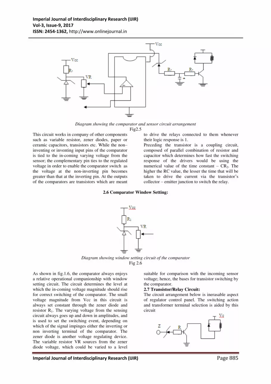
Diagram showing the comparator and sensor circuit arrangement
Fig2.5
This circuit works in company of other components
such as variable resistor, zener diodes, paper or
ceramic capacitors, transistors etc. While the non–inventing or inventing input pins of the comparator
is tied to the in-coming varying voltage from the
sensor; the complementary pin ties to the regulated
voltage in order to enable the comparator switch as
the voltage at the non-inverting pin becomes
greater than that at the inverting pin. At the outputs
of the comparators are transistors which are meant
to drive the relays connected to them whenever
their logic response is 1.
Preceding the transistor is a coupling circuit,
composed of parallel combination of resistor and
capacitor which determines how fast the switching
response of the drivers would be using the
numerical value of the time constant – CR2. The
higher the RC value, the lesser the time that will be
taken to drive the current via the transistor’s
collector – emitter junction to switch the relay.
2.6 Comparator Window Setting:
Diagram showing window setting circuit of the comparator
Fig 2.6
As shown in fig.1.6, the comparator always enjoys
a relative operational companionship with window
setting circuit. The circuit determines the level at
which the in-coming voltage magnitude should rise
for correct switching of the comparator. The small
voltage magnitude from Vcc in this circuit is
always set constant through the zener diode and
resistor R1. The varying voltage from the sensing
circuit always goes up and down in amplitudes, and
is used to set the switching event, depending on
which of the signal impinges either the inverting or
non inverting terminal of the comparator. The
zener diode is another voltage regulating device.
The variable resistor VR sources from the zener
diode voltage, which could be varied to a level
suitable for comparison with the incoming sensor
voltage; hence, the bases for transistor switching by
the comparator.
2.7 Transistor/Relay Circuit:
The circuit arrangement below is inerasable aspect
of regulator control panel. The switching action
and transformer terminal selection is aided by this
circuit

Imperial Journal of Interdisciplinary Research (IJIR)
Vol-3, Issue-9, 2017
ISSN: 2454-1362, http://www.onlinejournal.in
Imperial Journal of Interdisciplinary Research (IJIR) Page 886
Diagram showing relay/transistor circuit
arrangement Fig2.7
The zener diode, Z ensures that the voltage from
comparator output, intended for transistor
switching, does not reduce below its voltage rating
before it passes base current for transistor
switching. The resistor is a current limiter, which
does not permit excessive current flow to the risk
of the transistor.
3.0 DESIGN AND CONTRACTION
The main design of this work is allocated this area
of the thesis. We begin by focusing on the various
components that give rise to the complete
realization of the work. Identifying their respective
values will be a good thing, in attempt to permit
imitation, should any one desires to practically
make a copy of this product.
3.1 Component Values:
1. Transformer construction –Auto-transformer:
a. Lamination core of “ E” and ” I” shapes
b. Copper wire – gauge 17 (AWG)
c. Insulating materials- Masking tape
d. lamination liquid
e. Metal standing frame – angular frame
2. Internal wiring:
a. Casing socket – 13AMP
b. Fuse – 13AMP
c. Two voltmeters for input and output
d. Telephone wires for voltmeter, Vero or bread
board connection
e. Light emitting diodes for voltage level indication
3. Control Panel:
a. Bridge diodes-IN4001
b. Voltage regulators-7815
c. Variable resistors
d. Comparators – LM324
e. Zener diodes
f. Diodes
g. Transistors – TIP42
i. Relays – 15V DC
j. Capacitors
k. LED
l. Vero board
m. Resistors
Note that all the component values are as indicated
on the schematic diagram of the control panel
below.
3.2 Control Panel Building
As shown in the diagram, the panel sources power
form AC output of the transformer, and the step
down output is rectified, filtered of the ripples and
regulated to obtain a fairly stable dc voltage taken
as VCC to the electronic components. The 24v
output of the transformer is regulated to 15V DC
after rectification. I decided to dualize this section
to avoid over loading each of the 15V DC source,
and more importantly to make adequate and
sufficient amount of voltage and current available
to the components. The smoothing capacitor is
electrolytic and is chosen to 1000uf capacitance for
better filtration reason. I install 35V to give a
tolerance of 20v against unexpected rise in voltage
from the source; thus, helping to prevent a possible
break down of the filtering capacitor at a large
sudden system voltage surge .The figure below
shows the diagram of the typical power section of
the constructed voltage stabilizer- regulator
Fig3.1
3.3 Voltage sensing unit:

Imperial Journal of Interdisciplinary Research (IJIR)
Vol-3, Issue-9, 2017
ISSN: 2454-1362, http://www.onlinejournal.in
Imperial Journal of Interdisciplinary Research (IJIR) Page 887
Diagram showing the sensor circuit arrangement
fig 3.2
Voltage regulator depends immensely on the
reliability of the sensor unit for effective operation.
Therefore, the sensor sees the changing behavior of
the line voltage at the outlet socket and quickly
relates the development to the comparator. The
comparator senses the fluctuating voltage and
switches the transistor at its output. Actually, the
unit originates directly from 230v of the
transformer input; reason being to enable the
unstable voltage at the regulator input be registered
on the panel for effective control.
The voltage is split into smaller unit to avoid
damages to the subsequent modules. This is done
with voltage divider, using 1MΩ and l00kΩ variable resistors. The connection of the variable
resistor in such a mode on the diagram reduces
excess current against damages, and the reduced
current passes through the serially connected diode
and resistor in order to be partly rectified. The
subsequent capacitor aids speedy signal transfer to
the adjoining circuit; and the speed is determined
by time constant formula, 0.693RC.
3.4 Operation Mechanism of the Comparator
Diagram showing the comparator circuit
Fig3.3
ZD1 = ZD2 = ZD3 = 6V zener diode
VR1 = VR2 = VR3 = 10K variable resistor
From the diagram the 15v Vcc is dropped down to
6v by the zener diode using 1k resistors. The
incoming varying voltage at sensor line is 6v, and
is connected to pin 2, 6 and 10 of the op-amp. Pin
3, 5 are connected to the variable resistors for their
respective fixed voltage of 4.5v, 3.3v and 7.0v.
Conventionally, the normal operating voltage is
230v. Since the voltage at the autotransformer
terminals ranges from 230v, 290v to 360v, the
corresponding op- amp switching voltages are set
to 7.0v, 4.5 and 3.3v.
In the choice of voltage for the transformer
terminal, 60V difference is considered between any
two adjacent producing terminals. This is done so
that when the transformer terminal voltage

Imperial Journal of Interdisciplinary Research (IJIR)
Vol-3, Issue-9, 2017
ISSN: 2454-1362, http://www.onlinejournal.in
Imperial Journal of Interdisciplinary Research (IJIR) Page 888
decreases by 60V, the 230V output terminal drops
to 170V, and 290V terminal drops to 230V and be
selected by the relay assigned to it; thus, releasing
230V at the regulator output socket. At this time
the 360V terminal will drop to 300V. Again when
another 60V drop is encountered on the line, it will
show on the transformer’s terminal voltages as
follows: 170V at the input will drop to 110V, 230V
terminal will drop to 170V while 300V will drop
to 240V which is a bit convenient value to be
conveyed to the output socket by the assigned
relay. In the same manner the small input
comparator voltages drop in corresponding way to
necessitate relay switching that brings about the
terminal selection at the transformer output.
The recommendable characteristic of this work is
its special feature of step-up capability when there
is up to 60V drop on the line which reflects at the
transformer input and output voltages. At this
moment, all the connected appliances at the
regulator output experiences low voltage and
power supply should there be no means of
upgrading the voltage at the socket.
The essence of voltage window setting to 7.0v,
4.5v and 3.3v is to realize the above events. At any
time that the input voltage comes down from 230V
to 170v, the 6v sensor voltage must decrease below
4.5v to make 290 terminals to experience 230v.
When it decrease further than 3.3v, the 360V
terminal runs with 230v and the input voltage will
then decrease by 120v, leaving behind only 110v to
run the autotransformer.
On the contrary, the state of the system supply
equally degenerates in reverse order, that instead of
the usual unwanted decrement, the voltage may
detrimentally surge up far above 230v. In this case,
the sensor voltage will correspondingly rise slightly
above 7.0v on the inverting input of op-am. This
causes the relay to select the step down terminal of
the transformer which now must have increased to
230v.
3.5 Relay Arrangement
Diagram showing transistor/relay connection
fig 3.4
It is the relay logic circuit arrangement that brings
in the sumptuous function of the regulator panel
which attracts beauty to the performance of the
regulator. The terminals–NO (normally open) and
NC (normally close) are connected in a manner to
allow proper coordination of the relays in a bid to
escape the bridging of autotransformer output
terminal; and still maintain a continuous and serial
link that transfers a voltage magnitude of 230V to
the load.
The relay switching takes place when the
transistors base sees a forward biasing voltage that
is greater or equal to 0.6v for NPN transistor. The
voltage above 0.6v for the transistor, must always
be considered within the thermal limit tolerance of
the transistor’s base–emitter junction, in order to
avoid damages. Also, it is often an appreciable
practice, to protect the transistors with resistors so
as to prevent excess heat occurrence at the PN
junctions.
When all these precautions are observed, the
transistor drivers obviously become effective
witching device that drive the relays “on and off “
depending on the set voltage values on the
comparator as well as the prevailing manner of
voltage variation on the line.
4.0 PRINCIPLE OF TRANSFORMER
OPERATION Transformer is a stationary device whose electric
power on the primary is transformed to electric
power of the same frequency on the secondary side
of the circuit. The secondary voltage can be
decreased or increased in proportion to decrease or
increase of the voltage magnitude in the primary.
This feature is as a result of mutual induction
between the primary and secondary winding.
Common magnetic flux that flows through the

Imperial Journal of Interdisciplinary Research (IJIR)
Vol-3, Issue-9, 2017
ISSN: 2454-1362, http://www.onlinejournal.in
Imperial Journal of Interdisciplinary Research (IJIR) Page 889
laminated core is responsible for this induction as it alternates during the full electric cycle.
Diagram showing transformer core and the flux lines
fig 4.0
Induction transformer can be referred as a static
magnetic circuit or device of two or more layers of
inductive coils-windings which are electrically
separated but magnetically connected through the
magnetic flux in the laminated core. Connection of
the input terminals of the transformer into the AC
source sets up a magnetic flux in the core; and most
of these flux do link the transformer coils to
produce an induced e.m.f which according to
faraday’s law of electromagnetic induction can be
expressed as
E = NdФm /dt
4.1 Transformer Construction:
In transformer construction, appropriate care is
always taken to achieve conveniently working
device that is devoid of errors which can result
electrical faults. The coils are properly insulated
from one other and from the laminated core around
which they are wound.
A good transformer construction always ends in
assembling a structure that will give effective
support for, a balance standing, when mounted on
the ground.
Diagram showing a cut -out section of the
transformer core
Fig4.1
In transformer building, the cores are constructed
of laminated silicon metallic material, well
assembled to produce a continuous magnetic path
with minimum air gap
The laminated sheets of silicon metal are specially
treated at manufacturing stage to achieve high
permeability and low hysteresis and copper losses.
The essence of core lamination is to reduce eddy
current. The thickness of the lamination metal may
vary from 0.35mm for a frequency of 50Hz to
0.5mm for a frequency of 25Hz.The diagram above
shows a sort of laminated core slices that are
carefully cut and separated from a fully and
completely packed transformer E-I-core of a
voltage regulator.
4.2 Types of Transformer:
Generally, transformers can be basically classified
into two distinct natures that are different by
structure, with two different shapes that are
categorized into two different names, shell and core
type transformer.
A picture of small unit induction/shell type
transformer used in some home electric appliance
Fig4.2
4.3 Core Type Transformer:
In a small size core type transformer, a rectangular
core is always used with cylindrical coil which are
either circular or flat (e.g. flat copper for arc
welding transformer construction).
The long cylindrical coils are often used in most
cases due to their tough mechanical strength.

Imperial Journal of Interdisciplinary Research (IJIR)
Vol-3, Issue-9, 2017
ISSN: 2454-1362, http://www.onlinejournal.in
Imperial Journal of Interdisciplinary Research (IJIR) Page 890
Diagram showing a schematic view of a core type transformer/symbols
Fig4.3
5.0 TRANSFORMER EQUATION
Diagram showing the wave flux of the transformer
Fig4.4
Let Np = No of turns in primary
Ns = No of turns in secondary
Фm = maximum flux in Weber
F = frequency of ac input in Hz
Always rate of change of flux = Фm /1/4f
(wb)
Average emf /turn = 4f Фm voltS
rms value /average value =1.11
r.m.s value of emf/turn = 1.11 x 4f Фm = 4.44
f Фm
But, E =4.44FNs Фm
=4.44FNs A Bm
Similarly, we can still derive the root mean square
value of the electromotive force of the transformer
as shown bellow, considering the fact that the
transformer is examined under ideal condition.
E = NdФm /dt
E = N . ɷ .Фm . COSɷt
Emax = N . ɷ .Фm
Erms = N /21/2
Фm
Erms = 2π /21/2 Фmf N
Erms = 4.44 Фmf N
All the parameters still retain their definition as
stated above
Therefore, under lossless and no load condition
VP = EP
ES = VS
VOLTAGE TRANSFORMATION RATIO
ES NP = EP NS
ES = NS = K
EP NP
K=voltage transformation ratio
If NS >NP ie K>1, then the transformer is called
step up transformer
If NS<NP ie K<1, the transformer is a step down
transformer.
Input VA = output VA
VP IP = VS IS
IS/IP = VP/VS
This shows that the current is in inverse ratio of the
voltage in the transformer.
As the mathematical illustration above shows, the
turn ratio of the transformer determines the step-up
and step-down status of the device. If the
transformation ratio is lesser than one, ie n< 1,then
NS is greater than NP and the transformer is
categorized as a step-up transformer. However, if
the reverse is the case then the device is a step-
down transformer. In this case NS must be greater
than NP.
In a situation where both Np and Ns are of the same
number of turns, then the transformer can be
referred as isolation transformer. In this
transformer, Voltage and current magnitude of the
two sides are equal and the transformation ratio
must be equal to unity, n = 1.
6.0 Efficiency in Induction Transformer
Input power = Output power + Losses
VPIP = VSIS + Losses
Eff. = KVA/ IVcosα
= [Output Power / Input Power ] x 100/1
= [(Input Power – Losses) / (Input
Power)] x 100/1

Imperial Journal of Interdisciplinary Research (IJIR)
Vol-3, Issue-9, 2017
ISSN: 2454-1362, http://www.onlinejournal.in
Imperial Journal of Interdisciplinary Research (IJIR) Page 891
= [1 – (Losses) / Input Power] x 100/1
It is good to note that transformer does not have
any moving part as its body component. Therefore,
the wind-age and fictional losses are not accounted
for when considering the losses that reduce the
device’s efficiency while in operation. The main
losses that are obtainable with this device is
electrical in nature, and so, we have copper or
ohmic losses owing to the flowing current that
causes the heat which the device experiences when
it is working .This is the product of coil resistance
and the square of the moving current on the coil
winding (I2R).Another type of loss apart from cu
loss is iron loss which is hysteresis in nature and
can be accounted for due to the molecular
composition of the metallic material with which the
laminated core is manufactured.
The impart of losses in all engineering equipments
does not make a good effect on the efficiency of
the devices. Transformer device, among other
electrical equipments is not exempted; therefore,
the degree of transformer usefulness, rating from
efficiency is highly reduced by the iron and copper
losses. In effect, all the electrical input at the
primary side of the device are not always harnessed
at the output following the electrical losses within
the circuit.
An ideal transformer is assumed loss free, as a
result; the efficiency is said to be 100% .This
means that an ideal transformer can convey all the
power at its primary circuit to the secondary side
without suffering any electric power loss.
In reality, ideal transformer is always a fiction
since there is often times power loss problem even
at no load when the transformer struggles to build
up the magnetic flux upon which the e.m.f at the
output depends. And the inrush magnetizing
current that sustains the functions of the device
cannot be completely blameless of power losses.
Nevertheless, a well constructed transformer
should be built on a reasonable value of efficiency
for optimum performance and efficiency value of
94% to 96% at full load is admirable.
CONCLUSION
Looking at the explanation details as an account of
the basic operational phenomenon that leads to
accomplishment of voltage regulation in this work,
a good understanding of the thesis can obviously
show that the autotransformer and the electronic
panel are the two major key units that drive the
device. While, the transformer serves as the major
nucleus for power and voltage transformation, the
electronic panel automates the terminal selection to
initiate the required 230V transfer onto the
regulator outlet. The operation of these components
is, of course, the force that moves the regulator into
action. The regulator is designed to monitor the
230V on the secondary circuit of the power
network which it sees through the cut-out on the
meter board. The 230V is at the same time fed to
the connected home- equipments via the regulator
output-socket. It is necessary to state at this point
that the steady 230V needed at the stabilizer outlet
is relatively plausible following the logical
selection of the autotransformer multiple output
voltages which is meant to occur within two
consecutive voltage drops at a magnitude value of
60V.

Imperial Journal of Interdisciplinary Research (IJIR)
Vol-3, Issue-9, 2017
ISSN: 2454-1362, http://www.onlinejournal.in
Imperial Journal of Interdisciplinary Research (IJIR) Page 892
Diagrams showing different views of the inner circuitry and casing of automatic voltage regulator
Fig.6.1
Diagram showing electronic circuit of regulator

Imperial Journal of Interdisciplinary Research (IJIR)
Vol-3, Issue-9, 2017
ISSN: 2454-1362, http://www.onlinejournal.in
Imperial Journal of Interdisciplinary Research (IJIR) Page 893
Reference [1] Adelakun Adedayo Oke1*, Rabiu
Jamiu.Ariyo1, Egunjobi Abiodun Isiaka etc:
Design and Construction of a Stabilize Variable
Power Supply
[2] Filtegerald A. E. Higginbotham. O. E And
Grabel. L. A. M. (1988): Basic Electrical
Engineering (5th Edition) Megraw-Hill Books
Company, New York.
[3] Fair Child Groups; 1967: Appliction
Engineering Staff Of The S. G. S. Industrial Circuit
Handbook. Fair Child Publication.
[4] G. L. Tater; 1976: The Mpc1000 – Super
Regulator, Ham Radio, Pg 52-54
[5] Harrison G; 1975: Basic Electronics, Resistor in
Circuit, Capacitor In Circuit. The English
University Press Ltd Ibadan, Nigeria.
[6] Horowitz. P. And Hill W; 1995: The Art Of
Electronics, Cambridge University Press,
Campbridge.
[11] Martin Hartley. J. 1990: A Practical
Introduction To Electronic Circuits, Cambridge,
University Press.