generator control and protection automatic voltage regulators
TRANSCRIPT
GENERATOR CONTROL AND PROTECTION
Automatic Voltage Regulators
GENERATOR CONTROL AND PROTECTION
Outline
• Basics of a Practical AVR
• Control Functions
• Per-Unitization
• AVR Control Configurations
GENERATOR CONTROL AND PROTECTION
Basics of a Practical AVR
AVR for small generators
Microcontroller based
Inputs
– Voltage sensing
– Current sensing
– External voltage adjustment
– Auxiliary input (+/- 3Vdc)
– Operating Power
GENERATOR CONTROL AND PROTECTION
Basics of a Practical AVR
Internal Adjustments
– Voltage
– Droop
– Stability
– Under frequency knee / slope
Outputs
– Exciter field voltage
GENERATOR CONTROL AND PROTECTION
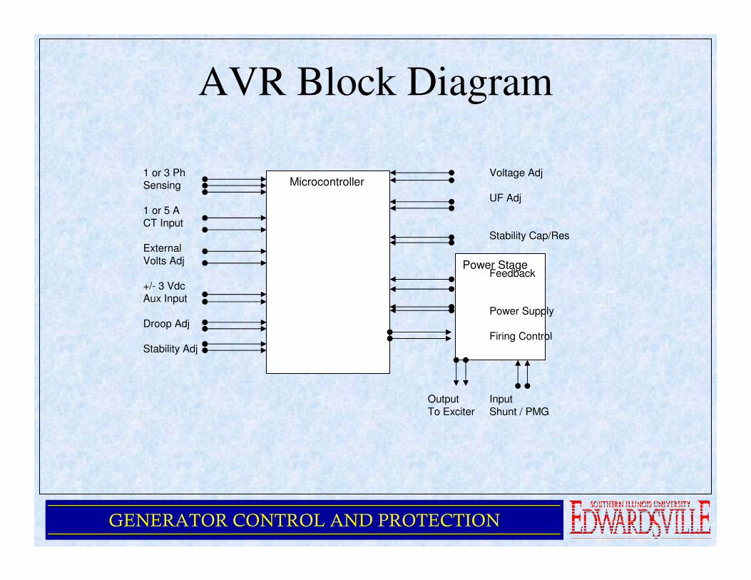
AVR Block Diagram
Power Stage
Microcontroller1 or 3 Ph Voltage AdjSensing
UF Adj1 or 5 A CT Input
Stability Cap/ResExternal
Volts AdjFeedback
+/- 3 VdcAux Input
Power Supply
Droop AdjFiring Control
Stability Adj
Output Input
To Exciter Shunt / PMG
GENERATOR CONTROL AND PROTECTION
Control Functions
• Voltage Control
• Droop Compensation
• V/Hz Compensation
• Over Excitation Shutdown
• Loss of Sensing Protection
• Build up from Residual
• Internal Adjustments
GENERATOR CONTROL AND PROTECTION
Control Functions
• External Adjustments
• Auxiliary Input
• Regulation Accuracy
• Temperature Drift
• Operating Temperature Range
GENERATOR CONTROL AND PROTECTION
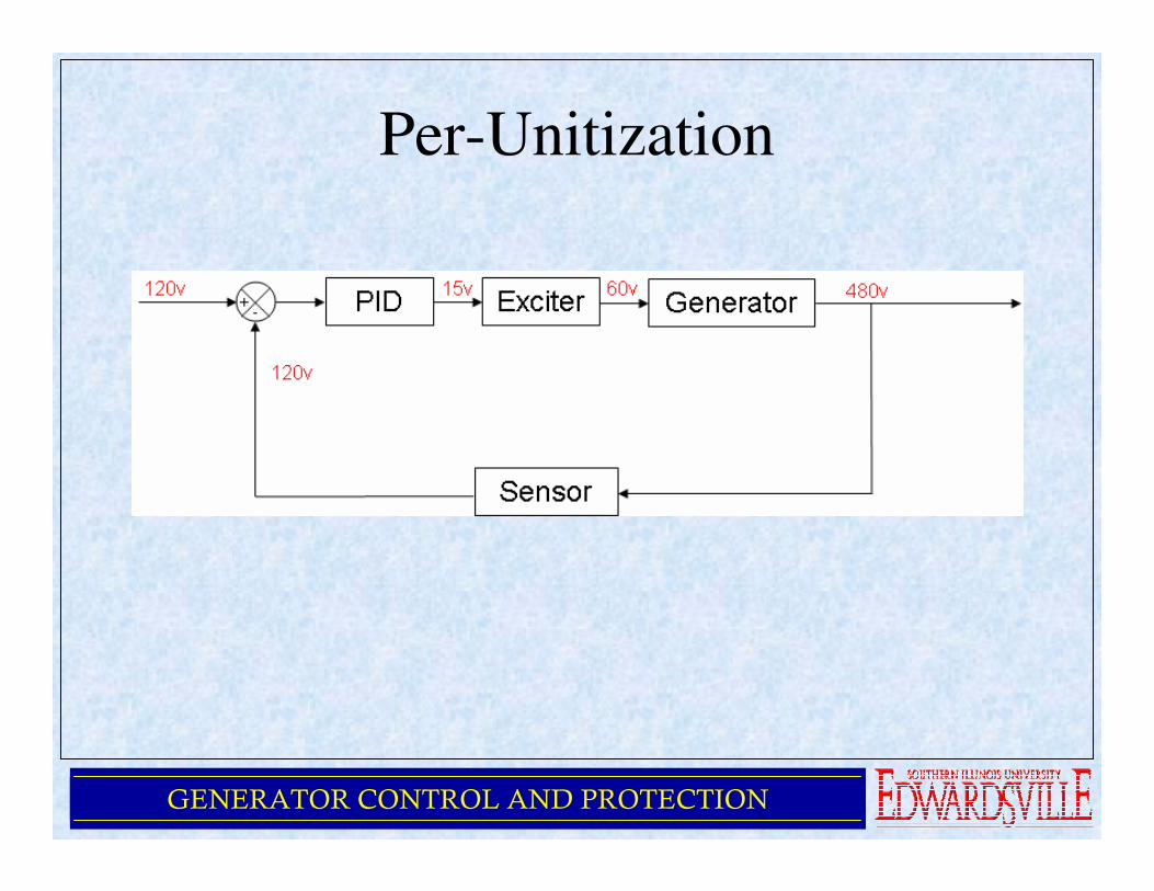
Per-Unitization
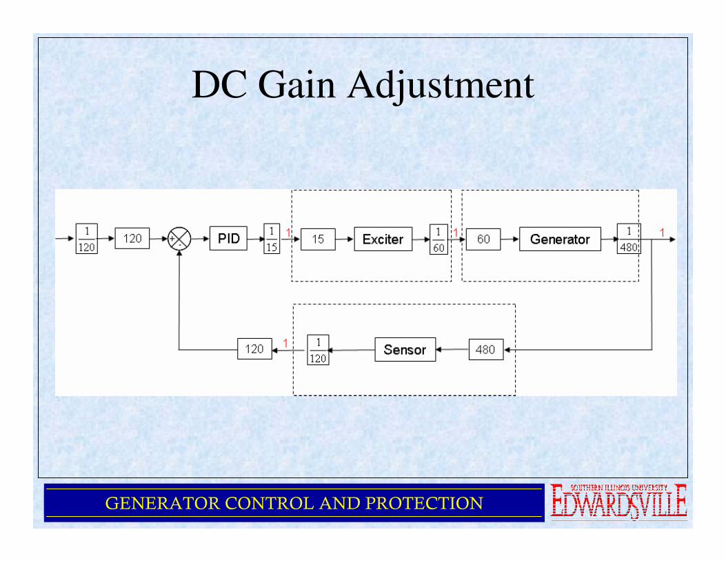
• Goal is to set the gain for each block to “1” except the controller block
• The gain of each block is determined by dividing the output by the input for that block
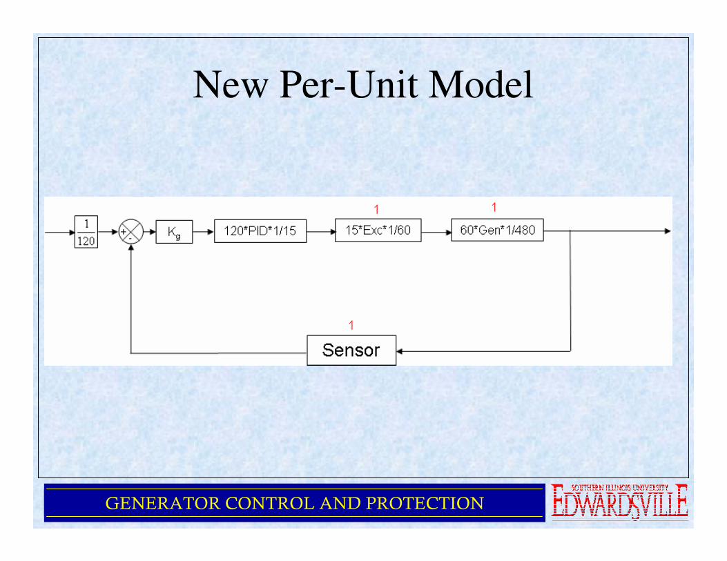
• The gains for the blocks are combined together and the result appears in the controller block
GENERATOR CONTROL AND PROTECTION
Per-Unitization
GENERATOR CONTROL AND PROTECTION
DC Gain Adjustment
GENERATOR CONTROL AND PROTECTION
New Per-Unit Model
GENERATOR CONTROL AND PROTECTION
Algorithm
• Once we determine the overall loop gain,
we compensate for it by introducing Kg,
with the inverse of the loop gain
• Once we have done this, now the PID
controller gains reflect what is really
happening in the loop
GENERATOR CONTROL AND PROTECTION
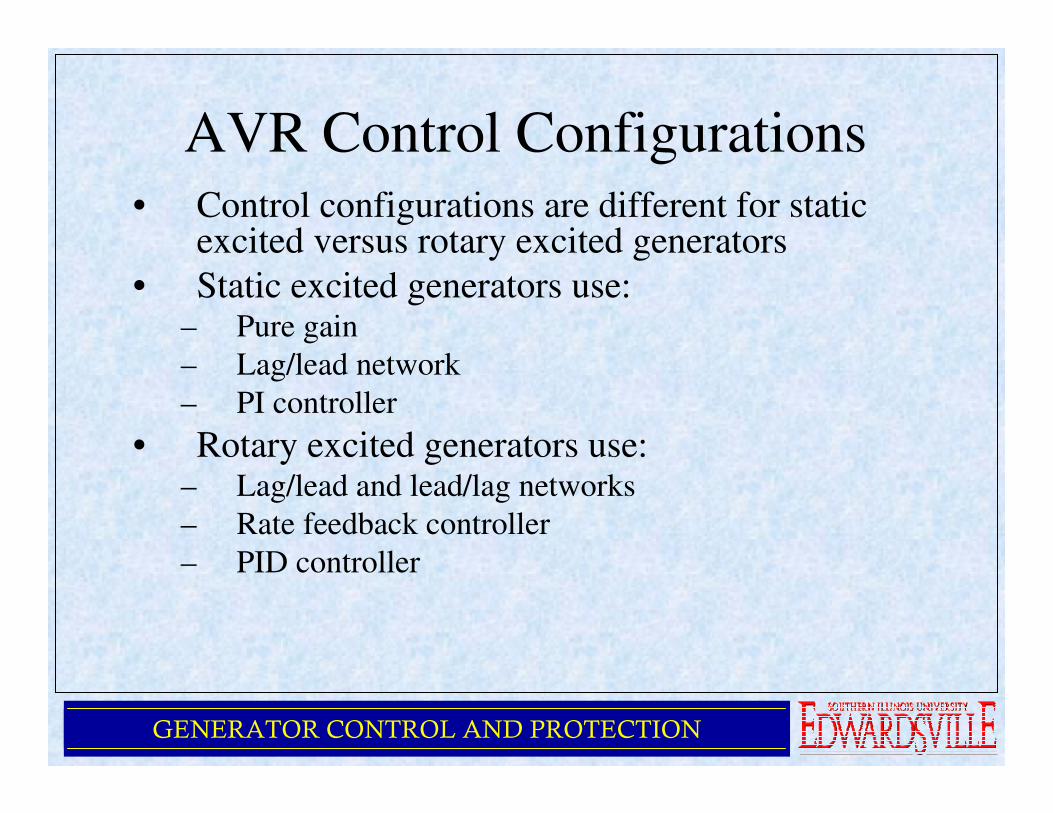
AVR Control Configurations• Control configurations are different for static
excited versus rotary excited generators
• Static excited generators use:– Pure gain
– Lag/lead network
– PI controller
• Rotary excited generators use:– Lag/lead and lead/lag networks
– Rate feedback controller
– PID controller
GENERATOR CONTROL AND PROTECTION
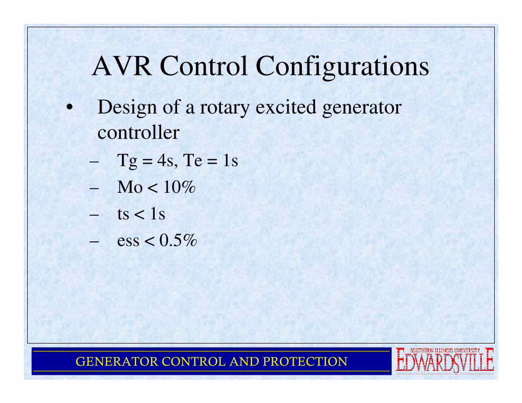
AVR Control Configurations
• Design of a rotary excited generator
controller
– Tg = 4s, Te = 1s
– Mo < 10%
– ts < 1s
– ess < 0.5%
GENERATOR CONTROL AND PROTECTION
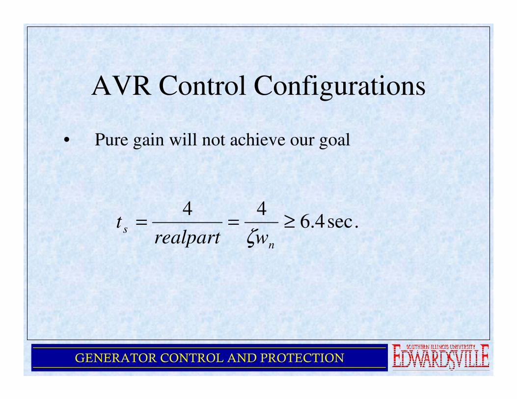
AVR Control Configurations
• Pure gain will not achieve our goal
.sec4.644
≥==n
swrealpart
tζ
GENERATOR CONTROL AND PROTECTION
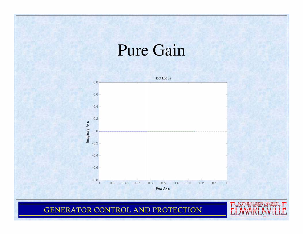
Pure Gain
-1 -0.9 -0.8 -0.7 -0.6 -0.5 -0.4 -0.3 -0.2 -0.1 0-0.8
-0.6
-0.4
-0.2
0
0.2
0.4
0.6
0.8Root Locus
Real Axis
Imagin
ary
Axis
GENERATOR CONTROL AND PROTECTION
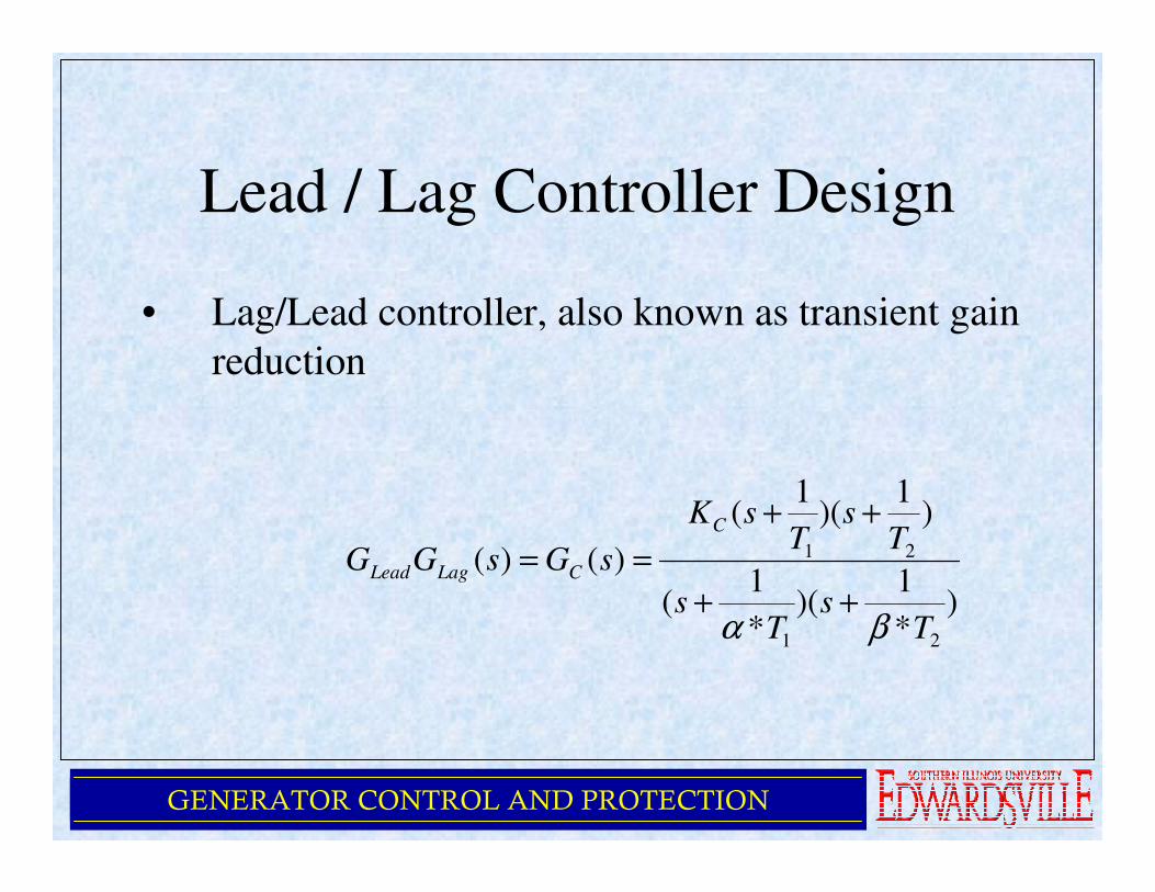
Lead / Lag Controller Design
• Lag/Lead controller, also known as transient gain
reduction
)*
1)(
*
1(
)1
)(1
(
)()(
21
21
Ts
Ts
Ts
TsK
sGsGG
C
CLagLead
βα++
++
==
GENERATOR CONTROL AND PROTECTION
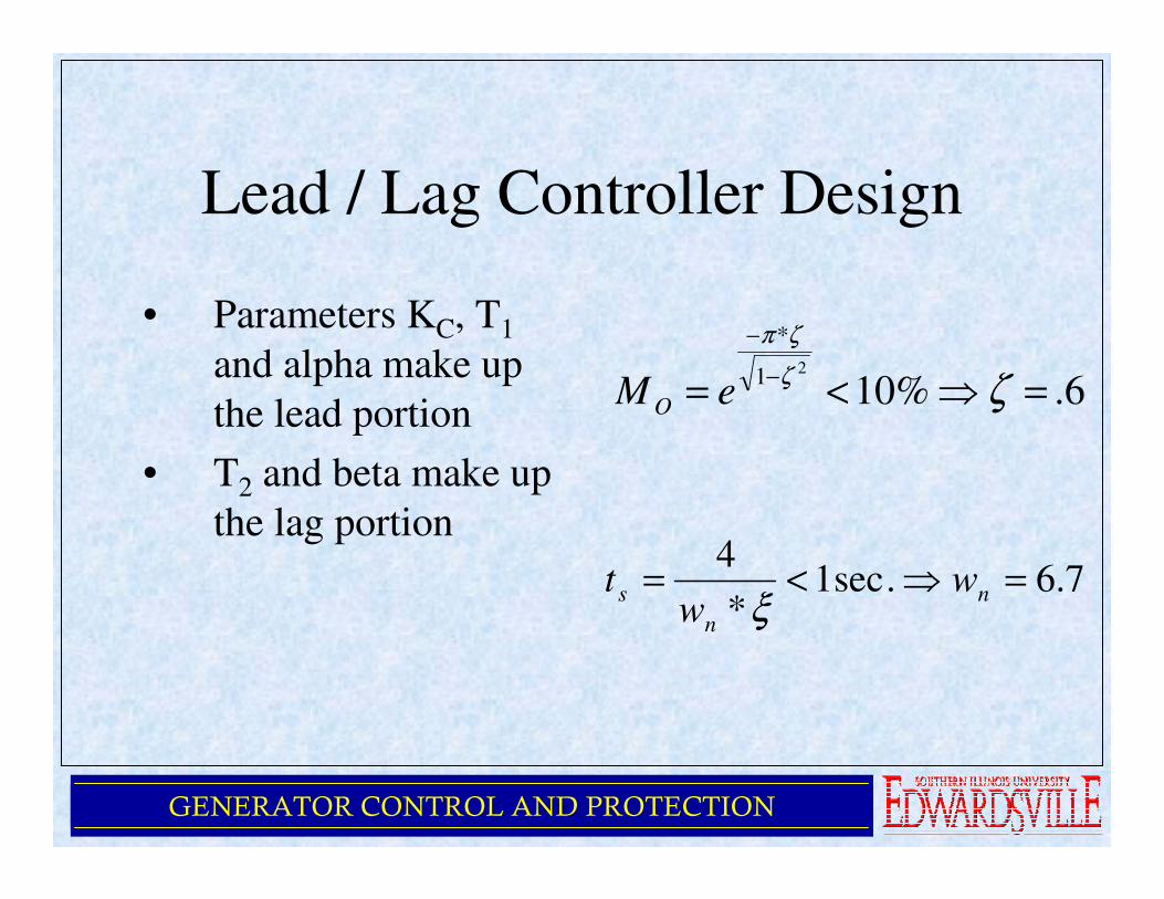
Lead / Lag Controller Design
• Parameters KC, T1
and alpha make up
the lead portion
• T2 and beta make up
the lag portion
6.%1021
*
=⇒<= −
−
ζζ
ζπ
eM O
7.6.sec1*
4=⇒<= n
n
s ww
tξ
GENERATOR CONTROL AND PROTECTION
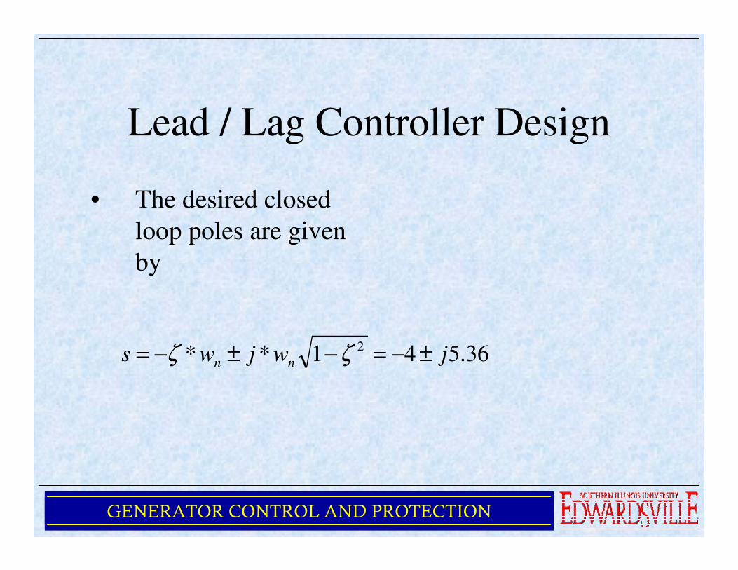
Lead / Lag Controller Design
• The desired closed
loop poles are given
by
36.541** 2jwjws nn ±−=−±−= ζζ
GENERATOR CONTROL AND PROTECTION
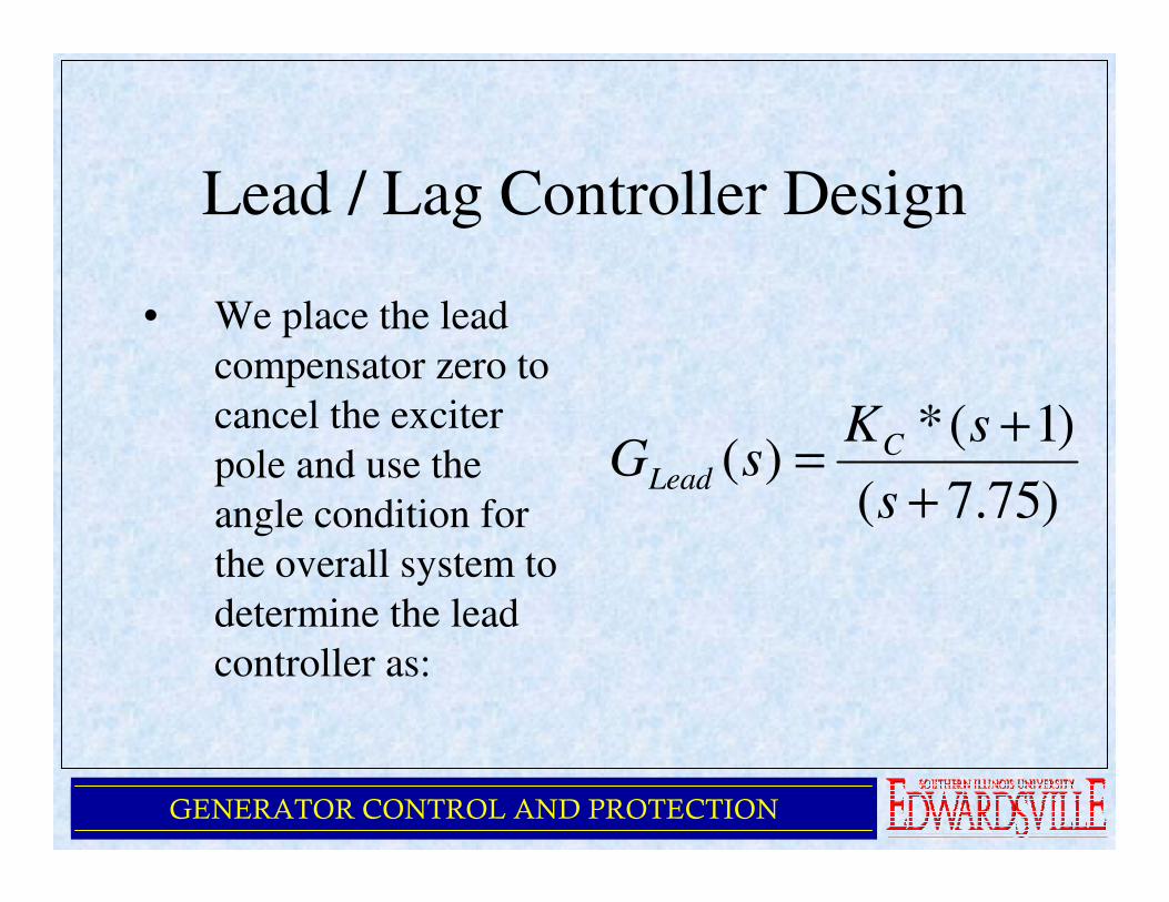
Lead / Lag Controller Design
• We place the lead
compensator zero to
cancel the exciter
pole and use the
angle condition for
the overall system to
determine the lead
controller as:
)75.7(
)1(*)(
+
+=
s
sKsG C
Lead
GENERATOR CONTROL AND PROTECTION
Lead / Lag Controller Design
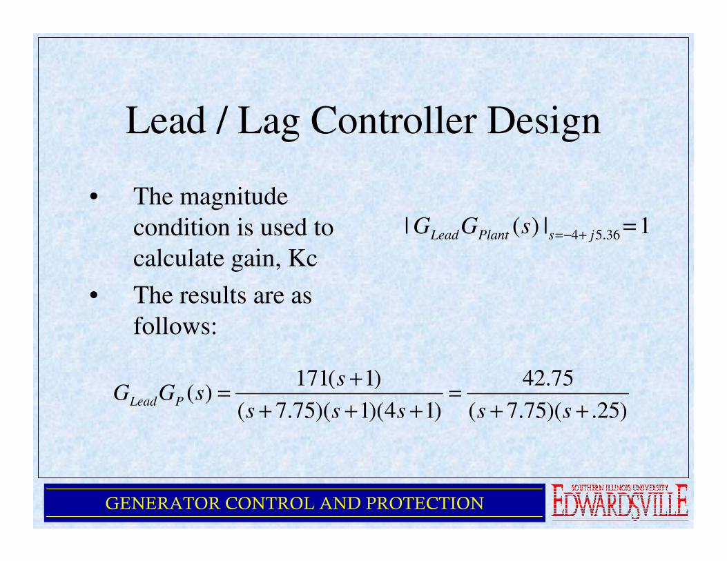
• The magnitude
condition is used to
calculate gain, Kc
• The results are as
follows:
1|)(| 36.54 =+−= jsPlantLead sGG
)25.)(75.7(
75.42
)14)(1)(75.7(
)1(171)(
++=
+++
+=
sssss
ssGG PLead
GENERATOR CONTROL AND PROTECTION
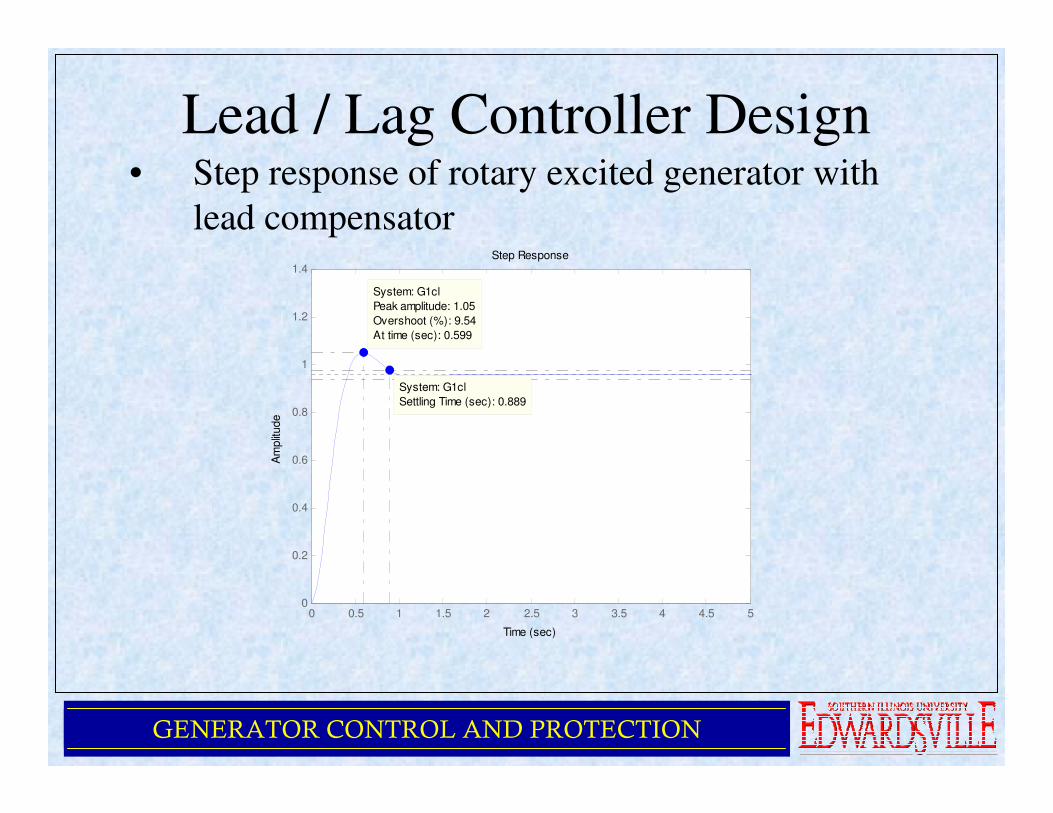
Lead / Lag Controller Design• Step response of rotary excited generator with
lead compensatorStep Response
Time (sec)
Am
plit
ude
0 0.5 1 1.5 2 2.5 3 3.5 4 4.5 50
0.2
0.4
0.6
0.8
1
1.2
1.4
System: G1cl
Peak amplitude: 1.05
Overshoot (%): 9.54
At time (sec): 0.599
System: G1cl
Settling Time (sec): 0.889
GENERATOR CONTROL AND PROTECTION
Lead / Lag Controller Design
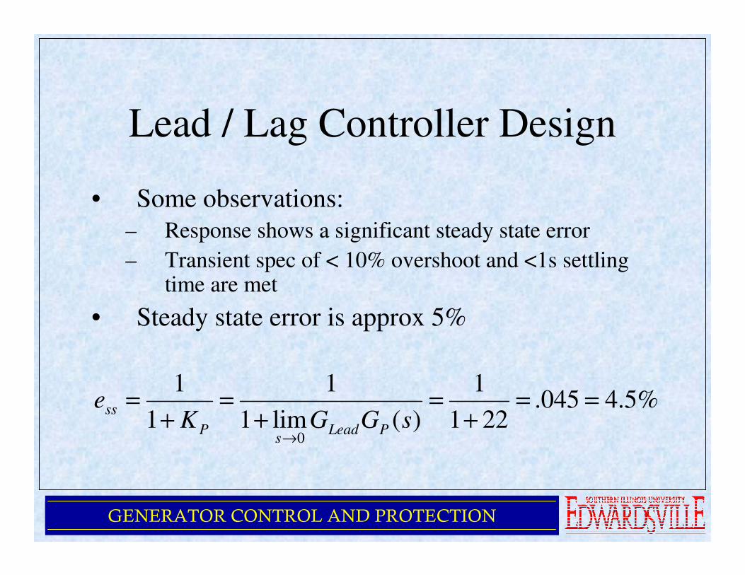
• Some observations:
– Response shows a significant steady state error
– Transient spec of < 10% overshoot and <1s settling time are met
• Steady state error is approx 5%
%5.4045.221
1
)(lim1
1
1
1
0
==+
=+
=+
=
→sGGK
ePLead
sP
ss
GENERATOR CONTROL AND PROTECTION
Lead / Lag Controller Design
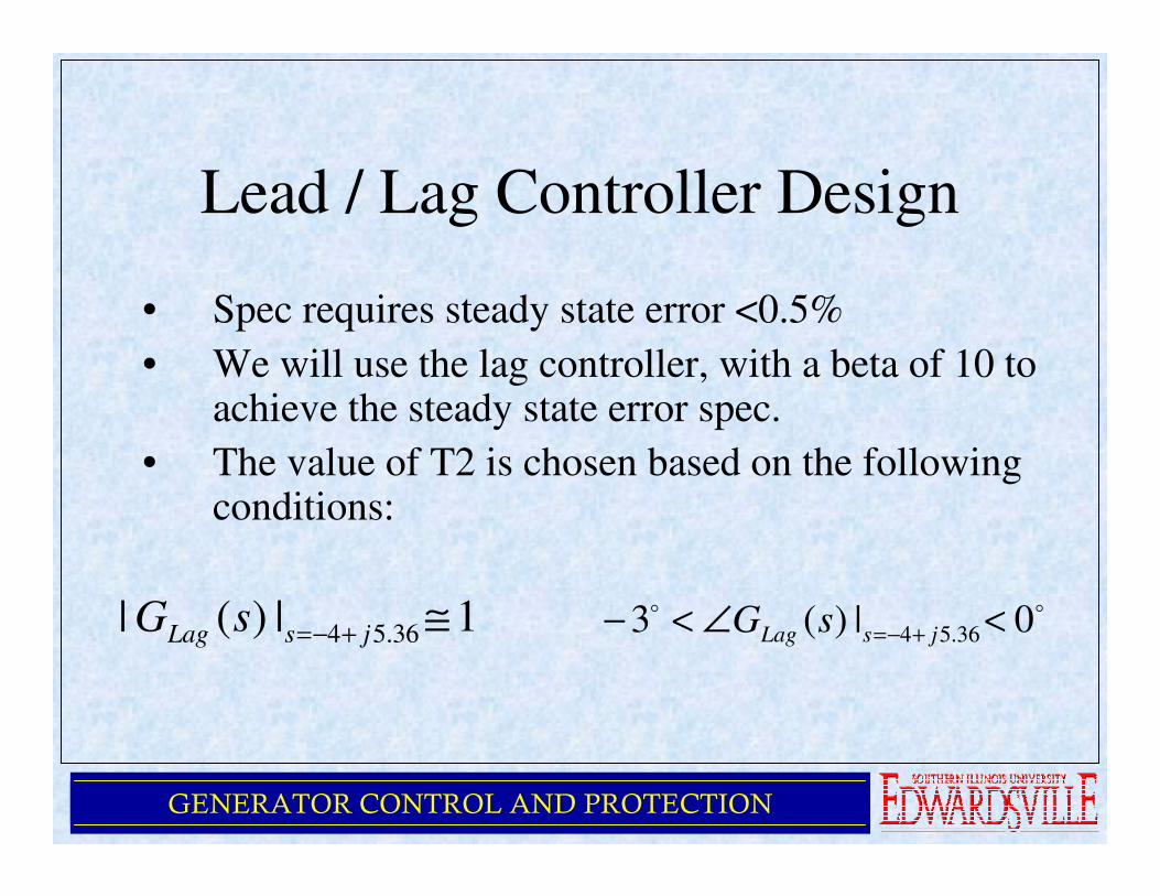
• Spec requires steady state error <0.5%
• We will use the lag controller, with a beta of 10 to achieve the steady state error spec.
• The value of T2 is chosen based on the following conditions:
1|)(| 36.54 ≅+−= jsLag sG oo 0|)(3 36.54 <∠<− +−= jsLag sG
GENERATOR CONTROL AND PROTECTION
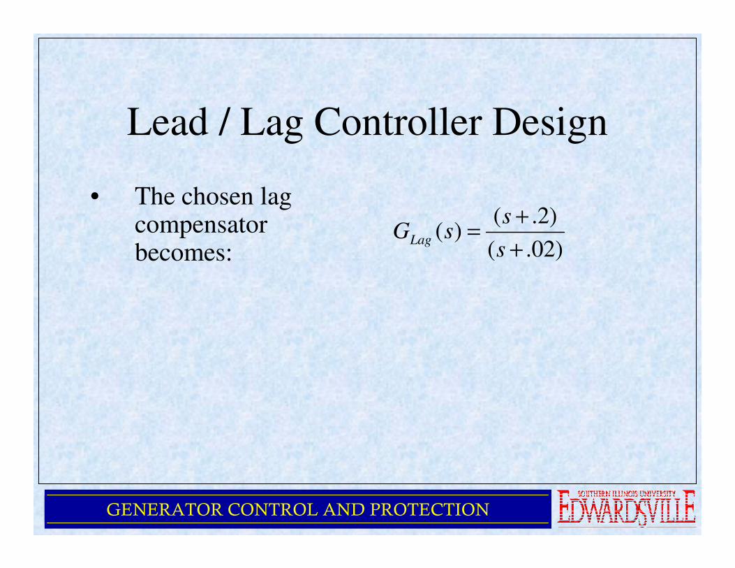
Lead / Lag Controller Design
• The chosen lag compensator becomes: )02.(
)2.()(
+
+=
s
ssGLag
GENERATOR CONTROL AND PROTECTION
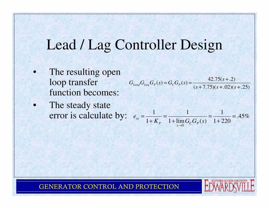
Lead / Lag Controller Design
• The resulting open loop transfer function becomes:
• The steady state error is calculate by:
)25.)(02.)(75.7(
)2.(75.42)()(
+++
+==
sss
ssGGsGGG PCPLagLead
%45.2201
1
)(lim1
1
1
1
0
=+
=+
=+
=
→sGGK
ePC
sP
ss
GENERATOR CONTROL AND PROTECTION
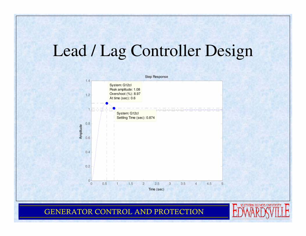
Lead / Lag Controller Design
Step Response
Time (sec)
Am
plit
ude
0 0.5 1 1.5 2 2.5 3 3.5 4 4.5 50
0.2
0.4
0.6
0.8
1
1.2
1.4
System: G12cl
Peak amplitude: 1.08
Overshoot (%): 8.97
At time (sec): 0.6
System: G12cl
Settling Time (sec): 0.874
GENERATOR CONTROL AND PROTECTION
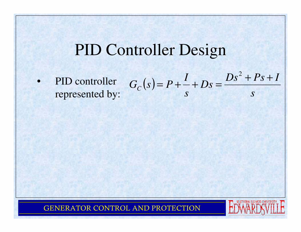
PID Controller Design
• PID controller
represented by:( )
s
IPsDsDs
s
IPsGC
++=++=
2
GENERATOR CONTROL AND PROTECTION
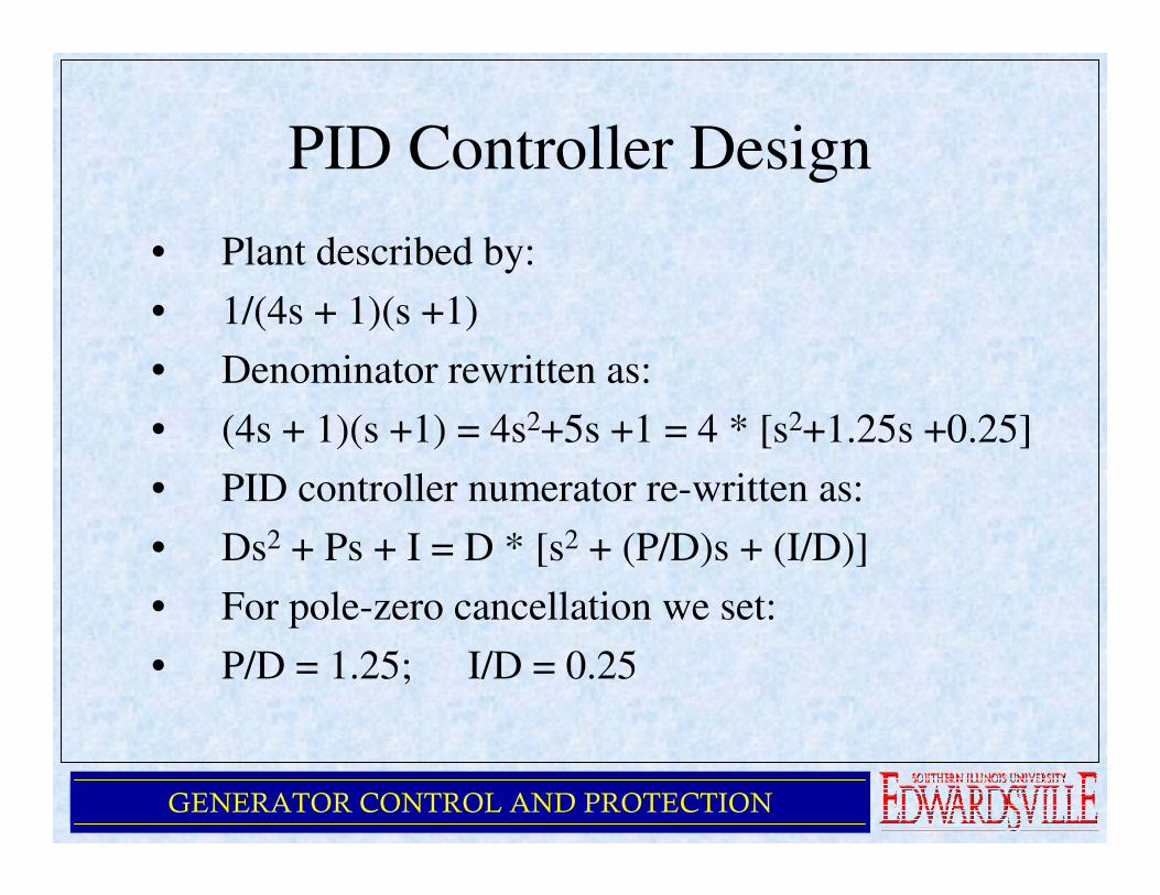
PID Controller Design
• Plant described by:
• 1/(4s + 1)(s +1)
• Denominator rewritten as:
• (4s + 1)(s +1) = 4s2+5s +1 = 4 * [s2+1.25s +0.25]
• PID controller numerator re-written as:
• Ds2 + Ps + I = D * [s2 + (P/D)s + (I/D)]
• For pole-zero cancellation we set:
• P/D = 1.25; I/D = 0.25
GENERATOR CONTROL AND PROTECTION
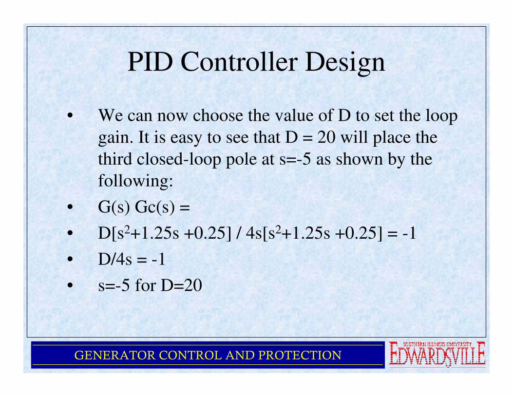
PID Controller Design
• We can now choose the value of D to set the loop
gain. It is easy to see that D = 20 will place the
third closed-loop pole at s=-5 as shown by the
following:
• G(s) Gc(s) =
• D[s2+1.25s +0.25] / 4s[s2+1.25s +0.25] = -1
• D/4s = -1
• s=-5 for D=20
GENERATOR CONTROL AND PROTECTION
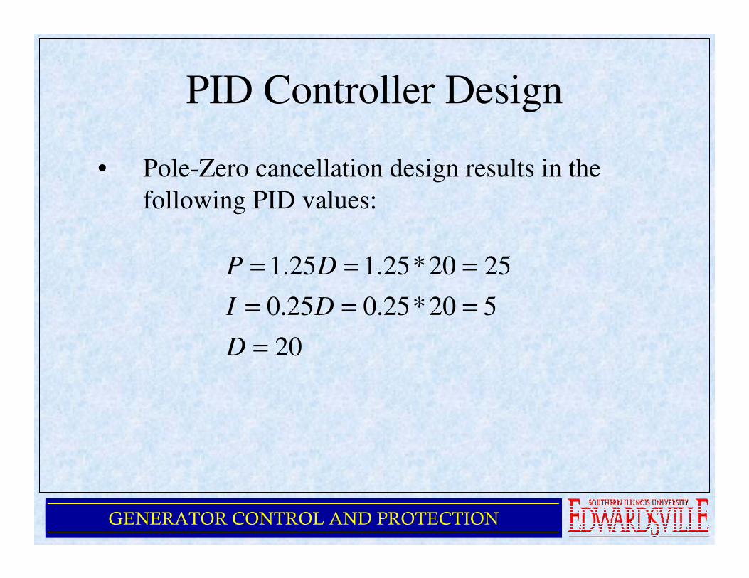
PID Controller Design
• Pole-Zero cancellation design results in the
following PID values:
20
520*25.025.0
2520*25.125.1
=
===
===
D
DI
DP
GENERATOR CONTROL AND PROTECTION
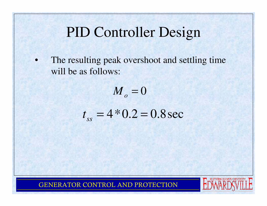
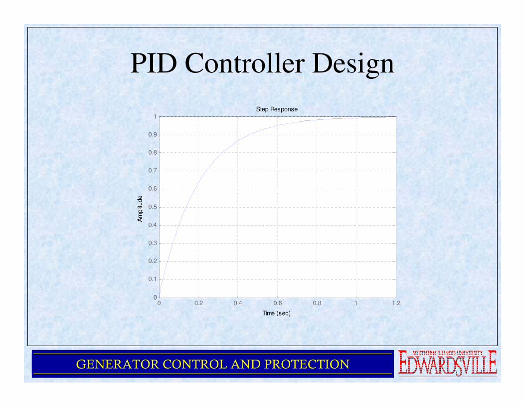
PID Controller Design
• The resulting peak overshoot and settling time
will be as follows:
0=oM
sec8.02.0*4 ==sst
GENERATOR CONTROL AND PROTECTION
PID Controller Design
0 0.2 0.4 0.6 0.8 1 1.20
0.1
0.2
0.3
0.4
0.5
0.6
0.7
0.8
0.9
1Step Response
Time (sec)
Am
plit
ude
GENERATOR CONTROL AND PROTECTION
Summary
• Basics of a Practical AVR
• Control Functions
• Per-Unitization
• AVR Control Configurations
GENERATOR CONTROL AND PROTECTION
QUESTIONS?