msb generator replacement
TRANSCRIPT

Houston,Texas
MSB GENERATOR REPLACEMENT
ISSUED FOR CONSTRUCTION
SEPTEMBER 30, 2016
E N G I N E E R
Shah Smith & associates, inc.Shah Smith & associates, inc.Shah Smith & associates, inc.Shah Smith & associates, inc.houston/austin/dallas/college stationTx. Registration no. F-2113
10/3
/2016 2
:09:2
2 P
M
DRAWING LIST
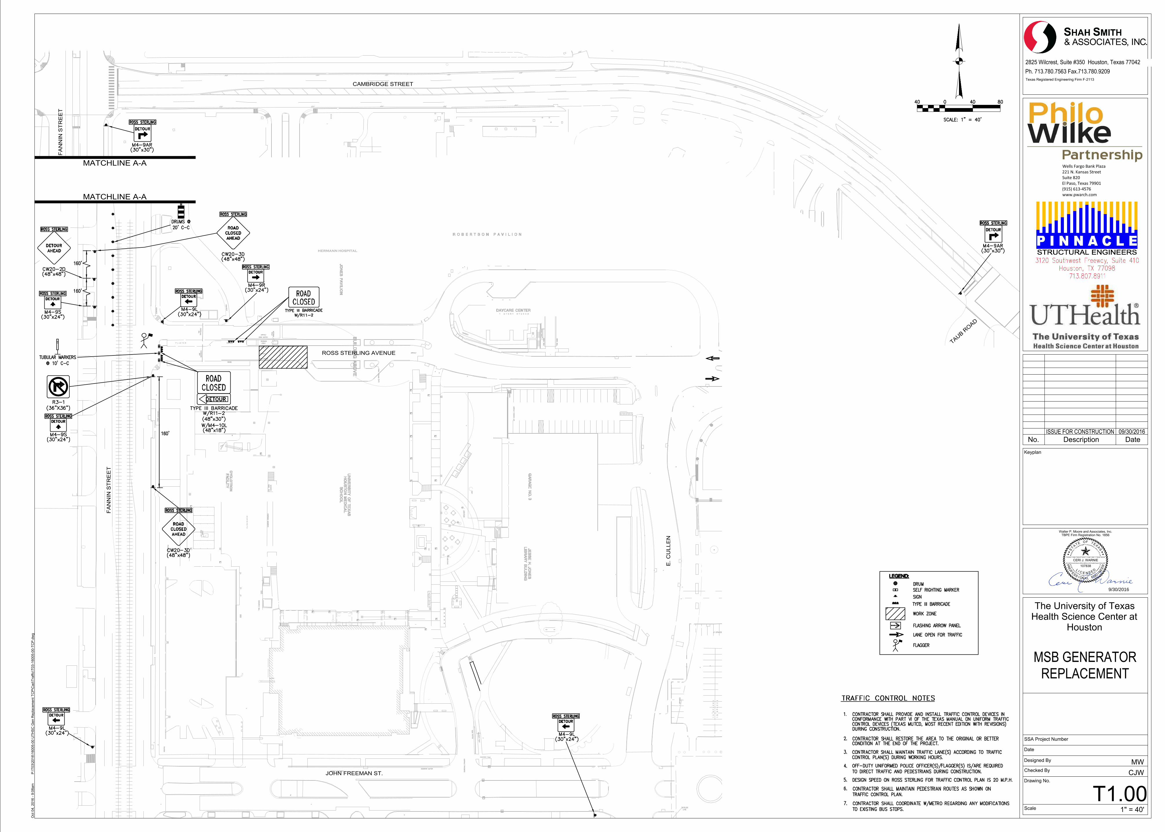
TRAFFIC CONTROL
T1.00 - TRAFFIC CONTROL PLAN
ARCHITECTURAL
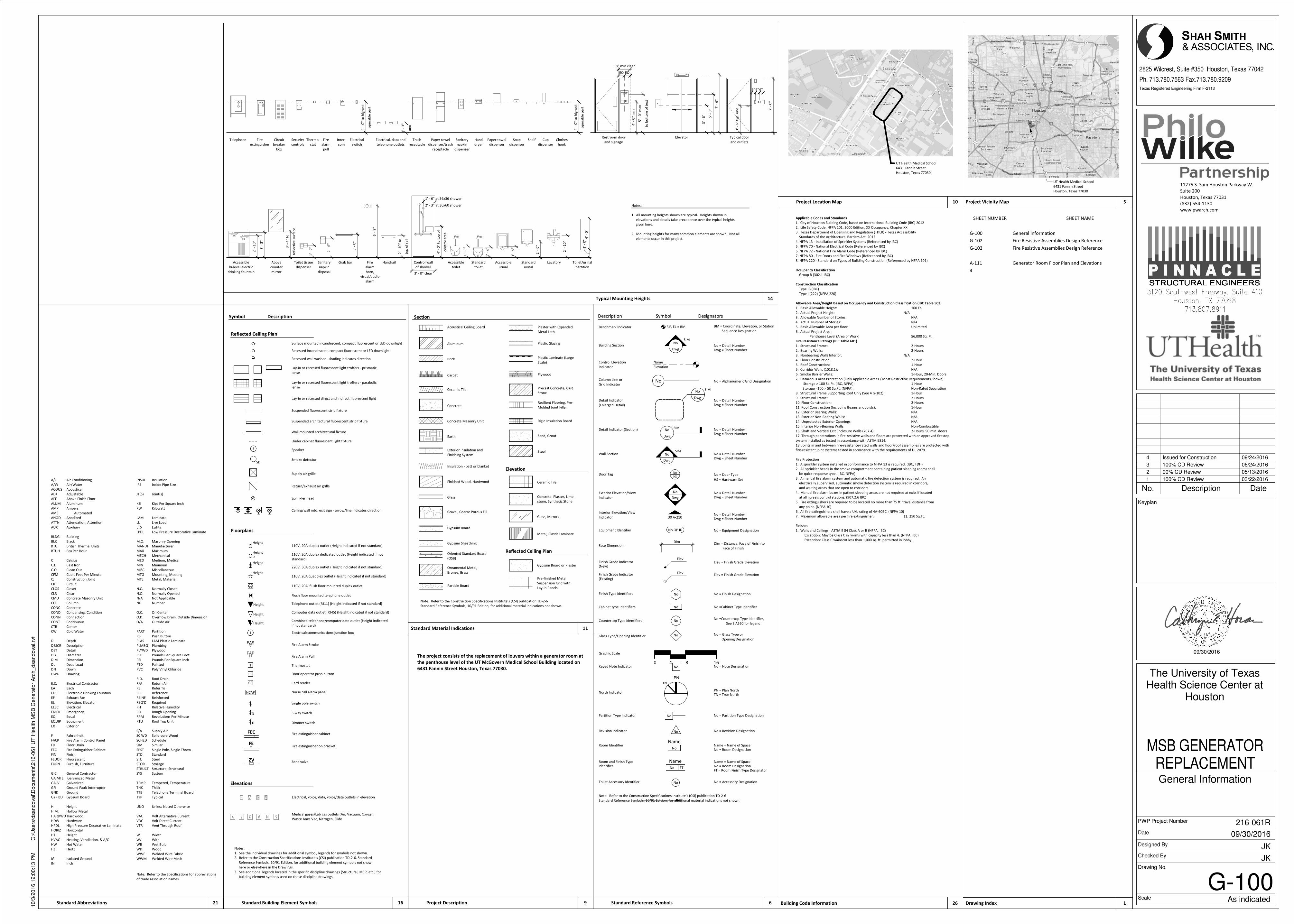
G-100 - GENERAL INFORMATION
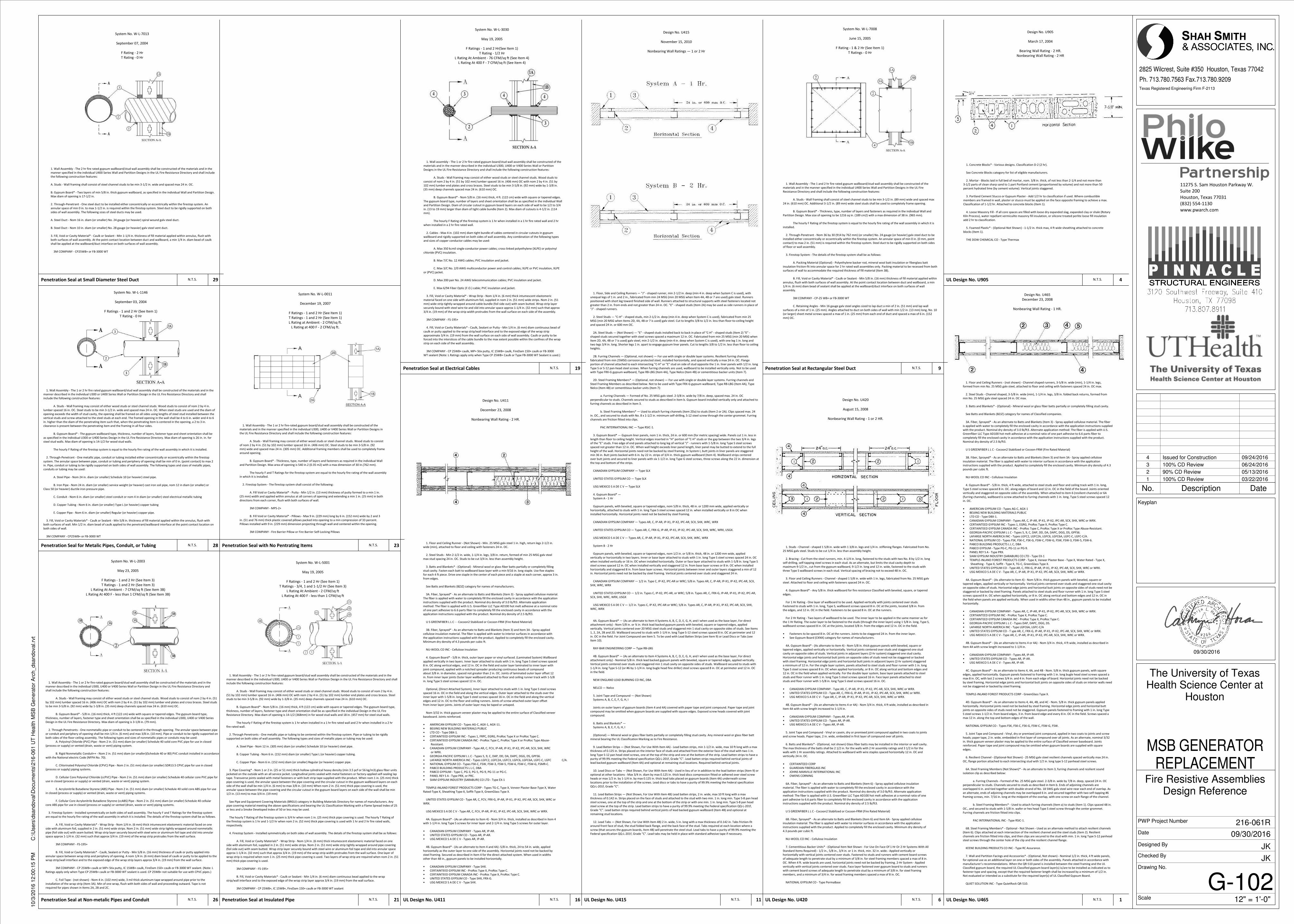
G-102 - FIRE RESISTIVE ASSEMBLIES DESIGN REFERENCE
G-103 - FIRE RESISTIVE ASSEMBLIES DESIGN REFERENCE
A-111 - GENERATOR ROOM PLAN AND ELEVATIONS
STRUCTURAL
S.101 - GENERAL NOTES
S.201 - FRAMING PLANS
S.301 - DETAILS
ELECTRICAL
E001 - ELECTRICAL LEGEND SYMBOLS AND ABBREVIATIONS
E010D - ELECTRICAL ONE LINE DIAGRAMS - DEMOLITION
E010R - ELECTRICAL ONE LINE DIAGRAMS - RENOVATION
E100 - ELECTRICAL SITE PLAN
E200 - GROUND LEVEL ELECTRICAL PLAN
E201 - LEVEL 1 ELECTRICAL PLAN
E202 - LEVEL 2 ELECTRICAL PLAN
E207 - LEVEL 7 ELECTRICAL PLAN
E208 - PENTHOUSE ELECTRICAL PLAN
E308 - PENTHOUSE ENLARGED ELECTRICAL PLAN
E401 - CRANE AND BUILDING ELEVATION
E701 - ELECTRICAL PANELBOARD SCHEDULES
MECHANICAL
M100 - MECHANICAL PLAN PENTHOUSE LEVEL & DETAILS
PLUMBING
P001 - PLUMBING LEGEND, GENERAL NOTES AND SPECIFICATIONS
P110 - BASEMENT PLUMBING PLAN
P208 - PENTHOUSE PLUMBING PLAN
P308 - ENLARGED PLUMBING PLAN
PROJECT SITE
HERMANN HOSPITAL
ROSS STERLING AVENUE
E. C
ULL
EN
JOHN FREEMAN ST.
FA
NN
IN S
TR
EE
T
FA
NN
IN S
TR
EE
T
CAMBRIDGE STREET
TAUB ROAD
T1.00
MATCHLINE A-A
MATCHLINE A-A
Scale
Date
Designed By
Checked By
SSA Project Number
The University of TexasHealth Science Center at
Houston
MSB GENERATORREPLACEMENT
Drawing No.
No. Description Date
Texas Registered Engineering Firm F-2113
2825 Wilcrest, Suite #350 Houston, Texas 77042Ph. 713.780.7563 Fax.713.780.9209
Keyplan
Wells Fargo Bank Plaza221 N. Kansas StreetSuite 820El Paso, Texas 79901(915) 613-4576www.pwarch.com
1" = 40'
CJWMW
P:\T
03\2
016\
1600
5-00
UTH
SC
Gen
Rep
lace
men
t TC
P\C
ad\T
raffi
c\T0
3-16
005-
00-T
CP
.dw
gO
ct 0
4, 2
016
- 9:0
8am
107838 RR
NLA
L
S
O
SEF I C ENOI
IGS E D
NE
EEN
CERI J. WARNIE
F
P
TATS
OE XET
SA
Walter P. Moore and Associates, Inc.TBPE Firm Registration No. 1856
ISSUE FOR CONSTRUCTION09/30/2016
9/30/2016
J
FAS
FAP
T
S
PB
CR
S3
SD
NCAP
Applicable Codes and Standards
1. City of Houston Building Code, based on International Building Code (IBC) 2012
2. Life Safety Code, NFPA 101, 2000 Edition, XX Occupancy, Chapter XX
3. Texas Department of Licensing and Regulation (TDLR) - Texas Accessibility
Standards of the Architectural Barriers Act, 2012
4. NFPA 13 - Installation of Sprinkler Systems (Referenced by IBC)
5. NFPA 70 - National Electrical Code (Referenced by IBC)
6. NFPA 72 - National Fire Alarm Code (Referenced by IBC)
7. NFPA 80 - Fire Doors and Fire Windows (Referenced by IBC)
8. NFPA 220 - Standard on Types of Building Construction (Referenced by NFPA 101)
Occupancy Classification
Group B (302.1 IBC)
Construction Classification
Type IB (IBC)
Type II(222) (NFPA 220)
Allowable Area/Height Based on Occupancy and Construction Classification (IBC Table 503)
1. Basic Allowable Height: 160 Ft.
2. Actual Project Height: N/A
3. Allowable Number of Stories: N/A
4. Actual Number of Stories: N/A
5. Basic Allowable Area per floor: Unlimited
6. Actual Project Area:
Penthouse Level (Area of Work) 56,000 Sq. Ft.
Fire Resistance Ratings (IBC Table 601)
1. Structural Frame: 2-Hours
2. Bearing Walls: 2-Hours
3. Nonbearing Walls Interior: N/A
4. Floor Construction: 2-Hour
5. Roof Construction: 1-Hour
5. Corridor Walls (1018.1): N/A
6. Smoke Barrier Walls: 1-Hour, 20-Min. Doors
7. Hazardous Area Protection (Only Applicable Areas / Most Restrictive Requirements Shown):
Storage > 100 Sq.Ft. (IBC, NFPA): 1-Hour
Storage <100 > 50 Sq.Ft. (NFPA): Non-Rated Separation
8. Structural Frame Supporting Roof Only (See 4 G-102): 1-Hour
9. Structural Frame: 2-Hours
10. Floor Construction: 2-Hours
11. Roof Construction (Including Beams and Joists): 1-Hour
12. Exterior Bearing Walls: N/A
13. Exterior Non-Bearing Walls: N/A
14. Unprotected Exterior Openings: N/A
15. Interior Non-Bearing Walls: Non-Combustible
16. Shaft and Vertical Exit Enclosure Walls (707.4): 2-Hours, 90 min. doors
17. Through penetrations in fire-resistive walls and floors are protected with an approved firestop
system installed as tested in accordance with ASTM E814.
18. Joints in and between fire-resistance-rated walls and floor/roof assemblies are protected with
fire-resistant joint systems tested in accordance with the requirements of UL 2079.
Fire Protection
1. A sprinkler system installed in conformance to NFPA 13 is required. (IBC, TDH)
2. All sprinkler heads in the smoke compartment containing patient sleeping rooms shall
be quick-response type. (IBC, NFPA)
3. A manual fire alarm system and automatic fire detection system is required. An
electrically supervised, automatic smoke detection system is required in corridors,
and waiting areas that are open to corridors.
4. Manual fire alarm boxes in patient sleeping areas are not required at exits if located
at all nurse's control stations. (907.2.6 IBC)
5. Fire extinguishers are required to be located no more than 75 ft. travel distance from
any point. (NFPA 10)
6. All fire extinguishers shall have a U/L rating of 4A-60BC. (NFPA 10)
7. Maximum allowable area per fire extinguisher: 11, 250 Sq.Ft.
Finishes
1. Walls and Ceilings: ASTM E 84 Class A or B (NFPA, IBC)
Exception: May be Class C in rooms with capacity less than 4. (NFPA, IBC)
Exception: Class C wainscot less than 1,000 sq. ft. permitted in lobby.
3' -
6"
5' -
0"
7' -
6"
3' -
6"
typ
. u
no 7' -
0"
6"6"6"
op
era
ble
pa
rt
4' -
0"
to h
igh
est
un
o
1' -
3"
op
era
ble
pa
rt
4' -
0"
to h
igh
est
2'
- 1
0"
3' -
3"
refl
ect
ive
su
rfa
ce
3' -
4"
to
1' -
7"
2' -
6"
3' -
0"
6' -
8"
top
of
rail
2' -
10
" to
3' - 0" clear
con
tro
l a
rea
4' -
0"
to t
op
of
2' - 3" at 30x60 shower
1' - 6" at 36x36 shower
1' -
6"
1' -
4"
1' -
5"
2' -
0"
2'
- 1
0"
1' -
0"
4' -
0"
Restroom door
and signage
Elevator Typical door
and outletsTelephone Fire
extinguisher
Circuit
breaker
box
Security
controls
Thermo-
stat
Fire
alarm
pull
Inter-
com
Electrical
switch
Electrical, data and
telephone outlets
Trash
receptacle
Paper towel
dispenser/trash
receptacle
Sanitary
napkin
dispenser
Hand
dryer
Paper towel
dispenser
Soap
dispenser
Shelf Cup
dispenser
Clothes
hook
Accessible
bi-level electric
drinking fountain
Above
counter
mirror
Toilet tissue
dispenser
Sanitary
napkin
disposal
Grab bar Fire
alarm
horn,
visual/audio
alarm
Handrail Control wall
of shower
Accessible
toilet
Standard
toilet
Accessible
urinal
Standard
urinal
Lavatory Toilet/urinal
partition
TEXT
Notes:
1. All mounting heights shown are typical. Heights shown in
elevations and details take precedence over the typical heights
given here.
2. Mounting heights for many common elements are shown. Not all
elements occur in this project.
TEXT
4'
- 0
" m
in
to b
ott
om
of
text
5'
- 0
" m
ax
18" min clear
EQ EQ
Gypsum Board or Plaster
Reflected Ceiling Plan
Pre-finished Metal
Suspension Grid with
Lay-in Panels
Elevation
Ceramic Tile
Concrete, Plaster, Lime-
stone, Synthetic Stone
Glass, Mirrors
Metal, Plastic Laminate
Plaster with Expanded
Metal Lath
Plastic Glazing
Plastic Laminate (Large
Scale)
Plywood
Precast Concrete, Cast
Stone
Resilient Flooring, Pre-
Molded Joint Filler
Rigid Insulation Board
Sand, Grout
Steel
Acoustical Ceiling Board
Aluminum
Brick
Concrete
Carpet
Ceramic Tile
Concrete Masonry Unit
Earth
Exterior Insulation and
Finishing System
Insulation - batt or blanket
Finished Wood, Hardwood
Glass
Gravel, Coarse Porous Fill
Gypsum Board
Gypsum Sheathing
Oriented Standard Board
(OSB)
Ornamental Metal,
Bronze, Brass
Particle Board
Section
Note: Refer to the Construction Specifications Institute's (CSI) publication TD-2-6
Standard Reference Symbols, 10/91 Edition, for additional material indications not shown.
No
No
Dwg
SIM
Dwg
NoSIM
NoHS
30 A-210
No QP ID
No
PN
No
No
Name
No
No FT
Name
No
0 8 164
Face Dimension
Toilet Accessory Identifier
Detail Indicator (Section)
Detail Indicator
(Enlarged Detail)
Glass Type/Opening Identifier
Graphic Scale
Building Section
Column Line or
Grid Indicator
Door Tag
Benchmark Indicator
Keyed Note Indicator
Equipment Identifier
Finish Grade Indicator(New)
Finish Grade Indicator
(Existing)
Finish Type Identifiers
North Indicator
Partition Type Indicator
Revision Indicator
Room Identifier
Room and Finish TypeIdentifier
Control Elevation
Indicator
Interior Elevation/View
Indicator
Wall Section
SymbolDescription Designators
No
Dwg
SIM
No
Dwg
SIM
Dwg = Sheet Number
No = Detail Number
Dim = Distance, Face of Finish to
Face of Finish
No = Alphanumeric Grid Designation
Elev = Finish Grade Elevation
Dwg = Sheet Number
No = Equipment Designation
No = Glass Type or
Opening Designation
No = Detail Number
No = Note Designation
Elev = Finish Grade Elevation
No = Detail Number
Dwg = Sheet Number
No = Room Designation
Name = Name of SpaceNo = Room Designation
No = Accessory Designation
BM = Coordinate, Elevation, or Station
Sequence Designation
No = Partition Type Designation
No = Revision Designation
Name = Name of Space
PN = Plan NorthTN = True North
FT = Room Finish Type Designator
No = Detail NumberDwg = Sheet Number
No = Detail NumberDwg = Sheet Number
No = Finish Designation
No =Cabinet Type Identifier
No =Countertop Type Identifier,
See 3 A560 for legend
No = Door Type
HS = Hardware Set
Dim
No
Name
Elevation
F.F. EL = BM
TN
Cabinet type Identifiers
Countertop Type Identifiers
Elev
Elev
No
No
Note: Refer to the Construction Specifications Institute's (CSI) publication TD-2-6
Standard Reference Symbols, 10/91 Edition, for additional material indications not shown.
Exterior Elevation/View
Indicator
No = Detail Number
Dwg = Sheet Number
No
Dwg
No
Elevations
Electrical, voice, data, voice/data outlets in elevation
Medical gases/Lab gas outlets (Air, Vacuum, Oxygen,
Waste Anes Vac, Nitrogen, Slide
Notes:
1. See the individual drawings for additional symbol, legends for symbols not shown.
2. Refer to the Construction Specifications Institute's (CSI) publication TD-2-6, Standard
Reference Symbols, 10/91 Edition, for additional building element symbols not shown
here or elsewhere in the Drawings.
3. See additional legends located in the specific discipline drawings (Structural, MEP, etc.) for
building element symbols used on those discipline drawings.
Symbol Description
Reflected Ceiling Plan
Lay-in or recessed fluorescent light troffers - parabolic
lense
Surface mounted incandescent, compact fluorescent or LED downlight
Lay-in or recessed fluorescent light troffers - prismatic
lense
Recessed incandescent, compact fluorescent or LED downlight
Recessed wall washer - shading indicates direction
Lay-in or recessed direct and indirect fluorescent light
Under cabinet fluorescent light fixture
Smoke detector
Speaker
Suspended fluorescent strip fixture
Suspended architectural fluorescent strip fixture
Wall mounted architectural fixture
Supply air grille
Ceiling/wall mtd. exit sign - arrow/line indicates direction
Return/exhaust air grille
Sprinkler head
Floorplans
110V, 20A quadplex outlet (Height indicated if not standard)
110V, 20A duplex dedicated outlet (Height indicated if not
standard)
110V, 20A flush floor mounted duplex outlet
220V, 30A duplex outlet (Height indicated if not standard)
110V, 20A duplex outlet (Height indicated if not standard)
Telephone outlet (RJ11) (Height indicated if not standard)
Electrical/communications junction box
Computer data outlet (RJ45) (Height indicated if not standard)
Combined telephone/computer data outlet (Height indicated
if not standard)
Flush floor mounted telephone outlet
Thermostat
Fire Alarm Strobe
Fire Alarm Pull
Door operator push button
Card reader
Nurse call alarm panel
Single pole switch
3-way switch
Dimmer switch
Fire extinguisher cabinet
Fire extinguisher on bracket
Zone valve
FEC
FE
ZV
Height
Height
Height
Height
Height
Height
Height
D
SD
S
UT Health Medical School
6431 Fannin Street
Houston, Texas 77030
11275 S. Sam Houston Parkway W.
Suite 200
Houston, Texas 77031
(832) 554-1130
www.pwarch.com
Texas Registered Engineering Firm F-2113
Scale
Date
Designed By
Checked By
PWP Project Number
Drawing No.
2825 Wilcrest, Suite #350 Houston, Texas 77042
Ph. 713.780.7563 Fax.713.780.9209
Keyplan
09/30/2016
As indicated
10/3
/2016 1
2:0
0:1
3 P
MC
:\U
sers
\dsandoval\D
ocum
ents
\216-0
61 U
T H
ealth M
SB
Genera
tor
Arc
h_dsandoval.rv
t
G-100
General Information
The University of TexasHealth Science Center at
Houston
MSB GENERATORREPLACEMENT
JK
JK
09/30/2016
216-061R
Drawing Index 1Standard Reference Symbols 6
Project Vicinity Map 5
The project consists of the replacement of louvers within a generator room at
the penthouse level of the UT McGovern Medical School Building located on
6431 Fannin Street Houston, Texas 77030.
Standard Building Element Symbols 16Standard Abbreviations 21
Note: Refer to the Specifications for abbreviations
of trade association names.
A/C Air Conditioning
A/W Air/Water
ACOUS Acoustical
ADJ Adjustable
AFF Above Finish Floor
ALUM Aluminum
AMP Ampers
AMS Automated
ANOD Anodized
ATTN Attenuation, Attention
AUX Auxiliary
BLDG Building
BLK Black
BTU British Thermal Units
BTUH Btu Per Hour
C Celsius
C.I. Cast Iron
C.O. Clean Out
CFM Cubic Feet Per Minute
CJ Construction Joint
CKT Circuit
CLOS Closet
CLR Clear
CMU Concrete Masonry Unit
COL Column
CONC Concrete
COND Condensing, Condition
CONN Connection
CONT Continuous
CTR Center
CW Cold Water
D Depth
DESCR Description
DET Detail
DIA Diameter
DIM Dimension
DL Dead Load
DN Down
DWG Drawing
E.C. Electrical Contractor
EA Each
EDF Electronic Drinking Fountain
EF Exhaust Fan
EL Elevation, Elevator
ELEC Electrical
EMER Emergency
EQ Equal
EQUIP Equipment
EXT Exterior
F Fahrenheit
FACP Fire Alarm Control Panel
FD Floor Drain
FEC Fire Extinguisher Cabinet
FIN Finish
FLUOR Fluorescent
FURN Furnish, Furniture
G.C. General Contractor
GA MTL Galvanized Metal
GALV Galvanized
GFI Ground Fault Interrupter
GND Ground
GYP BD Gypsum Board
H Height
H.M. Hollow Metal
HARDWD Hardwood
HDW Hardware
HPDL High Pressure Decorative Laminate
HORIZ Horizontal
HT Height
HVAC Heating, Ventilation, & A/C
HW Hot Water
HZ Hertz
IG Isolated Ground
IN Inch
INSUL Insulation
IPS Inside Pipe Size
JT(S) Joint(s)
KSI Kips Per Square Inch
KW Kilowatt
LAM Laminate
LL Live Load
LTS Lights
LPDL Low Pressure Decorative Laminate
M.O. Masonry Opening
MANUF Manufacturer
MAX Maximum
MECH Mechanical
MED Medium, Medical
MIN Minimum
MISC Miscellaneous
MTG Mounting, Meeting
MTL Metal, Material
N.C. Normally Closed
N.O. Normally Opened
N/A Not Applicable
NO Number
O.C. On Center
O.D. Overflow Drain, Outside Dimension
O/A Outside Air
PART Partition
PB Push Button
PLAS LAM Plastic Laminate
PLMBG Plumbing
PLYWD Plywood
PSF Pounds Per Square Foot
PSI Pounds Per Square Inch
PTD Painted
PVC Poly Vinyl Chloride
R.D. Roof Drain
R/A Return Air
RE Refer To
REF Reference
REINF Reinforced
REQ'D Required
RH Relative Humidity
RO Rough Opening
RPM Revolutions Per Minute
RTU Roof Top Unit
S/A Supply Air
SC WD Solid-core Wood
SCHED Schedule
SIM Similar
SPST Single Pole, Single Throw
STD Standard
STL Steel
STOR Storage
STRUCT Structure, Structural
SYS System
TEMP Tempered, Temperature
THK Thick
TTB Telephone Terminal Board
TYP Typical
UNO Unless Noted Otherwise
VAC Volt Alternative Current
VDC Volt Direct Current
VTR Vent Through Roof
W Width
W/ With
WB Wet Bulb
WD Wood
WWF Welded Wire Fabric
WWM Welded Wire Mesh
Building Code Information 26
Typical Mounting Heights 14
Standard Material Indications 11
Project Description 9
Project Location Map 10
UT Health Medical School
6431 Fannin Street
Houston, Texas 77030
SHEET NUMBER SHEET NAME
G-100 General Information
G-102 Fire Resistive Assemblies Design Reference
G-103 Fire Resistive Assemblies Design Reference
A-111 Generator Room Floor Plan and Elevations
4
No. Description Date
1 100% CD Review 03/22/2016
2 90% CD Review 05/13/2016
3 100% CD Review 06/24/2016
4 Issued for Construction 09/24/2016
Design No. U905
March 17, 2004
Bearing Wall Rating - 2 HR.
Nonbearing Wall Rating - 2 HR
1. Concrete Blocks* - Various designs. Classification D-2 (2 hr).
See Concrete Blocks category for list of eligible manufacturers.
2. Mortar - Blocks laid in full bed of mortar, nom. 3/8 in. thick, of not less than 2-1/4 and not more than
3-1/2 parts of clean sharp sand to 1 part Portland cement (proportioned by volume) and not more than 50
percent hydrated lime (by cement volume). Vertical joints staggered.
3. Portland Cement Stucco or Gypsum Plaster - Add 1/2 hr to classification if used. Where combustible
members are framed in wall, plaster or stucco must be applied on the face opposite framing to achieve a max.
Classification of 1-1/2 hr. Attached to concrete blocks (Item 1).
4. Loose Masonry Fill - If all core spaces are filled with loose dry expanded slag, expanded clay or shale (Rotary
Kiln Process), water repellant vermiculite masonry fill insulation, or silicone treated perlite loose fill insulation
add 2 hr to classification.
5. Foamed Plastic* - (Optional-Not Shown) - 1-1/2 in. thick max, 4 ft wide sheathing attached to concrete
blocks (Item 1).
THE DOW CHEMICAL CO - Type Thermax
Design No. U420
August 15, 2008
Nonbearing Wall Rating - 1 or 2 HR.
1. Studs - Channel - shaped 1 5/8 in. wide with 1 3/8 in. legs and 1/4 in. stiffening flanges. Fabricated from No.
25 MSG galv steel. Studs to be cut 1/4 in. less than assembly height.
2. Bracing - Cut from the steel runners, min. 4-1/4 in. long, fastened to the studs with two No. 8 by 1/2 in. long
self-drilling, self-tapping steel screws in each stud. As an alternate, but limits the stud cavity depth to
maximum 9-1/2 in., cut from the gypsum wallboard, 9-1/2 in. long and 12 in. wide, fastened to the studs with
three Type S wallboard screws in each stud. Vertical spacing of bracing not to exceed 48 in. OC.
3. Floor and Ceiling Runners - Channel - shaped 1 5/8 in. wide with 1 in. legs, fabricated from No. 25 MSG galv
steel. Attached to floor and ceiling with fasteners spaced 24 in. OC.
4. Gypsum Board* - Any 5/8 in. thick wallboard for fire resistance Classified with beveled, square, or tapered
edges.
For 1 Hr Rating - One layer of wallboard to be used. Applied vertically with joints centered over studs.
Fastened to studs with 1 in. long, Type S, wallboard screws spaced 8 in. OC at the joints, located 3/8 in. from
the edges, and 12 in. OC in the field. Fasteners to be spaced 8 in. OC at the runners.
For 2 Hr Rating - Two layers of wallboard to be used. The inner layer to be applied in the same manner as for
the 1 Hr Rating. The outer layer to be fastened to the studs (through the inner layer) using 1 5/8 in. long, Type S,
wallboard screws spaced 8 in. OC at the joints, located 3/8 in. from the edges and 12 in. OC in the field.
• Fasteners to be spaced 8 in. OC at the runners. Joints to be staggered 24 in. from the inner layer.
• See Gypsum Board (CKNX) category for names of manufacturers.
4A. Gypsum Board* - (As alternate to Item 4) - Nom 5/8 in. thick gypsum panels with beveled, square or
tapered edges, applied vertically or horizontally. Vertical joints centered over studs and staggered one stud
cavity on opposite sides of studs. Vertical joints in adjacent layers (2-hr system) staggered one stud cavity.
Horizontal edge joints and horizontal butt joints on opposite sides of studs need not be staggered or backed
with steel framing. Horizontal edge joints and horizontal butt joints in adjacent layers (2-hr system) staggered
a minimum of 12 in. For the single layer system, panels attached to steel studs and floor runner with 1 in. long
Type S steel screws spaced 8 in. OC when applied horizontally, or 8 in. OC along vertical and bottom edges and
12 in. OC in the field when applied vertically. For the double layer system, base layer panels attached to steel
studs and floor runner with 1 in. long Type S steel screws spaced 16 in. Face layer panels attached to steel
studs and floor runner with 1-5/8 in. long Type S steel screws spaced 16 in. OC.
• CANADIAN GYPSUM COMPANY - Type AR, C, IP-AR, IP-X1, IP-X2, IPC-AR, SCX, SHX, WRC or WRX.
• UNITED STATES GYPSUM CO - Type AR, C, FRX-G, IP-AR, IP-X1, IP-X2, IPC-AR, SCX, SHX, WRC or WRX.
• USG MEXICO S A DE C V - Type AR, C, IP-AR, IP-X1, IP-X2, IPC-AR, SCX, SHX, WRC or WRX.
4B. Gypsum Board* - (As an alternate to Items 4 or 4A) - Nom 3/4 in. thick, 4 ft wide, installed as described in
Item 4A with screw length increased to 1-1/4 in.
• CANADIAN GYPSUM COMPANY - Types AR, IP-AR.
• UNITED STATES GYPSUM CO - Types AR, IP-AR.
• USG MEXICO S A DE C V - Types AR, IP-AR.
5. Joint Tape and Compound - Vinyl or casein, dry or premixed joint compound applied in two coats to joints
and screw heads. Paper tape, 2 in. wide, embedded in first layer of compound over all joints.
6. Batts and Blankets* - (Optional, not shown) Glass fiber batts may be installed in the interior or wall cavity.
The max thickness of the batts shall be 2 1/2 in. for the walls with 2 Hr assembly ratings and 3 1/2 in for the
walls with 1 Hr assembly ratings. Attached to wallboard with wire staples spaced horizontally 12 in. OC and
vertically 24 in. OC.
• CERTAINTEED CORP
• GUARDIAN FIBERGLASS INC
• JOHNS MANVILLE INTERNATIONAL INC
• OWENS CORNING
6A. Fiber, Sprayed* - As an alternate to Batts and Blankets (Item 6) - Spray applied cellulose insulation
material. The fiber is applied with water to completely fill the enclosed cavity in accordance with the
application instructions supplied with the product. Nominal dry density of 3.0 lb/ft3. Alternate application
method: The fiber is applied with U.S. Greenfiber LLC Type AD100 hot melt adhesive at a nominal ratio of one
part adhesive to 6.6 parts fiber to completely fill the enclosed cavity in accordance with the application
instructions supplied with the product. Nominal dry density of 2.5 lb/ft3.
U S GREENFIBER L L C - Cocoon2 Stabilized or Cocoon-FRM (Fire Rated Material)
6B. Fiber, Sprayed* - As an alternate to Batts and Blankets (Item 6) and Item 6A - Spray applied cellulose
insulation material. The fiber is applied with water to interior surfaces in accordance with the application
instructions supplied with the product. Applied to completely fill the enclosed cavity. Minimum dry density of
4.3 pounds per cubic ft.
NU-WOOL CO INC - Cellulose Insulation
7. Cementitious Backer Units* - (Optional Item Not Shown - For Use On Face Of 1 Hr Or 2 Hr Systems With All
Standard Items Required) - 1/2 in., 5/8 in., 3/4 in. or 1 in. thick, min. 32 in. wide.- Applied vertically or
horizontally with vertical joints centered over studs. Fastened to studs and runners with cement board screws
of adequate length to penetrate stud by a minimum of 3/8 in. for steel framing members spaced a max of 8 in.
OC. When 4 ft. wide boards are used, horizontal joints need not be backed by framing. 2-Hr System - Applied
vertically with vertical joints centered over studs. Face layer fastened over gypsum board to studs and runners
with cement board screws of adequate length to penetrate stud by a minimum of 3/8 in. for steel framing
members, and a minimum of 3/4 in. for wood framing members spaced a max of 8 in. OC.
NATIONAL GYPSUM CO - Type PermaBase
Design No. U411
December 23, 2008
Nonbearing Wall Rating - 2 HR.
1. Floor and Ceiling Runner - (Not Shown) - Min. 25 MSG galv steel 1 in. high, return legs 2-1/2 in.
wide (min), attached to floor and ceiling with fasteners 24 in. OC.
2. Steel Studs - Min 2-1/2 in. wide, 1-1/4 in. legs, 3/8 in. return, formed of min 25 MSG galv steel
max stud spacing 24 in. OC. Studs to be cut 3/4 in. less than assembly height.
3. Batts and Blankets* - (Optional) - Mineral wool or glass fiber batts partially or completely filling
stud cavity. Fasten each batt to wallboard base layer with a min 9/16 in. long staple. Use five staples
for each 4 ft piece. Drive one staple in the center of each piece and a staple at each corner, approx 3 in.
from edges.
See Batts and Blankets (BZJZ) category for names of manufacturers.
3A. Fiber, Sprayed* - As an alternate to Batts and Blankets (Item 3) - Spray applied cellulose material.
The fiber is applied with water to completely fill the enclosed cavity in accordance with the application
instructions supplied with the product. Nominal dry density of 3.0 lb/ft3. Alternate application
method: The fiber is applied with U.S. Greenfiber LLC Type AD100 hot melt adhesive at a nominal ratio
of one part adhesive to 6.6 parts fiber to completely fill the enclosed cavity in accordance with the
application instructions supplied with the product. Nominal dry density of 2.5 lb/ft3.
U S GREENFIBER L L C - - Cocoon2 Stabilized or Cocoon-FRM (Fire Rated Material)
3B. Fiber, Sprayed* - As an alternate to Batts and Blankets (Item 3) and Item 3A - Spray applied
cellulose insulation material. The fiber is applied with water to interior surfaces in accordance with
the application instructions supplied with the product. Applied to completely fill the enclosed cavity.
Minimum dry density of 4.3 pounds per cubic ft.
NU-WOOL CO INC - Cellulose Insulation
4. Gypsum Board* - 5/8 in. thick, outer layer paper or vinyl surfaced. (Laminated System) Wallboard
applied vertically in two layers. Inner layer attached to studs with 1 in. long Type S steel screws spaced
8 in. OC along vertical edges, and 12 in. OC in the field and outer layer laminated to inner layer with
joint compound, applied with a notched spreader producing continuous beads of compound
about 3/8 in. in diameter, spaced not greater than 2 in. OC. Joints of laminated outer layer offset 12
in. from inner layer joints Outer layer wallboard attached to floor and ceiling runner track with 1-5/8
in. long Type S steel screws spaced 12 in. OC.
Optional, (Direct Attached System), Inner layer attached to studs with 1 in. long Type S steel screws
spaced 16 in. OC in the field and along the vertical edges. Outer layer attached to the studs over the
inner layer with 1-5/8 in. long Type S steel screws spaced 16 in. OC in the field and along the vertical
edges and 12 in. OC to the floor and ceiling runners. Joints of screw-attached outer layer offset
from inner layer joints. Joints of outer layer may be taped or untaped.
Nom 3/32 in. thick gypsum veneer plaster may be applied to the entire surface of Classified veneer
baseboard. Joints reinforced.
• AMERICAN GYPSUM CO - Types AG-C, AGX-1, AGX-11.
• BEIJING NEW BUILDING MATERIALS PUBLIC
• LTD CO - Type DBX-1.
• CERTAINTEED GYPSUM INC - Types 1, FRPC, EGRG, ProRoc Type X or ProRoc Type C.
• CERTAINTEED GYPSUM CANADA INC - ProRoc Type C, ProRoc Type X or ProRoc Type Abuse-
Resistant.
• CANADIAN GYPSUM COMPANY - Type AR, C, FCV, IP-AR, IP-X1, IP-X2, IPC-AR, SCX, SHX, WRC
or WRX.
• GEORGIA-PACIFIC GYPSUM L L C - Types 5, 9, C, DAP, DD, DA, DAPC, DGG, DS, GPFS6.
• LAFARGE NORTH AMERICA INC - Types LGFC2, LGFC2A, LGFC3, LGFC6, LGFC6A, LGFC-C, LGFC C/A.
• NATIONAL GYPSUM CO - Types FSK-C, FSW, FSW-3, FSW-5, FSW-6, FSW-C, FSW-G, FSMR-C.
• PABCO BUILDING PRODUCTS L L C, DBA
• PABCO GYPSUM - Type C, PG-3, PG-5, PG-9, PG-11 or PG-C.
• PANEL REY S A - Type PRX, or PRC.
• SIAM GYPSUM INDUSTRY (SARABURI) CO LTD - Type EX-1
TEMPLE-INLAND FOREST PRODUCTS CORP - Types TG-C, Type X, Veneer Plaster Base-Type X, Water
Rated-Type X, Sheathing Type-X, Soffit-Type X, GreenGlass Type X.
UNITED STATES GYPSUM CO - Type AR, C, FCV, FRX-G, IP-AR, IP-X1, IP-X2, IPC-AR, SCX, SHX, WRC or
WRX.
USG MEXICO S A DE C V - Type AR, C, FCV, IP-AR, IP-X1, IP-X2, IPC-AR, SCX, SHX, WRC or WRX.
4A. Gypsum Board* - (As an alternate to Item 4) - Nom 3/4 in. thick, installed as described in Item 4
with 1-1/4 in. long Type S screws for inner layer and 2-1/4 in. long Type S screws for outer layer.
• CANADIAN GYPSUM COMPANY - Types AR, IP-AR.
• UNITED STATES GYPSUM CO - Types AR, IP-AR.
• USG MEXICO S A DE C V - Types AR, IP-AR.
4B. Gypsum Board* - (As an alternate to Item 4 and 4A) -5/8 in. thick, 24 to 54 in. wide, applied
horizontally as the outer layer to one side of the assembly. Horizontal joints need not be backed by
steel framing. Secured as described in Item 4 for the direct attached system. When used in widths
other than 48 in., gypsum panels to be installed horizontally.
• CANADIAN GYPSUM COMPANY - Type SHX.
• CERTAINTEED GYPSUM INC - ProRoc Type X, ProRoc Type C.
• CERTAINTEED GYPSUM CANADA INC - ProRoc Type X, ProRoc Type C.
• UNITED STATES GYPSUM CO - Type SHX, FRX-G.
• USG MEXICO S A DE C V - Type SHX.
Design No. U465
December 23, 2008
Nonbearing Wall Rating - 1 HR.
1. Floor and Ceiling Runners - (not shown) - Channel shaped runners, 3-5/8 in. wide (min), 1-1/4 in. legs,
formed from min No. 25 MSG galv steel, attached to floor and ceiling with fasteners spaced 24 in. OC max.
2. Steel Studs - Channel shaped, 3-5/8 in. wide (min), 1-1/4 in. legs, 3/8 in. folded back returns, formed from
min No. 25 MSG galv steel spaced 24 in. OC max.
3. Batts and Blankets* - (Optional) - Mineral wool or glass fiber batts partially or completely filling stud cavity.
See Batts and Blankets (BZJZ) category for names of Classified companies.
3A. Fiber, Sprayed* - As an alternate to Batts and Blankets (Item 3) - Spray applied cellulose material. The fiber
is applied with water to completely fill the enclosed cavity in accordance with the application instructions supplied
with the product. Nominal dry density of 3.0 lb/ft3. Alternate application method: The fiber is applied with U.S.
Greenfiber LLC Type AD100 hot melt adhesive at a nominal ratio of one part adhesive to 6.6 parts fiber to
completely fill the enclosed cavity in accordance with the application instructions supplied with the product.
Nominal dry density of 2.5 lb/ft3.
U S GREENFIBER L L C - Cocoon2 Stabilized or Cocoon-FRM (Fire Rated Material)
3B. Fiber, Sprayed* - As an alternate to Batts and Blankets (Item 3) and Item 3A - Spray applied cellulose
insulation material. The fiber is applied with water to interior surfaces in accordance with the application
instructions supplied with the product. Applied to completely fill the enclosed cavity. Minimum dry density of 4.3
pounds per cubic ft.
NU-WOOL CO INC - Cellulose Insulation
4. Gypsum Board* - 5/8 in. thick, 4 ft wide, attached to steel studs and floor and ceiling track with 1 in. long,
Type S steel screws spaced 8 in. OC. along edges of board and 12 in. OC in the field of the board. Joints oriented
vertically and staggered on opposite sides of the assembly. When attached to item 6 (resilient channels) or 6A
(furring channels), wallboard is screw attached to furring channels with 1 in. long, Type S steel screws spaced 12
in. OC.
• AMERICAN GYPSUM CO - Types AG-C, AGX-1
• BEIJING NEW BUILDING MATERIALS PUBLIC
• LTD CO - Type DBX-1.
• CANADIAN GYPSUM COMPANY - Types AR, C, IP-AR, IP-X1, IP-X2, IPC-AR, SCX, SHX, WRC or WRX.
• CERTAINTEED GYPSUM INC - Types 1, EGRG, ProRoc Type X, ProRoc Type C.
• CERTAINTEED GYPSUM CANADA INC - ProRoc Type C, ProRoc Type X or ProRoc Type Abuse-Resistant.
• GEORGIA-PACIFIC GYPSUM L L C - Types 5, 9, C, DAP, DD, DA, DAPC, DGG, DS, GPFS6.
• LAFARGE NORTH AMERICA INC - Types LGFC2, LGFC2A, LGFC6, LGFC6A, LGFC-C, LGFC-C/A.
• NATIONAL GYPSUM CO - Types FSK, FSK-C, FSK-G, FSW-C, FSW-G, FSW, FSW-3, FSW-5, FSW-6.
• PABCO BUILDING PRODUCTS L L C, DBA
• PABCO GYPSUM - Type PG-C, PG-11 or PG-9.
• PANEL REY S A - Type PRX.
• SIAM GYPSUM INDUSTRY (SARABURI) CO LTD - Type EX-1
• TEMPLE-INLAND FOREST PRODUCTS CORP - Type X, Veneer Plaster Base - Type X, Water Rated - Type X,
Sheathing - Type X, Soffit - Type X, TG-C, GreenGlass Type X.
• UNITED STATES GYPSUM CO - Type AR, C, FRX-G, IP-AR, IP-X1, IP-X2, IPC-AR, SCX, SHX, WRC or WRX.
• USG MEXICO S A DE C V - Type AR, C, IP-AR, IP-X1, IP-X2, IPC-AR, SCX, SHX, WRC or WRX.
4A. Gypsum Board* - (As alternate to Item 4) - Nom 5/8 in. thick gypsum panels with beveled, square or
tapered edges, applied vertically or horizontally. Vertical joints centered over studs and staggered one stud cavity
on opposite sides of studs. Horizontal edge joints and horizontal butt joints on opposite sides of studs need not be
staggered or backed by steel framing. Panels attached to steel studs and floor runner with 1 in. long Type S steel
screws spaced 8 in. OC when applied horizontally, or 8 in. OC along vertical and bottom edges and 12 in. OC in
the field when panels are applied vertically. When used in widths other than 48 in., gypsum panels to be installed
horizontally.
• CANADIAN GYPSUM COMPANY - Types AR, C, IP-AR, IP-X1, IP-X2, IPC-AR, SCX, SHX, WRC or WRX.
• CERTAINTEED GYPSUM INC - ProRoc Type X, ProRoc Type C.
• CERTAINTEED GYPSUM CANADA INC - ProRoc Type X, ProRoc Type C.
• GEORGIA-PACIFIC GYPSUM L L C - Types DAP, DAPC, DGG, DS.
• LAFARGE NORTH AMERICA INC - Type LGFC6A, LGFC-C/A
• UNITED STATES GYPSUM CO - T ype AR, C, FRX-G, IP-AR, IP-X1, IP-X2, IPC-AR, SCX, SHX, WRC or WRX.
• USG MEXICO S A DE C V - Type AR, C, IP-AR, IP-X1, IP-X2, IPC-AR, SCX, SHX, WRC or WRX.
4B. Gypsum Board* - (As an alternate to Items 4 or 4A) - Nom 3/4 in. thick, 4 ft wide, installed as described in
Item 4A with screw length increased to 1-1/4 in.
• CANADIAN GYPSUM COMPANY - Types AR, IP-AR.
• UNITED STATES GYPSUM CO - Types AR, IP-AR.
• USG MEXICO S A DE C V - Types AR, IP-AR.
4C. Gypsum Board* - As an alternate to Items 4, 4A, and 4B - Nom. 5/8 in. thick gypsum panels, with square
edges, applied horizontally. Gypsum panels fastened to framing with 1 in. long bugle head steel screws spaced a
max 8 in. OC, with last 2 screws 3/4 in. and 4 in. from each edge of board. Horizontal joints need not be backed
by steel framing. Horizontal edge joints and horizontal butt joints on opposite sides of studs on interior walls need
not be staggered or backed by steel framing.
TEMPLE-INLAND FOREST PRODUCTS CORP - GreenGlass Type X.
4D. Gypsum Board* - As an alternate to Items 4, 4A, 4B, and 4C - Nom. 5/8 in. thick gypsum panels applied
horizontally. Horizontal joints need not be backed by steel framing. Horizontal edge joints and horizontal butt
joints on opposite sides of studs need not be staggered. Gypsum panels fastened to framing with 1 in. long Type
S steel screws 1-1/2 in. from board edges, 3 in. from board edge and every 8 in. OC in the field. Screws spaced a
max 12 in. along the top and bottom edges of the wall.
NATIONAL GYPSUM CO - Types FSK, FSK-C, FSK-G, FSW-C, FSW-G, FSW.
5. Joint Tape and Compound - Vinyl, dry or premixed joint compound, applied in two coats to joints and screw
heads; paper tape, 2 in. wide, embedded in first layer of compound over all joints. As an alternate, nominal 3/32
in. thick gypsum veneer plaster may be applied to the entire surface of Classified veneer baseboard. Joints
reinforced. Paper tape and joint compound may be omitted when gypsum boards are supplied with square
edges.
6. Resilient Channel - (Optional-Not Shown) - 25 MSG galv steel resilient channels spaced vertically max 24 in.
OC, flange portion attached to each intersecting stud with 1/2 in. long type S-12 panhead steel screws.
6A. Steel Framing Members (Not Shown)* - As an alternate to Item 3, furring channels and resilient sound
isolation clip as described below:
a. Furring Channels - Formed of No. 25 MSG galv steel. 2-3/8 in. wide by 7/8 in. deep, spaced 24 in. OC
perpendicular to studs. Channels secured to studs as described in Item b. Ends of adjoining channels are
overlapped 6 in. and tied together with double strand of No. 18 SWG galv steel wire near each end of overlap. As
an alternate, ends of adjoining channels may be overlapped 6 in. and secured together with two self-tapping #6
framing screws, min. 7/16 in. long at the midpoint of the overlap, with one screw on each flange of the channel.
b. Steel Framing Members* - Used to attach furring channels (Item a) to studs (Item 1). Clips spaced 48 in.
OC., and secured to studs with 1-5/8 in. wafer or hex head Type S steel screw through the center grommet.
Furring channels are friction fitted into clips.
PAC INTERNATIONAL INC - Type RSIC-1.
6B. Steel Framing Members* - Optional - Not Shown - Used as an alternate method to attach resilient channels
(Item 6). Clips attached at each intersection of the resilient channel and the steel studs (Item 2). Resilient
channels are friction fitted into clips, and then clips are secured to the stud with min. 1 in. long Type S-12 panhead
steel screws through the center hole of the clip and the resilient channel flange.
KEENE BUILDING PRODUCTS CO INC - Type RC Assurance.
7. Wall and Partition Facings and Accessories* - (Optional, Not shown) - Nominal 1/2 in. thick, 4 ft wide panels,
for optional use as an additional layer on one or both sides of the assembly. Panels attached in accordance with
manufacturer's recommendations. When the QR-510 panel is installed between the steel framing and the UL
Classified gypsum board, the required UL Classified gypsum board layer(s) is/are to be installed as indicated as to
fastener type and spacing, except that the required fastener length shall be increased by a minimum of 1/2 in.
Not evaluated or intended as a substitute for the required layer(s) of UL Classified Gypsum Board.
QUIET SOLUTION INC - Type QuietRock QR-510.
System No. W-L-7013
September 07, 2004
F Rating - 2 Hr
T Rating - 0 Hr
1. Wall Assembly - The 2 hr fire rated gypsum wallboard/stud wall assembly shall be constructed of the materials and in the
manner specified in the individual U400 Series Wall and Partition Designs in the UL Fire Resistance Directory and shall include
the following construction features:
A. Studs - Wall framing shall consist of steel channel studs to be min 3-1/2 in. wide and spaced max 24 in. OC.
B. Gypsum Board* - Two layers of min 5/8 in. thick gypsum wallboard, as specified in the individual Wall and Partition Design.
Max diam of opening is 17-1/2 in.
2. Through-Penetrant - One steel duct to be installed either concentrically or eccentrically within the firestop system. An
annular space of min 0 in. to max 1-1/2 in. is required within the firestop system. Steel duct to be rigidly supported on both
sides of wall assembly. The following sizes of steel ducts may be used.
A. Steel Duct - Nom 16 in. diam (or smaller) No. 24 gauge (or heavier) spiral wound galv steel duct.
B. Steel Duct - Nom 10 in. diam (or smaller) No. 28 gauge (or heavier) galv steel vent duct.
3. Fill, Void or Cavity Material* - Caulk or Sealant - Min 1-1/4 in. thickness of fill material applied within annulus, flush with
both surfaces of wall assembly. At the point contact location between duct and wallboard, a min 1/4 in. diam bead of caulk
shall be applied at the wallboard/duct interface on both surfaces of wall assembly.
3M COMPANY - CP25WB+ or FB-3000 WT
System No. W-L-1146
September 03, 2004
F Ratings - 1 and 2 Hr (See Item 1)
T Rating - 0 Hr
1. Wall Assembly - The 1 or 2 hr fire rated gypsum wallboard/stud wall assembly shall be constructed of the materials and in the
manner described in the individual U300 or U400 Series Wall or Partition Design in the UL Fire Resistance Directory and shall
include the following construction features:
A. Studs - Wall framing may consist of either wood studs or steel channel studs. Wood studs to consist of nom 2 by 4 in.
lumber spaced 16 in. OC. Steel studs to be min 3-1/2 in. wide and spaced max 24 in. OC. When steel studs are used and the diam of
opening exceeds the width of stud cavity, the opening shall be framed on all sides using lengths of steel stud installed between the
vertical studs and screw-attached to the steel studs at each end. The framed opening in the wall shall be 4 to 6 in. wider and 4 to 6
in. higher than the diam of the penetrating item such that, when the penetrating item is centered in the opening, a 2 to 3 in.
clearance is present between the penetrating item and the framing in all four sides.
B. Gypsum Board* - The gypsum wallboard type, thickness, number of layers, fastener type and sheet orientation shall be
as specified in the individual U300 or U400 Series Design in the UL Fire Resistance Directory. Max diam of opening is 26 in. in. for
steel stud walls. Max diam of opening is 14-1/2 for wood stud walls.
The hourly F Rating of the firestop system is equal to the hourly fire rating of the wall assembly in which it is installed.
2. Through-Penetrant - One metallic pipe, conduit or tubing installed either concentrically or eccentrically within the firestop
system. The annular space between pipe, conduit or tubing and periphery of opening shall be min of 0 in. (point contact) to max 2
in. Pipe, conduit or tubing to be rigidly supported on both sides of wall assembly. The following types and sizes of metallic pipes,
conduits or tubing may be used:
A. Steel Pipe - Nom 24 in. diam (or smaller) Schedule 10 (or heavier) steel pipe.
B. Iron Pipe - Nom 24 in. diam (or smaller) service weight (or heavier) cast iron soil pipe, nom 12 in diam (or smaller) or
Class 50 (or heavier) ductile iron pressure pipe.
C. Conduit - Nom 6 in. diam (or smaller) steel conduit or nom 4 in diam (or smaller) steel electrical metallic tubing
D. Copper Tubing - Nom 6 in. diam (or smaller) Type L (or heavier) copper tubing
E. Copper Pipe - Nom 6 in. diam (or smaller) Regular (or heavier) copper pipe.
3. Fill, Void or Cavity Materials* - Caulk or Sealant - Min 5/8 in. thickness of fill material applied within the annulus, flush with
both surfaces of wall. Min 1/2 in. diam bead of caulk applied to the penetrant/wallboard interface at the point contact location on
both sides of wall.
3M COMPANY - CP25WB+ or FB-3000 WT
System No. W-L-0011
December 19, 2007
F Ratings - 1 and 2 Hr (See Item 1)
T Ratings - 1 and 2 Hr (See Item 1)
L Rating at Ambient - 2 CFM/sq ft.
L Rating at 400 F - 2 CFM/sq ft.
1. Wall Assembly - The 1 or 2 hr fire-rated gypsum board/stud wall assembly shall be constructed of the
materials and in the manner specified in the individual U300, U400 or V400 Series Wall or Partition Designs in
the UL Fire Resistance Directory and shall include the following construction features:
A. Studs - Wall framing may consist of either wood studs or steel channel studs. Wood studs to consist
of nom 2 by 4 in. (51 by 102 mm) lumber spaced 16 in. (406 mm) OC. Steel studs to be min 3-5/8 in. (92
mm) wide and spaced max 24 in. (305 mm) OC. Additional framing members shall be used to completely frame
around opening.
B. Gypsum Board* - Thickness, type, number of layers and fasteners as required in the individual Wall
and Partition Design. Max area of opening is 540 in.2 (0.35 m2) with a max dimension of 30 in.(762 mm).
The hourly F and T Ratings for the firestop system are equal to the hourly fire rating of the wall assembly
in which it is installed.
2. Firestop System - The firestop system shall consist of the following:
A. Fill Void or Cavity Material* - Putty - Min 1/2 in. (13 mm) thickness of putty formed to a min 1 in.
(25 mm) width and applied within annulus at all corners of opening and extending a min 1 in. (25 mm) in both
directions from each corner, flush with both surfaces of wall.
3M COMPANY - MPS-2+
B. Fill Void or Cavity Material* - Pillows - Max 9 in. (229 mm) long by 6 in. (152 mm) wide by 2 and 3
in. (51 and 76 mm) thick plastic covered pillows packed into opening to a min compression of 33 percent.
Pillows installed with 9 in. (229 mm) dimension projecting through wall and centered within the opening.
3M COMPANY - Fire Barrier Pillow or Fire Barrier Self-Locking Pillows
System No. W-L-5001
May 19, 2005
F Ratings - 1 and 2 Hr (See Item 1)
T Ratings - 3/4, 1 and 1-1/2 Hr (See Item 3)
L Rating At Ambient - 2 CFM/sq ft
L Rating At 400 F - less than 1 CFM/sq ft
1. Wall Assembly - The 1 or 2 hr fire-rated gypsum board/stud wall assembly shall be constructed of the materials and in the
manner described in the individual U300, U400 or V400 Series Wall or Partition Design in the UL Fire Resistance Directory and shall
include the following construction features:
A. Studs - Wall framing may consist of either wood studs or steel channel studs. Wood studs to consist of nom 2 by 4 in.
(51 by 102 mm) lumber spaced 16 in. (406 mm) OC with nom 2 by 4 in. (51 by 102 mm) lumber end plates and cross braces. Steel
studs to be min 3-5/8 in. (92 mm) wide by 1-3/8 in. (35 mm) deep channels spaced max 24 in. (610 mm) OC.
B. Gypsum Board* - Nom 5/8 in. (16 mm) thick, 4 ft (122 cm) wide with square or tapered edges. The gypsum board type,
thickness, number of layers, fastener type and sheet orientation shall be as specified in the individual Design in the UL Fire
Resistance Directory. Max diam of opening is 14-1/2 (368mm) in for wood stud walls and 18 in. (457 mm) for steel stud walls.
The hourly F Rating of the firestop system is 1 hr when installed in a 1 hr fire rated wall and 2 hr when installed in a 2 hr
fire rated wall.
2. Through Penetrants - One metallic pipe or tubing to be centered within the firestop system. Pipe or tubing to be rigidly
supported on both sides of wall assembly. The following types and sizes of metallic pipes or tubing may be used:
A. Steel Pipe - Nom 12 in. (305 mm) diam (or smaller) Schedule 10 (or heavier) steel pipe.
B. Copper Tubing - Nom 6 in. (152 mm) diam (or smaller) Type L (or heavier) copper tubing.
C. Copper Pipe - Nom 6 in. (152 mm) diam (or smaller) Regular (or heavier) copper pipe.
3. Pipe Covering* - Nom 1 or 2 in. (25 or 51 mm) thick hollow cylindrical heavy density (min 3.5 pcf or 56 kg/m3) glass fiber units
jacketed on the outside with an all service jacket. Longitudinal joints sealed with metal fasteners or factory-applied self-sealing lap
tape. Transverse joints sealed with metal fasteners or with butt strip tape supplied with the product. When nom 1 in. (25 mm) thick
pipe covering is used, the annular space between the pipe covering and the circular cutout in the gypsum wallboard layers on each
side of the wall shall be min 1/4 in. (6 mm) to max 3/8 in. (10 mm) When nom 2 in. (51 mm) thick pipe covering is used, the
annular space between the pipe covering and the circular cutout in the gypsum board layers on each side of the wall shall be min
1/2 in. (13 mm) to max 3/4 in. (19 mm)
See Pipe and Equipment Covering Materials (BRGU) category in Building Materials Directory for names of manufacturers. Any
pipe covering material meeting the above specifications and bearing the UL Classification Marking with a Flame Spread Index of 25
or less and a Smoke Developed Index of 50 or less may be used.
The hourly T Rating of the firestop system is 3/4 hr when nom 1 in. (25 mm) thick pipe covering is used. The hourly T Rating of
the firestop system is 1 hr and 1-1/2 hr when nom 2 in. (52 mm) thick pipe covering is used with 1 hr and 2 hr fire rated walls,
respectively.
4. Firestop System - Installed symmetrically on both sides of wall assembly. The details of the firestop system shall be as follows:
A. Fill, Void or Cavity Materials* - Wrap Strip - Nom 1/4 in. (6 mm) thick intumescent elastomeric material faced on one
side with aluminum foil, supplied in 2 in. (51 mm) wide strips. Nom 2 in. (51 mm) wide strip tightly wrapped around pipe covering
(foil side out) with seam butted. Wrap strip layer securely bound with steel wire or aluminum foil tape and slid into annular space
approx 1-1/4 in. (32 mm) such that approx 3/4 in. (19 mm) of the wrap strip width protrudes from the wall surface. One layer of
wrap strip is required when nom 1 in. (25 mm) thick pipe covering is used. Two layers of wrap strip are required when nom 2 in. (51
mm) thick pipe covering is used.
3M COMPANY - FS-195+
B. Fill, Void or Cavity Materials* - Caulk or Sealant - Min 1/4 in. (6 mm) diam continuous bead applied to the wrap
strip/wall interface and to the exposed edge of the wrap strip layer approx 3/4 in. (19 mm) from the wall surface.
3M COMPANY - CP 25WB+, IC 15WB+, FireDam 150+ caulk or FB-3000 WT sealant
System No. W-L-3030
May 19, 2005
F Ratings - 1 and 2 Hr(See Item 1)
T Rating - 1/2 Hr
L Rating At Ambient - 76 CFM/sq ft (See Item 4)
L Rating At 400 F - 7 CFM/sq ft (See Item 4)
1. Wall assembly - The 1 or 2 hr fire rated gypsum board/stud wall assembly shall be constructed of the
materials and in the manner described in the individual U300, U400 or V400 Series Wall or Partition
Designs in the UL Fire Resistance Directory and shall include the following construction features:
A. Studs - Wall framing may consist of either wood studs or steel channel studs. Wood studs to
consist of nom 2 by 4 in. (51 by 102 mm) lumber spaced 16 in. (406 mm) OC with nom 2 by 4 in. (51 by
102 mm) lumber end plates and cross braces. Steel studs to be min 3-5/8 in. (92 mm) wide by 1-3/8 in.
(35 mm) deep channels spaced max 24 in. (610 mm) OC.
B. Gypsum Board* - Nom 5/8 in. (16 mm) thick, 4 ft. (122 cm) wide with square or tapered edges.
The gypsum board type, number of layers and sheet orientation shall be as specified in the individual Wall
and Partition Design. Diam of circular cutout in gypsum board layers on each side of wall to be 1/2 to 3/4
in. (13 to 19 mm) larger than diam of tight cable bundle (Item 2). Max diam of cutouts is 4-1/2 in. (114
mm).
The hourly F Rating of the firestop system is 1 hr when installed in a 1 hr fire rated wall and 2 hr
when installed in a 2 hr fire rated wall.
2. Cables - Max 4 in. (102 mm) diam tight bundle of cables centered in circular cutouts in gypsum
wallboard and rigidly supported on both sides of wall assembly. Any combination of the following types
and sizes of copper conductor cables may be used:
A. Max 350 kcmil single-conductor power cables; cross-linked polyethylene (XLPE) or polyvinyl
chloride (PVC) insulation.
B. Max 7/C No. 12 AWG cables; PVC insulation and jacket.
C. Max 3/C No. 2/0 AWG multiconductor power and control cables; XLPE or PVC insulation, XLPE
or (PVC) jacket.
D. Max 200 pair No. 24 AWG telecommunication cables; PVC insulation and jacket.
E. Max 6/94 Fiber Optic (F.O.) cable; PVC insulation and jacket.
3. Fill, Void or Cavity Material* - Wrap Strip - Nom 1/4 in. (6 mm) thick intumescent elastomeric
material faced on one side with aluminum foil, supplied in nom 2 in. (51 mm) wide strips. Nom 2 in. (51
mm) wide strip tightly-wrapped around cable bundle (foil side out) with seam butted. Wrap strip layer
securely bound with steel wire tie and slid into annular space approx 1-1/4 in. (32 mm) such that approx
3/4 in. (19 mm) of the wrap strip width protrudes from the wall surface on each side of the assembly.
3M COMPANY - FS-195+
4. Fill, Void or Cavity Materials* - Caulk, Sealant or Putty - Min 1/4 in. (6 mm) diam continuous bead of
caulk or putty applied to the wrap strip/wall interface and to the exposed edge of the wrap strip
approximate 3/4 in. (19 mm) from the wall surface on each side of wall assembly. Caulk or putty to be
forced into the interstices of the cable bundle to the max extent possible within the confines of the wrap
strip on each side of the wall assembly.
3M COMPANY - CP 25WB+ caulk, MP+ Stix putty, IC 15WB+ caulk, FireDam 150+ caulk or FB-3000
WT sealant (Note: L Ratings apply only when Type CP 25WB+ Caulk or Type FB-3000 WT Sealant is used.)
System No. W-L-7008
June 15, 2005
F Rating - 1 & 2 Hr (See Item 1)
T Ratings - 0 Hr
1. Wall Assembly - The 1 and 2 hr fire rated gypsum wallboard/stud wall assembly shall be constructed of the
materials and in the manner specified in the individual U400 Series Wall and Partition Designs in the UL Fire
Resistance Directory and shall include the following construction features:
A. Studs - Wall framing shall consist of steel channel studs to be min 3-1/2 in. (89 mm) wide and spaced max
24 in. (610 mm) OC. Additional 3-1/2 in. (89 mm) wide steel studs shall be used to completely frame opening.
B. Gypsum Board* - Thickness, type, number of layers and fasteners as required in the individual Wall and
Partition Design. Max size of opening to be 1216 sq in. (189 cm2) with a max dimension of 38 in. (965 mm).
The hourly F Rating of the firestop system is equal to the hourly fire rating of the wall assembly in which it is
installed.
2. Through-Penetrant - Nom 36 by 30 (914 by 762 mm) (or smaller) No. 24 gauge (or heavier) galv steel duct to be
installed either concentrically or eccentrically within the firestop system. An annular space of min 0 in. (0 mm, point
contact) to max 2 in. (51 mm) is required within the firestop system. Steel duct to be rigidly supported on both sides
of floor or wall assembly.
3. Firestop System - The details of the firestop system shall be as follows:
A. Packing Material (Optional) - Polyethylene backer rod, mineral wool batt insulation or fiberglass batt
insulation friction-fit into annular space for 2 hr rated wall assemblies only. Packing material to be recessed from both
surfaces of wall to accommodate the required thickness of fill material (Item 3B).
B. Fill, Void or Cavity Material* - Caulk or Sealant - Min 5/8 in. (16 mm) thickness of fill material applied within
annulus, flush with both surfaces of wall assembly. At the point contact location between duct and wallboard, a min
1/4 in. (6 mm) diam bead of sealant shall be applied at the wallboard/duct interface on both surfaces of wall
assembly.
3M COMPANY - CP-25 WB+ or FB-3000 WT
C. Retaining Angles - Min 16 gauge galv steel angles sized to lap duct a min of 2 in. (51 mm) and lap wall
surfaces of a min of 1 in. (25 mm). Angles attached to duct on both sides of wall with min 1/2 in. (13 mm) long, No. 10
(or larger) sheet metal screws spaced a max of 1 in. (25 mm) from each end of duct and spaced a max of 6 in. (152
mm) OC.
System No. W-L-2003
May 23, 2005
F Ratings - 1 and 2 Hr (See Item 3)
T Ratings - 1 and 2 Hr (See Item 3)
L Rating At Ambient - 7 CFM/sq ft (See Item 3B)
L Rating At 400 F - less than 1 CFM/sq ft (See Item 3B)
1. Wall Assembly - The 1 or 2 hr fire-rated gypsum board/stud wall assembly shall be constructed of the materials and in the
manner described in the individual U300, U400 or V400 Series Wall or Partition Design in the UL Fire Resistance Directory and
shall include the following construction features:
A. Studs - Wall framing may consist of either wood studs or steel channel studs. Wood studs to consist of nom 2 by 4 in. (51
by 102 mm) lumber spaced 16 in. (406 mm) OC with nom 2 by 4 in. (51 by 102 mm) lumber end plates and cross braces. Steel studs
to be min 3-5/8 in. (92 mm) wide by 1-3/8 in. (35 mm) deep channels spaced max 24 in. (610 mm) OC.
B. Gypsum Board* - 5/8 in. (16 mm) thick, 4 ft (122 cm) wide with square or tapered edges. The gypsum board type,
thickness, number of layers, fastener type and sheet orientation shall be as specified in the individual U300, U400 or V400 Series
Design in the UL Fire Resistance Directory. Max diam of opening is 3-1/8 in. (79 mm).
2. Through Penetrants - One nonmetallic pipe or conduit to be centered in the through opening. The annular space between pipe
or conduit and periphery of opening shall be min 1/4 in. (6 mm) and max 3/8 in. (10 mm). Pipe or conduit to be rigidly supported on
both sides of the floor-ceiling assembly. The following types and sizes of nonmetallic pipes or conduits may be used:
A. Polyvinyl Chloride (PVC) Pipe - Nom 2 in. (51 mm) diam (or smaller) Schedule 40 solid core PVC pipe for use in closed
(process or supply) or vented (drain, waste or vent) piping system.
B. Rigid Nonmetallic Conduit++ - Nom 2 in. (51 mm) diam (or smaller)(Schedule 40 or 80) PVC conduit installed in accordance
with the National electric Code (NFPA No. 70).
C. Chlorinated Polyvinyl Chloride (CPVC) Pipe - Nom 2 in. (51 mm) diam (or smaller) SDR13.5 CPVC pipe for use in closed
(process or supply) piping systems.
D. Cellular Core Polyvinyl Chloride (ccPVC) Pipe - Nom 2 in. (51 mm) diam (or smaller) Schedule 40 cellular core PVC pipe for
use in closed (process or supply) or vented (drain, waste or vent) piping system.
E. Acrylonitrile Butadiene Styrene (ABS) Pipe - Nom 2 in. (51 mm) diam (or smaller) Schedule 40 solid core ABS pipe for use
in closed (process or supply) or vented (drain, waste or vent) piping systems.
F. Cellular Core Acrylonitrile Butadiene Styrene (ccABS) Pipe - Nom 2 in. (51 mm) diam (or smaller) Schedule 40 cellular
core ABS pipe for use in closed (process or supply) or vented (drain, waste or vent) piping systems.
3. Firestop System - Installed symmetrically on both sides of wall assembly. The hourly F and T Ratings for the firestop system
are equal to the hourly fire rating of the wall assembly in which it is installed. The details of the firestop system shall be as follows.
A. Fill, Void or Cavity Materials* - Wrap Strip - Nom 1/4 in. (6 mm) thick intumescent elastomeric material faced on one
side with aluminum foil, supplied in 2 in. (51 mm) wide strips. Nom 2 in. (51 mm) wide strip tightly wrapped around nonmetallic
pipe (foil side out) with seam butted. Wrap strip layer securely bound with steel wire or aluminum foil tape and slid into annular
space approx 1-1/4 in. (32 mm) such that approx 3/4 in. (19 mm) of the wrap strip protrudes from the wall surface.
3M COMPANY - FS-195+
B. Fill, Void or Cavity Materials* - Caulk, Sealant or Putty - Min 5/8 in. (16 mm) thickness of caulk or putty applied into
annular space between wrap strip and periphery of opening. A nom 1/4 in. (6 mm) diam bead of caulk or putty to be applied to the
wrap strip/wall interface and to the exposed edge of the wrap strip layers approx 3/4 in. (19 mm) from the wall surface.
3M COMPANY - CP 25WB+ caulk or MP+ Stix putty, IC 15WB+ caulk, FireDam 150+ caulk or FB-3000 WT sealant. (Note: L
Ratings apply only when Type CP 25WB+ caulk or FB-3000 WT sealant is used. CP 25WB+ not suitable for use with CPVC pipes.)
C. Foil Tape - (not shown) - Nom 4 in. (102 mm) wide, 3 mil thick aluminum tape wrapped around pipe prior to the
installation of the wrap strip (Item 3A). Min of one wrap, flush with both sides of wall and proceeding outward. Tape is not
required for pipes shown in Items 2A, 2B and 2C.
1. Floor, Side and Ceiling Runners — "J" - shaped runner, min 2-1/2 in. deep (min 4 in. deep when System C is used), with
unequal legs of 1 in. and 2 in., fabricated from min 24 MSG (min 20 MSG when Item 4A, 4B or 7 are used) galv steel. Runners
positioned with short leg toward finished side of wall. Runners attached to structural supports with steel fasteners located not
greater than 2 in. from ends and not greater than 24 in. OC. "E" - shaped studs (Item 2A) may be used as side runners in place of
"J" - shaped runners.
2. Steel Studs — "C-H" - shaped studs, min 2-1/2 in. deep (min 4 in. deep when System C is used), fabricated from min 25
MSG (min 20 MSG when Items 2D, 4A, 4B or 7 is used) galv steel. Cut to lengths 3/8 to 1/2 in. less than floor-to-ceiling height
and spaced 24 in. or 600 mm OC.
2A. Steel Studs — (Not Shown) — "E" - shaped studs installed back to back in place of "C-H" - shaped studs (Item 2) "E" -
shaped studs secured together with steel screws spaced a maximum 12 in. OC. Fabricated from min 25 MSG (min 20 MSG when
Item 2D, 4A, 4B or 7 is used) galv steel, min 2-1/2 in. deep (min 4 in. deep when System C is used), with one leg 1 in. long and
two legs 3/4 in. long. Shorter legs 1 in. apart to engage gypsum liner panels. Cut to lengths 3/8 to 1/2 in. less than floor to ceiling
heights.
2B. Furring Channels — (Optional, not shown) — For use with single or double layer systems. Resilient furring channels
fabricated from min 25MSG corrosion protected steel, installed horizontally, and spaced vertically a max 24 in. OC. Flange
portion of channel attached to each intersecting "C-H" or "E" stud on side of stud opposite the 1 in. liner panels with 1/2 in. long
Type S or S-12 pan-head steel screws. When furring channels are used, wallboard to be installed vertically only. Not to be used
with Type FRX-G gypsum wallboard, Type RB-LBG (Item 4A), Type Nelco (Item 4B) or cementitious backer units (Item 7).
2D. Steel Framing Members* — (Optional, not shown) — For use with single or double layer systems. Furring channels and
Steel Framing Members as described below. Not to be used with Type FRX-G gypsum wallboard, Type RB-LBG (Item 4A), Type
Nelco (Item 4B) or cementitious backer units (Item 7):
a. Furring Channels — Formed of No. 25 MSG galv steel. 2-3/8 in. wide by 7/8 in. deep, spaced max. 24 in. OC
perpendicular to studs. Channels secured to studs as described in Item b. Gypsum board installed vertically only and attached to
furring channels as described in Item 3.
b. Steel Framing Members* — Used to attach furring channels (Item 2Da) to studs (Item 2 or 2A). Clips spaced max. 24
in. OC., and secured to studs with No. 8 x 1-1/2 in. minimum self-drilling, S-12 steel screw through the center grommet. Furring
channels are friction fitted into clips.
PAC INTERNATIONAL INC — Type RSIC-1.
3. Gypsum Board* — Gypsum liner panels, nom 1 in. thick, 24 in. or 600 mm (for metric spacing) wide. Panels cut 1 in. less in
length than floor to ceiling height. Vertical edges inserted in "H" portion of "C-H" studs or the gap between the two 3/4 in. legs
of the "E" studs. Free edge of end panels attached to long leg of vertical "J" - runners with 1-5/8 in. long Type S steel screws
spaced not greater than 12 in. OC. When wall height exceeds liner panel length, liner panel may be butted to extend to the full
height of the wall. Horizontal joints need not be backed by steel framing. In System I, butt joints in liner panels are staggered
min 36 in. Butt joints backed with 6 in. by 22 in. strips of 3/4 in. thick gypsum wallboard (Item 4). Wallboard strips centered
over butt joints and secured to liner panels with six 1-1/2 in. long Type G steel screws, three screws along the 22 in. dimension at
the top and bottom of the strips.
CANADIAN GYPSUM COMPANY — Type SLX
UNITED STATES GYPSUM CO — Type SLX
USG MEXICO S A DE C V — Type SLX
4. Gypsum Board* —
System A - 1 Hr
Gypsum panels, with beveled, square or tapered edges, nom 5/8 in. thick, 48 in. or 1200 mm wide, applied vertically or
horizontally, attached to studs with 1 in. long Type S steel screws spaced 12 in. when installed vertically or 8 in OC when
installed horizontally. Horizontal joints need not be backed by steel framing.
CANADIAN GYPSUM COMPANY — Types AR, C, IP-AR, IP-X1, IP-X2, IPC-AR, SCX, SHX, WRC, WRX
UNITED STATES GYPSUM CO — Types AR, C, FRX-G, IP-AR, IP-X1, IP-X2, IPC-AR, SCX, SHX, WRC, WRX, USGX.
USG MEXICO S A DE C V — Types AR, C, IP-AR, IP-X1, IP-X2, IPC-AR, SCX, SHX, WRC, WRX
System B - 2 Hr
Gypsum panels, with beveled, square or tapered edges, nom 1/2 in. or 5/8 in. thick, 48 in. or 1200 mm wide, applied
vertically or horizontally in two layers. Inner or base layer attached to studs with 1 in. long Type S steel screws spaced 24 in. OC
when installed vertically or 16 in. OC when installed horizontally. Outer or face layer attached to studs with 1-5/8 in. long Type S
steel screws spaced 12 in. OC when installed vertically and staggered 12 in. from base layer screws or 8 in. OC when installed
horizontally and staggered 8 in. from base layer screws. Horizontal joints between inner and outer layers staggered a min of 12
in. Horizontal joints need not be backed by steel framing. Vertical joints centered over studs and staggered 24 in.
CANADIAN GYPSUM COMPANY — 1/2 in. Type C, IP-X2, IPC-AR or WRC; 5/8 in. Types AR, C, IP-AR, IP-X1, IP-X2, IPC-AR, SCX,
SHX, WRC, WRX
UNITED STATES GYPSUM CO — 1/2 in. Types C, IP-X2, IPC-AR, or WRC; 5/8 in. Types AR, C, FRX-G, IP-AR, IP-X1, IP-X2, IPC-AR,
SCX, SHX, WRC, WRX, USGX
USG MEXICO S A DE C V — 1/2 in. Types C, IP-X2, IPC-AR or WRC; 5/8 in. Types AR, C, IP-AR, IP-X1, IP-X2, IPC-AR, SCX, SHX,
WRC, WRX
4A. Gypsum Board* — (As an alternate to Item 4 Systems A, B, C, D, E, G, H, and I when used as the base layer, For direct
attachment only) - Nom 5/8 in. or ¾ in. thick lead backed gypsum panels with beveled, square or tapered edges, applied
vertically. Vertical joints centered over 20 MSG steel studs and staggered min 1 stud cavity on opposite sides of studs. See Items
1, 2, 2A, 2B and 2D. Wallboard secured to studs with 1-1/4 in. long Type S-12 steel screws spaced 8 in. OC at perimeter and 12
in. OC in the field. For Joint Compound see Item 5. To be used with Lead Batten Strips (see Item 9) or Lead Discs or Tabs (see
Item 10).
RAY-BAR ENGINEERING CORP — Type RB-LBG
4B. Gypsum Board* — (As an alternate to Item 4 Systems A, B, C, D, E, G, H, and I when used as the base layer, For direct
attachment only) - Nominal 5/8 in. thick lead backed gypsum panels with beveled, square or tapered edges, applied vertically.
Vertical joints centered over studs and staggered min 1 stud cavity on opposite sides of studs. Wallboard secured to studs with
1-1/4 in. long Type S-12 (or #6 by 1-1/4 in. long bugle head fine driller) steel screws spaced 8 in. OC at perimeter and 12 in. OC
in the field.
NEW ENGLAND LEAD BURNING CO INC, DBA
NELCO — Nelco
5. Joint Tape and Compound — (Not Shown)
Systems A, B, C, E, F, G, H, I
Joints on outer layers of gypsum boards (Item 4 and 4A) covered with paper tape and joint compound. Paper tape and joint
compound may be omitted when gypsum boards are supplied with square edges. Exposed screw heads covered with joint
compound.
6. Batts and Blankets* —
Systems A, B, E, F, G, H, I
(Optional) — Mineral wool or glass fiber batts partially or completely filling stud cavity. Any mineral wool or glass fiber batt
mineral bearing the UL Classification Marking as to Fire Resistance.
9. Lead Batten Strips — (Not Shown, For Use With Item 4A) - Lead batten strips, min 1-1/2 in. wide, max 10 ft long with a max
thickness of 0.125 in. Strips placed on the interior face of studs and attached from the exterior face of the stud with two 1 in.
long Type S-12 pan head steel screws, one at the top of the strip and one at the bottom of the strip. Lead batten strips to have a
purity of 99.9% meeting the Federal specification QQ-L-201f, Grade "C". Lead batten strips required behind vertical joints of
lead backed gypsum wallboard (Item 4A) and optional at remaining stud locations. Required behind vertical joints.
10. Lead Discs or Tabs — (Not Shown, For Use With Item 4A) - Used in lieu of or in addition to the lead batten strips (Item 9) or
optional at other locations - Max 3/4 in. diam by max 0.125 in. thick lead discs compression fitted or adhered over steel screw
heads or max 1/2 in. by 1-1/4 in. by max 0.125 in. thick lead tabs placed on gypsum boards (Item 4A) underneath screw
locations prior to the installation of the screws. Lead discs or tabs to have a purity of 99.9% meeting the Federal specification
QQ-L-201f, Grade "C".
11. Lead Batten Strips — (Not Shown, For Use With Item 4B) Lead batten strips, 2 in. wide, max 10 ft long with a max
thickness of 0.142 in. Strips placed on the face of studs and attached to the stud with two min. 1 in. long min. Type S-8 pan head
steel screws, one at the top of the strip and one at the bottom of the strip or with one min. 1 in. long min. Type S-8 pan head
steel screw at the top of the strip. Lead batten strips to have a purity of 99.9% meeting the Federal specification QQ-L-201f,
Grade "C". Lead batten strips required behind vertical joints of lead backed gypsum wallboard (Item 4B) and optional at
remaining stud locations.
12. Lead Tabs — (Not Shown, For Use With Item 4B) 2 in. wide, 5 in. long with a max thickness of 0.142 in. Tabs friction-fit
around front face of stud, the stud folded back flange, and the back face of the stud. Tabs required at each location where a
screw (that secures the gypsum boards, Item 4B) will penetrate the steel stud. Lead tabs to have a purity of 99.9% meeting the
Federal specification QQ-L-201f, Grade "C". Lead tabs may be held in place with standard adhesive tape if necessary.
Design No. U415
November 15, 2010
Nonbearing Wall Ratings — 1 or 2 Hr
11275 S. Sam Houston Parkway W.
Suite 200
Houston, Texas 77031
(832) 554-1130
www.pwarch.com
Texas Registered Engineering Firm F-2113
Scale
Date
Designed By
Checked By
PWP Project Number
Drawing No.
2825 Wilcrest, Suite #350 Houston, Texas 77042
Ph. 713.780.7563 Fax.713.780.9209
Keyplan
09/30/2016
12" = 1'-0"
10/3
/2016 1
2:0
0:1
5 P
MC
:\U
sers
\dsandoval\D
ocum
ents
\216-0
61 U
T H
ealth M
SB
Genera
tor
Arc
h_dsandoval.rv
t
G-102
Fire Resistive AssembliesDesign Reference
The University of TexasHealth Science Center at
Houston
MSB GENERATORREPLACEMENT
JK
JK
09/30/2016
216-061R
N.T.S.UL Design No. U905 4
N.T.S.UL Design No. U420 6N.T.S.UL Design No. U411 16 N.T.S.UL Design No. U465 1
N.T.S.Penetration Seal at Small Diameter Steel Duct 29
N.T.S.Penetration Seal for Metalic Pipes, Conduit, or Tubing 28 N.T.S.Penetration Seal with No Pentrating Items 23
N.T.S.Penetration Seal at Insulated Pipe 21
N.T.S.Penetration Seal at Electrical Cables 19 N.T.S.Penetration Seal at Rectangular Steel Duct 9
N.T.S.Penetration Seal at Non-metalic Pipes and Conduit 26 N.T.S.UL Design No. U415 11
No. Description Date
1 100% CD Review 03/22/2016
2 90% CD Review 05/13/2016
3 100% CD Review 06/24/2016
4 Issued for Construction 09/24/2016
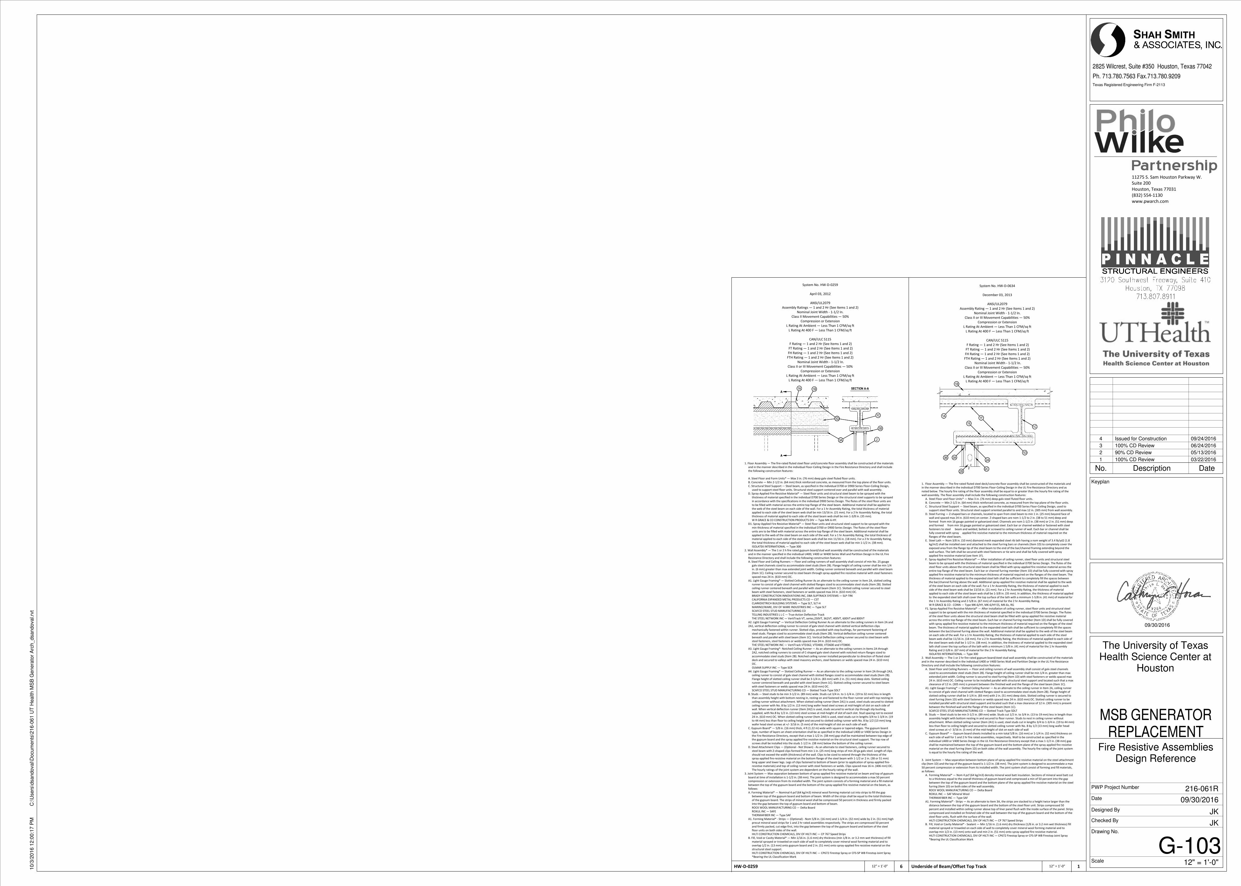
System No. HW-D-0634
December 03, 2013
ANSI/UL2079
Assembly Rating — 1 and 2 Hr (See Items 1 and 2)
Nominal Joint Width - 1-1/2 In.
Class II or III Movement Capabilities — 50%
Compression or Extension
L Rating At Ambient — Less Than 1 CFM/sq ft
L Rating At 400 F — Less Than 1 CFM/sq ft
CAN/ULC S115
F Rating — 1 and 2 Hr (See Items 1 and 2)
FT Rating — 1 and 2 Hr (See Items 1 and 2)
FH Rating — 1 and 2 Hr (See Items 1 and 2)
FTH Rating — 1 and 2 Hr (See Items 1 and 2)
Nominal Joint Width - 1-1/2 In.
Class II or III Movement Capabilities — 50%
Compression or Extension
L Rating At Ambient — Less Than 1 CFM/sq ft
L Rating At 400 F — Less Than 1 CFM/sq ft
1. Floor Assembly — The fire-rated fluted steel deck/concrete floor assembly shall be constructed of the materials and
in the manner described in the individual D700 Series Floor-Ceiling Design in the UL Fire Resistance Directory and as
noted below. The hourly fire rating of the floor assembly shall be equal to or greater than the hourly fire rating of the
wall assembly. The floor assembly shall include the following construction features:
A. Steel Floor and Floor Units* — Max 3 in. (76 mm) deep galv steel fluted floor units.
B. Concrete — Min 2-1/2 in. (64 mm) thick reinforced concrete, as measured from the top plane of the floor units.
C. Structural Steel Support — Steel beam, as specified in the individual D700 Series Floor-Ceiling Design, used to
support steel floor units. Structural steel support oriented parallel to and max 12 in. (305 mm) from wall assembly.
D. Steel Furring — Z-shaped bars or channels, located to span from steel beam to min 1 in. (25 mm) beyond face of
wall and spaced max 24 in. (610 mm) on center. Z-shaped bars are nom 1-1/2 to 2 in. (38 to 51 mm) deep and
formed from min 16 gauge painted or galvanized steel. Channels are nom 1-1/2 in. (38 mm) or 2 in. (51 mm) deep
and formed from min 16 gauge painted or galvanized steel. Each bar or channel welded or fastened with steel
fasteners to steel beam and welded, bolted or screwed to ceiling runner of wall. Each bar or channel shall be
fully covered with spray applied fire resistive material to the minimum thickness of material required on the
flanges of the steel beam.
E. Steel Lath — Nom 3/8 in. (10 mm) diamond mesh expanded steel rib lath having a nom weight of 3.4 lb/yd2 (1.8
kg/m2) shall be installed over and attached to the steel furring bars or channels (Item 1D) to completely cover the
exposed area from the flange tip of the steel beam to the end of the bar/channel framing extending beyond the
wall surface. The lath shall be secured with steel fasteners or tie wire and shall be fully covered with spray
applied fire resistive material (see Item 1F).
F. Spray-Applied Fire Resistive Material* — After installation of ceiling runner, steel floor units and structural steel
beam to be sprayed with the thickness of material specified in the individual D700 Series Design. The flutes of the
steel floor units above the structural steel beam shall be filled with spray-applied fire resistive material across the
entire top flange of the steel beam. Each bar or channel furring member (Item 1D) shall be fully covered with spray
applied fire resistive material to the minimum thickness of material required on the flanges of the steel beam. The
thickness of material applied to the expanded steel lath shall be sufficient to completely fill the spaces between
the bar/channel furring above the wall. Additional spray-applied fire resistive material shall be applied to the web
of the steel beam on each side of the wall. For a 1 hr Assembly Rating, the thickness of material applied to each
side of the steel beam web shall be 13/16 in. (21 mm). For a 2 hr Assembly Rating, the thickness of material
applied to each side of the steel beam web shall be 1-3/8 in. (35 mm). In addition, the thickness of material applied
to the expanded steel lath shall cover the top surface of the lath with a minimum 1-5/8 in. (41 mm) of material for
the 1 hr Assembly Rating and 2-5/8 in. (67 mm) of material for the 2 hr Assembly Rating.
W R GRACE & CO - CONN — Type MK-6/HY, MK-6/HY ES, MK-6s, RG
F1. Spray-Applied Fire Resistive Material* — After installation of ceiling runner, steel floor units and structural steel
support to be sprayed with the min thickness of material specified in the individual D700 Series Design. The flutes
of the steel floor units above the structural steel beam shall be filled with spray-applied fire resistive material
across the entire top flange of the steel beam. Each bar or channel furring member (Item 1D) shall be fully covered
with spray applied fire resistive material to the minimum thickness of material required on the flanges of the steel
beam. The thickness of material applied to the expanded steel lath shall be sufficient to completely fill the spaces
between the bar/channel furring above the wall. Additional material shall be applied to the web of the steel beam
on each side of the wall. For a 1 hr Assembly Rating, the thickness of material applied to each side of the steel
beam web shall be 11/16 in. (18 mm). For a 2 hr Assembly Rating, the thickness of material applied to each side of
the steel beam web shall be 1-1/2 in. (38 mm). In addition, the thickness of material applied to the expanded steel
lath shall cover the top surface of the lath with a minimum 1 5/8 in. (41 mm) of material for the 1 hr Assembly
Rating and 2-5/8 in. (67 mm) of material for the 2 hr Assembly Rating.
ISOLATEK INTERNATIONAL — Type 300
2. Wall Assembly — The 1 or 2 hr fire rated gypsum board/steel stud wall assembly shall be constructed of the materials
and in the manner described in the individual U400 or V400 Series Wall and Partition Design in the UL Fire Resistance
Directory and shall include the following construction features:
A. Steel Floor and Ceiling Runners — Floor and ceiling runners of wall assembly shall consist of galv steel channels
sized to accommodate steel studs (Item 2B). Flange height of ceiling runner shall be min 1/4 in. greater than max
extended joint width. Ceiling runner is secured to steel furring (Item 1D) with steel fasteners or welds spaced max
24 in. (610 mm) OC. Ceiling runner to be installed parallel with structural steel support and located such that a max
clearance of 12 in. (305 mm) is present between the finished wall and the flange of the steel beam (Item 1C).
A1. Light Gauge Framing* — Slotted Ceiling Runner — As an alternate to the ceiling runner in Item 2A, ceiling runner
to consist of galv steel channel with slotted flanges sized to accommodate steel studs (Item 2B). Flange height of
slotted ceiling runner shall be 3-1/4 in. (83 mm) with 2 in. (51 mm) deep slots. Slotted ceiling runner is secured to
steel furring (Item 1D) with steel fasteners or welds spaced max 24 in. (610 mm) OC. Slotted ceiling runner to be
installed parallel with structural steel support and located such that a max clearance of 12 in. (305 mm) is present
between the finished wall and the flange of the steel beam (Item 1C).
SCAFCO STEEL STUD MANUFACTURING CO — Slotted Track-Type SDLT
B. Studs — Steel studs to be min 3-1/2 in. (89 mm) wide. Studs cut 1/2 in. to 3/4 in. (13 to 19 mm) less in length than
assembly height with bottom nesting in and secured to floor runner. Studs to nest in ceiling runner without
attachment. When slotted ceiling runner (Item 2A1) is used, steel studs cut in lengths 3/4 to 1-3/4 in. (19 to 44 mm)
less than floor to ceiling height and secured to slotted ceiling runner with No. 8 by 1/2 (13 mm) long wafer head
steel screws at +/- 3/16 in. (5 mm) of the mid-height of slot on each side of wall
C. Gypsum Board* — Gypsum board sheets installed to a min total 5/8 in. (16 mm) or 1-1/4 in. (32 mm) thickness on
each side of wall for 1 and 2 hr fire rated assemblies, respectively. Wall to be constructed as specified in the
individual U400 or V400 Series Design in the UL Fire Resistance Directory except that a max 1-1/2 in. (38 mm) gap
shall be maintained between the top of the gypsum board and the bottom plane of the spray applied fire resistive
material on the steel furring (Item 1D) on both sides of the wall assembly. The hourly fire rating of the joint system
is equal to the hourly fire rating of the wall.
3. Joint System — Max separation between bottom plane of spray-applied fire resistive material on the steel attachment
clip (Item 1D) and the top of the gypsum board is 1-1/2 in. (38 mm). The joint system is designed to accommodate a max
50 percent compression or extension from its installed width. The joint system shall consist of forming and fill materials,
as follows:
A. Forming Material* — Nom 4 pcf (64 kg/m3) density mineral wool batt insulation. Sections of mineral wool batt cut
to a thickness equal to the overall thickness of gypsum board and compressed a min of 50 percent into the gap
between the top of the gypsum board and the bottom plane of the spray applied fire resistive material on the steel
furring (Item 1D) on both sides of the wall assembly.
ROCK WOOL MANUFACTURING CO — Delta Board
ROXUL INC — SAF Mineral Wool
THERMAFIBER INC — Type SAF
A1. Forming Material* - Strips — As an alternate to Item 3A, the strips are stacked to a height twice larger than the
distance between the top of the gypsum board and the bottom of the steel floor unit. Strips compressed 50
percent and installed within ceiling runner above top of liner panel flush with the inside surface of the panel. Strips
compressed and installed on finished side of the wall between the top of the gypsum board and the bottom of the
steel floor units, flush with the surface of the wall.
HILTI CONSTRUCTION CHEMICALS, DIV OF HILTI INC — CP 767 Speed Strips
B. Fill, Void or Cavity Material* - Sealant — Min 1/16 in. (1.6 mm) dry thickness (1/8 in. or 3.2 mm wet thickness) fill
material sprayed or troweled on each side of wall to completely cover mineral wool forming material and to
overlap min 1/2 in. (13 mm) onto wall and min 2 in. (51 mm) onto spray-applied fire resistive material.
HILTI CONSTRUCTION CHEMICALS, DIV OF HILTI INC — CP672 Firestop Spray or CFS-SP WB Firestop Joint Spray
*Bearing the UL Classification Mark
System No. HW-D-0259
April 03, 2012
ANSI/UL2079
Assembly Ratings — 1 and 2 Hr (See Items 1 and 2)
Nominal Joint Width - 1-1/2 In.
Class II Movement Capabilities — 50%
Compression or Extension
L Rating At Ambient — Less Than 1 CFM/sq ft
L Rating At 400 F — Less Than 1 CFM/sq ft
CAN/ULC S115
F Rating — 1 and 2 Hr (See Items 1 and 2)
FT Rating — 1 and 2 Hr (See Items 1 and 2)
FH Rating — 1 and 2 Hr (See Items 1 and 2)
FTH Rating — 1 and 2 Hr (See Items 1 and 2)
Nominal Joint Width - 1-1/2 In.
Class II or III Movement Capabilities — 50%
Compression or Extension
L Rating At Ambient — Less Than 1 CFM/sq ft
L Rating At 400 F — Less Than 1 CFM/sq ft
1. Floor Assembly — The fire-rated fluted steel floor unit/concrete floor assembly shall be constructed of the materials
and in the manner described in the individual Floor-Ceiling Design in the Fire Resistance Directory and shall include
the following construction features:
A. Steel Floor and Form Units* — Max 3 in. (76 mm) deep galv steel fluted floor units.
B. Concrete — Min 2-1/2 in. (64 mm) thick reinforced concrete, as measured from the top plane of the floor units.
C. Structural Steel Support — Steel beam, as specified in the individual D700 or D900 Series Floor-Ceiling Design,
used to support steel floor units. Structural steel support centered over and parallel with wall assembly.
D. Spray-Applied Fire Resistive Material* — Steel floor units and structural steel beam to be sprayed with the
thickness of material specified in the individual D700 Series Design or the structural steel supports to be sprayed
in accordance with the specifications in the individual D900 Series Design. The flutes of the steel floor units are
to be filled with material across the entire top flange of the steel beam. Additional material shall be applied to
the web of the steel beam on each side of the wall. For a 1 hr Assembly Rating, the total thickness of material
applied to each side of the steel beam web shall be min 13/16 in. (21 mm). For a 2 hr Assembly Rating, the total
thickness of material applied to each side of the steel beam web shall be min 1-3/8 in. (35 mm).
W R GRACE & CO CONSTRUCTION PRODUCTS DIV — Type MK-6-HY.
D1. Spray-Applied Fire Resistive Material* — Steel floor units and structural steel support to be sprayed with the
min thickness of material specified in the individual D700 or D900 Series Design. The flutes of the steel floor
units are to be filled with material across the entire top flange of the steel beam. Additional material shall be
applied to the web of the steel beam on each side of the wall. For a 1 hr Assembly Rating, the total thickness of
material applied to each side of the steel beam web shall be min 11/16 in. (18 mm). For a 2 hr Assembly Rating,
the total thickness of material applied to each side of the steel beam web shall be min 1-1/2 in. (38 mm).
ISOLATEK INTERNATIONAL — Type 300
2. Wall Assembly* — The 1 or 2 h fire rated gypsum board/stud wall assembly shall be constructed of the materials
and in the manner specified in the individual U400, V400 or W400 Series Wall and Partition Design in the UL Fire
Resistance Directory and shall include the following construction features:
A. Steel Floor and Ceiling Runners — Floor and ceiling runners of wall assembly shall consist of min No. 25 gauge
galv steel channels sized to accommodate steel studs (Item 2B). Flange height of ceiling runner shall be min 1/4
in. (6 mm) greater than max extended joint width. Ceiling runner centered beneath and parallel with steel beam
(Item 1C). Ceiling runner secured to steel beam through spray-applied fire resistive material with steel fasteners
spaced max 24 in. (610 mm) OC.
A1. Light Gauge Framing* — Slotted Ceiling Runner As an alternate to the ceiling runner in Item 2A, slotted ceiling
runner to consist of galv steel channel with slotted flanges sized to accommodate steel studs (Item 2B). Slotted
ceiling runner centered beneath and parallel with steel beam (Item 1C). Slotted ceiling runner secured to steel
beam with steel fasteners, steel fasteners or welds spaced max 24 in. (610 mm) OC.
BRADY CONSTRUCTION INNOVATIONS INC, DBA SLIPTRACK SYSTEMS — SLP-TRK
CALIFORNIA EXPANDED METAL PRODUCTS CO — CST
CLARKDIETRICH BUILDING SYSTEMS — Type SLT, SLT-H
MARINO/WARE, DIV OF WARE INDUSTRIES INC — Type SLT
SCAFCO STEEL STUD MANUFACTURING CO
TELLING INDUSTRIES L L C — True-Action Deflection Track
THE STEEL NETWORK INC — VertiTrack VT, series,250VT, 362VT, 400VT, 600VT and 800VT
A2. Light Gauge Framing* — Vertical Deflection Ceiling Runner As an alternate to the ceiling runners in Item 2A and
2A1, vertical deflection ceiling runner to consist of galv steel channel with slotted vertical deflection clips
mechanically fastened within runner. Slotted clips, provided with step bushings, for permanent fastening of
steel studs. Flanges sized to accommodate steel studs (Item 2B). Vertical deflection ceiling runner centered
beneath and parallel with steel beam (Item 1C). Vertical Deflection ceiling runner secured to steel beam with
steel fasteners, steel fasteners or welds spaced max 24 in. (610 mm) OC.
THE STEEL NETWORK INC — VertiTrack VTD362, VTD400, VTD600 and VTD800.
A3. Light Gauge Framing*- Notched Ceiling Runner — As an alternate to the ceiling runners in Items 2A through
2A2, notched ceiling runners to consist of C-shaped galv steel channel with notched return flanges sized to
accommodate steel studs (Item 2B). Notched ceiling runner installed perpendicular to direction of fluted steel
deck and secured to valleys with steel masonry anchors, steel fasteners or welds spaced max 24 in. (610 mm)
OC.
OLMAR SUPPLY INC — Type SCR
A4. Light Gauge Framing* — Slotted Ceiling Runner — As an alternate to the ceiling runner in Item 2A through 2A3,
ceiling runner to consist of galv steel channel with slotted flanges sized to accommodate steel studs (Item 2B).
Flange height of slotted ceiling runner shall be 3-1/4 in. (83 mm) with 2 in. (51 mm) deep slots. Slotted ceiling
runner centered beneath and parallel with steel beam (Item 1C). Slotted ceiling runner secured to steel beam
with steel fasteners or welds spaced max 24 in. (610 mm) OC.
SCAFCO STEEL STUD MANUFACTURING CO — Slotted Track-Type SDLT
B. Studs — Steel studs to be min 3-1/2 in. (89 mm) wide. Studs cut 3/4 in. to 1-1/4 in. (19 to 32 mm) less in length
than assembly height with bottom nesting in, resting on and fastened to the floor runner and with top nesting in
ceiling runner without attachment. When slotted ceiling runner (Item 2A1) is used, steel studs secured to slotted
ceiling runner with No. 8 by 1/2 in. (13 mm) long wafer head steel screws at mid-height of slot on each side of
wall. When vertical deflection runner (Item 2A2) is used, studs secured to vertical clip through slip bushing,
supplied, with No.8 by 1/2 in. (13 mm) steel screws at mid-height of slot of each slot. Stud spacing not to exceed
24 in. (610 mm) OC. When slotted ceiling runner (Item 2A4) is used, steel studs cut in lengths 3/4 to 1-3/4 in. (19
to 44 mm) less than floor to ceiling height and secured to slotted ceiling runner with No. 8 by 1/2 (13 mm) long
wafer head steel screws at +/- 3/16 in. (5 mm) of the mid-height of slot on each side of wall.
C. Gypsum Board* — 5/8 in. (16 mm) thick, 4 ft (1.22 m) wide with square or tapered edges. The gypsum board
type, number of layers an sheet orientation shall be as specified in the individual U400 or V400 Series Design in
the Fire Resistance Directory, except that a max 1-1/2 in. (38 mm) gap shall be maintained between top edge of
the gypsum board and the spray applied fire resistive material on the structural steel support. The top row of
screws shall be installed into the studs 1-1/2 in. (38 mm) below the bottom of the ceiling runner.
D. Steel Attachment Clips — (Optional - Not Shown) - As an alternate to steel fasteners, ceiling runner secured to
steel beam with Z-shaped clips formed from min 1 in. (25 mm) long strips of min 20 ga galv steel. Length of clips
should not exceed the width (thickness) of the wall. Clips to be sized to extend through the thickness of the
spray-applied fire-resistive material on the bottom flange of the steel beam with 1-1/2 or 2 in. (38 or 51 mm)
long upper and lower legs. Legs of clips fastened to bottom of beam (prior to application of spray-applied fire-
resistive materials) and top of ceiling runner with steel fasteners or welds. Clips spaced max 16 in. (406 mm) OC.
The hourly ratings of the joint system are dependent on the hourly rating of the wall.
3. Joint System — Max separation between bottom of spray-applied fire resistive material on beam and top of gypsum
board at time of installation is 1-1/2 in. (38 mm). The joint system is designed to accommodate a max 50 percent
compression or extension from its installed width. The joint system consists of a forming material and a fill material
between the top of the gypsum board and the bottom of the spray-applied fire resistive material on the beam, as
follows:
A. Forming Material* — Nominal 4 pcf (64 kg/m3) mineral wool forming material cut into strips to fill the gap
between top of the gypsum board and bottom of beam. Width of the strips shall be equal to the total thickness
of the gypsum board. The strips of mineral wool shall be compressed 50 percent in thickness and firmly packed
into the gap between the top of gypsum board and bottom of beam.
ROCK WOOL MANUFACTURING CO — Delta Board
ROXUL INC — SAFE
THERMAFIBER INC — Type SAF
A1. Forming Material* - Strips — (Optional) - Nom 5/8 in. (16 mm) and 1-1/4 in. (32 mm) wide by 2 in. (51 mm) high
precut mineral wool strips for 1 and 2 hr rated assemblies respectively. The strips are compressed 50 percent
and firmly packed, cut edge first, into the gap between the top of the gypsum board and bottom of the steel
floor units on both sides of the wall.
HILTI CONSTRUCTION CHEMICALS, DIV OF HILTI INC — CP 767 Speed Strips
B. Fill, Void or Cavity Material* — Min 1/16 in. (1.6 mm) dry thickness (min 1/8 in. or 3.2 mm wet thickness) of fill
material sprayed or troweled on each side of wall to completely cover mineral wool forming material and to
overlap 1/2 in. (13 mm) onto gypsum board and 2 in. (51 mm) onto spray-applied fire resistive material on the
structural steel support.
HILTI CONSTRUCTION CHEMICALS, DIV OF HILTI INC — CP672 Firestop Spray or CFS-SP WB Firestop Joint Spray
*Bearing the UL Classification Mark
11275 S. Sam Houston Parkway W.
Suite 200
Houston, Texas 77031
(832) 554-1130
www.pwarch.com
Texas Registered Engineering Firm F-2113
Scale
Date
Designed By
Checked By
PWP Project Number
Drawing No.
2825 Wilcrest, Suite #350 Houston, Texas 77042
Ph. 713.780.7563 Fax.713.780.9209
Keyplan
09/30/2016
12" = 1'-0"
10/3
/2016 1
2:0
0:1
7 P
MC
:\U
sers
\dsandoval\D
ocum
ents
\216-0
61 U
T H
ealth M
SB
Genera
tor
Arc
h_dsandoval.rv
t
G-103
Fire Resistive AssembliesDesign Reference
The University of TexasHealth Science Center at
Houston
MSB GENERATORREPLACEMENT
JK
JK
09/30/2016
216-061R
12" = 1'-0"Underside of Beam/Offset Top Track 1 12" = 1'-0"HW-D-0259 6
No. Description Date
1 100% CD Review 03/22/2016
2 90% CD Review 05/13/2016
3 100% CD Review 06/24/2016
4 Issued for Construction 09/24/2016
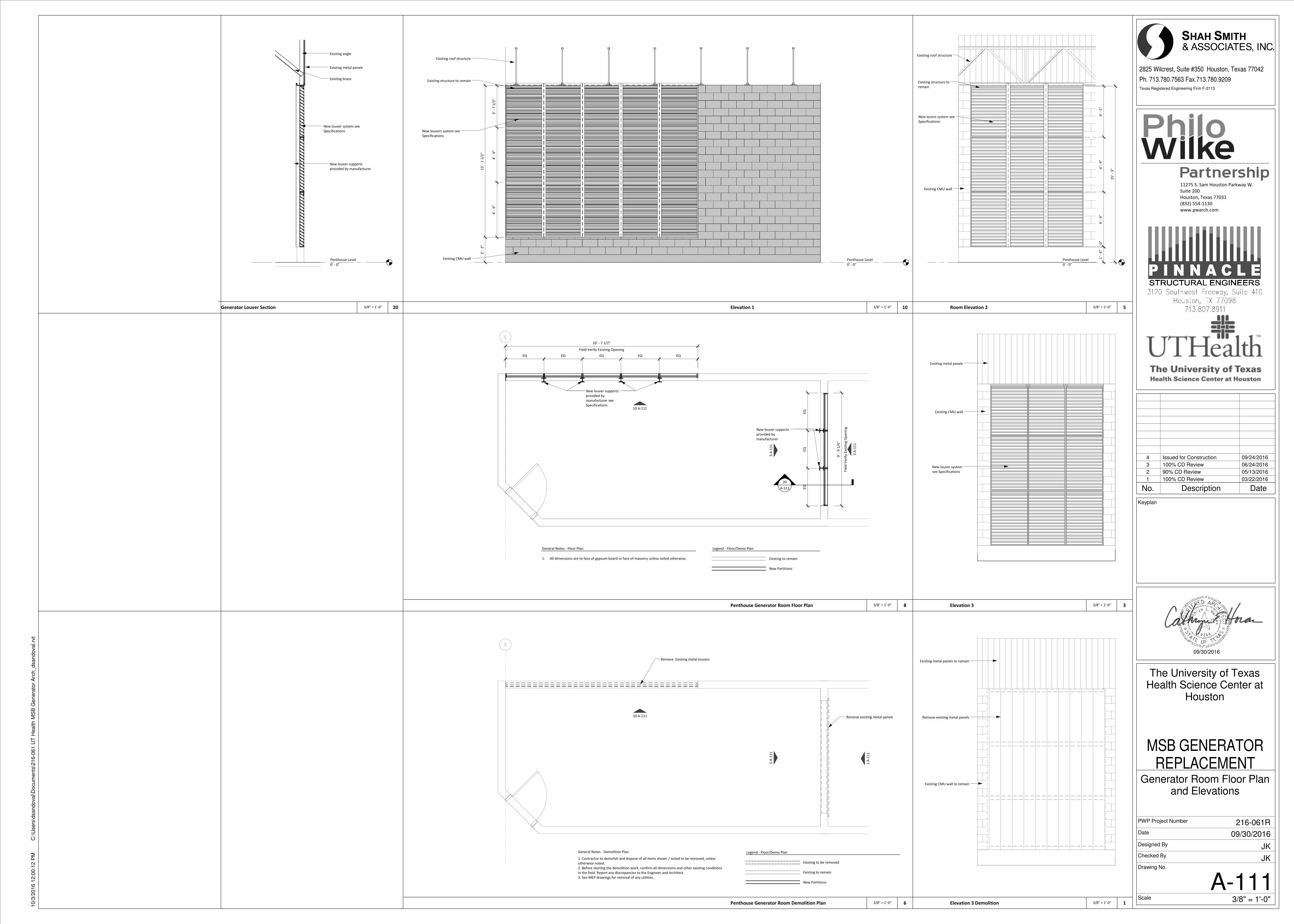
5
5 A
-11
1
10 A-111
Field Verify Existing Opening
16' - 7 1/2"
20
A-111
3 A
-11
1
Fie
ld V
er i
fy E
xis
tin
g O
pe
nin
g
9'
- 9
1/4
"
EQ
EQ
EQ
New louver supports
provided by
manufacturer
New louver supports
provided by
manufacturer see
Specifications
EQ EQ EQ EQ EQ
Penthouse Level
0' - 0"
Existing structure to remain
New louvers system see
Specifications
Existing CMU wall
Existing roof structure
13
' -
1 1
/2"
2' -
2"
3'
- 7
1/2
"4
' -
9"
4' -
9"
Penthouse Level
0' - 0"
15
' -
3"
Existing roof structure
Existing structure to
remain
New louvre system see
Specifications
Existing CMU wall
4' -
5"
4' -
9"
4' -
9"
0"
1' -
4"
5
5 A
-11
1
10 A-111
Remove Existing metal louvers
1 A
-11
1
Remove existing metal panels
Penthouse Level
0' - 0"
Existing metal panels
New louver system see
Specifications
New louver supports
provided by manufacturer
Existing angle
Existing brace
Exsiting metal panels
Existing CMU wall
New louver system
see Specifications
Remove existing metal panels
Existing metal panels to remain
Existing CMU wall to remain
11275 S. Sam Houston Parkway W.
Suite 200
Houston, Texas 77031
(832) 554-1130
www.pwarch.com
Texas Registered Engineering Firm F-2113
Scale
Date
Designed By
Checked By
PWP Project Number
Drawing No.
2825 Wilcrest, Suite #350 Houston, Texas 77042
Ph. 713.780.7563 Fax.713.780.9209
Keyplan
09/30/2016
3/8" = 1'-0"
10/3
/2016 1
2:0
0:1
2 P
MC
:\U
sers
\dsandoval\D
ocum
ents
\216-0
61 U
T H
ealth M
SB
Genera
tor
Arc
h_dsandoval.rv
t
A-111
Generator Room Floor Planand Elevations
The University of TexasHealth Science Center at
Houston
MSB GENERATORREPLACEMENT
JK
JK
09/30/2016
216-061R
Legend - Floor/Demo Plan
Existing to remain
New Partitions
General Notes - Floor Plan
1. All dimensions are to face of gypsum board or face of masonry unless noted otherwise.
3/8" = 1'-0"Penthouse Generator Room Floor Plan 8
3/8" = 1'-0"Elevation 1 10 3/8" = 1'-0"Room Elevation 2 5
3/8" = 1'-0"Penthouse Generator Room Demolition Plan 6
3/8" = 1'-0"Generator Louver Section 20
3/8" = 1'-0"Elevation 3 3
3/8" = 1'-0"Elevation 3 Demolition 1
Legend - Floor/Demo Plan
Existing to be removed
Existing to remain
New Partitions
General Notes - Demolition Plan
1. Contractor to demolish and dispose of all items shown / noted to be removed, unless
otherwise noted.
2. Before starting the demolition work, confirm all dimensions and other existing conditions
in the field. Report any discrepancies to the Engineer and Architect.
3. See MEP drawings for removal of any utilities.
No. Description Date
1 100% CD Review 03/22/2016
2 90% CD Review 05/13/2016
3 100% CD Review 06/24/2016
4 Issued for Construction 09/24/2016
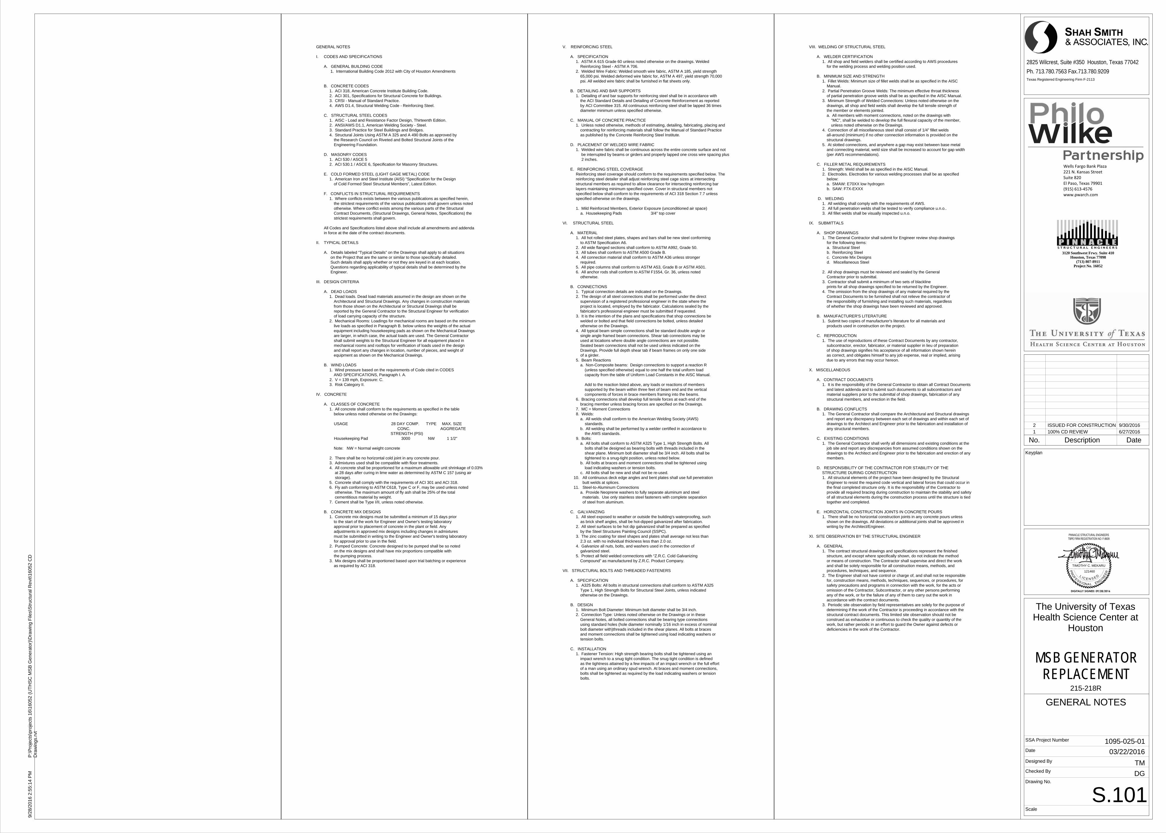
GENERAL NOTES
I. CODES AND SPECIFICATIONS
A. GENERAL BUILDING CODE 1. International Building Code 2012 with City of Houston Amendments
B. CONCRETE CODES 1. ACI 318, American Concrete Institute Building Code. 2. ACI 301, Specifications for Structural Concrete for Buildings. 3. CRSI - Manual of Standard Practice. 4. AWS D1.4, Structural Welding Code - Reinforcing Steel.
C. STRUCTURAL STEEL CODES 1. AISC - Load and Resistance Factor Design, Thirteenth Edition. 2. ANSI/AWS D1.1, American Welding Society - Steel. 3. Standard Practice for Steel Buildings and Bridges. 4. Structural Joints Using ASTM A 325 and A 490 Bolts as approved by the Research Council on Riveted and Bolted Structural Joints of the Engineering Foundation.
D. MASONRY CODES 1. ACI 530 / ASCE 5 2. ACI 530.1 / ASCE 6, Specification for Masonry Structures.
E. COLD FORMED STEEL (LIGHT GAGE METAL) CODE 1. American Iron and Steel Institute (AISI) “Specification for the Design of Cold Formed Steel Structural Members”, Latest Edition.
F. CONFLICTS IN STRUCTURAL REQUIREMENTS 1. Where conflicts exists between the various publications as specified herein, the strictest requirements of the various publications shall govern unless noted otherwise. Where conflict exists among the various parts of the Structural Contract Documents, (Structural Drawings, General Notes, Specifications) the strictest requirements shall govern.
All Codes and Specifications listed above shall include all amendments and addenda in force at the date of the contract documents.
II. TYPICAL DETAILS
A. Details labeled “Typical Details” on the Drawings shall apply to all situations on the Project that are the same or similar to those specifically detailed. Such details shall apply whether or not they are keyed in at each location. Questions regarding applicability of typical details shall be determined by the Engineer.
III. DESIGN CRITERIA
A. DEAD LOADS 1. Dead loads. Dead load materials assumed in the design are shown on the Architectural and Structural Drawings. Any changes in construction materials from those shown on the Architectural or Structural Drawings shall be reported by the General Contractor to the Structural Engineer for verification of load carrying capacity of the structure. 2. Mechanical Rooms: Loadings for mechanical rooms are based on the minimum live loads as specified in Paragraph B. below unless the weights of the actual equipment including housekeeping pads as shown on the Mechanical Drawings are larger, in which case, the actual loads are used. The General Contractor shall submit weights to the Structural Engineer for all equipment placed in mechanical rooms and rooftops for verification of loads used in the design and shall report any changes in location, number of pieces, and weight of equipment as shown on the Mechanical Drawings.
B. WIND LOADS 1. Wind pressure based on the requirements of Code cited in CODES AND SPECIFICATIONS, Paragraph I. A. 2. V = 139 mph, Exposure: C. 3. Risk Category II.
IV. CONCRETE
A. CLASSES OF CONCRETE 1. All concrete shall conform to the requirements as specified in the table below unless noted otherwise on the Drawings:
USAGE 28 DAY COMP. TYPE MAX. SIZE CONC. AGGREGATE STRENGTH (PSI) Housekeeping Pad 3000 NW 1 1/2"
Note: NW = Normal weight concrete
2. There shall be no horizontal cold joint in any concrete pour. 3. Admixtures used shall be compatible with floor treatments. 4. All concrete shall be proportioned for a maximum allowable unit shrinkage of 0.03% at 28 days after curing in lime water as determined by ASTM C 157 (using air storage). 5. Concrete shall comply with the requirements of ACI 301 and ACI 318. 6. Fly ash conforming to ASTM C618, Type C or F, may be used unless noted otherwise. The maximum amount of fly ash shall be 25% of the total cementitious material by weight. 7. Cement shall be Type I/II, unless noted otherwise.
B. CONCRETE MIX DESIGNS 1. Concrete mix designs must be submitted a minimum of 15 days prior to the start of the work for Engineer and Owner's testing laboratory approval prior to placement of concrete in the plant or field. Any adjustments in approved mix designs including changes in admixtures must be submitted in writing to the Engineer and Owner's testing laboratory for approval prior to use in the field. 2. Pumped Concrete: Concrete designed to be pumped shall be so noted on the mix designs and shall have mix proportions compatible with the pumping process. 3. Mix designs shall be proportioned based upon trial batching or experience as required by ACI 318.
V. REINFORCING STEEL
A. SPECIFICATION 1. ASTM A 615 Grade 60 unless noted otherwise on the drawings. Welded Reinforcing Steel - ASTM A 706. 2. Welded Wire Fabric: Welded smooth wire fabric, ASTM A 185, yield strength 65,000 psi. Welded deformed wire fabric for, ASTM A 497, yield strength 70,000 psi. All welded wire fabric shall be furnished in flat sheets only.
B. DETAILING AND BAR SUPPORTS 1. Detailing of and bar supports for reinforcing steel shall be in accordance with the ACI Standard Details and Detailing of Concrete Reinforcement as reported by ACI Committee 315. All continuous reinforcing steel shall be lapped 36 times diameter minimum unless specified otherwise.
C. MANUAL OF CONCRETE PRACTICE 1. Unless noted otherwise, methods of estimating, detailing, fabricating, placing and contracting for reinforcing materials shall follow the Manual of Standard Practice as published by the Concrete Reinforcing Steel Institute.
D. PLACEMENT OF WELDED WIRE FABRIC 1. Welded wire fabric shall be continuous across the entire concrete surface and not be interrupted by beams or girders and properly lapped one cross wire spacing plus 2 inches.
E. REINFORCING STEEL COVERAGE Reinforcing steel coverage should conform to the requirements specified below. The reinforcing steel detailer shall adjust reinforcing steel cage sizes at intersecting structural members as required to allow clearance for intersecting reinforcing bar layers maintaining minimum specified cover. Cover in structural members not specified below shall conform to the requirements of ACI 318 Section 7.7 unless specified otherwise on the drawings.
1. Mild Reinforced Members, Exterior Exposure (unconditioned air space) a. Housekeeping Pads 3/4" top cover
VI. STRUCTURAL STEEL
A. MATERIAL 1. All hot rolled steel plates, shapes and bars shall be new steel conforming to ASTM Specification A6. 2. All wide flanged sections shall conform to ASTM A992, Grade 50. 3. All tubes shall conform to ASTM A500 Grade B. 4. All connection material shall conform to ASTM A36 unless stronger required. 5. All pipe columns shall conform to ASTM A53, Grade B or ASTM A501. 6. All anchor rods shall conform to ASTM F1554, Gr. 36, unless noted otherwise.
B. CONNECTIONS 1. Typical connection details are indicated on the Drawings. 2. The design of all steel connections shall be performed under the direct supervision of a registered professional engineer in the state where the project is located, employed by the fabricator. Calculations sealed by the fabricator's professional engineer must be submitted if requested. 3. It is the intention of the plans and specifications that shop connections be welded or bolted and that field connections be bolted, unless detailed otherwise on the Drawings. 4. All typical beam simple connections shall be standard double angle or single angle framed beam connections. Shear tab connections may be used at locations where double angle connections are not possible. Seated beam connections shall not be used unless indicated on the Drawings. Provide full depth shear tab if beam frames on only one side of a girder. 5. Beam Reactions a. Non-Composite beams: Design connections to support a reaction R (unless specified otherwise) equal to one half the total uniform load capacity from the table of Uniform Load Constants in the AISC Manual.
Add to the reaction listed above, any loads or reactions of members supported by the beam within three feet of beam end and the vertical components of forces in brace members framing into the beams. 6. Bracing connections shall develop full tensile forces at each end of the bracing member unless bracing forces are specified on the Drawings. 7. MC = Moment Connections 8. Welds: a. All welds shall conform to the American Welding Society (AWS) standards. b. All welding shall be performed by a welder certified in accordance to the AWS standards. 9. Bolts: a. All bolts shall conform to ASTM A325 Type 1, High Strength Bolts. All bolts shall be designed as bearing bolts with threads included in the shear plane. Minimum bolt diameter shall be 3/4 inch. All bolts shall be tightened to a snug-tight position, unless noted below. b. All bolts at braces and moment connections shall be tightened using load indicating washers or tension bolts. c. All bolts shall be new and shall not be re-used. 10. All continuous deck edge angles and bent plates shall use full penetration butt welds at splices. 11. Steel-to-Aluminum Connections a. Provide Neoprene washers to fully separate aluminum and steel materials. Use only stainless steel fasteners with complete separation of steel from aluminum.
C. GALVANIZING 1. All steel exposed to weather or outside the building's waterproofing, such as brick shelf angles, shall be hot-dipped galvanized after fabrication. 2. All steel surfaces to be hot dip galvanized shall be prepared as specified by the Steel Structures Painting Council (SSPC). 3. The zinc coating for steel shapes and plates shall average not less than 2.3 oz. with no individual thickness less than 2.0 oz. 4. Galvanize all nuts, bolts, and washers used in the connection of galvanized steel. 5. Protect all field welded connections with “Z.R.C. Cold Galvanizing Compound” as manufactured by Z.R.C. Product Company.
VII. STRUCTURAL BOLTS AND THREADED FASTENERS
A. SPECIFICATION 1. A325 Bolts: All bolts in structural connections shall conform to ASTM A325 Type 1, High Strength Bolts for Structural Steel Joints, unless indicated otherwise on the Drawings.
B. DESIGN 1. Minimum Bolt Diameter: Minimum bolt diameter shall be 3/4 inch. 2. Connection Type: Unless noted otherwise on the Drawings or in these General Notes, all bolted connections shall be bearing type connections using standard holes (hole diameter nominally 1/16 inch in excess of nominal bolt diameter with)threads included in the shear planes. All bolts at braces and moment connections shall be tightened using load indicating washers or tension bolts.
C. INSTALLATION 1. Fastener Tension: High strength bearing bolts shall be tightened using an impact wrench to a snug tight condition. The snug tight condition is defined as the tightness attained by a few impacts of an impact wrench or the full effort of a man using an ordinary spud wrench. At braces and moment connections, bolts shall be tightened as required by the load indicating washers or tension bolts.
VIII. WELDING OF STRUCTURAL STEEL
A. WELDER CERTIFICATION 1. All shop and field welders shall be certified according to AWS procedures for the welding process and welding position used.
B. MINIMUM SIZE AND STRENGTH 1. Fillet Welds: Minimum size of fillet welds shall be as specified in the AISC Manual. 2. Partial Penetration Groove Welds: The minimum effective throat thickness of partial penetration groove welds shall be as specified in the AISC Manual. 3. Minimum Strength of Welded Connections: Unless noted otherwise on the drawings, all shop and field welds shall develop the full tensile strength of the member or elements jointed. a. All members with moment connections, noted on the drawings with "MC", shall be welded to develop the full flexural capacity of the member, unless noted otherwise on the Drawings. 4. Connection of all miscellaneous steel shall consist of 1/4” fillet welds all-around (minimum) if no other connection information is provided on the structural drawings. 5. At slotted connections, and anywhere a gap may exist between base metal and connecting material, weld size shall be increased to account for gap width (per AWS recommendations).
C. FILLER METAL REQUIREMENTS 1. Strength: Weld shall be as specified in the AISC Manual. 2. Electrodes. Electrodes for various welding processes shall be as specified below: a. SMAW: E70XX low hydrogen b. SAW: F7X-EXXX
D. WELDING 1. All welding shall comply with the requirements of AWS. 2. All full penetration welds shall be tested to verify compliance u.n.o.. 3. All fillet welds shall be visually inspected u.n.o.
IX. SUBMITTALS
A. SHOP DRAWINGS 1. The General Contractor shall submit for Engineer review shop drawings for the following items: a. Structural Steel b. Reinforcing Steel c. Concrete Mix Designs d. Miscellaneous Steel
2. All shop drawings must be reviewed and sealed by the General Contractor prior to submittal. 3. Contractor shall submit a minimum of two sets of blackline prints for all shop drawings specified to be returned by the Engineer. 4. The omission from the shop drawings of any material required by the Contract Documents to be furnished shall not relieve the contractor of the responsibility of furnishing and installing such materials, regardless of whether the shop drawings have been reviewed and approved.
B. MANUFACTURER'S LITERATURE 1. Submit two copies of manufacturer's literature for all materials and products used in construction on the project.
C. REPRODUCTION 1. The use of reproductions of these Contract Documents by any contractor, subcontractor, erector, fabricator, or material supplier in lieu of preparation of shop drawings signifies his acceptance of all information shown herein as correct, and obligates himself to any job expense, real or implied, arising due to any errors that may occur hereon.
X. MISCELLANEOUS
A. CONTRACT DOCUMENTS 1. It is the responsibility of the General Contractor to obtain all Contract Documents and latest addenda and to submit such documents to all subcontractors and material suppliers prior to the submittal of shop drawings, fabrication of any structural members, and erection in the field.
B. DRAWING CONFLICTS 1. The General Contractor shall compare the Architectural and Structural drawings and report any discrepancy between each set of drawings and within each set of drawings to the Architect and Engineer prior to the fabrication and installation of any structural members.
C. EXISTING CONDITIONS 1. The General Contractor shall verify all dimensions and existing conditions at the job site and report any discrepancies from assumed conditions shown on the drawings to the Architect and Engineer prior to the fabrication and erection of any members.
D. RESPONSIBILITY OF THE CONTRACTOR FOR STABILITY OF THE STRUCTURE DURING CONSTRUCTION 1. All structural elements of the project have been designed by the Structural Engineer to resist the required code vertical and lateral forces that could occur in the final completed structure only. It is the responsibility of the Contractor to provide all required bracing during construction to maintain the stability and safety of all structural elements during the construction process until the structure is tied together and completed.
E. HORIZONTAL CONSTRUCTION JOINTS IN CONCRETE POURS 1. There shall be no horizontal construction joints in any concrete pours unless shown on the drawings. All deviations or additional joints shall be approved in writing by the Architect/Engineer.
XI. SITE OBSERVATION BY THE STRUCTURAL ENGINEER
A. GENERAL 1. The contract structural drawings and specifications represent the finished structure, and except where specifically shown, do not indicate the method or means of construction. The Contractor shall supervise and direct the work and shall be solely responsible for all construction means, methods, and procedures, techniques, and sequence. 2. The Engineer shall not have control or charge of, and shall not be responsible for, construction means, methods, techniques, sequences, or procedures, for safety precautions and programs in connection with the work, for the acts or omission of the Contractor, Subcontractor, or any other persons performing any of the work, or for the failure of any of them to carry out the work in accordance with the contract documents. 3. Periodic site observation by field representatives are solely for the purpose of determining if the work of the Contractor is proceeding in accordance with the structural contract documents. This limited site observation should not be construed as exhaustive or continuous to check the quality or quantity of the work, but rather periodic in an effort to guard the Owner against defects or deficiencies in the work of the Contractor.
121460 RE
E
OR
P
IL
SAXETFOETATS
NIGNELANOI
SSE
F DESNEC
TBPE FIRM REGISTRATION NO: F-8609PINNACLE STRUCTURAL ENGINEERS
TIMOTHY C. MEKARU
Wells Fargo Bank Plaza221 N. Kansas StreetSuite 820El Paso, Texas 79901(915) 613‐4576www.pwarch.com
Texas Registered Engineering Firm F-2113
Scale
Date
Designed By
Checked By
SSA Project Number
Drawing No.
2825 Wilcrest, Suite #350 Houston, Texas 77042
Ph. 713.780.7563 Fax.713.780.9209
Keyplan
3120 Southwest Frwy. Suite 410Houston, Texas 77098
(713) 807-8911Project No. 16052
1095-025-01
9/28
/201
6 2:
55:1
4 P
MP
:\Pro
ject
s\pr
ojec
ts 1
6\16
052
(UT
HS
C M
SB
Gen
erat
or)\
Dra
win
g F
iles\
Str
uctu
ral R
evit\
1605
2 C
DD
raw
ings
.rvt
S.101
GENERAL NOTES
The University of TexasHealth Science Center at
Houston
MSB GENERATORREPLACEMENT
DG
TM
03/22/2016
215-218R
No. Description Date1 100% CD REVIEW 6/27/20162 ISSUED FOR CONSTRUCTION 9/30/2016
DIGITALLY SIGNED: 09/28/2016
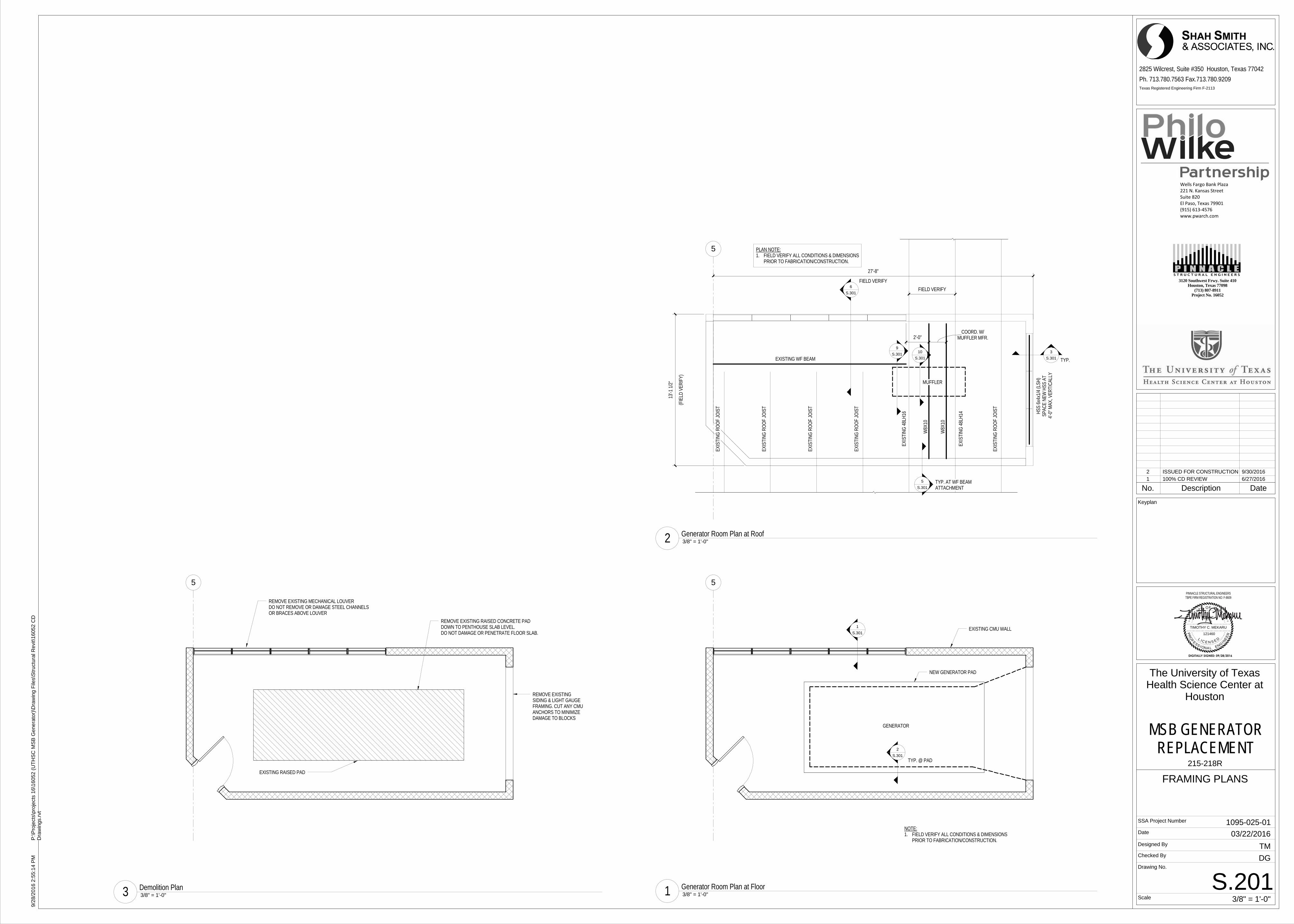
1
S.301
5
EXISTING CMU WALL
GENERATOR
NOTE:1. FIELD VERIFY ALL CONDITIONS & DIMENSIONS
PRIOR TO FABRICATION/CONSTRUCTION.
2
S.301
NEW GENERATOR PAD
TYP. @ PAD
5
6
S.301
EXISTING WF BEAM
FIELD VERIFY
2'-0" MUFFLER MFR.COORD. W/
W8X
10
W8X
10
EXIS
TIN
G 4
8LH
16
EXIS
TIN
G 4
8LH
14
MUFFLER
5
S.301
9
S.301
PLAN NOTE:1. FIELD VERIFY ALL CONDITIONS & DIMENSIONS
PRIOR TO FABRICATION/CONSTRUCTION.
3
S.301
EXIS
TIN
G R
OO
F JO
IST
EXIS
TIN
G R
OO
F JO
IST
EXIS
TIN
G R
OO
F JO
IST
EXIS
TIN
G R
OO
F JO
IST
EXIS
TIN
G R
OO
F JO
IST
HSS
6x4
x1/4
(LSH
)SP
ACE
NEW
HSS
AT
4'-0
" MAX
, VER
TIC
ALLY
10
S.301 TYP.
TYP. AT WF BEAMATTACHMENT
FIELD VERIFY
27'-8"
(FIE
LD V
ERIF
Y)
13'-1
1/2
"
5
REMOVE EXISTING RAISED CONCRETE PADDOWN TO PENTHOUSE SLAB LEVEL.DO NOT DAMAGE OR PENETRATE FLOOR SLAB.
EXISTING RAISED PAD
REMOVE EXISTINGSIDING & LIGHT GAUGEFRAMING. CUT ANY CMUANCHORS TO MINIMIZEDAMAGE TO BLOCKS
REMOVE EXISTING MECHANICAL LOUVERDO NOT REMOVE OR DAMAGE STEEL CHANNELSOR BRACES ABOVE LOUVER
121460 RE
E
OR
P
IL
SAXETFOETATS
NIGNELANOI
SSE
F DESNEC
TBPE FIRM REGISTRATION NO: F-8609PINNACLE STRUCTURAL ENGINEERS
TIMOTHY C. MEKARU
Wells Fargo Bank Plaza221 N. Kansas StreetSuite 820El Paso, Texas 79901(915) 613‐4576www.pwarch.com
Texas Registered Engineering Firm F-2113
Scale
Date
Designed By
Checked By
SSA Project Number
Drawing No.
2825 Wilcrest, Suite #350 Houston, Texas 77042
Ph. 713.780.7563 Fax.713.780.9209
Keyplan
3120 Southwest Frwy. Suite 410Houston, Texas 77098
(713) 807-8911Project No. 16052
1095-025-01
3/8" = 1'-0"
9/28
/201
6 2:
55:1
4 P
MP
:\Pro
ject
s\pr
ojec
ts 1
6\16
052
(UT
HS
C M
SB
Gen
erat
or)\
Dra
win
g F
iles\
Str
uctu
ral R
evit\
1605
2 C
DD
raw
ings
.rvt
S.201
FRAMING PLANS
The University of TexasHealth Science Center at
Houston
MSB GENERATORREPLACEMENT
DG
TM
03/22/2016
215-218R
3/8" = 1'-0"1 Generator Room Plan at Floor
3/8" = 1'-0"2 Generator Room Plan at Roof
3/8" = 1'-0"3 Demolition Plan
No. Description Date1 100% CD REVIEW 6/27/20162 ISSUED FOR CONSTRUCTION 9/30/2016
DIGITALLY SIGNED: 09/28/2016
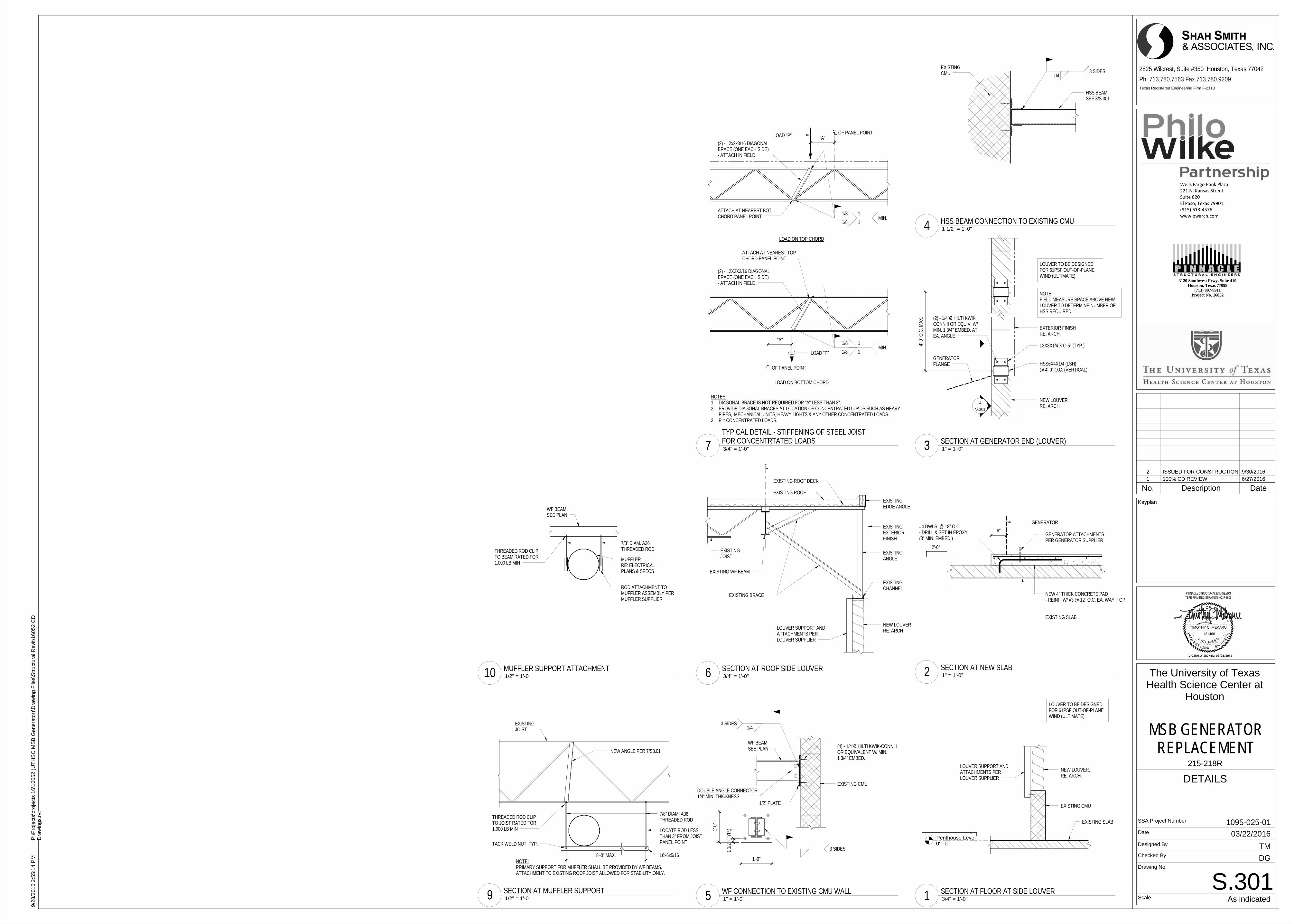
Penthouse Level0' - 0"
EXISTING CMU
EXISTING SLAB
NEW LOUVER,RE: ARCH.
LOUVER SUPPORT ANDATTACHMENTS PERLOUVER SUPPLIER
LOUVER TO BE DESIGNEDFOR 61PSF OUT-OF-PLANEWIND (ULTIMATE)
7/8" DIAM. A36THREADED ROD
NEW ANGLE PER 7/S3.01
THREADED ROD CLIPTO JOIST RATED FOR1,000 LB MIN
EXISTINGJOIST
NOTE:PRIMARY SUPPORT FOR MUFFLER SHALL BE PROVIDED BY WF BEAMS.ATTACHMENT TO EXISTING ROOF JOIST ALLOWED FOR STABILITY ONLY.
L6x6x5/168'-0" MAX.
LOCATE ROD LESSTHAN 3" FROM JOISTPANEL POINTTACK WELD NUT, TYP.
EXISTING CMU
(4) - 1/4"Ø HILTI KWIK-CONN IIOR EQUIVALENT W/ MIN.1 3/4" EMBED.
1/2" PLATE
WF BEAM,SEE PLAN
1/43 SIDES
1 1/
2" (T
YP.)
3 SIDES
1'-0"
1'-0
"
DOUBLE ANGLE CONNECTOR1/4" MIN. THICKNESS
GENERATOR
6"GENERATOR ATTACHMENTSPER GENERATOR SUPPLIER
NEW 4" THICK CONCRETE PAD- REINF. W/ #3 @ 12" O.C. EA. WAY, TOP
EXISTING SLAB
#4 DWLS. @ 18" O.C.- DRILL & SET IN EPOXY(3" MIN. EMBED.)
2'-0"
EXISTING ROOF
EXISTING ROOF DECK
EXISTINGJOIST
EXISTING WF BEAM
EXISTINGCHANNEL
NEW LOUVERRE: ARCHLOUVER SUPPORT AND
ATTACHMENTS PERLOUVER SUPPLIER
EXISTING BRACE
EXISTINGEDGE ANGLE
EXISTINGEXTERIORFINISH
EXISTINGANGLEMUFFLER
RE: ELECTRICALPLANS & SPECS
THREADED ROD CLIPTO BEAM RATED FOR1,000 LB MIN
WF BEAM,SEE PLAN
7/8" DIAM. A36THREADED ROD
ROD ATTACHMENT TOMUFFLER ASSEMBLY PERMUFFLER SUPPLIER
HSS6X4X1/4 (LSH)@ 4'-0" O.C. (VERTICAL)
L3X3X1/4 X 0'-5" (TYP.)
(2) - 1/4"Ø HILTI KWIKCONN II OR EQUIV. W/MIN. 1 3/4" EMBED. ATEA. ANGLE
EXTERIOR FINISHRE: ARCH.
GENERATORFLANGE
NEW LOUVERRE: ARCH
4
S.301
LOUVER TO BE DESIGNEDFOR 61PSF OUT-OF-PLANEWIND (ULTIMATE)
NOTE:FIELD MEASURE SPACE ABOVE NEWLOUVER TO DETERMINE NUMBER OFHSS REQUIRED
4'-0
" O.C
. MAX
.
HSS BEAM,SEE 3/S.301
EXISTINGCMU 1/4
3 SIDES
NOTES:1. DIAGONAL BRACE IS NOT REQUIRED FOR "A" LESS THAN 3".2. PROVIDE DIAGONAL BRACES AT LOCATION OF CONCENTRATED LOADS SUCH AS HEAVY
PIPES, MECHANICAL UNITS, HEAVY LIGHTS & ANY OTHER CONCENTRATED LOADS.3. P = CONCENTRATED LOADS.
LOAD ON BOTTOM CHORD
LOAD ON TOP CHORD
ATTACH AT NEAREST TOPCHORD PANEL POINT
(2) - L2X2X3/16 DIAGONALBRACE (ONE EACH SIDE)- ATTACH IN FIELD
1/8 1
1/8 1MIN.
"A"
(2) - L2x2x3/16 DIAGONALBRACE (ONE EACH SIDE)- ATTACH IN FIELD
1/8 1
1/8 1MIN.
"A"LOAD "P"
ATTACH AT NEAREST BOT.CHORD PANEL POINT
OF PANEL POINT
LOAD "P"
OF PANEL POINT
121460 RE
E
OR
P
IL
SAXETFOETATS
NIGNELANOI
SSE
F DESNEC
TBPE FIRM REGISTRATION NO: F-8609PINNACLE STRUCTURAL ENGINEERS
TIMOTHY C. MEKARU
Wells Fargo Bank Plaza221 N. Kansas StreetSuite 820El Paso, Texas 79901(915) 613‐4576www.pwarch.com
Texas Registered Engineering Firm F-2113
Scale
Date
Designed By
Checked By
SSA Project Number
Drawing No.
2825 Wilcrest, Suite #350 Houston, Texas 77042
Ph. 713.780.7563 Fax.713.780.9209
Keyplan
3120 Southwest Frwy. Suite 410Houston, Texas 77098
(713) 807-8911Project No. 16052
1095-025-01
As indicated
9/28
/201
6 2:
55:1
4 P
MP
:\Pro
ject
s\pr
ojec
ts 1
6\16
052
(UT
HS
C M
SB
Gen
erat
or)\
Dra
win
g F
iles\
Str
uctu
ral R
evit\
1605
2 C
DD
raw
ings
.rvt
S.301
DETAILS
The University of TexasHealth Science Center at
Houston
MSB GENERATORREPLACEMENT
DG
TM
03/22/2016
215-218R
3/4" = 1'-0"1 SECTION AT FLOOR AT SIDE LOUVER 1/2" = 1'-0"9 SECTION AT MUFFLER SUPPORT
1" = 1'-0"5 WF CONNECTION TO EXISTING CMU WALL
1" = 1'-0"2 SECTION AT NEW SLAB 3/4" = 1'-0"6 SECTION AT ROOF SIDE LOUVER
1/2" = 1'-0"10 MUFFLER SUPPORT ATTACHMENT
1" = 1'-0"3 SECTION AT GENERATOR END (LOUVER)
1 1/2" = 1'-0"4 HSS BEAM CONNECTION TO EXISTING CMU
No. Description Date1 100% CD REVIEW 6/27/20162 ISSUED FOR CONSTRUCTION 9/30/2016
3/4" = 1'-0"7TYPICAL DETAIL - STIFFENING OF STEEL JOISTFOR CONCENTRTATED LOADS
DIGITALLY SIGNED: 09/28/2016
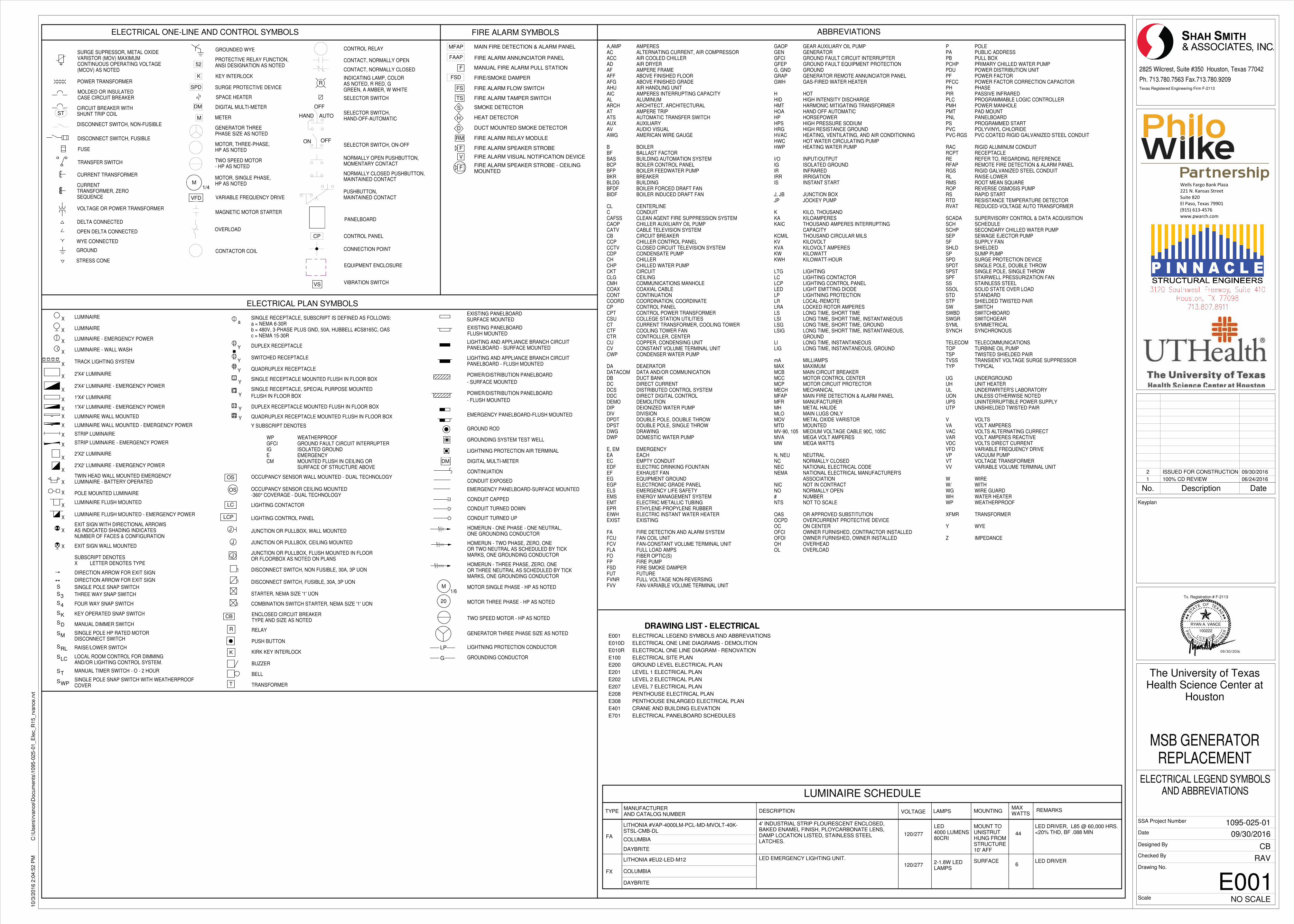
OFF
AUTOHAND
OFFON
ST
J
LCP
LC
D
RL
K
4
3
T
M
LC
OS
OS
LUMINAIRE WALL MOUNTED
ELECTRICAL ONE-LINE AND CONTROL SYMBOLS
TRANSFER SWITCH
CONNECTION POINT
PANELBOARD
VARIABLE FREQUENCY DRIVE
MAGNETIC MOTOR STARTER
DIGITAL MULTI-METER
DISCONNECT SWITCH, FUSIBLE
FUSE
CURRENT TRANSFORMER
POWER TRANSFORMER
STRIP LUMINAIRE
GROUND
LIGHTING CONTACTOR
MANUAL DIMMER SWITCH
THREE WAY SNAP SWITCH
FOUR WAY SNAP SWITCH
KEY OPERATED SNAP SWITCH
SINGLE POLE SNAP SWITCH
LUMINAIRE
LUMINAIRE - WALL WASH
2'X2' LUMINAIRE
2'X4' LUMINAIRE
LUMINAIRE
QUADRUPLEX RECEPTACLE MOUNTED FLUSH IN FLOOR BOX
DISCONNECT SWITCH, NON FUSIBLE, 30A, 3P UON
DISCONNECT SWITCH, FUSIBLE, 30A, 3P UON
COMBINATION SWITCH STARTER, NEMA SIZE '1' UON
CONDUIT CAPPED
CONDUIT TURNED DOWN
CONDUIT TURNED UP
SINGLE RECEPTACLE, SUBSCRIPT IS DEFINED AS FOLLOWS:a = NEMA 6-30Rb = 480V, 3-PHASE PLUS GND, 50A, HUBBELL #CS8165C, OASc = NEMA 15-30R
ELECTRICAL PLAN SYMBOLS
POWER/DISTRIBUTION PANELBOARD
LIGHTNING PROTECTION AIR TERMINAL
GROUND ROD
EQUIPMENT ENCLOSURE
OVERLOAD
SPACE HEATER
1'X4' LUMINAIRE
1'X4' LUMINAIRE - EMERGENCY POWER
2'X2' LUMINAIRE - EMERGENCY POWER
2'X4' LUMINAIRE - EMERGENCY POWER
LUMINAIRE - EMERGENCY POWER
TWIN HEAD WALL MOUNTED EMERGENCYLUMINAIRE - BATTERY OPERATED
EXIT SIGN WITH DIRECTIONAL ARROWSAS INDICATED SHADING INDICATESNUMBER OF FACES & CONFIGURATION
RAISE/LOWER SWITCH
OCCUPANCY SENSOR CEILING MOUNTED-360° COVERAGE - DUAL TECHNOLOGY
MANUAL TIMER SWITCH - O - 2 HOUR
DM
OPEN DELTA CONNECTED
SURGE PROTECTIVE DEVICE
DELTA CONNECTED
WYE CONNECTEDCONTROL PANEL
LIGHTNING PROTECTION CONDUCTORLP
GROUNDING CONDUCTORG
EMERGENCY PANELBOARD-FLUSH MOUNTED
HOMERUN - TWO PHASE, ZERO, ONEOR TWO NEUTRAL AS SCHEDULED BY TICKMARKS, ONE GROUNDING CONDUCTOR
HOMERUN - THREE PHASE, ZERO, ONEOR THREE NEUTRAL AS SCHEDULED BY TICKMARKS, ONE GROUNDING CONDUCTOR
MOTOR SINGLE PHASE - HP AS NOTED
X
POLE MOUNTED LUMINAIRE
TRACK LIGHTING SYSTEM
LOCAL ROOM CONTROL FOR DIMMINGAND/OR LIGHTING CONTROL SYSTEM.
SINGLE RECEPTACLE MOUNTED FLUSH IN FLOOR BOX
SINGLE RECEPTACLE, SPECIAL PURPOSE MOUNTED
DUPLEX RECEPTACLE MOUNTED FLUSH IN FLOOR BOX
Y SUBSCRIPT DENOTES
WP WEATHERPROOFGFCI GROUND FAULT CIRCUIT INTERRUPTERIG ISOLATED GROUNDE EMERGENCYCM MOUNTED FLUSH IN CEILING OR
SURFACE OF STRUCTURE ABOVE
OCCUPANCY SENSOR WALL MOUNTED - DUAL TECHNOLOGY
JUNCTION OR PULLBOX, WALL MOUNTED
JUNCTION OR PULLBOX, FLUSH MOUNTED IN FLOOROR FLOORBOX AS NOTED ON PLANS
JUNCTION OR PULLBOX, CEILING MOUNTED
LIGHTING AND APPLIANCE BRANCH CIRCUITPANELBOARD - SURFACE MOUNTED
POWER/DISTRIBUTION PANELBOARD
GROUNDING SYSTEM TEST WELL
DIGITAL MULTI-METER
CONDUIT EXPOSED
CONDUIT EMBEDDED
MOTOR THREE PHASE - HP AS NOTED
CONTACTOR COIL
SELECTOR SWITCH
TWO SPEED MOTOR - HP AS NOTED
HOMERUN - ONE PHASE - ONE NEUTRAL,ONE GROUNDING CONDUCTOR
CONTINUATION
EMERGENCY PANELBOARD-SURFACE MOUNTED
CIRCUIT BREAKER WITHSHUNT TRIP COIL
SURGE SUPRESSOR, METAL OXIDEVARISTOR (MOV) MAXIMUMCONTINUOUS OPERATING VOLTAGE(MCOV) AS NOTED
METER
1/4
CONTROL RELAY
CONTACT, NORMALLY OPEN
CONTACT, NORMALLY CLOSED
INDICATING LAMP, COLORAS NOTED, R RED, GGREEN, A AMBER, W WHITE
SELECTOR SWITCH, ON-OFF
NORMALLY OPEN PUSHBUTTON,
GROUNDED WYE
EXIT SIGN WALL MOUNTED
DIRECTION ARROW FOR EXIT SIGN
DIRECTION ARROW FOR EXIT SIGN
LIGHTING CONTROL PANEL
LIGHTING AND APPLIANCE BRANCH CIRCUITPANELBOARD - FLUSH MOUNTED
GENERATOR THREE PHASE SIZE AS NOTED
LUMINAIRE WALL MOUNTED - EMERGENCY POWER
STRIP LUMINAIRE - EMERGENCY POWER
QUADRUPLEX RECEPTACLE
DUPLEX RECEPTACLE
M1/6
KEY INTERLOCKK
M
CP
SPD
STARTER, NEMA SIZE '1' UON
ABBREVIATIONS
X
X
X
X
X
X
X
X
X
X
X
X
X
X
X
X
X
X
LUMINAIRE FLUSH MOUNTEDX
LUMINAIRE FLUSH MOUNTED - EMERGENCY POWERX
NORMALLY CLOSED PUSHBUTTON,MAINTAINED CONTACT
MOMENTARY CONTACT
VIBRATION SWITCH
FLUSH IN FLOOR BOX
- SURFACE MOUNTED
- FLUSH MOUNTED
MOLDED OR INSULATEDCASE CIRCUIT BREAKER
DISCONNECT SWITCH, NON-FUSIBLE
CURRENTTRANSFORMER, ZEROSEQUENCE
VOLTAGE OR POWER TRANSFORMER
PROTECTIVE RELAY FUNCTION,ANSI DESIGNATION AS NOTED
SELECTOR SWITCH,HAND-OFF-AUTOMATIC
PUSHBUTTON,MAINTAINED CONTACT
GENERATOR THREEPHASE SIZE AS NOTED
MOTOR, THREE-PHASE,HP AS NOTED
TWO SPEED MOTOR- HP AS NOTED
MOTOR, SINGLE PHASE,HP AS NOTED
SUBSCRIPT DENOTESX LETTER DENOTES TYPE
SINGLE POLE HP RATED MOTORDISCONNECT SWITCH
20
SINGLE POLE SNAP SWITCH WITH WEATHERPROOFCOVER
a
Y
Y
Y
Y
Y
Y
WP
RELAY
TRANSFORMER
ENCLOSED CIRCUIT BREAKERTYPE AND SIZE AS NOTED
PUSH BUTTON
KIRK KEY INTERLOCK
BUZZER
BELL
K
R
DM
VS
R
M
VFD
CB
T
S
S
S
S
S
S
S
S
S
S
J
J
EXISTING PANELBOARDSURFACE MOUNTED
EXISTING PANELBOARDFLUSH MOUNTED
AMPERESALTERNATING CURRENT, AIR COMPRESSORAIR COOLED CHILLERAIR DRYERAMPERE FRAMEABOVE FINISHED FLOORABOVE FINISHED GRADEAIR HANDLING UNITAMPERES INTERRUPTING CAPACITYALUMINUMARCHITECT, ARCHITECTURALAMPERE TRIPAUTOMATIC TRANSFER SWITCHAUXILIARYAUDIO VISUALAMERICAN WIRE GAUGE
BOILERBALLAST FACTORBUILDING AUTOMATION SYSTEMBOILER CONTROL PANELBOILER FEEDWATER PUMPBREAKERBUILDINGBOILER FORCED DRAFT FANBOILER INDUCED DRAFT FAN
CENTERLINECONDUITCLEAN AGENT FIRE SUPPRESSION SYSTEMCHILLER AUXILIARY OIL PUMPCABLE TELEVISION SYSTEMCIRCUIT BREAKERCHILLER CONTROL PANELCLOSED CIRCUIT TELEVISION SYSTEMCONDENSATE PUMPCHILLERCHILLED WATER PUMPCIRCUITCEILINGCOMMUNICATIONS MANHOLECOAXIAL CABLECONTINUATIONCOORDINATION, COORDINATECONTROL PANELCONTROL POWER TRANSFORMERCOLLEGE STATION UTILITIESCURRENT TRANSFORMER, COOLING TOWERCOOLING TOWER FANCONTROLLER, CENTERCOPPER, CONDENSING UNITCONSTANT VOLUME TERMINAL UNITCONDENSER WATER PUMP
DEAERATORDATA AND/OR COMMUNICATIONDUCT BANKDIRECT CURRENTDISTRIBUTED CONTROL SYSTEMDIRECT DIGITAL CONTROLDEMOLITIONDEIONIZED WATER PUMPDIVISIONDOUBLE POLE, DOUBLE THROWDOUBLE POLE, SINGLE THROWDRAWINGDOMESTIC WATER PUMP
EMERGENCYEACHEMPTY CONDUITELECTRIC DRINKING FOUNTAINEXHAUST FANEQUIPMENT GROUNDELECTRONIC GRADE PANELEMERGENCY LIFE SAFETYENERGY MANAGEMENT SYSTEMELECTRIC METALLIC TUBINGETHYLENE-PROPYLENE RUBBERELECTRIC INSTANT WATER HEATEREXISTING
FIRE DETECTION AND ALARM SYSTEMFAN COIL UNITFAN-CONSTANT VOLUME TERMINAL UNITFULL LOAD AMPSFIBER OPTIC(S)FIRE PUMPFIRE SMOKE DAMPERFUTUREFULL VOLTAGE NON-REVERSINGFAN-VARIABLE VOLUME TERMINAL UNIT
POLEPUBLIC ADDRESSPULL BOXPRIMARY CHILLED WATER PUMPPOWER DISTRIBUTION UNITPOWER FACTORPOWER FACTOR CORRECTION CAPACITORPHASEPASSIVE INFRAREDPROGRAMMABLE LOGIC CONTROLLERPOWER MANHOLEPAD MOUNTPANELBOARDPROGRAMMED STARTPOLYVINYL CHLORIDEPVC COATED RIGID GALVANIZED STEEL CONDUIT
RIGID ALUMINUM CONDUITRECEPTACLEREFER TO, REGARDING, REFERENCEREMOTE FIRE DETECTION & ALARM PANELRIGID GALVANIZED STEEL CONDUITRAISE-LOWERROOT MEAN SQUAREREVERSE OSMOSIS PUMPRAPID STARTRESISTANCE TEMPERATURE DETECTORREDUCED-VOLTAGE AUTO TRANSFORMER
SUPERVISORY CONTROL & DATA ACQUISITIONSCHEDULESECONDARY CHILLED WATER PUMPSEWAGE EJECTOR PUMPSUPPLY FANSHIELDEDSUMP PUMPSURGE PROTECTION DEVICESINGLE POLE, DOUBLE THROWSINGLE POLE, SINGLE THROWSTAIRWELL PRESSURIZATION FANSTAINLESS STEELSOLID STATE OVER LOADSTANDARDSHIELDED TWISTED PAIRSWITCHSWITCHBOARDSWITCHGEARSYMMETRICALSYNCHRONOUS
TELECOMMUNICATIONSTURBINE OIL PUMPTWISTED SHIELDED PAIRTRANSIENT VOLTAGE SURGE SUPPRESSORTYPICAL
UNDERGROUNDUNIT HEATERUNDERWRITER'S LABORATORYUNLESS OTHERWISE NOTEDUNINTERRUPTIBLE POWER SUPPLYUNSHIELDED TWISTED PAIR
VOLTSVOLT AMPERESVOLTS ALTERNATING CURRECTVOLT AMPERES REACTIVEVOLTS DIRECT CURRENTVARIABLE FREQUENCY DRIVEVACUUM PUMPVOLTAGE TRANSFORMERVARIABLE VOLUME TERMINAL UNIT
WIREWITHWIRE GUARDWATER HEATERWEATHERPROOF
TRANSFORMER
WYE
IMPEDANCE
A,AMPACACCADAFAFFAFGAHUAICALARCHATATSAUXAVAWG
BBFBASBCPBFPBKRBLDGBFDFBIDF
CLCCAFSSCAOPCATVCBCCPCCTVCDPCHCHPCKTCLGCMHCOAXCONTCOORDCPCPTCSUCTCTFCTRCUCVCWP
DADATACOMDBDCDCSDDCDEMODIPDIVDPDTDPSTDWGDWP
E, EMEAECEDFEFEGEGPELSEMSEMTEPREIWHEXIST
FAFCUFCVFLAFOFPFSDFUTFVNRFVV
PPAPBPCHPPDUPFPFCCPHPIRPLCPMHPMTPNLPSPVCPVC-RGS
RACRCPTRERFAPRGSRLRMSROPRSRTDRVAT
SCADASCHSCHPSEPSFSHLDSPSPDSPDTSPSTSPFSSSSOLSTDSTPSWSWBDSWGRSYMLSYNCH
TELECOMTOPTSPTVSSTYP
UGUHULUONUPSUTP
VVAVACVARVDCVFDVPVTVV
WW/WGWHWP
XFMR
Y
Z
FIRE ALARM SYMBOLS
F
MFAP
FSD
MANUAL FIRE ALARM PULL STATION
FIRE/SMOKE DAMPER
MAIN FIRE DETECTION & ALARM PANEL
FAAP FIRE ALARM ANNUNCIATOR PANEL
FS FIRE ALARM FLOW SWITCH
TS FIRE ALARM TAMPER SWITCH
SMOKE DETECTORS
HEAT DETECTORH
RM FIRE ALARM RELAY MODULE
F FIRE ALARM SPEAKER STROBE
V FIRE ALARM VISUAL NOTIFICATION DEVICE
F FIRE ALARM SPEAKER STROBE - CEILINGMOUNTED
DUCT MOUNTED SMOKE DETECTORD
SWITCHED RECEPTACLEY
GEAR AUXILIARY OIL PUMPGENERATORGROUND FAULT CIRCUIT INTERRUPTERGROUND FAULT EQUIPMENT PROTECTIONGROUNDGENERATOR REMOTE ANNUNCIATOR PANELGAS-FIRED WATER HEATER
HOTHIGH INTENSITY DISCHARGEHARMONIC MITIGATING TRANSFORMERHAND OFF AUTOMATICHORSEPOWERHIGH PRESSURE SODIUMHIGH RESISTANCE GROUNDHEATING, VENTILATING, AND AIR CONDITIONINGHOT WATER CIRCULATING PUMPHEATING WATER PUMP
INPUT/OUTPUTISOLATED GROUNDINFRAREDIRRIGATIONINSTANT START
JUNCTION BOXJOCKEY PUMP
KILO, THOUSANDKILOAMPERESTHOUSAND AMPERES INTERRUPTINGCAPACITYTHOUSAND CIRCULAR MILSKILOVOLTKILOVOLT AMPERESKILOWATTKILOWATT-HOUR
LIGHTINGLIGHTING CONTACTORLIGHTING CONTROL PANELLIGHT EMITTING DIODELIGHTNING PROTECTIONLOCAL-REMOTELOCKED ROTOR AMPERESLONG TIME, SHORT TIMELONG TIME, SHORT TIME, INSTANTANEOUSLONG TIME, SHORT TIME, GROUNDLONG TIME, SHORT TIME, INSTANTANEOUS,GROUNDLONG TIME, INSTANTANEOUSLONG TIME, INSTANTANEOUS, GROUND
MILLIAMPSMAXIMUMMAIN CIRCUIT BREAKERMOTOR CONTROL CENTERMOTOR CIRCUIT PROTECTORMECHANICALMAIN FIRE DETECTION & ALARM PANELMANUFACTURERMETAL HALIDEMAIN LUGS ONLYMETAL OXIDE VARISTORMOUNTEDMEDIUM VOLTAGE CABLE 90C, 105CMEGA VOLT AMPERESMEGA WATTS
NEUTRALNORMALLY CLOSEDNATIONAL ELECTRICAL CODENATIONAL ELECTRICAL MANUFACTURER'SASSOCIATIONNOT IN CONTRACTNORMALLY OPENNUMBERNOT TO SCALE
OR APPROVED SUBSTITUTIONOVERCURRENT PROTECTIVE DEVICEON CENTEROWNER FURNISHED, CONTRACTOR INSTALLEDOWNER FURNISHED, OWNER INSTALLEDOVERHEADOVERLOAD
GAOPGENGFCIGFEPG, GNDGRAPGWH
HHIDHMTHOAHPHPSHRGHVACHWCHWP
I/OIGIRIRRIS
J, JBJP
KKAKAIC
KCMILKVKVAKWKWH
LTGLCLCPLEDLPLRLRALSLSILSGLSIG
LILIG
mAMAXMCBMCCMCPMECHMFAPMFRMHMLOMOVMTDMV-90, 105MVAMW
N, NEUNCNECNEMA
NICNO#NTS
OASOCPDOCOFCIOFOIOHOL
52
STRESS CONE
LUMINAIRE SCHEDULE
TYPEMANUFACTURERAND CATALOG NUMBER
FA
FX
LITHONIA #VAP-4000LM-PCL-MD-MVOLT-40K-STSL-CMB-DL
4' INDUSTRIAL STRIP FLOURESCENT ENCLOSED,BAKED ENAMEL FINISH, PLOYCARBONATE LENS,DAMP LOCATION LISTED, STAINLESS STEELLATCHES.
120/277
LED4000 LUMENS80CRI
MOUNT TOUNISTRUTHUNG FROMSTRUCTURE10' AFF
44
LED DRIVER, L85 @ 60,000 HRS.<20% THD, BF .088 MIN
6
DESCRIPTION VOLTAGE LAMPS MOUNTINGMAXWATTS
REMARKS
COLUMBIA
DAYBRITE
COLUMBIA
DAYBRITE
LITHONIA #EU2-LED-M12 LED EMERGENCY LIGHTING UNIT.SURFACE LED DRIVER
120/2772-1.8W LEDLAMPS
������������� ������
��������������������
���������
��������������� ��
! �"#�$�%&'"�$
(((�)(��*+�*,
Texas Registered Engineering Firm F-2113
TA
S
E OF TEXAS
P RE
ENI
GNELANOISS
FO
R
EL I C E N S E D
T
RYAN A. VANCE
100222
Tx. Registration # F-2113
Scale
Date
Designed By
Checked By
SSA Project Number
Drawing No.
2825 Wilcrest, Suite #350 Houston, Texas 77042
Ph. 713.780.7563 Fax.713.780.9209
Keyplan
NO SCALE
10/3
/2016 2
:04:5
2 P
MC
:\U
sers
\rvance\D
ocum
ents
\1095-0
25-0
1_E
lec_R
15_rv
ance.r
vt
E001
ELECTRICAL LEGEND SYMBOLSAND ABBREVIATIONS
The University of TexasHealth Science Center at
Houston
MSB GENERATORREPLACEMENT
RAV
CB
09/30/2016
1095-025-01
DRAWING LIST - ELECTRICAL
E001 ELECTRICAL LEGEND SYMBOLS AND ABBREVIATIONS
E010D ELECTRICAL ONE LINE DIAGRAMS - DEMOLITION
E010R ELECTRICAL ONE LINE DIAGRAM - RENOVATION
E100 ELECTRICAL SITE PLAN
E200 GROUND LEVEL ELECTRICAL PLAN
E201 LEVEL 1 ELECTRICAL PLAN
E202 LEVEL 2 ELECTRICAL PLAN
E207 LEVEL 7 ELECTRICAL PLAN
E208 PENTHOUSE ELECTRICAL PLAN
E308 PENTHOUSE ENLARGED ELECTRICAL PLAN
E401 CRANE AND BUILDING ELEVATION
E701 ELECTRICAL PANELBOARD SCHEDULES
No. Description Date
1 100% CD REVIEW 06/24/2016
2 ISSUED FOR CONSTRUCTION 09/30/2016
09/30/2016
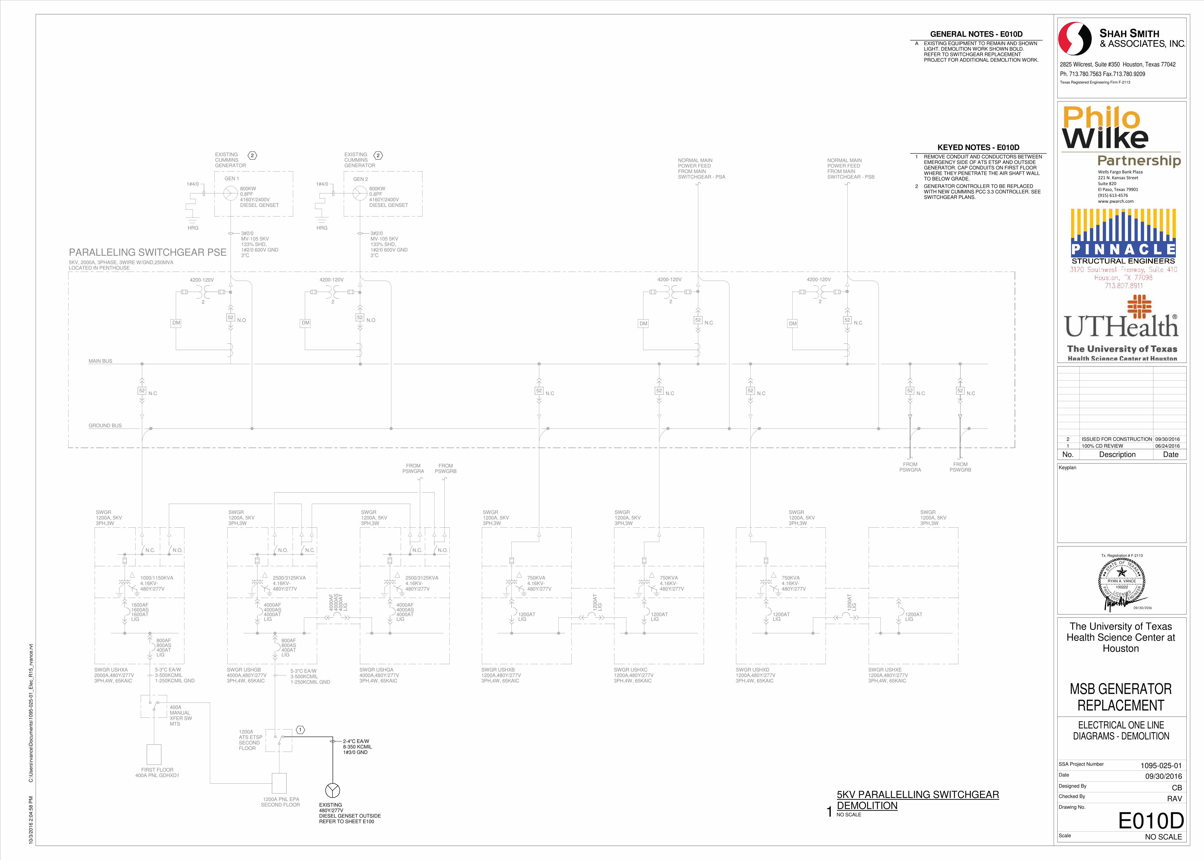
MAIN BUS
PARALLELING SWITCHGEAR PSE5KV, 2000A, 3PHASE, 3WIRE W/GND,250MVALOCATED IN PENTHOUSE
GEN 11#4/0
DM
GEN 2
DM
800KW0.8PF4160Y/2400VDIESEL GENSET
800KW0.8PF4160Y/2400VDIESEL GENSET
2
4200-120V
2
4200-120V
DM
2
4200-120V
NORMAL MAINPOWER FEEDFROM MAINSWITCHGEAR - PSA
3#2/0MV-105 5KV133% SHD,1#2/0 600V GND3"C
3#2/0MV-105 5KV133% SHD,1#2/0 600V GND3"C
1#4/0
N.C52
N.C52N.O
52N.O
52
GROUND BUS
2500/3125KVA4.16KV-480Y/277V
5-3"C EA/W3-500KCMIL1-250KCMIL GND
SWGR1200A, 5KV3PH,3W
4000AS4000AF
4000ATLIG
800AS800AF
400ATLIG
SWGR USHGB4000A,480Y/277V3PH,4W, 65KAIC
SWGR1200A, 5KV3PH,3W
SWGR USHGA4000A,480Y/277V3PH,4W, 65KAIC
1000/1150KVA4.16KV-480Y/277V
5-3"C EA/W3-500KCMIL1-250KCMIL GND
SWGR1200A, 5KV3PH,3W
1600AS1600AF
1600ATLIG
800AS800AF
400ATLIG
SWGR USHXA2000A,480Y/277V3PH,4W, 65KAIC
2500/3125KVA4.16KV-480Y/277V
4000AS4000AF
4000ATLIG
40
00A
S40
00A
F
40
00A
TLIG
FROMPSWGRA
FROMPSWGRB
750KVA4.16KV-480Y/277V
SWGR1200A, 5KV3PH,3W
1200ATLIG
SWGR USHXB1200A,480Y/277V3PH,4W, 65KAIC
SWGR1200A, 5KV3PH,3W
SWGR USHXC1200A,480Y/277V3PH,4W, 65KAIC
750KVA4.16KV-480Y/277V
1200ATLIG
12
00A
TLIG
N.C52
N.C52
750KVA4.16KV-480Y/277V
SWGR1200A, 5KV3PH,3W
1200ATLIG
SWGR USHXD1200A,480Y/277V3PH,4W, 65KAIC
SWGR1200A, 5KV3PH,3W
SWGR USHXE1200A,480Y/277V3PH,4W, 65KAIC
1200ATLIG
12
00A
TLIG
N.C52
EXISTINGCUMMINSGENERATOR
EXISTINGCUMMINSGENERATOR
1200AATS ETSPSECONDFLOOR
1200A PNL EPASECOND FLOOR
400AMANUALXFER SWMTS
FIRST FLOOR400A PNL GDHXD1
N.O.N.C. N.C.N.O. N.O.N.C.
N.C52
FROMPSWGRA
N.C52
FROMPSWGRB
EXISTING480Y/277VDIESEL GENSET OUTSIDEREFER TO SHEET E100
2-4"C EA/W8-350 KCMIL1#3/0 GND
1
HRG HRG
DM
2
4200-120V
NORMAL MAINPOWER FEEDFROM MAINSWITCHGEAR - PSB
N.C52
2 2
������������� ������
��������������������
���������
��������������� ��
! �"#�$�%&'"�$
(((�)(��*+�*,
Texas Registered Engineering Firm F-2113
TA
S
E OF TEXAS
P RE
ENI
GNELANOISS
FO
R
EL I C E N S E D
T
RYAN A. VANCE
100222
Tx. Registration # F-2113
Scale
Date
Designed By
Checked By
SSA Project Number
Drawing No.
2825 Wilcrest, Suite #350 Houston, Texas 77042
Ph. 713.780.7563 Fax.713.780.9209
Keyplan
NO SCALE
10/3
/2016 2
:04:5
8 P
MC
:\U
sers
\rvance\D
ocum
ents
\1095-0
25-0
1_E
lec_R
15_rv
ance.r
vt
E010D
ELECTRICAL ONE LINEDIAGRAMS - DEMOLITION
The University of TexasHealth Science Center at
Houston
MSB GENERATORREPLACEMENT
RAV
CB
09/30/2016
1095-025-01
NO SCALE1
5KV PARALLELLING SWITCHGEARDEMOLITION
KEYED NOTES - E010D
1 REMOVE CONDUIT AND CONDUCTORS BETWEENEMERGENCY SIDE OF ATS ETSP AND OUTSIDEGENERATOR. CAP CONDUITS ON FIRST FLOORWHERE THEY PENETRATE THE AIR SHAFT WALLTO BELOW GRADE.
2 GENERATOR CONTROLLER TO BE REPLACEDWITH NEW CUMMINS PCC 3.3 CONTROLLER. SEESWITCHGEAR PLANS.
GENERAL NOTES - E010D
A EXISTING EQUIPMENT TO REMAIN AND SHOWNLIGHT. DEMOLITION WORK SHOWN BOLD.REFER TO SWITCHGEAR REPLACEMENTPROJECT FOR ADDITIONAL DEMOLITION WORK.
No. Description Date
1 100% CD REVIEW 06/24/2016
2 ISSUED FOR CONSTRUCTION 09/30/2016
09/30/2016
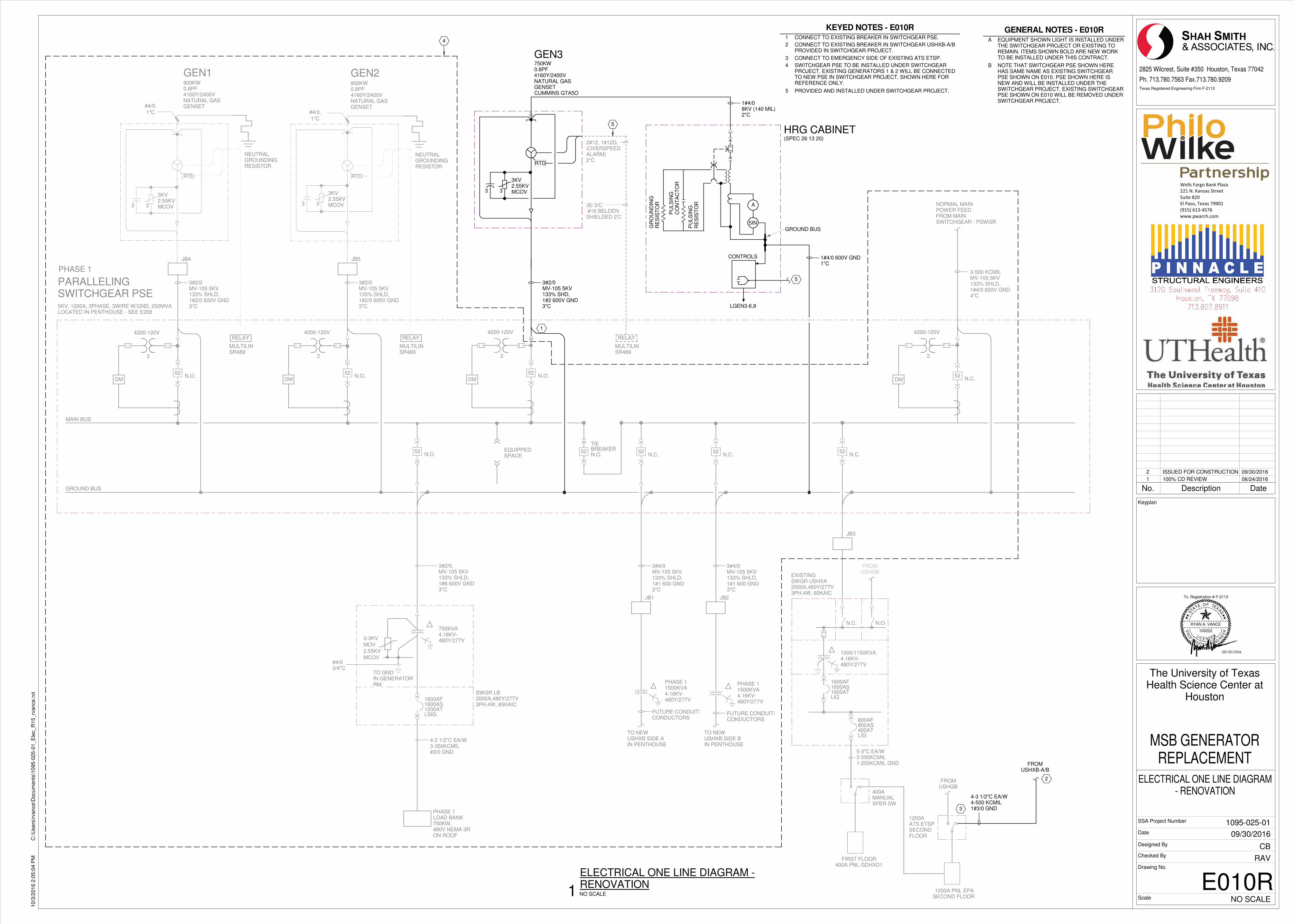
MAIN BUS
DM
PARALLELINGSWITCHGEAR PSE5KV, 1200A, 3PHASE, 3WIRE W/GND, 250MVALOCATED IN PENTHOUSE - SEE E208
2
4200-120V
DM
2
4200-120V
NORMAL MAINPOWER FEEDFROM MAINSWITCHGEAR - PSWGR
3#2/0MV-105 5KV133% SHD,1#2 600V GND3"C
EQUIPPEDSPACE
N.C.52N.O.
52
GROUND BUS
3-500 KCMILMV-105 5KV133% SHLD,1#4/0 600V GND4"C
FROMUSHGB
1200AATS ETSPSECONDFLOOR
1200A PNL EPASECOND FLOOR
400AMANUALXFER SW
FIRST FLOOR400A PNL GDHXD1
3
4-3 1/2"C EA/W4-500 KCMIL1#3/0 GND
1
FROMUSHGB
N.C.52
1000/1150KVA4.16KV-480Y/277V
5-3"C EA/W3-500KCMIL1-250KCMIL GND
1600AS1600AF
1600ATLIG
800AS800AF
400ATLIG
EXISTINGSWGR USHXA2000A,480Y/277V3PH,4W, 65KAIC
N.O.N.C.
JB3
750KVA4.16KV-480Y/277V
PHASE 1LOAD BANK750KW,480V NEMA 3RON ROOF
3#2/0,MV-105 5KV133% SHLD,1#6 600V GND3"C
4-2 1/2"C EA/W3-350KCMIL#3/0 GND
#4/03/4"C
SWGR LB2000A,480Y/277V3PH,4W, 65KAIC
3-3KV
MOV
2.55KV
MCOV
TO GNDIN GENERATORRM
1600AS1600AF
1200ATLSIG
N.O.52
DMDM
2
4200-120V
2
4200-120V
TO NEWUSHXB SIDE BIN PENTHOUSE
TO NEWUSHXB SIDE AIN PENTHOUSE
PHASE 11500KVA4.16KV-480Y/277V
PHASE 11500KVA4.16KV-480Y/277V
3#2/0MV-105 5KV133% SHLD,1#2/0 600V GND3"C
3#2/0MV-105 5KV133% SHLD,1#2/0 600V GND3"C
3#4/0MV-105 5KV133% SHLD,1#1 600 GND3"C
FUTURE CONDUIT/CONDUCTORS
FUTURE CONDUIT/CONDUCTORS
N.C.52
N.O.52
N.O.52
3#4/0MV-105 5KV133% SHLD,1#1 600 GND3"C
JB4 JB5
JB1 JB2
N.C.52
4
TIE
N.O.BREAKER
52
2
GEN1800KW0.8PF4160Y/2400VNATURAL GASGENSET
RTD
GEN2
RTD
GEN3
RTD
800KW0.8PF4160Y/2400VNATURAL GASGENSET
750KW0.8PF4160Y/2400VNATURAL GASGENSETCUMMINS GTA5O
3KV2.55KVMCOV33
3KV2.55KVMCOV33
3KV2.55KVMCOV33
#4/0,
1"C #4/0,
1"C
NEUTRALGROUNDINGRESISTOR
NEUTRALGROUNDINGRESISTOR
RELAY
MULTILINSR489
(8) 3/C #16 BELDENSHIELDED 2'C
2#12, 1#12G,(OVERSPEEDALARM)2"C
RELAY
MULTILINSR489
RELAY
MULTILINSR489
5
1#4/08KV (140 MIL)2"C
GR
OU
ND
ING
RE
SIS
TO
R
PU
LS
ING
RE
SIS
TO
R
PU
LS
ING
CO
NT
AC
TO
R
A
5IN
HRG CABINET(SPEC 26 13 20)
5
CONTROLS
LGEN3-6,8
GROUND BUS
PHASE 1
1#4/0 600V GND1"C
FROMUSHXB-A/B
������������� ������
��������������������
���������
��������������� ��
! �"#�$�%&'"�$
(((�)(��*+�*,
Texas Registered Engineering Firm F-2113
TA
S
E OF TEXAS
P RE
ENI
GNELANOISS
FO
R
EL I C E N S E D
T
RYAN A. VANCE
100222
Tx. Registration # F-2113
Scale
Date
Designed By
Checked By
SSA Project Number
Drawing No.
2825 Wilcrest, Suite #350 Houston, Texas 77042
Ph. 713.780.7563 Fax.713.780.9209
Keyplan
NO SCALE
10/3
/2016 2
:05:0
4 P
MC
:\U
sers
\rvance\D
ocum
ents
\1095-0
25-0
1_E
lec_R
15_rv
ance.r
vt
E010R
ELECTRICAL ONE LINE DIAGRAM- RENOVATION
The University of TexasHealth Science Center at
Houston
MSB GENERATORREPLACEMENT
RAV
CB
09/30/2016
1095-025-01
NO SCALE1
ELECTRICAL ONE LINE DIAGRAM -RENOVATION
KEYED NOTES - E010R
1 CONNECT TO EXISTING BREAKER IN SWITCHGEAR PSE.
2 CONNECT TO EXISTING BREAKER IN SWITCHGEAR USHXB-A/BPROVIDED IN SWITCHGEAR PROJECT.
3 CONNECT TO EMERGENCY SIDE OF EXISTING ATS ETSP.
4 SWITCHGEAR PSE TO BE INSTALLED UNDER SWITCHGEARPROJECT. EXISTING GENERATORS 1 & 2 WILL BE CONNECTEDTO NEW PSE IN SWITCHGEAR PROJECT. SHOWN HERE FORREFERENCE ONLY.
5 PROVIDED AND INSTALLED UNDER SWITCHGEAR PROJECT.
GENERAL NOTES - E010R
A EQUIPMENT SHOWN LIGHT IS INSTALLED UNDERTHE SWITCHGEAR PROJECT OR EXISTING TOREMAIN. ITEMS SHOWN BOLD ARE NEW WORKTO BE INSTALLED UNDER THIS CONTRACT.
B NOTE THAT SWITCHGEAR PSE SHOWN HEREHAS SAME NAME AS EXISTING SWITCHGEARPSE SHOWN ON E010. PSE SHOWN HERE ISNEW AND WILL BE INSTALLED UNDER THESWITCHGEAR PROJECT. EXISTING SWITCHGEARPSE SHOWN ON E010 WILL BE REMOVED UNDERSWITCHGEAR PROJECT.
No. Description Date
1 100% CD REVIEW 06/24/2016
2 ISSUED FOR CONSTRUCTION 09/30/2016
09/30/2016
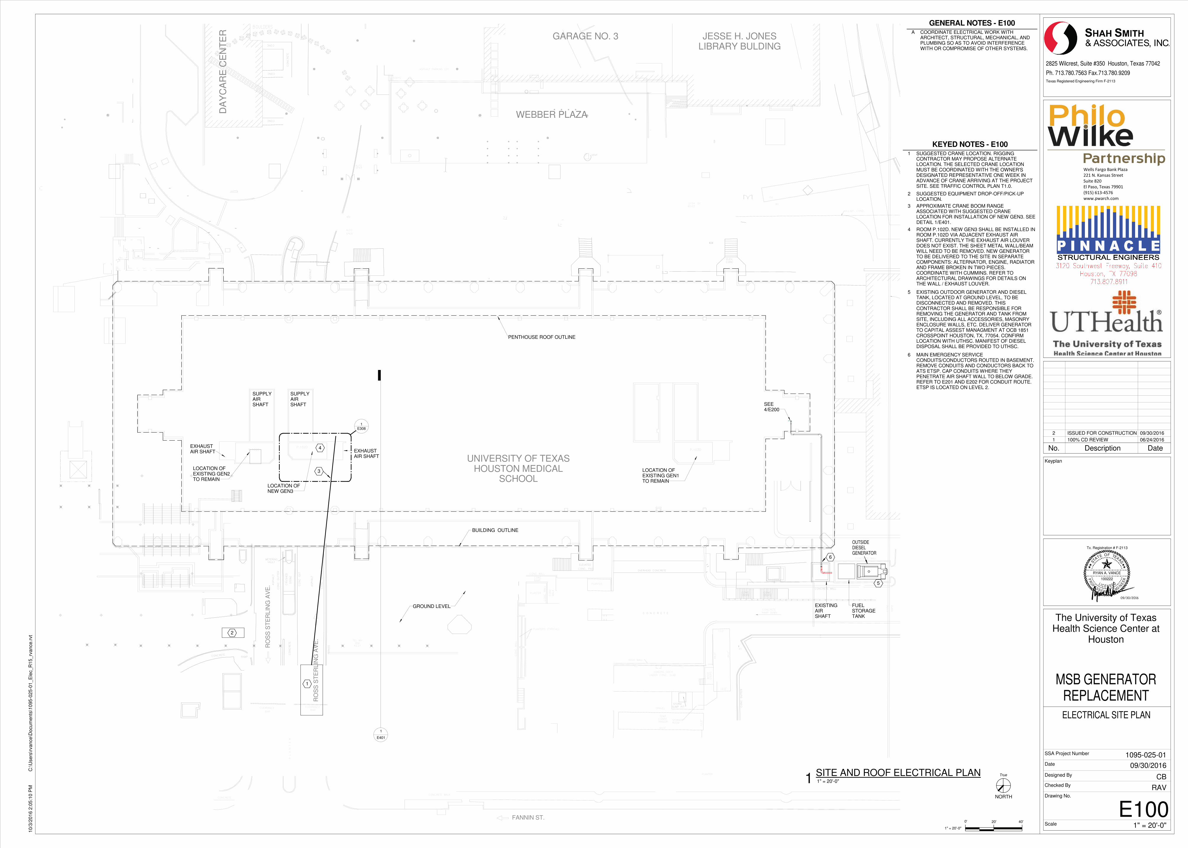
������������
������
RO
SS
ST
ER
LIN
G A
VE
.
RO
SS
ST
ER
LIN
G A
VE
.
FANNIN ST.
���� �
���
���� ����
DA
YC
AR
E C
EN
TE
R
HOUSTON MEDICALSCHOOL
UNIVERSITY OF TEXAS
JESSE H. JONESLIBRARY BULDING
GARAGE NO. 3
WEBBER PLAZA
������������ ����
�����
����
�
�������� ��
ii
i
� �
l��
�����������
I I
I
I
I
I
I
I
I
I
I
I
����
����
��
��������
��
��
� ���
�� ������� ���!
� �������
� ����� �����
�������
�������� � ����
� ����
�� ���
� ���
� ���
�
���
�� ���
���� �����
����
� ����
� ���� ����
������
������
������
���
�
�����
� ����
�
�
�
������
�� �
���������� ����
��� ���������
� �������� �������
� �������
� ����
� �������
������ �
�������������
�������
� �����
� �����
� �����
�����
����� ���
���
����
� ����
� ����
� ���� ����
������
������
������
���
�
�����
� ����
�
�
�
������
� ��������
�� �
���������� ����
��� ���������
� �������� �������
� �������
� ����
� �������
�� ���
������ �
�������������
�������
� �����
� �����
� �����
�����
��������
������
�����������
����� ���������
����
�����
�����
"���#
����#
����#
����#
����#
����#
�������
1
2
3
4
5
OUTSIDEDIESELGENERATOR
PENTHOUSE ROOF OUTLINE
GROUND LEVEL
BUILDING OUTLINE
SUPPLYAIRSHAFT
EXHAUSTAIR SHAFT
SUPPLYAIRSHAFT
EXHAUSTAIR SHAFT
LOCATION OFNEW GEN3
LOCATION OFEXISTING GEN2TO REMAIN
1
E401
LOCATION OFEXISTING GEN1TO REMAIN
EXISTINGAIRSHAFT
6
FUELSTORAGETANK
E3081
SEE4/E200
������������� ������
��������������������
���������
��������������� ��
! �"#�$�%&'"�$
(((�)(��*+�*,
NORTH
Texas Registered Engineering Firm F-2113
0'
TA
S
E OF TEXAS
P RE
ENI
GNELANOISS
FO
R
EL I C E N S E D
T
RYAN A. VANCE
100222
Tx. Registration # F-2113
Scale
Date
Designed By
Checked By
SSA Project Number
Drawing No.
1" = 20'-0"
20' 40'
2825 Wilcrest, Suite #350 Houston, Texas 77042
Ph. 713.780.7563 Fax.713.780.9209
Keyplan
True
1" = 20'-0"
10/3
/2016 2
:05:1
0 P
MC
:\U
sers
\rvance\D
ocum
ents
\1095-0
25-0
1_E
lec_R
15_rv
ance.r
vt
E100
ELECTRICAL SITE PLAN
The University of TexasHealth Science Center at
Houston
MSB GENERATORREPLACEMENT
RAV
CB
09/30/2016
1095-025-01
1" = 20'-0"1SITE AND ROOF ELECTRICAL PLAN
KEYED NOTES - E100
1 SUGGESTED CRANE LOCATION. RIGGINGCONTRACTOR MAY PROPOSE ALTERNATELOCATION. THE SELECTED CRANE LOCATIONMUST BE COORDINATED WITH THE OWNER'SDESIGNATED REPRESENTATIVE ONE WEEK INADVANCE OF CRANE ARRIVING AT THE PROJECTSITE. SEE TRAFFIC CONTROL PLAN T1.0.
2 SUGGESTED EQUIPMENT DROP-OFF/PICK-UPLOCATION.
3 APPROXIMATE CRANE BOOM RANGEASSOCIATED WITH SUGGESTED CRANELOCATION FOR INSTALLATION OF NEW GEN3. SEEDETAIL 1/E401.
4 ROOM P.102D. NEW GEN3 SHALL BE INSTALLED INROOM P.102D VIA ADJACENT EXHAUST AIRSHAFT. CURRENTLY THE EXHAUST AIR LOUVERDOES NOT EXIST. THE SHEET METAL WALL/BEAMWILL NEED TO BE REMOVED. NEW GENERATORTO BE DELIVERED TO THE SITE IN SEPARATECOMPONENTS: ALTERNATOR, ENGINE, RADIATORAND FRAME BROKEN IN TWO PIECES.COORDINATE WITH CUMMINS. REFER TOARCHITECTURAL DRAWINGS FOR DETAILS ONTHE WALL / EXHAUST LOUVER.
5 EXISTING OUTDOOR GENERATOR AND DIESELTANK, LOCATED AT GROUND LEVEL, TO BEDISCONNECTED AND REMOVED. THISCONTRACTOR SHALL BE RESPONSIBLE FORREMOVING THE GENERATOR AND TANK FROMSITE, INCLUDING ALL ACCESSORIES, MASONRYENCLOSURE WALLS, ETC. DELIVER GENERATORTO CAPITAL ASSEST MANAGMENT AT OCB 1851CROSSPOINT HOUSTON, TX, 77054. CONFIRMLOCATION WITH UTHSC. MANIFEST OF DIESELDISPOSAL SHALL BE PROVIDED TO UTHSC.
6 MAIN EMERGENCY SERVICECONDUITS/CONDUCTORS ROUTED IN BASEMENT.REMOVE CONDUITS AND CONDUCTORS BACK TOATS ETSP. CAP CONDUITS WHERE THEYPENETRATE AIR SHAFT WALL TO BELOW GRADE.REFER TO E201 AND E202 FOR CONDUIT ROUTE.ETSP IS LOCATED ON LEVEL 2.
GENERAL NOTES - E100
A COORDINATE ELECTRICAL WORK WITHARCHITECT, STRUCTURAL, MECHANICAL, ANDPLUMBING SO AS TO AVOID INTERFERENCEWITH OR COMPROMISE OF OTHER SYSTEMS.
No. Description Date
1 100% CD REVIEW 06/24/2016
2 ISSUED FOR CONSTRUCTION 09/30/2016
09/30/2016
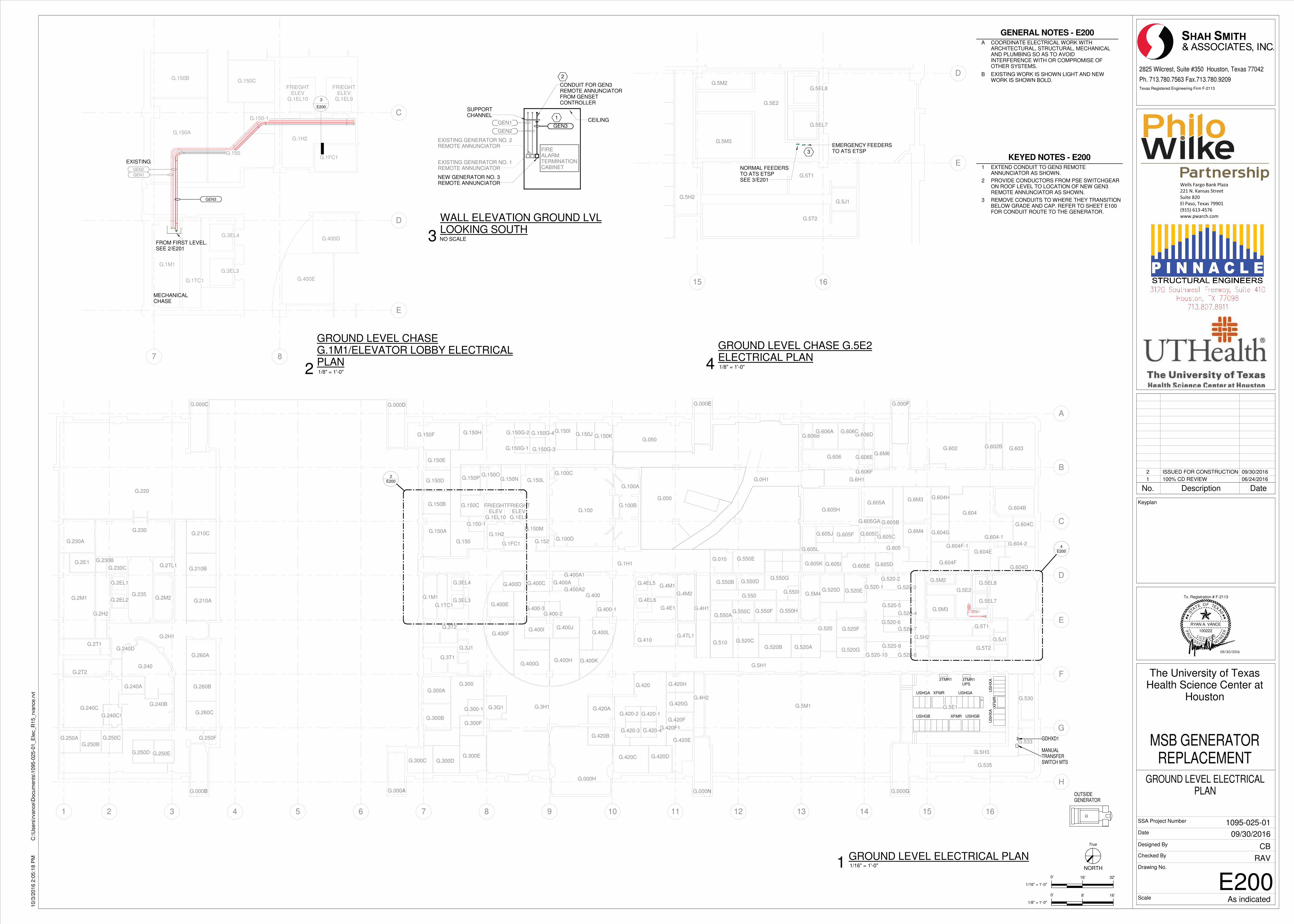
G.533
G.5H1
G.4H1
G.3H1
G.0H1
G.420F1
G.400-3
G.400A2
G.520-10
G.606F
G.606E
G.606DG.606C
G.606BG.606A
G.550I
G.550H
G.550G
G.550F
G.550E
G.550D
G.550C
G.550B
G.550AG.400-2G.400-1
G.150G-3
G.150G-4
G.150G-1
G.150G-2G.150H
G.150-1
G.300F
G.300-1
G.420-4G.420-3
G.420-2 G.420-1
G.050
G.520-9
G.520-8
G.520-7
G.520-6
G.520-5
G.520-4
G.520-3
G.520-2
G.520-1
G.605J
G.605I
G.605H
G.605GG.605F
G.605EG.605K
G.605GA
G.605L
G.605D
G.605C
G.605B
G.605A
G.2H1
G.1FC1 G.152
G.150N
G.150M
G.150L
G.150KG.150JG.150I
G.150OG.150P
G.150F
G.150E
G.150D
G.150CG.150B
G.150A
G.150
G.400L
G.400K
G.400JG.400I
G.400HG.400G
G.400F
G.400E
G.400D G.400C
G.400A1
G.400A
G.400
G.4TL1G.410
G.4H2
G.420H
G.420G
G.420F
G.420E
G.420DG.420C
G.420B
G.420A
G.420
G.3G1
G.300B
G.300A
G.300
G.300EG.300DG.300C
G.250F
G.250EG.250D
G.240D
G.210B
G.2H2
G.230
G.010
G.000
G.1H1
G.1H2
G.5H3
G.535
G.530
G.5H2
G.5M2
G.520G
G.520F
G.520EG.520D
G.520AG.520B
G.520C
G.520
G.510
G.550
G.6M6
G.605
G.602B
G.606
G.603
G.6H1
G.602
G.604F-1 G.604-2
G.604-1
G.604H
G.604G
G.604F
G.604E
G.604D
G.604C
G.604BG.604
G.6M4
G.6M3
G.5E1G.5M1
G.235
G.2TL1
G.240
G.2E1
G.210C
G.4M2G.2EL2
G.2EL1
G.260C
G.2M2
FRIEGHTELEV
G.1EL9
FRIEGHTELEV
G.1EL10
G.3EL3
G.3EL4
G.1M1
G.000H
G.4EL6
G.4EL5
G.5M4
G.5M3
G.5EL7
G.5EL8
G.000FG.000E
G.000A G.000N G.000G
G.3T1
G.3J1
G.3T2
G.1TC1G.4E1
G.4M1G.5E2
G.5T2
G.5J1
G.5T1
G.100D
G.100
G.100A
G.100C
G.100B
G.000D
G.000B
G.260A
G.240B
G.250CG.250A
G.250B
G.2T1
G.240C
G.260B
G.210A
G.240A
G.2T2
G.2M1
G.230A
G.000C
G.220
G.230C
G.230B
G.240C1
1 2 3 4 5 6 7 8 9 10 11 12 13 14 15 16
A
B
C
D
E
F
G
H
E2002
E2004
OUTSIDEGENERATOR
USHGA XFMR USHGA
3TMR1
USHGB
3TMR1UPS
XFMR USHGB
XF
MR
US
HX
AU
SH
XA
GDHXD1
MANUALTRANSFERSWITCH MTS
C D E F
B A N G
G.150-1
G.1FC1
G.150CG.150B
G.150A
G.150
G.400E
G.400D
G.1H2
FRIEGHTELEV
G.1EL9
FRIEGHTELEV
G.1EL10
G.3EL3
G.3EL4
G.1M1
G.1TC1
7 8
C
D
E
GEN2
EXISTING
GEN1
GEN3
FROM FIRST LEVEL.SEE 2/E201
MECHANICALCHASE
3
E200
1
EXISTING GENERATOR NO. 1REMOTE ANNUNCIATOR
NEW GENERATOR NO. 3REMOTE ANNUNCIATOR
CEILING
CONDUIT FOR GEN3REMOTE ANNUNCIATORFROM GENSETCONTROLLER
FIREALARMTERMINATIONCABINET
SUPPORTCHANNEL
EXISTING GENERATOR NO. 2REMOTE ANNUNCIATOR
GEN3GEN1
GEN2
2
G.5H2
G.5M2
G.5M3
G.5EL7
G.5EL8
G.5E2
G.5T2
G.5J1
G.5T1
15 16
D
E
EMERGENCY FEEDERSTO ATS ETSP
NORMAL FEEDERSTO ATS ETSPSEE 3/E201
3
������������� ������
��������������������
���������
��������������� ��
! �"#�$�%&'"�$
(((�)(��*+�*,
NORTH
0'
Texas Registered Engineering Firm F-2113
0'
TA
S
E OF TEXAS
P RE
ENI
GNELANOISS
FO
R
EL I C E N S E D
T
RYAN A. VANCE
100222
Tx. Registration # F-2113
Scale
Date
Designed By
Checked By
SSA Project Number
Drawing No.
1/8" = 1'-0"
8' 16'
2825 Wilcrest, Suite #350 Houston, Texas 77042
Ph. 713.780.7563 Fax.713.780.9209
Keyplan
1/16" = 1'-0"
16' 32'
True
As indicated
10/3
/2016 2
:05:1
8 P
MC
:\U
sers
\rvance\D
ocum
ents
\1095-0
25-0
1_E
lec_R
15_rv
ance.r
vt
E200
GROUND LEVEL ELECTRICALPLAN
The University of TexasHealth Science Center at
Houston
MSB GENERATORREPLACEMENT
RAV
CB
09/30/2016
1095-025-01
1/16" = 1'-0"1GROUND LEVEL ELECTRICAL PLAN
1/8" = 1'-0"2
GROUND LEVEL CHASEG.1M1/ELEVATOR LOBBY ELECTRICALPLAN
NO SCALE3
WALL ELEVATION GROUND LVLLOOKING SOUTH
1/8" = 1'-0"4
GROUND LEVEL CHASE G.5E2ELECTRICAL PLAN
KEYED NOTES - E200
1 EXTEND CONDUIT TO GEN3 REMOTEANNUNCIATOR AS SHOWN.
2 PROVIDE CONDUCTORS FROM PSE SWITCHGEARON ROOF LEVEL TO LOCATION OF NEW GEN3REMOTE ANNUNCIATOR AS SHOWN.
3 REMOVE CONDUITS TO WHERE THEY TRANSITIONBELOW GRADE AND CAP. REFER TO SHEET E100FOR CONDUIT ROUTE TO THE GENERATOR.
GENERAL NOTES - E200
A COORDINATE ELECTRICAL WORK WITHARCHITECTURAL, STRUCTURAL, MECHANICALAND PLUMBING SO AS TO AVOIDINTERFERENCE WITH OR COMPROMISE OFOTHER SYSTEMS.
B EXISTING WORK IS SHOWN LIGHT AND NEWWORK IS SHOWN BOLD.
No. Description Date
1 100% CD REVIEW 06/24/2016
2 ISSUED FOR CONSTRUCTION 09/30/2016
09/30/2016
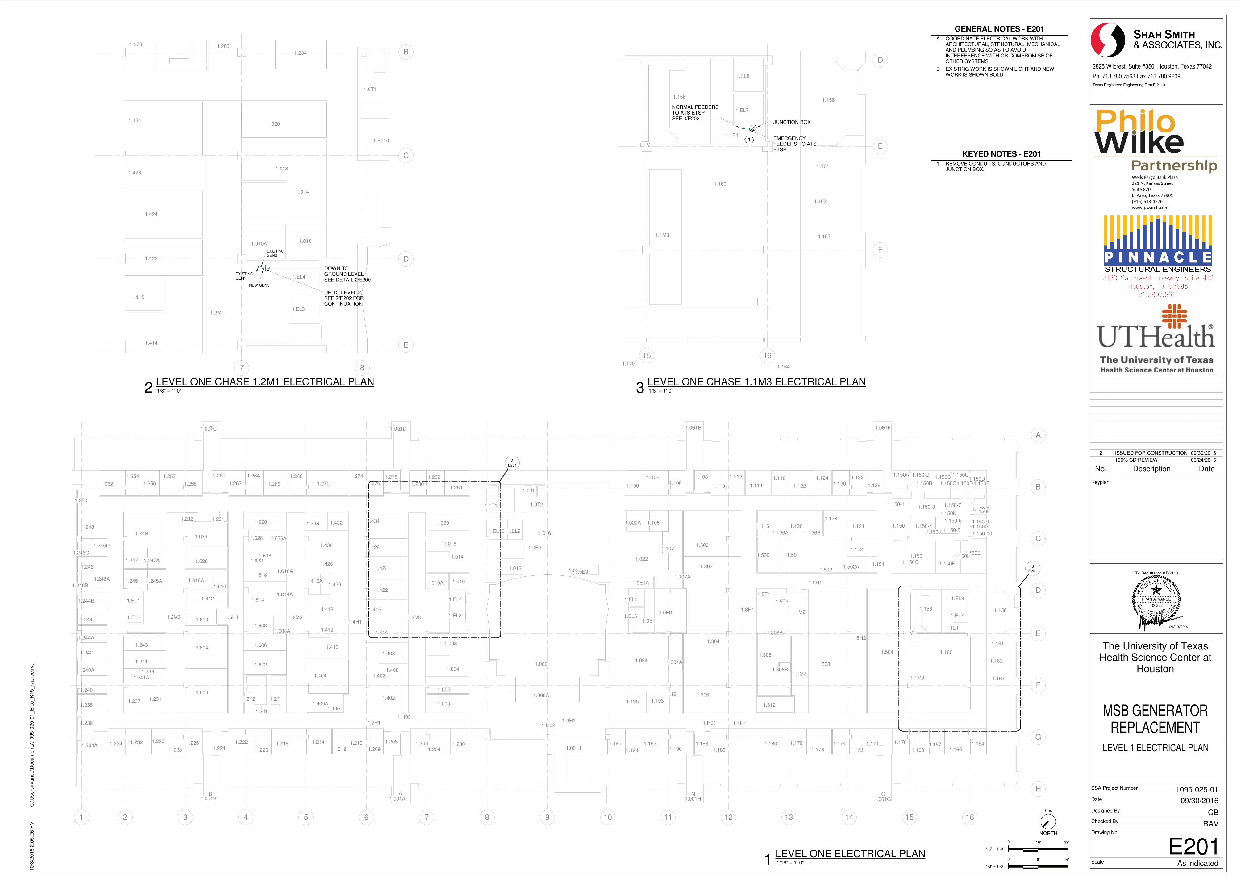
J
1.163
1.162
1.161
1.6H11.4H1
1.5H2
1.5H1
1.3H1
1.150-2
1.150-1 1.150-7
1.150-51.150-4
1.150-6
1.150-3
1.158
1.130
1.616A 1.010A
1.608A
1.114
1.126B1.126A
1.234A
1.1H11.2H1 1.0H1
1.269
1.231
1.156
1.124
1.171
1.EL2
1.EL1
1.EL10 1.EL9
1.EL4
1.EL3
1.001J
1.EL5
1.EL6 1.EL7
1.EL8
1.001F1.001E
1.001G1.001H1.001A1.001B
1.001D1.001C
1.5T1
1.5T2
1.1M21.0M1
1.0E11.2M11.2M21.2M3
1.2J1
1.2T2 1.2T1
1.024
1.195 1.1931.3061.191
1.1M41.1M3
1.1E11.1M1
1.0E2
1.0J1
1.0T21.0T1
1.2611.2J2
1.250
1.308B1.508
1.504
1.1541.502A
1.1521.500
1.502
1.501
1.308
1.304
1.304A
1.0E1A
1.302
1.300
1.022
1.107
1.0E3
1.006
1.006A
1.004
1.002
1.414
1.416
1.010
1.422
1.424
1.428
1.014
1.410A
1.618
1.614
1.608
1.606 1.410
1.602
1.404
1.600
1.604
1.610
1.612
1.616
1.620
1.624
1.248
1.249
1.247A1.247
1.245A1.245
1.246C
1.246D
1.246
1.246A
1.246B
1.244B
1.244
1.244A
1.243
1.242
1.241
1.240A
1.241A
1.240
1.2381.237
1.236
1.234 1.232 1.230
1.228
1.2261.224
1.222
1.220
1.218 1.214
1.212
1.400
1.210
1.209
1.208
1.402
1.204
1.000
1.200 1.196
1.194
1.1921.190
1.188
1.186
1.312
1.180 1.178
1.176
1.174
1.172
1.170
1.1681.167
1.1661.164
1.160
1.150D
1.150-10
1.150-9
1.150G
1.150-8
1.150F
1.150E
1.150C1.150A 1.150B1.132
1.1501.134
1.136
1.128
1.122
1.1261.116
1.1181.112
1.110
1.108
1.1051.022A
1.1061.102
1.100
1.020
1.284
1.282
1.280
1.278
1.434
1.276
1.274
1.270
1.4321.628
1.268
1.266
1.264
1.262
1.260
1.2581.256
1.2571.254
1.252
1.206
1.400A1.402
1.408
1.H03
1.412
1.418
1.426
1.430
1.614A
1.6181.618A
1.622
1.626 1.626A
1.H02
1.008
1.018
1.012 1.026
1.H01
1.150H
1.150F
1.150B 1.150C1.150D1.150E
1.150K
1.150J
1.150I
1.308A
1.206
1.239
1.400A1.402
1.408
1.406
1.H03
1.412
1.418
1.420
1.426
1.430
1.614A
1.6181.618A
1.622
1.626 1.626A
1.H02
1.008
1.018
1.012
1.016
1.026
1.107A
1.H01
1.150H
1.150G
1.150F
1.150B 1.150C1.150D1.150E
1.150K
1.150J
1.150I
1.308A
1 2 3 4 5 6 7 8 9 10 11 12 13 14 15 16
A
B
C
D
E
F
G
H
E2012
E2013
J
C D E F
B A N G
1.010A
1.EL10
1.EL4
1.EL31.2M1
1.0T1
1.414
1.416
1.010
1.422
1.424
1.428
1.014
1.020
1.284
1.280
1.434
1.276
1.0181.018
7 8
B
C
D
E
EXISTINGGEN1
EXISTINGGEN2
DOWN TOGROUND LEVELSEE DETAIL 2/E200
UP TO LEVEL 2.SEE 2/E202 FORCONTINUATION
NEW GEN3
1.163
1.162
1.161
1.1581.156
1.EL7
1.EL8
1.1M3
1.1E1
1.1M1
1.1701.164
1.160
15 16
D
E
F
EMERGENCYFEEDERS TO ATSETSP
NORMAL FEEDERSTO ATS ETSPSEE 3/E202
1
JUNCTION BOX
������������� ������
��������������������
���������
��������������� ��
! �"#�$�%&'"�$
(((�)(��*+�*,
NORTH
0'
Texas Registered Engineering Firm F-2113
0'
TA
S
E OF TEXAS
P RE
ENI
GNELANOISS
FO
R
EL I C E N S E D
T
RYAN A. VANCE
100222
Tx. Registration # F-2113
Scale
Date
Designed By
Checked By
SSA Project Number
Drawing No.
1/8" = 1'-0"
8' 16'
2825 Wilcrest, Suite #350 Houston, Texas 77042
Ph. 713.780.7563 Fax.713.780.9209
Keyplan
1/16" = 1'-0"
16' 32'
True
As indicated
10/3
/2016 2
:05:2
6 P
MC
:\U
sers
\rvance\D
ocum
ents
\1095-0
25-0
1_E
lec_R
15_rv
ance.r
vt
E201
LEVEL 1 ELECTRICAL PLAN
The University of TexasHealth Science Center at
Houston
MSB GENERATORREPLACEMENT
RAV
CB
09/30/2016
1095-025-01
1/16" = 1'-0"1LEVEL ONE ELECTRICAL PLAN
1/8" = 1'-0"2LEVEL ONE CHASE 1.2M1 ELECTRICAL PLAN
1/8" = 1'-0"3LEVEL ONE CHASE 1.1M3 ELECTRICAL PLAN
KEYED NOTES - E201
1 REMOVE CONDUITS, CONDUCTORS ANDJUNCTION BOX.
GENERAL NOTES - E201
A COORDINATE ELECTRICAL WORK WITHARCHITECTURAL, STRUCTURAL, MECHANICALAND PLUMBING SO AS TO AVOIDINTERFERENCE WITH OR COMPROMISE OFOTHER SYSTEMS.
B EXISTING WORK IS SHOWN LIGHT AND NEWWORK IS SHOWN BOLD.
No. Description Date
1 100% CD REVIEW 06/24/2016
2 ISSUED FOR CONSTRUCTION 09/30/2016
09/30/2016
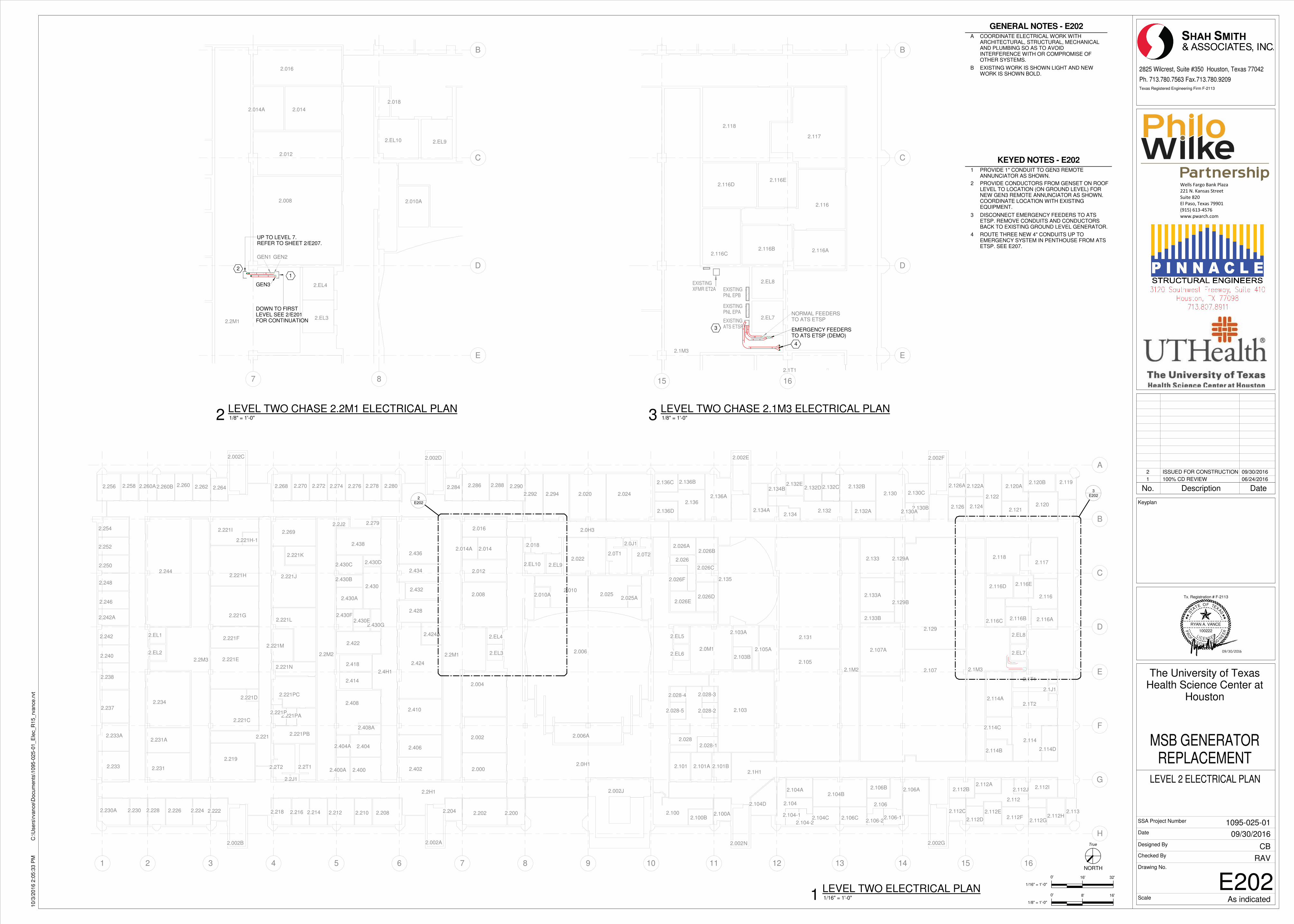
2.026F
2.233A
2.4H1
2.0H1
2.106-22.106-1
2.104-2
2.104-1
2.221PB
2.221PA
2.221PC
2.028-5
2.028-4
2.100B2.113
2.2602.260A
2.010A
2.0H3
2.2H1
2.1H1
2.130C
2.130B
2.114D
2.116D 2.116E
2.116C
2.116
2.100A
2.404A
2.221
2.242A
2.EL1
2.EL2
2.EL4
2.EL3
2.EL92.EL10
2.002J
2.EL6
2.EL5
2.101 2.101B
2.114C
2.112A
2.116B
2.1172.118
2.EL7
2.EL8
2.002F2.002E
2.002G2.002M
2.002D
2.002A2.002B
2.002C
2.1002.208
2.2M2
2.2J1
2.2T2 2.2T1
2.2M32.2M1
2.0M1
2.104B
2.1M2 2.1M3
2.1J1
2.1T2
2.1T1
2.129A
2.129B
2.133B
2.133A
2.1332.0T2
2.0J1
2.0T1
2.294
2.0182.014A
2.2792.2J2
2.129
2.107
2.107A
2.131
2.103B2.105
2.105A
2.103A
2.006
2.424A
2.424
2.428
2.418
2.422
2.430G2.430E
2.430F2.221L
2.221M
2.221E
2.221F
2.221G
2.240
2.242
2.238
2.237
2.233
2.234
2.231A
2.231
2.230A 2.230 2.228 2.226 2.224 2.222
2.219
2.221C
2.221D
2.221N
2.221P
2.218 2.216 2.214 2.212 2.210
2.414
2.408
2.408A
2.404
2.400A 2.400 2.402
2.406
2.410
2.004
2.002
2.000
2.204 2.202 2.200
2.006A
2.101A
2.028-3
2.028-2
2.0282.028-1
2.103
2.104D 2.104
2.104A
2.104C 2.106C
2.106
2.106B 2.106A
2.112
2.112J 2.112I
2.112H2.112G
2.112F2.112E2.112C
2.112B
2.112D
2.114B
2.114
2.114A
2.116A
2.120
2.1192.120B2.120A
2.121
2.122
2.126 2.124
2.122A2.126A
2.130A2.134
2.132 2.132A
2.130
2.132B2.132C2.132D2.132E
2.134B
2.134A
2.135
2.026E2.026D
2.026C
2.026
2.026B2.026A
2.136A2.136
2.136B2.136C
2.136D
2.025A2.025
2.010
2.292 2.0242.020
2.022
2.290
2.014
2.008
2.012
2.2882.2862.284
2.016
2.436
2.434
2.432
2.430A
2.430
2.430D
2.430B
2.430C
2.438
2.221K
2.2802.2782.2762.2742.2722.270
2.221J2.221H
2.269
2.2682.264
2.221H-1
2.221I
2.244
2.246
2.248
2.250
2.252
2.254
2.2622.260B2.2582.256
1 2 3 4 5 6 7 8 9 10 11 12 13 14 15 16
A
B
C
D
E
F
G
H
E2022
E2023
C D E F
B A N G
2.010A
2.EL4
2.EL3
2.EL92.EL10
2.2M1
2.018
2.014A 2.014
2.008
2.012
2.016
7 8
B
C
D
E
GEN1 GEN2
GEN3
DOWN TO FIRSTLEVEL SEE 2/E201FOR CONTINUATION
UP TO LEVEL 7.REFER TO SHEET 2/E207.
1
2
2.116D2.116E
2.116C
2.116
2.116B
2.117
2.118
2.EL7
2.EL8
2.1M3
2.1T1
2.116A
15 16
B
C
D
E
3
EXISTINGXFMR ET2A
EMERGENCY FEEDERSTO ATS ETSP (DEMO)
NORMAL FEEDERSTO ATS ETSPEXISTING
ATS ETSP
EXISTINGPNL EPA
EXISTINGPNL EPB
4
������������� ������
��������������������
���������
��������������� ��
! �"#�$�%&'"�$
(((�)(��*+�*,
NORTH
0'
Texas Registered Engineering Firm F-2113
0'
TA
S
E OF TEXAS
P RE
ENI
GNELANOISS
FO
R
EL I C E N S E D
T
RYAN A. VANCE
100222
Tx. Registration # F-2113
Scale
Date
Designed By
Checked By
SSA Project Number
Drawing No.
1/8" = 1'-0"
8' 16'
2825 Wilcrest, Suite #350 Houston, Texas 77042
Ph. 713.780.7563 Fax.713.780.9209
Keyplan
1/16" = 1'-0"
16' 32'
True
As indicated
10/3
/2016 2
:05:3
3 P
MC
:\U
sers
\rvance\D
ocum
ents
\1095-0
25-0
1_E
lec_R
15_rv
ance.r
vt
E202
LEVEL 2 ELECTRICAL PLAN
The University of TexasHealth Science Center at
Houston
MSB GENERATORREPLACEMENT
RAV
CB
09/30/2016
1095-025-01
KEYED NOTES - E202
1 PROVIDE 1" CONDUIT TO GEN3 REMOTEANNUNCIATOR AS SHOWN.
2 PROVIDE CONDUCTORS FROM GENSET ON ROOFLEVEL TO LOCATION (ON GROUND LEVEL) FORNEW GEN3 REMOTE ANNUNCIATOR AS SHOWN.COORDINATE LOCATION WITH EXISTINGEQUIPMENT.
3 DISCONNECT EMERGENCY FEEDERS TO ATSETSP. REMOVE CONDUITS AND CONDUCTORSBACK TO EXISTING GROUND LEVEL GENERATOR.
4 ROUTE THREE NEW 4" CONDUITS UP TOEMERGENCY SYSTEM IN PENTHOUSE FROM ATSETSP. SEE E207.
1/16" = 1'-0"1LEVEL TWO ELECTRICAL PLAN
1/8" = 1'-0"2LEVEL TWO CHASE 2.2M1 ELECTRICAL PLAN
1/8" = 1'-0"3LEVEL TWO CHASE 2.1M3 ELECTRICAL PLAN
GENERAL NOTES - E202
A COORDINATE ELECTRICAL WORK WITHARCHITECTURAL, STRUCTURAL, MECHANICALAND PLUMBING SO AS TO AVOIDINTERFERENCE WITH OR COMPROMISE OFOTHER SYSTEMS.
B EXISTING WORK IS SHOWN LIGHT AND NEWWORK IS SHOWN BOLD.
No. Description Date
1 100% CD REVIEW 06/24/2016
2 ISSUED FOR CONSTRUCTION 09/30/2016
09/30/2016
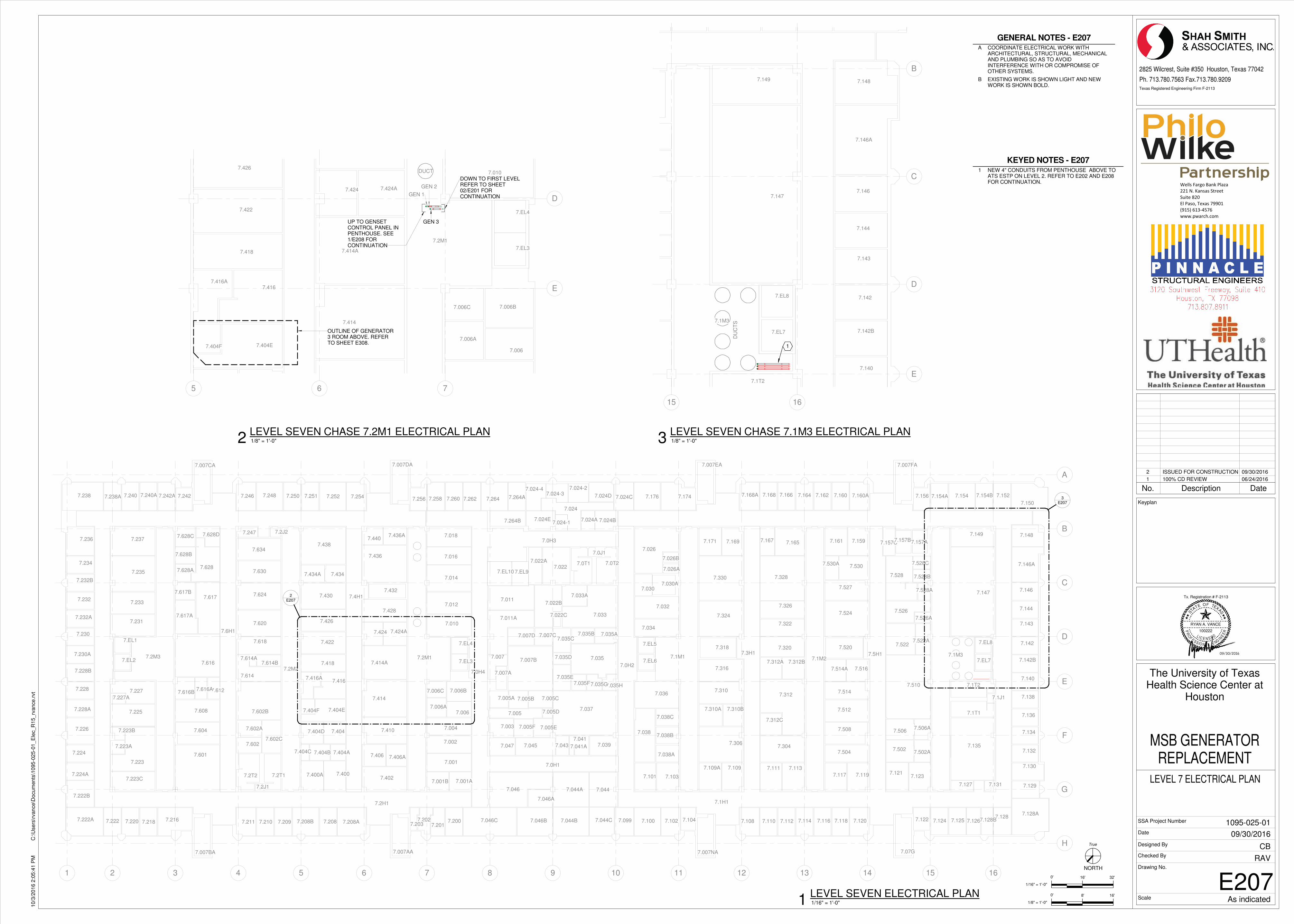
7.006C
7.024-47.024-3
7.024-2
7.024-1
7.6H1
7.4H1
7.0H4
7.0H3
7.0H2
7.5H1
7.0H1
7.224A
7.502
7.157C
7.123
7.526A
7.530A 7.528C
7.502A
7.628D
7.617B
7.038C
7.038B
7.522A
7.026
7.026B
7.006B
7.006A
7.167
7.227A
7.223B
7.223A
7.001A
7.528A
7.007D
7.033A
7.033
7.035H7.035G7.035F7.035E
7.035D
7.035C7.035A
7.041A
7.022C
7.406A
7.404F
7.404A
7.400
7.024E
7.0437.047
7.005F 7.005E
7.005C7.005B
7.005
7.005A
7.3H1
7.2H1 7.1H1
7.119
7.514A
7.007FA7.007EA
7.007BA
7.EL2
7.EL1
7.617A
7.614B7.614A
7.614
7.428
7.EL4
7.EL3
7.EL10 7.EL9
7.007B 7.EL6
7.EL5
7.EL7
7.EL8
7.126
7.127
7.076
7.1207.104
7.007NA7.007AA
7.2J1
7.2T2 7.2T1
7.2M3
7.2M2
7.2M1 7.1M1 7.1M2
7.131
7.1T1
7.1T2
7.1J1
7.1M3
7.0T27.0T1
7.0J1
7.256
7.526
7.007DA
7.2J2
7.007CA
7.130
7.129
7.128A7.128
7.128B7.1257.1247.122
7.1217.117
7.1187.1167.1147.1127.1107.108
7.1137.1117.1097.109A
7.103
7.102
7.101
7.099 7.100
7.044A 7.044
7.044B 7.044C7.046B
7.046A
7.046
7.046C7.2007.201
7.2027.203
7.001B
7.001
7.402
7.208A7.2087.208B7.209
7.400A
7.404B
7.2107.211
7.223C
7.2167.2187.220
7.222B
7.222A 7.222
7.224
7.226
7.228A
7.228
7.228B
7.230A
7.230
7.223
7.225
7.227
7.616
7.6127.616A7.616B
7.608
7.604
7.601
7.602C7.602
7.602A
7.602B
7.618
7.620
7.404
7.404C
7.404E
7.404D
7.416A7.416
7.418
7.422
7.424A7.424
7.414A
7.414
7.410
7.406
7.002
7.004
7.006
7.010
7.038A
7.038
7.034
7.036
7.003
7.0397.041
7.045
7.005D7.037
7.007
7.007A
7.007C
7.035
7.306
7.310B7.310A
7.310
7.316
7.318
7.322
7.320
7.312B7.312A
7.312
7.312C
7.3047.504
7.508
7.512
7.514
7.516
7.5207.522
7.510
7.506A7.506
7.1357.132
7.134
7.136
7.138
7.140
7.142B
7.142
7.143
7.144
7.146
7.146A
7.148
7.150
7.1527.154B7.1547.154A7.156
7.147
7.149
7.528 7.528B
7.157A7.157B
7.524
7.527
7.530
7.1597.161
7.160A7.1607.1627.1647.1667.1687.168A
7.326
7.328
7.165
7.324
7.330
7.1697.171
7.174
7.030A
7.032
7.030
7.026A
7.1767.024D 7.024C
7.035B
7.022B
7.011A
7.011
7.0227.022A
7.264B 7.024A
7.024
7.024B
7.264A7.2647.262
7.426
7.430
7.4347.434A
7.438
7.436A7.440
7.436
7.432
7.012
7.014
7.016
7.018
7.2607.2587.2547.2527.2517.2507.248
7.624
7.630
7.634
7.247
7.628
7.617
7.628A
7.628B
7.628C
7.231
7.233
7.235
7.237
7.232A
7.232
7.232B
7.234
7.236
7.2467.2427.242A7.240A7.2407.238A7.238
1 2 3 4 5 6 7 8 9 10 11 12 13 14 15 16
A
B
C
D
E
F
G
H
E2072
E2073
C D E F
B A N G
7.006C 7.006B
7.006A
7.404F
7.EL4
7.EL3
7.2M1
7.404E
7.416A7.416
7.418
7.422
7.424A7.424
7.414A
7.414
7.006
7.0107.426
5 6 7
D
E
OUTLINE OF GENERATOR3 ROOM ABOVE. REFERTO SHEET E308.
GEN 1
GEN 2
GEN 3
DUCT
DOWN TO FIRST LEVELREFER TO SHEET02/E201 FORCONTINUATION
UP TO GENSETCONTROL PANEL INPENTHOUSE. SEE1/E208 FORCONTINUATION
7.EL7
7.EL8
7.1T2
7.1M3
7.140
7.142B
7.142
7.143
7.144
7.146
7.146A
7.148
7.147
7.149
15 16
B
C
D
E
1
DU
CT
S
������������� ������
��������������������
���������
��������������� ��
! �"#�$�%&'"�$
(((�)(��*+�*,
NORTH
0'
Texas Registered Engineering Firm F-2113
0'
TA
S
E OF TEXAS
P RE
ENI
GNELANOISS
FO
R
EL I C E N S E D
T
RYAN A. VANCE
100222
Tx. Registration # F-2113
Scale
Date
Designed By
Checked By
SSA Project Number
Drawing No.
1/8" = 1'-0"
8' 16'
2825 Wilcrest, Suite #350 Houston, Texas 77042
Ph. 713.780.7563 Fax.713.780.9209
Keyplan
1/16" = 1'-0"
16' 32'
True
As indicated
10/3
/2016 2
:05:4
1 P
MC
:\U
sers
\rvance\D
ocum
ents
\1095-0
25-0
1_E
lec_R
15_rv
ance.r
vt
E207
LEVEL 7 ELECTRICAL PLAN
The University of TexasHealth Science Center at
Houston
MSB GENERATORREPLACEMENT
RAV
CB
09/30/2016
1095-025-01
1/16" = 1'-0"1LEVEL SEVEN ELECTRICAL PLAN
1/8" = 1'-0"2LEVEL SEVEN CHASE 7.2M1 ELECTRICAL PLAN
1/8" = 1'-0"3LEVEL SEVEN CHASE 7.1M3 ELECTRICAL PLAN
KEYED NOTES - E207
1 NEW 4" CONDUITS FROM PENTHOUSE ABOVE TOATS ESTP ON LEVEL 2. REFER TO E202 AND E208FOR CONTINUATION.
GENERAL NOTES - E207
A COORDINATE ELECTRICAL WORK WITHARCHITECTURAL, STRUCTURAL, MECHANICALAND PLUMBING SO AS TO AVOIDINTERFERENCE WITH OR COMPROMISE OFOTHER SYSTEMS.
B EXISTING WORK IS SHOWN LIGHT AND NEWWORK IS SHOWN BOLD.
No. Description Date
1 100% CD REVIEW 06/24/2016
2 ISSUED FOR CONSTRUCTION 09/30/2016
09/30/2016
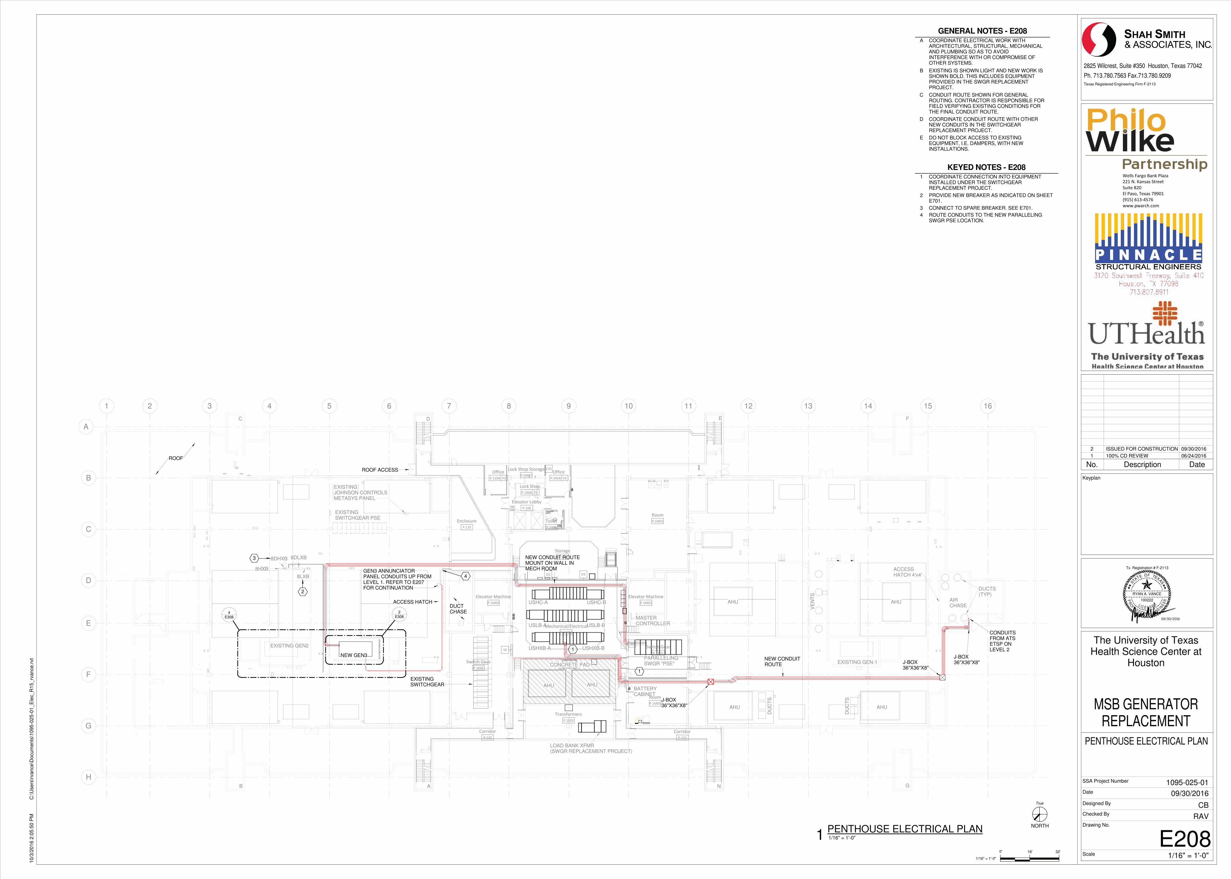
FD
��
1 2 3 4 5 6 7 8 9 10 11 12 13 14 15 16
A
B
C
D
E
F
G
H
USHXB-A USHXB-B
USLB-A USLB-B
USHC-A USHC-B
LOAD BANK XFMR(SWGR REPLACEMENT PROJECT)
PARALLELINGSWGR "PSE"CONCRETE PAD
MASTERCONTROLLER
BATTERYCABINET
AHUAHU
EXISTING GEN-1
EXISTING GEN2
NEW GEN3
E3084
E3082
GEN3 ANNUNCIATORPANEL CONDUITS UP FROMLEVEL 1. REFER TO E207FOR CONTINUATION
J-BOX36"X36"X8"
CONDUITSFROM ATSETSP ONLEVEL 2
NEW CONDUIT ROUTEMOUNT ON WALL INMECH ROOM
J-BOX36"X36"X8"
ROOF
ROOF ACCESS
8LXB
8DLXB8DHXB
8HXBT
ACCESS HATCHDUCTCHASE
ACCESSHATCH 4'x4'
AIRCHASE
AHUAHU
AHU AHU
NEW CONDUITROUTE
DU
CT
S
DU
CT
S
DUCTS(TYP)
VE
NT
S
C D E F
B A N G
EXISTINGSWITCHGEAR PSE
EXISTINGJOHNSON CONTROLSMETASYS PANEL
J-BOX36"X36"X8"
EXISTINGSWITCHGEAR
1
1
2
3
��������
������
��
���������������� ����
������
��������
������
����
������
������� �������
������
������� �������
������
� �� !� ��
������
��� �"�
�����
����� # �
�����
����
������
$������%
&��'���(
��
��
��
$������%
)!!���
������
�����*
$������%
)!!���
������� &�++,
�����
�� �-�
�����
�� �-�
�����
���&��'���(��� �"�
�����.
4
/��� $� "�*��'���0�
���1�2�� � �� ���
�#���3��
���� �4��5� .66��
76��89��:��.9
����(�� ������
NORTH
Texas Registered Engineering Firm F-2113
0'
TA
S
E OF TEXAS
P RE
ENI
GNELANOISS
FO
R
EL I C E N S E D
T
RYAN A. VANCE
100222
Tx. Registration # F-2113
Scale
Date
Designed By
Checked By
SSA Project Number
Drawing No.
1/16" = 1'-0"
16' 32'
2825 Wilcrest, Suite #350 Houston, Texas 77042
Ph. 713.780.7563 Fax.713.780.9209
Keyplan
True
1/16" = 1'-0"
10/3
/2016 2
:05:5
0 P
MC
:\U
sers
\rvance\D
ocum
ents
\1095-0
25-0
1_E
lec_R
15_rv
ance.r
vt
E208
PENTHOUSE ELECTRICAL PLAN
The University of TexasHealth Science Center at
Houston
MSB GENERATORREPLACEMENT
RAV
CB
09/30/2016
1095-025-01
1/16" = 1'-0"1PENTHOUSE ELECTRICAL PLAN
GENERAL NOTES - E208
A COORDINATE ELECTRICAL WORK WITHARCHITECTURAL, STRUCTURAL, MECHANICALAND PLUMBING SO AS TO AVOIDINTERFERENCE WITH OR COMPROMISE OFOTHER SYSTEMS.
B EXISTING IS SHOWN LIGHT AND NEW WORK ISSHOWN BOLD. THIS INCLUDES EQUIPMENTPROVIDED IN THE SWGR REPLACEMENTPROJECT.
C CONDUIT ROUTE SHOWN FOR GENERALROUTING. CONTRACTOR IS RESPONSIBLE FORFIELD VERIFYING EXISTING CONDITIONS FORTHE FINAL CONDUIT ROUTE.
D COORDINATE CONDUIT ROUTE WITH OTHERNEW CONDUITS IN THE SWITCHGEARREPLACEMENT PROJECT.
E DO NOT BLOCK ACCESS TO EXISTINGEQUIPMENT, I.E. DAMPERS, WITH NEWINSTALLATIONS.
KEYED NOTES - E208
1 COORDINATE CONNECTION INTO EQUIPMENTINSTALLED UNDER THE SWITCHGEARREPLACEMENT PROJECT.
2 PROVIDE NEW BREAKER AS INDICATED ON SHEETE701.
3 CONNECT TO SPARE BREAKER. SEE E701.
4 ROUTE CONDUITS TO THE NEW PARALLELINGSWGR PSE LOCATION.
No. Description Date
1 100% CD REVIEW 06/24/2016
2 ISSUED FOR CONSTRUCTION 09/30/2016
09/30/2016
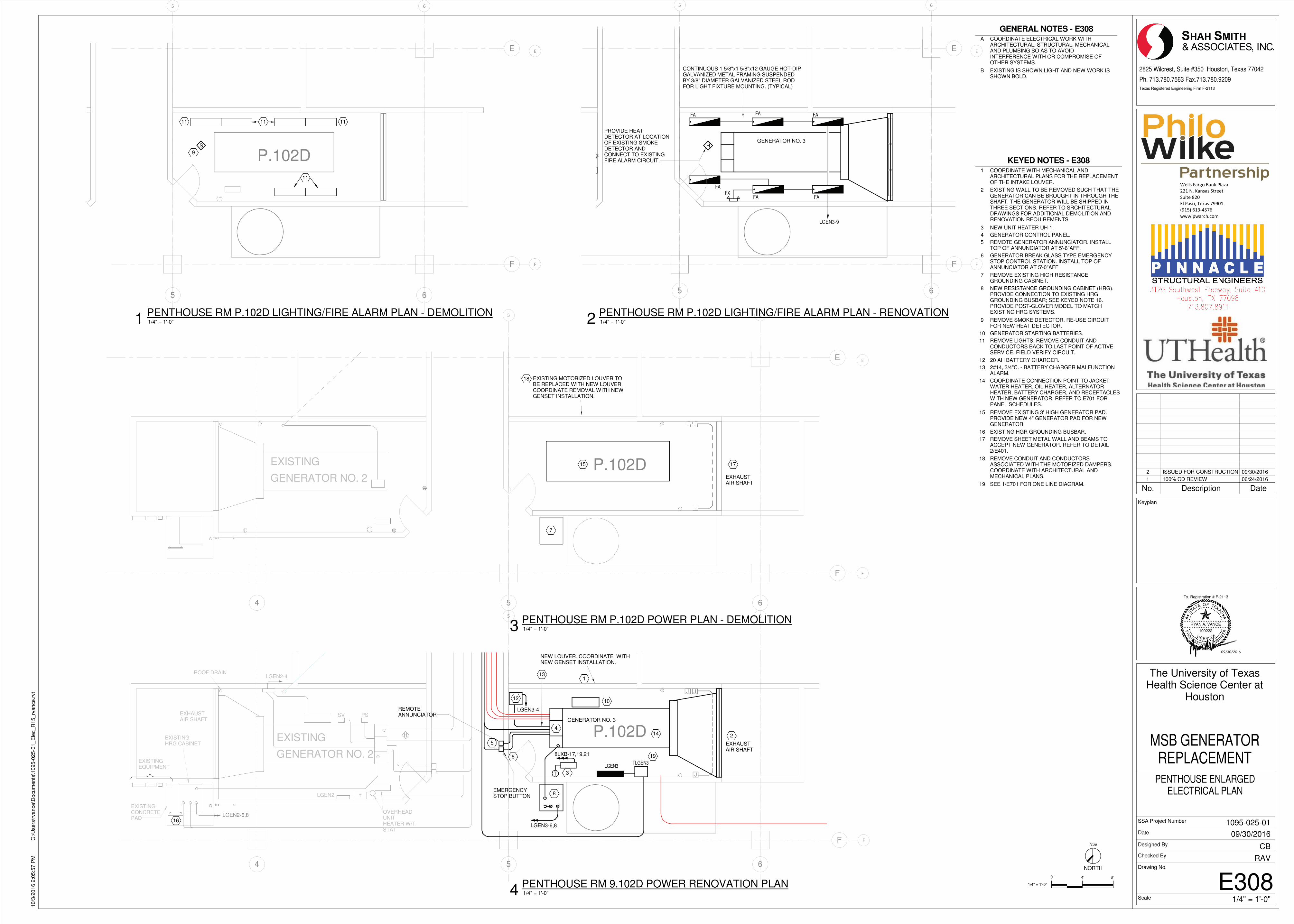
P.102D
�
P.102D
��
�
�
P.102D
4 5 6
F
1
4
8
12
13
LGEN2-6,8
LGEN2-4
JJ
J
H
T
EXISTING
GENERATOR NO. 2
EXISTINGCONCRETEPAD
EXISTINGEQUIPMENT
PSSV
LGEN2
EXHAUSTAIR SHAFT
T
NEW LOUVER. COORDINATE WITHNEW GENSET INSTALLATION.
OVERHEADUNITHEATER W/T-STAT
ROOF DRAIN
GENERATOR NO. 3
5
6
LGEN3-6,8
LGEN3-4
TLGEN3LGEN3
10
EXISTINGHRG CABINET
16
2
EXHAUSTAIR SHAFT
REMOTEANNUNCIATOR
EMERGENCYSTOP BUTTON
3
14
8LXB-17,19,21
�
��
19
5 6
E
F
PROVIDE HEATDETECTOR AT LOCATIONOF EXISTING SMOKEDETECTOR ANDCONNECT TO EXISTINGFIRE ALARM CIRCUIT.
GENERATOR NO. 3H
FAFAFA
FA FA
CONTINUOUS 1 5/8"x1 5/8"x12 GAUGE HOT-DIPGALVANIZED METAL FRAMING SUSPENDEDBY 3/8" DIAMETER GALVANIZED STEEL RODFOR LIGHT FIXTURE MOUNTING. (TYPICAL)
FX
LGEN3-9
FA
�
�
��
5 6
E
F
11
11
1111
9
S
�
�
��
4 5 6
E
F
7
15EXISTING
GENERATOR NO. 2
17
EXHAUSTAIR SHAFT
18 EXISTING MOTORIZED LOUVER TOBE REPLACED WITH NEW LOUVER.COORDINATE REMOVAL WITH NEWGENSET INSTALLATION.
�
�
��
�������� ������
���������������
��������
���� ��� �!""��
#"��$��%&'�!�
(((�)(�*+�* ,
NORTH
0'
Texas Registered Engineering Firm F-2113
TA
S
E OF TEXAS
P RE
ENI
GNELANOISS
FO
R
EL I C E N S E D
T
RYAN A. VANCE
100222
Tx. Registration # F-2113
Scale
Date
Designed By
Checked By
SSA Project Number
Drawing No.
2825 Wilcrest, Suite #350 Houston, Texas 77042
Ph. 713.780.7563 Fax.713.780.9209
Keyplan
1/4" = 1'-0"
4' 8'
True
1/4" = 1'-0"
10/3
/2016 2
:05:5
7 P
MC
:\U
sers
\rvance\D
ocum
ents
\1095-0
25-0
1_E
lec_R
15_rv
ance.r
vt
E308
PENTHOUSE ENLARGEDELECTRICAL PLAN
The University of TexasHealth Science Center at
Houston
MSB GENERATORREPLACEMENT
RAV
CB
09/30/2016
1095-025-01
1/4" = 1'-0"4PENTHOUSE RM 9.102D POWER RENOVATION PLAN
KEYED NOTES - E308
1 COORDINATE WITH MECHANICAL ANDARCHITECTURAL PLANS FOR THE REPLACEMENTOF THE INTAKE LOUVER.
2 EXISTING WALL TO BE REMOVED SUCH THAT THEGENERATOR CAN BE BROUGHT IN THROUGH THESHAFT. THE GENERATOR WILL BE SHIPPED INTHREE SECTIONS. REFER TO SRCHITECTURALDRAWINGS FOR ADDITIONAL DEMOLITION ANDRENOVATION REQUIREMENTS.
3 NEW UNIT HEATER UH-1.
4 GENERATOR CONTROL PANEL.
5 REMOTE GENERATOR ANNUNCIATOR. INSTALLTOP OF ANNUNCIATOR AT 5'-6"AFF.
6 GENERATOR BREAK GLASS TYPE EMERGENCYSTOP CONTROL STATION. INSTALL TOP OFANNUNCIATOR AT 5'-0"AFF
7 REMOVE EXISTING HIGH RESISTANCEGROUNDING CABINET.
8 NEW RESISTANCE GROUNDING CABINET (HRG).PROVIDE CONNECTION TO EXISTING HRGGROUNDING BUSBAR; SEE KEYED NOTE 16.PROVIDE POST-GLOVER MODEL TO MATCHEXISTING HRG SYSTEMS.
9 REMOVE SMOKE DETECTOR. RE-USE CIRCUITFOR NEW HEAT DETECTOR.
10 GENERATOR STARTING BATTERIES.
11 REMOVE LIGHTS. REMOVE CONDUIT ANDCONDUCTORS BACK TO LAST POINT OF ACTIVESERVICE. FIELD VERIFY CIRCUIT.
12 20 AH BATTERY CHARGER.
13 2#14, 3/4"C. - BATTERY CHARGER MALFUNCTIONALARM.
14 COORDINATE CONNECTION POINT TO JACKETWATER HEATER, OIL HEATER, ALTERNATORHEATER, BATTERY CHARGER, AND RECEPTACLESWITH NEW GENERATOR. REFER TO E701 FORPANEL SCHEDULES.
15 REMOVE EXISTING 3' HIGH GENERATOR PAD.PROVIDE NEW 4" GENERATOR PAD FOR NEWGENERATOR.
16 EXISTING HGR GROUNDING BUSBAR.
17 REMOVE SHEET METAL WALL AND BEAMS TOACCEPT NEW GENERATOR. REFER TO DETAIL2/E401.
18 REMOVE CONDUIT AND CONDUCTORSASSOCIATED WITH THE MOTORIZED DAMPERS.COORDINATE WITH ARCHITECTURAL ANDMECHANICAL PLANS.
19 SEE 1/E701 FOR ONE LINE DIAGRAM.
1/4" = 1'-0"2PENTHOUSE RM P.102D LIGHTING/FIRE ALARM PLAN - RENOVATION
1/4" = 1'-0"1PENTHOUSE RM P.102D LIGHTING/FIRE ALARM PLAN - DEMOLITION
1/4" = 1'-0"3PENTHOUSE RM P.102D POWER PLAN - DEMOLITION
GENERAL NOTES - E308
A COORDINATE ELECTRICAL WORK WITHARCHITECTURAL, STRUCTURAL, MECHANICALAND PLUMBING SO AS TO AVOIDINTERFERENCE WITH OR COMPROMISE OFOTHER SYSTEMS.
B EXISTING IS SHOWN LIGHT AND NEW WORK ISSHOWN BOLD.
No. Description Date
1 100% CD REVIEW 06/24/2016
2 ISSUED FOR CONSTRUCTION 09/30/2016
09/30/2016
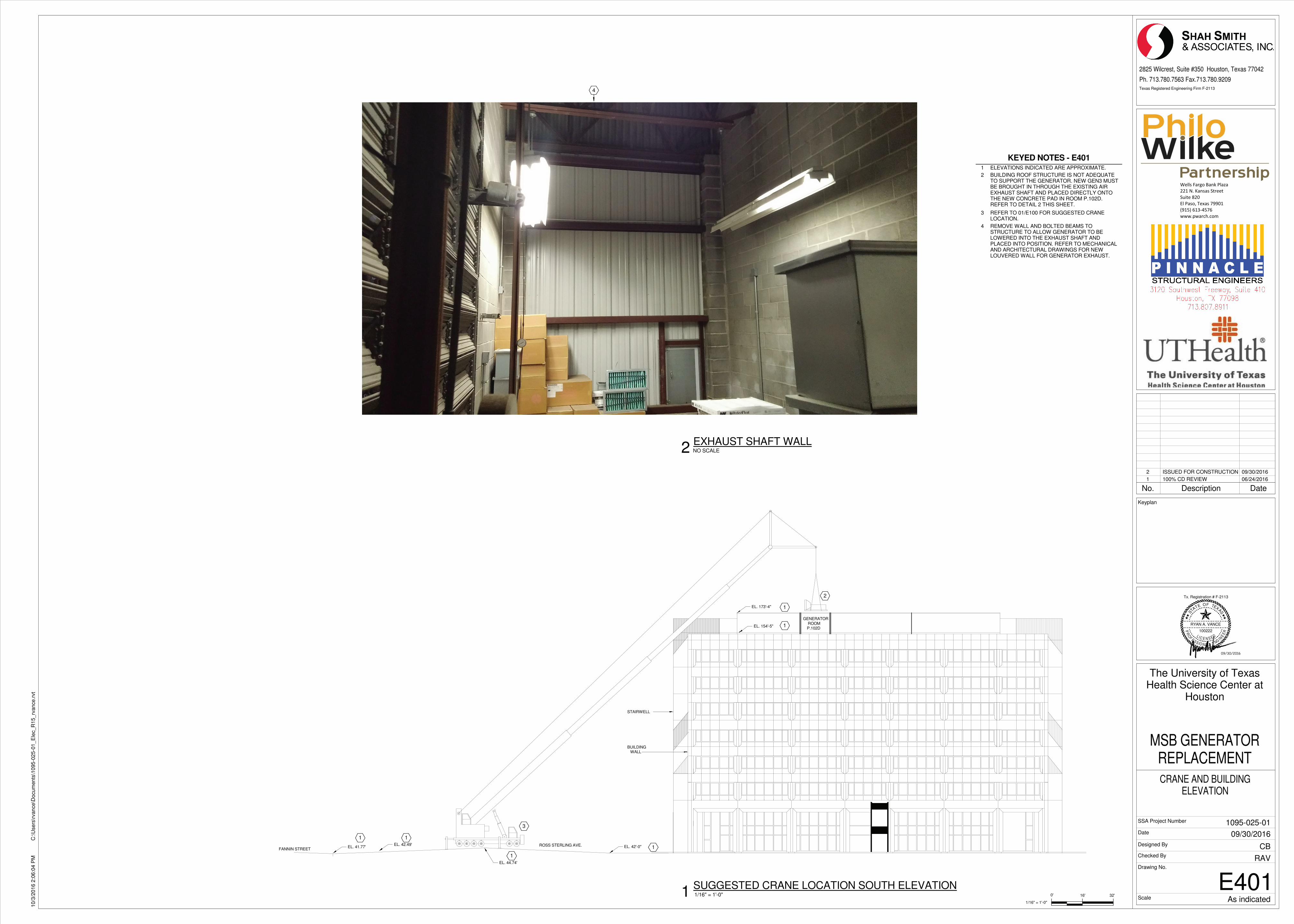
EL. 173'-4"
EL. 154'-5"
EL. 41.77' EL. 42'-0"
GENERATORROOMP.102D
EL. 42.49'
EL. 44.74'
FANNIN STREETROSS STERLING AVE.
STAIRWELL
BUILDINGWALL
1
1
11
1
1
2
3
4
������������� ������
��������������������
���������
��������������� ��
! �"#�$�%&'"�$
(((�)(��*+�*,
Texas Registered Engineering Firm F-2113
0'
TA
S
E OF TEXAS
P RE
ENI
GNELANOISS
FO
R
EL I C E N S E D
T
RYAN A. VANCE
100222
Tx. Registration # F-2113
Scale
Date
Designed By
Checked By
SSA Project Number
Drawing No.
1/16" = 1'-0"
16' 32'
2825 Wilcrest, Suite #350 Houston, Texas 77042
Ph. 713.780.7563 Fax.713.780.9209
Keyplan
As indicated
10/3
/2016 2
:06:0
4 P
MC
:\U
sers
\rvance\D
ocum
ents
\1095-0
25-0
1_E
lec_R
15_rv
ance.r
vt
E401
CRANE AND BUILDINGELEVATION
The University of TexasHealth Science Center at
Houston
MSB GENERATORREPLACEMENT
RAV
CB
09/30/2016
1095-025-01
1/16" = 1'-0"1SUGGESTED CRANE LOCATION SOUTH ELEVATION
KEYED NOTES - E401
1 ELEVATIONS INDICATED ARE APPROXIMATE.
2 BUILDING ROOF STRUCTURE IS NOT ADEQUATETO SUPPORT THE GENERATOR. NEW GEN3 MUSTBE BROUGHT IN THROUGH THE EXISTING AIREXHAUST SHAFT AND PLACED DIRECTLY ONTOTHE NEW CONCRETE PAD IN ROOM P.102D.REFER TO DETAIL 2 THIS SHEET.
3 REFER TO 01/E100 FOR SUGGESTED CRANELOCATION.
4 REMOVE WALL AND BOLTED BEAMS TOSTRUCTURE TO ALLOW GENERATOR TO BELOWERED INTO THE EXHAUST SHAFT ANDPLACED INTO POSITION. REFER TO MECHANICALAND ARCHITECTURAL DRAWINGS FOR NEWLOUVERED WALL FOR GENERATOR EXHAUST.
NO SCALE2EXHAUST SHAFT WALL
No. Description Date
1 100% CD REVIEW 06/24/2016
2 ISSUED FOR CONSTRUCTION 09/30/2016
09/30/2016
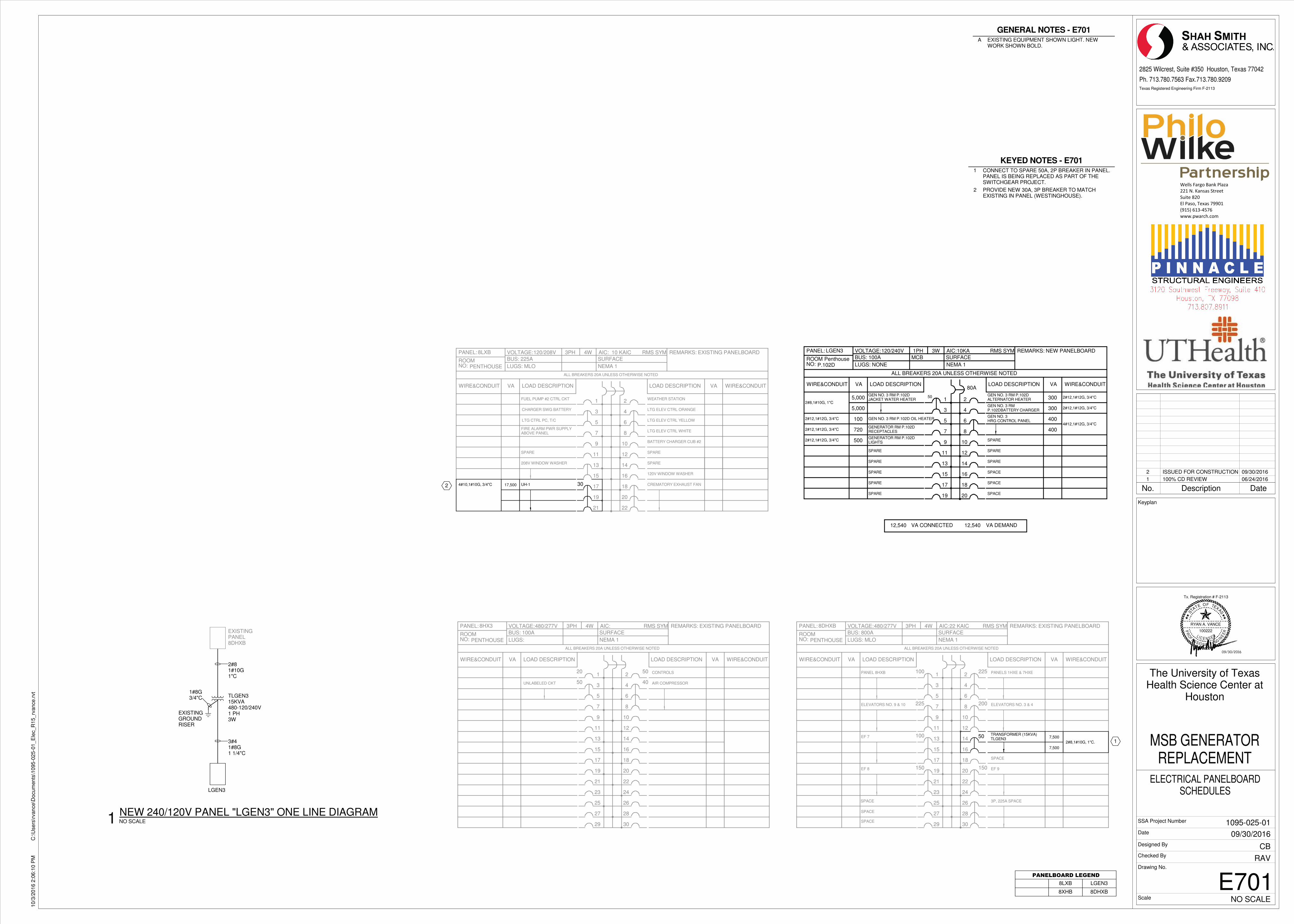
NO: NEMA 1LUGS: NONE
LOAD DESCRIPTIONWIRE&CONDUIT VA
VA DEMANDVA CONNECTED
ALL BREAKERS 20A UNLESS OTHERWISE NOTED
LOAD DESCRIPTION
15
17
19
9
11
13
16
18
20
10
12
14
1
3
5
7
2
4
6
8
PANEL:
ROOM
VOLTAGE:
BUS:
RMS SYMAIC:1PH 3W
MCB SURFACE
REMARKS:
50
WIRE&CONDUITVA
LGEN3 120/240V 10KA
100A
80A
PenthouseP.102D
NEW PANELBOARD
5,000
GEN NO. 3 RM P.102DJACKET WATER HEATER5,000
12,540 12,540
GEN NO. 3HRG CONTROL PANEL
GEN NO. 3 RMP.102DBATTERY CHARGER
GEN NO. 3 RM P.102DALTERNATOR HEATER
300
300
400
400
2#8,1#10G, 1"C
GENERATOR RM P.102DRECEPTACLES
GENERATOR RM P.102DLIGHTS
GEN NO. 3 RM P.102D OIL HEATER100
720
500
2#12,1#12G, 3/4"C
2#12,1#12G, 3/4"C
2#12,1#12G, 3/4"C
2#12,1#12G, 3/4"C
2#12,1#12G, 3/4"C
4#12,1#12G, 3/4"C
SPARE
SPARE
SPARE
SPARE
SPARE
SPARE
SPARE
SPARE
SPACE
SPACE
SPACE
ELEVATORS NO. 9 & 10
EF 7
PANEL 8HXB
EF 9
3P, 225A SPACE
ELEVATORS NO. 3 & 4
PANELS 1HXE & 7HXE
EF 8
SPACE
PANEL:
ROOMNO:
WIRE&CONDUIT
AIC:
SURFACE
NEMA 1
ALL BREAKERS 20A UNLESS OTHERWISE NOTED
9
29
23
25
27
15
17
19
21
11
13
VOLTAGE:
BUS: 800A
LUGS: MLO
LOAD DESCRIPTIONVA
3
5
7
1
3PH 4W
10
30
24
26
28
16
18
20
22
12
14
LOAD DESCRIPTION
4
6
8
2
RMS SYM REMARKS:8DHXB 480/277V 22 KAIC
PENTHOUSE
EXISTING PANELBOARD
1
100
SPACE
225
225
200
150
100
150
WIRE&CONDUITVA
50 TRANSFORMER (15KVA)TLGEN3
7,500
7,500
2#8,1#10G, 1"C.
SPACE
PANEL:
ROOMNO:
WIRE&CONDUIT
AIC:
SURFACE
NEMA 1
ALL BREAKERS 20A UNLESS OTHERWISE NOTED
9
29
23
25
27
15
17
19
21
11
13
VOLTAGE:
BUS: 100A
LUGS:
LOAD DESCRIPTIONVA
3
5
7
1
3PH 4W
10
30
24
26
28
16
18
20
22
12
14
LOAD DESCRIPTION
4
6
8
2
RMS SYM REMARKS:8HX3 480/277V
PENTHOUSE
EXISTING PANELBOARD
20 50
WIRE&CONDUITVA
50 40 AIR COMPRESSOR
CONTROLS
UNLABELED CKT
SPACE
LGEN3
3#41#8G1 1/4"C
EXISTINGPANEL8DHXB
TLGEN315KVA480-120/240V1 PH3W
EXISTINGGROUNDRISER
1#8G3/4"C
2#81#10G1"C
PANEL:
ROOMNO:
WIRE&CONDUIT
AIC: 10 KAIC
SURFACE
NEMA 1
ALL BREAKERS 20A UNLESS OTHERWISE NOTED
9
15
17
19
21
11
13
VOLTAGE:
BUS: 225A
LUGS: MLO
LOAD DESCRIPTIONVA
3
5
7
1
3PH 4W
10
16
18
20
22
12
14
LOAD DESCRIPTION
4
6
8
2
RMS SYM REMARKS:8LXB 120/208V
PENTHOUSE
EXISTING PANELBOARD
WIRE&CONDUITVA
LTG ELEV CTRL ORANGE
WEATHER STATION
CHARGER SWG BATTERY
FUEL PUMP #2 CTRL CKT
BATTERY CHARGER CUB #2
SPARE
FIRE ALARM PWR SUPPLYABOVE PANEL
208V WINDOW WASHER
UH-1
SPARE
SPARE
120V WINDOW WASHER
17,500 304#10,1#10G, 3/4"C CREMATORY EXHAUST FAN
LTG ELEV CTRL YELLOW
LTG ELEV CTRL WHITE
LTG CTRL PC, T/C
2
������������� ������
��������������������
���������
��������������� ��
! �"#�$�%&'"�$
(((�)(��*+�*,
Texas Registered Engineering Firm F-2113
TA
S
E OF TEXAS
P RE
ENI
GNELANOISS
FO
R
EL I C E N S E D
T
RYAN A. VANCE
100222
Tx. Registration # F-2113
Scale
Date
Designed By
Checked By
SSA Project Number
Drawing No.
2825 Wilcrest, Suite #350 Houston, Texas 77042
Ph. 713.780.7563 Fax.713.780.9209
Keyplan
NO SCALE
10/3
/2016 2
:06:1
0 P
MC
:\U
sers
\rvance\D
ocum
ents
\1095-0
25-0
1_E
lec_R
15_rv
ance.r
vt
E701
ELECTRICAL PANELBOARDSCHEDULES
The University of TexasHealth Science Center at
Houston
MSB GENERATORREPLACEMENT
RAV
CB
09/30/2016
1095-025-01
��������������
8LXB LGEN3
8XHB 8DHXB
KEYED NOTES - E701
1 CONNECT TO SPARE 50A, 2P BREAKER IN PANEL.PANEL IS BEING REPLACED AS PART OF THESWITCHGEAR PROJECT.
2 PROVIDE NEW 30A, 3P BREAKER TO MATCHEXISTING IN PANEL (WESTINGHOUSE).
GENERAL NOTES - E701
A EXISTING EQUIPMENT SHOWN LIGHT. NEWWORK SHOWN BOLD.
NO SCALE1NEW 240/120V PANEL "LGEN3" ONE LINE DIAGRAM
No. Description Date
1 100% CD REVIEW 06/24/2016
2 ISSUED FOR CONSTRUCTION 09/30/2016
09/30/2016
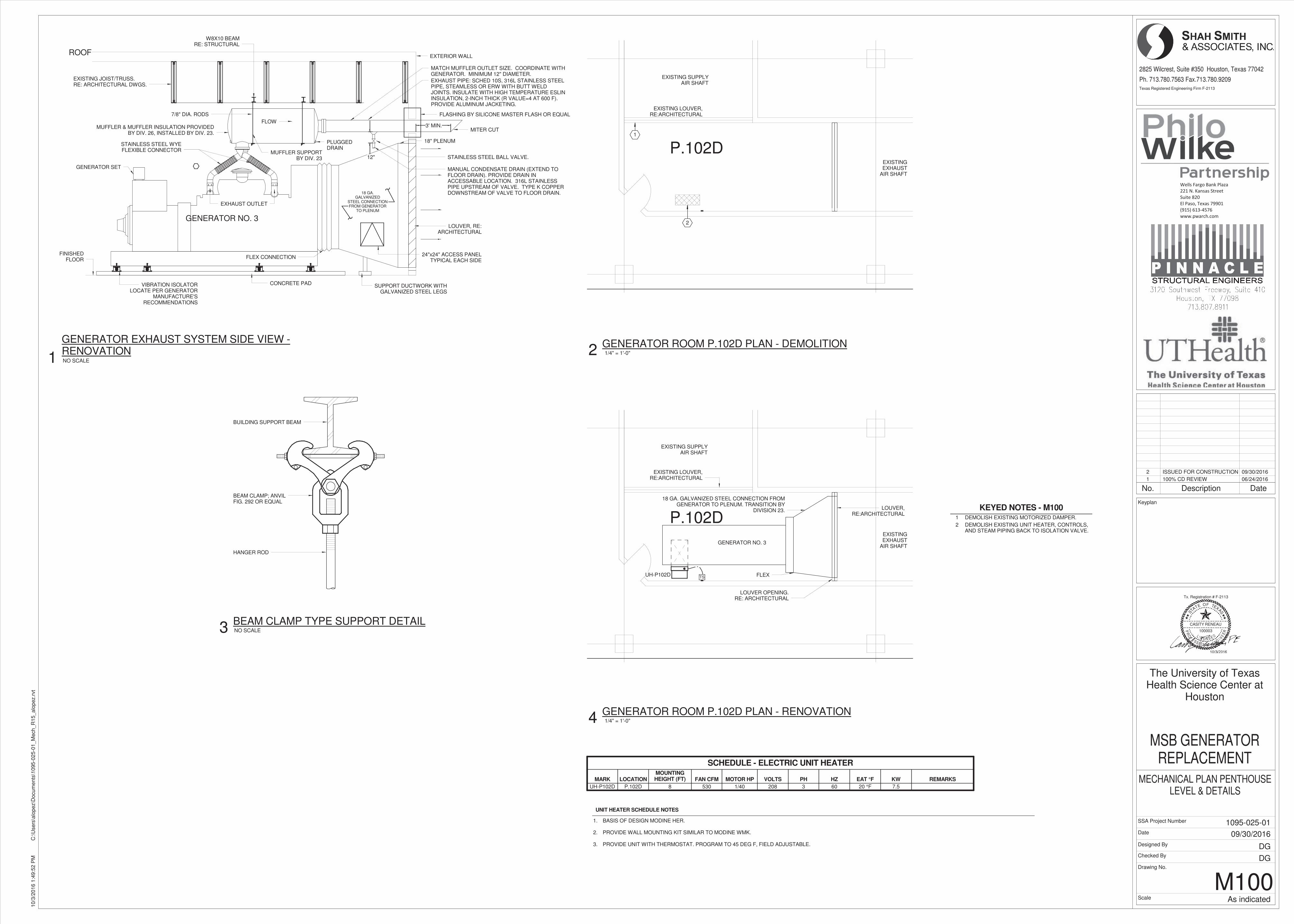
P.102D
P.102D
CONCRETE PAD
FLEX CONNECTION
18 GA.GALVANIZED
STEEL CONNECTIONFROM GENERATOR
TO PLENUM
EXISTING JOIST/TRUSS.RE: ARCHITECTURAL DWGS.
FLOW
LOUVER, RE:ARCHITECTURAL
EXHAUST OUTLET
MITER CUT
MATCH MUFFLER OUTLET SIZE. COORDINATE WITHGENERATOR. MINIMUM 12" DIAMETER.
18" PLENUM
MANUAL CONDENSATE DRAIN (EXTEND TOFLOOR DRAIN). PROVIDE DRAIN INACCESSABLE LOCATION. 316L STAINLESSPIPE UPSTREAM OF VALVE. TYPE K COPPERDOWNSTREAM OF VALVE TO FLOOR DRAIN.
EXTERIOR WALL
FLASHING BY SILICONE MASTER FLASH OR EQUAL
12"
3' MIN.
ROOF
PLUGGEDDRAIN
FINISHEDFLOOR
VIBRATION ISOLATORLOCATE PER GENERATOR
MANUFACTURE'SRECOMMENDATIONS
SUPPORT DUCTWORK WITHGALVANIZED STEEL LEGS
W8X10 BEAMRE: STRUCTURAL
STAINLESS STEEL WYEFLEXIBLE CONNECTOR
GENERATOR NO. 3
MUFFLER SUPPORTBY DIV. 23
24"x24" ACCESS PANELTYPICAL EACH SIDE
GENERATOR SET
MUFFLER & MUFFLER INSULATION PROVIDEDBY DIV. 26, INSTALLED BY DIV. 23.
7/8" DIA. RODS
STAINLESS STEEL BALL VALVE.
EXHAUST PIPE: SCHED 10S, 316L STAINLESS STEELPIPE, STEAMLESS OR ERW WITH BUTT WELDJOINTS. INSULATE WITH HIGH TEMPERATURE ESLININSULATION, 2-INCH THICK (R VALUE=4 AT 600 F).PROVIDE ALUMINUM JACKETING.
EXISTING LOUVER,RE:ARCHITECTURAL
EXISTINGEXHAUST
AIR SHAFT
EXISTING SUPPLYAIR SHAFT
1
2
BEAM CLAMP; ANVILFIG. 292 OR EQUAL
HANGER ROD
BUILDING SUPPORT BEAM
LOUVER OPENING.RE: ARCHITECTURAL
LOUVER,RE:ARCHITECTURAL
FLEX
18 GA. GALVANIZED STEEL CONNECTION FROMGENERATOR TO PLENUM. TRANSITION BY
DIVISION 23.
EXISTING LOUVER,RE:ARCHITECTURAL
GENERATOR NO. 3
EXISTINGEXHAUST
AIR SHAFT
EXISTING SUPPLYAIR SHAFT
TSUH-P102D
UNIT HEATER SCHEDULE NOTES
1.
2.
3.
BASIS OF DESIGN MODINE HER.
PROVIDE WALL MOUNTING KIT SIMILAR TO MODINE WMK.
PROVIDE UNIT WITH THERMOSTAT. PROGRAM TO 45 DEG F, FIELD ADJUSTABLE.
������������� ������
��������������������
���������
��������������� ��
! �"#�$�%&'"�$
(((�)(��*+�*,
Texas Registered Engineering Firm F-2113
TA
S
E OF TEXAS
P RE
ENI
GNELANOISS
FO
R
EL I C E N S E D
T
CASITY RENEAU
100003
Tx. Registration # F-2113
Scale
Date
Designed By
Checked By
SSA Project Number
Drawing No.
2825 Wilcrest, Suite #350 Houston, Texas 77042
Ph. 713.780.7563 Fax.713.780.9209
Keyplan
As indicated
10/3
/2016 1
:49:5
2 P
MC
:\U
sers
\alo
pez\D
ocum
ents
\1095-0
25-0
1_M
ech_R
15_alo
pez.r
vt
M100
MECHANICAL PLAN PENTHOUSELEVEL & DETAILS
The University of TexasHealth Science Center at
Houston
MSB GENERATORREPLACEMENT
DG
DG
09/30/2016
1095-025-01
NO SCALE
GENERATOR EXHAUST SYSTEM SIDE VIEW -RENOVATION
1 1/4" = 1'-0"
GENERATOR ROOM P.102D PLAN - DEMOLITION2
NO SCALE
BEAM CLAMP TYPE SUPPORT DETAIL3
1/4" = 1'-0"
GENERATOR ROOM P.102D PLAN - RENOVATION4
KEYED NOTES - M1001 DEMOLISH EXISTING MOTORIZED DAMPER.
2 DEMOLISH EXISTING UNIT HEATER, CONTROLS,AND STEAM PIPING BACK TO ISOLATION VALVE.
SCHEDULE - ELECTRIC UNIT HEATER
MARK LOCATIONMOUNTINGHEIGHT (FT) FAN CFM MOTOR HP VOLTS PH HZ EAT °F KW REMARKS
UH-P102D P.102D 8 530 1/40 208 3 60 20 °F 7.5
No. Description Date
1 100% CD REVIEW 06/24/2016
2 ISSUED FOR CONSTRUCTION 09/30/2016
EE
NIGGGGGGGGGGGGGGGGGGGGNNNNNNNNNNNNNNNNNNNNNNNNNNNNNNNNNNNNNNNNNNNNNNNNNNNNNNNNNNNNNNNNNNNNNNNNNNNNNEEEEEEEEEEEEEEEEEEEEEEEEEEEEEEEEEEEEEEEEEEEEEEEEEEEEEEEEEEEEEEELLLLLLLLLLLLLLLLLLLLLLLLLLLLLLLLLLLLLLLLLLLLLLLLLLLLLLLLLLLLLLLLLLAAAAAAAAAAAAAAAAAAAAAAAAAAAAAAAAAAAAAAAAAAAAAAAAAAAANNNNNNNNNNNNNNNNNNNNNNNNNNNNNNNNNNNNNNNNNNNNNNNNNNNNNOOOOOOOOOOOOOOOOOOOOOOOOOOOOOOOOOIIIIIIIIIIIIIIIIIIIIISS
FFFFFFFFFFFFFFFFFFFFFFFFFFFFOO
R
EEEEEEEEEEEEEEEEEEEEEEEEEEEEEEEEEEEEEEEEEEEEEEEEEEEEEEEEEL I CCCCCCCCCCCCCCCCCCCCCCCCCCCCCCCCCCCC EEEEEEEEEEEEEEEEEEEEEEEEE NNNNNNNNNNNNNNNNNNNNNNNNNNNN SSSSS E D� � � � � � � � �
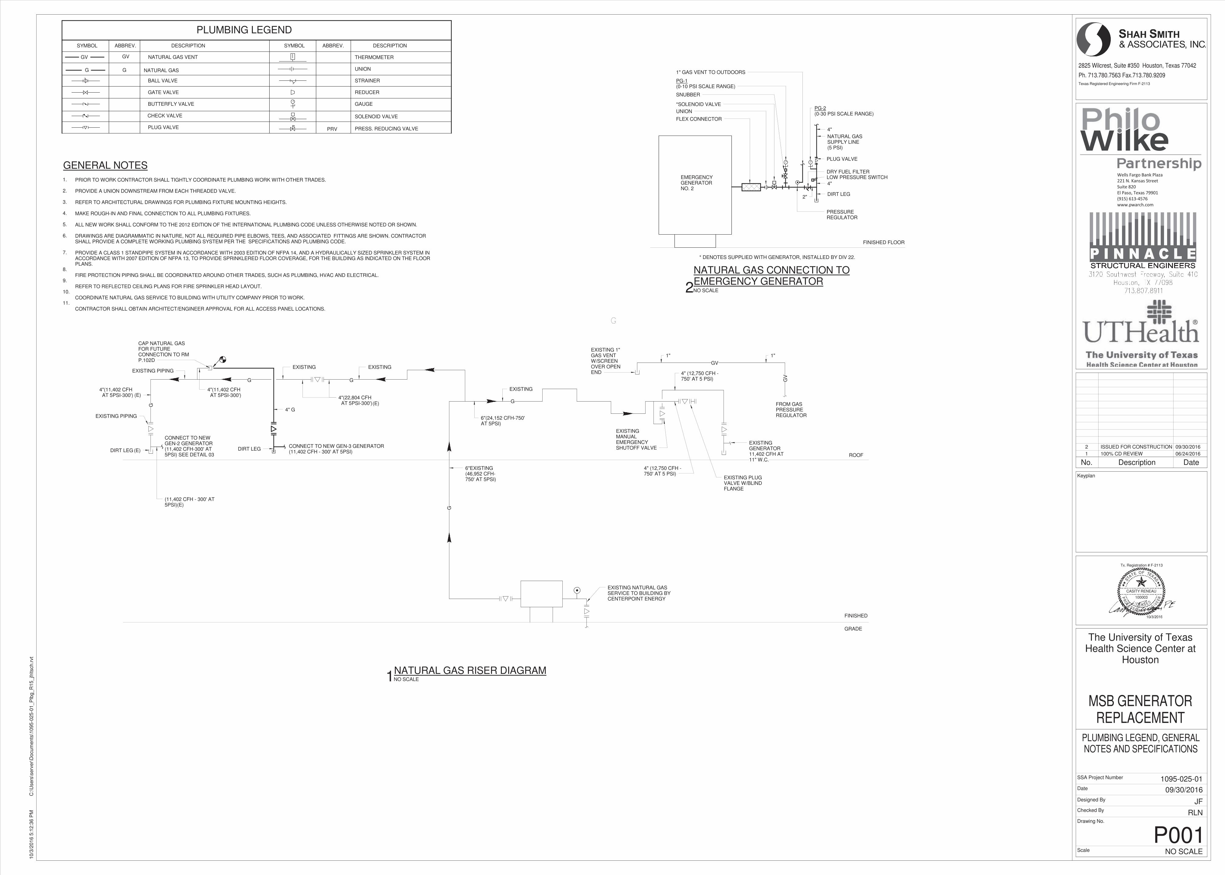
PLUMBING LEGEND
SYMBOLSYMBOL ABBREV. DESCRIPTION ABBREV. DESCRIPTION
PRESS. REDUCING VALVEPRVPLUG VALVE
CHECK VALVE
GATE VALVE
BALL VALVE
GAUGE
REDUCER
STRAINER
THERMOMETER
UNIONNATURAL GASG G
BUTTERFLY VALVE
SOLENOID VALVE
GV GV NATURAL GAS VENT
GENERAL NOTES
PRIOR TO WORK CONTRACTOR SHALL TIGHTLY COORDINATE PLUMBING WORK WITH OTHER TRADES.
PROVIDE A UNION DOWNSTREAM FROM EACH THREADED VALVE.
REFER TO ARCHITECTURAL DRAWINGS FOR PLUMBING FIXTURE MOUNTING HEIGHTS.
MAKE ROUGH-IN AND FINAL CONNECTION TO ALL PLUMBING FIXTURES.
ALL NEW WORK SHALL CONFORM TO THE 2012 EDITION OF THE INTERNATIONAL PLUMBING CODE UNLESS OTHERWISE NOTED OR SHOWN.
DRAWINGS ARE DIAGRAMMATIC IN NATURE, NOT ALL REQUIRED PIPE ELBOWS, TEES, AND ASSOCIATED FITTINGS ARE SHOWN. CONTRACTORSHALL PROVIDE A COMPLETE WORKING PLUMBING SYSTEM PER THE SPECIFICATIONS AND PLUMBING CODE.
PROVIDE A CLASS 1 STANDPIPE SYSTEM IN ACCORDANCE WITH 2003 EDITION OF NFPA 14, AND A HYDRAULICALLY SIZED SPRINKLER SYSTEM INACCORDANCE WITH 2007 EDITION OF NFPA 13, TO PROVIDE SPRINKLERED FLOOR COVERAGE, FOR THE BUILDING AS INDICATED ON THE FLOORPLANS.
FIRE PROTECTION PIPING SHALL BE COORDINATED AROUND OTHER TRADES, SUCH AS PLUMBING, HVAC AND ELECTRICAL.
REFER TO REFLECTED CEILING PLANS FOR FIRE SPRINKLER HEAD LAYOUT.
COORDINATE NATURAL GAS SERVICE TO BUILDING WITH UTILITY COMPANY PRIOR TO WORK.
CONTRACTOR SHALL OBTAIN ARCHITECT/ENGINEER APPROVAL FOR ALL ACCESS PANEL LOCATIONS.
1.
2.
3.
4.
5.
6.
7.
8.
9.
10.
11.
EXISTING
(E)
(E)
CONNECT TO NEW GEN-3 GENERATOR(11,402 CFH - 300' AT 5PSI)
DIRT LEG(E)
4" G
EXISTING PIPING
EXISTING PIPING
(11,402 CFH - 300' AT5PSI)(E)
G
G
G
G
�
6"EXISTING(46,952 CFH-750' AT 5PSI)
CONNECT TO NEWGEN-2 GENERATOR(11,402 CFH-300' AT5PSI) SEE DETAIL 03
4"(22,804 CFH AT 5PSI-300')
6"(24,152 CFH-750'AT 5PSI)
CAP NATURAL GASFOR FUTURECONNECTION TO RMP.102D
4"(11,402 CFH AT 5PSI-300')
4"(11,402 CFH AT 5PSI-300')
EXISTING
EXISTING
FINISHED
GRADE
ROOFDIRT LEG
EXISTING NATURAL GASSERVICE TO BUILDING BYCENTERPOINT ENERGY
EXISTING PLUGVALVE W/BLINDFLANGE
EXISTINGGENERATOR11,402 CFH AT11" W.C.
GV
FROM GASPRESSUREREGULATOR
1"
GV
1"EXISTING 1"GAS VENTW/SCREENOVER OPENEND
EXISTINGMANUALEMERGENCYSHUTOFF VALVE
4" (12,750 CFH -750' AT 5 PSI)
4" (12,750 CFH -750' AT 5 PSI)G
EMERGENCYGENERATORNO. 2
FINISHED FLOOR
FLEX CONNECTOR
UNION
DIRT LEG2"
4"
LOW PRESSURE SWITCHDRY FUEL FILTER
PLUG VALVE
NATURAL GASSUPPLY LINE(5 PSI)
4"
PG-2(0-30 PSI SCALE RANGE)
*SOLENOID VALVE
SNUBBER
PG-1(0-10 PSI SCALE RANGE)
1" GAS VENT TO OUTDOORS
* DENOTES SUPPLIED WITH GENERATOR, INSTALLED BY DIV 22.
PRESSUREREGULATOR
������������� ������
��������������������
���������
��������������� ��
! �"#�$�%&'"�$
(((�)(��*+�*,
Texas Registered Engineering Firm F-2113
TA
S
E OF TEXAS
P RE
ENI
GNELANOISS
FO
R
EL I C E N S E D
T
CASITY RENEAU
100003
Tx. Registration # F-2113
Scale
Date
Designed By
Checked By
SSA Project Number
Drawing No.
2825 Wilcrest, Suite #350 Houston, Texas 77042
Ph. 713.780.7563 Fax.713.780.9209
Keyplan
NO SCALE
10/3
/2016 5
:12:3
6 P
MC
:\U
sers
\serv
er\
Docum
ents
\1095-0
25-0
1_P
lbg_R
15_jfrits
ch.r
vt
P001
PLUMBING LEGEND, GENERALNOTES AND SPECIFICATIONS
The University of TexasHealth Science Center at
Houston
MSB GENERATORREPLACEMENT
RLN
JF
09/30/2016
1095-025-01
NO SCALE1NATURAL GAS RISER DIAGRAM
NO SCALE2
NATURAL GAS CONNECTION TOEMERGENCY GENERATOR
No. Description Date
1 100% CD REVIEW 06/24/2016
2 ISSUED FOR CONSTRUCTION 09/30/2016
EE
NIGGGGGGGGGGGGGGGGGGGGGGGGGGGGGGGGGGGGGGGGGGGGGGGGGGGGGGGGGGGGGGGGGGGGGNNNNNNNNNNNNNNNNNNNNNNNNNNNNNNNNNNNNNNNNNNNNNNNNNNNNNNNNNNNNNNNNNNNNNEEEEEEEEEEEEEEEEEEEEEEEEEEEEEEEEEEEEEEEEEEEEEEEEEEEEEEEEEEEEEEEEEEEEEEEEEEEELLLLLLLLLLLLLLLLLLLLLLLLLLLLLLLLLLLLLLLLLLLLLLLLLLLLLLLLLLLLLLLLLLLLLLLLLLLLLLLLLLAAAAAAAAAAAAAAAAAAAAAAAAAAAAAAAAAAAAAAAAAAAAAAAAAAAAAAAAAAAAAAAAANNNNNNNNNNNNNNNNNNNNNNNNNNNNNNNNNNOOOOOOOOOOOOOOOOOOOOOOOOOOOOOOOOOOOOOOOOOOOOOOOOOOOOOOOOOOOOOOIIIIIIIIIIIIIIISSSSSSSSSSSSSSSSSSSS
FFFFFFFFFFFFFFFFFFFFFFFFFFFFFFFFFFFFFFFFFFFO
R
EEEEEEEEEEEEEEEEEEEEEEEEEEEEEEEEEEEEEEEEEEEEEEEEEEEEEEEEELLLLLLLLL I C EEEEEEEEEEEEEEEEEEEEEEEEEEE NNNNNNNNNNNNNNNNNNNNNNN SSSSSS E D� � � � � � � � �
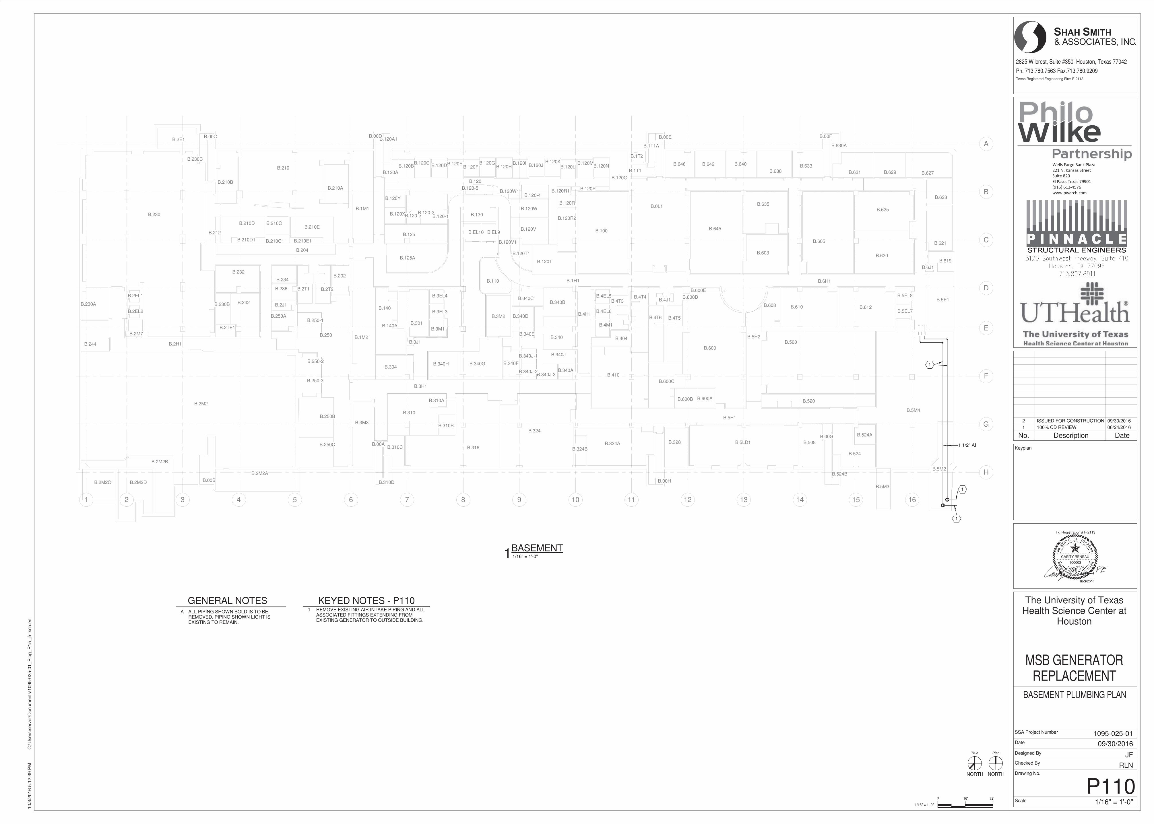
1 2 3 4 5 6 7 8 9 10 11 12 13 14 15 16
B
A
C
D
E
F
G
H
B.250-3
B.250-2
B.250-1
B.5H2
B.4H1
B.6H1
B.610 B.612
B.500
B.120-5
B.627B.629B.1T1
B.1T2
B.125A
B.125
B.120-4
B.120-3B.120-2
B.120-1
B.120W1
B.120V1
B.120
B.120Y
B.120X
B.120A1
B.212
B.210E1
B.210E
B.210D1
B.210D
B.210C1
B.210C
B.210B
B.210A
B.120V
B.120T1
B.120T
B.120R2
B.120R
B.120R1 B.120P
B.120W
B.120O
B.120NB.120M
B.120LB.120K
B.120JB.120IB.120H
B.120GB.120F
B.120EB.120DB.120C
B.120B
B.524B
B.310D
B.6J1
B.130
B.600E
B.600D
B.340J-3B.340J-2
B.340J-1
B.5LD1
B.1H1
B.3H1
B.608
B.328
B.410
B.5M3
B.600B B.600A
B.600
B.5H1
B.4T6 B.4T5
B.4T4B.4T3 B.4J1
B.404
B.630A
B.619
B.631
B.633B.638
B.640B.642B.646
B.645
B.603
B.635
B.605
B.625
B.620
B.623
B.621
B.508
B.524A
B.324BB.324A
B.324
B.316B.310C
B.310B
B.310A
B.310
B.340
B.340B
B.340A
B.340J
B.340G B.340F
B.340E
B.340D
B.340C
B.1M1
B.3M3
B.340HB.304
B.3J1
B.140A
B.0L1
B.100
B.250C
B.250B
B.2H1B.244
B.230A
B.230
B.2TE1
B.230B B.242
B.250A
B.250
B.202
B.2T2B.2T1
B.2J1
B.236
B.234
B.232
B.204
B.210
B.5M2
B.3EL4
B.3EL3
B.EL10 B.EL9
B.2EL2
B.2EL1
B.2M2B
B.4EL6
B.4EL5 B.5EL8
B.5EL7
B.00G
B.524
B.00H
B.00A
B.2M2A
B.00BB.2M2DB.2M2C
B.2M2
B.2M7B.3M1
B.3M2
B.4M1
B.5M4
B.5E1
B.520
B.00FB.00E
B.1T1A
B.00DB.00CB.2E1
B.120A
B.230C
B.301
B.110
B.140
B.600C
B.1M2
1
1
1
1 1/2" AI1 1/2" AI
������������� ������
��������������������
���������
��������������� ��
! �"#�$�%&'"�$
(((�)(��*+�*,
NORTHNORTH
Texas Registered Engineering Firm F-2113
0'
TA
S
E OF TEXAS
P RE
ENI
GNELANOISS
FO
R
EL I C E N S E D
T
CASITY RENEAU
100003
Tx. Registration # F-2113
Scale
Date
Designed By
Checked By
SSA Project Number
Drawing No.
1/16" = 1'-0"
16' 32'
2825 Wilcrest, Suite #350 Houston, Texas 77042
Ph. 713.780.7563 Fax.713.780.9209
Keyplan
True Plan
1/16" = 1'-0"
10/3
/2016 5
:12:3
9 P
MC
:\U
sers
\serv
er\
Docum
ents
\1095-0
25-0
1_P
lbg_R
15_jfrits
ch.r
vt
P110
BASEMENT PLUMBING PLAN
The University of TexasHealth Science Center at
Houston
MSB GENERATORREPLACEMENT
RLN
JF
09/30/2016
1095-025-01
1/16" = 1'-0"1BASEMENT
GENERAL NOTESA ALL PIPING SHOWN BOLD IS TO BE
REMOVED. PIPING SHOWN LIGHT ISEXISTING TO REMAIN.
KEYED NOTES - P1101 REMOVE EXISTING AIR INTAKE PIPING AND ALL
ASSOCIATED FITTINGS EXTENDING FROMEXISTING GENERATOR TO OUTSIDE BUILDING.
No. Description Date
1 100% CD REVIEW 06/24/2016
2 ISSUED FOR CONSTRUCTION 09/30/2016
� � � � � � � � �EE
NIGGGGGGGGGGGGGGGGGGGGGGGGGGGGGGGGGGGGGGGNNNNNNNNNNNNNNNNNNNNNNNNNNNNNNNNNNNNNNNNNNNNNNNNNNNNNNNNNNNNNNNNNNNNNEEEEEEEEEEEEEEEEEEEEEEEEEEEEEEEEEEEEEEEEEEEEEEEEEEEEEEEEEEEEEEEEEEELLLLLLLLLLLLLLLLLLLLLLLLLLLLLLLLLLLLLLLLLLLLLLLLLLLLLLLLLLLLLLLLLLLLLLLLLLLLLLLLLLLAAAAAAAAAAAAAAAAAAAAAAAAAAAAAAAAAAAAAAAAAAAAAAAAAAAANNNNNNNNNNNNNNNNNNNNNNNNNNNNNNNNNNNNNNNNOOOOOOOOOOOOOOOOOOOOOOOOOOOOOOOOOOOOOIIIIIIIIIISSSSS
FFFFFFFFFFFFFFFFFFFFFFFFFFFFFO
R
EEEEEEEEEEEEEEEEEEEEEEEEEEEEEEEEEEEEEEEEEEEEEEEEEEEEEEEEEEEEEEEEEEEEEL I CCCCCCCCCCCCCCCCCCCCCCCCCC EEEEEEEEEEEEEEEEEE NNNNNNNNNNNNNNNNNNNNNNNNNN SSSSSS E D� � � � � � � � �
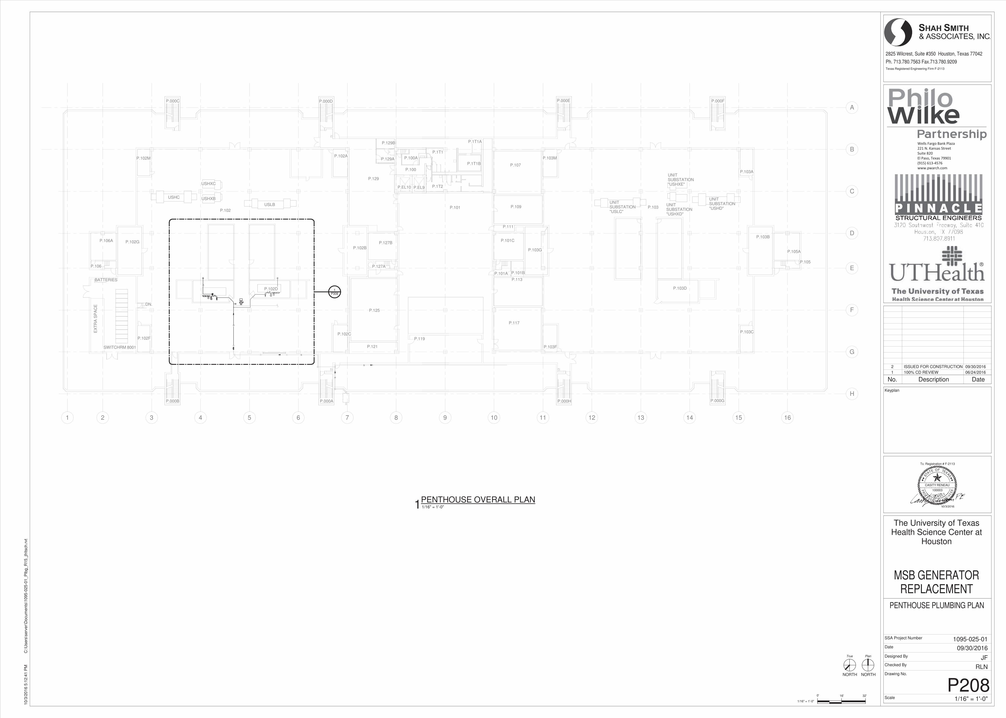
GV
G
G
G
G
1 2 3 4 5 6 7 8 9 10 11 12 13 14 15 16
B
A
C
D
E
F
G
H
BATTERIES
USHC USHXB
USHXC
UNITSUBSTATION"USHXD"
UNITSUBSTATION"USHXE"
UNITSUBSTATION"USLC"
UNITSUBSTATION"USHD"
USLB
EX
TR
A S
PA
CE DN.
P.129B
P.100
P.EL9P.EL10
P.101
P.1T1B
P.000H P.000G
P.000FP.000E
P.105
P.103D
P.103A
P.103C
P.105A
P.103B
P.103
P.103M
P.103F
P.117
P.113
P.103G
P.101A P.101B
P.101C
P.111
P.109
P.107
P.119
P.1T2
P.1T1A
P.1T1
P.100AP.129A
P.129
P.127B
P.127A
P.102B
P.125
P.121
P.102C
P.000C P.000D
P.102A
P.000AP.000B
P.102F
P.102D
SWITCHRM 8001
P.102
P.102M
P.102G
P.106
P.106A
P3081
������������� ������
��������������������
���������
��������������� ��
! �"#�$�%&'"�$
(((�)(��*+�*,
NORTHNORTH
Texas Registered Engineering Firm F-2113
0'
TA
S
E OF TEXAS
P RE
ENI
GNELANOISS
FO
R
EL I C E N S E D
T
CASITY RENEAU
100003
Tx. Registration # F-2113
Scale
Date
Designed By
Checked By
SSA Project Number
Drawing No.
1/16" = 1'-0"
16' 32'
2825 Wilcrest, Suite #350 Houston, Texas 77042
Ph. 713.780.7563 Fax.713.780.9209
Keyplan
True Plan
1/16" = 1'-0"
10/3
/2016 5
:12:4
1 P
MC
:\U
sers
\serv
er\
Docum
ents
\1095-0
25-0
1_P
lbg_R
15_jfrits
ch.r
vt
P208
PENTHOUSE PLUMBING PLAN
The University of TexasHealth Science Center at
Houston
MSB GENERATORREPLACEMENT
RLN
JF
09/30/2016
1095-025-01
1/16" = 1'-0"1PENTHOUSE OVERALL PLAN
No. Description Date
1 100% CD REVIEW 06/24/2016
2 ISSUED FOR CONSTRUCTION 09/30/2016
� � � � � � � � �EE
NIGGGGGGGGGGGGGGGGGGGGGGGGGGGGGGGGGGGGGGGGGGGGGGGGGNNNNNNNNNNNNNNNNNNNNNNNNNNNNNNNNNNNNNNNNNNNNNNNNNNNNNNNNNNNNNEEEEEEEEEEEEEEEEEEEEEEEEEEEEEEEEEEEEEEEEEEEEEEEEEEEEEEEEEEELLLLLLLLLLLLLLLLLLLLLLLLLLLLLLLLLLLLLLLLLLLLLLLLLLLLLLLLLLLLLLLLLLLLLLLLLLLAAAAAAAAAAAAAAAAAAAAAAAAAAAAAAAAAAAAAAAAAAAAAAAAAAAAAAAAANNNNNNNNNNNNNNNNNNNNNNNNNNNNOOOOOOOOOOOOOOOOOOOOOOOOOOOOOOOOOOOOOOOOOOOOOIIIIIIIIIIISSSSSSS
FFFFFFFFFFFFFFFFFFFFFFFFFFFFFFFFFFFFFO
R
EEEEEEEEEEEEEEEEEEEEEEEEEEEEEEEEEEEEEEEEEEEEEEEEEEEEEEEEEEEEEEEEEL I CCCCCCCCCCC EEEEEEEEEEEEEEEEEEEEEEE NNNNNNNNNNNNNNNNNNNNNNNNNN SSSSSSSSSSS E D� � � � � � � � �
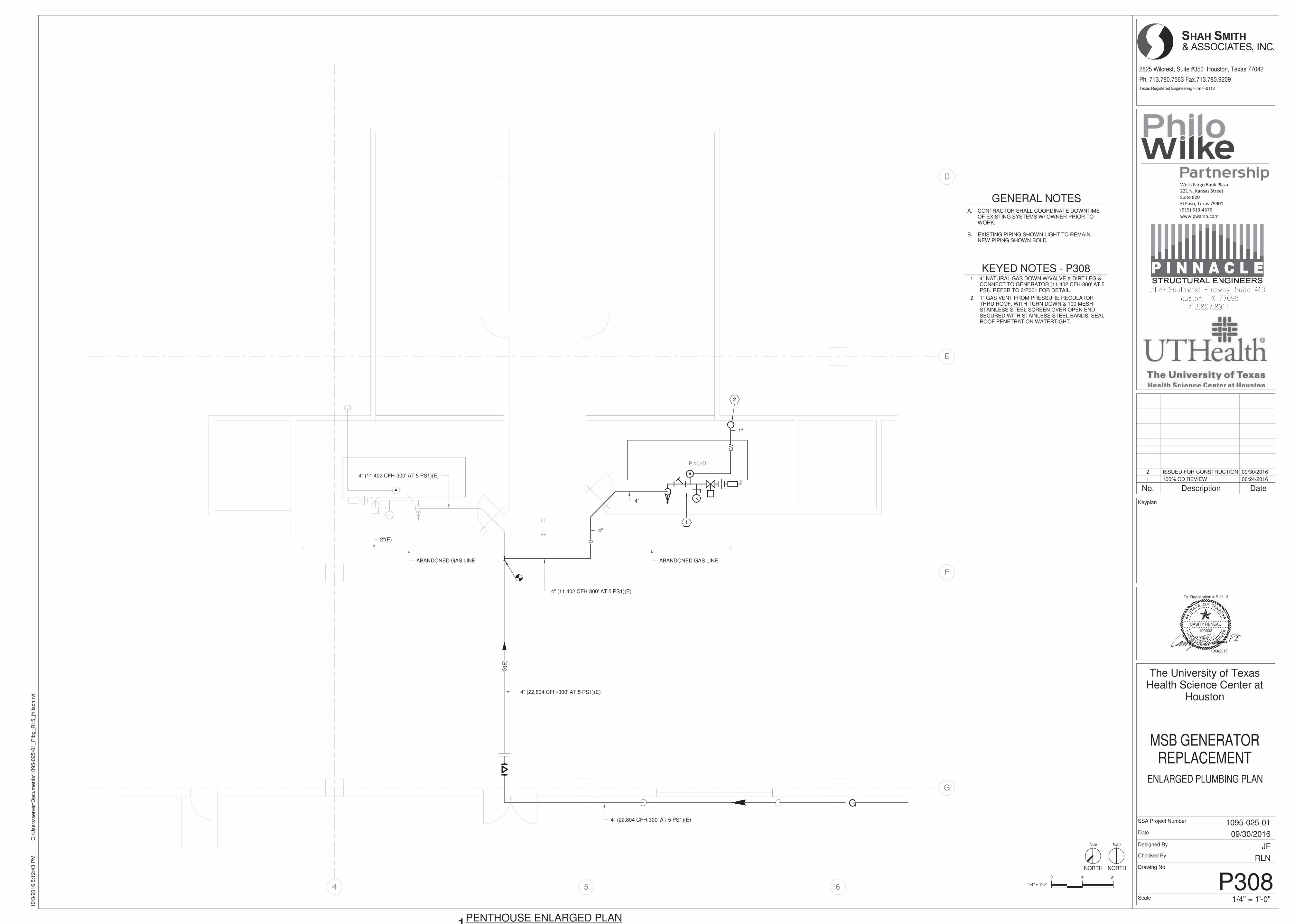
G
4 5 6
D
E
F
G
P.102D
G(E
)
4" (22,804 CFH-300' AT 5 PS1)(E)
4" (11,402 CFH-300' AT 5 PS1)(E)
4"
G
4"
4" (11,402 CFH-300' AT 5 PS1)(E)
ABANDONED GAS LINE
2"(E)
1
ABANDONED GAS LINE
4" (22,804 CFH-300' AT 5 PS1)(E)
GV
1"
2
������������� ������
��������������������
���������
��������������� ��
! �"#�$�%&'"�$
(((�)(��*+�*,
NORTHNORTH
0'
Texas Registered Engineering Firm F-2113
TA
S
E OF TEXAS
P RE
ENI
GNELANOISS
FO
R
EL I C E N S E D
T
CASITY RENEAU
100003
Tx. Registration # F-2113
Scale
Date
Designed By
Checked By
SSA Project Number
Drawing No.
2825 Wilcrest, Suite #350 Houston, Texas 77042
Ph. 713.780.7563 Fax.713.780.9209
Keyplan
1/4" = 1'-0"
4' 8'
True Plan
1/4" = 1'-0"
10/3
/2016 5
:12:4
3 P
MC
:\U
sers
\serv
er\
Docum
ents
\1095-0
25-0
1_P
lbg_R
15_jfrits
ch.r
vt
P308
ENLARGED PLUMBING PLAN
The University of TexasHealth Science Center at
Houston
MSB GENERATORREPLACEMENT
RLN
JF
09/30/2016
1095-025-01
1PENTHOUSE ENLARGED PLAN
GENERAL NOTESA.
B.
CONTRACTOR SHALL COORDINATE DOWNTIMEOF EXISTING SYSTEMS W/ OWNER PRIOR TOWORK.
EXISTING PIPING SHOWN LIGHT TO REMAIN.NEW PIPING SHOWN BOLD.
KEYED NOTES - P3081 4" NATURAL GAS DOWN W/VALVE & DIRT LEG &
CONNECT TO GENERATOR (11,402 CFH-300' AT 5PSI). REFER TO 2/P001 FOR DETAIL.
2 1" GAS VENT FROM PRESSURE REGULATORTHRU ROOF, WITH TURN DOWN & 100 MESHSTAINLESS STEEL SCREEN OVER OPEN ENDSECURED WITH STAINLESS STEEL BANDS. SEALROOF PENETRATION WATERTIGHT.
No. Description Date
1 100% CD REVIEW 06/24/2016
2 ISSUED FOR CONSTRUCTION 09/30/2016
� � � � � � � � �EE
NIGGGGGGGGGGGGGGGGGGGGGGGGGGGGGGGGGGGGGGGGGGGGGGGGGGGGGGGGGGGGGGGGGGGGGGGGGGGGGGGGGNNNNNNNNNNNNNNNNNNNNNNNNNNNNNNNNNNNNNNNNNNNNNNNNNNNNNNNNNNNNNNNNNNNNNNNNNNNNNNNNNNNNNNNNNEEEEEEEEEEEEEEEEEEEEEEEEEEEEEEEEEEEEEEEEEEEEEEEEEEEEEEEEEEEEEEEEEEELLLLLLLLLLLLLLLLLLLLLLLLLLLLLLLLLLLLLLLLLLLLLLLLLLLLLLLLLLLLLLLLLLLLLAAAAAAAAAAAAAAAAAAAAAAAAAAAAAAAAAAAAAAAAAAAAAAAAAAAAAAANNNNNNNNNNNNNNNNNNNNNNNNNNNNNNNNOOOOOOOOOOOOOOOOOOOOOOOOOOOOOOOOOOOOOOOOOOOOOOOOOOOOOIIIIIIIIIIIIIISSSSSSSSSSSSSSSSSSSSSSSSSSSSS
FFFFFFFFFFFFFFFFFFFFFFFFFOOOOOOOOO
R
EEEEEEEEEEEEEEEEEEEEEEEEEEEEEEEEEEEEEEEEEEEEEEEEEEEEEEEEL I CCCCCCCCCCCCCCCCC EEEEEEEEEEEEEEEEEEEEE NNNNNNNNNNNNNNNNNNNN S E D� � � � � � � � �