generator paralleling controller, gpc-3 + variants generator
TRANSCRIPT

DEIF A/S · Frisenborgvej 33 · DK-7800 Skive · Tel.: +45 9614 9614 · Fax: +45 9614 9615 · [email protected] · www.deif.com
DEIF A/S · Frisenborgvej 33 · DK-7800 Skive · Tel.: +45 9614 9614 · Fax: +45 9614 9615 · [email protected] · www.deif.com
DEIF A/S · Frisenborgvej 33 · DK-7800 Skive · Tel.: +45 9614 9614 · Fax: +45 9614 9615 · [email protected] · www.deif.com
INSTALLATION INSTRUCTIONS
Generator Paralleling Controller, GPC-3 + variantsGenerator Protection Unit, GPU-3 + variants
Paralleling and Protection Unit, PPU-3 Mounting Board slot positions I/O lists Wiring
Document no.: 4189340582OSW version: 3.06.x or later
1. Delimitation1.1. Scope of Installation Instructions............................................................................................................4
1.1.1. GPC-3, GPU-3 and PPU-3 ........................................................................................................... 4
2. General information2.1. Warnings, legal information and safety.................................................................................................. 5
2.1.1. Warnings and notes ......................................................................................................................52.1.2. Legal information and disclaimer ..................................................................................................52.1.3. Safety issues ................................................................................................................................ 52.1.4. Electrostatic discharge awareness ............................................................................................... 52.1.5. Factory settings ............................................................................................................................ 6
2.2. About the installation instructions...........................................................................................................62.2.1. General purpose ...........................................................................................................................62.2.2. Intended users ..............................................................................................................................62.2.3. Contents and overall structure ......................................................................................................6
3. Mounting and dimensions3.1. Mounting of the unit................................................................................................................................7
3.1.1. Unit dimensions............................................................................................................................. 73.1.2. Panel cutout...................................................................................................................................83.1.3. Drilling template.............................................................................................................................93.1.4. Mounting instructions.....................................................................................................................93.1.5. Tightening torques....................................................................................................................... 10
4. Hardware4.1. General hardware description.............................................................................................................. 11
4.1.1. Board slot positions......................................................................................................................114.1.2. Unit topside overview...................................................................................................................12
5. I/O lists5.1. I/O list and terminal strip description - GPU, GPU Hydro.....................................................................13
5.1.1. Slot #1, power supply and binary I/O...........................................................................................135.1.2. Slot #2, external communication (optional)..................................................................................145.1.3. Slot #3, digital I/Os (option M12) ................................................................................................ 165.1.4. Slot #4, GOV/AVR (optional)....................................................................................................... 175.1.5. Slot #5, AC measuring ................................................................................................................195.1.6. Slot #6, I/O extension (optional) ................................................................................................. 205.1.7. Slot #7, engine interface board (option M4).................................................................................225.1.8. Slot #8, communication and I/O (optional) ..................................................................................235.1.9. Digital inputs ............................................................................................................................... 255.1.10. Relay outputs ............................................................................................................................25
5.2. I/O list and terminal strip description - GPC, PPU................................................................................265.2.1. Slot #1, power supply and binary I/O...........................................................................................265.2.2. Slot #2, external communication (optional)..................................................................................275.2.3. Slot #3, digital I/Os ......................................................................................................................295.2.4. Slot #4, GOV/AVR....................................................................................................................... 305.2.5. Slot #5, AC measuring ................................................................................................................335.2.6. Slot #6, I/O extension (optional) ................................................................................................. 335.2.7. Slot #7, engine interface board (option M4).................................................................................355.2.8. Slot #8, communication and I/O (optional) ..................................................................................365.2.9. Digital inputs ............................................................................................................................... 385.2.10. Relay outputs ............................................................................................................................39
6. Wirings6.1. AC connections.................................................................................................................................... 40
6.1.1. 3-phase .......................................................................................................................................406.1.2. 3-phase, 2-phase voltage, 1-phase current ................................................................................416.1.3. 1-phase .......................................................................................................................................42
ML-2 installation instructions 4189340582UK
DEIF A/S Page 2 of 64
6.1.4. 2-phase........................................................................................................................................436.1.5. CAN bus load sharing (option G9)...............................................................................................446.1.6. Modbus, RS-485 (option H2) ......................................................................................................446.1.7. Modbus, RS-232 (option H9.2) ...................................................................................................466.1.8. Profibus DP (option H3) ..............................................................................................................476.1.9. CAN bus engine communication (option H5)...............................................................................476.1.10. CAN bus engine communication (option H7).............................................................................486.1.11. CAN bus external I/O communication - Axiomatic.....................................................................496.1.12. Display cable (option J)............................................................................................................. 506.1.13. Load sharing lines (option G3)...................................................................................................506.1.14. Mechanical speed governor.......................................................................................................516.1.15. AVR with relay outputs...............................................................................................................516.1.16. Electronic speed governor.........................................................................................................526.1.17. AVR with analogue outputs........................................................................................................526.1.18. Digital inputs.............................................................................................................................. 536.1.19. Digital inputs with wire break supervision (option M4)...............................................................536.1.20. Multi-functional inputs (option M4).............................................................................................546.1.21. Magnetic pickup (MPU) input (option M4)................................................................................. 556.1.22. Analogue inputs (option M15.x) ................................................................................................566.1.23. Stop coil with wire break detection (option M4)......................................................................... 566.1.24. Transistor outputs ..................................................................................................................... 576.1.25. Additional display unit, DU-2 (option X2) ..................................................................................586.1.26. Additional operator panel, AOP-1 (option X3) .......................................................................... 596.1.27. Additional operator panel, AOP-2 (option X4) .......................................................................... 59
7. Technical information7.1. Technical specifications........................................................................................................................61
ML-2 installation instructions 4189340582UK
DEIF A/S Page 3 of 64
1. Delimitation1.1 Scope of Installation Instructions
1.1.1 GPC-3, GPU-3 and PPU-3This document covers the following products and product variants:
GPC Software version 3.06.x
GPC Gas Software version 3.06.x
GPC Hydro Software version 3.06.x
GPU Software version 3.06.x
GPU Gas Software version 3.06.x
GPU Hydro Software version 3.06.x
PPU Software version 3.06.x
ML-2 installation instructions 4189340582UK
Delimitation
DEIF A/S Page 4 of 64

2. General information2.1 Warnings, legal information and safety
2.1.1 Warnings and notesThroughout this document, a number of warnings and notes with helpful user information will be presented.To ensure that these are noticed, they will be highlighted as follows in order to separate them from the gener-al text.
Warnings
Warnings indicate a potentially dangerous situation, which could result in death, personal in-jury or damaged equipment, if certain guidelines are not followed.
Notes
Notes provide general information, which will be helpful for the reader to bear in mind.
2.1.2 Legal information and disclaimerDEIF takes no responsibility for installation or operation of the generator set. If there is any doubt about howto install or operate the engine/generator controlled by the Multi-line 2 unit, the company responsible for theinstallation or the operation of the set must be contacted.
The Multi-line 2 unit is not to be opened by unauthorised personnel. If opened anyway, the war-ranty will be lost.
DisclaimerDEIF A/S reserves the right to change any of the contents of this document without prior notice.
The English version of this document always contains the most recent and up-to-date information about theproduct. DEIF does not take responsibility for the accuracy of translations, and translations might not be up-dated at the same time as the English document. If there is a discrepancy, the English version prevails.
2.1.3 Safety issuesInstalling and operating the Multi-line 2 unit may imply work with dangerous currents and voltages. Therefore,the installation should only be carried out by authorised personnel who understand the risks involved in work-ing with live electrical equipment.
Be aware of the hazardous live currents and voltages. Do not touch any AC measurement in-puts as this could lead to injury or death.
2.1.4 Electrostatic discharge awarenessSufficient care must be taken to protect the terminal against static discharges during the installation. Once theunit is installed and connected, these precautions are no longer necessary.
ML-2 installation instructions 4189340582UK
General information
DEIF A/S Page 5 of 64
2.1.5 Factory settingsThe Multi-line 2 unit is delivered from factory with certain factory settings. These are based on average valuesand are not necessarily the correct settings for matching the engine/generator set in question. Precautionsmust be taken to check the settings before running the engine/generator set.
2.2 About the installation instructions
2.2.1 General purposeThese Installation Instructions mainly include general product and hardware information, mounting instruc-tions, terminal strip descriptions, I/O lists and wiring descriptions.
The general purpose of this document is to give the user important information to be used in the installation ofthe unit.
Make sure to read this document before starting to work with the Multi-line 2 unit and the gen-set to be controlled. Failure to do this could result in human injury or damage to the equip-ment.
2.2.2 Intended usersThese Installation Instructions are mainly intended for the person responsible for the design and installation.In most cases, this would be a panel builder designer. Naturally, other users might also find useful informationin the document.
2.2.3 Contents and overall structureThis document is divided into chapters, and in order to make the structure simple and easy to use, eachchapter will begin from the top of a new page.
ML-2 installation instructions 4189340582UK
General information
DEIF A/S Page 6 of 64
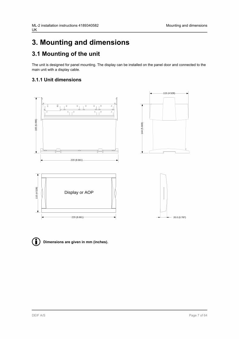
3. Mounting and dimensions3.1 Mounting of the unitThe unit is designed for panel mounting. The display can be installed on the panel door and connected to themain unit with a display cable.
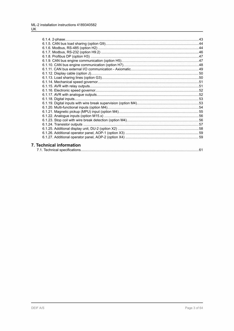
3.1.1 Unit dimensions
Display or AOP
220 (8.661)
16
5 (
6.4
96
)
14
4 (
5.6
69
)
11
5 (
4.5
28
)
220 (8.661)
115 (4.528)
20.0 (0.787)
Dimensions are given in mm (inches).
ML-2 installation instructions 4189340582UK
Mounting and dimensions
DEIF A/S Page 7 of 64
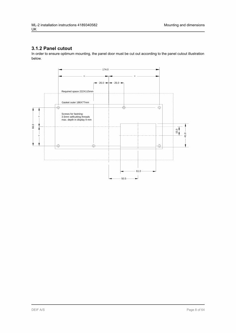
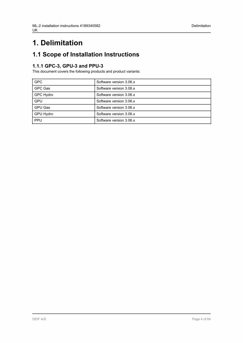
3.1.2 Panel cutoutIn order to ensure optimum mounting, the panel door must be cut out according to the panel cutout illustrationbelow.
Required space 222X115mm
Gasket outer 186X77mm
Screws for fastning:
3.5mm selfcutting threads
max. depth in display 9 mm
26.0
= =
=
=
50.5
66
.0
26.0
61.0
174.0
15
.0
41
.0
ML-2 installation instructions 4189340582UK
Mounting and dimensions
DEIF A/S Page 8 of 64
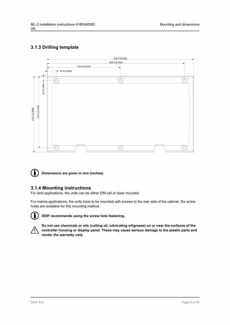
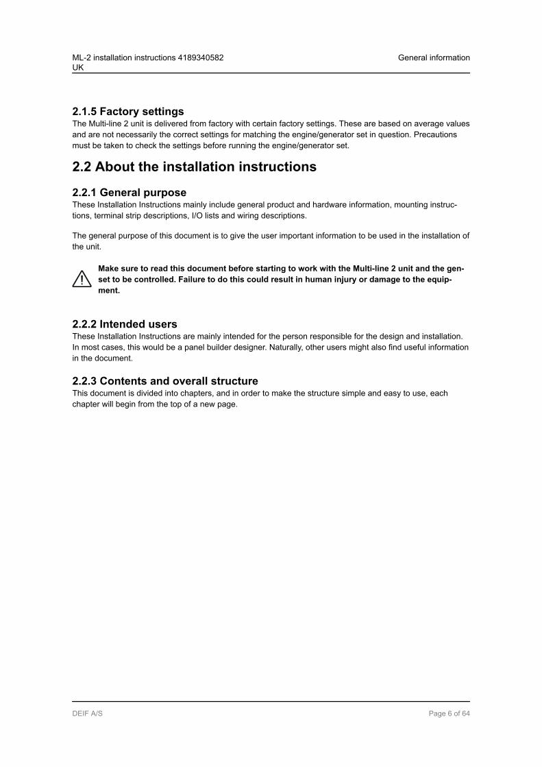
3.1.3 Drilling template
230.0 (9.055)
11
9.1
(4.6
89)
6.6
(0.2
60)
11
2.6
(4.4
33)
215.5 (8.484)
114.9 (4.524)
14.3 (0.563)
Dimensions are given in mm (inches).
3.1.4 Mounting instructionsFor land applications, the units can be either DIN-rail or base mounted.
For marine applications, the units have to be mounted with screws to the rear side of the cabinet. Six screwholes are available for this mounting method.
DEIF recommends using the screw hole fastening.
Do not use chemicals or oils (cutting oil, lubricating oil/grease) on or near the surfaces of thecontroller housing or display panel. These may cause serious damage to the plastic parts andrender the warranty void.
ML-2 installation instructions 4189340582UK
Mounting and dimensions
DEIF A/S Page 9 of 64

3.1.5 Tightening torques
Base unit mounting: 0.3 Nm, 2.7 lb-inPlug connections (terminals): 0.5 Nm, 4.4 lb-in
Display, AOP-1 and AOP-2 (see diagram below)Panel door mounting: 0.7 Nm, 6.2 lb-inSub-D screw: 0.2 Nm, 1.8 lb-inDC-DC converter terminals: 0.5 Nm, 4.4 lb-in
220.0 (8.661)
11
5.0
(4.5
28
)
Display
20.0 (0.787)
0.7 NmScrew M3
Bossard BN5687
or similar
0.2 Nm
9P Female
Sub 0
connector
Max. 10 mm
Min. 6 mm
ML-2 installation instructions 4189340582UK
Mounting and dimensions
DEIF A/S Page 10 of 64
4. Hardware4.1 General hardware description
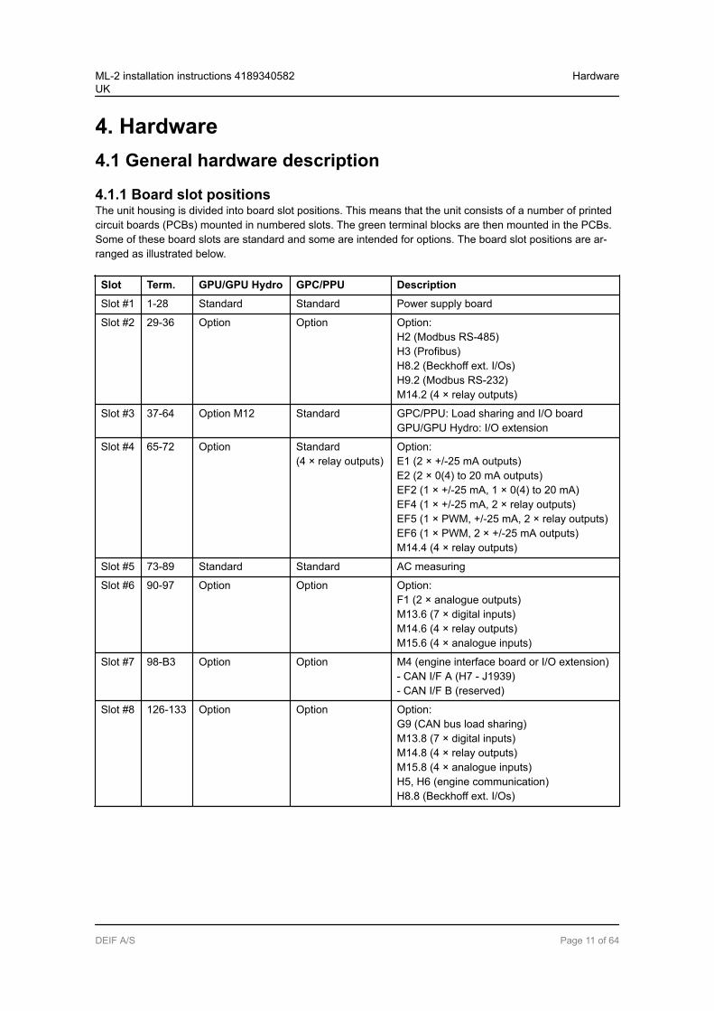
4.1.1 Board slot positionsThe unit housing is divided into board slot positions. This means that the unit consists of a number of printedcircuit boards (PCBs) mounted in numbered slots. The green terminal blocks are then mounted in the PCBs.Some of these board slots are standard and some are intended for options. The board slot positions are ar-ranged as illustrated below.
Slot Term. GPU/GPU Hydro GPC/PPU Description
Slot #1 1-28 Standard Standard Power supply board
Slot #2 29-36 Option Option Option:H2 (Modbus RS-485)H3 (Profibus)H8.2 (Beckhoff ext. I/Os)H9.2 (Modbus RS-232)M14.2 (4 × relay outputs)
Slot #3 37-64 Option M12 Standard GPC/PPU: Load sharing and I/O boardGPU/GPU Hydro: I/O extension
Slot #4 65-72 Option Standard(4 × relay outputs)
Option:E1 (2 × +/-25 mA outputs)E2 (2 × 0(4) to 20 mA outputs)EF2 (1 × +/-25 mA, 1 × 0(4) to 20 mA)EF4 (1 × +/-25 mA, 2 × relay outputs)EF5 (1 × PWM, +/-25 mA, 2 × relay outputs)EF6 (1 × PWM, 2 × +/-25 mA outputs)M14.4 (4 × relay outputs)
Slot #5 73-89 Standard Standard AC measuring
Slot #6 90-97 Option Option Option:F1 (2 × analogue outputs)M13.6 (7 × digital inputs)M14.6 (4 × relay outputs)M15.6 (4 × analogue inputs)
Slot #7 98-B3 Option Option M4 (engine interface board or I/O extension)- CAN I/F A (H7 - J1939)- CAN I/F B (reserved)
Slot #8 126-133 Option Option Option:G9 (CAN bus load sharing)M13.8 (7 × digital inputs)M14.8 (4 × relay outputs)M15.8 (4 × analogue inputs)H5, H6 (engine communication)H8.8 (Beckhoff ext. I/Os)
ML-2 installation instructions 4189340582UK
Hardware
DEIF A/S Page 11 of 64
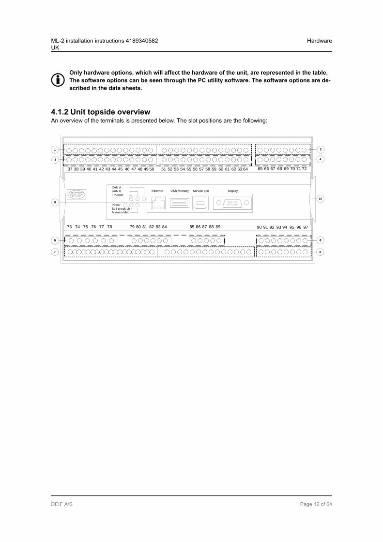
Only hardware options, which will affect the hardware of the unit, are represented in the table.The software options can be seen through the PC utility software. The software options are de-scribed in the data sheets.
4.1.2 Unit topside overviewAn overview of the terminals is presented below. The slot positions are the following:
Ethernet
787776757473 96 979594929190 9389888785 8683 8482818079
727169 70686765 6662 6359 60 615856 575553 54 645251504947464443 45 4841403837 39 42
Service port Display
Ethernet
CAN BCAN A
Power
Self check okAlarm inhibit
1
4
9
5
10
6
3
7 8
2
USB Memory
ML-2 installation instructions 4189340582UK
Hardware
DEIF A/S Page 12 of 64
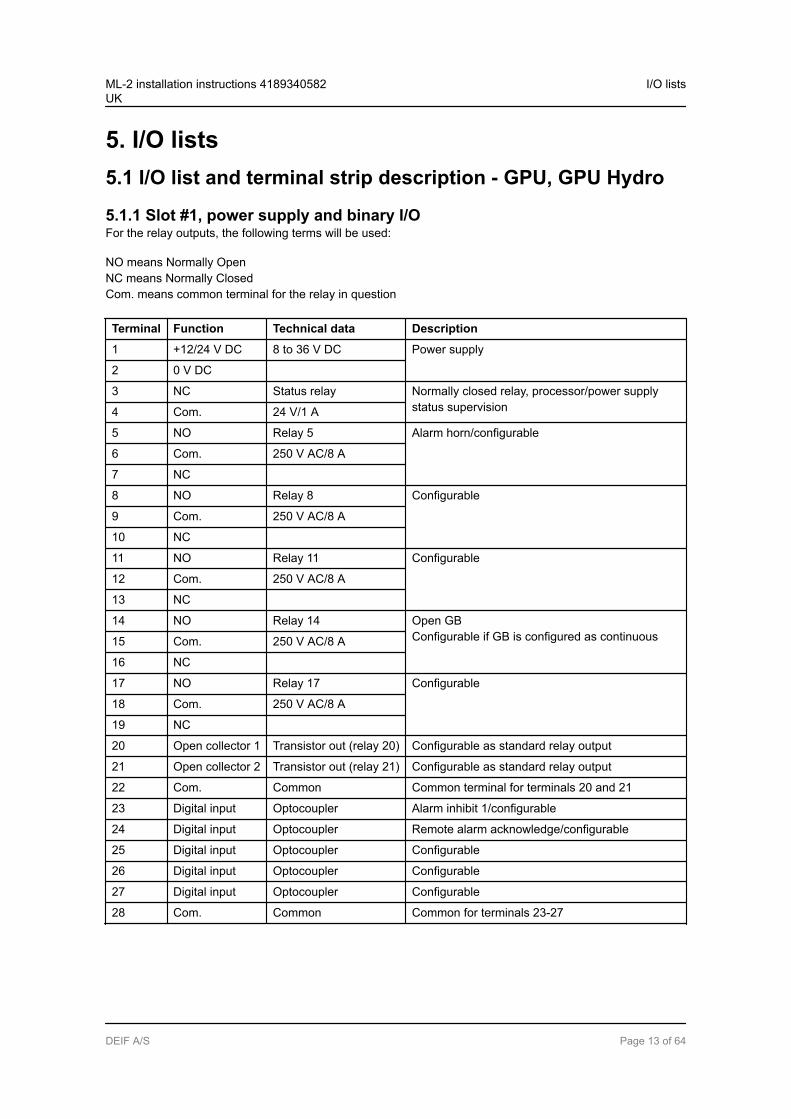
5. I/O lists5.1 I/O list and terminal strip description - GPU, GPU Hydro
5.1.1 Slot #1, power supply and binary I/OFor the relay outputs, the following terms will be used:
NO means Normally OpenNC means Normally ClosedCom. means common terminal for the relay in question
Terminal Function Technical data Description
1 +12/24 V DC 8 to 36 V DC Power supply
2 0 V DC
3 NC Status relay Normally closed relay, processor/power supplystatus supervision4 Com. 24 V/1 A
5 NO Relay 5 Alarm horn/configurable
6 Com. 250 V AC/8 A
7 NC
8 NO Relay 8 Configurable
9 Com. 250 V AC/8 A
10 NC
11 NO Relay 11 Configurable
12 Com. 250 V AC/8 A
13 NC
14 NO Relay 14 Open GBConfigurable if GB is configured as continuous15 Com. 250 V AC/8 A
16 NC
17 NO Relay 17 Configurable
18 Com. 250 V AC/8 A
19 NC
20 Open collector 1 Transistor out (relay 20) Configurable as standard relay output
21 Open collector 2 Transistor out (relay 21) Configurable as standard relay output
22 Com. Common Common terminal for terminals 20 and 21
23 Digital input Optocoupler Alarm inhibit 1/configurable
24 Digital input Optocoupler Remote alarm acknowledge/configurable
25 Digital input Optocoupler Configurable
26 Digital input Optocoupler Configurable
27 Digital input Optocoupler Configurable
28 Com. Common Common for terminals 23-27
ML-2 installation instructions 4189340582UK
I/O lists
DEIF A/S Page 13 of 64
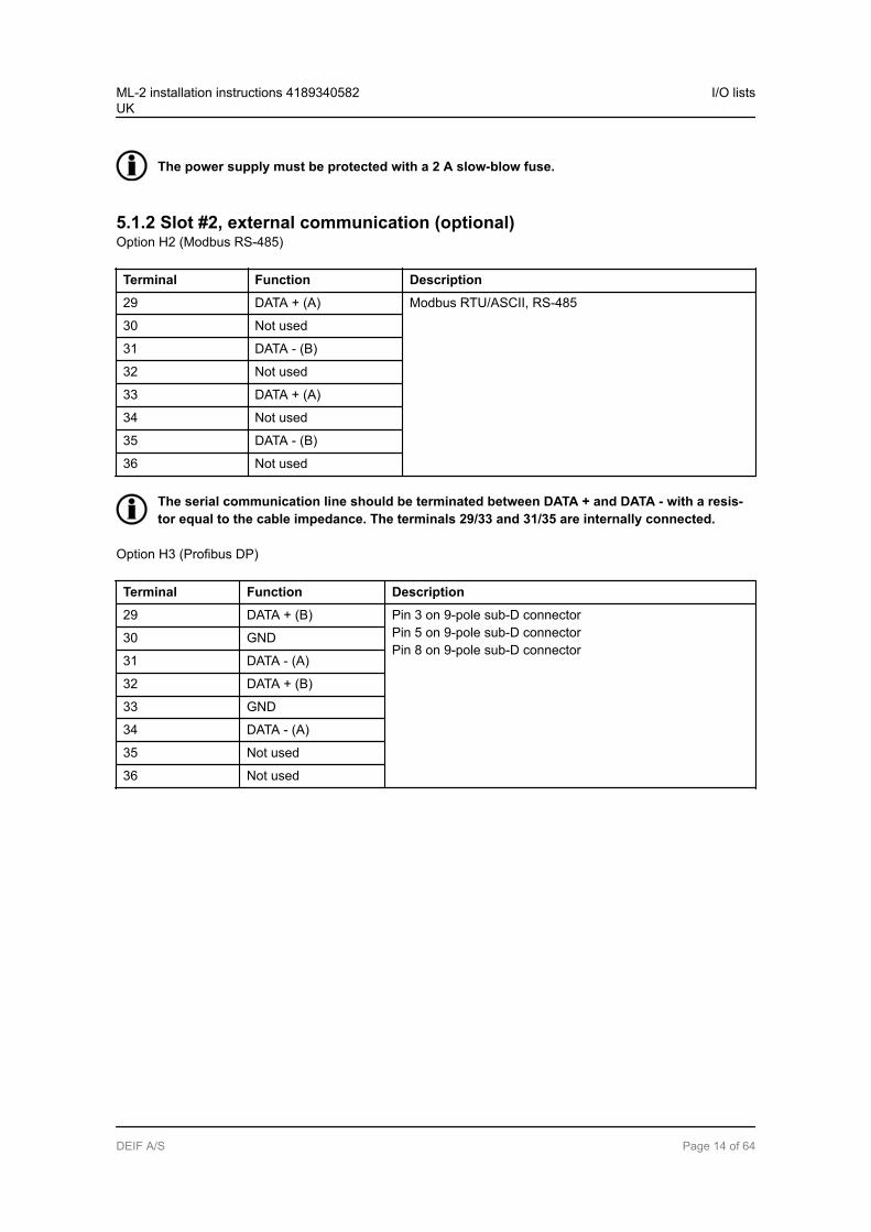
The power supply must be protected with a 2 A slow-blow fuse.
5.1.2 Slot #2, external communication (optional)Option H2 (Modbus RS-485)
Terminal Function Description
29 DATA + (A) Modbus RTU/ASCII, RS-485
30 Not used
31 DATA - (B)
32 Not used
33 DATA + (A)
34 Not used
35 DATA - (B)
36 Not used
The serial communication line should be terminated between DATA + and DATA - with a resis-tor equal to the cable impedance. The terminals 29/33 and 31/35 are internally connected.
Option H3 (Profibus DP)
Terminal Function Description
29 DATA + (B) Pin 3 on 9-pole sub-D connectorPin 5 on 9-pole sub-D connectorPin 8 on 9-pole sub-D connector
30 GND
31 DATA - (A)
32 DATA + (B)
33 GND
34 DATA - (A)
35 Not used
36 Not used
ML-2 installation instructions 4189340582UK
I/O lists
DEIF A/S Page 14 of 64
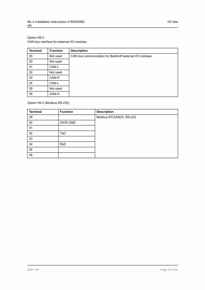
Option H8.2CAN bus interface for external I/O modules.
Terminal Function Description
29 Not used CAN bus communication for Beckhoff external I/O modules
30 Not used
31 CAN-L
32 Not used
33 CAN-H
34 CAN-L
35 Not used
36 CAN-H
Option H9.2 (Modbus RS-232)
Terminal Function Description
29 Modbus RTU/ASCII, RS-232
30 DATA GND
31
32 TxD
33
34 RxD
35
36
ML-2 installation instructions 4189340582UK
I/O lists
DEIF A/S Page 15 of 64
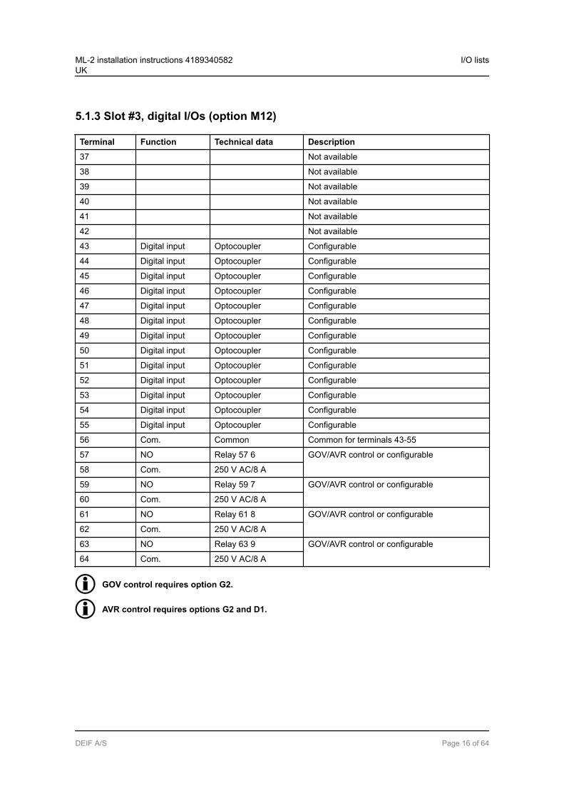
5.1.3 Slot #3, digital I/Os (option M12)
Terminal Function Technical data Description
37 Not available
38 Not available
39 Not available
40 Not available
41 Not available
42 Not available
43 Digital input Optocoupler Configurable
44 Digital input Optocoupler Configurable
45 Digital input Optocoupler Configurable
46 Digital input Optocoupler Configurable
47 Digital input Optocoupler Configurable
48 Digital input Optocoupler Configurable
49 Digital input Optocoupler Configurable
50 Digital input Optocoupler Configurable
51 Digital input Optocoupler Configurable
52 Digital input Optocoupler Configurable
53 Digital input Optocoupler Configurable
54 Digital input Optocoupler Configurable
55 Digital input Optocoupler Configurable
56 Com. Common Common for terminals 43-55
57 NO Relay 57 6 GOV/AVR control or configurable
58 Com. 250 V AC/8 A
59 NO Relay 59 7 GOV/AVR control or configurable
60 Com. 250 V AC/8 A
61 NO Relay 61 8 GOV/AVR control or configurable
62 Com. 250 V AC/8 A
63 NO Relay 63 9 GOV/AVR control or configurable
64 Com. 250 V AC/8 A
GOV control requires option G2.
AVR control requires options G2 and D1.
ML-2 installation instructions 4189340582UK
I/O lists
DEIF A/S Page 16 of 64
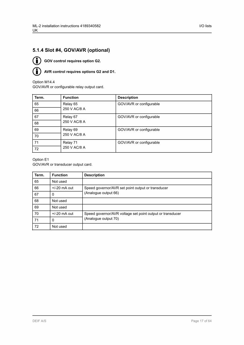
5.1.4 Slot #4, GOV/AVR (optional)
GOV control requires option G2.
AVR control requires options G2 and D1.
Option M14.4GOV/AVR or configurable relay output card.
Term. Function Description
65 Relay 65250 V AC/8 A
GOV/AVR or configurable
66
67 Relay 67250 V AC/8 A
GOV/AVR or configurable
68
69 Relay 69250 V AC/8 A
GOV/AVR or configurable
70
71 Relay 71250 V AC/8 A
GOV/AVR or configurable
72
Option E1GOV/AVR or transducer output card.
Term. Function Description
65 Not used
66 +/-20 mA out Speed governor/AVR set point output or transducer(Analogue output 66)67 0
68 Not used
69 Not used
70 +/-20 mA out Speed governor/AVR voltage set point output or transducer(Analogue output 70)71 0
72 Not used
ML-2 installation instructions 4189340582UK
I/O lists
DEIF A/S Page 17 of 64

Option E2GOV/AVR or transducer output card.
Term. Function Description
65 Not used
66 0 to 20 mA out Speed governor/AVR set point output or transducer(Analogue output 66)67 0
68 Not used
69 Not used
70 0 to 20 mA out Speed governor/AVR voltage set point output or transducer(Analogue output 70)71 0
72 Not used
Option EF2GOV/AVR or transducer output card.
Term. Function Description
65 Not used
66 +/-20 mA Speed governor/AVR set point output or transducer(Analogue output 66)67 0
68 Not used
69 Not used
70 0(4) to 20 mA out Speed governor/AVR set point output or transducer(Analogue output 70)71 0
72 Not used
Option EF4GOV/AVR or transducer combination output card.
Term. Function Description
65 ANA + Speed governor/AVR set point output or transducer(Analogue output 66)66 ANA -
67 Not used
68 Not used
69 Relay 69250 V AC, 8 A
GOV/AVR control or configurable
70
71 Relay 71250 V AC, 8 A
GOV/AVR control or configurable
72
ML-2 installation instructions 4189340582UK
I/O lists
DEIF A/S Page 18 of 64
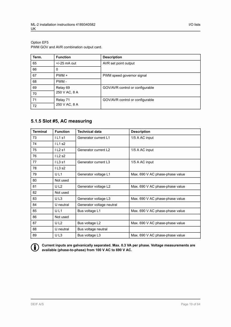
Option EF5PWM GOV and AVR combination output card.
Term. Function Description
65 +/-25 mA out AVR set point output
66 0
67 PWM + PWM speed governor signal
68 PWM -
69 Relay 69250 V AC, 8 A
GOV/AVR control or configurable
70
71 Relay 71250 V AC, 8 A
GOV/AVR control or configurable
72
5.1.5 Slot #5, AC measuring
Terminal Function Technical data Description
73 I L1 s1 Generator current L1 1/5 A AC input
74 I L1 s2
75 I L2 s1 Generator current L2 1/5 A AC input
76 I L2 s2
77 I L3 s1 Generator current L3 1/5 A AC input
78 I L3 s2
79 U L1 Generator voltage L1 Max. 690 V AC phase-phase value
80 Not used
81 U L2 Generator voltage L2 Max. 690 V AC phase-phase value
82 Not used
83 U L3 Generator voltage L3 Max. 690 V AC phase-phase value
84 U neutral Generator voltage neutral
85 U L1 Bus voltage L1 Max. 690 V AC phase-phase value
86 Not used
87 U L2 Bus voltage L2 Max. 690 V AC phase-phase value
88 U neutral Bus voltage neutral
89 U L3 Bus voltage L3 Max. 690 V AC phase-phase value
Current inputs are galvanically separated. Max. 0.3 VA per phase. Voltage measurements areavailable (phase-to-phase) from 100 V AC to 690 V AC.
ML-2 installation instructions 4189340582UK
I/O lists
DEIF A/S Page 19 of 64
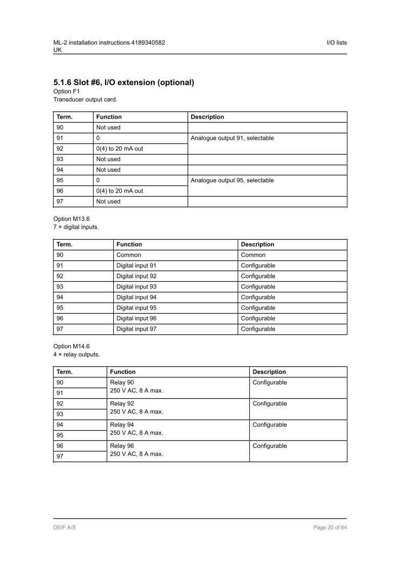
5.1.6 Slot #6, I/O extension (optional)Option F1Transducer output card.
Term. Function Description
90 Not used
91 0 Analogue output 91, selectable
92 0(4) to 20 mA out
93 Not used
94 Not used
95 0 Analogue output 95, selectable
96 0(4) to 20 mA out
97 Not used
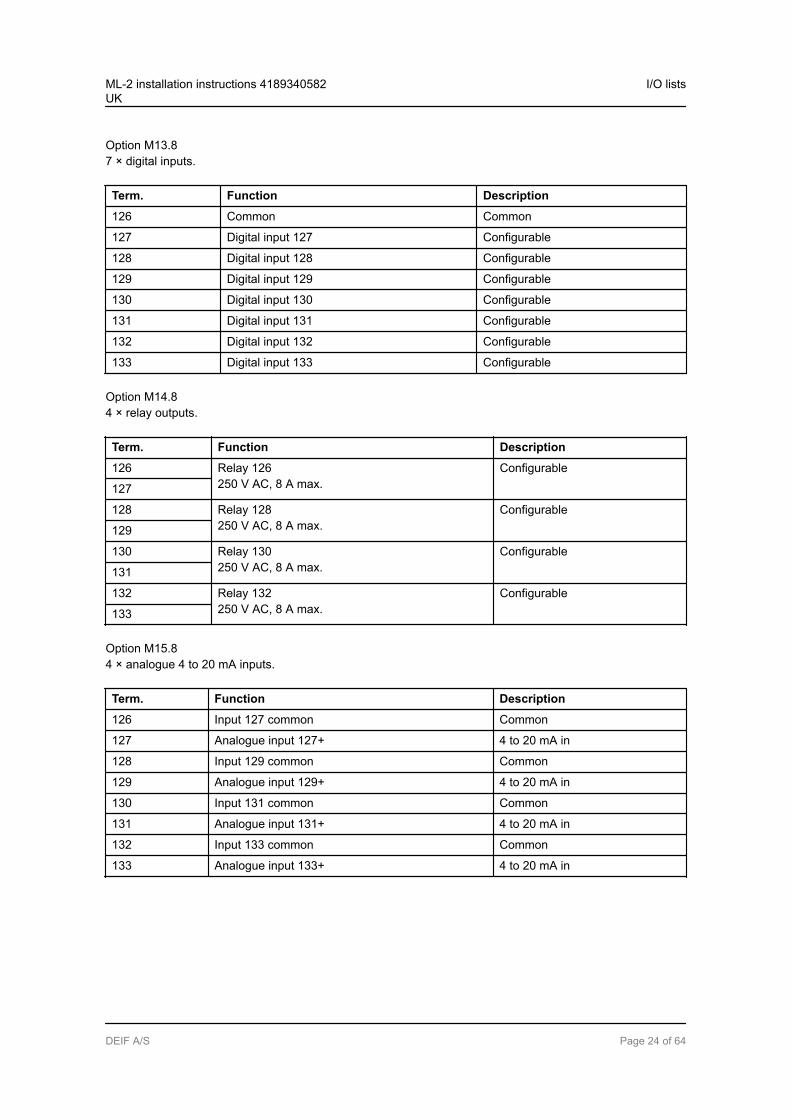
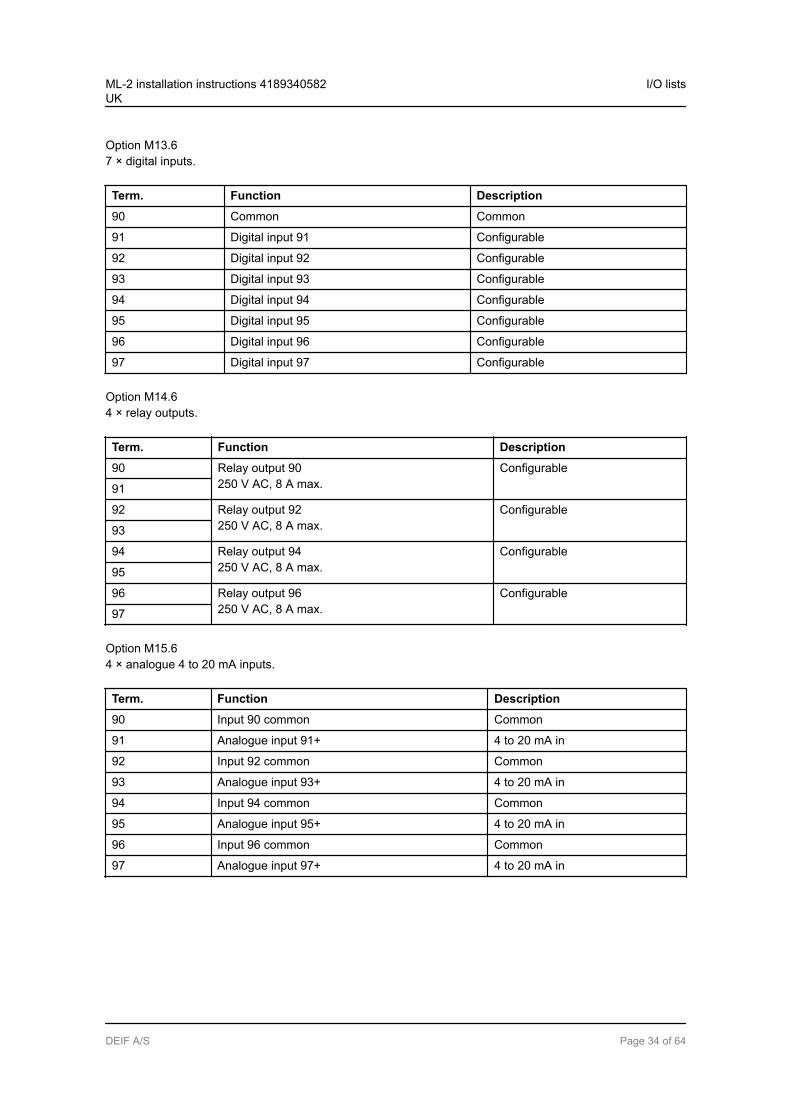
Option M13.67 × digital inputs.
Term. Function Description
90 Common Common
91 Digital input 91 Configurable
92 Digital input 92 Configurable
93 Digital input 93 Configurable
94 Digital input 94 Configurable
95 Digital input 95 Configurable
96 Digital input 96 Configurable
97 Digital input 97 Configurable
Option M14.64 × relay outputs.
Term. Function Description
90 Relay 90250 V AC, 8 A max.
Configurable
91
92 Relay 92250 V AC, 8 A max.
Configurable
93
94 Relay 94250 V AC, 8 A max.
Configurable
95
96 Relay 96250 V AC, 8 A max.
Configurable
97
ML-2 installation instructions 4189340582UK
I/O lists
DEIF A/S Page 20 of 64
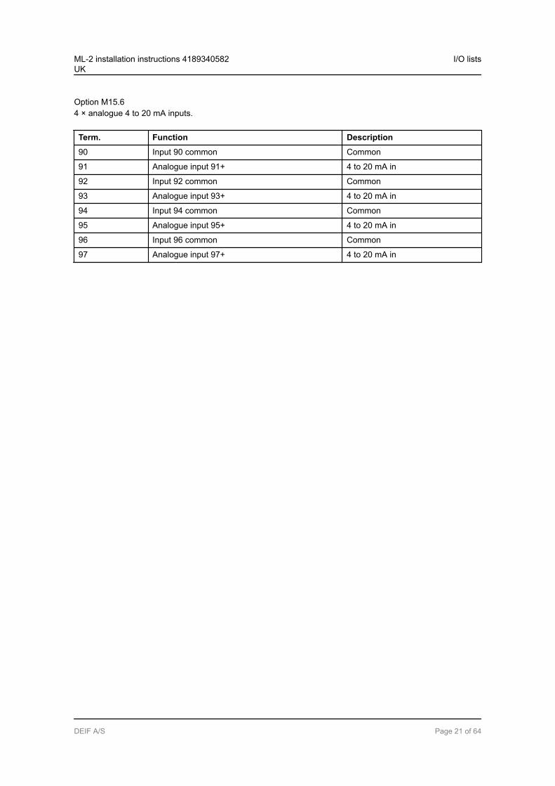
Option M15.64 × analogue 4 to 20 mA inputs.
Term. Function Description
90 Input 90 common Common
91 Analogue input 91+ 4 to 20 mA in
92 Input 92 common Common
93 Analogue input 93+ 4 to 20 mA in
94 Input 94 common Common
95 Analogue input 95+ 4 to 20 mA in
96 Input 96 common Common
97 Analogue input 97+ 4 to 20 mA in
ML-2 installation instructions 4189340582UK
I/O lists
DEIF A/S Page 21 of 64
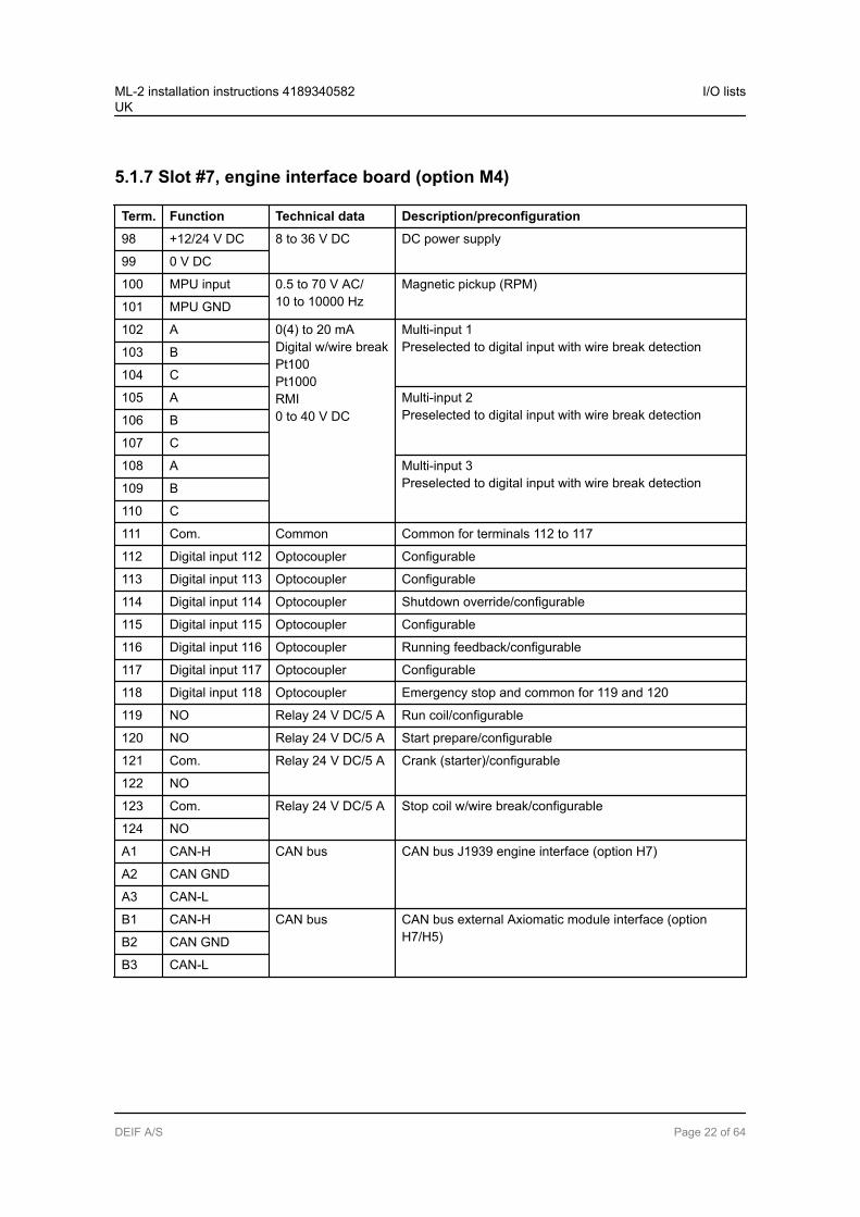
5.1.7 Slot #7, engine interface board (option M4)
Term. Function Technical data Description/preconfiguration
98 +12/24 V DC 8 to 36 V DC DC power supply
99 0 V DC
100 MPU input 0.5 to 70 V AC/10 to 10000 Hz
Magnetic pickup (RPM)
101 MPU GND
102 A 0(4) to 20 mADigital w/wire breakPt100Pt1000RMI0 to 40 V DC
Multi-input 1Preselected to digital input with wire break detection103 B
104 C
105 A Multi-input 2Preselected to digital input with wire break detection106 B
107 C
108 A Multi-input 3Preselected to digital input with wire break detection109 B
110 C
111 Com. Common Common for terminals 112 to 117
112 Digital input 112 Optocoupler Configurable
113 Digital input 113 Optocoupler Configurable
114 Digital input 114 Optocoupler Shutdown override/configurable
115 Digital input 115 Optocoupler Configurable
116 Digital input 116 Optocoupler Running feedback/configurable
117 Digital input 117 Optocoupler Configurable
118 Digital input 118 Optocoupler Emergency stop and common for 119 and 120
119 NO Relay 24 V DC/5 A Run coil/configurable
120 NO Relay 24 V DC/5 A Start prepare/configurable
121 Com. Relay 24 V DC/5 A Crank (starter)/configurable
122 NO
123 Com. Relay 24 V DC/5 A Stop coil w/wire break/configurable
124 NO
A1 CAN-H CAN bus CAN bus J1939 engine interface (option H7)
A2 CAN GND
A3 CAN-L
B1 CAN-H CAN bus CAN bus external Axiomatic module interface (optionH7/H5)B2 CAN GND
B3 CAN-L
ML-2 installation instructions 4189340582UK
I/O lists
DEIF A/S Page 22 of 64

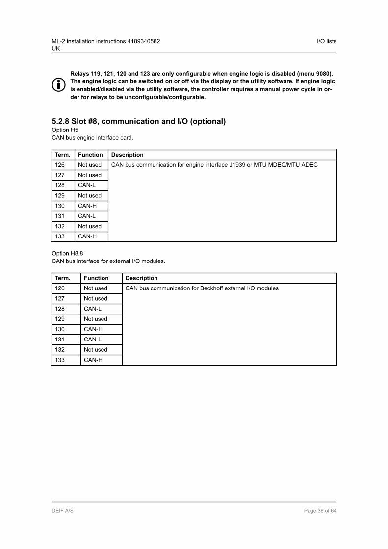
Relays 119, 121, 120 and 123 are only configurable when engine logic is disabled (menu 9080).The engine logic can be switched on or off via the display or the utility software. If engine logicis enabled/disabled via the utility software, the controller requires a manual power cycle in or-der for relays to be unconfigurable/configurable.
5.1.8 Slot #8, communication and I/O (optional)Option H5CAN bus engine interface card.
Term. Function Description
126 Not used CAN bus communication for engine interface J1939 or MTU MDEC/MTU ADEC
127 Not used
128 CAN-L
129 Not used
130 CAN-H
131 CAN-L
132 Not used
133 CAN-H
Option H8.8CAN bus interface for external I/O modules.
Term. Function Description
126 Not used CAN bus communication for Beckhoff external I/O modules
127 Not used
128 CAN-L
129 Not used
130 CAN-H
131 CAN-L
132 Not used
133 CAN-H
ML-2 installation instructions 4189340582UK
I/O lists
DEIF A/S Page 23 of 64
Option M13.87 × digital inputs.
Term. Function Description
126 Common Common
127 Digital input 127 Configurable
128 Digital input 128 Configurable
129 Digital input 129 Configurable
130 Digital input 130 Configurable
131 Digital input 131 Configurable
132 Digital input 132 Configurable
133 Digital input 133 Configurable
Option M14.84 × relay outputs.
Term. Function Description
126 Relay 126250 V AC, 8 A max.
Configurable
127
128 Relay 128250 V AC, 8 A max.
Configurable
129
130 Relay 130250 V AC, 8 A max.
Configurable
131
132 Relay 132250 V AC, 8 A max.
Configurable
133
Option M15.84 × analogue 4 to 20 mA inputs.
Term. Function Description
126 Input 127 common Common
127 Analogue input 127+ 4 to 20 mA in
128 Input 129 common Common
129 Analogue input 129+ 4 to 20 mA in
130 Input 131 common Common
131 Analogue input 131+ 4 to 20 mA in
132 Input 133 common Common
133 Analogue input 133+ 4 to 20 mA in
ML-2 installation instructions 4189340582UK
I/O lists
DEIF A/S Page 24 of 64
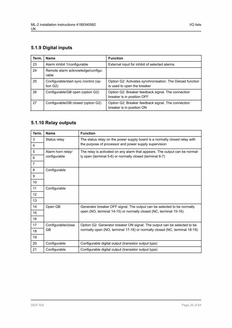
5.1.9 Digital inputs
Term. Name Function
23 Alarm inhibit 1/configurable External input for inhibit of selected alarms
24 Remote alarm acknowledge/configu-rable
25 Configurable/start sync./control (op-tion G2)
Option G2: Activates synchronisation. The Deload functionis used to open the breaker
26 Configurable/GB open (option G2) Option G2: Breaker feedback signal. The connectionbreaker is in position OFF
27 Configurable/GB closed (option G2) Option G2: Breaker feedback signal. The connectionbreaker is in position ON
5.1.10 Relay outputs
Term. Name Function
3 Status relay The status relay on the power supply board is a normally closed relay withthe purpose of processor and power supply supervision4
5 Alarm horn relay/configurable
The relay is activated on any alarm that appears. The output can be normal-ly open (terminal 5-6) or normally closed (terminal 6-7)6
7
8 Configurable
9
10
11 Configurable
12
13
14 Open GB Generator breaker OFF signal. The output can be selected to be normallyopen (NO, terminal 14-15) or normally closed (NC, terminal 15-16)15
16
17 Configurable/closeGB
Option G2: Generator breaker ON signal. The output can be selected to benormally open (NO, terminal 17-18) or normally closed (NC, terminal 18-19)18
19
20 Configurable Configurable digital output (transistor output type)
21 Configurable Configurable digital output (transistor output type)
ML-2 installation instructions 4189340582UK
I/O lists
DEIF A/S Page 25 of 64
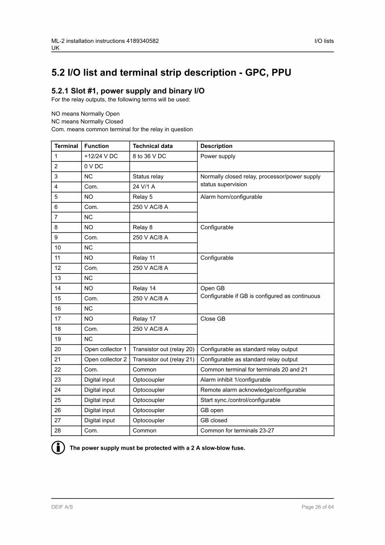
5.2 I/O list and terminal strip description - GPC, PPU
5.2.1 Slot #1, power supply and binary I/OFor the relay outputs, the following terms will be used:
NO means Normally OpenNC means Normally ClosedCom. means common terminal for the relay in question
Terminal Function Technical data Description
1 +12/24 V DC 8 to 36 V DC Power supply
2 0 V DC
3 NC Status relay Normally closed relay, processor/power supplystatus supervision4 Com. 24 V/1 A
5 NO Relay 5 Alarm horn/configurable
6 Com. 250 V AC/8 A
7 NC
8 NO Relay 8 Configurable
9 Com. 250 V AC/8 A
10 NC
11 NO Relay 11 Configurable
12 Com. 250 V AC/8 A
13 NC
14 NO Relay 14 Open GBConfigurable if GB is configured as continuous15 Com. 250 V AC/8 A
16 NC
17 NO Relay 17 Close GB
18 Com. 250 V AC/8 A
19 NC
20 Open collector 1 Transistor out (relay 20) Configurable as standard relay output
21 Open collector 2 Transistor out (relay 21) Configurable as standard relay output
22 Com. Common Common terminal for terminals 20 and 21
23 Digital input Optocoupler Alarm inhibit 1/configurable
24 Digital input Optocoupler Remote alarm acknowledge/configurable
25 Digital input Optocoupler Start sync./control/configurable
26 Digital input Optocoupler GB open
27 Digital input Optocoupler GB closed
28 Com. Common Common for terminals 23-27
The power supply must be protected with a 2 A slow-blow fuse.
ML-2 installation instructions 4189340582UK
I/O lists
DEIF A/S Page 26 of 64
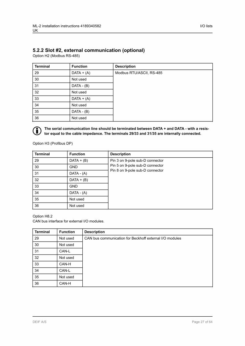
5.2.2 Slot #2, external communication (optional)Option H2 (Modbus RS-485)
Terminal Function Description
29 DATA + (A) Modbus RTU/ASCII, RS-485
30 Not used
31 DATA - (B)
32 Not used
33 DATA + (A)
34 Not used
35 DATA - (B)
36 Not used
The serial communication line should be terminated between DATA + and DATA - with a resis-tor equal to the cable impedance. The terminals 29/33 and 31/35 are internally connected.
Option H3 (Profibus DP)
Terminal Function Description
29 DATA + (B) Pin 3 on 9-pole sub-D connectorPin 5 on 9-pole sub-D connectorPin 8 on 9-pole sub-D connector
30 GND
31 DATA - (A)
32 DATA + (B)
33 GND
34 DATA - (A)
35 Not used
36 Not used
Option H8.2CAN bus interface for external I/O modules.
Terminal Function Description
29 Not used CAN bus communication for Beckhoff external I/O modules
30 Not used
31 CAN-L
32 Not used
33 CAN-H
34 CAN-L
35 Not used
36 CAN-H
ML-2 installation instructions 4189340582UK
I/O lists
DEIF A/S Page 27 of 64
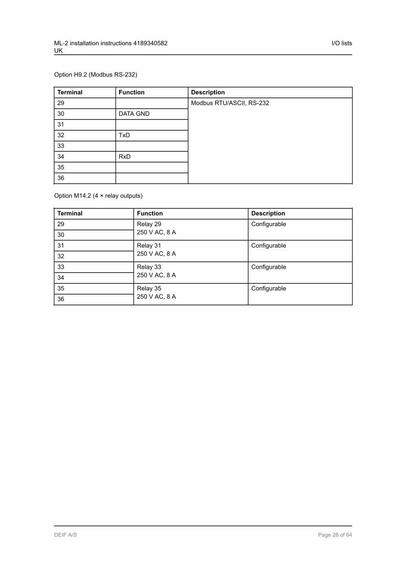
Option H9.2 (Modbus RS-232)
Terminal Function Description
29 Modbus RTU/ASCII, RS-232
30 DATA GND
31
32 TxD
33
34 RxD
35
36
Option M14.2 (4 × relay outputs)
Terminal Function Description
29 Relay 29250 V AC, 8 A
Configurable
30
31 Relay 31250 V AC, 8 A
Configurable
32
33 Relay 33250 V AC, 8 A
Configurable
34
35 Relay 35250 V AC, 8 A
Configurable
36
ML-2 installation instructions 4189340582UK
I/O lists
DEIF A/S Page 28 of 64
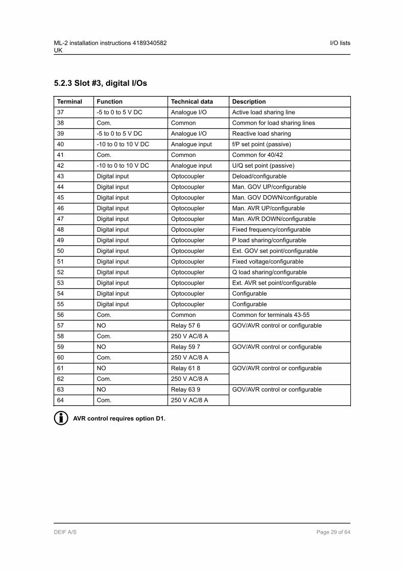
5.2.3 Slot #3, digital I/Os
Terminal Function Technical data Description
37 -5 to 0 to 5 V DC Analogue I/O Active load sharing line
38 Com. Common Common for load sharing lines
39 -5 to 0 to 5 V DC Analogue I/O Reactive load sharing
40 -10 to 0 to 10 V DC Analogue input f/P set point (passive)
41 Com. Common Common for 40/42
42 -10 to 0 to 10 V DC Analogue input U/Q set point (passive)
43 Digital input Optocoupler Deload/configurable
44 Digital input Optocoupler Man. GOV UP/configurable
45 Digital input Optocoupler Man. GOV DOWN/configurable
46 Digital input Optocoupler Man. AVR UP/configurable
47 Digital input Optocoupler Man. AVR DOWN/configurable
48 Digital input Optocoupler Fixed frequency/configurable
49 Digital input Optocoupler P load sharing/configurable
50 Digital input Optocoupler Ext. GOV set point/configurable
51 Digital input Optocoupler Fixed voltage/configurable
52 Digital input Optocoupler Q load sharing/configurable
53 Digital input Optocoupler Ext. AVR set point/configurable
54 Digital input Optocoupler Configurable
55 Digital input Optocoupler Configurable
56 Com. Common Common for terminals 43-55
57 NO Relay 57 6 GOV/AVR control or configurable
58 Com. 250 V AC/8 A
59 NO Relay 59 7 GOV/AVR control or configurable
60 Com. 250 V AC/8 A
61 NO Relay 61 8 GOV/AVR control or configurable
62 Com. 250 V AC/8 A
63 NO Relay 63 9 GOV/AVR control or configurable
64 Com. 250 V AC/8 A
AVR control requires option D1.
ML-2 installation instructions 4189340582UK
I/O lists
DEIF A/S Page 29 of 64
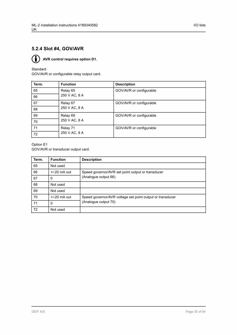
5.2.4 Slot #4, GOV/AVR
AVR control requires option D1.
StandardGOV/AVR or configurable relay output card.
Term. Function Description
65 Relay 65250 V AC, 8 A
GOV/AVR or configurable
66
67 Relay 67250 V AC, 8 A
GOV/AVR or configurable
68
69 Relay 69250 V AC, 8 A
GOV/AVR or configurable
70
71 Relay 71250 V AC, 8 A
GOV/AVR or configurable
72
Option E1GOV/AVR or transducer output card.
Term. Function Description
65 Not used
66 +/-20 mA out Speed governor/AVR set point output or transducer(Analogue output 66)67 0
68 Not used
69 Not used
70 +/-20 mA out Speed governor/AVR voltage set point output or transducer(Analogue output 70)71 0
72 Not used
ML-2 installation instructions 4189340582UK
I/O lists
DEIF A/S Page 30 of 64
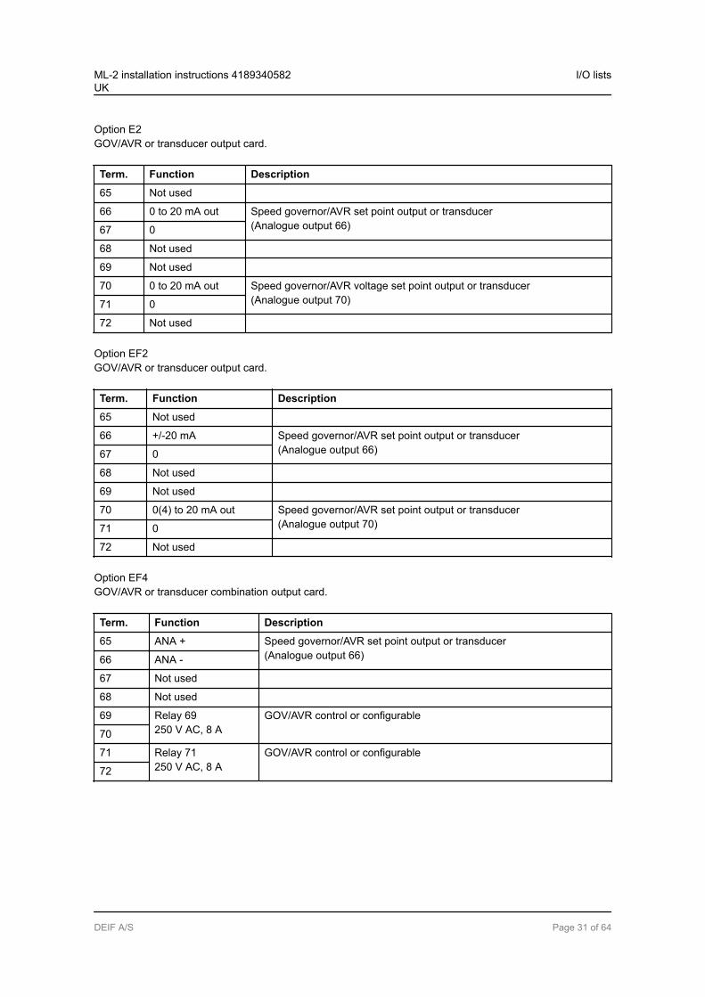
Option E2GOV/AVR or transducer output card.
Term. Function Description
65 Not used
66 0 to 20 mA out Speed governor/AVR set point output or transducer(Analogue output 66)67 0
68 Not used
69 Not used
70 0 to 20 mA out Speed governor/AVR voltage set point output or transducer(Analogue output 70)71 0
72 Not used
Option EF2GOV/AVR or transducer output card.
Term. Function Description
65 Not used
66 +/-20 mA Speed governor/AVR set point output or transducer(Analogue output 66)67 0
68 Not used
69 Not used
70 0(4) to 20 mA out Speed governor/AVR set point output or transducer(Analogue output 70)71 0
72 Not used
Option EF4GOV/AVR or transducer combination output card.
Term. Function Description
65 ANA + Speed governor/AVR set point output or transducer(Analogue output 66)66 ANA -
67 Not used
68 Not used
69 Relay 69250 V AC, 8 A
GOV/AVR control or configurable
70
71 Relay 71250 V AC, 8 A
GOV/AVR control or configurable
72
ML-2 installation instructions 4189340582UK
I/O lists
DEIF A/S Page 31 of 64
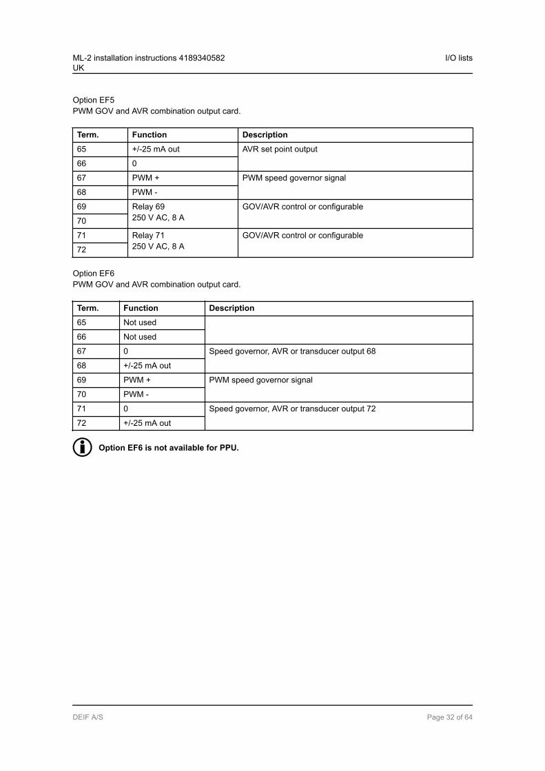
Option EF5PWM GOV and AVR combination output card.
Term. Function Description
65 +/-25 mA out AVR set point output
66 0
67 PWM + PWM speed governor signal
68 PWM -
69 Relay 69250 V AC, 8 A
GOV/AVR control or configurable
70
71 Relay 71250 V AC, 8 A
GOV/AVR control or configurable
72
Option EF6PWM GOV and AVR combination output card.
Term. Function Description
65 Not used
66 Not used
67 0 Speed governor, AVR or transducer output 68
68 +/-25 mA out
69 PWM + PWM speed governor signal
70 PWM -
71 0 Speed governor, AVR or transducer output 72
72 +/-25 mA out
Option EF6 is not available for PPU.
ML-2 installation instructions 4189340582UK
I/O lists
DEIF A/S Page 32 of 64
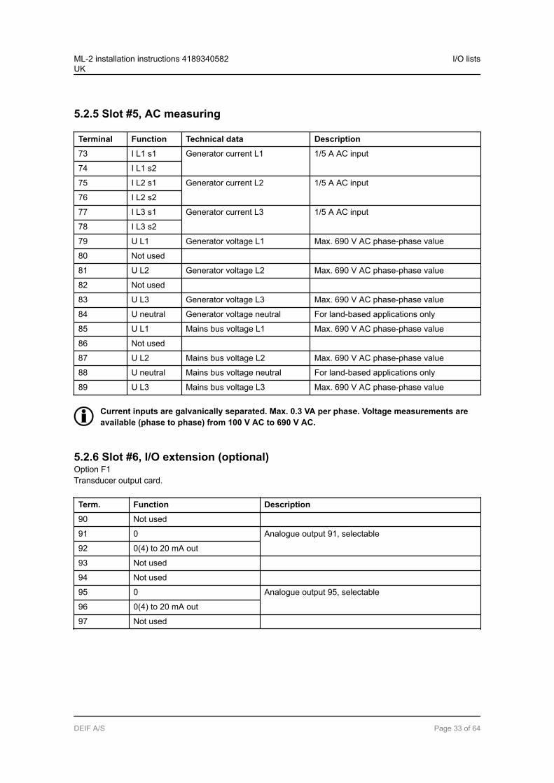
5.2.5 Slot #5, AC measuring
Terminal Function Technical data Description
73 I L1 s1 Generator current L1 1/5 A AC input
74 I L1 s2
75 I L2 s1 Generator current L2 1/5 A AC input
76 I L2 s2
77 I L3 s1 Generator current L3 1/5 A AC input
78 I L3 s2
79 U L1 Generator voltage L1 Max. 690 V AC phase-phase value
80 Not used
81 U L2 Generator voltage L2 Max. 690 V AC phase-phase value
82 Not used
83 U L3 Generator voltage L3 Max. 690 V AC phase-phase value
84 U neutral Generator voltage neutral For land-based applications only
85 U L1 Mains bus voltage L1 Max. 690 V AC phase-phase value
86 Not used
87 U L2 Mains bus voltage L2 Max. 690 V AC phase-phase value
88 U neutral Mains bus voltage neutral For land-based applications only
89 U L3 Mains bus voltage L3 Max. 690 V AC phase-phase value
Current inputs are galvanically separated. Max. 0.3 VA per phase. Voltage measurements areavailable (phase to phase) from 100 V AC to 690 V AC.
5.2.6 Slot #6, I/O extension (optional)Option F1Transducer output card.
Term. Function Description
90 Not used
91 0 Analogue output 91, selectable
92 0(4) to 20 mA out
93 Not used
94 Not used
95 0 Analogue output 95, selectable
96 0(4) to 20 mA out
97 Not used
ML-2 installation instructions 4189340582UK
I/O lists
DEIF A/S Page 33 of 64
Option M13.67 × digital inputs.
Term. Function Description
90 Common Common
91 Digital input 91 Configurable
92 Digital input 92 Configurable
93 Digital input 93 Configurable
94 Digital input 94 Configurable
95 Digital input 95 Configurable
96 Digital input 96 Configurable
97 Digital input 97 Configurable
Option M14.64 × relay outputs.
Term. Function Description
90 Relay output 90250 V AC, 8 A max.
Configurable
91
92 Relay output 92250 V AC, 8 A max.
Configurable
93
94 Relay output 94250 V AC, 8 A max.
Configurable
95
96 Relay output 96250 V AC, 8 A max.
Configurable
97
Option M15.64 × analogue 4 to 20 mA inputs.
Term. Function Description
90 Input 90 common Common
91 Analogue input 91+ 4 to 20 mA in
92 Input 92 common Common
93 Analogue input 93+ 4 to 20 mA in
94 Input 94 common Common
95 Analogue input 95+ 4 to 20 mA in
96 Input 96 common Common
97 Analogue input 97+ 4 to 20 mA in
ML-2 installation instructions 4189340582UK
I/O lists
DEIF A/S Page 34 of 64

5.2.7 Slot #7, engine interface board (option M4)
Term. Function Technical data Description/preconfiguration
98 +12/24 V DC 8 to 36 V DC DC power supply
99 0 V DC
100 MPU input 0.5 to 70 V AC/10 to 10000 Hz
Magnetic pickup (RPM)
101 MPU GND
102 A 0(4) to 20 mADigital w/wire breakPt100Pt1000RMI0 to 40 V DC
Multi-input 1Preselected to digital input with wire break detection103 B
104 C
105 A Multi-input 2Preselected to digital input with wire break detection106 B
107 C
108 A Multi-input 3Preselected to digital input with wire break detection109 B
110 C
111 Com. Common Common for terminals 112 to 117
112 Digital input 112 Optocoupler Configurable
113 Digital input 113 Optocoupler Configurable
114 Digital input 114 Optocoupler Shutdown override/configurable
115 Digital input 115 Optocoupler Configurable
116 Digital input 116 Optocoupler Running feedback/configurable
117 Digital input 117 Optocoupler Configurable
118 Digital input 118 Optocoupler Emergency stop and common for 119 and 120
119 NO Relay 24 V DC/5 A Run coil/configurable
120 NO Relay 24 V DC/5 A Start prepare/configurable
121 Com. Relay 24 V DC/5 A Crank (starter)/configurable
122 NO
123 Com. Relay 24 V DC/5 A Stop coil w/wire break/configurable
124 NO
A1 CAN-H CAN bus CAN bus J1939 engine interface (option H7)
A2 CAN GND
A3 CAN-L
B1 CAN-H CAN bus CAN bus external Axiomatic module interface (optionH7/H5)B2 CAN GND
B3 CAN-L
ML-2 installation instructions 4189340582UK
I/O lists
DEIF A/S Page 35 of 64
Relays 119, 121, 120 and 123 are only configurable when engine logic is disabled (menu 9080).The engine logic can be switched on or off via the display or the utility software. If engine logicis enabled/disabled via the utility software, the controller requires a manual power cycle in or-der for relays to be unconfigurable/configurable.
5.2.8 Slot #8, communication and I/O (optional)Option H5CAN bus engine interface card.
Term. Function Description
126 Not used CAN bus communication for engine interface J1939 or MTU MDEC/MTU ADEC
127 Not used
128 CAN-L
129 Not used
130 CAN-H
131 CAN-L
132 Not used
133 CAN-H
Option H8.8CAN bus interface for external I/O modules.
Term. Function Description
126 Not used CAN bus communication for Beckhoff external I/O modules
127 Not used
128 CAN-L
129 Not used
130 CAN-H
131 CAN-L
132 Not used
133 CAN-H
ML-2 installation instructions 4189340582UK
I/O lists
DEIF A/S Page 36 of 64

Option M13.87 × digital inputs.
Term. Function Description
126 Common Common
127 Digital input 127 Configurable
128 Digital input 128 Configurable
129 Digital input 129 Configurable
130 Digital input 130 Configurable
131 Digital input 131 Configurable
132 Digital input 132 Configurable
133 Digital input 133 Configurable
Option M14.84 × relay outputs.
Term. Function Description
126 Relay 126250 V AC, 8 A max.
Configurable
127
128 Relay 128250 V AC, 8 A max.
Configurable
129
130 Relay 130250 V AC, 8 A max.
Configurable
131
132 Relay 132250 V AC, 8 A max.
Configurable
133
Option M15.84 × analogue 4 to 20 mA inputs.
Term. Function Description
126 Input 127 common Common
127 Analogue input 127+ 4 to 20 mA in
128 Input 129 common Common
129 Analogue input 129+ 4 to 20 mA in
130 Input 131 common Common
131 Analogue input 131+ 4 to 20 mA in
132 Input 133 common Common
133 Analogue input 133+ 4 to 20 mA in
ML-2 installation instructions 4189340582UK
I/O lists
DEIF A/S Page 37 of 64
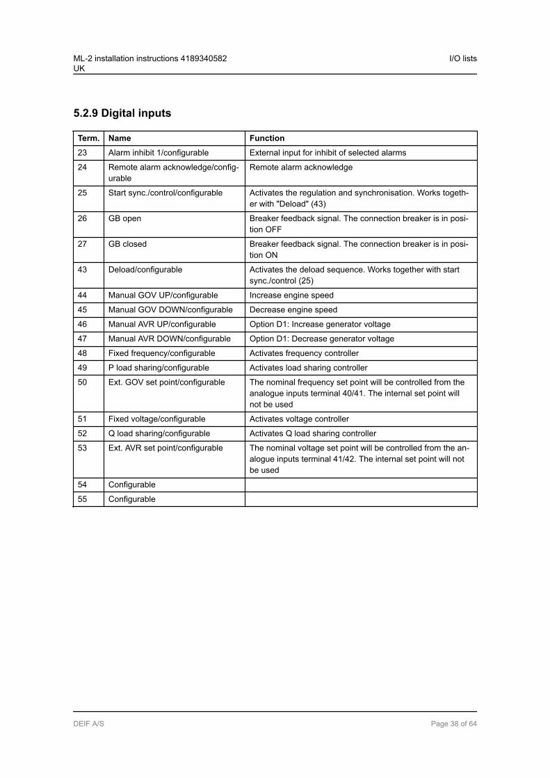
5.2.9 Digital inputs
Term. Name Function
23 Alarm inhibit 1/configurable External input for inhibit of selected alarms
24 Remote alarm acknowledge/config-urable
Remote alarm acknowledge
25 Start sync./control/configurable Activates the regulation and synchronisation. Works togeth-er with "Deload" (43)
26 GB open Breaker feedback signal. The connection breaker is in posi-tion OFF
27 GB closed Breaker feedback signal. The connection breaker is in posi-tion ON
43 Deload/configurable Activates the deload sequence. Works together with startsync./control (25)
44 Manual GOV UP/configurable Increase engine speed
45 Manual GOV DOWN/configurable Decrease engine speed
46 Manual AVR UP/configurable Option D1: Increase generator voltage
47 Manual AVR DOWN/configurable Option D1: Decrease generator voltage
48 Fixed frequency/configurable Activates frequency controller
49 P load sharing/configurable Activates load sharing controller
50 Ext. GOV set point/configurable The nominal frequency set point will be controlled from theanalogue inputs terminal 40/41. The internal set point willnot be used
51 Fixed voltage/configurable Activates voltage controller
52 Q load sharing/configurable Activates Q load sharing controller
53 Ext. AVR set point/configurable The nominal voltage set point will be controlled from the an-alogue inputs terminal 41/42. The internal set point will notbe used
54 Configurable
55 Configurable
ML-2 installation instructions 4189340582UK
I/O lists
DEIF A/S Page 38 of 64

5.2.10 Relay outputs
Term. Name Function
3 Status relay The status relay on the power supply board is a normally closed relay withthe purpose of processor and power supply supervision4
5 Alarm horn relay/configurable
The relay is activated on any alarm that appears. The output can be nor-mally open (terminal 5-6) or normally closed (terminal 6-7)6
7
8 Configurable
9
10
11 Configurable
12
13
14 Open GB Generator breaker OFF signal. The output can be selected to be normallyopen (NO, terminal 14-15) or normally closed (NC, terminal 15-16)15
16
17 Close GB Generator breaker ON signal. The output can be selected to be normallyopen (NO, terminal 17-18) or normally closed (NC, terminal 18-19)18
19
20 Configurable Configurable digital output (transistor output type)
21 Configurable Configurable digital output (transistor output type)
65 Configurable GOV/AVR control or configurable
66
67 Configurable GOV/AVR control or configurable
68
69 Configurable GOV/AVR control or configurable
70
71 Configurable GOV/AVR control or configurable
72
ML-2 installation instructions 4189340582UK
I/O lists
DEIF A/S Page 39 of 64
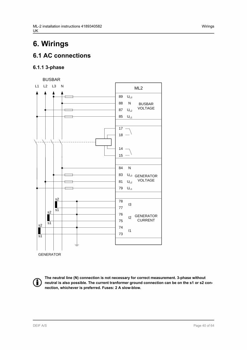
6. Wirings6.1 AC connections
6.1.1 3-phase
BUSBAR
89 UL3
88 N
87 UL2
85 UL1
BUSBAR
VOLTAGE
17
18
15
14
L1 L2 L3 N ML2
84
83
81
79
78I3
77
76I2
75
74I1
73
s1
s1
s2
s2
GENERATOR
VOLTAGE
GENERATOR
CURRENT
N
UL3
UL2
UL1
s1
s2
GENERATOR
The neutral line (N) connection is not necessary for correct measurement. 3-phase withoutneutral is also possible. The current tranformer ground connection can be on the s1 or s2 con-nection, whichever is preferred. Fuses: 2 A slow-blow.
ML-2 installation instructions 4189340582UK
Wirings
DEIF A/S Page 40 of 64
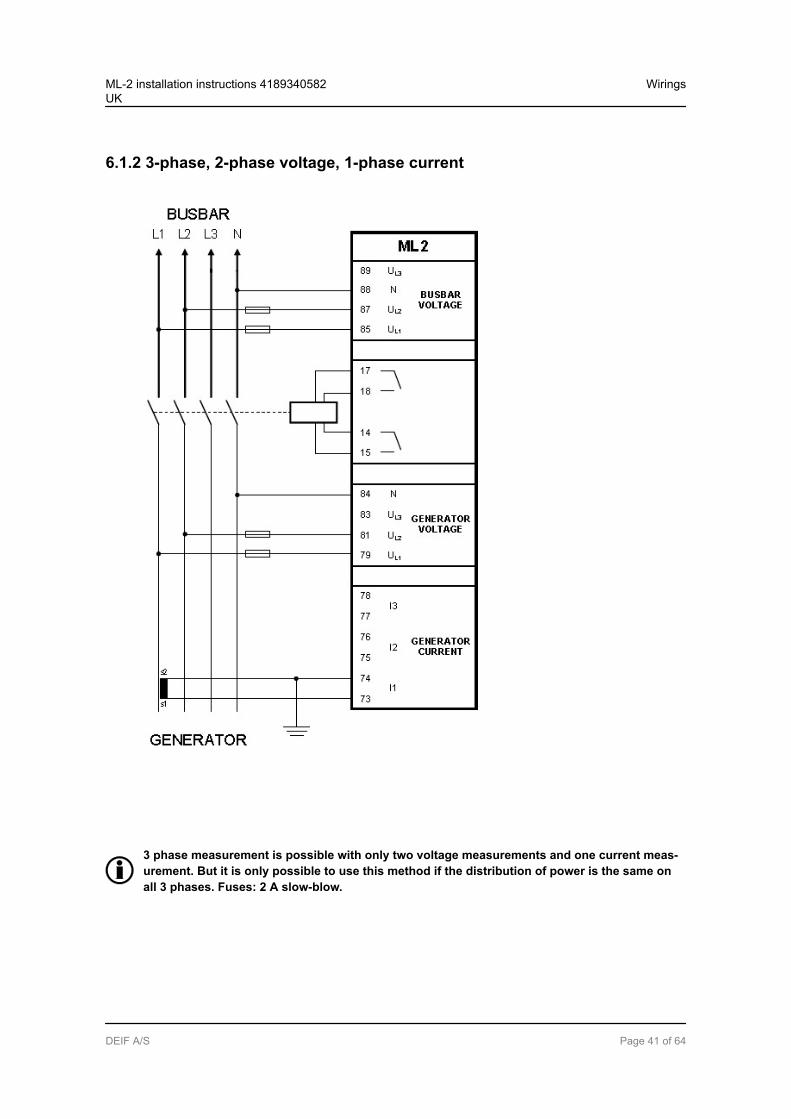
6.1.2 3-phase, 2-phase voltage, 1-phase current
3 phase measurement is possible with only two voltage measurements and one current meas-urement. But it is only possible to use this method if the distribution of power is the same onall 3 phases. Fuses: 2 A slow-blow.
ML-2 installation instructions 4189340582UK
Wirings
DEIF A/S Page 41 of 64
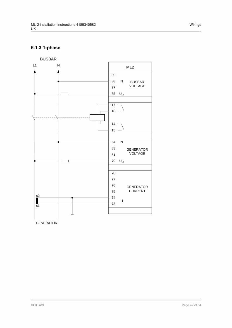
6.1.3 1-phase
BUSBAR
89
UL1
88
87
85
N BUSBAR
VOLTAGE
17
18
15
14
L1 N ML2
84
83
81
79
78
77
76
75
74I1
73s1
s2
GENERATOR
VOLTAGE
GENERATOR
CURRENT
N
UL1
GENERATOR
ML-2 installation instructions 4189340582UK
Wirings
DEIF A/S Page 42 of 64
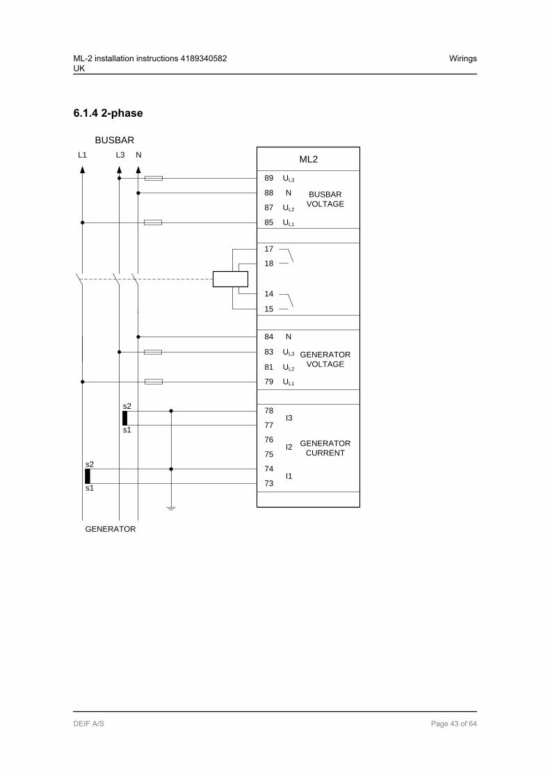
6.1.4 2-phase
BUSBAR
89 UL3
88 N
87 UL2
85 UL1
BUSBAR
VOLTAGE
17
18
15
14
L1 L3 N ML2
84
83
81
79
78I3
77
76I2
75
74I1
73s1
s2
GENERATOR
VOLTAGE
GENERATOR
CURRENT
N
UL3
UL2
UL1
s1
s2
GENERATOR
ML-2 installation instructions 4189340582UK
Wirings
DEIF A/S Page 43 of 64
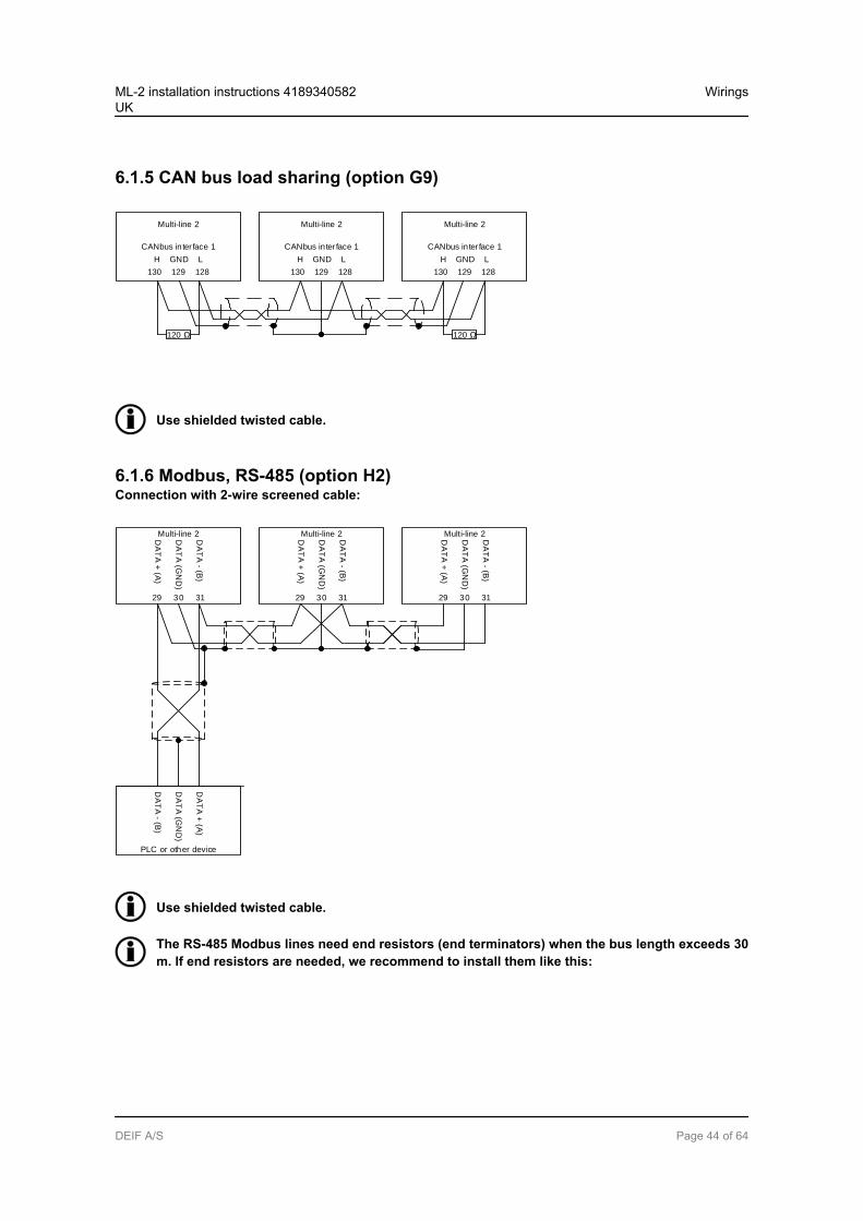
6.1.5 CAN bus load sharing (option G9)
Multi-line 2
CANbus inter face 1
130 129 128
H GND L
Multi-line 2
CANbus inter face 1
130 129 128
H GND L
Multi-line 2
CANbus inter face 1
130 129 128
H GND L
120 120
Use shielded twisted cable.
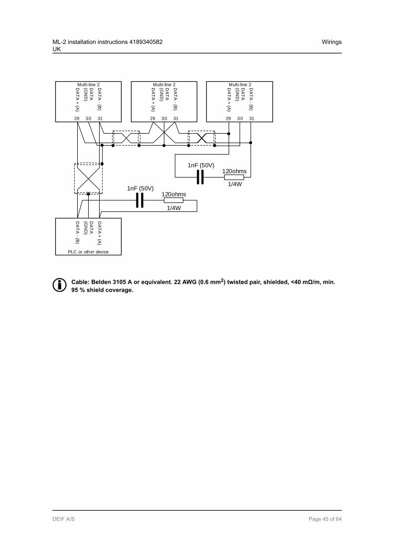
6.1.6 Modbus, RS-485 (option H2)Connection with 2-wire screened cable:
Multi-line 2DA
TA
+ (A
)
29 30 31
DA
TA
(GN
D)
DA
TA
- (B)
Multi-line 2DA
TA
+ (A
)
29 30 31
DA
TA
(GN
D)
DA
TA
- (B)
Multi-line 2DA
TA
+ (A
)
29 30 31
DA
TA
(GN
D)
DA
TA
- (B)
DA
TA
- (B)
PLC or other device
DA
TA
(GN
D)
DA
TA
+ (A
)
Use shielded twisted cable.
The RS-485 Modbus lines need end resistors (end terminators) when the bus length exceeds 30m. If end resistors are needed, we recommend to install them like this:
ML-2 installation instructions 4189340582UK
Wirings
DEIF A/S Page 44 of 64
Multi-line 2DA
TA
+ (A
)
29 30 31
DA
TA
(GN
D)
DA
TA
- (B)
Multi-line 2DA
TA
+ (A
)
29 30 31
DA
TA
(GN
D)
DA
TA
- (B)
Multi-line 2DA
TA
+ (A
)
29 30 31
DA
TA
(GN
D)
DA
TA
- (B)
DA
TA
- (B)
PLC or other device
DA
TA
(GN
D)
DA
TA
+ (A
)
1nF (50V)120ohms
1nF (50V)120ohms
1/4W
1/4W
Cable: Belden 3105 A or equivalent. 22 AWG (0.6 mm2) twisted pair, shielded, <40 mΩ/m, min.95 % shield coverage.
ML-2 installation instructions 4189340582UK
Wirings
DEIF A/S Page 45 of 64
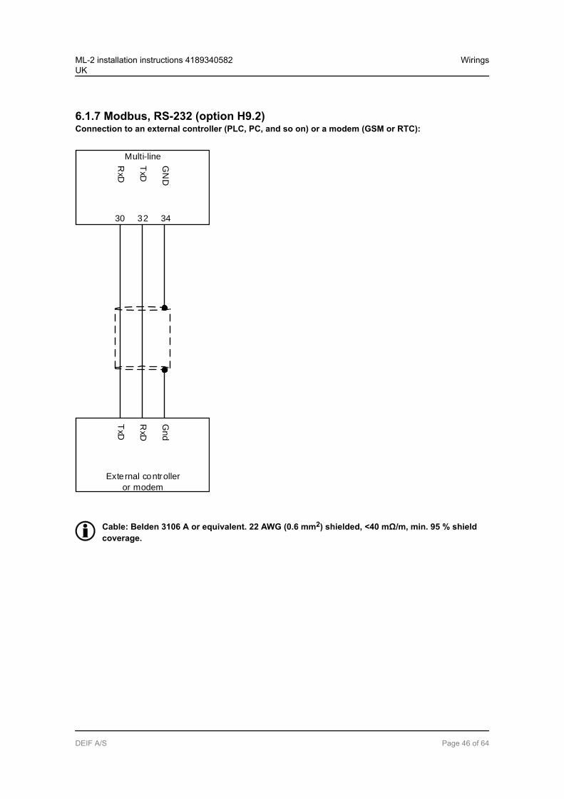
6.1.7 Modbus, RS-232 (option H9.2)Connection to an external controller (PLC, PC, and so on) or a modem (GSM or RTC):
Multi-line
GN
D
30 32 34
TxD
RxD
TxD
External controller
or modem
RxD
Gnd
Cable: Belden 3106 A or equivalent. 22 AWG (0.6 mm2) shielded, <40 mΩ/m, min. 95 % shieldcoverage.
ML-2 installation instructions 4189340582UK
Wirings
DEIF A/S Page 46 of 64
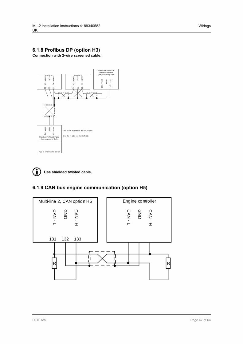
6.1.8 Profibus DP (option H3)Connection with 2-wire screened cable:
Multi-line 2DA
TA
+ (B
)
29 30 31
CO
M
DA
TA
- (A)
Multi-line 2DA
TA
+ (B
)
29 30 31
CO
M
DA
TA
- (A)
Standard Profibus DP
Active termination
(not provided by Deif)
DA
TA
+ (B
)
Shie
ld
DA
TA
- (A)
DA
TA
- (A)
Standard Profibus DP plug
(not provided by Deif)
Shie
ld
DA
TA
+ (B
)
PLC or other master device
The switch must be on the ON position
Use the IN side, not the OUT side
Use shielded twisted cable.
6.1.9 CAN bus engine communication (option H5)
Multi-line 2, CAN option H5
CA
N - L
131 132 133
GN
D
CA
N - H
Engine contro ller
CA
N - L
CA
N - H
RR
GN
D
ML-2 installation instructions 4189340582UK
Wirings
DEIF A/S Page 47 of 64
Use shielded twisted cable.
End resistor R = 120 Ohm.
The terminating resistor at the engine side might not be needed, see the engine manufacturer’sliterature.
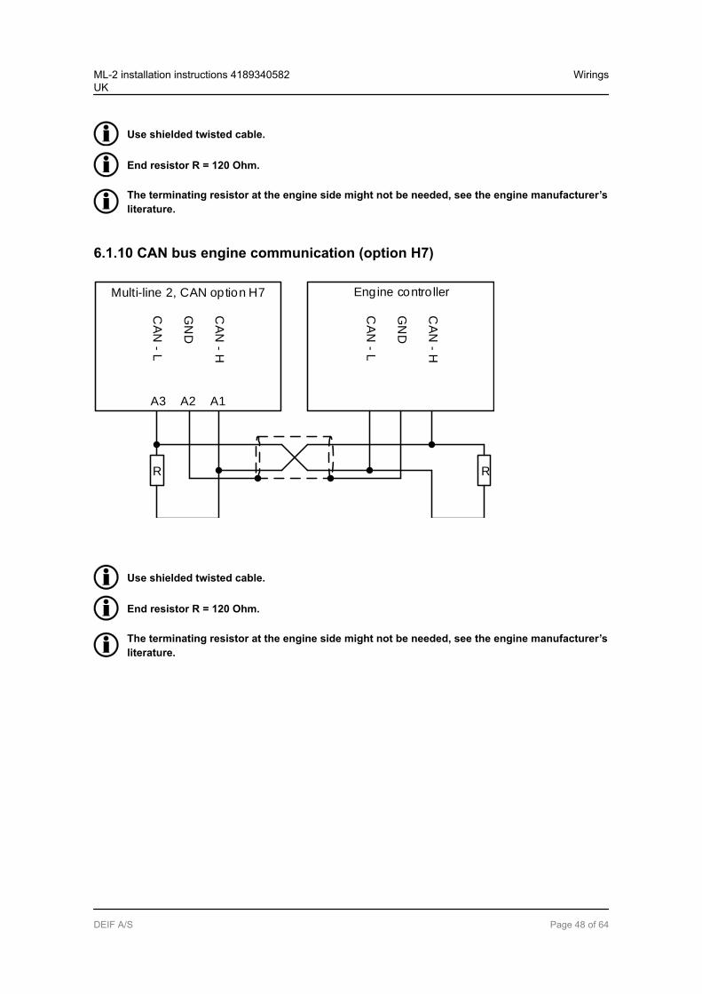
6.1.10 CAN bus engine communication (option H7)
Multi-line 2, CAN option H7
CA
N - L
A3 A2 A1
GN
D
CA
N - H
Engine contro ller
CA
N - L
CA
N - H
RR
GN
D
Use shielded twisted cable.
End resistor R = 120 Ohm.
The terminating resistor at the engine side might not be needed, see the engine manufacturer’sliterature.
ML-2 installation instructions 4189340582UK
Wirings
DEIF A/S Page 48 of 64
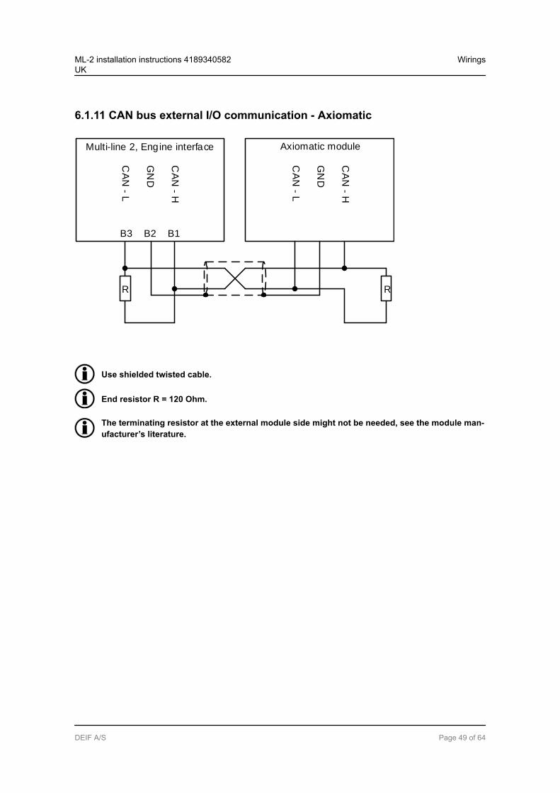
6.1.11 CAN bus external I/O communication - Axiomatic
Multi-line 2, Engine interface
CA
N - L
B3 B2 B1
GN
D
CA
N - H
Axiomatic module
CA
N - L
CA
N - H
RR
GN
D
Use shielded twisted cable.
End resistor R = 120 Ohm.
The terminating resistor at the external module side might not be needed, see the module man-ufacturer’s literature.
ML-2 installation instructions 4189340582UK
Wirings
DEIF A/S Page 49 of 64
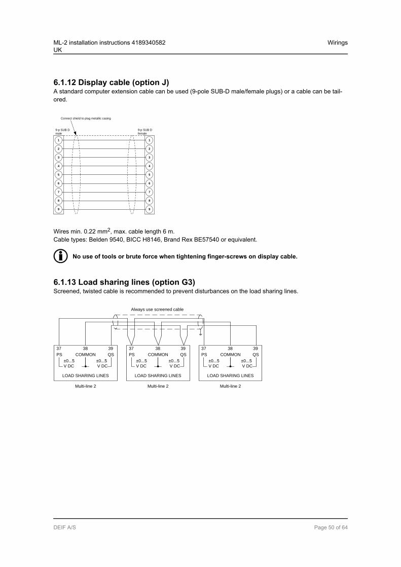
6.1.12 Display cable (option J)A standard computer extension cable can be used (9-pole SUB-D male/female plugs) or a cable can be tail-ored.
4
5
6
7
8
9
2
1
3
1
2
3
4
5
6
7
8
9
9-p SUB D
male
9-p SUB D
female
Connect shield to plug metallic casing
Wires min. 0.22 mm2, max. cable length 6 m.Cable types: Belden 9540, BICC H8146, Brand Rex BE57540 or equivalent.
No use of tools or brute force when tightening finger-screws on display cable.
6.1.13 Load sharing lines (option G3)Screened, twisted cable is recommended to prevent disturbances on the load sharing lines.
37 38 39
PS COMMON QS
LOAD SHARING LINES
±0...5 ±0...5
V DC V DC
Multi-line 2
37 38 39
PS COMMON QS
LOAD SHARING LINES
±0...5 ±0...5
V DC V DC
Multi-line 2
37 38 39
PS COMMON QS
LOAD SHARING LINES
±0...5 ±0...5
V DC V DC
Multi-line 2
Always use screened cable
ML-2 installation instructions 4189340582UK
Wirings
DEIF A/S Page 50 of 64

6.1.14 Mechanical speed governorThe illustration below shows the necessary connections to carry out speed control using relay outputs.
Multi-line 2
Speed lower
Speed raise
Ø
68
67
66
65
Supply for
Pilot motor
Ø
Pilot
motor
Lower
speed
Raise
speed
In order to extend the lifetime of the internal relays and prevent unwanted switching noise, it is recommendedto use freewheeling diodes (1N4007), if a DC voltage is used for the regulation. If an AC voltage is used forthe regulation, it is recommended to use a varistor. The diode/varistor must be placed across the terminals ofthe pilot motor/external regulation relay coil.
6.1.15 AVR with relay outputs
Multi-line 2
Voltage lower
Voltage raise
Ø
71
72
69
70
Supply for
AVR voltage
control
Ø
Common
Lower Voltage
Raise Voltage
AVR
ML-2 installation instructions 4189340582UK
Wirings
DEIF A/S Page 51 of 64
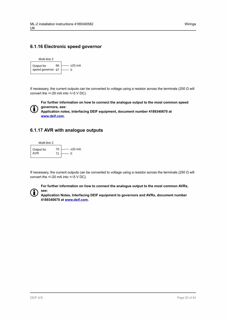
6.1.16 Electronic speed governor
Multi-line 2
Output for
speed governor
66
67
±20 mA
0
If necessary, the current outputs can be converted to voltage using a resistor across the terminals (250 Ω willconvert the +/-20 mA into +/-5 V DC).
For further information on how to connect the analogue output to the most common speedgovernors, see:Application notes, Interfacing DEIF equipment, document number 4189340670 atwww.deif.com.
6.1.17 AVR with analogue outputs
Multi-line 2
Output for
AVR
70
71
±20 mA
0
If necessary, the current outputs can be converted to voltage using a resistor across the terminals (250 Ω willconvert the +/-20 mA into +/-5 V DC).
For further information on how to connect the analogue output to the most common AVRs,see:Application Notes, Interfacing DEIF equipment to governors and AVRs, document number4189340670 at www.deif.com.
ML-2 installation instructions 4189340582UK
Wirings
DEIF A/S Page 52 of 64
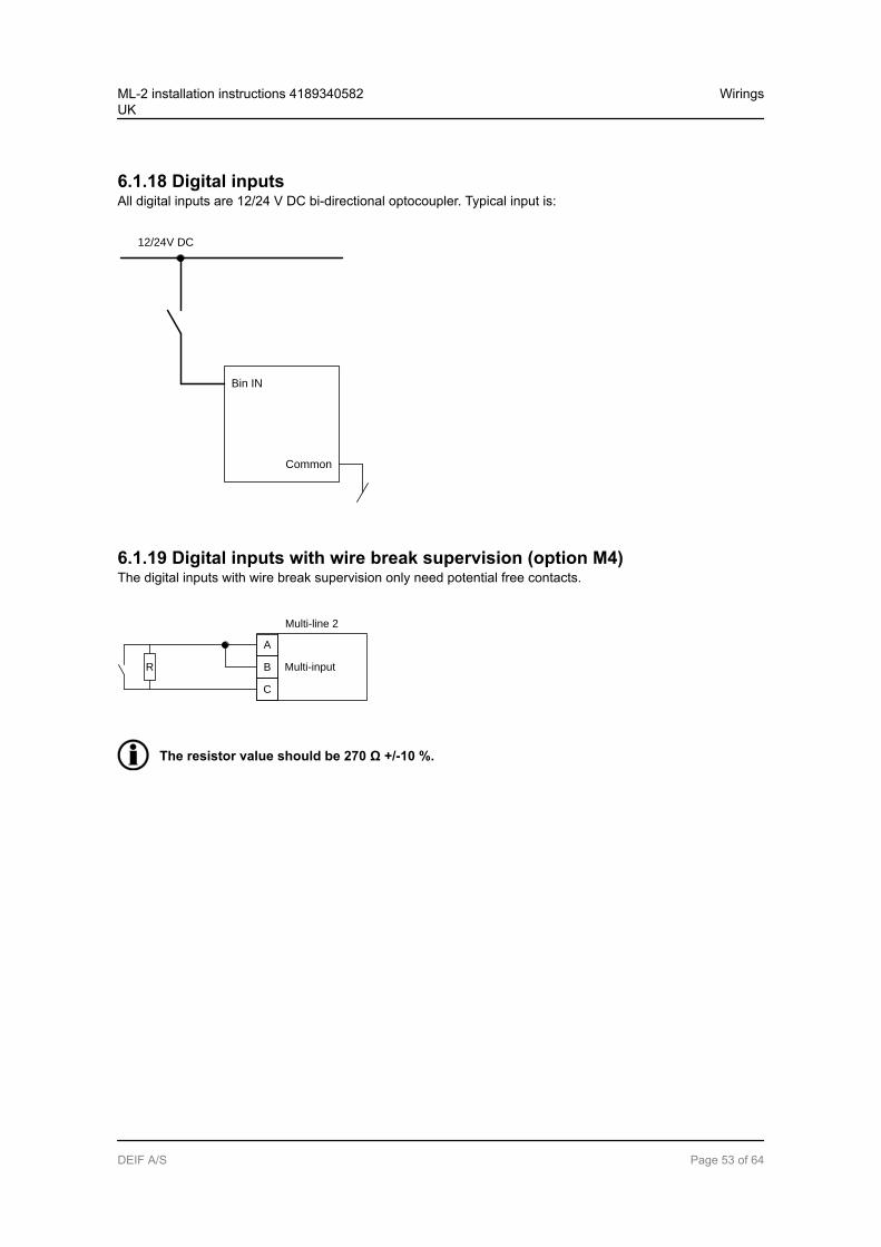
6.1.18 Digital inputsAll digital inputs are 12/24 V DC bi-directional optocoupler. Typical input is:
Bin IN
Common
12/24V DC
6.1.19 Digital inputs with wire break supervision (option M4)The digital inputs with wire break supervision only need potential free contacts.
Multi-line 2
Multi-input
A
B
C
R
The resistor value should be 270 Ω +/-10 %.
ML-2 installation instructions 4189340582UK
Wirings
DEIF A/S Page 53 of 64
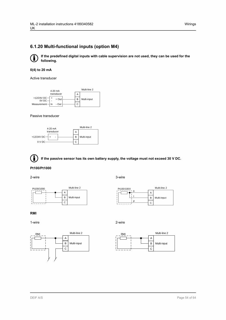
6.1.20 Multi-functional inputs (option M4)
If the predefined digital inputs with cable supervision are not used, they can be used for thefollowing.
0(4) to 20 mA
Active transducer
0V DC
Multi-line 2
Multi-input+12/24V DC +
-
4-20 mA
transducer
Measurement
A
B
CIn - Out
+ Out
Passive transducer
0 V DC
Multi-line 2
Multi-input+12/24V DC + -
4-20 mA
transducer A
B
C
If the passive sensor has its own battery supply, the voltage must not exceed 30 V DC.
Pt100/Pt1000
2-wire 3-wire
Multi-line 2
Multi-input
A
B
C
Pt100/1000 Multi-line 2
Multi-input
A
B
C
Pt100/10000
I
P
RMI
1-wire 2-wire
Multi-line 2
Multi-input
A
B
C
RMI Multi-line 2
Multi-input
A
B
C
RMI
ML-2 installation instructions 4189340582UK
Wirings
DEIF A/S Page 54 of 64
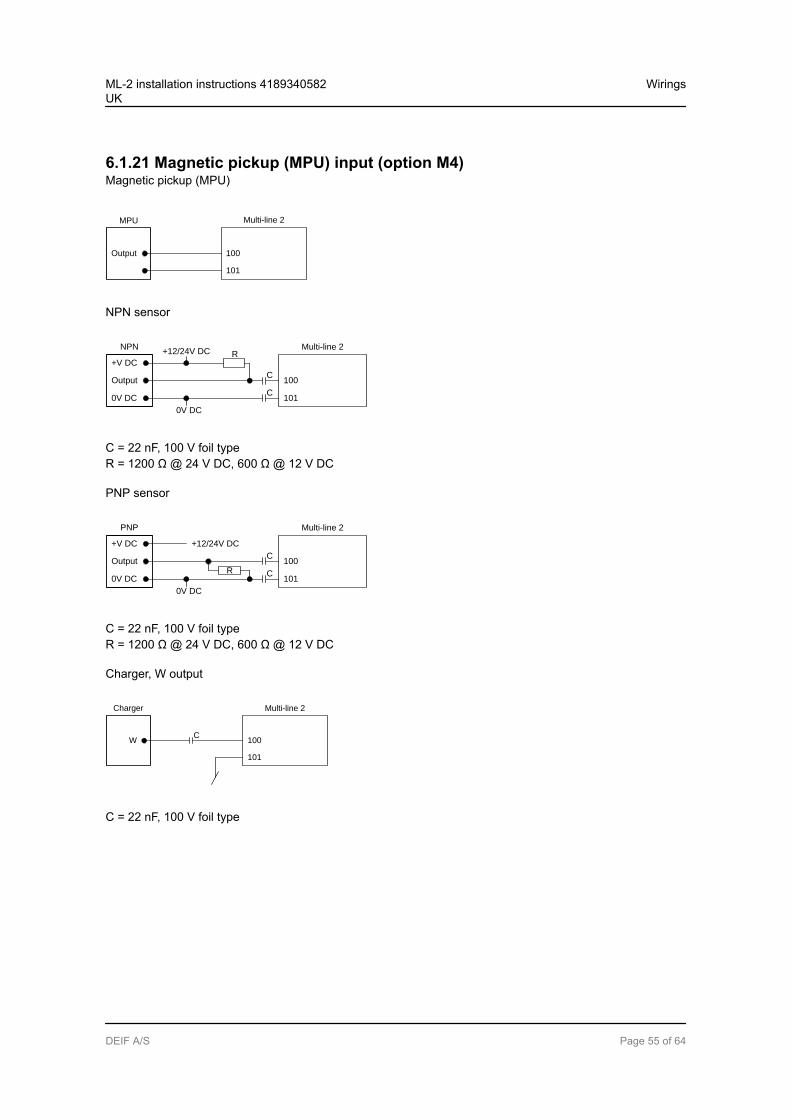
6.1.21 Magnetic pickup (MPU) input (option M4)Magnetic pickup (MPU)
Multi-line 2
100
MPU
Output
101
NPN sensor
Multi-line 2
100
NPN
Output
101
+V DC
0V DC
R+12/24V DC
0V DC
C
C
C = 22 nF, 100 V foil typeR = 1200 Ω @ 24 V DC, 600 Ω @ 12 V DC
PNP sensor
Multi-line 2
100
PNP
Output
101
+V DC
0V DC
+12/24V DC
0V DC
C
CR
C = 22 nF, 100 V foil typeR = 1200 Ω @ 24 V DC, 600 Ω @ 12 V DC
Charger, W output
Multi-line 2
100
Charger
W
101
C
C = 22 nF, 100 V foil type
ML-2 installation instructions 4189340582UK
Wirings
DEIF A/S Page 55 of 64
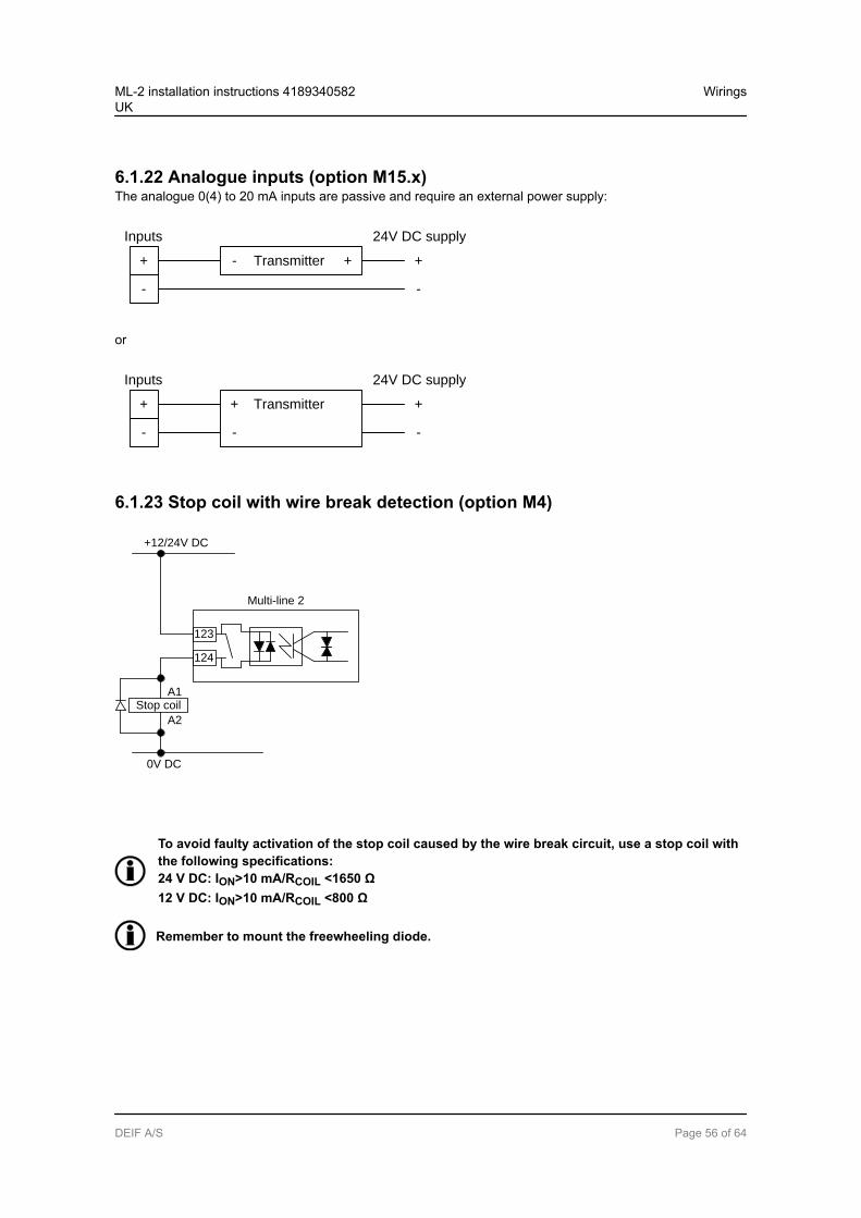
6.1.22 Analogue inputs (option M15.x)The analogue 0(4) to 20 mA inputs are passive and require an external power supply:
Transmitter-+
-
+
-
+
24V DC supplyInputs
or
Transmitter++
-
+
-
24V DC supplyInputs
-
6.1.23 Stop coil with wire break detection (option M4)
Multi-line 2
+12/24V DC
123
124
0V DC
Stop coilA1
A2
To avoid faulty activation of the stop coil caused by the wire break circuit, use a stop coil withthe following specifications:24 V DC: ION>10 mA/RCOIL <1650 Ω12 V DC: ION>10 mA/RCOIL <800 Ω
Remember to mount the freewheeling diode.
ML-2 installation instructions 4189340582UK
Wirings
DEIF A/S Page 56 of 64
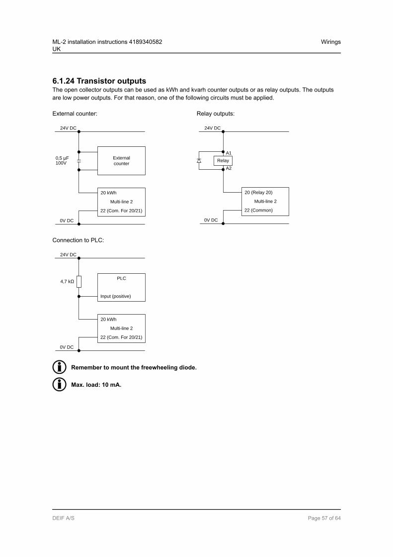
6.1.24 Transistor outputsThe open collector outputs can be used as kWh and kvarh counter outputs or as relay outputs. The outputsare low power outputs. For that reason, one of the following circuits must be applied.
External counter:
20 kWh
Multi-line 2
22 (Com. For 20/21)
External
counter
24V DC
0V DC
0,5 µF 100V
Relay outputs:
20 (Relay 20)
Multi-line 2
22 (Common)
24V DC
0V DC
Relay
A1
A2
Connection to PLC:
20 kWh
Multi-line 2
22 (Com. For 20/21)
24V DC
0V DC
4,7 kΩPLC
Input (positive)
Remember to mount the freewheeling diode.
Max. load: 10 mA.
ML-2 installation instructions 4189340582UK
Wirings
DEIF A/S Page 57 of 64
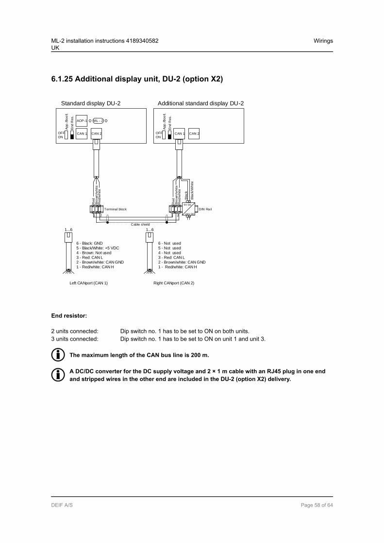
6.1.25 Additional display unit, DU-2 (option X2)
Standard display DU-2 Additional standard display DU-2
OFF
ON
App
./B
oo
tl.
End
Res.
CAN 1
AOP-1
CAN 2
ML - 2
Red
Re
d/w
hite
Terminal block
OFF
ON
App
./B
oo
tl.
End
Res.
CAN 1 CAN 2
Red
Red
/white
DIN Rail
5V DC
24V DC
+-
+-
Bla
ck
Bla
ck/W
hite
1 2 1 2
Cable shield
Bro
wn
/wh
ite
Bro
wn
/white
6 - Black: GND 5 - Black/White: +5 VDC4 - Brown: Not used3 - Red: CAN L 2 - Brown/white: CAN GND 1 - Red/white: CAN H
6 - Not used5 - Not used4 - Not used3 - Red: CAN L 2 - Brown/white: CAN GND 1 - Red/white: CAN H
Left CANport (CAN 1) Right CANport (CAN 2)
1...6 1...6
End resistor:
2 units connected: Dip switch no. 1 has to be set to ON on both units.3 units connected: Dip switch no. 1 has to be set to ON on unit 1 and unit 3.
The maximum length of the CAN bus line is 200 m.
A DC/DC converter for the DC supply voltage and 2 × 1 m cable with an RJ45 plug in one endand stripped wires in the other end are included in the DU-2 (option X2) delivery.
ML-2 installation instructions 4189340582UK
Wirings
DEIF A/S Page 58 of 64
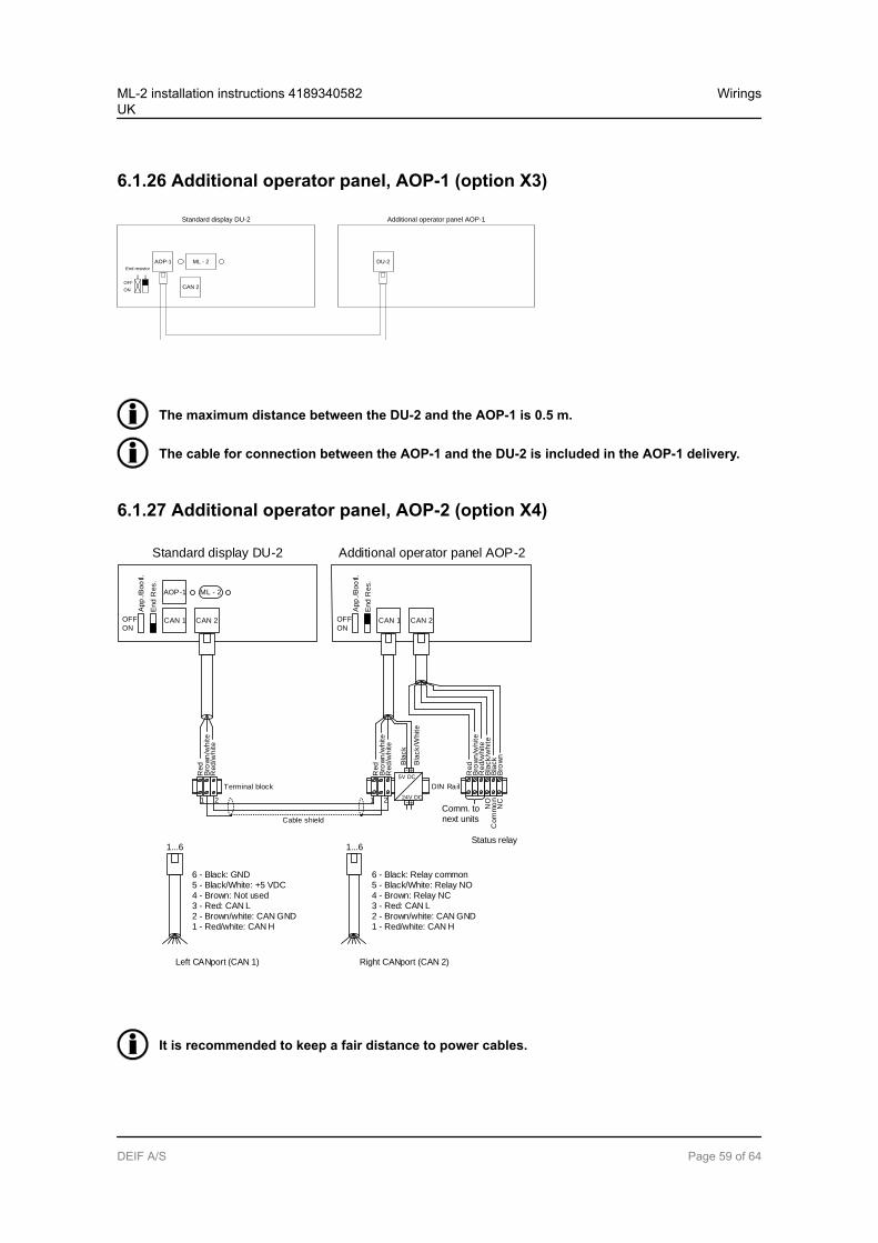
6.1.26 Additional operator panel, AOP-1 (option X3)
AOP-1
CAN 2
ML - 2
Standard display DU-2
OFF
ON
2 1
End resistor
DU-2
Additional operator panel AOP-1
The maximum distance between the DU-2 and the AOP-1 is 0.5 m.
The cable for connection between the AOP-1 and the DU-2 is included in the AOP-1 delivery.
6.1.27 Additional operator panel, AOP-2 (option X4)
Standard display DU-2 Additional operator panel AOP-2
OFF
ON
App
./B
oo
tl.
En
d R
es.
CAN 1
AOP-1
CAN 2
ML - 2
Red
Red
/white
Terminal block
OFF
ON
App
./B
oo
tl.
End
Res.
CAN 1
Red
Red
/white
DIN Rail
5V DC
24V DC
+-
+-
Bla
ck
Bla
ck/W
hite
Bro
wn
/white
Bro
wn
/white
Red
Bro
wn
/wh
ite
Red
/white
Bla
ck/w
hite
Bla
ck
Bro
wn
6 - Black: GND 5 - Black/White: +5 VDC4 - Brown: Not used3 - Red: CAN L 2 - Brown/white: CAN GND 1 - Red/white: CAN H
6 - Black: Relay common 5 - Black/White: Relay NO4 - Brown: Relay NC3 - Red: CAN L 2 - Brown/white: CAN GND 1 - Red/white: CAN H
Left CANport (CAN 1) Right CANport (CAN 2)
1 2 1 2
Cable shield
CAN 2
1...61...6
Comm. tonext units
NC
Com
mo
nN
O
Status relay
It is recommended to keep a fair distance to power cables.
ML-2 installation instructions 4189340582UK
Wirings
DEIF A/S Page 59 of 64

A DC/DC converter for the DC supply voltage and 2 × 1 m cable with an RJ12 plug in one endand stripped wires in the other end are included in the AOP-2 delivery.
The cable between the terminal blocks should be shielded twisted pair.
The maximum length of the CAN bus line is 200 m.
ML-2 installation instructions 4189340582UK
Wirings
DEIF A/S Page 60 of 64
7. Technical information7.1 Technical specifications
Accuracy Class 1.0-25 to 15 to 30 to 70 °CTemperature coefficient: +/-0.2 % of full scale per 10 °C
Positive, negative and zero sequence alarms: class 1 within 5 % voltage unbalanceClass 1.0 for negative sequence currentFast over-current: 3 % of 350 %*InAnalogue outputs: class 1.0 according to total rangeOption EF4/EF5: class 4.0 according to total rangeTo IEC/EN 60688
Operatingtempera-ture
-25 to 70 °C (-13 to 158 °F)With option N: -25 to 60 °C (-13 to 140 °F)(UL/cUL Listed: max. surrounding air temperature: 55 °C/131 °F)
Storagetempera-ture
-40 to 70 °C (-40 to 158 °F)
Climate 97 % RH to IEC 60068-2-30
Operatingaltitude
0 to 4000 m above sea levelDerating 2001 to 4000 m above sea level:Max. 480 V AC phase-phase 3W4 measuring voltageMax. 690 V AC phase-phase 3W3 measuring voltage
Measuringvoltage
100 to 690 V AC +/-20 %(UL/cUL Listed: 600 V AC phase-phase)Consumption: max. 0.25 VA/phase
Measuringcurrent
-/1 or -/5 A AC(UL/cUL Listed: from CTs 1 to 5 A)Consumption: max. 0.3 VA/phase
Currentoverload
4 × In continuously20 × In, 10 s (max. 75 A)80 × In, 1 s (max. 300 A)
Measuringfrequency
30 to 70 Hz
Aux. supply Terminals 1 and 2: 12/24 V DC nominal (8 to 36 V DC operational). Max. 11 W consumptionBattery voltage measurement accuracy: ±0.8 V within 8 to 32 V DC, ±0.5 V within 8 to 32 VDC @ 20 °CTerminals 98 and 99: 12/24 V DC nominal (8 to 36 V DC operational). Max. 5 W consump-tion0 V DC for 10 ms when coming from at least 24 V DCThe aux. supply inputs are to be protected by a 2 A slow-blow fuse(UL/cUL Listed: AWG 24)
ML-2 installation instructions 4189340582UK
Technical information
DEIF A/S Page 61 of 64
Digital in-puts
Optocoupler, bi-directionalON: 8 to 36 V DCImpedance: 4.7 kΩOFF: <2 V DC
Analogueinputs
0(4) to 20 mAImpedance: 50 Ω. Not galvanically separatedRPM (MPU): 2 to 70 V AC, 10 to 10000 Hz, max. 50 kΩ
Multi-inputs 0(4) to 20 mA: 0 to 20 mA, +/-1 %. Not galvanically separatedDigital: max. resistance for ON detection: 100 Ω. Not galvanically separatedPt100/1000: -40 to 250 °C, +/-1 %. Not galvanically separated. To IEC/EN 60751RMI: 0 to 1700 Ω, +/-2 %. Not galvanically separatedV DC: 0 to 40 V DC, +/-1 %. Not galvanically separated
Relay out-puts
Electrical rating: 250 V AC/30 V DC, 5 A. (UL/cUL Listed: 250 V AC/24 V DC, 2 A resistiveload)Thermal rating @ 50 °C: 2 A: continuously. 4 A: tON = 5 s, tOFF = 15 s(Unit status output: 1 A)
Open col-lector out-puts
Supply: 8 to 36 V DC, max. 10 mA
Analogueoutputs
0(4) to 20 mA and +/-25 mA. Galvanically separated. Active output (internal supply). Loadmax. 500 Ω. (UL/cUL Listed: max. 20 mA output)Update rate: transducer output: 250 ms. Regulator output: 100 ms
Analogueload shar-ing lines
-5 to 0 to 5 V DC. Impedance: 23.5 kΩ
Galvanicseparation
Between AC voltage and other I/Os: 3250 V, 50 Hz, 1 min.Between AC current and other I/Os: 2200 V, 50 Hz, 1 min.Between analogue outputs and other I/Os: 550 V, 50 Hz, 1 min.Between digital input groups and other I/Os: 550 V, 50 Hz, 1 min.
ML-2 installation instructions 4189340582UK
Technical information
DEIF A/S Page 62 of 64
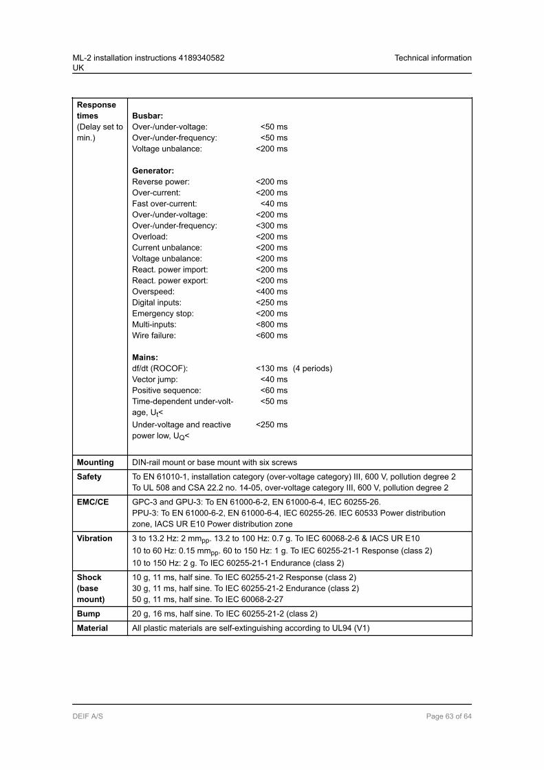
Responsetimes(Delay set tomin.)
Busbar:Over-/under-voltage: <50 msOver-/under-frequency: <50 msVoltage unbalance: <200 ms
Generator:Reverse power: <200 msOver-current: <200 msFast over-current: <40 msOver-/under-voltage: <200 msOver-/under-frequency: <300 msOverload: <200 msCurrent unbalance: <200 msVoltage unbalance: <200 msReact. power import: <200 msReact. power export: <200 msOverspeed: <400 msDigital inputs: <250 msEmergency stop: <200 msMulti-inputs: <800 msWire failure: <600 ms
Mains:df/dt (ROCOF): <130 ms (4 periods)Vector jump: <40 msPositive sequence: <60 msTime-dependent under-volt-age, Ut<
<50 ms
Under-voltage and reactivepower low, UQ<
<250 ms
Mounting DIN-rail mount or base mount with six screws
Safety To EN 61010-1, installation category (over-voltage category) III, 600 V, pollution degree 2To UL 508 and CSA 22.2 no. 14-05, over-voltage category III, 600 V, pollution degree 2
EMC/CE GPC-3 and GPU-3: To EN 61000-6-2, EN 61000-6-4, IEC 60255-26.PPU-3: To EN 61000-6-2, EN 61000-6-4, IEC 60255-26. IEC 60533 Power distributionzone, IACS UR E10 Power distribution zone
Vibration 3 to 13.2 Hz: 2 mmpp. 13.2 to 100 Hz: 0.7 g. To IEC 60068-2-6 & IACS UR E1010 to 60 Hz: 0.15 mmpp. 60 to 150 Hz: 1 g. To IEC 60255-21-1 Response (class 2)10 to 150 Hz: 2 g. To IEC 60255-21-1 Endurance (class 2)
Shock(basemount)
10 g, 11 ms, half sine. To IEC 60255-21-2 Response (class 2)30 g, 11 ms, half sine. To IEC 60255-21-2 Endurance (class 2)50 g, 11 ms, half sine. To IEC 60068-2-27
Bump 20 g, 16 ms, half sine. To IEC 60255-21-2 (class 2)
Material All plastic materials are self-extinguishing according to UL94 (V1)
ML-2 installation instructions 4189340582UK
Technical information
DEIF A/S Page 63 of 64
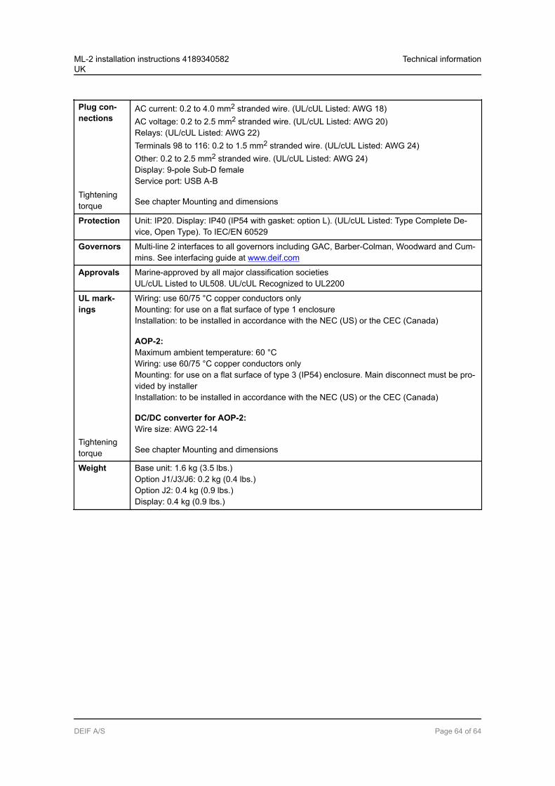
Plug con-nections
Tighteningtorque
AC current: 0.2 to 4.0 mm2 stranded wire. (UL/cUL Listed: AWG 18)AC voltage: 0.2 to 2.5 mm2 stranded wire. (UL/cUL Listed: AWG 20)Relays: (UL/cUL Listed: AWG 22)Terminals 98 to 116: 0.2 to 1.5 mm2 stranded wire. (UL/cUL Listed: AWG 24)Other: 0.2 to 2.5 mm2 stranded wire. (UL/cUL Listed: AWG 24)Display: 9-pole Sub-D femaleService port: USB A-B
See chapter Mounting and dimensions
Protection Unit: IP20. Display: IP40 (IP54 with gasket: option L). (UL/cUL Listed: Type Complete De-vice, Open Type). To IEC/EN 60529
Governors Multi-line 2 interfaces to all governors including GAC, Barber-Colman, Woodward and Cum-mins. See interfacing guide at www.deif.com
Approvals Marine-approved by all major classification societiesUL/cUL Listed to UL508. UL/cUL Recognized to UL2200
UL mark-ings
Tighteningtorque
Wiring: use 60/75 °C copper conductors onlyMounting: for use on a flat surface of type 1 enclosureInstallation: to be installed in accordance with the NEC (US) or the CEC (Canada)
AOP-2:Maximum ambient temperature: 60 °CWiring: use 60/75 °C copper conductors onlyMounting: for use on a flat surface of type 3 (IP54) enclosure. Main disconnect must be pro-vided by installerInstallation: to be installed in accordance with the NEC (US) or the CEC (Canada)
DC/DC converter for AOP-2:Wire size: AWG 22-14
See chapter Mounting and dimensions
Weight Base unit: 1.6 kg (3.5 lbs.)Option J1/J3/J6: 0.2 kg (0.4 lbs.)Option J2: 0.4 kg (0.9 lbs.)Display: 0.4 kg (0.9 lbs.)
ML-2 installation instructions 4189340582UK
Technical information
DEIF A/S Page 64 of 64