generator - makita
TRANSCRIPT
ISSUE EMD-GU2016
PRINTED IN JAPANNovember 2004 CE-SK
Makita Corporation3-11-8, Sumiyoshi-choAnjo, Aichi 446-8502 Japan
3ZZ9020166
GENERATOR
INSTRUCTIONS FOR USE
アメリカ
The engine exhaust from this product containschemicals known to the State of California tocause cancer, birth defects or other reproductiveharm.
WARNING:
NOTICEFEDERAL EMISSION COMPONENT DEFECT WARRANTY and CALIFORNIAEMISSION CONTROL WARRANTY are applicable to only those engines/generators complied with EPA (Environmental Protection Agency) and CARB(California Air Resources Board) emission regulations in the U.S.A.
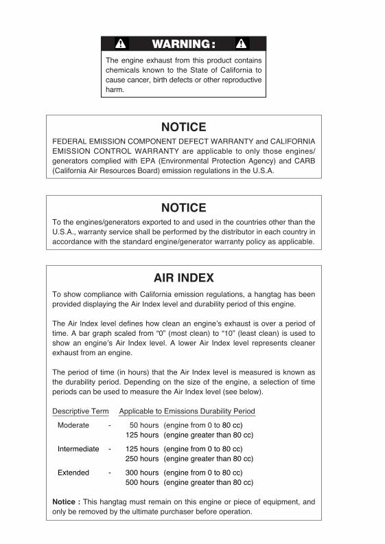
AIR INDEXTo show compliance with California emission regulations, a hangtag has beenprovided displaying the Air Index level and durability period of this engine.
The Air Index level defines how clean an engine’s exhaust is over a period oftime. A bar graph scaled from “0” (most clean) to “10” (least clean) is used toshow an engine’s Air Index level. A lower Air Index level represents cleanerexhaust from an engine.
The period of time (in hours) that the Air Index level is measured is known asthe durability period. Depending on the size of the engine, a selection of timeperiods can be used to measure the Air Index level (see below).
Descriptive Term Applicable to Emissions Durability Period
Moderate - 50 hours (engine from 0 to 80 cc)125 hours (engine greater than 80 cc)
Intermediate - 125 hours (engine from 0 to 80 cc)250 hours (engine greater than 80 cc)
Extended - 300 hours (engine from 0 to 80 cc)500 hours (engine greater than 80 cc)
Notice : This hangtag must remain on this engine or piece of equipment, andonly be removed by the ultimate purchaser before operation.
NOTICETo the engines/generators exported to and used in the countries other than theU.S.A., warranty service shall be performed by the distributor in each country inaccordance with the standard engine/generator warranty policy as applicable.
G28R-G61R 米国取説GU2016 05.1.26 11:14 AM ページ01
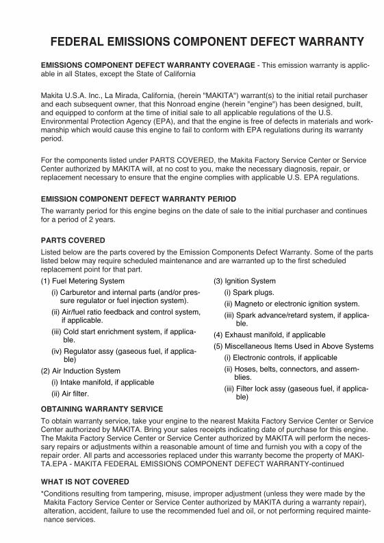
FEDERAL EMISSIONS COMPONENT DEFECT WARRANTY
EMISSIONS COMPONENT DEFECT WARRANTY COVERAGE - This emission warranty is applic-able in all States, except the State of California
Makita U.S.A. Inc., La Mirada, California, (herein "MAKITA") warrant(s) to the initial retail purchaserand each subsequent owner, that this Nonroad engine (herein "engine") has been designed, built,and equipped to conform at the time of initial sale to all applicable regulations of the U.S.Environmental Protection Agency (EPA), and that the engine is free of defects in materials and work-manship which would cause this engine to fail to conform with EPA regulations during its warrantyperiod.
For the components listed under PARTS COVERED, the Makita Factory Service Center or ServiceCenter authorized by MAKITA will, at no cost to you, make the necessary diagnosis, repair, orreplacement necessary to ensure that the engine complies with applicable U.S. EPA regulations.
EMISSION COMPONENT DEFECT WARRANTY PERIOD
The warranty period for this engine begins on the date of sale to the initial purchaser and continuesfor a period of 2 years.
PARTS COVERED
Listed below are the parts covered by the Emission Components Defect Warranty. Some of the partslisted below may require scheduled maintenance and are warranted up to the first scheduledreplacement point for that part.
(1) Fuel Metering System
(i) Carburetor and internal parts (and/or pres-sure regulator or fuel injection system).
(ii) Air/fuel ratio feedback and control system,if applicable.
(iii) Cold start enrichment system, if applica-ble.
(iv) Regulator assy (gaseous fuel, if applica-ble)
(2) Air Induction System
(i) Intake manifold, if applicable
(ii) Air filter.
(3) Ignition System
(i) Spark plugs.
(ii) Magneto or electronic ignition system.
(iii) Spark advance/retard system, if applica-ble.
(4) Exhaust manifold, if applicable
(5) Miscellaneous Items Used in Above Systems
(i) Electronic controls, if applicable
(ii) Hoses, belts, connectors, and assem-blies.
(iii) Filter lock assy (gaseous fuel, if applica-ble)
OBTAINING WARRANTY SERVICE
To obtain warranty service, take your engine to the nearest Makita Factory Service Center or ServiceCenter authorized by MAKITA. Bring your sales receipts indicating date of purchase for this engine.The Makita Factory Service Center or Service Center authorized by MAKITA will perform the neces-sary repairs or adjustments within a reasonable amount of time and furnish you with a copy of therepair order. All parts and accessories replaced under this warranty become the property of MAKI-TA.EPA - MAKITA FEDERAL EMISSIONS COMPONENT DEFECT WARRANTY-continued
WHAT IS NOT COVERED
*Conditions resulting from tampering, misuse, improper adjustment (unless they were made by theMakita Factory Service Center or Service Center authorized by MAKITA during a warranty repair),alteration, accident, failure to use the recommended fuel and oil, or not performing required mainte-nance services.
G28R-G61R 米国取説GU2016 05.1.26 11:14 AM ページ02
*The replacement parts used for required maintenance services.
*Consequential damages such as loss of time, inconvenience, loss of use of the engine orequip-ment, etc.
*Diagnosis and inspection charges that do not result in warranty-eligible service being performed.
*Any non-authorized replacement part, or malfunction of authorized parts due to use of non-autho-rized parts.
OWNER'S WARRANTY RESPONSIBILITIES
As the engine owner, you are responsible for the performance of the required maintenance listed inyour owner's manual. MAKITA recommends that you retain all receipts covering maintenance onyour engine, but MAKITA cannot deny warranty solely for the lack of receipts or for your failure toensure the performance of all scheduled maintenance.
As the engine owner, you should however be aware that MAKITA may deny warranty coverage ifyour engine or a part has failed due to abuse, neglect, improper maintenance or unapproved modi-fications.
You are responsible for presenting your engine to the nearest Makita Factory Service Center orService Center authorized by MAKITA when a problem exists.
If you have any questions regarding your warranty rights and responsibilities, you should contactthe Makita Warranty Department at 1-800-4-MAKITA for the information.
THINGS YOU SHOULD KNOW ABOUT THE EMISSION CONTROL SYSTEM WARRANTYMAINTENANCE AND REPAIRS
You are responsible for the proper maintenance of the engine. You should keep all receipts andmaintenance records covering the performance of regular maintenance in the event questionsarise. These receipts and maintenance records should be transferred to each subsequent owner ofthe engine. MAKITA reserves the right to deny warranty coverage if the engine has not been prop-erly maintained. Warranty claims will not be denied, however, solely because of the lack of requiredmaintenance or failure to keep maintenance records.
MAINTENANCE, REPLACEMENT OR REPAIR OF EMISSION CONTROL DEVICES AND SYS-TEMS MAY BE PERFORMED BY ANY REPAIR ESTABLISHMENT OR INDIVIDUAL ; HOWEVER,WARRANTY REPAIRS MUST BE PERFORMED BY THE MAKITA FACTORY SERVICE CENTEROR SERVICE CENTER AUTHORIZED BY MAKITA. THE USE OF PARTS THAT ARE NOTEQUIVALENT IN PERFORMANCE AND DURABILITY TO AUTHORIZED PARTS MAY IMPAIRTHE EFFECTIVENESS OF THE EMISSION CONTROL SYSTEM AND MAY HAVE A BEARINGON THE OUTCOME OF A WARRANTY CLAIM.
If other than the parts authorized by MAKITA are used for maintenance replacements or for therepair of components affecting emission control, you should assure yourself that such parts arewarranted by their manufacturer to be equivalent to the parts authorized by MAKITA in their perfor-mance and durability.
HOW TO MAKE A CLAIM
All repair qualifying under this limited warranty must be performed by a Makita Factory ServiceCenter or Service Center authorized by MAKITA. In the event that any emission-related part isfound to be defective during the warranty period, you shall notify Makita Warranty Department at 1-800-4-MAKITA and you will be advised of the appropriate warranty service dealer or serviceproviders where the warranty repair can be performed.
G28R-G61R 米国取説GU2016 05.1.26 11:14 AM ページ03
CALIFORNIA EMISSION CONTROL WARRANTY STATEMENT(This warranty does not apply in any other state.)YOUR WARRANTY RIGHTS AND OBLIGATIONS
The California Air Resources Board and Makita U.S.A., Inc. (herein "MAKITA") are pleased toexplain the emission control warranty on your 2005 and later small off-road engine (herein"engine"). In California, new engine must be designed, built and equipped to meet the State'sstringent anti-smog standards. MAKITA must warrant the emission control system on yourengine for the periods of time listed below provided there has been no abuse, neglect orimproper maintenance of your engine.
Your emission control system includes parts such as the carburetor or fuel injection systems,the ignition system and the catalytic converter. Also included are the hoses, belts, connectorsand other emission-related assemblies.
Where a warrantable condition exists, MAKITA will repair your engine at no cost to you includingdiagnosis, parts and labor.
MANUFACTURER'S WARRANTY COVERAGE :
The 2005 and later engines are warranted for two years. If any emission-related part on yourengine is defective, the part will be repaired or replaced by MAKITA.
OWNER'S WARRANTY RESPONSIBILITIES :
-As the engine owner, you are responsible for the performance of the required mainte-nance listed in your Owner's Manual. MAKITA recommends that you retain all receiptscovering maintenance on your engine, but MAKITA cannot deny warranty solely for thelack of receipts or for your failure to ensure the performance of all scheduled mainte-nance.
-As the engine owner, you should be aware, however, that MAKITA may deny you warran-ty coverage if your engine or a part has failed due to abuse, neglect, improper mainte-nance or unapproved modifications.
-You are responsible for presenting your engine to a MAKITA service center as a problemexists.The warranty repairs should be completed in a reasonable time, not to exceed 30 days.
If you have any questions regarding your warranty rights and responsibilities, you should con-tact a Makita Factory Service Center Manager nearest you. A list of the Factory Service Centerlocations and phone numbers is provided below for your convenience.
G28R-G61R 米国取説GU2016 05.1.26 11:14 AM ページ04
LIMITED WARRANTYon Emission Control Systems
- California Only -
MAKITA , a distributor of small off-road equipment in the U.S., warrants to the owner of 2005and later engines that the engine (1) has been designed, built, and equipped at the time of man-ufacture so as to conform with the applicable regulations of the California Air Resources Boardand, (2) is free from defects in materials and workmanship which may cause it to fail to conformwith those regulations as applicable according to the terms and conditions stated below.
WARRANTY PERIODThis warranty period begins on the date which the engine is delivered to the original retail pur-chaser and ends two years after that date. During this two year period MAKITA warrants to theoriginal retail purchaser and each subsequent purchaser that the engine is free from defect inmaterial and workmanship that can cause the failure of a warranted emission-related part.
WHAT IS COVERED UNDER THIS WARRANTYRepair and/or replacement of any warranted emission-related part will be performed at nocharge provided the work is performed at an authorized warranty station. There will also be nocharge for any diagnostic labor performed at an authorized warranty station which leads to thedetermination that a warranted emission-related part is defective.
Any warranted part which is not scheduled for replacement as required maintenance, or which isscheduled only for regular inspection to the effect of "repair or replace as necessary" shall bewarranted for the warranty period. Any warranted part which is scheduled for replacement asrequired maintenance shall be warranted for the period of time up to the first scheduled replace-ment of that part. This warranty shall apply only towards the repair, replacement, and/or adjust-ment of the component parts listed below.
EMISSION-RELATED PARTS COVERED UNDER THIS WARRANTY(1) Fuel Metering System
(i) Carburetor and internal parts (and/or pressure regulator or fuel injection system).
(ii) Air/fuel ratio feedback and control system, if applicable.
(iii) Cold start enrichment system, if applicable.
(iv) Regulator assy (gaseous fuel, if applicable)
(2) Air Induction System
(i)Intake manifold, if applicable
(ii)Air filter.
(3) Ignition System
(i)Spark plugs.
(ii)Magneto or electronic ignition system.
(iii)Spark advance/retard system, if applicable.
(4) Exhaust manifold, if applicable
(5) Miscellaneous Items Used in Above Systems
(i)Electronic controls, if applicable
(ii)Hoses, belts, connectors, and assemblies.
(iii) Filter lock assy (gaseous fuel, if applicable)
G28R-G61R 米国取説GU2016 05.1.26 11:14 AM ページ05
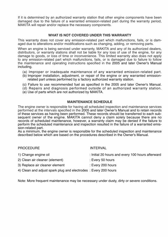
If it is determined by an authorized warranty station that other engine components have beendamaged due to the failure of a warranted emission-related part during the warranty period,MAKITA will repair and/or replace the necessary components.
WHAT IS NOT COVERED UNDER THIS WARRANTYThis warranty does not cover any emission-related part which malfunctions, fails, or is dam-aged due to alterations and/or modifications such as changing, adding, or removing parts.
When an engine is being serviced under warranty, MAKITA and any of its authorized dealers,distributors, or warranty stations shall not be liable for any loss of use of the engine, for anydamage to goods, or loss of time or inconvenience. This limited warranty also does not applyto any emission-related part which malfunctions, fails, or is damaged due to failure to followthe maintenance and operating instructions specified in the 2005 and later Owner's Manualincluding.
(a) Improper or inadequate maintenance of any warranted emission-related part.(b) Improper installation, adjustment, or repair of the engine or any warranted emission-
related part unless performed by a factory authorized warranty station.
(c) Failure to use recommended fuel as specified in the 2005 and later Owner's Manual.(d) Repairs and diagnosis performed outside of an authorized warranty station.(e) Use of parts which are not authorized by MAKITA.
MAINTENANCE SCHEDULEThe engine owner is responsible for having all scheduled inspection and maintenance servicesperformed at the intervals specified in the 2005 and later Owner's Manual and to retain recordsof these services as having been performed. These records should be transferred to each sub-sequent owner of the engine. MAKITA cannot deny a claim solely because there are norecords of scheduled maintenance, however, a warranty claim may be denied if the failure toperform the scheduled maintenance and inspection resulted in the failure of a warranted emis-sion-related part.As a minimum, the engine owner is responsible for the scheduled inspection and maintenancedescribed below which are based on the procedures described in the Owner's Manual.
PROCEDURE INTERVAL
1) Change engine oil : Initial 20 hours and every 100 hours afterward
2) Clean air cleaner (element) : Every 50 hours
3) Replace air cleaner element : Every 200 hours
4) Clean and adjust spark plug and electrodes : Every 200 hours
Note: More frequent maintenance may be necessary under dusty, dirty or severe conditions.
G28R-G61R 米国取説GU2016 05.1.26 11:14 AM ページ06
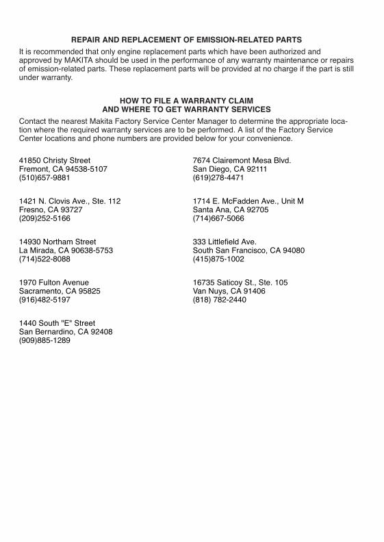
REPAIR AND REPLACEMENT OF EMISSION-RELATED PARTS
It is recommended that only engine replacement parts which have been authorized andapproved by MAKITA should be used in the performance of any warranty maintenance or repairsof emission-related parts. These replacement parts will be provided at no charge if the part is stillunder warranty.
HOW TO FILE A WARRANTY CLAIM AND WHERE TO GET WARRANTY SERVICES
Contact the nearest Makita Factory Service Center Manager to determine the appropriate loca-tion where the required warranty services are to be performed. A list of the Factory ServiceCenter locations and phone numbers are provided below for your convenience.
41850 Christy StreetFremont, CA 94538-5107(510)657-9881
1421 N. Clovis Ave., Ste. 112Fresno, CA 93727(209)252-5166
14930 Northam StreetLa Mirada, CA 90638-5753(714)522-8088
1970 Fulton AvenueSacramento, CA 95825(916)482-5197
1440 South "E" StreetSan Bernardino, CA 92408(909)885-1289
7674 Clairemont Mesa Blvd.San Diego, CA 92111(619)278-4471
1714 E. McFadden Ave., Unit MSanta Ana, CA 92705(714)667-5066
333 Littlefield Ave.South San Francisco, CA 94080(415)875-1002
16735 Saticoy St., Ste. 105 Van Nuys, CA 91406(818) 782-2440
G28R-G61R 米国取説GU2016 05.1.26 11:14 AM ページ07
Thank you for purchasing a Makita generator.
This manual covers operation and maintenance of the Makita generators.All information in this publication is based on the latest production informa-tion available at the time of approval for printing.
Pay special attention to statements preceded by the following words:
■ The generator is designed to give safe and dependable service ifoperated according to instructions.
■ Do not operate the generator before you have read and under-stood the instructions. Failure to do so could result in death, per-sonal injury or equipment damage.
WARNING
Indicates a strong possibility of severe personal injury, loss of life and equip-ment damage if instructions are not followed.
[CAUTION]Indicates a possibility of personal injury or equipment damage if instructionsare not followed.
NOTE:Gives helpful information.
If a problem should arise, or if you have any questions about the generator,consult an authorized dealer or service shop
WARNING
FOREWORD
G28R-G61R 米国取説GU2016 05.1.26 11:14 AM ページ08
CONTENTS
1. SAFETY PRECAUTIONS・・・・・・・・・・・・・・・・・・・・・・1
2. SPECIFICATIONS・・・・・・・・・・・・・・・・・・・・・・・・・・4
3. COMPONENTS ・・・・・・・・・・・・・・・・・・・・・・・・・・・5
4. PRE-OPERATION CHECKS ・・・・・・・・・・・・・・・・・・・・6
5. OPERATING PROCEDURES・・・・・・・・・・・・・・・・・・・・11
6. WATTAGE INFORMATION ・・・・・・・・・・・・・・・・・・・・・24
7. SPARK ARRESTER ・・・・・・・・・・・・・・・・・・・・・・・・25
8. MAINTENANCE SCHEDULE・・・・・・・・・・・・・・・・・・・・26
9. "HOW-TO" MAINTENANCE ・・・・・・・・・・・・・・・・・・・・28
10. PREPARATION FOR STORAGE・・・・・・・・・・・・・・・・・・31
11. TROUBLESHOOTING ・・・・・・・・・・・・・・・・・・・・・・・32
12. WIRING DIAGRAM ・・・・・・・・・・・・・・・・・・・・・・・・・33
13. OPTIONAL PARTS ・・・・・・・・・・・・・・・・・・・・・・・・・38
G28R-G61R 米国取説GU2016 05.1.26 11:14 AM ページ09
1. SAFETY PRECAUTIONS
- 1-
Do not operate the generator near gasoline or gaseous fuel because of thepotential danger of explosion or fire.Do not fill the fuel tank with fuel while the engine is running. Do not smoke oruse open flame near the fuel tank. Be careful not to spill fuel during refueling.If fuel is spilt, wipe it off and let dry before starting the engine.
Do not place in flammables near the generator.Be careful not to place fuel, matches, gunpowder, oily cloths, straw, trash, orany other in flammables near the generator.
Do not operate the generator inside a room, cave, tunnel, or other insufficient-ly ventilated area. Always operate it in a well-ventilated area, otherwise theengine may become overheated, and the poisonous carbon monoxide gascontained in the exhaust gases will endanger human lives. Keep the,genera-tor at least 1 meter (3 feet) away from any structure or building during use.If the generator must be used indoors, the area must be well-ventilated andextreme caution must be taken regarding the discharge of exhaust gases.
Do not enclose the generator nor cover it with a box.The generator has a built-in forced air cooling system, and may become over-heated if it is enclosed. If generator has been covered to protect it from theweather during non use, be sure to remove it and keep it well away from thearea during generator use.
Operate the generator on a level surface.It is not necessary to prepare a special foundation for the generator. However, the generator will vibrate on an irregular surface, so choose a levelplace without surface irregularities.If the generator is tilted or moved during operation, fuel may spill and / or thegenerator may tip over, causing a hazardous situation.Proper lubrication cannot be expected if the generator is operated on a steepincline or slope. In such a case, piston seizure may occur even if the oil isabove the upper level.
G28R-G61R 米国取説GU2016 05.1.26 11:14 AM ページ1
- 2-
Pay attention to the wiring or extension cords from the generator to the con-nected device.If the wire is under the generator or in contact with a vibrating part, it maybreak and possibly cause a fire, generator burnout, or electric shock hazard.Replace damaged or worn cords immediately.
Do not operate in rain, in wet or damp conditions, or with wet hands.The operator may suffer severe electric shock if the generator is wet due torain or snow.
If wet, wipe and dry it well before starting. Do not pour water directly over thegenerator, nor wash it with water.
Be extremely careful that all necessary electrical grounding procedures arefollowed during each and every use. Failure to do so can be fatal.
Do not contact the generator to a commercial power line. Connection to acommercial power line may short circuit the generator and ruin it or causeelectric shock hazard. Use the transfer switch for connecting to domestic cir-cuit.
No smoking while handling the battery. The battery emits flammable hydrogengas, which can explode if exposed to electric arcing or open flame.Keep the area well-ventilated and keep open flames/sparks away when han-dling the battery.
Engine becomes extremely hot during and for some time after operation.Keep combustible materials well away from generator area.Be very careful not to touch any parts of the hot engine especially the mufflerarea or serious burns may result.
Keep children and all bystanders at a safe distance from work areas.
G28R-G61R 米国取説GU2016 05.1.26 11:14 AM ページ2
- 3-
It is absolutely essential that you know the safe and proper use of the powertool or appliance that you intend to use. All operators must read, understandand follow the tool/appliance owners manual. Tool and appliance applica-tions and limitations must be understood. Follow all directions given onlabels and warnings. Keep all instruction manuals and literature in a safeplace for future reference.
Use only "LISTED" extension cords.When a tool or appliance is used outdoors, use only extension cordsmarked "For Outdoor Use". Extension cords, when not in use should bestored in a dry and well ventilated area.
Always switch off generator's no-fuse breaker and disconnect tools or appli-ances when not in use, before servicing, adjusting, or installing accessoriesand attachments.
G28R-G61R 米国取説GU2016 05.1.26 11:14 AM ページ3
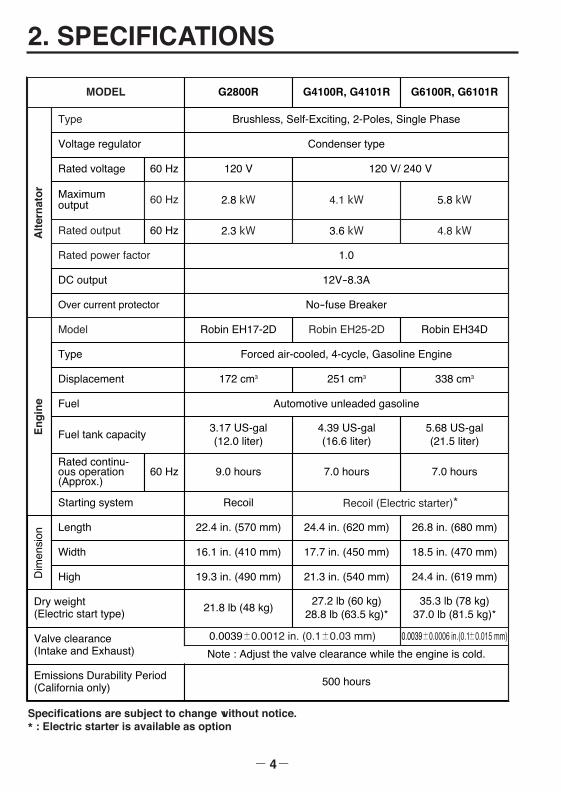
Specifications are subject to change without notice.* : Electric starter is available as option
2. SPECIFICATIONS
- 4-
MODEL G2800R G4100R, G4101R G6100R, G6101R
Robin EH25-2D
Alt
ern
ato
r
Type Brushless, Self-Exciting, 2-Poles, Single Phase
251 cm3
4.39 US-gal(16.6 liter)
Voltage regulator Condenser type
Rated voltage 120 V
Maximumoutput 2.8 kW
Rated output 2.3 kW
Rated power factor 1.0
Over current protector No-fuse Breaker
En
gin
e
Model Robin EH17-2D Robin EH34D
Type Forced air-cooled, 4-cycle, Gasoline Engine
Displacement 172 cm3 338 cm3
Fuel Automotive unleaded gasoline
Fuel tank capacity3.17 US-gal(12.0 liter)
Rated continu-ous operation(Approx.)
9.0 hours
Starting system Recoil
Dim
ensi
on
Length 22.4 in. (570 mm) 24.4 in. (620 mm) 26.8 in. (680 mm)
Width 16.1 in. (410 mm) 17.7 in. (450 mm) 18.5 in. (470 mm)
High 19.3 in. (490 mm) 21.3 in. (540 mm) 24.4 in. (619 mm)
Dry weight(Electric start type) 21.8 lb (48 kg)
27.2 lb (60 kg)28.8 lb (63.5 kg)*
35.3 lb (78 kg)37.0 lb (81.5 kg)*
5.68 US-gal (21.5 liter)
7.0 hours7.0 hours
60 Hz
60 Hz
60 Hz
DC output 12V-8.3A
5.8 kW4.1 kW60 Hz
3.6 kW 4.8 kW
Recoil (Electric starter)*
120 V/ 240 V
Valve clearance(Intake and Exhaust)
0.0039±0.0012 in. (0.1±0.03 mm)
Emissions Durability Period(California only) 500 hours
Note : Adjust the valve clearance while the engine is cold.
0.0039±0.0006 in.(0.1±0.015 mm)
G28R-G61R 米国取説GU2016 05.1.26 11:14 AM ページ4
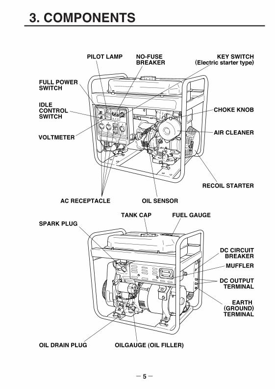
3. COMPONENTS
- 5-
V
FUEL GAUGE
PILOT LAMP
SPARK PLUG
OIL DRAIN PLUG OILGAUGE (OIL FILLER)
KEY SWITCH(Electric starter type)
CHOKE KNOB
AIR CLEANER
RECOIL STARTER
OIL SENSORAC RECEPTACLE
MUFFLER
NO-FUSE BREAKER
TANK CAP
DC CIRCUITBREAKER
EARTH (GROUND)TERMINAL
DC OUTPUTTERMINAL
VOLTMETER
FULL POWERSWITCH
IDLECONTROLSWITCH
G28R-G61R 米国取説GU2016 05.1.26 11:14 AM ページ5
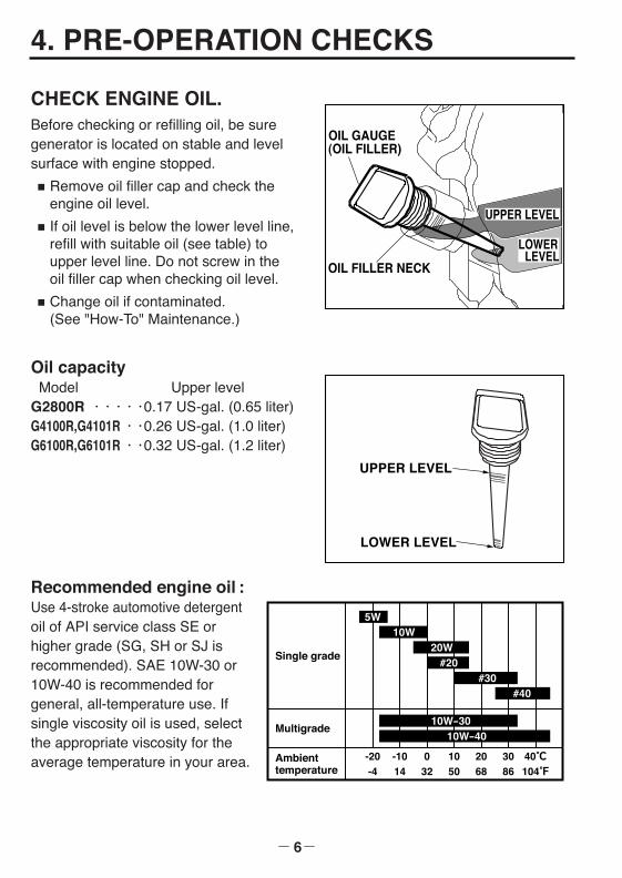
UPPER LEVEL
LOWERLEVEL
OIL FILLER NECK
OIL GAUGE(OIL FILLER)
UPPER LEVEL
LOWER LEVEL
4. PRE-OPERATION CHECKS
- 6-
CHECK ENGINE OIL.Before checking or refilling oil, be suregenerator is located on stable and levelsurface with engine stopped.
■ Remove oil filler cap and check theengine oil level.
■ If oil level is below the lower level line,refill with suitable oil (see table) toupper level line. Do not screw in theoil filler cap when checking oil level.
■ Change oil if contaminated.(See "How-To" Maintenance.)
Oil capacityModel Upper level
G2800R ・・・・・0.17 US-gal. (0.65 liter)G4100R,G4101R・・0.26 US-gal. (1.0 liter)G6100R,G6101R・・0.32 US-gal. (1.2 liter)
Recommended engine oil :Use 4-stroke automotive detergentoil of API service class SE orhigher grade (SG, SH or SJ isrecommended). SAE 10W-30 or10W-40 is recommended for general, all-temperature use. Ifsingle viscosity oil is used, selectthe appropriate viscosity for theaverage temperature in your area. Ambient
temperature
Single grade
Multigrade
5W10W
20W#20
#30#40
10W-3010W-40
G28R-G61R 米国取説GU2016 05.1.26 11:14 AM ページ6
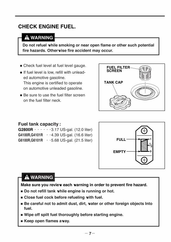
■ Check fuel level at fuel level gauge.
■ If fuel level is low, refill with unlead-ed automotive gasoline.This engine is certified to operateon automotive unleaded gasoline.
■ Be sure to use the fuel filter screenon the fuel filter neck.
Fuel tank capacity :G2800R・・・・・・3.17 US-gal. (12.0 liter)G4100R,G4101R ・・4.39 US-gal. (16.6 liter)G6100R,G6101R ・・5.68 US-gal. (21.5 liter)
- 7-
TANK CAP
FUEL FILTERSCREEN
Do not refuel while smoking or near open flame or other such potentialfire hazards. Otherwise fire accident may occur.
CHECK ENGINE FUEL.
Make sure you review each warning in order to prevent fire hazard.■ Do not refill tank while engine is running or hot.■ Close fuel cock before refueling with fuel.■ Be careful not to admit dust, dirt, water or other foreign objects Into
fuel.■ Wipe off spilt fuel thoroughly before starting engine.■ Keep open flames away.
WARNING
WARNING
FULL
EMPTY
G28R-G61R 米国取説GU2016 05.1.26 11:14 AM ページ7
CHECKING COMPONENT PARTSCheck following items before starting engine:
■ Fuel leakage from fuel hose, etc.
■ Bolts and nuts for looseness.
■ Components for damage or breakage.
■ Generator not resting on or against any adjacent wiring.
CHECK GENERATOR SURROUNDINGS.
- 8-
Make sure you review each warning in order to prevent fire hazard.
■ Keep area clear of in flammables or other hazardous materials.
■ Keep generator at least 3 feet (1 meter) away from buildings or otherstructures.
■ Only operate generator in a dry, well ventilated area.
■ Keep exhaust pipe clear of foreign objects.
■ Keep generator away from open flame. No smoking!
■ Keep generator on a stable and level surface.
■ Do not block generator air vents with paper or other material.
WARNING
G28R-G61R 米国取説GU2016 05.1.26 11:14 AM ページ8
- 9-
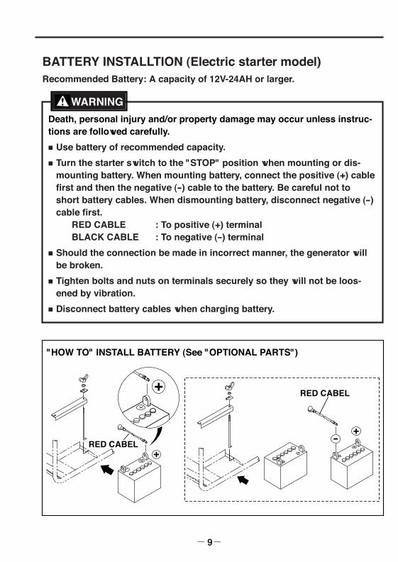
BATTERY INSTALLTION (Electric starter model)Recommended Battery: A capacity of 12V-24AH or larger.
Death, personal injury and/or property damage may occur unless instruc-tions are followed carefully.
■ Use battery of recommended capacity.
■ Turn the starter switch to the "STOP" position when mounting or dis-mounting battery. When mounting battery, connect the positive (+) cablefirst and then the negative (-) cable to the battery. Be careful not toshort battery cables. When dismounting battery, disconnect negative (-)cable first.
RED CABLE : To positive (+) terminalBLACK CABLE : To negative (-) terminal
■ Should the connection be made in incorrect manner, the generator willbe broken.
■ Tighten bolts and nuts on terminals securely so they will not be loos-ened by vibration.
■ Disconnect battery cables when charging battery.
WARNING
��� �����
��� �����
"HOW TO" INSTALL BATTERY (See "OPTIONAL PARTS")
G28R-G61R 米国取説GU2016 05.1.26 11:14 AM ページ9
- 10-
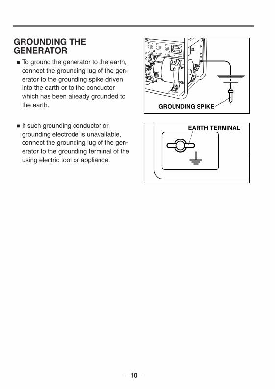
GROUNDING THE GENERATOR■ To ground the generator to the earth,
connect the grounding lug of the gen-erator to the grounding spike driveninto the earth or to the conductorwhich has been already grounded tothe earth.
■ If such grounding conductor orgrounding electrode is unavailable,connect the grounding lug of the gen-erator to the grounding terminal of theusing electric tool or appliance.
GROUNDING SPIKE
EARTH TERMINAL
G28R-G61R 米国取説GU2016 05.1.26 11:14 AM ページ10
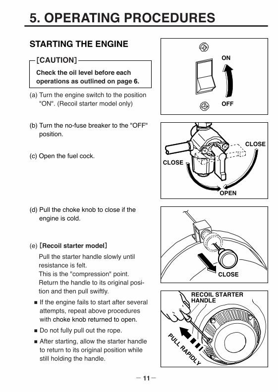
(a) Turn the engine switch to the position"ON". (Recoil starter model only)
(b) Turn the no-fuse breaker to the "OFF"position.
(c) Open the fuel cock.
(d) Pull the choke knob to close if theengine is cold.
5. OPERATING PROCEDURES
STARTING THE ENGINE
- 11-
Check the oil level before eachoperations as outlined on page 6.
[CAUTION] ON
OFF
OPEN
CLOSE
CLOSE
CLOSE
RECOIL STARTERHANDLE
PULL RAPIDLY
(e)[Recoil starter model]
Pull the starter handle slowly untilresistance is felt. This is the "compression" point. Return the handle to its original posi-tion and then pull swiftly.
■ If the engine fails to start after severalattempts, repeat above procedureswith choke knob returned to open.
■ Do not fully pull out the rope.
■ After starting, allow the starter handleto return to its original position whilestill holding the handle.
G28R-G61R 米国取説GU2016 05.1.26 11:14 AM ページ11
- 12-
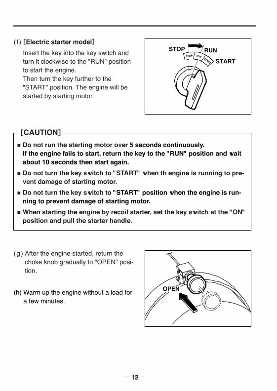
( f )[Electric starter model]
Insert the key into the key switch andturn it clockwise to the "RUN" positionto start the engine.Then turn the key further to the"START" position. The engine will bestarted by starting motor.
RUNSTOPSTOP RUN START START
OPEN
■ Do not run the starting motor over 5 seconds continuously.If the engine fails to start, return the key to the "RUN" position and waitabout 10 seconds then start again.
■ Do not turn the key switch to "START" when th engine is running to pre-vent damage of starting motor.
■ Do not turn the key switch to "START" position when the engine is run-ning to prevent damage of starting motor.
■ When starting the engine by recoil starter, set the key switch at the "ON"position and pull the starter handle.
[CAUTION]
(g) After the engine started, return thechoke knob gradually to "OPEN" posi-tion.
(h) Warm up the engine without a load fora few minutes.
G28R-G61R 米国取説GU2016 05.1.26 11:14 AM ページ12
- 13-
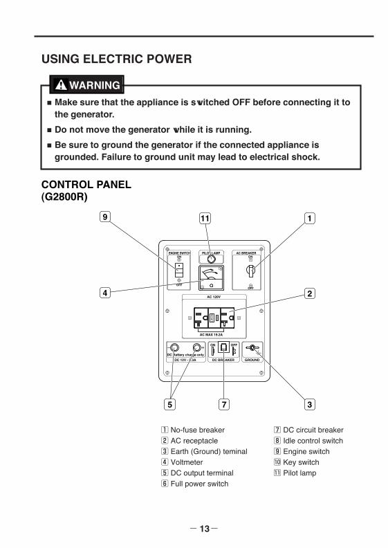
USING ELECTRIC POWER
■ Make sure that the appliance is switched OFF before connecting it tothe generator.
■ Do not move the generator while it is running.
■ Be sure to ground the generator if the connected appliance isgrounded. Failure to ground unit may lead to electrical shock.
WARNING
CONTROL PANEL(G2800R)
DC Battery charge only
DC BREAKERDC 12V - 8.3A GROUND
ON OFF
ON
OFF
ON
OFF
PILOT LAMP
AC 120V
ENGINE SWITCH AC BREAKER
AC MAX 19.2A
RE
SE
T
TE
ST
9 11 1
2
375
4
1 No-fuse breaker2 AC receptacle3 Earth (Ground) teminal4 Voltmeter5 DC output terminal6 Full power switch
7 DC circuit breaker8 Idle control switch9 Engine switch!0 Key switch!1 Pilot lamp
G28R-G61R 米国取説GU2016 05.1.26 11:14 AM ページ13
- 14-
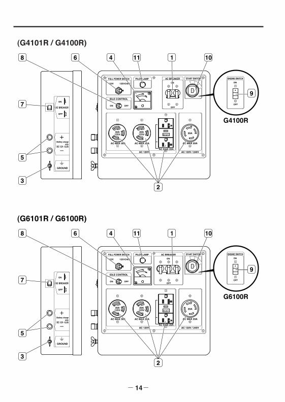
(G4101R / G4100R)
AC MAX 30A
30A125V
20A125V 20A
RESET
TEST
AC MAX 20A
AC MAX 20A
AC MAX 20A
120V/240V120V
FULL POWER SWITCH
IDLE CONTROL
G4100R
Battery chargeonly
DC 12V - 8.3A
GROUND
ON
OFFON
OFF
ON OFFDC BREAKER
PILOT LAMP
AC 120V AC 120V / 240V
ENGINE SWITCHSTART SWITCH
5
8 6 4 11 10
9
2
7
3
ON
OFF
AC BREAKER
1
(G6101R / G6100R)
AC MAX 30A
30A125V
20A125V 20A
RESET
TEST
AC MAX 20A
AC MAX 20A
AC MAX 20A
AC BREAKER
120V/240V120V
FULL POWER SWITCH
IDLE CONTROL
G6100R
Battery chargeonly
DC 12V - 8.3A
GROUND
ON
OFF
ON
OFF
ON
OFF
ON OFFDC BREAKER
PILOT LAMP
AC 120V AC 120V / 240V
ENGINE SWITCHSTART SWITCH
5
8 6 4 11 1 10
9
2
7
3
G28R-G61R 米国取説GU2016 05.1.26 11:14 AM ページ14
- 15-
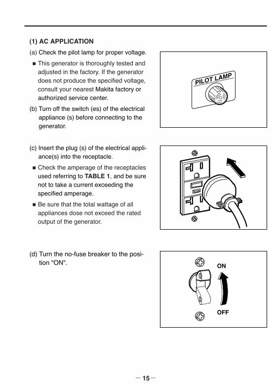
(1) AC APPLICATION
(a) Check the pilot lamp for proper voltage.
■ This generator is thoroughly tested andadjusted in the factory. If the generatordoes not produce the specified voltage,consult your nearest Makita factory orauthorized service center.
(b) Turn off the switch (es) of the electricalappliance (s) before connecting to thegenerator.
(c) Insert the plug (s) of the electrical appli-ance(s) into the receptacle.
■ Check the amperage of the receptaclesused referring to TABLE 1, and be surenot to take a current exceeding thespecified amperage.
■ Be sure that the total wattage of allappliances dose not exceed the ratedoutput of the generator.
PILOT LAMP
ON
OFF
(d) Turn the no-fuse breaker to the posi-tion "ON".
G28R-G61R 米国取説GU2016 05.1.26 11:14 AM ページ15

- 16-
NOTE :
When the no-fuse breaker turns off during operation, the generator is over loadedor the appliance is defective. Stop the generator immediately, check the applianceand / or generator for overloading or detect and have repaired as necessary byMakita factory or authorized service center.
■ To take power out from the TWISTLOCK RECEPTACLE, insert theplug into the receptacle, and turnit clockwise to the lock position.
■ Be sure to ground the generator ifthe connected electrical device Isgrounded.
WARNING
TWIST
The duplex 120V receptacle is protected by a GFCI (Ground Fault CircuitInterrupter). GFCI shuts off the output current from the duplex 120Vreceptacle when a ground fault occurs in the generator or the appliance.Please note that other receptacles are not protected by GFCI.
[CAUTION]
up to 30A
up to 20A
up to 20ANEMA5-20R
NEMAL14-20R
NEMAL5-30R
NEMA5-20P
NEMAL14-20P
NEMAL5-30P
GFCI (Ground FaultCircuit Interrupter)Receptacle, duplex(REC 1)
Locking Receptacle(REC 4)
Locking Receptacle(REC 2)
Style Ampere Receptacle AC plug Description
up to 20ANEMAL5-20R
NEMAL5-20P
Locking Receptacle(REC 3)
TABLE 1
G28R-G61R 米国取説GU2016 05.1.26 11:14 AM ページ16
- 17-
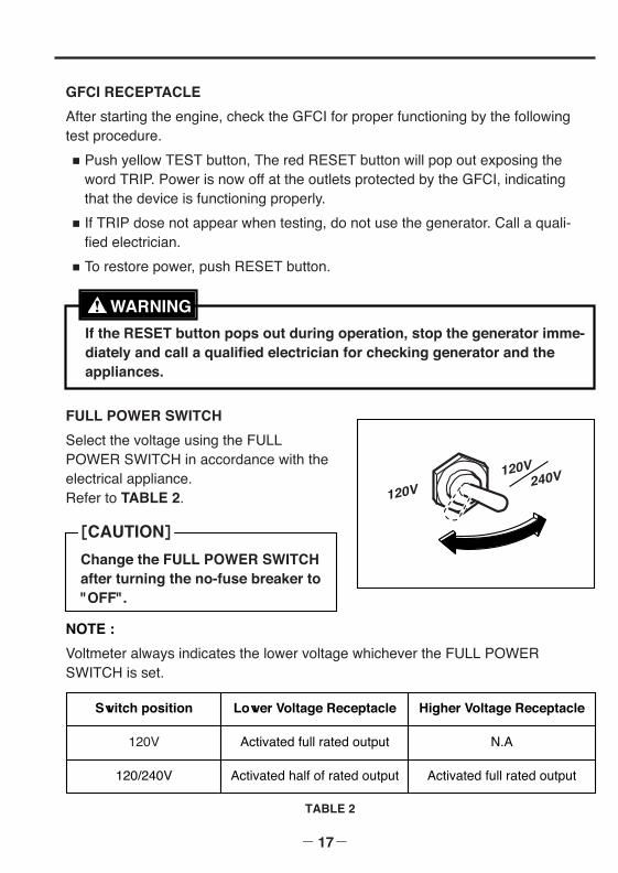
FULL POWER SWITCH
Select the voltage using the FULLPOWER SWITCH in accordance with theelectrical appliance. Refer to TABLE 2. 120V
120V 240V
Change the FULL POWER SWITCHafter turning the no-fuse breaker to"OFF".
[CAUTION]
GFCI RECEPTACLE
After starting the engine, check the GFCI for proper functioning by the followingtest procedure.
■ Push yellow TEST button, The red RESET button will pop out exposing theword TRIP. Power is now off at the outlets protected by the GFCI, indicatingthat the device is functioning properly.
■ If TRIP dose not appear when testing, do not use the generator. Call a quali-fied electrician.
■ To restore power, push RESET button.
If the RESET button pops out during operation, stop the generator imme-diately and call a qualified electrician for checking generator and theappliances.
WARNING
NOTE :
Voltmeter always indicates the lower voltage whichever the FULL POWERSWITCH is set.
TABLE 2
Switch position Lower Voltage Receptacle Higher Voltage Receptacle
120V Activated full rated output N.A
120/240V Activated half of rated output Activated full rated output
G28R-G61R 米国取説GU2016 05.1.26 11:14 AM ページ17
- 18-
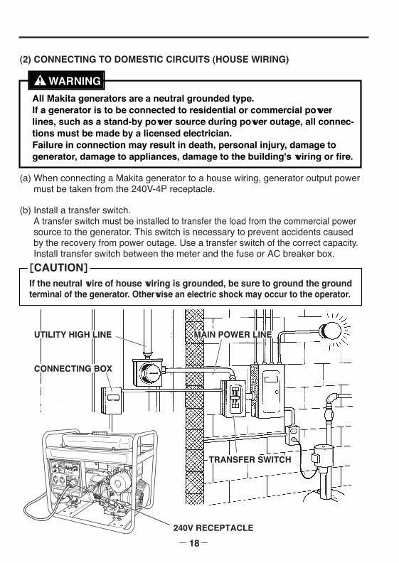
(2) CONNECTING TO DOMESTIC CIRCUITS (HOUSE WIRING)
All Makita generators are a neutral grounded type.If a generator is to be connected to residential or commercial powerlines, such as a stand-by power source during power outage, all connec-tions must be made by a licensed electrician.Failure in connection may result in death, personal injury, damage togenerator, damage to appliances, damage to the building's wiring or fire.
WARNING
(a) When connecting a Makita generator to a house wiring, generator output powermust be taken from the 240V-4P receptacle.
(b) Install a transfer switch.A transfer switch must be installed to transfer the load from the commercial powersource to the generator. This switch is necessary to prevent accidents causedby the recovery from power outage. Use a transfer switch of the correct capacity.Install transfer switch between the meter and the fuse or AC breaker box.
If the neutral wire of house wiring is grounded, be sure to ground the groundterminal of the generator. Otherwise an electric shock may occur to the operator.
[CAUTION]
240V RECEPTACLE
MAIN POWER LINE
TRANSFER SWITCH
UTILITY HIGH LINE
CONNECTING BOX
G28R-G61R 米国取説GU2016 05.1.26 11:14 AM ページ18
- 19-
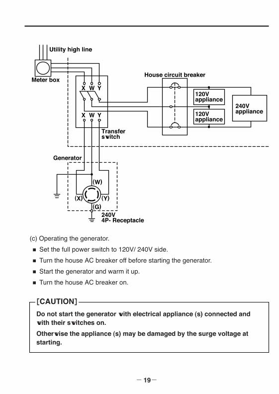
Utility high line
Meter box
Generator
House circuit breaker
X W Y
X
(X) (Y)(G)
(W)
W Y
Transferswitch
240V4P- Receptacle
120Vappliance
120Vappliance
240Vappliance
(c) Operating the generator.
■ Set the full power switch to 120V/ 240V side.
■ Turn the house AC breaker off before starting the generator.
■ Start the generator and warm it up.
■ Turn the house AC breaker on.
Do not start the generator with electrical appliance (s) connected andwith their switches on.
Otherwise the appliance (s) may be damaged by the surge voltage atstarting.
[CAUTION]
G28R-G61R 米国取説GU2016 05.1.26 11:14 AM ページ19
- 20-
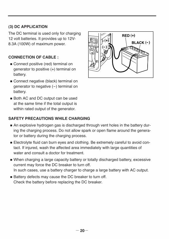
(3) DC APPLICATION
The DC terminal is used only for charging12 volt batteries. It provides up to 12V-8.3A (100W) of maximum power.
CONNECTION OF CABLE :
■ Connect positive (red) terminal ongenerator to positive (+) terminal onbattery.
■ Connect negative (black) terminal ongenerator to negative (-) terminal onbattery.
■ Both AC and DC output can be usedat the same time if the total output iswithin rated output of the generator.
RED (+)
BLACK (- ) (+)
(- )
SAFETY PRECAUTIONS WHILE CHARGING
■ An explosive hydrogen gas is discharged through vent holes in the battery dur-ing the charging process. Do not allow spark or open flame around the genera-tor or battery during the charging process.
■ Electrolyte fluid can burn eyes and clothing. Be extremely careful to avoid con-tact. If injured, wash the affected area immediately with large quantities ofwater and consult a doctor for treatment.
■ When charging a large capacity battery or totally discharged battery, excessivecurrent may force the DC breaker to turn off. In such cases, use a battery charger to charge a large battery with AC output.
■ Battery defects may cause the DC breaker to turn off. Check the battery before replacing the DC breaker.
G28R-G61R 米国取説GU2016 05.1.26 11:14 AM ページ20
- 21-
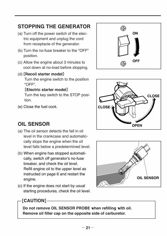
STOPPING THE GENERATOR(a) Turn off the power switch of the elec-
tric equipment and unplug the cordfrom receptacle of the generator.
(b) Turn the no-fuse breaker to the "OFF"position.
(c) Allow the engine about 3 minutes tocool down at no-load before stopping.
(d)[Recoil starter model]Turn the engine switch to the position "OFF".[Electric starter model]Turn the key switch to the STOP posi-tion.
(e) Close the fuel cock.
OIL SENSOR(a) The oil sensor detects the fall in oil
level in the crankcase and automatic-cally stops the engine when the oillevel falls below a predetermined level.
(b) When engine has stopped automati-cally, switch off generator's no-fusebreaker, and check the oil level. Refill engine oil to the upper level asinstructed on page 6 and restart theengine.
(c) If the engine does not start by usualstarting procedures, check the oil level.
OPEN
CLOSE
CLOSE
OIL SENSOR
Do not remove OIL SENSOR PROBE when refilling with oil. Remove oil filler cap on the opposite side of carburetor.
[CAUTION]
OFF
ON
G28R-G61R 米国取説GU2016 05.1.26 11:14 AM ページ21
- 22-
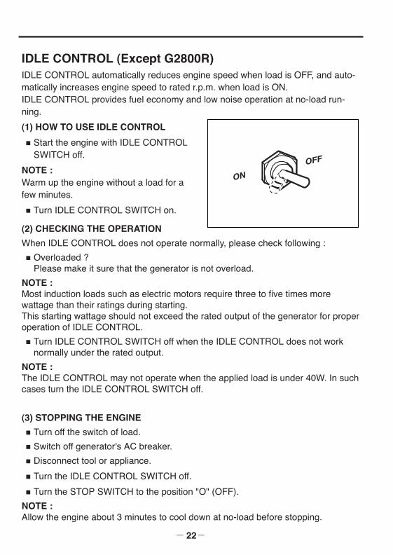
(1) HOW TO USE IDLE CONTROL
■ Start the engine with IDLE CONTROLSWITCH off.
NOTE :Warm up the engine without a load for afew minutes.
■ Turn IDLE CONTROL SWITCH on.
(2) CHECKING THE OPERATION
When IDLE CONTROL does not operate normally, please check following :
■ Overloaded ?Please make it sure that the generator is not overload.
NOTE :Most induction loads such as electric motors require three to five times morewattage than their ratings during starting.This starting wattage should not exceed the rated output of the generator for properoperation of IDLE CONTROL.
■ Turn IDLE CONTROL SWITCH off when the IDLE CONTROL does not worknormally under the rated output.
NOTE :The IDLE CONTROL may not operate when the applied load is under 40W. In suchcases turn the IDLE CONTROL SWITCH off.
(3) STOPPING THE ENGINE■ Turn off the switch of load.
■ Switch off generator's AC breaker.
■ Disconnect tool or appliance.
■ Turn the IDLE CONTROL SWITCH off.
■ Turn the STOP SWITCH to the position "O" (OFF).
NOTE :Allow the engine about 3 minutes to cool down at no-load before stopping.
IDLE CONTROL (Except G2800R)IDLE CONTROL automatically reduces engine speed when load is OFF, and auto-matically increases engine speed to rated r.p.m. when load is ON.IDLE CONTROL provides fuel economy and low noise operation at no-load run-ning.
ON
OFF
G28R-G61R 米国取説GU2016 05.1.26 11:14 AM ページ22
6. WATTAGE INFORMATION
- 23-
Some appliances need a "surge" of energy when starting. This means that the amount of electrical power needed to start the appliance may exceedthe amount needed to maintain its use.Electrical appliances and tools normally come with a label indicating voltage, cycles / Hz,amperage (amps) and electrical power needed to run the appliance or tool. Check with your nearest dealer or service center with questions regarding power surge ofcertain appliances or power tools.
■ Electrical loads such as incandescent lamps and hot plates require the same wattageto start as is needed to maintain use.
■ Loads such as fluorescent lamps require 1.2 to 2 times the indicated wattage duringstart-up.
■ Loads for mercury lamps require 2 to 3 times the indicated wattage during start-up.
■ Electrical motors require a large starting current. Power requirements depend on thetype of motor and its use. Once enough "surge" is attained to start the motor, the appliance will require only 50% to 30% of the wattage to continue running.
■ Most electrical tools require 1.2 to 3 times their wattage for running under load duringuse. For example, a 5,000 watt generator can power a 1800 to 4000 watt electricaltool.
■ Loads such as submersible pumps and air compressors require a very large force tostart. They need 3 to 5 times the normal running wattage in order to start. For example, a 5,000 watt generator would only be able to drive a 1,000 to 1,700 wattpump.
NOTE :
The following wattage chart is general guide only. Refer to your specific appliance for cor-rect wattage.
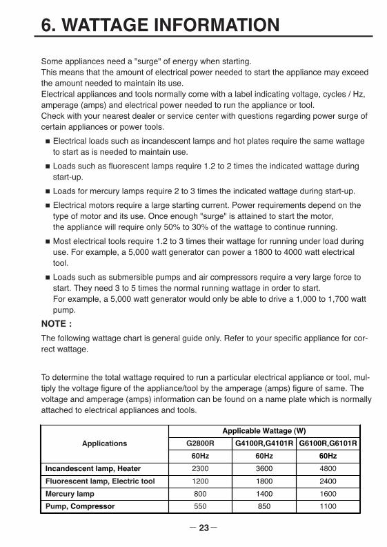
To determine the total wattage required to run a particular electrical appliance or tool, mul-tiply the voltage figure of the appliance/tool by the amperage (amps) figure of same. Thevoltage and amperage (amps) information can be found on a name plate which is normallyattached to electrical appliances and tools.
Applications
Applicable Wattage (W)
G6100R,G6101R
4800
2400
G2800R
60Hz
G4100R,G4101R
1600
60Hz
1100
60Hz
Incandescent lamp, Heater 2300 3600
Fluorescent lamp, Electric tool 1200 1800
Mercury lamp 800 1400
Pump, Compressor 550 850
G28R-G61R 米国取説GU2016 05.1.26 11:14 AM ページ23

- 24-
VOLTAGE DROP IN ELECTRIC EXTENSION CORDSWhen a long electric extension cord is used to connect an appliance or tool to thegenerator, a certain amount of voltage drop or loss occurs in the extension cordwhich reduces the effective voltage available for the appliance or tool. The use of improper size or gauge of extension cords may cause unsafe or ineffi-cient operation of your tool or appliance. It may also damage the tool or appliance.Be sure that any extension cord that you use is rated to allow sufficient current flowto the motor or appliance. Select the required wire gauge size according to thechart below. Chart lists the minimum wire gauge size for the proper extension cord.
EXTENSION CORD CHARTUse the right extension cord. An extension cord should have a suitable wire sizefor the overall cord length and tool amperage rating. This is to prevent a seriousvoltage drop, power loss and possible motor damage. Generally, heavier gaugewire is required as cord length increases. Use the recommendations in this table.
Not normally available as flexible extension cord.
ExtensionCord Length
Amperage Rating of Tool
0.2 2.1-3.4 3.5-5.0 5.1-7.0 7.1-12.0 12.1-16.0
Recommended Wire Size (A.W.G. Gauge No.)
7.5m 18 18 18 18 16 14
15m 18 18 18 16 14 12
22.5m 18 18 16 14 12 10
30m 18 16 14 12 10 8
45m 16 14 12 10 8 8
60m 16 14 12 10 8 6
90m 14 12 10 8 6 4
120m 12 10 8 6 4 4
150m 12 10 8 6 4 2
180m 10 8 6 4 2 2
240m 10 8 6 4 2 1
G28R-G61R 米国取説GU2016 05.1.26 11:14 AM ページ24
7. SPARK ARRESTER
- 25-
SPARK ARRESTERIn a dry or wooded area, it is recommendable to use the product with a spark arrester.Some areas require the use of a spark arrester. Please check your local laws andregulations before operating your product.
The spark arrester must be cleaned regularly to keep it functioning as designed. A clogged spark arrester :
● Prevents the flow of exhaust gas ● Reduces engine output ● Increases fuel consumption●Makes starting difficult
If the engine has been running, the muffler and the spark arrester will be very hot.Allow the muffler to cool before cleaning the spark arrester.
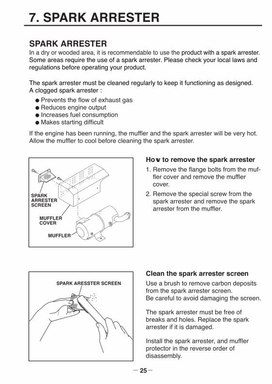
How to remove the spark arrester1. Remove the flange bolts from the muf-
fler cover and remove the mufflercover.
2. Remove the special screw from thespark arrester and remove the sparkarrester from the muffler.
SPARK ARRESTER SCREEN
MUFFLER
MUFFLERCOVER
Clean the spark arrester screenUse a brush to remove carbon depositsfrom the spark arrester screen.Be careful to avoid damaging the screen.
The spark arrester must be free ofbreaks and holes. Replace the sparkarrester if it is damaged.
Install the spark arrester, and mufflerprotector in the reverse order of disassembly.
SPARK ARESSTER SCREEN
G28R-G61R 米国取説GU2016 05.1.26 11:14 AM ページ25
8. MAINTENANCE SCHEDULE
- 26-
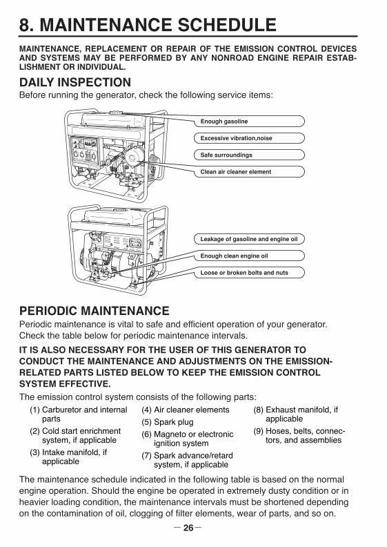
DAILY INSPECTIONBefore running the generator, check the following service items:
Excessive vibration,noise
Clean air cleaner element
Safe surroundings
Enough clean engine oil
Leakage of gasoline and engine oil
Loose or broken bolts and nuts
Enough gasoline
PERIODIC MAINTENANCEPeriodic maintenance is vital to safe and efficient operation of your generator.Check the table below for periodic maintenance intervals.
IT IS ALSO NECESSARY FOR THE USER OF THIS GENERATOR TO CONDUCT THE MAINTENANCE AND ADJUSTMENTS ON THE EMISSION-RELATED PARTS LISTED BELOW TO KEEP THE EMISSION CONTROL SYSTEM EFFECTIVE.The emission control system consists of the following parts:
The maintenance schedule indicated in the following table is based on the normalengine operation. Should the engine be operated in extremely dusty condition or inheavier loading condition, the maintenance intervals must be shortened dependingon the contamination of oil, clogging of filter elements, wear of parts, and so on.
(1) Carburetor and internalparts
(2) Cold start enrichmentsystem, if applicable
(3) Intake manifold, ifapplicable
(4) Air cleaner elements
(5) Spark plug
(6) Magneto or electronicignition system
(7) Spark advance/retardsystem, if applicable
(8) Exhaust manifold, ifapplicable
(9) Hoses, belts, connec-tors, and assemblies
MAINTENANCE, REPLACEMENT OR REPAIR OF THE EMISSION CONTROL DEVICESAND SYSTEMS MAY BE PERFORMED BY ANY NONROAD ENGINE REPAIR ESTAB-LISHMENT OR INDIVIDUAL.
G28R-G61R 米国取説GU2016 05.1.26 11:14 AM ページ26
- 27-
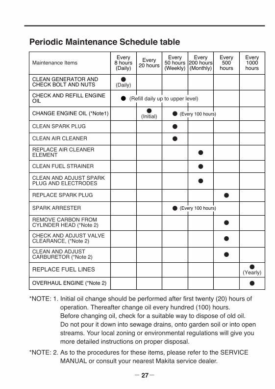
*NOTE: 1. Initial oil change should be performed after first twenty (20) hours ofoperation. Thereafter change oil every hundred (100) hours. Before changing oil, check for a suitable way to dispose of old oil. Do not pour it down into sewage drains, onto garden soil or into openstreams. Your local zoning or environmental regulations will give youmore detailed instructions on proper disposal.
*NOTE: 2. As to the procedures for these items, please refer to the SERVICEMANUAL or consult your nearest Makita service dealer.
Periodic Maintenance Schedule table
Maintenance ItemsEvery
8 hours(Daily)
Every20 hours
Every50 hours(Weekly)
Every200 hours(Monthly)
Every500
hours
Every1000hours
CLEAN GENERATOR ANDCHECK BOLT AND NUTS
●(Daily)
CHECK AND REFILL ENGINEOIL
CHANGE ENGINE OIL (*Note1) ●(Initial) ●
CLEAN SPARK PLUG ●
CLEAN AIR CLEANER ●
REPLACE AIR CLEANER ELEMENT ●
CLEAN FUEL STRAINER ●
REMOVE CARBON FROMCYLINDER HEAD (*Note 2) ●
CHECK AND ADJUST VALVECLEARANCE, (*Note 2) ●
CLEAN AND ADJUST CARBURETOR (*Note 2) ●
REPLACE FUEL LINES ●(Yearly)
OVERHAUL ENGINE (*Note 2) ●
CLEAN AND ADJUST SPARKPLUG AND ELECTRODES ●
REPLACE SPARK PLUG ●
SPARK ARRESTER ●
● (Refill daily up to upper level)
(Every 100 hours)
(Every 100 hours)
G28R-G61R 米国取説GU2016 05.1.26 11:14 AM ページ27

- 28-
9. "HOW-TO" MAINTENANCE
ENGINE OIL CHANGE■ Change engine oil every 100 hours.
(For new engine, change oil after 20hours.)
(a) Drain oil by removing the drain plugand the oil filler cap while the engineis warm.
(b) Reinstall the drain plug and fill theengine with oil until it reaches theupper level on the oil filler cap.
OIL DRAIN PLUG
■ Use fresh and high quality lubricating oil to the specified level as directed onpage 6. If contaminated or deteriorated oil is used or the quantity of the engineoil is not sufficient, the engine damage will result and its life will be greatlyshortened.
CLEANING AIR CLEANER(Model G2800R)
Maintaining an air cleaner in proper condi-tion is very important. Dirt induced through improperly installed,improperly serviced or inadequate ele-ments damages and wears out engines.Always keep the air cleaner elementclean.
(a) Unhook the cover and remove thecleaner element.
(b) Inner element : Wash the element withkerosene, then soak it in mixed oil(Kerosene (3 parts) : Engine oil (1 part)). Drain the mixed oil.
(c) Outer element : Wash the element withkerosene, then dip it into the mixed oil(Kerosene (3 parts) : Engine oil (1part)). Squeeze out the mixed oil. (Donot twist.)
HOOK
COVER
INNERELEMENT
OUTERELEMENT
G28R-G61R 米国取説GU2016 05.1.26 11:14 AM ページ28
- 29-
COVER
INNERELEMENT
OUTERELEMENT
1. Urethane Foam ElementWash and clean the urethane foam with detergent. After cleaning, dry it.Clean the urethane foam element every 50 hours.
2. Paper elementClean by tapping gently to remove dirt and blow off dust.Never use oil. Clean the paper element every 50 hours of operation, andreplace element set every 200 hours.
Clean and replace air cleaner elements more often when operating in dustyenvironments.
Do not wash elements withkerosene, gasoline or oil.
[CAUTION]
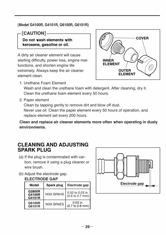
A dirty air cleaner element will causestarting difficulty, power loss, engine mal-functions, and shorten engine lifeextremely. Always keep the air cleanerelement clean.
(Model G4100R, G4101R, G6100R, G6101R)
CLEANING AND ADJUSTINGSPARK PLUG(a) If the plug is contaminated with car-
bon, remove it using a plug cleaner orwire brush.
(b) Adjust the electrode gap.ELECTRODE GAP
Electrode gapModel Spark plug
G2800RG4100RG4101R
NGK BR6HS
Electrode gap
0.02 to 0.03 in.(0.6 to 0.7 mm)
G6100RG6101R
NGK BR6ES 0.03 in.(0.7 to 0.8 mm)
G28R-G61R 米国取説GU2016 05.1.26 11:15 AM ページ29
- 30-
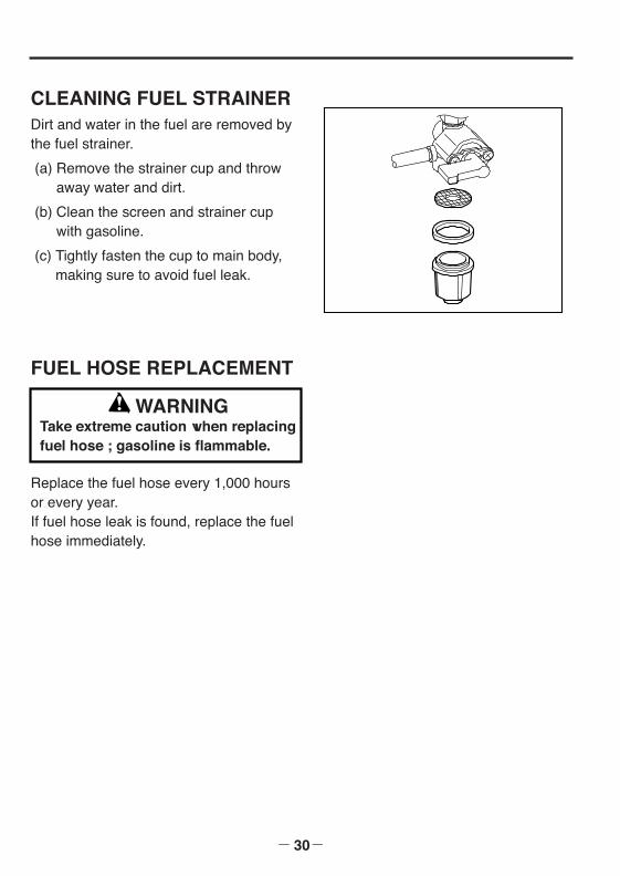
CLEANING FUEL STRAINERDirt and water in the fuel are removed bythe fuel strainer.
(a) Remove the strainer cup and throwaway water and dirt.
(b) Clean the screen and strainer cupwith gasoline.
(c) Tightly fasten the cup to main body,making sure to avoid fuel leak.
FUEL HOSE REPLACEMENT
Replace the fuel hose every 1,000 hoursor every year.If fuel hose leak is found, replace the fuelhose immediately.
WARNINGTake extreme caution when replacingfuel hose ; gasoline is flammable.
G28R-G61R 米国取説GU2016 05.1.26 11:15 AM ページ30
- 31-
10. PREPARATION FOR STORAGE
The following procedures should be followed prior to storage of your generator forperiods of 6 months or longer.
■ Drain fuel from fuel tank carefully by disconnecting the fuel line. Gasoline left in the fuel tank will eventually deteriorate making engine-startingdifficult.
■ Remove the carburetor float chamber and also drain the carburetor.
■ Change engine oil.
■ Check for loose bolts and screws, tighten them if necessary.
■ Clean generator thoroughly with oiled cloth. Spray with preservative if avail-able. NEVER USE WATER TO CLEAN GENERATOR !
■ Pull starter handle until resistance is felt, leaving handle in that position.
■ Store generator in a well ventilated, low humidity area.
G28R-G61R 米国取説GU2016 05.1.26 11:15 AM ページ31
11. TROUBLESHOOTING
- 32-
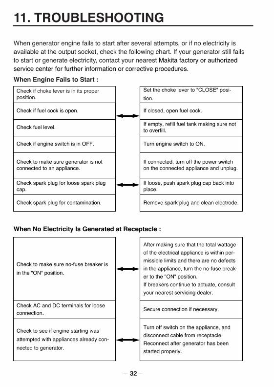
When generator engine fails to start after several attempts, or if no electricity isavailable at the output socket, check the following chart. If your generator still failsto start or generate electricity, contact your nearest Makita factory or authorizedservice center for further information or corrective procedures.
When Engine Fails to Start :
When No Electricity Is Generated at Receptacle :
Check if choke lever is in its properposition.
Check if fuel cock is open.
Check fuel level.
Check to make sure generator is notconnected to an appliance.
Check spark plug for loose spark plugcap.
Check spark plug for contamination.
Check if engine switch is in OFF.
Set the choke lever to "CLOSE" posi-
tion.
If closed, open fuel cock.
If empty, refill fuel tank making sure notto overfill.
If connected, turn off the power switchon the connected appliance and unplug.
If loose, push spark plug cap back intoplace.
Remove spark plug and clean electrode.
Turn engine switch to ON.
Check to make sure no-fuse breaker is
in the "ON" position.
Check AC and DC terminals for looseconnection.
Check to see if engine starting was
attempted with appliances already con-
nected to generator.
After making sure that the total wattage
of the electrical appliance is within per-
missible limits and there are no defects
in the appliance, turn the no-fuse break-
er to the "ON" position.
If breakers continue to actuate, consult
your nearest servicing dealer.
Secure connection if necessary.
Turn off switch on the appliance, and
disconnect cable from receptacle.
Reconnect after generator has been
started properly.
G28R-G61R 米国取説GU2016 05.1.26 11:15 AM ページ32
12. WIRING DIAGRAM
- 33-
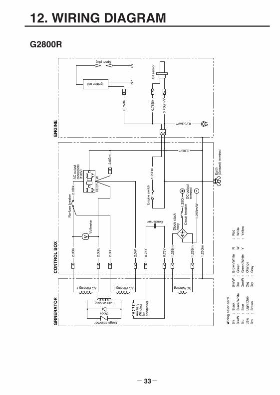
G2800R
V
+ -RE
C1
Field Winding
Diode
Surge absorber
Aux
iliar
yW
indi
ngfo
rco
nden
ser
AC Winding 1 AC Winding 2
1.25
Grn
1.25
Brn
1.25
Brn
0.75
Y
0.75
Y
2.0W
2.0R
2.0B
lu
2.0B
lk2.
0Blk
Vol
tmet
er
No-
fuse
bre
aker
AC
out
put
rece
ptac
le( 1
20V
)
Condenser
Eng
ine
switc
h1.
25B
lk
DC
out
put
term
inal
1.25
Brn
/W1.25
Or
Circ
uit b
reak
er
Dio
de s
tack
Ass
y
2.0Grn
2.0G
rn
Ear
th(G
roun
d) te
rmin
al
0.75Grn/Y
0.75
Grn
/Y
0.75
Blk
Oil
sens
or0.
75B
lk
Ignition coil
Spark plug
GR
NE
RA
TO
RC
ON
TR
OL
BO
XE
NG
INE
DC Winding
W
Wir
ing
co
lor
cord
Blk
Bla
ckB
rn/W
Bro
wn/
Whi
teR
Red
Blk
/WB
lack
/Whi
teG
rnG
reen
WW
hite
Blu
Blu
eG
rn/W
Gre
en/W
hite
YY
ello
wLB
luLi
ght b
lue
Org
Ora
nge
Brn
Bro
wn
Gry
Gra
y
: : : : :
: : : : :
: : :
G28R-G61R 米国取説GU2016 05.1.26 11:15 AM ページ33
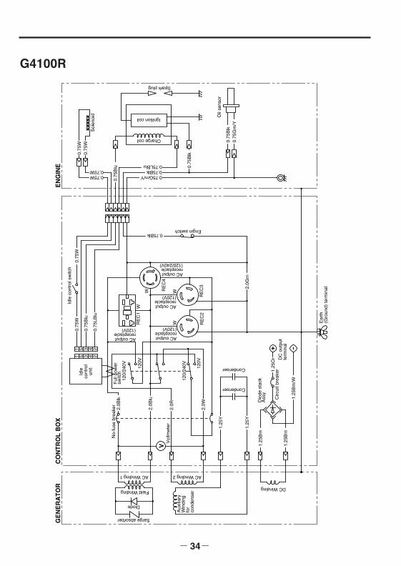
- 34-
G4100R
V
+ -
120V
120V
120/
240V
120/
240V
RE
C1
W
W
RE
C4
GE
NE
RA
TO
RC
ON
TR
OL
BO
X
Field Winding
AC Winding 2AC Winding 1
DC Winding
Diode
Sarge absorber
Aux
iliar
yW
indi
ngfo
rco
nden
ser
2.0B
lu
2.0B
lkN
o-fu
se b
reak
er 2.0R
Vol
tmet
er 1.25
Y
1.25
Brn
Condenser
2.0W
1.25
Or
1.25
Brn
/W
DC
out
put
term
inal
Circ
uit b
reak
er
Dio
de s
tack
Ass
y
Ear
th(G
roun
d) te
rmin
al
Ful
l pow
ersw
itchIdle
cont
rol
unit
AC outputreceptacle(120V)
AC outputreceptacle(120/240V)
Idle
con
trol
sw
itch
EN
GIN
E
0.75W
0.75
W
Sol
enoi
d
0.75
Blu
Charge coil
Ignition coil
Spark plug
Engin switch
1.25
Y
Condenser
1.25
Brn
1 5 3 4 2
1 5 3 4 2
0.75
W0.
75W
0.75
Blu
0.75
LBlu
AC outputreceptacle(120V)
RE
C2
W
2.0G
rn
0.75Blk
0.75
W
0.75W 0.75Grn/Y0.75Blk0.75LBlu 0.
75B
lk
Oil
sens
or
0.75
Grn
/Y0.
75B
lk
RE
C3
AC outputreceptacle(120V)
W
G28R-G61R 米国取説GU2016 05.1.26 11:15 AM ページ34

- 35-
G4101R
Ear
th(G
roun
d) te
rmin
al
1.25
Grn
1.25
R
1.25
Or
ST
B
-M+
MIG
Key
sw
itch
Bat
tery
Mag
netie
csw
itch
14R
14B
lk
Ele
ctric
star
ter
V
+ -
120V
120V
120/
240V
RE
C1
W
W
RE
C4
GE
NE
RA
TO
RC
ON
TR
OL
BO
X
Field Winding
AC Winding 2AC Winding 1
DC Winding
Diode
Sarge absorber
Aux
iliar
yW
indi
ngfo
rco
nden
ser
2.0B
lu
2.0B
lkN
o-fu
se b
reak
er
2.0R
Vol
tmet
er
1.25
Y
1.25
Brn
Condenser
2.0W
1.25
Or
1.25
Brn
/W
DC
out
put
term
inal
Circ
uit b
reak
er
Dio
dest
ack
Ass
y
Ful
l pow
ersw
itch
120/
240V
Idle
cont
rol
unit
AC outputreceptacle(120V)
AC outputreceptacle(120/240V)
Idle
con
trol
sw
itch
EN
GIN
E
0.75W
0.75
W
Sol
enoi
d
0.75
Blu
Oil
sens
or
Charge coil
Ignition coil
Spark plug
1.25
Y
Condenser
1.25
Brn
1 5 3 4 2
1 5 3 4 2
0.75
W0.
75W
0.75
Blu
0.75
LBlu
AC outputreceptacle(120V)
RE
C2
W
2.0G
rn
0.75
W
0.75W 0.75Grn/Y0.75Blk0.75LBlu 0.
75B
lk
0.75
Grn
/Y
0.75
Blk
0.75
Gry
0.75LBlu
0.75Blk
Dio
de s
tack
Ass
y
0.75
Blk
RE
C3
AC outputreceptacle(120V)
W
Fus
e ( 1
0A)
G28R-G61R 米国取説GU2016 05.1.26 11:15 AM ページ35
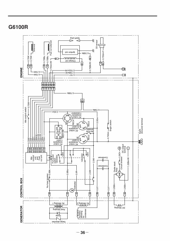
- 36-
G6100R
V
+ -
120V
120V
120/
240V
8 1 9 5 3 6 7 428 91 5 3 6 7 4
RE
C1
RE
C4
W
W
RE
C2
GE
NE
RA
TO
RC
ON
TR
OL
BO
X
Field Winding
AC Winding 2AC Winding 1
DC Winding
Diode
Sarge absorber
20.
75W
0.75
W0.
75W
0.75
Blu
0.75
Blu
0.75
Blk
/W0.
75G
rn/W
0.75
Grn
/W0.
75B
lk0.
75G
rn
2.0Grn
Aux
iliar
yW
indi
ngfo
rco
nden
ser
2.0B
lu
2.0B
lkN
o-fu
se b
reak
er 2.0R
2.0W
Vol
tmet
er
2.0Y
2.0Y
1.25
Brn
1.25
Brn
Condenser
Condenser
2.0W
1.25
Or
1.25
Brn
/W
DC
out
put
term
inal
Circ
uit b
reak
er
Dio
de s
tack
Ass
y
Ear
th(G
roun
d) te
rmin
al
Ful
l pow
ersw
itch
120/
240V
Idle
cont
rol
unit
and
Fue
lcu
t uni
t
AC outputreceptacle(120V)
AC outputreceptacle(120/240V)
AC outputreceptacle(120V)
No-fusebreaker
Idle
con
trol
sw
itch
0.75Blk
EN
GIN
E
0.75
W0.
75W
0.75W0.75W
Sol
enoi
d
0.75
Blu
0.75
Blu
Fue
l cut
sol
enoi
d0.
75G
rn/W
0.75Blk
0.75
Blk
/W
Oil
sens
or
0.75
Grn
/Y
Charge coil
Ignition coil
0.75Y0.75Blk/W0.75Grn/W
Spark plug
0.75
Grn
0.75Blk
Eng
in s
witc
h
W
RE
C3
AC outputreceptacle(120V)
W
2.0G
rn
G28R-G61R 米国取説GU2016 05.1.26 11:15 AM ページ36
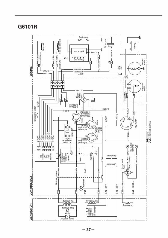
- 37-
G6101R
V
+ -
120V
120V
120/
240V
8 1 9 5 3 6 7 428 91 5 3 6 7 4
RE
C1
RE
C4
W
+-
RE
C2
GE
NE
RA
TO
RC
ON
TR
OL
BO
XField Winding
AC Winding 2AC Winding 1
DC Winding
Diode
Sarge absorber
20.
75W
0.75
W0.
75W
0.75
Blu
0.75
Blu
0.75
Blk
/W0.
75G
rn/W
0.75
Grn
/W0.
75B
lk0.
75G
rn
Aux
iliar
yW
indi
ngfo
rco
nden
ser
2.0B
lu
2.0B
lkN
o-fu
se b
reak
er 2.0R
2.0W
Vol
tmet
er
2.0Y
2.0Y
1.25
Brn
1.25
Brn
Condenser
Condenser
2.0W
1.25
Or
1.25
Brn
/W
DC
out
put
term
inal
Circ
uit b
reak
er
Dio
de s
tack
Ass
y
Ear
th(G
roun
d) te
rmin
al
1.25
Grn
1.25
R1.25
Or
1.25
Gry
ST
B
-M+
MIG
Key
sw
itch
Ful
l pow
ersw
itch
120/
240V
Idle
cont
rol
unit
and
Fue
lcu
t uni
t
AC outputreceptacle(120/240V)
AC outputreceptacle(120V)
AC outputreceptacle(120V)
Idle
con
trol
sw
itch
0.75Blk
Dio
dest
ack
Ass
y
EN
GIN
E
0.75Blk
0.75
Blk
/W
Oil
sens
or
0.75
Grn
/Y
0.75Y0.75Blk/W0.75Grn/W
Spark plug
Bat
tery
Mag
netie
csw
itch
14R
14B
lk
W
W
2.0G
rn
0.75Grn / Y0.75Grn / Y
1.25Blk2.0Grn
Ele
ctric
star
ter0.
75W
0.75
W
0.75W0.75W
Sol
enoi
d
0.75
Blu
0.75
Blu
Fue
l cut
sol
enoi
d0.
75G
rn/W
Charge coil
Ignition coil
No-fusebreaker
RE
C3
AC outputreceptacle(120V)
W
Fus
e ( 1
0A)
G28R-G61R 米国取説GU2016 05.1.26 11:15 AM ページ37
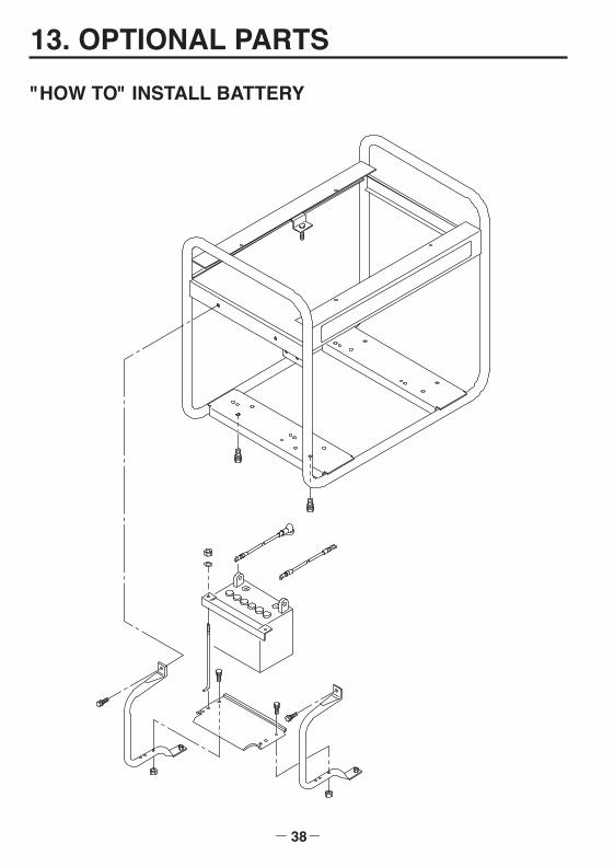
13. OPTIONAL PARTS
- 38-
"HOW TO" INSTALL BATTERY
G28R-G61R 米国取説GU2016 05.1.26 11:15 AM ページ38
ISSUE EMD-GU2016
PRINTED IN JAPANNovember 2004 CE-SK
Makita Corporation3-11-8, Sumiyoshi-choAnjo, Aichi 446-8502 Japan
3ZZ9020166
GENERATOR
INSTRUCTIONS FOR USE
アメリカ