tsunami-induced forces on structures
TRANSCRIPT

May 14, 2009 9:13 9.75in x 6.5in b684-ch11 FA
Chapter 11
Tsunami-Induced Forces on Structures
Ioan Nistor∗, Dan Palermo, Younes Nouri, Tad Murtyand Murat Saatcioglu
Department of Civil Engineering, University of Ottawa161 Louis Pasteur, CBY, A115, Ottawa, Canada
This chapter deals with the estimation of tsunami-induced hydrodynamic forceson infrastructure located in the vicinity of the shoreline. While extensive researchhas been conducted on the impact of hydrodynamic forces on classical coastalprotection works (breakwaters, seawalls, reefs, etc.), there is limited research ontheir impact on structures such as buildings and bridges located inland. The dev-astation brought by the 26 December 2004 Indian Ocean Tsunami on coastal com-munities in Indonesia, India, Sri Lanka, Thailand, and other countries outlinedthe urgent need for research on the evaluation of structural resilience of infras-tructure located in tsunami-prone areas. This chapter summarizes the state-of-the-art knowledge with respect to forces generated by tsunami-induced hydraulicbores, including debris impact. Further, sample calculations of tsunami loadingon a prototype structure are presented.
11.1. Introduction
Tsunami waves represent extreme, often catastrophic events, which significantly andadversely impact coastal areas. In spite of the lower frequency of occurrence com-paring to storms and storm-induced surges, tsunami-induced coastal flooding oftenleads to massive casualties and tremendous economic losses.1–3 Hence, tsunamis arerare events, high-impact natural disasters.
The devastating effects of the 26 December 2004 Tsunami on many coun-tries bordering the Indian Ocean raised public concern and revealed existing defi-ciencies within the current warning and defense systems against tsunamis. One ofthe important elements that needs significant improvement is the estimation offorces generated by tsunami-induced bores, as well as water-borne debris. Beforethe 2004 Indian Ocean Tsunami, the design of structures against tsunami-inducedforces was considered of minor importance when compared to the attention givento tsunami warning systems. This was due to the assumption that tsunamis are
261

May 14, 2009 9:13 9.75in x 6.5in b684-ch11 FA
262 I. Nistor et al.
(a) (b)
(c) (d)
Fig. 11.1. Tsunami damage in Thailand and Indonesia (December 2004 Indian Ocean Tsunami):(a) severe structural damage, Khao Lak, Thailand; (b) column failure of a reinforced con-
crete frame, Phuket, Thailand; (c) column failure due to debris impact, Banda Aceh, Indonesia;(d) punching failure of infill walls, Banda Aceh, Indonesia.4
rare events, with significantly high return periods (sometimes more than 500 years).Reconnaissance missions of the December 2004 Indian Ocean Tsunami disasterrevealed that tsunami-induced forces can lead to severe damage or collapse of struc-tures as shown in Fig. 11.1.3–11 Therefore, these forces should be properly accountedfor in the design of infrastructure built within a certain distance from the shorelinein tsunami-prone areas.
The design of coastal structures such as breakwaters, jetties, and groins againstwaves is typically based on considering the effect of breaking waves and their asso-ciated forces, and is well established. Unlike coastal structures, the evaluation oftsunami-induced hydrodynamic forces on structures used for habitation and/or eco-nomic activity, received little attention by researchers and engineers.
Results of field surveys conducted in the aftermath of the December 2004 IndianOcean Tsunami in Indonesia and Thailand showed that poorly detailed concretestructures experienced severe damage.3,4 This highlighted the fact that the currentstructural design codes do not account for tsunami-induced forces and the impactof associated debris. Reinforced concrete structures have been observed to with-stand tsunamis with acceptable low levels of damage.12 However, as shown in

May 14, 2009 9:13 9.75in x 6.5in b684-ch11 FA
Tsunami-Induced Forces on Structures 263
0 1 2 3 4 5 6 7Inundation Depth (m)
: The 2004 Indian Ocean Tsunami
Partial Damage
Lack of data
: Past Tsunamis
Damage
Withstand
20
Fig. 11.2. Relation between the inundation depth and degree of damage to reinforced concretebuildings.13
Fig. 11.2, inundation depths of more than 5m can induce partial damage to concretestructures.
Currently, there are no clearly established procedures to address the aforemen-tioned forces. Moreover, significant disagreement on existing empirical formula fos-tered new research interest in an effort to properly address the inclusion of bothtsunami-induced forces and the impact of debris into design codes. Aspects relatedto these forces are discussed in this chapter. Some of the shortcomings and incon-sistencies of existing codes are also highlighted.
11.2. Literature Review
11.2.1. Tsunami-induced hydraulic bores
As tsunami waves advance toward the shoreline and water depth decreases, theirwave height increases while celerity decreases. Tsunami waves may break offshore orat shoreline, inundating low-lying coastal areas in the form of a hydraulic bore. Onthe other hand, tsunami inundation can also occur as a gradual rise and recessionof the sea level for the case of nonbreaking tsunami waves. The width of the conti-nental shelf, the initial tsunami wave shape, the beach slope, and the tsunami wavelength are the parameters which govern the breaking pattern of tsunami waves.2,15
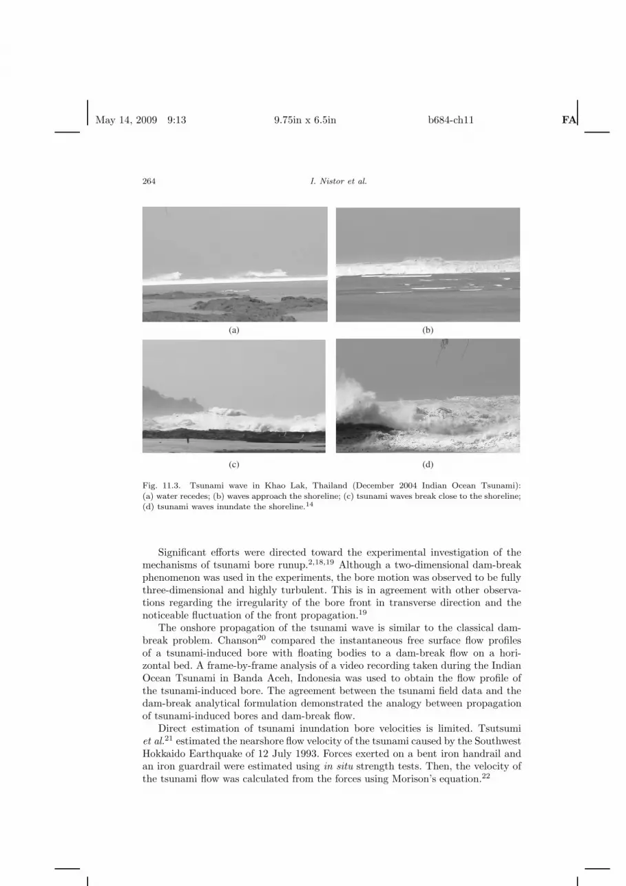
Figure 11.3 shows a tsunami wave approaching the Khao Lak Beach in Thailandduring the December 2004 Indian Ocean Tsunami.
Tsunami waves have a larger horizontal length scale compared to the vertical.Consequently, implementing shallow water wave theory (i.e., depth-integrated equa-tions of momentum and mass conservation with the assumption of a hydrostaticpressure field) seems to be a reasonable method for representing tsunami wave prop-agation. Using these equations, it has been shown that the behavior and runup ofnonbreaking tsunami waves can be predicted with acceptable accuracy. However,disagreement has been observed between experiment and prediction, in terms ofbehavior and runup of breaking waves and the resulting bore.16,17
May 14, 2009 9:13 9.75in x 6.5in b684-ch11 FA
264 I. Nistor et al.
(a) (b)
(c) (d)
Fig. 11.3. Tsunami wave in Khao Lak, Thailand (December 2004 Indian Ocean Tsunami):
(a) water recedes; (b) waves approach the shoreline; (c) tsunami waves break close to the shoreline;(d) tsunami waves inundate the shoreline.14
Significant efforts were directed toward the experimental investigation of themechanisms of tsunami bore runup.2,18,19 Although a two-dimensional dam-breakphenomenon was used in the experiments, the bore motion was observed to be fullythree-dimensional and highly turbulent. This is in agreement with other observa-tions regarding the irregularity of the bore front in transverse direction and thenoticeable fluctuation of the front propagation.19
The onshore propagation of the tsunami wave is similar to the classical dam-break problem. Chanson20 compared the instantaneous free surface flow profilesof a tsunami-induced bore with floating bodies to a dam-break flow on a hori-zontal bed. A frame-by-frame analysis of a video recording taken during the IndianOcean Tsunami in Banda Aceh, Indonesia was used to obtain the flow profile ofthe tsunami-induced bore. The agreement between the tsunami field data and thedam-break analytical formulation demonstrated the analogy between propagationof tsunami-induced bores and dam-break flow.
Direct estimation of tsunami inundation bore velocities is limited. Tsutsumiet al.21 estimated the nearshore flow velocity of the tsunami caused by the SouthwestHokkaido Earthquake of 12 July 1993. Forces exerted on a bent iron handrail andan iron guardrail were estimated using in situ strength tests. Then, the velocity ofthe tsunami flow was calculated from the forces using Morison’s equation.22

May 14, 2009 9:13 9.75in x 6.5in b684-ch11 FA
Tsunami-Induced Forces on Structures 265
Matsutomi et al.13 and Chanson20 estimated inundation flow velocities in termsof inundation depth. Frame-by-frame analysis of video recordings from the 2004Indian Ocean Tsunami in Banda Aceh was conducted. The videos showed thatthe inundation flow carried numerous floating bodies with approximately the samespeed as that of the bore. This may have influenced the bore characteristics. Fur-thermore, Matsutomi et al.13 developed an empirical model that predicts the borefront velocity. Also, surveyed data were used to improve the criterion for estimatingthe degree of structural damage.
11.2.2. Tsunami-induced forces on structures
Snodgrass et al.23 noticed that broken waves induced larger hydrodynamic hori-zontal forces on a test pile compared to waves breaking at the pile location. Aspreviously mentioned, broken tsunami waves inundate shoreline in the form of ahydraulic bore, which is a fast moving body of water with an abrupt front. However,mechanisms of impingement of broken tsunami waves on structures located inlandare not yet well understood.
Pioneering analytical and experimental attempts to quantify forces due to boresdate back to Stoker,24 Cumberbatch,25 Fukui,26 Cross,27 and Dames and Moore.28
Comprehensive experimental investigation of the interaction of bores and dry-bed surges with a vertical wall was performed by Ramsden and Raichlen29 andRamsden.30,31 In these experiments, three flow conditions were analyzed: (1) tur-bulent bores (initial still water downstream of the gate); (2) dry-bed surges (noinitial water depth downstream of the gate); and (3) solitary waves. Forces and over-turning moments due to bores and dry-bed surges were recorded and calculated,respectively. The results of Ramsden’s studies are not applicable to the estimationof impulsive forces.31 It was observed that the pressure distribution during impactis essentially nonhydrostatic. The experiment also demonstrated that the transitionfrom undular to turbulent bores led to a discontinuous increase in water-surfaceslope, followed by an increase in measured runup, pressure head, and exerted forcesand moments. Figure 11.4 shows the difference between a strong turbulent bore anda dry-bed surge with approximately the same celerity.
It was shown that recorded forces gradually increased to an approximately con-stant value for both the case of a surge and a bore. No impulsive (shock) forceexceeding the hydrodynamic force was observed. However, an initial impulsivepressure equal to three times the pressure head, corresponding to the mea-sured runup, was recorded. Ramsden31 further derived empirical formulae for themaximum force and moment exerted on a vertical wall due to the bore impact[Eqs. (11.1) and (11.2)].
F
Fl= 1.325 + 0.347
(H
h
)+
158.5
(H
h
)2
+1
7160
(H
h
)3
, (11.1)
M
Ml= 1.923 + 0.454
(H
h
)+
18.21
(H
h
)2
+1
808
(H
h
)3
, (11.2)

May 14, 2009 9:13 9.75in x 6.5in b684-ch11 FA
266 I. Nistor et al.
Fig. 11.4. Comparison of: (a) wave profile; (b) runup; (c) pressure head; (d) force due to a strong
turbulent bore and a dry-bed surge.31
where F is the force on the wall; Fl is the force on the wall due to a runup equal totwice the wave height, assuming hydrostatic pressure; H is the wave height at thewall; h is still water depth; M is the moment on the wall; and Ml is the momentcorresponding to Fl.
Okada et al.32 conducted a survey of previous studies on tsunami wave forcesand pressures, and identified five empirical formulas for tsunami-induced forces orpressures. It was found that calculation of tsunami load on structures using theseformula would result in approximately the same magnitude of load. These formulaare as follows:
• Tsunami wave pressure without soliton breakup,33
• Tsunami wave pressure with soliton breakup,33
• Tsunami wave pressure without soliton breakup,34
• Tsunami-induced wave forces on houses,35
• Tsunami force exerted on houses.36

May 14, 2009 9:13 9.75in x 6.5in b684-ch11 FA
Tsunami-Induced Forces on Structures 267
Fig. 11.5. Measured and nondimensional force history for a square column.37
Arnason37 measured forces exerted on rectangular, rhomboidal, and circularstructures due to a hydraulic bore on a dry bed. It was observed that the surgeforce overshot the hydrodynamic force in the case of a square column for small boreheights (Fig. 11.5). However, no overshoot was recorded for the case of circularand rhomboidal columns. This is in agreement with the results obtained by Nouriet al.,38 where similar experiments with larger bore heights, up to three times thoseof Arnason,37 were performed (Fig. 11.6).
Nouri et al.38 conducted experiments with the objective of estimating bore-induced forces on free-standing structural components. The effect of other param-eters such as upstream obstacles, flow constrictions, and debris impact was alsoinvestigated. The structural components were subjected to a dam-break flow gen-erated by impoundment depths of 0.5, 0.75, and 0.85m.

May 14, 2009 9:13 9.75in x 6.5in b684-ch11 FA
268 I. Nistor et al.
-50
50
150
250
350
10 12 14 16 18 20 22
Time (s)
Fo
rce
(N
)
h0 = 1.00 m
h0 = 0.85 m
Fig. 11.6. Time history of exerted forces on a circular structure38; h0 is the impoundment depth.
0
10
20
30
40
50
60
-2 3 8 13 18
P (kPa)
Hei
ght o
f th
e st
ruct
ure
(cm
)
t=0.000 st=0.006 st=0.006 st=0.009 s
0
10
20
30
40
50
60
-2 3 8 13 18P (kPa)
Hei
ght o
f th
e st
ruct
ure
(cm
)
t=0.160 st=0.170 st=0.180 st=0.190 s
Fig. 11.7. Variation of pressure distribution on the front face — circular structure38; t = 0.0 s isthe instant when the bore impacts the structure.
The variation of the vertical distribution of pressure was measured. Selectedsnapshots from the variation of pressure distribution due to bore impact generatedby an impoundment depth of 1.0m are shown in Fig. 11.7.
11.2.3. Debris impact force
Matsutomi39 performed small- and full-scale experiments on impact forces gen-erated by driftwood on rigid structures. Dam-break waves generated in a smallflume carried pieces of lumber to the point of impact on a downstream wall. Also,full-scale experiments in which wooden logs impacted a frame were conducted inopen air, and impact forces were measured. An empirical formula for estimating theimpact force, F , was derived using regression analysis of collected data [Eq. (11.3)].
F
γwD2L= 1.6CM
(u√gD
)1.2(σf
γwL
)0.4
, (11.3)

May 14, 2009 9:13 9.75in x 6.5in b684-ch11 FA
Tsunami-Induced Forces on Structures 269
0
40
80
120
0.0 1.0 2.0 3.0 VA0/(gD)0.5
Fm/γD2L
σf / γL = 2000
1500
1000
500
200
100
20
Fig. 11.8. Impact forces of wood logs for bores and surges.39
where γw is the specific weight of wood, D is the diameter of the log, L is thelength of the log, CM is a coefficient which depends on the flow passing around thereceiving wall (≈ 1.7 for bore or surge, and 1.9 for steady flow), u is the velocity ofthe log at impact, and σf is the yield stress of the log. Figure 11.8 shows the designchart based on Eq. (11.3).
Currently, three basic models are proposed for estimating the forces due to theimpact of debris on structures, which are used by a few design codes. In thesemodels, the impact force is calculated based on the mass and velocity of debris,while ignoring the mass and rigidity of the structure. However, other than the massand velocity of debris, each model needs an additional parameter. The three modelsand their corresponding additional parameters are
• Contact stiffness — stiffness between debris and structure,• Impulse–momentum — stopping time of debris after impact and time history of
impact,• Work energy — distance traveled from where initial contact occurs, to where
debris stops.
Haehnel et al.40,41 used a single-degree-of-freedom model with effective collisionstiffness as an additional parameter. They reviewed the current models discussedabove and demonstrated that none of the additional parameters are independent.Hence, the three models are equivalent, provided that additional parameters areappropriately selected. Further, small- and large-scale experiments were performedin order to develop the single-degree-of-freedom model. Small-scale tests were per-formed in a flume where wooden logs were released into the flow and impacted aload frame located further downstream. Large-scale experiments were performed in
May 14, 2009 9:13 9.75in x 6.5in b684-ch11 FA
270 I. Nistor et al.
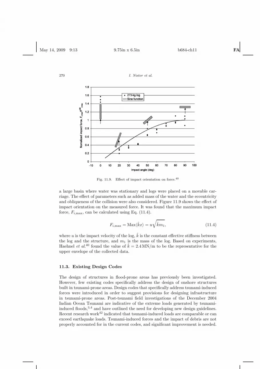
Fig. 11.9. Effect of impact orientation on force.40
a large basin where water was stationary and logs were placed on a movable car-riage. The effect of parameters such as added mass of the water and the eccentricityand obliqueness of the collision were also considered. Figure 11.9 shows the effect ofimpact orientation on the measured force. It was found that the maximum impactforce, Fi,max, can be calculated using Eq. (11.4).
Fi,max = Max〈k̂x〉 = u
√k̂m1, (11.4)
where u is the impact velocity of the log, k̂ is the constant effective stiffness betweenthe log and the structure, and m1 is the mass of the log. Based on experiments,Haehnel et al.40 found the value of k̂ = 2.4MN/m to be the representative for theupper envelope of the collected data.
11.3. Existing Design Codes
The design of structures in flood-prone areas has previously been investigated.However, few existing codes specifically address the design of onshore structuresbuilt in tsunami-prone areas. Design codes that specifically address tsunami-inducedforces were introduced in order to suggest provisions for designing infrastructurein tsunami-prone areas. Post-tsunami field investigations of the December 2004Indian Ocean Tsunami are indicative of the extreme loads generated by tsunami-induced floods,3,4 and have outlined the need for developing new design guidelines.Recent research work42 indicated that tsunami-induced loads are comparable or canexceed earthquake loads. Tsunami-induced forces and the impact of debris are notproperly accounted for in the current codes, and significant improvement is needed.

May 14, 2009 9:13 9.75in x 6.5in b684-ch11 FA
Tsunami-Induced Forces on Structures 271
At present, only four design codes and guidelines specifically account for tsunami-induced loads as listed below:
• FEMA 55: The code is adopted by the Federal Emergency Management Agency,the United States, and recommends formula for tsunami-induced flood and waveloads.43
• The City and County of Honolulu Building Code (CCH): The code, developedby the Department of Planning and Permitting of Honolulu, Hawaii, UnitedStates, makes provisions for regulations that apply to districts located in floodand tsunami-risk areas.44
• Structural Design Method of Buildings for Tsunami Resistance (SMBTR): Thecode is proposed by the Building Center of Japan32 and outlines the structuraldesign for tsunami refuge buildings.
• Development of Guidelines for Structures that Serve as Tsunami Vertical Evacu-ation Sites: The guidelines were prepared by Yeh et al.45 for estimating tsunami-induced forces on structures for the Washington State Department of NaturalResources.
There are several other design codes (sometimes country-specific) which containprescriptions and design guidelines for flood-induced loads. Examples of widely usedcodes are indicated below:
• 1997 Uniform Building Code, Appendix 33, proposed by the InternationalConference of Buildings Officials (ICBO),47
• ASCE 7-05 of the American Society of Civil Engineers,48
• 2006 International Building Code by the International Code Council.49
However, none of the above codes address directly the tsunami-induced forces,which represent the focus of this chapter. The reader is advised to refer to thesecodes when seeking guidance for the design of structures subjected to flood-inducedloads other than tsunamis: coastal flooding due to storm surges, flooding of riverbanks above bank-full conditions, etc.
11.3.1. Tsunami-induced forces
A broken tsunami wave running inland generates forces which affect structureslocated in its path. Three parameters are essential for defining the magnitude andapplication of these forces: (1) inundation depth, (2) flow velocity, and (3) flowdirection. The parameters mainly depend on: (a) tsunami wave height and waveperiod; (b) coast topography; and (c) roughness of the coastal inland. The extentof tsunami-induced coastal flooding, and therefore the inundation depth at a spe-cific location, can be estimated using various tsunami scenarios (magnitude anddirection) and modeling coastal inundation accordingly. However, the estimation offlow velocity and direction is generally more difficult. Flow velocities can vary inmagnitude from zero to significantly high values, while flow direction can also varydue to onshore local topographic features, as well as soil cover and obstacles. Forcesassociated with tsunami bores consist of: (1) hydrostatic force, (2) hydrodynamic

May 14, 2009 9:13 9.75in x 6.5in b684-ch11 FA
272 I. Nistor et al.
(drag) force, (3) buoyant force, (4) surge force, and (5) impact of debris. A briefdescription of these forces is further presented.
11.3.1.1. Hydrostatic force
The hydrostatic force is generated by still or slow-moving water acting perpen-dicular onto planar surfaces. The hydrostatic force per unit width, FHS , can becalculated using Eq. (11.5), where ρ is the seawater density, g is the gravitationalacceleration, ds is the inundation depth, and up is the normal component of flowvelocity. Equation (11.5) is proposed by CCH and accounts for the velocity head.Alternatively, FEMA 55 does not include the velocity head in its formulation sinceit is assumed to be a negligible component of the hydrostatic force:
FHS =12ρg
(dS +
u2p
2g
)2
. (11.5)
The point of application of the resultant hydrostatic force is located at one-thirddistance from the base of the triangular hydrostatic pressure distribution. In thecase of a broken tsunami wave, the hydrostatic force is significantly smaller than thedrag and surge forces. Conversely, Dames and Moore28 noted that the hydrostaticforce becomes important when tsunami is similar to a rapidly-rising tide.
11.3.1.2. Buoyant force
The buoyant force is the vertical force acting through the center of mass of a sub-merged body. Its magnitude is equal to the weight of the volume of water displacedby the submerged body. The effect of buoyant forces generated by tsunami floodingwas clearly evident during post-tsunami field observations.1,5,6 Buoyant forces cangenerate significant damage to structural elements, such as floor slabs, and are cal-culated as follows:
FB = ρgV, (11.6)
where V is the volume of water displaced by submerged structure.
11.3.1.3. Hydrodynamic (drag) force
As the tsunami bore moves inland with moderate to high velocity, structures aresubjected to hydrodynamic forces caused by drag. Currently, there are differences inestimating the magnitude of the hydrodynamic force. The general expression for thisforce is shown in Eq. (11.7). Existing codes use the same expression, but differentdrag coefficient values (CD). For example, values of 1.0 and 1.2 are recommendedfor circular piles by CCH and FEMA 55, respectively. For the case of rectangular

May 14, 2009 9:13 9.75in x 6.5in b684-ch11 FA
Tsunami-Induced Forces on Structures 273
piles, the drag coefficient recommended by FEMA 55 and CCH is 2.0:
FD =ρCDAu2
2, (11.7)
where FD is the drag force acting in the direction of flow, A is the projected areaof the body normal to the direction of flow, and u is the tsunami-bore velocity.
The flow is assumed to be uniform, and therefore, the resultant force will act atthe centroid of the projected area. As indicated, the hydrodynamic force is directlyproportional to the square of the tsunami-bore velocity. The estimation of thebore velocity remains one of the critical elements on which there is significant dis-agreement in literature. A brief discussion on the tsunami-bore velocity is presentedbelow.
Tsunami-bore Velocity. Previous research shows that significant differences in esti-mating forces exerted on structures by tsunami bores, as well as impact of debris,are due to differences in estimating bore velocity. Since the hydrodynamic force isproportional to the square of the bore velocity, uncertainties in estimating veloc-ities induce large differences in the magnitude of the resulting hydrodynamic force.Tsunami-bore velocity and direction can vary significantly during a major tsunamiinundation. Current estimates of the velocity are crude; a conservatively high flowvelocity impacting the structure at a normal angle is usually assumed. Also, theeffects of runup, backwash, and direction of velocity are not addressed in the currentdesign codes.
Although there is certain consensus in the general form of equation for thehydrodynamic force, several researchers proposed different empirical coefficients.The general form of the bore velocity is shown below [Eq. (11.8)]:
u = C√
gds, (11.8)
where u is the bore velocity, ds is the inundation depth, and C is a constantcoefficient.
Various formulations were proposed by FEMA 55 (based on Dames andMoore28), Iizuka and Matsutomi,35 CCH,44 Kirkoz,50 Murty,51 Bryant,52 andCamfield53 for estimating the velocity of a tsunami bore in terms of inundationdepth (Fig. 11.10). Velocities calculated using CCH and FEMA 55 represent a lowerand upper boundary, respectively.
11.3.1.4. Surge force
The surge force is generated by the impingement of the advancing water front of atsunami bore on a structure. Due to lack of detailed experiments specifically appli-cable to tsunami bores running up the shoreline, the calculation of the surge forceexerted on a structure is subject to substantial uncertainty. Accurate estimation ofthe impact force in laboratory experiments is a challenging and difficult task. CCHrecommends using Eq. (11.9), based on Dames and Moore28:
FS = 4.5ρgh2, (11.9)
where FS is the surge force per unit width of wall and h is the surge height.

May 14, 2009 9:13 9.75in x 6.5in b684-ch11 FA
274 I. Nistor et al.
0
4
8
12
16
0 2 4 6d S (m)
V (
m/s
)
CCH: u=hFEMA 55: u=2(gh)^0.5Iizuka: u=1.1(gh)^0.5Kirkoz: u=(2gh)^0.5Murty: u=1.83(gh)^0.5Bryant: u=1.67h^(0.7)
Fig. 11.10. Comparison of various tsunami-bore velocities as a function of inundation depth.42
building
3h
Design inundation depth
z
h
3 gh
qx
z
x
Fig. 11.11. Tsunami wave pressure for structural design recommended by SMBTR.32
The point of application of the resultant surge force is located at a distance habove the base of the wall. This equation is applicable to walls with heights equalto, or greater than 3h. Structural walls with height less than 3h require surge forcesto be calculated using an appropriate combination of hydrostatic and drag force foreach specific situation.
SMBTR recommends using the equation for tsunami wave pressure withoutsoliton breakup derived by Asakura et al.33 [Eq. (11.10)]. The equivalent staticpressure resulting from the tsunami impact is associated with a triangular dis-tribution where water depth equals three times the tsunami inundation depth(Fig. 11.11):
qx = ρg(3hmax − z), (11.10)

May 14, 2009 9:13 9.75in x 6.5in b684-ch11 FA
Tsunami-Induced Forces on Structures 275
where qx is the tsunami wave pressure for structural design, z is the height of therelevant portion from ground level (0 ≤ z ≤ 3h), ρ is the mass per unit volume ofwater, and g is the gravitational acceleration.
Integration of the wave pressure formula for walls with heights equal to or greaterthan 3h results in the same equation as the surge force formula recommended byCCH [Eq. (11.9)]. The magnitude of the surge force calculated using Eqs. (11.9)and (11.10) will generate a value equal to nine times the magnitude of the hydro-static force for the same flow depth. However, a number of experiments31,37 did notcapture such differences in magnitude. Yeh et al.45 commented on the validity ofEq. (11.9) and indicated that this equation gives “excessively overestimated values.”On the other hand, Nakano and Paku46 conducted extensive field surveys in orderto examine the validity of the proposed tsunami wave pressure formula [Eq. (11.10)].The coefficient 3.0 in Eq. (11.10) was taken as a variable, α, and was calculatedsuch that it could represent the boundary between damage and no damage in thesurveyed data. A value of α equal to 3.0 and 2.0 was found for walls and columns,respectively. The former is in agreement with the proposed formula by both CCHand SMBTR [Eqs. (11.9) and (11.10)].
The tsunami wave force may be composed of drag, inertia, impulse, andhydraulic gradient components. However, SMBTR does not specify different compo-nents for the tsunami-induced force, and the proposed formula presumably accountsfor other components.
11.3.1.5. Debris impact force
A high-speed tsunami bore traveling inland carries debris such as floating automo-biles, floating pieces of buildings, drift wood, boats, and ships. The impact of floatingdebris can induce significant forces on a building, leading to structural damage orcollapse.5,6
Both FEMA 55 and CCH codes account consistently for debris impact forces,using the same approach and recommend using Eq. (11.11) for the estimation ofdebris impact force:
Fi = mbdub
dt= m
ui
∆t, (11.11)
where Fi is the impact force, mb is the mass of the body impacting the structure,ub is the velocity of the impacting body (assumed equal to the flow velocity), ui isapproach velocity of the impacting body (assumed equal to the flow velocity), and∆t is the impact duration taken equal to the time between the initial contact of thefloating body with the building and the instant of maximum impact force.
The only difference between CCH and FEMA 55 resides in the recommendedvalues for the impact duration which has a noticeable effect on the magnitude ofthe force. For example, CCH recommends the use of impact duration of 0.1 s forconcrete structures, while FEMA 55 provides different values for walls and piles forvarious construction types as shown in Table 11.1.
According to FEMA 55, the impact force (a single concentrated load) acts hor-izontally at the flow surface or at any point below it. Its magnitude is equal to

May 14, 2009 9:13 9.75in x 6.5in b684-ch11 FA
276 I. Nistor et al.
Table 11.1. Impact duration of floatingdebris (FEMA 55).
Impact duration (s)
Type of construction Wall Pile
Wood 0.7–1.1 0.5–1.0Steel N.A. 0.2–0.4Reinforced concrete 0.2–0.4 0.3–0.6Concrete masonry 0.3–0.6 0.3–0.6
the force generated by 455kg (1000-pound) of debris traveling with the bore andacting on a 0.092m2 (1 ft2) surface of the structural element. The impact force isto be applied to the structural element at its most critical location, as determinedby the structural designer. It is assumed that the velocity of the floating body goesfrom ub to zero over some small finite time interval (∆t). Finding the most criticallocation of impact is a trial and error procedure that depends, to a large extent, onthe experience and intuition of the engineer.
11.3.1.6. Breaking wave force
Tsunami waves tend to break offshore and approach shoreline as a broken hydraulicbore or a soliton, depending on the wave characteristics and coastal bathymetry.Consequently, classic breaking wave force formula are not directly applicable tothe case of tsunami bores. Hence, this chapter does not discuss the estimation ofbreaking wave forces.
11.3.2. Loading combinations for calculating
tsunami-induced forces
Based on the location and type of structural elements, appropriate combinationsof tsunami-induced force components (hydrostatic, hydrodynamic, surge, buoyant,and debris impact force) should be used in calculating the total tsunami force.This is due to the fact that a certain element may not be subjected to all of theseforce components simultaneously. Loading combinations can significantly influencethe total tsunami force and the subsequent structural design. Unlike the case oftsunami waves, loading combinations for flood-induced surges are well-establishedand have been included in design codes. The literature review revealed that proposedtsunami loading combinations must be significantly improved and incorporated intonew design codes. Tsunami-induced loads are different from flood-induced loads.Therefore, load combinations based on flood surges are not directly applicable totsunamis. Loading combinations proposed in the literature are as follows:
(i) FEMA 55 does not provide loading combinations specifically for calculationof tsunami force. However, flood load combinations can be used as guidance.Flood load combinations for piles or open foundations, as well as solid walls(foundation) in flood hazard zones and coastal high hazard zones are presented

May 14, 2009 9:13 9.75in x 6.5in b684-ch11 FA
Tsunami-Induced Forces on Structures 277
as follows:
Pile or open foundation:Fbrkp (on all piles) + Fi (on one corner or critical pile only), orFbrkp (on front row of piles only) + Fdyn (on all piles but front row) +Fi (on one corner or critical pile only).
Solid (wall) foundation:Fbrkw (on walls facing shoreline, including hydrostatic component) +Fdyn (assumes one corner is destroyed by debris),
where Fbrkp, Fi, Fdyn, and Fbrkw refer to breaking force on piles, impact force,hydrodynamic force, and breaking force on walls, respectively. The reader canrefer to FEMA 5543 for more details.
(ii) Yeh et al.45 modified flood load combinations provided by FEMA 55 andadapted them for tsunami forces as follows:
Pile or open foundation:Fbrkp (on column) + Fi (on column), orFd (on column) + Fi (on column),
where Fd is the drag force.
Solid (wall ) foundation (perpendicular to flow direction):Fbrkw (on walls facing shoreline) + Fi (on one corner), orFs (on walls facing shoreline) + Fi (on one corner), orFd (on walls facing shoreline) + Fi (on one corner),
where Fs is the surge force on walls.(iii) Dias et al.54 proposed two load combinations called “point of impact” and
“post-submergence/submerged” (Fig. 11.12). These load combinations arebased on two conditions: (i) the instant that tsunami bore impacts thestructure, and (ii) when the whole structure is inundated.
Point of impact:Fd (on walls facing shoreline) + Fs (on walls facing shoreline),
where Fs is defined as the hydrostatic force by Dias et al.54
Post-submergence/submerged:Fd (on walls facing shoreline) + Fb (on submerged section of the structure).The net hydrostatic force is zero and Fb (γV) is the buoyant force.
Fd
Fs
W
Fs Fs
Fd
W - V
(a) (b)
Fig. 11.12. Loading combinations: (a) point of impact/not submerged; and (b) post-submergence/submerged.54

May 14, 2009 9:13 9.75in x 6.5in b684-ch11 FA
278 I. Nistor et al.
h
i
F
d
i
S
(a)
(b)
F
Fd
FHS FHS
FS
Fig. 11.13. Proposed loading conditions: (a) point of impact; and (b) post-impact.42
(iv) Nouri et al.42 proposed two new load combinations based on the two condi-tions considered by Dias et al.,54 as shown in Fig. 11.13. The proposed loadcombinations by Nouri et al.42 are adapted to follow a consistent format as theabove combinations:
Columns:Fs (on front row of piles only) + Fi (on one corner or critical column in thefront row only), orFd (on all piles) + Fi (on one corner or critical column only),
where Fs is the surge force on walls.
Solid (wall) foundation:Fs (on walls facing shoreline) + Fi (on walls facing shoreline), orFd (on walls facing shoreline) + Fi (on one critical wall facing shoreline) +Fb (on submerged section of the structure).
11.4. Design Example
Building codes provide guidance for the design of lateral force resisting systemssubjected to wind and seismic excitations. Tsunami-induced loading is normallynot considered. The objective of this example is to demonstrate the levels oflateral loading associated with tsunamis for a prototype reinforced concrete buildinglocated in a tsunami-prone area. Specifically, the loads generated by a tsunamibore are addressed. Other researchers have provided comparisons between tsunamiloading and other lateral loads (Okada et al.,32 Pacheco and Robertson,55 Nouriet al.,42 and Palermo et al.56).
May 14, 2009 9:13 9.75in x 6.5in b684-ch11 FA
Tsunami-Induced Forces on Structures 279
6.0
6.0
6.0
6.0
1 2 543
A
B
D
C
6
6.0 6.0 m 6.0 6.0
Tsunami
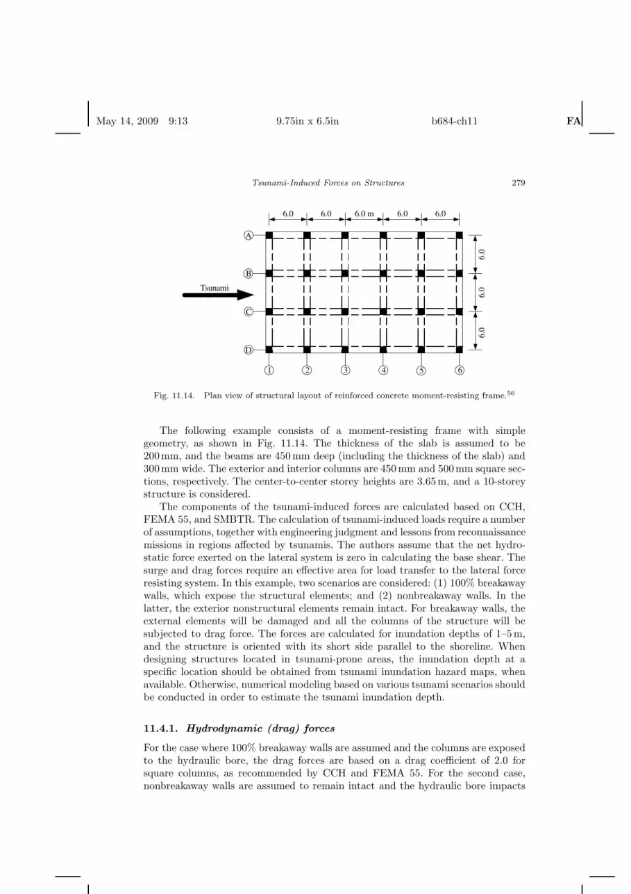
Fig. 11.14. Plan view of structural layout of reinforced concrete moment-resisting frame.56
The following example consists of a moment-resisting frame with simplegeometry, as shown in Fig. 11.14. The thickness of the slab is assumed to be200mm, and the beams are 450mm deep (including the thickness of the slab) and300mm wide. The exterior and interior columns are 450mm and 500mm square sec-tions, respectively. The center-to-center storey heights are 3.65m, and a 10-storeystructure is considered.
The components of the tsunami-induced forces are calculated based on CCH,FEMA 55, and SMBTR. The calculation of tsunami-induced loads require a numberof assumptions, together with engineering judgment and lessons from reconnaissancemissions in regions affected by tsunamis. The authors assume that the net hydro-static force exerted on the lateral system is zero in calculating the base shear. Thesurge and drag forces require an effective area for load transfer to the lateral forceresisting system. In this example, two scenarios are considered: (1) 100% breakawaywalls, which expose the structural elements; and (2) nonbreakaway walls. In thelatter, the exterior nonstructural elements remain intact. For breakaway walls, theexternal elements will be damaged and all the columns of the structure will besubjected to drag force. The forces are calculated for inundation depths of 1–5m,and the structure is oriented with its short side parallel to the shoreline. Whendesigning structures located in tsunami-prone areas, the inundation depth at aspecific location should be obtained from tsunami inundation hazard maps, whenavailable. Otherwise, numerical modeling based on various tsunami scenarios shouldbe conducted in order to estimate the tsunami inundation depth.
11.4.1. Hydrodynamic (drag) forces
For the case where 100% breakaway walls are assumed and the columns are exposedto the hydraulic bore, the drag forces are based on a drag coefficient of 2.0 forsquare columns, as recommended by CCH and FEMA 55. For the second case,nonbreakaway walls are assumed to remain intact and the hydraulic bore impacts

May 14, 2009 9:13 9.75in x 6.5in b684-ch11 FA
280 I. Nistor et al.
the entire surface of the building. In this situation, the drag coefficients are takenas 1.5 and 1.25 for CCH and FEMA 55, respectively.
11.4.2. Debris impact forces
To calculate debris impact, a mass of 455kg is used to represent a floating object atthe water surface. The mass used is consistent with the recommendations of CCHand FEMA 55. In this example, it is assumed that the debris will impact a singlereinforced concrete column. CCH assumes a duration of 0.1 s for concrete structures.FEMA 55 recommends an impact duration ranging from 0.3 to 0.6 s for reinforcedconcrete piles or columns. Hence, impact duration of 0.3 s is assumed in the designexample.
11.4.3. Surge forces
In this example, the surge force is applied over the full length of the building in thedirection of the tsunami for nonbreakaway walls. For the case of 100% breakawaywalls, it is assumed that the surge force will develop on the four exterior columnswhich face the hydraulic bore. Note that the surge force is not applicable for FEMA55 and that SMBTR assumes a different surge force per unit width for columns andwalls, as mentioned in Sec. 11.3.1.4.
11.4.4. Sample calculation: Breakaway walls
The following is a sample calculation for breakaway walls for the given structuresubjected to a tsunami inundation depth of 5 m:
g = 9.81ms2
; ρ = 1030kgm3
; ds = 5 m.
Surge Force:
FS = 2.0ρgh2 = 2.0(
1030kgm3
)(9.81
ms2)
(5 m)2
= 0.505 × 10⁶ Nm
; SMBTR
FS × width =(
0.505× 10⁶ Nm
)(4(0.45 m)) = 909 × 103 N = 909 kN;
FS = 4.5 ρgh2 = 4.5(
1030kgm3
)(9.81
ms2)
(5 m)2
= 1.14 × 10⁶ Nm
; CCH
FS × width =(
1.14 × 10⁶ Nm
)(4(0.45 m)) = 2046 × 103 N = 2046 kN.

May 14, 2009 9:13 9.75in x 6.5in b684-ch11 FA
Tsunami-Induced Forces on Structures 281
Drag Force:
FD =ρCDAu2
2
u = C√
gds = 2√(
9.81ms2)
(5 m) = 14ms
; FEMA 55
u = ds = 5ms
; CCH
CD = 2.0 Rectangular columns;
A = (5 m)((16 × 0.45 m) + 8(0.50 m)) = 56 m2;
FD =
(1030 kg/m3
)(2)(56 m2) (14m/s)2
2= 11,317 × 103 N = 11,317 kN; FEMA 55
FD =
(1030 kg/m3
)(2)(56 m2) (5 m/s)2
2= 1442× 103 N = 1442 kN. CCH
Debris Impact Force:
Fi = mui
∆t= 455 kg
(14m/s0.3 s
)= 21.2 × 10³ N = 21 kN; FEMA 55
Fi = 455 kg(
5 m/s0.1 s
)= 22.8 × 10³ N = 23 kN. CCH
11.4.5. Sample calculation: Nonbreakaway walls
The following is a sample calculation for nonbreakaway walls for the given structuresubjected to a tsunami inundation depth of 5 m.
g = 9.81ms2
; ρ = 1030kgm3
; ds = 5 m
Surge Force:
FS =(
1.14 × 10⁶ Nm
)(18 m + 0.45 m)
= 20,973 × 103 N = 20,973 kN SMBTR/CCH

May 14, 2009 9:13 9.75in x 6.5in b684-ch11 FA
282 I. Nistor et al.
Drag Force:
FD =ρCDAu2
2
CD = 1.25 Walls FEMA 55
CD = 1.5 Walls CCH
A = (5 m)(18 m + 0.45 m) = 92 m2;
FD =
(1030 kg
m3
)(1.25)(92 m2)
(14 m
s
)22
= 11,652 × 103 N = 11,652 kN; FEMA 55
FD =
(1030 kg/m3
)(1.5)
(92 m2
)(5 m/s)2
2= 1782× 103 N = 1782 kN. CCH
Debris Impact Force:
Fi = mui
∆t= 455 kg
(14 m/s0.3 s
)= 21.2 × 10³ N = 21 kN; FEMA 55
Fi = 455 kg(
5 m/s0.1 s
)= 22.8 × 10³ N = 23 kN. CCH
11.4.6. Results
Tables 11.2 through 11.7 provide the results for the calculation of the individualforce components for the structure considered using CCH, FEMA 55, and SMBTR,respectively.
Given the force components, a loading combination must be specified in orderto evaluate the maximum tsunami load that would be used for either design oranalysis purposes. Yeh et al.45 suggested loading combinations that are applicablefor tsunami loading. CCH does not specifically provide guidance to evaluate themaximum tsunami load. Nouri et al.42 proposed a two-part loading combination:Initial impact and Post-impact flow. For this example, these loading combinationsare similar to those of Nouri et al.42 Table 11.8 provides the results of the tsunami
Table 11.2. Tsunami-induced force components based on CCH forbreakaway walls.
Inundation depth Velocity Surge Drag Debris impactCode (m) (m/s) (kN) (kN) (kN)
CCH 1 1 82 12 52 2 327 92 93 3 737 311 144 4 1310 738 185 5 2046 1442 23

May 14, 2009 9:13 9.75in x 6.5in b684-ch11 FA
Tsunami-Induced Forces on Structures 283
Table 11.3. Tsunami-induced force components based on CCH for non-breakaway walls.
Inundation depth Velocity Surge Drag Debris impactCode (m) (m/s) (kN) (kN) (kN)
CCH 1 1 839 14 52 2 3356 114 93 3 7550 385 144 4 13,423 912 185 5 20,973 1782 23
Table 11.4. Tsunami-induced force components based on FEMA 55for breakaway walls.
Inundation depth Velocity Drag Debris impactCode (m) (m/s) (kN) (kN)
FEMA 55 1 6 453 102 9 1811 133 11 4074 164 13 7243 195 14 11,317 21
Table 11.5. Tsunami-induced force components based on FEMA 55for nonbreakaway walls.
Inundation depth Velocity Drag Debris impactCode (m) (m/s) (kN) (kN)
FEMA 55 1 6 466 102 9 1864 133 11 4195 164 13 7457 195 14 11,652 21
load calculation for CCH, FEMA 55 and SMBTR for an inundation depth of 5 mbased on loading combinations of Nouri et al.42
For the prototype moment-resisting frame structure with the short side per-pendicular to the advancing bore, it is apparent that nonbreakaway walls or rigidexterior nonstructural components can lead to large design base shears. CCH andSMBTR estimate significantly larger base shears relative to FEMA 55 due to theomission of a surge component in FEMA 55. It is evident that the width of exposedsurfaces affects the magnitude of total forces exerted on a structure. Therefore, itwould be prudent to orient buildings such that the short side is placed parallel to theshoreline. Furthermore, using breakaway or flexible walls at the lower level wouldreduce the lateral force that is transmitted to the lateral force resisting system. Notethat although the debris impact force is a negligible component in the base shear,

May 14, 2009 9:13 9.75in x 6.5in b684-ch11 FA
284 I. Nistor et al.
Table 11.6. Tsunami-induced force componentsbased on SMBTR for breakaway walls.
Code Inundation depth (m) Surge (kN)
SMBTR 1 362 1463 3274 5825 909
Table 11.7. Tsunami-induced force componentsbased on SMBTR for nonbreakaway walls.
Code Inundation depth (m) Surge (kN)
SMBTR 1 8392 33563 75504 13,4235 20,973
Table 11.8. Tsunami-induced load based on CCH, FEMA 55, and SMBTR for5m inundation depth.
Surge + Impact Drag + Impact Tsunami loadStandard Case (kN) (kN) (kN)
CCH Breakaway 2069 1465 2069CCH Nonbreakaway 20,995 1804 20,995FEMA 55 Breakaway N.A. 11,338 11,338FEMA 55 Nonbreakaway N.A. 11,673 11,673SMBTR Breakaway 909 N.A. 909SMBTR Nonbreakaway 20,973 N.A. 20,973
it could be critical in the design of individual structural components subjected tothe debris impact.
Acknowledgment
Special thanks to Dr Andrew Cornett, Group Leader — Coastal, Ports andOffshore at the Canadian Hydraulics Centre, National Research Council of Canadain Ottawa, Canada, for his valuable advice.
References
1. D. C. Cox and J. F. Mink, Bull. Seism. Soc. Am. 53, 1191–1209 (1963).2. H. Yeh, Natural Hazards 4, 209–220 (1991).

May 14, 2009 9:13 9.75in x 6.5in b684-ch11 FA
Tsunami-Induced Forces on Structures 285
3. A. Ghobarah, M. Saatcioglu and I. Nistor, Eng. Struct. 28, 312–326 (2006).4. I. Nistor, M. Saatcioglu and A. Ghobarah, Ann. Conf. Canadian Society for Civil
Eng. (2006).5. M. Saatcioglu, I. Nistor and A. Ghobarah, Earthquake Spectra (Earthquake Engi-
neering Research Institute, 22, 2006), pp. 295–320.6. M. Saatcioglu, I. Nistor and A. Ghobarah, Earthquake Spectra (Earthquake Engi-
neering Research Institute, 22, 2006), pp. 355–375.7. C. V. R. Murty, D. C. Rai, S. K. Jain, H. B. Kaushik, G. Mondal and S. R.
Dash, Earthquake Spectra (Earthquake Engineering Research Institute, 22, 2006),pp. 321–354.
8. A. Ruangrassamee, H. Yanagisawa, P. Foytong, P. Lukkunaprasit, S. Koshimura andF. Imamura, Earthquake Spectra (Earthquake Engineering Research Institute, 22,2006), pp. 377–401.
9. B. K. Maheshwari, M. L. Sharma and J. P. Narayan, Earthquake Spectra (EarthquakeEngineering Research Institute, 22, 2006), pp. 475–493.
10. Y. Yamamoto, H. Takanashi, S. Hettiarachchi and S. Samarawickrama, Coastal Eng. J.48(2), 117–145 (2006).
11. T. Tomita, F. Imamura, T. Arikawa, T. Yasuda and Y. Kawata, Coastal Eng. J. 48(2),99–116 (2006).
12. N. Shuto, Tsunami Engineering Technical Report No.11, DCRC, Tohoku University(in Japanese) (1994).
13. H. Matsutomi, T. Sakakiyama, S. Nugroho and M. Matsuyama, Coastal Eng. J. 48(2),167–195 (2006).
14. CNN, http://www.cnn.com/interactive/world/0502/gallery.tsunami.photos/frameset.exclude.html (2007).
15. H. Yeh, Int. Workshop on Fundamentals of Coastal Effects of Tsunamis, Hilo, Hawaii(2006).
16. S. Hibberd and D. H. Peregrine, J. Fluid Mech. 95, 323–345 (1979).17. A. R. Packwood and D. H. Peregrine, Report AM-81-07, University of Bristol (1981).18. H. Yeh, A. Ghazali and I. Marton, J. Fluid Mech. 206, 563–578 (1989).19. H. Yeh and K. M. Mok, Phys. Fluids A 2, 821–828 (1990).20. H. Chanson, Coastal Eng. J. 48(4), 355–370 (2006).21. A. Tsutsumi, T. Shimamoto, E. Kawamoto and J. M. Logan, J. Waterway, Port,
Coastal, Ocean Eng., ASCE 126(3), 136–143 (2000).22. J. R. Morison, M. P. O’Brien, J. W. Johnson and S. A. Schaaf, Petroleum Trans.,
AIME 189, 149–157 (1950).23. F. E. Snodgrass, E. K. Rice and M. Hall, University of California, Berkeley, CA, Inst.
of Engineering Research, Technical Report Series 35, Issue 4, June (1951).24. J. J. Stoker, Water Waves (Interscience Publishers, New York, 1957).25. E. Cumberbatch, J. Fluid Mech. 7(3), 353–373 (1960).26. Y. Fukui, M. Nakamura, H. Shiraishi and Y. Sasaki, Coastal Eng. Jpn. 6, 67–82 (1963).27. R. H. Cross, PhD thesis, Dept. Civil Engineering, University of California, Berkeley,
CA (1966), p. 106.28. Dames and Moore, in Design and Construction Standards for Residential Construction
in Tsunami-Prone Areas in Hawaii (Prepared for the Federal Emergency ManagementAgency) (1980).
29. J. D. Ramsden and F. Raichlen, J. Waterway Port, Coastal and Ocean Eng., ASCE116(5), 592–613 (1990).
30. J. D. Ramsden, Report No. KH-R-54, W. M. Keck Laboratory, California Institute ofTechnology, Pasadena, California (1993), p. 251.

May 14, 2009 9:13 9.75in x 6.5in b684-ch11 FA
286 I. Nistor et al.
31. J. D. Ramsden, J. Waterways, Port, Coastal and Ocean Eng. 122(3), 134–141 (1996).32. T. Okada, T. Sugano, T. Ishikawa, S. Takai and T. Tateno, The Building Centre of
Japan (2005).33. R. Asakura, K. Iwase and T. Iketani, Proc. Coastal Eng. JSCE 47, 911–915 (2000).34. M. Ikeno, N. Mori and H. Tanaka, Proc. Coastal Eng. JSCE 48, 846–850 (2001).35. H. Iizuka and H. Matsutomi, Proc. Conf. Coastal Eng., JSCE 47 (2000) (in Japanese).36. M. Omori, N. Fujii and O. Kyotani, Proc. Coastal Eng. JSCE 47, 376–380 (2000).37. H. Arnason, PhD thesis, University of Washington, Seattle (2005), p. 172.38. Y. Nouri, I. Nistor, D. Palermo and A. Cornett, Coastal Structures 2007, Venice, Italy
(2007).39. H. Matsutomi, J. Hyd. Coastal Environ. Eng. JSCE, No. 621/II-47, 111–127 (1999)
(in Japanese, with English abs.).40. R. B. Haehnel and S. F. Daly, Technical Report: ERDC/CRREL TR-02-2, US Army
Corps of Engineers (2002), p. 40.41. R. B. Haehnel and S. F. Daly, J. Hydraul. Eng. 130(2), 112–120 (2004).42. Y. Nouri, I. Nistor, D. Palermo and M. Saatcioglu, 9th Canad. Conf. Earthquake
Engineering, Ottawa, Canada, June (2007).43. Federal Emergency Management Agency, Coastal Construction Manual (3 Vols.),
3rd edn. (FEMA 55) (Jessup, MD, 2003).44. Department of Planning and Permitting of Honolulu Hawai, Chapter 16, City and
County of Honolulu Building Code, Article 11 (2000).45. H. Yeh, I. Robertson and J. Preuss, Report No 2005-4, Washington Dept. of Natural
Resources (2005).46. Y. Nakano and C. Paku, Summaries of technical papers of Annual Meeting Architec-
tural Institute of Japan (Kinki) (2005).47. UBC, Int. Conf. Building Officials, 1997 Uniform Building Code, California (1997).48. ASCE Standard, Minimum design loads for buildings and other structures, SEI/ASCE
7-05, 424 (2006).49. International Code Council (INC), 2006 International Building Code 2006, Country
Club Hills, IL (2006), p. 675.50. M. S. Kirkoz, 10th IUGG Int. Tsunami Symposium, Sendai-shi/Miyagi-ken, Japan,
Terra Scientific Publishing, Tokyo, Japan (1983).51. T. S. Murty, Bull. Fisheries Res. Board of Canada, No. 198, Department of Fisheries
and the Environment, Fisheries and Marine Service, Scientific Information and Pub-lishing Branch, Ottawa, Canada (1977).
52. E. A. Bryant, Tsunami: The Underrated Hazard (Cambridge University Press, London,UK, 2001), p. 320.
53. F. Camfield, Tsunami Engineering (Coastal Engineering Research Center, US ArmyCorps of Engineers, 1980), p. 222, Special Report (SR-6).
54. P. Dias, L. Fernando, S. Wathurapatha and Y. De Silva, Int. Conf. Disaster Reductionon Coasts, Melbourne (2005).
55. K. H. Pacheco and I. N. Robertson, Evaluation of Tsunami Loads and Their Effecton Reinforced Concrete Buildings. University of Hawaii Research Report (2005).
56. D. Palermo, I. Nistor, Y. Nouri and A. Cornett, PROTECT 2007, Whistler, Canada(2007).