transmission line distance
TRANSCRIPT

Section 13 - Transmission Line Distance Protection - Part I
Power System Protection for Engineers – PROT 401
Transmission Line Distance Prot 1_r12 1
Copyright © SEL 2005
Power System Protectionfor Engineers
Transmission Line Distance Protection
Part 1
Technical papers supporting this section:
6022.pdf, Z = V/I Does Not Make a Distance Relay by J. Roberts; A. Guzman; E.O. Schweitzer, III
General books of Power System Protection.
Section 13 - Transmission Line Distance Protection - Part I
Power System Protection for Engineers – PROT 401
Transmission Line Distance Prot 1_r12 2
Transmission Line Distance Protection (Part 1) Objectives
Describe distance relay operation, design principles, and connections
Discuss infeed effect in distance relays
Describe the effect of fault resistance on the impedance measured by distance relays
Discuss impedances measured by distance elements for different fault types, and the resulting need for fault type selection

Section 13 - Transmission Line Distance Protection - Part I
Power System Protection for Engineers – PROT 401
Transmission Line Distance Prot 1_r12 3
Transmission Line Protection Principles
Overcurrent (50, 51, 50N, 51N)
Directional Overcurrent (67, 67N)
Distance (21, 21N)
Differential (87)
This section is an introduction to the topic of transmission line protection using distance relays. Further sections and courses will complete the wide and interesting topic of distance protection.

Section 13 - Transmission Line Distance Protection - Part I
Power System Protection for Engineers – PROT 401
Transmission Line Distance Prot 1_r12 4
Three-Phase Fault on a Radial Line
Three-Phase Bolted Fault
d
L
RadialLine
For a perfect three-phase fault, only the positive-sequence impedance is involved in the calculations. With the usual convention, the phase “a” voltage and current are equal to the positive-sequence voltage and current.

Section 13 - Transmission Line Distance Protection - Part I
Power System Protection for Engineers – PROT 401
Transmission Line Distance Prot 1_r12 5
Impedance Diagram
111 )/( LS
FAULTa ZLdZEIII
+===
Zs1 is System’s Thevenin Equivalent Impedance. It Depends on Whole System State (Topology, Load, etc.)
BoltedFault
aII =1aVV =1
+
-
1SZ 1)/( LZLd
E
+
-
The positive-sequence impedance diagram for a three-phase fault is as shown in the figure.
For this radial system, disregarding the influence of load, the fault current in each phase is balanced and is equal to the phase current measured by the relays at the substation.
This current depends on the following parameters:
• System voltage
• Line impedance
• Distance to the fault
• Thevenin impedance equivalent to the system “behind” the substation bus
The Thevenin impedance depends on the conditions of the system, such as the topology and system loading.

Section 13 - Transmission Line Distance Protection - Part I
Power System Protection for Engineers – PROT 401
Transmission Line Distance Prot 1_r12 6
Overcurrent Relay Setting and ReachPhase Instantaneous Element (50) Commonly Set to Reach Faults up to 80% of Total Line Length
0.8L
L
11 )8.0( LSSETTING ZZ
EI+
≈
RadialLine
Three-Phase Bolted Fault
Relay Setting Calculated for a Given Value of ZS1
A phase instantaneous overcurrent element is set to detect fault currents up to 80 percent of the line length. This gives enough security margin (20 percent) to avoid non-selective operation for faults beyond the remote bus. The relay setting is calculated for a given value of the equivalent ZS1.

Section 13 - Transmission Line Distance Protection - Part I
Power System Protection for Engineers – PROT 401
Transmission Line Distance Prot 1_r12 7
Overcurrent Relay Problem
11 )8.0( LSSETTING ZZ
EI+
≈
11)( )8.0( LS
LIMITFAULT ZZEI
+′=
Relay Operates When the Following Condition Holds:
SETTINGaFAULT III >=
As Zs1 Changes, the Relay’s “Reach” Will Change, Since Setting is Fixed
As the system topology behind the substation bus changes, ZS1 changes. As a result, the relay “reach” will change. The only way to avoid non-selective operations for faults beyond the remote bus is to calculate the instantaneous setting for the worst case value of ZS1, which results in a shorter reach of the instantaneous element for all other system configurations. It is highly probable that the system presents the worst case value for relatively short periods of time, meaning that the relay reach will be permanently sacrificed for a situation that occurs for short periods. This is a disadvantage of instantaneous overcurrent relays.
Section 13 - Transmission Line Distance Protection - Part I
Power System Protection for Engineers – PROT 401
Transmission Line Distance Prot 1_r12 8
Distance Relay Principle
Three-Phase Solid Fault
d
L
RadialLine21
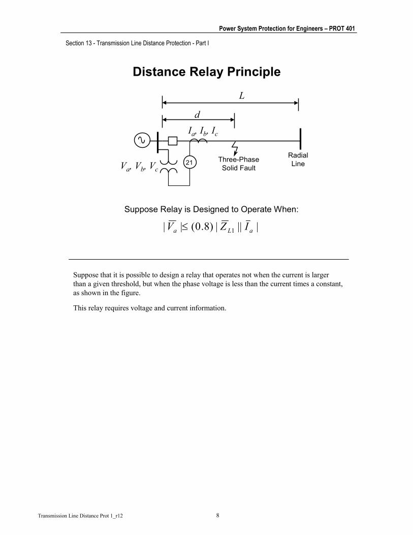
Suppose Relay is Designed to Operate When:
||||)8.0(|| 1 aLa IZV ≤
Va, Vb, Vc
Ia, Ib, Ic
Suppose that it is possible to design a relay that operates not when the current is larger than a given threshold, but when the phase voltage is less than the current times a constant, as shown in the figure.
This relay requires voltage and current information.

Section 13 - Transmission Line Distance Protection - Part I
Power System Protection for Engineers – PROT 401
Transmission Line Distance Prot 1_r12 9
Distance Relay Principle
For a Perfectly Balanced Three-Phase Fault at Distance d:
aLa IZLdV 1)/(=
Therefore, the Relay will Operate when:
⇒≤ ||||)8.0(|)/(| 11 aLaL IZIZLd
Ld 8.0≤This Result Does Not Depend on the Thevenin Impedance
The inequality originally stated in terms of voltage and current implicitly states that the relay will operate when the distance to the fault is less than a given limit distance, called the distance relay reach.
Ideally, the reach of such a relay does not depend on the source impedance.
Section 13 - Transmission Line Distance Protection - Part I
Power System Protection for Engineers – PROT 401
Transmission Line Distance Prot 1_r12 10
Impedance Relay
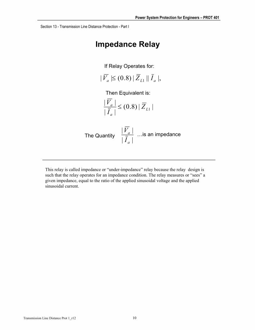
If Relay Operates for:
|,|||)8.0(|| 1 aLa IZV ≤
Then Equivalent is:
||)8.0(||||
1La
a ZIV
≤
||||
a
a
IV
The Quantity …is an impedance
This relay is called impedance or “under-impedance” relay because the relay design is such that the relay operates for an impedance condition. The relay measures or “sees” a given impedance, equal to the ratio of the applied sinusoidal voltage and the applied sinusoidal current.
Section 13 - Transmission Line Distance Protection - Part I
Power System Protection for Engineers – PROT 401
Transmission Line Distance Prot 1_r12 11
Apparent Impedance
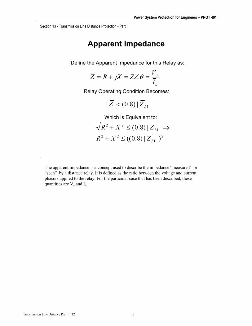
Define the Apparent Impedance for this Relay as:
a
a
IVZjXRZ =∠=+= θ
Relay Operating Condition Becomes:
||)8.0(|| 1LZZ <
Which is Equivalent to:
21
221
22
|)|)8.0((
||)8.0(
L
L
ZXR
ZXR
≤+
⇒≤+
The apparent impedance is a concept used to describe the impedance “measured’ or “seen” by a distance relay. It is defined as the ratio between the voltage and current phasors applied to the relay. For the particular case that has been described, these quantities are Va and Ia.

Section 13 - Transmission Line Distance Protection - Part I
Power System Protection for Engineers – PROT 401
Transmission Line Distance Prot 1_r12 12
Relay Setting
||)8.0( 11 Lr ZZ =
21
22rZXR ≤+
Define the Relay Setting as:
The Relay Operating Condition Becomes:
Or….
1rZZ ≤
The maximum reach of the distance relay, in terms of impedance, is normally an adjustable value of the relay. Therefore, the same relay can be used for different lines.

Section 13 - Transmission Line Distance Protection - Part I
Power System Protection for Engineers – PROT 401
Transmission Line Distance Prot 1_r12 13
Under-Impedance Relay Implementation
MagnitudeComparator TRIP
Operates When:1
1 ||||
r
r
ZZIZV
≤⇒≤
V
I1rZ
IZ r1
The figure shows the simplest design for an under-impedance relay. The current is passed through a single amplifier. The magnitude of the resulting quantity is compared to the magnitude of the voltage by a two-input magnitude comparator. The gain of the amplifier Zr1 is the relay setting.
In the past, these devices were implemented through use of an electromechanical balance unit. Today, in computer-based relays, the relay equation is directly implemented in the relay routines.

Section 13 - Transmission Line Distance Protection - Part I
Power System Protection for Engineers – PROT 401
Transmission Line Distance Prot 1_r12 14
Impedance Calculation Example
21Va, Vb, Vc
Ia, Ib, Ic
69 kV LinezL1=0.24+j0.80 Ohms/mileL = 15 miles
Relay will operate for:
Ohms4.10002.10 222 =≤+ XR
Ohms126.315)8.024.0(1
jjZL
+==⋅+=
Relay setting: Ohms02.10|126.3|)8.0(1 =+= jZr
This example shows the calculations involved in the determination of a simple impedance relay setting.
Section 13 - Transmission Line Distance Protection - Part I
Power System Protection for Engineers – PROT 401
Transmission Line Distance Prot 1_r12 15
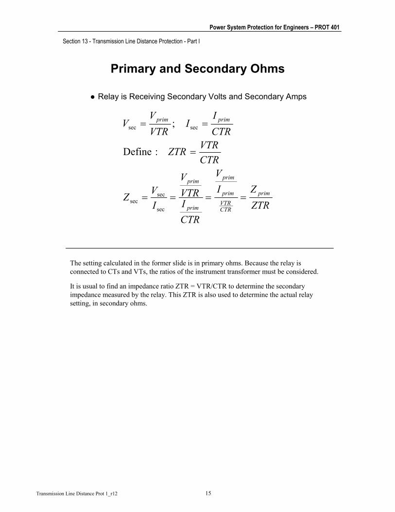
Primary and Secondary Ohms
Relay is Receiving Secondary Volts and Secondary Amps
ZTRZI
V
CTRIVTRV
IVZ
CTRVTRZTR
CTRI
IVTRV
V
prim
CTRVTRprim
prim
prim
prim
primprim
====
=
==
sec
secsec
secsec
:Define
;
The setting calculated in the former slide is in primary ohms. Because the relay is connected to CTs and VTs, the ratios of the instrument transformer must be considered.
It is usual to find an impedance ratio ZTR = VTR/CTR to determine the secondary impedance measured by the relay. This ZTR is also used to determine the actual relay setting, in secondary ohms.

Section 13 - Transmission Line Distance Protection - Part I
Power System Protection for Engineers – PROT 401
Transmission Line Distance Prot 1_r12 16
Impedance Calculation Example
21Va, Vb, Vc
Ia, Ib, Ic
69 kV LinezL1 = 0.24+j0.80 Ohms/mileL = 15 miles
Ohms126.315)8.024.0(1
jjZL
+==⋅+=
Relay setting at 80% of Line Z: OhmsSecondary62.377.2/02.101 ==rZ
77.2/5/600120/40000
==⇒==
CTRVTRZTRCTRVTR
This is the same example as before, but now the relay setting is calculated in secondary ohms.
Section 13 - Transmission Line Distance Protection - Part I
Power System Protection for Engineers – PROT 401
Transmission Line Distance Prot 1_r12 17
The Complex Impedance Plane
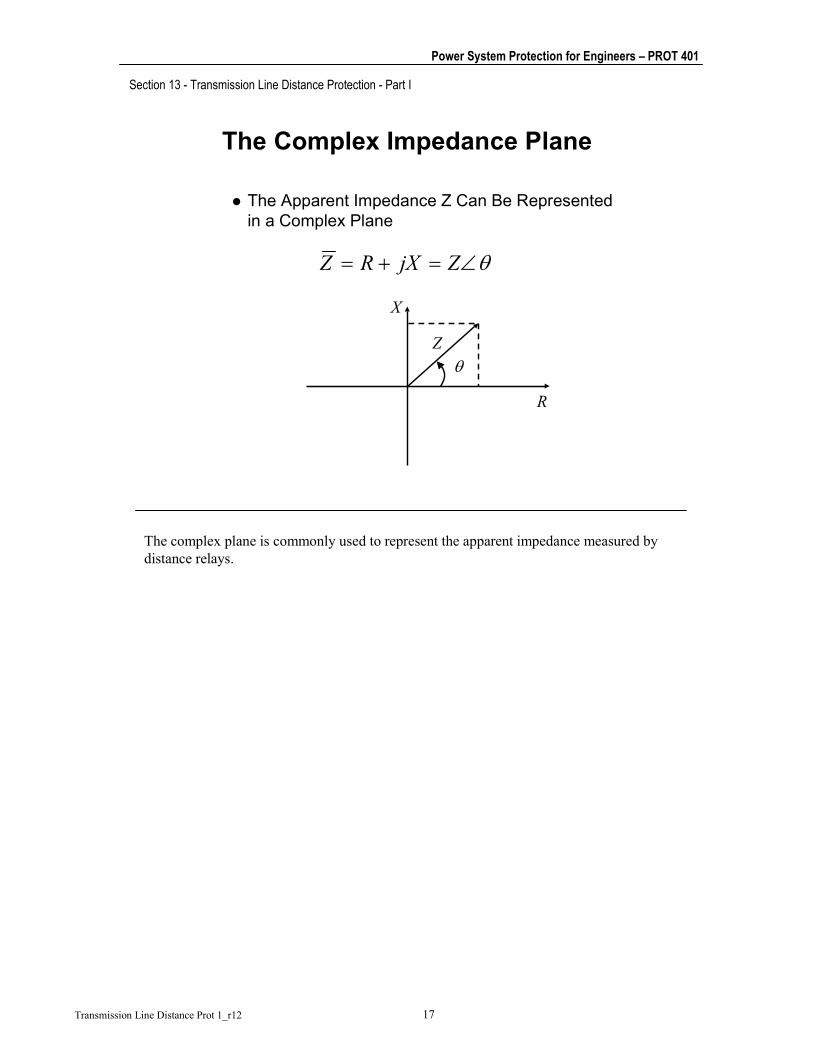
The Apparent Impedance Z Can Be Represented in a Complex Plane
θ∠=+= ZjXRZ
R
X
θZ
The complex plane is commonly used to represent the apparent impedance measured by distance relays.

Section 13 - Transmission Line Distance Protection - Part I
Power System Protection for Engineers – PROT 401
Transmission Line Distance Prot 1_r12 18
The Impedance Relay Characteristic
21
22rZXR ≤+
R
X Plain Impedance RelayOperation Zone
Zr1
Radius Zr11rZZ ≤
A plain impedance relay will operate for any apparent impedance whose magnitude is less than, or equal to, the relay setting. In the complex plane, this is represented by the region within a circle with radius equal to the relay setting. The border of the circle represents the operation threshold of the relay.

Section 13 - Transmission Line Distance Protection - Part I
Power System Protection for Engineers – PROT 401
Transmission Line Distance Prot 1_r12 19
Unit Distance Definition
Three-Phase Bolted Fault
d
L
RadialLine
21Va, Vb, Vc
Ia, Ib, Ic
Ldm =
The unit distance is the distance to the fault in per unit of the total line’s length. This parameter is commonly used in protective relaying.

Section 13 - Transmission Line Distance Protection - Part I
Power System Protection for Engineers – PROT 401
Transmission Line Distance Prot 1_r12 20
The Bolted Fault Locus
aLa IZLdV 1)/(=
The Apparent Impedance is:
11)/( LLa
a ZmZLdIVZ ===
Three-Phase Bolted Fault
d
L
RadialLine
21Va, Vb, Vc
Ia, Ib, Ic
If the apparent impedance of a distance relay is calculated for three-phase bolted faults along the line, for distances varying from 0 miles to L miles, the resulting set of complex numbers can be plotted in the complex impedance plane.

Section 13 - Transmission Line Distance Protection - Part I
Power System Protection for Engineers – PROT 401
Transmission Line Distance Prot 1_r12 21
The Bolted Fault Locus
10For
;11111
≤≤
+=∠==
m
jmXmRmZZmZ LLLLL θ
R
X
RL1
XL1This line segment is the locus of the apparent impedance for solid faults over the line.
Apparent Impedance:
θL1
ZL1
This set of points is a line segment as shown in the figure. The segment has the same length and angle as the total line impedance and is called the bolted fault locus.

Section 13 - Transmission Line Distance Protection - Part I
Power System Protection for Engineers – PROT 401
Transmission Line Distance Prot 1_r12 22
Line Protection With Impedance Relay
R
XOperation zone
Zr1
Solid Fault Locus
1rZZ ≤10
;1
≤≤=
mZmZ L
If the fault locus is superimposed with the relay operating characteristic in the same complex plane, the resulting plot indicates the degree of protection of the relay. The case shown in the figure represents a case in which the relay has been set to reach faults up to ~80 percent of the line.

Section 13 - Transmission Line Distance Protection - Part I
Power System Protection for Engineers – PROT 401
Transmission Line Distance Prot 1_r12 23
Distance Protection Load vs. Fault Apparent Impedance
IVZ =
Fault
Relay
V I
R
X
Operation Zone
Bolted Fault Locus
LoadFault
During normal load conditions, the impedance “seen” by a distance relay has a magnitude much larger than the length of the bolted fault locus (line). When a fault occurs, the impedance moves instantly to a point in the complex plane located on, or very near, the bolted fault locus. The accuracy of this statement for non-bolted faults will be shown later.

Section 13 - Transmission Line Distance Protection - Part I
Power System Protection for Engineers – PROT 401
Transmission Line Distance Prot 1_r12 24
Need for Directionality
1 2 3 4 5 6
F1F2
R
XRELAY 3Operation Zone
F1
F2Non-Selective Relay Operation

Section 13 - Transmission Line Distance Protection - Part I
Power System Protection for Engineers – PROT 401
Transmission Line Distance Prot 1_r12 25
Directionality Improvement
1 2 3 4 5 6
F1F2
R
XRELAY 3Operation Zone
F1
F2The Relay Will Not Operate for This Fault
Directional Impedance Relay Characteristic

Section 13 - Transmission Line Distance Protection - Part I
Power System Protection for Engineers – PROT 401
Transmission Line Distance Prot 1_r12 26
Mho Element Characteristic (Directional Impedance Relay)
( )MTMZZ ϕϕ −≤ cosZM
Z
R
ϕϕMT
X
( )MTMZIV ϕϕ −≤ cosOperates when:
There are three traditional distance elements: impedance-type, reactance-type, and Mho-type distance elements.
The figure shows the operation equation and operating characteristic of a Mho distance element. The characteristic is the locus of all apparent impedance values for which the relay element is on the verge of operation. The operation zone is located inside the circle, and the resraint zone is the region outside the circle.
The Mho characteristic is a circle passing through the origin of the impedance plane. The Mho element operates for impedances inside the circle. The characteristic is oriented towards the first quadrant, which is where forward faults are located. For reverse faults, the apparent impedance lies in the third quadrant and represents a restraint condition. The fact that the circle passes through the origin is an indication of the inherent directionality of the Mho elements. However, close-in bolted faults result in a very small voltage at the relay that may result in a loss of the voltage polarizing signal. This needs to be taken into consideration when selecting the appropriate Mho element polarizing quantity.
There are typically two settings in a Mho element: the characteristic diameter, ZM, and the angle of this diameter with respect to the R axis, ϕMT. The angle is equivalent to the maximum torque angle of a directional element. The Mho element presents its longest reach (greatest sensitivity) when the apparent impedance angle ϕ coincides with ϕMT.
Normally, ϕMT is set close to the protected line impedance angle to ensure maximum relay sensitivity for faults and minimum sensitivity for load conditions.

Section 13 - Transmission Line Distance Protection - Part I
Power System Protection for Engineers – PROT 401
Transmission Line Distance Prot 1_r12 27
How to Implement a Mho Relay
Signal
Forming
Signal
Forming
Phase
ComparisonV
I
S1
S2
Trip
Operation Condition:
Operating Quantity
Polarizing QuantityVSZIVS r
=
+−=
2
1 ;
( ) 2211 arg λλ ≤≤− SS
The early electromechanical relays with a Mho characteristic used a product unit (induction cylinder element) to achieve the torque equation: V2 – V I cos(θ-θMT) > 0.
Analog static relays used a two-input phase comparator to create the Mho characteristic. The inputs to the comparator are properly mixed from the original voltage and current to obtain the desired behavior.
Section 13 - Transmission Line Distance Protection - Part I
Power System Protection for Engineers – PROT 401
Transmission Line Distance Prot 1_r12 28
How to Implement a Mho Relay
( )( )
oro
oro
or
o
oor
ZZZ
IVZIV
VZIVSS
VSZIVS
90arg90
90/
/arg90
90)(arg9090arg90
;
21
21
≤⎟⎟⎠
⎞⎜⎜⎝
⎛ −≤−
≤⎟⎟⎠
⎞⎜⎜⎝
⎛ +−≤−
≤+−≤−
≤≤−
=+−=
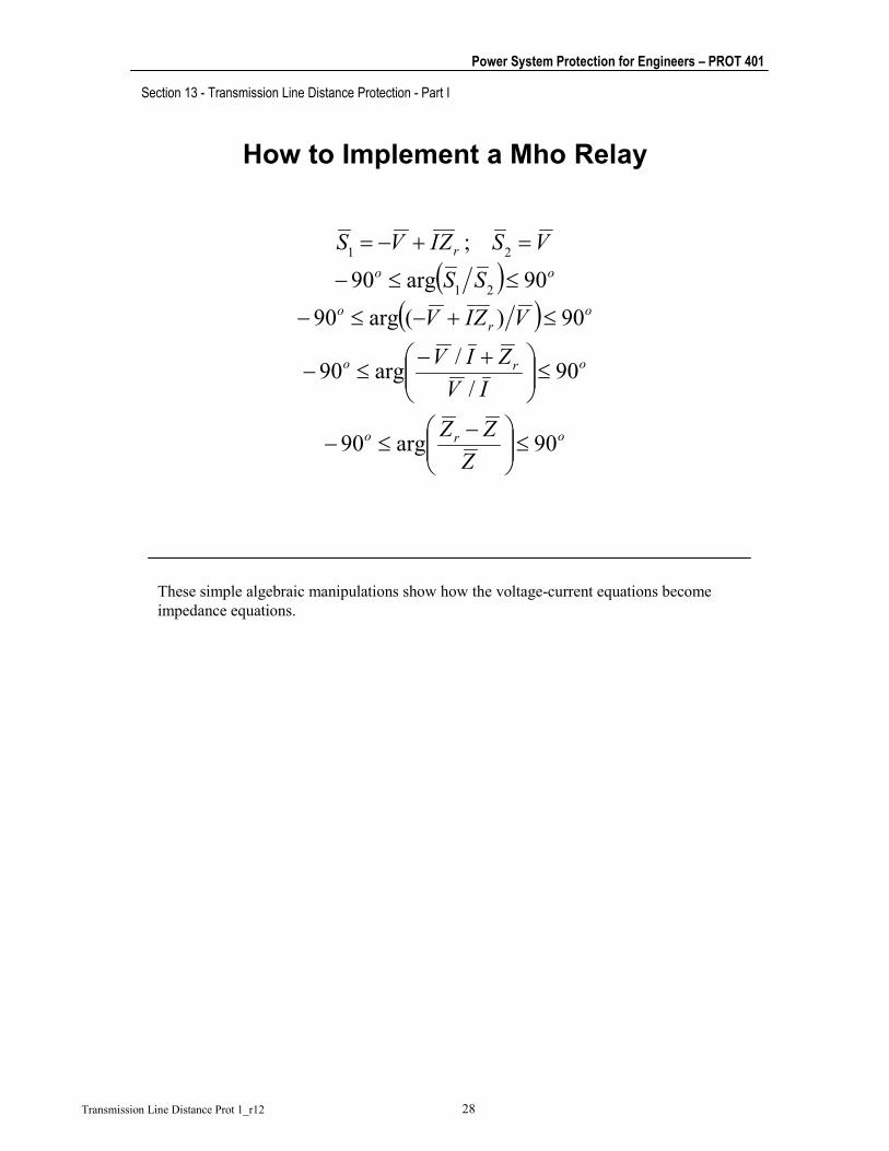
These simple algebraic manipulations show how the voltage-current equations become impedance equations.
Section 13 - Transmission Line Distance Protection - Part I
Power System Protection for Engineers – PROT 401
Transmission Line Distance Prot 1_r12 29
How to Implement a Mho Relay
Z r
X
RA
B
( ) 90)(arg ±=− ZZZ r
Z
Zr-Z90o
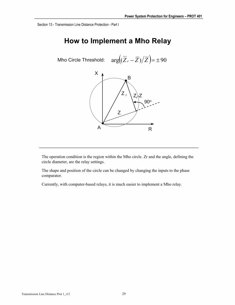
Mho Circle Threshold:
The operation condition is the region within the Mho circle. Zr and the angle, defining the circle diameter, are the relay settings.
The shape and position of the circle can be changed by changing the inputs to the phase comparator.
Currently, with computer-based relays, it is much easier to implement a Mho relay.

Section 13 - Transmission Line Distance Protection - Part I
Power System Protection for Engineers – PROT 401
Transmission Line Distance Prot 1_r12 30
Distance Relay Timing and Coordination
1 2 3 4 5 6
Zone 1Zone 2
Zone 3
Operation Time
B CA
Zone 1 is Instantaneous
So far, a directional distance relay, which operates instantaneously and is set to reach less than 100 percent of the protected line, has been described. Two important principles of protection have been missing:
1. What happens for a fault on the protected line that is beyond the reach of the relay?
2. If the relay operates instantaneously, it cannot be used as a remote back-up for a relay protecting a line adjacent to the remote substation.
These two problems are overcome by adding time-delay distance relays. This is accomplished by using the distance relay to start a definite time timer. The output of the timer can then be used as a tripping signal.
The figure shows how a second zone (or step) is added to each of the directional impedance relays. A third zone, with a larger delay, can also be added.
The operation time of the second zone is usually around 0.3 seconds, and the third zone around 0.6 seconds. However, the required time depends on the particular application.
The ohmic reach of each zone also depends on the particular power system. The figure and the next slide show a typical reach scheme for three zones.
What about Circuit Breakers 2, 4 and 5?

Section 13 - Transmission Line Distance Protection - Part I
Power System Protection for Engineers – PROT 401
Transmission Line Distance Prot 1_r12 31
The Reach of Mho ElementsRelay Settings
X
R
B
C
A
Zone 1
Zone 2
Zone 3
Relays at A(CB 1)
The slide shows how the instantaneous Zone 1, and the delayed Zones 2 and 3 look in a complex impedance plane if Mho units are used for all three zones. Note the reference to buses A, B, and C of the previous slide, which indicate that the distance elements correspond to the relays associate with Circuit Breaker 1, located at Substation A.

Section 13 - Transmission Line Distance Protection - Part I
Power System Protection for Engineers – PROT 401
Transmission Line Distance Prot 1_r12 32
Three-Zone Distance Protection
1 2 3 4 5 6
Zone 1Zone 2
Zone 3
Time
Time
What about Circuit Breakers 2, 4, and 5? The figure shows the operating time as a function of the electrical distance for six distance relays. Here, the relays “looking” in both directions are shown. We show the characteristics for Relays 1, 3, and 5 above the system one-line diagram. We represent the characteristics for Relays 2, 4, and 5 below the one-line diagram.
Zone 1 must underreach the remote line end to make sure that it will not operate for faults in the adjacent lines. Zone 2 is intended to cover the end of the protected line, so it must overreach the protected line. Zone 3 is intended to provide remote backup protection to adjacent lines, so it must overreach the longest adjacent line.
We typically leave a coordination interval (including breaker tripping time) between Zones 1 and 2 and between Zones 2 and 3 of adjacent distance relays. This means that the end of Zone 2 of a backup relay should not overlap with the begininning of Zone 2 of the primary relay. The same is true for adjacent third zones. This is not always possible, however.
In the figure, we can see that faults located in the central section of a given line are cleared by simultaneous and instantaneous operation of the first zones at both line ends. Should a first zone fail to operate, the remote backup relay operates in second or third zone. On the other hand, faults close to one line end will be cleared sequentially: the nearest line end will operate in first zone, and the remote end will operate in second zone. This sequential fault clearing is a limitation of distance protection, because it could jeopardize system stability.
An advantage of distance protection over directional overcurrent protection is that the distance first zone reach depends less on system operating conditions than the reach of the instantaneous overcurrent element. In other words, distance protection provides better instantaneous line coverage.

Section 13 - Transmission Line Distance Protection - Part I
Power System Protection for Engineers – PROT 401
Transmission Line Distance Prot 1_r12 33
Line Protection with Mho Elements
E
X
RA
B
C
D
The figure is an impedance-plane representation of a line protection scheme using Mho distance relays (both directions). A longitudinal system is formed by transmission lines AB, BC, AD, and DE. The line impedances are plotted on the complex plane, using substation A as the origin of coordinates for convenience. The Mho circles represent the three zones of the distance schemes at both ends of line AB.

Section 13 - Transmission Line Distance Protection - Part I
Power System Protection for Engineers – PROT 401
Transmission Line Distance Prot 1_r12 34
Circular Distance Relay Characteristics
MHO
OFFSETMHO (1)
PLAIN IMPEDANCE
R
X
R
X
R
X
OFFSETMHO (2)
R
X
LENS(RESTRICTED MHO 1)
TOMATO(RESTRICTED MHO 2)
R
X
R
X
The figure shows several commonly used circular distance relay characteristics. For analog relays, these characteristics can be obtained with phase and/or magnitude comparators. In microprocessor-based relays, they are implemented through the use of mathematical algorithms.

Section 13 - Transmission Line Distance Protection - Part I
Power System Protection for Engineers – PROT 401
Transmission Line Distance Prot 1_r12 35
Semi-Plane Type Characteristics
REACTANCE
OHM
DIRECTIONAL
R
X
R
X
R
X
RESTRICTEDDIRECTIONAL
R
X
RESTRICTEDREACTANCE
QUADRILATERAL
R
X
R
X
Here is another group of traditional distance relay characteristics.
The use of one characteristic or another depends on several factors associated with the power system. These factors will be studied during this course.

Section 13 - Transmission Line Distance Protection - Part I
Power System Protection for Engineers – PROT 401
Transmission Line Distance Prot 1_r12 36
Quadrilateral Element Characteristic
X
RA
B
C
Solid-state and digital relays permit creation of highly sophisticated distance characteristics.
An example is the quadrilateral characteristic, shown here. You can shape the characteristic to meet different line protection requirements.
The price for this flexibility is setting complexity: there are four settings in a quadrilateral characteristic.

Section 13 - Transmission Line Distance Protection - Part I
Power System Protection for Engineers – PROT 401
Transmission Line Distance Prot 1_r12 37
Distance Relay Connections

Section 13 - Transmission Line Distance Protection - Part I
Power System Protection for Engineers – PROT 401
Transmission Line Distance Prot 1_r12 38
Line Faults – Simplified Analysis
Fault
21
dp q
POWER SYSTEM
L
Va, Vb, Vc
Ia, Ib, Ic
So far, the design, operation, and setting of distance relays for three-phase bolted faults has been studied. In this part of the course, it will be shown that the voltage and current applied to the relay for it to correctly measure the “distance to the fault” depends on the type of fault.
Different types of bolted short circuits on a transmission line will be studied to determine the phase currents and voltages (Ia, Ib, Ic, Va, Vb, Vc) at the distance relay location.

Section 13 - Transmission Line Distance Protection - Part I
Power System Protection for Engineers – PROT 401
Transmission Line Distance Prot 1_r12 39
Line Equations During a 3-Phase Fault
Ia
Ib
Ic
a
b
c
aV bVcV
Three-Phase Fault
cmSccSbmamc
bmScmbSamb
amScmbmaSa
IZZmIZIZIZmVIZZmIZIZIZmVIZZmIZIZIZmV
)(0)()(0)()(0)(
−=+++=
−=+++=
−=+++=
The three-phase, short-circuit case is repeated here to introduce the procedure to be used.
The line equations correspond to a symmetrical, or transposed, line. The three phases are set to zero voltage at the fault location. The unit distance, m, is used as the distance to the fault point.

Section 13 - Transmission Line Distance Protection - Part I
Power System Protection for Engineers – PROT 401
Transmission Line Distance Prot 1_r12 40
Review of Self and Mutual Impedances
mSL
mSL
ZZZZZZ2
;
0
1
+=
−=
3/)(;3/)2(
10
10
LLm
LLS
ZZZZZZ
−=
+=
⇒
Recall the relationships between the self and mutual impedances with the positive-sequence and zero-sequence impedances.

Section 13 - Transmission Line Distance Protection - Part I
Power System Protection for Engineers – PROT 401
Transmission Line Distance Prot 1_r12 41
Relay Connection for a 3-Phase Fault
cLcmSc
bLbmSb
aLamSa
IZmIZZmVIZmIZZmVIZmIZZmV
1
1
1
)()()(
=−=
=−=
=−=
;;; 111 Lc
cL
b
bL
a
a ZmIVZm
IVZm
IV
===
⇒
A single distance element could be enough to detect balanced three-phase faults. The element should be connected to any phase voltage and current.
The algebraic development shows that a single distance element is enough to detect balanced three-phase faults. The element should be connected to any phase voltage and current to properly measure the positive-sequence impedance existing between the relay location and the fault. This impedance is directly proportional to the distance.

Section 13 - Transmission Line Distance Protection - Part I
Power System Protection for Engineers – PROT 401
Transmission Line Distance Prot 1_r12 42
Line Equations for a “B-C” Fault
Ib
Ic
a
b
c
aV bVcV
B-C Fault
fbcSbmamc
fbcmbSamb
facmbmaSa
VIZIZIZmV
VIZIZIZmV
VIZIZIZmV
+++=
+++=
+++=
)(
)(
)(
For a b-c fault, the relevant border condition is that the voltages of phase b and c are equal at the fault point.

Section 13 - Transmission Line Distance Protection - Part I
Power System Protection for Engineers – PROT 401
Transmission Line Distance Prot 1_r12 43
Relay Connection for a B-C Fault
)())((
1 cbLcb
cbmScb
IIZmVVIIZZmVV
−=−
−−=−⇒
1Lcb
cb ZmIIVV
=−−
A single distance element for Vb-Vc and Ib-Icwill measure the fraction of positive-sequence line impedance between the relay location and the fault
The algebraic manipulation leads to the conclusion shown in the slide.
A similar development can be done for a-b and c-a faults.
Section 13 - Transmission Line Distance Protection - Part I
Power System Protection for Engineers – PROT 401
Transmission Line Distance Prot 1_r12 44
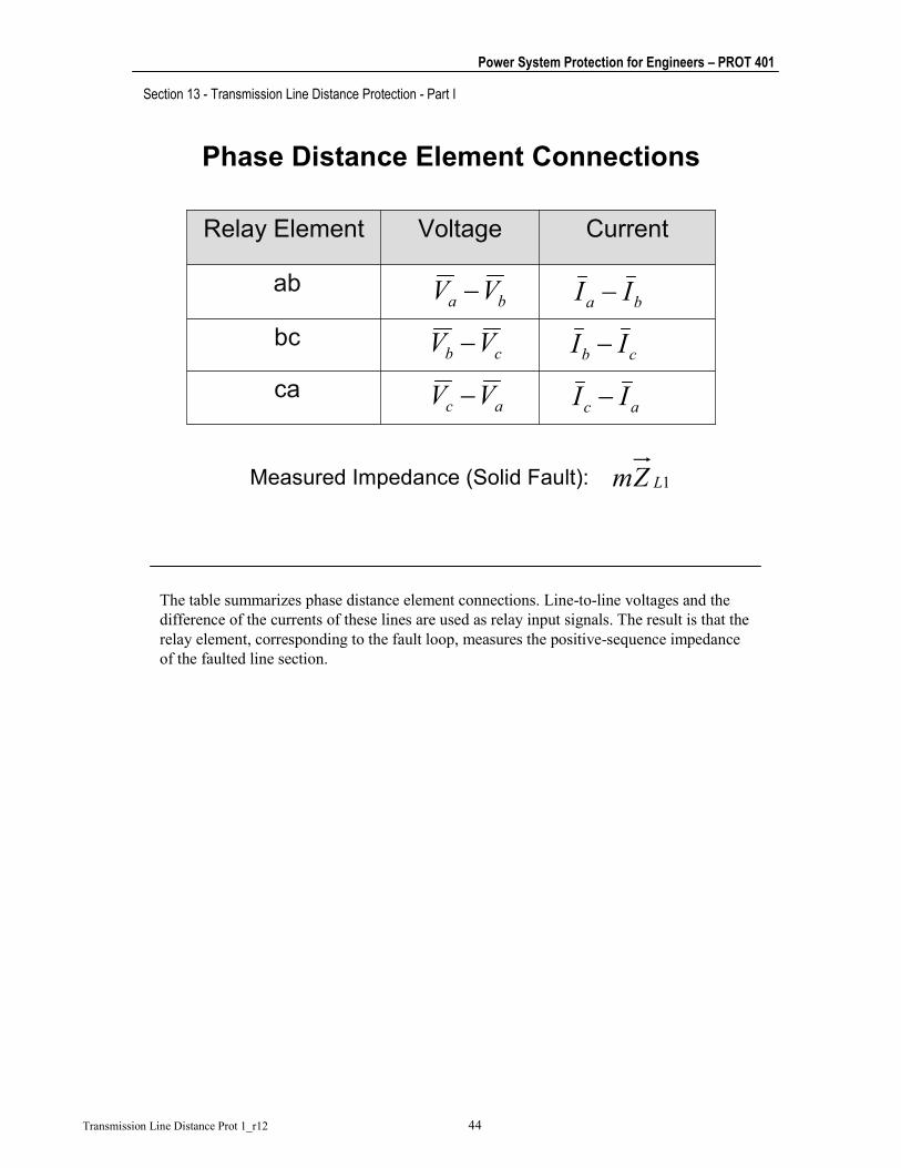
Phase Distance Element Connections
ca
bc
ab
CurrentVoltageRelay Element
ba VV − ba II −
Measured Impedance (Solid Fault): 1LZm
cb VV − cb II −
ac VV − ac II −
The table summarizes phase distance element connections. Line-to-line voltages and the difference of the currents of these lines are used as relay input signals. The result is that the relay element, corresponding to the fault loop, measures the positive-sequence impedance of the faulted line section.
Section 13 - Transmission Line Distance Protection - Part I
Power System Protection for Engineers – PROT 401
Transmission Line Distance Prot 1_r12 45
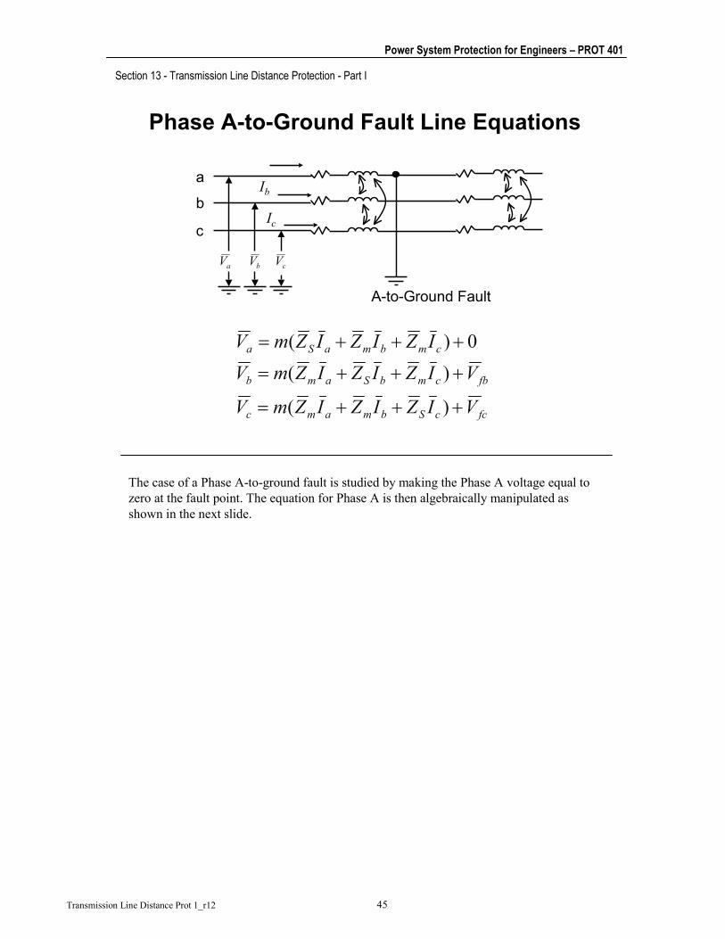
Phase A-to-Ground Fault Line Equations
Ib
Ic
a
b
c
aV bV cV
A-to-Ground Fault
fccSbmamc
fbcmbSamb
cmbmaSa
VIZIZIZmV
VIZIZIZmVIZIZIZmV
+++=
+++=
+++=
)(
)(0)(
The case of a Phase A-to-ground fault is studied by making the Phase A voltage equal to zero at the fault point. The equation for Phase A is then algebraically manipulated as shown in the next slide.

Section 13 - Transmission Line Distance Protection - Part I
Power System Protection for Engineers – PROT 401
Transmission Line Distance Prot 1_r12 46
[ ] )3/()(where;
3)(
3
))()(()(
110001
1
101
101
LLLresaL
resL
LLaLres
LLaL
cbamamS
cmbmamamaSa
ZZZkIkIZm
IZ
ZZIZmIZZIZm
IIIZIZZmIZIZIZIZIZmV
−=+=
=⎥⎦
⎤⎢⎣
⎡ −+=⎥
⎦
⎤⎢⎣
⎡ −+=
=+++−=
=+++−=
10
Lresa
a ZmIkI
V=
+
Phase A-to-Ground FaultRelay Connection
The result of the manipulation is that, for the relay to properly measure the positive sequence impedance between the relay location and the fault, the relay must receive:
• The phase “a” voltage
• The phase “a” current plus a residual current compensation factor.
The compensation factor, ko, is called the residual compensation factor, or the zero sequence compensation factor because the residual current is three times the zero-sequence current.
A similar result is obtained for b-to-ground and c-to-ground faults.

Section 13 - Transmission Line Distance Protection - Part I
Power System Protection for Engineers – PROT 401
Transmission Line Distance Prot 1_r12 47
Ground Distance Relay Connections
CG
BG
AG
CurrentVoltageRelay Element
aV
bV
cV
Measured Impedance (Bolted Fault): 1LZm
resb IkI 0
r+
resc IkI 0
r+
1
100
3 L
LL
ZZZk −
=
resa IkI 0
r+
Compensation factor
The table summarizes ground distance element connections. Phase voltages and compensated line currents are used as relay input signals. The current signal is compensated by adding a factor derived from the zero-sequence current. The multiplying factor k0 is, in general, a complex number that depends on the line zero-sequence and positive-sequence impedances.
There are two basic sources of error in this connection. One of these is line asymmetry. By using a symmetrical component scope, it is assumed that the line is ideally transposed. Untransposed lines, however, are becoming common. Line asymmetry could produce errors on the order of 5 percent in distance estimation. This error must be accomodated by pulling back the relay first zone reach.
Another source of error is the typical assumption that angles ZL1 and ZL0 are equal. Under this assumption, k0 is a real number. In analog relays, it is much easier to create a real number than a complex multiplying factor.
There are other connections for ground distance elements. One of these uses the phase voltage and a compensated line current as input signals. The connection uses the currents of the other two lines (instead of the zero-sequence current) for compensation. Asymmetrical lines are not a source of error for this connection. A drawback is complexity: you must set two multiplying factors (instead of only k0).

Section 13 - Transmission Line Distance Protection - Part I
Power System Protection for Engineers – PROT 401
Transmission Line Distance Prot 1_r12 48
Self-Polarizing Scheme Connections
GROUND
RELAYS
PHASERELAYS
Ic + k0 IresVcC
Ib + k0 IresVbB
Ia + k0 IresVaA
Ic-IbVc-VaC-A
Ib-IcVb-VcB-C
Ia-IbVa-VbA-B
IVRELAYS
The table summarizes the results obtained in the former development.
There are other ways of connecting (polarizing) the distance relays. This particular way is called the self-polarizing scheme.
In the past, six relays (or measuring units) were required for each distance relay zone to implement a non-switching scheme like this. Today, this protection can be implemented in a single microprocessor-based relay.

Section 13 - Transmission Line Distance Protection - Part I
Power System Protection for Engineers – PROT 401
Transmission Line Distance Prot 1_r12 49
Distance ProtectionSummary
Current and Voltage Information
Phase Elements: More Sensitive Than 67 Elements
Ground Elements: Less Sensitive Than 67N Elements
Application: Looped and Parallel Lines
In summary, distance protection uses current and voltage information to make a direct, or indirect, estimate of the distance to the fault. Phase distance elements (21) are more sensitive than phase directional overcurrent elements (67). On the other hand, ground distance elements (21N) are less sensitive than ground directional overcurrent elements (67N). A widely used combination for transmission line protection uses 21 elements for phase fault protection and 67N elements for ground fault protection.
Section 13 - Transmission Line Distance Protection - Part I
Power System Protection for Engineers – PROT 401
Transmission Line Distance Prot 1_r12 50
Distance Protection Problems
Infeed
Fault Resistance
Unequal Measured Impedances During Faults
Evolving Faults
Load Encroachment
Transmission line protection is complex. Problems such as infeed, fault resistance, unequal measured impedances during faults, load encroachment, and mutual coupling affect the apparent impedance of distance relays. Fault resistance and mutual coupling also affect ground directional overcurrent relays. These problems may be complicated by the evolving character of many faults.

Section 13 - Transmission Line Distance Protection - Part I
Power System Protection for Engineers – PROT 401
Transmission Line Distance Prot 1_r12 51
Distance Protection Problems
Mutual Coupling
Simultaneous Faults
Cross-Country Faults
Power Swings
Series-Compensated Lines
All these problems may affect distance and directional overcurrent relays. Cross-country faults, simultaneous faults, and CT saturation may also present a problem for differential schemes.
Series-compensated lines are extremely difficult to protect. All protection principles may have problems, because of the possibility of voltage and current inversions. If the series compensation capacitors are carefully selected, the possibility of current inversions can be eliminated. In this case, a differential protection scheme may be the best option.

Section 13 - Transmission Line Distance Protection - Part I
Power System Protection for Engineers – PROT 401
Transmission Line Distance Prot 1_r12 52
Distance Protection Problems
Three-Terminal Lines
Short Lines
CT Saturation
CCVT Transients
Three-terminal lines and short lines also have special protection requirements. The ringdown at subharmonic frequency resulting from compensation reactors may also create protection problems.

Section 13 - Transmission Line Distance Protection - Part I
Power System Protection for Engineers – PROT 401
Transmission Line Distance Prot 1_r12 53
Infeed Effect
'L
'L ZIZIV +=
'LL
'L
'
L ZZZIIZIVZ +>+==
Infeed Produces Relay Underreach
21
V I
Fault
'LZLZ
'I
A generation source connected between the relay location and the fault point affects the value of the impedance a distance relay estimates. This is called the infeed effect. The intermediate generation source causes the relay to see an impedance that is equal to the adjacent line multiplied by a factor. This factor is the ratio of the current in the adjacent line to the relay current. The infeed-effect factor is, in general, a complex number with a magnitude greater than unity. The infeed effect results in the relay estimating an impedance value greater than the real impedance between the relay and the fault, ZL + Z’L. This inaccurate impedance value estimation produces distance relay underreach.

Section 13 - Transmission Line Distance Protection - Part I
Power System Protection for Engineers – PROT 401
Transmission Line Distance Prot 1_r12 54
Example: Third Zone Setting
BCAB ZZZ +=
BCAB
BCAB Z
I
IZZ +=
Without Infeed:
With Infeed:
Set Third Zone Considering Infeed
21Fault
A B CZAB
IAB IBC
ZBC
The infeed effect needs to be taken into account when distance relay settings are calculated. For example, the third zone at A (see figure) will measure ZAB + ZBC for a fault at C without infeed. When the intermediate source is present, the impedance estimate is greater because of the IBC/IAB factor. The third zone needs to completely cover the adjacent line BC for all system operating conditions. Thus, the third zone reach needs to be set considering the possible infeed. As a result, the third zone may reach far beyond substation C when the intermediate source is out of service. This factor needs to be considered when checking adjacent third zones for possible overlap.
Infeed effect does not affect first zones, except in three-terminal lines. In this case, the first zone needs to be set without infeed to make sure that the zone will not overreach the remote line end. Setting a first zone in this manner results in the presence of the intermediate source reducing the first zone reach, thus limiting the high-speed coverage of the protected line.
The infeed effect also needs to be considered for second zone reach settings. In three-terminal lines, the second zone should be set with maximum infeed at the third terminal to ensure full coverage of the protected line. On the other hand, in two-terminal lines, the second zone should be set for minimum infeed at the remote-end substation to avoid overlapping with the beginning of the adjacent second zone.

Section 13 - Transmission Line Distance Protection - Part I
Power System Protection for Engineers – PROT 401
Transmission Line Distance Prot 1_r12 55
Outfeed
'LL
'LL ZZZ
I'IZZ +<+=
Outfeed Produces Relay Overreach
21
21
ZL
I'LZ
'I
ZL 'LZ
'I
Outfeed is the result of having two paths of current flow after the relay has monitored the current. An outfeed condition may exist when two or more adjacent lines are connected in parallel. In three-terminal lines, outfeed may exist if there is a strong external tie between two line terminals. The magnitude of the outfeed effect factor, I’ / I, is smaller than unity, which produces a reduced impedance estimate. The result is relay overreach. The outfeed effect also needs consideration when calculating settings for a distance relay.

Section 13 - Transmission Line Distance Protection - Part I
Power System Protection for Engineers – PROT 401
Transmission Line Distance Prot 1_r12 56
Any Questions?
Line Distance Protection is Continued in the Next Section