monitoring fault coordination in transmission line system
TRANSCRIPT
Journal of Engineering Technology Vol. 9(1): 14-21, 2021 ISSN 2231-8798© 2013 UniKLBMI
14
Monitoring Fault Coordination in Transmission Line System via MATLAB
Nor Hasimah Binti Zulkifli1, Mohd Badrulhisham Ismail2 1,2Electrical Engineering Section,
University Kuala Lumpur British Malaysian Institute, Malaysia.
Corresponding email: [email protected],
_______________________________________________________________________________________ Abstract: Current faults finding method used taking a long time to locate the fault location since the implementation of distance relay as a protection system in transmission line only gives the range of the fault area but not the exact location. Locating exact fault in a transmission line is crucial in determining the efficiency of the power system network since fast restoration and clearing fault is the priority in maintaining the flow of power supply. Thus, to locate the exact location, distance relay schemes are implemented in the network system. In this paper, enhancement of distance relay scheme determining the precise location of fault area in the transmission line by using the algorithm of the distance relay. Apparent impedance is the determinant value in this study. The variables that consist of 33 fault location ranges from 1km to 300 km, and ten types of faults are executed. Detected fault location distance is collected for the data analysis to determine the implemented distance relay's accuracy at the fault location. The simulation proved that the distance relay schemes could locate a more accurate location for detecting single line faults and double faults. The three-line faults showed accuracy for the long-distance transmission line ranging from 100 km-200 km. In the future, the distance location can be integrated into the system for controlling purposes, not only for monitoring purposes.
Keywords: Distance relay, fault location, transmission line, apparent impedance
1.0 INTRODUCTION
Discontinuity or interruption of electricity could lead to discomfort condition. Several factors lead to intermittent electricity from natural phenomena, either direct to the line or indirect strikes. When these conditions occurred, there is a high value of current flow in the power system circuit that can cause equipment failure or damage. In this case, this occurrence is known as a fault. Faults in the power system will cause some effect since the power grid system has complex equipment to enable electricity to be generated and sent to the customer. To avoid damages to these equipment's, protective system such as surge protective devices, circuit breaker and relay is introduced as a solution for this problem. Protection systems operate by a trip the relay of the involved area or region where the fault occurred and isolate them from another region. Isolated areas will have interruptions in electric supply or power outages before they are supplied from backup supplies [1]. In any protection system, protective relays are the primary devices that will trigger and operate when the system has some problem. It will provide instruction through a trip signal to the involved circuit breaker to trip
or not [2]. Most of the systems used distance relay as a protective relay as it operates in high-speed operation to trip the lines of faults that occurred. A faster process is required to isolate the fault area faster and enable other areas to be protected. Distance relay usually has three zones, including zone 1, zone 2, and zone 3. Each zone has a specific range that shows the region where the fault occurs. By referring to the zone triggered by the distance relay, the range coordination of the faults detected and cleared by TNB crew thorough inspection methods, including foot patrols or patrols with equipped transportation and suitable equipment such as binocular [3]. The faults can be cleared as soon as the location of the faults is found. The longer the time taken to locate the coordinate of the location, the longer the restoration process can be finished. Here, Estimation with good accuracy to detect the location is essential. Due to the significant impact of fault detection in power systems, much research has been done related to fault detection accuracy. For this project, the implementation of a distance relay to detect accurate area of fault detection is proposed. The performance enables the system to monitor the location of the fault. Thus, the fault location no longer

Journal of Engineering Technology Vol. 9(1): 14-21, 2021 ISSN 2231-8798© 2013 UniKLBMI
15
needed to be inspected to find the exact location.
2.0 RELATED WORKS
Various studies on system protection of transmission lines use a distance relay scheme as the primary or backup system protection. The studies mainly focused on the mal-operation of the relay when a fault occurs and the accuracy of the fault area detection. Project distance relay scheme focussed on zone 2 relay [4]. The circuit breaker of zone 2 will not trip instantaneously after a fault occurs unless the system has reliable communication that is not available in some lines or is damaged. This study proposed an algorithm to increase the speed of fault detection of a relay at zone 2. The proposed algorithm can detect all types of fault, either with low or high resistances cases. The result of the proposed idea was affected mainly through remote circuit breaker operation (RCBO). This project enables zone 2 of distance relay to trip faster than the standard time, and more of the range area can be protected [4].
The second project on [5] used a digital distance
relay to display all the input and output of the power system. All the fault behavior is observed in the online variation of input signals shown by the distance relay. The data collected from the graph obtained from the simulation are manually calculated and analyzed to indicate the fault area's location. A research study was designing the distance relay and performances of impedance type distance relay [6]. The fault is simulated on the modeled lines/cables of the simulation to trip the circuit breaker only. The circuit breaker that trips well determines the zone area of the faults.
The previous project on [1] studies detail on
performances of distance relay. Correct performances of distance relay can be determined when the system only operates when there is fault on the line with a fast response to detect and prevent worse damage. In other meaning, the system will not trip unnecessarily. In this scheme, the Mho distance relay type is used for simulation purposes. The voltages and currents parameters of the simulated power system grid obtained from VT and CT, respectively, are processed using FFT block, Fault measurement, and Discrete Fourier Transform to calculate pre-fault and post-fault conditions. As a result, the project's algorithm successfully trips the correct circuit breaker of a correct zone when the fault is injected accordingly.
In research paper [7] stated that the accuracy of parameters on a transmission line is essential for fault location estimation. The errors of the parameters and their effect on the distance Relay protection have been discussed. Measurement for the Estimation of fault location used the formula below.
m = (1)[3]
Va = Phase voltage (fault) Vpol = Polarizing quantity Ia = Phase current (fault) IG = Residual current ZIL = Positive sequence line impedance k0 = Zero sequence compensation factor =
Z0L = Zero sequence line impedance The estimation error that has been conducted shows that the relay distance relay could be in overreach and underreach conditions. The estimation result is 73% of the line and 86% of the line. This error can affect the zone detection and could lead to maloperation of distance relay.
As the transmission line transfers the bulk of electricity over long distances, a project of [8] has proposed implementing Wide Area Measurement Systems (WAMS) in the network suitable with transmission line complexity and long-distance length. The proposed project can monitor and control the wide range of transmission lines. Phasor voltage is used as the determinant in determining the faulted area. The data was collected from PMUs and PDC in real-time. The voltage magnitude of minimum and maximum of positive, negative, and zero sequences proposed to be compared with a threshold value to identify the presence of the fault. Then, the fault type, either balanced or unbalanced, was checked to improve the pickup criterion of the circuit breaker either to trip or not.
Meanwhile for the project on [9] focuses on power swing fault on the transmission line. The introduced algorithm is capable of detecting and identifying accurate fault locations—the technique used a high pass filter to extract the signals from the fault occurrence. The fault location can be detected when the transmission line is injected with the current. Traveling of the wave speed and the arrival times of the first signal to arrive at the end of the fault are the parameter required. The average accuracy of the technique is 99.940086%. Therefore, it is considered an accurate Estimation of fault location. However, this technique will use a lot of equipment to inject the current into the cable.
3.0 METHODOLOGY
This study used the quantitative method as the research design. Data is collected through the MATLAB simulation of the designated algorithm of distance relay systems, and results are presented in numbers and percentages. This research study starts with the study on distance relay schemes. Proposed distance relay schemes performed as protection schemes in transmission lines and will start and execute the simulation when faults are applied on transmission lines.

Journal of Engineering Technology Vol. 9(1): 14-21, 2021 ISSN 2231-8798© 2013 UniKLBMI
16
The faults were applied in 33 different locations during the simulation on a 300 km transmission line consisting of a single line fault, double line fault, and three-line fault. The fault is including AG, BG, CG, ABG, BCG, ACG, AB, BC, AC, and ABCG. The actual distance where a fault is applied ranges from 1Km to 300 Km. The detected fault distance location is displayed in meter gauge in the Matlab software that helps in visualizing the distance of fault in a transmission line. User or customer, in this case, someone that responsible for maintaining the stability of power networks, including TNB crews, can locate the location by monitor the data displayed on the output of the fault distance detection subsystem in MATLAB. The visualization in the form of a meter is also provided to shows the fault location.
Collected data obtained based on the Estimation of the apparent impedance of transmission line is calculated by the subsystem of the designated distance relay schemes. The accuracy of obtained apparent impedance determines the accuracy of the fault distance estimation.
3.1 Designation of power system network model The power system network of the transmission line has been designed and constructed in MATLAB/SIMULINK for simulation purposes. Figure 1 shows the power system model, and Table 1 shows the parameters for the power system network model.
Figure 1 Power system network model with a new distance relay
system
The power source of the transmission line that will be used in this project is 500kV because the range of the transmission line is between 132kV to 500kV, suitable with the TNB requirement.
All the power system network parameters, including the cable or transmission line length, are considered since these parameters are crucial in determining the fault's location. Initial parameters and properties of the power system network such as waveform and values of voltages, currents, impedances, and time have taken are collected and analyzed to determine the setting on the distance relay 3.2 Designation And Construction of Distance Relay Block Model
Distance relay schemes chosen are mho relay that used Apparent impedance as their determinant quantity in detecting and locating the fault. The apparent impedance is the parameter that has been used to determine and detect the detected fault location. The complexity to obtain apparent impedance leads to the development of few subsystems to get accurate data. Each subsystem is modeled separately and then are connected in one block system. Five subsystems for the distance relay scheme are designed, including Fault classification subsystem, Apparent impedance subsystem, Zone detection subsystem, tripping signal subsystem, and Estimation of fault distance subsystem 3.2.1 Fault Classification subsystem
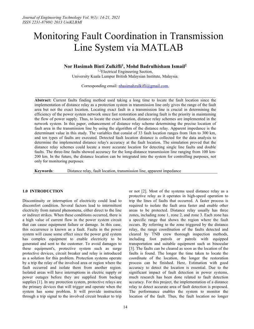
In this study, the faults classification subsystem must use apparent impedance as the determinant quantity in obtaining data. Each type of fault has a different formula in calculating the apparent impedance, as in Table 1 . Likewise, each different type of fault required different formula in determining impedance. The ability to detect correct types of faults detection will trigger the proper subsystem for apparent impedance calculation. The presence of fault is determined by the current magnitude measured in each phase and compared to the pre-fault current. With the chances detected, the subsystem produced a binary number of one (1) and gave the signal to the classification block subsystem as in Figure 2.
Journal of Engineering Technology Vol. 9(1): 14-21, 2021 ISSN 2231-8798© 2013 UniKLBMI
17
Figure 2 Current comparator
Karnaugh method has been chosen to determine the types of faults where this method used the binary output of 0 and 1, where this output was obtained from the first subsystem of the comparator.
Table 1: Determination type of fault based on karnaugh map method
Ia
Ib
Ic
IG
AG
BG
CG
ABG
AB
BCG
BC
ACG
AC
ABCG
ABC
0 0 1 1 0 0 1 0 0 0 0 0 0 0 0
0 1 0 1 0 1 0 0 0 0 0 0 0 0 0 0 1 1 1 0 0 0 0 0 1 0 0 0 0 0 0 1 1 0 0 0 0 0 0 0 1 0 0 0 0 1 0 0 1 1 0 0 0 0 0 0 0 0 0 0 1 0 1 1 0 0 0 0 0 0 0 1 0 0 0 1 0 1 0 0 0 0 0 0 0 0 0 1 0 0 1 1 0 1 0 0 0 1 0 0 0 0 0 0 0 1 1 0 0 0 0 0 0 1 0 0 0 0 0 0 1 1 1 1 0 0 0 0 0 0 0 0 0 1 0 1 1 1 0 0 0 0 0 0 0 0 0 0 0 1
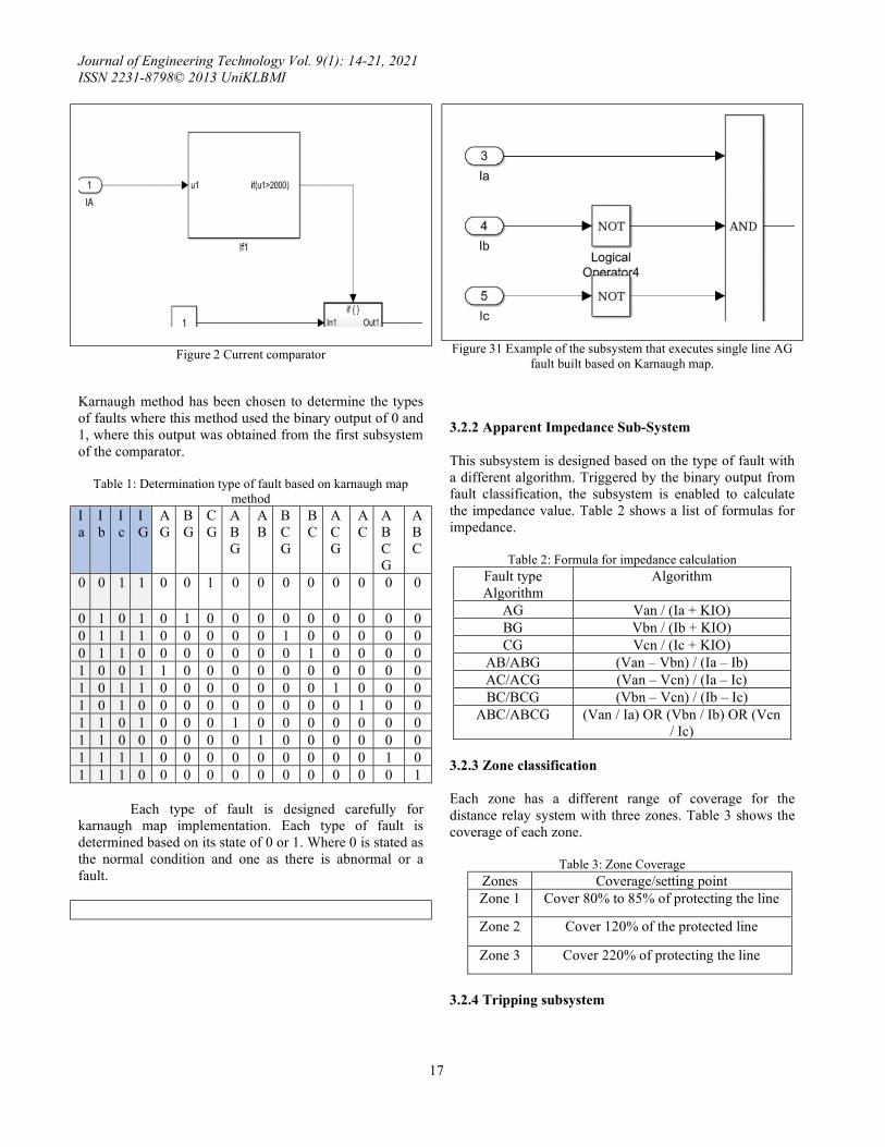
Each type of fault is designed carefully for karnaugh map implementation. Each type of fault is determined based on its state of 0 or 1. Where 0 is stated as the normal condition and one as there is abnormal or a fault.
Figure 31 Example of the subsystem that executes single line AG
fault built based on Karnaugh map.
3.2.2 Apparent Impedance Sub-System This subsystem is designed based on the type of fault with a different algorithm. Triggered by the binary output from fault classification, the subsystem is enabled to calculate the impedance value. Table 2 shows a list of formulas for impedance.
Table 2: Formula for impedance calculation Fault type Algorithm
Algorithm
AG Van / (Ia + KIO) BG Vbn / (Ib + KIO) CG Vcn / (Ic + KIO)
AB/ABG (Van – Vbn) / (Ia – Ib) AC/ACG (Van – Vcn) / (Ia – Ic) BC/BCG (Vbn – Vcn) / (Ib – Ic)
ABC/ABCG (Van / Ia) OR (Vbn / Ib) OR (Vcn / Ic)
3.2.3 Zone classification Each zone has a different range of coverage for the distance relay system with three zones. Table 3 shows the coverage of each zone.
Table 3: Zone Coverage
Zones Coverage/setting point Zone 1 Cover 80% to 85% of protecting the line
Zone 2 Cover 120% of the protected line
Zone 3 Cover 220% of protecting the line
3.2.4 Tripping subsystem

Journal of Engineering Technology Vol. 9(1): 14-21, 2021 ISSN 2231-8798© 2013 UniKLBMI
18
This subsystem aims to signal the circuit breaker to trip and isolate the affected transmission line. The tripping signal is triggered by the output of the zone classification subsystem, and the output is the tripping signal for the circuit breaker. 3.2.5 Estimation of Fault distance This subsystem calculated the impedance measured by the apparent impedance subsystem and displayed the detected fault location of the actual fault. The internal resistance of the transmission line per km is applied to detect the fault distance. This value is obtained from the transmission line parameter. 4.0 DISCUSSION This section consists of the analysis of fault distance in transmission line using comparison of actual fault location and detected fault location included with error calculation. This comparison will show the accuracy of the distance relay schemes proposed in locating accurate fault locations. The list of 33 actual fault locations compared with detected fault location data is executed in the MATLAB simulation. Table 4 shows the error percentage in determining the accuracy of distance relay to detect fault location. The performance of proposed distance relay schemes indicates nearly accurate data detection for double fault type with the lowest percentage error of 0.797% at fault applied at 300 km with a detected distance of 297.61km. The accuracy error of the double fault line at 1km is at 6% error and gradually decreases with the increase in distance of actual fault occur in the transmission line from 6% to 0.797%.
For single faults detection, the distance relay scheme proposed successfully maintaining the error of faults distance ranging from the lowest error of 7% to 8.19% at a distance 1km and 140km, respectively.
Meanwhile, the error percentage for three-phase fault is at the highest, 1271% of error at 1Km faults with detected fault distance at 13.71km. Even though the error value is unexpectedly high, the fault distance location detected can still provide a smaller range area of the fault location than the essential function of the distance relay that only shows a zone section with a broader range area. Thus, this proposed scheme should be considered. The percentage of error for the three-phase fault application drastically decreases when the fault is applied farther in the transmission line, which are from 1271%,248%to 25.80% error at 1km(F1), 5km(F2), and 40km(F7) of actual faults respectively. The values are gradually decreasing to 220km with an error of 2.41%. At 300km, the error percentage slightly increased to 3.293% error where the actual fault occurs at 300km and the detected fault shows 309.88 km.
Therefore, based on the error percentage calculated, it can be concluded that the proposed distance relay scheme can detect accurate fault location.
Table 4: Overall Error Percentage of fault distance detection
Fault location
Double line fault
(%)
Single line fault
(%)
Three line fault
(%)
F1 1 km 6.00 7.00 1271
F2 5 km 5.80 7.60 248
F3 8 km 5.88 7.63 152.625
F4 10 km 5.90 7.60 120.9
F5 15 km 5.87 7.67 78.60
F6 20 km 5.85 7.75 57.45
F7 30 km 5.83 7.80 36.33
F8 40 km 5.80 7.85 25.80
F9 50 km 5.74 7.92 19.50
F10 60 km 5.68 7.97 15.33
F11 70 km 5.61 8.01 12.37
F12 80 km 5.54 8.05 10.19
F13 90 km 5.44 8.09 8.522
F14 100 km 5.35 8.12 7.21
F15 110 km 5.24 8.15 6.173
F16 120 km 5.11 8.17 5.333
F17 130 km 4.97 8.18 46.615
F18 140 km 4.83 8.19 4.11
F19 150 km 4.67 8.19 3.66
F20 160 km 4.51 8.18 3.30
F21 170 km 4.32 8.18 3.02
F22 180 km 4.12 8.16 2.79
F23 190 km 3.92 8.14 2.63
F24 200 km 3.70 8.11 2.515
F25 210 km 3.47 8.07 2.443
F26 220 km 3.23 8.03 2.41
F27 225 km 3.10 8.00 2.409
F28 240 km 2.70 7.92 2.45
F29 255 km 2.27 7.82 2.57
F30 270 km 1.82 7.71 2.75
F31 280 km 1.49 7.62 2.907
F32 290 km 1.15 7.52 3.897
F33 300 km 0.797 7.42 3.293
F1 indicates fault applied at 1 km from the source of the power system network. F2 at 5 km, F3 at 8 km, and
Journal of Engineering Technology Vol. 9(1): 14-21, 2021 ISSN 2231-8798© 2013 UniKLBMI
19
respectively until F33 as listed in the table above.
Data obtained showed that fault under the same types of fault of different categories measured the same data. There are three types of faults: a single line fault, a double line fault, and a three-phase fault. Each type of fault is categorized into a few types based on where the fault occurred. For example, all three categories of AG, BG, and CG of single line fault measured 0.93 km and 4.62km at 1 km fault and at 5km, respectively. And for all six categories of AB, BC, AC, ABG, ACG, BCG of double line fault type measured 0.94 km, at 1 km and 4.71km at 5 km fault. And both categories of ABC and ABCG of three-phase fault both at 13.71 km at 1km fault location and 17.40 at 5 km fault.
The project proposed showed the greatest performance for single line and double line fault detection at short distances. Meanwhile showed good performance for three-phase fault detection at long distance. For example, at first ten (10) km distance, for single-line faults detection, the error is less than 1km, at 1 km, 5km,8km, and 10km detect at 0.93,4.62,7.39 9.24 with 0.07km, 0.38km,0.61km, and 0.76 differences respectively. Although the error percentage calculated for single line faults was maintained at 7% to 8.19%, the differences between actual and detected fault distance locations gradually increased until faults were applied at F33. Whereat 10km ,20km, 30km,40km,50 km, 280km,290km and 300km of faults applied, the differences of distance detected from actual value are 0.76km, 1.55km, 2.34km, 3.14km, 3.96km, 21.33km,21.82km, and 22.25km respectively. Minimum differences value of distance detected is at 1km actual fault location with differences of 0.07 km from the detected value that detect fault at 0.93km. The maximum differences value is at 300km actual location with detected value at 227.75 km where the differences are 22.25 km. Meanwhile, for at first 10 km of three-phase fault detection, the error average of 12 km where at 1km, 5km,8km, and 10km the data detected at 13.71,17.40,20.21 and 22.09 km respectively with differences are 12.71km,12.40km,12.21km, and 12.06 km. It shows that this proposed scheme can estimate the accurate location of fault distance at a short distance for single line faults and double line faults and not for three-phase faults detection. Compared to values for detection fault distance for single line faults, three-phase fault detection shows decreasing and steady in Differences values. The distance detected minimum differences value is at 190km actual fault location with differences of 5 km from the detected value that detect fault at 195 km. The maximum differences value is at 1km actual location with detected value at 13.71km with differences of 12.71 km. In table 10 shows
the value of the difference between actual and detected distance values.
For double line faults detection at first ten (10) km distance shows the slight difference compared to single-line faults detection with slightly more accurate with the error are also less than 0.6km where at 1 km, 5km,8km, and 10km detect at 0.94,4.71,7.53 and 9.41 with 0.06km, 0.29km,0.47 km, and 0.59 differences respectively. As for double line fault detection, minimum differences values are at 1km of the actual location where the detected fault distance at 0.94km, with the lowest differences between all applied faults detection with differences at 0.06km. Meanwhile, the maximum difference value is 7.29 km at the actual location at F25(210KM), with the detected fault occur at 202.71km. In Figure 4, differences between the actual distance location of faults applied and detected distance location are calculated manually based on the data obtained from the simulation of the distance scheme proposed. The differences value ranges from 0.06 km to 22.25 km; this is proven to detect accurate fault location. Based on Figure 5, the proposed schemed showed the greatest performance for double line faults compared to single lines faults and three-phase fault detection. Meanwhile, in Figure 17, the detected fault distance location for all fault types is compared with the actual location where the faults were applied. The red line shows the actual line of faults applied. All three lines of faults detection are closely lined up to the value of the actual location. Three-phase fault detection is less accurate for a short distance than the green line; meanwhile, for single line fault less accurate at long-distance fault detection. Hence, based on the results above, the distance relay scheme proposed can detect precise fault location.
5.0 CONCLUSION In this paper, the research is conducted by using a designated distance relay with a new algorithm that calculates the accurate distance of fault location in the transmission line. This study analyzed the accuracy of data detection measured in km had been done with the implementation of three types of faults that lead to 11 types of faults as variables. The error percentage for each data obtained is manually calculated to analyze the accuracy of the proposed system. By using the value of apparent impedance from the data relay, the distance of fault location is automatically calculated by a new algorithm that used the internal resistance of the transmission line as a determinant in estimating the location of a fault in the transmission line. The correct formula for the apparent impedance calculation must be executed correctly for each type of fault. Different types of faults required different formulas to calculate the apparent impedance. Wrong

Journal of Engineering Technology Vol. 9(1): 14-21, 2021 ISSN 2231-8798© 2013 UniKLBMI
20
execution of formula used to calculate apparent impedance affects the distance relay's accuracy to calculate accurate fault location. The fault location is then displayed in km that can be monitor by users. The karnaugh map method is chosen as a simple method to determine the correct formula used to measure the apparent impedance. In conclusion, the distance scheme can detect the nearly accurate location of the fault, especially for detection location for all types of faults applied. Thus, this scheme can be used to improve the fault locating method in the transmission line. Furthermore, this estimated and calculated data help to reduce the scope area of fault location. For future study, the distance location can be integrated into the system for controlling purposes, not only for monitoring purposes.
Figure 4 Comparison Between Differences Of Fault Distance Detected And Actual Fault Distance Of Three Types Of Faults
Applied
FIGURE 5 DETECTION FAULT LOCATION
REFERENCES
[1] A.M. Purohit, V.N. Gohokar.(2016) Analysis of distance relay performance in the protection of high voltage transmission line. International conference on computing, communication and energy systems (access-16)., P. ID-EE01, 1-6
[2] Husam Samkari and Mohammed Allehyani, Brian K. Johnson (2016) Modeling and Simulation the Impacts of STATCOMs on Distance Protection. North American Power Symposium (NAPS),1-6
[3] Sophi Shilpa Gururajapathy, Hazlie Mokhlis, Hazlee Azil Bin Illias, Ab Halim Abu Bakar, and Lilik Jamilatul Awalin. (2017). Fault Location in an Unbalanced Distribution System using Support Vector Classification and Regression Analysis. Eej Transactions On Electrical And Electronic Engineering. 237-245
[4] Sadegh Vejdan , Majid Sanaye-Pasand, Tarlochan S. Sidhu. (2017). Accelerated Zone II Operation of Distance Relay Using Impedance Change Directions. IEEE transactions on power delivery. 6(32). 1-10
[5] Nilesh S. Wadhe, Rupesh A. Juware, Dr. N. N. Khalsa.(2016). Determining fault location on Transmission Line using Distance Relay. International Journal of Innovative and Emerging Research in Engineering (ICSTSD). 1(3). 1-6
Journal of Engineering Technology Vol. 9(1): 14-21, 2021 ISSN 2231-8798© 2013 UniKLBMI
21
[6] M.Rambabu, M.Venkatesh, J.S.V.SivaKumar, T.S.L.V.AyyaRao.(2015). Three Zone Protection By Using Distance Relays in SIMULINK/MATLAB International Research Journal of Engineering and Technology (IRJET). 05(02). 1-10.
[7] Hugo E. Prado-Félix and Víctor H. Serna-Reyna .(2015.)Improve Transmission Fault Location and Distance Protection Using Accurate Line Parameters. Comisión Federal de Electricidad and Schweitzer Engineering Laboratories, Inc. 1-13.
[8] S. Roy and Dr. P.S. Babu. (2016). An Advanced Fault Locating Technique with WAMS based Backup Protection Scheme for Power System with Simultaneous Faults. Balkan Journal Of Electrical & Computer Engineering. 1(4). 1-13.
[9] Ahmed Magdy Abeid, Hossam A. Abd el-Ghany, Ahmed M. Azmy .(2017). An Advanced Traveling-Wave Fault-Location Algorithm for Simultaneous Faults. International Middle East Power Systems Conference (MEPCON).746-752.
[10] Zhiying Zhang, Anil Jacques, ilia Voloh. (2016). Challenges in Application of Distance Relays under Power Swing Conditions. Annual conference for protective relay Engineers (CPRE).1-13