ieee guide for inspection of overhead transmission line
TRANSCRIPT
IEEE Std 1441™-2004
IEE
E S
tan
dar
ds 1441TM
IEEE Guide for Inspection of OverheadTransmission Line Construction
3 Park Avenue, New York, NY 10016-5997, USA
IEEE Power Engineering Society
Sponsored by theTransmission and Distribution Committee
IEE
E S
tan
dar
ds
8 June 2005
Print: SH95304PDF: SS95304

The Institute of Electrical and Electronics Engineers, Inc.3 Park Avenue, New York, NY 10016-5997, USA
Copyright © 2005 by the Institute of Electrical and Electronics Engineers, Inc.All rights reserved. Published 8 June 2005. Printed in the United States of America.
IEEE is a registered trademark in the U.S. Patent & Trademark Office, owned by the Institute of Electrical and ElectronicsEngineers, Incorporated.
Print: ISBN 0-7381-4635-8 SH95304PDF: ISBN 0-7381-4636-6 SS95304
No part of this publication may be reproduced in any form, in an electronic retrieval system or otherwise, without the priorwritten permission of the publisher.
IEEE Std 1441™-2004
IEEE Guide for Inspection of Overhead Transmission Line Construction
Sponsor
Transmission and Distribution Committeeof theIEEE Power Engineering Society
Approved 8 December 2004
IEEE-SA Standards Board
Abstract: Various approaches to good inspection practices for the construction of overheadtransmission lines are covered in this guide. Inspection responsibilities and reporting, as well asinspection of various overhead transmission line components, are discussed. The guide is intendedto be used as a reference for those involved in the ownership, design, and construction of overheadtransmission lines.Keywords: construction, inspection, transmission lines
IEEE Standards documents are developed within the IEEE Societies and the Standards Coordinating Committees of theIEEE Standards Association (IEEE-SA) Standards Board. The IEEE develops its standards through a consensusdevelopment process, approved by the American National Standards Institute, which brings together volunteersrepresenting varied viewpoints and interests to achieve the final product. Volunteers are not necessarily members of theInstitute and serve without compensation. While the IEEE administers the process and establishes rules to promote fairnessin the consensus development process, the IEEE does not independently evaluate, test, or verify the accuracy of any of theinformation contained in its standards.
Use of an IEEE Standard is wholly voluntary. The IEEE disclaims liability for any personal injury, property or otherdamage, of any nature whatsoever, whether special, indirect, consequential, or compensatory, directly or indirectly resultingfrom the publication, use of, or reliance upon this, or any other IEEE Standard document.
The IEEE does not warrant or represent the accuracy or content of the material contained herein, and expressly disclaimsany express or implied warranty, including any implied warranty of merchantability or fitness for a specific purpose, or thatthe use of the material contained herein is free from patent infringement. IEEE Standards documents are supplied “AS IS.”
The existence of an IEEE Standard does not imply that there are no other ways to produce, test, measure, purchase, market,or provide other goods and services related to the scope of the IEEE Standard. Furthermore, the viewpoint expressed at thetime a standard is approved and issued is subject to change brought about through developments in the state of the art andcomments received from users of the standard. Every IEEE Standard is subjected to review at least every five years forrevision or reaffirmation. When a document is more than five years old and has not been reaffirmed, it is reasonable toconclude that its contents, although still of some value, do not wholly reflect the present state of the art. Users are cautionedto check to determine that they have the latest edition of any IEEE Standard.
In publishing and making this document available, the IEEE is not suggesting or rendering professional or other servicesfor, or on behalf of, any person or entity. Nor is the IEEE undertaking to perform any duty owed by any other person orentity to another. Any person utilizing this, and any other IEEE Standards document, should rely upon the advice of acompetent professional in determining the exercise of reasonable care in any given circumstances.
Interpretations: Occasionally questions may arise regarding the meaning of portions of standards as they relate to specificapplications. When the need for interpretations is brought to the attention of IEEE, the Institute will initiate action to prepareappropriate responses. Since IEEE Standards represent a consensus of concerned interests, it is important to ensure that anyinterpretation has also received the concurrence of a balance of interests. For this reason, IEEE and the members of itssocieties and Standards Coordinating Committees are not able to provide an instant response to interpretation requests exceptin those cases where the matter has previously received formal consideration. At lectures, symposia, seminars, or educationalcourses, an individual presenting information on IEEE standards shall make it clear that his or her views should be consideredthe personal views of that individual rather than the formal position, explanation, or interpretation of the IEEE.
Comments for revision of IEEE Standards are welcome from any interested party, regardless of membership affiliation withIEEE. Suggestions for changes in documents should be in the form of a proposed change of text, together with appropriatesupporting comments. Comments on standards and requests for interpretations should be addressed to:
Secretary, IEEE-SA Standards Board
445 Hoes Lane
Piscataway, NJ 08854
USA
Authorization to photocopy portions of any individual standard for internal or personal use is granted by the Institute ofElectrical and Electronics Engineers, Inc., provided that the appropriate fee is paid to Copyright Clearance Center. Toarrange for payment of licensing fee, please contact Copyright Clearance Center, Customer Service, 222 Rosewood Drive,Danvers, MA 01923 USA; +1 978 750 8400. Permission to photocopy portions of any individual standard for educationalclassroom use can also be obtained through the Copyright Clearance Center.
NOTE−Attention is called to the possibility that implementation of this standard may require use of subjectmatter covered by patent rights. By publication of this standard, no position is taken with respect to the exist-ence or validity of any patent rights in connection therewith. The IEEE shall not be responsible for identifyingpatents for which a license may be required by an IEEE standard or for conducting inquiries into the legal valid-ity or scope of those patents that are brought to its attention.
Introduction
This guide is one of several documents, covering all aspects of overhead transmission construction, that arebeing prepared by the Working Group on Construction of Overhead Lines of the Towers, Poles, andConductors Subcommittee of the Transmission and Distribution Committee of the IEEE Power EngineeringSociety. This guide presents, in one document, the considerations necessary for the inspection of overheadline construction. This guide is intended to be used as a reference source for parties involved in theownership, design, and construction of transmission lines.
Notice to users
Errata
Errata, if any, for this and all other standards can be accessed at the following URL: http://standards.ieee.org/reading/ieee/updates/errata/index.html. Users are encouraged to check this URL forerrata periodically.
Interpretations
Current interpretations can be accessed at the following URL: http://standards.ieee.org/reading/ieee/interp/index.html.
Patents
Attention is called to the possibility that implementation of this standard may require use of subject mattercovered by patent rights. By publication of this standard, no position is taken with respect to the existence orvalidity of any patent rights in connection therewith. The IEEE shall not be responsible for identifyingpatents or patent applications for which a license may be required to implement an IEEE standard or forconducting inquiries into the legal validity or scope of those patents that are brought to its attention.
This introduction is not part of IEEE Std 1441-2004, IEEE Guide for Inspection of Overhead TransmissionLine Construction.
Participants
This guide was developed by a task force of the Working Group on Construction of Overhead Lines. At thetime this guide was completed, the task force had the following membership:
William G. Eisinger, ChairGlenn A. Davidson
Frank Denbrock
At the time that this guide was approved, the Working Group had the following membership.
P. D. Quinn, Chair
The following members of the individual balloting committee voted on this standard. Balloters may havevoted for approval, disapproval, or abstention.
Dick AichingerTom AldertonW. L. CalhounBill CarterW. CaulkinsLen ConsalvoAnibal DelaoNicholas J. DeSantisRobert L. DonelsonDale DouglassJ. W. DuncanTom EvisonFrank FerracaneElias GhannoumPhillip A. Hall
Jerome G. HansonIbrahim HathoutMagdi F. IshacArjan S. JagtianiDonald T. JonesDon KoonceSammy KrishnasamyRobert C. LathamKeith E. LindseySandy MartinezGeorge B. NilesRon OdemannThomas J. F. OrdonRobert G. Oswald
Robert PetersCraig PonDoug ProctorTim RahillRon RandleJerry RedingJames W. ReillyNeil SchmidtDoug ShermanRobert SchultzPaul SpringerRidley ThrashL. L. WeitzelH. Brian WhiteW. B. Zollars
William ByrdAnthony BakerThomas BlairJames BoufordJoseph BuchThomas BuonincontriThomas CallsenGiuseppe CarboneJames ChristensenRobert ChristmanMike ClodfelderF. Leonard ConsalvoTommy CooperLuis CoronadoJose DacontiR. DaubertFrank DenbrockAndrew DettloffJ. Frederick Doering
Randall DotsonDonald DunnMarcia EblenWilliam EisingerAmir El-SheikhClifford ErvenCharles W GroseRandall GrovesEdward Horgan, Jr.Magdi IshacGeorge KaradyLeon Kempner, Jr.Gael R KennedyHenry KientzStephen R. LambertGregory LuriJohn MerandoG. Michel
Abdul MousaJohn OlenikRobert OswaldThomas PekarekRobert PetersFrancis PeverlyOrville PlumPercy PoolPatrick QuinnThomas RozekBob SaintSurya SantosoNeil SchmidtDevki SharmaJohn TeixeiraDaniel WardWilliam WessmanLewis WhisonantDonald W. Zipse
When the IEEE-SA Standards Board approved this standard on 8 December 2004, it had the followingmembership:
Don Wright, ChairSteve M. Mills, Vice ChairJudith Gorman, Secretary
*Member Emeritus
Also included are the following nonvoting IEEE-SA Standards Board liaisons:
Satish K. Aggarwal, NRC RepresentativeRichard DeBlasio, DOE Representative
Alan Cookson, NIST Representative
Jennie SteinhagenIEEE Standards Project Editor
Chuck AdamsStephen BergerMark D. BowmanJoseph A. BruderBob DavisRoberto de Marca BoissonJulian Forster*Arnold M. GreenspanMark S. Halpin
Raymond HapemanRichard J. HollemanRichard H. HulettLowell G. JohnsonJoseph L. Koepfinger*Hermann KochThomas J. McGean
Daleep C. MohlaPaul NikolichT. W. OlsenRonald C. PetersenGary S. RobinsonFrank StoneMalcolm V. ThadenDoug ToppingJoe D. Watson
Contents 1. Overview .................................................................................................................................................... 1
1.1 Scope ................................................................................................................................................... 1 1.2 Purpose ................................................................................................................................................ 1 1.3 Application .......................................................................................................................................... 1 1.4 Safety................................................................................................................................................... 1
2. Normative references.................................................................................................................................. 2
3. Inspection responsibilities .......................................................................................................................... 2
3.1 Inspector qualifications........................................................................................................................ 2 3.2 Inspector responsibilities ..................................................................................................................... 2
4. Inspection reports ....................................................................................................................................... 3
4.1 Daily field reports................................................................................................................................ 3 4.2 Weekly inspection reports ................................................................................................................... 4 4.3 Monthly progress reports..................................................................................................................... 5 4.4 Specific reports .................................................................................................................................... 5
5. Inspection ................................................................................................................................................... 5
5.1 Gates and road approaches .................................................................................................................. 5 5.2 Clearing right-of-way .......................................................................................................................... 6 5.3 Access.................................................................................................................................................. 6 5.4 Distribution and inspection of materials .............................................................................................. 7 5.5 Excavation ........................................................................................................................................... 7 5.6 Structure grounding ............................................................................................................................. 8 5.7 Setting rebar and forms for concrete foundations................................................................................ 8 5.8 Lattice steel structures—layout and assembly................................................................................... 10 5.9 Tubular steel structures—layout and assembly ................................................................................. 10 5.10 Wood pole framing and blocking .................................................................................................... 11 5.11 Steel (lattice and tubular structure) erection .................................................................................... 12 5.12 Wood structure erection................................................................................................................... 13 5.13 Stringing conductors and overhead shieldwires............................................................................... 13 5.14 Stringing blocks............................................................................................................................... 15 5.15 Joints, splices, repair sleeves, and deadends.................................................................................... 16 5.16 Sagging conductors.......................................................................................................................... 17 5.17 Offset calculations ........................................................................................................................... 18 5.18 Clipping ........................................................................................................................................... 19 5.19 Vibration dampers ........................................................................................................................... 20 5.20 Stringing adjacent to energized circuits........................................................................................... 20 5.21 Temporary grounds.......................................................................................................................... 21 5.22 Control of debris.............................................................................................................................. 21 5.23 Cleanup............................................................................................................................................ 21 5.24 Closeout........................................................................................................................................... 21
Annex A (informative) Sample forms .......................................................................................................... 22
vi Copyright © 2005 IEEE. All rights reserved.
IEEE Guide for Inspection of Overhead Transmission Line Construction
1.
1.1
1.2
1.3
1.4
Overview
This guide contains a consensus of the industry related good practice for inspecting the construction of transmission lines. It is not intended to be all-inclusive, and does not supersede the related typical practices of various utilities formulated for their specific locations and conditions.
Scope
This guide covers the inspection procedures and practices for right-of-way issues, foundations, structures, and wire installation for overhead lines.
Purpose
The objective of this guide is to provide a convenient tool to facilitate thorough and consistent administrative and quality control techniques for the transmission line owner. The guidelines and procedures presented in this document are intended to not only document the standards expected of the construction inspectors, but also to help ensure that the project is constructed in compliance with the drawings and specifications.
The owner’s specification is the inspector’s primary source of direction when specific guidance is required. In the absence of specific owner’s directions, this guide may be used.
Application
This guide is applicable to inspection methods and procedures used during the construction of overhead transmission lines. Actual practices for transmission line construction will be governed and detailed by the individual owner’s construction specifications, drawings, and instructions. This guide is intended as a reference for field personnel to aid in ensuring that overhead transmission line construction is accomplished in accordance with the owner’s specifications.
Safety
Construction of overhead transmission lines requires the constructor to implement a safety and health program that takes all reasonable precautions to protect the safety and health of workers and members of the public and to prevent damage to private property.
1 Copyright © 2005 IEEE. All rights reserved.
IEEE Std 1441-2004 IEEE Guide for Inspection of Overhead Transmission Line Construction
In the United States, compliance with the latest applicable Occupational Safety and Health Administration (OSHA) standards and other applicable federal, state, or local regulations is required.
a) In any state where the state OSHA’s plan is accepted by the federal government, the constructor must comply with the state OSHA regulations.
b) The inspector should have completed at least the minimum level of OSHA Construction Safety and Health training as applicable to the work.
c) The constructor should also keep a copy of applicable OSHA standards at the jobsite.
The inspector should have a working knowledge of applicable safety practices and requirements. Safety authority and responsibility should be discussed at the start of construction with the owner and constructor. This is especially important if the inspector finds or observes life threatening construction procedures or acts.
2.
3.
3.1
3.2
Normative references
The following referenced documents are indispensable for the application of this standard. For dated references, only the edition cited applies. For undated references, the latest edition of the referenced document (including any amendments or corrigenda) applies.
IEEE Std 524™, IEEE Guide to the Installation of Overhead Transmission Line Conductors.1, 2
IEEE Std 951™, IEEE Guide to the Assembly and Erection of Metal Transmission Structures.
IEEE Std 977™, IEEE Guide to Installation of Foundations for Transmission Line Structures.
IEEE Std 1025™, IEEE Guide to the Assembly and Erection of Concrete Pole Structures.
IEEE Std 1048™, IEEE Guide for Protective Grounding of Power Lines.
Inspection responsibilities
Inspector qualifications
Inspectors should have practical experience and understanding of construction principles. An inspector should know how the work is to be done and why it is to be done in a certain way. Knowledge of and consideration for typical environmental construction stipulations is important. The inspector should also be aware of basic safety issues and concerns, including the potential hazards of induction coupling to other nearby electrical facilities.
Ideally, the inspector should have previous experience in the construction of transmission lines or similar facilities.
Inspector responsibilities
Communication is the key to effective construction inspection.
a) An inspector’s primary responsibilities are to
1) Know the drawings and specifications, including any standard specifications for the project.
2) Verify that work is executed according to drawings and specifications.
3) Prepare complete and accurate written reports in a timely manner, describing all events that occur.
1 IEEE publications are available from the Institute of Electrical and Electronics Engineers, Inc., 445 Hoes Lane, Piscataway, NJ 08854, USA (http://standards.ieee.org/). 2 The IEEE standards or products referred to in this clause are trademarks of the Institute of Electrical and Electronics Engineers, Inc.
2 Copyright © 2005 IEEE. All rights reserved.
IEEE Std 1441-2004 IEEE Guide for Inspection of Overhead Transmission Line Construction
4) Review the constructor’s final drawings of record for compliance with the as-constructed
transmission line.
5) Ensure that access to right-of-way is according to arrangements with landowners.
6) Be proactive in observing any construction practices to avoid potential problems. Maintain good communication with the construction supervisor and crews.
b) On-site inspector functions include the following:
1) Check preparatory work, such as preparation of subgrade, placement of reinforcement steel, alignment of forms, and operations requiring inspection during progress of work.
2) Check the use of materials, equipment, and workmanship for conformance with specifications and for acceptable construction practices.
3) Inform the constructor of the potential unacceptability of any phase of construction that is not being performed in accordance with drawings and specifications.
4) Notify the constructor of any faulty construction.
5) Inform the constructor of violations of access conditions.
6) Observe constructor safety meetings or briefings.
c) Authority for requiring the removal of faulty construction or of construction performed without inspection is a function generally reserved for the owner.
4.
4.1
4.1.1
Inspection reports
Inspection reports are intended to document construction progress on a daily, weekly, or monthly basis. Specific item reports document quality and verify conformance with the specifications. Sample inspection reports are included in Annex A.
Inspection reports are a very important part of the construction process and serve as the ultimate project record in terms of progress payments, contract compliance, and what was installed.
Daily field reports
Inspectors should make daily field reports for work under their inspection. Daily reports should be complete and accurate.
Normally, field reports are to be written and submitted to the lead inspector at the completion of each day. A good practice is to acquire the constructor’s signature on all reports as they are submitted. This practice will help to reduce potential disputes as issues arise during the project.
Purpose of daily field reports
a) Advise the lead inspector of work progress, difficulties encountered, noncompliance with drawings and specifications, and other similar matters.
b) Substantiate or refute constructor’s claims.
c) Record details of methods and materials that can be referred to in later years in order to evaluate the methods and materials involved.
d) Pass on to other inspectors details that will assist them in their work.
e) Record items completed.
3 Copyright © 2005 IEEE. All rights reserved.
IEEE Std 1441-2004 IEEE Guide for Inspection of Overhead Transmission Line Construction
4.1.2
4.1.2.1
4.1.2.2
4.1.2.3
4.2
Information contained in daily field reports
The information contained in daily field reports answers the questions related to what, how, and who.
Routine data
a) Time—date, shift starting and quitting time for both the inspector and the constructor
b) Description and location of each phase of the work
c) Description of weather, including approximate average temperature
d) Number of workers on the job
e) Description of work accomplished
f) A record of construction items completed
Description of construction activities
a) Type and location of work being performed.
b) Problems or unusual conditions encountered.
c) Any protest by the constructor’s representative regarding work requested that constructor believes is “extra work.”
d) The start of any new phase of the operations or a new subcontractor. Report the completion of any phase of the work.
e) Delays affecting the work and the cause of the delays.
f) Any instruction to or discussions with the constructor. Include who, what, when, where, and why.
g) A record of contacts with landowners citing who, what, when, and where. Observational reports also should be made if property damage, either on or off right-of-way, is observed.
h) Photographs documenting work in progress, specifically any work believed to be not in conformance with the specifications, drawings, or owner’s directions.
Specifics
a) Location, quantities and/or limits from which quantities may be computed, and field measurement for payment. If necessary, include a sketch to show work accomplished or payment quantity.
b) Constructor’s personnel and equipment including the following:
1) Number and classification of all workers including subcontractor’s personnel
2) Description of what each crew is working on
3) Number and type of major pieces of equipment, identifying by brand, year, model number, and size
4) Idle time for all equipment
Weekly inspection reports
The primary purpose of weekly inspection reports is for the lead inspector to summarize construction progress, particularly those pay items that the constructors will be claiming in their monthly pay requests. Diligent accounting for completed work on daily and weekly reports greatly simplifies the owner’s monthly verification of the constructor’s pay request.
4 Copyright © 2005 IEEE. All rights reserved.
IEEE Std 1441-2004 IEEE Guide for Inspection of Overhead Transmission Line Construction
5
4.3
4.4
5.
5.1
Monthly progress reports
The lead inspector should prepare a narrative report of monthly progress during the last week of every month. Pictures of constructor activities or unusual job-related occurrences might accompany this report. The purpose of the report is to verify the constructor’s pay request.
Inspectors are to submit, for verification purposes, quantities of work for the respective contract bid items. If and when contract modifications are executed and involve items for pay, a record of the quantities of these items should also be reported with the original contract bid items. Use the copy of the latest contract summary and project payment request to determine the pay quantities when making out each month’s quantity report. During the month, pay quantities are recorded on respective daily and weekly inspection reports.
Specific reports
The inspector should prepare specific reports documenting certain construction activities for conformance with specification requirements and for the owner’s records. These reports may include, but are not limited to, the following at the owner’s option, as applicable:
a) Material receiving reports
b) Pulling site reports
c) Vendor shortage lists
d) Foundation reports
e) Stub angle checklists
f) Gate and fence grounding lists
g) Right-of-way clearing reports
h) Structure shakedown reports
i) Tree clearing inspection reports
j) Sag check reports (verifies location of sag checks and values measured)
See Annex A for sample report forms.
Inspection
The inspection process includes the review of construction of the various components of an overhead transmission line.
Gates and road approaches
Location and function of gates during and after construction is an important landowner concern. The inspector must verify that gates are properly installed, function properly, and are secure against unauthorized personnel entry or escape of livestock.
Permanent installation of gates prior to clearing is desirable because it provides orderly access, and constructor’s crews and equipment are less likely to trespass beyond the limits of access provided. This is frequently a property owner complaint. Fencing should not be cut until the gateposts are installed and fencing prepared for reinstallation.
Copyright © 2005 IEEE. All rights reserved.
IEEE Std 1441-2004 IEEE Guide for Inspection of Overhead Transmission Line Construction
6
5.1.1
5.1.2
5.1.3
5.2
5.2.1
5.3
5.3.1
Access roads
Location of access roads should be coordinated with agreements made with landowners or in accordance with local regulations for the safety of the public and constructor’s workers. Road access should be gated to prevent the entry of unauthorized personnel to the right-of-way and private property.
List of gate locations
A list of gate locations is important for the owner’s future operations and maintenance activities. A record of the location, type, and size of gates will facilitate movement of workers and equipment when required for maintenance or restoration.
Prepare and review, with the constructor, a list of all gate locations before the work commences, in order to plan and organize the work and to rule out in advance the cutting of fences and leaving them temporarily unrepaired. The list will note the type and location of gates to be installed and should correspond with quantities and requirements of the specifications.
Gate installation
Coordinate with constructor as to optimum location for installing the gates and approaches within the right-of-way, and/or access easements. Report accurately as to stationing, type, and location with the right-of-way and other pertinent information pertaining to the gates and approaches.
Clearing right-of-way
Right-of-way clearing is an important public relations issue. Frequently, the owner will have made commitments to the local government or landowners regarding the method of clearing, appearance of the right-of-way after clearing, and disposition of timber and slash. The inspector must be familiar with those commitments, and verify that they are met.
Clearing specifications
Review the specifications and field verify clearing areas for specific requirements. Clearing shall be in accordance with specification requirements. Monitor and report any unnecessary clearing damage to property or the landscape.
Access
Access to transmission line facilities is a major concern to both the owner and the landowner once the facilities are in operation. Separate agreements may have been acquired for construction access. The inspector should be aware of any access stipulations that have been specified.
Maps and documentation of agreed access
Identifying and documenting access to the right-of-way is important in maintaining a cooperative relationship between the owner and landowner. Maps, pictures, and written correspondence should be utilized to properly understand access agreements. The contractor should be kept aware of the agreements and unauthorized access should be reported and prohibited.
Copyright © 2005 IEEE. All rights reserved.
IEEE Std 1441-2004 IEEE Guide for Inspection of Overhead Transmission Line Construction
7
5.3.2
5.4
5.4.1
5.4.2
5.4.3
5.5
Maintenance of access
Any special work that was performed to allow access should be identified and documented. In some situations access improvements are of mutual benefit. The improvements need to be approved by the landowner. Such agreements need to be identified at the time of construction and in writing, if possible.
Distribution and inspection of materials
It is important to verify the proper catalog number and quantity that has been received. Confirm that the material is approved and that it is undamaged. The inspector, working with a constructor’s representative, should carefully inspect the material as it is received. Responsibility for the care and custody of the material will be described in the specification. The inspector should verify that the material is suitably stored and protected from the elements, as applicable.
Receipt of property
Upon delivery of materials, verify the constructor’s receipt of property with documentation to ensure the constructor is responsible for proper storage, protection, etc.
Defective/non-standard material
Notify the constructor if a material item appears defective or non-standard so loading, hauling, and possible incorporation into the work is avoided.
Observe material deliveries and ensure that material items are neither dropped nor dragged along the ground from one location to another. Inspectors cannot direct the constructor with regard to handling materials; however, the inspector can caution the constructor that damage resulting from mishandling could be cause for materials to be rejected.
Materials inspection
Inspection of materials should be done, if possible, at time of delivery, and signed off by both the inspector and the constructor to avoid later disputes about the quantity and condition of material received.
a) Inspect material for possible substitution of unapproved items.
b) Have the constructor assemble each of the insulator, conductor, and overhead groundwire assemblies to assure all pieces fit together as required. Check the constructor’s assembly to assure all pieces fit together and the hardware allows free movement and does not bind up.
c) Verify that the orientation of the assemblies will connect to the structure attachment points and are in the correct horizontal or vertical plane.
Excavation
Excavation for foundations and anchors is important to the structural integrity of the transmission line. Foundations need to be founded in soil of suitable strength and installed at the specified depth in order to develop their required strength. The walls of excavations should be secure and sound so that the foundation will bear on good soil and so that loose soil will not fall off and contaminate the concrete used in the foundation.
Copyright © 2005 IEEE. All rights reserved.
IEEE Std 1441-2004 IEEE Guide for Inspection of Overhead Transmission Line Construction
8
5.5.1
5.6
5.7
5.7.1
5.7.1.1
Inspection criteria
a) Verify location stationing.
b) Verify that the constructor has checked for buried and overhead utility lines, buried pipelines, and commercial facilities.
c) Verify that the depth of cuts and bells (if required) meet specification requirements. Over-excavated holes should be brought back to proper depth in accordance with the specifications.
d) Verify alignment, diameter, and batter of excavation.
e) If rock is encountered that is too hard to excavate with an auger or a loose boulder is encountered, check the specifications to make sure blasting is allowed. Verify any notification requirements.
f) Record information on soil type and properties, as required by the specifications.
Structure grounding
Structure grounding is an engineering consideration in the design of the transmission line. The line’s lightning performance is greatly affected by the structure grounding resistance. Good electrical connections between the structure and the grounding system are important. The specified grounding resistance must be achieved during construction, or the engineer notified to determine a remedial action.
Structure grounding is also important in the safety of maintenance personnel; however, structure grounding is designed for operating and lightning performance. Maintenance activities require that the structure grounding system be evaluated for the maximum anticipated fault current available at the structure and provide worker protection as required. The importance of achieving the required ground resistance and the quality of the material and connections used in the grounding system cannot be overemphasized.
Inspect grounding to ensure that proper ground rods, conductors, and connection materials are used in accordance with the specifications. Check connections for tightness. Check attachments of grounding conductor to structure, ground rods, or hardware for tightness and compliance with specifications.
Setting rebar and forms for concrete foundations
Concrete foundations develop their strength from the interaction of concrete and reinforcing steel. The concrete must properly bond to the steel. This is achieved by having clean, grease-free reinforcing bars and the proper concrete mix. The concrete protects the steel from water and air in the soil that would cause it to corrode. The strength of a concrete foundation is dependent on the proper number, size, and placement of the reinforcing bars. Since the foundation will be buried and not visible for inspection in the future, it is important that the inspector verify that the reinforcing steel is properly installed.
Many specifications require a continuous (monolithic) pour of concrete to avoid the possibility of a “cold joint” that could weaken the foundation and allow the penetration of ground water into the foundation and corrode the reinforcing steel. The inspector should be sure that the contractor has the proper amount of concrete ordered and that the conductor is prepared for the pour with adequate equipment and workers.
Prior to concrete delivery
Prior to the placement of concrete, the inspector should verify the following:
Preparation
Monitor removal of excess material from around the ground line of the excavation.
Copyright © 2005 IEEE. All rights reserved.
IEEE Std 1441-2004 IEEE Guide for Inspection of Overhead Transmission Line Construction
9
5.7.1.2
5.7.1.3
5.7.2
5.7.3
5.7.4
5.7.5
Rebar
Check rebar for excessive corrosion, flaking, and contamination.
Assure rebar is the specified size, strength, or grade, and is in a condition to provide proper bonding with the concrete.
Prior to concrete placement, it is common to dampen rebar, excavation walls, and forms.
Advise the constructor to avoid applying excessive quantities of water, which can result in ponding and subsequent detrimental increase to the water/cement ratio and reduction of strength.
Concrete forms
Check all dimensions shown on the footing drawings. Forms for concrete should maintain the lines required and should be tight to prevent the leakage of mortar.
Forms should be strong enough to maintain their shape without distortion while the concrete is being placed.
Wood or steel forms should receive a proper application of a release agent prior to placing concrete.
Assure that all concrete to be exposed is formed to prevent boil-out and that forms are sufficiently supported.
Forms that are damaged to the point where finished concrete will be distorted should be repaired or discarded.
Concrete delivery
Collect copies of concrete delivery tickets and check portions against approved mix design.
Verify that the constructor is prepared for concrete delivery, working concrete vibrators, curing compound, testing equipment and personnel, finishing tools, pumps, tremie pipes, etc. Verify that the constructor has properly planned for extreme ambient temperature conditions (excessively cold or hot) in accordance with specifications.
Test samples
Assure concrete test samples are properly taken, stored, and tested in accordance with specifications.
Visual inspection
Inspectors should be prepared to perform visual checks on the concrete and placement methods.
Honeycombs, shrinkage cracks, bug holes, and other defects should be repaired prior to application of curing compound and in accordance with the repair of concrete section of the specifications.
The top of foundations that project above ground should be finished in accordance with the specifications (surface finish, elevation, slope, and other characteristics).
Backfill of foundations
The backfill material should be free of frozen, organic, and other unsuitable materials.
Verify that the backfill material has moisture content and other properties as indicated in the specifications.
Observe that material is placed in lifts of a specified height.
Verify that compaction is carried out using approved equipment and achieves the required density values.
Copyright © 2005 IEEE. All rights reserved.
IEEE Std 1441-2004 IEEE Guide for Inspection of Overhead Transmission Line Construction
10
5.8
5.8.1
5.8.2
5.9
Lattice steel structures—layout and assembly
Lattice steel structures develop their strength through the size and straightness of their members. It is important that structures be assembled with the members in their proper location and orientation. Bent and bowed members are considerably weaker than straight members, and must not be used. The members are joined by bolts. The proper size, strength, and length bolts are required in each splice. Bolts must be properly torqued to enable the joint to develop its design strength. Joints transfer load from member to member through the friction between the members developed by the pressure provided by properly torqued bolts, and through direct transfer of load through the cross- sectional area of the bolts. Bolts that are not torqued sufficiently do not exert the proper pressure to develop the required friction. They may also loosen due to wind-induced vibration of the structure. Bolts that are over-torqued may be stretched and in danger of failure, or may have their threads stripped and not be capable of maintaining the required pressure.
Assembly
When portions of structures are being ground assembled, such assembly shall be in accordance with the specifications and supported on blocking.
If assembly occurs during the winter, a more observant inspection is required to assure that all ice and snow is removed from splices.
It is common to find missing holes and corners, which need to be clipped. These are usually repaired in the field. The specification will describe allowable field repairs. Written records of repairs and modifications should be kept for future reference.
Fasteners
Review installation of nuts and bolts to ensure that placement and torque are in conformance with the specifications.
Inspection should verify proper installation of locking devices as applicable.
Discrepancies should be flagged with ribbon and documented to assure future location and correction.
Tubular steel structures—layout and assembly
When laying out and assembling tubular steel structures, the inspector should observe that the proper connection bolts are used, that the bolts are torqued to the specified values, and that the individual members fit together properly. Particular attention needs to be given to the slip joints. The manufacturer will specify a minimum slip distance that must be achieved in order to obtain the design strength. The manufacturer will also specify the minimum jacking force to mate the sections together. Proper orientation of the mating sections must also be maintained so that the arms and other pole top attachments will be in the proper orientation with respect to the ground and no gaps between sections are evident. The finishes on steel poles are susceptible to damage during handling and erection. Care must be taken to minimize the damage to finishes (as applicable) and to repair the damage that does occur. The finishes protect the steel poles against corrosion.
Hydraulic jacks supplied by the manufacturer or the constructor are typically used to properly assemble slip joints. The force of the jacks and the length of the slip section determine the stress in the joint. Too much pressure can split the wall of the female section of the pole.
The pole manufacturers typically supply connection bolts. They are usually high strength bolts. If they are lost or missing, verify that replacements are in accordance with manufacturer’s requirements.
Copyright © 2005 IEEE. All rights reserved.
IEEE Std 1441-2004 IEEE Guide for Inspection of Overhead Transmission Line Construction
11
5.9.1
5.9.2
5.9.3
5.9.4
5.9.5
5.9.6
5.10
Delivery and handling
Observe pole delivery to the erection sites to assure that loading, hauling, and unloading are in accordance with the specification to prevent damage to the surface of the poles and crossarms.
Assure that poles are handled at the erection site in accordance with the specifications, utilizing appropriate slings and tools to prevent damage.
Inspection of slip joints
Inspect slip joints to ensure that specifications have been met, including any utilization of a hydraulic jack, specified splice overlap and, if specified, fastening of the splice with bolts.
Inspection of flange connection joints
On certain types of steel pole structures, flange type connections may be used to join the pole sections. Confirm that these joints are assembled with the correct size and type of bolts and that the bolts are torqued in accordance with the specifications.
Anchor bolt foundations
These types of foundations have very specific requirements in terms of the number and type of nuts and the requirements for plate washers and other fasteners. Inspect all anchor bolt foundations to confirm that the proper number of nuts and washers has been installed, the nuts have been torqued to the required values, and that any required spaces under the baseplates have been provided. Where the baseplate sits directly on the foundation, confirm that the bearing surface between the baseplate and foundation meets the requirements of the specifications.
Direct embedded poles
Verify that depth of the excavation is in accordance with the specifications. Verify that backfill materials and placement are also in accordance with the specifications.
Arms and braces
Arms and braces are to be installed in accordance with the manufacturer’s drawings with bolts, nuts, and washers furnished by the manufacturer. When arms and braces are ground-installed, poles shall be supported by blocking in accordance with the specifications to prevent distortion of the pole or damage to the finish.
Wood pole framing and blocking
Poles may be framed in the air or on the ground and raised intact. Either method yields satisfactory results. The required method may be described in the specifications or may be left to the constructor’s discretion. Prior to either aerial or ground assembly, wood poles should be laid out straight and in proper orientation for framing on the ground so that the spacing and orientation of holes can be checked. The attachment of insulators, arms, and braces must be in the proper orientation to develop both the strength of the structure and the electrical clearances. Attachments to wood poles need to be installed within the owner’s specified tolerances in order to provide proper fit-up and strength of the assembled structure. Holes should be drilled so that the attachment of insulators, arms, or braces does not require bending of bolts or deformation (crushing) of the wood. Both are deleterious to the structure.
Framing on the ground is the easiest for the inspector to check. Important observations include the proper size of bolts, installation of required washers and locking devices, and adequate bolt extension beyond the nut. Nuts or hardware should be uniformly installed and tightened in accordance with specifications. Verify proper grade of steel for bolts and hardware. The orientation and spacing of the assembled members should be checked for conformance with the structure drawings.
Copyright © 2005 IEEE. All rights reserved.
IEEE Std 1441-2004 IEEE Guide for Inspection of Overhead Transmission Line Construction
12
5.11
5.11.1
5.11.2
5.11.3
5.11.4
When poles are laid out for framing, they should be supported so that they are straight. Blocking should be used to keep the structure level and off the ground until erected. Lifting and handling should be performed carefully so that the poles are not damaged.
If poles are field drilled, the inspector should check holes for proper size and location and also for parallel holes where required. Many specifications call for field treatment of field-drilled holes through the application of a preservative solution. If required in the specification, this should be carefully verified. Untreated wood is subject to decay and an untreated hole may allow the penetration of water into the heart of the pole making it more susceptible to decay.
Poles with minor damage or misdrilled holes should be field repaired and treated in accordance with the specifications.
Verify proper grade of steel for bolts and hardware.
Steel (lattice and tubular structure) erection
Steel structures may be damaged by mishandling during erection. The proper size and number of bolts, properly tightened, is important to allow the structure to develop its required strength. Structure Erection Diagrams show the proper size and length of bolts required in each connection. It is important that the proper bolts be used. Many connections require high strength bolts. Where specified, they must be used in order to provide the proper strength connection.
Connections between members transfer the load from member to member. The holes in the joints are normally factory drilled. Some misdrilling might be expected in normal manufacturing practice. Standard, catalogue-type structures are sometimes drilled in the field. The specification will indicate the allowable tolerance for misdrilling and corrective reaming to make holes match up. Reaming holes removes material from the structural members and may result in oversized holes. Both the area of the member and the proper fit of the bolts in their holes are important to the structural integrity of the structure. Many specifications require the touch up of holes after reaming with a cold galvanizing and/or paint product to protect the joint from corrosion. If specified, it needs to be properly applied as recommended by the manufacturer.
Member placement
Verify that structures are erected plumb. Members bent during erection may be cause for rejection.
Lifting
Verify that slings or other equipment used for picking up members or portions of structures are of such material or protected in such a way as not to cut into corners of the members, damage the finish, or distort or overstress members when lifts are made. Observe that members or portions of structures are raised in such a manner that no dragging on the ground or against portions of structures already erected will occur.
Cleaning
Verify that mud, dirt, and other foreign matter are removed from the members before erection with special attention given to cleaning the contact surfaces of bolted and slip joints before bolting-up.
Bolts
Verify the use of the proper size and strength bolts. Verify that nuts have been properly tightened and torqued, as specified, and that the specified locking method, if required, has been used. Verify that permanent climbing bolts have been installed as applicable.
Copyright © 2005 IEEE. All rights reserved.
IEEE Std 1441-2004 IEEE Guide for Inspection of Overhead Transmission Line Construction
13
5.11.5
5.11.6
5.12
5.12.1
5.12.2
5.12.3
5.12.4
5.12.5
5.12.6
5.13
Raking
Poles will be erected on each foundation as shown on the construction drawing. Verify that poles are plumbed or raked as directed.
Damages
Any painted or galvanized surfaces that are damaged for any reason shall be repaired in the field as directed in the specifications.
Wood structure erection
Wood structures may be damaged by mishandling during erection. Proper tightening of hardware is required and appropriate lifting techniques should be used to keep the structure in proper alignment.
Spacing
For multi-pole structures, before tamping, the distance between pole centerlines should be checked at or near ground line to see that it agrees with the specified distance.
Damage
Verify that poles are not damaged during erection.
Cleaning
Verify that mud, dirt, and other foreign matter is removed from the poles before erection to ensure safety of climbers and workers on the ground.
Orientation
Verify that the pole is plumb or raked (depending on the application) and oriented properly before starting the backfilling operation.
Backfilling
During the backfilling operation, verify that the soil is replaced and tamped in accordance with the specifications.
Completeness
After setting and backfilling, verify that all necessary pole framing and hardware has been installed.
Stringing conductors and overhead shieldwires
During conductor stringing and sagging operations, it is important to keep the surface of conductors clean and smooth. If the conductor comes in contact with the ground or structure, the soft aluminum strands may become abraded and roughened. The rough surface of conductors becomes a source for radio and television interference and corona when energized. For voltages over 115kV, protection of the conductor surface becomes more important, with the importance increasing with increasing voltage.
Splices and deadends must be carefully made in accordance with the manufacturer’s instructions. The conductor surface must be cleaned immediately before the installation of compression accessories. The surface of aluminum oxidizes quickly. The use of an oxidized conductor in a new splice or deadend will lead to a high resistance joint that could overheat and fail under high current load.
Copyright © 2005 IEEE. All rights reserved.
IEEE Std 1441-2004 IEEE Guide for Inspection of Overhead Transmission Line Construction
14
5.13.1
5.13.2
5.13.3
5.13.4
Proper sag and tension is required because wires strung to tension in excess of the design tension may overload and cause failure of the deadend and angle structures, or may cause the wires to vibrate in the wind and fail due to vibration fatigue. Wires installed with a tension lower than designed will sag too much and may not provide the proper clearance to ground to meet the requirements of the pertinent jurisdictional safety codes. This could produce a danger to the public.
The equipment and methods used for transporting, handling, and stringing conductors should be such that the conductors or structures will not be damaged. Particular care should be taken at all times to ensure that structures, hardware, and insulator assemblies are not unduly stressed.
Sagging
The length of line that may be sagged in one operation is dependent upon the number and magnitude of angles in the line, the irregularity of the terrain, and the tension to which the conductor is to be subjected.
a) In fairly level country, several kilometers of tangent line may typically be sagged in one operation, depending on conductor reel lengths, constructor’s equipment, etc.
b) In rough or mountainous country or where there are numerous large angles, it may be necessary to sag every few spans.
Conductor inspection
Conductors are carefully inspected at the factory prior to shipment, but all reels should be inspected again in the field prior to installation.
a) Reels showing signs of careless or unusually rough handling, such as split frames or crushed outer protective lagging, should be inspected carefully for conductor abrasion, crushing, and kinking.
b) Damaged sections of conductors should be repaired in accordance with the specifications.
c) Preparatory to unreeling a conductor from the reel, the outer protective lagging should be removed carefully and all surfaces in contact with the running conductor should be examined for protruding nails, screws, or other projections that might damage the conductor. Quality and workmanship of reels is very important in protection of the conductor.
Set-ups
The constructor’s stringing set-up should be observed to verify that no damage to the conductor from stringing equipment occurs and that specified conductor tensions are maintained during stringing operations.
Material handling
Materials, insulators, hardware, etc. should be handled with care and stored on lagging as they are hauled to the sites.
a) Verify insulator quantities and check hardware at the time they are installed in the structures. Require the constructor to remove and replace chipped insulators.
b) Installing insulators: When hanging insulators, make sure the methods used will not bend the insulator shanks.
1) During lifting of insulator strings, the lifting force must be in line with the axis of the insulator string or appropriate insulator cradles must be used to avoid bending forces on the insulator shanks.
2) Bent shanks will almost always break under load.
3) All insulators should be cleaned of dirt, mud, and other debris before being installed.
4) Polymer insulators require special handling. The constructor shall follow the manufacturer’s recommendations, including the installation of any corona rings.
Copyright © 2005 IEEE. All rights reserved.
IEEE Std 1441-2004 IEEE Guide for Inspection of Overhead Transmission Line Construction
15
5.13.5
5.13.6
5.14
5.14.1
5) Make sure the constructor does not lay polymer insulators on the ground unprotected or drag them along the ground during structure installation. During installation of insulators on structures, care must be taken that no cantilever loads are applied to the insulators as a result of binding in any part of the assembly. Any polymer fiberglass insulator damage to the sheds, sheath, or that which is observed to have had a cantilever load applied, shall be noted and reported to the constructor. During stringing, ensure that torsional loads are not applied to deadend type polymer insulators. This type of loading can cause serious damage to the fiberglass core of the insulators.
c) Verify that the insulator, conductor, and overhead groundwire assembly hardware fit together properly. The hardware should allow free movement and should not bind up.
Tensioning equipment
The tension machine should be spotted in accordance with the specifications from the first structure to be threaded. Proper placement of the tension machine allows the conductor sufficient space to position itself to proper alignment before going into the first structure and minimizes the danger of the conductor strands being forced out of normal position due to heavy tensions. Proper placement of the tension machine is also required to maintain specified maximum stringing loads on the first structure. In most cases, this can be alleviated by using larger diameter blocks on the first and last structures. The inspector should check for proper alignment of the reel trailers with the tension machine to prevent damage to the soft aluminum conductor rubbing against the steel rim as it comes off the reel.
Temporary guying
During stringing and sagging, the inspector should verify that temporary guying has been placed on structures, if required by the specifications, to withstand the unbalanced strain of the conductors during stringing and sagging operation.
Stringing blocks
Stringing blocks need to be properly sized for the conductor being strung. Construction specifications usually indicate the minimum groove diameter, groove radius, and groove width required for the conductor, as well as the proper working load rating of the block. Improperly sized blocks may cause the conductor to climb out of the groove and be damaged, or produce a large longitudinal load that may damage the structure or insulators. Blocks should be free running, or their friction will distort the pulling and sagging tensions producing wire that is improperly sagged. The grooves of the blocks should be clean and free of sharp abrasions that might damage the surface of the conductor. High voltage conductors must be smooth to avoid generation of radio and TV interference and corona. If the blocks are lined, the lining should be checked to see that it is in good condition and properly bonded to the sheave groove.
Damage to stringing blocks
Stringing blocks should be checked to be sure they are in accordance with the specifications.
The blocks should be inspected prior to use and regularly thereafter. Any blocks showing evidence of broken housings, broken or chipped sheaves, defective bearings, or loose rivets should be repaired or replaced. The use of damaged blocks may result in abrasion or serious damage to conductors. Many sagging problems can be traced to bad blocks.
Copyright © 2005 IEEE. All rights reserved.
IEEE Std 1441-2004 IEEE Guide for Inspection of Overhead Transmission Line Construction
16
5.14.2
5.15
5.15.1
5.15.2
5.15.3
5.15.4
5.15.5
Attachment of stringing blocks
The inspector should verify that stringing blocks are supported so that the conductor will lie in the sheave at approximately the same elevation as in the suspension clamp on the insulator string. This is important because the conductor is sagged while hanging in the blocks.
Joints, splices, repair sleeves, and deadends
Installation of joints and splices is a critical procedure in the construction of a transmission line. Manufacturer’s instructions must be carefully followed. The inspector should check for the use of the proper dies and properly functioning presses. A joint or deadend serves two purposes: as strength members and as electrical contact members. Their proper function and long life both depend on proper installation. The correct size dies, which fully close in the press, are critical to reliable operation. Cleaning of the conductors prior to insertion into the fittings is necessary for good electrical contact. Dirty conductors will produce poor joint contact and could lead to premature failure. Even new, clean conductors have a layer of aluminum oxide on their surface and should be cleaned immediately prior to making the presses. Aluminum oxide is a good insulator and needs to be removed to provide a good electrical contact.
When aged conductors are joined, the cleaning process is especially critical. On severely old conductors, it is sometimes advisable to unwrap the outer layer of strands and clean the inner layer prior to compressing the joint or deadend.
The manufacturer’s instructions regarding proper insertion of the ends of the wires into the fitting and the number of presses to use must be observed in order to provide a joint or deadend of the proper strength.
Manufacturer’s recommendations
All joints or splices in conductors should be made in accordance with the recommendation of the manufacturer in order to assure maximum strength in the joint or splice.
Placement
Placement of joints or splices should be in accordance with the specifications. Separation between splices and structures should be per the specifications.
Damage repair
Repair sleeves or formed patch rods may be used to repair minor damage, in accordance with the specifications.
Jumpers
The inspector should verify that jumpers are assembled and have proper clearance to the structure, in accordance with specifications.
Measurements and dimensions
Sleeving is very important and should be observed very closely by the inspector. The inspector should verify all measurements and marks. Sleeves should be checked for make, conductor, size, and die number. The inspector should verify that the operator of the press lets the dies go completely together before releasing the press to insure that the sleeve is properly pressed.
It is recommended that the outside dimensions of completed splices and deadends be checked with a go/no-go gauge or micrometer to verify that the compression meets specifications. This check will also confirm that the dies are not worn and that the dies have closed properly. The quality of the compression connection may be confirmed by the use of approved go/no-go gauges.
Copyright © 2005 IEEE. All rights reserved.
IEEE Std 1441-2004 IEEE Guide for Inspection of Overhead Transmission Line Construction
17
5.15.6
5.15.7
5.16
5.16.1
5.16.2
5.16.3
5.16.4
Storage of press accessories
The inspector should verify that the constructor maintains and stores dies and die seats in a manner suitable to keep them clean and protected from the effects of weather.
Sleeve alignment
The inspector should verify that, upon completion of the sleeving operation, the completed sleeve is straight, or within the specified (approved) tolerances.
Sagging conductors
Conductor sagging operations are critical in the future operation of the transmission line. Most specifications require that the sagging operation be done continuously and smoothly. Aluminum is a soft metal, which stretches when it is under tension. This stretch is known as “creep.” The creep in the conductors is taken into account in determining what clearances and tensions the wires will experience during the operating lifetime of the wires. Creep occurs quickly when tension is initially applied. Conductor’s tensions should be held as low as possible during the sagging operation. Most specifications require that the conductor be brought up to sag quickly and smoothly. It should not be pulled up too tight and then dropped down to proper sag because the higher tension resulting would cause excessive creep and would influence the conductor’s future sag and tension characteristics.
Since the wire tension is generally applied by the puller or sagging winch at one end of the sag section, the smooth operation of all the stringing blocks is important so that the tension in the conductor is uniform throughout the sag section.
Sag checks
The inspector is responsible for checking the sag during the constructor’s sagging operation. This check span may or may not be one of the spans used by the constructor for sagging. The constructor shall be responsible for sagging the conductor to the specified tolerance. Final approval of sag should be given only after the deadending and clipping-in is complete, except that in areas where snubs are required, approval of sag should be given only after all clipping-in has been completed, the snubs removed, and the adjacent sag section sagged and clipped-in.
Sag spans
It is the constructor’s sagger’s duty to pick the sag spans, if not detailed in the specifications. Wherever possible, the longer, more level spans or spans approximately the same length as the ruling span lengths should be picked.
Sag verification
The inspector should verify that the amount of sag in each conductor is in accordance with sag tables furnished in the specifications. The inspector should note that the sag is in accordance with the given span and conductor temperatures as defined in the sag tables.
Temperature
The inspector should document the temperature with an accurate thermometer each time a sag is set.
Copyright © 2005 IEEE. All rights reserved.
IEEE Std 1441-2004 IEEE Guide for Inspection of Overhead Transmission Line Construction
18
5.16.5
5.16.6
5.17
5.17.1
5.17.2
5.17.3
Sagging methodology
The inspector should verify that the constructor’s method for checking sag is in accordance with the specifications. The inspector also needs to verify that the method employed is suitable for spans being sagged and the terrain in which the line is located.
Sagging trouble spots
The inspector should be observant of potential problems as they arise during a sagging operation. Potential areas of concern are:
a) Sticking sheaves, which can occur from poor maintenance of the sheaves or inclement weather.
b) Uneven terrain.
c) The type of equipment used may potentially cause difficulties, such as the equipment causing problems in controlling the conductor pulling tension.
d) Errors in the sag check due to misreading the sag tables, sighting in the wrong span or phase, incorrect positioning of the target, or errors in the set-up and use of the instrument. If structures are guyed, movement of anchors on deadend structures may affect the sag measurement. The flexibility of self-supporting structures such as steel poles may also affect the sag.
Offset calculations
Transmission lines in mountainous terrain often have several spans in a row going up or down hill. During stringing and sagging, it can be observed that the insulators in these sections do not hang plumb. Offset clipping as required in the specification is necessary to insure proper sag and tension in these areas. The drawings and specifications should indicate where offset clipping is required and provide instruction as to the methods and procedures to be used and the measured offsets required. These instructions must be carefully followed.
Purpose of offsets
Conductor (overhead groundwire, cable, etc.), like water, tends to run downhill. The purpose of the offsets is to mechanically pull a measured amount of conductor upward from the downhill side of the sag section; the result being a section of line with all insulators plumb and with the conductor at tabulated sag in every span.
Structure immobilization
When sagging out of snubs in an offset section, especially when there are large offsets near the last clipped structure, it is imperative that the first clipped structure be made immobile so that it acts just like a deadend structure while the next section is being sagged. This is generally accomplished by tying at the clip point to keep it from moving.
Offset sagging procedures
Where conductor supports on a series of structures are at considerably different elevations, conductors tend to run down from the high spans into the low spans. So, if a conductor were clipped-in at the desired sag with the insulator strings of the adjacent structures in a vertical position, the insulator strings would soon move out of their vertical position and the sags would no longer be correct.
a) To avoid inaccurate sagging, it is necessary to sag the conductor in free running sheaves at a sag other than that shown in the sag tables and then to offset the suspension clamps before clipping-in the conductor. When the proper sag corrections and insulator offsets are used, the conductor should assume the correct sag after the conductor is clipped-in with the insulator strings at each structure in a vertical position.
Copyright © 2005 IEEE. All rights reserved.
IEEE Std 1441-2004 IEEE Guide for Inspection of Overhead Transmission Line Construction
19
5.17.4
5.18
5.18.1
b) The entire length of a conductor between deadends should be sagged in one operation, except where otherwise discussed in 5.17.4.
c) The constructor will determine which sections of each line require insulator offset and sag corrections.
d) These required insulator offsets and sag corrections will be calculated by the constructor.
e) Insulator offset and sag correctional data will be furnished to the inspector.
f) The conductor should be brought to sheave sag by checking the corrected sag (tabulated sag plus correction) of several spans in the section of line between deadends.
1) After the sheave sag has been checked, a reference mark should be placed in the conductor directly under the point from which each insulator string is supported. This should be done for every structure in those sections of line requiring correctional sags and offsets.
2) Clip structures adjacent to energized crossings first. The center of each suspension clamp should be placed at the proper offset distance and in the proper direction from the reference mark.
Temporary deadends
Where the distance between deadend structures is too great to permit the conductor to be sagged in one operation, intermediate temporary deadends should be established.
a) For the purpose of this guide, a temporary deadend is the last structure in the section of line being sagged at which the suspension clamp will be clipped to the conductor.
b) There should be at least one structure between the temporary deadend and the point at which the conductor is snubbed to maintain tension during the clipping operation.
c) The locations of all temporary deadends will be designated by the constructor. The insulator offsets and the correctional sags cannot be calculated until the temporary deadends have been located.
1) Selection of temporary deadends so as to isolate hilly sections from relatively level sections of the line will reduce to a minimum the number of insulator offsets and sag corrections required.
2) Before stringing between temporary deadends is begun, the insulator string of the last previous temporary deadend should be held in a fixed vertical position. If the insulator string is not properly held in a vertical position, the difference in horizontal tension after the conductor is transferred from the stringing sheaves to the suspension clamp may cause it to swing toward or away from the section of line being sagged. This may cause a serious error in the sagging and clipping-in of the conductor.
Clipping
After the stringing and sagging operations are completed, the final operation is to clip-in the conductor. While conductors are in the stringing blocks they are more susceptible to vibration damage than after they are clipped-in, especially if they are required to be protected by vibration dampers. Specifications usually limit the amount of time that the conductor may remain in the blocks after sagging before they are clipped-in. In the absence of specific information, a good rule of thumb is to limit this time to no more than 24 hours.
Installation of proper strength and size hardware should be verified. The free movement of parts should be checked to avoid binding. Proper tightening of bolts, especially U-bolts in suspension clamps, is important to avoid damage to the conductor. Vibration damage to the conductor usually occurs at the mouth of suspension clamps. Cushioned supports, armor rods, and vibration dampers are often used to control vibration damage. The proper installation and location of these devices affects their performance in protecting the conductor.
Time period
The inspector should verify that clipping is performed as soon as practicable following sagging and within the time period defined in the specifications.
Copyright © 2005 IEEE. All rights reserved.
IEEE Std 1441-2004 IEEE Guide for Inspection of Overhead Transmission Line Construction
20
5.18.2
5.18.3
5.19
5.19.1
5.19.2
5.20
Lifting of conductor
The inspector should verify that slings used for lifting the conductor from the sheaves are of sufficient design so as not to severely bend the conductor.
Accessory placement
The inspector should observe the placement of cushioned supports or armor rods, if applied, to verify that they are properly centered and installed in accordance with the specification.
Vibration dampers
Vibration dampers and spacer dampers are used to eliminate vibration damage on conductors as well as potential damage to supporting structure members. Their performance is dependent on their location. The manufacturer’s directions for placement and bolt tightening must be followed explicitly. A vibration damper that is improperly located may have no effect in controlling vibration and avoiding conductor damage.
Causes of vibration
Conductors (overhead groundwire, cable, etc.) of any material supported above ground in long spans under relatively high tension are frequently subject to vibration. When a steady wind blows across the conductors, eddy currents of air are created along the conductor, and if the frequency of eddies corresponds to a natural frequency of the conductor, there exists a tendency for the conductor to vibrate. Under certain conditions, the vibration may build up alternating stresses large enough to cause conductor failure due to fatigue. Vibration is not continuous and prevailing conditions are variable. Therefore, a failure may be experienced after a period of many years or it may occur within a few months.
Damper installation
The problem of vibration in aluminum or aluminum alloy stranded conductors has been the subject of extensive study and experimentation. The inspector should verify that vibration dampers and spacer dampers are installed in accordance with the specification. Items to be verified include:
a) Damper manufacturer number
b) Number of dampers per span
c) Location and placement of dampers
d) Alignment of damper to verify vertical placement of the drain hole, if applicable
Stringing adjacent to energized circuits
Conductors that run parallel to energized wires will acquire an induced voltage due to electromagnetic coupling with the energized conductor. This voltage may be high enough to cause annoying sparking to a worker’s hands or may be high enough to be fatal or cause serious injury. Grounding is an essential safety measure to protect workers. There is also a remote possibility that the conductor being worked on may swing into an adjacent energized conductor, producing an extreme safety issue. Smooth movement and handling of the conductor being installed can prevent this hazard.
Copyright © 2005 IEEE. All rights reserved.
IEEE Std 1441-2004 IEEE Guide for Inspection of Overhead Transmission Line Construction
21
5.20.1
5.21
5.21.1
5.22
5.23
5.23.1
5.23.2
5.24
Safety precautions
Stringing conductors adjacent and parallel to an energized transmission line requires special safety precautions. Unless adequate grounding measures are used, excessive and hazardous voltage could be induced on pulling cable, conductors, or overhead groundwires that parallel energized circuits. When such conditions exist, the specifications require special grounding procedures.
Temporary grounds
Temporary grounds are required for the safety of the workers and public. Wires being pulled or sagged should have rolling grounds to protect the workers from transferred potential in the event that a moving wire contacts a remote energized parallel or crossing line. Clearance poles are a great assist in eliminating or minimizing these contacts.
Moving grounds
The inspector shall verify that rolling-type grounds are adequately maintained. Items to observe are that the contact rollers move, they are properly lubricated, free running, and they are spring loaded to ensure adequate control pressure on the cable. The inspector should verify that all structure and equipment grounding is in place in accordance with the specifications prior to stringing operations.
Control of debris
Inspectors should watch for paper and trash that is obvious debris from the line construction not only on the right-of-way, but also off the right-of-way.
Cleanup
Project cleanup is important so that the right-of-way is left free of residual materials, debris, and potential safety hazards.
Punch Lists
Punch lists of items not completed or needing attention should be made up and maintained throughout the entire construction schedule.
Right-of-way restoration
As a minimum, the inspector should verify that the constructor makes every effort to restore property to original conditions or to the satisfaction of landowners. In order to avoid conflicts with landowners, completion of the reclamation within a reasonable time after the completion of construction is desirable. Deadlines for restoration should be agreed upon by the constructor and owner and should be documented for sign off by the inspector.
Closeout
Upon completion of all cleanup activities, the inspector should transfer all project documentation and materials to the owner. When necessary, the transfer of documentation may be in advance of the completion of the cleanup activities should circumstances exist where conditions prohibit the cleanup work being done. In such cases, it may be necessary to negotiate and document a new deadline for project completion.
Copyright © 2005 IEEE. All rights reserved.
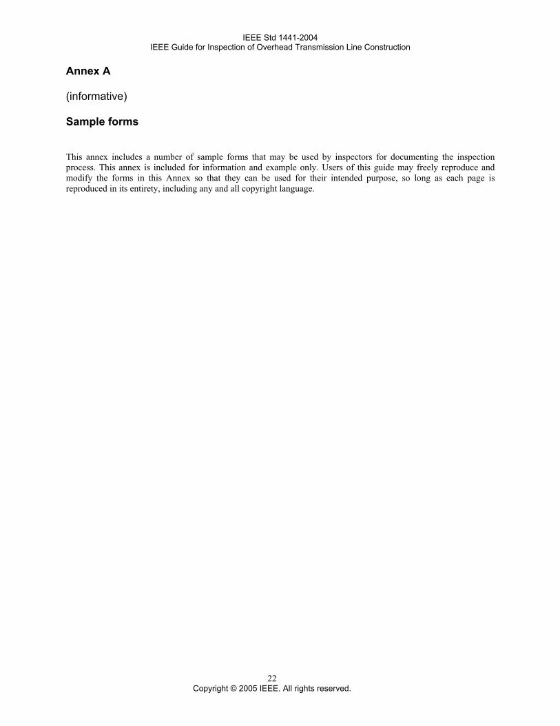
IEEE Std 1441-2004 IEEE Guide for Inspection of Overhead Transmission Line Construction
22
Annex A
(informative)
Sample forms
This annex includes a number of sample forms that may be used by inspectors for documenting the inspection process. This annex is included for information and example only. Users of this guide may freely reproduce and modify the forms in this Annex so that they can be used for their intended purpose, so long as each page is reproduced in its entirety, including any and all copyright language.
Copyright © 2005 IEEE. All rights reserved.
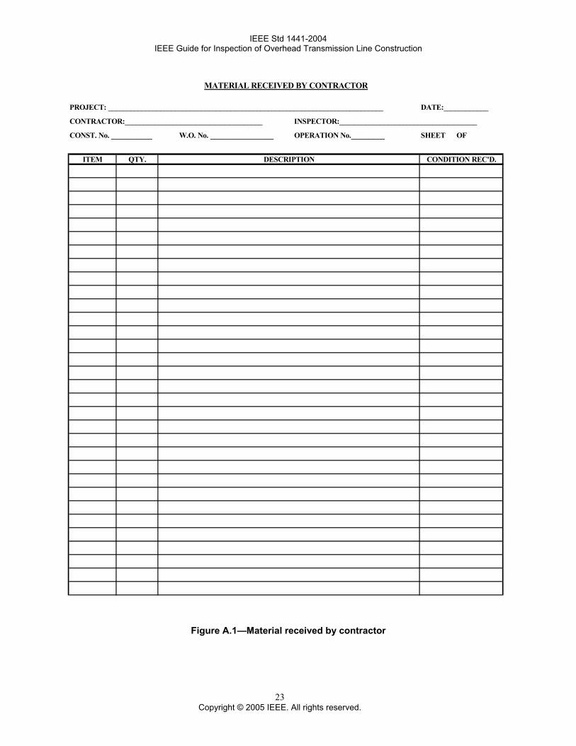
IEEE Std 1441-2004 IEEE Guide for Inspection of Overhead Transmission Line Construction
23
MATERIAL RECEIVED BY CONTRACTOR
PROJECT: __________________________________________________________________________ DATE:____________
CONTRACTOR:_____________________________________ INSPECTOR:_____________________________________
CONST. No. ___________ W.O. No. _________________ OPERATION No._________ SHEET OF
ITEM QTY. DESCRIPTION CONDITION REC'D.
Figure A.1—Material received by contractor
Copyright © 2005 IEEE. All rights reserved.
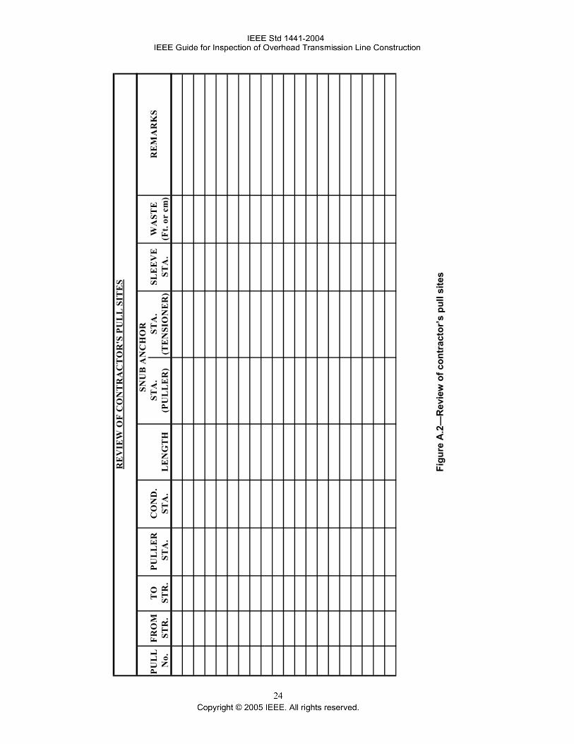
RE
VIE
W O
F C
ON
TR
AC
TO
R'S
PU
LL
SIT
ES
PUL
L
FRO
MT
OPU
LL
ER
CO
ND
.ST
A.
STA
.SL
EE
VE
WA
STE
RE
MA
RK
SN
o.ST
R.
STR
. S
TA
.ST
A.
LE
NG
TH
(PU
LL
ER
)(T
EN
SIO
NE
R)
STA
.(F
t. or
cm
)
SNU
B A
NC
HO
R
Figu
re A
.2—
Rev
iew
of c
ontr
acto
r’s p
ull s
ites
IEEE Std 1441-2004 IEEE Guide for Inspection of Overhead Transmission Line Construction
INSPECTOR'S DAILY REPORT
PROJECT: DATE:
CONTRACTOR: _______________________________________ CONTR. REP:
SUB CONTRACTOR (S): INSPECTOR:
CONTRACT No. _____________ WORK ORDER No:___________________ DATE:
WEATHER: CLEAR OVERCAST RAIN SNOW TEMP. MAX.: MIN
R-O-W: DRY WET SNOW MUDDY SNOW DEPTH:
ACTIVITY & LOCATIONS:
ORDERS RECEIVED FROM SUPERVISOR:
JOB CONDITIONS:
SAFETY:
GENERAL REMARKS:
INSPECTOR'S INITIAL
SEE REVERSE FOR EQUIPMENT AND MANPOWER AND FURTHER REMARKS.
Figure A.3—Inspector’s daily report (side 1 of 2)
25 Copyright © 2005 IEEE. All rights reserved.
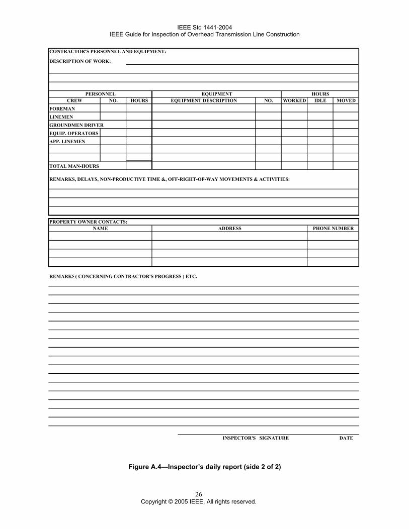
IEEE Std 1441-2004 IEEE Guide for Inspection of Overhead Transmission Line Construction
CONTRACTOR'S PERSONNEL AND EQUIPMENT:
DESCRIPTION OF WORK:
PERSONNEL EQUIPMENT HOURSCREW NO. HOURS EQUIPMENT DESCRIPTION NO. WORKED IDLE MOVED
FOREMAN
LINEMEN
GROUNDMEN DRIVER
EQUIP. OPERATORS
APP. LINEMEN
TOTAL MAN-HOURS
REMARKS, DELAYS, NON-PRODUCTIVE TIME &, OFF-RIGHT-OF-WAY MOVEMENTS & ACTIVITIES:
PROPERTY OWNER CONTACTS:NAME ADDRESS PHONE NUMBER
REMARKS( CONCERNING CONTRACTOR'S PROGRESS ) ETC.
INSPECTOR'S SIGNATURE DATE
Figure A.4—Inspector’s daily report (side 2 of 2)
26 Copyright © 2005 IEEE. All rights reserved.
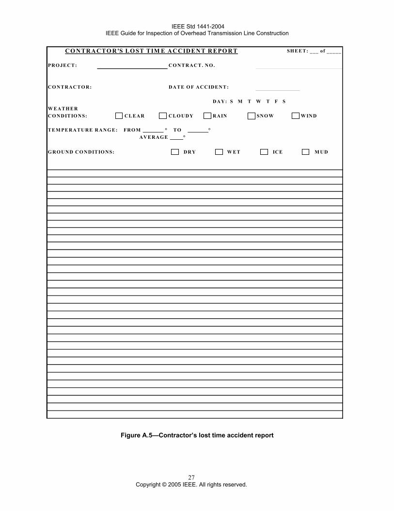
IEEE Std 1441-2004 IEEE Guide for Inspection of Overhead Transmission Line Construction
SH E ET: ___ of _____
PRO JE CT: CO NT RACT. NO .
CO NTRACT O R: DAT E O F ACCIDENT :
DAY: S M T W T F SW EAT H ER CO NDIT IO NS: CL EAR CLO UDY RAIN SNO W W IND
T EM PE RATURE RANG E: FRO M ° TO ° AVE RAG E °
G RO UND CO NDIT IO NS: DRY W ET ICE M UD
CO NTRACTO R'S LO ST TIM E ACCIDENT R EPO RT
Figure A.5—Contractor’s lost time accident report
27 Copyright © 2005 IEEE. All rights reserved.
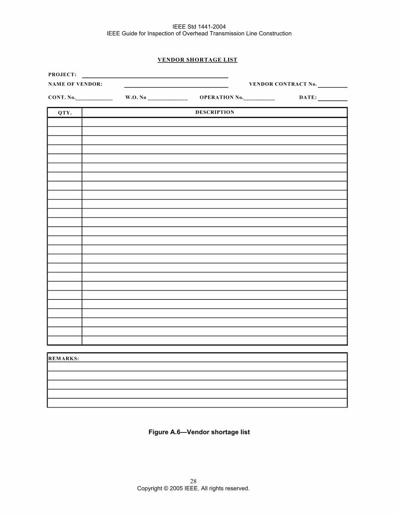
IEEE Std 1441-2004 IEEE Guide for Inspection of Overhead Transmission Line Construction
VENDOR SHORTAGE LIST
PROJECT:
NAME OF VENDOR: VENDOR CONTRACT No.
CONT. No._____________ W.O. No ______________ OPERATION No.___________ DATE:
QTY.
REMARKS:
DESCRIPTION
Figure A.6—Vendor shortage list
28 Copyright © 2005 IEEE. All rights reserved.
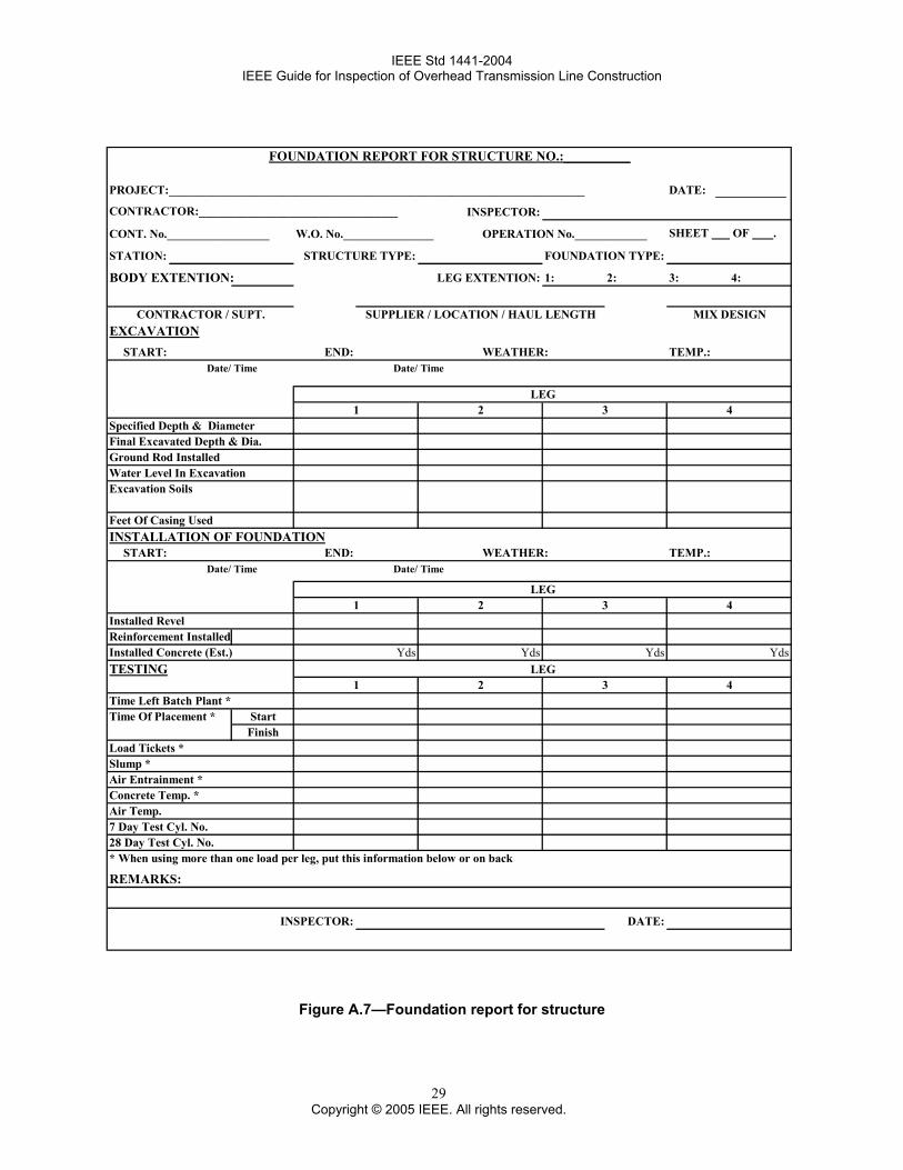
IEEE Std 1441-2004 IEEE Guide for Inspection of Overhead Transmission Line Construction
PROJECT:_____________________________________________________________________ DATE:
CONTRACTOR:_________________________________ INSPECTOR:
CONT. No._________________ W.O. No._______________ OPERATION No.____________ SHEET OF .
STATION: STRUCTURE TYPE: FOUNDATION TYPE:
BODY EXTENTION: LEG EXTENTION: 1: 2: 3: 4:
CONTRACTOR / SUPT. SUPPLIER / LOCATION / HAUL LENGTH MIX DESIGNEXCAVATION
START: END: WEATHER: TEMP.:Date/ Time Date/ Time
LEG1 2 3 4
Specified Depth & DiameterFinal Excavated Depth & Dia.Ground Rod InstalledWater Level In ExcavationExcavation Soils
Feet Of Casing UsedINSTALLATION OF FOUNDATION
START: END: WEATHER: TEMP.:Date/ Time Date/ Time
LEG1 2 3 4
Installed RevelReinforcement InstalledInstalled Concrete (Est.) Yds Yds Yds YdsTESTING LEG
1 2 3 4Time Left Batch Plant *Time Of Placement * Start
FinishLoad Tickets *Slump *Air Entrainment *Concrete Temp. *Air Temp.7 Day Test Cyl. No.28 Day Test Cyl. No.* When using more than one load per leg, put this information below or on back
REMARKS:
INSPECTOR: DATE:
FOUNDATION REPORT FOR STRUCTURE NO.:__________
Figure A.7—Foundation report for structure
29 Copyright © 2005 IEEE. All rights reserved.
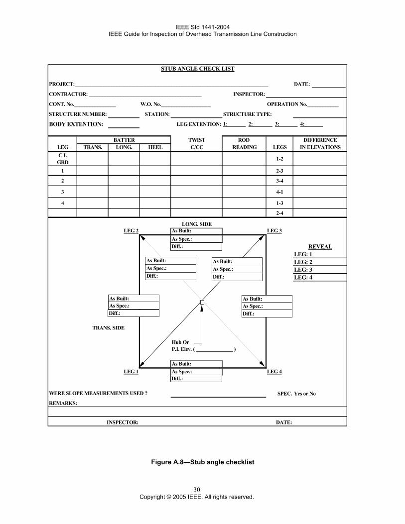
IEEE Std 1441-2004 IEEE Guide for Inspection of Overhead Transmission Line Construction
STUB ANGLE CHECK LIST
PROJECT:__________________________________________________________________________ DATE:
CONTRACTOR: ___________________________________________ INSPECTOR:
CONT. No.________________ W.O. No.___________________ OPERATION No.____________
STRUCTURE NUMBER: STATION: STRUCTURE TYPE:
BODY EXTENTION: LEG EXTENTION: 1: 2: 3: 4:
BATTER TWIST ROD DIFFERENCELEG TRANS. LONG. HEEL C/CC READING LEGS IN ELEVATIONSC L
GRD 1-2
1 2-3
2 3-4
3 4-1
4 1-3
2-4
LONG. SIDELEG 2 As Built: LEG 3
As Spec.:REVEAL
LEG: 1LEG: 2LEG: 3LEG: 4
TRANS. SIDE
Hub OrP.I. Elev. ( )
As Built:LEG 1 As Spec.: LEG 4
WERE SLOPE MEASUREMENTS USED ? SPEC. Yes or No
REMARKS:
INSPECTOR: DATE:
As Built:As Spec.:
As Built:As Spec.:
As Built:As Spec.: As Spec.:
As Built:
Diff.: Diff.:
Diff.:
Diff.:Diff.:
Diff.:
Figure A.8—Stub angle checklist
30 Copyright © 2005 IEEE. All rights reserved.
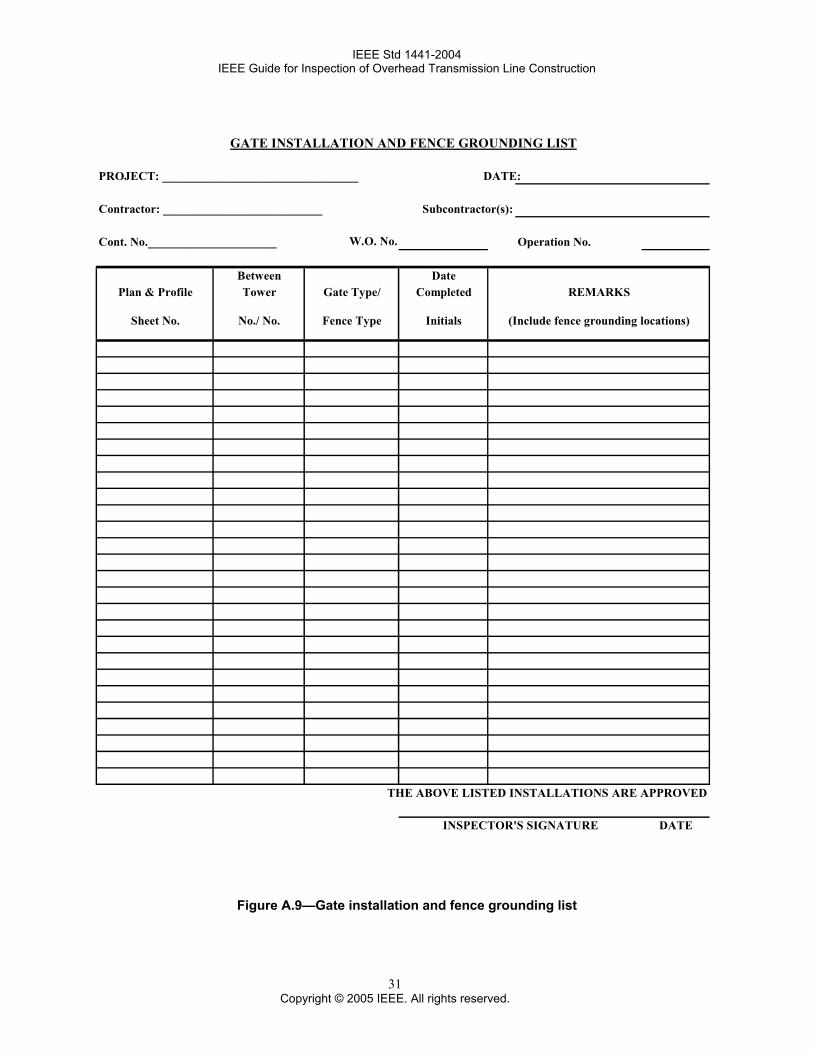
IEEE Std 1441-2004 IEEE Guide for Inspection of Overhead Transmission Line Construction
GATE INSTALLATION AND FENCE GROUNDING LIST
PROJECT: ________________________________ DATE:
Contractor: __________________________ Subcontractor(s):
Cont. No._____________________ W.O. No. Operation No.
Between DatePlan & Profile Tower Gate Type/ Completed REMARKS
Sheet No. No./ No. Fence Type Initials (Include fence grounding locations)
THE ABOVE LISTED INSTALLATIONS ARE APPROVED
INSPECTOR'S SIGNATURE DATE
Figure A.9—Gate installation and fence grounding list
31 Copyright © 2005 IEEE. All rights reserved.
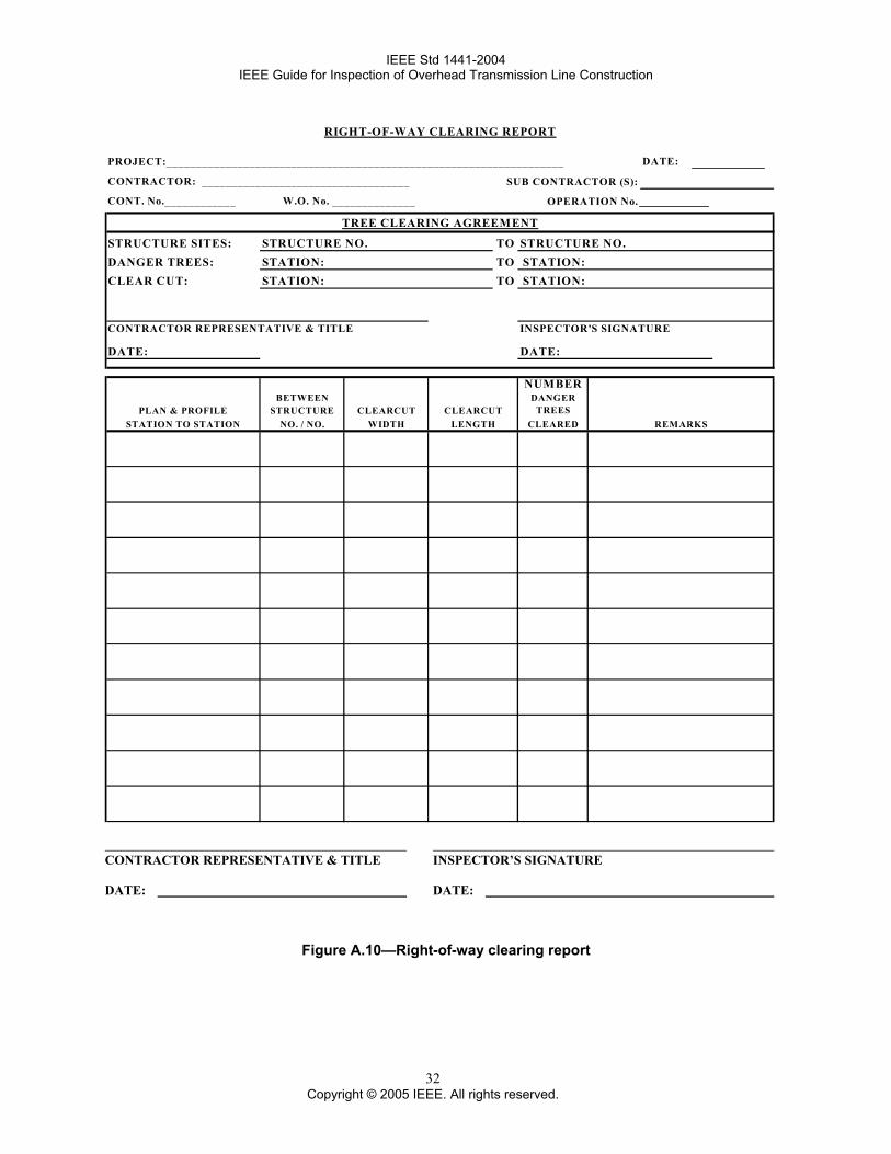
IEEE Std 1441-2004 IEEE Guide for Inspection of Overhead Transmission Line Construction
RIGHT-OF-WAY CLEARING REPORT
PROJECT:___________________________________________________________________ DATE:
CONTRACTOR: ___________________________________ SUB CONTRACTOR (S):
CONT. No.____________ W.O. No. ______________ OPERATION No.
TREE CLEARING AGREEMENT
STRUCTURE SITES: STRUCTURE NO. TO STRUCTURE NO.DANGER TREES: STATION: TO STATION:CLEAR CUT: STATION: TO STATION:
CONTRACTOR REPRESENTATIVE & TITLE INSPECTOR'S SIGNATURE
DATE: DATE:
NUMBERBETWEEN DANGER
PLAN & PROFILE STRUCTURE CLEARCUT CLEARCUT TREESSTATION TO STATION NO. / NO. WIDTH LENGTH CLEARED REMARKS
CONTRACTOR REPRESENTATIVE & TITLE INSPECTOR’S SIGNATURE DATE: DATE:
Figure A.10—Right-of-way clearing report
32 Copyright © 2005 IEEE. All rights reserved.
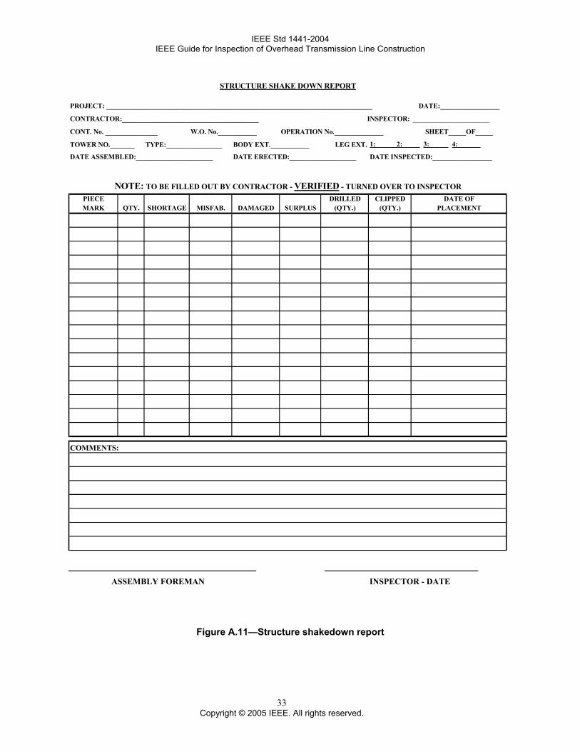
IEEE Std 1441-2004 IEEE Guide for Inspection of Overhead Transmission Line Construction
PROJECT: ____________________________________________________________________________ DATE:_________________
CONTRACTOR:_______________________________________ INSPECTOR: ____________________
CONT. No. _______________ W.O. No.___________ OPERATION No.______________ SHEET_____OF_____
TOWER NO._______ TYPE:________________ BODY EXT.___________ LEG EXT. 1: 2: 3: 4:
DATE ASSEMBLED:______________________ DATE ERECTED:___________________ DATE INSPECTED:_________________
NOTE: TO BE FILLED OUT BY CONTRACTOR - VERIFIED - TURNED OVER TO INSPECTORPIECE DRILLED CLIPPED DATE OFMARK QTY. SHORTAGE MISFAB. DAMAGED SURPLUS (QTY.) (QTY.) PLACEMENT
COMMENTS:
STRUCTURE SHAKE DOWN REPORT
ASSEMBLY FOREMAN INSPECTOR - DATE
Figure A.11—Structure shakedown report
33 Copyright © 2005 IEEE. All rights reserved.
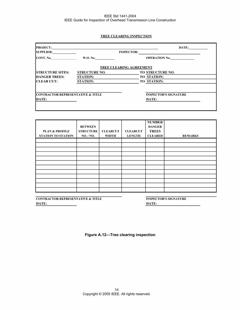
IEEE Std 1441-2004 IEEE Guide for Inspection of Overhead Transmission Line Construction
TREE CLEARING INSPECTION
PROJECT:___________________________________________________________________ DATE:____________SUPPLIER:_______________ INSPECTOR:
CONT. No.________________ W.O. No.____________ OPERATION No._______________
TREE CLEARING AGREEMENTSTRUCTURE SITES: STRUCTURE NO. TO STRUCTURE NO.DANGER TREES: STATION: TO STATION:CLEAR CUT: STATION: TO STATION:
CONTRACTOR REPRESENTATIVE & TITLE INSPECTOR'S SIGNATUREDATE: DATE:
NUMBERBETWEEN DANGER
PLAN & PROFILE STRUCTURE CLEARCUT CLEARCUT TREESSTATION TO STATION NO. / NO. WIDTH LENGTH CLEARED REMARKS
CONTRACTOR REPRESENTATIVE & TITLE INSPECTOR'S SIGNATUREDATE: DATE:
Figure A.12—Tree clearing inspection
34 Copyright © 2005 IEEE. All rights reserved.