power swing protection of series compensated transmission line
TRANSCRIPT
ISSN No: 2309-4893
International Journal of Advanced Engineering and Global Technology Vol-2, Issue-2, February 2014
Power Swing Protection of Series Compensated Transmission Line
Saptarshi Roy Dr. Suresh Babu Perli
Student M.Tech-PSE
Department of Electrical Engineering NIT Warangal, WARANGAL,INDIA
Assistant Professor Department of Electrical Engineering NIT Warangal, WARANGAL,INDIA
ABSTRACT- Fault detection during power swing condition is a challenge for stable operation of power system due to several reasons like protection problems, Voltage/current inversion,sub-harmonic oscillations and transients especially if it is series compensated modulation of voltage and current waveforms with swing frequency etc. This paper proposes a negative-sequence current–based technique for detecting presence of fault, classification of fault occurred, estimated zone and location of the fault occurred and the fault inception time with respect to system reference clock during the power swing condition in a series compensated line. In proposed work negative sequence current was analysed as it keeps the other parameters in the system in healthy state. The technique is tested for different series-compensated power systems including a SMIB system and a WSCC-9bus-3machine power system with their different configurations and contingency combinations. Power swing caused by various faults are simulated with PSCAD / EMTDC and MATLAB/SIMULINK and compared with available techniques to prove the effectiveness of the proposed technique algorithm.
INDEX TERMS : fault detection, power swing, series compensation, negative sequence current, fault classification & location. INTRODUCTION: Fast and accurate determination of a fault in electrical power system is a vital part in
power restoration. Power Swing is caused by large disturbances in power system, which if not blocked caused mal-operation of distance relays and undesired tripping of breakers,change in load impedance, unwanted relay operations at different locations of the network, major power-outages or even power blackout. If a fault occurs during the power swing, the relay must detect the fault and operate quickly. The detection of faults in a series-compensated line during power swings is more challenging due to different frequency components in the fault signals which depend on the fault location, type,level of compensation etc cause the apparent impedance seen by the relay to oscillate and imposes difficulty to distinguish faults from the power swing. This paper proposes a technique for detecting faults in a series-compensated line during the power swing. During unbalanced faults, the negative-sequence components become significant and due to transients in current signals in the initial period, a negative sequence component is present even in three-phase faults. To detect the faults during swing in a series-compensated line, a cumulative sum (CUSUM) of change in the magnitude of the negative-sequence current-based approach is proposed in this paper[5]. The performance is tested for numerous cases for an SMIB system and a 9-bus system simulated with SIMULINK/PSCAD.
466 www.ijaegt.com
ISSN No: 2309-4893
International Journal of Advanced Engineering and Global Technology Vol-2, Issue-2, February 2014
Further we detected the classification of the fault using fine tuning method and detected the location of the fault.
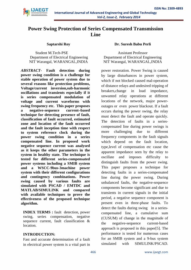
Fig1:Implementation of a Transmission Line using PSCAD Software
FAULT DETECTION CHALLENGES DURING POWER SWING IN SERIES-COMPENSATED LINES: Series compensation imposes protection problems.The use of series capacitors in transmission lines results voltage/current inversion,sub-harmonic oscillations,transients, sub -synchronous oscillations[10].
Fig2: 400KV SMIB Test System.
A test system shown in Fig. 1 is considered[2]. Both Line-1 and Line-2 are 40% compensated and the capacitors are placed [10] . The system details are provided in Appendix A. The system with the distributed line model is simulated using SIMULINK/PSCAD. The traditional fault detection techniques, like the sample-to-sample or cycle-to-cycle comparison of current (or voltage) signals cannot be reliable during the power swing[9].
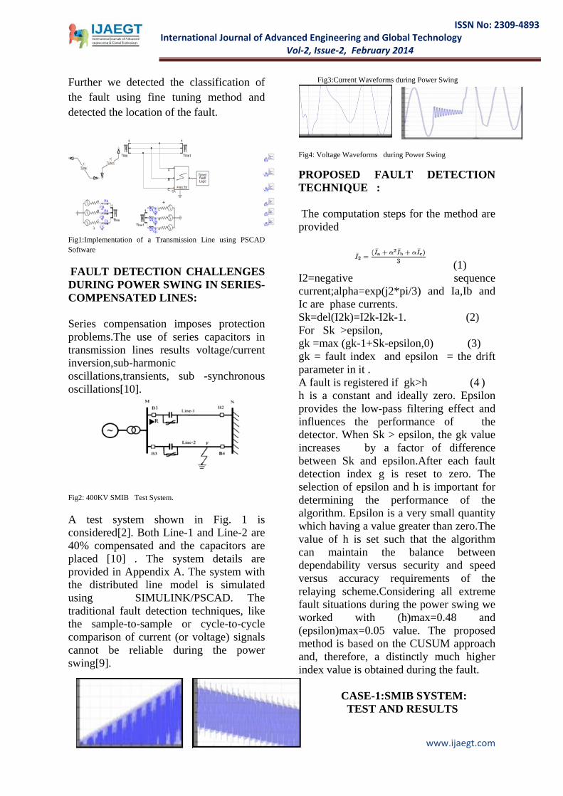
Fig3:Current Waveforms during Power Swing
Fig4: Voltage Waveforms during Power Swing PROPOSED FAULT DETECTION TECHNIQUE : The computation steps for the method are provided
(1) I2=negative sequence current;alpha=exp(j2*pi/3) and Ia,Ib and Ic are phase currents. Sk=del(I2k)=I2k-I2k-1. (2) For Sk >epsilon, gk =max (gk-1+Sk-epsilon,0) (3) gk = fault index and epsilon = the drift parameter in it . A fault is registered if gk>h (4 ) h is a constant and ideally zero. Epsilon provides the low-pass filtering effect and influences the performance of the detector. When Sk > epsilon, the gk value increases by a factor of difference between Sk and epsilon.After each fault detection index g is reset to zero. The selection of epsilon and h is important for determining the performance of the algorithm. Epsilon is a very small quantity which having a value greater than zero.The value of h is set such that the algorithm can maintain the balance between dependability versus security and speed versus accuracy requirements of the relaying scheme.Considering all extreme fault situations during the power swing we worked with (h)max=0.48 and (epsilon)max=0.05 value. The proposed method is based on the CUSUM approach and, therefore, a distinctly much higher index value is obtained during the fault.
CASE-1:SMIB SYSTEM:
TEST AND RESULTS
467 www.ijaegt.com
ISSN No: 2309-4893
International Journal of Advanced Engineering and Global Technology Vol-2, Issue-2, February 2014
The algorithm is tested for different conditions including balanced and unbalanced faults etc. Using SIMULINK/PSCAD with distributed parameter line model data was generated. The data-sampling rate was maintained at 4 kHz for the 50-Hz power system. Line-to-Ground Fault in the Series-Compensated Line
Fig5 : Implementation of SMIB Test System Using PSCAD a)g - t plot b) output-t plot Fig6 :(a &b):LG fault Analysis
Fig:7 : SIMULINK Implementation of SMIB system Algorithm is tested for a line to ground fault of ag–type with a fault resistance of 0.1 ohm initiated at 0.34 sec for 0.04 sec duration at a distance 240KM from bus1.
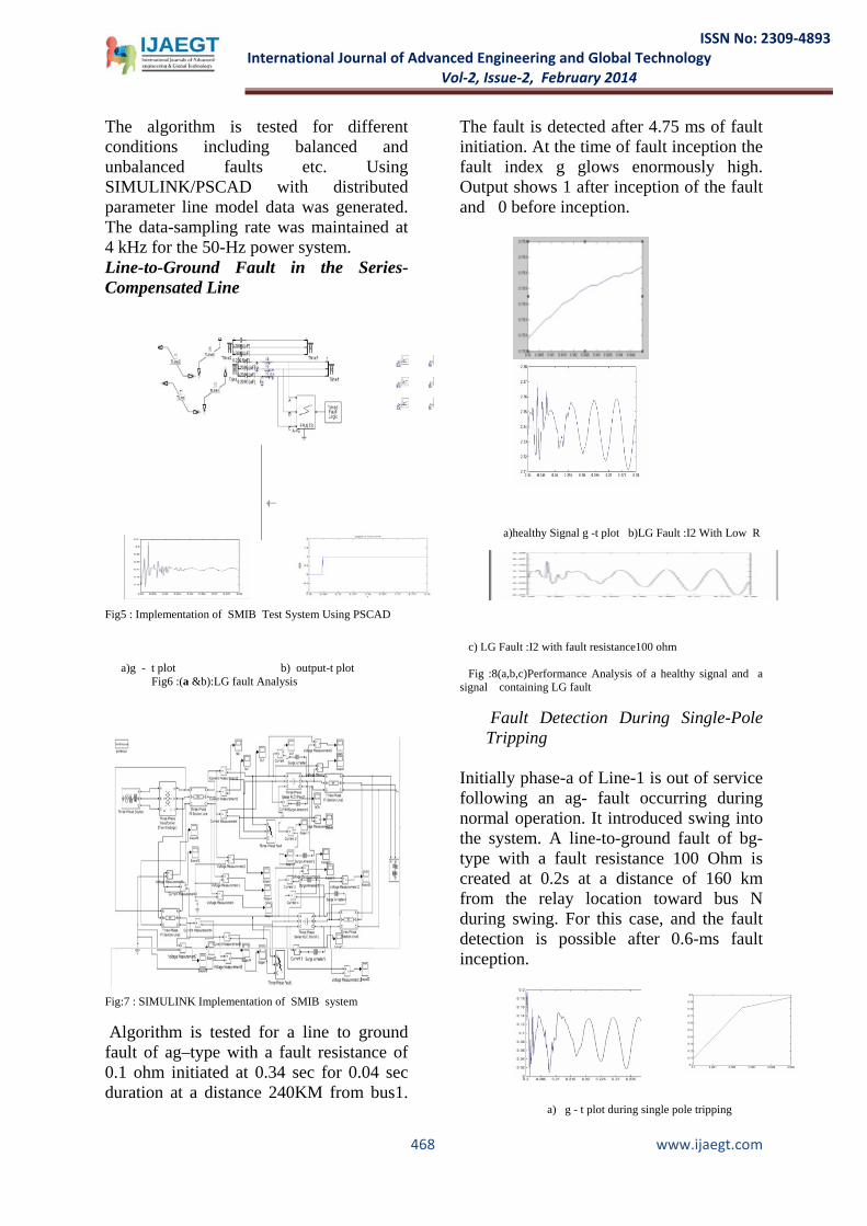
The fault is detected after 4.75 ms of fault initiation. At the time of fault inception the fault index g glows enormously high. Output shows 1 after inception of the fault and 0 before inception.
a)healthy Signal g -t plot b)LG Fault :I2 With Low R c) LG Fault :I2 with fault resistance100 ohm
Fig :8(a,b,c)Performance Analysis of a healthy signal and a signal containing LG fault
Fault Detection During Single-Pole Tripping
Initially phase-a of Line-1 is out of service following an ag- fault occurring during normal operation. It introduced swing into the system. A line-to-ground fault of bg-type with a fault resistance 100 Ohm is created at 0.2s at a distance of 160 km from the relay location toward bus N during swing. For this case, and the fault detection is possible after 0.6-ms fault inception.
a) g - t plot during single pole tripping
468 www.ijaegt.com
ISSN No: 2309-4893
International Journal of Advanced Engineering and Global Technology Vol-2, Issue-2, February 2014
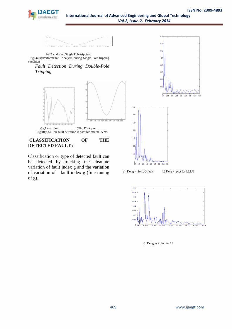
b) I2 - t during Single Pole tripping
Fig:9(a,b):Performance Analysis during Single Pole tripping condition
Fault Detection During Double-Pole Tripping
a) g2 vs t plot b)Fig: I2 - t plot Fig:10(a,b) Here fault detection is possible after 0.55 ms. CLASSIFICATION OF THE DETECTED FAULT : Classification or type of detected fault can be detected by tracking the absolute variation of fault index g and the variation of variation of fault index g (fine tuning of g).
a) Del g - t for LG fault b) Delg - t plot for LLLG
c) Del g vs t plot for LL
469 www.ijaegt.com
ISSN No: 2309-4893
International Journal of Advanced Engineering and Global Technology Vol-2, Issue-2, February 2014
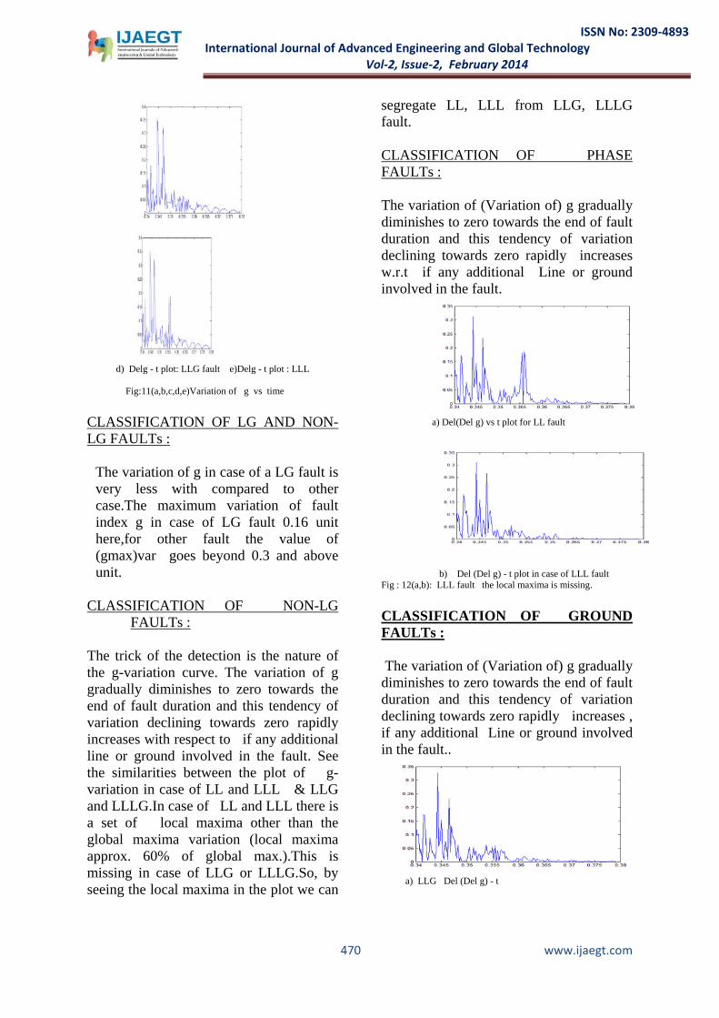
d) Delg - t plot: LLG fault e)Delg - t plot : LLL
Fig:11(a,b,c,d,e)Variation of g vs time
CLASSIFICATION OF LG AND NON-LG FAULTs :
The variation of g in case of a LG fault is very less with compared to other case.The maximum variation of fault index g in case of LG fault 0.16 unit here,for other fault the value of (gmax)var goes beyond 0.3 and above unit.
CLASSIFICATION OF NON-LG
FAULTs : The trick of the detection is the nature of the g-variation curve. The variation of g gradually diminishes to zero towards the end of fault duration and this tendency of variation declining towards zero rapidly increases with respect to if any additional line or ground involved in the fault. See the similarities between the plot of g-variation in case of LL and LLL & LLG and LLLG.In case of LL and LLL there is a set of local maxima other than the global maxima variation (local maxima approx. 60% of global max.).This is missing in case of LLG or LLLG.So, by seeing the local maxima in the plot we can
segregate LL, LLL from LLG, LLLG fault.
CLASSIFICATION OF PHASE FAULTs : The variation of (Variation of) g gradually diminishes to zero towards the end of fault duration and this tendency of variation declining towards zero rapidly increases w.r.t if any additional Line or ground involved in the fault.
a) Del(Del g) vs t plot for LL fault
b) Del (Del g) - t plot in case of LLL fault
Fig : 12(a,b): LLL fault the local maxima is missing. CLASSIFICATION OF GROUND FAULTs : The variation of (Variation of) g gradually diminishes to zero towards the end of fault duration and this tendency of variation declining towards zero rapidly increases , if any additional Line or ground involved in the fault..
a) LLG Del (Del g) - t
470 www.ijaegt.com
ISSN No: 2309-4893
International Journal of Advanced Engineering and Global Technology Vol-2, Issue-2, February 2014
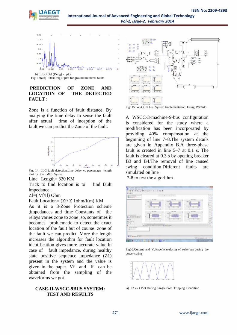
b) LLLG Del (Del g) - t plot Fig: 13(a,b) :Del(Delg)-t plot for ground involved faults PREDICTION OF ZONE AND LOCATION OF THE DETECTED FAULT : Zone is a function of fault distance. By analying the time delay to sense the fault after actual time of inception of the fault,we can predict the Zone of the fault.
Fig: 14: LLG fault detection:time delay vs percentage length Plot for the SMIB System Line Length= 320 KM Trick to find location is to find fault impedance . Zf=( Vf/If) Ohm Fault Location= (Zf/ Z 1ohm/Km) KM As it is a 3-Zone Protection scheme ,impedances and time Constants of the relays varies zone to zone ,so, sometimes it becomes problematic to detect the exact location of the fault but of course zone of the fault we can predict. More the length increases the algorithm for fault location identification gives more accurate value.In case of fault impedance, during healthy state positive sequence impedance (Z1) present in the system and the value is given in the paper. Vf and If can be obtained from the sampling of the waveforms we got.
CASE-II-WSCC-9BUS SYSTEM: TEST AND RESULTS
Fig: 15: WSCC-9 bus System Implementation Using PSCAD A WSCC-3-machine-9-bus configuration is considered for the study where a modification has been incorporated by providing 40% compensation at the beginning of line 7–8.The system details are given in Appendix B.A three-phase fault is created in line 5–7 at 0.1 s. The fault is cleared at 0.3 s by opening breaker B3 and B4.The removal of line caused swing condition.Different faults are simulated on line 7-8 to test the algorithm.
Fig16:Current and Voltage Waveforms of relay bus during the power swing
a) I2 vs t Plot During Single Pole Tripping Condition
471 www.ijaegt.com

ISSN No: 2309-4893
International Journal of Advanced Engineering and Global Technology Vol-2, Issue-2, February 2014
b) g - t plot during Single Pole Tripping Fig:17. Single pole tripping
Fig18: Single-Line Diagram of the Modified WSCC 9-bus System Case-1: Line-to-Ground Fault: An ag- fault with a fault resistance of 0.1ohm is created during the power swing on line7–8 at a distance of 160 km from the relay location at 0.3 s. The index increases to a higher value at the inception of the fault. The technique is able to detect the fault within half-a-cycle of its inception.
a) g - t plot b) I2 - t plot Fig19(a,b):LG fault analysis
Case-2: Double Line-to-Ground Fault:
The performance of the algorithm for a double-line-to-ground fault of abg-type
with a ground fault resistance of 0.1 is created at 0.3 s on line 7–8 during the power swing at a distance of 160 km from the relay location.
a) g2 vs t b) I2 vs t Fig 20(a,b): Fault detection. ANALYSIS USING POSITIVE SEQUENCE COMPONENTS OF CURRENTS If we replace Ib with Ic and Ic with Ib in the negative sequence Current expression,we will get positive sequence current.We can achieve the same feet here,if we use positive sequence components of currents instead of negative sequence components of currents in our algorithm.But the use of positive sequence component of current incurs fault detection(protection) sensitivity problems, specially incase of detection of High Impedance faults (HIFS),low fault current levels and ground fault detection in case of involvement of non-linearity in the ground path[13]-[4]-[14].It may imposes insulation problem also during practical implementation.
a)g vs t b)I2 vs t Fig 21(a,b):LG Fault Analysis using positive sequence components of currents
472 www.ijaegt.com
ISSN No: 2309-4893
International Journal of Advanced Engineering and Global Technology Vol-2, Issue-2, February 2014
a)g vs t b)I2 vs t
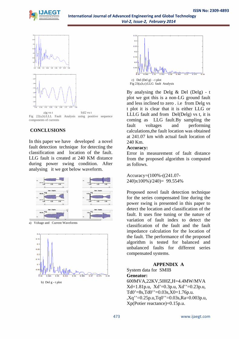
Fig 22(a,b):LLL Fault Analysis using positive sequence components of currents CONCLUSIONS
In this paper we have developed a novel fault detection technique for detecting the classification and location of the fault. LLG fault is created at 240 KM distance during power swing condition. After analysing it we got below waveform.
a) Voltage and Current Waveforms
b) Del g - t plot
c) Del (Del g) - t plot Fig 23(a,b,c):LLG fault Analysis By analysing the Delg & Del (Delg) - t plot we got this is a non-LG ground fault and less inclined to zero . i.e from Delg vs t plot it is clear that it is either LLG or LLLG fault and from Del(Delg) vs t, it is coming as LLG fault.By sampling the fault voltages and performing calculations,the fault location was obtained at 241.07 km with actual fault location of 240 Km. Accuracy: Error in measurement of fault distance from the proposed algorithm is computed as follows. Accuracy=(100%-((241.07-240)x100%)/240)= 99.554% Proposed novel fault detection technique for the series compensated line during the power swing is presented in this paper to detect the location and classification of the fault. It uses fine tuning or the nature of variation of fault index to detect the classification of the fault and the fault impedance calculation for the location of the fault. The performance of the proposed algorithm is tested for balanced and unbalanced faults for different series compensated systems.
APPENDIX A System data for SMIB Geneator: 600MVA,22KV,50HZ,H=4.4MW/MVA Xd=1.81p.u, Xd’=0.3p.u, Xd’’=0.23p.u, Td0’=8s,Td0’’=0.03s,X0=1.76p.u. ,Xq’’=0.25p.u,Tq0’’=0.03s,Ra=0.003p.u, Xp(Potier reactance)=0.15p.u.
473 www.ijaegt.com
ISSN No: 2309-4893
International Journal of Advanced Engineering and Global Technology Vol-2, Issue-2, February 2014
Transformer: 600MVA,22/400KV,50HZ,D/Y,X=0.163p.u, Xcore=0.33p.u,Rcore=0.0p.u,Pcopper=0.00177p.u Transmission lines: Length=320Km Positive-sequence impedance=0.12+j0.88 Ohm/Km Zero-Sequence Impedance=0.309+j1.297 Ohm/Km Positive-sequence capacitive reactance=487.723x1000 Ohm-Km Zero-sequence capacitive reactance=419.34x1000 Ohm-Km.
APPENDIX B System data for 3-machine 9-bus configuration: Gererators Gen-1: 600 MVA,22KV,50HZ Gen-2: 465 MVA,22KV,50HZ Gen-3: 310 MVA,22KV,50HZ Transformers T1: 600 MVA,22/400KV,50HZ,D/Y; T2: 465 MVA,22/400KV,50HZ,D/Y; T3: 310 MVA,22/400KV,50HZ,D/Y; Transmission line: Length of line 7-8=320Km.,line 8-9=400Km,line 7-5=310Km.,line 5-4=350Km,line 6-4=350Km,line 6-9=300km. Loads Load A=300MW+j100MVAr. Load B=200MW+j75MVAr. Load C=150MW+j75MVAr. Other parameter used are same as APPENDIX A
REFERENCES [1] H. J. Alture, J. B. Mooney, and G. E. Alexander, “Advances in series compensated line protection,” 2008. [Online]. Available: www.selinc.com/20081022, TP6340-01 [2] S. M. Brahma, “Distance relay with out-of-step blocking function using wavelet transform,” IEEE Trans. Power Del., vol. 22, no. 3, pp.1360–1366, Jul. 2007.
[3] A. Esmaeilian, A. Ghaderi, M. Tasdighi, and A. Rouhani, “Evaluation and performance comparison of power swing detection algorithms in presence of series compensation on transmission lines,” in Proc. 10th Int. Conf. Environment Elect. Eng., May 8–11, 2011, pp. 1842–1848. [4]Normann Fischer and Daqing Hou,”Methods For Detecting Ground Faults in Medium Voltage DistributionPowerSystems”,[2006].[Online].Available:https://www.selinc.com/WorkArea/DownloadAsset.aspx?id=2385 . [5] F. Gustafsson, Adaptive Filtering and Change Detection. NewYork: Wiley, 2000. [6]S. Lotfifard,J. Faiz, and M. Kezunovic, “Detection of symmetrical faults by distance relays during power swings,” IEEE Trans. Power Del., vol. 25, no. 1, pp. 81–87, Jan. 2010. [7] X. Lin, Y. Gao, and P. Liu, “A novel scheme to identify symmetrical faults occurring during power swings,” IEEE Trans. Power Del., vol.23, no. 1, pp. 73–78, Jan. 2008. [8] S. R. Mohanty, A. K. Pradhan, and A. Routray, “A cumulative sum-based fault detector for power system relaying application,”IEEE Trans. Power Del., vol. 23, no. 1, pp. 79–86, Jan. 2008. [9] R. J. Marttila, “Performance of distance relay mho elements on MOVprotected series-compensated lines,” IEEE Trans. Power Del., vol. 7,no. 3, pp. 1167–1178, Jul. 1992. [10] Abdolamir Nekoubin,”Simulation of Series Compensated Transmission Lines Protected with Mov”, World Academy of Science, Engineering and Technology 58,pp.1002-1006 2011. [11] P. K. Nayak, A. K. Pradhan, and P. Bajpai, “Detecting fault during power swing for a series compensated line,” presented at the Int. Conf. Energy, Autom., Signal, Bhubaneswar, Odisha, India, Dec. 28–30,2011. [12] A. Newbould and I. A. Taylor, “Series compensated line protection:System
474 www.ijaegt.com
ISSN No: 2309-4893
International Journal of Advanced Engineering and Global Technology Vol-2, Issue-2, February 2014
modeling and relay testing,” in Proc. 4th Int. Conf.Develop.Power Protect., 1989, pp. 182–186. [13]John P.Nelson,”System Grounding and Ground-Fault Protection in Petrochemical Industry:A need for a better Understanding”,IEEE Transactions on Industrial Applications,Vol.38,No.6,Nov.-Dec 002,pp.1633-1640. [14]A.M.Sharaf,L.A.Snider and K.Debnath,”A Neural Network Based Relaying Scheme for Distribution System High Impedance FaultDetection”,[1993].[Online].Available: www.researchgate.net/...fault_detection/.../79e41510b7791025bb.pd
BIBLIOGRAPHY
Saptarshi Roy: Received the B.E degree in Electrical Engineering from Jadavpur University, West Bengal,India in 2009. He was an Engineer
in Crompton Greaves Limited from 2009 to 2010 and associated with Tata Consultancy Services Limited from 2011 to 2012. Currently he is pursuing second year of M.Tech in Power Sysem Engineering in the department of Electrical Engineering, National Institute of Technology,Warangal,India. His area of interest is power system protection.
Dr. Suresh Babu Perli: Currently he is working as an Assistant Professor,in Department Of Electrical Engineering, National
Institut of Technology,Warangal. His area of interest is Power System Protection.
475 www.ijaegt.com