transmission line protection principles
TRANSCRIPT
7TransmissionLineProtectionPrinciples
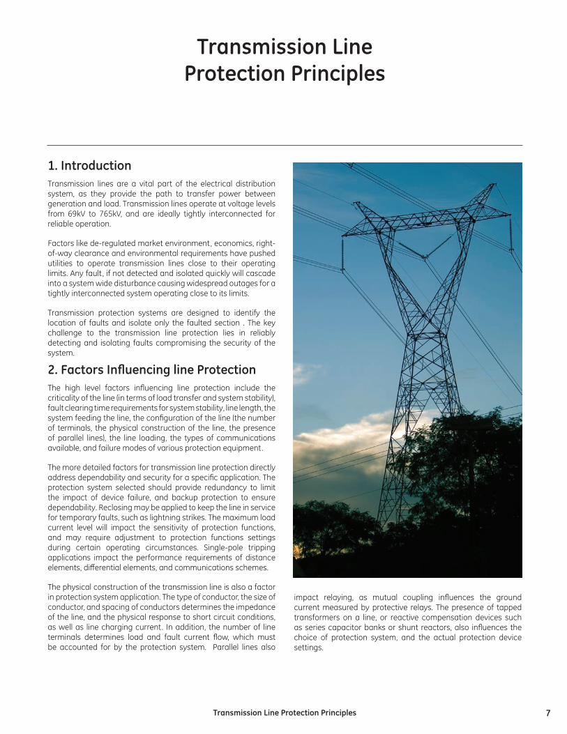
1.IntroductionTransmission lines are a vital part of the electrical distribution system, as they provide the path to transfer power between generation and load. Transmission lines operate at voltage levels from 69kV to 765kV, and are ideally tightly interconnected for reliable operation.
Factors like de-regulated market environment, economics, right-of-way clearance and environmental requirements have pushed utilities to operate transmission lines close to their operating limits. Any fault, if not detected and isolated quickly will cascade into a system wide disturbance causing widespread outages for a tightly interconnected system operating close to its limits.
Transmission protection systems are designed to identify the location of faults and isolate only the faulted section . The key challenge to the transmission line protection lies in reliably detecting and isolating faults compromising the security of the system.
2. Factors Influencing line ProtectionThe high level factors influencing line protection include the criticality of the line (in terms of load transfer and system stability), fault clearing time requirements for system stability, line length, the system feeding the line, the configuration of the line (the number of terminals, the physical construction of the line, the presence of parallel lines), the line loading, the types of communications available, and failure modes of various protection equipment.
The more detailed factors for transmission line protection directly address dependability and security for a specific application. The protection system selected should provide redundancy to limit the impact of device failure, and backup protection to ensure dependability. Reclosing may be applied to keep the line in service for temporary faults, such as lightning strikes. The maximum load current level will impact the sensitivity of protection functions, and may require adjustment to protection functions settings during certain operating circumstances. Single-pole tripping applications impact the performance requirements of distance elements, differential elements, and communications schemes.
The physical construction of the transmission line is also a factor in protection system application. The type of conductor, the size of conductor, and spacing of conductors determines the impedance of the line, and the physical response to short circuit conditions, as well as line charging current. In addition, the number of line terminals determines load and fault current flow, which must be accounted for by the protection system. Parallel lines also
impact relaying, as mutual coupling influences the ground current measured by protective relays. The presence of tapped transformers on a line, or reactive compensation devices such as series capacitor banks or shunt reactors, also influences the choice of protection system, and the actual protection device settings.
TransmissionLineProtectionPrinciples
8 TransmissionLineProtectionPrinciples
3.GEMultilinApplicationAdvantagesBefore considering using a GE Multilin relay for a specific transmission line protection application, it is important to understand how the relay meets some more general application requirements for simplicity, security, and dependability. GE Multilin relays provide simplicity and security for single pole tripping, dependability for protection communications between line terminals, security for dual-breaker line terminals, and simplicity and dependability of redundant protection schemes.
3.1Single-PoleTrippingSingle pole tripping using distance protection is a challenging application. A distance relay must correctly identify a single-phase fault, and trip only the circuit breaker pole for the faulted phase. The relay also must initiate the recloser and breaker failure elements correctly on the fault event. The distance elements protecting the unfaulted phases must maintain security during the open-pole condition and any reclosing attempts.
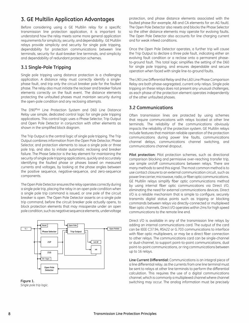
The D90Plus Line Protection System and D60 Line Distance Relay use simple, dedicated control logic for single pole tripping applications. This control logic uses a Phase Selector, Trip Output and Open Pole Detector in conjunction with other elements as shown in the simplified block diagram.
The Trip Output is the central logic of single pole tripping. The Trip Output combines information from the Open Pole Detector, Phase Selector, and protection elements to issue a single pole or three pole trip, and also to initiate automatic reclosing and breaker failure. The Phase Selector is the key element for maintaining the security of single pole tripping applications, quickly and accurately identifying the faulted phase or phases based on measured currents and voltages, by looking at the phase angles between the positive sequence, negative-sequence, and zero-sequence components.
The Open Pole Detector ensures the relay operates correctly during a single pole trip, placing the relay in an open pole condition when a single pole trip command is issued, or one pole of the circuit breaker is open. The Open Pole Detector asserts on a single pole trip command, before the circuit breaker pole actually opens, to block protection elements that may misoperate under an open pole condition, such as negative sequence elements, undervoltage
protection, and phase distance elements associated with the faulted phase (for example, AB and CA elements for an AG fault). The Open Pole Detector also resets and blocks the Phase Selector so the other distance elements may operate for evolving faults. The Open Pole Detector also accounts for line charging current and for weak infeed conditions.
Once the Open Pole Detector operates, a further trip will cause the Trip Output to declare a three pole fault, indicating either an evolving fault condition or a reclose onto a permanent phase-to-ground fault. This total logic simplifies the setting of the D60 for single pole tripping, and ensures dependable and secure operation when faced with single line-to-ground faults.
The L90 Line Differential Relay and the L60 Line Phase Comparison Relay are both phase-segregated, current only relays. Single pole tripping on these relays does not present any unusual challenges, as each phase of the protection element operates independently of the other unfaulted phases.
3.2CommunicationsOften transmission lines are protected by using schemes that require communications with relays located at other line terminals. The reliability of the communications obviously impacts the reliability of the protection system. GE Multilin relays include features that maintain reliable operation of the protection communications during power line faults, communications channel delays, communications channel switching, and communications channel dropout.
Pilot protection: Pilot protection schemes, such as directional comparison blocking and permissive over-reaching transfer trip, use simple on/off communications between relays. There are many methods to send this signal. The most common method is to use contact closure to an external communication circuit, such as power line carrier, microwave, radio, or fiber optic communications. GE Multilin relays simplify fiber optic communications method by using internal fiber optic communications via Direct I/O, eliminating the need for external communications devices. Direct I/O is a reliable mechanism that is simple to configure, securely transmits digital status points such as tripping or blocking commands between relays via directly-connected or multiplexed fiber optic channels. Direct I/O operates within 2ms for high speed communications to the remote line end.
Direct I/O is available in any of the transmission line relays by adding an internal communications card. The output of the card can be IEEE C37.94, RS422 or G.703 communications to interface with fiber optic multiplexers, or may be a direct fiber connection to other relays. The communications card can be single-channel or dual-channel, to support point-to-point communications, dual point-to-point communications, or ring communications between up to 16 relays.
Line Current Differential: Communications is an integral piece of a line differential relay, as the currents from one line terminal must be sent to relays at other line terminals to perform the differential calculation. This requires the use of a digital communications channel, which is commonly a multiplexed channel where channel switching may occur. The analog information must be precisely
Phase Selector
21P
21G
Trip Output
Reset
Dir. Supv.
Open Pole
Init BF
AR
V, I Open Pole(s)
Open PoleDetector
Figure1.Single pole trip logic.
9TransmissionLineProtectionPrinciples
time synchronized between the line ends for the differential calculation to be correct. Synchronization errors show up as phase angle offset, where identical currents produce phasors with different phase angles, and transient errors, where changes in current are seen at different times at different measurement points. For example, on a 60 Hz system, every 1ms of time shift between terminals introduces a 21.6° phase shift into the measured currents.
There are two methods to account for the phase shift between line terminals due to the communications channel delay. One method is to measure the round-trip channel delay, and shift the local current phase by an angle equal to ½ of the round-trip delay time. This method is simple to implement, but creates a transient error when the communications channel is switched. In addition, the differential element will be temporarily blocked when the communications channel switches, or noise in the communications channel causes communications packet loss.
The L90 Line Differential Relay employs a different method, using synchronous sampling by internally synchronizing the clocks on each L90. This method achieves high reliability, as the round-trip channel delay is not vitally important. The differential element successfully operates during channel switching or after packet loss, because the communications packets are precisely synchronized.
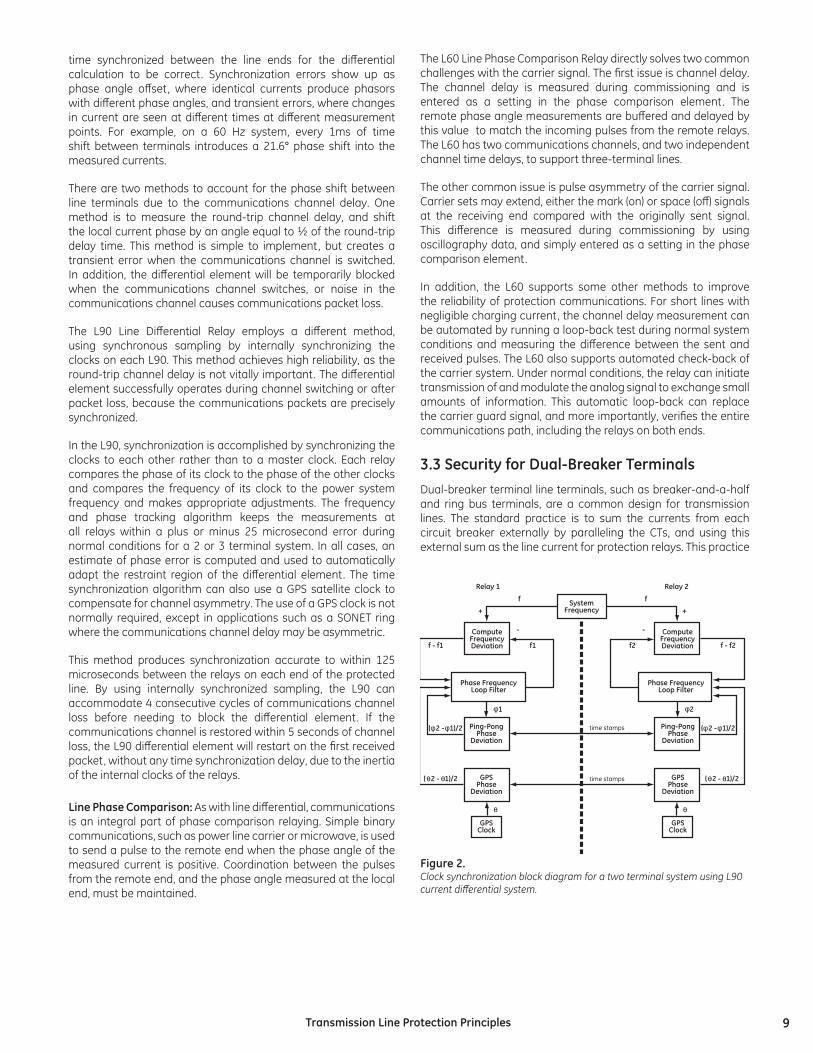
In the L90, synchronization is accomplished by synchronizing the clocks to each other rather than to a master clock. Each relay compares the phase of its clock to the phase of the other clocks and compares the frequency of its clock to the power system frequency and makes appropriate adjustments. The frequency and phase tracking algorithm keeps the measurements at all relays within a plus or minus 25 microsecond error during normal conditions for a 2 or 3 terminal system. In all cases, an estimate of phase error is computed and used to automatically adapt the restraint region of the differential element. The time synchronization algorithm can also use a GPS satellite clock to compensate for channel asymmetry. The use of a GPS clock is not normally required, except in applications such as a SONET ring where the communications channel delay may be asymmetric.
This method produces synchronization accurate to within 125 microseconds between the relays on each end of the protected line. By using internally synchronized sampling, the L90 can accommodate 4 consecutive cycles of communications channel loss before needing to block the differential element. If the communications channel is restored within 5 seconds of channel loss, the L90 differential element will restart on the first received packet, without any time synchronization delay, due to the inertia of the internal clocks of the relays.
LinePhaseComparison: As with line differential, communications is an integral part of phase comparison relaying. Simple binary communications, such as power line carrier or microwave, is used to send a pulse to the remote end when the phase angle of the measured current is positive. Coordination between the pulses from the remote end, and the phase angle measured at the local end, must be maintained.
The L60 Line Phase Comparison Relay directly solves two common challenges with the carrier signal. The first issue is channel delay. The channel delay is measured during commissioning and is entered as a setting in the phase comparison element. The remote phase angle measurements are buffered and delayed by this value to match the incoming pulses from the remote relays. The L60 has two communications channels, and two independent channel time delays, to support three-terminal lines.
The other common issue is pulse asymmetry of the carrier signal. Carrier sets may extend, either the mark (on) or space (off) signals at the receiving end compared with the originally sent signal. This difference is measured during commissioning by using oscillography data, and simply entered as a setting in the phase comparison element.
In addition, the L60 supports some other methods to improve the reliability of protection communications. For short lines with negligible charging current, the channel delay measurement can be automated by running a loop-back test during normal system conditions and measuring the difference between the sent and received pulses. The L60 also supports automated check-back of the carrier system. Under normal conditions, the relay can initiate transmission of and modulate the analog signal to exchange small amounts of information. This automatic loop-back can replace the carrier guard signal, and more importantly, verifies the entire communications path, including the relays on both ends.
3.3SecurityforDual-BreakerTerminalsDual-breaker terminal line terminals, such as breaker-and-a-half and ring bus terminals, are a common design for transmission lines. The standard practice is to sum the currents from each circuit breaker externally by paralleling the CTs, and using this external sum as the line current for protection relays. This practice
SystemFrequency
f
f - f1 f1
1
f - f2f2
Relay 1
time stamps
time stamps
Relay 2
f
+
- -
+
ComputeFrequencyDeviation
Ping-PongPhase
Deviation
Phase FrequencyLoop Filter
GPSPhase
Deviation
GPSClock
ComputeFrequencyDeviation
Ping-PongPhase
Deviation
Phase FrequencyLoop Filter
GPSPhase
Deviation
GPSClock
( 2 - 1)/2
2
( 2 - 1)/2
( 2 - 1)/2 ( 2 - 1)/2
Figure2.Clock synchronization block diagram for a two terminal system using L90 current differential system.
10 TransmissionLineProtectionPrinciples
works well during actual line faults. However, for some external fault events, poor CT performance may lead to improper operation of line protection relays.
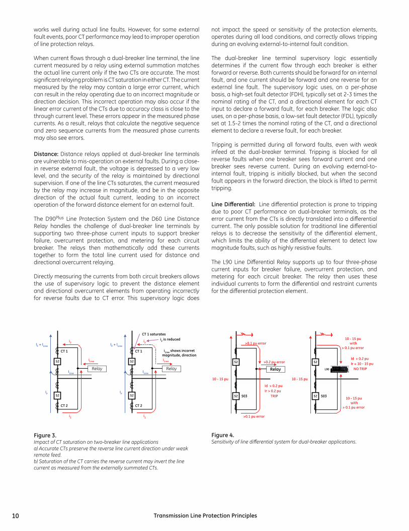
When current flows through a dual-breaker line terminal, the line current measured by a relay using external summation matches the actual line current only if the two CTs are accurate. The most significant relaying problem is CT saturation in either CT. The current measured by the relay may contain a large error current, which can result in the relay operating due to an incorrect magnitude or direction decision. This incorrect operation may also occur if the linear error current of the CTs due to accuracy class is close to the through current level. These errors appear in the measured phase currents. As a result, relays that calculate the negative sequence and zero sequence currents from the measured phase currents may also see errors.
Distance:Distance relays applied at dual-breaker line terminals are vulnerable to mis-operation on external faults. During a close-in reverse external fault, the voltage is depressed to a very low level, and the security of the relay is maintained by directional supervision. If one of the line CTs saturates, the current measured by the relay may increase in magnitude, and be in the opposite direction of the actual fault current, leading to an incorrect operation of the forward distance element for an external fault.
The D90Plus Line Protection System and the D60 Line Distance Relay handles the challenge of dual-breaker line terminals by supporting two three-phase current inputs to support breaker failure, overcurrent protection, and metering for each circuit breaker. The relays then mathematically add these currents together to form the total line current used for distance and directional overcurrent relaying.
Directly measuring the currents from both circuit breakers allows the use of supervisory logic to prevent the distance element and directional overcurrent elements from operating incorrectly for reverse faults due to CT error. This supervisory logic does
not impact the speed or sensitivity of the protection elements, operates during all load conditions, and correctly allows tripping during an evolving external-to-internal fault condition.
The dual-breaker line terminal supervisory logic essentially determines if the current flow through each breaker is either forward or reverse. Both currents should be forward for an internal fault, and one current should be forward and one reverse for an external line fault. The supervisory logic uses, on a per-phase basis, a high-set fault detector (FDH), typically set at 2-3 times the nominal rating of the CT, and a directional element for each CT input to declare a forward fault, for each breaker. The logic also uses, on a per-phase basis, a low-set fault detector (FDL), typically set at 1.5-2 times the nominal rating of the CT, and a directional element to declare a reverse fault, for each breaker.
Tripping is permitted during all forward faults, even with weak infeed at the dual-breaker terminal. Tripping is blocked for all reverse faults when one breaker sees forward current and one breaker sees reverse current. During an evolving external-to-internal fault, tripping is initially blocked, but when the second fault appears in the forward direction, the block is lifted to permit tripping.
Line Differential: Line differential protection is prone to tripping due to poor CT performance on dual-breaker terminals, as the error current from the CTs is directly translated into a differential current. The only possible solution for traditional line differential relays is to decrease the sensitivity of the differential element, which limits the ability of the differential element to detect low magnitude faults, such as highly resistive faults.
The L90 Line Differential Relay supports up to four three-phase current inputs for breaker failure, overcurrent protection, and metering for each circuit breaker. The relay then uses these individual currents to form the differential and restraint currents for the differential protection element.
52
52
CT 1
IF
Relay
i1
CT 2
i2
iLine
ILine
IF + ILine
52
52
CT 1
IF
Relay
i1
CT 2
i2
iLine
ILine
IF + ILine
CT 1 saturatesi2 is reduced
iLine shows incorretmagnitude, direction
52
52 503
10 - 15 pu
Relay
>0.1 pu error
>0.1 pu error
>0.2 pu error
Id > 0.2 puIr > 0.2 puTRIP
52
52 503
10 - 15 pu
10 - 15 puwith
> 0.1 pu error
Id > 0.2 puIr = 10 - 15 puNO TRIP
10 - 15 puwith
> 0.1 pu error
L90
Figure3.Impact of CT saturation on two-breaker line applicationsa) Accurate CTs preserve the reverse line current direction under weak remote feed.b) Saturation of the CT carries the reverse current may invert the line current as measured from the externally summated CTs.
Figure4.Sensitivity of line differential system for dual-breaker applications.
11TransmissionLineProtectionPrinciples
52
52
CT 1
CT 2
L90 LineDifferential
L60 PhaseComparison
D90Plus Distance -POTT Scheme
D90Plus Distance -POTT Scheme
L90 LineDifferential
L60 PhaseComparison
52
52
CT 1
CT 2
Power Line Carrier
Multilplexed Fiber Optic (different channel)
D60 Distance -POTT Scheme
D60 Distance -POTT Scheme
Multilplexed Fiber Optic
Multilplexed Fiber Optic
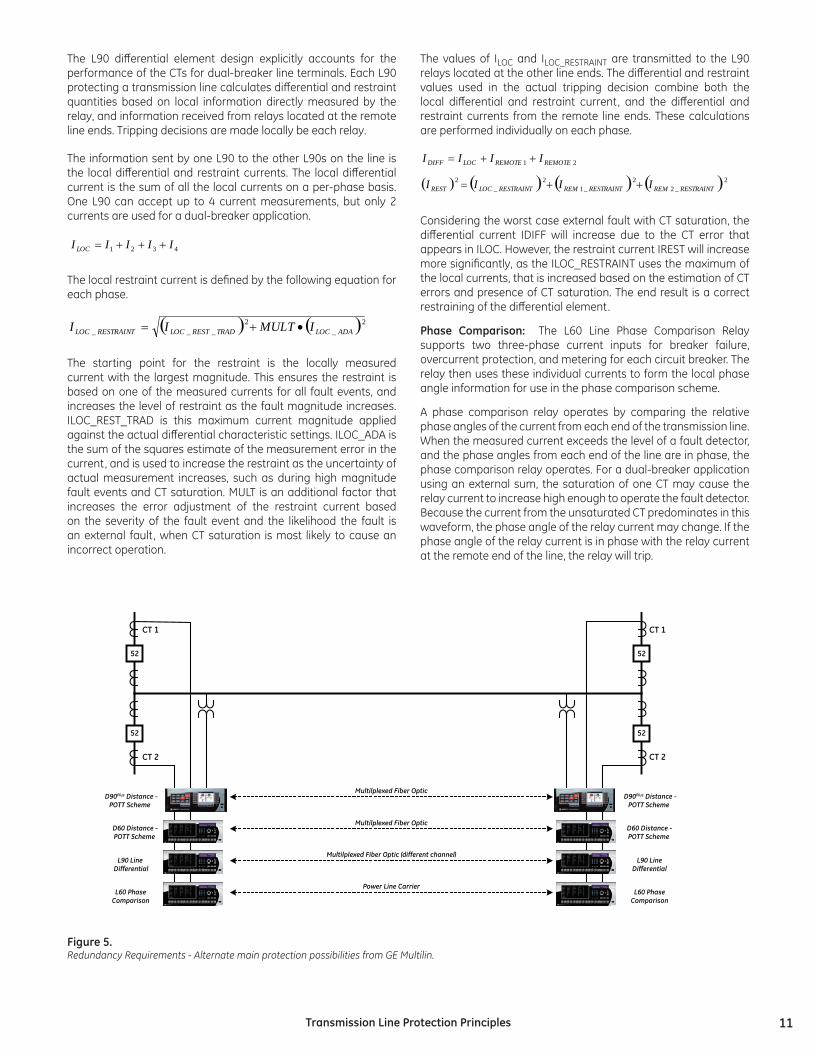
The L90 differential element design explicitly accounts for the performance of the CTs for dual-breaker line terminals. Each L90 protecting a transmission line calculates differential and restraint quantities based on local information directly measured by the relay, and information received from relays located at the remote line ends. Tripping decisions are made locally be each relay.
The information sent by one L90 to the other L90s on the line is the local differential and restraint currents. The local differential current is the sum of all the local currents on a per-phase basis. One L90 can accept up to 4 current measurements, but only 2 currents are used for a dual-breaker application.
4321 IIIII LOC +++=
The local restraint current is defined by the following equation for each phase.
( ) ( )2_
2___ ADALOCTRADRESTLOCRESTRAINTLOC IMULTII •+=
The starting point for the restraint is the locally measured current with the largest magnitude. This ensures the restraint is based on one of the measured currents for all fault events, and increases the level of restraint as the fault magnitude increases. ILOC_REST_TRAD is this maximum current magnitude applied against the actual differential characteristic settings. ILOC_ADA is the sum of the squares estimate of the measurement error in the current, and is used to increase the restraint as the uncertainty of actual measurement increases, such as during high magnitude fault events and CT saturation. MULT is an additional factor that increases the error adjustment of the restraint current based on the severity of the fault event and the likelihood the fault is an external fault, when CT saturation is most likely to cause an incorrect operation.
The values of ILOC and ILOC_RESTRAINT are transmitted to the L90 relays located at the other line ends. The differential and restraint values used in the actual tripping decision combine both the local differential and restraint current, and the differential and restraint currents from the remote line ends. These calculations are performed individually on each phase.
21 REMOTEREMOTELOCDIFF IIII ++=
( ) ( ) ( ) ( )2_2
2_1
2_
2RESTRAINTREMRESTRAINTREMRESTRAINTLOCREST IIII ++=
Considering the worst case external fault with CT saturation, the differential current IDIFF will increase due to the CT error that appears in ILOC. However, the restraint current IREST will increase more significantly, as the ILOC_RESTRAINT uses the maximum of the local currents, that is increased based on the estimation of CT errors and presence of CT saturation. The end result is a correct restraining of the differential element.
Phase Comparison: The L60 Line Phase Comparison Relay supports two three-phase current inputs for breaker failure, overcurrent protection, and metering for each circuit breaker. The relay then uses these individual currents to form the local phase angle information for use in the phase comparison scheme.
A phase comparison relay operates by comparing the relative phase angles of the current from each end of the transmission line. When the measured current exceeds the level of a fault detector, and the phase angles from each end of the line are in phase, the phase comparison relay operates. For a dual-breaker application using an external sum, the saturation of one CT may cause the relay current to increase high enough to operate the fault detector. Because the current from the unsaturated CT predominates in this waveform, the phase angle of the relay current may change. If the phase angle of the relay current is in phase with the relay current at the remote end of the line, the relay will trip.
Figure5.Redundancy Requirements - Alternate main protection possibilities from GE Multilin.
12 TransmissionLineProtectionPrinciples
The L60 in dual-breaker applications selects the appropriate phase angle, based on the information measured from the current flow through both circuit breakers. The relay uses fault detectors on each current input, and develops the phase angle for each current input, and then special dual breaker logic consolidates the fault detector flags and the phase angle pulses for the line terminal.
The fault detector flag is set for a line terminal if either fault detector from the two breakers is picked up. The type of phase comparison protection scheme, tripping or blocking, controls the pulse combination logic. For a tripping scheme, a positive polarity is declared for the terminal if one breaker displays positive polarity with its respective fault detector picked up, while the other breaker either does not show negative polarity or its fault detector is not picked up.
3.4RedundancyConsiderationstoEnhanceReliabilityThe reliability of transmission system protection is dependent on the reliability of the protection scheme used and the individual components of the protection scheme. Transmission protection systems typically use redundancy to increase the dependability of the system. There are two general methods of implementing redundancy. One method is to use multiple sets of protection using the same protection scheme. The other method is to use multiple sets of protection using different protection principles. Depending on the voltage class, either method of redundancy may involve using 2 or 3 sets of protection. In both cases, the goal is to increase dependability, by ensuring the protection operates for a fault event. Security may be improved through the use of so-called voting schemes (e.g. 2-out-of-3), potentially at the expense of dependability.
Multiple sets of protection using the same protection scheme involves using multiple relays and communications channels. This is a method to overcome individual element failure. The simplest method is to use two protection relays of the same type, using the same scheme and communications channel. This only protects against the failure of one relay. In some instances, relays of different manufacturers are used, to protect against common mode failures. It is also common to use redundant communications channels, in case of failure on one communications channel. Often, the communications channels use different methods, such as power line carrier and fiber optic. This is especially true due to the concerns of power line carrier operation during internal fault events.
An alternative way to increase reliability through redundancy is to use multiple protection methods on the same line such as phase comparison and permissive over-reaching transfer trip, using different communications channels. This method protects against individual element failure of both relays and communications channels. More importantly, it protects against the failure of one of the protection methods. For example, a VT circuit fuse failure blocks a distance relay from operating, while a line differential system or phase comparison system will continue to operate. For this reason, often at least one current-only scheme, such as phase comparison or line differential, and then one pilot protection scheme based on distance relays are employed.
A second advantage of using multiple protection methods to protect one line is the ability to increase the security of the line. It is possible to implement a “voting” scheme, where at least 2 protection methods must operate before the line can be actually tripped. Such a voting scheme may be applied permanently on lines where security is an issue, such as major inter-tie lines. A voting scheme may also be applied only when the system is at risk, such as during wide-area disturbances, either automatically based on system conditions, or by command from system operators.
GE Multilin simplifies solutions when multiple protection schemes are used by providing both protective relays that only use current and protective relays that use both current and voltage. The L60 Line Phase Comparison Relay and the L90 Line Differential Relay are both current-only protection relays with different operating principles. The D90Plus, D60 and D30 Line distance protection systems are full-featured distance relays. These relays are on a common hardware and software platform, simplifying engineering, design, installation, and operations issues. All of these relays support multiple communications options, including power line carrier, microwave, and fiber optic communications. The relays are also designed to communicate with each other, to implement voting schemes, reclosing control, and other applications.
4.TypicalApplicationsThis section highlights some typical application of GE Multilin line protection relays. This section is not intended as a comprehensive list of possible applications. For questions about the correct relay for a specific application, visit www.GEMultilin.com to review the brochure for a specific relay model, or contact GE Multilin.
13TransmissionLineProtectionPrinciples
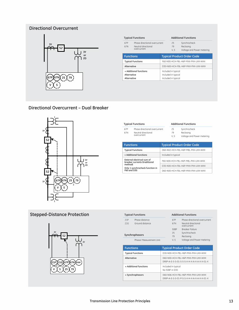
TypicalFunctions
21P21G
Phase distance Ground distance
AdditionalFunctions
67P67N 50BF2579V, S
Phase directional overcurrent Neutral directional overcurrent Breaker FailureSynchrocheckReclosingVoltage and Power metering
Functions TypicalProductOrderCode
TypicalFunctions D30-N00-HCH-F8L-H6P-MXX-PXX-UXX-WXX
Alternative D60-N00-HCH-F8L-H6P-MXX-PXX-UXX-WXXD90P-A-E-S-S-01-S-S-S-X-H-X-A-X-A-X-X-01-X
+Additionalfunctions Included in typicalNo 50BF in D30
+Synchrophasors D60-N06-HCH-F8L-H6P-MXX-PXX-UXX-WXXD90P-A-E-S-S-01-P-S-S-X-H-X-A-X-A-X-X-01-X
52
21G21P
V S3 3
67N
25 79
50BF
3Y
3Y
67P
Stepped-DistanceProtection
Synchrophasors
Phasor Measurement Unit
TypicalFunctions
67P67N
Phase directional overcurrent Neutral directional overcurrent
AdditionalFunctions
2579V, S
Synchrocheck ReclosingVoltage and Power metering
Functions TypicalProductOrderCode
TypicalFunctions F60-N00-HCH-F8L-H6P-MXX-PXX-UXX-WXX
Alternative D30-N00-HCH-F8L-H6P-MXX-PXX-UXX-WXX
+AdditionalfunctionsAlternativeAlternative
Included in typicalIncluded in typicalIncluded in typical
523Y
67N
V S
3Yor2D
25 7967P
DirectionalOvercurrent
52
52
3Yor2D
67N67P
V S
3Y
3Y 25 79
1
2
1
DirectionalOvercurrent–DualBreaker
TypicalFunctions
67P67N
Phase directional overcurrent Neutral directional overcurrent
AdditionalFunctions
2579V, S
Synchrocheck ReclosingVoltage and Power metering
Functions TypicalProductOrderCode
TypicalFunctions D60-N02-HCH-F8L-H6P-M8L-PXX-UXX-WXX
+Additionalfunctions Included in typical
Externalelectricalsumofbreakercurrents(traditionalmethod)Only1synchrocheckfunctioninF60andD30
F60-N00-HCH-F8L-H6P-M8L-PXX-UXX-WXX
D30-N00-HCH-F8L-H6P-MXX-PXX-UXX-WXX
D60-N00-HCH-F8L-H6P-MXX-PXX-UXX-WXX
14 TransmissionLineProtectionPrinciples
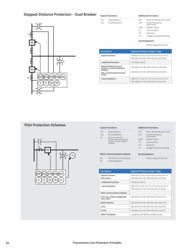
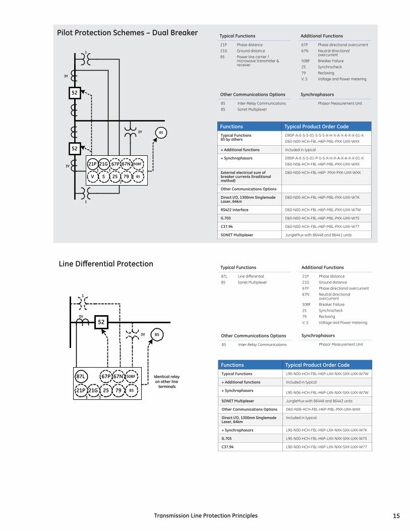
TypicalFunctions
21P21G85
Phase distance Ground distance Power line carrier / microwave transmitter & receiver / fiber or digital channel
AdditionalFunctions
67P67N 50BF2579V, S
Phase directional overcurrent Neutral directional overcurrent Breaker FailureSynchrocheckReclosingVoltage and Power metering
Functions TypicalProductOrderCode
TypicalFunctions85byothers
D90P-A-E-S-S-01-S-S-S-X-H-X-A-X-A-X-X-01-XD60-N00-HCH-F8L-H6P-MXX-PXX-UXX-WXX
+Additionalfunctions Included in typical
+Synchrophasors D90P-A-E-S-S-01-P-S-S-X-H-X-A-X-A-X-X-01-XD60-N06-HCH-F8L-H6P-MXX-PXX-UXX-WXX
OtherCommunicationsOptions
DirectI/O,1300nmSinglemodeLaser,64km
D60-N00-HCH-F8L-H6P-M8L-PXX-UXX-W7K
RS422interface D60-N00-HCH-F8L-H6P-M8L-PXX-UXX-W7W
G.703 D60-N00-HCH-F8L-H6P-M8L-PXX-UXX-W7S
C37.94 D60-N00-HCH-F8L-H6P-M8L-PXX-UXX-W77
SONETMultiplexer JungleMux with 86448 and 86441 units
52
21G21P
V S3 3
67N
25 79
50BF
3Y
3Y 85
85
67P
PilotProtectionSchemes
Synchrophasors
Phasor Measurement Unit
OtherCommunicationsOptions
8585
Inter-Relay CommunicationsSonet Multiplexer
1
1
52
52
3Y
3Y 21G21P
V S3 3
67N
25 79
50BF
3Y
2
267P
Stepped-DistanceProtection–DualBreaker
Functions TypicalProductOrderCode
TypicalFunctions D90P-A-E-S-S-01-S-S-S-X-H-X-A-X-A-X-X-01-X D60-N02-HCH-F8L-H6P-M8L-PXX-UXX-WXX
+Additionalfunctions Included in typical
Externalelectricalsumofbreakercurrents(traditionalmethod)Only1synchrocheckfunctionInD30
D60-N00-HCH-F8L-H6P- MXX-PXX-UXX-WXX
D30-N00-HCH-F8L-H6P-MXX-PXX-UXX-WXX
+Synchrophasors D90P-A-E-S-S-01-P-S-S-X-H-X-A-X-A-X-X-01-X D60-N08-HCH-F8L-H6P-M8L-PXX-UXX-WXX
TypicalFunctions
21P21G
Phase distance Ground distance
AdditionalFunctions
67P67N 50BF2579V, S
Phase directional overcurrent Neutral directional overcurrent Breaker FailureSynchrocheckReclosingVoltage and Power metering
Synchrophasors
Phasor Measurement Unit
15TransmissionLineProtectionPrinciples
52
21G21P3 3
67N
25 79
50BF
3Y
3Y 85
85
1
87L Identical relayon other lineterminals
67P
Line Differential Protection TypicalFunctions
87L85
Line differentialSonet Multiplexer
AdditionalFunctions
21P21G67P67N
50BF2579V, S
Phase distanceGround distancePhase directional overcurrent Neutral directional overcurrent Breaker FailureSynchrocheckReclosingVoltage and Power metering
Synchrophasors
Phasor Measurement Unit
OtherCommunicationsOptions
85 Inter-Relay Communications
Functions TypicalProductOrderCode
TypicalFunctions L90-N00-HCH-F8L-H6P-LXX-NXX-SXX-UXX-W7W
+Additionalfunctions Included in typical
+Synchrophasors L90-N06-HCH-F8L-H6P-LXX-NXX-SXX-UXX-W7W
SONETMultiplexer JungleMux with 86448 and 86443 units
OtherCommunicationsOptions D60-N08-HCH-F8L-H6P-M8L-PXX-UXX-WXX
DirectI/O,1300nmSinglemodeLaser,64km
Included in typical
+Synchrophasors L90-N00-HCH-F8L-H6P-LXX-NXX-SXX-UXX-W7K
G.703 L90-N00-HCH-F8L-H6P-LXX-NXX-SXX-UXX-W7S
C37.94 L90-N00-HCH-F8L-H6P-LXX-NXX-SXX-UXX-W77
TypicalFunctions
21P21G85
Phase distance Ground distancePower line carrier / microwave transmitter & receiver
AdditionalFunctions
67P67N 50BF2579V, S
Phase directional overcurrent Neutral directional overcurrent Breaker FailureSynchrocheckReclosingVoltage and Power metering
Functions TypicalProductOrderCode
TypicalFunctions85byothers
D90P-A-E-S-S-01-S-S-S-X-H-X-A-X-A-X-X-01-XD60-N00-HCH-F8L-H6P-M8L-PXX-UXX-WXX
+Additionalfunctions Included in typical
+Synchrophasors D90P-A-E-S-S-01-P-S-S-X-H-X-A-X-A-X-X-01-XD60-N06-HCH-F8L-H6P-M8L-PXX-UXX-WXX
Externalelectricalsumofbreakercurrents(traditionalmethod)
D60-N00-HCH-F8L-H6P- MXX-PXX-UXX-WXX
OtherCommunicationsOptions
DirectI/O,1300nmSinglemodeLaser,64km
D60-N00-HCH-F8L-H6P-M8L-PXX-UXX-W7K
RS422interface D60-N00-HCH-F8L-H6P-M8L-PXX-UXX-W7W
G.703 D60-N00-HCH-F8L-H6P-M8L-PXX-UXX-W7S
C37.94 D60-N00-HCH-F8L-H6P-M8L-PXX-UXX-W77
SONETMultiplexer JungleMux with 86448 and 86441 units
1
1
52
52
3Y
3Y 21G21P
V S3 3
67N
25 79
50BF
3Y
2
2
85
85
67P
PilotProtectionSchemes–DualBreaker
Synchrophasors
Phasor Measurement Unit
OtherCommunicationsOptions
8585
Inter-Relay CommunicationsSonet Multiplexer

16 TransmissionLineProtectionPrinciples
TypicalFunctions
87PC85
Phase ComparisonPower Line Carrier / Microwave
Functions TypicalProductOrderCode
TypicalFunctions L60-N00-HCH-F8P-H6P-L8L-NXX-SXX-UXX-WXX
52
21G21P3 3
67N
25 79
50BF
3Y
3Y 85
85
1
87PC Identical relay
on other lineterminals
67P
PhaseComparisonProtection AdditionalFunctions
21P21G67P67N 50BF2579V, S
Phase distanceGround distancePhase directional overcurrent Neutral directional overcurrent Breaker FailureSynchrocheckReclosingVoltage and Power metering
TypicalFunctions
87PC85
Line differentialPower Line Carrier / Microwave
1
52
52
3Y
3Y
21G21P3 3
67N
25 79
50BF
3Y
2
85
85
87PC Identical relay
on other lineterminals
67P
PhaseComparisonProtection–DualBreakersAdditionalFunctions
21P21G67P67N 50BF2579V, S
Phase distanceGround distancePhase directional overcurrent Neutral directional overcurrent Breaker FailureSynchrocheckReclosingVoltage and Power metering
Functions TypicalProductOrderCode
TypicalFunctions L60-N00-HCH-F8P-H6P-L8L-NXX-SXX-UXX-WXX
1
1
52
52
3Y
3Y
21G21P3 3
67N
25 79
50BF
3Y
2
2
85
85
87L
Identical relayon other lineterminals
67P
Line Differential Protection – Dual Breaker TypicalFunctions
87L85
Line differentialSonet Multiplexer
AdditionalFunctions
21P21G67P67N
50BF2579V, S
Phase distanceGround distancePhase directional overcurrent Neutral directional overcurrent Breaker FailureSynchrocheckReclosingVoltage and Power metering
Synchrophasors
Phasor Measurement Unit
OtherCommunicationsOptions
85 Inter-Relay Communications
Functions TypicalProductOrderCode
TypicalFunctions L90-N02-HCH-F8L-H6P-L8L-NXX-SXX-UXX-W7W
+Additionalfunctions Included in typical
+Synchrophasors L90-N08-HCH-F8L-H6P-LXX-NXX-SXX-UXX-W7W
Electricalsumofbreakercurrents(traditionalmethod) L90-N00-HCH-F8L-H6P-LXX-NXX-SXX-UXX-W7W
SONETMultiplexer JungleMux with 86448 and 86443 units
OtherCommunicationsOptions
DirectI/O,1300nmSinglemodeLaser,64km
L90-N02-HCH-F8L-H6P-L8L-NXX-SXX-UXX-W7K
G.703 L90-N02-HCH-F8L-H6P-L8L-NXX-SXX-UXX-W7S
C37.94 L90-N02-HCH-F8L-H6P-L8L-NXX-SXX-UXX-W77
0925-v5