radioembolization with 90y microspheres: angiographic and technical considerations
TRANSCRIPT

REVIEW/STATE OF THE ART
Radioembolization with 90Y Microspheres: Angiographic andTechnical Considerations
Robert J. Lewandowski Æ Kent T. Sato Æ Bassel Atassi Æ Robert K. Ryu ÆAlbert A. Nemcek Jr. Æ Laura Kulik Æ Jean-Francois Geschwind ÆRavi Murthy Æ William Rilling Æ David Liu Æ Lourens Bester ÆJose Ignacio Bilbao Æ Andrew S. Kennedy Æ Reed A. Omary Æ Riad Salem
Received: 26 March 2007 / Revised: 26 March 2007 / Accepted: 1 April 2007
� Springer Science+Business Media, LLC 2007
Abstract The anatomy of the mesenteric system and the
hepatic arterial bed has been demonstrated to have a high
degree of variation. This is important when considering
pre-surgical planning, catheterization, and trans-arterial
hepatic therapies. Although anatomical variants have been
well described, the characterization and understanding of
regional hepatic perfusion in the context of radioemboli-
zation have not been studied with great depth. The purpose
of this review is to provide a thorough discussion and
detailed presentation of the angiographic and technical
aspects of radioembolization. Normal vascular anatomy,
commonly encountered variants, and factors involved in
changes to regional perfusion in the presence of liver tu-
mors are discussed. Furthermore, the principles described
here apply to all liver-directed transarterial therapies.
Keywords Brachytherapy � Radioembolization �Yttrium-90 � Liver cancer � Embolization � SIR-Spheres �TheraSphere � Selective internal radiation
Introduction
As the incidence of primary and metastatic liver cancer
continues to increase [1, 2], the use of minimally invasive
techniques as a treatment option is becoming more com-
D. Liu
Inland Imaging LLC, Angio/Interventional Section Providence/
Sacred Heart Medical Center, Spokane, WA, USA
L. Bester
Department of Interventional Radiology, University of New
South Wales, Sydney, Australia
J. I. Bilbao
Departamento de Radiologia, Clinica Universitaria de Navarra,
Pamplona, Navarra, Spain
A. S. Kennedy
Wake Radiology Oncology, Cary, NC, USA
R. Salem (&)
Department of Radiology, 676 North St. Claire, Suite 800,
Chicago, IL 60611, USA
e-mail: [email protected]
R.S. and J.-F.G. are consultants for MDS Nordion. R.M., D.L., L.B.,
and J.I.B. are proctors for Sirtex Medical. A.S.K. has received
honoraria from MDS Nordion and Sirtex Medical. This work was not
funded.
R. J. Lewandowski � K. T. Sato � B. Atassi �R. K. Ryu � A. A. Nemcek Jr. � R. A. Omary �R. Salem
Department of Radiology, Section of Interventional Radiology,
Northwestern Memorial Hospital, Robert H. Lurie
Comprehensive Cancer Center, Chicago, IL, USA
L. Kulik
Department of Hepatology, Northwestern University, Chicago,
IL, USA
J.-F. Geschwind
Department of Radiology, Section of Interventional Radiology,
The Johns Hopkins Hospital, Baltimore, MD, USA
R. Murthy
Department of Radiology, Section of Interventional Radiology,
MD Anderson Cancer Center, University of Texas, Houston, TX,
USA
W. Rilling
Department of Radiology, Section of Interventional Radiology,
Medical College of Wisconsin, Milwaukee, WI, USA
123
Cardiovasc Intervent Radiol
DOI 10.1007/s00270-007-9064-z
mon. Percutaneous interventions such as radiofrequency
ablation, cryoablation, and percutaneous ethanol ablation
have been shown to be effective for the treatment of small
liver tumors [3–5]. Similarly, endovascular techniques such
as transcatheter arterial chemoembolization (TACE) and
transcatheter arterial embolization (TAE) have shown
clinical benefit in selected patients [6–8].
Recently a new form of transarterial therapy involving
infusion of radioactive microparticles has been developed,
and has shown promise for the treatment of patients with
liver tumors. Radioembolization, a form of intra-arterial
brachytherapy, is a technique where particles of glass or
resin, impregnated with the isotope yttrium-90 (90Y), are
infused through a catheter directly into the hepatic arteries.90Y is a pure b emitter and decays to stable Zr-90 with a
physical half-life of 64.1 h. The average energy of the bparticles is 0.9367 MeV, has a mean tissue penetration of
2.5 mm, and has a maximum penetration of 10 mm. There
are currently two commercially available agents: SIR-
Spheres (Sirtex Medical Ltd., Lane Cove, Australia), and
TheraSphere (MDS Nordion, Ottawa, Canada). Radio-
embolization refers to the use of TheraSphere, SIR-
Spheres, or other microsphere agents that have the emis-
sion of radiation as their primary and microembolization as
their secondary modes of action. For the purposes of this
review, unless otherwise specified, radioembolization re-
fers to all such devices.
TheraSphere was approved by the U.S. Food and Drug
Administration (FDA) in 1999 under a humanitarian device
exemption, defined as safe and probably beneficial for the
approved indication. The approval was for treatment of
unresectable hepatocellular carcinoma (HCC), with or
without portal vein thrombosis, or as a bridge to trans-
plantation in patients who could have appropriately posi-
tioned catheters. This device is also approved for the
treatment of liver neoplasia in Europe. Its composition is
that of nonbiodegradable glass microspheres where 90Y is
an integral constituent of the glass and, therefore, cannot
leach. Ninety-five percent of the particles are between 15
and 35 lm in diameter. Each microsphere contains 2500
Bq of activity at the time of calibration. Available activity
vials are 3, 5, 7, 10, 15, and 20 GBq, corresponding to 1.2
million, 2 million, 2.8 million, 4 million, 6 million, and 8
million microspheres per activity vial, respectively [9]. As
opposed to SIR-Spheres, the vial cannot be split, and
hence, the entire vial of TheraSphere must be injected
during the administration.
SIR-Spheres were granted premarket approval by the
FDA in 2002, defined as safe and effective for the approved
indication. The indication is for the treatment of metastatic
colorectal cancer to the liver with concomitant use of
floxuridine (FUDR). This device is also approved in Eur-
ope, Australia, and various Asian countries for liver neo-
plasia. SIR-Spheres are resin-based particles,
approximately 29–35 lm in diameter, in which the 90Y and
resin are intimately bound. The standard activity vial is 3
GBq, of which a predetermined amount is decanted in the
nuclear medicine pharmacy from the vial for injection into
the patient. A 3-GBq activity vial contains between 40
million and 80 million microspheres [10]. Each micro-
sphere contains 50 Bq of activity at the time of calibration.
Once the particles are infused through the catheter into
the hepatic artery, they travel to the distal arterioles within
the tumors, where the b-emissions from the isotope irra-
diate the tumor. With traditional external beam radiation to
the liver, doses are limited to 30–40 Gray (Gy) due to the
risk of radiation-induced liver disease (radiation hepatitis)
that may occur with higher doses [11, 12]. With radio-
embolization, tumors receive a much higher dose of radi-
ation given the direct arterial deliver of the microspheres,
as well as the hypervascularity of the tumors and target
tissue. Hence, radiation doses that are significantly higher
can be delivered directly to the tumor with minimal irra-
diation of normal liver tissue. This has been shown to be
effective for both primary and metastatic tumors [13–18].
Radioembolization is defined as the injection of embolic
particles loaded with a radioisotope using percutaneous
transarterial techniques. There are two distinct aspects to
the procedure: the first being the injection of embolic
particles (‘‘embolization’’) as the vehicle and the second
being the delivery and administration, via this embolic
vehicle, of radiation (‘‘radio’’). Fluoroscopic guidance,
angiographic end points of embolization and stasis, and the
need to modify this based on angiographic findings make
this treatment a true embolization procedure. Furthermore,
the administration and delivery of radiation, modification
of dose based on tumor and hepatic volume, and required
knowledge of radiation effects on tissue make this a
brachytherapy procedure as well. There is a spectrum of
radioembolic effect that exists with this therapy: with
TheraSphere, there is high specific activity and a small
number of microspheres (mild radioembolic effect); with
SIR-Spheres, there is low specific activity and a large
number of microspheres (moderate/high radioembolic ef-
fect). It is this varying number of microspheres, embolic
effect, and possible vascular saturation that makes fluoro-
scopic observation necessary.
These technical aspects of radioembolization are an in-
terventional radiology procedure almost in its entirety.
Given this, it is important that interventional radiologists
play a leading role in the future evolution of this technol-
ogy, including angiographic delivery, dosimetry, and
overall technical enhancements in radioembolization.
Depending on institutional policies and hospital radiation
safety committees, interventional radiologists (IRs) should
function in a collegial manner with other authorized users
R. J. Lewandowski et al.: Radioembolization with 90Y Microspheres
123

of brachytherapy devices such as radiation oncologists and
nuclear medicine physicians. Although local regulatory
bodies may impose some hurdles that limit the ability of
IRs from performing radioembolization independently, this
model should not be discouraged. Many successful radio-
embolization practices involving the interventional radiol-
ogists as authorized user have been established, supporting
this practice model [19, 20]. IRs receive formal didactic
training in radiation biology, radiation physics, and radia-
tion safety, making them fully able to undertake roles and
responsibilities of authorized users. In most clinical or
hospital settings, radiologists, radiation oncologists and
nuclear medicine physicians are the most knowledgeable in
matters regarding radiation and radiation safety. Interven-
tional radiologists also provide the full spectrum of patient
clinical care services—from consultation and initial patient
evaluation to actual performance of the procedure, post-
operative care, and follow-up care. Hence, IRs (as well as
nuclear medicine and radiation oncology physicians) are
ideally suited to be authorized users for this therapy.
The principles described in this review represent the
international collective angiographic experience of the
authors accumulated over 2000 90Y infusions in over 1000
patients at eight major internationally renowned cancer
centers. They are meant to provide an in-depth review and
stimulate dialogue in the interventional radiology com-
munity on optimizing and improving the techniques used
for radioembolization. Also, the angiographic techniques
described herein may be applied to radioembolization
using radioisotopes other than 90Y (holmium, rhenium).
Finally, although the focus of this article is radioemboli-
zation with 90Y, the angiographic concepts described
herein apply to all transarterial therapies, including TACE,
TAE, and drug-eluting microspheres.
Patient Selection
With both devices, patient selection criteria are similar.
Patients should have a reasonable performance status.
Using the Eastern Cooperative Oncology Group (ECOG)
criteria, a score of 0–2 is acceptable. If Karnofsky perfor-
mance status is used, a score of at least 60 (requires
occasional assistance, but is able to care for most personal
needs) is necessary. In general, patients must have non-
compromised pulmonary function, be able to undergo
angiography and selective visceral catheterization, have
adequate hematology (platelet count >75 · 109/L [unless
closure devices are used]), serum creatinine <2.0 mg/dl,
and adequate liver function. An in-depth discussion of
patient selection criteria has been published previously
[21].
The optimal selection criteria for patients with HCC
have been described previously [22, 23]. For patients with
HCC, the tumor volume should be less than 70% of the
total liver volume, not have infiltrative disease or main
portal vein thrombosis, and have alanine or aspartate
aminotransferase levels less than five times the upper-
normal limit. Radioembolization may be undertaken in the
setting of abnormal/elevated liver function if a segmental
infusion can be performed, without significant impact on
liver functions [24, 25]. Patients with metastatic liver dis-
ease should have normal liver function tests and acceptable
performance status.
Portal vein thrombosis has been seen as a relative con-
traindication for such treatments as TACE; however, it is
not necessarily a contraindication for radioembolization.
TheraSphere is indicated for patients with PVT and has
been shown to be safe in this setting, even when the portal
vein has been invaded by tumor [9, 26]. SIR-Spheres are
contraindicated in the setting of portal vein thrombosis, as
the number of particles in a typical vial may result in
embolic occlusion of the parent vessel [27]. Hence, if SIR-
Spheres are to be used in the setting of PVT, dose frac-
tionation should be considered.
Other exclusionary criteria include immediate life-
threatening extrahepatic disease, uncorrectable flow to the
gastrointestinal (GI) tract, and hepatopulmonary lung
shunting. For TheraSphere, the limitation of what can be
administered to the lungs is based on cumulative dose,
irrespective of lung shunt [9]. Although the literature
supports the safety of a 50-Gy cumulative lung dose, cer-
tain centers use the more conservative 30 Gy (16.5 mCi).
For SIR-Spheres, infusion is limited by the lung shunt
fraction (20%). Activity of SIR-Spheres infused is adjusted
based on tumor volume and lung shunt fraction [10].
Dosimetric and device-specific technical considerations are
not addressed in this article, as these have been discussed
in depth by previous authors [13, 16, 17, 21, 28–30].
Technical Considerations
Angiographic Evaluation
Once a patient has been selected as a candidate for radio-
embolization, an initial angiographic evaluation is per-
formed. The proper sequence of vessels to be addressed
and evaluated has been published previously [31]. This is
done primarily to document the visceral anatomy, identify
anatomic variants, and isolate the hepatic circulation by
occluding extrahepatic vessels [32]. The technique includes
standard visceral angiography using a hooked catheter such
as a Cobra-2 (Boston Scientific, Natick, MA), Sos Omni
R. J. Lewandowski et al.: Radioembolization with 90Y Microspheres
123
select (Angiodynamics, Queensbury, NY), or a Simmons-
1/2/3 (Cook, Bloomington, IN). Once an abdominal
aortogram has been performed, a superior mesenteric
arteriogram is performed to assess for the presence of
accessory or replaced hepatic arteries arising from the
superior mesenteric artery (SMA). A venous phase is also
obtained to evaluate the status/patency of the portal vein.
Next, the celiac trunk is selectively catheterized to evaluate
the hepatic arterial supply. Subsequent to celiac injection, it
is imperative that selective right and left hepatic angiog-
raphy with power injection angiography be performed,
usually with 3-French microcatheter systems (Renegade
High-Flow; Boston Scientific, Natick, MA, or Progreat,
Somerset, NJ). This will allow for the identification of
variant mesenteric anatomy and subsequent prophylactic
embolization of extrahepatic vessels such as the right
gastric, gastroduodenal, or falciform artery. Other vessels
that may be identified and may require prophylactic
embolization include the supraduodenal, retroduodenal,
left inferior phrenic, accessory left gastric, and inferior
esophageal. Care should be taken when considering
embolization of the gastroduodenal artery (GDA), as
accessory hepatic vessels feeding tumor may arise from
this artery [31].
The following is the technical protocol for mapping
mesenteric angiography that is recommended prior to ra-
dioembolization. This is meant as guidance and should be
modified accordingly based on institutional standards. The
particular rationale for each step is described in detail.
Following radiation safety, optimization of imaging (fil-
tering) and power injection (not hand injection) are highly
recommended.
Abdominal aorta: injection of 15 ml/s for 30 ml. The
reasons for this step include identification of patent celiac,
SMA, and aortic tortuosity, as well as guiding proper vis-
ceral catheter selection. For example, SMA and celiac
vessels that have acute angles are best catheterized by re-
verse curve catheters such as the Sos-Omni (Angiody-
namics, Queensbury, NY) and Simmons (Cook,
Bloomington, IN). Otherwise, C-shaped catheters may be
used routinely.
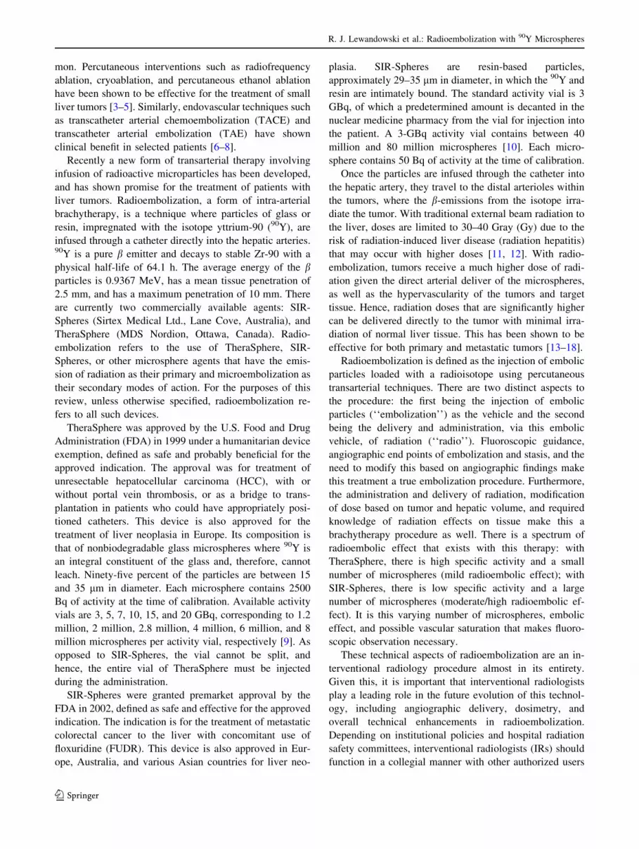
Fig. 1 A Selective SMA
injection shows a common
hepatic artery (C) arising from
it, with the right hepatic (R) and
left hepatic (L) arteries
branching in standard fashion. BReplaced common hepatic
artery. C Celiacomesenteric
trunk seen on aortography. DAccessory right hepatic arising
off the SMA perfusing segments
6/7
Fig. 2 HCC causing parasitization from the SMA
R. J. Lewandowski et al.: Radioembolization with 90Y Microspheres
123

Superior mesenteric artery : injection of 3 ml/s for 30
ml. Although several institutions use rates such as 6–7 ml/s
for 60–70 ml, we use a more conservative approach. Using
a 3 ml/s for 30 ml injection allows for the identification of a
replaced right hepatic, replaced proper hepatic (Fig. 1a),
replaced common hepatic (Fig. 1b) celiacomesenteric
trunk (Fig. 1c), accessory right hepatic (Fig. 1d), patency
of the portal vein, and the rare parasitization of blood flow
from the SMA to the liver (Fig. 2). Furthermore, contrast
use is preserved and not refluxed into the aorta, which
usually occurs with injection rates that are higher than
those advocated herein. Retrograde flow (from tumor
sumping, or celiac occlusion/stenosis) into the GDA is also
assessed. Finally, contrast is preserved for injections that
matter most, such as may be required during angiography
and embolization of the hepatic and extrahepatic vessels.
Celiac artery: injection of 3–4 ml/s for 12–15 ml.
Classic branches of the celiac artery include the splenic,
common hepatic, and left gastric arteries. Interrogation of
the celiac trunk allows for assessment of the celiac anat-
omy and identifies the presence of any possible variants,
including a replaced left hepatic artery arising off the left
gastric (gastrohepatic trunk) as well as the right and left
inferior phrenic arteries. In the presence of such variants,
selective catheterization of these vessels should be per-
formed. Catheterization of the replaced left hepatic artery
Fig. 3 A Common hepatic arteriogram demonstrates small extrahe-
patic perforating branches (arrows). Reflux into the common hepatic
artery may result in inadvertent gastritis, duodenitis, and pancreatitis.
B Common hepatic angiogram demonstrates a trifurcation into a
GDA and right and left hepatic arteries. C Injection with reflux
demonstrates the patient to have the ‘‘double hepatic’’ artery variant
Fig. 4 A Triphasic CT
demonstrates right lobe lesions.
Lesions (arrows) did not
respond to right lobe treatment,
while response and tumor
shrinkage were seen in the third
and smaller lesion (arrowhead).
B CT angiogram via the right
hepatic artery demonstrates lack
of opacification of the two
tumors (arrows), but
opacification of the more
posterior lesion that did respond
to Y90 (arrowhead). C GDA
angiogram demonstrates a
hypertrophied epiploic vessel
(arrows) providing flow to the
medial tumor. D Epiploic artery
catheterization. E Injection of
epiploic artery demonstrates
opacification of the medial
tumor. F CT angiogram via the
hypertrophied epiploic artery
provides flow to the medial
tumor (arrow). The patient
underwent successful Y90
treatment from this location. GRight inferior phrenic
arteriogram demonstrates
parasitization of flow to the
lateral tumor, successfully
treated
R. J. Lewandowski et al.: Radioembolization with 90Y Microspheres
123

should be performed and an injection rate selected that
would not result in gastric/esophageal artery reflux. If re-
flux is a possibility depending on the radioembolic device
used, prophylactic embolization of the left gastric should
be undertaken. In the presence of a gastrohepatic trunk, it is
quite common for several small esophageal, phrenic, and
gastric perforators to be present, particularly at the hori-
zontal portion of the left hepatic artery variant. Consider-
ation of embolization of these vessels should be made,
functionally converting the gastrohepatic trunk into a left
hepatic artery. In the presence of large hepatic tumors,
particularly in the dome of the liver, the right inferior
phrenic may be a source of parasitization of blood flow.
Although this occurs in patients with metastases, it is more
common in cases of HCC. Injection of this vessel will
result in the proper outlining of blood flow to tumor and
will allow for optimization of transarterial therapy. Finally,
the dorsal pancreatic artery may arise off the celiac. Its
presence should be recognized and the possibility of reflux
into this vessel should be recognized if excessive micro-
spheres are injected within the hepatic circulation.
Common hepatic artery (CHA): injection rate of 3 ml/s
for 12 ml. The use of the same injection rate as the celiac
artery allows for the ‘‘flooding’’ of the hepatic circulation,
optimizing the likelihood that extrahepatic vessels will be
identified. Vessels of note that may require embolization
arising off the common hepatic include the right gastric,
dorsal pancreatic, and gastroduodenal (Fig. 3a). Other
complex variants exist. (1) A replaced right hepatic artery
off the SMA with a trifurcation from the CHA into a GDA
and left hepatic arteries (possibly also a middle hepatic). In
such cases, a right gastric is often seen, and unless seg-
mental infusions of radioembolization are planned, the
GDA/right gastric should be embolized. This functionally
converts the CHA (in the presence of a replaced right he-
patic) into a left hepatic artery. (2) Trifurcation of the CHA
into a GDA, right, and left hepatic arteries. Given the low
margin of error if reflux occurs from a lobar or segmental
infusion, the GDA should be embolized in this case. (3)
‘‘Double hepatic’’ artery: a very early takeoff of the right
hepatic artery. Unless sufficient contrast is injected and
refluxed to the origin of the celiac, this vessel may be
missed (Figs. 3b and c). Finally, in some cases, the dorsal
pancreatic artery arising off the CHA may be large enough
that prophylactic embolization may be considered. Given
the rich collaterals to the pancreas, embolization of the
dorsal pancreatic is safe, since this would result in
recruitment of flow from the pancreatica magna and the
Fig. 5 A Left hepatic
arteriogram demonstrates a
vessel clearly coursing outside
the expected confines of the left
lobe of the liver (arrow). BCatheterization confirms that
this is the left inferior phrenic
artery. C Coil embolization of
this vessel. D Left hepatic
arteriogram demonstrates three
vessels. Arrow points to
extrahepatic vessel. A
hypervascular tumor is seen. EInjection of this vessel confirms
that it is the left inferior phrenic
artery (arrows). F Left hepatic
arteriogram demonstrates a
vessel clearly coursing outside
the expected location of the left
lobe of the liver (arrows). GInterrogation of this vessel
confirms that it is the inferior
esophageal artery. Note
opacification of the stomach and
esophagus, as well as the
coronary vein. HPostembolization of the inferior
esophageal demonstrates
complete coil occlusion (arrow)
R. J. Lewandowski et al.: Radioembolization with 90Y Microspheres
123

caudal pancreatic arteries. Nontarget radioembolization of
the pancreatic vessels may result in pancreatitis [31].
Gastroduodenal artery: injection rate of 2 ml/s for 8 ml.
Vessels sought include the (accessory) cystic artery,
superior pancreaticoduodenal, and parasitization of flow to
the liver from the GDA or from its branches (right gas-
troepiploic, omental/epiploic branches) (Fig. 4), as well as
accessory hepatic arteries (usually providing flow to seg-
ment 5 or 6) [31]. Given the clinically inconsequential
effects, prophylactic embolization of the GDA is recom-
mended if a highly radioembolic device is to be considered.
Settings where the GDA might not be embolized include
where there is parasitization of flow to liver that may re-
quire future catheterization and radioembolization, where
there is retrograde flow from the SMA from either hyper-
dynamic flow or celiac stenosis, or a minimally embolic
device is considered. In cases of GDA parasitization to
segments 5/6, embolization of all distal vessels except the
one feeding the liver tumors is recommended if possible,
essentially converting the GDA into an accessory hepatic
vessel feeding the tumor vasculature. Otherwise, if com-
plete embolization of the GDA is undertaken, it should be
embolized to the origin of the vessel, as small, very
proximal GDA branches may hypertrophy in response to
incomplete embolization.
Proper hepatic angiogram: 3 ml/s for 12 ml. Injection of
this vessel at this rate will often result in supraphysiolog-
ical flow rates and reflux but will opacify small and often
overlooked vessels. The vessel most commonly of interest
upon assessment of this vessel is the right gastric artery. At
times, the right gastric artery may have two parallel bran-
ches, both of which may require prophylactic embolization.
Left hepatic angiogram: injection of 2 ml/s for 8 ml.
Vessels of interest here include the left inferior phrenic
artery, accessory left gastric artery, inferior esophageal
artery, right gastric artery, and falciform artery (Figs. 5 and
6) [33]. Prophylactic embolization of these vessels may
decrease adverse events following radioembolization, such
as abdominal pain, gastritis, and ulceration. Furthermore,
delayed imaging of the left hepatic angiogram is recom-
mended in order to confirm the lack of opacification of the
coronary vein. Finally, injection of the left hepatic artery
Fig. 6 A Left hepatic
arteriogram demonstrates a
falciform artery (arrows). BSelective catheterization of the
falciform artery (arrow). CSuccessful embolization of the
falciform artery (arrow). DCeliac angiogram demonstrates
patent GDA, right and left
hepatic arteries. E Left hepatic
angiogram demonstrates a
patent falciform artery (arrow).
F Arrow points to the
‘‘falciform artery complex’’. GSuccessful embolization of the
GDA and falciform artery
R. J. Lewandowski et al.: Radioembolization with 90Y Microspheres
123

should outline where there is flow to segment 4 via the
medial branch. If the medial branch is absent, a separate
middle hepatic artery should be sought, usually off the
right hepatic artery.
Right hepatic angiogram: injection of 2 ml/s for 10–12
ml. Vessels of interest include the middle hepatic artery,
supraduodenal, and cystic artery. In some cases of (large)
HCCs, a hypertrophied caudate artery may require angio-
graphic interrogation (Fig. 7). Also, selective injection may
identify the vascular dynamics that may be underappreci-
ated using cross-sectional imaging. For example, although
metastatic colorectal cancer carries the label of ‘‘hypo-
vascular,’’ selective injection often demonstrates the
opposite (Fig. 8). Finally, in rare instances, the right he-
patic artery may arise directly from the aorta (Fig. 9).
Phrenic arteries (right and left): injection of 1–2 ml/s
for 4–6 ml. Depending on the findings of the hepatic
angiogram, if a portion of the liver tumor (especially HCC)
is not visualized angiographically, interrogating this vessel
may identify the remainder of the flow to the tumor
(Fig. 10) [31]. Interrogating the right inferior phrenic and
other extrahepatic vessel parasitizing to liver tumors
(omental, intercostals, internal mammary) should be sus-
pected when tumors in the same vascular distribution re-
spond differently (Fig. 4). Tumors in the dome of the right
lobe may have parasitization from this vessel.
As can be noted from the above protocol, complete
mesenteric angiography and embolization can be per-
formed with 150 ml of contrast or less. Prophylactic
embolization of the above-mentioned vessels essentially
functions to convert the hepatic blood flow into one that is
analogous to surgically placed hepatic arterial ports. Usu-
ally, in surgical port placement, the CHA is skeletonized,
the GDA and right gastric are ligated, and any other he-
patic-mesenteric or extrahepatic vessels are ligated. This is
identical to what is accomplished with the above-described
angiographic technique. Furthermore, it is important that
all hepatic vessels be interrogated during the initial
angiographic assessment of the patient. Given the pro-
pensity of tumors to parasitize blood flow from vessels
other than the actual tumor location, only such direct
catheterization and interrogation of all vessels would
demonstrate this phenomenon (Fig. 11). The lack of rec-
ognition of this phenomenon may result in incomplete
treatment of the target tumor bed irrespective of the tran-
sarterial treatment modality that is used.
Once the anatomy has been established, selective arte-
riography is performed in the expected location of the 90Y
treatment. Microcatheters should be used, particularly if
the vessels are small in caliber or demonstrate significant
tortuosity (Renegade Hi-flow [Boston Scientific, Natick,
MA], Progreat [Terumo, Somerset, NJ], or 2.3-French
Prowler Plus [Cordis, Miami, FL]). Once a catheter has
been placed into the appropriate location, the presence of
any lung shunting through the tumor must be determined.
The lung-shunt fraction, F (fraction of Tc-99m macroag-
gregated albumin [MAA] observed in the lungs relative to
the total Tc-99m MAA activity observed), can be deter-
mined by infusing 4 mCi of Tc-99m labeled MAA particles
through the catheter into the desired liver distribution.
MAA particles range in size from 10 to 60 lm, with a mean
diameter of 35 lm. The same technique is used for both
SIR-Spheres and TheraSphere and gives an accurate esti-
mate of distribution of 90Y microspheres. The Tc-99m
MAA scan can also demonstrate the presence of any GI
flow. The shunting evaluation allows the physician to plan
Fig. 7 A Pretreatment MRI of a
caudate lobe (segment 1) HCC
(arrows). B Common hepatic
arteriogram demonstrates a
hypertrophied caudate artery
(arrows). C Selective
catheterization with a Prowler
Plus (Cordis, Miami, FL)
demonstrates tumor
hypervascularity. D One-year-
posttreatment MRI
demonstrates necrosis and near-
complete involution of the
caudate HCC
R. J. Lewandowski et al.: Radioembolization with 90Y Microspheres
123
for radioembolization therapy and minimize any uncer-
tainty in microspheres distribution at the time of treatment.
It is recommended that MAA injection be performed
once all vessels of concern have been embolized. In all
cases of metastases, injection is performed in the proper
hepatic artery, given the low incidence of lung shunting in
patients with metastatic disease to the liver (unless very
high tumor burden is present) [21]. In contrast, the ap-
proach to MAA injection in patients with HCC is slightly
different. If the patient has bilobar HCC, proper hepatic
artery injection of MAA is performed unless gross vascular
shunting into the hepatic or portal vein is seen. The
shunting fraction obtained is assumed to be representative
of the tumors in both lobes of the liver. In cases of bilobar
disease where angiographic shunting is seen, a unilobar
injection of MAA is performed and only one lobe is as-
sessed at any one time. A repeat MAA injection is per-
formed at a later date when the second treatment site
requires treatment.
It is important to note that in cases where variant arterial
anatomy exists, the MAA should be fractionated in order to
cover the entire liver in one setting if possible, saving the
patient an unnecessary catheterization. For example, in
cases where there is a replaced right hepatic artery, 2–3
mCi of MAA is given in that vessel, while the remaining
1–2 mCi is given in the left hepatic. In cases of a gastro-
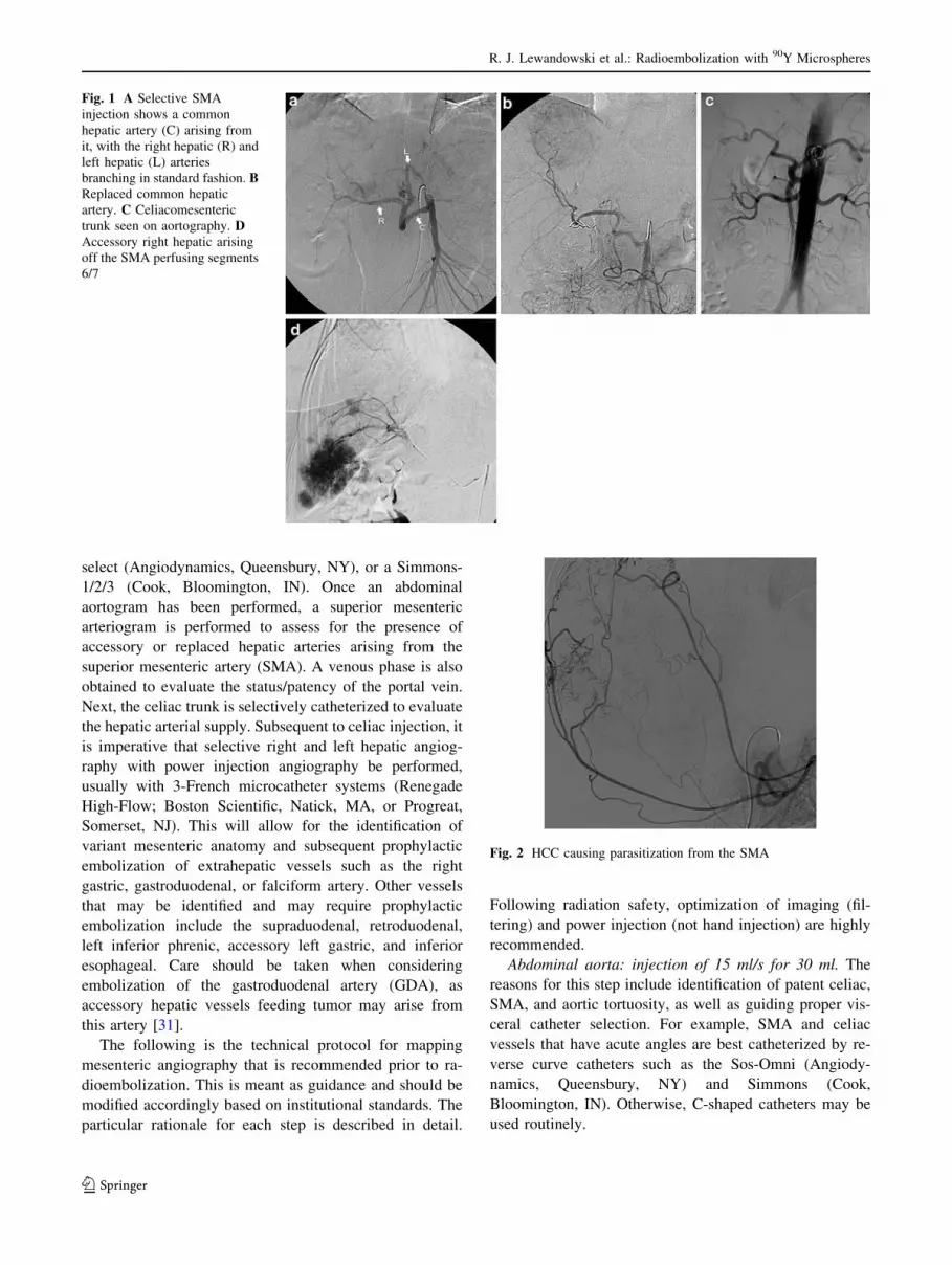
Fig. 8 A Proper hepatic
angiogram clearly demonstrates
hypervascular tumors that were
described as ‘‘hypovascular’’
on cross-sectional imaging (CT)
(arrows). B ‘‘Hypovascular’’
metastases from colon
metastases. C Hepatic
angiogram does not demonstrate
hypervascularity on
fluoroscopy. D CT angiography
confirms hypervascularity of
tumors. E Six-month follow-up
after radioembolization
confirms excellent response.
F Bilobar ‘‘hypovascular’’
colorectal metastases. GHepatic angiography (left)
confirms the metastases are in
fact ‘‘hypervascular’’
Fig. 9 A Reflux of contrast into
aorta from an SMA injection
shows an unusual branch arising
from the right side (arrow). BSelective injection of this vessel
shows it to be a right hepatic
artery arising directly from the
aorta
R. J. Lewandowski et al.: Radioembolization with 90Y Microspheres
123

hepatic trunk, 1–2 mCi of MAA is injected in the left
hepatic, while the remainder is injected in the right hepatic
artery.
Variant Mesenteric Anatomy
In 55% to 65% of cases [34], the celiac artery gives rise to
the splenic artery, left gastric artery, and CHA. The dorsal
pancreatic artery commonly arises from the celiac origin,
although it may also arise off the CHA or splenic [31]. The
CHA then gives rise to the GDA and becomes the proper
hepatic artery, which divides into the right and left hepatic
arteries. When a distinct vessel arising from the right he-
patic artery provides flow to segment IV, it is referred to as
the middle hepatic artery (Fig. 11). In more than 40% of
cases, the origin and course of the hepatic arteries vary, as
does the vascular distribution of the vessel irrespective of
its anticipated course [34]. Vessels supplying one segment
may be recruited to provide flow to other anatomic seg-
ments (Fig. 11). The most common variants include a re-
placed right hepatic artery which arises from the SMA, a
replaced CHA (Fig. 1) arising from the SMA, and bifur-
cation of a short CHA into right and left hepatic arteries.
The right and left hepatic arteries may arise separately
from the celiac trunk, or directly from the aorta (Fig. 9).
The caudate lobe most commonly receives its blood supply
from a small branch off the left or right hepatic artery. This
caudate artery is normally rather diminutive; however, it
may become quite prominent in the setting of tumor,
thereby allowing selective catheterization and treatment
(Fig. 7). Given that traditional TACE and other large-par-
ticle-type therapy involves a high-viscosity chemothera-
peutic agent as well as embolic particles (300–700 lm), the
use of significantly smaller 90Y microspheres (20–60 lm)
are particularly advantageous in the setting of diminutive
vasculature (Fig. 7).
Extrahepatic Vasculature
The identification and isolation of the hepatic vasculature
are critical when performing radioembolization. One dev-
astating complication is extrahepatic delivery of 90Y par-
ticles, most commonly to the GI tract, invariably leading to
severe gastritis and possibly even ulceration [35, 36]. Al-
though some gastric and duodenal ulcers can be treated
medically, it is also possible for surgical intervention to be
required. In cases where GI ulceration or radiation gastritis
is suspected as an adverse event, patients should undergo
endoscopy for confirmation of ulceration and location of
injury, as well as to assess the size of the ulcer. Giant (>3-
cm) ulcers are at times unlikely to heal using medical
therapy [37, 38]. Also, as opposed to standard GI ulcers,
radioembolization-induced ulceration is caused from the
serosal surface, possibly decreasing the ability for the ulcer
to heal or be seen using endoscopy. Hence, every effort
should be made to minimize the risk of nontarget 90Y
administration.
The largest extrahepatic vessel is the GDA. Normally,
this vessel provides branches to the duodenum, pancreas,
and stomach. Angiographic assessment of this vessel is
important not only prior to embolization, but also to assessFig. 10 Right inferior phrenic arteriogram demonstrating significant
parasitization of blood flow to hepatic tumors (arrows)
Fig. 11 Proper hepatic
angiogram demonstrates tumor
blush in the right lobe. B Middle
hepatic artery injection
demonstrates parasitization of
flow across hepatic lobes.
Treatment of the right lobe
tumor via the middle hepatic
artery was performed
R. J. Lewandowski et al.: Radioembolization with 90Y Microspheres
123
for (1) variant cystic artery origin, (2) presence of acces-
sory right hepatic artery, and (3) presence of parasitization
of flow from the GDA or other branches to the liver
(Fig. 4).
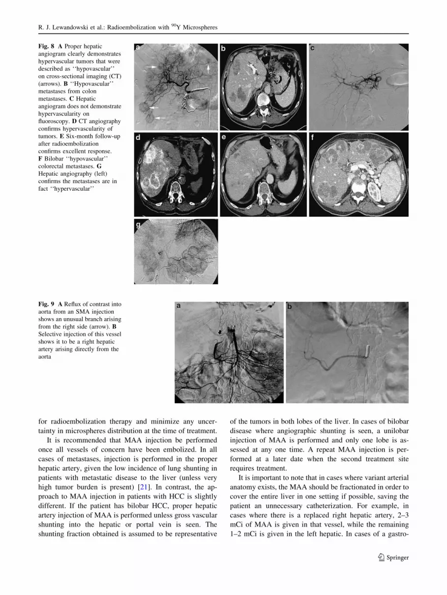
The next most important vessel to identify is the right
gastric artery (Fig. 12). The origin of this vessel is variable,
arising from any site from the hepatic artery, and usually
anastamoses via an arterial arcade to the left gastric artery.
In some cases of a continuous anastomosis with the left
gastric artery, catheterization can be accomplished from
the left gastric artery if antegrade catheterization of the
right gastric cannot be performed (Fig. 13).
There are many other arterial variants and accessory
vessels that deserve special mention [31]. The falciform
artery is one such vessel that is occasionally identified
angiographically. This vessel runs in the double fold of
peritoneum that is the falciform ligament and anastomoses
with the vasculature from the anterior abdominal wall,
usually the terminal vessels of the internal mammary and
inferior epigastric arteries (musculophrenic and superior
epigastric). Failure to identify and prophylactically occlude
this vessel may result in delivery of 90Y particles to the
anterior abdominal wall, which may result in adverse
events in the form of severe abdominal pain, skin necrosis,
and rash (Fig. 14) [39]. Another branch includes the
supraduodenal artery, which provides blood supply to the
upper portion of the duodenum and pylorus [31]. The ori-
gin of this vessel is also variable, and it communicates with
the pancreaticoduodenal arcade as well as right gastric
branches [40].
The cystic artery deserves special discussion. Although
the usual origin of this vessel is the right hepatic artery, it
may also arise from the left hepatic, middle hepatic, gas-
troduodenal, or replaced (accessory) right hepatic arteries
[31]. Furthermore, the blood supply to the gallbladder
comes not only from the cystic artery, but also from per-
forators to the body of the gallbladder from the hepatic
parenchyma and the GDA (Fig. 15) [31]. The gallbladder
may therefore be assumed to have redundant blood supply.
In the context of radioembolization, although infusion of90Y distal to the cystic artery is ideal, it is often not pos-
sible. This is because 90Y microspheres should be infused
at a location that will allow admixture of microspheres with
flowing blood, resulting in even and flow-dependent
microsphere distribution. The cystic artery often arises
deep within the right hepatic artery near its bifurcation into
anterior (segments 5/8) and posterior (segments 6/7) sec-
toral vessels. When this is the case and the cystic artery
arises distal to the ideal location for 90Y infusion, avoiding
microsphere flow into the gallbladder becomes impossible.
Although the incidence of radiation-induced cholecystitis
is very low, prophylactic embolization may be considered.
The technical approach to cystic artery embolization
should be addressed. At all times during 90Y infusion, the
treating physician should balance the risks of (1) infusion
proximal to the cystic artery with potential radiation
Fig. 12 A Celiac arteriogram
shows the right gastric artery
(arrow) arising from the
common hepatic artery.
B Selective right gastric artery
angiogram shows the
communication with the left
gastric artery (arrow)
Fig. 13 A Left gastric artery
injection demonstrates flow
through the lesser curve arcade
to the right gastric artery
(arrows). B Retrograde
catheterization complete.
C Successful right gastric artery
coil embolization from the left
gastric artery (arrows)
R. J. Lewandowski et al.: Radioembolization with 90Y Microspheres
123

cholecystitis; (2) infusion distal to the cystic artery but with
suboptimal microsphere distribution; and (3) infusion
proximal to the cystic following prophylactic embolization
of cystic artery, resulting in optimal microsphere distribu-
tion but with a risk of ischemic cholecystitis. First, for all
cases of 90Y radioembolization, if the cystic artery is large
and appears to represent the dominant blood supply to the
gallbladder, prophylactic embolization should be avoided,
as the risk of ischemic cholecystitis may outweigh the risk
of radiation cholecystitis if infused proximally. However, if
the cystic artery is small, then the redundant blood supply
to the gallbladder may be assumed to be present and pro-
phylactic occlusion may be considered. The approach to
this differs between radioembolic devices. The risk of
radiation-induced cholecystitis is sufficiently low with
TheraSphere (low radioembolic load) that infusion proxi-
mal to the cystic artery may be preferable to the potential
benefits of advancing the catheter distal and risking inad-
equate microsphere distribution. However, given the higher
radioembolic load of SIR-Spheres, it is suggested that
treating physicians have a lower threshold for prophylactic
embolization of the cystic artery with the latter device.
Gelfoam torpedoes or microcoils may be used to provide
cystic artery blockade. Prophylactic antibiotics are also
advocated in such cases.
The above-described approach to cystic artery is a result
of two cases of radiation cholecystitis (one case with each
type of 90Y microsphere) and two cases of ischemic cho-
lecystitis we have encountered. All four patients required
surgery. Although a previous report had suggested that the
incidence of radiation cholecystitis without coil emboli-
zation of the vessel is clinically acceptable, we have
adopted this enhanced approach when necessary [41].
Another possible strategy to deal with the cystic artery,
should embolization be essential for proper 90Y infusion,
relates to the approach to the GDA. Since the blood supply
to the gallbladder may also come from the perforators from
the liver parenchyma or GDA, a modified GDA emboli-
zation technique may be considered, where embolization
with as few coils as possible very close to the origin of the
Fig. 14 A Left hepatic artery
injection shows a distal vessel
(arrows) traveling in a divergent
course from the other hepatic
vessels. Its course parallels the
falciform ligament. B Following
coil embolization, there is no
flow in this vessel (arrow).
C Left hepatic arteriogram in a
different patient demonstrates a
falciform artery (arrows).
D Falciform arteriogram
demonstrates retrograde anterior
abdominal wall flow into the
superior epigastric and
musculophrenic arteries
(arrows). E Postembolization of
the falciform artery
demonstrates no flow. F CT
scan confirms coils within the
falciform artery (arrow)
Fig. 15 A The right hepatic artery is very tortuous, with a cystic
artery (white arrow) arising from the apex of a bend. The optimal
catheter position for treatment (black arrow) would be directed at the
origin of the cystic artery. B Coil embolization minimizes the risk of a
radiation cholecystitis (arrow). C Injection of the cystic arrow
demonstrates flow to the body of the gallbladder (large arrow). There
is trans-cystic flow to the hepatic parenchyma (small arrow),
confirming a redundant blood supply
R. J. Lewandowski et al.: Radioembolization with 90Y Microspheres
123
GDA may be in order. This may permit branches from the
GDA distal to the coils to receive retrograde blood from the
gastroepiploic artery and provide flow to the gallbladder
once the cystic artery is embolized. Finally, it should be
stated that the long-term consequences of this approach
have not been formally studied (Fig. 15).
The occlusion of extrahepatic vessels (excluding the
above discussion on cystic artery) is best accomplished by
superselective microcoil embolization. Due to the redun-
dant vasculature in this area, embolization of these vis-
ceral vessels can be performed safely, similar to treating
acute upper GI bleeding [42]. Larger vessels such as the
GDA can sometimes be catheterized by 4-French cathe-
ters (e.g., glide or C-shaped catheters) and embolized with
0.035- or 0.038-in. coils, such as Nester Coils (Cook,
Bloomington, IN). In the event that the GDA is not
accessible with a standard catheter due to size or vessel
course, a microcatheter can be used to select the vessel,
and embolization performed with 0.018-in. microcoils.
Catheterization of small vessels such as the falciform
artery is best accomplished using 2.3-French systems such
as the Prowler Plus (Cordis, Miami, FL). Coils can be
deployed with the use of a coil pusher, or by saline flush,
and should be deployed well within the vessel being
embolized as close to the origin as possible. Completion
angiography should demonstrate no further flow in the
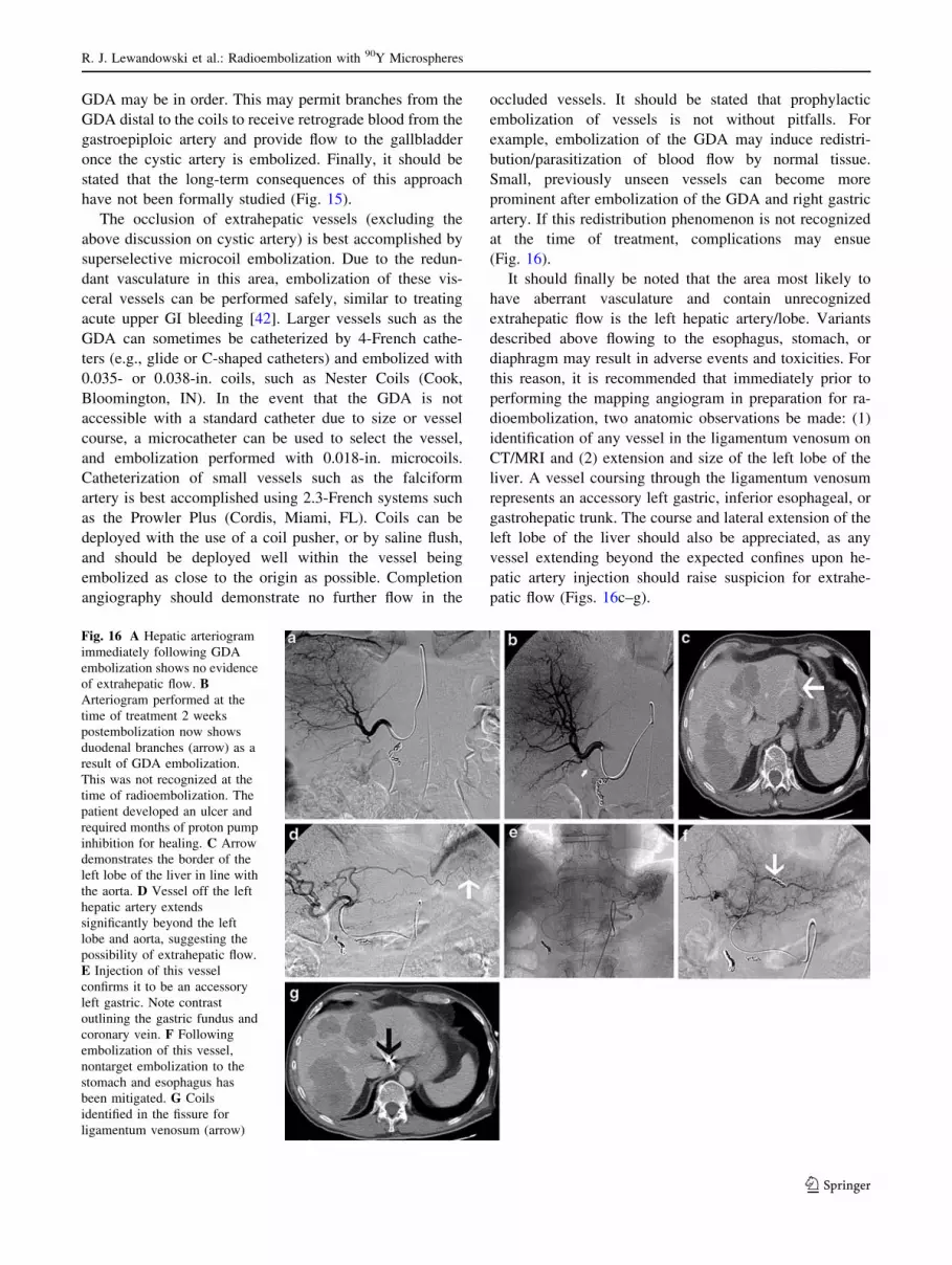
occluded vessels. It should be stated that prophylactic
embolization of vessels is not without pitfalls. For
example, embolization of the GDA may induce redistri-
bution/parasitization of blood flow by normal tissue.
Small, previously unseen vessels can become more
prominent after embolization of the GDA and right gastric
artery. If this redistribution phenomenon is not recognized
at the time of treatment, complications may ensue
(Fig. 16).
It should finally be noted that the area most likely to
have aberrant vasculature and contain unrecognized
extrahepatic flow is the left hepatic artery/lobe. Variants
described above flowing to the esophagus, stomach, or
diaphragm may result in adverse events and toxicities. For
this reason, it is recommended that immediately prior to
performing the mapping angiogram in preparation for ra-
dioembolization, two anatomic observations be made: (1)
identification of any vessel in the ligamentum venosum on
CT/MRI and (2) extension and size of the left lobe of the
liver. A vessel coursing through the ligamentum venosum
represents an accessory left gastric, inferior esophageal, or
gastrohepatic trunk. The course and lateral extension of the
left lobe of the liver should also be appreciated, as any
vessel extending beyond the expected confines upon he-
patic artery injection should raise suspicion for extrahe-
patic flow (Figs. 16c–g).
Fig. 16 A Hepatic arteriogram
immediately following GDA
embolization shows no evidence
of extrahepatic flow. BArteriogram performed at the
time of treatment 2 weeks
postembolization now shows
duodenal branches (arrow) as a
result of GDA embolization.
This was not recognized at the
time of radioembolization. The
patient developed an ulcer and
required months of proton pump
inhibition for healing. C Arrow
demonstrates the border of the
left lobe of the liver in line with
the aorta. D Vessel off the left
hepatic artery extends
significantly beyond the left
lobe and aorta, suggesting the
possibility of extrahepatic flow.
E Injection of this vessel
confirms it to be an accessory
left gastric. Note contrast
outlining the gastric fundus and
coronary vein. F Following
embolization of this vessel,
nontarget embolization to the
stomach and esophagus has
been mitigated. G Coils
identified in the fissure for
ligamentum venosum (arrow)
R. J. Lewandowski et al.: Radioembolization with 90Y Microspheres
123

Lobar Versus Whole-Liver Injection
Although much of the early clinical experience with 90Y
involved whole-liver infusion, this treatment paradigm is
no longer recommended. Whole-liver treatment was
undertaken given limitations in microcatheters and imag-
ing, as well as in patients who underwent treatment using
surgically placed intrahepatic pumps. Enhancements in
microcatheter technology have decreased the use of sur-
gically implanted pumps for the treatment of liver tumors.
Furthermore, there exists significant extrahepatic flow,
described throughout this article, through small vessels that
can only be avoided using lobar/segmental infusions. For
radioembolization, a treatment paradigm that parallels
TACE is recommended, i.e., lobar or sub-/segmental
infusions. If a treating physician insists on treatment to the
entire liver at once, then a ‘‘bilobar lobar’’ infusion is
recommended. This involves placement of the catheter in
one, followed by the other, hepatic artery where infusion is
performed. Infusion of 90Y via the proper or common he-
patic arteries should be avoided, despite prophylactic
embolization of extrahepatic vessels.
Difficult Scenarios
It is not uncommon to observe anatomic abnormalities
other than the common variants described above. One
condition encountered is a stenotic or occluded celiac ar-
tery. This is usually evident on the initial SMA arterio-
gram, where a hypertrophied pancreaticoduodenal arcade is
visualized (Fig. 17). To continue with radioembolization,
there are two options available: (1) recanalize or stent the
celiac artery occlusion and proceed as usual, or (2) traverse
the pancreaticoduodenal vessel with a microcatheter and
proceed to the liver from the SMA.
Stenting a stenotic or occluded celiac origin can be
difficult. The various techniques available have been
described elsewhere and are not discussed in depth here
[43–46]. This technique is appropriate in the setting of
atherosclerotic disease of the celiac origin; however,
median arcuate ligament compression of the celiac artery
creates more difficulty. From a long-term patency stand-
point, any stent placed in the celiac will undoubtedly fail
over time due to the continued extrinsic stresses and
pressure on the vessel. However, the primary purpose of
stenting the vessel in the case of radioembolization is for
access to the hepatic arteries in patients who will require
repeated transarterial therapy for liver cancer. In our
experience, we have resorted to stenting a compressed
celiac artery when all other options were exhausted.
A less invasive, but equally challenging and time-con-
suming method is to try to navigate the pancreaticoduo-
denal arcade with a microcatheter and access the hepatic
arteries through the SMA. The route is almost always cir-
cuitous and will require a flexible microcatheter such as a
Prowler Plus (Cordis) and a maneuverable wire, such as a
Headliner (Boston Scientific) or Glidewire GT (Terumo)
(Fig. 18). If successful, it will allow the physician to per-
form radioembolization safely from the SMA.
Although stenotic celiac arteries can result in flow
limitations when delivering microspheres, other medical
conditions or previous procedures may do the same. Pa-
tients undergoing 90Y radioembolization following TACE
to the vascular bed invariably display angiographic hall-
marks of vascular injury such as sluggish flow, limited
tumor enhancement, and hypervascularity. Sluggish flow
may result in patients who have been treated with growth-
factor inhibitors (e.g., bevacizumab, cetuximab), compro-
mised cardiac output, and spasm induced when large
catheters are used in smaller vessels. Despite the ability of
most experienced interventional radiologists to be able to
advance 4- or 5-French catheters distal within the liver, this
approach is highly discouraged at the time of radioembo-
lization. This may be performed at the time of mesenteric
angiography and prophylactic embolization of collateral
vessels. However, on the day of radioembolization, given
that 90Y microspheres rely principally on blood flow
dynamics and hypervascularity, catheterization and infu-
sion should be performed at enough distance from the
vessel of interest to allow proper admixing of the micro-
spheres with flowing blood. For example, in a patient
where a right lobe infusion is intended, catheter position
should be such that enough distance exists to allow inter-
mixing of the microspheres with blood, allowing flow
dynamics and hypervascularity of the tumor to absorb the
microspheres. If the catheter is too close to the bifurcation
into the anterior and posterior branches, flow of micro-
spheres will preferentially be in the more dependent pos-
terior branch (segment 6/7) and will result in suboptimal
Fig. 17 Superior mesenteric arteriogram demonstrates hypertrophied
GDA (arrow) and pancreaticoduodenal arcade with opacification of
the hepatic artery. These are secondary findings suggesting the
presence of a celiac origin stenosis or occlusion
R. J. Lewandowski et al.: Radioembolization with 90Y Microspheres
123

Fig. 18 A Selective
catheterization of a
pancreaticoduodenal branch of
the SMA shows a hypertrophied
and tortuous route to the hepatic
circulation. B Circuitous
microcatheter placement
through the vessel into the
hepatic circulation. C Injection
through the microcatheter
confirming catheter placement
prior to radioembolization
Fig. 19 A Posterior segment exophytic right lobe tumor. B Right
renal artery arteriogram demonstrates both adrenal artery branches
(arrows) providing blood flow to the tumor. C Transrenal parasiti-
zation of flow to the HCC. D Right lobe HCC which appears to be
perfused by an extrahepatic vessel (arrow). E Axial CT demonstrates
a vessel crossing the abdomen anterior to the liver (arrow). F Splenic
angiogram demonstrates a vessel from the splenic hilum crossing the
abdomen to the right upper quadrant (arrow). G Microcatheterization
of this vessel confirms that this is a splenic vessel providing blood
flow to the right lobe HCC (arrows)
R. J. Lewandowski et al.: Radioembolization with 90Y Microspheres
123

flow to the lesions located anteriorly (segment 5/8). Be-
cause of this flow dependence, described above, the tech-
nique of balloon occlusion for microsphere injection is
highly discouraged. Balloon occlusion eliminates hyper-
vascularity dynamics and creates dependent layering of
microspheres that are ‘‘pushed’’ into the target tissue by
injected fluid, rather than being ‘‘absorbed’’ by the hy-
perdynamics of tumor flow.
Exophytic tumors can present a challenge due to the
complex vascular supply. Vascular tumors, especially HCC,
can parasitize blood flow from many other sources, such as
intercostal arteries, renal, adrenal, and splenic (Fig. 19).
Treatment through these vessels should only be performed
when a thorough evaluation has been performed to confirm
that the vessel only perfuses the tumor. A transcatheter CT
angiogram can be performed with the catheter in the vessel
in question. Contrast is injected directly into the catheter
while CT images of the liver are acquired, giving an ex-
tremely accurate view of contrast distribution. If no extra-
tumoral blood flow is seen, one can use this vessel to deliver
the 90Y microspheres. In other instances, tumors that appear
hypovascular on conventional contrast-enhanced CT scans
may in fact be shown to be hypervascular when the artery is
directly injected under CT. This can help predict the dis-
tribution as well as the concentration of the microspheres at
the time of therapy (Fig. 20) [24]. Hence, tumors should not
be assumed to be hypovascular without proper angiographic
and CT assessment.
One of the most difficult scenarios to deal with involves
tumor masses (either solitary or as part of multifocal dis-
ease) that are at angiographic watershed zones of the liver.
Although several scenarios exist, only the most common
are reviewed here. However, readers are directed to an
excellent review of these anatomic scenarios published
recently [47]. The first involves disease dominance in the
center of the liver, by either one or several large centrally
located masses, occupying segments 4A, 4B, 1, 5, and 8.
By virtue of this location, both right and left hepatic
arteries will require attention and infusion in order to
completely treat this disease presentation. Careful and
meticulous angiographic technique is required to ensure
that all portions of the tumor are covered by microspheres
while minimizing the risk of nontarget embolization
(Fig. 21). A second watershed area is that near or adjacent
to the gallbladder. Lesions near or adjacent to the gall-
bladder may derive their blood supply from the right, left,
or even proper hepatic arteries. Treatment using a lobar
approach where the catheter is placed well into the lobar
artery may result in inadequate microsphere coverage. A
third watershed area is that of the dome of the liver (seg-
ment 4A/8). In some cases, it can be quite difficult to
definitively assess whether a vessel will perfuse a certain
segmental territory of the liver. The blood supply to that
area may be from the anterior branch of the right hepatic
artery, the cranial portion of the middle hepatic artery
(segment 4A), the right inferior phrenic artery, the internal
mammary artery, or the cranial portions of the medial he-
patic artery. Parasitization of blood flow from the lateral
segment left hepatic artery to the dome of the liver may
also occur. A fourth watershed area is that of the tip of the
right lobe (segment 5/6). Treating this area may result in
inadequate tumor coverage since some of this territory may
be supplied by the right inferior phrenic, the right adrenal,
an intercostal/lumbar artery, a renal capsular branch, chest
wall vessels (thoracodorsal, lateral thoracic artery), or even
colic branches off the SMA (Figs. 2, 4, 10, 19). Given the
difficulties that may arise in difficult cases of blood supply,
the use of CT angiography is recommended (Fig. 22) [24].
Also, it is important when imaging response is being
evaluated that the location of the tumor be taken into
consideration, especially if in a watershed area. The 90Y
microspheres may be declared ineffective for a particular
tumor when, in fact, the microspheres were suboptimally
delivered given the lack of recognition of the exact blood
supply.
Another difficult scenario involves the management of
the gastrohepatic trunk. As the name implies, this repre-
sents blood supply to the left lobe of the liver as well as the
Fig. 20 A Conventional contrast-enhanced CT shows multiple ‘‘hyp-
ovascular’’ lesions in the liver (arrows). B Hepatic arteriogram shows
multiple areas of enhancement (arrows) consistent with the lesions seen
on CT. C Transcatheter CT arteriography shows the lesions to be
extremely vascular relative to the hepatic parenchyma, justifying the
use of radioembolization or other arterial therapies in this case
R. J. Lewandowski et al.: Radioembolization with 90Y Microspheres
123

stomach from a common trunk. The presence of this vessel
can often be prospectively identified on cross-sectional
imaging, where the vessel is seen to provide flow to the
liver as it traverses the fissure for ligamentum venosum
(Fig. 23). The left hepatic lobe supplied by this vessel is
most commonly to segments 2 and 3 but may also supply
segment 4. The difficulty arises when trying to delineate
the extrahepatic blood supply from the gastrohepatic trunk.
It is not uncommon for branches such as the inferior
phrenic, inferior esophageal, and accessory left gastric as
well as the left gastric proper to arise from the gastrohe-
patic trunk. Radioembolization in the left hepatic artery
arising off a gastrohepatic trunk carries a risk of nontarget
embolization to the extrahepatic vessels described above.
Given this, the proper identification and embolization of
these vessels are critical during the angiographic evaluation
of patients. The selective catheterization of each of the
vessels arising off the gastrohepatic trunk is advocated.
Admittedly, it may be difficult to confirm whether a vessel
is a hepatic or an extrahepatic branch. CT Angiography can
aid in the defining of the vascular bed being perfused
(Fig. 22). Alternatively, we strongly advocate the use of a
consistently identified secondary sign of extrahepatic flow
when the gastrohepatic trunk is injected: opacification of
the coronary vein. This vein represents the venous drainage
of the body and fundus of the stomach, as well as the distal
Fig. 21 A Celiac injection demonstrates patent common hepatic
and splenic artery. No right hepatic artery is seen, given the
previously documented replaced right hepatic artery. B Selective
injection of the left hepatic artery following embolization of the
GDA demonstrates an inferior esophageal artery (top arrow), as
well as two other vessels (lower arrows: falciform and right gastric
arteries) in the area of the abdominal wall and right gastric
distribution that require interrogation. C The top arrow represents
the inferior esophageal artery. Inferior esophageal arteriogram prior
to embolization demonstrates flow to the esophagus and stomach.
D Injection of a vessel heading toward the stomach suggests
anterior abdominal wall flow. E Prolonged injection in the
anteroposterior plane confirms that this is flow into the anterior
abdominal (superior epigastric and musculophrenic arteries) wall via
the falciform artery. F Interrogation of the right gastric artery prior
to embolization. G, H Completion injection of the left and common
hepatic arteries, respectively, demonstrates embolization of all
extrahepatic vessels. Compared to B, more pronounced flow into the
tumors is noted and there is no extrahepatic flow, allowing for safe
radioembolization
R. J. Lewandowski et al.: Radioembolization with 90Y Microspheres
123

esophagus. Opacification of this vessel confirms extrahe-
patic flow. Figure 24 demonstrates a case where complex
arterial anatomy is demonstrated and each extrahepatic
vessel is interrogated. Once all vessels have been embol-
ized, coronary venous flow has been obliterated, making
radioembolization feasible.
Radiation segmentectomy is a technique that has been
described in which the dose of 90Y is delivered superse-
lectively into a branch of the hepatic artery. This results in
a higher dose of radiation delivered to a smaller area and is
useful for focal lesions. The information obtained from CT
angiography can be helpful in better delineating tumor
location, tumor volume, and blood distribution pattern
(Fig. 22). Because this technique can accurately demon-
strate tumor volume within the hepatic lobe, more accurate
dose calculations can be performed, potentially resulting in
more effective treatments [24].
Idiosyncratic Reaction
During the immediate postprocedural time following ra-
dioembolization, patients may experience a rare and unu-
sual reaction. Just as penicillin and sulfa may cause
Stevens-Johnson syndrome, radioembolization with 90Y
may cause a short-lived idiosyncratic reaction. This reac-
tion is nearly identical to that obtained in patients receiving
urokinase, with clinical symptoms of shakes, chills, and
alterations in hemodynamics and vital signs [48]. Just as
with a urokinase reaction, management is supportive,
including fluids if hypotensive, as well as diphendydramine
and meperidine. This reaction is short-lived, usually lasting
less than 1 h. Both the onset of symptoms and their reso-
lution are quite rapid. Although it is difficult to predict
which patients will have this reaction, it has been seen
commonly in patients with arterioportal shunting who un-
dergo radioembolization (Fig. 25). In our series, we have
observed this reaction in 10 patients. All patients had re-
ceived TheraSphere and all had arterioportal shunting from
HCC. When we first observed this phenomenon, we
admitted all patients for possible fever and sepsis, includ-
ing chest x-ray, urinalysis, and blood cultures. Prophylactic
broad-spectrum antibiotics were given. In no case were any
of the tests or cultures positive. The diagnosis of 90Y-re-
lated idiosyncratic reaction was made in all cases.
Postprocedure Management and Follow-up
Radioembolization is performed on an outpatient basis.
Following the procedure, the arterial puncture is closed
with the assistance of a closure device or with manual
compression. After the appropriate recovery time, patients
are discharged home (2 h with closure devices, 6 h with
manual compression). Nondiabetic patients receive a Me-
drol DosePak for 6 days as directed to help combat the
fatigue that invariably ensues in most patients [21]. Patients
may receive 7–10 days of a fluoroquinolone if the entire
right lobe is to be treated and the cystic artery was perfused
with microspheres. All patients are placed on a proton
pump inhibitor for 7–10 days following treatment. Tumor
markers (AFP, CEA, CA-19-9, chromogranin A, CA-125),
complete blood count, liver function tests, and general
chemistries are obtained 4–6 weeks postprocedure. Cross-
sectional (triphasic CT, dynamic gadolinium-enhanced
MRI, perfusion imaging) and functional imaging (PET)
tests are obtained at that time to assess the results of
therapy. The opposite lobe is usually treated shortly fol-
lowing assessment of response and the demonstration of
lack of diffuse progression. Completion evaluation and
assessment of response (CT/PET/MR/tumor markers) are
usually performed once both lobes have been treated and
30–60 days have elapsed since last treatment.
Fig. 22 A CT demonstrates a
lesion in segment 3 of the liver.
B Selective arteriogram of the
segment 3 vessel does not
convincingly demonstrate the
lesion. C Direct CT
arteriography through the
microcatheter shows the area of
distribution encompasses the
lesion in question
Fig. 23 Gastrohepatic trunk coursing through the fissure for the
ligamentum venosum (arrow)
R. J. Lewandowski et al.: Radioembolization with 90Y Microspheres
123

Conclusion
Radioembolization has been shown to be an effective
treatment for patients with either primary liver cancer or
metastatic liver disease [14, 36, 49]. Unlike other locore-
gional therapies, the preprocedure planning and meticulous
mesenteric angiography are of paramount importance in
order to determine the safest and most effective treatment
strategy. Identifying anatomic variants, isolating the he-
patic circulation and prophylactic embolization requires
attention to detail that is usually not necessary with treat-
ments such as TACE or TAE. Extrahepatic blood vessels
may occasionally be used to deliver the 90Y microspheres
as well if flow is confined to the tumor. Given the need for
in-depth comprehension of hepatic and extrahepatic vas-
culature to liver tumors, investigators are strongly urged to
Fig. 24 A Injection of the gastrohepatic trunk demonstrates complex
vascularity to the left lobe and hypervascular tumors. B Delayed
imaging illustrates a prominent coronary vein (arrows). C Injection of
the inferior esophageal artery clearly shows flow to the fundus of the
stomach and lower esophagus (arrows). D Left gastric artery injection
prior to embolization. E Injection of the gastrohepatic trunk following
embolization of the inferior esophageal and right and left gastric
arteries demonstrate persistent opacification of the coronary vein,
implying flow to the gastric circulation. F Retrospective evaluation of
the gastrohepatic trunk demonstrates an accessory left gastric artery
that was not recognized (arrow). G Injection of the accessory left
gastric artery demonstrates flow into the coronary vein. H Completion
injection following embolization of the accessory left gastric artery. IDelayed injection demonstrates no flow into the coronary vein,
implying that all vessels with gastric contribution have been
successfully embolized
R. J. Lewandowski et al.: Radioembolization with 90Y Microspheres
123

review the available literature on angiographic anatomy, in
particular, three recent angiographic reviews [31, 32, 47].
Despite the in-depth review presented, it should be no-
ted that the prophylactic embolization of vessels during
mapping angiography is not being advocated for all cases.
Rather, investigators and treating physicians should rec-
ognize that the delivery of 90Y microspheres requires a
higher level of awareness of vascular anatomy, dosimetry,
and risks of nontarget administration compared to other
embolic therapies. The degree of pretreatment emboliza-
tion should be tailored based on the treating physicians’
experience, vessel size, planned treatment location, and
radioembolic device being considered. For example, the
prophylactic embolization of vessels is not necessary in all
cases of patients being treated with TheraSphere, given its
lower radioembolic load. IRs should make this decision
based on anatomy, experience, blood flow dynamics, and
planned injection site. However, this is not true of SIR-
Spheres; all patients receiving this therapy should undergo
prophylactic embolization (i.e., GDA, right gastric and
other vessels described herein) given the high radioembolic
mechanism of action and risks of nontarget administration.
Advancements in microcatheter technology now allow
access into vessels that were previously out of reach of
transvascular techniques (Fig. 26). Techniques such as
Fig. 25 Image demonstrating arterioportal shunting (arrow) in a
patient treated with Y90 radioembolization who experienced an
idiosyncratic reaction. Follow-up evaluation demonstrated a response,
with reduction in tumor size and portal vein retraction
Fig. 26 A Hepatic arteriogram
in a patient with a ligated
common hepatic from surgical
exploration demonstrates
alternate flow through the
pancreas to the proper hepatic
artery. B Transpancreatic
microcatheterization of the
hepatic artery. CTranspancreatic right hepatic
arteriogram
Fig. 27 A Patient with a large HCC treated with radioembolization.
Blood supply to the tumor was from the right, middle, and left
hepatic artery. B Pretreatment gastrohepatic trunk angiogram
demonstrates tumor hypervascularity from the medial branch left
hepatic artery. C Tumor has decreased in size on MR, with
significant necrosis 10 months following treatment. D Follow-up
angiogram 10 months after radioembolization demonstrates com-
plete obliteration of flow to tumor and preserved normal paren-
chyma: the angiographic ‘‘complete’’ response. A hemangioma is
noted in the lateral segment
R. J. Lewandowski et al.: Radioembolization with 90Y Microspheres
123

radiation segmentectomy allow for more focused delivery
of radiation to a much smaller area, thus reducing the
amount of normal liver parenchyma exposed to radiation.
Taking advantage of tumor hypervascularity as well as the
controlled embolic burden of radioembolization can result
in the ‘‘angiographic’’ complete response (Fig. 27). That
is, the microspheres preferentially accumulate in the tumor
vasculature, spare normal parenchyma, and obliterate the
tumor from an angiographic standpoint, removing all dis-
cernible flow to the tumor. Ultimately, this technique is one
that is well tolerated by the patient, may be as effective as
other alternatives available, and may have more wide-
spread adoption once additional studies have been per-
formed [14–17, 24, 26, 27, 49]. Finally, we believe that the
toxicity profile of all hepatic embolization therapies, irre-
spective of their nature (embolic, radiation, drug-eluting),
can be improved significantly by applying the principles
described in this comprehensive review article.
References
1. El-Serag HB (2002) Hepatocellular carcinoma and hepatitis C in
the United States. Hepatology 36:S74–S83
2. Jemal A, Murray T, Ward E, et al. (2005) Cancer statistics, 2005.
CA Cancer J Clin 55:10–30
3. Buscarini L, Buscarini E, Di Stasi M, Vallisa D, Quaretti P,
Rocca A (2001) Percutaneous radiofrequency ablation of small
hepatocellular carcinoma: long-term results. Eur Radiol 11:914–
921
4. Seifert JK, Cozzi PJ, Morris DL (1998) Cryotherapy for neuro-
endocrine liver metastases. Semin Surg Oncol 14:175–183
5. Clark TW, Soulen MC (2002) Chemical ablation of hepatocel-
lular carcinoma. J Vasc Interv Radiol 13:S245–S252
6. Lo CM, Ngan H, Tso WK, et al. (2002) Randomized controlled
trial of transarterial lipiodol chemoembolization for unresectable
hepatocellular carcinoma. Hepatology 35:1164–1171
7. Llovet JM, Real MI, Montana X, et al. (2002) Arterial emboli-
sation or chemoembolisation versus symptomatic treatment in
patients with unresectable hepatocellular carcinoma: a rando-
mised controlled trial. Lancet 359:1734–1739
8. Brown KT, Nevins AB, Getrajdman GI, et al. (1998) Particle
embolization for hepatocellular carcinoma. J Vasc Interv Radiol
9:822–828
9. MDS Nordion (2004) TheraSphere yttrium-90 microspheres
package insert. MDS Nordion, Kanata, Canada
10. SIRTeX Medical (2004) SIR-Spheres yttrium-90 microspheres
package insert, SIRTeX Medical, Lane Cove, Australia
11. Lawrence TS, Robertson JM, Anscher MS, Jirtle RL, Ensminger
WD, Fajardo LF (1995) Hepatic toxicity resulting from cancer
treatment. Int J Radiat Oncol Biol Phys 31:1237–1248
12. Ingold JA, Reed GB, Kaplan HS, Bagshaw MA (1965) Radiation
hepatitis. Am J Roentgenol Radium Ther Nucl Med 93:200–208
13. Stubbs RS, Cannan RJ, Mitchell AW (2001) Selective internal
radiation therapy (SIRT) with 90-yttrium microspheres for
extensive colorectal liver metastases. Hepatogastroenterology
48:333–337
14. Geschwind JF, Salem R, Carr BI, et al. (2004) Yttrium-90
microspheres for the treatment of hepatocellular carcinoma.
Gastroenterology 127:S194–S205
15. Carr BI (2004) Hepatic arterial 90-yttrium glass microspheres
(Therasphere) for unresectable hepatocellular carcinoma: interim
safety and survival data on 65 patients. Liver Transpl 10:S107–
S110
16. Gray B, Van Hazel G, Hope M, et al. (2001) Randomised trial of
SIR-Spheres plus chemotherapy vs. chemotherapy alone for
treating patients with liver metastases from primary large bowel
cancer. Ann Oncol 12:1711–1720
17. Van Hazel G, Blackwell A, Anderson J, et al. (2004) Randomised
phase 2 trial of SIR-Spheres plus fluorouracil/leucovorin che-
motherapy versus fluorouracil/leucovorin chemotherapy alone in
advanced colorectal cancer. J Surg Oncol 88:78–85
18. Salem R, Lewandowski RJ, Atassi B, et al. (2005) Treatment of
unresectable hepatocellular carcinoma with use of 90Y micro-
spheres (TheraSphere): safety, tumor response, and survival. J
Vasc Interv Radiol 16:1627–1639
19. Touzios JG, Kiely JM, Pitt SC, et al. (2005) Neuroendocrine
hepatic metastases: Does aggressive management improve sur-
vival? Ann Surg 241:776–783, discussion 783–775
20. Romano W (2005) Personal communication. Interventional
Radiology, Beaumont Hospital, Royal Oak, MI
21. Salem R, Thurston KG (2006) Radioembolization with 90yttrium
microspheres: a state-of-the-art brachytherapy treatment for pri-
mary and secondary liver malignancies: Part 1: Technical and
methodologic considerations. J Vasc Interv Radiol 17:1251–1278
22. Goin JE, Salem R, Carr BI, et al. (2005) Treatment of unresec-
table hepatocellular carcinoma with intrahepatic yttrium 90
microspheres: factors associated with liver toxicities. J Vasc In-
terv Radiol 16:205–213
23. Goin JE, Salem R, Carr BI, et al. (2005) Treatment of unresec-
table hepatocellular carcinoma with intrahepatic yttrium 90
microspheres: a risk-stratification analysis. J Vasc Interv Radiol
16:195–203
24. Rhee TK, Omary RA, Gates V, et al. (2005) The effect of cath-
eter-directed ct angiography on yttrium-90 radioembolization
treatment of hepatocellular carcinoma. J Vasc Interv Radiol
16:1085–1091
25. Gray BN (2003) Use of SIR-Spheres in patients with impaired
liver function. Safety Notice. Sirtex Medical, Lane Cove, Aus-
tralia
26. Salem R, Lewandowski R, Roberts C, et al. (2004) Use of yt-
trium-90 glass microspheres (TheraSphere) for the treatment of
unresectable hepatocellular carcinoma in patients with portal vein
thrombosis. J Vasc Interv Radiol 15:335–345
27. Murthy R, Xiong H, Nunez R, et al. (2005) Yttrium 90 resin
microspheres for the treatment of unresectable colorectal hepatic
metastases after failure of multiple chemotherapy regimens:
preliminary results. J Vasc Interv Radiol 16:937–945
28. Gray BN, Burton MA, Kelleher D, Klemp P, Matz L (1990)
Tolerance of the liver to the effects of yttrium-90 radiation. Int J
Radiat Oncol Biol Phys 18:619–623
29. Murthy R, Nunez R, Szklaruk J, et al. (2005) Yttrium-90
microsphere therapy for hepatic malignancy: devices, indications,
technical considerations, and potential complications. Radio-
graphics 25 (Suppl 1):S41–S55
30. Stubbs RS, Cannan RJ, Mitchell AW (2001) Selective internal
radiation therapy with 90yttrium microspheres for extensive
colorectal liver metastases. J Gastrointest Surg 5:294–302
31. Liu DM, Salem R, Bui JT, et al. (2005) Angiographic consider-
ations in patients undergoing liver-directed therapy. J Vasc Interv
Radiol 16:911–935
32. Covey AM, Brody LA, Maluccio MA, Getrajdman GI, Brown KT
(2002) Variant hepatic arterial anatomy revisited: digital sub-
traction angiography performed in 600 patients. Radiology
224:542–547
R. J. Lewandowski et al.: Radioembolization with 90Y Microspheres
123
33. Cosin O, Bilbao JI, Alvarez S, de Luis E, Alonso A, Martinez-
Cuesta A (2007) Right gastric artery embolization prior to
treatment with yttrium-90 microspheres. Cardiovasc Intervent
Radiol 30:98–103
34. Uflacker R, Feldman CJ (1997) Atlas of vascular anatomy: an
angiographic approach. Williams & Wilkins, Baltimore
35. Yip D, Allen R, Ashton C, Jain S (2004) Radiation-induced
ulceration of the stomach secondary to hepatic embolization with
radioactive yttrium microspheres in the treatment of metastatic
colon cancer. J Gastroenterol Hepatol 19:347–349
36. Goin JE, Dancey JE, Hermann GA, Sickles CJ, Roberts CA,
MacDonald JS (2003) Treatment of unresectable metastatic
colorectal carcinoma to the liver with intrahepatic Y-90 micro-
spheres: a dose-ranging study. World J Nucl Med 2:216–225
37. Raju GS, Bardhan KD, Royston C, Beresford J (1999) Giant
gastric ulcer: its natural history and outcome in the H2RA era.
Am J Gastroenterol 94:3478–3486
38. Eaden JA, Roberts-Thomson IC (2001) Gastrointestinal: giant
gastric ulcers. J Gastroenterol Hepatol 16:573
39. Arora R, Soulen MC, Haskal ZJ (1999) Cutaneous complications
of hepatic chemoembolization via extrahepatic collaterals. J Vasc
Interv Radiol 10:1351–1356
40. Kadir S, Brothers MF (1991) Atlas of normal and variant
angiographic anatomy. 1st ed. Saunders, Philadelphia
41. Lewandowski R, Salem R (2004) Incidence of radiation chole-
cystitis in patients receiving Y-90 treatment for unresectable liver
malignancies. J Vasc Interv Radiol 15:S162
42. Funaki B (2002) Endovascular intervention for the treatment of
acute arterial gastrointestinal hemorrhage. Gastroenterol Clin
North Am 31:701–713
43. Finch IJ (1992) Use of the Palmaz stent in ostial celiac artery
stenosis. J Vasc Interv Radiol 3:633–635, discussion 636–637
44. Glickerman DJ, Hathaway PB, Hatsukami T, Daly CP, Althaus S,
Kohler TR (1997) Transluminal treatment of a celiac artery
pseudoaneurysm with a stent graft occlusion device. Cardiovasc
Intervent Radiol 20:466–469
45. Gotsman I, Verstandig A (2001) Intravascular stent implantation
of the celiac artery in the treatment of chronic mesenteric
ischemia. J Clin Gastroenterol 32:164–166
46. Razavi M, Chung HH (2004) Endovascular management of
chronic mesenteric ischemia. Tech Vasc Interv Radiol 7:155–159
47. Kim HC, Chung JW, Lee W, Jae HJ, Park JH (2005) Recognizing
extrahepatic collateral vessels that supply hepatocellular carci-
noma to avoid complications of transcatheter arterial chemo-
embolization. Radiographics 25 (Suppl 1):S25–S39
48. Matsumoto AH, Selby JB Jr, Tegtmeyer CJ, et al. (1994) Recent
development of rigors during infusion of urokinase: Is it related
to an endotoxin? J Vasc Interv Radiol 5:433–438
49. Salem R, Thurston KG, Carr BI, Goin JE, Geschwind JF (2002)
Yttrium-90 microspheres: radiation therapy for unresectable liver
cancer. J Vasc Interv Radiol 13:S223–S229
R. J. Lewandowski et al.: Radioembolization with 90Y Microspheres
123