nrrr hydropower (put) ltd. - nepra
TRANSCRIPT
NRRR HYDROPOWER (PUT) LTD.1sf Floor, Block 3, Hockey Club of Pakistan Stadium, Liaquat Barracks, Karachi.
-,....1.A- Tel # +92-21-111666447 Fax-# +92-213-5680533-,....1.A-
Ref No: NHPLlCMP/1902
The RegistrarNational Electric Power Regulatory Authority (NEPRA)2nd Floor, OPF Building, G-5/2 ISLAMABAD.
February 19, 2018
APPLICATION FOR A GENERATION LICENSE
Dear Sir,
e I, Gul Hassan Bhutto General Manager Engineering & Operations of the Nara Hydro Power (Pvt.)Limited, being the duly authorized representative of Nara Hydro Power (Pvt.) Limited by virtue ofBoard of Directors Resolution dated February 12, 2018, hereby apply to the National Electric PowerRegulatory Authority for the grant of a Generation License to the Nara Hydro Power (Pvt.) Lim ired.pursuant to section Schedule I Regulation 3(1) of the Regulation of Generation, Transmission andDistribution of Electric Power Act, 1997.
1 certify that the documents-in-support attached with this application are prepared and submitted inconformity with the provisions of the National Electric Power Regulatory Authority Licensing(Application and Modification Procedure) Regulations, 1999, and undertake to abide by the terms andprovisions of the above-said regulations. I further undertake and confirm that the information providedin the attached documents-in-support is true and correct to the best of Illy knowledge and bel ief
A Pay order No: 00030037 February 19,2018 for PKR. 229,392/- drawn on Summit Bank Limited. beingthe non-refundable license application fee calculated in accordance with Schedule II to the NationalElectric Power Regulatory Authority Licensing (Application and Modification Procedure)Regul' ,1999, is also attached herewith.
ering & Operationsdro Power (Pvt.) Limited
Enclosed:1. Three Copies a/Generation License Application including all documents 0.1' pel' onnexures.
Cc to:1. Group Chief Operating Officer Nara Hydro Power (Pvt.) LId2. Master File
...
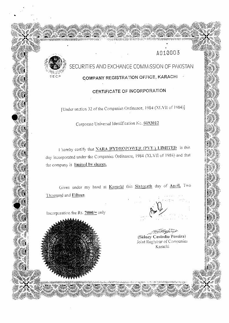
A010003
SECURITIES AND EXCHANGE COMMISSION OF PP,KISTANSEep COMPANY REGISTRAllON OFFICE, KARACHI
CERTIFICATE OF INCORPORATION
[Under section 32 of the Companies Ordinance, 1984 (XLVII of 1(84)]
Corporate Universalldentif.cation No. 0093012
I hereby certify that NARA HYDROPOWER (PVT.) LIMITED is this
day incorporated under the Companies Ordinance, 1984 (XLVII of 1984) and that
the company is limited by shares.
Given under my hand at Karal,;hi this Sixteenth day of April. Two
Thousand and Fifteen.
Incorporation fee Rs. 7000/= only
,; ; ....
. ,.~ ,
..~ .. ,~.:.,I _,._ ~ ~"rl--.
~-d~~~P~(Sidney Custodio Pereira)Joint Registrar of Companies
Karachi

MEMORANDUMAND
ARTICLES OF ASSOCIATION
***
•
· ,
THE COMPANIES ORDINANCE, 1984
A PIRVATE COMPANY LIMITED BY SHARES
MEMORANDUM
AND
ARTICLES OF ASSOCIATION
OF
NARA HYDROPOWER (PRIVATE) LIMITED
1
..
THE COMPANIES ORDINANCE, 1984
(XL VII OF 1984)
A PRIVATE COMPANY LIMITED BY SHARES
MEMORANDUM OF ASSOCIATION
OF
NARA HYDROPOWER (PRIVATE) LIMITED
NAME
I. The name of the Company is "NARA HYDROPOWER (PRIVATE) LIMITED".
REGISTERED OFFICE
II. The Registered Office of the Company will be situated the province of Sindh.
OBJECTS
III. The Sole Objects for which the company is established is as under:
1. To set up, establish, operate, manage, generate and run Power GenerationPlants, from different means and sources and to generate and supplyelectricity to all concerns.
2. In order to carryout and fulfill the above object, the Company shall beauthorized:
a. To generate, produce, manufacture, store, sell, export to supplyelectricity to all concerns, by whatever means including hydral,electricity generation by hydropower and production of electrical powerthrough the use of the gravitational force of falling of flowing water,wind-mill, thermal, gas, and solar for industrial, commercial andresidential use through distribution network and to construct, install,operate and maintain thereon power house, civil and mechanical worksand structures, hydro, grid stations, transmission towers, power lines,building, workshops and other facilities as may time to time benecessary for the attainment of the object of the company.
~.
2
b. To construct, lay-down, establish, fix, and carry out all necessaryhydral power stations, Power station, cables, wires, lines,accumulators, and works and to generate accumulate, distribute andsupply electricity to cities, towns, streets, docks, markets, theaters,industrial zones, sites, areas and parks, buildings and places publicand private.
To carry, on and undertake all hydral power, civil, electrical andmechanical works related to the aforementioned business, and togenerate, accumulate, distribute and such by electricity for thepurposes of light, heat, motive power and for all other purposes forwhich electrical energy can be employed, and to deal in allapparatuses and things required for or cable of being used inconnection with the generation with the distribution, supply,accumulation and employment of electricity.
d. To manufacture, process, buy, sell, exchange, alter improve, otherwisedeal in all kinds of hydral power plants, electrical plants, machinery,equipments, appliance, energy saving devices, and products, gadgets,components and parts including specialized equipments for thepurposes of the business for the Company, and to manufacture, import,export, sell, buy, and deal in all accessories, articles, apparatus,equipment and goods, which may seem calculated to promote or to becapable of being used in connection with the use of electric powersupply.
e. To enter into, make and perform contracts and arrangements of everykind and description with the Central, Provincial government, CityGovernment, or Local Authority or person that may be conducive tothe Company's Object and to obtain from any Government Authority,firm or person any rights, privileges, contracts, concessions,exemptions, permissions approvals and grants which the companymay think desirable, and to obtain and carry out, exercise and complywith any arrangements, rights, privileges, contracts and concessionand dispose of the same or turn into account the same.
To purchase, take on lease or in exchange, or otherwise acquire anylands and buildings in Pakistan or elsewhere, and any estates orinterest therein and any rights connected with any such lands andbuildings, and to buy, sell, lease, mortgage any such lands, buildings,estates, interests and rights therein, to enter into such arrangements,collaborations, joint ventures or else with local and/or foreigncompanies for acquiring, undertaking building, and development ofpower projects in Pakistan and elsewhere.
To manage, improve, develop, buy, sell, exchange. mortgage, charge,hypothecate, pledge, assign, transfer or otherwise deal with all or anypart of the property and assets, whether movable or immovable,tangible or intangible, and any right, title and interest of the Company.
3

..
h. To carryon any other business, which may deemed to the companycapable of being conveniently carried with the above or calculateddirectly or indirectly to enhance the value or render profitable any of the
company's properties or rights, but the company shall not do anyunlawful act or business.
i. To sell or dispose off machinery, plants, equipment, materials and allarticles and things belong to the company and also all the productsthereof either for immediate or future delivery upon such terms andconditions as may be deem expedient.
j. To acquire technical knowledge, know how, process, recipes formulas,engineering and manufacturing data, to appoint consultants andadvisers for advice on managerial, financial and technical problems ofthe company.
k. To apply for purchase or otherwise acquire and protect and renew inany part of the world any patents, patent rights, trade marks, designs,licenses, concessions and the like conferring any exclusive or limitedright to their use, or any secret or other information as to any inventionwhich may seem capable of being used for any of the purposes of thecompany, or the acquisition of which may seem calculated directly orindirectly to benefit the company, and to use, exercise, develop, orgrant license in respect of or otherwise turn to account the property,rights or information so acquired and to expand money inexperimenting upon, testing or improving any such patents, inventionsor rights.
I. To purchase, or otherwise acquire, and invest in shares, scrip, stocks,debentures, certificates, bonds or other financial instruments, of anyentity, whether listed or non-listed, and public or private, and to receivedividends, profits or mark-up, and/or to sell and dispose of the same asdeem fit.
m. To takeover, acquire, amalgamate and merge with any other companyor spin-off its division, and to sign, execute, arrangement, schemes,and contracts relating to such arrangements, as deem expedient ornecessary in achieving these objects.
To enter into partnership or into arrangement for sharing profits,cooperation, joint venture, reciprocal concessions with local domesticand/or international foreign companies, for expansion of business, andtrade or otherwise with any persons, firms or company, to carryon anybusiness or transaction which the company is authorized to carryon.
o. To employ professionals, and other persons well conversant withrelevant knowledge, experience and skills, and having alt technicalexpertise as may be deemed necessary or proper for the efficienthanding and carrying on the business of the company.
4

p. In the event of winding-up, to distribute any of the properties of thecompany amongst the members in species or kind but it manner thatno distributing amounting to a reducing of capital be made except withthe sanction (if any) for the time required by law.
q. To adopt such means of making known the articles, goods andproducts of the company as may seem expedients, and in particularsby advertising in the media, through books, journals, press, films,projectors and cinema houses, television, radio and through circulars,publication of books and periodicals.
r. To grant donations, make contributions and give financial assistance tocharitable and other societies, association, clubs, schools, colleges anduniversities and other institutions as may be deemed proper.
s. To open and maintain offices, branches, commercials centers, depots,, show rooms, offices, go-downs and to appoint agents, sub-agents,
attorneys, representatives, distributors and to establish and run tradingand distributorship agencies; factories, laboratories, testing centers,technical institutions on such terms and conditions as may be deemedreasonable and proper.
t. To sell or dispose of or transfer the business, property, whethermovable or immovable, undertaking of the company or any part thereoffor such consideration as the company may think fit.
u. To open account, overdraft accounts and cash credit with or withoutsecurity, to keep fixed and other deposits with any banks accept!discount, executes, sign, issue and deal in cheques, bills of exchange,drafts, promissory notes, bill of landing, debentures, bonds, warrants,debenture coupons and other negotiable instruments in connectionwith the business of this company.
,-To borrow money in Pakistan as well as in foreign currencies at any timeand from time to time for the purpose of the company with or withoutsecurities and to avail third party guarantees and collateral, upon suchterms as the directors may deem expedients, to take advances from or bycash credit or current or overdraft accounts with any bank, financialinstitutions, society, company or organizations, including the directors ofthe company and/or mortgage, hypothecation, charges, pledge or by theissue of debenture charged upon or any of the company's properties (bothpresent and future) or by such other means as the Directors may in theirabsolute discretion deem fit.
v./
w. To do such other things as are incidental or conductive in the opinion of.../' the board of Directors to the attainment of the above objects or any of
them.
x.! To pay all or any costs, charges and expenses preliminary and/ incidental to the promotion, formation, establishment and registration,
of the company.
5
I~..
.-
v. To create charge on all or any of the moveable and immoveableproperties/assets both present and future of the company by way ofmortgage, pledge, hypothecation, lien, assignment, fixed/floatingcharges, guarantee, LC, or any other form of security in favor of anyperson including a banking company and/or financial institution inrespect of any finance facility whether fund based or non-fund basedallowed to it/the company or its associated companies, groupconcerns, subsidiaries and/or companies under common directorshipand/or under common membership and/or to any company,association, firm or person and/or any other third person and toundertake and/or stand as surety, indemnifier, guarantor forperformance of its/company's own obligations or the obligations of itsassociated companies, group concerns, subsidiaries and/or companiesunder common directorship and/or under common membership and/orof any company association, firm or person and/or any other thirdperson.
It is hereby undertaking that the company shall not engage in banking, finance,leasing or the business of any investment company, or housing finance company, orinsurance company or in any other unlawful business and that nothing in the objectclauses shall be construed to entitle it to engage in such business. The companyshall not launch multi-level marketing & prize schemes.
It is further declared that the company shall not do any kind of pyramid scheme,brokerage & lottery business or such other business through which money from thepublic can be collected and interest of the public at large is jeopardize.
Notwithstanding anything stated in any object clause, the company shall obtainsuch other approvals or license from competent authority as may be required underany law for the time being in force, to undertake any such business.
SPECIAL CLAUSE: Notwithstanding anything stated in any object clause, theCompany shall obtain such other approval or license from the competent authority,as may be required under any law for the time being in force, to undertake aparticular business.
LIABILITIES OF MEMBERS
IV. The liability of members is limited.
CAPITALv. The Authorized Capital of the company is Rs.1,OOO,000/= (Rupees One
Million Only) divided into 10,000 (Ten Thousand) Ordinary Shares of Rs.1~O/-Rupees Hundred) each, with power to increase or reduce capital of thecompany, and from time to time consolidate, such divided of otherwise
/ reorganize the share capital of the company and to issue shares of variousclasses, and in such denominations with such special rights, privileges andconditions in accordance with the Companies Ordinance, 1984 and itsstatutory amendments, alternations and modifications for the time being inforce and regulations of the Company and to vary, modify or abrogate suchrights.
6
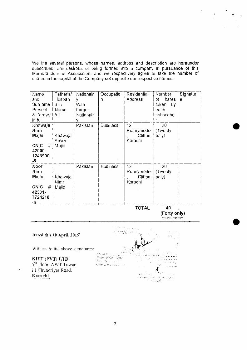
We the several persons, whose names, address and description are hereundersubscribed, are desirous of being formed into a company in pursuance of thisMemorandum of Association, and we respectively agree to take the number ofshares in the capital of the Company set opposite our respective names:
NanandSurrPres& Fain fuKhaNimMaji
CNIC42001246-5NODNimMaji
CNIC42307724-6
le Father's/ Nationalit Occupatio Residential Number SignaturHusban y n Address of hares e
lame d in With taken byent Name former eachrmer full Nationalit subscribe
" y rwaja Pakistan Business 12 20r Runnymede (Twentyd Khawaja , Clifton, only)
Anver Karachi# Majid
0-900
---- c---r Pakistan Business 12 20r Runnymede (Twentyd Khawaja , Clifton, only)
Nimr Karachi# Majid
1-218
--TOTAL 40
(Forty only)----------------
Dated this 10 April, 2015(
Witness to the above signatures:
NUT (PVT) LTD5th Floor, A WT Tower,1.1 C'hundrigar Road,Karachi.
/j;'il)1
tiU'!'J7 rh.<;-,
1J~-jiF ci
7
;
•
THE COMPANIES ORDINANCE, 1984
COMPANY LIMITED BY SHARES
ARTICLES OF ASSOCIATION
OF
NARA HYDROPOWER (PRIVATE) LIMITED
PRELIMINARY
Table "A-" excluded
I. The regulations contained in Table "A" in the First Schedule to the CompaniesOrdinance, 1984, shall not apply to the company except in so far as they are repeatedOf contained in these Articles.
interpretation
The chapter headings shall not affect the construction hereof, and in these Articlesunless there is something in the subject or context inconsistent therewith.
"The Articles" mean the Articles of Association, as originally framed or as alteredfrom time to lime or the Company acting ill a meeting or pursuant to unanimouswritten consent.
Books and Papers etc
"Book and Paper", "Book or Paper", or "Books of Account" includes accounts, deeds,vouchers, registers, writings and documents.
Company
"The Company" means NARA HYDROI}OWER (PRIVA TE) LIMITED
Chief Executive
"The Chief Executive" means the Chief Executive appointed [rom time to time by thecompany pursuant to these Articles.
Directors
"The Directors" mean the directors of the Company appointed from time to timepursuant to these Articles.
Debenture
"Debenture" includes stock, bonds, term finance certificate and any other securityother than the shares of the company whether constituting a charge on the assets ofthe company or not.

2
Documents
"Documents" include summon, notice, requisition, order, other legal process, vouch-ers and register.
Dividend
"Dividend" means the distribution of profits of the company to its members, andincludes bonus.
Holding Company
"Holding Company" shall have the meaning assigned to it by section 3.
Member •"Member" means a member of the company within the meaning of the provision ofSection 2(1) (21).
"Month" means as calendar month according to the English calendar.
Ordinance
"The Ordinance" means the Companies Ordinance, 1984 as amended and anyamendment or re-enactment thereof for the time being in force.
"Office" means the registered office of the Company.
Participatory Redeemable Capital
"Participatory redeemable capital" means such redeemable capital as is entitled toparticipate in the profit and loss of the company.
"Proxy" includes attorney duly constituted under a Power of Attorney.
Investor
"Investor" means a corporation, a company incorporated under the Ordinance,financial institution, Federal Government, Provincial Government or such other bodywhich holds shares in the company.
Register
"The Register" means the register of members to be kept pursuant to Section 147 ofthe Ordinance.
Redeemable Capital
"Redeemable capital" has the meaning assigned to it by section 2( I )(30A).Share
"Share" means share in the capital of the company.

3
Secretilrv
"Secretary" means any individual appointed to perform the secretarial, administrativeor other duties ordinarily performed by the Secretary.
"Section" means section of the Ordinance.
"Security" has the meaning assigned to it by section 2(1) (34).
S.E.CY .• "S.I:.C.P." means Securities and Exchange Commission of Pak istan.
Special Resolution
"Special resolution" has the meaning assigned to it by Section 2( I) (36).
"The Seal" means the common seal adopted by the company.
In Writing ahd Written
"In writing" and "Written" includes printings, lithography and in writing and othermodes of representing or reproducing words in a visible written form.
Word importing the singular number includes the plural number and vice versa.
Word importing the masculine gender only includes the feminine gender .• Words importing persons includes bodies corporate.
PRIVATE COMPANY
Private- Company
.v. The Company is a private company within the meaning of Clause 28 of Section 2(1)of the Companies Ordinance, 1984 and accordingly:
(a) No invitation shall be issued to the public to subscribe for any shares, de-bentures or debenture stock of the Company.
(b) The number of the members of the Company (exclusive of persons in theemployment of the Company) shall be limited to fifty, provided that for thepurposes of this provision where two or more persons jointly hold one ormore shares in the Company they shall be treated as a single member, and
(c) The right to transfer shares in the company is restricted in the manner and tothe extent hereinafter appearing.

4
Business
·1. The business of the Company shall include all or any of the business objectsenumerated in the Memorandum of Association and can be commenced immediatelyafter the incorporation of the Company as the Directors may think fit, not with-standing that part of the capital has been subscribed.
Place of Business
The business of the Company shall be carried at Karachi or at such place in the wholeof Pakistan or elsewhere as the Directors may deem proper or, advisable from time totime,
CAPITAL
•(,. The authorized Capital of the Company is Rs.l,OOO,OtlO (Rupees One Million: divided into 10,000 (TenThousand Only) Ordinary Shares of Its. 100/- each with powers to mcrcuse or reduce the capital, todivide the shares ill the capital for Ihe time being into several classes and 10 nnach to them rights,privileges, cnnditinus, and to vary. modify or abfl\gnlc [\Ill of such rights. pri' ilcges, conditions, as arerequired or permiued by the Companies Ordinance. I ()S4 and its statutor. ameudments, alterations andmoclificanons for the time being in force.
Increase of CClpitClI
Where at any time the Board decides to increase the issued capital of the company byissuing any further Alternation shares, then subject to any direction to the contrary thatmay be given by the company in general meeting, such shares shall be offered to themembers in proportion to the existing shares held by each member, and such offersshall be made by notice specifying the number of shares to which the member isentitled and limiting a time within which the offer, ifnot accepted, will be deemed tobe declined and after the expiration of such time, or on receipt of (In intimation fromthe members to whom such notice is given IhM he declines to accept the sharesoffered, the Board may dispose of the same in such manners ClSthey think mostbeneficial to the company. The notice shall be accompanied by the circular requiredunder section 80. •Shares at the Disposal of Directors
g. The shares shall be under the control of the Directors who may allot or otherwisedispose of the same to such persons, firms or corporations, 011 such terms andconditions and at such time as may be thought fit.
Allotment of Shares
l) The Shares in the capital of the Company may be issued or allotted in payment orpart-payment of any property, land, building, machinery, goodwill or goods suppliedor any services rendered or likely to be rendered to the COll1pClI1Yin promotion andestablishment of the Company or conduct of its business and any shares so allottedmav be issued as fully paid-up shares.
Consolidation or Sub-division of Shares
10. Ir and whenever as a result of an issue of new shares or any consolidation or sub-division of shares any member becomes entitled to hold shares in fractions, the Boardshall not be required to issue such fractional shares and shall be entitled to sell wholeshares at a reasonable price and pay and distribute to and amongst the members
5
entitled to such fractional shares in due proportion with the net proceeds of the salethereof. For the purpose of giving effect to any such sale the Board may authorize anyperson to transfer the shares sold, to the purchaser thereof, and the purchaser shall beregistered as the holder of the shares comprised in any such transfer and he shall notbe entitled to see the application of the purchase money nor shall his title to the sharesbe affected by any irregularity or invalidity in the proceedings in reference to the sale.
Issue of Convertible Securities
1 I. The company may issue ordinary shares or grant option to convert into ordinaryshares the outstanding balance of any loans, advances or credit, as defined in the.banking companies ordinance, 1962 (L V II of 1962) or other non-interest bearingsecurities and obligations in accordance with the provisions or section 87.
12. The company may issue to one or more schedule banks, financial institutions or suchother persons, as are specified for the purpose by the Federal Government bynotification in the official gazette, any investment in the nature of redeemable capitalin any or several form in accordance with the provisions of section 120.•
Shares for Consideration Other than Cash
1:). Subject to the provision of the Ordinance and these Articles, the Board may allot andissue Shares in the capital of the company as payment for any property sold ortransferred, goods or machinery supplied, or for services rendered to the company inthe conduct of its business or affairs and any shares which may be so allotted may beissued as fully paid up shares and if so issued, shall be deemed to be fully paid upshares.
14. Any application or subscription signed by or on behalf of an applicant or Subscriberlor shares in the company, followed by an allotment of any shares therein, shall be anacceptance of shares, within the meaning of these Articles, and every person who thusor otherwise accepts any shares and whose name is entered on the register shall forthe purpose of these Articles be a member.
15. The money (if any) which the Board shall on the allotment 01" any shares being madeby it require or direct to be paid shall immediately on the insertion of the name of theallottee in the register of members as the holder of such Shares, become a debt due toand, recoverable by the company from the allottee thereof, and shall be paid by himaccordingly.•
Right of ownership of Shares
16. Save as herein otherwise provided the company shall be entity to treat the personwhose name appears on the register of members as the holder of any shares as theabsolute owner thereof, and accordingly shall not (except as ordered by a court ofcompetent jurisdiction or as required that law) be bound to recognize any trust orequity or benami, equitable, contingent or other claim to or interest in such shares, onthe part of any other person whether or not it shall have express or implied noticethereof
UNDERWRITING, COMMISSION AND BROKE RAG E
Brokefilgc
17. The Company may at any time pay a commission to any person for subscribing or
6
agreeing to subscribe (whether absolutely or conditionally), for any shares ordebentures or procuring or agreeing to procure, subscriptions, whether absolute orconditional, for, any shares or debentures or the company, but so that the amount orrate of commission shall not exceed the rate per cent of amount as may be fixed bythe S.E.C.P. The commission may be paid or satisfied in cash or in any shares ordebentures of the company. The company may also pay the usual brokerage notexceeding one (I) per cent in respect of any subscription for shares or debentures.
CERTIFICATES
Members Entitled to Share Certificate
18. Every member shall be entitled without payment to one certificate for all the sharesregistered in his name, or if the Board so approved (upon paying sllch fee as theBoard may from time to time determine), to several certificates, each for one or moreshares, Every certificate of shares shall specify the number and denoting numbers ofthe shares in respect of which it is issued and the amount paid thereon, suchcertificate shall be issued under seal and bear the signature of one Director and shallbe countersigned by the Secretary or by a second Director or by some other personappointed for that purpose by the Board.
•Renewal of Certificate
19. If any certificate is worn out, defaced or rendered useless. then upon productionthereof to the Board, it may order the same to be cancelled and may issue a newcertificate in lieu thereof and if any certificate is lost or destroyed, then on proofthereof, to the satisfaction of the Board and 011 such indemnity as the board deemsadequate being given, a new certificate thereof shall be given to the party entitled tosuch lost or destroyed certificate.
.'0. The company shall, within ninety (90) days after the allotment and within forty five(45) days after the application for the registration of the transfer of any share,complete and h ave ready for delivery the certi Iicates for shares and unless sent bypost or delivered to the persons entitled thereto, within that period. shall give noticeor tile fact to the shareholder immediately thereafter. •A duplicate of a certificate of shares, shall he issued within forty-five (45) days fromthe date of appl ication,
TRANSFER AND TRANSM ISSION
Register of Transfer
21. The Company shall keep a book to be called the "Register of Transfer" and thereinshall be fairly and distinctly entered the particulars of any transfer and transmission ofany shares.
Y) The instrument of transfer of ally share shall be in writing in the usual common formor ill the following form or as near thereto as circumstances wil] admit:
NARA HYDROPOWER (I'IUV ATE) LIMITED
7
National, In
beingConsideration the sum of Rs.
(Rupees --------------,-"------
l'aid to me by ______ S/O
-------------------------------
•(If National Hereinafter called "TheTransferee") do hereby transfer to the Ordinary Share(s)numbered in the undertaking called NARA HVDROPOWER (PRIVATE) LIMITED tohold the same into the said Transferee, his (or her) executors, administrators and assignssubject to the several conditions on which I held the same immediately before the executionhereof, and I, the Transferee, do hereby agree to take the said shareis) subject to the saidconditions aforesaid. As witness etc.
Condition for Transfer
23. The share shall be transferred subject to following restrictions:
(a) the shares shall in the first instance be offered to the existing shareholders.
(b) if the existing shareholders are not willing to accept the shares the Boardshall approved transfer of shares, subject to the consent of all existingshareholders, to other persons.
(c) the shares shall be sold at a market value to be determined by the Aud itors ofthe company with other experts ofthe company; if necessary.
No 'fransfer to an Infant
24. No shares in any circumstances shall be transferred to an infant, fin Infant insolvent orperson of unsound mind .• Closure of Transfer Books
..'5. The Board shall have power to close the register of transfer for such period or periodsof time not exceeding thirty days at a time and 45 days in a year.
Right of Nomination
:'6. A person may on acquiring interest in the company as a member, nominationrepresented by shares, at any time after acquisition of such interest deposit with thecompany a nomination conferring on one or more persons the right to acquire interestin the shares specified therein in the event of his death.
Transmission 0 f Shares
27. In the case of death of shareholders the survivor where the deceased was a jomtholder. and (subject as hereinafter provided), where the deceased was a sole or onlysurviving holder. the execution or administrators of the deceased holding a grant ofprobate or letters of administration effective in Pakistan, shall be the only personsrecognized by the company IlS having any title to the shares. but nothing herein
8
contained shall release the estate of a deceased holder (whether sole or joint), formany liability (whether sole or joint), in respect of any share solely or jointly held byhim. In any case in which such a grant of probate or letters of admiuistration to theestate of a deceased sole or only surviving holder has not been obtained, the Boardmay, but shall not be bound to, recognize the title of any person claiming to beentitled to the deceased holder's shares on production by such claimant of asuccession certificate or such other evidence of title as the Board may deemsufficient, and upon the claimant furnishing such indemnity, if any, as the Board mayrequire.
Right of persons becoming entitled to share
_:s. Any person becoming entitled to a share in consequence of tile death or insolvency ofa member shall, upon such evidence being produced as may Irom time to time berequired by the Board, have the right either to be registered as member in respect ofthe share or instead of being registered himself to make such transfer of the share asthe deceased or insolvent person could have made but the Board shall, in either caseshave the Same right to decline registration (IS they would have had in the case of atransfer of the share by the deceased or insolvent person the death or insolvency .
•.)9. A person becoming entitled to a share by reason at the death or insolvency of the
holder shall subject to Article 28 above, be entitled to the same dividends and otheradvantages to which he would be entitled ilhe was the registered holder of the share,except that he shall not before being register as a member in respect of the share, beentitled in respect of it to exercise any rights conferred by membership in relation tomeeting of the company.
,0. The company shall incur no liability whatsoever in consequence of its registering orgiving effect to any transfer of shares made or purporting to be made by any apparentlegal owner thereof (as shown or appearing in the register) to the prejudice of personshaving or claiming any equitable right, title or interest to or in the same shares,notwithstanding that the company may have haclnotice of such equitable right, title orinterest or notice prohibiting registration of such transfer, anti the company shall notbe bound or required to regard or attend or give effect to any notice which may begiven to it of any equitable right, title or interest, or be under any liability whatsoeverfor refusing or neglecting so to do, but the company shall nevertheless be at liberty toregard and attend any such notice and give affect thereto, if the Board shall so thinksfit. •
ALTERATJON OF CAPITAL
Increase of Cnpital
_;I. The company may by a Resolution increase its Authorized Share Capital comprisingof any class and denomination .
.;2. Except and so far as otherwise provided by the conditions of issued or by theseArticles, any capital raised by the creation of new shares shall be considered part ofthe Authorized Capital and shall be subject to the provisions herein contained withreference to transfer and transmission, voting and otherwise.
Reduction of Share Capital
~3_ 'file company may by special resolution reduce its share capital in any manner andwith and subject to any incident authorized and consent required by law.
9
.14. The company may in general meeting hy Resolution alter the conditions of itsmemorandum as follows:
Consolidation and Division of Share
(a) Consolidate and divide all or any of its share capital into shares of largeramount than its existing shares;
(b) Sub-divide shares or any of them into shares of smaller amounts thanoriginally fixed by the memorandum and subject nevertheless to theprovisions of tile Ordinance in that hehal f;
(c) Cancel shares which at the date 01' such General Meeting have not been takenor agreed to be taken by any person, and diminish the amount of its sharecapital by the amount of the shares so canceled .• Variation of Rights
.i5. The variation in the right of shareholders shall he made in the manner provided bySection 108.
BORROWING POWERS
Powers to Borrow
;6. The Directors may from time to time at their discretion borrow or secure the paymentof any sum or sums of money for the purposes of the Company from any personsfirms or companies, banks, or investment corporation, government or semi-govern-ment institutions or any other source whatsoever (expressly including any member orthe Company) and may themselves but to the Company any such sum or slims onsecurity or otherwise.
Condition on which money may be borrowed
• n. The Company may create charge on all or any of the moveable and immoveableproperties/assets both present and future of the company by way of mortgage, pledge,hypothecation, lien, assignment, fixed/floating charges, guarantee, LC, or any otherform of security in favor of any person including a banking company and/or financialinstitution in respect of any finance facility whether fund based or non-fund basedallowed to it/the company or its associated companies, group concerns, subsidiariesand/or companies under common directorship and/or under common membershipand/or to any company, association, firm or person and/or any other third person andto undertake and/or stand as surety, indemnifier, guarantor for performance ofits/company's own obligations or the obligations of its associated companies, groupconcerns, subsidiaries and/or companies under common directorship and/or undercommon membership and/or of any company association, firm or person and/or anyother third person .
.1l\. The Directors may borrow or secure the payment of such slim or slims of money insuch manner and upon such terms and conditions in all respect as they think fit, eitherby creation of any mortgage, hypothecation as charge on the whole or any part of theproperty of the Company and in particular by the issue ()f the debentures ordebenture-stock of the Company charged upon the whole or any part of the propertyof the Company both present and future.
•
10
Assignment of Securities
.~9. The debenture, debenture-stock or other securities may be made assignable free fromany equities between the company and the person to whom the same may be issued. ,
Issue at Discount etc.
·10. Any bonds, debentures or other securities may be issued at <l discount, premium orotherwise and with any special privileges ,IS to redemption, surrender, drawings,Convertibility into shares, attending and voting at general Meeting of that company,appointment of Directors and otherwise, provided that debentures with the right tovote or be converted into shares shall not be issued without the consent of thecompany in General Meeting.
Liability lor payment of sum due froll1 the CompallY •·11. If the Directors or any of them or any other person shall become personally liable for
the payment of any sum primarily due from the company, the Board may execute orcause to be executed any mortgage, charge or security over or affecting the whole orany part of the assets of the company by way or indemnity to secure the Directors orpersons so becoming liable as aforesaid from any loss in respect of such liability.
GENERAL MEETING
General Meeting
An Annual General Meeting shall be held within eighteen months from the date ofincorporation of the Company. and thereafter once at least in every calendar yearwithin a period of four months following the close of its financial year. Every AnnualGeneral Meeting shall be called during business hours on a day that is not Publicholiday and shall be held either at the Registered Office of the Company or at someother place within the City, town or village in which Registered Office of theCompany is situated and the notice calling the meeting shall specify it as the AnnualGeneral Meeting. •
Extra-ordinary GeneralM eeting
·13. The Board may call an Extraordinary General Meeting whenever it shall think fit. AnExtraordinary General Meeting may also be convened on the requisition of themembers in accordance with the provision of Section 159.
Notice oHileeting
,14. At least twenty-one days notice specifying the place, the clay and the hour of thegeneral meeting and in case of special business, the general nature of such business,shall be given to the members in the manner hereinafter mentioned, or in such othermanner as may be prescribed by the Company in General I\leeting but accidentalomission to give such notice to or non-receipt of such notice by any member shall notinvalidate the proceeding of the Genera I Meeting, subject to the provisions of theOrdinance. The Directors may whenever they think fit, and shall on requisition inaccordance with the ordinance proceed to convene of Extraordinary General Meeting.
II
Quorum
,15. No business shall be transacted at any General Meeting unless a quorum of membersis present, two members present, in person who represent twenty-five percent of thetotal voting power of the company either of their own account or as proxies shall be aquorum for a General Meeting.
Quorum for Adjourn Meeting
,16. If within half an hour of the time appointed for the holding of a general meeting aquorum be to present, the meeting if convened on the requisition of shareholders,shall be dissolved and in every other case shall stand adjourned to the same day in thenext week, at time and place as was appointed for holding the general meeting and ifas Stich adjourned meeting the quorum is not present within IiIteen minutes from thelime appointed for holding the meeting the members present being not less two shallbe a quorum.•
PROCEEDINGS AT GENERAL MEETINGS
Chairman to Preside
-17. The Chairman of the Board of Directors shall preside at every general meeting but ifat any meeting he may not be present within IS minutes after the time appointed forholding the same or is unwilling to preside, members present shall choose someDirector or if no Director be present or if the Directors present decline to take chair,the members shall choose some member to be the Chairman of the meeting.
Power of Chairman to Adjourn
·18. The Chairman with the consent of the meeting may adjourn <my meeting from time totime and from place to place, but no business shall be transacted at any adjournedmeeting other than business which might have been transacted at the meeting fromwhich the adjournment took place. The resolution at an adjourned meeting shall forall purposes, be treated as having been passed all the date on which it was in factpassed and shall not he deemed to have been passed on any earlier dates.•
Carrying of Resolution
,19. At any General Meeting a resolution put to the vote of the Meeting shall be decidedon it show of hands unless poll is (before or on the declaration of the result of theshow of hands) demanded by one Member having right to vote on the resolution andpresent in person or by proxy, if not more than seven members are personally present,and by two such members present in person or by proxy if more than seven suchmembers are personally present or by the Chairman of the Meeting Of any member ormembers present or by proxy and holding OJ' representing not less than one - tenth ofthe issued capital carrying voting rights, and unless a poll is so demanded, asdeclaration by the chairman then a resolution has been carried OJ' carried unanimouslyor hy a particular majority or lost, and an entry to that effect in the books of theproceedings of the company, shall be conclusive evidence of the fact without furtherproof of the number or proportion of the votes recorded in favour of or against suchresolution.
12
Demand for Poll
:'(). If a poll is demanded as aforesaid it shall be taken in such manner as the Chairman ofthe meeting directs, and either at once or after an interval or adjournment, and theresults of the poll shall be deemed to be the resolution of the meeting at which thepoll was demanded. The demand for a poll may be withdrawn at anytime by theperson or persons who made the demand.
Time for taking, poll
Any poll duly demanded on the election of a Chairman of a Meeting or on anyquestion of adjournment shall be taken forthwith and without adjournment and a polldemanded on any other question shall be taken at such time, not more than fourteendays from the day on which it was demanded, as the chairman of the meeting maydirect. •Business may proceed not withstanding demand 01 poll
'12. The demand for a poll shall not prevent the continuation of meeting for thetransaction of any business other than the question on which the poll was demanded.
Minutes
S]. Minutes shall be made in book provided for the purpose of all resolutions andproceedings at General Meetings, and such minutes if signed by any person pur-porting to have been the Chairman of the Meeting to which it relates or by theChairman of the Board shall be receivable as evidence of the facts therein statedwithout further proof.
Minutes Book
~4, The books containing minutes of proceedings of General Meetings of the companyshall be kept at the registered office of the company and shall during business hours(subject to reasonable restrictions as the Board may from time to time impose but sothai not less than two hours each day is allowed for inspection) be open to theinspection of any member without charge. •
VOTES OF MEMBERS
:"5. Upon a show of hands every member entitled to vote and present in person or byproxy shall have one vote, and upon a poll every member entitled to vote and presentin person or by proxy shall have one vote for every share conferring voting rights asaforesaid held by him.
Right to Vote
)G. Any person entitled under the Transmission Clause to Transfer any shares may voteat <lily General Meeting in respect thereof as if he was the registered holder of suchshares, provided that at least 48 hours before the time of holding the meeting oradjourned meeting as the case may be at which he proposes to vote he shall satisfy theDirectors of his right to transfer such shares unless the Director shall have previouslyadmitted his right to vote at such meeting in respect thereof.
13
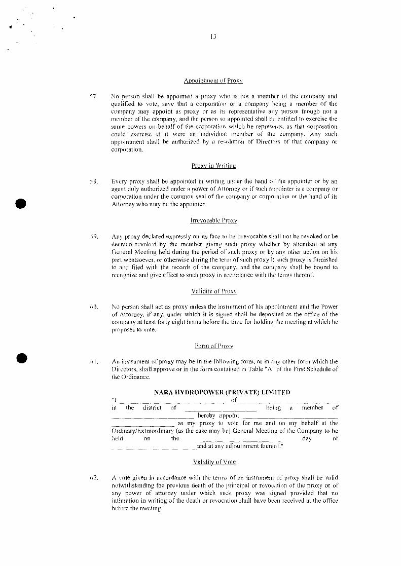
Appointment of Proxv
'.7. No person shall be appointed a proxy who is not a member of the company andqualified to vote, save that a corporation or a company being a member of thecompany may appoint as proxy or as its representative any person though not amember of the company, and the person so appointed shall he entitled to exercise thesame powers on behalf of the corporation which he represents, as that corporationcould exercise if it were an individual member of the company. Any suchappointment shall be authorized by a reso lution of Directors of that company orcorporation.
Proxy in Writing
•Every proxy shall be appointed in writing under the hand or the appointer or by anagent duly authorized under a power of A ttorney or if such appointer is a company orcorporation under the common seal of the company or corporation or the hand of itsAttorney who may be the appointer.
Irrevocable Proxy
S9. Any proxy declared expressly on its face to he irrevocable shall not be revoked or bedeemed revoked by the member giving such proxy whether by attendant at anyGeneral Meeting held during the period of such proxy or by any other action on hispart whatsoever, or otherwise during the term of such proxy itsuch proxy is furnishedto and filed with the records of the company, and the company shall be bound torecognize and give effect to such proxy in accordance with the terms thereof.
Validity of Proxv
(,0. No person shall act as proxy unless the instrument of his appointment and the Powerof Attorney, if any, under which it is signed shall be deposited as the office of thecompany at least forty eight hours before the time for holding the meeting at which heproposes to vote.
Form of Proxy• (,J . An instrument of proxy may be in the following form, or in any other form which theDirectors, shall approve or in the form contained in Table "A" of the First Schedule ofthe Ordinance.
NARA HYDROPOWER (PRIVATE) LIMITED"I ~ ~ of _in the district of being a member of
hereby appoint_________ as my proxy to vote for me and on my behalf at theOrdinary/Extraordinary (as the case may be) General Meeting of the Company to beheld on the day of
____________ and at any adjournment thereof."
Validity of' Vote
(l2. A vote given in accordance with the terms of an instrument of proxy shall be validnotwithstanding the previous death of the principal or revocation of the proxy or ofany power of attorney under which such proxy was signed provided that nointimation in writing of the death or revocation shall have been received at the officebefore the meeting.
14
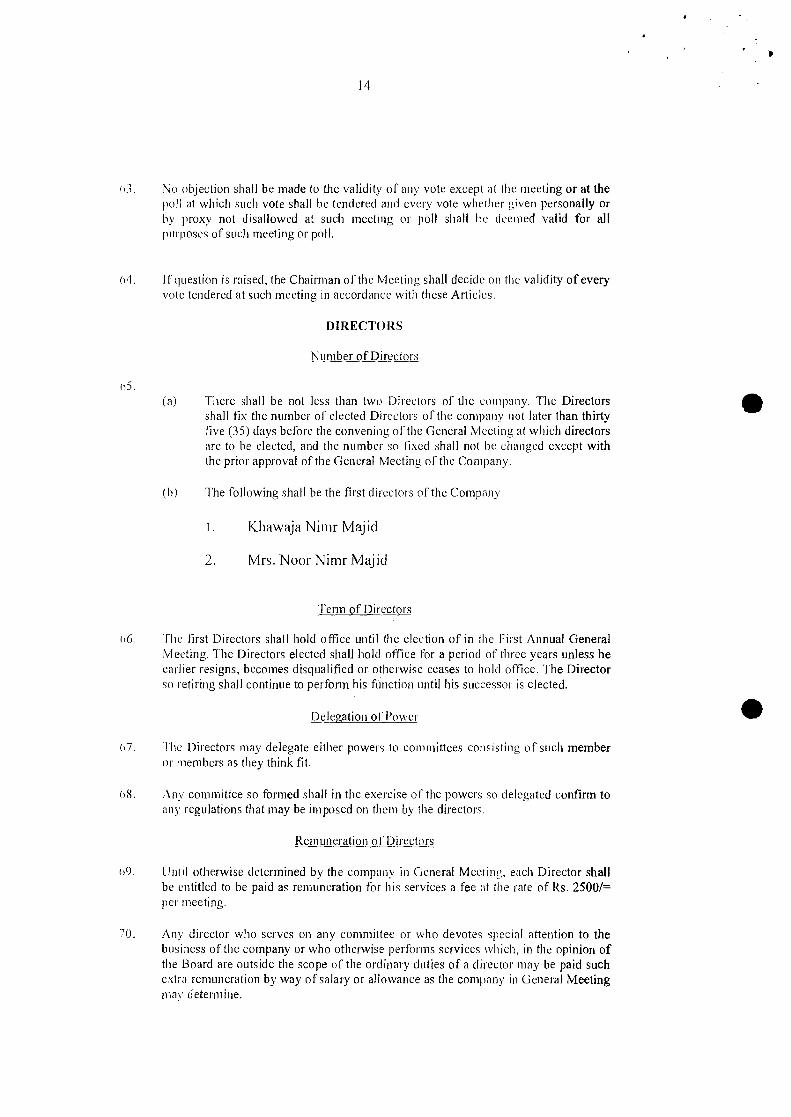
(,J. No objection shall be made to the validity of any vote except at the meeting or at thepoll at which such vote shall be tendered and every vote whether given personally orby proxy not disallowed at such meeting or poll shall be deemed valid for allpurposes of such meeting or poll.
(14. If question is raised, the Chairman of the Meeting shall decide on the validity of everyvote tendered at such meeting in accordance with these Articles.
DIRECTORS
Number of Directors
(15.(a) There shall be not less than two Directors of the company. The Directors
shall fix the number of elected Directors of the company not later than thirtylive (35) days before the convening of the General Meeting at which directorsare to be elected, and the number so fixed shall not be changed except withthe prior approval of the General Meeting of the Company.
•(b) The following shall be the first directors of the Company.
l. Khawaja Nimr Majid
2. Mrs. Noor Nimr Majid
Term of Directors
IlG. The first Directors shall hold office until the election of in the First Annual GeneralMeeting. The Directors elected shall hold office for a period of three years unless heearlier resigns, becomes disqualified or otherwise ceases to hold office. The Directorso retiring shall continue to perform his function until his successor is elected.
Delegation of Power •(,7. The Directors may delegate either powers to committees consisting of such member
or members as they think fit.
(l8. Any committee so formed shall in the exercise of the powers so delegated confirm toany regulations that may be imposed on them by the directors.
Remuneration or Directors
(19. Until otherwise determined by the company in General Meeting. each Director shallbe entitled to be paid as remuneration for his services a fee at the rate of Rs. 2500/=per meeting.
70. Any director who serves on any committee or who devotes special attention to thebusiness of the company or who otherwise performs services which, in the opinion ofthe Board are outside the scope of the ordinary duties of a director may be paid suchextra remuneration by way of salary or allowance as the company in General Meetingmay determine.

15
Share Qualification or Director
71. A director shall be required to hold at least one qualification share subject to Section187.
Nomination by Directors
72. The investor, shall have powers to nominate such number of directors in the Board ofDirectors of the Company, as are proportionate to its holding in the paid up capital ofthe company. The Directors so nominated shall not be subject to the provisions ofthese Articles and Ordinance relating to the eligibility for appointment, election,retirement, removal, filling of casual vacancy and vacation of office etc.
POWERS AND DUTIES OF DIRECTORS• Management of Business
73. The control of the company shall be vested in the Board and the business of thecompany shall be managed by the Board, which may pay all expenses incurred informing ancl registering the company, and may exercise <III such powers of thecompany as are not by Ordinance or by these Articles required to be exercised by thecompany in General Meeting, subject nevertheless to the regulations of these Articles,to the provisions of the Ordinance and such regulations (not inconsistent with theaforesaid regulations or provisions), as may be prescribed by the company in GeneralMeeting but no regulation made by the company in General Meeting shall invalidateany prior act of the board which have been valid if the regulation had not been made.
Power of Board
•}4. The Board may exercise all the powers of the company to borrow money and to
mortgage or charge its undertaking, property and assets (both present and future), andto issue debentures and other securities whether out right or as collateral security forany debt, liability or obligation of the company, or of any third party.
Books to keep
75. The Board sha II cause minutes to be made in books provided for the purpose;
(a) of the name of Director present at each meeting of the Board and of anyCommittee of Directors;
(b) of all resolutions and proceedings at all meetings of the company and of theBoard and of committee of Directors.
Any such minutes of any meeting of Board or of a Committee of Directors or of thecompany, if signed or purporting to be signed by the Chairman of Stich meeting, or ofthe next succeeding meeting, shall be receivable as evidence of the matters stated insuch minutes. The books containing minutes of General Meeting shall be kept at theregistered office of company and shall be open to inspection as required by SectionIn
Payment of Retirement Benefits
76. The Board may pay and agree to pay pension or other retirement, superannuation,
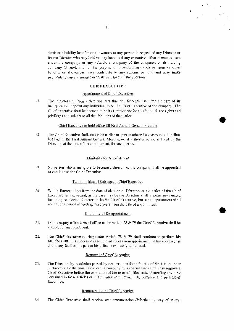
16
death or disability benefits or allowances to any person in respect of any Director orformer Director who may hold or may have held any executive office or employmentunder the company, or any subsidiary company of the company, or its holdingcompany (if any), and for the purpose of providing any such pensions or otherbenefits or allowances, may contribute to any scheme or lund and may makepayments towards insurance or trusts in respect 0 f such persons.
CHIEF EXECUTIVE
77.
Appointment of Chief Executive
The Directors as from a date not later than the fifteenth day after the date of itsincorporation, appoint any individual to he the Chief Executive of the company. TheChief Executive shall be deemed to be its Director and be entitled to all the rights andprivileges and subject to all the liabilities of that office. •Chief Executive to hold office till First Annual Genefill iVleeting
/8. The Chief Executive shall, unless he earlier resigns or otherwise ceases to hold office,hold up to the First Annual General Meeting or, if a shorter period is fixed by theDirectors at the time of his appointment, Ior such period.
Eligibility for Appointment
79. No person who is ineligible to become a director of the company shall he appointedor continue as the Chief Executive.
Term of office of Subsequent Chief Executive
IW. Within fourteen days from the date of election ()f Directors or the office of the ChiefExecutive falling vacant, as the case may be the Directors shall appoint any person,including an elected Director, to be the Chief Executive, but such appointment shallnot he for a period exceeding three years from the date of appointment.
Eligibility of Re-<lprointment •g I. On the expiry of his term of office under Article 78 & 79 the Chief Executive shall be
eligible for reappointment.
l>2. The Chief Executive retiring under Article 78 & 79 shall continue to perform hisfunctions until his successor is appointeci unless non-appointment of his successor isdue to any fault on his part or his office is expressly terminated.
Removal of Chief Executive
X3. The Directors by resolution passed by not less than three-fourths of the total numberof directors for the time being, or the company by a special resolution, may remove aChief Executive before the expiration of his term of office notwithstanding anythingcontained in these articles or in any agreement between the company and such ChiefExecutive.
Remuneration of Chief Executive
l-:4. The Chief Executive shall receive such remuneration (Whether by way of salary,
17
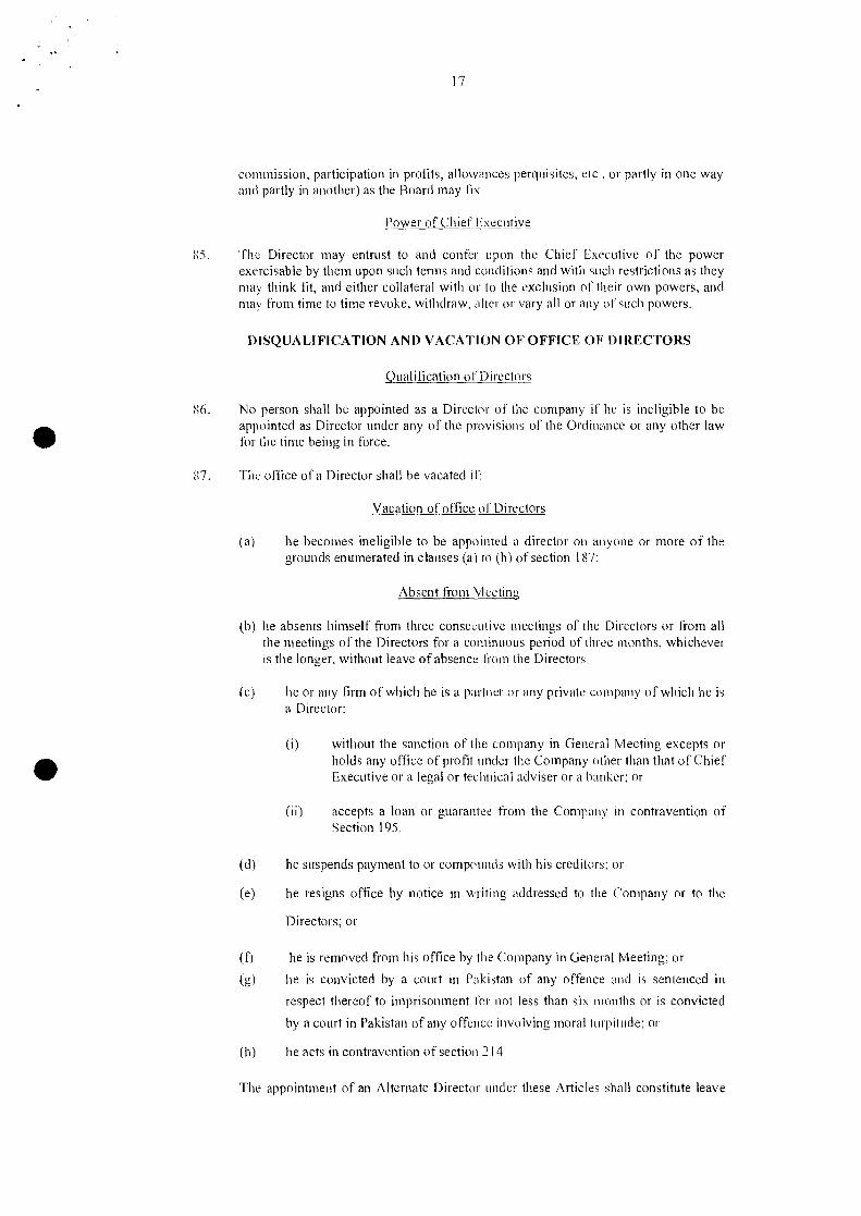
commission, participation in profits, allowances perquisites, etc, or partly in one wayand partly in another) as the Board may fix.
Power of Chief Executive
g5. The Director may entrust to and confer upon the Chief Executive of the powerexercisable by them upon such terms and conditions and with such restrictions as theymay think fit, and either collateral with or to the exclusion of their own powers, andmay from time to time revoke, withdraw, alter or vary all or any of such powers.
DISQUALIFICATION AND VACATION OFOFFICE OF DIRECTORS
Qualification oj" Directors
• No person shall be appointed as a Director of the company if he is ineligible to beappointed as Director under any of the provisions of the Ordinance or any other lawfor the time being in force.
g7. The office of a Director shall be vacated if:
Vacation of office oj" Directors
(a) he becomes ineligible to be appointed a director on anyone or more of thegrounds enumerated in clauses (a) to (h) of section 187:
Absent from Meeting
(b) he absents himself from three consecutive meetings of the Directors or from allthe meetings of the Directors for a continuous period of three months, whicheveris the longer, without leave of absence from the Directors:
(c) he or any firm of which he is a partner or any private company of which he isa Director:
(i) without the sanction of the company in General Meeting excepts orholds any office of profit under the Company other than that of ChiefExecutive or a legal or technical adviser or a banker; or•
(ii) accepts a loan or guarantee from the Company in contravention ofSection 195.
(eI) he suspends payment to or compounds with his creditors; or
(e) he resigns office by notice in writing addressed to the Company or to the
Directors; or
(f) he is removed from his office by the Company in General Meeting; or
(g) he is convicted by a court in Pakistan of any offence and is sentenced 111
respect thereof to imprisonment 1'01' not less than six months or is convicted
by a court in Pakistan of any offence involving moral turpitude; or
(h) he acts in contravention of section J 14
The appointment of an Alternate Director under these Articles shall constitute leave
18
or absence to the Director for whom such an alternate IS appointed during suchDirectors absence.
Directors Contract with the Company
S ubject to the provisions of Section 214 of the Ord inance the Directors shall not bedisqualified from contracting with the company either as vendor purchaser orotherwise nor shall any such contract or arrangement entered into by or on behalf ofthe company with any company or partnership of Or in which any director shall be amember or so interested be liable to account the company for any profit realized byany such contract or arrangement by reasons of such Director holding that office or ofthe fiduciary relation thereby established but the nature of his interest must bedisclosed by him at the meeting of the Directors at which the contract or arrangementis determined on if the interest then exists. or in any other case at the meeting of theDirectors after the acquisition of the interest. Provided nevertheless that no Directorsshall take part ill the discussion of such contract or arrangement or Vote as a Directorin respect of any contract or arrangement in which he is so interested as aforesaid andif he does so vote his vote shall not be counted but he shall be entitled to be present atthe meeting during the transaction of the business in relation to which he is precludedIrom voting although he shall not be reckoned for the purpose of ascertaining whetherthere is a quorum of directors present. This provision shall not apply to any contractby or on behalf of the company to give to the Directors or any loss which they or anyof advanced or by way of indemnity against any loss which they or any of them maysutler by reason of becoming or being sureties for the company. A general notice thatany Director is a director or a member of any specified company, or is a member ofany specified firm and is to be regarded as interested in and subsequent transactionwith such firm Or company shall, as regards any such transactions, be sufficientdisclosures under this Article, and after such general notice it shall not be necessaryto give any special notice relating to any particular transaction with such firm orcompany. Any such general notice shall expire at the end of the financial year inwhich it is given, but may be renewed for further period of one financial year inwhich it would otherwise expire. No such general notice, and no renewal thereof,shall be of effect unless it is given at the meeting of the Directors. or the Directorsconcerned take reasonable step to ensure that it is brought up and read at the firstmeeting of the Directors after it is given.
•
•Register of Directors Contract
,',9. A register shall be kept by the Director in which shall be entered particulars of allcontracts or arrangement to which Article 87 applies.
Loan to Directors
()D. The Company shall not, directly or indirectly make any loan to, or give any guaranteeor provide any security in connection with a loan made by any other person to, or toany other person by such persons as are specified in and to the extent permitted bysect ion 195.
ROTATION, ELECTION AND REMOVAL OF DIRECTORS
Election of Directors
() I. Any person who seeks to contest an election to the office of Director shall, whether
19
he is a retiring Director or otherwise, file, with the company, not later than fourteendays before the date of the meeting at which election are to be held, a notice of hisintention to offer himself or election as Director. The notice shall be transmitted bythe company to the members not later than seven days before the date of themeeting,
Manner of Election of Director
<)2. The Director shall be elected by the members of the company ill General Meeting inthe following manner namely:
(a) a member shall have such number of votes as is equal to the product of thenumber of voting shares held by him and the number of Directors to beelected;
• (b) a member may given all his votes to a single candidate or divide thembetween more than one of the candidates in such manner as he may chooseand the candidate who gets the highest number of votes shall be declaredelected as Director and then the candidate who gets the next highest numberof votes shall be so declared and so on until the total number of Directors tobe elected.
Casual Vacancv
In. Any casual vacancy occurring among the Directors may be 1~11 lip by the Directorsand the person so appointed shall hold office for the remainder of the term of theDirector in whose place he is appointed.
Removal of Directors
1)4. A resolution for removing a Director elected in the manner provided for in Article 91or 1'01' reducing the number of Directors shall 110tbe deemed to have been passed ifthe number of votes against it is equal to election of a Director at the immediatelypreceding annual election of Director in the aforesaid manner.
• PROCEEDINGS OF DIRECTORS
Meeting of Directors
1)5. The directors may meet together for the dispatch of business, adjourn and otherwiseregulate meetings of the Board as they til ink fit. The Chairman or the Chief Executiveif any may at time and shall on the written requisition of two Directors at and timesummons a meeting of the Board. At least Ten clear days notice must he given to allDirectors to summon a meeting of the Board and such notice shall set forth thepurpose or purposes for which such meeting is Summoned, However with the consentof all Directors entitled to receive notice of a meeting or to attend and vote at anysuch meeting, a meeting of the Board Illay be convened by shorter notice thanspecified in this Article,
Quorum
116. A meeting of the board for the time being at which a quorum is present shall becompetent to exercise all or any of authorities, persons and discretions by or underthese Articles vested in or exercisable hy the Board generally. Two Directorspersonally present shall constitute a quorum.
20
Election ofChairlllan
'i], The Chairman shall whenever present preside as Chairman at each meeting of theBoard but if at any meeting the Chairman is present and not wi Iling to act or is absentbeyond ten minutes after the time fixed for holding the same, the Vice Chairman shallact as Chairman, in the absence of both the Chairman anal the Vice Chairman or inthe event of the unwillingness of both to act, the directors present shall within fifteenminutes of the time fixed for the meeting choose one or their members to beChairman of such meeting.
When Act of Directofs Of Committee valid notwithstanding defective appointment etc
All acts done by meeting of the Board or or 11 Committee of Directors, or by anyperson acting IlS a Director or Alternate Director shall, notwithstanding that it beafterwards discovered that there was some defect n the appointment of any suchDirectors or persons acting as aforesaid. or that they or. any of them weredisqualified, be as valid as if every such Director or person had been duly appointedand was qualified to act. •
Resolution in Writing
til). A resolution in writing, except for the matter specified in section 196, signed by allDirectors present in Pakistan shall be effective ,IS if such resolution had been passedat a meeting of the Directors. Any director may waive notice of the time, place andpurpose of any meeting either before, at or after such meeting.
ALTERNATE DIRECTORS
Alternate Director
100. Anv Director not permanently resident in Pakistan and any Director so resident butintending to be absent there from for a period of not less than three months mayappoint any person acceptable to the Board to be an Alternate Director of theCompany to act for him. Every such appointment shall be in writing under the handof the Director making the appointment. An Alternate Director so appointed shall notbe entitled to appoint another Alternate Director, but shall otherwise be subject to theprovisions of these Articles with regard to Directors, except that he shall require noshare qualification. An Alternate Director shall be entitled to receive notices of allmeetings of the Board and to attend and vote as a director at any such meeting atwhich the Director appointing him is not personally present, and generally to suchappointed an Alternate Director shall ipso facto cease to be as Alternate Director ifhis appointer for any reason ceases to be a Director or if and when his appointerreturns to Pakistan, or removes the appointee from office by notice in writing underthe hand of the appointor.
•DJVlDENDS ANn RESERVES
Declaration of Dividend
10 I. The company in General Meeting may declare dividends. but 110 dividends shallexceed the amount recommended by the Board.
Payment of Interilll Dividend
102. The Board I11nyfrom time to time pay to the members such interim dividend asappear to be j usti fred by the pro fits of the cornpan y.
21
No Dividend Except out of pro tit
103. No dividends shall be paid otherwise than out of profits of the year or of any otherundistributed profits from prior years or in contravention of section 135 and 248.
104. Subject to the right of any person entitled to shares with rights as to dividends theprofits distributed as dividends shall be distributed among the shareholders and all suchdividends shall be declared and paid according to the amounts paid on the shares. If anyshares are issued on term that it shall rank for dividend as from a particular date, suchshare shall rank for dividend accordingly.
Creation of Reserve
• 105. The lsoard may. before recommending any dividend, set aside out of the profits of thecompany such slims as they think proper reserve as a reserve or reserves, which shall, atthe discretion of the Board, be applicable for meeting contingencies. or for equalizingdividends, or for any other purpose to which the profits of the company may beproperly applied and pending such application may, at the like discretion, either beemployed in the business of the company or he invested in such investments subject tothe provisions of section 208, or any other provisions of the Ordinance (other thanshares of the company) as the Board may from time to time think fit.
Payment of Dividend to .Ioint Holders
106. If several persons are registered as joint holders of any share, anyone of them may giveeffectual receipts for any dividends payable 011 the share.
Dividend shall bear no Interest
107. No d iv idend shall bear interest against the company.
Mode of payment of Dividend
108.(a) Any dividend may be paid by cheque or warrant sent through the registered post to
tile registered address of the member or person entitled thereto. or in the case ofjoint holders to anyone of such joint holders at his registered address or to suchperson and at such address as the member or person entitled or such joint holders,as the case may be direct. No dividend shall be paid by the company in respect ofany share therein except to the registered holder or to his order or to his banker orto a financial institution nominated by him for the purpose and the payment shall bemade within thirty (30) days of the declaration.
(b) Dividends unclaimed for one year may be invested or otherwise used by the Boardfor the benefit of the company until claimed.
CAPITALIZATION
Capitalization 0 I' Reserves
109. Any General Meeting may, upon recommendation of the Board resolve that anyundivided profits of the company (including profits carried nne! standing to the credit
"
22
of any reserve or reserves or other Special accounts or representing premiumsreceived on the issue of shares and standing to the credit or the share premiumaccount), not required for paying the Dividends on any shares issued be capitalized.Such capitalized undivided profits shall be distributed amongst such of the share-holders as would be entitled thereto as capital. All or any part or such capitalizedfund may be applied on behalf of such shareholders for payment in full or in parteither at par or at such premium as the resolution may provide, for any unissuedshare or debentures of the company which shall be distributed accordingly, or foroutwards payment of uncalled liability on any issued debentures and that suchdistribution or payment shall be accepted by such shareholders in full satisfaction oftheir interest in the said capitalized slim.
ACCOUNTS
Books of Account
110. The Hoard shall cause to be kept proper books of accounts as required under section230.
Keeping of Books of Account
I II. The books of account shall he kept at the registered office or at such other place asthe Board shall think fit in accordance section 230.
Inspection of Books of Account
I 12. The Board shall from time to time determine whether and to what extent and at whattimes and places and under what conditions or regulations the accounts and books ofthe cnmpany or any of them shall be open to inspection of members and no membershall have any right of inspecting any account or hooks or document of the companyexcept as conferred by Laws or authorized by the Board or by special resolution of thecompany in General Meeting.
Laying Account before the l\nnLlal (Jeneral Meeting
113. Within eighteen months of the incorporation of the company, and subsequently once inevery Calendar year, within a period of four months following the close of its financialyear and not more than fifteen months after the holding of its last preceding AnnualGeneral Meeting, the Director shall lay before the company in General Meeting abalance sheet and profit and loss account. both made up in accordance with theOrdinance. Every such balance sheet shall he accompanied by auditor's report and theDirector's report, in accordance with the provisions of the Ordinance in that behalf.
Dispatch of Accounts & Directors Report to Memllers
114. A copy of the report of the Directors and of the balance sheet (including everydocument required by law to be annexed thereto) and of the profit and loss accountshall he sent to all members along with tile notice convening tile General Meetingbefore which the same are required to be laid.
AUDIT
Auditors
I 15. Auditors shall be appointed at each Annual General Meeting and their appointment,qualification, removal, casual vacancy, powers and duties etc. shall be regulated inaccordance with sections 252 to 255.
116. The Auditors report shall be read before the company in general meeting and shall beopen to inspection by any member.
NOTICE
Dispatch of Notices to Members and Directors
117.(a) A notice may be given by the company to any member either personally or by
sending it by post to him at his registered address or (i f he has not registeredaddress in Pakistan), to the address, if any, within Pak istau supplied by him tothe company for the giving of notices to him.
(b) Where a notice is sent by post, services of the notice shall deemed to beeffective by properly addressing, prepaying and posting a letter containingthe notice, and unless the contrary is proved to have been effected at the timeat the letter would be delivered in the ordinary course of post.
118.(a) If a member has no registered address in Pakistan and has not supplied to the
company an address within Pakistan for the giving 0 r notice to him, a noticeadvertised in a newspaper circuinring in the neighborhood of the registeredoffice of the company shall be deemed to duly given to him on the day whichthe advertisement appears.
(b) If a member has supplied an address to the company within Pakistan ascontemplated by sub-clause (a) above, the company, in addition, shall furnishto such members notice at an address outside Pakistan which has beensupplied by him to the company.
Notice to Joint Holders
119. A notice may be given by the company to the joint holders of shares by giving thenotice to the joint holder named first in the register in respect of the shares.
Notice at death of a member
120. A notice may be given by the company to the persons entitled to a share in consequenceof the death or insolvency of a member by sending it through the post in a prepaid letteraddressed to them by name, or by the title of letter addressed to them by name, or bythe title of representative of the deceased, or assignee of the insolvent, or by any likedescription, at the address (i f any) in Pakistan supp lied for the purpose by the personsclaiming to be so entitled, or (until such an address has been supplied) by giving the
..24
notice in any manner in which the same migh! have been given if the death orinsolvency had not occurred.
Notice of General Meeling
121. Notice of every general meeting shall be given in some manner here in beforeauthorized to:
(a) Every member of the company;
(b) Every person entitle to a share in consequence of the death or insolvency of amem ber: and
(c) The auditors of the company;
SECRETAI{Y
Secretarv
122. A secretary shall be appointed by Directors at such remuneration and upon suchterms and conditions as they may think III and any secretary so appointed may beremoved by them. The Secretary shall be responsible to ensure compliance with thesecretarial formalities under the Ordinance.
THE SEAL
Affixing or Seal
123. The Board shall provide for the safe custody of the Seal, and the seal shall never beused except by the authority of the Board or a Committee of Directors previously given,and one Director at least shall sign every instrument to which the seal is affixedprovided, nevertheless, that any instrument bearing the seal of the company and issuedfor valuable consideration shall be binding on the company notwithstanding anyirregularity touching any authority to issue the same.
SECRECY
Secrecy
124. Every Director, Chief Executive, Manager. Auditor, Trustee member of a committee,officer, servant, agent, accountant or other person employed in the business of thecompany shall, if so required by the Board before entering upon his duties, sign adeclaration in the form approved by the Board pledging himself to observe strictsecrecy respecting all transaction of the company its customers and the statement ofaccounts with individuals and in matters relating thereto, and shall by declarationpledge himself not to reveal any of the mailers which come 10 his knowledge in thedischarge of his duties except when required so to do by the Board or by any generalmeeting, or by a court of law, and except as may he necessary ill order to comply withany provisions in these presents contained.
Entitlement to enter the property orlhe Company
J 25. No member or other person (not being a Director), shall be entitled 10 enter the property
-, ,
25
of the company, without permission of the Board or the, Chief Executive and to requiredisclosure of any information respecting any detail of the company's trading, or anymatter which is or may be in the nature over trade secret, mystery of trade, or secretprocess or of any matter whatsoever which may relate to the conduct of the business ofthe company and which in the opinion of the Board or the Chief Executive, if any, willbe inexpedient in the interest of the members to communicate.
WINDING UP
Distribution of Assets
126. If the company shall be wound up (whether voluntarily or otherwise), the liquidatormay, with the sanction of a Special Resolution, divide among the members in specieany part of the assets of the company in trustees upon such trust for the benefit of themembers as liquidator shall think fit.
INDEMNITY
Indemnity of Directors and Officers
127. Every Director, Chief Executive, Manager or Officer of the company or any person(whether an officer of the company or not), employed by the Company as Auditor orAdvisor shall be indemnified out of the funds of the company against any liabilityinsurrect by him, as such Director, Chief Executive, Manager, Officer, Auditor orAdvisor, in defending any proceedings, whether civil or criminal, in which judgment isgiven or in which he is acquitted, or in Connection with any application under Section488 in which reliefto him by court.
\ 28. No Director, Chief Executive, or other Officer of the company will be liable for theacts, receipts, neglects or defaults of any other Director or any Officer or for joining inany receipt of other act for Conformity, or for any loss or expense happening to thecompany through the insufficiency or deficiency of title to any property acquire byorder of the Directors, Chief Executive, or other Officer fur or on behalf of thecompany, or for inefficiency or deficiency of any security in or upon which any of themonies of the company shall be invested or for any loss or damage arising from thebankruptcy, insolvency or tortuous act of any person with Wh0111any monies, securitiesor effects shall be deposited, or for any loss occasioned by an error of judgment oroversight on his part, or for ally other loss, damage or misfortune whatever which shallhappen in the execution of the duties of his office or in relation thereto, unless the samehappens through his own dishonesty.

,/
26
We the several persons, whose names, address and description are hereunder subscribed,are desirous of being formed into a company in pursuance of this Articles of Association, andwe respectively agree to take the number of shares in the capital of the Company setopposite our respective names:
NameandSurnamePresent &Former infullKhawajaNimrMajid
CNIC #42000-1246900-5NoorNimrMajid
CNIC #42301-7724218-6
Father's/ Nationality Occupation Residential Number SignatureHusband With Address of haresin former taken byName full Nationality each
SUbscriber
--~---- -----Pakistan Business 12 20
Khawaja Runnymede, (TwentyAnver Clifton, only)Majid Karachi
!--------Pakistan Business 12 20
Khawaja Runnymede, (TwentyNimr Clifton, only)Majid Karachi
TOTAL 40(Forty only)----------------
..•...--~,...---.
~eu(jl /',fo "."tl.-i'iV' (,Ji (:i_diJ.l.':
Dated this 10 April, 2015
Witness to the above signatures:NIFT (PVT) LTDs" Floor, J\ WT Tower,J.J Chundrigar Road,Kat·achi. ".=., :,' ;_,,:·· ..,:rf ,'.',(:('iF_{J:1j;j
,"-':;-"";,,i
PROJECT TECHNICALDETAIL
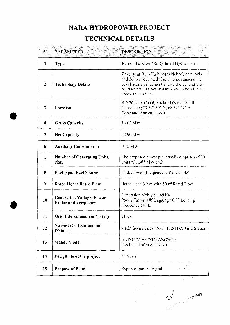
NARA HYDROPOWER PROJECT
TECHNICAL DETAILS
· ..--.---.---------------..-------------.-..-------------.------......-..--.-----.~---..--- ..-_~ L. ...".._.• .._~n_.~,~__~, ~
[ Peter Rae Hydro Consulting Ltd .
.J
Rohri and Nara ,Canals
Hydropower Project
Fe-asibility Study
Report Prepared for
,)
June 2015
Rev 0
; --
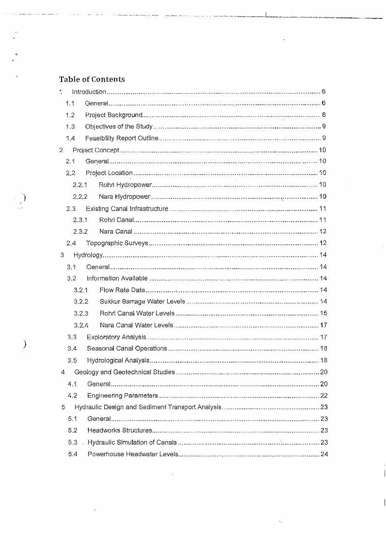
.__ -~-.------ -_ ' .•.. ---- .••--." _ .-.-- -...... . _.... .. . ..••. .L···_··_· ···_ _" __ ,_ ..I __ ,.. _ _"~~_~I__-___ao .. ,
..{.
Table of Contents
)
1 lntroducfion.i.. , , ,. , ",' ,..'" ' ' " ..,' ., .. , , ,.. ,.." 6
1,1 General .; ,6·
1.2 Project Backqround , , , " ,.. , , ,", .. ,""" 8
1,3 Objectives of the Study ", .." " .. , ", " ,.. " " " 9
1.4 Feasibility Report Outllne " " 9
2 Project Concept " " ,' " ","" " "" " " , 10
2,1 General , ,.. ,"", .. ,"', .. , ,.." " , 1.0
2.2 Project Location , , , , ", , , 10
2.2.1 Rohrl Hydropower ,.., "" : , 10
2.2.2 Nara Hydropower , " 10
2.3 Existing Canal Infrastructure " 112.3.1 Rohrl Canal 11
2,3,2 Nara Canal "" ,.." " " " 12
2.4 Topographic Surveys , " " , '" " 12
3 Hydrology , """, , ,, ' 14
3.1 General " ,." ,," " .. " " 14
3,2 Information Available ., , " " ',." ,,, 14
3.2,1 Flow Rate Data , ,.;'''', " " ,''', , " , 14
3.2.2 Sukkur Barrage Water Levels " " " " 14
3.2.3 Rohri Canal Water Levels ".15
3.2.4 Nara Canal Water Levels 17
3.3 Exploratory Analysis " 17
3.4 Seasonal Canal Operations " " " ", "" "." " 18
3,5 Hydrol.ogical Analysls.i... , ,." "" " : 18
4 Geology and Geotechnical Studies " " 20
4.1 General " 20
)
4.2 Engineering. Parameters 22
5 Hydraulic Design and Sediment Transport Analysis " 23
5.1 General .., , ,.. ,.. ,." .. , , " .. , , , " 23
5.2 Headworks Structures ,', , 23
5.3 Hydraulic Simulation of Canals "." " : " " 23
5.4 Powerhouse Headwater Levels , 24
~)
5.5 Powerhouse Tailwater Levels 24
5.6 Sediment Transport and Deposition 24
6 Power Station Design : 25
6.1 General 25
6.2 Powerhouse Layout , 25
6.3 Structural Design , 26
6.4 Auxiliary Structures 26
6,5 Existing Canal Drop structure Closure 26
7 Electrical and Mechanical Equipment 27
7.1 Scope and Objectives , , ,.. ,', " 27
7.2 Turbine Selectlon, " .., , 27
7.3 Power Generation Equipment , 27
7.4 Balance of Plant Systems , , 27
7.5 Spillway Equipment 27
7.6 Transmission Line Connection " , 27
8 Power and Energy yield , , 28
9 Construction Planning, Cost Estimates, and Schedule 29
9.1 General 29
9.2 Construction Plan , , , 29
9.3 Construction Schedule ; 29
9.4 Cost Estimate " , 29
10 Conclusions and Recommendations , 30
) List of FiguresFigure 1 Project Area , , 6
Figure 2 Sukkur Barrage and Left Bank Canals Headworks Regulator 7
Figure 3 Rohri Powerhouse Location " "" " 10
Figure 4 Nara Power Station Locatlon " "" "." " 11
Figure 5 sukkur Barrage Water Levels ,,, , ,, ,,,.,,,,, ,, 15
Figure 6: Measured Water Levels Upstream of RD15 15.Figure 7: Water Levels Downstream from Drop Structure .." ; 16
Figure 8 Mass Curves " "" 17
Figu re 9 Flow Duration eu rYes ,', , 18

_ _ ~ ~_ _.~ _. . _' .. _. __ ,_.__ _. . . .__ ~~_ _ r.__ .~ _ .,_., __ ~l _~_..:.,~-"AI.I:~~";"lIl_ _ ~ __ ..._---.-.I_
Figure 10 Regional Geological Map ,"",., , " .." , 21
..)
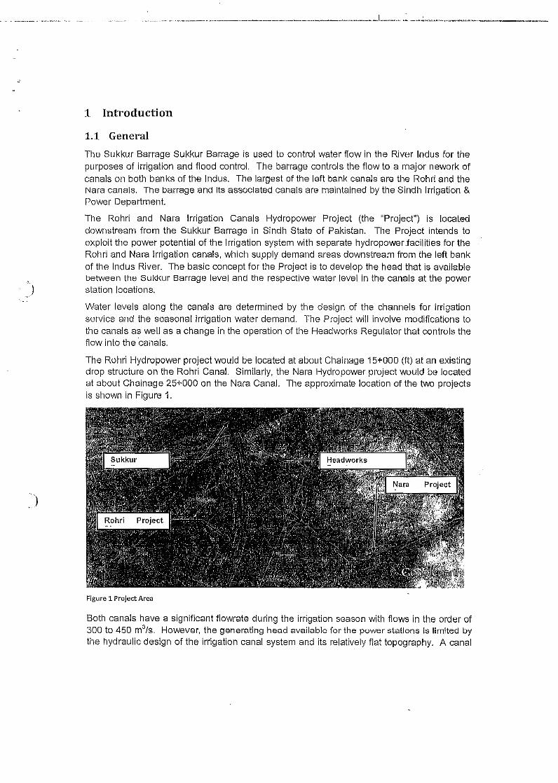
____.__'.. . . ~~__~ . ..~_ .._.._.__L.__...._~.__:.:__-_...__ - , _
1 Introduction
1.1 General
.~.
The Sukkur Barrage Sukkur Barrage is used to control water flow in the River Indus for thepurposes of irrigation and flood control. The barrage controls the flow to a major nework ofcanals on both banks of the Indus. The largest of the left bank canals are the Rohri and theNara canals. The barrage and Its associated canals are maintained by the Sindllirrigation &Power Department.
The Rohri and Nara Irrigation Canals Hydropower Project (the "Project") is locateddownstream from the Sukkur Barrage in Sindh State of Pakistan. The Project intends toexploit the power potential of the Irrigation system with separate hydropowerJacillties for theRohri and Nara Irrigation canals, which supply demand areas downstream from the left bankof the Indus River. The basic concept for the Project is to develop the head that is availablebetween the Sukkur Barrage level and the respective water level In the canals at the powerstation locations.
Water levels along the canals are determined by the design of the channels for irrigationservice and the seasonal irrigation water demand. The Project will involve modifications tothe canals as well as a change in the operation of the Headworks Regulator that controls theflow into the canals,
The Rohri Hydropower project would be located at about Chainage 15+000 (f.t) at an existingdrop structure on the Rohri Canal. Similarly, the Nara Hydropower project would be locatedat about Chainage 25+000 on the Nara Canal. The approximate location of the two projectsis shown in Figure 1.
)
F.lgure 1 Project Area
Both canals have a significant tlowrate during the irrigation season with flows in the order of300 to 450 m3/s, However, the generating head available for the power stations Is limited bythe hydraulic design of the irrigation canal system and its relatively flat topography. A canal
drop occurs at both of the project sites, which provides for some generating head. Additionalhead will be created by modification of the canals, as discussed in this report.
The water level upstream from the drop structures is determined by the flowrate and thecharacteristics of the free overflow structures at the sites. The water level downstream isdetermined by the hydraulic characteristics of the channels and the location of the variousflow abstractions.
J
The Headworks Regulator (see Figure 2) regLIIates the flow into the canal based on theantici pated demands downstream. The Reg ulator has separate gate controls for each of thecanals. The gate position Is set according to the flow demand and a head drop occurs fromthe water level upstream from the Sukkur Barrage to the canal water level. The HeadworksRegUlator was apparently designed to create a head drop of about 1.5 ft (0.45 m) althoughthis will vary depending on the flow conditions. .
The generating head at the proposed generating stations might be Increased if the functionof the Headworks Regulator at the Sukkur Barrage could be transferred to the new powerproject.
)
Figure 2 Sukkur Barrage and Left BankCanals Headworks Regulator
In this scheme, the water level In the upstream of the power station would be equal to thelevel upstream of the Sukkur Barrage. A small drop In water level would occur from thislocation to the power station as required to provide the hydraulic gradient. The existingHeadworks Regulator would be left with all gates in the fully open position and would nolonger be used to control the flow to the canal. The flow control would be provided by theregulation of flow through the power station and over a bypass weir that would be installed atthe site.
J
The installed generating capacity at the two sites would depend on the rated discharge andthe amount of head that could be achieved.
The Project would also require provisions for discharge of flow along the canal at the siteduring periods when the power station is not operating. A barrage structure is necessary atboth of the sites. This structure can be used as the head regulator in concert with the flowthrough the power station.
Modifications to the canal dikes will provide freeboard for power plant operation and toaccommodate the transfer of the ·head regulator function downstream. The modifications willrequire raising and perhaps some reformation of the existing dikes.
The profile and cross section of the canal has degraded since the original construction inabout 1932 due to the effects of sediment erosion and depositions. Sustenance of the fulldesign capacity of the canals will require ongoing maintenance works because sedimentdeposition is likely to occur in the future.
Development of the Project is proposed as independent power projects that would beundertaken under the regulatory environment established in Pakistan. Key implementationagreements would be required if the projects are confirmed to be commercially feasible fordevelopment, Including: power purchase agreement, concession agreement, transmissionline access agreement, etc.
)
1.2 Project BackgroundA feasibility study was completed for the Rohri Canal project in 2013 by W.S. Atkins'. Thestudy considered the hydraulic characteristics of the site, the available geologicalinformation, and other available details for the project. Five years of daily flow rate andwater level' data was provided for the canal drop structure. The study proposed anarrangement with eight generating units with total installed capacity of 4.8 MW. However,several details of the project remained to be confi rmed and the study did not consideroptimization of the site by changing the Hsadworks Regulator. The study provides a usefulbackground reference for the present study.
The potential for the Nara Canal Project was identified in an earlier project ranking study,which was also prepared by W.S. Atkins2 in 2012. No feasibility study appears to beavailable for the proposed Nara Canal project.
The Power Department released the Rohri Canal RD15 Project for tenders for the design,construction, and operation of the power station in 2013. The Project and its commercialframework was described in an Information Mernorandurrr' prepared as part of an intendedpublic private partnership (PPP) for the development of the Rohri RD15 Project. The Projectwas selected as being the most viable of the sites identified in the ranking performed by thePower Department. "
The proposed Project would have been developed assuming that the water levels in thecanal were according substantially unchanged from the operating experience in the period
1 W.S. Atkins, "Run-oF-River Hydroelectricity Generation, Feasibility Study - Run of River Hydropower at RohriCanal RD15", report prepared for Power Department, Government of Sindh, 22 February 2013.2 W.S. Atkins, "Pre-Feasibility Study for Run of the River Hydroelectric Power, Site Analysis and Selection",report prepared for Power Department, Government of Sindh, 12 September 012.3 Ernst and Young, "Run of the River Hydropower Project at Rohrl RD15", document prepared for the EnergyDepartment, Government of Sindh, 14 March 2013.
since the Sukkur Barrage was completed in 1932. The intended capacity was about ·1.8MW.
The Rohri Project has not yet been successfully developed under the terms offered as partof tile PPP transaction tender.
')
1.3 Objectives of the StudyAn alternative to the Project described in the previous studies was identified to Improve thefinancial viability of the scheme. The proposed project concept is to increase the generatinghead by allowi ng impoundment in the headrace canal up to the level in the head pond of theSukkur Barrage. This concept would increase the installed capacity of the Rohrl RDi5scheme. The Nara Canal was also identified as providing hydropower generation potential.The development of a combined project is being considered as a means to improveperformance by exploiting economies of scale in the development.
A feasibility study is required for both sites to include geological investigation, topographicalsurveys, site optimization, and feasibility level design of the works. The study mustdetermine the hydraulic conditions in the canals so as to confirm the head available at thepower station and the scope of work required for the canal dikes. The study must alsovalidate the available data for water levels in the canals given the 'large errors inmeasurements illustrated by the previous stuoles.
')
1.4- Feasibility Report Outline
This report describes the Project Concept for the Rohri and Nara Hydropower Projects.Section 2 describes the Project Concept and the base case conditions along the canals.Section 3 presents the hydrological data assessment that forms the basis for selecting theinstalled capacity and the estimate of the project revenue. Section 4 presents the availableinformation for the geotechnical conditions relevant to the power station design. Section 5describes the hydraulic model developed to simulate the water levels along the canals usingcross sections surveyed in the field. The model was used to determined head water andtailwater levels for the canals, which resultsin the head available for generation.
The design of the power stations Is described in Section 6 and the proposed electro-mechanical equipment is summarized in Section 7, The estimate of power and energy yieldis provided in Section 8.
The construction planning, schedules, and cost estimate are summarized in Section 9. Anoverview of key conclusions and recommendations are presented in Section 10.
·,
2 Project Concept
2.1 GeneralThe project concept is to exploitthe available flow and topography of the two main canals onthe left bank of the Indus River at Sukkur Barrage to maximize the potential installedgenerating capacity. The flow rate is defined by the operation of the irrigation system, whichcan be defined from the available data base.
The generating head depends on the water levels In the canals and the works that can beinstalled control the headwater levels. Existing grade control drop structures are at bothproposed power station locations.
2.2 Project Location
2.2.1 Rohri Hydropower
) The Rohrl Hydropower project would be located at about Chai nage 15+000 (ft) at an existing. drop structure on the Rohri Canal. The power station will be developed at the canal drop
structure location, as illustrated in Figure 2. The drop structure Is at approximately 27 38' N,6851' E. The power station would be located in the abandoned reach of canal adjacent tothe drop structure.
Figure 3 Rohrl Powerhouse Location
z,z.z- Nara Hydropower
Similarly, the Nara Hydropower project would be located at about Chalnage 25+000 on theNara Canal. The power station will be developed at the canal drop structure location, asillustrated in Figure 3, The drop structure is at approximately 27 37' 50" N, 68 54' 27" E.
The power station would be located in the abandoned reach of canal adjacent to the dropstructure.
:...._J
Figure 4 Nara Power Statlon location
2.3 Existing Canal Infrastructure
2.3.1 Rohri Canal
Flow into the canal is control by a Head Regulator that was constructed as part of the SukkurBarrage works. The existing canal from the mgulator to the RD15 drop is reported" to havea bed width of 84.43 m (277 ft.) and a slope of 0.0060. The canal is designed for a flow rateof 467.28 m3/s (16,500 ft3/s). The bed level varies from el 176.50 ft. downstream from theregulator to 175.62 ft. at the drop structure. The water surface level varies from 192.5 to'191.62 along the reach. The design flow depth is 16 ft.
Improvements are proposed by the Water and Power Development Authority for lining of thecanal. The slope would be increased to 0.0080 with a reduction in the bed ,width to 230 ft.The flow depth would be 14.96 ft. with a slope from 191.78 ft. upstream to 190.58 ft.downstream. The bed level would be remodeled to 176.82 ft. upstream and 175.62 ft.downstream.
The canal downstream from the drop also has a gradient of 0.0060% and a bed width of 276ft.
The available Information suggests an available generating head of about 0.66 m withoutany modification to the canal profile.
The water level upstream from the Head Regulator is controlled by the Sukkur Barrage.Water levels vary seasonally and with the operation of the barrage in response to flow
4 All data is provided from Water and Power Development Authority, "Feasibility Study & Detail Designfor Lining of Rohri, Dadu and Rice Canals, December 2010.
.••., .~_.__.,."•._..•...__•.••"u .._.",_",._"",,,..._.~_~",_,,,,_,_,,,,,,,,,~,~,---,_~_,__. ,.........,~.....__.._. _ ......_ .....~....."'L~, ~..,..~.-............~,..~,.......~.-~~ ......-.-...""'--__,.--
demands and the inflow of the Indus River. The median water level with the irrigation canalsoperating is el 197.5 ft. and the operating range5 is from about 193.7 ft. to 1m1.8 ft.
The data suggest a head drop of about 1.524 m (5 ft.) through the Head F<egulator to theRohri Canal. Flow through the Regulator Is controlled by gates installed as part of theoriginal construction of the Sukkur Barrage. A total of twelve gates are believed to be in theRegulator for the Rohri Canal.
The shoreline of the canal is utilized for housing and small industrial enterprises along thefirst 2.5 km downstream from the Head Regulator. A major highway crossing is located atabout 1500 m from the Regulator. The' maximum feasible level in the Rohri canal is likelydefined by the level of this bridge.
J
2.3.2 Nara Canal
Flow into the canal is control by a Head Regulator that was constructed as part of the SukkurBarrage works. The Nara Canal is one of the three canals on the left bank 'of the Indus atSukkur. At the Head Regulator the Nara Canal is immediately adjacent to the Rohri Canaland a smaller canal located between the two larger waterways.
The gradient of the canal after construction of the fall at the proposed power station locationis 1:8,125. The canal profile has evolved due to the effects of sedimentation and erosion.The existing canal from the regulator to the RD25 drop is reported to have a bed width of84.43 m (277 ft.) and a slope of 1:8,125. The canal is designed for a flow rate of 13,602fe/so The bed level varies from el174.40 ft. downstream from the regulator to 171.2 ft. at thedrop structure. The working water depth is believed to be about 10.5 ft. The water level atthe upstream end is understood to be el 194.5 ft. although this value has not yet beenconfirmed in the field.
The canal gradient downstream from the fall is 1: 15,140. The bed level at the downstreamfrom the fall is el 169.0 giving a fall height of about 2.2 ft.
The existing information suggests an available "lead of about 0.3 m without any changes tothe canal profile.
The water level upstream from the Head Regulator is controlled by the Sukkur Barrage in thesame manner as for the Rohri Canal.
The shoreline of the canal is utilized for housing and small industrial enterprises along thefirst 2.5 km downstream from the Head Regulator. A major highway crossing is located atabout 1500 m from the Regulator.
_J
2.4 Topographic SurveysTopographic information from previous studies comprised limited topographic information atthe Rohrl powerhouse site. The available information was not sufficient for a feasibilitystudy, AccordlnglY,'a program of site investigations was undertaken to provide:
• A coordinate monument system for all subsequent works up to the start ofconstruction.
5 Based on operating period from 2006 to 2014.
• Project Site Mapping: the topography of each of the Project sites was mapped at ascale of 1:500 with 0.5 m contour intervals. A Digital Elevation Model. (OEM) of thesites was prepared.
.J
• Cross sections of the canal downstream from the powerhouse locations for adistance of about 5 km or until the first grade control structure, whichever occuredfirst. Sections were at a spacing of 100 m for the first 2 km downstream and then ata spacing of 200 m for the remainIng distance.
• Cross sections measured from the power stations upstream to the Head Regulator.Sections were located at not more than 100 m spacing and extended laterally to
about 5.m from the external toe of the existing dikes.
• . Water levels and flow rate were recorded at each cross section for calibration ofhydraulic models.
• A proposed access road alignment, profile and typical cross sections was surveyedfrom the end of the nearest existing public road to the power station site.
• The dimensions of the Headworks Regulator were measured including number ofopenings, width and height of openings, sill elevation, and any other data relevant forthe computation of flow rate through the structure.
• The dimensions of the existing drop structures were measured including the sillelevation, cross section and longitudinal sections.
The above information was collected to supplement data available from the IrrigationDepartment and other sources.
----.--.----- .•~----- - "_"-' ._.' . .._. -· ""· _~~ ·."'·_._ .._~ "._,.u ~ _ ,,_ _""_ " "" _ ~ ~~~ __ "'• ..-...J_........._.~_ ,'._ '": ~, .._. ~
3 Hydrology
3.1 General
Hydrological analysis was performed to characterize the flow available in the canals. Theobjective was to determine the range of flow rates during irrigation operations. A flowduration curve was required to estimate the energy available from the Project.
Exploratory analysis was carried out to assess whether the data can be considered to bestationary and homogenous, as required to represent possible future flows for the powerstations.
The hydrology for the power stations depends on the operation of the irrigation systems andthe releases from the Sukkur Barrage. The flow in the canal will vary seasonally and inter-annually depending on the irrigation fiow demand and the capacity of the canal system toservice the demands. The canals are closed for a period each winter for maintenance.
J 3.2 Information Available
3.2.1 Flow Rate Data
Flow rate data was obtained from the Irrigation Department for the two canals. A data setprepared by W.S Atkins for the Rohri Feasibility Study was also examined ..for consistencywith the raw data. Corrections adopted by Atkins were made in the raw data where errors intranscription or entering of data appeared.
The data from 2006 to 2014 was selected as being indicative of present operations for thesystem. Analysis of the longer historical period is of less interest due to the possibility oftrends caused by changes in water demands, cropping patterns, or the condition of thecanals.
Daily flow releases were provided for both the Nara and the Rohri canals as part of the dataprovided from the Irrigation Department.
3.2.2 Sukkur Barrage Water Levels
Daily water levels upstream from the Head Regulator at the Sukkur Barrage. The waterlevel upstream is generally in the range of e1194.5 to 200 ft. The variability in the water levelarises because of the operation of the Barrage gates in response to the flow of the Indus andthe diversions to the irrigation canals on the right and left banks.
No information was available about the water levels downstream from the Head Regulator Inthe Irrigation canals.
The water levels at Sukkur show a relationship between water level and flow rate in theIndus River, as illustrated In Figure 5. Note that the relationship is a result of the operationalpolicy for the Barrage and is not a physical characteristic of the hydraulic system.
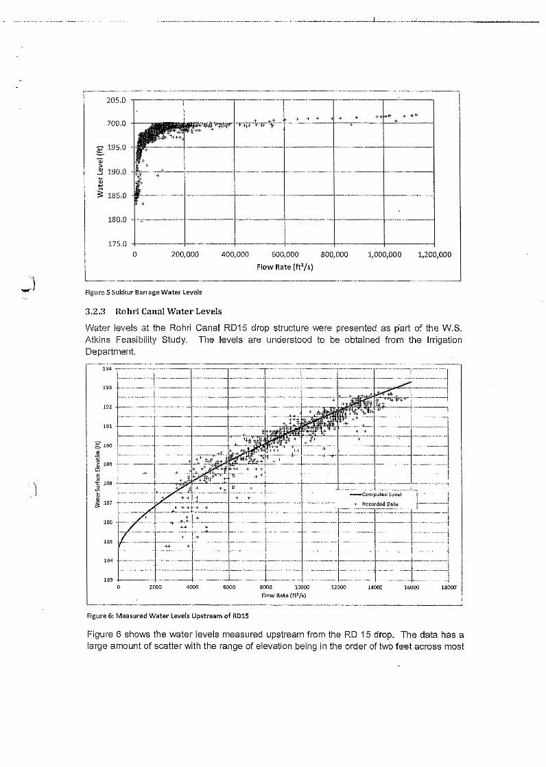
'\. .J
.. _ •••• _.< ••••• ~_._._. __ • • __ ._. __ .... _ •••.•_. __ ._. __ __ ... _ ..... _._~_._ •• __ .. __ ~~ __ ._ •.L._~...~_~.: .__....__ ._._., .
_. __ ._-_._ ......_- ..- ....._-_ .._-------_ .._--_._--- ----_ ..-.--_ ....__ ..------_ ..._-----,205.0
.. .- .. + +< ~..... -4 ... *
r: .. .+ .,+I>
~+r-f'lI"V .. "i-+ ... ~. 'II' T
+, . .,f-"~,.
'.
18000'
Figure 6 shows the water levels measured upstream from the RD 15 drop. The data has alarge amount of scatter with the range of elevation being in the order of two feet across most
200.0
g 195.0
~2:l 190.0:u~~ 185.0
180.0
175.0200,000 400,000 800,000o 600,000
Flow Rate (ft3/s)
1,000,000 1,200,000
.--- ....--...-..-..-- ...--.-----~Figure 5 Sukkur Bartage Water levels
3.2.3 Rohrt Canal Water Levels
Water levels at the Rohri Canal RD15 drop structure were presented as part of the W.S.Atkins Feasibility Study. The levels are understood to be obtained from the IrrigationDepartment.
194 r-..-........-·-~------·--r-..·..--....·--""·,."..-----r--·-· ..··..-....-T·_ ..- ..-·--r--......·-..·-·-..·..---..-_·_..,r-..·..·....--_·_,1"-"-'----- ..!--·---- ..---I------- ....--·-I-·· ..--- ....I·----....· -. ----.- -;--..-----·- ..1----- .....
l~-I--- ..----+---- ....I-,,----+------~-- ..f--- ..-..-· +---· ..----.. --+------..·-i·--~~~~"..+--,,·-·-----:i ~.192 1-- _ +ii ." _._ -l-r- __.. __ ._+ _ + -i- ,.--V--' ., 11~1"t, 'F'+
191 +1._-..__ ., ., ·+iIi .•••'••...•••••..~.-:_~: +I, __ + _ _, j., .. . ..' ..~+'.+ ' __ 11..+ _ --i. __.. ..1
<- ,.
g 190 1.- - +----- + -----1 "'· '_'I* ,....,.."c.. " ..__IL..<-C...:f ., ".; ··1---- -..·..+..---·. 1---.-- ..- , ..-.-- -1
·5 .,.or. ,. ..+c~,--··.....;'!'i'-:·' .. ''--f" --~·'·.-+'-I-------I·---·---·---+--- ..---I~ 189 ---.-.- .... ~.t--.-..-.-1·~..:..~--;j.•;~;!>.·.•i\:t,'~+·111Hff'~;$,...,....___:~.it'*·;j'·,,··,t'-·:.+'--t ..~.-;-: •. _ +. -----I- ..·----t----- ..-I·-·-·- ..j-----!~ . . ":>-£+1 + -l- .,.
~188 .~.-_ ....·-·-+_ ...-·~·~~:~1~..",~\"I"~._-··~~+··~~----···--'·-r··-.....- ....-I ....-·- ..--r·..·.-.------t·---------r-----' ..-~.ii <, . E.~, ___:~:..: '.,.._ _j 187 .,,- _ ,':""7,_· ': .. ". .t . '. +'.
_'''''''' L. ".•,."';'.'.,".186./' .1 ...:>'_R:2~~'..·· ..... ,~+~. .L.195 ]_ .,_ .. 1 ........ • .. -':- :;:-A.. __.._... I'"'' ... - ""--j.-" .-- ... -...... -._ ..... '-1--' .
__.~; ... - ~ - -,_, , 1--- - -"1'184 +""--"·-'--'1''''''--''--'''-1'''''''----'--·'1-'------''-'-;-·- -..·..···---1..·· ·-··..·..··-,..··--·--..--· ..-..,..---- ..-----, ...------- -_.,
1__ - ..• • 1 • · " --+ ---,..- 1__ .._ _ .11 " + ·-..· ,,- .."1..·..· · ,,, ·· ,..·I,---·-· ·---~
. ' ..",. "" . . , .......... Com pure d Lave I
.. Roco,do<t Oat.
. ....- ....... __ .._".
183 ~ ..---····+····"·······- ..--·I· ..,,,·-..-·..·~-···....····..···············..·····1.... ········..··........,·,,1···..···········..---II·· ....·....· .... ~·--····--·· ..I- ....···········--~2000o 4000 6000 8000 lOOPO l~OOO 1400Q 16000
Flow Hat9 ((t·' Is)........ ----...-....---..•.---------- .." ..----- ..--- ..---~,--.------.Figure 6: Measured Water levels Upstream of RD15
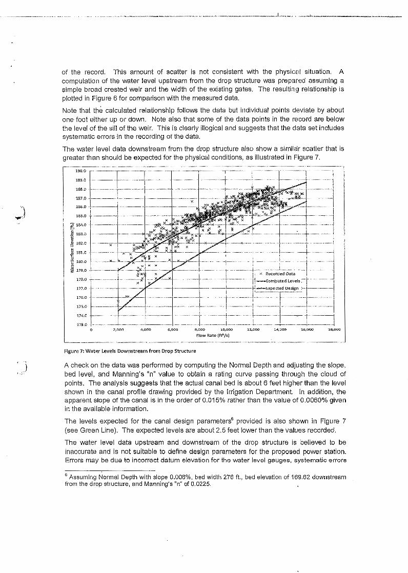
"_ ..' _ _ ~ ._._._. __.__ ._._ _..•._~ ..__ .._ _J_. _ .....• _,_. ,.. • .. ;__
of the record. This amount of scatter is not consistent with the physical situation. Acomputation of the water level upstream from the drop structure was prepared assuming asimple broad crested weir and the width of the existing gates. The resulting relationship isplotted In Figure 6 for comparison with the measured data,
Note that the calculated relationship follows the data but individual points deviate by aboutone foot either up or down. Note also that some of the data paints in the record are belowthe level of the sill of the weir. This is clearly illogical and suggests that the data set includessystematic errors in the recording of the data.
The water level data downstream from the drop structure also show a sirralar scatter that isgreater than should be expected for the physical conditions, as illustrated In Figure 7.._ ..•..__ __ __ __ _ __ -_ -.__ .--_ _ -._._ .._-_ - - -------_ -._ __-
100·&,·---·---·,·-·----,- ..---,-·-----·,---· ...-r----,,-·----,-------,...--.-.-~189.0
188.0
187.0
") 186'.0
..,r:1 185.0
i[ 184.0r::
183.0.21j" 182.0w
~ 181.0
"OIl 180.0~~ 179.0;5'
178.0
177.0 ..
176.0
175.0
174.0
17-'1.00
-I-------;'---·---,i"-'-r--·-·---:..-r-'-----------I· ..··---- ----·r ---._ - .. --i _ -, _.i ' :< Recorded Data
-j. -' _- ..-l- - ·---.}'-I··..- .. !\I"'.' ..·······x.J----.-! -----.-+--.----.-.-.'i'; -Goniputed Level .:.
2,000 4,000 ~6,OQO~4.000.s.ccc s.ooc ao.cooFlow Rate (ft'/s)
1.2,000
-----.--.--.-.---~~-.Figure 7: Water Levels Downstream from Drop Structure
f )
1'_; ..
"3:8,006
A check on the data was performed by computing the Normal Depth and adjusting the slope,bed level, and Manning's "n" value to obtain a rating curve passing through the cloud ofpoInts. The analysis suggests that the actual canal bed is about 6 feet higher than the levelshown in the canal profile drawing provided by the Irrigation Department. In addition, theapparent Slope of the canal is in the order of 0.015% rather than the value of 0,0060% givenin the available information.
The levels expected for the canal design parameters" provided is also shown in Figure 7(see Green Line). The expected levels are about 2.5 feet lower than the values recorded.
The water level data upstream and downstream of the drop structure is believed to beinaccurate and is not suitable to define design parameters for the proposed power station.Errors may be due to incorrect datum elevation for the water level gauges, systematic errors
6 Assuming Normal Depth with slope 0.006%, bed width 276 ft., bed elevation of 169.62 downstreamfrom the drop structure, and Manning's "n" of 0.0225.
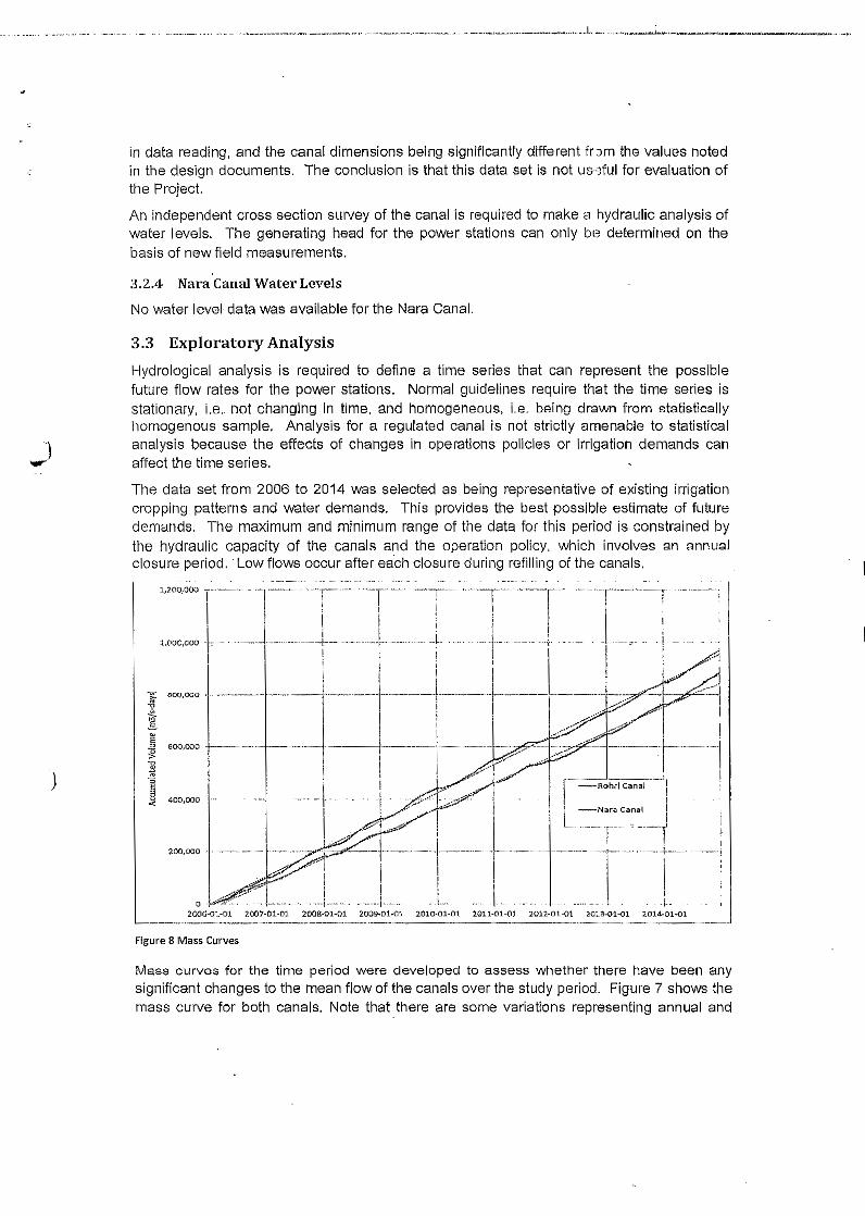
in data reading, and the canal dimensions being significantly different trorn the values notedin the design documents. The conclusion is that this data set is not us-eful for evaluation ofthe Project.
An independent cross section survey of the canal is required to make a hydraulic analysis ofwater levels. The generating head for the power stations can only be determined on thebasis of new field measurements.
3.2.4 Nara Canal Water Levels
No water level data was available for the Nara Canal.
3.3 Exploratory Analysis
Hydrological analysis is required to define a time series that can represent the possiblefuture flow rates for the power stations. Normal guidelines require that the time series isstationary, i.e. not changing in time, and homonaneous, l.a. being drawn from statisticallyhomogenous sample. Analysis for a regulated canal is not strictly amenable to statisticalanalysis because the effects of changes in operations policies or irrigation demands canaffect the time series.
The data set from 2006 to 2014 was selected as being representative of existing irrigationcropping patterns and water demands, This provides the best possible estimate of futuredemands, The maximum and minimum range of the data for this period is constrained bythe hydraulic capacity of the canals and the operation policy, which involves an annualclosure period, .Low flows occur after each closure during refilling of the canals.
1,200,000 r·_..·····l,OOQ,OOO I,
~v~].~
.E!~]i§ I
~ '00,000 f .•
200,000 .r-I ...o .
2006·01-01 2007·01·01 2008.01-01 2009·01·01 2010·01 ..01 2011..01-01. 2012·01·01 201!-01-01 2014·01-01--- --.••..•.--•..•,- ~ ..----.-.---." --.---_.,---Figure 8 Mass Curves
Mass curves for the time period were developed to assess whether there have been anysignificant changes to the mean flow of the canals over the study period. Figure 7 shows themass curve for both canals, Note that there are some variations representing annual and
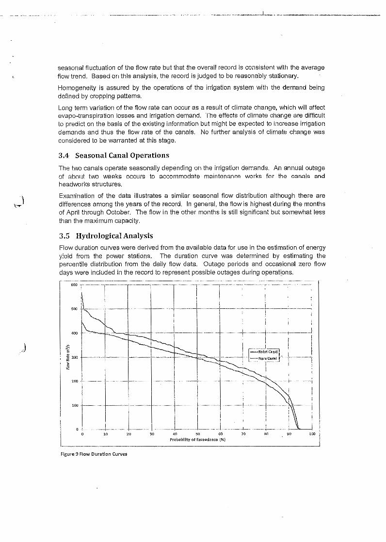
· ' ..' _ _~ _._ _.,__._. _ _ _._. .__.,. ,L._. '".. ._~_.~_._ .. ..__ . _._~
seasonal fluctuation of the flow rate but that the overall record is consistent with the averageflow trend. Based on this analysis, the record is judged to be reasonably stationary.
Homogeneity is assured by the operations of the irrigation system with the demand beingdefined by cropping patterns.
Long term variation of the flow rate can occur as a result of climate change, which will affectevapo-transplratlon losses and Irrigation demand. The effects of climate change are difficultto predict on the basis of the existing information but might be expected to Increase irrigationdemands and thus the flow rate of the canals. No further analysis of climate change wasconsidered to be warranted at this stage.
3.4 Seasonal Canal OperationsThe two canals operate seasonally depending on the irrigation demands. An annual outageof about two weeks occurs to accommodate maintenance works for the canals andheadworks structures.
Examination of the data illustrates a similar seasonal flow distribution although there aredifferences among the years of the record. In general, the flow is highest during the monthsof April through October. The flow in the other months is still significant but somewhat lessthan the maximum capacity.
3.5 Hydrological AnalysisFlow duration curves were derived from the available data for use In the estimation of energyyield from the power stations. The duration curve was determined by estimating thepercentile distribution from the daily flow data. Outage periods and occasional zero flowdays were included in the record to represent possible outages during operations.
10 40 SO 60
Probability· of Exceed.nce t%)70 so 90o 20 30
Figure 9 Flow DuratIon Curves
100

Figure 9 shows the flow duration curves for the two canals. The Nara Canal han a meanannual flow of 295 m3/s and a maximum of 569 m3/s. The Rohri canal has a mean annualflow of 269 m3/s and a maximum of 447 m3/s.
A tentative rated capacity for the power stations will be approximately the 90% exceedancevalue, which is 396.5 m3ts for the Rohri site and 433.3 m3ts for the Nara site. The maximumcapacity of the power stations can be found by designing for the maximum flow rates above.The selected capacity should be derived by optimization of the equipment and energy yield.
J
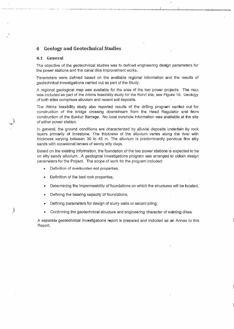
, ,..... ~_~~ __ ~_•••. ~._..._~ ._..._.'u __ "._.•• ,_.,~._, ....... --..>......... - ......... -----~__..~ ................ _,_ .......................... I~..,,,_,.,.,,...""..._ ......""I~~.,.,__ ..,_~_~ __ ~
4 Geology and Geotechnical Studies
4.1 GeneralThe objective of the geotechnical studies was to defined engineering design parameters forthe power stations and the canal dike improvement works.
Parameters were defl ned based on the available regional information and the results ofgeotechnical investigations carried out as part of the Study,
A regional geological map was available for the area of the two power projects, The mapwas included as part of the Atki ns feaSibility study for the Rohri site, see Figure 10, Geologyof both sites comprises alluvium and recent soil deposits.
The Atkins feasibility study also reported results of the drilling program carried out forconstruction of the bridge crossing downstream from the Head Regulator and fromconstruction of the Sukkur Barrage, No local borehole information was available at the siteof either power station,
In general, the ground conditions are characterized by alluvial deposits underlain by rocklayers primarily of limestone, The thickness of the alluvium varies along the river withthickness varying between 30 to 45 m. The alluvium is predominantly pervious fine siltysands with occasional lenses of sandy silty Clays,
Based on the existing information, the foundation of the two power stations is expected to beon silty sandy alluvium. A geological investigations program was arranged to obtain designparameters for the Project. The scope of work for the prog ram included:
• Definition of overburden soil properties,
• Definition of the bed rock properties,
, Determining the impermeability of foundations on which the structures will be located,
• Defining the bearing capacity of foundations,
J• Defining parameters for design of slurry walls or secant piling,
• Confirming the geotechnical structure and engineering character of existing dikes,
A separate geotechnical investigations report is prepared and included as an Annex to thisReport.
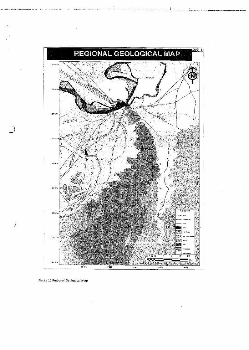
.)
.J
Figure 10 Regional Geological Map

· __--.. _, , ~_~ __ _,....__ ~ _ , ~,- ,.~".., ~ __ ~ _. _ _ ~_ ~..J _ ""~,.,.j ~.:......~£"'_ _ _~~.~_ ~_
4.2 Engineering Parameters
[To be inserted based on investigations)
)
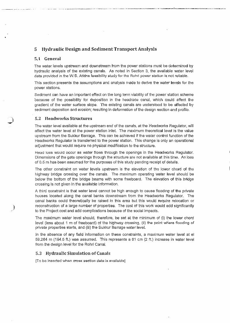
,. _.... _. ...._._.u. ._...... .... .-;J .... ,.. ....... • __ •••• _~ __ ~._,, __ .... _~_~ .... _ ................ ""~.~ ~_ ........ _.At~~._.........""""""'_~..__.._........,,_ ...__
5 Hydraulic Design and Sediment Transport Analysis
5.1 GeneralThe water levels upstream and downstream from the power stations must be determined byhydraulic analysis of the existing canals. As noted in Section 3, the available water leveldata provided in the W.S. Atkins feasibility study for the Rohri power station is_not reliable.
This section presents the assumptions and analysis made to derive the water levels for thepower stations.
Sediment can have an important effect on the long term viability of the power station schemebecause of the possibility for deposition in the head race canal, which could affect thegradient of the water surface slope. The existing canals are understood to be affected bysediment deposition and erosion; resulting In deformation of the design section and profile.
)
5.2 Headworks StructuresThe water level available at the upstream end of the canals, at the Headworks Regulator, willaffect the water level at the power station inlet. The maximum theoretical level is the valueupstream from the Sukkur Barrage. This can be achieved if the water control function of theHeadworks Regulator is transferred to the power station. This change is only an operationaladjustment that would require no physical modification to the structure.
Head loss would occur as water flows through the openings in the Headworks Regulator.Dimensions of the gate openings through the structure are not available at this time, An lossof 0.5 m has-been assumed for the purposes of this study pending receipt of details.
The other constraint on water levels upstream is the elevation of the lower chord of thehighway bridge crossing over the canals. The maximum operating water level should bebelow the bottom of the bridge beams. with some freeboard, The elevation of this bridgecrossing is not given in the available information.
A third constraint is that water level cannot be high enough to cause flooding of the privatehouses located along the canal banks downstream from the Headworks Regulator. Thecanal banks could theoretically be raised in this area but this would require relocation orreconstruction of a large number of properties. The cost of this work would add significantlyto the Project cost and add complications because of the social Impacts.
The maximum water level should, therefore, be set at the minimum of (i) the lower chordlevel (less about 1 m of freeboard) of the highway crossing, (ii) the point where flooding ofprivate properties starts, and (iii) the Sukkur Barrage water level.
In the absence of any field information on these constraints, a maximum water level at el59.284 m (194.5 ft.) was assumed. Tht"s represents a 61 em (2 ft.) increase In water levelfrom the design level for the Rohri Canal.
5.3 Hydraulic Simulation of Canals[To be Inserted when cross section data is available]
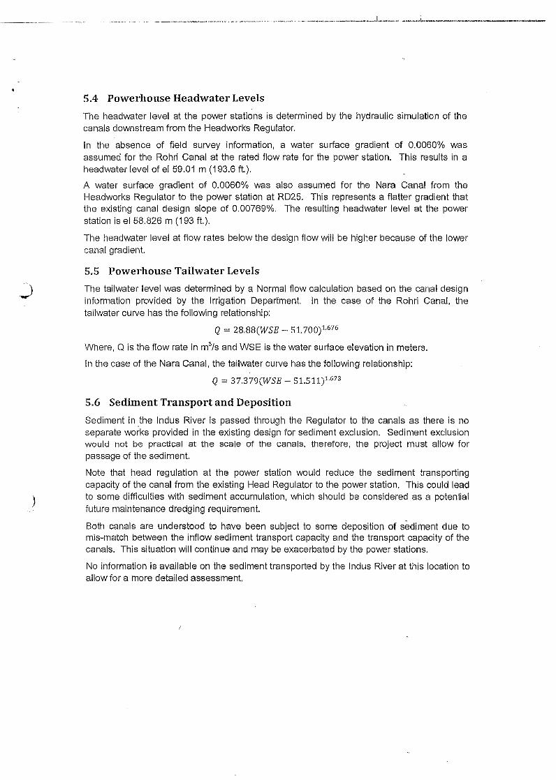
._~ . . __ .__ ~_~ _. . .. ._._~._." ~ .. ~. ._.~_ .. _ .. ~~ ~. ._._. ._ ._ ,. _,._.. _ _ __ _ _, .••l_ _ _, ,l....-;_ ...._",_ .."'~ ,. .......___ ~_,~
5.4 Powerhouse Headwater LevelsThe headwater level at the power stations is determined by the hydraulic simulation of thecanals downstream from the Headworks Regulator.
In the absence of field survey information, a water surface gradient of 0.0060% wasassumed for the Rohri Canal at the rated flow rate for the power station. This results in aheadwater level of el 59.01 m (193.6 ft.).
A water surface gradient of 0.0060% was also assumed for the Nara Canal from theHeadworks Regulator to the power station at RD25. This represents a flatter gradient thatthe existing canal design slope of 0.00769%. The resulting headwater level at the powerstation is el 58.826 m (193 ft.).
The headwater level at flow rates below the design flow will be higher because of the lowercanal gradient.
)
5.5 Powerhouse Tailwater LevelsThe tailwater level was determined by a. Normal flow calculation based on the canal designinformation provided by the Irrigation Department. In the case of the Rohri Canal, thetailwater curve has the following relationship:
Q = 28.88(WSE - 51.700)1.676
Where, Q is the flow rate in m3/s and WSE is the water surface elevation in meters.
In the case of the Nara Canal, the tailwater curve has the following relationship:
Q =: 37,379(WSE - 51.511?·673
5.6 Sediment Transport and DepositionSediment in .the Indus River is passed through the Regulator to the canals as there is noseparate works provided in the existing design for sediment exclusion. Sediment exclusionwould not be practical at the scale of the canals, therefore, the project must allow forpassage of the sediment.
Note that head regulation at the power station would reduce the sediment transportingcapacity of the canal from the existing Head Regulator to the power station. This could leadto some difficulties with sediment accumulation, which should be considered as a potentialfuture maintenance dredging requirement.
Both canals are understood to have been subject to some deposition of sediment due tomis-match between the inflow sediment transport capacity and the transport capacity of thecanals. This situation will continue and may be exacerbated by the power stations.
No information is available on the sediment transported by the Indus River at this location toallow for a more detailed assessment.
.J
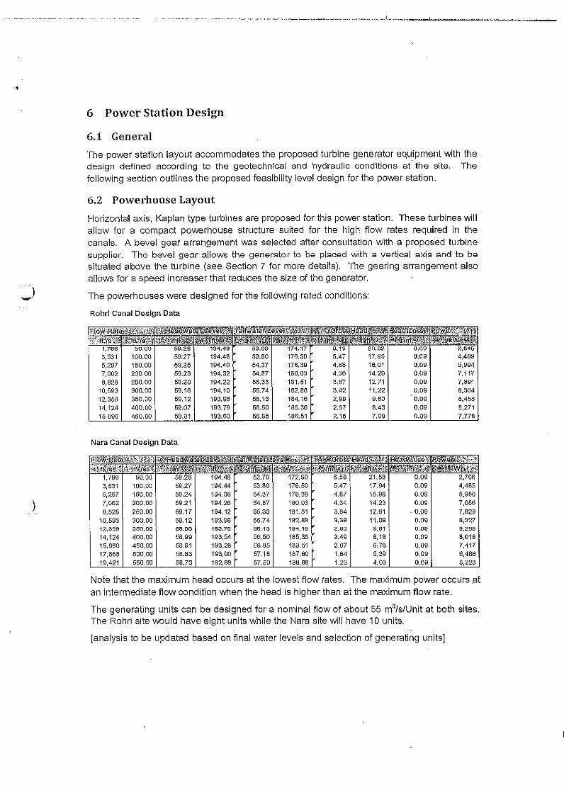
6 Power Station Design
6.1 General
The power station layout accommodates the proposed turbine generator equipment with thedesign defined according to the geotechnical and hydraulic conditions at" the site. Thefo[lowing section outlines the proposed feas'blllty level design for the power station.
6.2 Powerhouse Layout
Horizontal axis, Kaplan type turbines are proposed for this power station. These turbines willallow for a compact powerhouse structure suited for the high flow rates required ln thecanals. A bevel gear arrangement was selected after consultation with a proposed turbinesupplier. The bevel gear allows the generator to be placed with a vertical axis and to besituated above the turbine (see Section 7 for more details). The gearing arrangement alsoallows for a speed increaser that reduces the size of the generator.
The powerhouses were designed for the following rated conditions:
Rohrl Canal Design Data
1, 2,
3,531 100.00 4,4895,297 150.00 59.25 54.37 17B.39 4.88 16,01 0.09 5,9947,062 200.00 59.23 194.32 54.87 180.03 4.36 14.29 0.09 7,1178,826 250,00 59.20 194.22 55.33 181.51 3.87 12,71 0.09 7.891
10,593 300.00 59,16 194,10 55.74 182.86 3.42 11.22 0.09 8,33412,359 350.00 59,12 193.96 56,13 164.16 2.99 9.80 0.09 8,45814,124 400.00 59.07 193.79 66.50 185.36 2.57 8.43 0.09 8,271
890 450,00 59,01 193.60 56.85 186,51 2.16 7.09 0.09 7778
Nara Canal Design Data
100.00 59.27 194.44 53.80 176.50 5.47 17.94 0.09 4.465150,00 59,24 194,36 54,37 178,39 4.87 15.98 O.OS 5,980
) 200,00 59.21 194.26 54.67 180.03 4.34 14.23 0.09 7,0668,628 250,00 69,17 194,12 55.3:l 161.51 3.84 12.61 " 0.09 7,62tJ
10,593 300.00 59.12 193.96 55.74 182.88 3.38 11.08 0.09 8,227'12,3~e 350,00 59,06 193.76 56.13 164.16 2.e3 1;),61 o.os 6,266
14,124 400.00 58,99 193.54 56,50 185.36 2.49 8,18 0.09 8,01815,890 450.00 56,91 193,28 56.85 186.51 2.07 6,78 0.09 7,41717,655 500,00 5B.83 193.00 57.16 167.60 1.64 5.39 0.09 6,486
550,00 58.73 192,68 57.50 188.66 1.23 4.03 0.09
Note that the maximum head occurs at the lowest flow rates, The maximum power occurs atan intermediate flow condition when the head is higher than at the maximum flow rate.
The generating units can be designed for a nominal flow of about 55 m3/s/Unit at both sites.The Rohri site would have eight units while the Nara site will have 10 units.
[analysis to be updated based on final water levels and selection of generating units]
oThe powerhouse structure will be arranged by allowing for flow over top of the powerhousewith control by flap gates. The gates could be adjusted to supplement the flow through thepower station during some operating conditions. The gates would also open rapidly in theevent of a power system load rejection so that the flow rate along the canal would not bedisrupted.
6.3 Structural Design
6.4 Auxiliary Structures
6.5 Existing Canal Drop Structure Closure
The existlnq canal drop structures at each site will be permanently closed as part of thepower project. The closure will be accomplished by placing an embankment across thecanal immediately upstream from the drop structure during the January canal outage.
The embankment will be designed as a homogenous earth fill founded on the existing canalbed. The crest elevation will be the same as the dike bank levels and will accommodateopen channel transient conditions from power station operations.
The downstream slope of the embankment will be protected by turf. The upstream slope willbe covered with stone pitching founded on filter layer.
The existing structures will be left in their present condition and not demolished .
.J
.. -.- ... _ -. __>-. - ... - .• --__..__ ..__ .•• .. _ •• _.__ • __ ... ._... __ ,." ,.. _ .... .. ., l. .•• _.~~_;_,. "_. , _
o
7 Electrical and Mechanical Equipment
7.1 Scope and Objectives
7.2 Turbine Selection
7.3 Power Generation Equipment
7.4 Balance of Plant Systems
7.5 Spillway Equipment
7.6 Transmission Line Connection
)

8 Power and Energy Yield
J
)

· _ _._ .._. "._._._. ._._._ .. .__....J._.._ _~.__ ..__ ._u. _
9 Construction Planning, Cost Estimates, and Schedule
9.1 General
9.2 Construction Plan
9.3 Construction Schedule
9.4 Cost Estimate
).. '"

___ .__ . .. _ _ . . ,." .. ._._.._..__.._•• .._..__ .l__ . .l .__ .••__ .
'1
10 Conclusions and Recommendations
)
---_._-
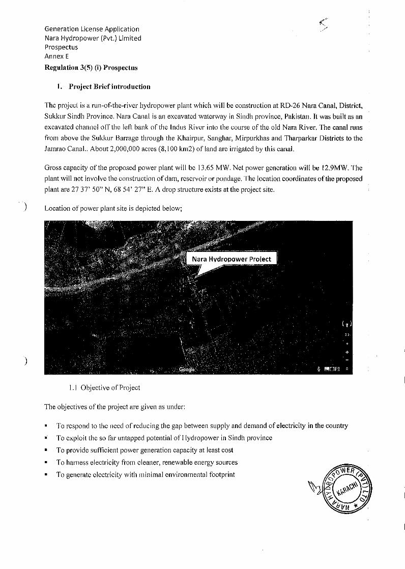
Generation License ApplicationNara Hydropower (Pvt.) LimitedProspectusAnnex E
Regulation 3(5) (i) Prospectus
1. Project Brief introd uction
The project is a run-of-the-river hydropower plant which will be construction at RD-26 Nara Canal, District,Sukkur Sindh Province. Nara Canal is an excavated waterway in Sindh province, Pakistan. It was built as anexcavated channel off the left bank of the Indus River into the course of the old Nara River. The canal runsfrom above the Sukkur Barrage through the Khairpur, Sanghar, Mirpurkhas and Tharparkar Districts to theJamrao Canal., About 2,000,000 acres (8,100 k1l12) of land are irrigated by this canal.
Gross capacity of the proposed power plant will be 13,65 MW. Net power generation will be 12.9MW. Theplant will not involve the construction of dam, reservoir or pondage. The location coordinates of the proposedplant are 27 37' 50" N, 68 54' 27" E. A drop structure exists at the project site.
) Location of power plant site is depicted below;
)
1.1 Objective of Project
The objectives of the project are given as under:
• To respond to the need of reducing the gap between supply and demand of electricity in the country.. To exploit the so far untapped potential of Hydropower in Sindh province
• To provide sufficient power generation capacity at least cost
• To harness electricity from cleaner, renewable energy sources• To generate electricity with minimal environmental footprint
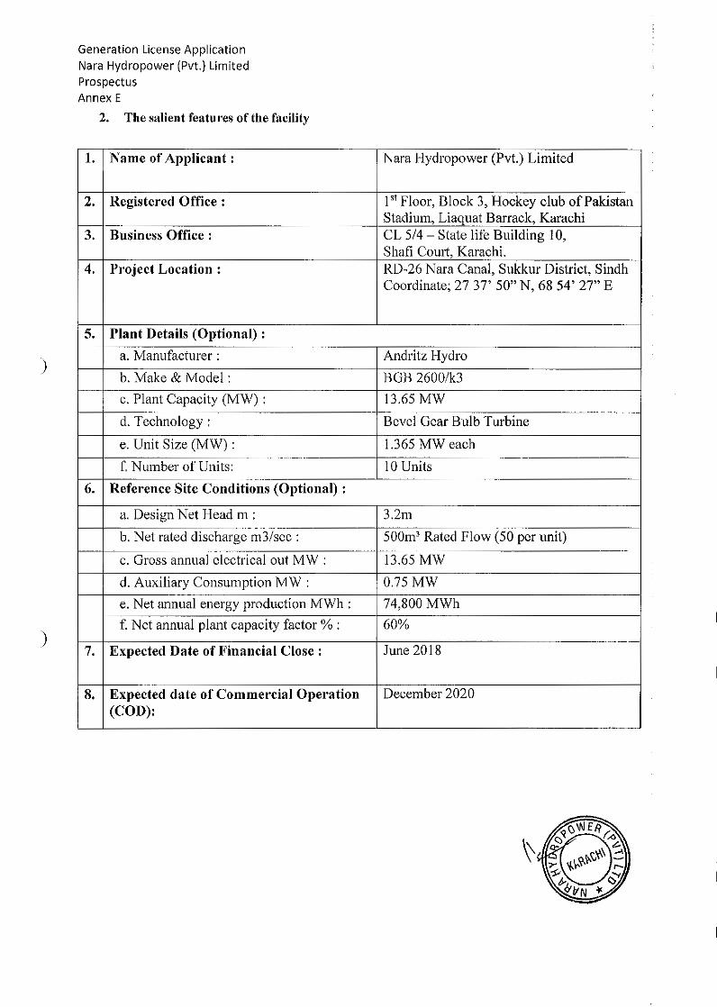
Generation License ApplicationNara Hydropower (Pvt.) LimitedProspectusAnnex E
2. The salient features of the facility
)
1. Name of Applicant: Nara Hydropower (Pvt.) Limited
2. Registered Office: 1st Floor, Block 3, Hockey club of PakistanStadium, Liaquat Barrack, Karachi
3. Business Office: CL 5/4 - State life Building 1O,Shafi Court, Karachi.
4. Project Location: RD-26 Nara Canal, Sukkur District, SindhCoordinate; 27 37' 50" N, 68 54' 27" E
S. Plant Details (Optional) :
a. Manufacturer: Andritz Hydro
b. Make & Model: BGB 2600/k3c. Plant Capacity (MW) : 13.65 MW
d. Technology: Bevel Gear Bulb Turbine
e. Unit Size (MW) : 1.365 MW each
f. Number of Units: 10 Units
6. Reference Site Conditions (Optional) :
a. Design Net Head m : 3.2m
b. Net rated discharge m3/sec : 500m3 Rated Flow (50 per unit)
c. Gross annual electrical out MW : 13.65 MW
d. Auxiliary Consumption MW : 0.75 MWe. Net annual energy production MWh : 74,800 MWhf. Net annual plant capacity factor % : 60%
7. Expected Date of Financial Close: June 2018
8. Expected date of Commercial Operation December 2020(COD):
)
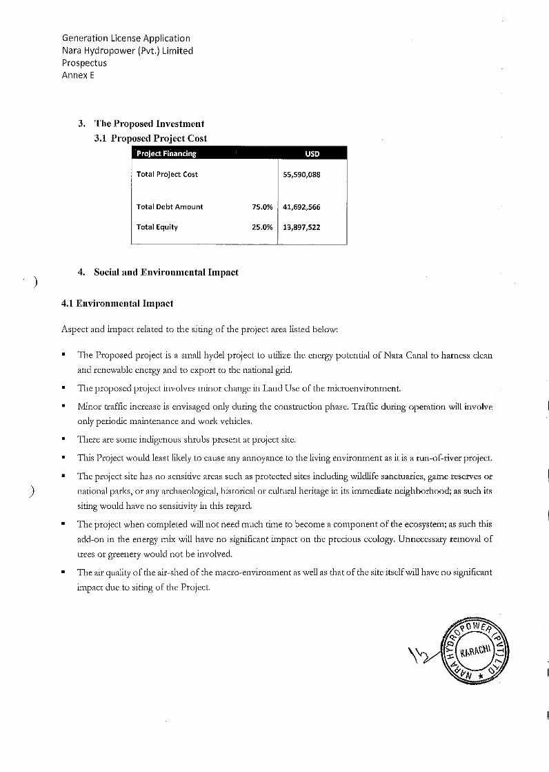
)
)
Generation License ApplicationNara Hydropower (Pvt.) LimitedProspectusAnnex E
3. The Proposed Investment3.1 Proposed Project Cost
Project Financ1ng USD
55,590,088Total Project Cost
Total Debt Amount 75.0% 41,692,566
Total Equity 25.0% 13,897,522
4. Social and Environmental Impact
4.1 Environmental Impact
Aspect and impact related to the siting of the project area listed below:
• The Proposed project is a small hydel project to utilize the energy potential ofNara Canal to harness clean
and renewable energy and to expmt to the national grid.
• The proposed project involves minor change in Land Use of the microenvironment.
Minor traffic increase is envisaged only during the construction phase. Traffic during operation will involve
only periodic maintenance and work vehicles.
There are some indigenous shrubs present at project site.
This Project would least likely to cause any annoyance to the living environment as it is a run-of-river project.
The project site has no sensitive areas such as protected sites including wildlife sanctuaries, game reserves 01'
national parks, or any archaeological, historical or cultural heritage in its immediate neighborhood; as such its
siting would have no sensitivity in this regard.
• The project when completed will not need much time to become a component of the ecosystem; as such this
•
•
•
•
•
add-on in the energy mix will have no significant impact on the precious ecology. Unnecessary removal of
trees or greenel'Y would not be involved.
The air quality of the air-shed of the macro-environment as weU as that of the site itself will have no significant
impact due to siting of the Project.
\"

Generation License ApplicationNara Hydropower (Pvt.) LimitedProspectusAnnex E
4.2 Socioeconomic Impacts
Positive socioeconomic impacts are envisaged from the construction and operation of 13.65MW NaraHydropower Project. Local skilled and unskilled labor will be hired during the construction phase of project.This would improve the quality of life of the nearby communities.
)
)
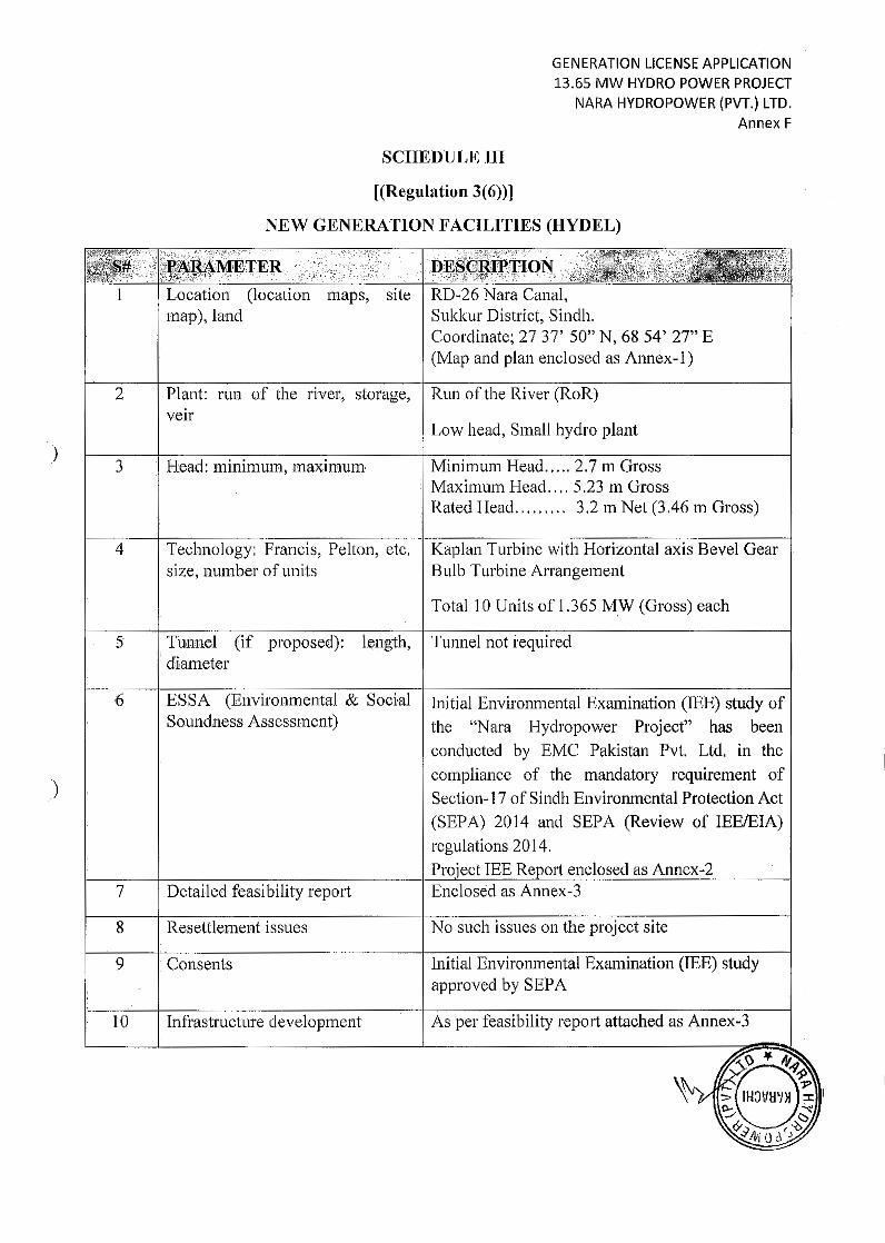
GENERATION LICENSE APPLICATION13.65 MW HYDRO POWER PROJECT
NARA HYDROPOWER (PVT.) LTD.Annex F
SCHEDULE III
[(Regulation 3(6))]
NEW GENERATION FACILITIES (HYDEL)
)
Location (location maps, sitemap), land
Plant: run of the river, storage,veir
RD~26 Nara Canal,Sukkur District, Sindh.Coordinate; 2737' 50" N, 68 54' 27" E(Map and plan enclosed as Annex- 1)
Run of the River (RoR)
Low head, Small hydro plant
3
4
. Head: minimum, maximum
Technology: Francis, Pelton, etc.size, number of units
Minimum Head ..... 2.7 m GrossMaximum Head .. " 5.23 m GrossRated Head ... "" .. 3.2 m Net (3.46 m Gross)
Kaplan Turbine with Horizontal axis Bevel GearBulb Turbine Arrangement
Total 10 Units of 1.365 M.W (Gross) each
)
5
6
. Tunnel (if proposed}: length,
. diameter
ESSA (Environmental & SocialSoundness Assessment)
7 Detailed feasibility report
Tunnel not required
Initial Environmental Examination (lEE) study ofthe "Nara Hydropower Project" has beenconducted by EMC Pakistan Pvt. Ltd. in thecompliance of the mandatory requirement ofSection- 17 of Sindh Environmental Protection Act(SEPA) 2014 and SEPA (Review of IEE/EIA)
enclosed as Annex-ZEnclosed as Annex-J
8 Resettlement issues No such issues on the project site
9 •Consents Initial Environmental Examination (lEE) studyapproved by SEPA
10 Infrastructure development As per feasibility report attached as Annex-J
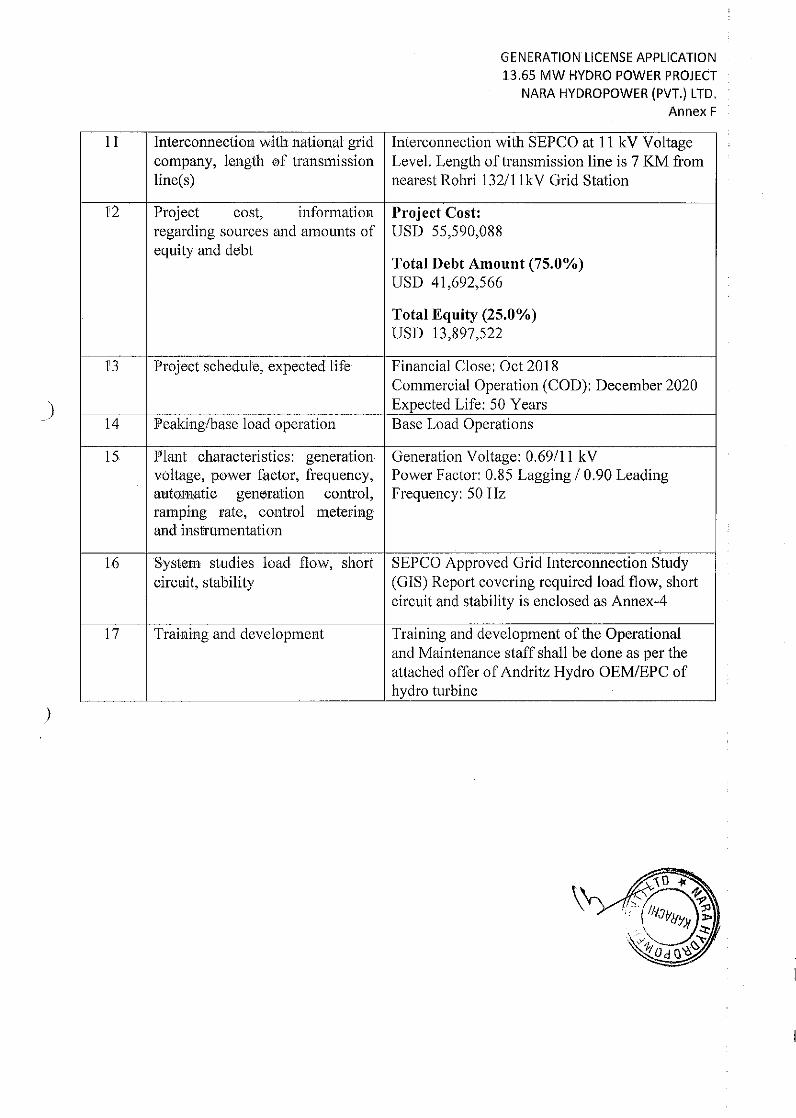
GENERATION LICENSE APPLICATION13.65 MW HYDRO POWER PROJECT
NARA HYDROPOWER (PVT.) LTD.Annex F
)
11 Interconnection with national grid Interconnection with SEPCO at 11 kV Voltagecompany, length of transmission Level. Length of transmission line is 7 KM fromline(s) nearest Rohri 132/11 kV Grid Station
]2 Project cost, information Project Cost:regarding sources and amounts of USD 55,590,088equity and debt
Total Debt Amount (75.0%)USD 41,692,566
Total Equity (25.0%)USD 13,897,522
r3 Project schedule, expected life Financial Close: Oct 2018Commercial Operation (COD): December 2020Expected Life: 50 Years
14 Peaking/base load operation Base Load Operations
15 Plant characteri sties: generation Generation Voltage: 0.69/11 kVvoltage, power factor, frequency, Power Factor: 0.85 Lagging 10.90 Leadingautomatie generation control, Frequency: 50 Hzramping rate, control meteringand instrumentation
16 System studies load flow, short SEPCO Approved Grid Interconnection Studycircuit, stability (GIS) Report covering required load flow, short
circuit and stability is enclosed as Annex-4
17 Training and development Training and development of the Operationaland Maintenance staff shall be done as per theattached offer of Andritz Hydro OEMIEPC ofhydro turbine
)
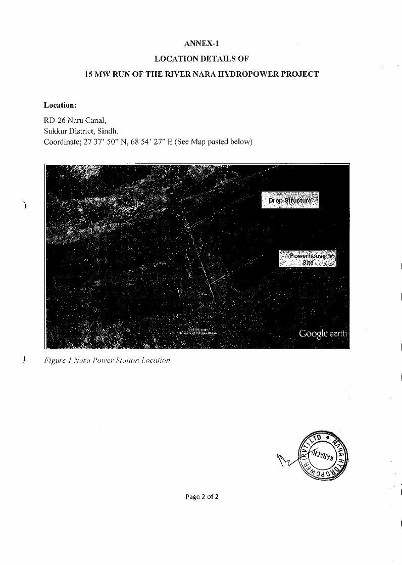
ANNEX-l
LOCATION DETAILS OF
15 MW RUN OF THE RIVER NARA HYDROPOWER PROJECT
Location:
RD-26 Nara Canal,Sukkur District, Sindh.Coordinate; 27 37' 50" N, 6854' 27" E (See Map pasted below)
)
) Figure i Nora Power Station Location
Page 2 of 2
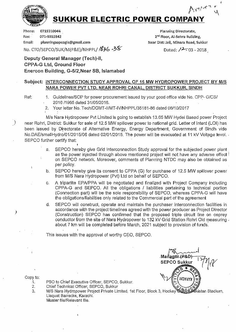
• "-1 ~;..A 'r\'.fv'~.' ~
SUKKUR ELECTRIC POWER COMPANYPhone: 0719310044Fax;. 071-9310342Email: [email protected]
No. CTO!SEPCO!SUK!M(P&E)!NHPPL/ It?b ....?~Deputy General Manam~r (Techj-ll,CPPA-G Ltd, Ground FloorEnercon Building, G-5/2,Near SB, Islamabad
Planning Directorate,2nd Floor, AI-Sehra Building,
Near Dist: Jail, Mlnara Road, Sukkur
Dated: 1.2--:-03 - 2018
Subject: INTERCONNECTION STUDY APPROVAL OF 15 MW HYDROPOWER PROJECT BY MISNARA POWER PVT LTD, NEAR ROHRI CANAL, DISTRICT SUKKUR, SINDH
Ref: 1. Guidelines/SOP for power procurement issued by your good office vide No. CP~- G/CS/2016/1965 dated 31/05/2016.
2. Your letter No. Tech/OGMT-II/MT-IV/NHPPL/35181-86 dated 06/10/2017!
)
Mis Nara Hydropower Pvt Limited is going to establish 13.65 MW Hydel Based power Projectnear Rohri, District: Sukkur for sale of 12.5 MW spillover power to national grid. Letter of Intent (LOI) hasbeen issued by Di_rectorate of Alternative Energy, Energy Department, Government of Sindh videNo.DAE/smaIiHydro/01/2015/06 dated 02/01/2015. The power will be evacuated at 11 kV Voltaqe level. .SEPCO further certify that:
a. SEPCO hereby give Grid Interconnection Study approval for the subjected power plant,as the power injected through above mentioned project will not have any adverse effect:on SEPCO network. Moreover, comments of Planning NTDC may also be obtained asper policy.
b. SEPCO hereby give its consent to CPPA (G) for purchase of 12.5 MW spillover powerfrom MIS Nara Hydropower (Pvt) Ltd on behalf of SEPCO.
c. A tripartite EPA/PPA will be negotiated and finalized with Project Company includingCPPA-G and SEPCO. All the obligations I liabilities pertaining to technical portion(Connection part) will be the sole responsibility of SEPGO, whereas CPPA-G will havethe obligationslliabilities only related to the Commercial part of the agreement
d. SEPGO will construct, operate and maintain the purchaser interconnection facilities inaccordance with the project timelines agreed with the power producer as Project Director(Construction) SEPCO has confirmed that the proposed triple circuit line on ospreyconductor from the site of Nara Hydropower to 132 kV Grid Station Rohri Old measuring .about 7 km will be completed before March, 2021 subject to provision of funds.
)
This issues with the approval of worthy CEO, SEPCO.
Copy to:,1. PSO to Chief Executive Officer, SEPCO, Sukkuf.2.3.
"
Report No. PPI-277.l-Final/17
T-~.•~.,PPI
INTERCONNECTION STUDY. For
15 MW Nara Hydro Power Project
Final Report(February 2017)
)POWER PLANNERS INTERNATIONAL
UK Office: Pakistan Office:3-Sylvester Road, 9S-H2, Wapda Town,Sudbury Town, Middlesex, Lahore 54770, PakistanHAO 3AQ, UK Phone: +92-42-35968118;Phone & Fax:+44-(O)208-9223219 Fax: + 92-42-35183166
Email: [email protected]
Report No. PPI-277.l-FinaI/17
.:;S-••••~.,PPI
INTERCONNECTION STUDYFor
15 MW Nara Hydro Power Project
.d.\~
~
Final Report(February 2017)
POWER PLANNERS INTERNATIONAL
) UK Office:3-Sylvester Road,Sudbury Town, Middlesex,HAD 3A~ UK
. Phone & Fax:+44-(O}208-9223219
Pakistan Office:95-H2, Wapda Town,Lahore 54770, PakistanPhone: +92-42-35968118;Fax: + 92-42-35183166
Email: [email protected]
Executive Summary
,)
.:. The Final Report of 15 MW Nara Hydro Power Plant is submitted herewith after
incorporating the comments issued by SEPCO via letter no.
CTO/SEPCO/SUKIM(P&E)INHPPL 5578~80 Dated 10~11-2017.
(+ While the LOI issued for Nara Hydro Power Project was for 15 MW, the feasibility
reports suggested maximum plant capacity of 13.65 MW, which is also the installed
capacity of the plant out of which 1.15 MW shall be consumed by the auxiliary load
of the plant leaving 12.50 MW as the spillover .
The study objective, approach and methodology have been described and the plant's
data received from the Client is validated .
The latest generation, transmission plan and load forecast of NT DC has been used
for the study .
The network around Nara Hydro Power Project (referred to as Nara HPP in the
remainder of the report) at 132 kV and 11 kV has been modeled as shown in
Appendix-B (Sketch-2) .
•:. The nearest grid interconnection facility is Rohri 132/11 kV grid station of SEPCO.
The following scheme of interconnection of Nara HPP to evacuate its maximum
power of 12.5 MW is envisaged and studied in detail:
• A direct 11 kV Triple circuit of 7 km using Osprey conductor to be laid from
11 kV Bus Bar ofNara HPP till Rohri 132111 kV grid station .
• In this context, three 11 kV breaker bays need to be added in the 11 kV
switchgear hall ofRohri 132111 kV grid station .
•:. III view of planned COD of Nara HPP in March 2021, the above proposed
interconnection scheme has been tested for steady state conditions through detailed
load flow studies for the Peak and Off-Peak conditions of September 2021 for
maximum hydropower dispatches. The system conditions of normal and N-l
contingency have been studied to meet the reliability criteria ofNEPRA Grid Code .
•:. In view of planned COD ofNara HPP Steady state analysis by load flow for all the
scenarios described above reveals that the proposed scheme is adequate to evacuate
.:.'_.,,;; .:.
.:.
.."'-',.,:';POWER PLANNERS INTERNATIONAL PAGE20F26
""
the spillover of up to 12.5 MW power of the Plant under normal as well as
contingency conditions
.:. The proposed interconnection scheme has been tested for steady state conditions
through detailed load flow studies for the Peak and Off-Peak conditions of
September 2021 for maximum hydropower dispatches .
•:. The short circuit level ofthe Nara HPP 11 kV is 11.58 kA and 11.09 kA for 3-phase
and l-phase faults respectively for the year 2021 .Therefore, to go for standard size
switchgear of short circuit rating of 25 kA at 11 kV buses of Nara Hl'P would
suffice. It would provide large margin for any future increase in short circuit levels
due to future generation additions and network reinforcements in this area .
•:. The dynamic stability analysis of proposed scheme of interconnection has been
carried out. The stability check for the worst case of three phase fault right on the .
0.69 kV bus bar of Nara HPP substation followed by the final trip of 1110.69 kV
transformer emanating from this substation, has been performed for fault clearing
of5 cycles (100 ms) as understood to be the normal fault clearing time of protection
system. Also, the worst case of stuck breaker (breaker failure) has been studied
where the fault clearing time is assumed 9 cycles i.e. 180 ms. In all events, the
system is found strong enough to stay stable and recovered with fast damping. The
stability of system for far end faults of3-phase occurring at Rohri 132 kV bus bar
bus bar have also been checked. The proposed scheme successfully passed the
dynamic stability checks for near and far faults even for the most stringent cases .
•:. The proposed scheme of interconnection has no technical constraints or problems,
it fulfills all the criteria of reliability and stability under steady state load flow,
contingency load flows, short circuit currents and dynamic/transient conditions; and
is therefore recommended to be adopted.)
fa\Ir;,.,'! POWER PLANNERS INTERNATIONAL PAGE30F26
Report Conten ts
)
1. Introduction
1.1. Background
1.2. Objectives
1.3. Planning Criteria
2. Assumptions of Data
2.1 Nal'a HPP Data
2.2 Network Data
Study Approach & Methodology
3.1 Understanding of the Problem
3.2 Approach to the Problem
Development of Scheme of Interconnection
4. I The Existing and Ongoing Network
4.2 The Scheme of Interconnection of Nara HPP
5. Detailed Load Flow Studies
5.1. Peak Case Load Flow September 2021, without Nara HPP
5.2. Peak Case Load Flow September 2021 with Nara HPP
5.3. Off-Peak Case Load Flow September 2021, with Nara HPP
5.4. Conclusion of Load Flow Analysis
6. Short Circuit Analysis
6.1 Methodology and assumptions
6.2 Fault current calculations without Nara HPP - Year 2021
6.3 Fault current calculations with Nara HPP - Year 2021
6.4 Conclusion of short circuit analysis
7. Dynamic Stability Analysis
7.1 Assumptions & Methodology
7.1.1 Dynamic Models
7.1.2 System Conditions
7.1.3 Presentation of Results
3.
e.I;
4.
{t"'~ POWER PLANNERS INTERNATIONAL PAGE40F26
7.1.4 Worst Fault Cases
7.2 Dynamic stability simulations for September 2021
7.2.1 Fault at 0.69 kV Nata HPP
7.2.2 Fault at 0.69 kV Nara HPP (Stuck Breaker)
7.2.3 Fault at 11 kV Nara
7.2.4 Fault at 11 kV Nara (Stuck Breaker)
7.2.5 Fault at 132 kV Rohri
7.3 Conclusion of Dynamic Stability Analysis
8. Conclusions
Appendices
Appendix -A:
• Data Permission Letter of NTDC
• NTDC Generation Plan
• NTDC Transmission Plan
• NTDC Load Forecast
• SEPCO Grid Wise PMS Load ForecastAppendix -B:
• Sketches and Maps for Chapter-4
Appendix -C: Plotted Results of Load Flow for Chapter - 5
Appendix -D: Results of Short Circuit Analysis for Chapter - 6
Appendix -E: Plotted Results of Stability Analysis for Chapter -7
Appendix -F: Dynamic Data used for Stability Analysis
)
(8I"" POWER PLANNERS INTERNATIONAL PAGE50F26
1. Introduction
1.1 Background
Nara HPP aims to install ten units of 1.365 MW each for the aim of exporting 12.50
MW to the national grid to the national grid, where 1.15 MW is consumed by its
auxiliary load. The project is expected to start commercial operation by March
2021. The electricity generated from this project would be supplied to the grid
system of SEPCO through 132 kV grid of Rohri, available in the vicinity of this
project.
1.2 Objectives
The overall objective of the Study is to evolve an interconnection scheme between
Nara HPP and SEPCO network," for stable and reliable evacuation of 13.65 MWof
electrical power generated from this plant, fulfilling N·l reliability criteria. The
specific objectives of this report are:
1. To develop scheme of interconnections at 132 kV for which right of way
(ROW) and space at the terminal substations would be available.
2. To determine the performance of interconnection scheme during steady
state conditions of system, normal and N-I contingency, through load-
flow analysis.
3. To check if the contribution of fault current from this new plant increases
the fault levels at the adjoining substations at 132 kV voltage levels to be
• within the rating of equipment of these substations, and also determine the
short circuit ratings of the proposed equipment of the substation at Nara
) HPP.
4. To check if the interconnection withstands dynamic stability criteria of
post fault recovery with good damping .
.. POWER PLANNERS INTERNATIONAL PAGE60F26
1.3 Planning CriteriaThe planning criteria required to be fulfilled by the proposed interconnection is as
follows:
Steady State:
Power Factor
Short Circuit:
132 kV Substation Equipment Rating 31.5 or 40 kA
± 5 %, Normal Operating Condition
± 10 %, Contingency Conditions
50Hz Nominal
49.8 Hz to 50.2 Hz variation in steady state
49.4 - 50.5 Hz, MinIMax Contingency Freq.
Band
0.85 Lagging; 0.90 Leading
Voltage
Frequency
•
Dynamic/Transient:
The system should revert back to normal condition after dying out of transients withoutlosing synchronism with good damping after permanent three-phase fault on anyprimary transmission element; including: transmission circuit, substation bus section,transformer, or circuit breaker. It is assumed that such a fault shall be cleared by theassociated circuit breaker action in 5 cycles.In case offailure of primary protection (stuck breaker case), the total fault clearing timefrom the instant of initiation of fault current to the complete interruption of current toisolate the faulted element, including the primary protection plus the backup protectionto operate and isolate the fault, is equal to 180 ms (9 cycles) for 132 kV and highervoltage levels .
)
.."';,.,r:'; POWER PLANNERS INTERNATIONAL PAGE 70F26
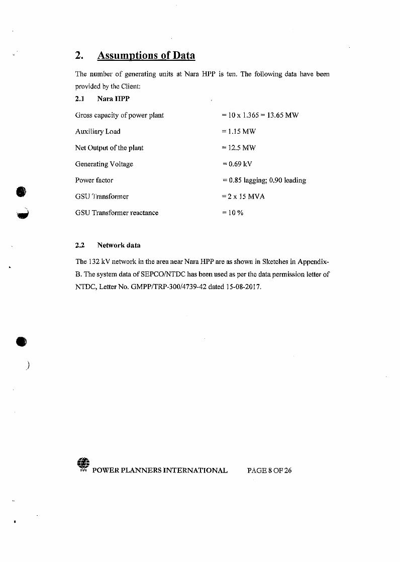
2. Assumptions of Data
The number of generating units at Nara HPP is ten. The following data have been
provided by the Client:
2.1 NaraHPP
Gross capacity of power plant = 10 x 1.365 = 13.65 MW
Auxiliary Load = 1.15 MW
Net Output of the plant = 12.5 MW
Generating Voltage = 0.69 kV
Power factor = 0.85 lagging; 0.90 leading
e GSU Transformer :::;2x 15 MVA
.;; GSU Transformer reactance = 10%
2.2 Network data
The 132 kV network in the area near Nara HPP are as shown in Sketches in Appendix-
B. The system data of SEPCOINTDC has been used as per the data permission letter of
NTDC, Letter No. GMPP/TRP-300/4739-42 dated 15-08-2017 .
•)
(fJ• •• •",'1( POWER PLANNERS INTERNATIONAL PAGE80F26
3. Study Approach and Methodology
3.1 Understanding of the Problem
Nara Hydro Power Project intends to put up generating capacity of 13.65 MW, utilizing
10 units each of l.365 MW. The plant has an auxiliary load of 1.15 MW making its
total spillover to 12.50 MW to the national grid during high water season.
The location of the plant is around the 132 kV grid facility of Rohri, The plant generates
at the low voltage of 0.69 kY, steps up to 11 kV and transmits power via three feeders
of 7 km length each, of Osprey conductor. Nara HPP added to the existing network is
shown in Sketch-2 in Appendix-B.
The adequacy of SEPCO network of 132 kV in and around the proposed site ofNara
HPP would be investigated in this study for absorbing and transmitting this power
fulfilling the reliability criteria.
)
3.2 Approach to the problem
The consultant has applied the following approaches to the problem:
• A base case network model has been prepared for September 2021 after the
commissioning of Nara HPP in March 2021, comprising all 500 kV, 220 kV
and 132 kV system, envisaging the load forecast, the generation additions and
transmission expansions for that year particularly in SEPCO.
• Month of September 2021 has been selected, while representing high water
conditions respectively in the grid system. Thus, the high water flow patterns
can be observed allowing us to judge the maximum impact of the plant on the
transmission system in its.vicinity.
• Interconnection scheme without any physical constraints, like right of way or
availability of space in the terminal substations, have been identified.
• Perform technical system studies for peak load conditions to confirm technical
feasibility of the interconnections. The scheme will be subjected to standard
analysis like load flow, short circuit, and transient stability study to check the
strength of the machines and the proposed interconnection scheme under
•
t't.tel.}! POWER PLANNERS INTERNATIONAL PAGE90F26

disturbed conditions. Interconnection scheme without any physical constraints,
like right of way 01' availability of space in the terminal substations, have been
identified,
• Perform technical system studies for peak load conditions to confirm technical
feasibility of the interconnections. The scheme will be subjected to standard
analysis like load flow, short circuit, and transient stability study to check the
strength of the machines and the proposed interconnection scheme under
disturbed conditions.
• Determine the relevant equipment for the proposed technically feasible scheme.
• Recommend the technically most feasible scheme of interconnection .
•)
..»
(i• •• •,.,~ POWER PLANNERS INTERNATIONAL PAGE lOOF26
4. Development of Scheme of Interconnection4.1 The Existing and Ongoing Network
The existing 132 kV network available around Rohri 132 kV grid station is shown in
Sketch-l in Appendix-B.
Nara HPP is in District Sukkur embedded in the distribution network of SEPCO.
Network is being fed from the sources substation ofGuddu 500/220/132 kV, Shikarpur
220/132 kV and Sibbi 220 kV grid station.
These are multiple feeding points in the vicinity which provides reliability and voltage
support to the system. All these substations provide a strong 220 kV and 500 kV
network around the proposed plant. A strong system helps in stable operation of a power
plant.
4.2 The Scheme of Interconnection of Nara HPP
Keeping in view of the above mentioned 132 kV network available in the vicinity of
the site of the Nara HPP, the interconnection scheme has already been developed and
the 132 kV transmission lines have also been constructed. The interconnection scheme
has been developed by connecting the 11 kV lines emanating from the step up point of
the plant by two 15 MVA transformers to the existing 132/11 kV transformers ofRohri
via three circuits, each of7 km length. The conductor used was Osprey. This proposed
interconnection scheme is shown in Sketch-2 of Appendix-B.
)
f'&\!rJ'",::-POWER PLANNERS INTERNATIONAL PAGE 11 OF 26
5. Detailed Load Flow Studies
5.1 Peak Case Load Flow September 2021. without Nara HPPA base case has been developed for the peak load of September 2021 using the network
data of NTDC and SEPCO available with PPJ, after updating with latest load forecast
and expansion plan of NT DC and SEPCO. The peak load of the year 2021 for SEPCO
have been modeled as per the latest PMS Demand forecast obtained from NTDC.
The results of load flow for this base case are plotted in Exhibit 0.0 of Appendix-C. The
system plotted in this Exhibit comprises of 132 kV network feeding Rohri and its
surrounding substations including Mirpur Mathelo, Panu Akil and Ghotki
The load flow results show that the power flows on all the circuits are within their
normal rating. The voltage profile of these surrounding substations is also within
normal limits.
For N-1 contingency conditions we have performed the following cases
Exhibit 0.1 Rohri-l to SUKURSTE 132 kV Single Circuit Out
Exhibit 0.2 Arain Road to SUKURSTE 132 kV Single Circuit Out
Exhibit 0.3 Ghotki to Rohri-1 132 kV Single Circuit Out
Exhibit 0.4 Panuakil to Rohri-I 132 kV Single Circuit Out
We see that in all the cases the power flows on all circuits remain within their rated
limits. Also, the bus voltages are within the acceptable operating range.
)5.2 Peak Case Load Flow September 2021, with Nara HPPThe scenario of Nara HPP after the COD of the plant when it starts exporting 12.50
MW to the SEPCO network has been studied. The results of load flows with Nara HPP
under normal conditions have been plotted in Exhibit 1.0 in Appendix-C.
The power flows on the circuits are seen well within the rated capacities and the
voltages on the bus bars are also within the permissible operating range of ± 5 % off
the nominal. We find no capacity constraints on 132 kV circuits under normal
.. POWER PLANNERS INTERNATIONAL PAGE 120F26
conditions i.e, without any outages of circuits.
N-l contingency analysis has been carried out and the plotted results are attached in
Appendix - C as follows:
Exhibit 1.1 Nara HPP 11/0.69 kV Single Transformer Out
Exhibit 1.2 Nara to Tl 11 kV Single Circuit Out
Exhibit 1.3 Nara to T2 11 kV Single Circuit Out
Exhibit 1.4 Rohri-I to SUKURSTE 132 kV Single Circuit Out
Exhibit 1.5 Arain Road to SUKURSTE 132 kV Single Circuit Out
Exhibit 1.6 Ghotki to Rohri-I 132 kV Single Circuit Out
Exhibit 1.7 Panuakil to Rohri-l 132 kV Single Circuit Out
We see that in all the contingency cases, in the event of outage of any circuit, the intact
circuits remain within the rated capacity.
Also, the bus bar voltages are well within the permissible limits in all the contingency
events.
)
5.3 Off~Peak Case Load Flow September 2021, with Nara HPPThe scheme of interconnection modeled in the load flow for Nara HPP is as described
in Chapter-s.
Load flow studies have been carried out for off-peak scenario of September 2021
allowing us to judge the maximum impact of the plant on the transmission system in its
vicinity. The results of load flow with Nara HPP interconnected as per proposed scheme
are shown in Appendix-C.
The results of Normal case of Off-Peak September 2021 are plotted in Exhibit 2.0. We
find no capacity constraints on 132 kV circuits under normal conditions i.e. without any
outages of circuits.
The power flows on the circuits are seen well within the rated capacities and the
voltages on the bus bars are also within the permissible operating range of ± 5 % off
the nominal.
.. POWER PLANNERS INTERNATIONAL PAGE 13 OF 26
N-l contingency analysis has been carried out and the plotted results' are attached in
Appendix - C as follows;
Exhibit 2.1 Nara HPP 11/0.69 kV Single Transformer Out
Exhibit 2.2 Nara to TIll kV Single Circuit Out
Exhibit 2.3 Nara to T2 11 kV Single Circuit Out
Exhibit 2.4 Rohri-l to SUKURSTE 132 kV Single Circuit Out
Exhibit 2.5 Arain Road to SUKURSTE 132 kV Single Circuit Out
Exhibit 2.6 Ghotki to Rohri-I 132 kV Single Circuit Out
Exhibit 2.7 Panuakil to Rohri-l 132 kV Single Circuit Out
We see that in all the contingency cases, in the event of outage of any circuit. the intact
circuits remain within the rated capacity.
Also. the bus bar voltages are well within the permissible limits in all the contingency
events.
5.4 Transmission Losses
)
The transmission line losses were evaluated for normal case of peak load September
2021 from Nara Hydel PP to the point of interconnection (distance of 7 km).
% Power Loss from Nara PP towards Rohri-I 11 kV =: (12.500~12.122)/12.5== 0.03024x 100 =: 3.024 %
It can be seen that the transmission loss of the transmission line from Power plant to
the point of interconnections is less than NEPRA's allowed 3.5%.
5.5 Conclusion of Load Flow AnalysisThe proposed interconnection scheme ofNara HPP is adequate to evacuate the spillover
electrical power from plant under normal and contingency conditions tested for peak
load conditions of September 2021 after the COD ofNara HPP.
In all the normal and contingency cases, we find that the loading on the circuits remain
within the rated capacity. Also, the bus bar voltages are well within the permissible
limits in all the norma) and contingency events. Hence the proposed interconnection
scheme ofNara HPP has no constraints according to the Load Flow Analysis.
tf&"';I'I~ POWER PLANNERS INTERNATIONAL PAGE 140F26
e_)
6. Short Circuit Analysis6.1 Methodology and AssumptionsThe methodology oflEC 909 has been applied in all short circuit analyses in this report
for which provision is available in the PSS/E software used for these studies.
The maximum fault currents have been calculated with the following assumptions
under lEG 909:
• Set tap ratios to unity
• Set line charging to zero
• Set shunts to zero in positive sequence
• Desired voltage magnitude at bus bars set equal to 1.10 P.U. i.e. 10 % higher
than nominal, which is the maximum permissible voltage under contingency
condition.
For evaluation of maximum short circuit levels, we have assumed contribution in the
fault currents from all the installed generation capacity of hydal, thermal and nuclear
plants in the system in the year 2021 i.e. all the generating units have been assumed on-
bar in fault calculation's simulations.
The assumptions about the generator and the transformers data are the same as
mentioned in Ch.2 of this report.
6.2 Fault Current Calculations without Nara HPP, 2021
)
In order to assess the short circuit strength of the network of 132 kV and 11 kV without
Nara HPP for the grid of SEPCO in the vicinity of the site of the Plant, fault currents
have been calculated for balanced three-phase and unbalanced single-phase short circuit
conditions. These levels will give us the idea of the fault levels without Nara HPP and
later on how much the contribution of fault current from Nara HPP may add to the
existing levels.
The results are attached in Appendix - D.
The short circuit levels have been calculated and plotted on the bus bars of 132 kV
substations lying in the electrical vicinity of our area of interest i.e. Rohri- I, Arain Road,
Sukkur Site, Ghotki and surrounding bus bars are shown plotted in the Exhibit 3.0 .
(@;••••1'1':'; POWER PLANNERS INTERNATIONAL PAGE 15 OF26
attached in Appendix-D. Both 3-phase and I-phase fault currents are indicated in the
Exhibit which are given in polar coordinates l.e. the magnitude and the angle of the
current. The total fault currents are shown below the bus bar.
The tabular output of the short circuit calculations is also attached in Appendix-D for the132 kV bus bars of our interest i.e. the substations connecting in the 132 kV circuits lyingclose to Nara HPP. The total maximum fault currents for 3-phase and l-phase shalt circuitat these substations are summarized in Table 6.1. We see that the maximum fault currentsdo not exceed the short circuit ratings of the equipment at these 132 kV substations which
normally are 20 kA, 25 kA or 40 kA for older substations and 40 kA for new substations.
Table-6.1
)
_,3-Phase fault current, J-Phase fault current,
SubstationkA kA
Rohri T-l11kV 16.32 16.70Rohri T-211kV 11.74 11.93Rohri 132kV 19.85 16.35Sukkur Site 132kV 17.45 13.56Arain Road 132kV 18.79 16.10Panu Akil132kV 8.43 6.00Ghotld 132kV 13.31 11.53
Maximum Short Circuit Levels without Nara HPP 2021
6.3 Fault Current Calculations with Nara HPP, Year 2021Fault currents have been calculated for the electrical interconnection of proposed
scheme. Fault types applied are three phase and single-phase at 132 kV and 11 kV bus
bat' ofNara HPP itself and other bus bars of the 132 kV substations in the electrical
vicinity of the plant. The graphic results showing maximum 3-phase and l-phase fault
levels are indicated in Exhibit 3.1. Both 3-phase and l-phase fault currents are indicated
in the Exhibit which are given in polar coordinates i.e. the magnitude and the angle of
the current. The total fault currents are shown below the bus bar.
The tabulated results of short circuit analysis showing all the fault current contributions
with short circuit impedances on 132 kV bus bars of the network in the electrical
.. POWER PLANNERS INTERNATIONAL PAGE 160F26
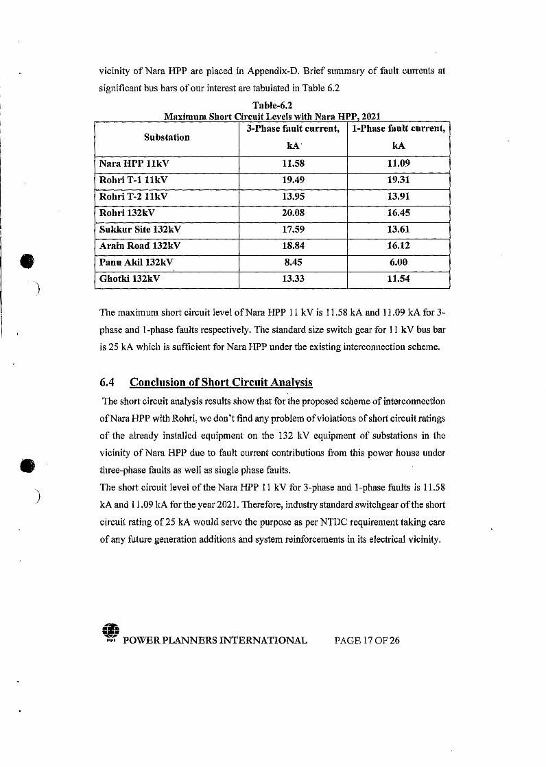
vicinity of Nara HPP are placed in Appendix-D. Brief summary of fault currents at
significant bus bars of our interest are tabulated in Table 6.2
Table-6.2Maximum Short Circuit Levelswith Nara HPP 2021
e.. )
'.!.
3-Phase fault current, J-Phase fault current,Substation
kA' kA
Nara HPP llkV 11.58 11.09
Rohri T-l11kV 19.49 19.31
Rohri T-211kV 13.95 13.91
Rohl'i 132kV 20.08 16.45
Sukkur Site 132kV 17.59 13.61Arain Road 132kV 18.84 16.12Panu Aki1132kV 8.45 6.00
Ghotki 132kV 13.33 11.54
The maximum short circuit level ofNara HPP 11 kV is 11.58 kA and 11.09 kA for 3-
phase and l-phase faults respectively. The standard size switch gear for 11 kV bus bar
is 25 kA which is sufficient for Nara HPP under the existing interconnection scheme.
)
6.4 Conclusion of Short Circuit AnalysisThe short circuit analysis results sbow that for the proposed scheme of interconnection
ofNara HPP with Rohri, we don't find any problem of violations of short circuit ratings
of the already installed equipment on the 132 kV equipment of substations in the
vicinity of Nara HPP due to fault current contributions from this power house under
three-phase faults as well as single phase faults.
The short circuit level of the Nara HPP 11 kV for 3-phase and l-phase faults is 11.58
kA and 11.09 kA for the year 2021. Therefore, industry standard switchgear ofthe short
circuit rating of 25 kA would serve the purpose as per NTDC requirement taking care
of any future generation additions and system reinforcements in its electrical vicinity.
(f),.,'! POWER PLANNERS INTERNATIONAL PAGE 17 OF26
7. Dynamic Stability Analysis
)
7.1 Assumptions & Methodology
7.1.1 Dynamic Models
The assumptions about the generator and its parameters are the same as mentioned in
Ch.2 of this report.
We have employed the generic dynamic models for available in the PSS/E model
library for dynamic modeling of the exciter and the governor as follows;
Excitation System EXSTI
Speed Governing System HYGOV
GENSAL model in PSS/E for hydel generator has been employed and the parameters
as provided by clients has been used in the model.
7.1.2 System Conditions
Month of September 2021 has been selected for the study because it represents the peak
load season after the COD of Nara Hydro Power Plant and thus the loading on the lines
in the vicinity of plant will be maximum, allowing us to judge the full impact of the
plant.
All the power plants of WAPDA/PEPCO and IPPs from Tarbela to Hub have been
dynamically represented in the simulation model.
7.1.3 Presentation of Results
The plotted results of the simulation runs are placed in Appendix-E. Bach simulation
is run for its first one second for the steady state conditions of the system prior to fault
or disturbance. This is to establish the pre-fault/disturbance conditions of the network
under study were smooth and steady. Post fault recovery has been monitored for nine
seconds. Usually all the transients due to non-linearity die out within 4-5 seconds after
disturbance is cleared in the system.
7.1.4 Worst Fault Cases
Three phase faults are considered as the worst disturbance in the system. We have
considered 3-phase fault in the closest vicinity ofNara HPP i.e. right at the 0.69 kV bus
bar of Nara HPP substation, cleared in 5 cycles, as normal clearing time i.e. 100 ms,
e.J
..9;,.~ POWER PLANNERS INTERNATIONAL PAGE 180F26
followed by a permanent trip of a 1110.69 kV single transformer emanating from this
substation. Fault at 11 kV bus bar ofNara HPP has also been simulated for 5 and 9 cycles.
7.2 Dynamic Stability Simulations' Results with Nara HPP, Year
September 2021
7.2.1 Fault at 0.69 kV Nara HPP
.)
We applied three-phase fault 011 Nara HPP 0.69 kV bus bar, cleared fault in 5 cycles
(100 ms) followed by trip of a 1110.69 kV transformer circuit between Nara HPP 0.69
kV and Nara 11 kV. We monitored different quantities for one second pre-fault and
nine cycles after clearance of fault (post-fault) conditions and plotted the results
attached in Appendix -:-E and discussed as follows;
Fig. 1.1 Bus Voltages
The bus voltages of 132 kV bus bars ofNara HPP 0.69 kV, Nara 11 kV, Rohri, Sukkur
Site, Panu Akil and Ghotki 132 kV are plotted. The results show quick recovery of the
voltages after clearing of fault.
Fig. 1.2 Frequency
We see the system frequency recovers back to normal quickly after fault clearance.
Fig. 1.3 MW/MVAR Output of Generators of Nara HPP
The MW/MVAR output of both units of Nara HPP gets back to the pre-fault output
quickly after fast damping of the oscillations in its output. However MV AR outputs
acquires equilibrium at a slightly different value.
Fig. 1.4 Speed and mechanical power of Generators at Nara HPP
The speed deviation of the generator, after clearing fault, damps down quickly returning
to normal speed as of before fault. The transients in mechanical power also damp
quickly and settle to a new equilibrium.
Fig. 1.5 MW Flow on Nara HPP 11/0.69 kV Transformer
Followed by clearing of fault, the trip of Nara HPP 11/0.69 kV single transformer
causes significant output to flow on the intact second transformer of the plant. We
plotted the flows ofMW and MVAR on this intact circuit and see that the power flows
on this circuit attains to steady state level with power swings damping down fast.
IJ• •• •,.r.: POWER PLANNERS INTERNATIONAL PAGE 190F26
Fig. 1.6 Rotor Angles
The rotor angles of the generators of Nara HPP, Liberty, Arian Road, Engro Energy,
and Foundation-P are plotted relative to machine at Hub 500 kV. The results show that
the rotor angle ofNara HPP gets back after the first swing and damps down quickly.
Similarly, the rotor angles of other machine swing little after the fault and damp fast
after clearing offault. The system is strongly stable and very strong in damping the post
fault oscillations.
)
7.2.2 Fault at O.69kVNara HPP (Stuck Breaker)We applied single-phase fault on Nara HPP 0.69 kV bus bar, cleared fault in 9 cycles
(180 ms) followed by trip of a ] 1I0~69 kV transformer circuit between Nara HPP 0.69
kV and Nara 11 kV. We monitored different quantities for one second pre-fault and
nine cycles after clearance of fault (post-fault) conditions and plotted the results
attached in Appendix - E and discussed as follows;
Fig. 2.1 Bus Voltages
The bus voltages of 132 kV bus bars ofNara HPP 0.69 kV, Nara 11 kV, Rohri, Sukkur
Site, Panu Akil and Ghotki 132 kV are plotted. The results show quick recovery of the
voltages after clearing of fault.
Fig. 2.2 Frequency
We see the system frequency recovers back to normal quickly after fault clearance.
Fig. 2.3 MWIMVAR Output of Generators of Nara HPP
The MW/MV AR output of both units of Nara HPP gets back to the pre- fault output
quickly after fast damping of the oscillations in its output. However MV AR outputs
acquires equilibrium at a slightly different value.
Fig. 2.4 Speed and mechanical power of Generators at Nara HPP
The speed deviation of the generator, after clearing fault, damps down quickly returning
to normal speed as of before fault. The transients in mechanical power also damp
quickly and settle to a new equilibrium.
Fig. 2.5 MW Flow on Nara HPP 11/0.69 uv Transformer
Followed by clearing of fault, the trip of Nara HPP 11/0.69 kV single transformer
causes significant output to flow on the intact second transformer of the plant. We
e.J
r&wJI','! POWER PLANNERS INTERNATIONAL PAGE200F26
plotted the flows ofMW and MVAR on this intact circuit and see that the power flows
on this circuit attains to steady state level with power swings damping down fast.
Fig. 2.6 Rotor Angles
The rotor angles of the generators of Nara HPP, Liberty, Arian Road, Engro Energy,
and Foundation-P are plotted relative to machine at Hub 500 kV. The results show that
the rotor angle ofNara HPP gets back after the first swing and damps down quickly.
Similarly, the rotor angles of other machine swing little after the fault and damp fast
after clearing offault. The system is strongly stable and very strong in damping the post
fault oscillations.
e... )
7.2.3 Fault at 11 kV NaraWe applied three-phase fault on far 11 kV bus bar ofNara HPP to study the impact of
a disturbance in the grid on the performance of the plant. The fault is cleared in 5 cycles
(100 ms) as standard clearing time for 11 kV systems, followed by trip of 11 kV single
circuit between Nara 11 kV and Rohri T-I 11 kV. We monitored different quantities
for one second pre-fault and nine seconds after clearance offault (post-fault) conditions
and plotted the results attached in Appendix - E and discussed as follows;
Fig. 3.1 Bus Voltages
The bus voltages of 132 kV bus bars of Nara HPP 0.69 kV, Nara 11 kV, Rohri, Sukkur
Site, Panu Akil and Ghotki 132 kV are plotted. The results show quick recovery of the
voltages after clearing offault.
Fig. 3.2 Frequency
We see the system frequency recovers back to normal quickly after fault clearance.
Fig. 3.3 MW IMV AR Output of Generators of Nara HPP
The MW IMV AR output of both units of Nara HPP gets back to the pre-fault output
quickly after fast damping of the oscillations in its output. However MV AR outputs
acquires equilibrium at a slightly different value.
Fig. 3.4 Speed and mechanical power of Generators at Nara HPP
The speed deviation of the generator, after clearing fault, damps down quickly returning
to normal speed as of before fault. The transients in mechanical power also damp
quickly and settle to a new equilibrium .
-)
., POWER PLANNERS INTERNATIONAL PAGE2} OF26
Fig. 3.5 MW Flow on Nara to Rohrl T-111 kV circuit
Followed by clearing of fault, the trip of an 11 kV single circuit from Nara to Rohri T-
1 causes significant loading on the intact 11 kV circuit between them. We plotted the
flows of MW and MV AR on this intact circuit and see that the power flows on this
circuit attains to steady state level with power swings damping down fast.
Fig. 3.6 Rotor Angles
The rotor angles of the generators of Nara HPP, Liberty, Arian Road, Engro Energy,
and Foundation-P are plotted relative to machine at Hub 500 kV, The results show that
the rotor angle of Nara HPP gets back after the first swing and damps down quickly.
Similarly, the rotor angles of other machine swing little after the fault and damp fast
after clearing offault. The system is strongly stable and very strong in damping the post
fault oscillations.
)
7.2.4 Fault at 11 kV Nara (Stuck Breaker)We applied one-phase fault on Nara HPP 11 kV to study the impact ofa disturbance in
the grid on the performance of the plant. The fault is c1eared in 9 cycles (100 ms) as
standard clearing time for 11 kV systems, followed by trip of 11 kV single circuit
between Nara and Rohri T-l. We monitored different quantities for one second pre-
fault and nine seconds after clearance of fault (post-fault) conditions and plotted the
results attached in Appendix - E and discussed as follows;
Fig. 4.1 Bus Voltages
The bus voltages ofl32 kV bus bars of Nara Hl'P 0.69 kV, Nara 11 kV, Rohri, Sukkur
Site, Panu Akil and Ghotki 132 kV are plotted. The results show quick recovery of the
voltages after clearing offault.
Fig. 4.2 Frequency
We see the system frequency recovers back to normal quickly after fault clearance.
Fig. 4.3 MW IMY AR Output of Generators of Nara HPP
The MW IMV AR output of both units of Nara HPP gets back to the pre-fault output
quickly after fast damping of the oscillations in its output. However MV AR outputs
acquires equilibrium at a slightly different value.
(t",,! POWER PLANNERS INTERNATIONAL PAGE220F26
Fig. 4.4 Speed and mechanical power of Generators at Nara HPP
The speed deviation of the generator, after clearing fault, damps down quickly returning
to normal speed as of before fault. The transients in mechanical power also damp
quickly and settle to a new equilibrium.
Fig. 4.5 MW Flow on Nara to Rohri T-l11 kV circuit
Followed by clearing of fault, the trip of an 11 kV single circuit from Nara to Rohri T-
1 causes significant loading on the intact 11 kV circuit between them. We plotted the
flows of MW and MV AR on this intact circuit and see that the power flows on this
circuit attains to steady state level with power swings damping down fast.
Fig. 4.6 Rotor Angles
The rotor angles of the generators ofNara HPP, Liberty, Arian Road, Engro Energy,
and Foundation-P are plotted relative to machine at Hub 500 kV. The results show that
the rotor angle of Nara HPP gets back after the first swing and damps down quickly.
Similarly, the rotor angles of other machine swing little after the fault and damp fast
after clearing offault. The system is strongly stable and very strong in damping the post
fault oscil1ations.
7.2.5 Fault at 132 kV RohriWe applied three-phase fault on Rohri 132 kV bus bar, cleared fault in 5 cycles (100
ms) followed by trip of a132 kV single circuit between Rohri and Sukkur Site 132 kV
substation. We monitored different quantities for one second pre-fault and nine cycles
after clearance of fault (post-fault) conditions and plotted the results attached in
Appendix - E and discussed as follows;
Fig. 5.1 Bus Voltages
The bus voltages of 132 kV bus bars ofNara HPP 0.69 kV, Nara 11 kV, Rohri, Sukkur
Site, Panu Akil and Ghotki 132 kV are plotted. The results show quick recovery of the
voltages after clearing of fault.
Fig. 5.2 Frequency
We see the system frequency recovers back to normal quickly after fault clearance .
.. POWER PLANNERS INTERNATIONAL PAGE 23 OF26
Fig. 5.3 MW/MVAR Output of Generators of Nara HPP
e__>
The MW/MVAR output of both units of Nara HPP gets back to the pre-fault output
quickly after fast damping of the oscillations in its output. However MV AR outputs
acquires equilibrium at a slightly different value.
Fig. 5.4 Speed and mechanical power of Generators at Nara HPP
The speed deviation of the generator, after clearing fault, damps down quickly returning
to normal speed as of before fault. The transients in mechanical power also damp
quickly and settle to a new equilibrium.
Fig. 5.5 MW Flow on Rohri to Sukkur Site 132 kV circuit
Followed by clearing of fault, the trip of a 132 kV single circuit from Rohri to Sukkur
Site causes significant output to flow on the intact 132 kV circuit between them. We
plotted the flows ofMW and MVAR on this intact circuit and see that the power flows
on this circuit attains to steady state level with power swings damping down fast.
Fig. 5.6 Rotor Angles
The rotor angles of the generators of Nara HPP, Liberty, Arian Road, Engro Energy,
and Foundation-P are plotted relative to machine at Hub 500 kV. The results show that
the rotor angle ofNara HPP gets back after the first swing and damps down quickly.
Similarly, the rotor angles of other machine swing little after the fault and damp fast
after clearing offault. The system is strongly stable and very strong in damping the post
fault oscillations.
)
7.3 Conclusion of Dynamic Stability AnalysisThe results of dynamic stability carried out for the planned system of September 2021
show that the system is very strong and stable for the proposed scheme for the severest
possible faults of 132 kV systems near to and far of Nara PP under all events of
disturbances. Therefore there is no problem of dynamic stability for interconnection of
Nara PP; it fulfills all the criteria of dynamic stability.
~..¥;,.,:'; POWER PLANNERS INTERNATIONAL PAGE 24 OF 26
8. Conclusions
)
.:. The study objective, approach and methodology have been described and the plant's
data received from the Client is validated .
•:. The latest generation, transmission plan and load forecast of NT DC has been used
for the study .
•:. The network around Nara Hydro Power Project (referred to as Nara HPP in the
remainder of the report) at 132 kV and 11 kV has been modeled as shown in
Appendix-B (Sketch-2) .
•:. The nearest grid interconnection facility is Rohri 132111 kV grid station ofSEPCO.
The following scheme of interconnection of Nara HPP to evacuate its maximum
power of 12.5 MW is envisaged and studied in detail:
• A direct 11 kV Triple circuit of7 km using Osprey conductor to be laid from
II kV Bus Bar ofNara HPP till Rohri 132111 kV grid station.
• In this context, three 1I kV breaker bays need to be added in the I] kV
switchgear hall ofRohri 132111 kV grid station .
•:. In view of planned COD of Nara HPP in March 2021, the above proposed
interconnection scheme has been tested for steady state conditions through detailed
load flow studies for the Peak and Off-Peak conditions of September 2021 for
maximum hydropower dispatches. The system conditions of normal and N- I
contingency have been studied to meet the reliability criteria ofNEPRA Grid Code .
•:. In view of planned COD of Nara HPP Steady state analysis by load flow for all the
scenarios described above reveals that the proposed scheme is adequate to evacuate
the spillover of up to 12.5 MW power of the Plant under normal as well as
contingency conditions
.:. The proposed interconnection scheme has been tested for steady state conditions
through detailed load flow studies for the Peak and Off-Peak conditions of
September 2021 for maximum hydropower dispatches .
•:. The short circuit level of the Nara HPP 11 kV is 11.58 kA and 11.09 kA for 3-phase
and l-phase faults respectively for the year 2021. Therefore, to go for standard size
switchgear of short circuit rating of 25 kA at 11 kV buses of Nara HPP would
(fJ,.,,! POWER PLANNERS INTERNATIONAL PAGE 25 OF26
)
suffice. It would provide large margin for any future increase in short circuit levels
due to future generation additions and network reinforcements in this area.
+!. The dynamic stability analysis of proposed scheme of interconnection has been
carried out. The stability check for the worst case of three phase fault right on the
0.69 kV bus bar of Nara HPP substation followed by the final trip of I 110.69 kV
transformer emanating from this substation, has been performed for fault clearing
of5 cycles (100 ms) as understood to be the normal fault clearing time of protection
system. Also, the worst case of stuck breaker (breaker failure) has been studied
where the fault clearing time is assumed 9 cycles i.e. 180 ms. In all events, the
system is found strong enough to stay stable and recovered with fast damping. The
stability of system for far end faults of 3-phase occurring at Rohri 132 kV bus bar
bus bar has also been checked. The proposed scheme successfully passed the
dynamic stability checks for near and far faults even for the most stringent cases.
.:. The proposed scheme of interconnection has no technical constraints or problems,
it fulfills all the criteria of reliability and stability under steady state load flow,
contingency load flows, short circuit currents and dynamic/transient conditions; and
is therefore recommended to be adopted .
. ~
.t&'\.It')',.,':';POWER PLANNERS INTERNATIONAL PAGE260F26
j
Ii
~ -
!~
. '- , ..' ( ,.'
;' ",' ,"
_,,0- . -__ ~"" . '.' .
..: . . -
Initial Environmental Examination
NARA HYDROPOWER ~lPROJECT
· ~
IE\W.J
NARA HYDROPOWER (PVT.) LIMITED
Initial Environmental Examination
NARA HYDROPOWER PROJECT
)
Final ReportDecember 2017
Ref: IEE/02/12/17
EMC PAKISTAN PVT. LTD.503, Anum Estate, Opp. Duty Free Shop, Main Shahrah-e-Faisal, Karachi.Phones: 9221-34311466, 34324680, Fax: 9221-34311467.
E-mail: [email protected]@emc.com.12kWebsite: www.emc.com.12k

)
Disclaimer:
This report has Attorney - Client Privilege. EMC Pakistan Pvt. Ltd has prepared this report in accordancewith the informacion provided by Nata Hydropower (pvt.) Limited for their sole and specific use. Any otherperson(s) who use any information contained herein do so at their own risk. This report cannot be used inthe court of law for any negotiation or standardization.
© EMC Pakistan Pvt. Ltd. 2017
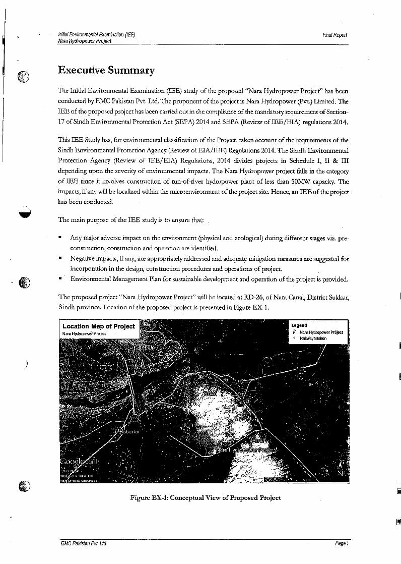
)
. Initial Environmental E!(amlnatiol1 (lEE)Mara Hydropower Project
Final Report
Executive Summary
The Initial Environmental Examination (lEE) study of the proposed "Nara Hydropower Project" has been
conducted by EMC Pakistan Pvt. Ltd. The proponent of the project is Nara Hydropower (pvt.) Limited. The
lEE of the proposed proj ect has been carried out in the compliance of the mandatory requirement of Section-
17 of Sindh Environmental Protection Act (SEPA) 2014 and SEPA (Review of IEE/EIA) regulations 2014.
This lEE Study has, for environmental classification of the Project, taken account of the requirements of the
Sindh Environmental Protection Agency (Review ofEIA/IEE) Regulations 2014. The Sindh Environmental
Protection Agency (Review of lEE/EIA) Regulations, 2014 divides projects in Schedule I, II & IIIdepending upon the severity of environmental impacts. The Nara Hydropower project falls in the category
of IEE since it involves construction of run-of-river hydropower plant of less than 50MW capacity. The
impacts, if any will be localized within the microenvironment of the project site. Hence, an lEE of the project.
has been conducted.
The main purpose of the lEE study is to ensure that:
Any major adverse impact on the environment (physical and ecological) during different stages viz. pre-
construction, construction and operation are identified.
Negative impacts, if any, are appropriately addressed and adequate mitigation measures are suggested forincorporation in the design, construction procedures and operations of project.
• Environmental Management Plan for sustainable development and operation of the project is provided.
•
•
The proposed project "Nara Hydropower Project" will be located at RD-26, of Nara Canal, District Sukkur,
Sindh province. Location of the proposed project is presented in Figure EX-1.
Location Map of ProjectN~raHydropowe,Ptoject
Figure EX~l: Conceptual View of Proposed Project
EMC Pakistan Pvt. Ltd Pagei
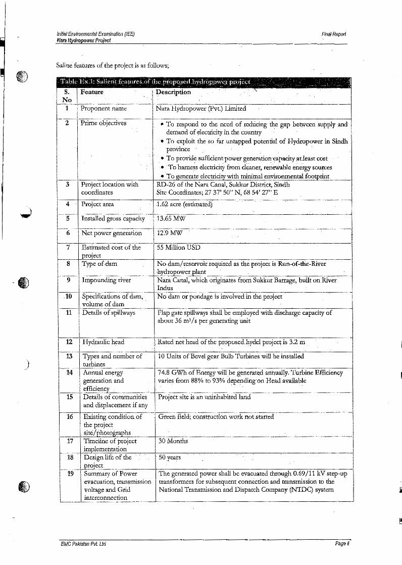
)
Initial Environmental Examination (lEE)Nara Hydropower Project
FillalReport
Saline features of the project is as follows;
Table Ex.1: Salient features of theproposed hydropmver pl"Oject ~.~"I ~~ Feature DescriptionIf Propone-n-t-n-a-m-e-~-'---+~N-a-r-a""'H:-y-d-:-r-o-p-o-w-c-r-':(p-v-t-.)-L-l-·tnl-·:-t.e'-d---~·--~--~----~-I
I·--I-::::-:-----:-,----,:-----:--~+------------------·...,-·--------·--I
I2 Prime objectives • To respond to the need of reducing the gap between supply and
'.demand of electricity in the country .
! '. ;~~~~it.the so far untapped potential..of Hydropower in Sindh
'
I • Tq provide sufficiertt-powergenerationcapacity at.least cost•. To 'harness electricity from cl~aner) re~eWabie en'etgy sources
l--._:.-. ~ .' To generate elect1~citywith mi~mal environmental footprintI 3 Project location with RD-26 of the Nara Canal, Sukkur District, Sindh! coordinates Site Coordinates; 27 37' 50" N, 68 54' 27" E
1_._4 Piojec"".. .1.6~acre(estimated) =jI 5 Installed gross capacity 13.65 MW It 6 Netpowor genero:tion 12.9 MW
I 7 Es~mated cost of the 55 Million USD
l--_...__ +-~_~ect -...---+:-::--:--:------:----:---:-~-:----c----:-~----::-~- ----11 8 Type of dam '. No dam/reservoir requited as the project is Rua·of-the·-River . .'L- hydropower plant! 9 Impounding river Nara Canal, which originates from Sukkur Barrage, built on River ,
IL-.-t-O- Specifications of dam, .. ~ ~:~:m or-p~n'dage is involved in the project ~I
volume of dam11 Details of spillways Flap gate spillways shall be employed with discharge capacity of
about 36 m3/s per generating unitI
., Rated net head of the proposed ~ydei project is 3.2 mI 12 Hydraulic head
~1'-3-1-T:--yp-e-s-a-n-d':-n--u~b'e-r'-o'''''f:--'--+-:-1-0-:::U'''''n-:i-ts-o-f:-:B:-:e-v~e-lg-e-a-r-B~u""'lb~T-:-u-rb:-i-n-es-W1-'ll---:-b~~i-ns-t~l-e~d~"-------I I
!1--14 turbines
Annual energyi generation and
I ' efficiency---:-...........-I--:--:-:---<-=------------~ -:---:--____:__.:__:__--:--:----:-----------lI 15 Details of communities Project site is an uninhabited landi and displacement if any
t-..·EXl."Stingcondition ofthe project . r
__ .srte/pho~~_~ ._ ~ ~ __ ~ ~l 17 Timeline of project 30 MonthsI implementationI'" 18 .. Design life of thel!---:----l...Ero;ect'II 19 Summary of Power
evacuation, transmissionI voltage and GridI interconnectionL_._.. . '- -'--_J
74.8 GWh of Energy willbe generated annually, Turbine Efficiencyvaries from 88% to 93% depending on Head available
---'7'-----,;--- ....------------lGreen field; construction work not .started
~---~~~--~--~.~.--~------~------------------J. 50 years
The generated power shall be evacuated through 0.69/11 kV step-uptransformers for subsequent connection and transmission to theNational Transmission and Dispatch Company (NTDC) system Ii
EMC Pakistan Pvt. Ltd Pageii
Initial Environmental Examination (lEE)Nara Hydropower Prajeci
Final Report
The Study has taken into consideration, all the relevant national and provincial legislation, and details of
@ construction and operation activities of the proposed project. Environmental and Socio-economic baseline
data has been taken from previous studies of the same area conducted by the EMC Pakistan. The baseline has
been further investigated and revalidated using secondary published literature.
The assessment has primarily focused on the pre-construction, construction activities and later on the
operations of the proposed project. The major areas coveted in impact analysis including, siting of the project,
wastewater, solid waste, Indus River Dolphin, Freshwater Turtles and Aquatic life in general, community
safety, socioeconomic factors and traffic management.
Mitigation measures are provided and an Environmental Management Plan (EMF) has been developed to
assist the management and contractor of the proposed project, in implementation and monitoring of proposed
mitigation measures. The project management and subsequent contractorfs) are required to follow theEMP
and where necessary EMP shall be amended as per gaps arises .
.,,' Based on the findings of the lEE study of the proposed Nara Hydropower Project, it is concluded that the
environmental impacts of the construction and operation of project are manageable and can be mitigated
by implementing the Environmental Management Plan which forms an integral part of lEE document.
The Study therefore recommends that the Initial Environmental Examination (lEE) report should be
approved with the provision that the suggested mitigation measures will be adopted and the Environmental
Management Plan will be followed in letter and spirit.
)
Ii
cMC Pakistan Pvt. Ltd Page iii
Initial Environmental Examination (lEE)Nara Hydropower Project
Final Report
Table of Contents
Chapter 1 Introduction ~ " 1
1.1 The Proposed Project 11.2 Objective of Project 21.3 Project Proponent 21.4 lEE Consultant 21.5 Categorization of Project 21.6 Scope & Needof Ilsfs Study 3
Methodology for lEE Study : 31.7.1 Understanding the Proposed Project 41.7.2 Site Visit 41.7.3 Review of Literature 41.7.4 Impact Identification ~ 41.7.5 Impact Assessment and EMP 41.7.6 Documentation : 5
1.8 Organization of lEE Report 51.9 lEE Study Team ; 5
1.7
Chapter 2 Policy, Legal & Administrative Framework ; 6
2.1 Administrative Framework 62.2 Statutory Framework 72.3 Constitutional Provision 7
. 2.4 SindhEnvironmentalProtectionAct,2014 82.5 Sindh EPA (Review ofIEE and EIA) Regulations 2014 10
Chapter 3 Description of Project " ~ 18 .
3.1 Project Setting 183.23.3
The Project 19Overview of Hydropower ; 25
3.3.1 Design and Types , 273.3.2 Site Layouts , 293.3.3 Components of Hydropower Schemes 29
Overview of Run-of-the-river Hydropower 313.4.1 Economics 32
")./
3.4
Chapter 4 Environmental & Social Baseline of the Project Area 34
4.1 General 344.1.1 The Aim of Baseline Study 344.1.2 Methodology 344.1.3 Study Area - Microenvironment 34
Physical Environment 3S4.2.1 Climate and Ambient Air Quality 354.2.2 Hydrogeological features of Sukkur Region 374.2.3 Topography and soil features: 414.2.4 Seismicity 42
4.3 Description of Biological Environment 42
4.2
Ii
EMC Pakistan Pvt. Ltd Table of Contents
Initial Environmental Examination (lEE)Nara Hydropower Project
Final RepoJ1
4.4 Description of Socio-Economic Environment , 474.4.1 Overview , 474.4.2 Macro-environment: District Sukkur 47
Chapter 5 Screening of Potential Environmental Impacts & Proposed MitigationMeasures 54
)
5.1 Impact Assessment Methodology 545.2 Assessment of Aspects & Impacts related to Siting ofProject 555.3 Screening of Potentia lImp acts at Planning & Designing (pre-Construction) Phase 55
5.3.1 Land Acquisition 555.3.2 Structural Stability 555.3.3 Reduce Liquefaction Hazard 565.3.4 Threat to Biodiversity 595.3.5 Archaeological/Cultural / Protected Areas 59
Screening of Potential Impacts at Construction Phase 595.4.1 Site Clearance 595.4.2 Soil Erosion 605.4.3 Land Contamination 605.4.4 Ambient Air Quality 615.4.5 Water Consumption 625.4.6 Wastewater Generation & Disposal. 635.4.7 Solid Waste Generation &Management ;..63504.8 Construction Noise 655.4.9 Operation of Vehicular Traffic 665.4.10 Materials Selection ; 665.4.11 Energy Use 675.4.12 Community Health and Safety 67
Screening of Potential Impacts at Operation Phase 685.5.1 Flooding of Natural Habitat 685.5.2 Loss of Terrestrial Wildlife 685.5.3 Involuntary Displacement 685.5.4 Deterioration of Water Quality 685.5.5 Downriver Hydrological Changes 695.5.6 Fish and other Aquatic Life ~ 695.5.7 Loss of Cultural Property 735.5.8 Greenhouse Gases 735.5.9 Air Emissions 73
H
5.4
5.5
5.6 Socioeconomic Impacts 73
Chapter 6 Environmental Management Plan (EMP) : 76
6.1 Introduction 766.2 Objectives 766.3 Structure of the EMP : 776.4 Legal Framework · : 776.5 Organizational Structure and Roles and Responsibilities 78
6.5.1 Organizational Structure , 786.5.2 Roles and Responsibilities 78
6.6 Maintenance of the EMP 806.7 Environmental Health and SafetyManagement System 00 00 00 80
6.7.1 Health and Safety during Construction Phase 816.7.2 Health and Safety during Operation Phase 81
Iil
EMC Pakistan Pvt. Ltd Table of Contents
\_;
Initial Environmental Examination (lEE)Mara H!ldropower Project
Fillal Report
6.8 Emergency Response Plan ., , , 816.8.1 Objectives 826.8.2 Emergency Response Manuals 82
Standard Operating Procedures (During Construction phase) 826.9.1 Wastewater/ Storm water management 826.9.2 Solid Waste Management Plan 836.9.3 Air and Noise Emissions 86
Standard Operating Procedures (During Operational Phase) 886.10.1 Wastewater Management 886.10.2 Solid Waste Management Plan 89
6.11 Environmental Compliance Reporting, Documentation and Trainings , .,. 92
6.12 Mitigation Management Matrix ~ .,. 936.13 Environmental Monitoring Programme : 936.14 Compliance Monitoring 93
6.14.1 Effects Monitoring , 946.14.2 Environmental Reporting : 94
6.15 Change Management Plan : 946.15.1 Changes to the EMP : 956.15.2 Changes to the Operation 95
6.16 Training Programme 966.16.1 Objectives 966.16.2 Roles and Responsibilities 966.16.3 Training Programme 96
6.9
6.10
Chapter 7 Conclusion ~, 110
Annexure
Annex - I: Sindh Environmental Protection Act, 2014
Annex - II: Sindh EPA (Review of lEE lElA) Regulations, 2014
Annex - III: Sindh Environmental Quality Standards (SEQS)
EMC Pakistan Pvt. Ltd Table of Contents
Initial Environmental Examination (lEE)Mara Hydropower Project
Final Rep0/1
~'fiV
Chapter 1 Introduction
This report presents the Initial Environmental Examination (lEE) Study of the Proposed Project "Nara
Hydropower Project", a Run-of-the-River Hydropower plant. The report is being submitted to Sindh
Environmental Protection Agency for grant of approval for the construction of the proposed project RD-26Nata Canal, Sukkur District, Sindh with coordinates 27 37' 50" N, 68 54' 27" E.
The IEE of the proposed project has been carried out in the compliance of the mandatory requirement of
Section-17 of Sindh Environmental Protection Act (SEPA) 2014. Compliance with the Provisions of SEPA
2014, Section-17 requires that: "No proponent of a project shall commence consttuction or operation unless
he has filed with the Agency an initial environmental examination or environmental impact assessment, and
has obtained from the Agency approval in respect thereof."
The compliance of said section requires the submission of lEE of the proposed project to Sindh
~ Environmental Protection Agency for review and approval.
1.1 The Proposed Project
The project is a run-of-the-river hydropower plant which will be construction at RD-26 Nata Canal, District,
Sukkur Sindh Province. Nara Canal is an excavated waterway in Sindh province, Pakistan. It was built as an
excavated channel off the left bank of the Indus River into the course of the old Nata River. The canal runs
from above the Sukkur Barrage through the Khairpur, Sanghar, Mirpurkhas and Tharparkar Districts to the
jamrao Canal. About 2,000,000 acres (8,100 km2) ofland are irrigated by this canal.
Gross capacity of the proposed power plant will be 13.65 MW. Net power generation will be 12.9 MW. The
plant will not involve the construction of dam, reservoir or pondagc. The location coordinates of the proposed
plant are 2737' SO"N, 68 54' 27" E. A drop structure exists at the project site.
Location of power plant site is depicted below;
Figure 1.1: Location of the Proposed Project
EMC Pakistan Pvt. Ltd Page 1
Initial Environmental Examlnatloll (lEE)Nara Hydropower Project
Final Rep0l1
1.2 Objective of Project
The objectives of the project are given as under:
•
To respond to the need of reducing the gap between supply and demand of electricity in the country
To exploit the so far untapped potential of Hydropower in Sindh province
To provide sufficient power generation capacity at least cost
To harness electricity from cleaner, renewable energy sources
To generate electricity with minimal environmental footprint
••
••
1.3 Project Proponent
Nata Hydropower (pvt.) Limited
CL 5/4 - Statelife Building 10,
Shafi Court, Karachi
T + 92-21 35205532 Ext: 311
F+ 92-21-56680533
1.4 lEE Consultant
EMC Pakistan (pvt.) Ltd.
503, Anum Estate, Opp. Duty Free Shop,
Main Shahrahe Paisal, Karachi
Phones: 9221-4311466,4311467, Fax: 9221-4311467.
E-Mail: [email protected]@emc.com.pk
Website: www.emc.corn.pk.
1.5 Categorization of Project
....)'
The Sindh Environmental Protection Agency (Revi.ew of IEE/EIA) Regulations, 2014 divides projects in
Schedule I, II & III depending l,lpon the severity of environmental impacts of the project as follows:
Schedule-I: A project falls in Schedule-I if it is likely to have adverse environmental impacts, but of lesser
degree and significant and all the mitigation measures to handle the impact is manageable. Such types of
projects need lEE report including EMP.
Schedule-If: Projects are categorized in Schedule-If if they generate significant adverse environmental
impacts that require a comprehensive management plan, or if the project is located within or passes through:
a) Areas declared by the Government of Pakistan as environmentally sensitive (National
Parks / Sanctuaries / Game Reserves),
b) Areas of the international significance (e.g. protected wedands as designated by the RAMSAR
Convention), or
c) Areas designated by the United Nations Educational, Scientific, and Cultural Organization (UNESCO)
as cultural heritage sites.
EMC Pakistan Pvt. Ltd Page 2
Initial Envkonmental Examil1atiol1 (lEE)Nara H)ldropoweJ' Project
Fillal Report
Schedule-III: Projects falling in schedule-III are small scale projects with localized and low impacts. TheseC!J projects require an Environmental Assessment Checklist.
The proposed project is a hydroelelectric power station with the installed capacity of 13.65 MW', which is less
than 50MW. Therefore, the proposed project falls in category B (1) of the Schedule I (List of Projects requiring
lEE) of the 2014 Regulations, which provides:
B.Energy
1. Hydroelectric power generation less than 50 MW
Hence, an lEE of the project has been conducted.
1.6 Scope & Need of lEE Study
This lEE study aims to:
i) Provide the environmental profile of the microenvironment where proposed project will be .located
and to assess the impact of its siting on the current physical, ecological and socioeconomic
environment, and
ii) Suggest measures in case the severity of negative impact is in contravention of provisions of the SindhEnvironmental Protection Act 2014.
The main purpose of the lEE study is to ensure that:
• Any major adverse impact on the environment (physical and ecological) during different stages viz. pre-
construction, construction and operation are identified.
Negative impacts, if any, arc appropriately addressed and adequate mitigation measures ate suggested for
incorporation in the design, construction procedures and operations of project.
• Severity of socioeconomic aspects is identified, and
• Environmental Management Plan for sustainable development and operation of the project is provided.
•
This lEE report has duly identified the environmental aspects and screened the potential impacts to ensure
that the impact of proposed activities pertaining to construction at the site 'have been carefully assessed and
are in accord with the Sindh Environmental Protection Act 2014. This lEE document responds to and is
in compliance with Section 17 of Sindh Environmental Protection Act 2014 which requires that:
II Initiation of all activities of each development project in Pakistan has to be preceded by an Initial
Environmental Examination (lEE) or Environmental Impact Assessment (EIA), depending on the
nature and severity of impacts anticipated on commissioning of the project, and
• Procedures set out in Sindh Environmental Protection Agency (Review of lEE and EIA) Regulations
2014 are followed.
1.7 Methodology for lEE Study
'The following methodology has been adopted to prepare the lEE report of the proposed project:
EMC Pakistan Pvt. Ltd Page 3
Inlllal Environmental Examination (lEE)Mara Hl,clropower Project
Fillal Report
1.7.1 Understanding the Proposed Project
Initially, the information specific to the proposed project was obtained through questionnaire and meetings
between the EMC team and proponent of the project.
1.7.2 Site Visit
EMC team conducts site visit to the proposed project to understand the baseline of the project area. The
team members gather around the site and carry out a survey to collect the primary environment and social
baseline data. of the microenvironment of the project. Discussions are also held with surrounding
community members to collect area specific information along with their views and concerns regarding the
project activities.
1.7.3 Review of Literature
National legislation and environmental guidelines were reviewed to set environmental framework for the
proposed project. Information form published and unpublished studies related to the proposed project and
project area was reviewed and the information was compiled up in relevance to the physical, biological and
social aspect prevailing in the macro environment as well as microenvironment of the project area.
1.7.4 Impact Identification
Identification of environmental aspects and their significance is fundamentally important for determination
of severity of incidence of impacts at different stages of the project. This step is aimed at obtaining an
inventory of the aspects. The aspects identified during this step cover all activities during construction and
operation, in order to determine those which have or can have significant impact on the environment.
1.7.5 Impact Assessment and EMP
Environmental experts at EMC analyzed and assessed the anticipated impacts that are likely to arise due to
the identified aspects. Each of the potential impacts identified during the seeping session was evaluated
using the environmental, socioeconomic, and project information collected.
Environmental Management Plan was compiled and included in the report to make it more comprehensive
and self-sustaining wi th the specific purpose of providing working guidelines for the project Proponent and
Management personnel who shall be responsible for the construction ~nd operations of the project, so as
to enable them to maintain the environmental and social conditions in conformity with the SEPA
regulations.
The management plan outlines the details required to manage environmental, safety and community risks
arising from the project activities as well as social issues. It also gives the details of monitoring that would
be required during the operation phase of the project in order to comply with the requirements of
sustainable development.
EMC Pakistan Pvt. Ltd Page 4
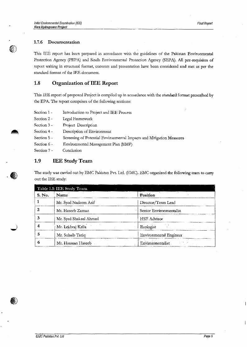
Initial Environmental Examination (lEE)Nara Hydropower Project
FInal RepO/t
1.7.6 Documentation
This IEE report has been prepared in accordance with the guidelines of the Pakistan Environmental
Protection Agency (pEP A) and Sindh Environmental Protection Agency (SEPA). All pre-requisites of
report writing in structural format, contents and presentation have been considered and met as per the
standard format of the lEE document,
1.8 Organizationof lEE Report
This IEE report of proposed Project is compiled up in accordance with the standard format prescribed by
the EPA. The report comprises of the following sections:
Section 1 -
Section 2 -Section 3-Section 4-
Introduction to Project and lEE Process
Legal Framework
Project Description
Description of Environment
Section 5 - Screening of Potential Environmental Impacts and Mitigation Measures
Section 6 - Environmental Management Plan (EMP)
Section 7 - Conclusion
1.9 lEE Study Team
The study was carried out by EMC Pakistan Pvt. Ltd. (EMC). EMC organized the following team to carry
out the lEE study:
1 , Mr. Syed Nadeem Arif Director/Team Lead
2 Mr ..Haseeb Zaman Senior Environmentalist
3 Mr. Syed Shakeel Ahmed HSE Advisor
4 Mr. Le~raj Kella:5 Mr. Sohaib Environmental Engineer
6 Mr. Hassaan Haseeb. E~~iibrimentalist .
EMC Pakistan Pvt. Ltd PageS
Inifial Environmental Examination (lEE)Mara Hydropower Project
Final Repolt
Chapter 2 .Policy, Legal & Administrative Framework
Presented in this section are the Policy, Legal and Administrative Framework of Project in the context of
sustainable development. All legal provisions relevant to environmental protection applicable to the planning,
construction and operation were identified under the scope of the lEE. The proponent has to be well aware
of these requirements and comply with the provisions as applicable and necessary.
2.1 Administrative Framework
Before the 18th amendment in the Constitution of Pakistan, the environmental issues were governed by three
levels of the government viz. Federal, Provincial and Local Government. As a result of the 18,h Amendment
this subject is now in the exclusive domain of the provincial government. The Ministry of Environment at the
federal level was abolished. Its functions related to national environmental management were transferred to .
the provinces. To manage the international obligations in the context of environment, a new ministry - the
Ministry of Climate Change - was created at the federal level. Punjab, Sindh, KPK and Balochistan have
enacted their own environmental protection laws.
At Sindh Provincial level, the Environmental Protection Council (EPC) has been formed consisting of
Chief Minister as Chairman with Minister in charge of Environment Protection Department, Addl. Chief
Secretary, Planning & Development Department, Government of Sindh and Secretaries of Environment,
Finance, Public Health Engineering, Irrigation, Health, Agriculture, Local Government, Industties, Livestock
& Fisheries Forest & Wildlife, Energy, Education Departments Government of Sindh and Divisional
Commissioners 0·£ Sindh. Non-official members are also included ~.e. representatives of Chamber of
Commerce & Industry and from medical or legal professions etc.) along with DG, EPA & two Members of
Provincial Assembly also form part of El'C.
The EPC is policy-making body under the provincial environmental legislation scheme. The functions and
powers of EPC include coordination & supervision of provisions of Act, approving provincial environmental
& sustainable development policies & SEQS, provide guidance for protection & conservation, consider
annual Sindh Environmental Report, deal with interprovincial and federal provincial issues, provide guidance
for bio safety and assist Federal Government in implementation of various provisions of UN Convention on
laws· on Seas (UNCLDS).
Sindh Environmental Protection Agency (SEPA) is administrative, implementation and enforcement
body. The SEPA is headed by a Director General (DG) with the aim to exercise the powers and perform the
functions assigned to-it under the provisions of the Sindh Environmental Protection Act, 2014 (SEP-Act,
2014) and the rules and regulations made there under. The SEPA has technical and legal staff and may form
advisory committees. It also prepares environmental policies, takes measures for implementation of
environmental policies, prepares Sindh Environment Report & prepares or revises Sindh Environmental
Quality Standards.
SEPA shall also establish systems and procedures for surveys, surveillance, monitoring, measurement,
examination, investigation research, inspection and audit to prevent and control pollution and to estimate the
costs of cleaning up pollution and rehabilitating the environment and sustainable development. SEPA would
EMC Pakistan Pvt. Ltd Page 6
Initial Environmental Examination (lEE)Nara Hydropower Project
FIlial Report
also take measures for protection of environment such as to promote research; issues licenses for dealing with
hazardous substances, certify laboratories, identify need for or initiate legislation, specify safeguards etc. SEPA
would also encourage public awareness and education regarding environmental issues.
SEPA has powers to enter or inspect under a search warrant issued by Environmental Protection Tribunal or
a Court search at any time, any land or building etc. where there are reasonable grounds to believe that an
offence under the Act has been or is being or likely to be committed. SEP A may also take samples, arrange
for testing or confiscate any article in discharge of their duties.
This act has also provided for Sindh Sustainable Fund derived from various sources such as voluntary
contributions or fees generated etc. This fund is utilized for protection, conservation 01' improvement of
environment. The Act is appendices in this IEE report.
2.2 StatutoryFramework
I!JfD.- .,
.~ The development of statutory environmental framework has progressively gained priority in Pakistan since
the late 1970s. The Pakistan Environmental Protection Ordinance 1983 was the first codifying legislation on
the issue of environmental protection. This was indeed a consolidated enactment to plug the gaps and remove
defects / deficiencies in the legislation. The promulgation of this ordinance was followed, in 1984, by the
establishment of the Pakistan Environmental Protection Agency, the primary government institution dealing
with environmental issues. Significant work on developing environmental policy was carried out in the late
1980s, which concluded in the drafting of the Pakistan National Conservation Strategy. Provincial
environmental protection agencies were also established at about the same time. The NEQS were established
in 1993 and were amended in 1995 and 2000. The Pakistan Environmental Protection Act (PEPA) 1997 was
enacted to replace the 1983 Ordinance. PEP A conferred broad-based enforcement powers to the
environmental protection agencies. Penalties were prescribed for those contravening the provisions of the
Act. The powers of the federal and provincial Environmental Protection Agencies (EPAs) were also
considerably enhanced under this legislation and these Agencies have been given the power to conduct
inquiries into possible breaches of environmental law either of their own accord, or upon registration of a
complaint. This was followed by the publication of the Pakistan Environmental Protection Agency Review of
IEE-EIA Regulations 2000 which provided the necessary details on the preparation, submission, and review
of lEE and EIA. Mter 18th amendment SEP-Act, 2014 was promulgated and the rules and regulations were
made there under.
2.3 Constitutional Provision
Prior to the 18th Amendment to the Constitution of Pakistan in 2010, the legislative powers were distributed
between the federal and provincial governments through two 'lists' attached to the Constitution as fourth
Schedule. The Federal list covered the subjects over which the federal government had exclusive legislative
power, while the 'Concurrent List' contained subjects regarding which both the federal and provincial
governments could enact laws. The subject of 'environmental pollution and ecology' was included in the
Concurrent List and hence allowed both the national and provincial governments to enact laws on the subject.
However, as a result of the 18th Amendment concurrent list has been omitted and this subject is now in the
exclusive domain of the provincial government.
EMC Pakistall Pvt. Ltd Page 7
Initial Environmental Examination (lEE)Nara Hydropower Project
Final Report
• The Ministry of Environment at the federal level was abolished. Its functions related to national
environmental management were transferred to the provinces. To manage the international obligations
in the context of environment, a new ministry - the Ministry of Climate Change - was created at the
federal level.
After the enactment of provincial legislation, the PEP A 1997 is technically no longer applicable to the
~'VfV
•provinces, The provinces are required to enact their own legislation for environmental protection.
As of now, Punjab, Sindh and Balochistan have enacted their own environmental protection laws. These
provincial laws are largely based on PEP A 1997 and, hence, provide the same level of environmental
protection as the PEPA 1997. Between 1993 and 2010, the Pale-EPA promulgated several rules, regulations,
standards, and guidelines to implement the provisions of the PEP A 1997. The provincial governments have
yet to draft their own instruments; therefore, rules, regulations, standards, and guidelines made under PEP A
1997 can still be benefited from where these are not made under the provincial law.
SEPA has, however taken lead in finalizing and notifying the Sindh Provincial rules, regulations and standards,
The discussion on regulatory requirements applicable to this Project is, therefore, based on the Sindh law, the
SEPA 2014, the Regulations; and, the rules, regulations, standards, and guidelines developed under the SEPA
2014.
• On December 16, 2014, SEPA framed the Sindh Environmental Protection Agency (Review of Initial
Environmental Examination and Environmental Impact Assessment) Regulations, 2014 (2014
Regulations'') .
.I) · On December 19, 2014, SEPA framed the ~) Environmental Sampling Rules 2014, Qi) Hazardous
Substances Rules, 2014, (iii) Sindh Environmental Protection (Composition of Offences and Payment of
Administrative Penalty) Rules 2014, (iv) Sindh Environmental Protection Tribunal Rules, 2014, (v) Sindh
Hospital Waste Management Rules, 2014, (vi) Sindh Environmental Quality Standards (Certification of
Environmental Laboratories) Rules 2014, (vii) Siodh Prohibition of Non-degradable Plastic Products
(Manufacturing, Sale and Usage) Rules 2014, (viii) Sindh Sustainable Development Fund (procedure and
Utilization) Rules 2014, and (ix) Sindh Environmental Quality Standards (Self-Monitoring and Reporting
by Industry) Rules 2014.
On June 28, 2016, the Sindh Environmental Industrial Waste Water, Effluent, Domestic, Sewerage,
Industrial Air Emission and. Ambient Air, Noise for Vehicles, Air Emissions for Vehicles and Drinking
Water Quality Standards, 2015 have been notified.
•
2.4 Sindh Environmental Protection Act, 2014
The Sindh Environmental Protection Act, 2014 (2014 Act) was passed by the Sindh Assembly on February
24, 2014, The 2014 Act is the basic legislative tool empowering the provincial government to frame regulations
for the protection of the environment. The 2014 Act envisages protection, improvement, conservation &
rehabilitation of environment of Sindh with the help of legal action against polluters and green awakening of
communities. It equally lays emphasis for the preservation of the natural resources of Sindh and to adopt ways
and means for restoring the balance in its eco-system by avoiding all types of environmental hazards. The
2014 Act is applicable to a broad range of issues and extends to air, water, industrial liquid effluent, marine,
and noise pollution, as well as to the handling of hazardous wastes. A copy of Sindh Environmental Protection
Act, 2014 is attached as Annexure - I.
EMC Pakistan Pvt. Ltd Page 8
1fJf;1\~
•
)
Initial Environmental Examinlltioll (lEE)Narll Hydropower Project
Final Report
The following articles of the SEPA 2014 have a direct bearing on the proposed Project
• Article 11(1): 'Subject to the provisions of this Act and the rules and regulations therein, no person shall
discharge or emit or allow the discharge or emission of any effluent, waste, pollutant, noise or any other
matter that may cause or likely cause pollution or adverse environmental effects, as defined in Section 2
of this Act, in all amount, concentration or level which is in excess to that specified in Sindh
Environmental Quality Standards ... '
Article 11(2): 'All persons, in industrial or commercial or other operations, shall ensure compliance with
the Environmental Quality Standards for ambient air, drinking water, noise or any other Standards
established under section 6(1)(g)Q); shall maintain monitoring records for such compliances; shall make
available these records to the authorized person for inspection; and shall report or communicate the
record to the Agency as required under any directions issued, notified or required under any rules and
regulations.'
Article 14 (1): 'Subject to the provisions of this Act and the rules and regulations, no person shall cause
any act, deed or any activity', including;
•
•
o (b) disposal of solid and hazardous wastes at unauthorized places as prescribed;
o (c) dumping of wastes or hazardous substances into coastal waters and inland water bodies; and
o (d) release of emissions or discharges from industrial or commercial operations as prescribed.
Article 15 (1): 'Subject to the provisions of this Act, no person shall operate or manufacture a motor
vehicle or class of vehicles from which air pollutants or noise are being emitted in an amount,
concentration or level which is in excess of the Sindh Environmental Quality Standards or, where
applicable, the standards established under sub-clause (i) of clause (g) of sub-section (1) of section 6'.
Article 17(1): 'No proponent of a project shall commence construction or operation unless he has filed
with the Agency an initial environmental examination or environmental impact assessment, and has
obtained from the Agency approval in respect thereof'
Article 17(2): The agency shall;
o a) review the initial environmental examination and accord its approval, subject to such terms and
conditions as it may prescribe, or require submission of an environmental impact assessment by the
proponent; Of
o (b) review the environmental impact assessment and accord its approval subject to such terms and
conditions as it may deem fit to impose or require that the environmental impact assessment be re-
submitted after such modifications as may be stipulated or decline approval of the environmental
impact assessment as being contrary to environmental objectives.
• Article 17(3): 'Every review of an environment impact assessment shall be carried out with public
participation and, subject to the provisions of this Act, after full disclosure of the particulars of the
•
•
•
•project'.
Article 17(4): 'The Agency shall communicate its approval or otherwise within a period of two months
from the date that the initial environmental examination is filed, and within a period of four months from
the date that the environmental impact assessment is filed complete in all respects in accordance with the
regulations, failing which the initial environmental examination or, as the case may be, the environmental
£MC Pakistan Pvt. Ltd Page 9
InifialEnvironmantal Examination (fEE)Nara Hydropower Projecf
Final Report
•
impact assessment shall be deemed to have been approved, to the extent to which it does not contravene
the provisions of this Act and the rules and regulations'.
Article 20(1): 'The Agency shall from time to time require the person in charge of a project to furnish,
within such period as may be specified, an environmental audit or environmental review report or
environmental management plan containing a comprehensive appraisal of the environmental aspects of
the project'.
• Article 20(2): The report of a project prepared under sub-section (1) shall include:
IJit\~
a. analysis of the predicted qualitative and quantitative impact of the project as compared to tile actual
impact;
b. evaluation of the efficacy of the preventive, mitigation and compensatory measures taken with respect
to the project; and
c. recommendations for further minimizing or mitigating the adverse environmental impact of the
project.
• Article 20(3): 'Based on its review of the environmental audit report, the Agency may, after giving the
• person in charge of the project an opportunity of being heard, direct that specified mitigation and
compensatory measures be adopted within a specified time period and may also, where necessary, modify
the approval granted by it under section 17'.
2.5 Sindh EPA (Review of lEE and EIA) Regulations 2014
Sindh Environmental Protection Agency (Review of IEE I EIA) Regulations, 2014 ~'2014 Regulations")
IV made in exercise of powers conferred under section 37 of the 2014 Act provide the necessary guidelines on
the preparation, submission, & review of Initial Environmental Examinations (lEEs) and Environmental
Impact Assessments (EIAs). The 2014 Regulations categorize projects in three categories provided inSchedule I (list of projects requiring lEE), II (list of projects requiring EIA) and III (list of projects requiring
Environmental Checklist) of the 2014 Regulations. A copy of SEPA (review of IEE/EIA) Regulations, 2014
is attached as Annexure - II.
The proposed project falls in category B (1) of the Schedule I (List of Projects requiring lEE) of the 2014
Regulations, which provides:
B.Energy
1. Hydroelectric power generation less than 50 MW
Hence, an lEE of the project has been conducted.
The submission and approval procedure for the IEE is summarized below:
• The lEE report shall be submitted, together with a review fee and form included as Schedule-V'of the
2014 Regulations.
The SEPA shall conduct a preliminary scrutiny and reply within 15 working days of the submittal of the
report a) confirming completeness, or b) asking for additional information, if needed, or c) returning the
report requiring additional studies, if necessary.
•
EMC Pakistan Pvt. Ltd Page 10
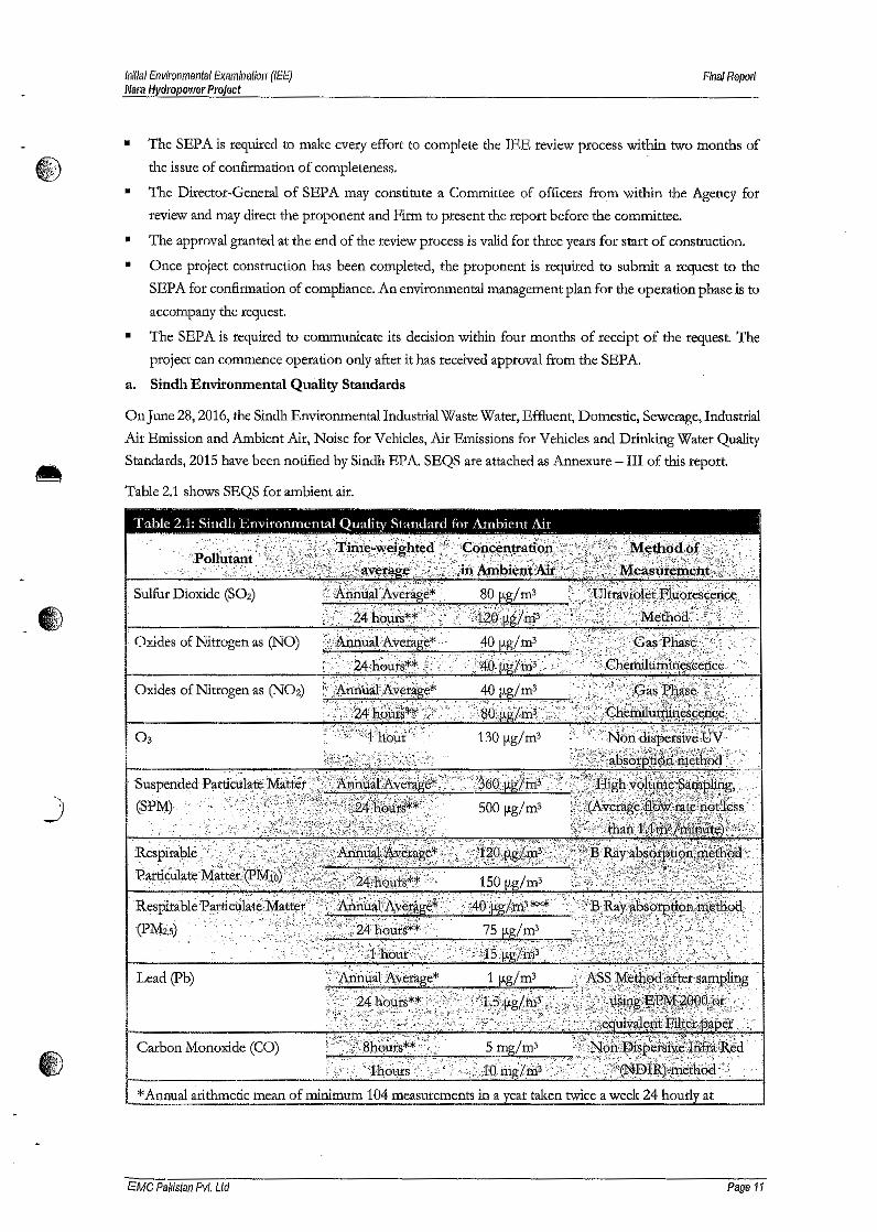
Initial Environmental Examination (lEE)f'Jara Hydropower Project
Final Report
• The SEPA is required to make every effort to complete the IEE review process within two months of
~ the issue of confirmation of completeness.
• The Director-General of SEP A may constitute a Committee of officers from within the Agency for
review and may direct the proponent and Firm to present the report before the committee.
• The approval granted at the end of the review process is valid for three years for start of construction.
• Once project construction has been completed, the proponent is required to submit a request to the
SEPA for confirmation of compliance. An environmental management plan for the operation phase is to
accompany the request.
• The SEPA is required to communicate its decision within four months of receipt of the request. 'The
project can commence operation only after it has received approval from the SEPA.
a. Sindh Environmental Quality Standards
On june 28,2016, the Sindh Environmental Industrial Waste Water, Effluent, Domestic, Sewerage, Industrial
Air Emission and Ambient Air, Noise for Vehicles, Air Emissions for Vehicles and Drinking Water Quality
Standards, 2015 have been notified by Sindh EPA. SEQS are attached as Annexure - III of this report.
Table 2.1 shows SEQS for ambient air.
Table 2.1: ~illdh Environmental Quality Standard for Ambient Ai_r_
Carbon Monoxide (CO)
*Annual arithmetic mean of minimum 104 measurements in a eat taken twice a week 24 hourl at
EMC Pakistan Pvt. Ltd Page 11
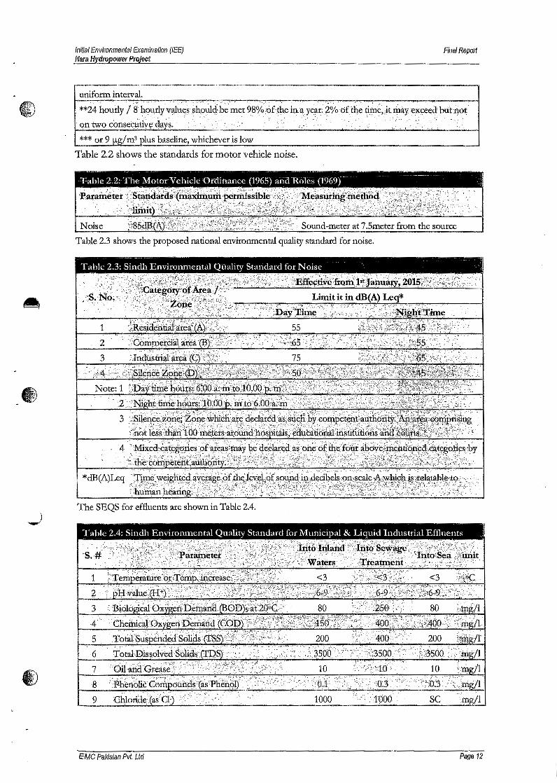
6A~
Initial Environmental Examination (lEE)Nara Hydropower Project
Final Report
'-----------_._-_._. __._'---------------'---------,uniform interval. '~'~~~~~~~~~----~--~----.-~-,**24 hourly / 8 h.Qt',rlYv~U:~§$h!?tM~bemet98°!~:9r:~hdn:~ye~t: i%bftlte tirri~,jt;riiayexl:!eed btit not ,(;)ntwo consecutiv~ days;' ; -. :,:~, ',,':,,' >," /,~' >, >' .:,..: ..~', "," .- ':i. " " ~' ',' : ,*** or 9 fl.g/ m3 _plus baseline, whichever is low
Table 2,2 shows the standards for motor vehicle noise,
, -Table 2.2: The Motor Vchiclt: Ordinance (1965) and Roles (1969)
Table 2.3 shows the proposed national environmental quality standard for noise.
Table 2.3~Sindh Jo:nviro~mental Quality Standard for Noise ,- 1
1
2
:,-··.·i~:4i,.:.•·':;._1;:':;Eisll~#¥~.;~~*:#;i(@:'ij{!,::~B~;~~W:~i;'~~!~ft1\id;~)&:~~i~1:~?;i~di~?:'t:.i;,f;~:~';:'': . ,"-Note: 1 :~~iy:ti#ii'h.dijfW,i'~fQ6:i:,;ih?~g#:(j;6q_~;~tii%I;'f.('~:~;\y:;;il;;y:'·':~';!:7't:",~:fF}\j{t·:?'::~;;
*dB(A)Leq ·~'i«i~~~~:t1;!-~~~~~~~f~~~;~~T~l);~i~1r;~~~~:;~~;;t~;~:.~;:,:~:);:..;:,.,;r~:~,:;1~£{:~~~~~~~:~?,~:',.The SEQS for effluents are shown in Table 2.4.
Table 2.4: Sindh Envirorunental Quality Standard for Municipal & Liquid Industrial Effluents
3'-456
7
9 1000 SC .m 11
EMC Pakistan Pvt, Ltd Page 12
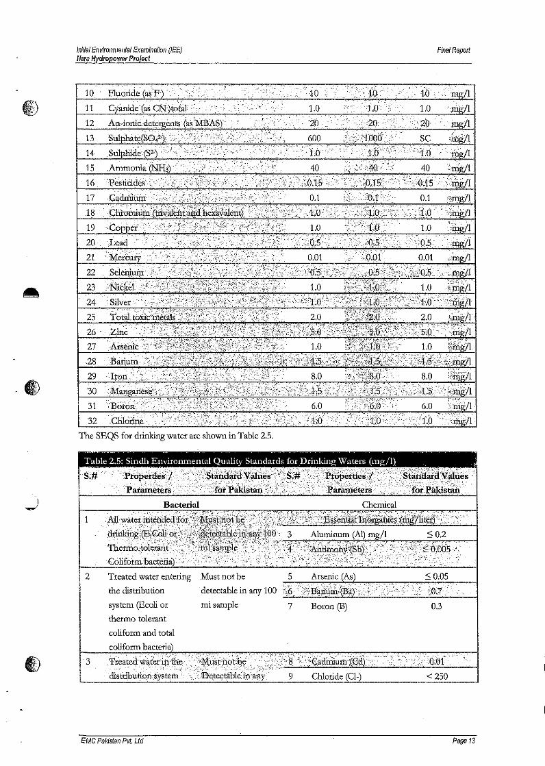
initial Environmel1tal Examinaifo/1 (lEE)Nara Hydropower Project
Fina! Report
~,-~
1011
12
13
14
15
16
17
19
20, ~
21
22
232425
26 -
27,28
29
'3031
32
The SEQS for drinking water are shown in Table 2.5.
"_ . . ~ - -.
!a~le 2.5: Sindh Environmental Quality Standards for Drinking Waters (mg/I) "
Bacterial Chemical
1
2 Treated water entering
the distribution
system (Eeoli or
thermo tolerant
coliform and total
0.3
,detectable in any 100ml sample 7 Boron (B)
3
EMC Pakistan Pvt, Ltd Page 13
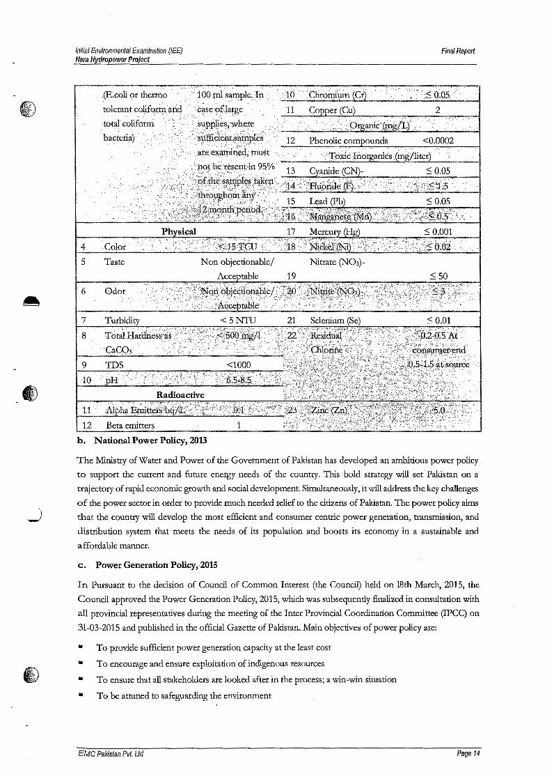
Illif/a! Environmental Examination (lEE)Nara Hydropower Project
Final Report
,. ':.. ~}.:..:.~.
. (Ii.colt"or th~tm~. ;1"00p:}1 ;~~ple. In .. '. '10 .. ;(:fuoM~.(~1..;...•._.:_.:._._.•';;...'.'..;;.:..;;.:.$_;;....•. .;...O..;.:O;_~5'-. '_',_; ..... "-I
tolerant coliform arid 2-totaLc-olif~~r¥;' ~ ::..:' .
··.hac~t!fia). :':.:J.'".i:»: "<:, .:.
<0,0002
4 ·Color·
5 Taste Non objectionable! Nitrate (N03)-Acce table 19 :::;50
6
7 Turbidity < 5 NTU 21 Selenium (Se) < o.ot
.-109 TDS <1000
·:~'.~~:~;h;~'{~)';;:~;ij;;1'i~i,];,~r~~~~~~II!~'l:1f:~t:~:l,;:,;W~~;':i:'h. National Power Policy, 2013
The Ministry of Water and Power of the Government of Pakistan has developed an ambitious power policy.
to support the current and future energy needs of the country. This bold strategy will set Pakistan on a
trajectory of rapid economic growth and social development. Simultaneously, it will address the key challenges
of the power sector in order to provide much needed relief to the citizens of Pakistan. The power policy aims
that the country will develop the most efficient and consumer centric power generation, transmission, and
distribution system that meets the needs of its population and boosts its economy in a sustainable and
affordable manner.
c. Power Generation Policy,·2015
In Pursuant to the decision of Council of Common Interest (the Council) held on 18th March, 2015, the
Council approved the Power Generation Policy, 2015, which was subsequently finalized in consultation with
all provincial representatives during the meeting of the Inter Provincial Coordination Committee (IPCC) on
31-03-2015 and published in the official Gazette of Pakistan, Main objectives of power policy are:
• To provide sufficient power generation capacity at the least cost
To encourage and ensure exploitation of indigenous resources
To ensure that all stakeholders are looked after in the process; a win-win situation
To be attuned to safeguarding the environment
•••
EMC Pakistan Pvt, LId Page 14

Initial Envirollmental Examination (IfE)Nara Hydropower Project
Final Report
Scope of the power policy summarized below;
•Private sector power projects
Public sector power projects, where required by the Project Sponsor
Public-Private Partnership (PPP) power projects
•
•• Power projects developed by the Public sector and subsequently divested
d. The Sindh Irrigation Act (1879) and the Canal and Drainage Act (1873)
This Sindh Irrigation Act covers the construction, maintenance and regulation of canals for the supply of
water and for the levy of rates of water supplied in the Province of Sindh. Canals are defined as channels,
pipes and reservoirs constructed and maintained by the Government for the supply for storage of water.
Under section 27 of the Act a person desiring to have a supply of water from a canal for purposes other than
irrigation shall submit a written application to a Canal Officer who may, with the sanction of the Provincial
Government give permission under special conditions. The Act under section 61 also prohibits the damaging,
altering, enlarging or obstructing the canals without proper authority.
A The Canal and Drainage Act (1873) prohibits corruption or fouling of water in canals (defined to include
channels, tube wells, reservoirs and watercourses), or obstruction of drainage.
The canals and associated irrigation network exists in the project area and provisions of these acts applies to
certain activities like water abstraction by project contractors etc. There is no project activity planned near the
canal and associated network which could directly cause physical damage to the canal or alteration in water
quality. Any abstraction of water from the canal shall be only done after getting formal approval from the
concerned irrigation department.
e. The Forest Act 1927
This act is applicable to all regions of Pakistan. It includes procedures for constituting and managing various
types of forests, such as reserved forests and protected forests. The act empowers the provincial forest
departments to declare any forest area as reserved or protected and also prohibit the breaking up or clearing
of forest for cultivation, grazing, hunting, removing forest produce; quarrying and felling, lopping and topping
of trees, branches in reserved and protected forests. It also defines the duties and roles of forest related public
servants, and penalties for any infringement of the rules. There is no protected forest located within the lEEproject area.
f. Land Acquisition Act, 1894
This Act is a colonial legacy which provides law for the acquisition of land needed for public purposes and
for companies. The Act provides complete mechanism for determining the amount of compensation for land,
trees, horticulture, to be made on account of such acquisitions. The law provides details of various peculiarities
involved in acquisition of land such as preliminary investigation, objection to acquisition, declaration of
intended acquisition, enquiry into measurements, value & claims, taking possession, reference to court and
procedure thereon, apportionment of compensation, payment, temporary occupation of land, acquisition of
land for companies, disputes resolutions, penalties and exemptions, etc. This Act has 55 sections addressing
different areas. Section 4(2) of the Act mentions that it shall be lawful for any official authorized by the
Collector to enter upon and survey, to dig or to do all other acts necessary to ascertain whether the land is
suitable for such purpose.
EMC Pakistan Pvt. Ltd Page 15
initial Environmental Examination (lEE)Mara Hydropower Project
Finai Report
The land will be acquired by the proponent.
CD g. Hazardous Substances Rules, 2014
The Hazardous Substances Rules 2014 define the hazardous substances in schedule 1 and make it compulsory
for any proponent who is filing an Environmental Assessment to apply for a license for transporting any
hazardous substance that it has in its plans. The rules also stipulate a waste management plan to be in place in
such a facility holding hazardous materials. Further SEP Act 2014 also requites the proponent to obtain a
license to store any such hazardous substance. The proponent is obligated to follow in accordance with the
provisions of the act and rules.
h. Laws on protection of Archaeological Sites & Cultural Heritage
i. Antiquities Act, 1975
•The act ensures the protection of cultural resources in Pakistan. It is designed to protect antiquities from
destruction, theft, negligence, unlawful excavation, trade and export. Antiquities have been defined in the Act
as ancient products of human activity, historical sites, or sites of anthropological or cultural interest, national
monuments etc. The Act prohibits new construction in the proximity of a protected antiquity and empowers
the Government of Pakistan to prohibit excavation in any area, which may contain articles of archaeological
significance. The developers are obligated to ensure that no activity is undertaken within 61 m (200 ft) of a
protected antiquity, and to report to the GoP's Dept. of Archaeology if any archaeological discovery made
during the course of the project.
N one of the archeological site exists in the microenvironment of proj ect area.
ii. Guidelines for Sensitive and Critical Area, October 1997
The above guidelines list up a number of areas subject to protection in terms of sensitive ecosystems and
archaeological importance. In Appendix II of the Guidelines, a list of eight Archaeological Sites and
Monuments, of which four of them are National Monuments, in Karachi is provided. Further, there are 203
sites declared as "Protected Heritage" within Karachi District.
.....) None of such sites however exist within the corridor of impact of the proposed Project.
iii. IFC General EHS Guidelines
The EHS guidelines published by IFC are technical reference documents that address IFC's expectations
regarding the industrial pollution management performance of its projects; however, these guidelines have
been benefited from for other projects as well. They are designed to assist managers and decision makers with
relevant industry background and technical information. This information supports actions aimed at avoiding,
minimizing, and controlling EHS impacts during construction, operation, and decommissioning phase of a
pro] ect or facility.
Environmental issues associated with the construction and maintenance activities may include, among others,
noise and vibration, soil erosion, and threats to biodiversity including habitat alteration and impacts to wildlife.
Examples of the impacts addressed in the General EHS Guidelines include:
EMC Pakistan Pvt. Ltd Page 16

.1)
Inifial Environmental Examination (lEE){'lara Hydropower Project
FinafReport
• Construction site waste generation;
• Soil erosion and sediment control from materials sourcing areas and site preparation activities;
• Fugitive dust & other emissions (e.g, from vehicle traffic, land clearing activities, & materials stockpiles);
• Noise from heavy equipment and truck traffic;
Potential for hazardous materials and oil spills associated with heavy equipment operation and fuelling
activities.
EMC Pakistan Pvt. Ltd Page 17
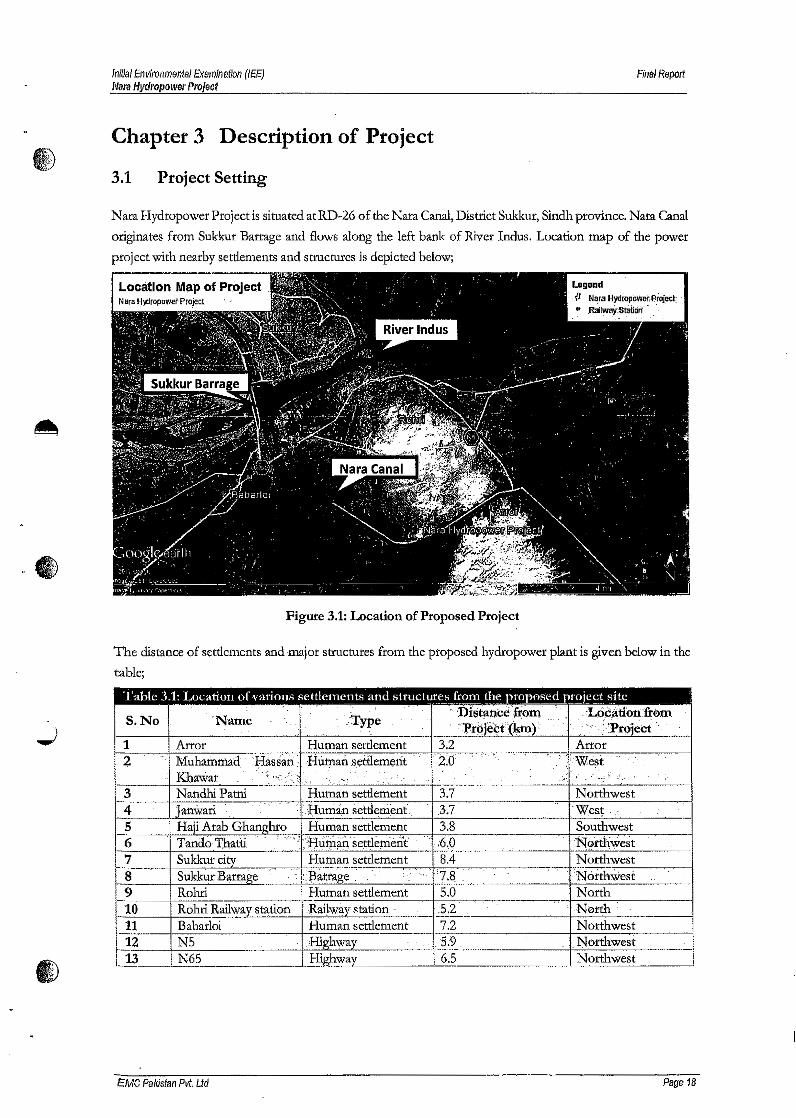
Initial Environmental Examination (lEE)Nara Hydropower Project
Final Report
fi,:;\~
Chapter 3 Description of Project
3.1 Project Setting
Nata Hydropower Projectis situated atRD-26 of the Nara Canal, District Sukkur, Sindh province, Nata Canal
originates from Sukkur Barrage and flows along the left bank of River Indus, Location map of the power
project with nearby settlements and structures is depicted below;
Figure 3,1: Location of Proposed Project
The distance of settlements and major structures from the proposed hydropower plant is given below in the
table;
E:MC Pakistan Pvt. Ltd Page 18
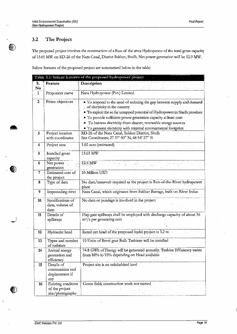
Initial Environmental Examination (lEE)!'lara Hydropower Project
Final Report
3.2 The Project
The proposed project involves the construction of a Run-of-the-river Hydropower. of the total gross capacity
of 13.65 MW on RD-26 of the Nata Canal, District Sukkur, Sindh. Net power generation will be 12.9 MW.
Salient features of the proposed project are summarized below in the table;
No1 Proponent name Nata Hydropower (pvt.) Limited
.2 .Prime objectives • T~respond to the need of reducing' gap between supply.and demand. of electricityin the country•. To exploit th~ so far untapped potencial of Hydropower in Sindh province.~ To provide sufficient poweq~eneration capacity at least cost.• 'To harness electricity from cleaner, renewable energy sources• To. with minimal environmental
-
A3
4
5
6-~.
7
8
9
10
11.....,,1
Project locationwith coordinates
RD-26 of the Nara Canal, Sukkur District, SindhSite Coordinates; 27 37' 50" N, 6854' 27" E
Pro; ect area acre (estimated)
ervoir required as the project is Run-of-the- River hydropower
Impounding river Nara Canal, which originates from Sukkur Barrage, built on River Indus
"'I..._....,.."\"O' ...." •.N of No dam or pondageis involved in thedam, volume ofdamDetails ofspillways
Flap gate spillways shall be employed with discharge capacity of about 36m3/ s per generating unit
.12 Hydraulic head of the pt;6posed
13
14
15 Project site is an uninhabited
Green field; .work not started
EMC Pakistan Pvt. Ltd Page 19
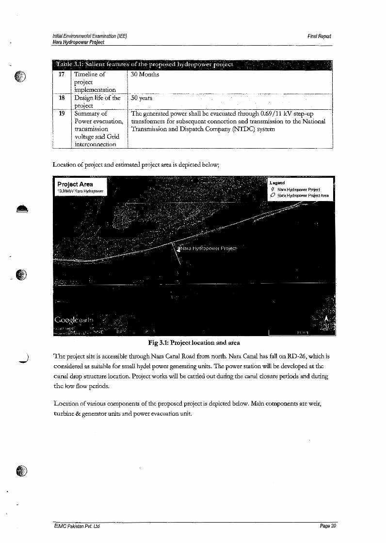
Initial Environmental Examination (lEE)Mara Hydropower Project
Final Report
Tabk 3.1: Salit:llt features of the proposed hydropower project - ,1
I, 17 Timeline of1 project~__ implementation _'__ -I__ ~I 18 Design life of the, .so years1 project
30 Months
. 19 Summary of The generated power shall be evacuated through 0~-69/11 kV step-up
11 Power evacuation, transformers for subsequent connection and transmission to the National
transmission Transmission and Dispatch Company (NTDC) system
II voltage and Grid
interconnection'----'----
_,.,.,~----,,'---.-,-. --.-. -" ~--..-..-. -~-, -.--
Location of project and estimated project area is depicted below;
proJect Area .Legend{I Nara Hydropower pr~Jecto 'Jilai<\ Hydropower ProJect Area
4)..W)
Fig 3.1: Project location and area
....) 'The project site is accessible through Nata Canal Road from north. Nara Canal has fall on RD-Z6, which is
considered as suitable for small hydel power generating units. The power station will be developed at the
canal drop structure location. Project works will be carried out during the canal closure periods and during
the low flow periods.
Location of various components of the proposed project is depicted below. Main components are weir,
turbine & generator units and power evacuation unit
cMC Pakistan Pvt, Ltd Page 20
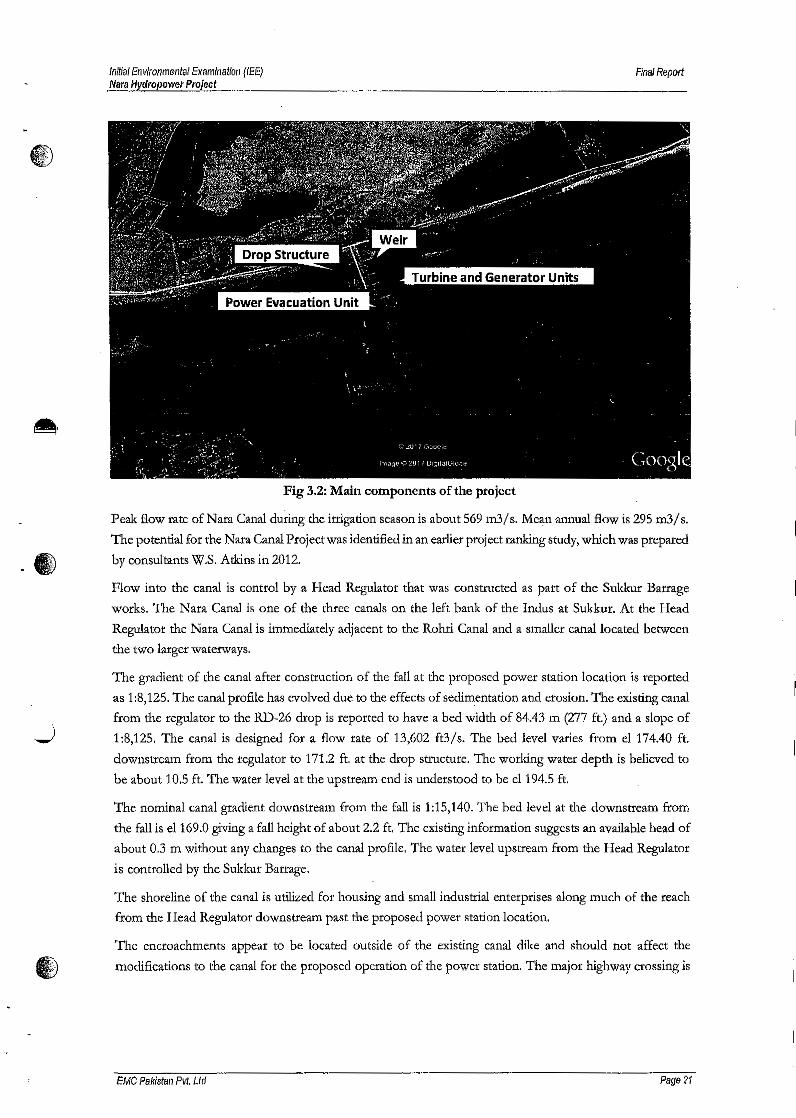
Initial Environmental Examination (lEE)Mara Hydropower Project
Final Report
·e
Fig 3.2: Main components of the project
Peak flow rate of Nara Canal during the irrigation season is about 569 m3/ s. Mean annual flow is 295 m3/ s.
The potential for the Nara Canal Project was identified in an earlier project ranking study, which was prepared
by consultants W.S. Atkins in 2012.
Flow into the canal is control by a Head Regulator that was constructed as part of the Sukkur Barrage
works. The N ara Canal is one of the three canals on the left bank of the Indus at Sukkur, At the Head
Regulator the Nara Canal is immediately adjacent to the Rohri Canal and a smaller canal located between
the two larger waterways.
The g~adient of the canal after construction of the fall at the proposed power station location is reported
as 1:8,125. The canal profile has evolved due to the effects of sedimentation and erosion. The existing canal
from the regulator to the RD-26 drop is reported to have a bed width of 84.43 m (277 ft.) and a slope of
1:8,125. The canal is designed for a flow rate of 13,602 ft3/s. The bed level varies from el 174.40 ft.
downstream from the regulator to 171.2 ft. at the drop structure. The working water depth is believed to
be about 10.5 ft. The water level at the upstream end is understood to be e1194.5 ft.
The nominal canal gradient downstream from the fall is 1:15,140. The bed level at the downstream from
the fall is e1169.0 giving a fall height of about 2.2 ft, The existing information suggests an available head of
about 0,3 m without any changes to the canal profile, The water level upstream from the Head Regulator
is controlled by the Sukkur Barrage.
The shoreline of the canal is utilized for housing and small industrial enterprises along much of the reach
from the Head Regulator downstream past the proposed power station location.
The encroachments appear to be located outside of the existing canal dike and should not affect the
I) modifications to the canal for the proposed operation of the power station. The major highway crossing is
EMC Pakistan Pvt. Ltd Page 21
Initial Environmental Examination (lEE)Nara Hydropower Project
Final Report
.. located at about 1500 01 from the Regulator as for the Rohri Canal. The level of this bridge will not affect
the design or operation of the proposed power station,
Site Layout
The powerhouse structure will be located adjacent to the existing canal drop structure in the abandoned
reach of canal. The powerhouse will be located in the canal reach. The existing canal dikes will be extended
to the inlet to the powerhouse and will transition to vertical approach channel walls. The inlet channel to
the powerhouse will slope to the inlet of the structure and will be lined with a concrete apron. Similarly, the
outlet channel will slope from the end of the draft tube to the canal invert. The outlet structure will have a
trapezoidal cross section with concrete lining from the draft tube to the canal invert.
A control building will be located at the end of the powerhouse adjacent to the switchyard that will connect
to the transmission lines.
Powerhouse Layout
A bevel gear Bulb Turbine arrangement was selected after the consultation with the proposed turbine
supplier (Andritz Hydro), The turbines will have a horizontal axis and double regulated Kaplan type
runners. These turbines will allow for a compact powerhouse structure suited for the high flow rates
required in the canals, The bevel gear arrangement allows the generator to be placed with a vertical axis and
to be situated above the turbine, The gearing arrangement also allows for a speed increaser that reduces the
size of the generator.
Powerhouse was designed for a turbine with runner diameter of 2.6 01 and rotational speed of 162 rpm,
The rated head for the selected turbine prototype is 3.2 01 and the rated flow per generating unit is 50 013/ s.
The actual turbine performance will depend on the water levels upstream from the Sukkur Barrage and the
flow rate through the canals. The Nara site will have 10 generating units, All units will be of the same design
to allow for economy during manufacture, installation, and operations and maintenance,
The powerhouse will house the generating units along with associated auxiliary equipment. An erection bay
area will be included at the end of the powerhouse, An overhead traveling crane will be provided for initial
installation of the equipment and for maintenance.
The powerhouse structure will be arranged by allowing for flow over top of the powerhouse with control
by flap gates. The gates could be adjusted to supplement the flow through the power station during high
flow conditions. The gates would also open rapidly in the event of a power system load rejection so that
the flow rate along the canal would not be disrupted. During conditions when the power station Cannot
operate (e.g, when the maximum head limit is exceeded) the canal flow will be discharged entirely by the
flap gates.
Control of the flow in the canalwill be at the power station rather than at the Head Regulator to allow for
the highest possible generating head, The flow rate in the canal can be automatically regulated by the power
station control system in response to specified demands for irrigation systems downstream, The Head
Regulator operating policy will be adjusted so that the water level in the canals is equal to the level in the
Indus at the Sukkur Barrage but with the gates used so that the maximum water level at the upstream end
of the canals is at el60,96 m,
EMC Pakistan Pvt. Ltd Page 22
Initial Environmental EXamination (lEE)lVaraHydropower Project
Final Report
The maximum static water level upstream will he at el 60.96 m (e1200 ft), which will correspond with thetJ highest level upstream from the Sukkur Barrage before the Head Regulator gates must be partially closedfor flood protection.
Dewatering of the foundation excavation will be required to allow construction work to be carried out in
the dry. Details of the dewatering scheme will be determined by the Contractor but is expected to include
a three-stage approach, The first stage would consist of excavation to the top of the groundwater table.
Tube wells would be installed to allow excavation to continue to a second stage level. A slurry wall or sheet
pile wall will be installed to reduce seepage into the excavation. Additional tube wells would be installed to
control seepage pressures at the ground surface.
The after bay will be concrete lined to prevent foundation scour or migration of sediment into the draft
tube. The approach channel to the intake would slope down from the canal bed level to the inlet elevation.
The turbines wilt be arranged with a horizontal axis set below the minimum water level for the power
station. A minimum level at el 55 m was selected for both stations based on a review of the water levels
computed as described in Section 8. The turbine centerline is set at about 6.5 m below the tailwater level.
Spillway Facilities
Flap gates will be installed on the top of each generating unit in the powerhouse, as illustrated in Appendix
A. The flap gates will be used to discharge flow in excess of the generating unit capacity and in the event
of an outage at the plant. The gates will open rapidly following a change in the load on the power station
so as to prevent the formation of open channel surges along the canal upstream.
The proposed flap gate spillways will provide a discharge capacity of about 36 m3/s per generating unit
with the water level at the maximum static level (el 60.96 m). During a load rejection for any of the units,
the gates can be opened to maintain the water level upstream from the powerhouse. The sill level for the
spillways will be at el 58.68 m and the crest will function as a broad crested weir when the gates are fully
retracted.
.)
The discharge capacity of the powerhouse spillway will vary depending on the upstream water level as
illustrated in Figure. The spillway will be effective for management of surge conditions following unit shut
down by opening gates to compensate for the unit going off line. During a full load shut down, a transient
wave would be created that would be mitigated by the operation of the gates to discharge part of the original
flow rate.
However, the capacity of the spillway will be less than the flow rate in the canal for many conditions with
the water level upstream of the Sukkur Barrage below the maximum control level. The average water level
upstream of Sukkur Barrage is at el59.94 m, which w111provide for a spillway flow capacity of only about
149 m3/s at Nara.
..,V;J
The capacity of the spillway emphasizes the importance of the power station to maintain the flow rate to
the irrigation areas. Normal operation of the facility will require that the generating units are functioning to
provide the flow rate satisfying the irrigation demand. The spillway.will operate to supplement the power
station discharge but would not be sufficient to pass the full flow rate in the canal system.
An auxiliary spillway would be required if the irrigation canal system were required to operate independently
of the power stations.
EMC Pakistan Pvt. Ltd Page 23
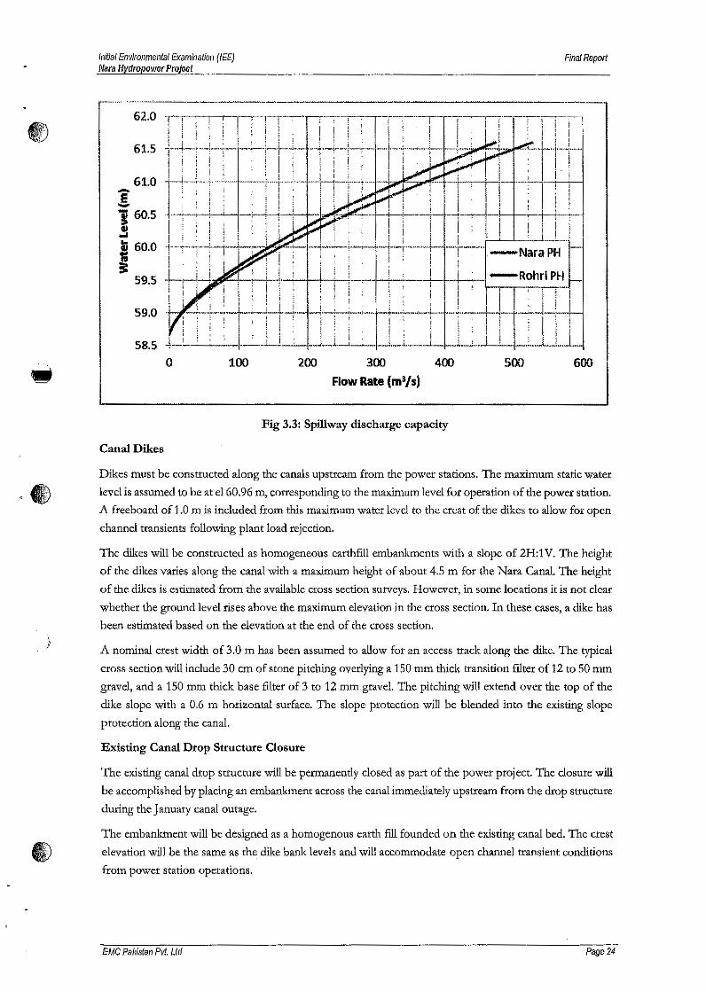
&< •
)
Inlt/al Environmental Examination (lEE)Mal'a Hydropower Project
Final Report
62.0
61,5
61.0! I
600
The existing canal drop structure will be permanently closed as part of the power project. The closure will
be accomplished by placing an embankment across the canal immediately upstream from the drop structure
during the January canal outage.
The embankment will be designed as a homogenous earth fill founded on the existing canal bed, The crest
I) elevation will be the same as the dike bank levels and will accommodate open channel transient conditions
from power station operations.
!160.5S" 60.0
~59.S
59.0
58.5100o 200 300 400
Flow Rate (m~/s)500
Fig 3.3: Spillway discharge capacity
Canal Dikes
Dikes must be constructed along the canals upstream from the power stations. The maximum static water
level is assumed to be at el60.96 m, corresponding to the maximum level for operation of the power station.
A freeboard of 1.0 m is included from this maximum water level to the crest of the dikes to allow for open
channel transients following plant load rejection.
The dikes will be constructed as homogeneous earthfill embankments with a slope of 2H:1V. The height
of the dikes varies along the canal with a maximum height of about 4.5 m for the Nata Canal. The height
of the dikes is estimated from the available cross section surveys. However, in some locations it is not cleat
whether the ground level rises above the maximum elevation in the cross section. In these cases, a dike has
been estimated based on the elevation at the end of the cross section.
A nominal crest width of 3.0 m has been assumed to allow for an access track along the dike. The typical
cross section will include 30 em of stone pitching overlying a 150 mm thick transition filter of 12 to 50 mm
gravel, and a 150 mrn thick base filter of 3 to 12 mm gravel. The pitching will extend over the top of the
dike slope with a 0.6 m horizontal surface. The slope protection will be blended into the existing slope
protection along the canal.
Existing Canal Drop Structure Closure
EMC Pair/stan Pvt. Ltd Page 24
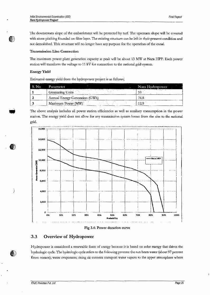
Inifial Environmental Examination (lEE)MaraHydropower Project
Final Report
The downstream slope of tile embankment will be protected by turf. The upstream slope will be coveredf~ with stone pitching founded on filter layer. The existing structure can be left in their present condition and
not demolished. This structure will no longer have any purpose for the operation of the canal.
Transmission Line Connection
The maximum power plant generation capacity at peak will be about 13 MW at Nara HPP. Each power
station will transform the voltage to 11 kV for connection to the national grid system.
Energy Yield
Estimated energy yield from tile hydropower project is as follows;
__ The above analysis includes all power station efficiencies as well as auxiliary consumption in the power
station. The energy yield does not allow for any transmission system losses from the site to the national
grid.
6- 1ttI
,)
§i 10,000
~i8,000
I6,000
4.000
~ +-l-~I-------+l-_-_-_ ~-_- ..-__-l1-..-._-__'4~ sa~ 60%
.f'rabebl1lty80% 90% 1009(,30%10% 2att.0'l6
Fig 3.4: Power duration curve
3.3 Overview of Hydropower
Hydropower is considered a renewable form of energy because it is based on solar energy that drives the
hydrologic cycle. The hydrologic cycle refers to the following process: the sun heats water (about 97 percent
from oceans); water evaporates; rising air currents transport water vapors to the upper atmosphere where
EMC Pal(istan Pvt. Ltd Page 25

I/)illal Environmental Examination (lEE)Nara Hydropower Projecf
Final Report
lower temperatures condense vapors into clouds. Air currents move the clouds around the globe and
I) eventually, water falls as precipitation. Through this process, water can reach altitudes higher than sea level.
,)
Gravity causes water to descend from higher elevations creating opportunities to harness water energy-
gravitational energy from falling water and kinetic energy from flowing water. The amount of kinetic energy
available from water flow depends on the height from which the water drops, the angle of the slope, and
the volume of water per unit of time, i.e., the discharge.
The energy of flowing water is harnessed by turbines, which are placed in the path of the water flow. The
force exerted by water moving over turbine blades rotates the turbine runner; the turbine runner rotates
the generator, which produces electricity.
Compared with other technologies, the most important advantages of hydropower are the following:
• Hydropower generation is based on a reliable proven technology that has been around for more than a
century and hydropower plants can be easily rehabilitated or upgraded utilizing recent advances in hydro
technologies.
• Hydropower generation is renewable because it does not reduce the water resources it uses and does not
require fuel.
• In most cases, hydropower is an economically competitive renewable source of energy. The levelized cost
of electricity (LCOE) is usually in the range of US$0.05 to US$0.10 per kWh [Energy Information
Administration, US, 2010]. Rehabilitating or upgrading existing hydropower schemes provides
opportunities for cost-effective capacity increases.
• Hydropower exploits domestic water resources, thereby achieving price stability by avoiding market
fluctuations.
• Storage hydropower schemes (dams, pumped storage) offer operational flexibility because they can be
easily ramped up or shut down, creating potential for immediate response to fluctuations in electricity
demand. Thus storage hydro are valuable to meet peak demand or to compensate for other plants in the
grid (especially solar and wind), which can experience sudden fluctuations in power output.
The creation of reservoirs also allows water to be stored for drinking or irrigation, reducing human
vulnerability to droughts. Reservoirs can provide flood protection, and can improve waterway transport
capacity. Further, HPPs with reservoirs can generate energy during dry periods and regulate fluctuations
in the energy supply network by using the stored water.
• Environmental impacts triggered by implementing hydropower schemes are well known and manageable.
•
Disadvantages of hydropower include the following:
• High up-front investment costs compared to other technologies, such as thermal power (but low
operational costs since no fuel is required).
• Reservoirs' may have a negative impact on the inundated area, damage river flora and fauna, or disrupt
rivet uses such as navigation. However, most negative impacts can be mitigated through project design.
£MC Pakistan Pvt. Ltd Pags 26
'D;.
)
Initial EnvIronmental Examination (lEE)Nitra Hydropower Project
FinalReport
3.3.1 Design and Types
Hydropower can be generated wherever a flow of water descends from a higher level to a lower level. The
difference between the two water surface elevations is referred to as. head. Head can exist in nature, for
instance when a stream runs down a steep hillside or when a sharp change in elevation creates a waterfall in a
river. However, head can also be created artificially by constructing a weir or dam; the dam creates a barrier
to water flow, raising the upstream water level to the desired elevation.
As a result of elevation differences gravitational potential energy is stored in the water; this energy can be
exploited by installing turbines and generators. Water flow moves the turbine blades, thereby converting
water's potential energy into kinetic energy. The turbine rotation forces the generator rotator to spin around
the stator thereby converting kinetic energy first to mechanical energy, and then to electrical energy.
Each hydropower plant is site-specific, but plants can be classified according to the following parameters:
• Size or installed capacity
• Head availability
• Operation regime
Purpose of plant structures
Classification by Size
•
HPPs are commonly classified based on installed capacity P (MW). Opinions vary on the threshold that
separates individual classes. HPPs are also classified based on dam head. The classification that follows is
approximate but widely accepted; criteria vary among different countries.
1. Micro P < 0.1 MW
2. Small 0.1 MW < P < 10 MW (some countries go up to 30-35 MW)
3. Medium 10 MW < P < 100 MW
4. Large P > 100 MW
1. Micro hydropower projects can supply electricity for an isolated industry, or small remote community.
Usually, micro HPPs are stand-alone, i.e., they are not connected to the grid, and they are always run-of-
river type. Small water storage tanks are sometimes constructed so that hydro generation is guaranteed
for minimum period per day, even during low-water flow conditions. Micro hydropower schemes are
commonly encountered in rural areas of developing countries where they provide an economical energy
source without fuel dependency.
2. Small HPPs are dimensioned considerably smaller than medium and large HPPs because small HPPs
usually exploit low discharges. Most small HPPs are run-of-river type that are connected to the power
grid.
3. Medium hydropower schemes are either of the run-of river or storage type and they almost always feed
into a grid. Their layout may include a dam to create a head pond. The E&M equipment is similar to that
oflarge hydropower schemes.
EMC PaWstan Pvt. Ltd Page 27
Initial Env/ronmental Exam/hat/oil (lEE)Nllt'll Hydropower Projecf
Final Repot1
4. Large hydropower schemes are always connected to a large grid;large HPPs can be run-of-river or storage
I) type; each layout is site-specific and each plant's E&M equipment is designed for local needs and
conditions.
Classification by Head size
Depending on the head being exploited for electricity production, HPP schemes are divided into the following
categories:
1. High head: H > 100 m
2. Medium head: 30 m < H < 100 m
3. Low head: H < 30 m
Classification by Operation
HPP schemes can be classified according to the type of operation as follows:
1. Run-of-river schemes
2. Storage schemes
3. Pump storage schemes
1. Run-qfriver schemes generate electricity by immediate use of the inflow. As a result, run-of-river HPPs are
subject to weather and seasonal variations resulting in variable power generation. Most run-of-river
schemes have no storage capacity, or limited storage, which limits peak power operation to a few hours.IliA
- WJ
2. Storage schemes are characterized by water impoundment upstream of a dam structure to create a reservoir
in which water is predominantly stored during high-flow periods and consumed for energy production
during low-flow periods. Using stored water for the inflow to generate energy creates some security
against natural fluctuations in water availability caused by weather and seasonal variations. Reservoir size
determines the level of flow regulation.
3. Pumped storage plants are HPPs that can store water by pumping it from a lower reservoir or a river to a
) higher reservoir. Water is pumped during off-peak hours (lower power demand/lower priced supply) by
reversing turbine operation to make more water available to generate electricity during peak demand
periods. This process creates efficiencies of up to 80 percent-pumping uses 20 percent or more energy
than the energy that is generated when an equal amount of water is released to generate electricity through
the HPP.
Classification by Purpose
Multi-purpose schemes provide water for other uses for human subsistence and development. About one-
third of existing hydropower projects serve other functions in addition to energy generation (LeComu
1998).
'The additional functions ofHPP schemes may include the following:
• Flood protection: water storage reduces the impact of floods.
EMC Pakistan Pvt. Ltd Page 28

Initial Environmental Examination (lEE)Mara Hydropower Project
Final Report
• Drought mitigation: supplement irrigation and community water supplies during dry periods.
CD • Irrigation: water for agriculture.
• Water suppfy: reservoir provides community water supply.
• Improved conditions: raising thewater level in a reservoir improves conditions for navigation, fishing, tourism
and recreation.
3.3.2 Site Layouts
Local topography, hydrology and geology characteristics vary widely, which is why hydropower scheme
layouts must be developed for each site in accordance with given natural conditions. In addition, each location
has unique environmental and social conditions that affect hydropower facility layout and design. Therefore,
each HPP layout aims to optimize the position of individual scheme components to fully exploit the natural
resources of available head and stream flow in the most efficient manner-technically, economically and
financially.
One task in the design of HPP scheme layouts involves positioning the powerhouse relative to headworks
used for water diversion from the river course. In general, two options exist:
Locate the powerhouse structure adjacent to the headworks
Construct a diversion scheme so the powerhouse is built in a remote location downstream of the
headworks to exploit a higher head. If the river channel below the dam has an appreciable fall, economic
studies should be made to determine whether a remote powerhouse location downstream from the da.m
is justifiable.
Existing topographical and geological condltions determine the length and the type of structures used to divert
••
power water from river to powerhouse.
3.3.3 Components of Hydropower Schemes
HPP scheme components can be grouped as follows:
) • Civil works
• Headworks
• Waterway
• Powerhouse and tailrace
• Electromechanical equipment
• Hydraulic steel structures
• Grid connection facilities
Civil Structures
The civil structures that comprise a HPP scheme can be grouped as follows:
• Headsores creates head, extracts water from the river course toward the generating equipment and allows
safe passage of flood flows
£MC Pakistan Pvt. Ltd Page 29
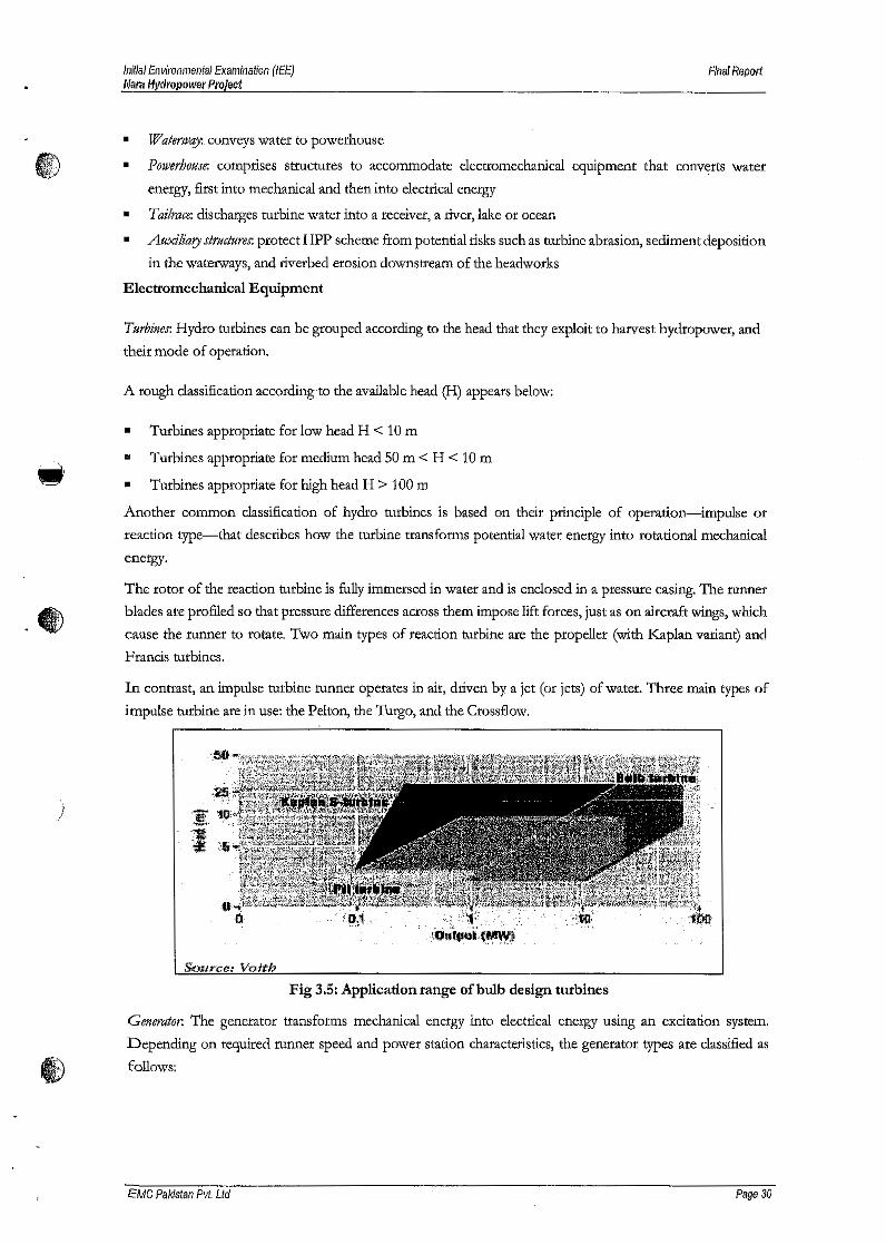
Initial Environmental Examination (lEE)Mam Hydropower Project
Final Report
• Watet'w~ conveys water to powerhouse
Powerhouse: comprises structures to accommodate electromechanical equipment that converts water
energy, first into mechanical and then into electrical energy
Tailrace: discharges turbine water into a receiver, a river, lake or ocean
Auxiliary strucft"t'eS: protect HPP scheme from potential risks such as turbine abrasion, sediment deposition
in the waterways, and riverbed erosion downstream of the headworks
Electromechanical Equipment
•
••
Turbines: Hydro turbines can be grouped according to the head that they exploit to harvest hydropower, and
their mode of operation.
A rough classification according to the available head (H) appears below:
""• Turbines appropriate for low head H < 10m
.. Turbines appropriate for medium head 50 m < H < 10m
• Turbines appropriate for high head H > 100 m
Another common classification of hydro turbines is based 011 their principle of operation-impulse or
reaction type-that describes how the turbine transforms potential water energy into rotational mechanical
energy.
&\.~
The rotor of the reaction turbine is fully immersed in water and is enclosed in a pressure casing. The runner
blades ate profiled so that pressure differences across them impose lift forces, just as on aircraft wings, which
cause the runner to rotate. Two main types of reaction turbine are the propeller (with Kaplan variant) and
Francis turbines.
In contrast, an impulse turbine runner operates in air, driven by a jet (or jets) of water. Three main types of
impulse turbine are in use: the Pelton, the Turgo, and the Ctossflow.
)
Source, Voitl.7
Fig 3.5: Application range of bulb design turbines
Generator. The generator transforms mechanical energy into electrical energy using an excitation system.
Depending on required runner speed and power station characteristics, the generator types are classified as
~ follows:
EMC Palcistan Pvt. Ltd Page 30
Innisi Environmental Examination (lEE)Mara Hydropower Project
Final Report
• Horizontal and vertical hydro generators are classified by their axis locations. Usually, large and medium-
CD sized units adopt a vertical layout; medium and small-capacity units adopt horizontal layouts.
• Brushless excitation generator and excitation with brush generator
• Synchronous generators are equipped with a DC electric or permanent magnet excitation system
associated with a voltage regulator that controls output voltage before the generator is connected to the
grid. Synchronous generator excitation is independent of the grid so synchronous generators can produce
power even without grid connection. Asynchronous generators are unable to regulate voltage output and
run at a speed related to system frequency; if isolated from the grid they cannot produce power because
their excitation current comes from the grid.
Typical generator efficiency in SHPP installation schemes increases with rated power. For very small units
(e.g., 10 kW') efficiency can be close to 90 percent; for larger capacities (> 1 l\I1W) efficiency approaches 98
percent.
Hydraulic Steel Structures
Hydraulic steel structures are installed in HPP schemes to control water flow using gates or valves and are
classified according to their operational purpose.
S ennce gates for continuous flow regulation in the waterway or of the water level in the reservoir include spillway
gates, bottom outlet gates, and lock gates (for navigation).
IlffAQ)
Emergenrygates are used to shut down water flow in conduits or open channels; typically they are designed only
to be fully open or fully closed and they include intake gates, gates upstream of penstock service valves, draft
tube gates, and gates installed upstream of bottom outlet gates
Maintenance gates are used to empty the conduit or canal for equipment maintenance (turbines, pumps or other
gates); the most common type is the stoplog gate.
Distributor vanes or turbine needle valves are used for flow regulation.
Trash racks (or screens) are nearly always required at pressure pipes entrances and intakes to prevent floating
debris from entering.
Grid Connection
)Before generated energy is transmitted through the grid, stepup transformers increase the voltage to reduce
energy losses in the lines. Generated electricity is transmitted to a gridconnection point where electricity is
converted to the voltage of the distribution network. In remote areas, new transmission lines can pose
considerable planning hurdles and costs; it is easier and more economical to locate an HPP scheme closer to
loads or existing transmission lines.
3.4 Overview of Run-of-the-riverHydropower
Run of River hydroelectric projects employ the natural elevation gradient of a flowing body of water to
generate electricity. Water is diverted from the main channel through a series of pipes that eventually turns
turbines in a power plant before returning to the river downstream. This is a method of energy generation
I) that is low impact on all three prongs: economic, social, and environmental. There are limited storage
reservoirs and large dams are not required for a project of this nature.
EMC Pakistan Pvt. Ltd Page 31
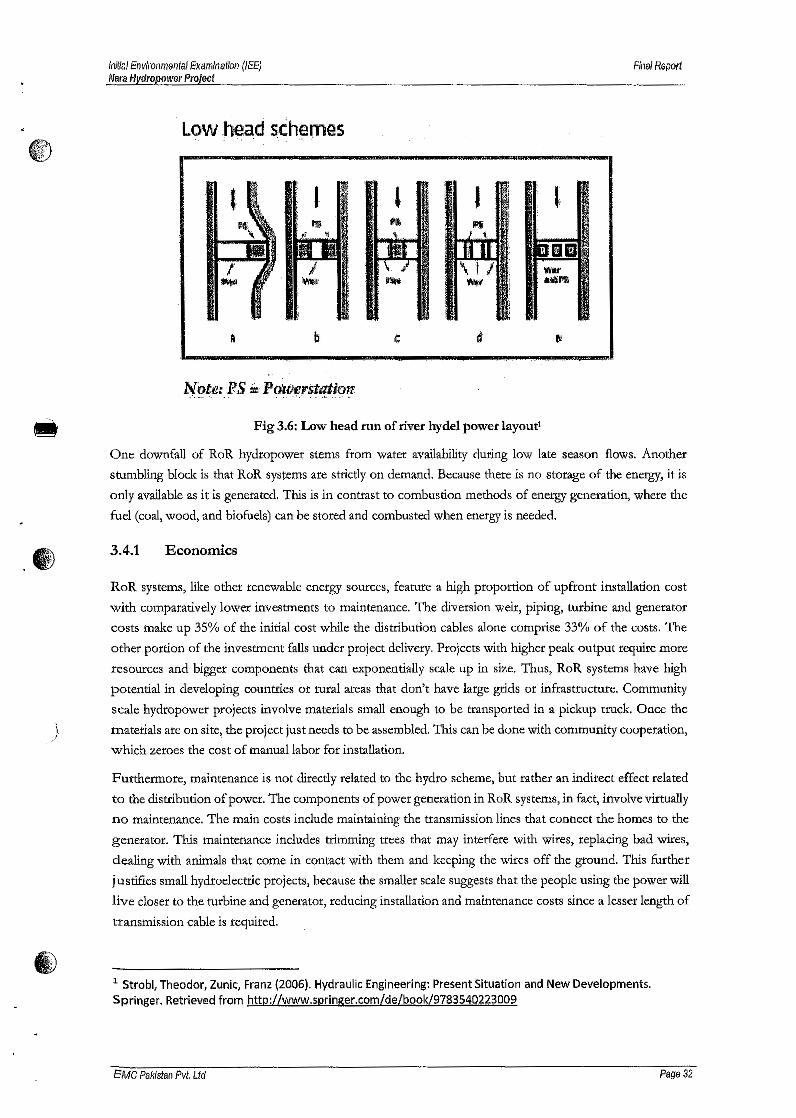
Initial Environmental Examination (lEE)filara Hydropower Project
Final Report
towhead schemes
I
·d
,~,to;te:PS .~.Po'r-tJerstation...... \ ' " .
Fig 3.6: Low head run of river hydel power layout'
One downfall of RoR hydropower stems from water availability during low late season flows. Another
stumbling block is that RoR systems are strictly on demand. Because there is no storage of the energy, it is
only available as it is generated. This is in contrast to combustion methods of energy generation, where the
fuel (coal, wood, and biofuels) can be stored and combusted when energy is needed.
3.4.1 Economics
RoR systems, like other renewable energy sources, feature a high proportion of upfront installation cost
with comparatively lower investments to maintenance. The diversion weir, piping, turbine and generator
costs make up 35% of the initial cost while the distribution cables alone comprise 33% of the costs. The
other portion of the investment falls under project delivery. Projects with higher peak output require more
resources and bigger components that can exponentially scale up in size. Thus, RoR systems have high
potential in developing countries or rural areas that don't have large grids or infrastructure. Community
scale hydropower projects involve materials small enough to be transported in a pickup truck. Once the
) materials are on site, the project just needs to be assembled. This can be done with community cooperation,
which zeroes the cost of manual labor for installation.
Furthermore, maintenance is not directly related to the hydro scheme, but rather an indirect effect related
to the distribution of power. The components of power generation in RoR systems, in fact, involve virtually
no maintenance. The main costs include maintaining the transmission lines that connect the homes to the
generator. This maintenance includes trimming trees that may interfere with wires, replacing bad wires,
dealing with animals that come in contact with them and keeping the wires off the ground. This further
justifies small hydroelectric projects, because the smaller scale suggests that the people using the power will
live closer to the turbine and generator, reducing installation and maintenance costs since a lesser length of
transmission cable is required.
1,11;:..WY
1Strobl, Theodor, Zunic, Franz (2006). Hydraulic Engineering: Present Situation and New Developments.Springer. Retrieved from http://www.springer.com/de/book/9783540223009
EMC Pakistan Pvt. Ltd Page 32
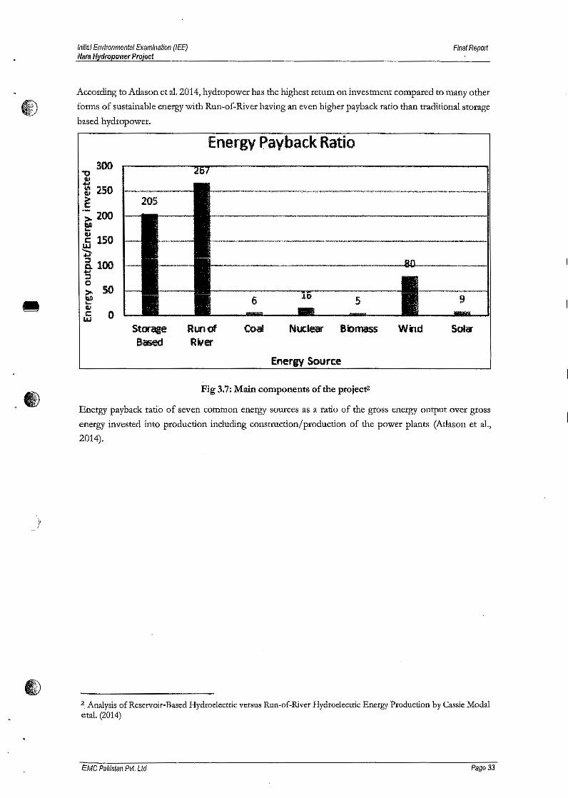
Initial Environmental Examination (lEE)Nara Hydropower Project
Final Repolt
According to Atlason et al. 2014, hydropower has the highest return on investment compared to many other
f) forms of sustainable energy with Run-of-River having an even higher payback ratio than traditional storage
based hydropower.
5
Energy Payback Ratio
StoraaeBased
Run ofRver
CoBi Nuclear Bbmass W~d
-WIFig 3.7: Main components of the projects
Energy payback ratio of seven common energy sources as a ratio of the gross energy output over gross
energy invested into production including construction/production of the power plants (Atlason et al.,
2014).
)'
2. Analysis of Reservoir-Based Hydroelectric versus Run-of-River Hydroelectric Energy Production by Cassie Modaleta!' (2014)
EMC Palristan Pvt. Ltef Page 33
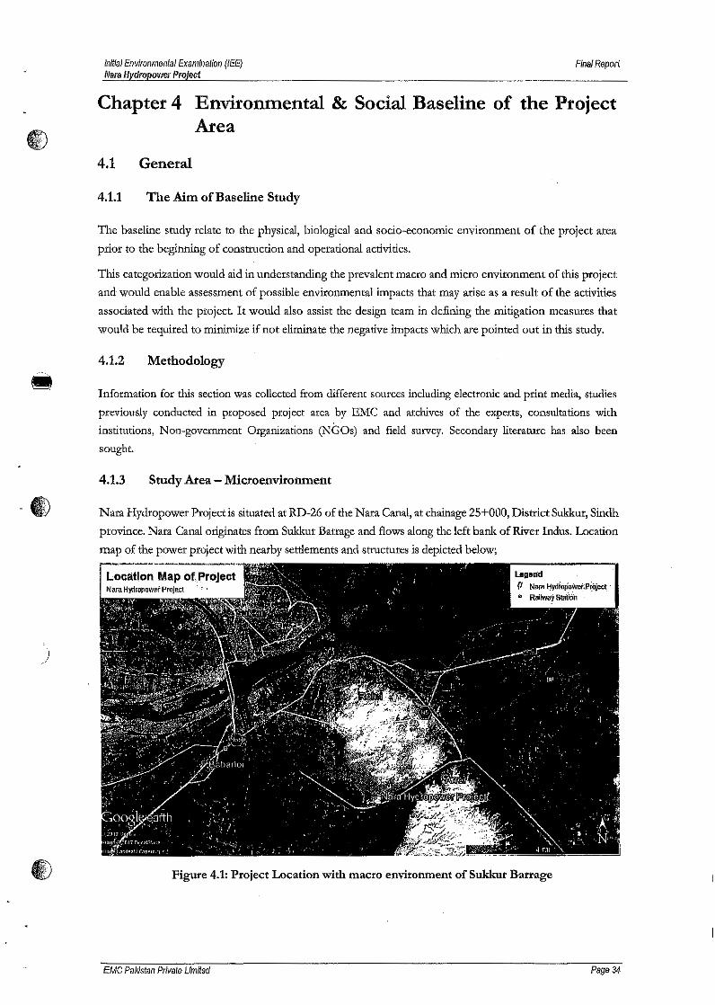
Initial Environmental Examination (lEE)Mara Hydropower Project
Final Report
Chapter 4 Environmental & Social Baseline of the ProjectArea
4.1 General
4.1.1 The Aim of Baseline Study
The baseline study relate to the physical, biological and socio-economic environment of the project area
prior to the beginning of construction and operational activities.
This categorization would aid in understanding the prevalent macro and micro environment of this project
and would enable assessment of possible environmental impacts that may arise as a result of the activities
associated with the project. It would also assist the design team in defining the mitigation measures that
would be required to minimize if not eliminate the negative impacts which are pointed out in this study.
4.1.2 Methodology
Information for this section was collected from different sources including electronic and print media, studies
previously conducted in proposed project area by EMC and archives of the experts, consultations with
institutions, Non-government Organizations (NGOs) and field survey. Secondary literature has also been
sought.
4.1.3 Study Area - Microenvironment
_1£0.~I Nara Hydropower Project is situated at RD-26 of the Nara Canal, at chain age 25+000, District Sukkur, Sindh
province. Nata Canal originates from Sukkur Barrage and flows along the left bank of River Indus. Location
map of the power project with nearby settlements and structures is depicted below;
)"
Location Map of,.ProJect
Figure 4.1: Project Location with macro environment of Sukkur Barrage
EMC Pakistan Private Limited Page 34
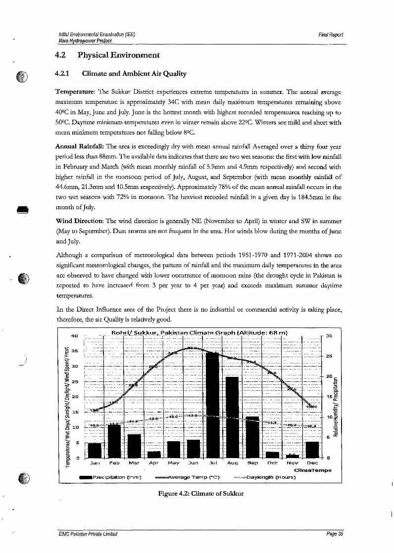
Initial Environmental Examlnat/on (lEE)Nays Hydropower Project
Final Report
Annual Rainfall: The area is exceedingly dry with mean annual rainfall Averaged over a thirty four yeal:period less than 88mm. The available data indicates that there are two wet seasons: the first with low rainfallin February and March (with mean monthly rainfall of 5.9mm and 4.9mm respectively) and second withhigher rainfall in the monsoon period of July, August, and September (with mean monthly rainfall of44.6mm, 21.3mm and 10.5mm respectively).Approximately 78% of the mean annual rainfall occurs in thetwo wet seasons with 72% in monsoon. The heaviest recorded rainfall in a given day is 184.5mm in the
.. month of July.
Wind Direction: The wind direction is generally NE (November to April) in winter and SW in summer(May to September). Dust storms are not frequent in the area. Hot winds blow during the months of Juneand July.
)
I/i;\"I1V
4.2 PhysicalEnvironment
4.2.1 Climate and Ambient Air Quality
Temperature: The Sukkur District experiences extreme temperatures in summer. The annual averagemaximum temperature is approximately 34C with mean daily maximum temperatures remaining above400C in May, June and July. June is the hottest month with highest recorded temperatures reaching up to500C. Daytime minimum temperatures even in winter remain above 220C. Winters are mild and shalt withmean minimum temperatures not fallingbelow 80C.
Although a comparison of meteorological data between periods 1951-1970 and 1971-2004 shows nosignificant meteorological changes, the pattern of rainfall and the maximum daily temperatures in the areaare observed to have changed with lower occurrence of monsoon rains (the drought cycle in Pakistan isreported to have increased from 3 per year to 4 per year) and exceeds maximum summer daytimetemperatures.
In the Direct Influence area of the Project there is no industrial or commercial activity is taking place,therefore, the air Quality is relativelygood.
40
Jan Feb Mar Apr May .)un .lui Aug Sap Oct Nov Dec:
ClinntTemps
~'~''''''Daylength (Hours)
Figure 4.2: Climate of Sukkur
EMC Pakistan Private Limited
30
25
o
Page 35
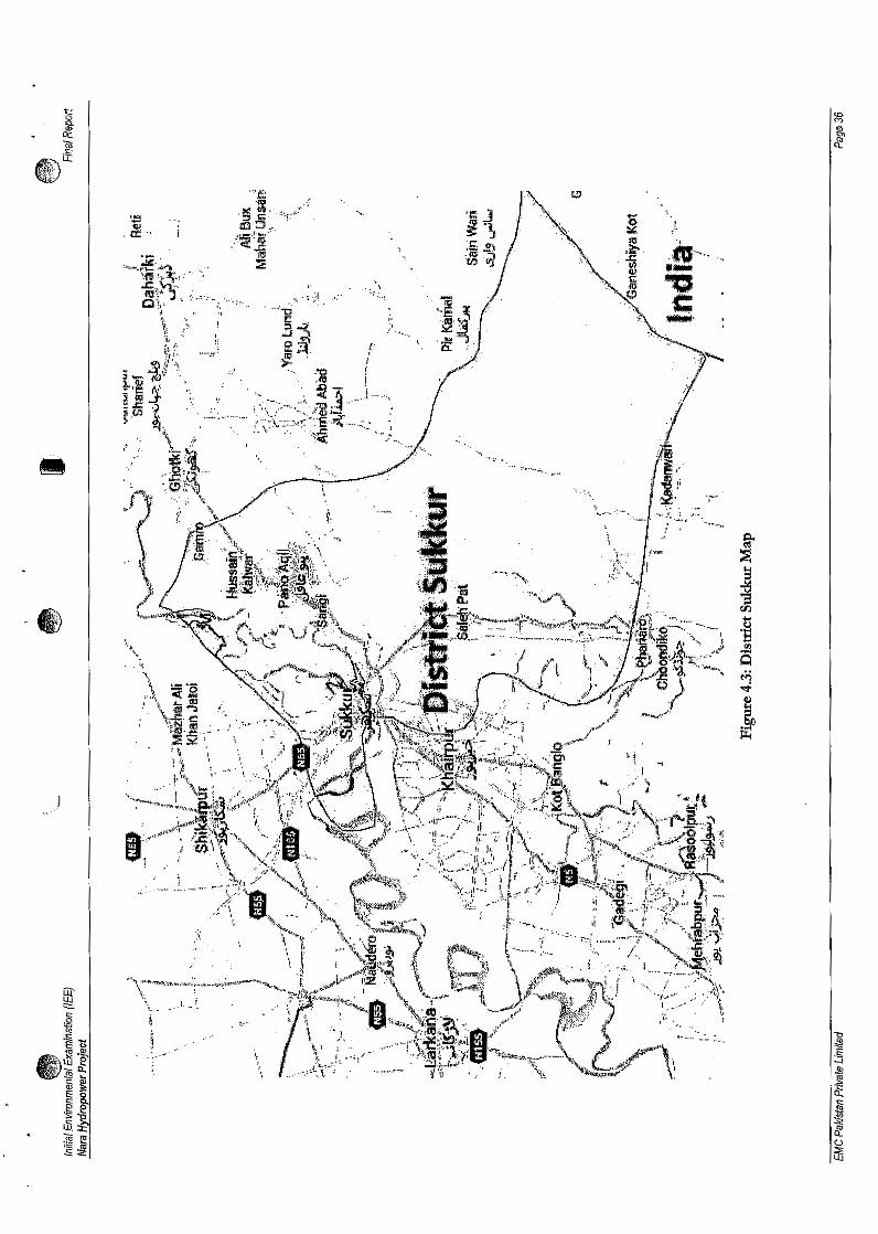
' ...... ~ ......~•...;......... :H
._ ....... ......... ..-~.~.,.
L _ ~.
·-~.......~
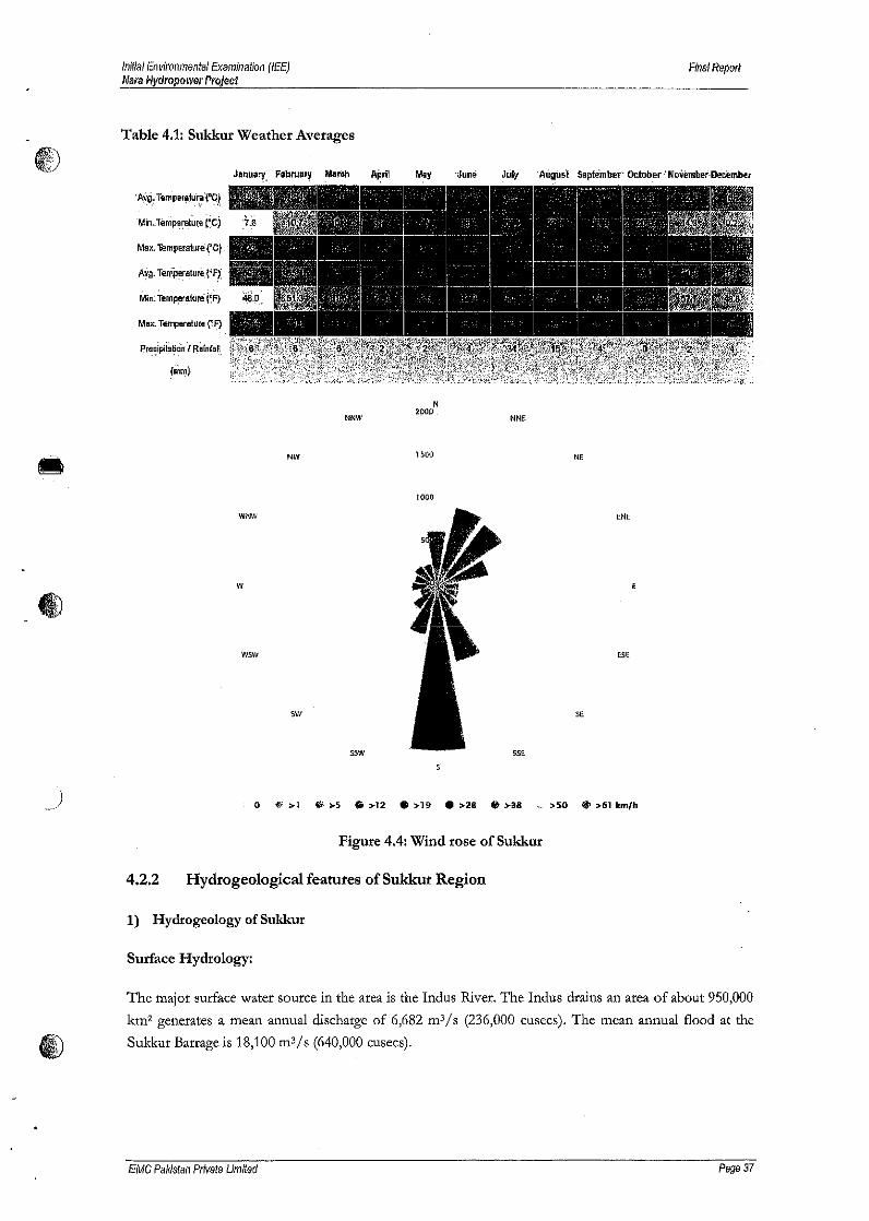
Iniflal Environmental Examination (lEE)Mara Nyclropower Project
Final Report
Table 4.1: Sukkur Weather Averages
P.11ia.ipii~tici:rr" H~rnf.n
(mm}
Febn.ta~ MarCh July .AilgU5'1 SeplembBt· OctDDI!f ' November·Deoember
'A,vg, TemJler~jui_;!('O,!
"'in.:remfMI~tu,et:cjMax, 'il!mpe!sll1JQ'('C,.
AVQ. TQmperature{'Ff
Min; TelllP!lIlfkJre (.~F)
Max. Temperalulfi (~FJ
NNW
N2900
NNE:
NW 1500 NE
1000
SW
ENEWNW
w
f),
WSW ESE
SE
SSW SSE
) o 'fi' >1 4IIl>5 • >12 • >1!} • >28 .. >98 '. >50 4iJIi >61 km/h
Figure 4.4: Wind rose of Sukkur
4.2.2 Hydrogeological features of Sukkur Region
1) Hydrogeology of Sukkur
Surface Hydrology:
The major surface water source in the area is the Indus River, The Indus drains an area of about 950,000
km2 generates a mean annual discharge of 6,682 m3/s (236,000 cusecs), The mean annual flood at theSukkur Barrage is 18,100 m3/s (640,000 cusecs).
EMC Pakistan Private Limited Page 37

Initial Environmental Examll1ation (lEE)Nara Nydropower Project·
Fillal Report
The hydrograph of the river is strongly seasonal with a long low water season between October and March
CD and a high water season between April and September - driven primarily by snowmelt in the upper
catchment and monsoon rainfall. The river usually peaks in mid-August or early September. The river
carries large sediment loads due to widespread and rapid erosion in its upper catchments. It is estimated
that about 1 billion m3 of sediment is deposited in its floodplain each year. As a result of this continuing
deposition, the river has developed natural levees along its length.
Three barrages Guddu, Sukkur, and Kotri regulate river flows in Sindh. Six canals take off from Sukkur
barrage for irrigation purposes. These include Dadu Canal, Nara Canal, Rohri Canal, Rice Canal, N.W Canaland Khitthar Canal.
Groundwater:
In Sukkur, Ground water at Numaish Gah and Bunder Road is saline. Drawing of large quantity of water
makes ground water more saline. The water table in the area along canals and Indus ranges from 12ft to
lit 20ft with a gradient generally oriented southwards. Groundwater for domestic consumption is abstracted
through shallow hand pumps (with motors installed on some). These hand pumps are usually dug to a
depth of 20 to 30ft. Water quality is generally sweet, but very few brackish groundwater can also be found.
Tube wells installed for supplementing canal irrigation are dug to depths of 75ft to 100ft. The water supply
for Sukkur and Rohri cities is also abstracted directly from the Indus.
Sweet groundwater is found in the areas along the canal network and River Indus. However a relative
decline from previous years has been reported. This has mainly been due to over abstraction through deep
tube wells installed for supplementing canal irrigation.
Water Quality:
_)
Intensification of water use in Pakistan threatens the quality of water in the Indus. Rapid population growth
over the past half century has intensified the pressure on agriculture and the need for irrigation water. The
management of the flow has historically been inefficient because of poor water storage capacity, seepage,
and inadequate maintenance of reservoirs. Heavy irrigation and seepage have overwhelmed the drainage of
irrigated land, leading to accumulation of salts on the surface of the soil and rendering large tracts of land
unfit for agricultural production. These inefficiencies have prevented the country from attaining food self-
sufficiency.
Environmental degradation of the Indus River has created additional health risks for the population. Water
pollution in the Indus comes from a number of sources, including return flow from agriculture, which adds
sodium nitrates, phosphates, and pesticides to the river. Additionally, untreated or incompletely treated
sewage from cities along the Indus is discharged into the river. The river also receives a wide range of
industrial waste: organic matter and ions such as sodium, potassium, calcium, magnesium, carbonates,
bicarbonates, and chloride as well as inorganic wastes such as fluoride, silica, and cyanide. Finally, thermal
power plants along the Indus cause sudden increases in surface water temperature that harm marine life.
e Much of the population along the Indus depends on the river for drinking water, and boiling does not
remove polluting chemicals. Water pollution in the Indus River has reduced the species diversity of fish
EMC Pakistan Private Limited Page 38

Initial Environmental Examination (lEE)Nata Hydropower Project .
Filial Report
and decreased the supply of subsistence food for many who live near the river. In parts of the lower Industo delta, mangroves that were once abundant with marine life and an important source of food for coastal
populations have almost disappear because of the toxic effect of polluted water that flow into this
ecosystem.
Regional climate change also threatens the future of the Indus water flow and the millions of people who
depend on it. The recent fast pace of glacier melt and warmer temperatures may lead to a serious diminution
of river flow. One of the suspected reasons for the rapid melting of these glaciers is settling of aerosolized
soot and particles on the icy surface. This "Asian brown cloud," caused by the burning of fossil fuels and
biomass by the more than one billion people who live on the subcontinent, can be seen from outer space.
As the cloud settles on the white glacial ice, light and heat are absorbed rather than reflected, melting the
ice. Even a small decrease in the flow in the rivers fed by these glaciers would have huge consequences for
agricultural production and human life':
According to "Status of drinking water, quality of surface and ground water sources in Sindh" submitted
to Sindh High Court in July 2017, 30 water samples were collected from surface and ground water sources
in Sukkur and 25 (83.3pc) were found unsafe for human consumption.
Coliforms /E.Coli were also found in drinking water. Coliforms and E.coli is normal flora of human
intestine and are excreted along with stool. This is an indicator group of bacteria which if present in water
means that water is contaminated with feces. As disease like Typhoid, Dysentery, Diahorrea, Cholera,
Hepatitis can also be transmitted tlu:ough feces and it is highly risky to drink contaminated water.
According to WHO there should be no Coliforms /E.Coli in 100 ml of water. At present, sources of water
contamination are open defecation, un-controlled disposal of domestic and livestock wastes (especially in
tars) by local communities; however, no quantitative analysis of the extent of this Contamination is
available.
Water Supply and Drainage/Sewerage:
)Potable Water Supply is a pre-requisite for the health of people. Lack of proper drinking Water Supply and
Sanitation in rural as well urban areas has caused wide spread water borne diseases of which diarrhea (among
small children) happens to be a major killer. The diseases are transmitted by water and poor sanitation
which deplete human energy resulting in sickness reducing thereby the productivity of the people.
Water Supply is vitally important sector for the urban and rural population of the district. The rural
population distribution in the district is quite unique in the sense that it has fewer larger villages and a very
large number of small settlements, most of which can hardly be called "Villages"; they are essentially on the
farm clusters of population "Widely Scattered". According to present arrangements Water Supply and
Drainage facilities are being provided to the people by the Departments i.e. Public Health Engineering
Department and Rural Development Department.
3 Gregory Pappas (2011). Pakistan and Water: New Pressures on Global Security and Human Health. Am JPublic Health. 2011 MaYi 101(5): 786-788.
EMC Pakistan Private Limited Page 39
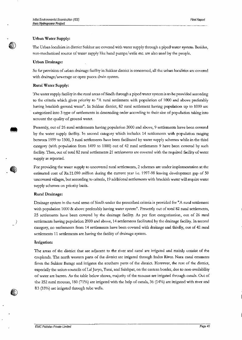
Initial Environmental Examination (lEE)NarIJ Hydropower Project
Filial Report
Urban Water Supply:
The Urban localities in district Sukkur are covered with water supply through a piped water system. Besides,
non-mechanized source of water supply like hand pumps/wells etc. are also used by the people.
Urban Drainage:
So far provision of urban drainage facility in Sukkur district is concerned, all the urban localities are covered
with drainage/sewerage or open pucca drain system.
Rural Water Supply:
The water supply facility in the rural areas ofSindh through a piped water system is to be provided according
to the criteria which gives priority to "A rural settlement with population of 1000 and above preferably
having brackish ground water". In Sukkur district, 82 rural settlement having population up to 1000 are
categorized into 3 type of settlements in descending order according to their size of population taking into
account the quality of ground water.
Presently, out of 26 rural settlements having population 2000 and above, 9 settlements have been covered
by the water supply facility. In second category which includes 14 settlements with population ranging
between 1999 to 1500, 3 rural settlements have been facilitated by water supply schemes while in the third
category (with population from 1499 to 1000) out of 42 rural settlements 9 have been covered by such
facility. Thus, out of total 82 rural settlements 21 settlements are covered with the required facility of water
supply as reported.
For providing the water supply to uncovered rural settlements, 2 schemes are under implementation at the
estimated cost of Rs.11.090 million during the current year i.e, 1997-98 leaving development gap of 59
uncovered villages, but according to criteria, 19 additional settlements with brackish water will require water
supply schemes on priority basis.
Rural Drainage:
Drainage system in the rural areas ofSindh under the prescribed criteria is provided for "A rural settlement
with population 1000 & above preferably having water system". Presently out of total 82 rural settlements,
25 settlements have been covered by the drainage facility. As per first categorization, out of 26 rural
) settlements having population 2000 and above, 14 settlements facilitated by the drainage facility. In second
category, no settlements from 14 settlements have been covered with drainage and thirdly, out of 42 rural
settlements 11 settlements are having the facility of drainage system.
Irrigation:
The areas of the district that are adjacent to the river and canal are irrigated and mainly consist of the
croplands. The north western parts of the district are irrigated through Indus River. Nara canal emanates
from the Sukkur Barage and irrigates the southern parts of the district. However, the test of the district,
especially the union councils of Lal Juryo, Tarai, and Salehpat, on the eastern border, due to non-availability
of water are barren. As the table below shows, majority of the mouzas ate irrigated through canals. Out of
the 252 rural mouzas, 180 (71%) are irrigated with the help of canals, 36 (14%) are irrigated with river and
83 (33%) are irrigated through tube wells.
eMC Pailistan Private Limited Page 40
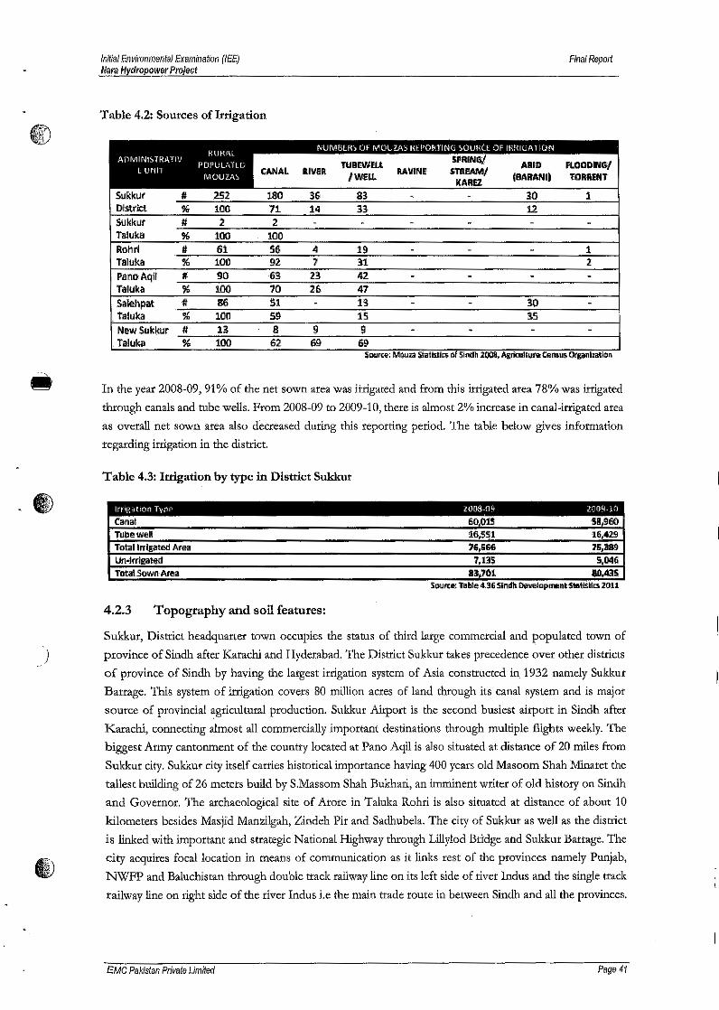
)
initial Environmental Examination (lEE)Wara Hydropower Project
Final Report
Table 4.2: Sources of Irrigation
RohrlTalukaPSl'loAqlfTalukaSal~hpatTalukaNew SukktJrTaluka
In the year 2008-09, 91% of the net sown area was irrigated and from this irrigated area 78% was irrigated
through canals and tube wells. From 2008-09 to 2009-10, there is almost 2% increase in canal-irrigated area
as overall net sown area also decreased during this reporting period. The table below gives information
regarding irrigation in the district.
Table 4.3: Irrigation by type in District Sukkur
Irng"tloIi TYPQ If)l)[1-o9 20(19·10
~l'lal 60;()iS S!I,960Ttlbewell !l6,S~1 16,429Total Irrigated Area 7&,S66 71i,aag,Un·lrrigatttd 7,1115 5j046Total SQ'Wfl'Area 8J,101 10,435
SO\II'(e:Table 4.36 Sind" D!M!Iapment$tatiStil:S 2011
4.2.3 Topography and soil features:
Sukkur, District headquarter town occupies the status of third large commercial and populated town of
province of Sindh after Karachi and Hyderabad. The District Sukkur takes precedence over other districts
of province of Sindh by having the largest irrigation system of Asia constructed in. 1932 namely Sukkur
Barrage. This system of irrigation covers 80 million acres of land through its canal system and is major
source of provincia! agricultural production. Sukkur Airport is the second busiest airport in Sindh after
Karachi, connecting 'almost all commercially important destinations through multiple flights weekly. The
biggest Army cantonment of the country located at Pano Aqil is also situated at distance of 20 miles from
Sukkur city. Sukkur city itself carries historical importance having 400 years old Masoom Shah Minaret the
tallest building of 26 meters build by S.Massom Shah Bukhari, an imminent writer of old history on Sindh
and Governor. The archaeological site of Arore in Taluka Rohri is also situated at distance of about 10
kilometers besides Masjid Manzilgah, Zindeh Pir and Sadhubela. The city of Sukkur as well as the district
is linked with important and strategic National Highway through Lillylod Bridge and Sukkur Barrage. The
city acquires focal location in means of communication as it links rest of the provinces namely Punjab,
NWFP and Baluchistan through double track railway line on its left side of river Indus and the single track
railway line on right side of the river Indus i.e the main trade route in between Sindh and all the provinces.
£MC Pakistan Private Limited Page 41

Initial Environmental Examination (lEE}Nars Hydropower Project
Fina! Report
The important industries of the district ate sugar, edible oil/ ghee, leather, tobacco, rice, cotton ginning, oil
€) mills, flour mills, biscuit factory etc.
Topographically, the district may be divided into two broad parts. A plain cultivated area in the western
half and a desert in the eastern half. With the exception of the low limestone hills running from the town
of Rohrl towards the south, and-on the west of Nata Canal. The test of the area of the district in the western
half, is flat and level plain. The hills vary in elevation from 100 to 125 meters. There are four prominent
hills namely, Adam Shah hills near Sukkur, Kalka hills at Arore, Laheri hills at Rohri and Shadi Shaheed
hills at Kandahra, The eastern half of the district is a waste land. It consists of barren tract of clay and ridges
of sand hills covered with caper and thorn jungle.
In the Project area, the rocks belong to Paleozoic, Mesozoic and Tertiary Geological timescale. Soils of
river plain are generally loamy, clayey and seasonally flooded soils. In Some areas of Sukkur salt affected
soils are also present. The Rohri hills area is designated as rough mountainous land. These soils found along
river i.e. Loamy and some sandy stratified soils (Torrifluvents and Torripsamments) of recent river plains.
4.2.4 Seismicity
According to the seismic zone map of Pakistan, the Project Area lies in the zone where minor to medium
damage can occur as shown in figure below;
)
Figure 4.5: Seismic Zones of Pakistan
4.3 Descriptionof BiologicalEnvironment
Habitats:
'The main habitat within the macroenvironment of project area - Indus River along with banks and Bukkur
Island. Description of the habitat along with the flora and fauna attributes is provided is the subsequent
paragaphs.
EMC Pakistan Private Limited Page 42
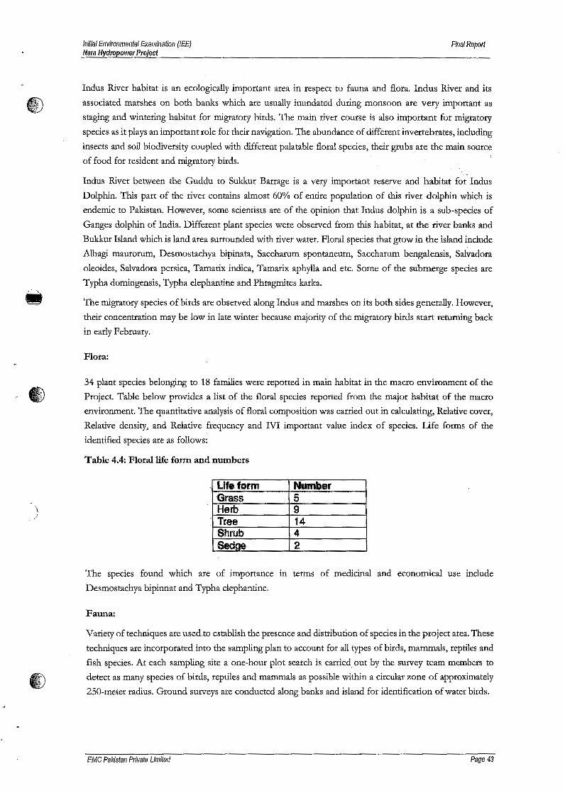
Initial Environmentel Examination (lEE)Nliral-fydropowfJl' Project
Final Report
Indus River habitat is an ecologically important area in respect to fauna and flora. Indus River and its
associated marshes on both banks which are usually inundated during monsoon are very important as
staging and wintering habitat for migratory birds. The main river course is also important for migratory
species as it plays an important role for their navigation. The abundance of different invertebrates, including
insects and soil biodiversity coupled with different palatable floral species, their grubs are the main source
of food for resident and migratory birds.
Indus River between the Guddu to Sukkur Barrage is a very important reserve and habitat for Indus
Dolphin. This part of the river contains almost 60% of entire population of this river dolphin which is
endemic to Pakistan. However, some scientists are of the opinion that Indus dolphin is a sub-species of
Ganges dolphin of India. Different plant species were observed from this habitat, at the river banks and
Bukkur Island which is land area surrounded with river water. Floral species that grow in the island include
Alhagi maurorum, Desmostachya bipinata, Saccharum spontaneum, Saccharum bengalensis, Salvadora
oleoides, Salvadora persica, Tamarix indica, Tamarix aphylla and etc. Some of the submerge species are
Typha domingensis, Typha elephantine and Phragmites karka.
The migratory species of birds are observed along Indus and marshes on its both sides generally. However,
their concentration may be low in late winter because majority of the migratory birds start returning back
in early February.
Flora:
34 plant species belonging to 18 families were reported in main habitat in the macro environment of the
Project. Table below provides a list of the floral species reported from the major habitat of the macro
environment. The quantitative analysis of floral composition was carried out in calculating, Relative cover,
Relative density, and Relative frequency and IVI important value index of species. Life forms of the
identified species are as follows:
'Table 4.4: Floral life form and numbers
)./
LlfefQrm Number·Grass 5Herb 9Tree 14Shrub 4Sedae· :2
The species found which are of importance in terms of medicinal and economical use include
Desmostachya bipinnat and Typha elephantine.
Fauna:
Variety of techniques are used.to establish the presence and distribution of species in the project area. These
techniques are incorporated into the sampling plan to account for all types of birds, mammals, reptiles and
fish species. At each sampling site a one-hour plot search is carried out by the survey team members to
detect as many species of birds, reptiles and mammals as possible within a circular zone of approximately
250-meter radius. Ground surveys are conducted along banks and island for identification of water birds.
EMC Pakistan Private Limited Page 43

iniliaIEnvironmental Examination (lEE)Mara Hydropower Project
Final Report
Protected Area:
G) Project is not located in or in a buffer zone of any protected Area. However, Indus Dolphin Reserve QDR),
the area between Guddu and Sukkur Barrages, lies over 7km from the project site.
Indus Dolphin Reserve (lDR), with an area of 125,000 hectares, notified in 1974 under the Sindh Wildlife
Protection Ordinance is a 200km stretch of Indus, situated in northern part of the Sindh province starting
from Guddu Barrage and ending at Sukkur Barrage. This Reserve has the biodiversity of great global
significance and stronghold of the endemic river dolphin of Pakistan known as Indus or Blind Dolphin. In
addition, the rivet bellas/belo and riverine forests provide habitat for Hog deer, Fishing cat and Smooth-
coated otter in addition to game birds like Grey and Black partridges. Indus River as such provides
navigation to the migratory birds when they travel to their wintering grounds (during autumn) and breeding
grounds (during spring). IDR is a protected area of high profile and is continuously monitored by the Sindh
Wildlife Department. In addition, this area is part of a recently launched Pakistan Wetlands Program which
is being implemented jointly by the Federal Ministry of Environment and WWF Pakistan with financial
assistance ofUNDP IGEF and Royal Netherlands Embassy (RNE) in Islamabad. In a recent survey (April,
2011) conducted in Indus Dolphin Reserve. While the population of Indus Dolphin in lDR has been
estimated 1171. According to the survey of Sindh Wildlife Department (SWD) and Global Environmental
Services, 918 Dolphins including young animals were recorded within limits of the Guddu to Sukkur
Barrage. IDR had been designated as Ramsar wetland site no. 1065 in 20014.
)
Lilliond·-·O'~~m;,M·
--.1Ii I.n~~.D~~~10R~tye:_DPIphIn:~;!.I'~o~ l1!-;;;,.'O""'''''''~~'Y.,'· '.
Figure 4.6: Location of Indus Dolphin Reserve
4 Retrieved from Ramsar site information service; https://rsis.ramsar.org/ris/l065
£MC Pakistan Private Limited Page 44
Iniiial Environmental Examination (lEE)Mara Hydropower Project
Final Report
Birds.
41 species of birds were recorded from the area. Abundant species include: bank myna, little green bee-
eater, white-cheeked bulbul, crested lark, pied bushchat, common babbler, house crow, common myna and
house sparrow.
Along with resident species, a few winter visitors are also recorded viz. black redstart, lesser whitethroat,
Common Chiffchaff, Common Sandpiper and yellow wagtail. Out of 41 recorded species, 19 are abundant,
21 are common, 1 less common while no species is rate in Pakistan. Depending upon the degree of threat,
8 (including Cattle Egret, Eurasian Kestrel, Grey Heron, Indian Pond Heron, Large Egret, Little
Cormorant, Little Egret and Marsh Harrier) are declared protected under the Sindh Wildlife Ordinance,
Longtailed Grass Warbler is listed in mCN Red List 2006, 3 (including Eurasian Kestrel, Little Stint and
Redshank) are covered in CMS and 6 (including Eurasian Kestrel, Little Stint and Redshank, Eurasian
Kestrel, Little Brown Dove, Marsh Harrier and Rose-ringed Parakeet) in CITES Appendices.
Mammals:
8 species of mammals were recorded during the field visit. Out of these 8, 4 are common, 3 are less common
while 1 is rare. Out of these 8 mammals, one species Indus dolphin is of global significance including, which
is listed in mCN Red List 2006 and is also protected under Sindh Wildlife Protection Ordinance. As per
Sindh Wildlife Department the total population of Indus Dolphin within the project area is around 40-50.
However during the field visit only 6 Indus Dolphin were sighted directly. Small mammals mainly gerbils,
birds, rats and mice are common as was noticed by their burrow system. These small mammals are a main
source of food for raptors and carnivore species and have an important role in the food web. A brief
description of the Indus. Smooth-coated Otter (Lutrogale perspicillata) is reported from Nata Canal. Its
distribution in Sindh has greatly declined due to disturbance and habitat destruction. It is found in Upper
Nara Canal in Khairpur district and lower Nara canal in Sanghar.
Blind Indus Dolphin (Platanista minor). Indus Blind Dolphin is probably the most specialized of the
world's fresh-water dolphins. Head and body length is 1.75-2.75 meters. Its rostrum is very narrow
proximally, 21-30 teeth on each side of jaw. Once it was common in Indus and all its tributaries but now it
is confined to the Central Indus. It is a quite social animal and has the schools up to 10 animals. Since the
Indus dolphins are blind, they continuously use echo-location technique to locate their prey and other
objects.
lE:\QD
As per observations of different scientists, the Indus dolphins start their courtship in March and early April
and most of the births take place during the same period. According to the survey conducted by Worldwide
Fund for Nature, Pakistan, the total population of Indus dolphin is more than one thousand in its entire
habitat. More than 60% is in Indus Dolphin Reserve (between Guddu and Sukkur Barrages). During the
flood season, sometimes, the dolphins are pushed to the canal system from the barrage gates. These
stranded dolphins are sometimes killed by the fishermen. Sindh Wildlife Department with the help ofWWF
Pakistan and Lahore Zoo has started a rescue program under which these stranded dolphins are captured
from canals and released back to Indus River. Because of its declining status, it is listed as "Endangered"
in IUCN Red List 2004. Indus dolphin may be seen in Indus waters throughout the project area. However,
upstream of Sukkur Barrage is its stronghold
EMC Palristan Private Limited Page 45

Initia! EllvilDllmental Examination (lEE)Nara Hydropower Project
Final Report
Echo location method in Indus Dolphin: The Indus River dolphin is functionally blind having evolvedwithout a crystallinelens orwell-developed light sensitiveorgan. A deep fold iust above the dolphin's mouthis the remnant of what might once have been eyes down the evolution line, However, this is not adisadvantage but an adaptation to living in the silt-laden turbid waters of the Indus where eyes are virtuallyuseless, as very little light penetrates below the su.rface of the murky water, Giorgio Piller! conductedresearch on two Indus dolphin kept in an aquarium in Switzerland during 1970. He has described the sonarsystem used by the Indus dolphins to locate any object or fish in turbid waters of Indus (The Secrets ofThe Blind Dolphins). Indus Dolphins has the ability to produce high-pitched clicks (Indus dolphin canproduce ultrasonic frequencies of over 20,000 Hz.
While a normal human can hear the audio frequencies in the 20-20,000 Hz. (range).These sound pulses areemitted into the water through the 'melon' at the front of the dolphin's head. When these clicks hit anobject, some of the sound echoes back to it. By listening to the echo and interpreting the time it took theecho to come back, the dolphin senses the distance of the object. This gives the dolphin some informationabout the structure and size of the object. By moving its head, the dolphin can get more information on
.. other aspects of the object
Reptiles:
A total of 9 reptile species including 2 species of fresh-water turtles were recorded from the project areaduring the field visit of which 5 are common, 4 are less common and none is rare. Comparativelyuncommon species include Indian cobra which is encountered in riverine and densely vegetative areas.Marsh Crocodiles are also reported in the Canal, However their main habitat is Nata Wetland LandComplex, in Khairpur District. About 198 Marsh Crocodiles are reported in the Nara Wetland Complex,out of Sindh's 480. The number of recorded species of reptiles is low during winter. It is expected thatmore species of reptiles may be recorded after the winter season as most of the reptiles hibernate duringwinters.
Out of 9 recorded species, Indian Monitor is protected under the Sindh Wildlife Protection Ordinance and4 (including Indian Cobra, Indian Monitor, Indian Soft-shell Turtle and Indian Pound Tuttle) are listed ondifferent Appendices of CITES in view of their importance for international trade.
)
Freshwater Turtles
There are eight.species of freshwater turtles found in the river Indus. The taxonomic classification is givenbelow;
Class Orderclass order
~~ ell
ell Ja~ '" ~ Bat ! B 5I) ~ '"~,
EMC Pa/(istan Private Limited Page 46
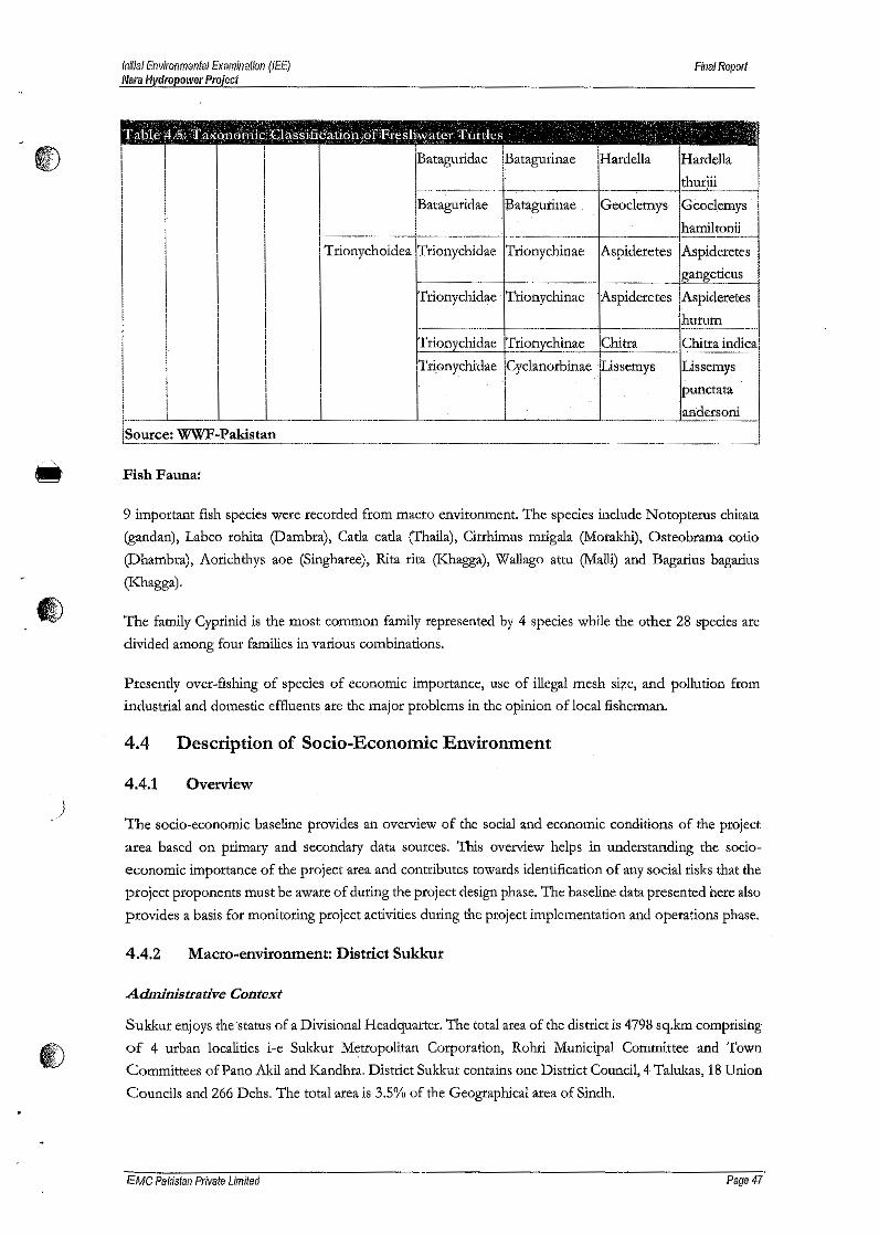
Inifial Environmental ExamInation (lEE)Mara Hydropower Project
Final Report
iII
I!I1··--ISource: WWF-P
Fish Fauna:
i Bataguridae Batagurinae Hardella HardellaI.~-.~. ---- --------,.----- Ql~l_·i___
Bataguridae Batagurinae Geoclemys Geoelemys
_._.__ ._--_ . harniltonii--Trionychoidea Trionychidae Trionychinae Aspideretes Aspideretes
gangeticusI
Trionychidae . Trionychinae •Aspideretes .Aspideretes
lhurumTrioD_y_chidae~rionychinae Chitta Chitta indica
Tlii.on_ychi-ciae. Cyclanorbiaae :Ussemys· US$emys
.Lpunctata
aadersoni..akistan
- ..-
9 important fish species were recorded from macro environment. The species include Noropterus chitata
(gandan), Labeo rohita (Dambra), Carla carla (Thaila}, Cirrhimus mrigala (.Morakhi), Osteobrama cotio
(Dhambra), Aorichthys aoe (Singharee), Rita rita (Khagga), Wallago attu (Malli) and Bagarius bagarius
(Khagga).
The family Cyprlnid is the most common family represented by 4 species while the oilier 28 species are
divided among four families in various combinations.
Presently over-fishing of species of economic importance, use of illegal mesh size, and pollution from
industrial and domestic effluents are the major problems in the opinion of local fisherman.
4.4 Description of Socio-Economic Environment
)4.4.1 ()vervie~
The socio-economic baseline provides an overview of the social and economic conditions of the project
area based on primary and secondary data sources. 'Ibis overview helps in understanding the socio-
economic importance of the project area and contributes towards identification of any social risks that the
project proponents must be aware of during the project design phase. The baseline data presented here also
provides a basis for monitoring project activities during the project implementation and operations phase.
4.4.2 Macro-environmenn District Sukkur
Administrative Context
Sukkur enjoys the status of a Divisional Headquarter. The total area of the district is 4798 sq.km comprising
of 4 urban localities i-e Sukkur Metropolitan Corporation, Rohri Municipal Committee and Town
Committees ofPano Akil and Kandhra, District Sukkur contains one District Council, 4 Talukas, 18 Union
Councils and 266 Dehs. The total area is 3.5% of the Geographical area of Sindh.
EMC Pakistan Private Umiled Page 47
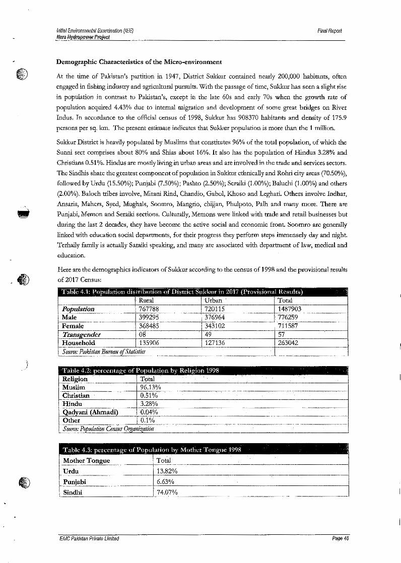
Inff/alEnvironmel1lal Examination (lEE)Nara Nydropower Project
Final Repolt
Demographic Characteristics of the Micro-environment
C"0 At the time of Pakistan's partition in 1947, District Sukkur contained nearly 200,000 habitants, often
engaged in fishing industry and agricultural pursuits. With the passage of time, Sukkur has seen a slight rise
in population in contrast to Pakistan's, except in the late 60s and early 70s when the growth rate of
population acquired 4.43% due to internal migration and development of some great bridges on Rivet
Indus. In accordance to the official census of 1998, Sukkur has 908370 habitants and density of 175.9
persons per sq. km. The present estimate indicates that Sukkur population is more than the 1 million.
Sukkur District is heavily populated by Muslims that constitutes 96% of the total population, of which the
Sunni sect comprises about 80% and Shias about 16%. It also has the population of Hindus 3.28% and
Christians 0.51 %. Hindus arc mostly living in urban areas and are involved in the trade and services sectors.
The Sindhis share the greatest component of population in Sukkur ethnically and Rohri city areas (70.50%),
followed by Urdu (15.50%); Punjabi (7.50%); Pashto (2.50%); Seraiki (1.00%); Baluchi (1.00%) and others
(2.00%). Baloch tribes involve, Miraui Rind, Chandio, Gabol, Khoso and Leghari, Others involve Indhar,
Ansaris, Mahers, Syed, Mughals, Soomro, Mangrio, chijjan, Phulpoto, Palh and many more. There are
Punjabi, Memon and Seraiki sections. Culturally, Memons were linked with trade and retail businesses but
during the last 2 decades, they have become the active social and economic front. Soornro are generally
linked with education social departments, for their progress they perform steps immensely day and night.
Terhaily family is actually Saraiki speaking, and many are associated with department of law, medical and
education.
~). 'Il~/
Here are the demographics indicators of Sukkur according to the census of 1998 and the provisional results
of 2017 Census:
J Table 4.2: percentage of Population by Religion 1995 t,Religion T9talMuslim 96.13%--.- ··0.51% .Christian
I Hindu ~ 3.28% - --_._._--Qadyanf(Ahmadi)- .. ,':0.04%Other 10.1%S of/ree: Population Census Qtganij"aiion ..
ITabk 4.3: perccntage of Population by Mother Tongue 1998 1
Urdu 13.82%.-...--.----,--------+...:::..::..:..:..:~-------~Punjabi 6.63%
L Sindhi 74.07%
Mother Tongue t Total·
EMC Pakistan Private Limited Page 48
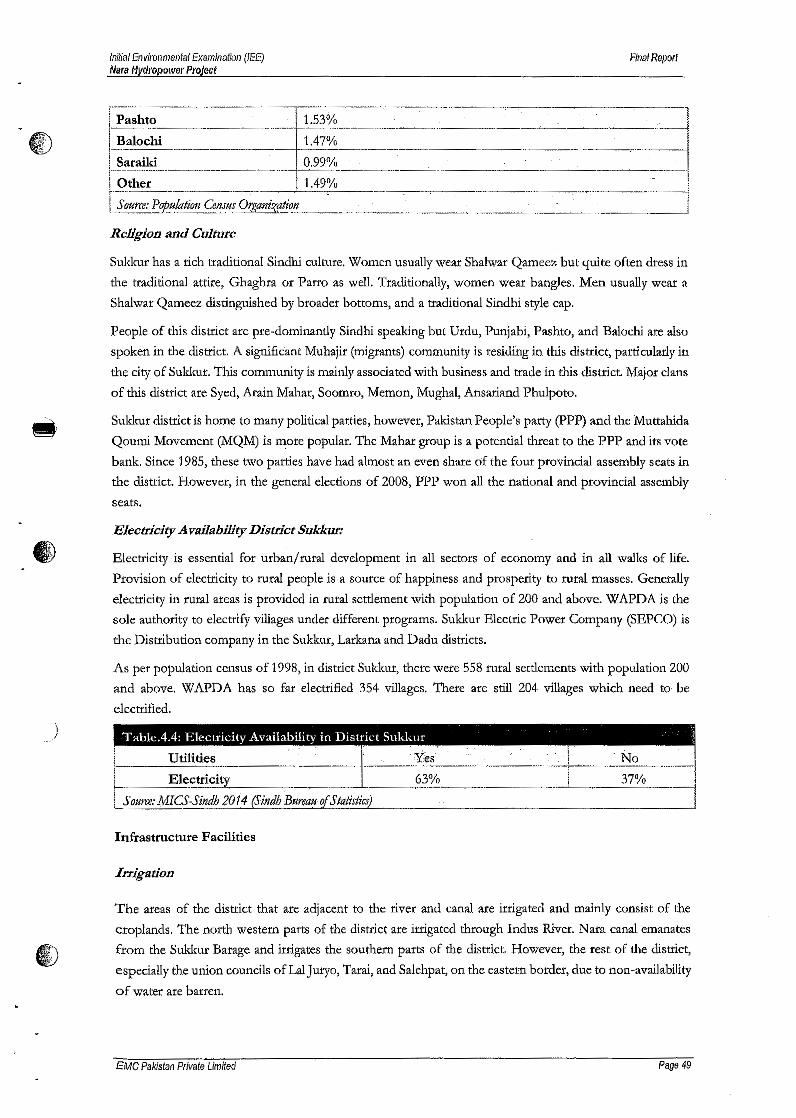
Initial Environmental Examination (lEE)Nara Hydropower Project
Final Report
R\V
f'P~shto .- 1_53%------_------_ .._._..... .~--- ....-_- -.--.- ...~--...•----.---.-. -_. ---":__;_---' ..~~-.
-_-- .-_-.--
Baloehi 1.47% -------.----~.-----ISaraiki 0.99%r·-Ofu~~-·-·---------------1.49010----· --- ...--
1"'.-------. .I S OHm: Population Census OrgaflizatiotJ
Religion and Culture
Sukkur has a rich traditional Sindhi culture. Women usually wear Shalwar Qameez but quite often dress in
the traditional attire, Ghaghra or Parro as well. Traditionally, women wear bangles. Men usually wear a
Shalwar Qameez distinguished by broader bottoms, and a traditional Sindhi style cap.
People of this district are pre-dominantly Sindhi speaking but Urdu, Punjabi, Pashto, and Balochi are also
spoken in the district. A significant Muhajir (migrants) community is residing in this district, particularly in
the city of Sukkur, This community is mainly associated with business and trade in this district. Major dans
of this district are Syed, Arain Mahar, Soomro, Memon, Mughal, Ansariand Phulpoto.
Sukkur district is home to many political parties, however, Pakistan People's party (PPP) and the Muttahida
Qoumi Movement (MQM) is more popular. The Mahar group is a potential threat to the PPP and its vote
bank. Since 1985, these two parties have had almost an even share of the four provincial assembly seats in
the district. However, in the general elections of 2008, PPP won all the national and provincial assembly
seats.
Electricity AvailabiUty District Sukkur:
Electricity is essential for urban/ rural development in all sectors of economy and in all walks of life.
Provision of electricity to rural people is a source of happiness and prosperity to rural masses. Generally
electricity in rural areas is provided in rural settlement with population of 200 and above. W APDA is the
sale authority to electrify villages under different programs. Sukkur Electric Power Company (SEPCO) is
the Distribution company in the Sukkur, Larkana and Dadu districts.
As per population census of 1998, in district Sukkur, there were 558 rural settlements with population 200
and above. WAPDA has so far electrified 354 villages. There are still 204 villages which need to be
electrified.
)
Infrastructure Facilities
Irrigation
The areas of the district that are adjacent to the river and canal are irrigated and mainly consist of the
croplands. The north western parts of the district are irrigated through Indus River. Nara canal emanates
from the Sukkur Batage and irrigates the southern parts of the district. However, the rest of the district,
especially the union councils of Lal Juryo, Tarai, and Salehpat, on the eastern border, due to non-availability
of water are barren.
EMC Pakistan Private Limited Page 49

Initial Environmental Examination (lEE)Mara Hydropower Project
Final Report
Land Use
The pattern of land use in a region determines crop production. Soil & climate play an important role in
the management of cropping pattern of a region. Crop area used for food and cash crops can be taken as
an index of the type ofland system and the economic use for these crops. Land use data for latest five years
reveals that the reported area in Sukkur district remained unchanged at 479.8 thousand hectares. However,
not all of this area is cultivable, 67.0% was reported "uncultivable" though its share was 67.5% in 1993-94.
The share of cultivated area (in the area reported) slightly increased from 32.5% in 1993-94 to about 33.0%
in 1997-98, Which however, is still much smaller as compared to overall Sindh. On the contrary it reflected
higher cropping intensities as compared to Sindh. Though the cropping intensities had been increasing
somewhat since last many years, and an acre of land in Sukkur district has almost cropped fully in a year.
The cropped area also increased from 143.5 thousand hectares in 1993-94 to 151.2 thousand hectares in
1997-98 with 95.4% cropping intensity.
~. The cropped area increased by about 5.4% likewise the cultivated area also increased by 1.7% during the
period of five years. A small part of the area about 6.8% is being used for grazing or forest and remaining
land is lying unused due to unfavorable condition or lack of irrigation water.
Road Network
Road network is considered as a vehicle for economic development and social change. It is used as an
Indicator for computing the stage of economic development. Efficient road network not only develops a
quick and .efficient transportation system but also opens up new area hitherto remained closed. It brings
about social integration among rural and urban sectors and greatly assists in accessibility to basic needs i.e,
schools, hospitals, etc. It brings rural areas in constant touch with urban segment of society and creates
better understanding necessary for social change and political awakening.
The district head-quarter of Sukkur which lies on the National Highway (N5) is connected with all the
taluka headquarters through metaled roads.
) Archaeological and Cultural Heritage Sites
Sukkur is rich with cultural monuments and archaeological sites. The land of Sukkur has seen many phases
and the remains of all those people, who inhabited this land and contributed their spice to its culture, ate
spread all over the country. There are many prominent and known archaeological sites and monuments in
within the vicinity of the project area include:
1. Bukkur Fort entire area, including walls and Tomb of Hazarat Sadruddin,
ii. Near Lansdowne Bridge "Sat Bahan Astan" is located. A small graveyard from 15th to 17th century has
beautifully decorated tombs with blue Glazed tiles.
iii. "Sadhu Belo" a Hindu Pilgrimage area on the main island in river Indus along Sukkur City, this was the
as than (places) of a Sadhu known as Bankhandi (Forest wonderer) in 1823
EMCPakisian Private Limited Page 50

Initial Environmental Examination (lEE)Mara Hydropower Project
Filial Report
Status of Education Sector
IffiDV4l1: The Majority of Schools in the District belonging to Government are functioning under the supervision of
District Education Officer (Male/Female). Education is basic right of the people, therefore Primary
Education for Children male/Female is mandatory and it is provided free of costin the province of Sindh.
The formal Educational structure in Sindh is divided into four main streams, the first level known as primary
refers to Grade l-V for age of school going population 5-9 years, 2nd stage includes middle secondary,
elementary and higher secondary. The third stream is called college education which consists of higher
education. After completion of the college. education, a candidate is awarded Bachelor degree in
Arts/Commerce or Science. Duration of post-secondary education varies in Technical and Professional
fields, the Poly Technic Institutes offer four years B. Tech course. A Bachelor degree in medicines requires
five years education. Similarly Bachelor degree courses in Engineering, Agriculture and Veterinary
medicines are awarded of four years duration after the intermediate examination.
An additional two years after the bachelor degree are required to acquire a master degree in Arts/Commerce
or Science leading to award of Ph.D. degree which may require two or three more years after the completionof master degree course.
Status of Health Sector
The total number of health facilities in district Sukkur is 72. There is only one Teaching hospital with a
capacity of 330 beds. These health facilities are sufficient for only 28.6% of the estimated 2010 population
of the district. Table 4.5 shows the details of these health facilities.
Table 4.5: Health Facilities in Sukkur District 1
!
rl
'Type . Number Bed StrengthTeaching Hospital 1 330 -District Headguarter HosEtta! 0 0
_!ehsil Headguarter Hospitals I~ 36Rural Health Centers 34----Basic Healili Units 26 52.--...~ .. --_._---, .....
Govt. Rural Dis[>ensaries 37 .-MCH Centers 3 --Sub Health Centers 0 -Grand Total
1----_._--45272_. -
\)
Economy
Sources of Income and Livelihoods:
IJ£\•
Since district Sukkur is a partly urban district, where 51% of the population resides in urban areas, sources
of livelihood are diversified for the resident population. While agriculture is the main source of employment
for the rural population, in the urban areas of the district, people are engaged in various other economic
activities like trade, services, personal business, and government and private jobs. Sukkur city is the main
trading center of this district.
EMC Pakistan Private Limited Page 51
Initial Environmental Examination (lEE)Mara Hydropower Project
Filial RepOlt
Majority of the male population is associated with agriculture (in 62% of rural mouzas). While in the .
category of some; trade, personal business, overseas employment and industry are frequent in the male
population.
Agriculture sector is the dominant employer for the population of this district. The Agriculture Census
2000 classifies rural households under three broad categories: agricultural households that operate land as
owner-cultivators or tenants; livestock owners; and non-agricultural households. In district Sukkut, the
share of non-agricultural households, in all the rural households, is 47.7% percent, while agricultural
households and livestock owners constitute 25.5% percent and 26.8% percent respectively13. Given the
cultural trait of Sindh and rural areas, where women actively work side by side with the men, the female
participation in economic activity is reasonable in this district, as 101 mouzas (41%) have reported that
women ate also engaged in agriculture. In the category of some, personal business and casual labor are the
main sources of livelihood for the female population
Agriculture
Agriculture sector plays a significant role In the overall economic performance of Pakistan. Currently, this
sector provides employment opportunities to 45% of the labor force in Pakistan, This sector provides
sources of livelihood to 60% of the population in the rural areas. Agriculture contributes 21% to the Gross
Domestic Product (GOP) of Pakistan. Sukkur contributes significantly in agriculture sector of Sindh
because its climate is suitable for production of various crops including the Kharif crops of cotton, rice,
jowar and sugarcane and the Rabi crops of wheat, gram and oil seeds. In addition to these, date orchards
are abundant in this district. Due to its soil and topography, Sukkur is an ideal place for date cultivation.
Sukkur has the largest dates and dry dates market of Sindh. Important date varieties include Aseel, Fasli,
Bhedir, Karbalian, Kupro and Mithri. The name of the dates' market is Agha Qadir Dad Agriculture Market,
situated at the left bank of Indus River. Dates and dry dates are exported to India, Australia and America
with a total export value of rupees two billions annually. Total reported area of the district is 480,000
hectares, out of which 153,000 hectares (31%) are cultivated. Within the cultivated area, 87,000 hectares are
net sown whereas 66,000 hectares are currently fallow lands. The remaining 69% of the total reported area
is un-cultivated; out of which 266,000 hectares are not available for cultivation and 26,000 hectares are
cultivable waste)
Livestock
Livestock sector maintains a unique position within the agriculture sector of Pakistan, It contributes 51%to the value addition in agriculture sector of Pakistan. It also contributes 9% to the GDP of Pakistan,
Besides, this sector provides foreign earnings, dairy products' needs, food security and daily cash income
to the people of Pakistan. It helps to reduce the income inequalities, especially in case of emergencies
(floods, crop failure). Hence this sector is considered as most secure source of livelihood for small farmers
and landless poor. The share of.Sindh province in livestock population of Pakistan is 20%
Enterprise and Industrial Sector
There are two industrial estates in Sukkur i.e, Sindh Industrial Trading Estate (SITE) and Small Industries
Estate (SIE). The former was established in 1963 over an area of about "1060 Acres. Various industries
EMC Pakistan Private Limited Page 52

Initial Envirollmental Examination (lEE)Nara Hydropower Project
Fillal Report
including ghee, oil, biscuits, soap, beverages, flour, straw paper board, poultry farm, dates, sulphuric acid,
f) ice and cold storage are established in it.
The Small Industries Estate (SIE) Sukkur was set up over an area of 110 acres. The Estate is being managed
by the Sindh Small Industries Corporation. The Estate comprises of industrial units like cotton seed
crushing units, RCC pipes, paints and varnishes, biscuits, flour, rice husking, printing press, ceramic wares
and light engineering. Fifty-five units are currently working in the SIB and 41 are sick! closed.
)
EMC Pakistan Private Urn/ted Page 53
inilial Environmental Examination (lEE)Nara Hydropower Project
Fillal Report
Chapter 5 Screening of Potential Environmental Impactsf) & Proposed Mitigation Measures
This section presents the screening process that identifies the environmental aspects and makes assessment
of impact of different activities during the pre-construction, construction and operation phases of the
proposed project located at RD-26 of Nata Canal, District Sukkur, Sindh. The screening process has been a
thorough review of literature, primary as well as secondary baseline data, and expert judgment, made
assessment of the potential impacts of the said activities on the physical, biological and socioeconomic
environment of the project. Mitigation measures have been proposed to reduce, minimize or compensate for
the identified potential negative impacts.
The proposed project will involve the construction and operation phase impacts associated with the activities
of the project at the proposed site. The environmental aspects of the project as identified by situation analysis
which are based on the following:
• Physical environment; particularly siting of the project
• Biological environment, and
• Socio-economic environment.
This section of the lEE Report presents an evaluation of the screening process and identifies the existence, if
any, of significant environmental impacts during the different phases of the Project and provides, if necessary,
the mitigation measures that may have to be adopted in order to reduce, minimize or compensate for the
negative impact.
5.1 ImpactAssessmentMethodology
)
Potential environmental impacts of the proposed Project on different features of micro and macro-
environment pertain to construction and operation of a 13.65MW Hyde! Power Project. The screening
process proceeds by identifying the potential environmental aspects of siting the project, identifying the
potential environmental impacts at pre-construction, construction and operational stages of the project and
identifying the residual impacts after adoption of mitigation measures that may be needed at the outset of
activities. The impacts on environmental resources from the proposed project will be short-term and
temporary in nature.
Environmental impact of a project is worked out using various factors, so that an environmental management
plan can be evolved to take mitigation measures.
A systematic strategy was developed to provide an assessment of the likely impacts on the micro and
macroenvironment of the Project site. The strategy included:
• Review of General Guidelines;
• Identification of potential environmental impacts by conducting survey, public consultation and using
checklists;
EMC Pakistan Private Limited Page 54

~"t'b'
)
Initial Environmental ExaminatIon (lEE)Nara Hydropower Project
Fillal Report
• Assessment of the intensity and significance of potential impacts by obtaining expert opinion and carrying
out environment analysis;
Defining mitigation measures to reduce impacts to as low as practicable;
Predicting any residual impacts, including all long-term and short-term, direct and indirect, and beneficial
and adverse impacts;
Monitoring of residual impacts.
••
•
5.2 Assessment of Aspects & Impacts related to Siting of Project
Aspect and impact related to the siting of the project area listed below:
• The Proposed project is a small hydel project to utilize the energy potential of Nata Canal to harness clean
and renewable energy and to export to the national grid.
The proposed project involves minor change in Land Use of the microenvironment.
Minor traffic increase is envisaged only during the construction phase. Traffic during operation will
involve only periodic maintenance and work vehicles.
There are some indigenous shrubs present at project site.
This Project would least likely to cause any annoyance to the living environment as it is a run-of-river
project.
The project site has no sensitive areas such as protected sites including wildlife sanctuaries, game reserves
or national parks, or any archaeological, historical or cultural heritage in its immediate neighborhood; as
such its siting would have no sensitivity in this regard.
The project when completed will not need much time to become a component of the ecosystem; as such
this add-on in the energy mix will have no significant impact on the precious ecology. Unnecessary
removal of trees or greenery would not be involved.
The air quality of the air-shed of the macro-environment as well as that of the site itself will have no
significant impact due to siting of the Project.
••
•
•
•
•
•
5.3 Screening of Potential Impacts at Planning & Designing (Pre-Construction) Phase
There are some of the environmental aspects which will be taken into account in the planning and designing
phase of the proposed project so that these may not impact the environment in both construction and
operational phase. These impacts are as follows:
5.3.1 LandAcquisition
Land will be acquired for the project by the proponent.
5.3.2 Structural Stability
The seismic zone map of Pakistan has divided the country into 5 seismic zones ranging in term of major,
moderate, medium, minor and negligible zones with respect to ground acceleration values.
EMC Pakistan Private Limited Page 55
Initial Environmental Examination (lEE)Nal'a Hycll'opower Project
Final Report
Under this zoning the proposed project site lies in the medium hazard zone with minor to medium
I) damaging impact.
The proposed project area lies into earthquake Zone 2A with respect to Peak Ground Acceleration (pGA).
The intensity which is estimated in accordance with the Modified Intensity Scale will be IV to VI. The
primary structure of the plant would be reinforced concrete. There are some mitigation measures which
will be followed for further removing the risk involved in the stability of the project structure:
Mitigation Measures
•Standards for hydraulic and structural engineering will be followed.
Dudng the construction, it will be important to maintain the stability of canal bed at the project site.
Any effects of water logging and salinity on structure should be adequately mitigated.
•
•
5.3.3 Reduce Liquefaction Hazard
There are basically three possibilities to reduce liquefaction hazards when designing and constructing
structures.
a) Avoid Liquefaction Susceptible Soils
The first possibility is to avoid construction on liquefaction susceptible soils. There are various criteria to
determine the liquefaction susceptibility of a soil. By characterizing the soil at a particular construction
site according to these criteria one can decide if the site is susceptible to liquefaction and therefore
unsuitable for the desired structure.
There are a number of different ways to evaluate the liquefaction susceptibility of a soil deposit.
Historical Criteria
Observations from earlier earthquakes provide a great deal of information about the liquefaction
susceptibility of certain types of soils and sites. Soils that have liquefied in the past can liquefy again in
future earthquakes. First, previous earthquakes can be investigated to see if they caused liquefaction at the
site. Information may also be available in the form of maps of areas where liquefaction has occurred inthe past and/ or is expected to occur in the future.
Geological Criteria
The type of geologic process that created a soil deposit has a strong influence on its liquefaction
susceptibility. Saturated soil deposits that have been created by sedimentation in rivers and lakes (fluvial
or alluvial deposits), deposition of debris or eroded material (colluvial deposits), or deposits formed bywind action (aeolian deposits) can be very liquefaction susceptible. These processes sort particles into
uniform grain sizes and deposit them in loose state which tends to densify when shaken by earthquakes.
The tendency for densification leads to increasing pore water pressure and decreasing strength. Man-made
soil deposits, particularly those created by the process of hydraulic filling, may also be susceptible to
liquefaction.
EMC Pakistan Private Limited Page 56

InitlaJEnvironmental Examination (lEE)Nara Nyaropower Project
Fillal Repolt
Compositional Criteria
Liquefaction susceptibility depends on the soil type, Clayey soil, particularly sensitive soils, may exhibit
strain-softening behavior similar to that of liquefied soil, but do not liquefy in the same manner as sandy
soils are,
Soils composed of particles that are all about the same size are more susceptible to liquefaction than soils
with a wide range of particle sizes, In a soil with many different size particles, the small particles tend to
fill in the voids between the bigger particles thereby reducing the tendency for densification and pore-
water pressure development when shaken,
The geological process described above produce rounded particles, The friction between angular particles
is higher than between rounded particles, hence a soil deposit with angular particles is normally stronger
and less susceptible to liquefaction,
State Criteria
The initial "state" of a soil is defined by its density and effective stress at the time it is subjected to rapid
loading, At a given effective stress level, looser soils are more susceptible to liquefaction than dense soils,
For a given density, soils at high effective stresses are generally more susceptible to liquefaction than soils
at 100v effective stresses,
b) Build Liquefaction Resistant Structures
If it is necessary to construct on liquefaction susceptible soil because of space restrictions, favorable
location, or other reasons, it may be possible to make the structure liquefaction resistant by designing the
foundation elements to resist the effects of liquefaction.
A structure that possesses ductility, has the ability to accommodate large deformations, adjustable supports
for correction of differential settlements, and having foundation design that can span soft spots can
decrease the amount of damage a structure may suffer in case of liquefaction (Committee on Earthquake
Engineering, NRC,. 1985). To achieve these features in a structure there are various aspects to consider:
Shallow foundation Aspects
It is important that all foundation elements in a shallow foundation is tied together to make the foundation
move or settle uniformly, thus decreasing the amount of shear forces induced in the structural elements
resting upon the foundation,
Deep foundation Aspects
Liquefaction can cause large lateral loads on pile foundations. Piles driven through a weak, potentially
liquefiable, soil layer to a stronger layer not only have to carry vertical loads from the superstructure, but
must also be able to resist horizontal loads and bending moment induced deep foundation by lateral
movements if the weak layer liquefies, Sufficient resistance can be achieved by piles of larger dimensions
and! or more reinforcement. It is important that the piles are connected to the cap in a ductile manner
EMC Palrlstan Private Limited Page 57

Initial Environmental Examination (lEE)Nllra Hydropower Project
Flllal Report
that allows some rotation to occur without a failure of the connection. If the pile connections fail, the cap
~ cannot resist overturning moments from the superstructure by developing vertical loads in the piles.
c) Improve the Soil
The third option involves mitigation of the liquefaction hazards by improving the strength, density, and/ or
drainage characteristics of the soiL This can be done using a variety of soil improvement techniques.
The main goal of most soil improvement techniques used for reducing liquefaction hazards is. to avoid
large increases in pore water pressure during earthquake shaking. This can be achieved by densification of
the soil and/or improvement of its drainage capacity.
Vibro flotation
Vibro flotation involves the use of a vibrating probe that can penetrate granular soil to depths of over 100
feet. The vibrations of the probe cause the grain structure to collapse thereby densifying the soil
surrounding the probe. To treat an area of potentially liquefiable soil, the vibro flot is raised and lowered
in a grid pattern. Vibro Replacement is a combination of vibro flotation with a gravel backfill resulting in
stone columns, which not only increases the amount of densification, but provides a degree of
reinforcement and a potentially effective means of drainage.
Dynamic Compaction
Densification by dynamic compaction is performed by dropping a heavy weight of steel or concrete in a
grid pattern from heights of 30 to 100 ft. It provides an economical way of improving soil for mitigation
of liquefaction hazards. Local liquefaction can be initiated beneath the drop point making it easier for the
sand grains to densify. When the excess pore water pressure from the dynamic loading dissipates,
additional densification occurs.
Stone Columns
)Stone columns are columns of gravel constructed in the ground. Stone columns can be constructed bythe vibro flotation method. They can also be installed in other ways, for example, with help of a steel
casing and a drop hammer as in the Frankl Method. In this approach, the steel casing is driven in to the
soil and gravel is filled in from the top and tamped with a drop hammer as the steel casing is successively
withdrawn.
Compaction Piles
Installing compaction piles is a very effective way of improving soil. Compaction piles are usually made
of pre-stressed concrete or timber. Installation of compaction piles both densifies and reinforces the soil.
'The piles are generally installed in a grid pattern and are generally driven to depth of up to 60 ft.
Compaction Grouting
Compaction grouting is a technique whereby a slow-flowing water/sand/cement mix is injected under
pressure into a granular soil, The grout forms a bulb that displaces and hence densifies, the surrounding
EMC Palcistan Private Limited Page 58

Initial Environmental Examination (lEE)Mara Hydropower Project
Fillal Report
soil. Compaction grouting is a good option if the foundation of an existing building requires improvement,
CD since it is possible to inject the grout from the side or at an inclined angle to reach beneath the building.
Drainagetechniques
Liquefaction hazards can be reduced by increasing the drainage ability of the soil. If the pore water within
the soil can drain freely, the build-up of excess pore water pressure will be reduced. Drainage techniques
include installation of drains of gravel, sand or synthetic materials, Synthetic wick drains can be installed
at various angles, in contrast to gravel or sand drains that are usually installed vertically. Drainage
techniques are often used in combination with other types of soil improvement techniques for more
effective liquefaction hazard reduction.
5.3.4 Threat to Biodiversity
The proposed project is located on RD-26 of Nata Canal. It is a run-of-river hydel project with minimal
footprint on environment. The project is not a threat to biodiversity of area as it requires minimal use of
land and water resources. Aquatic life protection measures will be taken into design to avoid their
mortality.
5.3.5 Archaeological/Cultural/Protected Areas
There is not a protected area which has been marked in the locality of the proposed project. There is not
even a trace for the existence of cultural heritage in the close vicinity of the project.
There is no evidence of any ancient civilization or there is any site belonging to the list of cultural heritage
sites. Hence, no negative effects would likely to be imparted during construction; therefore, no mitigation
measure is required.
5.4 Screening of Potential Impacts at Construction Phase
)
The activities that take place during the construction phase of the project are site clearance, leveling of
site, excavation, construction and erection of structures etc. and associated equipment. The potential
primary and secondary impacts on the environment due to these activities and their mitigation measures
are discussed as under:
5.4.1 Site Clearance
Site preparation would include dearing, excavation, earth and fill movement and transportation of
machinery and associated equipment to site and preparing the canal bed at RD-26 for construction of weir
and powerhouse structures. The said activities will not lead to extensive soil erosion, or alteration of soil
quality resulting from removal of topsoil. Trees removed during the site clearance will be compensated in
the order of 1:3 forimmature trees and 1:5 for mature trees.
EMC Pakistan Private Limited Page 59
Initial Envlrol1mental Examination (lEE)Nara 11ydrQPower Project
Final R&port
5.4.2 Soil Erosion
Generally, the exposed soil after excavation for foundations is vulnerable to erosions and runoffs by rains.
Such a situation is of temporary nature and limited duration. The following mitigation measures will be
adopted:
Mitigation Measures
• Identify and avoid areas with unstable slopes and local factors that can cause slope instability (groundwater
conditions, precipitation, seismic activity, slope angles, and geologic structure).
• Identify soil properties, engineering constraints, and plant design criteria.
• Develop a site grading and management plan to identify areas of disturbance, areas of cut and
fill, slope during and after grading, existing vegetation, and measures to protect slope, drainages, and
existing vegetation in the project area wherever feasible.
• Develop an erosion control and revegetation plan to delineate measures to minimize soil loss and reduce
sedimentation to protect water quality.
• Minimize the amount of land disturbed as much as possible. Use existing roads, disturbed areas, when
possible. Minimize vegetation removal.
• Place access roads to follow natural topography.
• Pave roads for construction traffic, if feasible.
• Design runoff control features to minimize soil erosion.
• Construct drainage ditches only where necessary.
Use appropriate structures at culvert outlets to prevent erosion.
Use special construction techniques in areas of steep slopes, erodible soils, and stream crossings.
••
5.4.3 Land Contamination
)During the construction stage, the contamination of land may occur due to unchecked chemicals or fuel
spillage through their improper handling, transportation and storage.
The sources of spills are:
•
During refueling, the transfer of fuel from one container to the other;
By the maintenance of vehicle and machinery;
Leakage from the container or equipment;
Traffic Accident;
••
•
Mitigation Measures
Actions necessary to manage the risk from contaminated land will depend on factors such as the level and
location of contamination, the type and risks of the contaminated media, and the intended land use.
However, a basic management strategy will include:
EMC Pakistan Private Limited Page 60

...~
)
Initial Environmental Examination (lEE)MaraHydropower Project
Flllal Report
• Fuel oils, lubricants, and chemicals will be stored in covered dyked areas, underlain with impervious lining.
Vehicles and equipment's maintenance will be taken place at specified site.
Washing of vehicles will be carried out in the designated areas.
Construction vehicles and machinery will be examined on a regular basis for leakage prevention.
Removal of oil and contaminated soil around the fuel and oil storage areas will be made-possibl~ by the
availability of appropriate implements i.e. shovels, plastic bags and absorbent materials.
Contaminated media will be managed with the objective of protecting the safety and health of labor at
the site and the environment.
••••
•
• The historical use of the land will be understood with rega.rd to the potential presence of hazardous
materials or oil prior to initiation of construction activities.
Plans and procedures will be prepared, to respond to the discovery of contaminated media to minimize
or reduce the risk to health, safety, and the environment.•
5.4.4 Ambient Air Quality
The major source of air pollution during the construction phase will be dust emission due to earth works
and gaseous emissions from construction equipment. Impacts from each source and proposed mitigation
measures are as follows:
Dust Emission: Dust emission from construction site is a concern particularly if the site is near residential
areas. The main health hazards are the particles smaller than 10 microns (designated as PM10) as they are
respirable. In cases where they teach the receptors, the dust is considered a nuisance as it may spoil
property and affect visibility. Particulate matter emitted during construction activities may result in
deterioration of ambient air quality in the vicinity of the source, and is usually a nuisance to the
neighborhood besides the construction workers. The impact on the environment would be considered
significant if there is an increase in suspended particulate matter within and beyond the boundaries of the
project site due to activities at the site, or if the dust affects local property or results in complaints from
the community. Potential sources of particulate matter emission during construction activities include
earthworks (dirt or debris pushing and grading), exposed surfaces, exposed storage piles, truck dumping,
hauling, vehicle movement on unpaved roads, and concrete mixing and batching. The quantity of dust
that is generated on a particular day depends on the magnitude and nature of activity and the atmospheric
conditions prevailing on the day.
Mitigation Measures
The following mitigation measures will be adopted during the earthwork and construction phase:
• Water will be sprinkled daily or when there is an obvious dust problem on all exposed surfaces to suppress
emission of dust.
• Dust emission from soil piles and aggregate storage stockpiles will be reduced by appropriate measures.
Construction materials that are fragile and vulnerable to raising visible dust will be transported only in
securely covered trucks to prevent dust emission during transportation.•
EMC Palcistan Private Limited Page 61
Initial Environmental Examination (lEE)Nara Hydropower Project
Final Report
• The exposure of construction workers to dust will be minimized by provision of dust masks .I§J0.\!:7JV Vehicle and Equipment Exhaust: Combustion exhaust from vehicles and construction equipment can
affect the ambient air quality of the site surroundings. The impact would be potentially significant when
the ambient air quality deteriorates due to emissions from construction equipment and machinery or the
construction generators etc. beyond the guidelines especially at the environmental receptors in the
neighborhood. The exhaust emissions will include particulate matter (PM), hydrocarbons, Oxides of
Nitrogen (NOx), Sulphur dioxides (S02) and Carbon monoxide (CO).
Mitigation Measures
The emissions from operation of construction equipment and machinery as well as generators is not
expected to have been significant as to affect the ambient air quality of the area in view of the observation
that the site is located away from communities and from any continuous emission source and that airshed
of microenvironment is not polluted. The small amount of exhaust emissions from the operation of
generators and equipment are expected to have dispersed with the prevailing wind and may not have had
any significant impact on the local air quality. Adoption of following mitigation measures will result in
further reduction / prevention of these emissions.
•
All vehicles, generators and other equipment used during the construction will be properly tuned and
maintained in good working condition in order to minimize emission of pollutants.
The stack height of the generators during operation phase will be vented through vertical stacks to
minimize exposure at ground level, if generators are required.
•
5.4.5 Water Consumption
Water will be required during the construction activity for human consumption at the construction stage
as well as for the construction activities including sprinkling of water for dust suppression.
Drinking Water: It is estimated that peak water requirement during construction phase will be about
several hundred liters/day for construction workers. Potable water will be provided for drinking for the
) construction workers and regular testing of the water will be conducted.
Water for construction activities will be obtained from canal in a manner not to impact the downstream
hydrology of canal.
Mitigation Measures
Adherence to the following measures will ensure efficient use of water during the subsequent stage of
construction:
• A complete record of water consumption during the construction phase will be maintained .
Water conservation practices will be adopted to prevent wastage of water .
• The water supply lines will be checked and repaired for leaks, if any, in order to reduce wastage of water.
•
EMC Pakistan Private Limited Page 62
I1iii\'''W.
•l
••••
Initial Environmental Examination (lEE)Nara Hydmpower Project
Final Report
• Use of water efficient sanitary fittings such as low flush toilets, water efficient shower heads, and aerators
on faucets will be ensured throughout the Project cycle.
5.4.6 Wastewater Generation & Disposal
During the construction phase, the wastewater is generated from the project site is mainly due to the
human activities, run-off from the project site during the season of precipitation, washing and leakage of
fuel from the construction vehicles etc, Construction activities of the project may include the generation'
of sanitary wastewater discharges in varying quantities depending on the number of workers involved,
The source of wastewater includes toilets, washrooms, laundry and kitchen, The wastewater would be
routed to the existing municipal drain/sewerage system. This wastewater would comply with the SEQS
values provided that other hazardous wastes (i.e, paints etc.) are not mixed with it.
The impact of disposal of such wastewater would not be significant since it is expected to comply with
the Sindh Environmental Quality Standards (SEQS) for municipal and industrial liquid effluent.
The untreated wastewater disposal will potentially deteriorate the water quality of the surface and
groundwater resources as well as contaminate the soil quality near the project site.
Mitigation Measures
The following are the recommendations to reduce and control the wastewater, generated during the
constructional activities:
• Maintenance of vehicles and equipment's used in the construction phase of the proposed project, in order
to overcome the generation of wastewater at large scale,
Washing of vehicles and construction machinery will be restricted to a designated area.
Wastewater will not be disposed of directly into the water bodies, but first be treated and then the effluent
will be disposed of in a proper manner,
Development of wastewater treatment facility i.e, septic tank with soakage pit, as far as possible from the
canal watershed,
••
The ansi te wastewater treatment facility of the pro] ect will be leak proof as feasible,
Wastewater generation will be minimized by controlling the pollutant at the source.
Regular monitoring of the wastewater generation will be taken into consideration.
Adequate portable or permanent sanitation facilities serving allworkers will be provided at all construction
sites.
• Sewage will not be mixed with any other waste,
5.4.7 Solid Waste Generation &Management
The construction phase of the project is expected to generate wastes including; packing waste; scrap,
excess construction materials and debris, domestic wastes from construction camp. empty containers and
EMC Pakistan Private Limited Page 63

InitialEnvil'Onmel1tal Examination (lEE)Nara Hydropower Projeci
Final Report
drums, used lubricating oils and chemicals etc. Besides being an eyesore, the solid waste can also poseIV health hazards; pollute soil surface and ground water if disposed of improperly.
The impact of solid waste disposal would be significant if the waste management is not carried out
appropriately. This may adversely affect the health of workers, cause soil pollution, and deteriorate the
quality of surface water and groundwater. Also, if excessive wastes are generated, recyclable wastes are not
recycled, wastes are scattered, handling of wastes will result in contamination, and wastes are improperly
disposed of, the result would be serious degradation of the environment.
Waste generated as a result of construction activity will be inherently less reactive and chemically inert
under normal conditions however; its handling and storage may pose adverse impacts of minor nature
which could be controlled by employing the recommended mitigation measures in the EMP.
Hazardous waste generated during the construction activities, if not managed properly can pose health
hazards, pollute or alter quality of soil, surface and groundwater .
.j Waste from construction and associated activities will be properly managed by proposed measures
described in the following section:
ID
Mitigation Measures
A waste management plan has been developed for the subsequent construction stage of the project. The
following are the key elements of the waste management system:
Separate bins will be placed for different type of wastes - plastic, paper, metal, glass, wood, and cotton.
Recyclable material will be separated at source. The recyclable waste will be sold to waste contractors for
recycling.
Non-hazardous non-recyclable wastes such as construction camp kitchen wastes will be disposed of in
landfill site through municipal administration or approved waste manager/contractor.
No wastes will he dumped at any location outside the project site boundary.
II . All hazardous waste will be separated from other wastes. Hazardous wastes will be stored in designated
areas with restricted access and proper marking. Hazardous wastes will be disposed of through approved
"•
•
•
•waste manager/contractor.
Surplus construction materials including partially filled chemical and paint containers will be returned to
suppliers. Inert construction wastes will be disposed of onsite as fill material or sold as scrap to
contractors.
• Records of all waste generated during the construction period will be maintained. Quantities of waste
disposed, recycled, or reused will be logged on a Waste Tracking Register.
Training will be provided to personnel for identification, segregation, and management of waste.
The waste management plan developed for construction phase shall be followed in letter and spirit.
••
EMC Pakistan Private Limited Page 64
Initial Environmental Examination (lEE)Nat'll Hydropower Project
Final Report
5.4.8 Construction Noise
The construction work, delivery of construction materials by heavy trucks and by the use of
machinery Iequipment including bulldozers and metal grinders will contribute high levels of noise within
the construction site and the surrounding areas.
In general, human sound perception is such that a change in sound level of 3 dB is clearly noticeable, and
a change of 10 dB is perceived as a doubling or halving of sound level. The noise in the project area may
increase during subsequent construction and completion of the proposed project and may result in
disturbance to the nearby receptors unless it is contained within the appropriately fenced site of the
Project.
During the construction phase of the project, noise is likely to be generated by the following activities:
• Operation of pile drivers .
...J • Earth moving and excavation equipment.
• Concrete mixers.
• Transportation of equipment's.
Diesel generator.
Increase in transport noise from within the site from the nearby roads.
••
Elevated noise levels within the site can affect project workers, residents and passer-by and other persons
within the vicinity of the project site.
Mitigation Measures
The following measures are adopted in order to keep the noise within the limits as prescribed by the EPA:
• The activities associated with greatest potential to generate noise will be planned during the day period
that will result in least disturbance to the nearby residents at night.
• . Noise control devices will be used such as temporary noise barriers and deflectors for impact activities.
• Transport associated with the construction of the project will be avoided or minimized through already
existing residential areas.
• Noise and vibration will be minimized in the projects site and surrounding areas through sensitization of
the truck drivers to switch off vehicle engines while offloading material.
• Truck drivers will be instructed to avoid gunning of vehicle engines or hooting especially when passing
through sensitive areas such as mosques, schools and hospitals.
•Construction machinery will be kept in good condition to reduce noise generation.
All generators and heavy-duty equipment'S will be installed and placed in enclosures to minimize ambient
noise levels.
•
EMC Pal<istan Private limited Page 65
\.~'
Initial Environmental Examination (lEE)Nara Nydropower Project
Final Report
5.4.9 Operation ofVehicular Traffic
It is envisaged that there would be considerable increase in the traffic volume during the construction and
completion of Project. Vehicular traffic management will have to be undertaken to restrain unnecessary
traffic jams that may cause annoyance to the commuters.
Mitigation Measures
The following mitigation measures ate being adopted to remove the constraints to smooth flow of traffic:
• Project vehicles shall not be fitted with pressure horns.
Speed of vehicles will be regulated during construction phase within the project area.
Designated parking areas will be provided for different type of project vehicles within and around the
proj ect site.
Traffic management plan will be introduced to manage smooth flow of vehicular traffic and to avoid
traffic jam and long queues.
Traffic management plan will he implemented and monitored.
Parking of vehicles alongside the road would he prohibited at all time.
••
•
••
5.4.10 Materials Selection
General specification/details have been worked out in respect of type of structures, concrete, and all other
materials required for the Construction of Project. The following measures will be adopted to ensure
sustainable development of the Project:
Mitigation Measures
• The structures and materials will, in the subsequent construction stage, conform to recommended
standards and follow standard practice of civil works.
Environmentally sound materials and goods will be selected, with priority being accorded to products
meeting national and international standards.
Traditionally well-tried materials and components will be selected and selection of construction materials
would be based on sustainable source.
•
•
• Construction site will be adequately isolated to prevent entry of public and general safety measures will
be evocatively imposed throughout the construction period.
• Temporary inconveniences due to construction works will be minimized through planning and
coordination with town administration.
• The production, use and disposal of construction materials during the construction stage of Project willutilize considerable amount of energy and resources; all attempts will be made towards efficient
consumption and minimization of wastage of water, energy and materials
EMC Pa/(istan Private Limited Page 66

Initial Envii"Ol1mental Examination (lEE)Nara Hydropower Projeot
Final Report
• The environmental impacts arising from selection of construction materials and components would take
account of the environmental issues during the materials selection process, and introduce Recycling
strategies such as Reuse and Reduction of Wastewater.
5.4.11 Energy Use
Electricity during construction phase will be produced from diesel generators. A back up diesel operated
generator will also be installed in case of emergency or suspension of power supply from the mains. The
power produced will not be significant in terms of costs both environmental and economic. Since energy
produced from non-renewable resource results in CO2, S02, and NOx emissions, it is important to ensure
that energy is used prudently and best management practices are adopted in hydel project design.
5.4.12 Community Health and Safety
a. General Site Hazards
Projects should implement risk management strategies to protect the community from physical, chemical,
or other hazards associated with sites under construction.
Risks may arise from inadvertent or intentional trespassing, including potential contact with hazardous
materials, contaminated soils and other environmental media, buildings that are under construction or
excavations and structures which may pose falling and entrapment hazards.
Mitigation Measures
Risk management strategies may include:
• Access to the site will be restricted through a combination of institutional and administrative controls.
• Removing hazardous conditions on construction sites that cannot be controlled affectively with site
access restrictions, such as covering openings to small confined spaces, ensuring means of escape for
larger openings such as trenches or excavations, or locked storage of hazardous materials.
)h. Disease Prevention
Increased incidence of communicable and vector-borne diseases attributable to construction activities
represents a potentially serious health threat to project personnel and residents of local communities,
Mitigation Measures
• The mobility of the community living in the area will be restricted from the project site inorder to prevent
ftom catching any type of communicable diseases.
• Any laborer found to catch any type of disease will leave the site immediately; and would be given proper
medical facilities.
EMC Pakistan Private Limited Page 67
Initial Environmental Examination (JEE)Mara 11vdropowel' Projecf
Fillal Report
c. Traffic Safety
Construction activities may result in an increase in movement of heavy vehicles for the transport of
construction materials and equipment increasing the risk of traffic-related accidents and injuries to
workers and local communities.
Mitigation Measures
• The incidence of road accidents involving project vehicles during construction will be minimized through
a combination of education and awareness-raising, and the adoption of procedures.
5.5 Screening of Potential Impacts at Operation Phase
During operational phase of the project, various activities may have impact on some environmental
parameters. Various environmental attributes are to be studied during this phase for their overall impact
on the surrounding environment.
5.5.1 Flooding of Natural Habitat
Hydropower with reservoirs may permanently flood extensive natural habitats causing local or even global
extinctions of animal and plant species. Very large hydroelectric reservoirs in the tropics are especially
likely to cause species extinctions, although such losses are rarely documented due to lack of scientific
data. Particularly hard-hit are riverine forests and other riparian ecosystems, which naturally occur only
along rivers and streams. From the perspective of biodiversity conservation, terrestrial natural habitats
lost to flooding are usually much more valuable than the aquatic habitats created by the reservoir.
Since the project does not involve any reservoir/pondage, no natural habitat will be affected.
5.5.2 Loss of Terrestrial Wildlife
Terrestrial wildlife will not be impacted as the project will not inundate the land for any reservoir, dam or
pondage.)
5.5.3 Involuntary Displacement
No displacement of people is involved as the project site is not inhabited.
5.5.4 Deterioration of Water Quality
Damming rivets can reduce water quality due to lower oxygenation and dilution of pollutants by reservoirs
that are relatively stagnant compared to fast-flowing rivers. Also, £looding of biomass (especially forests)
creates underwater decay; and due to reservoir stratification water quality can decline because deeper lake
waters lack oxygen.
Since the project does not involve dam, water quality changes is not envisaged.
EMC Pa/<lstan Private Limited Page 68
Initial Environmental Examination (lEE)Nara Nydropower Project
Final Report
5.5.5 Downriver Hydrological Changes
Major downriver hydrological changes can destroy riparian ecosystems dependent on periodic natural
floodin$, exacerbate water pollution during low-flow periods, and increase saltwater intrusion near river
mouths. Reduced sediment and nutrient loads downriver of dams can increase so-called river-edge and
coastal erosion, and damage the biological and economic productivity of rivers and estuaries. Induced
desiccation of rivers below dams (when the water is diverted to another portion of the river, or to a
different river) kills fish and other fauna and flora dependent on the river; it can also damage agriculture
and human water supplies.
The project does not involved induced desiccation of rivers or changing the river hydrology. Therefore
no downriver hydrological changes are expected. The flow of canal will not be stopped and adequate water
flow downstream will be ensured. Sindh Irrigation and Drainage Authority (SIDA) will be updated for
any potential changes in the flow. The major project work will be completed during canal. closure periods.
Remaining work will be completed during low flow periods.
5.5.6 Fish and other Aquatic Life
Hydroelectric projects often have major effects on fish and other aquatic life. Reservoirs positively affect
certain fish species (and fisheries) by increasing the area of available aquatic habitat. However, the net
impacts are often negative because (a) the dam blocks upriver fish migrations, while downriver passage
through turbines or over spillways is often unsuccessful; (b) many river-adapted fish and other aquaticID species cannot survive in artificial lakes; (c) changes in downriver flow patterns adversely affect many
species, and (d) water quality deterioration in or below reservoirs (usually low oxygen levels; sometimes gas
super-saturation) kills fish and damages aquatic habitats. Freshwater mollusks, crustaceans, and other
benthic organisms are even more sensitive to these changes than most fish species, due to their limited
mobility.
The project does not involve a reservoir; nevertheless, the key concern in the area is the presence of Aquatic
life. Key species are Indus River Dolphin (Platanistagangetica), Freshwater Turtles, Smooth-coated Otter and
Marsh Crocodile.
)Indus River Dophin is listed by International Union for Conservation of Nature (IUCN) as Endangered
on their Red List of Threatened Species>. It is the second most endangered cetacean in the world and is
endemic to the Indus River System in Pakistan. It is estimated that there are only about 1,200 individuals
remalning-. Indus Dolphin survival is threatened due to several reasons. There are many threats to their
survival. Reckless and extensive fishing that reduces their prey availability is a large factor. Also, they are
sometimes accidentally entangled in the fishing nets which can cause fatalities. Deforestation that occurs
along the river basin is causing sedimentation which degrades the dolphin's habitat. Another factor in their
decline is the construction of cross-river structures such as dams and barrages. They affect as they cause
more isolation in the already small sub-populations. Lastly, human induced water pollution is a major threat
5 Smith, B. D. & G. T. Braulik (2008). "Platanista gangetica". mCN Red List of Threatened Species. Version 2008. InternationalUnion for Conservation of Nature.6 Braulik, G.T. (2006). "Status assessment of the Indus river dolphin, Platanista gangetica minor, March-Ap1'il2001". BiologicalConservation. 129 (4): 579-590.
EMC Pakistan Private Limited Page 69
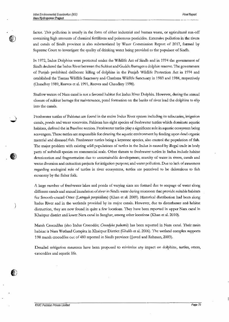
Initial Environmental Examination (lEE)Narll Hydropower Project
Final Report
factor. This pollution is usually in the form of either industrial and human waste, or agricultural run-off
containing high amounts of chemical fertilizers and poisonous pesticides. Extensive pollution in the rivers
and canals of Sindh province is also substantiated by Water Commission Report of 2017, formed by
Supreme Court to investigate the quality of drinking water being provided to the populace of Sindh.
In 1972, Indus Dolphins were protected under the Wildlife Act of Sindh and in 1974 the government of
Sindh declared the Indus River between the Sukkur and Guddu Barrages a dolphin reserve. The government
of Punjab prohibited deliberate killing of dolphins in the Punjab Wildlife Protection Act in 1974 and
established the Taunsa Wilcllife Sanctuary and Chashrna Wildlife Sanctuary in 1983 and 1984, respectively
(Chaudhry 1989, Reeves et al. 1991, Reeves and Chaudhry 1998).
Shallow waters of Nara canal is not a favored habitat for Indus River Dolphin. However, during the annual
closure of sukkur barrage for maintenance, pond formation on the banks of river lead the dolphins to slip
into the canals.
Freshwater turtles of Pakistan are found in the entire Indus River system including its tributaries, irrigation
canals, ponds and water reservoirs. Pakistan has eight species of freshwater turtles which dominate aquatic
habitats, defined the in Baseline section. Freshwater turtles playa significant role in aquatic ecosystem being
scavengers. These turtles are responsible for cleaning the aquatic environment by feeding upon dead organic
material and diseased fish. Freshwater turtles being a keystone species, also control the population of fish.
The major problem with existing wild populations of turtles in the Indus is caused by illegal trade in body
parts of softshell species on commercial scale. Other threats to freshwater turtles in Indus include habitat
deterioration and fragmentation due to unsustainable development; scarcity of water in rivers, canals and
water diversion and extraction projects for irrigation purpose; and water pollution. Due to lack of awareness
regarding ecological role of turtles in river ecosystems, turtles are perceived to be deleterious to fish
economy by the fisher folk.
.)
A large number of freshwater lakes and ponds of varying sizes are formed due to seepage of water along
different canals and annual inundation of river in Sindh water during monsoon that provide suitable habitats
for Smooth-coated Otter (Luttvgale perspicillata) (Khan et al. 2009). Historical distribution had been along
Indus River and in the wetlands provided by its major canals. However, due to disturbance and habitat
distruction, they are now found in quite a few locations. They have been reported In upper Nara canal in
Khairpur district and lower Nara canal in Sanghar, among other locations (Khan et al. 2010).
Marsh Crocodiles (also Indus Crocodile; Crococfyltfs paltlstris) has been reported in Nara canal. Their main
habitat is Nara Wetland Complex in Khairpur District (Ghalib et al. 2006). The. wetland complex supports
198 marsh crocodiles out of 480 reported in Sindh province Waved and Rehman, 2003).
Detailed mitigation measures have been proposed to minimize any impact on dolphins, turtles, otters,
crocodiles and aquatic life.
CD
EMC Palcistan Private Limited Page 70
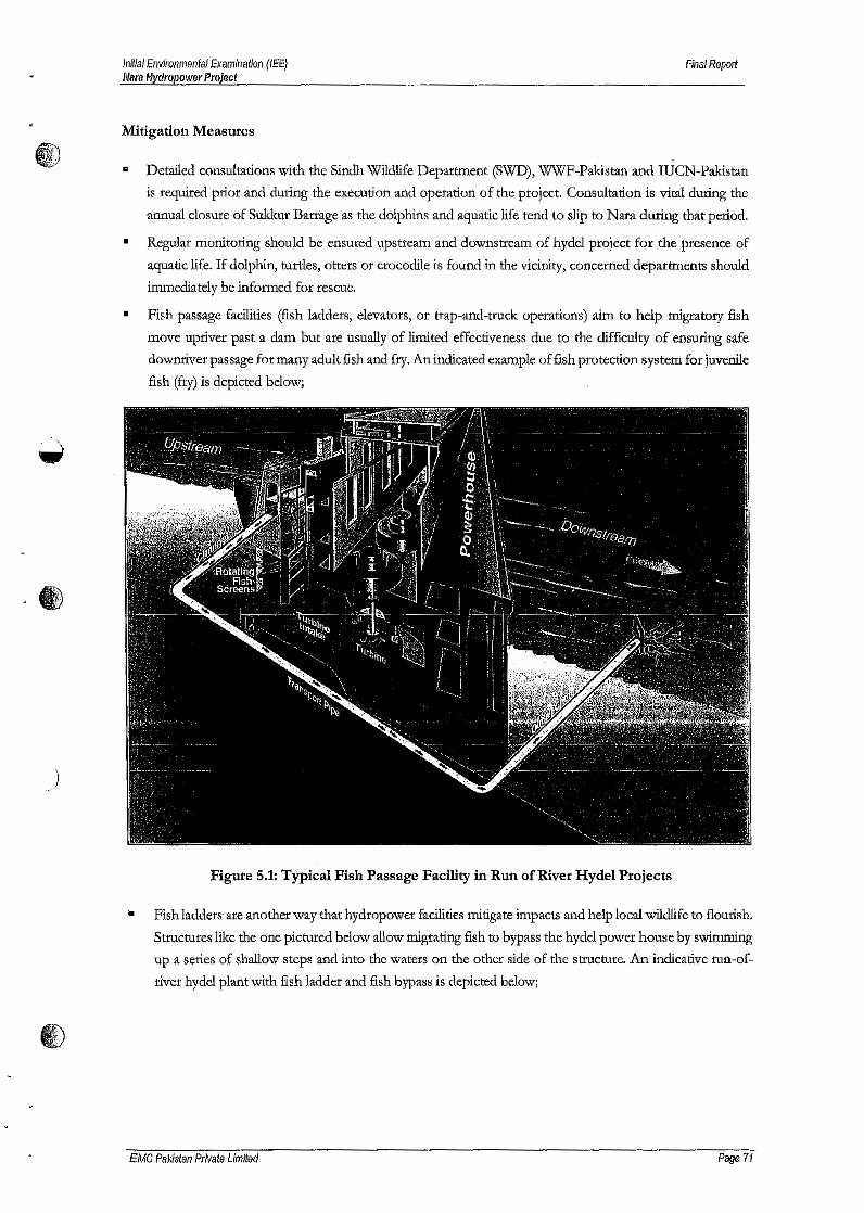
Initial Environmental Examination (lEE)/110m Hydropower Project
Final Report
Mitigation Measures
I)...
•
Detailed consultations with the Sindh Wildlife Department (SWD), WWF-Pakistan and IUCN-Pakistan
is required prior and during the execution and operation of the project. Consultation is vital during the
annual closure of Sukkur Barrage as the dolphins and aquatic life tend to slip to Nata during that period.
Regular monitoring should be ensured upstream and downstream of hydel project for the presence of
aquatic life. If dolphin, turtles, otters or crocodile is found in the vicinity, concerned departments should
immediately be informed for rescue.
Fish passage facilities (fish ladders, elevators, or trap-and-truck operations) aim to help migratory fish
move upriver past a dam but are usually of limited effectiveness due to the difficulty of ensuring safe
downriver passage for many adult fish and fry. An indicated example of fish protection system for juvenile
fish (fry) is depicted below;
•
•
)
Figure 5.1:Typical Fish Passage Facility in Run of River Hydel Projects
• Fish ladders are another way that hydropower facilities mitigate impacts and help local wildlife to flourish.
Structures like the one pictured below allow migrating fish to bypass the hyde! power house by swimming
up a series of shallow steps and into the waters on the other side of the structure. An indicative run-of-
river hyde! plant with fish ladder and fish bypass is depicted below;
EMC Pakistan Private Limited Page 71
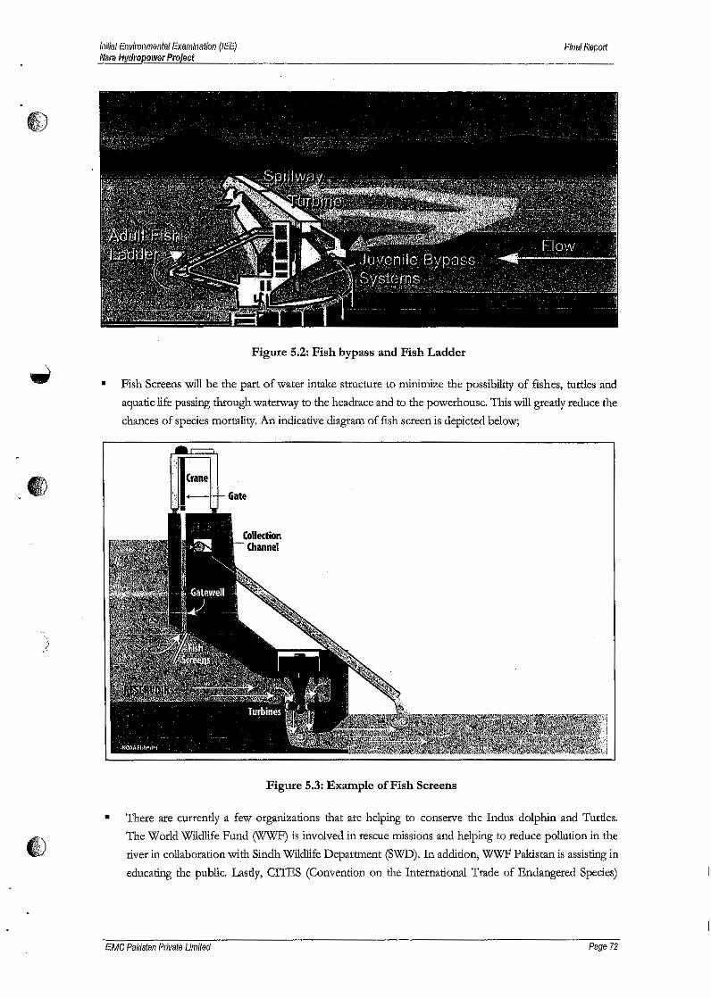
1110,WiV
'j
/
Initial Environmental Examination (lEE)Nara Hydropower Projecf
Final Report
Figure 5.2: Fish bypass and Fish Ladder
• Fish Screens will be the part of water intake structure to minimize the possibility of fishes, turtles and
aquatic life passing through waterway to the headrace and to the powerhouse. This will gready reduce the
chances of species mortality. An indicative diagram of fish screen is depicted below;
Figure 5.3: Example of Fish Screens
• There are currently a few organizations that are helping to conserve the Indus dolphin and Turtles.
The World Wildlife Fund (WWF) is involved in rescue missions and helping to reduce pollution in the
river in collaboration with Sindh Wildlife Department (SWD). In addition, WWF Pakistan is assisting in
educating the public. Lastly, CITES (Convention on the International Trade of Endangered Species)
EMC Pakistan Private Limited Page 72
Initial Environmental Examination (lEE)Nara Hydropower Project
Final Report
prohibits the hunting and trade of many endangered species, including this one. Regular discussion with
such organizations will be fruitful for saving strayed dolphins.
5.5.7 Loss of Cultural Property
No cultural property exists in the microenvironment of project.
5.5.8 Greenhouse Gases
Greenhouse gases (carbon dioxide and methane) are released into the atmosphere from reservoirs that
flood forests and other biomass, either slowly as flooded organic matter decomposes, or rapidly if the forest
is cut and burned before reservoir filling. Greenhouse gases are widely considered to be the main cause of
human-induced global climate change. Many hydroelectric reservoirs flood relatively little forest or other
biomass. Moreover, most such hydro projects generate sufficient electricity to more than offset the
greenhouse gases that would otherwise have been produced by burning fossil fuels (natural gas, fuel oil, or
coal) in power plants.
Since the project does not involve reservoir, so there would be no additional generation of GHG rather
energy generation from clean resource will save .the emissions.
5.5.9 Air Emissions
Hydroelectricity is one of the cleanest energy generation technique by utilizing energy potential of flowing
water. It does not generate air emissions or any direct waste.
5.6 Socioecono~ic Impacts
Positive socioeconomic impacts are envisaged from the construction and operation of 13.65MW Nara
Hydropower Project. Local skilled and unskilled labor will be hired during the construction phase of project.
This would improve the quality of life of the nearby communities.
)
EMC Pakistan Private Limited Page 73

&T:::::..~
:m'".S .......
~ .~ :5,~£.8l",m .....~~ ~Qe: 0
<::<:: Q"
roc 0
~'s -Blti:E' s:~ ~
~-E2:
.~. 'IV
)

~ !J
~ 'e~<Il ::I .U) II.S _
~ ~E;; ~ rJ) :510 S 'e' ~ .f,)
~-Q., C-' 's .!!!.m .... ~ 0 .~~ ~ ~ c:l .~E 00 0 c:c: Q.
-a 0 j.~ {; ~0Jj£ ~ '0 ~~~ ~ 0 (,)
C/)iTI
,s;;;:
)
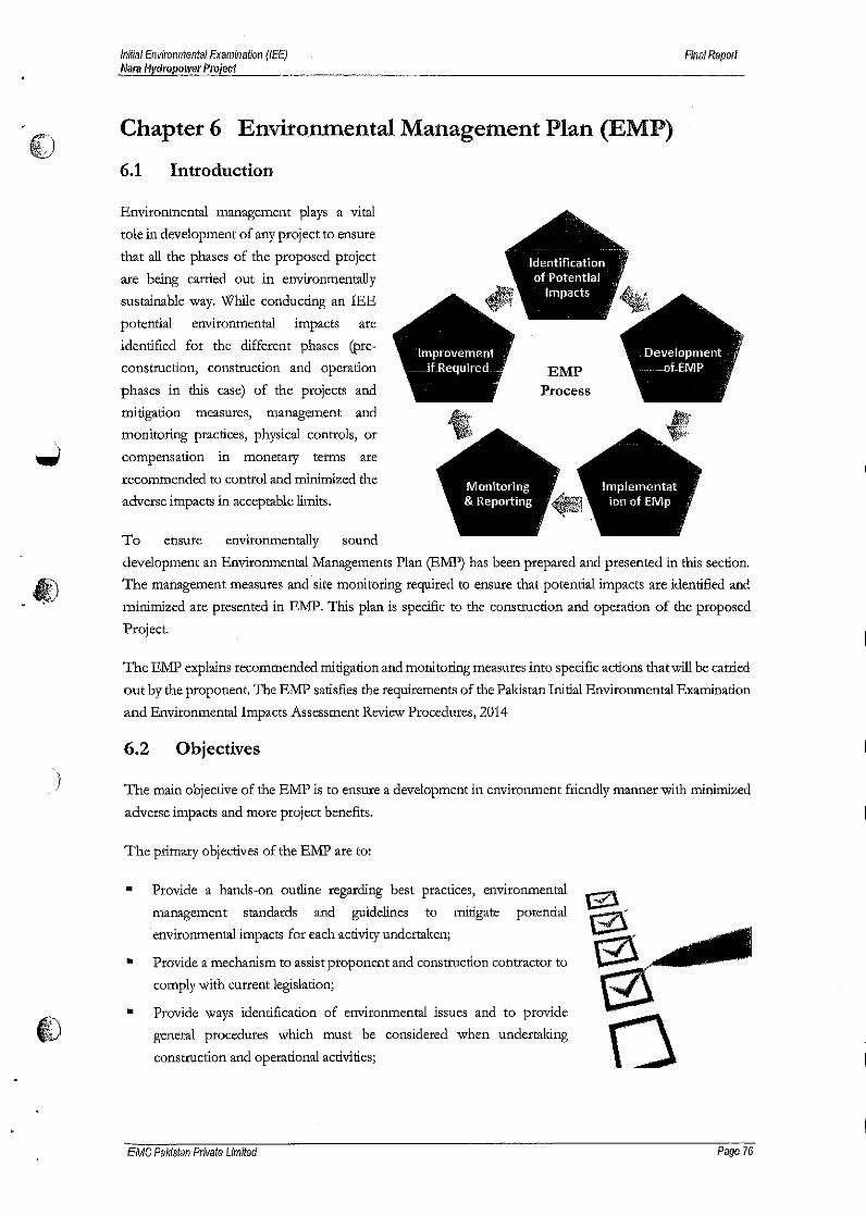
Initial Environmental Examination (lEE)Nara Hydropower Project
Final Repolt
Chapter 6 Environmental Management Plan (EMP)
6.1 Introduction
Environmental management plays a vital
role in development of any project to ensure
that all the phases of the proposed project
are being carried out in environmentally
sustainable way. While conducting an lEE
potential environmental impacts are
identified for the different phases (pre-
construction, construction and operation
phases in this case) of the projects and
mitigation measures, management and
monitoring practices, physical controls, or
.",,;; compensation in monetary terms are
recommended to control and minimized the
adverse impacts in acceptable limits.
EMPProcess
To ensure environmentally sound
development an Environmental Managements Plan (EMP) has been prepared and presented in this section.
The management measures and site monitoring required to ensure that potential impacts are identified and
minimized are presented in RJ\1:P.This plan is specific to the construction and operation of the proposed
Project.
4J. '
The EMP explains recommended mitigation and monitoring measures into specific actions that will be carried
out by the proponent. The EMF satisfies the requirements of the Pakistan Initial Environmental Examination
and Environmental Impacts Assessment Review Procedures, 2014
6.2 Objectives
The main objective of the EMP Is to ensure a development in environment friendly manner with minimized
adverse impacts and more project benefits.
The primary objectives of the EMP are to:
Provide a hands-on outline regarding best practices, environmental
management standards and guidelines to mitigate potential
environmental impacts for each activity undertaken;
Provide a mechanism to assist proponent and construction contractor to
comply with current legislation;
• Provide ways identification of environmental issues and to provide
general procedures which must be considered when undertaking
•
•
construction and operational activities; \)
EMC Palristan Private Limited Page 76
l!E')~>
)
Initial Environmental Examination (lEE)MaraHydropower Project
Final Report
Provide a mechanism to reduce the potential impacts of the construction and operation of the project
• Develop a monitoring mechanism and identify parameters that can confirm the implementation of the
•
mitigation of these measures;
Define roles and responsibilities of the project proponent for the implementation of EMP and identify
areas where these roles and responsibilities can be shared with other stakeholders and
• Define the requirements necessary for documenting compliance With the EMP and communicating it to
•
•all concerned regulatory agencies.
Identify training requirements at various levels and provide a plan for implementation.
For each impact, or activity, which could give rise to an impact, the following information is presented:
• Mitigation measure that will be implemented;
The person(s) responsible for ensuring full implementation of the mitigation measure;
The parameters that will be monitored to ensure effective implementation of the mitigation measure;
The timing for the implementation of the action, to ensure that the objectives of the mitigation are fully
met.
•"•
6.3 Structure of the EMP
The EMP consists of the following section.
Legal Framework
Organizational structure and roles and responsibilities;
Emergency Response Plan
Environmental aspects requiring management consideration;
Mitigation management's matrix
Environmental monitoring programme
• Change management plan
••••••
• Training Programme
6.4 Legal Framework
The lEE has discussed in detail all the Legal Framework (chapter 2)which has relevance to the project Project
Proponent shall ensure that the construction and operation of project is conducted in conformance to relevant
legislations and guidelines and guidance is sought as and when required. Proponent shall also ensure that the
key project management staff is aware of these legislations and guidelines. SEQS for municipal and industrial
effluents, selected gaseous pollutants from industrial sources and motor vehicle exhaust and noise are
provided in Section 2.
EMC Pa/(istan Private Limited Page 77
Initial Envll'Ol1mental Examlnatloll (lEE)N8Yi,I1ydropower Project
Final Report
6.5 Organizational Structure and Roles and Responsibilities/k"'J:)"\tlV 6.5.1 Organizational Structure
The proposed project includes the following main organization:
•Nara Hydropower (pvt.) Limited as the project proponent and owners of the EMP .
The construction contractor as well as contractor required during the operational phase (e.g. waste
contractor) as the executors of the EMP.
•
These organizations will have the following roles and responsibilities during the project activities.
6.5.2 Roles and Responsibilities
A. General
....;; Nata Hydropower (pvt.) Limited: As project proponents, Nata Hydropower (Pvt.) Limited will be
responsible for ensuring the implementation of the EMP. A person holding a. senior position will be
responsible for the overall environmental performances during the proposed project. The person will be
responsible for ensuring the implementation of the EMP by proponent and all project contractors. The
proponent's Site Representative (SR) will be responsible of implementation of the EMP and liaison with
project contractor and stakeholders at site regarding environmental issues during the construction phase.
Further the person holding a senior position in Project Management will also be responsible for monitoring
EMP's compliance and provided technical support in environmental issues.
Project Contractors: For the proposed project, Project Proponent will appoint construction contractors for
different field operations. Various contractors will also be hired during the operation phase of the project (e.g.
waste contractors) The contractors will be responsible for implementation of, or adherence to, all provisions
of the lEE and the EMP and with any environmental and other codes of conduct required by Project
Proponent. Overall responsibility of the contractor's environmental performances will rest with the person
holding the highest management position within the contractor's organization reporting to their management.
) 'The contractor's site managers will be responsible for the effective implementation of the lEE and the EMP.
'The contractor's HSE officers will have functional responsibilities to ensure implementation of Or adherence
to theEMP.
Planning and Design of the Operations
Details ojproject Activities; Details of the project activities are provided in Chapter 3 of the IEE report.
Following approval of the lEE, any changes to the proposed activities will be handled through the change
Management Plan provided in this EMP.
~wY
Approvals: Obtaining no objection Certificate (NOC)j Approval from SEPA will not relieve the proponent
from other legal obligation and hence Project Proponent and project contractors will obtain all other relevant
clearance and necessary approvals required by the Government of Sindh and Relevant departments prior to
commencing the respective operations.
fEMe Pa/(istan Private Limited Page 78

Initial Environmental Examination (lEE)Nara Hydropower Projeat
Final Report
Contractual Provision: Adherence to the requirements of the lEE and EMP in terms of environmentaltv mitigation will be required from all project contractors and thus EMP will form part of their contractor with
Pro; ect Proponent.
B. Implementation of the Operation
Co-ordination 1IJithStakeholders: Project Proponent will ensure that co-ordination with the regulators and other
stakeholders on environmental & social matters is maintained throughout construction & operation phase of
the project.
Monitoring: Project Proponent and the contractors will ensure that monitoring of the project activities is
carried out throughout the project. The Project Management site representative will monitor all project
activities during the construction and operation phase. He will keep a record of all non-conformances
observed and report these along with actions to Project Management for further action. The site representative
will also report any impacts anticipated along with his recommendation for further action.
Emergenry Procedures: Project Proponent and the contractors will prepare contingency plans to deal with any
emergency situation that may arise during the construction and operation e.g. major oil spills, medical
evacuation & communicate these to the regulatory agencies if required by these agencies.
Approvals: The project contractor will be responsible for obtaining all relevant approvals such as approvals
for waste contractors, water source & others as specified in Mitigation Management Matrix.
Trainings: The project contractors will be responsible for the selection and training of their staff capable of
completing the project activities properly and efficiently. The contractors will be responsible for providing
training to their staff members according to the training programme. The training programme is discussed
briefly latter in this chapter.
C. Communication and Documentation
').'
Project Proponent and the contractor will ensure that the communication and documentation requirements
specified in the EMP are fulfilled during the construction and operation phase.
Change Management: The lEE for the proposed operation recognizes that changes in the operation or the
EMP may be required during the project activities and therefore provides a Change Management Plan to
manage such changes. Overall responsibility for the preparation of change management statements will be
with Proponent's site representative.
Restoration: Project Proponent along with the construction contractor will be responsible for the final
restoration of work areas,
EMC Palristan Private Limited Page 7'1)
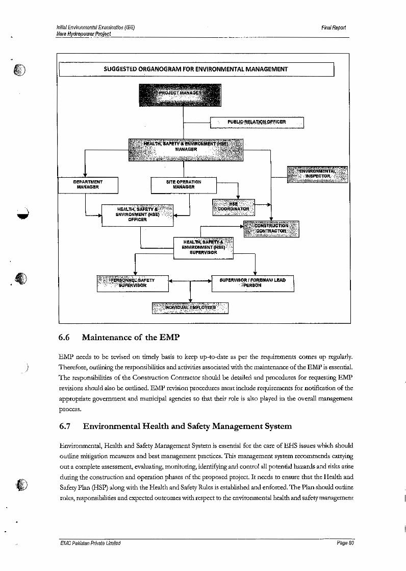
Initial Environmental Examination (lEE)Nara Hydropower Project
Final Report
i). SUGGESTED ORGANOGRAM FOR ENVIRONMENTAL MANAGEMENT
"
)
'_"" '~'ii""'l'f.'it';l, .~ ~~.. ' ,
• I" ~ , ,{ ,,( \:: ," , ., ... , l!':, • .
DI!PARTMENT liT! OP!RATIONMANAGER ~AO!R
SUPEl\VISORI FOREMANI LeAO: ;{PERiiisN
6.6 Maintenance of the EMP
EMP needs to be revised on timely basis to keep up-to-date as per the requirements comes up regularly,
Therefore, outlining the responsibilities and activities associated with the maintenance of the ElViP is essential.
The responsibilities of the Construction Contractor should be detailed and procedures for requesting EMP
revisions should also be outlined. EMP revision procedures must include requirements for notification of the
appropriate government and municipal agencies so that their role is also played in the overall management
process.
6.7 Environmental Health and Safety Management System
Environmental, Health and Safety Management System is essential for the care of EHS issues which should
outline mitigation measures and best management practices. This management system recommends carrying
out a complete assessment, evaluating, monitoring, identifying and control all potential hazards and risks arise
during the construction and operation phases of the proposed project. It needs to ensure that the Health and
Safety Plan (HSP) along with the Health and Safety Rules is established and enforced. The Plan should outline
roles, responsibilities and expected outcomes with respect to the environmental health and safety management
EMC Pa/(/stan Private Limited Page 80

Initial Environmental Examination (lEE)Nara Hydropower Project
Final Report
of the construction & operation phase of the Project. These measures should be implemented to ensure that
i) no significant adverse environmental, health and safety impacts are created by activities associated with the
construction of the project.
Protection of the public and workforce health and safety during both construction and operations is the prime
responsibility of proponent. Utilizing expert personnel and the Environment, Health and Safety Management
System (EHSMS), the potential health and safety hazards and risks will be identified and assessed, then the
subject of substantial planning, organization, procedures for various facility are developed.
6.7.1 Health and Safety during Construction Phase
Worker Health & Safety Management Plan will also be outlined to implement mitigation measures and best
management practices. The plan should be implemented to ensure that no significant adverse worker's health
and safety issues arise from activities associated with the construction of the project,
Potential hazards for workers in 'construction include:
• Falls (from heights);
• Trench collapse;
• Scaffold collapse;
• Electric shock and arc flash/ arc blast;
• Failure to use proper personal protective equipment; and
• Repetitive motion injuries .
6.7.2 Health and Safety ,during Operation Phase
Since proposed project is a hydel power project, occupational health & safety issues need to be addressed
managed effectively to ensure safety of its workers in particular and the neighborhood in general.
6.8 Emergency Response Plan
,)Emergency may be defined as a sudden event causing or has the potential to cause serious human injury and
!or environmental degradation of large magnitude. The best "cure" for an emergency is, of course,
"prevention". The probable emergency situation can be:
•Serious fire or explosion
Major gas leakage.
Major Spillage
•
•
•Natural calamity such as heavy rain, flooding, dust storm or earthquake, cyclone, etc.
Bomb threat or any sabotage / terrorist activity
•
.1) • Any other incident involving all or large part of the premises and its workers .
EMC Pakistan Private Limited Page 81
Initial Environmental Examination (lEE)Mara Hydropower Project
Final Report
Emergency Response Management is provided by a small team of senior managers (the "Control Committee")
~ who in turn will direct all response activities through the Emergency Response Unit
6.8.1 Objectives
The main objective of this plan is to establish the general guidelines for the actions to be taken in the event
of fires, explosion, emergencies, accidents, disasters and sabotage, aimed at minimizing their effects and
consequences, in order to protect:
•
The lives of own or third-party personnel present in the project facilities.
The lives of the occupants
The lives of the nearby residents & communities coming into the direct influence of the project area.
The lives of the ecological systems located in the surroundings of the Project.
••
•
6.8.2 Emergency Response Manuals
Based on the Risk Assessment the proponent should prepare written emergency preparedness and response
plans/procedures for the project to cover emergency situations that could occur. It may be required that
Emergency Response Manuals will be developed for various situations arising.
6.9 Standard Operating Procedures (During Construction phase)
6.9.1 Wastewater/ Storm water management
Purpose of Wastewater/storm water Management
The purpose of the adopted procedure is to provide guidelines and simplify the process of categorizing,
quantifying, managing, and disposing of wastewater wherever and whenever arising during the project's
construction phase. Wastewater management is a critical component of operating policies. Wastewater
management includes the proper disposal/recycling and reuse of the wastewater generated during
construction and operation phase.
Scope
Wastewater as part of construction operation will be managed as per this procedure. An integrated wastewater
management system. for proposed project is essential to reduce wastewater.
Substitute techniques must be investigated, including source reduction, recycling and reuse wherever possible
with a view towards maximizing the benefits and minimizing the cost of each method of wastewater
management.
Procedure
Main concern to manage the wastewater is listed below:
• Eliminate wastewater production wherever possible .
EMC PIlI(istan Private Limited Page 82
Initial Environmental Examination (lEE)Nal'll Hydropower Project
Final Report
• Minimize wastewater production,
•Recycle or Reuse
Wastewater disposal in an environmentally safe manner through adequately designed facility
Proper drainage of Storm water
•
•
a) Wastewater Minimization: Generation of wastewater will be minimized through the following steps
taken by working personnel at the facility:
•Through efficient use of raw water (minimizing the wastewater),
Reuse of wastewater after treatment.
•
b) Storage and Handling: Wastewater shall be stored/retained in specifically designed facility or storage
tanks till proper treatment and subsequently disposed off.
c) Segregation: Wastewater used in construction will be segregated from wastewater originating from
latrines used by construction staff.
d) Recycling: Reuse of wastewater is a best way to reduce the quantity of the wastewater that requires
subsequent treatment and disposal. Construction wastewater may be reused in construction activity
because it is generally Non-hazardous.
e) Treatment: Wastewater originates from latrines used by construction staff requires treatment through
retention in septic tanks and through soakage pits,
f) Disposal: Proper disposal should be done following the treatment through discharge into water bodies
or sewerage system where available.
Wastewater Management Options
• All storm water run-off from construction sites will be inspected for the sediment load and may be
directed to sedimentation basins to remove suspended solids (e.g., silt);
Sewage may be collected and temporarily stored in tank(s) until it is transported to a designated treatment
facility;
)) •
• Standard mobile sewage tankers may be engaged to collect and transport sewage from portable latrines
and temporary storage tanks;
Direct discharge will only be considered as a contingency option.•
6.9.2 Solid Waste Management Plan
Purpose
The purpose of this procedure is to provide guidelines and simplify the process of categorizing, managing and
I) disposing of solid wastes. Waste management includes the proper handling, collection, storage, manifesting,
transportation, and disposal/ recycling of the solid waste generated. The procedure is designed to assist in the
EMC Pal(/stan Private Limited Page 83
Injt{alEnvirollmental Examination (lEE)Mara Hydropower Project
Final Repan
management's wide effort to provide protection to the environment and to comply with proponent's
f;) requirement, environmental laws and regulations regarding proper waste management.
Scope
The waste management plan has been developed to ensure that the Management of solid waste generated as
a result of the construction is consistent, efficient, and in conformance with the laws and regulations.
With respect to monitoring, the waste management sets out the following objective:
• To monitor and inspect waste management-related facilities and activities directly resulting from executing
the scope of the contract in order to ensure compliance with the WMP. Guidelines for proper handling,
categorization, recording, minimization, recycling and disposal of all types of waste associated with
company operations and projects are part of this procedure.
Definitions
a) Waste: Any material, for which no further use is intended, is considered a waste. It can be solid, semi-
solid or liquid. Additionally, abandoned materials and materials intended to be recycled are considered
wastes. It is very important to understand this concept, because even though something is going to be
recycled, it must be managed as a waste until it is actually recycled.
b) Hazardous Waste: Waste is categorized as a hazardous waste if it has one or more of the following
properties:
•
Ignitability (flash point less than 600C);
Corrosivity (PH less than or equal to 2.0, or greater than or equal to 12.5);
Reactivity (inherently unstable under ordinary conditions or when exposed to water);
Irritability (when in contact with body causes inflammation)
Toxicity (may cause risk of injury to health of organisms or the environment)
•
••
•
) c) Non-hazardous Waste: The wastes are categorized as non-hazardous wastes, if they do not possess any
of the hazardous characteristics as defined above. However, non-hazardous waste may still present
hazards to employees who handle them. All recommended safety and handling practices must be
followed.
Procedure
Priorities to manage the waste are listed below:
()
• Eliminate waste production whenever and wherever possible. Use the material only for its intended
purpose on site
• Minimize waste production
• Reuse
EMC Pakistan Private Limited Page 84
Ifi:0.V
Initial Environmental Examination (lEE)Nara Hydropower Project
Fillal Report
• Dispose of waste through properly designed waste disposal facility.
a) Waste Minimization: To minimize waste, the following steps shall be taken by all personnel working
on sites (during construction phase):
• Only the needed amount of materials shall be ordered. Before purchasing hazardous material, all
alternatives for non-hazardous material should be explored.
Prior consideration shall be given to the sizes of containers available when ordering products that could
potentially generate waste. The intent is to avoid unused products and/or their containers from becoming
wastes that require special handling.
•
b) Waste Categorization: All wastes generated at facilities shall be categorized in two major categories (i.e.
Hazardous wastes and Non-hazardous wastes) as per the definitions in section above. Each category has
different types of requirement for handling, storage and disposal.
~ c) Labelling
)
• Name of the waste (e.g., waste oil, solvents, paints).
Waste category (e.g., toxic, ignitable).
Facility name and address (disposal site, etc.).
Date of waste accumulation: (date when waste was placed in drum).
Wastes are segregated and located in designated areas to optimize control; storage areas.
••••
d) Segregation: The scheme of segregation is as follow:
• All hazardous waste if found shall be segregated from other types of hazardous wastes as well as non-
hazardous wastes at the point of generation of waste.
• Food waste shall be collected in separate containers.
All containers must be clearly labeled. The label must dearly mention the name or type of waste. Also, if
the waste is hazardous, it should be clearly labeled on the container along with its hazardous characteristics
(e.g. flammable, toxic, radioactive, etc.), This is important to workers and to emergency response teams,
who need to know what they are dealing with. Missing or unreadable labels must be replaced.
•
e) Storageand Handling
Waste shall be temporarily stored at waste storage facility that will be sent for recycling or off-site disposal
shall be temporarily stored at designated site(s) within the project premises.
The oily sludge, contaminated soil shall be stored in containers
All other wastes awaiting disposal shall be kept in closed containers/boxes separately. Care must be taken
to prevent wastes giving rise to secondary environmental problems, such as odors or soil and groundwater
contamination through rainwater leaching.
• All stored wastes must be dearly labeled with type of waste and warning signs.
•
••
• Daily estimates of hazardous and non-hazardous waste and volumes generated on site.
EMC Pakistan Private Umited Page 85
Initial Environmental Examination (lEE)('Jara Hydropower Project
Final RepoI't
• Waste segregation, waste storage containers, general housekeeping and the provision of adequate
fi) resources will be monitored.
• All workers handling wastes shall use proper PPE.
f) Reuse
Construction waste can be reused in other construction projects & excavated material can be reused inbackftlling.
g) Disposal
Disposal becomes the only available alternatives, if reuse and recycling options are exhausted. A material
should be classified as a waste for disposal only if no other useful purpose can be identified and if the material
cannot be beneficially reused or recycled. The choice of a suitable disposal option for any waste depends on
both environmental and economic considerations. The final disposal can only be off-site disposal facilities
.",,/; due to limited space available.
It requires properly designed and well-operated commercial waste disposal facilities such as sanitary landfill.
All such facilities should be explored and evaluated for possible future use.
Recording & Reporting
The management has to record the information about source, composition, quantity, and final disposal of the
waste. This information is needed for regulatory compliance, risk assessment and setting reduction targets and
objectives as well as corporate statistics. The routine track of waste shall be recorded.
6.9.3 Air and Noise Emissions
Purpose
The pUlpose of this guideline is:
)• To monitor contents of polluting substances in the atmospheric air;
• To control observance of approved limiting permissible emissions at man-made sources;
• To monitor natural sources and a number of man-made sources of emission at work sites at the
construction phase;
• To identify sources of noise emissions and control noise pollution;
• To monitor noise emissions.
Scope
Scope of work includes:
() • Evaluation of present ambient air quality and noise level at existing area.
• Evaluation of impact of traffic movement at the proposed site and noise level.
EMC Pakistan Private Limited Page 86
Initial Environmental Examination (lEE)Narll Hydropower Project
Final Report
Evaluation of impacts on roads and in the adjacent area due to construction .
• Evaluation of impacts of air emissions and noise from various stationary sources.
•
• Recommendations for mitigation techniques to redress the expected impacts both for design phase .
Definitions
Air pollution may be referred to as contamination of pollutants dispersed in air affecting ambient air quality
that may be deleterious to life and property.
In common use, the word noise means unwanted sound or noise pollution. Excessive noise permanentlydamages hearing, but a continuous low-level sound can be dangerous too.
Procedure
Air emissions (continuous or non-continuous) from facilities such as power generators are comprising of
principal gases (greenhouse gases) which typically include carbon monoxide (CO), carbon dioxide (C02),
water vapors and other gases such as nitrogen oxides (NOx), and, in case of sour gases, sulphur dioxide (S02).
Air quality impacts should be estimated by the use of baseline air quality assessments and atmospheric
dispersion models to establish potential ground level ambient air concentrations during facility design and
operations planning. These studies should ensure that no adverse impacts to human health and the
environment result. All reasonable attempts should be made to maximize energy efficiency and design facilities
to minimize energy use. The overall objective should be to reduce air emissions and evaluate cost-effective
options for reducing emissions that are technically feasible.
Also, vehicular emissions and noise due to traffic movement in and around the project may of concern to bemitigated and monitored. Atmospheric conditions that may affect noise levels include humidity, wind
direction, and wind speed. Vegetation, such as trees, and walls can reduce noise levels. Installation of acoustic
insulating barriers can be implemented, where necessary.
Noise and Air Emissions Management Options
Noise and air emissions monitoring includes;
•Monitoring of air and noise emissions.
Pollution control technology assessment,
Emission inventory development,
Development of parametric monitoring, periodic monitoring, and compliance assurance monitoring.
•
••
Air and Noise Quality Monitoring
Refer attached Environmental Monitoring Plan for details of air and noise quality monitoring at the proposed
project site during construction phase.
a) Performance Indicator: Monitoring results of ambient air shall show the concentration of pollutant
in ambient air.
EMC Pakistan Private Limited Page 87

Initial Environmental Examination (lEE)Nara Hydropowej' Project
Final Repo/t
Itfij'\~
b) Record and Comments: Record would be kept with the laboratory report attached. A layout of record
keeping format for monitoring results is presented at the end of this EMP.
.6.10 Standard Operating Procedures (During Operational Phase)
6.10.1 Wastewater Management
Purpose of Wastewater Management
The purpose of this procedure is to provide guidelines and simplify the process of categorizing, managing,
and disposing of wastewater wherever and whenever arising during the project's operational phase.
Wastewater management includes the proper disposal/recycling and reuse of the wastewater generated during
operation phase.
Scope
• Wastewater generation as part of operational activity will be managed as per this procedure. An effective
wastewater management system for proposed project is essential to reduce wastewater. Substitute techniques
must be investigated, including source reduction, recycling and reuse wherever possible with a view towards
maximizing the benefits and minimizing the cost of each method of wastewater management.
Definitions
a) Wastewater: All water arising after use/consumption from the Project which can encompass a wide
range of potential contaminants and concentrations.
b) Non-hazardous Wastewater: All wastewaters are categorized as non-hazardous wastes, if they do not
possess any of the hazardous contaminant mainly comprising of consumed water arising from washing
area and sanitary wastewater.
Procedure
) Main concern to manage the wastewater is listed below:
•
Eliminate wastewater production wherever possible.
Minimize wastewater production,
Recycle or Reuse
Wastewater disposal in an environmentally safe manner through adequately designed facility
••
•
a) Wastewater Minimization: Generation of wastewater will be minimized through the following steps
taken by working personnel at the facility:
• Through efficient use of raw water (minimizing the wastewater).
EMC Pakistan Private Limited Page 88

Inlllal Environmental Examillation (lEE)Nata Nydropower Project
Fillal Report
b) Storage and Handling: Wastewater shall be stored/retained in specifically designed facility or storage
tanks till appropriate treatment is sought and subsequently disposed off.
c) Treatment
• Treatment of wastewater through retention in septic tanks and through primary and/or secondary
treatment proce£ses.
d) Disposal
Proper disposal should be done following the treatment through discharge into water bodies or sewerage
system where available.
Drinking Water Quality and Wastewater Monitoring Plan
Refer attached Environmental Monitoring Plan for details of drinking water quality and wastewater
'..i; monitoring plan.
a) Performance Indicator
Monitoring results of water quality shall show the extent of contamination in the drinking water and shall
regulate and maintain the quality of potable water for establishing its suitability for human consumption as
per SEQS for drinking water quality.IIfi:.,.v Monitoring results of wastewater quality shall show the lower concentration of pollutants in the sewage water
after onsite treatment and reduced potential for contamination of ground water if not disposed of properly.
b) Record and Comments
Record of analysis reports shall be maintained.
6.10.2 SolidWaste Management Plan
.. ) Purpose
The purpose of this procedure is to provide guidelines and simplify the process of categorizing, managing,
and disposing of solid wastes. Waste management is a critical component of management's operating policies.
Waste management includes the proper handling, collection, storage, manifesting, transportation, and disposal
I recycling of the solid waste generated.
Scope
The waste management plan has been developed to ensure that the Management of solid waste generated as
a result of operation is consistent, efficient, and in conformance with the laws and regulations.
EMC Pakistan Private Limited Page 89

Initial Enviwllmental Exam/nation (lEE)Nara Nydropower Project
Final Report
Definitions
a) Waste: Any material, for which no further use is intended, is considered a waste. It can be solid, semi
solid or liquid. Additionally, abandoned materials and materials intended to be recycled are considered
wastes. It is very important to understand this concept, because even though something is going to be
recycled, it must be managed as a waste until it is actually recycled.
b) Hazardous Waste: Waste is categorized as a hazardous waste if it has one or more of the following
properties:
Ignitability (flash point less than 60oC);
Corrosivity (PH less than or equal to 2.0, or greater than or equal to 12.5);
Reactivity (inherently unstable under ordinary conditions or when exposed to water);
Irritability (when in contact with body causes inflammation)
..",; • Toxicity (may cause risk of injury to health of organisms or the environment.)
••••
c) Non-hazardous Waste: The wastes are categorized as non-hazardous wastes, if they do not possess any
of the hazardous characteristics as defined above. However, non-hazardous waste may still present
hazards to employees who handle them. All recommended safety and handling practices must be
followed.
Procedure
Priorities to manage the waste are listed below:
• Eliminate waste production whenever and wherever possible.
• Minimize waste production
• Reuse
• Dispose of waste through properly designed waste disposal facility.
) a) Waste Minimization: To minimize waste, the following steps shall be taken by all personnel working
on sites:
• Only the needed amount of materials shall be ordered. Before purchasing hazardous material, allalternatives for non-hazardous material should be explored ..
• Prior consideration shall be given to the sizes of containers available when ordering products that could
potentially generate waste. The intent is to avoid unused products and/ at their containers from becoming
wastes that require special handling.
b) Waste Categorization: All wastes generated at facilities shall be categorized in two major categories (i.e.
Hazardous wastes and Non-hazardous wastes) as per the definitions in section above. Each category has
different types of requirement for handling, storage and disposal.
fEMe Pakistan Private Limited Page 90

)
Initial Environmental Examination (lEE)Mara Hydropower Project
Fillal Report
c) Labelling
• Name of the waste (e.g., chemical waste, solvents, paints, biomedical etc.).
Waste category (e.g., toxic, ignitable).
Facility name and address (disposal site, etc.).
Date of waste accumulation: (date when waste was placed in drum).
Wastes are segregated and located in designated areas to optimize control; storage areas.
••••
d) Segregation: As there are no hazardous wastes envisaged in the project therefore segregation among the
waste will be done as per their matter.
The scheme of segregation is as follow:
• All hazardous waste if found shall be segregated from other types of hazardous wastes as well as non-
hazardous wastes at the point of generation of waste.
Laboratory chemical waste is also to be segregated into chlorinated and non-chlorinated solvents.
Non- hazardous waste consists of containers, shipping cartons, bags, reject, broken bottles, rejected
cartons, labels, strips, corrugated boxes, paper etc.
••
e) Storage and Handling
• All waste from floor and equipment is to be collected using vacuum cleaners.
All containers must be properly and clearly labeled. The label must clearly mention the name or type of
waste. Also, if the waste is hazardous, it should be dearly labeled on the container along with its hazardous
characteristics (e.g. flammable, toxic, radioactive, etc.). This is important to workers and to emergency
response teams, who need to know what they are dealing with. Missing or unreadable labels must be
replaced.
Non-hazardous waste shall be temporarily stored at waste storage facility that will be sent for recycling or
off-site disposal shall be temporarily 'stored at waste storage facilities available at different sites such as
junkyard, scrap yard, pits, etc.
All other wastes awaiting disposal shall be kept in closed containers/boxes separately. Care must be taken
to prevent wastes giving rise to secondary environmental problems, such as odors or soil and groundwater
contamination through rainwater leaching.
Daily estimates of hazardous and non-hazardous waste and volumes generated on site,
Waste segregation, waste storage containers, general housekeeping and the provision of adequate
resources will be monitored.
•
•
•
••
• All workers handling wastes shall use proper PPE.
f) Recycling: Non-hazardous waste can be recycled and reuse to minimize the quantity of waste requiring
disposal. Some of the wastes (like one side printed paper) can be reused within the facilities while others
can only be recycled at off-site recycling centers.
EMC Pakistan Private Umlted Page 91
Initial Environmental Examination (lEE)Mara Hydropower Project
Final Repolt
g) Disposal: Disposal becomes the only available alternatives, if reuse and recycling options are exhausted.
Onsite burning or dumping of waste is strictly prohibited.
A material should be classified as a waste for disposal only if no other useful purpose can be identified and if
the material cannot be beneficially reused or recycled. The choice of a suitable disposal option for any waste
depends on both environmental and economic considerations. The final disposal can only be off-site disposal
facilities due to limited space available.
The waste shall be disposed of through a contractor.
Recording & Reporting
The management has to record the information about source, composition, quantity, and final disposal of the
waste. This information is needed for regulatory compliance, risk assessment and setting reduction targets and
objectives as well as corporate statistics .
..,J; The routine track of waste shall be recorded. It is the responsibility of the proponent to assign a suitable
person to sign off the record of waste tracking before the waste is dispatched outside.
6.11 Environmental Compliance Reporting, Documentation and Trainings
...'CV
The management will be responsible for the regular audit and review of the environmental management and
monitoring plan. This will include both on-site auditing and review of performance reports. Additional onsite
inspections and investigations will be undertaken in the event of significant environmental incidents. These
will be undertaken in conjunction with the Independent Monitoring Consultant (IMC).
The management will participate in the audits and inspections and investigations. The management will also
be responsible for regular review of the environmental performance of the site and site personnel, and for the
reporting on the implementation of commitments made in the EMP.
In particular, there will be:
•Periodic audit reports.
A review and improvement of the EMP .
l
,j •
Management recognizes that periodic external compliance audits and inspections will be made through a third-
party consultant (lMC) to monitor, assess and validate the level of performance and compliance pursuant to
the commitments made in the accepted Environmental Management Plan. The monitoring reports shall also
be submitted to Sindh Environmental Protection Agency (SEPA) on regular intervals.
Training: It an important step for the implementation of the EMP. All the employees will require to be
trained to work appropriately on EMF. EHS Manager will organize trainings in consultation with HSE
Officer, It will make sure that employees understand the Environment, Health and Safety issues. Trainings
should be arranged on regular basis with notification that it should be attended all respective employees.
£MC Pakistan PrIvate Limited Page 92

Initial Environmental Examlnet/on (lEE)Mara Hydropower Project
Final Report
HSE Officer will determine the training requirements during both phases. Induction will be the basis of allGi) training courses for contractor & subcontractor during construction phase.
Trainings identified in EMP are given below:
• Site induction course
• Training for emergency response and preparedness
• Training for familiarization With site environmental controls
Specific environmental training for relevant employees e.g, daily checks to maintain controls, waste
minimization, etc.
6.12 Mitigation Management Matrix
The Mitigation Management Matrix will be used as a management & monitoring tool for implementation of the
mitigation measures required by the lEE. Mitigation management matrix for construction and operation is
provided in the table 7.1. The matrix lists down the following:
• The mitigation measure recommended in the IEE.
The person! organization directly responsible for adhering to or executing the required mitigation
measures.•
• The parameters which will be monitored to ensure compliance with the mitigation measures;
The timing at which the mitigation or monitoring has to be carried out.•
It is highlighted that although responsibilities for executing and monitoring mitigation measures have been
delegated to different persons, Project Proponent will hold the primary and overall responsibility for ensuring
full implementation of the EMP.
6.13 Environmental Monitoring Programme
) 'The objective of the environmental monitoring during the construction & operation phase will be as follows:
• To check compliance of the contractors with the EMP by monitoring activities of the project on a daily
basis. This will be called compliance monitoring.
• To monitor impacts of the operation in which there has been a level of uncertainty in prediction such as
impacts of noise, water abstraction etc. and to recommend mitigation measures if the impacts are assessed
to be in excess of or different from those assessed in the lEE. The aim will be attained through effects
•moni toring.
To achieve these objectives, the following monitoring programme will be implemented.
6.14 Compliance Monitoring
I) Compliance monitoring will be carried out to ensure compliance with the requirements of the lEE and to
document and report all non-compliances. The mitigation management matrix provided in the Eill will be
EMC Pakistan Private Umited Page 93
Initial Environmental Examination (lEE)Nllt'a Hydropower Project
Final Report
used as a management and monitoring tool. The contractor's HSE Officer will be responsible for monitoring
~ the compliance of their organization with the relevant EMP requirements. Proponent's site representative will
monitor the contractor's compliance and will also ensure that during construction each activity system and
plan is in place for effective compliance monitoring. The site representative will make regular checks on the
contractor's works; keep records of all non-compliances observed during the execution of the project
activities; & the details of all remedial actions taken to mitigate the project impacts.
6.14.1 Effects Monitoring
The effects monitoring requirements have been detailed in Table 7.2. An independent monitoring consultant
(!MC) will be responsible to carry out the required effects monitoring during the construction and operation
phase.
6.14.2 Environmental Reporting
A. Final Monitoring Report (Construction Phase)
After completion of construction phase, a final monitoring report will be prepared by Proponent's site
representative. The report will include the following:
• Introduction.
• Details of the Project Activities.
e..
..Natural Resource used during the Project.
List of Non-compliances recorded .
Effects of the Project on Communities and Physical Resources.
Photographic Records
Approvals provided during the project
Change managements statements
Trainings
Conclusions
•
••••
•) •
B. Annual Environmental Monitoring Reports (Operation Phase)
The project proponent shall prepare annual environmental monitoring reports describing the conduct of the
operation phase for project along with details of the effects monitoring conducted annually during the
operation phase of the project. The report shall be submitted to the SEP A.
6.15 Change Management Plan
The lEE for the proposed project recognizes that changes in the operation or the EMP may be required
during the construction and operation and therefore provides a Change Management Plan to manage such
fi) changes. The management of changes is discussed under two separate headings, Additions to the EMP and
Changes to the Operation and the EMP.
EMC Pakistan Private Limited Page 94

Initial Environmental ExamlllCltion (lEE)Nara Hydropower Project
Final Report
6.15.1 Changes to the EMP
The lEE and the EMF have been developed based on the best possible information available at the time of
the lEE study. However, it is possible that during the conduct of the proposed operation additional mitigation
measures based on the findings of environmental monitoring during the operation may have to be included
in the EMP. In such cases following actions will be taken:
• A meeting will be held between Project Proponent and the concerned project contractors. During the
meeting, the proposed addition to the EMP will be discussed and agreed upon by all patties.
• Based on the discussion during the meeting, a change report will be produced collectively, which will
include the additional EMP clause and the reasons for the addition.
• The report will be signed by all patties and will be filled at the site office: A copy of the report will be sent
to Project Proponent and contractor head offices.
• All relevant project personnel will be informed of the addition.
fti;; 6.15.2 Changes to the Operation
The change management system recognizes three orders of changes:
A. First Order:
A first order change is one that leads to a significant departure from the project described or the impacts
assessed in the lEE and consequently require a reassessment of the environmental impacts associated with
the change. Example of Brst order change includes change in location of proposed project. Action required
in this case will be that the environmental impacts of the proposed change will be reassessed by Project
Proponent and sent to the SEP A for approval.
B. Second Order
)
A second order change is one that does not result in the change in project description 01' impacts that are
significantly different from those detailed in the lEE. Example of second order changes includes extension in
the site area. Action required for such changes will be evaluated by proponent to reassess the impact of the
activity on the environment & specify additional mitigation measures if required and report the changes to
SEPA.
C. Third Order
A third order change is one that does not result in impacts above those already assessed in the lEE, rather
these may be made site to minimize the impact of an activity such as:
• Increase in project workforce;
• Change in layout plan .
I) The only action requited for such changes will be to record the change in the Change Record Register.
EMC Pa/ristan Private Limited Page 95
Initial Environmental Examination (lEE)Mara Hydropower Project
Final Report
6.16 Training Programme
Environmental training will form part of the environmental management system. The training will be directed
towards all personnel for general environmental awareness.
6.16.1 Objectives
The key objective of training programme is to ensure that the requirements of the EMP axe clearly understood
and followed throughout the project The trainings to the staff will help in communicating environmental
related res trictions specified in the IEE and EMP.
6.16.2 Roles and Responsibilities
The contractors will be primarily responsible for providing environmental training to all project personnel on
potential environmental issues of the project. The contractors will be responsible to arrange trainings and
ensure the presence of targeted staff.
6.16.3 Training Programme
The environmental awareness, lEE and EMF training will be carried out during the project activities ..
A. Training log
I.tilA1If&1
A training log will be maintained by tine contractors. The training log will include:
• Topic
• Date, time and location
• Trainer
• Participants
B. Training Needs Assessment
) In addition to the training specified in the training log special/ additional trainings will be provided during the
project activity. The criteria to assess the need of training will be based on the following:
•
When a specified percentage of staff is newly inducted in the project
When any non-compliance is repeatedly reported refresher, training will be provided regarding that issue.
When any incident/accident of minor or major nature occurs. Arrival of new contractor/sub-contractor.
Start 0f any new process / activi ty.
••
•
c. Training Material
The contractors will develop & prepare training material regarding environmental awareness, sensitivity of the
i) area, lEE, EMP and restrictions to be followed during the project, Separate training material will be prepared
for each targeted staff.
EMC Pakistan Private Limited Page 96
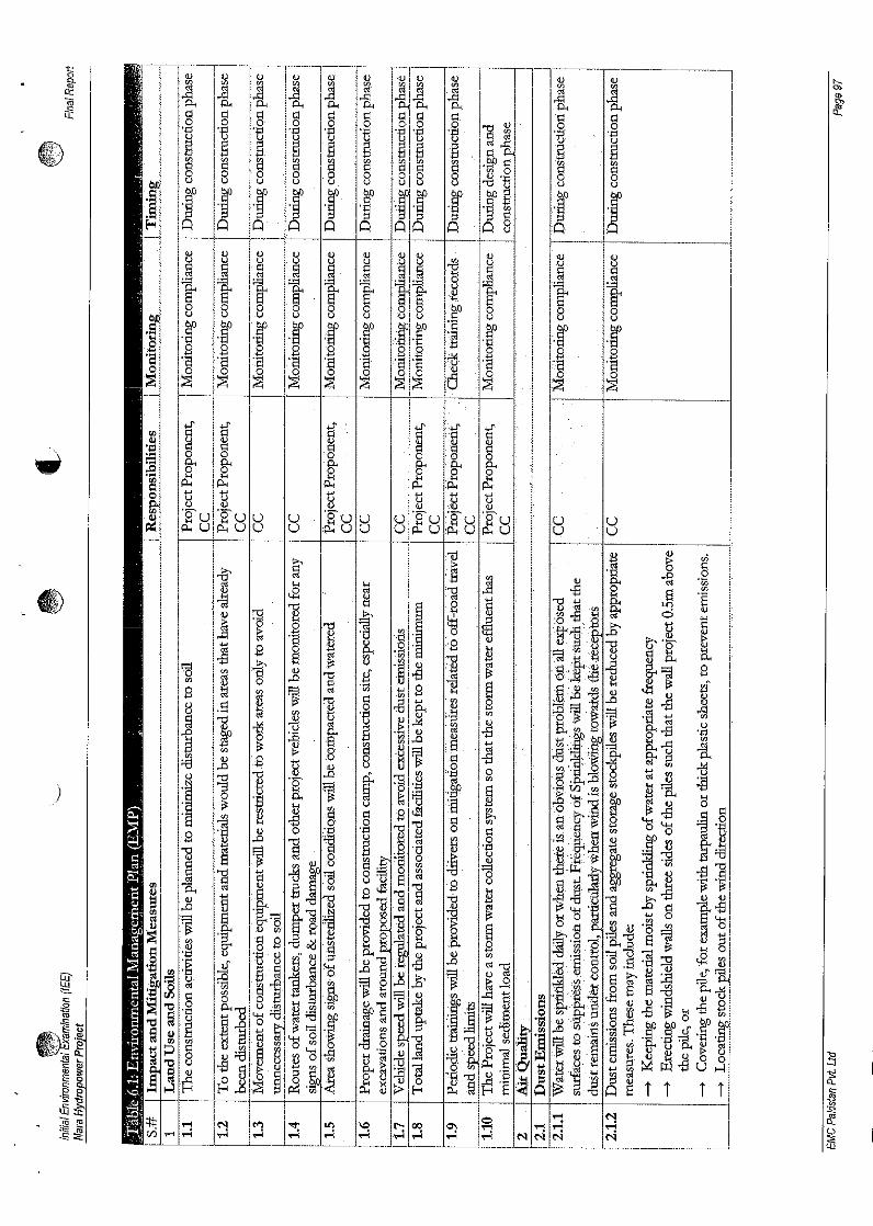
)
IJt t~ II)
'S'u 'Bu U UUp...up...uu
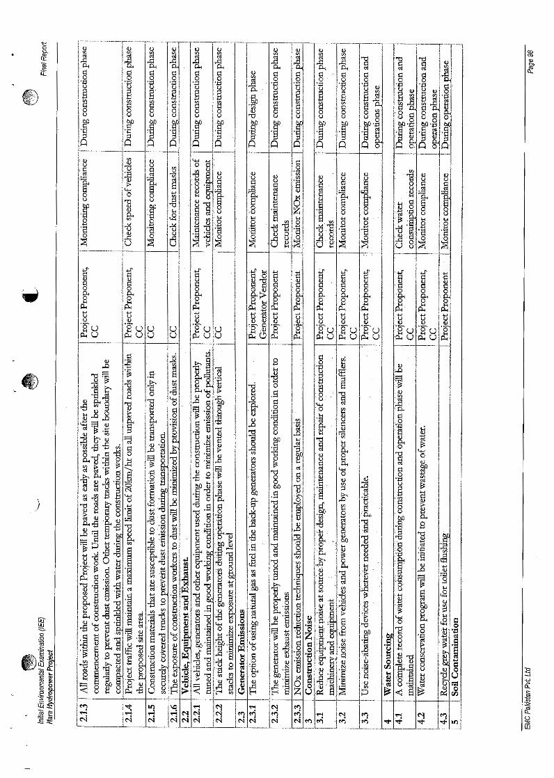
)
<00)
(j)
1
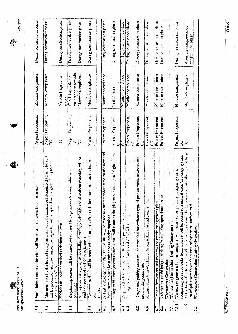
)
g-ot:i.o
1~
··Buup-<uu
I)
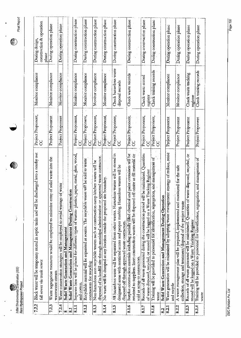
)
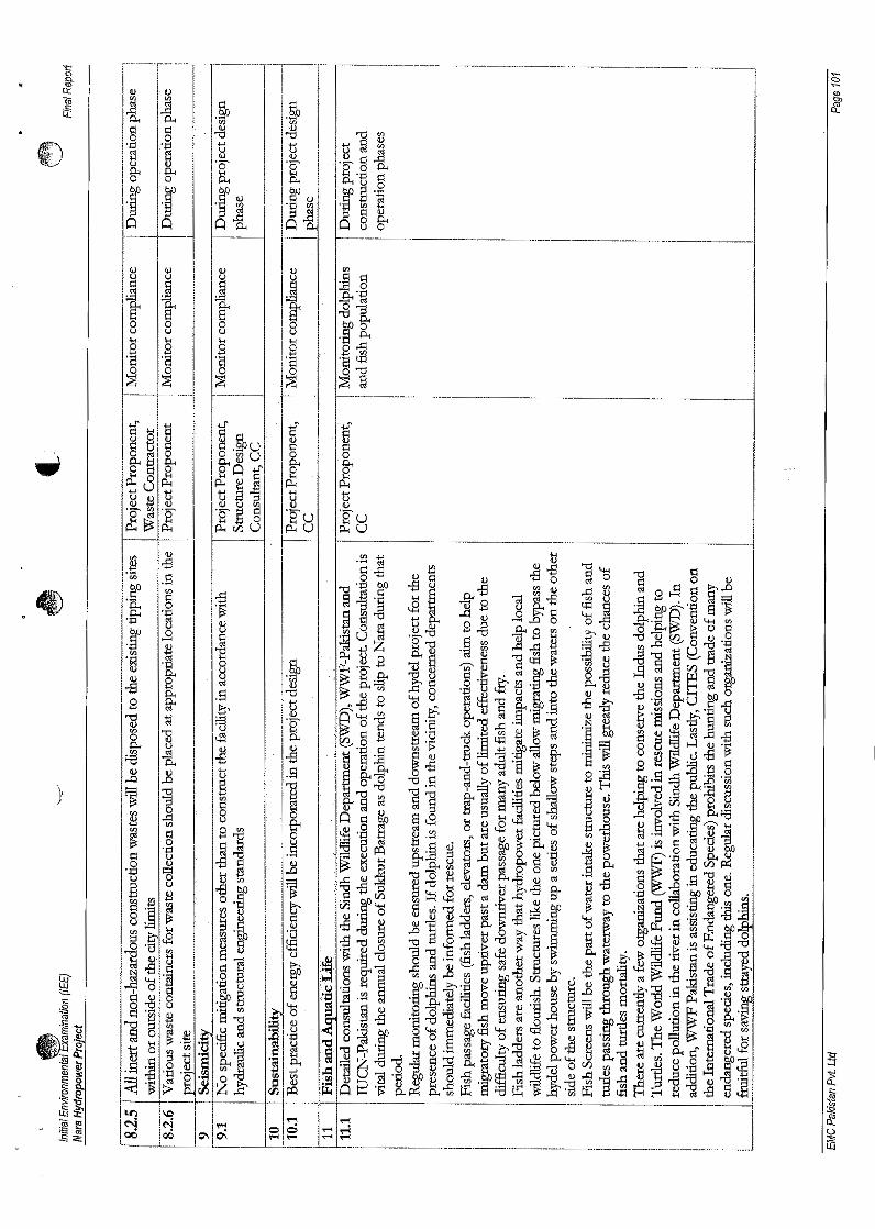
,··-----·r-···-····-,-- ·------rl--r-I I Ij I] , I
~ i~'0.. 0.. 'lil i''''Q ;::l ~ !~0 0
'a .'+:1 ~ , 1:)
~ 10'0 I'S
10.. ~ l:to . 10..
lJ_ ·r Xl ircu:" ~.
0 Io,g-.- r~-',
0 <U IUU U j IJt:: ]11.S" Ir ~ ift'0 0 0 10u u u ,u4-< H H 19B 8 B'E ·s ·s nl0
~ ~'0
~ I~--_ f---.-..-. _.-- r+tI
cfH~
...r II<u 8 . ~ .~ut:: u&a o ~ Ugo 8'0 ...r- Io..·0 ct J!.t=t 0 t=t I
.p:; <u Q...,u E t~~ ....~. 1:l u<u '" II)
l~l ._ B Q 'oue 0~r/)U P::u
f------.-- ,
II) I
.~
,.-s I.", t::
II'......'" 1s'p It'J <u ,.Q g II·r,~
-E I'e 0 15J41
0.. ~ i'~8~
,Ej !""ClB ~ IE"0 ~ =B 1-0<u'" 13 ''''0 ~ jo..0.. u -5 1.£'" -!;..0Q) 1$ .... It::
..0 u , ......§ i"O
11 ~ 8 IE~ ..8 '10
'"u
I~~Q o '"0 .... "8
'1=1 ~~ I~c u ......·0 cu .-s c:I II'p ::a ~ t1·U ig u . .-s r1:! o .. ~ .fl
~'. ~ ~8]'.' ~.~ E
gj e-- ~ '010'0
<.,:; i:E1<IJ .) El'<'l <u
Ij ~ .g ~ ~ "
I' 0c:I .~B
.~~§~ 8c:: ..... s 's .; o·
'1 g '" e-. u ~ .:;1 ~ ..~ .!l ~ u illl"5j '" '" '0 &1 .~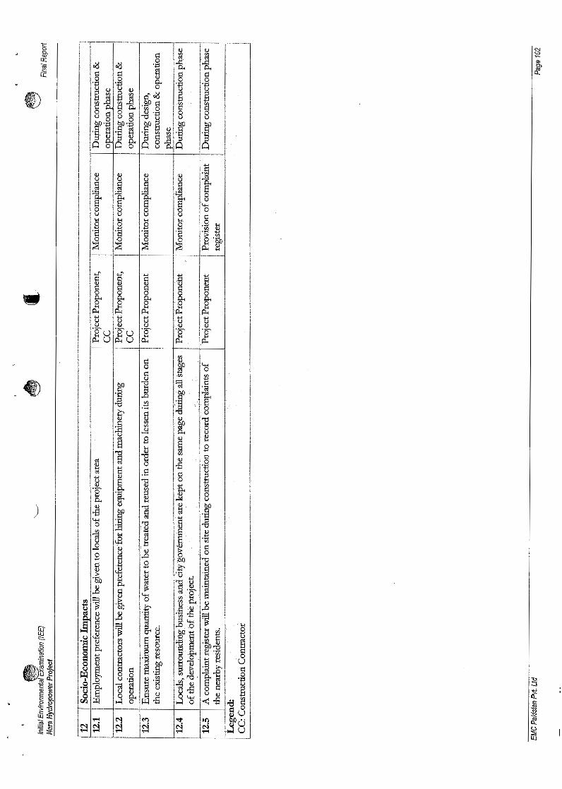
)
aT=
]i~8'0g
'F/j b'j; ..,o ,R
.~ ~----"1- .------;----rF'"-._--
§l0)
~)
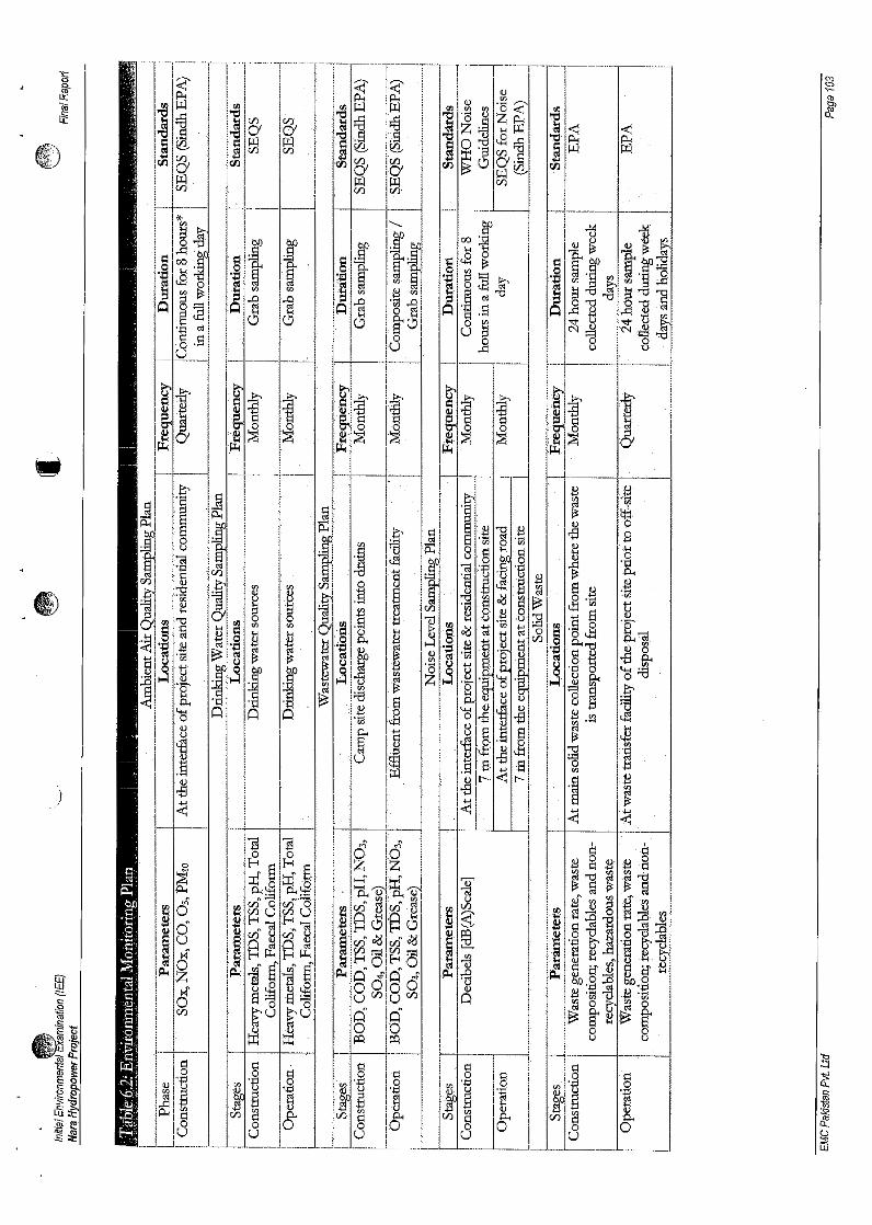
~ "{1OJ) 1 OJ) oo:.g ~ ~il ] ~ r·rt '0.. f~. g ~ ~en en § <'l "0 !:J"'O
~ 013(5 'q .8 ..c: 1:3
o ~ ~ 0U ::l ::a0..c: u
t ~ ~e-,;g
q q §~ ~ ~ ~• ~ .1lJ·
en .i;l~ cf1.il 0a
j B 4-<
i ·8~
0..{J) '" B E IlJ ~~G)~
0 .S § o .!::
~oj:j en~ .ll "-' S
'" v» .~ ·tJ . . S a1iJ !1 . ~ '0 <.fl . ~0.. .0.."'0 (/) ....,
cu.~
0~ ~ ~ s ~ 0..
f f... II 0 :.8'fj ~. cu 0...~ :=l '"II) o q:.e u B
~ ~ s ~ V>'!il II) ....
t ~"'0
U ~0II)
) .~~
~ 6 I0 .(:j
tl g 1lJ· .~0Z "-' (:j
~ ;1; ;1~ '" '.i:l~ '.~~ ~ ::lCl::o 0 .~ ::a
(:j-a'"E §iJo «I'l:l ~j 'p tJ'~ B a 0cu .\4..q i:f Q C:l' .
[f ~o cu 0'p OJ)'p
-=. ~ .... '!il<::: ~ ~ 0~ ~ a- t'".~ -.E: ... 8-.~ ·u
c,.."Q,::::J~ ~ § .q
I§g .(:! '0 g q 'SiE <:> 'B 0 .~ III 0 o,<: Q. 'p '1:1' '1:) P <:.~~ ~ g a t Ig el iQ]=.F i9 '" I", IlJ0.. 0.. 0 0- 0 '0.. e~e 0 0 0 0 0 0 o:s~ o u o i]
~~
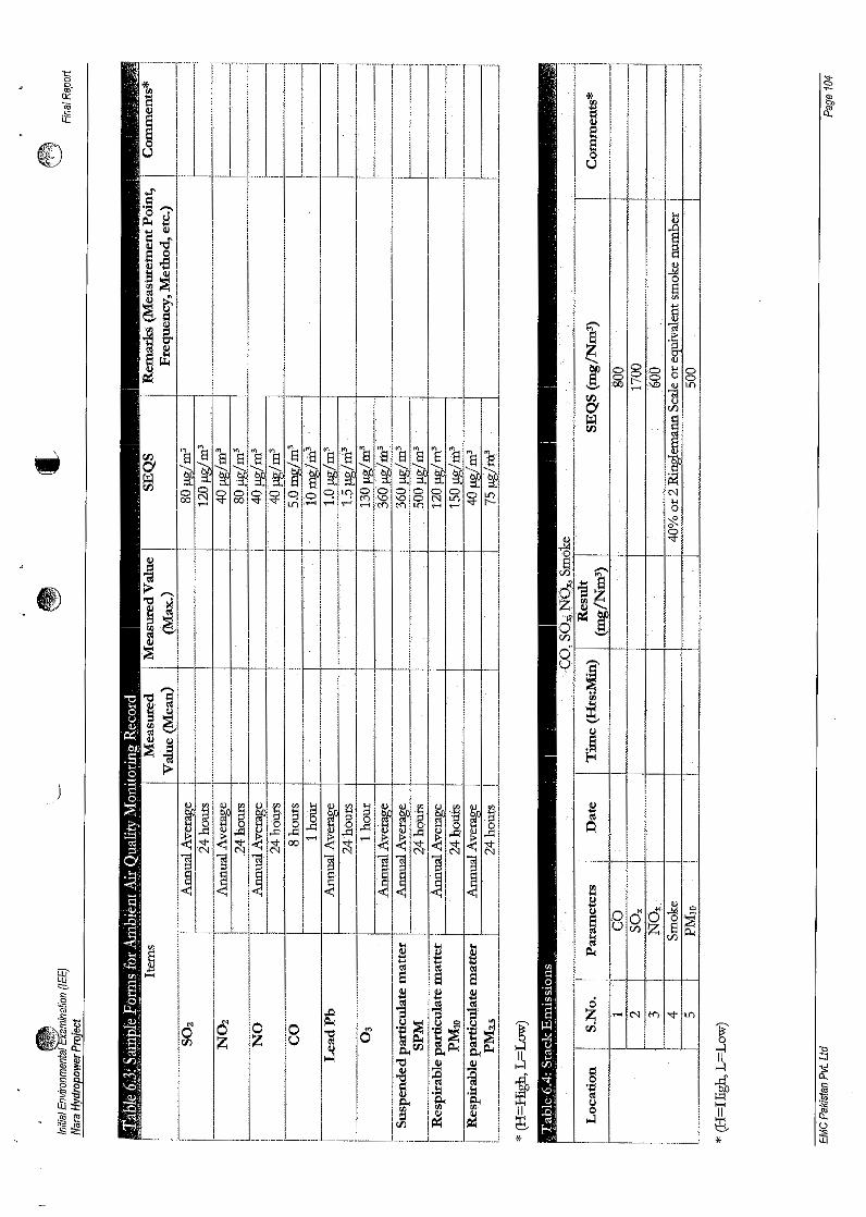
)
]
IU.§f-t
~I-<
~ffi'('Ie 8<:::. ~'":2 ]<II
.~- '" rS 'i 'i~~ 0 0 0 .., 'l:I~
'l Z z o 0 ~~ 0 :3rJ) p,.rJ) ~ 'b
-l!!~ II~
:::;j~ 'tI ~
~.If ~~
g~
c:: 'fj '"cU <'I ~di~ ~ u ~II 0 II ~. ~ ~ ~ ~ ...:I ~ '('):s~ ~* *
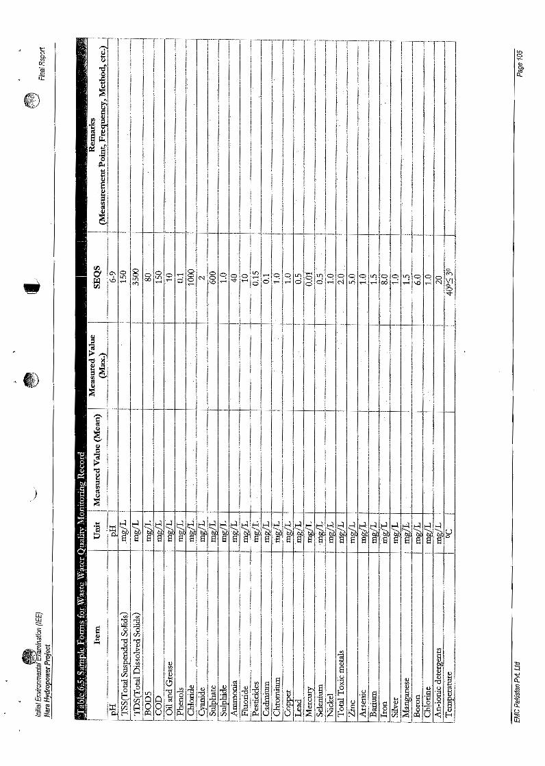
)
i :
15~
!J
i~ j I<u .~ ~ I
iII) _" I
.,
I
I j'I
II! II
IIIII
J'.~
1~~~~~~la~~I~~~~~~~~~~~~~~~~~~~~~i~ I
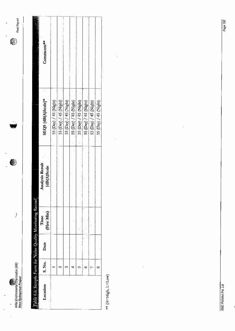
~Q
iff 0""- Z ..-< N ('(')
""'"..\,0 r-
c:: eli:8'" 1i'.~ 1>
". co ~~ 3~
~ !1 :9- .... -J53 ~
~
.~E 0'j:l
c,c:: CI. c:<:I
fa.~~ u0 1jU]:F ~ II;, ,£- ~~
(.)~~ * m*
)/
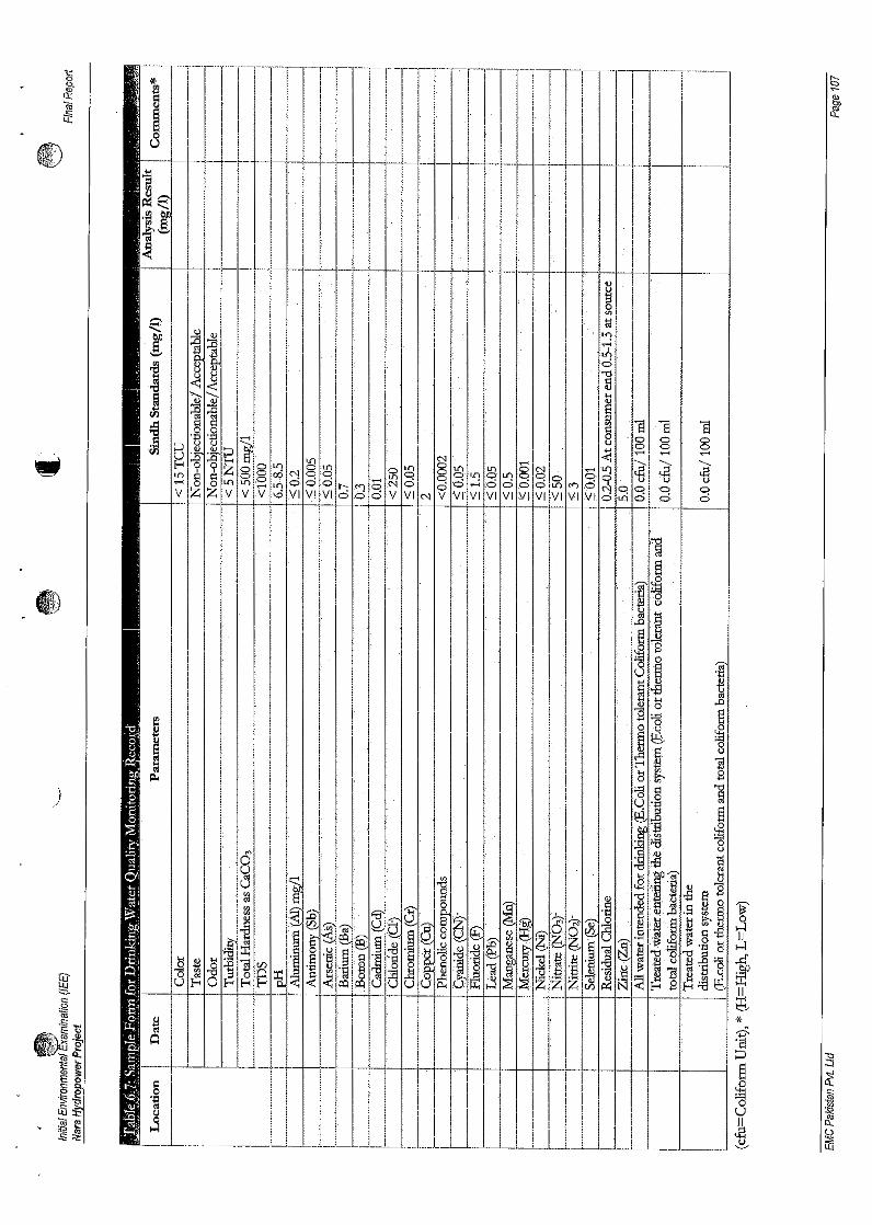
·.....1::: r-,0 * ~(j} '"Q: I , ;i'iiif
uI).I
S::~jj •
.)
~.sIIH
~II~*'Z''Q~ :e§ -I
-s:~
0..s:::<1J
0 ~U
~~~~ 1.lJ
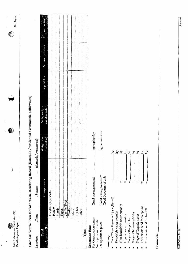
)
II II II II It II II II It
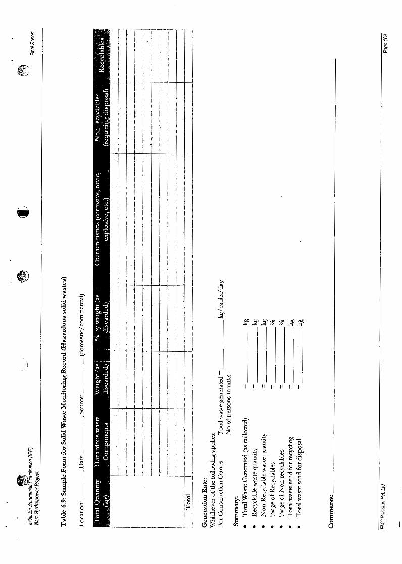
)
II II II II II II II

Initial Environmental Examinatlol1 (lEE)Nora Hydropower Project
Final Report
Chapter 7 Conclusion
The Initial Environmental Examination (lEE) Study was carried out to assess the potential environmental
and socioeconomic impacts of the project for construction and operation phases. The assessment was
carried out keeping in view the provincial and national environmental legislation and guidelines.
Based on the findings of the lEE study of the Proposed Project, it is concluded that the environmental
impacts of the construction and operation of project are manageable and can be mitigated by implementing
the Environmental Management Plan which forms an integral part of lEE document.
Proposed Project site has no sensitive areas such as protected sites includlng wildlife sanctuaries, game
reserves or national parks, or any archaeological, historical or cultural heritage in its immediate
neighborhood; as such its siting would have no sensitivity in this regard. No significant flora and fauna will
be disturbed. The impacts if any, will be limited to individual strayed Dolphins and aquatic life for which
'fIIij mitigations measures have been proposed.
The lEE Study therefore recommends that the Initial Environmental Examination (lEE) report should be
approved with the provision that the suggested mitigation measures will be adopted and the Environmental
Management Plan (EMF) will be followed in letter and spirit.
)
EMC Pakistan Pvt. Ltd Page 110