raghuganga hydropower limited
TRANSCRIPT
RAGHUGANGA HYDROPOWER LIMITED
PROJECT: RAHUGHAT HYDROELECTRIC PROJECT (2X20MW)
TECHNICAL SPECIFICATION FOR
EOT CRANES
SPECIFICATION NO.: PE-TS-479-501-A401
��
�
�
BHARAT HEAVY ELECTRICALS LTDPOWER SECTOR PROJECT ENGINEERING MANAGEMENT
PPEI BUILDING, NOIDA (U.P.)-INDIA
212851/2021/PS-PEM-MAX4
TECHNICAL SPECIFICATION FOR
EOT CRANE
PROJECT: RAHUGHAT HYDROELECTRIC PROJECT (2X20MW)
SPECIFICATION NO. PE-TS-479-501-A001
REV 00 DATE FEB 2021
PE
M-6
66
6-0
CONTENTS
SECTIONS TITLE Page I SPECIFIC TECHNICAL REQUIREMENT
IA Specific Technical Requirement (Mechanical) 1-9 Quality assurance and inspection requirement 10-23 Customer specification 24-36
ANNEXURES i) ANNEXURE-I -List of makes of BOIs 38-43 ii) ANNEXURE-II -Mandatory spare list 44-45 iii) ANNEXURE-III – Tools & tackles 46 iv) ANNEXURE-IV - Painting specification 47 v) ANNEXURE-V - Main Drawing list with schedule of submission 48-53 vi) ANNEXURE-VI - Packing procedure 54-65 vii) ANNEXURE-VII - Shop Test Procedure for Gear Boxes & Load/ Overload
testing of EOT crane at manufacturer’s works 66-70
viii) ANNEXURE-VIII- Input Drawing. 71-73
IB Specific Technical Requirement (Electrical) 74-100 IC Data Sheet-A 101-107 II STANDARD TECHNICAL REQUIREMENT
IIA Standard Technical Requirement (Mechanical) 108-124 VVVF specification 125-129 Field quality plan 130-133 Checklist for O&M manual 134-136
III DOCUMENTS TO BE SUBMITTED BY THE BIDDER i) List of documents to be submitted with bid 138 ii) Compliance cum confirmation certificate 139-140 iii) Pre Bid Clarification Schedule 141 iv) Schedule of Technical Deviation 142
212851/2021/PS-PEM-MAX5
TECHNICAL SPECIFICATION
FOREOT CRANE
PROJECT: RAHUGHAT HYDROELECTRIC PROJECT (2X20MW) SPECIFICATION No: PE-TS-479-501-A401 SECTION-I SUB-SECTION-IA REV. 00 DATE: FEB 2021
SUB SECTION-IA
SPECIFIC TECHNICAL REQUIREMENT (MECHANICAL)
Page 1 of 142
212851/2021/PS-PEM-MAX6
TECHNICAL SPECIFICATION
FOREOT CRANE
PROJECT: RAHUGHAT HYDROELECTRIC PROJECT (2X20MW) SPECIFICATION No: PE-TS-479-501-A401 SECTION-I SUB-SECTION-IA REV. 00 DATE: FEB 2021
SCOPE OF ENQUIRY/INTENT OF SPECIFICATION
1.1 This specification includes, but not limited to SUPPLY PART, SERVICE PART (SUPERVISION & MAINTENANCE SERVICES) & MANDATORY SPARES comprising of design (i.e. preparation and submission of drawing /documents including “As Built” drawings and O&M manuals), engineering, manufacture, fabrication, assembly, inspection / testing at vendor's & sub-vendor’s works, painting, maintenance tools & tackles, fill of lubricants & consumables along with all accessories and spares for erection, start up and commissioning as required, training of end customer at manufacturer's works, forwarding, proper packing, shipment and delivery as per SCC including warranty, supervision of erection and commissioning of crane, supervision of load & overload testing at site, supervision of erection of sole plate, anchor bolts and required accessories for rail & DSL fixing, training of operators at site and routine maintenance/ breakdown maintenance service of EOT cranes for thetotal scope defined as per BHEL NIT & tender technical specification, amendment & agreements till placement of order.
1.2 The contractor shall be responsible for providing all material, equipment & services, which are required to fulfil the intent of ensuring operability, maintainability, reliability and complete safety of the complete work covered under this specification, irrespective of whether it has been specifically listed herein or not. Omission of specific reference to any component / accessory necessary for proper performance of the equipment shall not relieve the contractor of the responsibility of providing such facilities to complete the supply, erection & commissioning and load testing of the cranes and its accessories.
1.3 It is not the intent to specify herein all the details of design and manufacture. However, the equipment shall conform in all respects to high standards of design, engineering and workmanship and shall be capable of performing the required duties in a manner acceptable to purchaser who will interpret the meaning of drawings and specifications and shall be entitled to reject any work or material which in his judgement is not in full accordance herewith.
1.4 The extent of supply under the contract includes all items shown in the drawings, notwithstanding the fact that such items may have been omitted from the specification or schedules. Similarly, the extent of supply also includes all items mentioned in the specification and /or schedules, notwithstanding the fact that such items may have been omitted in the drawing.
1.5 The general term and conditions, instructions to tenderer and other attachment referred to elsewhere are made part of the tender specification. The equipment materials and works covered by this specification is subject to compliance to all attachments referred to in the specification. The bidder shall be responsible for and governed by all requirements stipulated herein.
1.6 While all efforts have been made to make the specification requirement complete & unambiguous, it shall be bidders’ responsibility to ask for missing information, ensure completeness of specification, to bring out any contradictory / conflicting requirement in different sections of the specification and within a section itself to the notice of BHEL and to seek any clarification on specification requirement in the format enclosed under Section-III of the specification within 10 days of receipt of tender documents. In absence of any such clarifications, in case of any contradictory requirement, the more stringent requirement as per interpretation of Purchaser/Customer shall prevail and shall be complied by the bidder without any commercial implication on account of the same. Further in case of any missing information in the specification not brought out by the prospective bidders as part of pre-bid clarification, the same shall be furnished by Purchaser/ Customer as and when brought to their notice either by the bidder or by purchaser/ customer themselves. However, such requirements shall be binding on the successful bidder without any commercial & delivery implication.
1.7 The bidder’s offer shall not carry any sections like clarification, interpretations and /or assumptions.
Page 2 of 142
212851/2021/PS-PEM-MAX7
TECHNICAL SPECIFICATION
FOREOT CRANE
PROJECT: RAHUGHAT HYDROELECTRIC PROJECT (2X20MW) SPECIFICATION No: PE-TS-479-501-A401 SECTION-I SUB-SECTION-IA REV. 00 DATE: FEB 2021
1.8 Deviations, if any, should be very clearly brought out clause by clause in the enclosed deviation schedule along with cost of withdrawal; otherwise, it will be presumed that the vendor's offer is strictly in line with NIT specification. If no cost of withdrawal is given against the deviation, it will be presumed that deviation can be withdrawn without any cost to BHEL/its customer.
1.9 In the event of any conflict between the requirements of two clauses of this specification documents or requirements of different codes and standards specified, more stringent requirement as per theinterpretation of the owner shall apply.
1.10 In case all above requirements are not complied with, the offer may be considered as incomplete and would become liable for rejection.
1.11 Unless specified otherwise, all through the specification, the word contractor shall have same meaning as successful bidder /vendor and Customer/ Purchaser/Employer will mean BHEL and /or customer including their consultant as interpreted by BHEL in the relevant context. For details refer the relevant clause in GCC.
1.12 The standard quality plan is included in this specification to enable the bidder to understand the extent of inspection and testing requirements to execute this job. The successful bidder has to follow the quality plan as minimum along with requirement/s mentioned elsewhere in the specification during manufacturing and testing.
Page 3 of 142
212851/2021/PS-PEM-MAX8
TECHNICAL SPECIFICATION
FOREOT CRANE
PROJECT: RAHUGHAT HYDROELECTRIC PROJECT (2X20MW) SPECIFICATION No: PE-TS-479-501-A401 SECTION-I SUB-SECTION-IA REV. 00 DATE: FEB 2021
1.0.0. SCOPE OF WORK
1.1.0. SCOPE OF SUPPLY
1.1.1. Equipment and services to be furnished by the bidder for EOT Cranes with accessories as per
the details given in the technical specification and data sheet A. Any equipment / accessories
not specified in the specification but required to make the EOT crane complete for efficient
operation shall also be under the bidder’s scope of work.
1.1.2. Compliance with this specification shall not relieve the bidder of the responsibility of furnishing
material and workmanship to meet the specified working/duty conditions.
1.1.3. Crane shall include but not be limited to the following: -
a. Bridge girders
b. End carriages with wheels
c. Crab (trolley)
d. Cross Travel & Long Travel drive arrangement
e. All electrical equipment including cables, junction box, VVVF drive, RRC & pendent and
panels etc. as per datasheet A.
f. PVC insulated shrouded bus bar Cu conductor type DSL along with insert plates (fixing
plates for DSL) to be mounted at civil girder. DSL insert plate with anchor bolt details
drawing for encasing of insert plate in gantry girder has been indicated in input drawing.
The arrangement has to be followed completely by bidder during detail engineering.
g. Earthing arrangement
h. Fill of lubricants till handing over.
i. Painting of cranes and accessories including touch up painting at site.
j. Temporary cable of suitable size as per load calculation for commissioning, testing &
operation of EOT Crane till such time the DSL is charged.
k. Rail complete with sole plates, anchor bolts, clamps etc. including all accessories and end
stopper. Gantry rail & sole plate layout drawing for rail and sole plate dimensions, rail to rail
jointing and sole plate to sole plate jointing along with the anchor bolts details have been
indicated in input drawing. When installed on their concrete foundation, the crane rails shall
be shimmed by means of flat steel and fixed to the concrete with bolts. The layout has to be
followed completely during detail engineering w.r.t. alignment blocks and clamps
arrangement as indicated in the drawing. The dimensional details of alignment block and
clamps are for reference only. Bidder may propose their size for alignment blocks and
clamps during detail engineering without impacting the layout of rail and sole plate.
l. Maintenance tools & Tackle
m. Erection & Commissioning spares
n. Mandatory Spares
Page 4 of 142
212851/2021/PS-PEM-MAX9
TECHNICAL SPECIFICATION
FOREOT CRANE
PROJECT: RAHUGHAT HYDROELECTRIC PROJECT (2X20MW) SPECIFICATION No: PE-TS-479-501-A401 SECTION-I SUB-SECTION-IA REV. 00 DATE: FEB 2021
o. Main Isolating switch/Changeover in enclosure at operating floor for disconnecting supply to
DSL.
p. Slings and cradle for load testing
1.1.4 Mandatory Spares A complete unused and new set of Mandatory Spare parts shall be supplied. Each part shall be
stamped so as to be identified, easy for it use. The items supplied shall be of the best quality.
The minimum requirement of mandatory spare parts is listed in Annexure –II section-IA of this
specification.
1.1.5 Erection and Commissioning sparesThe Bidder shall also supply erection & commissioning spares along with his main equipment
as per his experience, for replacement of damaged or unserviceable parts during the execution
of the project at site, to avoid delay in the project schedule. This shall form part of the main
equipment supply. The Purchaser shall retain the unutilized commissioning spares. Fill of
lubricants; oil etc. till commissioning of the cranes shall also be supplied by the bidder. Bidder
shall supply minimum following spares
i) Oil seal for each gear box 1 Set
ii) Indicating Lamps 1 no. of each type 1 Set
iii) Push Button 1 no. of each type 1 Set
iv) Aux. contactor 1 no. of each size 1 Set
v) Limit switches- 1 no. of each type 1 Set
Note- One set means 100% requirement of one crane
1.1.6 Maintenance Tools and TacklesAs per Annexure III, section-IA of this specification
1.1.7 Any supplies to be done under warranty clause & any other clause of NIT, GCC, SCC as
relevant to the package
1.1.8 Packing as per specification, forwarding and transportation to delivery address as per SCC.
1.2.0 Services to be provided by the bidder1.2.1. Detailed Erection and commissioning procedure shall be submitted by successful bidder for
carrying out the erection and commissioning at site by BHEL.
1.2.2. Scope of Supervision for Erection & commissioning: Tentatively following visits shall be
planned by site team which shall be as follows: -
a) One visit for supervision for erection of sole plate and anchor bolts for rail fixing and insert
plates for DSL fixing for Power house crane & Valve house crane.
b) One visit for Supervision of Erection and commissioning of Power house crane & Valve
house crane.
c) One visit for Supervision of load & overload tests for Power house crane & Valve house
crane.
d) Any additional visit as per requirement of BHEL site office during erection of equipments.
Page 5 of 142
212851/2021/PS-PEM-MAX10
TECHNICAL SPECIFICATION
FOREOT CRANE
PROJECT: RAHUGHAT HYDROELECTRIC PROJECT (2X20MW) SPECIFICATION No: PE-TS-479-501-A401 SECTION-I SUB-SECTION-IA REV. 00 DATE: FEB 2021
Note: Bidder shall be informed at least 10 days in advance for the requirement of visit at
site. Visiting team shall consist of one or two expert of bidder as deemed necessary by
them
1.2.3. Scope of Maintenance Services: Maintenance services shall commence after commissioning
and load testing of crane at site till guarantee period after handing over as per NIT.
Maintenance services shall comprise of following.
Bidder may be called for maintenance services for either of the cases:
a) Routine maintenance including spare for wear and tear
i- Frequency of visits: 1 visit in every 6 months (Tentative 4 nos. visits after load/ overload
testing).
ii- Any tools and tackles, consumables like oil, grease etc., spares required for
replacement due to wear & tear shall be in bidder’s scope and bidder has to ensure
availability of the same before their arrival at site.
iii- Healthiness of crane is to be ensured.
b) Breakdown maintenance
i- Bidder to attend the crane within 72 hours of intimation by deputing expert. Any
damaged item shall be replaced by bidder under warranty condition as defined under
scope of supply.
ii- Any tools and tackles, consumables like oil, grease etc., spares required for
replacement due to wear & tear shall be in bidder’s scope.
iii- Healthiness of crane is to be ensured.
c) For checking healthiness of crane as per requirement of BHEL site office
i- Any tools and tackles, consumables like oil, grease etc., spares required for
replacement due to wear & tear shall be in bidder’s scope and bidder has to ensure
availability of the same before their arrival at site.
ii- Healthiness of crane is to be ensured.
Note: Bidder shall be informed at least 10 days in advance for the requirement of visit at site
(Except for breakdown maintenance). Visiting team shall consist of one or two expert of
bidder as deemed necessary by bidder.
1.2.4. Training to customer personal at manufacturer’s works (refer scope included in the
technical specification and unpriced schedule)
1.2.5. Training of operator at site
1.2.6. Bidder has to facilitate customer / BHEL to obtain statutory clearance / licensee for radio
remote control system from statutory authority.
1.2.7. Any service mentioned in GCC & SCC as relevant to the package.
1.3.0 PAINTING & COLOUR SCHEMEAs per Annexure IV, section-IA of this specification
2.0.0. Drawing and documents submission schedule along with number of prints.
Page 6 of 142
212851/2021/PS-PEM-MAX11
TECHNICAL SPECIFICATION
FOREOT CRANE
PROJECT: RAHUGHAT HYDROELECTRIC PROJECT (2X20MW) SPECIFICATION No: PE-TS-479-501-A401 SECTION-I SUB-SECTION-IA REV. 00 DATE: FEB 2021
Drawing and documents submission schedule along with number of prints / copies required for
various drawing and documents are listed in Annexure –V, section-IA of this specification.
3.0.0. Deviations
If the offer submitted has got any deviation from the technical stipulations in the tender
document, bidder shall tabulate the same in the format of “Cost of withdrawal of deviation”
attached in Section III / GCC / price schedule indicated in e- procurement portal and furnishing
full particular of such deviations. Deviations are to be furnished with mention to specific clause
number (reasons / explanations for such deviations shall be furnished). Notes / comments etc.
is not acceptable. If there are no deviations from the tender document, bidder shall mention
“NO DEVIATION’ in cost of withdrawal of deviation format.
4.0.0. Makes of Sub - Vendor itemsMakes of bought out items as per Annexure-I, section IA of the specification is for reference
only. Sub vendor list shall be subject to customer approval and same shall not have any impact
on manufacturing, delivery schedule and cost of the crane.
5.0.0 Parameter and tolerances for structural assembly including rail shall be as per the relevant standards.
6.0.0. Performance Test requirement
EOT crane along with its drives, controls and other accessories shall be checked for the rated
capacity against the rated speed of motions and for the service conditions specified.
The bidder shall have the full responsibility for the safe and efficient operation of the crane with
associated accessories as a single unit. If the site performance tests indicate the failure of any
of the components to achieve the desired performance, the deficiency shall be made good at
bidder’s cost.
Performance test shall be carried out each time after the rectification /modification is carried
out.
Performance test of the crane shall include load tests and speeds in various motions at site.
7.0.0 Testing of cranes:Refer section IA: “QUALITY ASSURANCE AND INSPECTION REQUIREMENT” include in the
specification.
8.0.0 ConsumablesThe Bidder’s scope includes requirements of consumables such as oils, lubricants including
grease, servo fluids, gases and essential chemicals etc. till handing over. Consumption of all
these consumables till handing over shall also be included in the scope of the Bidder. Bidder
shall also supply a quantity of the full charge of each variety of lubricants, servo fluids, gases,
chemicals etc. used which is expected to be utilized till handing over. This additional quantity
shall be supplied in separate Containers.
Page 7 of 142
212851/2021/PS-PEM-MAX12

TECHNICAL SPECIFICATION
FOREOT CRANE
PROJECT: RAHUGHAT HYDROELECTRIC PROJECT (2X20MW) SPECIFICATION No: PE-TS-479-501-A401 SECTION-I SUB-SECTION-IA REV. 00 DATE: FEB 2021
9.0.0 Works Excludeda. Erection and commissioning of cranes
b. Supply feeder shall be provided by BHEL (as per electrical scope matrix of section IB)
upto main isolating switch (vendor’s scope) on operating floor. The main isolating
switch shall be suitable for the incoming cable.
c. Gantry girder (RCC)
d. Dead load for load/ overload testing at site
e. Storage, unloading and transportation at site
f. Space for storage.
g. Erection hook
h. Exclusion, if any, mentioned in GCC, SCC.
i. Access ladder from operating floor to gantry girder walkway
10.0.0 Other requirements for the system.i. Temperature Effects
Where any portion of the structure is not free to expand or contract under variation of temperature, allowance shall be kept for stress resulting from these conditions. IS: 800- (latest edition) Code of practice for use of structural steel in General Building construction - shall also apply.Any limitation on above account shall be reported during detail engineering while submitting design calculation of crane components/equipment's/sub system.
ii. Minimum thickness of MetalFor load carrying members the component plates, bars, angles and other rolled sections shall be minimum 8mm thick. For tubes having both ends sealed the minimum thickness shall be 4.9 mm (6 SWG). For unsealed tubes the minimum thickness shall be 8mm. The chequered plates for platforms shall be minimum 6 mm thick.
iii. Safety arrangements such as under voltage and single-phase protection in addition to manufacturer’s standard will be provided through VVVF drive to prevent damage to motors on account of mechanical overload and electrical faults and to gearing shafts, etc. due to over stressing.Protective relays for protection against instantaneous over-current, over-load, single phasing and under voltage for all motors shall be provided. The OC relay to be adjustable between 2 to 3 times the full load motor current.
iv. All materials / components will be new and of tested quality and will conform to the specification requirements and standards mentioned.
v. No cast iron parts will be used on the crane except for electrical motors and gearbox castings. Similarly, no wood or other combustible material will be used in any part of the crane.
vi. Qualified welders as per approved QA plan will carry out welding in accordance with establishedWPS.
vii. Design will be provided for easy maintenance of all the parts, particularly the wheel bearings on end carriage.
viii. The contractor shall provide an earthing system to which all equipment under his scope of supply shall be interconnected. This system will in turn be connected by the Purchaser(Customer). to the power house earth mat or the PPV earth mat to be laid by the Purchaser(Customer).
Page 8 of 142
212851/2021/PS-PEM-MAX13
TECHNICAL SPECIFICATION
FOREOT CRANE
PROJECT: RAHUGHAT HYDROELECTRIC PROJECT (2X20MW) SPECIFICATION No: PE-TS-479-501-A401 SECTION-I SUB-SECTION-IA REV. 00 DATE: FEB 2021
ix. The cranes shall be subject to a dynamic overload testing of 25% and a subsequent static overload testing of 40%
CONSTRUCTION FEATURES
a) The cranes will be furnished with required components comprising the following:b) The cranes bridge shall be of solid welded steel construction designed to resist without undue
deflections vertical and horizontal stresses. Perfect parallelism of the structure shall be ensured when any load up to the rated load is applied.
c) Jacking pads will be provided on the structural frames of trolley end carriage, for removal of wheels.
d) Platforms and walkways shall be of either checkered plate or grated. Suitable hand and foot-rails shall also be provided. All visible parts shall be plain with smooth, flat and appropriately finished surfaces.
e) Wheelbases for end carriage will as per IS.807 (latest edition) f) PVC shrouded conductor bus bar type Cu DSL will be with suitable guards and service cage for
maintenance of DSL will be provided with indication lamps on ends.g) Power House Cranes shall be controlled for all three motions from the control desk located in the
operator’s Cabin, pendent push button station and Radio Remote Control (RRC). Valve house crane shall be controlled from pendent push button station only.
h) Crane shall be complete with trolley, tracks, wheels, axles, drive mechanism, hoisting drum brakes, horns, warning lights limit switches etc.
i) Portable hand operated lubrication equipment viz. grease gun etc. to be included in the supply. j) For girders, the following values of maximum span to depth ratio shall be governing:
Plate girders: Span/depth = 18 Lattice girders: Span/depth = 12
k) The rails or tracks of the cranes shall be resting on correspondingly provided concrete supporting structures. These shall be provided with the necessary stops. These shall be perfectly straight, free from scale and of a size to limit deflections not exceeding 1/2000 of the span between suspensions or supports if not continuously supported. Tracks or rails shall be supplied complete with fasteners, hangers, back-plates, expansion joints (where crossing concrete expansion joints) and stop blocks.
l) Bridge and Trolley frame
Bridge and trolley frames will be fabricated from steel plates / members. Mounting will be designed to facilitate easy removal of the wheels, bearings and journals. In bridge girder strength calculations, the trolleys, rails and chequered shall not be considered as load carrying members.
Bridge mechanism shall comprise of electric motors and totally enclosed speed reduction gear unit to drive the bridge wheels. The gear motors shall be keyed directly to the extended wheel shaft. The bridge motion shall be free from vibration, rocking etc. under all conditions of operations and the crane structure shall not have any tendency to get out of line.
m) Drive
All drive motors will be of crane duty conforming to IS: 325 and IS: 3177. The motor shall be suitable for 150 starts / hr. and 40% CDF. Motor nameplate rating at 400 C shall have Motor rating will be calculated keeping margin of at least 10% over the maximum power requirement in the duty condition specified.
Each motor equal to or more than 30 KW rating shall be provided with space heater. All electrical equipment accessories and wiring shall have tropical protection.
The VVF drive control shall be used for control of each motion.
Page 9 of 142
212851/2021/PS-PEM-MAX14
TECHNICAL SPECIFICATION
FOREOT CRANE
PROJECT: RAHUGHAT HYDROELECTRIC PROJECT (2X20MW) SPECIFICATION No: PE-TS-479-501-A401 SECTION-I SUB-SECTION-IA REV. 00 DATE: FEB 2021
QUALITY ASSURANCE AND INSPECTION REQUIREMENT
Page 10 of 142
212851/2021/PS-PEM-MAX15
TECHNICAL SPECIFICATION
FOREOT CRANE
PROJECT: RAHUGHAT HYDROELECTRIC PROJECT (2X20MW) SPECIFICATION No: PE-TS-479-501-A401 SECTION-I SUB-SECTION-IA REV. 00 DATE: FEB 2021
1.1.0. Inspection and Testing Bidder shall submit QAP based on the guidelines given in the specification & QAP enclosed
therein.
1.1.1. Inspection and testing at Manufacturer’s works Copy of approved documents with stamp and signature (one set) shall be available at the place
of Inspection which shall be ensured by supplier.
Shop inspection and tests will include but not limited to the following –
STAGE INSPECTIONStage inspection of various components of crane shall be guided by the MQP approved during
detail engineering. Indicative MQP is attached in the specification. However, following shall be
ensured and read in conjunction with relevant clause of MQP w.r.t. stage inspection:
i. All test certificates shall be in original and legible. Photocopies certified by Mill/ manufacturer of
raw material used, are acceptable.
ii. For tensile testing of hooks/ forgings, samples shall be drawn from the full cross section of the
shank diameter of hooks/ forgings Samples forged to reduced cross section for testing
purposes is not acceptable. Hooks shall be manufactured from Blooms, billets, rounds by forging with forging ratio of at least 3:1. Hooks manufactured from plates are not acceptable.
iii Radiographs shall be inspected to a sensitivity of 2%.
iv Ultrasonic test on forgings and casting of critical components like cross head (hook suspension
block), Hooks, Shafts, Axles, Gears, Wheels, Pulleys etc. Ultrasonic test on forgings shall be
carried out as per norms given below. UT shall be carried out in Proof machined condition
(single diameter/ Flat surface without steps, keyways, teeth cutting or other profile machining
which can create difficulty in ultrasonic testing). Components shall be identified with Heat
number and serial number by punching). Hardening operation shall be carried out prior to
Ultrasonic testing.
Unacceptable defects in forgings are as given below:
1. Cracks, flakes, seams and laps
2. Defects giving indication larger than ‘4 (four) mm diameter equivalent flaw’ except for wheels
for which Defects giving indication larger than ‘6 (six) mm diameter equivalent flaw.’
3. Group of defects with maximum indication less than that from a 4 mm diameter equivalent
flaw which cannot be separated at testing sensitivity if the back echo is reduced by 50%
except for wheels for which Group of defects with maximum indication less than that from a
6 mm dia. equivalent flaw which cannot be separated at testing sensitivity if the back echo is
reduced by 40%.
4. Defects giving indication of 2 to 4 mm dia. equivalent flaw, separated by a distance less than
4 (four) times the size of the larger of the adjacent flaws except for wheels for which Defects
giving indication of 3 to 6 mm dia. Equivalent flaw, separated by a distance less than 4 (four)
Page 11 of 142
212851/2021/PS-PEM-MAX16
TECHNICAL SPECIFICATION
FOREOT CRANE
PROJECT: RAHUGHAT HYDROELECTRIC PROJECT (2X20MW) SPECIFICATION No: PE-TS-479-501-A401 SECTION-I SUB-SECTION-IA REV. 00 DATE: FEB 2021
times the size of the larger of the adjacent flaws Ultrasonic test on Castings shall be carried
out as per ASTME 609.
Wherever, the Quality plan calls for witness of Ultrasonic test by BHEL or BHEL’s
representative, the material shall be offered for UT in proof machined condition as stated
above and hard stamping and subsequent stamp transferring by BHEL shall be followed at
subsequent stages to ensure trace ability.
v. Gear boxes shall be checked at No load for backlash, tooth contact, noise, temperature rise
and vibration as per attached Procedure No. PEM (Q)/001.
vi. Test certificates shall be furnished for verification of Type tests including environmental tests -
for electrical and electro-mechanical items. If Type tests for items with similar / identical
construction are not available, arrangement shall be made to conduct the same in the presence
of BHEL/ Customer’s representative (as required).
vii. Acceptance and routine tests (HV and insulation) for all electrical and electro-mechanical
components and system as per governing specification
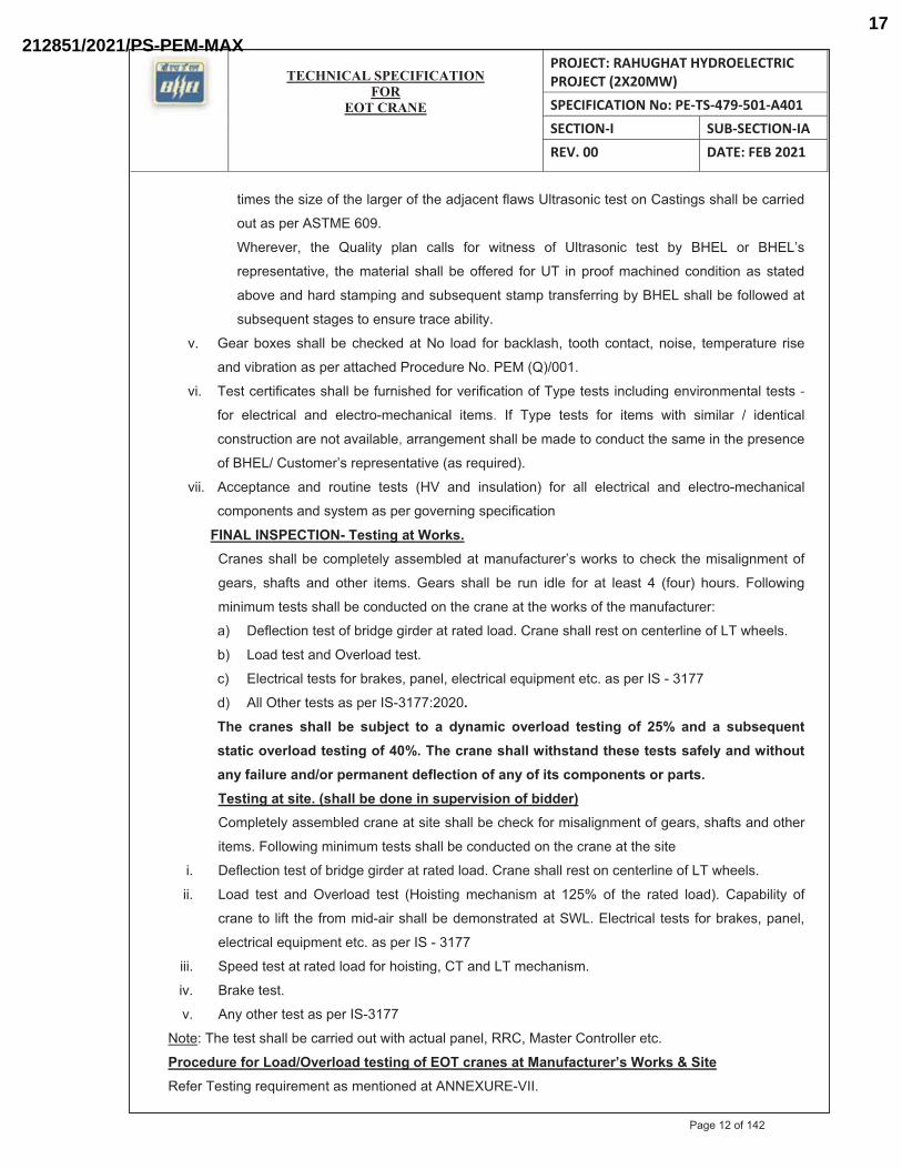
FINAL INSPECTION- Testing at Works.Cranes shall be completely assembled at manufacturer’s works to check the misalignment of
gears, shafts and other items. Gears shall be run idle for at least 4 (four) hours. Following
minimum tests shall be conducted on the crane at the works of the manufacturer:
a) Deflection test of bridge girder at rated load. Crane shall rest on centerline of LT wheels.
b) Load test and Overload test.
c) Electrical tests for brakes, panel, electrical equipment etc. as per IS - 3177
d) All Other tests as per IS-3177:2020.The cranes shall be subject to a dynamic overload testing of 25% and a subsequent static overload testing of 40%. The crane shall withstand these tests safely and without any failure and/or permanent deflection of any of its components or parts.Testing at site. (shall be done in supervision of bidder)Completely assembled crane at site shall be check for misalignment of gears, shafts and other
items. Following minimum tests shall be conducted on the crane at the site
i. Deflection test of bridge girder at rated load. Crane shall rest on centerline of LT wheels.
ii. Load test and Overload test (Hoisting mechanism at 125% of the rated load). Capability of
crane to lift the from mid-air shall be demonstrated at SWL. Electrical tests for brakes, panel,
electrical equipment etc. as per IS - 3177
iii. Speed test at rated load for hoisting, CT and LT mechanism.
iv. Brake test.
v. Any other test as per IS-3177
Note: The test shall be carried out with actual panel, RRC, Master Controller etc.
Procedure for Load/Overload testing of EOT cranes at Manufacturer’s Works & SiteRefer Testing requirement as mentioned at ANNEXURE-VII.
Page 12 of 142
212851/2021/PS-PEM-MAX17
MA
NU
FAC
TU
RE
R/B
IDD
ER
/SU
PPL
IER
NA
ME
& A
DD
RE
SSQ
UA
LIT
Y P
LA
NSP
EC
. NO
:PE
-TS-
479-
501-
A40
1D
AT
E:
CU
STO
ME
R :
QP
NO
.:PE
-V0-
479-
501-
A10
1R
ev :
PRO
JEC
T:
RA
HU
GH
AT
HY
DR
OE
LE
CT
RIC
PR
OJE
CT
(2X
20M
W)
PO N
O.:
DA
TE
ITE
M:
EO
T C
RA
NE
SSY
STEM
:EO
T C
RA
NE
SEC
TIO
N:
SHE
ET
OF
BH
EL
BID
DE
R/S
UPP
LIE
RFO
R C
UST
OM
ER
RE
VIE
W&
APP
RO
VA
L
EN
GIN
EE
RIN
GQ
UA
LIT
YS
ign
& D
ate
Doc
No:
Sig
n &
Dat
eN
ame
Sig
n &
Dat
eN
ame
Sea
lS
ign
& D
ate
Nam
eS
eal
Pre
par
ed
by:
Ch
ecked
b
y:
Rev
iew
ed
by:
Rev
iew
ed
by:
Rev
iew
ed
by:
Ap
pro
ved
b
y:
LEG
END
S: *
REC
OR
DS,
IND
ENTI
FIED
WIT
H "
TIC
K"(
√) S
HA
LLB
E ES
SEN
TIA
LLY
INC
LUD
ED B
Y SU
PPLI
ER IN
QA
DO
CU
MEN
TATI
ON
, **
M:
SUPP
LIER
/ MAN
UFA
CTU
RER
/ SU
B-S
UPP
LIER
, C:
MAI
N S
UPP
LIER
/ B
HEL
/ TH
IRD
PAR
TY IN
SPEC
TIO
N A
GEN
CY,
N: C
UST
OM
ER, P
: PER
FOR
M, W
: WIT
NES
S, V
: VER
IFIC
ATIO
N, A
S AP
PRO
PRIA
TE, M
A: M
AJO
R, M
I: M
INO
R, C
R: C
RIT
ICA
L
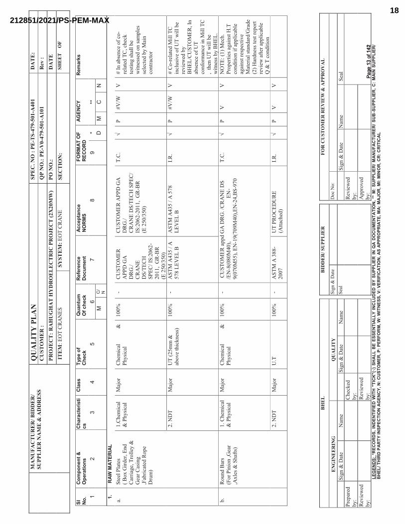
1.R
AW M
ATER
IAL
a.S
teel
Pla
tes
(
Bo
x G
ird
er,
En
d
Car
riag
e, T
roll
ey &
G
ear
Cas
ing
,Fab
rica
ted
Rop
e D
rum
)
1.C
hem
ical
&P
hysi
cal
M
ajo
r C
hem
ical
&P
hysi
cal
1
00
%-
CU
ST
OM
ER
A
PP
D G
A
DR
G./
CR
AN
E
DS
/TE
CH
S
PE
C/
IS:2
062
-2
011
, G
R-B
R
(E
250
/350
)
CU
ST
OM
ER
AP
PD
GA
D
RG
./
CR
AN
E D
S/T
EC
H S
PE
C/
IS:2
06
2-2
01
1,
GR
-BR
(E 2
50
/350
)
T.C
.
√P
#V
/WV
# I
n a
bse
nce
of
co-
rela
ted
TC
, ch
eck
test
ing s
hal
l b
e w
itn
esse
d o
n s
amp
les
sele
cted
by M
ain
co
ntr
acto
r
2.
ND
TM
ajo
rU
T (
25
mm
&
abo
ve
thic
kn
ess)
10
0%
-A
ST
M A
43
5 /
A
57
8 L
EV
EL
BA
ST
M A
43
5 /
A 5
78
LE
VE
L B
I.R
.√
P#
V/W
V#
Co
-rel
ated
Mil
l T
C
incl
usi
ve
of
UT
wil
l b
e re
vie
wed
by
BH
EL
/CU
ST
OM
ER
, In
ab
sen
ce o
f U
T
con
form
ance
in
Mil
l T
C
, t
hen
UT
wil
l b
e w
itn
ess
by B
HE
L.
b.
Ro
und
Bar
s
(Fo
r P
inio
n,G
ear
,Axle
s &
Sh
afts
)
1.
Ch
emic
al
&
Ph
ysi
cal
M
ajo
rC
hem
ical
&
Ph
ysi
cal
1
00
%-
CU
ST
OM
ER
ap
pd G
A D
RG
. /C
RA
NE
DS
/E
N-8
(08
0M
40
),
EN
-9
(07
0M
55
), E
N-1
9(7
09M
40
),E
N-2
4,B
S-9
70
T.C
.√
PV
VN
OT
E:
(1)
Mec
h.
Pro
per
ties
agai
nst
H.T
co
nd
itio
n i
f ap
pli
cab
le
agai
nst
res
pec
tive
Mat
eria
l st
and
ard
/Gra
de
(2
) H
ard
nes
s te
st r
epo
rt
revie
w a
fter
app
lica
ble
Q
& T
co
nd
itio
n
2.
ND
TM
ajo
r U
.T1
00
%-
AS
TM
A 3
88
-2
007
UT
PR
OC
ED
UR
E
(Att
ach
ed)
I.R
.√
PV
V
Sl No.
Com
pone
nt &
Ope
ratio
nsC
hara
cter
isti
csC
lass
Type
of
Chec
kQ
uant
umO
f che
ckR
efer
ence
Docu
men
tAc
cept
ance
NORM
SFO
RMAT
OF
RECO
RDAG
ENC
YRe
mar
ks
����
����
����
��
���� �
���
��
��
���
��
��
��
�
����
����
����
��Pa
ge 1
3 of
142
Page
13
of 1
42
212851/2021/PS-PEM-MAX18
MA
NU
FAC
TU
RE
R/B
IDD
ER
/SU
PPL
IER
NA
ME
& A
DD
RE
SSQ
UA
LIT
Y P
LA
NSP
EC
. NO
:PE
-TS-
479-
501-
A40
1D
AT
E:
CU
STO
ME
R :
QP
NO
.:PE
-V0-
479-
501-
A10
1R
ev :
PRO
JEC
T:
RA
HU
GH
AT
HY
DR
OE
LE
CT
RIC
PR
OJE
CT
(2X
20M
W)
PO N
O.:
DA
TE
ITE
M:
EO
T C
RA
NE
SSY
STEM
:EO
T C
RA
NE
SEC
TIO
N:
SHE
ET
OF
BH
EL
BID
DE
R/S
UPP
LIE
RFO
R C
UST
OM
ER
RE
VIE
W&
APP
RO
VA
L
EN
GIN
EE
RIN
GQ
UA
LIT
YS
ign
& D
ate
Doc
No:
Sig
n &
Dat
eN
ame
Sig
n &
Dat
eN
ame
Sea
lS
ign
& D
ate
Nam
eS
eal
Pre
par
ed
by:
Ch
ecked
b
y:
Rev
iew
ed
by:
Rev
iew
ed
by:
Rev
iew
ed
by:
Ap
pro
ved
b
y:
LEG
END
S: *
REC
OR
DS,
IND
ENTI
FIED
WIT
H "
TIC
K"(
√) S
HA
LLB
E ES
SEN
TIA
LLY
INC
LUD
ED B
Y SU
PPLI
ER IN
QA
DO
CU
MEN
TATI
ON
, **
M:
SUPP
LIER
/ MAN
UFA
CTU
RER
/ SU
B-S
UPP
LIER
, C:
MAI
N S
UPP
LIER
/ B
HEL
/ TH
IRD
PAR
TY IN
SPEC
TIO
N A
GEN
CY,
N: C
UST
OM
ER, P
: PER
FOR
M, W
: WIT
NES
S, V
: VER
IFIC
ATIO
N, A
S AP
PRO
PRIA
TE, M
A: M
AJO
R, M
I: M
INO
R, C
R: C
RIT
ICA
L
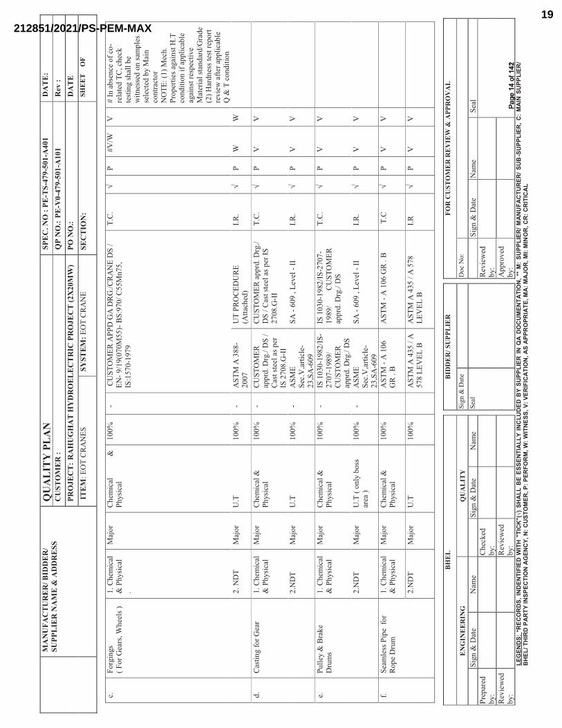
c.F
org
ings
(
Fo
r G
ears
, W
hee
ls )
1.
Ch
emic
al
&
Ph
ysi
cal
.
Maj
or
Ch
emic
al
&P
hysi
cal
1
00
%-
CU
ST
OM
ER
AP
PD
GA
DR
G./
CR
AN
E D
S /
E
N-
9/1
9(0
70M
55
)-B
S:9
70
/ C
55M
n75
, IS
:157
0-1
97
9
T.C
.√
P#
V/W
V#
In a
bse
nce
of
co-
rela
ted
TC
, ch
eck
test
ing s
hal
l b
e w
itn
esse
d o
n s
amp
les
sele
cted
by M
ain
co
ntr
acto
r
N
OT
E:
(1)
Mec
h.
Pro
per
ties
agai
nst
H.T
co
nd
itio
n i
f ap
pli
cab
le
agai
nst
res
pec
tive
Mat
eria
l st
and
ard
/Gra
de
(2
) H
ard
nes
s te
st r
epo
rt
revie
w a
fter
app
lica
ble
Q
& T
co
nd
itio
n
2.
ND
TM
ajo
rU
.T1
00
%-
AS
TM
A 3
88
-2
007
UT
PR
OC
ED
UR
E
(Att
ach
ed)
I.R
. √
PW
W
d.
Cas
tin
g f
or
Gea
r1
. C
hem
ical
&
Ph
ysi
cal
Maj
or
Chem
ical
&
Ph
ysi
cal
10
0%
-C
US
TO
ME
R
app
rd. D
rg./
DS
/
Cas
t st
eel
as p
er
IS 2
708
.G-I
I
CU
ST
OM
ER
ap
prd
. D
rg./
D
S /
Cas
t st
eel
as p
er I
S
27
08
.G-I
I
T.C
.√
PV
V
2.N
DT
Maj
or
U.T
10
0%
-A
SM
E
Sec
.V,a
rtic
le-
23
,SA
-60
9
SA
-6
09
, L
evel
-II
I.R
.√
PV
V
e.P
ull
ey &
Bra
ke
Dru
ms
1.
Chem
ical
&
Ph
ysi
cal
Maj
or
Chem
ical
&
Ph
ysi
cal
10
0%
-IS
10
30
-19
82
/IS
-2
707
-198
9/
C
US
TO
ME
R
app
rd. D
rg./
DS
IS 1
030
-19
82
/IS
-270
7-
19
89
/
CU
ST
OM
ER
ap
prd
. D
rg./
DS
T.C
.√
PV
V
2.N
DT
Maj
or
U.T
( o
nly
bo
ss
area
)1
00
%-
AS
ME
S
ec.V
,art
icle
-2
3,S
A-6
09
SA
-6
09
, L
evel
-II
I.R
.√
PV
V
f.S
eam
less
Pip
e f
or
Ro
pe
Dru
m1
. C
hem
ical
&
Ph
ysi
cal
Maj
or
Chem
ical
&
Ph
ysi
cal
10
0%
AS
TM
-A
10
6
GR
. B
A
ST
M -
A 1
06
GR
. B
T
.C
√P
VV
2.N
DT
Maj
or
U.T
10
0%
AS
TM
A 4
35
/ A
5
78 L
EV
EL
BA
ST
M A
43
5 /
A 5
78
L
EV
EL
BI.
R√
PV
V
����
����
����
��Pa
ge 1
4 of
142
Page
14
of 1
42
212851/2021/PS-PEM-MAX19
MA
NU
FAC
TU
RE
R/B
IDD
ER
/SU
PPL
IER
NA
ME
& A
DD
RE
SSQ
UA
LIT
Y P
LA
NSP
EC
. NO
:PE
-TS-
479-
501-
A40
1D
AT
E:
CU
STO
ME
R :
QP
NO
.:PE
-V0-
479-
501-
A10
1R
ev :
PRO
JEC
T:
RA
HU
GH
AT
HY
DR
OE
LE
CT
RIC
PR
OJE
CT
(2X
20M
W)
PO N
O.:
DA
TE
ITE
M:
EO
T C
RA
NE
SSY
STEM
:EO
T C
RA
NE
SEC
TIO
N:
SHE
ET
OF
BH
EL
BID
DE
R/S
UPP
LIE
RFO
R C
UST
OM
ER
RE
VIE
W&
APP
RO
VA
L
EN
GIN
EE
RIN
GQ
UA
LIT
YS
ign
& D
ate
Doc
No:
Sig
n &
Dat
eN
ame
Sig
n &
Dat
eN
ame
Sea
lS
ign
& D
ate
Nam
eS
eal
Pre
par
ed
by:
Ch
ecked
b
y:
Rev
iew
ed
by:
Rev
iew
ed
by:
Rev
iew
ed
by:
Ap
pro
ved
b
y:
LEG
END
S: *
REC
OR
DS,
IND
ENTI
FIED
WIT
H "
TIC
K"(
√) S
HA
LLB
E ES
SEN
TIA
LLY
INC
LUD
ED B
Y SU
PPLI
ER IN
QA
DO
CU
MEN
TATI
ON
, **
M:
SUPP
LIER
/ MAN
UFA
CTU
RER
/ SU
B-S
UPP
LIER
, C:
MAI
N S
UPP
LIER
/ B
HEL
/ TH
IRD
PAR
TY IN
SPEC
TIO
N A
GEN
CY,
N: C
UST
OM
ER, P
: PER
FOR
M, W
: WIT
NES
S, V
: VER
IFIC
ATIO
N, A
S AP
PRO
PRIA
TE, M
A: M
AJO
R, M
I: M
INO
R, C
R: C
RIT
ICA
L
Maj
or
Mac
ro
E
tch
ing/F
latt
enin
g
for
Sea
mle
ss P
ipe
10
0%
AS
TM
A 1
06
-2
007
,GR
-BA
ST
M A
10
6-2
00
7,G
R-B
I.R
.√
PV
V
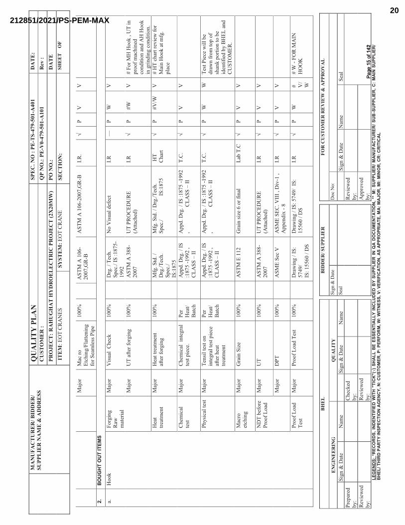
2.BO
UGHT
OUT
ITEM
S
a.
Ho
ok
Fo
rgin
g
Raw
m
ater
ial
Maj
or
Vis
ual
C
hec
k1
00
%D
rg.
/ T
ech
. S
pec
./ I
S :
18
75
-1
992
No V
isual
def
ect
I.R
—P
WV
Maj
or
UT
aft
er f
org
ing
10
0%
AS
TM
A 3
88
-2
007
UT
PR
OC
ED
UR
E
(Att
ach
ed)
I.R
√P
#W
V#
Fo
r M
H H
oo
k ,
UT
in
p
roo
f m
ach
ined
co
nd
itio
n a
nd
AH
Ho
ok
in g
rind
ing c
on
dit
ion
.
Hea
t tr
eatm
ent
Maj
or
Hea
t tr
eatm
ent
afte
r fo
rgin
g1
00
%M
fg.
Std
. /
Drg
./T
ech
. S
pec
./
IS:1
87
5
Mfg
. S
td.
/ D
rg./
Tec
h.
Sp
ec./
I
S:1
87
5H
T
Ch
art
√P
#V
/WV
# H
T c
har
t re
vie
w f
or
Mai
n H
oo
k a
t m
fg.
pla
ce
Chem
ical
te
st
Maj
or
Chem
ical
in
tegra
l te
st p
iece
.P
er
Hea
t/B
atch
Ap
pd
. D
rg.
/ IS
:1
87
5 -
199
2 ,
CL
AS
S –
II
Ap
pd
. D
rg.
/ IS
:18
75
-1
99
2
,
C
LA
SS
–II
T
.C.
√P
VV
Ph
ysi
cal
test
Maj
or
Ten
sil
test
on
in
tegra
l te
st p
iece
af
ter
hea
t tr
eatm
ent
Per
H
eat/
Bat
ch
Ap
pd
. D
rg.
/ IS
:1
87
5 -
199
2 ,
CL
AS
S –
II
Ap
pd
. D
rg.
/ IS
:18
75
-1
99
2
,
C
LA
SS
–II
T
.C.
√P
WW
Tes
t P
iece
wil
l b
e d
raw
n f
rom
to
p o
f sh
ank p
ort
ion
to b
e id
enti
fied
by B
HE
L a
nd
C
US
TO
ME
R.
Mac
ro
etch
ing
Maj
or
Gra
in S
ize
10
0%
AS
TM
E 1
12
Gra
in s
ize
6 o
r fi
nal
Lab
T.C
√P
VV
ND
T b
efo
re
Pro
of
Lo
adM
ajo
rU
T
10
0%
AS
TM
A 3
88
-2
007
UT
PR
OC
ED
UR
E
(Att
ach
ed)
I.R
√P
VV
Maj
or
DP
T
10
0%
AS
ME
Sec
VA
SM
E S
EC
. V
III
, D
iv-1
,
Ap
pen
dix
-8
I.R
√P
VV
Pro
of
Lo
ad
Tes
t M
ajo
r P
roo
f L
oad
Tes
t1
00
%D
raw
ing /
IS
: 5
749
/
IS
: 15
56
0 /
DS
Dra
win
g /
IS
: 57
49
/ I
S:
15
56
0 /
DS
I.R
√P
W# V
/W
# W
-F
OR
MA
IN
HO
OK
����
����
����
��Pa
ge 1
5 of
142
Page
15
of 1
42
212851/2021/PS-PEM-MAX20
MA
NU
FAC
TU
RE
R/B
IDD
ER
/SU
PPL
IER
NA
ME
& A
DD
RE
SSQ
UA
LIT
Y P
LA
NSP
EC
. NO
:PE
-TS-
479-
501-
A40
1D
AT
E:
CU
STO
ME
R :
QP
NO
.:PE
-V0-
479-
501-
A10
1R
ev :
PRO
JEC
T:
RA
HU
GH
AT
HY
DR
OE
LE
CT
RIC
PR
OJE
CT
(2X
20M
W)
PO N
O.:
DA
TE
ITE
M:
EO
T C
RA
NE
SSY
STEM
:EO
T C
RA
NE
SEC
TIO
N:
SHE
ET
OF
BH
EL
BID
DE
R/S
UPP
LIE
RFO
R C
UST
OM
ER
RE
VIE
W&
APP
RO
VA
L
EN
GIN
EE
RIN
GQ
UA
LIT
YS
ign
& D
ate
Doc
No:
Sig
n &
Dat
eN
ame
Sig
n &
Dat
eN
ame
Sea
lS
ign
& D
ate
Nam
eS
eal
Pre
par
ed
by:
Ch
ecked
b
y:
Rev
iew
ed
by:
Rev
iew
ed
by:
Rev
iew
ed
by:
Ap
pro
ved
b
y:
LEG
END
S: *
REC
OR
DS,
IND
ENTI
FIED
WIT
H "
TIC
K"(
√) S
HA
LLB
E ES
SEN
TIA
LLY
INC
LUD
ED B
Y SU
PPLI
ER IN
QA
DO
CU
MEN
TATI
ON
, **
M:
SUPP
LIER
/ MAN
UFA
CTU
RER
/ SU
B-S
UPP
LIER
, C:
MAI
N S
UPP
LIER
/ B
HEL
/ TH
IRD
PAR
TY IN
SPEC
TIO
N A
GEN
CY,
N: C
UST
OM
ER, P
: PER
FOR
M, W
: WIT
NES
S, V
: VER
IFIC
ATIO
N, A
S AP
PRO
PRIA
TE, M
A: M
AJO
R, M
I: M
INO
R, C
R: C
RIT
ICA
L
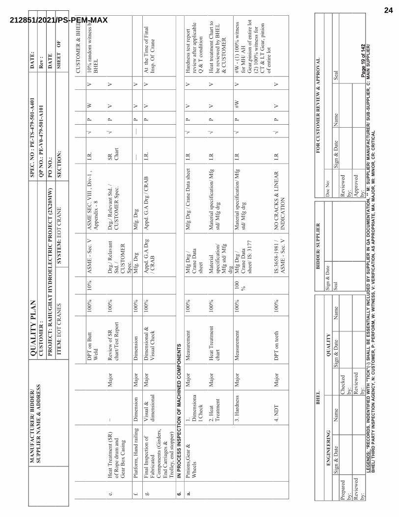
ND
T
afte
r P
roo
f L
oad
( U
T o
nly
sh
ank
po
rtio
n )
Maj
or
U.T
& M
PI
afte
r P
roo
f L
oad
Tes
t1
00
%A
ST
M A
38
8-
20
07
/
A
ST
M E
709
-2
007
AS
TM
A 3
88
-200
7 /
A
ST
M E
709
-20
07
I.R
√P
W# V
/W
Iden
tifi
cati
on
P
un
chM
ajo
r V
isual
10
0%
——
——
PH
HH
-H
old
poin
t
(
iden
tifi
cati
on
by
CU
ST
OM
ER
& B
HE
L )
b.
Wir
e R
op
e &
sli
ngs
Vis
ual
&
Bre
akin
g
Str
ength
Maj
or
Typ
e, g
rad
e,
bre
akin
g s
tren
gth
&
vis
ual
,
Dia
met
er
10
0%
IS:
22
66
–20
02
/
G.A
DR
G
/ D
AT
A S
HE
ET
IS:
22
66
–20
02
/ G
.A
DR
G
/ D
AT
A S
HE
ET
Mil
l T
.C.
√P
VV
c.R
ails
Chem
ical
&
Ten
sile
,
Cro
ss
sect
ion
,
Har
dn
ess
, D
imen
sion
Maj
or
Chem
ical
&
Ten
sile
, H
ard
nes
s ,
Dim
ensi
on
10
0%
G.A
D
raw
ing /
IS
: 34
43
-1
980
/AP
PD
D
AT
A S
HE
ET
G.A
D
raw
ing /
IS
: 34
43
-19
80
/AP
PD
D
AT
A S
HE
ET
T.C
/
I.R
√P
VV
3.EL
ECTR
ICAL
ITEM
S
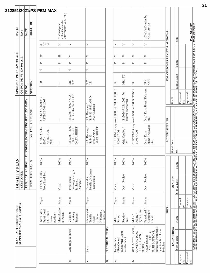
a.T
ran
sfo
rmer
( li
ke
Co
ntr
ol
tran
sfo
rmer
,L
igh
t tr
ansf
orm
er )
Mak
e ,
Rat
ing
Maj
or
Vis
ual
10
0%
CU
ST
OM
ER
ap
pro
ved
BO
I li
st /
SL
D /
DR
G /
B
OM
/ A
DS
IRP
VV
Rou
tin
e T
est
Maj
or
Do
c.
Rev
iew
10
0%
Mfg
. C
atal
og /
D
SIS
:20
26
& I
S:
12
02
1 f
or
con
tro
l tr
ansf
orm
erM
fg.
TC
PV
V
b.
SF
U ,
MC
CB
, M
CB
,
CO
NT
RA
CT
OR
S ,
DS
L,
RE
LA
YS
,
FU
SE
S ,
RE
SIS
TE
NC
E
BA
NK
,HO
OT
ER
, P
US
H B
UT
TO
NS
, in
dic
atin
g i
nst
rum
ents
,
jun
ctio
n b
ox,
Lim
it
Sw
itch
es
Mak
e /
Rat
ing /
T
yp
e /
Siz
e
Maj
or
Vis
ual
10
0%
CU
ST
OM
ER
ap
pro
ved
BO
I li
st /
SL
D /
DR
G /
B
OM
/ A
DS
IRP
VV
Fu
nct
ion
al /
C
on
tin
uit
yC
hec
k
Maj
or
Do
c.
Rev
iew
10
0%
Drg
./
Dat
a S
hee
t /
Rel
avan
t S
td.
Drg
./
Dat
a S
hee
t /
Rel
avan
t S
td.
IR /
C
OC
PV
V1
0%
Ver
ific
atio
n b
y
CU
ST
OM
ER
����
����
����
��Pa
ge 1
6 of
142
Page
16
of 1
42
212851/2021/PS-PEM-MAX21
MA
NU
FAC
TU
RE
R/B
IDD
ER
/SU
PPL
IER
NA
ME
& A
DD
RE
SSQ
UA
LIT
Y P
LA
NSP
EC
. NO
:PE
-TS-
479-
501-
A40
1D
AT
E:
CU
STO
ME
R :
QP
NO
.:PE
-V0-
479-
501-
A10
1R
ev :
PRO
JEC
T:
RA
HU
GH
AT
HY
DR
OE
LE
CT
RIC
PR
OJE
CT
(2X
20M
W)
PO N
O.:
DA
TE
ITE
M:
EO
T C
RA
NE
SSY
STEM
:EO
T C
RA
NE
SEC
TIO
N:
SHE
ET
OF
BH
EL
BID
DE
R/S
UPP
LIE
RFO
R C
UST
OM
ER
RE
VIE
W&
APP
RO
VA
L
EN
GIN
EE
RIN
GQ
UA
LIT
YS
ign
& D
ate
Doc
No:
Sig
n &
Dat
eN
ame
Sig
n &
Dat
eN
ame
Sea
lS
ign
& D
ate
Nam
eS
eal
Pre
par
ed
by:
Ch
ecked
b
y:
Rev
iew
ed
by:
Rev
iew
ed
by:
Rev
iew
ed
by:
Ap
pro
ved
b
y:
LEG
END
S: *
REC
OR
DS,
IND
ENTI
FIED
WIT
H "
TIC
K"(
√) S
HA
LLB
E ES
SEN
TIA
LLY
INC
LUD
ED B
Y SU
PPLI
ER IN
QA
DO
CU
MEN
TATI
ON
, **
M:
SUPP
LIER
/ MAN
UFA
CTU
RER
/ SU
B-S
UPP
LIER
, C:
MAI
N S
UPP
LIER
/ B
HEL
/ TH
IRD
PAR
TY IN
SPEC
TIO
N A
GEN
CY,
N: C
UST
OM
ER, P
: PER
FOR
M, W
: WIT
NES
S, V
: VER
IFIC
ATIO
N, A
S AP
PRO
PRIA
TE, M
A: M
AJO
R, M
I: M
INO
R, C
R: C
RIT
ICA
L
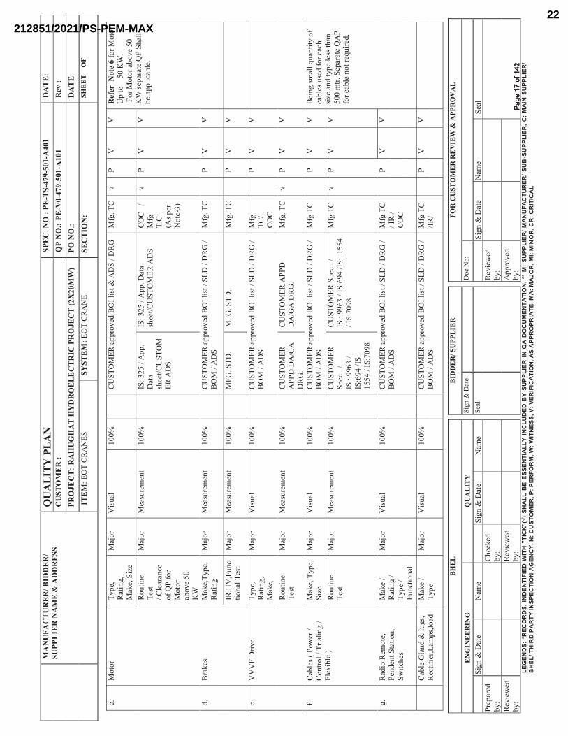
c.M
oto
r T
yp
e,
Rat
ing,
Mak
e, S
ize
Maj
or
Vis
ual
10
0%
CU
ST
OM
ER
ap
pro
ved
BO
I li
st &
AD
S /
DR
GM
fg.
TC
√P
VV
Ref
er N
ote
6fo
r M
oto
r U
p t
o 5
0 K
W.
Fo
r M
oto
r ab
ove
50
K
W s
epar
ate
QP
Sh
all
be
app
lica
ble
.
R
ou
tin
e T
est
/ C
lear
ance
o
f Q
P f
or
Mo
tor
abo
ve
50
K
W
Maj
or
Mea
sure
men
t1
00
%IS
: 32
5 /
Ap
p.
Dat
a sh
eet/
CU
ST
OM
ER
AD
S
IS:
32
5 /
Ap
p.
Dat
a sh
eet/
CU
ST
OM
ER
AD
SC
OC
/
Mfg
T
.C.
(A
s p
er
No
te-3
)
√P
VV
d.
Bra
kes
M
ake,
Typ
e,R
atin
g
Maj
or
Mea
sure
men
t1
00
%C
US
TO
ME
R a
pp
roved
BO
I li
st /
SL
D /
DR
G /
B
OM
/ A
DS
Mfg
. T
CP
VV
IR,H
V,F
un
cti
on
al T
est
Maj
or
Mea
sure
men
t1
00
%M
FG
. S
TD
.M
FG
. S
TD
.M
fg.
TC
PV
V
e.V
VV
F D
rive
Typ
e,
Rat
ing,
Mak
e,
Maj
or
Vis
ual
10
0%
CU
ST
OM
ER
ap
pro
ved
BO
I li
st /
SL
D /
DR
G /
B
OM
/ A
DS
Mfg
. T
C/
CO
C
PV
V
Rou
tin
e T
est
Maj
or
Mea
sure
men
t1
00
%C
US
TO
ME
R
AP
PD
DA
/GA
D
RG
.
CU
ST
OM
ER
AP
PD
D
A/G
A D
RG
.M
fg.
TC
√P
VV
f.C
able
s (
Po
wer
/
Co
ntr
ol
/ T
rial
ing /
F
lexib
le )
Mak
e, T
yp
e,
Siz
eM
ajo
r V
isual
10
0%
CU
ST
OM
ER
ap
pro
ved
BO
I li
st /
SL
D /
DR
G /
B
OM
/ A
DS
Mfg
TC
PV
VB
ein
g s
mal
l q
uan
tity
of
cab
les
use
d f
or
each
si
ze a
nd
typ
e le
ss t
han
5
00 m
tr.
Sep
arat
e Q
AP
for
cab
le n
ot
requ
ired
.
Rou
tin
e
Tes
tM
ajo
r M
easu
rem
ent
10
0%
CU
ST
OM
ER
S
pec
. /
IS
: 9
963
/
IS:6
94
/IS
:
15
54
/ I
S:7
09
8
CU
ST
OM
ER
Sp
ec.
/
IS
: 9
963
/ I
S:6
94
/IS
: 1
554
/
IS:7
098
Mfg
TC
√P
VV
g.
Rad
io R
emo
te,
P
end
ent
Sta
tio
n,
Sw
itch
es
Mak
e /
Rat
ing /
T
yp
e /
Fu
nct
ion
al
Maj
or
Vis
ual
10
0%
CU
ST
OM
ER
ap
pro
ved
BO
I li
st /
SL
D /
DR
G /
B
OM
/ A
DS
Mfg
TC
/
IR /
C
OC
PV
V
Cab
le G
land
& l
ugs,
Rec
tifi
er,L
amp
s,lo
ad
Mak
e /
T
yp
eM
ajo
rV
isual
10
0%
CU
ST
OM
ER
ap
pro
ved
BO
I li
st /
SL
D /
DR
G /
B
OM
/ A
DS
Mfg
TC
/I
R/
PV
V
����
���
����
��Pa
ge 1
7 of
142
Page
17
of 1
42
212851/2021/PS-PEM-MAX22
MA
NU
FAC
TU
RE
R/B
IDD
ER
/SU
PPL
IER
NA
ME
& A
DD
RE
SSQ
UA
LIT
Y P
LA
NSP
EC
. NO
:PE
-TS-
479-
501-
A40
1D
AT
E:
CU
STO
ME
R :
QP
NO
.:PE
-V0-
479-
501-
A10
1R
ev :
PRO
JEC
T:
RA
HU
GH
AT
HY
DR
OE
LE
CT
RIC
PR
OJE
CT
(2X
20M
W)
PO N
O.:
DA
TE
ITE
M:
EO
T C
RA
NE
SSY
STEM
:EO
T C
RA
NE
SEC
TIO
N:
SHE
ET
OF
BH
EL
BID
DE
R/S
UPP
LIE
RFO
R C
UST
OM
ER
RE
VIE
W&
APP
RO
VA
L
EN
GIN
EE
RIN
GQ
UA
LIT
YS
ign
& D
ate
Doc
No:
Sig
n &
Dat
eN
ame
Sig
n &
Dat
eN
ame
Sea
lS
ign
& D
ate
Nam
eS
eal
Pre
par
ed
by:
Ch
ecked
b
y:
Rev
iew
ed
by:
Rev
iew
ed
by:
Rev
iew
ed
by:
Ap
pro
ved
b
y:
LEG
END
S: *
REC
OR
DS,
IND
ENTI
FIED
WIT
H "
TIC
K"(
√) S
HA
LLB
E ES
SEN
TIA
LLY
INC
LUD
ED B
Y SU
PPLI
ER IN
QA
DO
CU
MEN
TATI
ON
, **
M:
SUPP
LIER
/ MAN
UFA
CTU
RER
/ SU
B-S
UPP
LIER
, C:
MAI
N S
UPP
LIER
/ B
HEL
/ TH
IRD
PAR
TY IN
SPEC
TIO
N A
GEN
CY,
N: C
UST
OM
ER, P
: PER
FOR
M, W
: WIT
NES
S, V
: VER
IFIC
ATIO
N, A
S AP
PRO
PRIA
TE, M
A: M
AJO
R, M
I: M
INO
R, C
R: C
RIT
ICA
L
Cel
lC
OC
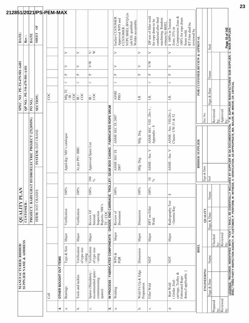
4.O
THER
BO
UGHT
OUT
ITEM
S
a.B
eari
ngs
Typ
e&
Siz
eM
ajo
rV
erif
icat
ion
1
00
%A
pp
d.d
rg./
Mfr
’s c
atal
ogue
M
fg T
C
/ IR
/
CO
C
√P
VV
b.
To
ols
an
d t
ackle
sV
erif
icat
ion
o
f ty
pe
size
/
rati
ng
Maj
or
Ver
ific
atio
n
10
0%
As
per
PO
/ B
BU
IR /
C
OC
√P
VV
c.S
par
es (
Man
dat
ory
/
reco
mm
end
ed s
par
e /
com
mis
sio
nin
g
spar
es)
Ver
ific
atio
n
of
typ
e si
ze
/ ra
tin
g
Maj
or
Rev
iew
Of
Inte
rnal
In
spec
tion
R
epor
ts /
Mfr
’s
TC
/ C
OC
10
0%
10
0%
Ap
pro
ved
Sp
are
Lis
tIR
/
CO
C√
PV
/WV
/W
5.IN
PRO
CESS
: FA
BRIC
ATED
CO
MPO
NENT
S : G
IRDE
R, E
ND C
ARRI
AGE,
TRO
LLEY
, GEA
R BO
X C
ASIN
G ,
FABR
ICAT
ED R
OPE
DR
UM
a.
Wel
din
gW
PS
&
PQ
RM
ajo
r R
evie
w o
f D
ocu
men
t1
00
%A
SM
ES
EC
IX
2
007
AS
ME
SE
C I
X 2
007
AS
ME
P
RO
√P
VV
Ear
lier
CU
ST
OM
ER
A
pp
roved
WP
S a
nd
C
US
TO
ME
R /
N
TP
C/B
HE
L/B
VQ
/Llo
yd
s /E
ILq
ual
ifie
d
Wel
der
acc
epta
ble
.
b.
Wel
d F
it U
p &
Ed
ge
Pre
par
atio
nD
imen
sion
Maj
or
Dim
ensi
on
10
0%
Mfg
. D
rg.
Mfg
. D
rg.
I.R
PV
V
c.F
ille
t W
eld
ND
TM
ajo
r D
PT
on
Fil
let
Wel
d
10
0%
10
%A
SM
E -
Sec
. V
AS
ME
SE
C. V
III
, D
iv-1
,
Ap
pen
dix
-8
I.R
. √
PV
/WV
DP
tes
t o
f fi
llet
wel
d
for
rop
e d
rum
to
be
con
du
cted
aft
er f
inal
m
ach
inin
g.
Ran
do
mw
itn
ess
by B
HE
L
d.
Bu
tt W
eld
( G
ird
er,E
nd
-ca
rria
ge,
Tro
lley
&
Fab
rica
ted
Rop
e d
rum
,if
app
lica
ble
)
ND
TM
ajo
r R
adio
gra
ph
y T
est
/ G
amm
a R
ay$
AS
ME
-S
ec.
VA
SM
E -
Sec
. V
III,
Div
-1,
Cla
use
-U
W-5
1 &
52
I.R
. √
PV
V$
10
0%
in
Ten
sion
Z
on
e, 2
5%
in
C
om
pre
ssio
n Z
on
e &
1
00
% f
or
rop
e d
rum
S
eam
wel
d,
R
T F
ilm
sh
all
be
revie
wed
by
����
���
����
��Pa
ge 1
8 of
142
Page
18
of 1
42
212851/2021/PS-PEM-MAX23
MA
NU
FAC
TU
RE
R/B
IDD
ER
/SU
PPL
IER
NA
ME
& A
DD
RE
SSQ
UA
LIT
Y P
LA
NSP
EC
. NO
:PE
-TS-
479-
501-
A40
1D
AT
E:
CU
STO
ME
R :
QP
NO
.:PE
-V0-
479-
501-
A10
1R
ev :
PRO
JEC
T:
RA
HU
GH
AT
HY
DR
OE
LE
CT
RIC
PR
OJE
CT
(2X
20M
W)
PO N
O.:
DA
TE
ITE
M:
EO
T C
RA
NE
SSY
STEM
:EO
T C
RA
NE
SEC
TIO
N:
SHE
ET
OF
BH
EL
BID
DE
R/S
UPP
LIE
RFO
R C
UST
OM
ER
RE
VIE
W&
APP
RO
VA
L
EN
GIN
EE
RIN
GQ
UA
LIT
YS
ign
& D
ate
Doc
No:
Sig
n &
Dat
eN
ame
Sig
n &
Dat
eN
ame
Sea
lS
ign
& D
ate
Nam
eS
eal
Pre
par
ed
by:
Ch
ecked
b
y:
Rev
iew
ed
by:
Rev
iew
ed
by:
Rev
iew
ed
by:
Ap
pro
ved
b
y:
LEG
END
S: *
REC
OR
DS,
IND
ENTI
FIED
WIT
H "
TIC
K"(
√) S
HA
LLB
E ES
SEN
TIA
LLY
INC
LUD
ED B
Y SU
PPLI
ER IN
QA
DO
CU
MEN
TATI
ON
, **
M:
SUPP
LIER
/ MAN
UFA
CTU
RER
/ SU
B-S
UPP
LIER
, C:
MAI
N S
UPP
LIER
/ B
HEL
/ TH
IRD
PAR
TY IN
SPEC
TIO
N A
GEN
CY,
N: C
UST
OM
ER, P
: PER
FOR
M, W
: WIT
NES
S, V
: VER
IFIC
ATIO
N, A
S AP
PRO
PRIA
TE, M
A: M
AJO
R, M
I: M
INO
R, C
R: C
RIT
ICA
L
CU
ST
OM
ER
& B
HE
L
DP
T o
n B
utt
W
eld
1
00
%1
0%
AS
ME
-S
ec.
VA
SM
E S
EC
. V
III
, D
iv-1
,
Ap
pen
dix
-8
I.R
. √
PW
V1
0%
ran
do
m w
itn
ess
by
BH
EL
e.H
eat
Tre
atm
ent
(SR
) o
f R
op
e d
rum
an
d
Gea
r B
ox C
asin
g
−M
ajo
rR
evie
w o
f S
R
char
t/T
est
Rep
ort
10
0%
Drg
./ R
elav
ant
Std
. /
CU
ST
OM
ER
S
pec
.
Drg
./ R
elev
ant
Std
. /
CU
ST
OM
ER
Sp
ec.
SR
C
har
t√
PV
V
f.P
latf
orm
, H
and
rai
lin
gD
imen
sion
Maj
or
Dim
ensi
on
10
0%
Mfg
. D
rgM
fg.
Drg
——
PV
V
g.
Fin
al I
nsp
ecti
on
of
Fab
rica
ted
C
om
po
nen
ts (
Gir
der
s,
En
d C
arri
ages
&
Tro
lley
, en
d s
top
per
)
Vis
ual
&
dim
ensi
on
alM
ajo
r D
imen
sion
al &
V
isu
al C
hec
k
10
0%
Ap
pd
. G
.A D
rg
/C
RA
BA
pp
d.
G.A
Drg
/ C
RA
BI.
R.
PV
VA
t t
he
Tim
e o
f F
inal
In
sp.
Of
Cra
ne
6.IN
PRO
CESS
INSP
ECTI
ON
OF
MAC
HINE
D CO
MPO
NEN
TS
a.P
inio
ns,
Gea
r &
W
hee
ls1
. D
imen
sion
al
Chec
k
Maj
or
Mea
sure
men
t1
00
%M
fg D
rg /
C
ran
e D
ata
shee
t
Mfg
Drg
/ C
ran
e D
ata
shee
t
I.
R√
PV
VH
ard
nes
s te
st r
epo
rt
revie
w a
fter
app
lica
ble
Q
& T
co
nd
itio
n
2.
Hea
t T
reat
men
tM
ajo
r H
eat
Tre
atm
ent
char
t1
00
%M
ater
ial
spec
ific
atio
n/
Mfg
std
/ M
fg
drg
Mat
eria
l sp
ecif
icat
ion
/ M
fg
std
/ M
fg d
rgI.
R√
PV
VH
eat
trea
tmen
t C
har
t to
be
revie
wed
by B
HE
L
& C
US
TO
ME
R
3.
Har
dn
ess
Maj
or
Mea
sure
men
t1
00
%1
00
%M
fg D
rg /
C
ran
e D
ata
shee
t/ I
S:
317
7
Mat
eria
l sp
ecif
icat
ion
/ M
fg
std
/ M
fg d
rgI.
R√
P#
WV
#W
-(1
) 1
00
% w
itn
ess
for
MH
/ A
H
Gea
r,p
inio
n o
f en
tire
lo
t(2
) 10
0%
wit
nes
s fo
r C
T &
LT
Gea
r, p
inio
n
of
enti
re l
ot
4.
ND
TM
ajo
r D
PT
on
tee
th1
00
%IS
:365
8-1
98
1 /
A
SM
E -
Sec
. V
NO
CR
AC
KS
& L
INE
AR
IN
DIC
AT
ION
I.R
√P
VV
����
����
����
��Pa
ge 1
9 of
142
Page
19
of 1
42
212851/2021/PS-PEM-MAX24
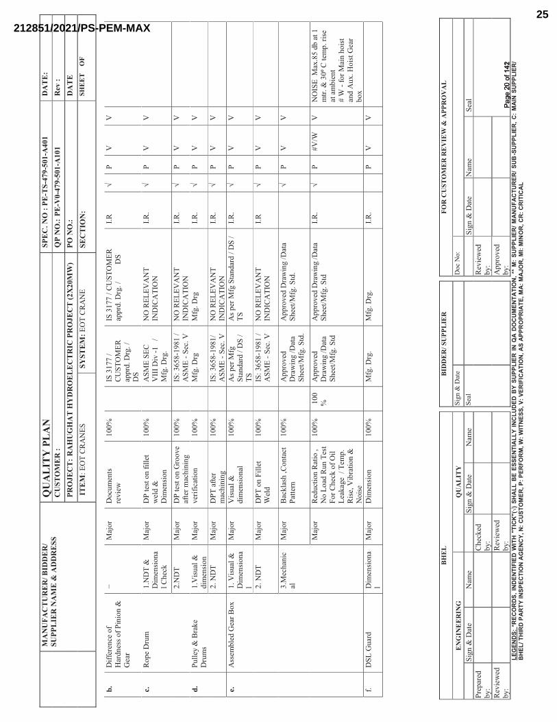
MA
NU
FAC
TU
RE
R/B
IDD
ER
/SU
PPL
IER
NA
ME
& A
DD
RE
SSQ
UA
LIT
Y P
LA
NSP
EC
. NO
:PE
-TS-
479-
501-
A40
1D
AT
E:
CU
STO
ME
R :
QP
NO
.:PE
-V0-
479-
501-
A10
1R
ev :
PRO
JEC
T:
RA
HU
GH
AT
HY
DR
OE
LE
CT
RIC
PR
OJE
CT
(2X
20M
W)
PO N
O.:
DA
TE
ITE
M:
EO
T C
RA
NE
SSY
STEM
:EO
T C
RA
NE
SEC
TIO
N:
SHE
ET
OF
BH
EL
BID
DE
R/S
UPP
LIE
RFO
R C
UST
OM
ER
RE
VIE
W&
APP
RO
VA
L
EN
GIN
EE
RIN
GQ
UA
LIT
YS
ign
& D
ate
Doc
No:
Sig
n &
Dat
eN
ame
Sig
n &
Dat
eN
ame
Sea
lS
ign
& D
ate
Nam
eS
eal
Pre
par
ed
by:
Ch
ecked
b
y:
Rev
iew
ed
by:
Rev
iew
ed
by:
Rev
iew
ed
by:
Ap
pro
ved
b
y:
LEG
END
S: *
REC
OR
DS,
IND
ENTI
FIED
WIT
H "
TIC
K"(
√) S
HA
LLB
E ES
SEN
TIA
LLY
INC
LUD
ED B
Y SU
PPLI
ER IN
QA
DO
CU
MEN
TATI
ON
, **
M:
SUPP
LIER
/ MAN
UFA
CTU
RER
/ SU
B-S
UPP
LIER
, C:
MAI
N S
UPP
LIER
/ B
HEL
/ TH
IRD
PAR
TY IN
SPEC
TIO
N A
GEN
CY,
N: C
UST
OM
ER, P
: PER
FOR
M, W
: WIT
NES
S, V
: VER
IFIC
ATIO
N, A
S AP
PRO
PRIA
TE, M
A: M
AJO
R, M
I: M
INO
R, C
R: C
RIT
ICA
L
b.D
iffe
ren
ce o
f H
ard
nes
s o
f P
inio
n &
G
ear
−M
ajo
rD
ocu
men
ts
revie
w1
00
%IS
31
77
/
CU
ST
OM
ER
app
rd. D
rg.
/
DS
IS 3
177
/ C
US
TO
ME
R
app
rd. D
rg.
/
DS
I.R
√P
VV
c.R
op
e D
rum
1
.ND
T &
D
imen
sion
al
Chec
k
Maj
or
DP
tes
t o
n f
ille
t w
eld
&
Dim
ensi
on
10
0%
AS
ME
SE
C
VII
I D
iv -
1
/
M
fg.
Drg
.
NO
RE
LE
VA
NT
IN
DIC
AT
ION
I.R
.√
PV
V
2.N
DT
Maj
or
DP
tes
t o
n G
roo
ve
afte
r m
ach
inin
g1
00
%IS
: 36
58
-19
81
/
AS
ME
-S
ec.
VN
O R
EL
EV
AN
T
IND
ICA
TIO
NI.
R.
√P
VV
d.P
ull
ey &
Bra
ke
Dru
ms
1.V
isual
&
dim
ensi
on
Maj
or
ver
ific
atio
n1
00
%M
fg.
Drg
Mfg
. D
rgI.
R.
√P
VV
2.
ND
T
Maj
or
DP
T a
fter
m
ach
inin
g
10
0%
IS:
36
58
-19
81
/
AS
ME
-S
ec.
VN
O R
EL
EV
AN
T
IND
ICA
TIO
NI.
R.
√P
VV
e.A
ssem
ble
d G
ear
Bo
x
1. V
isual
&
Dim
ensi
on
al
Maj
or
Vis
ual
&
dim
ensi
on
al1
00
%A
s p
er M
fg
Sta
nd
ard /
DS
/T
S
As
per
Mfg
Sta
nd
ard
/ D
S /
T
SI.
R.
√P
VV
2.
ND
TM
ajo
rD
PT
on
Fil
let
Wel
d
10
0%
IS:
36
58
-19
81
/
AS
ME
-S
ec.
VN
O R
EL
EV
AN
T
IND
ICA
TIO
NI.
R√
PV
V
3.M
ech
anic
alM
ajo
rB
ackla
sh ,
Con
tact
P
atte
rn1
00
%A
pp
roved
D
raw
ing /
Dat
a S
hee
t/M
fg.
Std
.
Ap
pro
ved
Dra
win
g /
Dat
a S
hee
t/M
fg.
Std
.√
PV
V
Maj
or
Red
uct
ion
Rat
io ,
N
o L
oad
Run
Tes
t F
or
Ch
eck o
f O
il
Lea
kag
e /
Tem
p.
Ris
e,V
ibra
tion
&
No
ise
10
0%
100
%A
pp
roved
D
raw
ing /
Dat
a S
hee
t/M
fg.
Std
Ap
pro
ved
Dra
win
g /
Dat
a S
hee
t/M
fg.
Std
I.
R.
√P
#V
/WV
NO
ISE
M
ax.8
5 d
b a
t 1
m
tr. &
30⁰
C te
mp.
ris
e at
am
bie
nt
#
W -
for
Mai
n h
ois
t an
d A
ux.
Hois
t G
ear
bo
x
f.D
SL
Gu
ard
D
imen
sion
al
Maj
or
Dim
ensi
on
1
00
%M
fg.
Drg
. M
fg.
Drg
. I.
R.
PV
V
����
����
����
��Pa
ge 2
0 of
142
Page
20
of 1
42
212851/2021/PS-PEM-MAX25
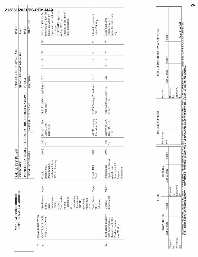
MA
NU
FAC
TU
RE
R/B
IDD
ER
/SU
PPL
IER
NA
ME
& A
DD
RE
SSQ
UA
LIT
Y P
LA
NSP
EC
. NO
:PE
-TS-
479-
501-
A40
1D
AT
E:
CU
STO
ME
R :
QP
NO
.:PE
-V0-
479-
501-
A10
1R
ev :
PRO
JEC
T:
RA
HU
GH
AT
HY
DR
OE
LE
CT
RIC
PR
OJE
CT
(2X
20M
W)
PO N
O.:
DA
TE
ITE
M:
EO
T C
RA
NE
SSY
STEM
:EO
T C
RA
NE
SEC
TIO
N:
SHE
ET
OF
BH
EL
BID
DE
R/S
UPP
LIE
RFO
R C
UST
OM
ER
RE
VIE
W&
APP
RO
VA
L
EN
GIN
EE
RIN
GQ
UA
LIT
YS
ign
& D
ate
Doc
No:
Sig
n &
Dat
eN
ame
Sig
n &
Dat
eN
ame
Sea
lS
ign
& D
ate
Nam
eS
eal
Pre
par
ed
by:
Ch
ecked
b
y:
Rev
iew
ed
by:
Rev
iew
ed
by:
Rev
iew
ed
by:
Ap
pro
ved
b
y:
LEG
END
S: *
REC
OR
DS,
IND
ENTI
FIED
WIT
H "
TIC
K"(
√) S
HA
LLB
E ES
SEN
TIA
LLY
INC
LUD
ED B
Y SU
PPLI
ER IN
QA
DO
CU
MEN
TATI
ON
, **
M:
SUPP
LIER
/ MAN
UFA
CTU
RER
/ SU
B-S
UPP
LIER
, C:
MAI
N S
UPP
LIER
/ B
HEL
/ TH
IRD
PAR
TY IN
SPEC
TIO
N A
GEN
CY,
N: C
UST
OM
ER, P
: PER
FOR
M, W
: WIT
NES
S, V
: VER
IFIC
ATIO
N, A
S AP
PRO
PRIA
TE, M
A: M
AJO
R, M
I: M
INO
R, C
R: C
RIT
ICA
L
7.FI
NAL
INSP
ECTI
ON
a.C
ON
TR
OL
PA
NE
L
Wit
h V
VV
F D
rive
Iden
tifi
cati
on
of
all
Ele
ct.
Co
mp
on
ents
, C
able
la
yin
g /
D
ress
ing/F
eru
llin
g
/Ter
min
atio
ns
Dim
ensi
on
al
Fun
ctio
nal
,
HV
, IR
, in
terl
ock
s,
Pro
tect
ion
D
OP
Maj
or
Vis
ual
, d
imen
sio
nal
, O
per
atio
nal
&
Fu
nct
ion
al C
hec
k
, H
V,I
R, P
ain
tin
g
10
0%
100
%IS
:317
7 -
19
99
/
Ap
pd
. D
rg /
D
ata
shee
t
IS:3
17
7 -
19
99
/ A
ppd
. D
rg /
D
ata
shee
tT
.C√
PW
W(H
V a
t 2
.5 K
V A
c fo
r p
ow
er c
kt
at 2
KV
fo
r co
ntr
ol
ckt
,DO
P b
y
pap
er i
nse
rtio
n m
eth
od
)
B
OI
as p
er
CU
ST
OM
ER
Ap
pro
ved
M
akes
. W
ill
be
Ch
ecked
at
the
tim
e o
f F
inal
In
spec
tion
.
Pai
nt
Sh
ade/
T
hk/
Ad
hes
ion
Maj
or
Vis
ual
/ D
FT
C
hec
k1
00
%A
PP
D P
ain
tin
g
Pro
ced
ure
/ G
AA
PP
D P
ain
tin
g P
roce
du
re /
G
AT
.CP
VV
7 T
ank P
retr
eatm
ent
bef
ore
Pai
nti
ng
b.
EO
T c
ran
e as
sem
bly
w
ith
co
ntr
ol
pan
el,
Rem
ote
Co
ntr
oll
er
Pen
den
t S
tati
on
(A
t W
ork
s)
Vis
ual
&
dim
ensi
on
alM
ajo
r D
imen
sion
al
,Sp
an, D
iago
nal
&
Wh
eel
Bas
e D
imen
sion
, L
T
Sto
pp
er
Dim
ensi
on
10
0%
100
%A
pp
roved
G.A
. D
rg.
/ IS
3
17
7
/ D
S
Ap
pro
ved
G.A
. D
rg.
/ IS
3
177
/
DS
I.R
. √
PW
WC
ran
e S
hou
ld b
e O
per
able
by R
RC
m
ean
t fo
r th
at C
ran
e o
nly
.
����
����
����
��Pa
ge 2
1 of
142
Page
21
of 1
42
212851/2021/PS-PEM-MAX26
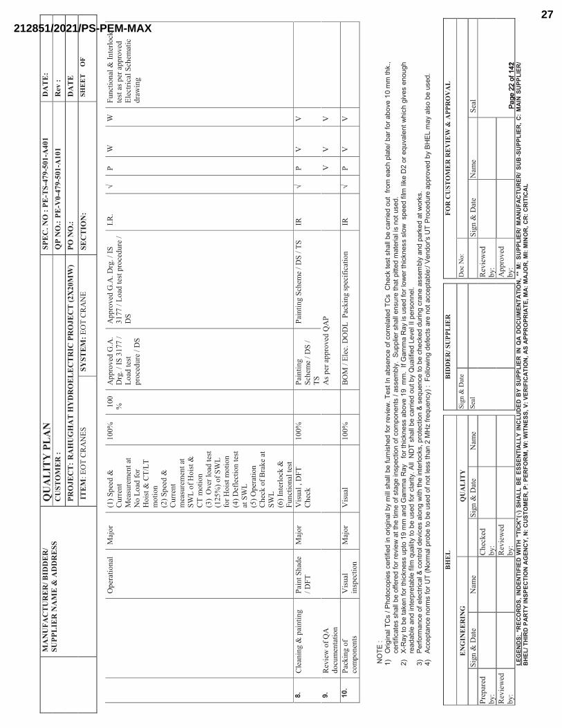
MA
NU
FAC
TU
RE
R/B
IDD
ER
/SU
PPL
IER
NA
ME
& A
DD
RE
SSQ
UA
LIT
Y P
LA
NSP
EC
. NO
:PE
-TS-
479-
501-
A40
1D
AT
E:
CU
STO
ME
R :
QP
NO
.:PE
-V0-
479-
501-
A10
1R
ev :
PRO
JEC
T:
RA
HU
GH
AT
HY
DR
OE
LE
CT
RIC
PR
OJE
CT
(2X
20M
W)
PO N
O.:
DA
TE
ITE
M:
EO
T C
RA
NE
SSY
STEM
:EO
T C
RA
NE
SEC
TIO
N:
SHE
ET
OF
BH
EL
BID
DE
R/S
UPP
LIE
RFO
R C
UST
OM
ER
RE
VIE
W&
APP
RO
VA
L
EN
GIN
EE
RIN
GQ
UA
LIT
YS
ign
& D
ate
Doc
No:
Sig
n &
Dat
eN
ame
Sig
n &
Dat
eN
ame
Sea
lS
ign
& D
ate
Nam
eS
eal
Pre
par
ed
by:
Ch
ecked
b
y:
Rev
iew
ed
by:
Rev
iew
ed
by:
Rev
iew
ed
by:
Ap
pro
ved
b
y:
LEG
END
S: *
REC
OR
DS,
IND
ENTI
FIED
WIT
H "
TIC
K"(
√) S
HA
LLB
E ES
SEN
TIA
LLY
INC
LUD
ED B
Y SU
PPLI
ER IN
QA
DO
CU
MEN
TATI
ON
, **
M:
SUPP
LIER
/ MAN
UFA
CTU
RER
/ SU
B-S
UPP
LIER
, C:
MAI
N S
UPP
LIER
/ B
HEL
/ TH
IRD
PAR
TY IN
SPEC
TIO
N A
GEN
CY,
N: C
UST
OM
ER, P
: PER
FOR
M, W
: WIT
NES
S, V
: VER
IFIC
ATIO
N, A
S AP
PRO
PRIA
TE, M
A: M
AJO
R, M
I: M
INO
R, C
R: C
RIT
ICA
L
Op
erat
ion
al
Maj
or
(1)
Sp
eed
&
Cu
rren
t M
easu
rem
ent
at
No
Lo
ad f
or
H
ois
t &
CT
/LT
m
oti
on
(2)
Sp
eed
&
Cu
rren
t m
easu
rem
ent
at
SW
L o
f H
ois
t &
C
T m
oti
on
(3)
Over
lo
ad t
est
(125
%)
of
SW
L
for
Ho
ist
mo
tio
n
(4
) D
efle
ctio
n t
est
at S
WL
(5)
Op
erat
ion
C
hec
k o
f B
rak
e at
S
WL
(6
) In
terl
ock
&
Fu
nct
ion
al t
est
10
0%
100
%A
pp
roved
G.A
. D
rg.
/ IS
31
77
/
Lo
ad t
est
pro
ced
ure
/ D
S
Ap
pro
ved
G.A
. D
rg.
/ IS
3
177
/ L
oad
tes
t p
roce
du
re /
D
S
I.R
. √
PW
WF
un
ctio
nal
& I
nte
rlo
ck
test
as
per
ap
pro
ved
E
lect
rica
l S
chem
atic
d
raw
ing
8.C
lean
ing &
pai
nti
ng
Pai
nt
Sh
ade
/ D
FT
Maj
or
Vis
ual
, D
FT
C
hec
k1
00
%P
ain
tin
g
Sch
eme
/ D
S /
T
S
Pai
nti
ng S
chem
e /
DS
/ T
SIR
√P
VV
9.R
evie
w o
f Q
A
do
cum
enta
tio
nA
s p
er a
pp
roved
QA
PV
VV
10.
Pac
kin
g o
f co
mp
on
ents
Vis
ual
in
spec
tion
Maj
or
Vis
ual
10
0%
BO
M /
Ele
c. D
OD
L
Pac
kin
g s
pec
ific
atio
nIR
√P
VV
� � ���
�����
���
����
�!�"
���
#����
$�*�
+�<�
�#�+
��*��
��>�
�!��
����!
�"�?
@�Z
�""�#$
�""�?
���[
�!�#
$�>�
�����
�\��
]^��
�#*�_
!��?
#�!+
����
�+��
��"�
*�>�
��#�
��$�
+`�*�
#*�#
$�""�
?��+
�����
>��[
*�����
Z��
�+$�
<"�*
���?
�����
���?�
\���
��Z
Z�*$
`^{��
+��*�
��+�*
�#�#
$�""�
?���
�����
>���
����\
��]
��*�*
$��*�
Z��
���#
*���
��!#<
�+*��
!���
�+�Z
<�!�
!*#�
���##
�Z?"
@^��|
[<<"
����#
$�""�
�!#[
���*$
�*�<
�**�>
�Z�*
����
"��#�
!�*�[
#�>^
���
�}~
��@
�*��?
��*�
`�!�
����*
$�+`
!�##
�[<*
����
�ZZ
��!>
���Z
Z��
��@
�����
��*$�
+`!�
##��
?�\�
����
�ZZ
^��_��
��Z
Z��
��@
��#�[
#�>�
����"
�]��
�*$�+
`!�#
#�#"
�]��#
<��>
���"Z
�"�`�
� ��
����
�[\�
"�!*
�]$�
+$��
�\�#
��!�
[�$�
���>
�?"�
��!>
��!*�
�<��
*�?"
����"
Z��
[�"�*
@�*�
�?��
[#�>
�����+
"���*
@^��
""���
��
#$�"
"�?��
+����
�>��
[*�?
@��
[�"��
��>�
��\�
"�__�<
��#�
!!�"
^���
���
����Z
�!+�
�����
"�+*
��+�"
���+
�!*��
"�>�\
�+�#
��"�
!��]
�*$�*$
���!
*��"�
+`#{
�<��
*�+*
��!�
��#�
�[�!
+��*�
�?��
+$�+
`�>�
>[��!
��+�
�!��
�##�
Z?"
@��!
>�<�
�`�>
��*�]
��`#
^���
��+
+�<*
�!+�
�!��
Z#�
�����
����
��Z
�"�<
��?�
�*��?
��[#
�>��
��!�*
�"�##
�*$�!
����
���
����[
�!+@
������
�""�
]�!
��>�
��+*
#���
��!�
*��++
�<*�
?"��
����!
>���#
����
���+
�>[�
���<
<��\
�>�?
@���
���Z
�@��
"#��
?��[
#�>^
��
����
����
����
��Pa
ge 2
2 of
142
Page
22
of 1
42
212851/2021/PS-PEM-MAX27
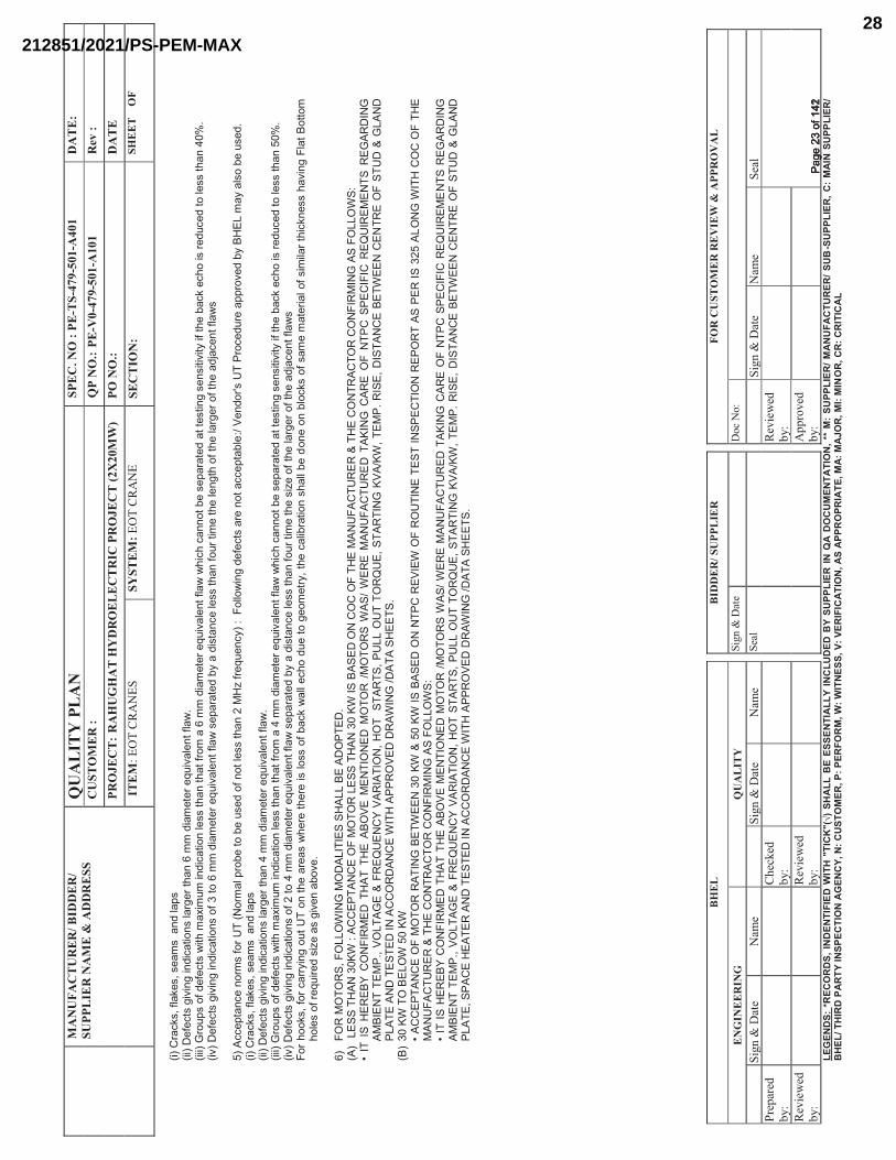
MA
NU
FAC
TU
RE
R/B
IDD
ER
/SU
PPL
IER
NA
ME
& A
DD
RE
SSQ
UA
LIT
Y P
LA
NSP
EC
. NO
:PE
-TS-
479-
501-
A40
1D
AT
E:
CU
STO
ME
R :
QP
NO
.:PE
-V0-
479-
501-
A10
1R
ev :
PRO
JEC
T:
RA
HU
GH
AT
HY
DR
OE
LE
CT
RIC
PR
OJE
CT
(2X
20M
W)
PO N
O.:
DA
TE
ITE
M:
EO
T C
RA
NE
SSY
STEM
:EO
T C
RA
NE
SEC
TIO
N:
SHE
ET
OF
BH
EL
BID
DE
R/S
UPP
LIE
RFO
R C
UST
OM
ER
RE
VIE
W&
APP
RO
VA
L
EN
GIN
EE
RIN
GQ
UA
LIT
YS
ign
& D
ate
Doc
No:
Sig
n &
Dat
eN
ame
Sig
n &
Dat
eN
ame
Sea
lS
ign
& D
ate
Nam
eS
eal
Pre
par
ed
by:
Ch
ecked
b
y:
Rev
iew
ed
by:
Rev
iew
ed
by:
Rev
iew
ed
by:
Ap
pro
ved
b
y:
LEG
END
S: *
REC
OR
DS,
IND
ENTI
FIED
WIT
H "
TIC
K"(
√) S
HA
LLB
E ES
SEN
TIA
LLY
INC
LUD
ED B
Y SU
PPLI
ER IN
QA
DO
CU
MEN
TATI
ON
, **
M:
SUPP
LIER
/ MAN
UFA
CTU
RER
/ SU
B-S
UPP
LIER
, C:
MAI
N S
UPP
LIER
/ B
HEL
/ TH
IRD
PAR
TY IN
SPEC
TIO
N A
GEN
CY,
N: C
UST
OM
ER, P
: PER
FOR
M, W
: WIT
NES
S, V
: VER
IFIC
ATIO
N, A
S AP
PRO
PRIA
TE, M
A: M
AJO
R, M
I: M
INO
R, C
R: C
RIT
ICA
L
�����
��+`
#{��"
�`�#
{�#��
Z#�
��!>
�"�<#
����
�� ��
�+*#
���\
�!��
�!>�
+�*��
!#�"�
����
�*$�!
���Z
Z�>
��Z
�*��
���[
�\�"
�!*��
"�]
^����
����
��[<
#���
�>��
�+*#
�]�*$
�Z��
�Z[Z
��!>�
+�*��
!�"�
##�*$
�!�*$
�*���
�Z��
���Z
Z�>
��Z
�*��
���[
�\�"
�!*��
"�]
�]$�
+$�+
�!!�
*�?��
#�<�
��*�
>��*
�*�#*
�!��
#�!#
�*�\�
*@���
�*$��
?�+`
��+$
���#
���>[
+�>�
*��"�
##�*$
�!��
��^�
��\��
���+
*#��
�\�!
���!
>�+�
*��!#
�����
�*���
�ZZ
�>��
Z�*
����
�[�\
�"�!
*��"�
]�#
�<��
�*�>
�?@�
��>�
#*�!
+��"�
##�*$
�!���
[��*�
Z��
*$��
"�!�
*$��
��*$�
�"���
����
��*$�
��>�
�+�!
*��"�
]#�
� ����
++�<
*�!+
��!�
�Z#�
�����
����
��Z
�"�<
��?�
�*��?
��[#
�>��
��!�*
�"�##
�*$�!
����
���
����[
�!+@
������
�""�
]�!
��>�
��+*
#���
��!�
*��++
�<*�
?"��
����!
>���#
����
���+
�>[�
���<
<��\
�>�?
@���
���Z
�@��
"#��
?��[
#�>^
����
����
+`#{
��"�`
�#{�#
��Z
#���
!>�"�
<#�
�����
���+
*#��
�\�!
���!
>�+�
*��!#
�"���
���*$
�!��
�ZZ
�>��
Z�*
����
�[�\
�"�!
*��"�
]^�
������
���
[<#�
���>
���+
*#�]
�*$�Z
���Z
[Z��!
>�+�
*��!�
"�##
�*$�!
�*$�*
����Z
����
�ZZ
�>��
Z�*
����
�[�\
�"�!
*��"�
]�]
$�+$
�+�!
!�*�?
��#�
<���
*�>�
�*�*�
#*�!
��#�
!#�*�
\�*@
����*$
��?�
+`��
+$��
�#���
>[+�
>�*�
�"�##
�*$�!
����
^���\
�� ��
�+*#
���\
�!��
�!>�
+�*��
!#��
����*�
���Z
Z�>
��Z
�*��
���[
�\�"
�!*��
"�]
�#�<
���*
�>�?
@���
>�#*
�!+�
�"�##
�*$�!
���[�
�*�Z
��*$
��#�
����
��*$�
�"���
����
��*$�
��>�
�+�!
*��"�
]#�
����$
��`#
{����
�+��
�@�!
���[
*����
�!�*$
����
��#�
]$�
���*$
����
�#�"�
##��
��?�+
`�]
�""��
+$��
>[��
*���
��Z
�*�@
{�*$�
�+�"
�?��
*��!�
#$�"
"�?��
>�!�
��!�
?"�+
`#��
��#�Z
��Z
�*��
��"��
��#�Z
�"���*
$�+`
!�##
�$�\
�!��
�"�*
���*
*�Z
�$�
"�#�
�����
�[���
>�#�
����
#���
\�!�
�?�\
�^�
��
���
���
���
���
|{��
���
��
_��
���
��
_�_�
|�|�
����
����
�
���
^���
����
�||�
����
����
����
���
����
��
���
���
���
���
�||�
����
����
���_|
���|
� ��
���
��
����
����
���
���
���
���
����
���
��
���
����
���
��
�_�
�_�
���
|���
���
�|�
���
_��_
|��
����
���
��
�_�
��
���
����
���
���
����
���_
��
� ��
���
���
��
���
|��
�|��
���
���
���
���
���
�
����
_��
����
���
���
���
�|��
�_�
_���
���
_���
���|
����
��
_��
����
�_��
����
��^
{���
����
����
����
���
���
���
_��_
��
{���
���|
���
�|{��
���
���
����
��
��{
�|��
��_
��
����
���
{����
�^��
_|�{
� _|
���
���
����
���
����
����
���
|��
��
����
�
���
����
��
���|
��
�_���
��
��
��
���
�_�
���
���
���
�
���
_��
�� �
���|
���
�|^�
����
����
���
���
���
���
����
������
��
����
��
���
���
���
���
��_�
���
���
���
����
����
����
���_|
���|
� ��
���
���
����
_��
����
��
��_
���
��|�
�_�|�
���_
��
����
��
���|
����
�_|��
����
���
���
_��
���
���
����
���
���
���
���
����
���
���
��
����
���
���
��_
��
_��
��|�
����
��
|����
������
������
������
������
������
�����
��_�
�_|��
����
���
��
�_�
��
���
����
���
���
����
���_
��
� ��
���
����
���
�|�
��|
�����
���
���
���
���
� ��
��_�
���
����
���
���
��|
���
_�_�
����
�_�
���
��|
����
��
_��
���
�_��
����
��^
{���
����
����
����
���
���
���
_��_
��
{���
��|�
���|
{���
����
���
���
��
�{�|
���
�_�
���
����
�{��
���^
��_|
�{�
_|��
��
����
����
���
����
���
��|�
�
����
���
�
����
�{�|
���
���
����
���
�
���|
��
�_���
��
��
��
���
�_�
���
���
���
�
���
_��
�� ��
��|�
���|
^�
����
����
����
��Pa
ge 2
3 of
142
Page
23
of 1
42
212851/2021/PS-PEM-MAX28
Raghuganga Hydropower Limited Lot 2- Mechanical and Electrical Works Myagdi, Nepal Bid Documents: Volume 3- Employer's Requirement Rahughat Hydroelectric Project Section 3.4: Particular Technical Specifications – Mechanical Chapter – 7 : Overhead E.O.T. Cranes
Page 1
7. OVERHEAD E.O.T. CRANES 7.1 GENERAL The Contractor shall supply install and commission the overhead E.O.T. Cranes required for the
powerhouse and valve chamber. The cranes shall be supplied and installed ready for operation,
including the runways and power in-feeds.
7.1.1 Scope and Limits of Supply
The scope of supply and services shall include:
- Design, calculations, manufacture, workshop assembly and workshop testing of the
equipment.
- Priming and application of the finishing coating on all equipment to be painted.
- Seaworthy packing of the equipment, including the protective varnishing or greasing of all
surfaces that will be left bright/un-painted during services.
- Transportation (sea and land), including en-route storage, the necessary loading and
unloading up to site, including the insurance from despatch/transport and upto defect liability
period of 2 years after commissioning.
- Unloading at site, necessary storage, erection (including the necessary erection equipment),
site tests and commissioning of the cranes.
- Supply of mandatory spare parts, tools and maintenance devices.
The limits of supply are as follows:
All concrete works are included in the scope of Lot 1 Civil & HM works, but alignment,
anchoring, welding and anti-corrosive protection of the equipment is responsibility of Lot 2
Mechanical and Electrical works Contractor as well as Supervision of the placing of concrete in
and around Lot 2 Mechanical and Electrical works embedded parts including rails.
The Lot-1 Civil and HM Works Contractor is responsible for all excavation and concreting
works and related safety measures. All equipment necessary for transport and erection of the
cranes shall be provided and operated by the Mechanical and Electrical works Contractor.
Necessary co-ordination with Lot-1: Civil & HM Contractor shall be made for use of crane by
Civil Contractor as well as amongst various sub-suppliers of mechanical & electrical equipment.
7.1.2 General Arrangement
Reference is made to powerhouse and valve chamber drawings showing required working space
and general arrangement lay-out drawings.
as per BHEL NIT
��������������Page 24 of 142Page 24 of 142
212851/2021/PS-PEM-MAX29
Raghuganga Hydropower Limited Lot 2- Mechanical and Electrical Works Myagdi, Nepal Bid Documents: Volume 3- Employer's Requirement Rahughat Hydroelectric Project Section 3.4: Particular Technical Specifications – Mechanical Chapter – 7 : Overhead E.O.T. Cranes
Page 2
7.1.3 Design Criteria
Design and calculation principles of the crane shall be in accordance with the FEM-Standards
(Federation Europeenne de Manutention) for light operation of cranes and hoists.Design
calcualtions shall be submitted for approval of Employer and/or Engineer.
Maximum deflection of the crane bridges or gantries under the rated load shall not exceed
1/1000 of the crane's span (rail axis to rail axis).
The cranes shall be subject to a dynamic overload testing of 25% and a subsequent static
overload testing of 40%. The crane shall withstand these tests safely and without any failure
and/or permanent deflection of any of its components or parts.
7.2 BRIDGES
The cranes bridge shall be of solid welded steel construction designed to resist without undue
deflections vertical and horizontal stresses. Perfect parallelism of the structure shall be ensured
when any load up to the rated load is applied. Standard size crab rails and appropriate crab stops
shall be provided.
Platforms and walkways shall be of either checkered plate or grated. Suitable hand and footrails
shall also be provided.
All visible parts shall be plain with smooth, flat and appropriately finished surfaces.
Suitably locked and fixed access ladders to the crane bridges/gantries/cabin shall be provided.
7.3 TRACKS
The rails or tracks of the cranes shall be resting on correspondingly provided concrete supporting
structures. These shall be provided with the necessary stops. These shall be perfectly straight,
free from scale and of a size to limit deflections not exceeding 1/2000 of the span between
suspensions or supports if not continuously supported.
Tracks or rails shall be supplied complete with fasteners, hangers, back-plates, expansion joints
(where crossing concrete expansion joints) and stop blocks.
Spring-type or rubber-type buffers shall be mounted at the ends of the crane tracks.
7.4 CRABS
Crabs of sturdy steel construction shall be provided for the main and auxiliary hoists of the
crane. They shall be mounted on the bridge and designed for equal load distribution on all
wheels when being applied under any load condition. Spring-type or rubber-type buffers shall be
��������������Page 25 of 142Page 25 of 142
212851/2021/PS-PEM-MAX30
Raghuganga Hydropower Limited Lot 2- Mechanical and Electrical Works Myagdi, Nepal Bid Documents: Volume 3- Employer's Requirement Rahughat Hydroelectric Project Section 3.4: Particular Technical Specifications – Mechanical Chapter – 7 : Overhead E.O.T. Cranes
Page 3
placed at the ends of the frames. Sturdy wheel braking supports shall be provided where
necessary.
Main crabs shall travel on rails mounted securely and absolutely parallel on the bridge. The rail
ends shall be provided with stop blocks. The crab of auxiliary hoists shall travel on an I-beam
arranged on one of the outer sides of the bridge and be, therefore, completely independent from
the main crab.
7.5 HOISTING MECHANISMS
All hoisting gears shall be mounted properly on the crab frame and be driven by suitable electric
motors and gears to obtain the stipulated hoisting and lowering speeds.
All reduction gears shall be fitted with ball or roller bearings, running in an oil bath within an oil
- and dust - tight gearbox, equipped with sight gauge glasses.
All rotating and moving parts shall be suitably protected by sheet metal guards or other
convenient protective devices.
The hoists shall be equipped with an electrically released, spring-set, friction type holding brake
(cone or disk) with a capacity not less than 200% of the full load torque of the motor, and with
an electro-hydraulic braking system.
Additionally, an emergency brake acting on the drum and operating with some retardation shall
be provided for each electric hoisting mechanism.
Load blocks shall be constructed to protect the hoisting ropes from damage and to prevent them
from leaving the sheaves under all operating conditions.
7.6 TRAVELLING AND TRANSLATION MECHANISMS
Bridge and main crab mechanisms shall be equipped with geared double motor drives.
Provisions shall be made to ensure individual protection of each motor and interlocking to
warrant full simultaneous operation of both drives. Flexible connections shall be provided
between motors and gears.
The mechanisms shall be designed and executed so that travel and translation respectively will
be steady and free from racking, objectionable vibrations and undue noise at rated speed and
under any load.
Electrically released, spring-set, friction-type disk brakes, with a capacity of twice the full load
torque exerted by the travel and translation mechanism motor(s) respectively shall be provided.
��������������Page 26 of 142Page 26 of 142
212851/2021/PS-PEM-MAX31
Raghuganga Hydropower Limited Lot 2- Mechanical and Electrical Works Myagdi, Nepal Bid Documents: Volume 3- Employer's Requirement Rahughat Hydroelectric Project Section 3.4: Particular Technical Specifications – Mechanical Chapter – 7 : Overhead E.O.T. Cranes
Page 4
The brakes shall operate when the power to the drive motor(s) is cut and shall be equally
effective in both directions of travel and translation.
Travelling and translation mechanisms shall be so designed that in the event of an axle break the
crane bridge or crab cannot drop more than 25 mm before striking the top of the rail.
7.7 DRUMS As the crane will have main and auxiliary hoisting hooks, rope drums are to be designed
accordingly. Rope drums shall be perfectly circular, in accordance with the diameter of the rope
used and provided with a finely ground grooving. The bottom of the grooving shall be circular
and its diameter larger than the rope diameter. Opposite pitch grooving shall be provided to
ensure perfect vertical lifting and lowering.
Each drum shall be of sufficient length to carry all the rope without overlapping when the hook
is in fully raised position. With the hook in its lowest position not less than 2.5 rope turns shall
remain on each drum.
All drums shall be designed to carry safely and without deformation any load up to the test loads,
and ensure ready access to the rope anchorage.
7.8 HOOKS Hooks for main hosit shall be of the Ram’s horn type and be either drop-forged or hammer-
forged. The hook of auxiliary hoist shall be of the single hook type and also forged.
All hooks shall swivel freely in both directions and rest on dust-protected ball or roller bearings.
For all hooks the relevant DIN-Standards or equivalent shall apply. Hooks shall have locking
system to protect from falling of materials to be lifted.
7.9 ROPES
All hoisting ropes shall be of special non-spinning type made of high-grade galvanized steel
wire.
Each rope shall be capable of supporting the maximum (rated) load during worst manoeuvring
positions. The minimum breaking strength of the ropes shall be not less than six (6) times the
hoist's rated load.
The ropes shall be impregnated with grease to resist wear and possible corrosion. Where more
than one part of rope is used for the support of the load, the tension in the various parts shall be
equalized by means of appropriate pulleys in the load block.
�������������Page 27 of 142Page 27 of 142
212851/2021/PS-PEM-MAX32
Raghuganga Hydropower Limited Lot 2- Mechanical and Electrical Works Myagdi, Nepal Bid Documents: Volume 3- Employer's Requirement Rahughat Hydroelectric Project Section 3.4: Particular Technical Specifications – Mechanical Chapter – 7 : Overhead E.O.T. Cranes
Page 5
7.10 RAILS Rails shall be made of profiles suitably dimensioned for the purpose and consist of wear resistant
steel such as manganese steel.
All rails shall be perfectly straight and even, and free from scale.
7.11 MOTORS Motors shall be of the induction type and with sufficient capacity to properly handle the loads.
They shall be rated for 40% relative duty factor (ED) of tropical-proof make and have class F or
better insulation.
7.12 CURRENT CONDUCTORS
The current conductors shall form part of the crane supply.
Feed rail systems shall be of the metal enclosed, collector bus way type with internally supported
collector having no live part outside of the enclosure. It shall consist of an assembly of
standardized, fully interchangeable units and shall include expansion sections at each concrete
expansion joint, two end feed boxes, coupling sets, dead-end caps, track hangers and all other
equipment required for completing the system.
The feed rail system, when assembled in place, shall permit independent longitudinal movement
of the steel housing and conductors in order to allow for unequal expansion and contraction due
to temperature changes. The conductors shall be housed in a common enclosure made of not less
than 2.5 mm thick sheet steel. Conductors shall be of hard-drawn copper, capable of carrying the
rated current per pole continuously without overheating.
Down shop leads shall be supplied and suitably fixed on concrete column/wall at one end of the
powerhouse for connection from 3-phase, 4 wire, 400 V AC supply for the feed rail system.
The current collector (trolley) shall be of the slide-shoe or tandem-wheel spring type. Crab
current conductors shall preferably be of the suspended looping type, with a corresponding
suspending wire arranged neatly between the crane's end pieces. Bare copper wire will not be
accepted.
7.13 LIGHTING
Two (2) mercury vapour lamp units (complete with reflector) shall be furnished for the crane.
They shall be arranged conveniently on the bridge girders or gantries for general illumination of
the area under the crane.
�������������Page 28 of 142Page 28 of 142
212851/2021/PS-PEM-MAX33
Raghuganga Hydropower Limited Lot 2- Mechanical and Electrical Works Myagdi, Nepal Bid Documents: Volume 3- Employer's Requirement Rahughat Hydroelectric Project Section 3.4: Particular Technical Specifications – Mechanical Chapter – 7 : Overhead E.O.T. Cranes
Page 6
Each lamp shall have a capacity of not less than 400 watts, whose maintenance and replacement
shall be possible from the bridge or gantry walkway. Lighgting in operator cabin shall also be
provided.
7.14 POWERHOUSE CRANE
The Powerhouse Crane of the travelling overhead bridge type shall be designed for installing,
removing and dismantling all equipment /accessories installed in the powerhouse.
The crane capacity will be determined by the weight of the generator rotor and/or stator,
whichever is the heaviest part. Apart of these stipulations the following main parameters apply:
- Length of crane runway As per drawing
- Crane beam elevation 884.60 masl
- Span of runway rails As per drawing
- Main Hook rated capacity About 60 tons or Adequate to handle
heaviest package +10% margin
- Main Hook Hoisting speed 1.0 m/min
- Main Hook Inching speed Step-less, frequency converter
Speed control system
- Auxiliary Hook capacity 10 ton
- Trolley travelling speed 0-5 m/min
- Crane travelling speed 0-15 m/min
All dimensions shall be confirmed by the Engineer prior to definite design and manufacturing.
Proper coordination among the manufacturers of generating unit and crane shall be made during
design of crane components.
7.15 VALVE CHAMBER CRANE
The Valve Chamber Crane of the travelling overhead bridge type shall be designed for installing,
removing and dismantling all equipment /accessories installed in the valve chamber.
The crane capacity will be determined by the weight of the butterfly valve. Apart of these
stipulations the following main parameters apply:
- Length of crane runway
- Crane beam elevation
- Span of runway rails
- Hook rated capacity
��������������Page 29 of 142Page 29 of 142
212851/2021/PS-PEM-MAX34
Raghuganga Hydropower Limited Lot 2- Mechanical and Electrical Works Myagdi, Nepal Bid Documents: Volume 3- Employer's Requirement Rahughat Hydroelectric Project Section 3.4: Particular Technical Specifications – Mechanical Chapter – 7 : Overhead E.O.T. Cranes
Page 7
- Hook Hoisting speed
- Hook Inching speed
- Trolley travelling speed
- Crane travelling speed
All dimensions shall be confirmed by the Engineer prior to definite design and manufacturing.
Proper coordination among the manufacturers of valve and crane shall be made during design of
crane components.
7.16 CONTROL AND PROTECTION DEVICES
7.16.1 Control
Control of the crane shall be locally from a bridge-mounted operator's cabin as well as remotely
from the radio operated portable control joy stick device. Switching over from local to remote
control and vice versa shall be accomplished by interlocked key switches. The control equipment
for crane shall be manufactured in accordance with the standard control equipment of the
Bidder/manufacturer.
The cabin shall be accessible from ladders from service bay and far-end of machine hall and
ensure an easy and free view of the load and area served. A desk comprising the controls for all
operation modes of the crane shall be mounted in a suitable and functional manner in the cabin.
Cabin and desk shall be of sturdy construction so as to withstand safely possible accidents or
sudden crane motions. Electric grounding of the cabin and control desk shall be provided.
All equipment installed on the control desk shall be arranged in an operational and symmetrical
manner, and marked clearly and permanently. A pilot lamp at the desk shall indicate when the
power supply to the crane is switched on. Switches for cabin lighting and the outside vapour
lamps shall also be provided.
The cabin installation shall include an operator's seat also.
7.16.2 Wiring
All wiring within the control desk and between control desk and the various equipment on the
crane shall be supplied.
The cables and wires shall be installed in rigid or flexible conduits, whereby separate conductor
systems shall be used for power and control circuits. All conductor systems shall be grounded.
��������������Page 30 of 142Page 30 of 142
212851/2021/PS-PEM-MAX35
Raghuganga Hydropower Limited Lot 2- Mechanical and Electrical Works Myagdi, Nepal Bid Documents: Volume 3- Employer's Requirement Rahughat Hydroelectric Project Section 3.4: Particular Technical Specifications – Mechanical Chapter – 7 : Overhead E.O.T. Cranes
Page 8
All wiring shall be stranded conductor and be brought out to terminal blocks to facilitate external
connection. All wires shall be tagged or marked for permanent identification to facilitate erection
and maintenance.
7.16.3 Protection
All security and protection devices and measures shall be provided and shall comply with
relevant IEC standards / other international standards / international practices / existing rules for
lifting equipment.
The following shall apply:
- All movements shall be provided with progressive action braking systems to avoid any
accidents. The braking systems shall be designed to come into operation in the event of a
power failure.
- A dead man switch shall also be provided to automatically stop all crane movement in the
unfortunate instance of death of operator during operation of the crane.
- All movements shall be provided with adjustable travel limit switches.
- The hoisting brakes shall be able to hold any load up to the rated load in stationary position
without slip.
- Cable slacks, over-speed limiters and overload limiters shall be provided.
- Each rail of the crane shall be of standard type and be connected to the
Powerhouse/Emergency closing valve grounding system, at each end and there shall be
perfect contact between rails and wheels.
- Rated loads shall be indicated on the bridge so that they are clearly readable from the
erection floor. Lifted load carried by the crane should be displaced by LED and be readable
from service bay/machine hall floor.
A separately mounted push-button switch with a lock-out lever shall be located in the cabin to
disconnect the main line contactor to the protective panel. A manually operated disconnect
switch with fuse or circuit breaker of requisite rating shall be connected in circuit in the line side
of the main line. The contactor of the protective panel end, shall have provisions for locking with
a padlock in the open position.
7.17 TOOLS AND MAINTENANCE DEVICES All tools, devices and equipment for the proper maintenance, servicing, assembly and
disassembly of the cranes shall be supplied. All such tools, devices and equipment shall be
stamped or marked for identification.
��������������Page 31 of 142Page 31 of 142
212851/2021/PS-PEM-MAX36

Raghuganga Hydropower Limited Lot 2- Mechanical and Electrical Works Myagdi, Nepal Bid Documents: Volume 3- Employer's Requirement Rahughat Hydroelectric Project Section 3.4: Particular Technical Specifications – Mechanical Chapter – 7 : Overhead E.O.T. Cranes
Page 9
An itemised list of these special tools & tackles, maintenance devices and equipment furnished
shall be submitted with the tender under the respective price schedule in Volume 1.
7.18 SPARE PARTS
7.18.1 Mandatory Spare Parts
The following spare parts shall be supplied with each crane:
- 1 (one) motor of each type used for the crane
- 1 (one) set of bearings, bearing bushings, wear pins, etc., of each type used
- 1 (one) set of brake shoes and sleeves for each type of brake used
- 3 (three) sets of carbon brushes for each type of motor used
- 3 (three) sets of carbon brush holders for each type of motor used
- 1 (one) set of gaskets and packings for each type used
- 1 (one) set of limit switches of each type used
- 5 (five) sets of lamps, fuses, indicators, coils, thermal relays, resistors, capacitors and other
important small parts of each type used
- Insulators for travelling trolley wires for one line
- 5 (five) grease nipples and/or cups for each size and type and grease gun with appropriate
nozzle
- 1 (one) complete assembly set of Switches, Contactors, Relays, etc
- 100% of finger tips and segments for controller
- 1 (one) hoisting rope of proper length of each type used,
- 1 (one) solenoid for each type of brake used,
- 1 (one) complete set of slings and lubricants used throughout the crane,
The itemized cost of these spares shall be entered in the Price Schedule in Volume 2.
7.18.2 Recommended Spare Parts
The Contractors shall provide list of such additional recommended spare parts (in addition to
mandatory spares mentioned above) necessary for five years of operation. The itemised price
shall be quoted under the respective price schedule for the recommended spare parts.
7.19 SHOP ASSEMBLY AND TESTS
The following tests and checks shall be carried out in the manufacturer's shops:
- Check of the straightness of the bridge girders and gantry girders,
��������������Page 32 of 142Page 32 of 142
212851/2021/PS-PEM-MAX37
Raghuganga Hydropower Limited Lot 2- Mechanical and Electrical Works Myagdi, Nepal Bid Documents: Volume 3- Employer's Requirement Rahughat Hydroelectric Project Section 3.4: Particular Technical Specifications – Mechanical Chapter – 7 : Overhead E.O.T. Cranes
Page 10
- Check of the assembled gantries and bridges with regard to proper fit, parallelism of the
girders and main dimensions,
- Load tests at rated load/dynamic overload (125%) and static overload (140%).
- Functional tests on the motors and limit switches,
- Check of the approach distances of main and auxiliary hooks,
- Check of the wiring and cabling work as far as readily mounted.
- Any other tests as per the relevant standards and as per normal practice of the manufacturer.
All these checks and tests shall be witnessed by the Employer and/or the Engineer.
7.20 SITE TESTS
Tests shall be carried out as per relevant standards and shall include the following tests and
checks after installation of the equipment at site:
- Functional checks, including limit switches,
- Check of the operating speeds,
- Check of the approach distances,
- Check of the braking distances,
- Check of the bridge and beam deflections.
- Load test (rated load/dynamic over load (125%)
- Check of the protection equipment
- Any other tests as per the relevant standards and as per normal practice of the manufacturer
7.21 PARTICULAR TENDER DOCUMENTS
The following particulars shall be supplied with the Tender for crane:
- Sets of scaled and comprehensive drawings, comprising plan view, longitudinal and
transverse sections of the cranes. These drawings shall also show the approach
distances/hook limits.
- A condensed description of the crane, with all important data and information.
- Various control schematic drawings with inter-locking scheme etc.
Description of erection procedure, including indication of number, capacity and position of
erection hooks being supplied.
��������������Page 33 of 142Page 33 of 142
212851/2021/PS-PEM-MAX38

Raghuganga Hydropower Limited LOT 2 – Electro-Mechanical Works Myagdi, Nepal Bid Documents: Volume 3 - Section 3.2 Rahughat Hydroelectric Project Employer's Requirements: General Specifications �
� � Page 9
20. TRAINING AND MAINTENANCE & GUIDANCE SERVICE �
20.1 Training �
20.1.1 Training for Employer’s Staff and Personnel
The Contractor shall invite the Employer's staff for the training in the Contractor's country, or any other country where any plant is ready for Training.
The Contractor shall provide the following for each of the employer's personnel participating in the training programme:
-� Return air ticket from Kathmandu to the place of training -� Hotel accommodation -� Travelling expenses -� Per diem allowance of US$ 150 -� Health insurance to cover all medical costs that may be required during the stay abroad
for factory /training.
Payment for training shall be made to the satisfaction of Employer and Engineer, after completion of all training activities.
The training of the Employer’s Personnel during the manufacture and testing of the equipment shall include several sessions of classroom and workshop training in the various premises of the Contractor and or sub-contractor where plant has been manufactured.
The training during the manufacture and testing shall comprise the following equipment:
-� Turbine and Accessories -� Governor systems -� Main Inlet valves and penstock valve -� Cooling water system -� Compressed air system -� E.O.T.Cranes -� Air-conditioning and Ventilation system -� Elevator -� Oil handling equipment -� Fire fighting system -� Generators -� Excitation systems and AVR -� Segregated Phase Bus Duct/Neutral Grounding Cubicles -� Generator step-up and other Transformers -� HV switchgears-� MV switchgears -� AC & DC Distribution System -� Automation, Control/Monitoring System -� Protection system
��������������Page 34 of 142Page 34 of 142
- E.O.T.Cranes
212851/2021/PS-PEM-MAX39

Raghuganga Hydropower Limited LOT 2 – Electro-Mechanical Works Myagdi, Nepal Bid Documents: Volume 3 - Section 3.2 Rahughat Hydroelectric Project Employer's Requirements: General Specifications �
� � Page 10
-� Communication systems -� RTU
The overall break-up of trainees and trainee man-months for the abroad training program shall be as follows:
Category of Trainee No. of Trainees Man-MonthMechanical Engineer 4 4 Electrical Engineer 4 4 Maintenance Engineer Mechanical 4 4 Maintenance Engineer Electrical 2 2 Maintenance Engineer (Protection 1 1 Maintenance Engineer (Communication) 1 1
Total 16 16
20.1.2 Training for Employer’s Management Personnel
The Contractor shall arrange observation tour for the Employer’s management personnel in manufacturer’s country in order to familiarise them with quality assurance method to be adopted during design and manufacturing process, and available after-sales services. The number of personnel for observation tours in manufacturer’s country shall be 4 (four) and the number of days allocated for this purpose for each person shall be 7 (seven) days including travelling.
The Contractor shall provide the following for each of the employer's personnel participating in the training programme:
-� Return air ticket from Kathmandu to the place of training -� Hotel accommodation -� Travelling expenses -� Per diem allowance of US$ 250 -� Health insurance to cover all medical costs that may be required during the stay abroad
for factory /training. �
20.2 Maintenance and Guidance Service at Site �From commencement of erection work at the Site until a date one month after the date of issuance of the Taking-Over Certificate, the Contractor shall instruct and train those employees designated by the Employer who will subsequently be responsible for the operation and maintenance of the equipment.
At least thirty (30) days prior to the date of commencement of the erection work, the Contractor shall submit the program of the said instructions and training in the English language, with time schedule for approval of the Engineer and /or the Employer.
The training at site shall consist of an adequate number of classroom sessions and the regular observation of the assembly and installation works as well as the participation in the work, if
��������������Page 35 of 142Page 35 of 142
212851/2021/PS-PEM-MAX40
Raghuganga Hydropower Limited LOT 2 – Electro-Mechanical Works Myagdi, Nepal Bid Documents: Volume 3 - Section 3.2 Rahughat Hydroelectric Project Employer's Requirements: General Specifications
Page 11
appropriate. The instructions and training shall take place during installation, testing, commissioning and trial operation of various equipment/systems.
During the trial operation the Contractor shall include the Employer’s Personnel into the operation and regular maintenance of the equipment. Complementary instructions may be given by presenting the Operation & Maintenance Instructions in adequate training sessions. Further, during the defect liability period, Contractor shall assist Employer in solving operational problem, trouble shooting and maintenance of plant properly by advising and suggesting to Employer's staff as and when required without any undue delay.
The cost of such instruction shall be deemed to be included in the Tender Price. The Contractor’s costs for this training shall be included in the overall costs for the Works provided in accordance with the Technical Specifications. All necessary expenses for such services shall be deemed to be included at the appropriate place in the contract price.
21. SPARE PARTS The Contractor shall enter detailed itemised price for mandatory spare parts, as specified under the Particular Technical Specification of the respective equipment/system, and in the Price Schedule. These prices will be included in the Tender Price during bid evaluation.
The Contractor shall enter in the provisional sum in the Price Schedules the recommended spare parts which he considers necessary for five years of operation of the respective equipment/system. Wherever, recommended spares for more than five years have been asked for some particular equipment/system, the item-wise price for the same shall be indicated as there may be change in quantities and all the items may not be ordered for supply.
The Contractor shall enter prices for each of these items of recommended spare parts in the Price Lists; however, these prices will not be included in the Tender Price during bid evaluation.
The Bidder may review list of mandatory spares. If some of these spares are not considered necessary, these may be deleted at the discretion of the Employer/Engineer.
All Spare parts supplied including the recommended ones, after approval and order for their supply, shall be packed or treated in such a manner as to be suitably stored in the tropical climate at the site for a period for not less than five years, and each part shall be clearly marked with the description and purpose on the outside of the packing. The spare parts are considered complete only after these are checked and approved by employer as complete.
22.SPECIAL TOOLS & MAINTENANCE DEVICES The contractor shall supply one set of maintenance equipment and special tools sufficient for the proper maintenance of all the plant provided by the Contractor as per the chapters of particular technical specifications. These tools and devices are additional supply and different from those mentioned in "Chapter 9, Mechanical Workshop Equipment of Section 3.4,volume 3" and "Chapter 14, Electrical Workshop Equipment of Section 3.5, volume 3".
Page 36 of 142Page 36 of 142
212851/2021/PS-PEM-MAX41
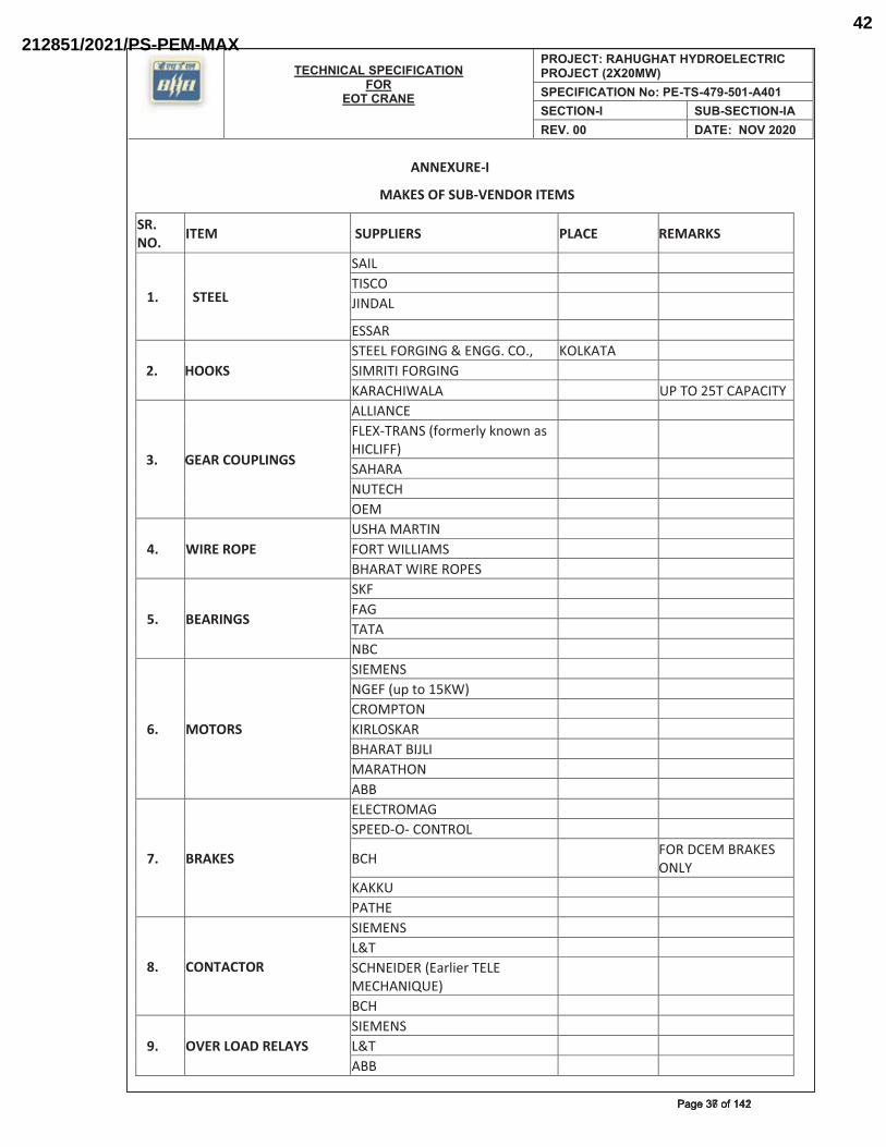
TECHNICAL SPECIFICATION FOR
EOT CRANE
PROJECT: RAHUGHAT HYDROELECTRIC PROJECT (2X20MW)SPECIFICATION No: PE-TS-479-501-A401SECTION-I SUB-SECTION-IAREV. 00 DATE: NOV 2020
ANNEXURE-I
MAKES OF SUB-VENDOR ITEMS
SR. NO. ITEM SUPPLIERS PLACE REMARKS
1. STEEL
SAIL TISCO JINDAL ESSAR
2. HOOKS STEEL FORGING & ENGG. CO., KOLKATA SIMRITI FORGING KARACHIWALA UP TO 25T CAPACITY
3. GEAR COUPLINGS
ALLIANCE FLEX-TRANS (formerly known as HICLIFF)
SAHARA NUTECH OEM
4. WIRE ROPE USHA MARTIN FORT WILLIAMS BHARAT WIRE ROPES
5. BEARINGS
SKF FAG TATA NBC
6. MOTORS
SIEMENS NGEF (up to 15KW) CROMPTON KIRLOSKAR BHARAT BIJLI MARATHON ABB
7. BRAKES
ELECTROMAG SPEED-O- CONTROL
BCH FOR DCEM BRAKES ONLY
KAKKU PATHE
8. CONTACTOR
SIEMENS L&T SCHNEIDER (Earlier TELE MECHANIQUE)
BCH
9. OVER LOAD RELAYS SIEMENS L&T ABB
��������������Page 37 of 142Page 37 of 142
212851/2021/PS-PEM-MAX42
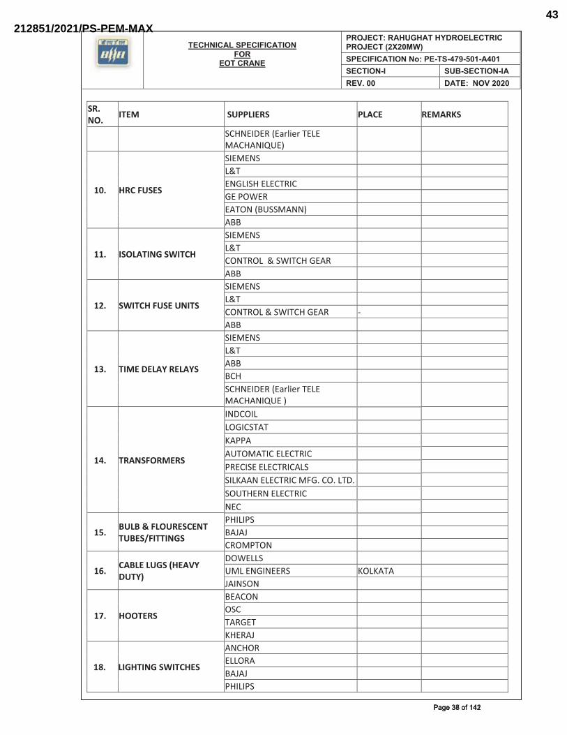
TECHNICAL SPECIFICATION FOR
EOT CRANE
PROJECT: RAHUGHAT HYDROELECTRIC PROJECT (2X20MW)SPECIFICATION No: PE-TS-479-501-A401SECTION-I SUB-SECTION-IAREV. 00 DATE: NOV 2020
SR. NO. ITEM SUPPLIERS PLACE REMARKS
SCHNEIDER (Earlier TELE MACHANIQUE)
10. HRC FUSES
SIEMENS L&T ENGLISH ELECTRIC GE POWER EATON (BUSSMANN) ABB
11. ISOLATING SWITCH
SIEMENS L&T CONTROL & SWITCH GEAR ABB
12. SWITCH FUSE UNITS
SIEMENS L&T CONTROL & SWITCH GEAR - ABB
13. TIME DELAY RELAYS
SIEMENS L&T ABB BCH SCHNEIDER (Earlier TELE MACHANIQUE )
14. TRANSFORMERS
INDCOIL LOGICSTAT KAPPA AUTOMATIC ELECTRIC PRECISE ELECTRICALS SILKAAN ELECTRIC MFG. CO. LTD. SOUTHERN ELECTRIC NEC
15. BULB & FLOURESCENT TUBES/FITTINGS
PHILIPS BAJAJ CROMPTON
16. CABLE LUGS (HEAVY DUTY)
DOWELLS UML ENGINEERS KOLKATA JAINSON
17. HOOTERS
BEACON OSC TARGET KHERAJ
18. LIGHTING SWITCHES
ANCHOR ELLORA BAJAJ PHILIPS
�������������Page 38 of 142Page 38 of 142
212851/2021/PS-PEM-MAX43
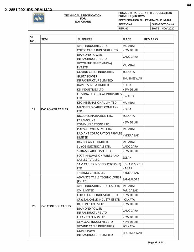
TECHNICAL SPECIFICATION FOR
EOT CRANE
PROJECT: RAHUGHAT HYDROELECTRIC PROJECT (2X20MW)SPECIFICATION No: PE-TS-479-501-A401SECTION-I SUB-SECTION-IAREV. 00 DATE: NOV 2020
SR. NO. ITEM SUPPLIERS PLACE REMARKS
19. PVC POWER CABLES
APAR INDUSTRIES LTD. MUMBAI CORDS CABLE INDUSTRIES LTD. NEW DELHI DIAMOND POWER INFRASTRUCTURE LTD VADODARA
GOYOLENE FIBRES (INDIA) PVT.LTD MUMBAI
GOVIND CABLE INDUSTRIES KOLKATA GUPTA POWER INFRASTRUCTURE LIMITED BHUBNESWAR
HAVELLS INDIA LIMITED NOIDA KEI INDUSTRIES LTD. NEW DELHI KRISHNA ELECTRICAL INDUSTRIES LTD GWALIOR
KEC INTERNATIONAL LIMITED MUMBAI MANSFIELD CABLES COMPANY LTD. NOIDA
NICCO CORPORATION LTD. KOLKATA PARAMOUNT COMMUNICATIONS LTD. NEW DELHI
POLYCAB WIRES PVT. LTD. MUMBAI RADIANT CORPORATION PRIVATE LIMITED HYDERABAD
RAVIN CABLES LIMITED MUMBAI SUYOG ELECTRICALS LTD. VADODARA SRIRAM CABLES PVT. LTD. NEW DELHI SCOT INNOVATION WIRES AND CABLES PVT. LTD. SOLAN
SAM CABLES & CONDUCTORS (P) LTD
UDHAM SINGH NAGAR
THERMO CABLES LTD HYDERABAD
20. PVC CONTROL CABLES
ADVANCE CABLE TECHNOLOGIES (P) LTD BANGALORE
APAR INDUSTRIES LTD., CMI LTD MUMBAI CMI LIMITED FARIDABAD CORDS CABLE INDUSTRIES LTD NEW DELHI CRYSTAL CABLE INDUSTRIES LTD KOLKATA DELTON CABLES LTD NEW DELHI DIAMOND POWER INFRASTRUCTURE LTD VADODARA ELKAY TELELINKS LTD NEW DELHI GEMSCAB INDUSTRIES LTD NEW DELHI GOVIND CABLE INDUSTRIES KOLKATA GUPTA POWER INFRASTRUCTURE LIMITED BHUBNESWAR
�������������Page 39 of 142Page 39 of 142
212851/2021/PS-PEM-MAX44
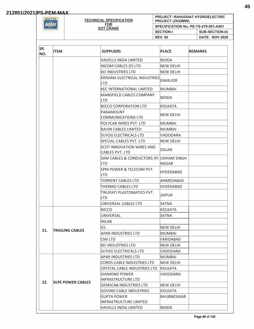
TECHNICAL SPECIFICATION FOR
EOT CRANE
PROJECT: RAHUGHAT HYDROELECTRIC PROJECT (2X20MW)SPECIFICATION No: PE-TS-479-501-A401SECTION-I SUB-SECTION-IAREV. 00 DATE: NOV 2020
SR. NO. ITEM SUPPLIERS PLACE REMARKS
HAVELLS INDIA LIMITED NOIDA INCOM CABLES (P) LTD NEW DELHI KEI INDUSTRIES LTD NEW DELHI KRISHNA ELECTRICAL INDUSTRIES LTD GWALIOR KEC INTERNATIONAL LIMITED MUMBAI MANSFIELD CABLES COMPANY LTD NOIDA NICCO CORPORATION LTD KOLKATA PARAMOUNT COMMUNICATIONS LTD NEW DELHI POLYCAB WIRES PVT. LTD MUMBAI RAVIN CABLES LIMITED MUMBAI SUYOG ELECTRICALS LTD VADODARA SPECIAL CABLES PVT. LTD NEW DELHI SCOT INNOVATION WIRES AND CABLES PVT. LTD SOLAN SAM CABLES & CONDUCTORS (P) LTD
UDHAM SINGH NAGAR
SPM POWER & TELECOM PVT. LTD HYDERABAD TORRENT CABLES LTD AHMEDABAD THERMO CABLES LTD HYDERABAD TIRUPATI PLASTOMATICS PVT. LTD JAIPUR UNIVERSAL CABLES LTD SATNA
21. TRAILING CABLES
NICCO KOLKATA UNIVERSAL SATNA INCAB ICL NEW DELHI APAR INDUSTRIES LTD MUMBAI CMI LTD FARIDABAD KEI INDUSTRIES LTD NEW DELHI SUYOG ELECTRICALS LTD VADODARA
22. XLPE POWER CABLES
APAR INDUSTRIES LTD MUMBAI CORDS CABLE INDUSTRIES LTD NEW DELHI CRYSTAL CABLE INDUSTRIES LTD KOLKATA DIAMOND POWER INFRASTRUCTURE LTD
VADODARA
GEMSCAB INDUSTRIES LTD NEW DELHI GOVIND CABLE INDUSTRIES KOLKATA GUPTA POWER INFRASTRUCTURE LIMITED
BHUBNESWAR
HAVELLS INDIA LIMITED NOIDA
��������������Page 40 of 142Page 40 of 142
212851/2021/PS-PEM-MAX45
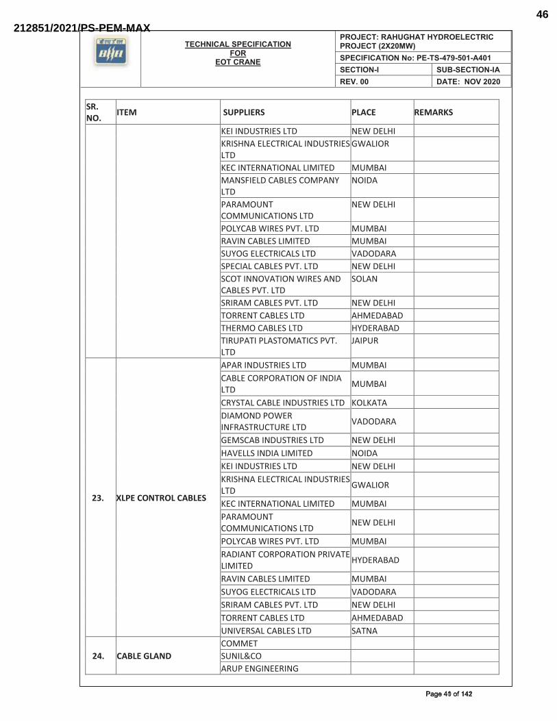
TECHNICAL SPECIFICATION FOR
EOT CRANE
PROJECT: RAHUGHAT HYDROELECTRIC PROJECT (2X20MW)SPECIFICATION No: PE-TS-479-501-A401SECTION-I SUB-SECTION-IAREV. 00 DATE: NOV 2020
SR. NO. ITEM SUPPLIERS PLACE REMARKS
KEI INDUSTRIES LTD NEW DELHI KRISHNA ELECTRICAL INDUSTRIES LTD
GWALIOR
KEC INTERNATIONAL LIMITED MUMBAI MANSFIELD CABLES COMPANY LTD
NOIDA
PARAMOUNT COMMUNICATIONS LTD
NEW DELHI
POLYCAB WIRES PVT. LTD MUMBAI RAVIN CABLES LIMITED MUMBAI SUYOG ELECTRICALS LTD VADODARA SPECIAL CABLES PVT. LTD NEW DELHI SCOT INNOVATION WIRES AND CABLES PVT. LTD
SOLAN
SRIRAM CABLES PVT. LTD NEW DELHI TORRENT CABLES LTD AHMEDABAD THERMO CABLES LTD HYDERABAD TIRUPATI PLASTOMATICS PVT. LTD
JAIPUR
23. XLPE CONTROL CABLES
APAR INDUSTRIES LTD MUMBAI CABLE CORPORATION OF INDIA LTD MUMBAI
CRYSTAL CABLE INDUSTRIES LTD KOLKATA DIAMOND POWER INFRASTRUCTURE LTD VADODARA
GEMSCAB INDUSTRIES LTD NEW DELHI HAVELLS INDIA LIMITED NOIDA KEI INDUSTRIES LTD NEW DELHI KRISHNA ELECTRICAL INDUSTRIES LTD GWALIOR
KEC INTERNATIONAL LIMITED MUMBAI PARAMOUNT COMMUNICATIONS LTD NEW DELHI
POLYCAB WIRES PVT. LTD MUMBAI RADIANT CORPORATION PRIVATE LIMITED HYDERABAD
RAVIN CABLES LIMITED MUMBAI SUYOG ELECTRICALS LTD VADODARA SRIRAM CABLES PVT. LTD NEW DELHI TORRENT CABLES LTD AHMEDABAD UNIVERSAL CABLES LTD SATNA
24. CABLE GLAND COMMET SUNIL&CO ARUP ENGINEERING
��������������Page 41 of 142Page 41 of 142
212851/2021/PS-PEM-MAX46
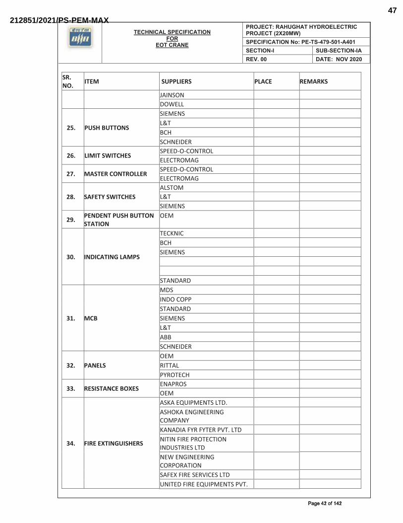
TECHNICAL SPECIFICATION FOR
EOT CRANE
PROJECT: RAHUGHAT HYDROELECTRIC PROJECT (2X20MW)SPECIFICATION No: PE-TS-479-501-A401SECTION-I SUB-SECTION-IAREV. 00 DATE: NOV 2020
SR. NO. ITEM SUPPLIERS PLACE REMARKS
JAINSON DOWELL
25. PUSH BUTTONS
SIEMENS L&T BCH SCHNEIDER
26. LIMIT SWITCHES SPEED-O-CONTROL ELECTROMAG
27. MASTER CONTROLLER SPEED-O-CONTROL ELECTROMAG
28. SAFETY SWITCHES ALSTOM L&T SIEMENS
29. PENDENT PUSH BUTTON STATION
OEM
30. INDICATING LAMPS
TECKNIC BCH SIEMENS STANDARD
31. MCB
MDS INDO COPP STANDARD SIEMENS L&T ABB SCHNEIDER
32. PANELS OEM RITTAL PYROTECH
33. RESISTANCE BOXES ENAPROS OEM
34. FIRE EXTINGUISHERS
ASKA EQUIPMENTS LTD. ASHOKA ENGINEERING COMPANY
KANADIA FYR FYTER PVT. LTD NITIN FIRE PROTECTION INDUSTRIES LTD
NEW ENGINEERING CORPORATION
SAFEX FIRE SERVICES LTD UNITED FIRE EQUIPMENTS PVT.
��������������Page 42 of 142Page 42 of 142
212851/2021/PS-PEM-MAX47
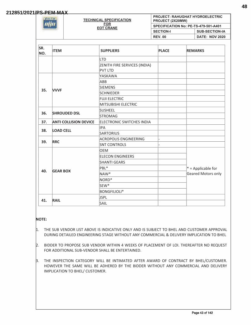
TECHNICAL SPECIFICATION FOR
EOT CRANE
PROJECT: RAHUGHAT HYDROELECTRIC PROJECT (2X20MW)SPECIFICATION No: PE-TS-479-501-A401SECTION-I SUB-SECTION-IAREV. 00 DATE: NOV 2020
SR. NO. ITEM SUPPLIERS PLACE REMARKS
LTD ZENITH FIRE SERVICES (INDIA) PVT LTD
35. VVVF
YASKAWA ABB SIEMENS SCHNIEDER FUJI ELECTRIC MITSUBISHI ELECTRIC
36. SHROUDED DSL SUSHEEL STROMAG
37. ANTI COLLISION DEVICE ELECTRONIC SWITCHES INDIA
38. LOAD CELL IPA SARTORIUS
39. RRC ACROPOLIS ENGINEERING - SNT CONTROLS -
40. GEAR BOX
OEM
* = Applicable for Geared Motors only
ELECON ENGINEERS SHANTI GEARS PBL* NAW* NORD* SEW* BONGFILIOLI*
41. RAIL JSPL SAIL
NOTE:
1.� THE SUB VENDOR LIST ABOVE IS INDICATIVE ONLY AND IS SUBJECT TO BHEL AND CUSTOMER APPROVAL DURING DETAILED ENGINEERING STAGE WITHOUT ANY COMMERCIAL & DELIVERY IMPLICATION TO BHEL
2.� BIDDER TO PROPOSE SUB VENDOR WITHIN 4 WEEKS OF PLACEMENT OF LOI. THEREAFTER NO REQUEST FOR ADDITIONAL SUB-VENDOR SHALL BE ENTERTAINED.
3.� THE INSPECTION CATEGORY WILL BE INTIMATED AFTER AWARD OF CONTRACT BY BHEL/CUSTOMER.
HOWEVER THE SAME WILL BE ADHERED BY THE BIDDER WITHOUT ANY COMMERCIAL AND DELIVERY IMPLICATION TO BHEL/ CUSTOMER.
��������������Page 43 of 142Page 43 of 142
212851/2021/PS-PEM-MAX48
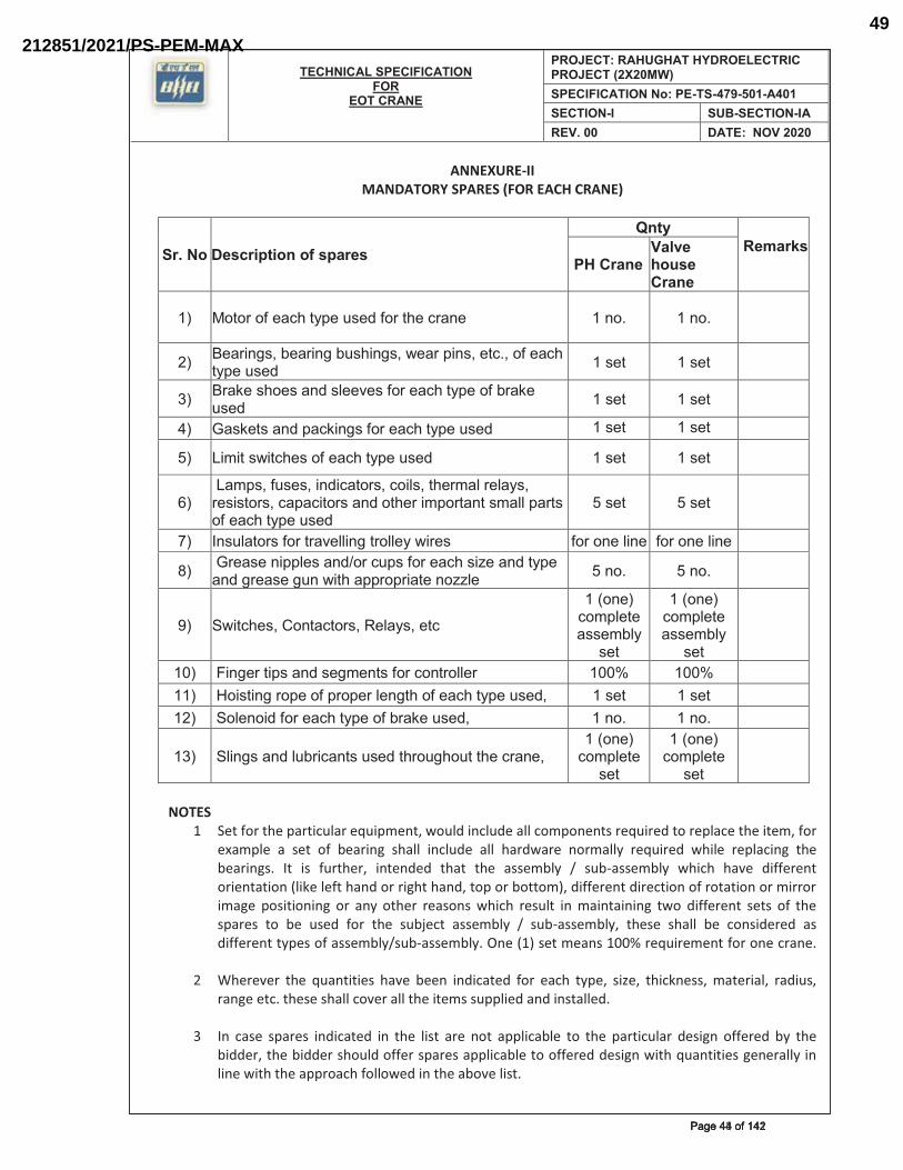
TECHNICAL SPECIFICATION FOR
EOT CRANE
PROJECT: RAHUGHAT HYDROELECTRIC PROJECT (2X20MW)SPECIFICATION No: PE-TS-479-501-A401SECTION-I SUB-SECTION-IAREV. 00 DATE: NOV 2020
ANNEXURE-II MANDATORY SPARES (FOR EACH CRANE)
Sr. No�Description of spares ��Qnty
�Remarks ���PH Crane �
Valve houseCrane ��
��� ��*��������+$�*@<��[#�>�����*$��+��!���� ��!�^�� ��!�^�� ����
��� �����!�#{�?����!��?[#$�!�#{�]����<�!#{��*+^{������+$�*@<��[#�>� ��#�*� ��#�*� ����
��� ���`��#$��#��!>�#"��\�#�������+$�*@<�����?��`��[#�>� ��#�*� ��#�*� ����
��� ��#`�*#��!>�<�+`�!�#�������+$�*@<��[#�>� ��#�*� ��#�*� �
��� ��Z�*�#]�*+$�#������+$�*@<��[#�>� ��#�*� ��#�*� �
������Z<#{��[#�#{��!>�+�*��#{�+��"#{�*$��Z�"���"�@#{���#�#*��#{�+�<�+�*��#��!>��*$����Z<��*�!*�#Z�""�<��*#������+$�*@<��[#�>�
��#�*� ��#�*� ����
�� _!#["�*��#�����*��\�""�!��*��""�@�]���#�� �����!��"�!�� �����!��"�!�� ����
�� �����#��!�<<"�#��!>����+[<#�������+$�#�����!>�*@<���!>�����#���[!�]�*$��<<��<���*��!���"�� ��!�^� ��!�^� ����
��� |]�*+$�#{���!*�+*��#{���"�@#{��*+���
����!���+�Z<"�*���##�Z?"@�
#�*�
����!���+�Z<"�*���##�Z?"@�
#�*�
����
���� ���!����*�<#��!>�#��Z�!*#�����+�!*��""����� ����� ����� �������� ����#*�!����<�����<��<���"�!�*$������+$�*@<��[#�>{� ��#�*� ��#�*� �������� �|�"�!��>�������+$�*@<�����?��`��[#�>{� ��!�^�� ��!�^�� ����
���� �|"�!�#��!>�"[?��+�!*#�[#�>�*$��[�$�[*�*$��+��!�{�����!���
+�Z<"�*��#�*��
����!���+�Z<"�*��
#�*���
NOTES 1� Set for the particular equipment, would include all components required to replace the item, for
example a set of bearing shall include all hardware normally required while replacing the bearings. It is further, intended that the assembly / sub-assembly which have different orientation (like left hand or right hand, top or bottom), different direction of rotation or mirror image positioning or any other reasons which result in maintaining two different sets of the spares to be used for the subject assembly / sub-assembly, these shall be considered as different types of assembly/sub-assembly. One (1) set means 100% requirement for one crane.
2� Wherever the quantities have been indicated for each type, size, thickness, material, radius, range etc. these shall cover all the items supplied and installed.
3� In case spares indicated in the list are not applicable to the particular design offered by the bidder, the bidder should offer spares applicable to offered design with quantities generally in line with the approach followed in the above list.
��������������Page 44 of 142Page 44 of 142
212851/2021/PS-PEM-MAX49
TECHNICAL SPECIFICATION FOR
EOT CRANE
PROJECT: RAHUGHAT HYDROELECTRIC PROJECT (2X20MW)SPECIFICATION No: PE-TS-479-501-A401SECTION-I SUB-SECTION-IAREV. 00 DATE: NOV 2020
4� Any item which is quoted as “not applicable” in the above list and is found to be “applicable” at a later date shall be supplied by the Bidder without any commercial implications. The Bidder shall note that if there in any change/ variation in equipment/ system during detail engineering which causes any change/ variation in the essential spares quantity, the same shall be supplied without any commercial implications. The price indicated for the mandatory spares shall be considered for the purpose of evaluation.
5� Mandatory spares shall not be dispatched before dispatch of corresponding main equipment. The spares shall be treated and packed for a long storage under the climatic condition prevailing at site.
6 Interchangeability and Packings: All spares supplied under this contract shall be strictly interchangeable with parts for which they are intended for replacements. These spares should include all mounted accessories like components, boards, add or items, fitting, connectors etc. and be complete in all respects so that the replacement of the main items by these spares does not require any additional item. The vendors must conform the pair to pair compatibility of each electrical spares modules with the modules should be supplied in the original package. All electronic modules should be pre-set and/or preprogrammed for ready use at site. Alternatively, suitable instruction sheet indicating the details of required PCB jumper position, BCD which is setting, EPROM/PROM listing etc. should be packed along with each module. Also a caution mark sign should be put on all such module which needs pre-setting/pre-programming before putting them in to service. The spare shall be treated and properly packed for long term storage.
7 Identification: Each spare shall be clearly marked and labeled on the outside of the packing with its description. When more than one spare part is packed in single case, a general description of the contents shall be shown on the outside of such case and a detailed list enclosed. All cases, containers and other packages must be suitably marked and numbered for the purpose of identification.
8� Mandatory spares listed above is bare minimum requirement. In case any additional mandatory spares requirement is covered elsewhere in the tender specification, same shall be deemed to have been covered in bidder’s scope of supply.
��������������Page 45 of 142Page 45 of 142
212851/2021/PS-PEM-MAX50
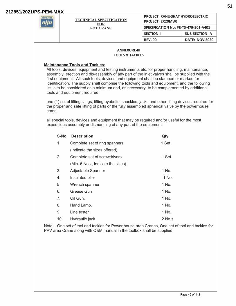
TECHNICAL SPECIFICATION
FOREOT CRANE
PROJECT: RAHUGHAT HYDROELECTRIC PROJECT (2X20MW) SPECIFICATION No: PE-TS-479-501-A401 SECTION-I SUB-SECTION-IA REV. 00 DATE: NOV 2020
ANNEXURE-III TOOLS & TACKLES
Maintenance Tools and Tackles: �""�*��"#{�>�\�+�#{���[�<Z�!*��!>�*�#*�!���!#*�[Z�!*#��*+^�����<��<���$�!>"�!�{�Z��!*�!�!+�{��##�Z?"@{����+*��!��!>�>�#~�##�Z?"@�����!@�<��*����*$���!"�*�\�"\�#�#$�""�?��#[<<"��>�]�*$�*$�����#*���[�<Z�!*^���""�#[+$�*��"#{�>�\�+�#��!>���[�<Z�!*�#$�""�?��#*�Z<�>����Z��`�>������>�!*���+�*��!^��$��#[<<"@�#$�""�+�Z<��#��*$����""�]�!��*��"#��!>���[�<Z�!*{��!>�*$����""�]�!��"�#*��#�*��?��+�!#�>���>��#���Z�!�Z[Z��!>{��#�!�+�##��@{�*��?��+�Z<"�Z�!*�>�?@��>>�*��!�"�*��"#��!>���[�<Z�!*����[���>^���!������#�*����"��*�!��#"�!�#{�"��*�!���@�?�"*#{�#$�+`"�#{���+`#��!>��*$���"��*�!��>�\�+�#����[���>�����*$��<��<����!>�#����"��*�!�����<��*#����*$���[""@��##�Z?"�>�#<$���+�"�\�"\��?@�*$��<�]��$�[#��+��!�^���""�#<�+��"�*��"#{�>�\�+�#��!>���[�<Z�!*�*$�*�Z�@�?�����[���>��!>����[#��["�����*$��Z�#*���<�>�*��[#��##�Z?"@����>�#Z�!*"�!������!@�<��*����*$����[�<Z�!*^�����
S-No. Description Qty. �� ��Z<"�*��#�*������!��#<�!!��#��������� � �������������|�*�
�� �_!>�+�*��*$��#���#�������>���
�� ��Z<"�*��#�*����#+��]>��\��#�� � � ��|�*�
� ���!^�����#^{�_!>�+�*��*$��#���#��
�^� �>�[#*�?"��|<�!!��� � � � � ����^��
�^� _!#["�*�>�<"������� � � � �����������������^�
�� ���!+$�#<�!!��� �� � � � ����^�
�^� ����#���[!�� � � � � � ����^�
^� ��"��[!^� � � � � � ����^��
^� ��!>���Z<^� � � � � � ����^�
�� ��!��*�#*���� � � � � � ����^�
��^� �@>��["�+���+`�� � � � � ����^#�������
��*���~��!��#�*����*��"��!>�*�+`"�#�������]���$�[#����������!�#{��!��#�*����*��"��!>�*�+`"�#�����������������!���"�!��]�*$�����Z�
TECHNICAL SPECIFICATION
FOREOT CRANE
PROJECT: RAHUGHAT HYDROELECTRIC PROJECT (2X20MW) SPECIFICATION No: PE-TS-479-501-A401 SECTION-I SUB-SECTION-IA REV. 00 DATE: NOV 2020
ANNEXURE-IV PAINTING SPECIFICATION
��^�Structural�
�Surface preparation:
�""�#[���+�#�*��?��<��!*�>�#$�""�?��*$���[�$"@�+"��!�>�����""�>��*{�>[#*{�����#�{�+�Z�!*�#+�"�������"�?������*$���<<"�+�*��!����<��!*^���"� �!>�����#�� #$�""� ?�� ��Z�\�>� ]�*$� #�"\�!*#� !�*� $��Z�["� *��*$��#[���+�^�_�����[���>�?@�*$��<��!*�#@#*�Z{�*$��#[���+��#$�""�?����!�""@� +"��!�>� ]�*$� ]�*��^� |[���+�#� #$�""� ?�� >�@� [!"�##�>�Z<�!�!�� �#� ���[���>� ���� �� <��*�+["��� ��!�#$� Z�*����"^� �!@�#[���+�� +�!*�Z�!�*�>� >[��!�� <��!*� �<<"�+�*��!� #$�""� ?�� ��~+"��!�>�*$���[�$"@�?������<��!*�!���#�?��!��+�!*�![�>^���$��#[���+��+"��!�!���[�"�*@�]�""�+�!���Z�*��|���^�����|]�>�#$�#*�!>��>#��!#*�*[*��!�|_|�������^�
Primer: � ���#*� "�@��� ��� <��Z�!�� <��!*� �Z�!�Z[Z� >�@� ��"Z� *$�+`!�##�� ���Z�+��!#����""�]�>�?@� *]������<��Z�!�� "�@��#�$�\�!����Z�!�Z[Z�>�@���"Z�*$�+`!�##�������Z�+��!#���+$^��""�*$�#��"�@��#�#$�""�?�������>�"��>��!�+$"���!�*�>��[??���#@!*$�*�+���#�!�?�#�#���Z�!�Z[Z�*�*�"�>�@���"Z�*$�+`!�##���������������Z�+��!#�^�
Finish Coat:� ��!�"� +��*�!��#$�""�?��]�*$��� ��!�#$�!��+��*#� �Z�!�Z[Z�>�@� ��"Z�*$�+`!�##�� ��� Z�+��!#� ��+$�� �!� +$"���!�*�>� �[??���#@!*$�*�+���#�!�?�#�#^�������������������
Total DFT:� ������������������
B. Electrical /Control Panel
� ��!*��"�<�!�"#�#$�""�?��<�]>���+��*�>^��Z�!� ����~�������
C. COLOR SHADE
���
D. Handrail- ��*��� +����["� ?"�#*~+"��!�!�� #�Z�� #$�""� ��+��\�� *]�� ���� "�@��#� ��+$� ��� ��<��Z����!>���"~��#�#*�!��\��!�#$�����!�Z�"^
�
|^���� _*�Z� �#+��<*��!� ��"���|$�>�� ��Z��`#��� ���!��|*�[+*[��� ��">�!���""�]~�#$�>�������#�<���
_|~���
�� ��**�Z�?"�+`��##�Z?"@� ��">�!���""�]~�#$�>��������#�<���_|~��
�
�� ���`#� �"�+`� ��� ��*��#� ���$*����@~�#$�>���������#�<���_|��� ��� ��!*��"���!�"#� ���$*����@~�#$�>���������#�<���
_|�����
��������������Page 47 of 142Page 47 of 142
212851/2021/PS-PEM-MAX52
TECHNICAL SPECIFICATION
FOREOT CRANE
PROJECT: RAHUGHAT HYDROELECTRIC PROJECT (2X20MW) SPECIFICATION No: PE-TS-479-501-A401 SECTION-I SUB-SECTION-IA REV. 00 DATE: DEC 2020
ANNEXURE-VMAIN DRAWING LIST WITH SCHEDULE OF SUBMISSION
A. DRAWINGS/ DOCUMENTS TO BE SUBMITTED AFTER AWARD OF CONTRACT
�$��#[++�##�["�?�>>���#$�""�#[?Z�*�*$����""�]�!��>��]�!�#���>�+[Z�!*#�>[��!��>�*��"��!��!����!��
�����<<��\�"��
BASIC ENGINEERING DRAWINGS/DOCUMENTS
S.N. BHEL drawing No. Title Schedule date of submission from date of
LOI. (in week)�� ��~��~���~���~
����������������������������������![��+*[��!���[�"�*@��"�!�]�*$�#[?�\�!>���"�#*�����������������������������������������������������������������
��
�� ��~��~���~���~�������������������������������
��+$�!�#Z�|���!����"+["�*��!���������������|������������������������������������������������������
��
�� ��~��~���~���~�������������������������������
��+$�!�#Z�|���!����"+["�*��!���������������|������������������������������������������������������
��
�� ��~��~���~���~�������������������������������
��!���"�����!��Z�!*���������������|�������������]�*$���� |��>�*��"#�����������������������
��
�� ��~��~���~���~�������������������������������
��!���"�����!��Z�!*���������������|�������������]�*$���� |��>�*��"#��������������������������������
��
�� ��~��~���~���~�������������������������������
���?�#[?��##�Z?"@���������������|�������������]�*$����]$��"��##�Z?"@�������������������������
��
� ��~��~���~���~�������������������������������
�������"�+*��+�$��#*���������������|�������������]�*$����]$��"��##�Z?"@�������������������������
��
� ��~��~���~���~��������������������������������
���`�?"�+`��##�Z?"@�]�*$�>�*��"#����$��`{�![*��!>�+$�+`�<"�*���������������������������������������
��
�
OTHER DRAWING/DOCUMENTS
S.N.
BHEL drawing No. Title Schedule date of submission
FOR POWER HOUSE CRANE�� ��~��~���~���~
������������������������������ �*��#$��*����Z�*��#���������������|��������������������������������
���>�@#���*�������__��<<��\�"��+"����!+�����Z�������!���+$�!�+�"�#���!��+�"+["�*��!����~��~���~���~���������������������������������
�� ��~��~���~���~������������������������������
��!��*��\�"���+$�!��@��##�Z?"@�]�*$����]$��"��##�Z?"@���������������|�������������������������������������������
���>�@#���*�������__��<<��\�"��+"����!+�����Z�������!����>��]�!�����~��~���~���~������������
�� ��~��~���~���~�����
�|+$�Z�*�+�+��+[�*�>�����Z����������*�+*�\��<�!�"{����!��!>�"��$*�!��+��+[�*�������?�����!�$��#*�<�!�"�������+�����##����\��#��������>����!�����\��#��������_!+"[>�!�����*$�!��>�����Z���������������|����������!+"[>�!��+�!*��"�]��*��[<��
�>�@#���*�������__��<<��\�"��+"����!+�����Z�������!���+$�!�+�"�#���!��+�"+["�*��!����~��~���~���~���������������������������������
�� ��~��~���~���~�����������������������������
��!���"�����!��Z�!*����������*�+*�\��<�!�"�?�����!�$��#*�<�!�"�+�����##����\�"�<�!�"�>����!�����\��#��*��\�"�
�>�@#���*�������__��<<��\�"��+"����!+�����Z�������!��"�+*��+�"�#+$�Z�����~��~���~
�������������Page 48 of 142Page 48 of 142
212851/2021/PS-PEM-MAX53
TECHNICAL SPECIFICATION
FOREOT CRANE
PROJECT: RAHUGHAT HYDROELECTRIC PROJECT (2X20MW) SPECIFICATION No: PE-TS-479-501-A401 SECTION-I SUB-SECTION-IA REV. 00 DATE: DEC 2020
<�!�"^������!>�!*������Z�*����>�����!*��"���������������|�����������
���~��������������������������������������������
�� ��~��~���~���~������������������������������
��?"��|���!���!>�+�?"��#+$�>["����������������|����������������������������
�>�@#���*�������__��<<��\�"��+"����!+�����Z�������!��"�+*��+�"�#+$�Z�����~��~���~���~��������������������������������������������
�� ��~��~���~���~�����������������������������
�*��#$��*��������������|���������]�*$�<��!*�!��>�*��"#����������������
�>�@#���*�������__��<<��\�"��+"����!+�����Z�������!����>��]�!�����~��~���~���~������������
� ��~��~���~���~������������������������������
|*�[+*[��"�+�"+["�*��!#���������������|�������������������������������������������
���>�@#���*�������__��<<��\�"��+"����!+�����Z�������!����>��]�!�����~��~���~���~������������
� ��~��~���~���~������������������������������
��![��+*[��!���[�"�*@��"�!�]�*$�#[?�\�!>���"�#*����������"�+*��+�$��#*�
�>�@#���*�������__��<<��\�"��+"����!+�����Z�������!����>��]�!�����~��~���~���~������������
�� ��~��~���~���~������������������������������
�����"�+*��+�$��#*���{�#���!��+�"+["�*��!��!>��"�+*��+�"�#+$�Z��
�>�@#���*�������__��<<��\�"��+"����!+�����Z�������!����>��]�!�����~��~���~���~������������
VALVE HOUSE CRANE�� ��~��~���~���~
������������������������������ �*��#$��*����Z�*��#���������������|�������������������������������������������
��� >�@#� ��*��� ���� __� �<<��\�"��+"����!+�� ���Z� ����� �!���+$�!�+�"�#���!��+�"+["�*��!���
�� ��~��~���~���~�����
�|+$�Z�*�+�+��+[�*�>�����Z����������*�+*�\��<�!�"{����!��!>�"��$*�!��+��+[�*�������?�����!�$��#*�<�!�"�������?�����##����\��#��������+����!�����\��#��������_!+"[>�!�����*$�!��>�����Z���������������|���������!+"[>�!��+�!*��"�]��*��[<�
� >�@#� ��*��� ���� __� �<<��\�"��+"����!+�� ���Z� ����� �!���+$�!�+�"�#���!��+�"+["�*��!���
�� ��~��~���~���~�����������������������������
��!���"�����!��Z�!*����������*�+*�\��<�!�"�?�����!�$��#*�<�!�"�+�����##����\�"�<�!�"�>����!�����\��#��*��\�"�<�!�"^������!>�!*��
� >�@#� ��*��� ���� __� �<<��\�"��+"����!+�� ���Z� ����� �!��"�+*��+�"�#+$�Z����
�� ��~��~���~���~������������������������������
��?"��|���!���!>�+�?"��#+$�>["����������������|������������������������������
� >�@#� ��*��� ���� __� �<<��\�"��+"����!+�� ���Z� ����� �!��"�+*��+�"�#+$�Z����
�� ��~��~���~���~�����������������������������
�*��#$��*��������������|���������]�*$�<��!*�!��>�*��"#����������������
� >�@#� ��*��� ���� __� �<<��\�"��+"����!+�� ���Z� ����� �!� ���>��]�!����
�� ��~��~���~���~������������������������������
|*�[+*[��"�+�"+["�*��!#���������������|�������������������������������������������
��� >�@#� ��*��� ���� __� �<<��\�"��+"����!+�� ���Z� ����� �!� ���>��]�!��
Common drawings�� ��~��~���~���~
���������������������������������">��[�"�*@�<"�!��������������������� � >�@#� ��*��� ���� _� �<<��\�"�
�+"����!+�� ���Z� ����� �!� ���>��]�!���
�� ��~��~���~���~������������������������������
��������![�"������������������������� ���>�@#���*�������_��<<��\�"�����""�>��]�!�#�
�� ��~��~���~���~������������������������������
��!>�*��@�#<����<��*#�"�#*�����������������������������������������������������������������
��� >�@#� ��*��� ���� __� �<<��\�"��+"����!+�� ���Z�������!��^�^�������!�� {� ��+$�!�+�"� #���!��+�"+["�*��!{�*�+$!�+�"�>�*��#$��*���|+$�Z�*�+����+[�*�>�����Z���������������
�� ��~��~���~���~ ���+*��!�<��+�>[������������������� �� >�@#� ��*��� ���� __� �<<��\�"�
�������������Page 49 of 142Page 49 of 142
212851/2021/PS-PEM-MAX54
TECHNICAL SPECIFICATION
FOREOT CRANE
PROJECT: RAHUGHAT HYDROELECTRIC PROJECT (2X20MW) SPECIFICATION No: PE-TS-479-501-A401 SECTION-I SUB-SECTION-IA REV. 00 DATE: DEC 2020
������������������������������ �+"����!+�� ���Z�������!��^�^�������!�� {� ��+$�!�+�"� #���!��+�"+["�*��!� �� |+$�Z�*�+� ���+[�*�>�����Z��������������������������������������������
�� ��~��~���~���~�����������������������������
��!���"�����!��Z�!*���������#$��[>�>� |���������������������������
� >�@#� ��*��� ���� __� �<<��\�"��+"����!+�� ���Z� ����� �!� ���>��]�!���
�� ��~��~���~���~������������������������������
���!��"[?��+�*��!�>��]�!������������������������������������������������������������������
��� >�@#� ��*��� ���� __� �<<��\�"��+"����!+�� ���Z� ����� �!� ���>��]�!���
� ��~��~���~���~������������������������������
��!*�@����"��!#*�""�*��!�����������������������������������������������������������������
� >�@#� ��*��� ���� __� �<<��\�"��+"����!+�� ���Z� ����� �!� ���>��]�!���
��*�#�� ��^� �$���?�\��>��]�!�� "�#*� �#� *�!*�*�\���!>�#$�""�?�� ��!�"���>�]�*$� *$��#[++�##�["�?�>>���
��*���<"�+�Z�!*������>��^��$�"��#�Z����� *$��>��]�!�#� �!>�+�*�>��?�\��Z�@�!�*�?���<<"�+�?"�{�#�Z���>>�*��!�"�>��]�!�#�Z�@��"#��?�����[���>�?�#�>��!�#+�<�����]��`^��
�^� ��]�!�#�#$�""�?��<��<���>��!��[*�~��>�"�*�#*��>�*��!^����[���>�!�^����$��>��!>�#��*�+�<��#� ��>�*�?"��� ��� *$�� >��]�!�#� #$�""� ?�� �[�!�#$�>� �#� <��� ���[���Z�!*� #<�+����>��"#�]$�����!�*$��#<�+���+�*��!^�
�^� �!"@� Z�![�"� +�"+["�*��!� ]�*$� �[*$�!*�+� #[<<��*�!�� "�*���*[��� ��^�^� ��*��+*#� ��� $�!>����`�� #*�!>��>�+�>�#�� #$�""� ?�� �++�<*�?"�^� �""� >�#��!� +�"+["�*��!#� �!>� >��]�!�#�#$�""�?���!�|_�#@#*�Z��!"@^��
�^� ��>>��� *��!�*��*$�*��""�\�"[�#�>�Z�!#��!#��"�\�*��!#��*+^�]�*$�[*�#[<<��*�!��?�+`�[<�>�*���>�<*�>��##[Z�>�?@�*$��#[++�##�["�?�>>����>[��!��+�!*��+*�#*������!�*$��>�#��!�+�"+["�*��!�>��]�!�#�#$�""�?��*�`�!�?@�*$��+[#*�Z����]!���*��?��+����+*�[!"�##�*$�@�����#*�<["�*�>� �!� *$��#<�+���+�*��!^��!@�<��?"�Z����#�!�� "�*��� �!� *$�#� �����>�#$�""�?��Z�>�����>�?@� *$��#[++�##�["�?�>>����*�$�#�+�#*��!>�!����*�!#��!���� *�Z��#$�""�?�����!*�>�����*$��#�Z�^�
�^� �""�*$��>��]�!�#��!>�>�+[Z�!*#��!+"[>�!����!���"�����!��Z�!*�>��]�!�{�>�*��#$��*{�+�"+["�*��!� �*+^� *�� ?�� �[�!�#$�>� *�� *$�� +[#*�Z��� >[��!�� >�*��"�>� �!��!����!�� #*����#$�""� �!+"[>�����!>�+�*��*$����""�]�!��>�*��"#�����+"���*@�]^�^*^�_!#<�+*��!{�+�!#*�[+*��!{����+*��!��!>�Z��!*�!�!+���*+^�~�
��� �""�>��]�!�#��!>�>�+[Z�!*#�#$�""� �!>�+�*�� *$�� "�#*�����""� ������!+��>��]�!�#��!+"[>�!����!���"�����!��Z�!*^�
?�� �""�>��]�!�#�#$�""� �!+"[>�� ��#$�]�<"�!{��"�\�*��!{�#�>��\��]{�+��##� ~�#�+*��!{�#`�!� #�+*��!{� ?"�]� ~� [<� \��]�� �""� Z����� #�"�~Z�![��+*[��>� �!>� ?�[�$*� �[*��*�Z#�#$�""�?��"�?�"�>��!>��!+"[>�>��!������������!�*�?["������Z^�
+�� ���!*�!�� #+$�>["�� � � #$�""� �"#�� ?�� Z�>�� �#� �� <��*� ��� ��!���"� ����!��Z�!*�>��]�!�������+$���[�<Z�!*����*�Z#��!>�+�*�!���*�"��#*���*��>��!�Z�#^�
>�� �""� *$�� >��]�!�#� ���[���>� *�� ?�� �[�!�#$�>� *�� +[#*�Z��� >[��!�� >�*��"�>��!��!����!�� #*���� #$�""� �!+"[>�� *�+$!�+�"� <���Z�*��#{� >�*��"#� ��� <��!*#� �!>�"[?��+�*��!{� $��>!�##� �!>� ���� �� ���� �!� *�?["��� ���Z� �!>�+�*�!�� �""� Z�����+�Z<�!�!*#� �!+"[>�!�� ?�[�$*� �[*� �*�Z#� �!>� *$���� �[�!*�*@{� Z�*����"� ���+�!#*�[+*��!��!>�+�*�!���*#��<<"�+�?"��+�>����#*�!>��>{�]���$*{�Z�`���*+^�
��� ��]�!�#��>�+[Z�!*#� *��?��#[?Z�**�>� ����<[�+$�#��#���\��]���<<��\�"�#$�""�?��[!>�����\�#��!��{��{�����*+^�]$�"��>��]�!�#��>�+[Z�!*#�*��?��#[?Z�**�>�*$�����*��� ����+[#*�Z�� #��<<��\�"���*���<[�+$�#�� #��<<��\�"�#$�""�?��[!>����~�{��{��{����^�*+^��
��������������Page 50 of 142Page 50 of 142
212851/2021/PS-PEM-MAX55
TECHNICAL SPECIFICATION
FOREOT CRANE
PROJECT: RAHUGHAT HYDROELECTRIC PROJECT (2X20MW) SPECIFICATION No: PE-TS-479-501-A401 SECTION-I SUB-SECTION-IA REV. 00 DATE: DEC 2020
��� ��]�!�#��!>�>�+[Z�!*#�!�*�+�\���>��?�\��?[*����[���>�*��+$�+`�#���*@����Z�+$�!�#�� #@#*�Z{� #$�""� ?�� #[?Z�**�>� >[��!�� >�*��"�>� �!��!����!�� #*����]�*$�[*��!@�+�ZZ��+��"��Z<"�+�*��!^�
��� �""� >��]�!�#� #$�""� �!+"[>�� ��^�^��� �!>� �!>�+�*�� �[�!*�*@{� Z�*����"� ���+�!#*�[+*��!{�Z�`���"�!��]�*$�_|��|���^{���+$!�+�"�<���Z�*��#{�>�Z�!#��!#{�$��>!�##{�Z�+$�!�!��#@Z?�"��!>�*�"���!+�{����[���Z�!*������>�����<$@��!>�$@>��["�+� *�#*#{�<��!*�!��>�*��"#{��"�\�*��!{�#�>��\��]{�<"�!{�#`�!�#�+*��!��!>�?"�]~[<�\��]�����+"���*@^�
$�� �""� >��]�!�#� #$�""� ?�� <��<���>� �#� <��� �����#� *�*"�� ?"�+`� �!>� #$�""� ?���������#�>��]�!����^�
��� |+$�>["�����>��]�!�#�#[?Z�##��!#{�+�ZZ�!*��!+��<���*��!#����<<��\�"�#$�""�?���#�#*�<["�*�>��!�*$��#<�+���+�*��!#^��$��#[++�##�["�?�>>���#$�""�>�<[*��$�#�>�#��!�<��#�!!�"� *������ #���[#*�Z�� #����!#["*�!* #� ����+�� ���� �+��##� *$��*�?"�� ��#�"[*��!� ��� �##[�#� �!>� *�� ��*� >�+[Z�!*#� �<<��\�>� �!� *$�� #*�<["�*�>�*�Z�^�
��� ��>>���*����""�]�*$����""�]�!��*$��>��]�!��#[?Z�##��!�#+$�>["����^� �#*� #[?Z�##��!� ��� >��]�!�#� ���Z� >�*�� ��� ��_� �#� <��� *$�� #[?Z�##��!�
#+$�>["�^���^� �\��@���\�#�>�#[?Z�##��!��!+��<���*�!��+�ZZ�!*#�¡�]�*$�!��>�@#^�
`�� ��>>��� *��#[?Z�*� ��\�#�>�>��]�!�#�+�Z<"�*�� �!��""� ��#<�+*#� �!+��<���*�!���""�+�ZZ�!*#^� �!@� �!+�Z<"�*�� >��]�!�� #[?Z�**�>� #$�""� ?�� *���*�>� �#� !�!~#[?Z�##��!�]�*$�>�"�@#��**��?[*�?"��*��?�>>�� #��++�[!*^������!@�+"�����+�*��!��>�#+[##��!����[���>�*��+�Z<"�*��*$��>��]�!�#{�*$��?�>>���#$�""�$�Z#�"��>�<[*��$�#� <��#�!�"� *�� ����� ���� �+��##� *$�� *�?"�� >�#+[##��!#�� ��!�"���*��!#��#[?Z�##��!#����>��]�!�#^�
"�� �� ���������_������*�+"�[#��!�^��^�^�����+[#*�Z���#<�+���+�*��!��"#�� *��?���������>�������!�"���!��>��]�!��"�#*�>[��!��>�*��"��!��!����!�^�
�B. DOCUMENT MANAGEMENT SYSTEM:
��>>���*��!�*��*$�*�*$��#[++�##�["�?�>>��{�>[��!��>�*��"��!��!����!�{�]�""�#[?Z�*�*$��>���>�+�*$��[�$�]�?�?�#�>� �+[Z�!*���!���Z�!*�|@#*�Z��!��>>�*��!�*��$��>�+�<��#�*��?��#[?Z�**�>��#�<���>]���>�+[Z�!*�>�#*��?[*��!�#+$�>["�^���>>���]�[">�?��<��\�>�>��++�##�*��*$�� �|�����>���>�+��<<��\�"��!>��>��[�*��*���!�!������*$��#�Z�^� �*��"�>�Z�*$�>�"��@�]�[">�?����!�"���>���*����]��>����+�!*��+*^�����>>���*���!#[�����""�]�!���*�*$�����!>��������������_!*��!�*���<"�����\��#��!�¡���!�Z[Z�_!*��!�*���<"��������_!*��!�*�#<��>���Z?<#����!�Z[Z�<�������>����<�[<#����Z��[����*��!�"� �|�_������^���^��^����#$�[">�!�*�?��?"�+`�>�����!>�� #�_!*��!�"�<���@�#�**�!��#$�[">�!�*�?"�+`� �|��<<"�+�*��! #�"�!`��$**<������^���^��^���]��!+$]�?�++�##�"���!^�#<��¢�� �|�[#���Z�![�"#�*��?��[#�>�?@����������\�!>��#�����[<"��>�!�{�\��]�!�{���\�#�!�{�+�ZZ�!*�!���!>�*��+`�!��>�+[Z�!*#��!���� #� �|�$�\��?��!�[<"��>�>��!������!*��!�*�]�?#�*���]]]^?$�"<�Z^+�Z���[!>���*$����!>���#�##��!^�������[�+`��++�##�?�>>���Z�@�������*$��"�!`��$**<���?$�"<�Z^+�Z� �|��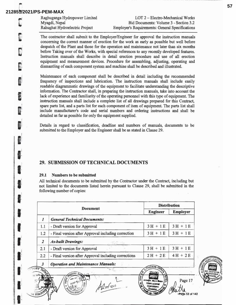
��������������Page 52 of 142Page 52 of 142
212851/2021/PS-PEM-MAX57
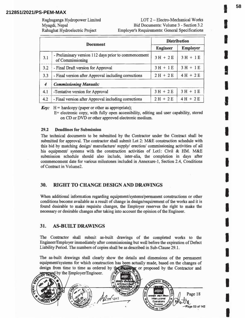
��������������Page 53 of 142Page 53 of 142
212851/2021/PS-PEM-MAX58

TECHNICAL SPECIFICATION
FOREOT CRANE
PROJECT: RAHUGHAT HYDROELECTRIC PROJECT (2X20MW) SPECIFICATION No: PE-TS-479-501-A401 SECTION-I SUB-SECTION-IA REV. 00 DATE: NOV 2020
ANNEXURE-VI PACKING PROCEDURE
Packing and Marking:
All the equipment shall be suitably protected, coated, covered or boxed and crated to prevent damage
or deterioration during transit, handling and storage at site till the time of erection. The Contractor shall
be responsible for all loss or damage during transportation, handling and storage due to improper
packing.
The identification marking indicating the name and address of the consignee shall be clearly marked in
indelible ink on two opposite sides and top of each of the packages. In addition, the Contractor shall
include in the marking gross and net weight, outer dimension and cubic measurement.
Each package shall be accompanied by a packing note (in weather proof paper) quoting specifically the
name of the Contractor, the number and date of contract and names of the office placing the contract,
nomenclature of contents and Bill of Material.
��������������Page 54 of 142Page 54 of 142
212851/2021/PS-PEM-MAX59
CORPORATE STANDARDAA0490004
Rev. No. 02
PAGE 1 of 11
Revisions: APPROVED:PROCEDURAL GUIDELINES COMMITTEE –
PGC (Packing)
Rev. No. 02 Amd. No. Reaffirmed PreparedHPEP, Hyderabad
IssuedCorp. R&D
Dt. of 1st Issue17-08-2013Dt: 27-07-2018 Dt: Year:
CO
PYR
IGH
T A
ND
CO
NFI
DEN
TIA
LTh
e In
form
atio
n on
this
doc
umen
t is
the
prop
erty
of B
HA
RA
T H
EA
VY
ELE
CTR
ICA
LS L
IMIT
ED
. It
mus
t not
be
used
dire
ctly
or
indi
rect
ly in
any
way
det
rimen
tal t
o th
e In
tere
st o
f the
com
pany
.D
RC
-519
5
SEAWORTHY PACKING(PACKING INSTRUCTIONS FOR GENERAL COMPONENTS / ASSEMBLIES / EQUIPMENT)
1 GENERAL
This standard lays down packing instructions for seaworthy packing of Components /Assemblies/Equipment to be dispatched against Customer's contracts, for which there are no special instructions issued by the Engineering Departments.
The Components/Assemblies need to be packed suitably to avoid physical damage & corrosion during transit for storage. For specific applications the concerned engineering department shall issue a product standard. Reference of this standard, must appear in the Shipping list/Packing List.
2 SCOPE
This procedure gives minimum guidelines for seaworthy packing to be complied with for packing of Components /Assemblies / Equipment. This packing shall be suitable for different handling operations and for the adverse conditions during transportation and during indoor / outdoor storage for periods more than one year.
3 CROSS REFERRED SPECIFICATION
– Multi-layered cross laminated plastic film : AA51420– Packing Wood : AA51401– Silica gel : AA55619– Thermocole : AA51416– Packing slip holders : AA7240901– Corrugated Fibre Board : AA51414– Rubber sheet : AA59001 – VCI paper : AA51406– High quality full glossy out door finishing paint : AA56126– Polyethylene air bubble film : IS 12787– Structural steel - standard quality (plates, sections, strips flats & bars) : AA10108– International Standards For Phytosanitary Measures No. 15 : ISPM-15:2009
4 WOOD SPECIFICATION FOR PACKING
The wood shall conform to specification AA51401.
For export packing wood in addition to the above the following has to be met:
The standard requires the use of debarked wood in the construction of compliant wood packaging material. Debarked wood is defined in the ISPM 5.
5 TYPE OF PACKING
The following 5 types of packings have been standardized for packing of General Components /Assemblies.
��������������Page 55 of 142Page 55 of 142
212851/2021/PS-PEM-MAX60
AA0490004
CORPORATE STANDARD
Rev. No. 02
PAGE 2 of 11
– ‘OP’ - Open Type– ‘PP’ - Partially Packed– ‘CP’ - Crate Packing - Components/Equipment requiring physical protection– ‘CQ’ - Case Packing - Small medium Components/ Assemblies/ Equipment which require corrosion &
physical protection– ‘CR’ - Case Packing - Electrical Components/Assemblies which require special packing viz. Water
Proof, Shock Proof, etc.
6 DESCRIPTION OF TYPES OF PACKING
The various types of packing, as standardized above, are described below.
6.1 ‘OP’ - Open TypeIn case, of components which are not affected by water & dust & do not require special protection &, are generally not machined, shall be sent as open packages. However these components may be sent in crates, wherever necessary.
6.2 ‘PP’ - Partially PackedComponents which need special protection, at selected portions only, shall be dispatched partiallypacked. Machined surfaces should not be allowed to come directly in contact with the wood. Such surfaces after application of TRP should be protected with Multi-layered cross laminated plastic film to AA51420.
6.3 ‘CP’ - Crate Packing – GeneralAssemblies/Components which need only physical protection from the point of view of handling shall be dispatched duly packed in crates.
6.4 ‘CQ’ - Case Packing - Machined Components/Assemblies/Equipmenta) Small & Medium sized components/assemblies/equipment due to size/weight & to avoid handling,
and pilferage, problems shall be packed in Case/Containers.b) Wherever required adequate quantity of silica gel to AA55619 or VCI Powder/ Tablets, packed in thin
muslin cloth cotton bags shall be suitably placed.c) Small machines/components of less weight shall be provided with suitable cushioning. Wood
Wool/Expanded Polyethylene Foam Sheet, if used, shall be sandwiched between polyethylene sheets and sealed.
d) The components inside the case shall be entirely covered with Multi-layered cross laminated plastic film to AA51420, where-ever required.
6.5 ‘CR’ - Case Packing - Electrical & Electronic Components/AssembliesDelicate components likely to be damaged e.g. Gauges, Instruments etc. are to be wrapped in waxed paper or polyethylene air bubble film and packed in cartons.
a) Adequate quantity of Silica gel to AA55619 packed in cotton bags, of 100 grams each are to be suitably placed in the cartons. The cartons shall be entirely covered with Multi-layered cross laminated plastic film to AA51420, before being packed in the cases.
b) VCI Powder/Tablets can be used as an alternative to Silica Gel to AA55619.c) Empty space in the cartons shall be filled with small chips of Expanded Polystyrene (Thermocole),
Wood Wool etc. Polyethylene air bubble film shall conform to IS 12787/AA51420 Expanded polystyrene (Thermocole) shall conform to AA51416.
d) The cartons shall be manufactured from corrugated Fibre Board, meeting requirements of AA51414.6.6 Special PackingComponents requiring special packing (as per customer/contractual/ engineering requirements) not included in this specification shall be covered by product standards.
��������������Page 56 of 142Page 56 of 142
212851/2021/PS-PEM-MAX61
CORPORATE STANDARD
AA0490004
Rev. No. 02
PAGE 3 of 11
7 PREPARATION OF PACKING CASE
1) Cases and crates with gross weight up to 1,000 kgs. shall be provided with bottom cleats of min. 40 mm thicknesses to ensure clearance for handling by forklift. Cases and crates exceeding gross weight of 1,000 kgs. shall be provided with skid runners, number and size according to weight of package.
2) The base of the case shall be made of wooden batons for planks giving necessary reinforcement, such that the bottom of the equipment is at a height of 100 to 200 mm from the ground level depending upon size & weight of equipment. However for packing cases of smaller size equipment can be at a height of 40 mm from the ground level.
3) In case of 'CR1 - Packing Viz. Electrical & Electronic components for instruments/assemblies, a rubber sheet, Self-expanded polyethene foam sheet, preferably 10 mm thick, shall be fixed on to the base to act as cushioning to the equipment.
4) The four sides, shall be lined, from inside with multi-layered cross-laminated polyethylene sheet of 90GSM as per AA51420 and tacked at suitable places.Whenever specified the top cover will have a layer of multi-layered cross laminated polyethylene sheet of 90 GSM over the cover. This should project about 100 - 250mm on all sides. It is preferable to have a single piece of the above Multi-layered cross laminated polyethylene sheet fixed on the four sides. In case jointing is unavoidable, it should be done by overlapping of approximately 100mm.
5) Place the Components/cartons with corrosion inhibitors duly applied wherever necessary for place suitably, thin muslin cloths bags containing 100 grams (approx.) of activated Blue Silica Gel to AA55619, wherever necessary. Alternatively VCI Powder or Tablet may be used.
6) In case, depression is formed, at the top, after the equipment is lowered, provide ply board/wooden batons.
7) Cover the whole equipment with polyethylene sheet of at least 100 micron thickness, on all sides preferably by a single piece.
8) For indoor panels/equipment, provide suitable packing batons with covering of Thermocole/expanded soft polyethylene foam/polyethylene air bubble film wrapped with suitable cords, to avoid cutting of the polyethylene sheet so that finished surface is not damaged.
9) Empty space in the box shall be filled with adequate cushioning material e.g. Thermocole Chips, Wood Wool etc. to avoid movement for shocks. Alternatively put wooden blocks/batons wherever necessary.
10) The inner side of the top cover shall be lined with polyethylene sheet, of at least11) 100 micron thickness, which shall project approximately 25 to 150 mm depending upon the size of
the case on all sides of the top cover shall be provided below the top cover. This projection, after nailing the top cover, shall be folded over, on the sides of the crates & tacked, to, prevent ingress of water from the top.
12) For specific requirement of packing the cases are to be provided with Tongue and Groove joints.
8 STEEL CONTAINERS
Steel containers for packing can be used in case of repeated supplies of the same equipment. Empty steel containers are to be returned back from customer's end and to be reused for the next supplies.
The containers are to be made of structural steel as per AA10108 with proper reinforcement with I, C and T Sections.
Following precautions are to be taken during packing:
– Put the Components/Assemblies/Equipment in the steel container properly. Cover the Components/Assemblies/Equipment with polythene.
– To arrest the movement in the steel container necessary wooden Blocks/Batons may be put.– Put cover on steel, container and Bolt Properly.
��������������Page 57 of 142Page 57 of 142
212851/2021/PS-PEM-MAX62
AA0490004
CORPORATE STANDARD
Rev. No. 02
PAGE 4 of 11
9 SEALED PACKING
Components sub-assemblies and assemblies sensitive to climatic conditions shall be packed seal tight. All the openings of the sensitive components, sub-assemblies and assemblies shall be blanketed to prevent the ingress of dust and moisture.
The components sub-assemblies and assemblies are completely covered with 2 layers of polyethylene sheet. All sharp corners and edges are to be protected by rubber mats to prevent the polyethylene sheet from damage. Top surface of the case shall be free from dents to prevent rain water pockets.
10 SLING PLATE
Sling plate shall be provided to prevent damage to the packing box during lifting. Size of the sling plate shall be selected depending upon the net weight of the consignment.
11 PACKING SLIP HOLDERS
Two nos. steel packing slip holders, specification no. AA7240901 containing the packing list, sealed in thick polyethylene film, shall be fixed one inside and the other outside the packing box.
12 Volatile Corrosion Inhibitor (VCI) Paper
a) Un-protected surfaces of steel and cast iron components, tools bearing, shaft seals etc. are covered with VCI paper. VCI paper has been impregnated with corrosion inhibitors which by evaporation and chemical conversion protect metals in an enclosed area against corrosion.
b) 7 m3 VCI paper is necessary for 1 m3 of packed item approximately as per AA51406.Application Limitation:VCI paper shall not be used for components made of aluminium, aluminium alloys as well as Zinc, copper, brass, cadmium and silver.
VCI powder is sprinkled inside the piping components ends shall be protected with end cover as specified in plant standards, drawings.
13 Moisture Absorber
Silica gel is used for this purpose to protect the contents over sufficiently long time from corrosion. At the time of use, silica gel should be so dried that its colour becomes dark blue. These shall be filled in small cotton bags. Before sealing the equipment, the silica gel bags should be kept inside the polyethylene film cover at different locations. The quantity of silica gel should not be less than 1.0 kg per cubic metre volume of the packing box
�������������Page 58 of 142Page 58 of 142
212851/2021/PS-PEM-MAX63
CORPORATE STANDARD
AA0490004
Rev. No. 02
PAGE 5 of 11
14 GENERAL PRECAUTIONS
a) While fixing nails during packing, necessary care shall be taken to ensure that materials used for protection inside the case e.g. paper, polyethylene sheet, coir etc. do not get damaged.
b) Sling protection brackets to be provided on cases wherever required.c) It shall be ensured that all stencil marks external, front & rear sides of the casing shall be of water
proof Material to prevent obliteration in transit.d) The various caution signs shall be marked with stencil on both sides of the packing box.e) Do not pack any other Mechanical items with this case (do not use any other non-permitted
packing materials). THE FOLLOWING DETAILS ARE TO BE MARKED ON THE PACKING CASES.a) Address of consignee.b) Purchase Order No./ SO No/WO No.c) Description of item or title of packing list.d) Case identification Number/ Packing List No.e) Net Weight.f) Gross Weight.g) Dimensions of boxh) Marking showing upright position.i) Marking showing sling position.j) Marking showing umbrella (i.e. for machines/components to be stored under covered storage.k) Loading and unloading precautions
�������������Page 59 of 142Page 59 of 142
212851/2021/PS-PEM-MAX64
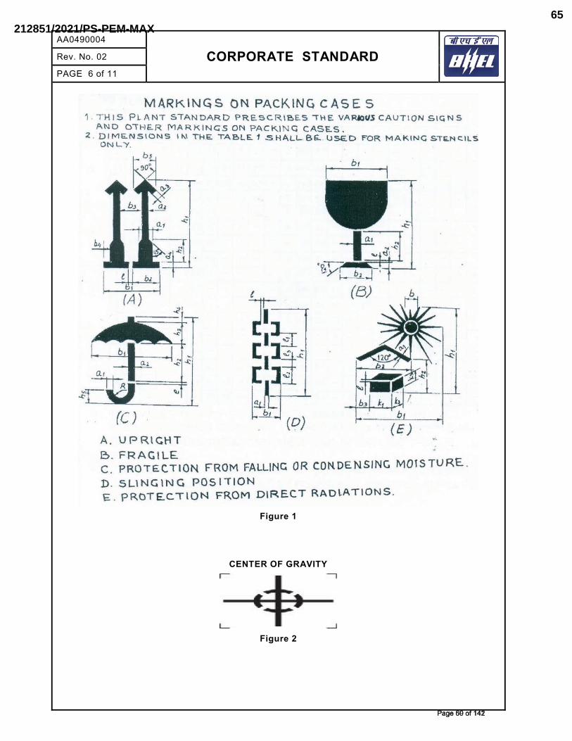
AA0490004
CORPORATE STANDARD
Rev. No. 02
PAGE 6 of 11
Figure 1
CENTER OF GRAVITY
Figure 2
��������������Page 60 of 142Page 60 of 142
212851/2021/PS-PEM-MAX65
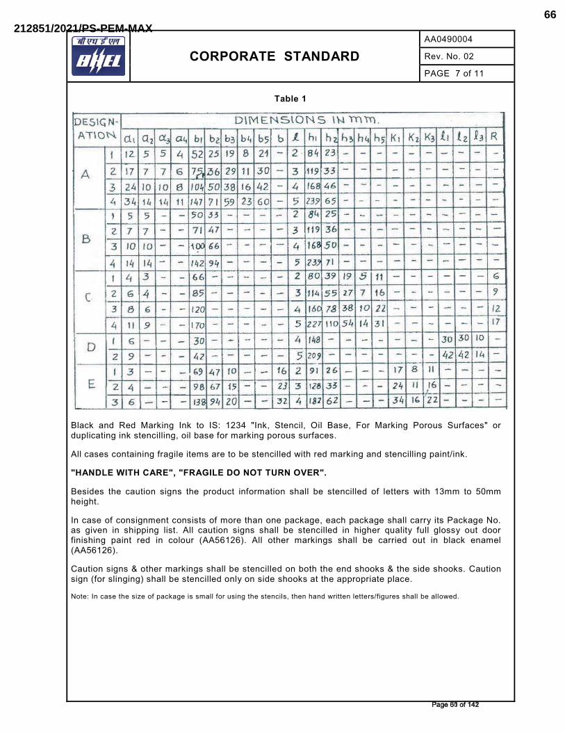
CORPORATE STANDARD
AA0490004
Rev. No. 02
PAGE 7 of 11
Table 1
Black and Red Marking Ink to IS: 1234 "Ink, Stencil, Oil Base, For Marking Porous Surfaces" or duplicating ink stencilling, oil base for marking porous surfaces.
All cases containing fragile items are to be stencilled with red marking and stencilling paint/ink.
"HANDLE WITH CARE", "FRAGILE DO NOT TURN OVER".
Besides the caution signs the product information shall be stencilled of letters with 13mm to 50mm height.
In case of consignment consists of more than one package, each package shall carry its Package No. as given in shipping list. All caution signs shall be stencilled in higher quality full glossy out door finishing paint red in colour (AA56126). All other markings shall be carried out in black enamel (AA56126).
Caution signs & other markings shall be stencilled on both the end shooks & the side shooks. Caution sign (for slinging) shall be stencilled only on side shooks at the appropriate place.
Note: In case the size of package is small for using the stencils, then hand written letters/figures shall be allowed.
��������������Page 61 of 142Page 61 of 142
212851/2021/PS-PEM-MAX66
AA0490004
CORPORATE STANDARD
Rev. No. 02
PAGE 8 of 11
15 PROCEDURE FOR HANDLING OF COMPONENTS
The purpose of this procedure is to protect the quality of the components/equipment while handling in various stages of manufacturing packing & despatching.
15.1 Adequate care shall be taken in handling the material, and components to avoid damage during receipts, storage issue manufacture & despatch operations.
15.2 Appropriate material handling equipment like fork lifters, cranes etc. Shall be used where needed.
15.3 Lifting by crane and transportation by trolley of critical items and large components like rotors castings etc. Shall be done carefully.
15.4 For critical items, where specified, special handling fixtures shall be used for lifting.15.5 Slings and shackles used for lifting the components/equipment shall be checked for fitness and
suitability before use.15.6 Slings used on machined surfaces shall be suitably padded. No slings shall be used on journal
surfaces.15.7 Precision machined components like blades, catches, rollers etc. Shall be lifted using suitable
wooden pallets.15.8 HANDLING OF COMPONENTS ON RECEIPT/DESPATCH:Before loading/unloading a packing case from the carrier look for the following shipping instructions painted on the packing case.
– The markings showing the upright position.– The markings showing the sling position– Markings showing the fragile contents.– Other required markings as per Clause No. 12 15.8.1 Appropriate cranes and slings should be used for different components/ cases. Slings should
normally make an angle as minimum as possible (width wise) but in no case more than 15º.15.8.2 Handling and lifting should be done without jerks or impacts.15.8.3 Immediately after receipt of the goods, the packing should be examined all-round for any sign
of damage. If necessary, lift the cover or a number of boards of the case so as to make the contents visible. In the event of sealed packing being used the plastic sheeting should not bedamaged. It is imperative that the packing material is restored in original condition after the inspection.
15.8.4 On receipt of the equipment it should be checked with the shipping list and missing or damage if any should be reported immediately. It is important to arrange for immediate examination to determine the extent of the damage, the cause of the damage and where applicable the person or persons responsible for the damage. According to general practice when transporting by railway or by road vehicle the carrier concerned should be immediately called upon (within specified periods) for jointly establishing a statement of the damage. This is essential as a basis for a subsequent claim and possible damage report to the insurance company.
15.8.5 Protective coating applied on machined surfaces should not be disturbed. The plastic covering should be put back carefully so that it prevents ingress of dust and moisture. Some packing may have vapour phase inhibitor (VPI) paper enclosed inside the packing cases. This should be restored to its original place as far as possible.
15.8.6 Silica gel and such other chemicals kept in the box as desiccants and indicators should also be left in the box itself.
16 GI SHEET
The packing cases are covered with GI sheet on outside for sides and top; inside for bottom as per the Figure-3 (GI sheet covering is applicable for all closed type of wooden packing).
��������������Page 62 of 142Page 62 of 142
212851/2021/PS-PEM-MAX67
CORPORATE STANDARD
AA0490004
Rev. No. 02
PAGE 9 of 11
17 Treatment of Wood & Application and use of the mark
For seaworthy export packing, treatment of wood has to be carried out as below subject to BHEL Engg & QC approval.
As per customer requirement for export packing, wood to be treated as applicable should be done as per International Standards for Phytosanitary Measures ISPM: 15 to control the growth stages viz. egg to adult of structural insects (beetles, borers, bugs, fleas, flies, lice, moths, roaches, termites) and other pests (mice, rats, spiders) etc. in stored products.
The specified marks applied to wood packaging material treated in accordance with ISPM 15 must conform to the requirements described in Annex 2 of ISPM 15.
17.1 Heat treatment using a conventional steam or dry kiln heat chamber (treatment code for the mark: HT)
When using conventional heat chamber technology, the fundamental requirement is to achieve a minimum temperature of 56 °C for a minimum duration of 30 continuous minutes throughout the entire profile of the wood (including its core).
This temperature can be measured by inserting temperature sensors in the core of the wood. Alternatively, when using kiln-drying heat chambers or other heat treatment chambers, treatment schedules may be developed based on a series of test treatments during which the core temperature of the wood at various locations inside the heat chamber has been measured and correlated with chamber air temperature, taking into account the moisture content of the wood and other substantial parameters (such as species and thickness of the wood, air flow rate and humidity). The test series must demonstrate that a minimum temperature of 56 °C is maintained for a minimum duration of 30 continuous minutes throughout the entire profile of the wood.
Treatment schedules should be specified or approved by the National Plant Protection Organisation (NPPO). Treatment providers should be approved by the NPPO.
17.2 Heat treatment using dielectric heating (treatment code for the mark: DH)Where dielectric heating is used (e.g. microwave), wood packaging material composed of wood not exceeding 20 cm when measured across the smallest dimension of the piece or the stack must be heated to achieve a minimum temperature of 60 °C for 1 continuous minute throughout the entire profile of the wood (including its surface). The prescribed temperature must be reached within 30 minutes from the start of the treatment.
Treatment schedules should be specified or approved by the NPPO.
17.3 Methyl bromide treatment (treatment code for the mark: MB)Wood packaging material containing a piece of wood exceeding 20 cm in cross-section at its smallest dimension must not be treated with methyl bromide.
The fumigation of wood packaging material with methyl bromide must be in accordance with a schedule specified or approved by the NPPO (National Plant Protection Organisation) that achieves the minimum concentration-time product (CT) over 24 hours at the temperature and final residual concentration specified in Table 1. This CT must be achieved throughout the profile of the wood, including its core, although the concentrations would be measured in the ambient atmosphere. The minimum temperature of the wood and its surrounding atmosphere must not be less than 10 °C and the minimum exposure time must not be less than 24 hours. Monitoring of gas concentrations must be carried out at a minimum at 2, 4 and 24 hours from the beginning of the treatment. In the case of longer exposure times and weaker concentrations, additional measurement of the gas concentrations should be recorded at the end of fumigation.
If the CT is not achieved over 24 hours, corrective action needs to be taken to ensure the CT is reached; for example, the treatment is restarted or the treatment time extended for a maximum of 2 hours without adding more methyl bromide to achieve the required CT (see the footnote to Table 2).
��������������Page 63 of 142Page 63 of 142
212851/2021/PS-PEM-MAX68
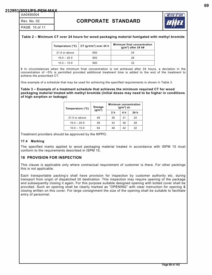
AA0490004
CORPORATE STANDARD
Rev. No. 02
PAGE 10 of 11
Table 2 – Minimum CT over 24 hours for wood packaging material fumigated with methyl bromide
Temperature (°C) �������3) over 24 h Minimum final concentration (g/m3) after 24 h#
21.0 or above 650 24
16.0 – 20.9 800 28
10.0 – 15.9 900 32
# In circumstances when the minimum final concentration is not achieved after 24 hours, a deviation in the concentration of ~5% is permitted provided additional treatment time is added to the end of the treatment to achieve the prescribed CT.
One example of a schedule that may be used for achieving the specified requirements is shown in Table 3.
Table 3 – Example of a treatment schedule that achieves the minimum required CT for wood packaging material treated with methyl bromide (initial doses may need to be higher in conditions of high sorption or leakage)
Temperature (°C) Dosage (g/m3)
Minimum concentration (g/m3) at:
2 h 4 h 24 h
21.0 or above 48 36 31 24
16.0 – 20.9 56 42 36 28
10.0 – 15.9 64 48 42 32
Treatment providers should be approved by the NPPO.
17.4 MarkingThe specified marks applied to wood packaging material treated in accordance with ISPM 15 must conform to the requirements described in ISPM 15.
18 PROVISION FOR INSPECTION
This clause is applicable only where contractual requirement of customer is there. For other packings this is not applicable.
Each transportable packing’s shall have provision for inspection by customer authority etc. during transport from origin of dispatched till destination. This inspection may require opening of the package and subsequently closing it again. For this purpose suitable designed opening with bolted cover shall be provided. Such an opening shall be clearly marked as “OPENING” with clear instruction for opening & closing written on this cover. For large consignment the size of the opening shall be suitable to facilitate entry of personnel.
��������������Page 64 of 142Page 64 of 142
212851/2021/PS-PEM-MAX69
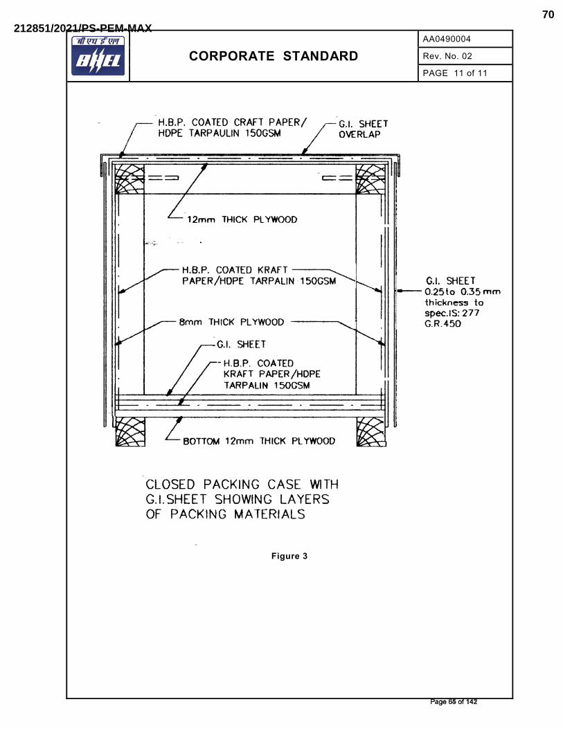
CORPORATE STANDARD
AA0490004
Rev. No. 02
PAGE 11 of 11
Figure 3
��������������Page 65 of 142Page 65 of 142
212851/2021/PS-PEM-MAX70
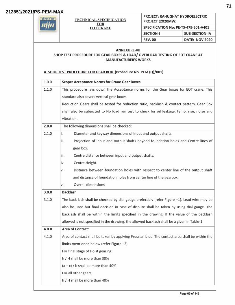
TECHNICAL SPECIFICATION
FOREOT CRANE
PROJECT: RAHUGHAT HYDROELECTRIC PROJECT (2X20MW) SPECIFICATION No: PE-TS-479-501-A401 SECTION-I SUB-SECTION-IA REV. 00 DATE: NOV 2020
ANNEXURE-VII SHOP TEST PROCEDURE FOR GEAR BOXES & LOAD/ OVERLOAD TESTING OF EOT CRANE AT
MANUFACTURER’S WORKS
A. SHOP TEST PROCEDURE FOR GEAR BOX (Procedure No. PEM (Q)/001) 1.0.0 Scope: Acceptance Norms for Crane Gear Boxes
1.1.0 This procedure lays down the Acceptance norms for the Gear boxes for EOT crane. This
standard also covers vertical gear boxes.
Reduction Gears shall be tested for reduction ratio, backlash & contact pattern. Gear Box
shall also be subjected to No load run test to check for oil leakage, temp. rise, noise and
vibration.
2.0.0 The following dimensions shall be checked:
2.1.0 i.� Diameter and keyway dimensions of input and output shafts.
ii.� Projection of input and output shafts beyond foundation holes and Centre lines of
gear box.
iii.� Centre distance between input and output shafts.
iv.� Centre Height.
v.� Distance between foundation holes with respect to center line of the output shaft
and distance of foundation holes from center line of the gearbox.
vi.� Overall dimensions
3.0.0 Backlash
3.1.0 The back lash shall be checked by dial gauge preferably (refer Figure –1). Lead wire may be
also be used but final decision in case of dispute shall be taken by using dial gauge. The
backlash shall be within the limits specified in the drawing. If the value of the backlash
allowed is not specified in the drawing, the allowed backlash shall be a given in Table-1
4.0.0 Area of Contact:
4.1.0 Area of contact shall be taken by applying Prussian blue. The contact area shall be within the
limits mentioned below (refer Figure –2)
For final stage of Hoist gearing:
h / H shall be more than 30%
(a – c) / b shall be more than 40%
For all other gears:
h / H shall be more than 40%
��������������Page 66 of 142Page 66 of 142
212851/2021/PS-PEM-MAX71
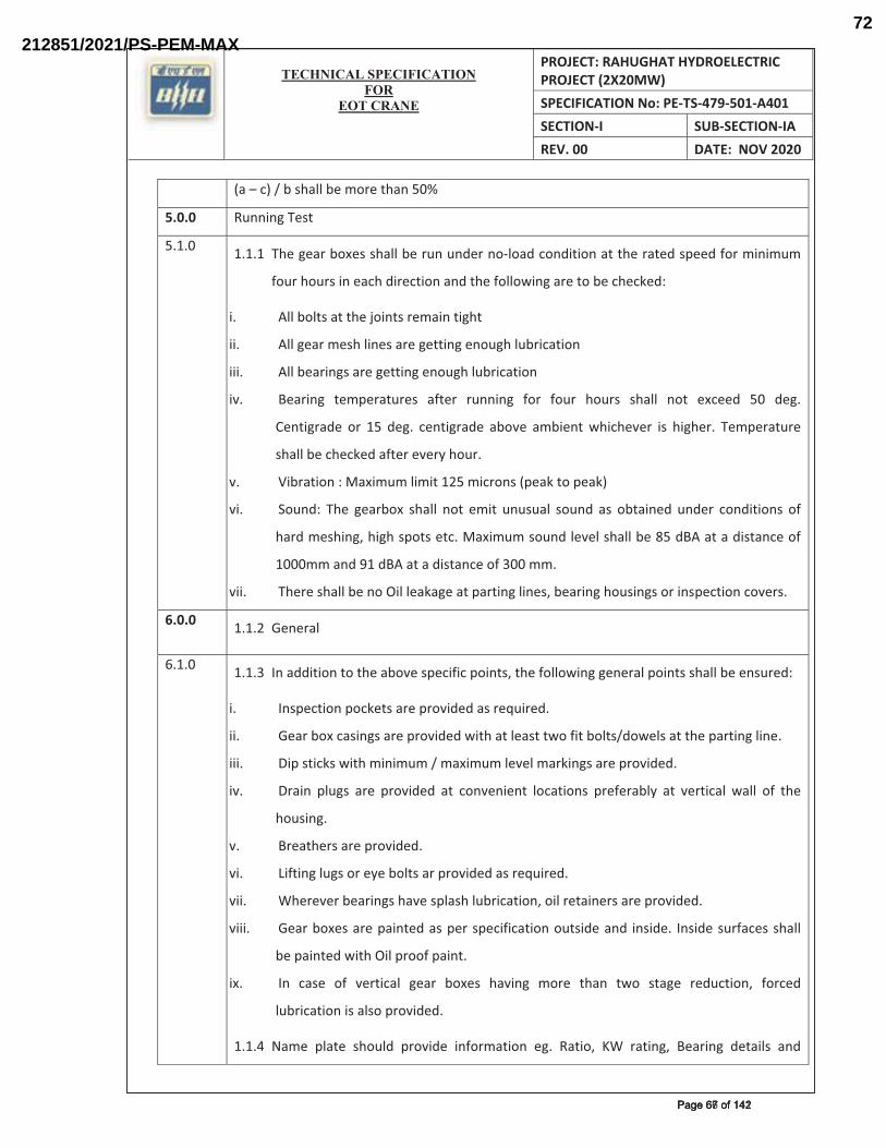
TECHNICAL SPECIFICATION
FOREOT CRANE
PROJECT: RAHUGHAT HYDROELECTRIC PROJECT (2X20MW) SPECIFICATION No: PE-TS-479-501-A401 SECTION-I SUB-SECTION-IA REV. 00 DATE: NOV 2020
(a – c) / b shall be more than 50%
5.0.0 Running Test
5.1.0 1.1.1� The gear boxes shall be run under no-load condition at the rated speed for minimum
four hours in each direction and the following are to be checked:
i.� All bolts at the joints remain tight
ii.� All gear mesh lines are getting enough lubrication
iii.� All bearings are getting enough lubrication
iv.� Bearing temperatures after running for four hours shall not exceed 50 deg.
Centigrade or 15 deg. centigrade above ambient whichever is higher. Temperature
shall be checked after every hour.
v.� Vibration : Maximum limit 125 microns (peak to peak)
vi.� Sound: The gearbox shall not emit unusual sound as obtained under conditions of
hard meshing, high spots etc. Maximum sound level shall be 85 dBA at a distance of
1000mm and 91 dBA at a distance of 300 mm.
vii.� There shall be no Oil leakage at parting lines, bearing housings or inspection covers.
6.0.0 1.1.2� General
6.1.0 1.1.3� In addition to the above specific points, the following general points shall be ensured:
i.� Inspection pockets are provided as required.
ii.� Gear box casings are provided with at least two fit bolts/dowels at the parting line.
iii.� Dip sticks with minimum / maximum level markings are provided.
iv.� Drain plugs are provided at convenient locations preferably at vertical wall of the
housing.
v.� Breathers are provided.
vi.� Lifting lugs or eye bolts ar provided as required.
vii.� Wherever bearings have splash lubrication, oil retainers are provided.
viii.� Gear boxes are painted as per specification outside and inside. Inside surfaces shall
be painted with Oil proof paint.
ix.� In case of vertical gear boxes having more than two stage reduction, forced
lubrication is also provided.
1.1.4� Name plate should provide information eg. Ratio, KW rating, Bearing details and
��������������Page 67 of 142Page 67 of 142
212851/2021/PS-PEM-MAX72
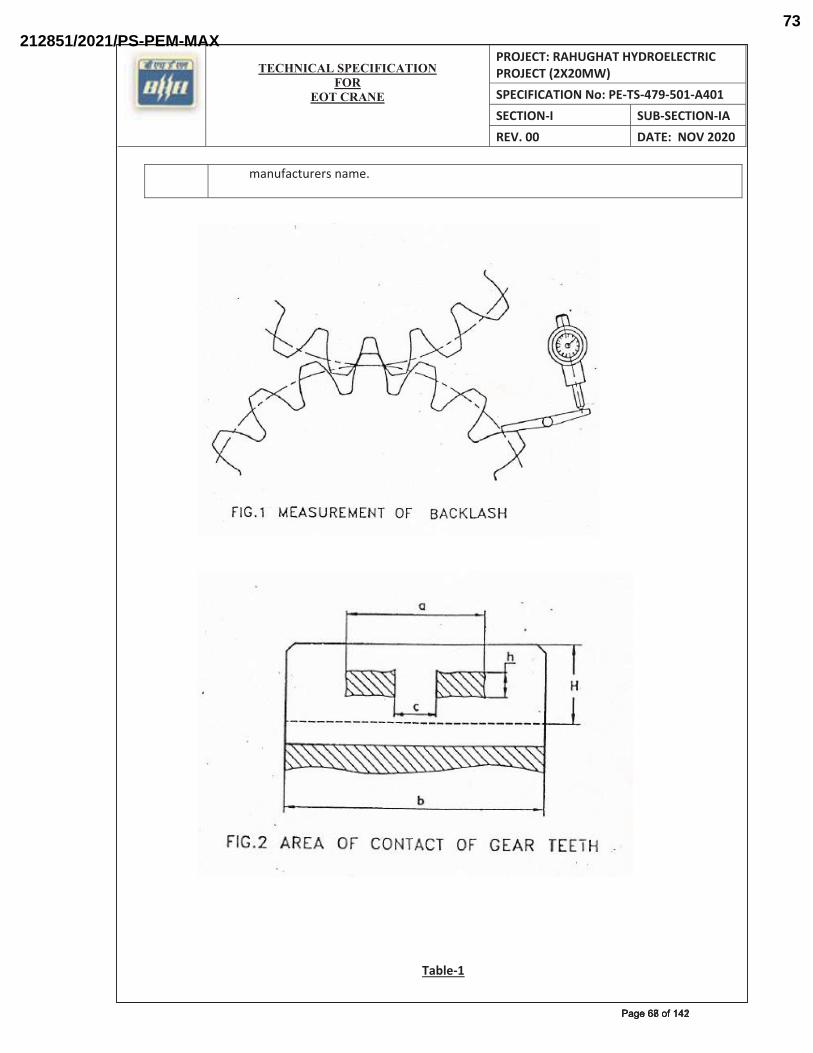
TECHNICAL SPECIFICATION
FOREOT CRANE
PROJECT: RAHUGHAT HYDROELECTRIC PROJECT (2X20MW) SPECIFICATION No: PE-TS-479-501-A401 SECTION-I SUB-SECTION-IA REV. 00 DATE: NOV 2020
manufacturers name.
Table-1
�������������Page 68 of 142Page 68 of 142
212851/2021/PS-PEM-MAX73
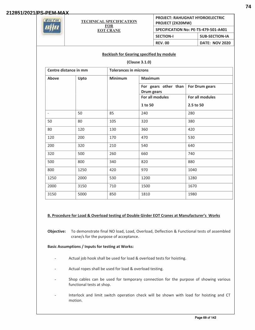
TECHNICAL SPECIFICATION
FOREOT CRANE
PROJECT: RAHUGHAT HYDROELECTRIC PROJECT (2X20MW) SPECIFICATION No: PE-TS-479-501-A401 SECTION-I SUB-SECTION-IA REV. 00 DATE: NOV 2020
Backlash for Gearing specified by module
(Clause 3.1.0)
Centre distance in mm Tolerances in microns
Above Upto Minimum Maximum
For gears other than Drum gears
For Drum gears
For all modules
1 to 50
For all modules
2.5 to 50
- 50 85 240 280
50 80 105 320 380
80 120 130 360 420
120 200 170 470 530
200 320 210 540 640
320 500 260 660 740
500 800 340 820 880
800 1250 420 970 1040
1250 2000 530 1200 1280
2000 3150 710 1500 1670
3150 5000 850 1810 1980
B. Procedure for Load & Overload testing of Double Girder EOT Cranes at Manufacturer’s Works
Objective: To demonstrate final NO load, Load, Overload, Deflection & Functional tests of assembled
crane/s for the purpose of acceptance.
Basic Assumptions / Inputs for testing at Works:
-� Actual job hook shall be used for load & overload tests for hoisting. -� Actual ropes shall be used for load & overload testing.
-� Shop cables can be used for temporary connection for the purpose of showing various
functional tests at shop.
-� Interlock and limit switch operation check will be shown with load for hoisting and CT motion.
�������������Page 69 of 142Page 69 of 142
212851/2021/PS-PEM-MAX74
TECHNICAL SPECIFICATION
FOREOT CRANE
PROJECT: RAHUGHAT HYDROELECTRIC PROJECT (2X20MW) SPECIFICATION No: PE-TS-479-501-A401 SECTION-I SUB-SECTION-IA REV. 00 DATE: NOV 2020
Procedure for Load / Overload testing: The cranes shall be tested for no load, load test & overload test at works generally in
conformance with the IS – 3177 (latest edition). Specifically with respect to the load / overload testing of crane, the following tests as per the outlined procedures shall be done at works.
-� Deflection of the girder will be measured at SWL when the trolley with load is at the middle
of the girder.
-� No load and full load current of the motors will be measured to verify whether it is as per the approved data sheet of the motor. Resisters in the circuit will be checked for any overheating of the element.
-� Overload relays will be checked for proper functioning.
Hoisting & Cross Travel motions:
The load will be gradually raised to 125 percent of the rated capacity (SWL) with actual hook.
The load will be lifted upward to about 1 meter height above its support and stop again.
Check for any undue drift in the load. If load drifts, check the adjustment of brakes and repeat
the above procedure. Then lower the load to rest on support/ground.
For checking the cross travel, raise the load up to one (1) meter height above supports and then
move the trolley with load about one (1) meter in either direction of the bridge. Then lower the load
to rest on support/ ground.
Creep speed motions shall be checked over a distance of about 500 mm.
Note: Complete No load, load & over load tests in line with IS-3177 (latest edition) shall also be done after erection of EOT crane at site.
��������������Page 70 of 142Page 70 of 142
212851/2021/PS-PEM-MAX75
TECHNICAL SPECIFICATION
FOREOT CRANE
PROJECT: RAHUGHAT HYDROELECTRIC PROJECT (2X20MW)SPECIFICATION No: PE-TS-479-501-A401SECTION-I SUB-SECTION-IA REV. 00 DATE: FEB 2021
ANNEXURE-VIII INPUT DRAWING
�������������Page 71 of 142Page 71 of 142
212851/2021/PS-PEM-MAX76
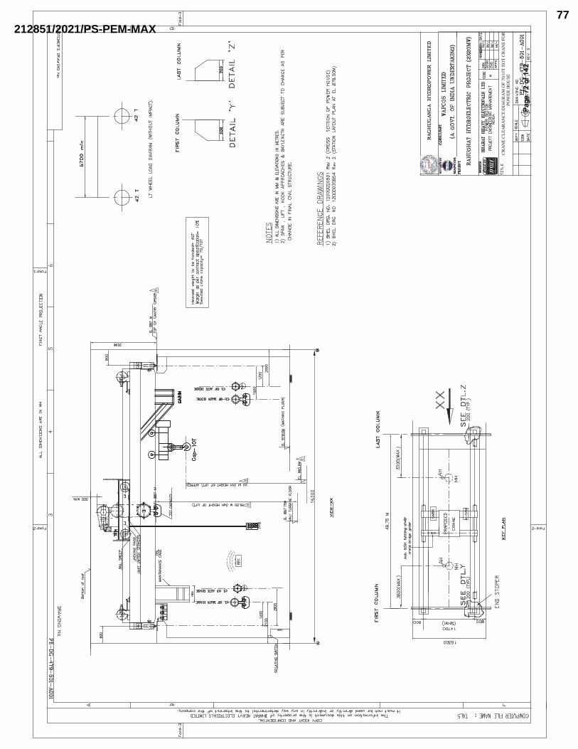
����
���
����
��Pa
ge 7
2 of
142
Page
72
of 1
42
212851/2021/PS-PEM-MAX77
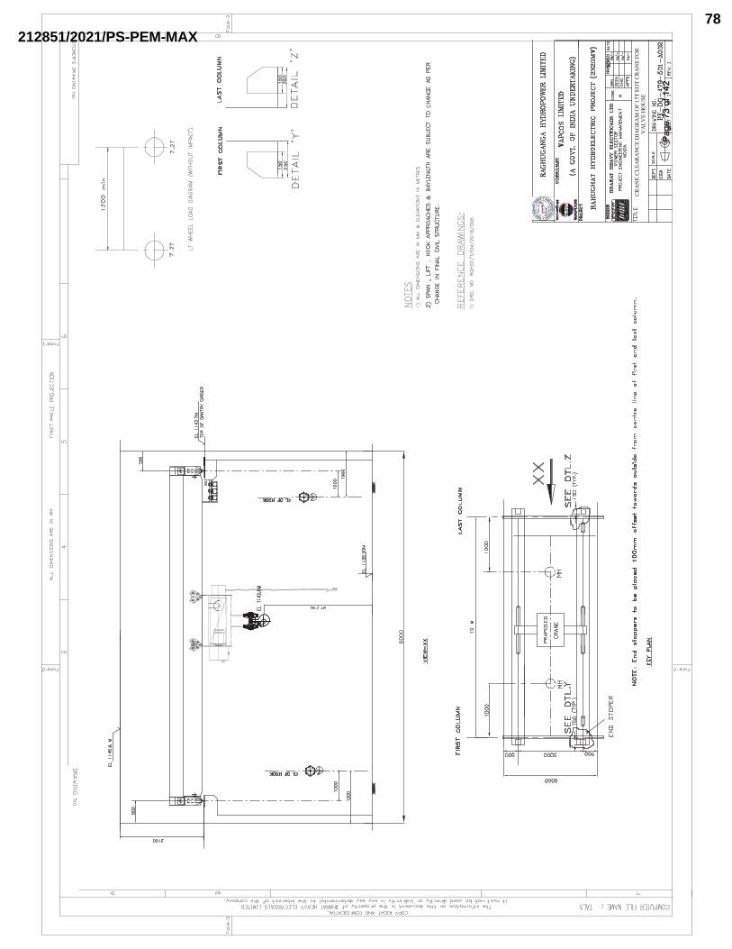
Page
73
of 1
42Pa
ge 7
3 of
142
212851/2021/PS-PEM-MAX78
TECHNICAL SPECIFICATION FOR
EOT CRANE
PROJECT: RAHUGHAT HYDROELECTRIC PROJECT (2X20MW) SPECIFICATION No: PE-TS-479-501-A401 SECTION-I REV. 00 DEC 2020
�SECTION-I
SPECIFIC TECHNICAL REQUIREMENT
� � �SUB-SECTION IB SPECIFIC TECHNICAL REQUIREMENT
(ELECTRICAL)�
�
�
�������������Page 74 of 142Page 74 of 142
212851/2021/PS-PEM-MAX79
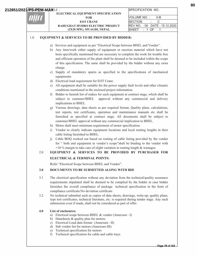
�����
���������
�������������� �������������������
������������������������������������
����� ��� ������������
�������������� ������������� ��������������������������������������������� ����������������� �� �����������������������������
�
�������� ��������������!���������!�!�����"
����� ����������������������������������������� �������������!*�������<�����=��
��� >�?� ����@���J� ���[��� �����?� �\� ���������� ��� ��������� ��������� �[��[� [���� ����
����������\�����?���������������������������?��������������[�����J�\�����������\����
�����\\������������������\��[���������[��������������������������������[����[��������
�\� �[��� �����\���������[��������[�����������������?� �[������������[������?��]����
�[��^��
��� ����?� �\� ��������?� ������� ��� �����\���� ��� �[�� �����\��������� �\� ���[�������
�����������
��� ����������������������������\����_��`�����
��� >��������������[����������������\����[�������������?�\������������������[������������
�������������������������[��������������{������\���������
\�� !���������\�����[�������\���J���\������[��������������������������^�|��[��[��[�������
���{���� ��� ��������@!*��� � ��������� ���[���� ��?� ����������� ���� �������?�
����������������!*����
^�� <�������������^�|������ �[����� ������� ��������� \�����|�}�����?������|� ������������|�
����� �������|� ����� �����\������|� ���������� ���� ������������ �������� ���� �[���� ���
\�����[��� ��� �����\���� ��� ��������� ���^�� >��� ���������� �[���� ��� ���{���� ���
��������@!*���������������[������?���������������������������!*���
[�� ~������[������������������������������\������������\��������
��� <������ ��� ������?� ��������� ���������� ���������� ���� ������ ������^� ���^�[�� ��� �[����
������������^�\�����[������!*���
{�� `�����!_}����J���������������� ������^��\������� ������^�����������?� �[���������
\��� �� ���[� ���� ���������� ��� ��������� �����=�[���� ��� ������^� ��� �[�� ������� ���[�
��������^��������J��������\����^[���������������������^����^�[��������^����
�� ���� ��� � �������� �� !� �������� !� ��������� ���
�������������� ����������"�
��\��������������� �������������!*�������<�����=��
#$�� ���� ������!���! ��������������!��
��� �[������������������\�����������[������?�����������\�����[�����[�����@������?�����������
������������� ����������� �[���� ��� ������� ��� ��� ����������?� �[��������� ��� ������������
\�����[��� �[�� �������� ����������� �\� ���J�^�� � ���[������ �����\�������� ��� �[�� \���� �\�
����������������\�����@������������������\�������
��� ������[�������������������[������������\�������[����|�������^�|���������|�������?������|��?�������������\������|����[����������������|����������������������^�����������^��>�?����[������������������\�����|��[�������������������������������\��\\���
�
%$�� �'*+,;<=>?,*@Z<*"��� �������������������������!*�������������>���]����������� �����[�������������?������\������������� ���������������������\��������>���]������������ ���������������\�����������>���]������������ ���[�����������\��������\����������\�� ���[�����������\��������\����������������������?��
�������������Page 75 of 142Page 75 of 142
212851/2021/PS-PEM-MAX80
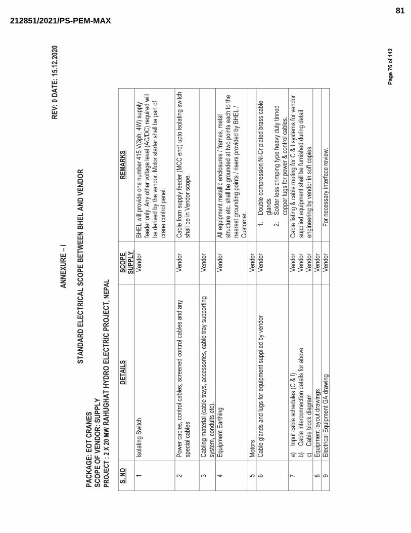
REV:
0 DA
TE: 1
5.12.2
020
ANNE
XURE
– I
STAN
DARD
ELE
CTRI
CAL
SCOP
E BE
TWEE
N BH
EL A
ND V
ENDO
R
PACK
AGE:
EOT
CRA
NES
SCOP
E OF
VEN
DOR:
SUP
PLY
PR
OJEC
T : 2
X 20
MW
RAH
UGHA
T HY
DRO
ELEC
TRIC
PRO
JECT
, NEP
AL
S. N
O DE
TAIL
S SC
OPE
SUPP
LYRE
MARK
S
1 Iso
lating
Swi
tch
Vend
or
BHEL
will
prov
ide on
e num
ber 4
15 V
(3ph
, 4W
) sup
ply
feede
r only
. Any
othe
r volt
age l
evel
(AC/
DC) r
equir
ed w
ill be
deriv
ed by
the v
endo
r. Mo
tor st
arter
shall
be pa
rt of
crane
contr
ol pa
nel.
2 Po
wer c
ables
, con
trol c
ables
, scre
ened
contr
ol ca
bles a
nd an
y sp
ecial
cable
s Ve
ndor
Ca
ble fr
om su
pply
feede
r (MC
C en
d) u
pto is
olatin
g sw
itch
shall
be in
Ven
dor s
cope
.
3 Ca
bling
mate
rial (c
able
trays
, acc
esso
ries,
cable
tray
supp
ortin
g sy
stem,
cond
uits e
tc).
Vend
or
4 Eq
uipme
nt Ea
rthing
Ve
ndor
Al
l equ
ipmen
t meta
llic en
closu
res /
fram
es, m
etal
struc
ture e
tc. sh
all be
grou
nded
at tw
o poin
ts ea
ch to
the
near
est g
roun
ding p
oints
/ rise
rs pr
ovide
d by B
HEL /
Cu
stome
r. 5
Motor
s Ve
ndor
6
Cable
glan
ds an
d lug
s for
equip
ment
supp
lied b
y ven
dor
Vend
or
1.�Do
uble
comp
ress
ion N
i-Cr p
lated
bras
s cab
le gla
nds
2.�So
lder le
ss cr
impin
g typ
e hea
vy du
ty tin
ned
copp
er lu
gs fo
r pow
er &
contr
ol ca
bles.
7 a)
�Inp
ut ca
ble sc
hedu
les (C
& I)
b)
�Ca
ble in
terco
nnec
tion d
etails
for a
bove
c)
Cab
le blo
ck di
agra
m
Vend
or
Vend
or
Vend
or
Cable
listin
g & ca
ble ro
uting
for C
& I s
ystem
s for
vend
or
supp
lied e
quipm
ent s
hall b
e fur
nishe
d dur
ing de
tail
engin
eerin
g by v
endo
r in so
ft cop
ies.
8 Eq
uipme
nt lay
out d
rawi
ngs
Vend
or
9
Elec
trical
Equip
ment
GA dr
awing
Ve
ndor
For
nece
ssar
y inte
rface
revie
w.
�
����
���
����
��Pa
ge 7
6 of
142
Page
76
of 1
42
212851/2021/PS-PEM-MAX81
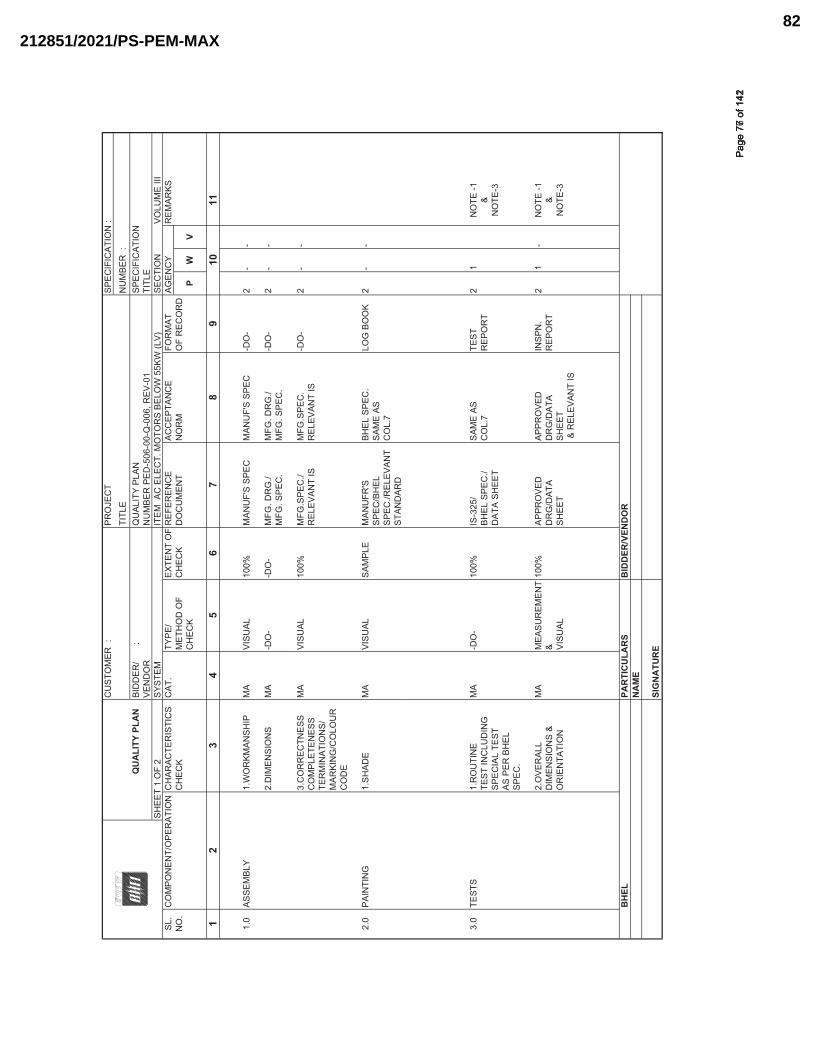
CU
STO
MER
:
PRO
JEC
TTI
TLE
NU
MBE
R :
Q
UA
LITY
PLA
N
BID
DER
/
:Q
UAL
ITY
PLAN
SPEC
IFIC
ATIO
NVE
ND
OR
NU
MBE
R P
ED-5
06-0
0-Q
-006
, REV
-01
TITL
ESH
EET
1 O
F 2
SYST
EMIT
EM A
C E
LEC
T. M
OTO
RS
BELO
W 5
5KW
(LV)
SEC
TIO
N
VOLU
ME
IIISL
.C
OM
PON
ENT/
OPE
RAT
ION
CH
ARAC
TER
ISTI
CS
CAT
.TY
PE/
EXTE
NT
OF
REF
EREN
CE
ACC
EPTA
NC
E FO
RM
AT
AGEN
CY
REM
ARKS
NO
.C
HEC
KM
ETH
OD
OF
CH
ECK
DO
CU
MEN
TN
OR
MO
F R
ECO
RD
CH
ECK
PW
V
13
45
67
89
1011
1.0
ASSE
MBL
Y1.
WO
RKM
ANSH
IPM
AVI
SUAL
100%
MAN
UF'
S SP
ECM
ANU
F'S
SPEC
-DO
-2
--
2.D
IMEN
SIO
NS
MA
-DO
--D
O-
MFG
. DR
G./
MFG
. DR
G./
-DO
-2
--
MFG
. SPE
C.
MFG
. SPE
C.
3.C
OR
REC
TNES
SM
AVI
SUAL
100%
MFG
.SPE
C./
MFG
.SPE
C.
-DO
-2
--
CO
MPL
ETEN
ESS
REL
EVAN
T IS
REL
EVAN
T IS
TER
MIN
ATIO
NS/
MAR
KIN
G/C
OLO
UR
CO
DE
2.0
PAIN
TIN
G1.
SHAD
EM
AVI
SUAL
SAM
PLE
MAN
UFR
'SBH
EL S
PEC
.LO
G B
OO
K2
--
SPEC
/BH
ELSA
ME
ASSP
EC./R
ELEV
ANT
CO
L.7
STAN
DAR
D
3.0
TEST
S1.
RO
UTI
NE
MA
-DO
-10
0%IS
-325
/SA
ME
ASTE
ST2
1N
OTE
-1TE
ST IN
CLU
DIN
GBH
EL S
PEC
./C
OL.
7R
EPO
RT
&SP
ECIA
L TE
STD
ATA
SHEE
TN
OTE
-3AS
PER
BH
EL
SPEC
.
2.O
VER
ALL
MA
MEA
SUR
EMEN
T 10
0%AP
PRO
VED
APPR
OVE
DIN
SPN
.2
1-
NO
TE -1
DIM
ENSI
ON
S &
&D
RG
/DAT
AD
RG
/DAT
AR
EPO
RT
&O
RIE
NTA
TIO
NVI
SUAL
SHEE
TSH
EET
NO
TE-3
& R
ELEV
ANT
IS
BH
ELPA
RTI
CU
LAR
SB
IDD
ER/V
END
OR
NA
ME
SIG
NA
TUR
E
SPEC
IFIC
ATIO
N :
2
����
���
����
��Pa
ge 7
7 of
142
Page
77
of 1
42
212851/2021/PS-PEM-MAX82
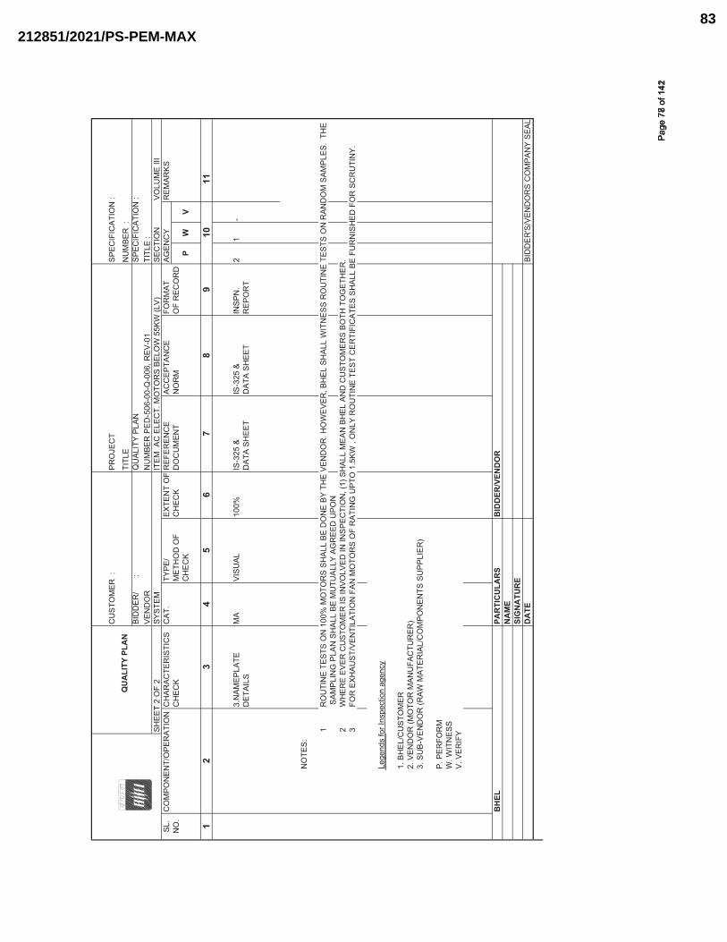
CU
STO
MER
:
PRO
JEC
T
QU
ALI
TY P
LAN
TI
TLE
NU
MBE
R :
BI
DD
ER/
:
QU
ALIT
Y PL
ANSP
ECIF
ICAT
ION
: VE
ND
OR
NU
MBE
R P
ED-5
06-0
0-Q
-006
, REV
-01
TITL
E :
SHEE
T 2
OF
2SY
STEM
ITEM
AC
ELE
CT.
MO
TOR
S BE
LOW
55K
W (L
V)SE
CTI
ON
VO
LUM
E III
SL.
CO
MPO
NEN
T/O
PER
ATIO
NC
HAR
ACTE
RIS
TIC
SC
AT.
TYPE
/EX
TEN
T O
FR
EFER
ENC
EAC
CEP
TAN
CE
FOR
MAT
AG
ENC
YR
EMAR
KSN
O.
CH
ECK
MET
HO
D O
FC
HEC
KD
OC
UM
ENT
NO
RM
OF
REC
OR
DC
HEC
KP
WV
13
45
67
89
1011
3.N
AMEP
LATE
MA
VISU
AL10
0%IS
-325
&IS
-325
&IN
SPN
.2
1-
DET
AILS
DAT
A SH
EET
DAT
A SH
EET
REP
OR
T
NO
TES:
1R
OU
TIN
E TE
STS
ON
100
% M
OTO
RS
SHAL
L BE
DO
NE
BY T
HE
VEN
DO
R. H
OW
EVER
, BH
EL S
HAL
L W
ITN
ESS
RO
UTI
NE
TEST
S O
N R
AND
OM
SAM
PLES
. TH
E S
AMPL
ING
PLA
N S
HAL
L BE
MU
TUAL
LY A
GR
EED
UPO
N2
WH
ERE
EVER
CU
STO
MER
IS IN
VOLV
ED IN
INSP
ECTI
ON
, (1)
SH
ALL
MEA
N B
HEL
AN
D C
UST
OM
ERS
BOTH
TO
GET
HER
.3
FOR
EXH
AUST
/VEN
TILA
TIO
N F
AN M
OTO
RS
OF
RAT
ING
UPT
O 1
.5KW
, O
NLY
RO
UTI
NE
TEST
CER
TIFI
CAT
ES S
HAL
L BE
FU
RN
ISH
ED F
OR
SC
RU
TIN
Y.
Lege
nds
for I
nspe
ctio
n ag
ency
1. B
HEL
/CU
STO
MER
2. V
END
OR
(MO
TOR
MAN
UFA
CTU
RER
)3.
SU
B-VE
ND
OR
(RAW
MAT
ERIA
L/C
OM
PON
ENTS
SU
PPLI
ER)
P. P
ERFO
RM
W. W
ITN
ESS
V. V
ERIF
Y
BH
ELPA
RTI
CU
LAR
SB
IDD
ER/V
END
OR
NA
ME
SIG
NA
TUR
ED
ATE
BID
DER
'S/V
END
OR
S C
OM
PAN
Y SE
AL
SPEC
IFIC
ATIO
N :
2
����
��
����
��Pa
ge 7
8 of
142
Page
78
of 1
42
212851/2021/PS-PEM-MAX83
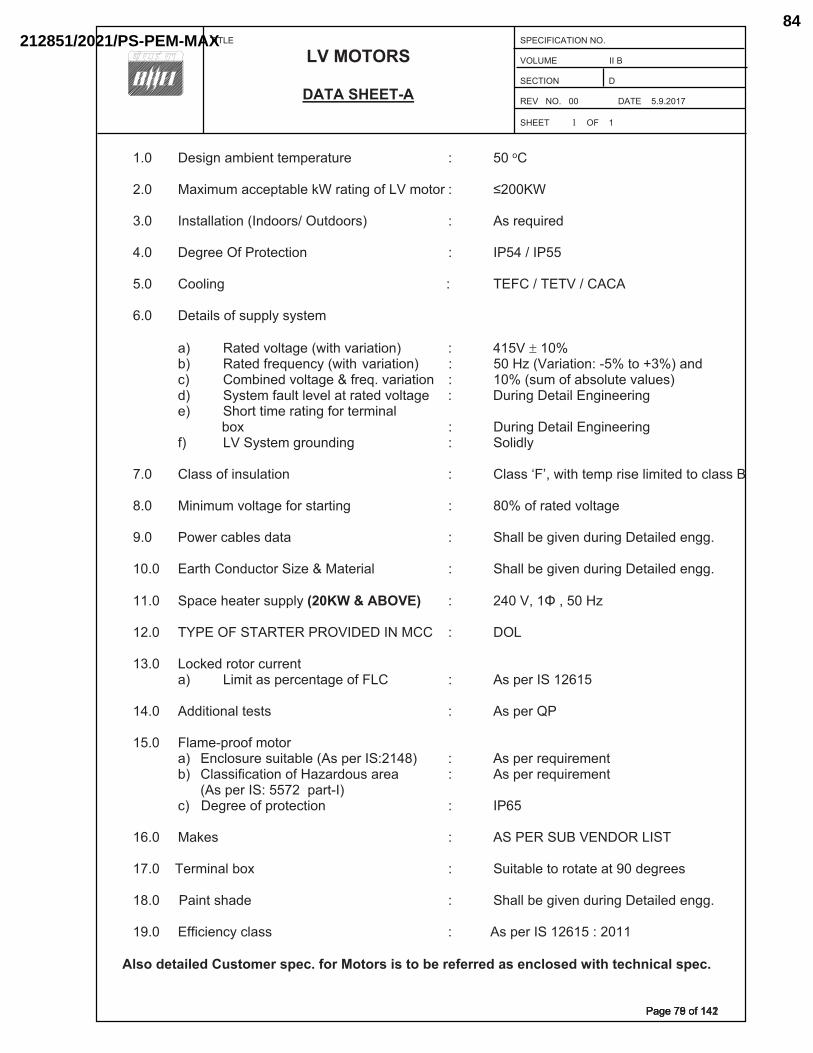
�
����� �
����
��� �������
�������������
������������� ���������������������������������������������������������������������� ����������������������������� � �������������������������������
�� �
�
� �� ���!$*�+<=!�*>�>�<?�@+>[@�� � � �� ���\���� �� �+]!<[<�+^^�?>+=_��`{�@+>!*$�\|����<\>\@��� }����{���� �� �*�>+__+>!\*���*�\\@���[>�\\@��� � �� ���@��[!@����� �� ��$@���|��@\>�^>!\*�������������������� � �� ������������� � � �
� � �� �� �\\_!*$������������������������������� ������������������������� ������������������� �� ��>+!_��\|��[??_�����>�<��� +�� �+>����\_>+$����!>���+@!+>!\*��� �� ������������ =�� �+>���|@��[�*^����!>����+@!+>!\*�� �� ��������+@!+>!\*������>\������+*����� ^�� �\<=!*����\_>+$����|@�� ��+@!+>!\*� �� ������[<�\|�+=�\_[>���+_[����� ��� ���>�<�|+[_>�_���_�+>�@+>����\_>+$�� �� �[@!*$���>+!_��*$!*��@!*$��
��� ��\@>�>!<��@+>!*$�|\@�>�@<!*+_��� ������������������������������������=\]� � � � � �� �[@!*$���>+!_��*$!*��@!*$�
� |�� ������>�<�$@\[*�!*$�� � �� �\_!�_���� �� �_+���\|�!*�[_+>!\*� � � � �� �_+���������!>��>�<?�@!���_!<!>���>\�^_+������� �� �!*!<[<��\_>+$��|\@��>+@>!*$� � � �� ����\|�@+>����\_>+$���� �� �\��@�^+=_����+>+� � � � �� ��+__�=��$!��*��[@!*$���>+!_����*$$ ���� �� �+@>���\*�[^>\@��!������+>�@!+_� � �� ��+__�=��$!��*��[@!*$���>+!_����*$$ ���� �� �?+^����+>�@��[??_����������������� �� ���������������������� �� ��������������������������������� ������ �� �\^`���@\>\@�^[@@�*>�
+�� �!<!>�+��?�@^�*>+$��\|����� � �� ���?�@������������� �� ���!>!\*+_�>��>�� � � � �� ���?�@���� � � �
� ��� �� �_+<��?@\\|�<\>\@�� � � � �
+�� �*^_\�[@���[!>+=_������?�@���������� �� ���?�@�@��[!@�<�*>�=�� �_+��!|!^+>!\*�\|��+�+@�\[��+@�+�� �� ���?�@�@��[!@�<�*>�
����?�@�����������?+@>����� ^������$@���\|�?@\>�^>!\*� � � �� �����
��� �� �+`��� �� ������������������������ ������@<!*+_�=\]� �� �[!>+=_��>\�@\>+>��+>������$@������� �������+!*>���+��� �� ��+__�=��$!��*��[@!*$���>+!_����*$$ ���� �� �||!^!�*^��^_+��� ��������������?�@�����������������
������������������������!$'+;�$!��<�'�$=��>$?@�Z�=� �'�=��;��'��[$�=$Z$==$!�+��$\?���$!�];'��'$?�\;?+���>$?@���
������������Page 79 of 142Page 79 of 142
212851/2021/PS-PEM-MAX84
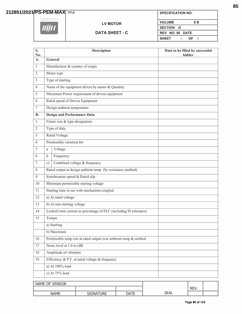
TITLE
LV MOTOR
DATA SHEET - C
SPECIFICATION NO.
VOLUME II B SECTION D REV NO. 00 DATE SHEET 1 OF 2
NAME OF VENDOR
SEAL REV.
NAME SIGNATURE DATE
S.No.
Description Data to be filled by successful bidder
A. General
1 Manufacturer & country of origin
2 Motor type
3 Type of starting
4 Name of the equipment driven by motor & Quantity
5 Maximum Power requirement of driven equipment
6 Rated speed of Driven Equipment
7 Design ambient temperature
B. Design and Performance Data
1 Frame size & type designation
2 Type of duty
3 Rated Voltage
4 Permissible variation for
5 a Voltage
6 b Frequency
7 c) Combined voltage & frequency
8 Rated output at design ambient temp (by resistance method)
9 Synchronous speed & Rated slip
10 Minimum permissible starting voltage
11 Starting time in sec with mechanism coupled
12 a) At rated voltage
13 b) At min starting voltage
14 Locked rotor current as percentage of FLC (including IS tolerance)
15 Torque
a) Starting
b) Maximum
16 Permissible temp rise at rated output over ambient temp & method
17 Noise level at 1.0 m (dB
18 Amplitude of vibration
19 Efficiency & P.F. at rated voltage & frequency
a) At 100% load
c) At 75% load
�������������Page 80 of 142Page 80 of 142
212851/2021/PS-PEM-MAX85
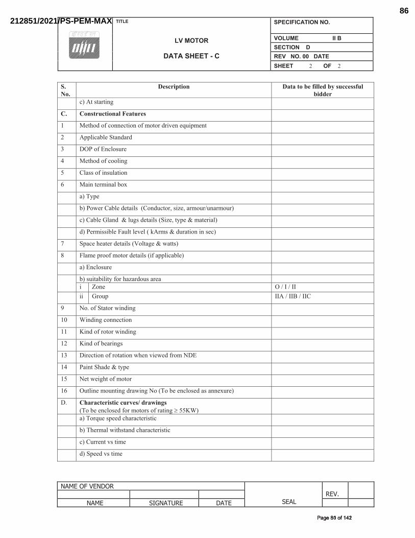
TITLE
LV MOTOR
DATA SHEET - C
SPECIFICATION NO.
VOLUME II B SECTION D REV NO. 00 DATE SHEET 2 OF 2
NAME OF VENDOR
SEAL REV.
NAME SIGNATURE DATE
S.No.
Description Data to be filled by successful bidder
c) At starting
C. Constructional Features
1 Method of connection of motor driven equipment
2 Applicable Standard
3 DOP of Enclosure
4 Method of cooling
5 Class of insulation
6 Main terminal box
a) Type
b) Power Cable details (Conductor, size, armour/unarmour)
c) Cable Gland & lugs details (Size, type & material)
d) Permissible Fault level ( kArms & duration in sec)
7 Space heater details (Voltage & watts)
8 Flame proof motor details (if applicable)
a) Enclosure
b) suitability for hazardous area
i Zone O / I / II
ii Group IIA / IIB / IIC
9 No. of Stator winding
10 Winding connection
11 Kind of rotor winding
12 Kind of bearings
13 Direction of rotation when viewed from NDE
14 Paint Shade & type
15 Net weight of motor
16 Outline mounting drawing No (To be enclosed as annexure)
D. Characteristic curves/ drawings(To be enclosed for motors of rating � 55KW)
a) Torque speed characteristic
b) Thermal withstand characteristic
c) Current vs time
d) Speed vs time
�������������Page 81 of 142Page 81 of 142
212851/2021/PS-PEM-MAX86
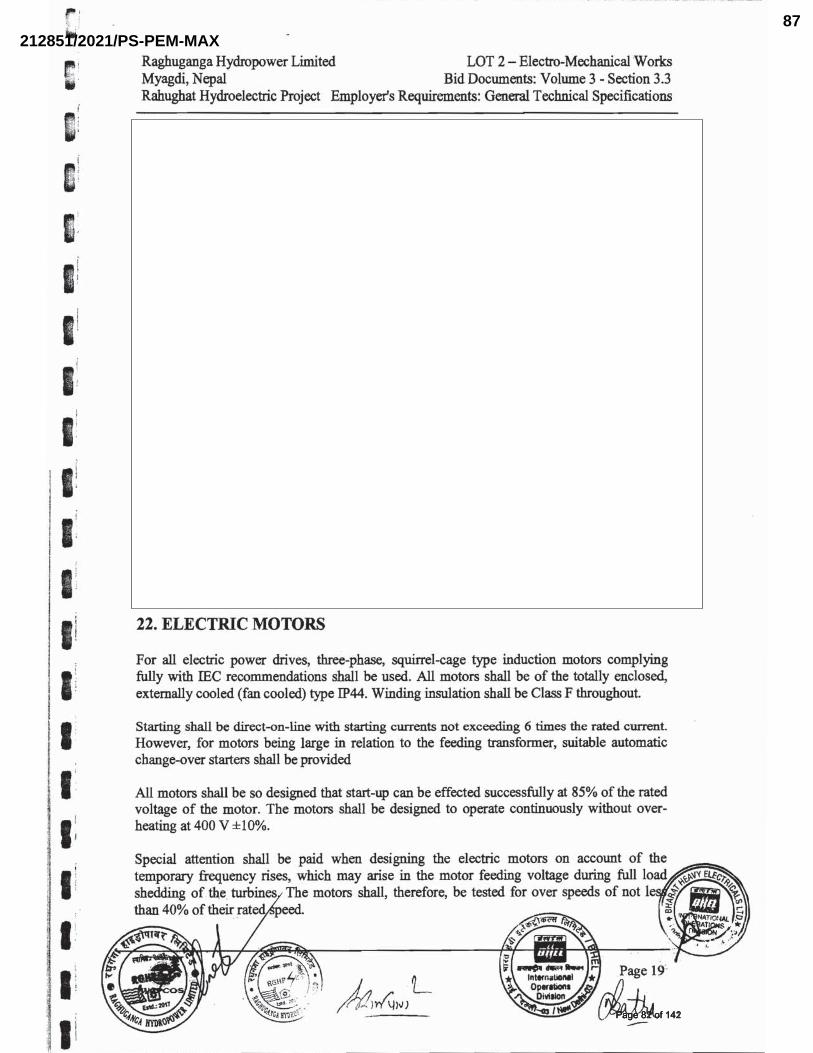
�������������Page 82 of 142Page 82 of 142
212851/2021/PS-PEM-MAX87
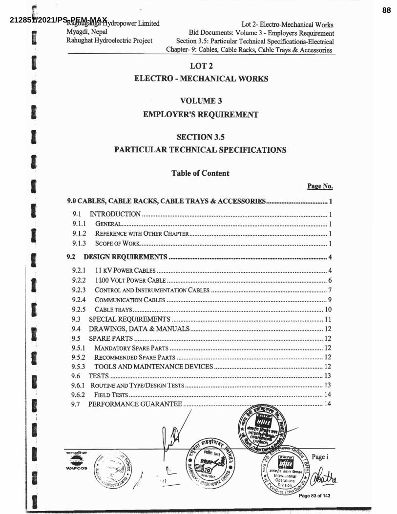
�������������Page 83 of 142Page 83 of 142
212851/2021/PS-PEM-MAX88
�������������Page 84 of 142Page 84 of 142
212851/2021/PS-PEM-MAX89
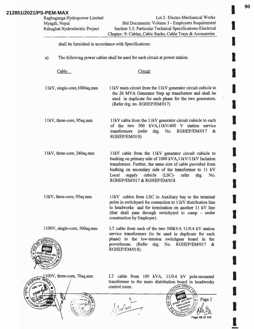
�������������Page 85 of 142Page 85 of 142
212851/2021/PS-PEM-MAX90
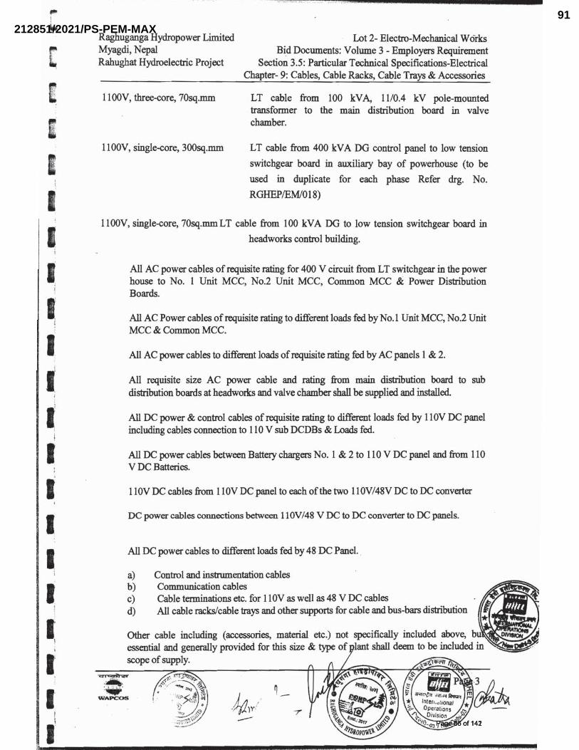
�������������Page 86 of 142Page 86 of 142
212851/2021/PS-PEM-MAX91
�������������Page 87 of 142Page 87 of 142
212851/2021/PS-PEM-MAX92
������������Page 88 of 142Page 88 of 142
212851/2021/PS-PEM-MAX93

������������Page 89 of 142Page 89 of 142
212851/2021/PS-PEM-MAX94
�������������Page 90 of 142Page 90 of 142
212851/2021/PS-PEM-MAX95
��������������Page 91 of 142Page 91 of 142
212851/2021/PS-PEM-MAX96
��������������Page 92 of 142Page 92 of 142
212851/2021/PS-PEM-MAX97
��������������Page 93 of 142Page 93 of 142
212851/2021/PS-PEM-MAX98
��������������Page 94 of 142Page 94 of 142
212851/2021/PS-PEM-MAX99
��������������Page 95 of 142Page 95 of 142
212851/2021/PS-PEM-MAX100
��������������Page 96 of 142Page 96 of 142
212851/2021/PS-PEM-MAX101
��������������Page 97 of 142Page 97 of 142
212851/2021/PS-PEM-MAX102
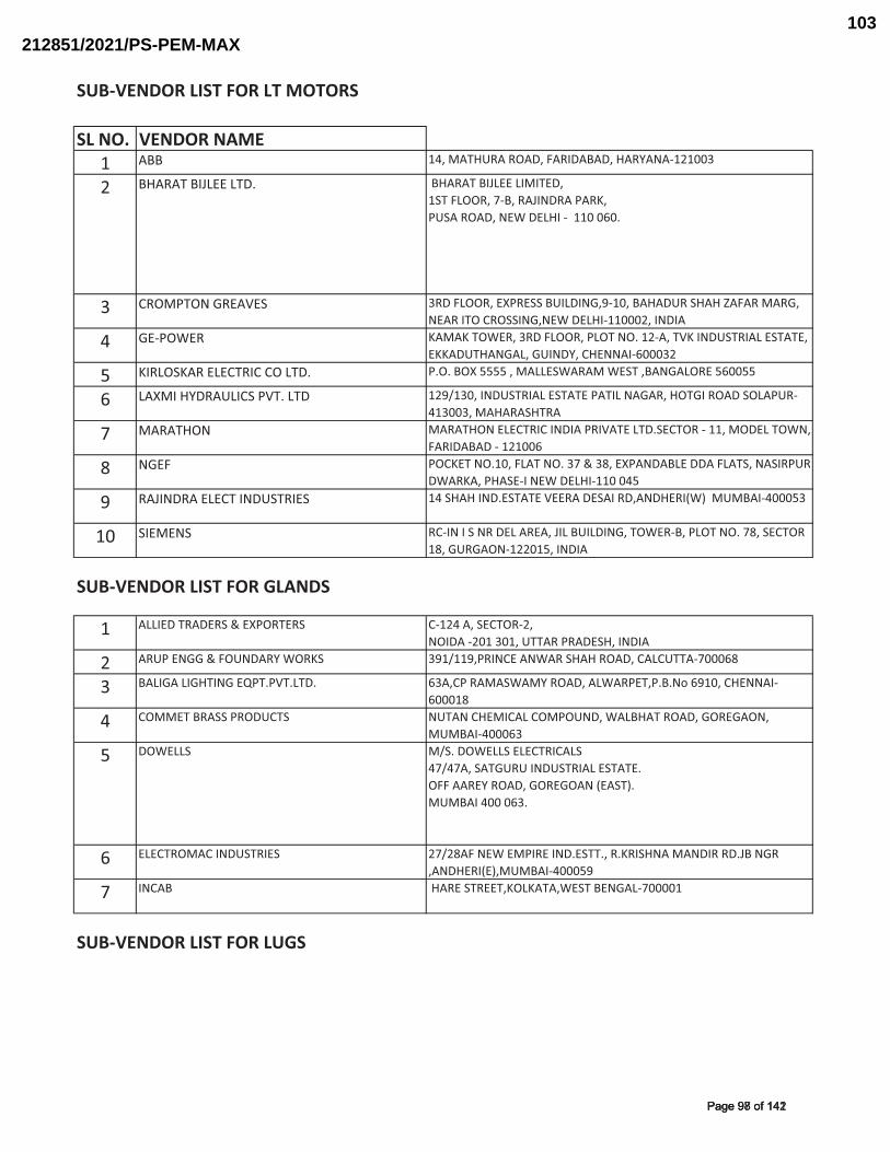
SUB�VENDOR�LIST�FOR�LT�MOTORS
SL�NO. VENDOR�NAME1 ABB 14,�MATHURA�ROAD,�FARIDABAD,�HARYANA�121003
2 BHARAT�BIJLEE�LTD. �BHARAT�BIJLEE�LIMITED,�1ST�FLOOR,�7�B,�RAJINDRA�PARK,�PUSA�ROAD,�NEW�DELHI����110�060.�
3 CROMPTON�GREAVES 3RD�FLOOR,�EXPRESS�BUILDING,9�10,�BAHADUR�SHAH�ZAFAR�MARG,�NEAR�ITO�CROSSING,NEW�DELHI�110002,�INDIA
4 GE�POWER KAMAK�TOWER,�3RD�FLOOR,�PLOT�NO.�12�A,�TVK�INDUSTRIAL�ESTATE,�EKKADUTHANGAL,�GUINDY,�CHENNAI�600032
5 KIRLOSKAR�ELECTRIC�CO�LTD. P.O.�BOX�5555�,�MALLESWARAM�WEST�,BANGALORE�560055
6 LAXMI�HYDRAULICS�PVT.�LTD 129/130,�INDUSTRIAL�ESTATE�PATIL�NAGAR,�HOTGI�ROAD�SOLAPUR�413003,�MAHARASHTRA
7 MARATHON MARATHON�ELECTRIC�INDIA�PRIVATE�LTD.SECTOR���11,�MODEL�TOWN,�FARIDABAD���121006
8 NGEF POCKET�NO.10,�FLAT�NO.�37�&�38,�EXPANDABLE�DDA�FLATS,�NASIRPUR�DWARKA,�PHASE�I�NEW�DELHI�110�045
9 RAJINDRA�ELECT�INDUSTRIES 14�SHAH�IND.ESTATE�VEERA�DESAI�RD,ANDHERI(W)��MUMBAI�400053
10 SIEMENS RC�IN�I�S�NR�DEL�AREA,�JIL�BUILDING,�TOWER�B,�PLOT�NO.�78,�SECTOR�18,�GURGAON�122015,�INDIA
SUB�VENDOR�LIST�FOR�GLANDS
1 ALLIED�TRADERS�&�EXPORTERS C�124�A,�SECTOR�2,NOIDA��201�301,�UTTAR�PRADESH,�INDIA
2 ARUP�ENGG�&�FOUNDARY�WORKS 391/119,PRINCE�ANWAR�SHAH�ROAD,�CALCUTTA�700068
3 BALIGA�LIGHTING�EQPT.PVT.LTD. 63A,CP�RAMASWAMY�ROAD,�ALWARPET,P.B.No�6910,�CHENNAI�600018
4 COMMET�BRASS�PRODUCTS NUTAN�CHEMICAL�COMPOUND,�WALBHAT�ROAD,�GOREGAON,�MUMBAI�400063
5 DOWELLS M/S.�DOWELLS�ELECTRICALS47/47A,�SATGURU�INDUSTRIAL�ESTATE.OFF�AAREY�ROAD,�GOREGOAN�(EAST).MUMBAI�400�063.
6 ELECTROMAC�INDUSTRIES 27/28AF�NEW�EMPIRE�IND.ESTT.,�R.KRISHNA�MANDIR�RD.JB�NGR�,ANDHERI(E),MUMBAI�400059
7 INCAB �HARE�STREET,KOLKATA,WEST�BENGAL�700001
SUB�VENDOR�LIST�FOR�LUGS
�������������Page 98 of 142Page 98 of 142
212851/2021/PS-PEM-MAX103
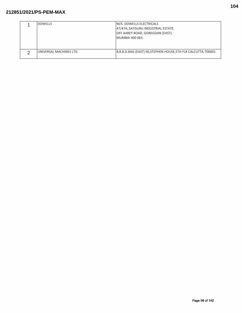
1 DOWELLS M/S.�DOWELLS�ELECTRICALS47/47A,�SATGURU�INDUSTRIAL�ESTATE.OFF�AAREY�ROAD,�GOREGOAN�(EAST).MUMBAI�400�063.
2 UNIVERSAL�MACHINES�LTD. 4,B.B.D.BAG�(EAST)�90,STEPHEN�HOUSE,5TH�FLR�CALCUTTA�700001
�������������Page 99 of 142Page 99 of 142
212851/2021/PS-PEM-MAX104
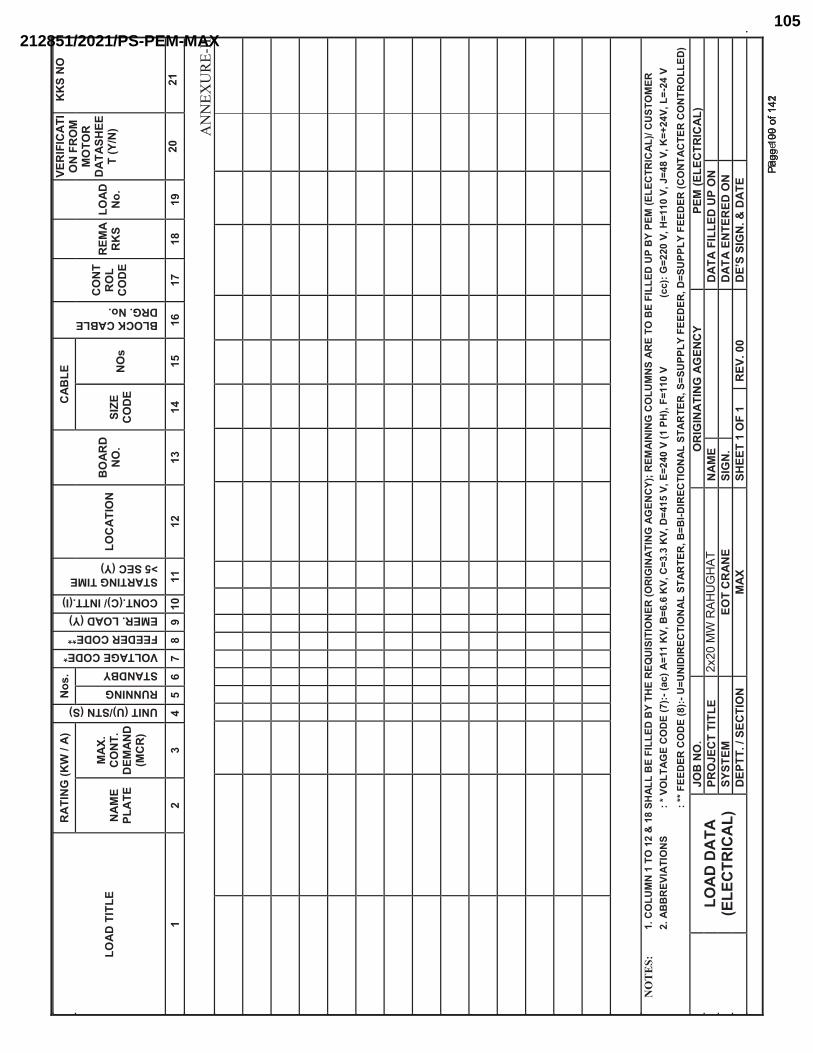
����
��^�
���
���
^_`
����
����
�
z_^���z���_�����
_��
@
�����`������{�|����������{{�� ��@�������}����_�@����^_��@�^��
�����^_`��^ ��~�������}��
���
��^�
_�
��
���
�_�
@�
���
���
��������������`@�_�@�
��_
��
���
���
���
�
����
����
�_
�@�
���
^|^�
��^
�_�
|��
�
�
���
��
����
���
���}
_���
���
�_�
�
_�
����
����
��
@��
�_
�@�
��
�_�
��
���
�
�z__^_`����_��}�
�^��
��
���
_�
��
����
���
��
��
���
���
���
���
���
���
���
���
���
���
���
���
�
��
��
�"
�@��
��z
_
����
���
���
����
����
���
��|^
����
��}�
����
���
z^�
^�^�
_��
����^
`^_
��^_
`��
`�_
�}�
����
�^_
^_`
���
�z
_��
����
����
��|^
����
�z��
�}�
��
�����
���
^���
���
z��
�
���
��@
���
��
��^�
�^�
_��
��{��
���
�`��
��
���
�����
��+?�
����
���
����
��@�
����
����
@���
����
����
�����
����
�����
���
���|�
����
���?
?���`
����
�����
����
�����
����
����
����
����
����
���
��
��{{�|
���
����
��
����
����z
�z_
^�^�
���^
�_
����
���
���
�����
^��^�
���^
�_
����
���
���
�����
z��
�}�|
���
�����
��z
���}
�|��
���
����
_��
���
���
�_
���
����
��
���
��
���
���
����
���
^��
���
����
_�
@��
��
^`^_
��^_
`��
`�_
�}�
��
�����
���
^���
����
���
���
�^��
���
_�
���
���
��|^
����
�z��
�_
��
�}��
� ��
����
��
�_�
�^`
_@
��
����
�_��
���
��_
��
����
@���
���^
�_
�
���
����
����
�|�
���
��@��
���
����
�^`
_@��
����
���
�
>�
��
��
��
����
��
��
��
��
��
��
��
��
��
��
��
��
��
��
��
��
��
��
��
��
��
��
��
��
��
��
��
��
��
��
��
��
��
��
��
��
��
��
��
��
��
��
��
��
��
��
��
��
��
��
��
��
��
��
��
��
��
��
��
��
��
��
��
��
��
��
��
��
��
��
��
��
��
��
��
��
��
��
��
��
��
��
��
��
��
��
��
��
��
��
��
��
��
��
��
��
��
��
��
��
��
��
��
��
��
��
��
��
��
��
��
��
��
��
��
��
��
��
��
��
��
��
��
��
��
��
��
��
��
��
��
��
��
��
��
��
��
��
��
��
�
����
����
����
��Pa
ge 1
00 o
f 142
Page
100
of 1
42
2x20
MW
RAH
UG
HAT
212851/2021/PS-PEM-MAX105
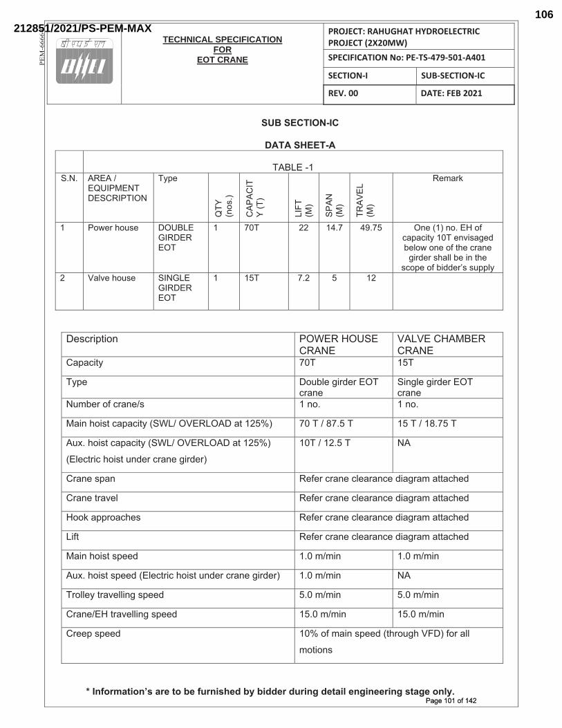
TECHNICAL SPECIFICATION
FOREOT CRANE
PROJECT: RAHUGHAT HYDROELECTRIC PROJECT (2X20MW) SPECIFICATION No: PE-TS-479-501-A401
SECTION-I SUB-SECTION-IC
REV. 00 DATE: FEB 2021
PE
M-6
66
6-0
SUB SECTION-IC
DATA SHEET-A TABLE -1
S.N. AREA / EQUIPMENT DESCRIPTION
Type
QTY
(n
os.)
CAP
ACIT
Y (T
)
LIFT
(M
)
SPAN
(M
)
TRAV
EL
(M)
Remark
1 Power house DOUBLE GIRDER EOT
1 70T 22 14.7 49.75 One (1) no. EH of capacity 10T envisaged below one of the crane
girder shall be in the scope of bidder’s supply
2 Valve house SINGLE GIRDER EOT
1 15T 7.2 5 12
Description POWER HOUSE CRANE
VALVE CHAMBER CRANE
Capacity 70T 15T
Type Double girder EOT crane
Single girder EOT crane
Number of crane/s 1 no. 1 no.
Main hoist capacity (SWL/ OVERLOAD at 125%) 70 T / 87.5 T 15 T / 18.75 T
Aux. hoist capacity (SWL/ OVERLOAD at 125%)
(Electric hoist under crane girder)
10T / 12.5 T NA
Crane span Refer crane clearance diagram attached
Crane travel Refer crane clearance diagram attached
Hook approaches Refer crane clearance diagram attached
Lift Refer crane clearance diagram attached
Main hoist speed 1.0 m/min 1.0 m/min
Aux. hoist speed (Electric hoist under crane girder) 1.0 m/min NA
Trolley travelling speed 5.0 m/min 5.0 m/min
Crane/EH travelling speed 15.0 m/min 15.0 m/min
Creep speed 10% of main speed (through VFD) for all
motions
* Information’s are to be furnished by bidder during detail engineering stage only.Page 101 of 142Page 101 of 142
212851/2021/PS-PEM-MAX106
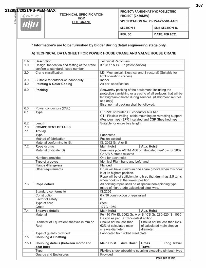
TECHNICAL SPECIFICATION
FOREOT CRANE
PROJECT: RAHUGHAT HYDROELECTRIC PROJECT (2X20MW) SPECIFICATION No: PE-TS-479-501-A401
SECTION-I SUB-SECTION-IC
REV. 00 DATE: FEB 2021
PE
M-6
66
6-0
* Information’s are to be furnished by bidder during detail engineering stage only.
A) TECHNICAL DATA SHEET FOR POWER HOUSE CRANE AND VALVE HOUSE CRANE
|^�^� �#+��<*��!� ��+$!�+�"����*�+["��#���^�� �#��!{���?��+�*��!��!>�*�#*�!�����*$��+��!��
+�!���Z�*��#*�!>��>���+�>��![Z?���_|�������_|����"�*�#*��>�*��!��
�^�� ���!��+"�##���+�*��!� ������+$�!�+�"{��"�+*��+�"��!>�|*�[+*[��"���|[�*�?"������"��$*��<���*��!�+��!�#��
�^�� |[�*�?"�������[*>��������!>����>[*@� _!>�����^�� Painting & Color Coding �#�<����#<�+���+�*��!�
�^�� Packing |��]��*$@�<�+`�!�����*$����[�<Z�!*{��!+"[>�!��*$��<��*�+*�\��\��!�#$�!���������#�!������""�#[���+�#�*$�*�]�""�?��"��*�?���$*�[!~<��!*�>�>[��!��#��\�+�#^�����#$�<Z�!*�#�!*�\���#����!"@���"#�{�!��Z�"�<�+`�!��#$�""�?����""�]�>^�
�^�� ��]���+�!>[+*��#�� |��� ��^�� �@<�� ��������#$��[>�>��[�+�!>[+*���?[#�?��^�
������"���?"��*���"�!���+�?"��Z�[!*�!���!���*��+*�!��#[<<��*����#*��!��*@<��������!#["�*�>��!>��|��|$��*$�>�*@<��
�^�� ��!�*$� |[�*�?"�������!*����?�@�"�!�*$��^�� COMPONENT DETAILS^�� Trolley �� �@<�� ��?��+�*�>�� ��*$�>������?��+�*��!� �[#��!�]�">�>�� ��*����"�+�!���Z�!��*��_|�� _|���������^��������^�� Rope drums Main hoist Aux. Hoist� ��*����"��_!>�+�*��_|�� |��Z"�##�<�<���|���~���������?��+�*�>������]�_|�������
���������#*��##���"��\�>�� �[Z?��#�<��\�>�>� �!��������+$�$��#*�� �@<���������\�#� _>�!*�+�"����$*�$�!>��!>����*�$�!>�� �"�!�����"�!��"�##� �"�!��>�� �*$������[���Z�!*#� �[Z�]�""�$�\��Z�!�Z[Z��!��#<��������\��]$�!�*$�#�$��`�
�#��*��*#�$��$�#*�<�#�*��!^���<��]�""�?�����#[���+��!*�"�!�*$�#��*$�*�>�[Z�$�#��^��*[�!#�]$�!�$��`��#��*�*$��"�]�#*�<�#�*��!^�
^�� Rope details �""�$��#*�!����<�#�#$�""�?�����#<�+��"�!�!~#<�!!�!��*@<��Z�>�����$��$~���>����"\�!���>�#*��"�]���^
� |*�!>��>�+�!���Z#�*�� _|������� ��!#*�[+*��!� �������+�!#*�[+*��!������[�\�"�!*�� ��+*������#���*@� ��� �@<�����+���� |*��"�� ���>�� ���������^�� Sheaves details Main hoist Aux. Hoist� ��*����"�
�����������_|���������^�����������|���^���~����_|������� �#��!��#�<���_|����~�"�*�#*��>�*��!�
� ��Z�*��������[�\�"�!*�#$��\�#��!�ZZ��!����*�
|$�[">�!�*�?��"�##�*$�!��������+�"+["�*�>�Z��!�#$��\��>��Z�*��^�
|$�[">�!�*�?��"�##�*$�!��������+�"+["�*�>�Z��!�#$��\��>��Z�*��^�
� �@<������[��>#�<��\�>�>� ��?��+�*�>����Z���""�>�#*��"�<"�*���^�� Coupling & Shafting �
^�^�� Coupling details (between motor and gear box)
Main Hoist Aux. Hoist Cross Travel
Long Travel
� �@<�� �"���?"��#$�+`��?#��?�!��+�[<"�!����+�<*�!��<�!�?[#$�*@<��� �[��>#��!>��!+"�#[��#�� ���\�>�>�
���������������Page 102 of 142Page 102 of 142
212851/2021/PS-PEM-MAX107
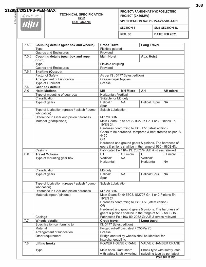
TECHNICAL SPECIFICATION
FOREOT CRANE
PROJECT: RAHUGHAT HYDROELECTRIC PROJECT (2X20MW) SPECIFICATION No: PE-TS-479-501-A401
SECTION-I SUB-SECTION-IC
REV. 00 DATE: FEB 2021
PE
M-6
66
6-0
^�^�� Coupling details (gear box and wheels) Cross Travel Long Travel� �@<�� �"���?"�������>�� �[��>#��!>��!+"�#[��#� ���\�>�>�^�^�� Coupling details (gear box and rope
drum)Main Hoist Aux. Hoist
� �@<�� �"���?"��+�[<"�!���� �[��>#��!>��!+"�#[��#� ���\�>�>�^�^�� Shafting (Output) �� ��+*������|���*@� �#�<���_|�������"�*�#*��>�*��!��� ����!��Z�!*�����[?��+�*��!� ����#��+[<#����<<"�#�� �@<������[?��+�!*� ����#��^�� Gear box details ��^�� Hoist Motions MH MH Micro AH AH micro� �@<�����Z�[!*�!����������?��� ������!*�"������*�+�"�� �"�##���+�*��!� |[�*�?"���������>[*@�� �@<���������#� ��"�+�"���
|<[����� ��"�+�"���|<[�� ���
� �@<�����"[?��+�*��!������#����#<"�#$���<[Z<�"[?��+�*��!��
|<"�#$��[?��+�*��!��
� ������!+���!�������!>�<�!��!�$��>!�##� ��!��������� ��*����"�������<�!��!#�� ���!�����#��!���������_|�����^����������!��!#��!�
��������^�����>!�##�+�!���Z�!��*��_|������"�*�#*��>�*��!������#�*��?��$��>�!�>{�*�Z<���>���$��*�*���*�>��#�<���_|������������>�!�>��!>����[!>�����#���<�!��!#^��$��$��>!�##��������#���<�!��!#�#$�""�?���!�*$����!����������~������^�
� ��#�!�#� ��?��+�*�>�������]�_|����������������#*��##���"��\�>��^�� Travel Motions ��� ���Z�+��� ��� ���Z�+���� �@<�����Z�[!*�!�������?��� ���*�+�"��
������!*�"���� ���*�+�"��
������!*�"�����
� �"�##���+�*��!� ���>[*@�� �@<���������#� ��"�+�"��
|<[����� ��"�+�"��|<[�� ���
� �@<�����"[?��+�*��!������#����#<"�#$���<[Z<�"[?��+�*��!��
|<"�#$��[?��+�*��!��
� ������!+���!�������!>�<�!��!�$��>!�##� ��!��������� ��*����"#���������<�!��!#�� ���!�����#��!���������_|�����^����������!��!#��!�
��������^�����>!�##�+�!���Z�!��*��_|������"�*�#*��>�*��!��������>�!�>��!>����[!>�����#���<�!��!#^��$��$��>!�##��������#���<�!��!#�#$�""�?���!�*$����!����������~������^�
� ��#�!�#� ��?��+�*�>�������]�_|����������������#*��##���"��\�>�^� Wheels details Cross travel Long travel� |<�+���+�*��!�+�!���Z�!��*�� _|������"�*�#*��>�*��!��� ��*����"�� �����>���""�>��+�#*�#*��"�������!����� ����!��Z�!*����"[?��+�*��!� ����#��� �*$������[���Z�!*� ���>����!>�*��""�@�]$��"#�#$�""�?���>�!*�+�"�����
�!*��+$�!���?�"�*@^�^� Lifting hooks ���������|�������� ��������������������
� �@<�� ���!�$��`~���Z�#$��!�]�*$�#���*@�"�*+$�#]�\�"�!��
|$�!`�*@<��]�*$�#���*@�"�*+$�#]�\�"�!��*@<���#�<���"�*�#*�
���������������Page 103 of 142Page 103 of 142
212851/2021/PS-PEM-MAX108
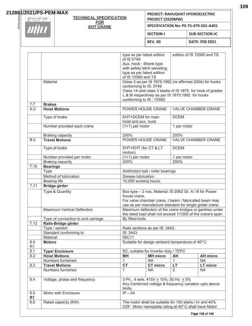
TECHNICAL SPECIFICATION
FOREOT CRANE
PROJECT: RAHUGHAT HYDROELECTRIC PROJECT (2X20MW) SPECIFICATION No: PE-TS-479-501-A401
SECTION-I SUB-SECTION-IC
REV. 00 DATE: FEB 2021
PE
M-6
66
6-0
*@<���#�<���"�*�#*��>�*��!����_|������[�^�$��`~��|$�!`�*@<��]�*$�#���*@�"�*+$�#]�\�"�!��*@<���#�<���"�*�#*��>�*��!����_|��������!>��|�
�>�*��!����_|��������!>��|�
� ��*����"� �"�##����#�<���_|������������������Z�>�����������$��`#�+�!���Z�!��*��_|�������"�##�����!>�+"�##���#*��"#����_|���������$��`�������>�#���������#<�+*�\�"@��#�<���_|��������������$��`#�+�!���Z�!��*��_|���������
^� Brakes�^�� Hoist Motions ���������|�������� ��������������������
� �@<�����?��`��� ���� ��������Z��!�$��#*��!>��[�^�$��#*�
����
�[Z?���<��\�>�>���+$�+��!�� ������<���Z�*��� ��<���Z�*����
� ���`�!��+�<�+�*@� ����� ������^�� Travel Motions ���������|�������� ��������������������
� �@<�����?��`��� ���������������������Z�*��!��
����
� �[Z?���<��\�>�>�<���Z�*��� ������<���Z�*��� ��<���Z�*���� ���`�!��+�<�+�*@� ����� �����^��� Bearings �� �@<�� �!*����+*��!�?�""�����""���?����!�#�� ��*$�>����"[?��+�*��!� ����#��"[?��+�*��!�� �����!��"���� ��{����]��`�!��$�[�#^�^��� Bridge girder �� �@<�����[�!*�*@� ����*@<��¡���!�#{���*����"��_|��������^�������������]���
$�[#��+��!�^�����\�"\��+$�Z?���+��!�{�_�?��Z�����?��+�*�>�?��Z�Z�@�[#���#�<���Z�![��+*[���#*�!>��>�����#�!�"�����>���+��!�^�
� ����Z[Z����*�+�"� ��"�+*��!� ����Z[Z�>��"�+*��!����*$��+��!��?��>��#������!*���#�[!>���*$����*�>�"��>�#$�""�!�*���+��>�����������*$��+��!��#�#<�!�
� �@<�����+�!!�+*��!�*���!>�+�������� �@���**�>�?�"*#�^��� Rails-Bridge girder �� �@<����#�+*��!� ���"#�#�+*��!#��#�<���_|������^�� |*�!>��>�+�!���Z�!��*�� _|�������� ��*����"�� ������^�����
Motors |[�*�?"������>�#��!��Z?��!*�*�Z<���*[������������
^�� Type/ Enclosure |�{�#[�*�?"������_!\��*���>[*@��������^�� Hoist Motions MH MH micro AH AH micro� �[Z?��#��[�!�#$�>� �� ��� �� ���^�� Travel Motions CT CT micro LT LT micro� �[Z?��#��[�!�#$�>� �� ��� �� ���
^�� ��"*���{�<$�#���!>�����[�!+@�� ���$^{���]���{�����������{���������������!@���Z?�!�>�\�"*����������[�!+@�\����*��!�[<*���?�\��"�Z�*#^�
^��R1
��*���]�*$��!+"�#[��� _��¡����
^�� ��*�>�+�<�+�*@������ �$��Z�*���#$�""�?��#[�*�?"����������#*��*#���$���!>������ �^���*���!�Z�<"�*����*�!���*�������#$�""�$�\����*���
���������������Page 104 of 142Page 104 of 142
212851/2021/PS-PEM-MAX109
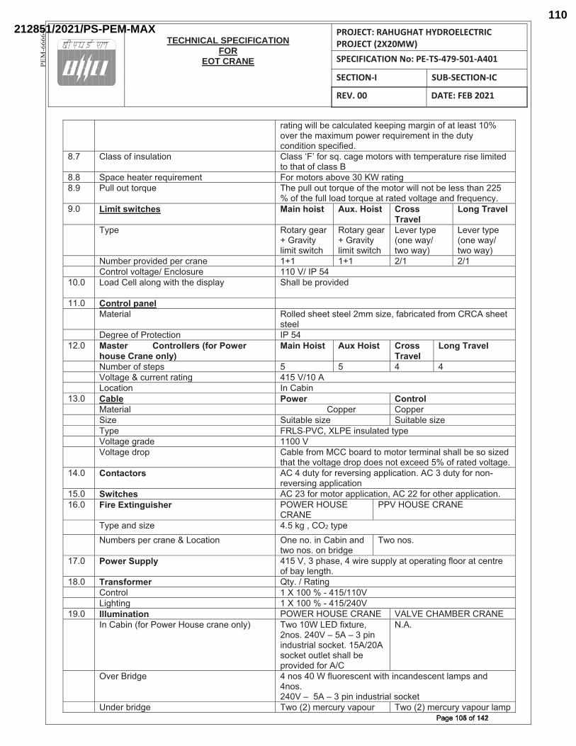
TECHNICAL SPECIFICATION
FOREOT CRANE
PROJECT: RAHUGHAT HYDROELECTRIC PROJECT (2X20MW) SPECIFICATION No: PE-TS-479-501-A401
SECTION-I SUB-SECTION-IC
REV. 00 DATE: FEB 2021
PE
M-6
66
6-0
��*�!��]�""�?��+�"+["�*�>�`��<�!��Z����!�����*�"��#*������\���*$��Z���Z[Z�<�]������[���Z�!*��!�*$��>[*@�+�!>�*��!�#<�+����>^��
^� �"�##�����!#["�*��!�� �"�##�£� �����#�^�+����Z�*��#�]�*$�*�Z<���*[�����#��"�Z�*�>�*��*$�*����+"�##���
^� |<�+��$��*������[���Z�!*� ����Z�*��#��?�\����������*�!��^�� �[""��[*�*���[�� �$��<[""��[*�*���[�����*$��Z�*���]�""�!�*�?��"�##�*$�!�����
�����*$���[""�"��>�*���[���*���*�>�\�"*�����!>�����[�!+@^��^�� Limit switches Main hoist Aux. Hoist Cross
TravelLong Travel
� �@<��� ��*��@�����������\�*@�"�Z�*�#]�*+$��
��*��@�����������\�*@�"�Z�*�#]�*+$�
��\���*@<����!��]�@��*]��]�@��
��\���*@<����!��]�@��*]��]�@��
� �[Z?���<��\�>�>�<���+��!�� ���� ���� ���� ����� ��!*��"�\�"*������!+"�#[��� �������_�������^�� ���>���""��"�!��]�*$�*$��>�#<"�@� |$�""�?��<��\�>�>�
���^�� Control panel� ��*����"� ��""�>�#$��*�#*��"��ZZ�#���{���?��+�*�>����Z������#$��*�
#*��"�� ������������*�+*��!� _�������^�� Master Controllers (for Power
house Crane only)Main Hoist Aux Hoist Cross
TravelLong Travel
� �[Z?������#*�<#� �� �� �� ��� ��"*������+[���!*���*�!�� ������������ ��+�*��!� _!���?�!���^�� Cable Power Control� ��*����"� ���������������������<<��� ��<<���
|���� |[�*�?"��#���� |[�*�?"��#����� �@<�� ���|����{�}�����!#["�*�>�*@<��� ��"*�������>�� �������� ��"*����>��<� ��?"�����Z�����?���>�*��Z�*���*��Z�!�"�#$�""�?��#��#���>�
*$�*�*$��\�"*����>��<�>��#�!�*���+��>���������*�>�\�"*���^���^�� Contactors �����>[*@�������\��#�!���<<"�+�*��!^������>[*@�����!�!~
��\��#�!���<<"�+�*��!���^�� Switches ����������Z�*����<<"�+�*��!{������������*$����<<"�+�*��!^���^�� Fire Extinguisher ���������|��
�������������|��������
� �@<���!>�#���� �^��`��{�����*@<��� �[Z?��#�<���+��!������+�*��!� �!��!�^��!���?�!��!>�
*]��!�#^��!�?��>����]��!�#^��
�^�� Power Supply �����{���<$�#�{���]����#[<<"@��*��<���*�!���"�����*�+�!*������?�@�"�!�*$^�
�^�� Transformer �*@^�����*�!��� ��!*��"� ��}�������~����������� ���$*�!�� ��}�������~������������^�� Illumination ���������|�������� ��������������������� _!���?�!��������]�����[#��+��!���!"@�� �]�������� ����*[��{�
�!�#^������¡����¡���<�!��!>[#*���"�#�+`�*^���������#�+`�*��[*"�*�#$�""�?��<��\�>�>���������
�^�^�
� �\������>��� ��!�#�������"[���#+�!*�]�*$��!+�!>�#+�!*�"�Z<#��!>��!�#^�������¡�����¡���<�!��!>[#*���"�#�+`�*�
� �!>���?��>��� �]������Z��+[�@�\�<�[�� �]������Z��+[�@�\�<�[��"�Z<����������������Page 105 of 142Page 105 of 142
212851/2021/PS-PEM-MAX110
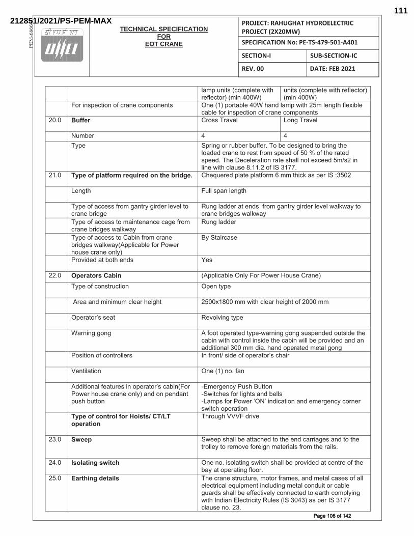
TECHNICAL SPECIFICATION
FOREOT CRANE
PROJECT: RAHUGHAT HYDROELECTRIC PROJECT (2X20MW) SPECIFICATION No: PE-TS-479-501-A401
SECTION-I SUB-SECTION-IC
REV. 00 DATE: FEB 2021
PE
M-6
66
6-0
"�Z<�[!�*#��+�Z<"�*��]�*$����"�+*�����Z�!�������
[!�*#��+�Z<"�*��]�*$����"�+*�����Z�!�������
� �����!#<�+*��!����+��!��+�Z<�!�!*#� �!������<��*�?"������$�!>�"�Z<�]�*$���Z�"�!�*$��"���?"��+�?"�������!#<�+*��!����+��!��+�Z<�!�!*#�
��^�� Buffer ���##����\�"� ��!�����\�"�
� �[Z?��� �� ��� �@<�� |<��!������[??���?[����^����?��>�#��!�>�*��?��!��*$��
"��>�>�+��!��*����#*����Z�#<��>������������*$����*�>�#<��>^��$�� �+�"���*��!���*��#$�""�!�*���+��>��Z�#���!�"�!��]�*$�+"�[#��^��^�����_|���^�
��^�� Type of platform required on the bridge. �$��[���>�<"�*��<"�*���Z���ZZ�*$�+`��#�<���_|�������
� ��!�*$� �[""�#<�!�"�!�*$�
� �@<������++�##����Z���!*�@����>���"�\�"�*��+��!��?��>���
�[!��"�>>����*��!>#�����Z���!*�@����>���"�\�"�]�"`]�@�*��+��!��?��>��#�]�"`]�@�
� �@<������++�##�*��Z��!*�!�!+��+�������Z�+��!��?��>��#�]�"`]�@�
�[!��"�>>���
� �@<������++�##�*����?�!����Z�+��!��?��>��#�]�"`]�@��<<"�+�?"��������]���$�[#��+��!���!"@��
�@�|*���+�#��
� ���\�>�>��*�?�*$��!>#� ��#�
��^�� Operators Cabin ��<<"�+�?"���!"@�������]�����[#�����!���� �@<�����+�!#*�[+*��!� �<�!�*@<��
� �������!>�Z�!�Z[Z�+"����$���$*� ���������ZZ�]�*$�+"����$���$*���������ZZ�
� �<���*�� #�#��*� ��\�"\�!��*@<��
� ���!�!����!��� �����*��<���*�>�*@<�~]��!�!����!��#[#<�!>�>��[*#�>��*$��+�?�!�]�*$�+�!*��"��!#�>��*$��+�?�!�]�""�?��<��\�>�>��!>��!��>>�*��!�"�����ZZ�>��^�$�!>��<���*�>�Z�*�"���!��
� ��#�*��!����+�!*��""��#� _!����!*��#�>������<���*�� #�+$����
��!*�"�*��!� �!������!�^���!��
�>>�*��!�"����*[��#��!��<���*�� #�+�?�!�������]���$�[#��+��!���!"@���!>��!�<�!>�!*�<[#$�?[**�!�
~�Z����!+@��[#$��[**�!�~|]�*+$�#�����"��$*#��!>�?�""#�~��Z<#�������]���£�� ��!>�+�*��!��!>��Z����!+@�+��!���#]�*+$��<���*��!�
� Type of control for Hoists/ CT/LT operation
�$��[�$������>��\��
��^�� Sweep |]��<�#$�""�?���**�+$�>�*��*$���!>�+�������#��!>�*��*$��*��""�@�*����Z�\��������!�Z�*����"#����Z�*$�����"#^�
��^�� Isolating switch �!��!�^��#�"�*�!��#]�*+$�#$�""�?��<��\�>�>��*�+�!*������*$��?�@��*��<���*�!���"���^��
��^���
Earthing details �$��+��!��#*�[+*[��{�Z�*������Z�#{��!>�Z�*�"�+�#�#�����""��"�+*��+�"���[�<Z�!*��!+"[>�!��Z�*�"�+�!>[�*����+�?"���[��>#�#$�""�?������+*�\�"@�+�!!�+*�>�*�����*$�+�Z<"@�!��]�*$�_!>��!��"�+*��+�*@��["�#��_|��������#�<���_|����+"�[#��!�^���^�
���������������Page 106 of 142Page 106 of 142
212851/2021/PS-PEM-MAX111
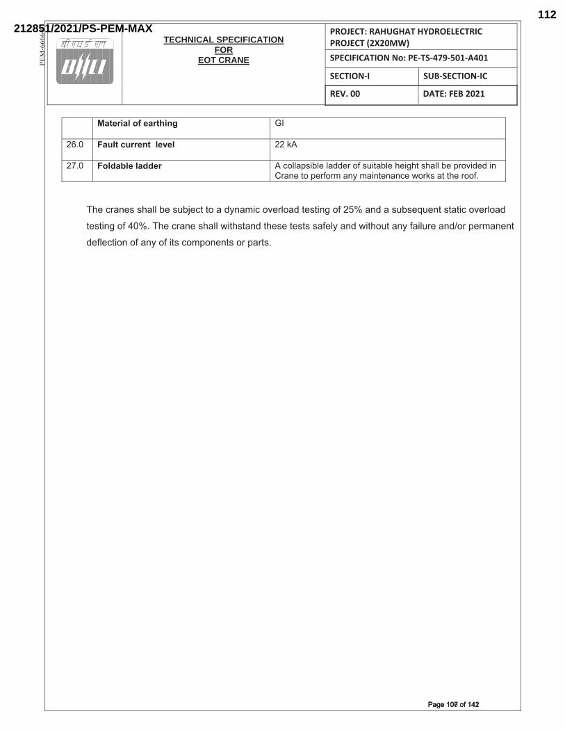
TECHNICAL SPECIFICATION
FOREOT CRANE
PROJECT: RAHUGHAT HYDROELECTRIC PROJECT (2X20MW) SPECIFICATION No: PE-TS-479-501-A401
SECTION-I SUB-SECTION-IC
REV. 00 DATE: FEB 2021
PE
M-6
66
6-0
� Material of earthing �_�
��^�� Fault current level ���`��
�^�� Foldable ladder ��+�""�<#�?"��"�>>������#[�*�?"��$���$*�#$�""�?��<��\�>�>��!����!��*��<�����Z��!@�Z��!*�!�!+��]��`#��*�*$������^��
�$��+��!�#�#$�""�?��#[?��+*�*����>@!�Z�+��\��"��>�*�#*�!����������!>���#[?#��[�!*�#*�*�+��\��"��>�
*�#*�!��������^��$��+��!��#$�""�]�*$#*�!>�*$�#��*�#*#�#���"@��!>�]�*$�[*��!@����"[����!>����<��Z�!�!*�
>��"�+*��!�����!@�����*#�+�Z<�!�!*#����<��*#^
���������������Page 107 of 142Page 107 of 142
212851/2021/PS-PEM-MAX112
TECHNICAL SPECIFICATION
FOREOT CRANE
PROJECT: RAHUGHAT HYDROELECTRIC PROJECT (2X20MW) SPECIFICATION No: PE-TS-479-501-A401
SECTION-II SUB-SECTION-IIA
REV. 00 DEC 2020
PE
M-6
66
6-0
SUB SECTION-IIA
STANDARD TECHNICAL REQUIREMENT (MECHANICAL)
��������������Page 108 of 142Page 108 of 142
212851/2021/PS-PEM-MAX113
TECHNICAL SPECIFICATION
FOREOT CRANE
PROJECT: RAHUGHAT HYDROELECTRIC PROJECT (2X20MW) SPECIFICATION No: PE-TS-479-501-A401
SECTION-II SUB-SECTION-IIA
REV. 00 DEC 2020
PE
M-6
66
6-0
DOUBLE GIRDER EOT CRANE
1.0.0 SCOPE
This specification covers the design, material, manufacture, assembly, inspection and testing at
manufacturer works for EOT cranes and shall be applicable unless the requirements are addressed
otherwise in BHEL / BHEL’s Customer approved documents.
2.0.0 CODES AND STANDARDS
The equipment to be supplied under this specification shall conform to the following codes and
standards (latest revisions) unless otherwise specified hereinafter.
i) IS 807 Codes of Practice for Design, Manufacture, Erection and Testing (Structural Portion) of cranes and hoists
ii) IS: 3177 Code of Practice for Design of Overhead Travelling Cranes and Gantry Cranes other than steel work cranes.
iii) IS: 2266 Specification for steel wire ropes for general Engineering purposes. iv) IS: 4029 Guide for testing induction motor (for temperature rise). v) IS: 15560 Steel hooks for standard shank design. vi) IS: 3443 Specification for crane rail section. vii) IS: 325 Three phase induction motors viii) IS: 900 Code of practice for installation and maintenance of induction motors. ix) IS: 4237 General requirement of switchgear and Control gear for voltage not
exceeding 1000V. x) IS:434 (Part I) Copper conductors rubber insulated cables for voltage up to 1000V. xi) IS 1596 Polyethylene insulated PVC sheathed cables xii) IS 3043 Code of practice Earthing xiii) IS: 3938 Electric Wire Rope Hoists. xiv) IS: 2147 Degree of protection provided by enclosures for Low voltage switchgear
and control gear. xv) IS: 1554 Part I PVC insulated (Heavy-duty) electric cables for working voltages up to and
including 1100 volts. xvi) IS: 691 Flexible trailing cables rubber insulated. xvii) IS: 1653 Steel conduits for general engineering purposes. xviii) IS: 2509 Rigid non-metallic conduit for electric-Installations xix) IS: 2062 Steel for General Engineering purposes. xx) IS: 1030 Carbon Steel castings for general engineering purposes. xxi) IS: 1570 Schedules for Wrought steels. xxii) IS: 1875 Carbon steel billets, blooms, slabs and bars for forgings. xxiii) IS: 808 Dimensions for hot rolled steel beam, column, channel and angle
sections. xxiv) IS: 1852 Rolling and cutting tolerances for Hot rolled steel products. xxv) IS: 2291 Tangential Keys and Keyways. xxvi) IS: 2292 Taper Keys and Keyways. xxvii) IS: 3961 Recommended current rating for cables. xxviii) IS: 694 PVC insulated cables for working voltages up to and including 1100V) xxix) IS: 1554 (part-I) PVC insulated (heavy duty) electric cables:
Part 1: for working voltages up to and including 1100 volts. xxx) IS: 4289 Flexible cables for lifts and other flexible connections:
��������������Page 109 of 142Page 109 of 142
212851/2021/PS-PEM-MAX114
TECHNICAL SPECIFICATION
FOREOT CRANE
PROJECT: RAHUGHAT HYDROELECTRIC PROJECT (2X20MW) SPECIFICATION No: PE-TS-479-501-A401
SECTION-II SUB-SECTION-IIA
REV. 00 DEC 2020
PE
M-6
66
6-0
Part 1: Elastomer insulated cables. xxxi) BS: 970 Wrought steels in the form of blooms, billets, bars and forgings xxxii) IS: 5749/ BS
3017 Specification for Forged Rams horn Hooks
Indian electricity rules - 1956.
In the event of any conflict between the specification (between section-I and section II), the
more stringent of the two as per interpretation of purchaser shall govern.
3.0.0 DOUBLE GIRDER EOT CRANE
3.1.0 DESIGN REQUIREMENTS
3.1.1 The crane shall be designed in accordance with the latest edition of IS-3177, IS-807 and any other
standard as referred there in and subject to any modification and requirement as specified herein
after. Class of crane mechanism shall correspond to that of the crane requirement and as
specified elsewhere.
3.1.2 Safety devices should be provided with all equipment/parts covered under this specification.
3.1.3 Parts requiring replacement or lubrication shall easily be accessible without dismantling the other
equipment or structures. All electrical cables shall be laid to comply with recognized standards and
purchaser’s requirements.
3.1.4 For welded construction such as bridge girders, end carriages, rope drum, gearboxes etc. steel
shall be conforming to IS-2062 quality. Welding shall be carried out only by qualified welders and
subjected to NDT as specified in Quality Plan.
a. Welding shall be performed by shielded electric arc, gas or other approved methods. The
electrodes used for welding shall conform to AWS A5.1.
b. Wherever lateral welding of the main plates of box girders are required, it shall be butt-
welded.
c. Qualification of welding procedure and welder: These shall be carried out as per ASME Boiler
and Pressure vessel code Sec. IX - Welding and brazing qualifications.
d. Electrode designations and qualifications shall be as per AWS A 5.1.
e. Electrodes should be of radiography quality with heavy covering as per IS: 814 and relevant
requirement of ASME Sec IX and IIC.
f. Bare electrodes as per IS: 7280 and flux wire combination as per IS: 3613.
3.1.5 No cast iron part shall be used on the crane and its accessories.
3.1.6 Guard shall be provided on crane to prevent the hoist ropes coming in contact with down shop
leads.
���������������Page 110 of 142Page 110 of 142
212851/2021/PS-PEM-MAX115
TECHNICAL SPECIFICATION
FOREOT CRANE
PROJECT: RAHUGHAT HYDROELECTRIC PROJECT (2X20MW) SPECIFICATION No: PE-TS-479-501-A401
SECTION-II SUB-SECTION-IIA
REV. 00 DEC 2020
PE
M-6
66
6-0
Guards/ rail sweep of an approved design, which will push forward or off the track any object such
as a person foot or arm, placed across it. Guards shall be attached to each end of the end
carriages.
Suitable guards shall be provided to revolving shafts, coupling etc.
3.1.7 All cables shall be clamped individually. All trailing cables shall be clamped with PVC or non-
metallic clamp.
3.1.8 Walkways of CT shall be of chequered plate minimum 6 mm thick O/P at least 800 mm clear inside
with non-skid toe plates 8mm thick, projecting 100 mm above the floor. Walkways shall be of rigid
construction and designed to sustain a distributed load of not less than 300 kg/ sq. mm.
Intermediate posts for supporting handrails shall not be spaced more than 1.5 meters apart.
Ladders provided shall have at least 450mm clear width with 20 mm rungs (rods) spaced 300 mm
apart.
3.1.9 All wheels, couplings, open gear etc. shall be provided with covers.
3.1.10 All bolts except those with locknut shall be provided with grip lock nuts or spring washers.
3.1.11 Fasteners for pedestal blocks, motors, gearboxes etc. shall be easily removable from the top. Studs
shall not be used as fasteners for mechanical items except for fixing covers.
3.1.12 Defects in the material like fractures, cracks, blowholes, pitting etc. are not allowed. Rectification
of any such flaw is permissible only with the approval of the purchaser.
3.1.13 All parts of the crane shall be thoroughly cleaned of mill scales, rust or foreign matter and then
painted as per the specification requirements.
The permissible camber shall be shown in drawing or data sheet submitted for approval.
3.2.0 STRUCTURAL DETAILS
3.2.1.0 Crane structure shall be designed in accordance with the latest edition of IS-807 after taking the
following additions/deviations as applicable.
3.2.1.1 Black bolts shall not be used in the main structure of the crane. The calculated strength of other
bolted joints in structural members shall not be less than net strength of member plus 25%.
3.2.1.2 The calculated strength of riveted joint or joints made by friction grip bolts in structure members
shall be not less than the calculated net strength of the member.
3.2.1.3 Bolts used in shear shall be fitted in to reamed hole.
3.2.1.4 Nuts and Bolts will be as per IS:1363, IS: 1364 and IS: 1367. High-tension friction grip bolts as per
IS: 3757 and High- tension friction grip nuts as per IS: 6623.
3.2.1.5 Transverse filled welding on load carrying member shall be avoided.
���������������Page 111 of 142Page 111 of 142
212851/2021/PS-PEM-MAX116
TECHNICAL SPECIFICATION
FOREOT CRANE
PROJECT: RAHUGHAT HYDROELECTRIC PROJECT (2X20MW) SPECIFICATION No: PE-TS-479-501-A401
SECTION-II SUB-SECTION-IIA
REV. 00 DEC 2020
PE
M-6
66
6-0
3.2.1.6 All butt welds on structural members subjected to tensile stress shall be of radiographic quality as
ASME Sec VIII Div.1 acceptance norms.
3.2.1.7 Fillet welding on load carrying members shall be avoided.
3.2.1.8 For load carrying members the component plates, bars, angles and other rolled sections shall be
minimum 8mm thick. For tubes having both ends sealed the minimum thickness shall be 6 mm. For
unsealed tubes the minimum thickness shall be 8mm.
3.2.1.9 The cranes working out door or in corrosive environment, an allowance of 1.5 mm shall be added
to the calculated thickness.
3.2.1.10 Minimum thickness of chequered plates for platform shall be over 6 mm over plain. Chequered
plates shall not be considered for strength calculations of load carrying members.
3.2.1.11 Splice shall be designed to resist all the forces and moments to which it is subjected to plus 50%
thereof.
3.2.1.12 However, in no case the strength developed by the splice shall be less than 50% of the effective
strength of the material spliced. Splices shall be proportioned and arranged, so that the gravity
axis of the splice in line with the gravity axis of the member joined so as to avoid the eccentricity
of the loading.
3.2.1.14 The material of construction of the major components shall be as specified in the
specification/data sheet. Manufacturer are however free to use alternate material which are
superior for the intended service. But in all the cases, prior concurrence of the purchaser is must.
3.2.1.15 Splices shall be designed to resist one and half times the forces and moments to which it is subjected,
but in no case it shall be less than 2/3rd of the effective strength of the material spliced except that
splices in the webs of the plate girders shall be designed for full strength of the web in shear as well
as bending. For splicing tension members, the net section of the splice plate shall be ten percent
more than that of the material spliced. Splices shall be proportioned and arranged, so that the gravity
axes of the splices are in line with the gravity axis of the member to avoid eccentricity.
3.2.2 Bridge Girder
3.2.2.1 The bridge girder shall consist of a box construction with double Web plate girders or lattice
girders and shall be of adequate strength to withstand the rolling loads and other stresses it is
subjected to. The design of the girder shall be in accordance with latest edition of IS- 807.
3.2.2.2 Maximum deflection of the bridge girder, with safe working load, shall not exceed 1/900 of the
span or as per latest IS. The girder shall be supported on the centerline of LT wheels during the
deflection check. The girder shall be cambered by an amount by an amount equal to the
maximum deflection. ���������������Page 112 of 142Page 112 of 142
212851/2021/PS-PEM-MAX117
TECHNICAL SPECIFICATION
FOREOT CRANE
PROJECT: RAHUGHAT HYDROELECTRIC PROJECT (2X20MW) SPECIFICATION No: PE-TS-479-501-A401
SECTION-II SUB-SECTION-IIA
REV. 00 DEC 2020
PE
M-6
66
6-0
3.2.2.3 Box section shall be adequately reinforced by internal diaphragms and ribs to withstand the most
severe combination of load that may develop under different working conditions. Additional
Internal diaphragms shall be provided at points where external members are welded for
providing support to drives etc.
3.2.2.4 Box girders shall be provided with end plates sealing. Diaphragms inside the girder shall extend
to the full - width & depth of the girder and the web plates shall be reinforced by angles all along
the full length of the plates spaced midway between the diaphragms. Full depth diaphragms or
stiffeners shall be furnished at bridge drive supports and below the line shaft bearings.
3.2.2.5 Short diaphragms shall be furnished and are required to transmit the trolley wheel loads to the
web plates. Trolley rail section shall not be considered into design of bridge girders.
3.2.2.6 Full length chequered platforms on both side shall be provided on the side of bridge girders as
specified in data sheet - A.
3.2.2.7 There should not be accumulation of water/oil inside the box girders. If required breathing holes
can be provided for expansion / contraction, due to change in temperature. Tapped (threaded)
holes shall be provided with ½” NPT plug in the bottom of the girders, at both ends, to drain off
any accumulation of water / Oil inside the girder. Instruction shall be painted on the girders to
remove the plug and check for water/oil before lifting. Plug shall be replaced after installation.
3.2.2.8 All connection splices shall be designed for full strength of member of loads indicated unless
otherwise approved. Beams and connections shall be designed for 60% of shear capacity of beam
section plus additional axial load if any. Not more than one splice shall be provided to make up full
length of number.
3.2.2.9 Maximum Span/ Depth ratio for Girder
� Plate Girder : 18
� Lattice Girder : 12
3.2.3 End carriage
3.2.3.1 End carriages shall be fabricated from rolled steel section or plates. End carriage shall be of ample
strength to resist all stresses likely to be imposed on them under service conditions including
collision with other cranes or stops. The length of the end carriages shall be such that no other
part of the crane is damaged in collision. End carriage shall be so designed as to distribute the load
evenly between the wheels from each bridge girders.
3.2.3.2 The wheel base shall not be less than 1/5th of the span. End carriage shall be fitted with safety
stop to prevent the end carriage falling more than 25 mm in the event of breakage of a track
wheel, bogies or axle. ���������������Page 113 of 142Page 113 of 142
212851/2021/PS-PEM-MAX118
TECHNICAL SPECIFICATION
FOREOT CRANE
PROJECT: RAHUGHAT HYDROELECTRIC PROJECT (2X20MW) SPECIFICATION No: PE-TS-479-501-A401
SECTION-II SUB-SECTION-IIA
REV. 00 DEC 2020
PE
M-6
66
6-0
3.2.3.3 Suitable jacking pads at a suitable height from rail level shall be provided on each crane for crane
jacking. Jacking pad dimensions shall be suitable for full seating of the jacking pad seat without
any instability. When changing the track wheel, jacking pads shall not interfere with replacement
of track wheel.
3.2.4 Crab (Trolley)
3.2.4.1 The crab frame shall be built from heavy steel section, welded properly to form single piece frame
& to resist vertical, lateral and torsional strain and to support all loads without undue deflection. It
should be properly machined to receive hoisting mechanism, cross traverse
arrangement/mechanism, wheels etc. etc.
3.2.4.2 Sheaves, part of hoisting mechanism, shall be so arranged on trolley that rope reeling
arrangement shall ensure lifting of load in vertical line with minimum of swing or side movement.
Trolley shall be provided with chequered plates all over except for opening required for ropes and
equipment foundation. Equipment foundation shall not be welded/ supported on chequered
plates. Toe plates 100 mm high and 6mm thick shall be provided around opening provided for
movement of ropes. Suitable railing shall also be provided around the opening for rope in case
the opening is large.
3.2.4.3 Platforms and Ladders
a) Safe means of access shall be provided to every place where any person engaged in the
examination or maintenance of the crane has to work. Adequate handholds and footholds shall be
provided as necessary..
b) Every platform shall be provided with steel chequered plate top and be securely fenced with
1050 mm high double tier hand rails and toe boards. Platforms shall be of sufficient width to enable
normal maintenance work to be undertaken safely
c) Safety hand railing of tubular construction 32 mm NB Medium class of IS: 1239 having top and
bottom rail at height of 1100 mm and 600 mm and vertical post spacing not exceeding 1750 mm
with provision of kick plate (100 mm high and 6mm thick) shall be provided on bridge walkways and
on end carriages, staircases, trolley and at any other place where access is provided. Bends shall be
neat and made by machine. The top rail should be so laid that there is no intermediate obstruction
and hand need not be lifted from rail while walking
d) In case lattice riveted construction is offered for the bridge girder, full length chequered plate
platform with adequate headroom shall also be provided at bottom chord level for periodic
checking of all rivets/bolts and other items.
���������������Page 114 of 142Page 114 of 142
212851/2021/PS-PEM-MAX119
TECHNICAL SPECIFICATION
FOREOT CRANE
PROJECT: RAHUGHAT HYDROELECTRIC PROJECT (2X20MW) SPECIFICATION No: PE-TS-479-501-A401
SECTION-II SUB-SECTION-IIA
REV. 00 DEC 2020
PE
M-6
66
6-0
3.2.5.0 Brief description of crane operation, Maintenance and periodical lubrication etc. typed in English
and in local language neatly framed in a permanent frame for easy reference.
3.2.6.0 Suitable inspection cages to accommodate two persons to facilitate inspection of DSL.
3.3.0 MECHANICAL
3.3.1 Rope drums
Rope drums shall be of mild steel plate fabricated/ cast steel/ as per IS 3177. All fabricated rope
drums shall be stress relieved. The drum shall be so designed to take full length of hoisting rope in
single layers. The end of the rope shall be anchored to the drum in such a way that the charger in
readily accessible. Each rope shall have not less than two (2) full turns on the drum when the hook
is at lowest position not taking into consideration the turns covered by the rope in charge. One
spare groove shall be provided for each rope drum when the hook is at the highest position. Each
rope end shall be clamped with minimum two clamping wedges with at least two bolts on each
clamping arrangement.
The pitch diameter of the drum shall be as per IS - 3177 or as specified elsewhere. The depth of
the grove shall not be less than 0.35 times the rope diameter. Each rope shall be clamped to drum
with two clamp wedges with at least two numbers of bolts on each clamping arrangement.
For evaluation of Radiography the designed thickness of the drum (top of crest to ID) shall be
taken into consideration and not the thickness of plate selected.
3.3.2 Hoist ropes
Ropes of steel core as specified in Data sheet” A” shall be of 6x36 or 6x37 construction of extra
flexible plough steel as per IS 2266 having minimum UTS of 1770 kN.
3.3.3 Rope sheaves
Sheaves shall be of cast (Castings to IS: 1030 Gr. II with Y.P. greater than 50% of UTS) or forged
steel. All sheaves shall be identical, however, exception may be made for equalizer sheave. Sheave
groove shall be ground finished for getting increase rope life. Equalizer sheave shall be arranged to
turn and swivel in order to maintain rope alignment under all circumstances.
3.3.4 Wheels
LT & CT wheels shall be double flanged with straight tread. The wheels shall be capable of taking
up misalignment in span as specified. Solid wheel shall either be of forged steel or as specified in
Data sheet. The wheel rim shall be with minimum hardness of BHN 300-350. Wheels may be
either hardened on tread portion as per IS –3177 or Volume hardened. Contact stresses between
wheels and rails should be within permissible limits.
3.3.5 Buffer ���������������Page 115 of 142Page 115 of 142
212851/2021/PS-PEM-MAX120
TECHNICAL SPECIFICATION
FOREOT CRANE
PROJECT: RAHUGHAT HYDROELECTRIC PROJECT (2X20MW) SPECIFICATION No: PE-TS-479-501-A401
SECTION-II SUB-SECTION-IIA
REV. 00 DEC 2020
PE
M-6
66
6-0
Each End carriage shall be provided with buffer as per data sheet ‘A’. Buffers should be so located
that removal is not required while changing wheels or bogies. Buffers shall have sufficient tension
on energy absorption capacity to bring the unloaded crane to rest from the speed of 100% of the
rated speed to zero speed. Buffer is to be fitted to each end of carriage assembly and crab so that
buffer contact takes place before the bridge or trolley reaches the end of rail.
3.3.6 LT drive
The bridge motion shall be achieved by suitable drive arrangement as specified
elsewhere. When twin drives are used, these shall be operating in unison to avoid skewing effect.
The drives shall be interlocked for simultaneous starting, stopping & speed control.
3.3.7 CT drive
Trolley drive shall be achieved by suitable drives & power shall be transmitted to the geared
wheel by means of pinions mounted on both ends of the output shaft.
3.3.8. Gearing
3.3.8.1 Gears in speed reducer unit for bridge drive, hoists and trolley drive gearing shall be enclosed in
substantial housing and shall operate in oil bath. The housing shall be of sufficient design not to
permit temperature in excess of 90oC for the oil bath. Spur and helical gearing shall normally be
used for all motions. Worms and bevel gears shall not be used. First high-speed reduction shall be
through helical gears. All gears shall be hardened and tempered and of alloy steel with machine
cut teeth 1.6 Micron finish or better and lapped with some minimum applied load to remove high
spots and to improve tooth contact. Cast alloy steel is acceptable only for gears in the last stage of
speed reduction. Surface hardening of teeth is not acceptable. Gear teeth shall preferably be cut in
metric module system. Gears shall be designed to meet requirement of crane duty as per IS: 3177.
The ratings of gears shall be established as per IS: 4660.
3.3.9 Gear Box
3.3.9.1 All gears shall be completely covered and enclosed in oil tight casing & sealed with gasket. In case
of totally enclosed gearboxes, splash or automatic lubrication system shall be used. Covers shall
be split horizontally at each shaft centre line, so that top half can be removed for inspection and
repair with out disturbing the bottom half. Gear shafts shall be supported on ball/roller bearings
mounted in gearbox unless specially agreed otherwise. The gear boxes shall be provided with
breather, air vent, oil level indicator, dip stick, drain plug and lugs for lifting.
Radial clearance between the gear boxes inner surface and outside diameter of the gears shall be
at least 1.25 times the depth of larger gear tooth inside the gear box or 20mm which ever in
���������������Page 116 of 142Page 116 of 142
212851/2021/PS-PEM-MAX121
TECHNICAL SPECIFICATION
FOREOT CRANE
PROJECT: RAHUGHAT HYDROELECTRIC PROJECT (2X20MW) SPECIFICATION No: PE-TS-479-501-A401
SECTION-II SUB-SECTION-IIA
REV. 00 DEC 2020
PE
M-6
66
6-0
higher. Facial clearance between inner surface of gearbox and face of gear or pinion shall be at
least 20 mm. Gearbox shall be inspected in line with QP and as per PEM (Q)/001 enclosed.
3.3.9.2 The gearboxes shall be of mild steel or cast steel. All fabricated gearboxes shall be stress relieved
at a temperature between 590 to 680 deg. C. The temperature shall be maintained within + 20
deg. C and at no time during the soaking cycle the temperature shall fall below 590 deg. C or
exceed 680 deg. C. Soaking shall be done for a period proportionate to 1 (one) hour/ 2.5 cm. of
wall thickness.
3.3.10 Bearing
3.3.10.1 Ball and roller antifriction bearing of attached sub-vendor list, make shall be used throughout,
except where specified otherwise. Drive side bearing on Hoisting equipment shall be ball / roller
bearing type. Rated life of ball and roller bearing shall be not less than total working life as per
data sheet-A. Life of bearing shall be calculated in accordance with manufacturer’s
recommendations.
3.3.10.2 Provision shall be made for service lubrication of all bearings. Lubrication arrangement and
clamping shall be done neatly. Bends in pipe shall be done with the help of machine. Bearing
enclosures shall be designed as far as practicable to exclude dirt and shall prevent oil leakage.
Accessibility should be such that parts may be safely lubricated from the walkway or ladder when
the crane is not in motion.
3.3.11. Shafts, Couplings and axles
3.3.11.1 Shafts and axles shall be made from solid rolled or forged steel bars and shall have ample strength
and rigidity and adequate bearing surface. If shouldered, they shall be provided with fillets of
ample radius and /or be tapered to avoid stress concentration.
Motor shafts shall be connected to gearbox input extension shafts through flexible
gear coupling. Solid coupling shall be used for connecting intermediate lengths of long travel
shafts. For driving hoist drum full-geared couplings shall be used between hoists drum & hoist
gearbox output shaft. Couplings shall be of cast steel/wrought steel conforming to IS: 1030 grade
280-520 and shall be designed to suit service conditions.
3.3.11.2 Self-aligning type gear couplings shall be used between connection shafts to take care of transverse
as well as axial movement whenever necessary. Whenever components of considerable amount
of inertia are directly mounted on the high-speed shaft (e.g. brake drum, coupling etc.) they shall
be balanced statically to minimise vibration.
3.3.12 Repair Cage
���������������Page 117 of 142Page 117 of 142
212851/2021/PS-PEM-MAX122
TECHNICAL SPECIFICATION
FOREOT CRANE
PROJECT: RAHUGHAT HYDROELECTRIC PROJECT (2X20MW) SPECIFICATION No: PE-TS-479-501-A401
SECTION-II SUB-SECTION-IIA
REV. 00 DEC 2020
PE
M-6
66
6-0
A repair cage shall be provided on the inside of the end carriage for attending the main current
collectors. The repair cage shall be adequately sized to accommodate two persons. And guarded
for safety and correctly located for the intended service. Suitable access to the cage shall be
provided. Repair cage shall be provided at the corner of the crane.
3.3.13 Lifting hook
Standard hooks shall be used unless otherwise specified. These hooks shall conform to the latest
edition. All hooks used shall be in normalized condition only.
3.3.14 LIFTING HOOK BLOCK ASSY
3.3.14.1 Lifting hook block assembly shall be Ram shorn type or approved for capacity greater than 50 Tonnes
and point hook with Shank for capacity below 50 Tonnes and shall be of forged steel construction.
Hooks shall be manufactured from Blooms, billets, rounds by forging with forging ratio of at least
3:1. Hooks manufactured from plates are not acceptable. All hooks used shall be in normalized
condition only. Each hook shall be supported on ball or roller thrust bearing and shall rotate
freely.
3.3.14.2 The sheaves of the hook block shall be enclosed in a casing permitting generous lubrication of wire
ropes, sheaves and also preventing accidental tapping of hands.
3.3.15 Brakes
3.3.15.1 Selection and design of brakes shall be such as to meet the requirement. Brakes shall be designed
to suit 150% of torque transmitted to the brake drum with full load for hoist motions and 125% of
motor rated torque before de-rating for LT/CT motion. Brakes shall be provided as specified in
Data Sheet ‘A’. Brake drum shall be separately mounted and coupling halves shall not be used as
brake drum.
i) SERVICE BRAKE
Double shoe types & disc type service brakes shall be provided for each motion of the crane as/or
as specified in Data Sheet. The service brakes shall apply automatically when power supply to the
drive motor is cut off or fails.
ii) HOIST CONTROL
Hoist motion shall be provided with a self-contained sturdy braking system to control the
speed of hoisting as well as lowering motion. The braking system shall be reasonably uniform and
effective in all loads at any position.
3.4.0 ELECTRICAL
3.4.1 The scope of supply shall cover all electrical equipments comprising from Main isolating switch,
down shop leads, trolley conductors, current collectors etc. ��������������Page 118 of 142Page 118 of 142
212851/2021/PS-PEM-MAX123
TECHNICAL SPECIFICATION
FOREOT CRANE
PROJECT: RAHUGHAT HYDROELECTRIC PROJECT (2X20MW) SPECIFICATION No: PE-TS-479-501-A401
SECTION-II SUB-SECTION-IIA
REV. 00 DEC 2020
PE
M-6
66
6-0
3.4.1.1 Main Disconnecting/Isolating Switch fuse unit shall be provided at 1.5M above the operating floor
level at one end / at both the ends of bay length or in the middle as specified in the data sheet A.
Termination of incoming power supply cable to isolating switch fuse unit and further cable from
switch to down shop leads shall be included in the bidder’s scope of work. The switch shall be
provided with Power ON Red indication lamp.
3.4.1.2 Run way conductors (Down shop leads) shrouded conductor as specified in the data sheet A shall
have four conductors. One of the conductors shall be connected to earth grid for earthing
connections of all electrical equipment on the crane and shall be connected to suitable collecting
gear of earth conductor. Voltage drop across the down shop leads shall be less than 2% or
specified in data sheet “A”. It shall be supplied with brackets. Maintenance cage for DSL shall be
provided on crane.
3.4.1.3 The current collectors shall be with adequate current carrying capacity and shall maintain
adequate contact pressure. Spacing between current collectors shall be such as to provide suffi-
cient quenching area for sparks coming out of collectors surface. The collector system per
conductor shall spring loaded CI/carbon metallic shoes to maintain adequate contact pressure.
3.4.1.4 The cable, supplying power to crane trolley shall be flexible trailing cable as per IS-9968
Part I (latest edition) and mounted on retracting supports (festoon type).
3.4.2 DRIVE MOTORS
3.4.2.1 Crane Motors shall be totally enclosed, fan cooled and as per data sheet ‘A’. The starting torque of
motor shall not be less than 2.25 times the rated torque and pull out torque shall not be less than
275% of the rated full load torque of motor.. In case of VVVF drive system, the creep speed will be
achieved through VVVF drives and the motors for Main hoists, Auxiliary hoist, CT and LT will be
Squirrel cage. Hoisting drive motors shall be provided with antifriction roller / ball bearings on the
drive side.
3.4.2.2 Ambient correction factors as well as voltage /frequency correction factors depending up on the
ambient temperature and voltage /frequency variation shall be applied to de-rate the motors. The
minimum margin of 10% shall be considered over the calculated rating of the motor. The
protection class of the motors shall be as IP-55. Motors shall be tested at manufacturer’s works in
accordance with IS-325/as per agreed Quality plan & Reports shall be submitted for approval.
Motors shall comply with the requirement of IS-325 or as per the motor spec.
3.4.2.3 All the motors shall be provided with lifting lugs two earth terminals of adequate size to accept the
earthing conductors shall be provided at diametrically opposite points unless specifically designed
For higher speeds, motors shall be capable of with-standing 2.5 times the rated speed. ��������������Page 119 of 142Page 119 of 142
212851/2021/PS-PEM-MAX124
TECHNICAL SPECIFICATION
FOREOT CRANE
PROJECT: RAHUGHAT HYDROELECTRIC PROJECT (2X20MW) SPECIFICATION No: PE-TS-479-501-A401
SECTION-II SUB-SECTION-IIA
REV. 00 DEC 2020
PE
M-6
66
6-0
3.4.2.4 Motors shall be painted in line with painting instructions specified in Painting Scheme Annexure IV
attached along with the technical specification.
3.4.3 Limit switches
The hoist mechanism of the crane shall be provided with rotary type limit switch to open the
control circuit & in order to prevent the crane hook from over hoisting and over lowering, one
gravity type back up limit switch of hand reset type shall also be provided. This switch will operate
in the event of failure of main limit switch. Lever operated limit switches shall be provided at both
ends of longitudinal travel and cross traverse. These limit switches shall be self-reset type. The
limit switches shall be as per “Data Sheet A”
3.4.4 Switch
All switches shall be hand operated; air break, heavy duty, quick make and quick break type.
Incoming supply disconnect switch shall be interlocked with panel door so that the same cannot
be opened unless the switch is in OFF position. Safety Interlocks-Disconnect Switch-The operating
handle of the main/ safety disconnect switch shall be mechanically interlocked with enclosure
cover such that the same cannot be opened unless the switch is in OFF position. Main/ safety
disconnect switch shall have provision of pad locking in OFF position
3.4.5. Contactors.
Contactors shall be suitable for heavy duty, with current rating not less than connected motor full
load current. All reversing contactors shall be mechanically and electrically interlocked.
Each contactor shall be provided with three positive acting ambient temp. Compensated thermal
overload relay with adjustable setting to suit the motor current. The relay shall be hand reset type,
suitable for current. The relays shall be replaceable from front. The main contactor shall be
electrically interlocked so that it cannot close unless all the motor overload relays are RESET and
all controllers are in OFF position. The main contactor shall be also opened by means of
emergency push buttons and hoist limit switches.
3.4.6 Push button and lamp
Push button shall be spring return type with 2 NO + 2 NC contacts, rated 10A, 240 V AC. Indicating
lamps and lens shall be replaceable from front.
3.4.7 Protective Panel
3.4.7.1 The electrical protective panel shall be a cubicle fabricated from Cold rolled sheet steel not less
than 2.5mm for front & rear & 2mm for side, top & bottom portion with gland plate of 3mm thick
with lockable-hinged door. The control cabinet’s door shall be interlocked with the operating
handles of isolating switches of supply circuits so as to prevent opening of the door when an ���������������Page 120 of 142Page 120 of 142
212851/2021/PS-PEM-MAX125
TECHNICAL SPECIFICATION
FOREOT CRANE
PROJECT: RAHUGHAT HYDROELECTRIC PROJECT (2X20MW) SPECIFICATION No: PE-TS-479-501-A401
SECTION-II SUB-SECTION-IIA
REV. 00 DEC 2020
PE
M-6
66
6-0
isolating switch is closed. A device for bypassing the interlock shall also be provided. It shall be
dust and vermin proof with degree of protection as IP-52 or as specified in data sheet A. All the
equipment inside the panel shall have permanent identification. The panels shall be front
connected type with front-hinged door for access to wiring and terminals. Engraved nameplate
shall be furnished for all panels and also for the equipment and devices mounted there on.
The following minimum equipment shall be provided.
a) One triple pole air break type main contactor with thermal overload relay.
b) One triple pole main line connecting/disconnecting switch.
c) Emergency push button at convenient height for the operation for interruption of the entire
power.
d) Thermal overload relay for each drive. It shall be ambient temperature compensated and
adjustable type.
e) Contactors, timer and auxiliary contactors.
f) Portable Lighting Transformer rated for 415/24V.
g) Lighting Voltage Transformer with fuse 415/24V.
h) Control transformer with fuses.
i) Indicating lamps to indicate the live condition of all three phases.
j) Main supply ON/OFF lamps on the door of the protective panel.
k) Electrical interlock shall be provided to prevent the main contactor being closed unless all con-
trollers are in OFF position.
l) Other equipment as per supplier’s standard practice. Air break contactors shall conform to
category AC-4 duty. The main contacts shall have the rating for 5 Amps or as specified in the data
sheet A. The contactor drop off voltage shall be between 45-50% of rated voltage.
m) All internal wiring shall be identified with numbering rules at both ends as per the relevant wiring
diagram.
n) Each panel shall have internal illumination with fluorescent lamp. The inside of the
panel shall be painted white.
o) Separate terminal blocks shall be provided for terminating circuits of various voltage classes. At
least 20% spare terminals for the wire terminations shall be provided in the cabinet.
3.4.8 Starter Panel
Separate panels shall be provided for CT, LT & hoist motion (Main and Auxiliary), with following
type of items.
a. Contactors : AC4 duty for reversing applications ���������������Page 121 of 142Page 121 of 142
212851/2021/PS-PEM-MAX126
TECHNICAL SPECIFICATION
FOREOT CRANE
PROJECT: RAHUGHAT HYDROELECTRIC PROJECT (2X20MW) SPECIFICATION No: PE-TS-479-501-A401
SECTION-II SUB-SECTION-IIA
REV. 00 DEC 2020
PE
M-6
66
6-0
AC3 duty for non-reversing applications
b. Switches : AC23 for motor application.
AC22 for other application
c. Fuses : HRC
d. Overload relays: Temperature compensated bi-metallic with single phasing preventer.
3.4.9 MOTOR CONTROL PANEL
The motor control panels shall be dust and weatherproof to IP-54/55 or as specified in “Data
Sheet A” & shall be provided separate for each motion. The panel shall contain minimum the
following components.
a. Switch fuse unit with contacts of adequate rating for each motion.
b. Thermal overload relay for each drive. These shall be ambient temperature compensated
adjustable type.
c. Contactors, timers and auxiliary contactors.
d. The panel shall be provided with space heater. The space heater with thermostat shall be
located at the bottom of the panel and shall have individual ON/OFF switch.
e. Terminal blocks shall be stud or snap on type. A protective cover shall be fixed on top of
terminal blocks to prevent accidental contact. A minimum of 20% spare terminals shall be
provided.
f. Air break contactors shall be provided for main supply as well as for motors. They shall
confirm to category AC-4 as per IS-1322. These shall have three main contacts and 2 No. &
2 NC auxiliary contacts.
g. The main contacts shall have the ratings as per duty requirement but auxiliary contact
shall be rated for 5 amp 240V AC. The contactor drop off voltage shall be between 45-50%
of rated voltage. The contactor coil shall be suitable for 240V AC supply.
h. The auxiliary contactors shall have 4 No. + 4 NC contacts for control and interlocking
purposes. The contacts shall be convertible. The contacts rating shall be suitable for 5
amps at 240 Volts AC.
i. Adequate protection for overload and short circuit shall be provided for all the three
phases of each motor.
j. Double pole switch fuse unit for control circuit of the contractor ‘START (push button and
a pilot lamp with the red lens for indicating the contactor “CLOSED” shall be furnished.
3.4.11 Illumination
���������������Page 122 of 142Page 122 of 142
212851/2021/PS-PEM-MAX127
TECHNICAL SPECIFICATION
FOREOT CRANE
PROJECT: RAHUGHAT HYDROELECTRIC PROJECT (2X20MW) SPECIFICATION No: PE-TS-479-501-A401
SECTION-II SUB-SECTION-IIA
REV. 00 DEC 2020
PE
M-6
66
6-0
Crane lighting and space heating system shall be designed for 240V, 1Phase 50Hz supply and
receptacle system with 24V 1Phase 50Hz supply or as specified in the Data sheet A. Suitable dry
type transformers shall be furnished for this purpose, complete with isolation facility and
Primary/secondary fuses.
a. Branch Circuits for lighting and receptacles shall be individually protected by switch fuse
units.
b. CFL fixtures shall be used for lighting operator's cabin and bridge platform.
c. 60W bulkhead fittings with fluorescent lamp shall be used for lighting bridge platform.
d. Four (4) no.s - 250 W HPSV lamps shall be provided under the bridge as specified in the
data sheet “A”
e. All lighting fixtures shall be mounted with anti-vibration mounting and shall be easily
accessible for maintenance.
f. 24V - 5A - 3 pin industrial socket outlets shall be provided. Minimum four (4) on the bridge
along the walk way on both sides of full length platforms.
g. One (1) portable 40 W hand lamp with min. half span length flexible cable for inspection of
crane components.
3.4.13 Grounding
3.4.13.1 The crane structure, motor frame and all other electrical equipment/s shall be grounded in
accordance with the Indian Electricity Rules. The connections from Crane Bridge to 4th conductor
of down shop leads shall be by means of current collector.
3.4.13.2 The equipment fed by flexible cables shall be grounded by means of fourth core provided in the
flexible trailing cable. Pendent push button station shall be earthed
Separately.
3.4.13.3 The crane structures, motor frames & metal of all electrical equipment on EOT crane shall be
effectively grounded as per Indian Electricity Rules. Grounding of the crane to the nearest pit shall
be in manufacturer’s scope.
3.4.14 Red warning light 3 Nos. shall be provided at both ends of the gantry girder to indicate the
aliveness of DSL.
3.4.15 Wiring Systems
a. All electrical equipment, accessories and wiring shall have tropical protection involving special
treatment of insulation and metal against fungus, insects and corrosion. All cabling shall be
carried out using XLPE insulated fire resistant (FRLS) cables & wiring by Heat resistance PVC
wires with stranded conductor ���������������Page 123 of 142Page 123 of 142
212851/2021/PS-PEM-MAX128
TECHNICAL SPECIFICATION
FOREOT CRANE
PROJECT: RAHUGHAT HYDROELECTRIC PROJECT (2X20MW) SPECIFICATION No: PE-TS-479-501-A401
SECTION-II SUB-SECTION-IIA
REV. 00 DEC 2020
PE
M-6
66
6-0
b. All wiring shall be done with 1100V grade fire resistance PVC insulated wire in conduits or by
1100V grade PVCA PVC cables with extruded inner sheath.
c. For selecting the cable rating, cable for power wiring, consideration shall be given to the
motor duty, ambient temperature grouping and disposition of the cables voltage drop etc.
d. Armoured cables or un-armoured running through the flexible conduits may be used for
power wiring / control and auxiliary circuit wiring shall run through flexible conduits.
e. Each motor shall be wired independently. Power and control wiring shall be effectively
separated.
f. Each wire shall be identified at both ends with wire designation in accordance with circuit
wiring diagram.
g. All wire termination to the panels shall be provided with clamp type connections screw.
Screw Type terminals with screw directly impinging on conductors are not acceptable.
h. Multi way terminal blocks complete with screw nut, washer and marking strips shall be
furnished for terminating the panel wiring.
i. Not more than two wires shall be connected to any terminal on either side of terminal block.
If necessary number of terminals shall be jumped together to provide the wiring points
j. Each terminal block shall be marked with designation in accordance with conductors wiring
diagram.
���������������Page 124 of 142Page 124 of 142
212851/2021/PS-PEM-MAX129
TITLE SPECIFICATION NO.
TECHNICAL SPECIFICATION
FOR VVVF DRIVE SECTION -D 24.01.2014
2 X 660 MW OPGCL IB VALLEY TPS, Rev 00
BANHARPALLI 1 OF 5
PE
M-6
666
-0
1.0 General a) This part of the specification describes the general requirements for the Variable
Voltage Variable frequency Drives, herein referred to as AC Drives, for use with standard IEC design AC squirrel cage induction motors. The nominal values, the standard documents and the drive’s minimum performance are defined in this part. To avoid any mismatch between the motor and its control equipment, the AC Drive shall be capable of auto adjustment by automatic measurement of the motor parameters with/without motor rotation.
b) Inverter construction and related devices: Construction shall be divided in 3 broad sections. Section one converts AC Supply into
DC supply. Section 2 Converts and controls DC supply into AC Supply with regulation. Section 3 shall be used for braking action of the motor and Dynamic Braking Unit (DBU) can be inbuilt or external depending upon the drive capacity. VVVF can be used in open loop (without external speed feed back) like in Travel motions or close loop (With external speed feed back) like in Hoist motions. Chokes on input supply side are generally used in crane application for power regulation. Like all other electronic / electric devices VVVF drives are also protected by MCB / MCCB / Fuses. VVVF drives are sensitive to temperature and hence drive internal as well as external cooling fans are provided.
c) Programming of VVVF Drives. VVVF drives shall be programmable and for that purpose detachable digital Operator
display unit shall be supplied along with the VVVF having required buttons for setting the user constant, functions etc. The VVVF drive is to be fine tuned by matching the motor parameters and setting the parameters on full load.
d) VVVF drives shall be connected with power supply and these drives generate their
own low voltage control supply. Potential free contacts shall be connected to this control supply and few programmable control terminals. Starting / stopping / set speeds operations of VVVF drive shall be achieved by above control connection.
e) VVVF shall give smooth control over acceleration and deceleration making the motion
jerk free and using Variable voltage variable frequency limits the inrush current to the squirrel cage motors. VVVF provides controlled torque to the motor due to which crane operations are jerk free.
1.1 Experience The Frequency Converter Manufacturer shall have adequate experience in frequency
converter manufacturing and have adequate business volume in order to provide credibility in his commitments and a capability of long term support.
1.2 Local support
Page 93 of 145
II B
PE-TS-479-501-A401
���������������Page 125 of 142Page 125 of 142
212851/2021/PS-PEM-MAX130

TITLE SPECIFICATION NO. PE-TS-391-501-A001
TECHNICAL SPECIFICATION
FOR VVVF DRIVE SECTION -__� 24.01.2014
2 X 660 MW OPGCL IB VALLEY TPS, Rev 00
BANHARPALLI 2 OF 5
PE
M-6
666
-0
The Supplier shall have a permanent representative office with a trained and skilled support staff, in the country where the goods are delivered, in order to prove his commitment for local support and to provide a channel for communication.
The engineers employed by the Supplier’s regional office shall be certified by the
Manufacturer and provide start-up service including physical inspection of the drive, connected wiring and final adjustments, to ensure that the AC Drive meets the required performance.
The Supplier shall be able to give basic drives training to the Customer’s engineers,
preferably on the site. The training shall, as a minimum, include system concepts and basic troubleshooting.
2.0 Basic requirements for the AC Drives 2.1 General requirements The AC Drive shall comply with National(country of origin) and International standards
and the recommendations for electrical industrial control devices (IEC, EN, UL, NFC, VDE).
The AC Drive shall be of the most modern design, yet user friendly and be simple to
install, commission and maintain. The AC Drive shall be able to start and control the speed of a standard squirrel cage induction AC motor. The AC Drives shall be : CE marked, conforming to European Low Voltage (73/23/CEE and 93/68/CEE) and EMC (89/336/CEE) Directives, UL/CSA marked according to UL 508C.
The AC Drives have to be built to comply with the IEC standards. The AC Drive shall be a digitally controlled drive, using, at least, the Pulse Width
Modulation (PWM) with flux vector control open loop(for travel ) and closed loop(for hoist). It shall have diodes / thyristors in rectifier and IGBT’s in the inverter section in their entire power range, and it shall have the following minimum specifications.
Rated Input Voltages 380V -15% 480V +10%, three-phase Rated Input Frequency 50Hz +/- 5% Output Voltage 0 – Input voltage, three-phase Output Frequency Range 0 to 400 Hz Acceleration / Deceleration Time 0.01 – 999s, adjustable, linear, with S,
with U or customised shapes
Overload capability (Constant Torque) 150% of nominal current for 1min. Operating ambient Temperature -10°C up to 50°C(shall be derated suitably
Page 94 of 145
PE-TS-410-501-A002PE-TS-479-501-A401
���������������Page 126 of 142Page 126 of 142
212851/2021/PS-PEM-MAX131
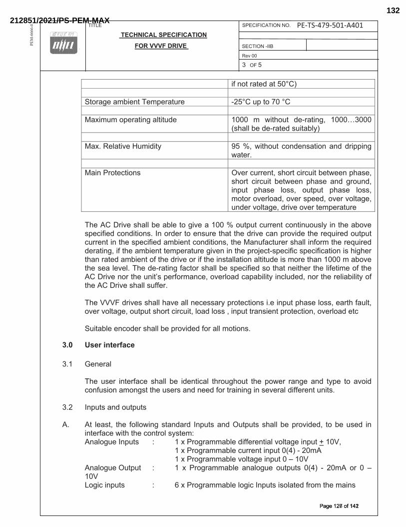
TITLE SPECIFICATION NO. PE-TS-391-501-A001
TECHNICAL SPECIFICATION
FOR VVVF DRIVE SECTION -__� 24.01.2014
2 X 660 MW OPGCL IB VALLEY TPS, Rev 00
BANHARPALLI 3 OF 5
PE
M-6
666
-0
if not rated at 50°C) Storage ambient Temperature -25°C up to 70 °C Maximum operating altitude 1000 m without de-rating, 1000…3000
(shall be de-rated suitably) Max. Relative Humidity 95 %, without condensation and dripping
water. Main Protections Over current, short circuit between phase,
short circuit between phase and ground, input phase loss, output phase loss, motor overload, over speed, over voltage, under voltage, drive over temperature
The AC Drive shall be able to give a 100 % output current continuously in the above
specified conditions. In order to ensure that the drive can provide the required output current in the specified ambient conditions, the Manufacturer shall inform the required derating, if the ambient temperature given in the project-specific specification is higher than rated ambient of the drive or if the installation altitude is more than 1000 m above the sea level. The de-rating factor shall be specified so that neither the lifetime of the AC Drive nor the unit’s performance, overload capability included, nor the reliability of the AC Drive shall suffer.
The VVVF drives shall have all necessary protections i.e input phase loss, earth fault, over voltage, output short circuit, load loss , input transient protection, overload etc
Suitable encoder shall be provided for all motions.
3.0 User interface 3.1 General The user interface shall be identical throughout the power range and type to avoid
confusion amongst the users and need for training in several different units. 3.2 Inputs and outputs A. At least, the following standard Inputs and Outputs shall be provided, to be used in
interface with the control system: Analogue Inputs : 1 x Programmable differential voltage input + 10V, 1 x Programmable current input 0(4) - 20mA 1 x Programmable voltage input 0 – 10V Analogue Output : 1 x Programmable analogue outputs 0(4) - 20mA or 0 –
10V Logic inputs : 6 x Programmable logic Inputs isolated from the mains
Page 95 of 145
PE-TS-410-501-A002
Page 221
PE-TS-479-501-A401
���������������Page 127 of 142Page 127 of 142
212851/2021/PS-PEM-MAX132
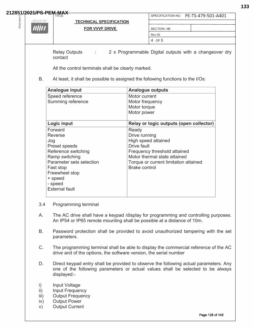
TITLE SPECIFICATION NO. PE-TS-391-501-A001
TECHNICAL SPECIFICATION
FOR VVVF DRIVE SECTION -__� 24.01.2014
2 X 660 MW OPGCL IB VALLEY TPS, Rev 00
BANHARPALLI 4 OF 5
PE
M-6
666
-0
Relay Outputs : 2 x Programmable Digital outputs with a changeover dry contact
All the control terminals shall be clearly marked. B. At least, it shall be possible to assigned the following functions to the I/Os:
Analogue input Analogue outputs Speed reference Summing reference
Motor current Motor frequency Motor torque Motor power
Logic input Relay or logic outputs (open collector)Forward Reverse Jog Preset speeds Reference switching Ramp switching Parameter sets selection Fast stop Freewheel stop + speed - speed External fault
Ready Drive running High speed attained Drive fault Frequency threshold attained Motor thermal state attained Torque or current limitation attained Brake control
3.4 Programming terminal A. The AC drive shall have a keypad /display for programming and controlling purposes.
An IP54 or IP65 remote mounting shall be possible at a distance of 10m. B. Password protection shall be provided to avoid unauthorized tampering with the set
parameters. C. The programming terminal shall be able to display the commercial reference of the AC
drive and of the options, the software version, the serial number D. Direct keypad entry shall be provided to observe the following actual parameters. Any
one of the following parameters or actual values shall be selected to be always displayed:-
i) Input Voltage ii) Input Frequency iii) Output Frequency iv) Output Power v) Output Current
Page 96 of 145
PE-TS-410-501-A002
Page 222
PE-TS-479-501-A401
��������������Page 128 of 142Page 128 of 142
212851/2021/PS-PEM-MAX133
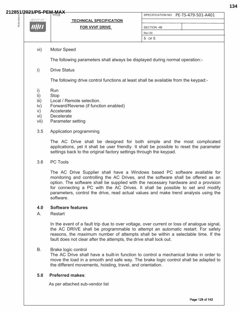
TITLE SPECIFICATION NO. PE-TS-391-501-A001
TECHNICAL SPECIFICATION
FOR VVVF DRIVE SECTION -__� 24.01.2014
2 X 660 MW OPGCL IB VALLEY TPS, Rev 00
BANHARPALLI 5 OF 5
PE
M-6
666
-0
vi) Motor Speed The following parameters shall always be displayed during normal operation:- i) Drive Status The following drive control functions at least shall be available from the keypad:- i) Run ii) Stop iii) Local / Remote selection. iv) Forward/Reverse (if function enabled) v) Accelerate vi) Decelerate vii) Parameter setting 3.5 Application programming The AC Drive shall be designed for both simple and the most complicated
applications, yet it shall be user friendly. It shall be possible to reset the parameter settings back to the original factory settings through the keypad.
3.6 PC Tools The AC Drive Supplier shall have a Windows based PC software available for
monitoring and controlling the AC Drives, and the software shall be offered as an option. The software shall be supplied with the necessary hardware and a provision for connecting a PC with the AC Drives. It shall be possible to set and modify parameters, control the drive, read actual values and make trend analysis using the software.
4.0 Software features A. Restart In the event of a fault trip due to over voltage, over current or loss of analogue signal,
the AC DRIVE shall be programmable to attempt an automatic restart. For safety reasons, the maximum number of attempts shall be within a selectable time. If the fault does not clear after the attempts, the drive shall lock out.
B. Brake logic control The AC Drive shall have a built-in function to control a mechanical brake in order to
move the load in a smooth and safe way. The brake logic control shall be adapted to the different movements, hoisting, travel, and orientation.
5.0 Preferred makes: Schneider Electric, L&T-YASKAWA, Siemens, ABB.
Page 97 of 145
PE-TS-410-501-A002
As per attached sub-vendor list
PE-TS-479-501-A401
��������������Page 129 of 142Page 129 of 142
212851/2021/PS-PEM-MAX134
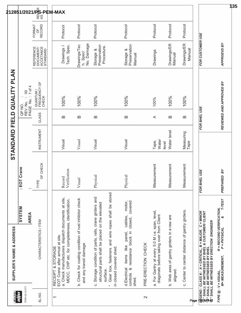
P
SS
R-Q
UA
LIT
Y
SUPP
LIER
’S N
AME
& A
DD
RES
S
STAN
DAR
D F
IELD
QU
ALIT
Y PL
AN
SYS
TEM
: E
OT
Cra
ne
AREA
:
QP
NO
.
:
REV
. No.
:
00
PAG
E N
o. :
1 o
f 4
SL.N
O.
CH
ARAC
TER
ISTI
CS
/ ITE
M
TYPE
OF
CH
ECK
INST
RU
MEN
T C
LASS
Q
UAN
TUM
/ FR
EQU
ENC
Y O
F C
HEC
K
REF
EREN
CE
DO
CU
MEN
T/
ACC
ETAN
CE
STAN
DAR
D
FOR
MAT
O
F R
ECO
RD
R
EMAR
KS
LE
GEN
D :
CLA
SS #
:: A
= C
RIT
ICA
L, B
= M
AJO
R,
C =
MIN
OR
“A
” SH
ALL
BE
WIT
NES
SED
BY
BH
EL &
CU
STO
MER
/ CLI
ENT
“B”
SHA
LL B
E W
ITN
ESSE
D B
Y B
HEL
“C
” SH
ALL
BE
WIT
NES
SED
BY
EREC
TIO
N E
NG
INEE
R
TYPE
@ :
V =
VISU
AL,
R
= R
ECO
RD
VER
IFIC
ATI
ON
,
M=
MEA
SUR
EMEN
T,
P
= P
HYS
ICA
L
&
T
- TES
T
FOR
BH
EL U
SE
PREP
AR
ED B
Y
FOR
BH
EL U
SE
REV
IEW
ED A
ND
APP
RO
VED
BY
FOR
CU
STO
MER
USE
A
PPR
OEV
D B
Y
1 R
ECEI
PT &
STO
RA
GE
EO
T C
rane
afte
r ar
rival
at s
ite.
a.
Che
ck m
anuf
actu
rers
dis
patc
h do
cum
ents
at s
ite,
MD
CC
, C
HP
etc
. for
com
plet
enes
s, id
entif
icat
ion.
Record
V
erif
icat
ion
Visu
al
B 10
0%
Dra
win
gs I
Tech
. Sp
ec.
Prot
ocol
b.
Che
ck f
or c
oatin
g co
nditi
on o
f rus
t inh
ibito
r che
ck
and
any
trans
it da
mag
e
Vis
ual
V
isu
al
B 10
0%
Dra
win
gs/T
ech.
Spe
c/
No.
Dam
age
Pro
toco
l
c.
Sto
rage
con
ditio
n of
par
ts, r
ails
, cra
ne g
irder
s an
d st
ruct
ural
par
ts s
hall
be p
lace
d on
the
elev
ated
su
rface
. *
Gea
r bo
x, fa
sten
ers
and
wire
rop
es s
hall
be s
tore
d in
clo
sed
cove
red
shed
.
Ph
ysi
cal
Visu
al
B 10
0%
Stor
age
& Pr
eser
vatio
n
Pro
cedu
re.
Pro
toco
l
d.
Elec
trica
l ite
ms
like
pane
l, ca
bles
, m
otor
, co
ntro
ls
& re
sist
ance
bl
ock
in c
lose
d,
cove
red
shed
.
Ph
ysi
cal
Visu
al
B 10
0%
Stor
age
& Pr
eser
vatio
n M
anua
l
Pro
toco
l
2 PR
E-ER
ECTI
ON
CH
ECK
a.
For
Gan
try a
t eve
ry 5
.0 M
i.e.
spa
n, le
vel,
diag
onal
s be
fore
taki
ng o
ver f
rom
Clie
nt
Mea
sure
men
t
Tape
, W
ater
le
vel
A 10
0%
D
raw
ings
Pro
toco
l
b.
Web
axe
s of
gan
try g
irder
s in
a ra
w a
re
alig
ned.
M
easu
rem
ent
W
ater
leve
l
B 10
0%
Dra
win
gs/E
R
Man
ual
Pro
toco
l
c.
Cen
ter
to c
ente
r di
stan
ce o
f gan
try g
irder
s.
M
easu
rem
ent
M
easu
ring
Tape
B
100%
D
raw
ings
/ER
M
anua
l P
roto
col
���������������Page 130 of 142Page 130 of 142
212851/2021/PS-PEM-MAX135
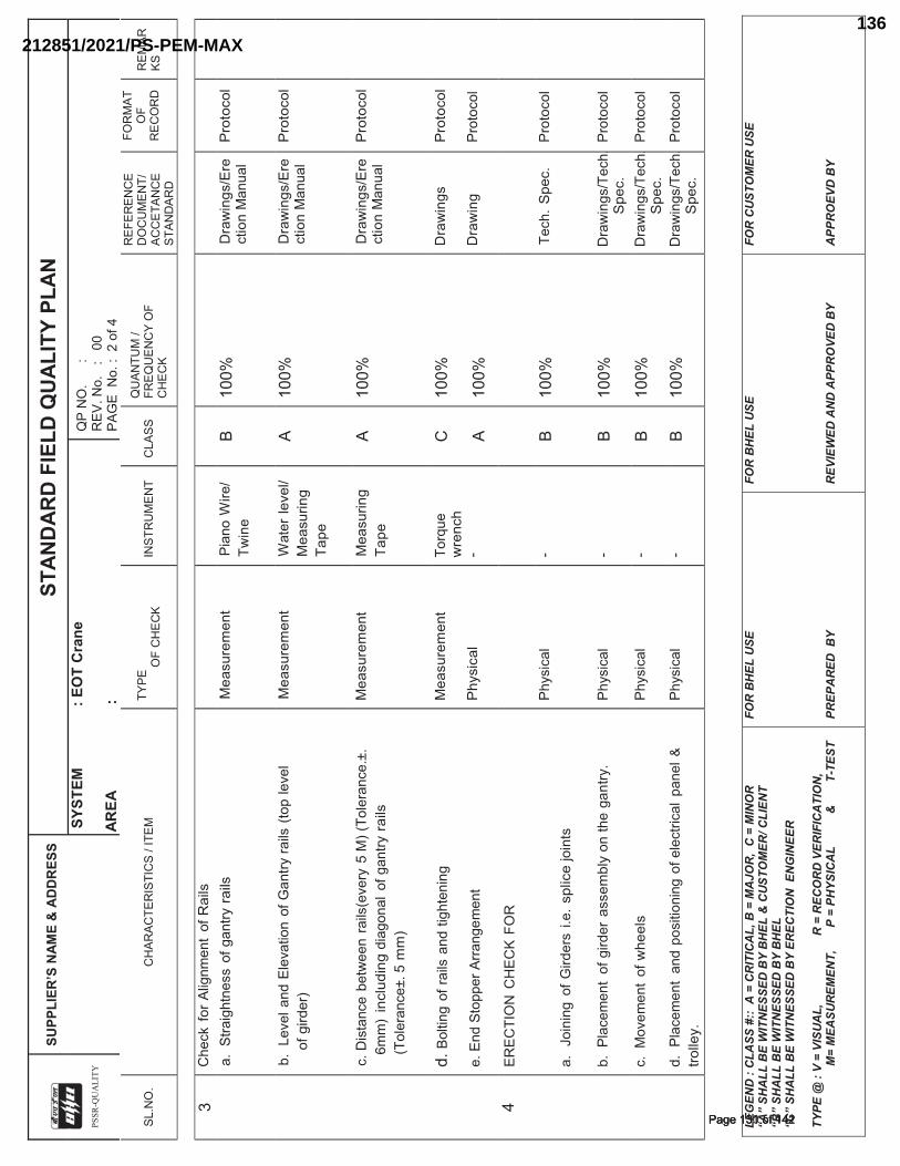
P
SS
R-Q
UA
LIT
Y
SUPP
LIER
’S N
AME
& A
DD
RES
S
STAN
DAR
D F
IELD
QU
ALIT
Y PL
AN
SYS
TEM
: E
OT
Cra
ne
AREA
:
QP
NO
.
:
REV
. No.
:
00
PAG
E N
o. :
2 o
f 4
SL.N
O.
CH
ARAC
TER
ISTI
CS
/ ITE
M
TYPE
OF
CH
ECK
INST
RU
MEN
T C
LASS
Q
UAN
TUM
/ FR
EQU
ENC
Y O
F C
HEC
K
REF
EREN
CE
DO
CU
MEN
T/
ACC
ETAN
CE
STAN
DAR
D
FOR
MAT
O
F R
ECO
RD
R
EMAR
KS
LE
GEN
D :
CLA
SS #
:: A
= C
RIT
ICA
L, B
= M
AJO
R,
C =
MIN
OR
“A
” SH
ALL
BE
WIT
NES
SED
BY
BH
EL &
CU
STO
MER
/ CLI
ENT
“B”
SHA
LL B
E W
ITN
ESSE
D B
Y B
HEL
“C
” SH
ALL
BE
WIT
NES
SED
BY
EREC
TIO
N E
NG
INEE
R
TYPE
@ :
V =
VISU
AL,
R
= R
ECO
RD
VER
IFIC
ATI
ON
,
M=
MEA
SUR
EMEN
T,
P
= P
HYS
ICA
L
&
T
- TES
T
FOR
BH
EL U
SE
PREP
AR
ED B
Y
FOR
BH
EL U
SE
REV
IEW
ED A
ND
APP
RO
VED
BY
FOR
CU
STO
MER
USE
A
PPR
OEV
D B
Y
3 C
heck
for
Alig
nmen
t of
Rai
ls
a. S
traig
htne
ss o
f gan
try r
ails
Mea
sure
men
t
Pian
o W
ire/
Twin
e B
100%
D
raw
ings
/Ere
ctio
n M
anua
l P
roto
col
b.
Lev
el a
nd E
leva
tion
of G
antry
rails
(to
p le
vel
of g
irder
) M
easu
rem
ent
W
ater
leve
l/ M
easu
ring
Tape
A 10
0%
Dra
win
gs/E
rect
ion
Man
ual
Pro
toco
l
c.
Dis
tanc
e be
twee
n ra
ils(e
very
5 M
) (To
lera
nce.
±.
6mm
) in
clud
ing
diag
onal
of g
antry
rai
ls
(Tol
eran
ce±.
5 m
m)
Mea
sure
men
t M
easu
ring
Tape
A 10
0%
Dra
win
gs/E
rect
ion
Man
ual
Pro
toco
l
d.
Bol
ting
of ra
ils a
nd ti
ghte
ning
e.
End
Sto
pper
Arra
ngem
ent
Mea
sure
men
t P
hysi
cal
Torq
ue
wre
nch
-
C A
100%
10
0%
Dra
win
gs
Dra
win
g
Pro
toco
l Pr
otoc
ol
4 ER
ECTI
ON
CH
ECK
FOR
a.
Joi
ning
of G
irder
s i.e
. spl
ice
join
ts
Phys
ical
-
B 10
0%
Tech
. S
pec.
Prot
ocol
b.
Pla
cem
ent
of g
irder
ass
embl
y on
the
gant
ry.
Ph
ysic
al
- B
100%
D
raw
ings
/Tec
h.S
pec.
Pr
otoc
ol
c.
Mov
emen
t of
whe
els
Ph
ysic
al
- B
100%
D
raw
ings
/Tec
h.S
pec.
Pr
otoc
ol
d.
Pla
cem
ent
and
posi
tioni
ng o
f ele
ctric
al p
anel
&
trolle
y.
Phys
ical
-
B 10
0%
Dra
win
gs/T
ech.
Spe
c.
Prot
ocol
���������������Page 131 of 142Page 131 of 142
212851/2021/PS-PEM-MAX136
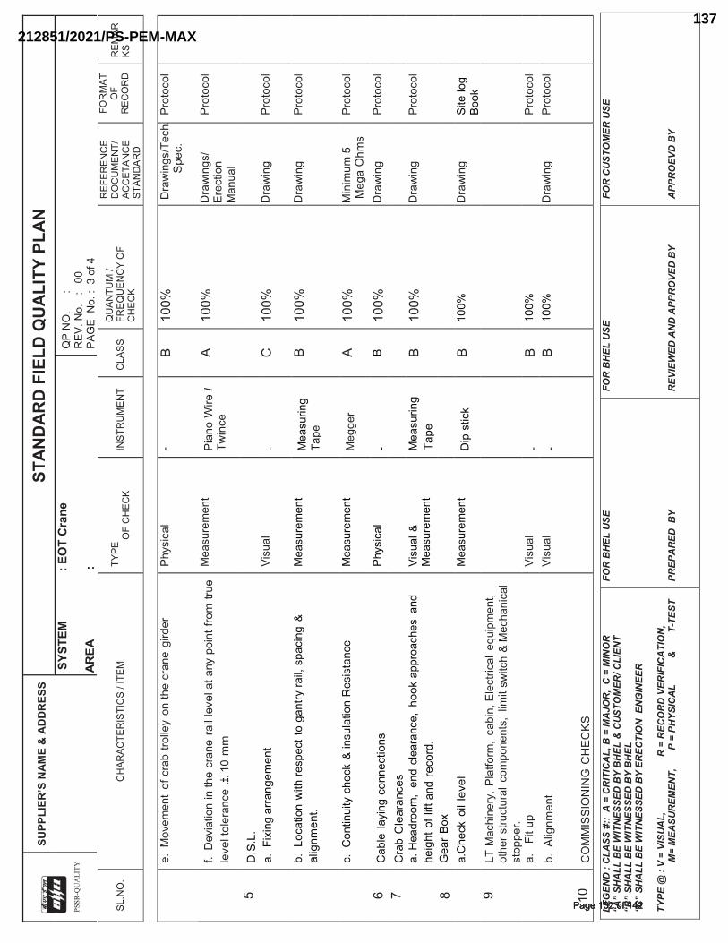
P
SS
R-Q
UA
LIT
Y
SUPP
LIER
’S N
AME
& A
DD
RES
S
STAN
DAR
D F
IELD
QU
ALIT
Y PL
AN
SYS
TEM
: E
OT
Cra
ne
AREA
:
QP
NO
.
:
REV
. No.
:
00
PAG
E N
o. :
3 o
f 4
SL.N
O.
CH
ARAC
TER
ISTI
CS
/ ITE
M
TYPE
OF
CH
ECK
INST
RU
MEN
T C
LASS
Q
UAN
TUM
/ FR
EQU
ENC
Y O
F C
HEC
K
REF
EREN
CE
DO
CU
MEN
T/
ACC
ETAN
CE
STAN
DAR
D
FOR
MAT
O
F R
ECO
RD
R
EMAR
KS
LE
GEN
D :
CLA
SS #
:: A
= C
RIT
ICA
L, B
= M
AJO
R,
C =
MIN
OR
“A
” SH
ALL
BE
WIT
NES
SED
BY
BH
EL &
CU
STO
MER
/ CLI
ENT
“B”
SHA
LL B
E W
ITN
ESSE
D B
Y B
HEL
“C
” SH
ALL
BE
WIT
NES
SED
BY
EREC
TIO
N E
NG
INEE
R
TYPE
@ :
V =
VISU
AL,
R
= R
ECO
RD
VER
IFIC
ATI
ON
,
M=
MEA
SUR
EMEN
T,
P
= P
HYS
ICA
L
&
T
- TES
T
FOR
BH
EL U
SE
PREP
AR
ED B
Y
FOR
BH
EL U
SE
REV
IEW
ED A
ND
APP
RO
VED
BY
FOR
CU
STO
MER
USE
A
PPR
OEV
D B
Y
e.
Mov
emen
t of
cra
b tro
lley
on th
e cr
ane
gird
er
Phys
ical
-
B 10
0%
Dra
win
gs/T
ech.
Spe
c.
Prot
ocol
f.
Dev
iatio
n in
the
cran
e ra
il le
vel a
t any
poi
nt fr
om tr
ue
leve
l tol
eran
ce .±
. 10
mm
Mea
sure
men
t Pi
ano
Wire
I Tw
ince
A 10
0%
Dra
win
gs/
Ere
ctio
n
Man
ual
Prot
ocol
5 D
.S.L
.
a.
Fix
ing
arra
ngem
ent
Vi
sual
-
C
100%
D
raw
ing
Prot
ocol
b.
Loc
atio
n w
ith re
spec
t to
gant
ry ra
il, s
paci
ng &
al
ignm
ent.
Mea
sure
men
t M
easu
ring
Tape
B
100%
D
raw
ing
Prot
ocol
c.
Con
tinui
ty c
heck
& in
sula
tion
Res
ista
nce
M
easu
rem
ent
Meg
ger
A 10
0%
Min
imum
5
Meg
a O
hms
Prot
ocol
6 C
able
layi
ng c
onne
ctio
ns
Phys
ical
-
B 10
0%
Dra
win
g Pr
otoc
ol
7
Cra
b C
lear
ance
s
a.
Hea
droo
m,
end
clea
ranc
e, h
ook
appr
oach
es a
nd
heig
ht o
f lift
and
rec
ord.
Vi
sual
&
Mea
sure
men
t M
easu
ring
Tape
B
100%
D
raw
ing
Prot
ocol
8 G
ear
Box
a.C
heck
oil
leve
l M
easu
rem
ent
Dip
stic
k B
100%
D
raw
ing
Site
log
Book
9 LT
Mac
hine
ry,
Plat
form
, ca
bin,
Ele
ctric
al e
quip
men
t, ot
her s
truct
ural
com
pone
nts,
lim
it sw
itch
& M
echa
nica
l st
oppe
r.
a.
Fi
t up
Visu
al
- B
100%
Prot
ocol
b.
Alig
nmen
t Vi
sual
-
B 10
0%
Dra
win
g Pr
otoc
ol
10
CO
MM
ISSI
ON
ING
CH
EC
KS
���������������Page 132 of 142Page 132 of 142
212851/2021/PS-PEM-MAX137
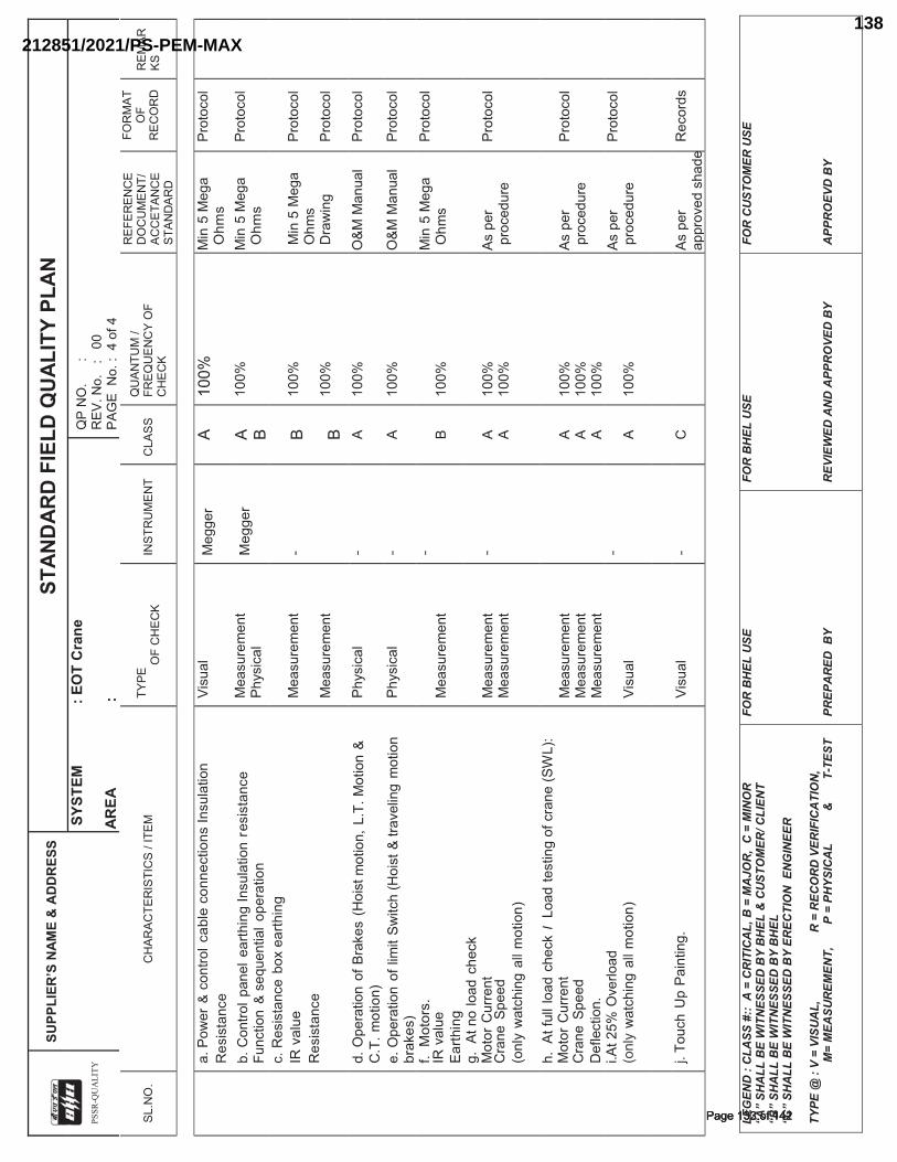
P
SS
R-Q
UA
LIT
Y
SUPP
LIER
’S N
AME
& A
DD
RES
S
STAN
DAR
D F
IELD
QU
ALIT
Y PL
AN
SYS
TEM
: E
OT
Cra
ne
AREA
:
QP
NO
.
:
REV
. No.
:
00
PAG
E N
o. :
4 o
f 4
SL.N
O.
CH
ARAC
TER
ISTI
CS
/ ITE
M
TYPE
OF
CH
ECK
INST
RU
MEN
T C
LASS
Q
UAN
TUM
/ FR
EQU
ENC
Y O
F C
HEC
K
REF
EREN
CE
DO
CU
MEN
T/
ACC
ETAN
CE
STAN
DAR
D
FOR
MAT
O
F R
ECO
RD
R
EMAR
KS
LE
GEN
D :
CLA
SS #
:: A
= C
RIT
ICA
L, B
= M
AJO
R,
C =
MIN
OR
“A
” SH
ALL
BE
WIT
NES
SED
BY
BH
EL &
CU
STO
MER
/ CLI
ENT
“B”
SHA
LL B
E W
ITN
ESSE
D B
Y B
HEL
“C
” SH
ALL
BE
WIT
NES
SED
BY
EREC
TIO
N E
NG
INEE
R
TYPE
@ :
V =
VISU
AL,
R
= R
ECO
RD
VER
IFIC
ATI
ON
,
M=
MEA
SUR
EMEN
T,
P
= P
HYS
ICA
L
&
T
- TES
T
FOR
BH
EL U
SE
PREP
AR
ED B
Y
FOR
BH
EL U
SE
REV
IEW
ED A
ND
APP
RO
VED
BY
FOR
CU
STO
MER
USE
A
PPR
OEV
D B
Y
a.
Pow
er &
con
trol c
able
con
nect
ions
Insu
latio
n R
esis
tanc
e Vi
sual
M
egge
r A
100%
M
in 5
Meg
a O
hms
Prot
ocol
b.
Con
trol p
anel
ear
thin
g In
sula
tion
resi
stan
ce
Func
tion
& se
quen
tial o
pera
tion
Mea
sure
men
t Ph
ysic
al
Meg
ger
A B 10
0%
Min
5 M
ega
Ohm
s Pr
otoc
ol
c.
Res
ista
nce
box
earth
ing
IR v
alue
R
esis
tanc
e
Mea
sure
men
t M
easu
rem
ent
- B B
100%
10
0%
Min
5 M
ega
Ohm
s D
raw
ing
Prot
ocol
Pr
otoc
ol
d.
Ope
ratio
n of
Bra
kes
(Hoi
st m
otio
n, L
.T. M
otio
n &
C.T
. mot
ion)
Ph
ysic
al
- A
100%
O
&M M
anua
l Pr
otoc
ol
e.
Ope
ratio
n of
lim
it Sw
itch
(Hoi
st &
trav
elin
g m
otio
n br
akes
) Ph
ysic
al
- A
100%
O
&M M
anua
l Pr
otoc
ol
f.
Mot
ors.
IR
val
ue
Ear
thin
g
Mea
sure
men
t -
B 10
0%
Min
5 M
ega
Ohm
s Pr
otoc
ol
g.
At n
o lo
ad c
heck
M
otor
Cur
rent
C
rane
Spe
ed
(onl
y w
atch
ing
all m
otio
n)
Mea
sure
men
t M
easu
rem
ent
- A A
100%
10
0%
As p
er
proc
edur
e
Prot
ocol
h.
At f
ull l
oad
chec
k I
Load
test
ing
of c
rane
(SW
L):
Mot
or C
urre
nt
Cra
ne S
peed
D
efle
ctio
n.
Mea
sure
men
t M
easu
rem
ent
Mea
sure
men
t
A A A
100%
10
0%
100%
As p
er
proc
edur
e
Prot
ocol
i.A
t 25%
Ove
rload
(o
nly
wat
chin
g al
l mot
ion)
Visu
al
- A
100%
As
per
pr
oced
ure
Prot
ocol
j. To
uch
Up
Pain
ting.
Vi
sual
-
C
As
per
ap
prov
ed s
hade
Rec
ords
���������������Page 133 of 142Page 133 of 142
212851/2021/PS-PEM-MAX138
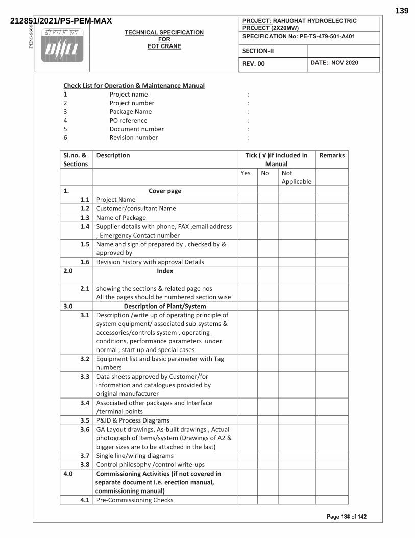
TECHNICAL SPECIFICATION FOR
EOT CRANE
PROJECT: RAHUGHAT HYDROELECTRIC PROJECT (2X20MW) SPECIFICATION No: PE-TS-479-501-A401
SECTION-II
REV. 00 DATE: NOV 2020
PE
M-6
66
6-0
Check List for Operation & Maintenance Manual 1 Project name : 2 Project number : 3 Package Name : 4 PO reference : 5 Document number : 6 Revision number : Sl.no. & Sections
Description Tick ( √ )if included in Manual
Remarks
Yes No Not Applicable
1. Cover page 1.1 Project Name 1.2 Customer/consultant Name 1.3 Name of Package 1.4 Supplier details with phone, FAX ,email address
, Emergency Contact number
1.5 Name and sign of prepared by , checked by & approved by
1.6 Revision history with approval Details 2.0 Index
2.1 showing the sections & related page nos All the pages should be numbered section wise
3.0 Description of Plant/System 3.1 Description /write up of operating principle of
system equipment/ associated sub-systems & accessories/controls system , operating conditions, performance parameters under normal , start up and special cases
3.2 Equipment list and basic parameter with Tag numbers
3.3 Data sheets approved by Customer/for information and catalogues provided by original manufacturer
3.4 Associated other packages and Interface /terminal points
3.5 P&ID & Process Diagrams 3.6 GA Layout drawings, As-built drawings , Actual
photograph of items/system (Drawings of A2 & bigger sizes are to be attached in the last)
3.7 Single line/wiring diagrams 3.8 Control philosophy /control write-ups
4.0 Commissioning Activities (if not covered in separate document i.e. erection manual, commissioning manual)
4.1 Pre-Commissioning Checks
���������������Page 134 of 142Page 134 of 142
212851/2021/PS-PEM-MAX139
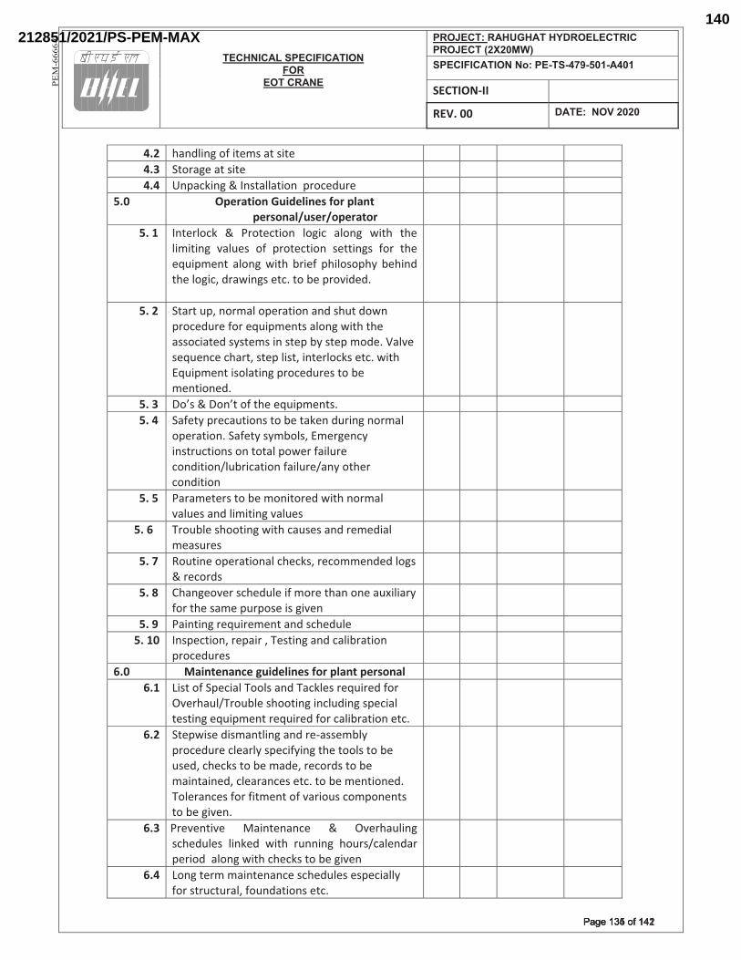
TECHNICAL SPECIFICATION FOR
EOT CRANE
PROJECT: RAHUGHAT HYDROELECTRIC PROJECT (2X20MW) SPECIFICATION No: PE-TS-479-501-A401
SECTION-II
REV. 00 DATE: NOV 2020
PE
M-6
66
6-0
4.2 handling of items at site 4.3 Storage at site 4.4 Unpacking & Installation procedure
5.0 Operation Guidelines for plant personal/user/operator
5. 1 Interlock & Protection logic along with the limiting values of protection settings for the equipment along with brief philosophy behind the logic, drawings etc. to be provided.
5. 2 Start up, normal operation and shut down procedure for equipments along with the associated systems in step by step mode. Valve sequence chart, step list, interlocks etc. with Equipment isolating procedures to be mentioned.
5. 3 Do’s & Don’t of the equipments. 5. 4 Safety precautions to be taken during normal
operation. Safety symbols, Emergency instructions on total power failure condition/lubrication failure/any other condition
5. 5 Parameters to be monitored with normal values and limiting values
5. 6 Trouble shooting with causes and remedial measures
5. 7 Routine operational checks, recommended logs & records
5. 8 Changeover schedule if more than one auxiliary for the same purpose is given
5. 9 Painting requirement and schedule 5. 10 Inspection, repair , Testing and calibration
procedures
6.0 Maintenance guidelines for plant personal 6.1 List of Special Tools and Tackles required for
Overhaul/Trouble shooting including special testing equipment required for calibration etc.
6.2
Stepwise dismantling and re-assembly procedure clearly specifying the tools to be used, checks to be made, records to be maintained, clearances etc. to be mentioned. Tolerances for fitment of various components to be given.
6.3 Preventive Maintenance & Overhauling schedules linked with running hours/calendar period along with checks to be given
6.4 Long term maintenance schedules especially for structural, foundations etc.
���������������Page 135 of 142Page 135 of 142
212851/2021/PS-PEM-MAX140
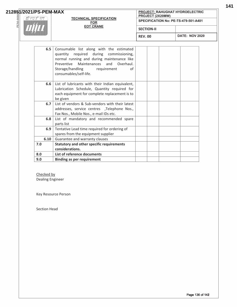
TECHNICAL SPECIFICATION FOR
EOT CRANE
PROJECT: RAHUGHAT HYDROELECTRIC PROJECT (2X20MW) SPECIFICATION No: PE-TS-479-501-A401
SECTION-II
REV. 00 DATE: NOV 2020
PE
M-6
66
6-0
6.5 Consumable list along with the estimated quantity required during commissioning, normal running and during maintenance like Preventive Maintenances and Overhaul. Storage/handling requirement of consumables/self-life.
6.6 List of lubricants with their Indian equivalent, Lubrication Schedule, Quantity required for each equipment for complete replacement is to be given
6.7 List of vendors & Sub-vendors with their latest addresses, service centres ,Telephone Nos., Fax Nos., Mobile Nos., e-mail IDs etc.
6.8 List of mandatory and recommended spare parts list
6.9 Tentative Lead time required for ordering of spares from the equipment supplier
6.10 Guarantee and warranty clauses 7.0 Statutory and other specific requirements
considerations.
8.0 List of reference documents 9.0 Binding as per requirement Checked by Dealing Engineer Key Resource Person Section Head
���������������Page 136 of 142Page 136 of 142
212851/2021/PS-PEM-MAX141
�
���������_^��������^|^���^�_��
|���
�������_���
���������������������������������������{������ �� ������������������������������������ �� �����������������������������
�
�
����������������������
��
����^�_�^^^�
���������������Page 137 of 142Page 137 of 142
212851/2021/PS-PEM-MAX142
�
�_�����TECHNICAL SPECIFICATION
FOR�
EOT CRANE
���§���������������� ��������_�����§������}������|���^���^����~�|~��~���~�����|���_������___����^���^����0���������� ���������������
�
�
�
DRAWINGS / DOCUMENTS TO BE SUBMITTED WITH THE BID
Bidder shall submit the following drawings / documents along with their bid-
a.� Signed and Stamped copy of Compliance cum Confirmation Certificate
b.� Deviation schedule with reference to specific clauses of the specification along with reason for such
deviation in the format attached in the tender
Or
No deviation certificate
c.� Un priced copy of price format indicating quoted/ not applicable against each row/column
OFFER WILL BE CONSIDERED AS INCOMPLETE IN ABSENCE OF ANY OF ABOVE DOCUMENTS. DOCUMENT
OTHER THAN ABOVE, IF ANY, SUBMITTED WITH THE OFFER WILL NOT FORM PART OF CONTRACT AND
ACCORDINGLY WILL NOT BE CONSIDERED FOR BID EVALUATION.
����� �
��������������Page 138 of 142Page 138 of 142
d. PQR related documents
212851/2021/PS-PEM-MAX143
�
�_�����TECHNICAL SPECIFICATION
FOR�
EOT CRANE
���§���������������� ��������_�����§������}������|���^���^����~�|~��~���~�����|���_������___����^���^����0���������� ���������������|������������1�������������2�
�
�
COMPLIANCE CUM CONFIRMATION CERTIFICATE The bidder shall confirm compliance with following by signing / stamping this compliance certificate (every sheet) and furnish same with the offer.
a)� The scope of supply, technical details, construction features, design parameters etc. shall be as per technical specification & there are no exclusions, other than those mentioned under “exclusion and those resolved as per ‘Schedule of Deviations’, with regard to same.
b)� There are no other deviations w.r.t. specifications other than those furnished in the ‘Schedule of
Deviations’. Any other deviation, stated or implied, taken elsewhere in the offer stands withdrawn unless specifically brought out in the ‘Schedule of Deviations’
c)� Bidder shall submit QP in the event of order based on the guidelines given in the specification & QP
enclosed therein. QP will be subject to BHEL / CUSTOMER approval & customer hold points for inspection / testing shall be marked in the QP at the contract stage. Inspection / testing shall be witnessed as per same apart from review of various test certificates/ Inspection records etc. This is within the contracted price without any extra implications to BHEL after award of the contract.
d)� All drawings/ data-sheets / calculations etc. submitted along with the offer shall not be taken
cognizance off. e)� The offered materials shall be either equivalent or superior to those specified in the specification &
shall meet the specified / intended duty requirements. In case the material specified in the specifications is not compatible for intended duty requirements then same shall be resolved by the bidder with BHEL during the pre-bid discussions, otherwise BHEL / Customer’s decision shall be binding on the bidder whenever the deficiency is pointed out.
For components where materials are not specified, same shall be suitable for intended duty, all materials shall be subject to approval in the event of order.
f)� The commissioning spares shall be supplied on ‘As Required Basis’ & prices for same included in
the base price itself.
g)� All sub vendors shall be subject to BHEL / CUSTOMER approval in the event of order.
h)� Guarantee for plant/equipment shall be as per relevant clause of GCC / SCC / Other Commercial Terms & Conditions
i)� In the event of order, all the material required for completing the job at site shall be supplied by the bidder within the ordered price even if the same are additional to approved billing break up, approved drawing or approved Bill of quantities within the scope of work as tender specification. This clause will apply in case during site commissioning, additional requirements emerges due to customer and / or consultant’s comments. No extra claims shall be put on this account
j)� Schedule of drawings submissions, comment incorporations & approval shall be as stipulated in
the specifications. The successful bidder shall depute his design personnel to BHEL’s / Customer’s / Consultant’s office for across the table resolution of issues and to get documents approved in the stipulated time.
k)� As built drawings shall be submitted as and when required during the project execution.
��������������Page 139 of 142Page 139 of 142
212851/2021/PS-PEM-MAX144
�
�_�����TECHNICAL SPECIFICATION
FOR�
EOT CRANE
���§���������������� ��������_�����§������}������|���^���^����~�|~��~���~�����|���_������___����^���^����0���������� ���������������|������������2�������������2�
�
�
l)� The bidder has not tempered with this compliance cum confirmation certificate and if at any stage
any tempering in the signed copy of this document is noticed then same shall be treated as breach of contract and suitable actions shall be taken against the bidder.
m)� Successful bidder shall furnish detailed erection manual for each of the equipment supplied under
this contract at least 3 months before the scheduled erection of the concerned equipment / component or along with supply of concerned equipment / component whichever is earlier.
n)� Document approval by customer under Approval category or information category shall not absolve the vendor of their contractual obligations of completing the work as per specification requirement. Any deviation from specified requirement shall be reported by the vendor in writing and require written approval. Unless any change in specified requirement has been brought out by the vendor during detail engineering in writing while submitting the document to customer for approval, approved document (with implicit deviation) will not be cited as a reason for not following the specification requirement.
o)� In case vendor submits revised drawing after approval of the corresponding drawing, any delay in approval of revised drawing shall be to vendor's account and shall not be used as a reason for extension in contract completion.
�
���������������Page 140 of 142Page 140 of 142
212851/2021/PS-PEM-MAX145
�
���������_^��������^|^���^�_��
|���
�������_��
���������������������������������������{������ �� ������������������������������������������������� ����������������
� � � � �� ������������������������
�
��
~��
��
��
�
�����^������^|^���^�_������z����
�@�_�@� �$?';�\��+<�$�+�$�_�@��
�'+'$$\'��Z�'�$�=$Z$==$!�?�+<�$�
��+=;Z;?+';�\��$�<;=$!�
� � � �� � � �� � � �� � � �� � � �� � � �� � � �� � � �� � � �� � � �� � � �� � � �� � � �� � � �� � � �����=!���@���@�=��^�@>!|!���>�+>�+=\���<�*>!\*���+@��>���\*_��^_+@!|!^+>!\*��@��[!@���\*�>���>�^�*!^+_��?�^!|!^+>!\*�|\@�>����[=��^>�?+^`+$� �������
���������� �������� ������������� ���������� ������� ��
����������������
�
���������������Page 141 of 142Page 141 of 142
212851/2021/PS-PEM-MAX146
� �
�����"
�������������������������
��������
��_��`����>*��*>��*���_���`���`���_��`������~���
��`��_������ ��������>���
�`��_���������
��<��_����������������>�����_<�����
�
� �������������
�z������^�_�^^^�����^��^�_������z���
����|������^��^�_������z���������|��^����������
|�� ����_�������^_�`�������
���������������Page 142 of 142Page 142 of 142
212851/2021/PS-PEM-MAX147