ec 1130-2-216, hydropower operations and maintenance
TRANSCRIPT
DEPARTMENT OF THE ARMY EC 1130-2-216 Corps of Engineers 441 G Street, NW
CECW-CO Washington, DC 20314-1000
Circular No. 1130-2-216 14 March 2019
EXPIRES 30 JUNE 2021 Project Operations
HYDROPOWER OPERATIONS AND MAINTENANCE POLICY TURBINE INTEGRITY INSPECTION PROCEDURES
TABLE OF CONTENTS
Paragraph Page Chapter 1: Hydropower Operations and Maintenance Policy Turbine Integrity Inspection Procedures
Purpose....................................................................... 1-1..............................1 Applicability ................................................................. 1-2..............................2 Distribution Statement................................................. 1-3..............................2 References.................................................................. 1-4..............................2 Definitions ................................................................... 1-5..............................2
Chapter 2: Head Cover Bolt, Stud, and Nut Inspection on Kapalan and Propeller Type Hydraulic
Objective ..................................................................... 2-1..............................4 Applicability ................................................................. 2-2..............................4 Glossary of Terms....................................................... 2-3..............................5 Qualifications of Inspectors. ........................................ 2-4..............................5 Pre-inspection Data Gathering.................................... 2-5..............................5 Inspection Methods and Procedures........................... 2-6..............................8 Repainting After Inspection ......................................... 2-7............................14 Reporting Criteria........................................................ 2-8............................14 Frequency ................................................................... 2-9............................15
Chapter 3: Head Cover Bolt, Stud, and Nut Inspection on Francis Hydraulic Turbines and Pump-Turbines
Objective. .................................................................... 3-1............................16 Applicability. ................................................................ 3-2............................16 Glossary of Terms....................................................... 3-3............................17 Qualifications of Inspectors. ........................................ 3-4............................17 Pre-inspection Data Gathering.................................... 3-5............................17 Inspection Methods and Procedures........................... 3-6............................20 Repainting After Inspection ......................................... 3-7............................26 Reporting Criteria........................................................ 3-8............................26
EC 1130-2-216 • 14 March 2019 i
Frequency ................................................................... 3-9............................26 Chapter 4: Hydraulic Turbine Wicket Gate Timing and Verification of Loss of Power Closure
Objective ..................................................................... 4-1............................28 Applicability ................................................................. 4-2............................28 References.................................................................. 4-3............................28 Glossary of Terms....................................................... 4-4............................28 Qualifications of Inspectors ......................................... 4-5............................29 Pre-inspection Data Gathering.................................... 4-6............................29 Inspection Methods and Procedures........................... 4-7............................30 Reporting Criteria........................................................ 4-8............................33 Frequency. .................................................................. 4-9............................34
Chapter 5: Reaction Turbine Runner Inspection Objective ..................................................................... 5-1............................35 Applicability ................................................................. 5-2............................35 Propeller and Kaplan Turbines.................................... 5-3............................35 Francis Turbines and Francis-Type Pump-Turbines. .. 5-4............................41 Repainting After Inspection ......................................... 5-5............................46 Reporting Criteria........................................................ 5-6............................46 Frequency ................................................................... 5-7............................46
Chapter 6: Turbine Head Cover Inspection Objective ..................................................................... 6-1............................47 Applicability ................................................................. 6-2............................47 Glossary of Terms....................................................... 6-3............................47 Qualifications of Inspectors ......................................... 6-4............................47 Pre-inspection Data Gathering.................................... 6-5............................47 Inspection Methods and Procedures........................... 6-6............................49 Reporting Criteria........................................................ 6-7............................53 Frequency ................................................................... 6-8............................53
Chapter 7: Water Passage Access Door Inspections Objective ..................................................................... 7-1............................54 Applicability ................................................................. 7-2............................54 Design Perspective ..................................................... 7-3............................54 Glossary of Terms....................................................... 7-4............................55 Qualifications of Inspectors ......................................... 7-5............................55 Pre-inspection Data Gathering.................................... 7-6............................55 Inspection Methods and Procedures........................... 7-7............................56 Repainting After Inspection ......................................... 7-8............................59 Reporting Criteria........................................................ 7-9............................59 Frequency ................................................................... 7-10..........................59
Chapter 8: Exposed Spiral Case Extension Inspections Objective ..................................................................... 8-1............................60
EC 1130-2-216 • 14 March 2019 ii
8-2. Applicability .................................................................... 8-2............................60 8-3. References..................................................................... 8-3............................60 8-4. Glossary of Terms.......................................................... 8-4............................60 8-5. Qualifications of Inspectors ............................................ 8-5............................60 8-6. Pre-inspection Data Gathering....................................... 8-6............................61 8-7. Inspection Methods and Procedures.............................. 8-7............................61 8-8. Required Maintenance................................................... 8-8............................64 8-9. Evaluation of Riveted Spiral Case Extension Inspection Results............................................................... .......................8-9............................64 8-10. Reporting Criteria........................................................... 8-10..........................65 8-11. Frequency ...................................................................... 8-11..........................66
List of Appendices Appendix A - Figures, Diagrams, Charts, Tables and Attachments for Chapter 2......... 67 Appendix B - Figures, Diagrams, Charts, Tables and Attachments for Chapter 3......... 79 Appendix C - Figures, Diagrams, Charts, Tables and Attachments for Chapter 4 ........ 91 Appendix D - Figures, Diagrams, Charts, Tables and Attachments for Chapter 5 ........ 93 Appendix E - Figures, Diagrams, Charts, Tables and Attachments for Chapter 6....... 105 Appendix F - Figures, Diagrams, Charts, Tables and Attachments for Chapter 7....... 112 Appendix G - Paint Procedures................................................................................... 117 Appendix H - Acknowledgements ............................................................................... 118 Glossary - Definitions and Acronyms .......................................................................... 119
EC 1130-2-216 • 14 March 2019 iii
Chapter 1 Hydropower Operations and Maintenance Policy Turbine Integrity Inspection Procedures
1-1. Purpose.
a. Recent events in the Hydropower industry, most notably the accident at the Siberian Sayano Shushenskaya project in 2009 that killed 75 people, have elevated awareness of the need to monitor the condition and performance of critical hydropower components. This Engineer Circular establishes requirements for the inspection of critical hydropower components whose failure, should it occur, have a high potential of allowing an uncontrolled release of water either into the powerhouse or bypassing the dam. In all cases this uncontrolled water release will also have a high probability of causing both substantial property damage and loss of life.
b. These Turbine Integrity Inspections are separated into chapters, which follow. Each chapter contains background information, inspection instructions, evaluation criteria and upward reporting instructions. Each chapter is a stand-alone document, and instructions from one chapter are not to be transferred to a different chapter.
c. These Turbine Integrity Inspections (TII) are not to be confused with the HydroAMP Condition Assessment procedures. TII is a safety inspection. HydroAMP is a condition assessment tool used in the asset management process.
d. It is intended that most inspections be performed in conjunction with normally scheduled major turbine maintenance. It is not expected that a special outage be scheduled in order to accomplish the inspections identified herein. Notwithstanding the preceding, every turbine to which these instructions apply will have all applicable inspections performed at least once prior to 31 December 2021.
e. These inspections are instituted to check turbine components that have been inadequately monitored, or perhaps totally overlooked, in the past. In many circumstances, the inspection of these components has only become necessary as a consequence of potential machine deterioration over time. These Turbine Integrity Inspections are in addition to any other inspections already being performed on the machines. They do not supplant, supersede or replace any other inspections or maintenance that has been established by previous instruction or authority.
f. These inspections do not certify that a machine is safe to operate for a given period of time into the future. Do not assume that, having passed these inspections, the
EC 1130-2-216 • 14 March 2019 1
machine is automatically safe to operate until the next inspection is scheduled. Any time an unsafe condition is suspected the situation should be investigated and, when determined necessary, corrective actions will be taken.
g. Do not assume that all the units of an identical design are safe just because one of the units passed the inspections. Different personnel, perhaps at different times, may have installed the units. Perhaps there was a rush to complete some aspect of the work on one machine and the job was performed in a poor manner. Maybe non-standard parts for one of the units were shipped to the site and the installation crew “made do”. Any one of these, and a hundred similar scenarios, could have happened, with the result that one of the units is more at risk than the rest. At one Corps powerhouse with two identical units, the head cover studs on one unit were tightened to a torque of 800 ft-lbs. On the other unit, they were tightened to a torque of 400 ft-lbs. Those tightened to 400 ft-lb were starting to loosen up when the problem was discovered.
h. Inspections that occur soon after a unit is reassembled following a major rehabilitation are just as important, perhaps more so, than inspections which occur after the unit has been in service for 40 years. Just because the unit was reassembled with a lot of new or refurbished parts does not assure that it was reassembled correctly. This is the case with the Sayano Shushenskaya plant that blew a head cover in 2009. The unit had been rehabilitated and placed back in service six months prior to the accident. It would be wise to perform all of the TII inspections on a unit about 1 year after it is placed back in service following a complete disassembly.
i. Machines at low head dams are no safer than machines at high head dams. The allowable design stress is the same for a high head unit as it is for a low head unit, and the units were designed to contain the loads that are applied to the equipment. All units, whether at high head or low head sites, should be inspected with equal diligence.
1-2. Applicability. This circular is applicable to all United States Army Corps of Engineers (USACE) commands having responsibility for maintenance and/or operation of Hydroelectric Generating Facilities.
1-3. Distribution Statement. This circulation is approved for unrestricted public release.
1-4. References. A list of applicable references is provided within each chapter.
1-5. Definitions. See glossary for a list of applicable terms.
EC 1130-2-216 • 14 March 2019 2


Chapter 2 Head Cover Bolt, Stud, and Nut Inspection on Kaplan and Propeller Type Hydraulic Turbines
2-1. Objective.
a. Hydropower industry workshops and forums that have been convened to address the accident at Sayano Shushenskaya have identified at least four events in the past 20 years (some of them publicized, some of them not) where turbine head cover studs (or bolts) have failed. These stud/bolt failures have caused substantial damage to the powerhouses, and in one case resulted in the death of about 75 people. Head cover stud/bolt failures worldwide occur more frequently than is typically thought to be the case, and these failures emphasize the need for more thorough inspection and monitoring of these components.
b. The force on the head cover of a typical large Kaplan or propeller-type turbine can be high, in excess of 1 million pounds. This load is constrained by the studded or bolted connections between the head cover and the adjacent components. A failure of this connection could cause an event which may result in a loss of the water containment, causing property damage and injury to personnel. The objective of this procedure is to perform an inspection of the various fasteners and the condition of the connections to assure that the bolted joints are secure.
c. If any inspection or test performed in addition to those described in these procedures identifies something unusual, questionable, or is suspected to indicate a problem, the field inspector should raise the issue through the powerhouse chain of command and with the Hydroelectric Design Center (HDC). Also, if an unsafe or questionable condition is found between inspection cycles, plant staff should immediately raise the issue through the powerhouse chain of command and with the HDC. The goal of this inspection process is to assure that the machines are safe for operation.
2-2. Applicability.
a. This procedure applies to all vertical shaft Kaplan and propeller-type turbines with runner diameters greater than 36 inches. The procedure can be used for smaller machines, if desired.
b. These procedures have been written for a typically designed Kaplan or propeller type turbine. If the design or construction of the turbine being inspected is different than what is described in these instructions, contact the HDC for additional guidance.
c. The bolted connections addressed by these inspections are engineered joints. The proper amount of pre-stress, or torque, to place on the fasteners in the joint should
EC 1130-2-216 • 14 March 2019 4
not be determined by simply obtaining the torque value from an industry standard table. There are a lot of variables that must be considered when calculating the proper torque to apply to these fasteners, and that calculation needs to be performed by an engineer who is familiar with bolted joint design. Later in the chapter there are tables of torque values for different size fasteners. These torque values should only be used as described in these procedures, most notably in the following circumstances:
(1) When less than 8% of the fasteners in the joint are being re-installed or replaced.
(2) When the fastener material is steel (as opposed to brass or bronze).
d. If the above conditions are not met, contact the Hydroelectric Design Center for support and guidance.
2-3. Glossary of Terms. See Glossary for definitions related to a typical Kaplan or propeller-type turbine. See Appendix A, Figure 1-A for an illustration of a Kaplan turbine.
2-4. Qualifications of Inspectors.
a. The inspector will have knowledge of hydraulic turbines and will have an understanding of mechanical drawings. This individual may be a tradesman, such as a millwright, machinist, or a mechanic. The inspector will also be fluent in the English language and will be able to perform the physical activities as described within.
b. For ultrasonic testing (UT) performed by a contractor or non-Corps personnel, the inspector will be certified by the American Society for Non-Destructive Testing (ASNT) to TC-1A Level 2, or equivalent. If Corps personnel with sufficient skill and ability perform the UT inspections, the Corps personnel need not be ASNT certified.
2-5. Pre-inspection Data Gathering.
a. Unit Age, Maintenance and Overhaul History
(1) It is recommended that the inspector review the original equipment manufacturer (OEM) drawings and overhaul history so that any unusual conditions may be readily recognizable. An overhaul is defined as the periodic major maintenance activity that occurs on intervals of between 2 and 6 years. Activities associated with an overhaul include dewatered inspections, checking wicket gate timing, replacing pumps, and cavitation repair. A Major Rehabilitation involves a significant disassembly of the unit beyond the scope of a typical overhaul. A Major Rehabilitation typically replaces the turbine runner, replaces other worn parts and restores the machine to almost “as new” condition. After the Major Rehabilitation is completed, it is expected that major repair work should not be needed for at least the next 20 years. It is recommended that
EC 1130-2-216 • 14 March 2019 5
the inspector be familiar with the overall scope of work for previous Major Rehabilitations and overhauls, and when each was performed.
(2) The inspector will document the following turbine nameplate information on the check sheet provided. See Appendix A, Figure 1-C.
(a) OEM;
(b) Year of unit manufacture;
(c) Unit number (for a multiple-unit powerhouse);
(d) Machine power (in MW or hp);
(e) Speed (rpm); and
(f) Head (ft).
(3) Any “problem areas” for the unit will also be noted. These problems could include severe cavitation damage on the runner, excessive vibration, shaft seal problems, bearing problems, etc. If the documents are readily available, previous inspection reports, maintenance logs and any defect documentation should also be reviewed. The intent of this document review is to make the inspector aware of any previously identified problems. As the inspector judges appropriate, pertinent information regarding past history may be included in the records of this inspection. Previous replacement of the bolts/studs on either the radial or annular sections of the head cover will be documented.
b. Head Cover Flange Descriptions - See Appendix A, Figure 1- B for illustration. The inspector will use Appendix A, Figure 1-C to document:
(1) A physical description of both the head cover annular and radial flanges. Assembly drawings, if available, are sufficient for reference. In the event that assembly drawings are unavailable, photographs of the head cover’s radial and annular flanges may be attached to the inspection sheet;
(2) The number of studs or bolts per flange.
c. Stud and Bolt Description – Annular - The annular studs and bolts are the hold-down bolts or studs between the outer head cover and the stay ring, the intermediate head cover and the outer head cover, and the intermediate head cover and the inner head cover. These three flanges are typically found on Kaplan or propeller-type turbines. The inspector will identify which are, or are not, present on the machine being inspected and adapt the inspection requirements and reporting forms as needed to document inspection of all annular head cover fasteners including bolts and studs. Bolts may have markings on their heads to determine the physical properties of the bolt
EC 1130-2-216 • 14 March 2019 6
material. Data may be available from the drawings, bills of materials, and descriptive literature such as equipment manuals provided by the OEM. The inspector will document:
(1) The total number of bolts or studs on each flange;
(2) The diameter of the fastener;
(3) The material of the fastener, if available. Fasteners may be marked on the head with a symbol that identifies the grade of the fasteners. The grade establishes the minimum mechanical properties that the fastener must meet. Refer to Appendix A, Table 1-A for grade markings on steel bolts; and
(4) Pre-stress or torque data, if available.
d. Stud and Bolt Descriptions – Radial Flanges - The radial flange studs and bolts are defined as the bolts or studs on the outer head cover, intermediate head, or inner head cover that hold the radial flanges together. Data may be available from the drawings and descriptive literature, such as equipment manuals, provided by the OEM. The inspector will document:
(1) The total number of bolts or studs on each flange;
(2) The diameter and length of the fastener;
(3) The material of the fastener, if available; and
(4) Pre-stress or torque data, if available.
e. Radial Studs and Bolts - Some axial flow turbines have radial fasteners between the various parts of the head cover, or between the outer head cover and the stay ring. The number, arrangement and location of these radial fasteners are very unique to the specific machine. If the machine being inspected has radial head cover fasteners, the inspector should create a sketch showing the location and indexing of the radial fasteners.
f. Spare Part Inventory and Procurement - The availability of replacement bolts, studs and nuts of the fasteners that are being inspected will be determined. Replacement fasteners will be needed in the event that fasteners are damaged during the inspection process, or if damaged fasteners are found during inspection.
g. Tools and Equipment Needed
(1) The following tools and equipment will be necessary for the inspections described in this document:
EC 1130-2-216 • 14 March 2019 7
(a) Calibrated torque wrench or hydraulic tensioner and sockets to fit hex nuts or bolt heads. The torque wrench will have sufficient range so that the applied torque will fall within 25% to 75% of the full scale on the torque wrench;
(b) Small ball peen hammer; and
(c) Tap for the size and thread pitch of the fasteners to be examined. The tap will be used to “chase” and thereby clean the female threads.
(2) When choosing the proper wrench for checking looseness, removal or reinstallation of the studs, nuts and bolts, consider the following:
(a) Hydraulic torque wrenches or hydraulic tensioners should be used on large fasteners that require large torques.
(b) Using a standard bar type torque wrench is very acceptable on the smaller studs and bolts.
(c) Innovative tooling such as using a lever arm and some kind of measured / calibrated force (such as a come-along acting through a load cell) may be needed.
(d) A slugging wrench should only be used when no other option is possible. Use of a slugging wrench requires that pre-stress be determined by the “turn of the nut” method. Contact HDC for guidance if a slugging wrench is used to reinstall any of the studs/bolts.
(e) Whenever force or pressure is being measured, use only tools with current calibration certifications.
(3) NOTE: Ultrasonic testing (UT) and equipment will probably be provided by an outside contractor.
2-6. Inspection Methods and Procedures.
a. Tests to be Performed on Various Flanges - The consequences of flange failure and the relative size of fasteners necessitate different inspection requirements for each type of flange on the head cover. Identified below are the inspections to be performed on each type of flange.
(1) For the Outer-Head-Cover-to-Stay-Ring Annular Flange: All of the inspections identified in this Chapter 1 will be performed.
(2) For the Intermediate-Head-Cover-to-Outer-Head-Cover Annular Flange: All of the inspections identified in this Chapter 1 will be performed.
EC 1130-2-216 • 14 March 2019 8
(3) For the Inner-Head-Cover-to-Intermediate-Head-Cover Annular Flange: Do not perform the ultrasonic inspection of Section 1-7.g. Perform all other inspections identified in this Chapter 1.
(4) For the Cover Plate at the bottom of the Inner Head Cover, i.e. the plate that is the bottom of the water sump: Perform the visual inspection of Section 1-7.e. Perform the tap test of Section 1-7.f.
(5) For Radial Flanges on the Outer Head Cover and on the Intermediate Head Cover: Perform the visual inspection of Section 1-7.e; to the extent possible as allowed by access, perform the tap test of Section 1-7.f; to the extent possible as allowed by access, perform the looseness checks of Section 1-7.h.
b. Recording Data – Appendix A, Figure 1-D is provided for use in recording the findings of the inspections.
c. Safety, Cleaning and Access
(1) Safety is the primary concern on any project. Each turbine design is unique, and there are unique safety concerns at each facility. Only personnel familiar with the plant and each specific unit should coordinate and lead the inspections described in this document. For the safety of the personnel and the plant, the unit will be taken out of service, dewatered and locked-out/tagged-out according to powerhouse procedures.
(2) To obtain a good visual inspection of the fastener and the surface to which the nut or bolt is connected, some general cleaning of the area may be required. Dirt, loose paint chips and any debris should be removed to allow a good visual inspection of the fastener and the head cover surface. If necessary, mechanical methods such as water blasting, a needle gun or a cold chisel may be required to remove encrusted deposits. The surfaces will be cleaned to sound metal, but not to the extent of a white metal blast or excess removal of fastener material. If a fastener is damaged by a cleaning process, it is an indication that the integrity of that fastener has previously been compromised, and that fastener would have required replacement regardless of the cleaning method.
(3) Lead paint may be present on the surfaces. Care should be exercised around this hazardous material. Lead can be absorbed in the human body by several ways that are hazardous: inhaled in the air, absorbed through the skin, or ingested through the mouth. If scraping or grinding on surfaces that are suspected of having lead paint is performed, proper procedures will be used. All paint removal will be according to powerhouse paint removal and environmental policies.
d. Fastener Indexing - The inspector will establish a numbering or index system for the fasteners that will identify each fastener. The same numbering system will be well documented and clearly defined so that it can be used in subsequent inspections and the numbering of each bolt will be consistent from inspection to inspection. If the powerhouse or the equipment drawings already have an established indexing system,
EC 1130-2-216 • 14 March 2019 9
use the established system. If the powerhouse does not have an established indexing system, then a good system for annular bolts and studs identifies bolt number 1 as the most upstream bolt on the flange, with the bolt numbers sequencing in the clockwise direction around the bolt circle.
e. Visual Inspection
(1) Every bolt or stud will be visually inspected first without removal of fasteners. Joints to be inspected include all annular and radially split flanges on the head cover.
(2) Any visible indications of a possible problem will be documented. Examples of problems include, but are not limited to:
(a) Missing studs, nuts or bolts;
(b) Heads of bolts or nuts on studs that are not in direct contact with the flange surface;
(c) Any cracking or other indications that could cause the fastener to lose its effectiveness mechanically, such as excessive corrosion. A certain amount of corrosion is to be anticipated, however excessive corrosion could result in a loss of material that effectively reduces strength. If the inspector judges that more than 10% of the material on the stud and/or nut has been lost due to corrosion, HDC should be contacted. If required, the area of the stud/nut or bolt should be cleaned (reference Section 1-7.c.) to remove excess corrosion and allow a good visual examination;
(d) Broken and/or bent fasteners; and
(e) Damaged threads
f. Tap Test
(1) After the visual inspection, a small ball peen hammer will be used to strike every bolt head or stud nut to determine if any items are broken or loose.
(2) Any change in the striking sound between the different fasteners or any observed physical movement will be documented as cause for further inspection. A change in the sound could indicate a change in the fastener, such as a loose fastener, a broken fastener, or a fastener that is not in contact with the mating surface.
g. Ultrasonic Testing (UT)
(1) Fastener Removal for UT Calibration
(a) Two studs/bolts will be removed for ultrasonic calibration. These will be the same studs/bolts that will be removed to accomplish the detailed visual inspection
EC 1130-2-216 • 14 March 2019 10
described in Section 1-7.i. Sample removal will take place only when the unit is dewatered and tagged out of service, and only if spare fasteners are available.
(b) The tops of rounded studs will probably need to be ground flat for the UT inspection.
(c) The same studs/bolts are to be used for calibration each time these inspections are performed. The stud/bolt location (or number) will be well documented so that future inspectors can identify and use the same stud/bolt.
(d) If there is evidence of welds on the fasteners, including “tack” welds, this evidence will be reported to plant management and/or engineering for review before proceeding. Otherwise, the welds will not be removed.
(e) The fasteners will be slowly and carefully removed, feeling for any increase in resistance. If an increase in resistance is encountered, the nut will be slowly worked back and forth to loosen the fastener. CAUTION: Excessive torque will not be applied to a seized fastener. The fastener or the threaded component could be stripped or otherwise damaged.
(f) One method of removal is by the double-nut method. Two nuts will be threaded onto the stud and tightened against one another. The lower nut will then be adjusted to remove the stud. This method will probably require the use of half nuts or jam nuts.
(g) If the fastener cannot be removed by mechanical means, heat may be applied to the flange to aid removal. The area will not be excessively heated.
(2) Fastener Preparation
(a) If the stud has a rounded end surface, the surface must be ground flat prior to performing a UT examination or UT calibration.
(b) If bolts have Grade Identification Marks on the head of the bolt, these will need to be ground off prior to performing a UT examination or UT calibration.
(3) UT Calibration
(a) Using the removed stud or bolt, the length of the stud/bolt will be ultrasonically measured. The stud/bolt will then be physically measured and the results compared with the UT measurement. The UT measurement will be calibrated to bolt length measured by calipers or other mechanical means.
(b) The initial ultrasonic examination will be repeated to ensure that the calibration measurement has been accurately taken.
EC 1130-2-216 • 14 March 2019 11
(c) If no problems are found, the stud/bolt will be reinstalled on the unit and torqued to the OEM-recommended torque, if that information is available. In the event that the OEM-recommended torque is not available and the stud/bolt material is steel, a 15,000-psi pre-stress will be used. Refer to APPENDIX A, Table 1-B for the applied bolt torque to achieve a 15,000 psi pre-stress. Then the ultrasonic examination will be performed again, and the results should be the same as the first examination. This procedure allows the ultrasonic examination to be calibrated for the material and the particular installation. If the stud/bolt material is something other than steel (likely brass or bronze), contact HDC for guidance.
(d) One of the goals of this inspection program is to remove as few studs/bolts as possible, while performing adequate inspections. For this reason, the same stud/bolt will be used for calibration each time the UT inspection is performed. Make sure the stud/bolt used for calibration is identified so that it can be reused for calibrations in subsequent inspections.
(4) UT Inspection
(a) After calibration is completed, a UT inspection will be performed on a minimum of 25 percent of studs and bolts. Studs and bolts to be tested can be selected from those that are accessible without disassembling major components, as nearly as possible inspecting every fourth fastener going around the bolt circle. Other than the fasteners removed for calibration, no fasteners should be removed for the UT inspection.
(b) In addition to every fourth fastener identified above, any studs or bolts that were identified as suspect during either visual inspection or tap test will be UT inspected.
(c) Readings that indicate a transverse flaw at a location that is significantly less than the “calibrated” stud or bolt length (a difference of ½ of an inch or more) could indicate a potential flaw, crack, or broken element. Any fastener that fails this examination will be removed and examined. The results will be documented. If cracks are discovered in two or more fasteners, 100 percent of the studs/bolts in the flange will be ultrasonically inspected.
(d) The inability to obtain good ultrasonic resolution near the threads is not a reason to fail the fastener. Only fasteners that clearly show a transverse crack should fail the inspection.
(e) If two or more studs or bolts fail the UT, the results will be upwardly reported.
h. Looseness Checks
(1) Every fastener that is accessible without disassembly will be tested for looseness by applying a small torque to the nut or stud and examining for any
EC 1130-2-216 • 14 March 2019 12
movement of the fastener. Using a torque wrench, a torque will be applied to the fastener in the tightening direction to a stress level of 5,000 psi. This torque is much less than the normal preload for the fastener. Any relative movement between the fastener and its threaded component is an unacceptable condition and will be documented and reported.
(2) This is not a re-torque, and nuts or bolts will not to be backed off prior to torque check. The torque required to achieve a 5,000 psi stress is approximately one third of the standard bolt torque, which normally is a pre-stress value of 15,000 psi or higher. This procedure should not be considered a tightness check, but rather a “looseness check.” See Appendix A, Table 1-B for the applied torque required to achieve a bolt stress of 5,000 psi.
(3) For those circumstances where access to the fastener is restricted, it may not be possible to fit a torque wrench on the fastener. In this case, do what is possible to confirm that the nut/stud/bolt is tight. Using a slugging wrench is one option. In the worst cases, visual observation and a “finger check” may be all that is possible.
(4) CAUTION: No fastener will be removed or loosened for this procedure.
i. Visual Inspection of Tapped Holes and Removed Studs - This detailed visual inspection is to be performed only on older units that have not had a visual inspection of tapped holes and removed studs in more than 20 years. This inspection is only to be performed once. Only four bolts per flange need to receive this detailed inspection. The purpose of this inspection is to make sure that the shanks and threads of the studs and bolts and the threads of the tapped holes have not “rusted out” after years in service. If there is no indication of corrosion damage on the shanks or threads after 20 years of service, then the project can be confident the shank area is sealed and no subsequent inspections are needed.
(1) When the unit is dewatered, four fasteners, including the studs, nuts, and bolts, will be removed from the joint to examine threads. Samples will be selected from separate quadrants of the bolt circle at approximately 90-degree increments.
(2) If there is evidence of welds on the fasteners, including “tack” welds, this evidence will be reported to plant management and/or engineering for review before proceeding. The welds will not be removed unless instructed to do so by engineering staff.
(3) If there are 36 or fewer bolts in the joint, the number of samples will be reduced to 2 at approximately 180-degree increments.
(4) The fasteners will be cleaned, especially the threaded area and the area that is in contact with the flange. A wire brush may be used to remove dirt and any loose paint and/or corrosion scale. The part will be visually examined for any signs of distress, such
EC 1130-2-216 • 14 March 2019 13
as galling, cracks, bent areas, elongated areas, or excessive corrosion. The removed fasteners may be re-installed unless they have been found to be defective.
(5) The female threads will be chased with a quality tap of the proper size and thread pitch. Questionable female threads that are found when chasing with a tap will be documented and reported. If available, a thread “Go-No Go” gage will be used to check the quality of the threads. If a gage is not available, the tap will be used to check for excessive clearance between the tap and the hole. Clearance will be measured by sideways movement of the tap when it is thread-engaged in the component for a depth of at least one tap diameter. Excessive clearance will be defined as sideways movement of approximately 1/32 inch of travel or more measured at the end of the tap shank.
(6) When reinstalling, the fasteners will be torqued to the OEM-specified torque if it is available. If OEM data is not available and the fastener is steel, it will be tightened to the 15,000-psi pre-stress level. If the fastener is a material other than steel, contact HDC for guidance. The fasteners and the adjacent surfaces will be cleaned prior to reinstallation. The flange face that is opposite the nut or bolt head may need to be ground to achieve a flush seating surface. Torque values are based on threads that are lightly lubricated, such as with a “never seize” thread lubricant. No thread-locking product will be applied without HDC approval.
(7) See Appendix A, Table 1-B for standard torque loads providing a 15,000-psi pre-stress for selected bolt/stud sizes.
2-7. Repainting After Inspection. If most of the paint has been removed from the fasteners, the fasteners will be repainted. See Appendix G for recommended paints.
2-8. Reporting Criteria.
a. Unusual Findings - Any unusual findings that may compromise the safe operation of the turbine such as extreme corrosion of the bolts, studs or nuts, base metal cracking, or cracked welds will be documented and immediately reported through the powerhouse chain of command and to HDC engineering staff.
b. HDC Coordination Required - The following findings are complex, potentially dangerous and require coordination with HDC. Any of the following findings will be reported to HDC:
(1) Missing studs or bolts;
(2) Heads of bolts or nuts on studs that are not in direct contact with the flange surface;
(3) Severely corroded fasteners as defined in the inspection procedures;
EC 1130-2-216 • 14 March 2019 14
(4) Broken and/or bent fasteners;
(5) Damaged threads;
(6) Welded fasteners;
(7) When any single flange has two or more failed UTs;
(8) Failed looseness checks; and
(9) Failed tap checks on female threads.
2-9. Frequency. The inspections of this Chapter 1, with the exception of Section 1-7.i, will be performed not less than once every 6 years. It is suggested that these inspections be performed at the same time as the machine’s major dewatered outages (i.e. overhauls). Inspections of pump-turbines will be approximately once every two years if the pump-turbines operate in both the pumping and generating modes.
2-10.Summary of Inspection Frequency.
Head Cover Studs/bolts and nuts
Visual Inspection of Tapped Holes and Removed Studs. Once (at 20+ years old) Inspect for Cracks using UT and Tap Test Every 6 years or less Visual Inspection Every 6 years or less Looseness Check Every 6 years or less
Check the Wicket Gate Timing with the Head Gates in place Every 2 years or less Check Francis and Kaplan runners for cracks Every 6 years or less Check Head Covers for Cracks Every 6 years or less Inspect Water passage Access Doors (Man Doors) Every 6 years or less Inspect exposed Spiral Case Extension Every 6 years or less
2-11.Summary of Inspections and Activities.
EC 1130-2-216 • 14 March 2019 15
Chapter 3 Head Cover Bolt, Stud, and Nut Inspection on Francis Hydraulic Turbines and Pump-Turbines
3-1. Objective.
a. Hydropower industry workshops and forums that have been convened to address the accident at Sayano Shushenskaya have identified at least four events in the past 20 years (some of them publicized, some of them not) where turbine head cover studs (or bolts) have failed. These stud/bolt failures have caused substantial damage to the powerhouses, and in one case resulted in the death of about 75 people. Head cover stud/bolt failures worldwide occur more frequently than is typically thought to be the case, and these failures emphasize the need for more thorough inspection and monitoring of these components.
b. The force on the head cover of a typical large Francis turbine or Francis-type pump-turbine can be high, in excess of 1 million pounds. This load is constrained by the studded or bolted connections between the head cover and the adjacent components. A failure of this connection could cause an event which may result in a loss of the water containment, causing property damage and injury to personnel. The objective of this procedure is to perform an inspection of the various fasteners and the condition of the connections to assure the bolted joints are secure.
c. If any inspection or test performed in addition to those described in these procedures identifies something unusual, questionable, or is suspected to indicate a problem, the field inspector should raise the issue through the powerhouse chain of command and with HDC. Also, if an unsafe or questionable condition is found between inspection cycles, plant staff should immediately raise the issue through the powerhouse chain of command and with the HDC. The goal of this inspection process is to assure that the machines are safe for operation.
3-2. Applicability.
a. This procedure applies to all vertical shaft Francis turbines and Francis-type pump-turbines with runner diameters greater than 36 inches. The procedure can be used for smaller machines, if desired.
b. These procedures have been written for a typically designed Francis turbine or Francis type pump-turbine. If the design or construction of the turbine being inspected is different than what is described in these instructions, contact the HDC for additional guidance.
c. The bolted connections addressed by these inspections are engineered joints. The proper amount of pre-stress, or torque, to place on the fasteners in the joint should not be determined by simply obtaining the torque value from an industry standard table. There are a lot of variables that must be considered when calculating the proper torque
EC 1130-2-216 • 14 March 2019 16
to apply to these fasteners, and that calculation needs to be performed by an engineer who is familiar with bolted joint design. Later in the chapter there are tables of torque values for different size fasteners. These torque values should only be used as described in these procedures, most notably in the following circumstances:
(1) When less than 8% of the fasteners in the joint are being re-installed or replaced.
(2) When the fastener material is steel (as opposed to brass or bronze).
If the above conditions are not met, contact the Hydroelectric Design Center for support and guidance.
3-3. Glossary of Terms. See Glossary for definitions related to a typical Francis turbine or Francis-type pump-turbine. See Appendix B, Figure 2-A for an illustration of a Francis turbine.
3-4. Qualifications of Inspectors.
a. The inspector will have knowledge of hydraulic turbines and will have an understanding of mechanical drawings. This individual may be a tradesman, such as a millwright, machinist, or a mechanic. The inspector will also be fluent in the English language and will be able to perform the physical activities as described within.
b. For ultrasonic testing (UT) performed by a contractor or non-Corps personnel, the inspector will be certified by the ASNT to TC-1A Level 2, or equivalent. If Corps personnel with sufficient skill and ability perform the UT inspections, the Corps personnel need not be ASNT certified.
3-5. Pre-inspection Data Gathering.
a. Unit Age, Maintenance and Overhaul History
(1) It is recommended that the inspector review the OEM drawings and overhaul history so that any unusual conditions may be readily recognizable. An overhaul is defined as the periodic major maintenance activity that occurs on intervals of between 2 and 6 years. Activities associated with an overhaul include dewatered inspections, checking wicket gate timing, replacing pumps, and cavitation repair. A Major Rehabilitation involves a significant disassembly of the unit beyond the scope of a typical overhaul. A Major Rehabilitation typically replaces the turbine runner, replaces other worn parts and restores the machine to almost “as new” condition. After the Major Rehabilitation is completed, it is expected that major repair work should not be needed for at least the next 20 years. It is recommended that the inspector be familiar with the overall scope of work for previous Major Rehabilitations and overhauls, and when each was performed.
EC 1130-2-216 • 14 March 2019 17
(2) The inspector will document the following turbine nameplate information on the check sheet provided. See Appendix B, Figure 2-C.
(a) OEM;
(b) Year of unit manufacture;
(c) Unit number (for a multiple-unit powerhouse);
(d) Machine power (in MW or hp);
(e) Speed (rpm); and
(f) Head (ft).
(3) Any “problem areas” for the unit will also be noted. These problems could include severe cavitation damage on the runner, excessive vibration, shaft seal problems, bearing problems, excessive weld repairs over time, etc. If the documents are readily available, previous inspection reports, maintenance logs and any defect documentation should also be reviewed. As the inspector judges appropriate, pertinent information regarding past history may be included in the records of this inspection. The intent of this document review is to make the inspector aware of any previously identified problems. Previous replacement of the bolts/studs on either the radial or annular sections of the head cover will be documented.
b. Head Cover Flange Descriptions - See Appendix B, Figure 2- B for illustration. The inspector will document:
(1) A physical description of both the head cover annular and radial flanges. Assembly drawings, if available, are sufficient for documentation. In the event that assembly drawings are unavailable, photographs of the head cover’s radial and annular flanges may be attached to the inspection sheet;
(2) The size and number of studs or bolts per flange.
c. Stud and Bolt Description – Annular
(1) The annular studs and bolts are the hold-down bolts or studs in the flanged joint between the head cover and the stay ring. If there are additional annular flanges on the head cover whose failure would result in a loss of water containment, these flanges will also be identified and inspected. The inspector will adapt the inspection requirements and reporting forms as needed to document the inspection of all annular head cover fasteners including bolts and studs. Data may be available from the drawings, bills of material, and descriptive literature such as equipment manuals provided by the OEM.
(2) The inspector will document:
EC 1130-2-216 • 14 March 2019 18
(a) The total number of bolts or studs on each flange;
(b) The diameter and length of the fastener to be inspected;
(c) The material of the fastener, if available. Fasteners may be marked on the head with a symbol that identifies the grade of the fasteners. The grade establishes the minimum mechanical properties that the fastener must meet. Refer to Appendix B, Table 2-A for grade markings on steel bolts;
(d) Pre-stress or torque data, if available; and
(e) Bolt-circle diameter for each of the flanges being inspected.
d. Stud and Bolt Descriptions – Radial Flanges
(1) For head covers that have radial flanges that split the head cover into either 2 sections (180 Degree segments) or 4 sections (90 degree segments), the radial flange studs and bolts are defined as the bolts and studs that couple these radial flanges together. Bolts may have markings on their heads to determine the physical properties, or grade, of the bolt material. Data may be available from the drawings and descriptive literature, such as equipment manuals, provided by the OEM.
(2) The inspector will document:
(a) The total number of bolts or studs on each flange;
(b) The diameter and length of the fasteners;
(c) The material of the fastener, if available; and
(d) Pre-stress or torque data, if available.
e. Spare Part Inventory and Procurement - The availability of replacement bolts, studs, and nuts of the fasteners to be inspected will be determined. Replacement fasteners will be needed in the event that fasteners are damaged during the inspection process, or if damaged fasteners are found during inspection.
f. Tools and Equipment Needed
(1) The following tools and equipment will be necessary for the inspections described in this document:
(a) Calibrated torque wrench or hydraulic tensioner and sockets to fit hex nuts or bolt heads. The torque wrench will have sufficient range so that the required torque will fall within 25-75 percent of full scale on the torque wrench;
(b) Small ball peen hammer; and
EC 1130-2-216 • 14 March 2019 19
(c) Tap for the size and thread pitch of the fasteners to be examined. The tap will be used to “chase” and thereby clean the female threads.
(2) When choosing the proper wrench for checking looseness, removal or reinstallation of the studs, nuts and bolts, consider the following:
(a) Hydraulic torque wrenches or hydraulic tensioners should be used on large fasteners that require large torques.
(b) Using a standard bar type torque wrench is very acceptable on the smaller studs and bolts.
(c) Innovative tooling such as using a lever arm and some kind of measured / calibrated force (such as a come-along acting through a load cell) may be needed.
(d) A slugging wrench should only be used when no other option is possible. Use of a slugging wrench requires that pre-stress be determined by the “turn of the nut” method. Contact HDC for guidance if a slugging wrench is used to reinstall any of the studs/bolts.
(e) Whenever force or pressure is being measured, use only tools with current calibration certifications.
(3) NOTE: Ultrasonic testing (UT) and equipment will probably be provided by an outside contractor.
3-6. Inspection Methods and Procedures.
a. Inspections to be Performed on Various Flanges
(1) The consequences of flange failure and the relative size of fasteners make it advisable to use differing inspection requirements for the different flanges on the head cover. Identified below are the inspections to be performed on each of the flanges.
(2) For the Head-Cover-to-Stay-Ring Flange: All of the inspections identified in Chapter 2 will be performed.
(3) For other water containing annular flanges on the head cover such as the shaft seal (packing box) flange, the visual inspection of Section 2-7.e, the tap test of Section 2-7.f. and the looseness check of Section 2-7.h. will be performed.
(4) For Radial Flanges on the Head Cover: Perform the visual inspection of Section 2-7.e; to the extent possible as allowed by access, perform the tap test of Section 2-7.f; to the extent possible as allowed by access, perform the looseness checks of Section 2-7.h.
EC 1130-2-216 • 14 March 2019 20
b. Recording Data – Appendix B, Figure 2-D is provided for use in recording the findings of the inspections.
c. Safety, Cleaning and Access
(1) Safety is the primary concern on any project. Each turbine design is unique, and there are unique safety concerns at each facility. Only personnel familiar with the plant and each specific unit should coordinate and lead the inspections described in this document. For the safety of the personnel and the plant, the unit will be taken out of service, dewatered and locked-out / tagged-out according to the powerhouse procedures.
(2) To obtain a good visual inspection of the fastener and the surface to which the nut or bolt is connected, some general cleaning of the area may be required. Dirt, loose paint chips and any debris should be removed to allow a good visual inspection of the fastener and the head cover surface. If necessary, mechanical methods such as water blasting, a needle gun or a cold chisel may be required to remove encrusted deposits. The surfaces will be cleaned to sound metal, but not to the extent of a white metal blast or excess removal of fastener material. If a fastener is damaged by a cleaning process, it is an indication that the integrity of that fastener has previously been compromised, and that fastener would have required replacement regardless of the cleaning method.
(3) Lead paint may be present on the surfaces. Care should be exercised around this hazardous material. Lead can be absorbed in the human body by several ways that are hazardous: inhaled in the air, absorbed through the skin, or ingested through the mouth. If scraping or grinding on surfaces that are suspected of having lead paint is performed, proper procedures will be used. All paint removal will be according to powerhouse paint removal and environmental policies.
d. Fastener Indexing - The inspector will establish a numbering or index system for the fasteners to identify each bolt/stud. The same numbering system will be well documented and clearly defined so that it can be used in subsequent inspections, and the numbering of each bolt will be consistent from inspection to inspection. If the powerhouse or the equipment drawings already have an established indexing system, use the established system. If the powerhouse does not have an established indexing system, then a good system for annular bolts and studs identifies bolt number 1 as the most upstream bolt, with the bolt numbers sequencing in the clockwise direction around the bolt circle.
e. Visual Inspection
(1) Every bolt or stud will be visually inspected first without removal of fasteners. Joints to be inspected include all annular and radial split flanges on the head cover.
(2) Any visible indications of a possible problem will be documented. Examples of problems include, but are not limited to:
EC 1130-2-216 • 14 March 2019 21
(a) Missing studs, nuts or bolts;
(b) Heads of bolts or nuts on studs that are not in direct contact with the flange surface;
(c) Any cracking or other indications that could cause the fastener to lose its effectiveness mechanically, such as excessive corrosion. A certain amount of corrosion is to be anticipated; however excessive corrosion could result in a loss of material and reduce strength. If the inspector judges that more than 10% of the material on the stud and/or bolt has been lost due to corrosion, HDC should be contacted. If required, the area of the stud/nut or bolt should be cleaned (reference Section 2-7.c.) to remove excess corrosion and allow a good visual examination to determine the present condition;
(d) Broken and/or bent fasteners; and
(e) Damaged threads.
f. Tap Test
(1) After the visual inspection, a small ball peen hammer will be used to strike every bolt head or stud nut to determine if any items are broken or loose.
(2) Any change in the striking sound between the different fasteners or any observed physical movement will be documented as cause for further inspection. A change in the sound could indicate a change in the fastener, such as a loose fastener, a broken fastener, or a fastener that is not in contact with its mating surface.
g. Ultrasonic Testing (UT)
(1) Fastener Removal for UT Calibration
(a) Two fasteners will be removed for ultrasonic calibration. These will be the same fasteners that will be removed to accomplish the detailed visual inspection described in Section 2.7.i. Sample removal will take place only when the unit is dewatered and tagged out of service, and only if spare fasteners are available.
(b) The tops of rounded studs will probably need to be ground flat for the UT inspection.
(c) The same studs/bolts are to be used for calibration each time these inspections are performed. The stud/bolt location (or number) will be well documented so that future inspectors can identify and use the same stud/bolt.
(d) If there is evidence of welds on the fasteners, including “tack” welds, this evidence will be reported to plant management and/or engineering for review before proceeding. Otherwise, the welds will not be removed.
EC 1130-2-216 • 14 March 2019 22
(e) The fasteners will be slowly and carefully removed, feeling for any increase in resistance. If an increase in resistance is encountered, slowly work the nut back and forth to loosen the fastener. CAUTION: Excessive torque will not be applied to a seized fastener. The fastener or the threaded component could be stripped or otherwise damaged.
(f) One method of removal is by the double-nut method. Two nuts will be threaded onto the stud and tightened against one another. The lower nut will then be adjusted to remove the stud. This method will probably require the use of half nuts or jam nuts.
(g) If the fastener cannot be removed by mechanical means, heat may be applied to the fastener to aid removal.
(2) Fastener Preparation
(a) If the stud has a rounded end surface, the surface must be ground flat prior to performing a UT examination or UT calibration.
(b) If bolts have Grade Identification Marks on the head of the bolt, these will need to be ground off prior to performing a UT examination or UT calibration.
(3) UT Calibration
(a) Using the removed stud or bolt, the length of the stud/bolt will be ultrasonically measured. The stud/bolt will then be physically measured and the results compared with the UT measurement. The UT measurement will be calibrated to bolt length measured by calipers or other mechanical means.
(b) The initial ultrasonic examination will be repeated to ensure the calibration measurement has been accurately taken.
(c) If no problems are found, the stud/bolt will be reinstalled on the unit and torqued to the OEM-recommended torque, if that information is available. In the event that the OEM-recommended torque is not available and the stud/bolt material is steel, a 15,000-psi pre-stress will be used. Refer to Appendix B, Table 2-B for applied bolt torque to achieve a 15,000 psi pre-stress. Then the ultrasonic examination will be performed again, and the results should be the same as the first examination. This procedure allows the ultrasonic examination to be calibrated for the material and the particular installation. If the stud/bolt material is something other than steel (likely brass or bronze), contact HDC for guidance.
(d) One of the goals of this inspection program is to remove as few studs/bolts as possible, consistent with performing adequate inspections. For this reason, the same stud/bolt will be used for calibration each time the UT inspection is performed. Make
EC 1130-2-216 • 14 March 2019 23
sure the stud/bolt used for calibration is identified so that it can be reused for calibrations in subsequent inspections.
(4) UT Inspection
(a) After calibration is completed, a UT inspection will be performed on at least 25 percent of the studs and bolts that are accessible without disassembling major components, as nearly as possible inspecting every fourth stud/bolt going around the bolt circle. The fasteners will not be removed except as identified in Section (c) below.
(b) In addition to every fourth fastener identified above, any studs or bolts that were identified as suspect during either visual inspection or tap test will be UT inspected.
(c) Readings that indicate a transverse flaw at a location significantly less than the calibrated stud or bolt length (a difference of ½ of an inch or more) could indicate a potential flaw, crack, or broken element. Any fastener that fails this inspection will be removed and examined. The results will be documented. If cracks are discovered in two or more studs/bolts, 100 percent of the studs/bolts in the flange will be ultrasonically inspected.
(d) The inability to obtain good ultrasonic resolution near the threads is not a reason to fail the fastener. Only fasteners that clearly show a transverse crack should fail the inspection.
(e) If two or more studs or bolts fail the UT, the results will be upwardly reported.
h. Looseness Checks
(1) Every fastener that is accessible without disassembly will be tested for looseness by applying a small torque to the nut or stud and examining for any movement of the fastener. Using a torque wrench, a torque will be applied to the fastener to a stress level of 5,000 psi. This torque is much less than the normal preload for the fastener. Any relative movement between the fastener and its threaded component is an unacceptable condition and will be documented and reported.
(2) This is not a re-torque, and nuts or bolts will not to be backed off prior to the torque check. The torque to achieve a 5000 psi stress is approximately one third of the standard bolt torque, which normally is a pre-stress value of 15,000 psi or higher. This procedure should not be considered a tightness check, but a “looseness check.” See Appendix B, Table 2-B for the applied torque required to achieve a bolt stress of 5,000 psi.
(3) For those circumstances where access to the fastener is restricted, it may not be possible to fit a torque wrench on the fastener. In this case, do what is possible to confirm that the nut/stud/bolt is tight. Using a slugging wrench is one option. In the worst cases, visual observation and a “finger check” may be all that is possible.
EC 1130-2-216 • 14 March 2019 24
(4) CAUTION: No studs/bolts will be removed or loosened for this procedure.
i. Visual Inspection of Tapped Holes and Removed Studs
(1) This visual inspection of tapped holes and removed studs is to be performed only on older units that have not had this inspection performed in more than 20 years. This inspection is only to be performed once. Only four fasteners per flange need be removed for this detailed visual inspection. The purpose of this inspection is to ensure that the shanks and threads of the studs and bolts and the threads of the tapped holes have not “rusted out” after years in service. If there is no indication of corrosion damage on the shanks or threads after 20 years of service, the project can be confident that the shank area is “sealed” and no subsequent inspections are needed.
(a) When the unit is dewatered, four fasteners, including the nuts, studs, and bolts, will be removed from each annular joint to examine threads. Samples will be selected from separate quadrants of the bolt circle at approximately 90-degree increments.
(b) If there is evidence of welds on the fasteners, including “tack” welds, this evidence will be reported to plant management and/or engineering for review before proceeding. Do not proceed with removal of welded fasteners until instructed to do so by engineering staff.
(c) If there are 36 or fewer bolts in the joint, the number of samples will be reduced to 2 at approximately 180-degree increments.
(d) The fasteners will be cleaned, especially the threaded area and the area that is in contact with the flange. A wire brush may be used to remove dirt and any loose paint and/or corrosion scale. The part will be visually examined for any signs of distress, for example: galling, cracks, bent areas, elongated areas, or excessive corrosion. The removed fasteners may be re-installed unless they have been found to be defective.
(e) The female threads will be chased with a quality tap of the proper size and thread pitch. Questionable female threads that are found when chasing with a tap will be documented and reported. If available, a thread “Go-No Go” gage will be used to check the quality of the threads. If a gage is not available, the tap will be used to check for excessive clearance between the tap and the hole. Clearance will be measured by sideways movement of the tap when it is thread-engaged in the component for a length of at least one tap diameter. Excessive clearance will be defined as sideways movement of approximately 1/32 of an inch or more at the end of the tap shank.
(f) When reinstalling, the fasteners will be torqued to the OEM-specified torque if it is available. If OEM data is not available and the fastener is steel, it will be tightened to the 15,000-psi pre-stress level. If the fastener is a material other than steel, contact HDC for guidance. The fasteners and the adjacent surfaces will be cleaned prior to
EC 1130-2-216 • 14 March 2019 25
reinstallation. The flange face that is opposite the nut or bolt head may need to be ground to achieve a flush seating surface. Torque values are based on threads that are lightly lubricated with a “never seize” type thread lubricant. No thread-locking product will be applied without HDC approval.
(g) See Appendix B, Table 2-B for standard torque loads providing a 15,000-psi pre-stress for selected bolt/stud sizes.
3-7. Repainting After Inspection. If most of the paint has been removed from the fasteners, the fasteners will be repainted. See Appendix G for recommended paints.
3-8. Reporting Criteria.
a. Unusual Findings - Any unusual findings that may compromise the safe operation of the turbine such as extreme corrosion of the bolts, studs or nuts, base metal cracking, cracked welds, obvious misalignment of components, bent cross beams, radically worn wicket gate bearings, etc. will be documented and reported upward through the powerhouse chain of command and to HDC engineering staff.
b. HDC Coordination Required - The following findings are complex, potentially dangerous and require coordination with HDC. Any of the following findings will be reported to HDC:
(1) Missing studs or bolts;
(2) Heads of bolts or nuts on studs that are not in direct contact with the flange surface;
(3) Severely corroded fasteners as defined in the inspection procedures;
(4) Broken and/or bent fasteners;
(5) Damaged threads;
(6) Welded fasteners;
(7) When any single flange has two or more failed UTs;
(8) Failed looseness checks; and
(9) Failed tap checks on female threads.
3-9. Frequency. The inspections of this Chapter 2, with the exception of Section 2-7.i, will be performed not less than once every 6 years. It is suggested that these inspections be performed at the same time as the machine’s scheduled dewatered inspection (i.e. overhauls). Inspections of pump-turbines will be approximately once every 2 years if the pump-turbines operate in both the pumping and generating modes.
EC 1130-2-216 • 14 March 2019 26
3-10.Summary of Inspection Frequency.
Head Cover Studs/bolts and nuts
Visual Inspection of Tapped Holes and Removed Studs. Once (at 20+ years old) Inspect for Cracks using UT and Tap Test Every 6 years or less Visual Inspection Every 6 years or less Looseness Check Every 6 years or less
Check the Wicket Gate Timing with the Head Gates in place Every 2 years or less Check Francis and Kaplan runners for cracks Every 6 years or less Check Head Covers for Cracks Every 6 years or less Inspect Water passage Access Doors (Man Doors) Every 6 years or less Inspect exposed Spiral Case Extension Every 6 years or less
3-11.Summary of Inspections and Activities.
EC 1130-2-216 • 14 March 2019 27
Chapter 4 Hydraulic Turbine Wicket Gate Timing and Verification of Loss of Power Closure
4-1. Objective.
a. Proper actuation of the wicket gates on a reaction turbine is essential to the operation and safety of the unit, plant, and personnel. The wicket gates must be able to open and close at the proper rate to control rotational speed and minimize fluctuations in water-passage pressures during normal operation, start-up, and any emergency loss of power. If the gates fail to close upon loss of power the turbine will experience an uncontrolled runaway. If the gates close too quickly, an excessive hydraulic pressure rise may occur in the water passages. Extreme wicket gate operation could result in a loss of the water containment, causing damage to property and injury to personnel. Due to improper gate timing, penstocks have been ruptured or collapsed. There are a number of instances where Kaplan turbine runners have been severely damaged by draft tube water column “slap-back” when the wicket gates were inadvertently closed too rapidly.
b. It is the objective of this procedure to inspect and verify wicket gate timing for each hydraulic turbine and to verify fail-safe shut-down upon loss of power. These instructions are accompanied by a check sheet to be used during the wicket-gate timing inspection.
c. If any inspection or test performed in addition to those described in these procedures identifies something unusual, questionable, or is suspected to indicate a problem, the field inspector should raise the issue through the powerhouse chain of command and with the Hydroelectric Design Center (HDC). Also, if an unsafe or questionable condition is found between inspection cycles, plant staff should immediately raise the issue through the powerhouse chain of command and with the HDC. The goal of this inspection process is to assure that the machines are safe for operation.
d. This procedure is not an alternative to the condition assessment described in the Appendix E3 of the HydroAMP Condition Assessment instructions.
4-2. Applicability. This document is applicable to all hydraulic turbines, including propeller turbines, Kaplan turbines, Francis turbines, and pump-turbines.
4-3. References.
a. American Governor Company, Governor School Manual, June 2010.
b. Allis-Chalmers Corporation, Hydro-turbine Division, Standard Definitions and Nomenclature: Hydraulic Turbines and Pump-turbines.
EC 1130-2-216 • 14 March 2019 28
4-4. Glossary of Terms. See Glossary for general hydraulic turbine definitions.
4-5. Qualifications of Inspectors. The inspectors will have knowledge of hydraulic turbine governor systems and will have an understanding of mechanical and electrical drawings. These individuals may be tradesmen, such as a millwright, machinist, mechanic or electrician. The inspectors also will be fluent in the English language and will be able to perform the physical activities as described.
4-6. Pre-inspection Data Gathering.
a. Turbine - The inspector will document the following turbine nameplate information on the check sheet provided with these procedures. Refer to Appendix C, Figure 3-A attached for the check sheet.
i. Original equipment manufacturer (OEM);
ii. Year of unit manufacture;
iii. Unit number (for a multiple-unit powerhouse); and
iv. Machine power (in MW or hp).
b. Governor
i. Historical gate timing will be documented, as this measurement is necessary to verify the safety of the wicket-gate timing. Data gathered from commissioning or recommissioning activities is the most relevant for this effort. Any wicket-gate timing checks from previous inspections and the OEM-recommended gate timing should also be documented. The OEM gate timing should be available from standard OEM documentation.
ii. If commissioning reports or OEM documentation cannot be obtained or verified, the HDC will be contacted for assistance. Anecdotal gate timing information without documentation is not a reliable source of information. The U.S. Army Corps of Engineers (USACE) has recently found plants in which the timing of the gates was set based on inadequate information. Occasionally, that governor timing was found to be incorrect, too fast, and very dangerous.
iii. The inspector will also document the governor nameplate information in the check sheet provided with these procedures, including:
1. OEM;
2. Year of manufacture of governing equipment;
3. Unit number (if applicable); and
EC 1130-2-216 • 14 March 2019 29
4. Governor model and serial number.
iv. The dates of major overhauls and/or upgrades to the governor system will also be documented. Upgrades include the conversion, or partial conversion, of a mechanical governor to a digital governor. Overhauls include repair or replacement of any of the major components to the system such as the accumulators or distributing valve.
c. Tools and Equipment Required - Two stopwatches.
4-7. Inspection Methods and Procedures.
a. Goals - The goals of this inspection procedure are:
i. Know the correct wicket gate timing.
ii. Confirm that the wicket gate timing has not changed through the years.
iii. Check the wicket gate timing to make certain it is correct.
iv. If needed, adjust the wicket gate timing.
b. Safety, Cleaning and Access - Safety is the primary concern on any project. Each turbine and governor design is unique, and there are unique safety concerns at each facility. Only personnel familiar with the plant and each specific unit should coordinate and lead the inspections described in this chapter. For the safety of personnel and the plant, the hydraulic turbine must be shut down with the head gates down for the wicket gate timing test. The governor and turbine will be isolated for work and inspection per the powerhouse’s lock-out/tag-out procedures.
c. Wicket Gate Timing Test
i. If the project has been using a wicket gate timing procedure which can be documented as the procedure recommended by the OEM, that procedure should be used to check the timing instead of the procedure described in Paragraph (4) below.
ii. If the project has been using a wicket gate timing procedure that differs from that described in Paragraph (4) below, but which cannot be documented as an OEM recommended procedure, then the timing procedure described in Paragraph (4) below should be used.
iii. If the project has concerns over what wicket gate timing procedure to use and how to use it, contact HDC for discussions and guidance.
EC 1130-2-216 • 14 March 2019 30
iv. In the absence of an OEM recommended wicket gate timing procedure, the following procedure should be used:
1. The penstock and spiral case will be isolated from the upper reservoir by lowering the intake head-gates or closing the intake valve. The penstock will be drained to the unit’s tailwater elevation. Dewatering the unit is not required, but if a dewatered inspection is preferred by plant personnel, the unit may be dewatered.
2. Slowly draining the penstock to tailwater level will protect the unit against a vacuum in the water passage. When the penstock is drained to the tailwater elevation, there should be no pressure differential across the unit. When the gates are stroked during the gate timing test, the unit should not spin.
3. If the governor has both a main and auxiliary distributing valve, the system will be set for using the main distributing valve. Any shutdown solenoids will be latched or blocked up to allow operation of the wicket gates. The accumulator tanks will be at maximum operating pressure.
4. The governor will be set to manual and the gates will be closed. Manual control in this instance ensures that the operator has local control of the governor and that the unit is not dispatched from a Supervisory Control and Data Acquisition (SCADA) system or operated in an automatic mode. The operator will manually use the gate control to open the gates after the inspectors who will be recording the gate position are in place, ready, and safe.
5. The inspectors will check that the displays for time and servomotor position are correct and that their transducers are working properly by directly observing the operation of the servomotor.
6. If the plant has a digital governor, the onboard computer timer may be used in place of a stopwatch, but confirmation of proper function of the computer clock is required.
7. Two inspectors will be positioned to observe the gate position indicator on the governor cabinet. If a more precise indicating device is located on the gate servomotor itself, that indicator may be used.
8. The speed adjustment on the governor will be moved rapidly from 0 percent to 100 percent. Each inspector will independently use a stop watch to record the time it takes for the gate position indicator to travel from 25% open up to 75% open. The two recorded times must agree with each other within 0.5 seconds. If the two measurements are not within 0.5 seconds of one another, the test will be repeated until the two independent measurements agree within 0.5 seconds. The gates will be allowed to stabilize at 100 percent. The test will be repeated in the closing direction.
EC 1130-2-216 • 14 March 2019 31
9. Cushioning behavior near 0 percent and near 100 percent gate opening will be verified. When the gate limit is near its start points, the servomotor rod’s speed should be noticeably slower in the last inch or so of closure.
10.The dry wicket gate timing will be calculated by the following equations:
Gate Opening Time = (Time from 25% open to 75% open) * 2
Gate Closing Time = (Time from 75% open to 25% open) * 2
11.The gate timing is measured from 25-percent to 75-percent gate opening to eliminate any errors that would be introduced by a slower rate during the cushion at the end of the stroke. See Figure A, below, for a graphic illustration.
v. The measured wicket gate timing will be documented on the check sheet provided with these procedures. The newly recorded gate timing will be compared to commissioning or recommissioning dry gate timing, the OEM-recommended dry gate timing, and the dry timing from previous inspections. The results of the inspection will be documented on the check sheet provided in Appendix C, Table 3-A.
d. Controls
i. The inspector will review available drawings and operating procedures to confirm that the turbine operates when the shutdown solenoid is energized and shuts down when the solenoid is de-energized. The inspector will document the findings. If the unit operates when the solenoid is de-energized and shuts down when the solenoid is energized, the HDC will be contacted immediately.
ii. The inspector will review available drawings and operating procedures to confirm that governor controls operate on the station service DC (battery) power system. The inspector will document the findings.
EC 1130-2-216 • 14 March 2019 32
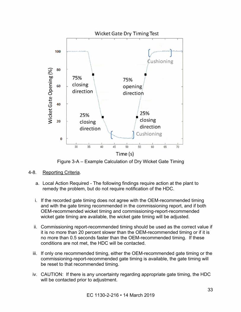
Figure 3-A – Example Calculation of Dry Wicket Gate Timing
4-8. Reporting Criteria.
a. Local Action Required - The following findings require action at the plant to remedy the problem, but do not require notification of the HDC.
i. If the recorded gate timing does not agree with the OEM-recommended timing and with the gate timing recommended in the commissioning report, and if both OEM-recommended wicket timing and commissioning-report-recommended wicket gate timing are available, the wicket gate timing will be adjusted.
ii. Commissioning report-recommended timing should be used as the correct value if it is no more than 20 percent slower than the OEM-recommended timing or if it is no more than 0.5 seconds faster than the OEM-recommended timing. If these conditions are not met, the HDC will be contacted.
iii. If only one recommended timing, either the OEM-recommended gate timing or the commissioning-report-recommended gate timing is available, the gate timing will be reset to that recommended timing.
iv. CAUTION: If there is any uncertainty regarding appropriate gate timing, the HDC will be contacted prior to adjustment.
EC 1130-2-216 • 14 March 2019 33
b. HDC Coordination Required - The following findings are complex, potentially dangerous and require coordination with the HDC. Plant staff will contact the HDC for further instructions if one of these conditions is discovered:
i. OEM-recommended gate timing data or the commissioning report timing information cannot be found;
ii. There is confusion regarding which historic gate timing should be used;
iii. The timing recommended in the commissioning report is more than 0.5 seconds faster than the OEM-recommended timing;
iv. The timing recommended in the commissioning report and the OEM-recommended timing differ by more than 20 percent;
v. The unit has a shutdown solenoid that allows the unit to operate when de-energized and shuts down the unit when energized; or
vi. The governor controls do not operate on the station service DC (battery) power system.
4-9. Frequency.
a. Wicket Gate Timing Tests - The governor gate-timing dry test will be performed once every two years.
b. Safe Shutdown Inspections - Inspection of the hydraulic lines, accumulators, shutdown solenoids and other equipment needed to ensure failsafe governor operation will be performed during the plant’s scheduled dewatered maintenance cycle, but not less frequently than every 6 years.
EC 1130-2-216 • 14 March 2019 34
Chapter 5 Reaction Turbine Runner Inspection
5-1. Objective.
a. Turbine runners are subject to water pressure, corrosion, cavitation, erosion, cyclic stresses, strain and fatigue. These conditions could result in wear, cracking and other damage. Additionally, if the original material were severely deteriorated or damaged, the runner could then be mechanically and hydraulically unbalanced. This could lead to higher cyclic loading on other portions of the unit, including damage to the water passage. It is the intent of this procedure to review the areas of concern on a runner in a systematic fashion, to document the present condition or any changes observed since the previous inspection, and to identify areas for additional investigation.
b. If any inspection or test performed in addition to those described in these procedures identifies something unusual, questionable, or is suspected to indicate a problem, the field inspector should raise the issue through the powerhouse chain of command and with the Hydroelectric Design Center (HDC). Also, if an unsafe or questionable condition is found between inspection cycles, plant staff should immediately raise the issue through the powerhouse chain of command and with the HDC. The goal of this inspection process is to assure that the machines are safe for operation.
c. This procedure is not an alternative to the condition assessment described in the Appendix E6 of the HydroAMP Condition Assessment instructions.
5-2. Applicability. This document is applicable to all reaction turbines with runner diameters larger than 36 inches, including propeller turbines, Kaplan turbines, Francis and pump-turbines. While these procedures can be used to inspect small station service units, their inspection is not required by the Turbine Integrity Inspection Program. Section 4-4 below addresses propeller and Kaplan turbines. Section 4-5 addresses Francis and pump-turbines.
5-3. Propeller and Kaplan Turbines.
a. Glossary of Terms – See Glossary for definitions related to a typical Kaplan or propeller- type turbine. See Appendix D, Figure 4-A for illustration of a Kaplan turbine.
b. Qualifications of Inspector - The inspector will have knowledge of hydraulic turbines and will have an understanding of mechanical drawings. This individual may be a tradesman, such as a millwright, machinist, or mechanic. The inspector will also be fluent in the English language and will be able to perform the physical activities as described.
EC 1130-2-216 • 14 March 2019 35
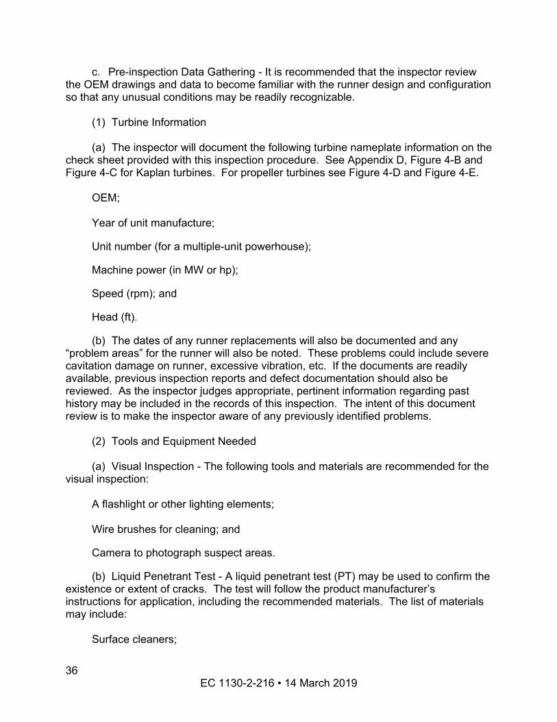
c. Pre-inspection Data Gathering - It is recommended that the inspector review the OEM drawings and data to become familiar with the runner design and configuration so that any unusual conditions may be readily recognizable.
(1) Turbine Information
(a) The inspector will document the following turbine nameplate information on the check sheet provided with this inspection procedure. See Appendix D, Figure 4-B and Figure 4-C for Kaplan turbines. For propeller turbines see Figure 4-D and Figure 4-E.
OEM;
Year of unit manufacture;
Unit number (for a multiple-unit powerhouse);
Machine power (in MW or hp);
Speed (rpm); and
Head (ft).
(b) The dates of any runner replacements will also be documented and any “problem areas” for the runner will also be noted. These problems could include severe cavitation damage on runner, excessive vibration, etc. If the documents are readily available, previous inspection reports and defect documentation should also be reviewed. As the inspector judges appropriate, pertinent information regarding past history may be included in the records of this inspection. The intent of this document review is to make the inspector aware of any previously identified problems.
(2) Tools and Equipment Needed
(a) Visual Inspection - The following tools and materials are recommended for the visual inspection:
A flashlight or other lighting elements;
Wire brushes for cleaning; and
Camera to photograph suspect areas.
(b) Liquid Penetrant Test - A liquid penetrant test (PT) may be used to confirm the existence or extent of cracks. The test will follow the product manufacturer’s instructions for application, including the recommended materials. The list of materials may include:
Surface cleaners;
EC 1130-2-216 • 14 March 2019 36
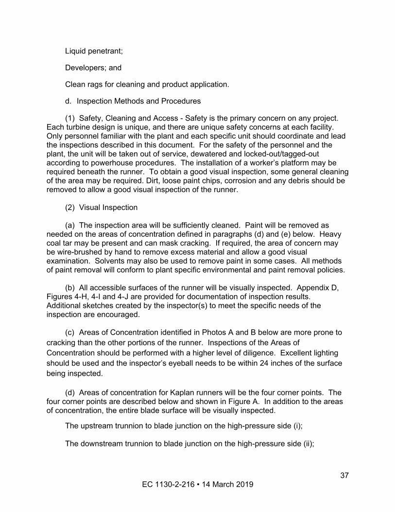
Liquid penetrant;
Developers; and
Clean rags for cleaning and product application.
d. Inspection Methods and Procedures
(1) Safety, Cleaning and Access - Safety is the primary concern on any project. Each turbine design is unique, and there are unique safety concerns at each facility. Only personnel familiar with the plant and each specific unit should coordinate and lead the inspections described in this document. For the safety of the personnel and the plant, the unit will be taken out of service, dewatered and locked-out/tagged-out according to powerhouse procedures. The installation of a worker’s platform may be required beneath the runner. To obtain a good visual inspection, some general cleaning of the area may be required. Dirt, loose paint chips, corrosion and any debris should be removed to allow a good visual inspection of the runner.
(2) Visual Inspection
(a) The inspection area will be sufficiently cleaned. Paint will be removed as needed on the areas of concentration defined in paragraphs (d) and (e) below. Heavy coal tar may be present and can mask cracking. If required, the area of concern may be wire-brushed by hand to remove excess material and allow a good visual examination. Solvents may also be used to remove paint in some cases. All methods of paint removal will conform to plant specific environmental and paint removal policies.
(b) All accessible surfaces of the runner will be visually inspected. Appendix D, Figures 4-H, 4-I and 4-J are provided for documentation of inspection results. Additional sketches created by the inspector(s) to meet the specific needs of the inspection are encouraged.
(c) Areas of Concentration identified in Photos A and B below are more prone to cracking than the other portions of the runner. Inspections of the Areas of Concentration should be performed with a higher level of diligence. Excellent lighting should be used and the inspector’s eyeball needs to be within 24 inches of the surface being inspected.
(d) Areas of concentration for Kaplan runners will be the four corner points. The four corner points are described below and shown in Figure A. In addition to the areas of concentration, the entire blade surface will be visually inspected.
The upstream trunnion to blade junction on the high-pressure side (i);
The downstream trunnion to blade junction on the high-pressure side (ii);
EC 1130-2-216 • 14 March 2019 37
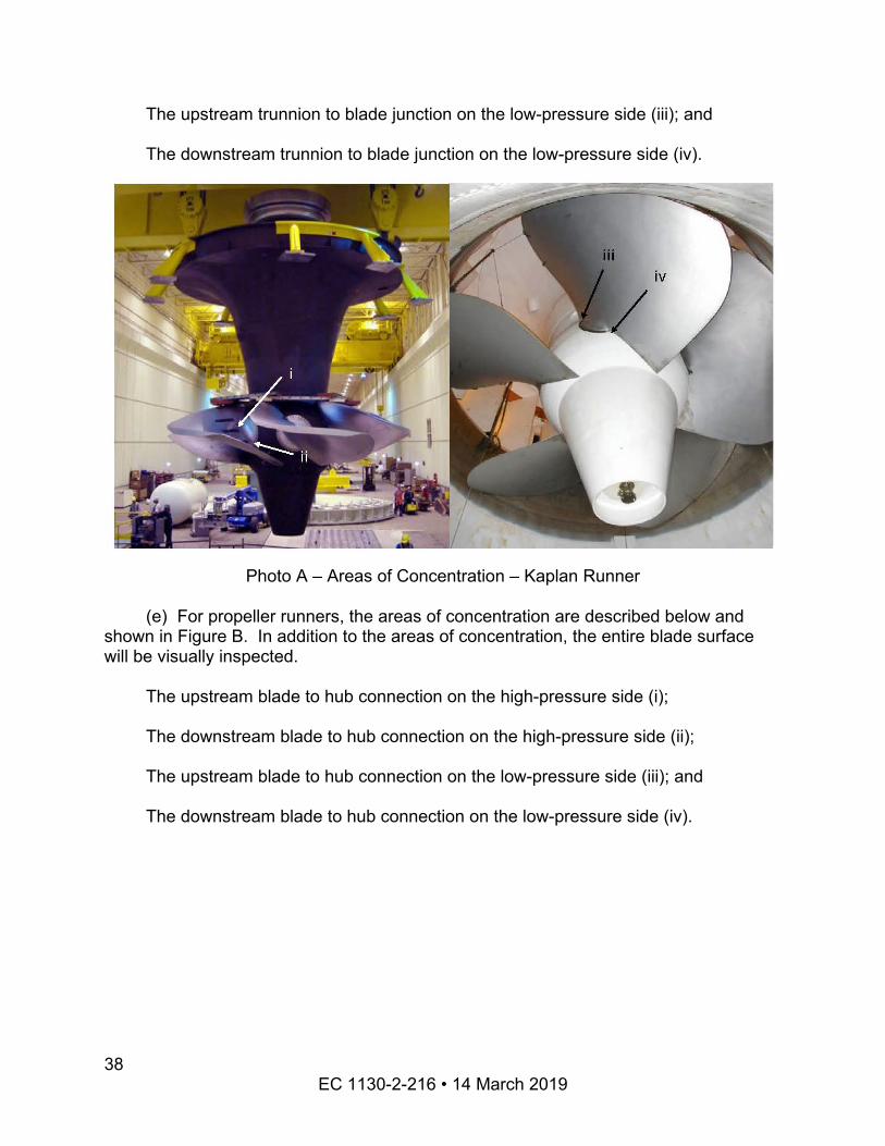
The upstream trunnion to blade junction on the low-pressure side (iii); and
The downstream trunnion to blade junction on the low-pressure side (iv).
Photo A – Areas of Concentration – Kaplan Runner
(e) For propeller runners, the areas of concentration are described below and shown in Figure B. In addition to the areas of concentration, the entire blade surface will be visually inspected.
The upstream blade to hub connection on the high-pressure side (i);
The downstream blade to hub connection on the high-pressure side (ii);
The upstream blade to hub connection on the low-pressure side (iii); and
The downstream blade to hub connection on the low-pressure side (iv).
EC 1130-2-216 • 14 March 2019 38
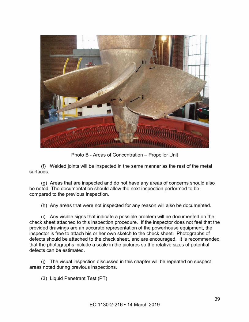
Photo B - Areas of Concentration – Propeller Unit
(f) Welded joints will be inspected in the same manner as the rest of the metal surfaces.
(g) Areas that are inspected and do not have any areas of concerns should also be noted. The documentation should allow the next inspection performed to be compared to the previous inspection.
(h) Any areas that were not inspected for any reason will also be documented.
(i) Any visible signs that indicate a possible problem will be documented on the check sheet attached to this inspection procedure. If the inspector does not feel that the provided drawings are an accurate representation of the powerhouse equipment, the inspector is free to attach his or her own sketch to the check sheet. Photographs of defects should be attached to the check sheet, and are encouraged. It is recommended that the photographs include a scale in the pictures so the relative sizes of potential defects can be estimated.
(j) The visual inspection discussed in this chapter will be repeated on suspect areas noted during previous inspections.
(3) Liquid Penetrant Test (PT)
EC 1130-2-216 • 14 March 2019 39
(a) The goal of the inspection is to identify cracks that need to be repaired, per the criteria identified in Section 4-4.d(4). Use PT as needed to help determine whether or not there are cracks and if they need to be repaired.
(b) If cracks are discovered consider the possibility of using PT to determine the extent of the cracks. If visual inspection identifies the possibility—but not the certainty— of a crack, then PT should be considered in order to confirm or deny the presence of a crack.
(c) Some of the Corps’ runners are badly rusted / corroded and because of this rust it is difficult to obtain reliable PT results. It is left to the inspector’s judgment as to whether the corrosion should be removed by grinding or other means in an attempt to obtain reliable PT results.
(4) Local Action Required
(a) For the purpose of this inspection, cracks are identified as either surface cracks or through cracks.
A surface crack is located on one surface, but does not propagate through the thickness of the material to appear as a crack on the opposite surface. There is no depth restriction on a surface crack: the crack could be only 1/64 of an inch deep, or it could be as deep as 99% of the material thickness. Either way, it’s characterized as a surface crack.
A through crack is a crack that appears on both the top surface and the bottom surface, propagating through the entire thickness of the material. The length of the crack on each surface does not need to be equal, and on thick sections it is highly likely that the crack length on each surface will be unequal. The proper way to characterize a through crack is by identifying the length of the crack on each surface—for example: “A through crack, 8 inches long on the top surface, 2 inches long on the bottom surface.”
(b) In the areas of concentration, no through cracks are permissible. Any units with a through crack in an area of concentration are to be taken out of service and repaired. The Hydroelectric Design Center will be contacted to provide weld procedures and for assistance in planning the repair process.
(c) In the areas of concentration, surface cracks whose length exceeds 35% of the material thickness (thickness at the location of the crack) are to be repaired before the unit is placed back in service. The Hydroelectric Design Center will be contacted to provide weld procedures and for assistance in planning the repair process.
(d) In areas of concentration, for surface cracks whose length is less than 35% of the material thickness, contact HDC for support in developing a monitoring program.
EC 1130-2-216 • 14 March 2019 40
(e) For surface cracks at locations other than areas of concentration, the Hydroelectric Design Center will be contacted to determine the proper course of action.
(f) If paint was removed in order to perform the inspections, the surfaces should be repainted per Appendix G.
5-4. Francis Turbines and Francis-Type Pump-Turbines.
a. Glossary of Terms – See the Glossary for definitions of typical Francis turbine components. These definitions are general and may not be applicable to all units. See Appendix D, Figure 4-F for illustration of typical Francis turbine components.
b. Qualifications of Inspectors - The inspector will have knowledge of hydraulic turbines and will have an understanding of mechanical and electrical drawings. This individual may be a tradesman, such as a millwright, machinist, or a mechanic. The inspector will also be fluent in the English language and will be able to perform the physical activities as described.
c. Pre-inspection Data Gathering - It is recommended that the inspector review the OEM drawings and data to become familiar with the runner design and configuration so that any unusual conditions may be readily recognizable.
(1) Turbine Information
(a) The inspector will document the following turbine nameplate information on the check sheet provided with this procedure. See Appendix D, Figure 4-G attached to this procedure for the check sheet.
OEM;
Year of unit manufacture;
Unit number (for a multiple-unit powerhouse);
Machine power (in MW or hp);
Speed (rpm); and
Head (ft).
(b) The dates of any runner replacements will also be documented. Any “problem areas” for the runner will also be documented. These problems could include severe cavitation damage on a runner, excessive vibration, etc. If the documents are readily available, previous inspection reports and defect documentation should also be reviewed. As the inspector judges appropriate, pertinent information regarding past
EC 1130-2-216 • 14 March 2019 41
history may be included in the records of this inspection. The intent of this document review is to make the inspector aware of any previously identified problems.
(2) Tools and Equipment Needed
(a) Visual Inspection - The following tools and materials are recommended for the visual inspection:
A flashlight or other lighting elements;
Wire brushes for cleaning;
A borescope for inspection of critical areas of the runner that are inaccessible for direct visual observation; and
A camera to photograph suspect areas.
(b) Liquid Penetrant Test - The PT may be performed and will follow the product manufacturer’s instructions for application, including the recommended materials. The list of materials may include:
Surface cleaners;
Liquid penetrant;
Developers; and
Clean rags for cleaning and product application.
d. Inspection Methods and Procedures
(1) Safety, Cleaning and Access - Safety is the primary concern on any project. Each turbine design is unique, and there are unique safety concerns at each facility. Only personnel familiar with the plant and each specific unit should coordinate and lead the inspections described in this document. For the safety of the personnel and the plant, the unit will be taken out of service, dewatered and locked-out/tagged-out according to the powerhouse’s procedures. The installation of a worker’s platform to facilitate the inspection may be required beneath the runner. To obtain a good visual inspection, some general cleaning of the area may be required. Dirt, loose paint chips, corrosion and any debris should be removed to allow a good visual inspection of the runner.
(2) Visual Inspection
(a) The inspection area will be sufficiently cleaned. Paint will be removed as needed on the areas of concentration defined in paragraph (b) below. Heavy coal tar
EC 1130-2-216 • 14 March 2019 42
may be present and can mask cracking. If required, the area of concern may be hand wire brushed to remove excess material and allow for a good visual examination to determine present condition. Solvents may also be used for paint removal. All methods of paint removal will conform to plant specific environmental and paint removal policies.
(b) Areas of Concentration identified below are more prone to cracking than the other portions of the runner. Inspections of the Areas of Concentration should be performed with a higher level of diligence. Excellent lighting should be used and the inspector’s eyeball needs to be within 24 inches of the surfaces being inspected. For a Francis runner or a Francis-type pump-turbine, areas of concentration are defined below and are shown on Photo C.
The junction of the blade leading edge to the runner band on the high-pressure side (a);
The junction of the blade leading edge to the runner crown on the high-pressure side (b);
The junction of the blade trailing edge to the runner band on the high-pressure side (c);
The junction of the blade trailing edge to the runner crown on the high-pressure side. In the entire runner, this is the area most prone to cracking (d);
The junction of the blade leading edge to the runner band on the low-pressure side (e);
The junction of the blade leading edge to the runner crown on the low-pressure side (f);
The junction of the blade trailing edge to the runner band on the low -pressure side (g); and
The junction of the blade trailing edge to the runner crown on the low-pressure side (h).
EC 1130-2-216 • 14 March 2019 43
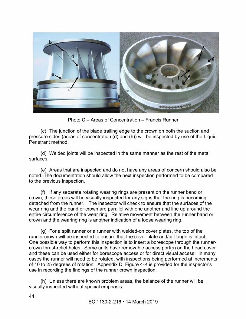
Photo C – Areas of Concentration – Francis Runner
(c) The junction of the blade trailing edge to the crown on both the suction and pressure sides (areas of concentration (d) and (h)) will be inspected by use of the Liquid Penetrant method.
(d) Welded joints will be inspected in the same manner as the rest of the metal surfaces.
(e) Areas that are inspected and do not have any areas of concern should also be noted. The documentation should allow the next inspection performed to be compared to the previous inspection.
(f) If any separate rotating wearing rings are present on the runner band or crown, these areas will be visually inspected for any signs that the ring is becoming detached from the runner. The inspector will check to ensure that the surfaces of the wear ring and the band or crown are parallel with one another and line up around the entire circumference of the wear ring. Relative movement between the runner band or crown and the wearing ring is another indication of a loose wearing ring.
(g) For a split runner or a runner with welded-on cover plates, the top of the runner crown will be inspected to ensure that the cover plate and/or flange is intact. One possible way to perform this inspection is to insert a borescope through the runner-crown thrust-relief holes. Some units have removable access port(s) on the head cover and these can be used either for borescope access or for direct visual access. In many cases the runner will need to be rotated, with inspections being performed at increments of 10 to 25 degrees of rotation. Appendix D, Figure 4-K is provided for the inspector’s use in recording the findings of the runner crown inspection.
(h) Unless there are known problem areas, the balance of the runner will be visually inspected without special emphasis.
EC 1130-2-216 • 14 March 2019 44
(i) Any areas that were not inspected for any reason will also be documented.
(j) Any visible signs that indicate a possible problem will be documented on the check sheet provided with this procedure. If the inspector does not feel that the provided drawings are an accurate representation of the powerhouse equipment, the inspector is free to attach his or her own sketch to the check sheet. Photographs of defects should be attached to the check sheet. It is recommended that the photographs include objects in the pictures so that the relative sizes of potential defects can be estimated.
(k) The visual inspection discussed in this chapter will be repeated on suspect areas noted during previous inspections.
(3) Liquid Penetrant Test (PT)
(a) The goal of the inspection is to identify cracks that need to be repaired, per the criteria identified in Section 4-5.d(4). Use PT as needed to help determine whether or not there are cracks and if they need to be repaired.
(b) If cracks are discovered consider the possibility of using PT to determine the extent of the cracks. If visual inspection identifies the possibility—but not the certainty— of a crack, then PT should be considered in order to confirm or deny the presence of a crack.
(c) Some of the Corps’ runners are badly rusted / corroded and because of this rust it is difficult to obtain reliable PT results. It is left to the inspector’s judgment as to whether the corrosion should be removed by grinding or other means in an attempt to obtain reliable PT results.
(4) Local Action Required
(a) The cracks found in the areas of concern defined by Section 4-5.d(2) paragraph (b) will be evaluated to determine whether or not they need to be repaired. The first step of the evaluation is to measure the attachment length of the runner blade. The blade-to-band attachment length is the length of the blade, from entrance edge to exit edge, measured along the attachment of the blade to the band. The blade-to-crown attachment length is the length of the blade, from entrance edge to exit edge, measured along the attachment of the blade to the crown.
(b) For Francis runners, unlike Kaplan runners, all cracks will be evaluated as surface cracks. While longer cracks are most likely through cracks, each crack will be evaluated according to its surface length.
(c) If the length of any crack in an area of concentration exceeds 20% of the attachment length, the unit will be taken out of service until the crack is repaired. The
EC 1130-2-216 • 14 March 2019 45
Hydroelectric Design Center will be contacted to provide weld procedures and for assistance in planning the repair process.
(d) For cracks in an area of concentration whose length is less than 20% of the attachment length, the following requirements apply:
A Repair Plan will be created in consultation with the Hydroelectric Design Center.
A Monitoring Plan will be developed in consultation with the Hydroelectric Design Center.
Initial monitoring of the crack, to determine the approximate rate at which the crack is growing, will be according to the following schedule:
Length of Crack, as a percentage of Attachment Length Frequency of Inspection Period
0% to 5% Every 2 years
5% to 10% Every Year
10% to 20% Every 6 Months
(e) For cracks found at locations other than an area of concentration, the Hydroelectric Design Center will be contacted for support in developing an appropriate monitoring and repair plan.
5-5. Repainting After Inspection. Any surface that was stripped for inspection should be repainted. See Appendix G for recommended painting procedures.
5-6. Reporting Criteria.
HDC Coordination Required - Repaired cracks that continuously re-occur and increase in length with each inspection and repair cycle will be documented and reported to the HDC for assistance.
5-7. Frequency. Crack inspections as described in this chapter will be performed during the unit’s scheduled dewatered inspection, but in no case less than once every 6 years.
EC 1130-2-216 • 14 March 2019 46
Chapter 6 Turbine Head Cover Inspection
6-1. Objective.
a. Head covers are subject to water pressure, corrosion, erosion, cyclic stresses, strain and fatigue. These conditions could cause the original materials to deteriorate and ultimately fail. This failure could result in a possible loss of water containment, causing property damage and injury to personnel. It is the intent of this procedure to review head covers in a systematic fashion and identify any conditions that place the hydraulic turbine at increased risk.
b. If any inspection or test performed in addition to those described in these procedures identifies something unusual, questionable, or is suspected to indicate a problem, the field inspector should raise the issue through the powerhouse chain of command and with the Hydroelectric Design Center (HDC). Also, if an unsafe or questionable condition is found between inspection cycles, plant staff should immediately raise the issue through the powerhouse chain of command and with the HDC. The goal of this inspection process is to assure that the machines are safe for operation.
6-2. Applicability. This document is applicable to all vertical shaft reaction turbines with runner diameters greater than 36 inches, including propeller turbines, Kaplan turbines, Francis and pump-turbines. While these procedures can be used to inspect small station service units, their inspection is not required by the Turbine Integrity Inspection Program.
6-3. Glossary of Terms. See Glossary for definitions related to a typical reaction type hydraulic turbine. See Appendix E, Figure 5-A and Figure 5-D for illustration of a reaction type hydraulic turbine.
6-4. Qualifications of Inspectors. The inspector will have knowledge of hydraulic turbines and will have an understanding of mechanical drawings. This individual may be a tradesman, such as a millwright, machinist, or a mechanic. The inspector will also be fluent in the English language and will be able to perform the physical activities as described.
6-5. Pre-inspection Data Gathering. It is recommended that the inspector review the original equipment manufacturer (OEM) drawings and data to become familiar with the head cover(s) design and configuration so that any unusual conditions may be readily recognizable. Particularly, it is recommended that the inspector research the OEM plate or wall thicknesses of the head covers so the severity of cavitation and erosion damage will be more recognizable.
EC 1130-2-216 • 14 March 2019 47
a. Turbine Information
(1) The inspector will document the following turbine nameplate information on the check sheet provided with these procedures. See Appendix E, Figure 5-B and Figure 5-E.
(a) OEM;
(b) Year of unit manufacture;
(c) Unit number (for a multiple-unit powerhouse);
(d) Machine power (in MW or hp);
(e) Speed (rpm); and
(f) Head (ft).
(2) It is recommended that the inspector review the original equipment manufacturer (OEM) drawings and overhaul history so that any unusual conditions may be readily recognizable. An overhaul is defined as the periodic major maintenance activity that occurs on intervals of between 2 and 6 years. Activities associated with an overhaul include dewatered inspections, checking wicket gate timing, replacing pumps, and cavitation repair. A Major Rehabilitation involves a significant disassembly of the unit beyond the scope of a typical overhaul. A Major Rehabilitation typically replaces the turbine runner, replaces other worn parts and restores the machine to almost “as new” condition. After the Major Rehabilitation is completed, it is expected that major repair work should not be needed for at least the next 20 years. It is recommended that the inspector be familiar with the overall scope of work for previous Major Rehabilitations and overhauls, and when each were performed
(3) Any “problem areas” for the unit will also be documented. These problems could include severe cavitation damage on the head cover, excessive vibration, etc.
b. Head Cover Information - A physical description of the head cover(s) will be provided. The description will include whether the head cover is of welded plate steel, cast steel, cast iron, or other construction. As-built drawings, if available, are sufficient. If drawings are not available, the inspector will provide photographs or sketches of the area. The material of the head cover will be documented.
c. Tools and Equipment Needed
(1) Visual Inspection - The following tools and materials are recommended for the visual inspection:
(a) A flashlight or other lighting elements;
EC 1130-2-216 • 14 March 2019 48
(b) Hand wire brushes for cleaning;
(c) Wrenches and tools as needed;
(d) A camera to photograph suspect areas; and.
(e) A borescope or remote camera.
(2) Liquid Penetrant Test - A liquid penetrant test (PT) may be performed as a result of the visual inspection. The PT will follow the product manufacturer’s instructions for application, including the recommended materials. The list of materials may include:
(a) Surface cleaners;
(b) Liquid penetrant;
(c) Developers; and
(d) Clean rags for cleaning and product application.
6-6. Inspection Methods and Procedures.
a. Safety, Cleaning and Access
(1) Safety is the primary concern on any project. Each turbine design is unique, and there are unique safety concerns at each facility. Only personnel familiar with the plant and each specific unit should coordinate and lead the inspections described in this document. For the safety of the personnel and the plant, the unit will be taken out of service, dewatered, and locked-out/tagged-out according to the powerhouse’s procedures.
(2) The areas to be inspected are not always easily accessible and may require some disassembly (such as walkways) to obtain access. Additional lighting may also be required. The areas that are being inspected are prone to water in and around the areas. These wet areas can be slippery and caution should be exercised. These wet areas can conduct electricity.
(3) Lead paint may be present on the surfaces. Care should be exercised around this hazardous material. Lead can be absorbed in the human body by several ways that are hazardous: inhaled in the air, absorbed through the skin, or ingested through the mouth. If scraping or grinding on surfaces that are suspected of having lead paint is performed, powerhouse procedures will be followed.
(4) To obtain a good visual inspection, some general cleaning of the area may be required. Dirt, loose paint chips, corrosion and any debris should be removed to allow a good visual inspection.
b. Visual Inspection
EC 1130-2-216 • 14 March 2019 49
(1) Inspection of bolts and studs is not required as part of this inspection. Chapters 1 and 2 address inspection of the bolts and studs
(2) Appendix E, Figure 5-C and Figure 5-F are provided for the inspector’s use in recording the results of the inspection. The inspector is free to create his/her own recording sheet if they would prefer. One of the best recording sheets is a photocopy of the manufacturer’s head cover drawing.
(3) The metal surfaces of the head cover will be visually inspected. All accessible surfaces will be inspected including the skin, ribs and welds on the dry side of the head cover. Magnetic particle (MT) and/or Ultrasonic inspection (UT) may be used to examine the components. The areas of concern for the head cover on a Kaplan or propeller type hydraulic turbine include the annular connection flanges at the stay ring, the connection flanges between the inner to intermediate head covers, and the connection flanges between the intermediate to outer head covers. The areas of concern for the head cover on a Francis turbine or Francis-type pump-turbine are the connection flanges at the stay ring. Particular attention will be paid to the area between the bolts on the bolt circles at these connections on all turbines. Attention should be paid to any cracking in the paint near these areas, as this may indicate unusual mechanical stress on the component, corrosion on the component, or other potential damage.
(4) The inspection area will be sufficiently cleaned. Heavy coal tar may be present and can mask cracking. If required, the surfaces may be wire-brushed by hand to remove excess material and allow a good visual examination. Solvents, surface grinding, and/or sandblasting may also be used to remove paint. If lead paint is present or suspected, then proper procedures must be used if the paint is removed. All methods of paint removal will conform to plant specific environmental and paint removal policies.
(5) The Inspector will establish a procedure that will provide 100% inspection to all accessible surfaces and can provide a good reference of the results. Hand sketches will identify land mark references such as pit entranceway, upstream direction, servomotor location, etc. The intent is to visually inspect and document all of the accessible surfaces of the head cover. Bright lighting will be used for the inspection. The inspection will utilize a similar 0-degree reference point for each inspection. If there is a reference system already established for the powerhouse (or unit) that system will be used. If there is no established reference system, consider using a reference system that uses 0 degrees as the upstream direction. Inspection will progress in a clockwise direction, as viewed from above, around the head cover. The same reference point for each unit will be used in subsequent inspections for consistency. The goal is to be able to properly document an inspection for future reference. Reference points and indexed locations may be marked for subsequent inspections using paint, stamping or permanent marker. The indexed locations will also be documented in the written records.
EC 1130-2-216 • 14 March 2019 50
(6) One possible inspection procedure is as follows: Mark a grid on the head cover by permanent marker, paint or other means. The gridlines will divide the head cover into squares that are no larger than 1 foot by 1 foot. Each square will be numbered. The grid will also be documented on the inspection check sheet provided with this procedure. The same inspection grid and the same numbering of the squares will be used in each subsequent inspection. The intent is to be able to properly document an inspection for future reference, and to more accurately track any potential defects.
(7) It is not the intent of this procedure that specialized scaffolding or rigging be used to access the wetted side of Kaplan or propeller head covers. In most cases, the wetted surface of Kaplan or propeller head covers will either be too rusty, or too far away from the inspector, to allow a meaningful inspection. In this situation, inspection of the dry side of the head cover will be sufficient.
(8) Inspection of the wetted side of Francis turbine head covers should be performed using a borescope, remote camera or similar device. Inspection access can be via removable hatches in the head cover (if they exist) or through the thrust relief holes in the runner crown. When inspecting the wetted side of the head cover, look for fasteners or cover plates that may be loose and cause damage. In most cases the wetted surface will be too rusty, or too difficult to access, to be meaningfully inspected for cracks.
(9) Welded joints will be inspected in the same manner as the rest of the metal surfaces.
(10) The visual inspection discussed in this chapter will be repeated on suspect areas noted during previous examinations.
(11) Any defects found will be documented with the check sheet provided with this procedure. If the inspector does not feel that the sketches provided in the check sheet are an accurate representation of the head cover, the inspector should attach his or her own sketch to the check sheet. Photographs of the suspect areas should be attached to the check sheet, and are encouraged. It is recommended that the photographs include objects in the pictures so that the relative sizes of potential defects can be estimated.
(12) Measurements of areas, depths, etc. will be recorded. Areas that are inspected and do not have any areas of concerns will also be noted. The documentation should allow the next inspection performed to be compared to the previous inspection.
(13) Any areas that were not inspected for any reason will also be documented.
c. Liquid Penetrant Test
EC 1130-2-216 • 14 March 2019 51
(1) If the visual inspection indicates possible problem areas, the suspected areas will be further examined by a liquid penetrant test (PT). Other non-destructive test methods such as magnetic particle testing or ultrasonic testing may be substituted for the PT inspection if qualified personnel are available.
(2) The PT will be conducted according to the PT product manufacturer’s instructions. The basic steps of a PT examination are presented below for reference. Should the manufacturer’s recommendations deviate from the instruction below, the manufacturer’s instructions will be followed.
(a) Pre-cleaning:
Proper surface cleaning is essential to a successful PT. Any dirt, paint, oil, grease or any loose scale that could either keep penetrant out of a defect or cause irrelevant or false indications will be removed from the test surface.
Cleaning methods may include solvents, alkaline cleaning steps, and vapor degreasing. Mechanical cleaning methods such as grinding, sandblasting, polishing or wire brushing by hand may be required. All methods of paint removal will conform to plant specific environmental and paint removal policies.
(b) Application of penetrant - The penetrant will be applied to the test surface and allowed to settle into surface impurities. The dwell time is dependent on the penetrant used; refer to the penetrant manufacturer’s instructions.
(3) Excess penetrant removal - The excess penetrant will then be removed from the surface according to the manufacturer’s instructions. If excess penetrant is not properly removed, the penetrant may leave a background in the developed area that can mask indications or defects or produce false positive indications.
(4) Application of developer - A developer will be applied to the test area. Several developer types are available; the choice should be compatible with the choice of penetrant.
(5) Inspection - The inspector will use light with adequate intensity to illuminate the area per the manufacturer’s instructions. Inspection will take place shortly after development time.
(6) Post-inspection cleaning - The test surface will be cleaned after inspection.
(7) Findings of all linear indications and rounded indications larger than 3/16 inch will be documented.
d. Shaft Seal Visual Inspection
(1) While the unit is in operation, the shaft seal will be visually inspected for excessive leakage. Excessive leakage will be defined as a substantial increase in
EC 1130-2-216 • 14 March 2019 52
leakage from normal conditions. Leakage that exceeds 75% of the capacity of the drains or sump pumps is excessive.
(2) If excessive leakage is found, the seal flange area will be visually inspected for flange cracks, loose bolts, or other questionable conditions. The shaft sleeve will be inspected for excessive wear. Repairs will be made as required. Contact HDC if support is needed.
e. Repainting after Inspection - Any surface that was stripped for inspection will be repainted per the instructions in Appendix G.
6-7. Reporting Criteria.
HDC Coordination Required - The following findings are complex, potentially dangerous and require coordination with HDC. Any of the following findings will be reported to HDC:
a. Cracks in the head cover.
(1) If cracks are found in the head cover, the unit will not be placed back in service until receiving approval from HDC.
(2) Head cover cracks will not be repaired until an engineering evaluation of the crack has been performed.
b. Loose cover plates between the bottom of the head cover and the top of a Francis runner.
c. If excessive leakage as defined above is found around the shaft seal, or if flange cracks, loose bolts, or other questionable conditions are found, and are unable to be repaired by project staff, upward reporting is required.
6-8. Frequency. The head covers will be inspected during the plant’s scheduled dewatered inspection, but not less than once every six years. Inspections on pump-turbines will be approximately twice the frequency of conventional turbines if the pump-turbines operate in both the pumping and generating modes.
EC 1130-2-216 • 14 March 2019 53
Chapter 7 Water Passage Access Door Inspections
7-1. Objective.
a. Water containment structures and mechanical components including penstocks, spiral cases, and draft tubes, are subject to pressure, corrosion, erosion, cyclic stresses, strain and fatigue. These conditions could cause the original materials to deteriorate and ultimately fail. This failure could result in a possible loss of water containment. It is the intent of this procedure to review access doors and access hatches associated with those components in a systematic fashion to document the present condition and any changes since the previous inspection.
b. If any inspection or test performed in addition to those described in these procedures identifies something unusual, questionable, or is suspected to indicate a problem, the field inspector should raise the issue through the powerhouse chain of command and with the Hydroelectric Design Center (HDC). Also, if an unsafe or questionable condition is found between inspection cycles, plant staff should immediately raise the issue through the powerhouse chain of command and with the HDC. The goal of this inspection process is to assure that the machines are safe for operation.
7-2. Applicability. This chapter applies to all hydraulic turbines including propeller turbines, Kaplan turbines, Francis turbines, and pump-turbines.
7-3. Design Perspective.
a. One common problem with access doors in frames that have tapped bolt holes is that the tapped holes “strip out” after years in service. This is caused by repeated application of too much torque to the bolts when securing the access door in the closed position or by using bolts that are stronger than the tapped holes. If the threads in access door tapped holes are “stripped out”, there is usually sufficient material to overbore and re-tap the threads only once. There is not usually enough material to overbore the frame a second time if a second “stripping” occurs. For this reason, if too much torque is applied, the fasteners in the access door (either bolts or studs) should be designed to fail before the tapped threads in the frame.
b. Considering this common problem, the following procedures should be followed when working with access doors:
(1) Proper tightening torque information for the access door fasteners will be obtained and used. If OEM information is not available, a determination of proper torque will be made by engineering personnel.
(2) If the fasteners fail in service, the fasteners will not simply be replaced with fasteners of stronger material. Engineering staff will evaluate the joint design and determine the proper fastener material.
EC 1130-2-216 • 14 March 2019 54
(3) A torque wrench or an impact wrench with adjustable torque should be used to tighten the stud nuts or bolts. The proper torque should be determined from the load bearing capacity of the tapped threads, not from the strength of the bolt or stud.
7-4. Glossary of Terms. See Glossary for definitions related to a typical vertical turbine.
7-5. Qualifications of Inspectors. The inspector will have knowledge of hydraulic turbines and/or hydraulic steel structures and will have an understanding of mechanical drawings. This individual may be a tradesman, such as a millwright, machinist, or a mechanic. The inspector will also be fluent in the English language and will be able to perform the physical activities as described.
7-6. Pre-inspection Data Gathering.
a. Age, Maintenance and Overhaul History
(1) The inspector will document the following turbine nameplate information on the check sheet provided with these procedures. See Appendix F, Figure 6-A for the form on which to record the information.
(a) Original equipment manufacturer (OEM);
(b) Year of unit manufacture;
(c) Unit number (for a multiple unit powerhouse);
(d) Machine power (in MW or hp); and
(e) Head (ft).
(2) Any “problem areas” for the unit will also be noted. These problems should be limited to areas that are associated with this inspection procedure. This would include the spiral case and draft tube steel plates as well as the access door areas. Any previous repairs and/or replacement of fasteners will be documented on the inspection check sheet.
b. Water Passage Access Door
(1) If manufacturer’s drawings are available, a copy of the drawing should be reviewed by the inspector and attached to the inspection report. If drawings are not available, the inspector will provide a physical description of the access door including whether it is of plate steel, cast steel, or other construction.
(2) The inspector will document OEM data such as material specifications, plate thickness, etc., if the information is available.
EC 1130-2-216 • 14 March 2019 55
(3) If available, the OEM-recommended bolt torque for the access door bolts will be documented.
c. Tools and Equipment Needed - The following tools and equipment will be necessary for the inspections described in this document:
(1) Additional lighting, power cords, ground fault interrupters, low voltage lighting, or other equipment as needed to provide adequate lighting and electrical safety;
(2) Wrenches, hand tools to open and close access doors;
(3) Taps and wire brushes to manually clean tapped holes and bolt threads;
(4) New access door gasket or seal material in the event that the existing seal is found damaged; and
(5) Calibrated torque wrench or calibrated adjustable torque impact driver.
7-7. Inspection Methods and Procedures.
a. Safety, Cleaning and Access
(1) Safety is the primary concern on any project. Each turbine design is unique, and there are unique safety concerns at each facility. Only personnel familiar with the plant and specific unit should perform the inspections described in this procedure. Care must be exercised when encountering any active power devices, such as electrical, hydraulic and/or pneumatic actuation systems. For the safety of the personnel and the plant, it is essential that the hydraulic turbine be shut down, locked and tagged out of service, and dewatered. The lock-out/tag-out should be performed according to powerhouse procedures.
(2) To obtain a good visual inspection, some general cleaning of the area may be required. Dirt, loose paint chips, corrosion and any debris will be removed to allow a good visual inspection of the inspection surface, especially the area near the fasteners. The general visual condition of the fasteners should be obtained as well as the surface to which the nut or bolt is connected.
(3) Lead paint may be present on the surfaces. Care should be exercised around this hazardous material. Lead can be absorbed in the human body by several ways that are hazardous: inhaled in the air, absorbed through the skin, or ingested through the mouth. If scraping or grinding on surfaces that are suspected of having lead paint is necessary, use proper procedures.
b. Access Door Visual Inspection
EC 1130-2-216 • 14 March 2019 56
(1) The inspector will create a sketch to record the findings of this inspection. The typical sketches in Appendix F, Figures 6-B, 6-C and 6-D may be used, or alternately the inspector may create his/her own sketch. Pictures will also be taken and included in the documentation.
(2) The metal surfaces of the door, the door frame and the area of the spiral case or draft tube near the access door itself will be inspected.
(3) If the visual inspection indicates possible problem areas, the suspected areas will be reported up the appropriate chain of command.
(4) Welded joints will be inspected in the same manner as the rest of the metal surfaces.
(5) Identify areas where the paint or protective coating is no longer effective or is completely gone.
(6) The connection of the access door frame to the spiral case or draft-tube liner will be examined. If the access door is rectangular (as opposed to round or oval), areas of concentration for this inspection are areas near the four corner points on the access door frame. This inspection may be difficult because the access around the frame is sometimes limited. At a minimum, areas near the four corners are prone to cracks and will be visually inspected.
(7) Verify that the studs/bolts match the material specified by the OEM, or that the material of the studs/bolts currently in use has been had an engineering analysis to assure they will not “strip out” any tapped threads.
(8) The bolted connections of the door to the frame are to be visually inspected. The hardware should have the threads cleaned with a wire brush and threads will be visually inspected. If the fastener is a bolt (as opposed to a stud), the connection of the bolt shank to the head will be visually examined for cracks or deterioration. Any fastener that is questionable will be replaced.
(9) The female threads will be chased with a quality tap of the proper size and thread pitch. Questionable female threads that are found when chasing with a tap will be documented and reported. A tap will be used to check for excessive clearance between the tap and the hole. Clearance will be measured by sideways movement of the tap when it is thread-engaged in the component for a depth of at least one tap diameter. Excessive clearance will be defined as sideways movement of approximately 1/32-inch of travel or more.
(10) If rivets are present near the access door, the rivets will be inspected per the procedures of Chapter 7.
(11) The alignment of the door to the frame will be checked. The inspector will ensure that the door closes with minimum effort and the door and frame are parallel to
EC 1130-2-216 • 14 March 2019 57

one another when in the closed position. The inspector will also ensure that there are no gaps between the door and the door frame when closed. If the door is warped or misaligned to the extent there is water leakage when the door is closed and the studs/bolts are tightened to the proper torque, the condition will be upward reported.
(12) Before closing the access door, the gasket or seal that was removed will be inspected and replaced, if necessary.
(13) The door fasteners will be reinstalled and tightened to the OEM-recommended torque, if available.
(a) If OEM torque values are not available, a torque value that produces a 15,000 psi stress in the fasteners may be used, provided that the following criteria are met:
The fastener is steel, stainless steel, brass or bronze.
If the fastener is brass or bronze it must have a material yield strength greater than 25,000 psi.
The depth of the tapped hole in the door frame is at least one stud/bolt diameter deep.
(b) Torque values that produce a 15,000 psi stress in the fasteners are found in Appendix A, Table 1-B.
(c) If any of the following exist, contact HDC for guidance:
The material strength of brass or bronze studs/bolts is unknown.
The depth of the tapped holes in the door frame is less than the diameter of the stud/bolt.
The stud/bolt material is something other than steel, stainless steel, brass or bronze.
(14) After the unit is watered-up, the area will be inspected for leaks.
(15) On units that have access door frames embedded into concrete with no plate-steel spiral case (typically access hatches in Kaplan units), the areas around the juncture of the access door frame and the concrete will be visually inspected. The inspector will create a sketch or drawing of the door/hatch and the frame and will indicate any defects found on the sketch. The manufacturer’s drawing may be the most convenient drawing to use for this purpose. All concrete will have incidental cracks. The goal of this inspection is to identify cracks, or concrete deterioration, that compromises the strength of the access door and its mounting/retention structure. Any of the following conditions will be documented and upwardly reported:
(a) Cracks larger than an 1/8” in width
EC 1130-2-216 • 14 March 2019 58
(b) Cracks forming a system. Examples of this include:
Individual cracks that connect with one another
Cracks that run from one structural element into another
(c) Cracks that are growing
(d) Cracks that are producing fine particles and aggregate
(e) Cracks that are leaking water
(f) If the inspector is uncertain as to whether there is reason for concern regarding a specific crack, the inspector should err on the side of caution and request engineering review.
7-8. Repainting After Inspection. If the protective coating on the access door or the access door frame has deteriorated or broken down, the surfaces will be repainted. The recommended paint is identified in Appendix G.
7-9. Reporting Criteria.
HDC Coordination Required - The following findings are complex, potentially dangerous and require coordination with HDC.
a. Bolt or Stud material different than what was supplied by the OEM.
b. Bolt, stud or tapped hole conditions identified in Section 6-8.b(13)(a) that require guidance from HDC.
c. Access door warped or misaligned with the door frame.
d. Access door frame tapped holes or fasteners with excessively worn or corroded threads.
e. Cracks in the door frame or the door.
f. Any abnormal or unusual findings such as an area that appears to be bulging.
g. Water leakage around the door frame.
h. Cracks in the concrete around embedded door frames as described in Section 6-8.b(15).
7-10.Frequency. All exposed spiral-case and water-passage access doors will be inspected not less than once every six years. Inspections of pump-turbines will be approximately twice the frequency of the inspections of conventional turbines units if the pump-turbines operate in both the pumping and generating modes.
EC 1130-2-216 • 14 March 2019 59
Chapter 8 Exposed Spiral Case Extension Inspections
8-1. Objective.
a. Metallic structures that constrain water pressure (spiral case, draft tube, etc.) are subject to pressure, corrosion, erosion and cyclic stresses that can cause the original material to deteriorate. This deterioration could result in a failed structure and a loss of water containment. This failure would result in a possible flooding condition. It is the intent of this procedure to visually inspect and perform a limited amount of non-destructive examination to document the present condition and to also establish a baseline for identifying any change of condition during subsequent inspections.
b. In addition to these procedures, if at any time an inspection or test identifies something unusual, doubtful or a suspected problem, the field inspector should raise the issue with the plant manager and engineering staff. Also, if an unsafe or questionable condition is found in between inspection cycles, plant staff should notify the plant manager and engineering staff. The goal of this process is to assure that the machines are safe for operation.
8-2. Applicability. This chapter applies to all plants where an exposed spiral case extension is located inside the powerhouse or where severe and sudden powerhouse flooding would result from failure of the penstock. A particular focus is directed at exposed riveted steel water passages where grease has been used as a protective exterior coating.
8-3. References.
a. USBR FIST Manual: Inspection of Steel Penstocks and Pressure Conduits, Sept 1996, McStraw. https://www.usbr.gov/power/data/fist/fist2_8/vol2-8.pdf
b. USACE Technical Report ITL-99-5: Rivet Replacement Analysis, Dec 1999, EE Reichle. https://www.google.com/?gws_rd=ssl#q=usace+technical+report+ITL99-5:+Rivet&spf=1500904187215
c. ASME Boiler and Pressure Vessel Code, Section VIII, Division 2, 1992. https://www.asme.org/getmedia/1adfc3df-7dab-44bf-a078-8b1c7d60bf0d/asme_bpvc_2013-brochure.aspx
8-4. Glossary of Terms. See Glossary for definitions related to a typical vertical turbine unit.
8-5. Qualifications of Inspectors. The lead inspector will have a background in penstocks, hydraulic turbines, or hydraulic steel structures and will have an understanding of structural and mechanical drawings. This individual may be a structural engineer or a tradesman, such as a millwright, machinist, or a mechanic. The
EC 1130-2-216 • 14 March 2019 60
inspector will also be fluent in the English language and will be able to perform the physical activities as described.
8-6. Pre-inspection Data Gathering.
a. As-Constructed Drawings - Obtain the turbine manufacturer’s final drawings of the spiral case – penstock extension. These show plate thicknesses, connection details, and material call-outs used in fabrication of the item.
b. Tools and equipment needed - The following tools and equipment will be necessary for the inspections described in this document:
(1) Digital camera
(2) Hammer
(3) Ultrasonic thickness gauge
8-7. Inspection Methods and Procedures.
a. Inspection of welded spiral case extensions
(1) Inspect the interior (wetted) surfaces of the welded spiral case extension for loss of coating (paint), corrosion, pitting or cracks. Take clear digital photographs of defects (corrosion, pitting, cracks or any condition indicating a decrease in the strength of the material) with marking and labels in the photo. Record the rough dimensions of the defect(s). Develop an identification marking system to show information on date, unit, location on the spiral case extension, type of defect.
(2) The interior surfaces may be missing significant portions of the coating, in which case a statement such as “Paint missing and corrosion present on approximately XX% of interior surface” can be used to characterize the extent of general corrosion.
(3) Examine corroded surfaces for deep pits or other defects that are localized areas of concern and record findings. Contact HDC if any pits deeper than 3/16 inch are identified.
(4) Coatings on the interior surfaces that are intact should not be removed. This is especially true for Coal Tar Epoxy that is intact.
(5) Welds should be inspected in the same manner as the plate steel.
b. Inspect the exterior surface of the welded spiral case extension for loss of coating (paint), corrosion, pitting, cracks or leaks.
(1) Visually inspect the condition of the protective coating. Identify formation of condensation or any leaking evidenced either by the presence of water or by staining.
EC 1130-2-216 • 14 March 2019 61
(2) Take clear digital photographs of defects (corrosion, pitting, leaks, cracks, or any condition indicating a decrease in the strength of the material) with marking and labels in the photo. Record the rough dimensions of the defect(s). Develop an identification marking system to show information on date, unit, location on the spiral case extension, type of defect.
(3) If 5 square feet or less of the exterior surface area is corroded, remove the corrosion by sanding, grinding or other means. If more than 5 square feet of the exterior surface is corroded, contact HDC for guidance prior to proceeding with the inspection.
(4) Identify any localized pitting. Use of a “pit gauge” is recommended. Contact HDC if any localized pitting exceeds 3/16 inch.
(5) Small local areas where coatings are bulging or seeping water should be removed to inspect for corrosion or pitting under the coating.
(6) Welds should be inspected in the same manner as the plate steel.
c. Determine the plate thickness at corroded portions of both the interior and exterior surfaces of the spiral case extension plates and penstock coupler plate using an Ultrasonic thickness gauge or other measuring device. If large portions of the plates are corroded, sample various locations, attempting to identify the worst areas. If the plate thickness is less than 90% of the design (drawing) thickness, contact HDC for guidance. Note that new “as installed” plates were typically thicker than the design requirement or drawing dimensions. The standard for upward reporting is 90% of the design requirement or drawing dimension, not 90% of the installed thickness.
d. Inspection of riveted spiral case extensions
(1) Plate Steel Inspection
(a) Inspect the interior (wetted) surfaces of the spiral case extension plates for loss of coating (paint), corrosion, pitting or cracks.
(b) Take clear digital photographs of defects (corrosion, pitting, cracks or any condition indicating a decrease in the strength of the material) with marking and labels in the photo. Record the rough dimensions of the defect(s). Develop an identification marking system to show information on date, unit, location on the spiral case extension, type of defect.
(c) The interior surfaces may be missing significant portions of the coating, in which case a statement such as “Paint missing and corrosion present on approximately XX% of interior surface” can be used to characterize the extent of general corrosion.
EC 1130-2-216 • 14 March 2019 62
(d) Examine corroded surfaces for deep pits or other defects that are localized areas of concern and record findings. Contact HDC if any pits deeper than 3/16 inch are identified.
(e) Coatings on the interior surfaces that are intact should not be removed. This is especially true for Coal Tar Epoxy that is intact.
(2) Inspect the exterior surface of the spiral case extension plates for loss of coating (paint), corrosion, pitting, cracks or leaks.
(a) Visually inspect the condition of the protective coating. Identify formation of condensation or any leaking evidenced either by the presence of water or by staining.
(b) Take clear digital photographs of defects (corrosion, pitting, leaks, cracks, or any condition indicating a decrease in the strength of the material) with marking and labels in the photo. Record the rough dimensions of the defect(s). Develop an identification marking system to show information on date, unit, location on the spiral case extension, type of defect.
(c) If 5 square feet or less of the exterior surface area is corroded, remove the corrosion by sanding, grinding or other means. If more than 5 square feet of the exterior surface is corroded, contact HDC for guidance prior to proceeding with the inspection.
(d) Identify any localized pitting. Use of a “pit gauge” is recommended. Contact HDC if any localized pitting exceeds 3/16 inch.
(e) Small local areas where coatings are bulging or seeping water should be removed to inspect for corrosion or pitting under the coating.
(3) Determine the plate thickness at corroded portions of both the interior and exterior surfaces of the spiral case extension plates and penstock coupler plate using an Ultrasonic thickness gauge or other measuring device. If large portions of the plates are corroded, sample various locations, attempting to identify the worst areas. If the plate thickness is less than 90% of the design (drawing) thickness, contact HDC for guidance. Note that new “as installed” plates were typically thicker than the design requirement or drawing dimensions. The standard for upward reporting is 90% of the design requirement or drawing dimension, not 90% of the installed thickness.
(a) Rivet Inspection
Clean the connections as much as reasonably possible. Take rough dimensions of corrosion found and defects observed, mark and photograph. Do not remove intact coatings (especially Coal Tar Epoxy). If there are intact coatings that cover the rivets, testing of the rivets will be performed without removing the coating.
EC 1130-2-216 • 14 March 2019 63
If rivet heads show signs of corrosion, measure or estimate the amount of rivet head deterioration. If in the inspector’s judgment a rivet head appears to have lost 35% or more of its material, this will be upward reported.
Hammer test rivets. A rivet will be deemed loose if it can be felt to move after being struck on the side of the head in a direction approximately perpendicular to its shank with a 40 oz. hammer. To determine if a rivet moves when struck the inspector, or a second person, will place their finger on the “non-struck” end of the rivet at the time the rivet is struck.
For circumferential joints with no visible deterioration, perform the hammer test on five randomly selected rivets near the bottom of the joint.
For circumferential joints with visual signs of deterioration, perform the hammer test on all suspect rivets, up to a maximum of 5% of the rivets in the joint. If more than 5% of the rivets show signs of deterioration, concentrate on the rivets which appear to be in the worst condition, which will typically be at the bottom of the joint.
For Longitudinal joints without visible deterioration, perform the hammer test on five randomly selected rivets in the joint.
For Longitudinal joints with visible signs of deterioration, perform the hammer test on all suspect rivets, up to a maximum of 10% of the rivets in the joint. If more than 10% of the rivets show signs of deterioration, concentrate on the rivets which appear to be in the worst condition.
8-8. Required Maintenance.
a. No weld repair or rivet replacement should be made without guidance from experienced engineering staff.
b. Protective Coatings will be repaired or re-applied on exterior surfaces. If more than 5 square feet of the exterior surface needs to have coatings applied, contact HDC for guidance.
c. Note that oil or grease is not acceptable as a protective coating for the exterior of penstocks and spiral case extensions. Recommendations on appropriate coatings for penstock exteriors can be found in the COE guide specification Painting: Hydraulic Structures and in Appendix G of these TII procedures. Currently, moisture-cured-urethanes are recommended for the exterior surfaces of spiral case extensions.
8-9. Evaluation of Riveted Spiral Case Extension Inspection Results.
a. This Section 7-9 is provided for information only. The items described below are not to be performed as part of the initial inspection. The items below outline the work that will be performed if problems are identified in the initial inspection and follow
EC 1130-2-216 • 14 March 2019 64
on work is required. If performed, follow on work will require the participation of a qualified Engineer (see below) and consultation with the Hydroelectric Design Center.
b. The engineers analyzing the spiral case or spiral case extension for the purpose of evaluating inspection results and making any required repairs or recommendations will be familiar with penstock design and hydraulic turbine-generators. All analyses will either be performed by or coordinated with and reviewed by the Hydroelectric Design Center.
c. The engineer will first perform an analysis to determine the maximum design pressure for that section of the water passage accounting for dynamic effects such as water hammer; and the engineer will calculate the stresses in the penstock section and in the riveted or welded connections. Then the engineer will categorize each riveted connection as to the type of loads the rivets carry (shear, tension, or combined shear and tension).
d. Finally, the engineer will determine what action is necessary based on the results of the physical inspection and the analysis. The engineer may recommend follow-up inspections, repair or rivet replacement. That recommendation will be informed by the following guidelines found in USACE Technical Report ITL-99-5:
(1) For shear connections, as long as there is a partial lip beyond the rivet hole and the corrosion has not entered the shank, the rivet need not be replaced.
(2) For tension connections, the measured amount of head deterioration should not exceed 35% of its total head volume. Application of this value should take into consideration the corrosion rate of the connection, its frequency of inspection, and the number of rivets.
(3) For connections subjected to combined shear and tension, a linear interaction between the percentage of force in tension and the amount of tolerable head deterioration can be assumed. Application of the value determined should also give due consideration to the corrosion rate of the connection, its frequency of inspection, and the number of rivets.
8-10.Reporting Criteria.
HDC Coordination Required - The following findings are complex, potentially dangerous and require coordination with HDC.
a. Any cracks found.
b. Loose or missing rivets.
c. Any signs of moving rivets or splice plates.
d. Severe erosion or corrosion (any pits 3/16 inch deep or greater).
EC 1130-2-216 • 14 March 2019 65
e. Steel plate that is less than 90% of its design thickness.
f. Rivet Heads that have lost more than 35% of their material due to corrosion.
g. Any signs of water leakage at welded or riveted seams
h. Any abnormal or unusual findings. An example of such a finding would be an area that appears to be bulging.
8-11.Frequency. All turbine exposed spiral case extensions will be inspected not less than once every six years.
EC 1130-2-216 • 14 March 2019 66
Appendix A Figures, Diagrams, Charts, Tables and Attachments for Chapter 2
LIST OF TABLES PAGE TABLE 1-A - Grade Identification Marks and Material Properties of Bolts and Screws ................................................................................................................... 68 TABLE 1-B - Torques required for bolt pre-stress based on 5,000 psi
LIST OF FIGURES
FIGURE 1-C - Documentation of Kaplan/Propeller Head Cover
and 15,000 psi stress in bolts........................................................................................ 69
FIGURE 1-A - Kaplan Turbine...................................................................................... 70 FIGURE 1-B - Head Cover Kaplan............................................................................... 71
Fastener Inspection....................................................................................................... 72 FIGURE 1-D - Stud Examination Record Sheet........................................................... 73
EC 1130-2-216 • 14 March 2019 67
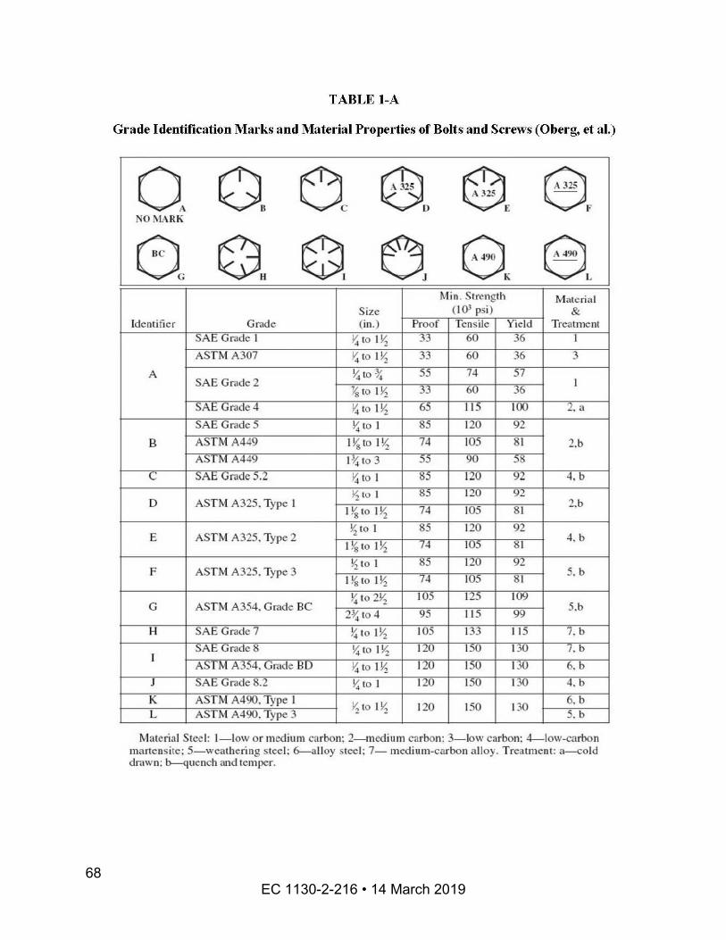
EC 1130-2-216 • 14 March 2019 68
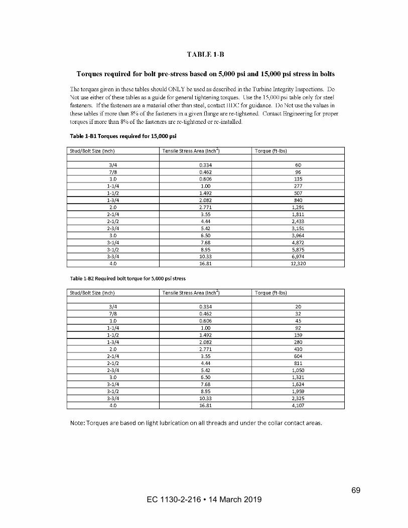
EC 1130-2-216 • 14 March 2019 69
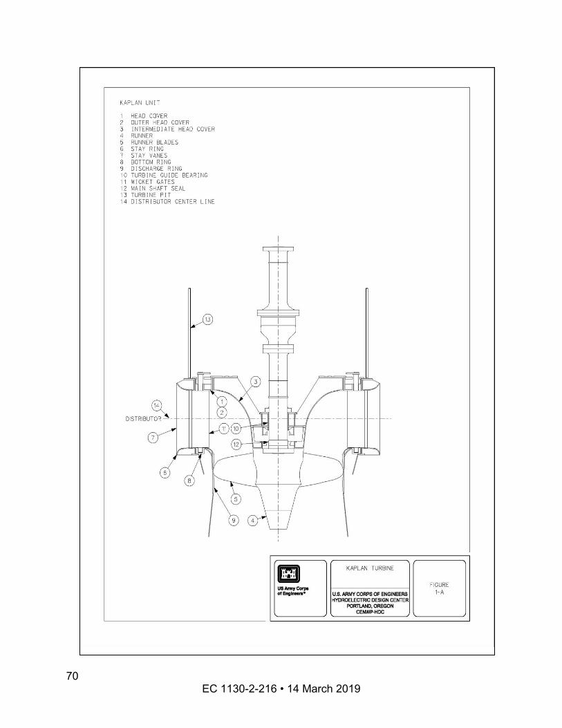
EC 1130-2-216 • 14 March 2019 70
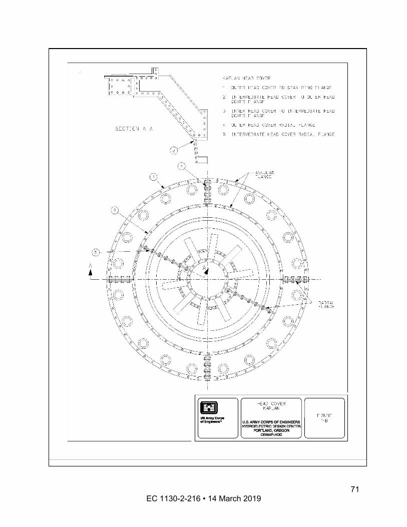
EC 1130-2-216 • 14 March 2019 71
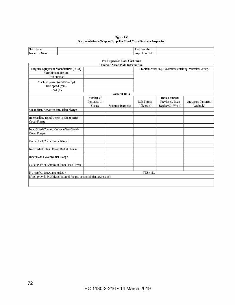
EC 1130-2-216 • 14 March 2019 72
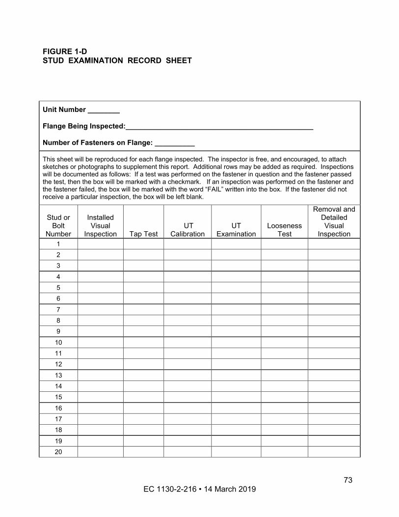
FIGURE 1-D STUD EXAMINATION RECORD SHEET
Unit Number ________
Flange Being Inspected:_______________________________________________
Number of Fasteners on Flange: __________
This sheet will be reproduced for each flange inspected. The inspector is free, and encouraged, to attach sketches or photographs to supplement this report. Additional rows may be added as required. Inspections will be documented as follows: If a test was performed on the fastener in question and the fastener passed the test, then the box will be marked with a checkmark. If an inspection was performed on the fastener and the fastener failed, the box will be marked with the word “FAIL” written into the box. If the fastener did not receive a particular inspection, the box will be left blank.
Stud or Bolt
Number
Installed Visual
Inspection Tap Test UT
Calibration UT
Examination Looseness
Test
Removal and Detailed Visual
Inspection 1 2 3
4 5 6
7 8 9
10 11 12
13 14 15
16 17 18
19 20
EC 1130-2-216 • 14 March 2019 73
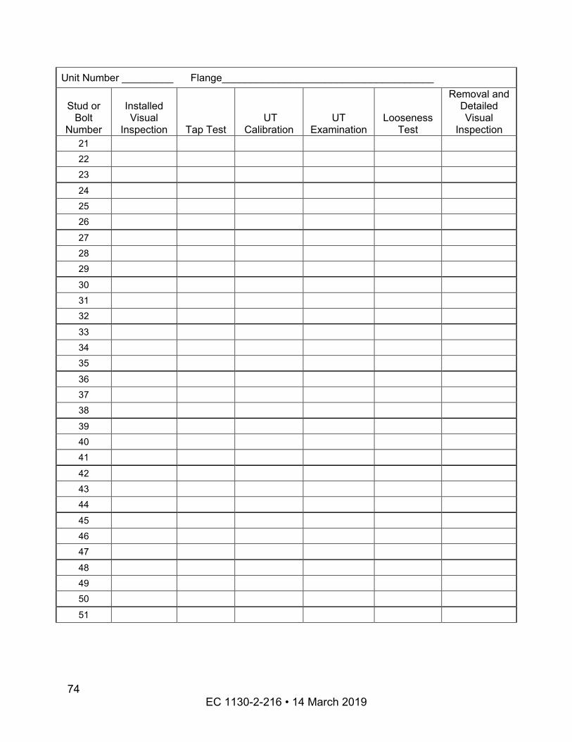
25
30
35
40
45
50
Unit Number _________ Flange_____________________________________
Stud or Bolt
Number
Installed Visual
Inspection Tap Test UT
Calibration UT
Examination Looseness
Test
Removal and Detailed Visual
Inspection 21 22 23
24
26
27 28 29
31 32
33 34
36 37 38
39
41
42 43 44
46 47
48 49
51
EC 1130-2-216 • 14 March 2019 74
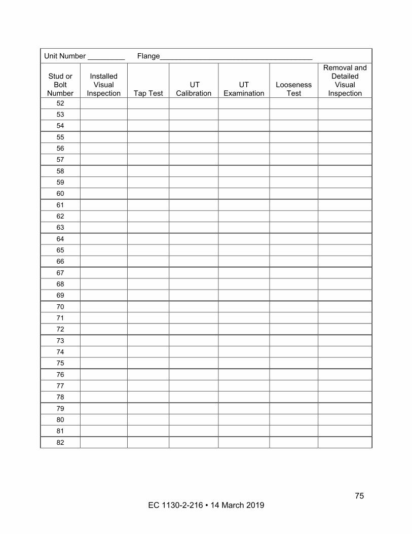
55
60
65
70
75
80
Unit Number _________ Flange_____________________________________
Stud or Bolt
Number
Installed Visual
Inspection Tap Test UT
Calibration UT
Examination Looseness
Test
Removal and Detailed Visual
Inspection 52 53 54
56 57
58 59
61 62 63
64
66
67 68 69
71 72
73 74
76 77 78
79
81
82
EC 1130-2-216 • 14 March 2019 75
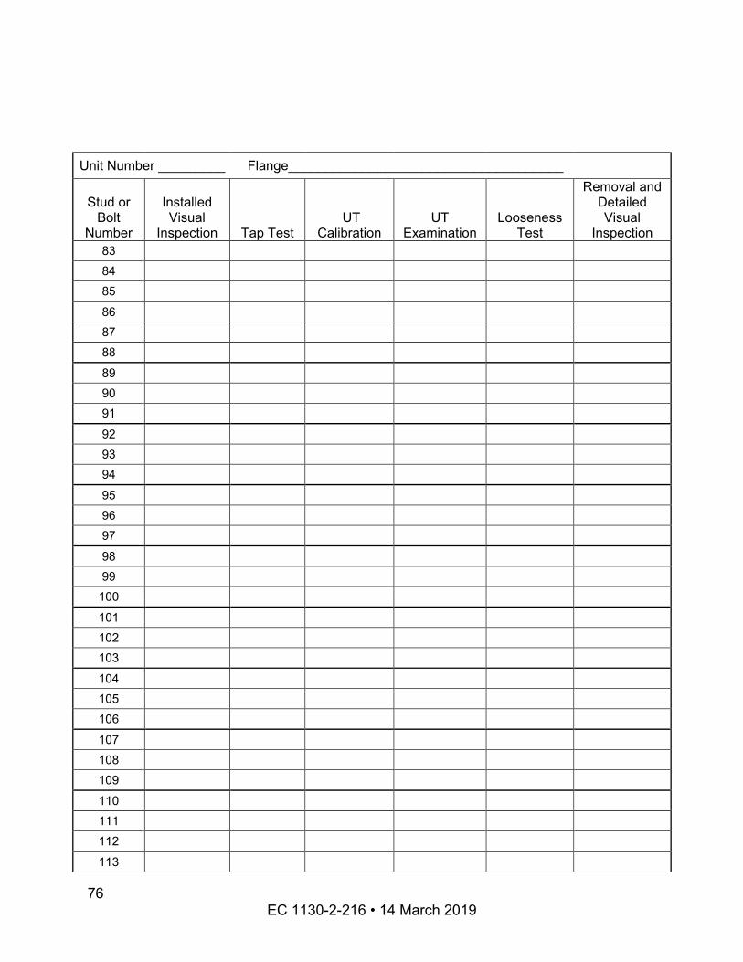
85
90
95
100
105
110
Unit Number _________ Flange_____________________________________
Stud or Bolt
Number
Installed Visual
Inspection Tap Test UT
Calibration UT
Examination Looseness
Test
Removal and Detailed Visual
Inspection 83 84
86 87 88
89
91
92 93 94
96 97
98 99
101 102 103
104
106 107 108 109
111 112
113
EC 1130-2-216 • 14 March 2019 76
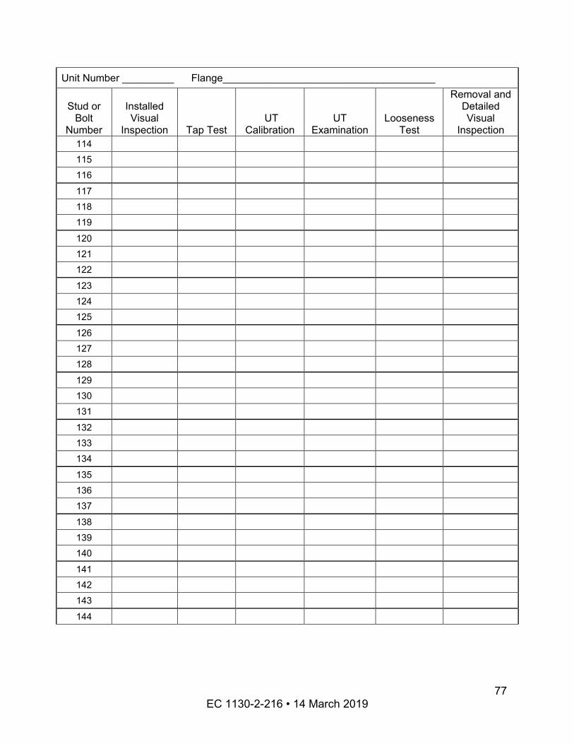
Unit Number _________ Flange_____________________________________
Stud or Bolt
Number
Installed Visual
Inspection Tap Test UT
Calibration UT
Examination Looseness
Test
Removal and Detailed Visual
Inspection 114 115 116
117 118 119
120 121 122
123 124 125
126 127 128
129 130 131
132 133 134
135 136 137
138 139 140
141 142 143
144
EC 1130-2-216 • 14 March 2019 77
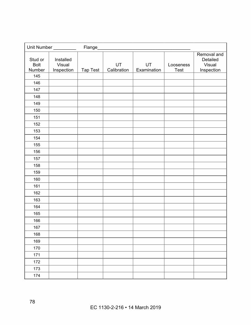
Unit Number _________ Flange_____________________________________
Stud or Bolt
Number
Installed Visual
Inspection Tap Test UT
Calibration UT
Examination Looseness
Test
Removal and Detailed Visual
Inspection 145 146 147
148 149 150
151 152 153
154 155 156
157 158 159
160 161 162
163 164 165
166 167 168
169 170 171
172 173 174
EC 1130-2-216 • 14 March 2019 78
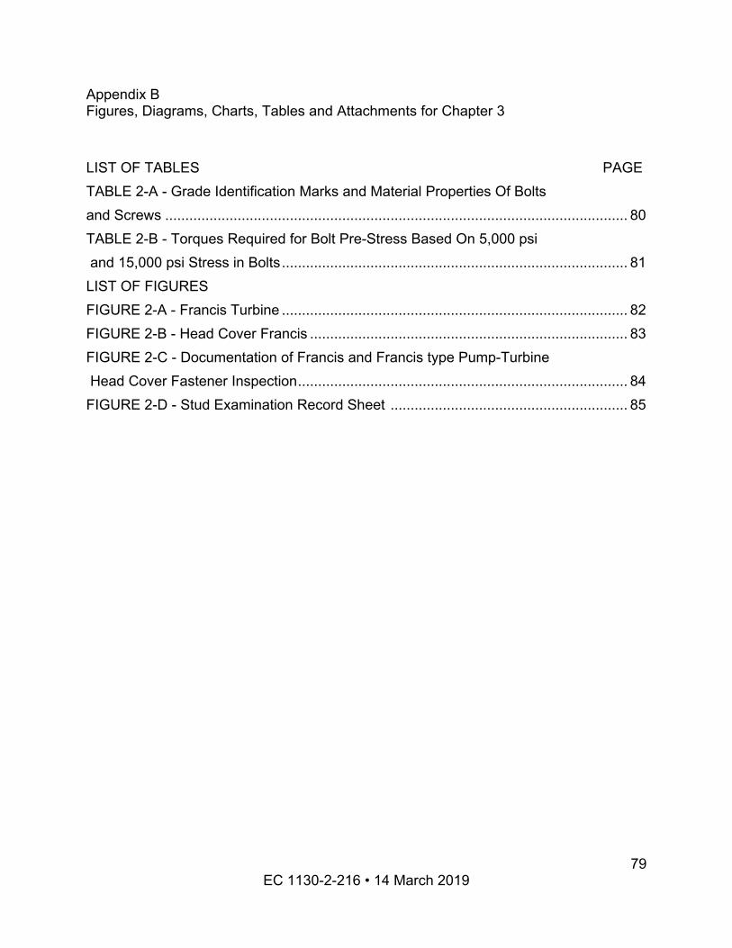
Appendix B Figures, Diagrams, Charts, Tables and Attachments for Chapter 3
LIST OF TABLES PAGE TABLE 2-A - Grade Identification Marks and Material Properties Of Bolts and Screws ................................................................................................................... 80 TABLE 2-B - Torques Required for Bolt Pre-Stress Based On 5,000 psi and 15,000 psi Stress in Bolts...................................................................................... 81
LIST OF FIGURES
FIGURE 2-C - Documentation of Francis and Francis type Pump-Turbine
FIGURE 2-A - Francis Turbine ...................................................................................... 82 FIGURE 2-B - Head Cover Francis ............................................................................... 83
Head Cover Fastener Inspection.................................................................................. 84 FIGURE 2-D - Stud Examination Record Sheet ........................................................... 85
EC 1130-2-216 • 14 March 2019 79
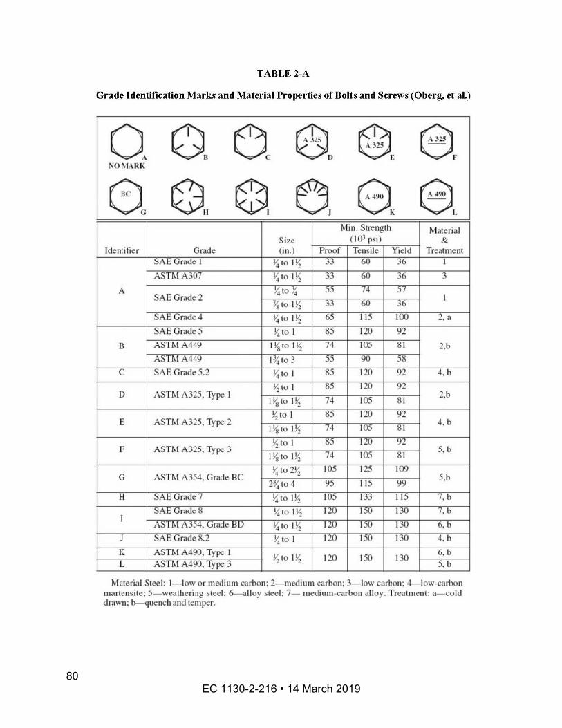
EC 1130-2-216 • 14 March 2019 80
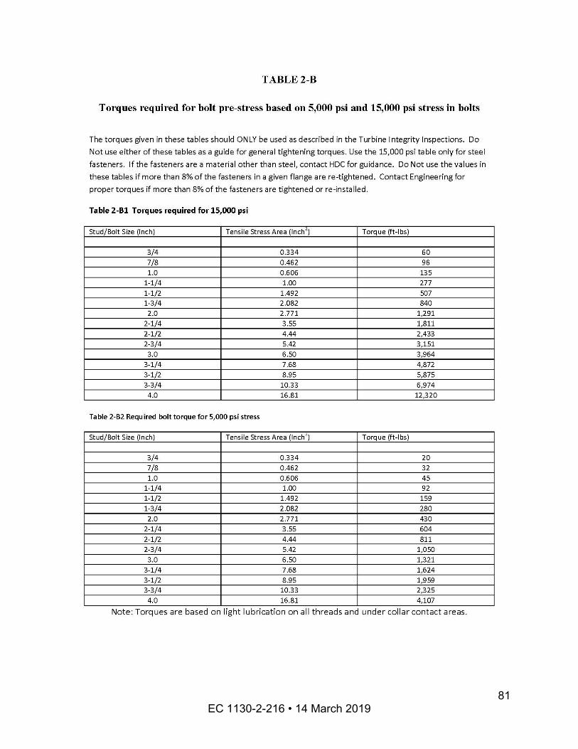
EC 1130-2-216 • 14 March 2019 81
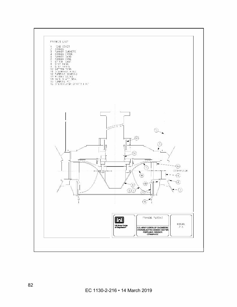
EC 1130-2-216 • 14 March 2019
82
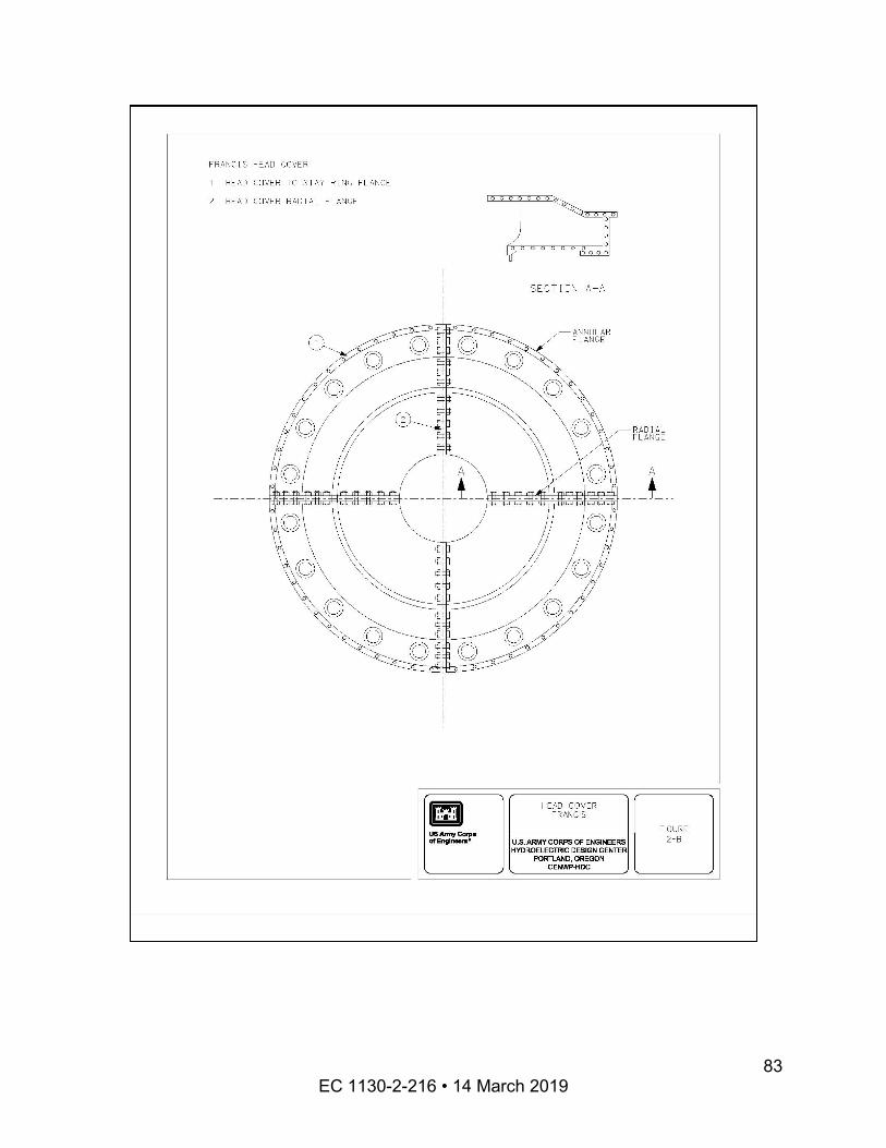
EC 1130-2-216 • 14 March 2019 83
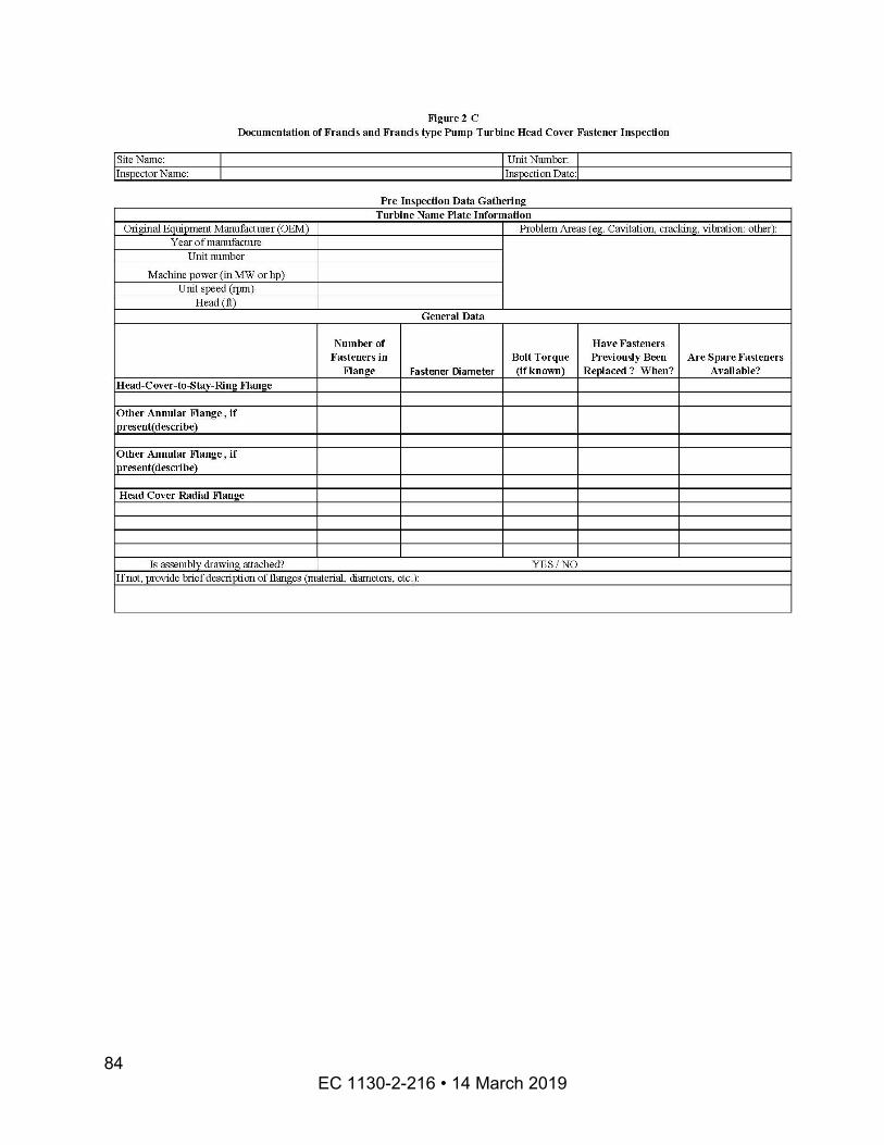
EC 1130-2-216 • 14 March 2019 84

FIGURE 2-D STUD EXAMINATION RECORD SHEET
Unit Number ________
Flange Being Inspected:_______________________________________________
Number of Fasteners on Flange: __________
This sheet will be reproduced for each flange inspected. The inspector is free, and encouraged, to attach sketches or photographs to supplement this report. Additional rows may be added as required. Inspections will be documented as follows: If a test was performed on the fastener in question and the fastener passed the test, then the box will be marked with a checkmark. If an inspection was performed on the fastener and the fastener failed, the box will be marked with the word “FAIL” written into the box. If the fastener did not receive a particular inspection, the box will be left blank.
Stud or Bolt
Number
Installed Visual
Inspection Tap Test UT
Calibration UT
Examination Looseness
Test
Removal and Detailed Visual
Inspection 1 2 3
4 5 6
7 8 9
10 11 12
13 14 15
16 17 18
19 20
EC 1130-2-216 • 14 March 2019 85
25
30
35
40
45
50
Unit Number _________ Flange_____________________________________
Stud or Bolt
Number
Installed Visual
Inspection Tap Test UT
Calibration UT
Examination Looseness
Test
Removal and Detailed Visual
Inspection 21 22 23
24
26
27 28 29
31 32
33 34
36 37 38
39
41
42 43 44
46 47
48 49
51
EC 1130-2-216 • 14 March 2019 86
55
60
65
70
75
80
Unit Number _________ Flange_____________________________________
Stud or Bolt
Number
Installed Visual
Inspection Tap Test UT
Calibration UT
Examination Looseness
Test
Removal and Detailed Visual
Inspection 52 53 54
56 57
58 59
61 62 63
64
66
67 68 69
71 72
73 74
76 77 78
79
81
82
EC 1130-2-216 • 14 March 2019 87
Unit Number _________ Flange_____________________________________
Stud or Bolt
Number
Installed Visual
Inspection Tap Test UT
Calibration UT
Examination Looseness
Test
Removal and Detailed Visual
Inspection 83 84 85
86 87 88
89 90 91
92 93 94
95 96 97
98 99
100
101 102 103
104 105 106
107 108 109
110 111 112
113
EC 1130-2-216 • 14 March 2019 88
Unit Number _________ Flange_____________________________________
Stud or Bolt
Number
Installed Visual
Inspection Tap Test UT
Calibration UT
Examination Looseness
Test
Removal and Detailed Visual
Inspection 114 115 116
117 118 119
120 121 122
123 124 125
126 127 128
129 130 131
132 133 134
135 136 137
138 139 140
141 142 143
144
EC 1130-2-216 • 14 March 2019 89
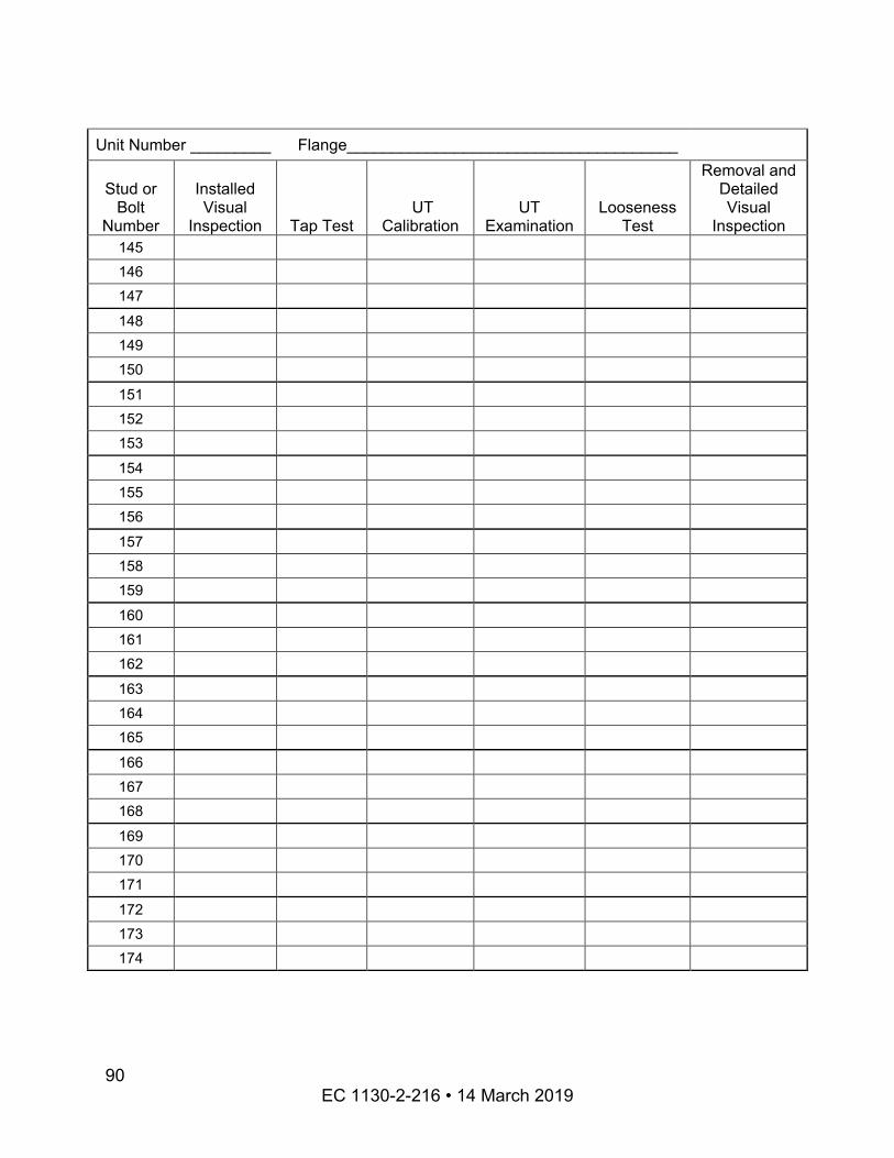
Unit Number _________ Flange_____________________________________
Stud or Bolt
Number
Installed Visual
Inspection Tap Test UT
Calibration UT
Examination Looseness
Test
Removal and Detailed Visual
Inspection 145 146 147
148 149 150
151 152 153
154 155 156
157 158 159
160 161 162
163 164 165
166 167 168
169 170 171
172 173 174
EC 1130-2-216 • 14 March 2019 90

Appendix C Figures, Diagrams, Charts, Tables and Attachments for Chapter 4
LIST OF TABLES PAGE TABLE 3-A - Documentation of Governor Gate Timing and Failsafe Shutdown upon Loss of Power...................................................................................... 92
EC 1130-2-216 • 14 March 2019 91
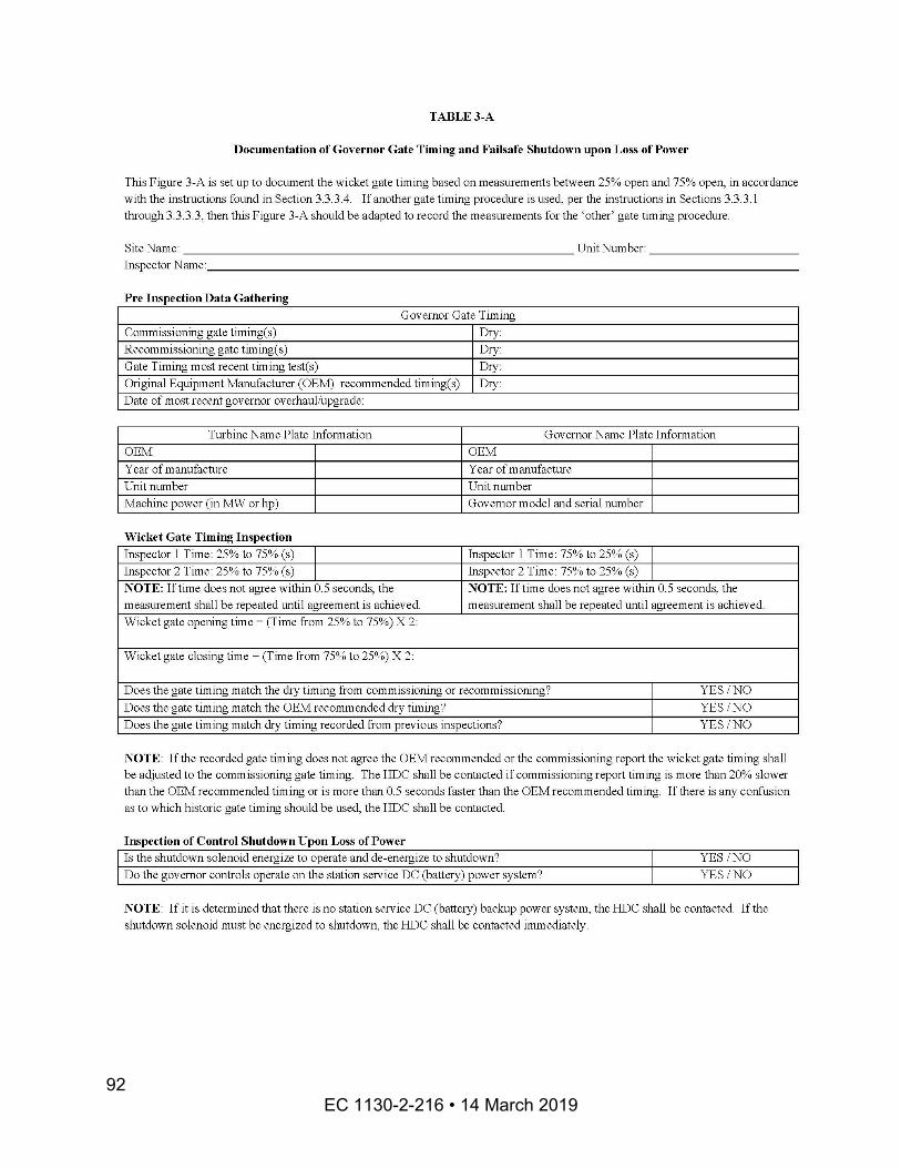
EC 1130-2-216 • 14 March 2019 92
Appendix D Figures, Diagrams, Charts, Tables and Attachments for Chapter 5
LIST OF FIGURES PAGE FIGURE 4-A - Kaplan Turbine....................................................................................... 94 FIGURE 4-B - Documentation of Kaplan Runner Inspection
FIGURE 4-G - Documentation of Francis and Francis-Type Pump-Turbine
......................................... 95 FIGURE 4-C - Inspection of Kaplan Unit ....................................................................... 96 FIGURE 4-D - Documentation of Propeller Runner Inspection ..................................... 97 FIGURE 4-E - Inspection of Propeller Unit .................................................................... 98 FIGURE 4-F - Francis Turbine ...................................................................................... 99
Runner/impeller Unit Inspection .................................................................................. 100 FIGURE 4-H - Inspection of Francis Unit - This is for low specific speed units ........... 101 FIGURE 4-I - Inspection of Francis Unit - This is for medium specific speed units ..... 102 FIGURE 4-J - Inspection of Francis Unit - This is for high specific speed units........... 103 FIGURE 4-K - Inspection of Runner Crown and Band Unit ......................................... 104
EC 1130-2-216 • 14 March 2019 93
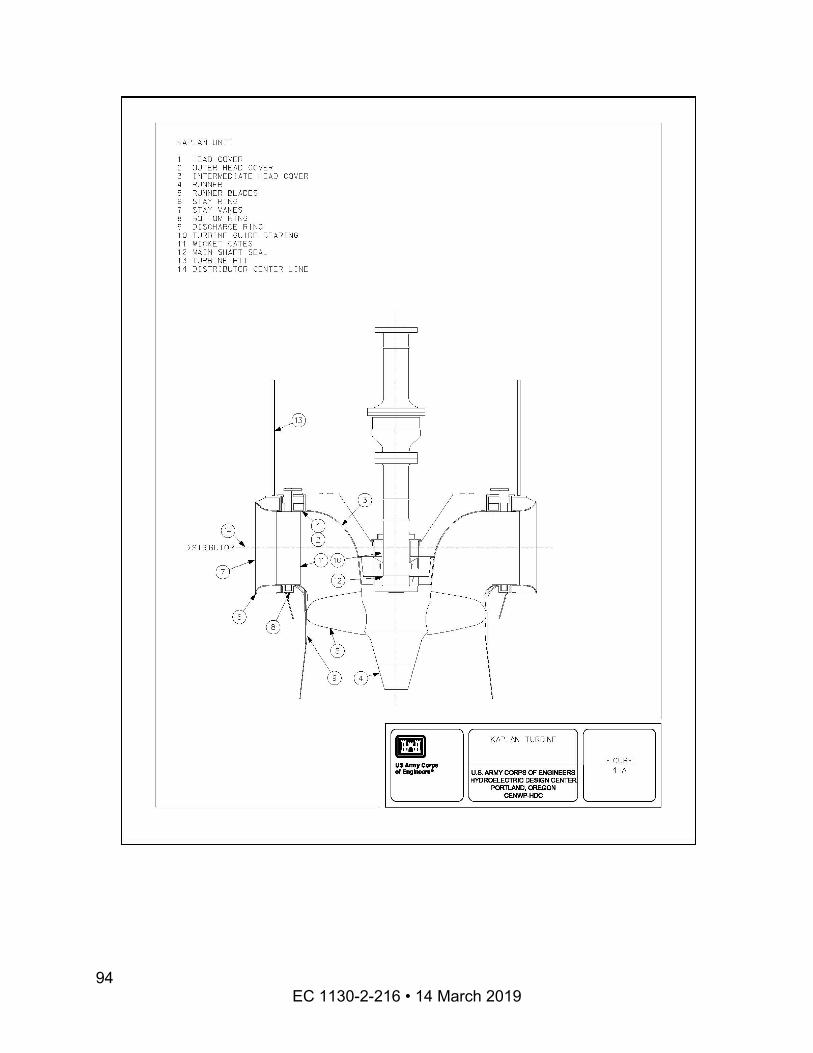
EC 1130-2-216 • 14 March 2019 94
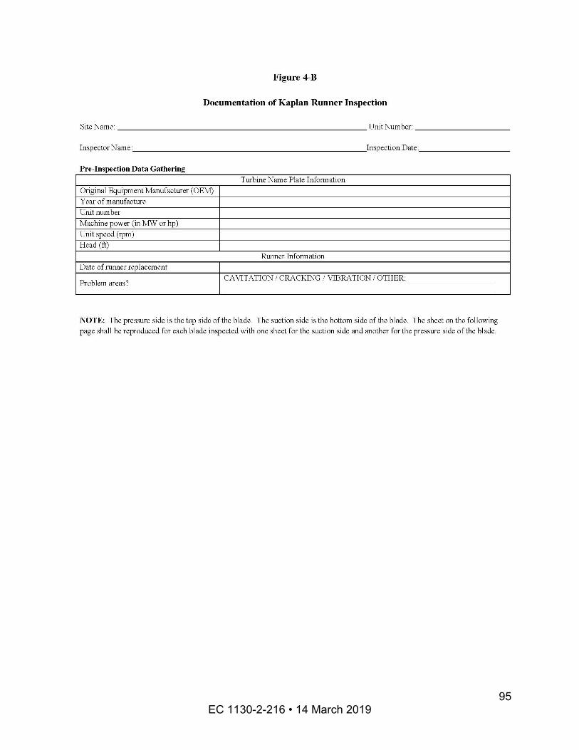
EC 1130-2-216 • 14 March 2019 95
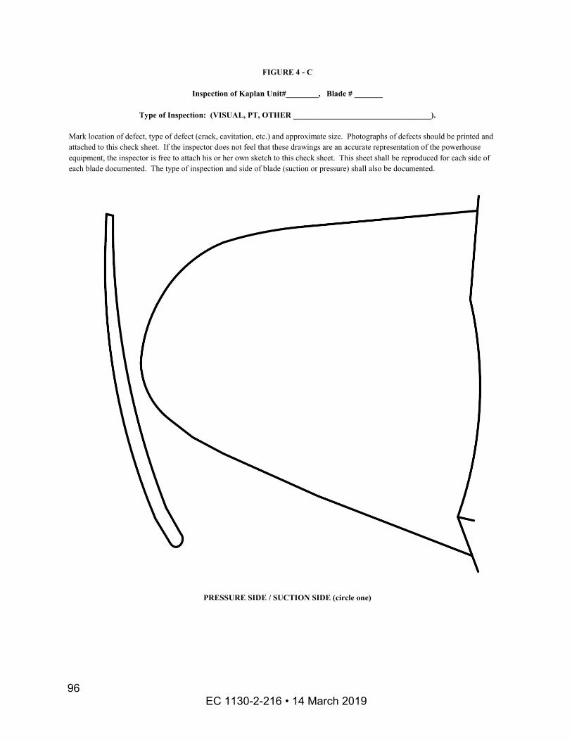
FIGURE 4 - C
Inspection of Kaplan Unit#________, Blade # _______
Type of Inspection: (VISUAL, PT, OTHER __________________________________).
Mark location of defect, type of defect (crack, cavitation, etc.) and approximate size. Photographs of defects should be printed and attached to this check sheet. If the inspector does not feel that these drawings are an accurate representation of the powerhouse equipment, the inspector is free to attach his or her own sketch to this check sheet. This sheet shall be reproduced for each side of each blade documented. The type of inspection and side of blade (suction or pressure) shall also be documented.
PRESSURE SIDE / SUCTION SIDE (circle one)
EC 1130-2-216 • 14 March 2019 96
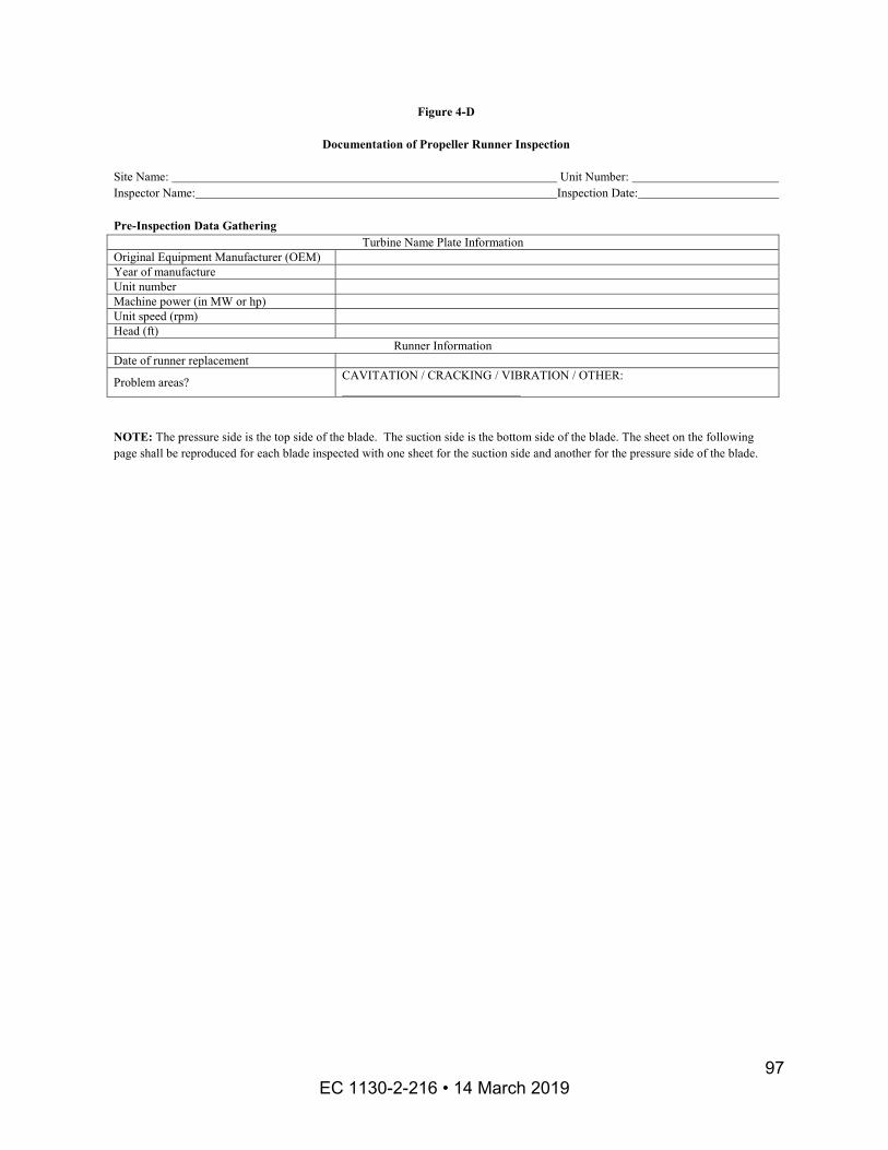
Figure 4-D
Documentation of Propeller Runner Inspection
Site Name: Unit Number: Inspector Name: Inspection Date:
Pre-Inspection Data Gathering Turbine Name Plate Information
Original Equipment Manufacturer (OEM) Year of manufacture Unit number Machine power (in MW or hp) Unit speed (rpm) Head (ft)
Runner Information Date of runner replacement
Problem areas? CAVITATION / CRACKING / VIBRATION / OTHER: _____________________________
NOTE: The pressure side is the top side of the blade. The suction side is the bottom side of the blade. The sheet on the following page shall be reproduced for each blade inspected with one sheet for the suction side and another for the pressure side of the blade.
EC 1130-2-216 • 14 March 2019 97
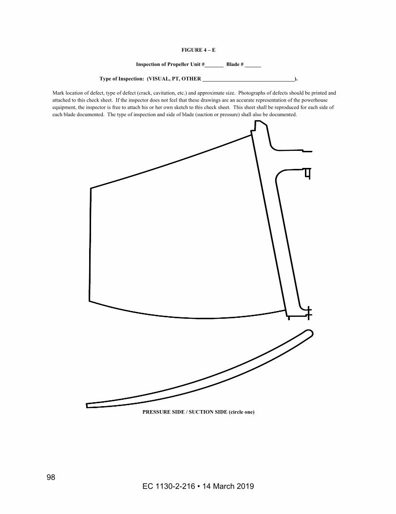
FIGURE 4 – E
Inspection of Propeller Unit #_______ Blade # ______
Type of Inspection: (VISUAL, PT, OTHER __________________________________).
Mark location of defect, type of defect (crack, cavitation, etc.) and approximate size. Photographs of defects should be printed and attached to this check sheet. If the inspector does not feel that these drawings are an accurate representation of the powerhouse equipment, the inspector is free to attach his or her own sketch to this check sheet. This sheet shall be reproduced for each side of each blade documented. The type of inspection and side of blade (suction or pressure) shall also be documented.
PRESSURE SIDE / SUCTION SIDE (circle one)
EC 1130-2-216 • 14 March 2019 98
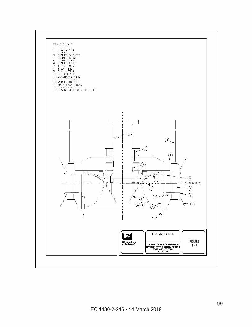
FIGURE 4 - F
EC 1130-2-216 • 14 March 2019 99
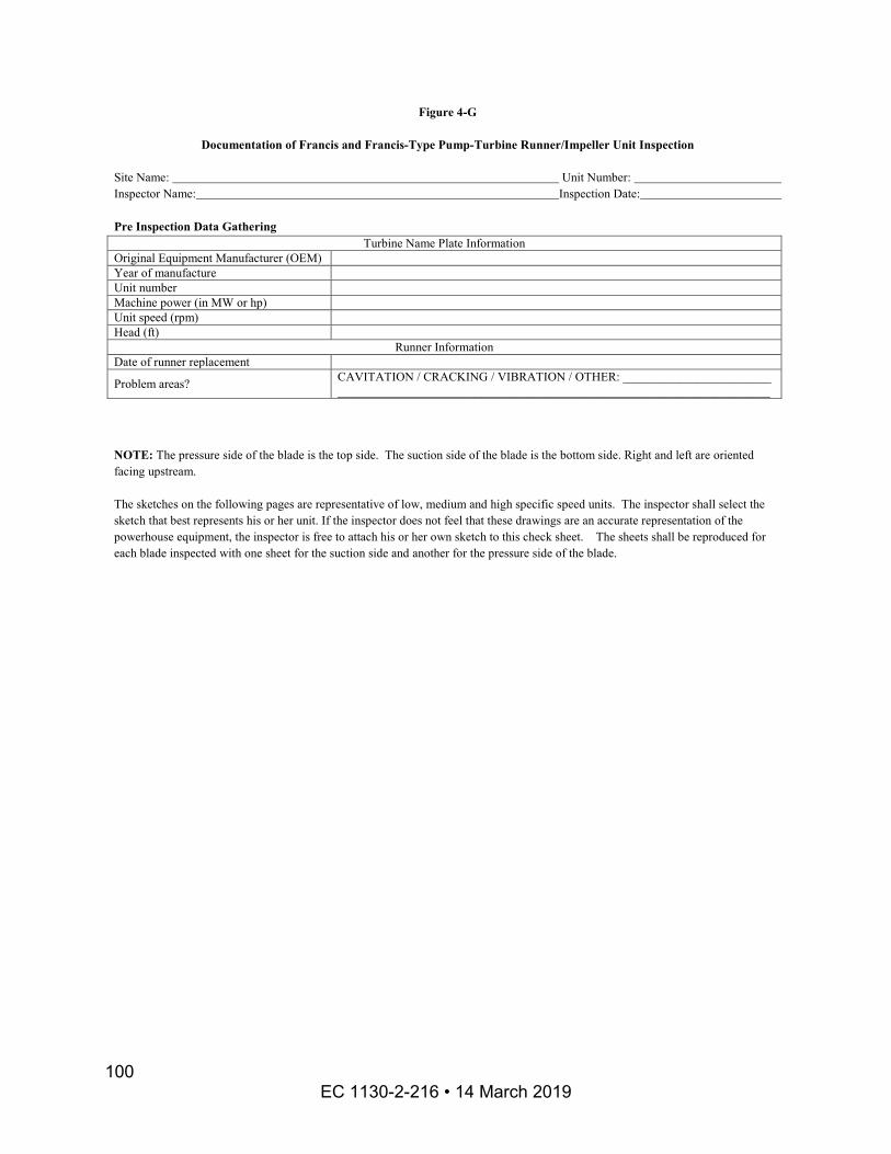
Figure 4-G
Documentation of Francis and Francis-Type Pump-Turbine Runner/Impeller Unit Inspection
Site Name: Unit Number: Inspector Name: Inspection Date:
Pre Inspection Data Gathering Turbine Name Plate Information
Original Equipment Manufacturer (OEM) Year of manufacture Unit number Machine power (in MW or hp) Unit speed (rpm) Head (ft)
Runner Information Date of runner replacement
Problem areas? CAVITATION / CRACKING / VIBRATION / OTHER: ________________________ ______________________________________________________________________
NOTE: The pressure side of the blade is the top side. The suction side of the blade is the bottom side. Right and left are oriented facing upstream.
The sketches on the following pages are representative of low, medium and high specific speed units. The inspector shall select the sketch that best represents his or her unit. If the inspector does not feel that these drawings are an accurate representation of the powerhouse equipment, the inspector is free to attach his or her own sketch to this check sheet. The sheets shall be reproduced for each blade inspected with one sheet for the suction side and another for the pressure side of the blade.
EC 1130-2-216 • 14 March 2019 100
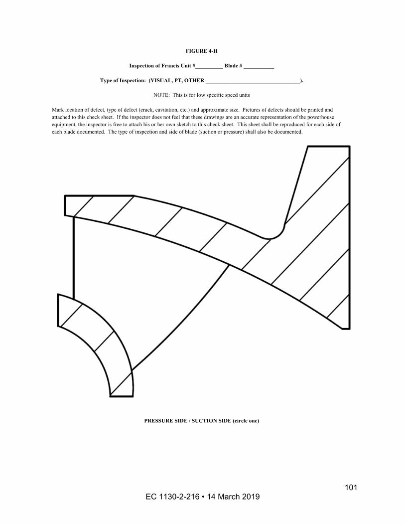
FIGURE 4-H
Inspection of Francis Unit #__________ Blade # ___________
Type of Inspection: (VISUAL, PT, OTHER __________________________________).
NOTE: This is for low specific speed units
Mark location of defect, type of defect (crack, cavitation, etc.) and approximate size. Pictures of defects should be printed and attached to this check sheet. If the inspector does not feel that these drawings are an accurate representation of the powerhouse equipment, the inspector is free to attach his or her own sketch to this check sheet. This sheet shall be reproduced for each side of each blade documented. The type of inspection and side of blade (suction or pressure) shall also be documented.
PRESSURE SIDE / SUCTION SIDE (circle one)
EC 1130-2-216 • 14 March 2019 101
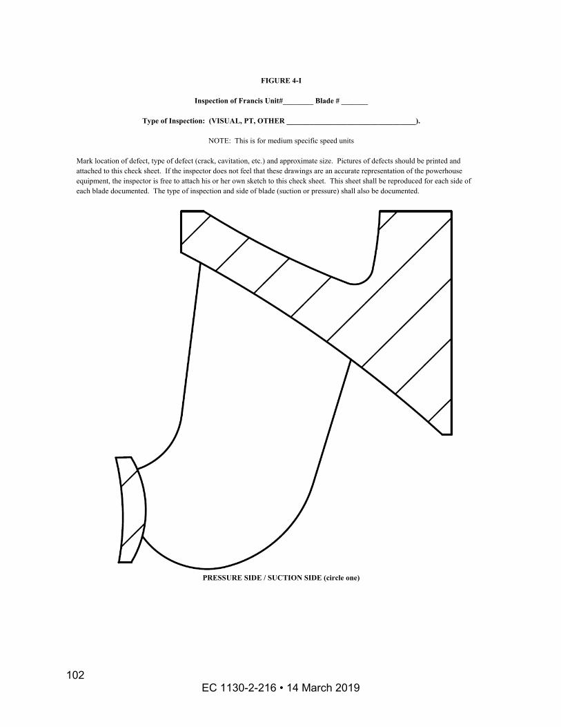
FIGURE 4-I
Inspection of Francis Unit#________ Blade # _______
Type of Inspection: (VISUAL, PT, OTHER __________________________________).
NOTE: This is for medium specific speed units
Mark location of defect, type of defect (crack, cavitation, etc.) and approximate size. Pictures of defects should be printed and attached to this check sheet. If the inspector does not feel that these drawings are an accurate representation of the powerhouse equipment, the inspector is free to attach his or her own sketch to this check sheet. This sheet shall be reproduced for each side of each blade documented. The type of inspection and side of blade (suction or pressure) shall also be documented.
PRESSURE SIDE / SUCTION SIDE (circle one)
EC 1130-2-216 • 14 March 2019 102
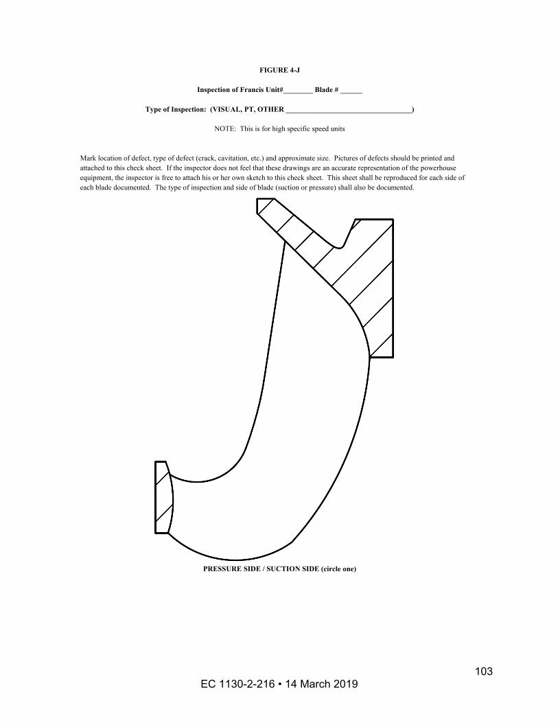
FIGURE 4-J
Inspection of Francis Unit#________ Blade # ______
Type of Inspection: (VISUAL, PT, OTHER __________________________________)
NOTE: This is for high specific speed units
Mark location of defect, type of defect (crack, cavitation, etc.) and approximate size. Pictures of defects should be printed and attached to this check sheet. If the inspector does not feel that these drawings are an accurate representation of the powerhouse equipment, the inspector is free to attach his or her own sketch to this check sheet. This sheet shall be reproduced for each side of each blade documented. The type of inspection and side of blade (suction or pressure) shall also be documented.
PRESSURE SIDE / SUCTION SIDE (circle one)
EC 1130-2-216 • 14 March 2019 103
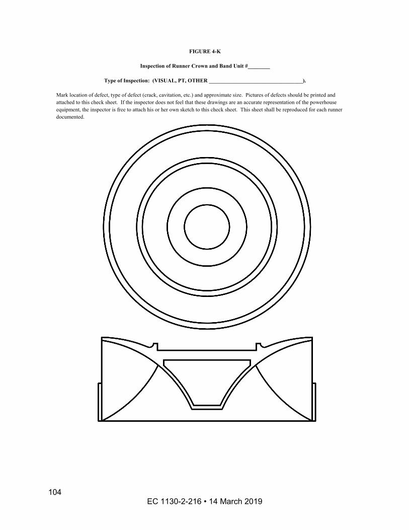
FIGURE 4-K
Inspection of Runner Crown and Band Unit #________
Type of Inspection: (VISUAL, PT, OTHER __________________________________).
Mark location of defect, type of defect (crack, cavitation, etc.) and approximate size. Pictures of defects should be printed and attached to this check sheet. If the inspector does not feel that these drawings are an accurate representation of the powerhouse equipment, the inspector is free to attach his or her own sketch to this check sheet. This sheet shall be reproduced for each runner documented.
EC 1130-2-216 • 14 March 2019 104

Appendix E Figures, Diagrams, Charts, Tables and Attachments for Chapter 6
LIST OF FIGURES PAGE FIGURE 5-A - Kaplan Turbine..................................................................................... 106 FIGURE 5-B - Documentation of Kaplan/Propeller Head Cover Inspection ............... 107 FIGURE 5-C - Inspection of Kaplan/Propeller Head Cover ........................................ 108 FIGURE 5-D - Francis Turbine................................................................................... 109 FIGURE 5-E - Documentation of Francis/Francis Type Pump-turbine Head Cover ... 110 FIGURE 5-F - Inspection of Francis/Francis Type Pump-turbine Head Cover ........... 111
EC 1130-2-216 • 14 March 2019 105
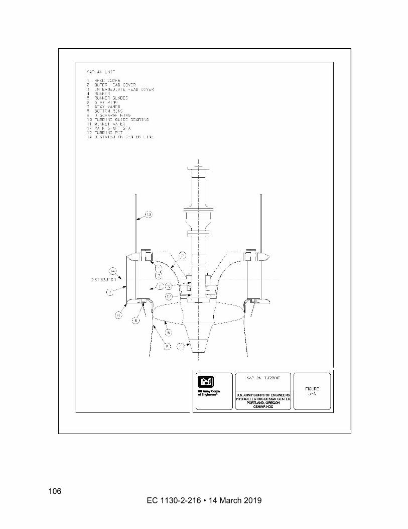
EC 1130-2-216 • 14 March 2019
106
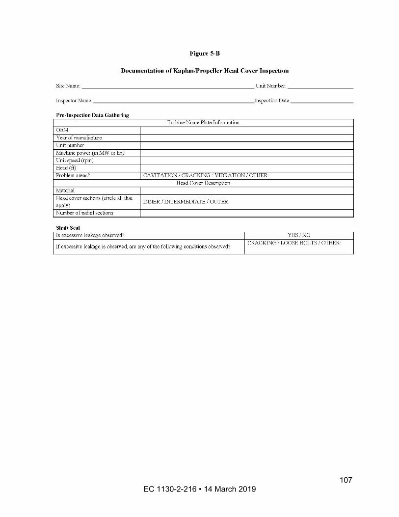
EC 1130-2-216 • 14 March 2019 107
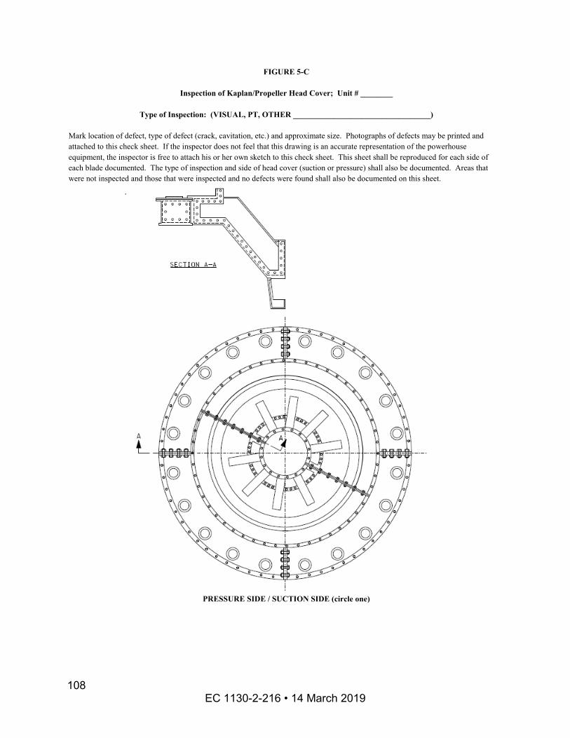
FIGURE 5-C
Inspection of Kaplan/Propeller Head Cover; Unit # ________
Type of Inspection: (VISUAL, PT, OTHER __________________________________)
Mark location of defect, type of defect (crack, cavitation, etc.) and approximate size. Photographs of defects may be printed and attached to this check sheet. If the inspector does not feel that this drawing is an accurate representation of the powerhouse equipment, the inspector is free to attach his or her own sketch to this check sheet. This sheet shall be reproduced for each side of each blade documented. The type of inspection and side of head cover (suction or pressure) shall also be documented. Areas that were not inspected and those that were inspected and no defects were found shall also be documented on this sheet.
PRESSURE SIDE / SUCTION SIDE (circle one)
EC 1130-2-216 • 14 March 2019 108
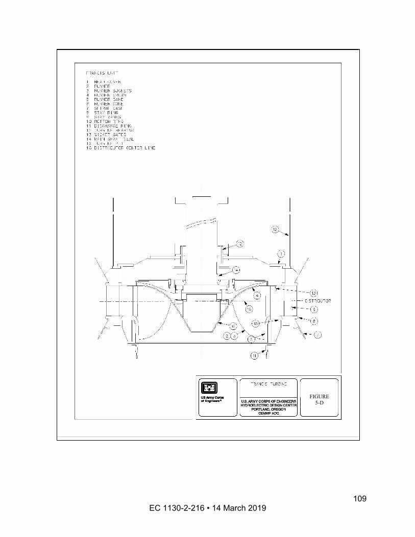
FIGURE 5-D
EC 1130-2-216 • 14 March 2019 109
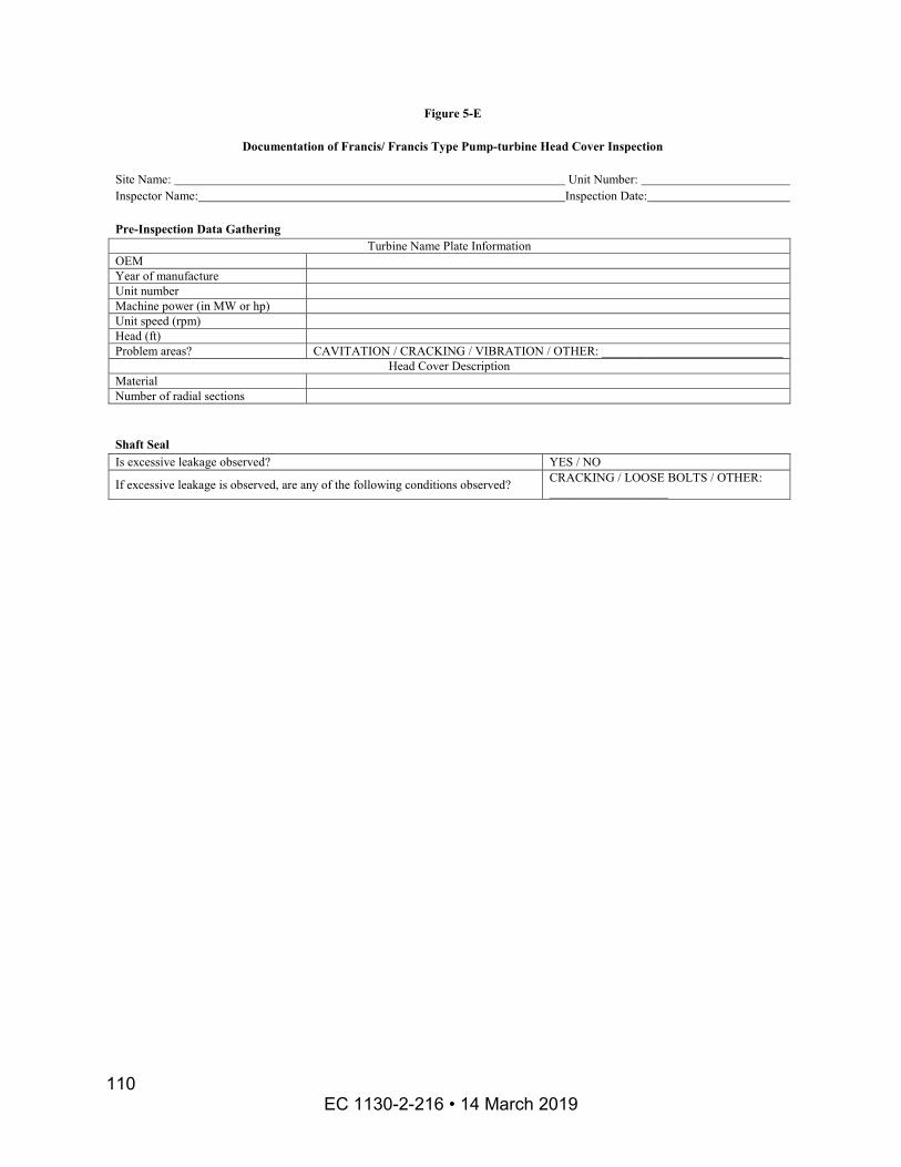
Figure 5-E
Documentation of Francis/ Francis Type Pump-turbine Head Cover Inspection
Site Name: Unit Number: Inspector Name: Inspection Date:
Pre-Inspection Data Gathering Turbine Name Plate Information
OEM Year of manufacture Unit number Machine power (in MW or hp) Unit speed (rpm) Head (ft) Problem areas? CAVITATION / CRACKING / VIBRATION / OTHER: _____________________________
Head Cover Description Material Number of radial sections
Shaft Seal Is excessive leakage observed? YES / NO
If excessive leakage is observed, are any of the following conditions observed? CRACKING / LOOSE BOLTS / OTHER: ___________________
EC 1130-2-216 • 14 March 2019 110
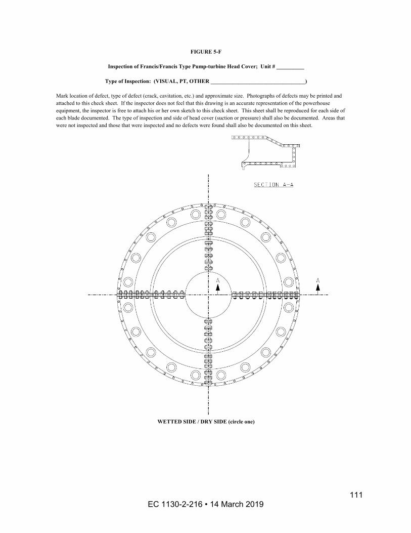
FIGURE 5-F
Inspection of Francis/Francis Type Pump-turbine Head Cover; Unit # __________
Type of Inspection: (VISUAL, PT, OTHER __________________________________)
Mark location of defect, type of defect (crack, cavitation, etc.) and approximate size. Photographs of defects may be printed and attached to this check sheet. If the inspector does not feel that this drawing is an accurate representation of the powerhouse equipment, the inspector is free to attach his or her own sketch to this check sheet. This sheet shall be reproduced for each side of each blade documented. The type of inspection and side of head cover (suction or pressure) shall also be documented. Areas that were not inspected and those that were inspected and no defects were found shall also be documented on this sheet.
WETTED SIDE / DRY SIDE (circle one)
EC 1130-2-216 • 14 March 2019 111
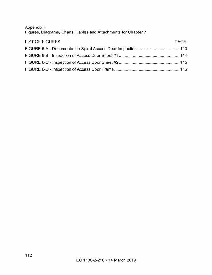
Appendix F Figures, Diagrams, Charts, Tables and Attachments for Chapter 7
LIST OF FIGURES PAGE FIGURE 6-A - Documentation Spiral Access Door Inspection .................................... 113 FIGURE 6-B - Inspection of Access Door Sheet #1 .................................................... 114 FIGURE 6-C - Inspection of Access Door Sheet #2.................................................... 115 FIGURE 6-D - Inspection of Access Door Frame........................................................ 116
EC 1130-2-216 • 14 March 2019 112
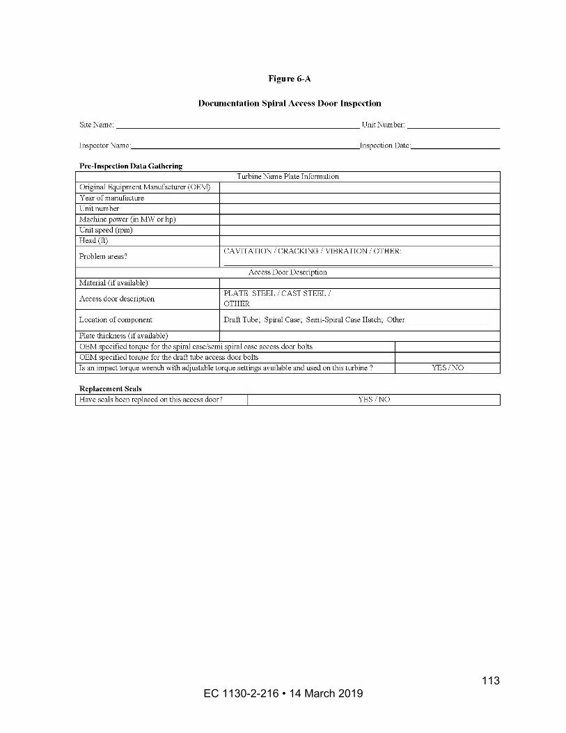
EC 1130-2-216 • 14 March 2019 113
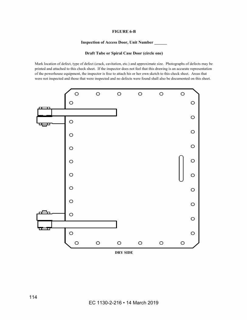
FIGURE 6-B
Inspection of Access Door, Unit Number ______
Draft Tube or Spiral Case Door (circle one)
Mark location of defect, type of defect (crack, cavitation, etc.) and approximate size. Photographs of defects may be printed and attached to this check sheet. If the inspector does not feel that this drawing is an accurate representation of the powerhouse equipment, the inspector is free to attach his or her own sketch to this check sheet. Areas that were not inspected and those that were inspected and no defects were found shall also be documented on this sheet.
DRY SIDE
EC 1130-2-216 • 14 March 2019 114
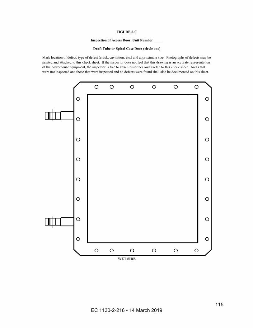
FIGURE 6-C
Inspection of Access Door, Unit Number _____
Draft Tube or Spiral Case Door (circle one)
Mark location of defect, type of defect (crack, cavitation, etc.) and approximate size. Photographs of defects may be printed and attached to this check sheet. If the inspector does not feel that this drawing is an accurate representation of the powerhouse equipment, the inspector is free to attach his or her own sketch to this check sheet. Areas that were not inspected and those that were inspected and no defects were found shall also be documented on this sheet.
WET SIDE
EC 1130-2-216 • 14 March 2019 115
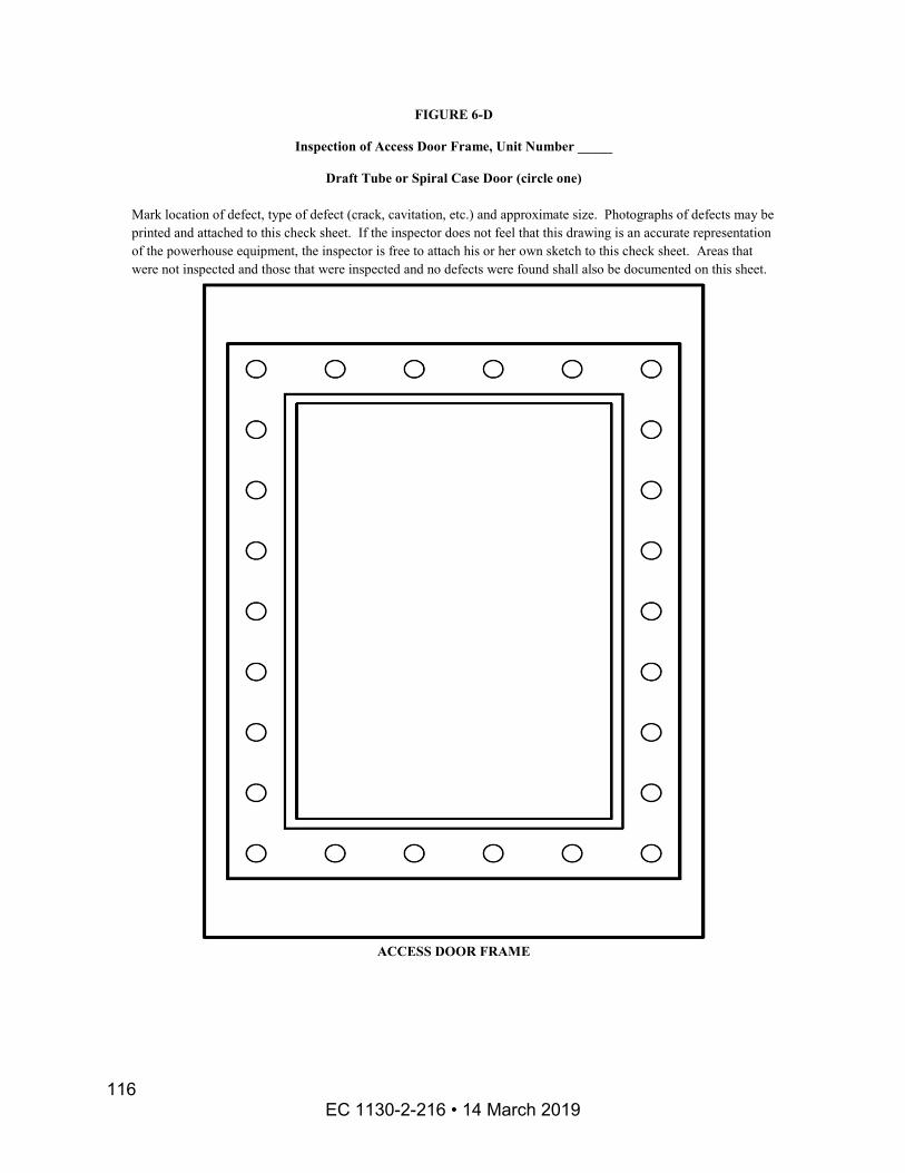
FIGURE 6-D
Inspection of Access Door Frame, Unit Number _____
Draft Tube or Spiral Case Door (circle one)
Mark location of defect, type of defect (crack, cavitation, etc.) and approximate size. Photographs of defects may be printed and attached to this check sheet. If the inspector does not feel that this drawing is an accurate representation of the powerhouse equipment, the inspector is free to attach his or her own sketch to this check sheet. Areas that were not inspected and those that were inspected and no defects were found shall also be documented on this sheet.
ACCESS DOOR FRAME
EC 1130-2-216 • 14 March 2019 116

Appendix G Paint Procedures
For surface preparation it is recommend that the project purchase a “Bristle Blaster”. This is essentially a power wire brush on an angle grinder with the bristles catching on a pin and snapping forward onto the steel. This essentially turns the wire brush into an impact tool that produces a surface profile somewhat similar to abrasive blasting.
The cleaned surface will be painted with a moisture cure urethane zinc primer (Both Wasser and Sherwin Williams have them.). Although this is a one component product like a vinyl, it does cure. The resin reacts with moisture in the air. As a result, take precautions such as pouring out only the quantity needed in a dry location rather than down in a moist pit area and tightly close the original can. Also when mixing a large container, do not stir moist air into the product or the next time the can is opened there will be a complexly solid mass of cured paint! For the type of work being done in the TII it may be best to purchase gallon or even quart size containers.
Moisture cure paints can be applied by brush. If there is condensation on the surface, it should be removed with a terry cloth towel immediately ahead of the brush application. Excessive application of any coat will result in bubbling of the coating. Workers should go back after an hour or so to inspect their work. If bubbling is noted, the paint should be scraped off and reapplied. Two coats should give good coverage in non-immersion areas – three should be used on immersed surfaces.
Moisture cure products are available in colors including aluminum if a topcoat is desired to match existing surfaces
EC 1130-2-216 • 14 March 2019 117
Appendix H Acknowledgements
The following personnel made significant contributions to the Beta Testing of these Turbine Integrity Inspection procedures and by their efforts substantially improved the quality of the final document:
From Portland District, Bonneville Powerhouse: Tony Kirk, Scott Harvey and the Structural Crew, Ken Rochefort, Miles Wagatsuma, Scott McKinnon and Ed Carroll.
From Mobile District, Allatoona Powerhouse and Operations Engineering Staff: Joshua Sills, Wayne Vanderburg, Jeff Ross and Eduardo Mazariegos.
EC 1130-2-216 • 14 March 2019 118
Glossary Definitions and Acronyms
Access door – a door installed to permit access for inspection and maintenance. Access doors are normally found at the spiral case and the draft tube to allow access to the water passageways of a hydraulic turbine. Typical designs have access doors for horizontal access. Some designs have access doors in the ceilings of spiral cases for vertical access.
Auxiliary valve – the valve in the Governor that allows bypassing of all normal control mechanisms. It is used for maintenance and should not be used during unobserved operation.
Ballhead assembly – a speed-sensitive device in the Governor that produces a mechanical output when its speed deviates, which consists of:
Flyballs – weights mounted in such a manner to form a rotating pendulum which is sensitive to speed changes;
A flyball spring – a spring arranged to oppose the force of the flyballs in such a manner as to produce the desired relationship between speed and output movement and to determine the equilibrium speed of the governor flyballs; and
A ballhead motor – a synchronous motor that is driven by a voltage from the PMG to operate the governor ballhead.
Blade link – the element that connects the rocker arm to the crosshead through the link bolt.
Blade link bolt – the element that attaches the link to the crosshead and the rocker arm.
Blade servomotor – the hydraulic cylinder actuated by governor oil pressure which supplies the force necessary to adjust the runner blades.
Bottom ring – the stationary ring which is bolted to the stay ring and contains the lower wicket gate bushings. The surfaces of the bottom ring lead the water to the discharge ring. It may be integral with or separate from the discharge ring.
Crosshead – the member that is connected to the blade servomotor and, through links and rocker arms, transmits the operating force to all blades simultaneously. On units with the blade servomotor in the runner hub, the crosshead is frequently integral with the servomotor housing or the servomotor piston. Many Kaplan units have servomotors in the shaft and a crosshead rod connecting the servomotor to the crosshead.
EC 1130-2-216 • 14 March 2019 119
Dashpot – a hydraulic element that adds temporary droop signal to the governor to provide stability. It is made up of two plungers hydraulically connected in a chamber of oil and a needle used to control the rate at which the plunger returns to its neutral position.
Discharge ring (Francis Turbine) – a structural member on a Francis turbine or Francis-type pump-turbine that surrounds the runner band. It may be integral with the bottom ring. The draft tube is attached to the downstream end of the discharge ring.
Discharge ring (Kaplan or propeller turbine) – the structural member that surrounds the blades of a Kaplan or propeller turbine and forms a guide for the water. It may be integral with the bottom ring. The draft-tube liner is attached to the downstream end of the discharge ring.
Distributor – the assembly which includes the stay ring, wicket gates, head cover, and bottom ring. Its “centerline” is a horizontal plane equidistant from the top and bottom of the wicket gates.
Draft tube – the diffuser which helps regain the residual velocity energy of the water leaving the turbine runner.
Draft tube liner – the steel lining used to protect the concrete from the high velocity of the water, normally located at the upper area of the draft tube.
Gate limit – A mechanism that limits the maximum gate opening.
Gate linkage – all connecting linkage between the gate operating ring and the wicket gates.
Gate mechanism – the components used to actuate the wicket gates consisting of the gate servomotors, the gate operating ring and the gate linkage.
Gate operating ring – the ring rotated by the servomotor(s) which distributes the force from the servomotors to the individual wicket-gate linkages to provide simultaneous movement of all wicket gates.
Gate servomotor(s) – the hydraulic cylinders actuated by oil pressure which supply the force necessary to operate the wicket gates via the gate operating ring and gate linkage.
Governor – a mechanism that responds to deviations from equilibrium and seeks to restore the system back to that equilibrium. In hydropower turbines, the deviation is a change in load resulting in a change in speed. The governor senses the speed deviation and opens or closes the water control mechanism to restore the turbine to normal speed.
EC 1130-2-216 • 14 March 2019 120
Head cover – the axis-symmetric structural disk in turbines that spans the top of the distributor, provides the separation between the watered runner chamber and the dry turbine pit, and supports the main shaft packing box, or shaft seal, and the main turbine guide bearing. In vertical turbines, the head cover also supports the upper wicket gate stems and is bolted to the stay ring. Kaplan and propeller-type turbines frequently have an outer, intermediate and inner head cover.
Hydraulic transients – Pressure increases or decreases in the penstock or intake that occur during rapid load changes or load rejection. Their formation is largely dependent on the rate at which the wicket gates close and open.
Impeller vanes – the contoured components of pump-turbine impellers that deflect the flowing water and transfer the energy to the runner crown or disc when operating as a turbine, or that transfer energy to the water when the impeller is operating as a pump.
Inner head cover – typically found on a Kaplan or propeller turbine, the inner ring of a circumferentially split head cover that is bolted to the outer or intermediate head cover and sometimes supports the turbine guide bearing and packing box.
NOTE: Some units have only two head cover segments—in which case there is an outer head cover and an inner head cover. For those units with three head cover segments, there is an outer, an intermediate and an inner. For units with three head cover segments, the turbine guide bearing is usually supported by the intermediate head cover and the inner head cover usually houses only the oil sump, the leakage water sump pump(s), and the shaft packing box.
Intermediate head cover – typically found on Kaplan or propeller turbines, the middle ring of a circumferentially split head cover that is bolted to the outer and inner head cover section. The Intermediate head cover of a “three head cover” design typically supports the turbine guide bearing.
Main shaft seal –a seal used to minimize water leakage at the main shaft. Sometimes also referred to as a packing box.
OEM—Original Equipment Manufacturer. The company that originally designed and /or manufactured the equipment.
Oil motor vibrator – an oil-operated motor on the Governor that vibrates the pilot and distributing valves to eliminate static friction and allow more accurate control of the unit.
Outer head cover – typically found on a Kaplan or propeller turbine, the outer ring of a circumferentially split head cover that supports the upper wicket gate stems and is bolted to the stay ring.
EC 1130-2-216 • 14 March 2019 121
Packing box – a particular type of shaft seal consisting of an annular chamber surrounding the main shaft, which contains pliable sealing material and has a movable gland permitting adjustment or replacement of the sealing material.
Permanent magnet generator (PMG) – a three-phase generator that is directly connected to the generator and drives the ballhead motor.
Pilot valve – a small valve on the Governor operated by low-force signals that transmits the signals to the relay/distributing valve, which then transmits the high-force signals to the servomotor. The pilot valve is made up of a bushing and plunger.
Pressure tank (or accumulator tank) – a reservoir containing gas over oil under pressure for use in the governor system.
Pump-turbine impeller – the rotating element of a pump-turbine which converts hydraulic energy into mechanical energy in the generating mode and converts mechanical energy into hydraulic energy in the pump mode.
Relay/distributing valve – a valve on the Governor that controls the flow of oil to a servomotor(s) that operates the turbine water flow control mechanism.
Rivet - A rivet comes as a steel rod with a forged head on one end. The length of a rivet is the distance from the underside of the head to the end of the fresh rivet. The thickness of the material to be joined is called the grip of the rivet. The shank is the diameter of the rod that forms the rivet. Rivets are heated to 950 – 1050 degrees F and driven into the rivet hole. The rivet is then set by forging a field head onto it either by hammering (hand riveting) or by machine riveting.
Rocker arm – the lever that attaches to the Kaplan runner blade trunnion and connects to the blade link.
Runner assembly – the assembly consisting of the runner, blades, and cone, and including all of the runner-blade operating mechanism that is used to adjust the pitch or angle of the runner blades on a Kaplan turbine.
Runner band – the lower axis-symmetric portion of the Francis runner or Pump-Turbine impeller to which the lower, or outer, ends of the runner buckets or impeller vanes attach.
Runner band seal – the close running clearance between the rotating runner band and the stationary bottom ring or discharge ring. The close clearance restricts the flow of water between the high pressure zone and the low pressure zone of the runner/impeller.
Runner blade trunnion – the Kaplan runner blade shaft segment integral with or bolted to the runner blade. It transfers the rotating action of the internal hub operating
EC 1130-2-216 • 14 March 2019 122

mechanism to the runner blades and supports the blade in the hub bearings. Some fixed-blade propellers have blade trunnions; these are essentially Kaplan blades that are pinned in place.
Runner blades – the contoured components of a Kaplan or propeller-type turbine runner that radiate from the runner hub, deflect the flowing water and transfer the energy to the runner hub. The blades may be angularly adjustable for a Kaplan turbine or rigidly fixed for a propeller turbine.
Runner buckets – on a Francis or Francis-type pump-turbine runner, these components deflect the flowing water and transfer the energy to the runner crown or disc.
Runner cone – the extension of the runner crown or runner hub that guides the water as it leaves the runner.
Runner crown – the upper axis-symmetric portion of the Francis runner or Pump-Turbine impeller which provides a mechanical attachment to the main shaft and to which the top, or inner ends, of the runner buckets or impeller vanes attach.
Runner crown seal – the close running clearance between the rotating runner crown and the stationary head cover. The close clearance restricts the flow of water into the chamber between the top of the runner and the bottom of the head cover.
Runner hub – the axis-symmetric portion of a propeller or Kaplan runner which provides the attachment to the main shaft and to which the inner ends of the runner blades attach.
Semi-spiral case – a concrete intake having direct flow to the upstream portion of the turbine wheelcase and a spiral volute providing water to the downstream portion of the turbine wheelcase. These are normally used in applications of less than 100 feet of water head and are normally shaped from concrete.
Shutdown solenoid – an inductive control element that activates the shutdown sequence of the governor.
Speed adjustment – the method by which the unit is able to increase or decrease speed while off line and increase or decrease load while on line.
Speed droop – a characteristic of a governor that determines the amount of change in gate opening as a result of a change in unit speed. May be shown graphically as a curve relating speed to servomotor position.
Speed signal generator (SSG) - a signal generator that creates a speed signal which is proportional to the shaft speed and provides this signal to the governor electronics. This is often used in place of a PMG.
EC 1130-2-216 • 14 March 2019 123
Spiral case – spiral shaped converging water passage, usually with steel lined circular cross-sections, which surrounds the turbine distributor to provide uniform flow to a reaction turbine runner and in the case of a pump from the diffuser of the pump. The upstream end of the spiral case connects to the pressure conduit or penstock. Spiral cases are usually found on higher head units, greater than 100 feet.
Spiral case or penstock extension – This portion of the water passage connects the penstock embedded in concrete to the spiral case. These items are normally manufactured from welded or riveted carbon plate steel.
Stay ring – the structural member surrounding the wicket gates consisting of two annular rings connected by a number of fixed stay vanes in the water passages. Its function is to provide support and structural continuity between the upper and lower portions of the turbine distributor while guiding the water as it enters or leaves the spiral case.
Stay vanes – the stationary vertical members which connect the upper and lower annular rings of the stay ring and provide a rigid connection for the top and bottom turbine structures.
Sump tank – the exhaust oil reservoir for the Governor hydraulic system, generally sized to hold all oil in the cabinet actuator governor system.
Turbine guide bearing – the bearing located nearest the runner. On vertical machines, it is typically a journal bearing.
Turbine pit – the open space on a vertical unit between the head cover and the generator which provides access to the gate mechanism, the turbine guide bearing, and the shaft seal.
Turbine runner – the rotating element of the turbine which converts hydraulic energy into mechanical energy. “Turbine runner” is a term equally applicable to Francis, Kaplan or propeller runners. Pump-Turbines runners are more generally referred to as impellers.
Turbine walkway – the platform in the turbine pit which facilitates inspection and servicing of the gate mechanism, the main guide bearing, and the shaft seal.
Wearing rings – replaceable rotating rings fastened to the runner or stationary rings fastened to the head cover and the bottom ring, or discharge ring, thus forming removable seals with small clearances.
Wicket gates – the angularly adjustable streamlined elements which control the flow of water to the turbine.
EC 1130-2-216 • 14 March 2019 124