hydropower-field report pokhara
TRANSCRIPT

TRIBHUVAN UNIVERSITY Institute of Engineering
KHWOPA COLLEGE OF ENGINEERING
Libali-2, Bhaktapur
Nepal
A REPORT ON
HYDROPOWER FIELD VISIT
SUBMITTED BY: SUBMITTED TO:
Name : Sulabh Ghimire Department Of Civil Engineering
Roll no. : 069BCE43 Khwopa College of Engineering
Group: B Tribhuvan University
29th November 2016

ii
Abstract
This is to recommend that the field Assessment report entitled “A Hydropower Field Visit to pokhara
, kaski ” is prepared as per the requirement of course "Hydropower Engineering " for civil engineering
4th year 1st part. This Academic report has been prepared as per observation carried out under guidance
of Er.Mila Silpakar. The field was based on the result of own observation and the secondary data
collected. I recommend her work for approval.
During field visit, we got opportunity to learn the different components of hydropower their operation
mechanism and output with their efficiency. The report has definitely been a great deal of hard work
and perseverance which has resulted in a fruitful journey and a wonderful experience as a whole. We
have gained a lot not only in the field of knowledge on the subject matter but also in working procedure
, their coordination and many more such virtue.

iii
Acknowledgement
We extend our sincere gratitude to Department of Civil Engineering, Khwopa College of
Engineering, for providing us the opportunity to participate in the Hydropower field visit. We put
our sincere thanks to our teachers Er.Rajan Duwal, Er.Aanand Kumar Mishra, Er.Suman Duwal,
Er. Ramesh Bala, Er. Mila Silpakar, and Er.Sunita Kharbuja for guiding us throughout the field
visit.The visit was conducted at the various Hydro Power Project around pokhara.
This journey has been fruitful to us as we were able to look into all the details of the Hydro Power
Plant and also observe the maintenance work being carried out there.
We are grateful to all the staff of those Hydropower Project Plant Dam Site as well as the Power
House for their great hospitality and answering all our queries without any hesitation.
We are thankful to all the friends and people who have helped directly or indirectly in the successful
completion of this project along with preparation of the report in this tangible form.

iv
Contents
1. Background ............................................................................................................................. 1
2. Objectives ............................................................................................................................... 1
3. Introduction ............................................................................................................................. 1
4. Status of Hydropower in Nepal.............................................................................................. 1
5. Components of Micro Hydropower Project ............................................................................ 2
6. LOWER MARSYANGDI HYDROPOWER STATION ...................................................... 2
6.1 Introduction / background ................................................................................................ 2
6.2 Objective and scope of visit ............................................................................................. 2
6.3 Location of Hydropower Station ...................................................................................... 3
6.4 Transmission Line ............................................................................................................ 3
6.5 Description of Different Component................................................................................ 3
7. Modikhola Hydropower Station ............................................................................................. 6
8. Lower Modi Khola Hydro Power Project .............................................................................. 8
7.1 Adit tunnels................................................................................................................... 9
7.2 Headrace tunnel ............................................................................................................ 9
7.3 Surface structures ......................................................................................................... 9
9. Fewa Dam ............................................................................................................................. 11
10. Seti Hydropower ................................................................................................................ 13
11. Conclusion and Discussion ................................................................................................ 15
12. Bibliography ..................................................................................................................... 15

v
List of Figures
Figure 1 View of Power House from Surge Tank ........................................................................ 4
Figure 2 Animated design of dam site by NEA .............................................................................. 4
Figure 3 modhi hydropower details ................................................................................................ 6
Figure 4 Modi Power Station .......................................................................................................... 7
Figure 5 Inlet tunnel at LMHP ........................................................................................................ 9
Figure 6 Construction of Intake and undersluice .......................................................................... 10
Figure 7 Construction of Gravel Trap ........................................................................................... 10
Figure 8 fewa drop canal............................................................................................................... 11
Figure 9 Phewa dam...................................................................................................................... 11
Figure 10 Diversion to irrigation and forebay at seti .................................................................... 13

1
1. Background
The hydropower field visit was organized by the Department of Civil Engineering , Khwopa College
of Engineering in order to acquire the practical knowledge about the hydropower project. The
hydropower tour was held on 14th feb to 18th feb, 2010.
2. Objectives
The main objectives of our field visit were: -
Study about the head work and intake.
Study about the types of turbine
Study about types of penstock pipe
Study about forebay and surge tank
3. Introduction
Hydropower is a power generated through flowing fluid (water). The hydraulic energy like
pressure, kinetic and potential are used to rotate mechanical device through turbine and the
electricity is generated with rotating shaft and generator. Energy can be generated by coal,
petroleum product, solar, wind and water. Fossil source are limited quantity and are not reusable.
Non fossil source are unlimited consumption and reusable. Water is non fossil source of energy.
In the context of Nepal, a hydropower scheme with an installed capacity of less than 100 kw is
classified as micro hydropower. Schemes in the range 100 kw to 1000kw are classified as mini
hydro power. Micro hydropower (MH) plants have played an important role in electrifying rural
villages in Nepal. There is local material and local peoples are investigating for the construction
of micro hydropower plant.So, micro hydropower is very suitable and better for our country.
(Garg, 2011)
4. Status of Hydropower in Nepal
Nepal’s electricity consumption is among the lowest in the world. Only 14 per cent of the
population has electric lighting at home. In rural areas, less than five per cent of the population has
access to electricity, but a number of large-scale hydro power projects are currently under
construction.

2
Governmental policies have stressed the potential for micro hydro schemes to provide
economically productive mechanical and electrical services for the people living in the hilly
regions. Although the country has the potential of generating 43,000 megawatts of hydropower,
only 327 megawatts have been developed thus far. The government has put into place a number
of legal and institutional provisions to encourage hydro power development. These provisions have
been successful in legalizing and standardizing the facilities, subsidies and cooperation to be
provided to the private sector. This strategy has been adopted to ensure that smaller schemes come
on line at regular intervals and provide a better match between growths of supply and demand.
In the mid-1990s, the government reinstated the policy of providing a direct subsidy of 50 per cent
(in remote mountain regions 75 per cent) for electrical components used in micro hydro systems.
This subsidy is equivalent to about 20 per cent of the total cost, which is typically $1,600 per
kilowatt. Credit is also available for micro hydro schemes from the Agricultural Development
Bank of Nepal, including a line of credit available for rural development from the Asian
Development Bank. (Nea, 2016)
5. Components of Micro Hydropower Project
Although no two micro hydro sites are similar, all of them required specific common components
of different dimensions to convey the stream water to the power generation units and back into the
stream. These components are follows. (Dandekar, 2010)
Headworks
Intake
Settling Basin
Fore bay
Crossings
Gravel Trap
Anchor Block
Tail Race
Penstocks
Head Race
Power House
Spillways and Escapes
Diversion weir
Support pier

2
6. LOWER MARSYANGDI HYDROPOWER STATION
6.1 Introduction / background
The lower Marsyangdi hydropower project is a daily peaking peaking run-of-river type scheme
with daily pondage for five hours type project able to generate 69 MWs for full 24 hrs during the
3 months of Monsoon with the Generation dropping during the dry season. The Project however
is equipped with Peaking pondage facility which enables it to generate 69 MWs for about 6 hrs
even in the extreme dry season every day when demands are high (evenings). The Natural path of
the river has been used for the pondage facility thus eliminating the need of a separate
infrastructure for pondage. The hydraulic energy like pressure, kinetic and potential are used to
rotate mechanical energy through turbine and the electricity is generate. The powerhouse was
commissioned in the year 1989. The cumulative generation of the station has reached 1574.84
GWh till 2011/12 with maximum generation of 425.34 GWh in this fiscal year, an increase of
40.65% compared to the last years' generation of 397.59 GWh and target generation of 399.31
GWh. The generation from this power station has contributed 13.92% of the total energy in the
INPS. (marsyngdi power station, 2016)
It was commissioned in 14 December, 2008 and uses latest technology amongst all power stations
of NEA. The powerhouse and headworks of MMHPS are located at a distance of 27 km and 34
km respectively from Dumre. The Dam site is located between Udipur and Chiti and the sub-
surface powerhouse is situated on the right bank of the Marsyangdi River at Siundibar, Bhoteodar
VDC. It was developed with the assistance from IDA, KFW, KFED, SFD, ADB and GON at a
cost of USD 22 million.
6.2 Objective and scope of visit
• To be familiar with different component of hydropower station and generation of power.
• Selection of suitable turbine and generation of power.
• Different component of hydropower structures with their technical and economical feasibility.
• Operating system of hydropower components and their stability.

3
6.3 Location of Hydropower Station
The lower Marsyangdi Hydro Power Station has been constructed on the right bank of Marsyangdi
River of Gandaki Basin. The site lies on the Kathmandu – Pokhara Highway at Aanboo
Khaireni,Tanahun District, about 120 Km west of Kathmandu at 84° 30' east longitude and 27° 55'
north latitude. (Nea, 2016)
6.4 Transmission Line
Marsyangdi Power Plant is connected to the Central Grid system with two Single Circuit 132 KV
Transmission Lines 83 and 25 KM in length which links the Power Plant with Suichatar Substation
in Kathmandu and Bharatpur Substation in Chitwan respectively.
6.5 Description of Different Component
Weir and Waterways :
A concrete Weir of about 102 m length has been constructed to divert Marsyangdi River. Five
Steel Radial Gates are provided in the weir to control water discharge designed up to the flood of
9100 m3/sec.
Headrace :
The water diverted enter 400 m long and 75 m wide De-silting Basin through a Concrete Sill and
finally enters to the Headrace Tunnel through the 11.5 m high and 11m wide Bell-mouth type
Intake Surge Tank is constructed. Water from Headrace Tunnel enters the Turbine through the
underground Steel Lined Pressure-Shaft connected through a Trifurcation to a manifold of three
branches. At the end of the Headrace Tunnel a 56m high and 20.5 m diameter.
Power House :
The Power House is Semi-underground type with three shafts to house Generating Equipments.
Three Francis types Turbines are installed in Powerhouse each with capacity of 26 MW. Each
Turbine is coupled with 30 MVA, 11 KV Generator. Electricity generated from the generating
units is stepped up to 132 KV by 11KV/132 KV Single Phase Transformers. (Nea, 2016) It is
connected with the central grid with GIS type Indoor Switchgear housed in Powerhouse itself
which has the advantage of minimum space and low operation and maintenance cost.

4
Figure 1 View of Power House from Surge Tank
Figure 2 Animated design of dam site by NEA

5
Salient Features : (http://nea.org.np/generation/index.php)
Type : Peak- run- of- the- river
Rated net head : 90.5 meter
Rated Turbine Discharge : 30.5 m3/s
Head race tunnel : 7199m, 6.4m dia., concrete lined
Pressure Shaft : 75m long, 5m dia., steel lined
Surge Tank : 20.5m dia., 56m high concrete throttle shaft
Installed Capacity 69 MW
Turbine Generator Set : 3 sets
Type of Turbine : Francis
Rated Output : 26 MW x 3
Rated Speed : 300 rpm
Type of Generator : Vertical shaft synchronous
Capacity : 30 MVA
Voltage Ratio : 11/132 KV
Power Transformer : 11/132 KV single phase, 3x 10 kva, 9 Nos.
Designed Average Annual Generation : 462.5 GWh
Catchment Area : 3850 sq. km
Average Annual Discharge : 210 m3/s
Civil Construction Started : February, 1886
Commercial Operation Started : 5 November, 1989
Construction Cost : 221.57 million USD

6
7. Modikhola Hydropower Station
Modikhola Hydropower Station with installed capacity of 14.8 MW and annual design generation
of 92.5 GWh is located at Dimuwa, Parbat. It was commissioned in 2000 AD and developed in
assistance from EDCF (Korea), Government of Nepal and NEA at a cost of USD 30 million.
Operation of this Plant has been adversely affected especially during rainy season reportedly due
to sub-optimal design and inadequate sediment handling facilities. Ongoing rehabilitation works
is expected to improve its performance. Major works this year include installation of digital
Governors, repair of inlet valves and replacement of spindle seals in desander, intake and sand
purging gates located at headworks. Problematic heat exchangers of thrust bearing in both units
were also replaced. Among rehabilitation activities, 70% of one of the two boulders located at
upstream has been demolished to uniformly distribute high flood towards diversion weir and under
sluice. Diversion weir rectification works which include replacement of plum concreting of
downstream apron with RCC apron and construction of cutoff wall at the end and application of
epoxy paintings are in progress. The existing tilted right wing wall has been replaced with new
RCC cantilever retaining wall. Erection of protection wall has also been completed for bye-pass
steel pipe system on the right bank of regulating pondage. In hydro-mechanical works, stop lugs
of under sluice gates has been repaired and detail design drawings are being reviewed for
improvement of intake trashrack panels.
The performance of the plant is largely unsatisfactory during rainy season compared to other
identical hydropower stations in spite of being a relatively new plant. Modi Khola has high content
of abrasive sediments. Due to reported sub-optimal design of the headworks, the existing sediment
handling facilities are inadequate prompting intrusion of abrasive sediments into turbines and
thereby eroding turbines, butter-fly valves, and wicket gates along with other allied facilities such
as combined bearing coolers. The station also lacks adequate spare parts to carry out the repair and
maintenance works. The ongoing rehabilitation project is expected to address these problems.
(http://modihydro.com, 2016)
Figure 3 modhi hydropower details

7
Salient Features : (http://nea.org.np/generation/index.php)
Type Run of river
Location Dimuwa, Parbat
Installed capacity 14.8MW
Annual average energy 92.5 GWh
Maximum Net head 66.96m
Catchment area 510 km2
Average annual flow 25 m3/s
Total length of the waterways 61.0 m (canal), 2071 m (tunnel)
Turbine Number and Type 2, Francis
Rated discharge 12.5 m3/s
Rated output 7.6 MW
Rated speed 428.6 rpm
Generator Rated output 8260 kVA
Rated voltage 6.6 kV
Rated frequency 50Hz
Power factor 0.9
Power transformer 7.8/8.3 MVA, 6.6/132 kV, 3 phase
Transmission line Single circuit 132 kV, upto Lekhnath s/s
Figure 4 Modi Power Station

8
8. Lower Modi Khola Hydro Power Project
Lower Modi Hydroelectric Project at KushmaMunicipality of Parbat district is an under
construction project. The developer of this project is Manang Trade Links Pvt. Ltd. It is a run of
river type project and has the design discharge of 28.8 m3/s, gross head of 87.79 m and installed
capacity of 20 MW. The average annual energy generation of the project is expected to be117.53
GWh. The energy generated from the project is evacuated through a 4.5 m long 132 kV
transmission line to NEA substation at Patichaur, Parbat. The construction of the project is in full
swing and almost 70% of headworks and 50% of underground works have been completed so far.
(middle modi, n.d.)
The LMKHEP was identified by MTL as a potential hydropower project in the Western Region of
Nepal between longitude 83º44’43” and 83º42’30” and latitudes 28º16’18” and 28º14’08” and”.
The altitude of the project area varies between 869 m and 767 m above mean sea level (masl).
The feasibility study of the project was undertaken by WRC and reviewed by Hydro Solutions
Private Limited and BPC Hydro consult in January 2008.The project has already accomplished the
financial closure with the consortium of 11 banks lead by Nepal Investment Bank Ltd and co-lead
by Sunrise Bank Ltd.
Name of Project lower Modi Hydro Power Plants
Development Region Westren
District Prabat
Nearest Bazar Kusma Bazar
Type of scheme Run of River
Design Discharge 28.80 m³/s
Inastalled Capacity 20MW
Dry Season Energy 19.82 GWh
Wet season Energy 97.7GWh
Net Annual Energy 117.53GWh
Transmission Line 132kv, 4.2 KM from power house to NEA modi hydro electric

9
7.1 Adit tunnels
There are two adit tunnels namely Adit-1 and Adit-2 being excavated. The excavation of two Adits
each of length 181 meter and 122 meter has been completed.
Figure 5 Inlet tunnel at LMHP
7.2 Headrace tunnel
Excavation of 4021 meter of headrace tunnel was in progress. All the primary support including
shotcrete, rockbolting and forepolling has been done along these excavated length of the Tunnel.
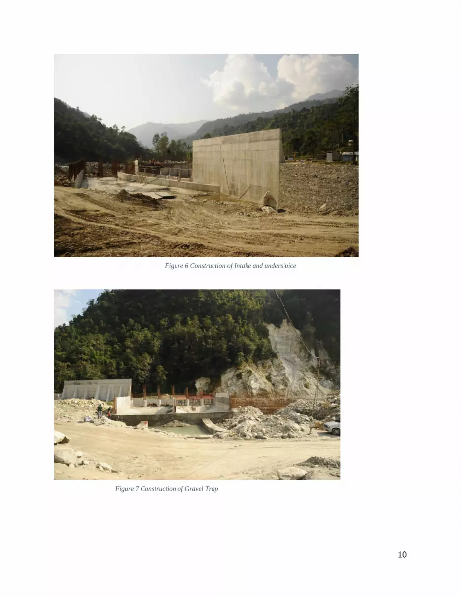
7.3 Surface structures
The concreting works of Undersluice, divide wall, counterfort wall, intake, bed load deflector and
gravel trap and approach canal is going on. Similarly excavation of settling basin is in progress.
Overall more than twenty five percent of headworks has completed.
10
Figure 6 Construction of Intake and undersluice
Figure 7 Construction of Gravel Trap

11
9. Fewa Dam Fewa Hydropower Station is a canal drop type power station having an installed capacity of 1.0
MW erected at the end of Fewa Canal which was mainly constructed to irrigate land in the vicinity
of Birauta. Fewa hydropower station is and located at Pardi Birauta , Pokhara with an annual design
generation of 6.5 GWh. (Nea, 2016) It consists of 4 units each 0.25 MW .Currently, three units
are in operation and Unit No. 4 is not in operation due to problem in generator turbine coupling. It
was commissioned in 1969 AD and developed jointly by Government of India and Government
of Nepal. The public encroachment of power canal leading to power house is a concern for normal
operation regardless of the availability of generating units.
The main Canal starts from the barrage which is located at one end of Fewa Lake at a popular
tourist destination called Dam site. This canal after traversing some distance is branched at Ram
Mandir to form main and branch canal. The main canal heads to the East for irrigation and branch
canal heads to the South for both power and irrigation .
Figure 9 Phewa dam
Figure 8 fewa drop canal

12
Salient Features : (http://nea.org.np/generation/index.php)
Type : Canal Drop
Location: Pardi Baidam, Pokhara Gandaki Zone
Operator: Nepal Electricity Authority
Installed capacity 1.0 MW
Turbine Configuration: 4 X 250-kW Francis
Operation: 1969
Annual average energy 6.5GWh
Maximum Net head 74.68m
Total length of the waterways 1.0 km
Number and Type 4, Horizontal Francis
Rated speed 1000 rpm
Rated output 288 kW
Rated voltage 400 V
Rated frequency 50 Hz
Power transformer 350kVA, 0.4/11kV, 4 Nos.
Transmission line 11 kV

13
Figure 10 Diversion to irrigation and forebay at seti
10. Seti Hydropower
Seti Hydropower Station is a run of river type with installed capacity of 1.5 MW and design
generation of 9.8 GWh consisting of 3 units each 0.5 MW. It is located at Nadipur, Pokhara. Weir
and radial gate are used near the intake for the diversion of water from river to intake.Power canal
of this Plant serves both objectives of irrigation and energy. Intake of the canal is regulated
primarily for irrigation by Department of Irrigation and hence, normal operation of the Plant
sometimes gets affected regardless of availability of Units. The discharge of seti canal is 9 m3/sec.
and the design discharge of the hydropower plant is 4.55 m3/sec. (Nea, 2016) The power canal for
this power station is jointly used for irrigation purposes looked after by Department of Irrigation
and hence, the operation of this power station is affected by irrigation as well. Some of the works
carried out this year include repair of runner and guide vane of Unit No. 1, temporary relocation
of desander gate and maintenance of power canal and protection of Furse Khola.
The cumulative generation of Seti HPS has reached 254.77 GWh till 2011/12 from its first run.
The station has generated 11.62 GWh in FY 2010/11 and 10.41 GWh in FY 2011/12 with decrease
of 10.37%. The station contributed 0.25% of the total energy in the INPS in 2011/12.
Forebay : Headpond with spillway Design WL at Forebay 978.2m Spillway Canal Existing
Irrigation Canal (807m)
Penstock Type : Mild Steel (1.9m dia) welded buried pipe Length of Penstock 732m

14
Salient Features : (http://nea.org.np/generation/index.php)
Type of hydropower plant: Run of River
Location Nadipur, Pokhara
PPA date: 08 Aswin 2063
Construction Started: Falgun 2063
CoD Date: 14 Falgun 2065
Installed Capacity: 1.5MW
Gross Head: 28.0 m
Discharge of Seti Canal : 9.0 m 3/sec
Deemed Energy: 6.98 GWh
Rated discharge 2.96m3/s
Rated output 543kW
Rated speed 500rpm
Rated output 625kVA
Rated voltage 6.3kV
Power factor 0.8
Rated frequency 50Hz
Power transformer 650kVA, 6.3/11kV, 3 Nos.
Transmission line 11kV
Cost of the Project with IDC : 19 crores
Financing Bank Rastriya Banijya Bank

15
11. Conclusion and Discussion
The visit was fruitful. We gain the practical knowledge about the different component of the
hydropower plant. We also get the knowledge of the current situation of the hydropower plant and
the current problem in the plant. We also got the chance to make the comparison between the
different hydropower plant. Overall we got the chance to see what we have read in theory .
In such a way we completed our Hydropower tour at pokhara meeting all our objectives in a fruitful
way.we learned various elements of hydropower and their operating mechanism.
12. Bibliography
(2016). Retrieved from http://modihydro.com.
Dandekar, M. (2010). Water Power Engineering. Vikas publicating house pvt ltd.
Garg, S. K. (2011). Irrigation Engineering And Hydraulis Structures. khanna publications.
(n.d.). http://nea.org.np/generation/index.php.
marsyngdi power station. (2016).
middle modi. (n.d.). Retrieved from http://middlemodi.com.np.
Nea. (2016). Annual Report 2016. Kathmandu , nepal: Nepal Electricity Authority.