mechanics of materials - civil iitb
TRANSCRIPT
MECHANICS OF MATERIALS
CHAPTER
3 Torsion
MECHANICS OF MATERIALS Contents
Introduction
Torsional Loads on Circular Shafts
Net Torque Due to Internal Stresses
Axial Shear Components
Shaft Deformations
Shearing Strain
Stresses in Elastic Range
Angle of Twist
Normal Stresses
Torsional Failure Modes
Sample Problem 3.1
Statically Indeterminate Shafts
Sample Problem 3.2
Design of Transmission Shafts
MECHANICS OF MATERIALS Net Torque Due to Internal Stresses
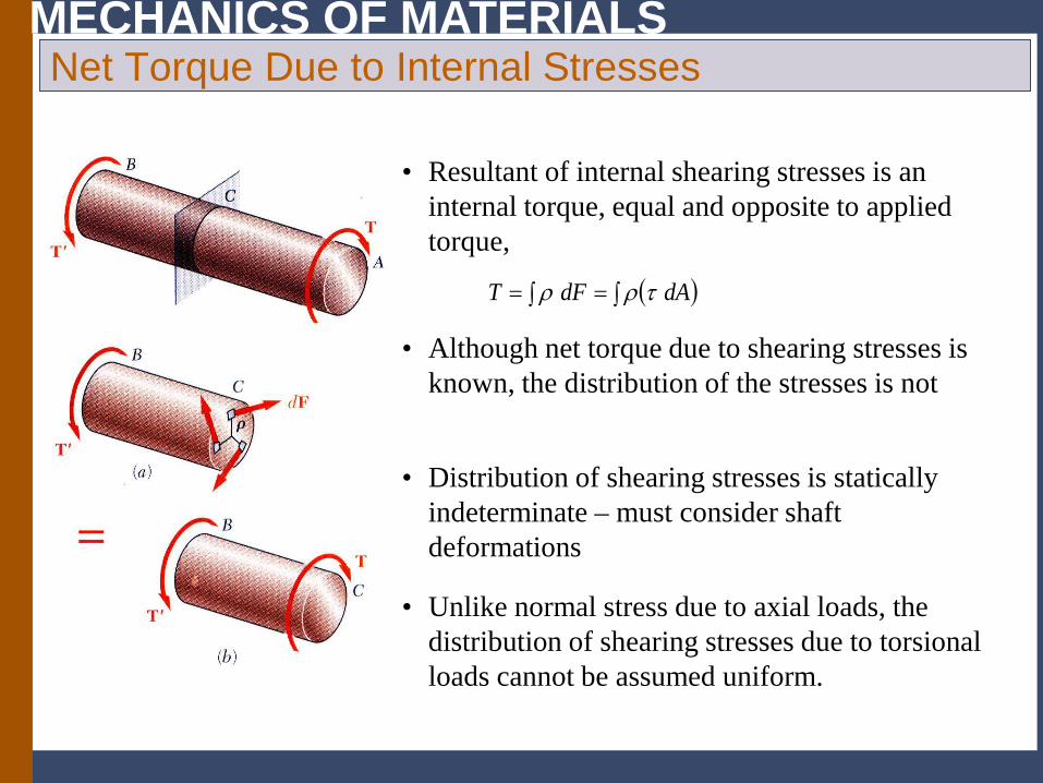
( )∫ ∫== dAdFT τρρ
• Resultant of internal shearing stresses is an internal torque, equal and opposite to applied torque,
• Although net torque due to shearing stresses is known, the distribution of the stresses is not
• Unlike normal stress due to axial loads, the distribution of shearing stresses due to torsional loads cannot be assumed uniform.
• Distribution of shearing stresses is statically indeterminate – must consider shaft deformations
MECHANICS OF MATERIALS Axial Shear Components
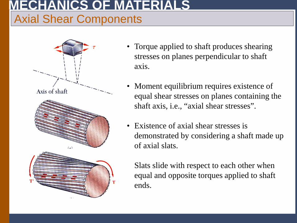
• Torque applied to shaft produces shearing stresses on planes perpendicular to shaft axis.
• Existence of axial shear stresses is demonstrated by considering a shaft made up of axial slats. Slats slide with respect to each other when equal and opposite torques applied to shaft ends.
• Moment equilibrium requires existence of equal shear stresses on planes containing the shaft axis, i.e., “axial shear stresses”.
MECHANICS OF MATERIALS
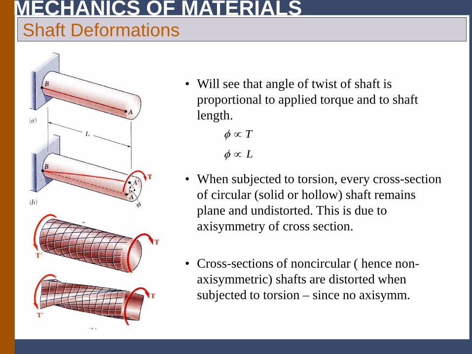
• Will see that angle of twist of shaft is proportional to applied torque and to shaft length.
L
T
∝
∝
φ
φ
Shaft Deformations
• When subjected to torsion, every cross-section of circular (solid or hollow) shaft remains plane and undistorted. This is due to axisymmetry of cross section.
• Cross-sections of noncircular ( hence non-axisymmetric) shafts are distorted when subjected to torsion – since no axisymm.
MECHANICS OF MATERIALS Shearing Strain
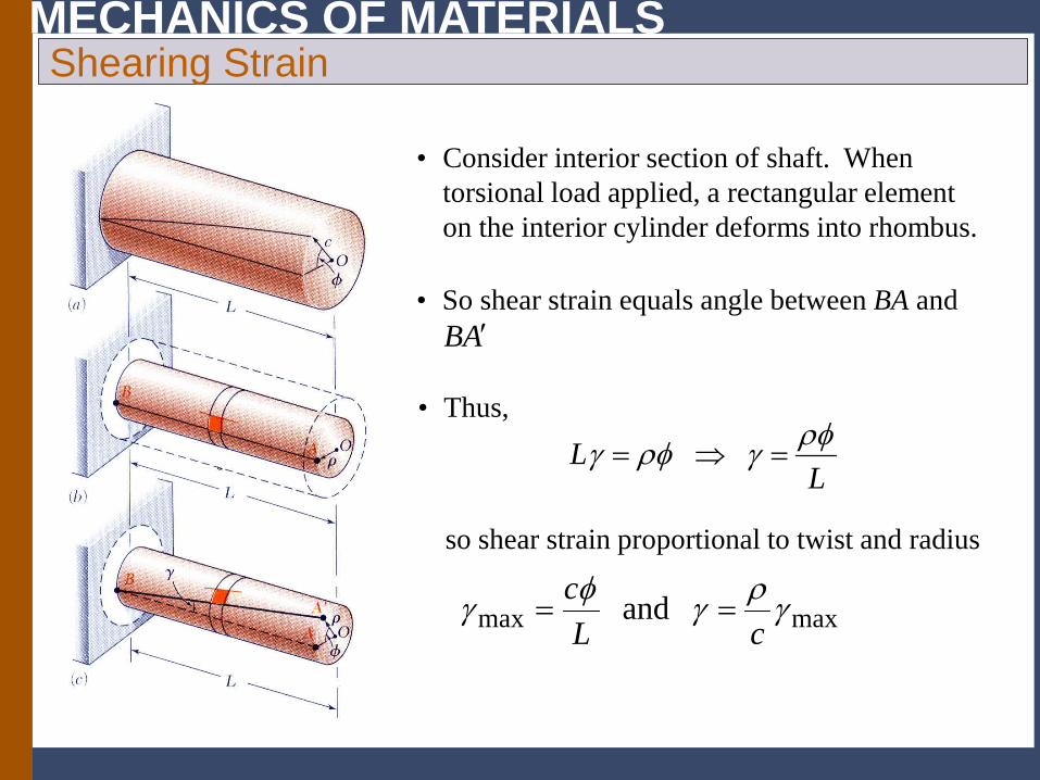
• Consider interior section of shaft. When torsional load applied, a rectangular element on the interior cylinder deforms into rhombus.
so shear strain proportional to twist and radius
maxmax and γργφγcL
c==
LL ρφγρφγ =⇒=
• Thus,
• So shear strain equals angle between BA and AB ′
MECHANICS OF MATERIALS Torsion Formulae in elastic range (shear stress, angle of twist
ρτφ
ρφρφρρτ
JL
GJ
dAL
GdAL
GdAT
==
=== ∫ ∫∫ 2
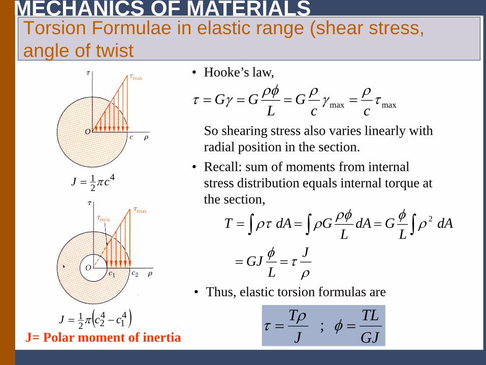
• Recall: sum of moments from internal stress distribution equals internal torque at the section,
421 cJ π=
( )41
422
1 ccJ −= π
GJTL
JT
== φρτ ;
• Thus, elastic torsion formulas are
• Hooke’s law,
maxmax τργρρφγτcc
GL
GG ====
So shearing stress also varies linearly with radial position in the section.
J= Polar moment of inertia
MECHANICS OF MATERIALS Torsion formulae in Elastic Range
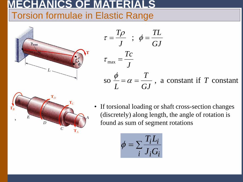
• If torsional loading or shaft cross-section changes (discretely) along length, the angle of rotation is found as sum of segment rotations
∑=i ii
iiGJLTφ
constantifconstanta,so
;
max
TGJT
L
JTc
GJTL
JT
==
=
==
αφ
τ
φρτ
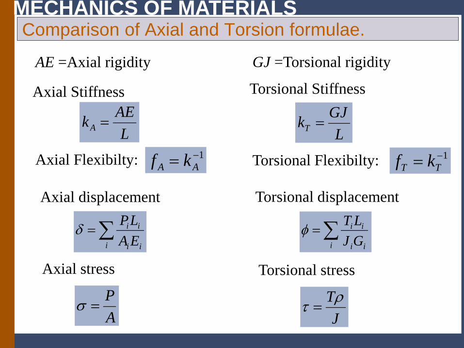
MECHANICS OF MATERIALS Comparison of Axial and Torsion formulae.
AE =Axial rigidity
Axial Stiffness
Axial Flexibilty:
GJ =Torsional rigidity
Torsional Stiffness
Torsional Flexibilty:
LAEkA =
1−= AA kfL
GJkT =
1−= TT kf
Axial displacement
∑=i ii
ii
GJLTφ∑=
i ii
ii
EALPδ
Torsional displacement
Axial stress
AP
=σJ
Tρτ =
Torsional stress
MECHANICS OF MATERIALS
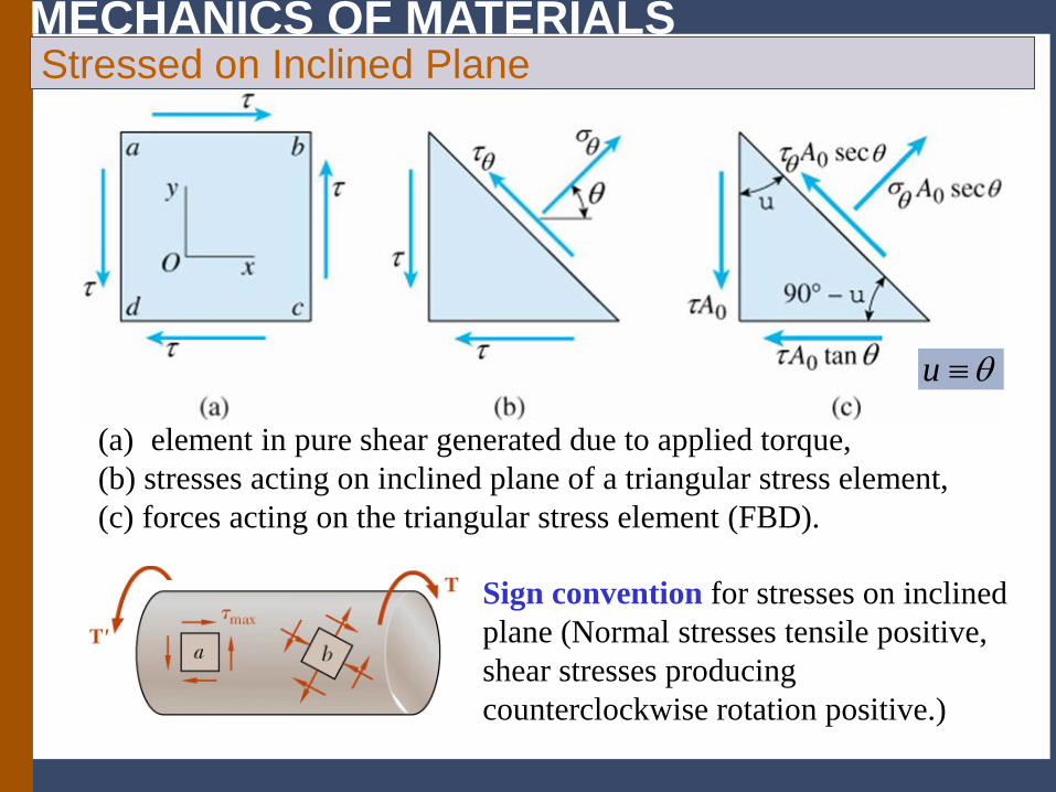
(a) element in pure shear generated due to applied torque, (b) stresses acting on inclined plane of a triangular stress element, (c) forces acting on the triangular stress element (FBD).
Stressed on Inclined Plane
θ≡u
Sign convention for stresses on inclined plane (Normal stresses tensile positive, shear stresses producing counterclockwise rotation positive.)
MECHANICS OF MATERIALS
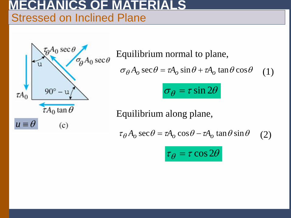
θθτθτθσθ costansinsec ooo AAA +=
Equilibrium normal to plane,
Equilibrium along plane,
θθτθτθτθ sintancossec ooo AAA −=
(1)
(2)
θτσθ 2sin=
θττθ 2cos=
θ≡u
Stressed on Inclined Plane
MECHANICS OF MATERIALS
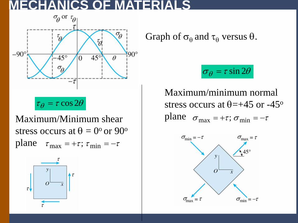
Graph of σθ and τθ versus θ.
Maximum/minimum normal stress occurs at θ=+45 or -45o
plane
θτσθ 2sin=
τστσ −=+= minmax ;Maximum/Minimum shear stress occurs at θ = 0o or 90o plane ττττ −=+= minmax ;
θττθ 2cos=
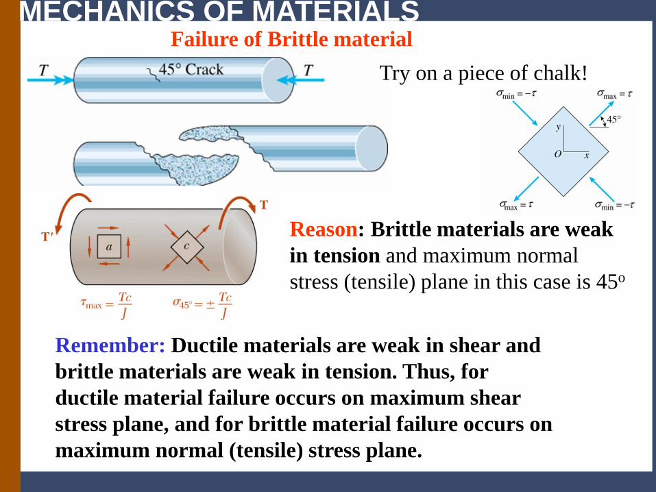
MECHANICS OF MATERIALS Failure of Brittle material
Try on a piece of chalk!
Reason: Brittle materials are weak in tension and maximum normal stress (tensile) plane in this case is 45o
Remember: Ductile materials are weak in shear and brittle materials are weak in tension. Thus, for ductile material failure occurs on maximum shear stress plane, and for brittle material failure occurs on maximum normal (tensile) stress plane.
MECHANICS OF MATERIALS
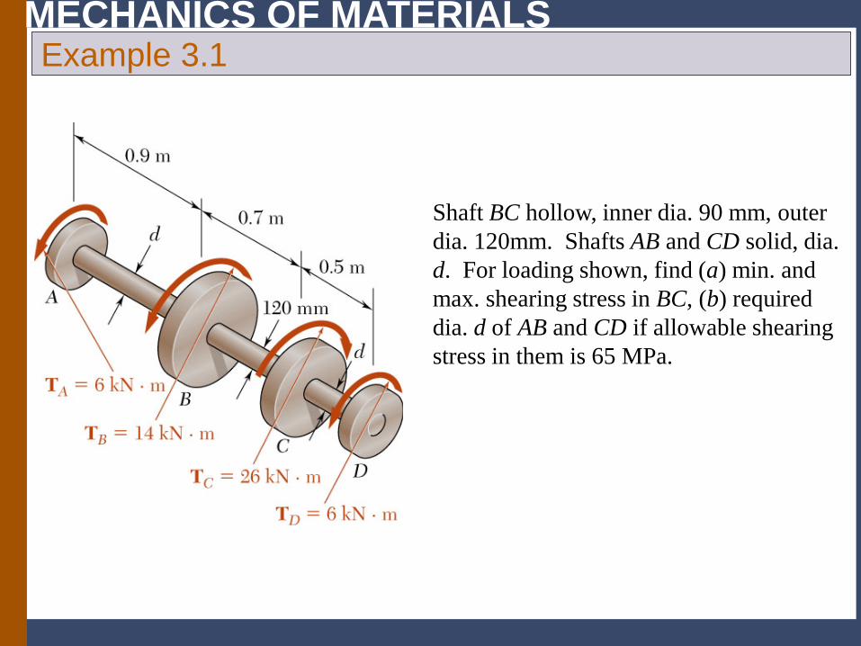
Shaft BC hollow, inner dia. 90 mm, outer dia. 120mm. Shafts AB and CD solid, dia. d. For loading shown, find (a) min. and max. shearing stress in BC, (b) required dia. d of AB and CD if allowable shearing stress in them is 65 MPa.
Example 3.1
MECHANICS OF MATERIALS
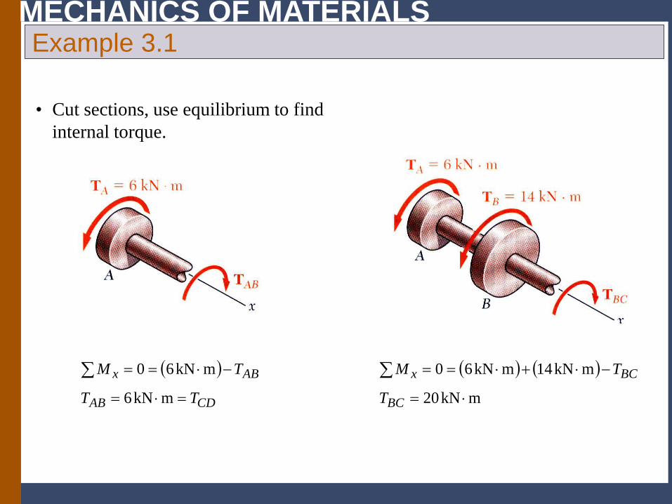
• Cut sections, use equilibrium to find internal torque.
( )
CDAB
ABx
TT
TM
=⋅=
−⋅==∑mkN6
mkN60 ( ) ( )mkN20
mkN14mkN60
⋅=
−⋅+⋅==∑
BC
BCx
T
TM
Example 3.1
MECHANICS OF MATERIALS
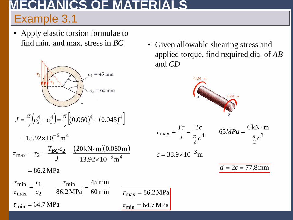
• Apply elastic torsion formulae to find min. and max. stress in BC
( )( )
MPa2.86m1092.13
m060.0mkN2046
22max
=
×
⋅=== −J
cTBCττ
MPa7.64
mm60mm45
MPa2.86
min
min
2
1
max
min
=
==
τ
τττ
cc
MPa7.64
MPa2.86
min
max
=
=
τ
τ
• Given allowable shearing stress and applied torque, find required dia. of AB and CD
m109.38
mkN665
3
32
42
max
−×=
⋅===
c
cMPa
cTc
JTc
ππτ
mm8.772 == cd
Example 3.1
( ) ( ) ( )[ ]46
4441
42
m1092.13
045.0060.022
−×=
−=−=ππ ccJ
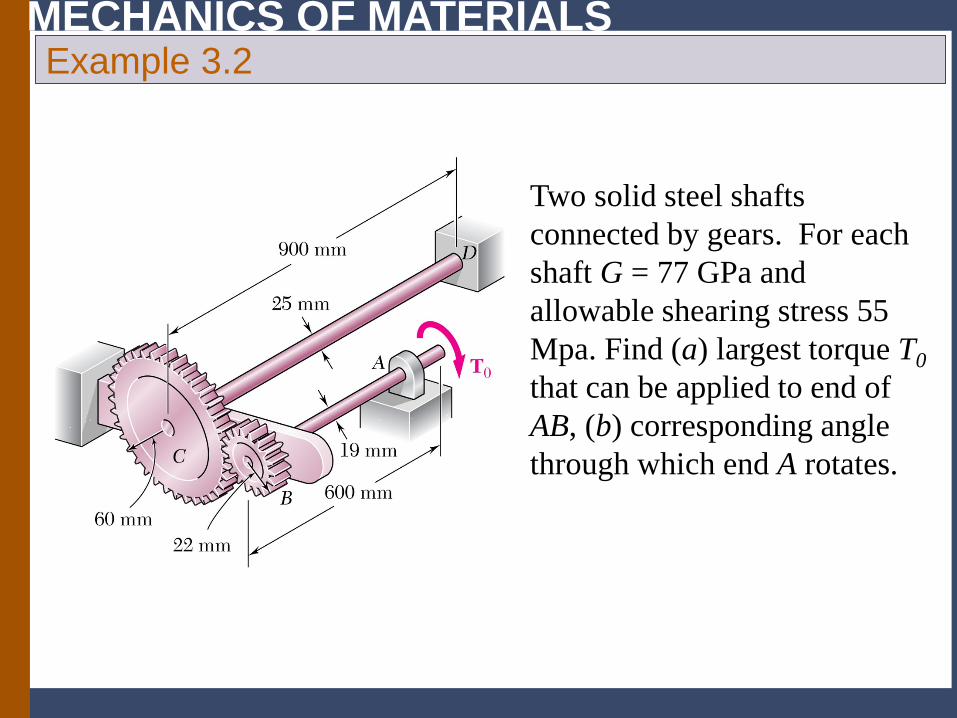
MECHANICS OF MATERIALS Example 3.2
Two solid steel shafts connected by gears. For each shaft G = 77 GPa and allowable shearing stress 55 Mpa. Find (a) largest torque T0 that can be applied to end of AB, (b) corresponding angle through which end A rotates.
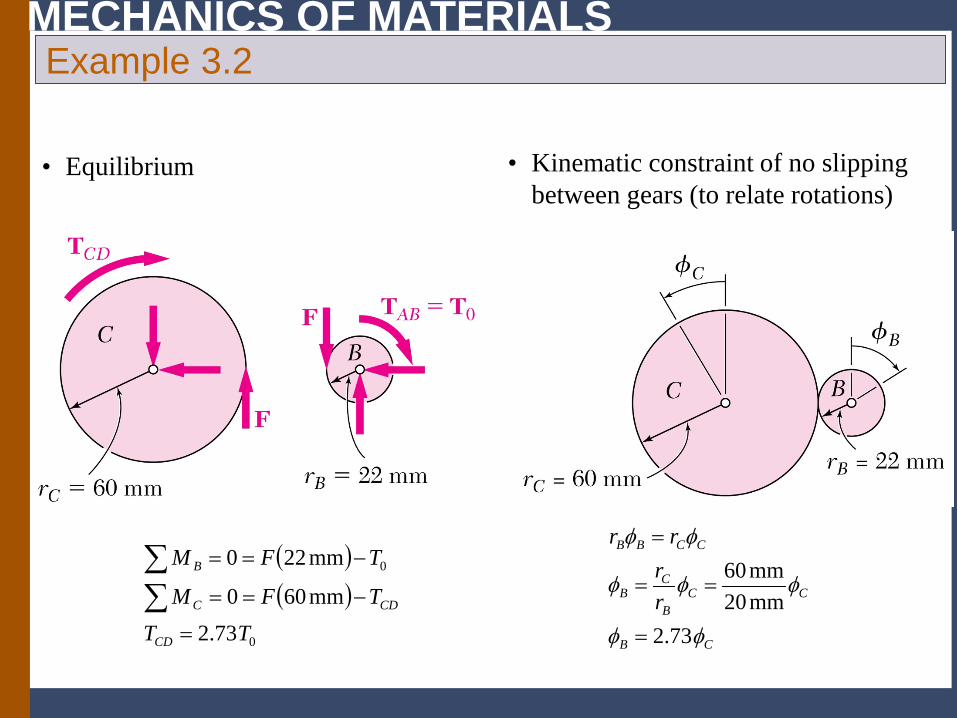
MECHANICS OF MATERIALS
• Equilibrium • Kinematic constraint of no slipping between gears (to relate rotations)
Example 3.2
( )( )
0
0
73.2mm600
mm220
TTTFM
TFM
CD
CDC
B
=
−==
−==
∑∑
CB
CCB
CB
CCBB
rr
rr
φφ
φφφ
φφ
73.2mm20mm60
=
==
=
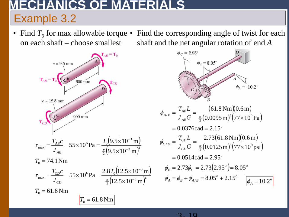
MECHANICS OF MATERIALS
• Find T0 for max allowable torque on each shaft – choose smallest
• Find the corresponding angle of twist for each shaft and the net angular rotation of end A
Example 3.2
3- 19
( )( )
( )( )
Nm8.61m105.12
m105.128.2Pa1055
Nm1.74m105.9m105.9Pa1055
0
432
306
max
0
432
306
max
=
×
×=×=
=
×
×=×=
−
−
−
−
T
TJ
cTT
TJ
cT
CD
CD
AB
AB
π
π
τ
τ
Nm8.610 =T
( )( )( ) ( )
( )( )( ) ( )
( )oo
/
oo
o
942
/
o
942
/
2.1505.8
05.895.273.273.295.2rad0514.0
psi1077m0125.0m6.0Nm8.6173.2
2.15rad0376.0
Pa1077m0095.0m6.0Nm8.61
+=+=
===
==
×==
==
×==
BABA
CB
CD
CDDC
AB
ABBA
GJLT
GJLT
φφφ
φφ
φ
φ
π
π
o2.10=Aφ
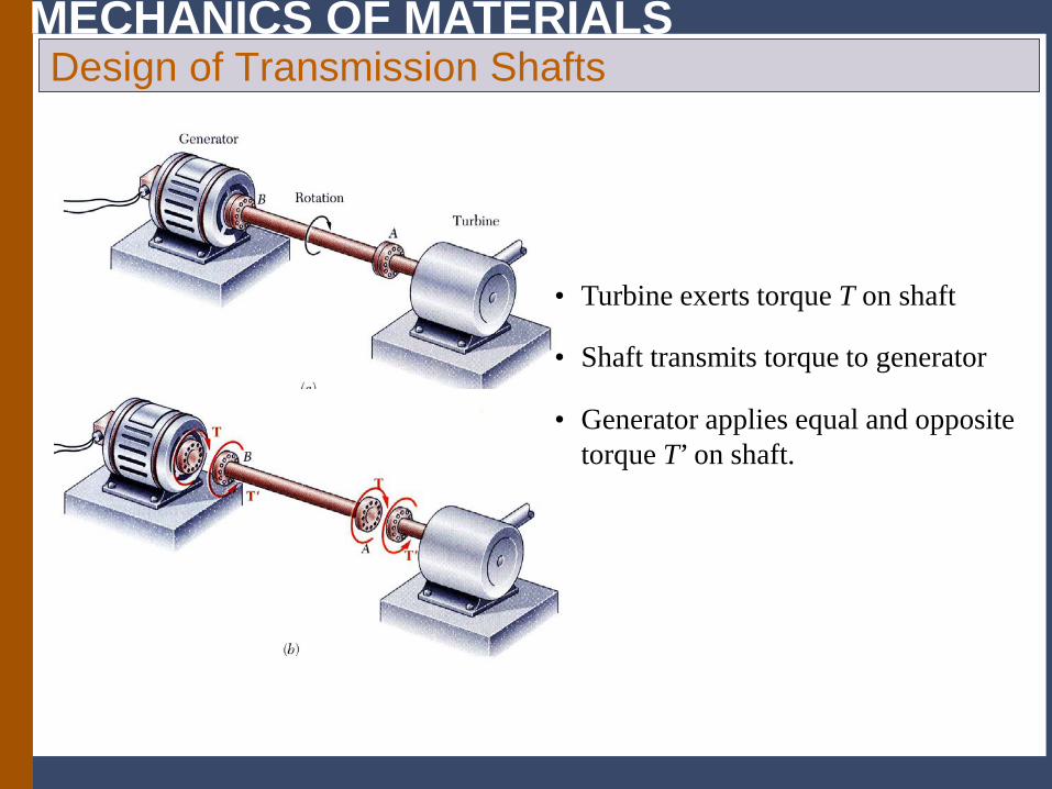
MECHANICS OF MATERIALS
• Generator applies equal and opposite torque T’ on shaft.
• Shaft transmits torque to generator
• Turbine exerts torque T on shaft
Design of Transmission Shafts
MECHANICS OF MATERIALS Design of Transmission Shafts
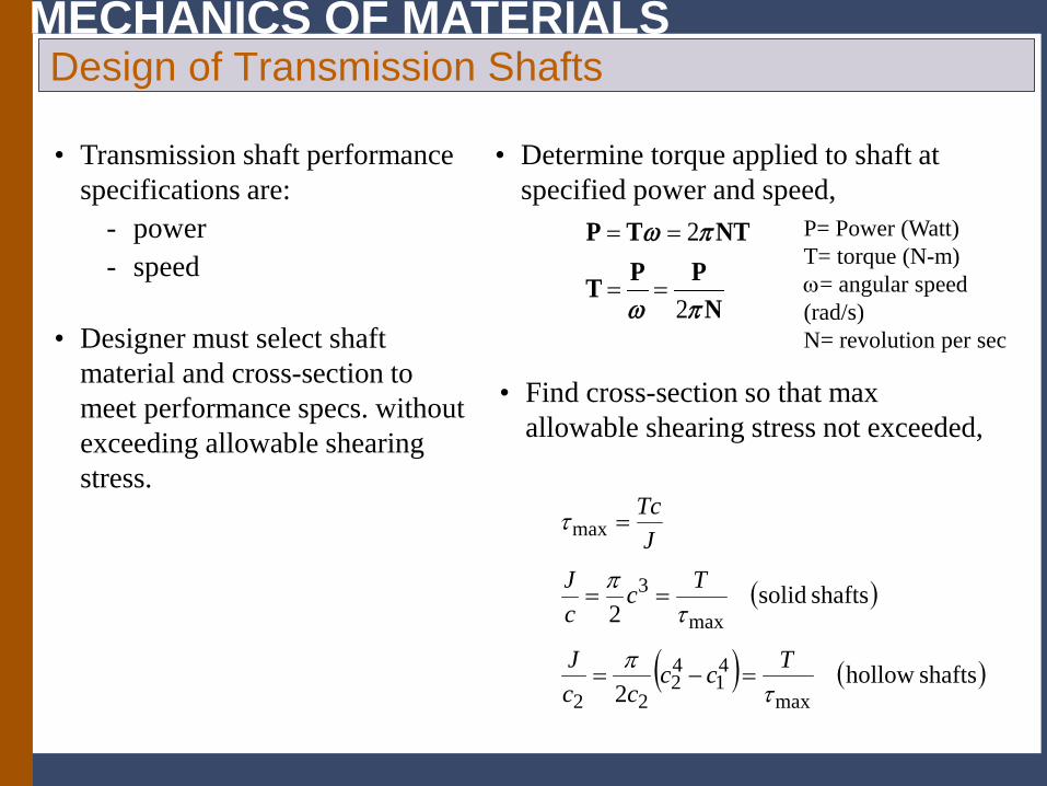
• Transmission shaft performance specifications are:
- power - speed
• Determine torque applied to shaft at specified power and speed,
2
2
P T NTP PT
N
ω π
ω π
= =
= =
• Find cross-section so that max allowable shearing stress not exceeded,
( )
( ) ( )shafts hollow2
shafts solid2
max
41
42
22
max
3
max
τπ
τπ
τ
Tcccc
J
TccJ
JTc
=−=
==
=
• Designer must select shaft material and cross-section to meet performance specs. without exceeding allowable shearing stress.
P= Power (Watt) T= torque (N-m) ω= angular speed (rad/s) N= revolution per sec
MECHANICS OF MATERIALS
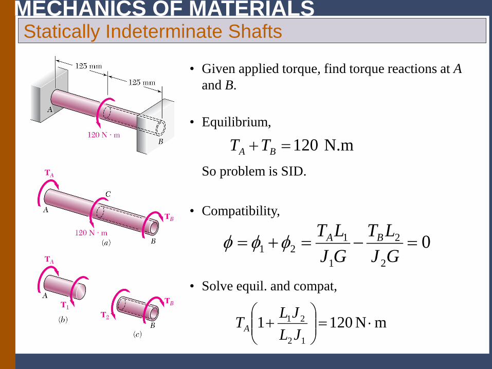
• Given applied torque, find torque reactions at A and B.
Statically Indeterminate Shafts
• Equilibrium, So problem is SID.
N.m120=+ BA TT
mN120112
21 ⋅=
+
JLJLTA
• Solve equil. and compat,
02
2
1
121 =−=+=
GJLT
GJLT BAφφφ
• Compatibility,
MECHANICS OF MATERIALS Thin-Walled Hollow Shafts
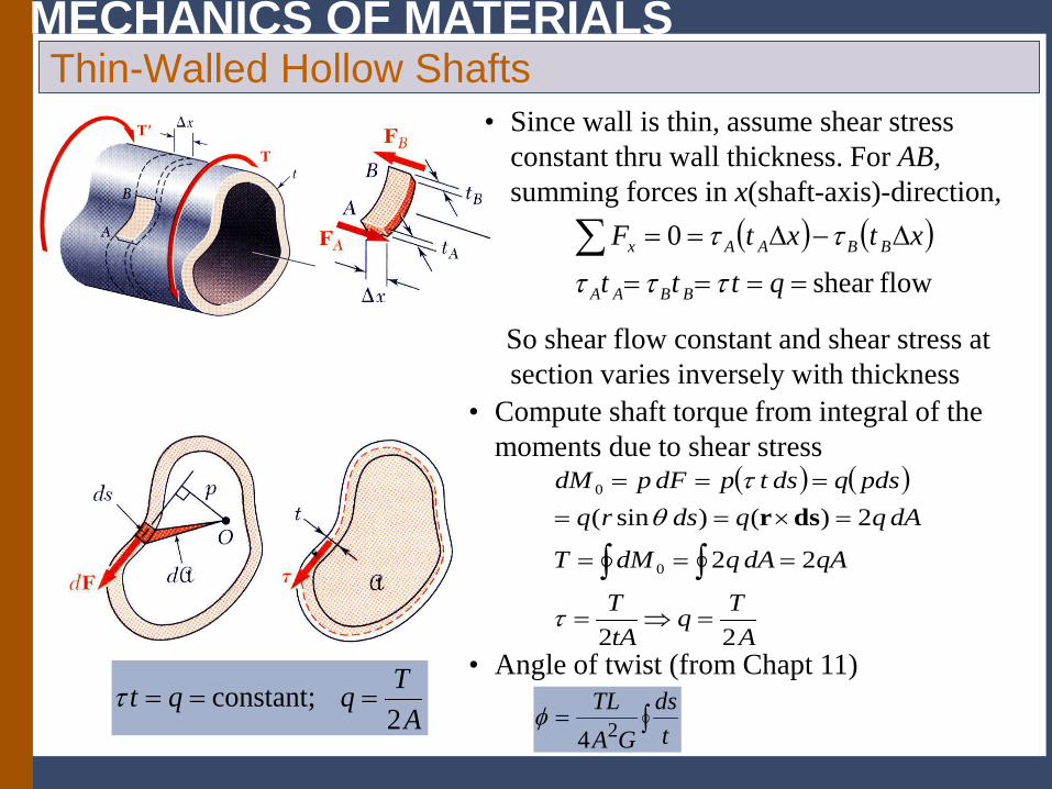
• Since wall is thin, assume shear stress constant thru wall thickness. For AB, summing forces in x(shaft-axis)-direction,
So shear flow constant and shear stress at section varies inversely with thickness
( ) ( )flowshear
0====
∆−∆==∑qttt
xtxtF
BBAA
BBAAx
τττ
ττ
( ) ( )
ATq
tAT
qAdAqdMT
dAqqdsrqpdsqdstpdFpdM
22
22
2)()sin(
0
0
=⇒=
===
=×=====
∫∫τ
θτ
dsr
• Compute shaft torque from integral of the moments due to shear stress
∫=t
dsGA
TL24
φ
• Angle of twist (from Chapt 11)
ATqqt2
constant; ===τ
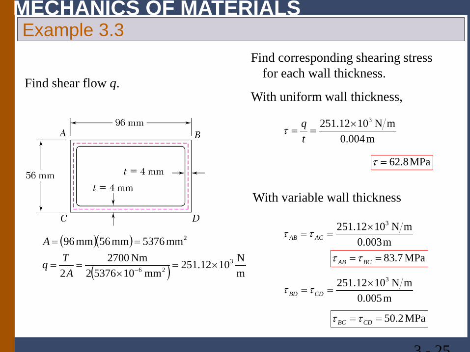
MECHANICS OF MATERIALS Example 3.3
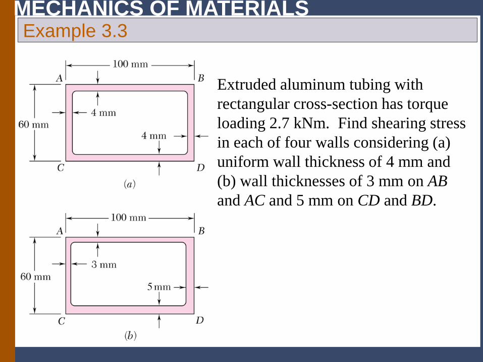
Extruded aluminum tubing with rectangular cross-section has torque loading 2.7 kNm. Find shearing stress in each of four walls considering (a) uniform wall thickness of 4 mm and (b) wall thicknesses of 3 mm on AB and AC and 5 mm on CD and BD.
MECHANICS OF MATERIALS
3 - 25
Example 3.3 Find corresponding shearing stress
for each wall thickness.
With uniform wall thickness,
m004.0mN1012.251 3×
==tqτ
MPa8.62=τ
With variable wall thickness
m003.0mN1012.251 3×
== ACAB ττ
m005.0mN1012.251 3×
== CDBD ττ
MPa7.83== BCAB ττ
MPa2.50== CDBC ττ
Find shear flow q.
( )( )
( ) mN1012.251
mm1053762Nm2700
2
mm5376mm56mm96
326
2
×=×
==
==
−ATq
A
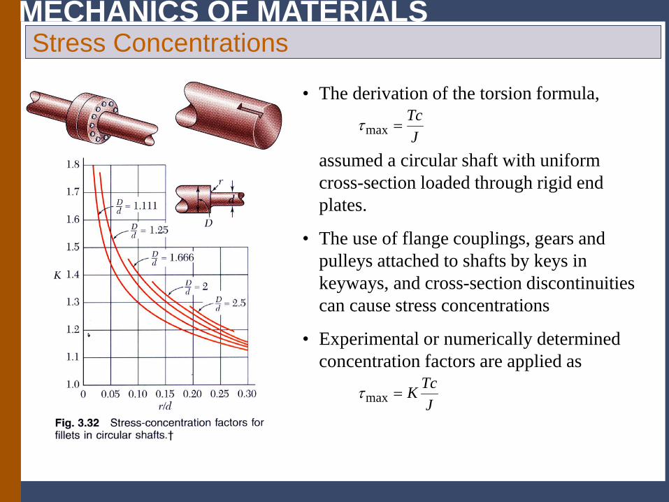
MECHANICS OF MATERIALS Stress Concentrations
• The derivation of the torsion formula, assumed a circular shaft with uniform cross-section loaded through rigid end plates.
JTc
=maxτ
JTcK=maxτ
• Experimental or numerically determined concentration factors are applied as
• The use of flange couplings, gears and pulleys attached to shafts by keys in keyways, and cross-section discontinuities can cause stress concentrations
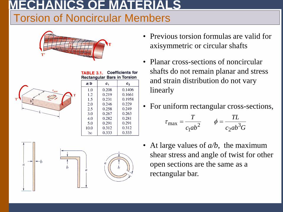
MECHANICS OF MATERIALS Torsion of Noncircular Members
• At large values of a/b, the maximum shear stress and angle of twist for other open sections are the same as a rectangular bar.
GabcTL
abcT
32
21
max == φτ
• For uniform rectangular cross-sections,
• Previous torsion formulas are valid for axisymmetric or circular shafts
• Planar cross-sections of noncircular shafts do not remain planar and stress and strain distribution do not vary linearly
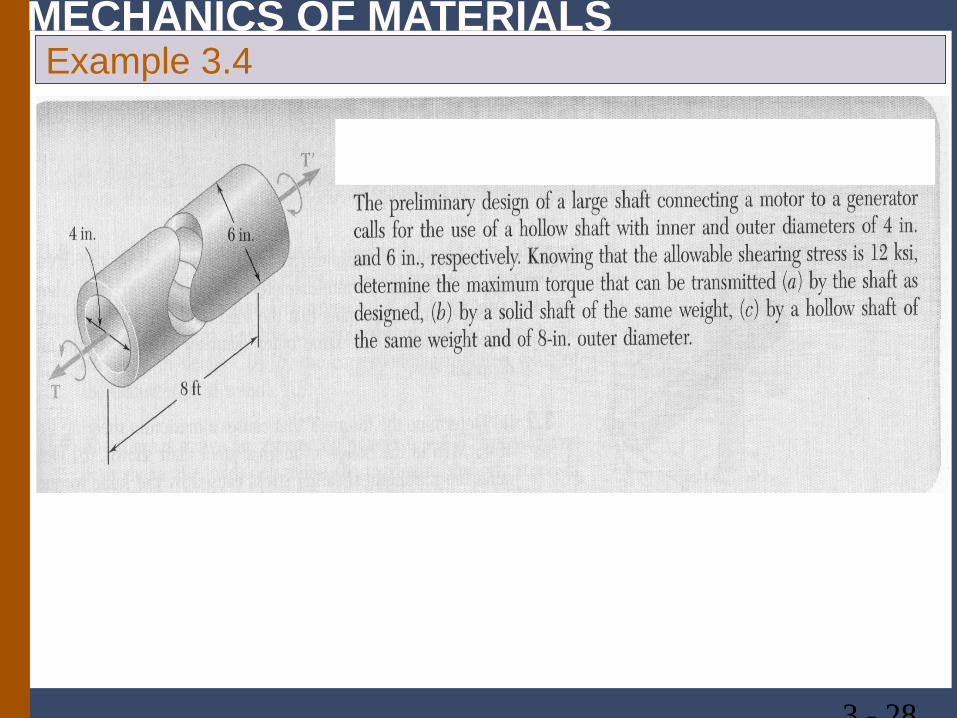
MECHANICS OF MATERIALS Example 3.4
3 - 28
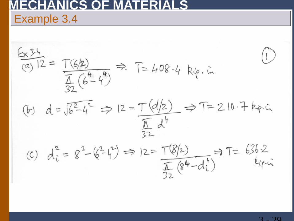
MECHANICS OF MATERIALS Example 3.4
3 - 29
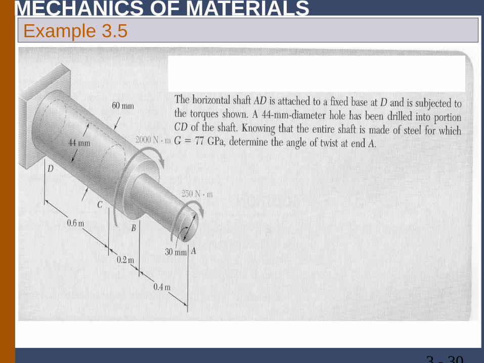
MECHANICS OF MATERIALS Example 3.5
3 - 30
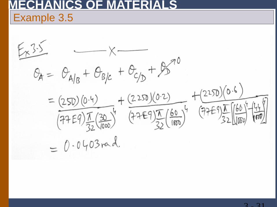
MECHANICS OF MATERIALS Example 3.5
3 - 31
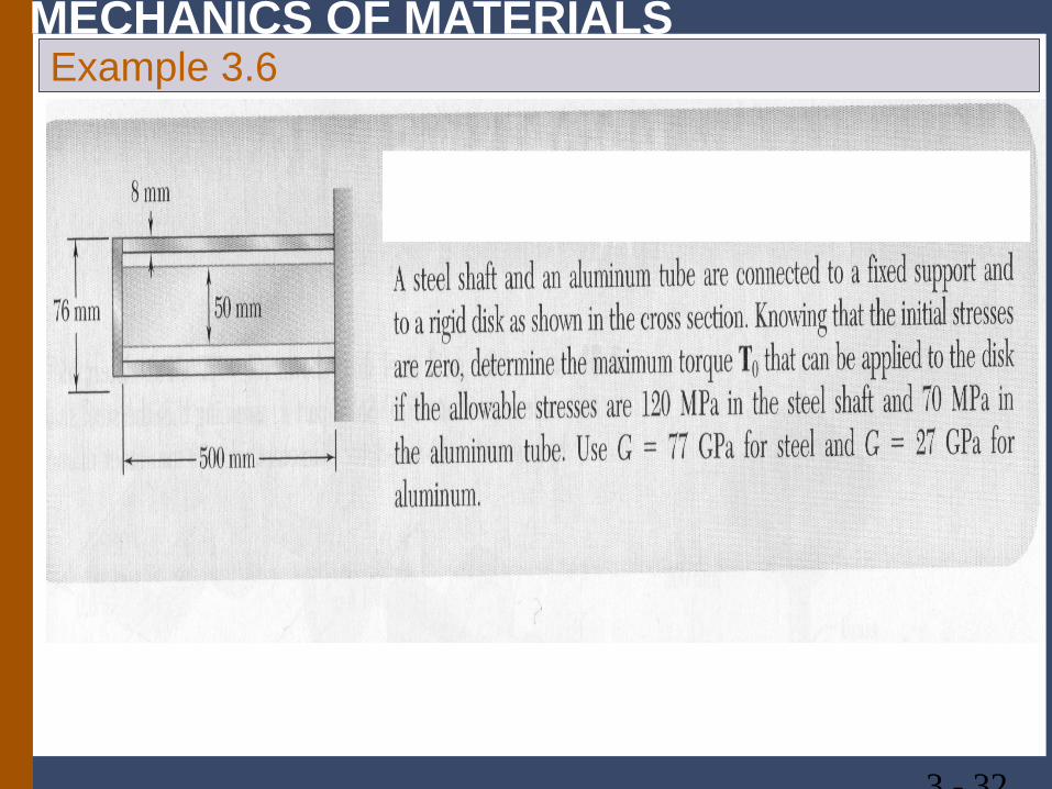
MECHANICS OF MATERIALS Example 3.6
3 - 32
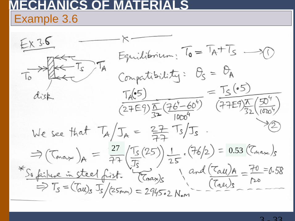
MECHANICS OF MATERIALS Example 3.6
3 - 33
27 0.53
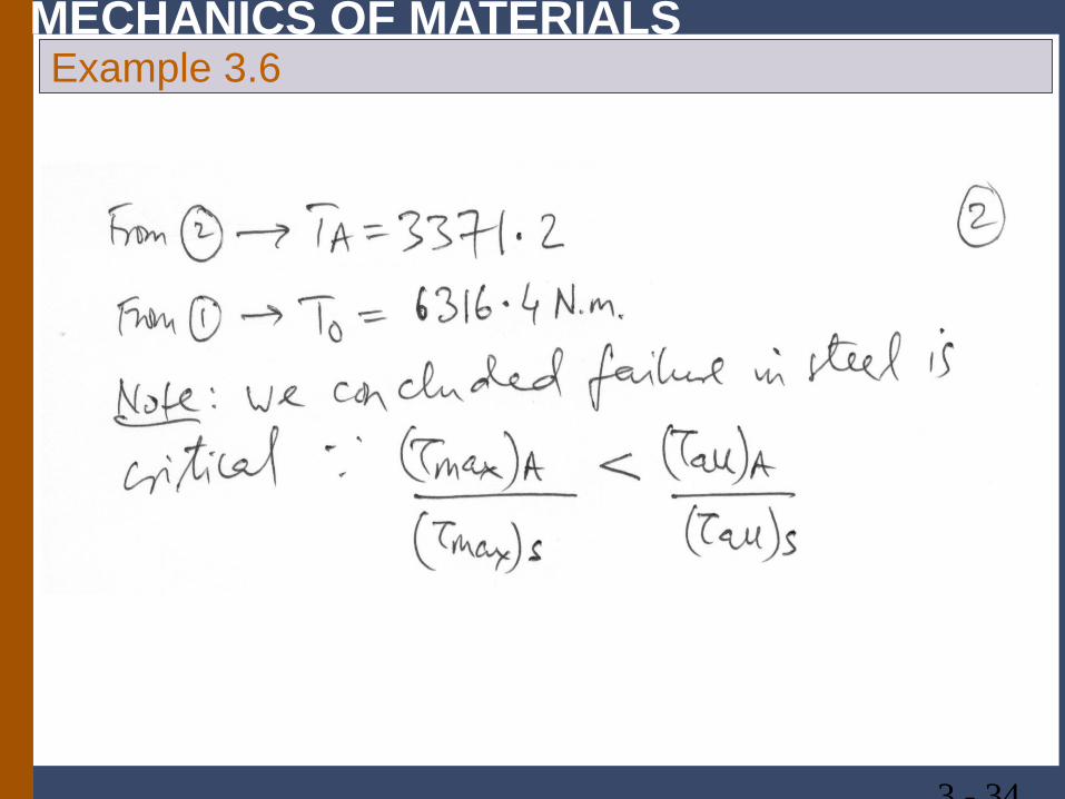
MECHANICS OF MATERIALS Example 3.6
3 - 34
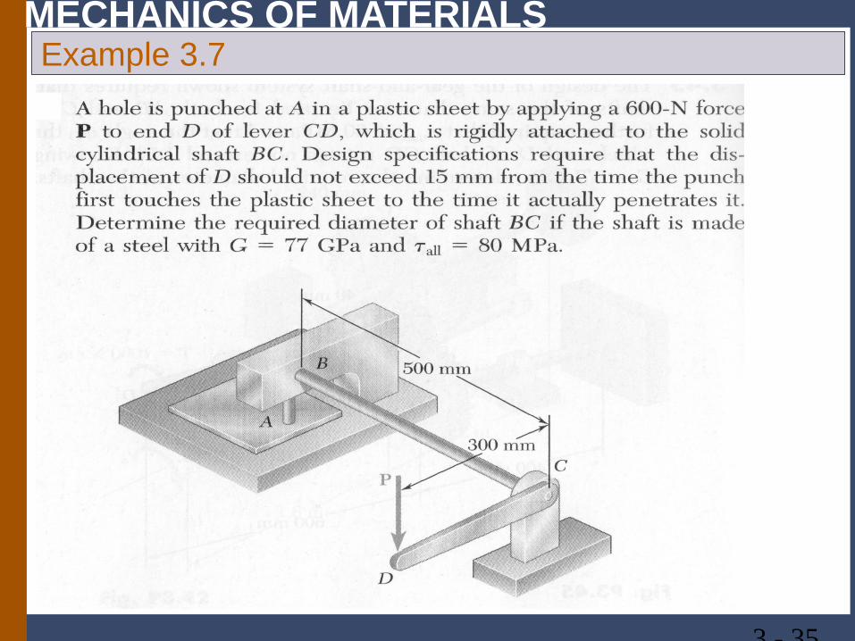
MECHANICS OF MATERIALS Example 3.7
3 - 35
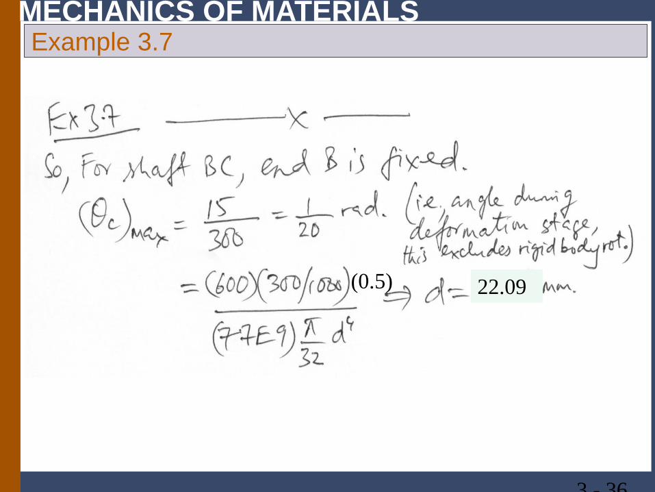
MECHANICS OF MATERIALS Example 3.7
3 - 36
22.09 (0.5)
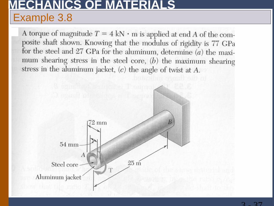
MECHANICS OF MATERIALS Example 3.8
3 - 37
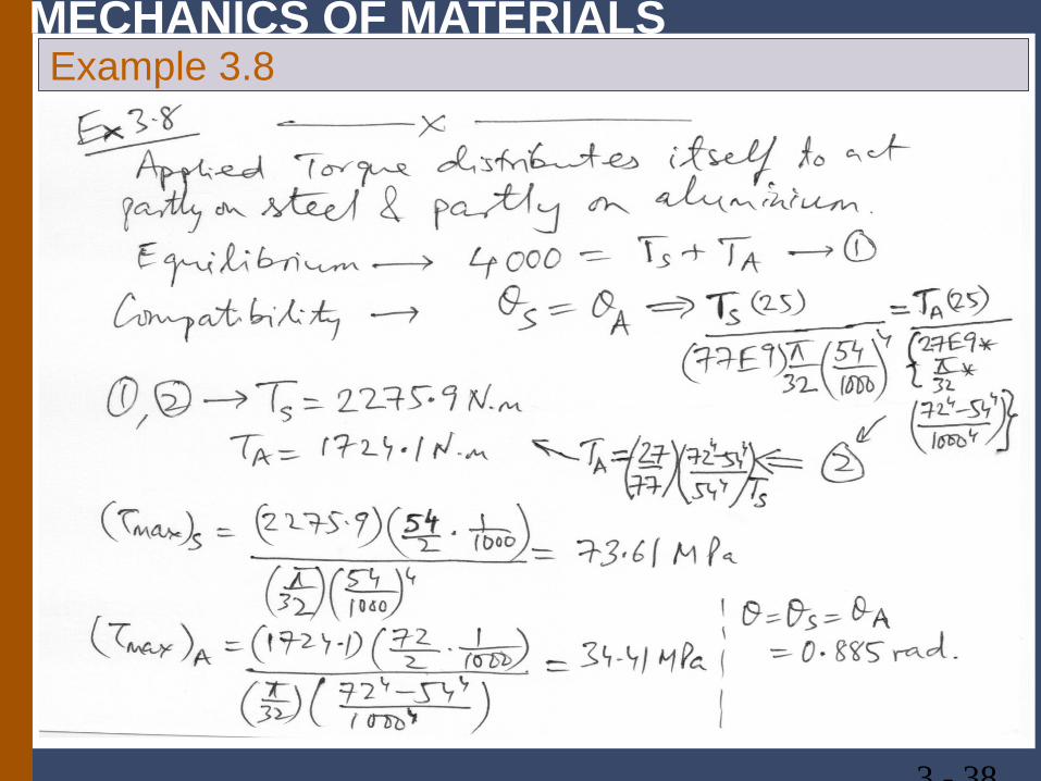
MECHANICS OF MATERIALS Example 3.8
3 - 38
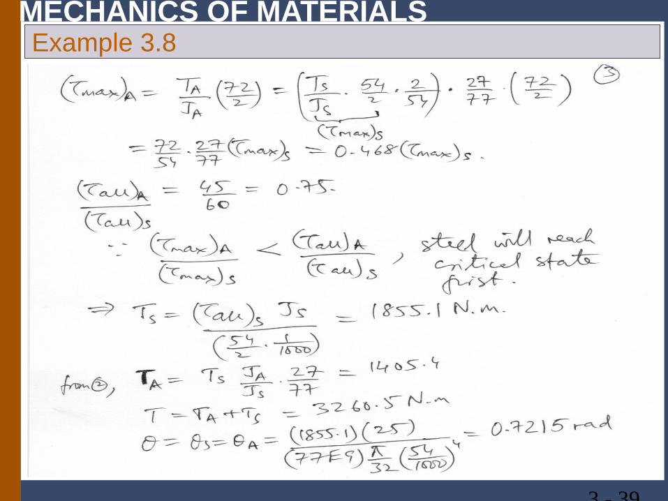
MECHANICS OF MATERIALS Example 3.8
3 - 39
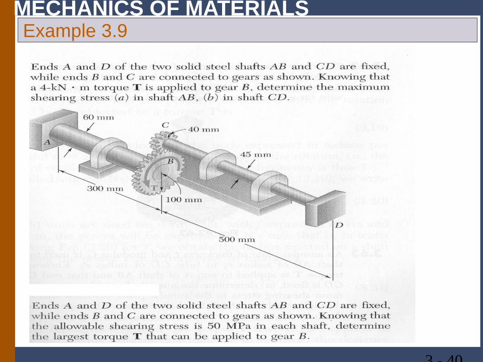
MECHANICS OF MATERIALS Example 3.9
3 - 40
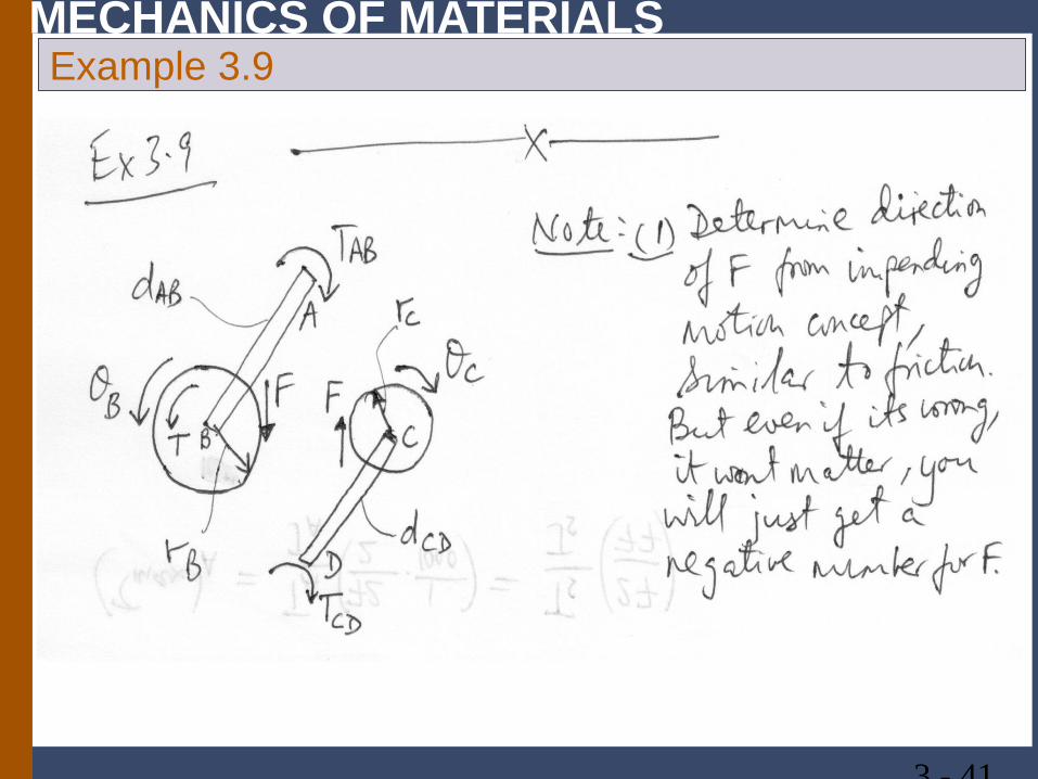
MECHANICS OF MATERIALS Example 3.9
3 - 41
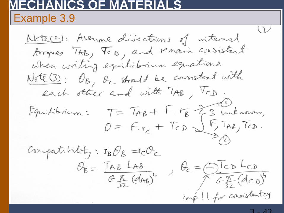
MECHANICS OF MATERIALS Example 3.9
3 - 42
rB rC
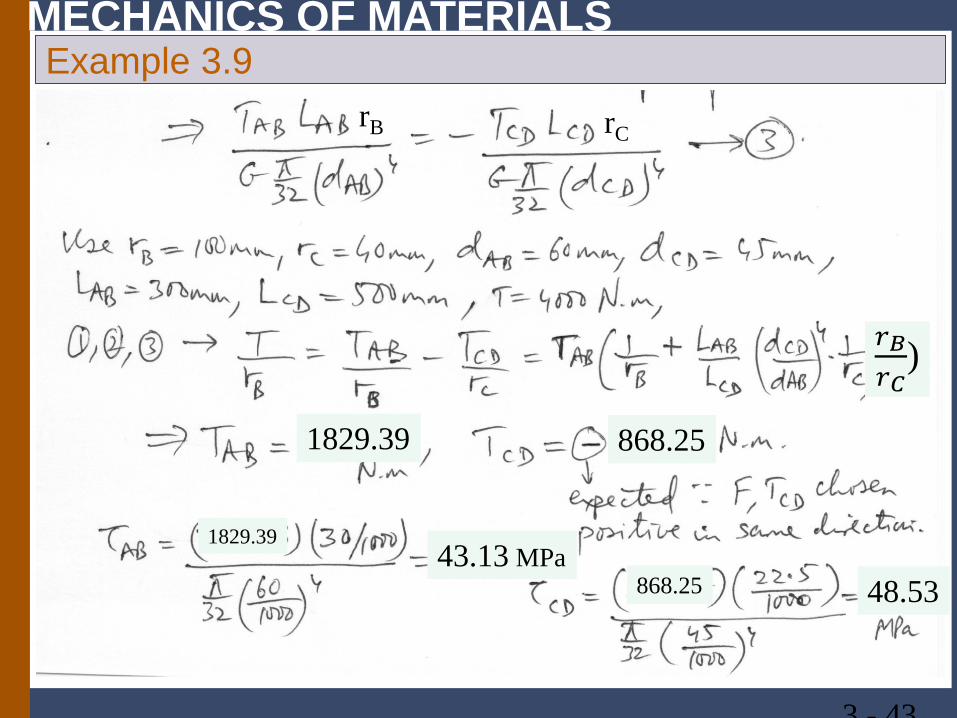
MECHANICS OF MATERIALS Example 3.9
3 - 43
rB rC
1829.39 868.25
1829.39
868.25 43.13 MPa
48.53
𝑟𝑟𝐵𝐵𝑟𝑟𝐶𝐶
)
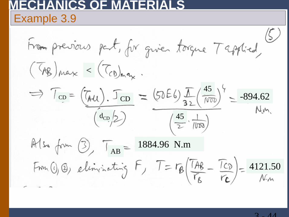
MECHANICS OF MATERIALS Example 3.9
3 - 44
45
45
-894.62 CD
dCD
AB 1884.96 N.m
4121.50
<
CD
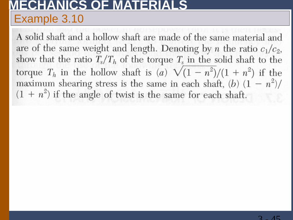
MECHANICS OF MATERIALS Example 3.10
3 - 45
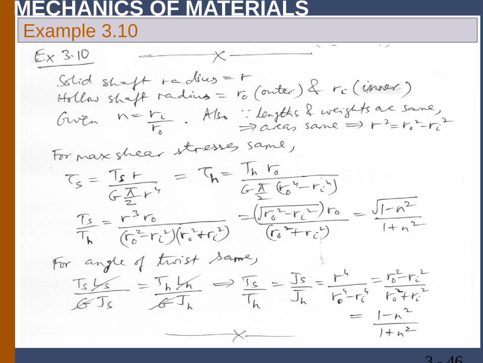
MECHANICS OF MATERIALS Example 3.10
3 - 46
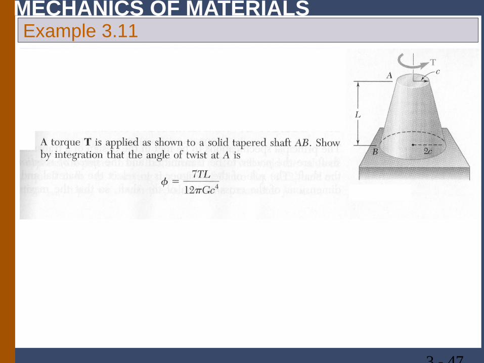
MECHANICS OF MATERIALS Example 3.11
3 - 47
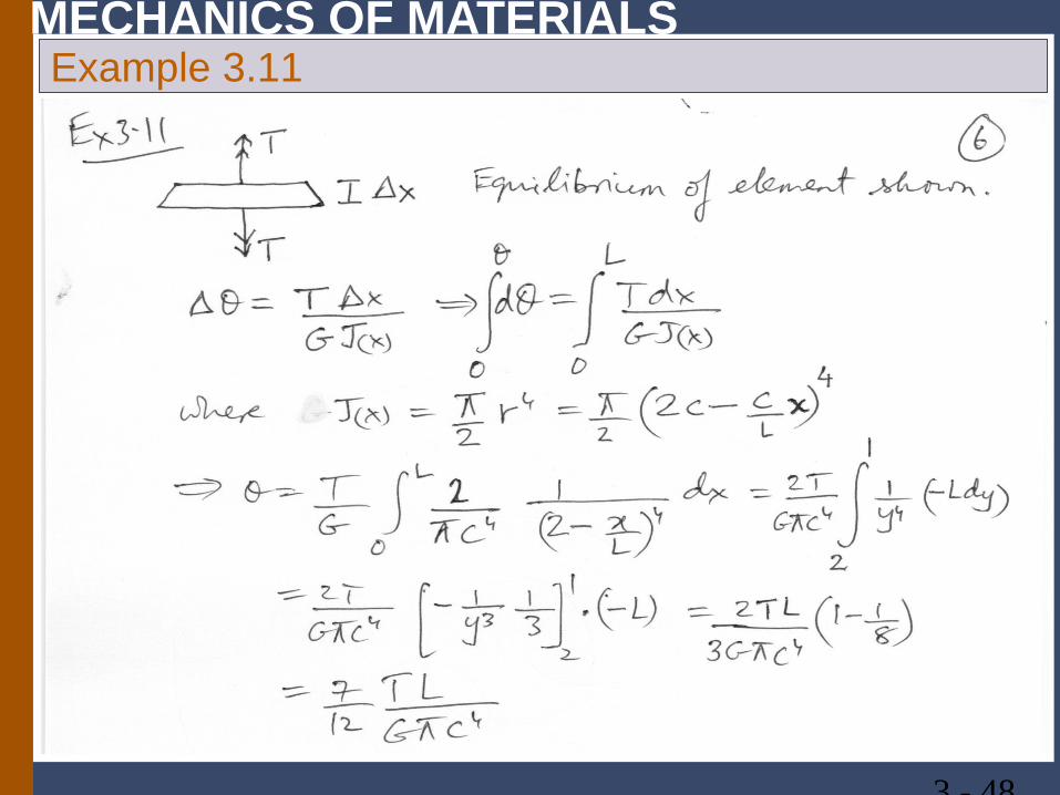
MECHANICS OF MATERIALS Example 3.11
3 - 48
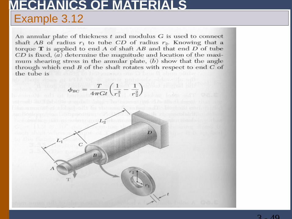
MECHANICS OF MATERIALS Example 3.12
3 - 49
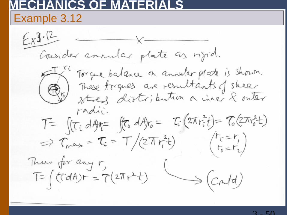
MECHANICS OF MATERIALS Example 3.12
3 - 50
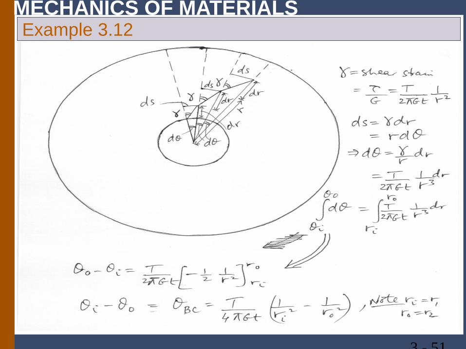
MECHANICS OF MATERIALS Example 3.12
3 - 51