cooperative multicasting based on superposition and layered coding
TRANSCRIPT
www.ietdl.org
IE
d
Published in IET CommunicationsReceived on 28th February 2013Revised on 3rd July 2013Accepted on 6th September 2013doi: 10.1049/iet-com.2013.0167
T Commun., 2014, Vol. 8, Iss. 3, pp. 267–277oi: 10.1049/iet-com.2013.0167
ISSN 1751-8628
Cooperative multicasting based on superposition andlayered codingMohamed Elgendi, Omar A. Nasr, Mohamed M. Khairy
Center for Wireless Studies, Faculty of Engineering, Cairo University, Giza, Egypt
E-mail: [email protected]
Abstract: Cooperative diversity plays an important role in combating channel fading and increasing reliability of wirelesscommunication links. The main purpose of cooperative diversity is to transmit the same data from multiple sources. Hence,there is no inherent capability in the cooperative diversity schemes to deal with scalable types of data, for example, scalablevideo coded signals. The authors introduce a two-phase cooperative multicast scheme based on superposition coding totransmit scalable video signals. The new scheme mixes the superposition with cooperative diversity, and chooses the rightparameters in both schemes to enhance the system's multicast capability. This study also derives an exact closed-formexpression of the average multicast group throughput in case of Rayleigh flat fading channel. The closed-form expressionallows system designers to choose the correct cooperation and superposition parameters to satisfy the network operator needs.Simulations show that, in addition to the additional degrees of freedom resulting from using cooperation with superposition,the proposed scheme outperforms the conservative scheme and schemes solely exploiting cooperative relaying orsuperposition. Simulations show that the new scheme can increase the average network throughput more than four timescompared to the conservative scheme.
1 Introduction
Multimedia broadcast and multicast have attracted greatattention in the last few years. Various multimedia serviceshave recently gained great popularity, such as InternetProtocol TV (IPTV) and mobile TV, increasing theimportance of efficient transmission algorithms that utilisethe system resources to serve the subscribers [1–5].Multicast transmission is necessary in multimedia services,
where subscribers that demand the same service are groupedlogically to form a multicast group. This is necessary, forexample, when multiple users in a cell request to watch thesame IPTV channel. The diverse channel conditions ofmultiple subscribers in the multicast group make it achallenge to adapt the transmission rate to simultaneouslysatisfy all group members and improve the total groupthroughput.A simple multicast scheme has been developed for
CDMA 2000 1xEV-DO networks by taking a defaulttransmission rate ignoring the diverse channel conditionsamong different subscribers [6]. A conservative multicastscheme uses the transmission rate accommodatingthe worst channel conditions in the group excluding thesubscribers that suffer from total fades. As a result, allthe subscribers in the multicast group get the service atthe same, low quality, level.Multicast systems are mainly used for video transmission.
Many advanced scalable video codecs have been proposedto improve the scalability of video transmission. Thesecodecs enable partial decoding, thus, the video quality
increases with the number of quality layers that the receiverdecodes correctly. In [7], the authors proposed two-levelsuperposition coded multicasting (SPCM) scheme for IPTV.A multicast signal is generated by superimposing the basequality layer bit stream, modulated with a low-ordermodulation scheme to the enhancement quality layer. Thebase layer contains essential information to decode thevideo stream while the enhancement layer containsinformation to enhance the quality of the video. Hence,subscribers with bad channel conditions can decode baselayer only, while other subscribers decode both base andenhancement layers to obtain better video quality.In addition to service scalability, delivering multimedia
service to subscribers experiencing bad channel conditionsis a great challenge in multicast transmission. Recently,cooperative transmission has been a subject of great interestamong the research community. It is considered as adesirable enhancement to future systems and is beingevaluated for the 4G standards long-termevolution-advanced (LTE-advanced) [8, 9] and WiMAX[10]. Subscribers in a wireless network help each other byforwarding data, aiming at increasing each subscriber’scapacity and the aggregate multicast group capacity. Thisincreases the spatial diversity than using fixed relays incooperative transmission as in [11]. Decode and forward(DF) protocol is widely used in cooperative transmission[12]. Such a scheme divides the downlink time slot intotwo phases. In the first phase, the base station (BS)broadcasts a message to all subscribers in the multicastgroup. In the second phase, relays that correctly decoded
267& The Institution of Engineering and Technology 2014
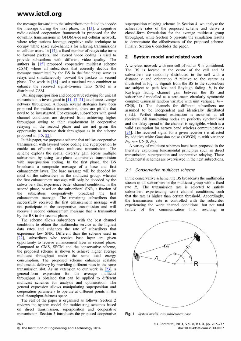
Fig. 1 System model: two subscribers case
www.ietdl.org
the message forward it to the subscribers that failed to decodethe message during the first phase. In [13], a cognitiveradio-assisted cooperation framework is proposed for thedownlink transmissions in OFDMA-based cellular network,where relay stations leverage cognitive radio technique tooccupy white space sub-channels for relaying transmissionsto cellular users. In [14], a fixed number of relays take turnsto forward packets, and layered video coding is used toprovide subscribers with different video quality. Theauthors in [15] proposed cooperative multicast scheme(CSM) where all subscribers that correctly decode themessage transmitted by the BS in the first phase serve asrelays and simultaneously forward the packets in secondphase. The work in [16] used a maximal ratio combiner toenhance the received signal-to-noise ratio (SNR) in adistributed CSM.Utilising superposition and cooperative relaying for unicasttransmission is investigated in [11, 17–21] to enhance averagenetwork throughput. Although several strategies have beenproposed for multicast transmission, there are pitfalls thatneed to be investigated. For example, subscribers with goodchannel conditions are deprived from achieving higherthroughput owing to their employment in cooperativerelaying in the second phase and are not given theopportunity to increase their throughput as in the schemeproposed in [15, 22].In this paper, we propose a scheme that utilises cooperative
transmission with layered video coding and superposition toenable an efficient video multicast transmission. Thescheme exploits the spatial diversity gain across multiplesubscribers by using two-phase cooperative transmissionwith superposition coding. In the first phase, the BSbroadcasts a composite message of a base and firstenhancement layer. The base message will be decoded bymost of the subscribers in the multicast group, whereasthe first enhancement message will only be decoded by thesubscribers that experience better channel conditions. In thesecond phase, based on the subscribers’ SNR, a fraction ofthe subscribers cooperatively broadcast the firstenhancement message. The remaining subscribers thatsuccessfully received the first enhancement message willnot participate in the cooperative transmission and willreceive a second enhancement message that is transmittedby the BS in the second phase.The scheme allows subscribers with the best channel
conditions to obtain the multimedia service at the highestdata rates and enhances the rate of subscribers thatexperience low SNR. Different than the scheme used in[22], subscribers who receive base layer are givenopportunity to receive enhancement layer in second phase.Compared to CMS, SPCM and the conservative scheme,the proposed scheme is shown to achieve higher averagemulticast throughput under the same total energyconsumption. The proposed scheme enhances scalablemultimedia delivery by providing different rates in the sametransmission slot. As an extension to our work in [23], ageneral-form expression for the average multicastthroughput is obtained that can be applied to differentmulticast schemes for analysis and optimisation. Thegeneral expression allows manipulating superposition andcooperation parameters to operate at different points in thetotal throughput-fairness space.The rest of the paper is organised as follows: Section 2
reviews the system model for multicasting schemes basedon direct transmission, superposition and cooperativetransmission. Section 3 introduces the proposed cooperative
268& The Institution of Engineering and Technology 2014
superposition relaying scheme. In Section 4, we analyse theachievable rates of the proposed scheme and derive aclosed-form formulation for the average multicast groupthroughput, while Section 5 presents the simulation resultsto demonstrate the effectiveness of the proposed scheme.Finally, Section 6 concludes the paper.
2 System model and related work
A wireless network with one cell of radius R is considered.The BS is located at the centre of the cell and Msubscribers are randomly distributed in the cell with adistance r and orientation θ relative to the centre asillustrated in Fig. 1. Signals from the BS to the subscribersare subject to path loss and Rayleigh fading. hi is theRayleigh fading channel gain between the BS andsubscriber i modelled as a zero-mean circularly symmetriccomplex Gaussian random variable with unit variance, hi∼CN(0, 1). The channels for different subscribers areassumed to be independent and identically distributed(i.i.d.). Perfect channel estimation is assumed at allreceivers. All transmitting nodes are perfectly synchronisedand the delay spread of the channel is negligible, which is avalid assumption for narrow band wireless communications[24]. The received signal for a given receiver i is affectedby additive white Gaussian noise (AWGN) ni with varianceN0, ni∼CN(0, N0).A variety of multicast schemes have been proposed in the
literature exploiting fundamental principles such as directtransmission, superposition and cooperative relaying. Thesefundamental schemes are overviewed in the next subsections.
2.1 Conservative multicast scheme
In the conservative scheme, the BS broadcasts the multimediastream to all subscribers in the multicast group with a fixedrate Rv. The transmission rate is selected to satisfysubscribers experiencing worst channel conditions, suchthat the rate is higher than certain threshold. Accordingly,the transmission rate is controlled with the subscriberexperiencing the worst channel conditions, but not totalfailure of the communication link, resulting in
IET Commun., 2014, Vol. 8, Iss. 3, pp. 267–277doi: 10.1049/iet-com.2013.0167
www.ietdl.org
underutilisation for group subscribers with good channelconditions. The received signal for a given subscriber i inthe multicast group can be given byyvi = hi�������Pdr
−ni
√xv + ni (1)
where xv is the transmitted signal by the BS after encoding themultimedia service into a single stream and yvi is the receivedsignal by subscriber i. The superscript v stands forconservative multicast scheme. Pd is the transmitting signalpower and n is the path loss exponent. The model usedassumes that PR / PT/r
ni
( ), where PR and PT are the
received and transmitted powers, respectively.According to (1), the received SNR for the subscriber i
under conservative scheme transmission is given bySNRv
i = |hi|2Pdr−ni /N0
( ).
2.2 Multicast scheme based on superposition
Utilising superposition in multicast transmission ofmultimedia services was first introduced by [7]. Usinglayered video coding, the multimedia stream can be codedinto two streams allowing partial decoding at the receiver attwo different layers. The BS broadcasts a compositemessage that consists of base layer and enhancement layerwith two different rates. If the total transmitting power is Pd
with power allocation fraction a, the power aPd and �aPdare allocated to the enhancement and base messages,respectively, where �a = 1− a. The transmitting ratesdepend mainly on the power allocation factor a [25].Subscribers with better channel conditions manage todecode both the base and enhancement layers resulting inbetter service quality. On the other hand, subscribers withbad channel conditions decode only the base layer, resultingin successfully decoding of the video, but with a worsevideo quality.The received signal for a given subscriber i in the multicast
group can be given by
ysi = hi��������aPdr
−ni
√xsb + hi
���������aPdr
−ni
√xse + ni (2)
where xsb is the base layer message, xse is the enhancementlayer message, ysi is the signal received by subscriber i andthe superscript ‘s’ stands for superposition scheme. Theeffective received SNR for the base message can be givenby SNRs
i,b = |hi|2�aPdr−ni
( )/ |hi|2aPdr
−ni + N0
( )( ), where the
enhancement message is considered as an interference onthe base message [26]. In case that subscriber i managed todecode the base message correctly, the base message willbe subtracted from the received signal. In this case, theeffective received SNR for the enhancement message isgiven by SNRs
i,e = |hi|2aPdr−ni /N0
( ).
2.3 Simple cooperative scheme
In cooperative multicast, the downlink time is divided intotwo phases. In the first phase, the BS broadcasts a messageto all subscribers in the multicast group. In the secondphase, subscribers that managed to decode the messagecooperatively retransmit the message to other subscribers inthe multicast group. The received signal for a givensubscriber i in the multicast group can be given by
yc,1i = hi�������Pdr
−ni
√xc,1 + ni (3)
IET Commun., 2014, Vol. 8, Iss. 3, pp. 267–277doi: 10.1049/iet-com.2013.0167
where xc,1 is the message transmitted by the BS in the firstphase and yc,1i is the signal received by subscriber i. Thesuperscript c, 1 stands for first phase in cooperative scheme.The SNR of subscriber i in the first phase is given bySNRc,1
i = |hi|2Pdr−ni /N0
( ). Only N out of M subscribers
correctly decode the message transmitted in the first phase.These N subscribers work as relays and cooperativelyretransmit the message in the second phase. Therefore, for asubscriber j that failed to decode the message in the firstphase, the received signal in the second phase is given by [24]
yc,2j =∑Ni=1
hi,j�������r−ni,j Pdr
√xc,2 + ni (4)
hi, j is the Rayleigh fading channel gain between thesubscribers i and j modelled as a zero-mean circularlysymmetric complex Gaussian random variable with unitvariance, hi, j∼CN(0, 1). Pdr is the relay transmittingpower. ri, j is the relative distance between the subscribers iand j, where
r2i,j = r2i + r2j − 2rirj cos ui − uj
( )
xc,2 is the message transmitted by the subscriber i in thesecond phase and yc,2j is the signal received by subscriber j.The superscript c, 2 stands for second phase in cooperativescheme. The received SNR for subscriber j in the secondphase, according to (4), is given by
SNRc,2j =
∑N
i=1hi,j
�������r−ni,j Pdr
√∣∣∣ ∣∣∣2( )/N0
( )
For fair comparison, we limit total transmission power usedby relays in cooperative relaying to the total transmittedpower used in conservative multicast and multicast basedon superposition schemes in the second phase. Thus,Pd =NPdr.
3 Proposed scheme
The objectives of the proposed scheme are to increase theaverage multicast group throughput, deliver the service tosubscribers experiencing bad channel conditions and enablescalable delivery of multimedia data, depending on theaverage channel conditions of different users. Fig. 2illustrates the principle of the proposed CSM. In thisscheme, the downlink frame that has a total duration T isdivided into two phases of equal durations T1 and T2. Themultimedia transmission in the two phases is discussed asfollows.
3.1 First phase
Using layered coding, the multimedia stream can be codedinto multiple streams allowing partial decoding at thereceiver at different layers. An example for superpositionmodulation is illustrated in Fig. 3. The BS broadcasts asignal which is a composite message of base layer B1 andfirst enhancement layer E1 with rates RB1 and RE1,respectively.
269& The Institution of Engineering and Technology 2014
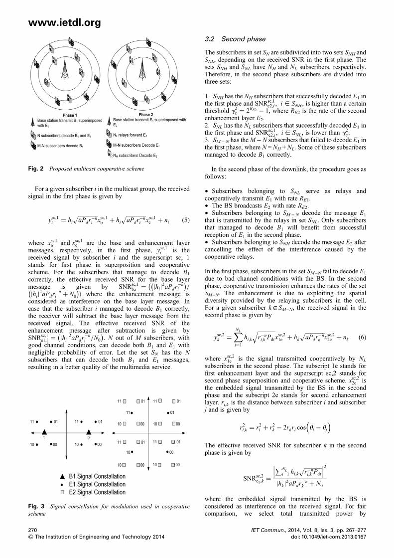
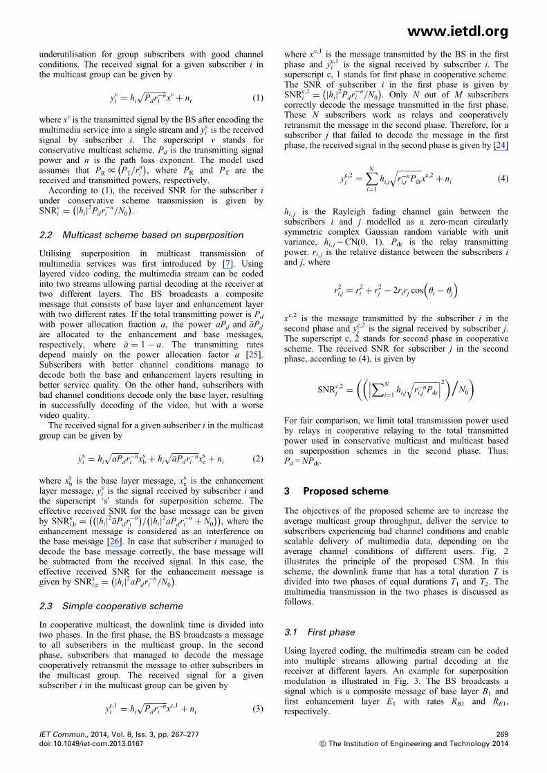
Fig. 2 Proposed multicast cooperative scheme
www.ietdl.org
For a given subscriber i in the multicast group, the receivedsignal in the first phase is given by
ysc,1i = hi���������aPdr
−ni
√xsc,1b + hi
��������aPdr
−ni
√xsc,1e + ni (5)
where xsc,1b and xsc,1e are the base and enhancement layermessages, respectively, in the first phase, ysc,1i is thereceived signal by subscriber i and the superscript sc, 1stands for first phase in superposition and cooperativescheme. For the subscribers that manage to decode B1
correctly, the effective received SNR for the base layermessage is given by SNRsc,1
b,i = |hi|2�aPdr−ni
( )/
(|hi|2aPdr
−ni + N0
( )) where the enhancement message isconsidered as interference on the base layer message. Incase that the subscriber i managed to decode B1 correctly,the receiver will subtract the base layer message from thereceived signal. The effective received SNR of theenhancement message after subtraction is given bySNRsc,1
e1,i = |hi|2aPdr−ni /N0
( ). N out of M subscribers, with
good channel conditions, can decode both B1 and E1 withnegligible probability of error. Let the set SN has the Nsubscribers that can decode both B1 and E1 messages,resulting in a better quality of the multimedia service.
Fig. 3 Signal constellation for modulation used in cooperativescheme
270& The Institution of Engineering and Technology 2014
3.2 Second phase
The subscribers in set SN are subdivided into two sets SNH andSNL, depending on the received SNR in the first phase. Thesets SNH and SNL have NH and NL subscribers, respectively.Therefore, in the second phase subscribers are divided intothree sets:
1. SNH has the NH subscribers that successfully decoded E1 inthe first phase and SNRsc,1
e2,i , i [ SNH , is higher than a certainthreshold g2e = 2RE2 − 1, where RE2 is the rate of the secondenhancement layer E2.2. SNL has the NL subscribers that successfully decoded E1 inthe first phase and SNRsc,1
e2,i , i [ SNL, is lower than g2e .3. SM− N has theM−N subscribers that failed to decode E1 inthe first phase, where N =NH +NL. Some of these subscribersmanaged to decode B1 correctly.
In the second phase of the downlink, the procedure goes asfollows:
† Subscribers belonging to SNL serve as relays andcooperatively transmit E1 with rate RE1.† The BS broadcasts E2 with rate RE2.† Subscribers belonging to SM− N decode the message E1
that is transmitted by the relays in set SNL. Only subscribersthat managed to decode B1 will benefit from successfulreception of E1 in the second phase.† Subscribers belonging to SNH decode the message E2 aftercancelling the effect of the interference caused by thecooperative relays.
In the first phase, subscribers in the set SM−N fail to decode E1
due to bad channel conditions with the BS. In the secondphase, cooperative transmission enhances the rates of the setSM−N. The enhancement is due to exploiting the spatialdiversity provided by the relaying subscribers in the cell.For a given subscriber k∈ SM−N, the received signal in thesecond phase is given by
ysc,2k =∑NL
i=1
hi,k�������r−ni,k Pdr
√xsc,21e + hk
��������aPdr
−nk
√xsc,22e + nk (6)
where xsc,21e is the signal transmitted cooperatively by NL
subscribers in the second phase. The subscript 1e stands forfirst enhancement layer and the superscript sc,2 stands forsecond phase superposition and cooperative scheme. xsc,22e isthe embedded signal transmitted by the BS in the secondphase and the subscript 2e stands for second enhancementlayer. ri,k is the distance between subscriber i and subscriberj and is given by
r2i,k = r2i + r2k − 2rkri cos ui − uj
( )
The effective received SNR for subscriber k in the secondphase is given by
SNRsc,2e1,k
=∑NL
i=1 hi,k�������r−ni,k Pdr
√∣∣∣ ∣∣∣2|hk |2aPdr
−nk + N0
where the embedded signal transmitted by the BS isconsidered as interference on the received signal. For faircomparison, we select total transmitted power by
IET Commun., 2014, Vol. 8, Iss. 3, pp. 267–277doi: 10.1049/iet-com.2013.0167
www.ietdl.org
cooperative relays and the BS in the second phase to be equalto total transmitted power used in transmission in themulticast schemes based on direct transmission,superposition and simple cooperative transmission. Thus,�aPd = NLPdr.A key element in the proposed procedure that should benoted is that the interfering signal received power caused bythe BS transmission of E2 is low compared to E1 receivedpower. This is due to the already bad channel conditions onthe direct link between the BS and the subscribers in the setSM−N. This is evident since all the subscribers in the setSM−N failed to decode E1 transmitted by the BS withthe same power correctly in the first phase. Therefore, thesignal power of E2 should be limited and not to exceed thesignal power of E1 in the second phase.Before the NH subscribers decode E2, they eliminate the
interference effect of the cooperative relays transmissiondue to the prior knowledge of E1 and the channels gains tothe other subscribers. In terms of channel estimation, thetechnique described in [27] is employed to reducecomputational complexity. This technique does not requirethe receiver to estimate the channel gains with eachtransmitter. Accordingly, the effective received SNR for agiven subscriber j∈ SNH is given bySNRsc,2
e2,j= (|hj|2aPdr
−nj /N0
).
To decrease processing overhead on the BS, all rates willbe determined based on long-term channel conditions as in[15]. The scheme enables scalable multimedia delivery byproviding three different rates for three sets of subscribers.The scheme exploits the capability of the subscribersexperiencing good channel conditions to receive service athigh rates and high quality of service.Choosing the rates RB1, RE1 and RE2 is critical for the
system performance. These rates determine the number ofsubscribers in the three sets stated above. Accordingly, thesystem can be driven to enhance the throughput of thesubscribers experiencing good channel conditions byincreasing the number of subscribers in the set SNH whichincreases the number of receivers in the second phase onthe expense of enhancing throughput of subscribers in theset SM−N. On the other hand, the system can be driven toenhance the throughput of subscribers experiencing badchannel conditions by increasing the number of cooperativerelays in the set SNL on the expense of increasing the rate ofsubscribers that are able to receive a second enhancementlayer. Since E1 is transmitted in the first and second phasewith the same rate RE1, therefore T1 is equal to T2 to ensurethat T1RE1 = T2RE1.For controlling the system thresholds, used to determine NH
and NL, two parameters are introduced: coverage ratio C andcooperative ratio α. The coverage ratio is the percentage ofsubscribers, on average, that can correctly receive the firstenhancement layer rate RE1 in the first phase and is givenby C = E(N )/M. The cooperative ratio is the percentage ofsubscribers, on average, that work as relays in the secondphase and is given by α = E(NL)/M.In the first phase, C is used to determine RE1. As C
increases, RE1 decreases to enable more subscribers toreceive the enhancement layer, that is, N increases. As Cdecreases, RE1 increases and a lower number of subscriberswill be able to decode the enhancement layer correctly inthe first phase.In the second phase, α is used to determine RE2. As α
increases more subscribers cooperate in transmission in thesecond phase, that is, NL increases. Increasing NL improves
IET Commun., 2014, Vol. 8, Iss. 3, pp. 267–277doi: 10.1049/iet-com.2013.0167
the probability that the subscribers in set SM−N decode E1
correctly in the second phase. Since the set SNH has thesubscribers with the highest SNR from the set SN,increasing α decreases NH resulting in higher RE2 and viceversa.The parameter α controls the system by either favouring
subscribers with high received SNR on the expense ofsubscribers with low SNR, or enhancing the system fairnessby increasing the number of cooperative subscribers NL
which leads to higher throughput for subscribers with lowSNR.
4 Performance analysis
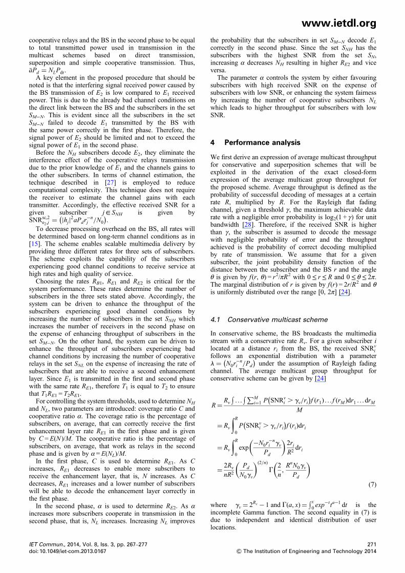
We first derive an expression of average multicast throughputfor conservative and superposition schemes that will beexploited in the derivation of the exact closed-formexpression of the average multicast group throughput forthe proposed scheme. Average throughput is defined as theprobability of successful decoding of messages at a certainrate R, multiplied by R. For the Rayleigh flat fadingchannel, given a threshold γ, the maximum achievable datarate with a negligible error probability is log2(1 + γ) for unitbandwidth [28]. Therefore, if the received SNR is higherthan γ, the subscriber is assumed to decode the messagewith negligible probability of error and the throughputachieved is the probability of correct decoding multipliedby rate of transmission. We assume that for a givensubscriber, the joint probability density function of thedistance between the subscriber and the BS r and the angleθ is given by f (r, θ) = r2/πR2 with 0≤ r≤ R and 0≤ θ≤ 2π.The marginal distribution of r is given by f (r) = 2r/R2 and θis uniformly distributed over the range [0, 2π] [24].
4.1 Conservative multicast scheme
In conservative scheme, the BS broadcasts the multimediastream with a conservative rate Rv. For a given subscriber ilocated at a distance ri from the BS, the received SNRv
ifollows an exponential distribution with a parameterl = N0r
−ni /Pd
( )under the assumption of Rayleigh fading
channel. The average multicast group throughput forconservative scheme can be given by [24]
R= Rv
�. . .
�∑Mi=1 P SNRv
i . gv/ri( )
f (r1) . . . f (rM )dr1 . . .drMM
= Rv
∫R0P SNRv
i . gv/ri( )
f (ri)dri
= Rv
∫R0exp
−N0r−ni gv
Pd
( )2riR2
dri
= 2Rv
nR2
Pd
N0gv
( )(2/n)
G2
n,RnN0gvPd
( )(7)
where gv = 2Rv − 1 and G(a, x)= �x0 exp
−t ta−1 dt is theincomplete Gamma function. The second equality in (7) isdue to independent and identical distribution of userlocations.
271& The Institution of Engineering and Technology 2014
www.ietdl.org
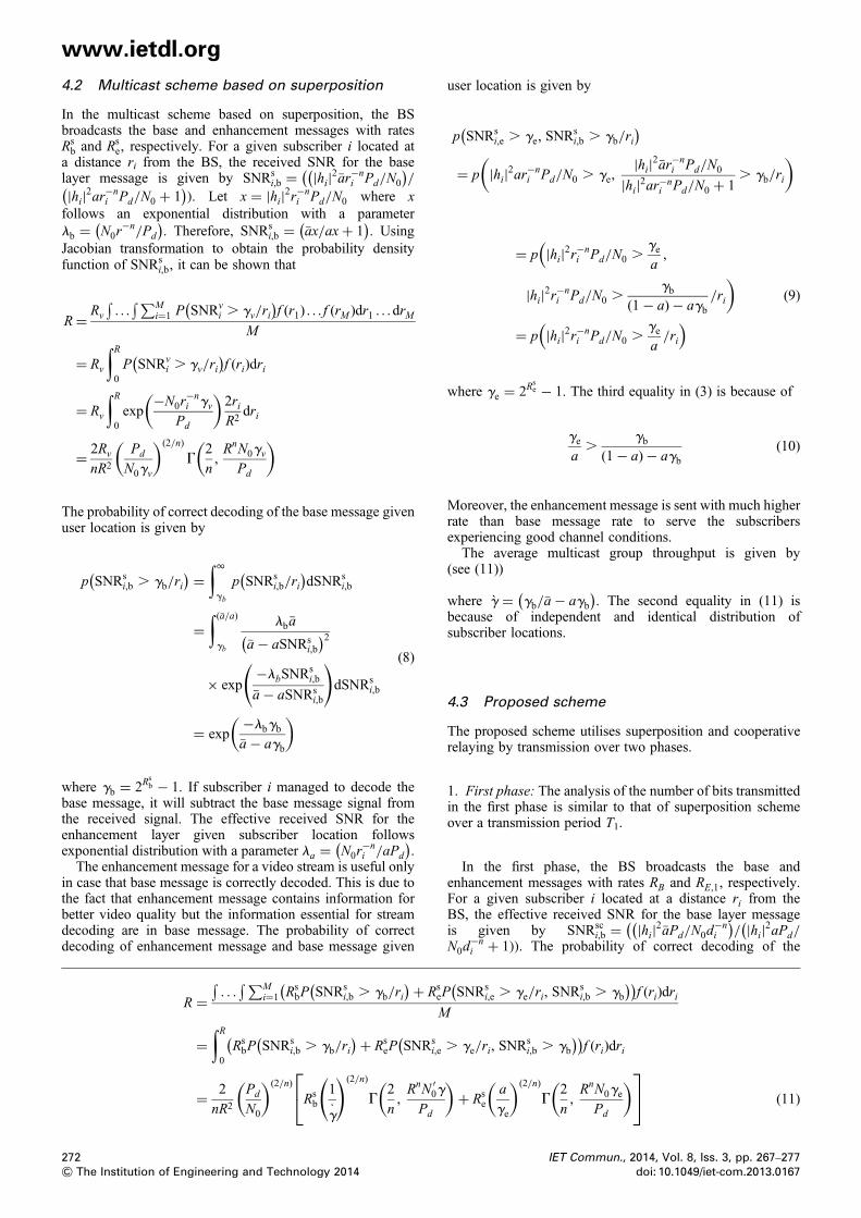
4.2 Multicast scheme based on superpositionIn the multicast scheme based on superposition, the BSbroadcasts the base and enhancement messages with ratesRsb and Rs
e, respectively. For a given subscriber i located ata distance ri from the BS, the received SNR for the baselayer message is given by SNRs
i,b = |hi|2�ar−ni Pd/N0
( )/
(|hi|2ar−n
i Pd/N0 + 1( )). Let x = |hi|2r−n
i Pd/N0 where xfollows an exponential distribution with a parameterlb = N0r
−n/Pd
( ). Therefore, SNRs
i,b = �ax/ax+ 1( )
. UsingJacobian transformation to obtain the probability densityfunction of SNRs
i,b, it can be shown that
R= Rv
�. . .
�∑Mi=1 P SNRv
i . gv/ri( )
f (r1) . . . f (rM )dr1 . . .drMM
= Rv
∫R0P SNRv
i . gv/ri( )
f (ri)dri
= Rv
∫R0exp
−N0r−ni gv
Pd
( )2riR2
dri
= 2Rv
nR2
Pd
N0gv
( )(2/n)
G2
n,RnN0gvPd
( )
The probability of correct decoding of the base message givenuser location is given by
p SNRsi,b . gb/ri
( ) = ∫1gb
p SNRsi,b/ri
( )dSNRs
i,b
=∫(�a/a)gb
lb�a
�a− aSNRsi,b
( )2× exp
−lbSNRsi,b
�a− aSNRsi,b
( )dSNRs
i,b
= exp−lbgb�a− agb
( )
(8)
where gb = 2Rsb − 1. If subscriber i managed to decode the
base message, it will subtract the base message signal fromthe received signal. The effective received SNR for theenhancement layer given subscriber location followsexponential distribution with a parameter la = N0r
−ni /aPd
( ).
The enhancement message for a video stream is useful onlyin case that base message is correctly decoded. This is due tothe fact that enhancement message contains information forbetter video quality but the information essential for streamdecoding are in base message. The probability of correctdecoding of enhancement message and base message given
R =�. . .
�∑Mi=1 Rs
bP SNRsi,b . gb/ri
( )+ RseP
(M
=∫R0RsbP SNRs
i,b . gb/ri( )+ Rs
eP SNRsi,e
((
= 2
nR2
Pd
N0
( )(2/n)
Rsb
1
g‘
( )(2/n)
G2
n,RnN ′
0g
Pd
(⎡⎣
272& The Institution of Engineering and Technology 2014
user location is given by
p SNRsi,e . ge, SNR
si,b . gb/ri
( )= p |hi|2ar−n
i Pd/N0 . ge,|hi|2�ar−n
i Pd/N0
|hi|2ar−ni Pd/N0 + 1
. gb/ri
( )
= p |hi|2r−ni Pd/N0 .
gea,
(
|hi|2r−ni Pd/N0 .
gb(1− a)− agb
/ri
)
= p |hi|2r−ni Pd/N0 .
gea/ri
( )(9)
where ge = 2Rse − 1. The third equality in (3) is because of
gea.
gb(1− a)− agb
(10)
Moreover, the enhancement message is sent with much higherrate than base message rate to serve the subscribersexperiencing good channel conditions.The average multicast group throughput is given by
(see (11))
where g̀ = gb/�a− agb( )
. The second equality in (11) isbecause of independent and identical distribution ofsubscriber locations.
4.3 Proposed scheme
The proposed scheme utilises superposition and cooperativerelaying by transmission over two phases.
1. First phase: The analysis of the number of bits transmittedin the first phase is similar to that of superposition schemeover a transmission period T1.
In the first phase, the BS broadcasts the base andenhancement messages with rates RB and RE,1, respectively.For a given subscriber i located at a distance ri from theBS, the effective received SNR for the base layer messageis given by SNRsc
i,b = |hi|2�aPd/N0d−ni
( )/ |hi|2aPd/((
N0d−ni + 1)). The probability of correct decoding of the
SNRsi,e . ge/ri, SNR
si,b . gb
( ))f (ri)dri
. ge/ri, SNRsi,b . gb
))f (ri)dri
)+ Rs
ea
ge
( )(2/n)
G2
n,RnN0gePd
( )⎤⎦ (11)
IET Commun., 2014, Vol. 8, Iss. 3, pp. 267–277doi: 10.1049/iet-com.2013.0167
www.ietdl.org
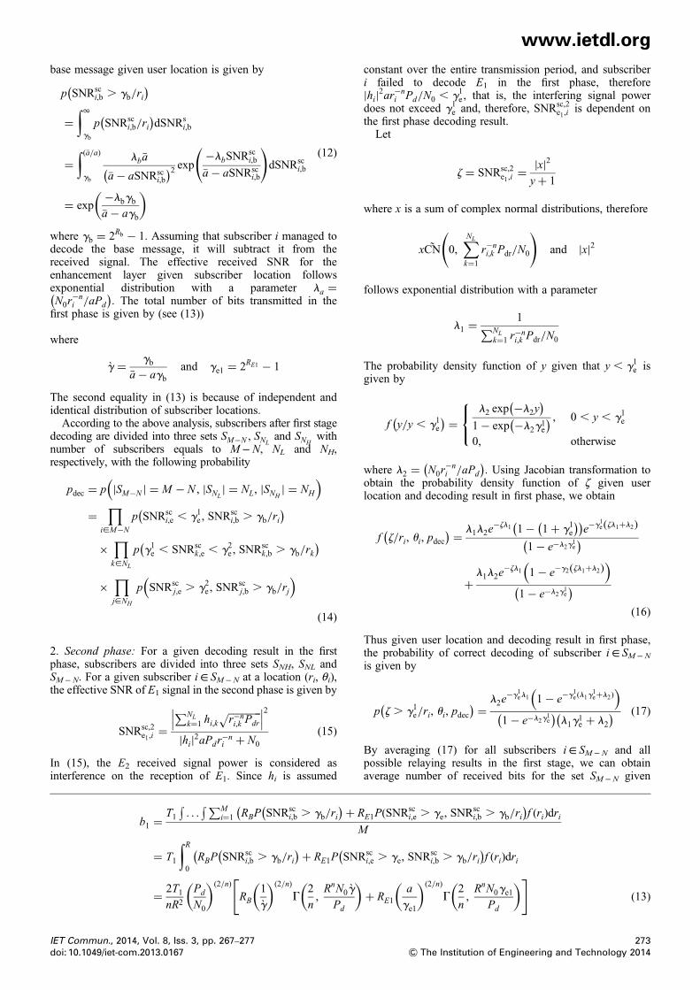
base message given user location is given byp SNRsci,b . gb/ri
( )=
∫1gb
p SNRsci,b/ri
( )dSNRs
i,b
=∫(�a/a)gb
lb�a
�a− aSNRsci,b
( )2 exp −lbSNRsci,b
�a− aSNRsci,b
( )dSNRsc
i,b
= exp−lbgb�a− agb
( )(12)
where gb = 2Rb − 1. Assuming that subscriber i managed todecode the base message, it will subtract it from thereceived signal. The effective received SNR for theenhancement layer given subscriber location followsexponential distribution with a parameter la =N0r
−ni /aPd
( ). The total number of bits transmitted in the
first phase is given by (see (13))
where
g̀ = gb�a− agb
and ge1 = 2RE1 − 1
The second equality in (13) is because of independent andidentical distribution of subscriber locations.According to the above analysis, subscribers after first stage
decoding are divided into three sets SM−N , SNLand SNH
withnumber of subscribers equals to M−N, NL and NH,respectively, with the following probability
pdec = p |SM−N | = M − N , |SNL| = NL, |SNH
| = NH
( )=
∏i[M−N
p SNRsci,e , g1e , SNR
sci,b . gb/ri
( )×
∏k[NL
p g1e , SNRsck,e , g2e , SNR
sck,b . gb/rk
( )
×∏j[NH
p SNRscj,e . g2e , SNR
scj,b . gb/rj
( )(14)
2. Second phase: For a given decoding result in the firstphase, subscribers are divided into three sets SNH, SNL andSM− N. For a given subscriber i∈ SM− N at a location (ri, θi),the effective SNR of E1 signal in the second phase is given by
SNRsc,2e1,i
=∑NL
k=1 hi,k��������r−ni,k Pdr
√∣∣∣ ∣∣∣2|hi|2aPdr
−ni + N0
(15)
In (15), the E2 received signal power is considered asinterference on the reception of E1. Since hi is assumed
b1 =T1
�. . .
�∑Mi=1 RBP SNRsc
i,b . gb/ri( )+ R
(M
= T1
∫R0
(RBP SNRsc
i,b . gb/ri( )+ RE1P SNR
(
= 2T1nR2
Pd
N0
( )(2/n)
RB1
g̀
( )(2/n)
G2
n,RnN0g̀
Pd
( )[
IET Commun., 2014, Vol. 8, Iss. 3, pp. 267–277doi: 10.1049/iet-com.2013.0167
constant over the entire transmission period, and subscriberi failed to decode E1 in the first phase, therefore|hi|2ar−n
i Pd/N0 , g1e , that is, the interfering signal powerdoes not exceed g1e and, therefore, SNRsc,2
e1,iis dependent on
the first phase decoding result.Let
z = SNRsc,2e1,i
= |x|2y+ 1
where x is a sum of complex normal distributions, therefore
xC̃N 0,∑NL
k=1
r−ni,k Pdr/N0
( )and |x|2
follows exponential distribution with a parameter
l1 =1∑NL
k=1 r−ni,k Pdr/N0
The probability density function of y given that y , g1e isgiven by
f y/y , g1e( ) = l2 exp −l2y
( )1− exp −l2g
1e
( ) , 0 , y , g1e
0, otherwise
⎧⎨⎩
where l2 = N0r−ni /aPd
( ). Using Jacobian transformation to
obtain the probability density function of ζ given userlocation and decoding result in first phase, we obtain
f z/ri, ui, pdec( ) = l1l2e
−zl1 1− 1+ g1e( )( )
e−g1e zl1+l2( )1− e−l2g
1e
( )
+l1l2e
−zl1 1− e−g2 zl1+l2( )( )1− e−l2g
1e
( )(16)
Thus given user location and decoding result in first phase,the probability of correct decoding of subscriber i∈ SM− N
is given by
p z . g1e/ri, ui, pdec( ) = l2e
−g1el1 1− e−g1e (l1g1e+l2)
( )1− e−l2g
1e
( )l1g
1e + l2
( ) (17)
By averaging (17) for all subscribers i∈ SM− N and allpossible relaying results in the first stage, we can obtainaverage number of received bits for the set SM −N given
E1P(SNRsci,e . ge, SNR
sci,b . gb/ri
)f (ri)dri
sci,e . ge, SNR
sci,b . gb/ri
)f (ri)dri
+ RE1a
ge1
( )(2/n)
G2
n,RnN0ge1
Pd
( )](13)
273& The Institution of Engineering and Technology 2014
www.ietdl.org
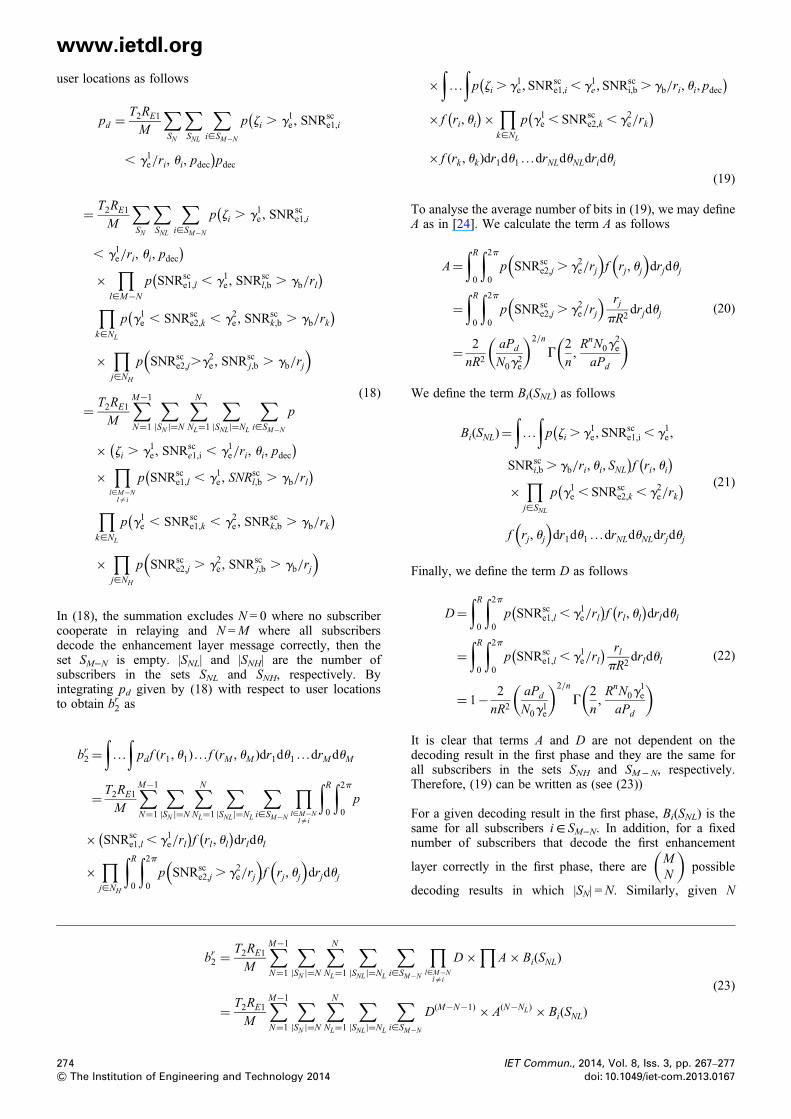
user locations as followspd =T2RE1
M
∑SN
∑SNL
∑i[SM−N
p zi . g1e , SNRsce1,i
(
, g1e/ri, ui, pdec)pdec
= T2RE1
M
∑SN
∑SNL
∑i[SM−N
p zi . g1e , SNRsce1,i
(
, g1e/ri, ui, pdec)
×∏
l[M−N
p SNRsce1,l , g1e , SNR
scl,b . gb/rl
( )∏k[NL
p g1e , SNRsce2,k , g2e , SNR
sck,b . gb/rk
( )
×∏j[NH
p SNRsce2,j.g2e , SNR
scj,b . gb/rj
( )
= T2RE1
M
∑M−1
N=1
∑|SN |=N
∑NNL=1
∑|SNL|=NL
∑i[SM−N
p
× zi . g1e , SNRsce1,i , g1e/ri, ui, pdec
( )×
∏l[M−N
l=i
p SNRsce1,l , g1e , SNR
scl,b . gb/rl
( )∏k[NL
p g1e , SNRsce1,k , g2e , SNR
sck,b . gb/rk
( )
×∏j[NH
p SNRsce2,j . g2e , SNR
scj,b . gb/rj
( )
(18)
In (18), the summation excludes N = 0 where no subscribercooperate in relaying and N =M where all subscribersdecode the enhancement layer message correctly, then theset SM−N is empty. |SNL| and |SNH| are the number ofsubscribers in the sets SNL and SNH, respectively. Byintegrating pd given by (18) with respect to user locationsto obtain br2 as
br2 =∫. . .
∫pdf (r1, u1) . . . f (rM , uM )dr1du1 . . .drMduM
= T2RE1
M
∑M−1
N=1
∑|SN |=N
∑NNL=1
∑|SNL|=NL
∑i[SM−N
∏l[M−N
l=i
∫R0
∫2p0p
× SNRsce1,l , g1e/rl
( )f rl, ul( )
drldul
×∏j[NH
∫R0
∫2p0p SNRsc
e2,j . g2e/rj
( )f rj, uj( )
drjduj
br2 =T2RE1
M
∑M−1
N=1
∑|SN |=N
∑NNL=1
∑|SNL|=NL
∑i[SM
= T2RE1
M
∑M−1
N=1
∑|SN |=N
∑NNL=1
∑|SNL|=NL
∑i[SM
274& The Institution of Engineering and Technology 2014
×∫. . .
∫p zi . g1e , SNR
sce1,i , g1e , SNR
sci,b . gb/ri, ui, pdec
( )× f ri, ui
( )× ∏k[NL
p g1e , SNRsce2,k , g2e/rk
( )× f (rk , uk)dr1du1 . . .drNLduNLdridui
(19)
To analyse the average number of bits in (19), we may defineA as in [24]. We calculate the term A as follows
A=∫R0
∫2p0p SNRsc
e2,j . g2e/rj
( )f rj, uj
( )drjduj
=∫R0
∫2p0p SNRsc
e2,j . g2e/rj
( ) rjpR2
drjduj
= 2
nR2
aPd
N0g2e
( )2/n
G2
n,RnN0g
2e
aPd
( )(20)
We define the term Bi(SNL) as follows
Bi(SNL)=∫. . .
∫p zi . g1e , SNR
sce1,i , g1e ,
(SNRsc
i,b . gb/ri, ui, SNL)f ri, ui( )
×∏j[SNL
p g1e , SNRsce2,k , g2e/rk
( )
f rj, uj
( )dr1du1 . . .drNLduNLdrjduj
(21)
Finally, we define the term D as follows
D=∫R0
∫2p0p SNRsc
e1,l , g1e/rl( )
f rl, ul( )
drldul
=∫R0
∫2p0p SNRsc
e1,l , g1e/rl( ) rl
pR2drldul
= 1− 2
nR2
aPd
N0g1e
( )2/n
G2
n,RnN0g
1e
aPd
( )(22)
It is clear that terms A and D are not dependent on thedecoding result in the first phase and they are the same forall subscribers in the sets SNH and SM− N, respectively.Therefore, (19) can be written as (see (23))
For a given decoding result in the first phase, Bi(SNL) is thesame for all subscribers i∈ SM−N. In addition, for a fixednumber of subscribers that decode the first enhancement
layer correctly in the first phase, there areMN
( )possible
decoding results in which |SN| =N. Similarly, given N
−N
∏l[M−N
l=i
D×∏
A× Bi(SNL)
−N
D(M−N−1) × A(N−NL) × Bi(SNL)
(23)
IET Commun., 2014, Vol. 8, Iss. 3, pp. 267–277doi: 10.1049/iet-com.2013.0167
www.ietdl.org
subscribers decoded the first enhancement layer correctly inthe first phase, there areNNL
( )possible decoding results in
which |SNL| = NL. Bi(SNL) = B(NL) is the same for alldecoding combinations with number of relays equals to NL.Based on the above analysis br2 in (9) can be written as
br2 =T2RE1
M
∑M−1
N=1
M
N
( )D(M−N−1)
∑NNL=1
N
NL
( )(M −N )A(N−NL)B(NL)
(24)
For a given subscriber, j∈ SNH can eliminate the effect of theinterference on the second enhancement layer using priorknowledge of the first enhancement layer message andperfect channel estimation. Accordingly, the effective SNRfor the second enhancement layer is given bySNRe,j = |hj|2aPdd
−nj /N0
( )which follows exponential
distribution with a parameter l= N0dnj /aPd
( ). Therefore,
average total number of bits received by subscribers in theset SNH in the second phase is given by
bBS2 =�. . .
�∑Mi=1T2RE2P SNRsc
e2,i . g2e/ri( )
f (ri)driM
=∫R0T2RE2P SNRsc
e2,i . g2e/ri( )
f (ri)dri
= 2T2RE2
nR2
aPd
g2eN0
( )(2/n)
G2
n,RnN0g
2e
Pd
( )(25)
According to (24) and (25), total average number of bitsreceived in the second phase is given by
b2 = br2+bBS2 (26)
Average total multicast group throughput is given by
R= b1+b2
T1+T2(27)
Table 2 Simulation parameters
Parameter Value
Pd /N0 85 dBN 4A 0.3cell radius (R) 100
4.4 Average multicast throughput generalequation
In this subsection, we are going to generalise (27) to hold allpossible schemes described in this work. Equation (27) can be
Table 1 Parameters ranges in each scheme
Scheme T1 T2 A
conservative T 0 0superposition T 0 0 < a < 1cooperative 0 < T1 < T 1− T1 0cooperative + superposition 0 < T1 < T 1− T1 0 < a < 1
IET Commun., 2014, Vol. 8, Iss. 3, pp. 267–277doi: 10.1049/iet-com.2013.0167
written as follows
R× (T1 + T2) = T1RB1p SNRb . 2RB1 − 1( )
+ T1RE1p SNRe . 2RE1 − 1/SNRb . 2RB1 − 1( )
+ T2RE1
∑M−1
N=1
M
N
( )p SNRe , 2RE1 − 1( )( )M−N−1
×∑NNL=1
M
N
( )M − N
M
p SNRe . 2RE2 − 1/SNRb . 2RB1 − 1( )( )N−NL
× p z . 2RE1 − 1( ) ∏
j[SNL
p
2RE1 − 1 , SNRe , 2RE2 − 1/SNRb . 2RB1 − 1( )
+ T2RE2p SNRe . 2RE2 − 1/SNRb . 2RB1 − 1( )
(28)
where SNRb and SNRe are the effective received SNR forbase and enhancement message layer, respectively. RB1 isthe base message rate, RE1 and RE2 are the first and secondenhancement layer message rates, respectively. Equation(28) is considered as a general equation to express theaverage multicast group throughput for different schemesby setting the parameters as illustrated in Table 1.
5 Simulation results
In this section, simulations are conducted to demonstrate theperformance of the proposed scheme. We consider a circularcell of radius R = 100 m with the BS located in the centre ofthe cell. The multicast group consists of 30 subscribers,randomly distributed in the cell according to the uniformprobability density function of r and θ. For a givensubscriber, the joint probability density function of thedistance between the subscriber and the BS r and the angleθ is given by f (r, θ) = r2/πR2 with 0≤ r≤ R and 0≤ θ≤ 2π.The marginal distribution of r is given by f (r) = 2r/R2 and θis uniformly distributed over the range [0, 2π] [24]. Weassume that the sum of the transmitted powers by the relaysis equal to the transmitted power by the BS. Othersimulation parameters are listed in Table 2.
Rb RE1 RE2 NL
0 0 0 00 <Rb <∞ 0 <RE1 <∞ 0 0
0 0 <RE1 <∞ 0 N0 <Rb <∞ 0 <RE1 <∞ 0 <RE2 <∞ 0 <NL <N
275& The Institution of Engineering and Technology 2014
www.ietdl.org
The generic mathematical expression for average networkthroughput derived in Section 4 can be applied on differentchannel models to optimise system parameters such as baserate, enhancement rates and power allocation factor. Weapplied the expression on Rayleigh fading channel to obtaina closed form of the average network throughput in (10).The closed form can be used in the design of systemmodels to manipulate system parameters and the exactresponse of the system. This also gives a standard andunique solution in comparing different system protocols.Fig. 4 compares the analytical model for the average
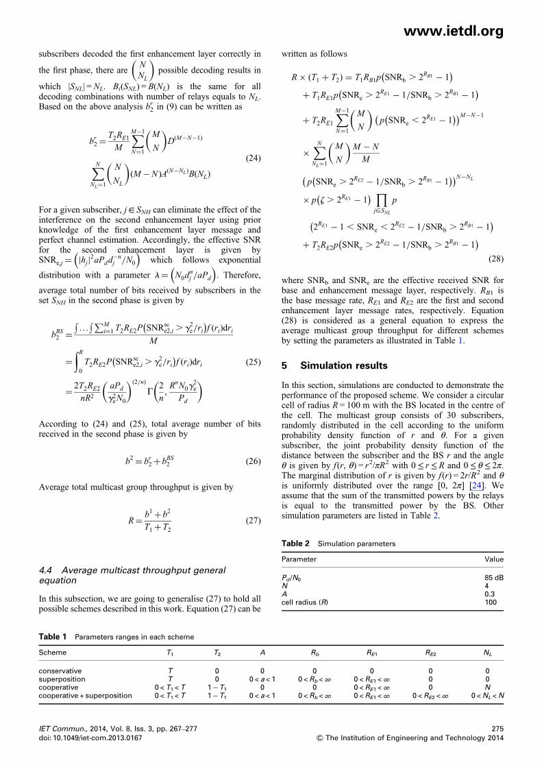
multicast throughput with simulation results. We useMonte-Carlo simulations to calculate the values of B(NL).Based on the analytical expression, we present two studiesfor the effect of varying power allocation factor a and thepercentage of subscribers that correctly decodes theenhancement layer in the first phase C.Fig. 5 shows the analytical results of the average network
throughput against transmitted power for different values ofa, which matches exactly simulation results. The case a = 0represents the conservative scheme and the maximum valueof a can be calculated from (10). For high values of a, lessnumber of subscribers will be able to correctly decode thebase message. However, these subscribers will have higherprobability to decode the two enhancement layers correctlysince more power are allocated to these layers. In this case,the system serves relatively less number of subscribers withhigh data rate and blocks other subscribers. As a increases,the number of subscribers served will increase, but this will
Fig. 4 Average subscriber throughput for different values of Pd/N0%
Fig. 5 Average multicast group throughput for different values of a
276& The Institution of Engineering and Technology 2014
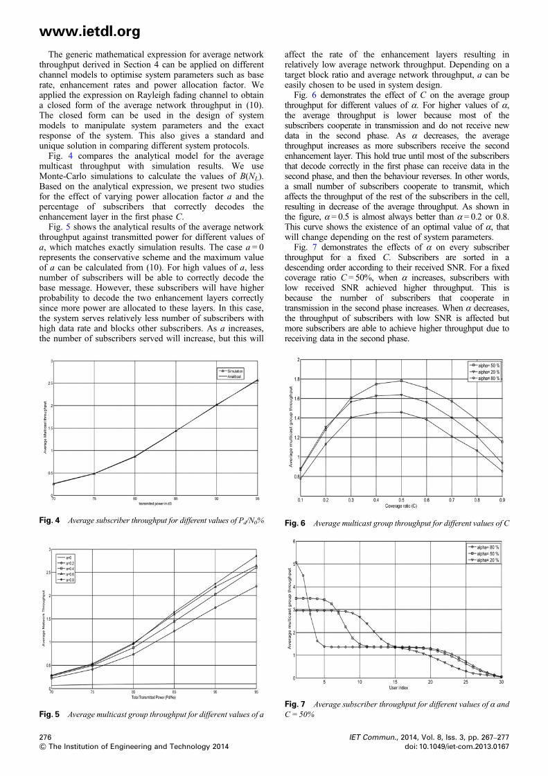
affect the rate of the enhancement layers resulting inrelatively low average network throughput. Depending on atarget block ratio and average network throughput, a can beeasily chosen to be used in system design.Fig. 6 demonstrates the effect of C on the average group
throughput for different values of α. For higher values of α,the average throughput is lower because most of thesubscribers cooperate in transmission and do not receive newdata in the second phase. As α decreases, the averagethroughput increases as more subscribers receive the secondenhancement layer. This hold true until most of the subscribersthat decode correctly in the first phase can receive data in thesecond phase, and then the behaviour reverses. In other words,a small number of subscribers cooperate to transmit, whichaffects the throughput of the rest of the subscribers in the cell,resulting in decrease of the average throughput. As shown inthe figure, α = 0.5 is almost always better than α = 0.2 or 0.8.This curve shows the existence of an optimal value of α, thatwill change depending on the rest of system parameters.Fig. 7 demonstrates the effects of α on every subscriber
throughput for a fixed C. Subscribers are sorted in adescending order according to their received SNR. For a fixedcoverage ratio C = 50%, when α increases, subscribers withlow received SNR achieved higher throughput. This isbecause the number of subscribers that cooperate intransmission in the second phase increases. When α decreases,the throughput of subscribers with low SNR is affected butmore subscribers are able to achieve higher throughput due toreceiving data in the second phase.
Fig. 7 Average subscriber throughput for different values of α andC = 50%
Fig. 6 Average multicast group throughput for different values of C
IET Commun., 2014, Vol. 8, Iss. 3, pp. 267–277doi: 10.1049/iet-com.2013.0167
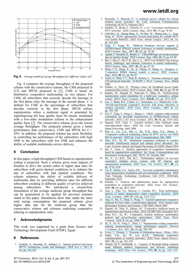
Fig. 8 Average multicast group throughput for different values of C
www.ietdl.org
Fig. 8 compares the average throughput of the proposedscheme with the conservative scheme, the CMS proposed in[15] and SPCM proposed in [7]. CMS is based ondistributive cooperative multicasting on two phases. ForCMS, all subscribers that correctly decode the message inthe first phase relay the message in the second phase. C isdefined for CMS as the percentage of subscribers thatdecodes correctly in the first phase. SPCM utilisessuperposition where a multicast signal is generated bysuperimposing the base quality layer bit stream, modulatedwith a low-order modulation scheme to the enhancementquality layer [7]. The conservative scheme gives the lowestaverage throughput. The proposed scheme gives a betterperformance than conservative, CMS and SPCM for C =50%. In addition, the proposed scheme has more flexibilityin controlling the performance of the subscribers with highSNR or the subscribers with low SNR and enhances theability of scalable multimedia service delivery.
6 Conclusion
In this paper, a high-throughput CSM based on superpositioncoding is proposed. Such a scheme gives more degrees offreedom to drive the system either to higher data rates forsubscribers with good channel conditions or to enhance therate of subscribers with bad channel conditions. Thescheme enhances the ability of scalable delivery ofmultimedia data by providing different rates for differentsubscribers resulting in different quality of service achievedamong subscribers. We introduced a closed-formformulation of the average multicast group throughput thatcan be generalised to be applied for previous schemesstated in this paper. Simulations show that, under the sametotal energy consumption, the proposed scheme giveshigher data rate for the multicast group than theconservative scheme and schemes exploiting cooperativerelaying or superposition only.
7 Acknowledgments
This work was supported by a grant from Science andTechnology Development Fund (STDF), Egypt.
8 References
1 Zeadally, S., Moustafa, H., Siddiqui, F.: ‘Internet protocol television)(IPTV): Architecture, trends, and challenges’, IEEE Syst. J., 2011, 5,(4), pp. 518–527
IET Commun., 2014, Vol. 8, Iss. 3, pp. 267–277doi: 10.1049/iet-com.2013.0167
2 Hyeonsik, Y., Heasook, P.: ‘A multicast service scheme for variouswireless access networks’. Int. Conf. Advanced CommunicationTechnology (ICACT), February 2012
3 Gardikis, G., Boula, L., Xilouris, G., et al.: ‘Cross-layer monitoring inIPTV networks’, IEEE Commun. Mag., 2012, 50, (7), pp. 76–84
4 Chih-Wei, H., Shiang-Ming, H., Po-Han, W., Shiang-Jiun, L., Jeng-Neng, H.: ‘OLM: opportunistic layered multicasting for scalable IPTVover mobile WiMAX’, IEEE Trans. Mobile Comput., 2012, 11, (3),pp. 453–463
5 Jiang, T., Xiang, W.: ‘Multicast broadcast services support inOFDMA-based WiMAX systems [Advances in mobile multimedia]’,IEEE Commun. Mag., 2007, 45, (8), pp. 78–86
6 Agashe, P., Rezaiifar, R., Bender, P.: ‘Cdma2000 high rate broadcast packetdata air interface design’, IEEE Commun. Mag., 2004, 42, (2), pp. 83–89
7 She, J., Hou, F., Ho, P.-H., Xie, L.-L.: ‘IPTV over WiMAX: key successfactors, challenges, and solutions [Advances in mobile multimedia]’,IEEE Commun. Mag., 2007, 45, (8), pp. 87–93
8 Wang, C.X., Hong, X., Ge, X., Cheng, X., Zhang, G., Thompso, J.:‘Cooperative MIMO channel models: a survey’, IEEE Commun.Mag., 2010, 48, (2), pp. 80–87
9 Teyeb, O., Phan, V.V., Raaf, B., Redana, S.: ‘Dynamic relaying in 3gppLTE-advanced networks’, EURASIP J. Wirel. Commun. Netw., March2009
10 Soldani, S., Dixit, D.: ‘Wireless relays for broadband access [radiocommunication series]’, IEEE Commun. Mag., 2008, 46, (3), pp. 58–60
11 Kaneko, M., Hayashi, K., Popovski, P., Sakai, H.: ‘Fairness-awaresuperposition coded scheduling for a multi-user cooperative cellularsystem’, IEICE Trans. Commun., 2011, E94.B, (12), pp. 3272–3279
12 Luo, J., Blum, R.S., Cimini, L.J., Greenstein, L.J., Haimovich, A.M.:‘Decode-and-forward cooperative diversity with power allocation inwireless networks’, IEEE Trans. Wirel. Commun., 2007, 6, (3),pp. 793–799
13 Cao, Y., Jiang, T., Wang, C., Zhang, L.: ‘CRAC: cognitive radio assistedcooperation for downlink transmissions in OFDMA-based cellularnetworks’, IEEE J. Sel. Areas Commun., 2012, 30, (9), pp. 1614–1622
14 Nguyen, X.H., Choi, J.: ‘Layered wireless video multicast usingomni-directional relays’. IEEE Int. Conf. Acoustics, Speech, andSignal Processing, April 2008
15 Hou, F., Cai, L.X., She, J., Ho, P.-H., Shen, X.S., Zhang, J.:‘Cooperative multicast scheduling scheme for IPTV service over IEEE802.16 networks’. IEEE Int. Conf. Communications, May 2008
16 Zhao, H.V., Su, W.: ‘Distributed cooperative multicast in wirelessnetworks: performance analysis and optimal power allocation’. Int.Conf. Acoustics Speech and Signal Processing (ICASSP), March 2010
17 Bui, T., Yuan, J.: ‘Iterative approaches of cooperative transmissionbased on superposition modulation’. Int. Symp. Communications andInformation Technologies 2007. ISCIT ‘07, October 2007
18 Hu, Y., Li, K.H., Teh, K.C.: ‘Performance analysis of two-usercooperative multiple access systems with DF relaying andsuperposition modulation’, IEEE Trans. Veh. Technol., 2011, 60, (7),pp. 3118–3126
19 Lin, R., Martin, P.A., Taylor, D.P.: ‘Two-user cooperative transmissionusing superposition modulation and soft information combining’. IEEE72nd Vehicular Technology Conference Fall (VTC 2010-Fall),September 2010
20 Krikidis, I.: ‘Analysis and optimization issues for superpositionmodulation in cooperative networks’, IEEE Trans. Veh. Technol.,2009, 58, (9), pp. 4837–4847
21 Xiao, L., Fuja, T.E., Kliewer, J., Costello, D.J.: ‘Error performanceanalysis of signal superposition coded cooperative diversity’, IEEETrans. Commun., 2009, 57, (10), pp. 3123–3131
22 Alay, O., Pan, X., Erkip, E., Wang, Y.: ‘Layered randomized cooperativemulticast for lossy data: a superposition approach’. 43rd Annual Conf.Information Sciences and Systems, CISS 2009, March 2009
23 Elgendi, M., Nasr, O., Khairy, M.: ‘Cooperative multicast based onsuperposition and layered coding’, IEEE GLOBECOM, December 2011
24 Zhao, H.V., Su, W.: ‘Cooperative wireless multicast: performanceanalysis and power/location optimization’, IEEE Trans. Wirel.Commun., 2010, 9, (6), pp. 2088–2100
25 Jia, X., Fu, H., Yang, L., Zhao, L.: ‘Superposition coding cooperativerelaying communications: outage performance analysis’, InternalJ. Commun. Syst., 2011, 24, (3), pp. 384–397
26 Cover, T., Thomas, J.: ‘Elements of information theory’ (Wiley, 1991)27 Sadek, A.K., Su, W., Liu, K.J.R.: ‘Multinode cooperative
communications in wireless networks’, IEEE Trans. Signal Process.,2007, 55, (1), pp. 341–355
28 Alouini, M.-S., Goldsmith, A.: ‘Capacity of Rayleigh fading channelsunder different adaptive transmission and diversity combiningtechniques’, IEEE Trans. Veh. Technol., 1999, 48, (4), pp. 1165–1181
277& The Institution of Engineering and Technology 2014