design code example superposition acc. to snip 2.01.07-85
TRANSCRIPT

Design Code Example
SOFiSTiK AG 2010
Design Code Example Superposition acc. to
SNIP 2.01.07-85 / SP 52-101-2003

Design Code Example
Page 1 Superposition SNIP 2.03.07-85 (01.2010)
1 Introduction
The following example of a concrete column according to Russian SP 52-101-2003
shows the superpositions according to SNIP 2.01.07-85. Here only the defaults of the
INI file (snip_52101.ini) are used for the selected actions.
The input is done exclusively on numeric basis with the CADINP input language in the TEDDY.
2 Definition of the Design Code and the System
2.1 Input of the Design Code
For each design code there is an INI file which includes information about materials,
actions, combinations and design values. This information is activated about the input
for record NORM in program AQUA.
Special feature in this example:
The combination coefficient for the action snow is dependent on the snow area ->
SNIP 2.03.07-85 Classification of loads 1.7 k)
The snow area has to be input already in AQUA record NORM at item SNOW. For
this example the snow area IV is chosen.
2.2 System
Here a concrete column with constant cross section and a height of 3 m is
considered as a plane system with the dead load direction in negative Y direction.
Following cross section is defined for this purpose:
Cross section: rectangle h/b= 40/20cm
concrete: B 35 according to SP 52-101-2003
reinforcement: A 500 according to SP 52-101-2003

Design Code Example
Page 2 Superposition SNIP 2.03.07-85 (01.2010)
CADINP input for AQUA and SOFiMSHA
3 Action and Loading The actions and loadings are defined with the program SOFiLOAD. For the definition
of the action it suffices to input the action only with its action code in record ACT, e.g.
ACT G for the permanent action dead load. The corresponding information about the
safety factors and combination coefficients as well as the definition, how the actions
is considered during superposition, are defined with the INI file and do not have to be
input explicitly.
Special feature in this example:
In the SNIP 2.03.07-85 there are given several coefficients ψ1 and ψ2 in dependence
on the combination and the variable loads. The code distinguishes between the main
and special combinations and sustain and instantaneous loads.
-> SNIP 2.03.07-85 Load combinations 1.10-1.13
For the main combination the code coefficient ψ1 is given for sustain loads and ψ2
for instantaneous loads. These both code coefficients are preset in the INI file at ψ0!
In case of three or more instantaneous loads the code prescribes following
coefficients for the first instantaneous load 1.0, for the second 0.8 and for the rest
0.6. The code coefficients for the instantaneous loads are preset in the INI file for the
second one at ψ1 (=0.8) and for the rest at ψ2 (=0.6)!

Design Code Example
Page 3 Superposition SNIP 2.03.07-85 (01.2010)
For the special combination the code coefficient ψ1 is given for sustain loads and ψ2
for instantaneous loads. These coefficients are different from those of the main
combination and are preset in the INI file at ψ1!
The coefficient for snow depends on the snow area for all combinations.
Following actions and loadings are planned:
Dead load G: dead load for load case 1
dead load of the column and single load at
column head of 15 kN
Variable action Q: imposed load for load case 2
single load at column head in dead load direction of 20 kN
Life loading L: life loading for load case 3
single load at column head in dead load direction of 25 kN
Snow S: snow for load case 4
single load at column head in dead load direction of 10 kN
Wind W: wind for load case 5
constant line load acting on beam 1 in global X direction
of 1.0 kN/m
Impact A: accidental action impact for load case 6
single load acting on beam 1 in global X direction 1.0 m
above column base
Design Code Example
Page 4 Superposition SNIP 2.03.07-85 (01.2010)
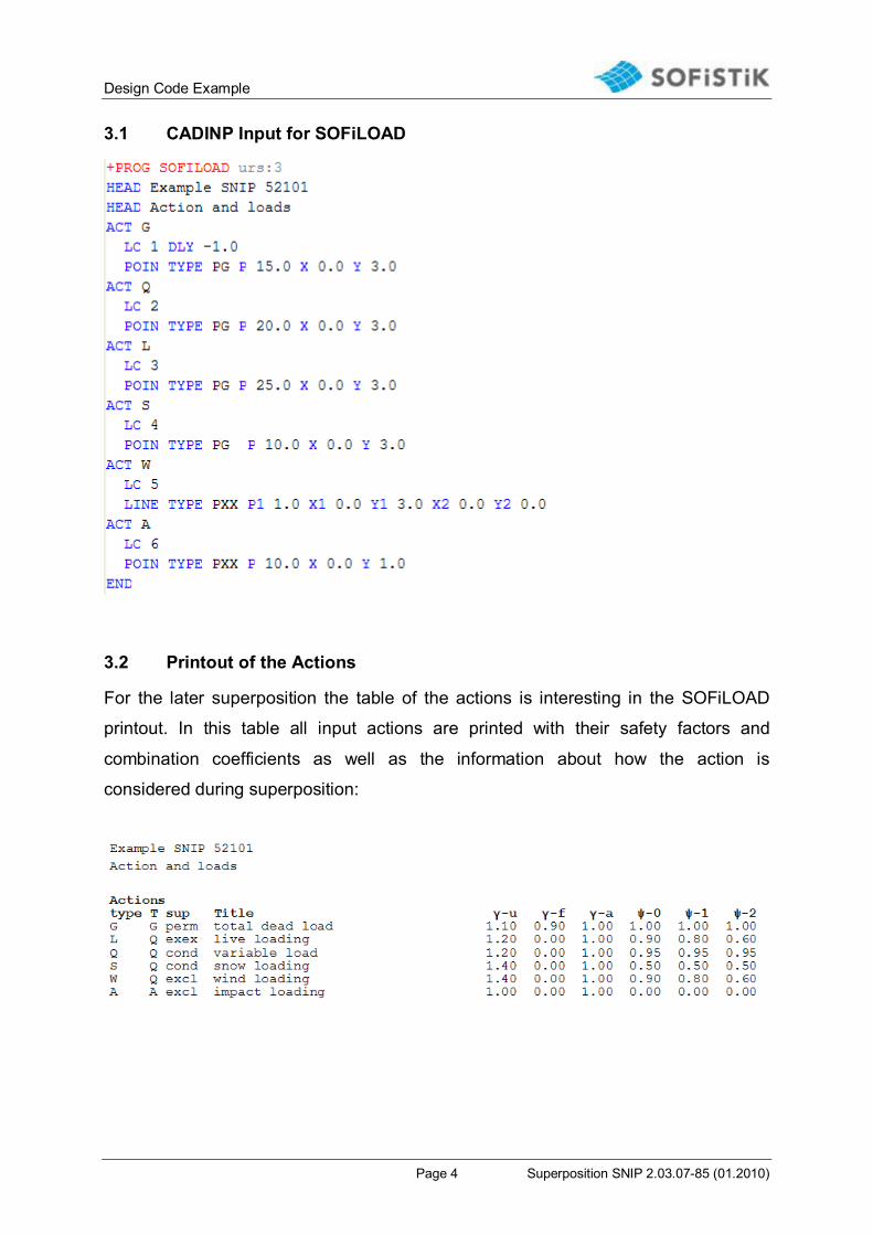
3.1 CADINP Input for SOFiLOAD
3.2 Printout of the Actions
For the later superposition the table of the actions is interesting in the SOFiLOAD
printout. In this table all input actions are printed with their safety factors and
combination coefficients as well as the information about how the action is
considered during superposition:

Design Code Example
Page 5 Superposition SNIP 2.03.07-85 (01.2010)
Special feature in this example:
Following coefficients ψ are used for the actions in dependence on the combination:
Action Main combination Combination for three
or more instant. loads
Special combination
Variable action Q
sustain load
Ψ0=0.95 Ψ0=0.95 Ψ1=0.95
Life loading L
instantaneous
load
Ψ0=0.9 Ψ1=0.8 or
Ψ2=0.6
Ψ1=0.8
Snow S
sustain load
Ψ0=0.5 Ψ0=0.5 Ψ1=0.5
Wind W
instantaneous
load
Ψ0=0.9 Ψ1=0.8 or
Ψ2=0.6
Ψ1=0.8
The information about the actions should be checked by the user. The modification of single values is possible with an explicit input of the value which should be changed in record ACT.
4 Calculation of the Single Load Cases The calculation of the single load cases is done with the program ASE according to
first order theory without consideration of imperfections.
5 Combinations and Superpositions
5.1 Defaults
The combinations with the corresponding superpositions are preset in the INI file.
These defaults are shown in the Superposition Manager (SSD tasks ‘Define
Combinations‘ and ’Superpositioning’) and can be modified there. With the following
MAXIMA input in TEDDY it is possible to calculate the defaults from the INI file. The
input of the records CTRL and ECHO is not urgently necessary here.
Design Code Example
Page 6 Superposition SNIP 2.03.07-85 (01.2010)
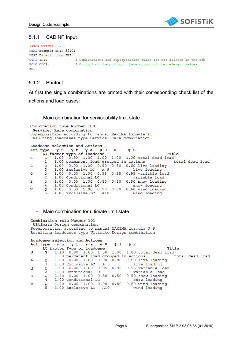
5.1.1 CADINP Input
5.1.2 Printout
At first the single combinations are printed with their corresponding check list of the
actions and load cases:
- Main combination for serviceability limit state
- Main combination for ultimate limit state

Design Code Example
Page 7 Superposition SNIP 2.03.07-85 (01.2010)
- Main combination with three or more instantaneous loads for ultimate limit
state (only for purposes of explanation because in this example only two
intstantaneous loads are available)
- Special combination

Design Code Example
Page 8 Superposition SNIP 2.03.07-85 (01.2010)
The table of the generated load cases follows:
Design Code Example
Page 9 Superposition SNIP 2.03.07-85 (01.2010)
The printout of the relevant values of the single superposition is requested with the
input ECHO CHCK. All factors which are necessary for the superposition as well as
the initial values of the single load cases are printed in the tables. A detailed
description of the combinations and the output is done in the following chapters.
The user should check the superposition by investigating random samples! For this the printout of the relevant values with ECHO CHCK is recommended.
5.2 Main Combination for Serviceability Limit State
In the INI file the main combination for the serviceability limit state is defined as
combination 100. According to the code SNIP 2.03.07-85 the main combination for
the serviceability limit state is formed here by:
dead load + 1.0 * (one live load)
or
dead load + Ψ0 * (all live loads)
These both equations correspond to the formulas 11 and 12 of the simplified
superpositions for serviceability limit state in the MAXIMA manual. The explicit
MAXIMA input for this combination should be explained now.
5.2.1 CADINP Input
For the combination 11 a serviceability design combination according to formulas 11
and 12 of the MAXIMA manual is chosen. Here the program MAXIMA searches
automatically for the most unfavourable variant of both formulas considering the
coefficients Ψ0 for this design code. The formulas 11 and 12 are requested with the
input COMB EXTR RARE-V. The type of the result load cases is RARE – rare
combination. With the input BASE 3100 in record COMB the basis load case number
of the result load cases is defined here. The actions are requested with the records
ACT. The single load cases of the actions do not have to be input here. The program
MAXIMA uses the single load cases of the actions from the database. For the

Design Code Example
Page 10 Superposition SNIP 2.03.07-85 (01.2010)
superposition the maximum and minimum values of the nodal displacements u-x, u-y
and nodal rotation phi-z are defined in the record SUPP.
5.2.2 Printout of the Superposition Results
As already described the printout of MAXIMA begins with the combination and their
corresponding check list of the actions and load cases. It follows the table of the
resultant load cases:
Design Code Example
Page 11 Superposition SNIP 2.03.07-85 (01.2010)
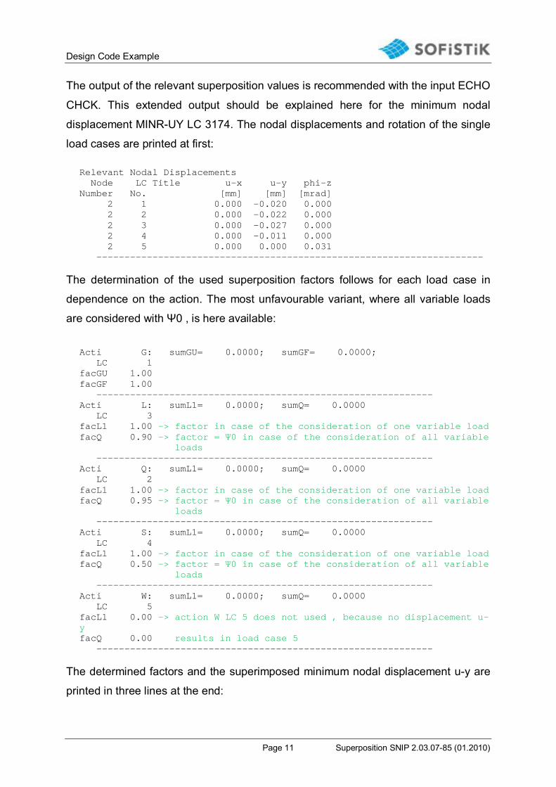
The output of the relevant superposition values is recommended with the input ECHO
CHCK. This extended output should be explained here for the minimum nodal
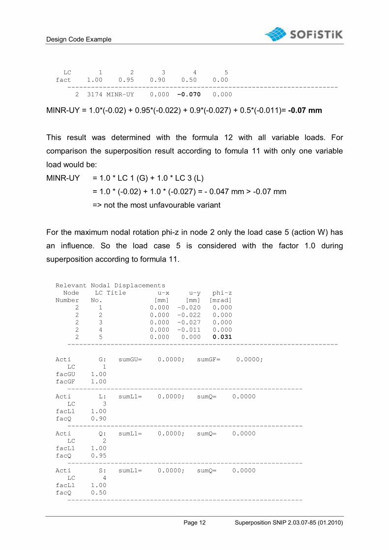
displacement MINR-UY LC 3174. The nodal displacements and rotation of the single
load cases are printed at first: Relevant Nodal Displacements Node LC Title u-x u-y phi-z Number No. [mm] [mm] [mrad] 2 1 0.000 -0.020 0.000 2 2 0.000 -0.022 0.000 2 3 0.000 -0.027 0.000 2 4 0.000 -0.011 0.000 2 5 0.000 0.000 0.031 ---------------------------------------------------------------------
The determination of the used superposition factors follows for each load case in
dependence on the action. The most unfavourable variant, where all variable loads
are considered with Ψ0 , is here available:
Acti G: sumGU= 0.0000; sumGF= 0.0000; LC 1 facGU 1.00 facGF 1.00 ------------------------------------------------------------ Acti L: sumL1= 0.0000; sumQ= 0.0000 LC 3 facL1 1.00 -> factor in case of the consideration of one variable load facQ 0.90 -> factor = Ψ0 in case of the consideration of all variable loads ------------------------------------------------------------ Acti Q: sumL1= 0.0000; sumQ= 0.0000 LC 2 facL1 1.00 -> factor in case of the consideration of one variable load facQ 0.95 -> factor = Ψ0 in case of the consideration of all variable loads ------------------------------------------------------------ Acti S: sumL1= 0.0000; sumQ= 0.0000 LC 4 facL1 1.00 -> factor in case of the consideration of one variable load facQ 0.50 -> factor = Ψ0 in case of the consideration of all variable loads ------------------------------------------------------------ Acti W: sumL1= 0.0000; sumQ= 0.0000 LC 5 facL1 0.00 -> action W LC 5 does not used , because no displacement u-y facQ 0.00 results in load case 5 ------------------------------------------------------------
The determined factors and the superimposed minimum nodal displacement u-y are
printed in three lines at the end:
Design Code Example
Page 12 Superposition SNIP 2.03.07-85 (01.2010)
LC 1 2 3 4 5 fact 1.00 0.95 0.90 0.50 0.00 --------------------------------------------------------------------- 2 3174 MINR-UY 0.000 -0.070 0.000
MINR-UY = 1.0*(-0.02) + 0.95*(-0.022) + 0.9*(-0.027) + 0.5*(-0.011)= -0.07 mm
This result was determined with the formula 12 with all variable loads. For
comparison the superposition result according to fomula 11 with only one variable
load would be:
MINR-UY = 1.0 * LC 1 (G) + 1.0 * LC 3 (L)
= 1.0 * (-0.02) + 1.0 * (-0.027) = - 0.047 mm > -0.07 mm
=> not the most unfavourable variant
For the maximum nodal rotation phi-z in node 2 only the load case 5 (action W) has
an influence. So the load case 5 is considered with the factor 1.0 during
superposition according to formula 11.
Relevant Nodal Displacements Node LC Title u-x u-y phi-z Number No. [mm] [mm] [mrad] 2 1 0.000 -0.020 0.000 2 2 0.000 -0.022 0.000 2 3 0.000 -0.027 0.000 2 4 0.000 -0.011 0.000 2 5 0.000 0.000 0.031 --------------------------------------------------------------------- Acti G: sumGU= 0.0000; sumGF= 0.0000; LC 1 facGU 1.00 facGF 1.00 ------------------------------------------------------------ Acti L: sumL1= 0.0000; sumQ= 0.0000 LC 3 facL1 1.00 facQ 0.90 ------------------------------------------------------------ Acti Q: sumL1= 0.0000; sumQ= 0.0000 LC 2 facL1 1.00 facQ 0.95 ------------------------------------------------------------ Acti S: sumL1= 0.0000; sumQ= 0.0000 LC 4 facL1 1.00 facQ 0.50 ------------------------------------------------------------
Design Code Example
Page 13 Superposition SNIP 2.03.07-85 (01.2010)
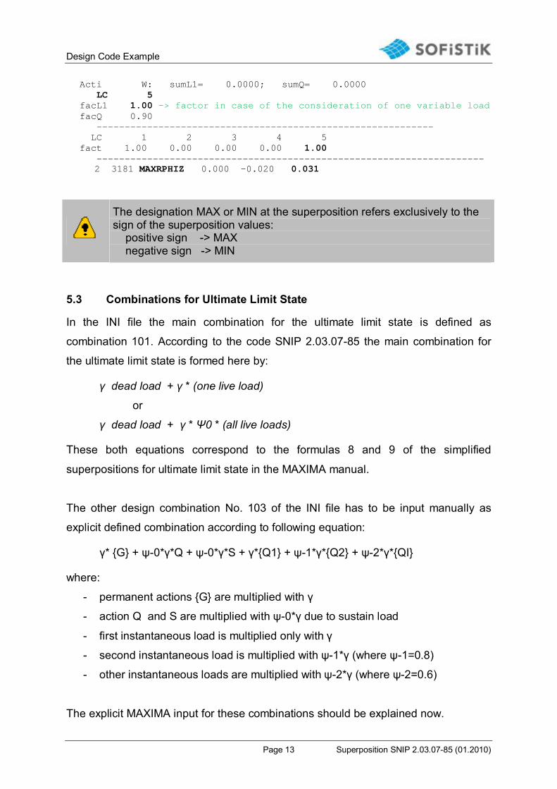
Acti W: sumL1= 0.0000; sumQ= 0.0000 LC 5 facL1 1.00 -> factor in case of the consideration of one variable load facQ 0.90 ------------------------------------------------------------ LC 1 2 3 4 5 fact 1.00 0.00 0.00 0.00 1.00 ---------------------------------------------------------------------
2 3181 MAXRPHIZ 0.000 -0.020 0.031
The designation MAX or MIN at the superposition refers exclusively to the sign of the superposition values: positive sign -> MAX negative sign -> MIN
5.3 Combinations for Ultimate Limit State
In the INI file the main combination for the ultimate limit state is defined as
combination 101. According to the code SNIP 2.03.07-85 the main combination for
the ultimate limit state is formed here by:
γ dead load + γ * (one live load)
or
γ dead load + γ * Ψ0 * (all live loads)
These both equations correspond to the formulas 8 and 9 of the simplified
superpositions for ultimate limit state in the MAXIMA manual.
The other design combination No. 103 of the INI file has to be input manually as
explicit defined combination according to following equation:
γ* {G} + ψ-0*γ*Q + ψ-0*γ*S + γ*{Q1} + ψ-1*γ*{Q2} + ψ-2*γ*{QI}
where:
- permanent actions {G} are multiplied with γ
- action Q and S are multiplied with ψ-0*γ due to sustain load
- first instantaneous load is multiplied only with γ
- second instantaneous load is multiplied with ψ-1*γ (where ψ-1=0.8)
- other instantaneous loads are multiplied with ψ-2*γ (where ψ-2=0.6)
The explicit MAXIMA input for these combinations should be explained now.
Design Code Example
Page 14 Superposition SNIP 2.03.07-85 (01.2010)
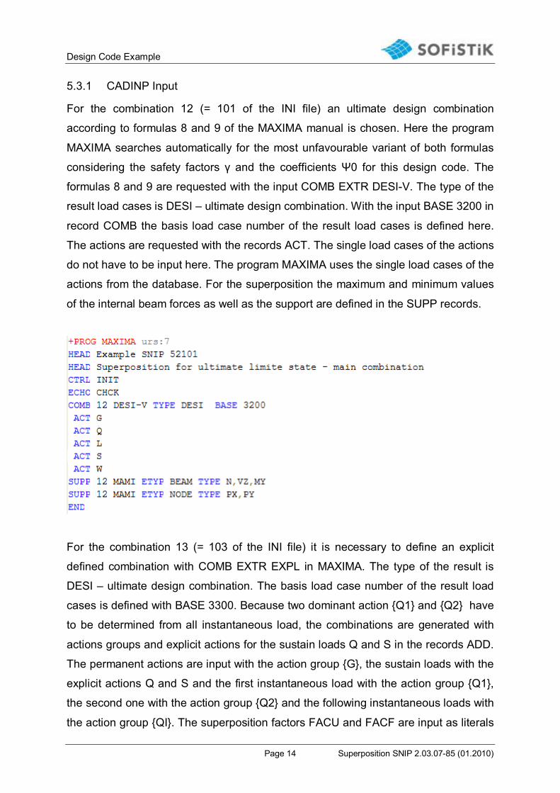
5.3.1 CADINP Input
For the combination 12 (= 101 of the INI file) an ultimate design combination
according to formulas 8 and 9 of the MAXIMA manual is chosen. Here the program
MAXIMA searches automatically for the most unfavourable variant of both formulas
considering the safety factors γ and the coefficients Ψ0 for this design code. The
formulas 8 and 9 are requested with the input COMB EXTR DESI-V. The type of the
result load cases is DESI – ultimate design combination. With the input BASE 3200 in
record COMB the basis load case number of the result load cases is defined here.
The actions are requested with the records ACT. The single load cases of the actions
do not have to be input here. The program MAXIMA uses the single load cases of the
actions from the database. For the superposition the maximum and minimum values
of the internal beam forces as well as the support are defined in the SUPP records.
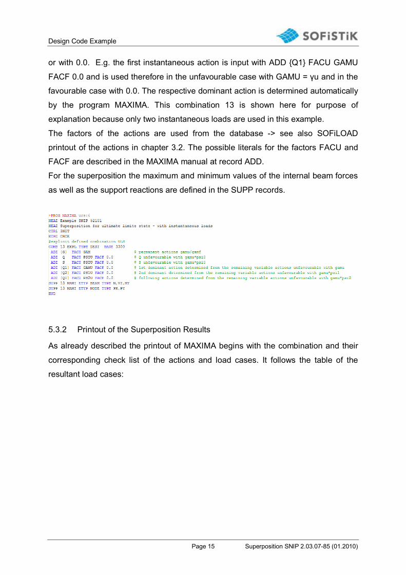
For the combination 13 (= 103 of the INI file) it is necessary to define an explicit
defined combination with COMB EXTR EXPL in MAXIMA. The type of the result is
DESI – ultimate design combination. The basis load case number of the result load
cases is defined with BASE 3300. Because two dominant action {Q1} and {Q2} have
to be determined from all instantaneous load, the combinations are generated with
actions groups and explicit actions for the sustain loads Q and S in the records ADD.
The permanent actions are input with the action group {G}, the sustain loads with the
explicit actions Q and S and the first instantaneous load with the action group {Q1},
the second one with the action group {Q2} and the following instantaneous loads with
the action group {QI}. The superposition factors FACU and FACF are input as literals
Design Code Example
Page 15 Superposition SNIP 2.03.07-85 (01.2010)
or with 0.0. E.g. the first instantaneous action is input with ADD {Q1} FACU GAMU
FACF 0.0 and is used therefore in the unfavourable case with GAMU = γu and in the
favourable case with 0.0. The respective dominant action is determined automatically
by the program MAXIMA. This combination 13 is shown here for purpose of
explanation because only two instantaneous loads are used in this example.
The factors of the actions are used from the database -> see also SOFiLOAD
printout of the actions in chapter 3.2. The possible literals for the factors FACU and
FACF are described in the MAXIMA manual at record ADD.
For the superposition the maximum and minimum values of the internal beam forces
as well as the support reactions are defined in the SUPP records.
5.3.2 Printout of the Superposition Results
As already described the printout of MAXIMA begins with the combination and their
corresponding check list of the actions and load cases. It follows the table of the
resultant load cases:

Design Code Example
Page 16 Superposition SNIP 2.03.07-85 (01.2010)
The output of the relevant superposition values is recommended with the input ECHO
CHCK. This extended output should be explained here for the minimum beam normal
force MIN-N LC 3222. The internal forces and moments of the single load cases are
printed at first: Relevant Forces in Beam-Elements Grp Beam x LC Title N Vz My No No. [m] No. [kN] [kN] [kNm] 0 1 0.000 1 -21.0 0.00 0.00 0 1 0.000 2 -20.0 0.00 0.00 0 1 0.000 3 -25.0 0.00 0.00 0 1 0.000 4 -10.0 0.00 0.00 0 1 0.000 5 0.0 1.50 0.00 ---------------------------------------------------------------------
The determination of the used superposition factors follows for each load case in
dependence on the action. The most unfavourable variant, where all variable loads
are considered with Ψ0*γ , is here available: Acti L: sumL1= -30.0000; sumQ= -27.0000* LC 3 facL1 1.20 -> factor=γ in case of the consideration of one variable load facQ 1.08 -> factor=Ψ0*γ in case of the consideration of all variable loads ------------------------------------------------------------ Acti Q: sumL1= -24.0000; sumQ= -22.8000* LC 2
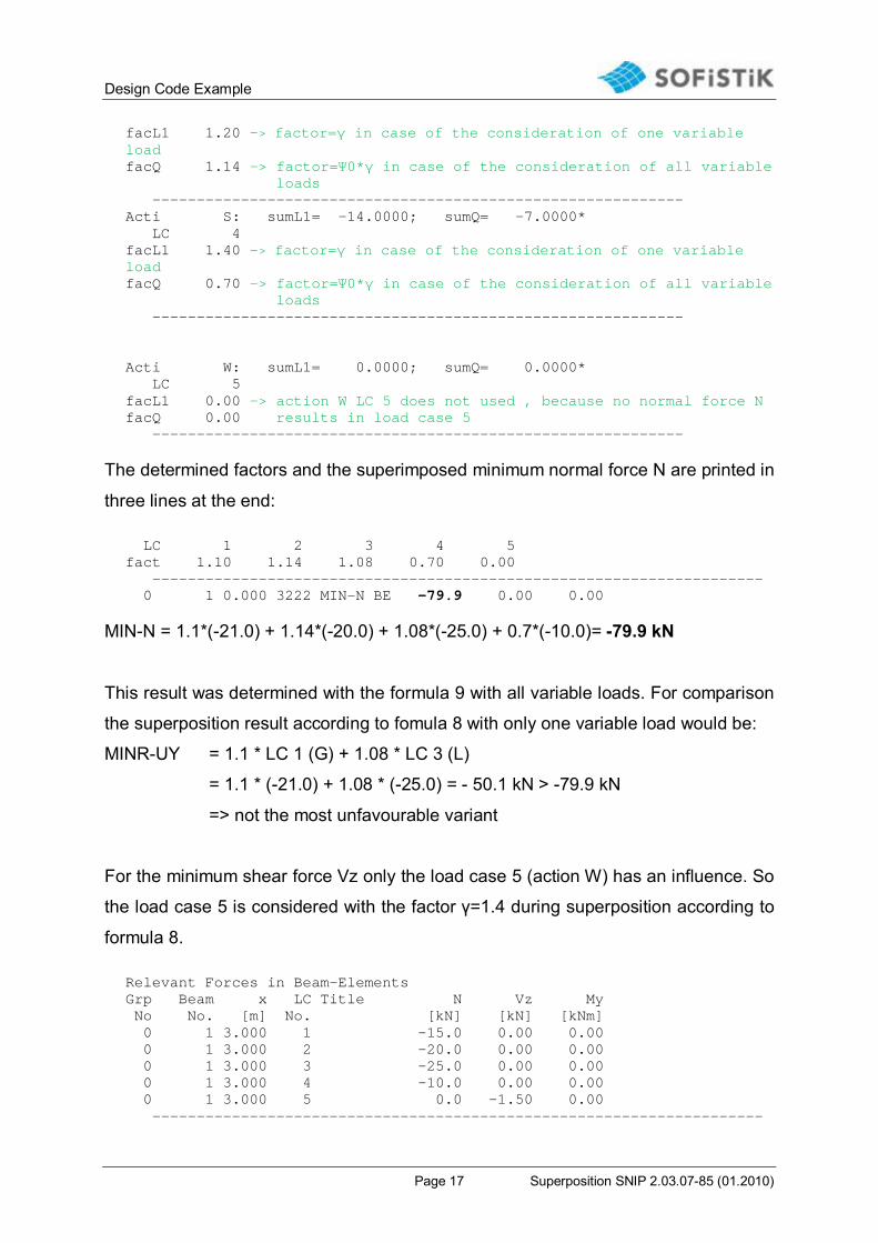
Design Code Example
Page 17 Superposition SNIP 2.03.07-85 (01.2010)
facL1 1.20 -> factor=γ in case of the consideration of one variable load facQ 1.14 -> factor=Ψ0*γ in case of the consideration of all variable loads ------------------------------------------------------------ Acti S: sumL1= -14.0000; sumQ= -7.0000* LC 4 facL1 1.40 -> factor=γ in case of the consideration of one variable load facQ 0.70 -> factor=Ψ0*γ in case of the consideration of all variable loads ------------------------------------------------------------ Acti W: sumL1= 0.0000; sumQ= 0.0000* LC 5 facL1 0.00 -> action W LC 5 does not used , because no normal force N facQ 0.00 results in load case 5 ------------------------------------------------------------
The determined factors and the superimposed minimum normal force N are printed in
three lines at the end: LC 1 2 3 4 5 fact 1.10 1.14 1.08 0.70 0.00 --------------------------------------------------------------------- 0 1 0.000 3222 MIN-N BE -79.9 0.00 0.00
MIN-N = 1.1*(-21.0) + 1.14*(-20.0) + 1.08*(-25.0) + 0.7*(-10.0)= -79.9 kN
This result was determined with the formula 9 with all variable loads. For comparison
the superposition result according to fomula 8 with only one variable load would be:
MINR-UY = 1.1 * LC 1 (G) + 1.08 * LC 3 (L)
= 1.1 * (-21.0) + 1.08 * (-25.0) = - 50.1 kN > -79.9 kN
=> not the most unfavourable variant
For the minimum shear force Vz only the load case 5 (action W) has an influence. So
the load case 5 is considered with the factor γ=1.4 during superposition according to
formula 8. Relevant Forces in Beam-Elements Grp Beam x LC Title N Vz My No No. [m] No. [kN] [kN] [kNm] 0 1 3.000 1 -15.0 0.00 0.00 0 1 3.000 2 -20.0 0.00 0.00 0 1 3.000 3 -25.0 0.00 0.00 0 1 3.000 4 -10.0 0.00 0.00 0 1 3.000 5 0.0 -1.50 0.00 ---------------------------------------------------------------------
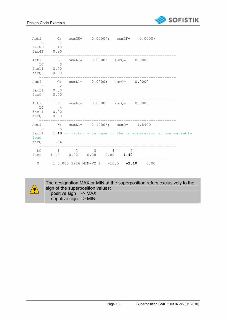
Design Code Example
Page 18 Superposition SNIP 2.03.07-85 (01.2010)
Acti G: sumGU= 0.0000*; sumGF= 0.0000; LC 1 facGU 1.10 facGF 0.90 ------------------------------------------------------------ Acti L: sumL1= 0.0000; sumQ= 0.0000 LC 3 facL1 0.00 facQ 0.00 ------------------------------------------------------------ Acti Q: sumL1= 0.0000; sumQ= 0.0000 LC 2 facL1 0.00 facQ 0.00 ------------------------------------------------------------ Acti S: sumL1= 0.0000; sumQ= 0.0000 LC 4 facL1 0.00 facQ 0.00 ------------------------------------------------------------ Acti W: sumL1= -2.1000*; sumQ= -1.8900 LC 5 facL1 1.40 -> factor γ in case of the consideration of one variable load facQ 1.26 ------------------------------------------------------------ LC 1 2 3 4 5 fact 1.10 0.00 0.00 0.00 1.40 --------------------------------------------------------------------- 0 1 3.000 3226 MIN-VZ B -16.5 -2.10 0.00
The designation MAX or MIN at the superposition refers exclusively to the sign of the superposition values: positive sign -> MAX negative sign -> MIN
Design Code Example
Page 19 Superposition SNIP 2.03.07-85 (01.2010)
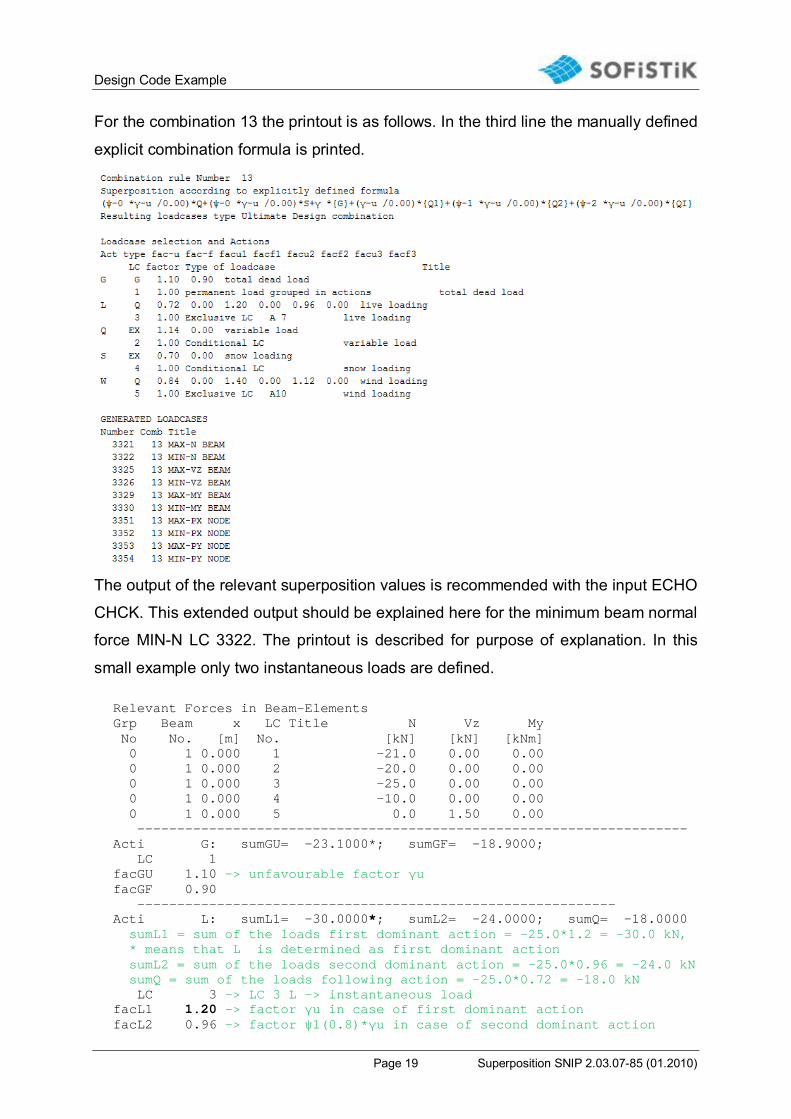
For the combination 13 the printout is as follows. In the third line the manually defined
explicit combination formula is printed.
The output of the relevant superposition values is recommended with the input ECHO
CHCK. This extended output should be explained here for the minimum beam normal
force MIN-N LC 3322. The printout is described for purpose of explanation. In this
small example only two instantaneous loads are defined. Relevant Forces in Beam-Elements Grp Beam x LC Title N Vz My No No. [m] No. [kN] [kN] [kNm] 0 1 0.000 1 -21.0 0.00 0.00 0 1 0.000 2 -20.0 0.00 0.00 0 1 0.000 3 -25.0 0.00 0.00 0 1 0.000 4 -10.0 0.00 0.00 0 1 0.000 5 0.0 1.50 0.00 --------------------------------------------------------------------- Acti G: sumGU= -23.1000*; sumGF= -18.9000; LC 1 facGU 1.10 -> unfavourable factor γu facGF 0.90 ------------------------------------------------------------ Acti L: sumL1= -30.0000*; sumL2= -24.0000; sumQ= -18.0000 sumL1 = sum of the loads first dominant action = -25.0*1.2 = -30.0 kN, * means that L is determined as first dominant action sumL2 = sum of the loads second dominant action = -25.0*0.96 = -24.0 kN sumQ = sum of the loads following action = -25.0*0.72 = -18.0 kN LC 3 -> LC 3 L -> instantaneous load facL1 1.20 -> factor γu in case of first dominant action facL2 0.96 -> factor ψ1(0.8)*γu in case of second dominant action
Design Code Example
Page 20 Superposition SNIP 2.03.07-85 (01.2010)
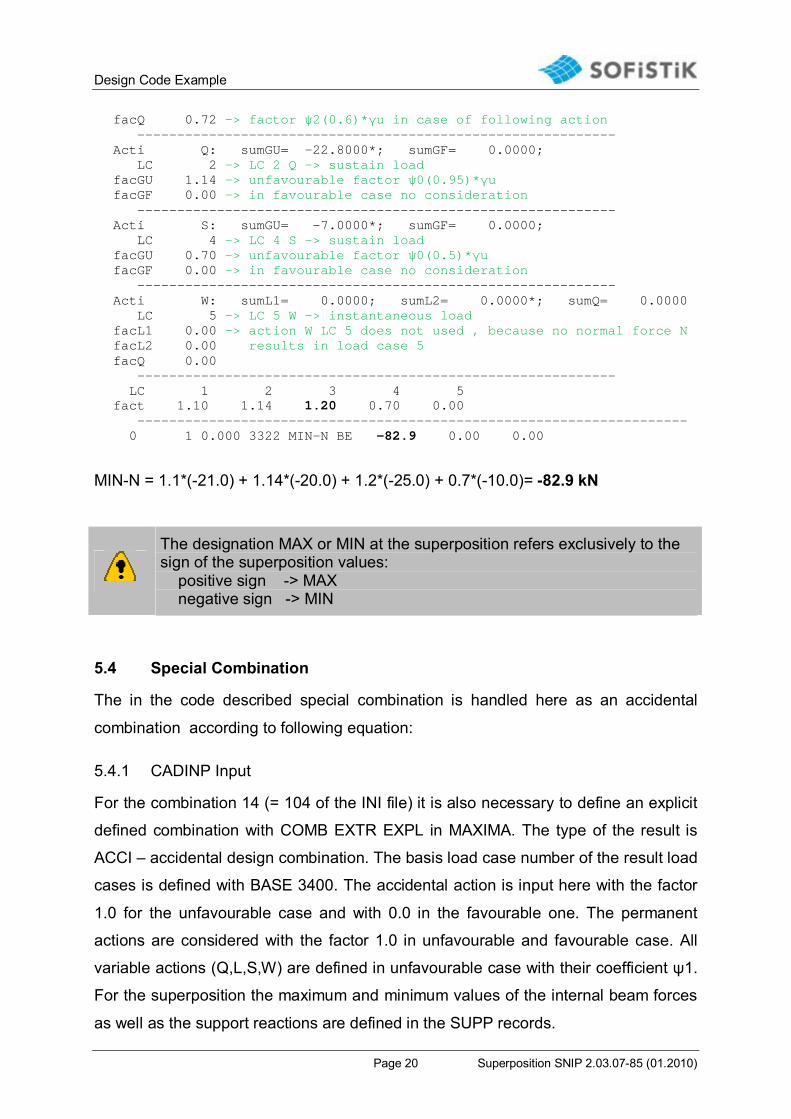
facQ 0.72 -> factor ψ2(0.6)*γu in case of following action ------------------------------------------------------------ Acti Q: sumGU= -22.8000*; sumGF= 0.0000; LC 2 -> LC 2 Q -> sustain load facGU 1.14 -> unfavourable factor ψ0(0.95)*γu facGF 0.00 -> in favourable case no consideration ------------------------------------------------------------ Acti S: sumGU= -7.0000*; sumGF= 0.0000; LC 4 -> LC 4 S -> sustain load facGU 0.70 -> unfavourable factor ψ0(0.5)*γu facGF 0.00 -> in favourable case no consideration ------------------------------------------------------------ Acti W: sumL1= 0.0000; sumL2= 0.0000*; sumQ= 0.0000 LC 5 -> LC 5 W -> instantaneous load facL1 0.00 -> action W LC 5 does not used , because no normal force N facL2 0.00 results in load case 5 facQ 0.00 ------------------------------------------------------------ LC 1 2 3 4 5 fact 1.10 1.14 1.20 0.70 0.00 --------------------------------------------------------------------- 0 1 0.000 3322 MIN-N BE -82.9 0.00 0.00
MIN-N = 1.1*(-21.0) + 1.14*(-20.0) + 1.2*(-25.0) + 0.7*(-10.0)= -82.9 kN
The designation MAX or MIN at the superposition refers exclusively to the sign of the superposition values: positive sign -> MAX negative sign -> MIN
5.4 Special Combination
The in the code described special combination is handled here as an accidental
combination according to following equation:
5.4.1 CADINP Input
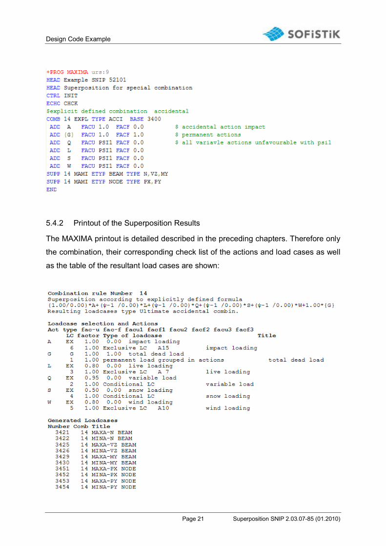
For the combination 14 (= 104 of the INI file) it is also necessary to define an explicit
defined combination with COMB EXTR EXPL in MAXIMA. The type of the result is
ACCI – accidental design combination. The basis load case number of the result load
cases is defined with BASE 3400. The accidental action is input here with the factor
1.0 for the unfavourable case and with 0.0 in the favourable one. The permanent
actions are considered with the factor 1.0 in unfavourable and favourable case. All
variable actions (Q,L,S,W) are defined in unfavourable case with their coefficient ψ1.
For the superposition the maximum and minimum values of the internal beam forces
as well as the support reactions are defined in the SUPP records.
Design Code Example
Page 21 Superposition SNIP 2.03.07-85 (01.2010)
5.4.2 Printout of the Superposition Results
The MAXIMA printout is detailed described in the preceding chapters. Therefore only
the combination, their corresponding check list of the actions and load cases as well
as the table of the resultant load cases are shown: