3.1 superposition theorem - bookspar
TRANSCRIPT
Many electric circuits are complex, but it is an engineer’s goal to reduce their complexity toanalyze them easily. In the previous chapters, we have mastered the ability to solve networkscontaining independent and dependent sources making use of either mesh or nodal analysis. Inthis chapter, we will introduce new techniques to strengthen our armoury to solve complicatednetworks. Also, these new techniques in many cases do provide insight into the circuit’s operationthat cannot be obtained from mesh or nodal analysis. Most often, we are interested only in thedetailed performance of an isolated portion of a complex circuit. If we can model the remainderof the circuit with a simple equivalent network, then our task of analysis gets greatly reduced andsimplified. For example, the function of many circuits is to deliver maximum power to load suchas an audio speaker in a stereo system. Here, we develop the required relationship betweeen aload resistor and a fixed series resistor which can represent the remaining portion of the circuit.Two of the theorems that we present in this chapter will permit us to do just that.
3.1 Superposition theorem
The principle of superposition is applicable only for linear systems. The concept of superpositioncan be explained mathematically by the following response and excitation principle :
�1 � �1
�2 � �2
then� �1 + �2 � �1 + �2
The quantity to the left of the arrow indicates the excitation and to the right, the systemresponse. Thus, we can state that a device, if excited by a current �1 will produce a response�1. Similarly, an excitation �2 will cause a response �2. Then if we use an excitation �1 + �2, wewill find a response �1 + �2.
The principle of superposition has the ability to reduce a complicated problem to several easierproblems each containing only a single independent source.
www.bookspar.com | VTU NOTES | QUESTION PAPERS | NEWS | RESULTS | FORUMS
www.bookspar.com | VTU NOTES | QUESTION PAPERS
160 � Network Theory
Superposition theorem states that,
In any linear circuit containing multiple independent sources, the current or voltage at any
point in the network may be calculated as algebraic sum of the individual contributions of each
source acting alone.
When determining the contribution due to a particular independent source, we disable allthe remaining independent sources. That is, all the remaining voltage sources are made zero byreplacing them with short circuits, and all remaining current sources are made zero by replacingthem with open circuits. Also, it is important to note that if a dependent source is present, it mustremain active (unaltered) during the process of superposition.
Action Plan:
(i) In a circuit comprising of many independent sources, only one source is allowed to be activein the circuit, the rest are deactivated (turned off).
(ii) To deactivate a voltage source, replace it with a short circuit, and to deactivate a currentsource, replace it with an open circuit.
(iii) The response obtained by applying each source, one at a time, are then added algebraicallyto obtain a solution.
Limitations: Superposition is a fundamental property of linear equations and, therefore, can beapplied to any effect that is linearly related to the cause. That is, we want to point out that,superposition principle applies only to the current and voltage in a linear circuit but it cannot beused to determine power because power is a non-linear function.
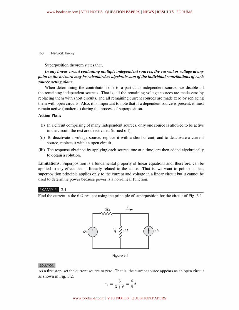
EXAMPLE 3.1
Find the current in the 6 Ω resistor using the principle of superposition for the circuit of Fig. 3.1.
Figure 3.1
SOLUTION
As a first step, set the current source to zero. That is, the current source appears as an open circuitas shown in Fig. 3.2.
�1 =6
3 + 6=
6
9A
www.bookspar.com | VTU NOTES | QUESTION PAPERS | NEWS | RESULTS | FORUMS
www.bookspar.com | VTU NOTES | QUESTION PAPERS
Circuit Theorems � 161
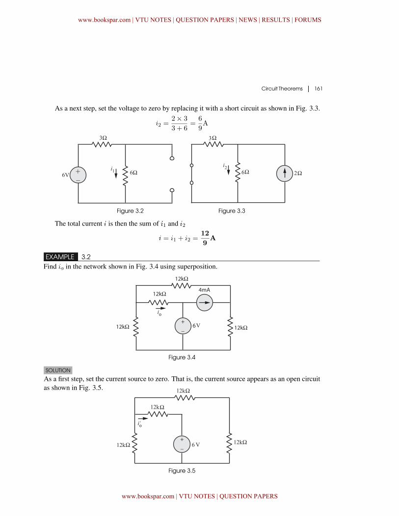
As a next step, set the voltage to zero by replacing it with a short circuit as shown in Fig. 3.3.
�2 =2� 3
3 + 6=
6
9A
Figure 3.2 Figure 3.3
The total current � is then the sum of �1 and �2
� = �1 + �2 =12
9A
EXAMPLE 3.2Find �� in the network shown in Fig. 3.4 using superposition.
Figure 3.4
SOLUTION
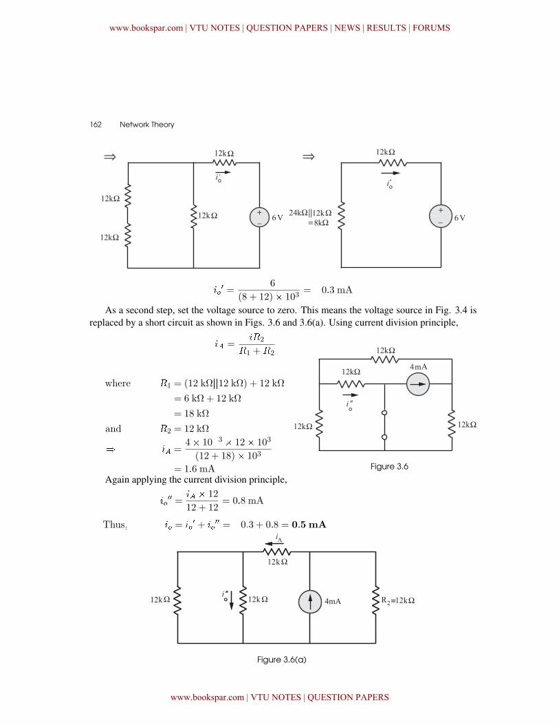
As a first step, set the current source to zero. That is, the current source appears as an open circuitas shown in Fig. 3.5.
Figure 3.5
www.bookspar.com | VTU NOTES | QUESTION PAPERS | NEWS | RESULTS | FORUMS
www.bookspar.com | VTU NOTES | QUESTION PAPERS
162 � Network Theory
��� =
�6(8 + 12)� 103
= �0�3 mA
As a second step, set the voltage source to zero. This means the voltage source in Fig. 3.4 isreplaced by a short circuit as shown in Figs. 3.6 and 3.6(a). Using current division principle,
�� =��2
�1 +�2
where �1 = (12 kΩ��12 kΩ) + 12 kΩ
= 6 kΩ + 12 kΩ
= 18 kΩ
and �2 = 12 kΩ
� �� =4� 10�3 � 12� 103
(12 + 18)� 103
= 1�6 mA Figure 3.6
Again applying the current division principle,
���� =
�� � 12
12 + 12= 0�8 mA
Thus� �� = ��� + ��
�� = �0�3 + 0�8 = 0�5 mA
Figure 3.6(a)
www.bookspar.com | VTU NOTES | QUESTION PAPERS | NEWS | RESULTS | FORUMS
www.bookspar.com | VTU NOTES | QUESTION PAPERS
Circuit Theorems � 163
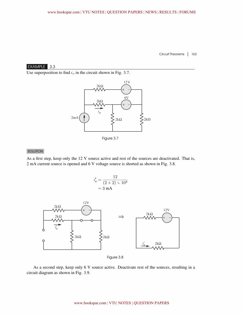
EXAMPLE 3.3Use superposition to find �� in the circuit shown in Fig. 3.7.
Figure 3.7
SOLUTION
As a first step, keep only the 12 V source active and rest of the sources are deactivated. That is,2 mA current source is opened and 6 V voltage source is shorted as shown in Fig. 3.8.
��� =12
(2 + 2)� 103
= 3 mA
Figure 3.8
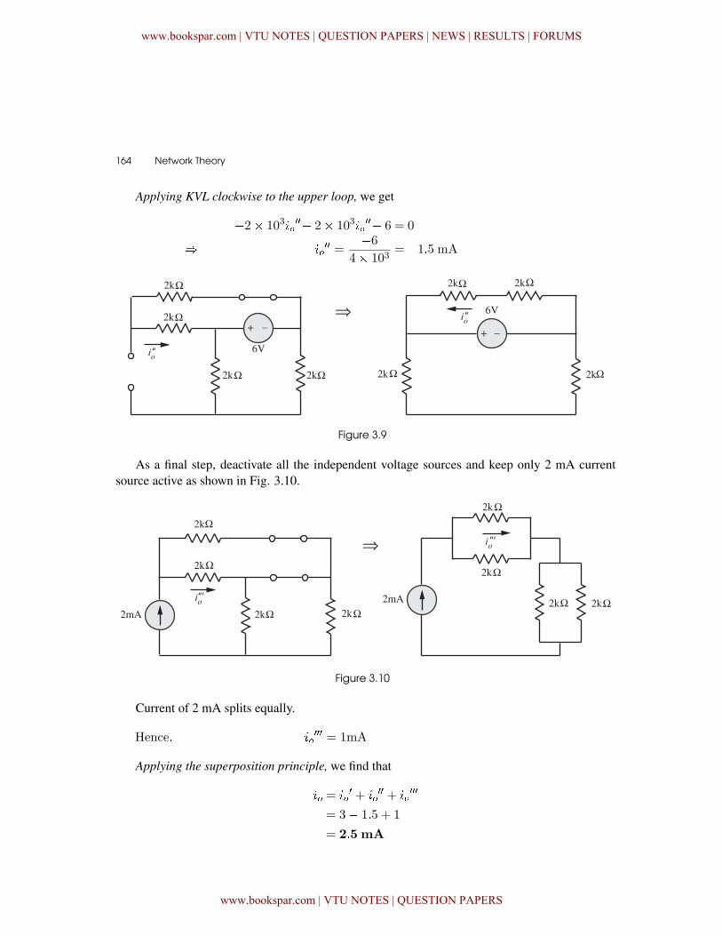
As a second step, keep only 6 V source active. Deactivate rest of the sources, resulting in acircuit diagram as shown in Fig. 3.9.
www.bookspar.com | VTU NOTES | QUESTION PAPERS | NEWS | RESULTS | FORUMS
www.bookspar.com | VTU NOTES | QUESTION PAPERS
164 � Network Theory
Applying KVL clockwise to the upper loop, we get
�2� 103����� 2� 103��
��� 6 = 0
� ���� =
�64� 103
= �1�5 mA
Figure 3.9
As a final step, deactivate all the independent voltage sources and keep only 2 mA currentsource active as shown in Fig. 3.10.
Figure 3.10
Current of 2 mA splits equally.
Hence� ����� = 1mA
Applying the superposition principle, we find that
�� = ��� + ��
�� + �����
= 3� 1�5 + 1
= 2�5 mA
www.bookspar.com | VTU NOTES | QUESTION PAPERS | NEWS | RESULTS | FORUMS
www.bookspar.com | VTU NOTES | QUESTION PAPERS
Circuit Theorems � 165
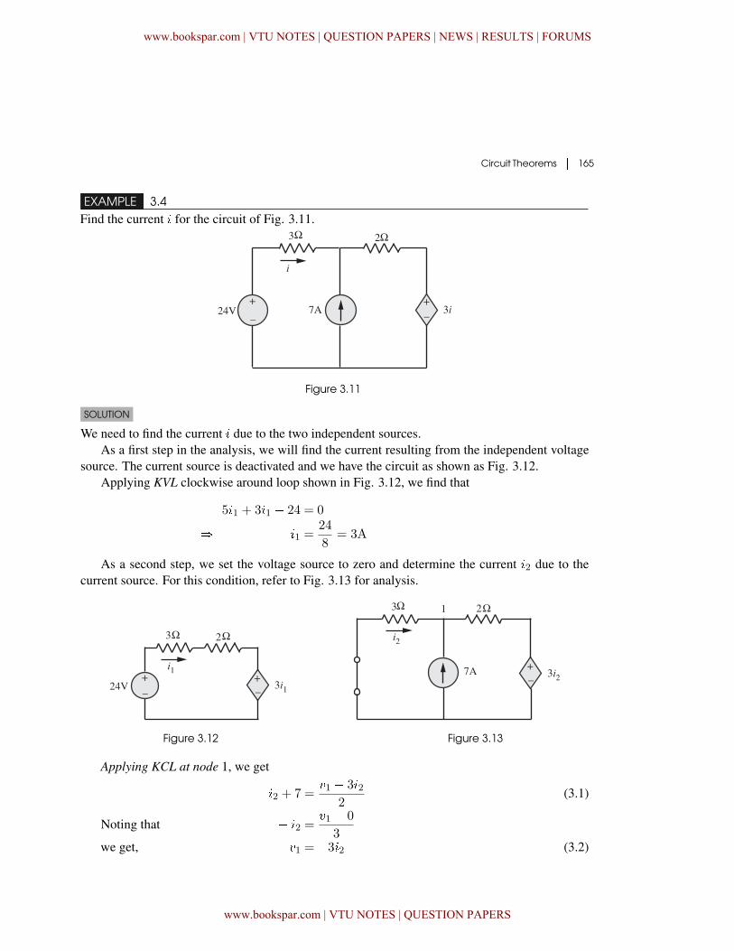
EXAMPLE 3.4Find the current � for the circuit of Fig. 3.11.
Figure 3.11
SOLUTION
We need to find the current � due to the two independent sources.As a first step in the analysis, we will find the current resulting from the independent voltage
source. The current source is deactivated and we have the circuit as shown as Fig. 3.12.Applying KVL clockwise around loop shown in Fig. 3.12, we find that
5�1 + 3�1 � 24 = 0
� �1 =24
8= 3A
As a second step, we set the voltage source to zero and determine the current �2 due to thecurrent source. For this condition, refer to Fig. 3.13 for analysis.
Figure 3.12 Figure 3.13
Applying KCL at node 1, we get
�2 + 7 =�1 � 3�2
2(3.1)
Noting that � �2 =�1 � 0
3we get, �1 = �3�2 (3.2)
www.bookspar.com | VTU NOTES | QUESTION PAPERS | NEWS | RESULTS | FORUMS
www.bookspar.com | VTU NOTES | QUESTION PAPERS
166 � Network Theory
Making use of equation (3.2) in equation (3.1) leads to
�2 + 7 =�3�2 � 3�2
2
� �2 = �7
4A
Thus, the total current
� = �1 + �2
= 3� 7
4A =
5
4A
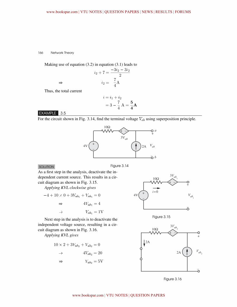
EXAMPLE 3.5For the circuit shown in Fig. 3.14, find the terminal voltage ��� using superposition principle.
Figure 3.14SOLUTION
Figure 3.15
As a first step in the analysis, deactivate the in-dependent current source. This results in a cir-cuit diagram as shown in Fig. 3.15.
Applying KVL clockwise gives
�4 + 10� 0 + 3���1 + ���1 = 0
� 4���1 = 4
� ���1 = 1V
Next step in the analysis is to deactivate theindependent voltage source, resulting in a cir-cuit diagram as shown in Fig. 3.16.
Applying KVL gives
�10� 2 + 3���2 + ���2 = 0
� 4���2 = 20
� ���2 = 5V
Figure 3.16
www.bookspar.com | VTU NOTES | QUESTION PAPERS | NEWS | RESULTS | FORUMS
www.bookspar.com | VTU NOTES | QUESTION PAPERS
Circuit Theorems � 167
According to superposition principle,
��� = ���1 + ���2
= 1 + 5 = 6V
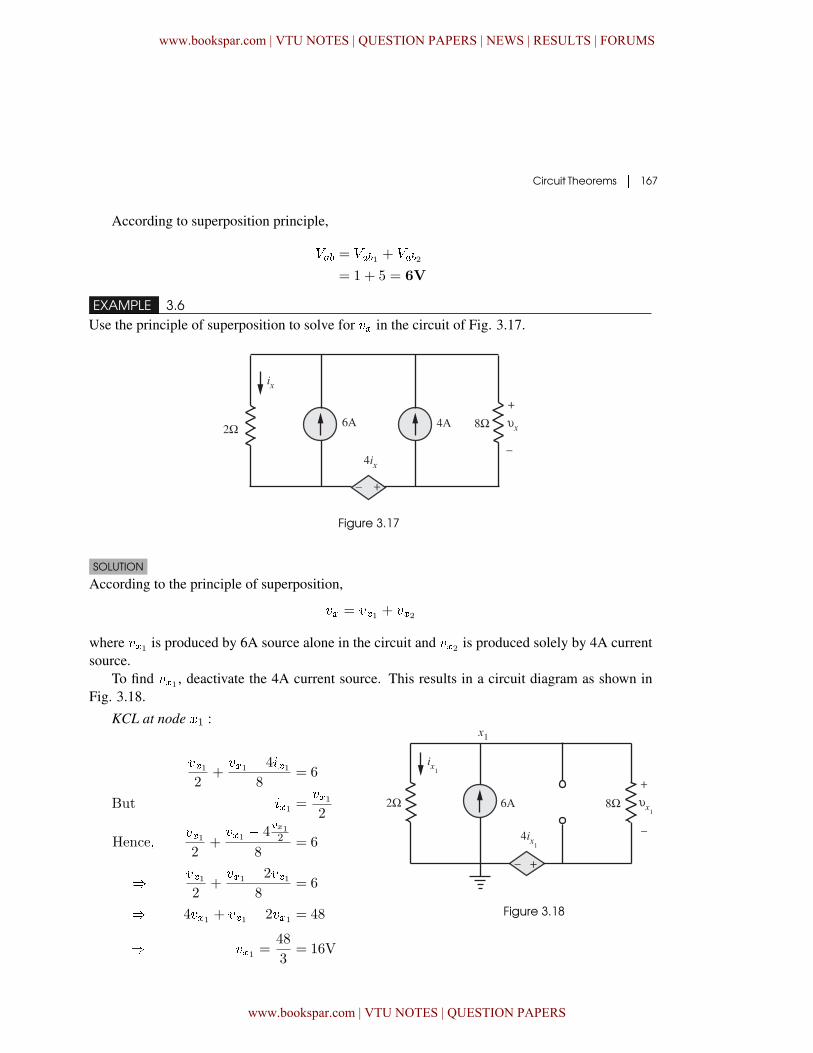
EXAMPLE 3.6Use the principle of superposition to solve for �� in the circuit of Fig. 3.17.
Figure 3.17
SOLUTION
According to the principle of superposition,
�� = ��1 + ��2
where ��1 is produced by 6A source alone in the circuit and ��2 is produced solely by 4A currentsource.
To find ��1 , deactivate the 4A current source. This results in a circuit diagram as shown inFig. 3.18.
KCL at node �1 :
��12
+��1 � 4��1
8= 6
But ��1 =��12
Hence���12
+��1 � 4
�x12
8= 6
� ��12
+��1 � 2��1
8= 6
� 4��1 + ��1 � 2��1 = 48
� ��1 =48
3= 16V
Figure 3.18
www.bookspar.com | VTU NOTES | QUESTION PAPERS | NEWS | RESULTS | FORUMS
www.bookspar.com | VTU NOTES | QUESTION PAPERS
168 � Network Theory
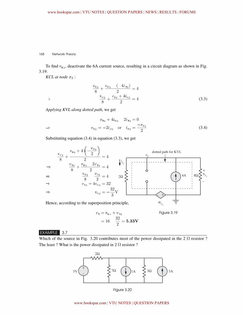
To find ��2 , deactivate the 6A current source, resulting in a circuit diagram as shown in Fig.3.19.
KCL at node �2 :
��28
+��2 � (�4��2)
2= 4
� ��28
+��2 + 4��2
2= 4 (3.3)
Applying KVL along dotted path, we get
��2 + 4��2 � 2��2 = 0
� ��2 = �2��2 or ��2 =���22
(3.4)
Substituting equation (3.4) in equation (3.3), we get
��28
+
��2 + 4
����22
�2
= 4
� ��28
+��2 � 2��2
2= 4
� ��28� ��2
2= 4
� ��2 � 4��2 = 32
� ��2 = �32
3V
Figure 3.19
Hence, according to the superposition principle,
�� = ��1 + ��2
= 16� 32
2= 5�33V
EXAMPLE 3.7Which of the source in Fig. 3.20 contributes most of the power dissipated in the 2 Ω resistor ?The least ? What is the power dissipated in 2 Ω resistor ?
Figure 3.20
www.bookspar.com | VTU NOTES | QUESTION PAPERS | NEWS | RESULTS | FORUMS
www.bookspar.com | VTU NOTES | QUESTION PAPERS
Circuit Theorems � 169
SOLUTION
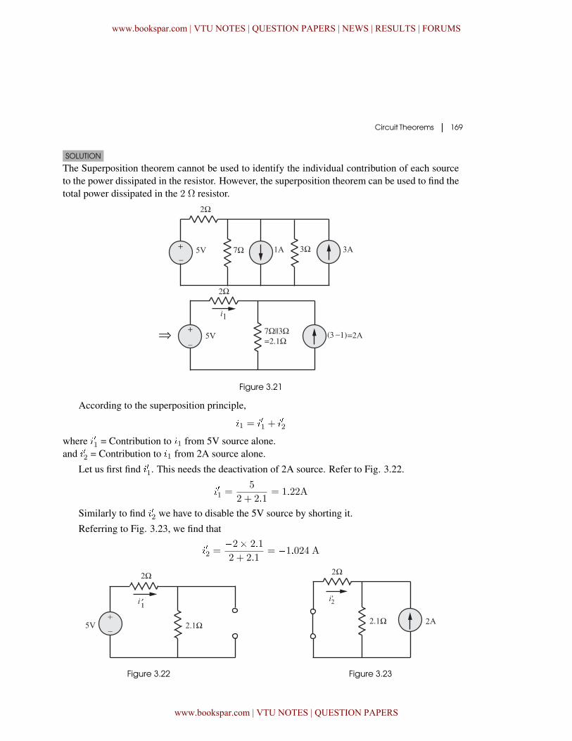
The Superposition theorem cannot be used to identify the individual contribution of each sourceto the power dissipated in the resistor. However, the superposition theorem can be used to find thetotal power dissipated in the 2 Ω resistor.
Figure 3.21
According to the superposition principle,
�1 = ��1 + ��2
where ��1 = Contribution to �1 from 5V source alone.and ��2 = Contribution to �1 from 2A source alone.
Let us first find ��1. This needs the deactivation of 2A source. Refer to Fig. 3.22.
��1 =5
2 + 2�1= 1�22A
Similarly to find ��2 we have to disable the 5V source by shorting it.
Referring to Fig. 3.23, we find that
��2 =�2� 2�1
2 + 2�1= �1�024 A
Figure 3.22 Figure 3.23
www.bookspar.com | VTU NOTES | QUESTION PAPERS | NEWS | RESULTS | FORUMS
www.bookspar.com | VTU NOTES | QUESTION PAPERS
170 � Network Theory
Total current,
�1 = ��1 + ��2
= 1�22� 1�024
= 0�196 A
Thus� �2Ω = (0�196)2 � 2
= 0�0768 Watts
= 76�8 mW
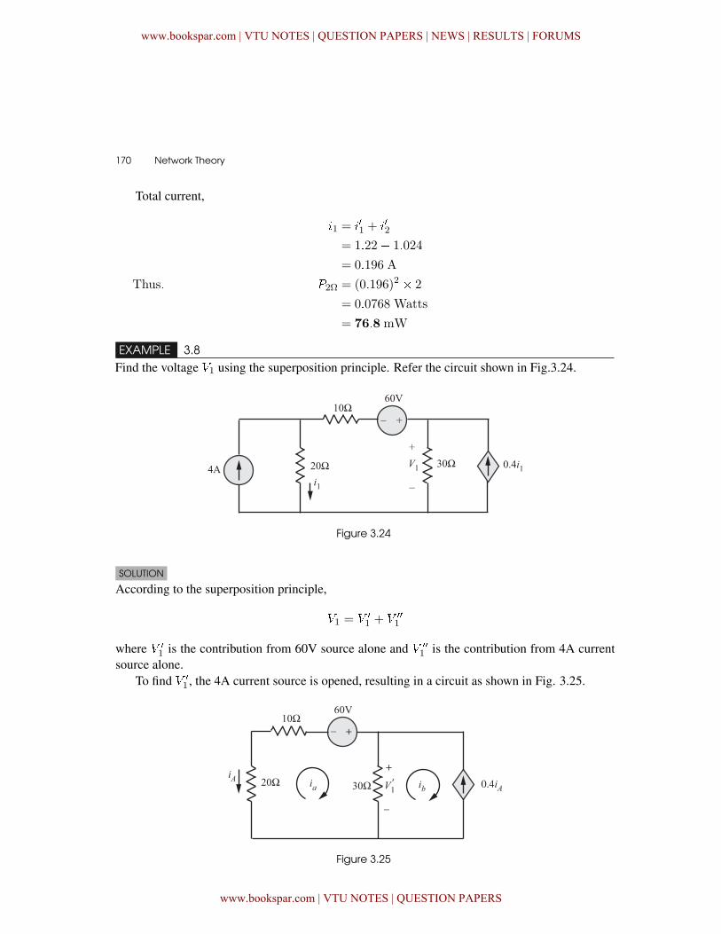
EXAMPLE 3.8Find the voltage �1 using the superposition principle. Refer the circuit shown in Fig.3.24.
Figure 3.24
SOLUTION
According to the superposition principle,
�1 = � �
1 + � ��
1
where � �
1 is the contribution from 60V source alone and � ��
1 is the contribution from 4A currentsource alone.
To find � �
1 , the 4A current source is opened, resulting in a circuit as shown in Fig. 3.25.
Figure 3.25
www.bookspar.com | VTU NOTES | QUESTION PAPERS | NEWS | RESULTS | FORUMS
www.bookspar.com | VTU NOTES | QUESTION PAPERS
Circuit Theorems � 171
Applying KVL to the left mesh:
30�� � 60 + 30 (�� � ��) = 0 (3.5)
Also �� = �0�4��= �0�4 (���) = 0�4�� (3.6)
Substituting equation (3.6) in equation (3.5), we get
30�� � 60 + 30�� � 30� 0�4�� = 0
� �� =60
48= 1�25A
�� = 0�4�� = 0�4� 1�25
= 0�5A
Hence� � �
1 = (�� � ��)� 30
= 22�5 V
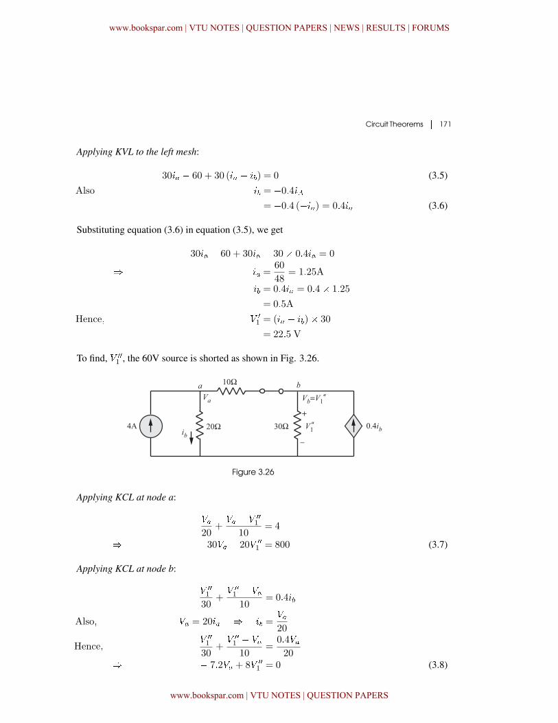
To find, � ��
1 , the 60V source is shorted as shown in Fig. 3.26.
Figure 3.26
Applying KCL at node a:
��20
+�� � � ��
1
10= 4
� 30�� � 20� ��
1 = 800 (3.7)
Applying KCL at node b:
� ��
1
30+� ��
1 � ��10
= 0�4��
Also� �� = 20�� � �� =��20
Hence�� ��
1
30+� ��
1 � ��10
=0�4��20
� � 7�2�� + 8� ��
1 = 0 (3.8)
www.bookspar.com | VTU NOTES | QUESTION PAPERS | NEWS | RESULTS | FORUMS
www.bookspar.com | VTU NOTES | QUESTION PAPERS
172 � Network Theory
Solving the equations (3.7) and (3.8), we find that
� ��
1 = 60V
Hence �1 = � �
1 + � ��
1
= 22�5 + 60 = 82�5V
EXAMPLE 3.9
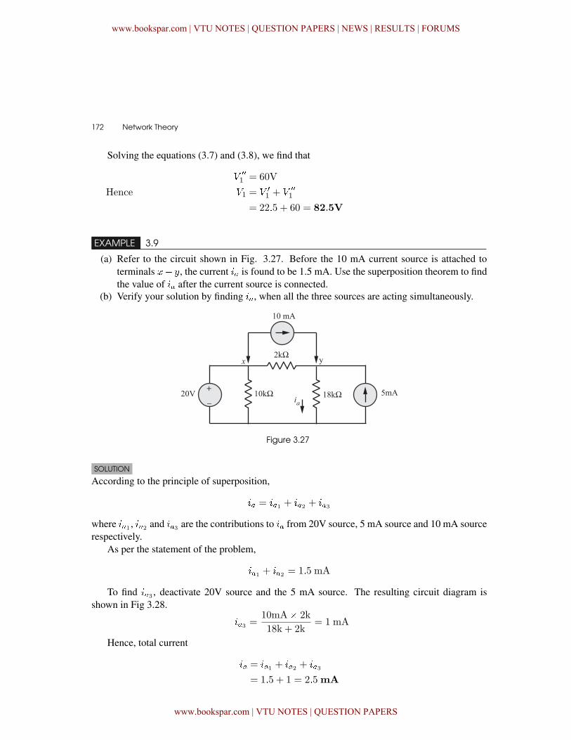
(a) Refer to the circuit shown in Fig. 3.27. Before the 10 mA current source is attached toterminals �� , the current �� is found to be 1.5 mA. Use the superposition theorem to findthe value of �� after the current source is connected.
(b) Verify your solution by finding ��, when all the three sources are acting simultaneously.
Figure 3.27
SOLUTION
According to the principle of superposition,
�� = ��1 + ��2 + ��3
where ��1 , ��2 and ��3 are the contributions to �� from 20V source, 5 mA source and 10 mA sourcerespectively.
As per the statement of the problem,
��1 + ��2 = 1�5 mA
To find ��3 , deactivate 20V source and the 5 mA source. The resulting circuit diagram isshown in Fig 3.28.
��3 =10mA� 2k
18k + 2k= 1 mA
Hence, total current
�� = ��1 + ��2 + ��3
= 1�5 + 1 = 2�5mA
www.bookspar.com | VTU NOTES | QUESTION PAPERS | NEWS | RESULTS | FORUMS
www.bookspar.com | VTU NOTES | QUESTION PAPERS
Circuit Theorems � 173
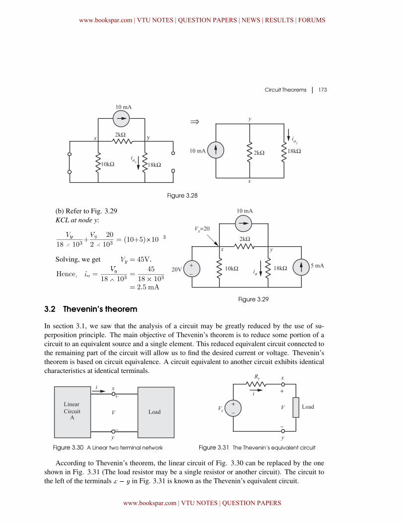
Figure 3.28
(b) Refer to Fig. 3.29KCL at node y:
��18� 103
+�� � 20
2� 103= (10+5)�10�3
Solving, we get �� = 45V�
Hence� �� =��
18� 103=
45
18� 103
= 2�5 mA
Figure 3.29
3.2 Thevenin’s theorem
In section 3.1, we saw that the analysis of a circuit may be greatly reduced by the use of su-perposition principle. The main objective of Thevenin’s theorem is to reduce some portion of acircuit to an equivalent source and a single element. This reduced equivalent circuit connected tothe remaining part of the circuit will allow us to find the desired current or voltage. Thevenin’stheorem is based on circuit equivalence. A circuit equivalent to another circuit exhibits identicalcharacteristics at identical terminals.
Figure 3.30 A Linear two terminal network Figure 3.31 The Thevenin’s equivalent circuit
According to Thevenin’s theorem, the linear circuit of Fig. 3.30 can be replaced by the oneshown in Fig. 3.31 (The load resistor may be a single resistor or another circuit). The circuit tothe left of the terminals �� in Fig. 3.31 is known as the Thevenin’s equivalent circuit.
www.bookspar.com | VTU NOTES | QUESTION PAPERS | NEWS | RESULTS | FORUMS
www.bookspar.com | VTU NOTES | QUESTION PAPERS
174 � Network Theory
The Thevenin’s theorem may be stated as follows:A linear two–terminal circuit can be replaced by an equivalent circuit consisting of a
voltage source V� in series with a resistor R�, Where V� is the open–circuit voltage at the termi-
nals and R� is the input or equivalent resistance at the terminals when the independent sources
are turned off or R� is the ratio of open–circuit voltage to the short–circuit current at the
terminal pair.
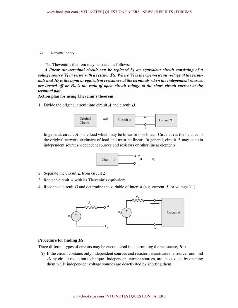
Action plan for using Thevenin’s theorem :
1. Divide the original circuit into circuit and circuit �.
In general, circuit � is the load which may be linear or non-linear. Circuit is the balance ofthe original network exclusive of load and must be linear. In general, circuit may containindependent sources, dependent sources and resistors or other linear elements.
2. Separate the circuit from circuit �.
3. Replace circuit with its Thevenin’s equivalent.
4. Reconnect circuit � and determine the variable of interest (e.g. current ‘�’ or voltage ‘�’).
Procedure for finding R�:Three different types of circuits may be encountered in determining the resistance, �� :
(i) If the circuit contains only independent sources and resistors, deactivate the sources and find�� by circuit reduction technique. Independent current sources, are deactivated by openingthem while independent voltage sources are deactivated by shorting them.
www.bookspar.com | VTU NOTES | QUESTION PAPERS | NEWS | RESULTS | FORUMS
www.bookspar.com | VTU NOTES | QUESTION PAPERS
Circuit Theorems � 175
(ii) If the circuit contains resistors, dependent and independent sources, follow the instructionsdescribed below:
(a) Determine the open circuit voltage �� with the sources activated.
(b) Find the short circuit current � when a short circuit is applied to the terminals ��
(c) �� =���
(iii) If the circuit contains resistors and only dependent sources, then
(a) �� = 0 (since there is no energy source)
(b) Connect 1A current source to terminals�� and determine ���.
(c) �� =���1
Figure 3.32
For all the cases discussed above, the Thevenin’s equivalent circuit is as shown in Fig. 3.32.
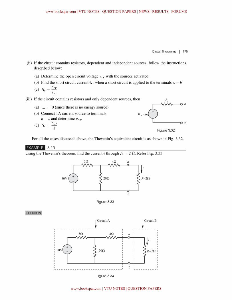
EXAMPLE 3.10Using the Thevenin’s theorem, find the current � through � = 2 Ω. Refer Fig. 3.33.
Figure 3.33
SOLUTION
Figure 3.34
www.bookspar.com | VTU NOTES | QUESTION PAPERS | NEWS | RESULTS | FORUMS
www.bookspar.com | VTU NOTES | QUESTION PAPERS
176 � Network Theory
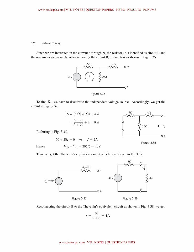
Since we are interested in the current � through �, the resistor � is identified as circuit B andthe remainder as circuit A. After removing the circuit B, circuit A is as shown in Fig. 3.35.
Figure 3.35
To find ��, we have to deactivate the independent voltage source. Accordingly, we get thecircuit in Fig. 3.36.
�� = (5 Ω��20 Ω) + 4 Ω
=5� 20
5 + 20+ 4 = 8 Ω
��
Figure 3.36
Referring to Fig. 3.35,
�50 + 25� = 0 � � = 2A
Hence ��� = �� = 20(�) = 40V
Thus, we get the Thevenin’s equivalent circuit which is as shown in Fig.3.37.
Figure 3.37 Figure 3.38
Reconnecting the circuit B to the Thevenin’s equivalent circuit as shown in Fig. 3.38, we get
� =40
2 + 8= 4A
www.bookspar.com | VTU NOTES | QUESTION PAPERS | NEWS | RESULTS | FORUMS
www.bookspar.com | VTU NOTES | QUESTION PAPERS
Circuit Theorems � 177
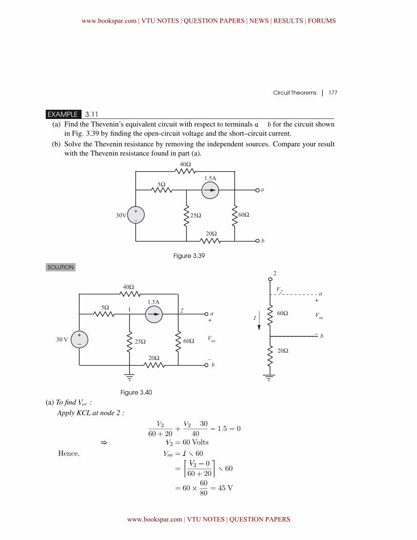
EXAMPLE 3.11(a) Find the Thevenin’s equivalent circuit with respect to terminals �� for the circuit shown
in Fig. 3.39 by finding the open-circuit voltage and the short–circuit current.(b) Solve the Thevenin resistance by removing the independent sources. Compare your result
with the Thevenin resistance found in part (a).
Figure 3.39
SOLUTION
Figure 3.40
(a) To find �� :Apply KCL at node 2 :
�260 + 20
+�2 � 30
40� 1�5 = 0
� �2 = 60 Volts
Hence� �� = � � 60
=
��2 � 0
60 + 20
�� 60
= 60� 60
80= 45 V
www.bookspar.com | VTU NOTES | QUESTION PAPERS | NEWS | RESULTS | FORUMS
www.bookspar.com | VTU NOTES | QUESTION PAPERS
178 � Network Theory
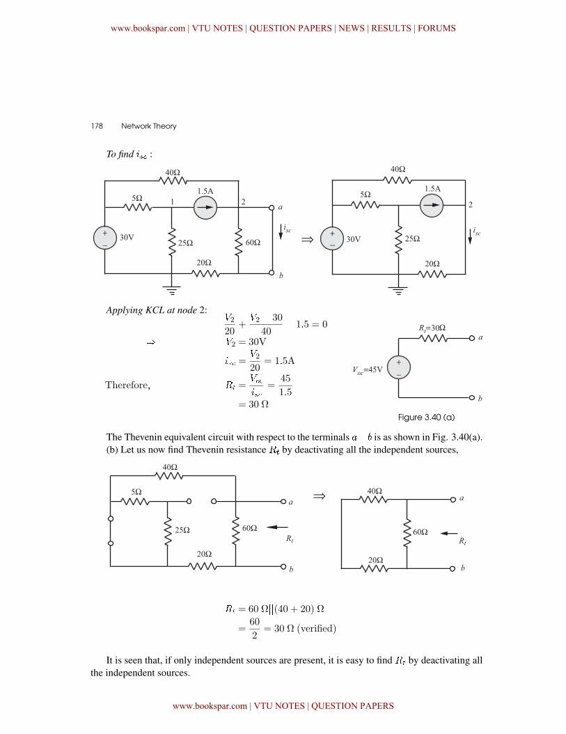
To find � :
�
Applying KCL at node 2:�220
+�2 � 30
40� 1�5 = 0
� �2 = 30V
� =�220
= 1�5A
Therefore� �� =���
=45
1�5= 30 Ω
Figure 3.40 (a)
The Thevenin equivalent circuit with respect to the terminals �� is as shown in Fig. 3.40(a).(b) Let us now find Thevenin resistance �� by deactivating all the independent sources,
�� ��
�� = 60 Ω��(40 + 20) Ω
=60
2= 30 Ω (verified)
It is seen that, if only independent sources are present, it is easy to find �� by deactivating allthe independent sources.
www.bookspar.com | VTU NOTES | QUESTION PAPERS | NEWS | RESULTS | FORUMS
www.bookspar.com | VTU NOTES | QUESTION PAPERS
Circuit Theorems � 179
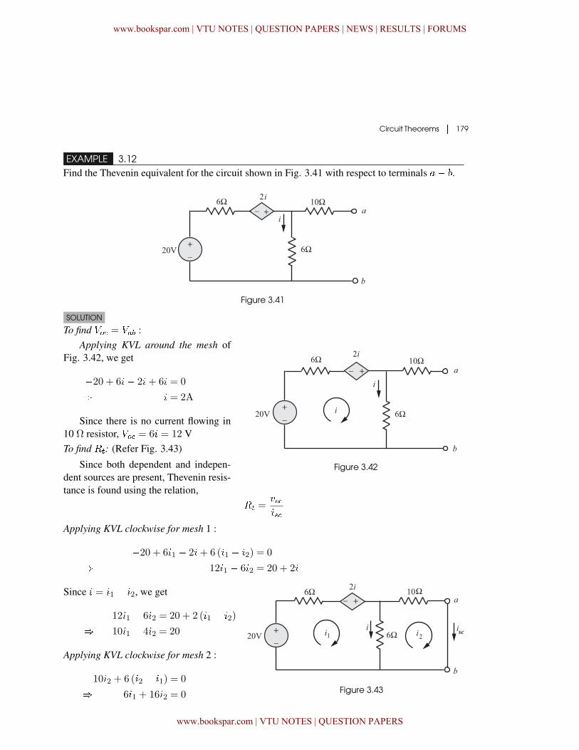
EXAMPLE 3.12Find the Thevenin equivalent for the circuit shown in Fig. 3.41 with respect to terminals �� .
Figure 3.41
SOLUTION
To find �� = ��� :
Figure 3.42
Applying KVL around the mesh ofFig. 3.42, we get
�20 + 6�� 2�+ 6� = 0
� � = 2A
Since there is no current flowing in10 ٠resistor, �� = 6� = 12 VTo find ��: (Refer Fig. 3.43)
Since both dependent and indepen-dent sources are present, Thevenin resis-tance is found using the relation,
�� =���
Applying KVL clockwise for mesh 1 :
�20 + 6�1 � 2�+ 6 (�1 � �2) = 0
� 12�1 � 6�2 = 20 + 2�
Since � = �1 � �2, we get
12�1 � 6�2 = 20 + 2 (�1 � �2)
� 10�1 � 4�2 = 20
Applying KVL clockwise for mesh 2 :
10�2 + 6 (�2 � �1) = 0
� � 6�1 + 16�2 = 0 Figure 3.43
www.bookspar.com | VTU NOTES | QUESTION PAPERS | NEWS | RESULTS | FORUMS
www.bookspar.com | VTU NOTES | QUESTION PAPERS
180 � Network Theory
Solving the above two mesh equations, we get
�2 =120
136A � � = �2 =
120
136A
�� =���
=12120
136
= 13�6 Ω
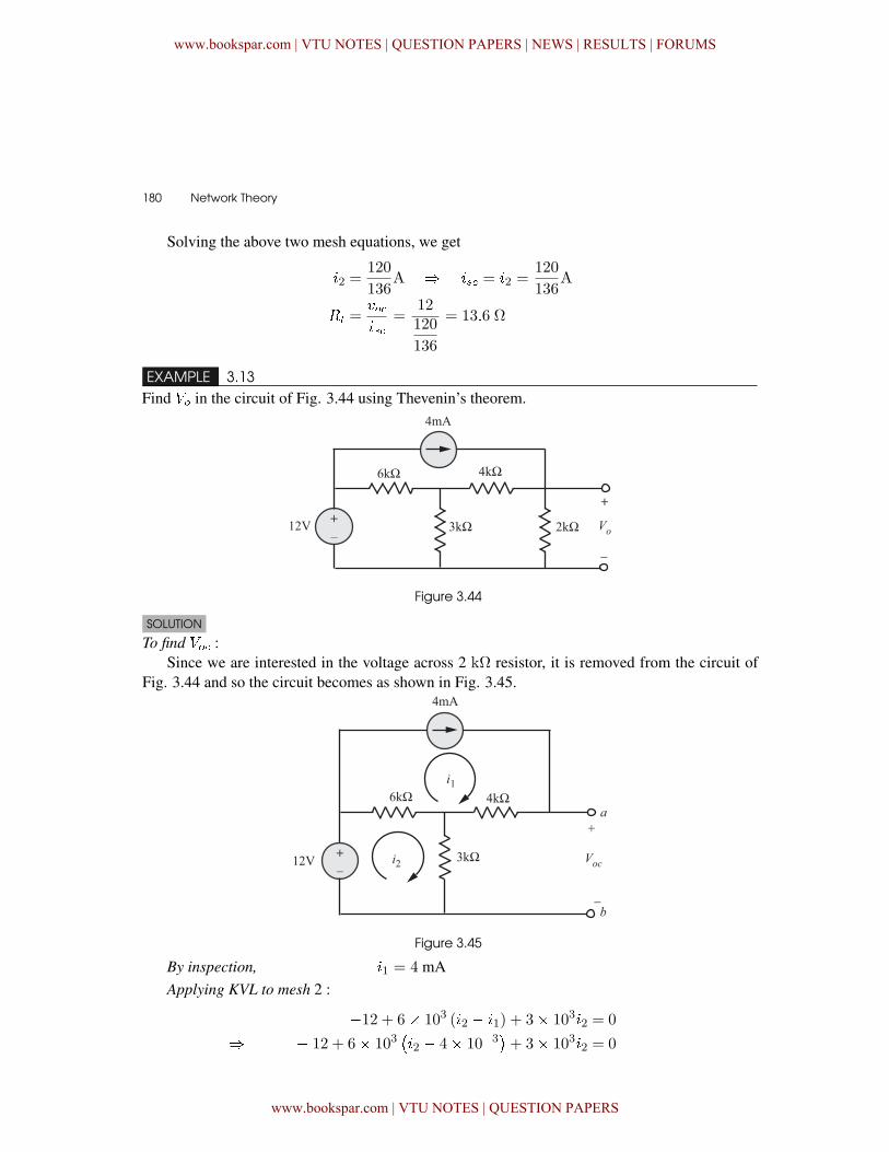
EXAMPLE 3.13Find �� in the circuit of Fig. 3.44 using Thevenin’s theorem.
Figure 3.44
SOLUTION
To find �� :Since we are interested in the voltage across 2 k٠resistor, it is removed from the circuit of
Fig. 3.44 and so the circuit becomes as shown in Fig. 3.45.
Figure 3.45
By inspection, �1 = 4 mAApplying KVL to mesh 2 :
�12 + 6� 103 (�2 � �1) + 3� 103�2 = 0
� � 12 + 6� 103��2 � 4� 10�3
�+ 3� 103�2 = 0
www.bookspar.com | VTU NOTES | QUESTION PAPERS | NEWS | RESULTS | FORUMS
www.bookspar.com | VTU NOTES | QUESTION PAPERS
Circuit Theorems � 181
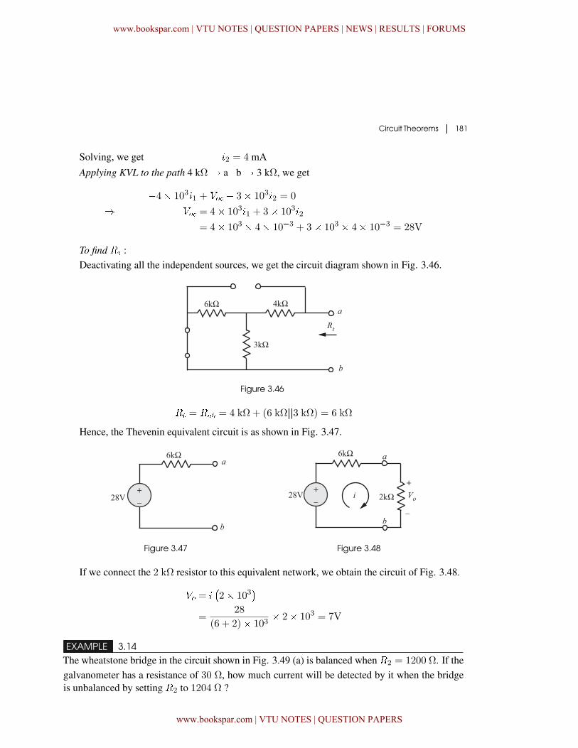
Solving, we get �2 = 4 mA
Applying KVL to the path 4 kΩ� a�b � 3 kΩ, we get
�4� 103�1 + �� � 3� 103�2 = 0
� �� = 4� 103�1 + 3� 103�2
= 4� 103 � 4� 10�3 + 3� 103 � 4� 10�3 = 28V
To find �� :Deactivating all the independent sources, we get the circuit diagram shown in Fig. 3.46.
Figure 3.46
�� = ��� = 4 kΩ + (6 kΩ��3 kΩ) = 6 kΩ
Hence, the Thevenin equivalent circuit is as shown in Fig. 3.47.
Figure 3.47 Figure 3.48
If we connect the 2 kΩ resistor to this equivalent network, we obtain the circuit of Fig. 3.48.
�� = ��2� 103
�=
28
(6 + 2)� 103� 2� 103 = 7V
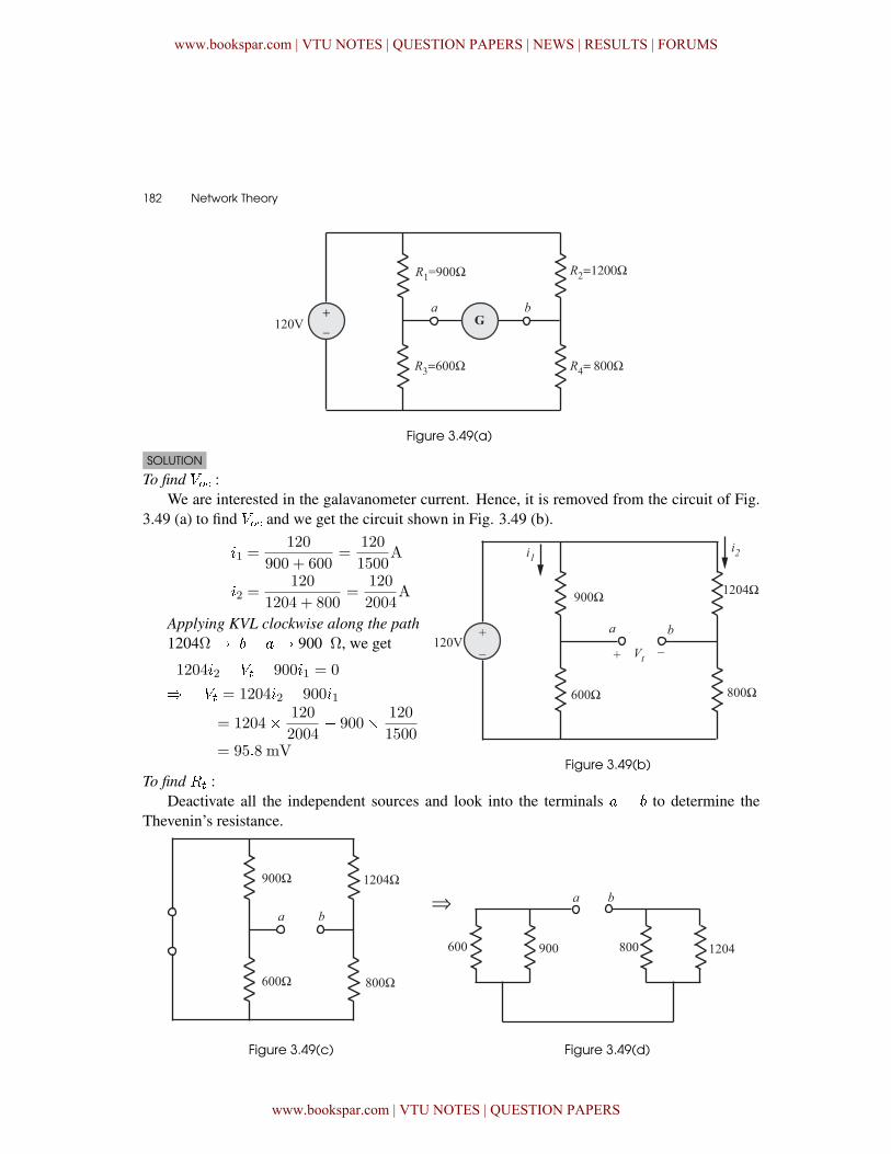
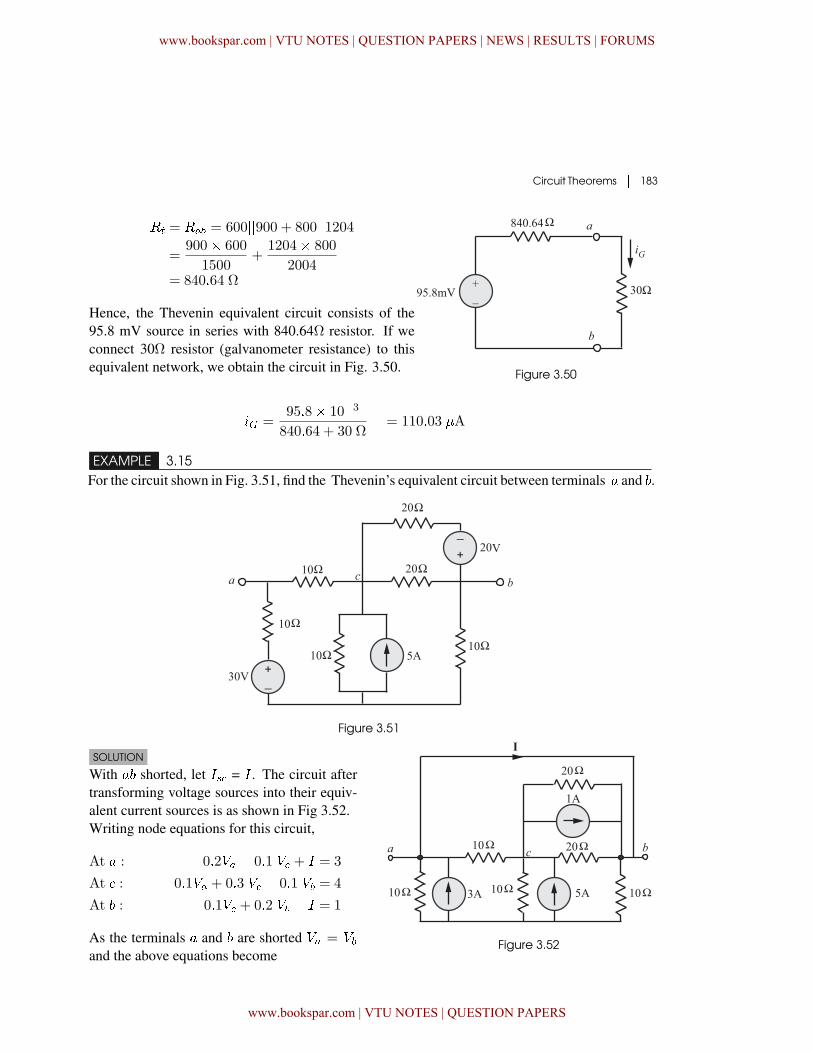
EXAMPLE 3.14The wheatstone bridge in the circuit shown in Fig. 3.49 (a) is balanced when �2 = 1200 Ω. If thegalvanometer has a resistance of 30 Ω, how much current will be detected by it when the bridgeis unbalanced by setting �2 to 1204 Ω ?
www.bookspar.com | VTU NOTES | QUESTION PAPERS | NEWS | RESULTS | FORUMS
www.bookspar.com | VTU NOTES | QUESTION PAPERS
182 � Network Theory
Figure 3.49(a)
SOLUTION
To find �� :We are interested in the galavanometer current. Hence, it is removed from the circuit of Fig.
3.49 (a) to find �� and we get the circuit shown in Fig. 3.49 (b).
�1 =120
900 + 600=
120
1500A
�2 =120
1204 + 800=
120
2004A
Applying KVL clockwise along the path1204Ω� � �� 900 Ω, we get
1204�2 � �� � 900�1 = 0
� �� = 1204�2 � 900�1
= 1204� 120
2004� 900� 120
1500= 95�8 mV
Figure 3.49(b)To find �� :
Deactivate all the independent sources and look into the terminals � � to determine theThevenin’s resistance.
Figure 3.49(c) Figure 3.49(d)
www.bookspar.com | VTU NOTES | QUESTION PAPERS | NEWS | RESULTS | FORUMS
www.bookspar.com | VTU NOTES | QUESTION PAPERS
Circuit Theorems � 183
�� = ��� = 600��900 + 800��1204=
900� 600
1500+
1204� 800
2004= 840�64 Ω
Hence, the Thevenin equivalent circuit consists of the95.8 mV source in series with 840.64Ω resistor. If weconnect 30Ω resistor (galvanometer resistance) to thisequivalent network, we obtain the circuit in Fig. 3.50. Figure 3.50
�� =95�8� 10�3
840�64 + 30 Ω= 110�03 �A
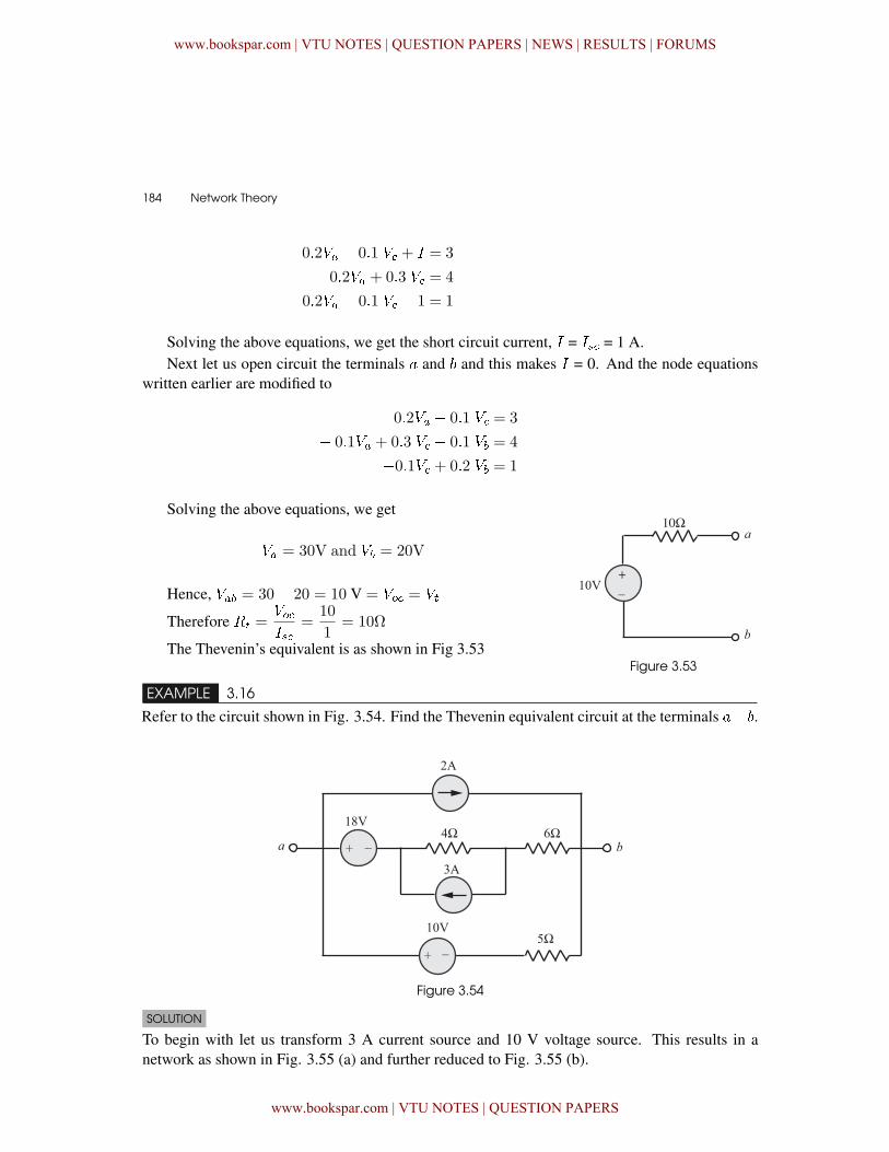
EXAMPLE 3.15For the circuit shown in Fig. 3.51, find the Thevenin’s equivalent circuit between terminals � and .
Figure 3.51
SOLUTION
With � shorted, let � = � . The circuit aftertransforming voltage sources into their equiv-alent current sources is as shown in Fig 3.52.Writing node equations for this circuit,
At � : 0�2�� � 0�1 � + � = 3
At � : � 0�1�� + 0�3 � � 0�1 �� = 4
At : � 0�1� + 0�2 �� � � = 1
As the terminals � and are shorted �� = ��and the above equations become
Figure 3.52
www.bookspar.com | VTU NOTES | QUESTION PAPERS | NEWS | RESULTS | FORUMS
www.bookspar.com | VTU NOTES | QUESTION PAPERS
184 � Network Theory
0�2�� � 0�1 � + � = 3
�0�2�� + 0�3 � = 4
0�2�� � 0�1 � � 1 = 1
Solving the above equations, we get the short circuit current, � = � = 1 A.Next let us open circuit the terminals � and and this makes � = 0. And the node equations
written earlier are modified to
0�2�� � 0�1 � = 3
� 0�1�� + 0�3 � � 0�1 �� = 4
�0�1� + 0�2 �� = 1
Figure 3.53
Solving the above equations, we get
�� = 30V and �� = 20V
Hence, ��� = 30� 20 = 10 V = �� = ��
Therefore �� =���
=10
1= 10Ω
The Thevenin’s equivalent is as shown in Fig 3.53
EXAMPLE 3.16
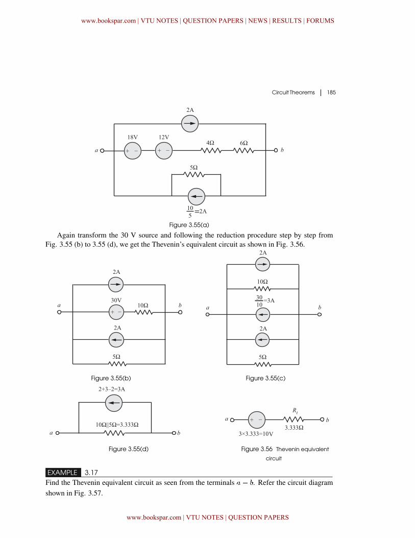
Refer to the circuit shown in Fig. 3.54. Find the Thevenin equivalent circuit at the terminals �� .
Figure 3.54
SOLUTION
To begin with let us transform 3 A current source and 10 V voltage source. This results in anetwork as shown in Fig. 3.55 (a) and further reduced to Fig. 3.55 (b).
www.bookspar.com | VTU NOTES | QUESTION PAPERS | NEWS | RESULTS | FORUMS
www.bookspar.com | VTU NOTES | QUESTION PAPERS
Circuit Theorems � 185
Figure 3.55(a)
Again transform the 30 V source and following the reduction procedure step by step fromFig. 3.55 (b) to 3.55 (d), we get the Thevenin’s equivalent circuit as shown in Fig. 3.56.
Figure 3.55(b) Figure 3.55(c)
Figure 3.55(d) Figure 3.56 Thevenin equivalent
circuit
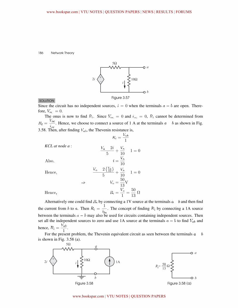
EXAMPLE 3.17Find the Thevenin equivalent circuit as seen from the terminals � � . Refer the circuit diagramshown in Fig. 3.57.
www.bookspar.com | VTU NOTES | QUESTION PAPERS | NEWS | RESULTS | FORUMS
www.bookspar.com | VTU NOTES | QUESTION PAPERS
186 � Network Theory
Figure 3.57SOLUTION
Since the circuit has no independent sources, � = 0 when the terminals � � are open. There-fore, �� = 0.
The onus is now to find ��. Since �� = 0 and � = 0, �� cannot be determined from
�� =���
. Hence, we choose to connect a source of 1 A at the terminals � � as shown in Fig.
3.58. Then, after finding ���, the Thevenin resistance is,
�� =���1
KCL at node a : �� � 2�
5+��10� 1 = 0
Also� � =��10
Hence��� � 2
��a10
�5
+��10� 1 = 0
� �� =50
13V
Hence� �� =��1
=50
13Ω
Alternatively one could find �� by connecting a 1V source at the terminals �� and then find
the current from to �. Then �� =1
���. The concept of finding �� by connecting a 1A source
between the terminals � � may also be used for circuits containing independent sources. Thenset all the independent sources to zero and use 1A source at the terminals � � to find ��� and
hence, �� =���1
.
For the present problem, the Thevenin equivalent circuit as seen between the terminals � �
is shown in Fig. 3.58 (a).
Figure 3.58 Figure 3.58 (a)
www.bookspar.com | VTU NOTES | QUESTION PAPERS | NEWS | RESULTS | FORUMS
www.bookspar.com | VTU NOTES | QUESTION PAPERS
Circuit Theorems � 187
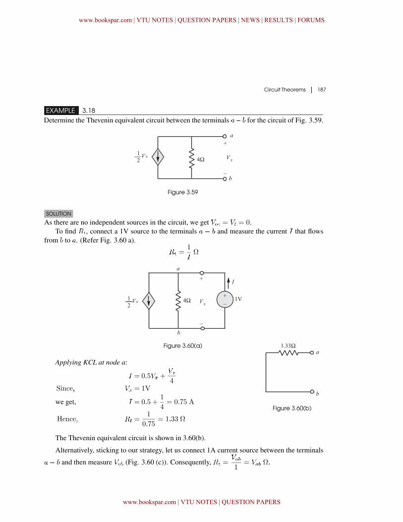
EXAMPLE 3.18Determine the Thevenin equivalent circuit between the terminals �� for the circuit of Fig. 3.59.
Figure 3.59
SOLUTION
As there are no independent sources in the circuit, we get �� = �� = 0�To find ��, connect a 1V source to the terminals � � and measure the current � that flows
from to �. (Refer Fig. 3.60 a).
�� =1
�Ω
Figure 3.60(a)
Applying KCL at node a:
� = 0�5�� +��4
Since� �� = 1V
we get, � = 0�5 +1
4= 0�75 A
Hence� �� =1
0�75= 1�33 Ω
Figure 3.60(b)
The Thevenin equivalent circuit is shown in 3.60(b).
Alternatively, sticking to our strategy, let us connect 1A current source between the terminals
�� and then measure ��� (Fig. 3.60 (c)). Consequently, �� =���1
= ��� �
www.bookspar.com | VTU NOTES | QUESTION PAPERS | NEWS | RESULTS | FORUMS
www.bookspar.com | VTU NOTES | QUESTION PAPERS
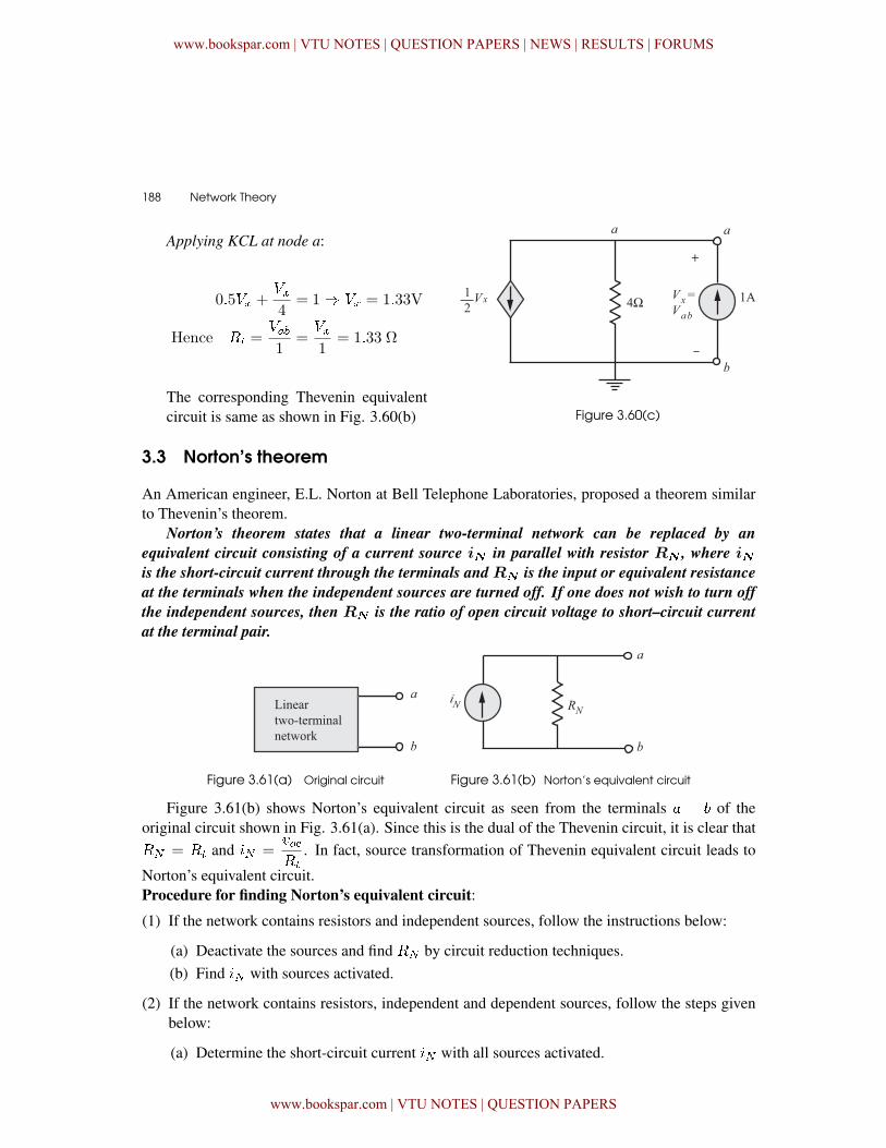
188 � Network Theory
Applying KCL at node a:
0�5�� +��4
= 1� �� = 1�33V
Hence �� =���1
=��1
= 1�33 Ω
The corresponding Thevenin equivalentcircuit is same as shown in Fig. 3.60(b) Figure 3.60(c)
3.3 Norton’s theorem
An American engineer, E.L. Norton at Bell Telephone Laboratories, proposed a theorem similarto Thevenin’s theorem.
Norton’s theorem states that a linear two-terminal network can be replaced by an
equivalent circuit consisting of a current source i� in parallel with resistor R� , where i�is the short-circuit current through the terminals and R� is the input or equivalent resistance
at the terminals when the independent sources are turned off. If one does not wish to turn off
the independent sources, then R� is the ratio of open circuit voltage to short–circuit current
at the terminal pair.
Figure 3.61(a) Original circuit Figure 3.61(b) Norton’s equivalent circuit
Figure 3.61(b) shows Norton’s equivalent circuit as seen from the terminals � � of theoriginal circuit shown in Fig. 3.61(a). Since this is the dual of the Thevenin circuit, it is clear that� = �� and � =
����
. In fact, source transformation of Thevenin equivalent circuit leads to
Norton’s equivalent circuit.Procedure for finding Norton’s equivalent circuit:
(1) If the network contains resistors and independent sources, follow the instructions below:
(a) Deactivate the sources and find � by circuit reduction techniques.(b) Find � with sources activated.
(2) If the network contains resistors, independent and dependent sources, follow the steps givenbelow:
(a) Determine the short-circuit current � with all sources activated.
www.bookspar.com | VTU NOTES | QUESTION PAPERS | NEWS | RESULTS | FORUMS
www.bookspar.com | VTU NOTES | QUESTION PAPERS
Circuit Theorems � 189
(b) Find the open-circuit voltage ��.
(c) �� = � =���
(3) If the network contains only resistors and dependent sources, follow the proceduredescribed below:
(a) Note that � = 0.
(b) Connect 1A current source to the terminals �� and find ���.
(c) �� =���1
Note: Also, since �� = �� and � = �
�� =���
= �
The open–circuit and short–circuit test are sufficient to find any Thevenin or Norton equiva-lent.
3.3.1 PROOF OF THEVENIN’S AND NORTON’S THEOREMS
The principle of superposition is employed to provide the proof of Thevenin’s and Norton’stheorems.
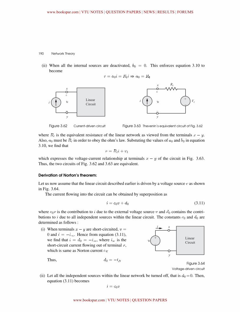
Derivation of Thevenin’s theorem:
Let us consider a linear circuit having two accessible terminals � � and excited by an externalcurrent source �. The linear circuit is made up of resistors, dependent and independent sources. Forthe sake of simplified analysis, let us assume that the linear circuit contains only two independentvoltage sources �1 and �2 and two independent current sources �1 and �2. The terminal voltage �may be obtained, by applying the principle of superposition. That is, � is made up of contributionsdue to the external source and independent sources within the linear network.
Hence� � = �0�+ �1�1 + �2�2 + �3�1 + �4�2 (3.9)
= �0�+ 0 (3.10)
where 0 = �1�1 + �2�2 + �3�1 + �4�2
= contribution to the terminal voltage � by
independent sources within the linear network.
Let us now evaluate the values of constants �0 and 0.
(i) When the terminals � and are open–circuited, � = 0 and � = �� = ��. Making use ofthis fact in equation 3.10, we find that 0 = ��.
www.bookspar.com | VTU NOTES | QUESTION PAPERS | NEWS | RESULTS | FORUMS
www.bookspar.com | VTU NOTES | QUESTION PAPERS
190 � Network Theory
(ii) When all the internal sources are deactivated, 0 = 0. This enforces equation 3.10 tobecome
� = �0� = ���� �0 = ��
��
��
Figure 3.62 Current-driven circuit Figure 3.63 Thevenin’s equivalent circuit of Fig. 3.62
where �� is the equivalent resistance of the linear network as viewed from the terminals � � .Also, �0 must be �� in order to obey the ohm’s law. Substuting the values of �0 and 0 in equation3.10, we find that
� = ���+ �1
which expresses the voltage-current relationship at terminals � � of the circuit in Fig. 3.63.Thus, the two circuits of Fig. 3.62 and 3.63 are equivalent.
Derivation of Norton’s theorem:
Let us now assume that the linear circuit described earlier is driven by a voltage source � as shownin Fig. 3.64.
The current flowing into the circuit can be obtained by superposition as
� = �0� + �0 (3.11)
where �0� is the contribution to � due to the external voltage source � and �0 contains the contri-butions to � due to all independent sources within the linear circuit. The constants �0 and �0 aredetermined as follows :
(i) When terminals �� are short-circuited, � =0 and � = ��. Hence from equation (3.11),we find that � = �0 = ��, where � is theshort-circuit current flowing out of terminal �,which is same as Norton current �
Thus, �0 = �� Figure 3.64
Voltage-driven circuit
(ii) Let all the independent sources within the linear network be turned off, that is �0=0. Then,equation (3.11) becomes
� = �0�
www.bookspar.com | VTU NOTES | QUESTION PAPERS | NEWS | RESULTS | FORUMS
www.bookspar.com | VTU NOTES | QUESTION PAPERS
Circuit Theorems � 191
For dimensional validity, �0 must have thedimension of conductance. This enforces �0 =1
��
where �� is the equivalent resistance of the
linear network as seen from the terminals � � .Thus, equation (3.11) becomes
� =1
��
� � �
=1
��
� � �
Figure 3.65 Norton’s equivalent of
voltage driven circuit
This expresses the voltage-current relationship at the terminals � � of the circuit in Fig.(3.65), validating that the two circuits of Figs. 3.64 and 3.65 are equivalents.
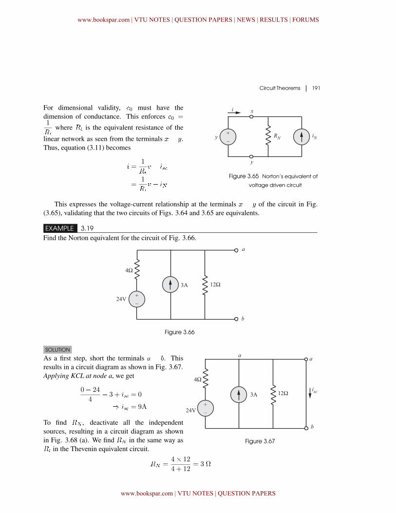
EXAMPLE 3.19Find the Norton equivalent for the circuit of Fig. 3.66.
Figure 3.66
SOLUTION
As a first step, short the terminals � � . Thisresults in a circuit diagram as shown in Fig. 3.67.Applying KCL at node a, we get
0� 24
4� 3 + � = 0
� � = 9A
To find � , deactivate all the independentsources, resulting in a circuit diagram as shownin Fig. 3.68 (a). We find � in the same way as�� in the Thevenin equivalent circuit.
Figure 3.67
� =4� 12
4 + 12= 3 Ω
www.bookspar.com | VTU NOTES | QUESTION PAPERS | NEWS | RESULTS | FORUMS
www.bookspar.com | VTU NOTES | QUESTION PAPERS
192 � Network Theory
Figure 3.68(a) Figure 3.68(b)
Thus, we obtain Nortion equivalent circuit as shown in Fig. 3.68(b).
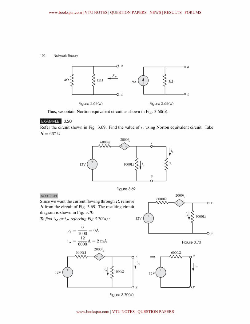
EXAMPLE 3.20Refer the circuit shown in Fig. 3.69. Find the value of �� using Norton equivalent circuit. Take� = 667 Ω.
Figure 3.69
SOLUTION
Since we want the current flowing through�, remove� from the circuit of Fig. 3.69. The resulting circuitdiagram is shown in Fig. 3.70.To find �� or � referring Fig 3.70(a) :
�� =0
1000= 0A
� =12
6000A = 2 mA Figure 3.70
Figure 3.70(a)
www.bookspar.com | VTU NOTES | QUESTION PAPERS | NEWS | RESULTS | FORUMS
www.bookspar.com | VTU NOTES | QUESTION PAPERS
Circuit Theorems � 193
To find � :The procedure for finding � is same that of ��
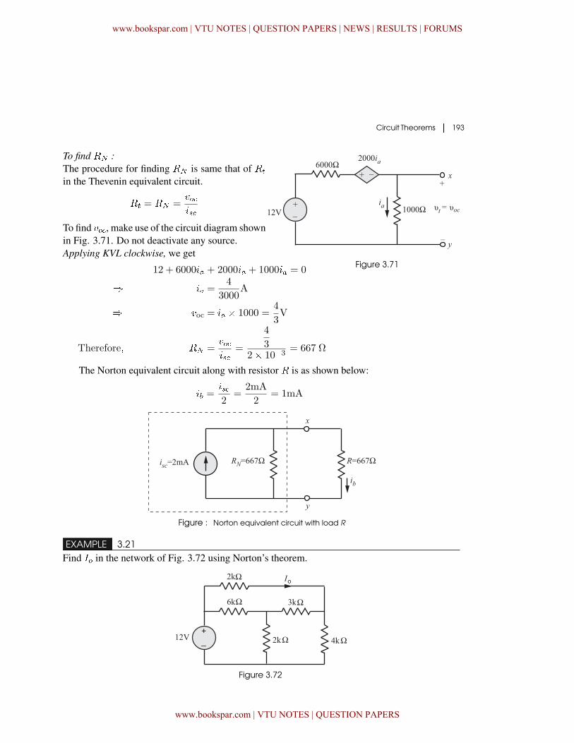
in the Thevenin equivalent circuit.
�� = � =���
To find ��, make use of the circuit diagram shownin Fig. 3.71. Do not deactivate any source.Applying KVL clockwise, we get
Figure 3.71�12 + 6000�� + 2000�� + 1000�� = 0
� �� =4
3000A
� �oc = �� � 1000 =4
3V
Therefore� � =���
=
4
32� 10�3
= 667 Ω
The Norton equivalent circuit along with resistor � is as shown below:
�� =�2
=2mA
2= 1mA
Figure : Norton equivalent circuit with load R
EXAMPLE 3.21Find �� in the network of Fig. 3.72 using Norton’s theorem.
Figure 3.72
www.bookspar.com | VTU NOTES | QUESTION PAPERS | NEWS | RESULTS | FORUMS
www.bookspar.com | VTU NOTES | QUESTION PAPERS
194 � Network Theory
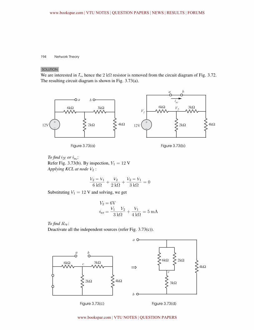
SOLUTION
We are interested in ��, hence the 2 k٠resistor is removed from the circuit diagram of Fig. 3.72.The resulting circuit diagram is shown in Fig. 3.73(a).
Figure 3.73(a) Figure 3.73(b)
To find � or �:Refer Fig. 3.73(b). By inspection, �1 = 12 VApplying KCL at node �2 :
�2 � �16 kΩ
+�22 kΩ
+�2 � �13 kΩ
= 0
Substituting �1 = 12 V and solving, we get
�2 = 6V
� =�1 � �23 kΩ
+�14 kΩ
= 5 mA
To find � :Deactivate all the independent sources (refer Fig. 3.73(c)).
Figure 3.73(c) Figure 3.73(d)
www.bookspar.com | VTU NOTES | QUESTION PAPERS | NEWS | RESULTS | FORUMS
www.bookspar.com | VTU NOTES | QUESTION PAPERS
Circuit Theorems � 195
Referring to Fig. 3.73 (d), we get
� = ��� = 4 kΩ�� [3 kΩ + (6 kΩ��2 kΩ)] = 2�12 kΩ
Hence, the Norton equivalent circuitalong with 2 kΩ resistor is as shown inFig. 3.73(e).
�� =� ��
�+�
= 2�57mAFigure 3.73(e)
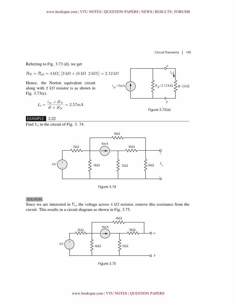
EXAMPLE 3.22Find �� in the circuit of Fig. 3. 74.
Figure 3.74
SOLUTION
Since we are interested in ��, the voltage across 4 k٠resistor, remove this resistance from thecircuit. This results in a circuit diagram as shown in Fig. 3.75.
Figure 3.75
www.bookspar.com | VTU NOTES | QUESTION PAPERS | NEWS | RESULTS | FORUMS
www.bookspar.com | VTU NOTES | QUESTION PAPERS
196 � Network Theory
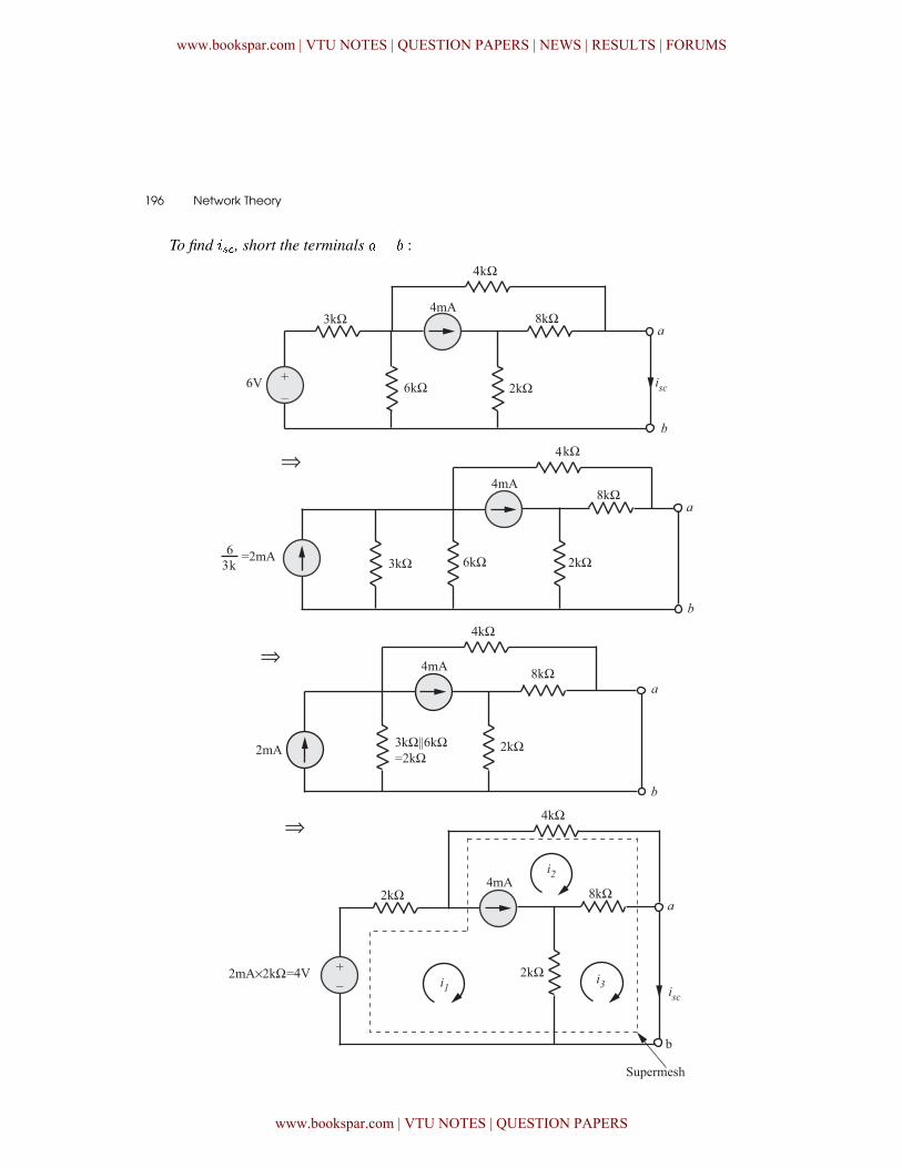
To find �, short the terminals �� :
www.bookspar.com | VTU NOTES | QUESTION PAPERS | NEWS | RESULTS | FORUMS
www.bookspar.com | VTU NOTES | QUESTION PAPERS
Circuit Theorems � 197
Constraint equation :�1 � �2 = 4mA (3.12)
KVL around supermesh :
� 4 + 2� 103�1 + 4� 103�2 = 0 (3.13)
KVL around mesh 3 :
8� 103(�3 � �2) + 2� 103(�3 � �1) = 0
Since �3 = �, the above equation becomes,
8� 103(� � �2) + 2� 103(� � �1) = 0 (3.14)
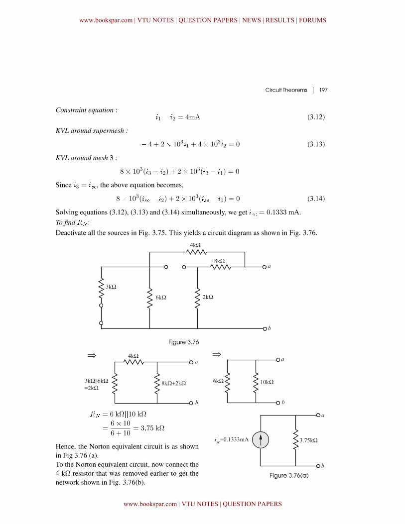
Solving equations (3.12), (3.13) and (3.14) simultaneously, we get � = 0�1333 mA.To find � :Deactivate all the sources in Fig. 3.75. This yields a circuit diagram as shown in Fig. 3.76.
Figure 3.76
� = 6 kΩ��10 kΩ=
6� 10
6 + 10= 3�75 kΩ
Hence, the Norton equivalent circuit is as shownin Fig 3.76 (a).To the Norton equivalent circuit, now connect the4 kΩ resistor that was removed earlier to get thenetwork shown in Fig. 3.76(b).
Figure 3.76(a)
www.bookspar.com | VTU NOTES | QUESTION PAPERS | NEWS | RESULTS | FORUMS
www.bookspar.com | VTU NOTES | QUESTION PAPERS
198 � Network Theory
�� = � (� ���)
= �� �
� +�
= 258 mV
Figure 3.76(b) Norton equivalent circuit with R = 4 kΩ
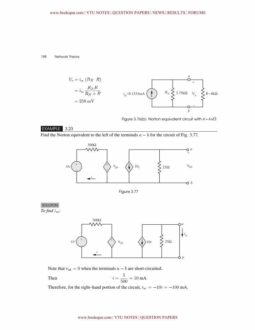
EXAMPLE 3.23Find the Norton equivalent to the left of the terminals �� for the circuit of Fig. 3.77.
Figure 3.77
SOLUTION
To find �:
Note that ��� = 0 when the terminals �� are short-circuited.
Then � =5
500= 10 mA
Therefore, for the right–hand portion of the circuit, � = �10� = �100 mA.
www.bookspar.com | VTU NOTES | QUESTION PAPERS | NEWS | RESULTS | FORUMS
www.bookspar.com | VTU NOTES | QUESTION PAPERS

Circuit Theorems � 199
To find � or �� :
Writing the KVL equations for the left-hand mesh, we get
�5 + 500�+ ��� = 0 (3.15)
Also for the right-hand mesh, we get
��� = �25(10�) = �250�Therefore � =
����250
Substituting � into the mesh equation (3.15), we get
�5 + 500
�����250
�+ ��� = 0
� ��� = �5 V� = �� � ��
�=����
=�5�0�1 = 50 Ω
The Norton equivalent circuit is shown inFig 3.77 (a).
Figure 3.77 (a)
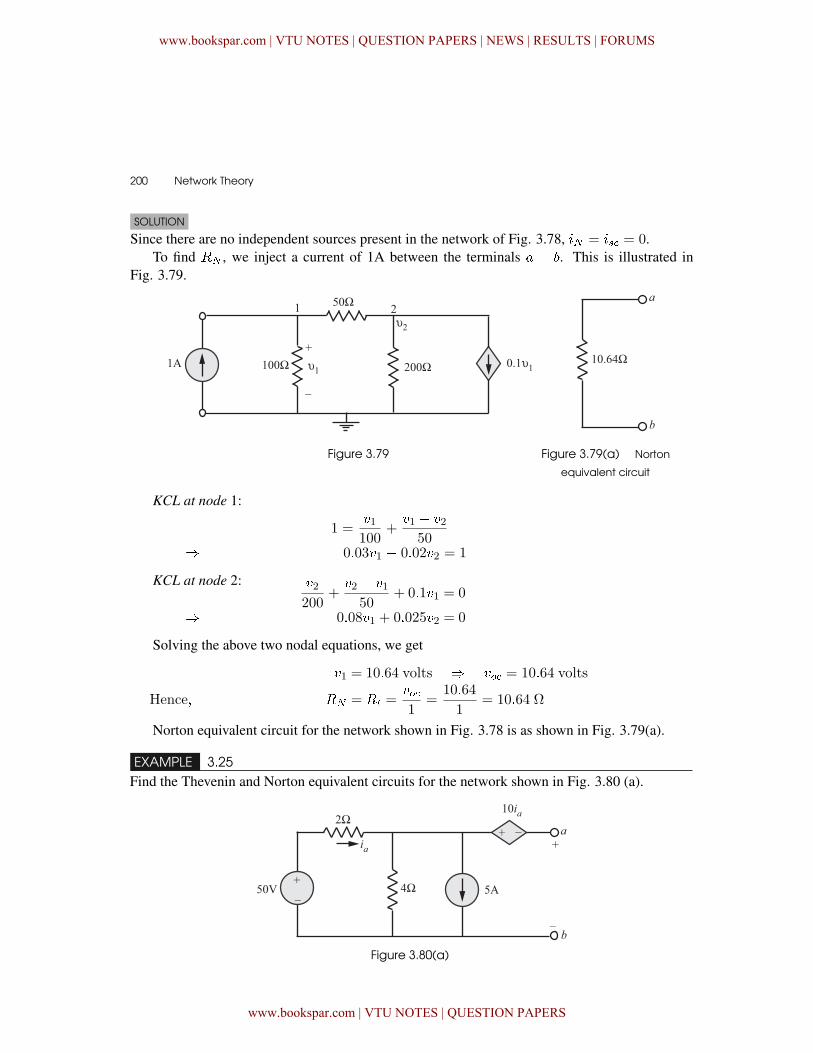
EXAMPLE 3.24Find the Norton equivalent of the network shown in Fig. 3.78.
Figure 3.78
www.bookspar.com | VTU NOTES | QUESTION PAPERS | NEWS | RESULTS | FORUMS
www.bookspar.com | VTU NOTES | QUESTION PAPERS
200 � Network Theory
SOLUTION
Since there are no independent sources present in the network of Fig. 3.78, � = � = 0.To find � , we inject a current of 1A between the terminals � � . This is illustrated in
Fig. 3.79.
Figure 3.79 Figure 3.79(a) Norton
equivalent circuit
KCL at node 1:
1 =�1100
+�1 � �2
50� 0�03�1 � 0�02�2 = 1
KCL at node 2: �2200
+�2 � �1
50+ 0�1�1 = 0
� 0�08�1 + 0�025�2 = 0
Solving the above two nodal equations, we get
�1 = 10�64 volts � �� = 10�64 volts
Hence� � = �� =��1
=10�64
1= 10�64 Ω
Norton equivalent circuit for the network shown in Fig. 3.78 is as shown in Fig. 3.79(a).
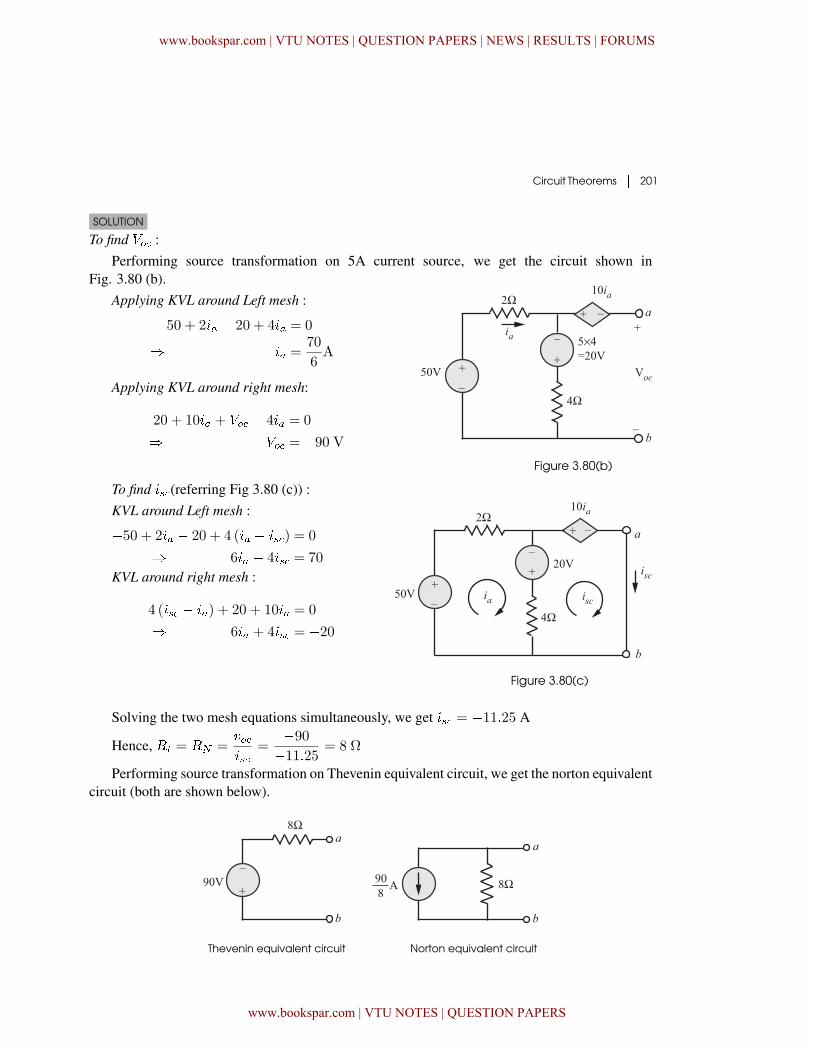
EXAMPLE 3.25Find the Thevenin and Norton equivalent circuits for the network shown in Fig. 3.80 (a).
Figure 3.80(a)
www.bookspar.com | VTU NOTES | QUESTION PAPERS | NEWS | RESULTS | FORUMS
www.bookspar.com | VTU NOTES | QUESTION PAPERS
Circuit Theorems � 201
SOLUTION
To find �� :Performing source transformation on 5A current source, we get the circuit shown in
Fig. 3.80 (b).Applying KVL around Left mesh :
�50 + 2�� � 20 + 4�� = 0
� �� =70
6A
Applying KVL around right mesh:
20 + 10�� + �� � 4�� = 0
� �� = �90 VFigure 3.80(b)
To find �(referring Fig 3.80 (c)) :KVL around Left mesh :
�50 + 2�� � 20 + 4 (�� � �) = 0
� 6�� � 4� = 70
KVL around right mesh :
4 (� � ��) + 20 + 10�� = 0
� 6�� + 4� = �20
Figure 3.80(c)
Solving the two mesh equations simultaneously, we get � = �11�25 A
Hence, �� = � =���
=�90�11�25 = 8 Ω
Performing source transformation on Thevenin equivalent circuit, we get the norton equivalentcircuit (both are shown below).
Thevenin equivalent circuit Norton equivalent circuit
www.bookspar.com | VTU NOTES | QUESTION PAPERS | NEWS | RESULTS | FORUMS
www.bookspar.com | VTU NOTES | QUESTION PAPERS
202 � Network Theory
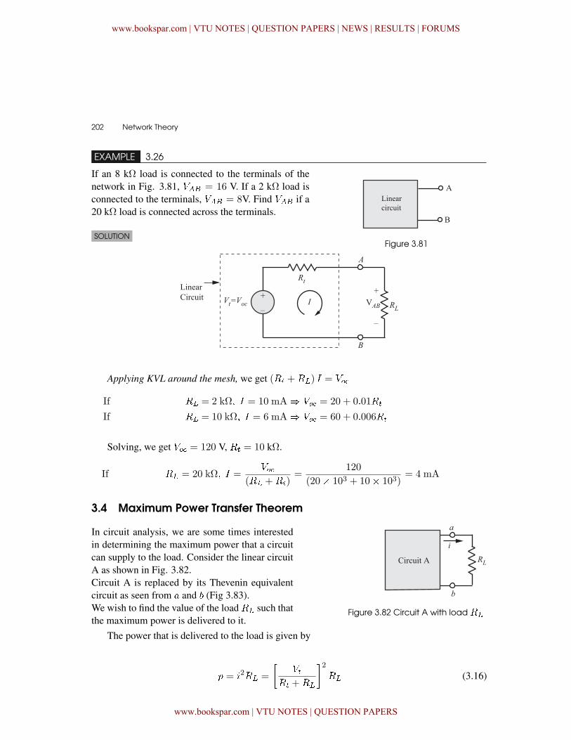
EXAMPLE 3.26
Figure 3.81
If an 8 k٠load is connected to the terminals of thenetwork in Fig. 3.81, ��� = 16 V. If a 2 k٠load isconnected to the terminals, ��� = 8V. Find ��� if a20 k٠load is connected across the terminals.
SOLUTION
Applying KVL around the mesh, we get (�� +��) � = ��
If �� = 2 k� � = 10 mA� �� = 20 + 0�01��
If �� = 10 k� � = 6 mA� �� = 60 + 0�006��
Solving, we get �� = 120 V, �� = 10 kΩ.
If �� = 20 k� � =��
(�� +��)=
120
(20� 103 + 10� 103)= 4 mA
3.4 Maximum Power Transfer Theorem
In circuit analysis, we are some times interestedin determining the maximum power that a circuitcan supply to the load. Consider the linear circuitA as shown in Fig. 3.82.Circuit A is replaced by its Thevenin equivalentcircuit as seen from � and (Fig 3.83).We wish to find the value of the load �� such thatthe maximum power is delivered to it.
Figure 3.82 Circuit A with load ��
The power that is delivered to the load is given by
� = �2�� =
���
�� +��
�2�� (3.16)
www.bookspar.com | VTU NOTES | QUESTION PAPERS | NEWS | RESULTS | FORUMS
www.bookspar.com | VTU NOTES | QUESTION PAPERS
Circuit Theorems � 203
Assuming that �� and �� are fixed for a given source, the maximum power is a function of��. In order to determine the value of �� that maximizes �, we differentiate � with respect to�� and equate the derivative to zero.
��
���
= � 2�
�(�� +��)
2 � 2 (�� +��)
(�� +��)2
�= 0
which yields �� = �� (3.17)
To confirm that equation (3.17) is a maximum,
it should be shown that�2�
��2�
� 0. Hence, maxi-
mum power is transferred to the load when�� isequal to the Thevenin equivalent resistance ��.The maximum power transferred to the load isobtained by substituting �� = �� in equation3.16.Accordingly,
�max =� 2� ��
(2��)2 =
� 2�
4��
Figure 3.83 Thevenin equivalent circuit
is substituted for circuit A
The maximum power transfer theorem states that the maximum power delivered by a source
represented by its Thevenin equivalent circuit is attained when the load R� is equal to the
Thevenin resistance R�.
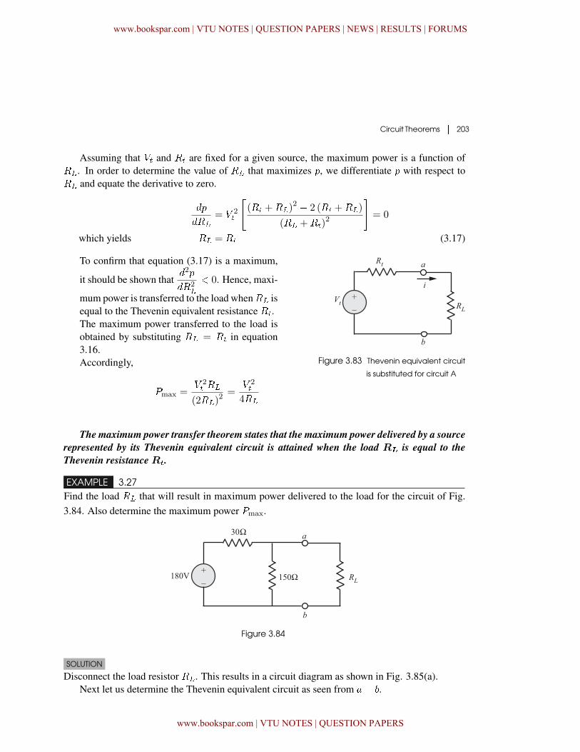
EXAMPLE 3.27Find the load �� that will result in maximum power delivered to the load for the circuit of Fig.3.84. Also determine the maximum power �max.
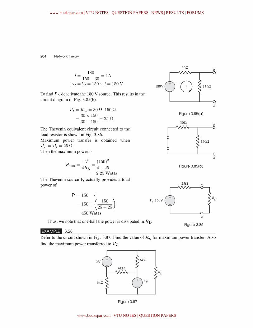
Figure 3.84
SOLUTION
Disconnect the load resistor ��. This results in a circuit diagram as shown in Fig. 3.85(a).Next let us determine the Thevenin equivalent circuit as seen from �� .
www.bookspar.com | VTU NOTES | QUESTION PAPERS | NEWS | RESULTS | FORUMS
www.bookspar.com | VTU NOTES | QUESTION PAPERS
204 � Network Theory
� =180
150 + 30= 1A
�� = �� = 150� � = 150 V
To find��, deactivate the 180 V source. This results in thecircuit diagram of Fig. 3.85(b).
�� = ��� = 30 Ω��150 Ω=
30� 150
30 + 150= 25 Ω
Figure 3.85(a)
The Thevenin equivalent circuit connected to theload resistor is shown in Fig. 3.86.Maximum power transfer is obtained when�� = �� = 25 �Then the maximum power is
�max =� 2�
4��
=(150)2
4� 25= 2�25 Watts
Figure 3.85(b)
The Thevenin source �� actually provides a totalpower of
�� = 150� �
= 150��
150
25 + 25
�= 450 Watts
Figure 3.86Thus, we note that one-half the power is dissipated in ��.
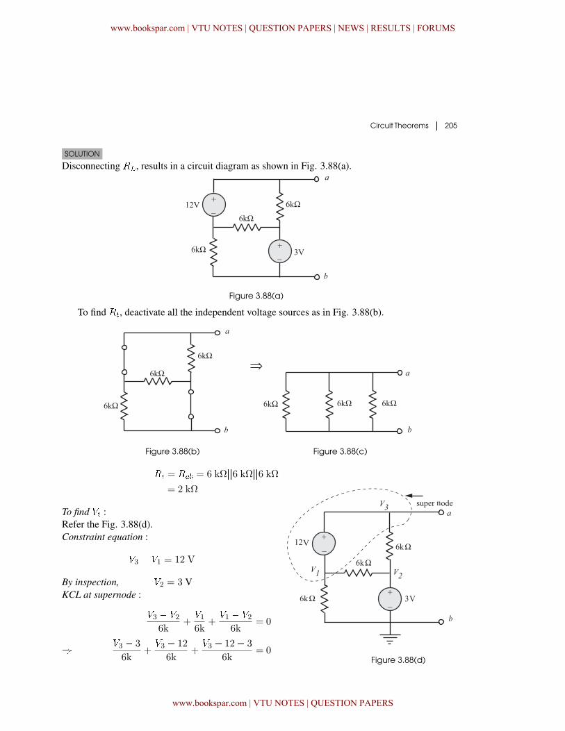
EXAMPLE 3.28Refer to the circuit shown in Fig. 3.87. Find the value of �� for maximum power transfer. Alsofind the maximum power transferred to ��.
Figure 3.87
www.bookspar.com | VTU NOTES | QUESTION PAPERS | NEWS | RESULTS | FORUMS
www.bookspar.com | VTU NOTES | QUESTION PAPERS
Circuit Theorems � 205
SOLUTION
Disconnecting ��, results in a circuit diagram as shown in Fig. 3.88(a).
Figure 3.88(a)
To find ��, deactivate all the independent voltage sources as in Fig. 3.88(b).
Figure 3.88(b) Figure 3.88(c)
�� = ��� = 6 kΩ��6 kΩ��6 kΩ= 2 kΩ
To find �� :Refer the Fig. 3.88(d).Constraint equation :
�3 � �1 = 12 V
By inspection, �2 = 3 VKCL at supernode :
�3 � �26k
+�16k
+�1 � �2
6k= 0
� �3 � 3
6k+�3 � 12
6k+�3 � 12� 3
6k= 0
Figure 3.88(d)
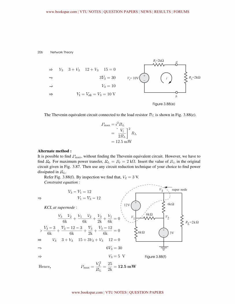
www.bookspar.com | VTU NOTES | QUESTION PAPERS | NEWS | RESULTS | FORUMS
www.bookspar.com | VTU NOTES | QUESTION PAPERS
206 � Network Theory
� �3 � 3 + �3 � 12 + �3 � 15 = 0
� 3�3 = 30
� �3 = 10
� �� = ��� = �3 = 10 V
Figure 3.88(e)
The Thevenin equivalent circuit connected to the load resistor �� is shown in Fig. 3.88(e).
�max = �2��
=
���2��
�2��
= 12�5 mW
Alternate method :It is possible to find �max, without finding the Thevenin equivalent circuit. However, we have tofind ��. For maximum power transfer, �� = �� = 2 kΩ. Insert the value of �� in the originalcircuit given in Fig. 3.87. Then use any circuit reduction technique of your choice to find powerdissipated in ��.
Refer Fig. 3.88(f). By inspection we find that, �2 = 3 V.
Figure 3.88(f)
Constraint equation :
�3 � �1 = 12
� �1 = �3 � 12
KCL at supernode :
�3 � �26k
+�1 � �2
6k+�32k
+�16k
= 0
� �3 � 3
6k+�3 � 12� 3
6k+�32k
+�3 � 12
6k= 0
� �3 � 3 + �3 � 15 + 3�3 + �3 � 12 = 0
� 6�3 = 30
� �3 = 5 V
Hence� �max =� 23
��
=25
2k= 12�5 mW
www.bookspar.com | VTU NOTES | QUESTION PAPERS | NEWS | RESULTS | FORUMS
www.bookspar.com | VTU NOTES | QUESTION PAPERS
Circuit Theorems � 207
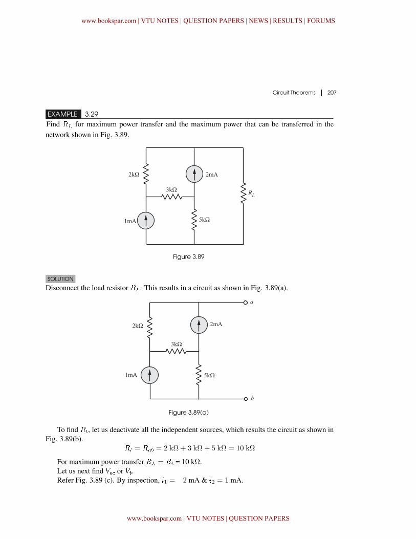
EXAMPLE 3.29Find �� for maximum power transfer and the maximum power that can be transferred in thenetwork shown in Fig. 3.89.
Figure 3.89
SOLUTION
Disconnect the load resistor ��. This results in a circuit as shown in Fig. 3.89(a).
Figure 3.89(a)
To find ��, let us deactivate all the independent sources, which results the circuit as shown inFig. 3.89(b).
�� = ��� = 2 kΩ + 3 kΩ + 5 kΩ = 10 kΩ
For maximum power transfer �� = �� = 10 kΩ.Let us next find �� or ��.Refer Fig. 3.89 (c). By inspection, �1 = �2 mA & �2 = 1 mA.
www.bookspar.com | VTU NOTES | QUESTION PAPERS | NEWS | RESULTS | FORUMS
www.bookspar.com | VTU NOTES | QUESTION PAPERS
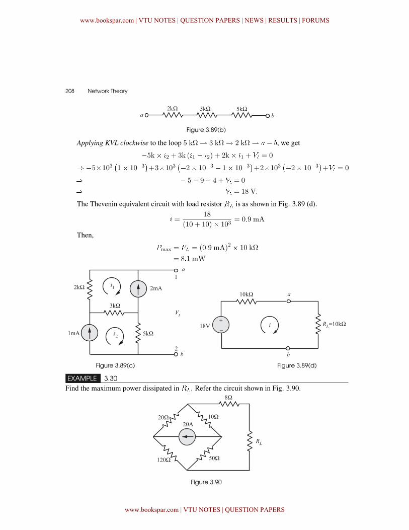
208 � Network Theory
Figure 3.89(b)
Applying KVL clockwise to the loop 5 k� 3 k� 2 k� �� , we get
�5k� �2 + 3k (�1 � �2) + 2k� �1 + �� = 0
� �5�103�1� 10�3
�+3�103
��2� 10�3 � 1� 10�3�+2�103
��2� 10�3�+�� = 0
� � 5� 9� 4 + �� = 0
� �� = 18 V�
The Thevenin equivalent circuit with load resistor �� is as shown in Fig. 3.89 (d).
� =18
(10 + 10)� 103= 0�9 mA
Then,
�max = �� = (0�9 mA)2 � 10 kΩ
= 8�1 mW
Figure 3.89(c) Figure 3.89(d)
EXAMPLE 3.30Find the maximum power dissipated in ��. Refer the circuit shown in Fig. 3.90.
Figure 3.90
www.bookspar.com | VTU NOTES | QUESTION PAPERS | NEWS | RESULTS | FORUMS
www.bookspar.com | VTU NOTES | QUESTION PAPERS
Circuit Theorems � 209
SOLUTION
Disconnecting the load resistor �� from the original circuit results in a circuit diagram as shownin Fig. 3.91.
Figure 3.91As a first step in the analysis, let us find ��. While finding ��, we have to deactivate all the
independent sources. This results in a network as shown in Fig 3.91 (a) :
Figure 3.91(a)
�� = ��� = [140 Ω��60 Ω] + 8 Ω
=140� 60
140 + 60+ 8 = 50 Ω�
For maximum power transfer, �� = �� = 50 Ω. Next step in the analysis is to find ��.Refer Fig 3.91(b), using the principle ofcurrent division,
�1 =���2
�1 +�2
=20� 170
170 + 30= 17 A
�2 =���1
�1 +�2=
20� 30
170 + 30
=600
200= 3A
Figure 3.91(a)
www.bookspar.com | VTU NOTES | QUESTION PAPERS | NEWS | RESULTS | FORUMS
www.bookspar.com | VTU NOTES | QUESTION PAPERS
210 � Network Theory
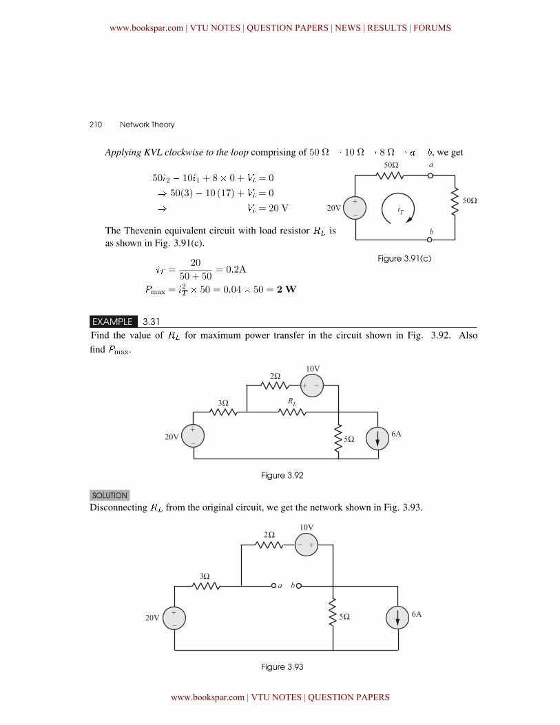
Applying KVL clockwise to the loop comprising of 50 � 10 � 8 � �� , we get
50�2 � 10�1 + 8� 0 + �� = 0
� 50(3)� 10 (17) + �� = 0
� �� = 20 V
The Thevenin equivalent circuit with load resistor �� isas shown in Fig. 3.91(c).
�� =20
50 + 50= 0�2A
�max = �2� � 50 = 0�04� 50 = 2W
Figure 3.91(c)
EXAMPLE 3.31Find the value of �� for maximum power transfer in the circuit shown in Fig. 3.92. Alsofind �max.
Figure 3.92
SOLUTION
Disconnecting �� from the original circuit, we get the network shown in Fig. 3.93.
Figure 3.93
www.bookspar.com | VTU NOTES | QUESTION PAPERS | NEWS | RESULTS | FORUMS
www.bookspar.com | VTU NOTES | QUESTION PAPERS
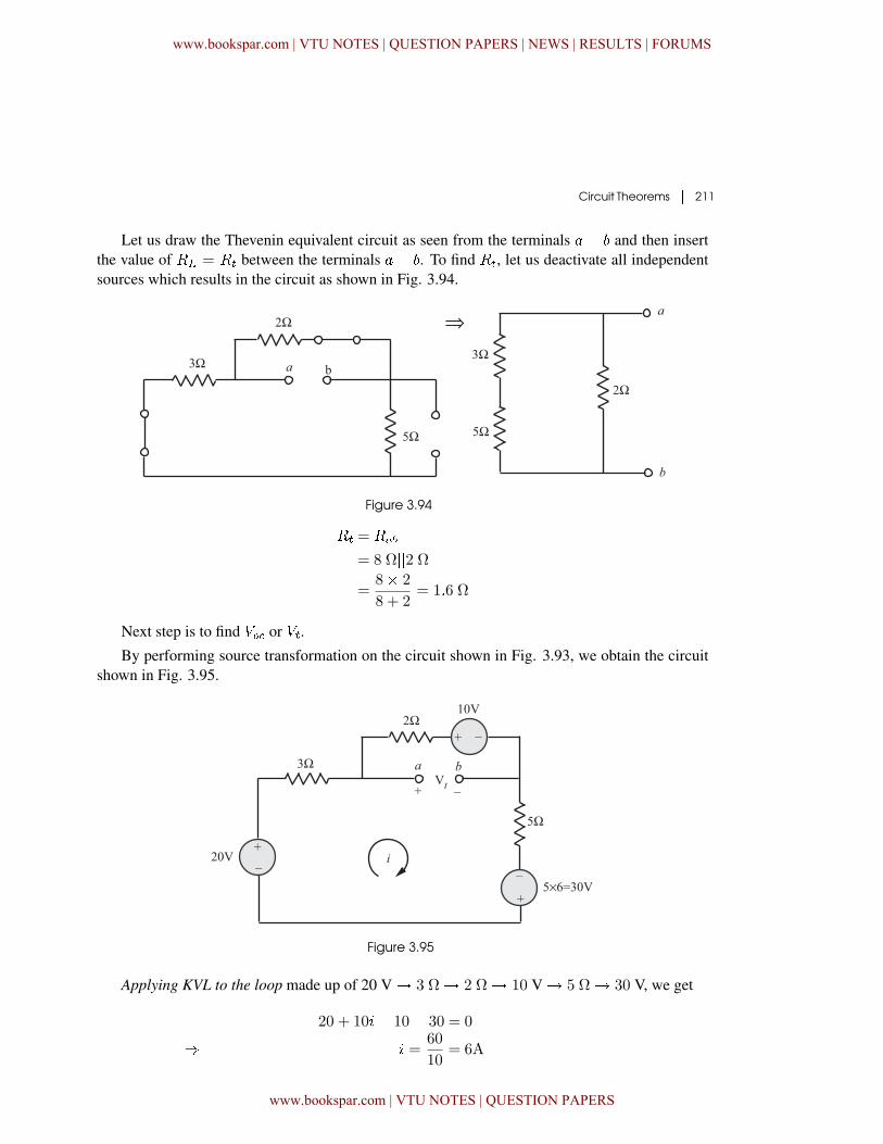
Circuit Theorems � 211
Let us draw the Thevenin equivalent circuit as seen from the terminals � � and then insertthe value of �� = �� between the terminals � � . To find ��, let us deactivate all independentsources which results in the circuit as shown in Fig. 3.94.
Figure 3.94
�� = ���
= 8 Ω��2 Ω=
8� 2
8 + 2= 1�6 Ω
Next step is to find �� or ��.
By performing source transformation on the circuit shown in Fig. 3.93, we obtain the circuitshown in Fig. 3.95.
Figure 3.95
Applying KVL to the loop made up of 20 V � 3 Ω� 2 Ω� 10 V � 5 Ω� 30 V, we get
�20 + 10�� 10� 30 = 0
� � =60
10= 6A
www.bookspar.com | VTU NOTES | QUESTION PAPERS | NEWS | RESULTS | FORUMS
www.bookspar.com | VTU NOTES | QUESTION PAPERS
212 � Network Theory
Again applying KVL clockwise to the path 2 � 10 V � �� , we get2�� 10� �� = 0
� �� = 2�� 10
= 2(6)� 10 = 2 V
The Thevenin equivalent circuit with load resistor�� is as shown in Fig. 3.95 (a).
�max = �2���
=� 2�
4��
= 625 mWFigure 3.95(a) Thevenin equivalent
circuit
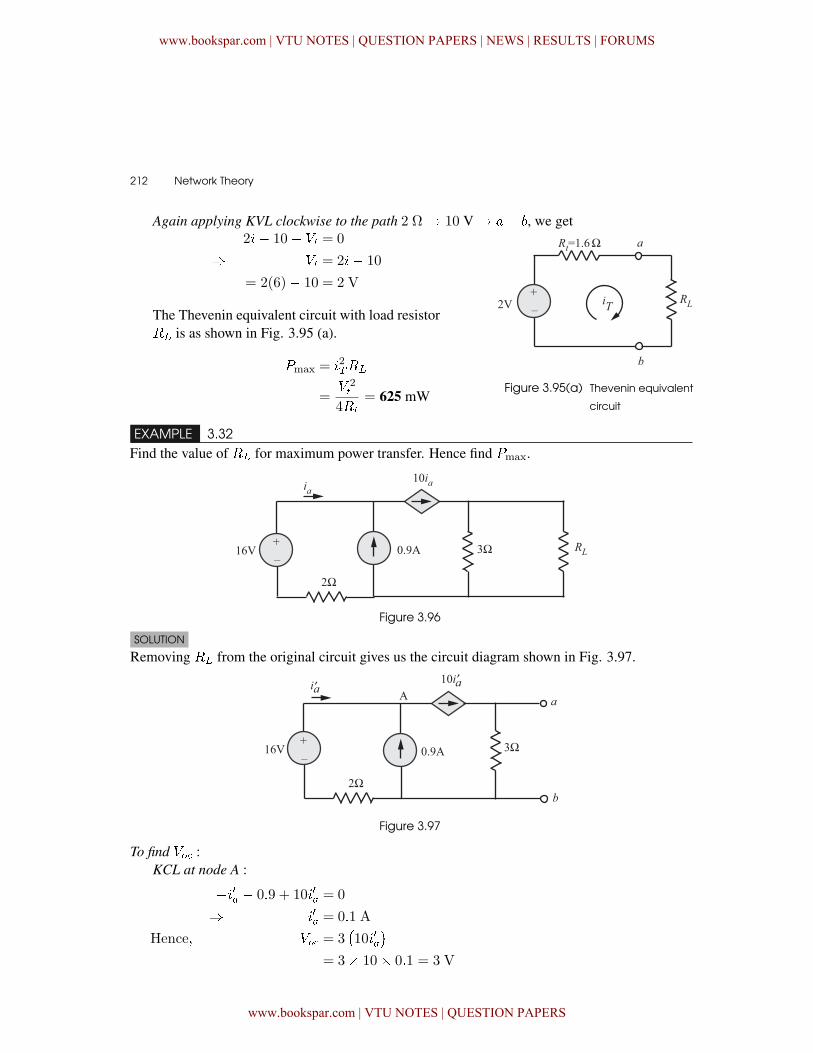
EXAMPLE 3.32Find the value of �� for maximum power transfer. Hence find �max.
Figure 3.96
SOLUTION
Removing �� from the original circuit gives us the circuit diagram shown in Fig. 3.97.
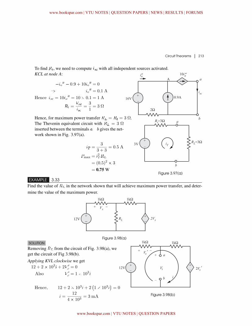
Figure 3.97
To find �� :KCL at node A :
���� � 0�9 + 10��� = 0
� ��� = 0�1 A
Hence� �� = 3�10���
�= 3� 10� 0�1 = 3 V
www.bookspar.com | VTU NOTES | QUESTION PAPERS | NEWS | RESULTS | FORUMS
www.bookspar.com | VTU NOTES | QUESTION PAPERS
Circuit Theorems � 213
To find ��, we need to compute � with all independent sources activated.KCL at node A:
����� � 0�9 + 10���� = 0
� ���� = 0�1 A
Hence � = 10���� = 10� 0�1 = 1 A
�� =���
=3
1= 3 Ω
Hence, for maximum power transfer �� = �� = 3 Ω.The Thevenin equivalent circuit with �� = 3 Ωinserted between the terminals �� gives the net-work shown in Fig. 3.97(a).
�� =3
3 + 3= 0�5 A
�max = �2���
= (0�5)2 � 3
= 0.75 WFigure 3.97(a)
EXAMPLE 3.33Find the value of �� in the network shown that will achieve maximum power transfer, and deter-mine the value of the maximum power.
Figure 3.98(a)SOLUTION
Removing �� from the circuit of Fig. 3.98(a), weget the circuit of Fig 3.98(b).
Applying KVL clockwise we get�12 + 2� 103�+ 2� �
� = 0
Also � �
� = 1� 103�
Figure 3.98(b)
Hence� � 12 + 2� 103�+ 2�1� 103�
�= 0
� =12
4� 103= 3 mA
www.bookspar.com | VTU NOTES | QUESTION PAPERS | NEWS | RESULTS | FORUMS
www.bookspar.com | VTU NOTES | QUESTION PAPERS
214 � Network Theory
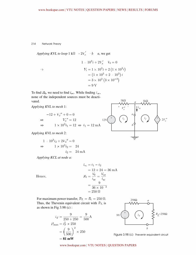
Applying KVL to loop 1 k� 2��
� � � �, we get
1� 103�+ 2� �
� � �� = 0
� �� = 1� 103�+ 2�1� 103�
�=�1� 103 + 2� 103
��
= 3� 103�3� 10�3
�= 9 V
To find ��, we need to find �. While finding �,none of the independent sources must be deacti-vated.
Applying KVL to mesh 1:
�12 + ���� + 0 = 0
� ���� = 12
� 1� 103�1 = 12 � �1 = 12 mA
Applying KVL to mesh 2:
1� 103�2 + 2���� = 0
� 1� 103�2 = �24�2 = �24 mA
Applying KCL at node a:
� = �1 � �2
= 12 + 24 = 36 mA
Hence� �� =���
=���
=9
36� 10�3
= 250 Ω
For maximum power transfer, �� = �� = 250 Ω.Thus, the Thevenin equivalent circuit with �� isas shown in Fig 3.98 (c) :
�� =9
250 + 250=
9
500A
�max = �2� � 250
=
�9
500
�2
� 250
= 81 mWFigure 3.98 (c) Thevenin equivalent circuit
www.bookspar.com | VTU NOTES | QUESTION PAPERS | NEWS | RESULTS | FORUMS
www.bookspar.com | VTU NOTES | QUESTION PAPERS
Circuit Theorems � 215
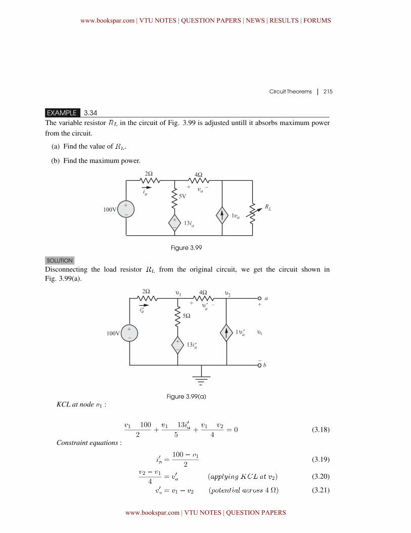
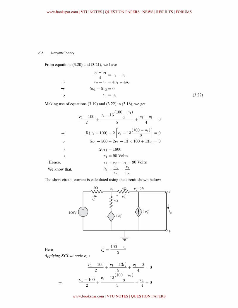
EXAMPLE 3.34The variable resistor �� in the circuit of Fig. 3.99 is adjusted untill it absorbs maximum powerfrom the circuit.
(a) Find the value of ��.
(b) Find the maximum power.
Figure 3.99
SOLUTION
Disconnecting the load resistor �� from the original circuit, we get the circuit shown inFig. 3.99(a).
Figure 3.99(a)KCL at node �1 :
�1 � 100
2+�1 � 13���
5+�1 � �2
4= 0 (3.18)
Constraint equations :
��� =100� �1
2(3.19)
�2 � �14
= ��� (������� ��� �� �2) (3.20)
��� = �1 � �2 (��������� ������ 4 Ω) (3.21)
www.bookspar.com | VTU NOTES | QUESTION PAPERS | NEWS | RESULTS | FORUMS
www.bookspar.com | VTU NOTES | QUESTION PAPERS
216 � Network Theory
From equations (3.20) and (3.21), we have
�2 � �14
= �1 � �2
� �2 � �1 = 4�1 � 4�2
� 5�1 � 5�2 = 0
� �1 = �2 (3.22)
Making use of equations (3.19) and (3.22) in (3.18), we get
�1 � 100
2+�2 � 13
(100� �1)
25
+�1 � �1
4= 0
� 5 (�1 � 100) + 2
��1 � 13
(100� �1)
2
�= 0
� 5�1 � 500 + 2�1 � 13� 100 + 13�1 = 0
� 20�1 = 1800
� �1 = 90 Volts
Hence� �� = �2 = �1 = 90 Volts
We know that, �� =���
=���
The short circuit current is calculated using the circuit shown below:
Here ���� =100� �1
2Applying KCL at node �1 :
�1 � 100
2+�1 � 13�
��
�
5+�1 � 0
4= 0
� �1 � 100
2+�1 � 13
(100� �1)
25
+�14
= 0
www.bookspar.com | VTU NOTES | QUESTION PAPERS | NEWS | RESULTS | FORUMS
www.bookspar.com | VTU NOTES | QUESTION PAPERS
Circuit Theorems � 217
Solving we get �1 = 80 volts = ����Applying KCL at node a :
0� �14
+ � = ����
� � =�14
+ ����
=80
4+ 80 = 100 A
Hence� �� =���
=���
=90
100= 0�9 Ω
Hence for maximum power transfer,
�� = �� = 0�9 Ω
The Thevenin equivalent circuit with �� = 0�9 Ωis as shown.
�� =90
0�9 + 0�9=
90
1�8
�max = �2� � 0�9
=
�90
1�8
�2
� 0�9 = 2250W
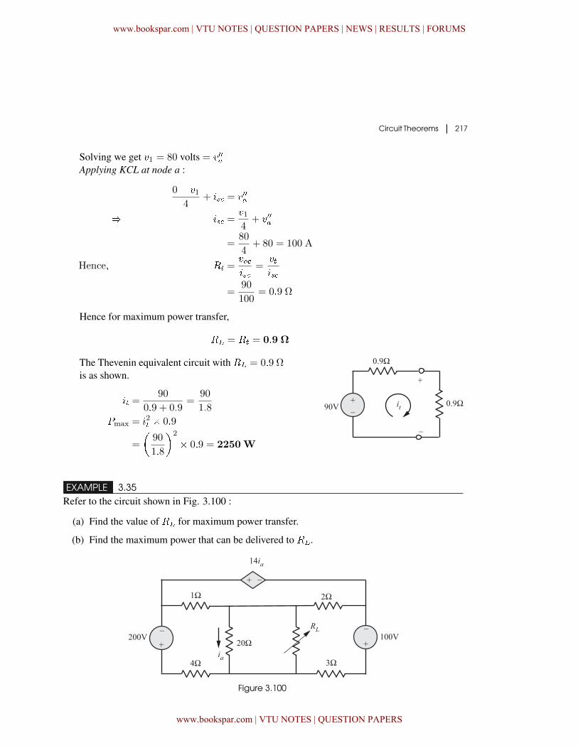
EXAMPLE 3.35Refer to the circuit shown in Fig. 3.100 :
(a) Find the value of �� for maximum power transfer.
(b) Find the maximum power that can be delivered to ��.
Figure 3.100
www.bookspar.com | VTU NOTES | QUESTION PAPERS | NEWS | RESULTS | FORUMS
www.bookspar.com | VTU NOTES | QUESTION PAPERS
218 � Network Theory
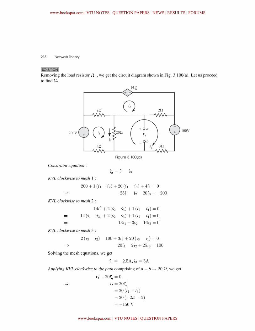
SOLUTION
Removing the load resistor ��, we get the circuit diagram shown in Fig. 3.100(a). Let us proceedto find ��.
Figure 3.100(a)
Constraint equation :��� = �1 � �3
KVL clockwise to mesh 1 :
200 + 1 (�1 � �2) + 20 (�1 � �3) + 4�1 = 0
� 25�1 � �2 � 20�3 = �200KVL clockwise to mesh 2 :
14��� + 2 (�2 � �3) + 1 (�2 � �1) = 0
� 14 (�1 � �3) + 2 (�2 � �3) + 1 (�2 � �1) = 0
� 13�1 + 3�2 � 16�3 = 0
KVL clockwise to mesh 3 :
2 (�3 � �2)� 100 + 3�3 + 20 (�3 � �1) = 0
� � 20�1 � 2�2 + 25�3 = 100
Solving the mesh equations, we get
�1 = �2�5A� �3 = 5A
Applying KVL clockwise to the path comprising of �� � 20 Ω, we get
�� � 20��� = 0
� �� = 20���
= 20 (�1 � �3)
= 20 (�2�5� 5)
= �150 V
www.bookspar.com | VTU NOTES | QUESTION PAPERS | NEWS | RESULTS | FORUMS
www.bookspar.com | VTU NOTES | QUESTION PAPERS
Circuit Theorems � 219
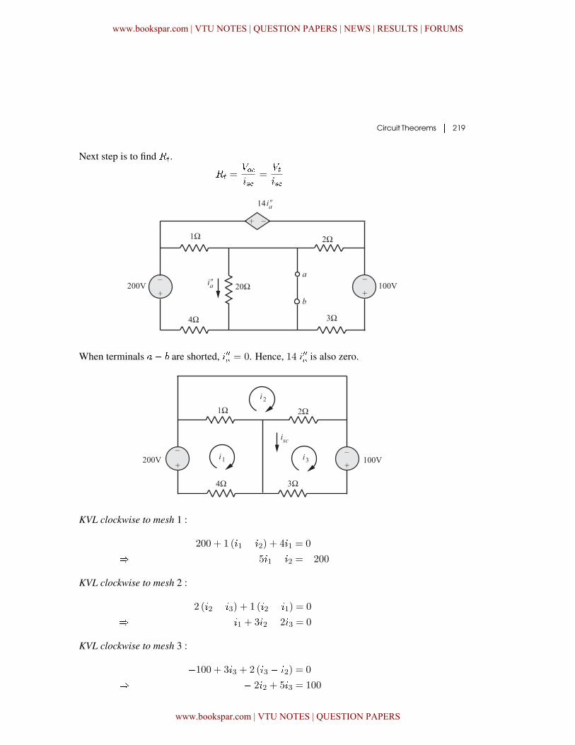
Next step is to find ��.
�� =���
=���
When terminals �� are shorted, ���� = 0. Hence, 14 ���� is also zero.
KVL clockwise to mesh 1 :
200 + 1 (�1 � �2) + 4�1 = 0
� 5�1 � �2 = �200
KVL clockwise to mesh 2 :
2 (�2 � �3) + 1 (�2 � �1) = 0
� � �1 + 3�2 � 2�3 = 0
KVL clockwise to mesh 3 :
�100 + 3�3 + 2 (�3 � �2) = 0
� � 2�2 + 5�3 = 100
www.bookspar.com | VTU NOTES | QUESTION PAPERS | NEWS | RESULTS | FORUMS
www.bookspar.com | VTU NOTES | QUESTION PAPERS
220 � Network Theory
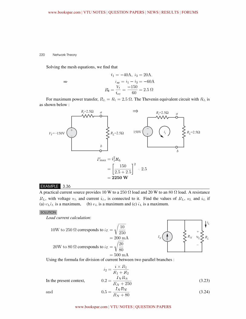
Solving the mesh equations, we find that
�1 = �40A� �3 = 20A�
� � = �1 � �3 = �60A�� =
���
=�150�60 = 2�5 Ω
For maximum power transfer, �� = �� = 2�5 Ω. The Thevenin equivalent circuit with �� isas shown below :
�max = �21��
=
�150
2�5 + 2�5
�2� 2�5
= 2250W
EXAMPLE 3.36A practical current source provides 10 W to a 250 ٠load and 20 W to an 80 ٠load. A resistance��, with voltage �� and current ��, is connected to it. Find the values of ��, �� and �� if(a) ���� is a maximum, (b) �� is a maximum and (c) �� is a maximum.
SOLUTION
Load current calculation:
10W to 250 ٠corresponds to �� =
10
250= 200 mA
20W to 80 ٠corresponds to �� =
20
80= 500 mA
Using the formula for division of current between two parallel branches :
�2 =���1
�1 +�2
In the present context, 0�2 =� �
� + 250(3.23)
and 0�5 =� �
� + 80(3.24)
www.bookspar.com | VTU NOTES | QUESTION PAPERS | NEWS | RESULTS | FORUMS
www.bookspar.com | VTU NOTES | QUESTION PAPERS
Circuit Theorems � 221
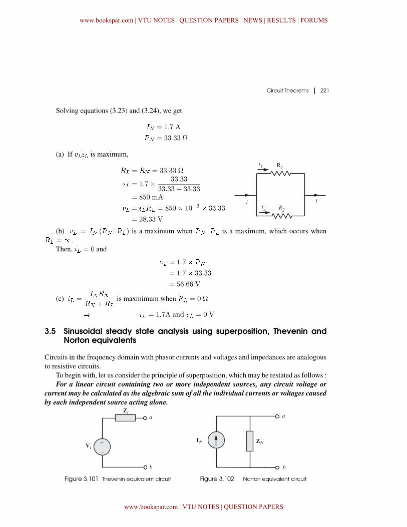
Solving equations (3.23) and (3.24), we get
� = 1�7 A
� = 33�33 Ω
(a) If ���� is maximum,
�� = � = 33�33 Ω
�� = 1�7� 33�33
33�33 + 33�33= 850 mA
�� = ���� = 850� 10�3 � 33�33
= 28�33 V
(b) �� = � (� ����) is a maximum when � ���� is a maximum, which occurs when�� =�.
Then, �� = 0 and
�� = 1�7��
= 1�7� 33�33
= 56�66 V
(c) �� =� �
� +��
is maxmimum when �� = 0 Ω
� �� = 1�7A and �� = 0 V
3.5 Sinusoidal steady state analysis using superposition, Thevenin andNorton equivalents
Circuits in the frequency domain with phasor currents and voltages and impedances are analogousto resistive circuits.
To begin with, let us consider the principle of superposition, which may be restated as follows :For a linear circuit containing two or more independent sources, any circuit voltage or
current may be calculated as the algebraic sum of all the individual currents or voltages caused
by each independent source acting alone.
Figure 3.101 Thevenin equivalent circuit Figure 3.102 Norton equivalent circuit
www.bookspar.com | VTU NOTES | QUESTION PAPERS | NEWS | RESULTS | FORUMS
www.bookspar.com | VTU NOTES | QUESTION PAPERS
222 � Network Theory
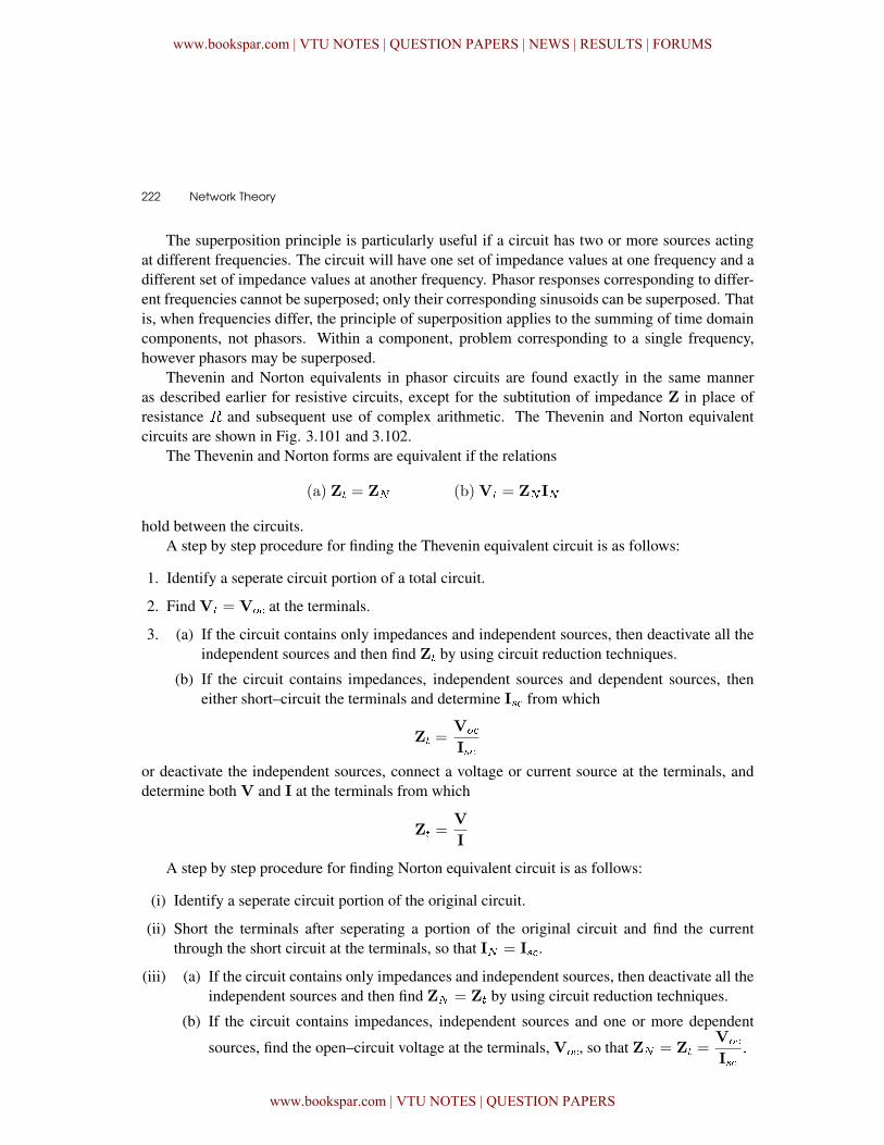
The superposition principle is particularly useful if a circuit has two or more sources actingat different frequencies. The circuit will have one set of impedance values at one frequency and adifferent set of impedance values at another frequency. Phasor responses corresponding to differ-ent frequencies cannot be superposed; only their corresponding sinusoids can be superposed. Thatis, when frequencies differ, the principle of superposition applies to the summing of time domaincomponents, not phasors. Within a component, problem corresponding to a single frequency,however phasors may be superposed.
Thevenin and Norton equivalents in phasor circuits are found exactly in the same manneras described earlier for resistive circuits, except for the subtitution of impedance Z in place ofresistance � and subsequent use of complex arithmetic. The Thevenin and Norton equivalentcircuits are shown in Fig. 3.101 and 3.102.
The Thevenin and Norton forms are equivalent if the relations
(a) Z� = Z (b)V� = Z I
hold between the circuits.A step by step procedure for finding the Thevenin equivalent circuit is as follows:
1. Identify a seperate circuit portion of a total circuit.
2. Find V� = V� at the terminals.
3. (a) If the circuit contains only impedances and independent sources, then deactivate all theindependent sources and then find Z� by using circuit reduction techniques.
(b) If the circuit contains impedances, independent sources and dependent sources, theneither short–circuit the terminals and determine I from which
Z� =V�
I
or deactivate the independent sources, connect a voltage or current source at the terminals, anddetermine both V and I at the terminals from which
Z� =V
I
A step by step procedure for finding Norton equivalent circuit is as follows:
(i) Identify a seperate circuit portion of the original circuit.
(ii) Short the terminals after seperating a portion of the original circuit and find the currentthrough the short circuit at the terminals, so that I = I.
(iii) (a) If the circuit contains only impedances and independent sources, then deactivate all theindependent sources and then find Z = Z� by using circuit reduction techniques.
(b) If the circuit contains impedances, independent sources and one or more dependent
sources, find the open–circuit voltage at the terminals, V�, so that Z = Z� =V�
I�
www.bookspar.com | VTU NOTES | QUESTION PAPERS | NEWS | RESULTS | FORUMS
www.bookspar.com | VTU NOTES | QUESTION PAPERS
Circuit Theorems � 223
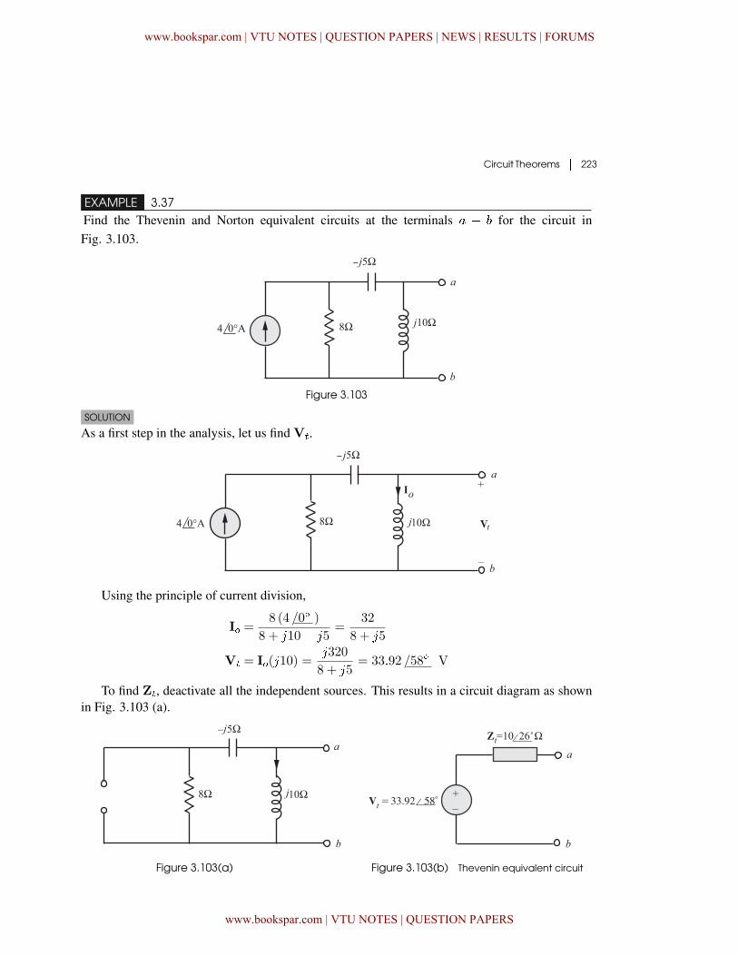
EXAMPLE 3.37Find the Thevenin and Norton equivalent circuits at the terminals � � for the circuit inFig. 3.103.
Figure 3.103
SOLUTION
As a first step in the analysis, let us find V��
Using the principle of current division,
I� =8 (4 /0� )
8 + �10� �5=
32
8 + �5
V� = I�(�10) =�320
8 + �5= 33�92 /58� V
To find Z�, deactivate all the independent sources. This results in a circuit diagram as shownin Fig. 3.103 (a).
Figure 3.103(a) Figure 3.103(b) Thevenin equivalent circuit
www.bookspar.com | VTU NOTES | QUESTION PAPERS | NEWS | RESULTS | FORUMS
www.bookspar.com | VTU NOTES | QUESTION PAPERS
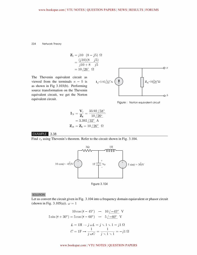
224 � Network Theory
Z� = �10�� (8� �5) Ω
=(�10)(8� �5)
�10 + 8� �5
= 10 /26� Ω
The Thevenin equivalent circuit asviewed from the terminals � � isas shown in Fig 3.103(b). Performingsource transformation on the Theveninequivalent circuit, we get the Nortonequivalent circuit.
Figure : Norton equivalent circuit
I =V�
Z�=
33�92 /58�
10 /26�
= 3�392 /32� A
Z = Z� = 10 /26� Ω
EXAMPLE 3.38Find �� using Thevenin’s theorem. Refer to the circuit shown in Fig. 3.104.
Figure 3.104
SOLUTION
Let us convert the circuit given in Fig. 3.104 into a frequency domain equiavalent or phasor circuit(shown in Fig. 3.105(a)). = 1
10 cos (�� 45�) � 10 /�45� V
5 sin (�+ 30�) = 5 cos (�� 60�) � 5 /�60� V
� = 1H� � � = � � 1� 1 = �1 Ω
� = 1F� 1
� �=
1
� � 1� 1= ��1 Ω
www.bookspar.com | VTU NOTES | QUESTION PAPERS | NEWS | RESULTS | FORUMS
www.bookspar.com | VTU NOTES | QUESTION PAPERS
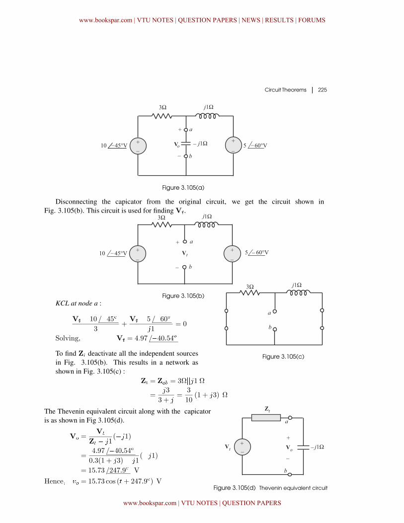
Circuit Theorems � 225
Figure 3.105(a)
Disconnecting the capicator from the original circuit, we get the circuit shown inFig. 3.105(b). This circuit is used for finding V�.
Figure 3.105(b)KCL at node a :
V� � 10 /�45�3
+V� � 5 /�60�
�1= 0
Solving� V� = 4�97 /�40�54�
To find Z� deactivate all the independent sourcesin Fig. 3.105(b). This results in a network asshown in Fig. 3.105(c) :
Figure 3.105(c)
Z� = Z�� = 3Ω���1 Ω=
�3
3 + �=
3
10(1 + �3) Ω
The Thevenin equivalent circuit along with the capicatoris as shown in Fig 3.105(d).
V� =V�
Z� � �1(��1)
=4�97 /�40�54�0�3(1 + �3)� �1
(��1)= 15�73 /247�9� V
Hence� �� = 15�73 cos (�+ 247�9�) VFigure 3.105(d) Thevenin equivalent circuit
www.bookspar.com | VTU NOTES | QUESTION PAPERS | NEWS | RESULTS | FORUMS
www.bookspar.com | VTU NOTES | QUESTION PAPERS
226 � Network Theory
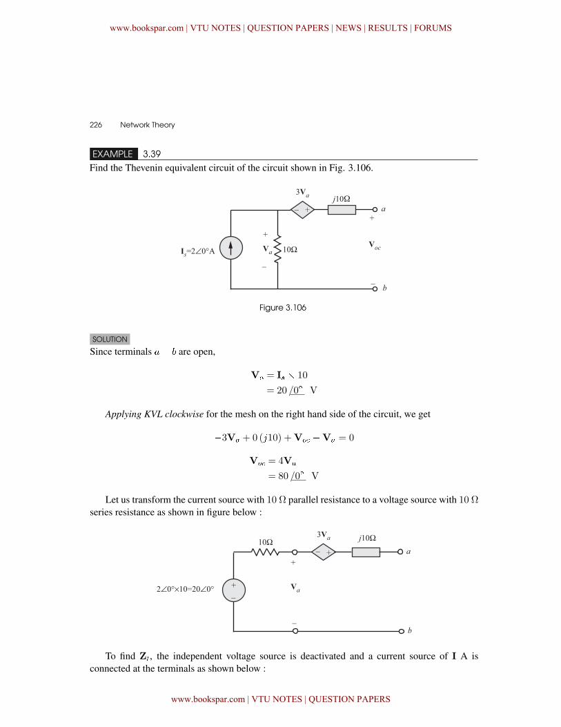
EXAMPLE 3.39Find the Thevenin equivalent circuit of the circuit shown in Fig. 3.106.
Figure 3.106
SOLUTION
Since terminals �� are open,
V� = I � 10
= 20 /0� V
Applying KVL clockwise for the mesh on the right hand side of the circuit, we get
�3V� + 0 (�10) +V� �V� = 0
V� = 4V�
= 80 /0� V
Let us transform the current source with 10 Ω parallel resistance to a voltage source with 10 Ωseries resistance as shown in figure below :
To find Z�, the independent voltage source is deactivated and a current source of I A isconnected at the terminals as shown below :
www.bookspar.com | VTU NOTES | QUESTION PAPERS | NEWS | RESULTS | FORUMS
www.bookspar.com | VTU NOTES | QUESTION PAPERS
Circuit Theorems � 227
Applying KVL clockwise we get,
�V�
� � 3V�
� � �10I+V� = 0
� �4V�
� � �10I+V� = 0
Since V�
� = 10I
we get � 40I� �10I = �V�
Hence� Z� =V�
I= 40 + �10Ω
Hence the Thevenin equivalent circuit is as shownin Fig 3.106(a) : Figure 3.106(a)
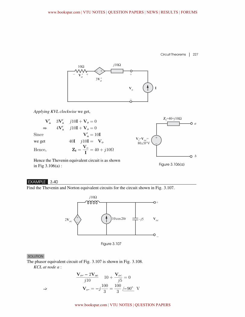
EXAMPLE 3.40Find the Thevenin and Norton equivalent circuits for the circuit shown in Fig. 3.107.
Figure 3.107
SOLUTION
The phasor equivalent circuit of Fig. 3.107 is shown in Fig. 3.108.KCL at node a :
V� � 2V�
�10� 10 +
V�
��5 = 0
� V� = �� 1003
=100
3/�90� V
www.bookspar.com | VTU NOTES | QUESTION PAPERS | NEWS | RESULTS | FORUMS
www.bookspar.com | VTU NOTES | QUESTION PAPERS
228 � Network Theory
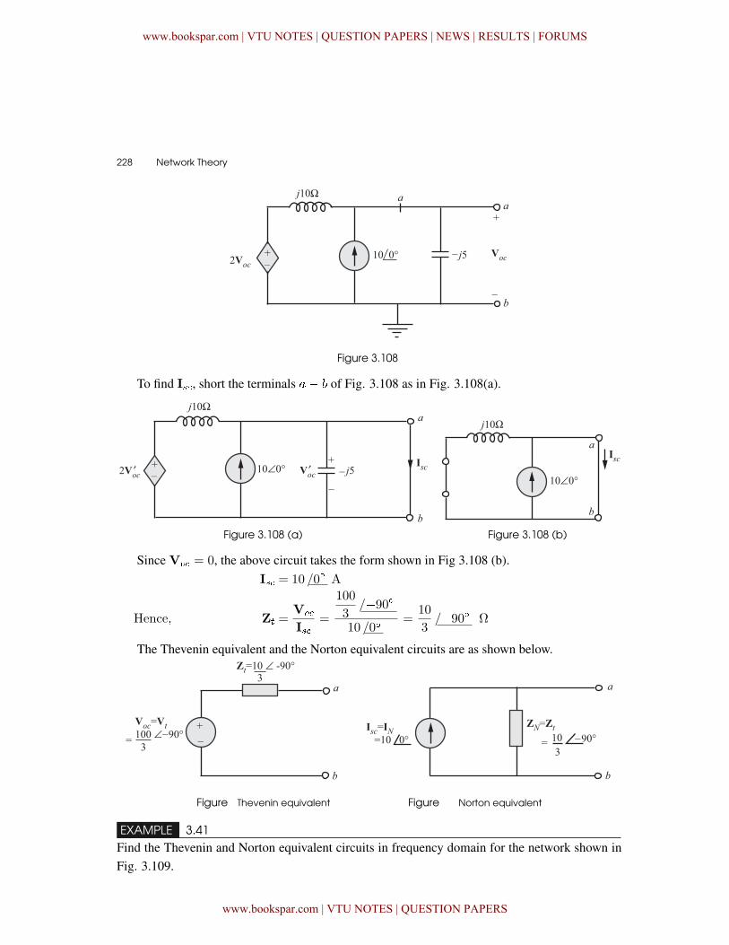
Figure 3.108
To find I, short the terminals �� of Fig. 3.108 as in Fig. 3.108(a).
Figure 3.108 (a) Figure 3.108 (b)
Since V� = 0, the above circuit takes the form shown in Fig 3.108 (b).I = 10 /0� A
Hence� Z� =V�
I=
100
3/�90�
10 /0�=
10
3/�90� Ω
The Thevenin equivalent and the Norton equivalent circuits are as shown below.
Figure Thevenin equivalent Figure Norton equivalent
EXAMPLE 3.41Find the Thevenin and Norton equivalent circuits in frequency domain for the network shown inFig. 3.109.
www.bookspar.com | VTU NOTES | QUESTION PAPERS | NEWS | RESULTS | FORUMS
www.bookspar.com | VTU NOTES | QUESTION PAPERS
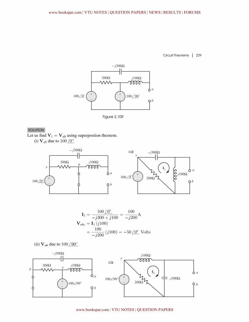
Circuit Theorems � 229
Figure 3.109
SOLUTION
Let us find V� = V�� using superpostion theorem.(i) V�� due to 100 /0�
I1 =100 /0�
��300 + �100=
100
��200AV��1 = I1 (�100)
=100
��200 (�100) = �50 /0� Volts
(ii) V�� due to 100 /90�
www.bookspar.com | VTU NOTES | QUESTION PAPERS | NEWS | RESULTS | FORUMS
www.bookspar.com | VTU NOTES | QUESTION PAPERS
230 � Network Theory
I2 =100 /90�
�100� �300
V��2 = I2 (��300)=
100 /90�
�100� �300(��300) = �150 V
Hence� V� =V��1 +V��2
= �50 + �150
= 158�11 /108�43� V
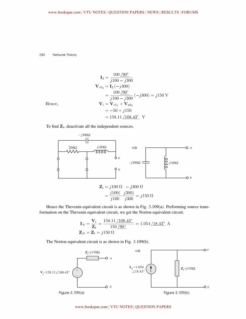
To find Z�, deactivate all the independent sources.
Z� = �100 Ω�� � �300 Ω
=�100(��300)�100� �300
= �150 Ω
Hence the Thevenin equivalent circuit is as shown in Fig. 3.109(a). Performing source trans-formation on the Thevenin equivalent circuit, we get the Norton equivalent circuit.
I =V�
Z�=
158�11 /108�43�
150 /90�= 1�054 /18�43� A
Z = Z� = �150 Ω
The Norton equivalent circuit is as shown in Fig. 3.109(b).
Figure 3.109(a) Figure 3.109(b)
www.bookspar.com | VTU NOTES | QUESTION PAPERS | NEWS | RESULTS | FORUMS
www.bookspar.com | VTU NOTES | QUESTION PAPERS
Circuit Theorems � 231
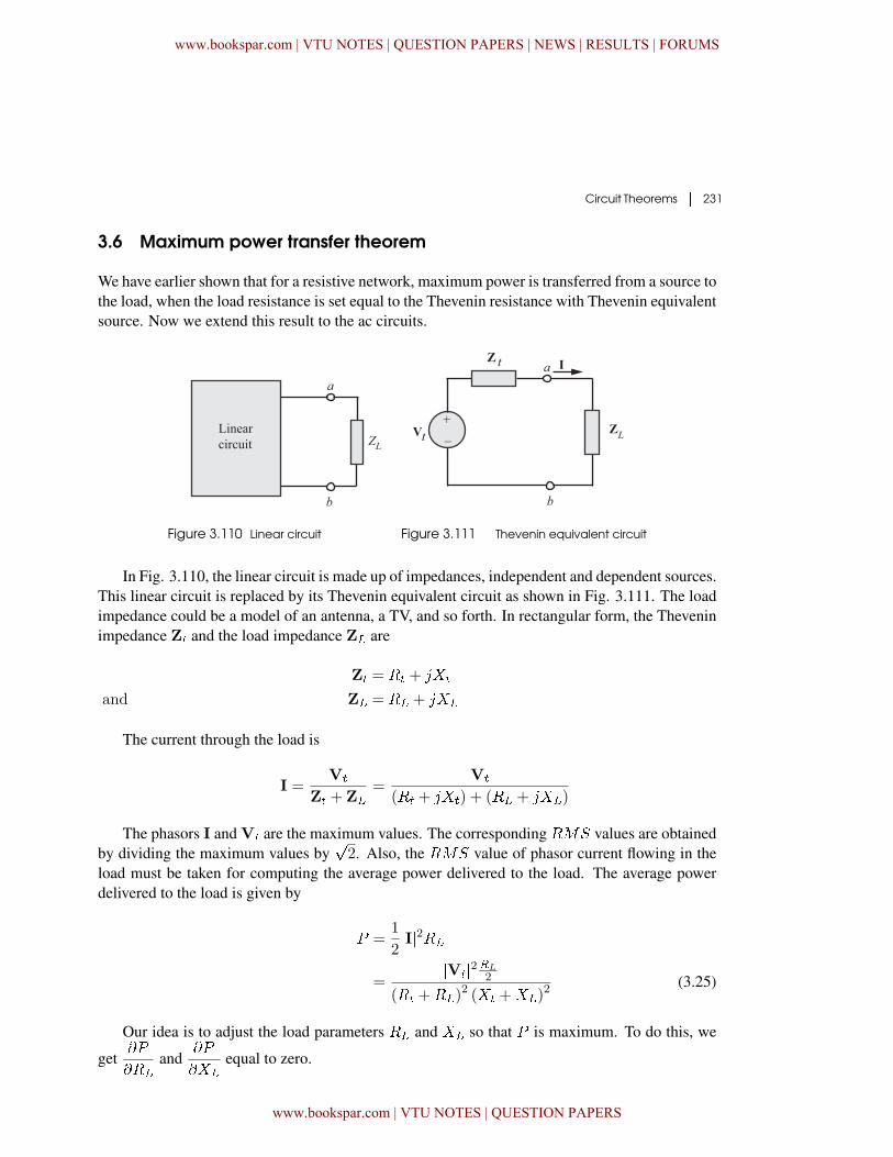
3.6 Maximum power transfer theorem
We have earlier shown that for a resistive network, maximum power is transferred from a source tothe load, when the load resistance is set equal to the Thevenin resistance with Thevenin equivalentsource. Now we extend this result to the ac circuits.
Figure 3.110 Linear circuit Figure 3.111 Thevenin equivalent circuit
In Fig. 3.110, the linear circuit is made up of impedances, independent and dependent sources.This linear circuit is replaced by its Thevenin equivalent circuit as shown in Fig. 3.111. The loadimpedance could be a model of an antenna, a TV, and so forth. In rectangular form, the Theveninimpedance Z� and the load impedance Z� are
Z� = �� + �!�
and Z� = �� + �!�
The current through the load is
I =V�
Z� + Z�=
V�
(�� + �!�) + (�� + �!�)
The phasors I and V� are the maximum values. The corresponding �"# values are obtainedby dividing the maximum values by
�2. Also, the �"# value of phasor current flowing in the
load must be taken for computing the average power delivered to the load. The average powerdelivered to the load is given by
� =1
2�I�2��
=�V��2�L
2
(�� +��)2 (!� +!�)
2 (3.25)
Our idea is to adjust the load parameters �� and !� so that � is maximum. To do this, we
get$�
$��
and$�
$!�
equal to zero.
www.bookspar.com | VTU NOTES | QUESTION PAPERS | NEWS | RESULTS | FORUMS
www.bookspar.com | VTU NOTES | QUESTION PAPERS
232 � Network Theory
$�
$!�
=�����2�� (!� +!�)
(�� +��)2 + (!� +!�)
2�2
$�
$��
=����2
(�� +��)
2 + (!� +!�)2 � 2�� (�� +��)
�2(�� +��)
2 + (!� +!�)2�2
Setting$�
$!�
= 0 gives
!� = �!� (3.26)
and Setting$�
$��
= 0 gives
�� =
��2� + (!� +!�)
2 (3.27)
Combining equations (3.26) and (3.27), we can conclude that for maximum average powertransfer, Z� must be selected such that !� = �!� and �� = ��. That is the maximum aver-age power of a circuit with an impedance Z� that is obtained when Z� is set equal to complexconjugate of Z�.
Setting �� = �� and !� = �!� in equation (3.25), we get the maximum average power as
� =����28��
In a situation where the load is purely real, the condition for maximum power transfer isobtained by putting !� = 0 in equation (3.27). That is,
�� =��2� +!2
� = �Z��Hence for maximum average power transfer to a purely resistive load, the load resistance is
equal to the magnitude of Thevenin impedance.
3.6.1 Maximum Power Transfer When Z is Restricted
Maximum average power can be delivered to Z� only if Z� = Z�
� . There are few situations inwhich this is not possible. These situations are described below :
(i) �� and !� may be restricted to a limited range of values. With this restriction,choose !� as close as possible to �!� and then adjust �� as close as possible to��2� + (!� +!�)
2�
(ii) Magnitude of Z� can be varied but its phase angle cannot be. Under this restriction,greatest amount of power is transferred to the load when [Z�] = �Z��.
Z�
t is the complex conjugate of Zt.
www.bookspar.com | VTU NOTES | QUESTION PAPERS | NEWS | RESULTS | FORUMS
www.bookspar.com | VTU NOTES | QUESTION PAPERS
Circuit Theorems � 233
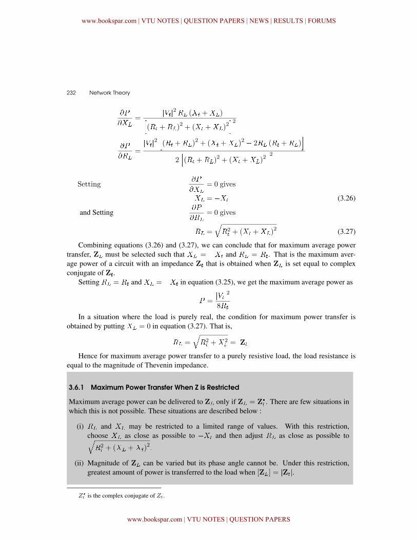
EXAMPLE 3.42Find the load impedance that transfers the maximum power to the load and determine the maxi-mum power quantity obtained for the circuit shown in Fig. 3.112.
Figure 3.112
SOLUTION
We select, Z� = Z�
� for maximum power transfer.
Hence Z� = 5 + �6
I =10 /0�
5 + 5= 1 /0�
Hence, the maximum average power transfered to theload is
� =1
2�I�2��
=1
2(1)2 � 5 = 2�5W
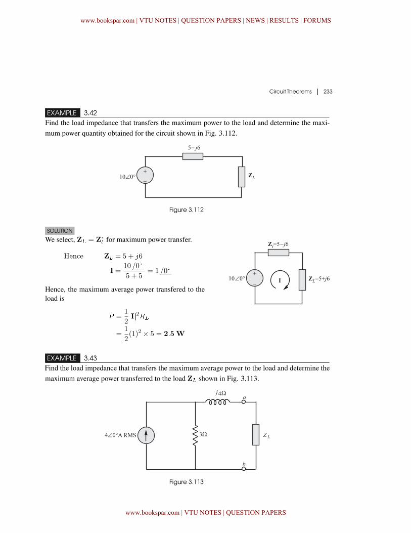
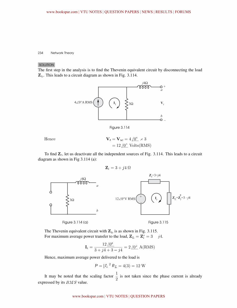
EXAMPLE 3.43Find the load impedance that transfers the maximum average power to the load and determine themaximum average power transferred to the load Z� shown in Fig. 3.113.
Figure 3.113
www.bookspar.com | VTU NOTES | QUESTION PAPERS | NEWS | RESULTS | FORUMS
www.bookspar.com | VTU NOTES | QUESTION PAPERS
234 � Network Theory
SOLUTION
The first step in the analysis is to find the Thevenin equivalent circuit by disconnecting the loadZ�. This leads to a circuit diagram as shown in Fig. 3.114.
Figure 3.114
Hence V� =V� = 4/0� � 3
= 12 /0� Volts(RMS)
To find Z�, let us deactivate all the independent sources of Fig. 3.114. This leads to a circuitdiagram as shown in Fig 3.114 (a):
Z� = 3 + �4 Ω
Figure 3.114 (a) Figure 3.115
The Thevenin equivalent circuit with Z� is as shown in Fig. 3.115.For maximum average power transfer to the load, Z� = Z�
� = 3� �4.
I� =12 /0�
3 + �4 + 3� �4= 2 /0� A(RMS)
Hence, maximum average power delivered to the load is
� = ����2�� = 4(3) = 12 W
It may be noted that the scaling factor1
2is not taken since the phase current is already
expressed by its �"# value.
www.bookspar.com | VTU NOTES | QUESTION PAPERS | NEWS | RESULTS | FORUMS
www.bookspar.com | VTU NOTES | QUESTION PAPERS
Circuit Theorems � 235
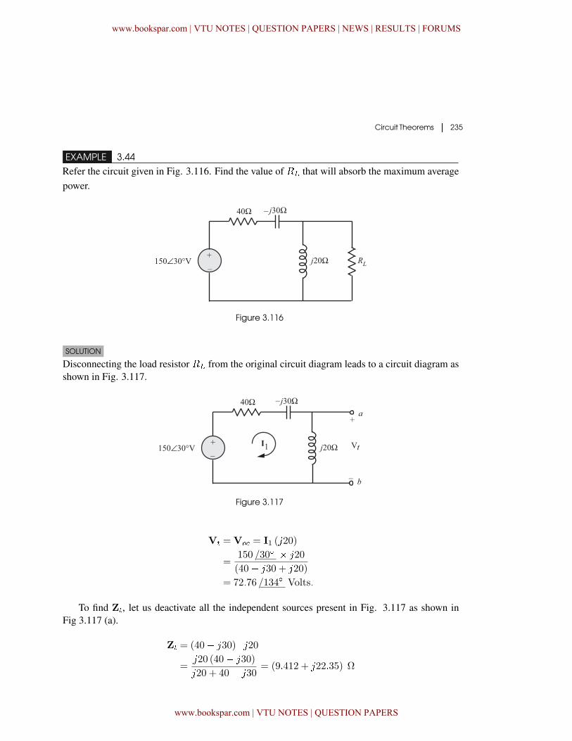
EXAMPLE 3.44
Refer the circuit given in Fig. 3.116. Find the value of �� that will absorb the maximum averagepower.
Figure 3.116
SOLUTION
Disconnecting the load resistor �� from the original circuit diagram leads to a circuit diagram asshown in Fig. 3.117.
Figure 3.117
V� =V� = I1 (�20)
=150 /30� � �20
(40� �30 + �20)
= 72�76 /134� Volts�
To find Z�, let us deactivate all the independent sources present in Fig. 3.117 as shown inFig 3.117 (a).
Z� = (40� �30) ���20=
�20 (40� �30)
�20 + 40� �30= (9�412 + �22�35) Ω
www.bookspar.com | VTU NOTES | QUESTION PAPERS | NEWS | RESULTS | FORUMS
www.bookspar.com | VTU NOTES | QUESTION PAPERS
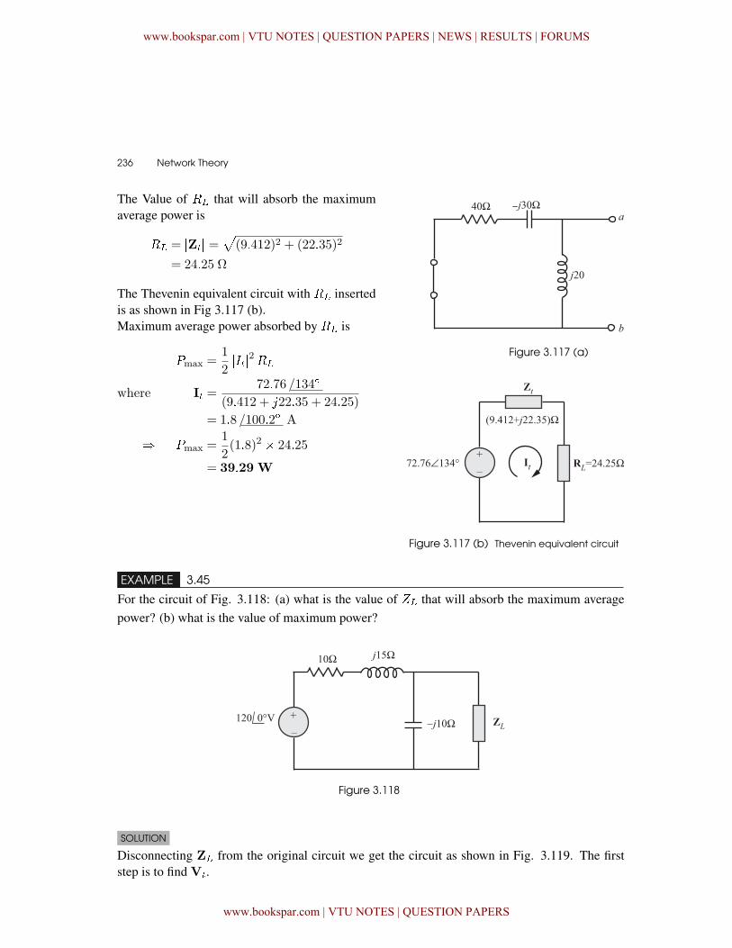
236 � Network Theory
The Value of �� that will absorb the maximumaverage power is
�� = �Z�� =
(9�412)2 + (22�35)2
= 24�25 Ω
The Thevenin equivalent circuit with �� insertedis as shown in Fig 3.117 (b).Maximum average power absorbed by �� is
�max =1
2����2��
where I� =72�76 /134�
(9�412 + �22�35 + 24�25)
= 1�8 /100�2� A
� �max =1
2(1�8)2 � 24�25
= 39�29 W
Figure 3.117 (a)
Figure 3.117 (b) Thevenin equivalent circuit
EXAMPLE 3.45
For the circuit of Fig. 3.118: (a) what is the value of %� that will absorb the maximum averagepower? (b) what is the value of maximum power?
Figure 3.118
SOLUTION
Disconnecting Z� from the original circuit we get the circuit as shown in Fig. 3.119. The firststep is to find V�.
www.bookspar.com | VTU NOTES | QUESTION PAPERS | NEWS | RESULTS | FORUMS
www.bookspar.com | VTU NOTES | QUESTION PAPERS
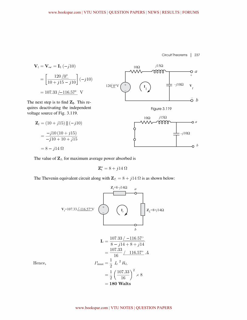
Circuit Theorems � 237
Figure 3.119
V� =V� = I1 (��10)
=
�120 /0�
10 + �15� �10
�(��10)
= 107�33 /�116�57� V
The next step is to find Z�. This re-quires deactivating the independentvoltage source of Fig. 3.119.
Z� = (10 + �15) �� (��10)
=��10 (10 + �15)
��10 + 10 + �15
= 8� �14 Ω
The value of Z� for maximum average power absorbed is
Z�
� = 8 + �14 Ω
The Thevenin equivalent circuit along with Z� = 8 + �14 Ω is as shown below:
I� =107�33 / �116�57�8� �14 + 8 + �14
=107�33
16/�116�57�
Hence� �max =1
2����2��
=1
2
�107�33
16
�2
� 8
= 180 Walts
www.bookspar.com | VTU NOTES | QUESTION PAPERS | NEWS | RESULTS | FORUMS
www.bookspar.com | VTU NOTES | QUESTION PAPERS
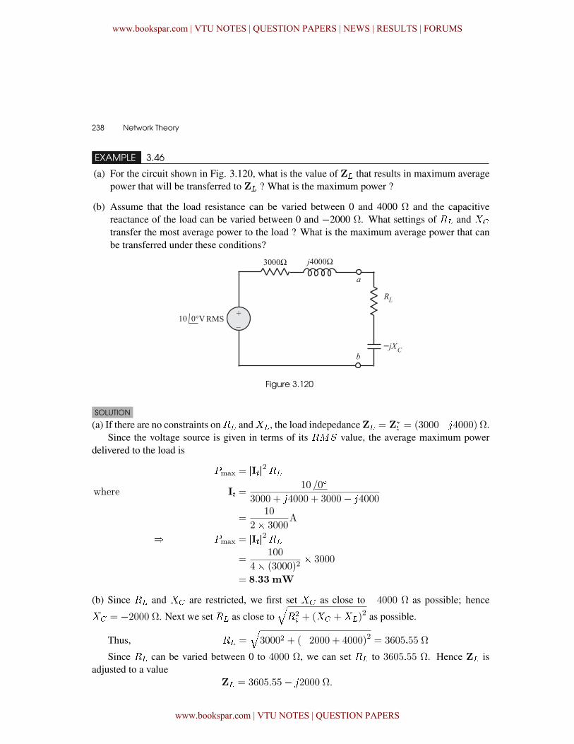
238 � Network Theory
EXAMPLE 3.46
(a) For the circuit shown in Fig. 3.120, what is the value of Z� that results in maximum averagepower that will be transferred to Z� ? What is the maximum power ?
(b) Assume that the load resistance can be varied between 0 and 4000 Ω and the capacitivereactance of the load can be varied between 0 and �2000 Ω. What settings of �� and !�
transfer the most average power to the load ? What is the maximum average power that canbe transferred under these conditions?
Figure 3.120
SOLUTION
(a) If there are no constraints on�� and!�, the load indepedance Z� = Z�
� = (3000��4000) Ω.Since the voltage source is given in terms of its �"# value, the average maximum power
delivered to the load is
�max = �I��2��
where I� =10 /0�
3000 + �4000 + 3000� �4000
=10
2� 3000A
� �max = �I��2��
=100
4� (3000)2� 3000
= 8�33 mW
(b) Since �� and !� are restricted, we first set !� as close to �4000 ٠as possible; hence
!� = �2000 Ω. Next we set �� as close to��2� + (!� +!�)
2 as possible.
Thus, �� =�30002 + (�2000 + 4000)2 = 3605�55 Ω
Since �� can be varied between 0 to 4000 Ω, we can set �� to 3605�55 Ω. Hence Z� isadjusted to a value
Z� = 3605�55� �2000 Ω�
www.bookspar.com | VTU NOTES | QUESTION PAPERS | NEWS | RESULTS | FORUMS
www.bookspar.com | VTU NOTES | QUESTION PAPERS
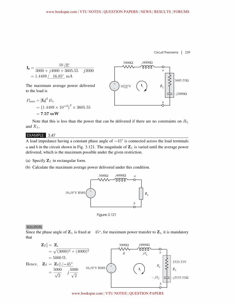
Circuit Theorems � 239
I� =10 /0�
3000 + �4000 + 3605�55� �2000
= 1�4489 /�16�85� mA
The maximum average power deliveredto the load is
�max = �I��2��
=�1�4489� 10�3
�2 � 3605�55
= 7�57 mW
Note that this is less than the power that can be delivered if there are no constraints on ��
and !�.
EXAMPLE 3.47A load impedance having a constant phase angle of �45� is connected across the load terminals� and in the circuit shown in Fig. 3.121. The magnitude of Z� is varied until the average powerdelivered, which is the maximum possible under the given restriction.
(a) Specify Z� in rectangular form.
(b) Calculate the maximum average power delivered under this condition.
Figure 3.121
SOLUTION
Since the phase angle of Z� is fixed at �45�, for maximum power transfer to Z� it is mandatorythat
�Z�� = �Z��= (3000)2 + (4000)2
= 5000 Ω�
Hence� Z� = �Z�� /�45�
=5000�
2� �
5000�2
www.bookspar.com | VTU NOTES | QUESTION PAPERS | NEWS | RESULTS | FORUMS
www.bookspar.com | VTU NOTES | QUESTION PAPERS
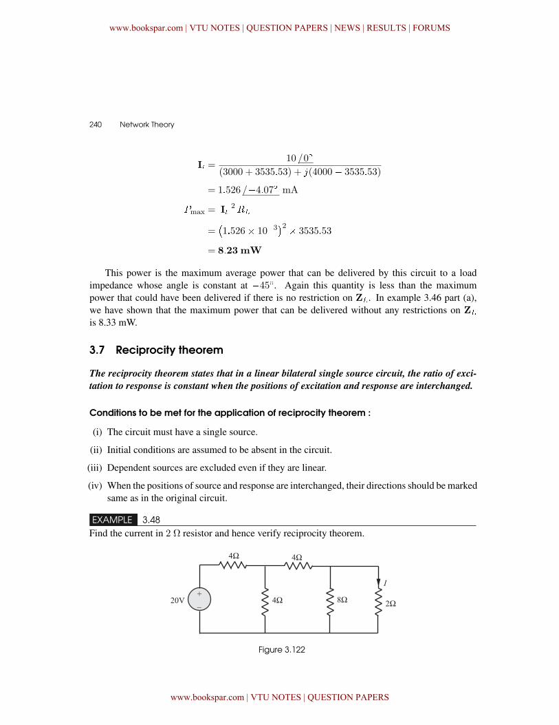
240 � Network Theory
I� =10 /0�
(3000 + 3535�53) + �(4000� 3535�53)
= 1�526 /�4�07� mA
�max = �I��2��
=�1�526� 10�3
�2 � 3535�53
= 8�23 mW
This power is the maximum average power that can be delivered by this circuit to a loadimpedance whose angle is constant at �45�. Again this quantity is less than the maximumpower that could have been delivered if there is no restriction on Z�. In example 3.46 part (a),we have shown that the maximum power that can be delivered without any restrictions on Z�is 8.33 mW.
3.7 Reciprocity theorem
The reciprocity theorem states that in a linear bilateral single source circuit, the ratio of exci-
tation to response is constant when the positions of excitation and response are interchanged.
Conditions to be met for the application of reciprocity theorem :
(i) The circuit must have a single source.
(ii) Initial conditions are assumed to be absent in the circuit.
(iii) Dependent sources are excluded even if they are linear.
(iv) When the positions of source and response are interchanged, their directions should be markedsame as in the original circuit.
EXAMPLE 3.48Find the current in 2 Ω resistor and hence verify reciprocity theorem.
Figure 3.122
www.bookspar.com | VTU NOTES | QUESTION PAPERS | NEWS | RESULTS | FORUMS
www.bookspar.com | VTU NOTES | QUESTION PAPERS
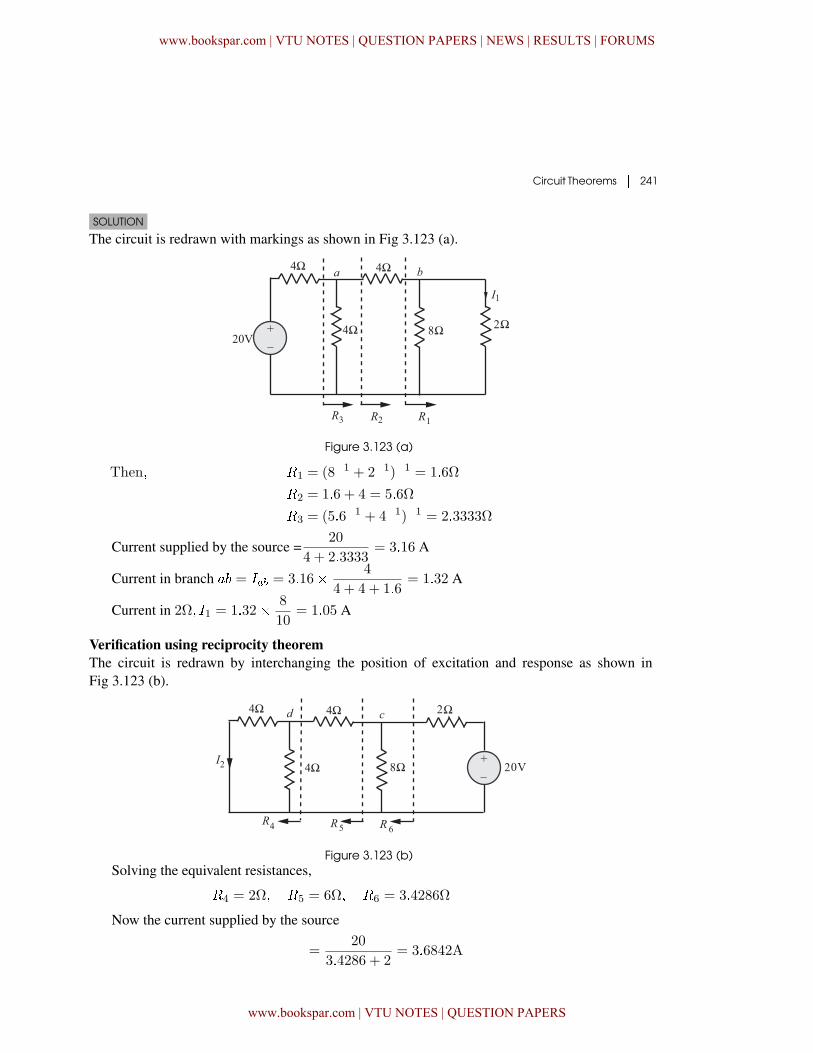
Circuit Theorems � 241
SOLUTION
The circuit is redrawn with markings as shown in Fig 3.123 (a).
Figure 3.123 (a)
Then� �1 = (8�1 + 2�1)�1 = 1�6Ω
�2 = 1�6 + 4 = 5�6Ω
�3 = (5�6�1 + 4�1)�1 = 2�3333Ω
Current supplied by the source =20
4 + 2�3333= 3�16 A
Current in branch � = ��� = 3�16� 4
4 + 4 + 1�6= 1�32 A
Current in 2Ω� �1 = 1�32� 8
10= 1�05 A
Verification using reciprocity theoremThe circuit is redrawn by interchanging the position of excitation and response as shown inFig 3.123 (b).
Figure 3.123 (b)Solving the equivalent resistances,
�4 = 2Ω� �5 = 6Ω� �6 = 3�4286Ω
Now the current supplied by the source
=20
3�4286 + 2= 3�6842A
www.bookspar.com | VTU NOTES | QUESTION PAPERS | NEWS | RESULTS | FORUMS
www.bookspar.com | VTU NOTES | QUESTION PAPERS
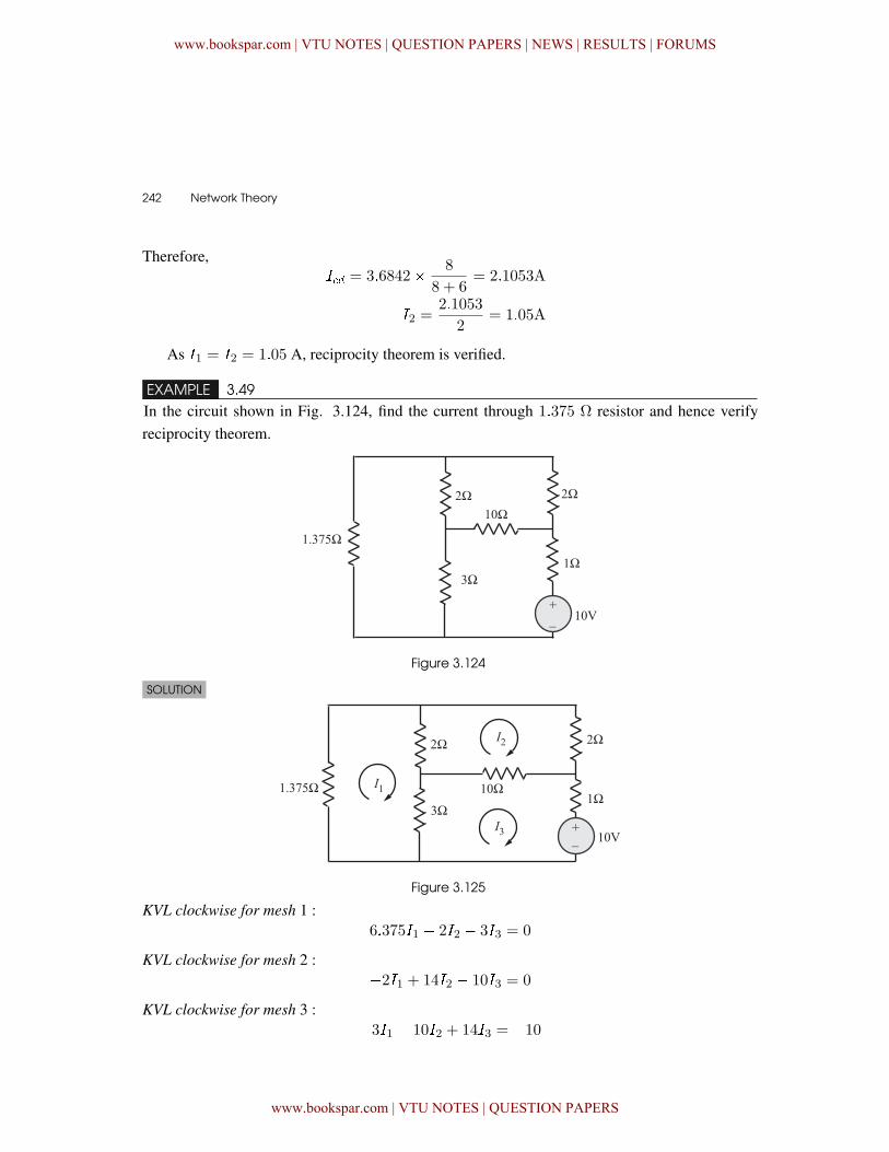
242 � Network Theory
Therefore,�� = 3�6842� 8
8 + 6= 2�1053A
�2 =2�1053
2= 1�05A
As �1 = �2 = 1�05 A, reciprocity theorem is verified.
EXAMPLE 3.49In the circuit shown in Fig. 3.124, find the current through 1�375 Ω resistor and hence verifyreciprocity theorem.
Figure 3.124
SOLUTION
Figure 3.125
KVL clockwise for mesh 1 :6�375�1 � 2�2 � 3�3 = 0
KVL clockwise for mesh 2 :�2�1 + 14�2 � 10�3 = 0
KVL clockwise for mesh 3 :�3�1 � 10�2 + 14�3 = �10
www.bookspar.com | VTU NOTES | QUESTION PAPERS | NEWS | RESULTS | FORUMS
www.bookspar.com | VTU NOTES | QUESTION PAPERS
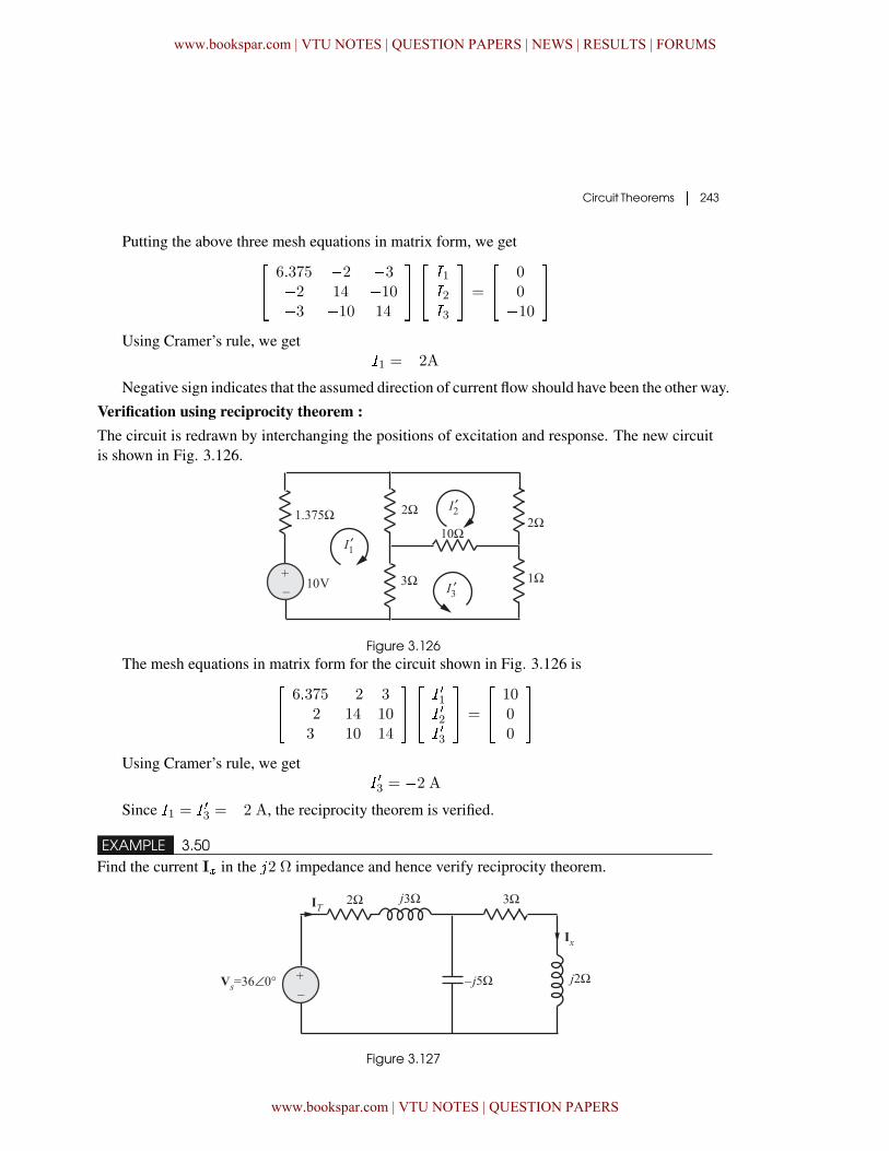
Circuit Theorems � 243
Putting the above three mesh equations in matrix form, we get�� 6�375 �2 �3
�2 14 �10�3 �10 14
���� �1�2�3
�� =
�� 0
0�10
��
Using Cramer’s rule, we get�1 = �2A
Negative sign indicates that the assumed direction of current flow should have been the other way.
Verification using reciprocity theorem :The circuit is redrawn by interchanging the positions of excitation and response. The new circuitis shown in Fig. 3.126.
Figure 3.126The mesh equations in matrix form for the circuit shown in Fig. 3.126 is�
� 6�375 �2 3�2 14 103 10 14
���� � �1� �2� �3
�� =
�� 10
00
��
Using Cramer’s rule, we get� �3 = �2 A
Since �1 = � �3 = �2 A, the reciprocity theorem is verified.
EXAMPLE 3.50Find the current I� in the �2 Ω impedance and hence verify reciprocity theorem.
Figure 3.127
www.bookspar.com | VTU NOTES | QUESTION PAPERS | NEWS | RESULTS | FORUMS
www.bookspar.com | VTU NOTES | QUESTION PAPERS
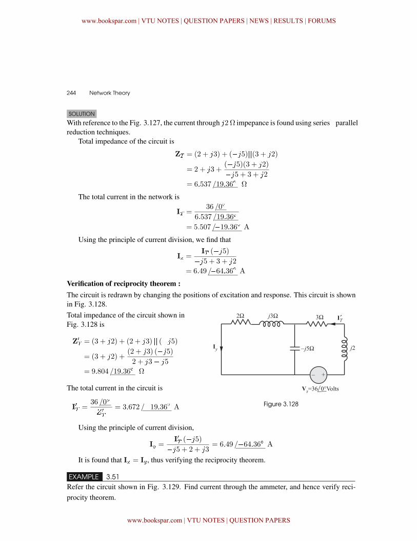
244 � Network Theory
SOLUTION
With reference to the Fig. 3.127, the current through �2 Ω impepance is found using series�parallelreduction techniques.
Total impedance of the circuit is
Z� = (2 + �3) + (��5)��(3 + �2)
= 2 + �3 +(��5)(3 + �2)
��5 + 3 + �2
= 6�537 /19�36� Ω
The total current in the network is
I� =36 /0�
6�537 /19�36�
= 5�507 /�19�36� A
Using the principle of current division, we find that
I� =I� (��5)
��5 + 3 + �2
= 6�49 /�64�36� A
Verification of reciprocity theorem :The circuit is redrawn by changing the positions of excitation and response. This circuit is shownin Fig. 3.128.
Figure 3.128
Total impedance of the circuit shown inFig. 3.128 is
Z�
� = (3 + �2) + (2 + �3) �� (��5)= (3 + �2) +
(2 + �3) (��5)2 + �3� �5
= 9�804 /19�36� Ω
The total current in the circuit is
I�� =36 /0�
% �
�
= 3�672 /�19�36� A
Using the principle of current division,
I� =I�� (��5)
��5 + 2 + �3= 6�49 /�64�36� A
It is found that I� = I�, thus verifying the reciprocity theorem.
EXAMPLE 3.51Refer the circuit shown in Fig. 3.129. Find current through the ammeter, and hence verify reci-procity theorem.
www.bookspar.com | VTU NOTES | QUESTION PAPERS | NEWS | RESULTS | FORUMS
www.bookspar.com | VTU NOTES | QUESTION PAPERS
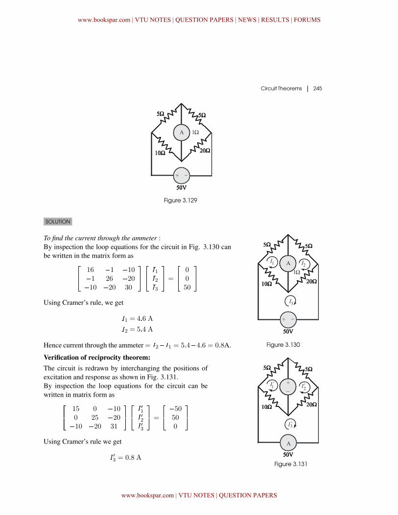
Circuit Theorems � 245
Figure 3.129
SOLUTION
Figure 3.130
To find the current through the ammeter :By inspection the loop equations for the circuit in Fig. 3.130 canbe written in the matrix form as�
� 16 �1 �10�1 26 �20�10 �20 30
���� �1�2�3
�� =
�� 0
050
��
Using Cramer’s rule, we get
�1 = 4�6 A
�2 = 5�4 A
Hence current through the ammeter = �2��1 = 5�4�4�6 = 0�8A.
Verification of reciprocity theorem:The circuit is redrawn by interchanging the positions ofexcitation and response as shown in Fig. 3.131.By inspection the loop equations for the circuit can bewritten in matrix form as�
� 15 0 �100 25 �20�10 �20 31
���� � �1� �2� �3
�� =
�� �50
500
��
Using Cramer’s rule we get
� �3 = 0�8 AFigure 3.131
www.bookspar.com | VTU NOTES | QUESTION PAPERS | NEWS | RESULTS | FORUMS
www.bookspar.com | VTU NOTES | QUESTION PAPERS
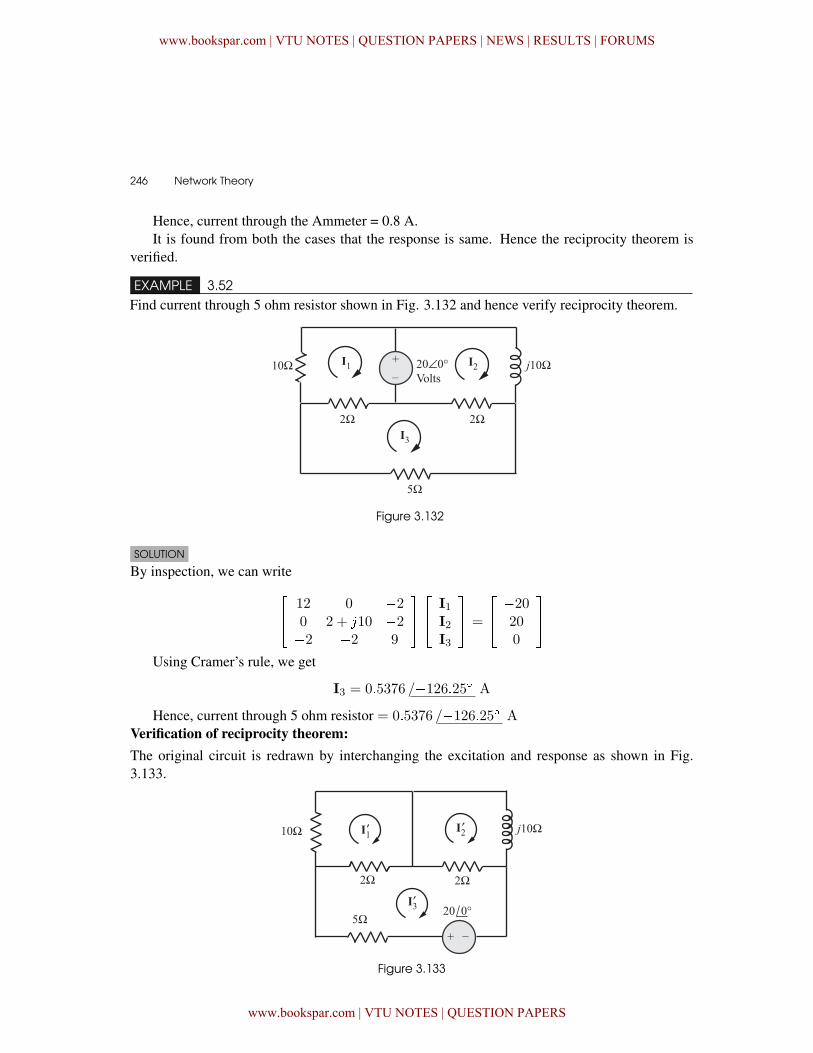
246 � Network Theory
Hence, current through the Ammeter = 0.8 A.It is found from both the cases that the response is same. Hence the reciprocity theorem is
verified.
EXAMPLE 3.52Find current through 5 ohm resistor shown in Fig. 3.132 and hence verify reciprocity theorem.
Figure 3.132
SOLUTION
By inspection, we can write�� 12 0 �2
0 2 + �10 �2�2 �2 9
���� I1
I2I3
�� =
�� �20
200
��
Using Cramer’s rule, we get
I3 = 0�5376 /�126�25� A
Hence, current through 5 ohm resistor = 0�5376 /�126�25� AVerification of reciprocity theorem:The original circuit is redrawn by interchanging the excitation and response as shown in Fig.3.133.
Figure 3.133
www.bookspar.com | VTU NOTES | QUESTION PAPERS | NEWS | RESULTS | FORUMS
www.bookspar.com | VTU NOTES | QUESTION PAPERS
Circuit Theorems � 247
Putting the three equations in matrix form, we get�� 12 0 �2
0 2 + �10 �2�2 �2 9
�����
I�1I�2I�3
��� =
�� 0
020
��
Using Cramer’s rule, we get
I�1 = 0�3876 /�2�35 A
I�2 = 0�456 /�78�9� A
Hence� I�2 � I�1 = �0�3179� �0�4335
= 0�5376 /�126�25� A
The response in both cases remains the same. Thus verifying reciprocity theorem.
3.8 Millman’s theorem
It is possible to combine number of voltage sources or current sources into a single equiva-lent voltage or current source using Millman’s theorem. Hence, this theorem is quite useful incalculating the total current supplied to the load in a generating station by a number of generatorsconnected in parallel across a busbar.
Millman’s theorem states that if n number of generators having generated emfsE1, E2� � � �E�
and internal impedances Z1�Z2� � � �Z� are connected in parallel, then the emfs and impedances
can be combined to give a single equivalent emf of E with an internal impedance of equivalent
value Z.
where E =E1Y1 +E2Y2 + � � � +E�Y�
Y1 +Y2 + � � � +Y�
and Z =1
Y1 +Y2 + � � � +Y�
where Y1�Y2 � � �Y� are the admittances corresponding to the internal impedances Z1�Z2 � � �Z�and are given by
Y1 =1
Z1
Y2 =1
Z2
...
Y� =1
Z�
Fig. 3.134 shows a number of generators having emfs E1�E2 � � �E� connected in parallelacross the terminals � and . Also, Z1�Z2 � � �Z� are the respective internal impedances of thegenerators.
www.bookspar.com | VTU NOTES | QUESTION PAPERS | NEWS | RESULTS | FORUMS
www.bookspar.com | VTU NOTES | QUESTION PAPERS
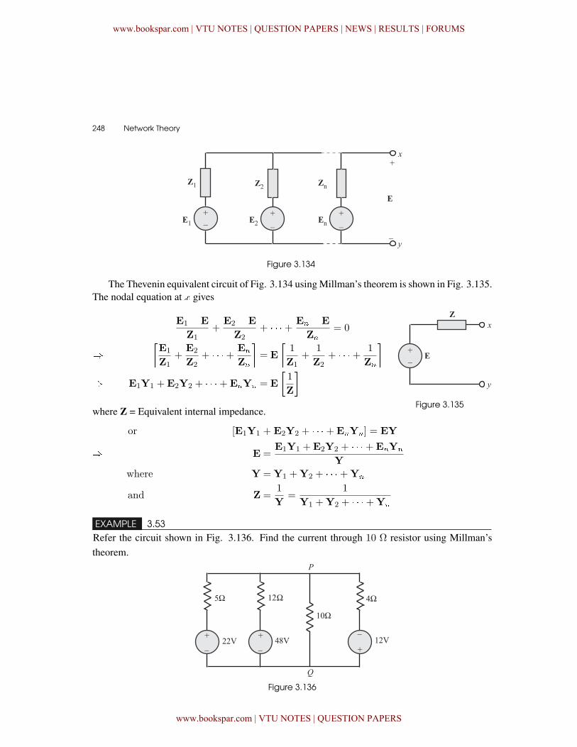
248 � Network Theory
Figure 3.134
The Thevenin equivalent circuit of Fig. 3.134 using Millman’s theorem is shown in Fig. 3.135.The nodal equation at � gives
Figure 3.135
E1 �E
Z1+
E2 �E
Z2+ � � � + E� �E
Z�= 0
��E1
Z1+
E2
Z2+ � � � + E�
Z�
�= E
�1
Z1+
1
Z2+ � � � + 1
Z�
�
� E1Y1 +E2Y2 + � � � +E�Y� = E
�1
Z
�
where Z = Equivalent internal impedance.
or [E1Y1 + E2Y2 + � � � +E�Y�] = EY
� E =E1Y1 +E2Y2 + � � � +E�Y�
Ywhere Y =Y1 +Y2 + � � � +Y�
and Z =1
Y=
1
Y1 +Y2 + � � � +Y�
EXAMPLE 3.53Refer the circuit shown in Fig. 3.136. Find the current through 10 Ω resistor using Millman’stheorem.
Figure 3.136
www.bookspar.com | VTU NOTES | QUESTION PAPERS | NEWS | RESULTS | FORUMS
www.bookspar.com | VTU NOTES | QUESTION PAPERS
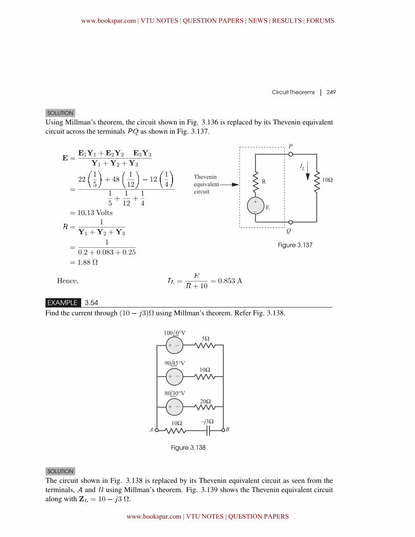
Circuit Theorems � 249
SOLUTION
Using Millman’s theorem, the circuit shown in Fig. 3.136 is replaced by its Thevenin equivalentcircuit across the terminals �& as shown in Fig. 3.137.
Figure 3.137
E =E1Y1 +E2Y2 �E3Y3
Y1 +Y2 +Y3
=
22
�1
5
�+ 48
�1
12
�� 12
�1
4
�1
5+
1
12+
1
4
= 10�13 Volts
� =1
Y1 +Y2 +Y3
=1
0�2 + 0�083 + 0�25
= 1�88 Ω
Hence� �� ='
�+ 10= 0�853 A
EXAMPLE 3.54Find the current through (10� �3)Ω using Millman’s theorem. Refer Fig. 3.138.
Figure 3.138
SOLUTION
The circuit shown in Fig. 3.138 is replaced by its Thevenin equivalent circuit as seen from theterminals, and � using Millman’s theorem. Fig. 3.139 shows the Thevenin equivalent circuitalong with Z� = 10� �3 Ω�
www.bookspar.com | VTU NOTES | QUESTION PAPERS | NEWS | RESULTS | FORUMS
www.bookspar.com | VTU NOTES | QUESTION PAPERS
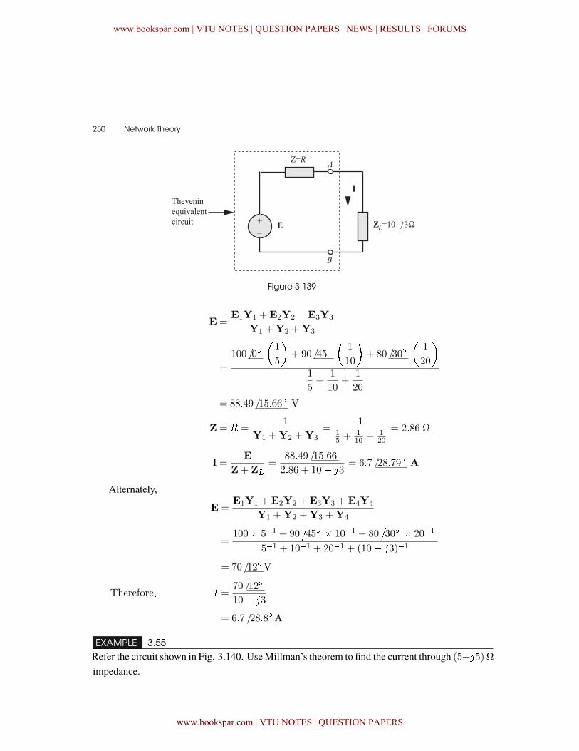
250 � Network Theory
Figure 3.139
E =E1Y1 +E2Y2 �E3Y3
Y1 +Y2 +Y3
=
100 /0��1
5
�+ 90 /45�
�1
10
�+ 80 /30�
�1
20
�1
5+
1
10+
1
20
= 88�49 /15�66� V
Z = � =1
Y1 +Y2 +Y3=
115 + 1
10 + 120
= 2�86 Ω
I =E
Z+ Z�=
88�49 /15�66
2�86 + 10� �3= 6�7 /28�79� A
Alternately,
E =E1Y1 +E2Y2 +E3Y3 +E4Y4
Y1 +Y2 +Y3 +Y4
=100� 5�1 + 90
�45� � 10�1 + 80
�30� � 20�1
5�1 + 10�1 + 20�1 + (10� �3)�1
= 70 /12�V
Therefore� � =70 /12�
10� �3
= 6�7 /28�8�A
EXAMPLE 3.55Refer the circuit shown in Fig. 3.140. Use Millman’s theorem to find the current through (5+�5) Ωimpedance.
www.bookspar.com | VTU NOTES | QUESTION PAPERS | NEWS | RESULTS | FORUMS
www.bookspar.com | VTU NOTES | QUESTION PAPERS
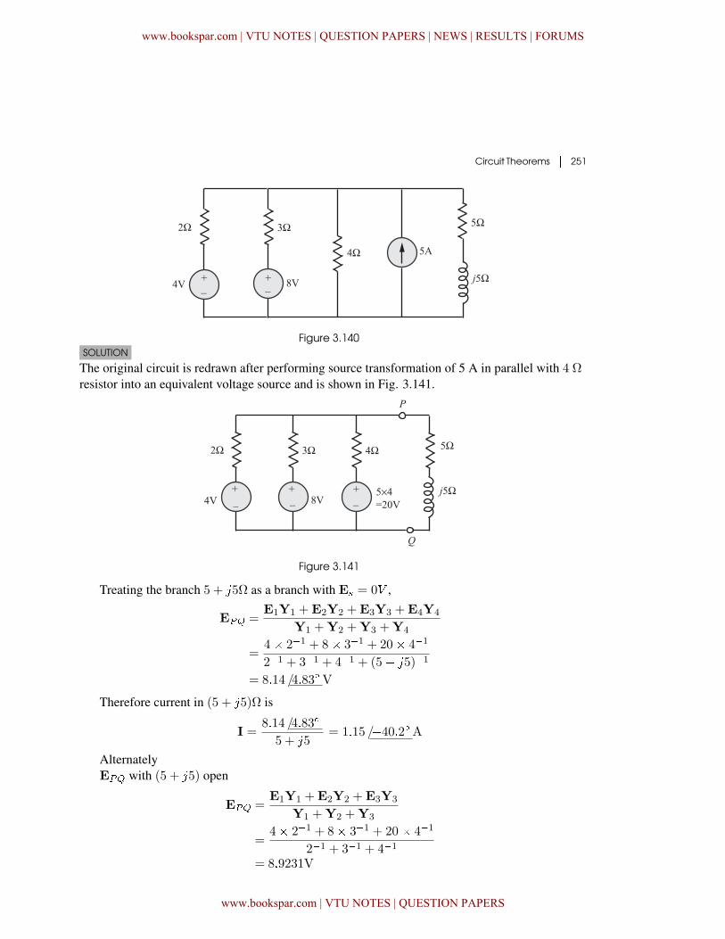
Circuit Theorems � 251
Figure 3.140SOLUTION
The original circuit is redrawn after performing source transformation of 5 A in parallel with 4 Ωresistor into an equivalent voltage source and is shown in Fig. 3.141.
Figure 3.141
Treating the branch 5 + �5Ω as a branch with E = 0� ,
E�� =E1Y1 +E2Y2 +E3Y3 +E4Y4
Y1 +Y2 +Y3 +Y4
=4� 2�1 + 8� 3�1 + 20� 4�1
2�1 + 3�1 + 4�1 + (5� �5)�1
= 8�14 /4�83�V
Therefore current in (5 + �5)Ω is
I =8�14 /4�83�
5 + �5= 1�15 /�40�2�A
AlternatelyE�� with (5 + �5) open
E�� =E1Y1 +E2Y2 +E3Y3
Y1 +Y2 +Y3
=4� 2�1 + 8� 3�1 + 20� 4�1
2�1 + 3�1 + 4�1
= 8�9231V
www.bookspar.com | VTU NOTES | QUESTION PAPERS | NEWS | RESULTS | FORUMS
www.bookspar.com | VTU NOTES | QUESTION PAPERS
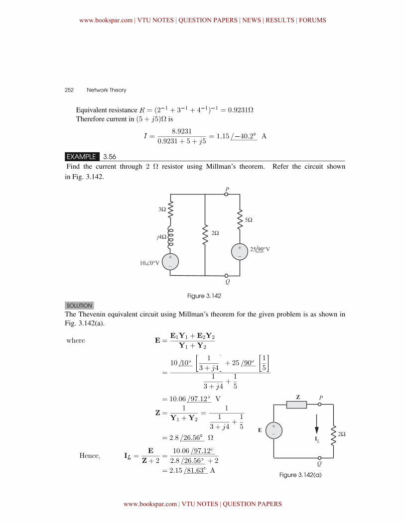
252 � Network Theory
Equivalent resistance � = (2�1 + 3�1 + 4�1)�1 = 0�9231ΩTherefore current in (5 + �5)Ω is
� =8�9231
0�9231 + 5 + �5= 1�15 /�40�2� A
EXAMPLE 3.56Find the current through 2 Ω resistor using Millman’s theorem. Refer the circuit shownin Fig. 3.142.
Figure 3.142
SOLUTION
The Thevenin equivalent circuit using Millman’s theorem for the given problem is as shown inFig. 3.142(a).
where E =E1Y1 +E2Y2
Y1 +Y2
=
10 /10��
1
3 + �4
�+ 25 /90�
�1
5
�1
3 + �4+
1
5
= 10�06 /97�12� V
Z =1
Y1 +Y2=
11
3 + �4+
1
5
= 2�8 /26�56� Ω
Hence� I� =E
Z+ 2=
10�06 /97�12�
2�8 /26�56� + 2
= 2�15 /81�63� AFigure 3.142(a)
www.bookspar.com | VTU NOTES | QUESTION PAPERS | NEWS | RESULTS | FORUMS
www.bookspar.com | VTU NOTES | QUESTION PAPERS
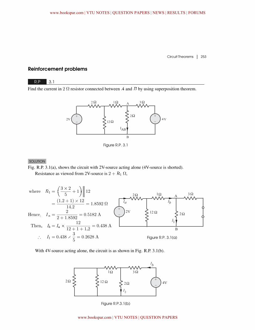
Circuit Theorems � 253
Reinforcement problems
R.P 3.1
Find the current in 2 Ω resistor connected between and � by using superposition theorem.
Figure R.P. 3.1
SOLUTION
Fig. R.P. 3.1(a), shows the circuit with 2V-source acting alone (4V-source is shorted).Resistance as viewed from 2V-source is 2 +�1 Ω,
where �1 =
�3� 2
5+ 1
����� 12=
(1�2 + 1)� 12
14�2= 1�8592 Ω
Hence� I � =2
2 + 1�8592= 0�5182 A
Then� I� = I� � 12
12 + 1 + 1�2= 0�438 A
∴ I1 = 0�438� 3
5= 0�2628 A Figure R.P. 3.1(a)
With 4V-source acting alone, the circuit is as shown in Fig. R.P. 3.1(b).
Figure R.P.3.1(b)
www.bookspar.com | VTU NOTES | QUESTION PAPERS | NEWS | RESULTS | FORUMS
www.bookspar.com | VTU NOTES | QUESTION PAPERS
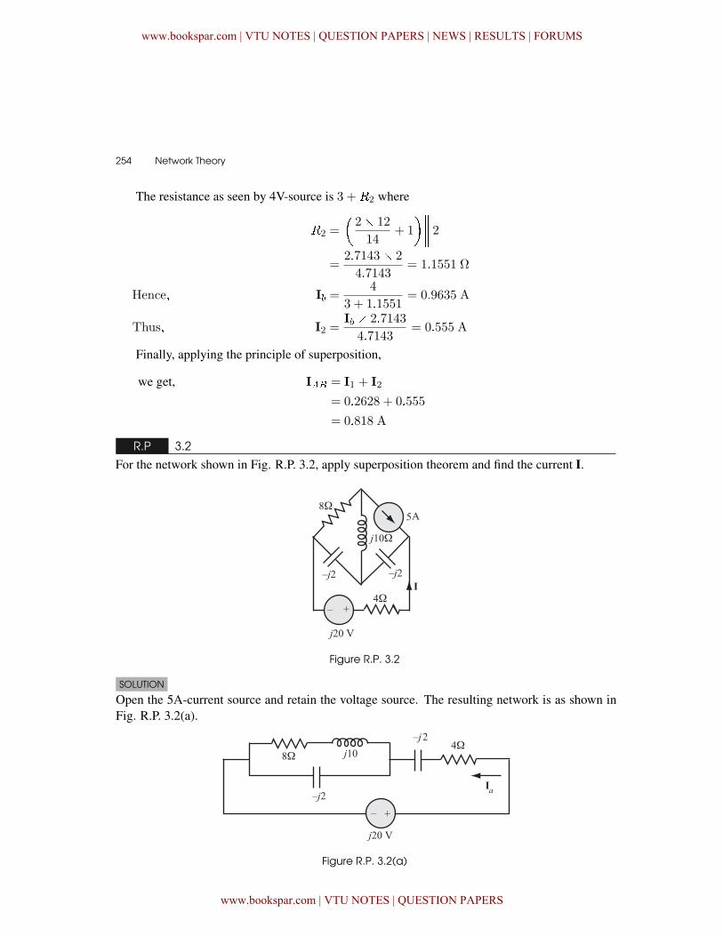
254 � Network Theory
The resistance as seen by 4V-source is 3 +�2 where
�2 =
�2� 12
14+ 1
����� 2=
2�7143� 2
4�7143= 1�1551 Ω
Hence� I� =4
3 + 1�1551= 0�9635 A
Thus� I2 =I� � 2�7143
4�7143= 0�555 A
Finally, applying the principle of superposition,
we get, I�� = I1 + I2
= 0�2628 + 0�555
= 0�818 A
R.P 3.2
For the network shown in Fig. R.P. 3.2, apply superposition theorem and find the current I.
Figure R.P. 3.2
SOLUTION
Open the 5A-current source and retain the voltage source. The resulting network is as shown inFig. R.P. 3.2(a).
Figure R.P. 3.2(a)
www.bookspar.com | VTU NOTES | QUESTION PAPERS | NEWS | RESULTS | FORUMS
www.bookspar.com | VTU NOTES | QUESTION PAPERS
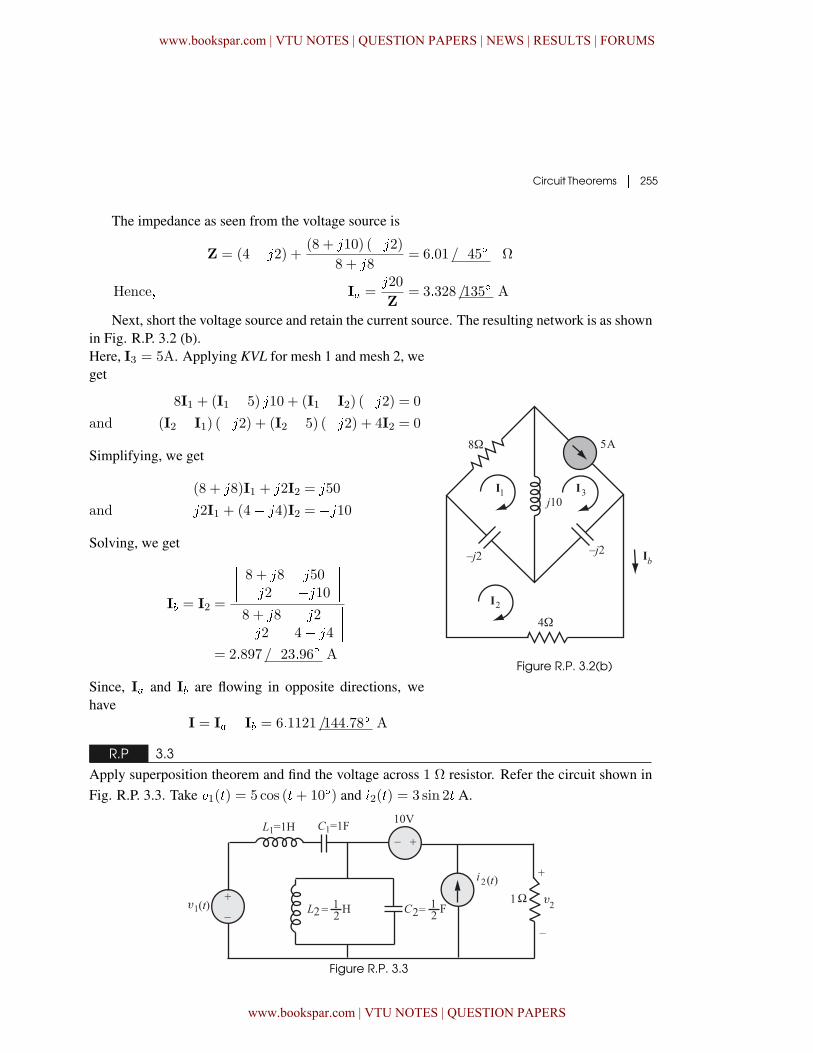
Circuit Theorems � 255
The impedance as seen from the voltage source is
Z = (4� �2) +(8 + �10) (��2)
8 + �8= 6�01 /�45� Ω
Hence� I� =�20
Z= 3�328 /135� A
Next, short the voltage source and retain the current source. The resulting network is as shownin Fig. R.P. 3.2 (b).Here, I3 = 5A. Applying KVL for mesh 1 and mesh 2, weget
8I1 + (I1 � 5) �10 + (I1 � I2) (��2) = 0
and (I2 � I1) (��2) + (I2 � 5) (��2) + 4I2 = 0
Simplifying, we get
(8 + �8)I1 + �2I2 = �50
and �2I1 + (4� �4)I2 = ��10
Solving, we get
I� = I2 =
���� 8 + �8 �50�2 ��10
�������� 8 + �8 �2�2 4� �4
����= 2�897 /�23�96� A
Since, I� and I� are flowing in opposite directions, wehave
I = I� � I� = 6�1121 /144�78� A
Figure R.P. 3.2(b)
R.P 3.3
Apply superposition theorem and find the voltage across 1 Ω resistor. Refer the circuit shown inFig. R.P. 3.3. Take �1(�) = 5 cos (�+ 10�) and �2(�) = 3 sin 2� A.
Figure R.P. 3.3
www.bookspar.com | VTU NOTES | QUESTION PAPERS | NEWS | RESULTS | FORUMS
www.bookspar.com | VTU NOTES | QUESTION PAPERS
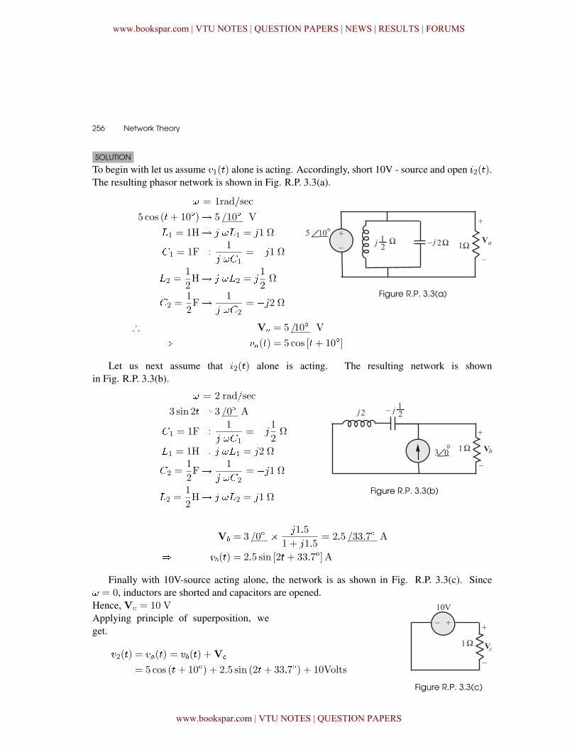
256 � Network Theory
SOLUTION
To begin with let us assume �1(�) alone is acting. Accordingly, short 10V - source and open �2(�).The resulting phasor network is shown in Fig. R.P. 3.3(a).
= 1rad(sec
5 cos (�+ 10�)� 5 /10� V
�1 = 1H� � �1 = �1 Ω
�1 = 1F� 1
� �1= ��1 Ω
�2 =1
2H� � �2 = �
1
2Ω
�2 =1
2F� 1
� �2= ��2 Ω
Figure R.P. 3.3(a)
∴ V� = 5/10� V
� ��(�) = 5 cos [�+ 10�]
Let us next assume that �2(�) alone is acting. The resulting network is shownin Fig. R.P. 3.3(b).
= 2 rad(sec
3 sin 2�� 3 /0� A
�1 = 1F� 1
� �1= �� 1
2Ω
�1 = 1H� � �1 = �2 Ω
�2 =1
2F� 1
� �2= ��1 Ω
�2 =1
2H� � �2 = �1 Ω
Figure R.P. 3.3(b)
V� = 3/0� � �1�5
1 + �1�5= 2�5 /33�7� A
� ��(�) = 2�5 sin [2�+ 33�7�] A
Finally with 10V-source acting alone, the network is as shown in Fig. R.P. 3.3(c). Since = 0, inductors are shorted and capacitors are opened.Hence, V = 10 VApplying principle of superposition, weget.
�2(�) = ��(�) = ��(�) +V
= 5 cos (�+ 10�) + 2�5 sin (2�+ 33�7�) + 10Volts
Figure R.P. 3.3(c)
www.bookspar.com | VTU NOTES | QUESTION PAPERS | NEWS | RESULTS | FORUMS
www.bookspar.com | VTU NOTES | QUESTION PAPERS
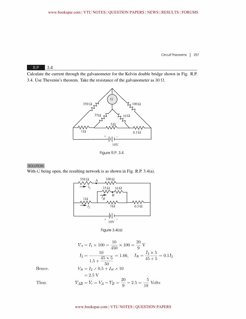
Circuit Theorems � 257
R.P 3.4
Calculate the current through the galvanometer for the Kelvin double bridge shown in Fig. R.P.3.4. Use Thevenin’s theorem. Take the resistance of the galvanometer as 30 Ω.
Figure R.P. 3.4
SOLUTION
With ) being open, the resulting network is as shown in Fig. R.P. 3.4(a).
Figure 3.4(a)
�� = �1 � 100 =10
450� 100 =
20
9V
�2 =10
1�5 +45� 5
50
= 1�66� �� =�2 � 5
45 + 5= 0�1�2
Hence� �� = �2 � 0�5 + �� � 10
= 2�5 V
Thus� ��� = �� = �� � �� =20
9� 2�5 =
�518
Volts
www.bookspar.com | VTU NOTES | QUESTION PAPERS | NEWS | RESULTS | FORUMS
www.bookspar.com | VTU NOTES | QUESTION PAPERS
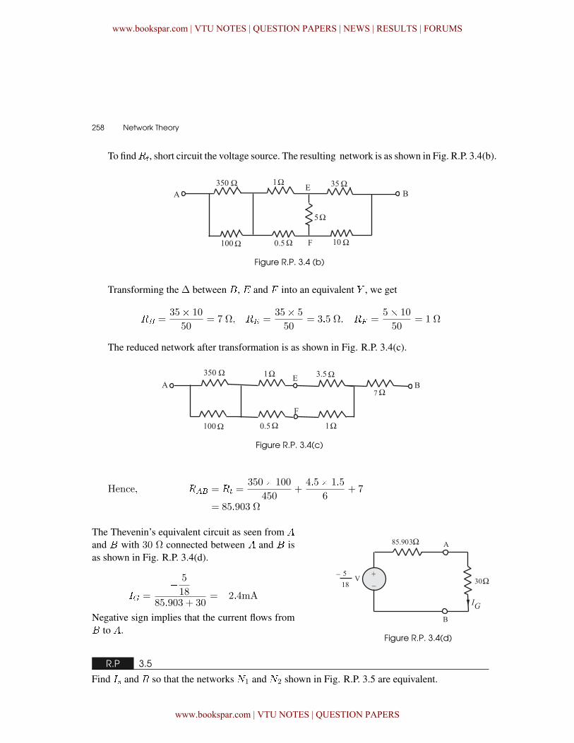
258 � Network Theory
To find��, short circuit the voltage source. The resulting network is as shown in Fig. R.P. 3.4(b).
Figure R.P. 3.4 (b)
Transforming the Δ between �, ' and * into an equivalent + , we get
�� =35� 10
50= 7 � �� =
35� 5
50= 3�5 � �� =
5� 10
50= 1 Ω
The reduced network after transformation is as shown in Fig. R.P. 3.4(c).
Figure R.P. 3.4(c)
Hence� ��� = �� =350� 100
450+
4�5� 1�5
6+ 7
= 85�903 Ω
The Thevenin’s equivalent circuit as seen from
and � with 30 Ω connected between and � isas shown in Fig. R.P. 3.4(d).
�� =� 5
1885�903 + 30
= �2�4mA
Negative sign implies that the current flows from� to .
Figure R.P. 3.4(d)
R.P 3.5
Find � and � so that the networks ,1 and ,2 shown in Fig. R.P. 3.5 are equivalent.
www.bookspar.com | VTU NOTES | QUESTION PAPERS | NEWS | RESULTS | FORUMS
www.bookspar.com | VTU NOTES | QUESTION PAPERS
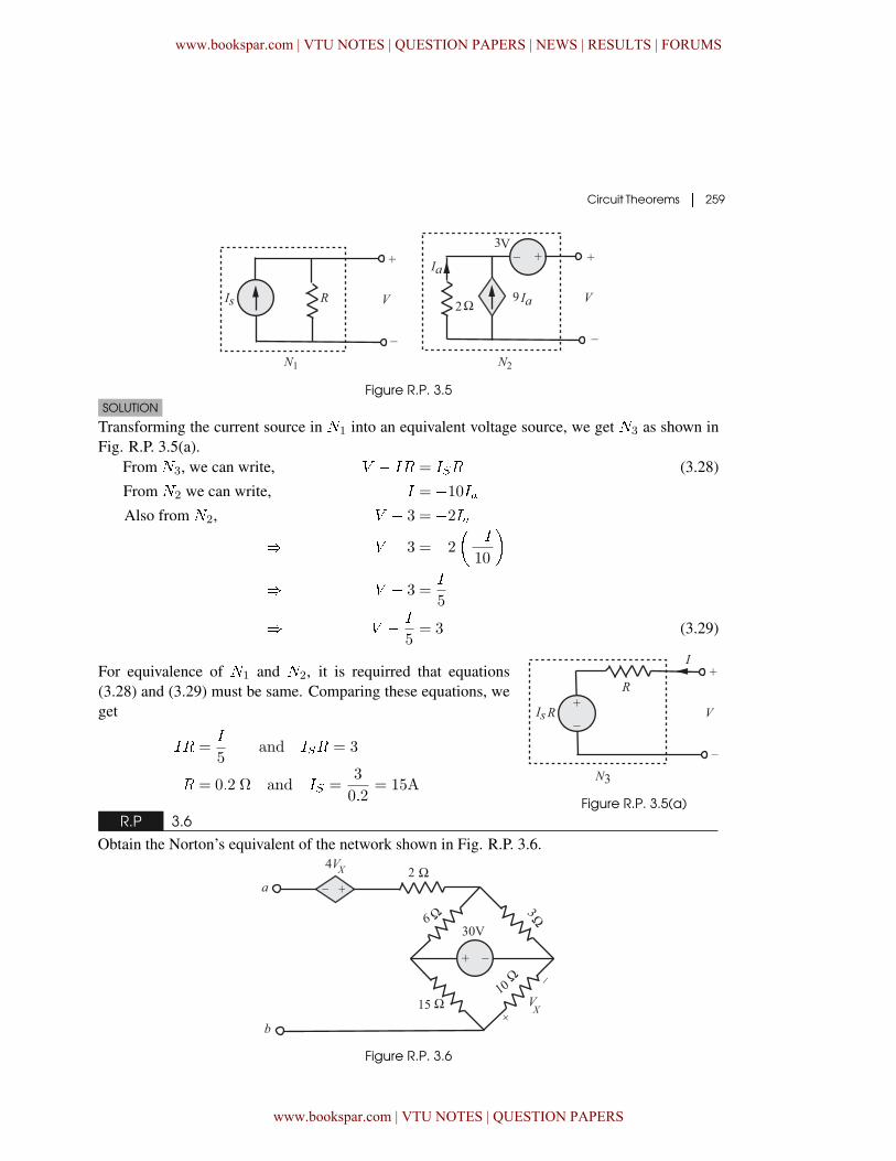
Circuit Theorems � 259
Figure R.P. 3.5SOLUTION
Transforming the current source in ,1 into an equivalent voltage source, we get ,3 as shown inFig. R.P. 3.5(a).
From ,3, we can write, � � �� = ��� (3.28)
From ,2 we can write, � = �10��Also from ,2, � � 3 = �2��
� � � 3 = �2���10
�
� � � 3 =�
5
� � � �
5= 3 (3.29)
Figure R.P. 3.5(a)
For equivalence of ,1 and ,2, it is requirred that equations(3.28) and (3.29) must be same. Comparing these equations, weget
�� =�
5and ��� = 3
� = 0�2 ٠and �� =3
0�2= 15A
R.P 3.6
Obtain the Norton’s equivalent of the network shown in Fig. R.P. 3.6.
Figure R.P. 3.6
www.bookspar.com | VTU NOTES | QUESTION PAPERS | NEWS | RESULTS | FORUMS
www.bookspar.com | VTU NOTES | QUESTION PAPERS
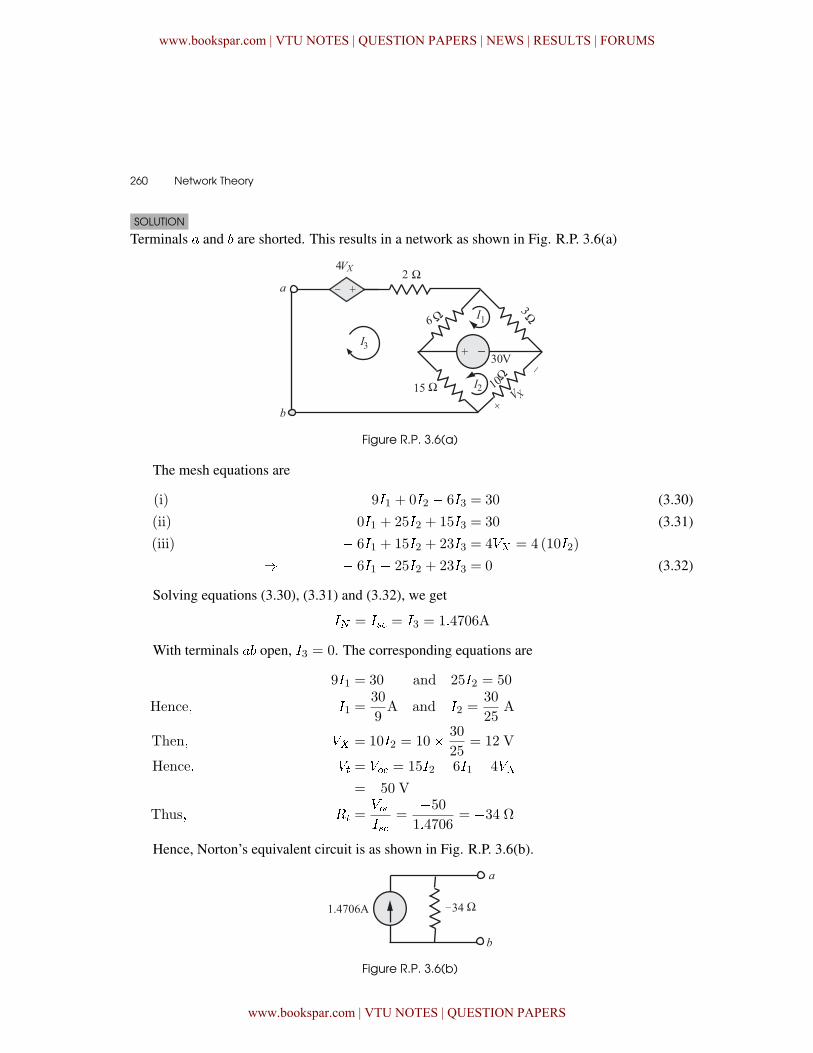
260 � Network Theory
SOLUTION
Terminals � and are shorted. This results in a network as shown in Fig. R.P. 3.6(a)
Figure R.P. 3.6(a)
The mesh equations are
(i) 9�1 + 0�2 � 6�3 = 30 (3.30)
(ii) 0�1 + 25�2 + 15�3 = 30 (3.31)
(iii) � 6�1 + 15�2 + 23�3 = 4�� = 4 (10�2)
� � 6�1 � 25�2 + 23�3 = 0 (3.32)
Solving equations (3.30), (3.31) and (3.32), we get
� = � = �3 = 1�4706A
With terminals � open, �3 = 0. The corresponding equations are
9�1 = 30 and 25�2 = 50
Hence� �1 =30
9A and �2 =
30
25A
Then� �� = 10�2 = 10� 30
25= 12 V
Hence� �� = �� = 15�2 � 6�1 � 4��
= �50 VThus� �� =
���
=�50
1�4706= �34 Ω
Hence, Norton’s equivalent circuit is as shown in Fig. R.P. 3.6(b).
Figure R.P. 3.6(b)
www.bookspar.com | VTU NOTES | QUESTION PAPERS | NEWS | RESULTS | FORUMS
www.bookspar.com | VTU NOTES | QUESTION PAPERS
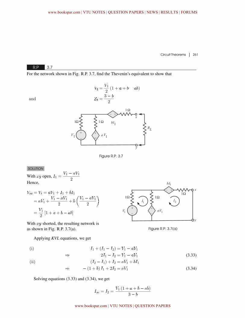
Circuit Theorems � 261
R.P 3.7
For the network shown in Fig. R.P. 3.7, find the Thevenin’s equivalent to show that
�� =�12
(1 + �+ � � )
and %� =3�
2
Figure R.P. 3.7
SOLUTION
With � open, �1 =�1 � ��1
2Hence,
�� = �� = ��1 + �1 + �1
= ��1 +�1 � ��1
2+
��1 � ��1
2
�
=�12
[1 + �+ � � ]
With � shorted, the resulting network isas shown in Fig. R.P. 3.7(a). Figure R.P. 3.7(a)
Applying KVL equations, we get
(i) �1 + (�1 � �2) = �1 � ��1
� 2�1 � �2 = �1 � ��1 (3.33)
(ii) (�2 � �1) + �2 = ��1 + �1
� � (1 + ) �1 + 2�2 = ��1 (3.34)
Solving equations (3.33) and (3.34), we get
� = �2 =�1 (1 + �+ � � )
3�
www.bookspar.com | VTU NOTES | QUESTION PAPERS | NEWS | RESULTS | FORUMS
www.bookspar.com | VTU NOTES | QUESTION PAPERS
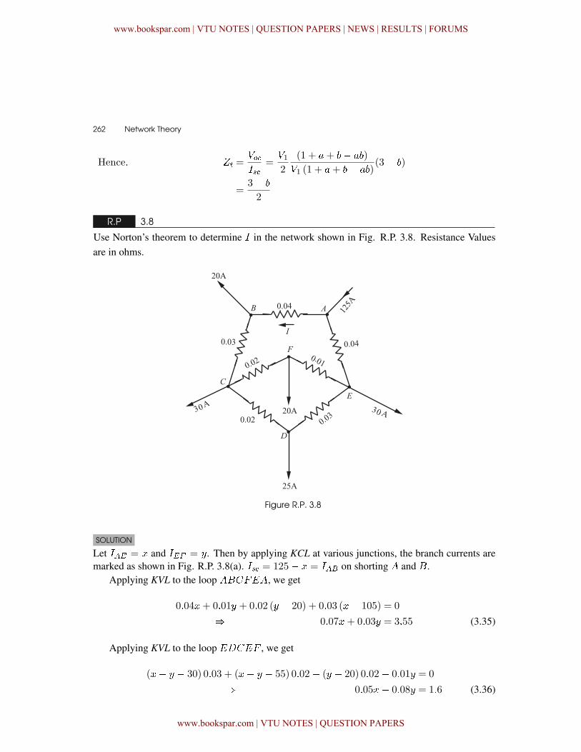
262 � Network Theory
Hence� %� =���
=�12
(1 + �+ � � )
�1 (1 + �+ � � )(3� )
=3�
2
R.P 3.8
Use Norton’s theorem to determine � in the network shown in Fig. R.P. 3.8. Resistance Valuesare in ohms.
Figure R.P. 3.8
SOLUTION
Let ��� = � and ��� = . Then by applying KCL at various junctions, the branch currents aremarked as shown in Fig. R.P. 3.8(a). � = 125� � = ��� on shorting and �.
Applying KVL to the loop ��*', we get
0�04�+ 0�01 + 0�02 ( � 20) + 0�03 (�� 105) = 0
� 0�07�+ 0�03 = 3�55 (3.35)
Applying KVL to the loop '-�'* , we get
(�� � 30) 0�03 + (�� � 55) 0�02� ( � 20) 0�02� 0�01 = 0
� 0�05�� 0�08 = 1�6 (3.36)
www.bookspar.com | VTU NOTES | QUESTION PAPERS | NEWS | RESULTS | FORUMS
www.bookspar.com | VTU NOTES | QUESTION PAPERS
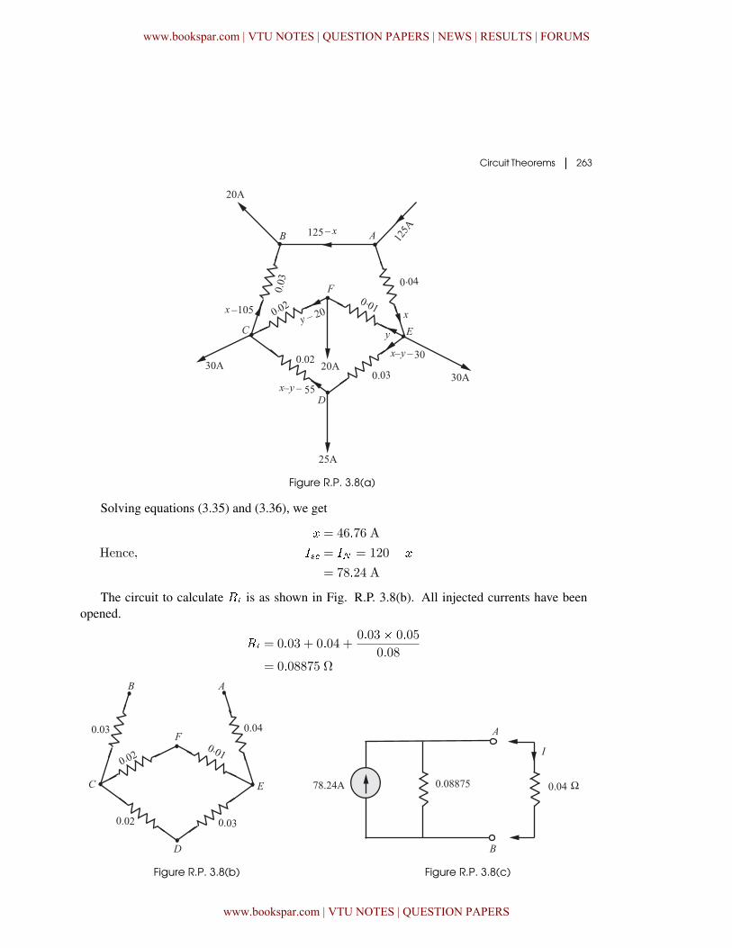
Circuit Theorems � 263
Figure R.P. 3.8(a)
Solving equations (3.35) and (3.36), we get
� = 46�76 A
Hence� � = � = 120� �
= 78�24 A
The circuit to calculate �� is as shown in Fig. R.P. 3.8(b). All injected currents have beenopened.
�� = 0�03 + 0�04 +0�03� 0�05
0�08= 0�08875 Ω
Figure R.P. 3.8(b) Figure R.P. 3.8(c)
www.bookspar.com | VTU NOTES | QUESTION PAPERS | NEWS | RESULTS | FORUMS
www.bookspar.com | VTU NOTES | QUESTION PAPERS
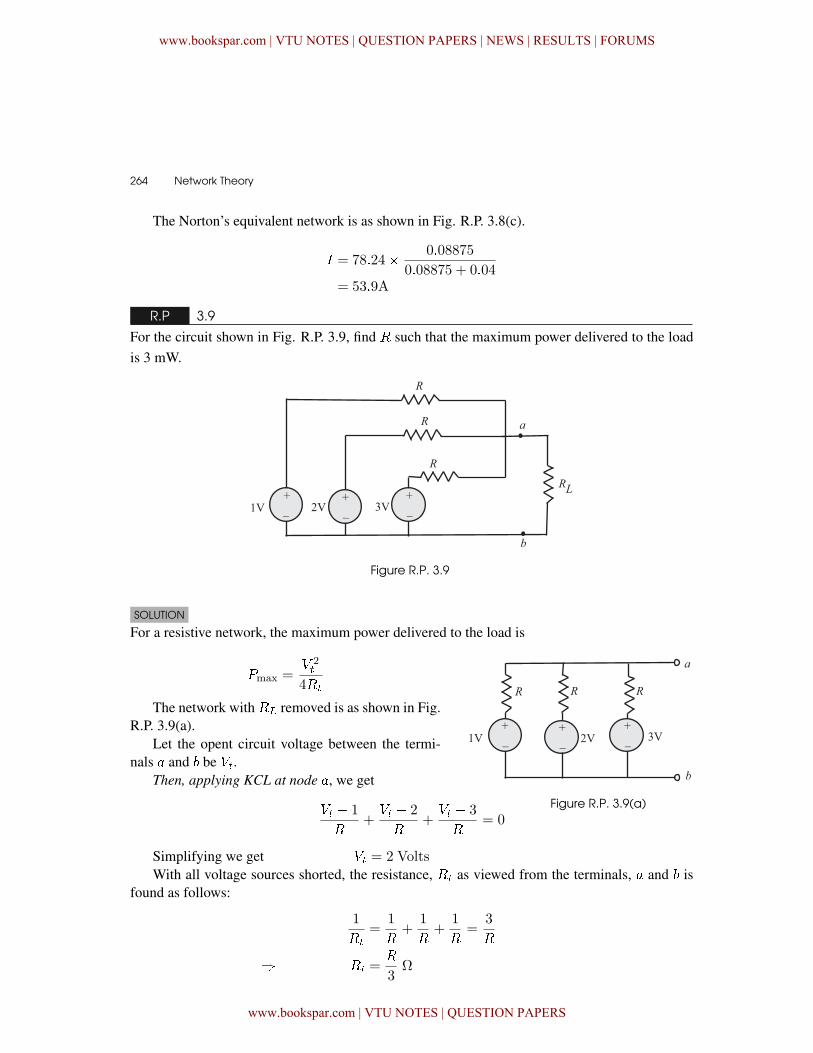
264 � Network Theory
The Norton’s equivalent network is as shown in Fig. R.P. 3.8(c).
� = 78�24� 0�08875
0�08875 + 0�04= 53�9A
R.P 3.9
For the circuit shown in Fig. R.P. 3.9, find � such that the maximum power delivered to the loadis 3 mW.
Figure R.P. 3.9
SOLUTION
For a resistive network, the maximum power delivered to the load is
Figure R.P. 3.9(a)
�max =� 2�
4��
The network with �� removed is as shown in Fig.R.P. 3.9(a).
Let the opent circuit voltage between the termi-nals � and be ��.
Then, applying KCL at node �, we get
�� � 1
�+�� � 2
�+�� � 3
�= 0
Simplifying we get �� = 2 Volts
With all voltage sources shorted, the resistance, �� as viewed from the terminals, � and isfound as follows:
1
��
=1
�+
1
�+
1
�=
3
�
� �� =�
3Ω
www.bookspar.com | VTU NOTES | QUESTION PAPERS | NEWS | RESULTS | FORUMS
www.bookspar.com | VTU NOTES | QUESTION PAPERS
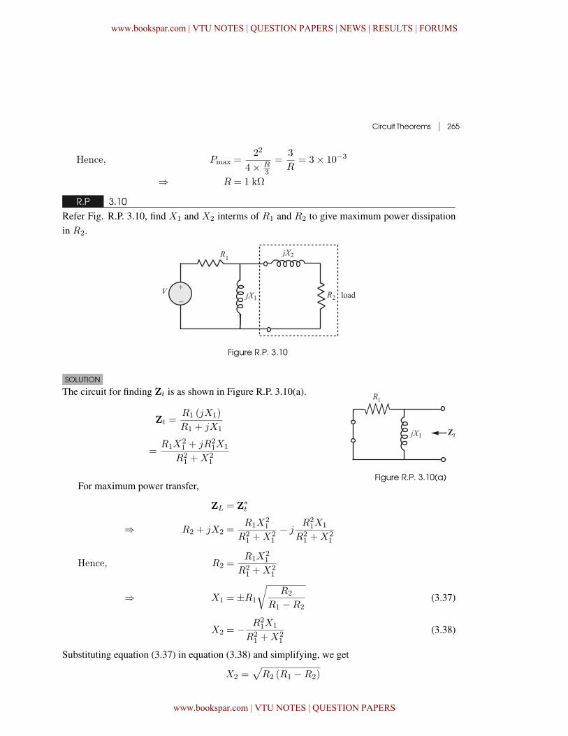
Circuit Theorems | 265
Hence, Pmax =22
4× R3
=3
R= 3× 10⁻³
⇒ R = 1 kΩ
R.P 3.10
Refer Fig. R.P. 3.10, find X1 and X2 interms of R1 and R2 to give maximum power dissipationin R2.
Figure R.P. 3.10
SOLUTION
The circuit for finding Zt is as shown in Figure R.P. 3.10(a).
Zt =R1 (jX1)
R1 + jX1
=R1X
21 + jR2
1X1
R21 +X2
1
Figure R.P. 3.10(a)For maximum power transfer,
ZL = Z∗t
⇒ R2 + jX2 =R1X
21
R21 +X2
1
− jR2
1X1
R21 +X2
1
Hence, R2 =R1X
21
R21 +X2
1
⇒ X1 = ±R1
√R2
R1 −R2(3.37)
X2 = − R21X1
R21 +X2
1
(3.38)
Substituting equation (3.37) in equation (3.38) and simplifying, we get
X2 =√R2 (R1 −R2)
www.bookspar.com | VTU NOTES | QUESTION PAPERS | NEWS | RESULTS | FORUMS
www.bookspar.com | VTU NOTES | QUESTION PAPERS
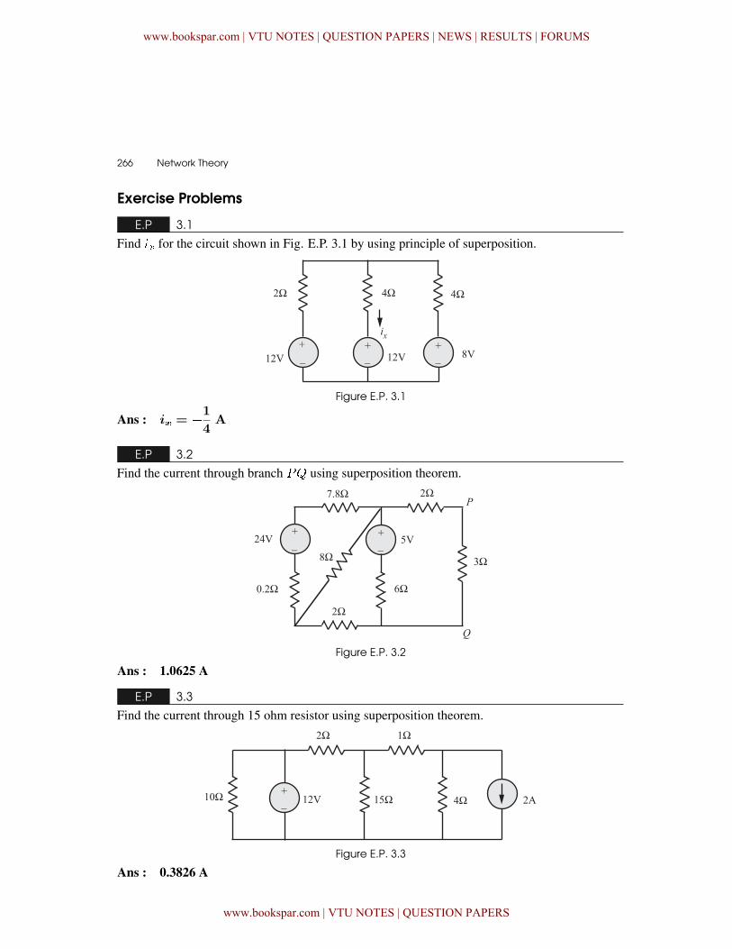
266 � Network Theory
Exercise Problems
E.P 3.1
Find �� for the circuit shown in Fig. E.P. 3.1 by using principle of superposition.
Figure E.P. 3.1
Ans : i� = �
1
4A
E.P 3.2
Find the current through branch �& using superposition theorem.
Figure E.P. 3.2
Ans : 1.0625 A
E.P 3.3
Find the current through 15 ohm resistor using superposition theorem.
Figure E.P. 3.3
Ans : 0.3826 A
www.bookspar.com | VTU NOTES | QUESTION PAPERS | NEWS | RESULTS | FORUMS
www.bookspar.com | VTU NOTES | QUESTION PAPERS
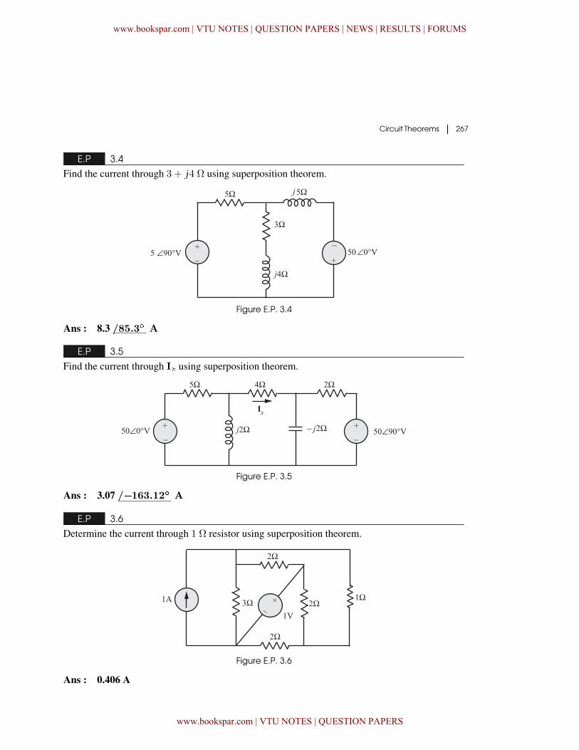
Circuit Theorems � 267
E.P 3.4
Find the current through 3 + �4 Ω using superposition theorem.
Figure E.P. 3.4
Ans : 8.3 /85.3� A
E.P 3.5
Find the current through I� using superposition theorem.
Figure E.P. 3.5
Ans : 3.07 /�163.12� A
E.P 3.6
Determine the current through 1 Ω resistor using superposition theorem.
Figure E.P. 3.6
Ans : 0.406 A
www.bookspar.com | VTU NOTES | QUESTION PAPERS | NEWS | RESULTS | FORUMS
www.bookspar.com | VTU NOTES | QUESTION PAPERS
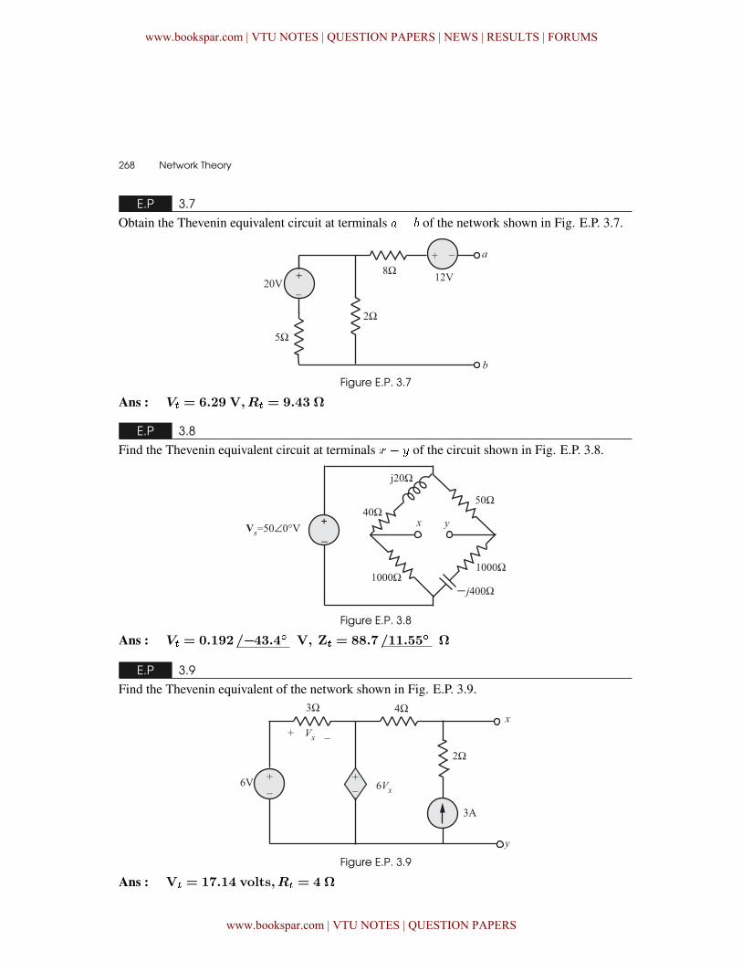
268 � Network Theory
E.P 3.7
Obtain the Thevenin equivalent circuit at terminals �� of the network shown in Fig. E.P. 3.7.
Figure E.P. 3.7
Ans : V� = 6.29 V,R� = 9.43 Ω
E.P 3.8
Find the Thevenin equivalent circuit at terminals �� of the circuit shown in Fig. E.P. 3.8.
Figure E.P. 3.8
Ans : V� = 0.192/�43.4� V, Z� = 88.7/11.55� Ω
E.P 3.9
Find the Thevenin equivalent of the network shown in Fig. E.P. 3.9.
Figure E.P. 3.9
Ans : V� = 17.14 volts,R� = 4 Ω
www.bookspar.com | VTU NOTES | QUESTION PAPERS | NEWS | RESULTS | FORUMS
www.bookspar.com | VTU NOTES | QUESTION PAPERS
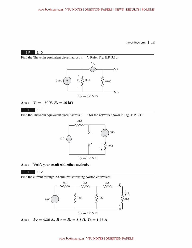
Circuit Theorems � 269
E.P 3.10
Find the Thevenin equivalent circuit across �� . Refer Fig. E.P. 3.10.
Figure E.P. 3.10
Ans : V� = �30 V,R� = 10 kΩ
E.P 3.11
Find the Thevenin equivalent circuit across �� for the network shown in Fig. E.P. 3.11.
Figure E.P. 3.11
Ans : Verify your result with other methods.
E.P 3.12
Find the current through 20 ohm resistor using Norton equivalent.
Figure E.P. 3.12
Ans : I� = 4.36 A, R� = R� = 8.8 Ω, I� = 1.33 A
www.bookspar.com | VTU NOTES | QUESTION PAPERS | NEWS | RESULTS | FORUMS
www.bookspar.com | VTU NOTES | QUESTION PAPERS
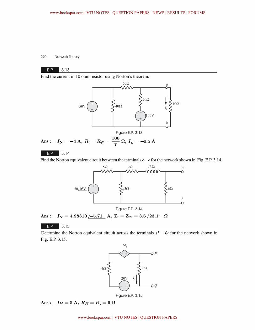
270 � Network Theory
E.P 3.13
Find the current in 10 ohm resistor using Norton’s theorem.
Figure E.P. 3.13
Ans : I� = �4 A, R� = R� =100
7Ω, I� = �0.5 A
E.P 3.14
Find the Norton equivalent circuit between the terminals �� for the network shown in Fig. E.P. 3.14.
Figure E.P. 3.14
Ans : I� = 4.98310/�5.71� A, Z� = Z� = 3.6/23.1� Ω
E.P 3.15
Determine the Norton equivalent circuit across the terminals � � & for the network shown inFig. E.P. 3.15.
Figure E.P. 3.15
Ans : I� = 5 A, R� = R� = 6 Ω
www.bookspar.com | VTU NOTES | QUESTION PAPERS | NEWS | RESULTS | FORUMS
www.bookspar.com | VTU NOTES | QUESTION PAPERS
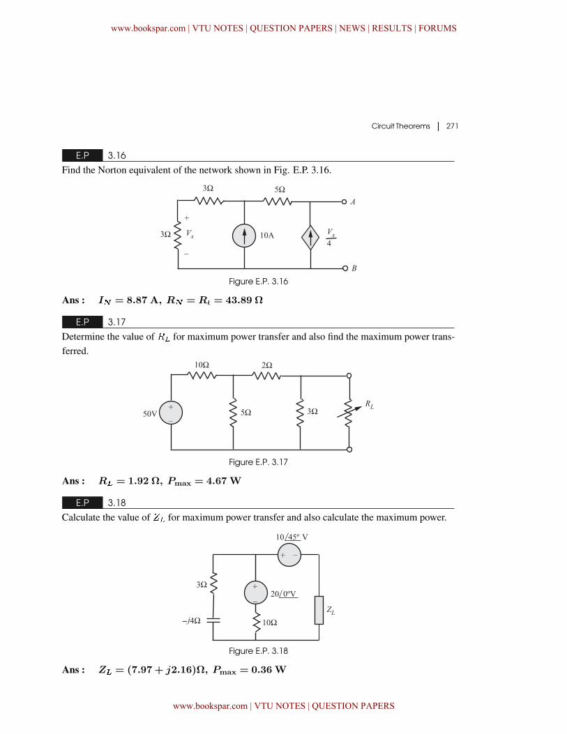
Circuit Theorems � 271
E.P 3.16
Find the Norton equivalent of the network shown in Fig. E.P. 3.16.
Figure E.P. 3.16
Ans : I� = 8.87 A, R� = R� = 43.89 Ω
E.P 3.17
Determine the value of �� for maximum power transfer and also find the maximum power trans-ferred.
Figure E.P. 3.17
Ans : R� = 1.92 Ω, Pmax = 4.67W
E.P 3.18
Calculate the value of %� for maximum power transfer and also calculate the maximum power.
Figure E.P. 3.18
Ans : Z� = (7.97 + j2.16)Ω, Pmax = 0.36W
www.bookspar.com | VTU NOTES | QUESTION PAPERS | NEWS | RESULTS | FORUMS
www.bookspar.com | VTU NOTES | QUESTION PAPERS
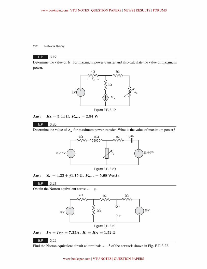
272 � Network Theory
E.P 3.19
Determine the value of �� for maximum power transfer and also calculate the value of maximumpower.
Figure E.P. 3.19
Ans : R� = 5.44 Ω, Pmax = 2.94W
E.P 3.20
Determine the value of %� for maximum power transfer. What is the value of maximum power?
Figure E.P. 3.20
Ans : Z� = 4.23 + j1.15 Ω, Pmax = 5.68Watts
E.P 3.21
Obtain the Norton equivalent across �� .
Figure E.P. 3.21
Ans : I� = I�� = 7.35A, R� = R� = 1.52 Ω
E.P 3.22
Find the Norton equivalent circuit at terminals �� of the network shown in Fig. E.P. 3.22.
www.bookspar.com | VTU NOTES | QUESTION PAPERS | NEWS | RESULTS | FORUMS
www.bookspar.com | VTU NOTES | QUESTION PAPERS
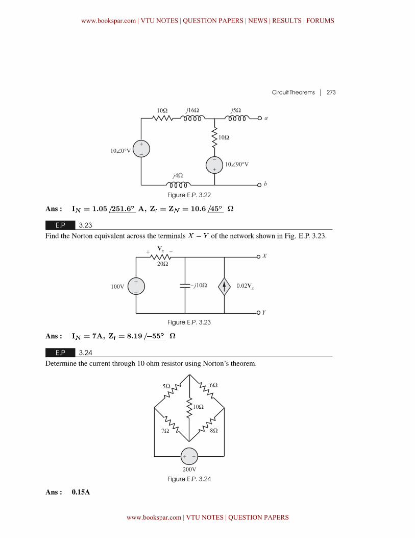
Circuit Theorems � 273
Figure E.P. 3.22
Ans : I� = 1.05/251.6� A, Z� = Z� = 10.6/45� Ω
E.P 3.23
Find the Norton equivalent across the terminals ! � + of the network shown in Fig. E.P. 3.23.
Figure E.P. 3.23
Ans : I� = 7A, Z� = 8.19/�55� Ω
E.P 3.24
Determine the current through 10 ohm resistor using Norton’s theorem.
Figure E.P. 3.24
Ans : 0.15A
www.bookspar.com | VTU NOTES | QUESTION PAPERS | NEWS | RESULTS | FORUMS
www.bookspar.com | VTU NOTES | QUESTION PAPERS
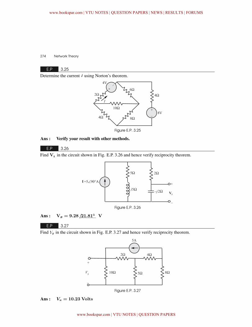
274 � Network Theory
E.P 3.25
Determine the current � using Norton’s theorem.
Figure E.P. 3.25
Ans : Verify your result with other methods.
E.P 3.26
Find V� in the circuit shown in Fig. E.P. 3.26 and hence verify reciprocity theorem.
Figure E.P. 3.26
Ans : V� = 9.28/21.81� V
E.P 3.27
Find �� in the circuit shown in Fig. E.P. 3.27 and hence verify reciprocity theorem.
Figure E.P. 3.27
Ans : V� = 10.23 Volts
www.bookspar.com | VTU NOTES | QUESTION PAPERS | NEWS | RESULTS | FORUMS
www.bookspar.com | VTU NOTES | QUESTION PAPERS
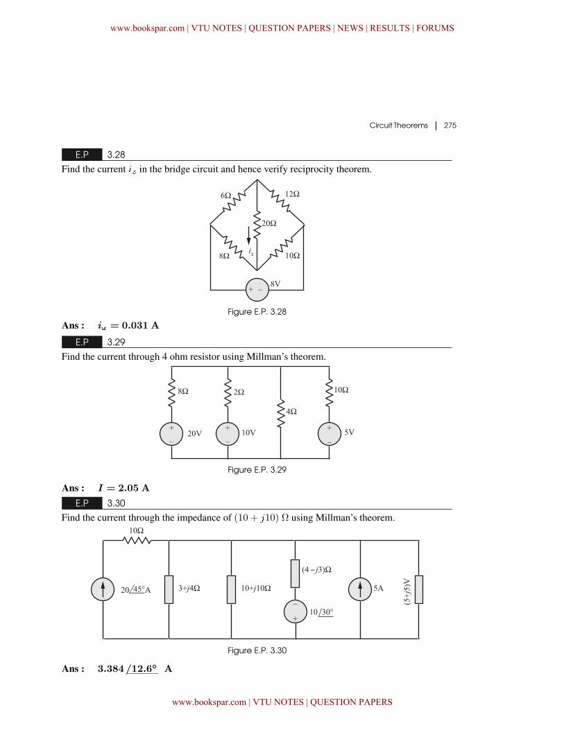
Circuit Theorems � 275
E.P 3.28
Find the current �� in the bridge circuit and hence verify reciprocity theorem.
Figure E.P. 3.28
Ans : i� = 0.031 A
E.P 3.29
Find the current through 4 ohm resistor using Millman’s theorem.
Figure E.P. 3.29
Ans : I = 2.05 A
E.P 3.30
Find the current through the impedance of (10 + �10) Ω using Millman’s theorem.
Figure E.P. 3.30
Ans : 3.384/12.6� A
www.bookspar.com | VTU NOTES | QUESTION PAPERS | NEWS | RESULTS | FORUMS
www.bookspar.com | VTU NOTES | QUESTION PAPERS
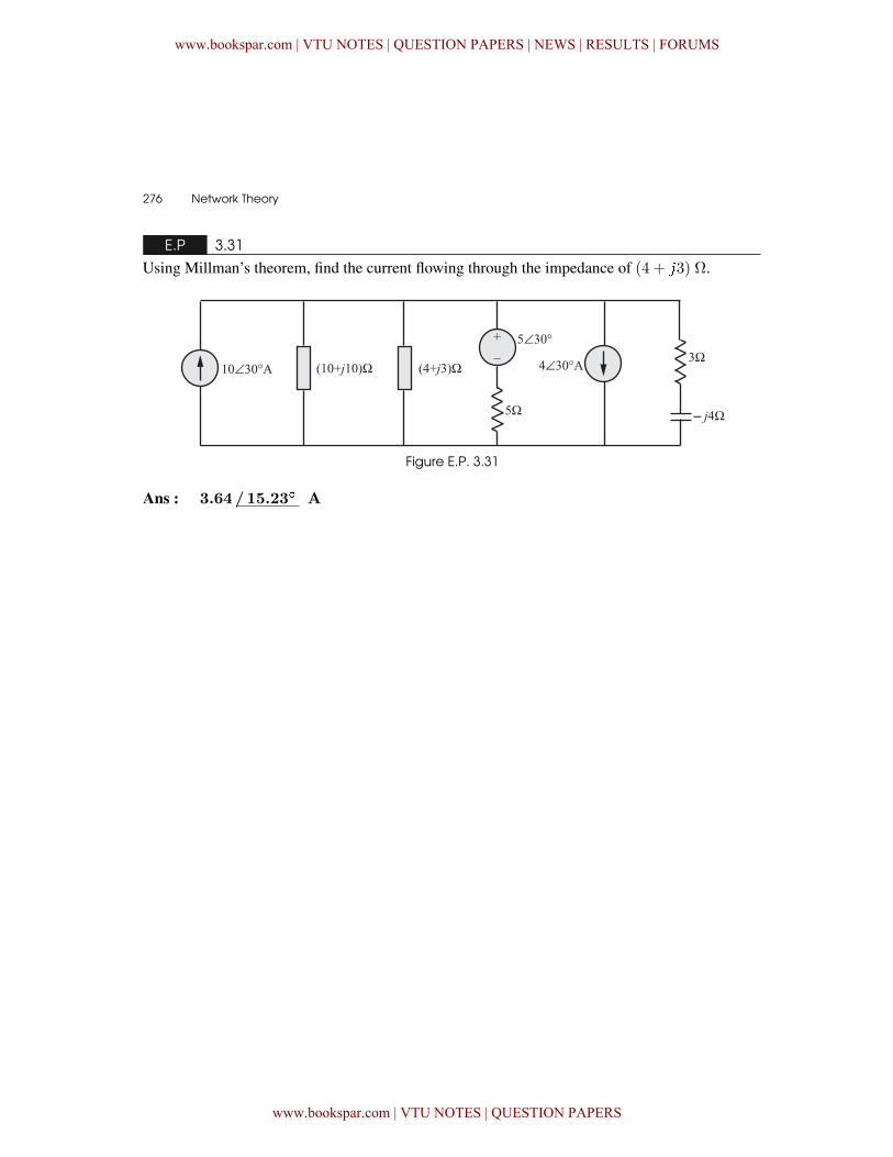
276 � Network Theory
E.P 3.31
Using Millman’s theorem, find the current flowing through the impedance of (4 + �3) Ω.
Figure E.P. 3.31
Ans : 3.64/15.23� A
www.bookspar.com | VTU NOTES | QUESTION PAPERS | NEWS | RESULTS | FORUMS
www.bookspar.com | VTU NOTES | QUESTION PAPERS