color based monocular visuo-inertial 3d pose estimation of a volant robot
TRANSCRIPT
2706 IEEE TRANSACTIONS ON INSTRUMENTATION AND MEASUREMENT, VOL. 59, NO. 10, OCTOBER 2010
Color-Based Monocular Visuoinertial 3-D PoseEstimation of a Volant RobotNikolaos Kyriakoulis and Antonios Gasteratos, Member, IEEE
Abstract—The pose estimation from visual sensors is widelypracticed nowadays. The pose vector is estimated by means ofhomographies and projection geometry. The integration of visualand inertial measurements is getting more attractive due to itsrobustness and flexibility. The cooperation of visual with inertialsensors for finding a robot’s pose bears many advantages, as itexploits their complementary attributes. Most of the visual poseestimation systems identify a geometrically known planar targetto extract the pose vector. In this paper, the pose is estimated froma set of colored markers arranged in a known geometry, fusedwith the measurements of an inertial unit. The utilization of anextended Kalman filter (EKF) compensates the error and fusesthe two heterogeneous measurements. The novelty of the proposedsystem is the use of low-cost colored post-it markers, along with thecapability of handling different frames of reference, as the cameraand the inertial unit are mounted on different mobile subsystemsof a sophisticated volant robotic platform. The proposed systemis computationally inexpensive, operates in real time, and exhibitshigh accuracy.
Index Terms—Color-based tracking, inertial pose estimation,visual pose estimation, visuoinertial fusion.
I. INTRODUCTION
ONE of the most common tasks in robotics is the com-putation of the robot’s pose. The adoption of visual
sensors for this task has been an active research field in thelast decades. In the contemporary pose estimation systems,much effort has been spent to integrate visual with inertialsensors. As the visual and inertial sensors are complementaryto each other, the high-frequency gyro measurements com-bined with the low-frequency visual measurements eventuallyprovide high-frequency pose estimates [1]. The visual poseestimation requires image processing algorithms that are re-source demanding. Considering the fact that high-frequencycameras are utilized more often to acquire a greater volume ofmeasurements, image processing has to be executed even faster.On the other hand, inertial sensors operate in high frequency.However, they suffer by drift error due to a cumulative processappearing during their operation. The need for fast and accurate
Manuscript received July 25, 2009; revised November 8, 2009; acceptedNovember 20, 2009. Date of publication June 21, 2010; date of current versionSeptember 15, 2010. This work was supported by the European Commissionunder the FP6 research project for Autonomous Collaborative Robots to Swingand Work in Everyday EnviRonment (ACROBOTER), FP6-IST-2006-045530.The Associate Editor coordinating the review process for this paper wasDr. Emil Petriu.
The authors are with the Laboratory of Robotics and Automation, De-partment of Production and Management Engineering, Democritus Uni-versity of Thrace, 67100 Xanthi, Greece (e-mail: [email protected];[email protected]).
Color versions of one or more of the figures in this paper are available onlineat http://ieeexplore.ieee.org.
Digital Object Identifier 10.1109/TIM.2010.2045258
measurements is fulfilled by integrating cameras with inertialunits, and it is challenging to integrate these sensors whileachieving balance between accuracy and processing time.
Vision is the overbearing sense for humans and many othercreatures, as it is straightforwardly comprehended throughyears and years of training. The evolution of the paintings wasachieved by introducing perspective to the drawings. The lackof perspective renders a noncomprehensive representation ofthe world. Apart from the visual quality of the perspectivefeatures, mathematical formulations decode much informationwhen analyzing them as well [2]–[4]. The perspective modelsexamine the relations between the 3-D world with its 2-Dprojection. The visual pose estimation problem concerns thesegeometrical references between a 3-D object and the respectiveprojections onto the 2-D image plane [5]. An example of the3-D representation onto an image is that the parallel lines ofthe real world are connected to a point inside the image, suchas, e.g., a pair of rail tracks. This point is called the vanishingpoint [6], and depending on the camera’s position, there can bemore than one in an image, e.g., a photo of a building with twovisible sides. The line that derives from at least two vanishingpoints is the horizon line, where infinite vanishing points lie.According to this, it is shown that the absolute orientation of anobject can be computed [7]. Except for the absolute orientation,by interpreting the projective geometry, the rotation matrix canalso be extracted [8].
Many efficient systems have recently been developed to findthe pose of a known object with visual sensors: the recognitionof the object is based on template matching [9]–[11] or featurerecognition [12]–[14]. The pose estimation of known objectscan be achieved by training the system with photos capturedfrom a learned mapping [11]–[13], [15]. These regression-based techniques track the features of the trained object insidethe image [12], and from regression mapping, they extract thepose estimates. Tracking techniques [16]–[18] have also beenused to solve the pose estimation problem. However, the 3-Dpose is not directly computed, but it is usually assumed[5], [19]–[21]. Nevertheless, most of the pose estimation ap-proaches present a high degree of error at the final transfor-mation matrix. The reduction of these errors optimizes theaccuracy of the final pose estimation [22], which can also be in-creased by using an inertial unit. Furthermore, additional infor-mation for the pose estimation problem is derived by combiningthe measurements from the camera with those of the inertialsensors [1], [23]. In [24], the problem is made observable, andthe pose is estimated by a geometrical observer-based approach.
In this paper, we present the optimization of the systemin [25] by revising the communication architecture and by
0018-9456/$26.00 © 2010 IEEE
KYRIAKOULIS AND GASTERATOS: VISUOINERTIAL 3-D POSE ESTIMATION OF A VOLANT ROBOT 2707
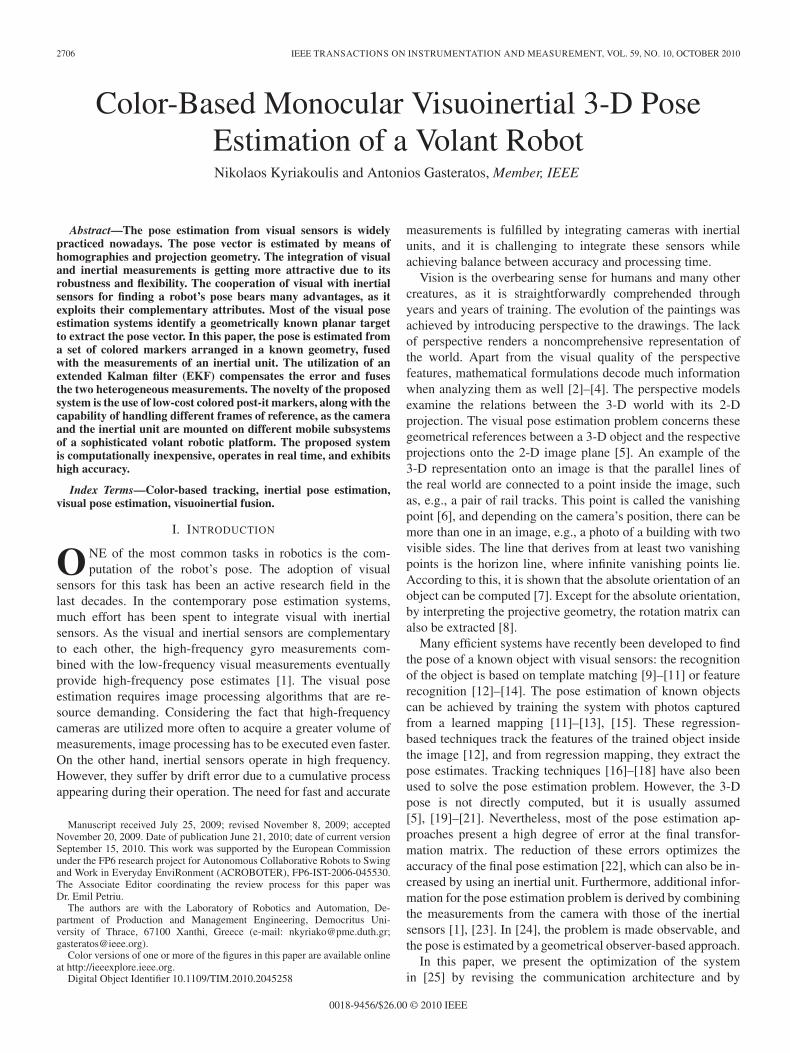
Fig. 1. Proposed system hardware architecture. The camera is on the climberunit, and the four colored markers are on the volant platform.
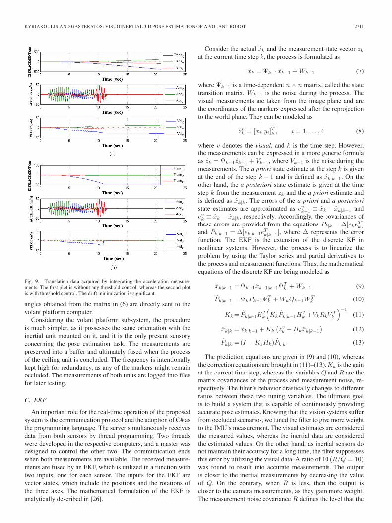
improving the visual pose estimation task. The camera ismounted on a climber mechatronic unit, which moves acrossthe ceiling. The orientation of the visual sensor is toward theground to observe a volant platform, the pose of which is undermeasurement. This platform is attached to the climber unit bymeans of a wire rope, and it can freely move inside its workingenvironment, which covers the majority of the room space.Instead of using geometrical patterns, the volant platform isrecognized by colored post-it markers at a known arrangement,from which the pose vector is estimated. In Fig. 1, the involvedmechatronic parts and their physical arrangement are depicted.The markers are tracked according to their respective colorhistograms and their motion vector. Tracking is implemented inreal time and provides accuracy and robustness against occlu-sions. To facilitate the function of color tracking, the previousposition of the markers is also taken into consideration. In thecase of occlusions, the estimated position of the previous state istaken into account to find the possible new position. In additionto the markers, an inertial unit is also available, which is placednext to the volant platform’s center of mass. Both sensorsare connected with a computer at the respective subsystem.The connection between the two computers is built on top ofsockets (server–client application) to meet the requirementsfor low latency. The fusion of the measurements occurs at thevolant platform computer, i.e., the server, whereas the climberunit computer is considered the client. The capability of theextended Kalman filter (EKF) to be used in nonlinear problems,along with its capacity due its recursive nature [26] to efficientlycompensate the error, led us to its utilization to the system. Theoutput of our system is the output of the EKF. The providedresults are very accurate, and the whole processing is realized inreal time. The proposed system was implemented for the needsof the ACROBOTER1 European research project [27]. The
1The ACROBOTER project is still under development. There are copyrightrestrictions preventing the presentation of the full-scale prototype. The onlyparts being allowed to be illustrated here are the camera, the inertial unit,and their communication architecture. For more information, please visithttp://www.acroboter-project.org.
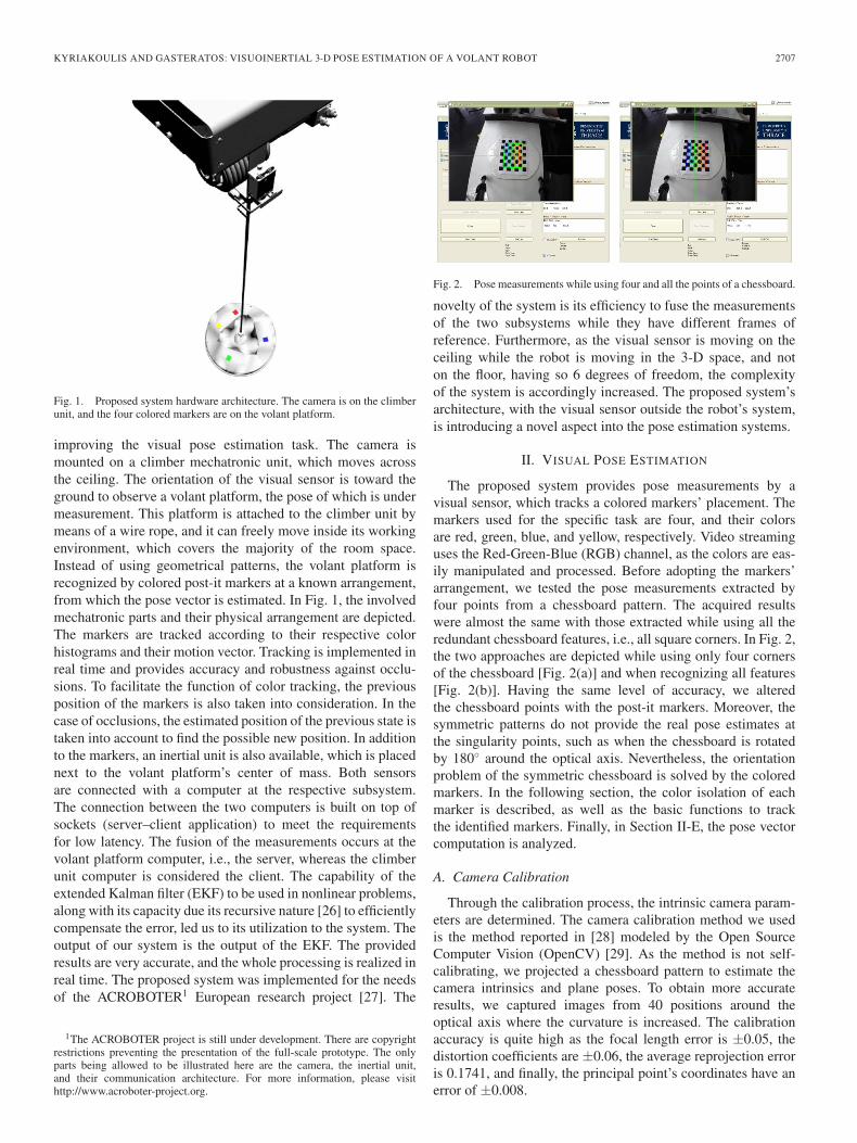
Fig. 2. Pose measurements while using four and all the points of a chessboard.
novelty of the system is its efficiency to fuse the measurementsof the two subsystems while they have different frames ofreference. Furthermore, as the visual sensor is moving on theceiling while the robot is moving in the 3-D space, and noton the floor, having so 6 degrees of freedom, the complexityof the system is accordingly increased. The proposed system’sarchitecture, with the visual sensor outside the robot’s system,is introducing a novel aspect into the pose estimation systems.
II. VISUAL POSE ESTIMATION
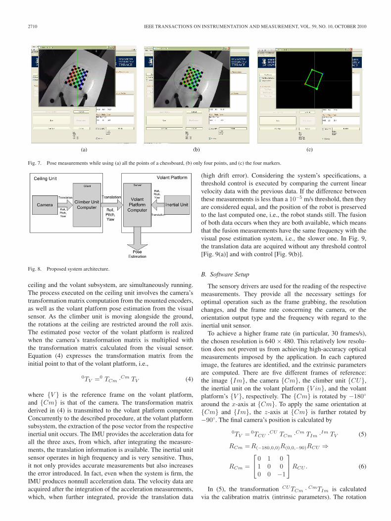
The proposed system provides pose measurements by avisual sensor, which tracks a colored markers’ placement. Themarkers used for the specific task are four, and their colorsare red, green, blue, and yellow, respectively. Video streaminguses the Red-Green-Blue (RGB) channel, as the colors are eas-ily manipulated and processed. Before adopting the markers’arrangement, we tested the pose measurements extracted byfour points from a chessboard pattern. The acquired resultswere almost the same with those extracted while using all theredundant chessboard features, i.e., all square corners. In Fig. 2,the two approaches are depicted while using only four cornersof the chessboard [Fig. 2(a)] and when recognizing all features[Fig. 2(b)]. Having the same level of accuracy, we alteredthe chessboard points with the post-it markers. Moreover, thesymmetric patterns do not provide the real pose estimates atthe singularity points, such as when the chessboard is rotatedby 180◦ around the optical axis. Nevertheless, the orientationproblem of the symmetric chessboard is solved by the coloredmarkers. In the following section, the color isolation of eachmarker is described, as well as the basic functions to trackthe identified markers. Finally, in Section II-E, the pose vectorcomputation is analyzed.
A. Camera Calibration
Through the calibration process, the intrinsic camera param-eters are determined. The camera calibration method we usedis the method reported in [28] modeled by the Open SourceComputer Vision (OpenCV) [29]. As the method is not self-calibrating, we projected a chessboard pattern to estimate thecamera intrinsics and plane poses. To obtain more accurateresults, we captured images from 40 positions around theoptical axis where the curvature is increased. The calibrationaccuracy is quite high as the focal length error is ±0.05, thedistortion coefficients are ±0.06, the average reprojection erroris 0.1741, and finally, the principal point’s coordinates have anerror of ±0.008.
2708 IEEE TRANSACTIONS ON INSTRUMENTATION AND MEASUREMENT, VOL. 59, NO. 10, OCTOBER 2010
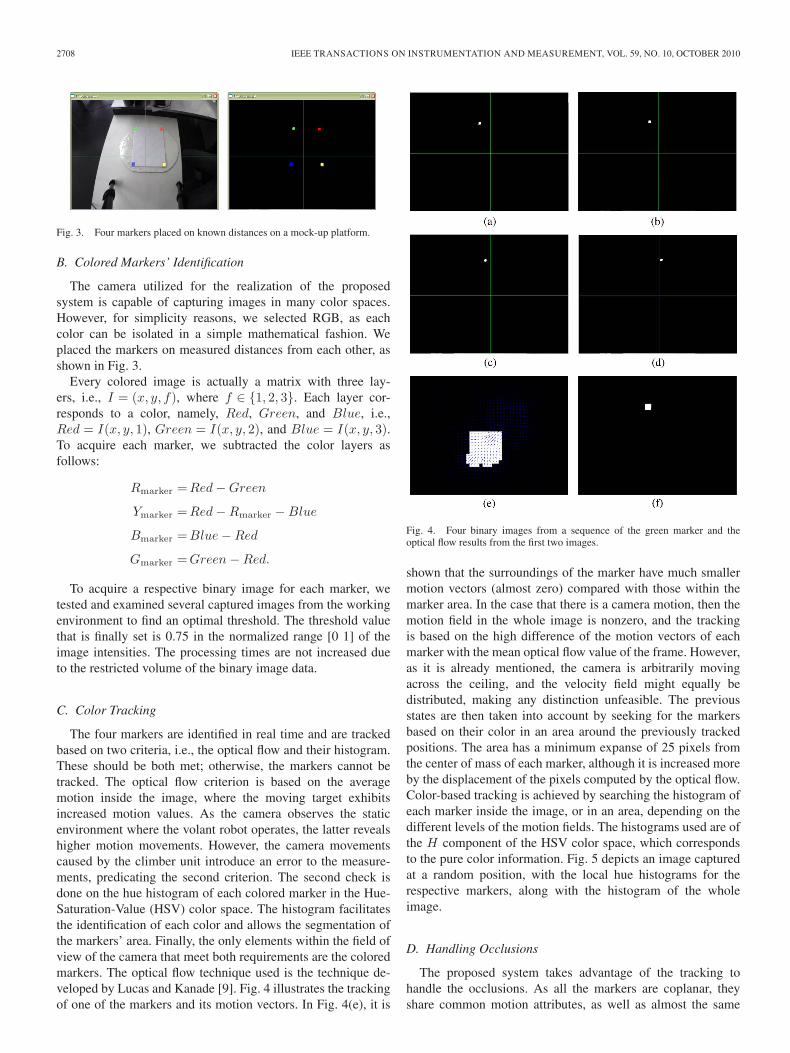
Fig. 3. Four markers placed on known distances on a mock-up platform.
B. Colored Markers’ Identification
The camera utilized for the realization of the proposedsystem is capable of capturing images in many color spaces.However, for simplicity reasons, we selected RGB, as eachcolor can be isolated in a simple mathematical fashion. Weplaced the markers on measured distances from each other, asshown in Fig. 3.
Every colored image is actually a matrix with three lay-ers, i.e., I = (x, y, f), where f ∈ {1, 2, 3}. Each layer cor-responds to a color, namely, Red, Green, and Blue, i.e.,Red = I(x, y, 1), Green = I(x, y, 2), and Blue = I(x, y, 3).To acquire each marker, we subtracted the color layers asfollows:
Rmarker =Red − Green
Ymarker =Red − Rmarker − Blue
Bmarker =Blue − Red
Gmarker =Green − Red.
To acquire a respective binary image for each marker, wetested and examined several captured images from the workingenvironment to find an optimal threshold. The threshold valuethat is finally set is 0.75 in the normalized range [0 1] of theimage intensities. The processing times are not increased dueto the restricted volume of the binary image data.
C. Color Tracking
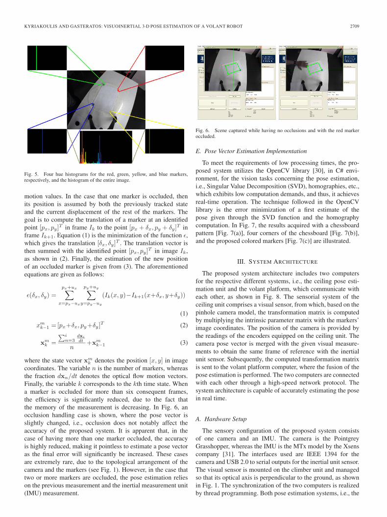
The four markers are identified in real time and are trackedbased on two criteria, i.e., the optical flow and their histogram.These should be both met; otherwise, the markers cannot betracked. The optical flow criterion is based on the averagemotion inside the image, where the moving target exhibitsincreased motion values. As the camera observes the staticenvironment where the volant robot operates, the latter revealshigher motion movements. However, the camera movementscaused by the climber unit introduce an error to the measure-ments, predicating the second criterion. The second check isdone on the hue histogram of each colored marker in the Hue-Saturation-Value (HSV) color space. The histogram facilitatesthe identification of each color and allows the segmentation ofthe markers’ area. Finally, the only elements within the field ofview of the camera that meet both requirements are the coloredmarkers. The optical flow technique used is the technique de-veloped by Lucas and Kanade [9]. Fig. 4 illustrates the trackingof one of the markers and its motion vectors. In Fig. 4(e), it is
Fig. 4. Four binary images from a sequence of the green marker and theoptical flow results from the first two images.
shown that the surroundings of the marker have much smallermotion vectors (almost zero) compared with those within themarker area. In the case that there is a camera motion, then themotion field in the whole image is nonzero, and the trackingis based on the high difference of the motion vectors of eachmarker with the mean optical flow value of the frame. However,as it is already mentioned, the camera is arbitrarily movingacross the ceiling, and the velocity field might equally bedistributed, making any distinction unfeasible. The previousstates are then taken into account by seeking for the markersbased on their color in an area around the previously trackedpositions. The area has a minimum expanse of 25 pixels fromthe center of mass of each marker, although it is increased moreby the displacement of the pixels computed by the optical flow.Color-based tracking is achieved by searching the histogram ofeach marker inside the image, or in an area, depending on thedifferent levels of the motion fields. The histograms used are ofthe H component of the HSV color space, which correspondsto the pure color information. Fig. 5 depicts an image capturedat a random position, with the local hue histograms for therespective markers, along with the histogram of the wholeimage.
D. Handling Occlusions
The proposed system takes advantage of the tracking tohandle the occlusions. As all the markers are coplanar, theyshare common motion attributes, as well as almost the same
KYRIAKOULIS AND GASTERATOS: VISUOINERTIAL 3-D POSE ESTIMATION OF A VOLANT ROBOT 2709
Fig. 5. Four hue histograms for the red, green, yellow, and blue markers,respectively, and the histogram of the entire image.
motion values. In the case that one marker is occluded, thenits position is assumed by both the previously tracked stateand the current displacement of the rest of the markers. Thegoal is to compute the translation of a marker at an identifiedpoint [px, py]T in frame Ik to the point [px + δx, py + δy]T inframe Ik+1. Equation (1) is the minimization of the function ε,which gives the translation [δx, δy]T . The translation vector isthen summed with the identified point [px, py]T in image Ik,as shown in (2). Finally, the estimation of the new positionof an occluded marker is given from (3). The aforementionedequations are given as follows:
ε(δx, δy) =px+ux∑
x=px−ux
py+uy∑y=py−uy
(Ik(x, y)−Ik+1(x+δx, y+δy))
(1)
xmk−1 = [px+δx, py+δy]T (2)
xmk =
∑in=3
dxi
dt
n+xm
k−1 (3)
where the state vector xmk denotes the position [x, y] in image
coordinates. The variable n is the number of markers, whereasthe fraction dxn/dt denotes the optical flow motion vectors.Finally, the variable k corresponds to the kth time state. Whena marker is occluded for more than six consequent frames,the efficiency is significantly reduced, due to the fact thatthe memory of the measurement is decreasing. In Fig. 6, anocclusion handling case is shown, where the pose vector isslightly changed, i.e., occlusion does not notably affect theaccuracy of the proposed system. It is apparent that, in thecase of having more than one marker occluded, the accuracyis highly reduced, making it pointless to estimate a pose vectoras the final error will significantly be increased. These casesare extremely rare, due to the topological arrangement of thecamera and the markers (see Fig. 1). However, in the case thattwo or more markers are occluded, the pose estimation relieson the previous measurement and the inertial measurement unit(IMU) measurement.
Fig. 6. Scene captured while having no occlusions and with the red markeroccluded.
E. Pose Vector Estimation Implementation
To meet the requirements of low processing times, the pro-posed system utilizes the OpenCV library [30], in C# envi-ronment, for the vision tasks concerning the pose estimation,i.e., Singular Value Decomposition (SVD), homographies, etc.,which exhibits low computation demands, and thus, it achievesreal-time operation. The technique followed in the OpenCVlibrary is the error minimization of a first estimate of thepose given through the SVD function and the homographycomputation. In Fig. 7, the results acquired with a chessboardpattern [Fig. 7(a)], four corners of the chessboard [Fig. 7(b)],and the proposed colored markers [Fig. 7(c)] are illustrated.
III. SYSTEM ARCHITECTURE
The proposed system architecture includes two computersfor the respective different systems, i.e., the ceiling pose esti-mation unit and the volant platform, which communicate witheach other, as shown in Fig. 8. The sensorial system of theceiling unit comprises a visual sensor, from which, based on thepinhole camera model, the transformation matrix is computedby multiplying the intrinsic parameter matrix with the markers’image coordinates. The position of the camera is provided bythe readings of the encoders equipped on the ceiling unit. Thecamera pose vector is merged with the given visual measure-ments to obtain the same frame of reference with the inertialunit sensor. Subsequently, the computed transformation matrixis sent to the volant platform computer, where the fusion of thepose estimation is performed. The two computers are connectedwith each other through a high-speed network protocol. Thesystem architecture is capable of accurately estimating the posein real time.
A. Hardware Setup
The sensory configuration of the proposed system consistsof one camera and an IMU. The camera is the PointgreyGrasshopper, whereas the IMU is the MTx model by the Xsenscompany [31]. The interfaces used are IEEE 1394 for thecamera and USB 2.0 to serial outputs for the inertial unit sensor.The visual sensor is mounted on the climber unit and managedso that its optical axis is perpendicular to the ground, as shownin Fig. 1. The synchronization of the two computers is realizedby thread programming. Both pose estimation systems, i.e., the
2710 IEEE TRANSACTIONS ON INSTRUMENTATION AND MEASUREMENT, VOL. 59, NO. 10, OCTOBER 2010
Fig. 7. Pose measurements while using (a) all the points of a chessboard, (b) only four points, and (c) the four markers.
Fig. 8. Proposed system architecture.
ceiling and the volant subsystem, are simultaneously running.The process executed on the ceiling unit involves the camera’stransformation matrix computation from the mounted encoders,as well as the volant platform pose estimation from the visualsensor. As the climber unit is moving alongside the ground,the rotations at the ceiling are restricted around the roll axis.The estimated pose vector of the volant platform is realizedwhen the camera’s transformation matrix is multiplied withthe transformation matrix calculated from the visual sensor.Equation (4) expresses the transformation matrix from theinitial point to that of the volant platform, i.e.,
0TV =0 TCm ·Cm TV (4)
where {V } is the reference frame on the volant platform,and {Cm} is that of the camera. The transformation matrixderived in (4) is transmitted to the volant platform computer.Concurrently to the described procedure, at the volant platformsubsystem, the extraction of the pose vector from the respectiveinertial unit occurs. The IMU provides the acceleration data forall the three axes, from which, after integrating the measure-ments, the translation information is available. The inertial unitsensor operates in high frequency and is very sensitive. Thus,it not only provides accurate measurements but also increasesthe error introduced. In fact, even when the system is firm, theIMU produces nonnull acceleration data. The velocity data areacquired after the integration of the acceleration measurements,which, when further integrated, provide the translation data
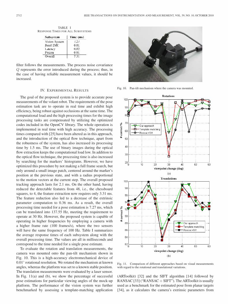
(high drift error). Considering the system’s specifications, athreshold control is executed by comparing the current linearvelocity data with the previous data. If the difference betweenthese measurements is less than a 10−5 m/s threshold, then theyare considered equal, and the position of the robot is preservedto the last computed one, i.e., the robot stands still. The fusionof both data occurs when they are both available, which meansthat the fusion measurements have the same frequency with thevisual pose estimation system, i.e., the slower one. In Fig. 9,the translation data are acquired without any threshold control[Fig. 9(a)] and with control [Fig. 9(b)].
B. Software Setup
The sensory drivers are used for the reading of the respectivemeasurements. They provide all the necessary settings foroptimal operation such as the frame grabbing, the resolutionchanges, and the frame rate concerning the camera, or theorientation output type and the frequency with regard to theinertial unit sensor.
To achieve a higher frame rate (in particular, 30 frames/s),the chosen resolution is 640 × 480. This relatively low resolu-tion does not prevent us from achieving high-accuracy opticalmeasurements imposed by the application. In each capturedimage, the features are identified, and the extrinsic parametersare computed. There are five different frames of reference:the image {Im}, the camera {Cm}, the climber unit {CU},the inertial unit on the volant platform {V in}, and the volantplatform’s {V }, respectively. The {Cm} is rotated by −180◦
around the x-axis at {Cm}. To apply the same orientation at{Cm} and {Im}, the z-axis at {Cm} is further rotated by−90◦. The final camera’s position is calculated by
0TV = 0TCU ·CU TCm ·Cm TIm ·Im TV (5)
RCm = R(−180,0,0)R(0,0,−90)RCU ⇒
RCm =
⎡⎣
0 1 01 0 00 0 −1
⎤⎦RCU . (6)
In (5), the transformation CUTCm · CmTIm is calculatedvia the calibration matrix (intrinsic parameters). The rotation
KYRIAKOULIS AND GASTERATOS: VISUOINERTIAL 3-D POSE ESTIMATION OF A VOLANT ROBOT 2711
Fig. 9. Translation data acquired by integrating the acceleration measure-ments. The first plot is without any threshold control, whereas the second plotis with threshold control. The drift minimization is significant.
angles obtained from the matrix in (6) are directly sent to thevolant platform computer.
Considering the volant platform subsystem, the procedureis much simpler, as it possesses the same orientation with theinertial unit mounted on it, and it is the only present sensoryconcerning the pose estimation task. The measurements arepreserved into a buffer and ultimately fused when the processof the ceiling unit is concluded. The frequency is intentionallykept high for redundancy, as any of the markers might remainoccluded. The measurements of both units are logged into filesfor later testing.
C. EKF
An important role for the real-time operation of the proposedsystem is the communication protocol and the adoption of C# asthe programming language. The server simultaneously receivesdata from both sensors by thread programming. Two threadswere developed in the respective computers, and a master wasdesigned to control the other two. The communication endswhen both measurements are available. The received measure-ments are fused by an EKF, which is utilized in a function withtwo inputs, one for each sensor. The inputs for the EKF arevector states, which include the positions and the rotations ofthe three axes. The mathematical formulation of the EKF isanalytically described in [26].
Consider the actual xk and the measurement state vector zk
at the current time step k, the process is formulated as
xk = Ψk−1xk−1 + Wk−1 (7)
where Ψk−1 is a time-dependent n × n matrix, called the statetransition matrix. Wk−1 is the noise during the process. Thevisual measurements are taken from the image plane and arethe coordinates of the markers expressed after the reprojectionto the world plane. They can be modeled as
zvk = [xi, yi]
Tk , i = 1, . . . , 4 (8)
where v denotes the visual, and k is the time step. However,the measurements can be expressed in a more generic formulaas zk = Ψk−1zk−1 + Vk−1, where Vk−1 is the noise during themeasurements. The a priori state estimate at the step k is givenat the end of the step k − 1 and is defined as xk|k−1. On theother hand, the a posteriori state estimate is given at the timestep k from the measurement zk and the a priori estimate andis defined as xk|k. The errors of the a priori and a posterioristate estimates are approximated as ev
k−1 ≡ xk − xk|k−1 andevk ≡ xk − xk|k, respectively. Accordingly, the covariances of
these errors are provided from the equations Pk|k = Δ[ekeTk ]
and Pk|k−1 = Δ[ek|k−1eTk|k−1], where Δ represents the error
function. The EKF is the extension of the discrete KF innonlinear systems. However, the process is to linearize theproblem by using the Taylor series and partial derivatives tothe process and measurement functions. Thus, the mathematicalequations of the discrete KF are being modeled as
xk|k−1 = Ψk−1xk−1|k−1ΨTk + Wk−1 (9)
Pk|k−1 = ΨkPk−1ΨTk + WkQk−1W
Tk (10)
Kk = Pk|k−1HTk
(KkPk|k−1H
Tk +VkRkV T
k
)−1
(11)
xk|k = xk|k−1 + Kk
(zvk − Hkxk|k−1
)(12)
Pk|k = (I − KkHk)Pk|k. (13)
The prediction equations are given in (9) and (10), whereasthe correction equations are brought in (11)–(13). Kk is the gainat the current time step, whereas the variables Q and R are thematrix covariances of the process and measurement noise, re-spectively. The filter’s behavior drastically changes to differentratios between these two tuning variables. The ultimate goalis to build a system that is capable of continuously providingaccurate pose estimates. Knowing that the vision systems sufferfrom occluded scenarios, we tuned the filter to give more weightto the IMU’s measurement. The visual estimates are consideredthe measured values, whereas the inertial data are consideredthe estimated values. On the other hand, as inertial sensors donot maintain their accuracy for a long time, the filter suppressesthis error by utilizing the visual data. A ratio of 10 (R/Q = 10)was found to result into accurate measurements. The outputis closer to the inertial measurements by decreasing the valueof Q. On the contrary, when R is less, then the output iscloser to the camera measurements, as they gain more weight.The measurement noise covariance R defines the level that the
2712 IEEE TRANSACTIONS ON INSTRUMENTATION AND MEASUREMENT, VOL. 59, NO. 10, OCTOBER 2010
TABLE IRESPONSE TIMES FOR ALL SUBSYSTEMS
filter follows the measurements. The process noise covarianceQ represents the error introduced during the process; thus, inthe case of having reliable measurement values, it should beincreased.
IV. EXPERIMENTAL RESULTS
The goal of the proposed system is to provide accurate posemeasurements of the volant robot. The requirements of the poseestimation task are to operate in real time and exhibit highefficiency, being robust against occlusions at the same time. Thecomputational load and the high processing times for the imageprocessing tasks are compensated by utilizing the optimizedcodes included in the OpenCV library. The whole operation isimplemented in real time with high accuracy. The processingtimes compared with [25] have been altered as in this approach,and the introduction of the optical flow technique, apart fromthe robustness of the system, has also increased its processingtime by 1.5 ms. The use of binary images during the opticalflow extraction keeps the computational load low. In addition tothe optical flow technique, the processing time is also increasedby searching for the markers’ histograms. However, we haveoptimized this procedure by not making a full frame search, butonly around a small image patch, centered around the marker’sposition at the previous state, and with a radius proportionalto the motion vectors at the current step. The overall proposedtracking approach lasts for 2.1 ms. On the other hand, havingreduced the detectable features from 48, i.e., the chessboardsquares, to 4, the feature extraction now requires only 3.31 ms.The feature reduction also led to a decrease of the extrinsicparameter computation to 0.36 ms. As a result, the overallprocessing time needed for a pose estimation is 7.27 ms, whichcan be translated into 137.55 Hz, meeting the requirement tooperate at 30 Hz. However, the proposed system is capable ofoperating in higher frequencies by employing a camera witha higher frame rate (100 frames/s), where the two sensorswill have the same frequency of 100 Hz. Table I summarizesthe average response times of each subsystem along with theoverall processing time. The values are all in milliseconds andcorrespond to the time needed for a single pose estimate.
To evaluate the rotation and translation measurements, thecamera was mounted onto the pan-tilt mechanism shown inFig. 10. This is a high-accuracy electromechanical device of0.01◦ rotational resolution. We rotated the mechanism at knownangles, whereas the platform was set to a known stable position.The translation measurements were evaluated by a laser sensor.In Fig. 11(a) and (b), we show the percentage of successfulpose estimations for particular viewing angles of the mock-upplatform. The performance of the vision system was furtherbenchmarked by assessing a template-matching application
Fig. 10. Pan-tilt mechanism where the camera was mounted.
Fig. 11. Comparison of different approaches based on visual measurementswith regard to the rotational and translational variations.
(ARToolkit) [32] and the SIFT algorithm [14] followed byRANSAC [33] (“RANSAC + SIFT”). The ARToolkit is usuallyused as a benchmark for the estimated pose from planar targets[34], as it calculates the camera’s extrinsic parameters from
KYRIAKOULIS AND GASTERATOS: VISUOINERTIAL 3-D POSE ESTIMATION OF A VOLANT ROBOT 2713
Fig. 12. Comparison of different approaches based on visual measurementswith regard to their errors and standard deviations.
a pattern on which a virtual object is placed with the sameorientation and size. The pose estimates from the “template-matching” and “RANSAC + SIFT” applications, were loggedand compared with those obtained while using the markers’arrangement. From Fig. 11 and the plots in Fig. 12, it isproved that the proposed method provides steadily less meanerror and with a small standard deviation; thus, it achieves abetter performance against the assessed ones. As a result, thevisual pose estimation application that is finally selected is theapplication that is presented in this paper.
The output of the visual pose estimation system is fusedwith the IMU by an EKF. The goal is to finally acquire anaccurate and robust pose estimation. Robustness is achievedby handling the occlusion while maintaining the accuracy fora short period of time. To verify and evaluate the overall perfor-mance of our system, we run similar tests with the mechanismof Fig. 10 to know the camera’s pose while having mountedthe IMU sensor on the platform, which was arbitrarily rotated
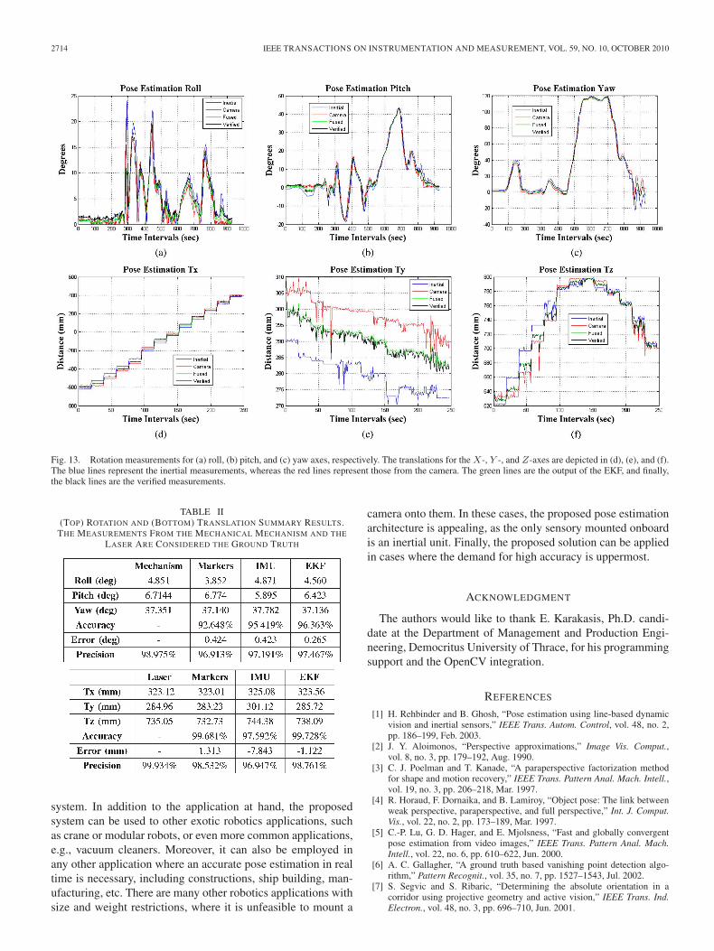
and translated. The final output of our system is apposed inFig. 13, and the overall data evaluation is demonstrated inTable II. The performance of our system is closer to the verifiedmeasurements. The system exhibits high accuracy due to thefusion of the short- and long-term accuracy values of the IMUand the visual sensor, respectively. As far as the rotations areconcerned, the IMU exhibits less error than the visual sensor,consequently increasing the accuracy of the EKF’s output. Onthe other hand, the drift error reduces in a high degree theefficiency of the IMU. However, the accuracy of the EKF ismaintained, as the visual measurements correct the erroneousIMU measurements, providing eventually higher accuracy. Thediagrams shown in Fig. 13 are the results acquired for all therotation and translation data. The outputs of our system arethe green lines, whereas the black lines represent the verifiedmeasurements. From these diagrams along with Table II, it isobvious that the proposed architecture improves the accuracy,providing measurements closer to the real ones.
V. DISCUSSION
We introduced a new pose estimation application based oncolored markers. The camera is placed on a mechatronic mech-anism on the ceiling, whereas four colored markers are placedon top of a volant robotic platform. The markers are trackedby their color and by the respective optical flow measurements.The local histograms for each marker are extracted and soughtinto a small region around the previously known position. Theoptical flow values determine whether the robot is moving orthe camera does. In the first case, the environment is static, andthe markers are distinguished due to their high motion values.In the latter case, where the camera is moving, the color of eachmarker is used for the tracking scheme. The proposed systemis capable of handling partial or overall occlusion of a markerby estimating the position of the occluded marker based on itsprevious position and the optical flow values of the remainingones.
The performance of our visual pose estimates was evaluatedby setting known angles and positions on a calibrated pan-tilt mechanism. We further examined our measurements bycomparing them with other existing vision-based measurementmethods, namely, the ARToolkit, and the SIFT algorithm fol-lowed by RANSAC. We demonstrated that our system hasbetter overall performance, particularly in the presence of oc-clusions. The visual pose estimation is applied to the presentedvisuoinertial task. The measurements of the visual sensor arefused with those acquired from an IMU sensor, which ismounted onto the volant robot. An EKF is responsible for thedata fusion, and its output is also the output of our system. Weevaluated the final output of our system by comparing it withthe measurements acquired from the markers’ arrangement andthose of the IMU’s. The overall performance of the proposedsystem outperforms those that individually use the sensors, interms of accuracy and robustness.
This paper proves the capacity of a system to obtain real-time pose estimates of two subsystems with different frames ofreference. The identification of a robot’s pose with a camerathat is not mounted onto it allows extended flexibility to the
2714 IEEE TRANSACTIONS ON INSTRUMENTATION AND MEASUREMENT, VOL. 59, NO. 10, OCTOBER 2010
Fig. 13. Rotation measurements for (a) roll, (b) pitch, and (c) yaw axes, respectively. The translations for the X-, Y -, and Z-axes are depicted in (d), (e), and (f).The blue lines represent the inertial measurements, whereas the red lines represent those from the camera. The green lines are the output of the EKF, and finally,the black lines are the verified measurements.
TABLE II(TOP) ROTATION AND (BOTTOM) TRANSLATION SUMMARY RESULTS.
THE MEASUREMENTS FROM THE MECHANICAL MECHANISM AND THE
LASER ARE CONSIDERED THE GROUND TRUTH
system. In addition to the application at hand, the proposedsystem can be used to other exotic robotics applications, suchas crane or modular robots, or even more common applications,e.g., vacuum cleaners. Moreover, it can also be employed inany other application where an accurate pose estimation in realtime is necessary, including constructions, ship building, man-ufacturing, etc. There are many other robotics applications withsize and weight restrictions, where it is unfeasible to mount a
camera onto them. In these cases, the proposed pose estimationarchitecture is appealing, as the only sensory mounted onboardis an inertial unit. Finally, the proposed solution can be appliedin cases where the demand for high accuracy is uppermost.
ACKNOWLEDGMENT
The authors would like to thank E. Karakasis, Ph.D. candi-date at the Department of Management and Production Engi-neering, Democritus University of Thrace, for his programmingsupport and the OpenCV integration.
REFERENCES
[1] H. Rehbinder and B. Ghosh, “Pose estimation using line-based dynamicvision and inertial sensors,” IEEE Trans. Autom. Control, vol. 48, no. 2,pp. 186–199, Feb. 2003.
[2] J. Y. Aloimonos, “Perspective approximations,” Image Vis. Comput.,vol. 8, no. 3, pp. 179–192, Aug. 1990.
[3] C. J. Poelman and T. Kanade, “A paraperspective factorization methodfor shape and motion recovery,” IEEE Trans. Pattern Anal. Mach. Intell.,vol. 19, no. 3, pp. 206–218, Mar. 1997.
[4] R. Horaud, F. Dornaika, and B. Lamiroy, “Object pose: The link betweenweak perspective, paraperspective, and full perspective,” Int. J. Comput.Vis., vol. 22, no. 2, pp. 173–189, Mar. 1997.
[5] C.-P. Lu, G. D. Hager, and E. Mjolsness, “Fast and globally convergentpose estimation from video images,” IEEE Trans. Pattern Anal. Mach.Intell., vol. 22, no. 6, pp. 610–622, Jun. 2000.
[6] A. C. Gallagher, “A ground truth based vanishing point detection algo-rithm,” Pattern Recognit., vol. 35, no. 7, pp. 1527–1543, Jul. 2002.
[7] S. Segvic and S. Ribaric, “Determining the absolute orientation in acorridor using projective geometry and active vision,” IEEE Trans. Ind.Electron., vol. 48, no. 3, pp. 696–710, Jun. 2001.
KYRIAKOULIS AND GASTERATOS: VISUOINERTIAL 3-D POSE ESTIMATION OF A VOLANT ROBOT 2715
[8] A. C. Gallagher, “Using vanishing points to correct camera rotation inimages,” in Proc. 2nd Can. Conf. CRV , 2005, pp. 460–467.
[9] B. Lucas and T. Kanade, “An iterative image registration technique withan application to stereo vision,” in Proc. DARPA Image UnderstandingWorkshop, 1981, pp. 121–130.
[10] S. Baker and I. Matthews, “Lucas–Kanade 20 years on: A unifying frame-work,” Int. J. Comput. Vis., vol. 56, no. 3, pp. 221–255, Feb. 2004.
[11] F. Tombari, S. Mattoccia, and L. Di Stefano, “Full-search-equivalentpattern matching with incremental dissimilarity approximations,” IEEETrans. Pattern Anal. Mach. Intell., vol. 31, no. 1, pp. 129–141, Jan. 2009.
[12] K. Zimmermann, J. Matas, and T. Svoboda, “Tracking by an optimalsequence of linear predictors,” IEEE Trans. Pattern Anal. Mach. Intell.,vol. 31, no. 4, pp. 677–692, Apr. 2009.
[13] V. Lepetit and P. Fua, “Keypoint recognition using randomized trees,”IEEE Trans. Pattern Anal. Mach. Intell., vol. 28, no. 9, pp. 1465–1479,Sep. 2006.
[14] D. G. Lowe, “Distinctive image features from scale-invariant keypoints,”Int. J. Comput. Vis., vol. 60, no. 2, pp. 91–110, Nov. 2004.
[15] S. Holzer, S. Hinterstoisser, S. Ilic, and N. Navab, “Distance transformtemplates for object detection and pose estimation,” in Proc. IEEE Com-put. Soc. Conf. Comput. Vis. Pattern Recog., 2009, pp. 1177–1184.
[16] S. Avidan, “Support vector tracking,” IEEE Trans. Pattern Anal. Mach.Intell., vol. 26, no. 8, pp. 1064–1072, Aug. 2004.
[17] P. Perez, C. Hue, J. Vermaak, and M. Gangnet, “Color-based probabilistictracking,” in Proc. 7th Eur. Conf. Comput. Vis., vol. 2350, Lecture Notesin Computer Science, 2002, pp. 661–675.
[18] G. R. Bradski and S. Clara, “Computer vision face tracking for use in aperceptual user interface,” Intel Technol. J., vol. 2, no. 2, pp. 12–21, 1998.
[19] A. Ansar and K. Daniilidis, “Linear pose estimation from points or lines,”IEEE Trans. Pattern Anal. Mach. Intell., vol. 25, no. 5, pp. 578–589,May 2003.
[20] M. Wilczkowiak, P. Sturm, and E. Boyer, “Using geometric constraintsthrough parallelepipeds for calibration and 3D modeling,” IEEE Trans.Pattern Anal. Mach. Intell., vol. 27, no. 2, pp. 194–207, Feb. 2005.
[21] V. Lepetit, F. Moreno-Noguer, and P. Fua, “ EPnP: An accurate O(n)solution to the PnP problem,” Int. J. Comput. Vis., vol. 81, no. 2, pp. 155–166, 2009.
[22] Z. Zhang, D. Zhu, and J. Zhang, “An improved pose estimation algorithmfor real-time vision applications,” in Proc. Int. Conf. Commun., CircuitsSyst., Jun. 2006, vol. 1, pp. 402–406.
[23] J. Lobo and J. Dias, “Vision and inertial sensor cooperation using gravityas a vertical reference,” IEEE Trans. Pattern Anal. Mach. Intell., vol. 25,no. 12, pp. 1597–1608, Dec. 2003.
[24] S. Bonnabel and P. Rouchon, “Fusion of visual and inertial: A geometricalobserver-based approach,” in Proc. CISA, vol. 1107, AIP ConferenceProceedings, 2009, pp. 54–58.
[25] N. Kyriakoulis, E. Karakasis, A. Gasteratos, and A. Amanatiadis, “Poseestimation of a volant platform with a monocular visuo-inertial system,”in Proc. IEEE Int. Workshop IST , 2009, pp. 421–426.
[26] G. Welch and G. Bishop, “An introduction to the Kalman filter,” Univ.North Carolina, Chapel Hill, NC, 1995.
[27] G. Stepan, A. Toth, L. L. Kovacs, G. Bolmsjo, G. Nikoleris, D. Surdilovic,A. Conrad, A. Gasteratos, N. Kyriakoulis, D. Chrysostomou,R. Kouskouridas, J. Canou, T. Smith, W. Harwin, R. Loureiro,R. Lopez, and M. Moreno, “ACROBOTER: A ceiling based crawling,hoisting and swinging service robot platform,” in Proc. Beyond GrayDroids: Domestic Robot Des. 21st Century Workshop HCI, 2009, pp. 1–4.
[28] J.-Y. Bouget, Camera Calibration Toolbox for Matlab, CaliforniaInst. Technol., Pasadena, CA, 2001. [Online]. Available: http//www.vision.caltech.edu
[29] G. R. Bradski and A. Kaehler, Learning OpenCV, 1st ed, Sebastopol, CA:O’Reilly Media, Inc., 2008.
[30] Open Source Computer Vision (OpenCV) home page. [Online].Available: http://sourceforge.net/projects/opencvlibrary
[31] X. Technologies, 2009. [Online]. Available: http://www.xsens.com/en/general/mtx?gclid=CKfIurnTiZ0CFcQSzAodfAjM2A
[32] ARToolKit Plus, 2006, [Online]. Available: http://studierstube.icg.tu-graz.ac.at/handheld_ar/artoolkitplus.php
[33] M. A. Fischler and R. C. Bolles, “Random sample consensus: A paradigmfor model fitting with applications to image analysis and automated car-tography,” in Readings in Computer Vision: Issues, Problems, Principles,and Paradigms. San Mateo, CA: Morgan Kaufmann, 1987, pp. 726–740.
[34] G. Schweighofer and A. Pinz, “Robust pose estimation from a planartarget,” IEEE Trans. Pattern Anal. Mach. Intell., vol. 28, no. 12, pp. 2024–2030, Dec. 2006.
Nikolaos Kyriakoulis received the Diploma degreein 2005 from the Democritus University of Thrace(DUTH), Xanthi, Greece, where he is currentlyworking toward the Ph.D. degree with the Laboratoryof Robotics and Automation, Department of Produc-tion and Management Engineering.
He has been involved in several national (Greek)and international (European) research projects in thefield of real-time machine vision systems. His areasof interest include machine vision, robotics, datafusion, and fuzzy systems.
Mr. Kyriakoulis is a member of the Technical Chamber of Greece (TEE) andthe National Union of Production and Management Engineers.
Antonios Gasteratos (M’99) received the Diplomaand Ph.D. degrees from the Democritus Universityof Thrace (DUTH), Xanthi, Greece, in 1999.
He is currently an Assistant Professor of mecha-tronics and artificial vision with the Department ofProduction and Management Engineering, DUTH,where he teaches the courses robotics, automaticcontrol systems, measurements technology, and elec-tronics. During 1999–2000, he was a PostdoctoralFellow with the Laboratory of Integrated AdvancedRobotics (LIRA-Lab), Department of Communica-
tion, Computer and Systems Science (DIST), University of Genoa, Genoa, Italy.He is the Greek Associate High Level Group (HLG) Delegate at EUREKAinitiative. He has served as a reviewer to numerous scientific journals and inter-national conferences. He has published one textbook, three book chapters, andmore than 60 scientific papers. His research interests are mainly in mechatronicsand robot vision.
Dr. Gasteratos is a member of the International Association of Pattern Recog-nition (IAPR), the European Coordinating Committee for Artificial Intelligence(ECCAI), the European Association for Signal-Image Processing (EURASIP),and the Technical Chamber of Greece (TEE). He is a member of EURON,euCognition and I∗PROMS European networks. He was the organizer of theInternational Conference on Computer Vision Systems (ICVS) 2008.