visuo-inertial stabilization in space-variant binocular systems
TRANSCRIPT
Robotics and Autonomous Systems 30 (2000) 195–214
Visuo-inertial stabilization in space-variant binocular systemsq
Francesco Paneraia,∗, Giorgio Mettab, Giulio Sandiniba Laboratoire de Physiologie de la Perception et de l’Action (LPPA), Collège de France, 11 place Marcelin Berthelot, 75005 Paris, France
b Laboratory for Integrated Advanced Robotics (LIRA), Department of Communication, Computers and Systems Science, University of Genoa,Via Opera Pia 13, 16145 Genoa, Italy
Abstract
Stabilization of gaze is a major functional prerequisite for robots exploring the environment. The main reason for a“steady-image” requirement is to prevent the robot’s own motion to compromise its “visual functions”. In this paper wepresent an artificial system, the LIRA robot head, capable of controlling its cameras/eyes to stabilize gaze. The systemfeatures a stabilization mechanism relying on principles exploited by natural systems: aninertial sensory apparatus andimages ofspace-variantresolution. The inertial device measures angular velocities and linear acceleration along the verticaland horizontal fronto-parallel axes. The space-variant image geometry facilitates real-time computation of optic flow andthe extraction of first-order motion parameters. Experiments which describe the performance of the LIRA robot head arepresented. The results show that the stabilization mechanism improves the reactivity of the system to changes occurringsuddenly at new spotted locations. ©2000 Elsevier Science B.V. All rights reserved.
Keywords:Inertial sensors; Image stabilization; Visuo-inertial integration; Space-variant binocular vision
1. Introduction
Stabilization mechanisms have developed in natu-ral systems as necessary functional elements to en-able consistent treatment of visual information. Thesemechanisms are indeed important when the visual sys-tem needs to exploit its maximum acuity, estimateself-motion or discriminate motion of the visual scene.As a matter of fact, images falling on the retinas arerequired to be relatively still, particularly in all thosetasks requiring the brain’s neural circuitry to discrim-
q The research described in this paper has been supported by theItalian Space Agency (ASI) and the EU Esprit project NARVAL.
∗ Corresponding author. Tel.: +33-1-4427-1389; fax: +33-1-4427-1382.E-mail address:[email protected](F. Panerai).
inate/extract/recognize relevant visual features. In hu-mans, for example, it is well known that the stabi-lization of the whole visual field enhances sensitiv-ity to individual moving objects and to motion paral-lax [27], contributing to enhancement in the percep-tion of distance, form [35], and relative depth [12]. Inrobotics too, image stabilization mechanisms shouldbe considered important functional elements. Robotsexploring the environment will certainly benefit from astable gaze-line. Two cases are of particular interest: (i)when performing dynamic visual measurements dur-ing their own movement [33]; (ii) when using fixationas a reference while navigating or manipulating [3].From an implementation perspective, how should onego about achieving robust performance and efficiencyat the same time? What is the sensory information thatshould be considered to achieve the goal? Does thesensing process satisfy the dynamics of the stimuli?
0921-8890/00/$ – see front matter ©2000 Elsevier Science B.V. All rights reserved.PII: S0921-8890(99)00072-X
196 F. Panerai et al. / Robotics and Autonomous Systems 30 (2000) 195–214
What are the computational cost of a particular imple-mentation and the resources available to the robot?
In animals with fixed eyes, like many insects andsome birds, retinal image stabilization is achievedby compensatory head or body movements. Primatesand many invertebrates with an efficient oculo-motorapparatus rely mostly on compensatory eye move-ments. As a matter of fact, the “hardware” triggeringcompensatory motor responses is common to manybiological species. A wide range of mechano-neuraltransducers, functionally equivalent to rotation ortranslation-sensitive mechanisms, are found in manyspecies [48]. One can speculate about the advan-tages of these particular motion sensing “transduc-ers”, but nevertheless it remains that such a partic-ular design solution has been naturally selected todeal with the image stabilization problem. In pri-mates, the mechanism controlling the direction ofgaze on the basis of inertial information is calledvestibulo-ocular reflex(VOR). It is subdivided intoangular VOR (AVOR) — generating oculo-motor re-sponses toangular head motion — andtranslationalVOR (TVOR) — generating responses tolinear headmotion [30,36]. In the case of the AVOR, the sens-ing is performed by three ring-shaped sensors (calledsemi-circular canals), measuring angular velocitiesalong three perpendicular directions. In the case ofthe LVOR, the sensing is performed by the otolithsorgans, which sense linear movements in horizontaland vertical directions and orientation of the headwith respect to gravity [19]. The vestibular reflexesare known to operate in open-loop, are very rapid andwork best for high frequency movements of the head[5,20,48]. On the other hand, the visual reflexes, likethe opto-kinetic reflex (OKR), operate in closed-loop,are slower and respond better for lower frequenciesof head movements [2,24].
The use of inertial information in artificial systemswas already proposed in the past by several authors(see [4,7,23,31,45]). On the other hand, only fewrobotics implementations have appeared exploitinginertial cues for line-of-sight stabilization (e.g. [1]).The problem of image stabilization can be approachedin different ways according to the structure of thesystem itself and to the nature of the environment. Inrecent work, Terzopoulos and Rabie [44] proved that a“pure visual” approach is successful within theirAnimat world, a virtual world where autonomous
virtual robots can perceive and interact in a physics-based environment. For the purpose of this paperthough, the only interesting situation is characterizedby real cameras moving in a dynamic environment.In this condition stabilization means being able totrack a point in the environment and not simply beingable to maintain a stable orientation of the camera’soptical axis. This goal can be achieved, in principle,through a process acting only on image features (seee.g. [11,28,38,47]). On the other hand, the goal of thiswork is to demonstrate that a more efficient solutionis based on inertial measures providing angular andlinear egomotion information independent of visualegomotion information derived, for example, throughthe optical flow field [15,16,22]. The inertial data,even if not sufficient to solve the stabilization problem,reduces the computation load of visual processing.
The paper is organized as follows. Section 2 de-scribes the inertial and visual sensory systems of theLIRA head. Section 3 outlines some basic kinematicsof gaze for translational and rotational movements.Section 4 proposes two control schemes developed inthe framework of stabilization control: the first, withthe intent to realize a monocular image stabilization,the second oriented to binocular systems. They bothrely on the integrated use of inertial and visual infor-mation. In Section 5 the experimental results and thestabilization performance of the LIRA robot are pre-sented. The stimuli used to characterize the system’sresponse are externally imposed rotational and trans-lational movements. Finally, the advantages of usinga visuo-inertial stabilization mechanism in the contextof fast coordinated eye-head movements are alsoaddressed.
2. Inertial and space-variant sensing
The inertial sensory system for the robot head hasbeen entirely designed and realized at LIRA Lab. Thissensory module is designed according to the principlesof the corresponding biological sensor, the vestibularsystem. The device is able to measure two angularvelocities and two linear accelerations along two per-pendicular directions. It is composed of modular, in-dependent, sensing elements packaged together withthe electronics for filtering and signal conditioning.The sensing modules are positioned as indicated in
F. Panerai et al. / Robotics and Autonomous Systems 30 (2000) 195–214 197
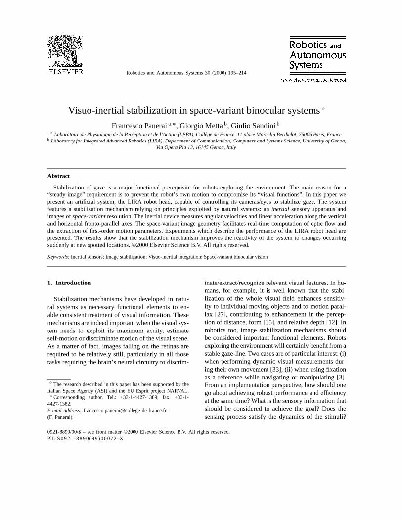
Fig. 1. The artificial vestibular system.Left: the spatial arrangement of the rotational and translational sensing elements.Right: the prototypeartificial vestibular system. Overall dimensions are kept relatively small (5× 4 × 4 cm) by implementing the design of the individualmodules using surface mount technology.
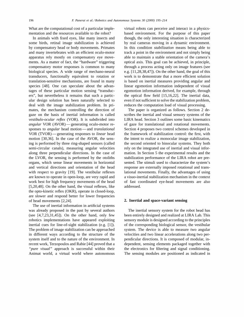
Fig. 2. The space-variant image geometry.Left: log-polar image of 128×64 pixels.Right: the corresponding reconstructed Cartesian image.
Fig. 1 (left); on the right side, the prototyped device isshown. The overall dimensions are 5 cm×4 cm×4 cm.The rotational part is composed of piezoelectric sen-sors (also known as vibrating gyros) produced by Mu-rata. These transducers can measure rotational veloc-ity around their longitudinal axis: the range of mea-surement extends from−90 to +90◦ per second, thebandwidth from DC to 50 Hz (90◦ phase delay). Theoutput of the sensor is band-pass filtered (0.03–5.0 Hz)and amplified by custom electronics. The linear part,on the other hand, is composed of sensing elementsexploiting a heat transfer design principle and are pro-duced by Pewatron. The output generated is propor-
tional to linear acceleration. The range of measure-ment extends from−1 to +1 g. In the linear part too,custom electronics is used to low-pass filter and am-plify the response of the sensing elements [32].
As for the visual sensing, the LIRA’s robot head ac-quires and processes images in a space-variant format(see [34] for a detailed description of the log-polar,space-variant geometry). Instead of a uniform resolu-tion across the whole visual field, the robot eyes ob-serve the environment throughfoveal image area ofhigh resolution and a peripheral image area of low res-olution. Fig. 2 (left) shows a space-variant, log-polarimage as acquired by the head’s vision system. The
198 F. Panerai et al. / Robotics and Autonomous Systems 30 (2000) 195–214
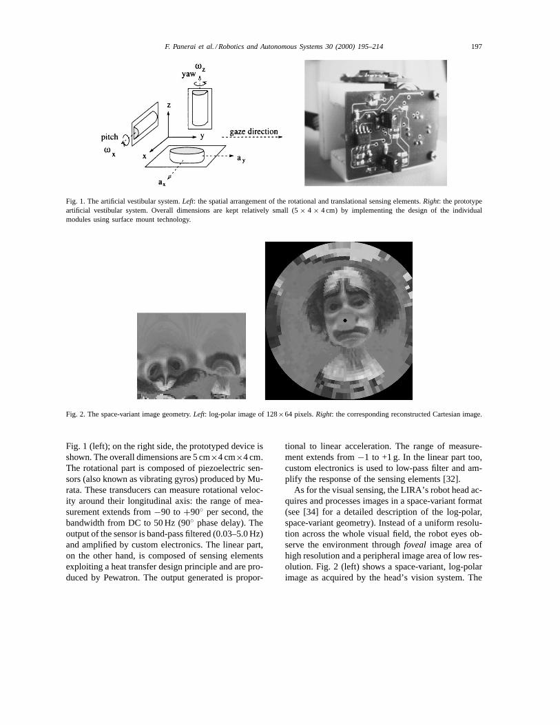
Fig. 3. The head mount.Left: front view of the robot head shows the offset position of the cameras with respect to the neck rotationalaxis (head geometrical parameters,b = 136 mm, a = 95 mm). Right: the artificial “vestibular” system is rigidly fixed on the back of thehead mount.
image (128×64 pixels) is magnified to better illustratethe resolution variability from foveal to peripheral ar-eas. Fig. 2 (right) displays the corresponding Cartesianreconstructed image. These two biologically inspiredsensory systems are integrated within a binocular ar-chitecture (see Fig. 3). More specifically, the active vi-sion hardware used in these experiments is composedof:• a four d.o.f. mount, independent vergence, common
elevation and common pan,• two color cameras simulating a space-variant
(log-polar) geometry,• an artificial vestibular system,• a double Pentium-Pro system architecture, a frame
grabber (IntegralTech Flash Point 128) and a motioncontrol board (Motion Engineering).
3. Head movement versus gaze kinematics
The goal of this section is to make explicit the rel-ative roles of inertial and visual information in differ-ent situations. It should help to highlight the advan-tages of visuo-inertial integration and the asymmetriesof eye-control commands. The description we develophere includes the eye–head geometric parameters andthe eye–head kinematic dependence on fixation dis-tance for rotations and translations. This formalismshould not be taken to suggest that biological systemsexplicitly compute direct or inverse kinematics.
3.1. Rotational movements
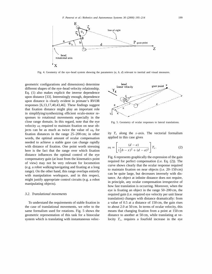
We consider here the compensatory eye move-ments required to maintain stable fixation of a targetat distanced, when the head rotates around a verti-cal, off-centered axis. Fig. 4 shows the geometry of abinocular system for this case and indicates the mostrelevant geometrical parameters: the inter-ocular dis-tance (or baseline)b, the perpendicular distanceabetween the rotational axis of the head and the base-line, and the viewing distanced, measured from thehead rotational axis and the gaze point. The analyt-ical relation among these parameters can be derivedby considering the kinematics of this model, and im-posing the constraint that the eyeE maintains gazeat pointP when the head rotates (see Appendix A.1for details). Simple vectorial rules and differentiationwith respect to time leads to the following expressionof angular velocityωl :
ωl =[
1 + dZl − (a2 + 14b2)
d2 − 2dZl + (a2 + 14b2)
]ωh, (1)
where Zl = (a cosθh + 12b sinθh) represents the
Z-coordinate of the left eye. Eq. (1) determines therelationship between eye velocity,ωl , and (i) the ge-ometrical parameters of the eye–head system (i.e.banda) and (ii) the distanced of the fixation pointPfor any given head velocityωh. In a robot vision sys-tem different choices of thea andb parameters (i.e.
F. Panerai et al. / Robotics and Autonomous Systems 30 (2000) 195–214 199
Fig. 4. Geometry of the eye–head system showing the parameters (a, b, d) relevant to inertial and visual measures.
geometric configurations and dimensions) determinedifferent shapes of the eye–head velocity relationship.Eq. (1) also makes explicit the inverse dependenceupon distance [33]. Interestingly enough, dependenceupon distance is clearly evident in primate’s RVORresponses [6,13,17,40,43,46]. These findings suggestthat fixation distance might play an important rolein simplifying/synthesizing efficient oculo-motor re-sponses to rotational movements especially in theclose range domain. In this regard, note that the eyevelocity ωl required to maintain fixation on near ob-jects can be as much as twice the value ofωh forfixation distances in the range 25–200 cm; in otherwords, the optimal amount of ocular compensationneeded to achieve a stable gaze can change rapidlywith distance of fixation. One point worth stressinghere is the fact that the range over which fixationdistance influences the optimal control of the eyecompensatory gain (at least from the kinematics pointof view) may not be very relevant for locomotion(e.g. a robot walking/navigating and fixating at a longrange). On the other hand, this range overlaps entirelywith manipulation workspace, and in this respect,might justify appropriate control circuits (e.g. a robotmanipulating objects).
3.2. Translational movements
To understand the requirements of stable fixation inthe case of translational movements, we refer to thesame formalism used for rotations. Fig. 5 shows thegeometric representation of this task for a binocularsystem which is translating with instantaneous veloc-
Fig. 5. Geometry of ocular responses to lateral translations.
ity Tx along the x-axis. The vectorial formalismapplied in this case gives
ωl =[
(d − a)
(12b − x)2 + (d − a)2
]Tx. (2)
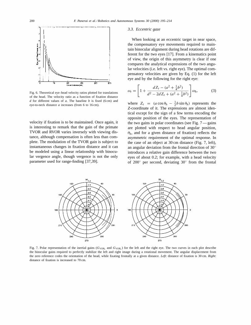
Fig. 6 represents graphically the expression of the gainrequired for perfect compensation (i.e. Eq. (2)). Thecurve shows clearly that the ocular response requiredto maintain fixation on near objects (i.e. 20–150 cm)can be quite large, but decreases inversely with dis-tance. An object at infinite distance does not require,in principle, any ocular compensation irrespective ofhow fast translation is occurring. Moreover, when theeye is fixating an object in the range 50–200 cm, therequired gain (i.e. required eye velocity per unit lineartranslation) changes with distance dramatically: froma value of 0.5 at a distance of 150 cm, the gain risesto about 2.0 at 50 cm. In terms of ocular velocity, thismeans that changing fixation from a point at 150 cmdistance to another at 50 cm, while translating at ve-locity Tx , requires a fourfold increase in the eye
200 F. Panerai et al. / Robotics and Autonomous Systems 30 (2000) 195–214
Fig. 6. Theoretical eye–head velocity ratios plotted for translationsof the head. The velocity ratio as a function of fixation distanced for different values ofa. The baselineb is fixed (6 cm) andeye-to-neck distancea increases (from 6 to 16 cm).
velocity if fixation is to be maintained. Once again, itis interesting to remark that the gain of the primateTVOR and RVOR varies inversely with viewing dis-tance, although compensation is often less than com-plete. The modulation of the TVOR gain is subject toinstantaneous changes in fixation distance and it canbe modeled using a linear relationship with binocu-lar vergence angle, though vergence is not the onlyparameter used for range-finding [37,39].
Fig. 7. Polar representation of the inertial gains (GVORl and GVORr ) for the left and the right eye. The two curves in each plot describethe binocular gains required to perfectly stabilize the left and right image during a rotational movement. The angular displacement fromthe zero reference codes the orientation of the head, while fixating frontally at a given distance.Left: distance of fixation is 30 cm.Right:distance of fixation is increased to 70 cm.
3.3. Eccentric gaze
When looking at an eccentric target in near space,the compensatory eye movements required to main-tain binocular alignment during head rotations are dif-ferent for the two eyes [17]. From a kinematics pointof view, the origin of this asymmetry is clear if onecompares the analytical expressions of the two angu-lar velocities (i.e. left vs. right eye). The optimal com-pensatory velocities are given by Eq. (1) for the lefteye and by the following for the right eye:
ωr =[
1 + dZr − (a2 + 14b2)
d2 − 2dZr + (a2 + 14b2)
]ωh, (3)
where Zr = (a cosθh − 12b sinθh) represents the
Z-coordinate of it. The expressions are almost iden-tical except for the sign of a few terms encoding theopposite position of the eyes. The representation ofthe two gains in polar coordinates (see Fig. 7 — gainsare plotted with respect to head angular position,θh, and for a given distance of fixation) reflects theasymmetric requirement of the optimal response. Inthe case of an object at 30 cm distance (Fig. 7, left),an angular deviation from the frontal direction of 30◦introduces a relative gain difference between the twoeyes of about 0.2; for example, with a head velocityof 200◦ per second, deviating 30◦ from the frontal
F. Panerai et al. / Robotics and Autonomous Systems 30 (2000) 195–214 201
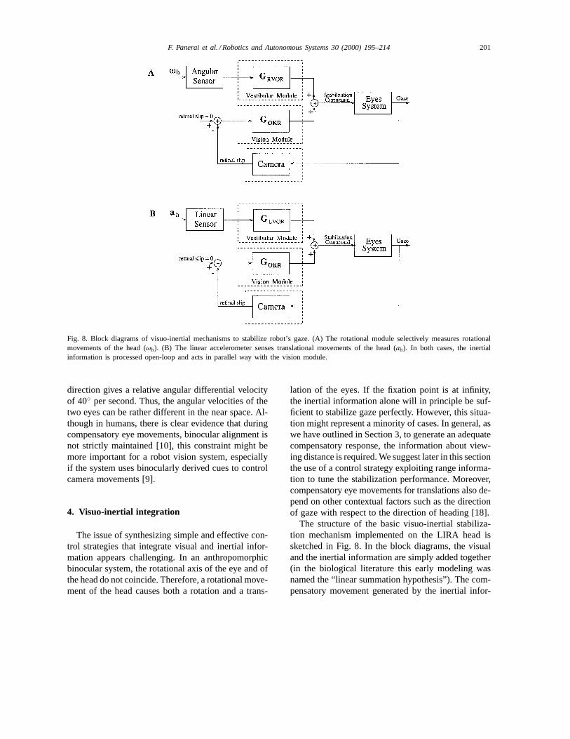
Fig. 8. Block diagrams of visuo-inertial mechanisms to stabilize robot’s gaze. (A) The rotational module selectively measures rotationalmovements of the head (ωh). (B) The linear accelerometer senses translational movements of the head (ah). In both cases, the inertialinformation is processed open-loop and acts in parallel way with the vision module.
direction gives a relative angular differential velocityof 40◦ per second. Thus, the angular velocities of thetwo eyes can be rather different in the near space. Al-though in humans, there is clear evidence that duringcompensatory eye movements, binocular alignment isnot strictly maintained [10], this constraint might bemore important for a robot vision system, especiallyif the system uses binocularly derived cues to controlcamera movements [9].
4. Visuo-inertial integration
The issue of synthesizing simple and effective con-trol strategies that integrate visual and inertial infor-mation appears challenging. In an anthropomorphicbinocular system, the rotational axis of the eye and ofthe head do not coincide. Therefore, a rotational move-ment of the head causes both a rotation and a trans-
lation of the eyes. If the fixation point is at infinity,the inertial information alone will in principle be suf-ficient to stabilize gaze perfectly. However, this situa-tion might represent a minority of cases. In general, aswe have outlined in Section 3, to generate an adequatecompensatory response, the information about view-ing distance is required. We suggest later in this sectionthe use of a control strategy exploiting range informa-tion to tune the stabilization performance. Moreover,compensatory eye movements for translations also de-pend on other contextual factors such as the directionof gaze with respect to the direction of heading [18].
The structure of the basic visuo-inertial stabiliza-tion mechanism implemented on the LIRA head issketched in Fig. 8. In the block diagrams, the visualand the inertial information are simply added together(in the biological literature this early modeling wasnamed the “linear summation hypothesis”). The com-pensatory movement generated by the inertial infor-
202 F. Panerai et al. / Robotics and Autonomous Systems 30 (2000) 195–214
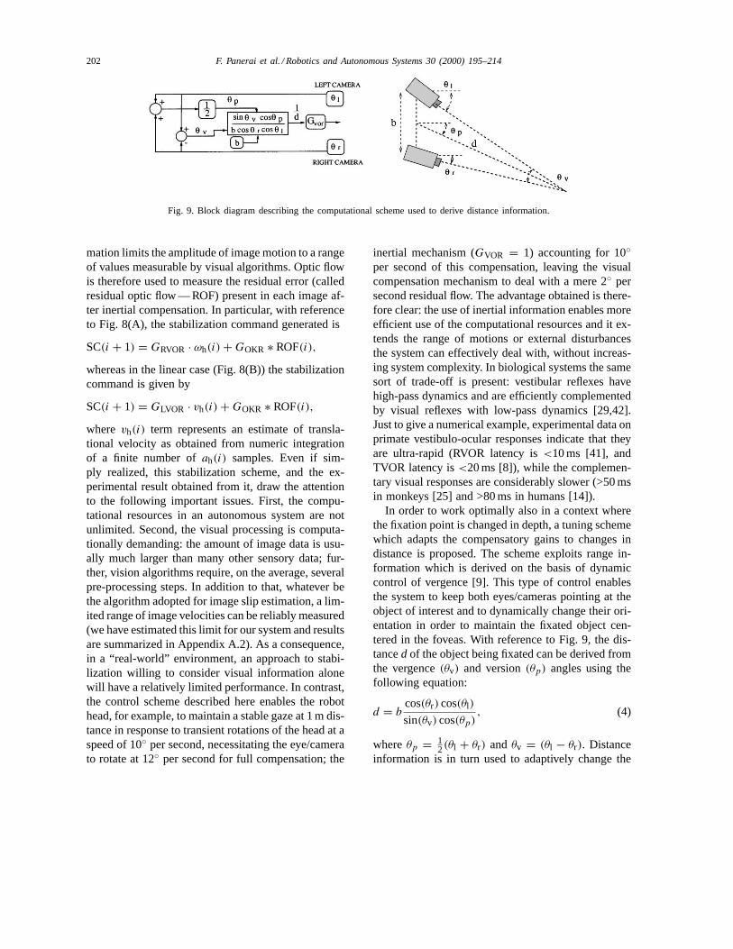
Fig. 9. Block diagram describing the computational scheme used to derive distance information.
mation limits the amplitude of image motion to a rangeof values measurable by visual algorithms. Optic flowis therefore used to measure the residual error (calledresidual optic flow — ROF) present in each image af-ter inertial compensation. In particular, with referenceto Fig. 8(A), the stabilization command generated is
SC(i + 1) = GRVOR · ωh(i) + GOKR ∗ ROF(i),
whereas in the linear case (Fig. 8(B)) the stabilizationcommand is given by
SC(i + 1) = GLVOR · vh(i) + GOKR ∗ ROF(i),
where vh(i) term represents an estimate of transla-tional velocity as obtained from numeric integrationof a finite number ofah(i) samples. Even if sim-ply realized, this stabilization scheme, and the ex-perimental result obtained from it, draw the attentionto the following important issues. First, the compu-tational resources in an autonomous system are notunlimited. Second, the visual processing is computa-tionally demanding: the amount of image data is usu-ally much larger than many other sensory data; fur-ther, vision algorithms require, on the average, severalpre-processing steps. In addition to that, whatever bethe algorithm adopted for image slip estimation, a lim-ited range of image velocities can be reliably measured(we have estimated this limit for our system and resultsare summarized in Appendix A.2). As a consequence,in a “real-world” environment, an approach to stabi-lization willing to consider visual information alonewill have a relatively limited performance. In contrast,the control scheme described here enables the robothead, for example, to maintain a stable gaze at 1 m dis-tance in response to transient rotations of the head at aspeed of 10◦ per second, necessitating the eye/camerato rotate at 12◦ per second for full compensation; the
inertial mechanism (GVOR = 1) accounting for 10◦per second of this compensation, leaving the visualcompensation mechanism to deal with a mere 2◦ persecond residual flow. The advantage obtained is there-fore clear: the use of inertial information enables moreefficient use of the computational resources and it ex-tends the range of motions or external disturbancesthe system can effectively deal with, without increas-ing system complexity. In biological systems the samesort of trade-off is present: vestibular reflexes havehigh-pass dynamics and are efficiently complementedby visual reflexes with low-pass dynamics [29,42].Just to give a numerical example, experimental data onprimate vestibulo-ocular responses indicate that theyare ultra-rapid (RVOR latency is<10 ms [41], andTVOR latency is<20 ms [8]), while the complemen-tary visual responses are considerably slower (>50 msin monkeys [25] and >80 ms in humans [14]).
In order to work optimally also in a context wherethe fixation point is changed in depth, a tuning schemewhich adapts the compensatory gains to changes indistance is proposed. The scheme exploits range in-formation which is derived on the basis of dynamiccontrol of vergence [9]. This type of control enablesthe system to keep both eyes/cameras pointing at theobject of interest and to dynamically change their ori-entation in order to maintain the fixated object cen-tered in the foveas. With reference to Fig. 9, the dis-tanced of the object being fixated can be derived fromthe vergence(θv) and version(θp) angles using thefollowing equation:
d = bcos(θr) cos(θl)
sin(θv) cos(θp), (4)
whereθp = 12(θl + θr) andθv = (θl − θr). Distance
information is in turn used to adaptively change the
F. Panerai et al. / Robotics and Autonomous Systems 30 (2000) 195–214 203
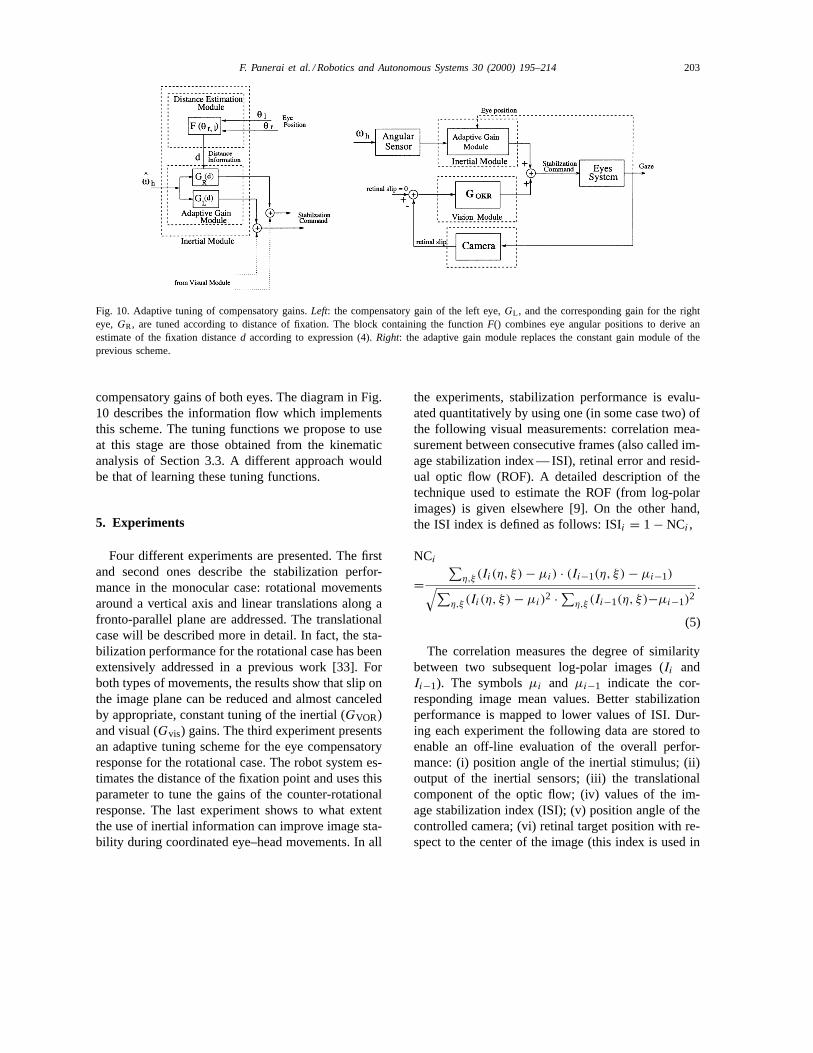
Fig. 10. Adaptive tuning of compensatory gains.Left: the compensatory gain of the left eye,GL , and the corresponding gain for the righteye,GR, are tuned according to distance of fixation. The block containing the functionF() combines eye angular positions to derive anestimate of the fixation distanced according to expression (4).Right: the adaptive gain module replaces the constant gain module of theprevious scheme.
compensatory gains of both eyes. The diagram in Fig.10 describes the information flow which implementsthis scheme. The tuning functions we propose to useat this stage are those obtained from the kinematicanalysis of Section 3.3. A different approach wouldbe that of learning these tuning functions.
5. Experiments
Four different experiments are presented. The firstand second ones describe the stabilization perfor-mance in the monocular case: rotational movementsaround a vertical axis and linear translations along afronto-parallel plane are addressed. The translationalcase will be described more in detail. In fact, the sta-bilization performance for the rotational case has beenextensively addressed in a previous work [33]. Forboth types of movements, the results show that slip onthe image plane can be reduced and almost canceledby appropriate, constant tuning of the inertial (GVOR)and visual (Gvis) gains. The third experiment presentsan adaptive tuning scheme for the eye compensatoryresponse for the rotational case. The robot system es-timates the distance of the fixation point and uses thisparameter to tune the gains of the counter-rotationalresponse. The last experiment shows to what extentthe use of inertial information can improve image sta-bility during coordinated eye–head movements. In all
the experiments, stabilization performance is evalu-ated quantitatively by using one (in some case two) ofthe following visual measurements: correlation mea-surement between consecutive frames (also called im-age stabilization index — ISI), retinal error and resid-ual optic flow (ROF). A detailed description of thetechnique used to estimate the ROF (from log-polarimages) is given elsewhere [9]. On the other hand,the ISI index is defined as follows: ISIi = 1 − NCi ,
NCi
=∑
η,ξ (Ii(η, ξ) − µi) · (Ii−1(η, ξ) − µi−1)√∑η,ξ (Ii(η, ξ) − µi)2 · ∑
η,ξ (Ii−1(η, ξ)−µi−1)2.
(5)
The correlation measures the degree of similaritybetween two subsequent log-polar images (Ii andIi−1). The symbolsµi and µi−1 indicate the cor-responding image mean values. Better stabilizationperformance is mapped to lower values of ISI. Dur-ing each experiment the following data are stored toenable an off-line evaluation of the overall perfor-mance: (i) position angle of the inertial stimulus; (ii)output of the inertial sensors; (iii) the translationalcomponent of the optic flow; (iv) values of the im-age stabilization index (ISI); (v) position angle of thecontrolled camera; (vi) retinal target position with re-spect to the center of the image (this index is used in
204 F. Panerai et al. / Robotics and Autonomous Systems 30 (2000) 195–214
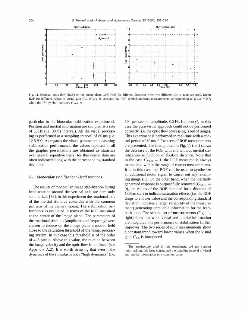
Fig. 11. Residual optic flow (ROF) on the image plane.Left: ROF for different distances when two differentGVOR gains are used.Right:ROF for different values of visual gainGvis (GVOR is constant: the “s” symbol indicates measurements corresponding toGVOR = 0.7,while the “*” symbol indicatesGVOR = 1.
particular in the binocular stabilization experiment).Position and inertial information are sampled at a rateof 33 Hz (i.e. 30 ms interval). All the visual process-ing is performed at a sampling interval of 80 ms (i.e.12.5 Hz). As regards the visual parameters measuringstabilization performance, the values reported in allthe graphic presentations are obtained as statisticsover several repetitive trials; for this reason data areoften indicated along with the corresponding standarddeviation.
5.1. Monocular stabilization: Head rotations
The results of monocular image stabilization duringhead rotation around the vertical axis are here onlysummarized [33]. In this experiment the rotational axisof the inertial stimulus coincides with the commonpan axis of the camera mount. The stabilization per-formance is evaluated in terms of the ROF measuredat the center of the image plane. The parameters ofthe rotational stimulus (amplitude and frequency) werechosen to induce on the image plane a motion fieldclose to the saturation threshold of the visual process-ing system. In our case this threshold is of the orderof 4–5 pixels. Above this value, the relation betweenthe image velocity and the optic flow is not linear (seeAppendix A.2). It is worth stressing that even if thedynamics of the stimulus is not a “high dynamics” (i.e.
10◦ per second amplitude, 0.2 Hz frequency), in thiscase the pure visual approach could not be performedcorrectly (i.e. the optic flow processing is out of range).This experiment is performed in real-time with a con-trol period of 80 ms.1 Two sets of ROF measurementsare presented. The first, plotted in Fig. 11 (left) showsthe decrease of the ROF with and without inertial sta-bilization as function of fixation distance. Note thatin the caseGVOR = 1, the ROF measured is alwaysmaintained within the range of correct measurements.It is in this case that ROF can be used to synthesizean additional motor signal to cancel out any remain-ing image slip. On the other hand, when the inertiallygenerated response is purposefully removed (GVOR =0), the values of the ROF obtained for a distance of130 cm start to indicate saturation effects (i.e. the ROFdrops to a lower value and the corresponding standarddeviation indicates a larger variability of the measure-ment) generating unreliable information for the feed-back loop. The second set of measurements (Fig. 11,right) show that when visual and inertial informationare integrated, the performance of stabilization furtherimproves. The two series of ROF measurements showa constant trend toward lower values when the visualgainGvis is introduced.
1 The architecture used in this experiment did not supportmulti-tasking; this issue constrained the sampling interval of visualand inertial information to a common value.
F. Panerai et al. / Robotics and Autonomous Systems 30 (2000) 195–214 205
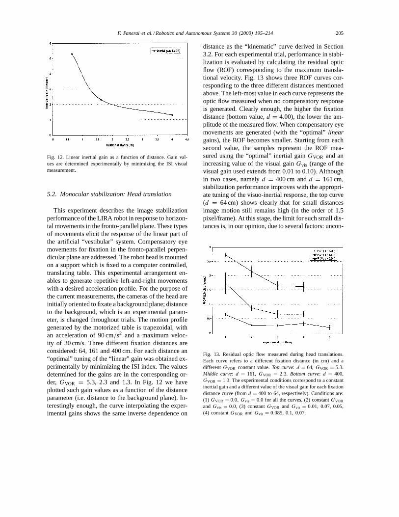
Fig. 12. Linear inertial gain as a function of distance. Gain val-ues are determined experimentally by minimizing the ISI visualmeasurement.
5.2. Monocular stabilization: Head translation
This experiment describes the image stabilizationperformance of the LIRA robot in response to horizon-tal movements in the fronto-parallel plane. These typesof movements elicit the response of the linear part ofthe artificial “vestibular” system. Compensatory eyemovements for fixation in the fronto-parallel perpen-dicular plane are addressed. The robot head is mountedon a support which is fixed to a computer controlled,translating table. This experimental arrangement en-ables to generate repetitive left-and-right movementswith a desired acceleration profile. For the purpose ofthe current measurements, the cameras of the head areinitially oriented to fixate a background plane; distanceto the background, which is an experimental param-eter, is changed throughout trials. The motion profilegenerated by the motorized table is trapezoidal, withan acceleration of 90 cm/s2 and a maximum veloc-ity of 30 cm/s. Three different fixation distances areconsidered: 64, 161 and 400 cm. For each distance an“optimal” tuning of the “linear” gain was obtained ex-perimentally by minimizing the ISI index. The valuesdetermined for the gains are in the corresponding or-der, GVOR = 5.3, 2.3 and 1.3. In Fig. 12 we haveplotted such gain values as a function of the distanceparameter (i.e. distance to the background plane). In-terestingly enough, the curve interpolating the exper-imental gains shows the same inverse dependence on
distance as the “kinematic” curve derived in Section3.2. For each experimental trial, performance in stabi-lization is evaluated by calculating the residual opticflow (ROF) corresponding to the maximum transla-tional velocity. Fig. 13 shows three ROF curves cor-responding to the three different distances mentionedabove. The left-most value in each curve represents theoptic flow measured when no compensatory responseis generated. Clearly enough, the higher the fixationdistance (bottom value,d = 4.00), the lower the am-plitude of the measured flow. When compensatory eyemovements are generated (with the “optimal”lineargains), the ROF becomes smaller. Starting from eachsecond value, the samples represent the ROF mea-sured using the “optimal” inertial gainGVOR and anincreasing value of the visual gainGvis (range of thevisual gain used extends from 0.01 to 0.10). Althoughin two cases, namelyd = 400 cm andd = 161 cm,stabilization performance improves with the appropri-ate tuning of the visuo-inertial response, the top curve(d = 64 cm) shows clearly that for small distancesimage motion still remains high (in the order of 1.5pixel/frame). At this stage, the limit for such small dis-tances is, in our opinion, due to several factors: uncon-
Fig. 13. Residual optic flow measured during head translations.Each curve refers to a different fixation distance (in cm) and adifferent GVOR constant value.Top curve: d = 64, GVOR = 5.3.Middle curve: d = 161, GVOR = 2.3. Bottom curve: d = 400,GVOR = 1.3. The experimental conditions correspond to a constantinertial gain and a different value of the visual gain for each fixationdistance curve (fromd = 400 to 64, respectively). Conditions are:(1) GVOR = 0.0, Gvis = 0.0 for all the curves, (2) constantGVOR
and Gvis = 0.0, (3) constantGVOR and Gvis = 0.01, 0.07, 0.05,(4) constantGVOR andGvis = 0.085, 0.1, 0.07.
206 F. Panerai et al. / Robotics and Autonomous Systems 30 (2000) 195–214
trollable delays in the sensori-motor loop, phase lagsintroduced by sensor filtering (to eliminate the sensornoise), but most importantly, the low sensitivity of thelinear sensing device. Further work is on-going to im-prove the linear part of the inertial sensory system.
5.3. Binocular stabilization: Adaptive gain control
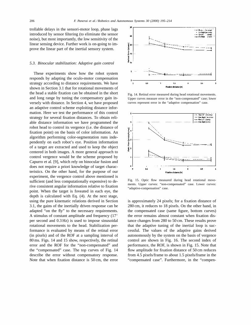
These experiments show how the robot systemresponds by adapting the oculo-motor compensationstrategy according to distance requirements. We haveshown in Section 3.1 that for rotational movements ofthe head a stable fixation can be obtained in the shortand long range by tuning the compensatory gain in-versely with distance. In Section 4, we have proposedan adaptive control scheme exploiting distance infor-mation. Here we test the performance of this controlstrategy for several fixation distances. To obtain reli-able distance information we have programmed therobot head to control its vergence (i.e. the distance offixation point) on the basis of color information. Analgorithm performing color-segmentation runs inde-pendently on each robot’s eye. Position informationof a target are extracted and used to keep the objectcentered in both images. A more general approach tocontrol vergence would be the scheme proposed byCapurro et al. [9], which rely on binocular fusion anddoes not require a priori knowledge of target charac-teristics. On the other hand, for the purpose of ourexperiment, the vergence control above mentioned issufficient (and less computationally expensive) to de-rive consistent angular information relative to fixationpoint. When the target is foveated in each eye, thedepth is calculated with Eq. (4). At the next stage,using the pure kinematic relations derived in Section3.1, the gains of the inertially driven response can beadapted “on the fly” to the necessary requirements.A stimulus of constant amplitude and frequency (17◦per second and 0.3 Hz) is used to impose sinusoidalrotational movements to the head. Stabilization per-formance is evaluated by means of the retinal error(in pixels) and of the ROF at a sampling interval of80 ms. Figs. 14 and 15 show, respectively, the retinalerror and the ROF for the “non-compensated” andthe “compensated” case. The top curves of Fig. 14describe the error without compensatory response.Note that when fixation distance is 50 cm, the error
Fig. 14. Retinal error measured during head rotational movements.Upper curves measure error in the “non-compensated” case; lowercurves represent error in the “adaptive compensation” case.
Fig. 15. Optic flow measured during head rotational move-ments. Upper curves: “non-compensated” case. Lower curves:“adaptive-compensation” case.
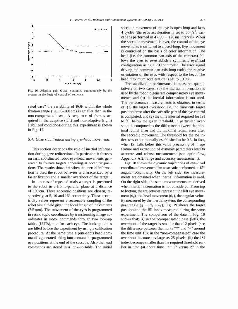
is approximately 24 pixels; for a fixation distance of280 cm, it reduces to 18 pixels. On the other hand, inthe compensated case (same figure, bottom curves)the error remains almost constant when fixation dis-tance changes from 280 to 50 cm. These results provethat the adaptive tuning of the inertial loop is suc-cessful. The values of the adaptive gains derivedautonomously by the system on the basis of vergencecontrol are shown in Fig. 16. The second index ofperformance, the ROF, is shown in Fig. 15. Note thatflow amplitude for fixation distance of 50 cm reducesfrom 4.5 pixels/frame to about 1.5 pixels/frame in the“compensated case”. Furthermore, in the “compen-
F. Panerai et al. / Robotics and Autonomous Systems 30 (2000) 195–214 207
Fig. 16. Adaptive gainGVORr computed autonomously by thesystem on the basis of control of vergence.
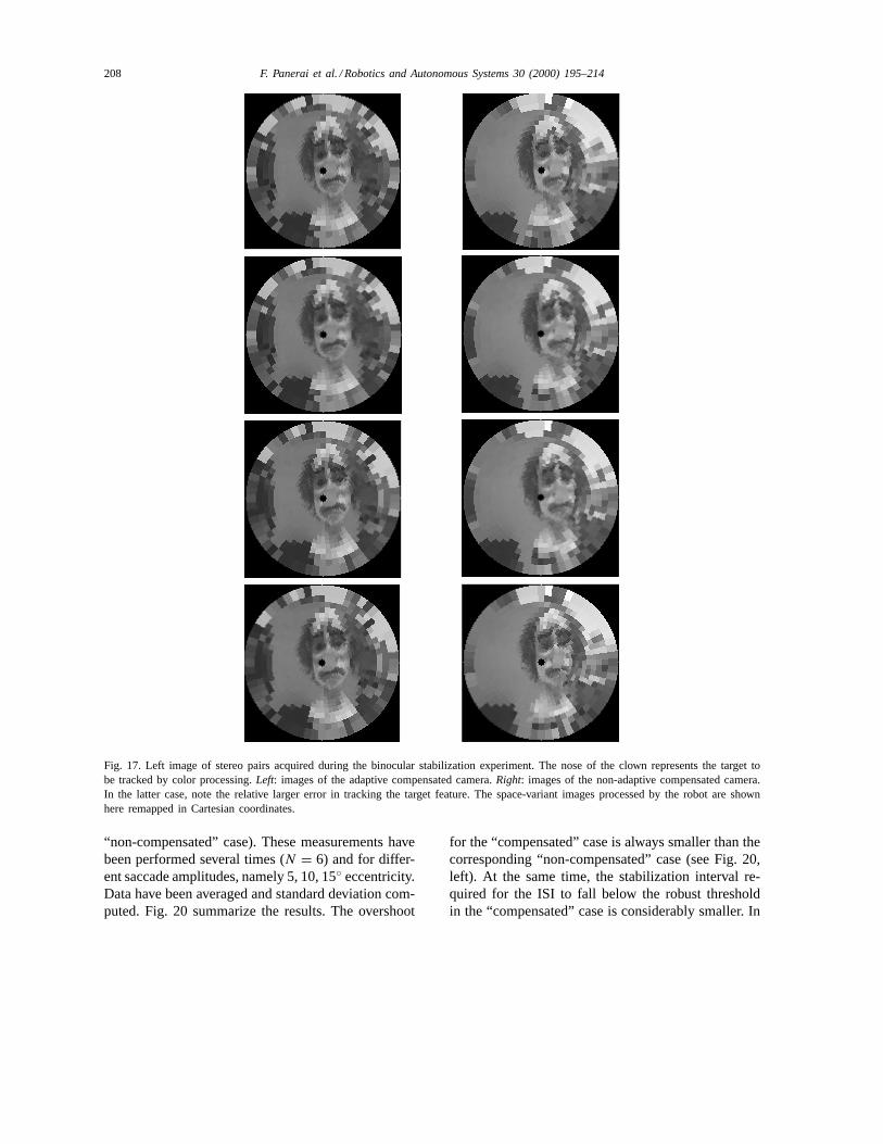
sated case” the variability of ROF within the wholefixation range (i.e. 50–280 cm) is smaller than in thenon-compensated case. A sequence of frames ac-quired in the adaptive (left) and non-adaptive (right)stabilized conditions during this experiment is shownin Fig. 17.
5.4. Gaze stabilization during eye–head movements
This section describes the role of inertial informa-tion during gaze redirections. In particular, it focuseson fast, coordinated robot eye–head movements gen-erated to foveate targets appearing at eccentric posi-tions. The results show that when the inertial informa-tion is used the robot behavior is characterized by afaster fixation and a smaller overshoot of the target.
In a series of repeated trials a target is presentedto the robot in a fronto-parallel plane at a distanceof 100 cm. Three eccentric positions are chosen, re-spectively, at 5, 10 and 15◦ eccentricity. These eccen-tricity values represent a reasonable sampling of therobot visual field given the focal length of the cameras(7.5 mm). The movement of the eyes is programmedin retino topic coordinates by transforming image co-ordinates in motor commands through two look-uptables (LUTs), one for each eye. The look-up tablesare filled before the experiment by using a calibrationprocedure. At the same time a (one-shot) head com-mand is generated taking into account the programmedeye positions at the end of the saccade. Also the headcommands are stored in a look-up table. The initial
saccadic movement of the eye is open-loop and lasts4 cycles (the eyes acceleration is set to 50◦/s2, sac-cade is performed in 4∗ 30 = 120 ms interval). Whenthe saccadic movement is over, the control of the eyemovements is switched to closed-loop. Eye movementis controlled on the basis of color information. Thehead (i.e. the common pan axis of the cameras) fol-lows the eyes to re-establish a symmetric eye/headconfiguration using a PID controller. The error signaldriving the common pan axis loop codes the relativeorientation of the eyes with respect to the head. Thehead maximum acceleration is set to 10◦/s2.
The stabilization performance is measured quanti-tatively in two cases: (a) the inertial information isused by the robot to generate compensatory eye move-ments, and (b) the inertial information is not used.The performance measurements is obtained in termsof: (1) the target overshoot, i.e. the transients targetposition error after the saccadic part of the eye controlis completed, and (2) the time interval required for ISIto fall below the given threshold. In particular, over-shoot is computed as the difference between the min-imal retinal error and the maximal retinal error afterthe saccadic movement. The threshold for the ISI in-dex was experimentally established to be 0.3. In fact,when ISI falls below this value processing of imagefeature and extraction of dynamic parameters lead toaccurate and robust measurement (see optic flow,Appendix A.2, range and accuracy measurement).
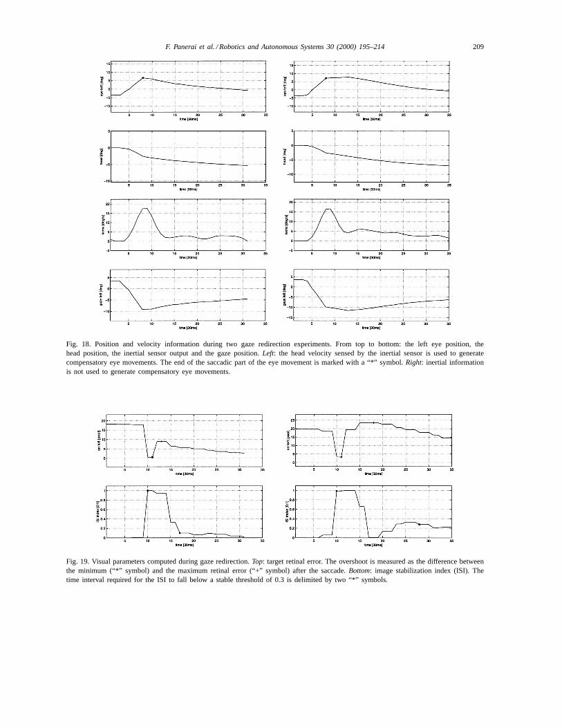
Fig. 18 shows the dynamic trajectories of eye–headcoordinated movement for a saccade performed at 15◦angular eccentricity. On the left side, the measure-ments are obtained when inertial information is used.On the right side, the same measurements are derivedwhen inertial information is not considered. From topto bottom, the trajectories represent: the left eye move-ment (θe), the head movement (θh), the angular veloc-ity measured by the inertial system, the correspondinggaze angle (g = θh + θe). Fig. 19 shows the targetposition and the ISI index measured during the sameexperiment. The comparison of the data in Fig. 19shows that: (i) in the “compensated” case (left), theovershoot of the target is smaller than 12 pixels (seethe difference between the marks “*” and “+” aroundthe time unit 15); in the “non-compensated” case theovershoot becomes as large as 25 pixels; (ii) the ISIindex becomes smaller than the required threshold ear-lier in time (at about time unit 17 versus 27 in the
208 F. Panerai et al. / Robotics and Autonomous Systems 30 (2000) 195–214
Fig. 17. Left image of stereo pairs acquired during the binocular stabilization experiment. The nose of the clown represents the target tobe tracked by color processing.Left: images of the adaptive compensated camera.Right: images of the non-adaptive compensated camera.In the latter case, note the relative larger error in tracking the target feature. The space-variant images processed by the robot are shownhere remapped in Cartesian coordinates.
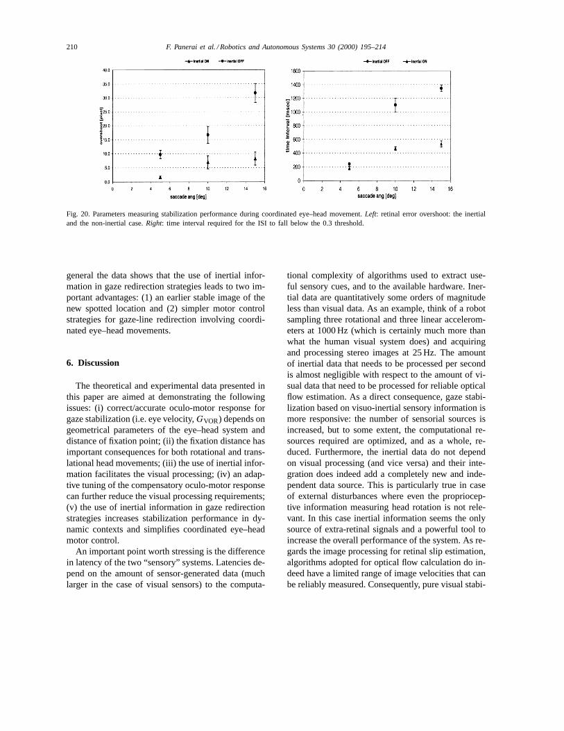
“non-compensated” case). These measurements havebeen performed several times (N = 6) and for differ-ent saccade amplitudes, namely 5, 10, 15◦ eccentricity.Data have been averaged and standard deviation com-puted. Fig. 20 summarize the results. The overshoot
for the “compensated” case is always smaller than thecorresponding “non-compensated” case (see Fig. 20,left). At the same time, the stabilization interval re-quired for the ISI to fall below the robust thresholdin the “compensated” case is considerably smaller. In
F. Panerai et al. / Robotics and Autonomous Systems 30 (2000) 195–214 209
Fig. 18. Position and velocity information during two gaze redirection experiments. From top to bottom: the left eye position, thehead position, the inertial sensor output and the gaze position.Left: the head velocity sensed by the inertial sensor is used to generatecompensatory eye movements. The end of the saccadic part of the eye movement is marked with a “*” symbol.Right: inertial informationis not used to generate compensatory eye movements.
Fig. 19. Visual parameters computed during gaze redirection.Top: target retinal error. The overshoot is measured as the difference betweenthe minimum (“*” symbol) and the maximum retinal error (“+” symbol) after the saccade.Bottom: image stabilization index (ISI). Thetime interval required for the ISI to fall below a stable threshold of 0.3 is delimited by two “*” symbols.
210 F. Panerai et al. / Robotics and Autonomous Systems 30 (2000) 195–214
Fig. 20. Parameters measuring stabilization performance during coordinated eye–head movement.Left: retinal error overshoot: the inertialand the non-inertial case.Right: time interval required for the ISI to fall below the 0.3 threshold.
general the data shows that the use of inertial infor-mation in gaze redirection strategies leads to two im-portant advantages: (1) an earlier stable image of thenew spotted location and (2) simpler motor controlstrategies for gaze-line redirection involving coordi-nated eye–head movements.
6. Discussion
The theoretical and experimental data presented inthis paper are aimed at demonstrating the followingissues: (i) correct/accurate oculo-motor response forgaze stabilization (i.e. eye velocity,GVOR) depends ongeometrical parameters of the eye–head system anddistance of fixation point; (ii) the fixation distance hasimportant consequences for both rotational and trans-lational head movements; (iii) the use of inertial infor-mation facilitates the visual processing; (iv) an adap-tive tuning of the compensatory oculo-motor responsecan further reduce the visual processing requirements;(v) the use of inertial information in gaze redirectionstrategies increases stabilization performance in dy-namic contexts and simplifies coordinated eye–headmotor control.
An important point worth stressing is the differencein latency of the two “sensory” systems. Latencies de-pend on the amount of sensor-generated data (muchlarger in the case of visual sensors) to the computa-
tional complexity of algorithms used to extract use-ful sensory cues, and to the available hardware. Iner-tial data are quantitatively some orders of magnitudeless than visual data. As an example, think of a robotsampling three rotational and three linear accelerom-eters at 1000 Hz (which is certainly much more thanwhat the human visual system does) and acquiringand processing stereo images at 25 Hz. The amountof inertial data that needs to be processed per secondis almost negligible with respect to the amount of vi-sual data that need to be processed for reliable opticalflow estimation. As a direct consequence, gaze stabi-lization based on visuo-inertial sensory information ismore responsive: the number of sensorial sources isincreased, but to some extent, the computational re-sources required are optimized, and as a whole, re-duced. Furthermore, the inertial data do not dependon visual processing (and vice versa) and their inte-gration does indeed add a completely new and inde-pendent data source. This is particularly true in caseof external disturbances where even the propriocep-tive information measuring head rotation is not rele-vant. In this case inertial information seems the onlysource of extra-retinal signals and a powerful tool toincrease the overall performance of the system. As re-gards the image processing for retinal slip estimation,algorithms adopted for optical flow calculation do in-deed have a limited range of image velocities that canbe reliably measured. Consequently, pure visual stabi-
F. Panerai et al. / Robotics and Autonomous Systems 30 (2000) 195–214 211
lization performance is bounded. Whatever this rangeis, inertial stabilization improves the performance ofthe system.
An additional important point has been demon-strated in the binocular stabilization experiment.Binocular vision systems can be more efficient ingaze stabilization in at least two senses: (i) If a robustcontrol of vergence exists, they can derive consistentdepth information and use it to tune the eye compen-satory movements. This in turn enables the systemto obtain more stable images during translation androtations at different fixation distances. (ii) Moreover,a binocular system can exploit binocular constrains(like the horopter) to perform motion analysis limitedto the visual area which is interesting to stabilize, i.e.the fixation plane (i.e. the plane in space correspond-ing to intersection of the optical axes, also known aszero disparity plane).
Finally, the experiment on the coordinated eye–headmovements has shown the following three mainpoints: first, fixation over-shoot produced by the headmovement is considerably reduced. Second, earlierstable fixation of the new spotted location (or target)is obtained. In this regard it is worth noting that algo-rithms for motion estimation need at least a few stableframes to compute motion parameters consistently.Therefore, the earlier the images are stable, the soonerthe “visual functions” of the robot are re-established.This, in turn, increases the robot’s reactive behaviorto sudden changes occurring at the new spotted loca-tion. Third, motor control strategies for coordinatedeye–head movements to eccentric targets can be sim-plified. It is not surprising that biological systemsexploit such strategies to increase efficiency of stabi-lization and to simplify “neural control” of the motorplant during gaze redirection [26]. Further work willconcentrate on improving the response of the linearmodule and on integrating it into the adaptive controlscheme.
Appendix A
A.1. Angular velocity of the eye
Consider Fig. 4 where two vectors, namelyvvvgand vvvb, indicate for the left eye, respectively, the
line-of-sight (i.e. the vector connecting the eye posi-tion E with the gaze pointP) and the semi-baselineorientation (i.e. the vector connecting eye positionEand the mid-baseline pointB). The instantaneous eyeangleθe can be expressed according to the following:
θe = arctan
(vvvb × vvvg
vvvb · vvvg
). (A.1)
Substituting the vector symbols with their expressionin terms ofa, b, d, θh and constraining gaze points totheZ axis, we get
vvvg=(
12b cosθh−a sinθh, d−
(a cosθh+1
2b sinθh
)),
(A.2)
vvvb =(
12b cosθh, −1
2b sinθh
), (A.3)
θe = arctan
(2(a − d cosθh)
b − 2d sinθh
). (A.4)
Differentiating Eq. (A.4) with respect to time andintroducing the two auxiliary expressionsZl =(a cosθh + 1
2b sinθh) andZr = (a cosθh − 12b) sinθh)
representing, respectively, theZ-coordinates of theleft and right eye, we have
ωl =[
d(d − Zl)
d2 − 2dZl + (a2 + 14b2)
]ωh (A.5)
for the left eye and
ωr =[
d(d − Zr)
d2 − 2dZr + (a2 + 14b2)
]ωh (A.6)
for the right eye. Eq. (A.5) can also be rewritten as
ωl =[
1 + dZl − (a2 + 14b2)
d2 − 2dZl + (a2 + 14b2)
]ωh, (A.7)
in which the inverse dependence upon distanced ismade more explicit.
A.2. Optic flow: Range and accuracy measurements
For the purpose of our measurements a first-orderapproximation (i.e. affine model) of the optic flow issufficient and easier to compute than local optic flow[21]. The technique applied to the space-variant image
212 F. Panerai et al. / Robotics and Autonomous Systems 30 (2000) 195–214
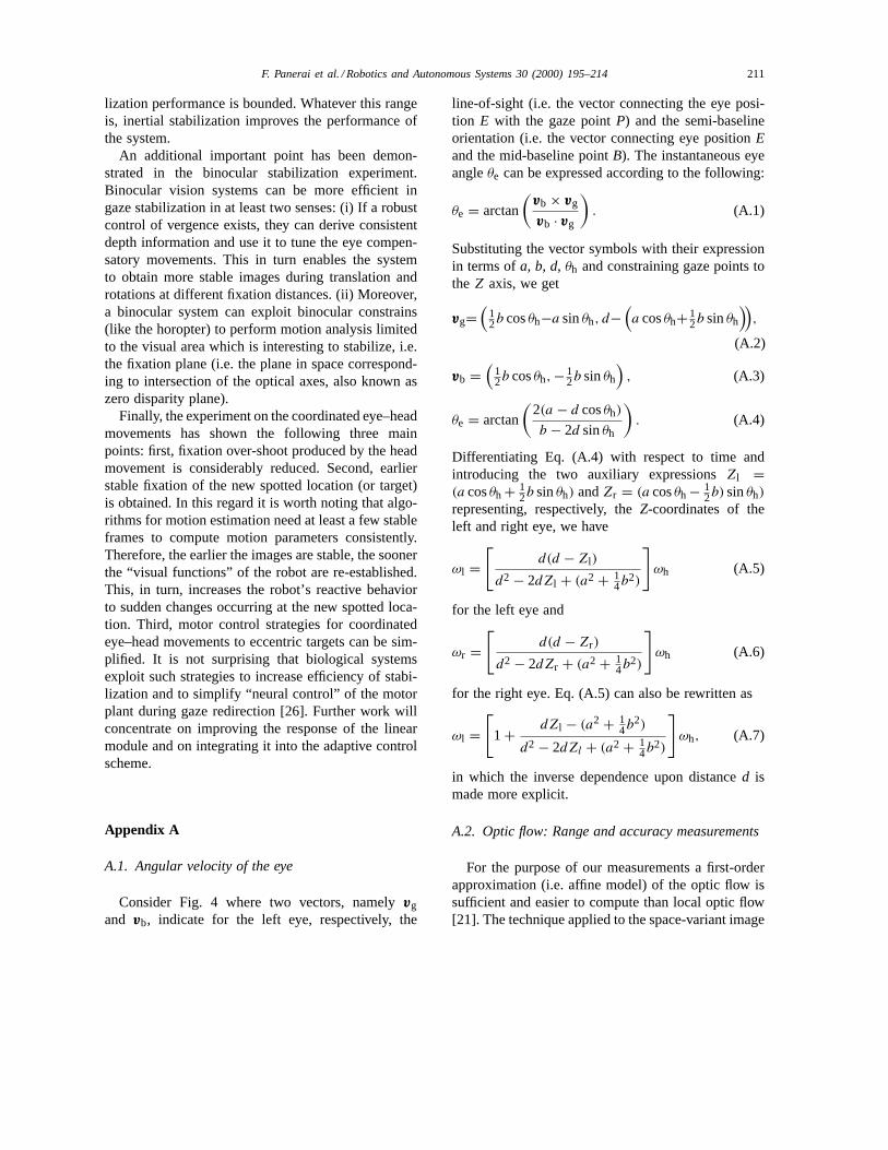
Fig. A.1. Range and accuracy of the optic flow horizontal com-ponentu0 as measured by our algorithm: saturation effect (left),and image stabilization index (right). An ISI value above the 0.3threshold indicates the beginning of the saturation process in theoptic flow measurement.
framework is detailed in [9] and revised in [33]. Sincewe are going to use this motion estimation techniqueto evaluate the performance of the stabilization con-trol, it is important to know quantitatively the rangeand the accuracy of the first-order optic flow estimates.In particular we are interested in theu0 horizontalcomponent of optic flow. We have derived this infor-mation experimentally by repetitive measurements: acamera fixed on top of a controllable slide is repeti-tively translated backward and forward at constant ve-locity, while theu0 estimates are collected. The cam-era is moving in front of a textured flat surface, 245 cmdistant, along a fronto-parallel trajectory. At the endof each back-and-forth motion sequence, the velocityof the slide is increased. The range of translation ve-locities is between 1 cm/s and more than 20 cm/s. Fig.A.1 shows theu0 component (left-side) and the imagestabilization index (ISI) (right-side) as a function oftranslation velocity. The mean value and the standarddeviation are plotted for each experiment. The datashow a good behavior of theu0 estimate for transla-tion velocities up to 17 cm/s. For higher translation ve-locities (more than 20 cm/s) theu0 estimate saturates.These recordings, once again, emphasize in a quanti-tative way that for a given amount of computational
resources, visual information alone can be used reli-ably only within the “good range” of measurements,i.e. up to the point where a “saturation effect” startscorrupting the accuracy and robustness of the visualmeasurement process. In Section 6, this point is fur-ther elaborated.
References
[1] M. Algrain, J. Quinn, Accelerometer based line-of-sightstabilization approach for pointing and tracking systems,in: Proceedings of Second IEEE Conference on ControlApplications, Vancouver, BC, 1993.
[2] E. Baarsma, M. Collewijn, Vestibulo-ocular and optokineticreactions to rotations and their interaction in the rabbit,Journal of Physiology 238 (1974) 603–625.
[3] D. Ballard, C.M. Brown, Principles of animate vision,Computer Vision Graphics and Image Processing 56 (1)(1992) 3–21.
[4] B. Barshan, H. Durrant-Whyte, Inertial sensing for mobilerobotics, IEEE Transactions on Robotics and Automation 11(1995) 328–342.
[5] A. Benson, F.E. Guedry, G.M. Jones, Response ofsemicircular canal dependent units in vestibular nuclei torotation of a linear acceleration vector without angularacceleration, Journal of Physiology 210 (1970) 475–494.
[6] B. Biguer, C. Prablanc, Modulation of the vestibulo-ocularreflex in eye–head orientation as a function of target distancein man, in: A. Fuchs, W. Becker (Eds.), Progress inOculomotor Research, Elsevier, Amsterdam, 1981.
[7] R. Brooks, Behavior-based humanoid robotics, in:Proceedings of IEEE/RSJ IROS’96, Vol. 1, 1996, pp. 1–8.
[8] G.A. Bush, F.A. Miles, Short-latency compensatory eyemovements associated with a brief period of free fall,Experimental Brain Research 108 (1996) 337–340.
[9] C. Capurro, F. Panerai, G. Sandini, Dynamic vergence usinglog-polar images, International Journal of Computer Vision24 (1) (1997) 79–94.
[10] H. Collewijn, C. Erkelens, Binocular eye movements and theperception of depth, in: E. Kowler (Ed.), Eye Movementsand Their Role in Visual and Cognitive Process: Reviewof Oculomotor Research, Elsevier, Amsterdam, pp. 213–261.
[11] D. Coombs, C. Brown, Intelligent gaze control in binocularvision, in: Proceedings of the Fifth IEEE InternationalSymposium on Intelligent Control, Philadelphia, PA,1990.
[12] V. Cornilleau-Pérès, J. Droulez, The visual perception ofthree-dimensional shape from self-motion and object-motion,Vision Research 34 (1994) 2331–2336.
[13] B.T. Crane, E.S. Viirre, J.L. Demer, The human horizontalvestibulo-ocular reflex during combined linear and angularacceleration, Experimental Brain Research 114 (1997) 304–320.
F. Panerai et al. / Robotics and Autonomous Systems 30 (2000) 195–214 213
[14] R.S. Gellman, J.R. Carl, F.A. Miles, Short latencyocular-following responses in man, Vision of Neuroscience 5(1990) 107–122.
[15] J. Gibson, The Perception of the Visual World, HoughtonMifflin, Boston, MA, 1950.
[16] J.J. Gibson, The Senses Considered as Perceptual Systems,Houghton Mifflin, Boston, MA, 1966.
[17] T. Hine, F. Thorn, Compensatory eye movements during activehead rotation for near targets: Effects of imagination, rapidhead oscillation and vergence, Vision Research 27 (1987)1639–1657.
[18] I. Howard, The stability of the visual world, in: F. Miles,J. Wallman (Eds.), Visual Motion and Its Role in theStabilization of Gaze, Elsevier, Amsterdam, pp. 103–118.
[19] E. Kandel, J. Schwartz, T. Jessel, Principles of Neuroscience,Elsevier, Amsterdam, 1991.
[20] E. Keller, Gain of vestibulo-ocular reflex in the monkey athigh rotational frequencies, Vision Research 18 (1978) 311–315.
[21] J. Koenderink, J. van Doorn, Affine structure from motion,Journal of the Optical Society of America 8 (2) (1991) 377–385.
[22] D. Lee, P. Reddish, Plummeting gannets: a paradigm ofecological optics, Nature 293 (1981).
[23] J. Lobo, J. Dias, Towards visual and inertial sensingintegration: Contribution to improve mobile robot autonomy,in: Proceedings of the Fifth Symposium on IntelligentRobotics Systems, Stockholm, Sweden, 1997.
[24] J. Micheal, G.M. Jones, Dependence of visual trackingcapability upon stimulus predictability, Vision Research 16(1966) 707–716.
[25] F.A. Miles, K. Kawano, L.M. Optican, Short-latencyocular following responses of monkey. I. Dependence ontemporospatial properties of the visual input, Journal ofNeurophysiology 56 (1986) 1321–1354.
[26] P. Morasso, G. Sandini, V. Tagliasco, R. Zaccaria, Controlstrategies in the eye–head coordination system, IEEETransactions on Systems, Man and Cybernetics 7 (9) (1977)639–651.
[27] K. Nakayama, Motion parallax sensitivity and spaceperception, in: A. Hein, M. Jeannerod (Eds.), SpatiallyOriented Behavior, Springer, New York, pp. 223–241.
[28] K. Pahlavan, T. Uhlin, J.-O. Eklundh, Integrating primaryocular processes, in: Proceedings of ECCV92 — EuropeanConference of Computer Vision, Santa Margherita Ligure,Italy, Lecture Notes in Computer Science, Vol. 588, Springer,Berlin, 1992.
[29] G.D. Paige, Vestibuloocular reflex and its interactions withvisual following mechanisms in the squirrel monkey. I.Response characteristics in normal animals, Journal ofNeurophysiology 49 (1983) 134–168.
[30] G.D. Paige, Linear vestibulo-ocular reflex (LVOR) andmodulation by vergence, Acta Otolaryngol Supplement 481(1991) 282–286.
[31] F. Panerai, Inertial sensors for controlled camera systems,Technical Report 2/95, LIRA-Lab, DIST University ofGenoa — LIRA laboratory, University of Genoa, 1995.
[32] F. Panerai, Integration of inertial and visual informationin binocular vision systems, Ph.D. Thesis, Department ofCommunication, Computers and Systems Science, Universityof Genova, Genova, Italy, 1998.
[33] F. Panerai, G. Sandini, Oculo-motor stabilization reflexes:integration of inertial and visual information, NeuralNetworks 11 (7–8) (1998) 1191–1204.
[34] P. Questa, G. Sandini, Time to contact computation with aspace-variant retina-like c-mos sensor, in: Proceedings of theInternational Conference on Intelligent Robots and Systems,Osaka, Japan, 1996.
[35] B. Rogers, M. Graham, Similarities between motion parallaxand stereopsis in human depth perception, Vision Research22 (1982) 261–270.
[36] U. Schwarz, C. Busettini, F.A. Miles, Ocular responses tolinear motion are inversely proportional to viewing distance,Science 245 (1989) 1394–1396.
[37] U. Schwarz, F.A. Miles, Ocular responses to translation andtheir dependence on viewing distance. I. Motion of theobserver, Journal of Neurophysiology 66 (1991) 851–864.
[38] P. Sharkey, D. Murray, S. Vandevelde, I. Reid, P. McLauchlan,A modular head/eye platform for real-time reactive vision,Mechatronics 3 (4) (1993).
[39] M. Shelhamer, D.M. Merfeld, J.C. Mendoza, Effect ofvergence on the gain of the linear vestibulo-ocularreflex, Acta Otolaryngol (Stockh) Supplement 520 (1995)72-76.
[40] L. Snyder, W. King, Effects of viewing distance and locationof the axis of head rotation on the monkey’s vestibuloocularreflex. I. Eye movement response, Journal of Neurophysiology67 (1992) 861–874 .
[41] S. Tabak, H. Collewijn, L.J. Boumans, J. Van der Steen, Gainand delay of human vestibulo-ocular reflexes to oscillationand steps of the head by a reactive torque helmet. I. Normalsubjects, Acta Otolaryngol 117 (1997) 785–795.
[42] L. Telford, S.H. Seidman, G.D. Paige, Dynamics of squirrelmonkey linear vestibuloocular reflex and interactions withfixation distance, Journal of Neurophysiology 78 (1997)1775–1790.
[43] L. Telford, S.H. Seidman, G.D. Paige, Canal–otolithinteractions in the squirrel monkey vestibulo-ocular reflexand the influence of fixation distance, Experimental BrainResearch 118 (1998) 115–125.
[44] D. Terzopoulos, T. Rabie, Animat vision: Active visionin artificial animals, Videre: Journal of Computer VisionResearch 1 (1) (1997) 2–19.
[45] T. Vieville, O.D. Faugeras, Computation of inertialinformation on a robot, in: Proceedings of Fifth InternationalSymposium of Robotic Research, Tokyo, MIT Press,Cambridge, MA, 1990.
[46] E. Viirre, D. Tweed, K. Milner, T. Vilis, Reexamination of thegain of the vestibuloocular reflex, Journal of Neurophysiology56 (1986) 439–450.
[47] C. Weiman, Binocular stereo via log-polar retinas, in:Proceedings of SPIE AeroSense95, Orlando, FL, 1995.
[48] V. Wilson, G.M. Jones, Mammalian Vestibular Physiology,Plenum Press, New York, 1979.
214 F. Panerai et al. / Robotics and Autonomous Systems 30 (2000) 195–214
Francesco Panerai graduated in Elec-tronic Engineering in 1993 at Universityof Genova. He did his Ph.D. in Roboticsand Computer Vision at LIRA Lab. Hisdoctoral thesis developed the idea of in-tegrating inertial sensors in robot visionsystems to improve gaze stabilization inactive vision tasks. In 1995 he joined for asemester the Hybrid Vision team at NASAJohnson Space Center, where he worked
on a binocular robot exploiting space-variant sensors and a uniquereal-time image remapper. In 1998 he started a post-doctoral fel-lowship at LPPA (Collége de France) working on psychophysicsof the visual system. He developed techniques for measuring sub-jects head movements in 3D space in real-time. These techniquesare currently used to investigate the integration of visual andnon-visual information in active vision observers.
Giorgio Metta was born in Cagliari, Italy,in 1970. He received the M.S. degree inElectronic Engineering from the Univer-sity of Genova, Italy, in 1994, discussing athesis on visual servoing and robot manip-ulation. In 1995 he was with the Depart-ment of Computer Science, Leeds Uni-versity, England, funded by a grant fromthe EU-HCM SMART project. After hismandatory national service he did in the
Italian Navy Chief Staff, in 1996 he won a Ph.D. position atthe Laboratory for Integrated Advanced Robotics (LIRA Lab,Genova). Currently, he is finalizing his Ph.D. studies. During thethree year course he investigated issues related to the developmentof sensori-motor coordination from both the artificial and thecomputational neuroscience point of view. For this reasons, hebuilt an anthropomorphic head–arm robotic setup.
Giulio Sandini teaches the course of Nat-ural and Artificial Intelligent Systems forstudents of the Electronics and ComputerScience curriculum. He currently coordi-nates the activity of researchers at the Lab-oratory of Integrated Advanced Robotics(LIRA Lab) where research related torobotics and computational neurosciencein carried out. Among the ongoing projectsthe control of a binocular head using
space-variant, anthropomorphic sensors and the guidance of mo-bile robots on the basis of visual information. Giulio Sandini hasbeen a member of programme committees of international confer-ences and chairman and co-chairman of international conferencesand workshops.