automated problem solving
TRANSCRIPT
Master Seminar: Automated ProblelmSolving
Team 4: Automatic Configuration
Kehinde FawumiDepartment for Informatics
TU MünchenGarching, Germany
László-A. ZsurzsaDepartment for Informatics
TU MünchenGarching, Germany
Alexander MüllerDepartment for Informatics
TU MünchenGarching, Germany
Abstract—This document gives an introductionto knowledge-based configuration, automaticconfiguration and validates the theory on acar configurator example.
Keywords—knowledge based configuration;configuration; car configurator.
I. INTRODUCTIONThis document gives a detailed overview
on knowledge-based configuration,automatic configuration and shows aconcrete implementation of a carconfigurator. Moreover, a theoretic modelof knowledge-based configuration and thespecific underlying of the carconfigurator will be addressedaccordingly.
Configuration, which belongs toArtificial Intelligence, was a steadygrowing topic of research in the last twodecades and became also commerciallysuccessful. “Configuration as a task canbe roughly defined as the problem ofdesigning a product using a set of pre-defined components while taking intoaccount a set of restrictions on how thecomponents can be combined.”[1]Furthermore, one distinguishes product
configuration, which is a routineengineering activity in the sales-order-delivery process and also configurationdesign, which encompasses more design-oriented activities that take place inthe product development [1]. Theimportance of configuration in generaland the specific knowledge basedconfiguration will be carved out in thispaper.
II. OVERVIEW OF KNOWLEDGE-BASED CONFIGURAITONA. Aspects of Configuration Models
The result of a configuration shall bedenoted as an artifact. The result, i.e.the artifact is comprised of differentcomponents, which can only be connected incertain ways. This knowledge can beapplied on many different domains, such ascomputer hardware, product configurators(e.g. a car configurator), kitchens,buildings or even functional trainingplans [2]. When sketching the system, wealready mentioned that a system consistsof components, ports, constraints,requirements (i.e. client input) and afunctional architecture.
Components are isolated parts, which arebeing used to design the system. The
components comprise several (one or more)ports, which allow connectivity amongstvarious components. Thus, each portincludes constraints, which may definethat only special connectivity types areallowed at the particular ports.
Within the model, certain key componentscan be identified. These are certain partsof the implementation / model, which arecrucial for the system as a whole. Keycomponents are domain-independent. Theassumption of key components bothrestricts and simplifies the model. On theone hand, the model is being restricted,because certain solutions are beingremoved from the solution space, whichlimits the scope to a certain degree(depending on the size and scope of thekey component). On the other hand, themodel is thus being simplified; thecomplexity of the configuration task isbeing reduced, when taking the mentionedassumptions into account. One example, howthe architectural limits can be realizedis “by restricting the presentation of acomponent to include only those parts thatparticipate in the desired function […]”[3].
The functional architecture of the system as awhole are the rules, constraints andrequirements, that abstract the system andthat define the way, how components can beput together. Ideally, the functionalarchitecture engineer uses a functionaldecomposition of the system. In this case,all details of the system are known thanksto the consistent display of allcomponents, constraints and ports in thesystem. This may lead to extensive work,but is the only way to get an overview onthe system and the architecture as awhole. Thus, it significantly increasesthe domain knowledge of the engineersinvolved and also limits the scope of thearchitecture [3].B. Quintessence of different domains
The academic research is trying toabstract the aforementioned domains andidentify an abstract, generic model.
However, “most published accounts ofconfiguration expert systems seem to referto only an intuitive definition of theconfiguration task, and often don’tdescribe their problem solving methodsclearly enough to enable meaningfulcomparisons.“ [3] We are trying to addressthe most important abstractions andrequirements for a generic concept of aconfigurator in III. Moreover we areillustrating a generic approach with theGECKO tool [2].
This yields several questions [3]: Can components of different
domains be represented the sameway?
Are the rules of compositionssimilar?
How are the requirementsexpressed?
What is the relationship betweenrequirements?
What problem solving methodsexist?
Would one method be also usefulin another context?
We are trying to address thesequestions in the next chapters.
III. KNOWLEDGE TYPESIn order to deal with the basic
concepts of knowledge based configuration,one distinguishes several knowledge typeswithin the configuration scenario [1].A. Configuration Model Knowledge
Configuration model knowledge definesthe components, ports, constraints andfunctional architecture of a modelingproblem. It yields all necessaryinformation for creating the model,increasing the domain knowledge andactually converting the model into anartifact. It “specifies the set of correctconfigurations of a product with respectto the configuration model andrequirements” [1].
B. Configuration Solution KnowledgeThe configuration solution knowledge
describes concrete artifacts of a model.The modeled artifacts must not becomplete, but can also be partial and thusmodel just a sub-part of the problem.Thus, configuration solution knowledgemaps real world problems to artifacts.C. Requirements Knowledge
Requirements Knowledge is basically theinput or the wishes of the client. Thisdoes not necessarily have to be an end-user, but can also be a developer whowants to place certain requirements intothe model. Requirements knowledge can berepresented by configuration modelknowledge and configuration solutionknowledge altogether with respect toproblem solving methods, which will bediscussed later.
IV. KNOWLEDGE BASED CONFIGURATIONThe approach of a knowledge based
configuration states that there is a setof given commodities. These include oneor more components with according portsand constraints, structural constraints(i.e. a functional architecture), adescription of the desired configuration(i.e. clients wishes or engineereddesign) and possibly fitting criteria forthe architect engineer for making theoptimal selection [3]. All mentionedcommodities finally lead to a possibleoutput of the model, namely an artifact,which satisfies all requirements,constraints that has furthermore beenbuild with the given components, ports,constraints and functional architecture.
V. PROBLEM SOLVING METHODSIn order to find a solution for the
limited solution space, one has to definecertain algorithms, which find a solutionbased on a structural approach. Problemsolving methods adhere to three criteria,which define the solution space andguarantee optimal solutions, if thereexists some:
Soundness: “once a solution isbeing found, it is correct”
Completeness: “if a solutionexists within the availableknowledge it will be found”
Exhaustivity: “all correctsolutions within the solutionspace will be found”.
When developing problem solvingmethods, it has to be assured that themethods satisfy the mentioned criteria.The methods can be further refinedregarding runtime optimization and fittingfor certain problems; but this shall notbe subject of this discussion [4].A. Bottom up
This approach starts with one basiccomponent from the lowest part (at thebottom) of the hierarchy decomposition andfollows each possible configuration outputto the top. As mentioned above, eachpossible output solution has to satisfythe requirements and structuralconstraints of the model (and so do allother problem solving methods). It isclear that the complexity and runtime ofthis method directly depends on the numberof connections, ports and constraints ofthe model. Hence, it has a rather badruntime for a rapid growing number ofbranches and should therefore be used onlyfor smaller solution domains.
B. Mixed StategiesFurther methods include a top down
approach, reducing search, re-usablecomponents and multi-function components.Since the array of problem solving methodsand its description will exceed thecoverage of this paper, we will refer to[5]. Moreover, a model-based problemsolving approach was introduced by P.Struss in [6].
VI. GENERIC CONCEPT OF A CONFIGURATORConfiguration is the task of composing a
customized system out of genericcomponents [7]. A configuration isessentially a set of customizedcomponents together with a description oftheir connections. The configurationprovides a set of ‘best fit’ componentsand their interactions in order tofulfill a set of user-definedrequirements or needs.
A customer usually has specificrequirements for the desired component-based system. For example, the customerwants to set up a home movie studio thatallows the filming, editing, and showingof movies and optionally the printing ofsnapshots and insertion of photos. Tomatch the specific customer requirements,a configuration of the components needsto be determined.A configuration is a set of instances of
the available component types that arecustomized and combined to meet therequirements. A configuration for thehome movie studio consists of a videocamera with analog output, a videorecorder with analog input, and a TVscreen. Another configuration consists ofa video camera with digital output, acomputer with a card for digital videocapture, software for video editing, aDVD reader/writer, a printer, and ascanner [7].
A component itself is defined by itstype, its attributes, and itssubcomponents. Attributes may expressfunctional properties of the components.In Videography for instance, functionalproperties may include: filmingcapability or edit capacity (in terms offilmed hours). However, attributes mayalso express technical properties thatdescribe how a given functional propertyis achieved.
The focus of this paper is on theautomobile industry where there exists awide range of attributes and userrequirements, thus making the process ofconfiguration a complicated task. Though,configuration has been an outgrowth ofresearch on rule-based expert systems,primitive rule-based decision-makingsystem cannot handle large sets ofoptions and thus are not optimal for usewithin the automobile industry.
This paper presents a constraint-basedsolution to configuration problems in theautomobile industry by designing a basiccar configurator.
A. Configuration ProblemA configuration problem is
characterized by two constituents:1. A catalog which describes the
generic components in terms oftheir functional and technicalproperties and the relationshipbetween both.
2. User requirements and userpreferences about the functionalcharacteristics of the desiredconfiguration.
The configuration task entails findingthe following answers:
1. One or more configurations thatsatisfy all requirements and thatoptimize the preferences if thoserequirements are consistent.
2. An explanation of failure in thecase of failing to satisfy allrequirements.
A configuration problem is therefore aclass of problems that consist ofspecifying an entity (configuration) by
• selecting, • parameterizing, and • ordering
generic components under consideration ofthe relevant domain knowledge. [2]REFERENCE TO FLORIANS PAPER.
In other words, a configurator needsto efficiently address the followingrequirements concerning problem solving:
• Generation of components to carryout the functional requirements
• Reasoning about the interactions ofmultiple components
• Detection of cases where thedesired functionality cannot beimplemented.
It is important that a configuratormake explanations in the case offailures. User-defined functionalrequirements can be ambiguous orunavailable within the set of components(because of defined constraints or otherfactors). The configurator must thus beable to identify these cases, provide afriendly error/unavailability message andimportantly, present possible optionalchoices of close configuration matchesbased on the user requirements.
This problem is common within theautomobile industry. Specific userrequirements definition depends largelyon the knowledge of the user within theindustry. A man who wants a family carmay not have a vast understanding ofdefining specifically the properties thecar should have. The configurator shouldthus be able to interpret basic keywordssuch as “Family Car”, “Fancy Car”, and“Sports Car” etc. and produce a set ofsecondary requirements based on thesekeywords. A set of components cantherefore be generated to satisfy theserequirements.
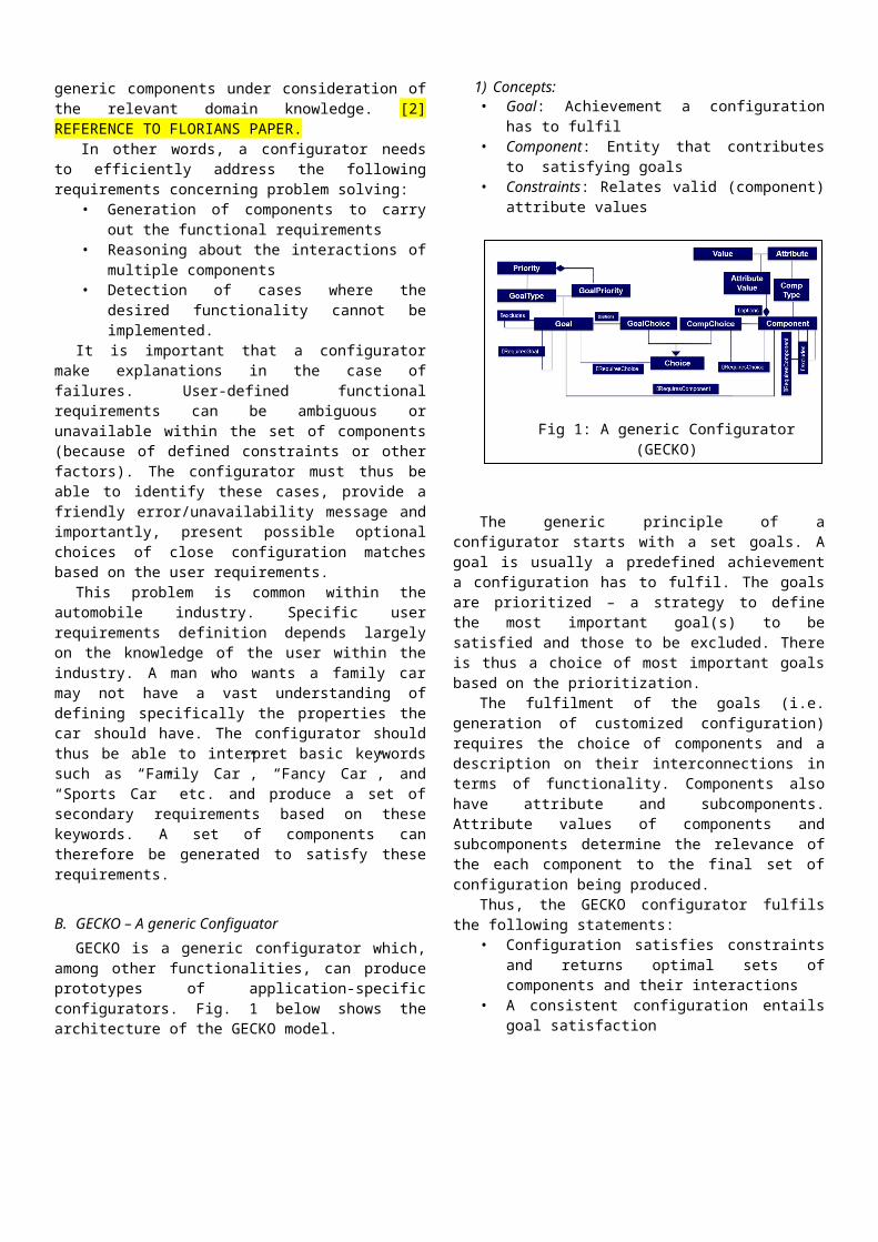
B. GECKO – A generic ConfiguatorGECKO is a generic configurator which,
among other functionalities, can produceprototypes of application-specificconfigurators. Fig. 1 below shows thearchitecture of the GECKO model.
1) Concepts:• Goal: Achievement a configuration
has to fulfil• Component: Entity that contributes
to satisfying goals• Constraints: Relates valid (component)
attribute values
The generic principle of aconfigurator starts with a set goals. Agoal is usually a predefined achievementa configuration has to fulfil. The goalsare prioritized – a strategy to definethe most important goal(s) to besatisfied and those to be excluded. Thereis thus a choice of most important goalsbased on the prioritization.
The fulfilment of the goals (i.e.generation of customized configuration)requires the choice of components and adescription on their interconnections interms of functionality. Components alsohave attribute and subcomponents.Attribute values of components andsubcomponents determine the relevance ofthe each component to the final set ofconfiguration being produced.
Thus, the GECKO configurator fulfilsthe following statements:
• Configuration satisfies constraintsand returns optimal sets ofcomponents and their interactions
• A consistent configuration entailsgoal satisfaction
Fig 1: A generic Configurator(GECKO)
• i.e ∀Goal ∈ UserGoals;Goal.satisfied=TRUE
Though GECKO is an ongoing project, itwill be able to provide additionalfunctions to visualize, modify and managethe connected configuration knowledgebase. Also guaranteeing certainproperties of the used knowledge base(KB), such as coherence, completeness,and consistency, esp. when modificationsand extensions are applied. It is beinginterfaced by an interactive tool, whichcontains some automated checks, displaysresults to the user and suggestsappropriate amendments.
Currently, GECKO is being developed tohandle hard, thus indefeasible,constraints. In many applications, thenumber of relevant constraints anddecisions made can result in an over-constraining, configuration problems. Tosolve this issue, the current concept hasbe extended by the introductiondefeasible constraints.
VII. A CAR CONFIGURATORThis section describes knowledge about
components and requirements within theautomobile domain; namely componentmodel, component catalogue, componentconstraints and functional requirements.It covers the different ingredients ofcomponents such as functions and features(e.g. attributes, subcomponents andconnections). It also provides the basicvocabulary for formulating constraintmodels.A. Major Tasks:
The major tasks involved in thecreation of a car configurator model are:
• Creating a car configurator whichreturns sets of components’specifications, based on userneeds.
• Modeling and representation ofautomobile knowledge
• Mapping of domain concepts toconfigurator concepts. i.e.
• Goals → ConfigurationGoals• Components → Car parts,
brands, attributes• TaskParameters →
UserRequirements
The task of finding a suitableconfiguration encounters lots ofdifficulties. Peculiar to the automobileindustry, there can be a huge number ofconfigurations responding to the customerrequirements. The number of possibleoptions and attributes of a singlecomponent may be large thus making thesearch space of the configurator verywide.
Customers are also usually is notsatisfied with an arbitrary choice, buthas preferences on multiple criteria ofthe catalog items such as the color orseat material of a desired car. Hence, aconfiguration problem may correspond to amulticriteria decision-making problem.Normally, a configuration does notconsist of a single component, butmultiple components [7].
The configuration problems of carsallows the choice of multiple optionsthat are subject to pre-definedconstraints. For example, the choices ofa roof rack and of a cabriolet areincompatible. In this case, theconfiguration problem is a combinatorialproblem. In more complex examples such asthe configuration of instrumentation andcontrol systems, the number of requiredcomponents is initially unknown. Theproblem space of the configuration taskthen contains a possibly infinite numberof candidate configurations [7]. Finally,a configuration problem can involve hugenumbers of component options andconstraints.
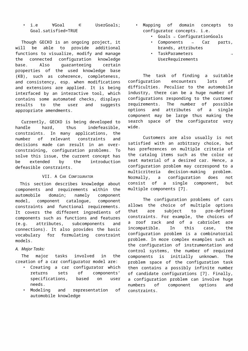
B. Configurator ArchitectureThe configurator architecture basicallydefines how components need to becombined to fulfill the functional userrequirements.
Fig. 2 shows the main architecture ofthe configurator. In the architecture:• Functional requirements define the
ConfigurationGoals of the users.• Technical requirements may restrict
the component sets of theconfiguration, they are thusmodeled as part of constraints.
• A component mostly have sub-components. These are (more orless) also components.
A configuration requires a set ofrequirements. These requirements aremajorly functional but there may betechnical requirements. These technicalrequirements further restricts the set ofconfiguration outputs. In sub-section D,we defined these functional and technicalrequirements.
On the other hand, a configurator isimplemented by components (or sub-components). These are chosen based onthe set of requirements. Typicalscenarios of the working of the model arepresented in sections H and I. C. Components Catalog
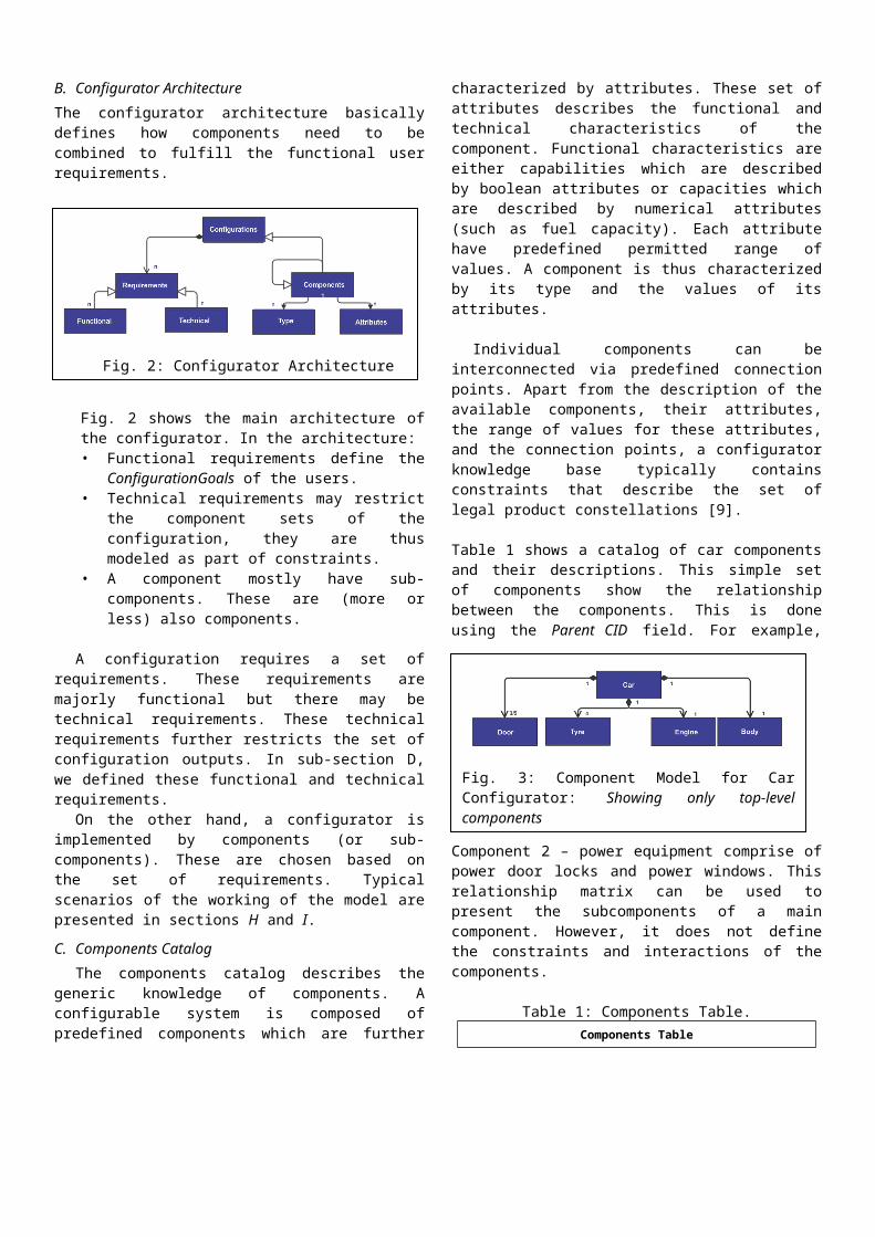
The components catalog describes thegeneric knowledge of components. Aconfigurable system is composed ofpredefined components which are further
characterized by attributes. These set ofattributes describes the functional andtechnical characteristics of thecomponent. Functional characteristics areeither capabilities which are describedby boolean attributes or capacities whichare described by numerical attributes(such as fuel capacity). Each attributehave predefined permitted range ofvalues. A component is thus characterizedby its type and the values of itsattributes.
Individual components can beinterconnected via predefined connectionpoints. Apart from the description of theavailable components, their attributes,the range of values for these attributes,and the connection points, a configuratorknowledge base typically containsconstraints that describe the set oflegal product constellations [9].
Table 1 shows a catalog of car componentsand their descriptions. This simple setof components show the relationshipbetween the components. This is doneusing the Parent CID field. For example,
Component 2 – power equipment comprise ofpower door locks and power windows. Thisrelationship matrix can be used topresent the subcomponents of a maincomponent. However, it does not definethe constraints and interactions of thecomponents.
Table 1: Components Table.Components Table
Fig. 2: Configurator Architecture
Fig. 3: Component Model for CarConfigurator: Showing only top-levelcomponents
CID CompName Description Parent(CID)
01Comfort and Convenience Features
Interior comfort and convenience
NULL
02 Power Equipment
Power component NULL
03 Audio Equipment
Audio and video component
NULL
04Safety and Security Features
Security and safety NULL
05 Air conditioning For cool air 01
06 Entertainment System Entertainment 01
07 Power Door Locks
For security purposes 02
08 Power Windows Power window 02
09 MP3-CD Audio entertainment 03
10 Premium Speakers Speakers 03
11 Front Airbags Airbags 04
12 Child-Sensing Airbags Child airbag 04
Fig. 3 shows the top level componentmodel of the car configurator. Each nodein the model is further decomposed in tosub components. The full model is shownin Appendix A.
The components model is formalized inChapter VIII of this paper.
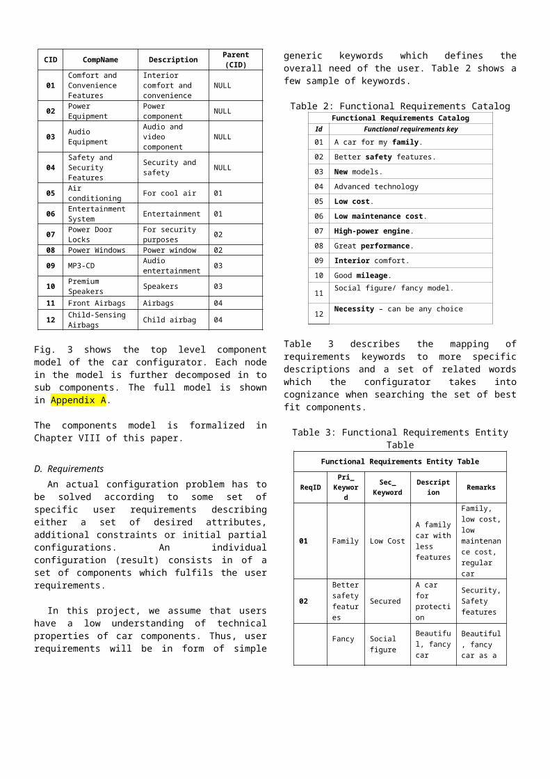
D. RequirementsAn actual configuration problem has to
be solved according to some set ofspecific user requirements describingeither a set of desired attributes,additional constraints or initial partialconfigurations. An individualconfiguration (result) consists in of aset of components which fulfils the userrequirements.
In this project, we assume that usershave a low understanding of technicalproperties of car components. Thus, userrequirements will be in form of simple
generic keywords which defines theoverall need of the user. Table 2 shows afew sample of keywords.
Table 2: Functional Requirements CatalogFunctional Requirements Catalog
Id Functional requirements key
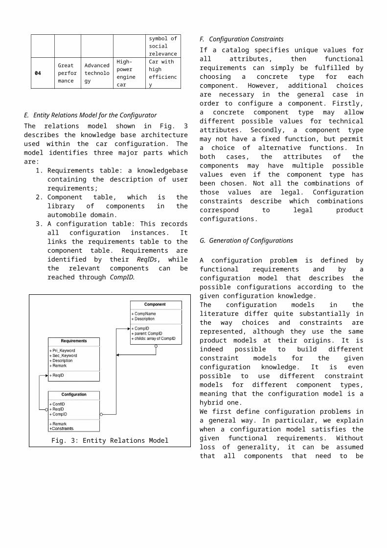
01 A car for my family.02 Better safety features.03 New models.04 Advanced technology05 Low cost.06 Low maintenance cost.07 High-power engine.08 Great performance.09 Interior comfort.10 Good mileage.
11 Social figure/ fancy model.
12 Necessity – can be any choice
Table 3 describes the mapping ofrequirements keywords to more specificdescriptions and a set of related wordswhich the configurator takes intocognizance when searching the set of bestfit components.
Table 3: Functional Requirements EntityTable
Functional Requirements Entity Table
ReqIDPri_Keywor
d
Sec_Keyword
Description Remarks
01 Family Low Cost
A familycar withless features
Family, low cost,low maintenance cost, regular car
02
Bettersafetyfeatures
Secured
A car for protection
Security,Safety features
Fancy Social figure
Beautiful, fancycar
Beautiful, fancy car as a
symbol ofsocial relevance
04Great performance
Advancedtechnology
High-power engine car
Car with high efficiency
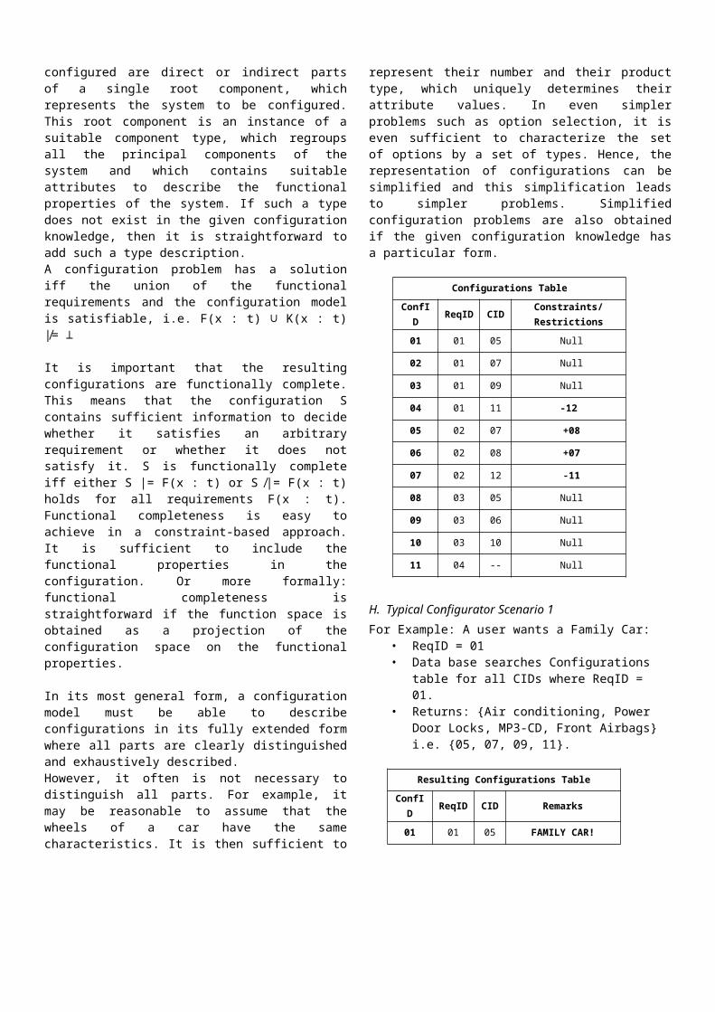
E. Entity Relations Model for the ConfiguratorThe relations model shown in Fig. 3describes the knowledge base architectureused within the car configuration. Themodel identifies three major parts whichare:
1. Requirements table: a knowledgebasecontaining the description of userrequirements;
2. Component table, which is thelibrary of components in theautomobile domain.
3. A configuration table: This recordsall configuration instances. Itlinks the requirements table to thecomponent table. Requirements areidentified by their ReqIDs, whilethe relevant components can bereached through CompID.
F. Configuration ConstraintsIf a catalog specifies unique values forall attributes, then functionalrequirements can simply be fulfilled bychoosing a concrete type for eachcomponent. However, additional choicesare necessary in the general case inorder to configure a component. Firstly,a concrete component type may allowdifferent possible values for technicalattributes. Secondly, a component typemay not have a fixed function, but permita choice of alternative functions. Inboth cases, the attributes of thecomponents may have multiple possiblevalues even if the component type hasbeen chosen. Not all the combinations ofthose values are legal. Configurationconstraints describe which combinationscorrespond to legal productconfigurations.
G. Generation of Configurations
A configuration problem is defined byfunctional requirements and by aconfiguration model that describes thepossible configurations according to thegiven configuration knowledge.The configuration models in theliterature differ quite substantially inthe way choices and constraints arerepresented, although they use the sameproduct models at their origins. It isindeed possible to build differentconstraint models for the givenconfiguration knowledge. It is evenpossible to use different constraintmodels for different component types,meaning that the configuration model is ahybrid one.We first define configuration problems ina general way. In particular, we explainwhen a configuration model satisfies thegiven functional requirements. Withoutloss of generality, it can be assumedthat all components that need to be
Fig. 3: Entity Relations Model
configured are direct or indirect partsof a single root component, whichrepresents the system to be configured.This root component is an instance of asuitable component type, which regroupsall the principal components of thesystem and which contains suitableattributes to describe the functionalproperties of the system. If such a typedoes not exist in the given configurationknowledge, then it is straightforward toadd such a type description.A configuration problem has a solutioniff the union of the functionalrequirements and the configuration modelis satisfiable, i.e. F(x : t) ∪ K(x : t)|̸= ⊥
It is important that the resultingconfigurations are functionally complete.This means that the configuration Scontains sufficient information to decidewhether it satisfies an arbitraryrequirement or whether it does notsatisfy it. S is functionally completeiff either S |= F(x : t) or S ̸|= F(x : t)holds for all requirements F(x : t).Functional completeness is easy toachieve in a constraint-based approach.It is sufficient to include thefunctional properties in theconfiguration. Or more formally:functional completeness isstraightforward if the function space isobtained as a projection of theconfiguration space on the functionalproperties.
In its most general form, a configurationmodel must be able to describeconfigurations in its fully extended formwhere all parts are clearly distinguishedand exhaustively described.However, it often is not necessary todistinguish all parts. For example, itmay be reasonable to assume that thewheels of a car have the samecharacteristics. It is then sufficient to
represent their number and their producttype, which uniquely determines theirattribute values. In even simplerproblems such as option selection, it iseven sufficient to characterize the setof options by a set of types. Hence, therepresentation of configurations can besimplified and this simplification leadsto simpler problems. Simplifiedconfiguration problems are also obtainedif the given configuration knowledge hasa particular form.
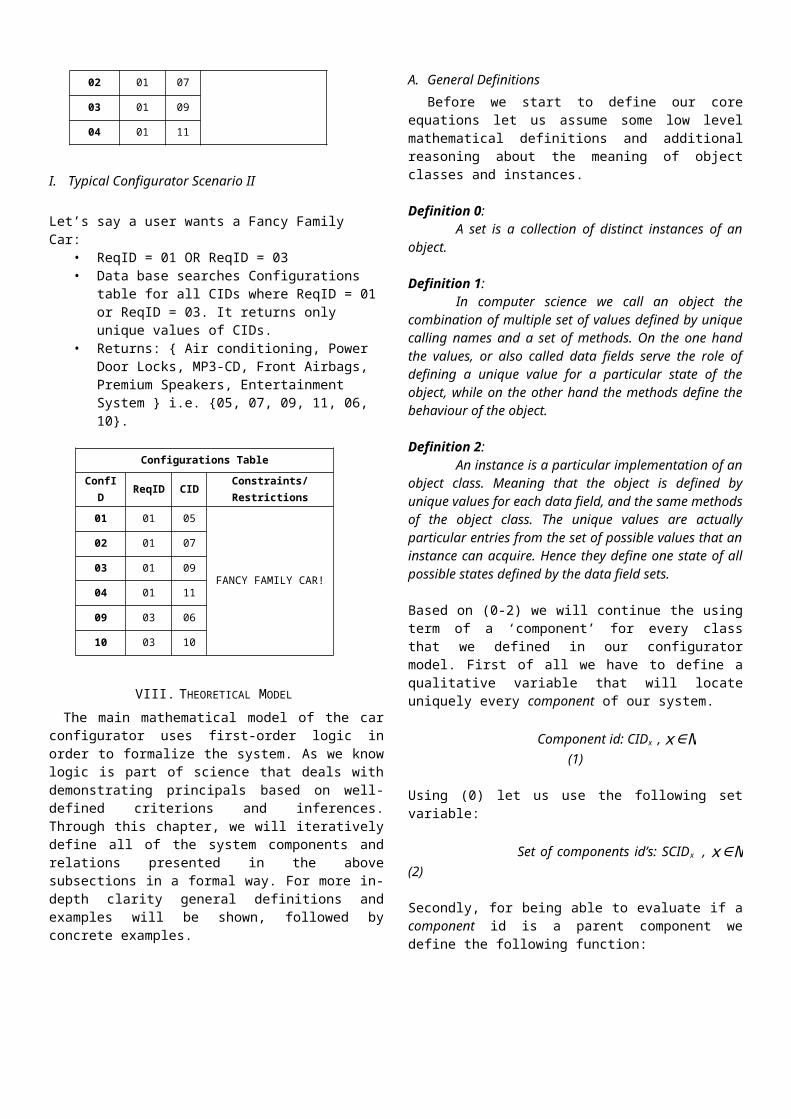
Configurations TableConfID ReqID CID Constraints/
Restrictions01 01 05 Null
02 01 07 Null
03 01 09 Null
04 01 11 -12
05 02 07 +08
06 02 08 +07
07 02 12 -11
08 03 05 Null
09 03 06 Null
10 03 10 Null
11 04 -- Null
H. Typical Configurator Scenario 1For Example: A user wants a Family Car:
• ReqID = 01• Data base searches Configurations
table for all CIDs where ReqID = 01.
• Returns: {Air conditioning, Power Door Locks, MP3-CD, Front Airbags} i.e. {05, 07, 09, 11}.
Resulting Configurations TableConfI
D ReqID CID Remarks
01 01 05 FAMILY CAR!
02 01 07
03 01 09
04 01 11
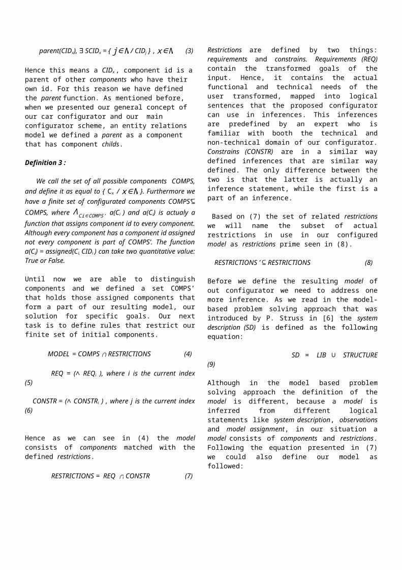
I. Typical Configurator Scenario II
Let’s say a user wants a Fancy Family Car:
• ReqID = 01 OR ReqID = 03• Data base searches Configurations
table for all CIDs where ReqID = 01or ReqID = 03. It returns only unique values of CIDs.
• Returns: { Air conditioning, Power Door Locks, MP3-CD, Front Airbags, Premium Speakers, Entertainment System } i.e. {05, 07, 09, 11, 06, 10}.
Configurations TableConfI
D ReqID CID Constraints/Restrictions
01 01 05
FANCY FAMILY CAR!
02 01 07
03 01 09
04 01 11
09 03 06
10 03 10
VIII. THEORETICAL MODELThe main mathematical model of the car
configurator uses first-order logic inorder to formalize the system. As we knowlogic is part of science that deals withdemonstrating principals based on well-defined criterions and inferences.Through this chapter, we will iterativelydefine all of the system components andrelations presented in the abovesubsections in a formal way. For more in-depth clarity general definitions andexamples will be shown, followed byconcrete examples.
A. General DefinitionsBefore we start to define our core
equations let us assume some low levelmathematical definitions and additionalreasoning about the meaning of objectclasses and instances.
Definition 0: A set is a collection of distinct instances of an
object.
Definition 1:In computer science we call an object the
combination of multiple set of values defined by uniquecalling names and a set of methods. On the one handthe values, or also called data fields serve the role ofdefining a unique value for a particular state of theobject, while on the other hand the methods define thebehaviour of the object. Definition 2:
An instance is a particular implementation of anobject class. Meaning that the object is defined byunique values for each data field, and the same methodsof the object class. The unique values are actuallyparticular entries from the set of possible values that aninstance can acquire. Hence they define one state of allpossible states defined by the data field sets.
Based on (0-2) we will continue the usingterm of a ‘component’ for every classthat we defined in our configuratormodel. First of all we have to define aqualitative variable that will locateuniquely every component of our system.
Component id: CIDx , x∈N(1)
Using (0) let us use the following setvariable:
Set of components id’s: SCIDx , x∈N(2)
Secondly, for being able to evaluate if acomponent id is a parent component wedefine the following function:
parent(CIDx), ∃ SCIDx = { j∈N / CIDj } , x∈N (3)
Hence this means a CIDx , component id is aparent of other components who have their own id. For this reason we have defined the parent function. As mentioned before, when we presented our general concept of our car configurator and our main configurator scheme, an entity relations model we defined a parent as a component that has component childs.
Definition 3 :
We call the set of all possible components COMPS,and define it as equal to { Cx / x∈N }. Furthermore wehave a finite set of configurated components COMPS’⊆COMPS, where ΛCi∈COMPS’ a(Ci ) and a(Ci) is actualy afunction that assigns component id to every component.Although every component has a component id assignednot every component is part of COMPS’. The functiona(Ci) = assigned(Ci, CIDi ) can take two quantitative value:True or False.
Until now we are able to distinguishcomponents and we defined a set COMPS’that holds those assigned components thatform a part of our resulting model, oursolution for specific goals. Our nexttask is to define rules that restrict ourfinite set of initial components.
MODEL = COMPS ∩ RESTRICTIONS (4)
REQ = (∧ REQi ), where i is the current index(5)
CONSTR = (∧ CONSTRi ) , where j is the current index(6)
Hence as we can see in (4) the modelconsists of components matched with thedefined restrictions.
RESTRICTIONS = REQ ∩ CONSTR (7)
Restrictions are defined by two things:requirements and constrains. Requirements (REQ)contain the transformed goals of theinput. Hence, it contains the actualfunctional and technical needs of theuser transformed, mapped into logicalsentences that the proposed configuratorcan use in inferences. This inferencesare predefined by an expert who isfamiliar with booth the technical andnon-technical domain of our configurator.Constrains (CONSTR) are in a similar waydefined inferences that are similar waydefined. The only difference between thetwo is that the latter is actually aninference statement, while the first is apart of an inference.
Based on (7) the set of related restrictionswe will name the subset of actualrestrictions in use in our configuredmodel as restrictions prime seen in (8).
RESTRICTIONS ’ ⊆ RESTRICTIONS (8)
Before we define the resulting model ofout configurator we need to address onemore inference. As we read in the model-based problem solving approach that wasintroduced by P. Struss in [6] the systemdescription (SD) is defined as the followingequation:
SD = LIB ∪ STRUCTURE(9)
Although in the model based problemsolving approach the definition of themodel is different, because a model isinferred from different logicalstatements like system description, observationsand model assignment, in our situation amodel consists of components and restrictions.Following the equation presented in (7)we could also define our model asfollowed:
MODEL = LIB ∪ STRUCTURE (10)
MODEL = SD(11)
In this case the library (LIB) and the structure(STRUCTURE) are the core elements of a model.Hence in our case the system description isthe model. We can infer to the library as theinfinite set of all possible componentsthat the configurator can use to set up apossible model.
Based on our reasoning a possibleconfigured model is defined by theformula:
MODELok = COMPS’ ∩ RESTRICTIONS’ (12)
B. Consistency Based Configuration Of Knowdledge-bases In the first sub section of the
theoretical model discussion, we arguedand inferred some basic logical equationsthat lay the bases of this subsectionsdefinitions. Furthermore we will presentsthe consistency-based approach ofconfiguring a knowledge-base. F. Fraymanand S. Mittal suggest in [5] multiplemodels for configuration. From this modelthe component-port model of configurationtype will be applied on the domain of thecar configurator presented above.
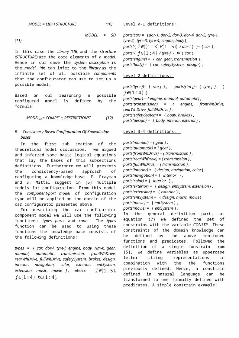
For describing the car configuratorcomponent model we will use the followingfunctions: types, ports and conn. The typesfunction can be used to using thesefunctions the knowledge base consists ofthe following definitions:
types = { car, dor-i, tyre-j, engine, body, rim-k, gear,manual, automatic, transmission, frontWhDrive,rearWhDrive, fullWhDrive, safetySystem, brakes, design,interior, navigation, color, exterior, entSystem,extension. music, movie }; where i∈(1:5),j∈(1:4) , k∈(1:4).
Level 0-1 definitions:
ports(car) = {dor-1, dor-2, dor-3, dor-4, dor-5, tyre-1, tyre-2, tyre-3, tyre-4, engine, body},ports({ i∈((1:3)∨(1:5)) / dor-i } )= { car },ports({ j∈(1:4) / tyre-j } )= { car }, ports(engine) = { car, gear, transmission },ports(body) = { car, safetySystem, design},
Level 2 definitions:
ports(tyre-j)= { rim-j }, ports(rim-j)= { tyre-j }, (j∈(1:4) }ports(gear) = { engine, manual, automatic},ports(transmission) = { engine, frontWhDrive,rearWhDrive, fullWhDrive },ports(safetySystem) = { body, brakes},ports(design) = { body, interior, exterior},
Level 3-4 definitions:
ports(manual) = { gear },ports(automatic) = { gear },ports(frontWhDrive) = { transmission },ports(rearWhDrive) = { transmission },ports(fullWhDrive) = { transmission },ports(interior) = { design, navigation, color},ports(navigation) = { interior },ports(color) = { interior }, ports(exterior) = { design, entSystem, extension},ports(extension) = { exterior },ports(entSystem) = { design, music, movie},ports(music) = { entSystem },ports(movie) = { entSystem },In the general definition part, atequation (7) we defined the set ofconstrains with the variable CONSTR. Theseconstraints of the domain knowledge canbe defined by the above mentionedfunctions and predicates. Followed thedefinition of a single constrain from[5], we define variables as uppercaseletter string representations incombination with the the functionspreviously defined. Hence, a constraindefined in natural language can betransformed to one formally defined withpredicates. A simple constrain example:
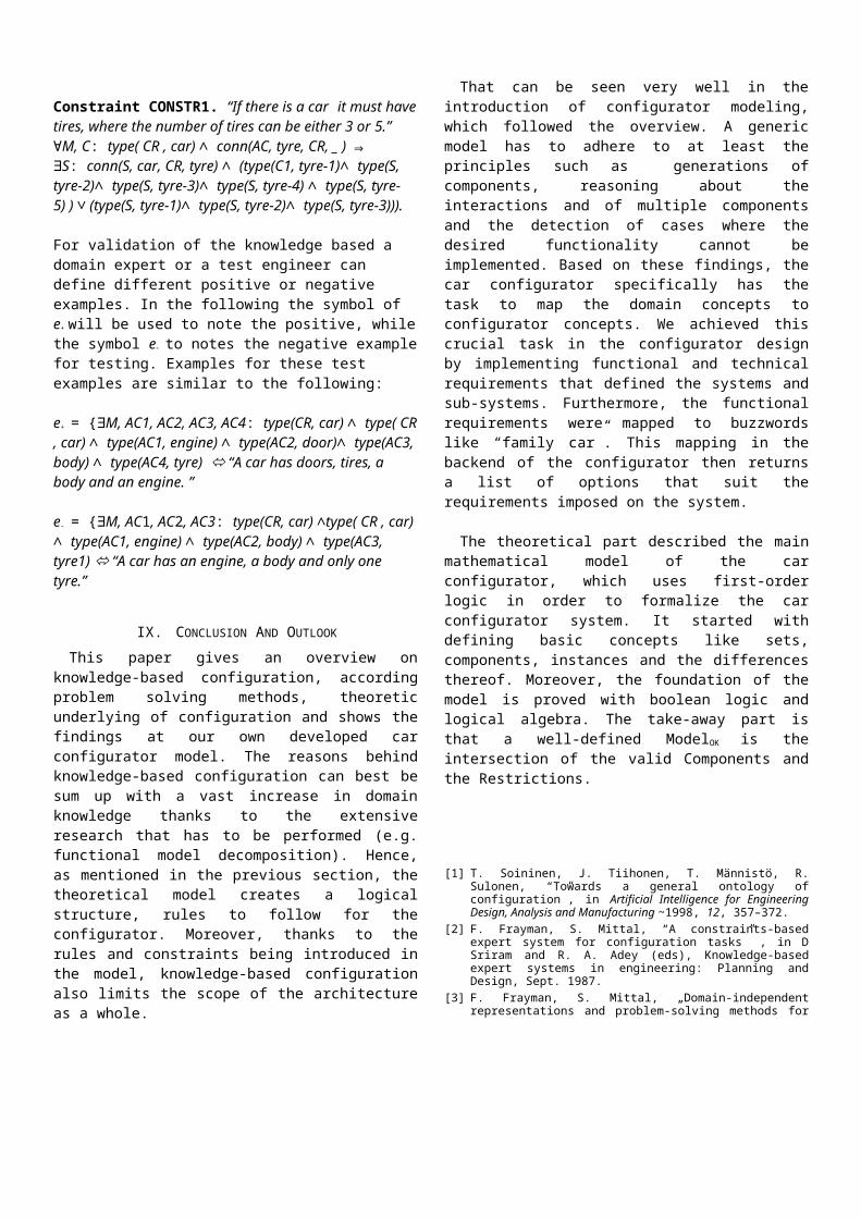
Constraint CONSTR1. “If there is a car it must havetires, where the number of tires can be either 3 or 5.”∀M, C: type( CR , car) ∧ conn(AC, tyre, CR, _ ) ⇒∃S: conn(S, car, CR, tyre) ∧ (type(C1, tyre-1)∧ type(S, tyre-2)∧ type(S, tyre-3)∧ type(S, tyre-4) ∧ type(S, tyre-5) ) ∨ (type(S, tyre-1)∧ type(S, tyre-2)∧ type(S, tyre-3))).
For validation of the knowledge based a domain expert or a test engineer can define different positive or negative examples. In the following the symbol of e+ will be used to note the positive, whilethe symbol e- to notes the negative examplefor testing. Examples for these test examples are similar to the following:
e+ = {∃M, AC1, AC2, AC3, AC4: type(CR, car) ∧ type( CR, car) ∧ type(AC1, engine) ∧ type(AC2, door)∧ type(AC3, body) ∧ type(AC4, tyre) “A car has doors, tires, a body and an engine. ”
e- = {∃M, AC1, AC2, AC3: type(CR, car) ∧type( CR , car) ∧ type(AC1, engine) ∧ type(AC2, body) ∧ type(AC3, tyre1) “A car has an engine, a body and only one tyre.”
IX. CONCLUSION AND OUTLOOKThis paper gives an overview on
knowledge-based configuration, accordingproblem solving methods, theoreticunderlying of configuration and shows thefindings at our own developed carconfigurator model. The reasons behindknowledge-based configuration can best besum up with a vast increase in domainknowledge thanks to the extensiveresearch that has to be performed (e.g.functional model decomposition). Hence,as mentioned in the previous section, thetheoretical model creates a logicalstructure, rules to follow for theconfigurator. Moreover, thanks to therules and constraints being introduced inthe model, knowledge-based configurationalso limits the scope of the architectureas a whole.
That can be seen very well in theintroduction of configurator modeling,which followed the overview. A genericmodel has to adhere to at least theprinciples such as generations ofcomponents, reasoning about theinteractions and of multiple componentsand the detection of cases where thedesired functionality cannot beimplemented. Based on these findings, thecar configurator specifically has thetask to map the domain concepts toconfigurator concepts. We achieved thiscrucial task in the configurator designby implementing functional and technicalrequirements that defined the systems andsub-systems. Furthermore, the functionalrequirements were mapped to buzzwordslike “family car”. This mapping in thebackend of the configurator then returnsa list of options that suit therequirements imposed on the system.
The theoretical part described the mainmathematical model of the carconfigurator, which uses first-orderlogic in order to formalize the carconfigurator system. It started withdefining basic concepts like sets,components, instances and the differencesthereof. Moreover, the foundation of themodel is proved with boolean logic andlogical algebra. The take-away part isthat a well-defined ModelOK is theintersection of the valid Components andthe Restrictions.
[1] T. Soininen, J. Tiihonen, T. Männistö, R.Sulonen, “Towards a general ontology ofconfiguration”, in Artificial Intelligence for EngineeringDesign, Analysis and Manufacturing ~1998, 12, 357–372.
[2] F. Frayman, S. Mittal, “A constraints-basedexpert system for configuration tasks” , in DSriram and R. A. Adey (eds), Knowledge-basedexpert systems in engineering: Planning andDesign, Sept. 1987.
[3] F. Frayman, S. Mittal, „Domain-independentrepresentations and problem-solving methods for
We suggest that you use a text box toinsert a graphic (which is ideally a300 dpi resolution TIFF or EPS filewith all fonts embedded) because thismethod is somewhat more stable thandirectly inserting a picture.
configuration tasks“, SSL Technical Report,Xerox PARC, 1989.
[4] F. Frayman, S. Mittal, “Towards a generic modelof configuration tasks”, 1989.
[5] P. Struss, “Model-based Problem Solving”, inHandbook of Knowledge Representation (2008),395-465, Elsevier.
[6] U. Junker, “Handbook of Constraint Programming”,Ch. 1: Configuration, 2006.
[7] A. Felfernig, G. Friedrich, D. Jannach, M.Stumptner, “Consistency-based diagnosis ofconfiguration knowledge bases”, in ArtificialIntelligence 152 (2004): 213-234.
[8] Alexander Felfernig et al, “Consistency-baseddiagnosis of
configuration knowledge bases” Ch. 2: MotivatingExample, 2004