tubular gas preconcentrators based on inkjet printed micro
TRANSCRIPT
HAL Id: hal-01337348https://hal.archives-ouvertes.fr/hal-01337348
Submitted on 26 Aug 2016
HAL is a multi-disciplinary open accessarchive for the deposit and dissemination of sci-entific research documents, whether they are pub-lished or not. The documents may come fromteaching and research institutions in France orabroad, or from public or private research centers.
L’archive ouverte pluridisciplinaire HAL, estdestinée au dépôt et à la diffusion de documentsscientifiques de niveau recherche, publiés ou non,émanant des établissements d’enseignement et derecherche français ou étrangers, des laboratoirespublics ou privés.
Tubular gas preconcentrators based on inkjet printedmicro-hotplates on foil
El Hadji Malik Camara, Philippe Breuil, Christophe Pijolat, Jean-PaulViricelle, Nicolaas F de Rooij, Danick Briand
To cite this version:El Hadji Malik Camara, Philippe Breuil, Christophe Pijolat, Jean-Paul Viricelle, Nicolaas F de Rooij,et al.. Tubular gas preconcentrators based on inkjet printed micro-hotplates on foil. Sensors andActuators B: Chemical, Elsevier, 2016, 236, pp.1111-1117. �10.1016/j.snb.2016.06.121�. �hal-01337348�
Tubular gas preconcentrators based on inkjet printed micro-
hotplates on foil
M. Camaraa, P. Breuilb, C. Pijolatb, J. P. Viricelleb, N.F. de Rooija, D. Brianda
aEcole Polytechnique Fédérale de Lausanne (EPFL), Institute of Microengineering (IMT), Sensors, Actuators and Microsystems Laboratory
(SAMLAB), Rue de la Maladière 71b, 2000 Neuchâtel, Switzerland bEcole Nationale Supérieure des Mines de Saint-Etienne, SPIN-EMSE, CNRS: UMR5307, LGF, 42023 Saint-Etienne, France
Abstract
This paper presents the design and implementation of a foil gas preconcentrator (FGP) based on a gold micro-
hotplate inkjet printed on a polyimide (PI) substrate. The device is made on flexible foil using printing whereas all
preconcentrators seen in literature are mainly based on rigid substrates and are micro-machined using cleanroom
processes. Printing allows the additive and localized deposition of materials at low temperature on large area and
can be applied to both the patterning of the heating element and the integration of the gas absorbent material. The
benefits are the easy and flexible processing of cost-effective and lightweight preconcentrators for a variety of target
gases. The tubular shape of the FGP is obtained by rolling up and sealing the inkjet printed gold hotplate on foil,
which is then filled with the gas absorbent material (Carbopack B and Tenax). The diameter of the inlet/outlet of
FGP is adjustable leading to high flow rates, up to 1.5 L/min, much larger than their silicon counterpart. The concept
was validated using four target gases (benzene, toluene, nitrobenzene and acetophenone) at concentrations down to
250 ppb. For example, the duty cycle of the FGP was reduced down 1 min and a preconcentration factor of 200 was
obtained after an adsorption on Carbopack B of 250ppb of toluene during 2 min at 1L/min.
Keywords: Gas preconcentration, Inkjet printing, Polymeric foil, Micro-hotplates, Printed preconcentrator, Pollution
monitoring
1. Introduction
The use of pre-concentration devices has become common-place in development of handheld detectors for
enhancing both their sensitivity and selectivity [1, 2, 3]. Indeed, the preconcentration presents two major advantages.
On one hand, it allows enriching the concentration of the target compound by an accumulation effect and on another
hand, it acts as a filter from its discrimination capacity. It is schematically characterized by two different phases. The
first step corresponds to the adsorption phase during which the target compound is injected through a bed of
adsorbent materials for an adsorption reaction. The second step is the desorption phase during which the adsorbent
material is heated up for releasing adsorbed compounds. The desorbed gas is then driven into the detector by a low
flow rate or just by difference of pressure between the sensor and the preconcentration cells.
As basic principle of operation for gas preconcentrators, a high adsorption flow rate (Af), a low desorption flow rate
(Df), a relatively long adsorption time, and a very short desorption time meaning a high heating rate are desired for
good preconcentration performance [4, 5]. The performance of a preconcentrator is characterized by the ratio
between concentration after and before preconcentration, namely the preconcentration factor (PF). Beside
experimental parameters, the choice of the adsorbent material is also a key factor for enhancing the preconcentrator
performance. This selection depends on the type of application, i.e. on the nature of the gases to be detected.
Different designs of preconcentrators have been reported in literature with two major concepts: a close
(microchannel device sealed with cover) versus an open (hotplate based device) configuration. Hotplate-based
preconcentrators are made with the sensor placed above it enabling the direct desorption of the target compound on
the sensor without carrier gas [6, 7, 8]; whereas micro-channel-based preconcentrators are closed with a cover
(mainly glass) for confining in a small volume the desorbed gas and thus avoiding any drawbacks related to
dilution[3, 5, 6, 9]. However all these devices are silicon-based and processed in a cleanroom environment involving
a succession of photolithography, dry etching and bonding steps which are restricted to wafer level and resulted in a
high component cost. Meanwhile, our group also reported on cleanroom processed low power micro-hotplates on
flexible polyimide foil applied to sensors operating up to 300°C [10]. Moreover, we have recently published our
work on low cost inkjet printed silver nanoparticles-based micro-hotplates on PEN (Polyethylene naphthalate) foil
for gas sensors operating at low temperature (<100 °C) [11]. Here we report on high operating temperature printed
micro-hotplates for gas preconcentration based on the patterning of gold nanoparticles-based heater on PI foil. We
propose a cost-effective process to develop a tubular gas preconcentrator by rolling up a printed micro-hotplate on
foil before filling it with an adsorbent. With its adjustable inlet/outlet, our foil gas preconcentrator allows operating
at higher flow rates (up to 1 L/min) than silicon devices previously reported. Since this study has been done in the
frame work of the EU project SNIFFER which aimed at detecting explosives, illicit drugs, and VOCs for a variety of
border security scenarios like smuggling prohibited goods (cigarettes, pills, foods...), the proposed concept was
validated by applying it to the preconcentration of benzene, toluene, nitrobenzene and acetophenone (cigarettes
additive)..
2. Design and fabrication
2.1. Design
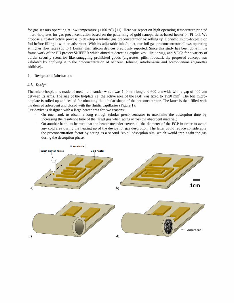
The micro-hotplate is made of metallic meander which was 140 mm long and 600 µm-wide with a gap of 400 µm
between its arms. The size of the hotplate i.e. the active area of the FGP was fixed to 15x8 mm2. The foil micro-
hotplate is rolled up and sealed for obtaining the tubular shape of the preconcentrator. The latter is then filled with
the desired adsorbent and closed with the fluidic capillaries (Figure 1).
Our device is designed with a large heater area for two reasons:
- On one hand, to obtain a long enough tubular preconcentrator to maximize the adsorption time by
increasing the residence time of the target gas when going across the absorbent material;
- On another hand, to be sure that the heater meander covers all the diameter of the FGP in order to avoid
any cold area during the heating up of the device for gas desorption. The latter could reduce considerably
the preconcentration factor by acting as a second “cold” adsorption site, which would trap again the gas
during the desorption phase.
a) b)
c) d)
1cm
e)
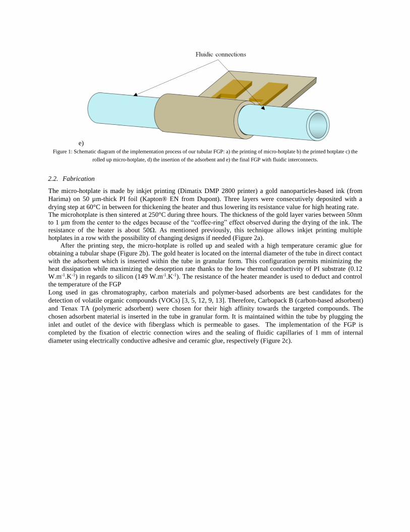
Figure 1: Schematic diagram of the implementation process of our tubular FGP: a) the printing of micro-hotplate b) the printed hotplate c) the
rolled up micro-hotplate, d) the insertion of the adsorbent and e) the final FGP with fluidic interconnects.
2.2. Fabrication
The micro-hotplate is made by inkjet printing (Dimatix DMP 2800 printer) a gold nanoparticles-based ink (from
Harima) on 50 µm-thick PI foil (Kapton® EN from Dupont). Three layers were consecutively deposited with a
drying step at 60°C in between for thickening the heater and thus lowering its resistance value for high heating rate.
The microhotplate is then sintered at 250°C during three hours. The thickness of the gold layer varies between 50nm
to 1 µm from the center to the edges because of the “coffee-ring” effect observed during the drying of the ink. The
resistance of the heater is about 50Ω. As mentioned previously, this technique allows inkjet printing multiple
hotplates in a row with the possibility of changing designs if needed (Figure 2a).
After the printing step, the micro-hotplate is rolled up and sealed with a high temperature ceramic glue for
obtaining a tubular shape (Figure 2b). The gold heater is located on the internal diameter of the tube in direct contact
with the adsorbent which is inserted within the tube in granular form. This configuration permits minimizing the
heat dissipation while maximizing the desorption rate thanks to the low thermal conductivity of PI substrate (0.12
W.m-1.K-1) in regards to silicon (149 W.m-1.K-1). The resistance of the heater meander is used to deduct and control
the temperature of the FGP
Long used in gas chromatography, carbon materials and polymer-based adsorbents are best candidates for the
detection of volatile organic compounds (VOCs) [3, 5, 12, 9, 13]. Therefore, Carbopack B (carbon-based adsorbent)
and Tenax TA (polymeric adsorbent) were chosen for their high affinity towards the targeted compounds. The
chosen adsorbent material is inserted in the tube in granular form. It is maintained within the tube by plugging the
inlet and outlet of the device with fiberglass which is permeable to gases. The implementation of the FGP is
completed by the fixation of electric connection wires and the sealing of fluidic capillaries of 1 mm of internal
diameter using electrically conductive adhesive and ceramic glue, respectively (Figure 2c).
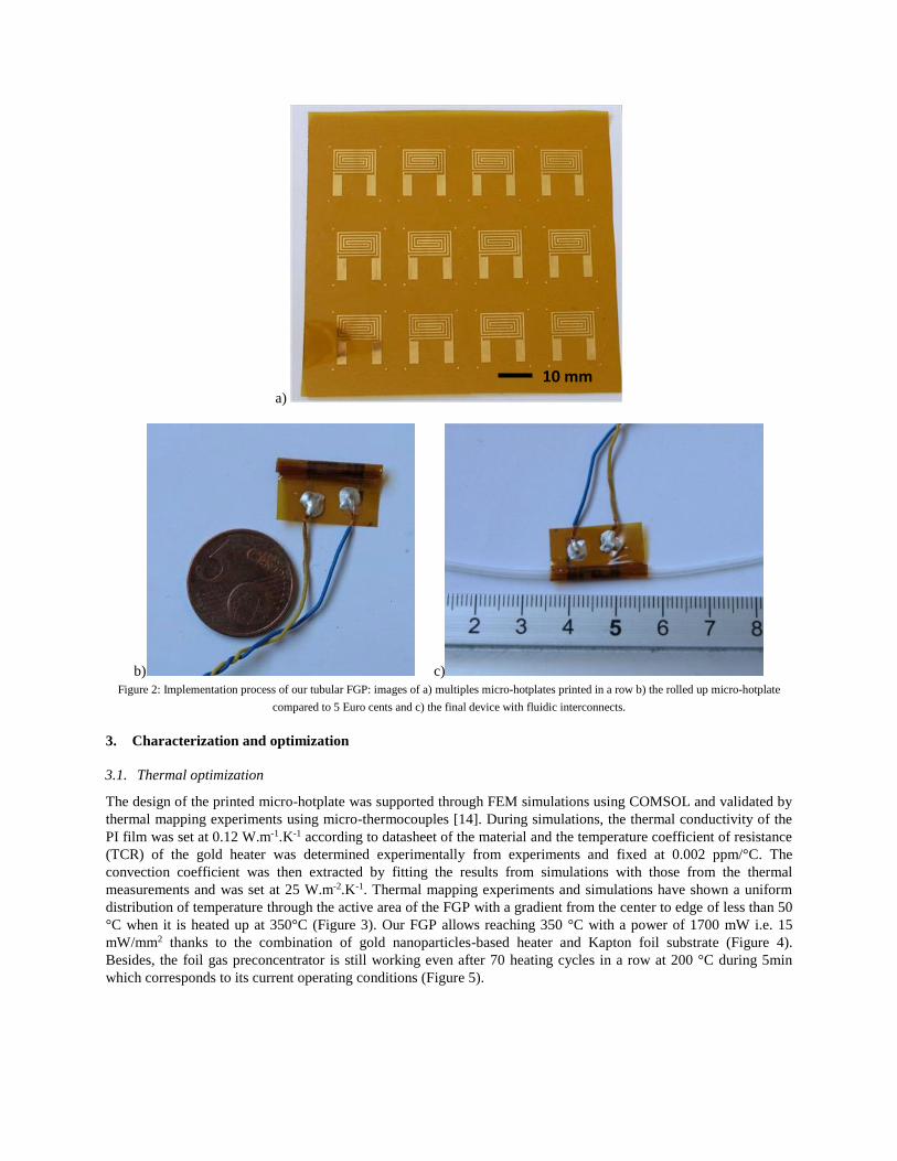
a)
b) c)
Figure 2: Implementation process of our tubular FGP: images of a) multiples micro-hotplates printed in a row b) the rolled up micro-hotplate
compared to 5 Euro cents and c) the final device with fluidic interconnects.
3. Characterization and optimization
3.1. Thermal optimization
The design of the printed micro-hotplate was supported through FEM simulations using COMSOL and validated by
thermal mapping experiments using micro-thermocouples [14]. During simulations, the thermal conductivity of the
PI film was set at 0.12 W.m-1.K-1 according to datasheet of the material and the temperature coefficient of resistance
(TCR) of the gold heater was determined experimentally from experiments and fixed at 0.002 ppm/°C. The
convection coefficient was then extracted by fitting the results from simulations with those from the thermal
measurements and was set at 25 W.m-2.K-1. Thermal mapping experiments and simulations have shown a uniform
distribution of temperature through the active area of the FGP with a gradient from the center to edge of less than 50
°C when it is heated up at 350°C (Figure 3). Our FGP allows reaching 350 °C with a power of 1700 mW i.e. 15
mW/mm2 thanks to the combination of gold nanoparticles-based heater and Kapton foil substrate (Figure 4).
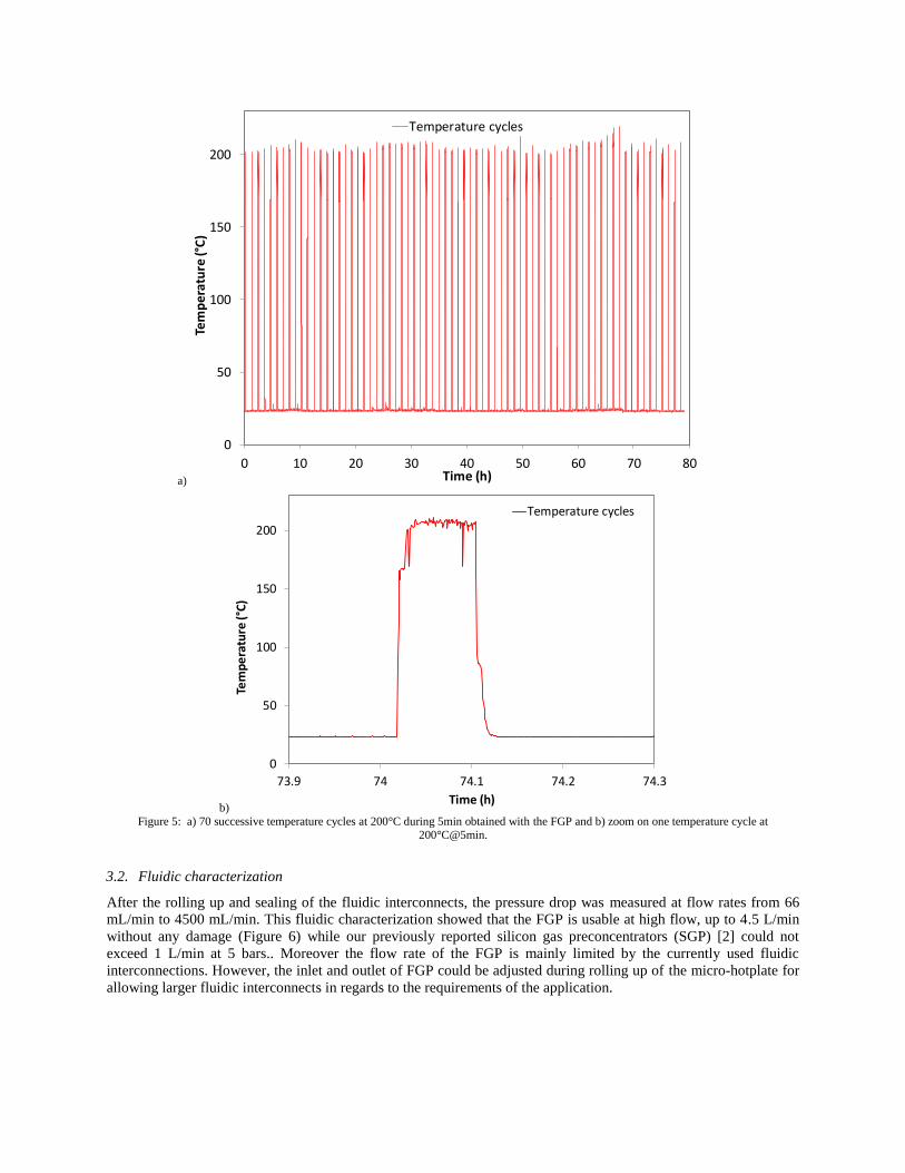
Besides, the foil gas preconcentrator is still working even after 70 heating cycles in a row at 200 °C during 5min
which corresponds to its current operating conditions (Figure 5).
10 mm
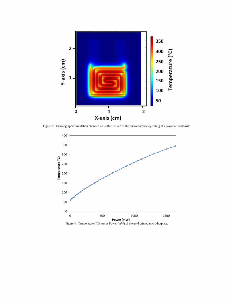
Figure 3: Thermographic simulation obtained on COMSOL 4.2 of the micro-hotplate operating at a power of 1700 mW.
Figure 4: Temperature (°C) versus Power (mW) of the gold printed micro-hotplate.
0
50
100
150
200
250
300
350
400
0 500 1000 1500
Tem
per
atu
re (°
C)
Power (mW)
a)
b)
Figure 5: a) 70 successive temperature cycles at 200°C during 5min obtained with the FGP and b) zoom on one temperature cycle at 200°C@5min.
3.2. Fluidic characterization
After the rolling up and sealing of the fluidic interconnects, the pressure drop was measured at flow rates from 66
mL/min to 4500 mL/min. This fluidic characterization showed that the FGP is usable at high flow, up to 4.5 L/min
without any damage (Figure 6) while our previously reported silicon gas preconcentrators (SGP) [2] could not
exceed 1 L/min at 5 bars.. Moreover the flow rate of the FGP is mainly limited by the currently used fluidic
interconnections. However, the inlet and outlet of FGP could be adjusted during rolling up of the micro-hotplate for
allowing larger fluidic interconnects in regards to the requirements of the application.
0
50
100
150
200
0 10 20 30 40 50 60 70 80
Tem
pe
ratu
re (°
C)
Time (h)
Temperature cycles
0
50
100
150
200
73.9 74 74.1 74.2 74.3
Tem
pe
ratu
re (°
C)
Time (h)
Temperature cycles
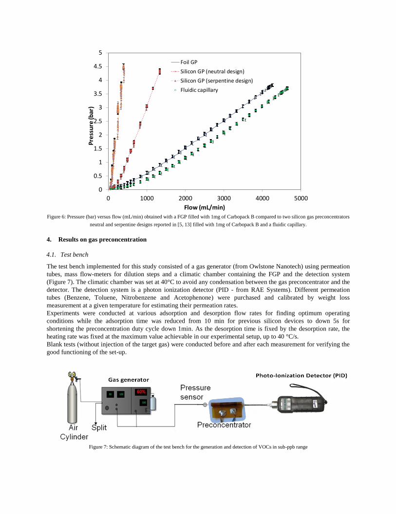
Figure 6: Pressure (bar) versus flow (mL/min) obtained with a FGP filled with 1mg of Carbopack B compared to two silicon gas preconcentrators
neutral and serpentine designs reported in [5, 13] filled with 1mg of Carbopack B and a fluidic capillary.
4. Results on gas preconcentration
4.1. Test bench
The test bench implemented for this study consisted of a gas generator (from Owlstone Nanotech) using permeation
tubes, mass flow-meters for dilution steps and a climatic chamber containing the FGP and the detection system
(Figure 7). The climatic chamber was set at 40°C to avoid any condensation between the gas preconcentrator and the
detector. The detection system is a photon ionization detector (PID - from RAE Systems). Different permeation
tubes (Benzene, Toluene, Nitrobenzene and Acetophenone) were purchased and calibrated by weight loss
measurement at a given temperature for estimating their permeation rates.
Experiments were conducted at various adsorption and desorption flow rates for finding optimum operating
conditions while the adsorption time was reduced from 10 min for previous silicon devices to down 5s for
shortening the preconcentration duty cycle down 1min. As the desorption time is fixed by the desorption rate, the
heating rate was fixed at the maximum value achievable in our experimental setup, up to 40 °C/s.
Blank tests (without injection of the target gas) were conducted before and after each measurement for verifying the
good functioning of the set-up.
Figure 7: Schematic diagram of the test bench for the generation and detection of VOCs in sub-ppb range
0
0.5
1
1.5
2
2.5
3
3.5
4
4.5
5
0 1000 2000 3000 4000 5000
Pre
ssu
re (b
ar)
Flow (mL/min)
Foil GP
Silicon GP (neutral design)
Silicon GP (serpentine design)
Fluidic capillary
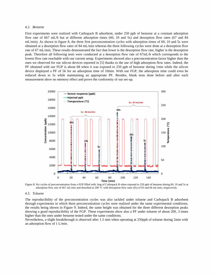
4.2. Benzene
First experiments were realized with Carbopack B adsorbent, under 250 ppb of benzene at a constant adsorption
flow rate of 667 mL/h but at different adsorption times (60, 10 and 5s) and desorption flow rates (67 and 84
mL/min). As shown in figure 8, the three first preconcentration cycles with adsorption times of 60, 10 and 5s were
obtained at a desorption flow rates of 84 mL/min whereas the three following cycles were done at a desorption flow
rate of 67 mL/min. These results demonstrated the fact that lower is the desorption flow rate, higher is the desorption
peak. Therefore all following tests were conducted at a desorption flow rate of 67mL/h which corresponds to the
lowest flow rate reachable with our current setup. Experiments showed also a preconcentration factor higher than the
ones we observed for our silicon devices reported in [5] thanks to the use of high adsorption flow rates. Indeed, the
PF obtained with our FGP is about 68 when it was exposed to 250 ppb of benzene during 1min while the silicon
device displayed a PF of 56 for an adsorption time of 10min. With our FGP, the adsorption time could even be
reduced down to 5s while maintaining an appropriate PF. Besides, blank tests done before and after each
measurement show no memory effect and prove the conformity of our set-up.
Figure 8: Six cycles of preconcentration from a FGP filled with 1mg of Carbopack B when exposed to 250 ppb of benzene during 60, 10 and 5s at
adsorption flow rate of 667 mL/min and desorbed at 200 °C with desorption flow rates (Df) of 83 and 66 mL/min, respectively.
4.3. Toluene
The reproducibility of the preconcentration cycles was also tackled under toluene and Carbopack B adsorbent
through experiments in which three preconcentration cycles were realized under the same experimental conditions,
the results being shown in Figure 9. Indeed, the same height was obtained for the three different desorption peaks
showing a good reproducibility of the FGP. These experiments show also a PF under toluene of about 200, 3 times
higher than the ones under benzene tested under the same conditions.
Nevertheless, a slight breakthrough is observed after 1.5 min when operating at 250ppb of toluene during 2min with
an adsorption flow of 1 L/min.
0
50
100
150
200
250
300
0
2000
4000
6000
8000
10000
12000
14000
16000
18000
20000
0 20 40 60 80 100 120 140
Tem
pe
ratu
re (
°C)
Co
nce
ntr
atio
n (
pp
b)
Time (min)
Sensor response (ppb)
Injected ppb
Temperature (°C)
60s
10s
5s
60s
10s
5s
Df = 67 mL/min
Df = 84 mL/min
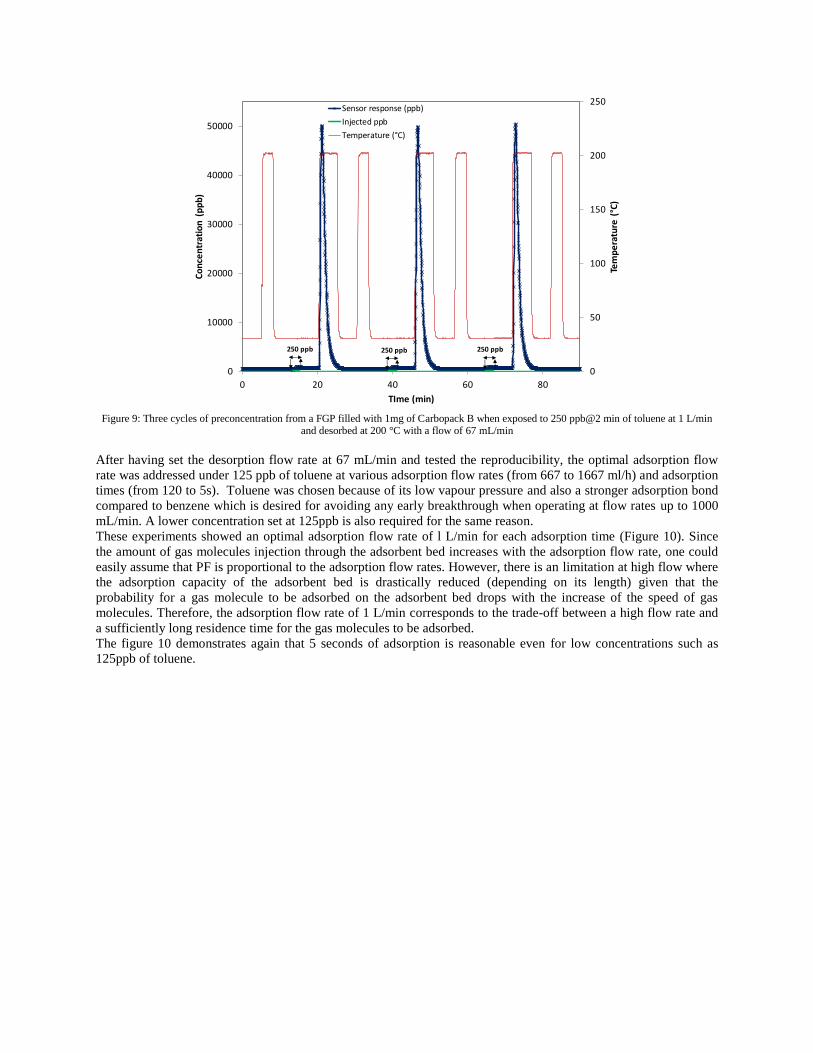
Figure 9: Three cycles of preconcentration from a FGP filled with 1mg of Carbopack B when exposed to 250 ppb@2 min of toluene at 1 L/min
and desorbed at 200 °C with a flow of 67 mL/min
After having set the desorption flow rate at 67 mL/min and tested the reproducibility, the optimal adsorption flow
rate was addressed under 125 ppb of toluene at various adsorption flow rates (from 667 to 1667 ml/h) and adsorption
times (from 120 to 5s). Toluene was chosen because of its low vapour pressure and also a stronger adsorption bond
compared to benzene which is desired for avoiding any early breakthrough when operating at flow rates up to 1000
mL/min. A lower concentration set at 125ppb is also required for the same reason.
These experiments showed an optimal adsorption flow rate of l L/min for each adsorption time (Figure 10). Since
the amount of gas molecules injection through the adsorbent bed increases with the adsorption flow rate, one could
easily assume that PF is proportional to the adsorption flow rates. However, there is an limitation at high flow where
the adsorption capacity of the adsorbent bed is drastically reduced (depending on its length) given that the
probability for a gas molecule to be adsorbed on the adsorbent bed drops with the increase of the speed of gas
molecules. Therefore, the adsorption flow rate of 1 L/min corresponds to the trade-off between a high flow rate and
a sufficiently long residence time for the gas molecules to be adsorbed.
The figure 10 demonstrates again that 5 seconds of adsorption is reasonable even for low concentrations such as
125ppb of toluene.
0
50
100
150
200
250
0
10000
20000
30000
40000
50000
0 20 40 60 80
Tem
pe
ratu
re (
°C)
Co
nce
ntr
atio
n (
pp
b)
TIme (min)
Sensor response (ppb)
Injected ppb
Temperature (°C)
250 ppb 250 ppb 250 ppb
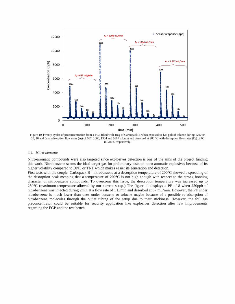
Figure 10 Twenty cycles of preconcentration from a FGP filled with 1mg of Carbopack B when exposed to 125 ppb of toluene during 120, 60, 30, 10 and 5s at adsorption flow rates (Af) of 667, 1000, 1334 and 1667 mLmin and desorbed at 200 °C with desorption flow rates (Df) of 66
mL/min, respectively.
4.4. Nitro-benzene
Nitro-aromatic compounds were also targeted since explosives detection is one of the aims of the project funding
this work. Nitrobenzene seems the ideal target gas for preliminary tests on nitro-aromatic explosives because of its
higher volatility compared to DNT or TNT which makes easier its generation and detection.
First tests with the couple Carbopack B - nitrobenzene at a desorption temperature of 200°C showed a spreading of
the desorption peak meaning that a temperature of 200°C is not high enough with respect to the strong bonding
character of nitrobenzene compounds. To overcome this issue, the desorption temperature was increased up to
250°C (maximum temperature allowed by our current setup.) The figure 11 displays a PF of 8 when 250ppb of
nitrobenzene was injected during 2min at a flow rate of 1 L/min and desorbed at 67 mL/min. However, the PF under
nitrobenzene is much lower than ones under benzene or toluene maybe because of a possible re-adsorption of
nitrobenzene molecules through the outlet tubing of the setup due to their stickiness. However, the foil gas
preconcentrator could be suitable for security application like explosives detection after few improvements
regarding the FGP and the test bench.
0
2000
4000
6000
8000
10000
12000
0 100 200 300 400 500
Co
nce
ntr
atio
n (
pp
b)
Time (min)
Sensor response (ppb)
Af = 667 mL/min
Af = 1000 mL/min
Af = 1334 mL/min
Af = 1 667 mL/min
120s
60s
30s
10s5s
120s
120s
120s
60s60s60s
30s
30s30s
10s
10s10s
5s
5s5s
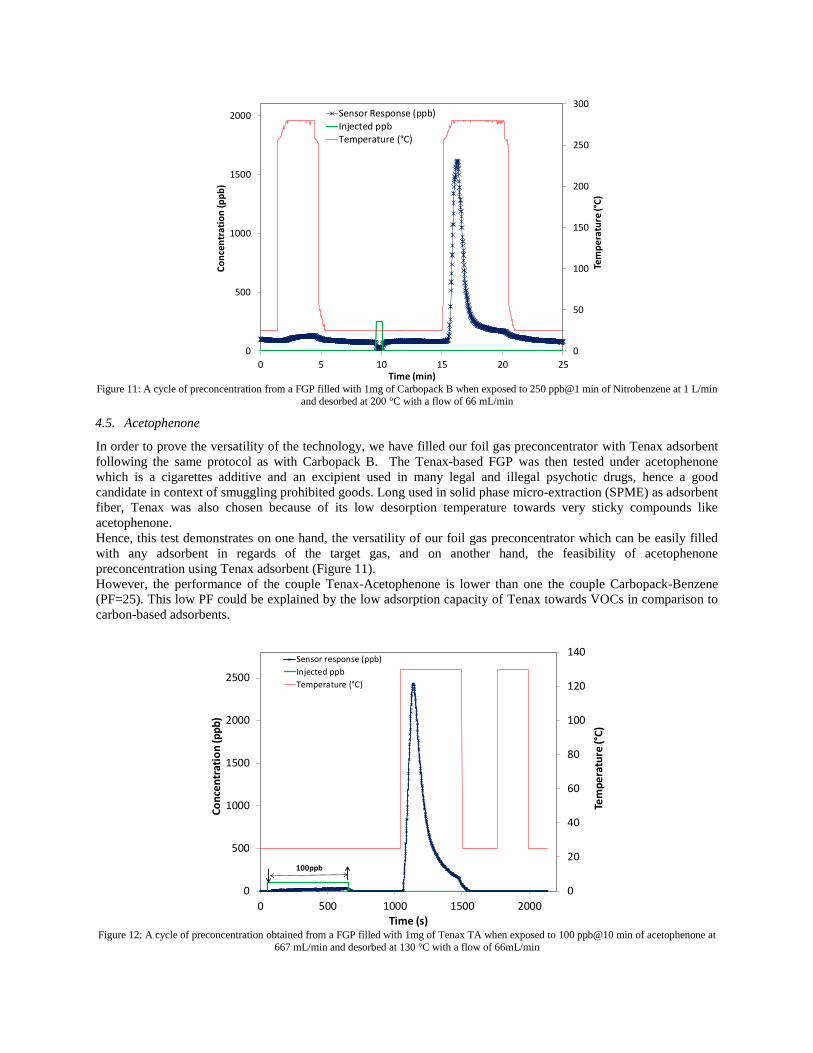
Figure 11: A cycle of preconcentration from a FGP filled with 1mg of Carbopack B when exposed to 250 ppb@1 min of Nitrobenzene at 1 L/min
and desorbed at 200 °C with a flow of 66 mL/min
4.5. Acetophenone
In order to prove the versatility of the technology, we have filled our foil gas preconcentrator with Tenax adsorbent
following the same protocol as with Carbopack B. The Tenax-based FGP was then tested under acetophenone
which is a cigarettes additive and an excipient used in many legal and illegal psychotic drugs, hence a good
candidate in context of smuggling prohibited goods. Long used in solid phase micro-extraction (SPME) as adsorbent
fiber, Tenax was also chosen because of its low desorption temperature towards very sticky compounds like
acetophenone.
Hence, this test demonstrates on one hand, the versatility of our foil gas preconcentrator which can be easily filled
with any adsorbent in regards of the target gas, and on another hand, the feasibility of acetophenone
preconcentration using Tenax adsorbent (Figure 11).
However, the performance of the couple Tenax-Acetophenone is lower than one the couple Carbopack-Benzene
(PF=25). This low PF could be explained by the low adsorption capacity of Tenax towards VOCs in comparison to
carbon-based adsorbents.
Figure 12: A cycle of preconcentration obtained from a FGP filled with 1mg of Tenax TA when exposed to 100 ppb@10 min of acetophenone at
667 mL/min and desorbed at 130 °C with a flow of 66mL/min
0
50
100
150
200
250
300
0
500
1000
1500
2000
0 5 10 15 20 25
Tem
pe
ratu
re (°
C)
Co
nce
ntr
atio
n (
pp
b)
Time (min)
Sensor Response (ppb)Injected ppbTemperature (°C)
0
20
40
60
80
100
120
140
0
500
1000
1500
2000
2500
0 500 1000 1500 2000Time (s)
Tem
pe
ratu
re (°
C)
Co
nce
ntr
atio
n (p
pb
)
Sensor response (ppb)
Injected ppb
Temperature (°C)
100ppb
5. Conclusions
We have successfully demonstrated the fabrication and testing of a versatile FGP based on gold heater printed on
a polyimide foil. Successful operation of the devices was demonstrated for the preconcentration of benzene, toluene,
nitrobenzene and acetophenone. The FGP shows better performances than silicon preconcentrators tested under the
same conditions thanks to their high flow rate capability, which is obtained by rolling up the flexible hotplate
device.
We are now working on the maximization of this PF by increasing the inlet/outlet diameter and the length of the
FGP during the rolling up for a higher flow rates and longer stay time for target molecules, respectively. This FGP
concept could be extended to numerous others applications like, breath analysis by changing the adsorbent and/or
the implementation protocol. Another perspective is the deposition of adsorbent materials by printing techniques.
Acknowledgements
The authors are grateful to the FP7 EU, SNIFFER for the funding of this work (grant no: 285203).
References
[1] http://www.pall.com/pdfs/Microelectronics/MEGPICO1000EN.pdf
[2] http://www.defiant-
tech.com/pdfs/Pittcon%202014%20A%20MicroGC%20Based%20Chemical%20Analysis%20System.pdf
[3] W. R. Collin, G. Serrano, L. K. Wright, H. Chang, N. Nuñovero, E. T. Zellers, Microfabricated gas
chromatograph for rapid, trace-level determinations of gas-phase explosive marker compounds, Analytical
Chemistry 86 (2014) 655-663.
[4] M. Camara, P. Breuil, D. Briand, J. Viricelle, C. Pijolat and N. F. de Rooij, Preconcentration Modeling for the
Optimization of a Micro Gas Preconcentrator Applied to Environmental Monitoring, Anal. Chem., 87 (2015)
4455–4463.
[5] E.H.M. Camara, P. Breuil, D. Briand, N. R. de Rooij and C. Pijolat, A micro gas preconcentrator with
improved performance for pollution monitoring and explosives detection. Analytica Chimica Acta vol. 688
(2011) 175-182.
[6] M. Martin, M. Crain, K. Walsh, R. E. McGill, E. Houser, J. Stepnowski, S. Stepnowski, H.-D. Wu, S. Ross,
Microfabricated vapor preconcentrator for portable ion mobility spectroscopy. Sensors and actuators B vol. 126
(2007) 447-454.
[7] I. Voiculescu, R. A. McGrill, M. E. Zaghoul, Micropreconcentrator for enhanced trace detection of explosives
and chemical agents. IEEE Sensors journal, Vol. 6, NO. 5, October 2006.
[8] A.M. Ruiz, I. Gracia, N. Sabate, P. Ivanov, A. Sanchez, M. Duch, M. Gerboles, A. Moreno, C. Cane,
Membrane-suspended microgrid as a gas preconcentrator for chromatographic applications. Sensors and
Actuators A vol. 135 (2007) 192–196.
[9] G. Serrano, T. Sukaew, E. T. Zellers, Hybrid preconcentrator/focuser module for determinations of explosive
marker compounds with a micro-scale gas chromatograph, Journal of Chromatography A, 1279 (2013) 76–85.
[10] J. Courbat, D Briand, L. Yue, S. Raible and N. F. de Rooij, Drop-coated metal-oxide gas sensor on polyimide
foil with reduced power consumption for wireless applications, Sensors and Actuators B: Chemical 161 (2012)
862-868.
[11] E. Danesh, F. Molina-Lopez, M. Camara, A. Bontempi, A. Vasquez Quintero, D. Teyssieux, L. Thiery, D.
Briand, N. F. de Rooij, K. C. Persaud, Development of a new generation of ammonia sensors on printed
polymeric hotplates , Analytical Chemistry 86 (2014) 8951–8958.
[12] B. Alfeeli, V. Jain, R. K. Johnson, F. L. Beyer, J. R. Heflin and M. Agah, Characterization of poly(2,6-
diphenyl-p-phenylene oxide) films as adsorbent for microfabricated preconcentrators. Microchemical Journal
V. 98 (2011) 240–245.
[13] M. Camara, C. Pijolat, L. Guillot, P. Breuil, D. Briand, N. de Rooij, Micro gas preconcentrator in porous
silicon filled with a carbon absorbent, Sens & Act B, 148 (2010) 610–619.
[14] L. Thiery, S. Toullier, D. Teyssieux, D. Briand, Thermal contact calibration between a thermocouple probe and
a micro-hotplate, Journal of Heat Transfer, Vol.130, 9 (2008) 091601–091608.