quick start guide - · pdf file1 about the quick start guide this quick start guide is...
TRANSCRIPT

Quick Start Guide

Copyright © 1991-2012 Automated Systems Researcha division of Mainland Research Inc.
Coquitlam, British Columbia, Canada
All rights reserved. No part of this publication may be reproduced, stored in a retrieval system, or transmitted, in any form or by any means, electrical, mechanical, photocopying or otherwise, without prior written
permission of the publisher, Automated Systems Research.

1
About the Quick Start GuideThis Quick Start Guide is task-based, and is designed to help new TopView users create basic roof estimating projects quickly and easily. It walks you through a sample job--step-by-step--giving you the basics needed to start using TopView to generate roofs and create estimates for your own projects. Note that TopView 9.9 is an amalgamation of TopView ME for metal roofing and TopView LE for tiles, shingles and other roofiing materials that estimate by coverage
Information in this chapter includes:
• using this guide• getting help with your projects• getting product information• an overview of the sample job you will create• a table of keyboard shortcuts for entering coordinates
Using the Quick Start GuideThis guide presents information in a consistent way to help you quickly find what you need. Simply follow the steps as they are set out for you.
Throughout the guide, you will notice Tips! in the left hand margin. These tips suggest shortcuts, and act as hints to help you use TopView as efficiently as possible.
Getting help
There are two ways for you to get the help you need:
• online help• technical support
Online help
For more detailed information on TopView features and optional settings see the online help.
The online help works in two ways:
• you can get help for a particular menu option, toolbar button, or window by pressing F1 when your mouse is positioned in one of these areas
• you can search the help file using the Table of Contents
To view the online help• Press F1, or• On the Help menu, click Table of Contents
Technical support
If you cannot find what you need in this guide or in the online help, our Technical Support Department is happy to assist you.
In Canada Automated Systems Research #1 20461 Douglas Crescent Langley , BC V3A 4B6
Toll free: 1-800-818-2051 Phone: 604-539-0122 Fax: 604-539-1334 E-mail: [email protected] Web: www.asrsoft.com
In the US Specwise Inc. 2000 Palm Beach Lakes Blvd, Ste 1003, West Palm Beach, FL 33409

TopView Quick Start Guide
2
Toll free: 1-888-264-8865 Phone: 581-835-9780Fax: 888-464-5011 Mail: [email protected] Web: www.topviewsoftware.com
About the sample job
The sample job teaches the BASIC functions of TopView, it does not introduce advanced features of the application. The job you create using this guide is by no means indicative of the limits of the software. It is simply the best way to introduce you to the interface.
For a more complete description of TopView’s many advanced features, press F1 at anytime to view the online help.
Here is the layout of the sample job you will work on.
You will want to print this page to refer to while working on the sample job.
The instructions set out in this sample job use the keyboard entry method.
For information on entering roof coordinates using your mouse, press F1 to view online help for TopView.
The following table contains all of the keyboard entry shortcuts you will need while working on the sample job.
Direction shortcut keys
U = up V = vertical
D = down S = sloped
R = right A = angled
L = left B = back up a step (undo)
H = horizontal M = change coordinate display
Q = quit section (closes section automatically)

T
opVi
ew
Qui
ck S
tart
Gui
de
Lesson 1: Drawing a roof The first lesson in this sample project walks you through creating a project.
Included in this section:
• opening a new project• adding a roof• zooming into a roof• changing drawing options and viewing project estimates• generating reports• printing a roof plan

TopView Quick Start Guide
4
Opening your projectTo open a new project
1. On the File menu, click Open Project.
The Open Project window appears as in Figure 1–1.
Figure 1–1 The Open Project window
2. In the text entry box, type the name of your project. Call this job “Sample 1”.
3. Click OK.
Tip !This is where you can specify your scale if using a digitizer. Set the scale to the same scale as the drawing.
The Project Title window appears, as in Figure 1–2.
Figure 1–2 The Project Title window
4. From the Template drop down menu, select “24 WIDE PANEL”, and click OK.

Lesson 1: Drawing a roof The Quick Menu
5
Tip !The Section Defaults window is where you change settings for flashing materials, accessories, panel offsets etc.
The Section Defaults window appears, as in Figure 1–3.
Figure 1–3 The Section Defaults window
5. Click OK to accept all of the settings belonging to the “24 WIDE PANELS” template that we chose in step 4.
The Section Default window closes, and you are returned to your drawing area. Note that if you had chosen a template for shingles or another material where the estimate is based on coverage the window wou ld look quite different.
The Quick MenuYou can right-click your mouse in the drawing area at any time to view a menu of common tasks. This menu is called the Quick Menu, similar to Figure 1–4, and can be customized to display only the tasks you use most often. For information on customizing the Quick Menu, see the online help.
Figure 1–4 The Quick Menu

TopView Quick Start Guide
6
Adding a roofA roof section can be an entire roof, or any part of a complete roof. In this project we will add an entire roof.
You can name your roof sections, for example “garage roof”, by typing the name in the Roof Section Name text box. By default, roof sections are given letter names, such as A, B, C and so on.
To add a roof
1. On the main menu, click Add, then click Roof Section, or click the Add Roof icon, .
The Add Roof Section window appears as in Figure 1–5.
Figure 1–5 The Add Roof Section window
Tip !You can use your keyboard or mouse to enter coordinates. For information on using the mouse, click F1 to view online help.
2. In the Roof Section type box, click the radio button beside Roof Outline & Low Area.
3. In the Slope text box, type 6, and click OK. This will set your slope to 6 in 12.
The Add Roof Section window closes, and you can enter the coordinates of your roof.
4. Click anywhere on your drawing area. This will set the first point, marked Start in Figure 1–7.
5. Type U for up.
6. A text box opens in the task bar on the bottom left corner of your screen, as in Figure 1–6.
Figure 1–6 The Coordinate Entry box
7. Type 14 in the text box, and hit Enter.
8. Type R to go right, and type 14’6 in the text box. Hit Enter.

Lesson 1: Drawing a roof Adding a roof
7
You can also use decimals to enter feet and inches. For example, to enter a length of 14 feet and 6 inches, type 14.5.
Tip !If you make a mistake at any time, simply type B to back up a step or several steps.
9. Continue entering the coordinates in a clockwise direction, as in Figure 1–7, until you reach the point marked Quit.
Figure 1–7 Roof coordinate instructions
10. Type Q to quit drawing the section.
Five options appear on the task bar at the bottom left of your screen, as in Figure 1–8.
Figure 1–8 The Close options
11. Click Right Angle, or type R to close the outline of your roof at a 90 degree angle. NOTE: the Right Angle option only appears on the task bar when a right angle close is possible.
Your roof outline should look like Figure 1–9.

TopView Quick Start Guide
8
Figure 1–9 The Roof Outline
Zooming into the roofThere are a number of ways to zoom in and out of the drawing area. The easiest is to zoom into the current roof section. Depending on your settings, this may be done automatically when you add a roof section.
To zoom into the roof section
• Click the Zoom Current icon, .
Changing drawing optionsThe drawing options determine what information is displayed on the roof plan.
To change drawing options
1. Click the Draw icon,
The Drawing Options window appears, as in Figure 1–10.

Lesson 1: Drawing a roof Changing drawing options
9
Figure 1–10 The Drawing Options window
2. In the Metal Panels section, click the radio button beside Layout. Leave all other settings as they appear, and click OK.
Your roof outline should look like Figure 1–11.
Figure 1–11 The Roof outline
Notice the new information on your completed drawing: slopes, trim lengths, and trim identification. You can customize these items in the Drawing Options window.
3. Click the Estimate icon, on the main toolbar.
Your drawing is displayed with estimates, as in Figure 1–12.

TopView Quick Start Guide
10
Figure 1–12 A roof estimate
4. To view your roof in 3D, click the 3D View icon, .
Your 3D view should look like Figure 1–13.
Figure 1–13 The 3D view of your project
5. Hold the right or left mouse button down and move your mouse around to zoom and rotate the roof.
6. Click Done to exit the 3D view and return to your project.
Generating reportsYou have several choices of reports from which to choose. For this sample job, you will create a Price report.
For more information on generating reports and other topics, click F1 to view our online help.
To generate a report
1. On the main menu, click Output, then click Reports.
The View Reports window appears, as in Figure 1–14.

Lesson 1: Drawing a roof Generating reports
11
Figure 1–14 Top of the View Reports window
2. Select Price, then click Generate.
The Generate Report window appears, as in Figure 1–15.
Figure 1–15 The Generate Report window
3. Select PRICE from the Template drop-down menu, and make sure that your settings match those in Figure 1–15.
4. Click OK.
The resulting report provides a summary of the cost and sell of each item. It will look like Figure 1–16.

TopView Quick Start Guide
12
Figure 1–16 A Price report
You may want to go back to the Generate Report window to check out the other report options available to you.
Printing your roof planWhen you have completed drawing your roof plan, you can generate a roof plan image to send directly to your printer.
Tip !For information on saving images to be viewed and modified in other CAD programs--.dfx files--or popular graphic programs--.tif files, please see our online help.
To Print a Roof Plan
1. On the Output menu, click Print/Plot/Export.
The Plot Preview window appears with a copy of the project in the center of the page, as in Figure 1–17.

Lesson 1: Drawing a roof Printing your roof plan
13
Figure 1–17 The Plot Preview window
Tip !Check our online help for information on using the Options and Move buttons to alter your plan preview.
2. In the Plot Type box, choose Printer Plot.
3. Select Bold Outline. NOTE: You can print in black and white by selecting Monochrome.
4. In the Metal Panels box, select Grid & Lengths.
5. In the Size box, select A. [A is 8 1/2 by 11]
6. Select all of the settings you want to see on your printed roof--section and plane labels, notes, dimensions, details, and borders.
7. Click Update Preview.
Your roof plan appears with the current settings.
8. If you cannot see your entire roof on the screen (as in Figure 1–17), click Move, then click Auto Center to move your roof to the center of your screen.
Cautio n!Cancel closes the Plot Preview without saving any changes you made to your roof image.
9. Click Print.
A dialog box appears, asking you if it is OK to print, as in Figure 1–18.
Figure 1–18 The Print dialog box
10. Click Yes to print your roof plan, or click No to close the dialog box and return to the preview pane without sending your roof plan to the printer.

TopView Quick Start Guide
14

T
opVi
ew
Qui
ck S
tart
Gui
de
Lesson 2: Modifying a roof planThe second lesson in this sample project walks you through modifying the roof plan you created in Lesson 1, and introduces you to the Dormer Wizard.
Included in this section:
• changing a hip to a gable• adding a dormer

TopView Quick Start Guide
16
Changing a hip to a gableYou can change a hip edge into a gable by simply “toggling” (switching between) edge types. When you toggle an edge--an eave in this project--you tell the program that the edge you selected is no longer a low edge. In other words, the roof will not slope in that direction, thus creating a gable.
Tip !You can also perform this task by right-clicking to view the Quick Menu, and selecting Edge Toggle.
To change a hip to a gable
1. On the main menu, click Change, then Low Area, then Edge Toggle.
Your mouse pointer turns into a box.
2. Select the eave line indicated in Figure 2–1.
Figure 2–1 Select the eave line
The eave you selected is now a gable edge, as in Figure 2–2.
Select this line

Lesson 2: Modifying a roof plan Adding a dormer
17
Figure 2–2 A gable end
3. Right-click or hit Esc to exit the toggle command. NOTE: When you are in Toggle Mode, the task bar on the bottom left of your screen displays the command Select Edge.
Adding a dormerAdding dormers to your roof plan is easy using the Dormer Wizard.
To add a dormer
1. On the main menu, click Add, then click Dormer Wizard.
The Create Dormer window appears, as in Figure 2–3.
Figure 2–3 The Dormer Wizard
2. Fill the text boxes on your screen to match the options selected in Figure 2–3, and click OK.
New gable end

TopView Quick Start Guide
18
The Create Dormer window closes, and your mouse cursor appears as a box.
3. Select the eave line indicated in Figure 2–4. This is where you will place the new dormer.
Figure 2–4 The Place Dormer dialog box
The Place Dormer dialog box appears on the task bar at the bottom left of your screen.
You have four options for placing the dormer:
A. adjusts the dormer across and up on the roof (on the flat dimension, as in blueprints)
O. adjusts the dormer across and up along the slope of the roof (on the sloped dimension, as in field dimensions)
R. the reference point from which you adjust
T. toggles between corners and wall corners of the dormer selected
4. With your mouse, move the dormer towards the middle of the edge and up away from the eave.
5. Type A to adjust.
The Placement dialog box appears on the task bar at the bottom left of your screen, as in Figure 2–5.
Figure 2–5 The placement dialog box
6. Type 7.0 in the Across box, and 3.0 in the Away From Eave box.
7. Hit Enter to place the dormer, then press Esc to exit the dormer wizard.
8. Click the icon, to view your roof plan in 3D.
Select this line
Lesson 2: Modifying a roof plan Adding a dormer
19
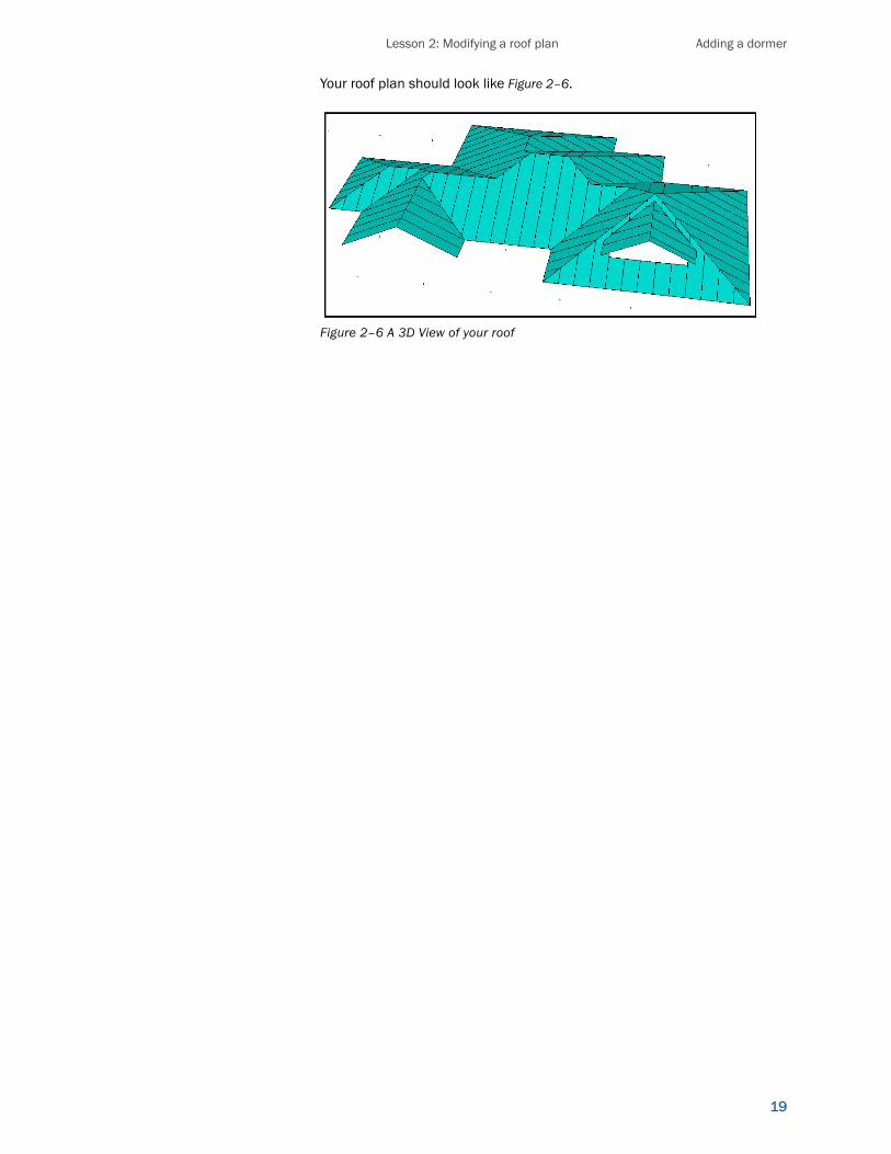
Your roof plan should look like Figure 2–6.
Figure 2–6 A 3D View of your roof

TopView Quick Start Guide
20

T
opVi
ew Q
uick
Sta
rt G
uide
Lesson 3: Dutch gables and eave extensionsThe third lesson in this sample project introduces you to the Dutch Gable and Eave Extension Wizards. You will continue to modify the roof plan you worked on in the previous two lessons.
Included in this section:
• adding a dutch gable• adding an eave extension

TopView 9.9 Quick Start Guide
22
Adding dutch gablesThe Dutch Gable Wizard makes adding dutch gables quick and seamless.
There are three ways to specify a dutch gable: Width, Up, and Up On Slope. This lesson details specifying by width only. For information on the remaining two ways of specifying, see the online help.
To add a dutch gable
1. On the main menu, click Add, then Dutch Gable Wizard.
The Create a Dutch Gable window appears, as in Figure 3–1.
Figure 3–1 The Create Dutch Gable for Section A window
2. Set the Name, Specify, Width, and Front Overhang boxes to match those in Figure 3–1, and ensure that the Add Appropriate Detail check box is selected.
3. Click OK.
The Create Dutch Gable window closes, and your mouse pointer becomes a box.
4. Select the eave line that the dutch gable will face, as in Figure 3–2.

Lesson 3: Dutch gables and eave extensions Adding dutch gables
23
Figure 3–2 Select the eave line
5. Click Cancel to stop adding dutch gables.
The dutch gable is added, and your roof plan should look like Figure 3–3.
Figure 3–3 Your project with the new dutch gable
6. Click the icon to view your roof plan in 3D.
Your plan should look like Figure 3–4.
Select this line
New dutch gable

TopView 9.9 Quick Start Guide
24
Figure 3–4 A 3D view of your roof plan
Adding an eave extensionAn eave extension is any section of an eave that extends below the rest of the eave. This extension can be either at the same pitch--a true eave extension--or at a different pitch, creating a pitch transition.
There are two ways to specify an eave extension: Length, and Length on Slope. This lesson details specifying by Length only. For information on specifying Length on Slope, see our online help.
To add an eave extension
1. On the main menu, click Add, then click Eave Extension Wizard.
The Create Eave Extension window appears, as in Figure 3–5.
Figure 3–5 The Create Eave Extension window
2. Set the Name, Slope, Specify, Length, and Width options to match those in Figure 3–5, and ensure that the Add Appropriate Details check box is selected.
3. Click OK.
The Create Eave Extension window closes and your cursor appears as a small box.
4. Select the eave line as indicated in Figure 3–6.

Lesson 3: Dutch gables and eave extensions Adding an eave extension
25
Figure 3–6 Select the eave line
5. With your mouse pointer, move the eave extension up, and type A to specify the position of the eave extension.
6. Type 1.5, and press Enter to place the eave extension in the middle of the edge.
Note: If the eave extension causes the elevation to be negative, an error message will appear. Simply click OK.
7. Click Cancel to stop adding eave extensions.
The eave extension is added. Your roof plan should look like Figure 3–7.
Figure 3–7 The new eave extension
8. Click the icon to view your roof in 3D.
Your plan should look like Figure 3–8.
Select this line
New eave extension

TopView 9.9 Quick Start Guide
26
Figure 3–8 3D view of roof with eave extension

T
opVi
ew
Qui
ck S
tart
Gui
de
Lesson 4: The Materials DatabaseThe final lesson in this sample project introduces you to the Materials Database.
Included in this section:
• accessing the materials database• creating the metal panel database• associating a panel with a supplier• specifying metal panel data• creating the roofing material database• selecting detail types• creating details• creating an items database• associating an item with a detail• adding extra information to the database• adding extra information to your project

TopView Quick Start Guide
28
Accessing the Materials DatabaseThe TOP VIEW database is designed to provide total flexibility in specifying a roof system. Initially, you have some work to do to customize the database according to your requirements; however, doing so will save you time when you are estimating jobs and ordering materials.
Tip !Check out Default Project Templates under the Setup menu to automate your work for commonly used roof systems.
To setup the Materials Database
1. On the Setup menu, click Materials Database.
The Setup Materials Database window appears as in Figure 4–1.
Figure 4–1 The Materials Database window
Tip !In the Materials Database, you can right-click on any cell to see a list of all options available. If no options are available, you are free to enter your own text or values.
Each of the tabs across the top of the Setup Materials Database window—Metal Panels, Tiles/Shingles, Details, Items, Suppliers, Detail Types, Flat Sheets, and Extras—represents a database. You can customize these databases, create cross-references between them, and fill them with detailed information about the materials required for your report.
Note: If you do not install the sample auxiliary file when installing TopView , a single entry (#0) is created in each database (except in the Extras database).
The Metal Panels tab
Column title Indicates...
# a unique, computer-generated number for each metal panel (0-999)
Description a description of the metal panel
Supplier the index number of the supplier of the metal panel. If the supplier number displayed is -1, the value has not been specified
UM the units of measurement by which the metal panels are priced. Options are PANEL, LN FT (linear feet), SQR FT (square feet) or SQUARE (100 sq.ft)

Lesson 4: The Materials Database Creating a metal panels database
29
Creating a metal panels databaseYou can create additional panels, or rename existing panels as your requirements grow or change.
Tip !When the supplier is already in the database, simply click the Suppliers tab to find the number.
To add a metal panel to the database
1. On the Metal Panels tab, click Add.
The program assigns a unique number to the new panel.
2. Tab to the Description column, and enter the name of the metal panel you want to add. Name it “Prestige Panel”.
3. Tab to UM. Right-click to access a list of options, select SQR FT, and click OK. This sets how the metal panels are priced.
Since you are using a new supplier, the next step is to add a new supplier to the database.
To add a supplier to the database
1. Click Supplier, then click Add.
A new supplier number is generated.
2. Tab to the Company Name column and enter the name ABC Roofing.
3. Tab through the rest of the columns, entering the Address, Phone Number and Fax Number information for the new supplier. When you have finished, click OK to save your new supplier to the database.
Associating a panel with a supplierYou can index and link the many materials suppliers for your project to individual metal panels and other items. This will assist you when ordering materials and estimating costs. For more information on associating a panel with a supplier, see our online help.
Specifying panel dataYou can specify the dimensions and costs of the metal panels you use in your projects.
The Panel Data tab has the following columns:
Panel Data columns
Column title What is it?
Width the width of the panel (in inches)
Length where you enter the length of the panel (in feet)
Eff Width the effective width of the unfolded metal panel, and should be set to the same distance as the panel’s width
Min Length the minimum panel length (in feet) for which the panel can be produced. All panels under the minimum length are cut from a panel of this size.

TopView Quick Start Guide
30
To add panel data
1. On the Metal Panels tab, select Prestige Panel, and click Panel Data.
The Panel Data window appears, as in Figure 4–2.
Figure 4–2 Prestige Panel data window
Tip !When working in the Materials Database, right-click a field to see the options available. If no options are listed, you can type any text into the field.
2. Click Add Panel.
The application assigns a unique number to the panel.
3. Tab across the row, entering information for the new panel. Don’t forget to scroll all the way to the right to the columns you can’t see!
Your new panel will look something Figure 4–3, only with your own values.
Min Action indicator of whether a panel below the minimum length is set to DISCARD (the panel is ignored), ACCCUM (all panels under the minimum length are collected and cut from a minimum length panel), or STRETCH (any panel below the minimum length is treated as a minimum length panel)
Horz Step the step size (in feet) for a panel that is aligned horizontally
Step Action the stepping style for a panel that is aligned horizontally. If set to ALTERNATE, the panel is shortened if the edge is within the step distance of the preceding row. If set to STAIRCASE, each panel is shortened to create a staircase look.
Tile Interval the interval (in inches) for panel surface details such as simulated tiling. Set this to zero if there are no surface details
Round Up indicator of whether or not the tile interval will "round up" to the nearest whole tile interval when a short piece of tile is required at the end of the panel. The column requires you to select YES or NO.
Start Offset the amount of space (in inches) that is left at the eave line before starting to place metal panels with simulated tiling
Cost the price in dollars of a panel, per unit of measure
Markup the markup expressed as a decimal
Order Info the metal panels number, or any other useful information
Panel Data columns
Column title What is it?

Lesson 4: The Materials Database Creating a Tile/Shingle Database
31
Figure 4–3 Prestige panel data
4. Click OK to save your new panel data. Note that each metal panel can have a list of items associated with it. See Setup Items in the online help
Creating a Tile/Shingle DatabaseTip !When the supplier is already in the database, simply click the Suppliers tab to find the number.
1. IOn the Tile/Shingle tab, click Add.
The program assigns a unique number to the new material.
2. Tab to the Description column, and enter the name of the material you want to add.
Tab to Width. The table below describes the purpose of each column. .
Tile/Shingle Data
Column Title What is it?
# a unique, computer-generated number (0-999)
Description a description of the particular tile/shinglematerial
Width the tile/shingle width in inches
Exposure the tile/shingle exposure in inches
Step the step size in inches
Step Action Has no effect if the step is set to zero. Indicates the stepping style for the tile/shingle. If the option is set to alternate, the tile/shingle width will be shortened only if the edge is within the step distance of the previous row. If the option is set to staircase, the tile/shingle width will be shortened for each tile /shingle to create a staircase look.
Reuse Extra Indicates if the wasted parts of the tile/shingle should be attempted to be reused. Note that barrels, barrel dormers, cones and domes all have their tiles/shingles estimated based on roof area. Therefore this reuse option will be ignored in those cases.
Reuse width the minimum width in inches that the wasted part of the tile/shingle needs to be before it can be reused
Pieces per Bundle the number of individual tile/shingle pieces in one bundle
Unit of Measure the tiles/shinglecan be priced by piece, linear feet , square feet, squares, or bundle

TopView Quick Start Guide
32
Selecting detail typesDetails—for example, ridges, hips, and eaves—are trim pieces that are used with metal panels, tiles, shingle and other roofing materials. Editing the detail types data and associating detail types with details, enables you to distinguish between different types of details more readily when you insert or delete them from your project.
The Detail Types tab looks like Figure 4–4.
Figure 4–4 The Detail Types tab
Cost the price of the ti/e/shingle material per unit of measure
Markup the markup percentage expressed as a decimal value
Supplier an index to the supplier that provides the particular tile/shingle material. I fthe the supplier number displayed is -1, no supplier has bee specified. See Setup-Suppliers or review the steps to add a supplier under the section titled Creating a metal panel database.
Order info the tile/shingle material’s catalogue number ooro any othe useful information.
Tile/Shingle Data
Column Title What is it?

Lesson 4: The Materials Database Creating details
33
Tip !In the Materials Database, you can right-click on any cell to see a list of options available. If no options are available, you are free to enter your own text or values.
To create a new detail type
1. On the Detail Types tab, click Add.
The program assigns a unique number for the new detail type.
2. Name the detail type "Vented Ridge".
3. Right-click in the Type column.
4. In the Fixed Detail Type box, select Ridge, and click OK.
5. Give it the abbreviation "VR", and an on-screen color of 5 (dark red).
From now on, whenever you select a vented ridge detail, it will be appear on-screen as dark red.
Creating detailsThe Details tab has the following columns:
Detail Types columns
Column title What is it?
# a unique, computer-generated number between 0 and 999
Description a description of the detail type
Type the fixed detail type. Many different detail types can be defined but most of these different detail types belong to a particular fixed detail type that can be specified here. Note that the fixed detail type is used to limit the details that are displayed in the Add Detail between Points, Add Detail on Edge, Change Detail Material , Section Defaults, Section Summary andn Setup Project Templates options. Note that the fixed detail type is used when computing the angle of the appropriate non-automatic detail.
Abbreviation used to identify the detail type.
Color an indication of how the detail type will appear on your monitor. The color codes are:0 Black 4 Red 8 Blue 12 Cyan1 White 5 Dk Red 9 Dk Blue 13 Dk Cyan2 Lt Gray 6 Green 10 Magenta 14 Yellow3 Dk Gray 7 Dk Green 11 Dk Magenta 15 Brown
Details columns
Column title What is it?
# a unique, computer-generated number for each detail from 0 to 999
Description a description of the particular detail
Type an index to the detail type. See setup Detail Type in online help
Width the width of the detail (in inches)
Length the maximum length of the detail (in feet)
Overlap the overlap (in inches) between successive details
UM the units of measure by which the details are priced. They could be by PIECE, LN FT (linear feet), SQR FT (square feet), or SQUARE (100 sq. feet)
Reuse Extra indicator of whether or not leftover pieces of details are reused
Reuse Length the minimum length in feet a leftover piece of detail must be before it can be reused

TopView Quick Start Guide
34
Tip !Group like details together by leaving a row between kinds of details. Doing so facilitates finding details quickly.
To create a detail
1. On the Details tab, click Add.
The program assigns a unique number for the detail. The Details database tab looks like Figure 4–5.
Figure 4–5 The Details database
2. Tab to the Description column, and enter the name of the detail you want to add.
3. Tab to each consecutive column, adding information pertaining to the new detail. NOTE: If you are entering more than one detail, you do not need to click OK at this point, simply repeat steps 1 through 3 until all of the details you want to add are entered, then click OK to save your new details.
Cost the price iof the detail, per unit of measure. It is important to note that the detail cost output on reports is the total of the cost specified by both detaila as well as flat sheets. This means that details and flat sheets can be priced using three different methods. The first method is to specify that the total cost of the details and flat sheets is only the detail costs and therefore the flat sheet costs should be set to $0.00. The second method is to specify that the total cost of the details and flat sheets is only the flat sheet costs and therefore the detail costs should be set to$0.00. The third method (which allows the most pricing flexibility) is to specify a base price in the flat sheet costs but then to specify the extra costs associated with details (accounting for nmber of bends, etc) in the detail costs. See Setup Flat Sheets in the online help.
Markup the markup expressed as a decimal
Supplier the index number of the detail supplier. A list of Suppliers is found under the Suppliers tab. If the number displayed is -1, the supplier has not been specified yet
Order Info the detail’s catalogue number, or any other useful information
Details columns
Column title What is it?

Lesson 4: The Materials Database Creating an items database
35
Creating an items databaseYou can create a database of items that you can associate with specific roofing materials and details. Although items such as screws, rivets, and sealant are small and inexpensive, they are integral to your project and cannot be ignored.
For accuracy in generating price reports, you need to know how the units are purchased—boxes of screws, tubes of caulk, and so on—the cost of each unit, and the markup percentage.
In the Items tab, you see #, Description, Report Units, Type, Unit Cost, and Markup columns, and you can scroll right to view the Supplier and Order Info columns. You should be familiar with most of these items, with the exceptions noted below.
To add an item to the database
1. Click the Items tab, then click Add.
The program assigns a unique number for the item. The Item database tab is set up like the one shown in Figure 4–6. Note that specific items are listed as examples and your screen will look different
Figure 4–6 The Details database
The Items columns
Column title What is it?
Report Units lists how the units are reported (by the piece, tube and so on)
Type indicator of whether an item is Discrete (screws, clips) or Continuous (tape, sealant). DISCRETE items are rounded up on a per panel basis. CONT items are not.
Unit Cost the cost per report unit

TopView Quick Start Guide
36
Tip !Group like items together by leaving a row between kinds of items. Doing so facilitates finding what you are looking for in a hurry.
2. Tab to the Description column, and enter the name of the item you wish to add.
3. Tab to each consecutive column, adding information pertaining to the new item. NOTE: If you are entering more than one item, you do not need to click OK at this point, simply repeat steps 1 through 3 until all of the items you want to add are entered. Then click OK to save your new items.
Associating an item with a detailEach detail can have a list of items with which it is associated. This list re-populates automatically when you add a detail. Creating an association between items and a detail assists you in ordering materials and estimating costs of your projects.
Tip !In the Materials Database, you can right-click on any cell to see a list of all options available. If no options are available, you are free to enter your own text or values.
To associate items to a detail
1. Click Details, then select a detail that you want to itemize. For this lesson, select Eave Detail, as in Figure 4–7.
Figure 4–7 The Details database
2. Click Itemize, then click Insert Items.
A window appears, listing all items in the Items database, as in Figure 4–8.

Lesson 4: The Materials Database Adding extra information to the data-
37
Figure 4–8 The Select Items window
3. Select (highlight) the items you want to associate with the eave detail you selected in step 1. NOTE: You do not need to click OK after selecting each item, simply select all of the items you want to associate with the eave detail, then click OK to save your selections.
4. Tab to the # of column, enter the number of items required, then tab to the UM column and right-click to see a list of units of measurement. Select the appropriate unit of measurement.
5. Repeat step 4 for each of the items you associated to the eave detail. When you have finished with all items, click OK to save your selections.
Your results should look similar to Figure 4–9.
Figure 4–9 Linking items to details
6. Click OK to return to the Details tab.
Adding extra information to the databaseThe Extras option allows you to add miscellaneous information to the database— for example, labor and shipping costs, roof skylights and so on—that is not

TopView Quick Start Guide
38
recorded elsewhere. You can include this extra information in projects and print it on reports, without associating it with any particular roofing material or detail.
To add an extra to the database
1. Select the Extras tab.
The Extras database opens.
2. Click Add to add a new extra to the database.
Tip !Clicking Add after you enter an extra allows you to add another extra before saving. When you have finished entering extras, be sure to click OK to save your extras.
3. Type “Shipping Fees” in the Description tab.
4. Tab to the Unit of Measure column, right-click to view your options for this setting, select “Miles”, and click OK.
5. Tab to the Cost per UM tab, and enter “2.1”.
The Extras database should look similar to Figure 4–10.
Figure 4–10 Adding an extra
6. Click OK to save all of the information in the materials database.
Adding extra information to your projectThe extra information you entered in the database can now be added to an individual project, and later printed out on a report.
To add extra information to your project
1. On the Project menu, select Extras.
The Extras columns
Column title What is it?
Description a description of the extra
UM the unit of measure by which the extra is priced
Cost per UM the cost of a single unit of measure of the extra
Markup the markup expressed as a decimal

Lesson 4: The Materials Database Adding extra information to your project
39
The Extras window opens listing the extra costs associated to the project.
You can add an extra to the project in the same way that you added it into the database, or select Add from List to add items from entries that are already in the Materials Database.
2. Click Add From List.
TipYou can also choose to add any other materials from the database as an extra.
The Add Extras from List window appears, as in Figure 4–11.
Figure 4–11 The Add Extras from List window
3. Select Permit Fees, Labor, and Travel Time, then click OK.
The Add Extras from List window closes, and the Extras database should look like Figure 4–12.
Figure 4–12 The Extras database
4. For each of the extras you added, tab to the quantity column and enter the amount of the extra you require. [Choose these numbers for yourself.]
5. When you have added quantities for each extra listed, click OK.

TopView Quick Start Guide
40
Congratulations! You have completed the final lesson of the TopView Quick Start Guide.